JP2020532377A - Adult incontinence equipment - Google Patents
Adult incontinence equipment Download PDFInfo
- Publication number
- JP2020532377A JP2020532377A JP2020512703A JP2020512703A JP2020532377A JP 2020532377 A JP2020532377 A JP 2020532377A JP 2020512703 A JP2020512703 A JP 2020512703A JP 2020512703 A JP2020512703 A JP 2020512703A JP 2020532377 A JP2020532377 A JP 2020532377A
- Authority
- JP
- Japan
- Prior art keywords
- zone
- wing
- stretch
- woven fabric
- zones
- Prior art date
- Legal status (The legal status is an assumption and is not a legal conclusion. Google has not performed a legal analysis and makes no representation as to the accuracy of the status listed.)
- Pending
Links
- 206010021639 Incontinence Diseases 0.000 title claims abstract description 28
- 239000004745 nonwoven fabric Substances 0.000 claims abstract description 81
- 238000004519 manufacturing process Methods 0.000 claims description 12
- 238000000034 method Methods 0.000 claims description 7
- 239000010410 layer Substances 0.000 description 62
- 239000012790 adhesive layer Substances 0.000 description 12
- 239000000463 material Substances 0.000 description 11
- 239000000853 adhesive Substances 0.000 description 6
- 230000001070 adhesive effect Effects 0.000 description 6
- 238000000465 moulding Methods 0.000 description 6
- 238000003466 welding Methods 0.000 description 5
- PPBRXRYQALVLMV-UHFFFAOYSA-N Styrene Chemical compound C=CC1=CC=CC=C1 PPBRXRYQALVLMV-UHFFFAOYSA-N 0.000 description 4
- 230000008878 coupling Effects 0.000 description 3
- 238000010168 coupling process Methods 0.000 description 3
- 238000005859 coupling reaction Methods 0.000 description 3
- 239000012778 molding material Substances 0.000 description 3
- 229920000642 polymer Polymers 0.000 description 3
- 235000001674 Agaricus brunnescens Nutrition 0.000 description 2
- 229920001400 block copolymer Polymers 0.000 description 2
- 238000003490 calendering Methods 0.000 description 2
- 238000009958 sewing Methods 0.000 description 2
- 229920001169 thermoplastic Polymers 0.000 description 2
- 239000004416 thermosoftening plastic Substances 0.000 description 2
- 238000002604 ultrasonography Methods 0.000 description 2
- VSKJLJHPAFKHBX-UHFFFAOYSA-N 2-methylbuta-1,3-diene;styrene Chemical compound CC(=C)C=C.C=CC1=CC=CC=C1.C=CC1=CC=CC=C1 VSKJLJHPAFKHBX-UHFFFAOYSA-N 0.000 description 1
- 208000019901 Anxiety disease Diseases 0.000 description 1
- 239000004677 Nylon Substances 0.000 description 1
- 239000004952 Polyamide Substances 0.000 description 1
- 206010040880 Skin irritation Diseases 0.000 description 1
- 230000004913 activation Effects 0.000 description 1
- 230000036506 anxiety Effects 0.000 description 1
- BLAJPPMSXMTCLR-UHFFFAOYSA-N but-1-ene styrene Chemical compound CCC=C.C=CC1=CC=CC=C1.C=CC1=CC=CC=C1 BLAJPPMSXMTCLR-UHFFFAOYSA-N 0.000 description 1
- 229920001577 copolymer Polymers 0.000 description 1
- 229920001971 elastomer Polymers 0.000 description 1
- 239000000806 elastomer Substances 0.000 description 1
- 230000029142 excretion Effects 0.000 description 1
- 239000000835 fiber Substances 0.000 description 1
- 239000011888 foil Substances 0.000 description 1
- 239000003292 glue Substances 0.000 description 1
- 238000010438 heat treatment Methods 0.000 description 1
- 238000005304 joining Methods 0.000 description 1
- 239000000203 mixture Substances 0.000 description 1
- 229920001778 nylon Polymers 0.000 description 1
- 239000004033 plastic Substances 0.000 description 1
- 229920002647 polyamide Polymers 0.000 description 1
- 229920000728 polyester Polymers 0.000 description 1
- 229920000098 polyolefin Polymers 0.000 description 1
- 229920000346 polystyrene-polyisoprene block-polystyrene Polymers 0.000 description 1
- 238000003825 pressing Methods 0.000 description 1
- 230000002787 reinforcement Effects 0.000 description 1
- 239000012779 reinforcing material Substances 0.000 description 1
- 238000005096 rolling process Methods 0.000 description 1
- 230000036556 skin irritation Effects 0.000 description 1
- 231100000475 skin irritation Toxicity 0.000 description 1
- 229920006132 styrene block copolymer Polymers 0.000 description 1
- 239000000126 substance Substances 0.000 description 1
- 229920002725 thermoplastic elastomer Polymers 0.000 description 1
- 239000002699 waste material Substances 0.000 description 1
- 238000004804 winding Methods 0.000 description 1
Images


Classifications
-
- A—HUMAN NECESSITIES
- A61—MEDICAL OR VETERINARY SCIENCE; HYGIENE
- A61F—FILTERS IMPLANTABLE INTO BLOOD VESSELS; PROSTHESES; DEVICES PROVIDING PATENCY TO, OR PREVENTING COLLAPSING OF, TUBULAR STRUCTURES OF THE BODY, e.g. STENTS; ORTHOPAEDIC, NURSING OR CONTRACEPTIVE DEVICES; FOMENTATION; TREATMENT OR PROTECTION OF EYES OR EARS; BANDAGES, DRESSINGS OR ABSORBENT PADS; FIRST-AID KITS
- A61F13/00—Bandages or dressings; Absorbent pads
- A61F13/15—Absorbent pads, e.g. sanitary towels, swabs or tampons for external or internal application to the body; Supporting or fastening means therefor; Tampon applicators
- A61F13/56—Supporting or fastening means
- A61F13/5605—Supporting or fastening means specially adapted for sanitary napkins or the like
- A61F13/5616—Supporting or fastening means specially adapted for sanitary napkins or the like using flaps, e.g. adhesive, for attachment to the undergarment
-
- A—HUMAN NECESSITIES
- A61—MEDICAL OR VETERINARY SCIENCE; HYGIENE
- A61F—FILTERS IMPLANTABLE INTO BLOOD VESSELS; PROSTHESES; DEVICES PROVIDING PATENCY TO, OR PREVENTING COLLAPSING OF, TUBULAR STRUCTURES OF THE BODY, e.g. STENTS; ORTHOPAEDIC, NURSING OR CONTRACEPTIVE DEVICES; FOMENTATION; TREATMENT OR PROTECTION OF EYES OR EARS; BANDAGES, DRESSINGS OR ABSORBENT PADS; FIRST-AID KITS
- A61F13/00—Bandages or dressings; Absorbent pads
- A61F13/15—Absorbent pads, e.g. sanitary towels, swabs or tampons for external or internal application to the body; Supporting or fastening means therefor; Tampon applicators
- A61F13/15577—Apparatus or processes for manufacturing
- A61F13/15756—Applying tabs, strips, tapes, loops; Knotting the ends of pads
-
- A—HUMAN NECESSITIES
- A61—MEDICAL OR VETERINARY SCIENCE; HYGIENE
- A61F—FILTERS IMPLANTABLE INTO BLOOD VESSELS; PROSTHESES; DEVICES PROVIDING PATENCY TO, OR PREVENTING COLLAPSING OF, TUBULAR STRUCTURES OF THE BODY, e.g. STENTS; ORTHOPAEDIC, NURSING OR CONTRACEPTIVE DEVICES; FOMENTATION; TREATMENT OR PROTECTION OF EYES OR EARS; BANDAGES, DRESSINGS OR ABSORBENT PADS; FIRST-AID KITS
- A61F13/00—Bandages or dressings; Absorbent pads
- A61F13/15—Absorbent pads, e.g. sanitary towels, swabs or tampons for external or internal application to the body; Supporting or fastening means therefor; Tampon applicators
- A61F13/45—Absorbent pads, e.g. sanitary towels, swabs or tampons for external or internal application to the body; Supporting or fastening means therefor; Tampon applicators characterised by the shape
- A61F13/47—Sanitary towels, incontinence pads or napkins
- A61F13/474—Sanitary towels, incontinence pads or napkins adjustable
-
- A—HUMAN NECESSITIES
- A61—MEDICAL OR VETERINARY SCIENCE; HYGIENE
- A61F—FILTERS IMPLANTABLE INTO BLOOD VESSELS; PROSTHESES; DEVICES PROVIDING PATENCY TO, OR PREVENTING COLLAPSING OF, TUBULAR STRUCTURES OF THE BODY, e.g. STENTS; ORTHOPAEDIC, NURSING OR CONTRACEPTIVE DEVICES; FOMENTATION; TREATMENT OR PROTECTION OF EYES OR EARS; BANDAGES, DRESSINGS OR ABSORBENT PADS; FIRST-AID KITS
- A61F13/00—Bandages or dressings; Absorbent pads
- A61F13/15—Absorbent pads, e.g. sanitary towels, swabs or tampons for external or internal application to the body; Supporting or fastening means therefor; Tampon applicators
- A61F13/45—Absorbent pads, e.g. sanitary towels, swabs or tampons for external or internal application to the body; Supporting or fastening means therefor; Tampon applicators characterised by the shape
- A61F13/49—Absorbent articles specially adapted to be worn around the waist, e.g. diapers
- A61F13/49007—Form-fitting, self-adjusting disposable diapers
- A61F13/49009—Form-fitting, self-adjusting disposable diapers with elastic means
- A61F13/49014—Form-fitting, self-adjusting disposable diapers with elastic means the elastic means is located at the side panels
- A61F13/49015—Form-fitting, self-adjusting disposable diapers with elastic means the elastic means is located at the side panels the elastic means being elastic panels
-
- A—HUMAN NECESSITIES
- A61—MEDICAL OR VETERINARY SCIENCE; HYGIENE
- A61F—FILTERS IMPLANTABLE INTO BLOOD VESSELS; PROSTHESES; DEVICES PROVIDING PATENCY TO, OR PREVENTING COLLAPSING OF, TUBULAR STRUCTURES OF THE BODY, e.g. STENTS; ORTHOPAEDIC, NURSING OR CONTRACEPTIVE DEVICES; FOMENTATION; TREATMENT OR PROTECTION OF EYES OR EARS; BANDAGES, DRESSINGS OR ABSORBENT PADS; FIRST-AID KITS
- A61F13/00—Bandages or dressings; Absorbent pads
- A61F13/15—Absorbent pads, e.g. sanitary towels, swabs or tampons for external or internal application to the body; Supporting or fastening means therefor; Tampon applicators
- A61F13/45—Absorbent pads, e.g. sanitary towels, swabs or tampons for external or internal application to the body; Supporting or fastening means therefor; Tampon applicators characterised by the shape
- A61F13/49—Absorbent articles specially adapted to be worn around the waist, e.g. diapers
- A61F13/49007—Form-fitting, self-adjusting disposable diapers
- A61F13/49009—Form-fitting, self-adjusting disposable diapers with elastic means
- A61F13/4902—Form-fitting, self-adjusting disposable diapers with elastic means characterised by the elastic material
-
- A—HUMAN NECESSITIES
- A61—MEDICAL OR VETERINARY SCIENCE; HYGIENE
- A61F—FILTERS IMPLANTABLE INTO BLOOD VESSELS; PROSTHESES; DEVICES PROVIDING PATENCY TO, OR PREVENTING COLLAPSING OF, TUBULAR STRUCTURES OF THE BODY, e.g. STENTS; ORTHOPAEDIC, NURSING OR CONTRACEPTIVE DEVICES; FOMENTATION; TREATMENT OR PROTECTION OF EYES OR EARS; BANDAGES, DRESSINGS OR ABSORBENT PADS; FIRST-AID KITS
- A61F13/00—Bandages or dressings; Absorbent pads
- A61F13/15—Absorbent pads, e.g. sanitary towels, swabs or tampons for external or internal application to the body; Supporting or fastening means therefor; Tampon applicators
- A61F13/45—Absorbent pads, e.g. sanitary towels, swabs or tampons for external or internal application to the body; Supporting or fastening means therefor; Tampon applicators characterised by the shape
- A61F13/49—Absorbent articles specially adapted to be worn around the waist, e.g. diapers
- A61F13/493—Absorbent articles specially adapted to be worn around the waist, e.g. diapers adjustable by adding or removing material, e.g. umbilical cord arrangements
-
- A—HUMAN NECESSITIES
- A61—MEDICAL OR VETERINARY SCIENCE; HYGIENE
- A61F—FILTERS IMPLANTABLE INTO BLOOD VESSELS; PROSTHESES; DEVICES PROVIDING PATENCY TO, OR PREVENTING COLLAPSING OF, TUBULAR STRUCTURES OF THE BODY, e.g. STENTS; ORTHOPAEDIC, NURSING OR CONTRACEPTIVE DEVICES; FOMENTATION; TREATMENT OR PROTECTION OF EYES OR EARS; BANDAGES, DRESSINGS OR ABSORBENT PADS; FIRST-AID KITS
- A61F13/00—Bandages or dressings; Absorbent pads
- A61F13/15—Absorbent pads, e.g. sanitary towels, swabs or tampons for external or internal application to the body; Supporting or fastening means therefor; Tampon applicators
- A61F13/45—Absorbent pads, e.g. sanitary towels, swabs or tampons for external or internal application to the body; Supporting or fastening means therefor; Tampon applicators characterised by the shape
- A61F13/49—Absorbent articles specially adapted to be worn around the waist, e.g. diapers
- A61F13/496—Absorbent articles specially adapted to be worn around the waist, e.g. diapers in the form of pants or briefs
-
- A—HUMAN NECESSITIES
- A61—MEDICAL OR VETERINARY SCIENCE; HYGIENE
- A61F—FILTERS IMPLANTABLE INTO BLOOD VESSELS; PROSTHESES; DEVICES PROVIDING PATENCY TO, OR PREVENTING COLLAPSING OF, TUBULAR STRUCTURES OF THE BODY, e.g. STENTS; ORTHOPAEDIC, NURSING OR CONTRACEPTIVE DEVICES; FOMENTATION; TREATMENT OR PROTECTION OF EYES OR EARS; BANDAGES, DRESSINGS OR ABSORBENT PADS; FIRST-AID KITS
- A61F13/00—Bandages or dressings; Absorbent pads
- A61F13/15—Absorbent pads, e.g. sanitary towels, swabs or tampons for external or internal application to the body; Supporting or fastening means therefor; Tampon applicators
- A61F13/56—Supporting or fastening means
- A61F13/5622—Supporting or fastening means specially adapted for diapers or the like
- A61F13/565—Supporting or fastening means specially adapted for diapers or the like pants type diaper
- A61F13/5655—Supporting or fastening means specially adapted for diapers or the like pants type diaper adjustable pants type diapers
-
- B—PERFORMING OPERATIONS; TRANSPORTING
- B32—LAYERED PRODUCTS
- B32B—LAYERED PRODUCTS, i.e. PRODUCTS BUILT-UP OF STRATA OF FLAT OR NON-FLAT, e.g. CELLULAR OR HONEYCOMB, FORM
- B32B5/00—Layered products characterised by the non- homogeneity or physical structure, i.e. comprising a fibrous, filamentary, particulate or foam layer; Layered products characterised by having a layer differing constitutionally or physically in different parts
- B32B5/02—Layered products characterised by the non- homogeneity or physical structure, i.e. comprising a fibrous, filamentary, particulate or foam layer; Layered products characterised by having a layer differing constitutionally or physically in different parts characterised by structural features of a fibrous or filamentary layer
- B32B5/022—Non-woven fabric
-
- B—PERFORMING OPERATIONS; TRANSPORTING
- B32—LAYERED PRODUCTS
- B32B—LAYERED PRODUCTS, i.e. PRODUCTS BUILT-UP OF STRATA OF FLAT OR NON-FLAT, e.g. CELLULAR OR HONEYCOMB, FORM
- B32B5/00—Layered products characterised by the non- homogeneity or physical structure, i.e. comprising a fibrous, filamentary, particulate or foam layer; Layered products characterised by having a layer differing constitutionally or physically in different parts
- B32B5/22—Layered products characterised by the non- homogeneity or physical structure, i.e. comprising a fibrous, filamentary, particulate or foam layer; Layered products characterised by having a layer differing constitutionally or physically in different parts characterised by the presence of two or more layers which are next to each other and are fibrous, filamentary, formed of particles or foamed
- B32B5/24—Layered products characterised by the non- homogeneity or physical structure, i.e. comprising a fibrous, filamentary, particulate or foam layer; Layered products characterised by having a layer differing constitutionally or physically in different parts characterised by the presence of two or more layers which are next to each other and are fibrous, filamentary, formed of particles or foamed one layer being a fibrous or filamentary layer
- B32B5/26—Layered products characterised by the non- homogeneity or physical structure, i.e. comprising a fibrous, filamentary, particulate or foam layer; Layered products characterised by having a layer differing constitutionally or physically in different parts characterised by the presence of two or more layers which are next to each other and are fibrous, filamentary, formed of particles or foamed one layer being a fibrous or filamentary layer another layer next to it also being fibrous or filamentary
-
- A—HUMAN NECESSITIES
- A61—MEDICAL OR VETERINARY SCIENCE; HYGIENE
- A61F—FILTERS IMPLANTABLE INTO BLOOD VESSELS; PROSTHESES; DEVICES PROVIDING PATENCY TO, OR PREVENTING COLLAPSING OF, TUBULAR STRUCTURES OF THE BODY, e.g. STENTS; ORTHOPAEDIC, NURSING OR CONTRACEPTIVE DEVICES; FOMENTATION; TREATMENT OR PROTECTION OF EYES OR EARS; BANDAGES, DRESSINGS OR ABSORBENT PADS; FIRST-AID KITS
- A61F13/00—Bandages or dressings; Absorbent pads
- A61F13/15—Absorbent pads, e.g. sanitary towels, swabs or tampons for external or internal application to the body; Supporting or fastening means therefor; Tampon applicators
- A61F2013/15008—Absorbent pads, e.g. sanitary towels, swabs or tampons for external or internal application to the body; Supporting or fastening means therefor; Tampon applicators characterized by the use
- A61F2013/15121—Absorbent pads, e.g. sanitary towels, swabs or tampons for external or internal application to the body; Supporting or fastening means therefor; Tampon applicators characterized by the use for mild incontinence
-
- A—HUMAN NECESSITIES
- A61—MEDICAL OR VETERINARY SCIENCE; HYGIENE
- A61F—FILTERS IMPLANTABLE INTO BLOOD VESSELS; PROSTHESES; DEVICES PROVIDING PATENCY TO, OR PREVENTING COLLAPSING OF, TUBULAR STRUCTURES OF THE BODY, e.g. STENTS; ORTHOPAEDIC, NURSING OR CONTRACEPTIVE DEVICES; FOMENTATION; TREATMENT OR PROTECTION OF EYES OR EARS; BANDAGES, DRESSINGS OR ABSORBENT PADS; FIRST-AID KITS
- A61F13/00—Bandages or dressings; Absorbent pads
- A61F13/15—Absorbent pads, e.g. sanitary towels, swabs or tampons for external or internal application to the body; Supporting or fastening means therefor; Tampon applicators
- A61F2013/15008—Absorbent pads, e.g. sanitary towels, swabs or tampons for external or internal application to the body; Supporting or fastening means therefor; Tampon applicators characterized by the use
- A61F2013/1513—Absorbent pads, e.g. sanitary towels, swabs or tampons for external or internal application to the body; Supporting or fastening means therefor; Tampon applicators characterized by the use for anal discharge
-
- A—HUMAN NECESSITIES
- A61—MEDICAL OR VETERINARY SCIENCE; HYGIENE
- A61F—FILTERS IMPLANTABLE INTO BLOOD VESSELS; PROSTHESES; DEVICES PROVIDING PATENCY TO, OR PREVENTING COLLAPSING OF, TUBULAR STRUCTURES OF THE BODY, e.g. STENTS; ORTHOPAEDIC, NURSING OR CONTRACEPTIVE DEVICES; FOMENTATION; TREATMENT OR PROTECTION OF EYES OR EARS; BANDAGES, DRESSINGS OR ABSORBENT PADS; FIRST-AID KITS
- A61F13/00—Bandages or dressings; Absorbent pads
- A61F13/15—Absorbent pads, e.g. sanitary towels, swabs or tampons for external or internal application to the body; Supporting or fastening means therefor; Tampon applicators
- A61F2013/15008—Absorbent pads, e.g. sanitary towels, swabs or tampons for external or internal application to the body; Supporting or fastening means therefor; Tampon applicators characterized by the use
- A61F2013/15146—Absorbent pads, e.g. sanitary towels, swabs or tampons for external or internal application to the body; Supporting or fastening means therefor; Tampon applicators characterized by the use for urine collection
Abstract
【解決手段】成人用失禁用具のためのウィングを開示する。成人用失禁用具は、側方の取り付け面を備えるシャーシを有する。ウィングは、少なくとも1つの不織布層と少なくとも1つの弾性層とを備える伸張性積層体を含む。不織布層及び弾性層は、対面接触して共に結合される。伸張性積層体は、少なくとも1つの伸張ゾーンと少なくとも1つの非伸張ゾーンとを有する。伸張性積層体は、伸張ゾーンと非伸張ゾーンとの間に重なった部分を有さない。ウィングの一端は、シャーシの側方の取り付け面に固定される。A wing for an adult incontinence device is disclosed. The adult incontinence device has a chassis with a side mounting surface. The wing comprises an extensible laminate comprising at least one non-woven fabric layer and at least one elastic layer. The non-woven fabric layer and the elastic layer are in face-to-face contact and are bonded together. The extensible laminate has at least one stretch zone and at least one non-stretch zone. The extensible laminate does not have an overlap between the stretch zone and the non-stretch zone. One end of the wing is secured to the lateral mounting surface of the chassis.
Description
本発明は、一般に成人用失禁用具に関し、特にそれらの用具で使用する「ウィング」に関するものである。 The present invention generally relates to adult incontinence devices, especially the "wings" used in those devices.
失禁用具市場は、2つのセグメント、乳児用具(又はおむつ)及び成人用具(又はブリーフ)に分けることができる。乳児及び大人用セグメントは、着用者への配慮(乳児対成人)、購入者(親対着用者)、及びニーズ(乳児のための排せつ訓練対成人のための医療ニーズ)を含むがこれに限らない、多くの要因のために異なっている。したがって、これらの2つのセグメントのための革新的な原動力は異なっており、ひとまとめにすることはできない。 The incontinence equipment market can be divided into two segments: baby equipment (or diapers) and adult equipment (or briefs). The infant and adult segment includes, but is limited to, wearer care (infant vs. adult), purchaser (parent vs. wearer), and needs (excretion training for infants vs. medical needs for adults). Not different due to many factors. Therefore, the innovative driving forces for these two segments are different and cannot be combined.
成人用失禁用具市場において、現在の製品は改良が必要である。例えば、製造の観点、及び効用の観点から、成人の着用者の周りに用具を固定するために用いる構成要素、典型的にウィングが必要とされている。現在、成人用失禁用具に使用するウィングは、用具に取り付ける前に共に接合されなければならない、2つ以上のサブコンポーネントから製造される。そのようなマルチコンポーネントのウィングは、少なくとも製造の複雑性(及びコスト)を増加させ、用具をあまり魅力でないものとしている。 In the adult incontinence equipment market, current products need improvement. For example, from a manufacturing point of view and a utility point of view, there is a need for components, typically wings, used to secure the device around an adult wearer. Currently, wings used in adult incontinence equipment are manufactured from two or more subcomponents that must be joined together before being attached to the equipment. Such multi-component wings at least increase manufacturing complexity (and cost) and make the equipment less attractive.
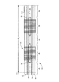
図1A及び1Bでは、そのような先行技術の用具が図示されている。図1Aにおいて、用具10は、取り付け面14を含むシャーシ12と、シャーシ12に結合部16を介して取り付けられるウィング20とを有する。ウィング20は、いくつかのサブコンポーネント、例えば第2の非伸張ゾーン24に重なり合い接合されている伸張ゾーン26に、重なり合い接合される第1の非伸張ゾーン22から製造される。用具10は、ウィング20の先端にファスナ(又はファスナ構成要素)18を含み得る。図1Bでは、図1Aの部分断面図に基づいて、重なり合う構成要素が横断面にて図示されている。重なり(又は継ぎ目)28、30では、サブコンポーネントが共に接合されている。
In FIGS. 1A and 1B, such prior art tools are illustrated. In FIG. 1A, the
本発明を説明する目的で、現時点で好ましい形態を図面に示すが、ただし、図示された通りの配置及び手段に本発明が限定されるものではないことは理解されたい。 For the purposes of explaining the present invention, the preferred embodiments are shown in the drawings at this time, but it should be understood that the present invention is not limited to the arrangement and means as shown.
上記の重なり(又は継ぎ目)により、少なくとも製造の複雑性が増加し、サブコンポーネントの一部を十分に活用しないことによって無駄が増え、用具の魅力を減少させ、用具の快適さを減少させ、摩擦による皮膚刺激のリスクを増加させている。加えて、そのような重なりを有する用具は、ロールに包装される製品の異なる厚みのため、巻付け及び巻戻しの困難さがもたらされる。更に、そのようなマルチコンポーネントのウィングは、ユーザに不安感をもたらす。例えば、2つの隣接する構成要素間の接合部が、用具の使用中に意図せずに破損する可能性があり、それによってユーザが困難な/不快な/厄介な状況に置かれる可能性がある。
したがって、成人用失禁用具(又はブリーフ)で使用するための新規なウィングが必要とされている。
The above overlaps (or seams) increase at least manufacturing complexity, increase waste by not fully utilizing some of the subcomponents, reduce the attractiveness of the tool, reduce the comfort of the tool, and rub. Increases the risk of skin irritation caused by. In addition, tools with such overlaps pose difficulties in winding and rewinding due to the different thicknesses of the products packaged in rolls. Moreover, such multi-component wings cause anxiety to the user. For example, the joint between two adjacent components can be unintentionally broken during use of the tool, which can put the user in a difficult / unpleasant / awkward situation. ..
Therefore, a new wing is needed for use in adult incontinence equipment (or briefs).
成人用失禁用具のためのウィングを開示する。成人用失禁用具は、側方の取り付け面を備えるシャーシを有する。ウィングは、少なくとも1つの不織布層と少なくとも1つの弾性層とを備える伸張性積層体を含む。不織布層及び弾性層は、対面接触して共に結合される。伸張性積層体は、少なくとも1つの伸張ゾーンと少なくとも1つの非伸張ゾーンとを有する。伸張性積層体は、伸張ゾーンと非伸張ゾーンとの間に重なった部分を有さない。ウィングの一端は、シャーシの側方の取り付け面に固定される。 Disclose wings for adult incontinence equipment. The adult incontinence device has a chassis with a side mounting surface. The wing comprises an extensible laminate comprising at least one non-woven fabric layer and at least one elastic layer. The non-woven fabric layer and the elastic layer are in face-to-face contact and are bonded together. The extensible laminate has at least one stretch zone and at least one non-stretch zone. The extensible laminate does not have an overlap between the stretch zone and the non-stretch zone. One end of the wing is secured to the lateral mounting surface of the chassis.
図2A、2B、3A、3B、3C、6A、6B及び6Cを参照すると、本発明のいくつかの例示的な実施形態が図示されている。同一の番号が同一の要素に使用される。 With reference to FIGS. 2A, 2B, 3A, 3B, 3C, 6A, 6B and 6C, some exemplary embodiments of the invention are illustrated. The same number is used for the same element.
図2A及び2Bを参照すると、成人用失禁用具100の2つの実施形態が図示されている。用具100は、一般にシャーシに固定されるウィング120、特に2つのウィングを備えるシャーシ112(従来型の)を含む。図2Aにおいて、用具は可閉であって、これは、用具を複数回開閉することができるファスナ構成要素(例えば、面ファスナ、及び/又は接着剤)118(及び、必要に応じてシャーシの別の部分の片方118A)が、ウィング120の自由端(又は先端)に付加されており、固定端(又は基端)がシャーシ112の取り付け面114に固定されている(任意の従来方式で−例えば、接着剤、熱溶接、超音波溶接、縫製によって116に結合される)ことを意味している。図2Bでは、用具100は閉じており、これは、ウィング120の両端が、シャーシ112の取り付け面114に固定して取り付けられている(任意の従来方式で−例えば、接着剤、熱溶接、超音波溶接、縫製によって116に結合される)ことを意味している。以下、便宜上、本発明は図2Aに示される実施形態を参照して述べられるが、本発明は、いずれの実施形態にも等しく適用可能である。
With reference to FIGS. 2A and 2B, two embodiments of the
図3A、3B及び3Cを参照すると、ウィング120のいくつかの実施形態が図示されている。ウィング120は、一般に、少なくとも1つの伸張ゾーン126、並びに1つの非伸張ゾーン122及び/又は124を含む。伸張ゾーン126及び非伸張ゾーン122、124は、互いに交互に並んでいてもよい。上記で述べたように、ウィング120は重なり(又は継ぎ目)がなく、不織布の連続層(一方の側面から対向する側面に至る)を使用して、すなわち重なり又は継ぎ目なしで製造されていてもよい。ウィング120は、サブコンポーネント、すなわち伸張ゾーン126及び非伸張ゾーン122、124を接合する継ぎ目のない、一体の(又は単一若しくはシームレスな)構成要素である。ウィング120は伸張性積層体であってもよく、又は少なくとも1つの伸張ゾーンと少なくとも1つの非伸張ゾーンとを備える伸張性積層体であってもよい。伸張ゾーンは、少なくとも機械横方向(CD)で弾性であってもよい。非伸張ゾーンは、少なくとも機械横方向で非弾性(又は非伸縮性)であってもよい。それぞれのウィングは、少なくとも1つの弾性層を有する。ウィングは、2つ又は少なくとも2つの弾性層を有してもよい。ウィングは、3つ又は少なくとも3つの弾性層を有してもよい。ウィングは、4つ又は少なくとも4つの弾性層を有してもよい。伸張性積層体は、2つのウィングが形成され得る4つの弾性層を含んでもよい。先行技術のウィングを本発明のウィングと比較した場合、同一の延長部分に対して、本発明のウィングの幅は、先行技術のウィングの幅より小さくてもよい。
With reference to FIGS. 3A, 3B and 3C, some embodiments of the
伸張性積層体は、任意の伸張性積層体であってよい。伸張性積層体とは、対面接触して共に結合される不織布層及び弾性層を含む材料を一般に意味する。結合は自己結合であってよく、並びに/又は、接着剤及び/若しくは溶接(例えば熱、超音波、又はその両方)によって促進されてもよい。伸張性積層体において、弾性層(又はフィルム)の面積は、不織布層の面積より小さくてもよく、それによって弾性レーン(又はゾーン)が非弾性レーン(又はゾーン)の間に生成される。弾性レーンは、活性化、非活性化、部分的に活性化されてもよく(弾性レーンの一部に対してのみ活性化される)、及び/又は様々な程度に活性化されてもよい。活性化は、伸張(例えば、リングローリング)によって実施してもよい。いくつかの実施形態では、伸張性積層体は、上部不織布及び下部不織布を含み、弾性フィルムがその間に挟まれている。以下、便宜上、伸張性積層体120は後者として説明される。
The extensible laminate may be any extensible laminate. The extensible laminate generally means a material including a non-woven fabric layer and an elastic layer which are face-to-face contact and bonded together. The bond may be self-bonding and / or may be facilitated by an adhesive and / or weld (eg, heat, ultrasound, or both). In an extensible laminate, the area of the elastic layer (or film) may be smaller than the area of the non-woven fabric layer, thereby creating elastic lanes (or zones) between the inelastic lanes (or zones). Elastic lanes may be activated, deactivated, partially activated (activated only for a portion of the elastic lane), and / or activated to varying degrees. Activation may be performed by stretching (eg, ring rolling). In some embodiments, the stretchable laminate comprises an upper non-woven fabric and a lower non-woven fabric, with an elastic film sandwiched between them. Hereinafter, for convenience, the
伸張性積層体50の一部の一実施形態が、図4に図示されている。分解されて示されているが、伸張性積層体50は一般に、上部不織布52と、下部不織布54と、その間に挟まれる弾性フィルム56とを含む。弾性フィルムを備える伸張性積層体の部分58は、伸張ゾーン(又は弾性レーン)を規定し、弾性フィルムのない伸張性積層体の部分60は、非伸張ゾーン(又は非弾性レーン)を規定する。伸張ゾーン58では、不織布によってフィルムの弾性が妨げられない(又は部分的に妨げられるにすぎない)ように、結合パターン62を介して不織布52、54が弾性フィルムに結合される。非伸張ゾーン60では、結合された不織布の任意の可能な伸張性が低減又は除去されるように、結合パターン64を介して、及び/又は硬化材料(例えば、非弾性フィルム又はフォイル)を使用することによって、不織布52、54が共に結合される。非伸張ゾーンは、接着剤層、超音波結合、熱カレンダー加工、コールドカレンダー加工、又はそれらの組み合わせからなる群から選択される固定手段によってそれらの間が固定される、2つの不織布層を含んでもよい。非伸張ゾーンは、2つの不織布層間の補強材として、追加の材料を含んでもよい。非伸張ゾーンに対応する2つの固定された不織布層には十分な強度があるため、非伸張ゾーンは、一体性又は補強のための追加の材料を必要としない場合がある。伸張性積層体に関しては、一般に、参考として本明細書に組み込まれている米国特許第7794819号明細書を参照されたい。結合パターン64は、任意の結合パターンであってよい。結合パターン64は、接着剤及び/又は溶接(熱及び/又は超音波)によって製造してもよい。
One embodiment of a portion of the
伸張ゾーン、弾性層及び非伸張ゾーンは、それぞれ幅を有する。伸張ゾーンにおいて、弾性層の幅は非伸張ゾーンの幅と等しくてもよく、及び/又は弾性層の幅は非伸張ゾーンの25〜90%の範囲内であってよく、及び/又は弾性層の幅は非伸張ゾーンの幅の40〜80%の範囲内であってよい。例えば、本発明のウィングが300mmの幅であり、それぞれ45mmの幅を有する2つの弾性フィルムを有する場合、弾性フィルムは43%である(90/(300−90)×100=43%[伸張:非伸張比]。本発明のウィングが225mmの幅であり、それぞれ45mmの幅を有する2つの弾性フィルムを有する場合、弾性フィルムは67%である(90/(225−90)×100=67%[伸張:非伸張比]。本発明のウィングが215mmの幅であり、それぞれ45mmの幅を有する2つの弾性フィルムを有する場合、弾性フィルムは72%である(90/(215−90)×100=72%[伸張:非伸張比]。本発明のウィングが205mmの幅であり、それぞれ45mmの幅を有する2つの弾性フィルムを有する場合、弾性フィルムは78%である(90/(205−90)×100=78%[伸張:非伸張比]。 The stretch zone, elastic layer and non-stretch zone each have a width. In the stretch zone, the width of the elastic layer may be equal to the width of the non-stretch zone, and / or the width of the elastic layer may be in the range of 25-90% of the non-stretch zone, and / or of the elastic layer. The width may be in the range of 40-80% of the width of the non-stretch zone. For example, if the wing of the present invention has a width of 300 mm and has two elastic films each having a width of 45 mm, the elastic film is 43% (90 / (300-90) x 100 = 43% [stretch:: Non-stretch ratio]. If the wing of the present invention has two elastic films with a width of 225 mm and each has a width of 45 mm, the elastic film is 67% (90 / (225-90) x 100 = 67%). [Stretching: Non-stretching ratio] When the wing of the present invention has two elastic films having a width of 215 mm and each having a width of 45 mm, the elastic film is 72% (90 / (215-90) × 100). = 72% [stretch: non-stretch ratio]. If the wings of the invention have a width of 205 mm and have two elastic films, each with a width of 45 mm, the elastic film is 78% (90 / (205-90). ) × 100 = 78% [stretch: non-stretch ratio].
不織布とは、任意の不織布を意味する。不織布は、カード不織布、エアレイド不織布、ウエットレイド不織布、メルトブローン(M)不織布、スパンボンド(S)不織布、スパンレース不織布、M及びSを組み合わせた不織布(例えば、SM、SMS、SMMS、SSMMS)、並びに/又はそれらの組み合わせであってよい。一実施形態では、不織布は、スパンボンド不織布である。繊維(ステープル及び/又はフィラメント)は、任意の材料、例えば、ポリエステル(例えば、PET)、ポリアミド(例えば、ナイロン)、ポリオレフィン(例えば、PE、PP)、それらのコポリマー、又はそれらのブレンドで製造してもよい。一実施形態では、不織布は10〜40g/m2の範囲内の坪量を有してもよく、別の実施形態では22〜30g/m2の範囲内であってよい。上部及び下部不織布は、同一でも異なっていてもよい。不織布は、開孔を有してもよいか、又は前もってカットされた形であってもよい。 The non-woven fabric means any non-woven fabric. The non-woven fabric includes card non-woven fabric, air-laid non-woven fabric, wet trade non-woven fabric, melt blown (M) non-woven fabric, spunbond (S) non-woven fabric, spunlace non-woven fabric, non-woven fabric combining M and S (for example, SM, SMS, SMMS, SSMMS), and / Or a combination thereof. In one embodiment, the non-woven fabric is a spunbonded non-woven fabric. Fibers (staples and / or filaments) are made from any material, such as polyester (eg PET), polyamide (eg nylon), polyolefin (eg PE, PP), copolymers thereof, or blends thereof. You may. In one embodiment, the nonwoven fabric may have a basis weight in the range of 10-40 g / m 2 , and in another embodiment it may be in the range of 22-30 g / m 2 . The upper and lower non-woven fabrics may be the same or different. The non-woven fabric may have perforations or may be in a pre-cut form.
弾性とは、任意の弾性を意味する。弾性フィルムは、任意のエラストマー性ポリマー、主に熱可塑性エラストマーから製造されてもよい。一実施形態では、エラストマー性ポリマーはスチレン系ブロックコポリマーであってよい。スチレン系ブロックコポリマーとしては、SIS(スチレン−イソプレン−スチレン)ブロックコポリマー、SBS(スチレン−ブテン−スチレン)ブロックコポリマー、若しくはSEBS(スチレン−エチレン−ブテン−スチレン)、又は、例えばExxonMobil Chemicalより入手可能なVistamaxx(商標)ポリマーをベースとした親油性エラストマー、及びそれらの組み合わせが挙げられるが、これらに限定される訳ではない。弾性フィルムは、一実施形態では20〜100g/m2、及び別の実施形態では40〜100g/m2、又は別の実施形態では30〜90g/m2、又は別の実施形態では40〜70g/m2の、任意の坪量を有してもよい。弾性フィルムは、一意の弾性フィルム構造である場合があるか、又は、弾性フィルム構造及びスキン層構造の少なくとも1つの層、若しくは2つのスキン層構造の間に挟まれる少なくとも弾性フィルム構造を含む、多層弾性フィルム構造である場合がある。
Elasticity means any elasticity. The elastic film may be made from any elastomeric polymer, primarily a thermoplastic elastomer. In one embodiment, the elastomeric polymer may be a styrene-based block copolymer. Styrene-based block copolymers can be obtained from SIS (styrene-isoprene-styrene) block copolymers, SBS (styrene-butene-styrene) block copolymers, SEBS (styrene-ethylene-butene-styrene), or, for example, ExxonMobile Chemical. Examples include, but are not limited to, styrenic elastomers based on Vistamaxx ™ polymer and combinations thereof. Elastic films, 40~70G at 20 to 100 g / m 2 or another
図3Aでは、ウィング120の第1の実施形態が示されている。ウィング120は、2つの非伸張ゾーン122、124の間に1つの伸張ゾーン126を有する。ウィング120の一方の端(又は基端)、例えば非伸張ゾーンは、結合部116を介してシャーシ112の取り付け面114に固定される。ウィングのもう一方の端(又は先端)は、ファスナ構成要素118を含んでもよく、又はシャーシ112の別の部分に固定されてもよい。伸張ゾーン及び非伸張ゾーンの幅及び長さは、変動させてもよい。
FIG. 3A shows a first embodiment of the
図3Bでは、ウィング120の第2の実施形態が示されている。本実施形態では、ウィングは、複数の伸張ゾーン126及び複数の非伸張ゾーン122、124を有し得る。本実施形態では、伸張ゾーンは、非伸張ゾーンと交互に並んでいる。しかし、その他の実施形態(図示せず)では、複数の伸張ゾーン及び複数の非伸張ゾーンは、グループ化されていてもよい。ウィング120の一方の端(又は基端)、例えば非伸張ゾーンは、結合部116を介してシャーシ112の取り付け面114に固定される。ウィングのもう一方の端(又は先端)は、ファスナ構成要素118を含んでもよく、又はシャーシ112の別の部分に固定されてもよい。伸張ゾーン及び非伸張ゾーンの幅及び長さは、変動させてもよい。
FIG. 3B shows a second embodiment of the
図3Cでは、ウィング120の第3の実施形態が示されている。本実施形態では、ウィングは、伸張ゾーン126及び非伸張ゾーン124で異なる順序を有する。ウィング120の一方の端(又は基端)、例えば伸張ゾーンが、結合部116を介してシャーシ112の取り付け面114に固定される。ウィングのもう一方の端(又は先端)は、ファスナ構成要素118を含んでもよく、又はシャーシ112の別の部分に固定されてもよい。伸張ゾーン及び非伸張ゾーンの幅及び長さは、変動させてもよい。
FIG. 3C shows a third embodiment of the
シャーシ112の一方の取り付け面114に対する接合点であることが意図される不織布層の層の領域から、シャーシ112の対向する取り付け面114に対する接合点であることが意図される不織布層の層の対向する領域に至るまでの、連続的かつおおよそ一意の平面において、不織布の1つの層が伸びている。ウィングが平坦な支持体に置かれる場合、この一意の平面は、おおよそ平坦にされ得る。ウィングがシャーシに接合される場合、この一意の平面は、湾曲され得る。
Opposition of layers of non-woven fabric layer intended to be junctions with one mounting
ウィングの不織布の1つの層は、シャーシ112の一方の取り付け面114に近い領域から対向する領域に至る連続経路を有してもよい。対向する領域は、シャーシ112の別の取り付け面114の近く、又はウィングの自由端の近く、特にファスナ構成要素118の近くのいずれかであってよい。換言すれば、背景技術において規定されるように、不織布の別の層としての境界面、又はマルチコンポーネントウィングの2つのウィングの接合点を通過しないものとして、連続経路が規定される。
One layer of non-woven fabric in the wing may have a continuous path from a region close to one mounting
本発明によるウィングの2つの不織布層のそれぞれは、シャーシ112の一方の取り付け面114の近くの領域と、シャーシ112の対向する取り付け面114の近くの対向する領域との間に、連続経路を有してもよい。
Each of the two non-woven fabric layers of the wing according to the invention has a continuous path between a region near one mounting
図2Aを参照すると(すなわち、機械横方向又はCDにおいて)、ウィング120は寸法d1を有し得る。寸法d1は、100mm、110mm、120mm、130mm、140mm、150mm、160mm、又は170mm超であってよい。ウィング120において、d1は、400mm未満であってよい。寸法d1は、600mm未満であってよい。寸法d1は、図2Aではシャーシからウィングの自由端まで、又は、図2Bでは2つの対向するシャーシの端部の間で、特に、シャーシによって規定される方向に対して実質的に直角方向で、若しくはシャーシへのウィング結合部の端部に対して実質的に直角方向で測定される。乳児用具のための耳部は、CDにおいて100mm未満の、シャーシからフックのタブの端までの長さを有する。ウィング120は、図2Aを参照すると(すなわち、機械方向又はMDにおいて)、100mm〜300mm、いくつかの実施形態では125mm〜250mmの寸法d2を有し得る。ウィング120は、成人用具において使用される場合、400mm〜3000mm、又は550mm〜2500mmの外周を有してもよい。いくつかの実施形態では、外周は、小さいサイズ用に559mm(22インチ)でもよく、肥満サイズ用に少なくとも2438mm(96インチ)(あるいは、肥満サイズ用に2591mm(102インチ)、又は肥満サイズ用に2693mm(106インチ))であってもよい。ウィングは、10000mm2、11000mm2、12000mm2、13000mm2、14000mm2、15000mm2、16000mm2、17000mm2、20000mm2、25000mm2、30000mm2、35000mm2、40000mm2より大きな1つの表面積を有してもよい。ウィングは、11000mm2〜200000mm2、特に11000mm2〜150000mm2、特に15000mm2〜120000mm2、特に50000mm2〜85000mm2の、1つの表面積を有してもよい。ウィングは、50,000mm2〜150,000mm2の、1つの表面積を有してもよい。ウィングの寸法は、ウィングが弛緩した段階のときに、それを使用する直前、例えば袋からそれを取り出した直後に測定される。
With reference to FIG. 2A (ie, in the machine lateral direction or in the CD), the
ウィングの1つの弾性層の「利用効率」は、以下の比率によって定義することができる:B″/B′、図1Bを参照のこと。一般に、「利用効率」は、伸張するために使用される弾性層の部分を示し、無駄(又は弾性層の過小利用−弾性層は不織布層より比較的高価であって、未利用の弾性体は、利益を増加させずに用具のコストを増加させる)を表すものである。一般に、図1A及び1Bにおいて表される先行技術のウィングに関しては、ウィングの1つの弾性層の「利用効率」は約60%である(又はウィングの弾性層の40%が弾性のために利用されていない(又は未利用である))。本発明によるウィングの1つの弾性層の「利用効率」は、およそ100%である。先行技術のウィングと比較する場合、ウィング120はコストが削減される。
The "utilization efficiency" of one elastic layer of the wing can be defined by the following ratio: B "/ B', see FIG. 1B. Generally, the" utilization efficiency "is used for stretching. Indicates a portion of the elastic layer that is wasteful (or underutilization of the elastic layer-the elastic layer is relatively more expensive than the non-woven layer, and the unused elastic body increases the cost of the tool without increasing the profit) It represents. Generally, for the prior art wings represented in FIGS. 1A and 1B, the "utilization efficiency" of one elastic layer of the wing is about 60% (or 40% of the elastic layer of the wing is utilized for elasticity. Not (or unused)). The "utilization efficiency" of one elastic layer of a wing according to the present invention is approximately 100%. The
本発明は、成人用具を対象としてもよく、乳児用具への適用性がなくてもよい(又は乳児用具を対象としない)。しかしながら、本発明のいくつかの態様では、乳児用具への適用性があってもよい。 The present invention may be intended for adult devices and may not be applicable to baby devices (or not to baby devices). However, in some aspects of the invention, it may be applicable to baby devices.
図1Bを参照すると、1つの伸張ゾーンは、MD方向に、及び/又はCD方向に、伸張ゾーンの2つの対向する外面に平行して伸張ゾーンの中央に伸びる、中間線MLを有し得る。換言すれば、伸張ゾーンの中間線MLは、伸張ゾーンの厚み内で伸びている。1つの非伸張ゾーンは、MD方向に、又はCD方向に、非伸張ゾーンの2つの対向する外面に平行して非伸張ゾーンの中央に伸びる、1つの中間線MLを有し得る。換言すれば、非伸張ゾーンの中間線MLは、非伸張ゾーンの厚み内で伸びている。本発明では、1つの伸張ゾーンの中間線MLと、1つの隣接する非伸張ゾーンの中間線とは、同一であることができる。本発明では、伸張ゾーンの1つの中間線と、1つの隣接する非伸張ゾーンの中間線とにより、隙間Gを規定することができる。隙間は、伸張ゾーンの厚みの50%未満、及び/又は、隙間Gは、非伸張ゾーンの厚みの50%未満である。いくつかの実施形態では、隙間は、1つの伸張ゾーン及び/又は1つの非伸張ゾーンの厚みの次の割合、45%、40%、35%、30%、25%、20%又は15%のうちの1つ未満であってよい。隙間は、0mm〜15mm、特に0mm〜10mm、特に0mm〜5mm、特に0mm〜2mm、特に0mm〜1mmであってよい。伸張ゾーン及び非伸張ゾーンの厚みは、ASTM D3774−96(2004)に記載されている方法によって測定されてもよい。 Referring to FIG. 1B, one extension zone may have an intermediate line ML extending in the MD direction and / or in the CD direction, parallel to the two opposing outer surfaces of the extension zone and in the center of the extension zone. In other words, the midline ML of the stretch zone extends within the thickness of the stretch zone. One non-stretch zone may have one midline ML extending in the MD direction or in the CD direction, parallel to the two opposing outer surfaces of the non-stretch zone and extending to the center of the non-stretch zone. In other words, the midline ML of the non-stretch zone extends within the thickness of the non-stretch zone. In the present invention, the midline ML of one extension zone and the midline of one adjacent non-extension zone can be the same. In the present invention, the gap G can be defined by one intermediate line of the extension zone and one intermediate line of one adjacent non-extension zone. The gap is less than 50% of the thickness of the stretch zone and / or the gap G is less than 50% of the thickness of the non-stretch zone. In some embodiments, the gap is the next percentage of the thickness of one stretch zone and / or one non-stretch zone, 45%, 40%, 35%, 30%, 25%, 20% or 15%. It may be less than one of them. The gap may be 0 mm to 15 mm, particularly 0 mm to 10 mm, particularly 0 mm to 5 mm, particularly 0 mm to 2 mm, particularly 0 mm to 1 mm. The thickness of the stretched and non-stretched zones may be measured by the method described in ASTM D3774-96 (2004).
伸張ゾーンは、非伸張ゾーンより小さい弾性歪み(elastic set)を有するゾーンである。伸張ゾーンは、40%未満、特に20%未満の弾性歪みを有するゾーンであってよい。弾性歪みは、ASTM D2731−15に記載されている方法に従って測定することができる。 The stretch zone is a zone having an elastic set smaller than the non-stretch zone. The stretch zone may be a zone having an elastic strain of less than 40%, particularly less than 20%. Elastic strain can be measured according to the method described in ASTM D2731-15.
伸張ゾーン及び/又は非伸張ゾーンは、全幅に、又は部分的に開孔していてもよい。開孔に関しては、一般に、参考として本明細書に組み込まれている米国特許出願公開第15/489,812号明細書を参照されたい。 The stretched zone and / or the non-stretched zone may be fully or partially perforated. For perforations, see US Patent Application Publication No. 15 / 489,812, which is incorporated herein by reference in general.
1つの伸張ゾーンは、MD方向に、及び/又はCD方向に、弾性層の2つの対向する外面に平行して弾性層の中央に伸びる、中間線を有し得る。1つの不織布層は、MD方向に、又はCD方向に、不織布層の2つの対向する外面に平行して不織布層の中央に伸びる、中間線を有し得る。換言すれば、不織布層の中間線は、不織布層の厚み内で伸びている。本発明では、1つの弾性層の中間線と、1つの隣接する不織布層の中間線とは、同一であることができる。本発明では、弾性層の1つの中間線と、1つの隣接する不織布層の1つの中間線とにより、隙間を規定することができる。隙間は、弾性層の厚みの50%未満、及び/又は、隙間は、不織布層の厚みの50%未満である。いくつかの実施形態では、隙間は、1つの弾性層及び/又は1つの不織布層の厚みの次の割合、45%、40%、35%、30%、25%、20%又は15%のうちの1つ未満であってよい。隙間は、0mm〜15mm、特に0mm〜10mm、特に0mm〜5mm、特に0mm〜2mm、特に0mm〜1mmであってよい。図1B(先行技術)による隙間(「隙間」)は、伸張ゾーン及び非伸張ゾーンの厚み(e1、e2)のそれぞれ少なくとも400%である。弾性層及び不織布層の厚みは、ASTM D3774−96(2004)に記載されている方法に従って測定することができる。 One extension zone may have an intermediate line extending in the MD direction and / or the CD direction in the center of the elastic layer parallel to the two opposing outer surfaces of the elastic layer. One non-woven fabric layer may have an intermediate line extending in the MD direction or in the CD direction in the center of the non-woven fabric layer parallel to the two opposing outer surfaces of the non-woven fabric layer. In other words, the intermediate line of the non-woven fabric layer extends within the thickness of the non-woven fabric layer. In the present invention, the intermediate line of one elastic layer and the intermediate line of one adjacent non-woven fabric layer can be the same. In the present invention, the gap can be defined by one intermediate line of the elastic layer and one intermediate line of one adjacent non-woven fabric layer. The gap is less than 50% of the thickness of the elastic layer and / or the gap is less than 50% of the thickness of the non-woven fabric layer. In some embodiments, the crevices are of the following percentages of the thickness of one elastic layer and / or one non-woven fabric layer, 45%, 40%, 35%, 30%, 25%, 20% or 15%. It may be less than one of. The gap may be 0 mm to 15 mm, particularly 0 mm to 10 mm, particularly 0 mm to 5 mm, particularly 0 mm to 2 mm, particularly 0 mm to 1 mm. The gap (“gap”) according to FIG. 1B (prior art) is at least 400% of the thickness (e1, e2) of the stretch zone and the non-stretch zone, respectively. The thickness of the elastic layer and the non-woven fabric layer can be measured according to the method described in ASTM D3774-96 (2004).
弾性層は、不織布層より小さい弾性歪みを有する層である。弾性層は、40%未満、特に20%未満の弾性歪みを有するゾーンであってよい。弾性歪みは、ASTM D2731−15に記載されている方法に従って測定することができる。 The elastic layer is a layer having an elastic strain smaller than that of the non-woven fabric layer. The elastic layer may be a zone having an elastic strain of less than 40%, particularly less than 20%. Elastic strain can be measured according to the method described in ASTM D2731-15.
弾性層及び/又は不織布層は、全幅に、又は部分的に開孔していてもよい。本発明で使用する場合、開孔とは、着用者と接触している(又は着用者の皮膚と接触している)とき、ウィング(又は伸張性積層体)が呼吸することができるように、ウィング(又は伸張性積層体)が複数の孔又は小さい孔を備えていることを意味する。開孔は、通気性(又は快適さ)を着用者に提供するのに十分な任意の開孔であってよい。一実施形態では、開孔は、0.2〜0.6mm2の面積を有してもよい。別の実施形態では、面積は0.30〜0.50mm2であってよい。別の実施形態では、面積は0.02〜0.20mm2であってよい。さらに別の実施形態では、面積は約0.04mm2であってよい。開孔は、ピン(又は加熱ピン)によって形成されてもよい。一実施形態では、開孔数は、1cm2当たり2〜6つの開孔の範囲内であってよい。別の実施形態では、開孔数は、1cm2当たり3〜5つの開孔の範囲内であってよい。さらに別の実施形態では、開孔は1cm2当たり約4つの範囲内であってよい。ウィング(又は伸張性積層体)は、完全に、又は部分的に開孔していてもよい。ウィング(又は伸張性積層体)は、少なくとも45%又は50%又は60%又は70%、又は80%、又は90%、又は95%の開孔されたウィング(又は伸張性積層体)の表面積を有してもよい。 The elastic layer and / or the non-woven fabric layer may be fully or partially perforated. As used in the present invention, a perforation is meant to allow the wing (or extensible laminate) to breathe when in contact with the wearer (or in contact with the wearer's skin). It means that the wing (or extensible laminate) has a plurality of holes or small holes. The perforation may be any perforation sufficient to provide the wearer with breathability (or comfort). In one embodiment, the perforations may have an area of 0.2-0.6 mm 2 . In another embodiment, the area may be 0.30 to 0.50 mm 2 . In another embodiment, the area may be 0.02 to 0.20 mm 2 . In yet another embodiment, the area may be about 0.04 mm 2 . The openings may be formed by pins (or heating pins). In one embodiment, the numerical aperture may be in the range of 2 to 6 openings per cm 2 . In another embodiment, the numerical aperture may be in the range of 3-5 openings per cm 2 . In yet another embodiment, the perforations may be within about 4 per cm 2 . The wings (or extensible laminates) may be completely or partially perforated. Wings (or extensible laminates) have a surface area of at least 45% or 50% or 60% or 70%, or 80%, or 90%, or 95% of perforated wings (or extensible laminates). You may have.
伸張性積層体は、接着剤層の少なくとも1つのパターンを含んでもよい。1つの伸張ゾーンは、接着剤層のパターンを有してもよく、1つの非伸張ゾーンは、接着剤層のパターンを有してもよく、伸張ゾーンの接着剤層のパターン及び非伸張ゾーンの接着剤層のパターンは、類似していてもよく、特に、完全な形状で、又はストライプ状で機械方向に伸びており、横方向で間隔を隔てていてもよい。伸張性積層体は、接着剤層の一意のパターンを含んでもよい。1つの伸張ゾーンは、接着剤層のパターンを有してもよく、1つの非伸張ゾーンは、接着剤層のパターンを有してもよく、伸張ゾーンの接着剤層のパターンは、非伸張ゾーンの接着剤層のパターンで異なっていてもよく、特に、非伸張ゾーンにおいて完全な形状で、伸張ゾーンにおいてストライプ状で機械方向に伸びており、横方向で間隔を隔てていてもよい。 The extensible laminate may contain at least one pattern of adhesive layers. One stretch zone may have a pattern of adhesive layers and one non-stretch zone may have a pattern of adhesive layers, of the pattern of the adhesive layer of the stretch zones and of the non-stretch zones. The patterns of the adhesive layers may be similar, especially in perfect shape or in stripes, extending in the machine direction and laterally spaced. The extensible laminate may include a unique pattern of adhesive layers. One stretch zone may have an adhesive layer pattern, one non-stretch zone may have an adhesive layer pattern, and the stretch zone adhesive layer pattern may have a non-stretch zone. The pattern of the adhesive layer of the adhesive layer may be different, in particular, it may be perfectly shaped in the non-stretch zone, striped and mechanically stretched in the stretch zone, and spaced laterally apart.
図2Aに図示される実施形態に留意されたいが、ファスナ構成要素118及び118Aは、面ファスナであってもよい。面ファスナは、任意の面ファスナであってよい。図5A及び5Bでは、フック300の一実施形態が図示され、それぞれ参考として本明細書に組み込まれている国際公開第2017187096号明細書、国際公開第2017187097号明細書、及び国際公開第2017187098号明細書でさらに開示される。図5Aは、フック300が、ベース302、ステム304、及びキャップ306を有することを示している。キャップ306は、ステム304より大きな直径を有する。図5Bでは、複数のフック300をリボン310に配置する(又は、リボンと共に形成するか若しくはリボンと一体形成する)ことができる。
Note that the embodiment illustrated in FIG. 2A, the
ファスナ構成要素118(フック又はマッシュルーム型であってもよい)は、側端部又はロール材に沿って固定されてもよい。図6B及び6Cでは、ファスナ構成要素118(フック又はマッシュルーム型であってもよい)は、ロールの中心部分に沿って、又はロール材の側端部に沿って固定され得る。 Fastener components 118 (which may be hook or mushroom type) may be secured along the side edges or roll material. In FIGS. 6B and 6C, the fastener component 118 (which may be hook or mushroom type) may be secured along the central portion of the roll or along the side edges of the roll material.
ファスナは、成形ベルトを含む成形装置を使用することによって製造してもよい。成形ベルトは、(例えば、少なくとも2つのローラーを含む)回転駆動手段に備え付けられていてもよく、成形ベルトは、内面に回転駆動手段が備え付けられている内面と外面とを含み、それぞれのキャビティが外面から内面に向かって伸びるステムを規定する複数のキャビティを含み、ステムから成形ベルトの内面に向かって伸びるヘッドを形成する端部を含む。次の急勾配(steep)において、材料分配手段と成形ベルトとの間に空隙を規定するように、成形ベルトに対向して配置される材料分配手段により、成形材料を成形ベルトの外側に分配してもよく、前記空隙及び成形材料のキャビティを充填するように成形材料を分配する工程が実行されて、空隙によってその厚みが規定されるベースと、成形ベルトのキャビティ内のプラスチック材料によって形成され、直接的又は間接的にファスナを得るために型から取り出されるステム及びヘッドとを含むテープを形成する。製造プロセスは、それぞれ参考として本明細書に組み込まれている国際公開第2017187096号明細書、国際公開第2017187097号明細書、国際公開第2017187098号明細書、国際公開第2017187099号明細書、国際公開第2017187101号明細書、国際公開第2017187102号明細書、及び国際公開第2017187103号明細書において図示され、さらに開示される。図7は、フック300の熱可塑性リボン310を自己結合部330を介して不織布(例えば52及び/又は54)に固定するための方法400の実施形態を図示している。不織布にリボンの軟化した熱可塑性物質を押圧するものとして(例えば接着剤を用いずに)結合部330が図示されているが、結合部は、接着剤及び/又は溶接(例えば熱及び/又は超音波)によって形成されてもよい。
Fasteners may be manufactured by using a molding apparatus that includes a molding belt. The molded belt may be mounted on a rotary drive means (including, for example, at least two rollers), and the molded belt includes an inner surface and an outer surface on which the rotary drive means is provided on the inner surface, and each cavity has a cavity. Includes a plurality of cavities that define a stem that extends from the outer surface to the inner surface, and includes an end that forms a head that extends from the stem toward the inner surface of the molded belt. At the next steep, the molding material is distributed to the outside of the molding belt by the material distributing means arranged opposite the molding belt so as to define a gap between the material distributing means and the molding belt. The step of distributing the molding material to fill the voids and the cavity of the molding material may be performed and formed by a base whose thickness is defined by the voids and a plastic material in the cavity of the molding belt. Form a tape containing a stem and head that are removed from the mold to obtain fasteners directly or indirectly. The manufacturing process is described in International Publication No. 2017187096, International Publication No. 2017187097, International Publication No. 2017187098, International Publication No. 2017187099, International Publication No. 2017, respectively, which are incorporated in the present specification for reference. It is illustrated and further disclosed in the specification of 2017178101, the specification of International Publication No. 2017187102, and the specification of International Publication No. 2017187103. FIG. 7 illustrates an embodiment of
使用時に、ウィング120はロールの形態(又はロール材)で供給されてもよい。ウィング120は、ロールの幅全体に、ロールの長さに沿って配置されてもよい。任意の数のウィング120が、ロールの幅全体に、及びロールの長さに沿って配置されてもよい。図6Aは、4つの伸張ゾーン58及び5つの非伸張ゾーン60を備える、ロールの実施形態の断面図を図示している。図6Bは、2つの伸張ゾーン58及び3つの非伸張ゾーン60を備える単一のウィング120を有する、ロールの実施形態の断面図を図示している。図6Cは、ロールの幅全体に配置される2つのウィング120(破線の境界線を留意されたい)を備える、ロールの実施形態の断面図を図示している。図6Bに図示されるウィングに関して、寸法d1は288mmであり、d2は240mmであり、弾性レーンの幅は等しく、その幅は45mmであって、ウィングは69,120mm2の表面積を有し、伸張ゾーンの中間線と非伸張ゾーンの中間線とは同一であり、したがって、隙間は0mmである。図6Cに図示されるウィングに関して、寸法d1は288mmであり、d2は240mmであり、弾性レーンの幅は等しく、その幅は45mmであって、ウィングは69,120mm2の表面積を有し、伸張ゾーンの中間線と非伸張ゾーンの中間線とは同一であり、したがって、隙間は0mmである。
At the time of use, the
本発明は、その精神と実質的な特性から外れることなく、他の形態で実用化することも可能であり、したがって、本発明の範囲を示すものとしては、前述の明細書よりは、添付の特許請求の範囲を参照するべきである。 The present invention can be put into practical use in other forms without departing from its spirit and substantive characteristics, and therefore, as an indication of the scope of the present invention, it is attached rather than the above-mentioned specification. The scope of claims should be referred to.
Claims (21)
前記成人用失禁用具のためのシャーシを提供することであって、前記シャーシは側方の取り付け面を有すること、
前記側方の取り付け面にウィングを固定することであって、前記ウィングは、少なくとも1つの不織布層と少なくとも1つの弾性層とを備える伸張性積層体であり、前記不織布層及び前記弾性層は、対面接触して共に結合され、前記伸張性積層体は、少なくとも1つの伸張ゾーンと少なくとも1つの非伸張ゾーンとを有し、前記伸張ゾーンと前記非伸張ゾーンとの間に重なった部分を有さず、及び
それによって前記成人用失禁用具を形成すること、
の工程を含む、製造方法。 A method of manufacturing incontinence equipment for adults
To provide a chassis for the adult incontinence device, the chassis having a lateral mounting surface.
By fixing the wing to the lateral mounting surface, the wing is an extensible laminate having at least one non-woven fabric layer and at least one elastic layer, and the non-woven fabric layer and the elastic layer are Face-to-face contact and co-bonded, the extensible laminate has at least one stretch zone and at least one non-stretch zone, with an overlapping portion between the stretch zone and the non-stretch zone. And thereby forming the adult incontinence device,
Manufacturing method including the process of.
1つの非伸張ゾーンが前記側方の取り付け面に固定される、2つの非伸張ゾーンの間に位置する1つの伸張ゾーン、又は、
前記伸張ゾーン及び前記非伸張ゾーンが前記ウィング全体に交互に並んでおり、1つの非伸張ゾーンが前記側方の取り付け面に固定される、少なくとも2つの伸張ゾーン及び少なくとも3つの非伸張ゾーン、又は、
前記伸張ゾーン及び前記非伸張ゾーンが前記ウィング全体に交互に並んでおり、1つの伸張ゾーンが前記側方の取り付け面に固定される、少なくとも2つの伸張ゾーン及び少なくとも1つの非伸張ゾーンを有する、請求項1に記載の製造方法。 The wing
One extension zone located between the two non-extension zones, or one non-extension zone, where one non-extension zone is secured to the lateral mounting surface.
At least two stretch zones and at least three non-stretch zones, or at least three non-stretch zones, in which the stretch zones and the non-stretch zones alternate across the wing and one non-stretch zone is secured to the lateral mounting surface. ,
The stretched zone and the non-stretched zone alternate across the wing and have at least two stretched zones and at least one non-stretched zone in which one stretched zone is secured to the lateral mounting surface. The manufacturing method according to claim 1.
第1の不織布、第2の不織布、及びその間に挟まれる弾性フィルム、又は、
第1のスパンボンド不織布、第2の不織布、及びその間に挟まれる弾性フィルム、又は、
第1のスパンボンド不織布、第2のスパンボンド不織布、及びその間に挟まれる弾性フィルムを含む、請求項1に記載の製造方法。 The extensible laminate
A first non-woven fabric, a second non-woven fabric, and an elastic film sandwiched between them, or
A first spunbonded non-woven fabric, a second non-woven fabric, and an elastic film sandwiched between them, or
The production method according to claim 1, further comprising a first spunbonded nonwoven fabric, a second spunbonded nonwoven fabric, and an elastic film sandwiched between them.
少なくとも1つの不織布層と少なくとも1つの弾性層とを備える伸張性積層体を含み、前記不織布層及び前記弾性層は、対面接触して共に結合され、前記伸張性積層体は、少なくとも1つの伸張ゾーンと少なくとも1つの非伸張ゾーンとを有し、前記伸張ゾーンと前記非伸張ゾーンとの間に重なった部分を有さず、及び
前記ウィングの一端は、前記シャーシの前記側方の取り付け面に固定されること、
を含む、ウィング。 A wing for an adult incontinence device, the device having a chassis for the adult incontinence device, the chassis having a lateral mounting surface.
It comprises an extensible laminate comprising at least one non-woven fabric layer and at least one elastic layer, the nonwoven fabric layer and the elastic layer are face-to-face contact and joined together, and the extensible laminate is at least one stretch zone. And at least one non-stretchable zone, with no overlapping portion between the stretched zone and the non-stretched zone, and one end of the wing fixed to the lateral mounting surface of the chassis. To be done,
Including, wing.
前記伸張ゾーン及び前記非伸張ゾーンが前記ウィング全体に交互に並んでおり、1つの非伸張ゾーンが前記側方の取り付け面に固定される、少なくとも2つの伸張ゾーン及び少なくとも3つの非伸張ゾーン、及び/又は、
前記伸張ゾーン及び前記非伸張ゾーンが前記ウィング全体に交互に並んでおり、1つの伸張ゾーンが前記側方の取り付け面に固定される、少なくとも2つの伸張ゾーン及び少なくとも1つの非伸張ゾーンをさらに含む、請求項8に記載のウィング。 One stretch zone located between the two non-stretch zones, where one non-stretch zone is secured to the lateral mounting surface, and / or
At least two stretch zones and at least three non-stretch zones, with stretch zones and non-stretch zones alternating across the wing, and one non-stretch zone secured to the lateral mounting surface. / Or
The extension zone and the non-extension zone are alternately arranged throughout the wing, and further includes at least two extension zones and at least one non-extension zone in which one extension zone is fixed to the lateral mounting surface. , The wing according to claim 8.
第1の不織布、第2の不織布、及びその間に挟まれる弾性フィルム、又は、
第1のスパンボンド不織布、第2の不織布、及びその間に挟まれる弾性フィルム、又は、
第1のスパンボンド不織布、第2のスパンボンド不織布、及びその間に挟まれる弾性フィルムを含む、請求項8に記載のウィング。 The extensible laminate
A first non-woven fabric, a second non-woven fabric, and an elastic film sandwiched between them, or
A first spunbonded non-woven fabric, a second non-woven fabric, and an elastic film sandwiched between them, or
The wing according to claim 8, further comprising a first spunbonded nonwoven fabric, a second spunbonded nonwoven fabric, and an elastic film sandwiched between them.
側方の取り付け面を備えるシャーシ、及び
少なくとも1つの不織布層と少なくとも1つの弾性層とを備える伸張性積層体を含むウィングであって、前記不織布層及び前記弾性層は、対面接触して共に結合され、前記伸張性積層体は、少なくとも1つの伸張ゾーンと少なくとも1つの非伸張ゾーンとを有し、前記伸張ゾーンと前記非伸張ゾーンとの間に重なった部分を有さず、前記ウィングの一端は、前記シャーシの前記側方の取り付け面に固定されるウィング、
を含む、成人用失禁用具。 An adult incontinence device
A wing comprising a chassis with side mounting surfaces and an extensible laminate with at least one non-woven fabric layer and at least one elastic layer, wherein the non-woven fabric layer and the elastic layer are face-to-face contact and joined together. The extensible laminate has at least one stretch zone and at least one non-stretch zone, does not have an overlapping portion between the stretch zone and the non-stretch zone, and is one end of the wing. Is a wing, which is fixed to the lateral mounting surface of the chassis.
Adult incontinence equipment, including.
前記伸張ゾーン及び前記非伸張ゾーンが前記ウィング全体に交互に並んでおり、1つの非伸張ゾーンが前記側方の取り付け面に固定される、少なくとも2つの伸張ゾーン及び少なくとも3つの非伸張ゾーン、又は、
前記伸張ゾーン及び前記非伸張ゾーンが前記ウィング全体に交互に並んでおり、1つの伸張ゾーンが前記側方の取り付け面に固定される、少なくとも2つの伸張ゾーン及び少なくとも1つの非伸張ゾーン、
をさらに含む、請求項15に記載の成人用失禁用具。 One extension zone located between the two non-extension zones, or one non-extension zone, where one non-extension zone is secured to the lateral mounting surface.
At least two stretch zones and at least three non-stretch zones, or at least three non-stretch zones, in which the stretch zones and the non-stretch zones alternate across the wing and one non-stretch zone is secured to the lateral mounting surface. ,
At least two stretch zones and at least one non-stretch zone, wherein the stretch zones and the non-stretch zones alternate across the wing and one stretch zone is secured to the lateral mounting surface.
The adult incontinence device according to claim 15, further comprising.
第1の不織布、第2の不織布、及びその間に挟まれる弾性フィルム、又は、
第1のスパンボンド不織布、第2の不織布、及びその間に挟まれる弾性フィルム、又は、
第1のスパンボンド不織布、第2のスパンボンド不織布、及びその間に挟まれる弾性フィルム、
を含む、請求項15に記載の成人用失禁用具。 The extensible laminate
A first non-woven fabric, a second non-woven fabric, and an elastic film sandwiched between them, or
A first spunbonded non-woven fabric, a second non-woven fabric, and an elastic film sandwiched between them, or
A first spunbonded non-woven fabric, a second spunbonded non-woven fabric, and an elastic film sandwiched between them.
The adult incontinence device according to claim 15, including the above.
Applications Claiming Priority (3)
| Application Number | Priority Date | Filing Date | Title |
|---|---|---|---|
| US201762553299P | 2017-09-01 | 2017-09-01 | |
| US62/553,299 | 2017-09-01 | ||
| PCT/US2018/048483 WO2019046388A1 (en) | 2017-09-01 | 2018-08-29 | Adult incontinent device |
Publications (1)
| Publication Number | Publication Date |
|---|---|
| JP2020532377A true JP2020532377A (en) | 2020-11-12 |
Family
ID=63643068
Family Applications (1)
| Application Number | Title | Priority Date | Filing Date |
|---|---|---|---|
| JP2020512703A Pending JP2020532377A (en) | 2017-09-01 | 2018-08-29 | Adult incontinence equipment |
Country Status (6)
| Country | Link |
|---|---|
| US (1) | US11478388B2 (en) |
| EP (1) | EP3675786B1 (en) |
| JP (1) | JP2020532377A (en) |
| CN (2) | CN111201003B (en) |
| BR (1) | BR112020004204A2 (en) |
| WO (1) | WO2019046388A1 (en) |
Families Citing this family (2)
| Publication number | Priority date | Publication date | Assignee | Title |
|---|---|---|---|---|
| BR112023018462A2 (en) * | 2021-03-12 | 2023-10-10 | Aplix Sa | EXTENSIBLE LAMINATE FOR INCONTINENT DEVICE |
| WO2024016309A1 (en) * | 2022-07-22 | 2024-01-25 | The Procter & Gamble Company | Pant type absorbent article |
Citations (3)
| Publication number | Priority date | Publication date | Assignee | Title |
|---|---|---|---|---|
| JPH07252762A (en) * | 1994-01-18 | 1995-10-03 | Nippon Kyushutai Gijutsu Kenkyusho:Kk | Conjugated elastic having multi-step elongation properties |
| JP2003520146A (en) * | 2000-01-24 | 2003-07-02 | トレドガー フィルム プロダクツ コーポレイション | Elastic laminate of rigid lane and method of manufacturing the same |
| JP2010502473A (en) * | 2006-08-24 | 2010-01-28 | アプリックス・インコーポレイテッド | Elastic composite material |
Family Cites Families (21)
| Publication number | Priority date | Publication date | Assignee | Title |
|---|---|---|---|---|
| US6159584A (en) * | 1998-03-27 | 2000-12-12 | 3M Innovative Properties Company | Elastic tab laminate |
| US6475600B1 (en) * | 1998-12-23 | 2002-11-05 | Kimberly-Clark Worldwide, Inc. | Composite material having stretch and recovery including a layer of an elastic material and a transversely extensible and retractable necked laminate of non-elastic sheet layers |
| DE60027137T2 (en) * | 1999-02-02 | 2006-12-14 | The Procter & Gamble Company, Cincinnati | ELASTIC LAMINATE AND DISPOSABLE MATERIALS CONTAINING A POLYETHYLENE / POLYPROPYLENE COPOLYMERIZATED SPINNING LUBRICANT |
| US6255236B1 (en) | 2000-01-24 | 2001-07-03 | Tredegar Film Products Corporation | Stiffened lane elastic laminate and method of forming |
| US20020128626A1 (en) * | 2000-12-21 | 2002-09-12 | S. Scott Friderich | Body fluid sealing extensible gaskets for personal care products |
| US7855316B2 (en) * | 2002-12-20 | 2010-12-21 | Kimberly-Clark Worldwide, Inc. | Preferentially stretchable laminates with perforated layers |
| US7905872B2 (en) * | 2004-06-04 | 2011-03-15 | The Procter & Gamble Company | Absorbent articles comprising a slow recovery stretch laminate |
| US20060241560A1 (en) | 2005-04-22 | 2006-10-26 | Chang Kuo-Shu E | Convertible absorbent article with extensible side panels |
| PL2029079T3 (en) | 2006-06-21 | 2013-01-31 | Essity Hygiene & Health Ab | Belted absorbent garment |
| CN101505700A (en) * | 2006-08-24 | 2009-08-12 | 雅柏利公司 | Elastic composite |
| WO2009042556A1 (en) | 2007-09-26 | 2009-04-02 | Avery Dennison Corporation | Elastic laminate |
| ES2432400T3 (en) * | 2008-10-20 | 2013-12-03 | Mondi Consumer Packaging Technologies Gmbh | Procedure for manufacturing a nonwoven composite material and device for performing the procedure |
| EP2401147B1 (en) * | 2009-02-27 | 2015-06-24 | ExxonMobil Chemical Patents Inc. | Biaxially elastic nonwoven laminates having inelastic zones |
| FR2943356B1 (en) * | 2009-03-23 | 2011-07-08 | Aplix Sa | ELASTIC AND NON-WOVEN REINFORCED LAMINATE |
| ES2443818T3 (en) | 2009-12-29 | 2014-02-20 | Mondi Gronau Gmbh | Incontinence article |
| EP2689760A1 (en) * | 2012-07-24 | 2014-01-29 | Ontex BVBA | Absorbent article |
| CN105188628B (en) | 2013-05-03 | 2019-08-09 | 宝洁公司 | Absorbent article including stretching lamilate |
| US20150257945A1 (en) * | 2014-03-17 | 2015-09-17 | First Quality Baby Products, Llc | Refastenable training pant |
| DE102015226814A1 (en) | 2015-12-29 | 2017-06-29 | Paul Hartmann Ag | Disposable incontinence diaper |
| DE102015226815A1 (en) | 2015-12-29 | 2017-06-29 | Paul Hartmann Ag | Disposable incontinence diaper |
| WO2017187097A1 (en) | 2016-04-29 | 2017-11-02 | Aplix | Improved hook fastening device having improved edges |
-
2018
- 2018-08-29 BR BR112020004204-8A patent/BR112020004204A2/en unknown
- 2018-08-29 CN CN201880056222.1A patent/CN111201003B/en active Active
- 2018-08-29 CN CN202210976079.6A patent/CN115300235A/en active Pending
- 2018-08-29 JP JP2020512703A patent/JP2020532377A/en active Pending
- 2018-08-29 EP EP18773311.8A patent/EP3675786B1/en active Active
- 2018-08-29 WO PCT/US2018/048483 patent/WO2019046388A1/en unknown
- 2018-08-29 US US16/115,933 patent/US11478388B2/en active Active
Patent Citations (3)
| Publication number | Priority date | Publication date | Assignee | Title |
|---|---|---|---|---|
| JPH07252762A (en) * | 1994-01-18 | 1995-10-03 | Nippon Kyushutai Gijutsu Kenkyusho:Kk | Conjugated elastic having multi-step elongation properties |
| JP2003520146A (en) * | 2000-01-24 | 2003-07-02 | トレドガー フィルム プロダクツ コーポレイション | Elastic laminate of rigid lane and method of manufacturing the same |
| JP2010502473A (en) * | 2006-08-24 | 2010-01-28 | アプリックス・インコーポレイテッド | Elastic composite material |
Also Published As
| Publication number | Publication date |
|---|---|
| US20190070048A1 (en) | 2019-03-07 |
| WO2019046388A1 (en) | 2019-03-07 |
| BR112020004204A2 (en) | 2020-09-01 |
| EP3675786A1 (en) | 2020-07-08 |
| EP3675786B1 (en) | 2022-11-23 |
| CN111201003A (en) | 2020-05-26 |
| CN115300235A (en) | 2022-11-08 |
| CN111201003B (en) | 2022-09-16 |
| US11478388B2 (en) | 2022-10-25 |
Similar Documents
| Publication | Publication Date | Title |
|---|---|---|
| JP5124188B2 (en) | Disposable diapers | |
| JP5124187B2 (en) | Stretchable part forming method and apparatus for forming absorbent article | |
| TWI609681B (en) | Shorts type wearing article and manufacturing method thereof | |
| WO2012090866A1 (en) | Pant-type clothing article and production method therefor | |
| TWI604833B (en) | Abandoned diapers | |
| JP5764319B2 (en) | Disposable diapers | |
| JP6112707B2 (en) | Disposable diapers | |
| WO2012105332A1 (en) | Disposable pant-type diaper and production method therefor | |
| JP6157110B2 (en) | Disposable diapers | |
| JP4916303B2 (en) | Method for manufacturing worn article | |
| JP6175227B2 (en) | Disposable diapers | |
| JP2020532377A (en) | Adult incontinence equipment | |
| JP5413000B2 (en) | Fastening tape, manufacturing method of fastening tape, and tape-type disposable diaper | |
| JP3933710B2 (en) | Extensive laminate structure | |
| JP5277302B2 (en) | Manufacturing method for pants-type wearing articles | |
| WO2019193906A1 (en) | Pant-type absorbent article | |
| JP2007044295A (en) | Method for manufacturing pants-type disposable diaper | |
| JPH10290818A (en) | Pants type throwaway diaper | |
| JP2019180486A (en) | Underpants type absorbent article | |
| TWI746604B (en) | Disposable diapers | |
| JP7383768B2 (en) | elastic sheet | |
| JP2023094942A (en) | Method of producing elastic laminate | |
| JP2023094943A (en) | Method of producing elastic laminate | |
| JP6265596B2 (en) | Diaper side panel, diaper, diaper side panel manufacturing method, and side panel web | |
| JP6180110B2 (en) | Disposable diapers |
Legal Events
| Date | Code | Title | Description |
|---|---|---|---|
| A621 | Written request for application examination |
Free format text: JAPANESE INTERMEDIATE CODE: A621 Effective date: 20210812 |
|
| A131 | Notification of reasons for refusal |
Free format text: JAPANESE INTERMEDIATE CODE: A131 Effective date: 20220823 |
|
| A521 | Request for written amendment filed |
Free format text: JAPANESE INTERMEDIATE CODE: A523 Effective date: 20221121 |
|
| A131 | Notification of reasons for refusal |
Free format text: JAPANESE INTERMEDIATE CODE: A131 Effective date: 20230404 |
|
| A521 | Request for written amendment filed |
Free format text: JAPANESE INTERMEDIATE CODE: A523 Effective date: 20230628 |
|
| A131 | Notification of reasons for refusal |
Free format text: JAPANESE INTERMEDIATE CODE: A131 Effective date: 20231010 |
|
| A521 | Request for written amendment filed |
Free format text: JAPANESE INTERMEDIATE CODE: A523 Effective date: 20240105 |
|
| A02 | Decision of refusal |
Free format text: JAPANESE INTERMEDIATE CODE: A02 Effective date: 20240409 |