JP2020527638A - Systems and methods for processing heavy oils by steam cracking following oil upgrades - Google Patents
Systems and methods for processing heavy oils by steam cracking following oil upgrades Download PDFInfo
- Publication number
- JP2020527638A JP2020527638A JP2020502474A JP2020502474A JP2020527638A JP 2020527638 A JP2020527638 A JP 2020527638A JP 2020502474 A JP2020502474 A JP 2020502474A JP 2020502474 A JP2020502474 A JP 2020502474A JP 2020527638 A JP2020527638 A JP 2020527638A
- Authority
- JP
- Japan
- Prior art keywords
- catalyst
- oil
- upgraded
- heavy
- weight
- Prior art date
- Legal status (The legal status is an assumption and is not a legal conclusion. Google has not performed a legal analysis and makes no representation as to the accuracy of the status listed.)
- Pending
Links
- 239000000295 fuel oil Substances 0.000 title claims abstract description 76
- 239000003921 oil Substances 0.000 title claims abstract description 67
- 238000000034 method Methods 0.000 title claims description 75
- 238000004230 steam cracking Methods 0.000 title claims description 8
- 238000012545 processing Methods 0.000 title description 5
- 239000003054 catalyst Substances 0.000 claims abstract description 268
- 238000004517 catalytic hydrocracking Methods 0.000 claims abstract description 64
- 230000007704 transition Effects 0.000 claims abstract description 63
- 238000005984 hydrogenation reaction Methods 0.000 claims abstract description 50
- 229910052751 metal Inorganic materials 0.000 claims abstract description 50
- 239000002184 metal Substances 0.000 claims abstract description 50
- IJGRMHOSHXDMSA-UHFFFAOYSA-N Atomic nitrogen Chemical compound N#N IJGRMHOSHXDMSA-UHFFFAOYSA-N 0.000 claims abstract description 41
- 125000003118 aryl group Chemical group 0.000 claims abstract description 21
- 229910052757 nitrogen Inorganic materials 0.000 claims abstract description 21
- 238000009835 boiling Methods 0.000 claims abstract description 14
- PNEYBMLMFCGWSK-UHFFFAOYSA-N aluminium oxide Inorganic materials [O-2].[O-2].[O-2].[Al+3].[Al+3] PNEYBMLMFCGWSK-UHFFFAOYSA-N 0.000 claims description 45
- 239000011148 porous material Substances 0.000 claims description 42
- 239000010457 zeolite Substances 0.000 claims description 37
- 229910021536 Zeolite Inorganic materials 0.000 claims description 29
- HNPSIPDUKPIQMN-UHFFFAOYSA-N dioxosilane;oxo(oxoalumanyloxy)alumane Chemical compound O=[Si]=O.O=[Al]O[Al]=O HNPSIPDUKPIQMN-UHFFFAOYSA-N 0.000 claims description 29
- 239000002994 raw material Substances 0.000 claims description 22
- 150000002739 metals Chemical class 0.000 claims description 18
- 239000007789 gas Substances 0.000 claims description 17
- 239000010779 crude oil Substances 0.000 claims description 14
- 238000009833 condensation Methods 0.000 claims description 6
- 230000005494 condensation Effects 0.000 claims description 6
- 230000005484 gravity Effects 0.000 claims description 4
- 239000003208 petroleum Substances 0.000 claims description 4
- 230000008016 vaporization Effects 0.000 claims description 2
- 238000010025 steaming Methods 0.000 abstract description 7
- 238000006243 chemical reaction Methods 0.000 description 143
- 230000008569 process Effects 0.000 description 44
- 238000000926 separation method Methods 0.000 description 34
- PXHVJJICTQNCMI-UHFFFAOYSA-N Nickel Chemical compound [Ni] PXHVJJICTQNCMI-UHFFFAOYSA-N 0.000 description 31
- 239000000126 substance Substances 0.000 description 27
- 229910052750 molybdenum Inorganic materials 0.000 description 21
- 238000009826 distribution Methods 0.000 description 19
- 238000011282 treatment Methods 0.000 description 19
- UFHFLCQGNIYNRP-UHFFFAOYSA-N Hydrogen Chemical compound [H][H] UFHFLCQGNIYNRP-UHFFFAOYSA-N 0.000 description 18
- 230000003197 catalytic effect Effects 0.000 description 18
- 238000000354 decomposition reaction Methods 0.000 description 18
- 229910052739 hydrogen Inorganic materials 0.000 description 18
- 239000001257 hydrogen Substances 0.000 description 18
- 238000011144 upstream manufacturing Methods 0.000 description 18
- ZOKXTWBITQBERF-UHFFFAOYSA-N Molybdenum Chemical compound [Mo] ZOKXTWBITQBERF-UHFFFAOYSA-N 0.000 description 16
- 238000006555 catalytic reaction Methods 0.000 description 16
- 239000000543 intermediate Substances 0.000 description 16
- 239000011733 molybdenum Substances 0.000 description 15
- 229910052759 nickel Inorganic materials 0.000 description 15
- 239000000203 mixture Substances 0.000 description 14
- 239000012876 carrier material Substances 0.000 description 13
- NINIDFKCEFEMDL-UHFFFAOYSA-N Sulfur Chemical compound [S] NINIDFKCEFEMDL-UHFFFAOYSA-N 0.000 description 12
- 229910052717 sulfur Inorganic materials 0.000 description 12
- 239000011593 sulfur Substances 0.000 description 12
- 239000007788 liquid Substances 0.000 description 11
- 150000004763 sulfides Chemical class 0.000 description 11
- XLYOFNOQVPJJNP-UHFFFAOYSA-N water Substances O XLYOFNOQVPJJNP-UHFFFAOYSA-N 0.000 description 11
- KAKZBPTYRLMSJV-UHFFFAOYSA-N Butadiene Chemical compound C=CC=C KAKZBPTYRLMSJV-UHFFFAOYSA-N 0.000 description 10
- 238000004519 manufacturing process Methods 0.000 description 10
- 229910052721 tungsten Inorganic materials 0.000 description 9
- 150000001875 compounds Chemical class 0.000 description 8
- 230000006870 function Effects 0.000 description 8
- 150000002430 hydrocarbons Chemical class 0.000 description 8
- 229910000480 nickel oxide Inorganic materials 0.000 description 8
- GNRSAWUEBMWBQH-UHFFFAOYSA-N oxonickel Chemical class [Ni]=O GNRSAWUEBMWBQH-UHFFFAOYSA-N 0.000 description 8
- 238000000197 pyrolysis Methods 0.000 description 8
- 230000009467 reduction Effects 0.000 description 8
- 239000004215 Carbon black (E152) Substances 0.000 description 7
- UCKMPCXJQFINFW-UHFFFAOYSA-N Sulphide Chemical compound [S-2] UCKMPCXJQFINFW-UHFFFAOYSA-N 0.000 description 7
- 239000011230 binding agent Substances 0.000 description 7
- 235000012438 extruded product Nutrition 0.000 description 7
- 229930195733 hydrocarbon Natural products 0.000 description 7
- FAHBNUUHRFUEAI-UHFFFAOYSA-M hydroxidooxidoaluminium Chemical compound O[Al]=O FAHBNUUHRFUEAI-UHFFFAOYSA-M 0.000 description 7
- 239000000463 material Substances 0.000 description 7
- UHOVQNZJYSORNB-UHFFFAOYSA-N Benzene Chemical compound C1=CC=CC=C1 UHOVQNZJYSORNB-UHFFFAOYSA-N 0.000 description 6
- NBIIXXVUZAFLBC-UHFFFAOYSA-N Phosphoric acid Chemical compound OP(O)(O)=O NBIIXXVUZAFLBC-UHFFFAOYSA-N 0.000 description 6
- QQONPFPTGQHPMA-UHFFFAOYSA-N Propene Chemical compound CC=C QQONPFPTGQHPMA-UHFFFAOYSA-N 0.000 description 6
- HEMHJVSKTPXQMS-UHFFFAOYSA-M Sodium hydroxide Chemical compound [OH-].[Na+] HEMHJVSKTPXQMS-UHFFFAOYSA-M 0.000 description 6
- YXFVVABEGXRONW-UHFFFAOYSA-N Toluene Chemical compound CC1=CC=CC=C1 YXFVVABEGXRONW-UHFFFAOYSA-N 0.000 description 6
- 238000010586 diagram Methods 0.000 description 6
- VNWKTOKETHGBQD-UHFFFAOYSA-N methane Chemical compound C VNWKTOKETHGBQD-UHFFFAOYSA-N 0.000 description 6
- 239000000243 solution Substances 0.000 description 6
- OAICVXFJPJFONN-UHFFFAOYSA-N Phosphorus Chemical compound [P] OAICVXFJPJFONN-UHFFFAOYSA-N 0.000 description 5
- 239000007864 aqueous solution Substances 0.000 description 5
- 239000002019 doping agent Substances 0.000 description 5
- 238000002156 mixing Methods 0.000 description 5
- 230000000737 periodic effect Effects 0.000 description 5
- 229910052698 phosphorus Inorganic materials 0.000 description 5
- 239000011574 phosphorus Substances 0.000 description 5
- 239000000047 product Substances 0.000 description 5
- WFKWXMTUELFFGS-UHFFFAOYSA-N tungsten Chemical compound [W] WFKWXMTUELFFGS-UHFFFAOYSA-N 0.000 description 5
- 239000010937 tungsten Substances 0.000 description 5
- ZOXJGFHDIHLPTG-UHFFFAOYSA-N Boron Chemical compound [B] ZOXJGFHDIHLPTG-UHFFFAOYSA-N 0.000 description 4
- VYPSYNLAJGMNEJ-UHFFFAOYSA-N Silicium dioxide Chemical compound O=[Si]=O VYPSYNLAJGMNEJ-UHFFFAOYSA-N 0.000 description 4
- XUIMIQQOPSSXEZ-UHFFFAOYSA-N Silicon Chemical compound [Si] XUIMIQQOPSSXEZ-UHFFFAOYSA-N 0.000 description 4
- 239000002253 acid Substances 0.000 description 4
- 229910052796 boron Inorganic materials 0.000 description 4
- 239000011203 carbon fibre reinforced carbon Substances 0.000 description 4
- 229910017052 cobalt Inorganic materials 0.000 description 4
- 239000010941 cobalt Substances 0.000 description 4
- GUTLYIVDDKVIGB-UHFFFAOYSA-N cobalt atom Chemical compound [Co] GUTLYIVDDKVIGB-UHFFFAOYSA-N 0.000 description 4
- 229920001577 copolymer Polymers 0.000 description 4
- 239000003085 diluting agent Substances 0.000 description 4
- -1 ethylene, propylene, butene Chemical class 0.000 description 4
- 238000001125 extrusion Methods 0.000 description 4
- 239000003502 gasoline Substances 0.000 description 4
- 229910052736 halogen Inorganic materials 0.000 description 4
- 150000002367 halogens Chemical class 0.000 description 4
- 239000012263 liquid product Substances 0.000 description 4
- 229910052976 metal sulfide Inorganic materials 0.000 description 4
- 238000002360 preparation method Methods 0.000 description 4
- 238000004064 recycling Methods 0.000 description 4
- 229910052710 silicon Inorganic materials 0.000 description 4
- 239000010703 silicon Substances 0.000 description 4
- 238000012546 transfer Methods 0.000 description 4
- VXNZUUAINFGPBY-UHFFFAOYSA-N 1-Butene Chemical compound CCC=C VXNZUUAINFGPBY-UHFFFAOYSA-N 0.000 description 3
- VGGSQFUCUMXWEO-UHFFFAOYSA-N Ethene Chemical compound C=C VGGSQFUCUMXWEO-UHFFFAOYSA-N 0.000 description 3
- 239000005977 Ethylene Substances 0.000 description 3
- 229910017318 Mo—Ni Inorganic materials 0.000 description 3
- 229910000147 aluminium phosphate Inorganic materials 0.000 description 3
- VXAUWWUXCIMFIM-UHFFFAOYSA-M aluminum;oxygen(2-);hydroxide Chemical compound [OH-].[O-2].[Al+3] VXAUWWUXCIMFIM-UHFFFAOYSA-M 0.000 description 3
- 238000004458 analytical method Methods 0.000 description 3
- DIYFBCCLCOWCMH-UHFFFAOYSA-N azane;heptane Chemical compound N.CCCCCCC DIYFBCCLCOWCMH-UHFFFAOYSA-N 0.000 description 3
- 239000011324 bead Substances 0.000 description 3
- 230000009286 beneficial effect Effects 0.000 description 3
- 230000005540 biological transmission Effects 0.000 description 3
- IAQRGUVFOMOMEM-UHFFFAOYSA-N butene Natural products CC=CC IAQRGUVFOMOMEM-UHFFFAOYSA-N 0.000 description 3
- 238000005516 engineering process Methods 0.000 description 3
- 239000012530 fluid Substances 0.000 description 3
- 239000000446 fuel Substances 0.000 description 3
- MEFBJEMVZONFCJ-UHFFFAOYSA-N molybdate Chemical compound [O-][Mo]([O-])(=O)=O MEFBJEMVZONFCJ-UHFFFAOYSA-N 0.000 description 3
- AOPCKOPZYFFEDA-UHFFFAOYSA-N nickel(2+);dinitrate;hexahydrate Chemical compound O.O.O.O.O.O.[Ni+2].[O-][N+]([O-])=O.[O-][N+]([O-])=O AOPCKOPZYFFEDA-UHFFFAOYSA-N 0.000 description 3
- KBJMLQFLOWQJNF-UHFFFAOYSA-N nickel(ii) nitrate Chemical compound [Ni+2].[O-][N+]([O-])=O.[O-][N+]([O-])=O KBJMLQFLOWQJNF-UHFFFAOYSA-N 0.000 description 3
- 239000002243 precursor Substances 0.000 description 3
- 229910018072 Al 2 O 3 Inorganic materials 0.000 description 2
- LZZYPRNAOMGNLH-UHFFFAOYSA-M Cetrimonium bromide Chemical compound [Br-].CCCCCCCCCCCCCCCC[N+](C)(C)C LZZYPRNAOMGNLH-UHFFFAOYSA-M 0.000 description 2
- RWSOTUBLDIXVET-UHFFFAOYSA-N Dihydrogen sulfide Chemical compound S RWSOTUBLDIXVET-UHFFFAOYSA-N 0.000 description 2
- VEXZGXHMUGYJMC-UHFFFAOYSA-N Hydrochloric acid Chemical compound Cl VEXZGXHMUGYJMC-UHFFFAOYSA-N 0.000 description 2
- GRYLNZFGIOXLOG-UHFFFAOYSA-N Nitric acid Chemical compound O[N+]([O-])=O GRYLNZFGIOXLOG-UHFFFAOYSA-N 0.000 description 2
- CTQNGGLPUBDAKN-UHFFFAOYSA-N O-Xylene Chemical compound CC1=CC=CC=C1C CTQNGGLPUBDAKN-UHFFFAOYSA-N 0.000 description 2
- GWEVSGVZZGPLCZ-UHFFFAOYSA-N Titan oxide Chemical compound O=[Ti]=O GWEVSGVZZGPLCZ-UHFFFAOYSA-N 0.000 description 2
- 150000001491 aromatic compounds Chemical class 0.000 description 2
- 229910001593 boehmite Inorganic materials 0.000 description 2
- 238000012993 chemical processing Methods 0.000 description 2
- 239000000470 constituent Substances 0.000 description 2
- 238000005336 cracking Methods 0.000 description 2
- 125000004122 cyclic group Chemical group 0.000 description 2
- 230000006837 decompression Effects 0.000 description 2
- 238000004821 distillation Methods 0.000 description 2
- 238000001035 drying Methods 0.000 description 2
- 230000000694 effects Effects 0.000 description 2
- 238000002474 experimental method Methods 0.000 description 2
- 238000011049 filling Methods 0.000 description 2
- 125000000623 heterocyclic group Chemical group 0.000 description 2
- 239000013335 mesoporous material Substances 0.000 description 2
- 230000004048 modification Effects 0.000 description 2
- 238000012986 modification Methods 0.000 description 2
- JKQOBWVOAYFWKG-UHFFFAOYSA-N molybdenum trioxide Chemical compound O=[Mo](=O)=O JKQOBWVOAYFWKG-UHFFFAOYSA-N 0.000 description 2
- 239000004570 mortar (masonry) Substances 0.000 description 2
- 229910017604 nitric acid Inorganic materials 0.000 description 2
- QJGQUHMNIGDVPM-UHFFFAOYSA-N nitrogen group Chemical group [N] QJGQUHMNIGDVPM-UHFFFAOYSA-N 0.000 description 2
- 230000003647 oxidation Effects 0.000 description 2
- 238000007254 oxidation reaction Methods 0.000 description 2
- 239000008188 pellet Substances 0.000 description 2
- 239000003209 petroleum derivative Substances 0.000 description 2
- 239000000843 powder Substances 0.000 description 2
- 238000000746 purification Methods 0.000 description 2
- 239000000377 silicon dioxide Substances 0.000 description 2
- 230000000153 supplemental effect Effects 0.000 description 2
- 230000004580 weight loss Effects 0.000 description 2
- 239000008096 xylene Substances 0.000 description 2
- PAWQVTBBRAZDMG-UHFFFAOYSA-N 2-(3-bromo-2-fluorophenyl)acetic acid Chemical compound OC(=O)CC1=CC=CC(Br)=C1F PAWQVTBBRAZDMG-UHFFFAOYSA-N 0.000 description 1
- QGZKDVFQNNGYKY-UHFFFAOYSA-O Ammonium Chemical compound [NH4+] QGZKDVFQNNGYKY-UHFFFAOYSA-O 0.000 description 1
- OKTJSMMVPCPJKN-UHFFFAOYSA-N Carbon Chemical compound [C] OKTJSMMVPCPJKN-UHFFFAOYSA-N 0.000 description 1
- UGFAIRIUMAVXCW-UHFFFAOYSA-N Carbon monoxide Chemical compound [O+]#[C-] UGFAIRIUMAVXCW-UHFFFAOYSA-N 0.000 description 1
- 229910018590 Ni(NO3)2-6H2O Inorganic materials 0.000 description 1
- 229920006362 Teflon® Polymers 0.000 description 1
- 239000010426 asphalt Substances 0.000 description 1
- 230000008901 benefit Effects 0.000 description 1
- 230000015572 biosynthetic process Effects 0.000 description 1
- 229920001400 block copolymer Polymers 0.000 description 1
- 229910052799 carbon Inorganic materials 0.000 description 1
- CREMABGTGYGIQB-UHFFFAOYSA-N carbon carbon Chemical compound C.C CREMABGTGYGIQB-UHFFFAOYSA-N 0.000 description 1
- 230000015556 catabolic process Effects 0.000 description 1
- 238000009903 catalytic hydrogenation reaction Methods 0.000 description 1
- 238000012512 characterization method Methods 0.000 description 1
- 239000007809 chemical reaction catalyst Substances 0.000 description 1
- 238000003776 cleavage reaction Methods 0.000 description 1
- 238000002425 crystallisation Methods 0.000 description 1
- 230000008025 crystallization Effects 0.000 description 1
- 230000009849 deactivation Effects 0.000 description 1
- 238000006731 degradation reaction Methods 0.000 description 1
- 239000008367 deionised water Substances 0.000 description 1
- 229910021641 deionized water Inorganic materials 0.000 description 1
- 238000006477 desulfuration reaction Methods 0.000 description 1
- 230000023556 desulfurization Effects 0.000 description 1
- 238000009792 diffusion process Methods 0.000 description 1
- 238000011143 downstream manufacturing Methods 0.000 description 1
- 238000001914 filtration Methods 0.000 description 1
- 239000012467 final product Substances 0.000 description 1
- 239000003546 flue gas Substances 0.000 description 1
- 125000005842 heteroatom Chemical group 0.000 description 1
- 150000002431 hydrogen Chemical class 0.000 description 1
- 229910000037 hydrogen sulfide Inorganic materials 0.000 description 1
- 238000005470 impregnation Methods 0.000 description 1
- 230000003993 interaction Effects 0.000 description 1
- 150000002500 ions Chemical group 0.000 description 1
- 239000003350 kerosene Substances 0.000 description 1
- 238000004898 kneading Methods 0.000 description 1
- 230000007246 mechanism Effects 0.000 description 1
- 239000012528 membrane Substances 0.000 description 1
- 229910044991 metal oxide Inorganic materials 0.000 description 1
- 150000004706 metal oxides Chemical class 0.000 description 1
- 239000012229 microporous material Substances 0.000 description 1
- 229910052680 mordenite Inorganic materials 0.000 description 1
- 150000002894 organic compounds Chemical class 0.000 description 1
- 150000002897 organic nitrogen compounds Chemical class 0.000 description 1
- 239000012188 paraffin wax Substances 0.000 description 1
- 230000037361 pathway Effects 0.000 description 1
- 239000003348 petrochemical agent Substances 0.000 description 1
- 229920001983 poloxamer Polymers 0.000 description 1
- 229920005547 polycyclic aromatic hydrocarbon Polymers 0.000 description 1
- 150000004032 porphyrins Chemical class 0.000 description 1
- 239000000376 reactant Substances 0.000 description 1
- 230000000717 retained effect Effects 0.000 description 1
- 229920006395 saturated elastomer Polymers 0.000 description 1
- 238000009738 saturating Methods 0.000 description 1
- 230000007017 scission Effects 0.000 description 1
- 239000002904 solvent Substances 0.000 description 1
- 238000000638 solvent extraction Methods 0.000 description 1
- 229910001220 stainless steel Inorganic materials 0.000 description 1
- 239000010935 stainless steel Substances 0.000 description 1
- 238000002352 steam pyrolysis Methods 0.000 description 1
- 238000003756 stirring Methods 0.000 description 1
- XCUPBHGRVHYPQC-UHFFFAOYSA-N sulfanylidenetungsten Chemical class [W]=S XCUPBHGRVHYPQC-UHFFFAOYSA-N 0.000 description 1
- 238000012360 testing method Methods 0.000 description 1
- 238000004227 thermal cracking Methods 0.000 description 1
- 238000005979 thermal decomposition reaction Methods 0.000 description 1
- 125000000101 thioether group Chemical group 0.000 description 1
- 229920000428 triblock copolymer Polymers 0.000 description 1
- 229910052720 vanadium Inorganic materials 0.000 description 1
- GPPXJZIENCGNKB-UHFFFAOYSA-N vanadium Chemical compound [V]#[V] GPPXJZIENCGNKB-UHFFFAOYSA-N 0.000 description 1
Images


Classifications
-
- C—CHEMISTRY; METALLURGY
- C10—PETROLEUM, GAS OR COKE INDUSTRIES; TECHNICAL GASES CONTAINING CARBON MONOXIDE; FUELS; LUBRICANTS; PEAT
- C10G—CRACKING HYDROCARBON OILS; PRODUCTION OF LIQUID HYDROCARBON MIXTURES, e.g. BY DESTRUCTIVE HYDROGENATION, OLIGOMERISATION, POLYMERISATION; RECOVERY OF HYDROCARBON OILS FROM OIL-SHALE, OIL-SAND, OR GASES; REFINING MIXTURES MAINLY CONSISTING OF HYDROCARBONS; REFORMING OF NAPHTHA; MINERAL WAXES
- C10G69/00—Treatment of hydrocarbon oils by at least one hydrotreatment process and at least one other conversion process
- C10G69/02—Treatment of hydrocarbon oils by at least one hydrotreatment process and at least one other conversion process plural serial stages only
-
- B01J35/647—
-
- C—CHEMISTRY; METALLURGY
- C10—PETROLEUM, GAS OR COKE INDUSTRIES; TECHNICAL GASES CONTAINING CARBON MONOXIDE; FUELS; LUBRICANTS; PEAT
- C10G—CRACKING HYDROCARBON OILS; PRODUCTION OF LIQUID HYDROCARBON MIXTURES, e.g. BY DESTRUCTIVE HYDROGENATION, OLIGOMERISATION, POLYMERISATION; RECOVERY OF HYDROCARBON OILS FROM OIL-SHALE, OIL-SAND, OR GASES; REFINING MIXTURES MAINLY CONSISTING OF HYDROCARBONS; REFORMING OF NAPHTHA; MINERAL WAXES
- C10G45/00—Refining of hydrocarbon oils using hydrogen or hydrogen-generating compounds
- C10G45/02—Refining of hydrocarbon oils using hydrogen or hydrogen-generating compounds to eliminate hetero atoms without changing the skeleton of the hydrocarbon involved and without cracking into lower boiling hydrocarbons; Hydrofinishing
- C10G45/04—Refining of hydrocarbon oils using hydrogen or hydrogen-generating compounds to eliminate hetero atoms without changing the skeleton of the hydrocarbon involved and without cracking into lower boiling hydrocarbons; Hydrofinishing characterised by the catalyst used
- C10G45/06—Refining of hydrocarbon oils using hydrogen or hydrogen-generating compounds to eliminate hetero atoms without changing the skeleton of the hydrocarbon involved and without cracking into lower boiling hydrocarbons; Hydrofinishing characterised by the catalyst used containing nickel or cobalt metal, or compounds thereof
- C10G45/08—Refining of hydrocarbon oils using hydrogen or hydrogen-generating compounds to eliminate hetero atoms without changing the skeleton of the hydrocarbon involved and without cracking into lower boiling hydrocarbons; Hydrofinishing characterised by the catalyst used containing nickel or cobalt metal, or compounds thereof in combination with chromium, molybdenum, or tungsten metals, or compounds thereof
-
- C—CHEMISTRY; METALLURGY
- C10—PETROLEUM, GAS OR COKE INDUSTRIES; TECHNICAL GASES CONTAINING CARBON MONOXIDE; FUELS; LUBRICANTS; PEAT
- C10G—CRACKING HYDROCARBON OILS; PRODUCTION OF LIQUID HYDROCARBON MIXTURES, e.g. BY DESTRUCTIVE HYDROGENATION, OLIGOMERISATION, POLYMERISATION; RECOVERY OF HYDROCARBON OILS FROM OIL-SHALE, OIL-SAND, OR GASES; REFINING MIXTURES MAINLY CONSISTING OF HYDROCARBONS; REFORMING OF NAPHTHA; MINERAL WAXES
- C10G47/00—Cracking of hydrocarbon oils, in the presence of hydrogen or hydrogen- generating compounds, to obtain lower boiling fractions
- C10G47/02—Cracking of hydrocarbon oils, in the presence of hydrogen or hydrogen- generating compounds, to obtain lower boiling fractions characterised by the catalyst used
- C10G47/10—Cracking of hydrocarbon oils, in the presence of hydrogen or hydrogen- generating compounds, to obtain lower boiling fractions characterised by the catalyst used with catalysts deposited on a carrier
- C10G47/12—Inorganic carriers
- C10G47/16—Crystalline alumino-silicate carriers
- C10G47/20—Crystalline alumino-silicate carriers the catalyst containing other metals or compounds thereof
-
- C—CHEMISTRY; METALLURGY
- C10—PETROLEUM, GAS OR COKE INDUSTRIES; TECHNICAL GASES CONTAINING CARBON MONOXIDE; FUELS; LUBRICANTS; PEAT
- C10G—CRACKING HYDROCARBON OILS; PRODUCTION OF LIQUID HYDROCARBON MIXTURES, e.g. BY DESTRUCTIVE HYDROGENATION, OLIGOMERISATION, POLYMERISATION; RECOVERY OF HYDROCARBON OILS FROM OIL-SHALE, OIL-SAND, OR GASES; REFINING MIXTURES MAINLY CONSISTING OF HYDROCARBONS; REFORMING OF NAPHTHA; MINERAL WAXES
- C10G53/00—Treatment of hydrocarbon oils, in the absence of hydrogen, by two or more refining processes
- C10G53/02—Treatment of hydrocarbon oils, in the absence of hydrogen, by two or more refining processes plural serial stages only
-
- C—CHEMISTRY; METALLURGY
- C10—PETROLEUM, GAS OR COKE INDUSTRIES; TECHNICAL GASES CONTAINING CARBON MONOXIDE; FUELS; LUBRICANTS; PEAT
- C10G—CRACKING HYDROCARBON OILS; PRODUCTION OF LIQUID HYDROCARBON MIXTURES, e.g. BY DESTRUCTIVE HYDROGENATION, OLIGOMERISATION, POLYMERISATION; RECOVERY OF HYDROCARBON OILS FROM OIL-SHALE, OIL-SAND, OR GASES; REFINING MIXTURES MAINLY CONSISTING OF HYDROCARBONS; REFORMING OF NAPHTHA; MINERAL WAXES
- C10G57/00—Treatment of hydrocarbon oils, in the absence of hydrogen, by at least one cracking process or refining process and at least one other conversion process
-
- C—CHEMISTRY; METALLURGY
- C10—PETROLEUM, GAS OR COKE INDUSTRIES; TECHNICAL GASES CONTAINING CARBON MONOXIDE; FUELS; LUBRICANTS; PEAT
- C10G—CRACKING HYDROCARBON OILS; PRODUCTION OF LIQUID HYDROCARBON MIXTURES, e.g. BY DESTRUCTIVE HYDROGENATION, OLIGOMERISATION, POLYMERISATION; RECOVERY OF HYDROCARBON OILS FROM OIL-SHALE, OIL-SAND, OR GASES; REFINING MIXTURES MAINLY CONSISTING OF HYDROCARBONS; REFORMING OF NAPHTHA; MINERAL WAXES
- C10G65/00—Treatment of hydrocarbon oils by two or more hydrotreatment processes only
- C10G65/02—Treatment of hydrocarbon oils by two or more hydrotreatment processes only plural serial stages only
- C10G65/10—Treatment of hydrocarbon oils by two or more hydrotreatment processes only plural serial stages only including only cracking steps
-
- C—CHEMISTRY; METALLURGY
- C10—PETROLEUM, GAS OR COKE INDUSTRIES; TECHNICAL GASES CONTAINING CARBON MONOXIDE; FUELS; LUBRICANTS; PEAT
- C10G—CRACKING HYDROCARBON OILS; PRODUCTION OF LIQUID HYDROCARBON MIXTURES, e.g. BY DESTRUCTIVE HYDROGENATION, OLIGOMERISATION, POLYMERISATION; RECOVERY OF HYDROCARBON OILS FROM OIL-SHALE, OIL-SAND, OR GASES; REFINING MIXTURES MAINLY CONSISTING OF HYDROCARBONS; REFORMING OF NAPHTHA; MINERAL WAXES
- C10G65/00—Treatment of hydrocarbon oils by two or more hydrotreatment processes only
- C10G65/02—Treatment of hydrocarbon oils by two or more hydrotreatment processes only plural serial stages only
- C10G65/12—Treatment of hydrocarbon oils by two or more hydrotreatment processes only plural serial stages only including cracking steps and other hydrotreatment steps
-
- C—CHEMISTRY; METALLURGY
- C10—PETROLEUM, GAS OR COKE INDUSTRIES; TECHNICAL GASES CONTAINING CARBON MONOXIDE; FUELS; LUBRICANTS; PEAT
- C10G—CRACKING HYDROCARBON OILS; PRODUCTION OF LIQUID HYDROCARBON MIXTURES, e.g. BY DESTRUCTIVE HYDROGENATION, OLIGOMERISATION, POLYMERISATION; RECOVERY OF HYDROCARBON OILS FROM OIL-SHALE, OIL-SAND, OR GASES; REFINING MIXTURES MAINLY CONSISTING OF HYDROCARBONS; REFORMING OF NAPHTHA; MINERAL WAXES
- C10G67/00—Treatment of hydrocarbon oils by at least one hydrotreatment process and at least one process for refining in the absence of hydrogen only
- C10G67/02—Treatment of hydrocarbon oils by at least one hydrotreatment process and at least one process for refining in the absence of hydrogen only plural serial stages only
-
- C—CHEMISTRY; METALLURGY
- C10—PETROLEUM, GAS OR COKE INDUSTRIES; TECHNICAL GASES CONTAINING CARBON MONOXIDE; FUELS; LUBRICANTS; PEAT
- C10G—CRACKING HYDROCARBON OILS; PRODUCTION OF LIQUID HYDROCARBON MIXTURES, e.g. BY DESTRUCTIVE HYDROGENATION, OLIGOMERISATION, POLYMERISATION; RECOVERY OF HYDROCARBON OILS FROM OIL-SHALE, OIL-SAND, OR GASES; REFINING MIXTURES MAINLY CONSISTING OF HYDROCARBONS; REFORMING OF NAPHTHA; MINERAL WAXES
- C10G69/00—Treatment of hydrocarbon oils by at least one hydrotreatment process and at least one other conversion process
- C10G69/02—Treatment of hydrocarbon oils by at least one hydrotreatment process and at least one other conversion process plural serial stages only
- C10G69/04—Treatment of hydrocarbon oils by at least one hydrotreatment process and at least one other conversion process plural serial stages only including at least one step of catalytic cracking in the absence of hydrogen
-
- C—CHEMISTRY; METALLURGY
- C10—PETROLEUM, GAS OR COKE INDUSTRIES; TECHNICAL GASES CONTAINING CARBON MONOXIDE; FUELS; LUBRICANTS; PEAT
- C10G—CRACKING HYDROCARBON OILS; PRODUCTION OF LIQUID HYDROCARBON MIXTURES, e.g. BY DESTRUCTIVE HYDROGENATION, OLIGOMERISATION, POLYMERISATION; RECOVERY OF HYDROCARBON OILS FROM OIL-SHALE, OIL-SAND, OR GASES; REFINING MIXTURES MAINLY CONSISTING OF HYDROCARBONS; REFORMING OF NAPHTHA; MINERAL WAXES
- C10G69/00—Treatment of hydrocarbon oils by at least one hydrotreatment process and at least one other conversion process
- C10G69/02—Treatment of hydrocarbon oils by at least one hydrotreatment process and at least one other conversion process plural serial stages only
- C10G69/06—Treatment of hydrocarbon oils by at least one hydrotreatment process and at least one other conversion process plural serial stages only including at least one step of thermal cracking in the absence of hydrogen
-
- C—CHEMISTRY; METALLURGY
- C10—PETROLEUM, GAS OR COKE INDUSTRIES; TECHNICAL GASES CONTAINING CARBON MONOXIDE; FUELS; LUBRICANTS; PEAT
- C10G—CRACKING HYDROCARBON OILS; PRODUCTION OF LIQUID HYDROCARBON MIXTURES, e.g. BY DESTRUCTIVE HYDROGENATION, OLIGOMERISATION, POLYMERISATION; RECOVERY OF HYDROCARBON OILS FROM OIL-SHALE, OIL-SAND, OR GASES; REFINING MIXTURES MAINLY CONSISTING OF HYDROCARBONS; REFORMING OF NAPHTHA; MINERAL WAXES
- C10G2300/00—Aspects relating to hydrocarbon processing covered by groups C10G1/00 - C10G99/00
- C10G2300/20—Characteristics of the feedstock or the products
- C10G2300/201—Impurities
- C10G2300/202—Heteroatoms content, i.e. S, N, O, P
-
- C—CHEMISTRY; METALLURGY
- C10—PETROLEUM, GAS OR COKE INDUSTRIES; TECHNICAL GASES CONTAINING CARBON MONOXIDE; FUELS; LUBRICANTS; PEAT
- C10G—CRACKING HYDROCARBON OILS; PRODUCTION OF LIQUID HYDROCARBON MIXTURES, e.g. BY DESTRUCTIVE HYDROGENATION, OLIGOMERISATION, POLYMERISATION; RECOVERY OF HYDROCARBON OILS FROM OIL-SHALE, OIL-SAND, OR GASES; REFINING MIXTURES MAINLY CONSISTING OF HYDROCARBONS; REFORMING OF NAPHTHA; MINERAL WAXES
- C10G2300/00—Aspects relating to hydrocarbon processing covered by groups C10G1/00 - C10G99/00
- C10G2300/20—Characteristics of the feedstock or the products
- C10G2300/201—Impurities
- C10G2300/205—Metal content
-
- C—CHEMISTRY; METALLURGY
- C10—PETROLEUM, GAS OR COKE INDUSTRIES; TECHNICAL GASES CONTAINING CARBON MONOXIDE; FUELS; LUBRICANTS; PEAT
- C10G—CRACKING HYDROCARBON OILS; PRODUCTION OF LIQUID HYDROCARBON MIXTURES, e.g. BY DESTRUCTIVE HYDROGENATION, OLIGOMERISATION, POLYMERISATION; RECOVERY OF HYDROCARBON OILS FROM OIL-SHALE, OIL-SAND, OR GASES; REFINING MIXTURES MAINLY CONSISTING OF HYDROCARBONS; REFORMING OF NAPHTHA; MINERAL WAXES
- C10G2300/00—Aspects relating to hydrocarbon processing covered by groups C10G1/00 - C10G99/00
- C10G2300/20—Characteristics of the feedstock or the products
- C10G2300/30—Physical properties of feedstocks or products
- C10G2300/308—Gravity, density, e.g. API
-
- C—CHEMISTRY; METALLURGY
- C10—PETROLEUM, GAS OR COKE INDUSTRIES; TECHNICAL GASES CONTAINING CARBON MONOXIDE; FUELS; LUBRICANTS; PEAT
- C10G—CRACKING HYDROCARBON OILS; PRODUCTION OF LIQUID HYDROCARBON MIXTURES, e.g. BY DESTRUCTIVE HYDROGENATION, OLIGOMERISATION, POLYMERISATION; RECOVERY OF HYDROCARBON OILS FROM OIL-SHALE, OIL-SAND, OR GASES; REFINING MIXTURES MAINLY CONSISTING OF HYDROCARBONS; REFORMING OF NAPHTHA; MINERAL WAXES
- C10G2400/00—Products obtained by processes covered by groups C10G9/00 - C10G69/14
- C10G2400/02—Gasoline
-
- C—CHEMISTRY; METALLURGY
- C10—PETROLEUM, GAS OR COKE INDUSTRIES; TECHNICAL GASES CONTAINING CARBON MONOXIDE; FUELS; LUBRICANTS; PEAT
- C10G—CRACKING HYDROCARBON OILS; PRODUCTION OF LIQUID HYDROCARBON MIXTURES, e.g. BY DESTRUCTIVE HYDROGENATION, OLIGOMERISATION, POLYMERISATION; RECOVERY OF HYDROCARBON OILS FROM OIL-SHALE, OIL-SAND, OR GASES; REFINING MIXTURES MAINLY CONSISTING OF HYDROCARBONS; REFORMING OF NAPHTHA; MINERAL WAXES
- C10G2400/00—Products obtained by processes covered by groups C10G9/00 - C10G69/14
- C10G2400/04—Diesel oil
Abstract
一実施形態によれば、重質油は、重質油の少なくとも一部をアップグレードして、アップグレードされた油を形成することを含み得る方法により処理されてもよく、アップグレードには、重質油を、水素化脱金属触媒、遷移触媒、水素化脱窒素触媒、および水素化分解触媒と接触させて、重質油から、金属、窒素、または芳香族成分の少なくとも一部を除去し、アップグレードされた油を形成することと、アップグレードされた油を蒸気分解装置に渡し、アップグレードされた油を蒸気分解して、蒸気分解された流出物を形成することと、が含まれ、アップグレードされた油の最終沸点は540℃以下である。According to one embodiment, the heavy oil may be treated in a manner that may include upgrading at least a portion of the heavy oil to form the upgraded oil, for upgrade the heavy oil. Is contacted with a hydrogenation demetallization catalyst, a transition catalyst, a hydrogenation denitrification catalyst, and a hydrocracking catalyst to remove at least some of the metal, nitrogen, or aromatic components from the heavy oil and upgrade. Of the upgraded oil, which includes forming the oil and passing the upgraded oil to a steam cracker and steaming the upgraded oil to form a steamed effluent. The final boiling point is 540 ° C. or lower.
Description
関連出願の相互参照
本出願は、2017年7月17日に出願された米国仮特許出願第62/533,416号に対する優先権を主張し、その全体の内容は参照により組み込まれる。
Cross-reference to related applications This application claims priority to US Provisional Patent Application No. 62 / 533,416 filed on July 17, 2017, the entire contents of which are incorporated by reference.
本開示は、石油系原料を処理するためのプロセスおよび装置に関する。より具体的には、本開示の実施形態は、化学製品および中間体を形成するための、原油を含む重質油の処理に関する。 The present disclosure relates to processes and equipment for processing petroleum-based raw materials. More specifically, embodiments of the present disclosure relate to the treatment of heavy oils, including crude oils, to form chemical products and intermediates.
原油などの石油化学原料は、石油化学産業の大部分の基礎的な中間体であるエチレン、プロピレン、ブテン、ブタジエン、ならびに芳香族化合物、例えばベンゼン、トルエン、およびキシレンなどの化学中間体に転化され得る。それらは主に、石油ガス、およびナフサ、灯油、またはさらには軽油などの留出物の熱分解(「蒸気熱分解」または「蒸気分解」と称されることもある)によって得られる。加えて、石油化学原料は、輸送用燃料、例えば、ガソリン、ディーゼルなどに転化されてもよい。しかしながら、これらの基本中間体化合物および燃料の需要が増加するにつれて、従来の精製プロセス以外の他の生産方法を検討する必要がある。 Petrochemical raw materials such as crude oil are converted to the basic intermediates of most of the petrochemical industry: ethylene, propylene, butene, butadiene, and chemical intermediates such as aromatic compounds such as benzene, toluene, and xylene. obtain. They are mainly obtained by thermal decomposition of petroleum gas and distillates such as naphtha, kerosene, or even light oil (sometimes referred to as "steam pyrolysis" or "steam decomposition"). In addition, petrochemical raw materials may be converted to transportation fuels such as gasoline and diesel. However, as the demand for these basic intermediate compounds and fuels increases, it is necessary to consider other production methods other than the conventional purification process.
原油などの重質油原料から、エチレン、プロピレン、ブテン、ブタジエン、ならびに芳香族化合物、例えば、ベンゼン、トルエン、およびキシレンなどの化学中間体を生成するプロセスが必要とされる。1つ以上の実施形態において、触媒処理プロセス(本明細書では前処理、水素化加工、または水素化処理と称されることもある)およびそのようなプロセスで使用するための触媒が開示される。1つ以上の実施形態において、そのようなプロセスで使用するための触媒は、触媒機能が強化され、特に芳香族分解機能が強化されており、そのような触媒処理プロセスにより、重質油がアップグレードされ、後続の蒸気分解により少なくとも化学中間体に転化され得る。蒸気分解は、アップグレードされた油の最終沸点を低下させる一切の中間ステップなく行われてもよい。 A process is required to produce chemical intermediates such as ethylene, propylene, butene, butadiene, and aromatic compounds such as benzene, toluene, and xylene from heavy oil sources such as crude oil. In one or more embodiments, a catalytic treatment process (sometimes referred to herein as pretreatment, hydrogenation, or hydrogenation) and catalysts for use in such processes are disclosed. .. In one or more embodiments, the catalysts for use in such processes are enhanced in catalytic function, especially in aromatic decomposition function, and such catalytic processing processes upgrade heavy oils. It can be converted to at least a chemical intermediate by subsequent vapor decomposition. Steam cracking may be performed without any intermediate steps to lower the final boiling point of the upgraded oil.
本明細書に記載される触媒処理プロセス(すなわち、アップグレード)により、本明細書に開示のある数の様々なプロセスにより後に精製されて所望の石油化学製品となり得る原油供給原料中の、少なくとも芳香族含有量、金属含有量、および窒素含有量を低下させることに関する触媒機能性が強化され得る。1つ以上の実施形態によれば、重質油は、直列に配置された4つの触媒によって処理されてもよく、第1の触媒(すなわち、水素化脱金属触媒)の主な機能は、重質油から金属を除去することであり、第2の触媒(すなわち、遷移触媒)の主な機能は、重質油から金属、硫黄、および窒素を除去すること、ならびに第1の触媒と第3の触媒との間の遷移領域を提供することであり、第3の触媒(すなわち、水素化脱窒素触媒)の主な機能は、重質油から、窒素、硫黄、またはそれらの両方をさらに除去し、芳香族を飽和させることであり、第4の触媒(すなわち、水素化分解触媒)の主な機能は、重質油中の芳香族含有量を低下させることである。総合的な前処理プロセスにより、パラフィンの濃度の増加、多核芳香族炭化水素の濃度の低下、および重質油供給原料に対する前処理油の最終沸点の低下のうちの1つ以上が得られてもよい。 At least aromatics in crude oil feedstocks that can be refined later into the desired petrochemical product by the catalytic treatment process (ie, upgrade) described herein by a number of various processes disclosed herein. Catalytic functionality with respect to reducing content, metal content, and nitrogen content can be enhanced. According to one or more embodiments, the heavy oil may be treated with four catalysts arranged in series, the main function of the first catalyst (ie, hydrogenated demetallized catalyst) is heavy. The removal of metals from the oil, the main function of the second catalyst (ie, the transition catalyst) is to remove metals, sulfur, and nitrogen from the heavy oil, as well as the first and third catalysts. The main function of the third catalyst (ie, hydrogenation denitrification catalyst) is to provide a transition region between the catalyst and the heavy oil, further removing nitrogen, sulfur, or both. However, it is to saturate the aromatics, and the main function of the fourth catalyst (ie, the hydrocracking catalyst) is to reduce the aromatic content in the heavy oil. Even if the comprehensive pretreatment process results in one or more of an increase in paraffin concentration, a decrease in polynuclear aromatic hydrocarbon concentration, and a decrease in the final boiling point of the pretreated oil relative to the heavy oil feedstock. Good.
水素化加工に続いて、アップグレードされた重質油は、蒸気分解によりさらに処理されてもよい。例えば、アップグレードされた重質油は、処理のために蒸気分解装置に直接送られてもよい。追加の実施形態では、いくつかの中間ステップが存在してもよいが、アップグレードされた重質油の最も重質な部分は、蒸気分解される流れの中に保持されてもよい。 Following the hydrogenation process, the upgraded heavy oil may be further processed by steam cracking. For example, the upgraded heavy oil may be sent directly to the steam cracker for processing. In additional embodiments, there may be some intermediate steps, but the heaviest portion of the upgraded heavy oil may be retained in the vaporized stream.
本明細書に開示の1つ以上の実施形態によれば、重質油は、重質油の少なくとも一部をアップグレードして、アップグレードされた油を形成することを含み得る方法により処理されてもよく、アップグレードには、重質油を、水素化脱金属触媒、遷移触媒、水素化脱窒素触媒、および水素化分解触媒と接触させて、重質油から、金属、窒素、または芳香族成分の少なくとも一部を除去し、アップグレードされた油を形成することと、アップグレードされた油を蒸気分解装置に渡し、アップグレードされた油を蒸気分解して、蒸気分解された流出物を形成することと、が含まれ、アップグレードされた油の最終沸点は540℃以下である。 According to one or more embodiments disclosed herein, heavy oils may be treated in a manner that may include upgrading at least a portion of the heavy oils to form an upgraded oil. Often, for upgrades, heavy oils are contacted with hydrogenated demetallized catalysts, transition catalysts, hydrogenated denitrified catalysts, and hydrocracking catalysts to from heavy oils to metal, nitrogen, or aromatic components. Removing at least part to form an upgraded oil, passing the upgraded oil to a steam cracker, steaming the upgraded oil to form a steamed effluent, The final boiling point of the upgraded oil is below 540 ° C.
本明細書に開示の1つ以上の追加の実施形態によれば、重質油は、重質油の少なくとも一部をアップグレードして、アップグレードされた油を形成することを含み得る方法により処理されてもよく、アップグレードには、重質油を、水素化脱金属触媒、遷移触媒、水素化脱窒素触媒、および水素化分解触媒と接触させて、重質油から、金属、窒素、または芳香族成分の少なくとも一部を除去し、アップグレードされた油を形成することと、アップグレードされた油を蒸気分解装置に渡し、アップグレードされた油を蒸気分解して、蒸気分解された流出物流を形成することと、が含まれ、アップグレードされた油の少なくとも最も重質な成分は、流れ分解装置に直接渡される。 According to one or more additional embodiments disclosed herein, the heavy oil is treated in a manner that may include upgrading at least a portion of the heavy oil to form an upgraded oil. The upgrade may include contacting the heavy oil with a hydrogenation demetallization catalyst, a transition catalyst, a hydrogenation denitrification catalyst, and a hydrocracking catalyst from the heavy oil to a metal, nitrogen, or aromatic. Removing at least some of the components to form an upgraded oil and passing the upgraded oil to a steam cracker and steaming the upgraded oil to form a steamed spillage. And, at least the heaviest component of the upgraded oil, including, is passed directly to the flow cracker.
本開示に記載された技術のさらなる特徴および利点は、以下の詳細な説明に記載され、部分的には、明細書の記載から当業者に容易に明らかになるか、または以下の詳細な説明、特許請求の範囲、ならびに添付の図面を含む、本開示に記載される技術を実施することによって認識されるであろう。 Further features and advantages of the techniques described in the present disclosure will be described in the detailed description below, and in part will be readily apparent to those skilled in the art from the description of the specification, or the detailed description below. It will be recognized by implementing the techniques described in this disclosure, including the claims, as well as the accompanying drawings.
本開示の特定の実施形態の以下の詳細な説明は、同様の構造が同様の参照番号で示されている以下の図面と併せて読むと、最もよく理解することができる。 The following detailed description of a particular embodiment of the present disclosure can best be understood when read in conjunction with the following drawings in which similar structures are indicated by similar reference numbers.
図1〜6の簡略化した概略図および説明のために、ある特定の化学処理操作の当業者に採用され、よく知られている多数のバルブ、温度センサ、電子コントローラなどは含まれていない。さらに、例えば、空気供給、触媒ホッパー、および煙道ガス処理などの精製装置のような従来の化学処理操作に多くの場合含まれる付随する構成要素は、図示されていない。これらの構成要素は、開示された本実施形態の趣旨および範囲内にあることが分かるであろう。しかしながら、本開示に記載のものなどの操作構成要素は、本開示に記載の実施形態に追加されてもよい。 Due to the simplified schematics and description of FIGS. 1-6, a large number of well-known valves, temperature sensors, electronic controllers, etc. adopted by those skilled in the art of certain chemical processing operations are not included. Moreover, ancillary components often included in conventional chemical processing operations such as, for example, air supply, catalytic hoppers, and purification equipment such as flue gas treatment are not shown. It will be appreciated that these components are within the disclosed gist and scope of this embodiment. However, operational components, such as those described in the present disclosure, may be added to the embodiments described in the present disclosure.
図面中の矢印は、プロセス流を指すことにさらに留意されたい。しかしながら、矢印は、2つ以上のシステム構成要素間でプロセス蒸気を移送するのに役立ち得る移送ラインを等価的に指してもよい。加えて、システム構成要素に接続する矢印は、各所定のシステム構成要素の流入口または流出口を定義する。矢印の方向は、矢印によって示される物理的伝達線内に含有される流れの材料の主な移動方向に概ね対応する。さらに、2つ以上のシステム構成要素を接続しない矢印は、描写されるシステムを出てもよい生成物流、または描写されるシステムに入ってもよいシステム流入口流を示す。生成物流は、付随する化学処理システムでさらに処理されても、最終生成物として市販されてもよい。システム流入口流は、付随する化学処理システムから伝達される流れであっても、未処理の供給原料流であってもよい。加えて、破線または点線は、任意選択のステップまたは流れを示してもよい。例えば、システム内のリサイクル流は任意選択であってもよい。しかしながら、全ての実線が必要とされる移送ラインまたは化学流を表すとは限らないことを理解されたい。 It should be further noted that the arrows in the drawing point to the process flow. However, the arrows may equivalently point to transfer lines that can help transfer process vapors between two or more system components. In addition, the arrows that connect to the system components define the inlet or outlet of each given system component. The direction of the arrow roughly corresponds to the main direction of movement of the flow material contained within the physical transmission line indicated by the arrow. In addition, arrows that do not connect two or more system components indicate a generated physical distribution that may leave the depicted system or a system inlet flow that may enter the depicted system. The product stream may be further processed in the accompanying chemical treatment system or marketed as the final product. The system inlet stream may be a stream transmitted from an accompanying chemical treatment system or an untreated feedstock stream. In addition, the dashed or dotted line may indicate an optional step or flow. For example, the recycling flow in the system may be optional. However, it should be understood that not all solid lines represent the required transfer line or chemical flow.
ここで、様々な実施形態をより詳細に参照し、それらのいくつかの実施形態が添付の図面に示される。可能な限り、図面全体を通して同じ参照番号を使用して、同じまたは類似の部分を指す。 Here, the various embodiments are referred to in more detail and some of those embodiments are shown in the accompanying drawings. Wherever possible, use the same reference numbers throughout the drawing to refer to the same or similar parts.
概して、原油などの重質油を処理するためのシステムおよび方法の様々な実施形態が本開示に記載される。1つ以上の実施形態によれば、重質油処理には、アップグレードプロセスに続く蒸気分解が含まれてもよい。概して、アップグレードプロセスは、重質油から窒素、硫黄、および1つ以上の金属の少なくとも一部のうちの1つ以上を除去することができ、重質油中の芳香族部分をさらに分解することができる。1つ以上の実施形態によれば、重質油は、水素化脱金属触媒(本明細書では「HDM触媒」と称されることがある)、遷移触媒、水素化脱窒素触媒(本明細書では「HDN触媒」と称されることがある)、および水素化分解触媒で処理することができる。HDM触媒、遷移触媒、HDN触媒、および水素化分解触媒は、複数の床を有する充填床反応器などの単一の反応器に収容されるか、または直列に配置された複数の反応器内に収容されるかのいずれであってもよい。 In general, various embodiments of systems and methods for treating heavy oils such as crude oil are described in this disclosure. According to one or more embodiments, the heavy oil treatment may include steam cracking following the upgrade process. In general, the upgrade process can remove nitrogen, sulfur, and at least one or more of at least some of the metals from the heavy oil, further decomposing the aromatic moieties in the heavy oil. Can be done. According to one or more embodiments, the heavy oil is a hydrogenated demetallized catalyst (sometimes referred to herein as a "HDM catalyst"), a transition catalyst, a hydrogenated denitrified catalyst (as used herein). (Sometimes referred to as "HDN catalyst"), and can be treated with a hydrocracking catalyst. HDM catalysts, transition catalysts, HDN catalysts, and hydrocracking catalysts are housed in a single reactor, such as a packed bed reactor with multiple beds, or in multiple reactors arranged in series. It may be housed.
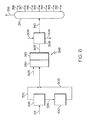
前処理プロセスの実施形態、および前処理プロセスに続く他のプロセスが本明細書に記載される。前処理後に利用され得るシステムは、「化学処理システム」、または「後処理プロセス」もしくは「下流処理」と称されてもよい。開示の化学処理システムのいずれも、本明細書に記載の前処理プロセスのいずれかと組み合わせて実施され得ることを理解されたい。例えば、図1〜4は前処理プロセスの実施形態を示し、図5および6は蒸気分解による化学処理システム(すなわち後処理プロセス)の実施形態を示す。図1〜4に示される、または図1〜4に関して説明されるものなどの前処理システムの実施形態のいずれも、図5もしくは6のいずれかのもの、または図5もしくは6に関して説明される他の処理構成のいずれかなどの本明細書に記載の下流処理構成のいずれかとともに利用され得ることを理解されたい。 Embodiments of the pretreatment process, and other processes following the pretreatment process, are described herein. Systems that can be utilized after pretreatment may be referred to as "chemical treatment systems", or "posttreatment processes" or "downstream treatments". It should be understood that any of the disclosed chemical treatment systems can be performed in combination with any of the pretreatment processes described herein. For example, FIGS. 1 to 4 show embodiments of a pretreatment process, and FIGS. 5 and 6 show embodiments of a steam decomposition chemical treatment system (ie, a posttreatment process). Any of the embodiments of the pretreatment system, such as those shown in FIGS. 1 to 4 or described with respect to FIGS. 1-4, are of any of FIGS. 5 or 6, or others described with respect to FIGS. 5 or 6. It should be understood that it can be used with any of the downstream processing configurations described herein, such as any of the processing configurations of.
本開示で使用される場合、「反応器」は、任意選択で1つ以上の触媒の存在下、1つ以上の反応物間で1つ以上の化学反応が生じ得る、任意の容器、入れ物、または同様のものを指す。例えば、反応器は、バッチ反応器、連続撹拌タンク反応器(CSTR)、または栓流反応器として動作するように構成されたタンクまたは管状反応器を含んでもよい。反応器の例には、固定床反応器などの充填床反応器、および流動床反応器が含まれる。1つ以上の「反応ゾーン」を反応器内に配置してもよい。本開示で使用される場合、「反応ゾーン」は、反応器内で特定の反応が起こる領域を指す。例えば、複数の触媒床を有する充填床反応器は、複数の反応ゾーンを有してもよく、各反応ゾーンは、各触媒床の面積によって画定される。 As used in the present disclosure, a "reactor" is an optional container, container, in which one or more chemical reactions can occur between one or more reactants in the presence of one or more catalysts. Or similar. For example, the reactor may include a batch reactor, a continuously stirred tank reactor (CSTR), or a tank or tubular reactor configured to operate as a tapped reactor. Examples of reactors include packed bed reactors such as fixed bed reactors and fluidized bed reactors. One or more "reaction zones" may be placed within the reactor. As used herein, "reaction zone" refers to the region in which a particular reaction takes place within the reactor. For example, a packed bed reactor with a plurality of catalyst beds may have a plurality of reaction zones, each reaction zone being defined by the area of each catalyst bed.
本開示で使用される場合、「分離ユニット」は、プロセス流中で互いに混合される1つ以上の化学物質を少なくとも部分的に分離する任意の分離デバイスを指す。例えば、分離ユニットは、異なる化学種を互いに選択的に分離して、1つ以上の化学留分を形成してもよい。分離ユニットの例には、蒸留塔、フラッシュドラム、ノックアウトドラム、ノックアウトポット、遠心分離機、濾過装置、トラップ、スクラバー、膨張装置、膜、溶媒抽出装置が挙げられるが、これらに限定されない。本開示に記載された分離プロセスは、1つの化学構成成分の全てを別の化学構成成分の全てから完全に分離することはできないことを理解されたい。本開示に記載された分離プロセスは、異なる化学成分を互いに「少なくとも部分的に」分離し、明示していないとしても、分離は部分的でしかない分離を含んでもよいことを理解されたい。本開示で使用される場合、1つ以上の化学成分は、プロセス流から「分離」されて、新たなプロセス流を形成してもよい。一般に、プロセス流は、分離ユニットに流入し、所望の組成の2つ以上のプロセス流に分割、または分離されてもよい。さらに、いくつかの分離プロセスでは、「軽質留分」および「重質留分」が分離ユニットから別々に流出してもよい。一般に、軽質留分流は、重質留分流よりも低い沸点を有する。加えて、1つの分離ユニットのみが図に示されているかまたは説明されている場合、2つ以上の分離ユニットを用いて、同一または実質的に同一の分離を実行してもよいことを理解されたい。例えば、複数の出口を備えた蒸留塔が説明される場合、直列に配置されたいくつかの分離器が供給流を等しく分離し得ることが企図され、そのような実施形態は本明細書に記載の実施形態の範囲内である。 As used herein, "separation unit" refers to any separation device that at least partially separates one or more chemicals that are mixed together in a process stream. For example, the separation unit may selectively separate different species from each other to form one or more chemical fractions. Examples of the separation unit include, but are not limited to, a distillation column, a flush drum, a knockout drum, a knockout pot, a centrifuge, a filtration device, a trap, a scrubber, an expansion device, a membrane, and a solvent extraction device. It should be understood that the separation process described in this disclosure cannot completely separate all of one chemical component from all of another. It should be understood that the separation process described in this disclosure separates different chemical components "at least partially" from each other, and the separation may include separation that is only partial, if not explicitly stated. As used in the present disclosure, one or more chemical components may be "separated" from the process stream to form a new process stream. In general, the process stream may flow into the separation unit and be split or separated into two or more process streams of the desired composition. In addition, in some separation processes, "light fractions" and "heavy fractions" may flow out of the separation unit separately. In general, light distillates have a lower boiling point than heavy distillates. In addition, it is understood that if only one separation unit is shown or described, two or more separation units may be used to perform the same or substantially the same separation. I want to. For example, when a distillation column with multiple outlets is described, it is contemplated that several separators arranged in series may separate the feed streams equally, such embodiments are described herein. Is within the scope of the embodiment of.
「反応流出物」は、一般に、特定の反応または分離に続いて分離ユニット、反応器、または反応ゾーンから流出する流れを指すことを理解されたい。一般に、分離ユニット、反応器、または反応ゾーンに流入した流れとは異なる組成を有する。流出物が別のシステムユニットに渡されるとき、そのシステム流の一部のみが渡されてもよいことを理解されたい。例えば、スリップ流は流出物の一部を運んでもよく、これは、流出物の一部のみが下流のシステムユニットに流入することを意味する。 It should be understood that "reaction effluent" generally refers to the flow out of a separation unit, reactor, or reaction zone following a particular reaction or separation. Generally, it has a different composition than the flow flowing into the separation unit, reactor, or reaction zone. It should be understood that when a spill is passed to another system unit, only part of that system stream may be passed. For example, a slip stream may carry a portion of the effluent, which means that only a portion of the effluent flows into the downstream system unit.
本開示で使用される場合、「触媒」は、特定の化学反応の速度を増加させる任意の物質を指す。本開示に記載された触媒は、限定されるものではないが、水素化脱金属、水素化脱硫、水素化脱窒素、水素化脱芳香族、芳香族分解、またはこれらの組み合わせなどの様々な反応を促進するために利用されてもよい。本開示において使用される場合、「分解」とは、一般に、炭素−炭素結合を有する分子が、1つ以上の炭素−炭素結合の切断によって2つ以上の分子に分解されるか、芳香族などの環状部分を含む化合物から環状部分を含まない化合物へ転化されるか、または炭素−炭素二重結合を有する分子が還元されて炭素−炭素単結合になる化学反応を指す。いくつかの触媒は、複数の形態の触媒活性を有してもよく、触媒がある特定の機能によって呼称されても、その触媒が他の機能に対して触媒的に活性になることができないことにはならない。 As used herein, "catalyst" refers to any substance that increases the rate of a particular chemical reaction. The catalysts described in the present disclosure include, but are not limited to, various reactions such as hydrogenation demetallization, hydrodesulfurization, hydrogenation denitrification, hydrogenation dearomatics, aromatic decomposition, or combinations thereof. May be used to promote. As used in the present disclosure, "decomposition" generally means that a molecule having a carbon-carbon bond is decomposed into two or more molecules by cleavage of one or more carbon-carbon bonds, or is aromatic or the like. Refers to a chemical reaction in which a compound containing a cyclic moiety is converted to a compound containing no cyclic moiety, or a molecule having a carbon-carbon double bond is reduced to a carbon-carbon single bond. Some catalysts may have multiple forms of catalytic activity, and even if the catalyst is referred to by a particular function, the catalyst cannot be catalytically active with respect to other functions. It does not become.
図1〜6の概略的な流れ図において2つ以上のラインが交差するとき、2つ以上のプロセス流が「混合」または「結合」されることを理解されたい。混合または組み合わせはまた、両方の流れを、同様の反応器、分離ユニット、または他のシステム構成要素へと直接導入することによって混合することを含んでもよい。 It should be understood that when two or more lines intersect in the schematic flow diagram of FIGS. 1-6, the two or more process flows are "mixed" or "combined". Mixing or combination may also include mixing both streams by introducing them directly into a similar reactor, separation unit, or other system component.
本開示に記載されるような触媒によって行われる反応は、化学構成成分(例えば、化学構成成分の一部のみ)をプロセス流から除去することができることを理解されたい。例えば、水素化脱金属(HDM)触媒は、プロセス流から1つ以上の金属の一部を除去する反応を促進するのに有効な量で存在してもよい。水素化脱窒素(HDN)触媒は、プロセス流に存在する窒素の一部を除去する反応を促進するのに有効な量で存在してもよい。水素化脱硫(HDS)触媒は、プロセス流に存在する硫黄の一部を除去する反応を促進するのに有効な量で存在してもよい。加えて、水素化脱芳香族(HDA)触媒などの水素化分解触媒は、その芳香族部分を飽和および分解することにより、プロセス流中の芳香族部分の量を低下させる反応を促進するのに有効な量で存在してもよい。本開示を通して、特定の触媒が、特定の機能性を有すると言われる場合、その機能性が必ずしも特定の化学構成成分または部分の除去または分解に限定されないことを理解されたい。例えば、本開示においてHDN触媒として特定された触媒は、HDA機能性、HDS機能性、またはそれらの両方をさらに提供してもよい。 It should be appreciated that catalytic reactions such as those described in the present disclosure can remove chemical constituents (eg, only some of the chemical constituents) from the process flow. For example, the hydrogenation demetallization (HDM) catalyst may be present in an amount effective to facilitate the reaction of removing a portion of one or more metals from the process stream. The hydrogenation denitrification (HDN) catalyst may be present in an amount effective to facilitate the reaction of removing some of the nitrogen present in the process stream. The hydrodesulfurization (HDS) catalyst may be present in an amount effective to facilitate the reaction of removing some of the sulfur present in the process stream. In addition, hydrocracking catalysts, such as hydrogenated dearomatic (HDA) catalysts, promote reactions that reduce the amount of aromatics in the process flow by saturating and decomposing the aromatics. It may be present in a valid amount. Throughout the disclosure, it should be understood that when a particular catalyst is said to have a particular functionality, that functionality is not necessarily limited to the removal or decomposition of a particular chemical component or moiety. For example, the catalyst identified as an HDN catalyst in the present disclosure may further provide HDA functionality, HDS functionality, or both.
また、流れは流れの成分について命名されることができ、流れを命名する成分は、流れの主成分であってもよい(例えば、流れの内容物の50重量パーセント(重量%)から、70重量%から、90重量%から、95重量%から、またはさらには95重量%から流れの内容物の100重量%までを含む)ことをさらに理解されたい。 Also, the flow can be named for a component of the flow, and the component naming the flow may be the main component of the flow (eg, from 50% by weight (% by weight) of the contents of the flow to 70% by weight. From% to 90% by weight, from 95% by weight, or even from 95% by weight to 100% by weight of the contents of the stream).
本開示を通じて使用される孔径は、他に特定されない限り、平均孔径に関するものであることを理解されたい。平均孔径は、Brunauer−Emmett−Teller(BET)分析から決定することができる。さらに、平均孔径は、透過型電子顕微鏡(TEM)特性化によって確認することができる。 It should be understood that the pore size used throughout this disclosure relates to the average pore size unless otherwise specified. The average pore size can be determined from Brunauer-Emmett-Teller (BET) analysis. Furthermore, the average pore size can be confirmed by transmission electron microscope (TEM) characterization.
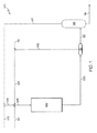
ここで図1を参照すると、一般化された水素化処理触媒システム132を含む前処理システム100が示されている。図1の水素化処理触媒システム132の追加の実施形態は、図2〜4で詳述されることを理解されたい。しかしながら、図1の一般化された前処理システム100の供給原料、製品、リサイクル流などは、図2〜4に関して説明された実施形態にも適用されることを理解されたい。
Here, with reference to FIG. 1, a
図1を参照すると、本開示の実施形態によれば、重質油供給流101を水素流104と混合してもよい。水素流104は、リサイクルされたプロセスガス成分流113からの未使用水素ガス、水素供給流114からの補給水素、またはそれらの両方を含み、重質油供給流101と混合し、前処理触媒投入流105を形成してもよい。1つ以上の実施形態では、前処理触媒投入流105を摂氏350度(℃)〜450℃のプロセス温度に加熱してもよい。前処理触媒投入流105は、水素化処理触媒システム132に流入し、それを通過してもよい。本明細書で説明するように、水素化処理触媒システム132は、HDM反応ゾーン、遷移反応ゾーン、HDN反応ゾーン、および水素化分解反応ゾーンを含む一連の反応ゾーンを含んでもよい。
Referring to FIG. 1, according to the embodiments of the present disclosure, the heavy
記載されたシステムおよびプロセスは、接触水素化処理前処理プロセスを使用して、原油、減圧残留物、タールサンド、ビチューメンおよび減圧軽油を含む、多種多様な重質油供給物(重質油供給流101中)に適用可能である。重質油供給原料が原油である場合、これは25度〜50度のアメリカ石油協会(API)比重を有することができる。例えば、利用される重質油原料はアラブ重質原油であってもよい。アラブ重質原油の典型的な特性を表1に示す。 The systems and processes described use a catalytic hydrogenation pretreatment process to create a wide variety of heavy oil feeds (heavy oil feed streams), including crude oil, decompression residues, tar sands, bitumen and decompression gas oil. It is applicable to (in 101). If the heavy oil feedstock is crude oil, it can have an American Petroleum Institute (API) specific gravity of 25 to 50 degrees. For example, the heavy oil raw material used may be Arab heavy crude oil. Table 1 shows the typical properties of Arab heavy crude oil.

引き続き図1を参照すると、前処理触媒反応流出物流109が、前処理触媒投入流105と水素化処理触媒システム132との相互作用により形成されてもよい。前処理触媒反応流出物流109は、分離ユニット112に流入してもよく、リサイクルされるプロセスガス成分流113と中間液体生成物流115とに分離されてもよい。一実施形態では、前処理触媒反応流出物流109を精製して、硫化水素および他のプロセスガスを除去して、リサイクルされるプロセスガス成分流113中の水素の純度を高めることもできる。このプロセスで消費される水素は、蒸気もしくはナフサ改質装置または他の供給源に由来し得る補給水素供給流114からの新鮮な水素の添加によって補償することができる。リサイクルされるプロセスガス成分流113および補給水素供給流114は、組み合わさり、水素流104を形成してもよい。一実施形態では、中間液体生成物流115を分離ユニット116内で分離して、軽質炭化水素留分流117と前処理最終液体生成物流118とを分離してもよいが、この分離工程は任意選択であることを理解されたい。さらなる実施形態では、分離ユニット116はフラッシュ容器であってもよい。一実施形態では、軽質炭化水素留分流117はリサイクルとして作用し、軽質炭化水素希釈剤流102と混合されて、軽質炭化水素希釈剤流103を生成する。新鮮な軽質炭化水素希釈剤流102を必要に応じて使用し、補給希釈剤をプロセスに提供して、水素化処理触媒システム132内の触媒の1つ以上の失活をさらに低減させるのを補助することができる。
Continuing with reference to FIG. 1, the pretreatment catalyst
1つ以上の実施形態において、前処理触媒反応流出物流109、中間液体生成物流115、および前処理最終液体生成物流118のうちの1つ以上は、重質油供給流101と比較して低減した芳香族含有量を有してもよい。加えて、実施形態では、前処理触媒反応流出物流109、中間液体生成物流115、および前処理最終液体生成物流118のうちの1つ以上は、重質油供給流101と比較して、顕著に低減した硫黄、金属、アスファルテン、コンラッドソン炭素、窒素の含有量、またはこれらの組み合わせ、ならびに増加したAPI比重および増加したディーゼルならびに減圧留出物の収率を有してもよい。
In one or more embodiments, one or more of the pretreatment catalytic
1つ以上の実施形態によれば、前処理触媒反応流出物流109は、重質油供給流101と比べて、窒素の少なくとも約80重量%の低減、少なくとも90重量%の低減、またはさらには少なくとも95重量%の低減を有することができる。別の実施形態によれば、前処理触媒反応流出物流109は、重質油供給流101と比べて、硫黄の少なくとも約85重量%の低減、少なくとも90重量%の低減、またはさらには少なくとも99重量%の低減を有することができる。別の実施形態によれば、前処理触媒反応流出物流109は、重質油供給流101と比べて、芳香族含有量の少なくとも約70重量%の低減、少なくとも80重量%の低減、またはさらには少なくとも85重量%の低減を有することができる。別の実施形態によれば、前処理触媒反応流出物流109は、重質油供給流101と比べて、金属の少なくとも約80重量%の低減、少なくとも90重量%の低減、またはさらには少なくとも99重量%の低減を有することができる。
According to one or more embodiments, the pretreatment
引き続き図1を参照すると、様々な実施形態では、前処理触媒反応流出物流109、中間液体生成物流115、および前処理最終液体生成物流118のうちの1つ以上は、本開示において後で説明するように、それぞれ図5および6の蒸気分解システム400および500のアップグレードされた油流220として使用するのに好適であってもよい。本開示で使用されるように、前処理触媒反応流出物流109、中間液体生成物流115、および前処理最終液体生成物流118のうちの1つ以上は、少なくとも図5または6のシステムによって下流処理されてもよい「アップグレードされた油」と称されてもよい。いくつかの実施形態では、アップグレードされた油は、540℃以下の最終沸点を有してもよく、これにより、下流蒸気分解におけるさらなる転化の効率が増大してもよい。追加の実施形態では、アップグレードされた油の少なくとも90重量%、少なくとも95重量%、または少なくとも99重量%でさえもが、540℃以下の沸点を有してもよい。追加の実施形態では、アップグレードされた油は、520℃、500℃、480℃、460℃、440℃、420℃、400℃、380℃、360℃、340℃、320℃、またはさらには300℃以下の最終沸点を有してもよい。アップグレードされた油の最終沸点は、前処理システム100の後続する任意選択の分離工程によって軽質留分のみが除去されるため、前処理反応触媒流出物流109の最終沸点に等しいことを理解されたい。
With reference to FIG. 1, in various embodiments, one or more of the pretreatment catalytic
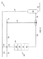
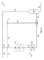
ここで図2を参照すると、1つ以上の実施形態によれば、水素化処理触媒システム132は、直列に配置された複数の充填床反応ゾーン(例えば、HDM反応ゾーン106、遷移反応ゾーン108、HDN反応ゾーン110、および水素化分解反応ゾーン120)を含むまたはそれらからなってもよく、これらの反応ゾーンの各々は、触媒床を備えてもよい。これらの反応ゾーンの各々は、図2の前処理反応器130として示されるように、直列の複数の床を有する充填床反応器として単一の反応器内に含まれてもよい。そのような実施形態では、前処理反応器130は、HDM反応ゾーン106内にHDM触媒を含むHDM触媒床、遷移反応ゾーン108内に遷移触媒を含む遷移触媒床、HDN反応ゾーン110内にHDN触媒を含むHDN触媒床、および水素化分解反応ゾーン120内に水素化分解触媒を含む水素化分解触媒床を含む。他の実施形態では、HDM反応ゾーン106、遷移反応ゾーン108、HDN反応ゾーン110、および水素化分解反応ゾーン120は、各々、直列に配置された複数の充填床反応器内に含まれてもよい。さらなる実施形態では、各反応ゾーンは、別個の単一充填床反応器内に含まれる。企図される実施形態には、直列に配置された充填触媒床が、単一の反応器内、または各々が1つ以上の触媒床を含有する複数の反応器内に含まれる実施形態が含まれることを理解されたい。比較的大量の触媒が必要とされる場合、それらの触媒を別々の反応器に収容することが望ましい場合があることを理解されたい。
Here, referring to FIG. 2, according to one or more embodiments, the
1つ以上の実施形態によれば、重質油を含む前処理触媒投入流105は、HDM反応ゾーン106に導入され、HDM触媒によって接触される。HDM触媒と前処理触媒投入流105との接触は、前処理触媒投入流105中に存在する金属の少なくとも一部を除去する反応を促進してもよい。HDM触媒と接触した後、前処理触媒投入流105をHDM反応流出物に転化してもよい。HDM反応流出物は、前処理触媒流105の含有量と比較して、低下した金属含有量を有してもよい。例えば、HDM反応流出物は、前処理触媒投入流105として、少なくとも70重量%未満、少なくとも80重量%未満、またはさらには少なくとも95重量%未満の金属を有してもよい。
According to one or more embodiments, the pretreatment
1つ以上の実施形態によれば、HDM反応ゾーン106は、重量平均床温度が、370℃〜415℃など、350℃〜450℃、圧力が、90バール〜110バールなど、30バール〜200バールであってもよい。HDM反応ゾーン106はHDM触媒を含み、HDM触媒はHDM反応ゾーン106の全体を満たしてもよい。
According to one or more embodiments, the
HDM触媒は、国際純粋および応用化学連合(IUPAC)の周期表の5、6、または8〜10族からの1つ以上の金属を含んでもよい。例えば、HDM触媒は、モリブデンを含んでもよい。HDM触媒は、担体材料をさらに含んでもよく、金属は、担体材料上に配設されてもよい。一実施形態では、HDM触媒は、アルミナ担体上にモリブデン金属触媒を含んでもよい(「Mo/Al2O3触媒」と称されることもある)。開示された触媒のいずれか中に含有される金属は、硫化物または酸化物として、またはさらには他の化合物として存在してもよいことは、本開示を通じて理解されたい。 The HDMI catalyst may contain one or more metals from groups 5, 6, or 8-10 of the Periodic Table of the International Pure and Applied Chemistry Association (IUPAC). For example, the HDMI catalyst may contain molybdenum. The HDMI catalyst may further comprise a carrier material and the metal may be disposed on the carrier material. In one embodiment, the HDMI catalyst may include a molybdenum metal catalyst on an alumina carrier (sometimes referred to as a "Mo / Al 2 O 3 catalyst"). It is to be understood throughout this disclosure that the metals contained in any of the disclosed catalysts may be present as sulfides or oxides, or even other compounds.
一実施形態では、HDM触媒は、担体材料上に金属硫化物を含んでもよく、ここで、金属は、周期表のIUPAC5、6、および8〜10族の元素、およびこれらの組み合わせからなる群から選択される。担体材料は、ガンマ−アルミナまたはシリカ/アルミナ押出物、球体、シリンダー、ビーズ、ペレット、およびこれらの組み合わせであってもよい。 In one embodiment, the HDMI catalyst may contain a metal sulfide on the carrier material, where the metal consists of the elements of groups IUPAC 5, 6, and 8-10 of the periodic table, and combinations thereof. Be selected. The carrier material may be gamma-alumina or silica / alumina extrusion, spheres, cylinders, beads, pellets, or a combination thereof.
一実施形態では、HDM触媒は、100m2/g〜160m2/g(100m2/g〜130m2/g、または130m2/g〜160m2/gなど)の表面積を有するガンマ−アルミナ担体を含んでもよい。HDM触媒は、少なくとも0.8cm3/g(例えば、少なくとも0.9cm3/g、またはさらには少なくとも1.0cm3/g)などの比較的大きな細孔容積を有するものとして最もよく説明することができる。HDM触媒の孔径は、主としてマクロ細孔性(すなわち、50nm超の孔径を有する)であってもよい。これは、HDM触媒の表面および任意選択でドーパント上の金属の取り込みのための大きな能力を提供し得る。一実施形態では、ドーパントは、ホウ素、ケイ素、ハロゲン、リン、およびこれらの組み合わせからなる群から選択することができる。 In one embodiment, HDM catalysts, 100m 2 / g~160m 2 / g (100m 2 / g~130m 2 / g, or 130m 2 / g~160m 2 / g, etc.) gamma having a surface area of - alumina carrier It may be included. The HDMI catalyst is best described as having a relatively large pore volume, such as at least 0.8 cm 3 / g (eg, at least 0.9 cm 3 / g, or even at least 1.0 cm 3 / g). Can be done. The pore size of the HDMI catalyst may be predominantly macroporous (ie, having a pore size greater than 50 nm). This can provide great capacity for uptake of metals on the surface of the HDMI catalyst and optionally on the dopant. In one embodiment, the dopant can be selected from the group consisting of boron, silicon, halogen, phosphorus, and combinations thereof.
1つ以上の実施形態では、HDM触媒は、0.5重量%〜12重量%のモリブデンの酸化物または硫化物(例えば、2重量%〜10重量%、または3重量%〜7重量%のモリブデンの酸化物または硫化物)と、88重量%〜99.5重量%のアルミナ(例えば、90重量%〜98重量%、または93重量%〜97重量%のアルミナ)とを含んでもよい。 In one or more embodiments, the HDM catalyst is 0.5% to 12% by weight of oxide or sulfide of molybdenum (eg, 2% to 10% by weight, or 3% to 7% by weight of molybdenum. Oxides or sulfides) and 88% to 99.5% by weight of alumina (eg, 90% by weight to 98% by weight, or 93% to 97% by weight of alumina).
理論に束縛されるものではないが、いくつかの実施形態では、HDM反応ゾーン106内での反応の間に、HDM触媒は、重質油中に存在するポルフィリン型化合物の水素を介した水素化を促進して、中間体を生成すると考えられる。この一次水素化の後、ポルフィリン分子の中心に存在するニッケルまたはバナジウムは、水素で還元され、次いで、硫化水素(H2S)で対応する硫化物にさらに還元される。最終金属硫化物をHDM触媒上に堆積させ、これにより、未精製原油から金属硫化物を除去する。硫黄はまた、並行経路を介して硫黄含有有機化合物から除去される。これらの並行反応の速度は、考慮される硫黄種に依存し得る。全体として、水素は、プロセス中でH2Sに転化される硫黄を抽出するために使用される。残部の硫黄不含炭化水素断片は、液体炭化水素流中に残る。
Without being bound by theory, in some embodiments, during the reaction within the
HDM反応流出物は、HDM反応ゾーン106から遷移反応ゾーン108に移されることができ、ここで遷移触媒によって接触される。遷移触媒とHDM反応流出物との接触は、HDM反応流出物流中に存在する金属の少なくとも一部分を除去する反応を促進してもよく、かつHDM反応流出物流中に存在する窒素の少なくとも一部分を除去してもよい。遷移触媒との接触後、HDM反応流出物は、遷移反応流出物に転化される。遷移反応流出物は、HDM反応流出物と比較して、低下した金属含有量および窒素含有量を有してもよい。例えば、遷移反応流出物は、HDM反応流出物として、少なくとも50重量%未満、少なくとも80重量%未満、またはさらには少なくとも90重量%未満の金属含有量を有してもよい。加えて、遷移反応流出物は、HDM反応流出物として、少なくとも10重量%未満、少なくとも15重量%未満、またはさらには少なくとも20重量%未満の窒素を有してもよい。
The HDMI reaction effluent can be transferred from the
実施形態によれば、遷移反応ゾーン108は、約370℃〜410℃の重量平均床温度を有する。遷移反応ゾーン108は遷移触媒を含み、遷移触媒は遷移反応ゾーン108の全体を満たしてもよい。
According to the embodiment, the
一実施形態では、遷移反応ゾーン108は、ある量の金属成分およびある量の硫黄成分をHDM反応流出物流から除去するように操作可能であってもよい。遷移触媒は、押出物の形態のアルミナ系担体を含んでもよい。
In one embodiment, the
一実施形態では、遷移触媒は、IUPACの6族からの1つの金属と、IUPACの8〜10族からの1つの金属とを含む。例示的なIUPACの6族の金属としては、モリブデンおよびタングステンが挙げられる。IUPACの8〜10族の金属の例としては、ニッケルおよびコバルトが挙げられる。例えば、遷移触媒は、チタニア担体上にMoおよびNiを含んでもよい(「Mo−Ni/Al2O3触媒」と称されることもある)。遷移触媒はまた、ホウ素、リン、ハロゲン、ケイ素、およびこれらの組み合わせからなる群から選択されるドーパントも含んでもよい。遷移触媒は、140m2/g〜200m2/g(140m2/g〜170m2/g、または170m2/g〜200m2/gなど)の表面積を有し得る。遷移触媒は、0.5cm3/g〜0.7cm3/g(0.6cm3/gなど)の中間細孔容積を有し得る。遷移触媒は、一般に、12nm〜50nmの範囲の孔径を有するメソ細孔性構造を含んでもよい。これらの特性により、HDMおよびHDSにおけるバランスの取れた活性が提供される。 In one embodiment, the transition catalyst comprises one metal from Group 6 of IUPAC and one metal from Group 8-10 of IUPAC. Illustrative Group 6 metals of IUPAC include molybdenum and tungsten. Examples of Group 8-10 metals of IUPAC include nickel and cobalt. For example, the transition catalyst may contain Mo and Ni on a titania carrier (sometimes referred to as a "Mo-Ni / Al 2 O 3 catalyst"). The transition catalyst may also include a dopant selected from the group consisting of boron, phosphorus, halogens, silicon, and combinations thereof. Transition catalyst may have a surface area of 140m 2 / g~200m 2 / g ( 140m 2 / g~170m 2 / g, or 170m 2 / g~200m 2 / g, etc.). Transition catalyst can have a mesopore volume of 0.5cm such 3 /g~0.7cm 3 /g(0.6cm 3 / g) . The transition catalyst may generally include a mesoporous structure having a pore size in the range of 12 nm to 50 nm. These properties provide balanced activity in HDMI and HDS.
1つ以上の実施形態では、遷移触媒は、10重量%〜18重量%のモリブデンの酸化物または硫化物(例えば、11重量%〜17重量%、または12重量%〜16重量%のモリブデンの酸化物または硫化物)と、1重量%〜7重量%のニッケルの酸化物または硫化物(例えば、2重量%〜6重量%、または3重量%〜5重量%のニッケルの酸化物または硫化物)と、75重量%〜89重量%のアルミナ(例えば、77重量%〜87重量%、または79重量%〜85重量%のアルミナ)とを含んでもよい。 In one or more embodiments, the transition catalyst is 10% to 18% by weight of oxide or sulfide of molybdenum (eg, 11% to 17% by weight, or 12% to 16% by weight of molybdenum oxidation. (Materials or sulfides) and 1% to 7% by weight of nickel oxides or sulfides (eg, 2% to 6% by weight, or 3% to 5% by weight of nickel oxides or sulfides). And 75% by weight to 89% by weight of alumina (for example, 77% by weight to 87% by weight, or 79% by weight to 85% by weight of alumina) may be contained.
遷移反応流出物は、遷移反応ゾーン108からHDN反応ゾーン110に渡されてもよく、ここでHDN触媒によって接触される。HDN触媒と遷移反応流出物との接触は、遷移反応流出物流中に存在する窒素の少なくとも一部分を除去する反応を促進してもよい。HDN触媒との接触により、遷移反応流出物流が、HDN反応流出物に転化され得る。HDN反応流出物は、遷移反応流出物と比較して、低下した金属含有量および窒素含有量を有してもよい。例えば、HDN反応流出物は、窒素含有量が、遷移反応流出物と比べて、少なくとも80重量%、少なくとも85重量%、またはさらには少なくとも90重量%低減していてもよい。別の実施形態では、HDN反応流出物は、硫黄含有量が、遷移反応流出物と比べて、少なくとも80重量%、少なくとも90重量%、またはさらには少なくとも95重量%低減していてもよい。別の実施形態では、HDN反応流出物は、芳香族含有量が、遷移反応流出物と比べて、少なくとも25重量%、少なくとも30重量%未満、またはさらには少なくとも40重量%低減していてもよい。
The transition reaction effluent may be passed from the
実施形態によれば、HDN反応ゾーン110は、370℃〜410℃の重量平均床温度を有する。HDN反応ゾーン110はHDN触媒を含み、HDN触媒はHDN反応ゾーン110の全体を満たしてもよい。
According to embodiments, the
一実施形態では、HDN触媒は、担体材料上に金属酸化物または硫化物を含み、ここで、金属は、周期表のIUPACの5、6、および8〜10族の元素、およびこれらの組み合わせからなる群から選択される。担体材料は、ガンマ−アルミナ、メソ細孔性アルミナ、シリカ、またはそれらの両方を、押出物、球体、シリンダー、およびペレットの形態で含んでもよい。 In one embodiment, the HDN catalyst comprises a metal oxide or sulfide on the carrier material, where the metal is from the elements of groups 5, 6, and 8-10 of IUPAC in the periodic table, and combinations thereof. Selected from the group of The carrier material may contain gamma-alumina, mesoporous alumina, silica, or both in the form of extrudes, spheres, cylinders, and pellets.
一実施形態では、HDN触媒は、180m2/g〜240m2/g(180m2/g〜210m2/g、または210m2/g〜240m2/gなど)の表面積を有するガンマ−アルミナ系担体を含有する。HDN触媒のこの比較的大きな表面積により、より小さな細孔容積(例えば、1.0cm3/g未満、0.95cm3/g未満、またはさらには0.9cm3/g未満)が可能となる。一実施形態では、HDN触媒は、モリブデンなどのIUPACの6族からの少なくとも1つの金属と、ニッケルなどのIUPACの8〜10族からの少なくとも1つの金属とを含有する。HDN触媒はまた、ホウ素、リン、シリコン、ハロゲン、およびこれらの組み合わせからなる群から選択される少なくとも1つのドーパントも含むことができる。一実施形態では、HDN触媒はコバルトを含んでもよく、これにより脱硫がさらに促進される。一実施形態では、HDN触媒は、HDM触媒と比較して、活性相に対してより高い金属充填量を有する。この増加した金属充填量により、触媒活性の増加が生じ得る。一実施形態では、HDN触媒はニッケルおよびモリブデンを含み、0.1〜0.3(0.1〜0.2または0.2〜0.3など)のニッケル対モリブデンのモル比(Ni/(Ni+Mo))を有する。コバルトを含む実施形態では、(Co+Ni)/Moのモル比は、0.25〜0.85(0.25〜0.5または0.5〜0.85など)の範囲であってもよい。 In one embodiment, HDN catalyst, gamma having a surface area of 180m 2 / g~240m 2 / g ( 180m 2 / g~210m 2 / g, or 210m 2 / g~240m 2 / g, etc.) - alumina support Contains. This relatively large surface area of the HDN catalyst allows for smaller pore volumes (eg, less than 1.0 cm 3 / g, less than 0.95 cm 3 / g, or even less than 0.9 cm 3 / g). In one embodiment, the HDN catalyst contains at least one metal from Group 6 of IUPAC such as molybdenum and at least one metal from Group 8-10 of IUPAC such as nickel. The HDN catalyst can also include at least one dopant selected from the group consisting of boron, phosphorus, silicon, halogens, and combinations thereof. In one embodiment, the HDN catalyst may contain cobalt, which further promotes desulfurization. In one embodiment, the HDN catalyst has a higher metal filling amount relative to the active phase as compared to the HDMI catalyst. This increased metal filling can result in increased catalytic activity. In one embodiment, the HDN catalyst comprises nickel and molybdenum and has a nickel to molybdenum molar ratio of 0.1 to 0.3 (0.1 to 0.2 or 0.2 to 0.3, etc.) (Ni / ( It has Ni + Mo)). In embodiments that include cobalt, the molar ratio of (Co + Ni) / Mo may be in the range of 0.25 to 0.85 (such as 0.25 to 0.5 or 0.5 to 0.85).
別の実施形態によれば、HDN触媒は、少なくとも25nmの平均孔径を有し得る、メソ細孔性アルミナなどのメソ細孔性材料を含有してもよい。例えば、HDN触媒は、少なくとも30nm、またはさらには少なくとも35nmの平均孔径を有するメソ細孔性アルミナを含んでもよい。2nm未満などの比較的小さな平均孔径を有するHDN触媒は、本開示では従来のHDN触媒と称されてもよく、より大きな孔径を有する本明細書に開示されるHDN触媒と比較して、触媒性能が比較的不良であり得る。2nm〜50nmの平均細孔径を有するアルミナ担体を有するHDN触媒の実施形態は、本開示において「メソ細孔性アルミナ支持触媒」と称されてもよい。1つ以上の実施形態では、HDM触媒のメソ細孔性アルミナは、2nm〜50nm、25nm〜50nm、30nm〜50nm、または35nm〜50nmの範囲の平均孔径を有してもよい。実施形態によれば、HDN触媒は、比較的大きな表面積、比較的大きな細孔容積、またはそれらの両方を有するアルミナを含んでもよい。例えば、メソ細孔性アルミナは、約225m2/g、少なくとも約250m2/g、少なくとも約275m2/g、少なくとも約300m2/g、またはさらには少なくとも約350m2/g、例えば、225m2/g〜500m2/g、200m2/g〜450m2/g、または300m2/g〜400m2/gの表面積を有することによって、比較的大きな表面積を有してもよい。1つ以上の実施形態では、メソ細孔性アルミナは、少なくとも約1mL/g、少なくとも約1.1mL/g、少なくとも1.2mL/g、またはさらには少なくとも1.2mL/g、例えば、1mL/g〜5mL/g、1.1mL/g〜3、または1.2mL/g〜2mL/gの細孔容積を有することによって、比較的大きな細孔容積を有することができる。理論に束縛されるものではないが、メソ細孔性アルミナ担持HDN触媒は、より大きな分子が触媒の内外に移動することを容易にすることができる追加の活性部位およびより大きな細孔チャンネルを提供し得ると考えられる。追加の活性部位およびより大きい細孔チャンネルにより、より高い触媒活性、より長い触媒寿命、またはそれらの両方がもたらされてもよい。一実施形態では、HDN触媒は、ホウ素、ケイ素、ハロゲン、リン、およびこれらの組み合わせからなる群から選択され得るドーパントを含んでもよい。 According to another embodiment, the HDN catalyst may contain a mesoporous material such as mesoporous alumina, which may have an average pore size of at least 25 nm. For example, the HDN catalyst may contain mesoporous alumina having an average pore size of at least 30 nm, or even at least 35 nm. HDN catalysts having a relatively small average pore size, such as less than 2 nm, may be referred to herein as conventional HDN catalysts and have catalytic performance as compared to the HDN catalysts disclosed herein having a larger pore size. Can be relatively bad. An embodiment of an HDN catalyst having an alumina carrier having an average pore diameter of 2 nm to 50 nm may be referred to in the present disclosure as a "mesoporous alumina-supported catalyst". In one or more embodiments, the mesoporous alumina of the HDMI catalyst may have an average pore size in the range of 2 nm to 50 nm, 25 nm to 50 nm, 30 nm to 50 nm, or 35 nm to 50 nm. According to embodiments, the HDN catalyst may comprise alumina having a relatively large surface area, a relatively large pore volume, or both. For example, mesoporous alumina is about 225 m 2 / g, at least about 250 m 2 / g, at least about 275 m 2 / g, at least about 300 m 2 / g, or even at least about 350 m 2 / g, eg, 225 m 2 / g~500m 2 / g, 200m 2 / g~450m 2 / g or by having a surface area of 300m 2 / g~400m 2 / g, , it may have a relatively large surface area. In one or more embodiments, the mesoporous alumina is at least about 1 mL / g, at least about 1.1 mL / g, at least 1.2 mL / g, or even at least 1.2 mL / g, eg, 1 mL / g. By having a pore volume of g to 5 mL / g, 1.1 mL / g to 3, or 1.2 mL / g to 2 mL / g, it is possible to have a relatively large pore volume. Without being bound by theory, mesoporous alumina-supported HDN catalysts provide additional active sites and larger pore channels that can facilitate the movement of larger molecules into and out of the catalyst. It is thought that it can be done. Additional active sites and larger pore channels may result in higher catalytic activity, longer catalytic life, or both. In one embodiment, the HDN catalyst may contain a dopant that can be selected from the group consisting of boron, silicon, halogen, phosphorus, and combinations thereof.
記載された実施形態によれば、HDN触媒は、アルミナなどの担体材料を、酸解膠されたアルミナなどの結合剤と混合することによって製造することができる。水または別の溶媒を、担体材料および結合剤の混合物に添加して押出可能な相を形成することができ、次いでこれを所望の形状に押出する。押出物は、高温(100℃超、例えば、110℃など)で乾燥され、次いで、好適な温度で(少なくとも400℃または少なくとも450℃、例えば500℃の温度などで)か焼することができる。か焼された押出物は、Mo、Ni、またはこれらの組み合わせを含む前駆体材料などの触媒前駆体材料を含有する水溶液で含浸されてもよい。例えば、水溶液は、ヘプタンモリブデン酸アンモニウム、硝酸ニッケル、およびリン酸を含有して、モリブデン、ニッケル、およびリンを含む化合物を含むHDN触媒を形成してもよい。 According to the described embodiments, the HDN catalyst can be produced by mixing a carrier material such as alumina with a binder such as acid deflated alumina. Water or another solvent can be added to the mixture of carrier material and binder to form an extrudable phase, which is then extruded into the desired shape. The extruded product can be dried at a high temperature (greater than 100 ° C., eg 110 ° C.) and then baked at a suitable temperature (at least 400 ° C. or at least 450 ° C., eg 500 ° C.). The calcinated extrude may be impregnated with an aqueous solution containing a catalytic precursor material such as Mo, Ni, or a precursor material containing a combination thereof. For example, the aqueous solution may contain ammonium heptane molybdate, nickel nitrate, and phosphoric acid to form an HDN catalyst containing a compound containing molybdic, nickel, and phosphorus.
メソ細孔性アルミナ担体が利用される実施形態では、メソ細孔性アルミナは、60℃〜90℃の水中にベーマイト粉末を分散させることによって合成してもよい。次いで、HNO3などの酸を、ベーマイト水溶液中に、0.3〜3.0のHNO3:Al3+の比で添加してもよく、この溶液を60℃〜90℃で数時間、例えば、6時間撹拌して、ゾルを得る。トリブロックコポリマーなどのコポリマーを室温でゾルに添加してもよく、このコポリマー:Alのモル比は0.02〜0.05であり、数時間、例えば、3時間、熟成される。ゾル/コポリマー混合物を数時間乾燥させた後、か焼する。 In embodiments where the mesoporous alumina carrier is utilized, the mesoporous alumina may be synthesized by dispersing boehmite powder in water at 60 ° C. to 90 ° C. Then, an acid such as HNO 3, during the boehmite solution, HNO 3 of 0.3 to 3.0: may be added at a ratio of Al 3+, several hours the solution 60 ° C. to 90 ° C., for example , Stir for 6 hours to obtain sol. Copolymers such as triblock copolymers may be added to the sol at room temperature and the copolymer: Al molar ratio is 0.02-0.05 and is aged for several hours, eg, 3 hours. The sol / copolymer mixture is dried for several hours and then calcinated.
1つ以上の実施形態によれば、HDN触媒は、10重量%〜18重量%のモリブデンの酸化物または硫化物(例えば、13重量%〜17重量%、または14重量%〜16重量%のモリブデンの酸化物または硫化物)と、2重量%〜8重量%のニッケルの酸化物または硫化物(例えば、3重量%〜7重量%または4重量%〜6重量%のニッケルの酸化物または硫化物)と、74重量%〜88重量%のアルミナ(例えば、76重量%〜84重量%、または78重量%〜82重量%のアルミナ)とを含んでもよい。 According to one or more embodiments, the HDN catalyst is an oxide or sulfide of 10% to 18% by weight of molybdenum (eg, 13% to 17% by weight, or 14% to 16% by weight of molybdenum. Oxides or sulfides) and 2% to 8% by weight of nickel oxides or sulfides (eg, 3% to 7% by weight or 4% to 6% by weight of nickel oxides or sulfides) ), And 74% to 88% by weight of alumina (for example, 76% by weight to 84% by weight, or 78% by weight to 82% by weight of alumina) may be contained.
HDM触媒と同様の様式で、やはりいかなる理論にも拘束されるものではないが、水素化脱窒素および水素化脱芳香族化は、関連する反応機構を介して作用することができると考えられる。両方とも、ある程度の水素化を伴う。水素化脱窒素のために、有機窒素化合物は、通常、複素環式構造の形態であり、ヘテロ原子は窒素である。これらの複素環式構造は、窒素のヘテロ原子の除去に先立って飽和されていてもよい。同様に、水素化脱芳香族化は芳香族環の飽和を伴う。これらの反応の各々は、触媒の各々の量または種類に応じて異なる程度で発生してもよく、これは、各触媒が、ある種類の伝達を他の種類よりも選択的に促進し得、伝達が競合しているためである。 It is believed that hydrogenation denitrification and hydrogenation dearomatization, in a manner similar to HDM catalysts and also not bound by any theory, can act through related reaction mechanisms. Both involve some degree of hydrogenation. Due to hydrogenation denitrification, the organic nitrogen compound is usually in the form of a heterocyclic structure and the heteroatom is nitrogen. These heterocyclic structures may be saturated prior to the removal of nitrogen heteroatoms. Similarly, hydrogenation dearomaticization involves saturation of the aromatic ring. Each of these reactions may occur to varying degrees depending on the amount or type of catalyst, which allows each catalyst to selectively facilitate the transfer of one type over the other. This is because the transmissions are competing.
本明細書に記載される方法およびシステムのいくつかの実施形態は、少なくとも25nmの平均孔径を有する多孔性アルミナを含むHDN触媒を利用してもよいことを理解されたい。しかしながら、他の実施形態では、多孔性アルミナの平均孔径は約25nm未満であってもよく、さらに微細孔性(すなわち、2nm未満の平均孔径を有する)であってもよい。 It should be understood that some embodiments of the methods and systems described herein may utilize HDN catalysts containing porous alumina with an average pore size of at least 25 nm. However, in other embodiments, the average porosity of the porous alumina may be less than about 25 nm and may be finer (ie, have an average porosity of less than 2 nm).
引き続き図2を参照すると、HDN反応流出物は、HDN反応ゾーン110から水素化分解反応ゾーン120に渡されてもよく、ここでは、HDN反応流出物が水素化分解触媒によって接触される。水素化分解触媒とHDN反応流出物との接触は、HDN反応流出物中に存在する芳香族含有量を低下させる反応を促進してもよい。水素化分解触媒と接触した後、HDN反応流出物は、前処理触媒反応流出物流109に転化される。前処理触媒反応流出物流109は、HDN反応流出物と比較して、低下した芳香族含有量を有してもよい。例えば、前処理触媒反応流出物流109は、HDN反応流出物より少なくとも50重量%少ない、少なくとも60重量%少ない、またはさらには少なくとも80重量%少ない芳香族含有量を有してもよい。
Continuing with reference to FIG. 2, the HDN reaction effluent may be passed from the
水素化分解触媒は、周期表のIUPACの5、6、8、9、または10族からの1つ以上の金属を含んでもよい。例えば、水素化分解触媒は、IUPACの5または6族からの1つ以上の金属と、周期表のIUPACの8、9、または10族からの1つ以上の金属とを含んでもよい。例えば、水素化分解触媒は、IUPACの6族からのモリブデンまたはタングステンと、IUPACの8、9、または10族からのニッケルまたはコバルトとを含んでもよい。HDM触媒は、ゼオライトなどの担体材料をさらに含んでもよく、金属は、この担体材料上に配置されてもよい。一実施形態では、水素化分解触媒は、メソ細孔性であるゼオライト担体上にタングステンおよびニッケル金属触媒を含んでもよい(「W−Ni/メソゼオライト触媒」と称されることもある)。別の実施形態では、水素化分解触媒は、メソ細孔性であるゼオライト担体上にモリブデンおよびニッケル金属触媒を含んでもよい(「Mo−Ni/メソゼオライト触媒」と称されることもある)。 The hydrocracking catalyst may contain one or more metals from groups 5, 6, 8, 9, or 10 of IUPAC in the periodic table. For example, the hydrocracking catalyst may contain one or more metals from groups 5 or 6 of IUPAC and one or more metals from groups 8, 9 or 10 of IUPAC in the periodic table. For example, the hydrocracking catalyst may contain molybdenum or tungsten from Group 6 of IUPAC and nickel or cobalt from Group 8, 9, or 10 of IUPAC. The HDMI catalyst may further comprise a carrier material such as zeolite, and the metal may be placed on this carrier material. In one embodiment, the hydrocracking catalyst may include tungsten and nickel metal catalysts on a mesoporous zeolite carrier (sometimes referred to as "W-Ni / mesozeolite catalysts"). In another embodiment, the hydrocracking catalyst may include molybdenum and nickel metal catalysts on a mesoporous zeolite carrier (sometimes referred to as "Mo-Ni / mesozeolite catalysts").
本開示に記載の水素化処理触媒システムの水素化分解触媒の実施形態によれば、担体材料(すなわち、メソ細孔性ゼオライト)は、2nm〜50nmの平均孔径を有することによって、メソ細孔性であると特徴付けられてもよい。比較として、従来のゼオライト系の水素化分解触媒は、2nm未満の平均孔径を有することを意味する微細孔性であるゼオライトを含有している。理論に束縛されるものではないが、本明細書に記載される水素化分解触媒の比較的大きな孔径(すなわち、メソ細孔性)により、より大きな分子がゼオライト内部に拡散することが可能となると考えられ、これが、触媒の反応活性および選択性を強化すると考えられる。孔径の増大のために、芳香族含有分子が触媒中により容易に拡散することができ、芳香族分解が増加し得る。例えば、いくつかの従来の実施形態では、水素化加工触媒によって転化された供給原料は、減圧軽油、例えば流動接触分解反応器からの軽質サイクル油、または例えばコーキングユニットからのコーカー軽油であってもよい。これらの油中の分子サイズは、本方法およびシステムの供給原料であってもよい原油および常圧残留物などの重質油の分子サイズと比べて比較的小さい。重質油は、一般に、従来のゼオライトの内部に拡散することができず、ゼオライト内部に位置する活性部位上で転化されることができない。したがって、より大きな孔径を有するゼオライト(すなわち、例えば、メソ細孔性ゼオライト)は、重質油のより大きな分子が拡散限界を克服することを可能にしてもよく、重質油のより大きな分子の反応および転化を促進してもよい。 According to the hydrocracking catalyst embodiment of the hydrotreating catalyst system described in the present disclosure, the carrier material (ie, mesoporous zeolite) has mesoporous properties by having an average pore size of 2 nm to 50 nm. May be characterized as. For comparison, conventional zeolite-based hydrocracking catalysts contain zeolite, which is microporous, meaning that it has an average pore size of less than 2 nm. Without being bound by theory, the relatively large pore size (ie, mesoporous) of the hydrocracking catalysts described herein allows for larger molecules to diffuse into the zeolite. It is believed that this enhances the reactive activity and selectivity of the catalyst. Due to the increased pore size, aromatic-containing molecules can more easily diffuse in the catalyst, which can increase aromatic degradation. For example, in some conventional embodiments, the feedstock converted by the hydrogenation catalyst may be reduced gas oil, such as gas cycle oil from a fluid cracking reactor, or caulker gas oil, for example from a caulking unit. Good. The molecular size in these oils is relatively small compared to the molecular size of heavy oils such as crude oil and atmospheric residue which may be the feedstock for this method and system. Heavy oils are generally unable to diffuse inside conventional zeolites and cannot be converted on active sites located inside zeolites. Thus, zeolites with larger pore sizes (ie, eg, mesoporous zeolites) may allow larger molecules of the heavy oil to overcome the diffusion limit and of the larger molecules of the heavy oil. Reactions and conversions may be promoted.
ゼオライト担体材料は、特定の種類のゼオライトに必ずしも限定されない。しかしながら、Y、Beta、AWLZ−15、LZ−45、Y−82、Y−84、LZ−210、LZ−25、シリカライト、またはモルデナイトなどのゼオライトが、本明細書に記載される水素化分解触媒で使用するのに好適であり得ることが企図される。例えば、W、Ni、Mo、またはこれらの組み合わせなどの1つ以上の触媒金属で含浸することができる好適なメソ細孔性ゼオライトは、少なくとも米国特許第7,785,563号明細書、Zhang et al.,Powder Technology 183(2008)73−78、Liu et al.,Microporous and Mesoporous Materials 181(2013)116−122、およびGarcia−Martinez et al.,Catalysis Science&Technology,2012(DOI:10.1039/c2cy00309k)に記載されている。 Zeolite carrier materials are not necessarily limited to specific types of zeolites. However, zeolites such as Y, Beta, AWLZ-15, LZ-45, Y-82, Y-84, LZ-210, LZ-25, silicalite, or mordenite are hydrocracked as described herein. It is contemplated that it may be suitable for use in catalysts. Suitable mesoporous zeolites that can be impregnated with one or more catalytic metals, such as, for example, W, Ni, Mo, or a combination thereof, are at least US Pat. No. 7,785,563, Zhang et. al. , Power Technology 183 (2008) 73-78, Liu et al. , Microporous and Mesoporous Materials 181 (2013) 116-122, and Garcia-Martinez et al. , Catalysis Science & Technology, 2012 (DOI: 10.1039 / c2cy00309k).
1つ以上の実施形態では、水素化分解触媒は、18重量%〜28重量%のタングステンの硫化物または酸化物(例えば、20重量%〜27重量%、または22重量%〜26重量%のタングステンまたはタングステンの硫化物もしくは酸化物)と、2重量%〜8重量%のニッケルの酸化物または硫化物(例えば、3重量%〜7重量%、または4重量%〜6重量%のニッケルの酸化物または硫化物)と、5重量%〜40重量%のメソ細孔性ゼオライト(例えば、10重量%〜35重量%、または10重量%〜30重量%のゼオライト)とを含んでもよい。別の実施形態では、水素化分解触媒は、12重量%〜18重量%のモリブデンの酸化物または硫化物(例えば、13重量%〜17重量%、または14重量%〜16重量%のモリブデンの酸化物または硫化物)と、2重量%〜8重量%のニッケルの酸化物または硫化物(例えば、3重量%〜7重量%または4重量%〜6重量%のニッケルの酸化物または硫化物)と、5重量%〜40重量%のメソ細孔性ゼオライト(例えば、10重量%〜35重量%、または10重量%〜30重量%のメソ細孔性ゼオライト)とを含んでもよい。 In one or more embodiments, the hydrocracking catalyst is a sulfide or oxide of 18% to 28% by weight of tungsten (eg, 20% to 27% by weight, or 22% to 26% by weight of tungsten). Or tungsten sulfides or oxides) and 2% to 8% by weight nickel oxides or sulfides (eg, 3% to 7% by weight, or 4% to 6% by weight nickel oxides). Or sulfides) and 5% to 40% by weight mesoporous zeolite (eg, 10% to 35% by weight, or 10% to 30% by weight zeolite) may be included. In another embodiment, the hydrocracking catalyst is 12% to 18% by weight of oxide or sulfide of molybdenum (eg, 13% to 17% by weight, or 14% to 16% by weight of molybdenum oxidation. With 2% to 8% by weight of nickel oxide or sulfide (eg, 3% to 7% by weight or 4% to 6% by weight of nickel oxide or sulfide) May include 5% to 40% by weight of mesoporous zeolite (eg, 10% to 35% by weight, or 10% to 30% by weight of mesoporous zeolite).
記載の水素化分解触媒は、メソ細孔性ゼオライトを選択し、メソ細孔性ゼオライトに1つ以上の触媒金属を含浸させることによって、またはメソ細孔性ゼオライトを他の成分と共混錬することによって調製されてもよい。含浸法については、メソ細孔性ゼオライト、活性アルミナ(例えば、ベーマイトアルミナ)、および結合剤(例えば、酸解膠アルミナ)を混合してもよい。適切な量の水を添加して生地を形成してもよく、この生地は、押出機を使用して押出することができる。押出物は、80℃〜120℃で4時間〜10時間乾燥させた後、500℃〜550℃で4時間〜6時間か焼してもよい。か焼した押出物は、Ni、W、Mo、Co、またはこれらの組み合わせを含む化合物によって調製された水溶液で含浸してもよい。2つの触媒金属が所望される場合、2つ以上の触媒金属前駆体を利用してもよい。しかしながら、いくつかの実施形態は、Ni、W、Mo、またはCoのうちの1つのみを含んでもよい。例えば、W−Ni蒸気分解触媒が所望される場合は、触媒担体材料を、硝酸ニッケル六水和物(すなわち、Ni(NO3)2・6H2O)とメタタングステン酸アンモニウム(すなわち、(NH4)6H2W12O40)との混合物によって含浸してもよい。含浸した押出物は、80℃〜120℃で4時間〜10時間乾燥させた後、450℃〜500℃で4時間〜6時間か焼してもよい。共混練法については、メソ細孔性ゼオライトを、アルミナ、結合剤、およびWまたはMo、NiまたはCoを含む化合物(例えば、Mo−Niが所望される場合、MoO3または硝酸ニッケル六水和物)と混合してもよい。 The hydrocracking catalyst according to the description selects mesoporous zeolite and impregnates mesoporous zeolite with one or more catalytic metals, or co-kneads mesoporous zeolite with other components. It may be prepared by. For the impregnation method, mesoporous zeolite, activated alumina (for example, boehmite alumina), and binder (for example, acid-glutinous alumina) may be mixed. An appropriate amount of water may be added to form the dough, which can be extruded using an extruder. The extruded product may be dried at 80 ° C. to 120 ° C. for 4 hours to 10 hours and then baked at 500 ° C. to 550 ° C. for 4 hours to 6 hours. The calcinated extrude may be impregnated with an aqueous solution prepared with a compound containing Ni, W, Mo, Co, or a combination thereof. If two catalyst metals are desired, two or more catalyst metal precursors may be utilized. However, some embodiments may include only one of Ni, W, Mo, or Co. For example, if a W-Ni vapor cracking catalyst is desired, the catalyst carrier materials are nickel nitrate hexahydrate (ie, Ni (NO 3 ) 2.6H 2 O) and ammonium metatungstate (ie, (NH). 4 ) It may be impregnated with a mixture with 6H 2 W 12 O 40 ). The impregnated extrusion may be dried at 80 ° C. to 120 ° C. for 4 hours to 10 hours and then baked at 450 ° C. to 500 ° C. for 4 hours to 6 hours. For the co-kneading method, the mesoporous zeolite is mixed with alumina, a binder, and a compound containing W or Mo, Ni or Co (eg, MoO 3 or nickel nitrate hexahydrate if Mo-Ni is desired). ) May be mixed.
本明細書に記載される方法およびシステムのいくつかの実施形態は、メソ細孔性ゼオライト(すなわち、2nm〜50nmの平均孔径を有する)を含む水素化分解触媒を利用してもよいことを理解されたい。しかしながら、他の実施形態では、ゼオライトの平均孔径は2nm未満(すなわち、微細孔性)であってもよい。 It is understood that some embodiments of the methods and systems described herein may utilize hydrocracking catalysts containing mesoporous zeolites (ie, having an average pore size of 2 nm to 50 nm). I want to be. However, in other embodiments, the average pore size of the zeolite may be less than 2 nm (ie, microporous).
記載される1つ以上の実施形態によれば、HDM触媒:遷移触媒:HDN触媒:水素化分解触媒の容積比は、5〜20:5〜30:30〜70:5〜30であってもよい。触媒の比は、処理される油供給原料中の金属含有量に少なくとも部分的に依存し得る。 According to one or more embodiments described, even if the volume ratio of HDMI catalyst: transition catalyst: HDN catalyst: hydrocracking catalyst is 5-20: 5-30: 30-70: 5-30. Good. The ratio of catalysts can depend, at least in part, on the metal content in the oil feedstock being processed.
ここで図3を参照すると、追加の実施形態によれば、水素化処理触媒システム132は、直列に配置された複数の充填床反応ゾーン(例えば、HDM反応ゾーン106、遷移反応ゾーン108、およびHDN反応ゾーン110)を含んでもよく、これらの反応ゾーンの各々は、触媒床を備え得てもよい。これらのゾーンの各々は、図3の上流充填ビーズ水素化処理反応器134および下流充填床水素化分解反応器136として示される、直列の複数の床を有する充填床反応器として単一の反応器内に含まれてもよい。他の実施形態では、HDM反応ゾーン106、遷移反応ゾーン108、およびHDN反応ゾーン110は、下流充填床水素化分解反応器136と直列に配置された複数の充填床反応器内に含まれてもよい。さらなる実施形態では、各反応ゾーンは、別個の単一充填床反応器内に含まれる。上流充填床水素化処理反応器134または複数の上流充填床反応器は、HDM反応ゾーン106、遷移反応ゾーン108、およびHDN反応ゾーン110を含んでもよい。下流充填床水素化分解反応器136は、水素化分解反応ゾーン120を含んでもよい。そのような実施形態では、HDM反応ゾーン106、遷移反応ゾーン108、HDN反応ゾーン110、および水素化分解反応ゾーン120は、図2のシステムに関して開示されるそれぞれの触媒、処理条件などを利用してもよい。図3の上流充填床水素化処理反応器134または複数の上流充填床反応器の構成は、限定されないが、水素含有量、温度、または圧力などの反応条件が、上流充填床水素化処理反応器134または複数の上流充填床反応器と下流充填床水素化分解反応器136との操作で異なる場合に、特に有益であり得る。そのような実施形態では、流れ131は、上流充填床水素化処理反応器134または複数の上流充填床反応器から下流充填床水素化分解反応器136に渡される。
With reference to FIG. 3, according to an additional embodiment, the
ここで図4を参照すると、追加の実施形態によれば、水素化処理触媒システム132は、直列に配置された複数の充填床反応ゾーン(例えば、HDM反応ゾーン106、遷移反応ゾーン108、およびHDN反応ゾーン110)を含んでもよく、これらの反応ゾーンの各々は、触媒床を備えてもよい。これらのゾーンの各々は、図3の上流充填ビーズ水素化処理反応器134および下流流動床水素化分解反応器138として示される、直列の複数の床を有する充填床反応器として単一の反応器内に含まれてもよい。他の実施形態では、HDM反応ゾーン106、遷移反応ゾーン108、およびHDN反応ゾーン110は、各々、下流充填床水素化分解反応器136と直列に配置された複数の充填床反応器内に含まれてもよい。さらなる実施形態では、各反応ゾーンは、別個の単一充填床反応器内に含まれる。上流充填床水素化処理反応器134または複数の上流充填床反応器は、HDM反応ゾーン106、遷移反応ゾーン108、およびHDN反応ゾーン110を含んでもよい。下流流動床水素化分解反応器138は、水素化分解反応ゾーン120を含んでもよい。そのような実施形態では、HDM反応ゾーン106、遷移反応ゾーン108、HDN反応ゾーン110、および水素化分解反応ゾーン120は、図2のシステムに関して開示されるそれぞれの触媒、処理条件などを利用してもよい。図4の上流充填床水素化処理反応器134または複数の上流充填床反応器の構成は、限定されないが、水素含有量、温度、または圧力などの反応条件が、上流充填床水素化処理反応器134または複数の上流充填床反応器と下流流動床水素化分解反応器138との操作で異なる場合に、特に有益であり得る。プロセス流体139は、水素化分解反応ゾーン120の水素化分解触媒を流動化してもよい。そのような実施形態では、流れ131は、上流充填床水素化処理反応器134または複数の上流充填床反応器から下流流動床水素化分解反応器138に渡される。図4の実施形態の流動床は、図2および3の充填床構成と比較して、特定の水素化分解触媒を用いると有益であり得る。
With reference to FIG. 4, according to an additional embodiment, the
ここで図5を参照すると、蒸気分解および分離システム400が示されている。アップグレードされた油流303(触媒反応流出物流109、中間液体生成物流115、または図1〜4の前処理システム100からの前処理最終液体生成物流118のうちのいずれか1つ以上を含んでもよい)は、蒸気分解装置ユニット348に直接渡されてもよい。蒸気分解装置ユニット348は、対流ゾーン350および熱分解ゾーン351を含んでもよい。アップグレードされた油流303は、蒸気305とともに対流ゾーン350に渡されてもよい。対流ゾーン350では、アップグレードされた油流303は、400℃〜650℃などの所望の温度に予熱されてもよい。次いで、対流ゾーン350に存在するアップグレードされた油流303の内容物は、熱分解ゾーン351に渡されてもよく、そこで蒸気分解される。蒸気分解流出物流307は、蒸気分解装置ユニット348から流出して、熱交換器308を通過してもよく、そこで、水または熱分解燃料油などのプロセス流体309が、蒸気分解流出物流307を冷却して、冷却された蒸気分解流出物流310を形成する。蒸気分解流出物流307および冷却された蒸気分解流出物流310は、1つ以上のシステム生成物流に含まれる1つ以上の石油化学製品に分離され得る分解された炭化水素系材料の混合物を含んでもよい。例えば、蒸気分解流出物流307および冷却された蒸気分解流出物流310は、熱分解燃料油、熱分解ガソリン、混合ブテン、ブタジエン、プロペン、エチレン、メタン、および水素のうちの1つ以上を含んでもよく、流れ分解からの水とさらに混合されてもよい。
With reference to FIG. 5, the vapor decomposition and
1つ以上の実施形態によれば、熱分解ゾーン351は、700℃〜900℃の温度で動作してもよい。熱分解ゾーン351は、0.05秒〜2秒の滞留時間で動作してもよい。蒸気305対アップグレードされた油流303の質量比は約0.3:1〜約2:1であってもよい。
According to one or more embodiments, the
冷却された蒸気分解流出物流310は、分離ユニット311によってシステム生成物流に分離されてもよい。例えば、分離ユニット311は、冷却された蒸気分解流出物流310の内容物を、燃料油流312、ガソリン流313、混合ブテン流314、ブタジエン流315、プロペン流316、エチレン流317、メタン流318、および水素流319のうちの1つ以上に分離する一連の分離容器であってもよい。本開示で使用される場合、システム生成物流(燃料油流312、ガソリン流313、混合ブテン流314、ブタジエン流315、プロペン流316、エチレン流317、およびメタン流318)は、下流の化学処理において時に供給物として使用されるシステム生成物と称されてもよい。
The cooled vapor
追加の実施形態によれば、燃料油流312の全部または一部は、図1〜4の前処理システム100にリサイクルされてもよい。燃料油流312は、燃料油リサイクル流362を介して前処理システム100に輸送されてもよい。燃料油リサイクル流は、水素化処理触媒システム132につながる前処理システム100内のいずれの流れと組み合わされてもよい。
According to additional embodiments, all or part of the
追加の実施形態では、ガス凝縮物364は、アップグレードされた油流303と組み合わされてもよく、アップグレードされた油およびガス凝縮物は、蒸気分解ユニット348に流入する。あるいは、ガス凝縮物は、蒸気分解ユニット348に直接流入してもよい。
In an additional embodiment, the
ガス凝縮物は、Khuff地層から入手可能なガス凝縮物であってもよい。Khuffガス凝縮物の特性を表2に示す。 The gas condensation may be a gas condensation available from the Khuff formation. The characteristics of the Khuff gas condensation are shown in Table 2.
ここで図6を参照すると、追加の実施形態では、原油などの供給流101は、軽質原料留分流372と重質原料留分流374とに分離されてもよい。分離は、フラッシュドラムまたは他の好適な分離装置であってもよい分離ユニット376で行われてもよい。重質留分流374の重質留分および軽質留分流372の軽質留分は、留分境界点によって分割されてもよく、重質留分の内容物は、一般に、沸点が留分境界点よりも高く、軽質留分の内容物は、一般に、沸点が留分境界点よりも低い。1つ以上の実施形態によると、分離ユニット376における分離の留分境界点は、300℃〜400℃、例えば、325℃〜375℃、340℃〜360℃、または345℃〜355℃であってもよい。追加の実施形態によると、分離ユニット376における分離の留分境界点は、120℃〜230℃、例えば、150℃〜210℃、160℃〜200℃、170℃〜190℃、または175℃〜185℃であってもよい。重質留分流374は、図1〜4のいずれかの前処理システム100に渡されてもよく、そこで水素化処理触媒システム132を介して水素化処理される。軽質原料留分流は、蒸気分解装置ユニット348に直接渡されてもよい。そのような実施形態では、原料流の比較的軽質な成分は前処理を回避してもよく、その結果、組み合わせシステムの効率が向上する。図6は軽質原料留分流372とアップグレードされた油流303との組み合わせを示しているが、これらの流れは、蒸気分解装置ユニット348に別々に渡されてもよいことに留意されたい。
Here, referring to FIG. 6, in an additional embodiment, the
重質燃料のアップグレードのための方法およびシステムの様々な実施形態は、以下の実施例によってさらに明らかになるであろう。これらの実施例は本質的に例示的なものであり、本開示の主題を限定するものと理解されるべきではない。 Various embodiments of methods and systems for heavy fuel upgrades will be further clarified by the following examples. These examples are exemplary in nature and should not be understood as limiting the subject matter of the present disclosure.
実施例1−メソ細孔性水素化分解触媒の調製
本開示で先に記載したメソ細孔性ゼオライトを含む水素化分解触媒を合成した。74.0gの市販のNaYゼオライト(ZeolystからCBV−100として市販されている)を、400ミリリットル(mL)の3モル(M)の水酸化ナトリウム(NaOH)溶液中に添加し、100℃で12時間撹拌した。次いで、60.0gの臭化セチルトリメチルアンモニウム(CTAB)を、調製した混合物中に添加し、この間、3Mの塩酸溶液を用いて、酸度を10のpHに制御した。この混合物を80℃で9時間熟成させた後、テフロン(登録商標)で裏打ちしたステンレス鋼製オートクレーブに移し、100℃で24時間結晶化させた。結晶化後、試料を脱イオン水で洗浄し、110℃で12時間乾燥させ、550℃で6時間か焼した。このように作製した試料を、2.5Mの硝酸アンモニウム(NH4NO3)溶液を用いて90℃で2時間イオン交換した後、蒸気処理(1ミリリットル毎分(mL/分)の流量で)を500℃で1時間行った。次に、試料を再び2.5MのNH4NO3溶液でイオン交換した。最後に、試料を100℃で12時間乾燥させ、550℃で4時間か焼して、メソ細孔性ゼオライトYを形成した。モルタル中に、34グラム(g)のメソ細孔性ゼオライトY、15gの三酸化モリブデン(MoO3)、20gの硝酸ニッケル(II)六水和物(Ni(NO3)2・6H2O)、および30.9gのアルミナ(SasolからPURALOX(登録商標)HP14/150として市販されている)を均一に混合した。次いで、アルミナ(SasolからCATAPAL(登録商標)として市販されている)および希硝酸(HNO3)(強熱減量:70重量%)から作製した結合剤98.6gを添加すると、混合物がペースト状になり、適切な量の水を添加することによって、生地を形成した。この生地を押出機で押出して円筒状押出物を形成した。この押出物を110℃で一晩乾燥させ、500℃で4時間か焼した。
Example 1-Preparation of mesoporous hydrocracking catalyst A hydrocracking catalyst containing the mesoporous zeolite described earlier in the present disclosure was synthesized. 74.0 g of commercially available NaY zeolite (commercially available from Zeolist as CBV-100) was added to 400 ml (mL) of 3 mol (M) sodium hydroxide (NaOH) solution and 12 at 100 ° C. Stirred for hours. 60.0 g of cetyltrimethylammonium bromide (CTAB) was then added to the prepared mixture, during which time the acidity was controlled to a pH of 10 using a 3M hydrochloric acid solution. The mixture was aged at 80 ° C. for 9 hours and then transferred to a stainless steel autoclave lined with Teflon® and crystallized at 100 ° C. for 24 hours. After crystallization, the sample was washed with deionized water, dried at 110 ° C. for 12 hours and baked at 550 ° C. for 6 hours. The sample thus prepared is ion-exchanged at 90 ° C. for 2 hours using a 2.5 M ammonium nitrate (NH 4 NO 3 ) solution, and then steam-treated (at a flow rate of 1 ml / min (mL / min)). It was carried out at 500 ° C. for 1 hour. The sample was then ion exchanged again with 2.5 M NH 4 NO 3 solution. Finally, the sample was dried at 100 ° C. for 12 hours and baked at 550 ° C. for 4 hours to form mesoporous zeolite Y. During the mortar, mesoporous zeolite Y of 34 g (g), 15 g of molybdenum trioxide (MoO 3), 20 g of nickel (II) nitrate hexahydrate (Ni (NO 3) 2 · 6H 2 O) , And 30.9 g of alumina (commercially available from Sasol as PURALOX® HP14 / 150) were uniformly mixed. Then, 98.6 g of a binder prepared from alumina (commercially available as CATAPAL® from Sasol) and dilute nitric acid (HNO 3 ) (Ignition weight loss: 70% by weight) was added to make the mixture into a paste. The dough was formed by adding an appropriate amount of water. This dough was extruded with an extruder to form a cylindrical extruder. The extrusion was dried at 110 ° C. overnight and baked at 500 ° C. for 4 hours.
実施例2−従来の水素化分解触媒の調製
市販の微細孔性ゼオライトを用いた実施例1と同様の方法により、従来の水素化分解触媒(微細孔性ゼオライトを含む)を製造した。モルタル中に、34gの微細孔性ゼオライト(MicrometricsからZEOLYST(登録商標)CBV−600として市販されている)、15gのMoO3、20gのNi(NO3)26H2O、および30.9gのアルミナ(SasolからPURALOX(登録商標)HP 14/150として市販されている)を均一に混合した。次いで、ベーマイトアルミナ(SasolからCATAPAL(登録商標)として市販されている)および希硝酸(HNO3)(強熱減量:70重量%)から作製された結合剤98.6gを添加し、この結合剤は、適切な量の水を添加することによって、混合物をペースト状にして、生地を形成した。生地を押出機で押出して円筒状押出物を形成した。この押出物を110℃で一晩乾燥させ、500℃で4時間か焼した。
Example 2-Preparation of conventional hydrocracking catalyst A conventional hydrocracking catalyst (including microporous zeolite) was produced by the same method as in Example 1 using a commercially available microporous zeolite. During the mortar, (commercially available as Zeolyst (TM) CBV-600 from Micrometrics) microporous zeolite 34g, the MoO 3, 20 g of 15g Ni (NO 3) 2 6H 2 O, and 30.9g of Alumina (commercially available from Sasol as PURALOX® HP 14/150) was uniformly mixed. Then, 98.6 g of a binder made from boehmite alumina (commercially available from Sasol as CATAPAL®) and dilute nitric acid (HNO 3 ) (ignition weight loss: 70% by weight) was added, and this binder was added. Made the mixture into a paste by adding an appropriate amount of water to form a dough. The dough was extruded with an extruder to form a cylindrical extruder. The extrusion was dried at 110 ° C. overnight and baked at 500 ° C. for 4 hours.
実施例3−調製された水素化分解触媒の分析
実施例1および2の調製した触媒を、BET分析によって分析して、表面積および細孔容積を測定した。加えて、微細孔(2nm未満)およびメソ細孔(2nm超)の表面積および細孔容積を測定した。結果を表3に示し、この表3は、実施例1の触媒(従来型)が、メソ細孔表面積およびメソ細孔の細孔容積よりも大きい微細孔表面積および微細孔の細孔容積を有していたことを示している。加えて、実施例2の触媒は、微細孔表面積および微細孔の細孔容積よりも大きいメソ細孔表面積およびメソ細孔の細孔容積を有していた。これらの結果は、実施例1の触媒が微細孔性(すなわち、平均孔径が2nm未満)であり、実施例2の触媒がメソ細孔性(すなわち、少なくとも2nmの平均孔径)であることを示している。
Example 3-Analysis of Prepared Hydrocracking Catalysts The prepared catalysts of Examples 1 and 2 were analyzed by BET analysis to measure surface area and pore volume. In addition, the surface area and pore volume of micropores (less than 2 nm) and mesopores (more than 2 nm) were measured. The results are shown in Table 3, which shows that the catalyst of Example 1 (conventional type) has a micropore surface area and a micropore pore volume larger than the mesopore surface area and the mesopore pore volume. It shows that it was doing. In addition, the catalyst of Example 2 had a mesopore surface area and a mesopore pore volume larger than the micropore surface area and the pore volume of the micropores. These results indicate that the catalyst of Example 1 is microporous (ie, the average pore size is less than 2 nm) and the catalyst of Example 2 is mesoporous (ie, the average pore size of at least 2 nm). ing.
実施例4−メソ細孔性HDN触媒の調製
メソ細孔性HDN触媒を、記載された方法によって調製し、このメソ細孔性HDN触媒は、29.0nmの測定された平均孔径を有していた。まず、68.35gのベーマイトアルミナ粉末(SasolからCATAPAL(登録商標)として市販されている)を1000mLの水中に80℃で混合することにより、50gのメソ細孔性アルミナを調製した。次いで、378mLの1M HNO3を、H+対Al3+のモル比が1.5になるように転化し、混合物を80℃で6時間撹拌して、ゾルを得た。次いで、113.5gの三元ブロックコポリマー(BASFからPLURONIC(登録商標)P123として市販されている)を室温でゾル中に溶解し、3時間熟成した(コポリマー対Alのモル比は0.04であった)。その後、混合物を110℃で一晩乾燥させ、次いで500℃で4時間か焼して、メソ細孔性アルミナを形成した。
Example 4-Preparation of Mesoporous HDN Catalyst A mesoporous HDN catalyst was prepared by the method described and the mesoporous HDN catalyst has a measured average pore size of 29.0 nm. It was. First, 50 g of mesoporous alumina was prepared by mixing 68.35 g of boehmite alumina powder (commercially available from Sasol as CATAPAL®) in 1000 mL of water at 80 ° C. 378 mL of 1M HNO 3 was then converted to a molar ratio of H + to Al 3+ to 1.5 and the mixture was stirred at 80 ° C. for 6 hours to give a sol. Next, 113.5 g of a ternary block copolymer (commercially available from BASF as PLURONIC® P123) was dissolved in a sol at room temperature and aged for 3 hours (copolymer to Al molar ratio of 0.04). there were). The mixture was then dried at 110 ° C. overnight and then baked at 500 ° C. for 4 hours to form mesoporous alumina.
触媒を、メソ細孔性アルミナ50g(乾燥基準)を酸解膠アルミナ(SasolからCATAPAL(登録商標)として市販されている)41.7g(乾燥基準で12.5gのアルミナ)と混合することによって調製した。適切な量の水を混合物に添加して生地を形成し、生地材料を押出して三葉状押出物を形成した。押出物を110℃で一晩乾燥させ、550℃で4時間か焼した。か焼した押出物を、94.75gのヘプタンモリブデン酸アンモニウム、12.5gの硝酸ニッケル、および3.16gのリン酸を含有する水溶液50mLでウェットインシピエント含浸させた。含浸した触媒を110℃で一晩乾燥させ、500℃で4時間か焼した。 The catalyst is mixed with 50 g of mesoporous alumina (drying standard) with 41.7 g (12.5 g of alumina by dry standard) of acid gelatinized alumina (commercially available from Sasol as CATAPAL®). Prepared. An appropriate amount of water was added to the mixture to form the dough, and the dough material was extruded to form a three-leaf extruded product. The extruded product was dried at 110 ° C. overnight and baked at 550 ° C. for 4 hours. The calcined extrude was wet imperiently impregnated with 50 mL of aqueous solution containing 94.75 g ammonium heptane molybdate, 12.5 g nickel nitrate, and 3.16 g phosphoric acid. The impregnated catalyst was dried at 110 ° C. overnight and baked at 500 ° C. for 4 hours.
実施例5−従来のHDN触媒の調製
触媒を、アルミナ(SasolからPURALOX(登録商標)HP14/150として市販されている)50g(乾燥基準)を、酸解膠アルミナ(SasolからCATAPAL(登録商標)として市販されている)41.7g(すなわち、乾燥基準で、12.5gのアルミナ)と混合することによって調製した。適切な量の水を混合物に添加して生地を形成し、生地材料を押出して三葉状押出物を形成した。押出物を110℃で一晩乾燥させ、550℃で4時間か焼した。か焼した押出物を、94.75gのヘプタンモリブデン酸アンモニウム、12.5gの硝酸ニッケル、および3.16gのリン酸を含有する水溶液50mLでウェットインシピエント含浸させた。含浸した触媒を110℃で一晩乾燥させ、500℃で4時間か焼した。従来のHDN触媒は、10.4nmの測定された平均孔径を有していた。
Example 5-Preparation of conventional HDN catalyst 50 g (drying standard) of alumina (commercially available as PURALOX® HP14 / 150 from Sasol), acid deflated alumina (Catapal® from Sasol) Prepared by mixing with 41.7 g (ie, 12.5 g of alumina on a dry basis) (commercially available as). An appropriate amount of water was added to the mixture to form the dough, and the dough material was extruded to form a three-leaf extruded product. The extruded product was dried at 110 ° C. overnight and baked at 550 ° C. for 4 hours. The calcined extrude was wet imperiently impregnated with 50 mL of aqueous solution containing 94.75 g ammonium heptane molybdate, 12.5 g nickel nitrate, and 3.16 g phosphoric acid. The impregnated catalyst was dried at 110 ° C. overnight and baked at 500 ° C. for 4 hours. Conventional HDN catalysts have a measured average pore size of 10.4 nm.
実施例6−調製されたHDN触媒の触媒性能
実施例4および実施例5の触媒の反応性能を比較するために、両方の触媒を固定床反応器内で試験した。各実験について、80mLの選択された触媒を充填した。供給原料の特性、操作条件、および結果を、表4に要約する。これらの結果により、実施例4の触媒の水素化脱窒素性能が、実施例5の従来の触媒の水素化脱窒素性能より良好であることが示された。
Example 6-Catalyst performance of prepared HDN catalysts Both catalysts were tested in a fixed bed reactor to compare the reaction performance of the catalysts of Example 4 and Example 5. For each experiment, 80 mL of the selected catalyst was charged. The characteristics, operating conditions, and results of the feedstock are summarized in Table 4. From these results, it was shown that the hydrogenation denitrification performance of the catalyst of Example 4 is better than the hydrogenation denitrification performance of the conventional catalyst of Example 5.
実施例7−HDNおよび水素化処理触媒の触媒性能
実施例2の触媒および実施例5の触媒を含む従来の触媒システムを、実施例1の触媒および実施例4の触媒を含む触媒システムと比較するために、四床反応器ユニット内で実験を実行した。四床反応器ユニットは、HDM触媒、遷移触媒、HDN触媒、および水素化分解触媒を全て直列に含んでいた。供給原料および反応器の条件は、表4に報告したものと同じであった。表5は、試料システムにおける構成成分および各構成成分の容積量を示す。300mL反応器を試験に利用した。
Catalytic Performance of Example 7-HDN and Hydrogenation Catalysts Compare conventional catalytic systems containing the catalysts of Example 2 and the catalysts of Example 5 with catalyst systems containing the catalysts of Example 1 and Example 4. Therefore, experiments were performed in a four-bed reactor unit. The four-bed reactor unit contained an HDMI catalyst, a transition catalyst, an HDN catalyst, and a hydrocracking catalyst all in series. The feedstock and reactor conditions were the same as those reported in Table 4. Table 5 shows the components in the sample system and the volume of each component. A 300 mL reactor was used for the test.
表6は、液空間速度が0.2時間-1および0.3時間-1である表4の試料システム1および試料システム2についての触媒結果を報告する。これらの結果により、実施例1および実施例4の触媒を含んだ触媒システム(試料システム2)が、水素化脱窒素、水素化脱硫、および540℃+残留物の転化におけるより良好な性能を呈したことが示された。 Table 6 reports the catalytic results for sample system 1 and sample system 2 in Table 4 with liquid space velocities of 0.2 hours- 1 and 0.3 hours- 1 . These results show that the catalyst system (Sample System 2) containing the catalysts of Example 1 and Example 4 exhibits better performance in hydrodesulfurization, hydrodesulfurization, and conversion of 540 ° C + residues. It was shown that it did.
以下の特許請求の範囲のうちの1つ以上は、用語「where」を移行句として利用することに留意されたい。本技術を定義する目的のために、この用語は、構造の一連の特性の列挙を導入するために使用される非限定型の移行句として、特許請求の範囲に導入され、より一般的に使用される非限定型の前提用語「含む(comprising)」と同様に解釈されるべきであることに留意されたい。 It should be noted that one or more of the following claims use the term "where" as a transitional phrase. For the purposes of defining the present technology, the term is introduced in the claims and used more commonly as a non-limiting transitional phrase used to introduce an enumeration of a set of properties of a structure. It should be noted that it should be interpreted in the same way as the non-limiting premise term "comprising".
ある特性に割り当てられた任意の2つの定量値は、その特性の範囲を構成することができ、所与の特性の全ての述べられる定量値から形成される範囲の全ての組み合わせが、本開示において企図されることを理解されたい。 Any two quantitative values assigned to a property can constitute a range of that property, and all combinations of ranges formed from all stated quantitative values of a given property are in the present disclosure. Please understand that it is intended.
本開示の主題を詳細に、かつ特定の実施形態を参照して説明したが、本開示に記載された様々な詳細は、本明細書に付随する図面の各々に特定の要素が示されている場合であっても、これらの詳細が本開示に記載された様々な実施形態の必須構成要素であることを暗示するものととられるべきではないことに留意されたい。むしろ、本明細書に添付された特許請求の範囲は、本開示の広がりおよび本開示に記載の様々な実施形態の対応する範囲の単なる表現として解釈されるべきである。さらに、添付の特許請求の範囲の範疇から逸脱することなく、修正および変形が可能であることは明らかであろう。 Although the subject matter of this disclosure has been described in detail and with reference to specific embodiments, the various details described herein show specific elements in each of the drawings accompanying the specification. It should be noted that, in some cases, these details should not be taken to imply that they are essential components of the various embodiments described in this disclosure. Rather, the scope of claims attached herein should be construed as merely an expression of the extent of this disclosure and the corresponding scope of the various embodiments described herein. Moreover, it will be clear that modifications and modifications can be made without departing from the scope of the appended claims.
本開示は、1つ以上の非限定的な態様を含む。第1の態様は、重質油を処理するための方法を含んでもよく、本方法は、重質油の少なくとも一部をアップグレードして、アップグレードされた油を形成することであって、アップグレードには、重質油を、水素化脱金属触媒、遷移触媒、水素化脱窒素触媒、および水素化分解触媒と接触させて、重質油から、金属、窒素、または芳香族成分の少なくとも一部を除去し、アップグレードされた油を形成することを含む、アップグレードされた油を形成することと、アップグレードされた油を蒸気分解装置に渡し、アップグレードされた油を蒸気分解して、蒸気分解された流出物を形成することと、を含み、アップグレードされた油の最終沸点は540℃以下である。 The present disclosure includes one or more non-limiting aspects. The first aspect may include a method for treating heavy oils, the method being to upgrade at least a portion of the heavy oils to form an upgraded oil, to upgrade. Brings heavy oils into contact with hydrodemetallization catalysts, transition catalysts, hydrodenitrification catalysts, and hydrocracking catalysts to remove at least some of the metal, nitrogen, or aromatic components from the heavy oils. Forming an upgraded oil, including removing and forming an upgraded oil, passing the upgraded oil to a steam cracker, steaming the upgraded oil, steaming outflow The final boiling point of the upgraded oil is 540 ° C or less, including forming objects.
第2の態様は、重質油を処理するための方法を含んでもよく、本方法は、重質油の少なくとも一部をアップグレードして、アップグレードされた油を形成することであって、アップグレードには、重質油を、水素化脱金属触媒、遷移触媒、水素化脱窒素触媒、および水素化分解触媒と接触させて、重質油から、金属、窒素、または芳香族成分の少なくとも一部を除去し、アップグレードされた油を形成することを含む、アップグレードされた油を形成することと、アップグレードされた油を蒸気分解装置に渡し、アップグレードされた油を蒸気分解して、蒸気分解された流出物流を形成することと、を含み、アップグレードされた油の少なくとも最も重質な成分は、流れ分解装置に直接渡される。 A second aspect may include a method for treating heavy oils, the method being to upgrade at least a portion of the heavy oils to form an upgraded oil, to upgrade. Brings heavy oils into contact with hydrodemetallization catalysts, transition catalysts, hydrodenitrification catalysts, and hydrocracking catalysts to remove at least some of the metal, nitrogen, or aromatic components from the heavy oils. Forming an upgraded oil, including removing and forming an upgraded oil, passing the upgraded oil to a steam cracker, steaming the upgraded oil, steaming outflow At least the heaviest component of the upgraded oil, including forming the logistics, is passed directly to the flow cracker.
別の態様は、原料油が、25度〜50度のアメリカ石油協会(API)比重を有する原油である、前述の態様のいずれかを含む。 Another embodiment comprises any of the aforementioned embodiments, wherein the feedstock is crude oil having a 25-50 degree American Petroleum Institute (API) gravity.
別の態様は、原料油を重質留分と軽質留分とに分離することと、軽質原料留分を蒸気分解装置に渡すことと、をさらに含み、重質原料留分が、アップグレードされた重質油である、前述の態様のいずれかを含む。 Another aspect further comprises separating the feedstock oil into a heavy fraction and a light fraction and passing the light feed fraction to a steam cracker, the heavy feedstock fraction being upgraded. Includes any of the aforementioned embodiments, which are heavy oils.
別の態様は、重質原料留分に対する軽質原料留分の留分境界点が300℃〜400℃である、前述の態様のいずれかを含む。 Another embodiment includes any of the aforementioned embodiments, wherein the fractional boundary point of the light raw material fraction with respect to the heavy raw material fraction is 300 ° C. to 400 ° C.
別の態様は、軽質原料留分と重質原料留分との留分境界点が120℃〜230℃である、前述の態様のいずれかを含む。 Another embodiment includes any of the aforementioned embodiments, wherein the fraction boundary point between the light raw material fraction and the heavy raw material fraction is 120 ° C. to 230 ° C.
別の態様は、水素化脱金属触媒、遷移触媒、および水素化脱窒素触媒が、複数の反応器内に直列に位置付けられ、水素化分解触媒が、複数の反応器の下流にある反応器内に位置付けられる、前述の態様のいずれかを含む。 In another embodiment, the hydrogenation demetallization catalyst, the transition catalyst, and the hydrogenation denitrification catalyst are positioned in series in the plurality of reactors, and the hydrocracking catalyst is located in the reactor downstream of the plurality of reactors. Includes any of the aforementioned aspects positioned in.
別の態様は、複数の反応器の下流にある反応器が充填床反応器である、前述の態様のいずれかを含む。 Another embodiment includes any of the aforementioned embodiments, wherein the reactor downstream of the plurality of reactors is a packed bed reactor.
別の態様は、複数の反応器の下流にある反応器が流動床反応器である、前述の態様のいずれかを含む。 Another embodiment includes any of the aforementioned embodiments, wherein the reactor downstream of the plurality of reactors is a fluidized bed reactor.
別の態様は、水素化分解触媒がメソ細孔性ゼオライトおよび1つ以上の金属を含み、メソ細孔性ゼオライトが2nm〜50nmの平均孔径を有するか、または水素化脱窒素触媒がアルミナ担体上に1つ以上の金属を含み、アルミナ担体が2nm〜50nmの平均孔径を有するか、またはそれらの両方のである、前述の態様のいずれかを含む。 In another embodiment, the hydrocracking catalyst comprises a mesoporous zeolite and one or more metals, the mesoporous zeolite has an average pore size of 2 nm to 50 nm, or the hydrogen denitrifying catalyst is on an alumina carrier. Includes one or more of the aforementioned embodiments, wherein the alumina carrier has an average pore size of 2 nm to 50 nm, or both.
別の態様は、ガス凝縮物をアップグレードされた油で蒸気分解することをさらに含む、前述の態様のいずれかを含む。 Another embodiment includes any of the aforementioned embodiments, further comprising vaporizing the gas condensation with upgraded oil.
Claims (13)
前記重質油の少なくとも一部をアップグレードして、アップグレードされた油を形成することであって、前記アップグレードには、前記重質油を、水素化脱金属触媒、遷移触媒、水素化脱窒素触媒、および水素化分解触媒と接触させて、前記重質油から、金属、窒素、または芳香族成分の少なくとも一部を除去することが含まれる、前記アップグレードされた油を形成することと、
前記アップグレードされた油を蒸気分解装置に渡し、前記アップグレードされた油を蒸気分解して、蒸気分解された流出物を形成することと、を含み、
前記アップグレードされた油の最終沸点が、540℃以下である、方法。 A method for treating heavy oils
At least a portion of the heavy oil is upgraded to form an upgraded oil, in which the heavy oil is hydrogenated with a demetallizing catalyst, a transition catalyst, a hydrogenated denitrifying catalyst. To form the upgraded oil, which comprises contacting with a hydrocracking catalyst to remove at least a portion of a metal, nitrogen, or aromatic component from the heavy oil.
Including passing the upgraded oil to a steam cracker and steam cracking the upgraded oil to form a vapor cracked effluent.
A method in which the final boiling point of the upgraded oil is 540 ° C. or lower.
前記重質油の少なくとも一部をアップグレードして、アップグレードされた油を形成することであって、前記アップグレードには、前記重質油を、水素化脱金属触媒、遷移触媒、水素化脱窒素触媒、および水素化分解触媒と接触させて、前記重質油から、金属、窒素、または芳香族成分の少なくとも一部を除去することが含まれる、前記アップグレードされた油を形成することと、
前記アップグレードされた油を蒸気分解装置に渡し、前記アップグレードされた油を蒸気分解して、蒸気分解された流出物流を形成することと、を含み、
前記アップグレードされた油の少なくとも最も重質な成分が、前記蒸気分解装置に直接渡される、方法。 A method for treating heavy oils
At least a portion of the heavy oil is upgraded to form an upgraded oil, in which the heavy oil is hydrogenated with a demetallizing catalyst, a transition catalyst, a hydrogenated denitrifying catalyst. To form the upgraded oil, which comprises contacting with a hydrocracking catalyst to remove at least a portion of a metal, nitrogen, or aromatic component from the heavy oil.
Including passing the upgraded oil to a steam cracker and steam cracking the upgraded oil to form a vapor cracked spillage stream.
A method in which at least the heaviest component of the upgraded oil is passed directly to the vapor cracker.
前記軽質原料留分を前記蒸気分解装置に渡すことと、をさらに含み、
前記重質原料留分が、アップグレードされる重質油である、請求項1または2に記載の方法。 Dividing the raw material oil into a heavy raw material fraction and a light raw material fraction,
Further including passing the light raw material fraction to the vapor cracker.
The method of claim 1 or 2, wherein the heavy raw material fraction is a heavy oil to be upgraded.
Applications Claiming Priority (3)
| Application Number | Priority Date | Filing Date | Title |
|---|---|---|---|
| US201762533416P | 2017-07-17 | 2017-07-17 | |
| US62/533,416 | 2017-07-17 | ||
| PCT/US2018/042011 WO2019018221A1 (en) | 2017-07-17 | 2018-07-13 | Systems and methods for processing heavy oils by oil upgrading followed by steam cracking |
Publications (2)
| Publication Number | Publication Date |
|---|---|
| JP2020527638A true JP2020527638A (en) | 2020-09-10 |
| JP2020527638A5 JP2020527638A5 (en) | 2021-12-16 |
Family
ID=63077989
Family Applications (4)
| Application Number | Title | Priority Date | Filing Date |
|---|---|---|---|
| JP2020502157A Pending JP2020527632A (en) | 2017-07-17 | 2018-07-13 | Systems and methods for processing heavy oils |
| JP2020502474A Pending JP2020527638A (en) | 2017-07-17 | 2018-07-13 | Systems and methods for processing heavy oils by steam cracking following oil upgrades |
| JP2020502212A Pending JP2020527454A (en) | 2017-07-17 | 2018-07-13 | Systems and methods for treating heavy oils by refining following oil refinement |
| JP2020502480A Pending JP2020527639A (en) | 2017-07-17 | 2018-07-13 | Systems and methods for treating heavy oils by distillation following oil upgrades |
Family Applications Before (1)
| Application Number | Title | Priority Date | Filing Date |
|---|---|---|---|
| JP2020502157A Pending JP2020527632A (en) | 2017-07-17 | 2018-07-13 | Systems and methods for processing heavy oils |
Family Applications After (2)
| Application Number | Title | Priority Date | Filing Date |
|---|---|---|---|
| JP2020502212A Pending JP2020527454A (en) | 2017-07-17 | 2018-07-13 | Systems and methods for treating heavy oils by refining following oil refinement |
| JP2020502480A Pending JP2020527639A (en) | 2017-07-17 | 2018-07-13 | Systems and methods for treating heavy oils by distillation following oil upgrades |
Country Status (8)
| Country | Link |
|---|---|
| US (4) | US10689585B2 (en) |
| EP (4) | EP3655502A1 (en) |
| JP (4) | JP2020527632A (en) |
| KR (4) | KR102474319B1 (en) |
| CN (4) | CN110892042A (en) |
| SA (4) | SA520411072B1 (en) |
| SG (4) | SG11202000372VA (en) |
| WO (4) | WO2019018223A1 (en) |
Families Citing this family (7)
| Publication number | Priority date | Publication date | Assignee | Title |
|---|---|---|---|---|
| US11148124B2 (en) * | 2019-12-04 | 2021-10-19 | Saudi Arabian Oil Company | Hierarchical zeolite Y and nano-sized zeolite beta composite |
| US11384299B2 (en) | 2019-12-19 | 2022-07-12 | Saudi Arabian Oil Company | Systems and processes for upgrading and converting crude oil to petrochemicals through steam cracking |
| US11046898B1 (en) * | 2020-05-15 | 2021-06-29 | Saudi Arabian Oil Company | Systems and processes for separating and upgrading hydrocarbons integrating a refinery system with steam cracking of an aromatic bottoms stream |
| US11370975B2 (en) | 2020-09-30 | 2022-06-28 | Saudi Arabian Oil Company | Steam-enhanced catalytic cracking of hydrocarbons to produce light olefins |
| US11230676B1 (en) | 2021-01-12 | 2022-01-25 | Saudi Arabian Oil Company | Processes for producing petrochemical products from crude oil |
| CN112473719B (en) * | 2021-01-25 | 2021-06-29 | 潍坊科技学院 | Preparation method of porous carbon-nitrogen material loaded nano bimetallic catalyst and use method of catalyst in benzoic acid hydrogenation reaction |
| WO2024005671A1 (en) * | 2022-06-29 | 2024-01-04 | Публичное акционерное общество "Газпром нефть" | Method for refining heavy hydrocarbon feedstock |
Citations (5)
| Publication number | Priority date | Publication date | Assignee | Title |
|---|---|---|---|---|
| JPH11319554A (en) * | 1998-05-11 | 1999-11-24 | Nippon Kecchen Kk | Granular carrier for catalyst and catalyst using this carrier, and method for hydrogenating hydrocarbon oil with this catalyst |
| JP2007313409A (en) * | 2006-05-24 | 2007-12-06 | Petroleum Energy Center | Hydrocracking catalyst composition and its manufacturing method |
| JP2010159416A (en) * | 2008-12-18 | 2010-07-22 | Ifp | Hydrocracking method including switchable reactor with feedstock containing asphaltene of 200 ppm to 2% by weight |
| CN101890383A (en) * | 2009-05-19 | 2010-11-24 | 中国石油化工股份有限公司 | Hydrodenitrogenation catalyst and application thereof |
| US20130118954A1 (en) * | 2008-09-18 | 2013-05-16 | Exxonmobil Research And Engineering Company | Mesoporous y hydrocracking catalyst and associated hydrocracking processes |
Family Cites Families (117)
| Publication number | Priority date | Publication date | Assignee | Title |
|---|---|---|---|---|
| US2358150A (en) | 1941-04-04 | 1944-09-12 | Gulf Oil Corp | Cracking hydrocarbon oils |
| NL274559A (en) | 1961-02-09 | |||
| GB1239972A (en) * | 1968-03-27 | 1971-07-21 | Robert Leard Irvine | A process for hydrogenating non-hydrocarbons in crude or residua feedstocks and a hydrocracking process for the treated crude or residua feedstock |
| JPS4934527B1 (en) | 1969-04-25 | 1974-09-14 | ||
| US3617493A (en) | 1970-01-12 | 1971-11-02 | Exxon Research Engineering Co | Process for steam cracking crude oil |
| JPS5216975B1 (en) | 1970-05-30 | 1977-05-12 | ||
| US3730879A (en) | 1970-11-19 | 1973-05-01 | Gulf Research Development Co | Two-bed catalyst arrangement for hydrodesulrurization of crude oil |
| GB1436943A (en) | 1972-06-07 | 1976-05-26 | Johnson Matthey Co Ltd | Brazing alloys |
| US3856659A (en) | 1972-12-19 | 1974-12-24 | Mobil Oil Corp | Multiple reactor fcc system relying upon a dual cracking catalyst composition |
| US3862898A (en) | 1973-07-30 | 1975-01-28 | Pullman Inc | Process for the production of olefinically unsaturated hydrocarbons |
| US3876523A (en) | 1973-08-29 | 1975-04-08 | Mobil Oil Corp | Catalyst for residua demetalation and desulfurization |
| US4016067A (en) | 1975-02-21 | 1977-04-05 | Mobil Oil Corporation | Process for demetalation and desulfurization of petroleum oils |
| US4134824A (en) | 1977-06-07 | 1979-01-16 | Union Carbide Corporation | Integrated process for the partial oxidation-thermal cracking of crude oil feedstocks |
| US4133777A (en) | 1977-06-28 | 1979-01-09 | Gulf Research & Development Company | Hydrodesulfurization catalyst |
| US4153539A (en) | 1978-01-03 | 1979-05-08 | The Standard Oil Company | Process for preparing improved amphora aggregates |
| US4264435A (en) | 1978-04-05 | 1981-04-28 | The Dow Chemical Company | Crude oil cracking using partial combustion gases |
| US4297203A (en) | 1980-04-14 | 1981-10-27 | Standard Oil Company (Indiana) | Apparatus for the catalytic cracking of hydrocarbons |
| NL8103964A (en) | 1981-08-26 | 1983-03-16 | Shell Int Research | PROCESS FOR EXTRACTING FIVE-VALUE VANADIUM COMPOUNDS FROM ACID CATALYST EXTRACTS |
| FR2538814B1 (en) | 1982-12-30 | 1986-06-27 | Inst Francais Du Petrole | PROCESS FOR TREATING HEAVY OIL OR HEAVY OIL FRACTION TO CONVERT THERE INTO LIGHTER FRACTIONS |
| JPS59159887A (en) | 1983-03-03 | 1984-09-10 | Mitsubishi Heavy Ind Ltd | Thermal cracking of hydrocarbon to produce olefin |
| US4992160A (en) | 1983-05-02 | 1991-02-12 | Uop | Conversion of crude oil feeds by catalytic cracking |
| US5019240A (en) | 1983-05-02 | 1991-05-28 | Uop | Hydrocracking process |
| JPS601138A (en) | 1983-06-17 | 1985-01-07 | Mitsubishi Heavy Ind Ltd | Thermal cracking process for selective production of olefin and aromatic hydrocarbon from hydrocarbon |
| JPS6011584A (en) | 1983-06-30 | 1985-01-21 | Mitsubishi Heavy Ind Ltd | Thermal cracking to produce petrochemicals selectively from hydrocarbon |
| JPS60219292A (en) | 1984-04-13 | 1985-11-01 | Mitsubishi Heavy Ind Ltd | Selective production of petrochemicals |
| DE3507617A1 (en) | 1985-03-04 | 1986-09-04 | Salzgitter Lummus GmbH, 6200 Wiesbaden | METHOD FOR PURIFYING THE EXHAUST GAS FROM CLAUS PLANTS AND RECOVERING THE SULFUR COMPOUNDS CONTAINED IN THESE EXHAUST GAS |
| US5171331A (en) | 1986-01-29 | 1992-12-15 | Fina Research, S.A. | Process for producing gasoline |
| US4830728A (en) | 1986-09-03 | 1989-05-16 | Mobil Oil Corporation | Upgrading naphtha in a multiple riser fluid catalytic cracking operation employing a catalyst mixture |
| US4832823A (en) * | 1987-04-21 | 1989-05-23 | Amoco Corporation | Coking process with decant oil addition to reduce coke yield |
| US5009768A (en) * | 1989-12-19 | 1991-04-23 | Intevep, S.A. | Hydrocracking high residual contained in vacuum gas oil |
| US5233121A (en) | 1990-10-23 | 1993-08-03 | Amoco Corporation | Process for the catalytic isomerization of light hydrocarbons |
| US5435907A (en) | 1992-04-20 | 1995-07-25 | Texaco Inc. | Hydrodearomatization of middle distillate hydrocarbons |
| JP2745099B2 (en) | 1993-03-23 | 1998-04-28 | 三菱化工機株式会社 | Klaus tail gas treatment equipment |
| US5523502A (en) | 1993-11-10 | 1996-06-04 | Stone & Webster Engineering Corp. | Flexible light olefins production |
| US5871650A (en) | 1994-07-08 | 1999-02-16 | Exxon Research And Engineering Company | Supported zeolite membranes with controlled crystal width and preferred orientation grown on a growth enhancing layer |
| US5603824A (en) | 1994-08-03 | 1997-02-18 | Mobil Oil Corporation | Hydrocarbon upgrading process |
| JP3580518B2 (en) | 1996-06-05 | 2004-10-27 | 新日本石油株式会社 | Fluid catalytic cracking of heavy oil |
| US6190533B1 (en) | 1996-08-15 | 2001-02-20 | Exxon Chemical Patents Inc. | Integrated hydrotreating steam cracking process for the production of olefins |
| US5906728A (en) | 1996-08-23 | 1999-05-25 | Exxon Chemical Patents Inc. | Process for increased olefin yields from heavy feedstocks |
| US5904837A (en) | 1996-10-07 | 1999-05-18 | Nippon Oil Co., Ltd. | Process for fluid catalytic cracking of oils |
| FR2754826B1 (en) | 1996-10-22 | 1998-12-11 | Inst Francais Du Petrole | PROCESS FOR THE SOFT HYDROCRACKING OF OIL CUTTINGS WITH A CATALYST CONTAINING AT LEAST TWO DESALUMINATED ZEOLITHS |
| US6133186A (en) | 1997-03-06 | 2000-10-17 | Shell Oil Company | Process for the preparation of a catalyst composition |
| US6033555A (en) | 1997-06-10 | 2000-03-07 | Exxon Chemical Patents Inc. | Sequential catalytic and thermal cracking for enhanced ethylene yield |
| NO319519B1 (en) | 1997-10-15 | 2005-08-22 | Res Inst Petroleum Processing | Process for Preparation of Ethylene and Propylene by Catalytic Pyrolysis of Heavy Hydrocarbons |
| US5958365A (en) | 1998-06-25 | 1999-09-28 | Atlantic Richfield Company | Method of producing hydrogen from heavy crude oil using solvent deasphalting and partial oxidation methods |
| MXPA98005494A (en) * | 1998-07-07 | 2002-07-30 | Mexicano Inst Petrol | Process for a catalyst preparation for hydrodenitrogenation, hydrodesulphurization and hidrodemetallized of intermediate and heavy fractions of petroleum and resulting product. |
| RU2223820C2 (en) | 1998-08-03 | 2004-02-20 | Шелл Интернэшнл Рисерч Маатсхаппий Б.В. | Method of preparing catalytic composition, catalytic composition and hydrocarbon feedstock hydrocracking process |
| US6123830A (en) | 1998-12-30 | 2000-09-26 | Exxon Research And Engineering Co. | Integrated staged catalytic cracking and staged hydroprocessing process |
| MXPA01011828A (en) | 1999-05-20 | 2004-12-06 | Exxon Chemical Patents Inc | Hydrocarbon conversion process and catalyst useful therein. |
| US6384285B1 (en) | 2000-03-29 | 2002-05-07 | Council Of Scientific And Industrial Research | Process for the preparation of 4′-isobutylacetophenone |
| US6316674B1 (en) | 2000-03-30 | 2001-11-13 | Council Scientific And Industrial Research | Process for the preparation of acyl aromatic ethers |
| FR2815041B1 (en) * | 2000-10-05 | 2018-07-06 | IFP Energies Nouvelles | PROCESS FOR THE PRODUCTION OF DIESEL BY MODERATE PRESSURE HYDROCRACKING |
| CN1133722C (en) * | 2001-01-05 | 2004-01-07 | 中国石油化工股份有限公司 | Catalyst sorting and loading method |
| US6656346B2 (en) | 2001-06-07 | 2003-12-02 | King Fahd University Of Petroleum And Minerals | Fluid catalytic cracking process for heavy oil |
| US6841062B2 (en) * | 2001-06-28 | 2005-01-11 | Chevron U.S.A. Inc. | Crude oil desulfurization |
| US7094333B2 (en) | 2001-09-04 | 2006-08-22 | The Regents Of The University Of Michigan | Selective sorbents for purification of hydrocarbons |
| DE10256431A1 (en) | 2002-05-31 | 2004-01-15 | SCHÜMANN SASOL GmbH | Microcrystalline paraffin, process for the preparation of microcrystalline paraffins and use of the microcrystalline paraffins |
| US6743961B2 (en) | 2002-08-26 | 2004-06-01 | Equistar Chemicals, Lp | Olefin production utilizing whole crude oil |
| US7019187B2 (en) | 2002-09-16 | 2006-03-28 | Equistar Chemicals, Lp | Olefin production utilizing whole crude oil and mild catalytic cracking |
| US6982074B2 (en) | 2002-09-20 | 2006-01-03 | Uop Llc | High silica zeolites: UZM-5HS |
| JP2004263117A (en) * | 2003-03-04 | 2004-09-24 | Idemitsu Kosan Co Ltd | Catalytic hydrogenation method for crude oil |
| US6979757B2 (en) | 2003-07-10 | 2005-12-27 | Equistar Chemicals, Lp | Olefin production utilizing whole crude oil and mild controlled cavitation assisted cracking |
| US20050145538A1 (en) | 2003-12-19 | 2005-07-07 | Wellington Scott L. | Systems and methods of producing a crude product |
| FR2863913B1 (en) | 2003-12-23 | 2006-12-29 | Inst Francais Du Petrole | ZEOLITHIC CATALYST, SILICO-ALUMINUM MATRIX AND ZEOLITE BASE, AND METHOD FOR HYDROCRACKING HYDROCARBON LOADS |
| US7247765B2 (en) | 2004-05-21 | 2007-07-24 | Exxonmobil Chemical Patents Inc. | Cracking hydrocarbon feedstock containing resid utilizing partial condensation of vapor phase from vapor/liquid separation to mitigate fouling in a flash/separation vessel |
| JP2008512223A (en) | 2004-09-08 | 2008-04-24 | シエル・インターナシヨネイル・リサーチ・マーチヤツピイ・ベー・ウイ | Catalyst composition for hydrocracking |
| US7601254B2 (en) | 2005-05-19 | 2009-10-13 | Uop Llc | Integrated fluid catalytic cracking process |
| US7374664B2 (en) | 2005-09-02 | 2008-05-20 | Equistar Chemicals, Lp | Olefin production utilizing whole crude oil feedstock |
| KR100727288B1 (en) | 2005-10-14 | 2007-06-13 | 한국과학기술원 | Method of the preparation of microporous crystalline molecular sieve possessing mesoporous frameworks |
| US8696888B2 (en) | 2005-10-20 | 2014-04-15 | Exxonmobil Chemical Patents Inc. | Hydrocarbon resid processing |
| US7594990B2 (en) | 2005-11-14 | 2009-09-29 | The Boc Group, Inc. | Hydrogen donor solvent production and use in resid hydrocracking processes |
| US7396449B2 (en) | 2006-03-01 | 2008-07-08 | Equistar Chemicals, Lp | Olefin production utilizing condensate feedstock |
| US7550642B2 (en) | 2006-10-20 | 2009-06-23 | Equistar Chemicals, Lp | Olefin production utilizing whole crude oil/condensate feedstock with enhanced distillate production |
| US20080277314A1 (en) | 2007-05-08 | 2008-11-13 | Halsey Richard B | Olefin production utilizing whole crude oil/condensate feedstock and hydrotreating |
| US20080283445A1 (en) | 2007-05-16 | 2008-11-20 | Powers Donald H | Hydrocarbon thermal cracking using atmospheric residuum |
| US7404889B1 (en) | 2007-06-27 | 2008-07-29 | Equistar Chemicals, Lp | Hydrocarbon thermal cracking using atmospheric distillation |
| US7858834B2 (en) | 2007-08-17 | 2010-12-28 | Equistar Chemicals, Lp | Olefin production utilizing a feed containing condensate and crude oil |
| US20090050523A1 (en) | 2007-08-20 | 2009-02-26 | Halsey Richard B | Olefin production utilizing whole crude oil/condensate feedstock and selective hydrocracking |
| US7744747B2 (en) | 2008-01-02 | 2010-06-29 | Equistar Chemicals, Lp | Olefin production utilizing whole crude oil/condensate feedstock with a partitioned vaporization unit |
| US7883618B2 (en) | 2008-02-28 | 2011-02-08 | Kellogg Brown & Root Llc | Recycle of olefinic naphthas by removing aromatics |
| US20090272674A1 (en) | 2008-04-30 | 2009-11-05 | Ying Zheng | Nano zeolite containing hydrotreating catalyst and method of preparation |
| FR2933088B1 (en) | 2008-06-27 | 2010-08-20 | Inst Francais Du Petrole | PROCESS FOR PREPARING CONTROLLED MESOPOROSITY ALUMINA |
| US20100018904A1 (en) * | 2008-07-14 | 2010-01-28 | Saudi Arabian Oil Company | Prerefining Process for the Hydrodesulfurization of Heavy Sour Crude Oils to Produce Sweeter Lighter Crudes Using Moving Catalyst System |
| US8372267B2 (en) * | 2008-07-14 | 2013-02-12 | Saudi Arabian Oil Company | Process for the sequential hydroconversion and hydrodesulfurization of whole crude oil |
| US20100122932A1 (en) * | 2008-11-15 | 2010-05-20 | Haizmann Robert S | Integrated Slurry Hydrocracking and Coking Process |
| MX2009002645A (en) * | 2009-03-11 | 2010-10-01 | Mexicano Inst Petrol | Hydroprocessing of heavy hydrocarbons using liquid streams for quenching a reaction. |
| EP2445997B1 (en) | 2009-06-22 | 2021-03-24 | Saudi Arabian Oil Company | Demetalizing and desulfurizing virgin crude oil for delayed coking |
| EP2525892A4 (en) | 2010-01-22 | 2014-01-22 | Exxonmobil Upstream Res Co | Removal of acid gases from a gas stream, with co2 capture and sequestration |
| US9382485B2 (en) | 2010-09-14 | 2016-07-05 | Saudi Arabian Oil Company | Petroleum upgrading process |
| US8658019B2 (en) | 2010-11-23 | 2014-02-25 | Equistar Chemicals, Lp | Process for cracking heavy hydrocarbon feed |
| US9382486B2 (en) | 2012-01-27 | 2016-07-05 | Saudi Arabian Oil Company | Integrated hydrotreating, solvent deasphalting and steam pyrolysis process for direct processing of a crude oil |
| CN107118801B (en) | 2012-01-27 | 2019-11-05 | 沙特阿拉伯石油公司 | For directly processing the hydrotreating and steam pyrolysis method of the integration of crude oil |
| EP3633013A1 (en) * | 2012-01-27 | 2020-04-08 | Saudi Arabian Oil Company | Integrated hydrotreating and steam pyrolysis process and system including hydrogen redistribution for direct processing of a crude oil |
| US9296961B2 (en) | 2012-01-27 | 2016-03-29 | Saudi Arabian Oil Company | Integrated hydrotreating and steam pyrolysis process including residual bypass for direct processing of a crude oil |
| US9279088B2 (en) | 2012-01-27 | 2016-03-08 | Saudi Arabian Oil Company | Integrated hydrotreating and steam pyrolysis process including hydrogen redistribution for direct processing of a crude oil |
| US9284497B2 (en) | 2012-01-27 | 2016-03-15 | Saudi Arabian Oil Company | Integrated solvent deasphalting and steam pyrolysis process for direct processing of a crude oil |
| US9255230B2 (en) | 2012-01-27 | 2016-02-09 | Saudi Arabian Oil Company | Integrated hydrotreating and steam pyrolysis process for direct processing of a crude oil |
| US9284502B2 (en) | 2012-01-27 | 2016-03-15 | Saudi Arabian Oil Company | Integrated solvent deasphalting, hydrotreating and steam pyrolysis process for direct processing of a crude oil |
| WO2013142620A1 (en) * | 2012-03-20 | 2013-09-26 | Saudi Arabian Oil Company | Integrated slurry hydroprocessing and steam pyrolysis of crude oil to produce petrochemicals |
| WO2013142609A1 (en) | 2012-03-20 | 2013-09-26 | Saudi Arabian Oil Company | Integrated hydroprocessing, steam pyrolysis catalytic cracking process to produce petrochemicals from crude oil |
| WO2013142623A1 (en) | 2012-03-20 | 2013-09-26 | Saudi Arabian Oil Company | Steam cracking process and system with integral vapor-liquid separation |
| CN104245892B (en) | 2012-03-20 | 2016-10-12 | 沙特阿拉伯石油公司 | Process and fluid catalytic cracking for processing the integrated hydrogenation of crude oil |
| US9228141B2 (en) | 2012-03-20 | 2016-01-05 | Saudi Arabian Oil Company | Integrated hydroprocessing, steam pyrolysis and slurry hydroprocessing of crude oil to produce petrochemicals |
| SG11201405865SA (en) | 2012-03-20 | 2014-11-27 | Saudi Arabian Oil Co | Integrated hydroprocessing and steam pyrolysis of crude oil to produce light olefins and coke |
| WO2013166361A1 (en) * | 2012-05-04 | 2013-11-07 | Saudi Arabian Oil Company | Integrated ebullated-bed process for whole crude oil upgrading |
| CN103805245B (en) * | 2012-11-07 | 2016-04-27 | 中国石油化工股份有限公司 | The method of hydrotreating of a kind of hydrocracking and hydrogenation dearomatization combination |
| US9080113B2 (en) | 2013-02-01 | 2015-07-14 | Lummus Technology Inc. | Upgrading raw shale-derived crude oils to hydrocarbon distillate fuels |
| JP6038708B2 (en) * | 2013-03-29 | 2016-12-07 | Jxエネルギー株式会社 | Production method of petroleum products |
| WO2015000842A1 (en) | 2013-07-02 | 2015-01-08 | Saudi Basic Industries Corporation | Process for the production of light olefins and aromatics from a hydrocarbon feedstock |
| JP6525978B2 (en) * | 2013-07-02 | 2019-06-05 | サウディ ベーシック インダストリーズ コーポレイション | Process for converting high-boiling hydrocarbon feedstocks to lower boiling hydrocarbon products |
| EP3404081B1 (en) | 2013-07-02 | 2021-04-21 | Saudi Basic Industries Corporation | Process and installation for the conversion of crude oil to petrochemicals having an improved propylene yield |
| KR102370172B1 (en) | 2014-02-25 | 2022-03-04 | 사빅 글로벌 테크놀러지스 비.브이. | An integrated hydrocracking process |
| JP6415588B2 (en) * | 2014-02-25 | 2018-10-31 | サウジ ベーシック インダストリーズ コーポレイションSaudi Basic Industries Corporaiton | A method for converting high-boiling hydrocarbon feeds to lighter-boiling hydrocarbon products. |
| KR102370265B1 (en) * | 2014-02-25 | 2022-03-04 | 사빅 글로벌 테크놀러지스 비.브이. | An integrated hydrocracking process |
| WO2016059569A1 (en) | 2014-10-15 | 2016-04-21 | Sabic Global Technologies B.V. | Integrated polycarbonate production process |
| GB201421261D0 (en) | 2014-12-01 | 2015-01-14 | Lindberg Erkki J | Improvements in and relating to the processing of matrices and/or the contents of matrices |
| KR102542845B1 (en) | 2015-05-29 | 2023-06-12 | 어드벤스드 리파이닝 테크놀로지즈 엘엘씨 | High hydrodenitrification selectivity hydrotreating catalyst |
-
2018
- 2018-07-13 SG SG11202000372VA patent/SG11202000372VA/en unknown
- 2018-07-13 JP JP2020502157A patent/JP2020527632A/en active Pending
- 2018-07-13 KR KR1020207004384A patent/KR102474319B1/en active IP Right Grant
- 2018-07-13 WO PCT/US2018/042015 patent/WO2019018223A1/en unknown
- 2018-07-13 SG SG11202000261UA patent/SG11202000261UA/en unknown
- 2018-07-13 SG SG11202000371XA patent/SG11202000371XA/en unknown
- 2018-07-13 KR KR1020207004385A patent/KR102474323B1/en active IP Right Grant
- 2018-07-13 KR KR1020207004596A patent/KR102472274B1/en active IP Right Grant
- 2018-07-13 JP JP2020502474A patent/JP2020527638A/en active Pending
- 2018-07-13 CN CN201880047090.6A patent/CN110892042A/en active Pending
- 2018-07-13 CN CN201880046967.XA patent/CN110892041A/en active Pending
- 2018-07-13 JP JP2020502212A patent/JP2020527454A/en active Pending
- 2018-07-13 CN CN201880047161.2A patent/CN110892044A/en active Pending
- 2018-07-13 WO PCT/US2018/042020 patent/WO2019018225A1/en unknown
- 2018-07-13 SG SG11202000260RA patent/SG11202000260RA/en unknown
- 2018-07-13 EP EP18749250.9A patent/EP3655502A1/en active Pending
- 2018-07-13 KR KR1020207004595A patent/KR102472273B1/en active IP Right Grant
- 2018-07-13 EP EP18749252.5A patent/EP3655504A1/en active Pending
- 2018-07-13 WO PCT/US2018/042016 patent/WO2019018224A1/en unknown
- 2018-07-13 CN CN201880047099.7A patent/CN110892043A/en active Pending
- 2018-07-13 EP EP18749251.7A patent/EP3655503A1/en active Pending
- 2018-07-13 WO PCT/US2018/042011 patent/WO2019018221A1/en unknown
- 2018-07-13 JP JP2020502480A patent/JP2020527639A/en active Pending
- 2018-07-13 EP EP18749247.5A patent/EP3655501A1/en active Pending
- 2018-07-16 US US16/036,319 patent/US10689585B2/en active Active
- 2018-07-16 US US16/036,283 patent/US10696910B2/en active Active
- 2018-07-16 US US16/036,260 patent/US10696909B2/en active Active
- 2018-07-16 US US16/036,304 patent/US11001770B2/en active Active
-
2020
- 2020-01-16 SA SA520411072A patent/SA520411072B1/en unknown
- 2020-01-16 SA SA520411069A patent/SA520411069B1/en unknown
- 2020-01-16 SA SA520411071A patent/SA520411071B1/en unknown
- 2020-01-16 SA SA520411070A patent/SA520411070B1/en unknown
Patent Citations (5)
| Publication number | Priority date | Publication date | Assignee | Title |
|---|---|---|---|---|
| JPH11319554A (en) * | 1998-05-11 | 1999-11-24 | Nippon Kecchen Kk | Granular carrier for catalyst and catalyst using this carrier, and method for hydrogenating hydrocarbon oil with this catalyst |
| JP2007313409A (en) * | 2006-05-24 | 2007-12-06 | Petroleum Energy Center | Hydrocracking catalyst composition and its manufacturing method |
| US20130118954A1 (en) * | 2008-09-18 | 2013-05-16 | Exxonmobil Research And Engineering Company | Mesoporous y hydrocracking catalyst and associated hydrocracking processes |
| JP2010159416A (en) * | 2008-12-18 | 2010-07-22 | Ifp | Hydrocracking method including switchable reactor with feedstock containing asphaltene of 200 ppm to 2% by weight |
| CN101890383A (en) * | 2009-05-19 | 2010-11-24 | 中国石油化工股份有限公司 | Hydrodenitrogenation catalyst and application thereof |
Also Published As
Similar Documents
| Publication | Publication Date | Title |
|---|---|---|
| KR102477322B1 (en) | Zeolites, their production, and their use to upgrade heavy oil | |
| KR102472273B1 (en) | Heavy oil processing system and method by steam cracking followed by heavy oil reforming | |
| KR102404295B1 (en) | Systems and methods for upgrading heavy oil | |
| JP2020520335A (en) | Mesoporous FAU zeolites, their manufacture, and their use for upgrading heavy oils | |
| US11148124B2 (en) | Hierarchical zeolite Y and nano-sized zeolite beta composite |
Legal Events
| Date | Code | Title | Description |
|---|---|---|---|
| RD01 | Notification of change of attorney |
Free format text: JAPANESE INTERMEDIATE CODE: A7426 Effective date: 20200319 |
|
| A521 | Request for written amendment filed |
Free format text: JAPANESE INTERMEDIATE CODE: A523 Effective date: 20200729 |
|
| A621 | Written request for application examination |
Free format text: JAPANESE INTERMEDIATE CODE: A621 Effective date: 20200729 |
|
| A977 | Report on retrieval |
Free format text: JAPANESE INTERMEDIATE CODE: A971007 Effective date: 20210708 |
|
| A131 | Notification of reasons for refusal |
Free format text: JAPANESE INTERMEDIATE CODE: A131 Effective date: 20210803 |
|
| A524 | Written submission of copy of amendment under article 19 pct |
Free format text: JAPANESE INTERMEDIATE CODE: A524 Effective date: 20211104 |
|
| A02 | Decision of refusal |
Free format text: JAPANESE INTERMEDIATE CODE: A02 Effective date: 20220322 |