JP2020527632A - Systems and methods for processing heavy oils - Google Patents
Systems and methods for processing heavy oils Download PDFInfo
- Publication number
- JP2020527632A JP2020527632A JP2020502157A JP2020502157A JP2020527632A JP 2020527632 A JP2020527632 A JP 2020527632A JP 2020502157 A JP2020502157 A JP 2020502157A JP 2020502157 A JP2020502157 A JP 2020502157A JP 2020527632 A JP2020527632 A JP 2020527632A
- Authority
- JP
- Japan
- Prior art keywords
- catalyst
- oil
- hydrocracking catalyst
- hydrocracking
- heavy
- Prior art date
- Legal status (The legal status is an assumption and is not a legal conclusion. Google has not performed a legal analysis and makes no representation as to the accuracy of the status listed.)
- Pending
Links
- 238000000034 method Methods 0.000 title claims abstract description 104
- 239000000295 fuel oil Substances 0.000 title claims abstract description 95
- 238000012545 processing Methods 0.000 title description 13
- 239000003054 catalyst Substances 0.000 claims abstract description 388
- 238000004517 catalytic hydrocracking Methods 0.000 claims abstract description 180
- 239000003921 oil Substances 0.000 claims abstract description 130
- 238000005984 hydrogenation reaction Methods 0.000 claims abstract description 83
- 229910052751 metal Inorganic materials 0.000 claims abstract description 67
- 239000002184 metal Substances 0.000 claims abstract description 67
- 239000011148 porous material Substances 0.000 claims abstract description 67
- 239000007789 gas Substances 0.000 claims abstract description 64
- 230000007704 transition Effects 0.000 claims abstract description 62
- IJGRMHOSHXDMSA-UHFFFAOYSA-N Atomic nitrogen Chemical compound N#N IJGRMHOSHXDMSA-UHFFFAOYSA-N 0.000 claims abstract description 41
- 125000003118 aryl group Chemical group 0.000 claims abstract description 30
- 229910052757 nitrogen Inorganic materials 0.000 claims abstract description 21
- 238000009835 boiling Methods 0.000 claims abstract description 14
- 239000010457 zeolite Substances 0.000 claims description 58
- PNEYBMLMFCGWSK-UHFFFAOYSA-N aluminium oxide Inorganic materials [O-2].[O-2].[O-2].[Al+3].[Al+3] PNEYBMLMFCGWSK-UHFFFAOYSA-N 0.000 claims description 52
- 229910021536 Zeolite Inorganic materials 0.000 claims description 46
- HNPSIPDUKPIQMN-UHFFFAOYSA-N dioxosilane;oxo(oxoalumanyloxy)alumane Chemical compound O=[Si]=O.O=[Al]O[Al]=O HNPSIPDUKPIQMN-UHFFFAOYSA-N 0.000 claims description 46
- 150000002739 metals Chemical class 0.000 claims description 29
- 239000010779 crude oil Substances 0.000 claims description 22
- 238000009826 distribution Methods 0.000 claims description 19
- 238000004230 steam cracking Methods 0.000 claims description 9
- 238000005336 cracking Methods 0.000 claims description 7
- 230000006872 improvement Effects 0.000 claims description 7
- 238000009833 condensation Methods 0.000 claims description 6
- 230000005494 condensation Effects 0.000 claims description 6
- 238000005520 cutting process Methods 0.000 claims description 5
- 230000005484 gravity Effects 0.000 claims description 5
- 239000003208 petroleum Substances 0.000 claims description 5
- 230000008016 vaporization Effects 0.000 claims description 2
- 238000006243 chemical reaction Methods 0.000 description 157
- 230000008569 process Effects 0.000 description 59
- PXHVJJICTQNCMI-UHFFFAOYSA-N Nickel Chemical compound [Ni] PXHVJJICTQNCMI-UHFFFAOYSA-N 0.000 description 48
- 238000011282 treatment Methods 0.000 description 42
- 238000000926 separation method Methods 0.000 description 37
- 239000000126 substance Substances 0.000 description 32
- 229910052750 molybdenum Inorganic materials 0.000 description 27
- 238000000354 decomposition reaction Methods 0.000 description 25
- 229910052759 nickel Inorganic materials 0.000 description 24
- 230000003197 catalytic effect Effects 0.000 description 23
- NINIDFKCEFEMDL-UHFFFAOYSA-N Sulfur Chemical compound [S] NINIDFKCEFEMDL-UHFFFAOYSA-N 0.000 description 20
- 239000000543 intermediate Substances 0.000 description 20
- 229910052717 sulfur Inorganic materials 0.000 description 20
- 239000011593 sulfur Substances 0.000 description 20
- UFHFLCQGNIYNRP-UHFFFAOYSA-N Hydrogen Chemical compound [H][H] UFHFLCQGNIYNRP-UHFFFAOYSA-N 0.000 description 19
- 229910052739 hydrogen Inorganic materials 0.000 description 19
- 239000001257 hydrogen Substances 0.000 description 19
- 229910052721 tungsten Inorganic materials 0.000 description 19
- ZOKXTWBITQBERF-UHFFFAOYSA-N Molybdenum Chemical compound [Mo] ZOKXTWBITQBERF-UHFFFAOYSA-N 0.000 description 18
- 239000012876 carrier material Substances 0.000 description 17
- 239000011733 molybdenum Substances 0.000 description 17
- 238000006555 catalytic reaction Methods 0.000 description 16
- 239000000571 coke Substances 0.000 description 16
- 239000000203 mixture Substances 0.000 description 16
- 150000003568 thioethers Chemical class 0.000 description 16
- UCKMPCXJQFINFW-UHFFFAOYSA-N Sulphide Chemical compound [S-2] UCKMPCXJQFINFW-UHFFFAOYSA-N 0.000 description 15
- 239000000446 fuel Substances 0.000 description 14
- 239000007788 liquid Substances 0.000 description 14
- 230000009467 reduction Effects 0.000 description 12
- 238000011144 upstream manufacturing Methods 0.000 description 12
- XLYOFNOQVPJJNP-UHFFFAOYSA-N water Substances O XLYOFNOQVPJJNP-UHFFFAOYSA-N 0.000 description 12
- 229930195733 hydrocarbon Natural products 0.000 description 11
- 150000002430 hydrocarbons Chemical class 0.000 description 11
- 238000004519 manufacturing process Methods 0.000 description 11
- 239000000047 product Substances 0.000 description 11
- WFKWXMTUELFFGS-UHFFFAOYSA-N tungsten Chemical compound [W] WFKWXMTUELFFGS-UHFFFAOYSA-N 0.000 description 11
- 239000010937 tungsten Substances 0.000 description 11
- KAKZBPTYRLMSJV-UHFFFAOYSA-N Butadiene Chemical compound C=CC=C KAKZBPTYRLMSJV-UHFFFAOYSA-N 0.000 description 10
- 239000011230 binding agent Substances 0.000 description 10
- 150000001875 compounds Chemical class 0.000 description 10
- 238000010586 diagram Methods 0.000 description 10
- 229910000480 nickel oxide Inorganic materials 0.000 description 10
- GNRSAWUEBMWBQH-UHFFFAOYSA-N oxonickel Chemical class [Ni]=O GNRSAWUEBMWBQH-UHFFFAOYSA-N 0.000 description 10
- 239000004215 Carbon black (E152) Substances 0.000 description 9
- 238000004231 fluid catalytic cracking Methods 0.000 description 9
- 235000012438 extruded product Nutrition 0.000 description 8
- 238000001125 extrusion Methods 0.000 description 8
- 230000006870 function Effects 0.000 description 8
- 238000000197 pyrolysis Methods 0.000 description 8
- 239000003502 gasoline Substances 0.000 description 7
- FAHBNUUHRFUEAI-UHFFFAOYSA-M hydroxidooxidoaluminium Chemical compound O[Al]=O FAHBNUUHRFUEAI-UHFFFAOYSA-M 0.000 description 7
- 239000012263 liquid product Substances 0.000 description 7
- 239000000463 material Substances 0.000 description 7
- 230000000737 periodic effect Effects 0.000 description 7
- 238000000746 purification Methods 0.000 description 7
- UHOVQNZJYSORNB-UHFFFAOYSA-N Benzene Chemical compound C1=CC=CC=C1 UHOVQNZJYSORNB-UHFFFAOYSA-N 0.000 description 6
- NBIIXXVUZAFLBC-UHFFFAOYSA-N Phosphoric acid Chemical compound OP(O)(O)=O NBIIXXVUZAFLBC-UHFFFAOYSA-N 0.000 description 6
- QQONPFPTGQHPMA-UHFFFAOYSA-N Propene Chemical compound CC=C QQONPFPTGQHPMA-UHFFFAOYSA-N 0.000 description 6
- HEMHJVSKTPXQMS-UHFFFAOYSA-M Sodium hydroxide Chemical compound [OH-].[Na+] HEMHJVSKTPXQMS-UHFFFAOYSA-M 0.000 description 6
- YXFVVABEGXRONW-UHFFFAOYSA-N Toluene Chemical compound CC1=CC=CC=C1 YXFVVABEGXRONW-UHFFFAOYSA-N 0.000 description 6
- 239000002253 acid Substances 0.000 description 6
- 239000007864 aqueous solution Substances 0.000 description 6
- 238000004821 distillation Methods 0.000 description 6
- -1 ethylene, propylene, butene Chemical class 0.000 description 6
- VNWKTOKETHGBQD-UHFFFAOYSA-N methane Chemical compound C VNWKTOKETHGBQD-UHFFFAOYSA-N 0.000 description 6
- 239000000243 solution Substances 0.000 description 6
- OAICVXFJPJFONN-UHFFFAOYSA-N Phosphorus Chemical compound [P] OAICVXFJPJFONN-UHFFFAOYSA-N 0.000 description 5
- 229910017052 cobalt Inorganic materials 0.000 description 5
- 239000010941 cobalt Substances 0.000 description 5
- GUTLYIVDDKVIGB-UHFFFAOYSA-N cobalt atom Chemical compound [Co] GUTLYIVDDKVIGB-UHFFFAOYSA-N 0.000 description 5
- 239000003085 diluting agent Substances 0.000 description 5
- 239000002019 doping agent Substances 0.000 description 5
- 230000000694 effects Effects 0.000 description 5
- AOPCKOPZYFFEDA-UHFFFAOYSA-N nickel(2+);dinitrate;hexahydrate Chemical compound O.O.O.O.O.O.[Ni+2].[O-][N+]([O-])=O.[O-][N+]([O-])=O AOPCKOPZYFFEDA-UHFFFAOYSA-N 0.000 description 5
- 229910052698 phosphorus Inorganic materials 0.000 description 5
- 239000011574 phosphorus Substances 0.000 description 5
- ZOXJGFHDIHLPTG-UHFFFAOYSA-N Boron Chemical compound [B] ZOXJGFHDIHLPTG-UHFFFAOYSA-N 0.000 description 4
- 229910017318 Mo—Ni Inorganic materials 0.000 description 4
- VYPSYNLAJGMNEJ-UHFFFAOYSA-N Silicium dioxide Chemical compound O=[Si]=O VYPSYNLAJGMNEJ-UHFFFAOYSA-N 0.000 description 4
- XUIMIQQOPSSXEZ-UHFFFAOYSA-N Silicon Chemical compound [Si] XUIMIQQOPSSXEZ-UHFFFAOYSA-N 0.000 description 4
- VXAUWWUXCIMFIM-UHFFFAOYSA-M aluminum;oxygen(2-);hydroxide Chemical compound [OH-].[O-2].[Al+3] VXAUWWUXCIMFIM-UHFFFAOYSA-M 0.000 description 4
- 230000008901 benefit Effects 0.000 description 4
- 229910052796 boron Inorganic materials 0.000 description 4
- 239000011203 carbon fibre reinforced carbon Substances 0.000 description 4
- 229920001577 copolymer Polymers 0.000 description 4
- 238000005516 engineering process Methods 0.000 description 4
- 239000002010 green coke Substances 0.000 description 4
- 229910052736 halogen Inorganic materials 0.000 description 4
- 150000002367 halogens Chemical class 0.000 description 4
- 238000004898 kneading Methods 0.000 description 4
- 229910052976 metal sulfide Inorganic materials 0.000 description 4
- 238000002156 mixing Methods 0.000 description 4
- 239000002243 precursor Substances 0.000 description 4
- 238000002360 preparation method Methods 0.000 description 4
- 238000004064 recycling Methods 0.000 description 4
- 238000007670 refining Methods 0.000 description 4
- 229910052710 silicon Inorganic materials 0.000 description 4
- 239000010703 silicon Substances 0.000 description 4
- VXNZUUAINFGPBY-UHFFFAOYSA-N 1-Butene Chemical compound CCC=C VXNZUUAINFGPBY-UHFFFAOYSA-N 0.000 description 3
- VGGSQFUCUMXWEO-UHFFFAOYSA-N Ethene Chemical compound C=C VGGSQFUCUMXWEO-UHFFFAOYSA-N 0.000 description 3
- 239000005977 Ethylene Substances 0.000 description 3
- 229910000147 aluminium phosphate Inorganic materials 0.000 description 3
- 238000004458 analytical method Methods 0.000 description 3
- DIYFBCCLCOWCMH-UHFFFAOYSA-N azane;heptane Chemical compound N.CCCCCCC DIYFBCCLCOWCMH-UHFFFAOYSA-N 0.000 description 3
- 230000005540 biological transmission Effects 0.000 description 3
- 230000015572 biosynthetic process Effects 0.000 description 3
- IAQRGUVFOMOMEM-UHFFFAOYSA-N butene Natural products CC=CC IAQRGUVFOMOMEM-UHFFFAOYSA-N 0.000 description 3
- 238000011143 downstream manufacturing Methods 0.000 description 3
- 239000012530 fluid Substances 0.000 description 3
- 239000013335 mesoporous material Substances 0.000 description 3
- MEFBJEMVZONFCJ-UHFFFAOYSA-N molybdate Chemical compound [O-][Mo]([O-])(=O)=O MEFBJEMVZONFCJ-UHFFFAOYSA-N 0.000 description 3
- KBJMLQFLOWQJNF-UHFFFAOYSA-N nickel(ii) nitrate Chemical compound [Ni+2].[O-][N+]([O-])=O.[O-][N+]([O-])=O KBJMLQFLOWQJNF-UHFFFAOYSA-N 0.000 description 3
- TVMXDCGIABBOFY-UHFFFAOYSA-N octane Chemical compound CCCCCCCC TVMXDCGIABBOFY-UHFFFAOYSA-N 0.000 description 3
- 229910018072 Al 2 O 3 Inorganic materials 0.000 description 2
- QGZKDVFQNNGYKY-UHFFFAOYSA-O Ammonium Chemical compound [NH4+] QGZKDVFQNNGYKY-UHFFFAOYSA-O 0.000 description 2
- OKTJSMMVPCPJKN-UHFFFAOYSA-N Carbon Chemical compound [C] OKTJSMMVPCPJKN-UHFFFAOYSA-N 0.000 description 2
- LZZYPRNAOMGNLH-UHFFFAOYSA-M Cetrimonium bromide Chemical compound [Br-].CCCCCCCCCCCCCCCC[N+](C)(C)C LZZYPRNAOMGNLH-UHFFFAOYSA-M 0.000 description 2
- RWSOTUBLDIXVET-UHFFFAOYSA-N Dihydrogen sulfide Chemical compound S RWSOTUBLDIXVET-UHFFFAOYSA-N 0.000 description 2
- VEXZGXHMUGYJMC-UHFFFAOYSA-N Hydrochloric acid Chemical compound Cl VEXZGXHMUGYJMC-UHFFFAOYSA-N 0.000 description 2
- GRYLNZFGIOXLOG-UHFFFAOYSA-N Nitric acid Chemical compound O[N+]([O-])=O GRYLNZFGIOXLOG-UHFFFAOYSA-N 0.000 description 2
- CTQNGGLPUBDAKN-UHFFFAOYSA-N O-Xylene Chemical compound CC1=CC=CC=C1C CTQNGGLPUBDAKN-UHFFFAOYSA-N 0.000 description 2
- GWEVSGVZZGPLCZ-UHFFFAOYSA-N Titan oxide Chemical compound O=[Ti]=O GWEVSGVZZGPLCZ-UHFFFAOYSA-N 0.000 description 2
- 150000001336 alkenes Chemical class 0.000 description 2
- 150000001491 aromatic compounds Chemical class 0.000 description 2
- 239000011324 bead Substances 0.000 description 2
- 230000009286 beneficial effect Effects 0.000 description 2
- 229910001593 boehmite Inorganic materials 0.000 description 2
- 229910052799 carbon Inorganic materials 0.000 description 2
- 230000015556 catabolic process Effects 0.000 description 2
- 238000012993 chemical processing Methods 0.000 description 2
- 238000004939 coking Methods 0.000 description 2
- 239000000470 constituent Substances 0.000 description 2
- 125000004122 cyclic group Chemical group 0.000 description 2
- 230000006837 decompression Effects 0.000 description 2
- 238000006731 degradation reaction Methods 0.000 description 2
- 230000000593 degrading effect Effects 0.000 description 2
- 238000001035 drying Methods 0.000 description 2
- 238000002474 experimental method Methods 0.000 description 2
- 238000011049 filling Methods 0.000 description 2
- 125000000623 heterocyclic group Chemical group 0.000 description 2
- 238000005470 impregnation Methods 0.000 description 2
- 239000003350 kerosene Substances 0.000 description 2
- 230000004048 modification Effects 0.000 description 2
- 238000012986 modification Methods 0.000 description 2
- 229910000476 molybdenum oxide Inorganic materials 0.000 description 2
- JKQOBWVOAYFWKG-UHFFFAOYSA-N molybdenum trioxide Chemical compound O=[Mo](=O)=O JKQOBWVOAYFWKG-UHFFFAOYSA-N 0.000 description 2
- 229910052680 mordenite Inorganic materials 0.000 description 2
- 239000004570 mortar (masonry) Substances 0.000 description 2
- 229910017604 nitric acid Inorganic materials 0.000 description 2
- QJGQUHMNIGDVPM-UHFFFAOYSA-N nitrogen group Chemical group [N] QJGQUHMNIGDVPM-UHFFFAOYSA-N 0.000 description 2
- PQQKPALAQIIWST-UHFFFAOYSA-N oxomolybdenum Chemical class [Mo]=O PQQKPALAQIIWST-UHFFFAOYSA-N 0.000 description 2
- 239000008188 pellet Substances 0.000 description 2
- 239000003209 petroleum derivative Substances 0.000 description 2
- 239000000843 powder Substances 0.000 description 2
- 239000002994 raw material Substances 0.000 description 2
- 239000000377 silicon dioxide Substances 0.000 description 2
- 230000000153 supplemental effect Effects 0.000 description 2
- 238000012546 transfer Methods 0.000 description 2
- 230000004580 weight loss Effects 0.000 description 2
- 239000008096 xylene Substances 0.000 description 2
- PAWQVTBBRAZDMG-UHFFFAOYSA-N 2-(3-bromo-2-fluorophenyl)acetic acid Chemical compound OC(=O)CC1=CC=CC(Br)=C1F PAWQVTBBRAZDMG-UHFFFAOYSA-N 0.000 description 1
- UGFAIRIUMAVXCW-UHFFFAOYSA-N Carbon monoxide Chemical compound [O+]#[C-] UGFAIRIUMAVXCW-UHFFFAOYSA-N 0.000 description 1
- 238000006679 Martin dehydration reaction Methods 0.000 description 1
- 229920006362 Teflon® Polymers 0.000 description 1
- 238000005899 aromatization reaction Methods 0.000 description 1
- 239000010426 asphalt Substances 0.000 description 1
- 229920001400 block copolymer Polymers 0.000 description 1
- 239000006227 byproduct Substances 0.000 description 1
- CREMABGTGYGIQB-UHFFFAOYSA-N carbon carbon Chemical compound C.C CREMABGTGYGIQB-UHFFFAOYSA-N 0.000 description 1
- 238000004523 catalytic cracking Methods 0.000 description 1
- 238000009903 catalytic hydrogenation reaction Methods 0.000 description 1
- 238000012512 characterization method Methods 0.000 description 1
- 239000007809 chemical reaction catalyst Substances 0.000 description 1
- 238000003776 cleavage reaction Methods 0.000 description 1
- 238000002425 crystallisation Methods 0.000 description 1
- 230000008025 crystallization Effects 0.000 description 1
- 230000009849 deactivation Effects 0.000 description 1
- 239000008367 deionised water Substances 0.000 description 1
- 229910021641 deionized water Inorganic materials 0.000 description 1
- 238000006477 desulfuration reaction Methods 0.000 description 1
- 230000023556 desulfurization Effects 0.000 description 1
- 238000009792 diffusion process Methods 0.000 description 1
- 238000001914 filtration Methods 0.000 description 1
- 239000012467 final product Substances 0.000 description 1
- 239000003546 flue gas Substances 0.000 description 1
- 125000005842 heteroatom Chemical group 0.000 description 1
- 150000002431 hydrogen Chemical class 0.000 description 1
- 125000004435 hydrogen atom Chemical group [H]* 0.000 description 1
- 229910000037 hydrogen sulfide Inorganic materials 0.000 description 1
- 239000012535 impurity Substances 0.000 description 1
- 230000003993 interaction Effects 0.000 description 1
- 150000002500 ions Chemical group 0.000 description 1
- 230000007246 mechanism Effects 0.000 description 1
- 239000012528 membrane Substances 0.000 description 1
- 229910044991 metal oxide Inorganic materials 0.000 description 1
- 150000004706 metal oxides Chemical class 0.000 description 1
- 239000012229 microporous material Substances 0.000 description 1
- 239000003607 modifier Substances 0.000 description 1
- JRZJOMJEPLMPRA-UHFFFAOYSA-N olefin Natural products CCCCCCCC=C JRZJOMJEPLMPRA-UHFFFAOYSA-N 0.000 description 1
- 150000002894 organic compounds Chemical class 0.000 description 1
- 150000002897 organic nitrogen compounds Chemical class 0.000 description 1
- 230000003647 oxidation Effects 0.000 description 1
- 238000007254 oxidation reaction Methods 0.000 description 1
- 230000037361 pathway Effects 0.000 description 1
- 239000002006 petroleum coke Substances 0.000 description 1
- 229920001983 poloxamer Polymers 0.000 description 1
- 229920005547 polycyclic aromatic hydrocarbon Polymers 0.000 description 1
- 150000004032 porphyrins Chemical class 0.000 description 1
- 230000008092 positive effect Effects 0.000 description 1
- 239000000376 reactant Substances 0.000 description 1
- 229920006395 saturated elastomer Polymers 0.000 description 1
- 238000009738 saturating Methods 0.000 description 1
- 230000007017 scission Effects 0.000 description 1
- 239000002904 solvent Substances 0.000 description 1
- 238000000638 solvent extraction Methods 0.000 description 1
- 229910001220 stainless steel Inorganic materials 0.000 description 1
- 239000010935 stainless steel Substances 0.000 description 1
- 238000002352 steam pyrolysis Methods 0.000 description 1
- 238000003756 stirring Methods 0.000 description 1
- 238000012360 testing method Methods 0.000 description 1
- 238000004227 thermal cracking Methods 0.000 description 1
- 238000005979 thermal decomposition reaction Methods 0.000 description 1
- 238000004627 transmission electron microscopy Methods 0.000 description 1
- 229920000428 triblock copolymer Polymers 0.000 description 1
- 238000005292 vacuum distillation Methods 0.000 description 1
- 229910052720 vanadium Inorganic materials 0.000 description 1
- GPPXJZIENCGNKB-UHFFFAOYSA-N vanadium Chemical compound [V]#[V] GPPXJZIENCGNKB-UHFFFAOYSA-N 0.000 description 1
Images

Classifications
-
- C—CHEMISTRY; METALLURGY
- C10—PETROLEUM, GAS OR COKE INDUSTRIES; TECHNICAL GASES CONTAINING CARBON MONOXIDE; FUELS; LUBRICANTS; PEAT
- C10G—CRACKING HYDROCARBON OILS; PRODUCTION OF LIQUID HYDROCARBON MIXTURES, e.g. BY DESTRUCTIVE HYDROGENATION, OLIGOMERISATION, POLYMERISATION; RECOVERY OF HYDROCARBON OILS FROM OIL-SHALE, OIL-SAND, OR GASES; REFINING MIXTURES MAINLY CONSISTING OF HYDROCARBONS; REFORMING OF NAPHTHA; MINERAL WAXES
- C10G69/00—Treatment of hydrocarbon oils by at least one hydrotreatment process and at least one other conversion process
- C10G69/02—Treatment of hydrocarbon oils by at least one hydrotreatment process and at least one other conversion process plural serial stages only
-
- B01J35/647—
-
- C—CHEMISTRY; METALLURGY
- C10—PETROLEUM, GAS OR COKE INDUSTRIES; TECHNICAL GASES CONTAINING CARBON MONOXIDE; FUELS; LUBRICANTS; PEAT
- C10G—CRACKING HYDROCARBON OILS; PRODUCTION OF LIQUID HYDROCARBON MIXTURES, e.g. BY DESTRUCTIVE HYDROGENATION, OLIGOMERISATION, POLYMERISATION; RECOVERY OF HYDROCARBON OILS FROM OIL-SHALE, OIL-SAND, OR GASES; REFINING MIXTURES MAINLY CONSISTING OF HYDROCARBONS; REFORMING OF NAPHTHA; MINERAL WAXES
- C10G45/00—Refining of hydrocarbon oils using hydrogen or hydrogen-generating compounds
- C10G45/02—Refining of hydrocarbon oils using hydrogen or hydrogen-generating compounds to eliminate hetero atoms without changing the skeleton of the hydrocarbon involved and without cracking into lower boiling hydrocarbons; Hydrofinishing
- C10G45/04—Refining of hydrocarbon oils using hydrogen or hydrogen-generating compounds to eliminate hetero atoms without changing the skeleton of the hydrocarbon involved and without cracking into lower boiling hydrocarbons; Hydrofinishing characterised by the catalyst used
- C10G45/06—Refining of hydrocarbon oils using hydrogen or hydrogen-generating compounds to eliminate hetero atoms without changing the skeleton of the hydrocarbon involved and without cracking into lower boiling hydrocarbons; Hydrofinishing characterised by the catalyst used containing nickel or cobalt metal, or compounds thereof
- C10G45/08—Refining of hydrocarbon oils using hydrogen or hydrogen-generating compounds to eliminate hetero atoms without changing the skeleton of the hydrocarbon involved and without cracking into lower boiling hydrocarbons; Hydrofinishing characterised by the catalyst used containing nickel or cobalt metal, or compounds thereof in combination with chromium, molybdenum, or tungsten metals, or compounds thereof
-
- C—CHEMISTRY; METALLURGY
- C10—PETROLEUM, GAS OR COKE INDUSTRIES; TECHNICAL GASES CONTAINING CARBON MONOXIDE; FUELS; LUBRICANTS; PEAT
- C10G—CRACKING HYDROCARBON OILS; PRODUCTION OF LIQUID HYDROCARBON MIXTURES, e.g. BY DESTRUCTIVE HYDROGENATION, OLIGOMERISATION, POLYMERISATION; RECOVERY OF HYDROCARBON OILS FROM OIL-SHALE, OIL-SAND, OR GASES; REFINING MIXTURES MAINLY CONSISTING OF HYDROCARBONS; REFORMING OF NAPHTHA; MINERAL WAXES
- C10G47/00—Cracking of hydrocarbon oils, in the presence of hydrogen or hydrogen- generating compounds, to obtain lower boiling fractions
- C10G47/02—Cracking of hydrocarbon oils, in the presence of hydrogen or hydrogen- generating compounds, to obtain lower boiling fractions characterised by the catalyst used
- C10G47/10—Cracking of hydrocarbon oils, in the presence of hydrogen or hydrogen- generating compounds, to obtain lower boiling fractions characterised by the catalyst used with catalysts deposited on a carrier
- C10G47/12—Inorganic carriers
- C10G47/16—Crystalline alumino-silicate carriers
- C10G47/20—Crystalline alumino-silicate carriers the catalyst containing other metals or compounds thereof
-
- C—CHEMISTRY; METALLURGY
- C10—PETROLEUM, GAS OR COKE INDUSTRIES; TECHNICAL GASES CONTAINING CARBON MONOXIDE; FUELS; LUBRICANTS; PEAT
- C10G—CRACKING HYDROCARBON OILS; PRODUCTION OF LIQUID HYDROCARBON MIXTURES, e.g. BY DESTRUCTIVE HYDROGENATION, OLIGOMERISATION, POLYMERISATION; RECOVERY OF HYDROCARBON OILS FROM OIL-SHALE, OIL-SAND, OR GASES; REFINING MIXTURES MAINLY CONSISTING OF HYDROCARBONS; REFORMING OF NAPHTHA; MINERAL WAXES
- C10G53/00—Treatment of hydrocarbon oils, in the absence of hydrogen, by two or more refining processes
- C10G53/02—Treatment of hydrocarbon oils, in the absence of hydrogen, by two or more refining processes plural serial stages only
-
- C—CHEMISTRY; METALLURGY
- C10—PETROLEUM, GAS OR COKE INDUSTRIES; TECHNICAL GASES CONTAINING CARBON MONOXIDE; FUELS; LUBRICANTS; PEAT
- C10G—CRACKING HYDROCARBON OILS; PRODUCTION OF LIQUID HYDROCARBON MIXTURES, e.g. BY DESTRUCTIVE HYDROGENATION, OLIGOMERISATION, POLYMERISATION; RECOVERY OF HYDROCARBON OILS FROM OIL-SHALE, OIL-SAND, OR GASES; REFINING MIXTURES MAINLY CONSISTING OF HYDROCARBONS; REFORMING OF NAPHTHA; MINERAL WAXES
- C10G57/00—Treatment of hydrocarbon oils, in the absence of hydrogen, by at least one cracking process or refining process and at least one other conversion process
-
- C—CHEMISTRY; METALLURGY
- C10—PETROLEUM, GAS OR COKE INDUSTRIES; TECHNICAL GASES CONTAINING CARBON MONOXIDE; FUELS; LUBRICANTS; PEAT
- C10G—CRACKING HYDROCARBON OILS; PRODUCTION OF LIQUID HYDROCARBON MIXTURES, e.g. BY DESTRUCTIVE HYDROGENATION, OLIGOMERISATION, POLYMERISATION; RECOVERY OF HYDROCARBON OILS FROM OIL-SHALE, OIL-SAND, OR GASES; REFINING MIXTURES MAINLY CONSISTING OF HYDROCARBONS; REFORMING OF NAPHTHA; MINERAL WAXES
- C10G65/00—Treatment of hydrocarbon oils by two or more hydrotreatment processes only
- C10G65/02—Treatment of hydrocarbon oils by two or more hydrotreatment processes only plural serial stages only
- C10G65/10—Treatment of hydrocarbon oils by two or more hydrotreatment processes only plural serial stages only including only cracking steps
-
- C—CHEMISTRY; METALLURGY
- C10—PETROLEUM, GAS OR COKE INDUSTRIES; TECHNICAL GASES CONTAINING CARBON MONOXIDE; FUELS; LUBRICANTS; PEAT
- C10G—CRACKING HYDROCARBON OILS; PRODUCTION OF LIQUID HYDROCARBON MIXTURES, e.g. BY DESTRUCTIVE HYDROGENATION, OLIGOMERISATION, POLYMERISATION; RECOVERY OF HYDROCARBON OILS FROM OIL-SHALE, OIL-SAND, OR GASES; REFINING MIXTURES MAINLY CONSISTING OF HYDROCARBONS; REFORMING OF NAPHTHA; MINERAL WAXES
- C10G65/00—Treatment of hydrocarbon oils by two or more hydrotreatment processes only
- C10G65/02—Treatment of hydrocarbon oils by two or more hydrotreatment processes only plural serial stages only
- C10G65/12—Treatment of hydrocarbon oils by two or more hydrotreatment processes only plural serial stages only including cracking steps and other hydrotreatment steps
-
- C—CHEMISTRY; METALLURGY
- C10—PETROLEUM, GAS OR COKE INDUSTRIES; TECHNICAL GASES CONTAINING CARBON MONOXIDE; FUELS; LUBRICANTS; PEAT
- C10G—CRACKING HYDROCARBON OILS; PRODUCTION OF LIQUID HYDROCARBON MIXTURES, e.g. BY DESTRUCTIVE HYDROGENATION, OLIGOMERISATION, POLYMERISATION; RECOVERY OF HYDROCARBON OILS FROM OIL-SHALE, OIL-SAND, OR GASES; REFINING MIXTURES MAINLY CONSISTING OF HYDROCARBONS; REFORMING OF NAPHTHA; MINERAL WAXES
- C10G67/00—Treatment of hydrocarbon oils by at least one hydrotreatment process and at least one process for refining in the absence of hydrogen only
- C10G67/02—Treatment of hydrocarbon oils by at least one hydrotreatment process and at least one process for refining in the absence of hydrogen only plural serial stages only
-
- C—CHEMISTRY; METALLURGY
- C10—PETROLEUM, GAS OR COKE INDUSTRIES; TECHNICAL GASES CONTAINING CARBON MONOXIDE; FUELS; LUBRICANTS; PEAT
- C10G—CRACKING HYDROCARBON OILS; PRODUCTION OF LIQUID HYDROCARBON MIXTURES, e.g. BY DESTRUCTIVE HYDROGENATION, OLIGOMERISATION, POLYMERISATION; RECOVERY OF HYDROCARBON OILS FROM OIL-SHALE, OIL-SAND, OR GASES; REFINING MIXTURES MAINLY CONSISTING OF HYDROCARBONS; REFORMING OF NAPHTHA; MINERAL WAXES
- C10G69/00—Treatment of hydrocarbon oils by at least one hydrotreatment process and at least one other conversion process
- C10G69/02—Treatment of hydrocarbon oils by at least one hydrotreatment process and at least one other conversion process plural serial stages only
- C10G69/04—Treatment of hydrocarbon oils by at least one hydrotreatment process and at least one other conversion process plural serial stages only including at least one step of catalytic cracking in the absence of hydrogen
-
- C—CHEMISTRY; METALLURGY
- C10—PETROLEUM, GAS OR COKE INDUSTRIES; TECHNICAL GASES CONTAINING CARBON MONOXIDE; FUELS; LUBRICANTS; PEAT
- C10G—CRACKING HYDROCARBON OILS; PRODUCTION OF LIQUID HYDROCARBON MIXTURES, e.g. BY DESTRUCTIVE HYDROGENATION, OLIGOMERISATION, POLYMERISATION; RECOVERY OF HYDROCARBON OILS FROM OIL-SHALE, OIL-SAND, OR GASES; REFINING MIXTURES MAINLY CONSISTING OF HYDROCARBONS; REFORMING OF NAPHTHA; MINERAL WAXES
- C10G69/00—Treatment of hydrocarbon oils by at least one hydrotreatment process and at least one other conversion process
- C10G69/02—Treatment of hydrocarbon oils by at least one hydrotreatment process and at least one other conversion process plural serial stages only
- C10G69/06—Treatment of hydrocarbon oils by at least one hydrotreatment process and at least one other conversion process plural serial stages only including at least one step of thermal cracking in the absence of hydrogen
-
- C—CHEMISTRY; METALLURGY
- C10—PETROLEUM, GAS OR COKE INDUSTRIES; TECHNICAL GASES CONTAINING CARBON MONOXIDE; FUELS; LUBRICANTS; PEAT
- C10G—CRACKING HYDROCARBON OILS; PRODUCTION OF LIQUID HYDROCARBON MIXTURES, e.g. BY DESTRUCTIVE HYDROGENATION, OLIGOMERISATION, POLYMERISATION; RECOVERY OF HYDROCARBON OILS FROM OIL-SHALE, OIL-SAND, OR GASES; REFINING MIXTURES MAINLY CONSISTING OF HYDROCARBONS; REFORMING OF NAPHTHA; MINERAL WAXES
- C10G2300/00—Aspects relating to hydrocarbon processing covered by groups C10G1/00 - C10G99/00
- C10G2300/20—Characteristics of the feedstock or the products
- C10G2300/201—Impurities
- C10G2300/202—Heteroatoms content, i.e. S, N, O, P
-
- C—CHEMISTRY; METALLURGY
- C10—PETROLEUM, GAS OR COKE INDUSTRIES; TECHNICAL GASES CONTAINING CARBON MONOXIDE; FUELS; LUBRICANTS; PEAT
- C10G—CRACKING HYDROCARBON OILS; PRODUCTION OF LIQUID HYDROCARBON MIXTURES, e.g. BY DESTRUCTIVE HYDROGENATION, OLIGOMERISATION, POLYMERISATION; RECOVERY OF HYDROCARBON OILS FROM OIL-SHALE, OIL-SAND, OR GASES; REFINING MIXTURES MAINLY CONSISTING OF HYDROCARBONS; REFORMING OF NAPHTHA; MINERAL WAXES
- C10G2300/00—Aspects relating to hydrocarbon processing covered by groups C10G1/00 - C10G99/00
- C10G2300/20—Characteristics of the feedstock or the products
- C10G2300/201—Impurities
- C10G2300/205—Metal content
-
- C—CHEMISTRY; METALLURGY
- C10—PETROLEUM, GAS OR COKE INDUSTRIES; TECHNICAL GASES CONTAINING CARBON MONOXIDE; FUELS; LUBRICANTS; PEAT
- C10G—CRACKING HYDROCARBON OILS; PRODUCTION OF LIQUID HYDROCARBON MIXTURES, e.g. BY DESTRUCTIVE HYDROGENATION, OLIGOMERISATION, POLYMERISATION; RECOVERY OF HYDROCARBON OILS FROM OIL-SHALE, OIL-SAND, OR GASES; REFINING MIXTURES MAINLY CONSISTING OF HYDROCARBONS; REFORMING OF NAPHTHA; MINERAL WAXES
- C10G2300/00—Aspects relating to hydrocarbon processing covered by groups C10G1/00 - C10G99/00
- C10G2300/20—Characteristics of the feedstock or the products
- C10G2300/30—Physical properties of feedstocks or products
- C10G2300/308—Gravity, density, e.g. API
-
- C—CHEMISTRY; METALLURGY
- C10—PETROLEUM, GAS OR COKE INDUSTRIES; TECHNICAL GASES CONTAINING CARBON MONOXIDE; FUELS; LUBRICANTS; PEAT
- C10G—CRACKING HYDROCARBON OILS; PRODUCTION OF LIQUID HYDROCARBON MIXTURES, e.g. BY DESTRUCTIVE HYDROGENATION, OLIGOMERISATION, POLYMERISATION; RECOVERY OF HYDROCARBON OILS FROM OIL-SHALE, OIL-SAND, OR GASES; REFINING MIXTURES MAINLY CONSISTING OF HYDROCARBONS; REFORMING OF NAPHTHA; MINERAL WAXES
- C10G2400/00—Products obtained by processes covered by groups C10G9/00 - C10G69/14
- C10G2400/02—Gasoline
-
- C—CHEMISTRY; METALLURGY
- C10—PETROLEUM, GAS OR COKE INDUSTRIES; TECHNICAL GASES CONTAINING CARBON MONOXIDE; FUELS; LUBRICANTS; PEAT
- C10G—CRACKING HYDROCARBON OILS; PRODUCTION OF LIQUID HYDROCARBON MIXTURES, e.g. BY DESTRUCTIVE HYDROGENATION, OLIGOMERISATION, POLYMERISATION; RECOVERY OF HYDROCARBON OILS FROM OIL-SHALE, OIL-SAND, OR GASES; REFINING MIXTURES MAINLY CONSISTING OF HYDROCARBONS; REFORMING OF NAPHTHA; MINERAL WAXES
- C10G2400/00—Products obtained by processes covered by groups C10G9/00 - C10G69/14
- C10G2400/04—Diesel oil
Abstract
一実施形態によれば、重質油は、重質油の少なくとも一部分を改良して、改良された油を形成することを含み得る方法によって処理され得、改良することは、重質油を、水素化脱金属触媒、遷移触媒、水素化脱窒素触媒、第1の水素化分解触媒、および第1の水素化分解触媒の下流の第2の水素化分解触媒と接触させて、重質油から、金属、窒素、または芳香族含有量のうちの少なくとも一部分を除去して、改良された油を形成することを含む。改良された油の最終沸点は、540℃以下であり得る。第2の水素化分解触媒は、重質油中の真空軽油の少なくとも一部分を分解する。第1の水素化分解触媒は、第2の水素化分解触媒よりも大きい平均細孔サイズを含み得る。According to one embodiment, the heavy oil can be treated by a method that may include improving at least a portion of the heavy oil to form an improved oil, and improving the heavy oil, From heavy oils in contact with a hydrogenation demetallization catalyst, a transition catalyst, a hydrogenation denitrification catalyst, a first hydrocracking catalyst, and a second hydrocracking catalyst downstream of the first hydrocracking catalyst. Includes removing at least a portion of the metal, nitrogen, or aromatic content to form an improved oil. The final boiling point of the improved oil can be 540 ° C or lower. The second hydrocracking catalyst decomposes at least a portion of the vacuum gas oil in the heavy oil. The first hydrocracking catalyst may contain a larger average pore size than the second hydrocracking catalyst.
Description
本出願は、参照によりその内容全体が組み込まれる、2017年7月17日に出願された米国仮特許出願第62/533,416号の優先権を主張する。 This application claims the priority of US Provisional Patent Application No. 62 / 533,416 filed on July 17, 2017, the entire contents of which are incorporated by reference.
本開示は、石油系供給物の処理のためのプロセスおよび装置に関する。より具体的には、本開示の実施形態は、化学製品および中間体を形成するための、原油を含む重質油の処理に関する。 The present disclosure relates to processes and equipment for the processing of petroleum-based supplies. More specifically, embodiments of the present disclosure relate to the treatment of heavy oils, including crude oils, to form chemical products and intermediates.
原油などの石油化学供給物は、石油化学産業の大部分のために、基本的中間体である化学中間体(エチレン、プロピレン、ブテン、およびブタジエンなど)、ならびに芳香族化合物(ベンゼン、トルエン、およびキシレンなど)に転化することができる。それらは主に、石油ガス、およびナフサ、灯油、またはさらには軽油などの留出物の熱分解(「蒸気熱分解」または「蒸気分解」と称されることもある)によって得られる。付加的に、石油化学供給物は、ガソリン、ディーゼルなどの輸送燃料に転化され得る。しかしながら、これらの基本的中間化合物および燃料に対する需要が高まるにつれて、従来の精製操作に勝る他の生産方法を考慮する必要がある。 Petrochemical supplies such as crude oil are the basic intermediates for most of the petrochemical industry, such as chemical intermediates (such as ethylene, propylene, butene, and butadiene), as well as aromatic compounds (benzene, toluene, and Can be converted to xylene, etc.). They are mainly obtained by thermal decomposition of petroleum gas and distillates such as naphtha, kerosene, or even light oil (sometimes referred to as "steam pyrolysis" or "steam decomposition"). In addition, petrochemical supplies can be converted to transport fuels such as gasoline and diesel. However, as the demand for these basic intermediate compounds and fuels increases, other production methods that outperform conventional refining operations need to be considered.
原油などの重質油供給物から、化学中間体(エチレン、プロピレン、ブテン、およびブタジエンなど)、ならびに芳香族化合物(ベンゼン、トルエン、およびキシレンなど)を産生するプロセスに対する必要性が存在する。1つ以上の実施形態では、触媒処理プロセス(本明細書では、時に、前処理、水素化処理(「hydroprocessing」または「hydrotreating」と称される)およびそのようなプロセスで使用するための触媒が開示されている。1つ以上の実施形態では、そのようなプロセスで使用するための触媒は、強化された触媒機能性を有し、特に、強化された芳香族分解機能性を有しており、そのような触媒処理プロセスを通じて、重質油は、蒸気分解などのその後の処理によって少なくとも化学中間体に改良かつ転化され得る。蒸気分解は、改良された油の最終沸点を低減させるいずれの中間工程も伴わずに実行され得る。他の実施形態では、改良された油は、輸送燃料に直接的に分離することができる。 There is a need for the process of producing chemical intermediates (such as ethylene, propylene, butene, and butadiene) and aromatic compounds (such as benzene, toluene, and xylene) from heavy oil supplies such as crude oil. In one or more embodiments, the catalytic treatment process (sometimes referred to herein as pretreatment, hydrodesulfurization (or "hydrotreating") and the catalyst for use in such a process Disclosed. In one or more embodiments, the catalyst for use in such a process has enhanced catalytic functionality, in particular enhanced aromatic decomposition functionality. Through such a catalytic treatment process, heavy oils can be modified and converted to at least chemical intermediates by subsequent treatments such as hydrocracking. Hydrodesulfurization reduces the final boiling point of the modified oils in any of the intermediates. It can be carried out without steps. In other embodiments, the improved oil can be separated directly into the transport fuel.
1つ以上の実施形態によれば、本明細書に記載される触媒処理プロセスは、次いで、本明細書に開示されるいくつかの異なるプロセスによって、所望の石油化学製品に精製され得る、原油供給原料中の少なくとも芳香族含有量、金属含有量、および窒素含有量を低減させることに関する強化された触媒機能性を有し得る。1つ以上の実施形態によれば、重質油は、直列に配置された5つの触媒によって処理され得、第1の触媒(すなわち、水素化脱金属触媒)の主な機能は、重質油から金属を除去することであり、第2の触媒(すなわち、遷移触媒)の主な機能は、重質油から金属、硫黄、および窒素を除去し、第1の触媒と第3の触媒との間の遷移領域を提供することであり、第3の触媒(すなわち、水素化脱窒素触媒)の主な機能は、重質油からの窒素、硫黄、またはこれらの両方を除去し、重質油から芳香族を飽和させることであり、第4の触媒(すなわち、第1の水素化分解触媒)の主な機能は、重質油中の芳香族含有量を低減させることであり、第5の触媒(すなわち、第2の水素化分解触媒)の主な機能は、重質油(特に、重質油の真空軽油構成成分のうち)中の芳香族含有量をさらに低減させることである。全体的な前処理プロセスは、パラフィン類の濃度の増加、多核芳香族炭化水素類の濃度の低下、および重質油供給原料に対する前処理油の最終沸点の低減のうちの1つ以上をもたらし得る。 According to one or more embodiments, the catalytic treatment process described herein can then be refined into the desired petrochemical product by several different processes disclosed herein, a crude oil supply. It may have enhanced catalytic functionality for reducing at least aromatic content, metal content, and nitrogen content in the raw material. According to one or more embodiments, the heavy oil can be treated by five catalysts arranged in series, the main function of the first catalyst (ie, hydrogenation demetallization catalyst) is the heavy oil. The main function of the second catalyst (ie, the transition catalyst) is to remove metals from, and the main function of the second catalyst (ie, transition catalyst) is to remove metals, sulfur, and nitrogen from heavy oils, with the first catalyst and the third catalyst. It is to provide a transition region between, and the main function of the third catalyst (ie, hydrogenation denitrification catalyst) is to remove nitrogen, sulfur, or both from the heavy oil, and the heavy oil. The main function of the fourth catalyst (ie, the first hydrocracking catalyst) is to reduce the aromatic content in the heavy oil, and the fifth The main function of the catalyst (ie, the second hydrocracking catalyst) is to further reduce the aromatic content in the heavy oil, especially among the vacuum light oil components of the heavy oil. The overall pretreatment process can result in one or more of an increase in the concentration of paraffins, a decrease in the concentration of polynuclear aromatic hydrocarbons, and a reduction in the final boiling point of the pretreated oil relative to the heavy oil feedstock. ..
理論に束縛されるものではないが、第1の水素化分解触媒および第2の水素化分解触媒は、一緒になって重質油流の油成分を分解して、改良された油を産生するのに役立ち得ると考えられる。第2の水素化分解触媒は、供給油中の真空軽油成分の分解を標的とし得る。理論に束縛されるものではないが、1つ以上の実施形態の本明細書に記載される水素化分解触媒の比較的大きな細孔サイズ(すなわち、メソ細孔性)は、原油のより大きな分子が担体内部に拡散することを可能にし得るとも考えられ、これが、触媒の反応活性および選択性を強化すると考えられる。本明細書に記載される第1の水素化分解触媒と比較して、第2の水素化分解触媒は、より小さな平均細孔サイズ、より小さな細孔容積、より大きな表面積、またはより大きな酸性度のうちの1つ以上を有し、それにより、第2の水素化分解触媒が、真空軽油の分子をさらに分解する反応を促進するのにより適したものとなり得る。第1の水素化分解触媒のいくつかの実施形態と比較して、追加の微多孔性部位の存在に少なくとも起因して、真空軽油の分子は、第2の水素化分解触媒によって効率的に分解され得る。さらに、第2の水素化分解触媒によって転化された改良された油は、例えば、蒸気分解などの下流処理により適したものであり得る。 Without being bound by theory, the first hydrocracking catalyst and the second hydrocracking catalyst together decompose the oil components of the heavy oil stream to produce improved oils. It is thought that it can be useful for. The second hydrocracking catalyst may target the cracking of the vacuum gas oil component in the feed oil. Without being bound by theory, the relatively large pore size (ie, mesoporous) of the hydrocracking catalysts described herein in one or more embodiments is a larger molecule of crude oil. It is also believed that can be allowed to diffuse into the carrier, which is believed to enhance the reaction activity and selectivity of the catalyst. Compared to the first hydrocracking catalysts described herein, the second hydrocracking catalysts have smaller average pore size, smaller pore volume, larger surface area, or greater acidity. Having one or more of these may make the second hydrocracking catalyst more suitable for facilitating the reaction of further degrading the molecules of the vacuum light oil. Compared to some embodiments of the first hydrocracking catalyst, the molecules of vacuum gas oil are efficiently degraded by the second hydrocracking catalyst, at least due to the presence of additional microporous sites. Can be done. In addition, the improved oil converted by the second hydrocracking catalyst may be more suitable for downstream treatments such as steam cracking.
一実施形態によれば、重質油は、重質油の少なくとも一部分を改良して、改良された油を形成することを含み得る方法によって処理され得、改良することは、重質油を、水素化脱金属触媒、遷移触媒、水素化脱窒素触媒、第1の水素化分解触媒、および第1の水素化分解触媒の下流の第2の水素化分解触媒と接触させて、重質油から、金属、窒素、または芳香族含有量のうちの少なくとも一部分を除去して、改良された油を形成することを含み得る。改良された油の最終沸点は、540℃以下であり得、第1の水素化分解触媒は、第2の水素化分解触媒よりも大きい平均細孔サイズを含み得る。 According to one embodiment, the heavy oil can be treated by a method that may include improving at least a portion of the heavy oil to form an improved oil, and improving the heavy oil, From heavy oils in contact with a hydrogenation demetallization catalyst, a transition catalyst, a hydrogenation denitrification catalyst, a first hydrocracking catalyst, and a second hydrocracking catalyst downstream of the first hydrocracking catalyst. , Metal, nitrogen, or aromatic content may include removing at least a portion to form an improved oil. The final boiling point of the improved oil can be 540 ° C. or lower, and the first hydrocracking catalyst can contain an average pore size larger than the second hydrocracking catalyst.
別の実施形態によれば、重質油は、重質油の少なくとも一部分を改良して、改良された油を形成することを含み得る方法によって処理され得、改良することは、重質油を、水素化脱金属触媒、遷移触媒、水素化脱窒素触媒、第1の水素化分解触媒、および第1の水素化分解触媒の下流の第2の水素化分解触媒と接触させて、重質油から、金属、窒素、または芳香族含有量のうちの少なくとも一部分を除去して、改良された油を形成することを含む。この方法は、改良された油を蒸気分解装置に送り、改良された油を蒸気分解して、蒸気分解流出物流を形成することをさらに含み得る。改良された油の少なくとも最重質成分は、蒸気分解装置に送られ得、第1の水素化分解触媒は、第2の水素化分解触媒よりも大きい平均細孔サイズを含み得る。 According to another embodiment, the heavy oil can be treated by a method that may include improving at least a portion of the heavy oil to form an improved oil, and improving the heavy oil. , Hydrogenation demetallization catalyst, transition catalyst, hydrogenation denitrification catalyst, first hydrocracking catalyst, and second hydrocracking catalyst downstream of the first hydrocracking catalyst, heavy oil Includes removing at least a portion of the metal, nitrogen, or aromatic content from the to form an improved oil. This method may further include sending the improved oil to a steam cracker and steam cracking the improved oil to form a steam cracking outflow stream. At least the heaviest component of the improved oil can be sent to the vapor cracker and the first hydrocracking catalyst can contain an average pore size larger than the second hydrocracking catalyst.
本開示に記載された技術のさらなる特徴および利点は、以下の詳細な説明に記載され、部分的には、明細書の記載から当業者に容易に明らかになるか、または以下の詳細な説明、特許請求の範囲、ならびに添付の図面を含む、本開示に記載される技術を実施することによって認識されるであろう。 Further features and advantages of the techniques described in the present disclosure will be described in the detailed description below, and in part will be readily apparent to those skilled in the art from the description of the specification, or the detailed description below. It will be recognized by implementing the techniques described in this disclosure, including the claims, as well as the accompanying drawings.
本開示の特定の実施形態の以下の詳細な説明は、同様の構造が同様の参照番号で示されている以下の図面と併せて読むと、最もよく理解することができる。 The following detailed description of a particular embodiment of the present disclosure can best be understood when read in conjunction with the following drawings in which similar structures are indicated by similar reference numbers.
図1〜図8の簡略化した概略図および説明のために、ある特定の化学処理操作の当業者に利用され得かつ周知の多数の弁、温度センサ、電子コントローラなどは含まれていない。さらに、精製装置、空気供給、触媒ホッパ、および煙道ガス処理などの従来の化学処理操作に多くの場合含まれる付随する構成要素は、描写されていない。これらの構成要素は、開示された本実施形態の趣旨および範囲内にあることが分かるであろう。しかしながら、本開示に記載されているものなどの操作構成要素は、本開示に記載の実施形態に追加され得る。 For the simplified schematics and description of FIGS. 1-8, a large number of valves, temperature sensors, electronic controllers, etc. that can be utilized and well known to those skilled in the art of a particular chemical treatment operation are not included. Moreover, the accompanying components often included in conventional chemical processing operations such as purification equipment, air supply, catalytic hoppers, and flue gas treatment are not depicted. It will be appreciated that these components are within the disclosed gist and scope of this embodiment. However, operational components, such as those described in this disclosure, may be added to the embodiments described in this disclosure.
図面中の矢印は、プロセス流を指すことにさらに留意されたい。しかしながら、矢印は、2つ以上のシステム構成要素間でプロセス蒸気を伝達するのに役立ち得る伝達線を等価的に指し得る。加えて、システム構成要素に接続する矢印は、各所定のシステム構成要素の流入口または流出口を定義する。矢印の方向は、矢印によって示される物理的伝達線内に含有される流れの材料の主な移動方向に概ね対応する。さらにまた、2つ以上のシステム構成要素を接続しない矢印は、描写されたシステムを出得る生成物流、または描写されたシステムに入り得るシステム入口流を意味する。生成物流は、付随する化学処理システムでさらに処理され得るか、または最終生成物として商業化され得る。システム入口流は、付随する化学処理システムから伝達される流れであり得るか、または未処理の供給原料流であり得る。付加的に、破線または点線は、任意選択的な工程または流れを意味する場合がある。例えば、システム内のリサイクル流は、任意選択的であってもよい。しかしながら、全ての実線が、必要な伝達線または化学流を表し得るとは限らないことを理解されたい。 It should be further noted that the arrows in the drawing point to the process flow. However, the arrows can equivalently point to transmission lines that can help transfer process vapors between two or more system components. In addition, the arrows that connect to the system components define the inlet or outlet of each given system component. The direction of the arrow roughly corresponds to the main direction of movement of the flow material contained within the physical transmission line indicated by the arrow. Furthermore, an arrow that does not connect two or more system components means a generated logistics that can exit the depicted system, or a system inlet flow that can enter the depicted system. The product stream can be further processed in the accompanying chemical processing system or commercialized as the final product. The system inlet stream can be a stream transmitted from an accompanying chemical treatment system or an untreated feedstock stream. Additionally, the dashed or dotted line may mean an optional process or flow. For example, the recycling flow in the system may be optional. However, it should be understood that not all solid lines can represent the required transmission line or chemical flow.
ここで、様々な実施形態をより詳細に参照し、そのいくつかの実施形態が添付の図面に示される。可能な限り、図面全体を通して同じ参照番号を使用して、同じまたは類似の部分を指す。 Here, various embodiments are referred to in more detail, some of which are shown in the accompanying drawings. Wherever possible, use the same reference numbers throughout the drawing to refer to the same or similar parts.
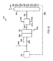
概して、原油などの重質油を処理するためのシステムおよび方法の様々な実施形態が、本開示に記載される。1つ以上の実施形態によれば、重油処理は、改良プロセスに続く、蒸気分解などの下流処理を含み得る。概して、改良プロセスは、重質油から、窒素、硫黄、および1つ以上の金属の少なくとも一部分のうちの1つ以上を除去し得、重質油中の芳香族部分を付加的に分解し得る。1つ以上の実施形態によれば、重質油は、水素化脱金属触媒(本明細書では「HDM触媒」と称されることがある)、遷移触媒、水素化脱窒素触媒(本明細書では「HDN触媒と称されることがある)、第1の水素化分解触媒、および第2の水素化分解触媒で処理することができる。本明細書に記載されるように、「第1の水素化分解触媒」および「第2の水素化分解触媒」は同じ触媒ではない。例えば、それらは、組成、多孔性、またはこれらの両方によって異なる場合がある。しかしながら、「第1」および「第2」は、記載されたシステムで位置付けることを必ずしも指すとは限らないことを理解されたい。HDM触媒、遷移触媒、HDN触媒、第1の水素化分解触媒、および第2の水素化分解触媒は、複数の床を有する充填床反応器などの単一の反応器内に含まれるか、または直列に配置された2つ以上の反応器内に含まれるかのいずれかで、直列に位置付けられ得る。 In general, various embodiments of systems and methods for treating heavy oils such as crude oil are described in this disclosure. According to one or more embodiments, the heavy oil treatment may include downstream treatments such as steam decomposition following the improvement process. In general, the improvement process can remove nitrogen, sulfur, and at least one or more of at least a portion of one or more metals from the heavy oil and can additionally decompose the aromatic moieties in the heavy oil. .. According to one or more embodiments, the heavy oil is a hydrogenated demetallized catalyst (sometimes referred to herein as a "HDM catalyst"), a transition catalyst, a hydrogenated denitrified catalyst (as used herein). Can be treated with "sometimes referred to as HDN catalysts", a first hydrocracking catalyst, and a second hydrocracking catalyst. As described herein, "first. The "hydrocracking catalyst" and the "second hydrocracking catalyst" are not the same catalyst. For example, they may vary by composition, porosity, or both. However, it should be understood that "first" and "second" do not necessarily refer to positioning in the described system. The HDM catalyst, transition catalyst, HDN catalyst, first hydrocracking catalyst, and second hydrocracking catalyst are either contained within a single reactor, such as a packed bed reactor with multiple beds. It can be positioned in series, either contained within two or more reactors arranged in series.
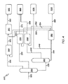
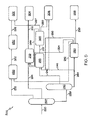
前処理プロセスの実施形態、ならびに前処理プロセスに続く他のプロセスが本明細書に記載されている。前処理後に利用され得るシステムは、「化学処理システム」、または代替的に「前処理後プロセス」もしくは「下流処理」と称され得る。開示された化学処理システムのいずれも、本明細書に記載される前処理プロセスのいずれかと併せて実践され得ることを理解されたい。例えば、図1〜図3は、前処理処理の実施形態を描写し、図4〜図8は、蒸気分解による化学処理システム(例えば、前処理後処理)の実施形態を描写する。図1〜図3に描写される、または図1〜図3に関して記載されるものなどの前処理システムの実施形態のいずれかは、図4〜図8のいずれか、または図4〜図8に関して記載される任意の他の処理構成などの本明細書に記載される下流処理構成のいずれかと共に利用され得ることを理解されたい。 Embodiments of the pretreatment process, as well as other processes following the pretreatment process, are described herein. Systems that can be utilized after pretreatment may be referred to as "chemical treatment systems", or alternative "post-treatment processes" or "downstream treatments". It should be understood that any of the disclosed chemical treatment systems can be practiced in conjunction with any of the pretreatment processes described herein. For example, FIGS. 1 to 3 depict embodiments of pretreatment, and FIGS. 4-8 depict embodiments of a steam decomposition chemical treatment system (eg, pretreatment and posttreatment). Any of the embodiments of the pretreatment system, such as those depicted in FIGS. 1 to 3 or described with respect to FIGS. 1 to 3, with respect to any of FIGS. 4 to 8 or FIGS. 4 to 8. It should be understood that it may be utilized with any of the downstream processing configurations described herein, such as any other processing configuration described.
本開示において使用される場合、「反応器」は、1つ以上の化学反応が、任意選択的に1つ以上の触媒の存在下で、1つ以上の反応物の間で起こり得る任意の容器を指す。例えば、反応器は、バッチ反応器、連続撹拌タンク反応器(CSTR)、または栓流反応器として動作するように構成されたタンクまたは管状反応器を含み得る。反応器の例には、固定床反応器などの充填床反応器、および流動床反応器が含まれる。1つ以上の「反応ゾーン」を反応器内に配置することができる。本開示で使用される場合、「反応ゾーン」は、反応器内で特定の反応が起こる領域を指す。例えば、複数の触媒床を有する充填床反応器は、複数の反応ゾーンを有することができ、各反応ゾーンは、各触媒床の面積によって画定される。 As used in the present disclosure, a "reactor" is any container in which one or more chemical reactions can optionally occur between one or more reactants in the presence of one or more catalysts. Point to. For example, the reactor may include a batch reactor, a continuous stirred tank reactor (CSTR), or a tank or tubular reactor configured to operate as a tapped reactor. Examples of reactors include packed bed reactors such as fixed bed reactors and fluidized bed reactors. One or more "reaction zones" can be placed within the reactor. As used herein, "reaction zone" refers to the region in which a particular reaction takes place within the reactor. For example, a packed bed reactor with multiple catalyst beds can have multiple reaction zones, each reaction zone being defined by the area of each catalyst bed.
本開示において使用される場合、「分離ユニット」は、プロセス流中で互いに混合される1つ以上の化学物質を少なくとも部分的に分離する任意の分離デバイスを指す。例えば、分離ユニットは、異なる化学種を互いに選択的に分離して、1つ以上の化学留分を形成することができる。分離ユニットの例としては、蒸留塔、フラッシュドラム、ノックアウトドラム、ノックアウトポット、遠心分離機、濾過デバイス、トラップ、スクラバー、膨張デバイス、膜、溶媒抽出デバイスなどが挙げられるが、これらに限定されない。本開示に記載された分離プロセスは、1つの化学構成成分の全てを別の化学構成成分の全てから完全に分離することはできないことを理解されたい。本開示に記載された分離プロセスは、異なる化学成分を互いに「少なくとも部分的に」分離することを理解されたく、また、明示していないとしても、分離は部分的な分離のみを含み得ることを理解されたい。本開示で使用される場合、1つ以上の化学成分をプロセス流から「分離」して、新たなプロセス流を形成することができる。概して、プロセス流は、分離ユニットに入り、所望の組成の2つ以上のプロセス流に分割または分離され得る。さらに、いくつかの分離プロセスでは、「軽質留分」および「重質留分」が分離ユニットを別々に出てもよい。一般に、軽質留分流は、重質留分流よりも低い沸点を有する。1つの分離ユニットのみが図に描写されるか、または説明される場合、2つ以上の分離ユニットを利用して、同一または実質的に同一の分離を実施し得ることをさらに理解されたい。例えば、複数の出口を有する蒸留塔が記載されている場合、直列に配置されたいくつかの分離器が、供給流を等しく分離し得、かつそのような実施形態が、本明細書に記載される実施形態の範囲内であることが企図される。 As used in the present disclosure, "separation unit" refers to any separation device that at least partially separates one or more chemicals that are mixed together in a process stream. For example, the separation unit can selectively separate different species from each other to form one or more chemical fractions. Examples of separation units include, but are not limited to, distillation columns, flash drums, knockout drums, knockout pots, centrifuges, filtration devices, traps, scrubbers, expansion devices, membranes, solvent extraction devices and the like. It should be understood that the separation process described in this disclosure cannot completely separate all of one chemical component from all of another. It should be understood that the separation process described in the present disclosure separates different chemical components "at least partially" from each other, and that separation may include only partial separation, if not explicitly stated. I want to be understood. As used in the present disclosure, one or more chemical components can be "separated" from the process stream to form a new process stream. In general, the process stream can enter the separation unit and be split or separated into two or more process streams of the desired composition. In addition, in some separation processes, the "light fraction" and the "heavy fraction" may leave the separation unit separately. In general, light distillates have a lower boiling point than heavy distillates. It should be further understood that if only one separation unit is depicted or described, two or more separation units can be utilized to perform the same or substantially the same separation. For example, if a distillation column with multiple outlets is described, several separators arranged in series may separate the feed streams equally, and such embodiments are described herein. It is intended to be within the scope of the above embodiments.
「反応流出物」は、概して、特定の反応または分離に続いて、分離ユニット、反応器、または反応ゾーンを出る流れを指すことを理解されたい。概して、反応流出物は、分離ユニット、反応器、または反応ゾーンに入った流れとは異なる組成を有する。流出物が別のシステムユニットに送られるとき、そのシステム流の一部分のみが送られ得ることを理解されたい。例えば、スリップ流は、流出物の部分を運び去ってもよく、つまり、流出物の一部分のみが、下流システムユニットに入る。 It should be understood that "reaction effluent" generally refers to the flow leaving a separation unit, reactor, or reaction zone following a particular reaction or separation. In general, the reaction effluent has a different composition than the flow entering the separation unit, reactor, or reaction zone. It should be understood that when a spill is sent to another system unit, only a portion of that system flow can be sent. For example, a slip stream may carry away a portion of the effluent, that is, only a portion of the effluent enters the downstream system unit.
本開示で使用される場合、「触媒」は、特定の化学反応の速度を促進させる任意の物質を指す。本開示に記載の触媒は、限定されるものではないが、水素化脱金属、水素化脱硫、水素化脱窒素、水素化脱芳香族化、芳香族分解、またはこれらの組み合わせなどの様々な反応を促進するために利用され得る。本開示において使用される場合、「分解」とは、概して、炭素−炭素結合を有する分子が、炭素−炭素結合のうちの1つ以上の切断によって2つ以上の分子に分解される場合、芳香族などの環状部分を含む化合物が、環状部分を含まない化合物に転化される場合、または炭素−炭素二重結合を有する分子が、炭素−炭素単結合に還元される場合の化学反応を指す。いくつかの触媒は、複数の形態の触媒活性を有し得、1つの特定の機能によって触媒と呼ぶことは、その触媒が他の機能性に対して触媒的に活性できないことを意味しない。 As used herein, "catalyst" refers to any substance that accelerates the rate of a particular chemical reaction. The catalysts described in the present disclosure include, but are not limited to, various reactions such as hydrogenation demetallization, hydrodesulfurization, hydrogenation denitrification, hydrogenation dearomatization, aromatization, or combinations thereof. Can be used to promote. As used in the present disclosure, "decomposition" generally means aroma when a molecule having a carbon-carbon bond is decomposed into two or more molecules by cleavage of one or more of the carbon-carbon bonds. It refers to a chemical reaction when a compound containing a cyclic moiety such as a group is converted into a compound containing no cyclic moiety, or when a molecule having a carbon-carbon double bond is reduced to a carbon-carbon single bond. Some catalysts may have multiple forms of catalytic activity, and calling them catalysts by one particular function does not mean that the catalyst cannot be catalytically activated for other functions.
図1〜図8の概略フロー図において2つ以上の線が交差するとき、2つ以上のプロセス流が「混合される」または「組み合わされる」ことを理解されたい。混合することまたは組み合わせることはまた、両方の流れを同様の反応器、分離ユニット、または他のシステム構成要素に直接的に導入することによって混合することを含み得る。 It should be understood that when two or more lines intersect in the schematic flow diagram of FIGS. 1-8, the two or more process streams are "mixed" or "combined". Mixing or combining can also include mixing by introducing both streams directly into a similar reactor, separation unit, or other system component.
本開示に記載されるような触媒によって促進される反応は、化学構成成分の一部分のみなどの化学構成成分をプロセス流から除去し得ることを理解されたい。例えば、水素化脱金属(HDM)触媒は、プロセス流から1つ以上の金属の一部分を除去する反応を促進するのに有効な量で存在し得る。水素化脱窒素(HDN)触媒は、プロセス流内に存在する窒素の一部分を除去する反応を促進するのに有効な量で存在し得る。水素化脱硫(HDS)触媒は、プロセス流内に存在する硫黄の一部分を除去する反応を促進するのに有効な量で存在し得る。さらに、水素化脱芳香族化(HDA)触媒などの第1の水素化分解触媒は、芳香族部分を飽和および分解することによって、プロセス流の芳香族部分の量を低減させる反応を促進するのに有効な量で存在し得、第2の水素化分解触媒は、芳香族部分をさらに飽和および分解することによって、第1の水素化分解ゾーンに続くプロセス流中の芳香族部分の量をさらに低減させる反応を促進するのに有効な量で存在し得る。本開示を通して、特定の触媒が、特定の機能性を有すると言われる場合、その機能性が必ずしも特定の化学的構成成分または部分の除去または分解に限定されないことを理解されたい。例えば、本開示においてHDN触媒として特定された触媒は、HDA機能性、HDS機能性、またはそれらの両方をさらに提供し得る。 It should be understood that catalyst-induced reactions such as those described in the present disclosure can remove chemical constituents, such as only a portion of the chemical constituents, from the process stream. For example, a hydrogenated demetallizing (HDM) catalyst may be present in an amount effective to facilitate a reaction that removes a portion of one or more metals from the process stream. The hydrogenation denitrification (HDN) catalyst may be present in an amount effective to facilitate the reaction of removing a portion of nitrogen present in the process stream. The hydrodesulfurization (HDS) catalyst may be present in an amount effective to facilitate the reaction of removing a portion of the sulfur present in the process stream. In addition, a first hydrocracking catalyst, such as a hydrogenation dearomatization (HDA) catalyst, promotes reactions that reduce the amount of aromatic moieties in the process stream by saturating and degrading the aromatic moieties. The second hydrocracking catalyst can further saturate and decompose the aromatic moieties to further saturate and decompose the aromatic moieties in the process flow following the first hydrocracking zone. It may be present in an amount effective to promote the reducing reaction. Throughout the disclosure, it should be understood that when a particular catalyst is said to have a particular functionality, that functionality is not necessarily limited to the removal or decomposition of a particular chemical component or moiety. For example, the catalysts identified as HDN catalysts in the present disclosure may further provide HDA functionality, HDS functionality, or both.
また、流れは流れの成分について命名することができ、流れを命名する成分は、流れの主成分であってもよい(例えば、流れの内容物の50重量パーセント(重量%)から、70重量%から、90重量%から、95重量%から、またはさらには95重量%から流れの内容物の100重量%までを含む)ことをさらに理解されたい。 The flow can also be named for the components of the flow, and the components naming the flow may be the components of the flow (eg, from 50% by weight (% by weight) of the contents of the flow to 70% by weight). From 90% by weight, from 95% by weight, or even from 95% by weight to 100% by weight of the contents of the stream).
本開示を通じて使用される細孔サイズは、他に特定されない限り、平均細孔サイズに関するものであることを理解されたい。平均細孔サイズは、Brunauer−Emmett−Teller(BET)分析から決定することができる。さらに、平均細孔サイズは、透過型電子顕微鏡(TEM)特性化によって確認することができる。 It should be understood that the pore size used throughout this disclosure relates to the average pore size unless otherwise specified. The average pore size can be determined from Brunauer-Emmett-Teller (BET) analysis. In addition, the average pore size can be confirmed by transmission electron microscopy (TEM) characterization.
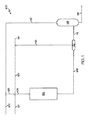
ここで図1を参照すると、一般化された水素化処理触媒系132を含む前処理システム100が描写されている。図1の水素化処理触媒系132の追加の実施形態は、図2〜図3で詳細に説明されることを理解されたい。しかしながら、図1の一般化された前処理システム100の供給原料、製品、リサイクル流などは、図2〜図8を参照して説明された実施形態にも適用されることを理解されたい。
Here, with reference to FIG. 1, a
図1を参照すると、本開示の実施形態によれば、重質油供給流101は、水素流104と混合され得る。水素流104は、再利用されたプロセスガス成分流113からの未使用水素ガス、水素供給流114からの補給水素、またはそれらの両方を含み、重質油供給流101と混合し、前処理触媒投入流105を形成し得る。1つ以上の実施形態では、前処理触媒投入流105を摂氏350度(℃)〜450℃のプロセス温度に加熱することができる。前処理触媒投入流105は、水素化処理触媒系132に入り、水素化処理触媒系132を通過し得る。本明細書に記載されるように、水素化処理触媒系132は、HDM反応ゾーン、遷移反応ゾーン、HDN反応ゾーン、第1の水素化分解反応ゾーン、および第2の水素化分解反応ゾーンを含む一連の反応ゾーンを含み得る。
Referring to FIG. 1, according to the embodiments of the present disclosure, the heavy
記載されたシステムおよびプロセスは、接触水素化処理前処理プロセスを使用して、原油、減圧残留物、タールサンド、ビチューメンおよび減圧軽油を含む、多種多様な重質油供給物(重質油供給流101中)に適用可能である。重質油供給物が原油である場合、これは25度〜50度の米国石油協会(API)比重を有することができる。例えば、利用される重質油供給物は、アラブ重質原油であってもよい。アラブ重質原油の典型的な特性を表1に示す。

引き続き図1を参照すると、前処理触媒反応流出物流109は、前処理触媒投入流105と水素化処理触媒系132との相互作用により形成され得る。前処理触媒反応流出物流109は、分離ユニット112に入り得、再利用されるプロセスガス成分流113および中間液体生成物流115に分離し得る。一実施形態では、前処理触媒反応流出物流109を精製して、硫化水素および他のプロセスガスを除去して、再利用されるプロセスガス成分流113中の水素の純度を高めることもできる。このプロセスで消費される水素は、蒸気もしくはナフサ改質装置または他の供給源に由来し得る補給水素供給流114からの新鮮な水素の添加によって補償することができる。再利用されるプロセスガス成分流113および新鮮な補給水素供給流114は、組み合わさり、水素流104を形成し得る。一実施形態では、中間液体生成物流115を分離ユニット116内で分離して、軽質炭化水素留分流117および前処理最終液体生成物流118を分離し得るが、この分離工程が任意選択的であることを理解されたい。さらなる実施形態では、分離ユニット116はフラッシュ容器であってもよい。一実施形態では、軽質炭化水素留分流117はリサイクルとして作用し、軽質炭化水素希釈剤流102と混合されて、軽質炭化水素希釈剤流103を生成する。新鮮な軽質炭化水素希釈剤流102は、水素化処理触媒系132内の触媒のうちの1つ以上の失活をさらに低減させるのを補助するために、必要に応じてプロセスに補給希釈剤を提供するために使用することができる。
Continuing with reference to FIG. 1, the pretreatment catalyst reaction outflow logistics 109 can be formed by the interaction of the pretreatment catalyst input stream 105 and the hydrogenation
1つ以上の実施形態において、前処理触媒反応流出流109、中間液体生成物流115、および前処理最終液体生成物流118のうちの1つ以上は、重質油供給流101と比較して低減された芳香族含有量を有することができる。付加的に、実施形態では、前処理触媒反応流出流109、中間液体生成物流115、および前処理最終液体生成物流118のうちの1つ以上は、重質油供給流101と比較して、著しく低減された硫黄、金属、アスファルテン、コンラドソン炭素、窒素の含有量、またはこれらの組み合わせ、ならびに増加したAPI比重および増加したディーゼルならびに減圧留出物の収率を有し得る。
In one or more embodiments, one or more of the pretreatment catalytic reaction outflow 109, the intermediate liquid production stream 115, and the pretreatment final liquid production stream 118 is reduced as compared to the heavy
1つ以上の実施形態によれば、前処理触媒反応流出物流109は、重質油供給流101と比べて、窒素の少なくとも約80重量%の低減、少なくとも90重量%の低減、またはさらには少なくとも95重量%の低減を有することができる。別の実施形態によれば、前処理触媒反応流出物流109は、重質油供給流101と比べて、硫黄の少なくとも約85重量%の低減、少なくとも90重量%の低減、またはさらには少なくとも99重量%の低減を有することができる。別の実施形態によれば、前処理触媒反応流出物流109は、重質油供給流101と比べて、芳香族含有量の少なくとも約70重量%の低減、少なくとも80重量%の低減、またはさらには少なくとも85重量%の低減を有することができる。別の実施形態によれば、前処理触媒反応流出物流109は、重質油供給流101と比べて、金属の少なくとも約80重量%の低減、少なくとも90重量%の低減、またはさらには少なくとも99重量%の低減を有することができる。
According to one or more embodiments, the pretreatment catalytic reaction effluent 109 has a reduction of at least about 80% by weight, at least 90% by weight, or even at least a reduction in nitrogen as compared to the heavy
引き続き図1を参照すると、様々な実施形態では、前処理触媒反応流出物流109、中間液体生成物流115、および前処理最終液体生成物流118のうちの1つ以上は、下流処理のための改良された油流220として使用するのに好適であり得、その実施形態は、本開示において後で説明する。本開示で使用されるように、前処理触媒反応流出流109、中間液体生成物流115、および前処理最終液体生成物流118のうちの1つ以上は、少なくとも図4〜図8の下流システムによって下流処理され得る「改良された油」と称され得る。いくつかの実施形態では、改良された油は、540℃以下の最終沸点を有し得、これにより、下流蒸気分解における効率またはさらなる転化を増加させ得る。追加の実施形態では、改良された油の少なくとも90重量%、少なくとも95重量%、または少なくとも99重量%でさえもが、540℃以下の沸点を有し得る。追加の実施形態では、改良された油は、520℃、500℃、480℃、460℃、440℃、420℃、400℃、380℃、360℃、340℃、320℃、さらには300℃以下の最終沸点を有し得る。改良された油の最終沸点は、前処理システム100の後続の任意選択的な分離工程によって軽留分のみが除去されるため、前処理反応触媒流出物流109の最終沸点に等しいことを理解されたい。
Continuing with reference to FIG. 1, in various embodiments, one or more of the pretreatment catalytic reaction effluent distribution 109, the intermediate liquid production distribution 115, and the pretreatment final liquid production distribution 118 have been modified for downstream treatment. It may be suitable for use as an
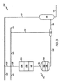
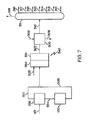
ここで図2を参照すると、1つ以上の実施形態によれば、水素化処理触媒系132は、直列に配置された複数の充填床反応ゾーン(例えば、HDM反応ゾーン106、遷移反応ゾーン108、HDN反応ゾーン110、第1の水素化分解反応ゾーン120、および第2の水素化分解反応ゾーン125)を含むまたはそれらから成り得、これらの反応ゾーンの各々は、触媒床を備え得る。これらの反応ゾーンの各々は、図2の前処理反応器130として示されるように、直列の複数の床を有する充填床反応器として単一の反応器内に含まれ得る。そのような実施形態では、前処理反応器130は、HDM反応ゾーン106内にHDM触媒を含むHDM触媒床、遷移反応ゾーン108内に遷移触媒を含む遷移触媒床、HDN反応ゾーン110内にHDN触媒を含むHDN触媒床、水素化分解反応ゾーン120内に第1の水素化分解触媒を含む第1の水素化分解触媒床、および第2の水素化分解反応ゾーン125内に第2の水素化分解触媒を含む第2の水素化分解触媒床を含む。他の実施形態では、HDM反応ゾーン106、遷移反応ゾーン108、HDN反応ゾーン110、および水素化分解反応ゾーン120は各々、直列に配置された複数の充填床反応器内に含まれ得る。さらなる実施形態では、各反応ゾーンは、別個の単一充填床反応器内に含まれる。企図される実施形態には、直列に配置された充填触媒床が、単一の反応器内、または各々が1つ以上の触媒床を含有する複数の反応器内に含まれる実施形態が含まれることを理解されたい。比較的大量の触媒が必要とされる場合、それらの触媒を別々の反応器に収容することが望ましい場合があることを理解されたい。)。
Here, referring to FIG. 2, according to one or more embodiments, the
1つ以上の実施形態によれば、重質油を含む前処理触媒投入流105は、HDM反応ゾーン106に導入され、HDM触媒によって接触される。HDM触媒と前処理触媒投入流105との接触は、前処理触媒投入流105中に存在する金属の少なくとも一部分を除去する反応を促進し得る。HDM触媒と接触した後、前処理触媒投入流105をHDM反応流出物に転化することができる。HDM反応流出物は、前処理触媒投入流105の含有量と比較して、低減した金属含有量を有し得る。例えば、HDM反応流出物は、前処理触媒投入流105として、少なくとも70重量%未満、少なくとも80重量%未満、またはさらには少なくとも95重量%未満の金属を有し得る。 According to one or more embodiments, the pretreatment catalyst feed stream 105 containing heavy oil is introduced into the HDMI reaction zone 106 and contacted by the HDMI catalyst. Contact between the HDMI catalyst and the pretreatment catalyst feed stream 105 can facilitate a reaction that removes at least a portion of the metal present in the pretreatment catalyst feed stream 105. After contact with the HDMI catalyst, the pretreatment catalyst feed stream 105 can be converted to an HDMI reaction effluent. The HDMI reaction effluent may have a reduced metal content compared to the content of the pretreatment catalyst feed stream 105. For example, the HDMI reaction effluent may have at least less than 70% by weight, at least less than 80% by weight, or even at least less than 95% by weight of metal as the pretreatment catalyst input stream 105.
1つ以上の実施形態によれば、HDM反応ゾーン106は、370℃〜415℃などの350℃〜450℃の重量平均床温度を有し得、90バール〜110バールなどの30バール〜200バールの圧力を有し得る。HDM反応ゾーン106はHDM触媒を含み、HDM触媒はHDM反応ゾーン106の全体を満たすことができる。 According to one or more embodiments, the HDMI reaction zone 106 can have a weight average floor temperature of 350 ° C. to 450 ° C., such as 370 ° C. to 415 ° C., and 30 bar to 200 bar, such as 90 bar to 110 bar. Can have a pressure of. The HDMI reaction zone 106 includes an HDMI catalyst, which can fill the entire HDMI reaction zone 106.
HDM触媒は、国際純粋および応用化学連合(IUPAC)の周期表の5、6、または8〜10族からの1つ以上の金属を含むことができる。例えば、HDM触媒は、モリブデンを含むことができる。HDM触媒は、担体材料をさらに含み得、金属は、担体材料上に配設され得る。一実施形態では、HDM触媒は、アルミナ担体上にモリブデン金属触媒を含むことができる(「Mo/Al2O3触媒」と称されることもある)。開示された触媒のいずれかの中に含有される金属が、硫化物または酸化物として、またはさらには他の化合物として存在してもよいことは、本開示を通じて理解されたい。 The HDMI catalyst can include one or more metals from groups 5, 6, or 8-10 of the Periodic Table of the International Pure and Applied Chemistry Association (IUPAC). For example, the HDMI catalyst can include molybdenum. The HDMI catalyst may further comprise a carrier material and the metal may be disposed on the carrier material. In one embodiment, the HDMI catalyst can include a molybdenum metal catalyst on an alumina carrier (sometimes referred to as a "Mo / Al 2 O 3 catalyst"). It is to be understood throughout this disclosure that the metals contained in any of the disclosed catalysts may be present as sulfides or oxides, or even other compounds.
一実施形態では、HDM触媒は、担体材料上に金属硫化物を含むことができ、ここで、金属は、周期表のIUPAC5、6、および8〜10族の元素、およびこれらの組み合わせからなる群から選択される。担体材料は、ガンマ−アルミナまたはシリカ/アルミナ押出物、球体、シリンダー、ビーズ、ペレット、およびこれらの組み合わせであってもよい。 In one embodiment, the HDMI catalyst can include a metal sulfide on the carrier material, where the metal is a group consisting of elements of groups IUPAC 5, 6, and 8-10 of the periodic table, and combinations thereof. Is selected from. The carrier material may be gamma-alumina or silica / alumina extrusion, spheres, cylinders, beads, pellets, or a combination thereof.
一実施形態では、HDM触媒は、100m2/g〜160m2/g(100m2/g〜130m2/g、または130m2/g〜160m2/gなど)の表面積を有するガンマ−アルミナ担体を含み得る。HDM触媒は、少なくとも0.8cm3/g(例えば、少なくとも0.9cm3/g、またはさらには少なくとも1.0cm3/g)などの比較的大きな細孔容積を有するものとして最もよく説明することができる。HDM触媒の細孔サイズは、主としてマクロ細孔性(すなわち、50nm超の細孔サイズを有する)であってもよい。これは、HDM触媒の表面および任意選択的にドーパント上の金属の取り込みのための大きな能力を提供し得る。一実施形態では、ドーパントは、ホウ素、ケイ素、ハロゲン、リン、およびこれらの組み合わせからなる群から選択することができる。 In one embodiment, HDM catalysts, 100m 2 / g~160m 2 / g (100m 2 / g~130m 2 / g, or 130m 2 / g~160m 2 / g, etc.) gamma having a surface area of - alumina carrier Can include. The HDMI catalyst is best described as having a relatively large pore volume, such as at least 0.8 cm 3 / g (eg, at least 0.9 cm 3 / g, or even at least 1.0 cm 3 / g). Can be done. The pore size of the HDMI catalyst may be predominantly macroporous (ie, having a pore size greater than 50 nm). This can provide great capacity for the uptake of metals on the surface of the HDMI catalyst and optionally on the dopant. In one embodiment, the dopant can be selected from the group consisting of boron, silicon, halogen, phosphorus, and combinations thereof.
1つ以上の実施形態では、HDM触媒は、0.5重量%〜12重量%のモリブデンの酸化物または硫化物(例えば、2重量%〜10重量%、または3重量%〜7重量%のモリブデンの酸化物または硫化物)と、88重量%〜99.5重量%のアルミナ(例えば、90重量%〜98重量%、または93重量%〜97重量%のアルミナ)とを含み得る。 In one or more embodiments, the HDM catalyst is an oxide or sulfide of 0.5% to 12% by weight of molybdenum (eg, 2% to 10% by weight, or 3% to 7% by weight of molybdenum. Oxides or sulfides) and 88% to 99.5% by weight of alumina (eg, 90% to 98% by weight, or 93% to 97% by weight of alumina).
理論に束縛されるものではないが、いくつかの実施形態では、HDM反応ゾーン106内での反応の間に、HDM触媒は、重質油中に存在するポルフィリン型化合物の、水素を介して水素化を促進して、中間体を生成すると考えられる。この一次水素化の後、ポルフィリン分子の中心に存在するニッケルまたはバナジウムは、水素で還元され、次いで、硫化水素(H2S)で対応する硫化物にさらに還元される。最終金属硫化物をHDM触媒上に堆積させ、これにより、未精製原油から金属硫化物を除去する。硫黄はまた、並行経路を介して硫黄含有有機化合物から除去される。これらの並行反応の速度は、考慮される硫黄種に依存し得る。全体として、水素は、プロセス中でH2Sに転化される硫黄を抽出するために使用される。残部の硫黄不含炭化水素断片は、液体炭化水素流中に残る。 Without being bound by theory, in some embodiments, during the reaction within the HDM reaction zone 106, the HDM catalyst is hydrogenated via hydrogen of the porphyrin-type compound present in the heavy oil. It is thought that it promotes the formation of intermediates. After the primary hydrogenation, nickel or vanadium is present in the center of the porphyrin molecules are reduced with hydrogen, then further reduced to the corresponding sulfides with hydrogen sulfide (H 2 S). The final metal sulfide is deposited on the HDMI catalyst, which removes the metal sulfide from the unrefined crude oil. Sulfur is also removed from sulfur-containing organic compounds via parallel pathways. The rate of these parallel reactions may depend on the sulfur species considered. Overall, hydrogen is used to extract the sulfur is converted to H 2 S in the process. The remaining sulfur-free hydrocarbon fragments remain in the liquid hydrocarbon stream.
HDM反応流出物は、HDM反応ゾーン106から遷移反応ゾーン108に移されることができ、ここで遷移触媒によって接触される。遷移触媒とHDM反応流出物との接触は、HDM反応流出物流中に存在する金属の少なくとも一部分を除去する反応、ならびにHDM反応流出物流中に存在する窒素の少なくとも一部分を除去し得る反応を促進し得る。遷移触媒との接触後、HDM反応流出物は、遷移反応流出物に転化される。遷移反応流出物は、HDM反応流出物と比較して、低減した金属含有量および窒素含有量を有し得る。例えば、遷移反応流出物は、HDM反応流出物として、少なくとも50重量%未満、少なくとも80重量%未満、またはさらには少なくとも90重量%未満の金属含有量を有し得る。加えて、遷移反応流出物は、HDM反応流出物として、少なくとも10重量%未満、少なくとも15重量%未満、またはさらには少なくとも20重量%未満の窒素を有することができる。 The HDMI reaction effluent can be transferred from the HDMI reaction zone 106 to the transition reaction zone 108, where it is contacted by the transition catalyst. Contact between the transition catalyst and the HDMI reaction effluent facilitates a reaction that removes at least a portion of the metal present in the HDMI reaction effluent and can remove at least a portion of the nitrogen present in the HDMI reaction effluent. obtain. After contact with the transition catalyst, the HDMI reaction effluent is converted to a transition reaction effluent. The transition reaction effluent may have a reduced metal content and nitrogen content as compared to the HDMI reaction effluent. For example, the transition reaction effluent can have a metal content of at least less than 50% by weight, at least less than 80% by weight, or even at least less than 90% by weight as an HDMI reaction effluent. In addition, the transition reaction effluent can have at least less than 10% by weight, at least less than 15% by weight, or even at least less than 20% by weight of nitrogen as the HDMI reaction effluent.
実施形態によれば、遷移反応ゾーン108は、約370℃〜410℃の重量平均床温度を有する。遷移反応ゾーン108は遷移触媒を含み、遷移触媒は遷移反応ゾーン108の全体を満たすことができる。 According to the embodiment, the transition reaction zone 108 has a weight average floor temperature of about 370 ° C to 410 ° C. The transition reaction zone 108 includes a transition catalyst, and the transition catalyst can fill the entire transition reaction zone 108.
一実施形態では、遷移反応ゾーン108は、ある量の金属成分およびある量の硫黄成分をHDM反応流出物流から除去するように操作することができる。遷移触媒は、押出物の形態のアルミナ系担体を含むことができる。 In one embodiment, the transition reaction zone 108 can be manipulated to remove certain amounts of metal and sulfur components from the HDMI reaction outflow stream. The transition catalyst can include an alumina-based carrier in the form of an extruded product.
一実施形態では、遷移触媒は、IUPACの6族からの1つの金属と、IUPACの8〜10族からの1つの金属とを含む。例示的なIUPACの6族の金属としては、モリブデンおよびタングステンが挙げられる。IUPACの8〜10族の金属の例としては、ニッケルおよびコバルトが挙げられる。例えば、遷移触媒は、チタニア担体上にMoおよびNiを含み得る(時に「Mo−Ni/Al2O3触媒」と称される)。遷移触媒はまた、ホウ素、リン、ハロゲン、ケイ素、およびこれらの組み合わせからなる群から選択されるドーパントも含み得る。遷移触媒は、140m2/g〜200m2/g(140m2/g〜170m2/g、または170m2/g〜200m2/gなど)の表面積を有することができる。遷移触媒は、0.5cm3/g〜0.7cm3/g(例えば、0.6cm3/g)の中間細孔容積を有することができる。遷移触媒は、一般に、12nm〜50nmの範囲の細孔サイズを有するメソ細孔性構造を含むことができる。これらの特性は、HDMおよびHDSにおけるバランスの取れた活性を提供する。
In one embodiment, the transition catalyst comprises one metal from Group 6 of IUPAC and one metal from Group 8-10 of IUPAC. Illustrative Group 6 metals of IUPAC include molybdenum and tungsten. Examples of Group 8-10 metals of IUPAC include nickel and cobalt. For example, the transition catalyst may contain Mo and Ni on a titania carrier (sometimes referred to as "Mo-Ni / Al 2 O 3 catalyst"). Transition catalysts may also include dopants selected from the group consisting of boron, phosphorus, halogens, silicon, and combinations thereof. Transition catalyst may have a surface area of 140m 2 / g~200m 2 / g ( 140m 2 / g~170m 2 / g, or 170m 2 / g~200m 2 / g, etc.). Transition catalyst, 0.5
1つ以上の実施形態では、遷移触媒は、10重量%〜18重量%のモリブデンの酸化物または硫化物(例えば、11重量%〜17重量%、または12重量%〜16重量%のモリブデンの酸化物または硫化物)と、1重量%〜7重量%のニッケルの酸化物または硫化物(例えば、2重量%〜6重量%、または3重量%〜5重量%のニッケルの酸化物または硫化物)と、75重量%〜89重量%のアルミナ(例えば、77重量%〜87重量%、または79重量%〜85重量%のアルミナ)とを含み得る。 In one or more embodiments, the transition catalyst is 10% to 18% by weight of oxide or sulfide of molybdenum (eg, 11% to 17% by weight, or 12% to 16% by weight of molybdenum oxidation. (Materials or sulfides) and 1% to 7% by weight of nickel oxides or sulfides (eg, 2% to 6% by weight, or 3% to 5% by weight of nickel oxides or sulfides). And 75% to 89% by weight of alumina (eg, 77% by weight to 87% by weight, or 79% by weight to 85% by weight of alumina).
遷移反応流出物は、遷移反応ゾーン108からHDN反応ゾーン110に移されることができ、ここでHDN触媒によって接触される。HDN触媒と遷移反応流出物との接触は、遷移反応流出物流中に存在する窒素の少なくとも一部分を除去する反応を促進してもよい。HDN触媒との接触は、遷移反応流出物流を、HDN反応流出物に転化することができる。HDN反応流出物は、遷移反応流出物と比較して、低減した金属含有量および窒素含有量を有し得る。例えば、HDN反応流出物は、遷移反応流出物と比べて、少なくとも80重量%、少なくとも85重量%、またはさらには少なくとも90重量%の窒素含有量の低減を有することができる。別の実施形態では、HDN反応流出物は、遷移反応流出物と比べて、少なくとも80重量%、少なくとも90重量%、またはさらには少なくとも95重量%の硫黄含有量の低減を有することができる。別の実施形態では、HDN反応流出物は、遷移反応流出物と比べて、少なくとも25重量%、少なくとも30重量%未満、またはさらには少なくとも40重量%の芳香族含有量の低減を有することができる。 The transition reaction effluent can be transferred from the transition reaction zone 108 to the HDN reaction zone 110, where it is contacted by the HDN catalyst. Contact between the HDN catalyst and the transition reaction effluent may facilitate a reaction that removes at least a portion of the nitrogen present in the transition reaction effluent flow. Contact with the HDN catalyst can convert the transition reaction effluent into an HDN reaction effluent. The HDN reaction effluent may have a reduced metal content and nitrogen content as compared to the transition reaction effluent. For example, the HDN reaction effluent can have a reduction in nitrogen content of at least 80% by weight, at least 85% by weight, or even at least 90% by weight compared to the transition reaction effluent. In another embodiment, the HDN reaction effluent can have a reduction in sulfur content of at least 80% by weight, at least 90% by weight, or even at least 95% by weight compared to the transition reaction effluent. In another embodiment, the HDN reaction effluent can have a reduction in aromatic content of at least 25% by weight, at least less than 30% by weight, or even at least 40% by weight, as compared to the transition reaction effluent. ..
実施形態によれば、HDN反応ゾーン110は、370℃〜410℃の重量平均床温度を有する。HDN反応ゾーン110はHDN触媒を含み、HDN触媒はHDN反応ゾーン110の全体を満たすことができる。 According to embodiments, the HDN reaction zone 110 has a weight average floor temperature of 370 ° C to 410 ° C. The HDN reaction zone 110 includes an HDN catalyst, and the HDN catalyst can fill the entire HDN reaction zone 110.
一実施形態では、HDN触媒は、担体材料上に金属酸化物または硫化物を含むことができ、ここで、金属は、周期表のIUPACの5、6、および8〜10族の元素、およびこれらの組み合わせからなる群から選択される。担体材料は、押出物、球体、シリンダーおよびペレットの形態のガンマ−アルミナ、メソ細孔性アルミナ、シリカまたはそれらの両方を含むことができる。 In one embodiment, the HDN catalyst can include metal oxides or sulfides on the carrier material, where the metal is an element of groups 5, 6, and 8-10 of IUPAC in the periodic table, and these. It is selected from the group consisting of combinations of. The carrier material can include gamma-alumina, mesoporous alumina, silica or both in the form of extrudes, spheres, cylinders and pellets.
一実施形態では、HDN触媒は、180m2/g〜240m2/g(例えば、180m2/g〜210m2/g、または210m2/g〜240m2/g)の表面積を有するガンマ−アルミナ系担体を含有する。HDN触媒のこの比較的大きな表面積は、より小さな細孔容積(例えば、1.0cm3/g未満、0.95cm3/g未満、またはさらには0.9cm3/g未満)を可能にする。一実施形態では、HDN触媒は、モリブデンなどのIUPACの6族からの少なくとも1つの金属と、ニッケルなどのIUPACの8〜10族からの少なくとも1つの金属とを含有する。HDN触媒はまた、ホウ素、リン、シリコン、ハロゲン、およびこれらの組み合わせからなる群から選択される少なくとも1つのドーパントも含むことができる。一実施形態では、HDN触媒は、コバルトを含み得、コバルトは、さらに脱硫を促進する。一実施形態では、HDN触媒は、HDM触媒と比較して、活性相に対してより高い金属充填量を有する。この増加した金属充填量は、触媒活性の増加を引き起こす可能性がある。一実施形態では、HDN触媒はニッケルおよびモリブデンを含み、0.1〜0.3(例えば、0.1〜0.2または0.2〜0.3)のニッケル対モリブデンのモル比(Ni/(Ni+Mo))を有する。コバルトを含む実施形態では、(Co+Ni)/Moのモル比は、0.25〜0.85(例えば、0.25〜0.5または0.5〜0.85)の範囲であってもよい。 In one embodiment, HDN catalyst, 180m 2 / g~240m 2 / g ( e.g., 180m 2 / g~210m 2 / g or 210m 2 / g~240m 2 / g, ) gamma having a surface area of - alumina Contains a carrier. This relatively large surface area of the HDN catalyst allows for smaller pore volumes (eg, less than 1.0 cm 3 / g, less than 0.95 cm 3 / g, or even less than 0.9 cm 3 / g). In one embodiment, the HDN catalyst contains at least one metal from Group 6 of IUPAC such as molybdenum and at least one metal from Group 8-10 of IUPAC such as nickel. The HDN catalyst can also include at least one dopant selected from the group consisting of boron, phosphorus, silicon, halogens, and combinations thereof. In one embodiment, the HDN catalyst may contain cobalt, which further promotes desulfurization. In one embodiment, the HDN catalyst has a higher metal filling amount relative to the active phase as compared to the HDMI catalyst. This increased metal filling can cause an increase in catalytic activity. In one embodiment, the HDN catalyst comprises nickel and molybdenum and has a nickel to molybdenum molar ratio of 0.1 to 0.3 (eg, 0.1 to 0.2 or 0.2 to 0.3) (Ni /). (Ni + Mo)). In embodiments that include cobalt, the molar ratio of (Co + Ni) / Mo may be in the range of 0.25 to 0.85 (eg, 0.25 to 0.5 or 0.5 to 0.85). ..
別の実施形態によれば、HDN触媒は、少なくとも25nmの平均細孔サイズを有することができるメソ細孔性アルミナなどのメソ細孔性材料を含有することができる。例えば、HDN触媒は、少なくとも30nm、またはさらには少なくとも35nmの平均細孔サイズを有するメソ細孔性アルミナを含み得る。2nm未満などの比較的小さな平均細孔サイズを有するHDN触媒は、本開示では従来のHDN触媒と称され得、より大きな細孔サイズを有する本明細書に開示されるHDN触媒と比較して、比較的不良な触媒性能を有し得る。2nm〜50nmの平均細孔サイズを有するアルミナ担体を有するHDN触媒の実施形態は、本開示において「メソ多孔質アルミナ支持触媒」と称され得る。1つ以上の実施形態では、HDM触媒のメソ多孔質アルミナは、2nm〜50nm、25nm〜50nm、30nm〜50nm、または35nm〜50nmの範囲の平均細孔サイズを有し得る。実施形態によれば、HDN触媒は、比較的大きな表面積、比較的大きな細孔容積、またはそれらの両方を有するアルミナを含むことができる。例えば、メソポーラスアルミナは、約225m2/g、少なくとも約250m2/g、少なくとも約275m2/g、少なくとも約300m2/g、またはさらには少なくとも約350m2/g、例えば225m2/g〜500m2/g、200m2/g〜450m2/g、または300m2/g〜400m2/gの表面積を有することによって、比較的大きな表面積を有することができる。1つ以上の実施形態では、メソ細孔性アルミナは、少なくとも約1mL/g、少なくとも約1.1mL/g、少なくとも1.2mL/g、またはさらには少なくとも1.2mL/g、例えば、1mL/g〜5mL/g、1.1mL/g〜3、または1.2mL/g〜2mL/gの細孔容積を有することによって、比較的大きな細孔容積を有することができる。理論に束縛されるものではないが、メソ細孔性アルミナ担持HDN触媒は、より大きな分子が触媒の内外に移動することを容易にし得、追加の活性部位およびより大きな細孔チャネルを提供し得ると考えられる。追加の活性部位およびより大きい細孔チャンネルは、より高い触媒活性、より長い触媒寿命、またはそれらの両方をもたらし得る。一実施形態では、HDN触媒は、ホウ素、ケイ素、ハロゲン、リン、およびこれらの組み合わせからなる群から選択することができるドーパントを含み得る。 According to another embodiment, the HDN catalyst can contain a mesoporous material such as mesoporous alumina that can have an average pore size of at least 25 nm. For example, the HDN catalyst may contain mesoporous alumina having an average pore size of at least 30 nm, or even at least 35 nm. HDN catalysts with a relatively small average pore size, such as less than 2 nm, may be referred to herein as conventional HDN catalysts, as compared to HDN catalysts disclosed herein with larger pore sizes. It may have relatively poor catalytic performance. An embodiment of an HDN catalyst having an alumina carrier with an average pore size of 2 nm to 50 nm can be referred to herein as a "mesoporous alumina-supported catalyst". In one or more embodiments, the HDMI-catalyzed mesoporous alumina can have an average pore size in the range of 2 nm to 50 nm, 25 nm to 50 nm, 30 nm to 50 nm, or 35 nm to 50 nm. According to embodiments, HDN catalysts can include alumina with a relatively large surface area, a relatively large pore volume, or both. For example, mesoporous alumina, about 225 m 2 / g, at least about 250 meters 2 / g, at least about 275 m 2 / g, at least about 300 meters 2 / g or even at least about 350 meters 2 / g,, for example, 225 m 2/500 m 2 / g, 200m 2 / g~450m 2 / g or by having a surface area of 300m 2 / g~400m 2 / g, , can have a relatively large surface area. In one or more embodiments, the mesoporous alumina is at least about 1 mL / g, at least about 1.1 mL / g, at least 1.2 mL / g, or even at least 1.2 mL / g, eg, 1 mL / g. By having a pore volume of g to 5 mL / g, 1.1 mL / g to 3, or 1.2 mL / g to 2 mL / g, it is possible to have a relatively large pore volume. Without being bound by theory, mesoporous alumina-supported HDN catalysts can facilitate the movement of larger molecules into and out of the catalyst, providing additional active sites and larger pore channels. it is conceivable that. Additional active sites and larger pore channels can result in higher catalytic activity, longer catalytic life, or both. In one embodiment, the HDN catalyst may include a dopant that can be selected from the group consisting of boron, silicon, halogen, phosphorus, and combinations thereof.
記載された実施形態によれば、HDN触媒は、アルミナなどの担体材料を、酸解膠アルミナなどの結合剤と混合することによって製造することができる。水または別の溶媒を、担体材料および結合剤の混合物に添加して押出可能な相を形成することができ、次いでこれが所望の形状に押出される。押出物は、高温(例えば100℃超、110℃など)で乾燥させ、次いで、好適な温度(例えば、少なくとも400℃、少なくとも450℃の温度、500℃など)でか焼され得る。か焼された押出物は、Mo、Ni、またはこれらの組み合わせを含む前駆体材料などの触媒前駆体材料を含有する水溶液で含浸され得る。例えば、水溶液は、ヘプタンモリブデン酸アンモニウム、硝酸ニッケル、およびリン酸を含有して、モリブデン、ニッケル、およびリンを含む化合物を含むHDN触媒を形成することができる。 According to the described embodiments, the HDN catalyst can be produced by mixing a carrier material such as alumina with a binder such as acid glutinous alumina. Water or another solvent can be added to the mixture of carrier material and binder to form an extrudable phase, which is then extruded into the desired shape. The extruded product can be dried at a high temperature (eg, above 100 ° C., 110 ° C., etc.) and then calcinated at a suitable temperature (eg, at least 400 ° C., at least 450 ° C., 500 ° C., etc.). The calcinated extrusion can be impregnated with an aqueous solution containing a catalytic precursor material such as a precursor material containing Mo, Ni, or a combination thereof. For example, the aqueous solution can contain ammonium heptane molybdate, nickel nitrate, and phosphoric acid to form an HDN catalyst containing compounds containing molybdic, nickel, and phosphorus.
メソ細孔性アルミナ担体が利用される実施形態では、メソ細孔性アルミナは、60℃〜90℃の水中にベーマイト粉末を分散させることによって合成することができる。次いで、HNO3などの酸をベーマイト水溶液中に、0.3〜3.0のHNO3:Al3+の比で添加してもよく、この溶液を60〜90℃で数時間、例えば、6時間撹拌して、ゾルを得る。トリブロックコポリマーなどのコポリマーを室温でゾルに添加することができ、このコポリマー:Alのモル比は0.02〜0.05であり、3時間などの数時間、熟成される。ゾル/コポリマー混合物を数時間乾燥し、次いでか焼する。 In embodiments where a mesoporous alumina carrier is utilized, mesoporous alumina can be synthesized by dispersing boehmite powder in water at 60 ° C. to 90 ° C. Then, HNO a acid such as in the boehmite solution 3, 0.3 to 3.0 of HNO 3: may be added at a ratio of Al 3+, several hours the solution 60 to 90 ° C., for example, 6 hours Stir to obtain a sol. Copolymers such as triblock copolymers can be added to the sol at room temperature and the copolymer: Al molar ratio is 0.02-0.05 and is aged for several hours, such as 3 hours. The sol / copolymer mixture is dried for several hours and then calcinated.
1つ以上の実施形態によれば、HDN触媒は、10重量%〜18重量%のモリブデンの酸化物または硫化物(例えば、13重量%〜17重量%、または14重量%〜16重量%のモリブデンの酸化物または硫化物)と、2重量%〜8重量%のニッケルの酸化物または硫化物(例えば、3重量%〜7重量%または4重量%〜6重量%のニッケルの酸化物または硫化物)と、74重量%〜88重量%のアルミナ(例えば、76重量%〜84重量%、または78重量%〜82重量%のアルミナ)とを含むことができる。 According to one or more embodiments, the HDN catalyst is an oxide or sulfide of 10% to 18% by weight of molybdenum (eg, 13% to 17% by weight, or 14% to 16% by weight of molybdenum. Oxides or sulfides) and 2% to 8% by weight of nickel oxides or sulfides (eg, 3% to 7% by weight or 4% to 6% by weight of nickel oxides or sulfides) ) And 74% by weight to 88% by weight of alumina (for example, 76% by weight to 84% by weight, or 78% by weight to 82% by weight of alumina).
HDM触媒と同様に、やはりいかなる理論にも束縛されるものではないが、水素化脱窒素および水素化脱芳香族化は、関連する反応機構を介して作用することができると考えられる。両方とも、ある程度の水素化を伴う。水素化脱窒素のために、有機窒素化合物は、通常、複素環式構造の形態であり、ヘテロ原子は窒素である。これらの複素環式構造は、窒素のヘテロ原子の除去に先立って飽和されていてもよい。同様に、水素化脱芳香族化は芳香族環の飽和を伴う。これらの反応の各々は、触媒の各々の量または種類に応じて異なる程度で発生し得、これは、各触媒が、ある種類の伝達を他の種類よりも選択的に促進し得、伝達が競合しているためである。 Like HDM catalysts, again without being bound by any theory, it is believed that hydrogenation denitrification and hydrogenation dearomatization can act through related reaction mechanisms. Both involve some degree of hydrogenation. Due to hydrogenation denitrification, the organic nitrogen compound is usually in the form of a heterocyclic structure and the heteroatom is nitrogen. These heterocyclic structures may be saturated prior to the removal of nitrogen heteroatoms. Similarly, hydrogenation dearomaticization involves saturation of the aromatic ring. Each of these reactions can occur to varying degrees depending on the amount or type of catalyst, which allows each catalyst to selectively facilitate the transfer of one type over the other. This is because they are in conflict.
本明細書に記載される方法およびシステムのいくつかの実施形態が、少なくとも25nmの平均細孔サイズを有する多孔性アルミナを含むHDN触媒を利用し得ることを理解されたい。しかしながら、他の実施形態では、多孔性アルミナの平均細孔サイズは約25nm未満であり、さらに微多孔性(すなわち、2nm未満の平均細孔サイズを有する)であってもよい。 It should be understood that some embodiments of the methods and systems described herein may utilize HDN catalysts containing porous alumina with an average pore size of at least 25 nm. However, in other embodiments, the average pore size of the porous alumina is less than about 25 nm and may be microporous (ie, having an average pore size of less than 2 nm).
引き続き図2を参照すると、HDN反応流出物は、HDN反応ゾーン110から第1の水素化分解反応ゾーン120に送られることができ、ここでは、HDN反応流出物が第1の水素化分解触媒によって接触される。第1の水素化分解触媒とHDN反応流出物との接触は、HDN反応流出物中に存在する芳香族含有量を低減させる反応を促進してもよい。第1の水素化分解触媒との接触後、HDN反応流出物は、主な水素化分解反応流出物に転化される。主な水素化分解反応流出物は、HDN反応流出物と比較して、低減した芳香族含有量を有し得る。例えば、主な水素化分解反応流出物は、HDN反応流出物として、少なくとも50重量%未満、少なくとも60重量%未満、またはさらには少なくとも80重量%未満の芳香族含有量を有し得る。 Continuing with reference to FIG. 2, the HDN reaction effluent can be sent from the HDN reaction zone 110 to the first hydrocracking reaction zone 120, where the HDN reaction effluent is driven by the first hydrocracking catalyst. Be touched. Contact between the first hydrocracking catalyst and the HDN reaction effluent may promote a reaction that reduces the aromatic content present in the HDN reaction effluent. After contact with the first hydrocracking catalyst, the HDN reaction effluent is converted to the main hydrocracking effluent. The major hydrocracking effluent may have a reduced aromatic content as compared to the HDN reaction effluent. For example, the major hydrocracking effluent may have an aromatic content of at least less than 50% by weight, at least less than 60% by weight, or even at least less than 80% by weight as the HDN reaction effluent.
第1の水素化分解触媒は、周期表のIUPACの5、6、8、9、または10族からの1つ以上の金属を含むことができる。例えば、第1の水素化分解触媒は、IUPACの5または6属からの1つ以上の金属と、周期表のIUPACの8、9、または10族からの1つ以上の金属とを含むことができる。例えば、第1の水素化分解触媒は、IUPACの6族からのモリブデンまたはタングステンと、IUPACの8、9、または10族からのニッケルまたはコバルトとを含み得る。第1の水素化分解触媒は、ゼオライトなどの担体材料をさらに含み得、金属は、担体材料上に配置され得る。一実施形態では、第1の水素化分解触媒は、メソ細孔性であるゼオライト担体上にタングステンおよびニッケル金属触媒を含み得る(時に「W−Ni/メソゼオライト触媒」と称される)。別の実施形態では、第1の水素化分解触媒は、メソ細孔性であるゼオライト担体上にモリブデンおよびニッケル金属触媒を含み得る(時に「Mo−Ni/メソゼオライト触媒」と称される)。 The first hydrocracking catalyst can include one or more metals from groups 5, 6, 8, 9, or 10 of IUPAC in the periodic table. For example, the first hydrocracking catalyst may include one or more metals from the 5 or 6 genera of IUPAC and one or more metals from groups 8, 9, or 10 of IUPAC in the periodic table. it can. For example, the first hydrocracking catalyst may include molybdenum or tungsten from Group 6 of IUPAC and nickel or cobalt from Group 8, 9, or 10 of IUPAC. The first hydrocracking catalyst may further comprise a carrier material such as zeolite, and the metal may be placed on the carrier material. In one embodiment, the first hydrocracking catalyst may include tungsten and nickel metal catalysts on a mesoporous zeolite carrier (sometimes referred to as "W-Ni / mesozeolite catalyst"). In another embodiment, the first hydrocracking catalyst may include molybdenum and nickel metal catalysts on a mesoporous zeolite carrier (sometimes referred to as "Mo-Ni / mesozeolite catalysts").
本開示に記載の水素化処理触媒系の第1の水素化分解触媒の実施形態によれば、担体材料(すなわち、メソ細孔性ゼオライト)は、2nm〜50nmの平均細孔サイズを有することによってメソ細孔性であることを特徴としてもよい。比較のために、従来のゼオライトベースの水素化分解触媒は、ゼオライトが2nm未満の平均細孔サイズを有することを意味する、微多孔性であるゼオライトを含有している。理論に束縛されるものではないが、本明細書に記載される第1の水素化分解触媒の比較的大きな細孔サイズ(すなわち、メソ細孔性)が、より大きな分子がゼオライト内部に拡散することを可能にすると考えられ、これが、触媒の反応活性および選択性を強化すると考えられる。細孔サイズの増大のために、芳香族含有分子が触媒中により容易に拡散することができ、芳香族分解が増加し得る。例えば、いくつかの従来の実施形態では、水素化処理触媒によって転化された供給原料は、真空軽油;例えば、流動接触分解反応器からの軽質サイクル油;または、例えば、コーキングユニットからのコーカー軽油であってもよい。これらの油中の分子サイズは、本方法およびシステムの供給原料であってもよい原油および常圧残留物などの重質油の分子サイズと比べて比較的小さい。重質油は、概して、従来のゼオライトの内部に拡散することができず、ゼオライト内部に位置する活性部位上で転化することができない。したがって、より大きな細孔サイズを有するゼオライト(すなわち、例えば、メソ細孔性ゼオライト)は、重質油のより大きな分子が拡散限界を克服することを可能にし得、重質油のより大きな分子の反応および転化を促進し得る。 According to the first hydrocracking catalyst embodiment of the hydrogenation catalyst system described in the present disclosure, the carrier material (ie, mesoporous zeolite) by having an average pore size of 2 nm to 50 nm. It may be characterized by being mesoporous. For comparison, conventional zeolite-based hydrocracking catalysts contain zeolites that are microporous, which means that zeolites have an average pore size of less than 2 nm. Without being bound by theory, the relatively large pore size (ie, mesoporous) of the first hydrocracking catalysts described herein allows larger molecules to diffuse into the zeolite. It is believed that this makes it possible, which enhances the reactive activity and selectivity of the catalyst. Due to the increased pore size, aromatic-containing molecules can more easily diffuse in the catalyst, which can increase aromatic degradation. For example, in some conventional embodiments, the feedstock converted by the hydrogenation catalyst is vacuum gas oil; eg, light cycle oil from a fluid cracking reactor; or, eg, caulker gas oil from a caulking unit. There may be. The molecular size in these oils is relatively small compared to the molecular size of heavy oils such as crude oil and atmospheric residue which may be the feedstock for this method and system. Heavy oils are generally unable to diffuse inside conventional zeolites and cannot be converted on active sites located inside zeolites. Thus, zeolites with larger pore sizes (ie, eg, mesoporous zeolites) can allow larger molecules of heavy oil to overcome the diffusion limit and of larger molecules of heavy oil. It can promote reactions and conversions.
第1の水素化分解触媒のゼオライト担体材料は、特定の種類のゼオライトに必ずしも限定されない。しかしながら、Y、Beta、AWLZ−15、LZ−45、Y−82、Y−84、LZ−210、LZ−25、シリカライト、またはモルデナイトなどのゼオライトが、本明細書に記載される第1の水素化分解触媒で使用するのに好適であり得ることが企図される。例えば、W、Ni、Mo、またはこれらの組み合わせなどの1つ以上の触媒金属で含浸することができる好適なメソ細孔性ゼオライトは、少なくとも米国特許第7,785,563号、Zhangら、Powder Technology 183(2008)73−78、Liuら、Microporous and Mesoporous Materials 181(2013)116−122、Garcia−Martinezら、Catalysis Science&Technology,2012(DOI:10.1039/c2cy00309k)に記載されている。 The zeolite carrier material of the first hydrocracking catalyst is not necessarily limited to a particular type of zeolite. However, zeolites such as Y, Beta, AWLZ-15, LZ-45, Y-82, Y-84, LZ-210, LZ-25, silicalite, or mordenite are the first described herein. It is contemplated that it may be suitable for use with zeolitic catalysts. Suitable mesoporous zeolites that can be impregnated with one or more catalytic metals, such as W, Ni, Mo, or a combination thereof, are at least US Pat. No. 7,785,563, Zhang et al., Powerer. Technology 183 (2008) 73-78, Liu et al., Microporous and Mesoporous Materials 181 (2013) 116-122, Garcia-Martinez et al., Catalysis Science / Technology: 0.13.
1つ以上の実施形態では、第1の水素化分解触媒は、18重量%〜28重量%のタングステンの硫化物または酸化物(例えば、20重量%〜27重量%、または22重量%〜26重量%のタングステンまたはタングステンの硫化物もしくは酸化物)と、2重量%〜8重量%のニッケルの酸化物または硫化物(例えば、3重量%〜7重量%、または4重量%〜6重量%のニッケルの酸化物または硫化物)と、5重量%〜40重量%のメソ細孔性ゼオライト(例えば、10重量%〜35重量%、または10重量%〜30重量%のゼオライト)とを含むことができる。別の実施形態では、第1の水素化分解触媒は、12重量%〜18重量%のモリブデンの酸化物または硫化物(例えば、13重量%〜17重量%、または14重量%〜16重量%のモリブデンの酸化物または硫化物)と、2重量%〜8重量%のニッケルの酸化物または硫化物(例えば、3重量%〜7重量%または4重量%〜6重量%のニッケルの酸化物または硫化物)と、5重量%〜40重量%のメソ細孔性ゼオライト(例えば、10重量%〜35重量%、または10重量%〜30重量%のメソ細孔性ゼオライト)とを含むことができる。 In one or more embodiments, the first hydrocracking catalyst is an 18% to 28% by weight sulfide or oxide of tungsten (eg, 20% to 27% by weight, or 22% to 26% by weight). % Tungsten or sulfide or sulfide of tungsten) and 2% to 8% by weight of nickel oxide or sulfide (eg, 3% to 7% by weight, or 4% to 6% by weight of nickel) Oxide or sulfide) and 5% to 40% by weight of mesoporous zeolite (eg, 10% to 35% by weight, or 10% to 30% by weight of zeolite). .. In another embodiment, the first hydrocracking catalyst is 12% to 18% by weight of oxide or sulfide of molybdenum (eg, 13% to 17% by weight, or 14% to 16% by weight). Molybdenum oxides or sulfides) and 2% to 8% by weight nickel oxides or sulfides (eg, 3% to 7% by weight or 4% to 6% by weight nickel oxides or sulfides) The product) and 5% to 40% by weight of mesoporous zeolite (for example, 10% by weight to 35% by weight, or 10% by weight to 30% by weight of mesoporous zeolite) can be contained.
記載された第1の水素化分解触媒は、メソ細孔性ゼオライトを選択し、かつメソ細孔性ゼオライトに1つ以上の触媒金属を含浸させることによって、またはメソ細孔性ゼオライトを他の成分と共混錬することによって調整してもよい。含浸法については、メソ細孔性ゼオライト、活性アルミナ(例えば、ベーマイトアルミナ)、および結合剤(例えば、酸解膠したアルミナ)を混合することができる。適切な量の水を添加して、押出成形機を使用して押出することができる生地を形成することができる。押出物は、80℃〜120℃で4時間〜10時間乾燥させ、次いで、500℃〜550℃で4時間〜6時間か焼され得る。か焼された押出物は、Ni、W、Mo、Co、またはこれらの組み合わせを含む化合物によって調製された水溶液で含浸され得る。2つの触媒金属が所望される場合、2つ以上の触媒金属前駆体を利用され得る。しかしながら、いくつかの実施形態では、Ni、W、Mo、またはCoのうちの1つのみを含むことができる。例えば、触媒担体材料は、W−Ni水素化分解触媒が所望される場合、硝酸ニッケル六水和物(すなわち、Ni(NO3)2・6H2O)とメタタングステン酸アンモニウム(すなわち、(NH4)6H2W12O40)との混合物によって含浸され得る。含浸された押出物は、80℃〜120℃で4時間〜10時間乾燥させ、次いで、450℃〜500℃で4時間〜6時間か焼され得る。共混練法については、メソ細孔性ゼオライトは、アルミナ、結合剤、およびWまたはMo、NiまたはCoを含む化合物(例えば、Mo−Niが所望される場合、MoO3または硝酸ニッケル六水和物)と混合され得る。 The first hydrocracking catalyst described is by selecting a mesoporous zeolite and impregnating the mesoporous zeolite with one or more catalytic metals, or by impregnating the mesoporous zeolite with other components. It may be adjusted by co-kneading with. For the impregnation method, mesoporous zeolite, activated alumina (eg, boehmite alumina), and binder (eg, acid deflated alumina) can be mixed. Appropriate amounts of water can be added to form a dough that can be extruded using an extruder. The extruded product can be dried at 80 ° C. to 120 ° C. for 4 hours to 10 hours and then baked at 500 ° C. to 550 ° C. for 4 hours to 6 hours. The calcinated extrusion can be impregnated with an aqueous solution prepared with a compound containing Ni, W, Mo, Co, or a combination thereof. Two or more catalyst metal precursors may be utilized if two catalyst metals are desired. However, in some embodiments, only one of Ni, W, Mo, or Co can be included. For example, the catalyst carrier material is nickel nitrate hexahydrate (ie, Ni (NO 3 ) 2.6H 2 O) and ammonium metatungstate (ie, (NH)) if a W-Ni hydrocracking catalyst is desired. 4 ) Can be impregnated with a mixture with 6H 2 W 12 O 40 ). The impregnated extrusion can be dried at 80 ° C. to 120 ° C. for 4 to 10 hours and then baked at 450 ° C. to 500 ° C. for 4 to 6 hours. For co-kneading method, mesoporous zeolites, alumina, binder, and W or Mo, a compound containing Ni or Co (e.g., if the Mo-Ni are desired, MoO 3 or nickel nitrate hexahydrate ) Can be mixed.
本明細書に記載される方法およびシステムのいくつかの実施形態が、メソ細孔性ゼオライト(すなわち、2nm〜50nmの平均細孔サイズを有する)を含む第1の水素化分解触媒を利用し得ることを理解されたい。しかしながら、他の実施形態では、ゼオライトの平均細孔サイズは2nm未満(すなわち、微多孔性)であってもよい。 Some embodiments of the methods and systems described herein may utilize a first hydrocracking catalyst comprising mesoporous zeolite (ie, having an average pore size of 2 nm to 50 nm). Please understand that. However, in other embodiments, the average pore size of the zeolite may be less than 2 nm (ie, microporous).
引き続き図2を参照すると、主な水素化分解反応流出物は、第1の水素化分解反応ゾーン120から第2の水素化分解反応ゾーン125に送られることができ、ここでは、主な水素化分解反応流出物が第2の水素化分解触媒によって接触される。第2の水素化分解触媒と主な水素化分解反応流出物との接触は、主な水素化分解反応流出物内に存在する芳香族含有量を減少させる反応を促進し、これには真空軽油および中間留出物が含まれる。第2の水素化分解触媒との接触後、主な水素化分解反応流出物は、前処理触媒反応流出物流109に転化される。前処理触媒反応流出物流109は、主な水素化分解反応流出物と比較して、低減した芳香族含有量を有し得る。例えば、前処理触媒反応流出物流109は、主な水素化分解反応流出物として少なくとも10重量%未満、少なくとも50重量%未満、またはさらには少なくとも80重量%未満の芳香族含有量を有することができる。 Continuing with reference to FIG. 2, the main hydrogenation reaction effluent can be sent from the first hydrogenation reaction zone 120 to the second hydrogenation reaction zone 125, where the main hydrogenation The decomposition reaction effluent is contacted by a second hydrocracking catalyst. Contact between the second hydrocracking catalyst and the major hydrocracking effluent facilitates a reaction that reduces the aromatic content present in the major hydrocracking effluent, which is a vacuum gas oil. And intermediate distillates are included. After contact with the second hydrocracking catalyst, the main hydrocracking reaction effluent is converted to the pretreatment catalytic reaction effluent distribution 109. The pretreatment catalytic reaction effluent Logistics 109 may have a reduced aromatic content as compared to the major hydrocracking reaction effluents. For example, the pretreatment catalytic reaction effluent 109 may have an aromatic content of at least less than 10% by weight, at least less than 50% by weight, or even at least less than 80% by weight as the main hydrocracking reaction effluent. ..
第2の水素化分解触媒は、周期表のIUPACの5、6、8、9、または10族からの1つ以上の金属を含むことができる。例えば、第2の水素化分解触媒は、IUPACの5または6属からの1つ以上の金属と、周期表のIUPACの8、9、または10族からの1つ以上の金属とを含むことができる。例えば、第2の水素化分解触媒は、IUPACの6族からのモリブデンまたはタングステンと、IUPACの8、9、または10族からのニッケルまたはコバルトとを含み得る。第2の水素化分解触媒は、ゼオライトなどの担体材料をさらに含んでもよく、金属は、担体材料上に配置され得る。一実施形態では、第2の水素化分解触媒は、ゼオライト担体上にタングステンおよびニッケル金属触媒を含み得る。別の実施形態では、第2の水素化分解触媒は、ゼオライト担体上にモリブデンおよびニッケル金属触媒を含み得る。第2の水素化分解触媒は、アルミナをさらに含み得る。 The second hydrocracking catalyst can include one or more metals from groups 5, 6, 8, 9, or 10 of IUPAC in the periodic table. For example, the second hydrocracking catalyst may contain one or more metals from the 5 or 6 genera of IUPAC and one or more metals from groups 8, 9, or 10 of IUPAC in the periodic table. it can. For example, the second hydrocracking catalyst may include molybdenum or tungsten from Group 6 of IUPAC and nickel or cobalt from Group 8, 9, or 10 of IUPAC. The second hydrocracking catalyst may further comprise a carrier material such as zeolite, and the metal may be placed on the carrier material. In one embodiment, the second hydrocracking catalyst may include tungsten and nickel metal catalysts on a zeolite carrier. In another embodiment, the second hydrocracking catalyst may include molybdenum and nickel metal catalysts on a zeolite carrier. The second hydrocracking catalyst may further contain alumina.
本開示に記載される水素化処理触媒系の第2の水素化分解触媒の実施形態によれば、本明細書に記載される第1の水素化分解触媒と比較した場合、第2の水素化分解触媒は、より小さい平均細孔サイズ、より小さい細孔容積、より大きな表面積、またはより高い酸性度のうちの1つ以上を有し得る。追加の実施形態では、第2の水素化分解触媒は、第1の水素化分解触媒よりも微多孔性を含み、メソ細孔を実質的に含まない場合がある。追加の実施形態では、第1の水素化分解触媒がメソ細孔を含むのに対し、第2の水素化分解触媒がメソ細孔(2〜50nm)を実質的に含まないため、第2の水素化分解触媒の平均細孔サイズは、第1の水素化分解触媒よりも小さくてもよい。理論に束縛されるものではないが、第2の水素化分解触媒のより高い酸性度および所望の細孔構造により、第2の水素化分解触媒は、真空軽油の分子のサイズを転化する反応を促進するのにより適していることを可能にすると考えられる。細孔サイズのため、真空軽油の分子は、第2の水素化分解触媒により容易に拡散することができ、芳香族分解は増加し得る。例えば、いくつかの従来の実施形態では、第2の水素化分解触媒によって転化された供給原料は、例えば、流動接触分解反応器からの軽質サイクル油;または、例えば、コーキングユニットからのコーカー軽油であってもよい。これらの油中の分子サイズは、本方法およびシステムの供給原料であってもよい、原油および常圧残留物などの重質油、ならびに真空軽油の分子サイズと比べて比較的小さい。 According to the second hydrogenation decomposition catalyst embodiment of the hydrogenation treatment catalyst system described in the present disclosure, the second hydrogenation when compared with the first hydrogenation decomposition catalyst described in the present specification. Degradation catalysts can have one or more of smaller average pore size, smaller pore volume, larger surface area, or higher acidity. In additional embodiments, the second hydrocracking catalyst may be more microporous than the first hydrocracking catalyst and substantially free of mesopores. In an additional embodiment, the first hydrocracking catalyst contains mesopores, whereas the second hydrocracking catalyst substantially does not contain mesopores (2-50 nm), so that the second The average pore size of the hydrocracking catalyst may be smaller than that of the first hydrocracking catalyst. Without being bound by theory, due to the higher acidity of the second hydrocracking catalyst and the desired pore structure, the second hydrocracking catalyst undergoes a reaction that converts the molecular size of the vacuum gas oil. It is believed to allow for better suitability to promote. Due to the pore size, the molecules of vacuum gas oil can be easily diffused by the second hydrocracking catalyst and aromatic cracking can be increased. For example, in some conventional embodiments, the feedstock converted by the second hydrocracking catalyst is, for example, light cycle oil from a fluid cracking reactor; or, for example, caulker gas oil from a caulking unit. There may be. The molecular size in these oils is relatively small compared to the molecular size of heavy oils such as crude oils and atmospheric residues, which may be feedstocks for the methods and systems, and vacuum gas oil.
1つ以上の実施形態では、ゼオライト担体材料を第2の水素化分解触媒に利用することができ、必ずしも特定のタイプのゼオライトに限定されない。しかしながら、Y、Beta、AWLZ−15、LZ−45、Y−82、Y−84、LZ−210、LZ−25、シリカライト、またはモルデナイトなどのゼオライトが、本明細書に記載される第2の水素化分解触媒で使用するのに好適であり得ることが企図される。本開示において前に参照したように、例えば、W、Ni、Mo、またはこれらの組み合わせなどの1つ以上の触媒金属で含浸することができる好適なメソ細孔性ゼオライトは、少なくとも米国特許第7,785,563号、Zhangら、Powder Technology 183(2008)73−78、Liuら、Microporous and Mesoporous Materials 181(2013)116−122、Garcia−Martinezら、Catalysis Science&Technology,2012(DOI:10.1039/c2cy00309k)に記載されている。 In one or more embodiments, the zeolite carrier material can be utilized as a second hydrocracking catalyst and is not necessarily limited to a particular type of zeolite. However, zeolites such as Y, Beta, AWLZ-15, LZ-45, Y-82, Y-84, LZ-210, LZ-25, silicalite, or mordenite are described herein as second. It is contemplated that it may be suitable for use with zeolitic catalysts. As previously referenced in the present disclosure, suitable mesoporous zeolites that can be impregnated with one or more catalytic metals, such as, for example, W, Ni, Mo, or a combination thereof, are at least US Pat. No. 7. , 785, 563, Zhang et al., Power Technology 183 (2008) 73-78, Liu et al., Micropores and Mesoporous Materials 181 (2013) 116-122, Garcia-Martines / Metals / Metals It is described in c2cy00309k).
1つ以上の実施形態では、第2の水素化分解触媒は、20重量%〜25重量%のタングステンの硫化物または酸化物(例えば、20重量%〜23重量%、または22重量%〜25重量%のタングステンまたはタングステンの硫化物もしくは酸化物)と、2重量%〜8重量%のニッケルの酸化物または硫化物(例えば、3重量%〜7重量%、または4重量%〜6重量%のニッケルの酸化物または硫化物)と、20重量%〜60重量%のメソ細孔性ゼオライト(例えば、20重量%〜40重量%、または40重量%〜60重量%のゼオライト)とを含むことができる。別の実施形態では、第2の水素化分解触媒は、12重量%〜18重量%のモリブデンの酸化物または硫化物(例えば、13重量%〜17重量%、または14重量%〜16重量%のモリブデンの酸化物または硫化物)と、2重量%〜8重量%のニッケルの酸化物または硫化物(例えば、3重量%〜7重量%または4重量%〜6重量%のニッケルの酸化物または硫化物)と、20重量%〜60重量%のメソ細孔性ゼオライト(例えば、20重量%〜40重量%、または40重量%〜60重量%のゼオライト)とを含むことができる。 In one or more embodiments, the second hydrocracking catalyst is a 20% to 25% by weight sulfide or oxide of tungsten (eg, 20% to 23% by weight, or 22% to 25% by weight). % Tungsten or sulfide or sulfide of tungsten) and 2% to 8% by weight of nickel oxide or sulfide (eg, 3% to 7% by weight, or 4% to 6% by weight of nickel) Oxide or sulfide) and 20% to 60% by weight mesoporous zeolite (eg, 20% to 40% by weight, or 40% to 60% by weight zeolite) can be included. .. In another embodiment, the second hydrocracking catalyst is a 12% to 18% by weight oxide or sulfide of molybdenum (eg, 13% to 17% by weight, or 14% to 16% by weight). Molybdenum oxides or sulfides) and 2% to 8% by weight nickel oxides or sulfides (eg, 3% to 7% by weight or 4% to 6% by weight nickel oxides or sulfides) The product) and 20% by weight to 60% by weight of mesoporous zeolite (for example, 20% by weight to 40% by weight, or 40% by weight to 60% by weight of zeolite) can be contained.
記載された第2の水素化分解触媒は、ゼオライトを選択し、かつゼオライトに1つ以上の触媒金属を含浸させることによって、またはゼオライトを他の成分と共混錬することによって調整してもよい。含浸法については、ゼオライト、活性アルミナ(例えば、ベーマイトアルミナ)、および結合剤(例えば、酸解膠したアルミナ)を混合することができる。適切な量の水を添加して、押出成形機を使用して押出することができる生地を形成することができる。押出物は、80℃〜120℃で4時間〜10時間乾燥させ、次いで、500℃〜550℃で4時間〜6時間か焼され得る。か焼された押出物は、Ni、W、Mo、Co、またはこれらの組み合わせを含む化合物によって調製された水溶液で含浸され得る。2つの触媒金属が所望される場合、2つ以上の触媒金属前駆体を利用され得る。しかしながら、いくつかの実施形態では、Ni、W、Mo、またはCoのうちの1つのみを含むことができる。例えば、触媒担体材料は、W−Ni水素化分解触媒が所望される場合、硝酸ニッケル六水和物(すなわち、Ni(NO3)2・6H2O)とメタタングステン酸アンモニウム(すなわち、(NH4)6H2W12O40)との混合物によって含浸され得る。含浸された押出物は、80℃〜120℃で4時間〜10時間乾燥させ、次いで、450℃〜500℃で4時間〜6時間か焼され得る。共混練法については、メソ細孔性ゼオライトは、アルミナ、結合剤、およびWまたはMo、NiまたはCoを含む化合物(例えば、Mo−Niが所望される場合、MoO3または硝酸ニッケル六水和物)と混合され得る。 The second hydrocracking catalyst described may be prepared by selecting the zeolite and impregnating the zeolite with one or more catalytic metals, or by co-kneading the zeolite with other components. .. For the impregnation method, zeolite, activated alumina (eg, boehmite alumina), and binder (eg, acid deflated alumina) can be mixed. Appropriate amounts of water can be added to form a dough that can be extruded using an extruder. The extruded product can be dried at 80 ° C. to 120 ° C. for 4 hours to 10 hours and then baked at 500 ° C. to 550 ° C. for 4 hours to 6 hours. The calcinated extrusion can be impregnated with an aqueous solution prepared with a compound containing Ni, W, Mo, Co, or a combination thereof. Two or more catalyst metal precursors may be utilized if two catalyst metals are desired. However, in some embodiments, only one of Ni, W, Mo, or Co can be included. For example, the catalyst carrier material is nickel nitrate hexahydrate (ie, Ni (NO 3 ) 2.6H 2 O) and ammonium metatungstate (ie, (NH)) if a W-Ni hydrocracking catalyst is desired. 4 ) Can be impregnated with a mixture with 6H 2 W 12 O 40 ). The impregnated extrusion can be dried at 80 ° C. to 120 ° C. for 4 to 10 hours and then baked at 450 ° C. to 500 ° C. for 4 to 6 hours. For co-kneading method, mesoporous zeolites, alumina, binder, and W or Mo, a compound containing Ni or Co (e.g., if the Mo-Ni are desired, MoO 3 or nickel nitrate hexahydrate ) Can be mixed.
本明細書に記載される方法およびシステムのいくつかの実施形態が、微多孔性ゼオライト(すなわち、2nm未満の平均細孔サイズを有する)を含む第2の水素化分解触媒を利用し得ることを理解されたい。しかしながら、他の実施形態では、ゼオライトの平均細孔サイズは2nm〜50nm未満(すなわち、メソ細孔性)であってもよい。 Some embodiments of the methods and systems described herein may utilize a second hydrocracking catalyst comprising microporous zeolite (ie, having an average pore size of less than 2 nm). I want to be understood. However, in other embodiments, the average pore size of the zeolite may be between 2 nm and less than 50 nm (ie, mesoporous).
記載された1つ以上の実施形態によれば、HDM触媒:遷移触媒:HDN触媒:水素化分解触媒:第2の水素化分解触媒の容積比は、5〜20:5〜30:30〜70:5〜30:5〜30であってもよい。触媒の比は、処理される油供給原料中の金属含有量に少なくとも部分的に依存し得る。 According to one or more embodiments described, the volume ratio of HDM catalyst: transition catalyst: HDN catalyst: hydrocracking catalyst: second hydrocracking catalyst is 5-20: 5-30: 30-70. : 5 to 30: 5 to 30 may be used. The ratio of catalysts can depend, at least in part, on the metal content in the oil feedstock being processed.
追加の実施形態によれば、水素化処理触媒システム132は、上流充填床水素化処理反応器134および1つ以上の追加の下流反応器を備え得る。例えば、下流反応器は、バッチ反応器、連続撹拌タンク反応器(CSTR)、または栓流反応器として動作するように構成されたタンクまたは管状反応器を含み得る。反応器の例には、固定床反応器などの充填床反応器、および流動床反応器が含まれる。下流反応器(複数可)は、第1の水素化分解反応ゾーン120および第2の水素化分解反応ゾーン125を含む1つ以上の反応ゾーンを有し得る。上流充填床水素化処理反応器134は、HDM反応ゾーン106、遷移反応ゾーン108、およびHDN反応ゾーン110を含み得る。そのような実施形態では、HDM反応ゾーン106、遷移反応ゾーン108、HDN反応ゾーン110、第1の水素化分解反応ゾーン120、および第2の水素化分解反応ゾーン125は、図2のシステムに関して開示されたそれぞれの触媒、処理条件などを利用し得る。水素化処理触媒システム132の構成は、これらに限定されないが、水素含有量、温度、または圧力などの反応条件が、上流充填床水素化処理反応器134および下流の1つ以上の反応器の操作で異なる場合に、特に有益であり得る。1つ以上の流動床反応器を含み得る実施形態は、充填層構成と比較して、特定の第1の水素化分解触媒、第2の水素化分解触媒、またはこれらの両方を用いると有益であり得る。
According to additional embodiments, the
ここで図3を参照すると、追加の実施形態によれば、水素化処理触媒系132は、直列に配置された複数の充填床反応ゾーン(例えば、HDM反応ゾーン106、遷移反応ゾーン108、およびHDN反応ゾーン110)を含み得、これらの反応ゾーンの各々は、触媒床を備え得る。これらのゾーンの各々は、図3の上流充填ビーズ水素化処理反応器134および下流充填床水素化分解反応器136として示される、直列の複数の床を有する充填床反応器として単一の反応器内に含まれ得る。他の実施形態では、HDM反応ゾーン106、遷移反応ゾーン108、およびHDN反応ゾーン110は、下流充填床水素化分解反応器136と直列に配置された複数の充填床反応器内に含まれ得る。さらなる実施形態では、各反応ゾーンは、別個の単一充填床反応器内に含まれる。上流充填床水素化処理反応器134または複数の上流充填床反応器は、HDM反応ゾーン106、遷移反応ゾーン108、およびHDN反応ゾーン110を含み得る。下流充填床水素化分解反応器136は、第1の水素化分解反応ゾーン120および第2の水素化分解反応ゾーン125を含み得る。そのような実施形態では、HDM反応ゾーン106、遷移反応ゾーン108、HDN反応ゾーン110、第1の水素化分解反応ゾーン120、および第2の水素化分解反応ゾーン125は、図2のシステムに関して開示されたそれぞれの触媒、処理条件などを利用し得る。図3の上流充填床水素化処理反応器134または複数の上流充填床反応器の構成は、これらに限定されないが、水素含有量、温度、または圧力などの反応条件が、上流充填床水素化処理反応器134または複数の上流充填床反応器および下流充填床水素化分解反応器136の操作で異なる場合に、特に有益であり得る。そのような実施形態では、流れ131は、上流充填床水素化処理反応器134または複数の上流充填床反応器から下流充填床水素化分解反応器136に送られる。
Now referring to FIG. 3, according to an additional embodiment, the
別個の反応器内の各触媒、または反応器を共有する1つ以上の触媒など、他の反応器構成が企図されることを理解されたい。様々な反応器は、充填床または流動床として操作してもよい。しかしながら、いくつかの実施形態では、流動床反応器は、通常、触媒が実質的に混合されないように、単一の触媒のみを含み得ることが企図される。 It should be understood that other reactor configurations are contemplated, such as each catalyst in a separate reactor, or one or more catalysts that share a reactor. The various reactors may be operated as filled beds or fluidized beds. However, in some embodiments, it is contemplated that the fluidized bed reactor may typically contain only a single catalyst so that the catalysts are not substantially mixed.
ここで図4および図5を参照すると、記載されたシステムおよびプロセスの実施形態では、改良された油流220は、図4に示されるような水素化分解プロセスユニットを有するコーキング精製装置200、または図5に示されるような流動接触分解(FCC)転化ユニットを有するコーキング精製装置300などの下流精製装置操作のための供給原料として、または供給原料の一部分として使用され得る。そのような実施形態では、改良された油流220は、改良された油を精製装置精留塔(図4および図5の常圧蒸留塔230)に導入し、次いで、水素化分解処理またはFCC処理のうちの1つ以上などの精製処理に精製装置精留塔の留分を供することによって、1つ以上の精製留分(例えばガソリン、留出油、燃料油、コークスなど)を形成するように処理される。改良された油流220が供給原料の一部分として使用される場合、供給原料の残部は、図1を参照して説明した前処理工程に由来するものではない原油であり得る。例示的なコーキング精製装置の簡略図が、図4に描写されている。下流精製処理システムの実施形態が、図4および図5を参照して本開示に記載されているが、これらの下流プロセスは、図1〜図3を参照して説明した前処理改良処理に限定するものではないことを理解されたい。付加的に、図4および図5は、いくつかの精製装置システムの表示を描写しているが、原油から輸送燃料を形成するために現在利用されている任意の精製システムなどの他の精製装置システムが企図されることを理解されたい。
With reference to FIGS. 4 and 5, in the described system and process embodiments, the
図4は、水素化分解プロセスユニットを有するコーキング精製装置を有する半連続式コーキング精製装置200の第1の実施形態を表す。図4では、図1からの前処理触媒反応流出物流109、中間液体生成物流115、または前処理最終液体生成物流118のいずれかを含み得る改良された油流220は、常圧蒸留塔230に入り、そこで、限定されるものではないが、少なくとも3つの留分に分離され得る。3つの留分は、直留ナフサ流232、常圧軽油流234、および常圧残留物流236を含み得る。追加の実施形態では、未精製原油は、図4および図5の半連続式コーキング精製装置200、300のための供給原料として、改良された油流220と共に添加され得る。
FIG. 4 represents a first embodiment of a semi-continuous
常圧残留物流236は、真空蒸留塔240に流入することができ、そこで常圧残留物流236は、真空ガス油流242と真空残留物流れ244とに分離することができる。図4に示される実施形態では、スリップ流246を真空残留物流244から除去し、燃料油収集タンク206に送ってもよい。真空残留物流244の残りの部分は、半連続式コーキングプロセスユニット250に流入し、真空残留物流244が処理されて、コーカーナフサ流252、コーカー軽油流254、重質コーカー軽油流256、およびグリーンコークス流258を生成することができき、グリーンコークス流258はその後、コークス収集タンク208に送られる。本開示で使用されるグリーンコークスは、より高品質のコークスの別の名称である。より低いコークス収率と相まって、より大きな液体収率が観察され得、コーカー軽油流254および重質コーカー軽油流256の量がより多くなる。開示されたシステムおよび方法におけるコーカー軽油流254は、軽油水素化処理装置270に供給することができる。いくつかの実施形態によれば、コーカー軽油流254は、下流のHDN触媒を失活させることがある比較的多量の不飽和含有量の、特にオレフィンを有する場合がある。この流れの増加した収率は、通常、軽油水素化装置270の触媒サイクル長さを制限することになる。しかしながら、開示されたシステムおよび方法の実施形態では、軽油水素化処理装置270へのこの増加した給送は、常圧軽油流234の改善された特性(すなわち、供給中の硫黄および芳香族がより少ない)により処理することができる。
The normal pressure residual distribution 236 can flow into the
引き続き図4を参照すると、不純物をさらに除去するために、コーカー軽油流254は常圧軽油流234と共に軽油水素化処理装置270に送られ得る。いくつかの実施形態によれば、コーカー軽油流254および常圧軽油流234は、下流HDN触媒を失活することができる多量の不飽和含有量、特にオレフィンを有する。これらの流れの増加した収率は、通常、軽油水素化装置270の触媒サイクル長さを制限する場合がある。しかしながら、開示されたシステムおよび方法の実施形態によると、軽油水素化処理装置270へのこの増加した給送は、常圧軽油流234およびコーカー軽油流254の改善された特性により処理することができる。留出物油流272が軽油水素化処理装置270を出て、留出物燃料収集タンク204内に導入される。
Continuing with reference to FIG. 4, the coker gas oil stream 254 may be sent to the gas oil
コーカーナフサ流252は、直留ナフサ流232と一緒に、ナフサ水素化処理装置280に送られる。コーカーナフサ流252および直留ナフサ流232は、図1〜図3を参照して説明した前処理工程がなければ通常含有されるであろう硫黄および芳香族化合物よりも少ない量の硫黄および芳香族を有するという事実により、ナフサ水素化処理装置280は、通常必要とされるであろう同じ程度の水素化脱硫を実行する必要はなくてもよく、これが処理量の増加、最終的にはガソリン留分のより大きな収率を可能にする。
The
半連続式コーキングプロセスユニット250における処理量の増加をさらに可能にする、開示されたシステムおよび方法の実施形態の別の利点は、常圧軽油流234が著しくより少ない硫黄含有量を有し得るという事実である。
Another advantage of the disclosed system and method embodiments that further allows for increased throughput in the semi-continuous caulking process unit 250 is that the atmospheric
重質コーカー軽油流256と一緒になった真空軽油流242は、改良用に水素化分解装置260に送られて、水素化分解ナフサ流262および水素化分解中間留出物流264を形成することができ、水素化分解中間留出物流264が留出物燃料流272と一緒に、留出物燃料収集タンク204に送られる。
The vacuum
水素化処理ナフサ流282および水素化分解ナフサ流262は、ナフサ改質装置290に導入され、ここでは水素化処理されたナフサ流282および水素化分解されたナフサ流262が、低オクタン価燃料からガソリン292として知られる高オクタン価液体生成物に転化され得る。ナフサ改質装置290は、ナフサ供給原料中の炭化水素分子を再配列または再構成し、ならびに分子のいくつかをより小さな分子に分解することができると考えられる。全体の効果は、生成物改質物が、ナフサ供給原料中の炭化水素よりも大きなオクタン価を有するより複雑な分子形状を有する炭化水素を含有することであり得る。このようにすれば、ナフサ改質装置290は、水素原子を炭化水素分子から分離し、図1〜図3の補給水素供給流114として使用するために有意な量の副産物水素ガスを産生する。
The hydrogenated naphtha stream 282 and the hydrogenated naphtha stream 262 were introduced into the
従来運転されているコーキング精製装置は、半連続式コーキング処理ユニット250による処理量が制限されると考えられる。したがって、精製装置の最大処理量もまた、半連続式コーキング処理ユニット250を介して可能な最大処理量によっても制限されることになる。しかしながら、開示された前処理システムおよび方法は、驚くほど改善された結果を有する精製装置を通る増加した量の重質油の処理を有利に可能にする。 It is considered that the amount of processing by the semi-continuous caulking processing unit 250 is limited in the conventional caulking purification apparatus. Therefore, the maximum processing amount of the purification apparatus will also be limited by the maximum processing amount possible via the semi-continuous caulking processing unit 250. However, the disclosed pretreatment systems and methods allow for the treatment of increased amounts of heavy oils through refineries with surprisingly improved results.
開示されたシステムおよび方法の場合のように、改良された重質油を図4に示されるような精製装置構成で処理してもよい場合、少なくとも硫黄および芳香族含有量の減少により、下流プロセスの性能が有利に影響を受けるようになるであろう。 Downstream processes, at least due to reduced sulfur and aromatic content, if the improved heavy oil may be treated in a refinery configuration as shown in FIG. 4, as in the case of the disclosed systems and methods. Performance will be positively affected.
後続の精製プロセス(図示せず)、例えば、半連続式コーキングプロセスユニットを有する半連続式コーキング設備のための供給原料として、改良された重質油が未処理の原油と組み合わされる実施形態では、半連続式コーキングプロセスユニットは、それが元々設計されていたものと本質的に同じコークス処理能力で実行することができるが、液体生成物の全てにおける改善された収率および石油コークス品質(低硫黄および金属)の向上を伴うことができる。半連続式コーキングプロセスユニット250に対する肯定的な影響のうちの1つは、改良された原油が希釈剤のように作用するので、供給流がより少ない金属、炭素および硫黄を有するようになることである。より少ない硫黄の影響は、最終コークス生成物がより高い等級となり、グリーンコークス流258の増加をもたらすことを意味するであろう。 In an embodiment in which an improved heavy oil is combined with untreated crude oil as a feedstock for a subsequent refining process (not shown), eg, a semi-continuous coke facility having a semi-continuous coke process unit. The semi-continuous coking process unit can be run with essentially the same coke processing capacity as it was originally designed, but with improved yields and petroleum coke quality (low sulfur) in all of the liquid products. And metal) can be accompanied by improvements. One of the positive effects on the semi-continuous caulking process unit 250 is that the improved crude oil acts like a diluent so that the feed stream has less metal, carbon and sulfur. is there. The effect of less sulfur would mean that the final coke product would be of higher grade, resulting in an increase in green coke flow 258.
図5に示される別の精製装置の実施形態300は、同じ底面転化を利用するが、異なる真空軽油転化を有する、FCC転化ユニットを有するコーキング精製装置を含む。この実施形態では、図4と同様に、改良された油流220をこの精製装置に供給することができる。図4および図5の実施形態は、図5が水素化分解装置の代わりに真空軽油水素化処理装置255およびFCC転化ユニット265の組み合わせを使用することを除いて、類似している。図4に描写されるプロセスを参照して説明したように、改良された油流220の前処理済みの処理は、図5の精製装置構成内のプロセスユニットの多くまたは全てに影響を与えるであろう。半連続式コーキングプロセスユニット250で見られる利点は、液体収率の増加およびコークス生成の低下など、前の実施形態と類似していてもよい。前述のように、これは、半連続式コーキング処理ユニット250を介してのより大きな処理量を可能にし、その結果、精製装置を介してのより大きな処理量を可能にするであろう。加えて、コーカー軽油流254の硫黄含有量がより低く、軽油水素化処理装置270からのHDS必要量が低減されるため、コークス軽油流254を軽油水素化処理装置270でさらに処理する能力が増大する可能性がある。
図5に描写されるように、脱硫された真空軽油流257(真空軽油水素化処理装置255からの)は、FCC転化ユニット265に導入され、そこで水素化分解されて複数の流れを産生してもよい。これらの流れは、軽質サイクル油流266、FCCガソリン流267、および重質サイクル油流269を含むことができる。軽質サイクル油流266は、軽油水素化処理装置270内の常圧軽油流234およびコーカー軽油流254と組み合わせて、留出物油流272を形成し得る。重質サイクル油流269は、燃料油収集タンク206でスリップ流246と組み合わせることができる。FCCガソリン流267は、ガソリンプール収集タンク202でガソリン流292によって結合され得る。
As depicted in FIG. 5, the desulfurized gas gas stream 257 (from vacuum gas oil hydrotreating device 255) is introduced into the FCC conversion unit 265, where it is hydrocracked to produce multiple streams. May be good. These streams can include a light cycle oil stream 266, an
ここで図6を参照すると、蒸気分解および分離システム400が描写される。改良された油流303(図1〜図3の前処理システム100からの触媒反応流出物流109、中間液体生成物流115、または前処理最終液体生成物流118のいずれか1つ以上を含み得る)は、蒸気分解装置ユニット348に送られ得る。蒸気分解装置ユニット348は、対流ゾーン350および熱分解ゾーン351を含み得る。改良された油流303は、蒸気305と共に対流ゾーン350内に通過してもよい。対流ゾーン350では、改良された油流303は、400℃〜650℃などからの所望の温度に予熱され得る。次いで、対流ゾーン350内に存在する改良された油流303の内容物は、熱分解ゾーン351に送られ得、そこで、それは蒸気分解される。蒸気分解流出物流307は、蒸気分解装置ユニット348を出て、熱交換器308を通過し得、そこで、水または熱分解燃料油などのプロセス流体309が、蒸気分解流出物流307を冷却して、冷却された蒸気分解流出物流310を形成する。蒸気分解流出物流307および冷却された蒸気分解流出物流310は、1つ以上のシステム生成物流内に含まれる1つ以上の石油化学生成物に分離され得る分解された炭化水素系材料の混合物を含み得る。例えば、蒸気分解流出物流307および冷却された蒸気分解流出物流310は、熱分解燃料油、熱分解ガソリン、混合ブテン、ブタジエン、プロペン、エチレン、メタン、および水素のうちの1つ以上を含み得、それらは流れ分解からの水とさらに混合され得る。
With reference to FIG. 6, the vapor decomposition and separation system 400 is depicted. The improved oil flow 303 (which may include any one or more of the catalytic reaction outflow distribution 109, the intermediate liquid production distribution 115, or the pretreatment final liquid production distribution 118 from the
1つ以上の実施形態によれば、熱分解ゾーン351は、700℃〜900℃の温度で操作し得る。熱分解ゾーン351は、0.05秒〜2秒の滞留時間で操作し得る。蒸気305対改良された油流303の質量比は、約0.3:1〜約2:1であり得る。
According to one or more embodiments, the
冷却された蒸気分解流出物流310は、分離ユニット311によってシステム生成物流に分離され得る。例えば、分離ユニット311は、冷却された蒸気分解流出流310の内容物を、燃料油流312、ガソリン流313、混合ブテン流314、ブタジエン流315、プロペン流316、エチレン流317、メタン流318、および水素流319のうちの1つ以上に分離する一連の分離容器であり得る。本開示で使用される場合、システム生成物流(燃料油流312、ガソリン流313、混合ブテン流314、ブタジエン流315、プロペン流316、エチレン流317、およびメタン流318など)は、下流化学処理において時に供給物として使用されるシステム生成物と称され得る。
The cooled vapor
追加の実施形態によれば、燃料油流312の全部または一部分は、図1〜図3の前処理システム100に再利用され得る。燃料油流312は、燃料油リサイクル流362を介して前処理システム100に輸送され得る。燃料油リサイクル流は、水素化処理触媒システム132につながる前処理システム100内の任意の流れと組み合わされ得る。
According to additional embodiments, all or part of the
追加の実施形態では、ガス凝縮物364は、改良された油流303と組み合わされ得、改良された油およびガス凝縮物は、蒸気分解ユニット348に入る。代替的に、ガス凝縮物は、蒸気分解ユニット348に直接的に入り得る。
In additional embodiments, the gas condensate 364 may be combined with an
ガス凝縮物は、Khuff地層から入手可能なガス凝縮物であり得る。Khuffガス凝縮物の特性が表2に示される。
ここで図7を参照すると、追加の実施形態では、原油などの供給流101は、軽質供給留分流372および重質供給留分流374に分離され得る。分離は、フラッシュドラムまたは他の好適な分離デバイスであり得る分離ユニット376内で行われ得る。重質留分流374の重質留分、および軽質留分流372の軽質留分は、切断点によって分割され得、重質留分の内容物は、概して、切断点よりも高い沸点を有し、軽質留分の内容物は、概して、切断点よりも低い沸点を有する。1つ以上の実施形態によれば、分離ユニット376における分離の切断点は、325℃〜375℃、340℃〜360℃、または345℃〜355℃などの300℃〜400℃であり得る。追加の実施形態によれば、分離ユニット376における分離の切断点は、150℃〜210℃、160℃〜200℃、170℃〜190℃、または175℃〜185℃などの120℃〜230℃であり得る。重質留分流374は、図1〜図4のいずれかの前処理システム100に送られ得、そこで、それは、水素化処理触媒システム132を介して水素化処理される。軽質供給留分流は、蒸気分解装置ユニット348に直接的に送られ得る。そのような実施形態では、供給流の比較的軽質な成分は、前処理を回避し得、したがって、組み合わされたシステムの効率を向上させる。図7は、軽質供給留分流372と改良された油流303との組み合わせを描写するが、これらの流れは、蒸気分解装置ユニット348に別々に送られ得ることに留意されたい。
Here, referring to FIG. 7, in an additional embodiment, the
ここで図8を参照すると、1つ以上の実施形態では、改良された油(分離投入流410内に存在する)は、改良された油を1つ以上の輸送燃料に分離する分離ユニット412に導入され得る。例えば、分離投入流410は、ガソリン414、灯油416、またはディーゼル418のうちの1つ以上に分離され得る。図8に描写されるような一実施形態では、単一の蒸留塔は、分離投入流410の内容物を分離する。追加の実施形態では、複数の分離ユニットは、分離投入流410を3つ以上の流れに分離するために利用される。
Now referring to FIG. 8, in one or more embodiments, the improved oil (present in the separate input stream 410) is in a separation unit 412 that separates the improved oil into one or more transport fuels. Can be introduced. For example, the separate input stream 410 can be separated into one or more of gasoline 414,
追加の実施形態では、他のプロセス生成物は、本明細書に記載される輸送燃料に加えて、またはそれと組み合わせて企図される。例えば、分離投入流410の何らかの留分は、さらなる処理のためにシステム内でさらに処理または再利用され得る非輸送燃料であり得る。 In additional embodiments, other process products are contemplated in addition to or in combination with the transport fuels described herein. For example, some fraction of the separate input stream 410 can be a non-transport fuel that can be further processed or reused in the system for further processing.
重質燃料の改良のための方法およびシステムの様々な実施形態は、以下の実施例によってさらに明らかになるであろう。これらの実施例は本質的に例示的なものであり、本開示の主題を限定するものと理解されるべきではない。 Various embodiments of methods and systems for improving heavy fuels will be further clarified by the following examples. These examples are exemplary in nature and should not be understood as limiting the subject matter of the present disclosure.
実施例1−メソ細孔性水素化分解触媒の調製
本開示で先に記載したメソ細孔性ゼオライトを含む第1の水素化分解触媒を合成した。74.0gの市販のNaYゼオライト(ZeolystからCBV−100として市販されている)を、400ミリリットル(mL)の3モル(M)の水酸化ナトリウム(NaOH)溶液中に添加し、100℃で12時間撹拌した。次いで、60.0gの臭化セチルトリメチルアンモニウム(CTAB)を、調製した混合物中に添加し、この間、3Mの塩酸溶液を用いて、酸度を10のpHに制御した。この混合物を80℃で9時間熟成させた後、テフロン(登録商標)で裏打ちステンレス鋼製オートクレーブに移し、100℃で24時間結晶化させた。結晶化後、試料を脱イオン水で洗浄し、110℃で12時間乾燥させ、550℃で6時間か焼した。このように作製した試料を、2.5Mの硝酸アンモニウム(NH4NO3)溶液で、90℃で2時間イオン交換した後、水蒸気処理(1ミリリットル毎分(mL/分)の流量で)を500℃で1時間行った。次に、試料を再び2.5MのNH4NO3溶液でイオン交換した。最後に、試料を100℃で12時間乾燥させ、550℃で4時間か焼して、メソ細孔性ゼオライトYを形成した。モルタル中に、34グラム(g)のメソ細孔性ゼオライトY、15gの三酸化モリブデン(MoO3)、20gの硝酸ニッケル(II)六水和物(Ni(NO3)2・6H2O)、および30.9gのアルミナ(SasolからPURALOX(登録商標)HP14/150として市販されている)を均一に混合した。次いで、アルミナ(SasolからCATAPAL(登録商標)として市販されている)および希硝酸(HNO3)(強熱減量:70重量%)から作製された結合剤98.6gを添加し、この結合剤は、適切な量の水を添加することによって、混合物をペースト状にして、生地を形成した。この生地を押出機で押出して円筒状押出物を形成した。この押出物を110℃で一晩乾燥し、500℃で4時間か焼した。
Example 1-Preparation of mesoporous hydrocracking catalyst A first hydrocracking catalyst containing the mesoporous zeolite described earlier in the present disclosure was synthesized. 74.0 g of commercially available NaY zeolite (commercially available from Zeolist as CBV-100) was added to 400 ml (mL) of 3 mol (M) sodium hydroxide (NaOH) solution and 12 at 100 ° C. Stirred for hours. 60.0 g of cetyltrimethylammonium bromide (CTAB) was then added to the prepared mixture, during which time the acidity was controlled to a pH of 10 using a 3M hydrochloric acid solution. The mixture was aged at 80 ° C. for 9 hours, then transferred to a stainless steel autoclave lined with Teflon® and crystallized at 100 ° C. for 24 hours. After crystallization, the sample was washed with deionized water, dried at 110 ° C. for 12 hours and baked at 550 ° C. for 6 hours. The sample thus prepared was ion-exchanged with a 2.5 M ammonium nitrate (NH 4 NO 3 ) solution at 90 ° C. for 2 hours, and then steam-treated (at a flow rate of 1 ml / min (mL / min)) for 500. It was carried out at ° C. for 1 hour. The sample was then ion exchanged again with 2.5 M NH 4 NO 3 solution. Finally, the sample was dried at 100 ° C. for 12 hours and baked at 550 ° C. for 4 hours to form mesoporous zeolite Y. During the mortar, mesoporous zeolite Y of 34 g (g), 15 g of molybdenum trioxide (MoO 3), 20 g of nickel (II) nitrate hexahydrate (Ni (NO 3) 2 · 6H 2 O) , And 30.9 g of alumina (commercially available from Sasol as PURALOX® HP14 / 150) were uniformly mixed. Then, 98.6 g of a binder made from alumina (commercially available from Sasol as CATAPAL®) and dilute nitric acid (HNO 3 ) (Ignition weight loss: 70% by weight) was added, and the binder was added. The mixture was made into a paste by adding an appropriate amount of water to form a dough. This dough was extruded with an extruder to form a cylindrical extruder. The extrusion was dried at 110 ° C. overnight and baked at 500 ° C. for 4 hours.
実施例2−従来の水素化分解触媒の調製
市販の微多孔性ゼオライトを用いた実施例1と同様の方法により、従来の水素化分解触媒(微多孔性ゼオライトを含む)を製造した。モルタル中に、34gの微多孔性ゼオライト(MicrometricsからZEOLYST(登録商標)CBV−600として市販されている)、15gのMoO3、20gのNi(NO3)26H2O)、および30.9gのアルミナ(SasolからPURALOX(登録商標)HP 14/150として市販されている)を均一に混合した。次いで、ベーマイトアルミナ(SasolからCATAPAL(登録商標)として市販されている)および希硝酸(HNO3)(強熱減量:70重量%)から作製された結合剤98.6gを添加し、この結合剤は、適切な量の水を添加することによって、混合物をペースト状にして、生地を形成した。この生地を押出機で押出して円筒状押出物を形成した。この押出物を110℃で一晩乾燥し、500℃で4時間か焼した。
Example 2-Preparation of conventional hydrocracking catalyst A conventional hydrocracking catalyst (including microporous zeolite) was produced by the same method as in Example 1 using a commercially available microporous zeolite. During the mortar, microporous zeolite 34g (commercially available as Zeolyst (TM) CBV-600 from Micrometrics), MoO 3, 20 g of Ni (NO 3) of 15g 2 6H 2 O), and 30.9g Alumina (commercially available from Sasol as
実施例3−調製された水素化分解触媒の分析
実施例1および2の調製した触媒を、BET分析によって分析して、表面積および細孔容積を測定した。さらに、微小孔(2nm未満)およびメソ細孔(2nm超)表面積および細孔容積を測定した。結果を表3に示し、表2は、実施例1の触媒(従来型)は、メソ細孔表面積およびメソ細孔の細孔容積よりも大きい微小孔表面積および微小孔の細孔容積を有していたことを示している。さらに、実施例2の触媒は、微小孔表面積および微小孔の細孔容積よりも大きいメソ細孔表面積およびメソ細孔の細孔容積を有していた。これらの結果は、実施例1の触媒が微多孔性(すなわち、平均細孔サイズが2nm未満)であり、実施例2の触媒がメソ細孔性(すなわち、少なくとも2nmの平均細孔サイズ)であることを示している。
実施例4−メソ細孔性HDN触媒の調製
メソ細孔性HDN触媒を、記載された方法によって調製し、このメソ細孔性HDN触媒は、29.0nmの測定された平均細孔サイズを有していた。まず、68.35gのベーマイトアルミナ粉末(SasolからCATAPAL(登録商標)として市販されている)を1000mLの水中に80℃で混合することにより、50gのメソ細孔性アルミナを調製した。次いで、1MのHNO3 378mLを、H+対Al3+のモル比が1.5になるように転化し、混合物を80℃で6時間撹拌して、ゾルを得た。次いで、113.5gの三元ブロックコポリマー(BASFからPLURONIC(登録商標)P123として市販されている)を室温でゾル中に溶解し、3時間熟成した(コポリマー対Alのモル比は0.04であった)。混合物を110℃で一晩乾燥させ、次いで500℃で4時間か焼して、メソ細孔性アルミナを形成した。
Example 4-Preparation of Mesoporous HDN Catalyst A mesoporous HDN catalyst was prepared by the method described and the mesoporous HDN catalyst has a measured average pore size of 29.0 nm. Was. First, 50 g of mesoporous alumina was prepared by mixing 68.35 g of boehmite alumina powder (commercially available from Sasol as CATAPAL®) in 1000 mL of water at 80 ° C. Then, 378 mL of 1M HNO 3 was converted to a molar ratio of H + to Al 3+ of 1.5 and the mixture was stirred at 80 ° C. for 6 hours to give a sol. Next, 113.5 g of a ternary block copolymer (commercially available from BASF as PLURONIC® P123) was dissolved in a sol at room temperature and aged for 3 hours (copolymer to Al molar ratio of 0.04). there were). The mixture was dried at 110 ° C. overnight and then baked at 500 ° C. for 4 hours to form mesoporous alumina.
触媒を、メソ細孔性アルミナ50g(乾燥基準)を酸解膠アルミナ(SasolからCATAPAL(登録商標)として市販されている)41.7g(乾燥基準で12.5gのアルミナ)と混合することによって調製した。適切な量の水を混合物に添加して生地を形成し、生地材料を押出して三葉状押出物を形成した。押出物を110℃で一晩乾燥し、550℃で4時間か焼した。か焼した押出物を、94.75gのヘプタンモリブデン酸アンモニウム、12.5gの硝酸ニッケル、および3.16gのリン酸を含有する水溶液50mLでウェットインシピエント含浸させた。含浸された触媒を110℃で一晩乾燥し、500℃で4時間か焼した。 The catalyst is mixed with 50 g of mesoporous alumina (drying standard) with 41.7 g (12.5 g of alumina by dry standard) of acid gelatinized alumina (commercially available from Sasol as CATAPAL®). Prepared. An appropriate amount of water was added to the mixture to form the dough, and the dough material was extruded to form a three-leaf extruded product. The extruded product was dried at 110 ° C. overnight and baked at 550 ° C. for 4 hours. The calcined extrude was wet imperiently impregnated with 50 mL of aqueous solution containing 94.75 g ammonium heptane molybdate, 12.5 g nickel nitrate, and 3.16 g phosphoric acid. The impregnated catalyst was dried at 110 ° C. overnight and baked at 500 ° C. for 4 hours.
実施例5−従来型のHDN触媒の調製
触媒を、アルミナ(SasolからPURALOX(登録商標)HP14/150として市販されている)50g(乾燥基準)を、酸解膠アルミナ(SasolからCATAPAL(登録商標)として市販されている)41.7g(すなわち、乾燥基準で、12.5gのアルミナ)と混合することによって調製した。適切な量の水を混合物に添加して生地を形成し、生地材料を押出して三葉状押出物を形成した。押出物を110℃で一晩乾燥し、550℃で4時間か焼した。か焼した押出物を、94.75gのヘプタンモリブデン酸アンモニウム、12.5gの硝酸ニッケル、および3.16gのリン酸を含有する水溶液50mLでウェットインシピエント含浸させた。含浸された触媒を110℃で一晩乾燥し、500℃で4時間か焼した。従来型のHDN触媒は、10.4nmの測定された平均細孔サイズを有していた。
Example 5-Preparation of conventional HDN catalyst The catalyst is 50 g (drying standard) of alumina (commercially available as PURALOX® HP14 / 150 from Sasol) and acid deflated alumina (Sasol to CATAPAL®). ) To 41.7 g (ie, 12.5 g of alumina on a dry basis). An appropriate amount of water was added to the mixture to form the dough, and the dough material was extruded to form a three-leaf extruded product. The extruded product was dried at 110 ° C. overnight and baked at 550 ° C. for 4 hours. The calcined extrude was wet imperiently impregnated with 50 mL of aqueous solution containing 94.75 g ammonium heptane molybdate, 12.5 g nickel nitrate, and 3.16 g phosphoric acid. The impregnated catalyst was dried at 110 ° C. overnight and baked at 500 ° C. for 4 hours. Conventional HDN catalysts had a measured average pore size of 10.4 nm.
実施例6−調製されたHDN触媒の触媒性能
実施例4および実施例5の触媒の反応性能を比較するために、両方の触媒を固定床反応器内で試験した。各実験について、80mLの選択された触媒を充填した。供給原料の特性、操作条件、および結果を表4に要約する。これらの結果は、実施例4の触媒の水素化脱窒素性能が、実施例5の従来型の触媒の水素化脱窒素性能より良好であることを示した。
実施例7−HDNおよび水素化処理触媒の触媒性能
実施例2の触媒および実施例5の触媒を含む従来の触媒系を、実施例1の触媒および実施例4の触媒を含む触媒系と比較するために、四床反応器ユニット内で実験を実行した。四床反応器ユニットは、HDM触媒、遷移触媒、HDN触媒、および第1の水素化分解触媒を全て直列に含んでいた。供給原料および反応器の条件は、表4に報告されたものと同じであった。表5は、試料系における構成成分および各構成成分の容積量を示す。300mL反応器を試験に利用した。
表6は、液空間速度が0.2時間−1および0.3時間−1である表4の試料系1および試料系2についての触媒結果を報告する。これらの結果は、実施例1および実施例4の触媒を含んだ触媒系(試料系2)が、水素化脱窒素、水素化脱硫、および540℃+残留物の転化におけるより良好な性能を呈した。
以下の特許請求の範囲のうちの1つ以上は、「where」という用語を移行句として利用することに留意されたい。本技術を定義する目的のために、この用語は、構造の一連の特性の列挙を導入するために使用される非限定型の移行句として、特許請求の範囲に導入され、より一般的に使用される「含む(comprising)」という非限定型の前提用語と同様に解釈されるべきであることに留意されたい。 Note that one or more of the following claims use the term "where" as a transitional phrase. For the purposes of defining the present technology, the term is introduced in the claims and used more commonly as a non-limiting transitional phrase used to introduce an enumeration of a set of properties of a structure. It should be noted that it should be interpreted in the same way as the non-limiting premise term "comprising".
ある特性に割り当てられた任意の2つの定量値は、その特性の範囲を構成することができ、所与の特性の全ての述べられる定量値から形成される範囲の全ての組み合わせが、本開示において企図されることを理解されたい。 Any two quantitative values assigned to a property can constitute a range of that property, and all combinations of ranges formed from all stated quantitative values of a given property are in the present disclosure. Please understand that it is intended.
本開示の主題を詳細に、かつ特定の実施形態を参照して説明したが、本開示に記載された様々な詳細は、本明細書に付随する図面の各々に特定の要素が示されている場合であっても、これらの詳細が本開示に記載された様々な実施形態の必須構成要素であることを暗示するものととられるべきではないことに留意されたい。むしろ、本明細書に添付された特許請求の範囲は、本開示の広がりおよび本開示に記載の様々な実施形態の対応する範囲の単なる表現として解釈されるべきである。さらに、添付の特許請求の範囲の範疇から逸脱することなく、修正および変形が可能であることは明らかであろう。 Although the subject matter of this disclosure has been described in detail and with reference to specific embodiments, the various details described herein show specific elements in each of the drawings accompanying the specification. It should be noted that, in some cases, these details should not be taken to imply that they are essential components of the various embodiments described in this disclosure. Rather, the scope of claims attached herein should be construed as merely an expression of the extent of this disclosure and the corresponding scope of the various embodiments described herein. Moreover, it will be clear that modifications and modifications can be made without departing from the scope of the appended claims.
本開示は、1つ以上の非限定的な態様を含む。第1の態様は、重質油を処理するための方法を含み得、この方法は、重質油の少なくとも一部分を改良して、改良された油を形成することであって、改良することは、重質油を、水素化脱金属触媒、遷移触媒、水素化脱窒素触媒、第1の水素化分解触媒、および第1の水素化分解触媒の下流の第2の水素化分解触媒と接触させて、重質油から、金属、窒素、または芳香族含有量のうちの少なくとも一部分を除去して、改良された油を形成することを含み、改良された油の最終沸点は、540℃以下であり、第2の水素化分解触媒は、重質油中の真空軽油の少なくとも一部分を分解し、第1の水素化分解触媒は、第2の水素化分解触媒よりも大きい平均細孔サイズを含む。 The present disclosure includes one or more non-limiting aspects. A first aspect may include a method for treating heavy oil, which method is to improve at least a portion of the heavy oil to form an improved oil, which can be improved. , Heavy oil is brought into contact with a hydrogenation demetallization catalyst, a transition catalyst, a hydrogenation denitrification catalyst, a first hydrogenation decomposition catalyst, and a second hydrogenation decomposition catalyst downstream of the first hydrogenation decomposition catalyst. The final boiling point of the improved oil is below 540 ° C., including the removal of at least a portion of the metal, nitrogen, or aromatic content from the heavy oil to form an improved oil. Yes, the second hydrocracking catalyst decomposes at least a portion of the vacuum light oil in the heavy oil, and the first hydrocracking catalyst contains an average pore size larger than the second hydrocracking catalyst. ..
第2の態様は、第1の態様を含み、改良された油を蒸気分解装置に送り、改良された油を蒸気分解して、蒸気分解流出物を形成することをさらに含む。 The second aspect comprises the first aspect, further comprising sending the improved oil to a steam cracker and steam cracking the improved oil to form a vapor cracking effluent.
第3の態様は、前述の態様のいずれかを含み、第1の水素化分解触媒は、第2の水素化分解触媒よりも大きい細孔容積を含む。 A third aspect comprises any of the aforementioned embodiments, wherein the first hydrocracking catalyst comprises a larger pore volume than the second hydrocracking catalyst.
第4の態様は、前述の態様のいずれかを含み、第1の水素化分解触媒は、第2の水素化分解触媒よりも低い酸性度を含む。 A fourth aspect comprises any of the aforementioned embodiments, wherein the first hydrocracking catalyst comprises a lower acidity than the second hydrocracking catalyst.
第5の態様は、前述の態様のいずれかを含み、第1の水素化分解触媒は、第2の水素化分解触媒よりも小さい表面積を含む。 A fifth aspect comprises any of the aforementioned aspects, wherein the first hydrocracking catalyst comprises a smaller surface area than the second hydrocracking catalyst.
第6の態様は、前述の態様のいずれかを含み、供給油は、25度〜50度の米国石油協会(API)比重を有する原油である。 A sixth aspect comprises any of the aforementioned embodiments, wherein the supplied oil is crude oil having a 25-50 degree American Petroleum Institute (API) specific gravity.
第7の態様は、前述の態様のいずれかを含み、供給油を重質供給留分および軽質供給留分に分離することと、軽質供給留分を蒸気分解装置に送ることと、をさらに含み、重質供給留分は、改良された重質油である。 A seventh aspect further comprises any of the aforementioned aspects, further comprising separating the feed oil into a heavy feed fraction and a light feed fraction and sending the light feed fraction to a vapor cracker. The heavy feed fraction is an improved heavy oil.
第8の態様は、前述の態様のいずれかを含み、重質供給留分に対する軽質供給留分の切断点は、300℃〜400℃である。 The eighth aspect includes any of the above-described aspects, and the cutting point of the light supply fraction with respect to the heavy supply fraction is 300 ° C. to 400 ° C.
第9の態様は、前述の態様のいずれかを含み、軽質供給留分および重質供給留分の切断点は、120℃〜230℃である。 The ninth aspect includes any of the above-described aspects, and the cutting points of the light feed fraction and the heavy feed fraction are 120 ° C. to 230 ° C.
第10の態様は、前述の態様のいずれかを含み、水素化脱金属触媒、遷移触媒、および水素化脱窒素触媒は、複数の反応器内に直列に位置付けられ、第1の水素化分解触媒、第2の水素化分解触媒、またはこれらの両方は、複数の反応器の下流の1つ以上の反応器内に位置付けられる。 A tenth aspect comprises any of the aforementioned embodiments, wherein the hydrogenation demetallization catalyst, the transition catalyst, and the hydrogenation denitrification catalyst are positioned in series in a plurality of reactors and a first hydrocracking catalyst. , The second hydrocracking catalyst, or both, are located in one or more reactors downstream of the plurality of reactors.
第11の態様は、前述の態様のいずれかを含み、複数の反応器の下流の1つ以上の反応器は、単一の充填床反応器である。 An eleventh aspect comprises any of the aforementioned aspects, wherein one or more reactors downstream of the plurality of reactors is a single packed bed reactor.
第12の態様は、前述の態様のいずれかを含み、第1の水素化分解触媒は、メソ細孔性ゼオライトおよび1つ以上の金属を含み、メソ細孔性ゼオライトは、2nm〜50nmの平均細孔サイズを有するか、または、水素化脱窒素触媒は、アルミナ担体上に1つ以上の金属を含み、アルミナ担体は、2nm〜50nmの平均細孔サイズを有する。 A twelfth aspect comprises any of the aforementioned embodiments, the first hydrocracking catalyst comprises a mesoporous zeolite and one or more metals, and the mesoporous zeolite has an average of 2 nm to 50 nm. The alumina carrier has a pore size or contains one or more metals on an alumina carrier, and the alumina carrier has an average pore size of 2 nm to 50 nm.
第13の態様は、前述の態様のいずれかを含み、改良された油でガス凝縮物を蒸気分解することをさらに含む。 A thirteenth aspect includes any of the aforementioned aspects and further comprises vaporizing the gas condensation with the improved oil.
第14の態様は、重質油を処理する方法を含み得、この方法は、重質油を処理するための方法であって、重質油の少なくとも一部分を改良して、改良された油を形成することであって、改良することは、重質油を、水素化脱金属触媒、遷移触媒、水素化脱窒素触媒、第1の水素化分解触媒、および第1の水素化分解触媒の下流の第2の水素化分解と接触させて、重質油から、金属、窒素、または芳香族含有量のうちの少なくとも一部分を除去して、改良された油を形成することと、改良された油を蒸気分解装置に送り、改良された油を蒸気分解して、蒸気分解流出物流を形成することと、を含み、第2の水素化分解触媒は、重質油中の真空軽油の少なくとも一部分を分解し、第1の水素化分解触媒は、第2の水素化分解触媒よりも大きい平均細孔サイズを含む。 A fourteenth aspect may include a method of treating heavy oil, which method is for treating heavy oil, in which at least a portion of the heavy oil is modified to produce the improved oil. To form and improve heavy oils, hydrogenation demetallization catalysts, transition catalysts, hydrogenation denitrification catalysts, first hydrogenation decomposition catalysts, and downstream of the first hydrogenation decomposition catalysts. To form an improved oil by removing at least a portion of the metal, nitrogen, or aromatic content from the heavy oil in contact with the second hydrocracking of the improved oil. The second hydrocracking catalyst contains at least a portion of the vacuum light oil in the heavy oil, including sending the modified oil to a steam cracker and steam cracking the improved oil to form a steam cracking outflow distribution. Decomposed, the first hydrocracking catalyst contains an average pore size larger than the second hydrocracking catalyst.
第15の態様は、第14の態様を含み、供給油を重質供給留分および軽質供給留分に分離することと、軽質供給留分を蒸気分解装置に送ることと、をさらに含み、重質供給留分は、改良された重質油である。 A fifteenth aspect further comprises a fourteenth aspect, further comprising separating the feed oil into a heavy feed fraction and a light feed fraction and sending the light feed fraction to a steam cracker, further comprising heavy weight. The quality feed fraction is an improved heavy oil.
第16の態様には、第14または15の態様のいずれかを含み、水素化脱金属触媒、遷移触媒、および水素化脱窒素触媒は、複数の反応器内に直列に位置付けられ、第1の水素化分解触媒、第2の水素化分解触媒、またはこれらの両方は、複数の反応器の下流の1つ以上の反応器内に位置付けられる。 The sixteenth aspect comprises any of the fourteenth or fifteenth aspects, wherein the hydrogenation demetallization catalyst, the transition catalyst, and the hydrogenation denitrification catalyst are positioned in series in the plurality of reactors and the first aspect. The hydrocracking catalyst, the second hydrocracking catalyst, or both, are located in one or more reactors downstream of the plurality of reactors.
第17の態様は、第16の態様を含み、複数の反応器の下流の1つ以上の反応器は、充填床反応器である。 The seventeenth aspect includes the sixteenth aspect, in which one or more reactors downstream of the plurality of reactors are packed bed reactors.
第18の態様は、第14〜17の態様のいずれかを含み、第1の水素化分解触媒は、第2の水素化分解触媒よりも大きい平均細孔容積、低い酸性度、および小さい表面積のうちの1つ以上を含む。 The eighteenth aspect comprises any of the fourteenth to seventeenth aspects, wherein the first hydrocracking catalyst has a larger average pore volume, lower acidity, and smaller surface area than the second hydrocracking catalyst. Includes one or more of them.
第19の態様は、第14〜18の態様のいずれかを含み、第1の水素化分解触媒は、メソ細孔性ゼオライトおよび1つ以上の金属を含み、メソ細孔性ゼオライトは、2nm〜50nmの平均細孔サイズを有するか、または、水素化脱窒素触媒は、アルミナ担体上に1つ以上の金属を含み、アルミナ担体は、2nm〜50nmの平均細孔サイズを有する。 A nineteenth aspect comprises any of aspects 14-18, the first hydrocracking catalyst comprises a mesoporous zeolite and one or more metals, and the mesoporous zeolite comprises 2 nm to. It has an average pore size of 50 nm, or the hydrodenitrification catalyst contains one or more metals on an alumina carrier, and the alumina carrier has an average pore size of 2 nm to 50 nm.
第20の態様は、態様14から19のいずれかを含み、供給油は、25度〜50度の米国石油協会(API)比重を有する原油である。 A twentieth aspect comprises any of aspects 14-19, the feed oil being crude oil having an American Petroleum Institute (API) specific gravity of 25 to 50 degrees.
Claims (15)
前記重質油の少なくとも一部分を改良して、改良された油を形成することであって、前記改良することが、前記重質油を、水素化脱金属触媒、遷移触媒、水素化脱窒素触媒、第1の水素化分解触媒、および前記第1の水素化分解触媒の下流の第2の水素化分解触媒と接触させて、前記重質油から、金属、窒素、または芳香族含有量のうちの少なくとも一部分を除去して、前記改良された油を形成することを含む、改良することを含み、
前記改良された油の最終沸点が、540℃以下であり、
前記第2の水素化分解触媒が、前記重質油中の真空軽油の少なくとも一部分を分解し、
前記第1の水素化分解触媒が、前記第2の水素化分解触媒よりも大きい平均細孔サイズを含む、方法。 A method for treating heavy oils
By improving at least a part of the heavy oil to form an improved oil, the improvement is to make the heavy oil a hydrogenation demetallization catalyst, a transition catalyst, a hydrogenation denitrification catalyst. , A first hydrocracking catalyst, and a second hydrocracking catalyst downstream of the first hydrocracking catalyst, from the heavy oil, out of metal, nitrogen, or aromatic content. Including improving, including removing at least a portion of the above to form the improved oil.
The final boiling point of the improved oil is 540 ° C. or lower.
The second hydrocracking catalyst decomposes at least a part of the vacuum gas oil in the heavy oil.
A method in which the first hydrocracking catalyst comprises a larger average pore size than the second hydrocracking catalyst.
前記重質油の少なくとも一部分を改良して、改良された油を形成することであって、前記改良することが、前記重質油を、水素化脱金属触媒、遷移触媒、水素化脱窒素触媒、第1の水素化分解触媒、および前記第1の水素化分解触媒の下流の第2の水素化分解触媒と接触させて、前記重質油から、金属、窒素、または芳香族含有量のうちの少なくとも一部分を除去して、前記改良された油を形成することを含む、改良することと、
前記改良された油を蒸気分解装置に送り、前記改良された油を蒸気分解して、蒸気分解流出物流を形成することと、を含み、
前記第2の水素化分解触媒が、前記重質油中の真空軽油の少なくとも一部分を分解し、
第1の水素化分解触媒が、前記第2の水素化分解触媒よりも大きい平均細孔サイズを含む、方法。 A method for treating heavy oils
By improving at least a part of the heavy oil to form an improved oil, the improvement is to make the heavy oil a hydrogenation demetallization catalyst, a transition catalyst, a hydrogenation denitrification catalyst. , A first hydrocracking catalyst, and a second hydrocracking catalyst downstream of the first hydrocracking catalyst, from the heavy oil, out of metal, nitrogen, or aromatic content. To improve, including removing at least a portion of the above to form the improved oil.
Including sending the improved oil to a steam cracker and steam cracking the improved oil to form a steam cracking outflow distribution.
The second hydrocracking catalyst decomposes at least a part of the vacuum gas oil in the heavy oil.
A method in which the first hydrocracking catalyst comprises a larger average pore size than the second hydrocracking catalyst.
前記軽質供給留分を前記蒸気分解装置に送ることと、をさらに含み、
前記重質供給留分が、前記改良された重質油である、請求項1〜3のいずれか一項に記載の方法。 Separating the feed oil into a heavy feed fraction and a light feed fraction,
Further including sending the light feed fraction to the vapor cracker.
The method according to any one of claims 1 to 3, wherein the heavy supply fraction is the improved heavy oil.
前記第1の水素化分解触媒、前記第2の水素化分解触媒、またはこれらの両方が、前記複数の反応器の下流の1つ以上の反応器内に位置付けられる、請求項1〜6のいずれか一項に記載の方法。 The hydrogenation demetallization catalyst, the transition catalyst, and the hydrogenation denitrification catalyst are positioned in series in a plurality of reactors.
Any of claims 1 to 6, wherein the first hydrocracking catalyst, the second hydrocracking catalyst, or both are located in one or more reactors downstream of the plurality of reactors. The method described in item 1.
Applications Claiming Priority (3)
| Application Number | Priority Date | Filing Date | Title |
|---|---|---|---|
| US201762533416P | 2017-07-17 | 2017-07-17 | |
| US62/533,416 | 2017-07-17 | ||
| PCT/US2018/042020 WO2019018225A1 (en) | 2017-07-17 | 2018-07-13 | Systems and methods for processing heavy oils |
Publications (2)
| Publication Number | Publication Date |
|---|---|
| JP2020527632A true JP2020527632A (en) | 2020-09-10 |
| JP2020527632A5 JP2020527632A5 (en) | 2021-05-20 |
Family
ID=63077989
Family Applications (4)
| Application Number | Title | Priority Date | Filing Date |
|---|---|---|---|
| JP2020502157A Pending JP2020527632A (en) | 2017-07-17 | 2018-07-13 | Systems and methods for processing heavy oils |
| JP2020502474A Pending JP2020527638A (en) | 2017-07-17 | 2018-07-13 | Systems and methods for processing heavy oils by steam cracking following oil upgrades |
| JP2020502212A Pending JP2020527454A (en) | 2017-07-17 | 2018-07-13 | Systems and methods for treating heavy oils by refining following oil refinement |
| JP2020502480A Pending JP2020527639A (en) | 2017-07-17 | 2018-07-13 | Systems and methods for treating heavy oils by distillation following oil upgrades |
Family Applications After (3)
| Application Number | Title | Priority Date | Filing Date |
|---|---|---|---|
| JP2020502474A Pending JP2020527638A (en) | 2017-07-17 | 2018-07-13 | Systems and methods for processing heavy oils by steam cracking following oil upgrades |
| JP2020502212A Pending JP2020527454A (en) | 2017-07-17 | 2018-07-13 | Systems and methods for treating heavy oils by refining following oil refinement |
| JP2020502480A Pending JP2020527639A (en) | 2017-07-17 | 2018-07-13 | Systems and methods for treating heavy oils by distillation following oil upgrades |
Country Status (8)
| Country | Link |
|---|---|
| US (4) | US10689585B2 (en) |
| EP (4) | EP3655502A1 (en) |
| JP (4) | JP2020527632A (en) |
| KR (4) | KR102474319B1 (en) |
| CN (4) | CN110892042A (en) |
| SA (4) | SA520411072B1 (en) |
| SG (4) | SG11202000372VA (en) |
| WO (4) | WO2019018223A1 (en) |
Families Citing this family (7)
| Publication number | Priority date | Publication date | Assignee | Title |
|---|---|---|---|---|
| US11148124B2 (en) * | 2019-12-04 | 2021-10-19 | Saudi Arabian Oil Company | Hierarchical zeolite Y and nano-sized zeolite beta composite |
| US11384299B2 (en) | 2019-12-19 | 2022-07-12 | Saudi Arabian Oil Company | Systems and processes for upgrading and converting crude oil to petrochemicals through steam cracking |
| US11046898B1 (en) * | 2020-05-15 | 2021-06-29 | Saudi Arabian Oil Company | Systems and processes for separating and upgrading hydrocarbons integrating a refinery system with steam cracking of an aromatic bottoms stream |
| US11370975B2 (en) | 2020-09-30 | 2022-06-28 | Saudi Arabian Oil Company | Steam-enhanced catalytic cracking of hydrocarbons to produce light olefins |
| US11230676B1 (en) | 2021-01-12 | 2022-01-25 | Saudi Arabian Oil Company | Processes for producing petrochemical products from crude oil |
| CN112473719B (en) * | 2021-01-25 | 2021-06-29 | 潍坊科技学院 | Preparation method of porous carbon-nitrogen material loaded nano bimetallic catalyst and use method of catalyst in benzoic acid hydrogenation reaction |
| WO2024005671A1 (en) * | 2022-06-29 | 2024-01-04 | Публичное акционерное общество "Газпром нефть" | Method for refining heavy hydrocarbon feedstock |
Citations (10)
| Publication number | Priority date | Publication date | Assignee | Title |
|---|---|---|---|---|
| JP2003049175A (en) * | 2001-06-28 | 2003-02-21 | Chevron Usa Inc | Crude oil desulfurization |
| JP2004510875A (en) * | 2000-10-05 | 2004-04-08 | アンスティテュ フランセ デュ ペトロール | Method for producing diesel by medium pressure hydrocracking |
| JP2010159416A (en) * | 2008-12-18 | 2010-07-22 | Ifp | Hydrocracking method including switchable reactor with feedstock containing asphaltene of 200 ppm to 2% by weight |
| CN101890383A (en) * | 2009-05-19 | 2010-11-24 | 中国石油化工股份有限公司 | Hydrodenitrogenation catalyst and application thereof |
| JP2014196395A (en) * | 2013-03-29 | 2014-10-16 | Jx日鉱日石エネルギー株式会社 | Method for manufacturing petroleum product |
| JP2015509127A (en) * | 2012-01-27 | 2015-03-26 | サウジ アラビアン オイル カンパニー | Integrated hydroprocessing and steam pyrolysis process including redistribution of hydrogen for direct processing of crude oil |
| JP2015511654A (en) * | 2012-03-20 | 2015-04-20 | サウジ アラビアン オイル カンパニー | Integrated, crude hydroprocessing, steam pyrolysis, and slurry hydroprocessing to produce petrochemical products |
| JP2016527343A (en) * | 2013-07-02 | 2016-09-08 | サウディ ベーシック インダストリーズ コーポレイション | Process for converting high boiling hydrocarbon feeds to lower boiling hydrocarbon products |
| JP2017511831A (en) * | 2014-02-25 | 2017-04-27 | サウジ ベーシック インダストリーズ コーポレイションSaudi Basic Industries Corporaiton | Integrated hydrocracking process |
| JP2017512232A (en) * | 2014-02-25 | 2017-05-18 | サウジ ベーシック インダストリーズ コーポレイションSaudi Basic Industries Corporaiton | A method for converting high-boiling hydrocarbon feeds to lighter-boiling hydrocarbon products. |
Family Cites Families (112)
| Publication number | Priority date | Publication date | Assignee | Title |
|---|---|---|---|---|
| US2358150A (en) | 1941-04-04 | 1944-09-12 | Gulf Oil Corp | Cracking hydrocarbon oils |
| NL274559A (en) | 1961-02-09 | |||
| GB1239972A (en) * | 1968-03-27 | 1971-07-21 | Robert Leard Irvine | A process for hydrogenating non-hydrocarbons in crude or residua feedstocks and a hydrocracking process for the treated crude or residua feedstock |
| JPS4934527B1 (en) | 1969-04-25 | 1974-09-14 | ||
| US3617493A (en) | 1970-01-12 | 1971-11-02 | Exxon Research Engineering Co | Process for steam cracking crude oil |
| JPS5216975B1 (en) | 1970-05-30 | 1977-05-12 | ||
| US3730879A (en) | 1970-11-19 | 1973-05-01 | Gulf Research Development Co | Two-bed catalyst arrangement for hydrodesulrurization of crude oil |
| GB1436943A (en) | 1972-06-07 | 1976-05-26 | Johnson Matthey Co Ltd | Brazing alloys |
| US3856659A (en) | 1972-12-19 | 1974-12-24 | Mobil Oil Corp | Multiple reactor fcc system relying upon a dual cracking catalyst composition |
| US3862898A (en) | 1973-07-30 | 1975-01-28 | Pullman Inc | Process for the production of olefinically unsaturated hydrocarbons |
| US3876523A (en) | 1973-08-29 | 1975-04-08 | Mobil Oil Corp | Catalyst for residua demetalation and desulfurization |
| US4016067A (en) | 1975-02-21 | 1977-04-05 | Mobil Oil Corporation | Process for demetalation and desulfurization of petroleum oils |
| US4134824A (en) | 1977-06-07 | 1979-01-16 | Union Carbide Corporation | Integrated process for the partial oxidation-thermal cracking of crude oil feedstocks |
| US4133777A (en) | 1977-06-28 | 1979-01-09 | Gulf Research & Development Company | Hydrodesulfurization catalyst |
| US4153539A (en) | 1978-01-03 | 1979-05-08 | The Standard Oil Company | Process for preparing improved amphora aggregates |
| US4264435A (en) | 1978-04-05 | 1981-04-28 | The Dow Chemical Company | Crude oil cracking using partial combustion gases |
| US4297203A (en) | 1980-04-14 | 1981-10-27 | Standard Oil Company (Indiana) | Apparatus for the catalytic cracking of hydrocarbons |
| NL8103964A (en) | 1981-08-26 | 1983-03-16 | Shell Int Research | PROCESS FOR EXTRACTING FIVE-VALUE VANADIUM COMPOUNDS FROM ACID CATALYST EXTRACTS |
| FR2538814B1 (en) | 1982-12-30 | 1986-06-27 | Inst Francais Du Petrole | PROCESS FOR TREATING HEAVY OIL OR HEAVY OIL FRACTION TO CONVERT THERE INTO LIGHTER FRACTIONS |
| JPS59159887A (en) | 1983-03-03 | 1984-09-10 | Mitsubishi Heavy Ind Ltd | Thermal cracking of hydrocarbon to produce olefin |
| US4992160A (en) | 1983-05-02 | 1991-02-12 | Uop | Conversion of crude oil feeds by catalytic cracking |
| US5019240A (en) | 1983-05-02 | 1991-05-28 | Uop | Hydrocracking process |
| JPS601138A (en) | 1983-06-17 | 1985-01-07 | Mitsubishi Heavy Ind Ltd | Thermal cracking process for selective production of olefin and aromatic hydrocarbon from hydrocarbon |
| JPS6011584A (en) | 1983-06-30 | 1985-01-21 | Mitsubishi Heavy Ind Ltd | Thermal cracking to produce petrochemicals selectively from hydrocarbon |
| JPS60219292A (en) | 1984-04-13 | 1985-11-01 | Mitsubishi Heavy Ind Ltd | Selective production of petrochemicals |
| DE3507617A1 (en) | 1985-03-04 | 1986-09-04 | Salzgitter Lummus GmbH, 6200 Wiesbaden | METHOD FOR PURIFYING THE EXHAUST GAS FROM CLAUS PLANTS AND RECOVERING THE SULFUR COMPOUNDS CONTAINED IN THESE EXHAUST GAS |
| US5171331A (en) | 1986-01-29 | 1992-12-15 | Fina Research, S.A. | Process for producing gasoline |
| US4830728A (en) | 1986-09-03 | 1989-05-16 | Mobil Oil Corporation | Upgrading naphtha in a multiple riser fluid catalytic cracking operation employing a catalyst mixture |
| US4832823A (en) * | 1987-04-21 | 1989-05-23 | Amoco Corporation | Coking process with decant oil addition to reduce coke yield |
| US5009768A (en) * | 1989-12-19 | 1991-04-23 | Intevep, S.A. | Hydrocracking high residual contained in vacuum gas oil |
| US5233121A (en) | 1990-10-23 | 1993-08-03 | Amoco Corporation | Process for the catalytic isomerization of light hydrocarbons |
| US5435907A (en) | 1992-04-20 | 1995-07-25 | Texaco Inc. | Hydrodearomatization of middle distillate hydrocarbons |
| JP2745099B2 (en) | 1993-03-23 | 1998-04-28 | 三菱化工機株式会社 | Klaus tail gas treatment equipment |
| US5523502A (en) | 1993-11-10 | 1996-06-04 | Stone & Webster Engineering Corp. | Flexible light olefins production |
| US5871650A (en) | 1994-07-08 | 1999-02-16 | Exxon Research And Engineering Company | Supported zeolite membranes with controlled crystal width and preferred orientation grown on a growth enhancing layer |
| US5603824A (en) | 1994-08-03 | 1997-02-18 | Mobil Oil Corporation | Hydrocarbon upgrading process |
| JP3580518B2 (en) | 1996-06-05 | 2004-10-27 | 新日本石油株式会社 | Fluid catalytic cracking of heavy oil |
| US6190533B1 (en) | 1996-08-15 | 2001-02-20 | Exxon Chemical Patents Inc. | Integrated hydrotreating steam cracking process for the production of olefins |
| US5906728A (en) | 1996-08-23 | 1999-05-25 | Exxon Chemical Patents Inc. | Process for increased olefin yields from heavy feedstocks |
| US5904837A (en) | 1996-10-07 | 1999-05-18 | Nippon Oil Co., Ltd. | Process for fluid catalytic cracking of oils |
| FR2754826B1 (en) | 1996-10-22 | 1998-12-11 | Inst Francais Du Petrole | PROCESS FOR THE SOFT HYDROCRACKING OF OIL CUTTINGS WITH A CATALYST CONTAINING AT LEAST TWO DESALUMINATED ZEOLITHS |
| US6133186A (en) | 1997-03-06 | 2000-10-17 | Shell Oil Company | Process for the preparation of a catalyst composition |
| US6033555A (en) | 1997-06-10 | 2000-03-07 | Exxon Chemical Patents Inc. | Sequential catalytic and thermal cracking for enhanced ethylene yield |
| NO319519B1 (en) | 1997-10-15 | 2005-08-22 | Res Inst Petroleum Processing | Process for Preparation of Ethylene and Propylene by Catalytic Pyrolysis of Heavy Hydrocarbons |
| JP4266406B2 (en) * | 1998-05-11 | 2009-05-20 | 日本ケッチェン株式会社 | Granular catalyst carrier, catalyst using the carrier, and method for hydrotreating hydrocarbon oil using the catalyst |
| US5958365A (en) | 1998-06-25 | 1999-09-28 | Atlantic Richfield Company | Method of producing hydrogen from heavy crude oil using solvent deasphalting and partial oxidation methods |
| MXPA98005494A (en) * | 1998-07-07 | 2002-07-30 | Mexicano Inst Petrol | Process for a catalyst preparation for hydrodenitrogenation, hydrodesulphurization and hidrodemetallized of intermediate and heavy fractions of petroleum and resulting product. |
| RU2223820C2 (en) | 1998-08-03 | 2004-02-20 | Шелл Интернэшнл Рисерч Маатсхаппий Б.В. | Method of preparing catalytic composition, catalytic composition and hydrocarbon feedstock hydrocracking process |
| US6123830A (en) | 1998-12-30 | 2000-09-26 | Exxon Research And Engineering Co. | Integrated staged catalytic cracking and staged hydroprocessing process |
| MXPA01011828A (en) | 1999-05-20 | 2004-12-06 | Exxon Chemical Patents Inc | Hydrocarbon conversion process and catalyst useful therein. |
| US6384285B1 (en) | 2000-03-29 | 2002-05-07 | Council Of Scientific And Industrial Research | Process for the preparation of 4′-isobutylacetophenone |
| US6316674B1 (en) | 2000-03-30 | 2001-11-13 | Council Scientific And Industrial Research | Process for the preparation of acyl aromatic ethers |
| CN1133722C (en) * | 2001-01-05 | 2004-01-07 | 中国石油化工股份有限公司 | Catalyst sorting and loading method |
| US6656346B2 (en) | 2001-06-07 | 2003-12-02 | King Fahd University Of Petroleum And Minerals | Fluid catalytic cracking process for heavy oil |
| US7094333B2 (en) | 2001-09-04 | 2006-08-22 | The Regents Of The University Of Michigan | Selective sorbents for purification of hydrocarbons |
| DE10256431A1 (en) | 2002-05-31 | 2004-01-15 | SCHÜMANN SASOL GmbH | Microcrystalline paraffin, process for the preparation of microcrystalline paraffins and use of the microcrystalline paraffins |
| US6743961B2 (en) | 2002-08-26 | 2004-06-01 | Equistar Chemicals, Lp | Olefin production utilizing whole crude oil |
| US7019187B2 (en) | 2002-09-16 | 2006-03-28 | Equistar Chemicals, Lp | Olefin production utilizing whole crude oil and mild catalytic cracking |
| US6982074B2 (en) | 2002-09-20 | 2006-01-03 | Uop Llc | High silica zeolites: UZM-5HS |
| JP2004263117A (en) * | 2003-03-04 | 2004-09-24 | Idemitsu Kosan Co Ltd | Catalytic hydrogenation method for crude oil |
| US6979757B2 (en) | 2003-07-10 | 2005-12-27 | Equistar Chemicals, Lp | Olefin production utilizing whole crude oil and mild controlled cavitation assisted cracking |
| US20050145538A1 (en) | 2003-12-19 | 2005-07-07 | Wellington Scott L. | Systems and methods of producing a crude product |
| FR2863913B1 (en) | 2003-12-23 | 2006-12-29 | Inst Francais Du Petrole | ZEOLITHIC CATALYST, SILICO-ALUMINUM MATRIX AND ZEOLITE BASE, AND METHOD FOR HYDROCRACKING HYDROCARBON LOADS |
| US7247765B2 (en) | 2004-05-21 | 2007-07-24 | Exxonmobil Chemical Patents Inc. | Cracking hydrocarbon feedstock containing resid utilizing partial condensation of vapor phase from vapor/liquid separation to mitigate fouling in a flash/separation vessel |
| JP2008512223A (en) | 2004-09-08 | 2008-04-24 | シエル・インターナシヨネイル・リサーチ・マーチヤツピイ・ベー・ウイ | Catalyst composition for hydrocracking |
| US7601254B2 (en) | 2005-05-19 | 2009-10-13 | Uop Llc | Integrated fluid catalytic cracking process |
| US7374664B2 (en) | 2005-09-02 | 2008-05-20 | Equistar Chemicals, Lp | Olefin production utilizing whole crude oil feedstock |
| KR100727288B1 (en) | 2005-10-14 | 2007-06-13 | 한국과학기술원 | Method of the preparation of microporous crystalline molecular sieve possessing mesoporous frameworks |
| US8696888B2 (en) | 2005-10-20 | 2014-04-15 | Exxonmobil Chemical Patents Inc. | Hydrocarbon resid processing |
| US7594990B2 (en) | 2005-11-14 | 2009-09-29 | The Boc Group, Inc. | Hydrogen donor solvent production and use in resid hydrocracking processes |
| US7396449B2 (en) | 2006-03-01 | 2008-07-08 | Equistar Chemicals, Lp | Olefin production utilizing condensate feedstock |
| JP2007313409A (en) * | 2006-05-24 | 2007-12-06 | Petroleum Energy Center | Hydrocracking catalyst composition and its manufacturing method |
| US7550642B2 (en) | 2006-10-20 | 2009-06-23 | Equistar Chemicals, Lp | Olefin production utilizing whole crude oil/condensate feedstock with enhanced distillate production |
| US20080277314A1 (en) | 2007-05-08 | 2008-11-13 | Halsey Richard B | Olefin production utilizing whole crude oil/condensate feedstock and hydrotreating |
| US20080283445A1 (en) | 2007-05-16 | 2008-11-20 | Powers Donald H | Hydrocarbon thermal cracking using atmospheric residuum |
| US7404889B1 (en) | 2007-06-27 | 2008-07-29 | Equistar Chemicals, Lp | Hydrocarbon thermal cracking using atmospheric distillation |
| US7858834B2 (en) | 2007-08-17 | 2010-12-28 | Equistar Chemicals, Lp | Olefin production utilizing a feed containing condensate and crude oil |
| US20090050523A1 (en) | 2007-08-20 | 2009-02-26 | Halsey Richard B | Olefin production utilizing whole crude oil/condensate feedstock and selective hydrocracking |
| US7744747B2 (en) | 2008-01-02 | 2010-06-29 | Equistar Chemicals, Lp | Olefin production utilizing whole crude oil/condensate feedstock with a partitioned vaporization unit |
| US7883618B2 (en) | 2008-02-28 | 2011-02-08 | Kellogg Brown & Root Llc | Recycle of olefinic naphthas by removing aromatics |
| US20090272674A1 (en) | 2008-04-30 | 2009-11-05 | Ying Zheng | Nano zeolite containing hydrotreating catalyst and method of preparation |
| FR2933088B1 (en) | 2008-06-27 | 2010-08-20 | Inst Francais Du Petrole | PROCESS FOR PREPARING CONTROLLED MESOPOROSITY ALUMINA |
| US20100018904A1 (en) * | 2008-07-14 | 2010-01-28 | Saudi Arabian Oil Company | Prerefining Process for the Hydrodesulfurization of Heavy Sour Crude Oils to Produce Sweeter Lighter Crudes Using Moving Catalyst System |
| US8372267B2 (en) * | 2008-07-14 | 2013-02-12 | Saudi Arabian Oil Company | Process for the sequential hydroconversion and hydrodesulfurization of whole crude oil |
| US8932454B2 (en) * | 2008-09-18 | 2015-01-13 | Exxonmobile Research And Engineering Co. | Mesoporous Y hydrocracking catalyst and associated hydrocracking processes |
| US20100122932A1 (en) * | 2008-11-15 | 2010-05-20 | Haizmann Robert S | Integrated Slurry Hydrocracking and Coking Process |
| MX2009002645A (en) * | 2009-03-11 | 2010-10-01 | Mexicano Inst Petrol | Hydroprocessing of heavy hydrocarbons using liquid streams for quenching a reaction. |
| EP2445997B1 (en) | 2009-06-22 | 2021-03-24 | Saudi Arabian Oil Company | Demetalizing and desulfurizing virgin crude oil for delayed coking |
| EP2525892A4 (en) | 2010-01-22 | 2014-01-22 | Exxonmobil Upstream Res Co | Removal of acid gases from a gas stream, with co2 capture and sequestration |
| US9382485B2 (en) | 2010-09-14 | 2016-07-05 | Saudi Arabian Oil Company | Petroleum upgrading process |
| US8658019B2 (en) | 2010-11-23 | 2014-02-25 | Equistar Chemicals, Lp | Process for cracking heavy hydrocarbon feed |
| US9382486B2 (en) | 2012-01-27 | 2016-07-05 | Saudi Arabian Oil Company | Integrated hydrotreating, solvent deasphalting and steam pyrolysis process for direct processing of a crude oil |
| CN107118801B (en) | 2012-01-27 | 2019-11-05 | 沙特阿拉伯石油公司 | For directly processing the hydrotreating and steam pyrolysis method of the integration of crude oil |
| US9296961B2 (en) | 2012-01-27 | 2016-03-29 | Saudi Arabian Oil Company | Integrated hydrotreating and steam pyrolysis process including residual bypass for direct processing of a crude oil |
| US9279088B2 (en) | 2012-01-27 | 2016-03-08 | Saudi Arabian Oil Company | Integrated hydrotreating and steam pyrolysis process including hydrogen redistribution for direct processing of a crude oil |
| US9284497B2 (en) | 2012-01-27 | 2016-03-15 | Saudi Arabian Oil Company | Integrated solvent deasphalting and steam pyrolysis process for direct processing of a crude oil |
| US9255230B2 (en) | 2012-01-27 | 2016-02-09 | Saudi Arabian Oil Company | Integrated hydrotreating and steam pyrolysis process for direct processing of a crude oil |
| US9284502B2 (en) | 2012-01-27 | 2016-03-15 | Saudi Arabian Oil Company | Integrated solvent deasphalting, hydrotreating and steam pyrolysis process for direct processing of a crude oil |
| WO2013142620A1 (en) * | 2012-03-20 | 2013-09-26 | Saudi Arabian Oil Company | Integrated slurry hydroprocessing and steam pyrolysis of crude oil to produce petrochemicals |
| WO2013142609A1 (en) | 2012-03-20 | 2013-09-26 | Saudi Arabian Oil Company | Integrated hydroprocessing, steam pyrolysis catalytic cracking process to produce petrochemicals from crude oil |
| WO2013142623A1 (en) | 2012-03-20 | 2013-09-26 | Saudi Arabian Oil Company | Steam cracking process and system with integral vapor-liquid separation |
| CN104245892B (en) | 2012-03-20 | 2016-10-12 | 沙特阿拉伯石油公司 | Process and fluid catalytic cracking for processing the integrated hydrogenation of crude oil |
| SG11201405865SA (en) | 2012-03-20 | 2014-11-27 | Saudi Arabian Oil Co | Integrated hydroprocessing and steam pyrolysis of crude oil to produce light olefins and coke |
| WO2013166361A1 (en) * | 2012-05-04 | 2013-11-07 | Saudi Arabian Oil Company | Integrated ebullated-bed process for whole crude oil upgrading |
| CN103805245B (en) * | 2012-11-07 | 2016-04-27 | 中国石油化工股份有限公司 | The method of hydrotreating of a kind of hydrocracking and hydrogenation dearomatization combination |
| US9080113B2 (en) | 2013-02-01 | 2015-07-14 | Lummus Technology Inc. | Upgrading raw shale-derived crude oils to hydrocarbon distillate fuels |
| WO2015000842A1 (en) | 2013-07-02 | 2015-01-08 | Saudi Basic Industries Corporation | Process for the production of light olefins and aromatics from a hydrocarbon feedstock |
| EP3404081B1 (en) | 2013-07-02 | 2021-04-21 | Saudi Basic Industries Corporation | Process and installation for the conversion of crude oil to petrochemicals having an improved propylene yield |
| KR102370172B1 (en) | 2014-02-25 | 2022-03-04 | 사빅 글로벌 테크놀러지스 비.브이. | An integrated hydrocracking process |
| WO2016059569A1 (en) | 2014-10-15 | 2016-04-21 | Sabic Global Technologies B.V. | Integrated polycarbonate production process |
| GB201421261D0 (en) | 2014-12-01 | 2015-01-14 | Lindberg Erkki J | Improvements in and relating to the processing of matrices and/or the contents of matrices |
| KR102542845B1 (en) | 2015-05-29 | 2023-06-12 | 어드벤스드 리파이닝 테크놀로지즈 엘엘씨 | High hydrodenitrification selectivity hydrotreating catalyst |
-
2018
- 2018-07-13 SG SG11202000372VA patent/SG11202000372VA/en unknown
- 2018-07-13 JP JP2020502157A patent/JP2020527632A/en active Pending
- 2018-07-13 KR KR1020207004384A patent/KR102474319B1/en active IP Right Grant
- 2018-07-13 WO PCT/US2018/042015 patent/WO2019018223A1/en unknown
- 2018-07-13 SG SG11202000261UA patent/SG11202000261UA/en unknown
- 2018-07-13 SG SG11202000371XA patent/SG11202000371XA/en unknown
- 2018-07-13 KR KR1020207004385A patent/KR102474323B1/en active IP Right Grant
- 2018-07-13 KR KR1020207004596A patent/KR102472274B1/en active IP Right Grant
- 2018-07-13 JP JP2020502474A patent/JP2020527638A/en active Pending
- 2018-07-13 CN CN201880047090.6A patent/CN110892042A/en active Pending
- 2018-07-13 CN CN201880046967.XA patent/CN110892041A/en active Pending
- 2018-07-13 JP JP2020502212A patent/JP2020527454A/en active Pending
- 2018-07-13 CN CN201880047161.2A patent/CN110892044A/en active Pending
- 2018-07-13 WO PCT/US2018/042020 patent/WO2019018225A1/en unknown
- 2018-07-13 SG SG11202000260RA patent/SG11202000260RA/en unknown
- 2018-07-13 EP EP18749250.9A patent/EP3655502A1/en active Pending
- 2018-07-13 KR KR1020207004595A patent/KR102472273B1/en active IP Right Grant
- 2018-07-13 EP EP18749252.5A patent/EP3655504A1/en active Pending
- 2018-07-13 WO PCT/US2018/042016 patent/WO2019018224A1/en unknown
- 2018-07-13 CN CN201880047099.7A patent/CN110892043A/en active Pending
- 2018-07-13 EP EP18749251.7A patent/EP3655503A1/en active Pending
- 2018-07-13 WO PCT/US2018/042011 patent/WO2019018221A1/en unknown
- 2018-07-13 JP JP2020502480A patent/JP2020527639A/en active Pending
- 2018-07-13 EP EP18749247.5A patent/EP3655501A1/en active Pending
- 2018-07-16 US US16/036,319 patent/US10689585B2/en active Active
- 2018-07-16 US US16/036,283 patent/US10696910B2/en active Active
- 2018-07-16 US US16/036,260 patent/US10696909B2/en active Active
- 2018-07-16 US US16/036,304 patent/US11001770B2/en active Active
-
2020
- 2020-01-16 SA SA520411072A patent/SA520411072B1/en unknown
- 2020-01-16 SA SA520411069A patent/SA520411069B1/en unknown
- 2020-01-16 SA SA520411071A patent/SA520411071B1/en unknown
- 2020-01-16 SA SA520411070A patent/SA520411070B1/en unknown
Patent Citations (10)
| Publication number | Priority date | Publication date | Assignee | Title |
|---|---|---|---|---|
| JP2004510875A (en) * | 2000-10-05 | 2004-04-08 | アンスティテュ フランセ デュ ペトロール | Method for producing diesel by medium pressure hydrocracking |
| JP2003049175A (en) * | 2001-06-28 | 2003-02-21 | Chevron Usa Inc | Crude oil desulfurization |
| JP2010159416A (en) * | 2008-12-18 | 2010-07-22 | Ifp | Hydrocracking method including switchable reactor with feedstock containing asphaltene of 200 ppm to 2% by weight |
| CN101890383A (en) * | 2009-05-19 | 2010-11-24 | 中国石油化工股份有限公司 | Hydrodenitrogenation catalyst and application thereof |
| JP2015509127A (en) * | 2012-01-27 | 2015-03-26 | サウジ アラビアン オイル カンパニー | Integrated hydroprocessing and steam pyrolysis process including redistribution of hydrogen for direct processing of crude oil |
| JP2015511654A (en) * | 2012-03-20 | 2015-04-20 | サウジ アラビアン オイル カンパニー | Integrated, crude hydroprocessing, steam pyrolysis, and slurry hydroprocessing to produce petrochemical products |
| JP2014196395A (en) * | 2013-03-29 | 2014-10-16 | Jx日鉱日石エネルギー株式会社 | Method for manufacturing petroleum product |
| JP2016527343A (en) * | 2013-07-02 | 2016-09-08 | サウディ ベーシック インダストリーズ コーポレイション | Process for converting high boiling hydrocarbon feeds to lower boiling hydrocarbon products |
| JP2017511831A (en) * | 2014-02-25 | 2017-04-27 | サウジ ベーシック インダストリーズ コーポレイションSaudi Basic Industries Corporaiton | Integrated hydrocracking process |
| JP2017512232A (en) * | 2014-02-25 | 2017-05-18 | サウジ ベーシック インダストリーズ コーポレイションSaudi Basic Industries Corporaiton | A method for converting high-boiling hydrocarbon feeds to lighter-boiling hydrocarbon products. |
Also Published As
Similar Documents
| Publication | Publication Date | Title |
|---|---|---|
| KR102474323B1 (en) | Systems and methods for processing heavy oil | |
| KR102477322B1 (en) | Zeolites, their production, and their use to upgrade heavy oil | |
| KR102404295B1 (en) | Systems and methods for upgrading heavy oil | |
| CN116113681A (en) | Method for producing petrochemical product by utilizing recycled oil hydrotreatment | |
| JP2020520335A (en) | Mesoporous FAU zeolites, their manufacture, and their use for upgrading heavy oils | |
| US11148124B2 (en) | Hierarchical zeolite Y and nano-sized zeolite beta composite |
Legal Events
| Date | Code | Title | Description |
|---|---|---|---|
| A521 | Request for written amendment filed |
Free format text: JAPANESE INTERMEDIATE CODE: A523 Effective date: 20210409 |
|
| A621 | Written request for application examination |
Free format text: JAPANESE INTERMEDIATE CODE: A621 Effective date: 20210409 |
|
| A977 | Report on retrieval |
Free format text: JAPANESE INTERMEDIATE CODE: A971007 Effective date: 20211209 |
|
| A131 | Notification of reasons for refusal |
Free format text: JAPANESE INTERMEDIATE CODE: A131 Effective date: 20220119 |
|
| A02 | Decision of refusal |
Free format text: JAPANESE INTERMEDIATE CODE: A02 Effective date: 20220810 |