JP2020525802A - Sample filter - Google Patents
Sample filter Download PDFInfo
- Publication number
- JP2020525802A JP2020525802A JP2020520436A JP2020520436A JP2020525802A JP 2020525802 A JP2020525802 A JP 2020525802A JP 2020520436 A JP2020520436 A JP 2020520436A JP 2020520436 A JP2020520436 A JP 2020520436A JP 2020525802 A JP2020525802 A JP 2020525802A
- Authority
- JP
- Japan
- Prior art keywords
- filtration device
- sample
- sample filtration
- filter
- substrate
- Prior art date
- Legal status (The legal status is an assumption and is not a legal conclusion. Google has not performed a legal analysis and makes no representation as to the accuracy of the status listed.)
- Pending
Links
Images


Classifications
-
- G—PHYSICS
- G01—MEASURING; TESTING
- G01N—INVESTIGATING OR ANALYSING MATERIALS BY DETERMINING THEIR CHEMICAL OR PHYSICAL PROPERTIES
- G01N1/00—Sampling; Preparing specimens for investigation
- G01N1/28—Preparing specimens for investigation including physical details of (bio-)chemical methods covered elsewhere, e.g. G01N33/50, C12Q
- G01N1/40—Concentrating samples
- G01N1/4077—Concentrating samples by other techniques involving separation of suspended solids
-
- B—PERFORMING OPERATIONS; TRANSPORTING
- B01—PHYSICAL OR CHEMICAL PROCESSES OR APPARATUS IN GENERAL
- B01L—CHEMICAL OR PHYSICAL LABORATORY APPARATUS FOR GENERAL USE
- B01L3/00—Containers or dishes for laboratory use, e.g. laboratory glassware; Droppers
- B01L3/50—Containers for the purpose of retaining a material to be analysed, e.g. test tubes
- B01L3/502—Containers for the purpose of retaining a material to be analysed, e.g. test tubes with fluid transport, e.g. in multi-compartment structures
-
- G—PHYSICS
- G01—MEASURING; TESTING
- G01N—INVESTIGATING OR ANALYSING MATERIALS BY DETERMINING THEIR CHEMICAL OR PHYSICAL PROPERTIES
- G01N33/00—Investigating or analysing materials by specific methods not covered by groups G01N1/00 - G01N31/00
- G01N33/48—Biological material, e.g. blood, urine; Haemocytometers
- G01N33/483—Physical analysis of biological material
- G01N33/487—Physical analysis of biological material of liquid biological material
- G01N33/49—Blood
- G01N33/492—Determining multiple analytes
-
- G—PHYSICS
- G01—MEASURING; TESTING
- G01N—INVESTIGATING OR ANALYSING MATERIALS BY DETERMINING THEIR CHEMICAL OR PHYSICAL PROPERTIES
- G01N33/00—Investigating or analysing materials by specific methods not covered by groups G01N1/00 - G01N31/00
- G01N33/48—Biological material, e.g. blood, urine; Haemocytometers
- G01N33/50—Chemical analysis of biological material, e.g. blood, urine; Testing involving biospecific ligand binding methods; Immunological testing
- G01N33/53—Immunoassay; Biospecific binding assay; Materials therefor
- G01N33/543—Immunoassay; Biospecific binding assay; Materials therefor with an insoluble carrier for immobilising immunochemicals
- G01N33/54366—Apparatus specially adapted for solid-phase testing
- G01N33/54386—Analytical elements
-
- G—PHYSICS
- G01—MEASURING; TESTING
- G01N—INVESTIGATING OR ANALYSING MATERIALS BY DETERMINING THEIR CHEMICAL OR PHYSICAL PROPERTIES
- G01N33/00—Investigating or analysing materials by specific methods not covered by groups G01N1/00 - G01N31/00
- G01N33/48—Biological material, e.g. blood, urine; Haemocytometers
- G01N33/50—Chemical analysis of biological material, e.g. blood, urine; Testing involving biospecific ligand binding methods; Immunological testing
- G01N33/53—Immunoassay; Biospecific binding assay; Materials therefor
- G01N33/558—Immunoassay; Biospecific binding assay; Materials therefor using diffusion or migration of antigen or antibody
-
- B—PERFORMING OPERATIONS; TRANSPORTING
- B01—PHYSICAL OR CHEMICAL PROCESSES OR APPARATUS IN GENERAL
- B01L—CHEMICAL OR PHYSICAL LABORATORY APPARATUS FOR GENERAL USE
- B01L2200/00—Solutions for specific problems relating to chemical or physical laboratory apparatus
- B01L2200/02—Adapting objects or devices to another
- B01L2200/026—Fluid interfacing between devices or objects, e.g. connectors, inlet details
-
- B—PERFORMING OPERATIONS; TRANSPORTING
- B01—PHYSICAL OR CHEMICAL PROCESSES OR APPARATUS IN GENERAL
- B01L—CHEMICAL OR PHYSICAL LABORATORY APPARATUS FOR GENERAL USE
- B01L2300/00—Additional constructional details
- B01L2300/04—Closures and closing means
- B01L2300/041—Connecting closures to device or container
- B01L2300/042—Caps; Plugs
-
- B—PERFORMING OPERATIONS; TRANSPORTING
- B01—PHYSICAL OR CHEMICAL PROCESSES OR APPARATUS IN GENERAL
- B01L—CHEMICAL OR PHYSICAL LABORATORY APPARATUS FOR GENERAL USE
- B01L2300/00—Additional constructional details
- B01L2300/04—Closures and closing means
- B01L2300/046—Function or devices integrated in the closure
-
- B—PERFORMING OPERATIONS; TRANSPORTING
- B01—PHYSICAL OR CHEMICAL PROCESSES OR APPARATUS IN GENERAL
- B01L—CHEMICAL OR PHYSICAL LABORATORY APPARATUS FOR GENERAL USE
- B01L2300/00—Additional constructional details
- B01L2300/06—Auxiliary integrated devices, integrated components
- B01L2300/0681—Filter
-
- B—PERFORMING OPERATIONS; TRANSPORTING
- B01—PHYSICAL OR CHEMICAL PROCESSES OR APPARATUS IN GENERAL
- B01L—CHEMICAL OR PHYSICAL LABORATORY APPARATUS FOR GENERAL USE
- B01L2300/00—Additional constructional details
- B01L2300/12—Specific details about materials
- B01L2300/123—Flexible; Elastomeric
-
- B—PERFORMING OPERATIONS; TRANSPORTING
- B01—PHYSICAL OR CHEMICAL PROCESSES OR APPARATUS IN GENERAL
- B01L—CHEMICAL OR PHYSICAL LABORATORY APPARATUS FOR GENERAL USE
- B01L2400/00—Moving or stopping fluids
- B01L2400/06—Valves, specific forms thereof
- B01L2400/0605—Valves, specific forms thereof check valves
- B01L2400/0616—Ball valves
-
- G—PHYSICS
- G01—MEASURING; TESTING
- G01N—INVESTIGATING OR ANALYSING MATERIALS BY DETERMINING THEIR CHEMICAL OR PHYSICAL PROPERTIES
- G01N1/00—Sampling; Preparing specimens for investigation
- G01N1/28—Preparing specimens for investigation including physical details of (bio-)chemical methods covered elsewhere, e.g. G01N33/50, C12Q
- G01N1/40—Concentrating samples
- G01N1/4077—Concentrating samples by other techniques involving separation of suspended solids
- G01N2001/4088—Concentrating samples by other techniques involving separation of suspended solids filtration
-
- G—PHYSICS
- G01—MEASURING; TESTING
- G01N—INVESTIGATING OR ANALYSING MATERIALS BY DETERMINING THEIR CHEMICAL OR PHYSICAL PROPERTIES
- G01N35/00—Automatic analysis not limited to methods or materials provided for in any single one of groups G01N1/00 - G01N33/00; Handling materials therefor
- G01N35/10—Devices for transferring samples or any liquids to, in, or from, the analysis apparatus, e.g. suction devices, injection devices
- G01N35/1065—Multiple transfer devices
Abstract
試料濾過装置が提供される。本装置は、入力基板と出力基板との間に配置され、粘着層を使用して接合されたフィルタ膜を含んでよい。フィルタアセンブリは、フレキシブル容器、バルブピペット、マイクロピペット等のような、様々な、試料を採取且つ定量供給する装置とともに使用されてよい。(例えば、フレキシブル容器、バルブピペット、又はマイクロピペットを使用して)フィルタアセンブリに圧力をかけることにより、流体をフィルタ膜に押し通して、検査ストリップ又は検査カートリッジの上に押し出すことが可能である。A sample filtration device is provided. The device may include a filter membrane that is located between the input and output boards and bonded using an adhesive layer. The filter assembly may be used with a variety of sample sampling and quantitative feeding devices such as flexible vessels, valve pipettes, micropipettes and the like. By applying pressure to the filter assembly (eg, using a flexible vessel, valve pipette, or micropipette), the fluid can be pushed through the filter membrane and pushed onto the test strip or test cartridge.
Description
関連出願の相互参照
本出願は、本明細書での参照によって開示の全体が本明細書に組み込まれている、2017年6月26日に出願された米国特許仮出願第62/525,039号の利益を主張するものである。
文献の引用
CROSS REFERENCE TO RELATED APPLICATION This application is US Provisional Application No. 62/525,039, filed June 26, 2017, the disclosure of which is incorporated herein by reference in its entirety. Claim the interests of.
Citation of literature
本明細書中において言及される全ての公表文献及び特許出願は、それぞれ個々の公表文献又は特許出願が参照により具体的且つ個別に示されて組み込まれるのと同程度に、参照により完全な形で本明細書に組み込まれる。 All publications and patent applications mentioned in this specification are, in their entirety, by reference, to the same extent as if each individual publication or patent application was specifically and individually indicated and incorporated by reference. Incorporated herein.
本出願は、試料処理用フィルタの分野に関する。 This application relates to the field of sample processing filters.
試料処理は複雑な処理である。これは、典型的には、訓練を積んだ専門家が特殊な装置を使用して、試料の調製に必要なステップの全てを実施することによって行われる為である。一般に、ラテラルフローイムノアッセイの為の試料処理は、特定量の血液を収集するステップと、この量の血液とランニング緩衝液とを混合するステップと、血球を緩衝液及び血漿と分離するステップと、特定量の希釈血漿を検査ストリップ又は検査装置に送り出すステップと、を含む。これらのタスクを達成する為の典型的なプロトコルは、静脈穿刺を経たバキュテイナ管から血液試料を精密ピペットで収集するステップと、その試料を遠心分離管に入れるステップと、を含む。次に、その血液試料が入った遠心分離管に特定量の緩衝液がピペットで入れられる。次にその混合物が、均一になるまで数回、ピペットに吸い込まれる。次にその混合物が、指定された時間の間、高回転速度で遠心分離される。例えば、エッペンドルフ卓上遠心機は、毎分8000回転で60秒回転して、500μLの全血を分離することが可能である。その後、特定量の上澄み液がピペットで検査ストリップ上に移される。 Sample processing is a complex process. This is typically done by a trained professional using specialized equipment to perform all of the steps required for sample preparation. Generally, sample processing for a lateral flow immunoassay involves collecting a specific amount of blood, mixing this amount of blood with a running buffer, separating blood cells from the buffer and plasma, and Delivering an amount of diluted plasma to a test strip or test device. A typical protocol for accomplishing these tasks involves precision pipetting a blood sample from a vacutainer tube that has undergone venipuncture and placing the sample in a centrifuge tube. Next, a specific amount of buffer solution is pipetted into the centrifuge tube containing the blood sample. The mixture is then pipetted several times until homogeneous. The mixture is then centrifuged at high rotational speed for a designated time. For example, an Eppendorf tabletop centrifuge can rotate at 8000 rpm for 60 seconds to separate 500 μL of whole blood. Then, a specified amount of supernatant is pipetted onto the test strip.
上述の手順から明らかなように、試料処理は、現時点では、時間のかかる処理であり、試料を用意する為に、訓練を積んだ専門家と高価な機器とを必要とする。専門家ではない一般人が家庭や現場で試料処理を実施することを可能にする、よりシンプルな処理が必要とされている。 As is apparent from the above procedure, sample processing is currently a time consuming process and requires trained professionals and expensive equipment to prepare the sample. There is a need for simpler processing that allows non-expert civilians to perform sample processing at home and in the field.
本発明は、上記従来技術における課題を解決するためになされたものである。 The present invention has been made to solve the problems in the above-mentioned conventional techniques.
一態様では、試料を処理する試料濾過装置の実施形態が提供される。本装置は、フレキシブル容器と、フレキシブル容器を封止するように構成されたキャップとを含み、キャップは、フレキシブル容器と流体連通している1つ以上の入口穴と、その1つ以上の入口穴と流体連通していて、試料を濾過して濾液にするように構成された非対称フィルタと、非対称フィルタからの濾液と流体連通する1つ以上のチャネルを含む支持構成要素と、フィルタをキャップ又は支持構成要素に接合するように構成された粘着層と、1つ以上のチャネルと流体連通している出口と、を含む。 In one aspect, embodiments of a sample filtration device for processing a sample are provided. The apparatus includes a flexible container and a cap configured to seal the flexible container, the cap including one or more inlet holes in fluid communication with the flexible container and the one or more inlet holes. An asymmetric filter in fluid communication with the filter configured to filter to a filtrate, a support component including one or more channels in fluid communication with the filtrate from the asymmetric filter, and a cap or support for the filter. An adhesive layer configured to bond to the component and an outlet in fluid communication with the one or more channels.
幾つかの実施形態では、粘着層は両面粘着層である。キャップは、ねじ式接続によりフレキシブル容器を封止してよい。幾つかの実施形態では、試料流体は全血を含む。粘着層は、粘着層が非対称フィルタに粘着されたときに非対称フィルタを露出させるように構成された切り抜き部を含んでよい。幾つかの実施形態では、1つ以上のチャネルは、曲がりくねったチャネル、又は複数のチャネルを含む。出口はスパウトを含んでよい。幾つかの実施形態では、キャップは、ポリプロピレン、ポリカーボネート、アルミニウム、及び鋼のうちの少なくとも1つを含む。粘着層と接合するキャップの表面がほぼフラットであってよい。幾つかの実施形態では、粘着層と接合するキャップの表面が突起形状物を含む。粘着層と接合する支持構成要素の表面がほぼフラットであってよい。幾つかの実施形態では、粘着層と接合する支持構成要素の表面が突起形状物を含む。粘着層は、シリコーン系又はアクリル系の粘着剤を含んでよい。幾つかの実施形態では、フィルタ膜の幅が約15mmである。フィルタ膜の長さは約15mmであってよい。幾つかの実施形態では、非対称フィルタの細孔径が約0.8μmである。フィルタ膜は、ポリカーボネート、ポリスルホン、ポリエステル、ポリエチレン、及びポリプロピレンのうちの少なくとも1つを含んでよい。幾つかの実施形態では、キャップは、その外周部の周囲にリッジを含む。支持構成要素は、キャップのリッジの内側にぴったり収まるサイズであってよい。幾つかの実施形態では、支持構成要素は、その外周部の周囲にリッジを含む。キャップは、支持構成要素のリッジの内側にぴったり収まるサイズであってよい。幾つかの実施形態では、1つ以上のチャネルは、フィルタ膜の領域全体にわたって延びる。1つ以上のチャネルは、チャネル間の間隔が約1.5mmであってよい。幾つかの実施形態では、チャネルの構成の選択が、支持構成要素の表面の材質及び粗度に基づいて行われる。容器の開口部のサイズより大きいフィルタサイズに対応する為に、キャップの封止部分はキャップの外周より小さくてよい。幾つかの実施形態では、本装置は、キャップに接続されてフレキシブル容器の長さ全体にわたって延びるスワブを含む。スワブの端部が、キャップの切り抜き部と結合するように構成されたアンダカットを含んでよい。幾つかの実施形態では、本装置は、キャップがスワブに取り付けられた場合にスワブの周囲の切り抜き部を通り抜ける流体経路を含む。粘着層は、フィルタをキャップに接合するように構成されてよい。粘着層は、フィルタを支持構成要素に接合するように構成されてよい。 In some embodiments, the adhesive layer is a double-sided adhesive layer. The cap may seal the flexible container with a threaded connection. In some embodiments, the sample fluid comprises whole blood. The adhesive layer may include cutouts configured to expose the asymmetric filter when the adhesive layer is adhered to the asymmetric filter. In some embodiments, the one or more channels include a tortuous channel, or multiple channels. The outlet may include a spout. In some embodiments, the cap comprises at least one of polypropylene, polycarbonate, aluminum, and steel. The surface of the cap joined to the adhesive layer may be substantially flat. In some embodiments, the surface of the cap that joins the adhesive layer comprises protrusions. The surface of the support component that joins the adhesive layer may be substantially flat. In some embodiments, the surface of the support component that joins the adhesive layer comprises protrusion features. The adhesive layer may include a silicone-based or acrylic-based adhesive. In some embodiments, the width of the filter membrane is about 15 mm. The length of the filter membrane may be about 15 mm. In some embodiments, the asymmetric filter has a pore size of about 0.8 μm. The filter membrane may include at least one of polycarbonate, polysulfone, polyester, polyethylene, and polypropylene. In some embodiments, the cap includes ridges around its perimeter. The support component may be sized to fit inside the ridge of the cap. In some embodiments, the support component includes ridges around its perimeter. The cap may be sized to fit inside the ridge of the support component. In some embodiments, the one or more channels extend across the area of the filter membrane. The one or more channels may have a spacing between the channels of about 1.5 mm. In some embodiments, the choice of channel configuration is made based on the surface material and roughness of the support component. The sealed portion of the cap may be smaller than the outer circumference of the cap to accommodate filter sizes larger than the size of the container opening. In some embodiments, the device includes a swab connected to the cap and extending the entire length of the flexible container. The ends of the swab may include undercuts configured to mate with the cutouts in the cap. In some embodiments, the device includes a fluid path through a cutout around the swab when the cap is attached to the swab. The adhesive layer may be configured to bond the filter to the cap. The adhesive layer may be configured to bond the filter to the support component.
別の態様では、試料を濾過する方法の実施形態が提供される。本方法は、フレキシブル容器と、フレキシブル容器を封止するように構成されたキャップと、を含む試料濾過装置を用意するステップと、フレキシブル容器に試料流体を入れるステップと、フレキシブル容器を圧搾することによって、試料流体をキャップの1つ以上の入口穴に押し通し、非対称フィルタに押し通して濾液を生成し、濾液を1つ以上のチャネルに押し通して出口まで押し出すステップと、を含む。 In another aspect, an embodiment of a method of filtering a sample is provided. The method comprises providing a sample filtration device that includes a flexible container and a cap configured to seal the flexible container, placing a sample fluid in the flexible container, and squeezing the flexible container. Pushing the sample fluid through one or more inlet holes of the cap and through an asymmetric filter to produce filtrate and pushing the filtrate through one or more channels to the outlet.
幾つかの実施形態では、本方法は、フレキシブル容器を圧搾するステップを含む。試料流体は全血を含んでよい。幾つかの実施形態では、本方法は、フレキシブル容器に緩衝液を追加するステップを含む。本方法は、フレキシブル容器を圧搾するステップの前に試料流体を混合するステップを含んでよい。幾つかの実施形態では、本方法は、フレキシブル容器を圧搾するステップの前にフレキシブル容器を逆さまにするステップを含む。容器を圧搾するステップは、約0.25〜5psiの圧力を発生させうる。幾つかの実施形態では、本方法は、検査装置又は診断装置において濾液を使用するステップを含む。本方法は、ラテラルフローイムノアッセイ(LFIA)検査において濾液を使用するステップを含んでよい。幾つかの実施形態では、本方法は、濾液を使用して、血中アルコール濃度、カンナビノイド検出、又はビタミン不足の検査を行うステップを含む。本方法は、濾液を使用して、血流中を循環する無細胞DNAを隔離するステップを含んでよい。幾つかの実施形態では、本方法は、ラテラルフローイムノアッセイ検査ストリップ上で濾液を使用するステップを含む。 In some embodiments, the method comprises squeezing the flexible container. The sample fluid may include whole blood. In some embodiments, the method comprises the step of adding a buffer to the flexible container. The method may include mixing the sample fluid prior to squeezing the flexible container. In some embodiments, the method includes inverting the flexible container prior to squeezing the flexible container. Squeezing the container can generate a pressure of about 0.25-5 psi. In some embodiments, the method comprises using the filtrate in a test or diagnostic device. The method may include using the filtrate in a lateral flow immunoassay (LFIA) test. In some embodiments, the method includes using the filtrate to test blood alcohol levels, cannabinoid detection, or vitamin deficiency. The method may include using the filtrate to sequester cell-free DNA circulating in the bloodstream. In some embodiments, the method comprises using the filtrate on a lateral flow immunoassay test strip.
別の態様では、試料濾過装置の製造方法の実施形態が提供される。本方法は、入口穴を含む第1の基板を用意するステップと、入口穴と流体連通していて、試料を濾過して濾液にするように構成された非対称フィルタを用意するステップと、フィルタからの濾液と流体連通し、出口穴と流体連通している1つ以上のチャネルを含む第2の基板を用意するステップと、非対称フィルタのサイズより小さい中央切り抜き部を含む粘着層であって、非対称フィルタを第1の基板又は第2の基板に接合するように構成された粘着層を用意するステップと、を含む。 In another aspect, an embodiment of a method of manufacturing a sample filtration device is provided. The method comprises the steps of providing a first substrate including an inlet hole, providing an asymmetric filter in fluid communication with the inlet hole and configured to filter a sample into a filtrate. Providing a second substrate in fluid communication with the filtrate and in one or more channels in fluid communication with the outlet hole, the adhesive layer including a central cutout smaller than the size of the asymmetric filter, the asymmetric Providing an adhesive layer configured to bond the filter to the first substrate or the second substrate.
幾つかの実施形態では、本方法は、フィルタアセンブリをまとめて圧縮して、粘着層が、隣接する面に結合し、フィルタ膜の外周部を封止するようにするステップを含む。第1の基板はキャップであってよい。幾つかの実施形態では、本方法は、フレキシブルコネクタを第1の基板又は第2の基板に取り付けるステップを含む。フレキシブルコネクタを取り付けるステップは、フレキシブルコネクタを第1の基板上にオーバモールドするステップを含んでよい。幾つかの実施形態では、本方法は、フレキシブルコネクタを取り付けるステップを含み、このステップは、機械式インタロックを使用してフレキシブルコネクタを第1の基板に取り付けるステップを含む。フレキシブルコネクタは、管部分につながる漏斗状入口を含んでよく、管部分は、管部分の径より小さい径を有する収縮穴と流体連通しており、収縮穴は、第1の基板の入口穴と流体連通している。幾つかの実施形態では、本方法は、入口穴の近くのキャビティ内にボール弁を設けるステップを含み、ボール弁は入口穴を可逆的に封止するように構成されている。本方法は、粘着層を使用して非対称フィルタを第1の基板に粘着させるステップを含んでよい。幾つかの実施形態では、本方法は、粘着層を使用して非対称フィルタを第2の基板に粘着させるステップを含む。本方法は、第2の基板の少なくとも一部分の周囲にリッジを形成するステップを含んでよい。幾つかの実施形態では、第1の基板は、リッジ内にぴったり収まる形状になっている。本方法は、第1の基板の少なくとも一部分の周囲にリッジを形成するステップを含んでよい。幾つかの実施形態では、第2の基板は、リッジ内にぴったり収まる形状になっている。 In some embodiments, the method includes the step of compressing the filter assembly together so that the adhesive layer bonds to the adjacent faces and seals the perimeter of the filter membrane. The first substrate may be a cap. In some embodiments, the method includes attaching the flexible connector to the first substrate or the second substrate. Attaching the flexible connector may include overmolding the flexible connector on the first substrate. In some embodiments, the method includes attaching a flexible connector, the step including attaching the flexible connector to the first substrate using a mechanical interlock. The flexible connector may include a funnel-shaped inlet leading to the tube portion, the tube portion in fluid communication with a contraction hole having a diameter smaller than the diameter of the tube portion, the contraction hole being in communication with the inlet hole of the first substrate. In fluid communication. In some embodiments, the method includes providing a ball valve in the cavity near the inlet hole, the ball valve configured to reversibly seal the inlet hole. The method may include adhering the asymmetric filter to the first substrate using an adhesive layer. In some embodiments, the method includes adhering the asymmetric filter to the second substrate using an adhesive layer. The method may include forming a ridge around at least a portion of the second substrate. In some embodiments, the first substrate is shaped to fit within the ridge. The method may include forming a ridge around at least a portion of the first substrate. In some embodiments, the second substrate is shaped to fit within the ridge.
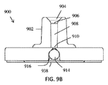
別の態様では、試料濾過装置が提供される。本装置は、管部分につながる漏斗状開口部を含むフレキシブルコネクタと、管部分と流体連通している入口収縮穴を含む入力基板と、入口収縮穴と流体連通していて、試料を濾過して濾液にするように構成された非対称フィルタ膜と、非対称フィルタ膜に接合するように構成された粘着層であって、フィルタ膜の中央部分を露出させるように構成された中央切り抜き部を含む粘着層と、非対称フィルタからの濾液と流体連通する1つ以上のチャネルを含む出力基板であって、1つ以上のチャネルは出力基板の出口と流体連通している、出力基板と、を含む。 In another aspect, a sample filtration device is provided. The device includes a flexible connector including a funnel-shaped opening connected to a tube portion, an input substrate including an inlet contraction hole in fluid communication with the tube portion, and a fluid communication with the inlet contraction hole for filtering a sample. An asymmetric filter membrane configured to form a filtrate and an adhesive layer configured to bond to the asymmetric filter membrane, the adhesive layer including a central cutout configured to expose a central portion of the filter membrane. And an output substrate including one or more channels in fluid communication with the filtrate from the asymmetric filter, the one or more channels in fluid communication with an outlet of the output substrate.
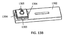
幾つかの実施形態では、試料濾過装置は、入口収縮穴を可逆的に封止するように構成されたボール弁を含む。ボールは、入口収縮穴とフィルタ膜との間のキャビティ内に配置されてよい。幾つかの実施形態では、ボール弁は、活性化動作の解除によって引き起こされる逆流を阻止するように構成されている。ボールは、ゴム、プラスチック、セラミック、及び金属のうちの少なくとも1つを含んでよい。幾つかの実施形態では、ボールの材料は、フィルタアセンブリの意図された使用方向に基づいて選択される。直立させる場合には低密度材料が選択されてよい。逆さまにする場合には高密度材料が選択されてよい。幾つかの実施形態では、フレキシブルコネクタの開口部及び管部分は、マイクロピペットチップを受ける形状になっている。フレキシブルコネクタの外側表面が、スクイーズボトルの開口部の内側表面と結合してその内側表面を封止する形状であってよい。幾つかの実施形態では、漏斗状開口部は長さが約1mmである。漏斗状開口部は角度が約45°であってよい。幾つかの実施形態では、管部分は長さが約7mmである。管部分は最小内径が約1.5mmであってよい。幾つかの実施形態では、収縮穴は径が約0.75mmである。フィルタ膜は入力基板に粘着されてよい。幾つかの実施形態では、フィルタ膜は出力基板に粘着される。フレキシブルコネクタは、TPE、シリコーン、ゴム、ポリウレタン、LDPE、HDPE、PP、及び可塑化PVCのうちの少なくとも1つを含んでよい。幾つかの実施形態では、フレキシブルコネクタの壁厚が約2mmである。粘着層は両面粘着層であってよい。幾つかの実施形態では、試料流体は全血を含む。非対称フィルタのサイズが、粘着層の外周部のサイズより小さくてよい。幾つかの実施形態では、1つ以上のチャネルは、曲がりくねったチャネル、又は複数のチャネルを含む。出口はスパウトを含んでよい。幾つかの実施形態では、フィルタ膜に隣接する入力基板及び出力基板の少なくとも一方の基板の表面がフラットである。フィルタ膜に隣接する入力基板及び出力基板の少なくとも一方の基板の表面が突起形状物を含んでよい。幾つかの実施形態では、粘着層は、シリコーン系又はアクリル系の粘着剤を含む。フィルタ膜の幅が約15mmであってよい。幾つかの実施形態では、フィルタ膜の長さが約15mmである。非対称フィルタの細孔径が約0.8μmであってよい。幾つかの実施形態では、フィルタ膜は、ポリカーボネート、ポリスルホン、ポリエステル、ポリエチレン、及びポリプロピレンのうちの少なくとも1つを含む。出力基板は、その外周部の周囲にリッジを含んでよい。幾つかの実施形態では、入力基板は、出力基板のリッジの内側にぴったり収まるサイズになっている。入力基板は、その外周部の周囲にリッジを含んでよい。幾つかの実施形態では、出力基板は、入力基板のリッジの内側にぴったり収まるサイズになっている。1つ以上のチャネルは、フィルタ膜の領域全体にわたって延びる。幾つかの実施形態では、1つ以上のチャネルは、チャネル間の間隔が約1.5mmである。チャネルの構成の選択が、支持構成要素の表面の材質及び粗度に基づいて行われてよい。幾つかの実施形態では、入口収縮穴の径が、管部分の径より小さい。フレキシブルコネクタは、機械式インタロックを使用して入力基板に接続されてよい。幾つかの実施形態では、試料濾過装置及び検査カートリッジを含む診断システムが提供される。検査カートリッジは、試料濾過装置の出口を検査カートリッジの試料入力領域と位置合わせするように構成された位置合わせ形状物を含む。カートリッジは、試料濾過装置を検査カートリッジに固定するように構成されたラッチを含んでよい。幾つかの実施形態では、位置合わせ形状物はラッチである。出力基板は、試料濾過装置を検査カートリッジに粘着させるように構成された粘着剤を含んでよい。幾つかの実施形態では、出力基板は、試料濾過装置を検査カートリッジに粘着させるように構成された接着剤を含む。管部分の上部が、バーブと結合するように構成されたアンダカットを含んでよい。幾つかの実施形態では、複数の試料濾過装置を含むアレイが提供される。アレイは、2個、3個、4個、6個、8個、又は12個の試料濾過装置を含んでよい。 In some embodiments, the sample filtration device includes a ball valve configured to reversibly seal the inlet constriction hole. The ball may be located in the cavity between the inlet shrink hole and the filter membrane. In some embodiments, the ball valve is configured to prevent backflow caused by release of the activation action. The ball may include at least one of rubber, plastic, ceramic, and metal. In some embodiments, the ball material is selected based on the intended direction of use of the filter assembly. If upright, a low density material may be selected. High density material may be selected for upside down. In some embodiments, the opening and tubing portion of the flexible connector are shaped to receive a micropipette tip. The outer surface of the flexible connector may be shaped to mate with and seal the inner surface of the opening of the squeeze bottle. In some embodiments, the funnel opening is about 1 mm in length. The funnel-shaped opening may have an angle of about 45°. In some embodiments, the tube section is about 7 mm long. The tube portion may have a minimum inner diameter of about 1.5 mm. In some embodiments, the shrink holes have a diameter of about 0.75 mm. The filter membrane may be adhered to the input substrate. In some embodiments, the filter membrane is adhered to the output substrate. The flexible connector may include at least one of TPE, silicone, rubber, polyurethane, LDPE, HDPE, PP, and plasticized PVC. In some embodiments, the flexible connector has a wall thickness of about 2 mm. The adhesive layer may be a double-sided adhesive layer. In some embodiments, the sample fluid comprises whole blood. The size of the asymmetric filter may be smaller than the size of the outer peripheral portion of the adhesive layer. In some embodiments, the one or more channels include a tortuous channel, or multiple channels. The outlet may include a spout. In some embodiments, the surface of at least one of the input and output substrates adjacent the filter membrane is flat. The surface of at least one of the input substrate and the output substrate adjacent to the filter membrane may include a protrusion shape. In some embodiments, the adhesive layer comprises a silicone or acrylic adhesive. The width of the filter membrane may be about 15 mm. In some embodiments, the length of the filter membrane is about 15 mm. The pore size of the asymmetric filter may be about 0.8 μm. In some embodiments, the filter membrane comprises at least one of polycarbonate, polysulfone, polyester, polyethylene, and polypropylene. The output substrate may include ridges around its outer periphery. In some embodiments, the input board is sized to fit snugly inside the ridge of the output board. The input substrate may include ridges around its outer periphery. In some embodiments, the output board is sized to fit inside the ridge of the input board. The one or more channels extend over the entire area of the filter membrane. In some embodiments, the one or more channels are about 1.5 mm apart. The choice of channel configuration may be made based on the surface material and roughness of the support component. In some embodiments, the diameter of the inlet constriction hole is smaller than the diameter of the tube section. The flexible connector may be connected to the input board using a mechanical interlock. In some embodiments, a diagnostic system is provided that includes a sample filtration device and a test cartridge. The test cartridge includes an alignment feature configured to align the outlet of the sample filtration device with the sample input area of the test cartridge. The cartridge may include a latch configured to secure the sample filtration device to the test cartridge. In some embodiments, the alignment feature is a latch. The output substrate may include an adhesive configured to adhere the sample filtration device to the test cartridge. In some embodiments, the output substrate includes an adhesive configured to adhere the sample filtration device to the test cartridge. The upper portion of the tube portion may include an undercut configured to mate with the barb. In some embodiments, an array including a plurality of sample filtration devices is provided. The array may include 2, 3, 4, 6, 8, or 12 sample filtration devices.
更に別の態様では、試料を濾過する方法が提供される。本方法は、管部分につながる漏斗状開口部を含むフレキシブルコネクタであって、管部分は入力基板の入口と流体連通しており、入口は非対称フィルタ膜と流体連通しており、非対称フィルタ膜は粘着層に接続されている、フレキシブルコネクタと、フィルタ膜から濾液を受けるように構成された1つ以上のチャネルを含み、出口を含む出力基板と、を含む試料濾過装置を用意するステップと、試料を採取又は定量供給する装置をフレキシブルコネクタに取り付けるステップと、試料を採取又は定量供給する装置に圧力をかけることによって、試料流体を非対称フィルタに押し通して濾液を生成し、濾液を1つ以上のチャネルに押し通して出口まで押し出すステップと、を含む。 In yet another aspect, a method of filtering a sample is provided. The method is a flexible connector that includes a funnel-shaped opening that connects to a tube section, the tube section being in fluid communication with an inlet of an input substrate, the inlet being in fluid communication with an asymmetric filter membrane, and the asymmetric filter membrane being Providing a sample filtration device that includes a flexible connector connected to the adhesive layer and an output substrate that includes one or more channels configured to receive filtrate from the filter membrane and that includes an outlet; Attaching a sample collection or quantitation device to the flexible connector, and pressing the sample collection or quantification device to force the sample fluid through the asymmetric filter to produce a filtrate, the filtrate being in one or more channels. Pushing through to the outlet to the outlet.
幾つかの実施形態では、試料を採取又は定量供給する装置を取り付けるステップは、漏斗状開口部にマイクロピペットチップを挿入するステップを含む。試料を採取又は定量供給する装置を取り付けるステップは、フレキシブル容器の開口部にフレキシブルコネクタを挿入するステップを含んでよい。幾つかの実施形態では、本方法は、フレキシブル容器に緩衝液を追加するステップを含む。本方法は、フレキシブル容器を圧搾して、濾液を検査ストリップ又は検査カートリッジの上に定量供給するステップを含んでよい。幾つかの実施形態では、本方法は、フレキシブル容器を逆さまにしてから圧搾するステップを含んでよい。容器を圧搾するステップは、0.25〜5psiの圧力を発生させてよい。幾つかの実施形態では、試料を採取又は定量供給する装置を取り付けるステップは、漏斗状開口部にバーブを挿入するステップを含む。試料を採取又は定量供給する装置を取り付けるステップは、漏斗状開口部にオスコネクタを挿入するステップを含んでよい。幾つかの実施形態では、本方法は、濾液を検査ストリップ上に定量供給するステップを含む。試料流体は全血を含んでよい。幾つかの実施形態では、試料流体は希釈血液を含む。本方法は、試料を採取又は定量供給する装置に緩衝液を追加するステップを含んでよい。幾つかの実施形態では、本方法は、試料流体と緩衝液とを混合するステップを含む。本方法は、検査装置又は診断装置において濾液を使用するステップを含んでよい。本方法は、ラテラルフローイムノアッセイ(LFIA)検査において濾液を使用するステップを含んでよい。幾つかの実施形態では、本方法は、濾液を使用して、血中アルコール濃度、ビタミン不足、又はカンナビノイド検出の検査を行うステップを含む。本方法は、濾液を使用して、血流中を循環する無細胞DNAを隔離するステップを含んでよい。幾つかの実施形態では、本方法は、ラテラルフローイムノアッセイ検査ストリップ上で濾液を使用するステップを含む。本方法は、試料濾過装置を検査カートリッジ上に配置するステップを含んでよい。幾つかの実施形態では、試料濾過装置を検査カートリッジ上に配置するステップは、試料濾過装置を検査カートリッジにラッチするステップを含む。試料濾過装置を検査カートリッジ上に配置するステップは、試料濾過装置を検査カートリッジに粘着させるステップを含んでよい。幾つかの実施形態では、試料濾過装置を検査カートリッジ上に配置するステップは、試料濾過装置を検査カートリッジに接着するステップを含む。 In some embodiments, mounting the device for sampling or dispensing a sample comprises inserting a micropipette tip into the funnel-shaped opening. The step of attaching the device for collecting or quantitatively supplying the sample may include the step of inserting the flexible connector into the opening of the flexible container. In some embodiments, the method comprises the step of adding a buffer to the flexible container. The method may include squeezing the flexible container to dispense the filtrate onto a test strip or test cartridge. In some embodiments, the method may include inverting and squeezing the flexible container. The step of squeezing the container may generate a pressure of 0.25-5 psi. In some embodiments, mounting the sample collection or dispensing device comprises inserting a barb into the funnel opening. Attaching the device for sampling or dispensing a sample may include inserting a male connector into the funnel-shaped opening. In some embodiments, the method comprises the step of dispensing the filtrate onto a test strip. The sample fluid may include whole blood. In some embodiments, the sample fluid comprises diluted blood. The method may include the step of adding a buffer to the device for sampling or dispensing the sample. In some embodiments, the method comprises mixing a sample fluid and a buffer. The method may include using the filtrate in a test or diagnostic device. The method may include using the filtrate in a lateral flow immunoassay (LFIA) test. In some embodiments, the method comprises using the filtrate to test for blood alcohol levels, vitamin deficiency, or cannabinoid detection. The method may include using the filtrate to sequester cell-free DNA circulating in the bloodstream. In some embodiments, the method comprises using the filtrate on a lateral flow immunoassay test strip. The method may include disposing a sample filtration device on the test cartridge. In some embodiments, disposing the sample filtration device on the test cartridge comprises latching the sample filtration device on the test cartridge. Placing the sample filtration device on the test cartridge may include adhering the sample filtration device to the test cartridge. In some embodiments, placing the sample filtration device on the test cartridge comprises adhering the sample filtration device to the test cartridge.
別の態様では、試料濾過装置が提供される。本装置は、入口穴を含む入力基板と、入口穴と流体連通していて、試料を濾過して濾液にするように構成された非対称フィルタ膜と、非対称フィルタ膜に接合するように構成された粘着層であって、フィルタ膜の中央部分を露出させるように構成された中央切り抜き部を含む粘着層と、非対称フィルタからの濾液と流体連通する1つ以上のチャネルを含む出力基板であって、1つ以上のチャネルは出力基板の出口と流体連通している、出力基板と、を含む。 In another aspect, a sample filtration device is provided. The device is configured to bond to an input substrate that includes an inlet hole, an asymmetric filter membrane that is in fluid communication with the inlet hole and that is configured to filter a sample into a filtrate, and an asymmetric filter membrane. An adhesive substrate comprising an adhesive layer comprising a central cutout configured to expose a central portion of a filter membrane, and an output substrate comprising one or more channels in fluid communication with filtrate from an asymmetric filter, The one or more channels include an output substrate in fluid communication with the outlet of the output substrate.
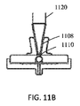
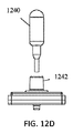
幾つかの実施形態では、本装置は、入口穴に取り付けられたフレキシブルコネクタであって、フレキシブルコネクタは、管状部分と流体連通している漏斗状開口部を含み、管状部分は入口穴と流体連通している、フレキシブルコネクタを含む。フレキシブルコネクタは、フレキシブル容器、バルブピペット、マイクロピペット、及びバーブと結合する形状であってよい。幾つかの実施形態では、入力基板又は出力基板の少なくとも一方が、フレキシブル容器のキャップの一部分を含む。本装置は、入口穴を可逆的に封止するように構成されたボール弁を含んでよい。幾つかの実施形態では、ボールは、入口穴とフィルタ膜との間のキャビティ内に配置されている。ボール弁は、活性化動作の解除によって引き起こされる逆流を阻止するように構成されてよい。幾つかの実施形態では、ボールは、ゴム、プラスチック、セラミック、及び金属のうちの少なくとも1つを含む。ボールの材料は、フィルタアセンブリの意図された使用方向に基づいて選択されてよい。幾つかの実施形態では、直立させる場合には低密度材料が選択される。幾つかの実施形態では、逆さまにする場合には高密度材料が選択される。フィルタ膜は入力基板に粘着されてよい。幾つかの実施形態では、フィルタ膜は出力基板に粘着される。粘着層は両面粘着層であってよい。幾つかの実施形態では、試料流体は全血を含む。幾つかの実施形態では、非対称フィルタのサイズが、粘着層の外周部のサイズより小さい。1つ以上のチャネルは、曲がりくねったチャネル、又は複数のチャネルを含んでよい。幾つかの実施形態では、出口はスパウトを含む。フィルタ膜に隣接する入力基板及び出力基板の少なくとも一方の基板の表面がほぼフラットであってよい。幾つかの実施形態では、フィルタ膜に隣接する入力基板及び出力基板の少なくとも一方の基板の表面が突起形状物を含む。粘着層は、シリコーン系又はアクリル系の粘着剤を含んでよい。フィルタ膜の幅及び/又は長さが約15〜17mmであってよい。幾つかの実施形態では、非対称フィルタの細孔径が約0.8μmである。フィルタ膜は、ポリカーボネート、ポリスルホン、ポリエステル、ポリエチレン、及びポリプロピレンのうちの少なくとも1つを含んでよい。幾つかの実施形態では、出力基板は、その外周部の周囲にリッジを含む。入力基板は、出力基板のリッジの内側にぴったり収まるサイズであってよい。幾つかの実施形態では、入力基板は、その外周部の周囲にリッジを含む。出力基板は、入力基板のリッジの内側にぴったり収まるサイズであってよい。幾つかの実施形態では、1つ以上のチャネルは、フィルタ膜の領域全体にわたって延びる。1つ以上のチャネルは、チャネル間の間隔が約1.5mmであってよい。幾つかの実施形態では、チャネルの構成の選択が、支持構成要素の表面の材質及び粗度に基づいて行われる。入力基板及び出力基板の少なくとも一方が剛体材料を含む。本装置は、本装置を、試料を採取且つ定量供給する装置に取り付けるように構成されたコネクタを含んでよい。 In some embodiments, the device is a flexible connector mounted in the inlet hole, the flexible connector including a funnel-shaped opening in fluid communication with the tubular portion, the tubular portion in fluid communication with the inlet hole. Including flexible connectors. The flexible connector may be shaped to mate with flexible containers, valve pipettes, micropipettes, and barbs. In some embodiments, at least one of the input or output substrate comprises a portion of the flexible container cap. The device may include a ball valve configured to reversibly seal the inlet hole. In some embodiments, the ball is located in the cavity between the inlet hole and the filter membrane. The ball valve may be configured to prevent backflow caused by release of the activation action. In some embodiments, the ball comprises at least one of rubber, plastic, ceramic, and metal. The ball material may be selected based on the intended direction of use of the filter assembly. In some embodiments, a low density material is selected for upstanding. In some embodiments, a high density material is selected for inversion. The filter membrane may be adhered to the input substrate. In some embodiments, the filter membrane is adhered to the output substrate. The adhesive layer may be a double-sided adhesive layer. In some embodiments, the sample fluid comprises whole blood. In some embodiments, the size of the asymmetric filter is smaller than the size of the perimeter of the adhesive layer. The one or more channels may include a tortuous channel, or multiple channels. In some embodiments, the outlet comprises a spout. The surface of at least one of the input substrate and the output substrate adjacent to the filter membrane may be substantially flat. In some embodiments, the surface of at least one of the input substrate and the output substrate adjacent the filter membrane comprises a protrusion feature. The adhesive layer may include a silicone-based or acrylic-based adhesive. The width and/or length of the filter membrane may be about 15-17 mm. In some embodiments, the asymmetric filter has a pore size of about 0.8 μm. The filter membrane may include at least one of polycarbonate, polysulfone, polyester, polyethylene, and polypropylene. In some embodiments, the output substrate includes ridges around its perimeter. The input substrate may be sized to fit inside the ridge of the output substrate. In some embodiments, the input substrate includes ridges around its perimeter. The output board may be sized to fit inside the ridge of the input board. In some embodiments, the one or more channels extend across the area of the filter membrane. The one or more channels may have a spacing between the channels of about 1.5 mm. In some embodiments, the choice of channel configuration is made based on the surface material and roughness of the support component. At least one of the input substrate and the output substrate includes a rigid material. The device may include a connector configured to attach the device to a device for sampling and dispensing a sample.
別の態様では、試料を濾過する方法が提供される。本方法は、入口穴を含む入力基板と、入口穴と流体連通していて、試料を濾過して濾液にするように構成された非対称フィルタ膜と、非対称フィルタ膜に接合するように構成された粘着層であって、フィルタ膜の中央部分を露出させるように構成された中央切り抜き部を含む粘着層と、非対称フィルタからの濾液と流体連通する1つ以上のチャネルを含む出力基板であって、1つ以上のチャネルは出力基板の出口と流体連通している、出力基板と、を含む試料濾過装置を用意するステップと、試料を採取又は定量供給する装置を入口穴に接続するステップと、試料を駆動してフィルタ膜に通すように、試料を採取又は定量供給する装置を活性化するステップと、を含む。 In another aspect, a method of filtering a sample is provided. The method is configured to bond an input substrate including an inlet hole, an asymmetric filter membrane in fluid communication with the inlet hole and configured to filter a sample into a filtrate, and an asymmetric filter membrane. An adhesive substrate comprising an adhesive layer comprising a central cutout configured to expose a central portion of a filter membrane, and an output substrate comprising one or more channels in fluid communication with filtrate from an asymmetric filter, Providing a sample filtration device comprising an output substrate, wherein one or more channels are in fluid communication with an outlet of the output substrate; connecting a device for sampling or dispensing a sample to the inlet hole; Activating the device so as to drive it through the filter membrane.
幾つかの実施形態では、本方法は、入口穴と流体連通するフレキシブルコネクタを濾過装置に接続するステップを含む。試料を採取又は定量供給する装置を接続するステップは、マイクロピペットチップを入口穴に流体接続するステップを含んでよい。幾つかの実施形態では、試料を採取又は定量供給する装置を接続するステップは、フレキシブルコネクタを入口穴に流体接続するステップを含む。本方法は、試料を駆動してフィルタ膜に通すように、試料を採取又は定量供給する装置を活性化するステップを含んでよい。幾つかの実施形態では、本方法は、濾液を検査ストリップ上に定量供給するステップを含む。試料流体は全血又は希釈血液を含んでよい。本方法は、試料を採取又は定量供給する装置に緩衝液を追加するステップを含んでよい。幾つかの実施形態では、本方法は、試料流体と緩衝液とを混合するステップを更に含む。本方法は、検査装置又は診断装置において濾液を使用するステップを含んでよい。幾つかの実施形態では、本方法は、ラテラルフローイムノアッセイ(LFIA)検査において濾液を使用するステップを含む。本方法は、濾液を使用して、血中アルコール濃度、ビタミン不足、又はカンナビノイド検出の検査を行うステップを含んでよい。幾つかの実施形態では、本方法は、濾液を使用して、血流中を循環する無細胞DNAを隔離するステップを含む。本方法は、ラテラルフローイムノアッセイ検査ストリップ上で濾液を使用するステップを含んでよい。幾つかの実施形態では、本方法は、試料濾過装置を検査カートリッジ上に配置するステップを含む。本方法は、試料濾過装置を検査カートリッジ上に配置するステップを含んでよく、このステップは、試料濾過装置を検査カートリッジにラッチするステップを含む。 In some embodiments, the method includes connecting a flexible connector in fluid communication with the inlet hole to the filtration device. Connecting the device for sampling or dispensing the sample may include fluidly connecting the micropipette tip to the inlet hole. In some embodiments, connecting the device for sampling or dispensing a sample comprises fluidly connecting a flexible connector to the inlet hole. The method may include activating a device for sampling or dispensing the sample to drive the sample through the filter membrane. In some embodiments, the method comprises the step of dispensing the filtrate onto a test strip. The sample fluid may include whole blood or diluted blood. The method may include the step of adding a buffer to the device for sampling or dispensing the sample. In some embodiments, the method further comprises mixing the sample fluid with a buffer. The method may include using the filtrate in a test or diagnostic device. In some embodiments, the method comprises using the filtrate in a lateral flow immunoassay (LFIA) test. The method may include using the filtrate to test for blood alcohol levels, vitamin deficiency, or cannabinoid detection. In some embodiments, the method comprises using the filtrate to sequester cell-free DNA circulating in the bloodstream. The method may include using the filtrate on a lateral flow immunoassay test strip. In some embodiments, the method includes disposing a sample filtration device on the test cartridge. The method may include placing a sample filtration device on the test cartridge, the step including latching the sample filtration device to the test cartridge.
後述の特許請求の範囲において、本発明の新規な特徴を具体的に説明する。本発明の原理が利用される例示的実施形態を説明する後述の詳細説明と、以下の添付図面とを参照することにより、本発明の特徴及び利点がよりよく理解されよう。 The novel features of the invention are set forth in the claims that follow. A better understanding of the features and advantages of the present invention may be obtained by reference to the following detailed description that sets forth exemplary embodiments in which the principles of the invention are utilized, and the following accompanying drawings.
本明細書では試料濾過装置の実施形態を示す。本装置は、フィルタ膜が2つの基板の間に配置され、隣接する面に貼り付けられて、粘着層(例えば、両面粘着層)で封止された、シンプルな構造を含む。フィルタ膜を取り囲む基板は、様々な構成要素を含んでよい。例えば、本明細書に開示の幾つかの実施形態では、基板は、フレキシブル容器とともに使用可能な蓋の一部を含む。別の実施形態では、基板は、フレキシブルなコネクタに接続可能な基板を含む。いずれの実施形態においても、本装置の濾過部分では、フィルタ膜が、フィルタ膜を露出させるように切り抜かれた部分を有する粘着層により、支持基板に接合されている。フィルタ膜に対して支持基板の反対側にある出力基板が、フィルタ膜によって得られた濾液を受けるように構成された単一又は複数のチャネルを含んでよい。濾過装置は、濾液を排出するように構成された出口を含んでよい。 Embodiments of a sample filtration device are shown herein. The device includes a simple structure in which a filter membrane is placed between two substrates, affixed to adjacent surfaces and sealed with an adhesive layer (eg, double-sided adhesive layer). The substrate surrounding the filter membrane may include various components. For example, in some embodiments disclosed herein, the substrate comprises a portion of a lid that can be used with a flexible container. In another embodiment, the substrate comprises a substrate connectable to a flexible connector. In any of the embodiments, in the filtration portion of the present device, the filter membrane is bonded to the support substrate by an adhesive layer having a portion cut out so as to expose the filter membrane. The output substrate opposite the support substrate with respect to the filter membrane may include single or multiple channels configured to receive the filtrate obtained by the filter membrane. The filtering device may include an outlet configured to discharge the filtrate.
本濾過装置のシンプルな構造は、容易な製造を可能にしうる。これは、粘着層による粘着が、従来の試料濾過装置の製造で用いられる典型的な接着処理(例えば、液状接着剤、超音波溶接等)の代わりになりうる為である。製造が容易であれば、濾過製品の消費者コストを減らすことが可能である。本濾過装置は更に、試料処理手順を非常にシンプルにする。処理がシンプルであれば、結果を得るのに通常は数日から数週間かかるタスクである、試料(例えば、全血)の採取及び処理をほぼ即座に行うことが可能になりうる。製品がシンプルであれば更に、通常は検査室で行われる処理を現場や家庭で実施することが可能になる。本装置は、検査装置や診断装置(例えば、HIV検査、妊娠検査等)と組み合わせて使用されてよく、これにより、試料採取、検査、及び診断を家庭や現場で迅速に行うことが可能になる。 The simple structure of the filtration device may allow easy manufacture. This is because the adhesion by the adhesive layer can replace the typical adhesion process (eg, liquid adhesive, ultrasonic welding, etc.) used in the manufacture of conventional sample filtration devices. The ease of manufacture can reduce consumer costs for filtered products. The filtration device further greatly simplifies the sample processing procedure. A simple process may allow the sample and the sample to be taken and processed almost immediately, a task that normally takes days to weeks to obtain results. The simplicity of the product also allows the processes normally performed in the laboratory to be carried out in the field or at home. The device may be used in combination with a test device or diagnostic device (eg, HIV test, pregnancy test, etc.), which allows for rapid sampling, testing and diagnosis at home or in the field. ..
図1A及び1Bは、試料濾過装置の一実施形態100の上面斜視図及び底面斜視図を示す。装置100は、フレキシブル容器102とキャップ104とを含む。フレキシブル容器102は、ねじ山106により、キャップ104と接続されるように構成されている。他の接続機構も可能である(例えば、スナップフィット等)。フレキシブル容器102は、円筒形であってよいが、他の形状も可能である(例えば、卵形、球形、正方形等)。
1A and 1B show a top perspective view and a bottom perspective view of one
キャップ104はキャップハウジング108を含む。フィルタ機構は、キャップ104の上部に配置される。入口穴110により、試料流体がフレキシブル容器からフィルタ機構に入ることが可能である。フレキシブル容器を圧搾することにより、試料流体を入口穴110から押し出す圧力勾配を生成することが可能である。フィルタ膜112が、入口穴110の上方に配置される。フィルタ膜112は形状が正方形であるように示されているが、他の形状も、キャップハウジング108のリッジ114のフットプリントに収まるのであれば可能である。フィルタ膜112の上方に、両面粘着層116が配置される。粘着層116は切り抜き部118を含み、切り抜き部118は、フィルタ膜112を露出させ、支持構成要素120へのアクセスを可能にするように構成されており、支持構成要素120は、ミニチャネル122及び出口124を含み、粘着層116の上方に配置される。ミニチャネル122は、支持構成要素120の底面に配置され、フィルタ膜112に最も近接する。チャネル内の出口穴126が出口124につながっている。図1Aに示されるように、出口124はスパウト機構を含んでよい。
The
ねじ山(又は他の結合機構)が係合されると、キャップ104とフレキシブル容器102は流体封止を形成する。この封止は、フレキシブル容器の開口部を形成する外周部130とキャップハウジングのフラット面132との締まり嵌めにおいて形成される。封止が行われた後、キャップは、流体だけが、キャップハウジング108上にある入口穴110からフィルタアセンブリに流入することを可能にする。幾つかの実施形態では、キャップは、適切に機能する為には開口部が1つあればよいが、本装置内での固形物による閉塞の発生を防ぐ為に、複数の穴によって冗長性が与えられている。このような固形物として、クロット、微粒子、ユーザがフレキシブル容器102内に残したものなどが考えられる。ハウジング108は更に、組み立て及び自己センタリングを容易にする為のリッジ114を含む。更に、このリッジは、組み立て後の粘着剤へのアクセスを阻止することによって、ユーザが本装置を細工するのを防ぐ。
When the threads (or other coupling mechanism) are engaged,
キャップ104は、十分な剛性を備える材料を含んでよく、そのような材料として、ポリプロピレンやポリカーボネートのような熱可塑性プラスチック、或いは、アルミニウムや鋼のような金属があり、これらに限定されない。
The
フィルタ積層物との接触面はほぼフラットである。即ち、これらの面の間には、隙間(即ち間隔)又は形状物が存在しないことが好ましい。フラットな構造であれば製造を容易にすることが可能である。幾つかの実施形態では、これらの面の間に隙間(即ち間隔)又は突起形状物が配置される。そのような形状物は流れの促進に役立ちうる。そのような実施形態では、その間隔又は形状物が、血液と緩衝液の混合物のラテラルフローを著しく制限することがないように注意を払う必要がある。流れが制限されるのは、フィルタが加圧された後に、フィルタ膜全体にわたる圧力差の結果として薄いポケットが形成される為である。 The contact surface with the filter laminate is almost flat. That is, it is preferable that no gap (that is, a gap) or a shape is present between these surfaces. A flat structure can facilitate manufacturing. In some embodiments, a gap (or gap) or protrusion feature is placed between these surfaces. Such features can help facilitate flow. In such embodiments, care must be taken that the spacing or features do not significantly limit the lateral flow of the blood and buffer mixture. The flow restriction is due to the formation of thin pockets as a result of the pressure differential across the filter membrane after the filter is pressurized.
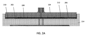
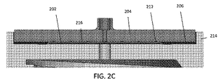
図2A〜2Cは、フィルタ膜202、支持構成要素204、及び両面粘着剤206の詳細図を示す。図2Aに示されるように、フィルタ膜202は底部に配置される。両面粘着剤206は、フィルタ膜202の上方に配置され、その中央に開口部又は切り抜き部208を有する。両面粘着剤206で封止される前のこのアセンブリには、図2Aに示されるように、両面粘着剤206とキャップハウジング214との間に隙間210があり、隙間210はフィルタ膜202を取り囲む。封止後は、図2Bに示されるように、粘着剤206がフィルタ膜202及びキャップハウジング214を封止して、隙間210を無くすか最小化する。加圧後(例えば、フレキシブル容器の圧搾後)は、図2Cに示されるように、フィルタ膜202とキャップハウジング214との間に薄いポケット216が形成されうる。
2A-2C show detailed views of the
両面粘着剤は感圧粘着剤であり、組み立て時に複数の面に粘着することを意図されている。両面粘着剤は、一方の面では支持構成要素とだけ結合される。他方の面では、両面粘着剤は、フィルタ膜及びキャップハウジングの両方と結合される。用途によっては、フィルタ及び両面粘着剤の積層順序を逆にすることによって、加圧時のフィルタ膜のたわみ(ポケットの形成)を防ぐことが必要とされる場合がある。この逆構成では、一方の面では、両面粘着剤は、フィルタ膜及び剛体支持構成要素の両方と結合され、他方の面では、両面粘着剤は、キャップハウジングとだけ結合される。この面は複数の面と結合される為、支持構造に過剰な残留応力がかかって両面粘着剤が剥がれるのを防ぐ為には、両面粘着剤の厚さを、フィルタ膜の圧縮された厚さより厚くしなければならない。 Double sided adhesives are pressure sensitive adhesives and are intended to adhere to multiple surfaces during assembly. The double-sided adhesive is only bonded on one side to the support component. On the other side, the double sided adhesive is bonded to both the filter membrane and the cap housing. Depending on the application, it may be necessary to reverse the stacking order of the filter and the double-sided pressure-sensitive adhesive to prevent the filter film from bending (forming pockets) when pressed. In this reverse configuration, on one side the double-sided adhesive is combined with both the filter membrane and the rigid support component, and on the other side the double-sided adhesive is only combined with the cap housing. Since this surface is bonded to multiple surfaces, the thickness of the double-sided adhesive should be set to be smaller than the compressed thickness of the filter membrane in order to prevent the double-sided adhesive from peeling off due to excessive residual stress on the support structure. Must be thick.
両面粘着剤は内側に切り抜き部があり、この切り抜き部の外周はフィルタ膜の外周より小さい。両面粘着剤の外周のサイズは、支持構成要素の外周より小さいことが好ましいが、両面粘着剤の外周は、支持構成要素以上の大きさであってよく、それでも適切に機能する。両面粘着剤は、流体がフィルタ膜の外周の外側から膜を迂回することによって膜を通り抜けるのを防ぎ、これによって、適切な濾過動作が確実に達成される。粘着強度は、ユーザが本装置を加圧して動作させたときに、両面粘着剤が、粘着しているどの面からも剥がれないような十分な大きさであってよい。両面粘着剤の厚さは、フィルタ膜が、加圧時に未濾過試料混合物のラテラルフローを可能にする為の十分な隙間があるように選択しなければならない。このラテラルフローによって、フィルタ領域全体が濾過に利用されることが可能になる。厚すぎる感圧粘着剤の使用を避ける為に、各面に両面粘着剤を有する基材ポリマーフィルムが使用することにより、本装置が機能するのに必要な厚さを考慮することが可能である。必要な厚さを考慮する別の一手法は、適切に機能する為に必要な厚さを考慮した隆起面を支持構成要素上に含むことである。 The double-sided adhesive has a cutout portion inside, and the outer circumference of this cutout portion is smaller than the outer circumference of the filter membrane. The size of the perimeter of the double-sided adhesive is preferably smaller than the perimeter of the support component, but the perimeter of the double-sided adhesive may be larger than the support component and still function properly. The double-sided adhesive prevents fluid from passing through the membrane by bypassing the membrane from outside the perimeter of the filter membrane, which ensures proper filtration action. The adhesive strength may be large enough so that the double-sided adhesive does not peel off from any adhered surface when the user pressurizes and operates the device. The thickness of the double-sided adhesive should be selected so that the filter membrane has sufficient clearance to allow lateral flow of the unfiltered sample mixture when pressurized. This lateral flow allows the entire filter area to be used for filtration. By using a base polymer film with double-sided adhesive on each side to avoid the use of too thick pressure sensitive adhesive, it is possible to consider the thickness required for this device to function. .. Another way to consider the required thickness is to include a raised surface on the support component that takes into account the thickness required to function properly.
粘着剤としては、シリコーン系又はアクリル系の粘着剤があってよく、これらに限定されない。両面粘着剤が全ての必要な面に適切に結合することが確実に行われるように、アセンブリはまとめて圧縮されてよい。更に、フィルタ膜のエッジが粘着剤によって圧縮されて、締め付けられて、封止されてよい。フィルタ膜の外周部を封止する別の方法として、超音波溶接による圧縮がある。フィルタ材料がキャップハウジング又は支持構成要素と適合する場合は、フィルタ膜をハウジング又は支持構成要素の表面に直接超音波溶接することが可能である。別の手法として、支持構成要素とキャップハウジングとの間で超音波ボンディングを行ってよい。このボンディングによって連続的な締め付け応力がかかって、フィルタ膜の外周部が封止されることが可能である。超音波ボンディングに加えて、液状粘着剤を使用する同じタイプのボンディングが実施されてよい。 The pressure-sensitive adhesive may include, but is not limited to, a silicone-based or acrylic-based pressure-sensitive adhesive. The assembly may be compressed together to ensure that the double-sided adhesive properly bonds to all required surfaces. Further, the edges of the filter membrane may be compressed with an adhesive, tightened and sealed. Another method of sealing the outer peripheral portion of the filter membrane is compression by ultrasonic welding. If the filter material is compatible with the cap housing or support component, it is possible to ultrasonically weld the filter membrane directly to the surface of the housing or support component. Alternatively, ultrasonic bonding may be performed between the support component and the cap housing. By this bonding, continuous tightening stress is applied, and the outer peripheral portion of the filter membrane can be sealed. In addition to ultrasonic bonding, the same type of bonding using liquid adhesive may be performed.
フィルタ膜は、アセンブリの中央に配置される薄い構成要素である。フィルタ膜には化学物質又はドライ試薬がコーティングされてよい。フィルタ膜は、ほぼ任意のサイズ及び形状にカットされてよい。フィルタ膜は、封止が適切に行われるように、フィルタ膜の外周部が両面粘着剤の内側の切り抜き部の外周部の外側にあるように位置合わせされる。更に、フィルタ膜の外周部は、両面粘着剤が支持構成要素に適切に粘着することを可能にする為に、(図2Aに最もよく示されるように)両面粘着剤の外周部より内側になければならない。 The filter membrane is a thin component located in the center of the assembly. The filter membrane may be coated with chemicals or dry reagents. The filter membrane may be cut to almost any size and shape. The filter membrane is aligned such that the outer periphery of the filter membrane is outside the outer periphery of the cutout inside the double-sided adhesive for proper sealing. Further, the outer perimeter of the filter membrane should be inside the outer perimeter of the double-sided adhesive (as best shown in Figure 2A) to allow the double-sided adhesive to properly adhere to the support components. I have to.
幾つかの実施形態では、フィルタは約15mm×約15mmであってよい。他の寸法も可能である。例えば、フィルタは、長さが約12〜18mm、幅が約12〜18mmであってよい。幾つかの実施形態では、フィルタの細孔径は約0.8μmである。他の細孔径も可能である(例えば、0.2μm、0.45μm、1.0μm、0.5μm等)。幾つかの実施形態では、細孔径が0.8μmである15×15mmの非対称フィルタを使用することにより、10倍希釈血液でラテラルフローイムノアッセイ検査を実施するのに十分な試料を生成することが可能である。この濃度であれば、約100μL又は2〜3滴の処理済み試料を生成してアッセイを実施することが可能である。典型的なラテラルフローイムノアッセイ検査ストリップであれば、約50μL以上の処理済み試料で実施可能である。 In some embodiments, the filter may be about 15 mm x about 15 mm. Other dimensions are possible. For example, the filter may be about 12-18 mm long and about 12-18 mm wide. In some embodiments, the filter pore size is about 0.8 μm. Other pore sizes are possible (eg 0.2 μm, 0.45 μm, 1.0 μm, 0.5 μm, etc.). In some embodiments, a 15×15 mm asymmetric filter with a pore size of 0.8 μm can be used to generate sufficient sample to perform a lateral flow immunoassay test with 10-fold diluted blood. Is. At this concentration, it is possible to generate about 100 μL or 2-3 drops of treated sample to perform the assay. A typical lateral flow immunoassay test strip can be performed with about 50 μL or more of the treated sample.
フィルタの濾過能力は、膜の露出面積と、生物学的試料混合物の濃度とに直接関係する。従って、様々な用途に対応する為に様々な形状及びサイズが用いられてよい。フィルタ膜が非対称フィルタである場合は、その向きが正しいように注意を払う必要がある。即ち、非対称フィルタの細孔径がより大きい側が、未濾過試料と最初に向き合わなければならない。液体がフィルタを通り抜けて、細孔径が小さく、生物学的粒子を非対称フィルタのマトリックスで捕捉する側から出る為には、この向きが重要である。これらのフィルタ膜は、細孔径が用途に応じて様々であってよい。幾つかの実施形態では、他の向きが可能である。様々な材料及びスタイルの様々なフィルタ膜も同様に使用されてよい。このような材料として、ポリカーボネート、ポリスルホン、ポリエステル、ポリエチレン、及びポリプロピレンがあってよく、これらに限定されない。 The filtration capacity of the filter is directly related to the exposed area of the membrane and the concentration of the biological sample mixture. Therefore, different shapes and sizes may be used to accommodate different applications. If the filter membrane is an asymmetric filter, care must be taken to ensure its orientation is correct. That is, the larger pore size side of the asymmetric filter must first face the unfiltered sample. This orientation is important for the liquid to pass through the filter, having a small pore size, and exiting the side of the matrix of the asymmetric filter that traps biological particles. The pore size of these filter membranes may vary depending on the application. Other orientations are possible in some embodiments. Different filter membranes of different materials and styles may be used as well. Such materials may include, but are not limited to, polycarbonate, polysulfone, polyester, polyethylene, and polypropylene.
複合フィルタも使用されてよい。複合フィルタは第2のフィルタを含んでよく、第2のフィルタは、外周が前述のフィルタより若干小さいが、それでも両面粘着剤の切り抜き部の外周よりは大きい。小さいほうのフィルタは、大きいほうのフィルタと両面粘着剤との間に配置される。このようにして、粘着剤は、各フィルタ膜の外周部に結合し、それぞれを封止することによって、流体が確実に、各フィルタの外周部の周囲ではなく中央を通り抜けるようにする。この複合フィルタの積層設計手順は、積層物が厚くなりすぎない範囲で、又は、粘着剤膜がその意図された面を全て封止することができなくなるまでは、フィルタを無限に増やして実施することが可能である。複合フィルタを作成する別の一方法は、フィルタ膜及び両面粘着剤の両方からなるアレイを直列に追加してフィルタを直列に積層する方法である。この追加アレイは、第1のフィルタ膜の出力と剛体支持構成要素との間に配置されることになる。これにより、無限の数のフィルタを直列に有するフィルタの作成が可能になる。この、フィルタを直列に積層する工程は、潜在的には、前述の、わずかに小さいフィルタを使用して両面粘着剤の使用量を減らす方法との組み合わせで行われることが可能である。 Composite filters may also be used. The composite filter may include a second filter, the outer circumference of the second filter being slightly smaller than the aforementioned filter, but still larger than the outer circumference of the cutout portion of the double-sided adhesive. The smaller filter is located between the larger filter and the double-sided adhesive. In this way, the adhesive bonds to and seals the outer perimeter of each filter membrane to ensure that the fluid passes through the center of the filter rather than around the perimeter. This composite filter stack design procedure is performed with an infinite number of filters until the stack does not become too thick or until the adhesive film is unable to seal all of its intended surface. It is possible. Another method of making a composite filter is to add an array of both filter membrane and double-sided adhesive in series and stack the filters in series. This additional array will be located between the output of the first filter membrane and the rigid support component. This allows the creation of filters with an infinite number of filters in series. This step of stacking the filters in series can potentially be performed in combination with the previously described method of reducing the usage of double-sided adhesive using a slightly smaller filter.
支持構成要素は、粘着剤及びフィルタ膜と結合される薄肉片を含む。その外周部は、キャップハウジング上にあるリッジの内側にぴったり収まって適切な位置合わせが達成されるように成形される。支持構成要素は、フィルタ材料の領域全体にわたって延びるミニチャネルを含む。ミニチャネルの数及びサイズを最小限に抑えることにより、濾過生成物のデッドボリュームの量を減らすことが可能である。ミニチャネルは、ミニチャネルにつながる出口穴まで濾液が移動する為の低抵抗経路を提供する。膜の露出領域の全体が出口穴までの低抵抗経路にアクセスできるように、十分なミニチャネルを組み込むことが可能である。複数のミニチャネルを使用することが最も一般的であるが、単一の曲がりくねったチャネルで、複数のチャネルと同じ領域をカバーすることも可能である。幾つかの実施形態では、チャネル間隔は約1.5mmである。他の間隔も可能である(例えば、1〜2mm、1〜3mm、1〜4mm、1mm、2mm、3mm等)。フィルタ材料が異なれば、生成物が最も近いチャネルまで移動する際の抵抗のレベルが異なる為、チャネルの構成は、フィルタの材料、及び支持構成要素の表面の粗さに基づいて選択されてよい。濾過生成物がチャネルに移動する為の経路の抵抗が低い、細孔径の大きいフィルタに比べると、細孔径の小さいフィルタはチャネル間隔が狭くてよい。 The support component comprises a thin piece that is bonded to the adhesive and the filter membrane. Its perimeter is shaped to fit snugly inside the ridge on the cap housing to achieve proper alignment. The support component includes minichannels that extend over the entire area of filter material. By minimizing the number and size of mini-channels, it is possible to reduce the amount of dead volume of filtration product. The mini-channel provides a low resistance path for the filtrate to travel to the exit hole leading to the mini-channel. Sufficient mini-channels can be incorporated so that the entire exposed area of the membrane has access to the low resistance path to the exit hole. Although it is most common to use multiple mini-channels, it is also possible for a single serpentine channel to cover the same area as multiple channels. In some embodiments, the channel spacing is about 1.5 mm. Other spacings are possible (eg 1-2 mm, 1-3 mm, 1-4 mm, 1 mm, 2 mm, 3 mm, etc.). Because different filter materials have different levels of resistance as the product travels to the nearest channel, the channel configuration may be selected based on the filter material and the surface roughness of the support components. A filter having a small pore size may have a narrow channel interval as compared with a filter having a large pore size, which has a low resistance of a path for moving a filtration product into a channel.
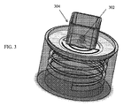
出口穴は、ミニチャネルにつながる任意の場所にあってよい。出口穴はスパウト機構を含んでもよい。スパウト機構は、流体の堆積及び採取を制御するように設計される。このスパウトにより、流体を様々な受け側装置に厳密に定量供給することが可能である。スパウト機構の形状は、バーブ、毛細管、先細ノズル、又はシンプルな管形状であってよい。本装置が加圧されたときにあまり曲がらないようにする為に、支持構成要素の壁厚は、その曲がりにくさを考慮に入れなければならない。これは、材料の選択、又は適切な厚さの構成要素の設計によって達成可能である。この構成要素の材料は、熱可塑性プラスチック、金属、及びセラミックであってよく、これらに限定されない。支持構成要素は更に、採取装置との接合部分の管理を支援する保護シースを含んでよい。これは特に、ポイントオブケア装置内に試料を堆積させる場合に有用である。ユーザが試料入力領域を狙い損ねるのを防いで、試料が時折不必要に試料入力領域に注がれて完全な滴下が形成されなくなることなく、完全な滴下が形成されるようにする為に、出口302の周囲に、図3に示される透明シース304が組み込まれてよい。
The exit hole may be anywhere where it leads to the mini-channel. The exit hole may include a spout mechanism. The spout mechanism is designed to control fluid deposition and collection. This spout allows the fluid to be dispensed exactly to the various receiving devices. The shape of the spout mechanism may be barbs, capillaries, tapered nozzles, or simple tube shapes. In order to make the device less likely to bend when pressed, the wall thickness of the support component must take into account its inflexibility. This can be achieved by the choice of materials or the design of components of suitable thickness. The material of this component may be, but is not limited to, thermoplastics, metals and ceramics. The support component may further include a protective sheath that assists in managing the interface with the sampling device. This is especially useful when depositing the sample in a point of care device. To prevent the user from failing to aim at the sample input area so that a complete drop is formed without the sample occasionally being unnecessarily poured into the sample input area and forming a complete drop. Around the
フレキシブル容器は、フィルタアセンブリを通り抜ける前の流体を収容するように構成されている。フレキシブル容器は更に、操作者が圧搾したときに、流体を駆動してフィルタアセンブリに通す圧力を提供する。流体を駆動して本装置に通すのに必要な圧力は、わずか0.25psiであってよく、最大5psiの圧力に達してよい。幾つかの実施形態では、細胞溶解が不要の場合、5psiを超える過大な圧力は血液試料には使用されない。駆動圧力が大きすぎると、細胞を破裂させて細胞内容物を放出させる可能性があり、これはアッセイの結果に影響を及ぼす可能性がある。フレキシブル容器の構造は、キャップと結合される為のねじ山を最上部に有する一般的なスクイーズボトルに非常によく似ている。スクイーズボトルを作る材料として、高密度ポリエチレン、低密度ポリエチレン、ポリプロピレン、及びポリエステルがあってよく、これらに限定されない。 The flexible container is configured to contain fluid prior to passing through the filter assembly. The flexible container also provides pressure to drive fluid through the filter assembly when squeezed by the operator. The pressure required to drive fluid through the device may be as low as 0.25 psi and may reach pressures up to 5 psi. In some embodiments, overpressure above 5 psi is not used for blood samples when cell lysis is not required. If the driving pressure is too great, it can rupture the cells and release the cell contents, which can affect the results of the assay. The structure of the flexible container is very similar to a typical squeeze bottle that has threads on top for connecting with a cap. Materials for making squeeze bottles may include, but are not limited to, high density polyethylene, low density polyethylene, polypropylene, and polyester.
本装置を動作させる為に、未濾過流体がフレキシブル容器に挿入される。容器は、事前充填量の流体を貯蔵中に内部に収容する為に、その開口部に着脱可能シールを有してよい。事前充填流体が不要な用途の場合は、操作者は未濾過流体を追加してよい。混合が必要であれば、操作者は、流体内で相対運動を引き起こすことによって混合を行う必要がある。これは、流体をかき混ぜるか、回転させるか、振ることによって行われてよい。かき混ぜ棒、スワブ、又は採取装置のように汚染される器具が使用される場合、これらは、廃棄物の散乱を防ぐ為にフレキシブル容器内に廃棄されてよい。試料が準備されたら、操作者は、キャップが封止されていることを確認し、アセンブリを逆さまにして、スパウト機構を所望の場所の中に向ける。操作者がフレキシブル容器を圧搾して圧力をかけると、濾液は、所望の量が採取されるまでアセンブリから出る。圧搾操作によって流体が駆動されてキャップハウジングの穴を通り抜け、横方向に動いてフィルタ膜の露出領域全体に達する。駆動圧力によって、膜が下方に押されるが、剛体支持構成要素に押しつけられてフィルタ膜とキャップハウジングとの間にポケットが形成されることにより、フィルタ膜が伸びすぎて裂ける事態が避けられる。非対称フィルタが使用される場合、流体は大きな細孔から膜に入り、濾液は小さい細孔から出る。非対称フィルタが使用されない場合、流体は、対称フィルタ膜の細孔を通り抜ける。捕捉された粒子は全て、フィルタ膜によって捕捉されたままとなる。複合フィルタが使用される場合、濾過された試料は、次のフィルタ膜を通って再度濾過される。その後、濾液は膜の出口からミニチャネルに移動する。濾液は、ミニチャネルに沿って、支持構成要素上にある出口穴まで流れる。最後に、濾液は、スパウト機構を通ってアセンブリ内から出て、所望の用途に従って採取される。 To operate the device, unfiltered fluid is inserted into the flexible container. The container may have a removable seal at its opening for containing a pre-filled amount of fluid therein during storage. For applications where prefilled fluid is not needed, the operator may add unfiltered fluid. If mixing is required, the operator must perform the mixing by causing relative motion within the fluid. This may be done by stirring, rotating, or shaking the fluid. If contaminated devices are used, such as stir bars, swabs, or harvesters, these may be disposed of in flexible containers to prevent waste clutter. Once the sample is prepared, the operator confirms that the cap is sealed and turns the assembly upside down and orients the spout mechanism into the desired location. When the operator squeezes the flexible container and applies pressure, the filtrate exits the assembly until the desired volume is collected. The squeezing operation drives the fluid through the holes in the cap housing and laterally to reach the entire exposed area of the filter membrane. The drive pressure pushes the membrane downward, but avoids overstretching and tearing the filter membrane by being pressed against the rigid support component to form a pocket between the filter membrane and the cap housing. When an asymmetric filter is used, fluid enters the membrane through the large pores and filtrate exits the small pores. If no asymmetric filter is used, the fluid will pass through the pores of the symmetrical filter membrane. All trapped particles remain trapped by the filter membrane. If a composite filter is used, the filtered sample is filtered again through the next filter membrane. The filtrate then moves from the membrane outlet to the minichannel. The filtrate flows along the mini-channel to the exit holes on the support component. Finally, the filtrate exits the assembly through the spout mechanism and is collected according to the desired application.
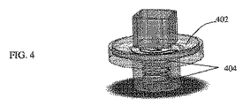
図4に示されるように、幾つかの実施形態では、フィルタのサイズは、フレキシブル容器の開口部より著しく大きいことが必要とされるであろう。大きなフィルタ402を小さなフレキシブル容器に対応させる為に、相補的ねじ山404のサイズを、キャップハウジングの外周全体のサイズより著しく小さくなるように変更してよい。そうすることにより、設計者は、キャップハウジングとフレキシブル容器の相補的ねじ山同士が適合する限り、任意のサイズ及び形状のフィルタを、任意のサイズ及び形状の任意のフレキシブル容器とぴったり合うようにすることが可能である。
As shown in FIG. 4, in some embodiments, the size of the filter will need to be significantly larger than the opening of the flexible container. To accommodate the
幾つかの実施形態では、フレキシブル容器を使用せずに済ませなければならない場合がある。理論的には、このアセンブリは任意の圧力発生装置とともに使用されてよい。他の圧力発生装置として、シリンジ、ポンプ、重力送り管、又は、ガスシリンダによく似た加圧式アキュムレータがある。従って、取り付けにはねじ山は不要である。例えば、アセンブリは、管と結合される入力バーブを有するように設計されてよい。バーブが二重に付けられたアセンブリであれば、別のタイプの用途で使用可能なインラインフィルタを生成する。別の用途では、アセンブリは、濾過対象の試料が装填されたシリンジに取り付けられる為のルアーテーパ接続が組み込まれてよい。別の用途では、フィルタは、感圧粘着剤につながるフラット面を含んでよい。この構造はフレキシブル容器との使用に限定されないが、フレキシブル容器を使用することにより、使いやすい装置としてのフィルタの可能性が示される。更に、フレキシブル容器を使用することにより、加圧過剰の結果としての細胞溶解(これはシリンジの場合に特に発生しやすい可能性がある)のリスクを減らす為の、駆動圧力の厳密な制御が可能になる。 In some embodiments, flexible containers may not have to be used. In theory, this assembly may be used with any pressure generator. Other pressure generators include syringes, pumps, gravity feed tubes, or pressure accumulators much like gas cylinders. Therefore, no threads are required for mounting. For example, the assembly may be designed to have an input barb associated with the tube. A doubly barbed assembly produces an in-line filter that can be used in other types of applications. In another application, the assembly may incorporate a luer taper connection for attachment to a syringe loaded with the sample to be filtered. In another application, the filter may include a flat surface leading to a pressure sensitive adhesive. Although this structure is not limited to use with flexible containers, the use of flexible containers demonstrates the potential of the filter as an easy-to-use device. In addition, the use of flexible containers allows tight control of the drive pressure to reduce the risk of cell lysis as a result of overpressurization, which can be especially likely with syringes. become.
幾つかの実施形態では、濾過の前に緩衝液が未濾過流体と混合される。緩衝液として、リン酸緩衝生理食塩水(PBS)が使用されてよい。水も使用可能であるが、水を使用すると、浸透圧によって過剰な流体が細胞内へと駆動されて、細胞膜の破裂と細胞内容物の放出とが引き起こされる。これには、細胞内に捕捉されたヘモグロビン及び他の細胞内成分が含まれ、これらは、混合物を不可逆的に赤色に染め、過剰なタンパク質を試料混合物内に放出する。場合によっては溶解が必要であり、それは、例えば、細胞からのDNA抽出が必要な場合であり、或いは、細胞内バイオマーカを検出する場合である。溶解が行われる場合には、フィルタは、アッセイにおいて流れの問題を引き起こしかねない細胞デブりを濾液から排除することが可能である。従来のラテラルフローイムノアッセイ検査では、ストリップ上の流れ落ちを改善する為に、緩衝液は、PBSに混合された界面活性剤を含む場合がある。よく使用される界面活性剤はTween−20及びTriton−X100であるが、Triton X−100は細胞溶解を引き起こす可能性がある。幾つかの実施形態では、これらの界面活性剤はストリップ自体の表面にある為、緩衝液は界面活性剤を含まなくてよい。更に、幾つかの実施形態では、緩衝液は動物性タンパク質を含んでよく、これは、関心対象の検体を、それらの領域において競合させて、バックグラウンドに結合するのを防ぐ為である。緩衝液は、混合物中に血液クロットが形成されるのを防ぐ為に、EDTAのような抗凝血剤を含んでもよい。 In some embodiments, the buffer is mixed with the unfiltered fluid prior to filtration. Phosphate buffered saline (PBS) may be used as a buffer. Although water can be used, it causes osmotic pressure to drive excess fluid into the cell, causing rupture of the cell membrane and release of cell contents. This includes hemoglobin and other intracellular components that are trapped inside the cells, which irreversibly stain the mixture red and release excess protein into the sample mixture. Lysis may be necessary in some cases, for example when DNA extraction from cells is required, or when detecting intracellular biomarkers. If lysis is performed, the filter is capable of eliminating cell debris from the filtrate that could cause flow problems in the assay. In conventional lateral flow immunoassay tests, the buffer may include a detergent mixed with PBS to improve runoff on the strip. Commonly used detergents are Tween-20 and Triton-X100, but Triton X-100 can cause cell lysis. In some embodiments, these surfactants are on the surface of the strip itself, so the buffer may be surfactant-free. In addition, in some embodiments, the buffer may contain animal proteins to prevent the analyte of interest from competing in those regions and binding to the background. The buffer may include an anticoagulant such as EDTA to prevent blood clots from forming in the mixture.
本明細書に記載の装置で生成される試料は、任意の数の検査装置及び診断装置とともに使用されてよく、これは、ヒトを含む、血液を産生する全ての動物種において同じ原理が適用されてよい為である。上述のように、タンパク質の検出にラテラルフローイムノアッセイ(LFIA)検査を用いることが考えられる。幾つかの実施形態では、本装置は、タンパク質ベースではない検査に使用されてよい。例えば、本装置は、血中アルコール濃度検査、大麻消費に起因する血中カンナビノイドの検出、ビタミン不足の測定、又は血流中を循環する無細胞DNAの隔離を実施することに使用されてよい。本質的には、本装置で血液を処理することにより、細胞間又は細胞内にあって血流中を循環する任意の検体を検査することが可能である。 The samples produced by the devices described herein may be used with any number of testing and diagnostic devices, which applies the same principles in all blood-producing animal species, including humans. This is because it is okay. As mentioned above, it is conceivable to use the lateral flow immunoassay (LFIA) test for the detection of proteins. In some embodiments, the device may be used for non-protein based tests. For example, the device may be used to perform blood alcohol concentration tests, detection of cannabinoids in blood due to cannabis consumption, vitamin deficiency measurements, or sequestration of cell-free DNA circulating in the bloodstream. In essence, by treating blood with this device, it is possible to test any analyte that is circulating in the bloodstream between or within cells.
本明細書に記載の装置及び方法を用いて全血試料を濾過することにより、ラテラルフローイムノアッセイ検査ストリップを使用して家庭や現場で信頼できる検査を行うことが可能になりうる。現時点では、この要求を満たす為に、全血を検査ストリップに直接付けている。全血を検査ストリップに直接付けることの問題は、多くのラテラルフローイムノアッセイ診断検査で使用されるコロイド金又は蛍光検査ラインの検出を妨げるバックグラウンドノイズが血液試料の赤色によって発生することである。血漿を濾過して細胞を取り除くことにより、検査ストリップはバックグラウンドノイズがない状態が保たれ、検査ラインの容易な検出が可能になる。信頼できる血液検査が家庭で行われれば、特定の場所ではいまだに後ろ指を差されることがある、HIVのような病気の検査に役立ちうる。 Filtration of whole blood samples using the devices and methods described herein may allow for reliable testing at home or in the field using lateral flow immunoassay test strips. At present, whole blood is applied directly to the test strip to meet this requirement. A problem with directly attaching whole blood to a test strip is that the red color of the blood sample causes background noise that interferes with the detection of colloidal gold or fluorescent test lines used in many lateral flow immunoassay diagnostic tests. By filtering the plasma to remove cells, the test strip remains background noise free and allows easy detection of the test line. A reliable blood test performed at home can help test for illnesses such as HIV, which can still be pointed back in certain places.
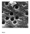
測定の対象に応じて、様々なタイプのフィルタが使用されてよい。例えば、血流中を循環する、血漿内の検体を測定する為に、単一の非対称フィルタが使用されてよい。別の実施形態では、特定の細胞集団を選択的に溶解する為に、複合フィルタが使用されてよい。別の実施形態では、バクテリアの細胞内容物を検出することにより、敗血症を引き起こすバクテリアを識別する迅速検査が動作可能になる。そのような実施形態では、2ステージ複合フィルタが使用されてよい。第1のフィルタは、大きな赤血球及び白血球を溶解させずに全て捕捉するように設計された非対称膜フィルタ(Pall MMMシリーズ、又はVividシリーズ、又はBTSシリーズ、図5を参照)であってよい。バクテリアは、通常、血球より小さい為、細孔がバクテリアより大きいことになるこのフィルタを通り抜けるであろう。その後、第1のフィルタ膜を通り抜けたところで、細孔が非常に小さい膜フィルタを使用してよい。そのフィルタは、バクテリア細胞を止めるだけでなく溶解させるように設計されてよい。第2のフィルタは、流体がその周囲を流れることを可能にする為に、第1のフィルタのような非対称ではない。その代わりに、第2のフィルタは、貫通穴を有する膜(ホワットマンヌクレポア(Whatman Nuclepore)トラックエッチ膜、図6を参照)として構成されてよく、駆動圧力は細胞を破裂させることになる。このタイプのフィルタ構造は、サイズに応じて、ある細胞集団を選択的に溶解させる一方、他の集団はそのまま残すようになっている。そのようなフィルタの別の用途として、他の、血液によって感染する寄生虫(マラリア等)の検出がある。本方法によれば、アセンブリは、小さい未成熟マラリア細胞を選択的に溶解させることによって、その細胞内容物を潜在的に検出することが可能である。 Various types of filters may be used depending on what is being measured. For example, a single asymmetric filter may be used to measure analytes in plasma that circulate in the bloodstream. In another embodiment, complex filters may be used to selectively lyse specific cell populations. In another embodiment, detecting the cellular content of the bacteria enables a rapid test to identify the bacteria causing sepsis. In such an embodiment, a two stage composite filter may be used. The first filter may be an asymmetric membrane filter (Pall MMM series or Vivid series, or BTS series, see FIG. 5) designed to capture all large red blood cells and white blood cells without lysing them. Bacteria will normally pass through this filter, which will be larger than bacteria because they are smaller than blood cells. Then, once through the first filter membrane, a membrane filter with very small pores may be used. The filter may be designed to lyse as well as kill bacterial cells. The second filter is not as asymmetrical as the first filter to allow the fluid to flow around it. Alternatively, the second filter may be configured as a membrane with through holes (Whatman Nuclepore track etch membrane, see Figure 6) and the driving pressure will cause cells to rupture. Depending on size, this type of filter structure selectively lyses some cell populations while leaving others intact. Another use of such filters is in the detection of other blood-borne parasites (such as malaria). According to this method, the assembly is capable of potentially detecting the cellular contents of small immature malaria cells by selectively lysing them.
様々な症状に関して検出すべきバイオマーカを見つける研究は、急激に変容しており、急速に進歩している。本装置は、既知量の血液及び緩衝液が本装置に挿入された場合に、定性検査及び定量検査の両方に向けて試料を処理する能力を備えている。 Research to find biomarkers to detect for a variety of conditions is rapidly transforming and advancing rapidly. The device has the ability to process a sample for both qualitative and quantitative testing when a known amount of blood and buffer are inserted into the device.
定性検査では、陽性/陰性の2値の結果が提示される。本明細書に記載の装置を使用して行われてよい定性検査の例として、妊娠に関連するhCGホルモンの検出、HIV感染に関連するHIVの抗体及び/又は表面抗原の検出、A、B、C型肝炎の感染又はワクチン接種に関連する肝炎の抗体及び/又は表面抗原の検出、ヘルペス感染に関連するヘルペス抗体の検出、ウマにおけるウマ感染性貧血に関連するEIAV抗体の検出、イヌ糸状虫病の検出の為の、イヌやネコにおける犬糸状虫抗体の検出、及び血流中の合法又は違法の薬物の存在の検出がある。HIV抗体を検出する検査の場合など、幾つかの実施形態では、本明細書に記載の濾過装置は、現行の唾液による検査より早く、HIV抗体の血液検査を家庭や現場でシンプルに行うことを可能にしうる。幾つかの実施形態では、本明細書に記載の濾過装置は、現在利用可能な、家庭で採取した尿による検査より早く、hCGの血液検査を家庭や現場でシンプルに行うことを可能にしうる。 The qualitative test provides a positive/negative binary result. Examples of qualitative tests that may be performed using the devices described herein include detection of pregnancy-related hCG hormones, detection of HIV antibodies and/or surface antigens associated with HIV infection, A, B, Detection of hepatitis antibodies and/or surface antigens associated with hepatitis C infection or vaccination, detection of herpes antibodies associated with herpes infection, detection of EIAV antibodies associated with equine infectious anemia in horses, canine heartworm disease There are detections of Dermatophytes antibodies in dogs and cats, and detection of the presence of legal or illegal drugs in the bloodstream for the detection of In some embodiments, such as in the case of tests that detect HIV antibodies, the filtration devices described herein allow for simple HIV antibody blood tests at home and in the field, faster than current saliva tests. It can be possible. In some embodiments, the filtration devices described herein may allow a simple blood test for hCG at home or in the field, faster than the currently available home urine tests.
定性検査では、血中の検体の濃度に関する数値が提示される。このタイプの検査は、実質的に実施がより困難である。それは、量を適切に採取及び処理するようにすることが非常に重要だからである。本明細書に記載の装置及び方法を使用して行われてよい定量検査の例を幾つか挙げると、排卵追跡の為の黄体形成ホルモンの急なスパイクの測定、潰瘍診断の為の高濃度のピロリ菌抗体の測定、前立腺癌のスクリーニングの為のPSA濃度の測定、副甲状腺腺腫の検出の為の副甲状腺ホルモン濃度の測定、コレステロールの監視の為のHDL/LDL濃度の測定、及び腎臓機能の監視の為のクレアチニン濃度の測定がある。 The qualitative test provides numerical values regarding the concentration of the sample in blood. This type of test is substantially more difficult to perform. The reason is that it is very important to properly collect and process the amount. Some examples of quantitative tests that may be performed using the devices and methods described herein include measuring luteinizing hormone spikes for follow-up ovulation, and high levels of concentration for ulcer diagnosis. Helicobacter pylori antibody measurement, PSA concentration measurement for prostate cancer screening, parathyroid hormone concentration measurement for parathyroid adenoma detection, HDL/LDL concentration measurement for cholesterol monitoring, and renal function There is a measurement of creatinine concentration for monitoring.
幾つかの実施形態では、検査ラインと対照ラインとを比較する定量検査は、それらのラインの強度を比較するように構成されたスマートフォンアプリケーションを使用して強化されてよい。幾つかの実施形態では、定量検査において、約20〜30μLを保持するように構成されたスワブを使用する。緩衝液を使用して、定量検査に十分な量を確保する為の10倍希釈を行うことが可能である。 In some embodiments, the quantitative test comparing the test line with the control line may be enhanced using a smartphone application configured to compare the intensities of those lines. In some embodiments, swabs configured to hold about 20-30 μL are used in a quantitative test. A buffer solution can be used to make a 10-fold dilution to ensure sufficient volume for a quantitative test.
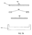
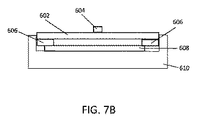
図7A及び7Bは、本明細書に記載の装置の構成要素の製造工程の一例を示す。図7Aは、出力604又はスパウトを含む出力基板602、両面粘着剤606、フィルタ608、及び入力基板610の分解側面図を示す。製造工程は、粘着剤606の上面を出力基板602の底面に粘着させるステップを含む。粘着剤606の底面が、フィルタ608の上面と、入力基板610の内側部分の上面とに粘着される。従来は、ほとんどのフィルタが超音波溶接を使用しており、従って、製造工程の時間はプラスチックの溶融時間等に依存する。本装置の場合、フィルタは粘着剤を使用して製造される為、製造工程の時間を格段に短縮することが可能である。
7A and 7B show an example of a process for manufacturing the components of the device described herein. FIG. 7A shows an exploded side view of
これまでの図は、フレキシブル容器の蓋の上で組み立てられるフィルタアセンブリを示していたが、ここからの図は、フレキシブルコネクタと一緒に組み立てられるフィルタアセンブリを示す。試料濾過装置の以下の実施形態(例えば、図8A〜17に関して説明される実施形態)は、図1A〜7Bに関して説明されたフィルタの特徴を含んでよい。フレキシブルコネクタは、試料の採取及び定量供給を行う様々な装置(スクイーズボトルを含む)にフィルタを接続する為に使用されてよい。フレキシブルコネクタは、試料濾過装置が、全血濾過を含む多様なタイプの用途で使用されることを可能にしうる。フレキシブルコネクタの材料の可撓性は、フレキシブルコネクタが様々なタイプの取付機構に適合して、フレキシブルコネクタを多様な用途に適応可能にすることを可能にしうる。上述のように、記載のフレキシブルコネクタは、試料の採取及び定量供給を行う従来式の装置をフレキシブルコネクタに接続して使用することを可能にする。そのような装置として、バルブピペット、マイクロピペットチップ、毛細管、シリンジ針、バーブ、スクイーズボトル、チューブ、又は他の、管状又はテーパ状の接続形状を有する装置があり、これらに限定されない。更に、フレキシブルコネクタは、分割線や鋳バリのような製造アーチファクトを含む非円形の形状及び構成要素(例えば、後述のバルブピペット)とも接続可能である。 Whereas the previous figures show the filter assembly assembled on the lid of the flexible container, the figures from here on show the filter assembly assembled with the flexible connector. The following embodiments of the sample filtration device (eg, the embodiments described with respect to FIGS. 8A-17) may include the filter features described with respect to FIGS. Flexible connectors may be used to connect the filter to a variety of devices for sample collection and dispensing, including squeeze bottles. Flexible connectors may allow the sample filtration device to be used in various types of applications, including whole blood filtration. The flexibility of the material of the flexible connector may allow the flexible connector to fit various types of attachment mechanisms, making the flexible connector adaptable to a variety of applications. As mentioned above, the described flexible connector allows the use of conventional devices for sample collection and dispensing in connection with the flexible connector. Such devices include, but are not limited to, valve pipettes, micropipette tips, capillaries, syringe needles, barbs, squeeze bottles, tubes, or other devices with tubular or tapered connections. Further, the flexible connector is also connectable to non-circular shapes and components (eg, valve pipettes described below), including manufacturing artifacts such as parting lines and cast burrs.
図8A〜8Cは、フィルタ(例えば、本明細書に記載のフィルタ)とともに使用されてよいフレキシブルコネクタ800を含むフィルタアセンブリの一実施形態800の様々な図を示す。図8Aは、フィルタアセンブリの入力基板830に取り付けられたフィルタアセンブリフレキシブルコネクタ802の斜視図を示す。入力基板830の下方に出力基板832がある。図8Bの正面断面図に示されるように、入力基板830と出力基板832との間にフィルタ膜838及び粘着層(例えば、両面粘着層)836が配置される。幾つかの実施形態では、粘着層836とフィルタ膜838の順序が逆である。例えば、フィルタ膜838は、フィルタ膜の正しい向きが保持されることを保証しながら、粘着層836の上又は下に横たわる。
8A-8C show various views of one
幾つかの実施形態では、フィルタ膜は、長さが約17mmであり、幅が約17mmである。他の寸法も可能である(例えば、幅及び/又は長さは約15mm、16mm、17mm、15〜20mm、10〜15mm、20mm超等)。幾つかの実施形態では、粘着層は、両面感圧粘着層を含む。粘着層は、基板(例えば、PET基板)のいずれかの面上に配置された感圧粘着層を含んでよい。各粘着層は、厚さが約0.005”であってよい。他の寸法も可能である(例えば、約0.004〜0.006”、約0.003〜0.007”、約0.002〜0.008”、約0.004”、約0.006”等)。基板は、厚さが約0.005”であってよい。他の寸法も可能である(例えば、約0.004〜0.006”、約0.003〜0.007”、約0.002〜0.008”、約0.004”、約0.006”等)。0.005”の基板のいずれかの面上に0.005”の粘着層が配置された粘着層であれば、合計厚さが約0.015”である。 In some embodiments, the filter membrane is about 17 mm long and about 17 mm wide. Other dimensions are possible (eg, width and/or length are about 15 mm, 16 mm, 17 mm, 15-20 mm, 10-15 mm, more than 20 mm, etc.). In some embodiments, the adhesive layer comprises a double sided pressure sensitive adhesive layer. The adhesive layer may include a pressure sensitive adhesive layer disposed on either side of the substrate (eg, PET substrate). Each adhesive layer may have a thickness of about 0.005″. Other dimensions are possible (eg, about 0.004 to 0.006″, about 0.003 to 0.007″, about 0). 0.002-", about 0.004", about 0.006", etc.). The substrate may be about 0.005″ thick. Other dimensions are possible (eg, about 0.004 to 0.006″, about 0.003 to 0.007″, about 0.002). ~0.008", about 0.004", about 0.006", etc.). An adhesive layer having a 0.005″ adhesive layer disposed on either side of a 0.005″ substrate has a total thickness of about 0.015″.
この厚さにより、寸法が17mm×17mmであるフィルタ膜との隙間が非常に薄い0.002”のままになり、これによって、流体が横方向に流れてフィルタ全体を湿らせることが可能になる。試料を駆動してフィルタに通すのに十分な圧力がアセンブリ内で発生するように、しかしそれでも流体が横方向に流れてフィルタ膜の露出部分全体に行き渡ることが十分可能であるように、この隙間を最小化することが重要であろう。隙間が大きすぎると、空間が空いて駆動圧力が不十分になることにより、試料の濾過が不完全になる可能性がある。隙間が不十分な場合には、試料は、フィルタ膜の露出部分全体に行き渡る為の流路が制限される可能性がある。この隙間が適切に設計されれば、加圧装置によって定量供給される空気の体積が小さくなって、液体試料の完全濾過が確実に行われることが可能になる。例えば、100〜1000μLのマイクロピペットは、典型的には、液量を定量供給した後にプランジャの第2のストップに達すると、約250μLの空気だけを定量供給することが可能である。この隙間を最小化すると、マイクロピペットのような、少量の空気を定量供給する装置を圧力源として使用して、試料を適切に駆動してフィルタアセンブリに完全に通すことが可能になる。他の隙間寸法も可能である(例えば、約1〜3mm、約1mm、約3mm等). This thickness leaves a very thin 0.002" gap with the filter membrane, which measures 17 mm x 17 mm, which allows fluid to flow laterally to wet the entire filter. This is so that sufficient pressure is generated in the assembly to drive the sample through the filter, but it is still possible for the fluid to flow laterally and over the entire exposed portion of the filter membrane. It may be important to minimize the gap, because if it is too large, it may lead to incomplete sample filtration due to voids and insufficient drive pressure. In some cases, the sample may have a restricted flow path to the entire exposed portion of the filter membrane, and if this gap is properly designed, the volume of air dispensed by the pressurizer will be limited. The small size allows for a complete filtration of the liquid sample to be ensured, eg 100-1000 μL micropipettes typically reach the second stop of the plunger after metering the volume. Then, it is possible to dispense only about 250 μL of air, and if this gap is minimized, a device for dispensing a small amount of air, such as a micropipette, can be used as a pressure source to properly sample. It is possible to drive it completely through the filter assembly, and other clearance dimensions are possible (eg, about 1-3 mm, about 1 mm, about 3 mm, etc.).
粘着層は、長さと幅が約22mmであってよい。他の長さ及び幅も可能である(例えば、約21mm、約23mm、約21〜23mm、約20〜24mm、約19〜25mm、約15〜25mm、25mm超等)。粘着層の切り抜き部は、長さと幅が約14mmであってよい。他の長さ及び幅も可能である(例えば、約13mm、約15mm、約13〜15mm、約11〜17mm、約10〜20mm等)。 The adhesive layer may be about 22 mm in length and width. Other lengths and widths are possible (eg, about 21 mm, about 23 mm, about 21-23 mm, about 20-24 mm, about 19-25 mm, about 15-25 mm, more than 25 mm, etc.). The cutouts of the adhesive layer may be about 14 mm in length and width. Other lengths and widths are possible (eg, about 13 mm, about 15 mm, about 13-15 mm, about 11-17 mm, about 10-20 mm, etc.).
幾つかの実施形態では、入力基板及び出力基板の一方又は両方がポリカーボネートを含む。他の材料も可能である(例えば、ポリプロピレン、ポリエチレン、及びポリスチレン)。ポリカーボネートは、有利なことに、デュロメータ硬度がショア50Aである熱可塑性エラストマ(TPE)でオーバモールドされているフレキシブルコネクタ材料と化学的に適合する。この適合性により、フレキシブルコネクタ材料が基板上に適切に固定されたままとなり、漏れ経路が発生しないことが保証されうる。入力基板は、厚さが約3mmであってよい。他の寸法も可能である(例えば、約2mm、約4mm、約2〜4mm、約1〜5mm等)。入力基板は、幅と長さが約22mmであってよい。他の長さ及び幅も可能である(例えば、約21mm、約23mm、約21〜23mm、約20〜24mm、約19〜25mm、約15〜25mm、25mm超等)。幾つかの実施形態では、入力基板の表面が、両面粘着剤への粘着の為にフラットである。幾つかの実施形態では、入力基板の表面は、突起形状物又はテクスチャ形状物を含む。幾つかの実施形態では、出力基板は、厚さが約2mmである。この厚さは、加圧中の曲がりを防ぐのに十分でありうる。他の厚さも可能である(例えば、約1mm、約3mm、約1〜3mm、約1〜5mm等)。出力基板は、長さと幅が約22.25mmであってよい。この寸法は、22mm×22mmの入力基板が、入力基板と出力基板の間に粘着層及びフィルタ膜を挟んで出力基板の領域にぴったり収まることを可能にしうる。他の長さ及び幅も可能である(例えば、約21mm、約23mm、約21〜23mm、約20〜24mm、約19〜25mm、約15〜25mm、25mm超等)。 In some embodiments, one or both of the input and output substrates comprises polycarbonate. Other materials are possible (eg, polypropylene, polyethylene, and polystyrene). Polycarbonate is advantageously chemically compatible with flexible connector materials that are overmolded with thermoplastic elastomer (TPE) having a durometer hardness of Shore 50A. This compatibility may ensure that the flexible connector material remains properly secured on the substrate and that no leak paths occur. The input board may have a thickness of about 3 mm. Other dimensions are possible (eg, about 2 mm, about 4 mm, about 2-4 mm, about 1-5 mm, etc.). The input board may be approximately 22 mm wide and long. Other lengths and widths are possible (eg, about 21 mm, about 23 mm, about 21-23 mm, about 20-24 mm, about 19-25 mm, about 15-25 mm, more than 25 mm, etc.). In some embodiments, the surface of the input substrate is flat due to adhesion to the double sided adhesive. In some embodiments, the surface of the input substrate comprises raised features or textured features. In some embodiments, the output substrate is about 2 mm thick. This thickness may be sufficient to prevent bending during pressing. Other thicknesses are possible (eg, about 1 mm, about 3 mm, about 1-3 mm, about 1-5 mm, etc.). The output board may be about 22.25 mm in length and width. This dimension may allow a 22mm x 22mm input substrate to fit exactly in the area of the output substrate with an adhesive layer and a filter membrane sandwiched between the input substrate and the output substrate. Other lengths and widths are possible (eg, about 21 mm, about 23 mm, about 21-23 mm, about 20-24 mm, about 19-25 mm, about 15-25 mm, more than 25 mm, etc.).
フレキシブルコネクタ802の上部に、コネクタへの容易な取り付けを可能にする漏斗804が含まれてよい。漏斗804は、取付機構を穴806内に導く(図8Cに最もよく示されている)。幾つかの実施形態では、漏斗は、大径が約3.6mm、小径が約1.6mm、面取り角度が45°、長さが約1mmである。他の寸法も可能である。例えば、大径は、約3〜4mm、約3mm、約4mm、約2〜6mm等であってよい。小径は、約1〜2mm、約1mm、約2mm、約0〜3mm等であってよい。面取り角度は、約40〜50°、約35〜55°、約30〜60°等であってよい。漏斗の長さは、約0.75〜1.25mm、約0.5〜1.5mm、約0.75mm、約1.25mm等であってよい。漏斗804の面取り箇所の後方に、狭い管又はパイプ808がある。このパイプは、取付機構(例えば、ピペットチップの端部)を把持及び封止できるように十分な長さであってよい。パイプの高さは約7mmであってよい。他の長さも可能である(例えば、約5〜7mm、約5mm、約6mm、約6〜8mm、約5〜9mm、約7〜8mm、約7〜9mm等)。パイプは、最小内径が約1.5mmであってよい。他の形状寸法も可能である(例えば、約1mm、約1〜2mm、約2mm等)。長さが約7mmであって最小内径が約1.5mmであるパイプが、市販の1000μLピペットチップ並びに他の多くの挿入された接続機構を把持且つ封止するように構成されてよい。
The top of
パイプ808の後方に、アセンブリ内へのそれ以上の挿入を阻止する収縮穴810がある。この収縮穴810は、フレキシブルコネクタへのオス接続機構の過挿入に起因するフィルタ膜の損傷を防ぐ。幾つかの実施形態では、収縮穴の径は約0.75mmである。他の径も可能である(例えば、約0.7mm、約0.8mm、約0.6〜0.9mm、約0.5〜1mm等)。収縮穴808のサイズは接続機構(例えば、ピペット)の先端より小さくなっており、これは、接続機構の先端が、収縮穴808に当たったときに急停止して、フィルタ膜に届かないようにする為である。
Behind the
フレキシブルコネクタに含まれてよい可撓材料として、TPE、シリコーン、ゴム、ポリウレタン、及び軟質熱可塑性プラスチック(LDPE、HDPE、PP、可塑化PVC等)があり、これらに限定されない。フレキシブルコネクタの壁厚は、接続装置がフレキシブルコネクタに取り付けられる際に十分な剛性の支持が得られるようになっており、それによって、わずかな位置合わせずれを許容しながらも位置合わせが保持される。フレキシブルコネクタのサイズは更に、スクイーズボトルのネックにあるようなボアに挿入される際に剛性を備えうるサイズである。幾つかの実施形態では、壁厚は2mmである。他の厚さも可能である(例えば、1.5〜2.5mm、約1.75〜2.25mm、約1〜3mm、約1〜4mm等)。 Flexible materials that may be included in the flexible connector include, but are not limited to, TPE, silicone, rubber, polyurethane, and soft thermoplastics (LDPE, HDPE, PP, plasticized PVC, etc.). The wall thickness of the flexible connector provides sufficient rigidity of support when the connecting device is attached to the flexible connector, thereby maintaining alignment while allowing for slight misalignment. .. The flexible connector is also sized to provide rigidity when inserted into a bore such as the neck of a squeeze bottle. In some embodiments, the wall thickness is 2 mm. Other thicknesses are possible (eg, 1.5-2.5 mm, about 1.75-2.25 mm, about 1-3 mm, about 1-4 mm, etc.).
フレキシブルコネクタの反対側の端部に、流体を所望の場所に入るように方向付ける出力機構812がある。この機構は、ほんのわずかに突出するようなサイズになっている(例えば、約2mm、約1〜3mm、約1mm、約3mm、3mm超等)。これにより、市販の検査カートリッジへの容易な位置合わせ及び取り付けが可能であり、このことは、他の利用可能なフィルタ構造では困難である可能性がある。出力側のフラット面がフラットな検査カートリッジの表面に取り付けられ、これにより、流体は常に、カートリッジ内に向かって垂直に方向付けられる。出力機構の小突起の長さと径は、小突起が検査カートリッジの試料入力機構内にあるときに空間に余裕があるようになっている。出力機構の外径は、約1.25mmであってよい。他の径も可能である(例えば、約1mm、約1.5mm、約1〜1.5mm、約0.5〜1.5mm、約0.5〜2mm、約1〜2mm、約1〜3mm等)。この機構は更に、流体がフィルタアセンブリの壁に付着せず、主に検査カートリッジ内へと方向付けられることを保証しうる。
At the opposite end of the flexible connector is an
図8Cは、入力基板830に接続されたフレキシブルコネクタの一実施形態802を示す。このフレキシブルコネクタは、漏斗部804、開口部806、パイプ808、及び収縮穴810を含む。図8Cの実施形態が図8Bに示された実施形態と異なるのは、収縮穴の先に、より大きなキャビティ811がある為であり、キャビティ811は、後で詳述するように、ボール弁を収容する為に使用されてよい。図8Dは、図8Cに示されたアセンブリとよく似ている、フィルタアセンブリの一実施形態850を示しているが、図8Dのフレキシブルコネクタ852は、パイプ856の上部にアンダカット854を含む。このアンダカット854は、バーブがフレキシブルコネクタに接続されたときに可聴スナップ音を鳴らすことが可能である。アンダカット854は更に、フィルタアセンブリに接続されたバーブを定位置で保持することが可能である。
FIG. 8C illustrates an
図8Eは、入力基板864に接続されたフレキシブルコネクタの別の実施形態862を示す。コネクタ862と基板864は機械式インタロック864で接続されており、機械式インタロック864は、フレキシブルコネクタが入力基板から離れない(例えば、剥がれない)ようにすることに役立ちうる。
FIG. 8E illustrates another
幾つかの実施形態では、フィルタアセンブリは、1ピースとして形成され、或いは、互いにつながっている複数の個別ピースとして形成されてよい。幾つかの実施形態では、ポリカーボネート基板が射出成形され、その後、物理的に別のモールドの上に置かれてよい。その後、フレキシブルコネクタ材料(例えば、弾性TPE)が基板上にオーバモールドされて、フレキシブルコネクタが作成されてよい。 In some embodiments, the filter assembly may be formed as one piece, or may be formed as multiple individual pieces that are connected together. In some embodiments, the polycarbonate substrate may be injection molded and then physically placed on another mold. A flexible connector material (eg, elastic TPE) may then be overmolded on the substrate to create a flexible connector.
図9A及び9Bに示されるように、幾つかの実施形態では、フィルタアセンブリ900はボール弁を含む。弁機構は、操作者が活性化動作を解除したとき(例えば、スクイーズボトルを放したとき、或いはマイクロピペットのプランジャを放したとき)に引き起こされる逆流に対処することが可能である。既に示された実施形態と同様に、フィルタアセンブリは、フレキシブルコネクタ902。漏斗904、開口部906、パイプ908、及び収縮穴910を含む。ボール914は、空間に余裕があるキャビティ916内で休止しており、収縮穴の直後に配置される。キャビティの壁のうちの1つの壁がフィルタ膜938で形成され、ボールは使用時以外はフィルタ上で休止する。加圧動作が活性化されると、ボールはキャビティを塞がないが、活性化動作が解除されると、流体が逆方向に流れる。これは、スクイーズボトルを放すような動作によってスクイーズボトルが元の形状に戻ろうとするときに負の相対圧力が発生し、これによって流体が逆吸引される為である。そこで、フィルタの構造にボールを含めると、ボールがキャビティ内で封止を形成して収縮穴910を塞ぐ為に逆流が阻止される。図9Aは封止されていない構成の弁を示しており、パイプ908からフィルタ膜938への流体経路がボール914の周囲にあり、一方、図9Bは封止された構成の弁を示しており、フィルタ膜938とパイプ908との間の流体経路がボール914によって封止されている。ボールは様々な材料を含んでよく、そのような材料としてゴム、プラスチック、セラミック、及び金属があり、これらに限定されない。更に、ユーザは、アセンブリが保持される向きに応じてボールが浮いたり沈んだりするような密度の材料を選択することが可能である。例えば、(密度が最大0.9g/cm3である)ポリプロピレン材料であれば、水に浮くことによって、垂直方向の封止がより容易になる。これに対し、(密度が最大1.3g/cm3である)ニトリルゴムボールであれば、フィルタが逆さまに保持された場合に沈むことによって、その向きにおけるよりよい封止材料となる。そして、加圧装置によって発生する負の相対圧力は、ボールの両側に圧力差を発生させることによって封止を保持し、ボールは入力である穴を封止して逆流を阻止する。
As shown in FIGS. 9A and 9B, in some embodiments the
図10A〜10Bは、フィルタアセンブリ1000をスクイーズボトル1006に取り付ける為のフレキシブルコネクタの使用方法を示す。フレキシブルコネクタ1002は、ボトルの内径の内側1004に挿入されて、これを封止してよい。ボトルの内径1004は、コネクタが挿入されるとコネクタと干渉して、本装置が(例えば、図1A〜1Bにおいて)上述されたように動作することを可能にする。
10A-10B illustrate the use of a flexible connector to attach the
フレキシブルコネクタの漏斗機構は、マイクロピペットチップをフレキシブルコネクタに取り付ける場合に特に有用でありうる。マイクロピペットはピペットチップの先端から遠く離れて保持される為、チップの狙いをフレキシブルコネクタ内に定めることが、図示されたような漏斗機構をしないと、より著しく困難になる。上述のように、高さが約7mmであって最小内径が約1.5mmであるパイプを有するフィルタアセンブリであれば、フレキシブルコネクタが市販の1000μLピペットチップ並びに他の多くの挿入された接続機構を把持且つ封止することを可能にしうる。 The flexible connector funnel mechanism may be particularly useful when attaching a micropipette tip to a flexible connector. Since the micropipette is held far away from the tip of the pipette tip, aiming the tip within the flexible connector becomes much more difficult without the funnel mechanism as shown. As mentioned above, for a filter assembly having a pipe with a height of about 7 mm and a minimum inner diameter of about 1.5 mm, a flexible connector may be used with commercially available 1000 μL pipette tips as well as many other inserted connection mechanisms. It may allow gripping and sealing.
図11A〜11Bは、フィルタアセンブリ1100とともに使用されているマイクロピペットの一例を示す。100〜1000μLのマイクロピペット1120が全血の試料(例えば、100μL)を採取する。そして、チップ1122がフレキシブルコネクタ1102の漏斗1104に挿入される。挿入後、フレキシブルコネクタは、図11Bに示されるように、チップ上に流体封止を形成する。コネクタとマイクロピペットとを接続することにより、アセンブリ全体が持ち上げられて、適切な使用場所まで輸送されることも可能になる。
11A-11B show an example of a micropipette used with a
図12A〜12Cは、フィルタアセンブリ1200に挿入されたマイクロピペットを示しており、マイクロピペットのプランジャが様々な位置まで押下されている様子を示している。図12Aでは、マイクロピペット1210がフレキシブルコネクタ1202に挿入されていて、プランジャ1214はまだ押されていない。一般的な検査用マイクロピペットのプランジャはストッパが2つある。図12Bに示されるように、プランジャを第1のストッパまで押下すると、ピペットチップの内容物が定量供給される。図12Cに示されるように、プランジャを第2のストッパまで押下すると、空気を追い出すことによって残りの液体が全て吐出される。図12Cでは、マイクロピペットが第2のストッパまで押下され、追い出された空気が、血液に印加される圧力のソースとして使用されて、血液がフィルタを通り抜けるように駆動される。適切な量の血漿が定量供給された後、ユーザはプランジャを放して、アセンブリに対する圧力を解放することが可能である。幾つかの実施形態では、プランジャは1分間保持されるが、用途に応じて、より長く、又はより短く保持されてよい。別の用途では、同じ動作モードを使用して、希釈血液も同様に濾過することが可能である。一般に、希釈血液は、フィルタを詰まらせる細胞が少ない為に短時間で濾過することが可能である。幾つかの実施形態では、希釈血液は、プランジャを約5秒間保持することにより濾過可能である。別の実施形態では、希釈血液を濾過する際に、プランジャをより短時間又はより長時間押下してよい。図12A〜12Cに関して説明されたように、一般的な検査用マイクロピペット1210は、全血だけでなく希釈血液を濾過するように容易に適合可能であり、その場合、本出願のフィルタアセンブリを使用する遠心分離は不要である。マイクロピペットの、追い出される空気及び液体の体積は厳密な量であり、これを用いて、信頼できる圧力を血液にかけて内容物を濾過することが可能である。
12A-12C show a micropipette inserted into a
更に、図12D〜12Gに示されるように、バルブピペット1240がフレキシブルコネクタ1242に挿入されてよい。フレキシブルコネクタの構造は、他の材料を封止する際にバルブピペットの分割線や鋳バリによって漏れ経路が発生することで提起される難題に対処することが可能である。バルブピペットをフレキシブルコネクタとともに使用することにより、分割線が試料漏れの問題を提起することはなくなる。これは、フレキシブルコネクタの可撓性により、理想的でない表面を封止することが可能になる為である。分割線や鋳バリのような成形欠陥は、理想的でない封止面を発生させ、これは、剛体又は半剛体の材料を封止することに関して、微細な漏れ経路を発生させる問題を提起する。フレキシブルコネクタの可撓材料は、不規則であって理想的でない表面及び成形欠陥に順応することによって、それらを封止し、望ましくない漏れの可能性を減らすことが可能である。
Additionally, a
以下の図に示されるように、フィルタアセンブリは、ラッチ又は粘着剤又はボンディングの機構を含むカートリッジ上に直接配置されてよく、これは、カートリッジが検査カートリッジ製造者によって梱包される間、アセンブリが定位置で固定されるようにする為である。ユーザは、自身にとって好ましい試料処理装置(マイクロピペットチップ、バルブピペット、適切なオスコネクタを有するスクイーズボトル)をカートリッジに対して直接適用することが可能になる。この動作モードでは、処理装置が定位置に固定された後に流体がアセンブリに直接送達される為、位置合わせが不要になる。更に、アセンブリの構造が本質的にフラットであることにより、容易な組み立て及び梱包が可能である。典型的には、市販のフィルタアセンブリは長い突起形状物を含んでおり、これによってカートリッジへの適合が困難になっている。本出願の構造では、様々な用途とのシンプルな統合が可能なように、本装置の表面はフラットであり、突起形状物はインパクトが最小限に抑えられている。図13A〜13Bは、カートリッジ1302に取り付けられるフィルタアセンブリの一実施形態1300の斜視図を示す。図13Aは、フィルタアセンブリ1300がカートリッジ1302上に配置される前のフィルタアセンブリ1300及びカートリッジ1302を示している。カートリッジ1302はラッチ機構1304を含む。フィルタアセンブリは、適切に、アライナ1305及びラッチ機構1306によりカートリッジ上に配置され、フィルタアセンブリを定位置に固定するラッチ機構1304の突起物1306によってカートリッジ上にスナップ接続されてよい。アライナ1306及びラッチ機構は、図13Bに示されるように、フィルタアセンブリの出力を、カートリッジ1302の試料入力領域1308と適切に位置合わせする。図13C及び13Dは、フィルタアセンブリ1300及びカートリッジ1302の側面断面図である。フィルタアセンブリの出力機構1312は、図13C及び13Dの側面図において見られる。図13Cは、フィルタアセンブリ1300がカートリッジ1302上に配置される前のフィルタアセンブリ1300及びカートリッジ1302を示している。図13Dは、アライナ1305(図13Dには示されず)及びラッチ1304を使用してカートリッジ1310上に配置されたフィルタアセンブリ1300を示している。図13A〜13Dは、ラッチがフィルタアセンブリの出力基板にスナップ接続される様子を示しているが、幾つかの実施形態では、ラッチはフィルタアセンブリの入力基板にスナップ接続されてよい。他の取付機構も可能である(例えば、感圧粘着剤、液状粘着剤、超音波溶接、クラッシュリブ、クラッシュピン、及び圧入)。
As shown in the figures below, the filter assembly may be placed directly on a cartridge that includes a latch or adhesive or bonding mechanism, which allows the assembly to be defined while the cartridge is packaged by the test cartridge manufacturer. This is because it is fixed in position. The user will be able to apply the sample processing device he prefers (micropipette tip, valve pipette, squeeze bottle with suitable male connector) directly to the cartridge. In this mode of operation, alignment is not required as fluid is delivered directly to the assembly after the processor is locked in place. Furthermore, the essentially flat structure of the assembly allows for easy assembly and packaging. Commercially available filter assemblies typically include long, protruding features that make them difficult to fit in a cartridge. In the structure of the present application, the surface of the device is flat and the projection features have a minimal impact to allow simple integration with various applications. 13A-13B show perspective views of one
図13E及び13Fは、カートリッジの別の実施形態1320とともに使用されているフィルタアセンブリ1300の斜視図を示す。図13Eは、カートリッジ1320上に配置される前のフィルタアセンブリ1300を示している。この実施形態では、カートリッジ1320はアライナ1322を含むが、アライナはラッチを形成する突起を含まない。アライナは、図13Fに示されるように、フィルタアセンブリをカートリッジの試料入力領域の上方に適切に配置する為に使用されてよい。フィルタアセンブリがカートリッジに対して位置合わせされ、濾液が定量供給されたら、フィルタアセンブリがカートリッジから取り外されてよく、これにより、フィルタアセンブリ及びマイクロピペットチップは、カートリッジとは別個に廃棄される。幾つかの実施形態では、図13E及び13Fに示されるように、フィルタアセンブリは、検査カートリッジに取り付けられたままでなくてよい。この動作モードにより、ユーザは、用途の必要に応じてフィルタアセンブリをカートリッジに取り付けたままにしたり、カートリッジから取り外したままにしたりすることを柔軟に行うことが可能である。例えば、カートリッジが後で分析器に挿入される場合、フィルタアセンブリは、物理的にカートリッジ挿入の邪魔になることがある。更に、フィルタアセンブリの廃棄を別個に行うことにより、分析器を汚染する可能性が減じられる。幾つかの実施形態では、アライナを感圧粘着剤又は接着剤と組み合わせて使用して、フィルタアセンブリ1300をカートリッジ1320に取り付けることが可能である。
13E and 13F show perspective views of a
図14Aは、市販の検査カートリッジの一実施形態1402と、フィルタアセンブリが取り付けられる予定の場所(例えば、試料入力領域1404)とを示す。図14Bは、カートリッジ1402にフィルタアセンブリ1400が取り付けられている様子を示す。
FIG. 14A illustrates one embodiment of a commercially
図15に示されるように、幾つかの実施形態では、フィルタ構造は、多チャネルマイクロピペット又はロボット式液体処理ステーション向けのアレイとして組み立てられてよい。この構成は、複数の試料を一度に処理しなければならない場合に検査室での時間を節約する為に特に有用でありうる。図15は、フィルタアセンブリがどのようにしてアレイの形に適合されうるかを示しており、ここでは、4つのポート1502、1504、1506、1508が全て、互いに独立に動作することで、異なる複数の試料が相互汚染されることなく別々に濾過されることが可能になる。各ポート1502、1504、1506、1508は、上述のフレキシブルコネクタ及びフィルタアセンブリの構造を含んでよい。この構造は、アレイ内の任意の数のフィルタに拡張されてよい。標準的且つ遍在的な96ウェルプレート形式では、検査機器全般において一般的であり、各ピペットチャネル同士の間隔が9mmである。入力チャネル同士は、9mm、又は9の任意の倍数(9、18、27等)の間隔を空けて配置されてよい。
As shown in FIG. 15, in some embodiments, the filter structure may be assembled as an array for a multi-channel micropipette or robotic liquid treatment station. This configuration can be particularly useful to save time in the laboratory when multiple samples must be processed at one time. FIG. 15 shows how a filter assembly can be adapted into an array form, where all four
図16A〜Cは、(例えば、図1A及び1Bに関して)上述された、フレキシブル容器1602とキャップ1604の構造を利用したフィルタ装置の別の実施形態を示す。フレキシブル容器を有する血液フィルタ構造の使いやすさを向上させる為に、図16Aの断面図に示されるように、キャップ1604にスワブ1606が含まれてよい。スワブの長さは、ユーザがキャップ1604をねじり始めると、スワブの先端1608がスクイーズボトル1602の内壁に突き当たるようなサイズになっている。スワブ1606は、理想的には、キャップ1604の取り付け中に力がかかって破損しないように、半剛体であって曲げられる材料及び形状で作られる。ボトルのねじ山1612に対してキャップのねじ山1610を回すねじり動作によって、流体の攪拌中もキャップは確実に定位置でロックされ、これによって、スワブ先端にある血液試料がボトルの内側で緩衝液と混合される。
16A-C show another embodiment of a filter device utilizing the
ねじ山を時計回りに回してキャップをスワブに取り付ける際に、曲げられたときのスワブの弾性により、キャップが反時計回り方向に跳ね返ることがわかっている。この跳ね返りを抑制する為に、キャップ1604に跳ね返りトルクがかかってもキャップ1604が反対方向にあまり回らないように、キャップ1610のねじ山とフレキシブル容器1612のねじ山との間に摩擦が導入された。スワブ1606は、スワブにアンダカット1614を含むことによって、キャップ1604上に固定されており、これは図16Bの拡大図に最もよく示されている。このことが図面において正しく参照されていることをご確認いただけますか?このアンダカット1614は、キャップ1604上の相補的結合機構1616により定位置にスナップ接続される。キャップは、回されている間はスワブを回転させるように、トルクをスワブに伝達できることが重要である。そこで、アンダカットは、トルクの伝達を可能にするファセット1618を含む。キャップは更に、キャップと結合する為の相補的なファセット1620を含む。
It has been found that when the threads are turned clockwise to attach the cap to the swab, the elasticity of the swab when bent causes the cap to bounce counterclockwise. In order to suppress this bounce, friction is introduced between the threads of the
これが適切に機能する為の別の重要な特徴として、試料がフィルタに入ることを可能にする為には、キャップとスワブは、取り付けられたときに流体封止を形成してはならないというものがあってよい。従って、スワブ1606とキャップ1604との間には形状の不整合がある可能性がある。この例では、キャップの六角形のフラット面間の寸法1622(例えば、六角形の平行なファセット同士の間隔)が、六角形の外側のフラット面間の寸法1624を(例えば、0.002”、0.001〜0.002”、0.001〜0.1”、0.001〜0.005”等だけ)上回ることにより、流体が隙間を通り抜けてフィルタに流入することが可能になる。スワブは、スワブのラッチ機構1614をキャップの六角形1620の先まで押すことにより、定位置にスナップ接続される。これらのラッチ機構により、スワブは確実に定位置に保持され、容易に引き抜くことができなくなる。フィルタが検査カートリッジ自体に配置されている場合、又は用途が濾過を必要としない場合には、キャップにフィルタが不要になり、本装置が圧搾されると、流体が自由に流れ出る。上述の構成は、このアセンブリにフィルタを組み込む方法を示しているが、試料の濾過を必要としない検査であれば、フィルタは不要である。その代わりに、本明細書では、血液試料が濾過済み試料又は未濾過試料として定量供給されることが可能であるように、フィルタ構造との統合を選択肢として有する、スクリューキャップを使用して血液試料を混合する方法を示す。
Another important feature for this to work properly is that the cap and swab must not form a fluid seal when fitted to allow the sample to enter the filter. You can Therefore, there may be a shape mismatch between
多くの用途では、その個々の用途で機能する為の様々な量の血液及び緩衝液が必要とされる為、フィルタ面積が可変量であるフィルタを設計できることが必要とされる。図17に示したアセンブリ1700では、らせん状のミニチャネル1706が粘着剤の切り抜き部の外周1702の上に延びている。更に、粘着剤を出力構成要素の封止面に押しつけた後、感圧粘着剤がチャネル内に広がって、チャネルの全体又は一部を封止する。このようにして、粘着剤の切り抜き部の外周を表す線1702は、(白色で示された)両面粘着層によって覆われて、使用されない。これは、粘着剤がチャネルのその長さ部分をブロックした為である。従って、この設計では、使用されているフィルタの使用可能部分は、両面粘着層によって画定される。影付き部分1704は、フィルタ膜のうちの、血液試料の濾過に使用されている領域である。このような、粘着剤による封止により、設計者は、剛体のハウジングを設計し直すことを必要とせずに、当該用途向けの切り抜き領域を指定することが可能になる。この利点により、同じ製造済み剛体ハウジング構成要素の使用が、量及び希釈度の要件が様々である多様な用途で機能することに適合可能であることが可能になる。この機能により、フィルタを新たなサイズフットプリントに合わせて再構成する為の新規且つ高価な治工具を設計することが不要になる。そうする代わりに、粘着層が用途に適合するサイズに改造される。これは、新たな用途に合わせて新規に金型を起こすことに比べて格段にシンプル且つ廉価に実施される。
Since many applications require varying amounts of blood and buffer to function in their particular application, it is necessary to be able to design filters with variable amounts of filter area. In the assembly 1700 shown in FIG. 17, a
上述のように、典型的には、試料処理は、静脈穿刺を経たバキュテイナ管から血液試料を精密ピペットで収集するステップと、その試料を遠心分離管に入れるステップと、を含む。次に、その血液試料が入った遠心分離管に特定量の緩衝液がピペットで入れられる。次にその混合物が、均一になるまで数回、ピペットに吸い込まれる。次にその混合物が、指定された時間の間、高回転速度で遠心分離される。その後、特定量の上澄み液がピペットで検査ストリップ上に移される。本明細書に記載の装置及び方法を使用すると、その量の血液が毛細管、スワブ、又はピペットに採取されることが可能である。本装置は、血液の採取方法に依存しない。血液の混合は、混合物をかき混ぜるか、回転させることによって行われてよい。細胞は、フィルタにより、希釈された血漿から分離される。この量は、滴数を数えるか、指定量の試料を採取することにより、ストリップ内に堆積される。 As mentioned above, sample processing typically involves collecting a blood sample from a vacutainer tube that has undergone venipuncture with a precision pipette and placing the sample in a centrifuge tube. Next, a specific amount of buffer solution is pipetted into the centrifuge tube containing the blood sample. The mixture is then pipetted several times until homogeneous. The mixture is then centrifuged at high rotational speed for a designated time. Then, a specified amount of supernatant is pipetted onto the test strip. Using the devices and methods described herein, that amount of blood can be drawn into a capillary, swab, or pipette. The device does not depend on the blood sampling method. The mixing of blood may be done by agitating or spinning the mixture. The cells are separated from the diluted plasma by a filter. This amount is deposited in the strip by counting drops or taking a specified amount of sample.
必要とされていたリソースであって、本明細書に記載の装置によって不要になるリソースとして、精密ピペット、遠心分離器、電力、及び専門トレーニング、並びにコストがある。多くのポイントオブケア用途において、細胞分離は、ケア提供者が直面す重要な課題であるが、本出願の装置及び方法は、フィルタアセンブリを使用してこの課題を解決した。他の製品は、接線流濾過及び慣性集束を利用するが、これらは、本明細書に記載の装置ほど迅速でもシンプルでもない。研究においては、これらのステップを全て自動化できるようにする為の作業がマイクロ流体工学においてはたくさんある。しかしながら、マイクロ流体装置は、やはり、電力、圧力ポンプ、特殊な計器、コンピュータ制御、弁、専門トレーニング、及びお金を必要とする。更に、微小規模においては、混合のような処理が重要になる。これは、レイノルズ数が低い、小さなチャネルが乱流混合を促進しない為である。細胞分離は、マイクロ流体工学での実施が非常に困難な作業でもある。血漿に対する血液の割合はおおよそ50%である。従って、細胞を血漿から分離する際にはフィルタが非常に効果的であることが必要になってくるが、高効率及び低コストであるそのようなフィルタは、これまで文献では適切に示されていない。更に、このマイクロ流体的な細胞分離の観点からの、大量生産への道筋は示されていない。 Resources that were needed and were eliminated by the devices described herein include precision pipettes, centrifuges, power and specialized training, and costs. In many point-of-care applications, cell separation is an important challenge faced by care providers, but the devices and methods of the present application have solved this problem using filter assemblies. Other products utilize tangential flow filtration and inertial focusing, which are not as quick or simple as the devices described herein. In research, there is much work in microfluidics to be able to automate all these steps. However, microfluidic devices still require power, pressure pumps, specialized instruments, computer controls, valves, specialized training, and money. Furthermore, on a microscale, processing such as mixing becomes important. This is because small channels with low Reynolds numbers do not promote turbulent mixing. Cell separation is also a very difficult task to perform in microfluidics. The blood to plasma ratio is approximately 50%. Therefore, while it is necessary for the filter to be very effective in separating cells from plasma, such a filter with high efficiency and low cost has been adequately shown in the literature to date. Absent. Furthermore, no route to mass production has been shown from the perspective of this microfluidic cell separation.
本明細書に記載の装置及び方法は、大量生産には十分な規模を活用する。本装置及び方法は、コストを大幅に抑える為に、射出成形された装置及び部品を有することが可能な寸法及び規模で動作する。これにより、混合作業は、かき混ぜたり、回転させたり、逆さまにしたり、ピペット操作を繰り返したりして容易に実施可能である。この規模では、本装置は、わずかに多めの試料(1〜2滴)を採取する負担で、大きなフィルタを利用することが可能である。本装置の圧力源は、フレキシブル容器を圧搾したり、マイクロピペットのプランジャを押下したりといった単純な操作から得られる。本試料処理のステップは全て直感的であって、正しく実施する為の十分なトレーニングを必要としない。 The devices and methods described herein utilize sufficient scale for mass production. The apparatus and method operates at a size and scale that allows having injection molded equipment and parts to significantly reduce costs. Thereby, the mixing operation can be easily performed by stirring, rotating, inverting, and repeating pipetting. At this scale, the device can utilize a large filter with the burden of collecting a slightly larger sample (1-2 drops). The pressure source of the device can be obtained by simple operations such as squeezing a flexible container or pressing the plunger of a micropipette. All of the steps in this sample processing are intuitive and do not require sufficient training to perform correctly.
本出願のフィルタ構造は、現在利用可能なフィルタ構造に比べて幾つかの点で有利でありうる。現在利用可能な幾つかのフィルタ構造では、フィルタから濾液を受けるチャネルは、薄い膜、又は他の薄くて軽い材料の上に配置されることがある。更に、これらのチャネルは、レーザエッチング又は別の手段で膜から材料を取り除いて、膜を更に薄くすることによって形成されることがある。これらのチャネルを含む膜が薄くて軽い為、各チャネルは、十分な間隔を空けて配置されなければならない。これは、チャネル間隔が狭すぎる場合に、膜がたわんだり圧迫されたりしてチャネル同士が互いの障害になりうることに対処する為である。これに対し、本出願の構造のチャネルは、曲げることができなくてよい、非可撓性の、又はより高剛性の基板の上に設けられる。チャネルを含む基板が剛体であることにより、チャネルの精密な位置決めが可能になりうる。例えば、基板のたわみによってチャネル同士が互いの障害になる懸念がない為、チャネル同士を互いに非常に近接させて配置することが可能である。これが可能であることで、チャネル網をより高密度にして、フィルタの出力能力を高速化且つ強化することが可能になりうる。 The filter structure of the present application may be advantageous in several respects over currently available filter structures. In some currently available filter structures, the channels that receive the filtrate from the filter may be disposed on a thin membrane, or other thin and light material. Further, these channels may be formed by laser etching or other means to remove material from the film to further thin the film. Because of the thinness and lightness of the membrane containing these channels, each channel must be well spaced. This is to deal with the possibility that the channels may interfere with each other by bending or compressing the membrane if the channel spacing is too narrow. In contrast, the channels of the structure of the present application are provided on a non-flexible or stiffer substrate that may not be bendable. The rigid body of the substrate containing the channels may allow precise positioning of the channels. For example, since there is no concern that the channels will interfere with each other due to the bending of the substrate, it is possible to arrange the channels very close to each other. Being able to do this may allow the network of channels to be denser, speeding up and enhancing the output capability of the filter.
現在利用可能なフィルタで提供可能な構造では又、緩衝液がフィルタの内部に与えられ、濾過過程の幾つかの時点で受動的に混合される。従って、試料の希釈度は、フィルタ構造の構成及び形状に依存する。これに対し、本出願の構造では、使用される全ての緩衝液が(例えば、フレキシブル容器内で)事前に混合されてから、緩衝液と試料の混合物がフィルタにかけられる。この事前混合により、ユーザは、試料の所望の希釈度を厳密に選択又は計算することが可能になる。 In structures that can be provided with currently available filters, the buffer is also provided inside the filter and passively mixed at some point during the filtration process. Therefore, the degree of dilution of the sample depends on the configuration and shape of the filter structure. In contrast, in the structure of the present application, all buffers used are pre-mixed (eg in a flexible container) before the buffer-sample mixture is filtered. This premixing allows the user to exactly select or calculate the desired dilution of the sample.
現在利用可能なフィルタは、マイクロピペット、スクイーズボトル、シリンジ、バルブピペット等のような様々な加圧装置の使用に対応するようには設計されていない。そのような現在利用可能な装置は、特定タイプの加圧装置とだけ動作可能なように設計されている。本出願の構造は、1つの構造で様々な加圧装置に適合し、これによって、より広範な用途で使用されることが可能になる。 Currently available filters are not designed to accommodate the use of various pressurizing devices such as micropipettes, squeeze bottles, syringes, valve pipettes and the like. Such currently available devices are designed to work only with certain types of pressurizing devices. The structure of the present application accommodates a variety of pressure devices in one structure, which allows it to be used in a wider range of applications.
更に、多くの現在利用可能なフィルタ構造には、フィルタを安定させる剛体の基板又はハウジングがない。そのような可撓構造は、検査カートリッジへの配置又は取り付け(例えば、スナップ接続)が容易ではない。これに対し、本出願のフィルタ構造は、剛体の基板又はハウジングを含む。更に、そのような可撓構造は、剛性が欠如している為に加圧されると変形し、アセンブリの不要な肥大化を引き起こすことになる。基板又はハウジングは、剛体であることにより、検査カートリッジに容易に配置又はスナップ接続され、加圧されてもその形状を維持することが可能でありうる。 Furthermore, many currently available filter structures lack a rigid substrate or housing to stabilize the filter. Such flexible structures are not easy to place or attach (eg, snap-connect) to the test cartridge. In contrast, the filter structure of the present application includes a rigid substrate or housing. Moreover, such a flexible structure will deform when pressurized due to its lack of rigidity, causing unwanted bloat in the assembly. The substrate or housing may be rigid so that it can be easily placed or snap-connected to the test cartridge and retain its shape even under pressure.
当業者であれば、本明細書に開示の装置及び方法の変形形態及び修正形態が容易に明らかであろう。従って、当然のことながら、上述の詳細説明及び添付図面は、明確さと理解されることとを目的として作成されており、本発明の範囲を限定することは意図されておらず、本発明の範囲は、添付の特許請求項によってのみ規定される。本明細書に記載のどの一実施形態において説明されたどの特徴であっても、それ以外のどの実施形態の他のどの特徴とも、好ましいかどうかにかかわらず、組み合わされてよい。 Variations and modifications of the devices and methods disclosed herein will be readily apparent to those of ordinary skill in the art. Therefore, it should be understood that the above detailed description and the accompanying drawings are made for the purpose of clarity and understanding, and are not intended to limit the scope of the present invention. Is defined only by the appended claims. Any feature described in any one embodiment described herein may be combined with any other feature of any other embodiment, whether preferred or not.
当然のことながら、本明細書に記載の実施例及び実施形態は、例示のみを目的としており、それらを踏まえた様々な修正又は変更が当業者に示唆されることとなり、本出願の趣旨及び範囲、並びに添付の特許請求項の範囲に包含されることとなる。本明細書で言及される全ての発行物、特許、及び特許出願は、あらゆる目的のために参照により本明細書に含まれている。 Of course, the examples and embodiments described herein are for illustrative purposes only, and various modifications or changes based on them will be suggested to those skilled in the art, and the spirit and scope of the present application. , And the scope of the appended claims. All publications, patents, and patent applications mentioned in this specification are hereby incorporated by reference for all purposes.
Claims (179)
フレキシブル容器と、
前記フレキシブル容器を封止するように構成されたキャップであって、
前記フレキシブル容器と流体連通している1つ以上の入口穴と、
前記1つ以上の入口穴と流体連通していて、前記試料を濾過して濾液にするように構成された非対称フィルタと、
前記非対称フィルタからの前記濾液と流体連通する1つ以上のチャネルを含む支持構成要素と、
前記フィルタを前記キャップ又は前記支持構成要素に接合するように構成された粘着層と、
前記1つ以上のチャネルと流体連通している出口と、
を含む前記キャップと、
を含む試料濾過装置。 A sample filtration device for processing a sample, comprising:
A flexible container,
A cap configured to seal the flexible container, comprising:
One or more inlet holes in fluid communication with the flexible container;
An asymmetric filter in fluid communication with the one or more inlet holes and configured to filter the sample into a filtrate;
A support component including one or more channels in fluid communication with the filtrate from the asymmetric filter;
An adhesive layer configured to bond the filter to the cap or the support component,
An outlet in fluid communication with the one or more channels,
And a cap including
A sample filtration device including.
フレキシブル容器と、前記フレキシブル容器を封止するように構成されたキャップと、を含む試料濾過装置を用意するステップと、
前記フレキシブル容器に試料流体を入れるステップと、
前記フレキシブル容器を圧搾することによって、前記試料流体を前記キャップの1つ以上の入口穴に押し通し、非対称フィルタに押し通して濾液を生成し、前記濾液を1つ以上のチャネルに押し通して出口まで押し出すステップと、
を含む方法。 A method of filtering a sample, the method comprising:
Providing a sample filtration device including a flexible container and a cap configured to seal the flexible container;
Placing a sample fluid in the flexible container,
Squeezing the flexible container to force the sample fluid through one or more inlet holes of the cap, through an asymmetric filter to produce filtrate, and force the filtrate through one or more channels to an outlet When,
Including the method.
入口穴を含む第1の基板を用意するステップと、
前記入口穴と流体連通していて、前記試料を濾過して濾液にするように構成された非対称フィルタを用意するステップと、
前記フィルタからの前記濾液と流体連通し、出口穴と流体連通している1つ以上のチャネルを含む第2の基板を用意するステップと、
前記非対称フィルタのサイズより小さい中央切り抜き部を含む粘着層であって、前記非対称フィルタを前記第1の基板又は前記第2の基板に接合するように構成された前記粘着層を用意するステップと、
を含む方法。 A method of manufacturing a sample filtration device, comprising:
Providing a first substrate including an inlet hole,
Providing an asymmetric filter in fluid communication with the inlet hole and configured to filter the sample into a filtrate.
Providing a second substrate comprising one or more channels in fluid communication with the filtrate from the filter and in fluid communication with an outlet hole;
A pressure-sensitive adhesive layer including a central cutout smaller than the size of the asymmetric filter, the step of providing the pressure-sensitive adhesive layer configured to bond the asymmetric filter to the first substrate or the second substrate;
Including the method.
前記管部分と流体連通している入口収縮穴を含む入力基板と、
前記入口収縮穴と流体連通していて、前記試料を濾過して濾液にするように構成された非対称フィルタ膜と、
前記非対称フィルタ膜に接合するように構成された粘着層であって、前記フィルタ膜の中央部分を露出させるように構成された中央切り抜き部を含む前記粘着層と、
前記非対称フィルタからの前記濾液と流体連通する1つ以上のチャネルを含む出力基板であって、前記1つ以上のチャネルは前記出力基板の出口と流体連通している、前記出力基板と、
を含む試料濾過装置。 A flexible connector including a funnel-shaped opening connected to the pipe portion,
An input substrate including an inlet constriction hole in fluid communication with the tube portion;
An asymmetric filter membrane in fluid communication with the inlet constriction hole and configured to filter the sample into a filtrate.
An adhesive layer configured to be bonded to the asymmetric filter membrane, the adhesive layer including a central cutout configured to expose the central portion of the filter membrane,
An output substrate including one or more channels in fluid communication with the filtrate from the asymmetric filter, the one or more channels in fluid communication with an outlet of the output substrate;
A sample filtration device including.
管部分につながる漏斗状開口部を含むフレキシブルコネクタであって、前記管部分は入力基板の入口と流体連通しており、前記入口は非対称フィルタ膜と流体連通しており、前記非対称フィルタ膜は粘着層に接続されている、前記フレキシブルコネクタと、前記フィルタ膜から濾液を受けるように構成された1つ以上のチャネルを含み、出口を含む出力基板と、を含む試料濾過装置を用意するステップと、
試料を採取又は定量供給する装置を前記フレキシブルコネクタに取り付けるステップと、
試料を採取又は定量供給する前記装置に圧力をかけることによって、前記試料流体を前記非対称フィルタに押し通して濾液を生成し、前記濾液を1つ以上のチャネルに押し通して前記出口まで押し出すステップと、
を含む方法。 A method of filtering a sample, the method comprising:
A flexible connector including a funnel-shaped opening connected to a tube portion, the tube portion being in fluid communication with an inlet of an input substrate, the inlet being in fluid communication with an asymmetric filter membrane, the asymmetric filter membrane being adhesive. Providing a sample filtration device comprising the flexible connector connected to a layer and an output substrate including one or more channels configured to receive filtrate from the filter membrane and including an outlet;
Attaching a device for collecting or quantitatively supplying a sample to the flexible connector;
Pressing the sample fluid through the asymmetric filter to produce a filtrate by applying pressure to the device for sampling or dispensing a sample and forcing the filtrate through one or more channels to the outlet.
Including the method.
前記入口穴と流体連通していて、前記試料を濾過して濾液にするように構成された非対称フィルタ膜と、
前記非対称フィルタ膜に接合するように構成された粘着層であって、前記フィルタ膜の中央部分を露出させるように構成された中央切り抜き部を含む前記粘着層と、
前記非対称フィルタからの前記濾液と流体連通する1つ以上のチャネルを含む出力基板であって、前記1つ以上のチャネルは前記出力基板の出口と流体連通している、前記出力基板と、
を含む試料濾過装置。 An input board including an inlet hole,
An asymmetric filter membrane in fluid communication with the inlet hole and configured to filter the sample into a filtrate.
An adhesive layer configured to be bonded to the asymmetric filter membrane, the adhesive layer including a central cutout configured to expose the central portion of the filter membrane,
An output substrate including one or more channels in fluid communication with the filtrate from the asymmetric filter, the one or more channels in fluid communication with an outlet of the output substrate;
A sample filtration device including.
入口穴を含む入力基板と、前記入口穴と流体連通していて、前記試料を濾過して濾液にするように構成された非対称フィルタ膜と、前記非対称フィルタ膜に接合するように構成された粘着層であって、前記フィルタ膜の中央部分を露出させるように構成された中央切り抜き部を含む前記粘着層と、前記非対称フィルタからの前記濾液と流体連通する1つ以上のチャネルを含む出力基板であって、前記1つ以上のチャネルは前記出力基板の出口と流体連通している、前記出力基板と、を含む試料濾過装置を用意するステップと、
試料を採取又は定量供給する装置を前記入口穴に接続するステップと、
前記試料を駆動して前記フィルタ膜に通すように、試料を採取又は定量供給する前記装置を活性化するステップと、
を含む方法。 A method of filtering a sample, the method comprising:
An input substrate including an inlet hole, an asymmetric filter membrane in fluid communication with the inlet hole and configured to filter the sample into a filtrate, and an adhesive configured to bond to the asymmetric filter membrane. A layer comprising an adhesive layer comprising a central cutout configured to expose a central portion of the filter membrane, and an output substrate comprising one or more channels in fluid communication with the filtrate from the asymmetric filter. Providing a sample filtration device including the output substrate, wherein the one or more channels are in fluid communication with an outlet of the output substrate.
Connecting a device for collecting or quantitatively supplying a sample to the inlet hole;
Activating the device for sampling or metering the sample so as to drive the sample through the filter membrane;
Including the method.
Applications Claiming Priority (3)
| Application Number | Priority Date | Filing Date | Title |
|---|---|---|---|
| US201762525039P | 2017-06-26 | 2017-06-26 | |
| US62/525,039 | 2017-06-26 | ||
| PCT/US2018/039556 WO2019005833A1 (en) | 2017-06-26 | 2018-06-26 | Sample filtration device |
Publications (2)
| Publication Number | Publication Date |
|---|---|
| JP2020525802A true JP2020525802A (en) | 2020-08-27 |
| JP2020525802A5 JP2020525802A5 (en) | 2021-04-30 |
Family
ID=64741868
Family Applications (1)
| Application Number | Title | Priority Date | Filing Date |
|---|---|---|---|
| JP2020520436A Pending JP2020525802A (en) | 2017-06-26 | 2018-06-26 | Sample filter |
Country Status (5)
| Country | Link |
|---|---|
| US (1) | US11946843B2 (en) |
| EP (1) | EP3645998B1 (en) |
| JP (1) | JP2020525802A (en) |
| CN (1) | CN110785649A (en) |
| WO (1) | WO2019005833A1 (en) |
Families Citing this family (10)
| Publication number | Priority date | Publication date | Assignee | Title |
|---|---|---|---|---|
| WO2018129056A1 (en) | 2017-01-04 | 2018-07-12 | The Research Foundation For The State University Of New York | Biomarker detection device |
| US11596943B2 (en) * | 2018-07-25 | 2023-03-07 | Canon Virginia, Inc. | Multi hole inlet structure |
| USD920534S1 (en) | 2018-12-21 | 2021-05-25 | CanaryQ, Inc. | Blood sample filtration device |
| CN112858085B (en) * | 2021-01-19 | 2021-11-02 | 竹简云(天津)生物科技有限公司 | Food drug solubility detection and analysis device |
| CN113252765B (en) * | 2021-06-21 | 2021-09-14 | 南昌大学 | Capillary electrophoresis apparatus |
| WO2023114978A1 (en) | 2021-12-17 | 2023-06-22 | Abbott Laboratories | Systems and methods for determining uch-l1, gfap, and other biomarkers in blood samples |
| CN114323803B (en) * | 2022-03-08 | 2022-05-20 | 潍坊市奎文区园林环卫服务中心 | Water quality sampling device for garden ecological management |
| CN115138406A (en) * | 2022-06-15 | 2022-10-04 | 安徽福贸生物科技有限公司 | Medical micro-fluidic chip advances appearance filter equipment convenient to disappear and kill |
| WO2024006876A1 (en) | 2022-06-29 | 2024-01-04 | Abbott Laboratories | Magnetic point-of-care systems and assays for determining gfap in biological samples |
| CN115950868B (en) * | 2022-12-26 | 2024-02-13 | 深圳市雷诺华科技实业有限公司 | Testing device and testing method for measuring glycosylated albumin by antibody-spot method |
Citations (6)
| Publication number | Priority date | Publication date | Assignee | Title |
|---|---|---|---|---|
| JPS5798857A (en) * | 1980-10-07 | 1982-06-19 | Buruukaa Anariyuuteitsushie Me | Liquid mixing chamber |
| JPH09196911A (en) * | 1996-01-19 | 1997-07-31 | Fuji Photo Film Co Ltd | Blood filter unit |
| JP2001299730A (en) * | 2000-04-21 | 2001-10-30 | Fuji Photo Film Co Ltd | Plasma collecting instrument |
| JP2004337852A (en) * | 2003-05-12 | 2004-12-02 | Bel Art Prod Inc | Pipette controller |
| JP2006118936A (en) * | 2004-10-20 | 2006-05-11 | Denka Seiken Co Ltd | Method of membrane enzyme immunoassay |
| US20100256350A1 (en) * | 2009-04-06 | 2010-10-07 | Samsung Electronics Co., Ltd. | Microfluidic apparatus for separating target substance and method of purifying the target substance from sample |
Family Cites Families (43)
| Publication number | Priority date | Publication date | Assignee | Title |
|---|---|---|---|---|
| US3939822A (en) | 1974-08-14 | 1976-02-24 | Jack Markowitz | Disposable blood collection and filtering device |
| BE849898A (en) | 1976-12-28 | 1977-06-28 | DILUTION AND FILTRATION DEVICE | |
| US4915847A (en) | 1987-08-04 | 1990-04-10 | Baxter International Inc. | Cryoglobulin separation |
| USD305934S (en) | 1986-11-27 | 1990-02-06 | Terumo Kabushiki Kaisha | Filter for treating blood |
| US4828716A (en) | 1987-04-03 | 1989-05-09 | Andronic Devices, Ltd. | Apparatus and method for separating phases of blood |
| US4761230A (en) | 1987-06-11 | 1988-08-02 | Millipore Corporation | Small volume tangential flow filtration apparatus |
| NL8800796A (en) * | 1988-03-29 | 1989-10-16 | X Flow Bv | METHOD FOR THE CHEMICAL ANALYSIS OF BODY FLUID COMPONENTS, AND A TESTING DEVICE AND TEST PACKAGE FOR SUCH ANALYSIS. |
| US4976851A (en) | 1988-06-06 | 1990-12-11 | Terumo Kabushiki Kaisha | Liquid separator |
| GB2232599A (en) | 1989-06-08 | 1990-12-19 | Summers Dr Julie Andrea | One-step blood to plasma device |
| USD355973S (en) | 1993-02-10 | 1995-02-28 | Terumo Kabushiki Kaisha | Blood filter |
| WO1997029369A1 (en) | 1996-02-09 | 1997-08-14 | Micro Diagnostic Innovations Nederland B.V. | Method and kit for separating plasma from whole blood |
| USD403975S (en) | 1997-06-17 | 1999-01-12 | Mercury Diagnostics, Inc. | Test strip device |
| US7745106B2 (en) | 1997-06-24 | 2010-06-29 | Cascade Medical Enterprises, Llc | Methods and devices for separating liquid components |
| JP2000074906A (en) | 1998-09-01 | 2000-03-14 | Fuji Photo Film Co Ltd | Simplified hemofilter dripping device |
| CA2374423C (en) * | 1999-05-28 | 2013-04-09 | Cepheid | Apparatus and method for analyzing a liquid sample |
| US20020058030A1 (en) | 2000-05-03 | 2002-05-16 | Eligix, Inc. | Whole blood separator apparatus and method of use |
| JP2001321368A (en) | 2000-05-16 | 2001-11-20 | Fuji Photo Film Co Ltd | Plasma taking tool |
| US6632681B1 (en) | 2000-07-24 | 2003-10-14 | Ey Laboratories | Reagent delivery device and method of use |
| AU2002240237A1 (en) * | 2001-02-06 | 2002-08-19 | Pall Corporation | Filtration assembly |
| AU151377S (en) | 2002-06-10 | 2003-04-04 | Daiichi Pure Chemicals Co Ltd | Device for test of specimen |
| USD566291S1 (en) | 2005-05-03 | 2008-04-08 | Handylab, Inc. | Microfluidic cartridge |
| GB0900176D0 (en) | 2009-01-08 | 2009-02-11 | Campbell James G | Detection system apparatus and method |
| EP2264453B1 (en) * | 2009-06-17 | 2013-04-03 | Leukocare Ag | Method for filtering blood |
| USD642908S1 (en) | 2009-11-17 | 2011-08-09 | Help Remedies, Inc. | Container |
| AU2013204820B2 (en) * | 2009-12-23 | 2014-01-30 | Cytovera, Inc. | A System and Method for Particle Filtration |
| AU2010336424B2 (en) | 2009-12-23 | 2013-06-13 | Cytovera, Inc. | A system and method for particle filtration |
| US8388566B2 (en) | 2010-04-29 | 2013-03-05 | Sorin Group Italia, S.r.l. | Oxygenator with integrated arterial filter including filter frame |
| WO2011155897A1 (en) | 2010-06-10 | 2011-12-15 | Hemcheck Sweden Aktiebolag | Arrangement for detection of hemolysis |
| JP2013533979A (en) | 2010-07-14 | 2013-08-29 | キアゲン ゲーエムベーハー | New storage, collection or isolation device |
| KR101749243B1 (en) * | 2010-12-06 | 2017-06-21 | 한국전자통신연구원 | Method and Device for Filtering Blood Using Magnetic Force |
| SE536634C2 (en) | 2011-12-09 | 2014-04-15 | Hemcheck Sweden Ab | Device for detecting hemolysis |
| EP2806972A1 (en) * | 2012-01-24 | 2014-12-03 | Koninklijke Philips N.V. | Filter unit for a cartridge |
| US20140080112A1 (en) | 2012-02-13 | 2014-03-20 | Streck, Inc. | Blood collection device for improved nucleic acid regulation |
| JP6556155B2 (en) | 2013-11-04 | 2019-08-07 | チャールズ リバー ラボラトリーズ, インコーポレイテッド | Filtration system and its use |
| USD734467S1 (en) | 2014-03-24 | 2015-07-14 | Fenwal, Inc. | Blood filter |
| WO2016073415A2 (en) * | 2014-11-04 | 2016-05-12 | Wainamics, Inc. | Microscale plasma separator |
| USD771833S1 (en) | 2015-04-28 | 2016-11-15 | University Of British Columbia | Microfluidic cartridge |
| USD772427S1 (en) | 2015-04-28 | 2016-11-22 | University Of British Columbia | Microfluidic cartridge |
| USD771834S1 (en) | 2015-04-28 | 2016-11-15 | University Of British Columbia | Microfluidic cartridge |
| PL3272760T3 (en) | 2016-07-19 | 2019-10-31 | Evonik Degussa Gmbh | 1,1'-bis(phosphino) ferrocene ligands for alkoxycarbonylation |
| DE102017125881B4 (en) * | 2017-11-06 | 2019-06-19 | Sartorius Stedim Biotech Gmbh | Filter module and method for detecting microorganisms |
| JP1610170S (en) | 2017-11-10 | 2018-07-30 | ||
| USD875271S1 (en) | 2018-08-03 | 2020-02-11 | Vdi Laboratory, Llc. | Collection and storage case for dry blood samples |
-
2018
- 2018-06-26 JP JP2020520436A patent/JP2020525802A/en active Pending
- 2018-06-26 WO PCT/US2018/039556 patent/WO2019005833A1/en unknown
- 2018-06-26 US US16/625,799 patent/US11946843B2/en active Active
- 2018-06-26 EP EP18823246.6A patent/EP3645998B1/en active Active
- 2018-06-26 CN CN201880042213.7A patent/CN110785649A/en active Pending
Patent Citations (6)
| Publication number | Priority date | Publication date | Assignee | Title |
|---|---|---|---|---|
| JPS5798857A (en) * | 1980-10-07 | 1982-06-19 | Buruukaa Anariyuuteitsushie Me | Liquid mixing chamber |
| JPH09196911A (en) * | 1996-01-19 | 1997-07-31 | Fuji Photo Film Co Ltd | Blood filter unit |
| JP2001299730A (en) * | 2000-04-21 | 2001-10-30 | Fuji Photo Film Co Ltd | Plasma collecting instrument |
| JP2004337852A (en) * | 2003-05-12 | 2004-12-02 | Bel Art Prod Inc | Pipette controller |
| JP2006118936A (en) * | 2004-10-20 | 2006-05-11 | Denka Seiken Co Ltd | Method of membrane enzyme immunoassay |
| US20100256350A1 (en) * | 2009-04-06 | 2010-10-07 | Samsung Electronics Co., Ltd. | Microfluidic apparatus for separating target substance and method of purifying the target substance from sample |
Also Published As
| Publication number | Publication date |
|---|---|
| EP3645998B1 (en) | 2023-11-15 |
| WO2019005833A1 (en) | 2019-01-03 |
| CN110785649A (en) | 2020-02-11 |
| EP3645998A1 (en) | 2020-05-06 |
| US11946843B2 (en) | 2024-04-02 |
| EP3645998A4 (en) | 2021-07-14 |
| US20200124508A1 (en) | 2020-04-23 |
Similar Documents
| Publication | Publication Date | Title |
|---|---|---|
| JP2020525802A (en) | Sample filter | |
| US10589265B2 (en) | Reagent storage in microfluidic systems and related articles and methods | |
| JP4513085B2 (en) | Sample container | |
| US10386356B2 (en) | Devices and methods for filtering blood plasma | |
| KR102090934B1 (en) | Microfluidic reactor system | |
| US20210231643A1 (en) | Vacuum-assisted plasma separation | |
| JP2020525802A5 (en) | ||
| US11698332B2 (en) | Devices having a sample delivery component | |
| WO2024067695A1 (en) | Microfluidic chip and test method | |
| US20080293156A1 (en) | Devices and methods for dispensing reagents into samples | |
| US9415390B2 (en) | Flat body in manner of chip card for biochemical analysis and method of using | |
| JP2008268198A (en) | Separation chip and separation method | |
| US11430279B2 (en) | Functionalized microfluidic device and method | |
| EP3508857A1 (en) | Attachment for liquid injection | |
| US10562026B2 (en) | Device and method for handling reagents | |
| MXPA01000691A (en) | Fluidic extraction of microdissected samples. | |
| US20190154680A1 (en) | Poc test system and method | |
| US20160354774A1 (en) | Centrifugal flow channel device and centrifugal flow channel body | |
| JP2008145212A (en) | Apparatus and method for mixing minute amount of liquid |
Legal Events
| Date | Code | Title | Description |
|---|---|---|---|
| A521 | Request for written amendment filed |
Free format text: JAPANESE INTERMEDIATE CODE: A523 Effective date: 20210317 |
|
| A621 | Written request for application examination |
Free format text: JAPANESE INTERMEDIATE CODE: A621 Effective date: 20210317 |
|
| A977 | Report on retrieval |
Free format text: JAPANESE INTERMEDIATE CODE: A971007 Effective date: 20220128 |
|
| A131 | Notification of reasons for refusal |
Free format text: JAPANESE INTERMEDIATE CODE: A131 Effective date: 20220201 |
|
| A601 | Written request for extension of time |
Free format text: JAPANESE INTERMEDIATE CODE: A601 Effective date: 20220426 |
|
| A601 | Written request for extension of time |
Free format text: JAPANESE INTERMEDIATE CODE: A601 Effective date: 20220627 |
|
| A02 | Decision of refusal |
Free format text: JAPANESE INTERMEDIATE CODE: A02 Effective date: 20221004 |