JP2004337852A - Pipette controller - Google Patents
Pipette controller Download PDFInfo
- Publication number
- JP2004337852A JP2004337852A JP2004141362A JP2004141362A JP2004337852A JP 2004337852 A JP2004337852 A JP 2004337852A JP 2004141362 A JP2004141362 A JP 2004141362A JP 2004141362 A JP2004141362 A JP 2004141362A JP 2004337852 A JP2004337852 A JP 2004337852A
- Authority
- JP
- Japan
- Prior art keywords
- pipette
- connector
- engagement
- cylinder
- assembly
- Prior art date
- Legal status (The legal status is an assumption and is not a legal conclusion. Google has not performed a legal analysis and makes no representation as to the accuracy of the status listed.)
- Granted
Links
Images


Classifications
-
- B—PERFORMING OPERATIONS; TRANSPORTING
- B01—PHYSICAL OR CHEMICAL PROCESSES OR APPARATUS IN GENERAL
- B01L—CHEMICAL OR PHYSICAL LABORATORY APPARATUS FOR GENERAL USE
- B01L3/00—Containers or dishes for laboratory use, e.g. laboratory glassware; Droppers
- B01L3/02—Burettes; Pipettes
-
- B—PERFORMING OPERATIONS; TRANSPORTING
- B01—PHYSICAL OR CHEMICAL PROCESSES OR APPARATUS IN GENERAL
- B01L—CHEMICAL OR PHYSICAL LABORATORY APPARATUS FOR GENERAL USE
- B01L3/00—Containers or dishes for laboratory use, e.g. laboratory glassware; Droppers
- B01L3/02—Burettes; Pipettes
- B01L3/021—Pipettes, i.e. with only one conduit for withdrawing and redistributing liquids
- B01L3/0213—Accessories for glass pipettes; Gun-type pipettes, e.g. safety devices, pumps
-
- B—PERFORMING OPERATIONS; TRANSPORTING
- B01—PHYSICAL OR CHEMICAL PROCESSES OR APPARATUS IN GENERAL
- B01L—CHEMICAL OR PHYSICAL LABORATORY APPARATUS FOR GENERAL USE
- B01L3/00—Containers or dishes for laboratory use, e.g. laboratory glassware; Droppers
- B01L3/02—Burettes; Pipettes
- B01L3/021—Pipettes, i.e. with only one conduit for withdrawing and redistributing liquids
- B01L3/0217—Pipettes, i.e. with only one conduit for withdrawing and redistributing liquids of the plunger pump type
-
- B—PERFORMING OPERATIONS; TRANSPORTING
- B01—PHYSICAL OR CHEMICAL PROCESSES OR APPARATUS IN GENERAL
- B01L—CHEMICAL OR PHYSICAL LABORATORY APPARATUS FOR GENERAL USE
- B01L2200/00—Solutions for specific problems relating to chemical or physical laboratory apparatus
- B01L2200/08—Ergonomic or safety aspects of handling devices
- B01L2200/087—Ergonomic aspects
-
- B—PERFORMING OPERATIONS; TRANSPORTING
- B01—PHYSICAL OR CHEMICAL PROCESSES OR APPARATUS IN GENERAL
- B01L—CHEMICAL OR PHYSICAL LABORATORY APPARATUS FOR GENERAL USE
- B01L2400/00—Moving or stopping fluids
- B01L2400/06—Valves, specific forms thereof
- B01L2400/0633—Valves, specific forms thereof with moving parts
-
- B—PERFORMING OPERATIONS; TRANSPORTING
- B01—PHYSICAL OR CHEMICAL PROCESSES OR APPARATUS IN GENERAL
- B01L—CHEMICAL OR PHYSICAL LABORATORY APPARATUS FOR GENERAL USE
- B01L2400/00—Moving or stopping fluids
- B01L2400/06—Valves, specific forms thereof
- B01L2400/0694—Valves, specific forms thereof vents used to stop and induce flow, backpressure valves
Landscapes
- Health & Medical Sciences (AREA)
- Clinical Laboratory Science (AREA)
- Chemical & Material Sciences (AREA)
- Chemical Kinetics & Catalysis (AREA)
- Devices For Use In Laboratory Experiments (AREA)
- Sampling And Sample Adjustment (AREA)
- Feeding, Discharge, Calcimining, Fusing, And Gas-Generation Devices (AREA)
Abstract
Description
本発明は、非電動式または手動操作式ピペット制御装置の分野、より詳しくは、ある範囲の容積測定容量、ピペット操作速度およびピペット操作精度の必要条件に対応できるピペット制御装置に関する。 The present invention relates to the field of non-motorized or manually operated pipette controls, and more particularly to a pipette control capable of meeting a range of volumetric capacity, pipetting speed and pipetting accuracy requirements.
典型的な非電動式または手動操作式ピペット制御装置は、ポンプシステムおよび、ピペットをハウジングに固定的または脱着可能のどちらかで連結するピペット連結機構を組み込んでいるハウジングを備える。これらの装置の一部は、ピペットによる液体の吸引および分注を制御するための指操作式機械的システムを備える。 A typical non-motorized or manually operated pipette control includes a housing incorporating a pump system and a pipette coupling mechanism that couples the pipette to the housing either fixedly or detachably. Some of these devices include a finger-operated mechanical system for controlling the aspiration and dispensing of liquid by a pipette.
種々の従来技術のピペット制御装置が存在し、ピペットによる液体の吸引および分注に有効である。しかし、従来技術のピペット制御装置は一般に、しばしばそれらを特定の用途に望ましくないか不適格にさせる1つ以上の欠点や限界を抱えている。通常、こうした欠点や限界は、広範な量の液体を効率的に収容できない装置から生じ、従って、特定の容積測定容量を有するある特定のピペットに限定される。さらに、それらの装置は、大量の液体を迅速に分注することができないという難点がある。 Various prior art pipette controls exist and are effective at aspirating and dispensing liquids with a pipette. However, prior art pipette controls generally have one or more disadvantages or limitations that often make them undesirable or unsuitable for a particular application. Typically, these drawbacks and limitations arise from devices that cannot efficiently accommodate a wide range of liquid volumes, and are therefore limited to certain pipettes having specific volumetric volumes. In addition, they have the disadvantage that large volumes of liquid cannot be dispensed quickly.
一例として、特許文献1は、ベローズ形ポンプシステムと結合されたサムホイール操作式機械的システムを組み込んでいる手動ピペット制御システムを開示している。この装置が、ベローズ形ポンプシステムの寸法に基づいてピペットにより吸引および/または分注され得る液体の特定量に限られることは明らかであろう。加えて、たとえ使用者が取付けられたピペットの内容物の全部またはほぼ全部を迅速に分注したいと望んでも、当該液体が分注されるまで使用者はサムホイールおよびそれと関係する他の機械的要素を反復的に操作しなければならないことも明らかである。 As an example, U.S. Pat. No. 6,059,064 discloses a manual pipette control system incorporating a thumbwheel operated mechanical system coupled to a bellows type pump system. It will be apparent that this device is limited to a certain amount of liquid that can be aspirated and / or dispensed by a pipette based on the dimensions of the bellows pump system. In addition, even if the user desires to quickly dispense all or almost all of the contents of the attached pipette, the user will continue to operate the thumbwheel and other mechanical components associated therewith until the liquid is dispensed. Obviously, the elements must be manipulated iteratively.
従って、従来技術の欠点および限界を回避するピペット制御システムに対する確固たる必要性が存在する。詳細には、多様な容積測定容量を有する複数のシリンダー・プランジャポンプシステムに対応できるピペット制御システムを提供することが望ましいであろう。さらに、ピペットに存在するいずれかの液体の迅速な放出を可能にする、ピペット制御システムに空気を迅速に導入し、かつ/またはその既存の真空を除去するための迅速放出機構を備えるピペット制御システムを提供することが望ましいであろう。またさらに、構成に関し比較的単純かつ安価であり、使用者にとって便利のよい操作に適応されているピペット制御システムを提供することが望ましいであろう。 Accordingly, there is a solid need for a pipette control system that avoids the shortcomings and limitations of the prior art. In particular, it would be desirable to provide a pipette control system that can accommodate multiple cylinder plunger pump systems having various volumetric volumes. Furthermore, a pipette control system with a quick release mechanism for quickly introducing air into the pipette control system and / or removing its existing vacuum, allowing for a quick release of any liquid present in the pipette. It would be desirable to provide Still further, it would be desirable to provide a pipette control system that is relatively simple and inexpensive in configuration and is adapted for convenient operation for the user.
従って、本発明の目的は、構造に関し比較的単純であり、異なる容積容量を有する複数のシリンダー・プランジャアセンブリに対応できるピペット制御装置を提供することである。 Accordingly, it is an object of the present invention to provide a pipette controller which is relatively simple in construction and which can accommodate a plurality of cylinder plunger assemblies having different volume capacities.
本発明のさらなる目的は、ピペットに存在するいずれかの液体の迅速な放出を可能にする、ピペット制御システムに空気を迅速に導入し、かつ/またはその既存の真空を除去するための迅速放出機構を備えるピペット制御装置を提供することである。 It is a further object of the present invention to provide a rapid release mechanism for rapidly introducing air into a pipette control system and / or removing its existing vacuum, which allows for rapid release of any liquid present in the pipette. The present invention provides a pipette control device including:
さらに、本発明の目的は、ピペット制御システムの構成要素の1つ以上または全部を取替えまたは交換するために操作者による迅速かつ効率的なアクセスを可能にする簡単でかつ安価に構成されるハウジングを備えるピペット制御装置を提供することである。 Further, it is an object of the present invention to provide a simple and inexpensive housing that allows quick and efficient access by an operator to replace or replace one or more or all of the components of a pipette control system. The present invention is to provide a pipette control device provided with the same.
本発明の他の目的は、部分的に明らかであろうし、また以下の説明に部分的に現れるであろう。従って本発明は、以下の詳細な説明において例示される構成の特徴、要素の組合せおよび部品の配置を含み、本発明の範囲は請求項において示される。 Other objects of the invention will in part be obvious and will in part appear in the description below. Accordingly, the invention includes configuration features, combinations of elements, and component arrangements exemplified in the following detailed description, the scope of which is set forth in the following claims.
本発明の別の側面に関して、ハウジングアセンブリは、首部および握り部よりなる逆L字形形状を有する。 According to another aspect of the invention, the housing assembly has an inverted L-shape comprising a neck and a grip.
本発明の一つの側面によれば、ピペットからの液体の容積測定吸引および/または分注を制御するためのピペット制御装置が提供される。ピペット制御装置は、ハウジングアセンブリおよびポンプアセンブリから構成される。ハウジングアセンブリと連結されているポンプアセンブリは、特定の容積を有しかつ脱着可能な複数のシリンダー・プランジャアセンブリのうちの1つを独立して収容するように装備されている。 According to one aspect of the present invention, there is provided a pipette controller for controlling volumetric aspiration and / or dispensing of liquid from a pipette. The pipette controller comprises a housing assembly and a pump assembly. A pump assembly coupled to the housing assembly is equipped to independently receive one of a plurality of removable cylinder plunger assemblies having a specific volume.
本発明の別の側面に関して、ハウジングアセンブリは、首部および握り部よりなる逆L字形形状を有する。 According to another aspect of the invention, the housing assembly has an inverted L-shape comprising a neck and a grip.
本発明のさらなる側面に関して、ピペット制御装置は、ハウジングアセンブリの首部と連結され、ピペットを脱着可能に連結するためのピペット連結システムを備える。 In accordance with a further aspect of the present invention, a pipette controller includes a pipette connection system coupled to a neck of a housing assembly for detachably coupling a pipette.
本発明のさらに別の側面に関して、ピペット制御装置は、ピペットに存在するあらゆる液体の迅速な放出を可能にするため、ピペット制御システムに空気を迅速に導入し、かつ/またはその既存の真空を除去する、ポンプアセンブリと連結された迅速放出用のばね付勢されたトリガ機構を備える。 In accordance with yet another aspect of the present invention, a pipette controller quickly introduces air into a pipette control system and / or removes its existing vacuum to allow for rapid release of any liquid present in the pipette. A quick-release spring-loaded trigger mechanism coupled to the pump assembly.
本発明の別のさらなる側面によれば、特定の容積を有して脱着可能に連結された複数のシリンダー・プランジャアセンブリのうちの少なくとも1つは、シリンダー・プランジャアセンブリをハウジングアセンブリ内に脱離可能に固定するための固定装置を備える。固定装置は、少なくとも1つのフィンおよび/または少なくとも1つのスロット構造を含む。 According to another further aspect of the invention, at least one of the plurality of removably coupled cylinder plunger assemblies having a specific volume is capable of disengaging the cylinder plunger assembly into the housing assembly. And a fixing device for fixing the fixing device. The securing device includes at least one fin and / or at least one slot structure.
本発明のさらに別の側面によれば、ポンプアセンブリは、調整可能な機械的駆動アセンブリを含む。機械的駆動アセンブリは、サムホイールピニオンアセンブリおよび、サムホイールピニオンアセンブリと連結されたプランジャ取付ラックアセンブリを含む。 According to yet another aspect of the invention, a pump assembly includes an adjustable mechanical drive assembly. The mechanical drive assembly includes a thumbwheel pinion assembly and a plunger mounting rack assembly coupled to the thumbwheel pinion assembly.
本発明の別のさらなる側面によれば、ピペットによる液体の容積吸引および/または分注を制御するためのピペット制御装置が提供される。ピペット制御装置は、首部および握り部を含むハウジングアセンブリ、ピペットを脱着可能に連結するためのピペットコネクタアセンブリ、特定容積を有していて脱着可能に連結された複数のシリンダー・プランジャアセンブリの1つを独立して収容するように装備されているポンプアセンブリおよび、ピペットコネクタアセンブリとポンプハウジングとの間に連結されたエアチューブを含む。ピペット制御装置はさらに、フレキシブルなピペットコネクタおよび、フレキシブルなピペットコネクタに空気を迅速に導入し、かつ/またはその既存の真空を除去し、それによってピペットに存在するあらゆる液体の迅速な放出を可能にする、迅速放出用のばね付勢されたトリガ機構を備える。 According to another further aspect of the present invention, there is provided a pipette controller for controlling volumetric aspiration and / or dispensing of a liquid by a pipette. The pipette controller includes a housing assembly including a neck and a grip, a pipette connector assembly for detachably connecting the pipette, and one of a plurality of detachably connected cylinder and plunger assemblies having a specific volume. Including a pump assembly that is equipped for independent accommodation and an air tube coupled between the pipette connector assembly and the pump housing. The pipette controller further allows for the quick introduction of air into the flexible pipette connector and the flexible pipette connector and / or removes its existing vacuum, thereby allowing for the rapid discharge of any liquid present in the pipette. A quick-release spring-loaded trigger mechanism.
本発明の好ましい実施形態は、同様の呼称は同様の要素を指示する、本発明を限定するためではなく例証するために提示された添付図面に関して以下に説明する。 Preferred embodiments of the present invention are described below with reference to the accompanying drawings, wherein like designations indicate like elements, and wherein the invention is illustrated by way of example, but not by way of limitation.
限定のためではなく、例示だけのために、本発明を特に図1〜12を参照して以下に説明する。本発明の図面は、本発明の典型的な実施形態のみを図示するように意図されており、必ずしも縮尺通りではなく単に図式的表現であり、本発明における特定の制御装置パラメータを図示することを意図しないことに留意されたい。本発明を添付図面によって付加的な具体性および詳細について以下に説明する。 The present invention is described below, by way of example only, and not by way of limitation, with particular reference to FIGS. The drawings in the present invention are intended to illustrate only exemplary embodiments of the present invention, and are not necessarily to scale, but are merely schematic representations, and are intended to illustrate certain controller parameters in the present invention. Note that it is not intended. BRIEF DESCRIPTION OF THE DRAWINGS The invention is described below with reference to the accompanying drawings, with additional specificity and details.
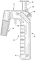
複数の図を通じて同様な数字が同様もしくは対応する部材を示している各図を参照すると、図1〜3は、液体の正確なピペット操作を容易とするピペット制御装置10の代表的実施形態を示す。ピペット制御装置10は、好ましくはプラスチック材料により成形され、好ましくは拳銃状の握りを備えたほぼ逆L字形の形状を有して形成されているハウジングアセンブリ20を含む。本発明の組立およびその要素の置換を容易とするために、ハウジングアセンブリ20は一般に、2つの部分すなわち半分21および23でできている。ハウジングアセンブリ20は、首部22および握り部24を含む。ピペット制御装置10はさらに、ピペット32をハウジングアセンブリ20と脱離可能に連結するためのピペットコネクタアセンブリ30および、液体の容積測定吸引および分注を制御するポンプユニットまたはアセンブリ40を含む。
Referring to the figures where like numerals indicate like or corresponding parts throughout the several views, FIGS. 1-3 illustrate an exemplary embodiment of a
コネクタアセンブリ30は、ハウジングアセンブリ20の首部22から外方に延出して図示されている。このようなハウジングアセンブリの形状により、ピペット32の動きおよび位置決めに対する向上された制御を使用者に提供し、より詳細には、ピペット先端34の正確な位置決めを容易とする。加えて、逆L字形形状は、ピペット32の液位36を監視する際の使用者のピペット制御装置10の操作の同時視覚的監視を向上する。この人間工学的に有益な構成はまた、使用者が中立的な手首位置を維持し、ピペット制御装置10の操作中に手首を上下または左右に曲げるのを最小限に留めることを可能にする。
好ましい実施形態において、コネクタアセンブリ30は、好ましくはゴムまたはシリコーンといった弾性材料で作られているフレキシブルなピペットコネクタ42とともに形成される。フレキシブルなピペットコネクタ42は一般に、ハウジングアセンブリ20の首部22の延出開口48内に挿入される第1の端部44および、ピペット32を受入れるため第2の端部46を有している。首部22へのコネクタアセンブリ30の取付を容易とするために、外ねじの形態とすることができる取付構造が開口48に設けられている。長手方向流路55がコネクタ42の内部に設けられ、第1の端部44と第2の端部46とを相互連結している。内ねじが切られた第1の端部52を有するノーズコーン50が、フレキシブルなピペットコネクタ42をハウジングアセンブリ20に脱離可能に固定する。作用開口53がコネクタ42の壁を貫通している。この特徴については本書において後述する。
In a preferred embodiment, the
ノーズコーン50が首部22に取付けられた状態で、ピペット32の口端60が、使用されるピペット32の外径より若干小さくてよい拡張可能な開口または流路54を備えるフレキシブルなピペットコネクタ42の第2の端部46に挿入される。ピペット32の口端60がフレキシブルなピペットコネクタ42の流路54に挿入されると、流路54は外方に拡張し、材料の弾性によってピペット32が定位置にしっかりと保持される。加えて、フレキシブルなピペットコネクタ42とピペット32との間にシールが形成され、それがピペット制御システム10内への外部空気の漏れおよび、それに伴うピペット先端34からの液体の漏れを防ぐ。
With the
ピペットコネクタアセンブリ30はまた、ピペットを位置決めし安定させる働きもし、膜フィルタまたは疎水性フィルタといった任意のフィルタ(図示せず)を備え得る。図面に示すように、ピペットコネクタアセンブリ30は、握り部24とほぼ平行でそれに隣り合うようになる位置に取付けられたピペット32を保持するためにハウジングアセンブリ20の首部22に固定されている。それに代えて、ピペットコネクタアセンブリ30は、他の装置によってハウジングアセンブリ20の首部に取付けることもできる。例えば、それは、使用者がピペット32と握り部24との間の角度を変えられるようにする旋回継手によって取付けられ得る。
好ましい実施形態において、ポンプアセンブリ40は、ピペット32に液体を吸引または引き込む低圧真空源および、試験のためにピペット32から一連のウェルへの液体のアリコートの分注を容易とする高圧空気源を提供する。ポンプアセンブリ40は、連結装置またはエアチューブ70によってフレキシブルなピペットコネクタ42の第1の端部44に連結されている。
In a preferred embodiment, the
ポンプアセンブリ40の主要要素には、シリンダー・プランジャサブアセンブリまたはユニット80および、それと関係する機械的駆動システム90がある。シリンダー・プランジャサブアセンブリまたはユニット80は、ほぼ中空のシリンダー84内で摺動可能なプランジャ82から構成される。この動きは、プランジャ82とシリンダーの底81との間のシリンダー84の内部空間内に形成される作用室100にある空気の圧縮または膨張をもたらす。機械的駆動システム90は、ラック部材94と噛み合うピニオン96と同軸に連結されているサムホイール92を含む。明確に図示した通り、ラック構造94はプランジャ82の一部を形成する。サムホイール92は、回転運動を行うものであり、握り部24の内部内に配置されていると同時に、使用者の指が都合よく届くようにハウジングアセンブリ20の外部に露出している。作用において、機械的駆動システム90は、サムホイール92およびそれと関係するピニオン96の回転運動をラック構造94およびプランジャ82の長手方向の並進運動に変換する。本発明の好ましい実施形態において機械的駆動システム90はラックおよびピニオンの組合せの形態であるが、他の形態の駆動装置の利用も考えられることに留意しなければならない。例えば、機械的駆動システム90は歯車列の形態とすることができる。
Key components of the
サムホイール92およびピニオン96が1方向(本実施形態の例では反時計回り)で回されると、それらの動きは、ラック94の動きおよび、シリンダー84内でのその底部81に向けたプランジャ82の動きに変換され(矢印Aで図示された)、その結果、内部に形成された開放空間または作用室100を縮小させる。この動きは空気を圧縮し、空気は、シリンダー84を出ると、フレキシブルなエアチューブ70または他の空気連結装置を通過して、フレキシブルなピペットコネクタ42に誘導される。さらに、圧縮空気は、フレキシブルなピペットコネクタ42の長手方向流路55を通過し、ピペット32内にある液体を漸増的に放出するように機能する。他方、サムホイール92およびピニオン96が反対方向(本実施形態の例では時計回りに)に回されると、プランジャ82は、(矢印Bで図示されたように)シリンダー84の底部81から離れて動かされ、その結果、作用室100は拡張し、内部に低圧または真空領域を形成する。この動きにおいて、空気または気体は、シリンダー84の底部81とプランジャ82との間の作用室100の空間に入って蓄積し得る。出口95の制限的性質を考慮して、(矢印Aに従った)プランジャ82の下方運動は作用室100からの空気または気体の段階的な圧縮および放出を生じさせ、それはその下方への動き対して増大する抵抗をもたらす。このようにして、プランジャ82の(矢印Aに従った)下方への動きは、圧縮空気または気体の作用によって減速されて、液体が制御された態様でピペットから放出されることになる。これは転じて、サムホイール92および駆動システム90が利用される際に、本発明の装置からの液体の過度な分注速度を防ぐ。
When the
図3〜5に例示されたように、サムホイール92が反対方向に(または時計回りに)回されてプランジャ82を矢印Bの方向でシリンダー84の底部81から離れるように移動させると、吸引作用が得られる。この動きにおいて、シリンダー84内の作用室100の空間は増大し、その結果、内部での減圧領域または真空の形成を可能とするする。こうした真空力は、連結装置またはフレキシブルなエアチューブ70を通じて伝えられ、第1の端部44の開口102を通じてフレキシブルなピペットコネクタ42の長手方向流路55に達する。減圧領域または真空は、フレキシブルなピペットコネクタ42内に吸引を生じ、外部容器からピペット32への液体の吸引または引き込みをもたらす。このようにして、液体は上方へ誘導され、それによってピペット32を部分的または完全に満たす。
As illustrated in FIGS. 3-5, when the
実験室環境において、ピペット32内に引き込まれ、その後そこから放出される液体の量はしばしば、極めて慎重に較正されなければならない。これは、特定の操作段階において、ピペット制御システム10が極めて精確な量の液体を正確に受入れて放出できなければならないことを意味する。サムホイール92の回転運動速度および/または量によって、どれほどの量を、またはどれほどの速さで液体を引き込むかまたは分注するかが制御されるので、ポンプアセンブリ40の感度および精度は、機械的駆動システム90の特定の特性を変更することによって使用者の要求に適合するように選定および/または調整され得る。例えば、これは、サムホイール92と機械的ラックアセンブリ94との間の歯車比を変えることによって調整できる。本発明の特定の実施形態において、サムホイール92は本質的に脱着可能であり、それは使用者に、異なる駆動比を有する種々のラック・ピニオン構造を使用する選択肢を提供する。
In a laboratory environment, the amount of liquid drawn into and subsequently discharged from the
一例として、本発明の特定の実施形態において、サムホイール92は、相当数の歯を有するピニオン96と同軸に結合されるのに対し、他の実施形態では、第2のサムホイール(図示せず)がより少ない歯を有するピニオン(図示せず)と同軸に連結され得る。実施形態の各々において、ピニオンは同じ機械的ラックアセンブリ94とかみ合うが、第1のサムホイールの回転運動は、第2のサムホイールの同じ角度の回転運動がもたらすものとは異なる程度のプランジャ82の並進運動をもたらす。
By way of example, in certain embodiments of the present invention,
ピペット制御システム10の精度を制御するための他の方法が考えられることに留意しなければならない。例えば、サムホイールおよびピニオンアセンブリは、機械的ラックアセンブリの特定の特性が調整される一方で一定に保たれ、それによって使用者がプランジャの動きの同様な範囲および制御を、従って上述と同様な範囲のピペット操作精度を得ることを可能にする。
It should be noted that other methods for controlling the accuracy of the
重要なことは、図6〜11に最良に例示された通り、ピペット制御システムの精度を調整できることに加えて、本発明の汎用性は、ピペット操作される液体のある特定の量に対する装置の容量を使用者が調整できる場合に向上される。一般にピペット制御装置10のハウジングアセンブリ20、より詳細には握り部24の内部は、種々の形式のシリンダー・プランジャユニットまたはアセンブリを収容できるように形成されており、各ユニットまたはアセンブリは所定の容積容量を有して形成される。
Importantly, as best illustrated in FIGS. 6-11, in addition to being able to adjust the accuracy of the pipette control system, the versatility of the present invention is a result of the device's capacity for a particular volume of pipetted liquid. It is improved when the user can adjust. Generally, the interior of the
本発明の好ましい実施形態において握り部の内部部分は少なくとも以下の3種類のシリンダーを収容する。約25mlの内容積または作用容積を有する第1のシリンダー、約10mlの内容積または作用容積を有する第2のシリンダー、約2mlの内容積または作用容積を有する第3のシリンダー。本発明の好ましい実施形態はこれらの3種類のシリンダーに関して説明するが、多数の他のシリンダーの本発明での利用も考えられることは明白である。図3〜7に最良に示されるように、最大の容積容量を有する第1のシリンダー110は、ハウジングアセンブリ20の握り部分24の内部領域内にぴったり嵌まっている。他方、他のシリンダー120および130の外周および/または直径(例えば図8〜11参照)は、第1のシリンダー110の外径よりも小さい。しかし、本発明の装置の信頼できる動作を付与するために、これらの小さいシリンダーも大きいシリンダー110と同様に握り部24の同じ内部領域内に安定して受入れられなければならない。小さいシリンダーと握り部の内部との間の付加的な空間を埋め合わせるために、小さいシリンダー120および130は、以下に述べるように、特殊な固定装置によってハウジングの内部内に固定して位置決めされる。
In a preferred embodiment of the invention, the inner part of the handle contains at least the following three types of cylinders. A first cylinder having an internal or working volume of about 25 ml, a second cylinder having an internal or working volume of about 10 ml, and a third cylinder having an internal or working volume of about 2 ml. Although the preferred embodiment of the present invention will be described with respect to these three types of cylinders, it will be apparent that many other cylinders are contemplated for use with the present invention. As best shown in FIGS. 3-7, the
本発明の構成要素を適正に収容するために、握り部24の内部は長手方向仕切り27によって、一般に弧状横断面を有する主区画29と補助区画35とに分離されている。本発明の組立状態において明確に例示された通り、主区画29は主にシリンダー110、120、130を収容するのに対し、補助区画35は握り部24内を長手方向に延びるエアチューブ70の一部を受入れる。第1のシリンダー110は、それが握り部24の主区画29の湾曲した内部部分のほぼ全体または相当部分を占めるように相当の外径112を有する(図3〜6参照)。第2のシリンダー120および第3のシリンダー130は、第1のシリンダーの外径112に比べて著しく小さい外径122、132を有して形成されている。しかし、全部のシリンダーは、握り部24の内部領域の同じ主区画29を占有しなければならない。小さいシリンダー120、130は、握り部24の内部内に第1のシリンダー110と同様に受入れられるように固定装置が形成されている。図6〜11に示されるように、この固定装置は、各シリンダーの外壁から外方に拡張するフランジまたはフィンの形態をしている。本発明の好ましい実施形態において、小さいシリンダー120、130は各々、それらから外方に拡張する少なくとも1対のフランジまたはフィン124a、124bおよび134a、134bを備えて形成されている。図9および11の断面図に明確に示された通り、固定装置の各フィンには、湾曲した内部主区画29内に小さいシリンダーを安定させる安定化アーチ形部分117、137および、握り部24の内部にわたって内壁から拡張する拘束リブ25と係合するための係合部分119、139が形成されている。係合部分119、139の主機能は、それらが拘束リブ140、142と係合した時に、握り部24の内部部分内でのそれぞれのシリンダーの長手方向移動を防止することである。他方、安定化部分117、137の主機能は、主区画29内に小さいシリンダーを位置決めしたときにできる余分な空間を埋め合わせ、係合部分との組合せにより、それぞれのシリンダーの横方向の移動を防止することである。明らかに、フィンまたはフランジの種々の組合せが本発明によって受入れられ得る。例えば、より良好な安定性を付与するために、第2または中間シリンダー120は第2の対のフィン126a、126bを備える(図8参照)。
To properly accommodate the components of the present invention, the interior of the
ここで図6を参照すると、第1のシリンダー110には、小径シリンダーのそれに類似の、2対のフィン114a、116aおよび114b、116bが形成されており、それらは1対の受入れ部分またはスロット1l8a、ll8bを形成する。スロット118a、118bは、握り部24の内部から延びていて、第1のシリンダー110をハウジングアセンブリ20内に確実に着座させる作用を行う、1対の拘束リブまたはフィン140、142と係合する。逆のフィン/スロット構成もまた考えられることに留意しなければならない。例えば、握り部の内部は、第1のシリンダー110の外側に設けられたフィンを受入れるための2つのスロットまたは受入れ構造を備え得る。
Referring now to FIG. 6, the
2つの部分または半分21、23を有するハウジングアセンブリ20の形成は、ポンプアセンブリ40、エアチューブ70および/またはピペットコネクタアセンブリ30といった本発明の構成要素の取替えまたは交換を容易とする。これらの要素の取替えは、ピペット32からの液体によるその汚染、通常の摩耗または、上述のように異なる容量または容積のシリンダー・プランジャ装置が必要とされる時に、必要になり得る。ポンプアセンブリ40、連結装置またはエアチューブ70およびピペットコネクタアセンブリ30は、使い捨て品として製造され、ピペット制御システム10においてそれらの取替えを容易とするために互いに即座に脱離可能に構成され得る。
The formation of the
ここで図12を参照すると、本発明の別の実施形態が示されている。液体の精確な測定が分注プロセスの際に必要とされる場合、機械的駆動システム90と関係する上述のサムホイール装置92が利用される。このようにして、液体は、制御された滴下態様で分注され得る。しかし、特定の状況において、液柱の相当量または全量が迅速にピペット管32から放出されなければならない場合、迅速放出機構150(例えば図12参照)を作動させる。
Referring now to FIG. 12, another embodiment of the present invention is shown. If an accurate measurement of the liquid is required during the dispensing process, the above described
迅速放出機構150は、ピペットコネクタアセンブリ30と連係する第1の係合端部160および、付勢部材またはばね装置170と連係する第2の係合端部162が形成されたプラグまたは係合部材151を含む。引金152が、案内室153の壁を貫通してプラグまたは係合部材154から外方に延出している。プラグまたは係合部材154は、首部22の底部領域に形成された案内室153内で長手方向流路55に対し横方向に開位置と閉位置との間およびその逆にスライド可能となっている。迅速放出機構が閉位置では、第1の端部160は、フレキシブルなピペットコネクタ42内に設けられた作用開口53内にぴったりと受入れられ、それを密封して閉じるようになっている。従って、ピペット32に液体が少なくとも部分的に満たされた時、ピペット32の内部領域、長手方向流路55およびエアチューブ70を包含する本発明の装置の作用通路は、外部環境からシールされる。この状態は、サムホイール装置92の操作による液体の段階的放出のために要求される。使用者が引金152を引くことによって迅速放出機構150が作動されると、プラグまたは係合部材154はその閉位置から開位置に動かされ、ばね装置170の圧縮を生じさせ、その結果、第1の係合端部160を作用開口53から解離させる。これは、フレキシブルなピペットコネクタ42の内部に形成された長手方向流路55を周囲大気と連通可能にする。周囲空気がフレキシブルなピペットコネクタ42の内部に入ると、作用通路に存在している真空は解放される。このようにして、重力がピペット32からの液体の迅速な分注を助ける。
The
機械的駆動システム90と関係したサムホイール装置92による液体の制御された取扱いに戻るには、引金152が解放される。この状態で、付勢部材またはばね170はプラグまたは係合部材154をピペットコネクタアセンブリ30に向けて押し、第1の係合端部160がフレキシブルなピペットコネクタ42の作用開口53をシールして閉じる。従って、真空または低圧状態が装置の作用通路に再確立され得る。
To return to the controlled handling of the liquid by the
前述の通り、試験プロセスの要求条件に適合するための特定の状況では、ピペット32内に含まれる吸引した液体のほぼ全量を迅速に分注することが望ましい。こうした場合、ピペット操作速度を増すことに加えて、使用者が上述のようにサムホイールを反復的に操作する必要なくピペットから液体を迅速に一掃できるようにすることは、人間工学的に有益である。この理由および他の理由で、迅速放出機構150は、ピペットコネクタアセンブリ30およびピペット32内の真空を解放するために効率的に利用され得る。引金152を作動させることによって、ピペットコネクタアセンブリ30を密閉するプラグ154が引き戻される。この動きにより、フレキシブルなピペットコネクタ42の作用開口53が開き、真空が解放され、その結果、重力が優勢になり、それがピペット32から液体を解放/放出させる。
As mentioned above, in certain situations to meet the requirements of the test process, it is desirable to dispense a substantially entire volume of the aspirated liquid contained within the
本発明を特定の実施形態に関して説明したが、当業者は、本発明の精神および範囲を逸脱することなく形態および詳細において変更が行い得ることを認識するであろう。従って、説明された実施形態はすべての点で例示的なものにすぎず、制限的なものではないとみなすべきである。それゆえ、本発明の範囲は、上述の説明によってではなく、特許請求の範囲の請求項によって示される。請求項の均等物の意味および範囲内にあるあらゆる変更は、それらの範囲内に包含される。 Although the present invention has been described with respect to particular embodiments, those skilled in the art will recognize that changes may be made in form and detail without departing from the spirit and scope of the invention. Therefore, the described embodiments are to be considered in all respects only as illustrative and not restrictive. The scope of the invention is, therefore, indicated by the appended claims rather than by the foregoing description. All changes that come within the meaning and range of equivalents of the claims are to be embraced within their scope.
10 ピペット制御装置
20 ハウジングアセンブリ
21、23 半分
22 首部
24 握り部
25 拘束リブ
27 縦方向仕切り
29 主区画
30 ピペットコネクタアセンブリ
32 ピペット
34 ピペット先端
35 補助区画
40 ポンプアセンブリ
42 フレキシブルなピペットコネクタ
44 第1の端部
46 第2の端部
48 延出開口
50 ノーズコーン
52 第1の端部
53 作用開口
54 流路
55 長手方向流路
60 口端
70 フレキシブルなエアチューブ
80 シリンダー・プランジャユニット
81 底部
82 プランジャ
84 シリンダー
90 機械的駆動システム
92 サムホイール
94 機械的ラックアセンブリ
95 出口
96 ピニオン
100 作用室
102 開口
110、120、130 シリンダー
114a、116a フィン
117、137 安定化部分
118a、118b スロット
119、139 係合部分
124a、124b フィン
126a、126b フィン
140、142 拘束リブ(フィン)
150 迅速放出機構
151 係合部材
152 引金
153 案内室
154 プラグ
160 第1の係合端部
162 第2の係合端部
170 付勢部材
150 quick release mechanism 151 engaging
Claims (20)
ハウジングアセンブリと、
ハウジングアセンブリに連結されたポンプアセンブリとを含み、ポンプアセンブリは、複数でかつ特定容積の取り外し可能に連結されたシリンダー・プランジャユニットを独立して収容するピペット制御装置。 A pipette controller for controlling volumetric aspiration and / or dispensing of a liquid by a pipette, comprising:
A housing assembly;
A pump assembly coupled to the housing assembly, the pump assembly independently accommodating a plurality of removably coupled cylinder and plunger units of a specific volume.
ピペットから液体の少なくとも一部を迅速に放出するための迅速放出機構とをさらに含む、請求項1記載のピペット制御装置。 A pipette connector formed with a first end coupled to the pump assembly by a coupling device and a second end for receiving a pipette;
A quick-release mechanism for rapidly releasing at least a portion of the liquid from the pipette.
ハウジングアセンブリと、
ハウジングアセンブリに連結されたポンプアセンブリと、
ポンプアセンブリに連結されていて、ピペットを受入れるためのピペットコネクタと、
ピペットから液体の少なくとも一部を迅速に放出するための迅速放出機構とを含む、ピペット制御装置。 A pipette controller,
A housing assembly;
A pump assembly coupled to the housing assembly;
A pipette connector coupled to the pump assembly for receiving the pipette;
A rapid release mechanism for rapidly releasing at least a portion of the liquid from the pipette.
20. The pipette controller of claim 19, wherein the mechanical drive assembly includes a thumbwheel pinion subassembly and a plunger mounting rack structure coupled to the thumbwheel pinion subassembly.
Applications Claiming Priority (2)
| Application Number | Priority Date | Filing Date | Title |
|---|---|---|---|
| US10/435,863 US7093507B2 (en) | 2003-05-12 | 2003-05-12 | Pipette control arrangement |
| US10/435863 | 2003-05-12 |
Publications (2)
| Publication Number | Publication Date |
|---|---|
| JP2004337852A true JP2004337852A (en) | 2004-12-02 |
| JP4884653B2 JP4884653B2 (en) | 2012-02-29 |
Family
ID=33029764
Family Applications (1)
| Application Number | Title | Priority Date | Filing Date |
|---|---|---|---|
| JP2004141362A Expired - Fee Related JP4884653B2 (en) | 2003-05-12 | 2004-05-11 | Pipette control device |
Country Status (10)
| Country | Link |
|---|---|
| US (1) | US7093507B2 (en) |
| EP (2) | EP1775023A1 (en) |
| JP (1) | JP4884653B2 (en) |
| KR (1) | KR20040097924A (en) |
| CN (1) | CN1572369B (en) |
| AT (1) | ATE350164T1 (en) |
| AU (1) | AU2004201909B8 (en) |
| CA (1) | CA2466256C (en) |
| DE (1) | DE602004003993T2 (en) |
| TW (1) | TWI311925B (en) |
Cited By (4)
| Publication number | Priority date | Publication date | Assignee | Title |
|---|---|---|---|---|
| JP2010531440A (en) * | 2007-06-25 | 2010-09-24 | ジルソン エス.アー.エス. | Pipette that samples liquid by the back and forth movement of the piston |
| JP2020525802A (en) * | 2017-06-26 | 2020-08-27 | メンドーサ, エステバンMENDOZA, Estevan | Sample filter |
| JP2020529211A (en) * | 2017-08-04 | 2020-10-08 | アーエルエス オートメーティド ラブ ソルーションズ ゲーエムベーハー | Use of adapters and adapters to house capillaries |
| JP7555633B1 (en) | 2023-10-06 | 2024-09-25 | 国立大学法人鳥取大学 | Micropipette System |
Families Citing this family (15)
| Publication number | Priority date | Publication date | Assignee | Title |
|---|---|---|---|---|
| PL200761B1 (en) * | 2003-07-24 | 2009-02-27 | Pz Htl Spo & Lstrok Ka Akcyjna | Pipette replaceable tip ejector unit |
| US20080223209A1 (en) * | 2007-03-16 | 2008-09-18 | Tricontinent Scientific | Syringe barrel wiper for liquid dispensing |
| FR2920675B1 (en) * | 2007-09-10 | 2010-12-03 | Gilson Sas | MULTICHANNEL PIPETTING SYSTEM COMPRISING AN IMPROVED GUIDE PISTON HOLDER |
| JP5550719B2 (en) | 2009-04-27 | 2014-07-16 | イーアイ・スペクトラ・エルエルシー | Pipette equipment |
| US8475739B2 (en) | 2011-09-25 | 2013-07-02 | Theranos, Inc. | Systems and methods for fluid handling |
| US9632102B2 (en) | 2011-09-25 | 2017-04-25 | Theranos, Inc. | Systems and methods for multi-purpose analysis |
| US9664702B2 (en) | 2011-09-25 | 2017-05-30 | Theranos, Inc. | Fluid handling apparatus and configurations |
| US20140170735A1 (en) | 2011-09-25 | 2014-06-19 | Elizabeth A. Holmes | Systems and methods for multi-analysis |
| US9810704B2 (en) | 2013-02-18 | 2017-11-07 | Theranos, Inc. | Systems and methods for multi-analysis |
| US10012664B2 (en) | 2011-09-25 | 2018-07-03 | Theranos Ip Company, Llc | Systems and methods for fluid and component handling |
| KR20150115391A (en) | 2014-04-04 | 2015-10-14 | 쓰리엠 이노베이티브 프로퍼티즈 캄파니 | Pipetting device |
| DE202017101009U1 (en) * | 2017-02-23 | 2018-05-24 | Brand Gmbh + Co Kg | Attaching and detaching a piston-cylinder unit to or from a dispenser for receiving and dispensing fluid volumes |
| EP3928868A1 (en) * | 2020-06-22 | 2021-12-29 | Eppendorf AG | Pipette for use with a pipette tip or syringe having a piston and a cylinder |
| KR102578537B1 (en) | 2021-02-24 | 2023-09-13 | 충남대학교산학협력단 | Shake control device for pipette use |
| CN113976198A (en) * | 2021-10-29 | 2022-01-28 | 美东汇成生命科技(昆山)有限公司 | Multifunctional liquid transfer suction head |
Citations (2)
| Publication number | Priority date | Publication date | Assignee | Title |
|---|---|---|---|---|
| JPH08187438A (en) * | 1992-06-24 | 1996-07-23 | Labsystems Oy | Drop pipette |
| EP0873790A2 (en) * | 1997-04-24 | 1998-10-28 | Walu Labortechnik GmbH | Pipette |
Family Cites Families (28)
| Publication number | Priority date | Publication date | Assignee | Title |
|---|---|---|---|---|
| US2517796A (en) | 1945-11-28 | 1950-08-08 | Waddy T Mathis | Liquid-measuring dispenser |
| US3660037A (en) * | 1970-08-10 | 1972-05-02 | Kurt Rudolf Sokol | Device for measuring blood sedimentation rate |
| US3954014A (en) * | 1974-12-16 | 1976-05-04 | Becton, Dickinson And Company | Multiple shot pipetter |
| US3963061A (en) * | 1975-09-16 | 1976-06-15 | Drummond Scientific Company | Apparatus for drawing liquids into, and expelling liquids from a pipette |
| DE2851532C2 (en) | 1978-11-29 | 1981-02-19 | Boehringer Mannheim Gmbh, 6800 Mannheim | Pipette with elastic bellows |
| FI59343C (en) * | 1979-01-23 | 1981-08-10 | Suovaniemi Finnpipette | FLERDOSPIPETT |
| US4257268A (en) | 1979-08-24 | 1981-03-24 | Data Packaging Corporation | Pipetter |
| US4527437A (en) * | 1983-07-06 | 1985-07-09 | Wescor, Inc. | Pipette controller |
| CN86210246U (en) * | 1986-12-15 | 1988-03-16 | 楼许柏 | Multipurpose liquid aspirator |
| US4988481A (en) | 1989-01-30 | 1991-01-29 | Labsystems Oy | Electrical pipette |
| US4926717A (en) | 1989-09-05 | 1990-05-22 | Manostat Corporation | Bottle uncapping and recapping machine |
| US5104624A (en) | 1989-10-20 | 1992-04-14 | Costar Corporation | Pipetter |
| US5090255A (en) * | 1990-03-27 | 1992-02-25 | Drummond Scientific Company | Programmable pipet apparatus |
| DE4141608C2 (en) | 1991-12-17 | 1993-12-02 | Eppendorf Geraetebau Netheler | Pipetting device |
| US5294405A (en) * | 1992-04-09 | 1994-03-15 | Drummond Scientific Company | Adjustable valve for pipette gun |
| US5364596A (en) | 1992-12-01 | 1994-11-15 | Rainin Instrument Co., Inc. | Manual pipette with plunger velocity governor, home position latch and trigger release |
| US5509318A (en) | 1993-10-13 | 1996-04-23 | Manostat Corporation | Memory Mopet |
| FR2723700B1 (en) | 1994-08-16 | 1996-11-15 | Marteau D Autry Eric | PIPETTE FOR DISPENSING SUCCESSIVE LIQUID VOLUMES |
| FI951766A0 (en) | 1995-04-12 | 1995-04-12 | Labsystems Oy | Faspipett |
| JP3699749B2 (en) | 1995-06-09 | 2005-09-28 | セーラー万年筆株式会社 | pipette |
| US5650124A (en) | 1995-07-24 | 1997-07-22 | Gilson; Warren E. | Adjustable pipette |
| US5616871A (en) | 1995-09-28 | 1997-04-01 | Drummond Scientific Company | Pipet gun assembly |
| US5849248A (en) | 1996-03-05 | 1998-12-15 | Rainin Instrument Co., Inc. | Adjustable volume pipette with improved volume adjustment lock mechanism |
| FI961649A0 (en) | 1996-04-15 | 1996-04-15 | Labsystems Oy | Spaerrpipett |
| US5983733A (en) | 1996-11-15 | 1999-11-16 | Hamilton Company | Manual pipette |
| FI105783B (en) | 1998-08-26 | 2000-10-13 | Biohit Oyj | Method and apparatus for dispensing fluid |
| US6299841B1 (en) | 1999-03-05 | 2001-10-09 | Rainin Instrument Co., Inc. | Bilaterally symmetrical battery powered microprocessor controlled lightweight hand-holdable electronic pipette |
| US6365110B1 (en) | 2000-03-09 | 2002-04-02 | Rainin Instrument | Blowout springless manual air displacement pipette with mechanical assist for aiding in locating and maintaining pipette plunger at a home position |
-
2003
- 2003-05-12 US US10/435,863 patent/US7093507B2/en not_active Expired - Lifetime
-
2004
- 2004-04-20 EP EP07000018A patent/EP1775023A1/en not_active Withdrawn
- 2004-04-20 DE DE602004003993T patent/DE602004003993T2/en not_active Expired - Lifetime
- 2004-04-20 EP EP04252316A patent/EP1477227B1/en not_active Expired - Lifetime
- 2004-04-20 AT AT04252316T patent/ATE350164T1/en not_active IP Right Cessation
- 2004-04-23 TW TW093111418A patent/TWI311925B/en active
- 2004-05-03 CA CA2466256A patent/CA2466256C/en not_active Expired - Lifetime
- 2004-05-05 AU AU2004201909A patent/AU2004201909B8/en not_active Ceased
- 2004-05-11 KR KR1020040033193A patent/KR20040097924A/en not_active Application Discontinuation
- 2004-05-11 JP JP2004141362A patent/JP4884653B2/en not_active Expired - Fee Related
- 2004-05-12 CN CN2004100435851A patent/CN1572369B/en not_active Expired - Fee Related
Patent Citations (2)
| Publication number | Priority date | Publication date | Assignee | Title |
|---|---|---|---|---|
| JPH08187438A (en) * | 1992-06-24 | 1996-07-23 | Labsystems Oy | Drop pipette |
| EP0873790A2 (en) * | 1997-04-24 | 1998-10-28 | Walu Labortechnik GmbH | Pipette |
Cited By (6)
| Publication number | Priority date | Publication date | Assignee | Title |
|---|---|---|---|---|
| JP2010531440A (en) * | 2007-06-25 | 2010-09-24 | ジルソン エス.アー.エス. | Pipette that samples liquid by the back and forth movement of the piston |
| JP2020525802A (en) * | 2017-06-26 | 2020-08-27 | メンドーサ, エステバンMENDOZA, Estevan | Sample filter |
| US11946843B2 (en) | 2017-06-26 | 2024-04-02 | Splitrx Llc | Sample filtration device |
| JP2020529211A (en) * | 2017-08-04 | 2020-10-08 | アーエルエス オートメーティド ラブ ソルーションズ ゲーエムベーハー | Use of adapters and adapters to house capillaries |
| US11738335B2 (en) | 2017-08-04 | 2023-08-29 | Als Automated Lab Solutions Gmbh | Adapter for receiving a capillary |
| JP7555633B1 (en) | 2023-10-06 | 2024-09-25 | 国立大学法人鳥取大学 | Micropipette System |
Also Published As
| Publication number | Publication date |
|---|---|
| TW200505578A (en) | 2005-02-16 |
| US7093507B2 (en) | 2006-08-22 |
| EP1775023A1 (en) | 2007-04-18 |
| CN1572369B (en) | 2010-06-09 |
| AU2004201909B8 (en) | 2009-11-26 |
| CA2466256C (en) | 2013-07-09 |
| JP4884653B2 (en) | 2012-02-29 |
| CN1572369A (en) | 2005-02-02 |
| DE602004003993D1 (en) | 2007-02-15 |
| EP1477227A2 (en) | 2004-11-17 |
| EP1477227B1 (en) | 2007-01-03 |
| US20040226389A1 (en) | 2004-11-18 |
| ATE350164T1 (en) | 2007-01-15 |
| KR20040097924A (en) | 2004-11-18 |
| DE602004003993T2 (en) | 2007-06-21 |
| EP1477227A3 (en) | 2004-12-08 |
| TWI311925B (en) | 2009-07-11 |
| CA2466256A1 (en) | 2004-11-12 |
| AU2004201909B2 (en) | 2009-11-19 |
| AU2004201909A1 (en) | 2004-12-02 |
Similar Documents
| Publication | Publication Date | Title |
|---|---|---|
| JP4884653B2 (en) | Pipette control device | |
| US4776840A (en) | Hand-held medical evacuator and irrigation device | |
| US3405843A (en) | Container-dispenser for collapsible tubes | |
| US3855867A (en) | Liquid transfer pipetting device | |
| US4527437A (en) | Pipette controller | |
| JP6169862B2 (en) | Pipetting device and manufacturing method thereof | |
| WO2007020624A1 (en) | Fluid supply for endoscope | |
| JPH06255700A (en) | Distributor | |
| US20080199361A1 (en) | Hand-held pipetting device | |
| US5817955A (en) | Apparatus for simultaneous aspiration and dispensation of fluids | |
| JP2018513734A (en) | Mixing group and method for mixing two compounds | |
| US4883476A (en) | Drainage device with disposable collection chamber | |
| JP5005278B2 (en) | Multi-chamber dispensing device | |
| RU2217235C2 (en) | Suction unit and method of proportioning liquid by means of this unit | |
| DK2207518T3 (en) | Portable blood chemistry analyzer including a solution bag | |
| CN109893687B (en) | Waste collection equipment and waste collection treatment system | |
| US5085345A (en) | Hydraulic dispenser | |
| US4294125A (en) | Pipette controller with graduate reading plunger and lever assembly for gravity drainage | |
| CN213726594U (en) | Quantitative sampling test tube | |
| US3881360A (en) | Measuring dispensing device | |
| CN108324330B (en) | Cross infection preventing multifunctional body fluid collecting and inspecting device | |
| US5096093A (en) | Hand held hydraulic dispenser | |
| US3250441A (en) | Liquid-dispensing apparatus | |
| JP6885949B2 (en) | Drop device and method of forming it | |
| US20040241022A1 (en) | Laboratory pump unit |
Legal Events
| Date | Code | Title | Description |
|---|---|---|---|
| A621 | Written request for application examination |
Free format text: JAPANESE INTERMEDIATE CODE: A621 Effective date: 20070511 |
|
| A131 | Notification of reasons for refusal |
Free format text: JAPANESE INTERMEDIATE CODE: A131 Effective date: 20100420 |
|
| A601 | Written request for extension of time |
Free format text: JAPANESE INTERMEDIATE CODE: A601 Effective date: 20100714 |
|
| A602 | Written permission of extension of time |
Free format text: JAPANESE INTERMEDIATE CODE: A602 Effective date: 20100720 |
|
| A521 | Request for written amendment filed |
Free format text: JAPANESE INTERMEDIATE CODE: A523 Effective date: 20100818 |
|
| A131 | Notification of reasons for refusal |
Free format text: JAPANESE INTERMEDIATE CODE: A131 Effective date: 20101026 |
|
| A521 | Request for written amendment filed |
Free format text: JAPANESE INTERMEDIATE CODE: A523 Effective date: 20110120 |
|
| TRDD | Decision of grant or rejection written | ||
| A01 | Written decision to grant a patent or to grant a registration (utility model) |
Free format text: JAPANESE INTERMEDIATE CODE: A01 Effective date: 20111122 |
|
| A01 | Written decision to grant a patent or to grant a registration (utility model) |
Free format text: JAPANESE INTERMEDIATE CODE: A01 |
|
| A61 | First payment of annual fees (during grant procedure) |
Free format text: JAPANESE INTERMEDIATE CODE: A61 Effective date: 20111207 |
|
| FPAY | Renewal fee payment (event date is renewal date of database) |
Free format text: PAYMENT UNTIL: 20141216 Year of fee payment: 3 |
|
| R150 | Certificate of patent or registration of utility model |
Free format text: JAPANESE INTERMEDIATE CODE: R150 Ref document number: 4884653 Country of ref document: JP Free format text: JAPANESE INTERMEDIATE CODE: R150 |
|
| R250 | Receipt of annual fees |
Free format text: JAPANESE INTERMEDIATE CODE: R250 |
|
| R250 | Receipt of annual fees |
Free format text: JAPANESE INTERMEDIATE CODE: R250 |
|
| R250 | Receipt of annual fees |
Free format text: JAPANESE INTERMEDIATE CODE: R250 |
|
| R250 | Receipt of annual fees |
Free format text: JAPANESE INTERMEDIATE CODE: R250 |
|
| R250 | Receipt of annual fees |
Free format text: JAPANESE INTERMEDIATE CODE: R250 |
|
| R250 | Receipt of annual fees |
Free format text: JAPANESE INTERMEDIATE CODE: R250 |
|
| R250 | Receipt of annual fees |
Free format text: JAPANESE INTERMEDIATE CODE: R250 |
|
| R250 | Receipt of annual fees |
Free format text: JAPANESE INTERMEDIATE CODE: R250 |
|
| LAPS | Cancellation because of no payment of annual fees |