JP2020509839A - Needle insertion due to overpressure - Google Patents
Needle insertion due to overpressure Download PDFInfo
- Publication number
- JP2020509839A JP2020509839A JP2019548732A JP2019548732A JP2020509839A JP 2020509839 A JP2020509839 A JP 2020509839A JP 2019548732 A JP2019548732 A JP 2019548732A JP 2019548732 A JP2019548732 A JP 2019548732A JP 2020509839 A JP2020509839 A JP 2020509839A
- Authority
- JP
- Japan
- Prior art keywords
- needle
- housing
- base
- pressure
- retracted position
- Prior art date
- Legal status (The legal status is an assumption and is not a legal conclusion. Google has not performed a legal analysis and makes no representation as to the accuracy of the status listed.)
- Pending
Links
- 238000003780 insertion Methods 0.000 title claims abstract description 139
- 230000037431 insertion Effects 0.000 title claims abstract description 139
- 230000007246 mechanism Effects 0.000 claims abstract description 174
- 238000012377 drug delivery Methods 0.000 claims abstract description 61
- 239000012530 fluid Substances 0.000 claims description 47
- 238000000034 method Methods 0.000 claims description 40
- 238000007789 sealing Methods 0.000 claims description 36
- 102000004169 proteins and genes Human genes 0.000 description 44
- 108090000623 proteins and genes Proteins 0.000 description 44
- 102000005962 receptors Human genes 0.000 description 17
- 108020003175 receptors Proteins 0.000 description 17
- 239000003814 drug Substances 0.000 description 13
- 108010074604 Epoetin Alfa Proteins 0.000 description 12
- 229940079593 drug Drugs 0.000 description 10
- OXCMYAYHXIHQOA-UHFFFAOYSA-N potassium;[2-butyl-5-chloro-3-[[4-[2-(1,2,4-triaza-3-azanidacyclopenta-1,4-dien-5-yl)phenyl]phenyl]methyl]imidazol-4-yl]methanol Chemical compound [K+].CCCCC1=NC(Cl)=C(CO)N1CC1=CC=C(C=2C(=CC=CC=2)C2=N[N-]N=N2)C=C1 OXCMYAYHXIHQOA-UHFFFAOYSA-N 0.000 description 10
- 102100034980 ICOS ligand Human genes 0.000 description 8
- 102000003951 Erythropoietin Human genes 0.000 description 6
- 108090000394 Erythropoietin Proteins 0.000 description 6
- 108010075944 Erythropoietin Receptors Proteins 0.000 description 6
- 102100036509 Erythropoietin receptor Human genes 0.000 description 6
- 108010017080 Granulocyte Colony-Stimulating Factor Proteins 0.000 description 6
- 102000004269 Granulocyte Colony-Stimulating Factor Human genes 0.000 description 6
- 102000002265 Human Growth Hormone Human genes 0.000 description 6
- 108010000521 Human Growth Hormone Proteins 0.000 description 6
- 239000000854 Human Growth Hormone Substances 0.000 description 6
- XEEYBQQBJWHFJM-UHFFFAOYSA-N Iron Chemical compound [Fe] XEEYBQQBJWHFJM-UHFFFAOYSA-N 0.000 description 6
- 230000008901 benefit Effects 0.000 description 6
- 229960003388 epoetin alfa Drugs 0.000 description 6
- 229940105423 erythropoietin Drugs 0.000 description 6
- 102100021866 Hepatocyte growth factor Human genes 0.000 description 5
- 230000027455 binding Effects 0.000 description 5
- 108010002601 epoetin beta Proteins 0.000 description 5
- 229960001972 panitumumab Drugs 0.000 description 5
- 210000001519 tissue Anatomy 0.000 description 5
- ZJNLYGOUHDJHMG-UHFFFAOYSA-N 1-n,4-n-bis(5-methylhexan-2-yl)benzene-1,4-diamine Chemical compound CC(C)CCC(C)NC1=CC=C(NC(C)CCC(C)C)C=C1 ZJNLYGOUHDJHMG-UHFFFAOYSA-N 0.000 description 4
- 208000019901 Anxiety disease Diseases 0.000 description 4
- 108010008165 Etanercept Proteins 0.000 description 4
- 108010029961 Filgrastim Proteins 0.000 description 4
- 101000884305 Homo sapiens B-cell receptor CD22 Proteins 0.000 description 4
- 101001019455 Homo sapiens ICOS ligand Proteins 0.000 description 4
- 101710093458 ICOS ligand Proteins 0.000 description 4
- 206010028980 Neoplasm Diseases 0.000 description 4
- 102000014128 RANK Ligand Human genes 0.000 description 4
- 108010025832 RANK Ligand Proteins 0.000 description 4
- -1 and analogs thereof Proteins 0.000 description 4
- 230000036506 anxiety Effects 0.000 description 4
- 102000023732 binding proteins Human genes 0.000 description 4
- 108091008324 binding proteins Proteins 0.000 description 4
- 239000003795 chemical substances by application Substances 0.000 description 4
- 108010084052 continuous erythropoietin receptor activator Proteins 0.000 description 4
- 229960004579 epoetin beta Drugs 0.000 description 4
- 108010067416 epoetin delta Proteins 0.000 description 4
- 229950002109 epoetin delta Drugs 0.000 description 4
- 229940125367 erythropoiesis stimulating agent Drugs 0.000 description 4
- 238000002347 injection Methods 0.000 description 4
- 239000007924 injection Substances 0.000 description 4
- 230000000174 oncolytic effect Effects 0.000 description 4
- 102100038080 B-cell receptor CD22 Human genes 0.000 description 3
- 101800000407 Brain natriuretic peptide 32 Proteins 0.000 description 3
- 102100039939 Growth/differentiation factor 8 Human genes 0.000 description 3
- 102000038455 IGF Type 1 Receptor Human genes 0.000 description 3
- 108010031794 IGF Type 1 Receptor Proteins 0.000 description 3
- 102100026261 Metalloproteinase inhibitor 3 Human genes 0.000 description 3
- 108090000445 Parathyroid hormone Proteins 0.000 description 3
- 102000016971 Proto-Oncogene Proteins c-kit Human genes 0.000 description 3
- 108010014608 Proto-Oncogene Proteins c-kit Proteins 0.000 description 3
- 102100034196 Thrombopoietin receptor Human genes 0.000 description 3
- 108010031429 Tissue Inhibitor of Metalloproteinase-3 Proteins 0.000 description 3
- 201000011510 cancer Diseases 0.000 description 3
- 229960001251 denosumab Drugs 0.000 description 3
- 108010081679 epoetin theta Proteins 0.000 description 3
- 229950008826 epoetin theta Drugs 0.000 description 3
- 108010030868 epoetin zeta Proteins 0.000 description 3
- 229950005185 epoetin zeta Drugs 0.000 description 3
- 229910052742 iron Inorganic materials 0.000 description 3
- 229940071846 neulasta Drugs 0.000 description 3
- 229940029345 neupogen Drugs 0.000 description 3
- 108010044644 pegfilgrastim Proteins 0.000 description 3
- 239000000825 pharmaceutical preparation Substances 0.000 description 3
- 229940127557 pharmaceutical product Drugs 0.000 description 3
- 238000003825 pressing Methods 0.000 description 3
- 102000004196 processed proteins & peptides Human genes 0.000 description 3
- 108090000765 processed proteins & peptides Proteins 0.000 description 3
- 230000002829 reductive effect Effects 0.000 description 3
- 230000004936 stimulating effect Effects 0.000 description 3
- 238000003860 storage Methods 0.000 description 3
- FWMNVWWHGCHHJJ-SKKKGAJSSA-N 4-amino-1-[(2r)-6-amino-2-[[(2r)-2-[[(2r)-2-[[(2r)-2-amino-3-phenylpropanoyl]amino]-3-phenylpropanoyl]amino]-4-methylpentanoyl]amino]hexanoyl]piperidine-4-carboxylic acid Chemical compound C([C@H](C(=O)N[C@H](CC(C)C)C(=O)N[C@H](CCCCN)C(=O)N1CCC(N)(CC1)C(O)=O)NC(=O)[C@H](N)CC=1C=CC=CC=1)C1=CC=CC=C1 FWMNVWWHGCHHJJ-SKKKGAJSSA-N 0.000 description 2
- ZKRFOXLVOKTUTA-KQYNXXCUSA-N 9-(5-phosphoribofuranosyl)-6-mercaptopurine Chemical compound O[C@@H]1[C@H](O)[C@@H](COP(O)(O)=O)O[C@H]1N1C(NC=NC2=S)=C2N=C1 ZKRFOXLVOKTUTA-KQYNXXCUSA-N 0.000 description 2
- 102000013455 Amyloid beta-Peptides Human genes 0.000 description 2
- 108010090849 Amyloid beta-Peptides Proteins 0.000 description 2
- 102100034608 Angiopoietin-2 Human genes 0.000 description 2
- 102000004414 Calcitonin Gene-Related Peptide Human genes 0.000 description 2
- 108010019673 Darbepoetin alfa Proteins 0.000 description 2
- 108091006020 Fc-tagged proteins Proteins 0.000 description 2
- 101000924533 Homo sapiens Angiopoietin-2 Proteins 0.000 description 2
- 101000669513 Homo sapiens Metalloproteinase inhibitor 1 Proteins 0.000 description 2
- 101000610604 Homo sapiens Tumor necrosis factor receptor superfamily member 10B Proteins 0.000 description 2
- 108010005716 Interferon beta-1a Proteins 0.000 description 2
- 102000019223 Interleukin-1 receptor Human genes 0.000 description 2
- 108050006617 Interleukin-1 receptor Proteins 0.000 description 2
- 102000051628 Interleukin-1 receptor antagonist Human genes 0.000 description 2
- 108700021006 Interleukin-1 receptor antagonist Proteins 0.000 description 2
- 102000004388 Interleukin-4 Human genes 0.000 description 2
- 108090000978 Interleukin-4 Proteins 0.000 description 2
- 239000005551 L01XE03 - Erlotinib Substances 0.000 description 2
- 102000005741 Metalloproteases Human genes 0.000 description 2
- 108010006035 Metalloproteases Proteins 0.000 description 2
- 102100039364 Metalloproteinase inhibitor 1 Human genes 0.000 description 2
- 108010056852 Myostatin Proteins 0.000 description 2
- 108010042215 OX40 Ligand Proteins 0.000 description 2
- 102100036893 Parathyroid hormone Human genes 0.000 description 2
- 210000001744 T-lymphocyte Anatomy 0.000 description 2
- 101710148535 Thrombopoietin receptor Proteins 0.000 description 2
- 102000003978 Tissue Plasminogen Activator Human genes 0.000 description 2
- 108090000373 Tissue Plasminogen Activator Proteins 0.000 description 2
- 108060008683 Tumor Necrosis Factor Receptor Proteins 0.000 description 2
- 102100026890 Tumor necrosis factor ligand superfamily member 4 Human genes 0.000 description 2
- 102100040112 Tumor necrosis factor receptor superfamily member 10B Human genes 0.000 description 2
- 102100033178 Vascular endothelial growth factor receptor 1 Human genes 0.000 description 2
- 108010023082 activin A Proteins 0.000 description 2
- 239000000556 agonist Substances 0.000 description 2
- 239000003173 antianemic agent Substances 0.000 description 2
- 229940115115 aranesp Drugs 0.000 description 2
- GXJABQQUPOEUTA-RDJZCZTQSA-N bortezomib Chemical compound C([C@@H](C(=O)N[C@@H](CC(C)C)B(O)O)NC(=O)C=1N=CC=NC=1)C1=CC=CC=C1 GXJABQQUPOEUTA-RDJZCZTQSA-N 0.000 description 2
- 238000004891 communication Methods 0.000 description 2
- 230000006835 compression Effects 0.000 description 2
- 238000007906 compression Methods 0.000 description 2
- 229960002806 daclizumab Drugs 0.000 description 2
- 230000007423 decrease Effects 0.000 description 2
- 229940073621 enbrel Drugs 0.000 description 2
- 238000005516 engineering process Methods 0.000 description 2
- 229940089118 epogen Drugs 0.000 description 2
- AAKJLRGGTJKAMG-UHFFFAOYSA-N erlotinib Chemical compound C=12C=C(OCCOC)C(OCCOC)=CC2=NC=NC=1NC1=CC=CC(C#C)=C1 AAKJLRGGTJKAMG-UHFFFAOYSA-N 0.000 description 2
- 230000010437 erythropoiesis Effects 0.000 description 2
- 230000000913 erythropoietic effect Effects 0.000 description 2
- 229960000403 etanercept Drugs 0.000 description 2
- OLNTVTPDXPETLC-XPWALMASSA-N ezetimibe Chemical compound N1([C@@H]([C@H](C1=O)CC[C@H](O)C=1C=CC(F)=CC=1)C=1C=CC(O)=CC=1)C1=CC=C(F)C=C1 OLNTVTPDXPETLC-XPWALMASSA-N 0.000 description 2
- 239000012634 fragment Substances 0.000 description 2
- 230000006870 function Effects 0.000 description 2
- 229960003297 gemtuzumab ozogamicin Drugs 0.000 description 2
- 229960001743 golimumab Drugs 0.000 description 2
- 238000001802 infusion Methods 0.000 description 2
- NOESYZHRGYRDHS-UHFFFAOYSA-N insulin Chemical compound N1C(=O)C(NC(=O)C(CCC(N)=O)NC(=O)C(CCC(O)=O)NC(=O)C(C(C)C)NC(=O)C(NC(=O)CN)C(C)CC)CSSCC(C(NC(CO)C(=O)NC(CC(C)C)C(=O)NC(CC=2C=CC(O)=CC=2)C(=O)NC(CCC(N)=O)C(=O)NC(CC(C)C)C(=O)NC(CCC(O)=O)C(=O)NC(CC(N)=O)C(=O)NC(CC=2C=CC(O)=CC=2)C(=O)NC(CSSCC(NC(=O)C(C(C)C)NC(=O)C(CC(C)C)NC(=O)C(CC=2C=CC(O)=CC=2)NC(=O)C(CC(C)C)NC(=O)C(C)NC(=O)C(CCC(O)=O)NC(=O)C(C(C)C)NC(=O)C(CC(C)C)NC(=O)C(CC=2NC=NC=2)NC(=O)C(CO)NC(=O)CNC2=O)C(=O)NCC(=O)NC(CCC(O)=O)C(=O)NC(CCCNC(N)=N)C(=O)NCC(=O)NC(CC=3C=CC=CC=3)C(=O)NC(CC=3C=CC=CC=3)C(=O)NC(CC=3C=CC(O)=CC=3)C(=O)NC(C(C)O)C(=O)N3C(CCC3)C(=O)NC(CCCCN)C(=O)NC(C)C(O)=O)C(=O)NC(CC(N)=O)C(O)=O)=O)NC(=O)C(C(C)CC)NC(=O)C(CO)NC(=O)C(C(C)O)NC(=O)C1CSSCC2NC(=O)C(CC(C)C)NC(=O)C(NC(=O)C(CCC(N)=O)NC(=O)C(CC(N)=O)NC(=O)C(NC(=O)C(N)CC=1C=CC=CC=1)C(C)C)CC1=CN=CN1 NOESYZHRGYRDHS-UHFFFAOYSA-N 0.000 description 2
- 108010010648 interferon alfacon-1 Proteins 0.000 description 2
- 229960005386 ipilimumab Drugs 0.000 description 2
- 230000000670 limiting effect Effects 0.000 description 2
- 239000007788 liquid Substances 0.000 description 2
- 229950001869 mapatumumab Drugs 0.000 description 2
- 229960001046 methoxy polyethylene glycol-epoetin beta Drugs 0.000 description 2
- 229940029238 mircera Drugs 0.000 description 2
- 229960003301 nivolumab Drugs 0.000 description 2
- 229960002087 pertuzumab Drugs 0.000 description 2
- 239000013612 plasmid Substances 0.000 description 2
- 229940092597 prolia Drugs 0.000 description 2
- 229960004641 rituximab Drugs 0.000 description 2
- 108010017584 romiplostim Proteins 0.000 description 2
- 229960004532 somatropin Drugs 0.000 description 2
- 230000009870 specific binding Effects 0.000 description 2
- 229960005267 tositumomab Drugs 0.000 description 2
- 102000003298 tumor necrosis factor receptor Human genes 0.000 description 2
- 229940014556 xgeva Drugs 0.000 description 2
- HMLGSIZOMSVISS-ONJSNURVSA-N (7r)-7-[[(2z)-2-(2-amino-1,3-thiazol-4-yl)-2-(2,2-dimethylpropanoyloxymethoxyimino)acetyl]amino]-3-ethenyl-8-oxo-5-thia-1-azabicyclo[4.2.0]oct-2-ene-2-carboxylic acid Chemical compound N([C@@H]1C(N2C(=C(C=C)CSC21)C(O)=O)=O)C(=O)\C(=N/OCOC(=O)C(C)(C)C)C1=CSC(N)=N1 HMLGSIZOMSVISS-ONJSNURVSA-N 0.000 description 1
- RTQWWZBSTRGEAV-PKHIMPSTSA-N 2-[[(2s)-2-[bis(carboxymethyl)amino]-3-[4-(methylcarbamoylamino)phenyl]propyl]-[2-[bis(carboxymethyl)amino]propyl]amino]acetic acid Chemical compound CNC(=O)NC1=CC=C(C[C@@H](CN(CC(C)N(CC(O)=O)CC(O)=O)CC(O)=O)N(CC(O)=O)CC(O)=O)C=C1 RTQWWZBSTRGEAV-PKHIMPSTSA-N 0.000 description 1
- HPNRHPKXQZSDFX-UHFFFAOYSA-N 2-[[2-[[2-[[2-[[2-[[6-amino-2-[[52-[[2-[[2-[[2-[[5-amino-2-[[2-[[2-[[6-amino-2-[[1-(2-amino-3-hydroxypropanoyl)pyrrolidine-2-carbonyl]amino]hexanoyl]amino]-4-methylsulfanylbutanoyl]amino]-3-methylbutanoyl]amino]-5-oxopentanoyl]amino]acetyl]amino]-3-hydroxypropanoyl]amino]acetyl]amino]-40-(4-aminobutyl)-49-benzyl-28-butan-2-yl-31,43-bis(3-carbamimidamidopropyl)-34-(carboxymethyl)-16,19,22,25-tetrakis(hydroxymethyl)-10-(2-methylpropyl)-37-(2-methylsulfanylethyl)-6,9,12,15,18,21,24,27,30,33,36,39,42,45,48,51-hexadecaoxo-1,2-dithia-5,8,11,14,17,20,23,26,29,32,35,38,41,44,47,50-hexadecazacyclotripentacontane-4-carbonyl]amino]hexanoyl]amino]-3-methylbutanoyl]amino]-4-methylpentanoyl]amino]-5-carbamimidamidopentanoyl]amino]-5-carbamimidamidopentanoyl]amino]-3-(1H-imidazol-5-yl)propanoic acid Chemical compound N1C(=O)C(NC(=O)CNC(=O)C(CO)NC(=O)CNC(=O)C(CCC(N)=O)NC(=O)C(NC(=O)C(CCSC)NC(=O)C(CCCCN)NC(=O)C2N(CCC2)C(=O)C(N)CO)C(C)C)CSSCC(C(=O)NC(CCCCN)C(=O)NC(C(C)C)C(=O)NC(CC(C)C)C(=O)NC(CCCNC(N)=N)C(=O)NC(CCCNC(N)=N)C(=O)NC(CC=2N=CNC=2)C(O)=O)NC(=O)CNC(=O)C(CC(C)C)NC(=O)CNC(=O)C(CO)NC(=O)C(CO)NC(=O)C(CO)NC(=O)C(CO)NC(=O)C(C(C)CC)NC(=O)C(CCCNC(N)=N)NC(=O)C(CC(O)=O)NC(=O)C(CCSC)NC(=O)C(CCCCN)NC(=O)C(CCCNC(N)=N)NC(=O)CNC(=O)C1CC1=CC=CC=C1 HPNRHPKXQZSDFX-UHFFFAOYSA-N 0.000 description 1
- MZZYGYNZAOVRTG-UHFFFAOYSA-N 2-hydroxy-n-(1h-1,2,4-triazol-5-yl)benzamide Chemical compound OC1=CC=CC=C1C(=O)NC1=NC=NN1 MZZYGYNZAOVRTG-UHFFFAOYSA-N 0.000 description 1
- MJZJYWCQPMNPRM-UHFFFAOYSA-N 6,6-dimethyl-1-[3-(2,4,5-trichlorophenoxy)propoxy]-1,6-dihydro-1,3,5-triazine-2,4-diamine Chemical compound CC1(C)N=C(N)N=C(N)N1OCCCOC1=CC(Cl)=C(Cl)C=C1Cl MJZJYWCQPMNPRM-UHFFFAOYSA-N 0.000 description 1
- 102100031585 ADP-ribosyl cyclase/cyclic ADP-ribose hydrolase 1 Human genes 0.000 description 1
- 102000018746 Apelin Human genes 0.000 description 1
- 108010052412 Apelin Proteins 0.000 description 1
- 101100067974 Arabidopsis thaliana POP2 gene Proteins 0.000 description 1
- 241000193738 Bacillus anthracis Species 0.000 description 1
- 229960005509 CAT-3888 Drugs 0.000 description 1
- 229940124296 CD52 monoclonal antibody Drugs 0.000 description 1
- 229940045513 CTLA4 antagonist Drugs 0.000 description 1
- 101100381481 Caenorhabditis elegans baz-2 gene Proteins 0.000 description 1
- 101100179591 Caenorhabditis elegans ins-22 gene Proteins 0.000 description 1
- 108090000932 Calcitonin Gene-Related Peptide Proteins 0.000 description 1
- 102000014468 Calcitonin Gene-Related Peptide Receptors Human genes 0.000 description 1
- 108010078311 Calcitonin Gene-Related Peptide Receptors Proteins 0.000 description 1
- 102000009410 Chemokine receptor Human genes 0.000 description 1
- 108050000299 Chemokine receptor Proteins 0.000 description 1
- 206010009900 Colitis ulcerative Diseases 0.000 description 1
- 102000007644 Colony-Stimulating Factors Human genes 0.000 description 1
- 108010071942 Colony-Stimulating Factors Proteins 0.000 description 1
- 108010047041 Complementarity Determining Regions Proteins 0.000 description 1
- 102100038497 Cytokine receptor-like factor 2 Human genes 0.000 description 1
- 101710194733 Cytokine receptor-like factor 2 Proteins 0.000 description 1
- RGHNJXZEOKUKBD-SQOUGZDYSA-N D-gluconic acid Chemical compound OC[C@@H](O)[C@@H](O)[C@H](O)[C@@H](O)C(O)=O RGHNJXZEOKUKBD-SQOUGZDYSA-N 0.000 description 1
- 229920002307 Dextran Polymers 0.000 description 1
- BWGNESOTFCXPMA-UHFFFAOYSA-N Dihydrogen disulfide Chemical compound SS BWGNESOTFCXPMA-UHFFFAOYSA-N 0.000 description 1
- 102000001301 EGF receptor Human genes 0.000 description 1
- 102100033183 Epithelial membrane protein 1 Human genes 0.000 description 1
- 102000010834 Extracellular Matrix Proteins Human genes 0.000 description 1
- 108010037362 Extracellular Matrix Proteins Proteins 0.000 description 1
- 101710198884 GATA-type zinc finger protein 1 Proteins 0.000 description 1
- 102400000322 Glucagon-like peptide 1 Human genes 0.000 description 1
- DTHNMHAUYICORS-KTKZVXAJSA-N Glucagon-like peptide 1 Chemical compound C([C@@H](C(=O)N[C@@H]([C@@H](C)CC)C(=O)N[C@@H](C)C(=O)N[C@@H](CC=1C2=CC=CC=C2NC=1)C(=O)N[C@@H](CC(C)C)C(=O)N[C@@H](C(C)C)C(=O)N[C@@H](CCCCN)C(=O)NCC(=O)N[C@@H](CCCNC(N)=N)C(N)=O)NC(=O)[C@H](CCC(O)=O)NC(=O)[C@H](CCCCN)NC(=O)[C@H](C)NC(=O)[C@H](C)NC(=O)[C@H](CCC(N)=O)NC(=O)CNC(=O)[C@H](CCC(O)=O)NC(=O)[C@H](CC(C)C)NC(=O)[C@H](CC=1C=CC(O)=CC=1)NC(=O)[C@H](CO)NC(=O)[C@H](CO)NC(=O)[C@@H](NC(=O)[C@H](CC(O)=O)NC(=O)[C@H](CO)NC(=O)[C@@H](NC(=O)[C@H](CC=1C=CC=CC=1)NC(=O)[C@@H](NC(=O)CNC(=O)[C@H](CCC(O)=O)NC(=O)[C@H](C)NC(=O)[C@@H](N)CC=1N=CNC=1)[C@@H](C)O)[C@@H](C)O)C(C)C)C1=CC=CC=C1 DTHNMHAUYICORS-KTKZVXAJSA-N 0.000 description 1
- 102100039619 Granulocyte colony-stimulating factor Human genes 0.000 description 1
- 101150043052 Hamp gene Proteins 0.000 description 1
- 206010019233 Headaches Diseases 0.000 description 1
- 108090000100 Hepatocyte Growth Factor Proteins 0.000 description 1
- 241000282412 Homo Species 0.000 description 1
- 101000777636 Homo sapiens ADP-ribosyl cyclase/cyclic ADP-ribose hydrolase 1 Proteins 0.000 description 1
- 101000741445 Homo sapiens Calcitonin Proteins 0.000 description 1
- 101100118549 Homo sapiens EGFR gene Proteins 0.000 description 1
- 101000850989 Homo sapiens Epithelial membrane protein 1 Proteins 0.000 description 1
- 101000599940 Homo sapiens Interferon gamma Proteins 0.000 description 1
- 101000845170 Homo sapiens Thymic stromal lymphopoietin Proteins 0.000 description 1
- 101000687727 Homo sapiens Transcriptional regulator PINT87aa Proteins 0.000 description 1
- 101000830603 Homo sapiens Tumor necrosis factor ligand superfamily member 11 Proteins 0.000 description 1
- 101000851018 Homo sapiens Vascular endothelial growth factor receptor 1 Proteins 0.000 description 1
- 102000016844 Immunoglobulin-like domains Human genes 0.000 description 1
- 108050006430 Immunoglobulin-like domains Proteins 0.000 description 1
- 102000004877 Insulin Human genes 0.000 description 1
- 108090001061 Insulin Proteins 0.000 description 1
- 108090000723 Insulin-Like Growth Factor I Proteins 0.000 description 1
- 102000004218 Insulin-Like Growth Factor I Human genes 0.000 description 1
- 108010078049 Interferon alpha-2 Proteins 0.000 description 1
- 108010005714 Interferon beta-1b Proteins 0.000 description 1
- 102000003996 Interferon-beta Human genes 0.000 description 1
- 108090000467 Interferon-beta Proteins 0.000 description 1
- 102000000589 Interleukin-1 Human genes 0.000 description 1
- 108010002352 Interleukin-1 Proteins 0.000 description 1
- 102000013264 Interleukin-23 Human genes 0.000 description 1
- 108010065637 Interleukin-23 Proteins 0.000 description 1
- 102000010787 Interleukin-4 Receptors Human genes 0.000 description 1
- 108010038486 Interleukin-4 Receptors Proteins 0.000 description 1
- 101710172072 Kexin Proteins 0.000 description 1
- 102000048850 Neoplasm Genes Human genes 0.000 description 1
- 108700019961 Neoplasm Genes Proteins 0.000 description 1
- 102000003982 Parathyroid hormone Human genes 0.000 description 1
- 101710194807 Protective antigen Proteins 0.000 description 1
- 101100372762 Rattus norvegicus Flt1 gene Proteins 0.000 description 1
- 101100123851 Saccharomyces cerevisiae (strain ATCC 204508 / S288c) HER1 gene Proteins 0.000 description 1
- 102100034201 Sclerostin Human genes 0.000 description 1
- 108050006698 Sclerostin Proteins 0.000 description 1
- 101710084578 Short neurotoxin 1 Proteins 0.000 description 1
- 206010041925 Staphylococcal infections Diseases 0.000 description 1
- 108090000787 Subtilisin Proteins 0.000 description 1
- 108700002718 TACI receptor-IgG Fc fragment fusion Proteins 0.000 description 1
- 108010070774 Thrombopoietin Receptors Proteins 0.000 description 1
- 102100031294 Thymic stromal lymphopoietin Human genes 0.000 description 1
- 101710182223 Toxin B Proteins 0.000 description 1
- 101710182532 Toxin a Proteins 0.000 description 1
- 102100024797 Transcriptional regulator PINT87aa Human genes 0.000 description 1
- 101710165473 Tumor necrosis factor receptor superfamily member 4 Proteins 0.000 description 1
- 102100022153 Tumor necrosis factor receptor superfamily member 4 Human genes 0.000 description 1
- 201000006704 Ulcerative Colitis Diseases 0.000 description 1
- 108010053096 Vascular Endothelial Growth Factor Receptor-1 Proteins 0.000 description 1
- 102000005789 Vascular Endothelial Growth Factors Human genes 0.000 description 1
- 108010019530 Vascular Endothelial Growth Factors Proteins 0.000 description 1
- 210000001015 abdomen Anatomy 0.000 description 1
- 230000001133 acceleration Effects 0.000 description 1
- 229940119059 actemra Drugs 0.000 description 1
- 229940099983 activase Drugs 0.000 description 1
- 229960002964 adalimumab Drugs 0.000 description 1
- 229950009084 adecatumumab Drugs 0.000 description 1
- 229960000548 alemtuzumab Drugs 0.000 description 1
- 229960003318 alteplase Drugs 0.000 description 1
- 150000001413 amino acids Chemical group 0.000 description 1
- 229960004238 anakinra Drugs 0.000 description 1
- 230000003042 antagnostic effect Effects 0.000 description 1
- 239000005557 antagonist Substances 0.000 description 1
- 230000002691 anti-thymic effect Effects 0.000 description 1
- BWVPHIKGXQBZPV-QKFDDRBGSA-N apelin Chemical compound NCC(=O)N[C@@H](CO)C(=O)N[C@@H](CC(C)C)C(=O)N[C@@H](CCSC)C(=O)N1CCC[C@H]1C(=O)N[C@@H](CC(C)C)C(=O)N1[C@H](C(=O)N[C@@H](CC(O)=O)C(=O)NCC(=O)N[C@@H](CC(N)=O)C(=O)NCC(=O)N[C@@H](CC(C)C)C(=O)N[C@@H](CCC(O)=O)C(=O)N[C@@H](CC(O)=O)C(=O)NCC(=O)N[C@@H](CC(N)=O)C(=O)N[C@@H](C(C)C)C(=O)N[C@@H](CCCNC(N)=N)C(=O)N[C@@H](CC=2NC=NC=2)C(=O)N[C@@H](CC(C)C)C(=O)N[C@@H](C(C)C)C(=O)N[C@@H](CCC(N)=O)C(=O)N2[C@@H](CCC2)C(=O)N[C@@H](CCCNC(N)=N)C(=O)NCC(=O)N[C@@H](CO)C(=O)N[C@@H](CCCNC(N)=N)C(=O)N[C@@H](CC(N)=O)C(=O)NCC(=O)N2[C@@H](CCC2)C(=O)NCC(=O)N2[C@@H](CCC2)C(=O)N[C@@H](CC=2C3=CC=CC=C3NC=2)C(=O)N[C@@H](CCC(N)=O)C(=O)NCC(=O)NCC(=O)N[C@@H](CCCNC(N)=N)C(=O)N[C@@H](CCCNC(N)=N)C(=O)N[C@@H](CCCCN)C(=O)N[C@@H](CC=2C=CC=CC=2)C(=O)N[C@@H](CCCNC(N)=N)C(=O)N[C@@H](CCCNC(N)=N)C(=O)N[C@@H](CCC(N)=O)C(=O)N[C@@H](CCCNC(N)=N)C(=O)N2[C@@H](CCC2)C(=O)N[C@@H](CCCNC(N)=N)C(=O)N[C@@H](CC(C)C)C(=O)N[C@@H](CO)C(=O)N[C@@H](CC=2NC=NC=2)C(=O)N[C@@H](CCCCN)C(=O)NCC(=O)N2[C@@H](CCC2)C(=O)N[C@@H](CCSC)C(=O)N2[C@@H](CCC2)C(=O)N[C@@H](CC=2C=CC=CC=2)C(O)=O)CCC1 BWVPHIKGXQBZPV-QKFDDRBGSA-N 0.000 description 1
- 210000000617 arm Anatomy 0.000 description 1
- 229940120638 avastin Drugs 0.000 description 1
- 229940003504 avonex Drugs 0.000 description 1
- 229960004669 basiliximab Drugs 0.000 description 1
- 229960003270 belimumab Drugs 0.000 description 1
- 229940022836 benlysta Drugs 0.000 description 1
- 229940021459 betaseron Drugs 0.000 description 1
- 229960000397 bevacizumab Drugs 0.000 description 1
- 239000003124 biologic agent Substances 0.000 description 1
- 229960000074 biopharmaceutical Drugs 0.000 description 1
- 229940101815 blincyto Drugs 0.000 description 1
- 229960001467 bortezomib Drugs 0.000 description 1
- 229960003735 brodalumab Drugs 0.000 description 1
- 229940112129 campath Drugs 0.000 description 1
- 229950007296 cantuzumab mertansine Drugs 0.000 description 1
- 108700001003 carbamylated erythropoietin Proteins 0.000 description 1
- 210000000845 cartilage Anatomy 0.000 description 1
- 210000004027 cell Anatomy 0.000 description 1
- 229960003115 certolizumab pegol Drugs 0.000 description 1
- 229960005395 cetuximab Drugs 0.000 description 1
- 229940090100 cimzia Drugs 0.000 description 1
- VDHAWDNDOKGFTD-MRXNPFEDSA-N cinacalcet Chemical compound N([C@H](C)C=1C2=CC=CC=C2C=CC=1)CCCC1=CC=CC(C(F)(F)F)=C1 VDHAWDNDOKGFTD-MRXNPFEDSA-N 0.000 description 1
- 229960003315 cinacalcet Drugs 0.000 description 1
- 229950006647 cixutumumab Drugs 0.000 description 1
- 230000000295 complement effect Effects 0.000 description 1
- 150000001875 compounds Chemical class 0.000 description 1
- 230000001010 compromised effect Effects 0.000 description 1
- 229950007276 conatumumab Drugs 0.000 description 1
- 210000002808 connective tissue Anatomy 0.000 description 1
- 238000007796 conventional method Methods 0.000 description 1
- 238000009795 derivation Methods 0.000 description 1
- 238000010586 diagram Methods 0.000 description 1
- 239000000539 dimer Substances 0.000 description 1
- 238000006471 dimerization reaction Methods 0.000 description 1
- FWZTTZUKDVJDCM-CEJAUHOTSA-M disodium;(2r,3r,4s,5s,6r)-2-[(2s,3s,4s,5r)-3,4-dihydroxy-2,5-bis(hydroxymethyl)oxolan-2-yl]oxy-6-(hydroxymethyl)oxane-3,4,5-triol;iron(3+);oxygen(2-);hydroxide;trihydrate Chemical compound O.O.O.[OH-].[O-2].[O-2].[O-2].[O-2].[O-2].[O-2].[O-2].[O-2].[Na+].[Na+].[Fe+3].[Fe+3].[Fe+3].[Fe+3].[Fe+3].O[C@H]1[C@H](O)[C@@H](CO)O[C@@]1(CO)O[C@@H]1[C@H](O)[C@@H](O)[C@H](O)[C@@H](CO)O1 FWZTTZUKDVJDCM-CEJAUHOTSA-M 0.000 description 1
- 239000006185 dispersion Substances 0.000 description 1
- 229960002224 eculizumab Drugs 0.000 description 1
- 229960001776 edrecolomab Drugs 0.000 description 1
- 229960000284 efalizumab Drugs 0.000 description 1
- 230000002526 effect on cardiovascular system Effects 0.000 description 1
- 230000000694 effects Effects 0.000 description 1
- 108010090921 epoetin omega Proteins 0.000 description 1
- 229950008767 epoetin omega Drugs 0.000 description 1
- 229950009760 epratuzumab Drugs 0.000 description 1
- 229940082789 erbitux Drugs 0.000 description 1
- 229960001433 erlotinib Drugs 0.000 description 1
- 210000002744 extracellular matrix Anatomy 0.000 description 1
- 229960004177 filgrastim Drugs 0.000 description 1
- 230000004927 fusion Effects 0.000 description 1
- 108020001507 fusion proteins Proteins 0.000 description 1
- 102000037865 fusion proteins Human genes 0.000 description 1
- 229950001109 galiximab Drugs 0.000 description 1
- 229940063135 genotropin Drugs 0.000 description 1
- 239000003102 growth factor Substances 0.000 description 1
- 231100000869 headache Toxicity 0.000 description 1
- 108010013846 hematide Proteins 0.000 description 1
- 210000003494 hepatocyte Anatomy 0.000 description 1
- 229940022353 herceptin Drugs 0.000 description 1
- 102000044389 human CD22 Human genes 0.000 description 1
- 102000053529 human TNFSF11 Human genes 0.000 description 1
- 229940045644 human calcitonin Drugs 0.000 description 1
- 229940065770 humatrope Drugs 0.000 description 1
- 229940048921 humira Drugs 0.000 description 1
- 210000004754 hybrid cell Anatomy 0.000 description 1
- 229960001001 ibritumomab tiuxetan Drugs 0.000 description 1
- 229950006359 icrucumab Drugs 0.000 description 1
- 239000002955 immunomodulating agent Substances 0.000 description 1
- 230000001024 immunotherapeutic effect Effects 0.000 description 1
- 229940090438 infergen Drugs 0.000 description 1
- 229960000598 infliximab Drugs 0.000 description 1
- 239000003112 inhibitor Substances 0.000 description 1
- 230000002401 inhibitory effect Effects 0.000 description 1
- 229940125396 insulin Drugs 0.000 description 1
- 102000006495 integrins Human genes 0.000 description 1
- 108010044426 integrins Proteins 0.000 description 1
- 230000003993 interaction Effects 0.000 description 1
- 229960003358 interferon alfacon-1 Drugs 0.000 description 1
- 229960004461 interferon beta-1a Drugs 0.000 description 1
- 229960001388 interferon-beta Drugs 0.000 description 1
- 229940032961 iron sucrose Drugs 0.000 description 1
- 229940054136 kineret Drugs 0.000 description 1
- 229950010470 lerdelimumab Drugs 0.000 description 1
- 239000003446 ligand Substances 0.000 description 1
- 229940076783 lucentis Drugs 0.000 description 1
- KHPKQFYUPIUARC-UHFFFAOYSA-N lumiracoxib Chemical compound OC(=O)CC1=CC(C)=CC=C1NC1=C(F)C=CC=C1Cl KHPKQFYUPIUARC-UHFFFAOYSA-N 0.000 description 1
- 229960000994 lumiracoxib Drugs 0.000 description 1
- 210000004698 lymphocyte Anatomy 0.000 description 1
- 230000001404 mediated effect Effects 0.000 description 1
- 201000001441 melanoma Diseases 0.000 description 1
- 208000015688 methicillin-resistant staphylococcus aureus infectious disease Diseases 0.000 description 1
- 239000000203 mixture Substances 0.000 description 1
- 229950000720 moxetumomab pasudotox Drugs 0.000 description 1
- 229960003816 muromonab-cd3 Drugs 0.000 description 1
- 230000035772 mutation Effects 0.000 description 1
- ONDPWWDPQDCQNJ-UHFFFAOYSA-N n-(3,3-dimethyl-1,2-dihydroindol-6-yl)-2-(pyridin-4-ylmethylamino)pyridine-3-carboxamide;phosphoric acid Chemical compound OP(O)(O)=O.OP(O)(O)=O.C=1C=C2C(C)(C)CNC2=CC=1NC(=O)C1=CC=CN=C1NCC1=CC=NC=C1 ONDPWWDPQDCQNJ-UHFFFAOYSA-N 0.000 description 1
- 229960005027 natalizumab Drugs 0.000 description 1
- 229940054205 natrecor Drugs 0.000 description 1
- 229960001267 nesiritide Drugs 0.000 description 1
- HPNRHPKXQZSDFX-OAQDCNSJSA-N nesiritide Chemical compound C([C@H]1C(=O)NCC(=O)N[C@@H](CCCNC(N)=N)C(=O)N[C@@H](CCCCN)C(=O)N[C@@H](CCSC)C(=O)N[C@@H](CC(O)=O)C(=O)N[C@@H](CCCNC(N)=N)C(=O)N[C@H](C(N[C@@H](CO)C(=O)N[C@@H](CO)C(=O)N[C@@H](CO)C(=O)N[C@@H](CO)C(=O)NCC(=O)N[C@@H](CC(C)C)C(=O)NCC(=O)N[C@@H](CSSC[C@@H](C(=O)N1)NC(=O)CNC(=O)[C@H](CO)NC(=O)CNC(=O)[C@H](CCC(N)=O)NC(=O)[C@@H](NC(=O)[C@H](CCSC)NC(=O)[C@H](CCCCN)NC(=O)[C@H]1N(CCC1)C(=O)[C@@H](N)CO)C(C)C)C(=O)N[C@@H](CCCCN)C(=O)N[C@@H](C(C)C)C(=O)N[C@@H](CC(C)C)C(=O)N[C@@H](CCCNC(N)=N)C(=O)N[C@@H](CCCNC(N)=N)C(=O)N[C@@H](CC=1N=CNC=1)C(O)=O)=O)[C@@H](C)CC)C1=CC=CC=C1 HPNRHPKXQZSDFX-OAQDCNSJSA-N 0.000 description 1
- 229940082926 neumega Drugs 0.000 description 1
- 208000015122 neurodegenerative disease Diseases 0.000 description 1
- 229950010203 nimotuzumab Drugs 0.000 description 1
- 229950005751 ocrelizumab Drugs 0.000 description 1
- 229960002450 ofatumumab Drugs 0.000 description 1
- 229950008516 olaratumab Drugs 0.000 description 1
- 229960000470 omalizumab Drugs 0.000 description 1
- 108010046821 oprelvekin Proteins 0.000 description 1
- 229950007283 oregovomab Drugs 0.000 description 1
- 229940035567 orencia Drugs 0.000 description 1
- 229940029358 orthoclone okt3 Drugs 0.000 description 1
- 201000008482 osteoarthritis Diseases 0.000 description 1
- 229960000402 palivizumab Drugs 0.000 description 1
- 239000000199 parathyroid hormone Substances 0.000 description 1
- 229960001319 parathyroid hormone Drugs 0.000 description 1
- 108010048732 pegylated erythropoietin Proteins 0.000 description 1
- 229950003203 pexelizumab Drugs 0.000 description 1
- 239000002157 polynucleotide Substances 0.000 description 1
- 102000040430 polynucleotide Human genes 0.000 description 1
- 108091033319 polynucleotide Proteins 0.000 description 1
- 229920001184 polypeptide Polymers 0.000 description 1
- 229940071643 prefilled syringe Drugs 0.000 description 1
- 238000002360 preparation method Methods 0.000 description 1
- 230000008569 process Effects 0.000 description 1
- 229940029359 procrit Drugs 0.000 description 1
- 230000035755 proliferation Effects 0.000 description 1
- 208000005069 pulmonary fibrosis Diseases 0.000 description 1
- 229960003876 ranibizumab Drugs 0.000 description 1
- 229940116176 remicade Drugs 0.000 description 1
- 229940107685 reopro Drugs 0.000 description 1
- 239000012858 resilient material Substances 0.000 description 1
- 230000004044 response Effects 0.000 description 1
- 206010039073 rheumatoid arthritis Diseases 0.000 description 1
- 230000035939 shock Effects 0.000 description 1
- 229940115586 simulect Drugs 0.000 description 1
- 150000003384 small molecules Chemical class 0.000 description 1
- 229940055944 soliris Drugs 0.000 description 1
- 239000000243 solution Substances 0.000 description 1
- 230000007480 spreading Effects 0.000 description 1
- 238000003892 spreading Methods 0.000 description 1
- 238000007920 subcutaneous administration Methods 0.000 description 1
- 238000010254 subcutaneous injection Methods 0.000 description 1
- 239000007929 subcutaneous injection Substances 0.000 description 1
- 239000000126 substance Substances 0.000 description 1
- 229940036185 synagis Drugs 0.000 description 1
- 229940120982 tarceva Drugs 0.000 description 1
- 230000008685 targeting Effects 0.000 description 1
- 229940124597 therapeutic agent Drugs 0.000 description 1
- 230000001225 therapeutic effect Effects 0.000 description 1
- 229960000575 trastuzumab Drugs 0.000 description 1
- 210000000689 upper leg Anatomy 0.000 description 1
- 229960003824 ustekinumab Drugs 0.000 description 1
- 229940099039 velcade Drugs 0.000 description 1
- 229950001212 volociximab Drugs 0.000 description 1
- 229940099073 xolair Drugs 0.000 description 1
- 229950008250 zalutumumab Drugs 0.000 description 1
- 229950009002 zanolimumab Drugs 0.000 description 1
- 229940051223 zetia Drugs 0.000 description 1
Images


Classifications
-
- A—HUMAN NECESSITIES
- A61—MEDICAL OR VETERINARY SCIENCE; HYGIENE
- A61M—DEVICES FOR INTRODUCING MEDIA INTO, OR ONTO, THE BODY; DEVICES FOR TRANSDUCING BODY MEDIA OR FOR TAKING MEDIA FROM THE BODY; DEVICES FOR PRODUCING OR ENDING SLEEP OR STUPOR
- A61M5/00—Devices for bringing media into the body in a subcutaneous, intra-vascular or intramuscular way; Accessories therefor, e.g. filling or cleaning devices, arm-rests
- A61M5/14—Infusion devices, e.g. infusing by gravity; Blood infusion; Accessories therefor
- A61M5/142—Pressure infusion, e.g. using pumps
- A61M5/14244—Pressure infusion, e.g. using pumps adapted to be carried by the patient, e.g. portable on the body
- A61M5/14248—Pressure infusion, e.g. using pumps adapted to be carried by the patient, e.g. portable on the body of the skin patch type
-
- A—HUMAN NECESSITIES
- A61—MEDICAL OR VETERINARY SCIENCE; HYGIENE
- A61M—DEVICES FOR INTRODUCING MEDIA INTO, OR ONTO, THE BODY; DEVICES FOR TRANSDUCING BODY MEDIA OR FOR TAKING MEDIA FROM THE BODY; DEVICES FOR PRODUCING OR ENDING SLEEP OR STUPOR
- A61M5/00—Devices for bringing media into the body in a subcutaneous, intra-vascular or intramuscular way; Accessories therefor, e.g. filling or cleaning devices, arm-rests
- A61M5/14—Infusion devices, e.g. infusing by gravity; Blood infusion; Accessories therefor
- A61M5/158—Needles for infusions; Accessories therefor, e.g. for inserting infusion needles, or for holding them on the body
-
- A—HUMAN NECESSITIES
- A61—MEDICAL OR VETERINARY SCIENCE; HYGIENE
- A61M—DEVICES FOR INTRODUCING MEDIA INTO, OR ONTO, THE BODY; DEVICES FOR TRANSDUCING BODY MEDIA OR FOR TAKING MEDIA FROM THE BODY; DEVICES FOR PRODUCING OR ENDING SLEEP OR STUPOR
- A61M5/00—Devices for bringing media into the body in a subcutaneous, intra-vascular or intramuscular way; Accessories therefor, e.g. filling or cleaning devices, arm-rests
- A61M5/14—Infusion devices, e.g. infusing by gravity; Blood infusion; Accessories therefor
- A61M5/142—Pressure infusion, e.g. using pumps
- A61M5/14244—Pressure infusion, e.g. using pumps adapted to be carried by the patient, e.g. portable on the body
- A61M5/14248—Pressure infusion, e.g. using pumps adapted to be carried by the patient, e.g. portable on the body of the skin patch type
- A61M2005/14252—Pressure infusion, e.g. using pumps adapted to be carried by the patient, e.g. portable on the body of the skin patch type with needle insertion means
- A61M2005/14256—Pressure infusion, e.g. using pumps adapted to be carried by the patient, e.g. portable on the body of the skin patch type with needle insertion means with means for preventing access to the needle after use
-
- A—HUMAN NECESSITIES
- A61—MEDICAL OR VETERINARY SCIENCE; HYGIENE
- A61M—DEVICES FOR INTRODUCING MEDIA INTO, OR ONTO, THE BODY; DEVICES FOR TRANSDUCING BODY MEDIA OR FOR TAKING MEDIA FROM THE BODY; DEVICES FOR PRODUCING OR ENDING SLEEP OR STUPOR
- A61M5/00—Devices for bringing media into the body in a subcutaneous, intra-vascular or intramuscular way; Accessories therefor, e.g. filling or cleaning devices, arm-rests
- A61M5/14—Infusion devices, e.g. infusing by gravity; Blood infusion; Accessories therefor
- A61M5/142—Pressure infusion, e.g. using pumps
- A61M5/14244—Pressure infusion, e.g. using pumps adapted to be carried by the patient, e.g. portable on the body
- A61M5/14248—Pressure infusion, e.g. using pumps adapted to be carried by the patient, e.g. portable on the body of the skin patch type
- A61M2005/1426—Pressure infusion, e.g. using pumps adapted to be carried by the patient, e.g. portable on the body of the skin patch type with means for preventing access to the needle after use
-
- A—HUMAN NECESSITIES
- A61—MEDICAL OR VETERINARY SCIENCE; HYGIENE
- A61M—DEVICES FOR INTRODUCING MEDIA INTO, OR ONTO, THE BODY; DEVICES FOR TRANSDUCING BODY MEDIA OR FOR TAKING MEDIA FROM THE BODY; DEVICES FOR PRODUCING OR ENDING SLEEP OR STUPOR
- A61M5/00—Devices for bringing media into the body in a subcutaneous, intra-vascular or intramuscular way; Accessories therefor, e.g. filling or cleaning devices, arm-rests
- A61M5/14—Infusion devices, e.g. infusing by gravity; Blood infusion; Accessories therefor
- A61M5/158—Needles for infusions; Accessories therefor, e.g. for inserting infusion needles, or for holding them on the body
- A61M2005/1583—Needle extractors
-
- A—HUMAN NECESSITIES
- A61—MEDICAL OR VETERINARY SCIENCE; HYGIENE
- A61M—DEVICES FOR INTRODUCING MEDIA INTO, OR ONTO, THE BODY; DEVICES FOR TRANSDUCING BODY MEDIA OR FOR TAKING MEDIA FROM THE BODY; DEVICES FOR PRODUCING OR ENDING SLEEP OR STUPOR
- A61M5/00—Devices for bringing media into the body in a subcutaneous, intra-vascular or intramuscular way; Accessories therefor, e.g. filling or cleaning devices, arm-rests
- A61M5/14—Infusion devices, e.g. infusing by gravity; Blood infusion; Accessories therefor
- A61M5/158—Needles for infusions; Accessories therefor, e.g. for inserting infusion needles, or for holding them on the body
- A61M2005/1585—Needle inserters
-
- A—HUMAN NECESSITIES
- A61—MEDICAL OR VETERINARY SCIENCE; HYGIENE
- A61M—DEVICES FOR INTRODUCING MEDIA INTO, OR ONTO, THE BODY; DEVICES FOR TRANSDUCING BODY MEDIA OR FOR TAKING MEDIA FROM THE BODY; DEVICES FOR PRODUCING OR ENDING SLEEP OR STUPOR
- A61M2205/00—General characteristics of the apparatus
- A61M2205/82—Internal energy supply devices
- A61M2205/8218—Gas operated
-
- A—HUMAN NECESSITIES
- A61—MEDICAL OR VETERINARY SCIENCE; HYGIENE
- A61M—DEVICES FOR INTRODUCING MEDIA INTO, OR ONTO, THE BODY; DEVICES FOR TRANSDUCING BODY MEDIA OR FOR TAKING MEDIA FROM THE BODY; DEVICES FOR PRODUCING OR ENDING SLEEP OR STUPOR
- A61M2205/00—General characteristics of the apparatus
- A61M2205/82—Internal energy supply devices
- A61M2205/8275—Mechanical
- A61M2205/8281—Mechanical spring operated
Landscapes
- Health & Medical Sciences (AREA)
- Life Sciences & Earth Sciences (AREA)
- Animal Behavior & Ethology (AREA)
- Engineering & Computer Science (AREA)
- Anesthesiology (AREA)
- Biomedical Technology (AREA)
- Heart & Thoracic Surgery (AREA)
- Vascular Medicine (AREA)
- Veterinary Medicine (AREA)
- Hematology (AREA)
- General Health & Medical Sciences (AREA)
- Public Health (AREA)
- Dermatology (AREA)
- Infusion, Injection, And Reservoir Apparatuses (AREA)
- Measurement Of The Respiration, Hearing Ability, Form, And Blood Characteristics Of Living Organisms (AREA)
- Acyclic And Carbocyclic Compounds In Medicinal Compositions (AREA)
Abstract
薬剤送達装置のための挿入機構。挿入機構は、近位端と、遠位端と、近位端の付近に留置された第一の開口と、遠位端に配置された第二の開口と、を含む。針又はカニューレアセンブリはハウジング内に配置され、近位面と遠位面を持つ基部と、遠位面に連結された針又はカニューレと、を有する。引込部材がハウジング内に配置されて、針又はカニューレアセンブリを伸展位置に移動するまで引込位置に保持し、引込部材は基部と接触する。第一の開口から、ある量の圧力P1が引込部材の抵抗力を超える作動力を基部の近位面に加えるまで圧力が供給されると、針アセンブリが引込位置から伸展位置へと移動される。An insertion mechanism for a drug delivery device. The insertion mechanism includes a proximal end, a distal end, a first opening placed near the proximal end, and a second opening located at the distal end. A needle or cannula assembly is disposed within the housing and has a base having a proximal surface and a distal surface and a needle or cannula coupled to the distal surface. A retraction member is disposed within the housing to hold the needle or cannula assembly in the retracted position until it is moved to the extended position, the retraction member contacting the base. The needle assembly is moved from the retracted position to the extended position when pressure is supplied from the first opening until an amount of pressure P1 exerts an actuating force on the proximal surface of the base that exceeds the drag force of the retracting member. .
Description
関連出願の相互参照
2017年3月7日に出願された米国仮特許出願第62/468,190号の優先権を主張するものであり、同仮出願の全体を参照によって本願に援用する。
CROSS-REFERENCE TO RELATED APPLICATIONS Claims priority of US Provisional Patent Application No. 62 / 468,190, filed March 7, 2017, which is incorporated herein by reference in its entirety.
本開示は一般に薬剤送達装置に関し、より詳しくは、薬剤送達装置の針及び/又はカニューレを挿入又は留置するための機構と方法に関する。 The present disclosure relates generally to drug delivery devices, and more particularly, to mechanisms and methods for inserting or deploying a needle and / or cannula of a drug delivery device.
装着型インジェクタ等、一部の薬剤送達装置は、注射針又は他の何れかの手段を通じて薬剤を長時間にわたって送達するために、一時的に患者に取り付けられてよい。薬剤送達装置は、患者の腹部、大腿部、腕、又は患者の体の他の何れかの部分の組織に取り付けられてよい。 Some drug delivery devices, such as a wearable injector, may be temporarily attached to a patient to deliver a drug over an extended period of time through a needle or any other means. The drug delivery device may be attached to the tissue of the patient's abdomen, thighs, arms, or any other part of the patient's body.
場合により、薬剤送達装置は、薬剤注入中に数分又は数時間にわたって患者により着用されてよい。例えば、生物製剤等の高粘性の薬剤は、薬剤送達装置からそれを押し出すために必要な力から、注入時間が長くかかる可能性がある。さらに、一部の薬剤送達装置は診療所で患者に取り付けられて、患者が自宅に戻ってから薬剤が患者に送達されるように構成される。これら及びその他の理由により、剛体の注入部材が患者の体内に実質的な時間にわたって残されるかもしれず、これは患者に不快や不安を与え得る。 In some cases, the drug delivery device may be worn by the patient for minutes or hours during drug infusion. For example, highly viscous drugs, such as biologics, can take longer to inject due to the force required to push it out of the drug delivery device. Further, some drug delivery devices are attached to the patient at the clinic and are configured to deliver the drug to the patient after the patient returns home. For these and other reasons, a rigid injection member may be left in the patient's body for a substantial amount of time, which can cause discomfort and anxiety to the patient.
さらに、一部の既存の薬剤送達装置は、針の安全のために外的な特徴を使用しており、それによって患者は、剛体の針がまだ体内にあるうちに薬剤送達装置を取り外す必要がある。針の角度、深さ、及び硬さによっては、これは患者の不快感と、後に針を目にする不安感の原因となり得る。 In addition, some existing drug delivery devices use external features for needle safety, which requires the patient to remove the drug delivery device while the rigid needle is still in the body. is there. Depending on the angle, depth and stiffness of the needle, this can cause discomfort to the patient and anxiety to see the needle later.
その結果、薬剤送達装置の中に、針の挿入及び/又は引込み運動を実現するための挿入機構が配置されている。しかしながら、このような挿入機構によって、薬剤送達装置の全体的な大きさ、複雑さ、及び/又はコストが増大するかもしれない。 As a result, an insertion mechanism for implementing the needle insertion and / or retraction movement is located in the drug delivery device. However, such an insertion mechanism may increase the overall size, complexity, and / or cost of the drug delivery device.
第一の態様によれば、装着式薬剤送達装置は、容器と、容器に連結された流体経路コネクタと、圧力供給装置と、を有する主ハウジングを含む。薬剤送達装置は、主ハウジング内に配置され、圧力供給装置に動作的に連結された挿入機構をさらに含み、流体経路コネクタは、容器と挿入機構との間の流体流路を画定する。挿入機構は、近位端、遠位端、近位端の付近に配置された第一の開口、及び遠位端に配置された第二の開口を有するハウジングを含み、第一の開口は圧力供給装置に連結される。針又はカニューレアセンブリは、ハウジング内に配置され、引込位置と伸展位置との間で移動可能である。針又はカニューレアセンブリは、近位面と遠位面を有する基部と、基部の遠位面に連結された針又はカニューレと、を含む。基部は、ハウジングを近位チャンバと遠位チャンバとに分割する。引込部材は、ハウジング内に配置されて、針又はカニューレアセンブリを、伸展位置に移動されるまで引込位置に保持する。引込部材は、基部と接触し、抵抗力をかける。圧力供給装置は、近位チャンバ内の圧力P1の量が、引込部材の抵抗力を超えて針アセンブリを引込位置から伸展位置へと移動させるような作動力を基部の近位面に加えるまで、第一の開口を通じて近位チャンバへと圧力を供給する。針は、ハウジングの遠位端の開口から、針を留置するための伸展位置に配置される。 According to a first aspect, a wearable drug delivery device includes a main housing having a container, a fluid path connector coupled to the container, and a pressure supply. The drug delivery device further includes an insertion mechanism disposed within the main housing and operatively connected to the pressure supply device, wherein the fluid path connector defines a fluid flow path between the container and the insertion mechanism. The insertion mechanism includes a housing having a proximal end, a distal end, a first opening located near the proximal end, and a second opening located at the distal end, wherein the first opening is pressurized. Connected to the supply device. A needle or cannula assembly is located within the housing and is movable between a retracted position and an extended position. The needle or cannula assembly includes a base having a proximal surface and a distal surface, and a needle or cannula connected to the distal surface of the base. The base divides the housing into a proximal chamber and a distal chamber. A retractable member is disposed within the housing to hold the needle or cannula assembly in the retracted position until moved to the extended position. The retraction member contacts the base and applies a resistive force. The pressure supply device may operate until the amount of pressure P1 in the proximal chamber exerts an actuating force on the proximal surface of the base that moves the needle assembly from the retracted position to the extended position beyond the resistance of the retracting member. Supply pressure to the proximal chamber through the first opening. The needle is positioned from an opening at the distal end of the housing to an extended position for placement of the needle.
第二の態様によれば、薬剤送達装置のための挿入機構は、近位端、遠位端、ハウジングの近位端の付近に配置された第一の開口であって、圧力供給装置に動作的に連結されるように適合された第一の開口、ハウジングの遠位端に配置された第二の開口を有するハウジングを含む。針又はカニューレアセンブリはハウジングの中に配置されて、引込位置と伸展位置との間で移動可能である。針又はカニューレアセンブリは、近位面と遠位面を有する基部と、基部に取り付けられた針又はカニューレと、を含む。引込部材は基部と接触し、抵抗力を付加して、針又はカニューレアセンブリを伸展位置へと移動するまで引込位置に保持する。圧力は第一の開口から、圧力P1の量が、引込部材の抵抗力を超えて針又はカニューレアセンブリを引込位置から伸展位置へと移動させるような作動力を基部の近位面に加えるまで供給され、針は伸展位置においてはハウジングの遠位端の第二の開口から延びる。 According to a second aspect, an insertion mechanism for a drug delivery device is a proximal end, a distal end, a first opening located near a proximal end of a housing, the insertion opening being operative for a pressure supply device. A housing having a first opening adapted to be operatively connected, a second opening disposed at a distal end of the housing. A needle or cannula assembly is disposed within the housing and is movable between a retracted position and an extended position. The needle or cannula assembly includes a base having a proximal surface and a distal surface, and a needle or cannula attached to the base. The retraction member contacts the base and applies resistance to hold the needle or cannula assembly in the retracted position until it is moved to the extended position. Pressure is supplied from the first opening until an amount of pressure P1 exerts an actuating force on the proximal surface of the base that moves the needle or cannula assembly from the retracted position to the extended position beyond the resistance of the retracting member. The needle extends from the second opening at the distal end of the housing in the extended position.
また別の態様によれば、薬剤送達装置から挿入機構の針を留置する方法が開示される。方法は、引込部材により挿入機構のハウジング内に配置された針又はカニューレアセンブリの引込位置を保持するステップを含む。方法はまた、挿入機構のハウジングの第一の開口に、ハウジング内の圧力P1の量が、引込部材又はハウジングの遠位チャンバ内の圧力P2のうちの1つ又は複数により基部に加えられる抵抗力を超える作動力を針又はカニューレアセンブリの基部に加えるまで圧力を供給するステップを含む。方法はまた、作動力が抵抗力を超えたときに、針アセンブリを引込位置から伸展位置へと移動させるステップを含む。方法はまたさらに、針アセンブリが針を留置するための伸展位置へと移動すると、針又はカニューレアセンブリの針を挿入機構のハウジングの遠位端の第二の開口の中に配置するステップを含む。 According to yet another aspect, a method of deploying a needle of an insertion mechanism from a drug delivery device is disclosed. The method includes maintaining a retracted position of a needle or cannula assembly disposed within a housing of the insertion mechanism by a retractable member. The method also includes the step of applying to the first opening of the housing of the insertion mechanism, an amount of pressure P1 within the housing that is applied to the base by one or more of the pressures P2 within the retraction member or the distal chamber of the housing. Applying pressure until applying more than an actuation force to the base of the needle or cannula assembly. The method also includes moving the needle assembly from the retracted position to the extended position when the actuation force exceeds the resistance. The method still further includes the step of positioning the needle or the needle of the cannula assembly into the second opening at the distal end of the housing of the insertion mechanism when the needle assembly is moved to the extended position for placement of the needle.
上記の第一及び第二の態様と方法のうちの何れか1つ又は複数によれば、薬剤送達装置のための挿入機構及び方法は以下の形態又は方法ステップのうちの何れか1つ又は複数を含んでいてもよい。 According to any one or more of the above first and second aspects and methods, an insertion mechanism and method for a drug delivery device can include any one or more of the following forms or method steps: May be included.
1つの形態において、引込部材は付勢機構を含んでいてもよく、付勢機構は、基部に取り付けられた第一の端とハウジングの遠位端に取り付けられた第二の端を有するばねを含み、ばねは近位チャンバ内の圧力P1が解放された後に針を引込位置へと引き込む。それに加えて、挿入機構は、基部の近位面から上方に延びる第一のコネクタと、基部の近位面から上方に延びるコネクタに動作的に連結された第一の端とハウジングの近位端から下方に延びる第二のコネクタに動作的に連結された第二の端を有する柔軟流体路部材と、をさらに含んでいてもよい。柔軟流体路部材は、針アセンブリと共に移動可能である。それに加えて、柔軟流体路部材は、針アセンブリが伸展位置にある時に伸展位置にあり、針アセンブリが引込位置にあるときに圧縮位置にあってもよい。 In one form, the retraction member may include a biasing mechanism, the biasing mechanism including a spring having a first end attached to the base and a second end attached to the distal end of the housing. And the spring retracts the needle to the retracted position after the pressure P1 in the proximal chamber is released. Additionally, the insertion mechanism includes a first connector extending upwardly from the proximal surface of the base, a first end operatively connected to the connector extending upwardly from the proximal surface of the base, and a proximal end of the housing. A flexible fluid path member having a second end operatively connected to a second connector extending downwardly from the flexible connector. The flexible fluid path member is movable with the needle assembly. Additionally, the flexible fluid path member may be in the extended position when the needle assembly is in the extended position and may be in the compressed position when the needle assembly is in the retracted position.
他の形態において、挿入機構はハウジングの遠位端の付近のハウジング側壁の周囲に配置された段差をさらに含んでいてもよい。段差はシーリング機構を有していてもよく、シーリング機構はOリングを含み得る。さらに、針又はカニューレアセンブリが引込位置から伸展位置へと移動したときに、基部の遠位面がOリングと接触して、その衝撃を和らげてもよい。それに加えて、ハウジングは、ねじ切り内面を有する側壁を含んでいてもよく、基部は側壁の内面と接触する表面又は1対の側面の1つ又は複数をさらに含んでいてもよい。基部の側面は各々、ハウジングの側壁のねじ切り内面に対応するねじ切り面を有していてもよい。それに加えて、ハウジングの側壁のねじ切り内面と基部の側面のねじ切り面は、粗いねじ山又は細かいねじ山の一方を含んでいてもよく、粗いねじ山によれば、針は挿入中に少なくとも2〜3回転でき、細かいねじ山によれば、針は挿入中に少なくとも8〜10回転できる。 In another form, the insertion mechanism may further include a step disposed about the housing side wall near the distal end of the housing. The step may have a sealing mechanism, which may include an O-ring. Further, as the needle or cannula assembly moves from the retracted position to the extended position, the distal surface of the base may contact the O-ring to mitigate its impact. In addition, the housing may include a side wall having a threaded inner surface, and the base may further include one or more of a surface or a pair of side surfaces that contact the inner surface of the side wall. The sides of the base may each have a threaded surface corresponding to the threaded inner surface of the housing side wall. In addition, the threaded inner surface of the side wall of the housing and the threaded surface of the side of the base may include one of a coarse thread or a fine thread, according to which the needle may have at least two With three turns, the fine thread allows the needle to turn at least 8-10 turns during insertion.
また別の形態において、基部はハウジングの側壁から最小限に離間された表面又は1対の側壁を含んでいてもよく、それによって圧力が近位チャンバに加えられたときの渦流(flow−around)が最小化される。また、引込部材は基部の側壁と接触する摩擦要素を含んでいてもよい。摩擦要素は、少なくとも1つのシーリング機構又はOリングの1つ又は複数を含んでいてもよい。それに加えて、第一の開口から負圧が加えられたこと、又はハウジングの側壁の、ハウジングの遠位端の付近に配置された第三の開口に陽圧が加えられたことのうちの一方の場合に、遠位チャンバ内の圧力P2は近位チャンバ内の圧力P1を超過し、それによって、針が留置された後、針又はカニューレアセンブリが引込位置へと上方に戻る。 In yet another form, the base may include a surface or a pair of side walls that are minimally spaced from a side wall of the housing, whereby flow-around when pressure is applied to the proximal chamber. Is minimized. The retraction member may also include a friction element that contacts the side wall of the base. The friction element may include one or more of at least one sealing mechanism or O-ring. In addition, one of the following: a negative pressure is applied from the first opening, or a positive pressure is applied to a third opening located on the side wall of the housing near the distal end of the housing. In this case, the pressure P2 in the distal chamber exceeds the pressure P1 in the proximal chamber, which causes the needle or cannula assembly to return to the retracted position after the needle has been deployed.
また別の形態において、針又はカニューレアセンブリは、(1)少なくとも1つのばね式指向性ラッチ、又は(2)ハウジングの側壁に配置された少なくとも1つの溝、のうちの1つ又は複数により引込位置に再び固定されてよい。少なくとも1つのシーリング機構を受けるための少なくとも1つの溝は、針アセンブリが再び伸展位置へと移動させられるのを防止するために、基部の側壁に配置されてもよい。それに加えて、少なくとも1つのばね式指向性ラッチは、ハウジングの側壁の1つの領域に配置された第一のばね式指向性ラッチと、ハウジングの側壁の別の領域に配置された第二のばね式ラッチを含んでいてもよい。各ラッチは傾斜側面を有していてもよく、これは基部のそれぞれの側で基部の対応する傾斜側面と接触して、針又はカニューレアセンブリの基部を固定し、再び留置されるのを防止する。さらに、少なくとも1つの溝は、ハウジングの側壁の1つの領域に配置された第一の溝と、ハウジングの側壁の別の領域に配置された第二の溝を含んでいてもよい。各溝は、基部の側壁に配置された対応する摩擦要素を受けて、針又はカニューレアセンブリの基部を固定し、再び留置されるのを防止するように適合されていてもよい。 In yet another form, the needle or cannula assembly is in a retracted position by one or more of (1) at least one spring-loaded directional latch, or (2) at least one groove located in a side wall of the housing. May be fixed again. At least one groove for receiving at least one sealing mechanism may be located on the side wall of the base to prevent the needle assembly from being moved back to the extended position. In addition, the at least one spring-loaded directional latch includes a first spring-loaded directional latch located in one region of the housing sidewall and a second spring-loaded latch located in another region of the housing sidewall. A formula latch may be included. Each latch may have a sloping side, which contacts the corresponding sloping side of the base on each side of the base to secure the base of the needle or cannula assembly and prevent re-deployment. . Further, the at least one groove may include a first groove located in one region of the housing sidewall and a second groove located in another region of the housing sidewall. Each groove may be adapted to receive a corresponding frictional element located on the side wall of the base to secure the base of the needle or cannula assembly and prevent re-deployment.
さらに、他の形態において、近位チャンバ内の圧力P1が遠位チャンバ内の圧力P2を超えると、針又はカニューレアセンブリは引込位置から伸展位置へと移動してもよい。 Further, in another form, the needle or cannula assembly may move from the retracted position to the extended position when the pressure P1 in the proximal chamber exceeds the pressure P2 in the distal chamber.
方法の1つの形態において、針又はカニューレアセンブリの引込位置を保持するステップは、(1)付勢機構を介して針アセンブリの基部の遠位面に抵抗力を加えるステップ又は、(2)基部の側壁の少なくとも1つの領域に摩擦要素を配置して、摩擦要素を介してハウジングの近位端に向かって抵抗力を加えるステップのうちの一方を含んでいてもよい。 In one form of the method, maintaining the retracted position of the needle or cannula assembly comprises: (1) applying a resistive force to a distal surface of the base of the needle assembly via a biasing mechanism; Placing a friction element in at least one region of the sidewall and applying a resistive force through the friction element toward a proximal end of the housing may be included.
方法の他の形態において、方法は、ハウジングの遠位チャンバ内の圧力P2が近位チャンバ内の圧力P1を超過して、針又はカニューレアセンブリが伸展位置から再び引込位置へと移動するまで第一の開口から負圧を加えるか、ハウジングの、ハウジングの遠位端の付近に配置された第三の開口に陽圧を加えるステップの一方をさらに含んでいてもよい。それに加えて、方法は、伸展位置から移動した後に針アセンブリを引込位置に固定して、針アセンブリの針が再び留置されるのを防止するステップをさらに含んでいてもよい。幾つかの例において、針アセンブリを引込位置に固定するステップは、(1)ハウジングの側壁に、少なくとも1つのばね式指向性ラッチであって、少なくとも1つのばね式指向性ラッチの中に移動したときに基部の少なくとも片側と接触するばね式指向性ラッチを提供するステップ又は、(2)基部の少なくとも片側に配置された少なくとも1つのシーリング機構をハウジングの側壁に配置された対応する溝の中に挿入するステップのうちの一方を含んでいてもよい。それに加えて、方法は、針又はカニューレアセンブリが引込位置から伸展位置へと移動する際に近位チャンバの大きさを増大させるステップと、針留置時に存在する排出力を減少させるステップと、をさらに含んでいてもよい。 In another form of the method, the method comprises the steps of: until the pressure P2 in the distal chamber of the housing exceeds the pressure P1 in the proximal chamber and the needle or cannula assembly moves from the extended position to the retracted position again. The method may further include one of applying a negative pressure through an opening of the housing or applying a positive pressure to a third opening of the housing located near a distal end of the housing. In addition, the method may further include securing the needle assembly in the retracted position after moving from the extended position to prevent the needle of the needle assembly from being deployed again. In some examples, securing the needle assembly in the retracted position includes: (1) moving at least one spring-loaded directional latch into the side wall of the housing, wherein the at least one spring-loaded directional latch; Providing a spring-loaded directional latch, sometimes in contact with at least one side of the base, or (2) placing at least one sealing mechanism located on at least one side of the base into a corresponding groove located on a side wall of the housing. One or more of the steps of inserting may be included. In addition, the method further comprises the steps of increasing the size of the proximal chamber as the needle or cannula assembly moves from the retracted position to the extended position, and reducing the exit force present during needle placement. May be included.
本開示は、添付の図面と共に読まれる以下の説明からよりよく理解されると思われる。図面のいくつかは、他の要素をより明瞭に示すことを目的として、選択された要素を省くことによって簡略化されているかもしれない。幾つかの図面におけるこのような要素の省略は、それに対応する説明文の中に明記されていないかぎり、必ずしもその例示的実施形態の何れかにおける特定の要素の有無を示しているわけではない。また、図面の何れも、必ずしも正確な縮尺によっているわけではない。 The present disclosure will be better understood from the following description read in conjunction with the accompanying drawings. Some of the figures may have been simplified by omitting selected elements in order to show other elements more clearly. The omission of such elements in some drawings does not necessarily indicate the presence or absence of a particular element in any of the exemplary embodiments, unless explicitly stated in the corresponding legend. Also, none of the drawings are necessarily to scale.
新規な挿入機構を有する装着式薬剤送達装置が開示される。挿入機構は、薬剤送達装置の主ハウジング内に配置され、近位端、遠位端、側壁、近位端の付近に配置された第一の開口、及びハウジングの遠位端の付近に配置された第二の開口を有するハウジングを含む。一般に、第一の開口は圧力供給装置からの圧力を受け、針をハウジングの第二の開口を通じて留置する。 A wearable drug delivery device having a novel insertion mechanism is disclosed. The insertion mechanism is located within the main housing of the drug delivery device, and is located near the proximal end, the distal end, the side wall, the first opening located near the proximal end, and near the distal end of the housing. And a housing having a second opening. Generally, the first opening receives the pressure from the pressure supply and places the needle through the second opening in the housing.
より具体的には、挿入機構は、ハウジング内に配置されて引込位置と伸展位置との間で移動可能な針又はカニューレアセンブリをさらに含む。針又はカニューレアセンブリは、近位面と遠位面を有する基部と、遠位面に連結された針と、を含み、基部はハウジングを近位チャンバと遠位チャンバとに分割する。引込部材は、針を、針を留置するために伸展位置に移動されるまで引込位置に保持する。圧力はハウジングの第一の開口を通じて近位チャンバ内に、近位チャンバ内の圧力P1の量が、引込部材の抵抗力を超えて針又はカニューレアセンブリを引込位置から伸展位置へと移動させるような作動力を基部の近位面に加えるまで付加される。伸展位置では、針は、針を留置するために、ハウジングの第二の開口を通じて配置される。針を抜いて、針又はカニューレアセンブリを伸展位置から引込位置に再び移動させるために、例えば遠位チャンバ内の圧力P2が近位チャンバ内の圧力P1より大きくなるまで、負圧が近位チャンバに供給されるか、陽圧が遠位チャンバに付加されるかの一方とされる。圧力P2が圧力P1を超えると、針アセンブリは引き込まれ、再び引込位置に固定されて、再使用が防止される。 More specifically, the insertion mechanism further includes a needle or cannula assembly disposed within the housing and movable between a retracted position and an extended position. The needle or cannula assembly includes a base having a proximal surface and a distal surface, and a needle connected to the distal surface, the base dividing the housing into a proximal chamber and a distal chamber. The retracting member holds the needle in the retracted position until it is moved to the extended position to place the needle. The pressure is through the first opening of the housing into the proximal chamber such that the amount of pressure P1 in the proximal chamber moves the needle or cannula assembly from the retracted position to the extended position beyond the resistance of the retracting member. The actuation force is applied until an actuation force is applied to the proximal surface of the base. In the extended position, the needle is positioned through the second opening in the housing to place the needle. To remove the needle and move the needle or cannula assembly back from the extended position to the retracted position, a negative pressure is applied to the proximal chamber until, for example, pressure P2 in the distal chamber is greater than pressure P1 in the proximal chamber. Either supplied or positive pressure is applied to the distal chamber. When the pressure P2 exceeds the pressure P1, the needle assembly is retracted and locked in the retracted position again, preventing reuse.
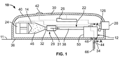
より具体的には、ここで図1を参照すると、本開示による挿入機構12を有する装着式薬剤送達装置10が示されている。少なくとも1つの例において、薬剤送達装置10は、装着型インジェクタ等の装着式薬剤送達装置として構成されてもよく、これは患者の組織11(例えば、患者の皮膚)に取り付けて投薬治療を行うように構成されていてもよい。薬剤送達装置10は、一定の、又は患者/オペレータが設定可能な量の薬剤の皮下注射を、制御又は選択された時間にわたり自動的に送達するかもしれない。薬剤送達装置10は、患者による自己投与用であっても、介護者又は正式な訓練を受けた医療者により注射剤を投与するために使用されてもよい。
More specifically, referring now to FIG. 1, a wearable
薬剤送達装置10は、流体経路コネクタ22により挿入機構12に連結された容器14、駆動機構24、及びコントローラ26を含んでいてもよく、その各々は薬剤送達装置10の主ハウジング30の中に配置されてよい。アクチュエータ28(例えば、押しボタン)が主ハウジング30の外部に配置されて、挿入機構12、駆動機構24、及び/又はコントローラ26を機械的及び/又は電気的手段(図1においては破線で示されている)を介して作動させることによって薬剤送達装置10の動作を開始するように構成されてもよい。流体経路コネクタ22は、容器14と挿入機構12との間の滅菌流体流路38を画定する。流体経路コネクタ22は容器アクセス機構29を含んでいてもよく、これは、例えばアクチュエータ28を介して薬剤送達装置10が作動されたことに応答して、容器の針31を容器14に関連付けられた隔壁32に穿刺して容器14と滅菌流体流路38との間の流体連通を確立させるように構成される。主ハウジング30は、釈放可能に患者の皮膚11に取り付けられる(例えば、接着剤により接着される)底壁36と、1つ又は複数の表示ランプ42及び/又は容器14を見るための窓(図示せず)を含む上壁40を含んでいてもよい。開口44が底壁36に形成されてもよく、任意選択により、隔壁48は開口44にわたって延び、使用前に主ハウジング30の内部が密閉された状態であるようにしてもよい。挿入機構12の外部は、主ハウジング30とは別の挿入機構ハウジングにより画定されてもよく、これについては、各例示的挿入機構に関して後でさらに説明する。
The
一般に、薬剤送達装置10を作動させると、挿入機構12は針又はカニューレアセンブリの針又はカニューレ34及び/又はトロカール66を開口44及び/又は隔壁48を貫通して患者の体内に挿入してよい。それと同時に、又はそれに続いて、薬剤送達装置10は容器14と流体経路コネクタ22との間の流体連通を確立させるために必要な接続を可能にし、つなぎ、又は開いてよい。次に、駆動機構24は、容器14に貯蔵されている薬剤46を流体経路コネクタ22の滅菌流体流路を通じてカニューレ34の中へと押し出して、患者へと皮下送達してよい。
In general, upon actuation of the
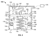
図2〜4は、図1に示される挿入機構12の1例に対応する挿入機構100を示す。挿入機構100は、図1に示される薬剤送達装置10のような薬剤送達装置に組み込まれてよい。挿入機構100は、近位端112、近位端112と反対に配置された遠位端114、近位及び遠位端112、114間に配置された側壁116、近位端112の付近に配置された第一の開口120、及び遠位端114に配置された第二の開口124を有するハウジング110を含む。第一の開口120は、圧力供給装置126に連結されるように適合されている。圧力供給装置126は、加圧された流体又はガスを供給してもよく、当業者であればわかるように、何れの圧力源、例えば空気圧源及び他の何れの圧力提供源を含んでいてもよい。それに加えて、圧力供給装置126は、図1の薬剤送達装置10の主ハウジング30の中に配置され、挿入機構100の第一の開口120に直接また間接に連結されてよい。
2 to 4 show an
図2にさらに示されているように、針又はカニューレアセンブリ130は挿入機構100のハウジング110の中に配置され、図2に示されている引込位置と、伸展位置との間で移動可能である。伸展位置は図2において破線で示され、後でさらに説明する。針又はカニューレアセンブリ130は、近位面134と遠位面136を有する基部132を含む。近位面134は、ハウジング110の近位端112により近く配置される。同様に、遠位面136は、ハウジング110の遠位端114により近く配置される。それに加えて、ハブ138が基部132及び遠位面136から下方に延び、この例では、針又はカニューレ140は基部132にハブ138を介して取り付けられている。より具体的には、1例において、針又はカニューレ140は、ハブ138に取り付けられ、そこから下方に延び、伸展位置において、ハウジング110の遠位端114に配置された第二の開口124に入り、そこから出るように適合されている。この例には示されていないが、針又はカニューレ140は、代替的に、基部132に直接取り付けられてもよく、これも依然として本開示の範囲に含まれる。基部132とハブ138は、円形又は円筒形であってよい。代替的に、基部132とハブ138は他の様々な形状と構成であってもよく、これも依然として本開示の範囲に含まれる。
As further shown in FIG. 2, a needle or
図2にさらに示されているように、針又はカニューレアセンブリ130の基部132は、ハウジング110を近位チャンバ118と遠位チャンバ119に分割する。1例において、近位チャンバ118は圧力P1を有し、遠位チャンバ119は圧力P2を有する。それぞれの近位及び遠位チャンバ118、119のそれぞれにおける圧力P1及びP2の各々は異なっている可能性があり、後でさらに説明するように、それによって針又はカニューレアセンブリ130が引込位置にあるか、伸展位置にあるかが決まる。
As further shown in FIG. 2, the
他の例において、また、図2に示されているように、基部132はハウジング110の側壁116から最小限に離間された側面又は1対の側面133の1つ又は複数を含んでいてもよく、これは例えば基部132の厚さと共に、圧力が近位チャンバ118に加えられた時の渦流(flow−around)を最小限にする。前記他の方法で、ハウジング110の側壁116と基部132の側面133との間の小さい間隙によって、近位チャンバ118が加圧されたときの渦流(flow−around)が最小化される。
In other examples, and as shown in FIG. 2,
引込部材142もまたハウジング110内に配置される。引込部材142は、基部132と接触し、後でさらに説明するように、針又はカニューレアセンブリ130を伸展位置に移動するまで引込位置に保持する抵抗力をかける。より具体的には、この例において、引込部材142は基部の遠位面136に付勢力等の抵抗力をかけ、基部132の遠位面136に取り付けられた第一の端143とハウジング110の遠位端114と接触する第二の端144を含む。引込部材142は基部132の遠位面136から、針140の周囲でハウジング110の遠位端114へと下方に延びる。より具体的には、1例において、引込部材142は圧縮ばね等の付勢機構であり、図2に示される引込位置で付勢される。例えば、近位チャンバ118内の圧力P1が解放されると、付勢機構、例えばばねは針又はカニューレ140を再び引込位置へと引き込む。
他の例において、引込部材142は代替的に、基部132の近位面134に取り付けられた第一の端とハウジング110の近位端112に取り付けられた第二の端を有する引張ばねであってもよい。引込部材142として引張ばねを有することは、上述の引込部材142として圧縮ばねを有することと同じ目的を実現するであろう。例えば、引張ばねもまた、図2の引込位置で針又はカニューレアセンブリ130を付勢し、したがって、圧力P1が近位チャンバ118から解放されると、針又はカニューレ140を再び引込位置へと引き込むであろう。
In another example, the
他の例において、挿入機構100は、基部132の近位面134から上方に延びる第一のコネクタ145と、ハウジング110の近位端112から近位チャンバ118へと下方に延びる第二のコネクタ152をさらに含む。柔軟流体路部材146は、第一のコネクタ145に動作的に連結された第一の端148と、第二のコネクタ152に動作的に接続された第二の端150を含む。そのように構成されると、柔軟流体路部材146は針又はカニューレアセンブリ130と共に伸縮する。言い換えれば、柔軟流体路部材146はまた、針アセンブリ130が引込位置から伸展位置へと移動するのに合わせて引込位置から伸展位置へと移動する。換言すれば、柔軟流体部材146は、針アセンブリと共に、柔軟流体路部材146が圧縮位置にある引込位置から、柔軟流体路部材146が伸展位置にある伸展位置へと移動する。
In another example, the
他の例において、柔軟流体路部材146は、代替的に、及び/又は追加的に、引込部材として使用されてよい。より具体的には、柔軟流体路部材146は、図2の引込位置において針又はカニューレアセンブリ130を付勢する付勢機構としての役割を果たしてよい。そのように構成されると、近位チャンバ118内で圧力P1が上昇すると、柔軟流体路部材146は伸展位置へと延び、又は膨張する。同様に、圧力P1が低下すると、柔軟流体路部材146は再び図2の引込位置へと移動して、留置後に針140を引き込む。この例において、柔軟流体路部材146は、この機能を実現するために適当な弾性の材料を有する導管を含む。
In other examples, the flexible
他の例において、挿入機構100は、ハウジング110の近位端112からハウジング110の外へと上方に延びる第三のコネクタ153を含んでいてもよい。外部流体路部材155は、第三のコネクタ153に動作的に連結された第一の端157と、流体経路コネクタ(図1)に動作的に連結された第二の端159を含む。そのように構成されると、1例において、薬剤は流体経路コネクタ22を通り、柔軟流体路部材146を通り、針又はカニューレ140を通り、患者へと押し出されてよい。外部流体路部材155は、曲がったL字型部材として示されているが、外部流体路部材155は代替的に、他の様々な形態と形状を含んでいてよく、それも依然として本開示の範囲に含まれる。例えば、外部流体路部材155は、柔軟流体路部材146を流体経路コネクタ22(図1)に動作的に連結する他の何れの接続部材であってもよい。
In another example, the
挿入機構100は、ハウジング110の遠位端114の付近のハウジング11の側壁116に、及び/又はその周囲に配置された段差156をさらに含む。段差156は、Oリング又は、同じ機能を実現することのできる、当業者に知られた他の何れかのシーリング機構等のシーリング機構160を含む。基部132の遠位面136は、針又はカニューレアセンブリ130がその伸展位置へと移動したときに、シーリング機構160と接触して肩部160に対する基部132の遠位面136の衝撃を和らげる。それに加えて、シーリング機構160、例えばOリングは、針又はカニューレ140が患者の皮膚に挿入されたときに漏れを防止し、圧力を保持し、例えば衝撃を和らげる。
The
動作時に、針アセンブリ130は、引込部材142の抵抗力によって引込位置に付勢されて、出荷、保管、又はその他の取扱い中に針140又は針アセンブリ130の移動が防止される。針140を留置するために、例えば圧力供給装置126は圧力を第一の開口120から近位チャンバ118へと供給する。針又はカニューレアセンブリ130は、近位チャンバ118内の圧力が上昇する間に、引込部材142を介して静止状態に保たれる。近位チャンバ内の圧力P1が、引込部材142の抵抗力を超える作動力を近位面134に加えると、針又はカニューレアセンブリ130は引込位置から伸展位置への移動を始める。他の例では、近位チャンバ118内の圧力P1が遠位チャンバ119内の圧力P2を超えると、針又はカニューレアセンブリ130は引込位置から伸展位置へと移動する。伸展位置において、基部132の遠位面136はハウジング110の遠位端114の付近の肩部158に配置されたシーリング機構160と接触し、針140は第二の開口124を通り、十分な力で患者の皮膚内へと延びる。針アセンブリ130と、したがって基部132がハウジング110の遠位端114に向かって移動すると、近位チャンバ118はより大きくなり、それによって針140の排出力が低下する。換言すれば、針アセンブリ130が引込位置にある間に近位チャンバP1内で圧力P1の初期上昇が生じるため、近位チャンバP1の体積が増大すると必然的に排出力が軽減する。
In operation, the
それゆえ、当業者であればわかるように、針140の挿入力と、速さは、近位チャンバ118に供給される圧力、供給される圧力の流速、及び針又はカニューレアセンブリ130の基部132の領域を調節することによって挿入機構100内で制御できる。それに加えて、基部132の遠位面136と接触したときに段差158上に配置されたシーリング機構160における跳ね返りから生じるわずかな過貫通により、針の留置中に針又はカニューレ140の組織による閉塞の発生率が減少するかもしれない。それに加えて、軽い力だけで針又はカニューレ140を挿入機構100のハウジング110の中に戻すことができ、それによってばね等の引込部材142の必要性が減少する。供給される圧力が低下すると、針140は再び引込位置に戻る。
Thus, as will be appreciated by those skilled in the art, the insertion force and speed of the
次に、図3及び4を参照すると、図2の挿入機構は代替的に、ねじ切り側壁116を含んでいてもよい。より具体的には、挿入機構100のハウジング110は、ねじ切り内面166を有する側壁116を含んでいてもよい。同様の方法で、側壁116から最小限に離間される代わりに、針又はカニューレアセンブリ130の基部132は代替的に、ハウジング110の側壁116のねじ切り内面166と接触する側面168を含んでいてもよい。より具体的には、基部132の各側面168もまたねじ切りされていてもよく、例えば、側壁116のねじ切り内面166に正確に対応するねじ切り面を有する。1例において、図3に示されるように、側壁116のねじ切り内面166と基部132のねじ切り側面168は細かいねじ山を含む。この例では、細かいねじ山によって針又はカニューレ140は例えば、留置中に少なくとも8〜10回転できる。当業者であればわかるように、針又はカニューレ140は代替的に、留置中に8〜10回より多く回転してもよく、それも依然として本開示の範囲に含まれる。他の例において、図4に示されるように、側壁(複数の場合もある)116のねじ切り内面166と基部132のねじ切り側面168は、粗いねじ山を含む。この、より大きいピッチのねじ山によって、針140は留置中により少ない回数回転することができる。1例において、粗いねじ山により、針又はカニューレ140は留置中、2〜3回転できる。
3 and 4, the insertion mechanism of FIG. 2 may alternatively include a threaded
そのように構成されると、ハウジング110の側壁116と基部132の側面168との間のこのねじ式界面によって、針又はカニューレ140の進入中の針又はカニューレ140の制御された回転が可能となる。さらに図4に示されているように、対応するねじ切り部分は相互にゆるくフィットしてもよく、例えばハウジング110のねじ切り側壁166と基部132のねじ切り側面168との間に小さい空間があり、それによって針留置中に摩擦が軽減され、よりスムーズな回転が得られる。さらに、図3及び4のどちらの例においても、針留置中の回転は、針又はカニューレ140の軸方向の振れを減少させるのを助け、それによってより快適で有効な針留置が可能となる。
When so configured, this threaded interface between the
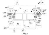
次に、図5を参照すると、本開示による他の例示的な挿入機構200が示されている。より具体的には、以下にさらに説明するように、挿入機構200の引込部材は、例えば図2に示されるようなばね142ではなく、少なくとも1つの摩擦要素280を含む。少なくとも1つの摩擦要素280は、以下にさらに説明するように、針又はカニューレアセンブリ130を引込位置に保持するための抵抗力を加え、基部132の側壁133と接触している。より一般的に、挿入機構200は図2に示され、上で説明された挿入機構100と同じであるが、図5において含められ、以下で説明される追加的及び/又は代替的な構造的特徴が異なる。簡潔にするために、挿入機構200のうち挿入機構100と同じ部品は、同じ参照番号が付けられ、挿入機構100に関してのみ説明される。
Referring now to FIG. 5, another
より具体的には、挿入機構200の少なくとも1つの摩擦要素280は、基部132の側壁133に配置された1対のシーリング機構282を含む。シーリング機構282等の少なくとも1つの摩擦要素280は、ハウジング110の近位端112に向かって抵抗力を加える。この例において、各シーリング機構282は基部133の側壁のほぼ中間点に配置される。代替的に、シーリング機構282は、基部132の側壁133の他の何れの部分に配置されてもよく、これも依然として本開示の範囲に含まれる。1例において、シーリング機構282はOリングである。他の何れの同様の種類のシールが代替的に使用されてもよく、これも依然として本開示の範囲に含まれる。挿入機構100の引込部材142と同様に、少なくとも1つの摩擦要素280、例えばシーリング機構282は、挿入機構200の出荷、保管、又は他の何れかの取扱いのうちの1つ又は複数の間に針アセンブリ130の針又はカニューレ140の移動を防止する。
More specifically, at least one
動作時に、圧力が挿入機構200のハウジング110の第一の開口120に加えられて、針又はカニューレアセンブリ130の針又はカニューレ140を留置する。より具体的には、近位チャンバ118内の圧力P1が、少なくとも1つの摩擦部材280の抵抗力を超える作動力を基部132の近位面134に加えると、針又はカニューレアセンブリ130は引込位置から伸展位置へと移動する。他の例において、基部の近位面134への圧力P1の作動力が遠位チャンバ119内の圧力P2の抵抗力を超えると、圧力P1の作動力が少なくとも1つの摩擦要素280、例えばシーリング機構282の力に打ち勝ち、針又はカニューレアセンブリ130を引込位置から伸展位置へと移動させ、針の留置を実現する。
In operation, pressure is applied to the
この例では、挿入機構200のハウジング110は第三の開口284をさらに含む。第三の開口284は、ハウジング110の遠位端114の付近、例えば側壁116に配置され、遠位チャンバ119へと開放する。代替的に、第三の開口284は、第三の開口282がハウジング110の遠位チャンバ119へと開放するか、それと連通するようにハウジング110の他の何れの部分に配置されてもよい。針又はカニューレアセンブリ130が伸展位置へと移動された後、及び幾つかの場合では近位チャンバ118内の圧力P1が排出された後、圧力は第三の開口284及び遠位チャンバ119へと供給される。遠位チャンバ119内の圧力P2が近位チャンバ118内の圧力P1を超えると、針140は開口124を通じて再びハウジング110の中に引き込まれ、針アセンブリ130は再び込み位置へと戻される。この例において、針140が引き抜かれた後に触覚フィードバックとして小さい圧力が提供され、圧力は引き続き第三の開口284を介して遠位チャンバ119へと加えられ、又は供給される。
In this example, the
代替的に、負圧が第一の開口120から近位チャンバ118に付加されて、近位チャンバ118内の圧力P1が下げられてもよい。近位チャンバ118内の圧力P1が遠位チャンバ119内の圧力P2より低くなると、針140は伸展位置から再び引込位置へと移動する。前記別の方法で、陽圧が第三の開口284から加えられるか、負圧が第一の開口120から加えられるかにかかわらず、針140が留置された後に圧力P2が圧力P1を超えると、針140と針アセンブリ130は伸展位置から再び引込位置へと戻る。
Alternatively, a negative pressure may be applied to the
針又はカニューレアセンブリ130が再び引込位置に戻ると、挿入機構200は針又はカニューレアセンブリ130を引込位置に固定して、例えば針140が再使用されるのを防止する。より具体的には、図5に示されるように、挿入機構200は針又はカニューレアセンブリ140を引込位置に再び固定又は保持するための少なくとも1つのラッチ286をさらに含む。1例において、少なくとも1つのラッチ286は1対のばね式指向性ラッチ288を含む。第一のばね式指向性ラッチ288は、ハウジングの側壁116の1つの領域に配置され、第二のばね式指向性ラッチ288はハウジングの側壁116の他の領域に配置され、第一及び第二のばね式ラッチはハウジング110の側壁116の対応する領域において、同じ高さと位置に配置される。それに加えて、第一及び第二のばね式ラッチの各々はばね289と、ハウジング110の内側に面する傾斜面290を有する。各ばね289は、各ラッチ288の周囲に配置されて、各ラッチ288を針又はカニューレアセンブリ130の基部134に向かう方向に付勢する。この例では、基部134は、各側133に傾斜した角又は面292をさらに含む。基部132の各側壁133上の傾斜面292は、針又はカニューレアセンブリ130が引込位置へと移動した後に、ラッチ288の対応する傾斜面290と接触する。各ばね式ラッチ288の基部134に向かう付勢力は、基部134及びしたがって針又はカニューレアセンブリ140を引込位置に固定して、再配置を防止する。
When the needle or
次に、図6を参照すると、本開示による他の例示的な挿入機構300が示されている。より具体的には、図5の挿入機構200と同様に、挿入機構300の引込部材は、例えば図2に示されるようなばね142ではなく、基部132と接触する少なくとも1つの摩擦要素280を含む。少なくとも1つの摩擦要素280は、後でさらに説明するように、針又はカニューレアセンブリ130を引込位置に保持するための抵抗力をかける。それに加えて、挿入機構300はまた、針またカニューレアセンブリ130を再び引込位置にロックして、再使用を防止する、挿入機構100及び200のどちらとも異なる方法も含む。より一般的に、挿入機構300はそれぞれ図2及び5に示され、上で説明された挿入機構100と同じであるが、図6に含められ、以下に説明される追加的及び/又は代替的な構造的特徴が異なる。簡潔にするために、挿入機構300のうち挿入機構100と同じ部品は、同じ参照番号が付けられ、挿入機構100に関してのみ説明される。
Referring now to FIG. 6, another
より具体的には、図5の挿入機構200と同様に、挿入機構300の少なくとも1つの摩擦要素280は、基部132の側壁133に配置された1対のシーリング機構282を含む。少なくとも1つの摩擦要素280、例えばシーリング機構282は、ハウジング110の近位端112に向かって抵抗力をかける。この例でもまた、各シーリング機構282は基部133の側壁のほぼ中間点に配置される。代替的に、シーリング機構282は基部132の側壁133の他の何れの部分に配置されてもよく、これも依然として本開示の範囲に含まれる。1例において、シーリング機構282はOリングである。他の何れの同様の種類のシールも代替的に使用されてよく、これも依然として本開示の範囲に含まれる。挿入機構100の引込部材142と同様に、少なくとも1つの摩擦要素280、例えばシーリング機構282は、挿入機構200の出荷、保管、又は他の何れかの取扱いのうちの1つ又は複数の間の針アセンブリ130の針又はカニューレ140の移動を防止する。
More specifically, as with the
シーリング機構282に加えて、挿入機構300は、針を挿入するまで針又はカニューレアセンブリ130を引込位置に保持するのを助けるための少なくとも1つの溝392をさらに含んでいてもよい。1例において、少なくとも1つの溝392は1対の溝394を含む。第一の溝394はハウジングの側壁116の1つの領域に配置され、第二の溝394はハウジングの側壁116の他の領域に配置され、第一及び第二の溝394は、ハウジング110の側壁116の対応する領域において同じ高さ及び位置に配置される。それに加えて、第一及び第二の溝394の各々は、半円形として示されており、それによって各溝394は、針アセンブリ130が再び引込位置に戻ったときに、基部132の各側133に配置された対応する円形のシーリング機構282をすぐに、容易に受けることができる。代替的に、各溝392は他の様々な形状の形態を取ってもよく、これも依然として本開示の範囲に含まる。より具体的には、他の例において、各溝394の形状は基部132の各シーリング機構282の形状と基本的にマッチし、それによって各溝392は基部132の各側133の対応するシーリング機構282、例えば摩擦要素を容易に受けて、針又はカニューレアセンブリ130の基部32を引込位置に固定し、再使用を防止することができる。動作時に、圧力が挿入機構200のハウジング110の第一の開口120に加えられて、針又はカニューレアセンブリ130の針又はカニューレ140を留置する。より具体的には、近位チャンバ118内の圧力P1の量が、少なくとも1つの摩擦要素280の抵抗力を超える作動力を基部132の近位面134に加えると、針又はカニューレアセンブリ130は引込位置から伸展位置へと移動する。他の例において、近位チャンバ118内の圧力P1の量が、遠位チャンバ119内の圧力P2により基部132に加えられる抵抗力を超える作動力を基部132に付与すると、針又はカニューレアセンブリ130は引込位置から伸展位置へと移動させ、針を留置する。
In addition to the
この例において、少なくとも1つの溝392によって、それを超えると針アセンブリ130が移動する力閾値が大きくなる。力閾値は、例えば摩擦抵抗だけの場合よりはるかに大きい。より具体的には、1例において、力閾値は摩擦抵抗より少なくとも5倍大きい。前記別の方法で、この例では、少なくとも1つの摩擦要素280と少なくとも1つの溝392との合同の抵抗力は、溝392を持たない少なくとも1つの摩擦要素280だけ(図5)の抵抗力よりはるかに大きい。当業者であればわかるように、摩擦要素280と溝392の力閾値は、力閾値が摩擦抵抗より大きいかぎり、摩擦抵抗の5倍より小さくても、それより大きくてもよく、それも依然として本開示の範囲に含まれる。
In this example, at least one
少なくとも1つの溝392を有するこの構成によって、圧力はより高まり、針140の迅速な挿入又は留置が確実に行われる。抵抗力が低いと、針アセンブリ130はゆっくりと移動し始めるかもしれない。針の留置又は挿入中は、1m/sの針140の速さが望ましい。この例での特に大きい初期抵抗により、針140が移動し始めた後に近位チャンバ118内の圧力が引き続き上昇又は増加しなくても、素早い初期加速が可能となる。
This configuration with at least one
近位チャンバ118内の圧力P1を下げるために、第一の開口120を通じて、圧力P1が排出されても、負圧が近位チャンバ118に加えられてもよい。近位チャンバ118内の圧力P1が遠位チャンバ119内の圧力P2より低いと、針140は伸展位置から再び引込位置に移動するかもしれない。前記他の方法で、針140の留置後に圧力P2が圧力P1を超えると、針140とアセンブリ130は伸展位置から再び引込位置に戻る。
In order to reduce the pressure P1 in the
針又はカニューレアセンブリ130が再び引込位置に戻った後、挿入機構300も針又はカニューレアセンブリ130を引込位置に固定して、例えば針140の再使用を防止する。より具体的には、図6にさらに示されるように、少なくとも1つの溝392は、基部132の側壁133に配置されたシーリング機構等の少なくとも1つの摩擦要素282を受けて、針140が伸展位置へと再び作動されるのを防止する。前記他の方法で、少なくとも1つの溝392は第一及び第二の溝394を含み、その各々は、基部132の側壁133に配置された対応する摩擦要素282、例えばシーリング機構、Oリング、又はCクリップの1つ又は複数を受けて、針又はカニューレアセンブリ140の基部132を引込位置に固定して、針130の再留置を防止する。1例において、各溝394と摩擦要素282との間の高い摩擦が、引込位置に戻った後の針アセンブリ130の動きを停止させ、針アセンブリ130を引込位置に固定する。
After the needle or
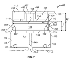
次に、図7を参照すると、本開示による他の例示的な挿入機構400が示されている。より具体的には、図6の挿入機構300と同様に、挿入機構400の引込部材は、例えば図2に示されるようなばね142ではなく、基部132と接触する少なくとも1つの摩擦要素280を含む。少なくとも1つの摩擦要素280は、後でさらに説明するように、針又はカニューレアセンブリ130を引込位置に保持するための抵抗力をかける。それに加えて、挿入機構400はまた、改造された基部132と、後でさらに説明するように、それぞれ図2、5、及び6に示される挿入機構100、200、及び300の近位チャンバ118の体積より小さい体積の近位チャンバ118も含む。より一般的に、挿入機構400はそれぞれ図2及び6に示される挿入機構100及び300と同じであるが、図7に含められ、以下に説明される追加的及び/又は代替的な構造的特徴が異なる。簡潔にするために、挿入機構400のうち挿入機構100と同じ部品は、同じ参照番号が付けられ、挿入機構100及び300に関してのみ説明される。
Referring now to FIG. 7, another
より具体的には、図7の挿入機構は、ハウジング110の近位端112から下方に延びるガイド部材496をさらに含む。ガイド部材496の片側はハウジングの側壁116と接触し、ガイド部材496の反対側は側壁116の別の領域から離間されて、例えば第一の開口120を通じて供給された圧力が近位チャンバ118に入ることができる。ガイド部材496は中央穴497を含み、1例においては円筒形である。当業者であれば、ガイド部材496は代替的に他の様々な形状をとってもよく、それも依然として本開示の範囲に含まれることがわかるであろう。他の例において、ガイド部材496は1対のガイド部材496を含んでいてもよく、ガイド部材496は単体の部品からなるのではなく、2部式の形態を含む。この例において、1対のガイド部材496の各ガイド部材496は、例えば円形、円筒形、半円形、半円筒形、若しくは長方形、又は他の何れかの形状若しくは形状の組合せのうちの1つ又は複数であってもよく、それも依然として本開示の範囲に含まれる。
More specifically, the insertion mechanism of FIG. 7 further includes a
それに加えて、基部132は、基部132の近位面134の中央からハウジング110の近位端112に向かって延びるガイドシャフト498をさらに含む。ガイドシャフト498は、ガイド部材496の中央穴497の中へと延びる。このようにして、ガイド部材496の中央穴497は、針アセンブリ130が引込及び伸展位置間で移動する際に基部132のシャフト498を案内する役割を果たす。前記他の方法により、中央穴497は、ガイド部材496の案内穴497であり、これは針140の留置及び引き戻し中にシャフト498を受け、案内する。図7にさらに示されているように、ガイドシャフト498が中央穴497の中に配置されたときに、ガイドシャフト498の何れかの側に小さい半径方向のギャップ499がある。さらに示されているように、ガイドシャフト498の直径は針アセンブリ130の基部132の直径Dより小さい。
In addition,
このように構成されると、近位チャンバ118の体積は、例えば図6の挿入機構300の近位チャンバ118より小さく、それでも引込及び伸展位置から、及びそれらの間で移動する際に、針アセンブリ130の安定性は損なわれない。それに加えて、基部132に案内シャフト498を含めることによって、図7に示されるように、基部132の有効長さは他の挿入機構100、200、300のようなLからL2の長さへと伸びる。この、より大きい長さによって基部132の安定性が増し、その一方で、基部の直径Dが一定に保たれて、例えば利用可能な圧力に対して所望の挿入力が保持される。
When configured in this manner, the volume of the
1例において、基部132の直径Dを縮小することによって、利用可能な圧力に対する挿入力が小さくなる。それに加えて、基部132の長さLを短くすることによって、例えば、ガイドシャフト498が含められないときの基部132及び、したがって針アセンブリ130の移動の安定性と予測可能性が低下する。したがって、基部132からハウジング110の近位端112に向かって延びるガイドシャフト498を含めることにより、基部132及びガイドシャフト498の合同での有効長さはL2に長くなり、その一方で、基部132の直径Dは一定に保たれて、基部132及び、針アセンブリ130の移動の安定性が保持される。
In one example, reducing the diameter D of the
上記に鑑み、当業者であれば、薬剤送達装置10(図1)のための挿入機構100、200、300、400の何れかの針又はカニューレアセンブリ130の針又はカニューレ140を患者の皮膚に挿入する、以下のような例示的な方法がわかるであろう。
In view of the above, one of ordinary skill in the art would insert the needle or
より具体的には、方法は、引込部材により挿入機構100、200、300、400のハウジング110内に配置された針又はカニューレアセンブリ130の引込位置を保持するステップを含む。方法はまた、圧力を挿入機構100、200、300、400のハウジング110の第一の開口120に、ハウジング110の近位チャンバ118内の圧力P1の量が、引込部材の1つ又は複数により基部132に加えられる抵抗力又は遠位チャンバ119内の圧力P2を超える作動力を針又はカニューレアセンブリ130の基部132に付与するまで供給するステップを含む。それに加えて、方法は、作動力が抵抗力を超えたところで、針アセンブリ130を引込位置から伸展位置へと移動させるステップと、針アセンブリ130が針140を留置するための伸展位置に移動したところで、挿入機構100、200、300、400のハウジング110の遠位端114の第二の開口124を通じて、針又はカニューレアセンブリ130の針140を配置するステップを含む。
More specifically, the method includes retaining a retracted position of a needle or
1例において、上で説明したように、針又はカニューレアセンブリ130の引込位置を保持するステップは、付勢機構142を介して針アセンブリ130の基部132の遠位面136に抵抗力を加えるステップを含む。他の例において、針又はカニューレアセンブリ130の引込位置を保持するステップは、基部132の側壁133に摩擦要素282を配置するステップと、摩擦要素282を介してハウジング110の近位端112に向かう抵抗力を加えるステップと、を含む。
In one example, maintaining the retracted position of the needle or
また別の例において、方法はまた、ハウジング110の遠位チャンバ119内の圧力P2が近位チャンバ118内の圧力P1を超えるまで、第一の開口120から負圧を供給するステップか、ハウジングの、ハウジング110の遠位端114の付近に配置された第三の開口284(図6)から陽圧を供給するステップの一方も含んでいてよい。これにより、今度は、針又はカニューレアセンブリ130は伸展位置から引込位置に移動する。
In yet another example, the method also includes providing a negative pressure through the
方法は、針アセンブリ130を伸展位置から移動した後に引込位置に固定して、針アセンブリ130の針140の再配置を防止するステップをさらに含んでいてよい。1例において、針アセンブリ140を引込位置に固定するステップは、少なくとも1つのばね式指向性ラッチ288をハウジング110の側壁116に提供するステップを含み、これは少なくとも1つのばね式指向性ラッチ288の中に移動した基部132の何れかの側133と接触する。他の例において、針アセンブリ130を引込位置に固定して、再留置を防止するステップは、基部132の各側133に配置された少なくとも1つのシーリング機構282をハウジング110の側壁116に配置された対応する溝392の中に挿入するステップを含む。何れの場合も、方法はまた、針又はカニューレアセンブリ130が引込位置から伸展位置に移動する際に近位チャンバ118の大きさを増大させるステップと、針留置の時点に存在する排出力を小さくするステップを含んでいてもよい。
The method may further include securing the
当業者であれば、本開示の前述の挿入機構100、200、及び300と方法の利点の多くがわかるであろう。例えば、挿入機構100、200、300の各々において、針又はカニューレアセンブリ130の針又はカニューレ140の挿入力と速さは、例えば、圧力供給装置126又は他の何れかの圧力源により供給される圧力、流速、及び/又は基部132の、例えば付加された近位チャンバ118内の圧力P1を受ける近位面134を調節することによって制御できる。それに加えて、遠位チャンバ119内の、ハウジング110の遠位端114の直前にOリング又は同様のシーリング機構を含めることによって、基部132の遠位面136は、伸展位置に移動されたときにOリング160と接触するとわずかに「跳ね返る」ことができる。このわずかな「跳ね返り」により、初期挿入中に針140のわずかな過剰貫通が起こり、これによって針又はカニューレ140の組織による閉塞の発生率が減少するかもしれない。
One skilled in the art will appreciate many of the advantages of the foregoing
さらに、好ましい挿入速さには、針又はカニューレアセンブリ130の釈放前に近位チャンバ118内の圧力P1を上昇させる必要があるかもしれず、それによって患者の皮膚に入る直前の摩擦力が低下する。その結果、挿入のために十分な力が存在し、挿入がより素早く、より痛みが少なくなる。挿入機構100、200、300、400はまた、患者の快適さを高め、患者の不安の可能性を軽減させるかもしれない。例えば、従来の方法と機構では、患者は自分で装置のボタンを押しながら自分自身に剛体の針を挿入する必要があるかもしれない。このタイプの挿入機構は、自分でボタンを押してトロカールの挿入を制御するため、患者の不安や怖さの原因となるかもしれない。それに加えて、既知の方法と機構は、外部の安全ガードと組み合わせられた剛体の針を含み、これは患者が装着式装置を取り外す際に患者の皮膚に残るかもしれない。それに対して、開示されている装着型式薬剤送達装置は、注射部位がより小さく、患者が装着式装置を取り外す前にカニューレ140を引き込むように構成できる。それに加えて、針140の自動留置及び引込みによって、針140は常に隠された状態にあり、装着式薬剤送達装置を取り外す際の患者にとっての快適さが改善される。さらに、針140の引込みはまた、注射が完了したことを患者がわかるようにするのにも役立つことができ、又はエラーがあった場合に、針140が引き込まれてから装着式薬剤送達装置を取り外すことは容認可能である。しかしながら、本開示の範囲はこれら及び本明細書に記載された他の何れの利点及び利益にも限定されず、開示されている実施形態及び本開示の原理によるそれらに対する改良から、その他の利益や利点が得られるかもしれない。
Further, the preferred insertion speed may require that the pressure P1 in the
上記の説明は、薬剤送達装置と共に使用するための様々なシステムと方法を述べている。システム、薬剤送達装置、又は方法は、後述の薬剤の使用をさらに含むことができる点を明確にすべきであるが、以下のリストは網羅的でも限定的でもないと考えるべきではないことに留意されたい。薬剤は、貯蔵器内に収容される。幾つかの例において、貯蔵器はその薬剤での治療のために充填又は事前充填された一次容器である。一次容器は、カートリッド又はプレフィルドシリンジとすることができる。 The above description has described various systems and methods for use with the drug delivery device. It should be clarified that the system, drug delivery device, or method can further include the use of drugs described below, but note that the following list should not be considered exhaustive or limiting. I want to be. The drug is contained in a reservoir. In some examples, the reservoir is a primary container that is filled or pre-filled for treatment with the drug. The primary container can be a cartridge or a pre-filled syringe.
例えば、薬剤送達装置又は、より具体的には装置の貯蔵器には、コロニ刺激因子、例えば顆粒球コロニ刺激因子(G−CSF)が充填されてよい。このようなG−CSF剤には、Neupogen(登録商標)(フィラグラスチム)及びNeulasta(登録商標)(ペグフィグラスチム)が含まれるが、これらに限定されない。他の各種の実施形態において、薬剤送達装置は様々な医薬製品、例えば赤血球造血刺激因子剤(ESA)等に使用されてもよく、これは液体又は凍結乾燥状態であってもよい。ESAは、赤血球造血を刺激するあらゆる分子であり、例えばEpogen(登録商標)(エポチエンアルファ)、Aranesp(登録商標)(ダルベポエチンアルファ)、Dynepo(登録商標)(エポエチンデルタ)、Mircera(登録商標)(メチオキシポリエチレングリコールエポエチンベータ)、Hematide(登録商標)、MRK−2578、INS−22、Retacrit(登録商標)(エポエチンゼータ)、Neorecormon(登録商標)(エポエチンベータ)、Silapo(登録商標)(エポエチンゼータ)、Binocrit(登録商標)(エポエチンアルファ)、エポエチンアルファHexal、Abseamed(登録商標)(エポエチンアルファ)、Ratioepo(登録商標)(エポエチンシータ)、Eporatio(登録商標)(エポエチンシータ)、Biopoin(登録商標)(エポエチンシータ)、エポエチンアルファ、エポエチンベータ、エポエチンゼータ、エポエチンシータ、及びエポエチンデルタのほか、各々、その全体が参照によって本願に援用される下記の特許又は特許出願において開示されている分子又はそのバリアント若しくは類似体である:米国特許第4,703,008号明細書、同第5,441,868号明細書、同第5,547,933号明細書、同第5,618,698号明細書、同第5,621,080号明細書、同第5,756,349号明細書、同第5,767,078号明細書、同第5,773,569号明細書、同第5,955,422号明細書、同第5,986,047号明細書、同第6,583,272号明細書、同第7,084,245号明細書、及び同第7,271,689号明細書、並びにPCT出願公開番号国際公開第91/05867号パンフレット、同第95/05465号パンフレット、同第96/40772号パンフレット、同第00/24893号パンフレット、同第01/81405号パンフレット、及び同第2007/136752号パンフレット。 For example, a drug delivery device, or more specifically, a reservoir of the device, may be filled with a colony stimulating factor, such as a granulocyte colony stimulating factor (G-CSF). Such G-CSF agents include, but are not limited to, Neupogen® (filaglastim) and Neulasta® (pegfigrastim). In various other embodiments, the drug delivery device may be used for various pharmaceutical products, such as erythropoiesis stimulating agents (ESAs), which may be in a liquid or lyophilized state. ESA is any molecule that stimulates erythropoiesis, for example, Epogen® (Epotien alpha), Aranesp® (Dalbepoetin alfa), Dynepo® (Epoetin delta), Mircera® (Methoxy polyethylene glycol epoetin beta), Hematide (registered trademark), MRK-2578, INS-22, Retacrit (registered trademark) (epoetin zeta), Neocormon (registered trademark) (epoetin beta), Silapo (registered trademark) (epoetin) Zeta), Binocrit® (epoetin alfa), epoetin alfa Hexal, Abseamed® (epoetin alfa), Ratioeopo® (epoetin alfa) Chincita), Eporatio® (epoetin theta), Biopoin® (epoetin theta), epoetin alfa, epoetin beta, epoetin zeta, epoetin theta, and epoetin delta, each of which is incorporated herein by reference in its entirety. Molecules or variants or analogs thereof disclosed in the following patents or patent applications incorporated by reference: US Pat. Nos. 4,703,008; 5,441,868; 5,547,933, 5,618,698, 5,621,080, 5,756,349, and 5,767,078. No. 5,773,569, No. 5,955,422, No. 5,986,047 Nos. 6,583,272, 7,084,245, and 7,271,689, and PCT Application Publication No. WO 91/05867 pamphlet; No. 95/05465 pamphlet, No. 96/40772 pamphlet, No. 00/24893 pamphlet, No. 01/81405 pamphlet, and No. 2007/136675 pamphlet.
ESAは赤血球造血刺激たんぱく質とすることができる。本明細書で使用されるかぎり、「赤血球造血刺激たんぱく質」とは、例えば受容体と結合し、二量体化を引き起こすことによって、エリスロポエチン受容体を直接又は間接に活性化させるあらゆるたんぱく質を意味する。エリスロポエチン刺激たんぱく質には、エリスロポエチン受容体と結合し、これを活性化させるエリスロポエチン及びそのバリアント、類似体、又は誘導体、エリスロポエチン受容体と結合し、受容体を作動させる抗体、又はエリスロポエチン受容体と結合し、これを活性化させるペプチドが含まれる。エリスロポエチン刺激たんぱく質には、エポエチンアルファ、エポエチンベータ、エポエチンデルタ、エポエチンオメガ、エポエチンイオタ、エポエチンゼータ、及びその類似体、ペグ化エリスロポエチン、カルバミル化エリスロポエチン、擬似ペプチド(EMP1/メマタイドを含む)、及び擬似抗体が含まれるが、これらに限定されない。例示的な赤血球造血刺激たんぱく質には、エリスロポエチン、ダルベポエチン、エリスロポエチンアゴニストバリアント、及びエリスロポエチン受容体と結合してこれを活性化させる(及び、各々、その全体が本願に援用される米国特許出願公開第2003/0215444号明細書及び同第2006/0040858号明細書において報告されている化合物を含む)ペプチド又は抗体のほか、各々、その全体が本願に援用される以下の特許又は特許出願において開示されているエリスロポエチン分子又はそのバリアント若しくは類似体が含まれる:米国特許第4,703,008号明細書、同第5,441,868号明細書、同第5,547,933号明細書、同第5,618,698号明細書、同第5,621,080号明細書、同第5,756,349号明細書、同第5,767,078号明細書、同第5,773,569号明細書、同第5,955,422号明細書、同第5,830,851号明細書、同第5,856,298号明細書、同第5,986,047号明細書、同第6,030,086号明細書、同第6,310,078号明細書、同第6,391,633号明細書、同第6,583,272号明細書、同第6,586,398号明細書、同第6,900,292号明細書、同第6,750,369号明細書、同第7,030,226号明細書、同第7,084,245号明細書、及び同第7,217,689号明細書、並びに米国特許出願公開第2002/0155998号明細書、同第2003/0077753号明細書、同第2003/0082749号明細書、同第2003/0143202号明細書、同第2004/0009902号明細書、同第2004/0071694号明細書、同第2004/0091961号明細書、同第2004/0143857号明細書、同第2004/0157293号明細書、同第2004/0175379号明細書、同第2004/0175824号明細書、同第2004/0229318号明細書、同第2004/0248815号明細書、同第2004/0266690号明細書、同第2005/0019914号明細書、同第2005/0026834号明細書、同第2005/0096461号明細書、同第2005/0107297号明細書、同第2005/0107591号明細書、同第2005/0124045号明細書、同第2005/0124564号明細書、同第2005/0137329号明細書、同第2005/0142642号明細書、同第2005/0143292号明細書、同第2005/0153879号明細書、同第2005/0158822号明細書、同第2005/0158832号明細書、同第2005/0170457号明細書、同第2005/0181359号明細書、同第2005/0181482号明細書、同第2005/0192211号明細書、同第2005/0202538号明細書、同第2005/0227289号明細書、同第2005/0244409号明細書、同第2006/0088906号明細書、及び同第2006/0111279号明細書、並びにPCT出願公開番号国際公開第91/05867号パンフレット、同第95/05465号パンフレット、同第99/66054号パンフレット、同第00/24893号パンフレット、同第01/81405号パンフレット、同第00/61637号パンフレット、同第01/36489号パンフレット、同第02/014356号パンフレット、同第02/19963号パンフレット、同第02/20034号パンフレット、同第02/49673号パンフレット、同第02/085940号パンフレット、同第03/029291号パンフレット、同第2003/055526号パンフレット、同第2003/084477号パンフレット、同第2003/094858号パンフレット、同第2004/002417号パンフレット、同第2004/002424号パンフレット、同第2004/009627号パンフレット、同第2004/024761号パンフレット、同第2004/033651号パンフレット、同第2004/035603号パンフレット、同第2004/043382号パンフレット、同第2004/101600号パンフレット、同第2004/101606号パンフレット、同第2004/101611号パンフレット、同第2004/106373号パンフレット、同第2004/018667号パンフレット、同第2005/001025号パンフレット、同第2005/001136号パンフレット、同第2005/021579号パンフレット、同第2005/025606号パンフレット、同第2005/032460号パンフレット、同第2005/051327号パンフレット、同第2005/063808号パンフレット、同第2005/063809号パンフレット、同第2005/070451号パンフレット、同第2005/081687号パンフレット、同第2005/084711号パンフレット、同第2005/103076号パンフレット、同第2005/100403号パンフレット、同第2005/092369号パンフレット、同第2006/50959号パンフレット、同第2006/02646号パンフレット、及び同第2006/29094号パンフレット。 ESA can be an erythropoiesis stimulating protein. As used herein, `` erythropoietic stimulating protein '' means any protein that directly or indirectly activates the erythropoietin receptor, for example, by binding to the receptor and causing dimerization. . Erythropoietin-stimulating protein binds to and activates erythropoietin receptor and erythropoietin and its variants, analogs or derivatives, binds to erythropoietin receptor, binds to erythropoietin receptor, and activates receptor, or binds to erythropoietin receptor. And peptides that activate it. Erythropoietin-stimulated proteins include epoetin alfa, epoetin beta, epoetin delta, epoetin omega, epoetin iota, epoetinzeta, and analogs thereof, pegylated erythropoietin, carbamylated erythropoietin, pseudopeptides (including EMP1 / mematide), and pseudoantibodies. But are not limited to these. Exemplary erythropoietic stimulating proteins include erythropoietin, darbepoetin, erythropoietin agonist variants, and erythropoietin receptor which bind to and activate it (and each of US Patent Application Publication No. 2003, which is incorporated herein in its entirety). In addition to peptides or antibodies (including the compounds reported in U.S. Patent Nos. / 0215444 and 2006/0040858), each is disclosed in the following patents or patent applications, each of which is incorporated herein by reference in its entirety: Erythropoietin molecules or variants or analogs thereof are included: US Patent Nos. 4,703,008, 5,441,868, 5,547,933, 5, Nos. 618,698, 5,621,080 and 5 No. 756,349, No. 5,767,078, No. 5,773,569, No. 5,955,422, No. 5,830,851 No. 5,856,298, No. 5,986,047, No. 6,030,086, No. 6,310,078, No. 6,391. 633, JP-A-6,583,272, JP-A-6,586,398, JP-A-6,900,292, JP-A-6,750,369, Nos. 7,030,226, 7,084,245, and 7,217,689, and U.S. Patent Application Publication Nos. 2002/0155998, 2003 / 0077753, 2003/0082749 Specification, No. 2003/0142022, No. 2004/0009902, No. 2004/0071694, No. 2004/0091961, No. 2004/0143857, No. 2004/0157293, 2004/0175379, 2004/0175824, 2004/0229318, 2004/0248815, and 2004/0266690. No. 2005/0019914, No. 2005/0026834, No. 2005/0096461, No. 2005/0107297, No. 2005/0107591, No. 2005 / 0124045, No. 2005 / 0124564, 2005/0137329, 2005/0142622, 2005/0142922, 2005/0153879, 2005/0158822. No. 2005/0158832, No. 2005/0170457, No. 2005/0181359, No. 2005/0181482, No. 2005/0192211, No. 2005/0158821. No. 0202538, No. 2005/0227289, No. 2005/0244409, No. 2006/0088906, No. 2006/0111279, and PCT Application Publication No. No. 91/05867 pamphlet, No. 95/05465 pamphlet, No. 99/66054 pamphlet, No. 00/24893 pamphlet, No. 01/81405 pamphlet, No. 00/61637 pamphlet, No. 01/36489 pamphlet, No. 02 / 014356 pamphlet, 02/19963 pamphlet, 02/020034 pamphlet, 02/49673 pamphlet, 02/085940 pamphlet, 03/029291 pamphlet, and 2003/055526 pamphlet , Pamphlet No. 2003/084377, pamphlet No. 2003/094858, pamphlet No. 2004/002417, pamphlet No. 2004/002424, and pamphlet No. 2004/00 No. 627, No. 2004/024761, No. 2004/033651, No. 2004/035603, No. 2004/043382, No. 2004/101600, No. 2004/101606. Pamphlet, pamphlet of 2004/101611, pamphlet of 2004/106373, pamphlet of 2004/018667, pamphlet of 2005/001025, pamphlet of 2005/001136, pamphlet of 2005/021579, No. 2005/025606, No. 2005/032460, No. 2005/051327, No. 2005 / Pamphlet Nos. 063808, 2005/063809, 2005/070451, 2005/081687, 2005/084711, 2005/103076, 2005/100403 Brochures, pamphlet No. 2005/092369, pamphlet No. 2006/50959, pamphlet No. 2006/02646, and pamphlet No. 2006/29094.
装置に使用するその他の医薬製品の例には、Vectibix(登録商標)(パニツムマブ)、Xgeva(商標)(デノスマブ)、及びProlia(商標)(デノスマブ)等の抗体、Enbrel(登録商標)(エタネルセプト、TNF−受容体/Fc融合たんぱく質、TNFブロッカ)、Neulasta(登録商標)(ペグフィグラスチム、ペグ化フィルグラチム、ペグ化G−CSF、ペグ化hu−Met−G−CSF)、Neupogen(登録商標)(フィルグラスチム、G−CS、hu−MetG−CSF)、及びNplate(登録商標)(ロミプロスチム)等のその他の生物学的薬剤、Sensipa(登録商標)(シナカルセト)等の低分子薬剤が含まれていてもよいが、これらに限定されない。装置はまた、治療用抗体、ポリペプチド、たんぱく質、又は鉄等のその他の化学物質、例えばフェルモキシトール、デキストラン鉄、グリコン酸鉄、及びスクロース鉄等であってもよい。医薬製品は、液体でも、凍結乾燥状態から還元されてもよい。 Examples of other pharmaceutical products for use in the device include antibodies such as Vectibix® (panitumumab), Xgeva® (denosumab), and Prolia® (denosumab), Enbrel® (etanercept, TNF-receptor / Fc fusion protein, TNF blocker), Neulasta® (pegfigrastim, pegylated filgratim, pegylated G-CSF, pegylated hu-Met-G-CSF), Neupogen® ( Filgrastim, G-CS, hu-MetG-CSF), and other biological agents such as Nplate® (Romiprostim), and small molecule agents such as Sensipa® (Cinacalcet). However, the present invention is not limited to these. The device may also be a therapeutic antibody, polypeptide, protein, or other chemical such as iron, such as fermoxytol, dextran iron, iron glyconate, and iron sucrose. The pharmaceutical product may be liquid or reduced from a lyophilized state.
特定の例示的なたんぱく質の中には下記の具体的なたんぱく質があり、これにはその融合体、フラグメント、類似体、バリアント、又は誘導体も含まれる:OPGL特異抗体及び抗体関連たんぱく質、特にその中に記載されている配列を有するものに関してその全体が本願に援用されるPCT出願公開番号国際公開第03/002713号パンフレットに記載された抗体を含むがこれに限定されない、完全ヒト化及びヒトOPGL特異抗体、特に完全ヒト化モノクローナル抗体を含むOPGL特異抗体、ペプチボディ、及び関連たんぱく質並びにその他(RANKL特異抗体、ペプチボディ、及びその他とも呼ばれる)、各々、個別に、明確に、上記公開文献において開示されているように、その全体が参照によって本願に援用される、その中の図2に示されている配列番号2の軽鎖及び/又はその中の図4に示されている配列番号4の重鎖の何れかを有するOPGL特異抗体を含む9H7、18B2、2D8、2E11、16E1、及び22B3。 Among certain exemplary proteins are the following specific proteins, including fusions, fragments, analogs, variants or derivatives thereof: OPGL-specific antibodies and antibody-related proteins, especially Fully humanized and human OPGL specific, including, but not limited to, the antibodies described in PCT Application Publication No. WO 03/002713, which has the sequences described in US Pat. Antibodies, particularly OPGL-specific antibodies, including fully humanized monoclonal antibodies, peptibodies, and related proteins and others (also referred to as RANKL-specific antibodies, peptibodies, and others), each individually and expressly disclosed in the above-cited publications. As such, the entirety of which is incorporated herein by reference. 9H7, 18B2, 2D8, 2E11 comprising an OPGL-specific antibody having any of the light chain of SEQ ID NO: 2 shown in FIG. 2 and / or the heavy chain of SEQ ID NO: 4 shown in FIG. , 16E1, and 22B3.
myostatin特異ペプチボディ、特に、特にmyostatin特異ペプチボディに関する部分においてその全体が参照によって本願に援用される米国特許出願公開第2004/0181033号明細書及びPCT特許公開番号国際公開第2004/058988号パンフレットに記載されているものを含むmyostatin結合たんぱく質であって、各々、個別に、明確に、上記公開文献において開示されているように、その全体が参照によって本願に援用される、配列番号305〜351のものを含むmTN8−19ファミリ、例えばTN8−19−1〜TN8−19−40、TN8−19 con1及びTN8−19 con2、配列番号357〜383のmL2ファミリのペプチボディ、配列番号384〜409のmL15ファミリ、配列番号410〜438のmL17ファミリ、配列番号439〜446のmL20ファミリ、配列番号447〜452のmL21ファミリ、配列番号453〜454のmL24ファミリ、及び配列番号615〜631のそれらを含むがこれらに限定されない。 The myostatin-specific peptibodies, particularly those relating to myostatin-specific peptibodies, are described in US Patent Application Publication No. 2004/0181033 and PCT Patent Publication No. WO 2004/058988, which are hereby incorporated by reference in their entirety. A myostatin binding protein, each of which independently and distinctly as disclosed in the above-cited publications, has the sequence of SEQ ID NOS: 305-351, incorporated herein by reference in its entirety. MTN8-19 family including, for example, TN8-19-1 to TN8-19-40, TN8-19 con1 and TN8-19 con2, peptibodies of the mL2 family of SEQ ID NOs: 357-383, mL15f of SEQ ID NOs: 384-409. Including the mL17 family of SEQ ID NOs: 410-438, the mL20 family of SEQ ID NOs: 439-446, the mL21 family of SEQ ID NOs: 447-452, the mL24 family of SEQ ID NOs: 453-454, and those of SEQ ID NOs: 615-631. It is not limited to.
IL−4受容体特異抗体、ペプチボディ、及び関連たんぱく質並びにその他、特にIL−4及び/又はIL−13を受容体に結合することによって媒介される活性を阻害するものであって、特にIL−4受容体特異抗体に関する部分においてその全体が参照によって本願に援用されるPCT出願公開番号国際公開第2005/047331号パンフレット又はPCT出願PCT/US2004/37242号及び米国特許出願公開第2005/112694号明細書に記載されているもの、特にその中に記載された抗体、特に、これらに限定されないが、各々、個別に、明確に、上記公開文献において開示されているように、その全体が参照によって本願に援用される、L1H1、L1H2、L1H3、L1H4、L1H5、L1H6、L1H7、L1H8、L1H9、L1H10、L1H11、L2H1、L2H2、L2H3、L2H4、L2H5、L2H6、L2H7、L2H8、L2H9、L2H10、L2H11、L2H12、L2H13、L2H14、L3H1、L4H1、L5H1、L6H1とその中て指定されているものを含む。 IL-4 receptor-specific antibodies, peptibodies, and related proteins and others, especially those that inhibit activities mediated by binding IL-4 and / or IL-13 to the receptor, especially IL-4 PCT Application Publication No. WO 2005/473331 or PCT Application PCT / US2004 / 37242 and US Patent Application Publication No. 2005/112694, which are hereby incorporated by reference in their entirety in the portion relating to receptor specific antibodies. In particular, but not limited to, those described therein, in particular, but not exclusively, each individually and expressly herein incorporated by reference in their entirety, as disclosed in the above publications. L1H1, L1H2, L1H3, L1H4, L1H5, L1H6, L1 7, L1H8, L1H9, L1H10, L1H11, L2H1, L2H2, L2H3, L2H4, L2H5, L2H6, L2H7, L2H8, L2H9, L2H10, L2H11, L2H12, L2H13, L2H1, L2H1, L2H1, L2H1, L2H1 Including those that are.
インタロイキン1−受容体(「IL1−R1」)特異抗体、ペプチボディ、及び関連たんぱく質並びにその他であって、その全体、IL1−R1特異結合たんぱく質、特にモノクローナル抗体に関する部分においてその全体が参照によって本願に援用される米国特許出願公開第2004/097712号明細書に記載されているもの、特に、これらに限定されないが、各々、個別に、明確に、上記公開文献において開示されているように、その全体が参照によって本願に援用される、15CA、26F5、27F2、24E12、及び10H7とその中で指定されているものが含まれるが、これらに限定されない。 Interleukin 1-receptor ("IL1-R1") specific antibodies, peptibodies, and related proteins and others, in their entirety, particularly those relating to IL1-R1 specific binding proteins, particularly monoclonal antibodies, are hereby incorporated by reference in their entirety. What is described in U.S. Patent Application Publication No. 2004/097972, which is incorporated herein by reference, in particular, but not exclusively, each individually and explicitly, as disclosed in the above-cited publications. Include, but are not limited to, 15CA, 26F5, 27F2, 24E12, and 10H7 and those designated therein.
Ang2特異抗体、ペプチボディ、及び関連たんぱく質並びにその他であって、各々、特にAng2特異抗体及びペプチボディ並びにその他に関する部分においてその全体が参照によって本願に援用されるPCT出願公開番号国際公開第03/057134号パンフレット及び米国特許出願公開第2003/0229023号明細書に記載されているもの、特にその中に記載された配列の、L1(N)、L1(N)WT、L1(N)1K WT、2xL1(N)、2xL1(N)WT、Con(N)、Con4(N)1K WT、2xCon4(N)1K、L1C、L1C 1K、2xL1C、Con4C、Con4C 1K、2xCon4C 1K、Con4−L1(N)、Con4−L1C、TN−12−9(N)、C17(N)、TN8−8(N)、TN8−14(N)、Con 1(N)を含むがこれらに限定されず、また、それに関してその全体が参照によって本願に援用されるPCT出願公開番号国際公開第2003/030833号パンフレットに記載されているもの等の抗Ang2抗体及び製剤、特に、各々、個別に、明確に、上記公開文献において開示されているように、その全体が参照によって本願に援用される、その中に記載されたその様々な置換配列のAb526、Ab528、Ab531、Ab533、Ab535、Ab536、Ab537、Ab540、Ab543、Ab544、Ab545、Ab546、A551、Ab553、Ab555、Ab558、Ab559、Ab565、AbF1AbFD、AbFE、AbFJ、AbFK、AbG1D4、AbGC1E8、AbH1C12、AbIA1、AbIF、AbIK、AbIP、及びAbIPが含まれるが、これらに限定されない。 PCT Application Publication No. WO 03/057134, which is incorporated herein by reference in its entirety, in particular for Ang2 specific antibodies, peptibodies, and related proteins and others, and especially for Ang2 specific antibodies and peptibodies and others, respectively. And L1 (N), L1 (N) WT, L1 (N) 1K WT, 2 × L1 (N) of those described in U.S. Patent Application Publication No. 2003/0229023, especially the sequences described therein. ), 2xL1 (N) WT, Con (N), Con4 (N) 1K WT, 2xCon4 (N) 1K, L1C, L1C 1K, 2xL1C, Con4C, Con4C 1K, 2xCon4C 1K, Con4-L1 (N), Con4- L1C, TN-12-9 (N), C17 (N), TN8- 8 (N), TN8-14 (N), Con 1 (N), including, but not limited to, PCT Application Publication No. WO 2003/030833, which is hereby incorporated by reference in its entirety. Anti-Ang2 antibodies and preparations, such as those described in US Pat. No. 6,058,075, and in particular, each individually and explicitly, as disclosed in the above-cited publications, is hereby incorporated by reference in its entirety. Ab526, Ab528, Ab531, Ab533, Ab535, Ab536, Ab537, Ab540, Ab543, Ab544, Ab545, Ab546, A551, Ab553, Ab555, Ab558, Ab559, Ab556, Ab556, Ab559, Ab556, Ab559, Ab559, Ab559 AbFJ, AbFK, AbG1D4, bGC1E8, AbH1C12, AbIA1, AbIF, AbIK, AbIP, and including but AbIP, without limitation.
NGF特異抗体、ペプチボディ、及び関連たんぱく質並びにその他であって、特に、この点においてNGF特異抗体及び関連たんぱく質に関してその全体が参照によって本願に援用される米国特許出願公開第2005/0074821号明細書及び米国特許第6,919,426号明細書に記載されているものを含むがこれらに限定されず、特に、各々、個別に、明確に、上記公開文献において開示されているように、その全体が参照によって本願に援用される、4D4、4G6、6H9、7H2、14D10、及び14D11とその中で指定されるNGF特異抗体が含まれるが、これらに限定されない。 NGF-specific antibodies, peptibodies, and related proteins and others, and in particular, US Patent Application Publication No. 2005/00784821, and US Pat. Includes, but is not limited to, those described in US Pat. No. 6,919,426, and in particular, each individually and explicitly referred to in its entirety as disclosed in the above-cited publications. Including, but not limited to, 4D4, 4G6, 6H9, 7H2, 14D10, and 14D11 and the NGF-specific antibodies specified therein.
CD22特異抗体、ペプチボディ、及び関連たんぱく質並びにその他、例えばCD22特異抗体及び関連たんぱく質についてその全体が参照によって本願に援用される米国特許第5,789,554号明細書に記載されているもの、特にヒトCD22特異抗体、例えば、これらに限定されないが、ヒト化された、及び完全なヒト抗体であって、ヒト化された、及び完全なヒトモノクローナル抗体を含むがこれに限定されず、特に、ヒトCD22特異IgG抗体、例えばヒト−マウスモノクローナルhLL2カッパ鎖に架橋されたヒト−マウスモノクローナルhLL2ガンマ鎖ジスルフィドの二量体で、例えばエプラツズマブ、CAS登録番号501423−23−0のヒトCD22特異完全ヒト化抗体が含まれるが、これらに限定されない。 CD22-specific antibodies, peptibodies, and related proteins and others, such as those described in US Pat. No. 5,789,554, herein incorporated by reference in its entirety for CD22-specific antibodies and related proteins, especially humans CD22-specific antibodies, such as, but not limited to, humanized and fully human antibodies, including but not limited to humanized and fully human monoclonal antibodies, particularly human CD22 A specific IgG antibody, such as a dimer of human-mouse monoclonal hLL2 gamma chain disulfide cross-linked to the human-mouse monoclonal hLL2 kappa chain, e.g. Including, but not limited to.
IGF−1受容体特異抗体、ペプチボディ、及び関連たんぱく質並びにその他、例えばIGF−1受容体特異抗体及び関連たんぱく質に関してその全体が本願に援用されるPCT出願公開番号国際公開第06/069202号パンフレットに記載されているものであって、各々、個別に、明確に、上記公開文献において開示されているように、その全体が参照によって本願に援用されるL1H1、L2H2、L3H3、L4H4、L5H5、L6H6、L7H7、L8H8、L9H9、L10H10、L11H11、L12H12、L13H13、L14H14、L15H15、L16H16、L17H17、L18H18、L19H19、L20H20、L21H21、L22H22、L23H23、L24H24、L25H25、L26H26、L27H27、L28H28、L29H29、L30H30、L31H31、L32H32、L33H33、L34H34、L35H35、L36H36、L37H37、L38H38、L39H39、L40H40、L41H41、L42H42、L43H43、L44H44、L45H45、L46H46、L47H47、L48H48、L49H49、L50H50、L51H51、L52H52並びにIGF−1R結合フラグメント及びその誘導体と指定されるIGF−1特異抗体が含まれるが、これらに限定されない。
IGF-1 receptor specific antibodies, peptibodies, and related proteins, and others, such as those described in PCT Application Publication No. WO 06/069202, which is hereby incorporated by reference in its entirety with respect to IGF-1 receptor specific antibodies and related proteins. L1H1, L2H2, L3H3, L4H4, L5H5, L6H6, L7H7, each individually and explicitly as disclosed in the above-cited publications, incorporated herein by reference in their entirety. , L8H8, L9H9, L10H10, L11H11, L12H12, L13H13, L14H14, L15H15, L16H16, L17H17, L18H18, L19H19, L20H20, L21H21, L22H22, L23H23, L24H24, L25H25,
また、本発明の方法及び組成物の中で使用するための抗IGF−1R抗体の非限定的な例の中には、以下の中に記載される各々及び全部が含まれる: Also, non-limiting examples of anti-IGF-1R antibodies for use in the methods and compositions of the present invention include each and all of those described below:
(i)米国特許出願公開第2006/0040358号明細書(2006年2月23日公開)、同第2005/0008642号明細書(2005年1月13日公開)、同第2004/0228859号明細書(2004年11月18日公開)で、その中に記載されている抗体1A(DSMZ寄託番号DSM ACC 2586)、抗体8(DSMZ寄託番号DSM ACC 2589)、抗体23(DSMZ寄託番号DSM ACC 2588)、及び抗体18が含まれるが、これらに限定されない。 (I) U.S. Patent Application Publication Nos. 2006/0040358 (released on February 23, 2006), 2005/0008642 (released on January 13, 2005), and 2004/0228859 (Published November 18, 2004), Antibody 1A (DSM Accession No. DSM ACC 2586), Antibody 8 (DSMZ Accession No. DSM ACC 2589), Antibody 23 (DSMZ Accession No. DSM ACC 2588) described therein , And antibody 18.
(ii)PCT出願公開番号国際公開第06/138729号パンフレット(2006年12月28日公開)及び同第05/016970号パンフレット(2005年2月24日公開)、及びLu et al.(2004),J.Biol.Chem.279:2856−2865で、その中に記載されている抗体2F8、A12、及びIMC−A12が含まれるが、これらに限定されない。 (Ii) PCT Application Publication Nos. WO 06/138729 pamphlet (published December 28, 2006) and WO 05/016970 pamphlet (published February 24, 2005), and Lu et al. (2004), J. Mol. Biol. Chem. 279: 2856-2865, including but not limited to antibodies 2F8, A12, and IMC-A12 described therein.
(iii)PCT出願公開番号国際公開第07/012614号パンフレット(2007年2月1日公開)、同第07/000328号パンフレット(2007年1月4日公開)、同第06/013472号パンフレット(2006年2月9日公開)、同第05/058967号パンフレット(2005年6月30日公開)、及び同第03/059951号パンフレット(2003年7月24日公開)。 (Iii) PCT application publication numbers WO 07/012614 pamphlet (published February 1, 2007), WO 07/000328 pamphlet (published January 4, 2007), and WO 06/014732 pamphlet ( No. 05/058967 pamphlet (released on June 30, 2005) and No. 03/059951 pamphlet (released on July 24, 2003).
(iv)米国特許出願公開第2005/0084906号明細書(2005年4月21日公開)で、その中に記載されている抗体7C10、キメラ抗体C7C10、抗体h7C10、抗体7H2M、キメラ抗体*7C10、抗体GM 607、ヒト化抗体7C10バージョン1、ヒト化抗体7C10バージョン2、ヒト化抗体7C10バージョン3、及び抗体7H2HMが含まれるが、これらに限定されない。
(Iv) U.S. Patent Application Publication No. 2005/0084906 (published April 21, 2005), which describes antibody 7C10, chimeric antibody C7C10, antibody h7C10, antibody 7H2M, chimeric antibody * 7C10, described therein. Includes, but is not limited to, antibody GM 607, humanized antibody 7C10 version 1, humanized antibody 7C10 version 2, humanized
(v)米国特許出願公開第2005/0249728号明細書(2005年11月10日公開)、同第2005/0186203号明細書(2005年8月25日公開)、同第2004/0265307号明細書(2004年12月30日公開)、及び同第2003/0235582号明細書(2003年12月25日公開)、及びMaloney et al.(2003),Cancer Res.63:5073−5083で、その中に記載されている抗体EM164、再表面形成された抗体EM164、ヒト化EM164、huEM164 v1.0、huEM164 v1.1、huEM164 v1.2、及びhuEM164 v1.3が含まれるが、これらに限定されない。 (V) U.S. Patent Application Publication Nos. 2005/0249728 (released November 10, 2005), 2005/0186203 (released August 25, 2005), and 2004/0265307. (Published on December 30, 2004), and the specification of 2003/0235582 (published on December 25, 2003), and Maloney et al. (2003), Cancer Res. 63: 5073-5083, wherein antibody EM164, resurfaced antibody EM164, humanized EM164, huEM164 v1.0, huEM164 v1.1, huEM164 v1.2, and huEM164 v1.3 described therein were obtained. Including, but not limited to.
(vi)米国特許第7,037,498号明細書(2006年5月2日発行)、米国特許出願公開第2005/0244408号明細書(2005年11月30日公開)、及び同第2004/0086503号明細書(2004年5月6日公開)、及びCohen,et al.(2005),Clinical Cancer Res.11:2063−2073、例えば抗体CP−751,871で、これらに記載されているATCCアクセション番号PTA−2792、PTA−2788、PTA−2790、PTA−2791、PTA−2789、PTA−2793を有する雑種細胞により生成される抗体及び抗体2.12.1、2.13.2、2.14,3、3.1.1、4.9.2、及び4.17.3の各々が含まれるが、これらに限定されない。 (Vi) U.S. Pat. No. 7,037,498 (issued on May 2, 2006), U.S. Patent Application Publication No. 2005/0244408 (published on November 30, 2005), and U.S. Pat. 0086503 (published May 6, 2004) and Cohen, et al. (2005), Clinical Cancer Res. 11: 2063-2073, e.g., antibody CP-751, 871, having ATCC accession numbers PTA-2792, PTA-2788, PTA-2790, PTA-2791, PTA-2789, PTA-2789, described therein. Antibodies produced by hybrid cells and each of antibodies 2.12.1, 2.13.2, 2.14, 3, 3.1.1, 4.9.2, and 4.17.3 are included. However, it is not limited to these.
(vii)米国特許出願公開第2005/0136063号明細書(2005年6月23日公開)及び同第2004/0018191号明細書(2004年1月29日公開)であり、これらに記載されている、抗体19D12及び、ATCCに番号PTA−5214で寄託された、プラスミド15H12/19D12 HCA(γ4)によりコード化される重鎖と、ATCCに番号PTA−5220で寄託された、プラスミド15H12/19D12 LCF(Κ)のポリヌクレオチドによりコード化される軽鎖を含む抗体が含まれるが、これらに限定されない。 (Vii) U.S. Patent Application Publication Nos. 2005/0136063 (published June 23, 2005) and 2004/0018191 (published January 29, 2004) and are described therein. Antibody 19D12 and the heavy chain encoded by plasmid 15H12 / 19D12 HCA (γ4), deposited at the ATCC under number PTA-5214, and plasmid 15H12 / 19D12 LCF, deposited at the ATCC under the number PTA-5220. Ii) Antibodies comprising the light chain encoded by the polynucleotide of, but not limited to.
(viii)米国特許出願公開第2004/0202655号明細書(2004年10月14日公開)で、その中に記載されている抗体PINT−6A1、PINT−7A2、PINT−7A4、PINT−7A5、PINT−7A6、PINT−8A1、PINT−9A2、PINT−11A1、PINT−11A2、PINT−11A3、PINT−11A4、PINT−11A5、PINT−11A7、PINT−11A12、PINT−12A1、PINT−12A2、PINT−12A3、PINT−12A4、及びPINT−12A5が含まれるが、これらに限定されず、これらの各々及び全部は、特にIGF−1受容体を標的とする上記の抗体、ペプチボディ、及び関連たんぱく質並びにその他に関して、その全体が参照によって本願に援用される。 (Viii) The antibodies PINT-6A1, PINT-7A2, PINT-7A4, PINT-7A5, PINT described in U.S. Patent Application Publication No. 2004/0202655 (published October 14, 2004). -7A6, PINT-8A1, PINT-9A2, PINT-11A1, PINT-11A2, PINT-11A3, PINT-11A4, PINT-11A5, PINT-11A7, PINT-11A12, PINT-12A1, PINT-12A2, PINT-12A3 , PINT-12A4, and PINT-12A5, including but not limited to, each and all of these, particularly with respect to the above-described antibodies, peptibodies, and related proteins and others that specifically target the IGF-1 receptor. The whole is by reference Are incorporated herein Te.
B7関連たんぱく質1特異抗体、ペプチボディ、関連たんぱく質並びにその他(「B7RP−1」、又は文献ではB7H2、ICOSL、B7h、及びCD275とも呼ばれる)、特にB7RP−特異完全ヒトモノクローナルIgG2抗体、特にB7RP−1の第一免疫グロブリン様ドメイン内のエピトープと結合する完全ヒトIgG2モノクローナル抗体、特に活性T細胞上の天然受容体ICOSとのB7RP−1の相互作用を阻害するもの、特に、上記の点のすべてにおいて、このような抗体及び関連たんぱく質に関してその全体が参照によって本願に援用される米国特許出願公開第2008/0166352号明細書及びPCT出願公開番号国際公開第07/011941号パンフレットにおいて開示されているもので、その中で、各々が個別に、明確に、上記公開文献の中に開示されているように、その全体が参照によって本願に援用される16H(その中のそれぞれ、軽鎖可変部及び重鎖可変部配列、配列番号1及び配列番号7を有する)、5D(その中のそれぞれ、軽鎖可変部及び重鎖可変部配列、配列番号2及び配列番号9を有する)、2H(その中のそれぞれ、軽鎖可変部及び重鎖可変部配列、配列番号3及び配列番号10を有する)、43H(その中のそれぞれ、軽鎖可変部及び重鎖可変部配列、配列番号6及び配列番号14を有する)、41H(その中のそれぞれ、軽鎖可変部及び重鎖可変部配列、配列番号5及び配列番号13を有する)、及び15H(その中のそれぞれ、軽鎖可変部及び重鎖可変部配列、配列番号4及び配列番号12を有する)として指定された抗体が含まれるがこれらに限定されない。 B7-related protein 1-specific antibodies, peptibodies, related proteins and others (also referred to as "B7RP-1" or B7H2, ICOSL, B7h, and CD275 in the literature), especially B7RP-specific fully human monoclonal IgG2 antibodies, especially B7RP-1 A fully human IgG2 monoclonal antibody that binds to an epitope within the first immunoglobulin-like domain, especially one that inhibits the interaction of B7RP-1 with the natural receptor ICOS on activated T cells, especially in all of the above respects, Such antibodies and related proteins are disclosed in U.S. Patent Application Publication No. 2008/0166352 and PCT Application Publication No. WO 07/011941, which are hereby incorporated by reference in their entirety, Among them, each Are individually and expressly disclosed in the above-cited publications, 16H (in each of which the light and heavy chain variable region sequences, SEQ ID NO: 1 and SEQ ID NO: 7), 5D (with light chain variable region and heavy chain variable sequence, respectively, SEQ ID NO: 2 and SEQ ID NO: 9), 2H (with light chain variable region and Heavy chain variable region sequence, having SEQ ID NO: 3 and SEQ ID NO: 10), 43H (including light chain variable region and heavy chain variable region sequence, SEQ ID NO: 6 and SEQ ID NO: 14, respectively), 41H (including therein) And 15H (having the light chain variable region and heavy chain variable region sequences, SEQ ID NO: 4 and SEQ ID NO :, respectively, respectively) having the light chain variable region and heavy chain variable region sequences, SEQ ID NO: 5 and SEQ ID NO: 13. 12) Although the included antibodies is not limited thereto.
IL−15特異抗体、ペプチボディ、及び関連たんぱく質並びにその他、例えば、特にヒトモノクローナル抗体、特に各々が、ペプチボディを含むIL−15特異抗体及び関連たんぱく質に関してその全体が参照によって本願に援用される米国特許出願公開第2003/0138421号明細書、同第2003/023586号明細書、同第2004/0071702号明細書、及び米国特許第7,153,507号明細書において開示されているもので、特に例えば、HuMax IL−15抗体及び関連たんぱく質、例えば146B7が含まれるが、これに限定されない。 U.S. Patent Application which is incorporated herein by reference in its entirety with respect to IL-15-specific antibodies, peptibodies, and related proteins and others, e.g., especially human monoclonal antibodies, especially IL-15-specific antibodies and related proteins, each comprising a peptibody. Publications 2003/0138421, 2003/023586, 2004/0071702, and US Pat. No. 7,153,507, particularly, for example, This includes, but is not limited to, HuMax IL-15 antibodies and related proteins such as 146B7.
IFNガンマ特異抗体、ペプチボディ、及び関連たんぱく質並びにその他、特にヒトIFNガンマ特異抗体、特に完全ヒト抗IFNガンマ抗体、例えばIFNガンマ特異抗体に関してその全体が参照によって本願に援用される米国特許出願公開第2005/0004353号明細書に記載されているもの、特に例えば、その中で1118、1118*、1119、1121、及び1121*と指定された抗体。これらの抗体の各々の重鎖及び軽鎖の全体的配列のほか、それらの重鎖及び軽鎖可変領域と相補性決定領域の配列は、各々、個別に、明確に、上記の公開文献及びThakur et al.(1999),Mol.Immunol.36:1107−1115において開示されているようにその全体が参照によって本願に援用される。それに加えて、上記の公開文献において提供されるこれらの抗体の特性の説明もまた、その全体が参照によって本願に援用される。具体的な抗体には、上記の公開文献において開示されているような、配列番号17の重鎖と配列番号18の軽鎖を有するもの、配列番号6の重鎖可変領域と配列番号8の軽鎖可変領域を有するの、配列番号19の重鎖と配列番号20の軽鎖を有するもの、配列番号10の重鎖可変領域と配列番号12の軽鎖可変領域を有するもの、配列番号32の重鎖と配列番号20の軽鎖を有するもの、配列番号30の重鎖可変領域と配列番号12の軽鎖可変領域を有するもの、配列番号21の重鎖配列と配列番号22の軽鎖配列を有するもの、配列番号14の重鎖可変領域と配列番号16の軽鎖可変領域を有するもの、配列番号21の重鎖と配列番号33の軽鎖を有するもの、及び配列番号14の重鎖可変領域と配列番号31の軽鎖可変領域を有するものが含まれる。上記の米国特許出願公開の中で開示され、その中で開示されているような配列番号17の完全重鎖を有し、その中に開示されているような配列番号18の完全軽鎖を有する抗体1119である。 IFN gamma-specific antibodies, peptibodies, and related proteins and others, particularly human IFN gamma-specific antibodies, particularly fully human anti-IFN gamma antibodies, eg, US Patent Application Publication No. 2005, which is hereby incorporated by reference in its entirety with respect to IFN gamma-specific antibodies. / 0004353, in particular, for example, the antibodies designated therein as 1118, 1118 * , 1119, 1211, and 1121 * . The entire sequences of the heavy and light chains of each of these antibodies, as well as the sequences of their heavy and light chain variable regions and complementarity determining regions, are individually and unambiguously each described in the above-cited publications and Thakur. et al. (1999), Mol. Immunol. 36: 1107-1115, which is hereby incorporated by reference in its entirety. In addition, descriptions of the properties of these antibodies provided in the above-cited publications are also incorporated herein by reference in their entirety. Specific antibodies include those having a heavy chain of SEQ ID NO: 17 and a light chain of SEQ ID NO: 18, a heavy chain variable region of SEQ ID NO: 6 and a light chain of SEQ ID NO: 8, as disclosed in the above-mentioned publications. Having a heavy chain of SEQ ID NO: 19 and a light chain of SEQ ID NO: 20, having a heavy chain variable region of SEQ ID NO: 10 and a light chain variable region of SEQ ID NO: 12, and having a heavy chain of SEQ ID NO: 32 Having the light chain variable region of SEQ ID NO: 30 and the light chain variable region of SEQ ID NO: 12, having the heavy chain variable region of SEQ ID NO: 12, and having the light chain sequence of SEQ ID NO: 22. Those having the heavy chain variable region of SEQ ID NO: 14 and the light chain variable region of SEQ ID NO: 16, those having the heavy chain of SEQ ID NO: 21 and the light chain of SEQ ID NO: 33, and the heavy chain variable region of SEQ ID NO: 14; Having the light chain variable region of SEQ ID NO: 31 It is included. Has the complete heavy chain of SEQ ID NO: 17 as disclosed in the above-mentioned U.S. Patent Application Publication and disclosed therein, and has the complete light chain of SEQ ID NO: 18 as disclosed therein. Antibody 1119.
TALL−1特異抗体、ペプチボディ、及び関連たんぱく質並びにその他と、TALL特異結合たんぱく質、例えば各々がTALL−1結合たんぱく質に関してその全体が参照によって本願に援用される米国特許出願公開第2003/0195156号明細書及び同第2006/0135431号明細書に記載されているもの、特にその各々が、完全に上記の公開文献の中で開示されているようにその全体が参照によって本願に援用される表4及び5Bの分子。 US Patent Application Publication No. 2003/0195156, herein incorporated by reference in its entirety with respect to TALL-I specific antibodies, peptibodies, and related proteins and others, as well as TALL-specific binding proteins, e.g., TALL-I binding proteins. And those described in WO 2006/0135431, in particular each of Tables 4 and 5B, which are hereby incorporated by reference in their entirety as fully disclosed in the above-mentioned published documents. Molecule.
副甲状腺ホルモン(「PTH」)特異抗体、ペプチボディ、及び関連たんぱく質並びにその他、例えば、特にPTHと結合するたんぱく質に関してその全体が参照によって本願に援用される米国特許第6,756,480号明細書に記載されているもの。 Parathyroid hormone ("PTH") specific antibodies, peptibodies, and related proteins and others, such as, for example, those specifically binding to PTH, are incorporated by reference herein in US Pat. No. 6,756,480. What is listed.
トロンボポエチン受容体(「TPO−R」)特異抗体、ペプチボディ、及び関連たんぱく質並びにその他、例えば、特にTPO−Rと結合するたんぱく質に関してその全体が参照によって本願に援用される米国特許第6,835,809号明細書に記載されているもの。 Thrombopoietin receptor ("TPO-R")-specific antibodies, peptibodies, and related proteins and others, such as, for example, proteins specifically binding to TPO-R, US Pat. No. 6,835,809, which is hereby incorporated by reference in its entirety. What is described in the specification.
肝細胞増殖因子(「HGF」)特異抗体、ペプチボディ、及び関連たんぱく質並びにその他であり、HGF/SF:cMet軸(HGF/SF:c−Met)を標的とするもの、例えば各々が、特にHGFと結合するたんぱく質に関する部分においてその全体が参照によって本願に援用される、米国特許出願公開第2005/0118643号明細書及びPCT出願公開番号国際公開第2005/017107号パンフレットに記載されている、肝細胞増殖因子/分散因子(HGF/SF)を中性化する完全ヒトモノクローナル抗体、米国特許第7,220,410号明細書に記載されているhuL2G7、及び米国特許第5,686,292号明細書及び同第6,468,529号明細書並びにPCT出願公開番号国際公開第96/38557号パンフレットに記載されているOA−5d5が含まれる。 Hepatocyte growth factor ("HGF") specific antibodies, peptibodies, and related proteins and others that target the HGF / SF: cMet axis (HGF / SF: c-Met), eg, Hepatocyte proliferation as described in U.S. Patent Application Publication No. 2005/0118643 and PCT Application Publication No. WO 2005/017107, which are hereby incorporated by reference in their entirety with respect to binding proteins. Fully human monoclonal antibodies that neutralize factor / dispersion factor (HGF / SF), huL2G7 described in US Pat. No. 7,220,410, and US Pat. No. 5,686,292; No. 6,468,529 and PCT Application Publication No. WO 96/385. It includes OA-5d5 listed in 7 pamphlet.
TRAIL−R2特異抗体、ペプチボディ、関連たんぱく質及びその他、例えば、特にTRAIL−R2と結合するたんぱく質に関する部分においてその全体が参照によって本願に援用される米国特許第7,521,048号明細書に記載されているもの。 TRAIL-R2 specific antibodies, peptibodies, related proteins and others, such as those described in U.S. Pat. No. 7,521,048, which is hereby incorporated by reference in its entirety, particularly in the context of proteins that bind TRAIL-R2. What you have.
アクチビンA特異抗体、ペプチボディ、関連たんぱく質、及びその他であり、アクチビンAと結合するたんぱく質に関する部分においてその全体が参照によって本願に援用される米国特許出願公開第2009/0234106号明細書に記載されているものが含まれるが、これに限定されない。 Activin A-specific antibodies, peptibodies, related proteins, and others are described in U.S. Patent Application Publication No. 2009/0234106, which is hereby incorporated by reference in its entirety with respect to proteins that bind to activin A. Including but not limited to:
TGF−ベータ特異抗体、ペプチボディ、関連たんぱく質、及びその他であり、TGF−ベータと結合するたんぱく質に関する部分においてその全体が参照によって本願に援用される米国特許第6,803,453号明細書及び米国特許出願公開第2007/0110747号明細書に記載されているものが含まれるが、これらに限定されない。 U.S. Pat. No. 6,803,453 and U.S. Pat. It includes, but is not limited to, those described in published application No. 2007/0110747.
アミロイドベータたんぱく質特異抗体、ペプチボディ、関連たんぱく質、及びその他であり、特にアミロイドベータたんぱく質と結合するたんぱく質に関する部分においてその全体が参照によって本願に援用されるPCT出願公開番号国際公開第2006/081171号パンフレットに記載されているものが含まれるが、これに限定されない。考えられる1つの抗体は、上記の公開文献において開示されている配列番号8を含む重鎖可変領域と配列番号6を有する軽鎖可変領域を有する抗体である。 PCT Application Publication No. WO 2006/081171, which is incorporated herein by reference in its entirety, with respect to amyloid beta protein-specific antibodies, peptibodies, related proteins, and others, particularly those relating to proteins that bind to amyloid beta protein. Includes but is not limited to those described. One possible antibody is an antibody having a heavy chain variable region comprising SEQ ID NO: 8 and a light chain variable region comprising SEQ ID NO: 6 disclosed in the above-cited publication.
c−Kit特異抗体、ペプチボディ、関連たんぱく質、及びその他であり、特にc−Kit及び/又はその他の幹細胞因子受容体と結合するたんぱく質に関する部分においてその全体が参照によって本願に援用される米国特許出願公開第2007/0253951号明細書に記載されているものが含まれるが、これに限定されない。 U.S. Patent Application Publication c-Kit specific antibodies, peptibodies, related proteins, and others, particularly those relating to proteins that bind c-Kit and / or other stem cell factor receptors, which are hereby incorporated by reference in their entirety. It includes, but is not limited to, those described in US 2007/0253951.
OX40L特異抗体、ペプチボディ、関連たんぱく質、及びその他であり、特にOX40L及び/又はOX40受容体のその他のリガンドと結合するたんぱく質に関する部分においてその全体が参照によって本願に援用される米国特許出願公開第2006/0002929号明細書に記載されているものが含まれるが、これに限定されない。 US Patent Application Publication No. 2006/2006, which is an OX40L-specific antibody, peptibodies, related proteins, and others, particularly those relating to proteins that bind to OX40L and / or other ligands of the OX40 receptor, is hereby incorporated by reference in its entirety. 0002929, including, but not limited to.
Activase(登録商標)(アルテプラーゼ、tPA)、Aranesp(登録商標)(ダルベポエチン)、Epogen(登録商標)(エポエチンアルファ、又はエリスロポエチン)、GLP−1、Avonex(登録商標)(インタフェロンベータ1a)、Bexxar(登録商標)(トシツモマブ、抗CD22モノクローナル抗体)、Betaseron(登録商標)(インタフェロン−ベータ)、Campath(登録商標)(アレムツズマブ、抗CD52モノクローナル抗体)、Dynepo(登録商標)(エポエチンデルタ)、Velcade(登録商標)(ボルテゾミブ)、MLN0002(抗α4β7 mAb)、MLN1202(抗CCR2ケモカイン受容体mAb)、Enbrel(エタネルセプト、TNF−受容体/Fc融合たんぱく質、TNFブロッカ)、Eprex(登録商標)(エポエチンアルファ)、Erbitux(登録商標)(セツキシマブ、抗EGFR/HER1/c−ErbB−1)、Genotropin(登録商標)(ソマトロピン、ヒト成長ホルモン)、Herceptin(登録商標)(トラスツズマブ、抗HER2/neu(erbB2)受容体mAb)、Humatrope(登録商標)(ソマトロピン、ヒト成長ホルモン)、Humira(登録商標)(アダリムマブ)、インスリン溶液、Infergen(登録商標)(インタフェロンアルファコン−1)、Natrecor(登録商標)(ネシリチド、組み換えヒトB型ナトリウム利尿ペプチド(hBNP)、Kineret(登録商標)(アナキンラ)、Leukine(登録商標)(サルガモスチム、rhuGM−CSF)、LymphoCide(登録商標)(エプラツズマブ、抗CD22 mAb)、Benlysta(商標)(lymphostat B、ベリムマブ、抗BlySmAb)、Metalyse(登録商標)(テネクテプラーゼ、t−PA類似体)、Mircera(登録商標)(メトキシポリエチレングリコールエポエチンベータ)、Mylotarg(登録商標)(ゲムツズマブオゾガマイシン)、Raptiva(登録商標)(エファリズマブ)、Cimzia(登録商標)(セルトリズマブペゴル、CDP 870)、Soliris(商標)(エクリズマブ)、ペキセリズマブ(抗C5補体)、Numax(登録商標)(MEDI−524)、Lucentis(登録商標)(ラニビズマブ)、Panorex(登録商標)(17−1A、エドレコロマブ)、Trabio(登録商標)(lerdelimumab)、TheraCim hR3(ニモツズマブ)、Omnitarg(ペルツズマブ、2C4)、Osidem(登録商標)(IDM−1)、OvaRex(登録商標)(B43.13)、Nuvion(登録商標)(ビジリズマブ)、cantuzumab mertansine(huC242−DM1)、NeoRecormon(登録商標)(エポエチンベータ)、Neumega(登録商標)(オプレルベキン、ヒトインタロイキン−11)、Neulasta(登録商標)(ペグ化フィルガストリム、ペグ化G−CSF、ペグ化hu−Met−G−CSF)、Neupogen(登録商標)(フィラグラスチム、G−CSF、hu−MetG−CSF)、Orthoclone OKT3(登録商標)(ムロモナブ−CD3、抗CD3モノクローナル抗体)、Procrit(登録商標)(エポエチンアルファ)、Remicade(登録商標)(インフリキシマブ、抗TNFαモノクローナル抗体)、Reopro(登録商標)(アブシキシマブ、抗GP llb/llia受容体モノクローナル抗体)、Actemra(登録商標)(抗IL6受容体mAb)、Avastin(登録商標)(ベバシズマブ)、HuMax−CD4(ザノリムマブ)、Rituxan(登録商標)(リツキシマブ、抗CD20 mAb)、Tarceva(登録商標)(エルロチニブ)、Roferon−A(登録商標)−(インタフェロンアルファ−2a)、Simulect(登録商標)(バシリキシマブ)、Prexige(登録商標)(ルミラコキシブ)、Synagis(登録商標)(パリビズマブ)、146B7−CHO(抗IL 15抗体、米国特許第7,153,507号明細書参照)、Tysabri(登録商標)(ナタリズマブ、抗α4integrin mAb)、Valortim(登録商標)(MDX−1303、抗B、炭そ菌防御抗原mAb)、ABthrax(商標)、Vectibix(登録商標)(パニツムマブ)、Xolair(登録商標)(オマリズマブ)、ETI211(抗MRSA mAb)、IL−1トラップ(ヒトIgG1のFc部及び両IL−1受容体成分(I型受容体と受容体補助たんぱく質)の細胞外ドメイン)、VEGFトラップ(IgG1 Fcに融合されたVEGFR1のIgドメイン)、Zenapax(登録商標)(ダクリズマブ)、Zenapax(登録商標)(ダクリズマブ、抗IL−2Rα mAb)、Zevalin(登録商標)(イブリツモマブチウキセタン)、Zetia(登録商標)(エゼチミブ)、Orencia(登録商標)(アタシセプト、TACI−Ig)、抗CD80モノクローナル抗体(ガリキシマブ)、抗CD23 mAb(ルミリキシマブ)、BR2−Fc(huBR3/huFc融合たんぱく質、可溶性BAFFアンタゴニスト)、CNTO 148(ゴリムマブ、抗TNFα mAb)、HGS−ETR1(マパツムマブ、ヒト抗TRAIL受容体−1 mAb)、HuMax−CD20(オクレリズマブ、抗CD20ヒトmAb)、HuMax−EGFR(ザルツムマブ)、M200(ボロシキシマブ、抗α5β1インテグリンmAb)、MDX−010(イピリムマブ、抗CTLA−4 mAb及びVEGFR−1(IMC−18F1)、抗BR3 mAb、抗C、ディフィシルトキシンA及びトキシンB C mAbs MDX−066(CDA−1)及びMDX−1388)、抗CD22 dsFv−PE38コンジュゲート(CAT−3888及びCAT−8015)、抗CD25 mAb(HuMax−TAC)、抗CD3 mAb(NI−0401)、アデカツムマブ、抗CD30 mAb(MDX−060)、MDX−1333(抗IFNAR)、抗CD38 mAb(HuMax CD38)、抗CD40L mAb、抗Cripto mAb、抗CTGF突発性肺線維症フェーズIフィブロゲン(FG−3019)、抗CTLA4 mAb、抗エオタキシン1 mAb(CAT−213)、抗FGF8 mAb、抗ガングリオシドGD2 mAb、抗ガングリオシドGM2 mAb、抗GDF−8ヒトmAb(MYO−029)、抗GM−CSF受容体mAb(CAM−3001)、抗HepC mAb(HuMax HepC)、抗IFNα mAb(MEDI−545、MDX−1103)、抗IGF1R mAb、抗IGF−1R mAb(HuMax−Inflam)、抗IL12 mAb(ABT−874)、抗IL 12/IL23 mAb(CNTO 1275)、抗IL 13 mAb(CAT−354)、抗IL2Ra mAb(HuMax−TAC)、抗IL5受容体mAb、抗インテグリン受容体mAb(MDX−018、CNTO 95)、抗IP10潰瘍性大腸炎mAb(MDX−1100)、抗LLY抗体、BMS−66513、抗マンノース受容体/hCGβ mAb(MDX−1307)、抗メソテリンdsFv−PE38コンジュゲート(CAT−5001)、抗PD1 mAb(MDX−1106(ONO−4538))、抗PDGFRα抗体(IMC−3G3)、抗TGFβmAb(GC−1008)、抗TRAIL受容体2ヒトmAb(HGS−ETR2)、抗TWEAK mAb、抗VEGFR/Flt−1 mAb、抗ZP3 mAb(HuMax−ZP3)、NVS抗体#1、及びNVS抗体#2を含む他の例示的なたんぱく質。 Activase® (alteplase, tPA), Aranesp® (darbepoetin), Epogen® (epoetin alfa or erythropoietin), GLP-1, Avonex® (interferon beta 1a), Bexxar (Registered trademark) (tositumomab, anti-CD22 monoclonal antibody), Betaseron (registered trademark) (interferon-beta), Campath (registered trademark) (alemtuzumab, anti-CD52 monoclonal antibody), Dynepo (registered trademark) (epoetin delta), Velcade ® (bortezomib), MLN0002 (anti-α4β7 mAb), MLN1202 (anti-CCR2 chemokine receptor mAb), Enbrel (etanercept, TNF-receptor) Fc fusion protein, TNF blocker), Eprex® (epoetin alpha), Erbitux® (cetuximab, anti-EGFR / HER1 / c-ErbB-1), Genotropin® (somatropin, human growth hormone) , Herceptin® (trastuzumab, anti-HER2 / neu (erbB2) receptor mAb), Humatrope® (somatropin, human growth hormone), Humira® (adalimumab), insulin solution, Infergen® ) (Interferon alfacon-1), Natrecor® (nesiritide, recombinant human B-type natriuretic peptide (hBNP), Kineret® (anakinra), Leuk ne® (sargamostim, rhuGM-CSF), LymphoCide® (epratuzumab, anti-CD22 mAb), Benlysta® (lymphostat B, belimumab, anti-BlySmAb), Metallyse (registered trademark) PA analogs), Mircera® (methoxypolyethylene glycol epoetin beta), Mylotarg® (gemtuzumab ozogamicin), Raptiva® (efalizumab), Cimzia® (celtoliz) Mabpegol, CDP 870), Soliris ™ (eculizumab), pexelizumab (anti-C5 complement), Numax® (MEDI-524), Lucentis® ) (Ranibizumab), Panorex® (17-1A, Edrecolomab), Trabio® (lerdelimumab), TheraCim hR3 (nimotuzumab), Omnitarg (pertuzumab, 2C4), Osidedem® (IDM) -1 (IDM) OvaRex® (B43.13), Nuvion® (Vizizumab), cantuzumab martansine (huC242-DM1), NeoRecormon® (Epoetinbeta), Neumega® (Oprelbekin, human) -11), Neulasta (registered trademark) (filgas trim pegylated, G-CSF pegylated, hu-Met-G-CSF pegylated), Neupogen (registered trademark) ) (Filagrastim, G-CSF, hu-MetG-CSF), Orthoclone OKT3 (registered trademark) (muromonab-CD3, anti-CD3 monoclonal antibody), Procrit (registered trademark) (epoetin alpha), Remicade (registered trademark) ( Infliximab, anti-TNFα monoclonal antibody), Reopro® (absiximab, anti-GP 11b / llia receptor monoclonal antibody), Actemra® (anti-IL6 receptor mAb), Avastin® (bevacizumab), HuMax -CD4 (zanolimumab), Rituxan (R) (rituximab, anti-CD20 mAb), Tarceva (R) (erlotinib), Roferon-A (R)-(interferona Fa-2a), Simulect® (basiliximab), Prexige® (lumilakoxib), Synagis® (palivizumab), 146B7-CHO (anti-IL 15 antibody, U.S. Pat. No. 7,153,507) Tisabri (registered trademark) (natalizumab, anti-α4integrin mAb), Valortim (registered trademark) (MDX-1303, anti-B, anthrax protective antigen mAb), ABthrax (registered trademark), Vectixix (registered trademark) Panitumumab), Xolair® (omalizumab), ETI211 (anti-MRSA mAb), IL-1 trap (Fc portion of human IgG1 and both IL-1 receptor components (type I receptor and receptor-assisted protein)) Outside domain), VEGF track (Ig domain of VEGFR1 fused to IgG1 Fc), Zenapax® (daclizumab), Zenapax® (daclizumab, anti-IL-2Rα mAb), Zevalin® (ibritumomab tiuxetane), Zetia (registered trademark) (ezetimibe), Orencia (registered trademark) (attacicept, TACI-Ig), anti-CD80 monoclonal antibody (galiximab), anti-CD23 mAb (lumiriximab), BR2-Fc (huBR3 / huFc fusion protein, soluble BAFF antagonist) ), CNTO 148 (golimumab, anti-TNFα mAb), HGS-ETR1 (mapatumumab, human anti-TRAIL receptor-1 mAb), HuMax-CD20 (ocrelizumab, anti-CD20 human mAb) ), HuMax-EGFR (salzumumab), M200 (borosiximab, anti-α5β1 integrin mAb), MDX-010 (ipilimumab, anti-CTLA-4 mAb and VEGFR-1 (IMC-18F1), anti-BR3 mAb, anti-C, difficile toxin A And toxin B C mAbs MDX-066 (CDA-1) and MDX-1388), anti-CD22 dsFv-PE38 conjugates (CAT-3888 and CAT-8015), anti-CD25 mAb (HuMax-TAC), anti-CD3 mAb (NI -0401), adecatumumab, anti-CD30 mAb (MDX-060), MDX-1333 (anti-IFNAR), anti-CD38 mAb (HuMax CD38), anti-CD40L mAb, anti-Cripto mAb, anti-CTGF bump Pulmonary fibrosis phase I fibrogen (FG-3019), anti-CTLA4 mAb, anti-eotaxin 1 mAb (CAT-213), anti-FGF8 mAb, anti-ganglioside GD2 mAb, anti-ganglioside GM2 mAb, anti-GDF-8 human mAb (MYO- 029), anti-GM-CSF receptor mAb (CAM-3001), anti-HepC mAb (HuMax HepC), anti-IFNα mAb (MEDI-545, MDX-1103), anti-IGF1R mAb, anti-IGF-1R mAb (HuMax-Inflam). ), Anti-IL12 mAb (ABT-874), anti-IL12 / IL23 mAb (CNTO 1275), anti-IL13 mAb (CAT-354), anti-IL2Ra mAb (HuMax-TAC), anti-IL5 receptor mAb, anti-integrin Receptor mAb (MDX-018, CNTO 95), anti-IP10 ulcerative colitis mAb (MDX-1100), anti-LLY antibody, BMS-66513, anti-mannose receptor / hCGβ mAb (MDX-1307), anti-mesothelin dsFv -PE38 conjugate (CAT-5001), anti-PD1 mAb (MDX-1106 (ONO-4538)), anti-PDGFRα antibody (IMC-3G3), anti-TGFβ mAb (GC-1008), anti-TRAIL receptor 2 human mAb (HGS -ETR2), anti-TWEAK mAb, anti-VEGFR / Flt-1 mAb, anti-ZP3 mAb (HuMax-ZP3), other exemplary proteins including NVS antibody # 1 and NVS antibody # 2.
また、スクレロスチン抗体も含めることができ、これは例えばロモソズマブ、ビオソズマブ、又はBPS 804(Novartis)であるが、これらに限定されない。さらに、リロツムマブ、ビキサロマ、トレバナニブ、ガニツマブ、コナツムマブ、モテサニブジフォスファート、ブロダルマブ、ビズピプラント、パニツムマブ、デノスマブ、NPLATE、PROLIA、VECTIBIX又はXGEVA等の治療薬を含めることができる。それに加えて、装置には、ヒトProprotein Convertase Subtilisin/Kexin Type 9(PCSK9)と結合するモノクローナル抗体(IgG)を含めることができ、例えば、米国特許第8,030,547号明細書、米国特許出願公開第2013/0064825号明細書、国際公開第2008/057457号パンフレット、同第2008/057458号パンフレット、同第2008/057459号パンフレット、同第2008/063382号パンフレット、同第2008/133647号パンフレット、同第2009/100297号パンフレット、同第2009/100318号パンフレット、同第2011/037791号パンフレット、同第2011/053759号パンフレット、同第2011/053783号パンフレット、同第2008/125623号パンフレット、同第2011/072263号パンフレット、同第2009/055783号パンフレット、同第2012/0544438号パンフレット、同第2010/029513号パンフレット、同第2011/111007号パンフレット、同第2010/077854号パンフレット、同第2012/088313号パンフレット、同第2012/101251号パンフレット、同第2012/101252号パンフレット、同第2012/101253号パンフレット、同第2012/109530号パンフレット、同第2001/031007号パンフレットである。 Also, a sclerostin antibody can be included, such as, but not limited to, lomosozumab, biosozumab, or BPS 804 (Novartis). In addition, therapeutic agents such as ritlotumumab, bixiloma, trevananib, ganizumab, conatumumab, motesanib diphosphate, brodalumab, bizpiplant, panitumumab, denosumab, NPLATE, PROLIA, VECTIBIX or XGEVA can be included. In addition, the device can include a monoclonal antibody (IgG) that binds to human Protein Convertase Subtilisin / Kexin Type 9 (PCSK9), for example, US Pat. No. 8,030,547, US patent application Ser. WO 2013/0064825, WO 2008/057457, WO 2008/057458, WO 2008/057459, WO 2008/063382, WO 2008/133647, No. 2009/100297 pamphlet, No. 2009/100318 pamphlet, No. 2011/037791 pamphlet, No. 2011/053759 pamphlet No. 2011/053783 pamphlet, No. 2008/125623 pamphlet, No. 2011/072263 pamphlet, No. 2009/055783 pamphlet, No. 2012/054438 pamphlet, No. 2010/029513 pamphlet, No. No. 2011/111007 pamphlet, No. 2010/077854 pamphlet, No. 2012/088833 pamphlet, No. 2012/101251 pamphlet, No. 2012/101252 pamphlet, No. 2012/101253 pamphlet, No. 2012 No./109530 pamphlet and No. 2001/031007 pamphlet.
また、悪性黒色腫やその他のがんの治療のための腫瘍溶解性免疫療法薬又は他の腫瘍溶解性HSVを含めることもできる。腫瘍溶解性HSVの例には、腫瘍溶解性免疫療法薬(米国特許第7,223,593号明細書及び同第7,537,924号明細書)、OncoVEXGALV/CD(米国特許第7,981,669号明細書)、OrienX010(Lei et al.(2013),World J. Gastroenterol,19:5138−5143)、G207、1716、NV 1020、NV12023、NV1034、及びNV1042(Vargehes et al.(2002)、Cancer Gene Ther.,9(12):967−978)が含まれるが、これらに限定されない。 Also, an oncolytic immunotherapeutic or other oncolytic HSV for the treatment of melanoma and other cancers may be included. Examples of oncolytic HSV include oncolytic immunotherapeutic agents (US Pat. Nos. 7,223,593 and 7,537,924), OncoVEXGALV / CD (US Pat. No. 7,981). Orion X010 (Lei et al. (2013), World J. Gastroenterol, 19: 5138-5143), G207, 1716, NV 1020, NV12023, NV1034, and NV1042 (Vargehes et al. (2002)). , Cancer Gene Ther., 9 (12): 967-978).
また、TIMPも含められる。TIMPは、内在性組織メタロプロテアーゼ阻害物質(TIMP=tissue inhibitors of metalloproteinase)であり、多くの自然のプロセスにおいて重要である。TIMP−3は、様々な細胞により作られ、細胞外マトリクス内に存在し、軟骨を変性させる主要なメタロプロテアーゼのすべてを阻害して、関節リウマチや骨関節炎のほか、がん及び心血管の状態を含む結合組織の多くの変性疾患において役割を果たすかもしれない。TIMP−3のアミノ酸配列及びTIMP−3をコード化するDNAの拡散配列は、2003年5月13日に発行された米国特許第6,562,596号明細書において開示されており、その開示を参照によって本願に援用する。TIMP変異説明は、米国特許出願公開第2014/0274874号明細書及びPCT出願公開番号国際公開第2014/152012号パンフレットにおいて見出すことができる。 Also, TIMP is included. TIMPs are tissue inhibitors of metalloproteinase (TIMPs) and are important in many natural processes. TIMP-3 is made by a variety of cells and is present in the extracellular matrix, inhibiting all of the major metalloproteases that degenerate cartilage, causing rheumatoid arthritis and osteoarthritis, as well as cancer and cardiovascular conditions. May play a role in many degenerative diseases of connective tissue, including: The amino acid sequence of TIMP-3 and the spreading sequence of the DNA encoding TIMP-3 are disclosed in US Pat. No. 6,562,596 issued May 13, 2003, Incorporated herein by reference. TIMP mutation descriptions can be found in US Patent Application Publication No. 2014/0274874 and PCT Application Publication No. WO 2014/152012.
また、CGRP受容体及びその他の頭痛ターゲットを標的とするヒトカルシトニン遺伝子関連ペプチド(CGRP)受容体及び2種特異性抗体分子のための拮抗抗体も含められる。これらの分子に関するより詳しい情報は、PCT出願番号国際公開第2010/075238号パンフレットにおいて見出すことができる。 Also included are human calcitonin gene-related peptide (CGRP) receptors targeting the CGRP receptor and other headache targets and antagonistic antibodies for bispecific antibody molecules. More information on these molecules can be found in PCT Application No. WO 2010/075238.
追加的に、装置では二種特異性T細胞誘導(BiTE(登録商標))抗体、例えばBLINCYTO(登録商標)(ブリナツモマブ)を使用できる。代替的に、APJ高分子アゴニスト、例えばアペリン又はその類似体を装置に含めることができる。このような分子に関する情報は、PCT出願公開番号国際公開第2014/099984号パンフレットにおいて見出すことができる。 Additionally, the device can use a bispecific T cell derivation (BiTE®) antibody, such as BLINCYTO® (brinatumomab). Alternatively, an APJ macromolecular agonist, such as apelin or an analog thereof, can be included in the device. Information about such molecules can be found in PCT Application Publication No. WO 2014/099984.
特定の実施形態において、薬剤は治療的に有効な量の抗胸腺間質リンパ球増殖因子(TSLP)又はTSLP受容体抗体を含む。このような実施形態で使用されてよい抗TSLP抗体には、米国特許第7,982,016号明細書及び同第8,232,372号明細書、及び米国特許出願公開第2009/0186022号明細書に記載されているものが含まれるが、これらに限定されない。抗TSLP受容体抗体の例には、米国特許第8,101,182号明細書に記載されたものが含まれるが、これらに限定されない。特に好ましい実施形態において、薬剤は、治療的に有効な量の、米国特許第7,982,016号明細書においてA5と指定されている抗TSLP抗体を含む。 In certain embodiments, the agent comprises a therapeutically effective amount of anti-thymic stromal lymphocyte growth factor (TSLP) or TSLP receptor antibody. Anti-TSLP antibodies that may be used in such embodiments include U.S. Patent Nos. 7,982,016 and 8,232,372 and U.S. Patent Application Publication No. 2009/0186022. Including but not limited to those described in this document. Examples of anti-TSLP receptor antibodies include, but are not limited to, those described in US Pat. No. 8,101,182. In a particularly preferred embodiment, the agent comprises a therapeutically effective amount of an anti-TSLP antibody designated A5 in US Pat. No. 7,982,016.
薬剤注入装置、システム、方法、及びそれらの要素は例示的実施形態に関して説明されているが、これらはそれに限定されない。詳細な説明は、例としてのみ解釈されものとし、考え得るすべての実施形態のひとつひとつを説明することは、不可能ではないとしても非現実的であることから、本発明の考え得るすべての実施形態を説明しているわけではない。現在の技術又は、本特許の出願日以降に開発される技術を使って、数多くの代替的実施形態が実装でき、これらも本発明を定義する特許請求の範囲に含められる。 Although the drug infusion devices, systems, methods, and components thereof have been described with respect to example embodiments, they are not so limited. The detailed description is to be construed as examples only, and it is impractical, if not impossible, to describe each and every possible embodiment. Is not explained. Numerous alternative embodiments may be implemented using current technology or technology developed after the filing date of the present patent, which are also within the scope of the claims defining the invention.
理解すべき点として、本発明の法的範囲は本特許末尾に示されている特許請求項の文言により定義される。付属の特許請求の範囲は、装置、システム、方法、及びそれらの要素の均等物の範囲から逸脱せずに当業者によりなされ得るその他のその変形型と実施形態を含めるように、広く解釈すべきである。 It should be understood that the legal scope of the present invention is defined by the language of the claims as set forth at the end of this patent. The appended claims should be interpreted broadly to include the device, system, method, and equivalents thereof, as well as other variations and embodiments thereof that may be made by those skilled in the art without departing from the scope of the invention. It is.
Claims (27)
前記主ハウジング内に配置され、前記圧力供給装置に動作的に連結された挿入機構であって、前記流体経路コネクタは、前記容器と前記挿入機構との間の流体流路を画定し、
近位端、遠位端、前記近位端の付近に配置された第一の開口、及び前記遠位端に配置された第二の開口を有するハウジングであって、前記第一の開口は前記圧力供給装置に連結されるハウジングと、
前記ハウジング内に配置され、引込位置と伸展位置との間で移動可能な針又はカニューレアセンブリであって、近位面と遠位面を有する基部と、前記基部の前記遠位面に連結された針又はカニューレと、を含み、前記基部が前記ハウジングを近位チャンバと遠位チャンバとに分割する針又はカニューレアセンブリと、
前記ハウジング内に配置されて、前記針又はカニューレアセンブリを、前記伸展位置に移動されるまで前記引込位置に保持する引込部材であって、前記基部と接触し、抵抗力をかける引込部材と、
を含む挿入機構と、
を含む装着式薬剤送達装置において、
前記圧力供給装置は、前記近位チャンバ内の圧力P1の量が、前記引込部材の抵抗力を超えて前記針又はカニューレアセンブリを前記引込位置から前記伸展位置へと移動させるような作動力を前記基部の前記近位面に加えるまで、前記第一の開口を通じて前記近位チャンバへと圧力を供給し、前記針は、前記ハウジングの前記遠位端の開口から、針を留置するための前記伸展位置に配置される装着式薬剤送達装置。 A main housing having a container, a fluid path connector coupled to the container, and a pressure supply;
An insertion mechanism disposed within the main housing and operatively connected to the pressure supply device, wherein the fluid path connector defines a fluid flow path between the container and the insertion mechanism;
A housing having a proximal end, a distal end, a first opening located near the proximal end, and a second opening located at the distal end, wherein the first opening is A housing coupled to the pressure supply;
A needle or cannula assembly disposed within the housing and movable between a retracted position and an extended position, the base having a proximal surface and a distal surface; and a base coupled to the distal surface of the base. A needle or cannula assembly including a needle or cannula, wherein the base divides the housing into a proximal chamber and a distal chamber;
A retractable member disposed within the housing for retaining the needle or cannula assembly in the retracted position until moved to the extended position, the retractable member contacting the base and applying a resistive force;
An insertion mechanism including
In a wearable drug delivery device comprising:
The pressure supply device may include an actuating force such that the amount of pressure P1 in the proximal chamber moves the needle or cannula assembly from the retracted position to the extended position beyond the resistance of the retractable member. Pressure is applied to the proximal chamber through the first opening until applied to the proximal surface of the base, and the needle extends from the opening at the distal end of the housing to deploy the needle therefrom. A wearable drug delivery device located at a location.
前記ハウジングの中に配置されて、引込位置と伸展位置との間で移動可能な針又はカニューレアセンブリであって、近位面と遠位面を有する基部と、前記基部に取り付けられた針又はカニューレと、を含む針又はカニューレアセンブリと、
前記基部と接触し、抵抗力を付加して、前記針又はカニューレアセンブリを前記伸展位置へと移動するまで前記引込位置に保持する引込部材と、
を含む、薬剤送達装置のための挿入機構において、
圧力は前記第一の開口から、圧力P1の量が、前記引込部材の抵抗力を超えて前記針又はカニューレアセンブリを前記引込位置から前記伸展位置へと移動させるような作動力を前記基部の前記近位面に加えるまで供給され、前記針は前記伸展位置においては前記ハウジングの前記遠位端の前記第二の開口から延びる挿入機構。 A housing, a proximal end, a distal end, a first opening disposed in the housing, the first opening adapted to be operatively coupled to a pressure supply; and A housing having a second opening disposed at the distal end of the housing;
A needle or cannula assembly disposed within the housing and movable between a retracted position and an extended position, the base having a proximal surface and a distal surface, and a needle or cannula attached to the base. A needle or cannula assembly comprising:
A retractable member that contacts the base and applies a resistive force to hold the needle or cannula assembly in the retracted position until the needle or cannula assembly is moved to the extended position;
An insertion mechanism for a drug delivery device, comprising:
Pressure is applied from the first opening to the base of the base such that the amount of pressure P1 moves the needle or cannula assembly from the retracted position to the extended position beyond the resistance of the retractable member. An insertion mechanism supplied until applied to a proximal surface, the needle extending in the extended position from the second opening at the distal end of the housing.
引込部材により、前記挿入機構のハウジング内に配置された針又はカニューレアセンブリの引込位置を保持するステップと、
前記挿入機構の前記ハウジングの第一の開口に、前記ハウジングの近位チャンバ内の圧力P1の量が、前記引込部材又は前記ハウジングの遠位チャンバ内の圧力P2のうちの1つ又は複数により前記針又はカニューレアセンブリの前記基部に加えられる抵抗力を超える作動力を針又はカニューレアセンブリの基部に加えるまで圧力を供給するステップと、
前記作動力が前記抵抗力を超えたときに、前記針アセンブリを前記引込位置から前記伸展位置へと移動させるステップと、
前記針アセンブリが前記針を留置するための前記伸展位置へと移動したときに、前記針又はカニューレアセンブリの針を前記挿入機構の前記ハウジングの前記遠位端の第二の開口の中に配置するステップと、
を含む方法。 A method of placing a needle of an insertion mechanism from a drug delivery device, wherein a retraction member holds a retraction position of a needle or cannula assembly disposed within a housing of the insertion mechanism;
At a first opening in the housing of the insertion mechanism, the amount of pressure P1 in the proximal chamber of the housing is increased by one or more of the retraction member or pressure P2 in the distal chamber of the housing. Providing pressure until an actuation force is applied to the base of the needle or cannula assembly that exceeds the resistive force applied to the base of the needle or cannula assembly;
Moving the needle assembly from the retracted position to the extended position when the actuation force exceeds the resistance;
Disposing a needle of the needle or cannula assembly into a second opening at the distal end of the housing of the insertion mechanism when the needle assembly is moved to the extended position for deploying the needle; Steps and
A method that includes
Priority Applications (1)
| Application Number | Priority Date | Filing Date | Title |
|---|---|---|---|
| JP2023133312A JP2023154080A (en) | 2017-03-07 | 2023-08-18 | Needle insertion by overpressure |
Applications Claiming Priority (3)
| Application Number | Priority Date | Filing Date | Title |
|---|---|---|---|
| US201762468190P | 2017-03-07 | 2017-03-07 | |
| US62/468,190 | 2017-03-07 | ||
| PCT/US2018/018687 WO2018164829A1 (en) | 2017-03-07 | 2018-02-20 | Needle insertion by overpressure |
Related Child Applications (1)
| Application Number | Title | Priority Date | Filing Date |
|---|---|---|---|
| JP2023133312A Division JP2023154080A (en) | 2017-03-07 | 2023-08-18 | Needle insertion by overpressure |
Publications (2)
| Publication Number | Publication Date |
|---|---|
| JP2020509839A true JP2020509839A (en) | 2020-04-02 |
| JP2020509839A5 JP2020509839A5 (en) | 2021-04-01 |
Family
ID=61527561
Family Applications (2)
| Application Number | Title | Priority Date | Filing Date |
|---|---|---|---|
| JP2019548732A Pending JP2020509839A (en) | 2017-03-07 | 2018-02-20 | Needle insertion due to overpressure |
| JP2023133312A Pending JP2023154080A (en) | 2017-03-07 | 2023-08-18 | Needle insertion by overpressure |
Family Applications After (1)
| Application Number | Title | Priority Date | Filing Date |
|---|---|---|---|
| JP2023133312A Pending JP2023154080A (en) | 2017-03-07 | 2023-08-18 | Needle insertion by overpressure |
Country Status (11)
| Country | Link |
|---|---|
| US (1) | US11571511B2 (en) |
| EP (1) | EP3592402A1 (en) |
| JP (2) | JP2020509839A (en) |
| KR (1) | KR102627069B1 (en) |
| AU (1) | AU2018230546B2 (en) |
| CA (1) | CA3052482A1 (en) |
| IL (1) | IL268478B2 (en) |
| MX (1) | MX2019010543A (en) |
| SG (1) | SG11201908058UA (en) |
| WO (1) | WO2018164829A1 (en) |
| ZA (1) | ZA201905075B (en) |
Families Citing this family (25)
| Publication number | Priority date | Publication date | Assignee | Title |
|---|---|---|---|---|
| EP1762259B1 (en) | 2005-09-12 | 2010-09-08 | Unomedical A/S | Inserter for an infusion set with a first and second spring units |
| US10194938B2 (en) | 2011-03-14 | 2019-02-05 | UnoMedical, AS | Inserter system with transport protection |
| JP6799001B2 (en) | 2015-03-10 | 2020-12-09 | リジェネロン・ファーマシューティカルズ・インコーポレイテッドRegeneron Pharmaceuticals, Inc. | Injection device |
| CN115025328A (en) | 2017-05-05 | 2022-09-09 | 里珍纳龙药品有限公司 | Auto-injectors and related methods of use |
| US11534547B2 (en) | 2019-01-24 | 2022-12-27 | Amgen Inc. | Drug delivery systems and methods with pressure sensitive control |
| CA3141608A1 (en) | 2019-05-20 | 2020-11-26 | Unomedical A/S | Rotatable infusion device and methods thereof |
| US20220362474A1 (en) * | 2019-07-18 | 2022-11-17 | Amgen Inc. | Drug delivery device having pressurized vessel |
| WO2021157654A1 (en) * | 2020-02-07 | 2021-08-12 | テルモ株式会社 | Medicine administering device |
| US11311666B1 (en) | 2021-02-18 | 2022-04-26 | Fresenius Kabi Deutschland Gmbh | Modular wearable medicament delivery device and method of use thereof |
| US11464902B1 (en) | 2021-02-18 | 2022-10-11 | Fresenius Kabi Deutschland Gmbh | Wearable medicament delivery device with compressible reservoir and method of use thereof |
| US11872369B1 (en) | 2021-02-18 | 2024-01-16 | Fresenius Kabi Deutschland Gmbh | Wearable medicament delivery device with leakage and skin contact sensing and method of use thereof |
| US11406755B1 (en) | 2021-02-19 | 2022-08-09 | Fresenius Kabi Deutschland Gmbh | Sensing fluid flow irregularities in an on-body injector |
| US11426523B1 (en) | 2021-02-19 | 2022-08-30 | Fresenius Kabi Deutschland Gmbh | Drug delivery assembly including a removable cartridge |
| US11344682B1 (en) | 2021-02-19 | 2022-05-31 | Fresenius Kabi Deutschland Gmbh | Drug supply cartridge with visual use indicator and delivery devices that use the same |
| US11497847B1 (en) | 2021-02-19 | 2022-11-15 | Fresenius Kabi Deutschland Gmbh | Wearable injector with adhesive substrate |
| US11607505B1 (en) | 2021-02-19 | 2023-03-21 | Fresenius Kabi Deutschland Gmbh | Wearable injector with sterility sensors |
| US11633537B1 (en) * | 2021-02-19 | 2023-04-25 | Fresenius Kabi Deutschland Gmbh | Drug delivery assembly including a pre-filled cartridge |
| US11413394B1 (en) | 2021-02-19 | 2022-08-16 | Fresenius Kabi Deutschland Gmbh | Display for wearable drug delivery device |
| US11529459B1 (en) | 2021-04-30 | 2022-12-20 | Fresenius Kabi Deutschland Gmbh | Wearable injector with adhesive module |
| US11504470B1 (en) | 2021-04-30 | 2022-11-22 | Fresenius Kabi Deutschland Gmbh | Deformable drug reservoir for wearable drug delivery device |
| US11351300B1 (en) | 2021-04-30 | 2022-06-07 | Fresenius Kabl Deutschland GmbH | Drug dispensing system with replaceable drug supply cartridges |
| US11419976B1 (en) | 2021-04-30 | 2022-08-23 | Fresenius Kabi Deutschland Gmbh | Wearable drug delivery device with pressurized fluid dispensing |
| US11717608B1 (en) | 2021-05-03 | 2023-08-08 | Fresenius Kabi Deutschland Gmbh | Drug delivery assembly including an adhesive pad |
| US11484646B1 (en) | 2021-05-04 | 2022-11-01 | Fresenius Kabi Deutschland Gmbh | Sealing systems for a reservoir of an on-body injector |
| USD1007676S1 (en) | 2021-11-16 | 2023-12-12 | Regeneron Pharmaceuticals, Inc. | Wearable autoinjector |
Citations (8)
| Publication number | Priority date | Publication date | Assignee | Title |
|---|---|---|---|---|
| US20040092874A1 (en) * | 2002-11-07 | 2004-05-13 | George Mazidji | Lockable tranquilizer bracelet |
| JP2005538773A (en) * | 2002-09-12 | 2005-12-22 | チルドレンズ ホスピタル メディカル センター | Method and apparatus for injecting drugs without pain |
| CN1870961A (en) * | 2003-10-21 | 2006-11-29 | 诺沃挪第克公司 | Reservoir device with inclined needle |
| JP2008520339A (en) * | 2004-11-22 | 2008-06-19 | インテリジェクト,エルエルシー | Device, system and method for drug delivery |
| US20090069750A1 (en) * | 2007-09-07 | 2009-03-12 | Stat Medical Devices, Inc. | Infusion device and method of using and making the same |
| JP2010525869A (en) * | 2007-04-30 | 2010-07-29 | メドトロニック ミニメド インコーポレイテッド | Needle insertion and fluid flow connections for infusion medium delivery systems |
| JP2013521987A (en) * | 2010-03-19 | 2013-06-13 | ハロザイム,インコーポレイティド | Gas pressure drug delivery device |
| WO2015164647A1 (en) * | 2014-04-24 | 2015-10-29 | Becton, Dickinson And Company | Cannula insertion and retraction device for infusion device |
Family Cites Families (156)
| Publication number | Priority date | Publication date | Assignee | Title |
|---|---|---|---|---|
| US4703008A (en) | 1983-12-13 | 1987-10-27 | Kiren-Amgen, Inc. | DNA sequences encoding erythropoietin |
| NZ210501A (en) | 1983-12-13 | 1991-08-27 | Kirin Amgen Inc | Erythropoietin produced by procaryotic or eucaryotic expression of an exogenous dna sequence |
| KR850004274A (en) | 1983-12-13 | 1985-07-11 | 원본미기재 | Method for preparing erythropoietin |
| US7217689B1 (en) | 1989-10-13 | 2007-05-15 | Amgen Inc. | Glycosylation analogs of erythropoietin |
| KR100263845B1 (en) | 1989-10-13 | 2000-08-16 | 스튜어트 엘.왓트 | Erythropoietin isoforms and preparation method thereof and pharmaceutical composition containing it |
| US5856298A (en) | 1989-10-13 | 1999-01-05 | Amgen Inc. | Erythropoietin isoforms |
| IL110669A (en) | 1993-08-17 | 2008-11-26 | Kirin Amgen Inc | Erythropoietin analogs |
| US6562596B1 (en) | 1993-10-06 | 2003-05-13 | Amgen Inc. | Tissue inhibitor of metalloproteinase type three (TIMP-3) composition and methods |
| US5830851A (en) | 1993-11-19 | 1998-11-03 | Affymax Technologies N.V. | Methods of administering peptides that bind to the erythropoietin receptor |
| US5773569A (en) | 1993-11-19 | 1998-06-30 | Affymax Technologies N.V. | Compounds and peptides that bind to the erythropoietin receptor |
| US5885574A (en) | 1994-07-26 | 1999-03-23 | Amgen Inc. | Antibodies which activate an erythropoietin receptor |
| WO1996004925A1 (en) | 1994-08-12 | 1996-02-22 | Immunomedics, Inc. | Immunoconjugates and humanized antibodies specific for b-cell lymphoma and leukemia cells |
| US5686292A (en) | 1995-06-02 | 1997-11-11 | Genentech, Inc. | Hepatocyte growth factor receptor antagonist antibodies and uses thereof |
| US5767078A (en) | 1995-06-07 | 1998-06-16 | Johnson; Dana L. | Agonist peptide dimers |
| US6753165B1 (en) | 1999-01-14 | 2004-06-22 | Bolder Biotechnology, Inc. | Methods for making proteins containing free cysteine residues |
| DE69838552T2 (en) | 1997-07-14 | 2008-05-21 | Bolder Biotechnology, Inc., Louisville | DERIVATIVES OF GROWTH HORMONE AND RELATED PROTEINS |
| PT986644E (en) | 1997-07-23 | 2007-01-31 | Roche Diagnostics Gmbh | Production of erythropoietin by endogenous gene activation with viral promoters |
| US6030086A (en) | 1998-03-02 | 2000-02-29 | Becton, Dickinson And Company | Flash tube reflector with arc guide |
| US6310078B1 (en) | 1998-04-20 | 2001-10-30 | Ortho-Mcneil Pharmaceutical, Inc. | Substituted amino acids as erythropoietin mimetics |
| US20050181482A1 (en) | 2004-02-12 | 2005-08-18 | Meade Harry M. | Method for the production of an erythropoietin analog-human IgG fusion proteins in transgenic mammal milk |
| AU775422B2 (en) | 1998-06-15 | 2004-07-29 | Gtc Biotherapeutics, Inc. | Erythropoietin analog-human serum albumin fusion |
| SI1813624T1 (en) | 1998-10-23 | 2010-12-31 | Amgen Inc | Methods and compositions for the prevention and treatment of anemia |
| KR100719202B1 (en) | 1998-10-23 | 2007-05-16 | 키린-암젠 인코포레이티드 | A COMPOUND BINDING TO MPl RECEPTOR AND A PHARMACEUTICAL COMPOSITION THEREOF |
| MXPA01005275A (en) | 1998-11-27 | 2003-06-06 | Darwin Discovery Ltd | Compositions and methods for increasing bone mineralization. |
| EP1006184A1 (en) | 1998-12-03 | 2000-06-07 | F. Hoffmann-La Roche Ag | IGF-1 receptor interacting proteins (IIPs) genes coding therefor and uses thereof |
| WO2000061637A1 (en) | 1999-04-14 | 2000-10-19 | Smithkline Beecham Corporation | Erythropoietin receptor antibodies |
| US7297680B2 (en) | 1999-04-15 | 2007-11-20 | Crucell Holland B.V. | Compositions of erythropoietin isoforms comprising Lewis-X structures and high sialic acid content |
| CZ299516B6 (en) | 1999-07-02 | 2008-08-20 | F. Hoffmann-La Roche Ag | Erythropoietin glycoprotein conjugate, process for its preparation and use and pharmaceutical composition containing thereof |
| AU1099601A (en) | 1999-10-22 | 2001-05-08 | Millennium Pharmaceuticals, Inc. | Nucleic acid molecules derived from rat brain and programmed cell death models |
| EP1228214A2 (en) | 1999-11-12 | 2002-08-07 | MERCK PATENT GmbH | Erythropoietin forms with improved properties |
| US20050202538A1 (en) | 1999-11-12 | 2005-09-15 | Merck Patent Gmbh | Fc-erythropoietin fusion protein with improved pharmacokinetics |
| EP1568779A1 (en) | 2000-01-21 | 2005-08-31 | BioVex Limited | HSV strains for the oncolytic treatment of cancer |
| AUPQ599700A0 (en) | 2000-03-03 | 2000-03-23 | Super Internet Site System Pty Ltd | On-line geographical directory |
| US6586398B1 (en) | 2000-04-07 | 2003-07-01 | Amgen, Inc. | Chemically modified novel erythropoietin stimulating protein compositions and methods |
| DK1274728T3 (en) | 2000-04-21 | 2008-09-01 | Amgen Inc | Methods and compositions for the prevention and treatment of anemia |
| US6756480B2 (en) | 2000-04-27 | 2004-06-29 | Amgen Inc. | Modulators of receptors for parathyroid hormone and parathyroid hormone-related protein |
| US7078376B1 (en) | 2000-08-11 | 2006-07-18 | Baxter Healthcare S.A. | Therapeutic methods for treating subjects with a recombinant erythropoietin having high activity and reduced side effects |
| SK2772003A3 (en) | 2000-09-08 | 2003-10-07 | Gryphon Therapeutics Inc | Synthetic erythropoiesis stimulating proteins |
| US7271689B1 (en) | 2000-11-22 | 2007-09-18 | Fonar Corporation | Magnet structure |
| DE60144439D1 (en) | 2000-12-20 | 2011-05-26 | Hoffmann La Roche | CONJUGATES OF ERYTHROPOIETIN (EPO) WITH POLYETHYLENE GLYCOL (PEG) |
| ME00502B (en) | 2001-01-05 | 2011-10-10 | Amgen Fremont Inc | Antibodies to insulin-like growth factor i receptor |
| EP1383927B1 (en) | 2001-04-04 | 2009-07-08 | GenOdyssee | New polynucleotides and polypeptides of the erythropoietin gene |
| BR0209546A (en) | 2001-05-11 | 2004-06-29 | Amgen Inc | Composition of matter, DNA, expression vector, host cell, and methods for treating B-cell mediated autoimmune disease, lupus, B-cell mediated cancer, and B-cell lymphoma |
| TR201809008T4 (en) | 2001-06-26 | 2018-07-23 | Amgen Fremont Inc | Antibodies against opgl. |
| US6900292B2 (en) | 2001-08-17 | 2005-05-31 | Lee-Hwei K. Sun | Fc fusion proteins of human erythropoietin with increased biological activities |
| US7153507B2 (en) | 2001-08-23 | 2006-12-26 | Genmab A/S | Human antibodies specific for interleukin 15 (IL-15) |
| US7247304B2 (en) | 2001-08-23 | 2007-07-24 | Genmab A/S | Methods of treating using anti-IL-15 antibodies |
| US6930086B2 (en) | 2001-09-25 | 2005-08-16 | Hoffmann-La Roche Inc. | Diglycosylated erythropoietin |
| US7214660B2 (en) | 2001-10-10 | 2007-05-08 | Neose Technologies, Inc. | Erythropoietin: remodeling and glycoconjugation of erythropoietin |
| US7138370B2 (en) | 2001-10-11 | 2006-11-21 | Amgen Inc. | Specific binding agents of human angiopoietin-2 |
| US7521053B2 (en) | 2001-10-11 | 2009-04-21 | Amgen Inc. | Angiopoietin-2 specific binding agents |
| WO2003055526A2 (en) | 2001-12-21 | 2003-07-10 | Maxygen Aps | Erythropoietin conjugates |
| US7241444B2 (en) | 2002-01-18 | 2007-07-10 | Pierre Fabre Medicament | Anti-IGF-IR antibodies and uses thereof |
| DE60312639T2 (en) | 2002-01-18 | 2007-11-29 | Pierre Fabre Médicament | ANTIBODIES TO IGF-IR AND ITS USES |
| EP1470232A1 (en) | 2002-01-31 | 2004-10-27 | Oxford Biomedica (UK) Limited | Physiologically regulated erythropoietin-expressing vector for the treatment of anaemia |
| GB0202252D0 (en) | 2002-01-31 | 2002-03-20 | Oxford Biomedica Ltd | Anemia |
| ATE363541T1 (en) | 2002-03-26 | 2007-06-15 | Lek Tovarna Farmacevtskih | METHOD FOR PRODUCING A DESIRED PROFILE OF ERYTHROPOIETIN GLYCO ISOFORMS |
| EP1572079A4 (en) | 2002-03-29 | 2006-09-06 | Centocor Inc | Mammalian cdr mimetibodies, compositions, methods and uses |
| US20050283855A1 (en) | 2002-03-29 | 2005-12-22 | Koichiro Kaku | Genes encoding acetolactate synthase |
| GB2403476A (en) | 2002-05-13 | 2005-01-05 | Modigenetech Ltd | CTP-extended erythropoietin |
| NZ554740A (en) | 2002-05-24 | 2009-01-31 | Schering Corp | Neutralizing human anti-IGFR antibody |
| US7538195B2 (en) | 2002-06-14 | 2009-05-26 | Immunogen Inc. | Anti-IGF-I receptor antibody |
| US8034904B2 (en) | 2002-06-14 | 2011-10-11 | Immunogen Inc. | Anti-IGF-I receptor antibody |
| WO2004002417A2 (en) | 2002-06-28 | 2004-01-08 | Centocor, Inc. | Mammalian ch1 deleted mimetibodies, compositions, methods and uses |
| BR0312276A (en) | 2002-06-28 | 2005-04-26 | Centocor Inc | Mammalian epo ch1-removed mimetibodies, compositions, methods and uses |
| AU2003246486A1 (en) | 2002-07-19 | 2004-02-09 | Cangene Corporation | Pegylated erythropoietic compounds |
| JP4406607B2 (en) | 2002-08-26 | 2010-02-03 | オンコセラピー・サイエンス株式会社 | Peptide and pharmaceutical containing the same |
| BRPI0314038B8 (en) | 2002-09-06 | 2021-05-25 | Amgen Inc | isolated human antibody, isolated nucleic acid molecule, vector, use of an antibody, and pharmaceutical composition |
| PL217085B1 (en) | 2002-09-11 | 2014-06-30 | Fresenius Kabi Gmbh | Hasylated polypeptides, especially hasylated erythropoietin |
| US6919426B2 (en) | 2002-09-19 | 2005-07-19 | Amgen Inc. | Peptides and related molecules that modulate nerve growth factor activity |
| TWI320716B (en) | 2002-10-14 | 2010-02-21 | Abbott Lab | Erythropoietin receptor binding antibodies |
| US20040071694A1 (en) | 2002-10-14 | 2004-04-15 | Devries Peter J. | Erythropoietin receptor binding antibodies |
| US7396913B2 (en) | 2002-10-14 | 2008-07-08 | Abbott Laboratories | Erythropoietin receptor binding antibodies |
| AU2003285874A1 (en) | 2002-10-16 | 2004-05-04 | Amgen Inc. | HUMAN ANTI-IFN-Gamma NEUTRALIZING ANTIBODIES AS SELECTIVE IFN-Gamma PATHWAY INHIBITORS |
| US20040091961A1 (en) | 2002-11-08 | 2004-05-13 | Evans Glen A. | Enhanced variants of erythropoietin and methods of use |
| AR042545A1 (en) | 2002-12-20 | 2005-06-22 | Amgen Inc | BINDING AGENTS THAT INHIBIT MIOSTATINE |
| CA2518980A1 (en) | 2003-03-14 | 2004-09-30 | Pharmacia Corporation | Antibodies to igf-i receptor for the treatment of cancers |
| ES2383014T3 (en) | 2003-04-02 | 2012-06-15 | F. Hoffmann-La Roche Ag | Antibodies against insulin-like growth factor I and their uses |
| US7220410B2 (en) | 2003-04-18 | 2007-05-22 | Galaxy Biotech, Llc | Monoclonal antibodies to hepatocyte growth factor |
| EP1622942B1 (en) | 2003-05-01 | 2014-11-19 | ImClone LLC | Fully human antibodies directed against the human insulin-like growth factor-1 receptor |
| TWI353991B (en) | 2003-05-06 | 2011-12-11 | Syntonix Pharmaceuticals Inc | Immunoglobulin chimeric monomer-dimer hybrids |
| CN1823088B (en) | 2003-05-12 | 2011-04-13 | 阿费麦克斯公司 | Novel peptides that bind to the erythropoietin receptor |
| MXPA05012315A (en) | 2003-05-12 | 2006-04-18 | Affymax Inc | Novel poly(ethylene glycol) modified compounds and uses thereof. |
| DE602004020610D1 (en) | 2003-05-12 | 2009-05-28 | Affymax Inc | NEW PEPTIDE BINDING TO THE ERYTHROPOIETIN RECEPTOR |
| US7074755B2 (en) | 2003-05-17 | 2006-07-11 | Centocor, Inc. | Erythropoietin conjugate compounds with extended half-lives |
| JP2007537986A (en) | 2003-05-30 | 2007-12-27 | セントカー・インコーポレーテツド | Formation of a novel erythropoietin complex using transglutaminase |
| US20050037390A1 (en) | 2003-06-04 | 2005-02-17 | Irm Llc, A Delaware Limited Liability Company | Methods and compositions for modulating erythropoietin expression |
| AR046071A1 (en) | 2003-07-10 | 2005-11-23 | Hoffmann La Roche | ANTIBODIES AGAINST RECEIVER I OF THE INSULINAL TYPE GROWTH FACTOR AND THE USES OF THE SAME |
| GEP20104887B (en) | 2003-07-15 | 2010-02-10 | Medarex Inc | Human anti-ngf neutralizing antibodies as selective ngf pathway inhibitors |
| EP1648998B1 (en) | 2003-07-18 | 2014-10-01 | Amgen Inc. | Specific binding agents to hepatocyte growth factor |
| US20050019914A1 (en) | 2003-07-24 | 2005-01-27 | Aventis Pharma Deutschland Gmbh | Perfusion process for producing erythropoietin |
| GB0317511D0 (en) | 2003-07-25 | 2003-08-27 | Biovex Ltd | Viral vectors |
| EP1663278A4 (en) | 2003-08-28 | 2009-07-29 | Biorexis Pharmaceutical Corp | Epo mimetic peptides and fusion proteins |
| BRPI0409650A (en) | 2003-09-09 | 2006-04-25 | Warren Pharmaceuticals Inc | methods for regulating hematocrit and human levels, artificial erythropoietin products, methods for preparing an erythropoietin product and for treating anemia in patients at risk of tissue damage, and, pharmaceutical composition |
| CN1890383A (en) | 2003-09-30 | 2007-01-03 | 森托科尔公司 | Hinge core mimetibodies, compositions, methods and uses |
| UA89481C2 (en) | 2003-09-30 | 2010-02-10 | Центокор, Инк. | Human epo mimetic hinge core mimetibodies, compositions, methods and uses |
| US7638606B2 (en) | 2003-11-07 | 2009-12-29 | Immunex Corporation | Antibodies that bind interleukin-4 receptor |
| AR046639A1 (en) | 2003-11-21 | 2005-12-14 | Schering Corp | ANTI-IGFR1 ANTIBODY THERAPEUTIC COMBINATIONS |
| US7405198B2 (en) | 2003-11-24 | 2008-07-29 | Neose Technologies, Inc. | Glycopegylated erythropoietin |
| US8633157B2 (en) | 2003-11-24 | 2014-01-21 | Novo Nordisk A/S | Glycopegylated erythropoietin |
| WO2005058967A2 (en) | 2003-12-16 | 2005-06-30 | Pierre Fabre Medicament | Novel anti-insulin/igf-i hybrid receptor or anti-insulin/igf-i hybrid receptor and igf-ir antibodies and uses thereof |
| EP1548031A1 (en) | 2003-12-22 | 2005-06-29 | Dubai Genetics FZ-LLC | Nature-identical erythropoietin |
| EP1699821B1 (en) | 2003-12-31 | 2012-06-20 | Merck Patent GmbH | Fc-ERYTHROPOIETIN FUSION PROTEIN WITH IMPROVED PHARMACOKINETICS |
| CA2551131A1 (en) | 2003-12-31 | 2005-07-21 | Centocor, Inc. | Novel recombinant proteins with n-terminal free thiol |
| US7423139B2 (en) | 2004-01-20 | 2008-09-09 | Insight Biopharmaceuticals Ltd. | High level expression of recombinant human erythropoietin having a modified 5′-UTR |
| US20050187158A1 (en) | 2004-01-22 | 2005-08-25 | Ranby Mats G. | Pharmaceutical composition |
| WO2005084711A1 (en) | 2004-03-02 | 2005-09-15 | Chengdu Institute Of Biological Products | A pegylated recombinant erythropoietin that has in vivo activity |
| WO2005092369A2 (en) | 2004-03-11 | 2005-10-06 | Fresenius Kabi Deutschland Gmbh | Conjugates of hydroxyethyl starch and erythropoietin |
| WO2005094879A2 (en) | 2004-03-23 | 2005-10-13 | Amgen, Inc. | Monoclonal antibodies specific for human ox40l (cd 134l) |
| US20050227289A1 (en) | 2004-04-09 | 2005-10-13 | Reilly Edward B | Antibodies to erythropoietin receptor and uses thereof |
| CA2563874A1 (en) | 2004-04-23 | 2005-11-03 | Cambridge Antibody Technology Limited | Erythropoietin protein variants |
| ES2325034T3 (en) | 2004-07-07 | 2009-08-24 | H. Lundbeck A/S | NEW CARBAMILATED EPO AND METHOD FOR YOUR PRODUCTION. |
| FR2873699B1 (en) | 2004-07-29 | 2009-08-21 | Pierre Fabre Medicament Sa | NOVEL ANTI-IGF ANTIBODIES IR RT USES THEREOF |
| US20060073563A1 (en) | 2004-09-02 | 2006-04-06 | Xencor, Inc. | Erythropoietin derivatives with altered immunogenicity |
| JP2008519589A (en) | 2004-11-10 | 2008-06-12 | アプラゲン ゲーエムベーハー | Molecules that promote hematopoiesis |
| MY146381A (en) | 2004-12-22 | 2012-08-15 | Amgen Inc | Compositions and methods relating relating to anti-igf-1 receptor antibodies |
| US7906625B2 (en) | 2005-01-24 | 2011-03-15 | Amgen Inc. | Humanized anti-amyloid antibody |
| US7592429B2 (en) | 2005-05-03 | 2009-09-22 | Ucb Sa | Sclerostin-binding antibody |
| SI2100618T1 (en) | 2005-06-17 | 2014-03-31 | Imclone Llc | An anti-PDGFRalpha antibody for use in the treatment of metastatic bone cancer |
| WO2007000328A1 (en) | 2005-06-27 | 2007-01-04 | Istituto Di Ricerche Di Biologia Molecolare P Angeletti Spa | Antibodies that bind to an epitope on insulin-like growth factor 1 receptor and uses thereof |
| CA2614972C (en) | 2005-07-18 | 2014-08-19 | Amgen Inc. | Human anti-b7rp1 neutralizing antibodies |
| FR2888850B1 (en) | 2005-07-22 | 2013-01-11 | Pf Medicament | NOVEL ANTI-IGF-IR ANTIBODIES AND THEIR APPLICATIONS |
| PE20071101A1 (en) | 2005-08-31 | 2007-12-21 | Amgen Inc | POLYPEPTIDES AND ANTIBODIES |
| GB0603683D0 (en) | 2006-02-23 | 2006-04-05 | Novartis Ag | Organic compounds |
| TWI395754B (en) | 2006-04-24 | 2013-05-11 | Amgen Inc | Humanized c-kit antibody |
| MX2008014744A (en) | 2006-05-19 | 2009-02-10 | Glycofi Inc | Erythropoietin compositions. |
| CL2007002567A1 (en) | 2006-09-08 | 2008-02-01 | Amgen Inc | ISOLATED PROTEINS FROM LINK TO ACTIVINE TO HUMAN. |
| CN101636179B (en) | 2006-11-07 | 2012-10-10 | 默沙东公司 | Antagonists of pcsk9 |
| US20100040611A1 (en) | 2006-11-07 | 2010-02-18 | Sparrow Carl P | Antagonists of pcsk9 |
| WO2008057458A2 (en) | 2006-11-07 | 2008-05-15 | Merck & Co., Inc. | Antagonists of pcsk9 |
| US20100040610A1 (en) | 2006-11-07 | 2010-02-18 | Ayesha Sitlani | Antagonists of pcsk9 |
| CN101605814B (en) | 2006-12-14 | 2014-02-19 | 默沙东公司 | Engineered anti-TSLP antibody |
| JP2010523135A (en) | 2007-04-13 | 2010-07-15 | ノバルティス アーゲー | Molecules and methods for preparing proprotein convertase subtilisin / kexin type 9 (PCSK9) |
| US8323250B2 (en) * | 2007-04-30 | 2012-12-04 | Medtronic Minimed, Inc. | Adhesive patch systems and methods |
| US8101182B2 (en) | 2007-06-20 | 2012-01-24 | Novartis Ag | Methods and compositions for treating allergic diseases |
| US7982016B2 (en) | 2007-09-10 | 2011-07-19 | Amgen Inc. | Antigen binding proteins capable of binding thymic stromal lymphopoietin |
| MX2010004454A (en) | 2007-10-26 | 2010-07-28 | Schering Corp | Anti-pcsk9 and methods for treating lipid and cholesterol disorders. |
| AR070315A1 (en) | 2008-02-07 | 2010-03-31 | Merck & Co Inc | ANTIBODIES 1B20 ANTAGONISTS OF PCSK9 |
| AR070316A1 (en) | 2008-02-07 | 2010-03-31 | Merck & Co Inc | PCSK9 ANTAGONISTS (SUBTILISINE-KEXINA TYPE 9 PROPROTEIN) |
| TWI516501B (en) | 2008-09-12 | 2016-01-11 | 禮納特神經系統科學公司 | Pcsk9 antagonists |
| JO3672B1 (en) | 2008-12-15 | 2020-08-27 | Regeneron Pharma | High Affinity Human Antibodies to PCSK9 |
| JO3382B1 (en) | 2008-12-23 | 2019-03-13 | Amgen Inc | Human cgrp receptor binding antibodies |
| WO2011037791A1 (en) | 2009-09-25 | 2011-03-31 | Merck Sharp & Dohme Corp. | Antagonists of pcsk9 |
| JP2013509194A (en) | 2009-10-30 | 2013-03-14 | メルク・シャープ・エンド・ドーム・コーポレイション | AX213 and AX132PCSK9 antagonists and variants |
| EP2493505A4 (en) | 2009-10-30 | 2013-06-12 | Merck Sharp & Dohme | Ax1 and ax189 pcsk9 antagonists and variants |
| AR079336A1 (en) | 2009-12-11 | 2012-01-18 | Irm Llc | ANTAGONISTS OF THE PRO-PROTEIN CONVERTASE-SUBTILISINE / TYPE 9 QUEXINE (PCSK9) |
| JP5932670B2 (en) | 2010-03-11 | 2016-06-08 | ライナット ニューロサイエンス コーポレイション | Antibody with pH-dependent antigen binding |
| WO2012054438A1 (en) | 2010-10-22 | 2012-04-26 | Schering Corporation | Anti-pcsk9 |
| KR20130118925A (en) | 2010-12-22 | 2013-10-30 | 제넨테크, 인크. | Anti-pcsk9 antibodies and methods of use |
| RU2721279C2 (en) | 2011-01-28 | 2020-05-18 | Санофи Байотекнолоджи | Human antibodies to pcsk9 for use in methods of treating specific groups of individuals |
| MX2013009258A (en) | 2011-02-11 | 2013-10-17 | Novartis Ag | Pcsk9 antagonists. |
| JOP20200043A1 (en) | 2011-05-10 | 2017-06-16 | Amgen Inc | Methods of treating or preventing cholesterol related disorders |
| EP2935311B1 (en) | 2012-12-20 | 2021-03-31 | Amgen Inc. | Apj receptor agonists and uses thereof |
| US20140274874A1 (en) | 2013-03-14 | 2014-09-18 | Amgen Inc. | Variants of tissue inhibitor of metalloproteinase type three (timp-3), compositions and methods |
| AP2015008729A0 (en) | 2013-03-14 | 2015-09-30 | Amgen Inc | Variants of tissue inhibitor of metalloproteinase type three (timp-3), compositions and methods |
| DK3057630T3 (en) | 2013-10-18 | 2019-04-29 | Sanofi Aventis Deutschland | INJECTION DEVICE FOR ADMINISTRATION OF A LIQUID MEDICINE WITH MEDICINAL CONTAINER SHIFT |
-
2018
- 2018-02-20 CA CA3052482A patent/CA3052482A1/en active Pending
- 2018-02-20 US US16/488,466 patent/US11571511B2/en active Active
- 2018-02-20 MX MX2019010543A patent/MX2019010543A/en unknown
- 2018-02-20 JP JP2019548732A patent/JP2020509839A/en active Pending
- 2018-02-20 SG SG11201908058UA patent/SG11201908058UA/en unknown
- 2018-02-20 EP EP18708303.5A patent/EP3592402A1/en active Pending
- 2018-02-20 WO PCT/US2018/018687 patent/WO2018164829A1/en unknown
- 2018-02-20 KR KR1020197028295A patent/KR102627069B1/en active IP Right Grant
- 2018-02-20 IL IL268478A patent/IL268478B2/en unknown
- 2018-02-20 AU AU2018230546A patent/AU2018230546B2/en active Active
-
2019
- 2019-07-31 ZA ZA2019/05075A patent/ZA201905075B/en unknown
-
2023
- 2023-08-18 JP JP2023133312A patent/JP2023154080A/en active Pending
Patent Citations (8)
| Publication number | Priority date | Publication date | Assignee | Title |
|---|---|---|---|---|
| JP2005538773A (en) * | 2002-09-12 | 2005-12-22 | チルドレンズ ホスピタル メディカル センター | Method and apparatus for injecting drugs without pain |
| US20040092874A1 (en) * | 2002-11-07 | 2004-05-13 | George Mazidji | Lockable tranquilizer bracelet |
| CN1870961A (en) * | 2003-10-21 | 2006-11-29 | 诺沃挪第克公司 | Reservoir device with inclined needle |
| JP2008520339A (en) * | 2004-11-22 | 2008-06-19 | インテリジェクト,エルエルシー | Device, system and method for drug delivery |
| JP2010525869A (en) * | 2007-04-30 | 2010-07-29 | メドトロニック ミニメド インコーポレイテッド | Needle insertion and fluid flow connections for infusion medium delivery systems |
| US20090069750A1 (en) * | 2007-09-07 | 2009-03-12 | Stat Medical Devices, Inc. | Infusion device and method of using and making the same |
| JP2013521987A (en) * | 2010-03-19 | 2013-06-13 | ハロザイム,インコーポレイティド | Gas pressure drug delivery device |
| WO2015164647A1 (en) * | 2014-04-24 | 2015-10-29 | Becton, Dickinson And Company | Cannula insertion and retraction device for infusion device |
Also Published As
| Publication number | Publication date |
|---|---|
| CA3052482A1 (en) | 2018-09-13 |
| KR102627069B1 (en) | 2024-01-18 |
| US11571511B2 (en) | 2023-02-07 |
| AU2018230546B2 (en) | 2024-03-21 |
| JP2023154080A (en) | 2023-10-18 |
| MX2019010543A (en) | 2019-10-21 |
| WO2018164829A1 (en) | 2018-09-13 |
| EP3592402A1 (en) | 2020-01-15 |
| US20200238004A1 (en) | 2020-07-30 |
| AU2018230546A1 (en) | 2019-08-22 |
| IL268478B1 (en) | 2023-06-01 |
| ZA201905075B (en) | 2020-03-25 |
| KR20190122757A (en) | 2019-10-30 |
| IL268478A (en) | 2019-09-26 |
| IL268478B2 (en) | 2023-10-01 |
| SG11201908058UA (en) | 2019-09-27 |
Similar Documents
| Publication | Publication Date | Title |
|---|---|---|
| KR102627069B1 (en) | Needle insertion due to overpressure | |
| JP7247174B2 (en) | plunger for drug delivery device | |
| EP3691717B1 (en) | Flow adapter for drug delivery device | |
| US11305056B2 (en) | Needle insertion-retraction system having dual torsion spring system | |
| JP2023072036A (en) | Insertion mechanism for drug delivery device | |
| EP3164175B1 (en) | Autoinjector with low energy plunger loading | |
| EP3785749A1 (en) | Autoinjector with shock reducing elements | |
| US11872374B2 (en) | Drug delivery device having a needle guard mechanism with a tunable threshold of resistance to needle guard movement | |
| US20220031939A1 (en) | Drug delivery devices with partial drug delivery member retraction | |
| US11213620B2 (en) | Drug delivery devices with partial drug delivery member retraction | |
| US20240082502A1 (en) | Drug delivery device | |
| US20220031953A1 (en) | Drug delivery devices with partial needle retraction |
Legal Events
| Date | Code | Title | Description |
|---|---|---|---|
| A521 | Request for written amendment filed |
Free format text: JAPANESE INTERMEDIATE CODE: A523 Effective date: 20210216 |
|
| A621 | Written request for application examination |
Free format text: JAPANESE INTERMEDIATE CODE: A621 Effective date: 20210216 |
|
| A977 | Report on retrieval |
Free format text: JAPANESE INTERMEDIATE CODE: A971007 Effective date: 20211027 |
|
| A131 | Notification of reasons for refusal |
Free format text: JAPANESE INTERMEDIATE CODE: A131 Effective date: 20211109 |
|
| A601 | Written request for extension of time |
Free format text: JAPANESE INTERMEDIATE CODE: A601 Effective date: 20220207 |
|
| A521 | Request for written amendment filed |
Free format text: JAPANESE INTERMEDIATE CODE: A523 Effective date: 20220506 |
|
| A131 | Notification of reasons for refusal |
Free format text: JAPANESE INTERMEDIATE CODE: A131 Effective date: 20220927 |
|
| A02 | Decision of refusal |
Free format text: JAPANESE INTERMEDIATE CODE: A02 Effective date: 20230425 |