JP2020196465A - Diffraction gloss laminated tube container - Google Patents
Diffraction gloss laminated tube container Download PDFInfo
- Publication number
- JP2020196465A JP2020196465A JP2019102599A JP2019102599A JP2020196465A JP 2020196465 A JP2020196465 A JP 2020196465A JP 2019102599 A JP2019102599 A JP 2019102599A JP 2019102599 A JP2019102599 A JP 2019102599A JP 2020196465 A JP2020196465 A JP 2020196465A
- Authority
- JP
- Japan
- Prior art keywords
- layer
- tube container
- laminated tube
- laminated
- film
- Prior art date
- Legal status (The legal status is an assumption and is not a legal conclusion. Google has not performed a legal analysis and makes no representation as to the accuracy of the status listed.)
- Granted
Links
- 238000007639 printing Methods 0.000 claims abstract description 53
- 230000004888 barrier function Effects 0.000 claims abstract description 47
- 239000010410 layer Substances 0.000 claims description 229
- 229920005989 resin Polymers 0.000 claims description 166
- 239000011347 resin Substances 0.000 claims description 166
- 239000000463 material Substances 0.000 claims description 59
- 239000002344 surface layer Substances 0.000 claims description 53
- 239000011241 protective layer Substances 0.000 claims description 31
- 230000001747 exhibiting effect Effects 0.000 claims description 26
- 239000002932 luster Substances 0.000 claims description 20
- 229910052751 metal Inorganic materials 0.000 claims description 15
- 239000002184 metal Substances 0.000 claims description 15
- 238000007789 sealing Methods 0.000 claims description 11
- 238000005096 rolling process Methods 0.000 claims description 2
- MYMOFIZGZYHOMD-UHFFFAOYSA-N Dioxygen Chemical compound O=O MYMOFIZGZYHOMD-UHFFFAOYSA-N 0.000 abstract description 11
- 229910001882 dioxygen Inorganic materials 0.000 abstract description 11
- 238000004806 packaging method and process Methods 0.000 abstract description 9
- 239000000606 toothpaste Substances 0.000 abstract description 8
- 229940034610 toothpaste Drugs 0.000 abstract description 8
- 239000002537 cosmetic Substances 0.000 abstract description 6
- 239000003814 drug Substances 0.000 abstract description 6
- 235000013305 food Nutrition 0.000 abstract description 5
- 230000014759 maintenance of location Effects 0.000 abstract description 5
- 239000010408 film Substances 0.000 description 134
- 238000000034 method Methods 0.000 description 57
- 239000000853 adhesive Substances 0.000 description 25
- 230000001070 adhesive effect Effects 0.000 description 25
- 238000007740 vapor deposition Methods 0.000 description 21
- -1 polypropylene, ethylene-vinyl acetate Polymers 0.000 description 20
- 238000004519 manufacturing process Methods 0.000 description 19
- 239000012790 adhesive layer Substances 0.000 description 18
- 238000005034 decoration Methods 0.000 description 18
- 238000001816 cooling Methods 0.000 description 16
- 229920000092 linear low density polyethylene Polymers 0.000 description 15
- 239000004707 linear low-density polyethylene Substances 0.000 description 14
- 238000010030 laminating Methods 0.000 description 13
- 230000000052 comparative effect Effects 0.000 description 11
- 229910044991 metal oxide Inorganic materials 0.000 description 11
- 150000004706 metal oxides Chemical class 0.000 description 11
- 239000000123 paper Substances 0.000 description 11
- 238000000576 coating method Methods 0.000 description 10
- 238000000465 moulding Methods 0.000 description 10
- 238000007493 shaping process Methods 0.000 description 10
- 239000010409 thin film Substances 0.000 description 10
- 239000007789 gas Substances 0.000 description 9
- 229920000139 polyethylene terephthalate Polymers 0.000 description 9
- 239000005020 polyethylene terephthalate Substances 0.000 description 9
- XLYOFNOQVPJJNP-UHFFFAOYSA-N water Chemical compound O XLYOFNOQVPJJNP-UHFFFAOYSA-N 0.000 description 9
- 229910052782 aluminium Inorganic materials 0.000 description 8
- XAGFODPZIPBFFR-UHFFFAOYSA-N aluminium Chemical compound [Al] XAGFODPZIPBFFR-UHFFFAOYSA-N 0.000 description 8
- 239000011248 coating agent Substances 0.000 description 8
- 229920001577 copolymer Polymers 0.000 description 8
- 238000011156 evaluation Methods 0.000 description 8
- 239000011888 foil Substances 0.000 description 8
- 229910052809 inorganic oxide Inorganic materials 0.000 description 8
- 230000035807 sensation Effects 0.000 description 8
- 239000004925 Acrylic resin Substances 0.000 description 7
- 229920000219 Ethylene vinyl alcohol Polymers 0.000 description 7
- 238000001125 extrusion Methods 0.000 description 7
- 239000004744 fabric Substances 0.000 description 7
- 229920001225 polyester resin Polymers 0.000 description 7
- 229920000178 Acrylic resin Polymers 0.000 description 6
- UFRKOOWSQGXVKV-UHFFFAOYSA-N ethene;ethenol Chemical compound C=C.OC=C UFRKOOWSQGXVKV-UHFFFAOYSA-N 0.000 description 6
- 239000004715 ethylene vinyl alcohol Substances 0.000 description 6
- 238000007646 gravure printing Methods 0.000 description 6
- 229920006122 polyamide resin Polymers 0.000 description 6
- 229920002635 polyurethane Polymers 0.000 description 6
- 239000004814 polyurethane Substances 0.000 description 6
- 229920002799 BoPET Polymers 0.000 description 5
- 239000004698 Polyethylene Substances 0.000 description 5
- 238000005229 chemical vapour deposition Methods 0.000 description 5
- 238000005520 cutting process Methods 0.000 description 5
- 238000009820 dry lamination Methods 0.000 description 5
- 238000005240 physical vapour deposition Methods 0.000 description 5
- 239000004645 polyester resin Substances 0.000 description 5
- 229920000573 polyethylene Polymers 0.000 description 5
- 229920005672 polyolefin resin Polymers 0.000 description 5
- 238000003466 welding Methods 0.000 description 5
- VGGSQFUCUMXWEO-UHFFFAOYSA-N Ethene Chemical compound C=C VGGSQFUCUMXWEO-UHFFFAOYSA-N 0.000 description 4
- JOYRKODLDBILNP-UHFFFAOYSA-N Ethyl urethane Chemical compound CCOC(N)=O JOYRKODLDBILNP-UHFFFAOYSA-N 0.000 description 4
- 239000005977 Ethylene Substances 0.000 description 4
- 239000004743 Polypropylene Substances 0.000 description 4
- 229920001328 Polyvinylidene chloride Polymers 0.000 description 4
- VYPSYNLAJGMNEJ-UHFFFAOYSA-N Silicium dioxide Chemical compound O=[Si]=O VYPSYNLAJGMNEJ-UHFFFAOYSA-N 0.000 description 4
- NIXOWILDQLNWCW-UHFFFAOYSA-N acrylic acid group Chemical group C(C=C)(=O)O NIXOWILDQLNWCW-UHFFFAOYSA-N 0.000 description 4
- 229920006242 ethylene acrylic acid copolymer Polymers 0.000 description 4
- 239000005038 ethylene vinyl acetate Substances 0.000 description 4
- 239000003205 fragrance Substances 0.000 description 4
- 229920001903 high density polyethylene Polymers 0.000 description 4
- 229920006262 high density polyethylene film Polymers 0.000 description 4
- 239000004700 high-density polyethylene Substances 0.000 description 4
- 229920001200 poly(ethylene-vinyl acetate) Polymers 0.000 description 4
- 229920002647 polyamide Polymers 0.000 description 4
- 229920005668 polycarbonate resin Polymers 0.000 description 4
- 239000004431 polycarbonate resin Substances 0.000 description 4
- 229920013716 polyethylene resin Polymers 0.000 description 4
- 229920002689 polyvinyl acetate Polymers 0.000 description 4
- 239000011118 polyvinyl acetate Substances 0.000 description 4
- 239000004800 polyvinyl chloride Substances 0.000 description 4
- 229920000915 polyvinyl chloride Polymers 0.000 description 4
- 239000005033 polyvinylidene chloride Substances 0.000 description 4
- 239000002966 varnish Substances 0.000 description 4
- 238000004804 winding Methods 0.000 description 4
- 229920000089 Cyclic olefin copolymer Polymers 0.000 description 3
- 239000004372 Polyvinyl alcohol Substances 0.000 description 3
- 229920000122 acrylonitrile butadiene styrene Polymers 0.000 description 3
- 229920001971 elastomer Polymers 0.000 description 3
- 229920005648 ethylene methacrylic acid copolymer Polymers 0.000 description 3
- 229920000554 ionomer Polymers 0.000 description 3
- 238000003475 lamination Methods 0.000 description 3
- 230000002093 peripheral effect Effects 0.000 description 3
- 229920001083 polybutene Polymers 0.000 description 3
- 229920000728 polyester Polymers 0.000 description 3
- 229920000642 polymer Polymers 0.000 description 3
- 229920001155 polypropylene Polymers 0.000 description 3
- 229920005749 polyurethane resin Polymers 0.000 description 3
- 229920002451 polyvinyl alcohol Polymers 0.000 description 3
- 239000005060 rubber Substances 0.000 description 3
- 239000000126 substance Substances 0.000 description 3
- 238000000427 thin-film deposition Methods 0.000 description 3
- JMMZCWZIJXAGKW-UHFFFAOYSA-N 2-methylpent-2-ene Chemical compound CCC=C(C)C JMMZCWZIJXAGKW-UHFFFAOYSA-N 0.000 description 2
- YCKRFDGAMUMZLT-UHFFFAOYSA-N Fluorine atom Chemical compound [F] YCKRFDGAMUMZLT-UHFFFAOYSA-N 0.000 description 2
- 229930182556 Polyacetal Natural products 0.000 description 2
- 239000004952 Polyamide Substances 0.000 description 2
- RTAQQCXQSZGOHL-UHFFFAOYSA-N Titanium Chemical compound [Ti] RTAQQCXQSZGOHL-UHFFFAOYSA-N 0.000 description 2
- XTXRWKRVRITETP-UHFFFAOYSA-N Vinyl acetate Chemical compound CC(=O)OC=C XTXRWKRVRITETP-UHFFFAOYSA-N 0.000 description 2
- 229920001893 acrylonitrile styrene Polymers 0.000 description 2
- QVGXLLKOCUKJST-UHFFFAOYSA-N atomic oxygen Chemical compound [O] QVGXLLKOCUKJST-UHFFFAOYSA-N 0.000 description 2
- 239000000919 ceramic Substances 0.000 description 2
- 239000003086 colorant Substances 0.000 description 2
- 238000003851 corona treatment Methods 0.000 description 2
- 229920006244 ethylene-ethyl acrylate Polymers 0.000 description 2
- 239000011737 fluorine Substances 0.000 description 2
- 229910052731 fluorine Inorganic materials 0.000 description 2
- 230000006870 function Effects 0.000 description 2
- 229920001684 low density polyethylene Polymers 0.000 description 2
- 239000004702 low-density polyethylene Substances 0.000 description 2
- 229920001179 medium density polyethylene Polymers 0.000 description 2
- 239000004701 medium-density polyethylene Substances 0.000 description 2
- 239000012968 metallocene catalyst Substances 0.000 description 2
- 239000000203 mixture Substances 0.000 description 2
- 229910052760 oxygen Inorganic materials 0.000 description 2
- 239000001301 oxygen Substances 0.000 description 2
- 239000005022 packaging material Substances 0.000 description 2
- 239000006072 paste Substances 0.000 description 2
- 229920002239 polyacrylonitrile Polymers 0.000 description 2
- 238000006116 polymerization reaction Methods 0.000 description 2
- 229920006324 polyoxymethylene Polymers 0.000 description 2
- 229920005990 polystyrene resin Polymers 0.000 description 2
- 238000012545 processing Methods 0.000 description 2
- SCUZVMOVTVSBLE-UHFFFAOYSA-N prop-2-enenitrile;styrene Chemical compound C=CC#N.C=CC1=CC=CC=C1 SCUZVMOVTVSBLE-UHFFFAOYSA-N 0.000 description 2
- 239000002994 raw material Substances 0.000 description 2
- 229910052814 silicon oxide Inorganic materials 0.000 description 2
- 230000003746 surface roughness Effects 0.000 description 2
- 229910052719 titanium Inorganic materials 0.000 description 2
- 239000010936 titanium Substances 0.000 description 2
- 238000009816 wet lamination Methods 0.000 description 2
- PZWQOGNTADJZGH-SNAWJCMRSA-N (2e)-2-methylpenta-2,4-dienoic acid Chemical compound OC(=O)C(/C)=C/C=C PZWQOGNTADJZGH-SNAWJCMRSA-N 0.000 description 1
- UPZFLZYXYGBAPL-UHFFFAOYSA-N 2-ethyl-2-methyl-1,3-dioxolane Chemical compound CCC1(C)OCCO1 UPZFLZYXYGBAPL-UHFFFAOYSA-N 0.000 description 1
- 229920000298 Cellophane Polymers 0.000 description 1
- VYZAMTAEIAYCRO-UHFFFAOYSA-N Chromium Chemical compound [Cr] VYZAMTAEIAYCRO-UHFFFAOYSA-N 0.000 description 1
- 229920000742 Cotton Polymers 0.000 description 1
- 239000004593 Epoxy Substances 0.000 description 1
- 241001293164 Eutrema japonicum Species 0.000 description 1
- 229920010126 Linear Low Density Polyethylene (LLDPE) Polymers 0.000 description 1
- OFOBLEOULBTSOW-UHFFFAOYSA-N Malonic acid Chemical compound OC(=O)CC(O)=O OFOBLEOULBTSOW-UHFFFAOYSA-N 0.000 description 1
- 239000000020 Nitrocellulose Substances 0.000 description 1
- CBENFWSGALASAD-UHFFFAOYSA-N Ozone Chemical compound [O-][O+]=O CBENFWSGALASAD-UHFFFAOYSA-N 0.000 description 1
- 239000005062 Polybutadiene Substances 0.000 description 1
- 239000004695 Polyether sulfone Substances 0.000 description 1
- 229920002873 Polyethylenimine Polymers 0.000 description 1
- 229920002367 Polyisobutene Polymers 0.000 description 1
- 239000004721 Polyphenylene oxide Substances 0.000 description 1
- 239000004734 Polyphenylene sulfide Substances 0.000 description 1
- 239000004793 Polystyrene Substances 0.000 description 1
- 229910052581 Si3N4 Inorganic materials 0.000 description 1
- ATJFFYVFTNAWJD-UHFFFAOYSA-N Tin Chemical compound [Sn] ATJFFYVFTNAWJD-UHFFFAOYSA-N 0.000 description 1
- GWEVSGVZZGPLCZ-UHFFFAOYSA-N Titan oxide Chemical compound O=[Ti]=O GWEVSGVZZGPLCZ-UHFFFAOYSA-N 0.000 description 1
- BZHJMEDXRYGGRV-UHFFFAOYSA-N Vinyl chloride Chemical compound ClC=C BZHJMEDXRYGGRV-UHFFFAOYSA-N 0.000 description 1
- 235000000760 Wasabia japonica Nutrition 0.000 description 1
- HCHKCACWOHOZIP-UHFFFAOYSA-N Zinc Chemical compound [Zn] HCHKCACWOHOZIP-UHFFFAOYSA-N 0.000 description 1
- QCWXUUIWCKQGHC-UHFFFAOYSA-N Zirconium Chemical compound [Zr] QCWXUUIWCKQGHC-UHFFFAOYSA-N 0.000 description 1
- 238000005299 abrasion Methods 0.000 description 1
- DHKHKXVYLBGOIT-UHFFFAOYSA-N acetaldehyde Diethyl Acetal Natural products CCOC(C)OCC DHKHKXVYLBGOIT-UHFFFAOYSA-N 0.000 description 1
- 125000002777 acetyl group Chemical class [H]C([H])([H])C(*)=O 0.000 description 1
- XECAHXYUAAWDEL-UHFFFAOYSA-N acrylonitrile butadiene styrene Chemical compound C=CC=C.C=CC#N.C=CC1=CC=CC=C1 XECAHXYUAAWDEL-UHFFFAOYSA-N 0.000 description 1
- 239000004676 acrylonitrile butadiene styrene Substances 0.000 description 1
- 239000000654 additive Substances 0.000 description 1
- 230000000996 additive effect Effects 0.000 description 1
- 239000004840 adhesive resin Substances 0.000 description 1
- 229920006223 adhesive resin Polymers 0.000 description 1
- PNEYBMLMFCGWSK-UHFFFAOYSA-N aluminium oxide Inorganic materials [O-2].[O-2].[O-2].[Al+3].[Al+3] PNEYBMLMFCGWSK-UHFFFAOYSA-N 0.000 description 1
- 238000004458 analytical method Methods 0.000 description 1
- 229920003235 aromatic polyamide Polymers 0.000 description 1
- 229910052788 barium Inorganic materials 0.000 description 1
- DSAJWYNOEDNPEQ-UHFFFAOYSA-N barium atom Chemical compound [Ba] DSAJWYNOEDNPEQ-UHFFFAOYSA-N 0.000 description 1
- 238000005452 bending Methods 0.000 description 1
- 230000015572 biosynthetic process Effects 0.000 description 1
- 230000000903 blocking effect Effects 0.000 description 1
- 239000006229 carbon black Substances 0.000 description 1
- 150000001732 carboxylic acid derivatives Chemical class 0.000 description 1
- 150000001735 carboxylic acids Chemical class 0.000 description 1
- 229920002678 cellulose Polymers 0.000 description 1
- 239000001913 cellulose Substances 0.000 description 1
- 239000012461 cellulose resin Substances 0.000 description 1
- 229910052804 chromium Inorganic materials 0.000 description 1
- 239000011651 chromium Substances 0.000 description 1
- 229920006026 co-polymeric resin Polymers 0.000 description 1
- 239000002131 composite material Substances 0.000 description 1
- 238000000748 compression moulding Methods 0.000 description 1
- 238000007796 conventional method Methods 0.000 description 1
- 239000006071 cream Substances 0.000 description 1
- 125000004122 cyclic group Chemical group 0.000 description 1
- 238000013461 design Methods 0.000 description 1
- 238000010586 diagram Methods 0.000 description 1
- 238000004512 die casting Methods 0.000 description 1
- 150000001993 dienes Chemical class 0.000 description 1
- 238000002845 discoloration Methods 0.000 description 1
- 238000009826 distribution Methods 0.000 description 1
- 230000000694 effects Effects 0.000 description 1
- 238000005516 engineering process Methods 0.000 description 1
- 239000003292 glue Substances 0.000 description 1
- 238000010438 heat treatment Methods 0.000 description 1
- AMGQUBHHOARCQH-UHFFFAOYSA-N indium;oxotin Chemical compound [In].[Sn]=O AMGQUBHHOARCQH-UHFFFAOYSA-N 0.000 description 1
- 239000011261 inert gas Substances 0.000 description 1
- 238000001746 injection moulding Methods 0.000 description 1
- 239000011256 inorganic filler Substances 0.000 description 1
- 238000007733 ion plating Methods 0.000 description 1
- 238000010884 ion-beam technique Methods 0.000 description 1
- 239000012948 isocyanate Substances 0.000 description 1
- 150000002513 isocyanates Chemical class 0.000 description 1
- 239000002655 kraft paper Substances 0.000 description 1
- 239000012939 laminating adhesive Substances 0.000 description 1
- 238000012423 maintenance Methods 0.000 description 1
- 229940117841 methacrylic acid copolymer Drugs 0.000 description 1
- 238000002156 mixing Methods 0.000 description 1
- 239000000178 monomer Substances 0.000 description 1
- 150000002825 nitriles Chemical class 0.000 description 1
- 229920001220 nitrocellulos Polymers 0.000 description 1
- 229920001778 nylon Polymers 0.000 description 1
- 239000002674 ointment Substances 0.000 description 1
- 239000012766 organic filler Substances 0.000 description 1
- TWNQGVIAIRXVLR-UHFFFAOYSA-N oxo(oxoalumanyloxy)alumane Chemical compound O=[Al]O[Al]=O TWNQGVIAIRXVLR-UHFFFAOYSA-N 0.000 description 1
- 239000003973 paint Substances 0.000 description 1
- 239000011087 paperboard Substances 0.000 description 1
- 239000000049 pigment Substances 0.000 description 1
- 229920003207 poly(ethylene-2,6-naphthalate) Polymers 0.000 description 1
- 229920003214 poly(methacrylonitrile) Polymers 0.000 description 1
- 229920002492 poly(sulfone) Polymers 0.000 description 1
- 229920006350 polyacrylonitrile resin Polymers 0.000 description 1
- 229920002857 polybutadiene Polymers 0.000 description 1
- 229920000570 polyether Polymers 0.000 description 1
- 229920006393 polyether sulfone Polymers 0.000 description 1
- 229920005678 polyethylene based resin Polymers 0.000 description 1
- 239000011112 polyethylene naphthalate Substances 0.000 description 1
- 229920001721 polyimide Polymers 0.000 description 1
- 239000009719 polyimide resin Substances 0.000 description 1
- 229920001195 polyisoprene Polymers 0.000 description 1
- 229920000069 polyphenylene sulfide Polymers 0.000 description 1
- 229920005673 polypropylene based resin Polymers 0.000 description 1
- 229920002223 polystyrene Polymers 0.000 description 1
- 230000002265 prevention Effects 0.000 description 1
- 239000011342 resin composition Substances 0.000 description 1
- 150000003839 salts Chemical class 0.000 description 1
- HBMJWWWQQXIZIP-UHFFFAOYSA-N silicon carbide Chemical compound [Si+]#[C-] HBMJWWWQQXIZIP-UHFFFAOYSA-N 0.000 description 1
- 229910010271 silicon carbide Inorganic materials 0.000 description 1
- 150000003377 silicon compounds Chemical class 0.000 description 1
- 239000000377 silicon dioxide Substances 0.000 description 1
- HQVNEWCFYHHQES-UHFFFAOYSA-N silicon nitride Chemical compound N12[Si]34N5[Si]62N3[Si]51N64 HQVNEWCFYHHQES-UHFFFAOYSA-N 0.000 description 1
- 229920002050 silicone resin Polymers 0.000 description 1
- 238000001179 sorption measurement Methods 0.000 description 1
- 238000004544 sputter deposition Methods 0.000 description 1
- 239000000758 substrate Substances 0.000 description 1
- 150000005846 sugar alcohols Polymers 0.000 description 1
- 229920003002 synthetic resin Polymers 0.000 description 1
- 239000000057 synthetic resin Substances 0.000 description 1
- KKEYFWRCBNTPAC-UHFFFAOYSA-L terephthalate(2-) Chemical compound [O-]C(=O)C1=CC=C(C([O-])=O)C=C1 KKEYFWRCBNTPAC-UHFFFAOYSA-L 0.000 description 1
- 238000012360 testing method Methods 0.000 description 1
- 229910052718 tin Inorganic materials 0.000 description 1
- 239000011135 tin Substances 0.000 description 1
- OGIDPMRJRNCKJF-UHFFFAOYSA-N titanium oxide Inorganic materials [Ti]=O OGIDPMRJRNCKJF-UHFFFAOYSA-N 0.000 description 1
- 238000012546 transfer Methods 0.000 description 1
- 229910052720 vanadium Inorganic materials 0.000 description 1
- LEONUFNNVUYDNQ-UHFFFAOYSA-N vanadium atom Chemical compound [V] LEONUFNNVUYDNQ-UHFFFAOYSA-N 0.000 description 1
- 239000000052 vinegar Substances 0.000 description 1
- 235000021419 vinegar Nutrition 0.000 description 1
- 229920006163 vinyl copolymer Polymers 0.000 description 1
- 230000002087 whitening effect Effects 0.000 description 1
- 229910052725 zinc Inorganic materials 0.000 description 1
- 239000011701 zinc Substances 0.000 description 1
- 229910052726 zirconium Inorganic materials 0.000 description 1
- 239000004711 α-olefin Substances 0.000 description 1
Images


Abstract
Description
本発明は、ラミネートチューブ容器に関し、更に詳しくは、表面に回折光沢を有し、さらに、表面に様々な加飾を加えることも可能であり、またさらには、表面から美麗な印刷模様等を視認することが可能であり、かつ、印刷インキの密着性に優れ、充填包装に適するラミネートチューブ容器、更には、触感性を付与すると共に持ちやすく、酸素ガス、水蒸気等に対するバリア性等に優れ、例えば、練り歯磨き、食品、化粧品、医薬品、その他等の内容物の充填包装に適するラミネートチューブ容器に関する。 The present invention relates to a laminated tube container, and more specifically, it has a diffractive luster on the surface, it is possible to add various decorations to the surface, and further, a beautiful printed pattern or the like can be visually recognized from the surface. Laminated tube container suitable for filling and packaging, which has excellent adhesion of printing ink, and is easy to hold while imparting tactile sensation, and has excellent barrier properties against oxygen gas, water vapor, etc., for example. , A laminated tube container suitable for filling and packaging of contents such as toothpaste, food, cosmetics, pharmaceuticals, etc.
従来、ラミネートチューブ容器は、通常、少なくとも、表面樹脂層、中間層、および、内面樹脂層を順次に積層して積層体を製造し、次いで、当該積層体を使用し、その両端部の表面樹脂層と内面樹脂層との面を重ね合わせてその対向面をヒートシールして筒状胴体部を製造し、しかる後、当該筒状胴体部の一方の開口部に口頸部、肩部等からなる頭部を形成し、更に、これにキャップを螺合させ、他方、上記の筒状胴体部の他方の開口部から内容物を充填し、しかる後、その開口部を密閉シールして底部シール部を形成して、ラミネートチューブ容器からなる包装製品を製造している。 Conventionally, in a laminated tube container, at least a surface resin layer, an intermediate layer, and an inner surface resin layer are sequentially laminated to produce a laminate, and then the laminate is used and the surface resins at both ends thereof are used. The surfaces of the layer and the inner surface resin layer are overlapped and the facing surfaces thereof are heat-sealed to manufacture a tubular body portion, and then, from the mouth neck, shoulder portion, etc. to one opening of the tubular body portion. A cap is screwed into the head, and the contents are filled from the other opening of the above-mentioned tubular body portion, and then the opening is hermetically sealed to seal the bottom. A part is formed to manufacture a packaged product composed of a laminated tube container.
上記のラミネートチューブ容器において、ラミネートチューブ容器を構成する表面樹脂層を形成する樹脂は、一般に、ポリエチレン系樹脂で構成されている。ところで、上記のようなラミネートチューブ容器において、通常、その胴体部外周表面に、所望の絵柄模様と共に、品名、製造者、販売者、製造年月日、その他等の所定の事項を表示する印刷絵柄層が形成されている。
そして、上記の印刷絵柄層は、一般的に、ラミネートチューブ容器を構成する表面樹脂層を形成する樹脂フィルムや中間層を形成する樹脂フィルムの原反フィルムの裏面に、予め、グラビア印刷方式等により形成され、しかる後、中間層や内面樹脂層等を構成する材料を積層して積層体を製造し、次いで、当該積層体を使用して、ラミネートチューブ容器を製造している。
In the above-mentioned laminated tube container, the resin forming the surface resin layer constituting the laminated tube container is generally composed of a polyethylene-based resin. By the way, in a laminated tube container as described above, a printed pattern that usually displays predetermined items such as a product name, a manufacturer, a seller, a date of manufacture, and the like along with a desired pattern on the outer peripheral surface of the body portion. Layers are formed.
Then, the above-mentioned printed pattern layer is generally formed on the back surface of the resin film forming the surface resin layer forming the laminated tube container or the raw film of the resin film forming the intermediate layer by a gravure printing method or the like in advance. After being formed, the materials constituting the intermediate layer, the inner surface resin layer, and the like are laminated to produce a laminate, and then the laminate is used to manufacture a laminate tube container.
あるいは、上記の印刷絵柄層は、表面樹脂層、中間層、および、内面樹脂層を順次に積層して積層体を製造し、次いで、その積層体の表面樹脂層の表面に形成される。次いで、当該積層体を使用して、上記の印刷絵柄層が、胴体部の外周表面に形成されるラミネートチューブ容器を製造している。 Alternatively, the above-mentioned printed pattern layer is formed by sequentially laminating a surface resin layer, an intermediate layer, and an inner surface resin layer to produce a laminated body, and then forming a laminated body on the surface of the surface resin layer of the laminated body. Next, the laminated body is used to manufacture a laminated tube container in which the above-mentioned printed pattern layer is formed on the outer peripheral surface of the body portion.
しかしながら、上記のようなラミネートチューブ容器の普及によって、消費者が、日常生活において類似した形状のチューブ容器を多く使われるようになってきたため、内容物の異なるラミネートチューブ容器を誤って使用することがあるという欠点がある。 However, with the spread of laminated tube containers as described above, consumers have come to use many tube containers with similar shapes in their daily lives, so it is possible to mistakenly use laminated tube containers with different contents. There is a drawback.
例えば、この欠点を解消したチューブ容器として、合成樹脂積層シートを巻回し、得られた重なり部を熱圧着することにより一体的に接合された筒状の胴体部を有するチューブ容器において、熱圧着された部分に、凹凸構造が設けられていることを特徴とする表面加工付きチューブ容器が提案されている(例えば、特許文献1参照)。 For example, as a tube container that eliminates this drawback, a tube container having a tubular body portion that is integrally joined by winding a synthetic resin laminated sheet and thermocompression bonding the obtained overlapping portions is thermocompression bonded. A tube container with surface processing, characterized in that a concave-convex structure is provided on the portion, has been proposed (see, for example, Patent Document 1).
しかしながら、上記のようなラミネートチューブ容器においては、熱圧着部にのみ凸部を形成するため、容器本体の滑り性が悪いため充填工程で滑りにくく、従来のチューブ容器に凸部を形成する工程が増えるため従来よりも生産性が悪く、また、各チューブ容器が嵩高くなるので容器をコンパクトに梱包できないという問題点がある。 However, in the above-mentioned laminated tube container, since the convex portion is formed only in the heat-bonded portion, the slipperiness of the container body is poor, so that it is difficult to slip in the filling step, and the step of forming the convex portion in the conventional tube container is performed. Since the number of tubes increases, the productivity is lower than before, and since each tube container becomes bulky, there is a problem that the container cannot be packed compactly.
本発明の目的は、ラミネートチューブ容器の筒状胴体部の全体に回折光沢を呈する微細凹凸構造を形成することによって、外観による被識別容易性を有し、印刷インキの密着性に優れ、内容物の充填包装に優れるラミネートチューブ容器を提供することである。
そして、さらには、触感による被識別容易性を有して消費者が持ち易く、酸素ガス、水蒸気等に対するバリア性と保香性に優れ、例えば、練り歯磨き、食品、化粧品、医薬品、その他等の内容物の充填包装に優れるラミネートチューブ容器を提供することである。
An object of the present invention is to form a fine concavo-convex structure that exhibits diffractive luster over the entire tubular body portion of a laminated tube container, thereby having easy identification by appearance, excellent adhesion of printing ink, and contents. It is to provide a laminated tube container excellent in filling and packaging.
Furthermore, it has ease of identification by touch and is easy for consumers to hold, and has excellent barrier properties against oxygen gas, water vapor, etc. and fragrance retention. For example, toothpaste, foods, cosmetics, pharmaceuticals, etc. It is to provide a laminated tube container excellent in filling and packaging of contents.
そこで、本発明者らは、上記課題を解決すべく、本発明のラミネートチューブ容器は、回折光沢を筒状胴体部の表面全体に有し、筒状胴体部と頭部とを有するラミネートチューブ容器であって、回折光沢用の特定の微細凹凸構造の態様を有する特定の層構成の積層体から作製されたラミネートチューブ容器が、上記課題を解決し得ることを見出した。
すなわち、本発明は、以下の点を特徴とする。
1.筒状胴体部と頭部とを有するラミネートチューブ容器であって、
該筒状胴体部は、ラミネートチューブ容器用積層体から作製され、回折光沢を表面に有し、
該ラミネートチューブ容器用積層体は、少なくとも、該ラミネートチューブ容器の外部表面を形成する外部表面層と、中間層と、片面の最表層である内部表面層とを、この順で含み、
該外部表面層は、少なくとも、表面樹脂層を含み、
さらに、該外部表面層は、回折光沢を呈する微細凹凸構造からなる態様を有し、
該筒状胴体部は、該ラミネートチューブ容器用積層体を、該外部表面層が最外層になるように丸めて、該ラミネートチューブ容器用積層体の片端辺の該外部表面層と、もう一方の片端辺の該内部表面層の両端辺とを対向するように重ねて、ヒートシールすることによって形成されたものであり、
該頭部は、該筒状胴体部の一方の開口部に設けられたものであり、肩部と口頸部とを有するものであり、
該微細凹凸構造の凸部は、形状が、該ラミネートチューブ容器の該頭部と底部とを結ぶ方向に対して略90度または略0度の方向に延びた線状であり、断面が略三角形であり、深さが50nm以上、2000nm以下であり、ピッチが1200nm以上、2800nm以下、
であることを特徴とするラミネートチューブ容器。
2.前記深さが、150nm以上、1500nm以下である、上記1に記載のラミネートチューブ容器。
3.前記ラミネートチューブ容器の外部表面の、回折光沢を呈する部分は、入射角60度におけるグロス値が、3以上、70以下であることを特徴とする、上記1または2に記載のラミネートチューブ容器。
4.前記ラミネートチューブ容器の外部表面の、回折光沢を呈する部分は、入射角60度におけるグロス値が、前記微細凹凸構造が無い場合に比べて低い値であり、その差分が、5以上、70以下であることを特徴とする、上記1〜3の何れかに記載のラミネートチューブ容器。
5.前記表面樹脂層が、押し出しラミネート成形膜、またはTダイキャスト成形膜からなることを特徴とする上記1〜4の何れかに記載のラミネートチューブ容器。
6.前記中間層が、基材層とバリア層とを有することを特徴とする、上記1〜5の何れかに記載のラミネートチューブ容器。
7.前記基材層が、その少なくとも片面に絵柄印刷層を有することを特徴とする、上記6に記載のラミネートチューブ容器。
8.前記バリア層が、金属蒸着膜、または、金属酸化物の蒸着膜、またはバリア性樹脂フィルムであることを特徴とする、上記6または7に記載のラミネートチューブ容器。
9.前記外部表面層が、表面保護層と、外面絵柄印刷層とを、更に含み、
該表面保護層と、該外面絵柄印刷層と、前記表面樹脂層とが、この順で積層されており、
回折光沢を呈する微細凹凸構造が、該表面保護層、該外面絵柄印刷層、前記表面樹脂層からなる群から選ばれる何れか1層または2層以上に賦型されており、
該表面保護層が最表面層であることを特徴とする、
上記1〜8の何れかに記載のラミネートチューブ容器。
Therefore, in order to solve the above problems, the present inventors have made the laminated tube container of the present invention a laminated tube container having a diffractive luster on the entire surface of the tubular body portion and having a tubular body portion and a head portion. It has been found that a laminated tube container made of a laminated body having a specific layer structure having a specific aspect of a fine concavo-convex structure for diffraction gloss can solve the above-mentioned problems.
That is, the present invention is characterized by the following points.
1. 1. A laminated tube container having a tubular body and a head.
The tubular body portion is made of a laminated body for a laminated tube container and has a diffractive luster on its surface.
The laminate for a laminated tube container includes at least an outer surface layer forming an outer surface of the laminated tube container, an intermediate layer, and an inner surface layer which is the outermost layer on one side in this order.
The outer surface layer includes at least a surface resin layer.
Further, the outer surface layer has an aspect of having a fine uneven structure exhibiting diffractive gloss.
The tubular body portion is formed by rolling the laminate for a laminated tube container so that the outer surface layer is the outermost layer, and the outer surface layer on one end of the laminate for the laminate tube container and the other. It is formed by overlapping and heat-sealing both ends of the inner surface layer on one end so as to face each other.
The head is provided in one opening of the tubular body portion, and has a shoulder portion and a mouth and neck portion.
The convex portion of the fine concavo-convex structure has a linear shape extending in a direction of approximately 90 degrees or approximately 0 degrees with respect to the direction connecting the head and the bottom of the laminated tube container, and has a substantially triangular cross section. The depth is 50 nm or more and 2000 nm or less, and the pitch is 1200 nm or more and 2800 nm or less.
Laminated tube container characterized by being.
2. 2. The laminated tube container according to 1 above, wherein the depth is 150 nm or more and 1500 nm or less.
3. 3. The laminated tube container according to 1 or 2 above, wherein the portion of the outer surface of the laminated tube container exhibiting diffraction gloss has a gloss value of 3 or more and 70 or less at an incident angle of 60 degrees.
4. The portion of the outer surface of the laminated tube container that exhibits diffractive gloss has a gloss value at an incident angle of 60 degrees that is lower than that without the fine concavo-convex structure, and the difference is 5 or more and 70 or less. The laminated tube container according to any one of 1 to 3 above, which is characterized by being present.
5. The laminate tube container according to any one of 1 to 4 above, wherein the surface resin layer is made of an extruded laminate molded film or a T die cast molded film.
6. The laminated tube container according to any one of 1 to 5 above, wherein the intermediate layer has a base material layer and a barrier layer.
7. The laminated tube container according to 6 above, wherein the base material layer has a pattern printing layer on at least one side thereof.
8. The laminated tube container according to 6 or 7, wherein the barrier layer is a metal vapor-deposited film, a metal oxide-deposited film, or a barrier resin film.
9. The outer surface layer further includes a surface protective layer and an outer surface pattern printing layer.
The surface protective layer, the outer surface pattern printing layer, and the surface resin layer are laminated in this order.
The fine uneven structure exhibiting diffractive gloss is formed into any one layer or two or more layers selected from the group consisting of the surface protective layer, the outer surface pattern printing layer, and the surface resin layer.
The surface protective layer is the outermost surface layer.
The laminated tube container according to any one of 1 to 8 above.
本発明のラミネートチューブ容器は、容器本体(筒状胴体部)の全体に凹凸を有し、回折光沢を付与されていることによって、ラミネートチューブ容器が外観による被識別容易性を有し、印刷インキの密着性に優れ、内容物の充填包装に適する。
さらには、触感による被識別容易性を有して消費者特に高齢者等が持ち易く、酸素ガスや水蒸気等に対するバリア性や保香性を有することによって、例えば、練り歯磨き、食品、化粧品、医薬品、その他等の内容物を充填することに優れる。
The laminated tube container of the present invention has irregularities on the entire container body (cylindrical body portion) and is imparted with diffractive luster, so that the laminated tube container has easy identification by appearance and printing ink. It has excellent adhesion and is suitable for filling and packaging contents.
Furthermore, it is easy to identify by touch, and it is easy for consumers, especially elderly people, to hold it, and by having barrier properties and aroma retention properties against oxygen gas, water vapor, etc., for example, toothpaste, foods, cosmetics, pharmaceuticals, etc. , Others, etc. are excellent for filling.
上記の本発明について以下に更に詳しく説明する。まず、本発明にかかるラミネートチューブ容器の構成について図面を用いて説明すると、図1、図2、図3および図4は、本発明にかかるラミネートチューブ容器を形成するラミネートチューブ容器用積層体の層構成を示す概略的断面図であり、図5は、図4に示すラミネートチューブ容器用積層体を使用して製造した本発明にかかるラミネートチューブ容器の構成を示す概略的半断面図であり、図6は、ラミネートチューブ容器用積層体の貼り合せ及び回折光沢を呈する微細凹凸構造や加飾のための凹凸構造からなる表面態様を形成する方法を示す概略図であり、図7は、ラミネートチューブ容器用積層体の表面形状の一例を示す概略図である。 The above invention will be described in more detail below. First, the configuration of the laminated tube container according to the present invention will be described with reference to the drawings. FIGS. 1, 2, 3, and 4 show layers of a laminated body for a laminated tube container forming the laminated tube container according to the present invention. FIG. 5 is a schematic cross-sectional view showing the configuration, and FIG. 5 is a schematic semi-cross-sectional view showing the configuration of the laminated tube container according to the present invention manufactured by using the laminate for the laminated tube container shown in FIG. FIG. 6 is a schematic view showing a method of forming a surface aspect including a fine uneven structure exhibiting a laminated body for a laminated tube container and a diffractive gloss and a concave-convex structure for decoration, and FIG. It is the schematic which shows an example of the surface shape of the laminated body.
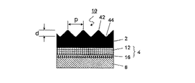
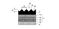
図1に示すように、ラミネートチューブ容器用積層体10は、外側から、少なくとも、外部表面層2、中間層4、および内部表面層6を順次に積層した構成からなることを基本構造とするものである。そして、更に、当該最外層である外部表面層2の全体に凹部44、および凸部42からなる、回折光沢を呈する微細凹凸構造からなる態様が形成されているものである。さらには、凹凸構造による様々な加飾が形成されていてもよい。
外部表面層2は、上記の態様を賦型され易くヒートシール性に優れた表面樹脂層を含む層である。
As shown in FIG. 1, the
The
ここで、図示はしないが、外部表面層2は、フレキソ印刷による外面絵柄印刷層をさらに有していてもよく、表面樹脂層の耐傷性、耐スクラッチ性、耐摩耗性、チュービング加工適性としての表面滑り性を高める為に、最表面に、表面保護層をまたさらに有することができる。但し、ヒートシールする箇所には、ヒートシール性を高めるために、表面保護層や外面絵柄印刷層を有していないことが好ましい。
表面保護層の厚さは、0.1μm以上、7μm以下が好ましい。上記範囲よりも薄いと表面保護効果が発揮され難く、上記範囲よりも厚いとラミネートチューブ容器用積層体10の剛性が強くなり過ぎて、ラミネートチューブ容器20を作製する際の加工性が低下する虞がある。
Here, although not shown, the
The thickness of the surface protective layer is preferably 0.1 μm or more and 7 μm or less. If it is thinner than the above range, the surface protection effect is difficult to be exhibited, and if it is thicker than the above range, the rigidity of the
また、回折光沢を呈する微細凹凸構造や加飾のための凹凸構造からなる態様は、外部表面層2に形成されているが、該表面保護層、該外面絵柄印刷層、前記表面樹脂層からなる群から選ばれる何れか1層または2層以上が、前期の回折光沢を呈する微細凹凸構造を有することができる。
外面絵柄印刷層および/または表面保護層が存在しない場合には、該態様は表面樹脂層に形成されているものである。
外面絵柄印刷層および/または表面保護層が存在する場合には、該態様は、最表面層である表面保護層に形成されていても、形成されていなくてもよい。
該態様が表面保護層に形成されていない場合であっても、外面絵柄印刷層または表面樹脂層に形成された該態様によって、回折光沢を生じることはできる。該態様が表面保護層に形成されている場合には、回折光沢を生じ易く、微細凹凸構造や加飾のための凹凸構造の触感による被識別容易性を得ることができる。
Further, an embodiment having a fine concavo-convex structure exhibiting diffractive gloss or a concavo-convex structure for decoration is formed on the
In the absence of the outer pattern printing layer and / or the surface protective layer, the embodiment is formed on the surface resin layer.
When the outer surface pattern printing layer and / or the surface protective layer is present, the embodiment may or may not be formed on the surface protective layer which is the outermost surface layer.
Even when the aspect is not formed on the surface protective layer, the diffractive gloss can be generated by the aspect formed on the outer surface pattern printing layer or the surface resin layer. When the aspect is formed on the surface protective layer, diffractive gloss is likely to occur, and it is possible to obtain easiness of identification by the tactile sensation of a fine concavo-convex structure or a concavo-convex structure for decoration.
そして、内部表面層は、ヒートシール性に優れた内面樹脂層を有する。
ラミネートチューブ容器用積層体10について更に具体的に例示すると、図2に示すように、少なくとも、外部表面層2、中間層4、および内部表面層6を順次に積層した構成からなり、当該外部表面層の表面に凹凸構造8を形成し、更に前記の中間層4が基材層12及びバリア層14を含むことができる。
The inner surface layer has an inner resin layer having excellent heat-sealing properties.
More specifically, as shown in FIG. 2, the
また、ラミネートチューブ容器用積層体10は、図3に示すように、少なくとも、外部表面層2、中間層4、および内部表面層6を順次に積層した構成からなり、当該外部表面層の全体に凹凸構造を形成し、更に、前記の中間層4を構成する基材層12が、その片面若しくは両面に文字、図形、記号、絵柄等の印刷層16を有することができる。
Further, as shown in FIG. 3, the laminate 10 for a laminated tube container has a structure in which at least the
さらにまた、ラミネートチューブ容器用積層体10は、図4に示すように、少なくとも、外部表面層2、中間層4、および内部表面層6を順次に積層した構成からなり、当該外部表面層2の全体に凹凸構造を形成し、更に、前記の中間層4を構成する基材層12がその片面に文字、図形、記号、絵柄等の印刷層16を有し、金属酸化物からなる蒸着膜18からなるバリア層14を有することができる。バリア層14は、金属蒸着膜、金属酸化物からなる蒸着膜、バリア性樹脂フィルムのいずれかであってよい。
Furthermore, as shown in FIG. 4, the
そして、上記に示したラミネートチューブ容器用積層体10は、その2,3の形態を例示したものであり、本発明は、上記に例示した構成からなるラミネートチューブ容器用積層体10にかかるもの限定されるものではなく、種々の形態のラミネートチューブ容器用積層体10を使用することができる。例えば、図示しないが、各層間には、用途、充填する内容物等によって、更に別の材料からなる層を設けることができ、また、その積層順序としては、任意に積層することができるものである。
The
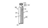
次に、上記のようなラミネートチューブ容器用積層体10を使用してラミネートチューブ容器20を製造する一例を挙げる。図5は、上記の図1〜図4に示すラミネートチューブ容器用積層体10を使用して製造した、ラミネートチューブ容器20の構成を示す概略的半断面図である。
Next, an example of manufacturing the
図5に示されたラミネートチューブ容器20を製造する際には、まず、上記の図1〜図4に示すラミネートチューブ容器用積層体10を丸めて、当該ラミネートチューブ容器用積層体10の両端部の最外層である外部表面層2の表面と、最内層である内部表面層6の表面とを重ね合わせ、その重合端部を溶着して溶着部22を形成して、筒状胴体部24を作製する。
次いで、上記の筒状胴体部24の一方の開口部の上部に、ラミネートチューブ容器20を構成する肩部26、口頸部28等からなる頭部30を常法に従って形成する。
When manufacturing the
Next, a
そして、図5に示すように、上記で形成した頭部30の口頸部28に、密閉する為のキャップ32を取り付けて、本発明のラミネートチューブ容器20を製造する。なお、上記で製造したラミネートチューブ容器20を完成する前に、筒状胴体部24の他方の開口部より、例えば、練り歯磨き等の内容物36を適量分だけ充填包装し、しかる後、該開口部を溶着して底溶着部34を形成して、内容物36を充填包装したラミネートチューブ包装体40を製造することができる。
上記に挙げた例は、一例を例示したに過ぎないものであり、これによって本発明が限定されるものではない。
Then, as shown in FIG. 5, a
The examples given above are merely examples, and the present invention is not limited thereto.
次に、ラミネートチューブ容器用積層体10や、ラミネートチューブ容器20等を構成する材料について説明する。
まず、外部表面層2、および、内部表面層6を構成する材料としては、前述のように、ラミネートチューブ容器用積層体10を丸めてその重合端部を溶着して筒状胴体部24を製造することから、加熱により溶融して相互に融着することができるヒートシール性を有する樹脂を使用して構成することが好ましいものである。そして、外部表面層2と内部表面層6を構成する材料とが、同じ種類の材料からなるものであれば、ヒートシール性を向上することができるので好ましい。
また、外部表面層2は、中間層4に形成される印刷層16を見ることができるようにする為には、透明であることが必要である。
Next, the materials constituting the
First, as the material constituting the
Further, the
上記のヒートシール性を有する樹脂としては、具体的には、例えば、低密度ポリエチレン、中密度ポリエチレン、高密度ポリエチレン、直鎖状(線状)低密度ポリエチレン、メタロセン触媒を使用して重合したエチレン−α・オレフィン共重合体、ポリプロピレン、エチレン−酢酸ビニル共重合体、アイオノマー樹脂、エチレン−アクリル酸共重合体、エチレン−アクリル酸エチル共重合体、エチレン−メタクリル酸共重合体、エチレン−メタクリル酸メチル共重合体、エチレン−プロピレン共重合体、メチルペンテンポリマー、ポリブテンポリマー、エチレン−アクリル酸共重合体、エチレン−メタクリル酸共重合体、ポリエチレンまたはポリプロピレン等のポリオレフィン系樹脂を不飽和カルボン酸を使用して酸変性した酸変性ポリオレフィン系樹脂、ポリ酢酸ビニル系樹脂、ポリ(メタ)アクリル系樹脂、ポリ塩化ビニル系樹脂、その他等の樹脂を使用することができる。 Specific examples of the resin having heat-sealing properties include low-density polyethylene, medium-density polyethylene, high-density polyethylene, linear (linear) low-density polyethylene, and ethylene polymerized using a metallocene catalyst. -Α-olefin copolymer, polypropylene, ethylene-vinyl acetate copolymer, ionomer resin, ethylene-acrylic acid copolymer, ethylene-ethyl acrylate copolymer, ethylene-methacrylic acid copolymer, ethylene-methacrylic acid Unsaturated carboxylic acids are used for polyolefin resins such as methyl copolymers, ethylene-propylene copolymers, methylpentene polymers, polybutene polymers, ethylene-acrylic acid copolymers, ethylene-methacrylic acid copolymers, polyethylene or polypropylene. Then, acid-modified acid-modified polyolefin-based resins, polyvinyl acetate-based resins, poly (meth) acrylic-based resins, polyvinyl chloride-based resins, and other resins can be used.
そして、上記のヒートシール性を有する樹脂は、例えば、フィルムないしシート、あるいは、その樹脂を含む組成物によるコーティング膜の状態で使用することができる。
その膜もしくはフィルムないしシートの厚さとしては、10μm〜200μmが好ましく、15μm〜100μmがより好ましい。
The above-mentioned resin having heat-sealing property can be used, for example, in the state of a film or sheet, or a coating film made of a composition containing the resin.
The thickness of the film or film or sheet is preferably 10 μm to 200 μm, more preferably 15 μm to 100 μm.
また、外部表面層2および内部表面層6において、多層積層して機能性樹脂層を形成する場合、その材料としては、酸素ガス、水蒸気等に対するバリア性、および/または、充填包装する内容物中に含まれる香料成分等の吸着が少なく保香性等に富み、更に、変味、異臭等を生じない性質を有し、かつ、押し出し成形が可能である樹脂を使用することができる。
Further, when the
上記の樹脂としては、具体的には、例えば、ポリアクリル系樹脂、ポリメタクリル系樹脂、ポリアクリロニトリル系樹脂、ポリメタクリロニトリル系樹脂、ポリスチレン系樹脂、ポリカーボネート系樹脂、ポリエチレンテレフタレート系樹脂若しくはそのエチレン成分および/またはテレフタレート成分の一部を他のジまたはそれ以上の多価アルコール成分またはジカルボン酸成分で共重合ないし変性した樹脂あるいはポリエチレンナフタレート系樹脂等のポリエステル系樹脂、ポリアミド系樹脂、エチレン−酢酸ビニル共重合体のケン化物、ポリビニルアルコール系樹脂、ポリ塩化ビニル系樹脂、ポリ塩化ビニリデン系樹脂、その他等の樹脂を使用することができる。 Specific examples of the above resin include polyacrylic resin, polymethacrylic resin, polyacrylonitrile resin, polymethacrylonitrile resin, polystyrene resin, polycarbonate resin, polyethylene terephthalate resin, and ethylene thereof. Resins in which some of the components and / or terephthalate components are copolymerized or modified with other di or higher polyhydric alcohol components or dicarboxylic acid components, polyester resins such as polyethylene naphthalate resins, polyamide resins, ethylene- Resins such as saponified vinyl acetate copolymers, polyvinyl alcohol-based resins, polyvinyl chloride-based resins, polyvinylidene chloride-based resins, and others can be used.
上記の樹脂の中でも、保香性を有すると共に酸素ガスあるいは水蒸気等に対するバリア性を有する樹脂を使用することが望ましく、具体的には、例えば、エチレン−酢酸ビニル共重合体のケン化物、ポリアミド系樹脂、ポリアクリロニトリル系樹脂、または、ポリエステル系樹脂等からなる保香性、バリア性等に富む樹脂を使用することが望ましいものである。 Among the above resins, it is desirable to use a resin having a fragrance-retaining property and a barrier property against oxygen gas, water vapor, etc. Specifically, for example, a saponified product of an ethylene-vinyl acetate copolymer or a polyamide-based resin. It is desirable to use a resin, a polyacrylonitrile-based resin, a polyester-based resin, or the like, which is rich in aroma-retaining property and barrier property.
次に、上記の各種の樹脂の1種ないしそれ以上を使用し、表面樹脂層2、および、内部表面層6を中間層4に形成する製造法について説明すると、その製造法としては、押し出しラミネート成形成膜法、Tダイキャスト成形成膜法等を採用することができる。
具体的には、フィードブロック法、マルチマニホールド法等のTダイキャスト成形法、あるいは、押し出しラミネート成形成膜法等の成形方法を使用して、上記の各種の樹脂を単独で製膜化する方法、あるいは、2種以上の各種の樹脂を使用して多層共押し出し製膜化する方法、更には、2種以上の樹脂を使用し、製膜化する前に混合して製膜化する方法等により、本発明にかかる表面樹脂層、および、内部表面層6を製造することができる。
Next, a manufacturing method for forming the
Specifically, a method of independently forming a film of the above-mentioned various resins by using a T-die cast molding method such as a feed block method or a multi-manifold method, or a molding method such as an extrusion laminate molding film forming method. Alternatively, a method of forming a multi-layer coextrusion film using two or more kinds of resins, a method of using two or more kinds of resins and mixing them before forming a film, etc. Thereby, the surface resin layer and the
図1〜4、7に示すように、回折光沢を呈する微細凹凸構造は、凹部44、凸部42を有し、深さdは、好ましくは50nm以上、2000nm以下、より好ましくは70nm以上、1500nm以下、更に好ましくは150nm以上、1500nm以下である。さらに、ピッチpは、1200nm以上、2800nm以下が好ましい。深さとピッチが上記範囲であれば、優れた視認性の回折光沢を安定して得ることができる。
As shown in FIGS. 1 to 4 and 7, the fine uneven structure exhibiting diffractive gloss has
図7に示すように、本発明において、回折光沢を呈する微細凹凸構造は、筒状胴体部24の外部表面層の全体に、頭部と筒状胴体部の底部とを結ぶ方向に対して略90度または略0度の方向に延びた線状の凸部として形成されている。
上記の角度の方向にすることによって、消費者の好みの回折光沢の視認性、干渉縞の太さの変更による意匠性、触感性に調節することができる。
ここで、線状の凸部の断面形状は略三角形であることが好ましい。
そして、該略三角形は、凸部頂点を挟む二辺の長さが略等しい略二等辺三角形であることが好ましく、凸部頂点および/または凹部底は明確な角でなく、丸まっていてもよい。略二等辺三角形であることによって、虹光沢が視認される方向の偏りを低減できる。また、角が明確でなくても虹光沢の視認性に大きな影響は発生しない
また、線状の凸部は、賦型方向(x方向)と直角の方向(y方向)に対して、0°以上、1°以下の傾きを有していることが好ましい。該角度を有することによって、賦型時の離型性に優れることができる。
As shown in FIG. 7, in the present invention, the fine uneven structure exhibiting diffractive luster is substantially relative to the direction connecting the head and the bottom of the tubular body portion over the entire outer surface layer of the
By setting the direction of the above angle, it is possible to adjust the visibility of the diffractive gloss of the consumer's preference, the design by changing the thickness of the interference fringes, and the tactile sensation.
Here, it is preferable that the cross-sectional shape of the linear convex portion is substantially triangular.
The substantially isosceles triangle having substantially the same length of the two sides sandwiching the convex apex is preferable, and the convex apex and / or the concave bottom may be rounded instead of a clear corner. .. By having a substantially isosceles triangle, it is possible to reduce the bias in the direction in which the rainbow gloss is visually recognized. Further, even if the angle is not clear, the visibility of the rainbow gloss is not significantly affected. Further, the linear convex portion is 0 ° with respect to the direction perpendicular to the shaping direction (x direction) (y direction). As mentioned above, it is preferable to have an inclination of 1 ° or less. By having the angle, the releasability at the time of molding can be excellent.
外部表面層2の外部表面は、回折光沢を呈し、入射角60度におけるグロス値が、3以上、70以下であることが好ましい。
さらに、該外部表面の入射角60度におけるグロス値は、微細凹凸構造が無い場合に比べて低い値であり、その差分が、5以上、70以下であることが好ましい。
The outer surface of the
Further, the gloss value at an incident angle of 60 degrees on the outer surface is a lower value than when there is no fine uneven structure, and the difference is preferably 5 or more and 70 or less.
回折光沢を呈する微細凹凸構造がラミネートチューブ容器20に視認性と触感性を付与することによって、ラミネートチューブ容器20は、外観および触感による被識別容易性を有し、また、消費者がラミネートチューブ容器20を持ちやすいという利点を有する。
外部表面層には、さらに、様々な加飾のための凹凸構造を加えることができ、これによって、上記の利点をさらに高めることができる。
The fine concavo-convex structure exhibiting diffractive luster imparts visibility and tactile sensation to the
The outer surface layer can also be added with a variety of concavo-convex structures for decoration, which can further enhance the above advantages.
図6は、本発明にかかるラミネートチューブ容器用積層体の貼り合わせ及び表面全体に凹凸構造を形成する方法を示す概略図である。
図6に示すように、第1給紙100より基材シート(中間層)4の巻取をセットし、基材シート(中間層)4が第1給紙100より案内ロール102を介して供給され、その片面側に溶融した表面樹脂層2として溶融押出し樹脂層を押出ラミネーターのTダイス104より押出して塗布後、表面に凹凸構造を形成した冷却ロール106と、表面が平滑のゴムロール108の間に通し、押出しラミネート成形製膜法によってラミネートすることにより、巻き取りロール112に巻き取り、表面に凹凸構造を有する積層シート110を得ることができる。
ロール表面への凹凸構造の形成は、微細凹凸構造は機械切削によって設け、回折光沢以外の加飾のための凹凸構造はミル彫刻によって設けてもよい。
FIG. 6 is a schematic view showing a method of laminating the laminated body for a laminated tube container and forming an uneven structure on the entire surface according to the present invention.
As shown in FIG. 6, the take-up of the base sheet (intermediate layer) 4 is set from the
As for the formation of the uneven structure on the roll surface, the fine uneven structure may be provided by mechanical cutting, and the uneven structure for decoration other than diffraction gloss may be provided by mill engraving.
上記の材料からなる溶融樹脂をTダイから押し出すTダイキャスト成形成膜法若しくはインフレーション成形製膜法にて、表面に凹凸構造を有するフィルムないしシートを製造することができる。しかる後に、他の層と通常の包装材料を製造するときに使用するラミネートする方法、例えば、ウエットラミネーション法、ドライラミネーション法、無溶剤型ドライラミネーション法、その他等の任意の方法でラミネートすることによりラミネートチューブ容器用積層体10の表面に均一な回折光沢を呈する微細凹凸構造や加飾のための凹凸構造を形成することができる。
あるいは、型からの熱圧転写による賦型を用いて、同様な、回折光沢を呈する微細凹凸構造や加飾のための凹凸構造を形成することができる。
A film or sheet having an uneven structure on the surface can be produced by a T-die cast molding film forming method or an inflation molding film forming method in which a molten resin made of the above materials is extruded from a T die. After that, by laminating with other layers by any method used in the production of ordinary packaging materials, such as wet lamination method, dry lamination method, solvent-free dry lamination method, etc. It is possible to form a fine concavo-convex structure exhibiting a uniform diffractive luster and a concavo-convex structure for decoration on the surface of the
Alternatively, by using the shaping by thermal pressure transfer from the mold, it is possible to form a similar fine concavo-convex structure exhibiting diffractive luster and a concavo-convex structure for decoration.
本発明のラミネートチューブ容器20において、中間層4は、基材層12、及び、バリア層18から構成することができる。
中間層4を構成する基材層12の材料として、例えば、ラミネートチューブ容器を構成する基本素材としての、機械的、物理的、化学的、その他等において優れた性質を有し、特に、強度を有して強靱であり、かつ耐熱性を有する樹脂のフィルムないしシートや、紙層を構成する各種の紙基材を使用することができる。
In the
As a material of the
樹脂のフィルムないしシートとしては、具体的には、例えば、ポリエステル系樹脂、ポリアミド系樹脂、ポリアラミド系樹脂、ポリオレフィン系樹脂、ポリカーボネート系樹脂、ポリアセタール系樹脂、フッ素系樹脂、その他等の強靱な樹脂のフィルムないしシート、その他等を使用することができる。 Specific examples of the resin film or sheet include tough resins such as polyester resin, polyamide resin, polyaramid resin, polyolefin resin, polycarbonate resin, polyacetal resin, fluorine resin, and others. A film, a sheet, etc. can be used.
そして、上記の樹脂のフィルムないしシートとしては、未延伸フィルム、あるいは一軸方向または二軸方向に延伸した延伸フィルム等のいずれのものでも使用することができる。
そのフィルムないしシートの厚さとしては、5μm〜100μmが好ましく、10μm〜50μmがより好ましい。
As the resin film or sheet, any unstretched film, stretched film stretched in the uniaxial direction or biaxial direction, or the like can be used.
The thickness of the film or sheet is preferably 5 μm to 100 μm, more preferably 10 μm to 50 μm.
紙基材としては、賦型性、耐屈曲性、剛性等を持たせるものを使用することができ、例えば、強サイズ性の晒または未晒の紙基材、あるいは純白ロール紙、クラフト紙、板紙、加工紙等の紙基材、その他等を使用することができる。 As the paper base material, those having shapeability, bending resistance, rigidity, etc. can be used. For example, strong size bleached or unbleached paper base material, pure white roll paper, kraft paper, etc. Paper base materials such as paperboard and processed paper, and others can be used.
上記の紙基材としては、坪量80g/m2〜600g/m2のものが好ましく、坪量100g/m2〜450g/m2のものがより好ましい。勿論、本発明においては、紙層を構成する紙基材と、上記に挙げた基材フィルムとしての各種の樹脂のフィルムないしシート等を併用して使用することができる。 As the paper substrate preferably has a basis weight of 80g / m 2 ~600g / m 2 , it is more preferred basis weight 100g / m 2 ~450g / m 2 . Of course, in the present invention, the paper base material constituting the paper layer and various resin films or sheets as the base material film mentioned above can be used in combination.
本発明においては、上記のような中間層4を構成する基材層12の片面若しくは両面に、グラビア印刷方式、フレキソ印刷方式等の印刷方法で、例えば、文字、図形、記号、絵柄、模様等の所望の絵柄印刷層16を形成することができる。
中間層を構成する基材層に絵柄印刷層16を形成する場合、当該最外層である外部表面層2の全体に凹凸構造を形成することによって、外部からの衝撃でインキ擦れ等を生じることもなく、インキの密着強度を向上させることができるという利点を有する。
In the present invention, a printing method such as a gravure printing method or a flexographic printing method is used on one or both sides of the
When the
表面保護層および/または外面絵柄印刷層は、硝化綿樹脂、ポリウレタン樹脂、アクリル樹脂、ポリアミド樹脂、塩酢ビ樹脂、塩素化PP樹脂等を含有する樹脂組成物またはインキを用いて、フレキソ印刷やグラビア印刷によって形成することができる。
表面保護層は、特に、アクリル系のOPニスを用いたグラビア印刷や、フレキソ印刷用のニスを用いたフレキソ印刷によって、形成することが好ましい。
外面絵柄印刷層は、特に、アクリルUVインキを用いたフレキソ印刷やグラビア印刷によって形成することが好ましい。
回折光沢を呈する微細凹凸構造や回折光沢以外の加飾のための凹凸構造の賦型を、表面保護層や外面絵柄印刷層が形成された原反に対して行うことができる。この方法による場合には、回折光沢を呈する微細凹凸構造や加飾のための凹凸構造は、最表面である表面保護層には形成されているが、その下層の外面絵柄印刷層および/または表面樹脂層に形成されていてもよく、形成されていなくてもよい。
または、回折光沢を呈する微細凹凸構造や加飾のための凹凸構造の賦型が完了した積層体の表面樹脂層上に、表面保護層や外面絵柄印刷層を形成することもできる。この方法による場合には、回折光沢を呈する微細凹凸構造や加飾のための凹凸構造は、表面保護層および/または外面絵柄印刷層には、回折光沢を呈する微細凹凸構造や加飾のための凹凸構造は、形成されていてもよく、形成されていなくてもよい。表面保護層および/または外面絵柄印刷層に該凹凸構造を形成する場合には、形成され易いように、表面保護層および/または外面絵柄印刷層の形成方法や厚さを調整することが好ましい。
あるいは、回折光沢を呈する微細凹凸構造や加飾のための凹凸構造の賦型が完了した積層体の外面絵柄印刷層上に、表面保護層を形成してもよい。この方法による場合には、回折光沢を呈する微細凹凸構造や加飾のための凹凸構造は、表面保護層には、回折光沢を呈する微細凹凸構造や加飾のための凹凸構造は、形成されていてもよく、形成されていなくてもよい。表面保護層に該凹凸構造を形成する場合には、形成され易いように、表面保護層の形成方法や厚さを調整することが好ましい。
さらに、賦型済みのラミネートチューブ容器用積層体10中の表面樹脂層や表面保護層を、EB硬化またはUV硬化することで表面硬度を高めて、耐傷性を高めることもできる。
The surface protective layer and / or the outer pattern printing layer may be flexo-printed using a resin composition or ink containing a nitrified cotton resin, a polyurethane resin, an acrylic resin, a polyamide resin, a salt vinegar resin, a chlorinated PP resin, or the like. It can be formed by gravure printing.
The surface protective layer is particularly preferably formed by gravure printing using an acrylic OP varnish or flexographic printing using a varnish for flexographic printing.
The outer pattern printing layer is particularly preferably formed by flexographic printing or gravure printing using acrylic UV ink.
The fine concavo-convex structure exhibiting diffractive gloss and the concavo-convex structure for decoration other than diffractive gloss can be formed on the original fabric on which the surface protection layer and the outer surface pattern printing layer are formed. In the case of this method, a fine concavo-convex structure exhibiting diffractive gloss and a concavo-convex structure for decoration are formed on the outermost surface protective layer, but the outer surface pattern printing layer and / or the surface of the lower layer thereof. It may or may not be formed on the resin layer.
Alternatively, a surface protective layer or an outer surface pattern printing layer can be formed on the surface resin layer of the laminate in which the fine uneven structure exhibiting diffractive gloss or the uneven structure for decoration has been molded. In the case of this method, the fine concavo-convex structure exhibiting diffractive gloss and the concavo-convex structure for decoration are provided, and the surface protective layer and / or the outer surface pattern printing layer is provided with the fine concavo-convex structure exhibiting diffractive gloss and the uneven structure for decoration. The uneven structure may or may not be formed. When the uneven structure is formed on the surface protective layer and / or the outer surface pattern print layer, it is preferable to adjust the method and thickness of the surface protective layer and / or the outer surface pattern print layer so that the uneven structure can be easily formed.
Alternatively, a surface protective layer may be formed on the outer surface pattern printing layer of the laminated body in which the shaping of the fine uneven structure exhibiting diffractive gloss or the uneven structure for decoration is completed. In the case of this method, a fine concavo-convex structure exhibiting diffractive gloss and a concavo-convex structure for decoration are formed, and a fine concavo-convex structure exhibiting diffractive gloss and a concavo-convex structure for decoration are formed on the surface protective layer. It may or may not be formed. When the uneven structure is formed on the surface protective layer, it is preferable to adjust the method and thickness of the surface protective layer so that the uneven structure can be easily formed.
Further, the surface resin layer and the surface protective layer in the molded laminate
更にまた、本発明において、上記の中間層4を構成するバリア層18の材料としては、例えば、酸素ガス、水蒸気等に対するバリア性素材、太陽光等に対する遮光性を有するバリア性素材、あるいは、内容物に対する保香性等を有するバリア性素材等を使用することができる。
Furthermore, in the present invention, the material of the
上記のバリア性素材としては、具体的には、例えば、金属箔や、金属蒸着層、無機酸化物の蒸着層、金属酸化物の蒸着層を有する樹脂フィルムや、バリア性樹脂からなるコーティング膜またはバリア性樹脂フィルムを使用することができる。特に、金属蒸着膜、または、金属酸化物の蒸着膜のいずれかであることが、酸素ガス、水蒸気、遮光性、保香性等のバリア性に優れ、容器の廃棄面において環境にやさしいという利点を有するため好ましい。 Specific examples of the barrier material include a metal foil, a metal vapor deposition layer, an inorganic oxide vapor deposition layer, a resin film having a metal oxide vapor deposition layer, and a coating film made of a barrier resin. A barrier resin film can be used. In particular, either a metal vapor deposition film or a metal oxide vapor deposition film has excellent barrier properties such as oxygen gas, water vapor, light shielding property, and fragrance retention property, and has an advantage of being environmentally friendly in terms of container disposal. It is preferable because it has.
具体的なバリア性素材としては、アルミニウム箔や、アルミニウム等の金属、シリカ、アルミナ、その他のセラミックの蒸着膜をPETフィルム等の樹脂フィルム上に形成したものが挙げられる。上記のその他のセラミックとしては、酸化インジウム錫(ITO)や、亜鉛、錫、チタン、ジルコニウム、バナジウム、バリウム、クロム等の酸化物、窒化珪素、炭化珪素等が使用できる。
これらのバリア性素材は、一種ないしそれ以上を組み合わせて使用することができ、使用する金属、金属酸化物または無機酸化物を1種または2種以上の混合物で使用し、異種の材質で混合した無機酸化物の蒸着膜を形成することもできる。
Specific examples of the barrier material include an aluminum foil, a metal such as aluminum, silica, alumina, and other ceramic vapor-deposited films formed on a resin film such as a PET film. As the above-mentioned other ceramics, indium tin oxide (ITO), oxides such as zinc, tin, titanium, zirconium, vanadium, barium and chromium, silicon nitride, silicon carbide and the like can be used.
These barrier materials can be used in combination of one or more, and the metal, metal oxide or inorganic oxide to be used is used in one or a mixture of two or more, and mixed with different materials. It is also possible to form a vapor-deposited film of an inorganic oxide.
上記の蒸着膜を支持する樹脂フィルムとしては、これに蒸着層を設けることから、機械的、物理的、化学的、その他等において優れた性質を有し、特に強度を有して強靭であり、かつ、耐熱性を有する樹脂のフィルムないしシートを使用することができる。 Since the resin film that supports the above-mentioned vapor-deposited film is provided with the vapor-deposited layer, it has excellent mechanical, physical, chemical, and other properties, and is particularly strong and tough. Moreover, a resin film or sheet having heat resistance can be used.
上記の蒸着膜を支持する樹脂フィルムとしては、具体的には、例えば、ポリエチレンテレフタレート等のポリエステル系樹脂フィルム、各種ナイロン等のポリアミド系樹脂フィルム、ポリエチレン系樹脂、ポリプロピレン系樹脂、環状ポリオレフィン樹脂、ポリスチレン系樹脂、アクリロニトリル−スチレン共重合体(AS樹脂)、アクリロニトリル−ブタジエン−スチレン共重合体(ABS樹脂)、ポリブデン樹脂フィルム等のポリオレフィンフィルム、ポリ塩化ビニル系樹脂、ポリカーボネート系樹脂、ポリイミド系樹脂、ポリアミドイミド系樹脂、ポリアリールフタレート樹脂、シリコーン系樹脂、ポリスルホン系樹脂、ポリフェニレンスルフィド系樹脂、ポリエーテルスルホン系樹脂、ポリウレタン系樹脂、セルロース系樹脂、ポリ(メタ)アクリル系樹脂、ポリ塩化ビニリデンフィルム、アセタール系樹脂フィルム、フッ素系樹脂、その他等を使用することができる。なお、本発明においては、特に、ポリプロピレン系樹脂、ポリエステル系樹脂、または、ポリアミド系樹脂のフィルムないしシートを使用することが好ましい。 Specific examples of the resin film supporting the above-mentioned vapor deposition film include polyester resin films such as polyethylene terephthalate, polyamide resin films such as various nylons, polyethylene resins, polypropylene resins, cyclic polyolefin resins, and polystyrenes. Polyethylene films such as based resins, acrylonitrile-styrene copolymers (AS resins), acrylonitrile-butadiene-styrene copolymers (ABS resins), polybuden resin films, polyvinyl chloride resins, polycarbonate resins, polyimide resins, polyamides Imid resin, polyarylphthalate resin, silicone resin, polysulfone resin, polyphenylene sulfide resin, polyether sulfone resin, polyurethane resin, cellulose resin, poly (meth) acrylic resin, polyvinylidene chloride film, acetal A based resin film, a fluororesin, etc. can be used. In the present invention, it is particularly preferable to use a polypropylene-based resin, a polyester-based resin, or a polyamide-based resin film or sheet.
本発明において、バリア層を構成する蒸着膜を形成する方法としては、上記のような金属または金属酸化物または無機酸化物を原料として用いた、例えば、真空蒸着法、スパッタリング法、イオンプレーティング法クラスターイオンビーム法等の物理気相成長法(PhysicalVaporDeposition法、PVD法)、あるいは、プラズマ化学気相成長法、熱化学気相成長法、光化学気相成長法等の化学気相成長法(ChemicalVaporDeposition法、CVD法)等が挙げられ、これらを利用して、樹脂のフィルムの上に蒸着薄膜を形成することができる。 In the present invention, as a method for forming a vapor deposition film constituting a barrier layer, for example, a vacuum vapor deposition method, a sputtering method, or an ion plating method using the above-mentioned metal or metal oxide or inorganic oxide as a raw material. Physical vapor deposition method such as cluster ion beam method (Physical Vapor Deposition method, PVD method), or chemical vapor deposition method such as plasma chemical vapor deposition method, thermochemical vapor deposition method, photochemical vapor deposition method, etc. , CVD method) and the like, and these can be used to form a thin-film vapor deposition thin film on a resin film.
更に具体的に説明すると、上記のPVD法では、例えば、巻き取り式蒸着機を使用し、真空チャンバーの中で、巻き出しロールから出た樹脂フィルムを蒸着チャンバーの中に入れ、ここで、るつぼで熱せられた蒸着源を蒸発させ、更に、必要ならば、酸素吹き出し口より酸素等を噴出させながら、冷却したコーティングドラム上の樹脂のフィルムの上に、マスクを介して蒸着膜を成膜化し、次いで蒸着薄膜を形成した樹脂のフィルムを巻き取りロールに巻き取ることによって、本発明にかかる蒸着薄膜を有する樹脂のフィルムを製造することができる。 More specifically, in the above PVD method, for example, a take-up type vapor deposition machine is used, and the resin film discharged from the unwinding roll is put into the vapor deposition chamber in a vacuum chamber, and here, a pot is used. The vapor deposition source heated by the above is evaporated, and if necessary, oxygen or the like is ejected from the oxygen outlet to form a thin film deposition film on the resin film on the cooled coating drum via a mask. Then, by winding the resin film on which the thin-film deposition thin film is formed on a take-up roll, the resin film having the thin-film deposition thin film according to the present invention can be produced.
一方、上記のCVD法では、蒸着チャンバー内に配置された巻き出しロールから繰り出した樹脂のフィルム面に、蒸着チャンバー内の冷却、電極ドラム周面上において、蒸着原料揮発供給装置から供給される例えばモノマーガスとしての有機珪素化合物、酸素ガス、不活性ガスからなる混合ガスを導入し、プラズマによって酸化珪素の蒸着薄膜を形成した樹脂のフィルムを製造することができる。
本発明においては、上記のような金属箔や、金属または金属酸化物または無機酸化物の蒸着薄膜を有する樹脂のフィルムは、酸素ガス、あるいは、水蒸気等が透過することを阻止し、これらに対するバリア層としての機能を奏するものである。
On the other hand, in the above CVD method, for example, the resin film surface unwound from the unwinding roll arranged in the vapor deposition chamber is cooled in the vapor deposition chamber and supplied from the vapor deposition raw material volatilization supply device on the peripheral surface of the electrode drum. A resin film in which a thin-film film of silicon oxide is formed by plasma can be produced by introducing a mixed gas composed of an organic silicon compound as a monomer gas, an oxygen gas, and an inert gas.
In the present invention, the metal foil as described above and the resin film having a thin-film film of metal or metal oxide or inorganic oxide prevent oxygen gas, water vapor, etc. from permeating and barrier against them. It functions as a layer.
十分なバリア性を得るために、通常、アルミニウム箔の厚さは5μm〜30μmが好ましく、また、金属、金属酸化物、または無機酸化物の蒸着膜の厚さは、50Å〜3000Åが好ましく、100Å〜2000Åがより好ましく、100Å〜1000Åが更に好ましい。
更に詳しくは、上記のPVD法においては、酸化アルミニウムの蒸着薄膜の膜厚は、200Å〜1000Åが好ましく、300Å〜500Åがより好ましく、また、上記のCVD法においては、酸化珪素の蒸着薄膜の膜厚は、50Å〜500Åが好ましく、100Å〜300Åがより好ましい。
なお、上記において、総じて、金属酸化物、無機酸化物の蒸着薄膜の厚さが2000Åを超えると、金属酸化物、無機酸化物の蒸着薄膜にクラック等が入りやすくなることによってバリア性が低下するという危険性があると共に、材料コストが高くなるという問題点であるので好ましくはなく、また、100Å未満であると、その機能を奏することが困難になることから好ましくない。
In order to obtain sufficient barrier properties, the thickness of the aluminum foil is usually preferably 5 μm to 30 μm, and the thickness of the vapor-deposited film of the metal, metal oxide, or inorganic oxide is preferably 50 Å to 3000 Å, 100 Å. ~ 2000 Å is more preferable, and 100 Å to 1000 Å is even more preferable.
More specifically, in the above PVD method, the film thickness of the thin-film film of aluminum oxide is preferably 200 Å to 1000 Å, more preferably 300 Å to 500 Å, and in the above CVD method, the film thickness of the thin-film film of silicon oxide is vapor-deposited. The thickness is preferably 50 Å to 500 Å, more preferably 100 Å to 300 Å.
In the above, if the thickness of the thin-film film of metal oxide or inorganic oxide exceeds 2000 Å, the barrier property is lowered because cracks or the like are likely to occur in the thin-film film of metal oxide or inorganic oxide. It is not preferable because it has a problem that the material cost is high, and it is not preferable if it is less than 100 Å because it becomes difficult to perform its function.
バリア性樹脂からなるコーティング膜またはバリア性樹脂フィルム、あるいは、保香性等を有する素材等としては、例えば、ポリ塩化ビニリデン系樹脂、ポリエステル系樹脂、ポリアミド系樹脂、エチレン−酢酸ビニル共重合体(酢酸ビニルがおよそ79質量%〜92質量%)を完全ケン化したエチレン含有率25モル%〜50モル%のエチレン−ビニルアルコール共重合体、ポリビニルアルコール、ポリアクリロニトリル、その他等のガスバリア性に富む樹脂のフィルムないしシート、あるいは、コーティング膜を使用することができる。 Examples of the coating film or barrier resin film made of a barrier resin, or a material having a fragrance-retaining property include polyvinylidene chloride resin, polyester resin, polyamide resin, and ethylene-vinyl acetate copolymer ( Ethylene-vinyl alcohol copolymer with an ethylene content of 25 mol% to 50 mol%, which is completely saponified from vinyl acetate (approximately 79% by mass to 92% by mass), polyvinyl alcohol, polyacrylonitrile, and other resins with rich gas barrier properties. A film or sheet of the above, or a coating film can be used.
中間層4を構成する材料としては、例えば、太陽光等の光を遮光する性質を有する遮光性素材使用することができ、これは、単体の基材でもよく、あるいは二種以上の基材を組み合わせてなる複合基材等であってもよい。
具体的な遮光性素材としては、例えば、アルミニウム箔ならば、5μm〜30μmの厚さのものが好ましく、また、アルミニウム等の金属の蒸着膜ならば、50Å〜3000Åの厚さのものが好ましく、100Å〜1000Åの厚さのものがより好ましい。
As the material constituting the
As a specific light-shielding material, for example, an aluminum foil having a thickness of 5 μm to 30 μm is preferable, and a metal vapor deposition film such as aluminum has a thickness of 50 Å to 3000 Å. More preferably, the thickness is 100 Å to 1000 Å.
さらに、遮光性素材としては、樹脂に顔料等の着色剤、更に、その他等の所望の添加剤を加えて混練してフィルム化してなる遮光性を有する各種の着色樹脂のフィルムないしシート等を使用することができる。これらの材料は、一種ないしそれ以上を組み合わせて使用することができる。上記のフィルムないしシートの厚さは、任意であるが、通常、5μm〜300μmが好ましく、10μm〜100μmがより好ましい。 Further, as the light-shielding material, various colored resin films or sheets having light-shielding properties, which are formed by adding a colorant such as a pigment to the resin and further adding a desired additive such as others to form a film, are used. can do. These materials can be used in combination of one or more. The thickness of the film or sheet is arbitrary, but is usually preferably 5 μm to 300 μm, more preferably 10 μm to 100 μm.
そして、通常、ラミネートチューブ容器20は、物理的にも化学的にも過酷な条件におかれることから、かかる容器を構成するラミネートチューブ容器用積層体10には、厳しい包装適性が要求され、変形防止強度、落下衝撃強度、耐ピンホール性、耐熱性、密封性、品質保全性、作業性、衛生性、その他等の種々の条件が要求される。このために、本発明においては、ラミネートチューブ容器用積層体10に、上記のような材料の他に、上記のような諸条件を充足するその他の材料を任意に使用することができる。
Since the
具体的には、例えば、低密度ポリエチレン、中密度ポリエチレン、高密度ポリエチレン、線状低密度ポリエチレン、ポリプロピレン、エチレン−プロピレン共重合体、エチレン−酢酸ビニル共重合体、アイオノマー樹脂、エチレン−アクリル酸エチル共重合体、エチレン−アクリル酸またはメタクリル酸共重合体、メチルペンテンポリマー、ポリブテン系樹脂、ポリ塩化ビニル系樹脂、ポリ酢酸ビニル系樹脂、ポリ塩化ビニリデン系樹脂、塩化ビニル−塩化ビニリデン共重合体、ポリ(メタ)アクリル系樹脂、ポリアクリルニトリル系樹脂、ポリスチレン系樹脂、アクリロニトリル−スチレン共重合体(AS系樹脂)、アクリロニトリル−ブタジェン−スチレン共重合体(ABS系樹脂)、ポリエステル系樹脂、ポリアミド系樹脂、ポリカーボネート系樹脂、ポリビニルアルコール系樹脂、エチレン−酢酸ビニル共重合体のケン化物、フッ素系樹脂、ジエン系樹脂、ポリアセタール系樹脂、ポリウレタン系樹脂、ニトロセルロース、その他等の公知の樹脂のフィルムないしシートから任意に選択して使用することができる。その他、例えば、セロハン等のフィルム、合成紙等も使用することができる。
また、無機・有機フィラー等の着色剤を練り込んだポリエチレン樹脂等のフィルムないしシートを用いることもでき、具体的には、酸化チタン等を練り込んだ乳白ポリエチレン、カーボンブラック等を練り込んだブラックポリエチレン等のフィルムないしシートを用いることができる。
Specifically, for example, low-density polyethylene, medium-density polyethylene, high-density polyethylene, linear low-density polyethylene, polypropylene, ethylene-propylene copolymer, ethylene-vinyl acetate copolymer, ionomer resin, ethyl ethylene-acrylate. Copolymer, ethylene-acrylic acid or methacrylic acid copolymer, methylpentene polymer, polybutene resin, polyvinyl chloride resin, polyvinyl acetate resin, polyvinylidene chloride resin, vinyl chloride-vinylidene chloride copolymer, Poly (meth) acrylic resin, polyacrylic nitrile resin, polystyrene resin, acrylonitrile-styrene copolymer (AS resin), acrylonitrile-butagen-styrene copolymer (ABS resin), polyester resin, polyamide resin Films of known resins such as resins, polycarbonate resins, polyvinyl alcohol resins, saponified ethylene-vinyl acetate copolymers, fluorine resins, diene resins, polyacetal resins, polyurethane resins, nitrocellulose, etc. It can be arbitrarily selected from the sheet and used. In addition, for example, a film such as cellophane, synthetic paper, or the like can also be used.
Further, a film or sheet such as polyethylene resin kneaded with a colorant such as an inorganic / organic filler can also be used. Specifically, opalescent polyethylene kneaded with titanium oxide or the like, black kneaded with carbon black or the like can be used. A film or sheet such as polyethylene can be used.
本発明において、上記のフィルムないしシートは、未延伸、一軸ないし二軸方向に延伸されたもの等のいずれのものでも使用することができる。また、その厚さは、任意であるが、数μm〜300μm位の範囲から選択して使用することができる。更に、本発明においては、フィルムないしシートとしては、押し出し成膜、インフレーション成膜、コーティング膜等のいずれの性状の膜でもよい。 In the present invention, the above-mentioned film or sheet can be any of unstretched, uniaxially and biaxially stretched films and the like. The thickness thereof is arbitrary, but can be selected and used from the range of several μm to 300 μm. Further, in the present invention, the film or sheet may be a film having any properties such as an extruded film, an inflation film, and a coating film.
次に、上記の本発明において、上記のような材料を使用して、本発明にかかるラミネートチューブ容器20を形成するラミネートチューブ容器用積層体10を製造する方法について説明する。
かかる方法としては、通常の包装材料を製造するときに使用するラミネートする方法、例えば、ウエットラミネーション法、ドライラミネーション法、無溶剤型ドライラミネーション法、押し出しラミネーション法、Tダイ共押し出し成形法、共押し出しラミネーション法、インフレーション法、その他等の任意の方法が挙げられる。
Next, in the above-mentioned present invention, a method for manufacturing the
Such a method includes a laminating method used in manufacturing ordinary packaging materials, for example, a wet lamination method, a dry lamination method, a solvent-free dry lamination method, an extrusion lamination method, a T-die co-extrusion molding method, and a co-extrusion method. Any method such as lamination method, inflation method, etc. can be mentioned.
そして、上記のラミネートを行う際には、必要ならば、例えば、コロナ処理、オゾン処理等の前処理をフィルムに施すことができ、また、例えば、イソシアネート系(ウレタン系)、ポリエチレンイミン系、ポリブタジェン系、有機チタン系等のアンカーコーティング剤、あるいはポリウレタン系、ポリアクリル系、ポリエステル系、エポキシ系、ポリ酢酸ビニル系、セルロース系、その他等のラミネート用接着剤等のアンカーコート剤、接着剤等を任意に使用することができる。 Then, when performing the above laminating, if necessary, pretreatment such as corona treatment and ozone treatment can be applied to the film, and for example, isocyanate-based (urethane-based), polyethyleneimine-based, and polybutagen can be applied. Anchor coating agents such as polyurethane-based and organic titanium-based, or anchor coating agents and adhesives such as polyurethane-based, polyacrylic-based, polyester-based, epoxy-based, polyvinyl acetate-based, cellulose-based, and other laminating adhesives. It can be used arbitrarily.
押し出しラミネートする際の接着性樹脂層を構成する押し出し樹脂としては、例えば、ポリエチレン、エチレン−α・オレフィン共重合体、ポリプロピレン、ポリブテン、ポリイソブテン、ポエイソブチレン、ポリブタジエン、ポリイソプレン、エチレン−メタクリル酸共重合体、あるいはエチレン−アクリル酸共重合体等のエチレンと不飽和カルボン酸との共重合体、あるいはそれらを変性した酸変性ポリオレフィン系樹脂、エチレン−アクリル酸エチル共重合体、アイオノマー樹脂、エチレン−酢酸ビニル共重合体、その他等を使用することができる。 Examples of the extruded resin constituting the adhesive resin layer at the time of extrusion laminating include polyethylene, ethylene-α / olefin copolymer, polypropylene, polybutene, polyisobutene, poeisobutylene, polybutadiene, polyisoprene, and ethylene-methacrylate copolymer. Combined or copolymer of ethylene and unsaturated carboxylic acid such as ethylene-acrylic acid copolymer, or acid-modified polyolefin resin, ethylene-ethyl acrylate copolymer, ionomer resin, ethylene-acetic acid modified from them Vinyl copolymers, etc. can be used.
ドライラミネートする際の接着剤層を構成する接着剤としては、具体的には、ドライラミネート等において使用される2液硬化型ウレタン系接着剤、ポリエステルウレタン系接着剤、ポリエーテルウレタン系接着剤、アクリル系接着剤、ポリエステル系接着剤、ポリアミド系接着剤、ポリ酢酸ビニル系接着剤、エボキシ系接着剤、ゴム系接着剤、その他等を使用することができる。 Specific examples of the adhesive constituting the adhesive layer for dry laminating include a two-component curable urethane-based adhesive, a polyester urethane-based adhesive, and a polyether urethane-based adhesive used in dry laminating and the like. Acrylic adhesives, polyester adhesives, polyamide adhesives, polyvinyl acetate adhesives, evoxy adhesives, rubber adhesives, etc. can be used.
ラミネートチューブ容器20を製造する際の、例えば、筒状胴体部24を製造する際の、ヒートシール(溶着)する方法としては、例えば、バーシール、回転ロールシール、ベルトシール、インパルスシール、高周波シール、超音波シール、火炎シール等を挙げることができる。
As a method of heat-sealing (welding) when manufacturing the
本発明においては、上記で製造したラミネートチューブ容器用積層体10を、まず丸めてその重合端部を溶着してラミネートチューブ容器20を構成する筒状胴体部24を製造し、次にその筒状胴体部24の上方に、例えば、高密度ポリエチレン等を射出成形法、圧縮成形法、その他の成形法で成形溶着して肩部26および口頸部28等からなる頭部30を形成し、次いで、頭部30を構成する口頸部28にキャップ32を取り付けて、本発明にかかるラミネートチューブ容器20を製造することができる。
そして、本発明においては、上記で製造したラミネートチューブ容器20が完成される前の下端部の開口部から充填包装する内容物36を充填し、次いでその開口部をヒートシールして底溶着部34を形成して、ラミネートチューブ包装体40を製造することができる。
In the present invention, the
Then, in the present invention, the
上記において、充填包装される内容物36としては、例えば、練り歯磨き、化粧品、糊、練りがらし、練りわさび、クリーム、絵の具、軟膏、医薬品、その他等を挙げることができる。
上記において、ラミネートチューブ容器20の肩部26、口頸部28等からなる頭部30を構成する材料としては、上記のような高密度ポリエチレンの他に、更に、前述のメタロセン触媒を使用して重合したエチレン−α・オレフィン共重合体等を使用することもできる。
In the above, examples of the
In the above, as the material constituting the
[実施例1]
次に本発明について実施例を挙げて更に具体的に本発明を説明する。
まず、基材層用の厚さ12μmの二軸延伸ポリエチレンテレフタレート(PET)フィルムに、ポリウレタン系グラビアインキによって、美麗な絵柄印刷層を形成した。
[Example 1]
Next, the present invention will be described in more detail with reference to examples.
First, a beautiful pattern printing layer was formed on a 12 μm-thick biaxially stretched polyethylene terephthalate (PET) film for a base material layer with a polyurethane-based gravure ink.
次に、前記の絵柄印刷層表面に、ロールコート法にてドライラミネーション用ポリウレタン系接着剤(DL接着剤)を4g/m2塗布、乾燥した後、厚さ9μmのアルミニウム箔を積層し、アルミニウム箔側表面に、ロールコート法にてDL接着剤を4g/m2塗布、乾燥した後、内面樹脂層として、厚さ170μmのコロナ処理された線状低密度ポリエチレン(LLDPE)フィルムを積層して、積層フィルムを得た。 Next, 4 g / m 2 of a polyurethane adhesive for dry lamination (DL adhesive) was applied to the surface of the pattern printing layer by a roll coating method, dried, and then an aluminum foil having a thickness of 9 μm was laminated to form aluminum. A DL adhesive of 4 g / m 2 was applied to the foil side surface by a roll coating method, dried, and then a 170 μm thick corona-treated linear low-density polyethylene (LLDPE) film was laminated as an inner resin layer. , A laminated film was obtained.
そして、二軸延伸ポリエチレンテレフタレートフィルム側の表面に、DL接着剤を4g/m2塗布、乾燥した後、表面樹脂層用に厚さ170μmの低密度乳白色ポリエチレン樹脂(LDPE)フィルムを積層して、下記層構成のラミネートチューブ容器用積層体の原反を得た。
表面樹脂層乳白色LDPEフィルム(170μm)/基材層PETフィルム(12μm)/絵柄印刷層/接着剤層DL接着剤/バリア層アルミニウム箔(9μm)/接着剤層DL接着剤/内面樹脂層LLDPEフィルム(170μm)
Then, 4 g / m 2 of DL adhesive was applied to the surface of the biaxially stretched polyethylene terephthalate film side, dried, and then a 170 μm-thick low-density milky white polyethylene resin (LDPE) film was laminated for the surface resin layer. The original fabric of the laminated body for the laminated tube container having the following layer structure was obtained.
Surface resin layer milky white LDPE film (170 μm) / base material layer PET film (12 μm) / picture printing layer / adhesive layer DL adhesive / barrier layer aluminum foil (9 μm) / adhesive layer DL adhesive / inner surface resin layer LLDPE film (170 μm)
次に、表面態様賦型において使用する熱ロールには、回折光沢を呈有する微細凹凸構造を有する原版となる表面態様を機械切削で形成した。 Next, on the thermal roll used in the surface aspect shaping, a surface aspect to be a prototype having a fine concavo-convex structure exhibiting diffraction gloss was formed by machine cutting.
そして、上記で準備した熱ロールを賦型装置に取り付けた後、ラミネートチューブ容器用積層体の原反中の表面樹脂層用の厚さ170μmの低密度乳白色ポリエチレン樹脂(LDPE)フィルムの非コロナ処理面側が上記の凹凸構造の表面態様を形成した熱ロールに接するように、該熱ロールとニップロールとの間挟み、表面態様を賦型した。
その結果、凹凸構造の深さ645nm、筒状胴体部の軸方向に形成する凹部と凹部とのピッチ2.0μmの線状凹凸構造を容器本体の高さ方向に対して略1度傾けて形成され、回折光沢を呈するラミネートチューブ容器用積層体Aが得られた。ラミネートチューブ容器用積層体の層構成を表1に示す。
Then, after attaching the heat roll prepared above to the molding apparatus, a non-corona treatment of a 170 μm-thick low-density milky white polyethylene resin (LDPE) film for the surface resin layer in the raw fabric of the laminate for the laminated tube container. The surface aspect was shaped by sandwiching it between the heat roll and the nip roll so that the surface side was in contact with the heat roll forming the surface aspect of the uneven structure.
As a result, a linear concavo-convex structure having a depth of 645 nm and a pitch of 2.0 μm between the recesses formed in the axial direction of the tubular body portion is formed at an angle of approximately 1 degree with respect to the height direction of the container body. Then, a laminated body A for a laminated tube container exhibiting diffractive luster was obtained. Table 1 shows the layer structure of the laminated body for the laminated tube container.
上記で得られたラミネートチューブ容器用積層体Aを用いて、マンドレルを利用して一方の側辺部と他方の側辺部とを重ね合わせて筒状に成形し、重ね合わせ部における積層シートの裏面層と表面層とを熱溶着法により溶着することによって筒状成形体を得た。
この時、線状凹凸構造は、頭部と筒状胴体部の底部とを結ぶ方向に対して略90度にした。
Using the laminate A for a laminated tube container obtained above, one side side portion and the other side side portion are overlapped and formed into a tubular shape by using a mandrel, and the laminated sheet in the overlapped portion is formed. A tubular molded product was obtained by welding the back surface layer and the front surface layer by a heat welding method.
At this time, the linear uneven structure was set to approximately 90 degrees with respect to the direction connecting the head and the bottom of the tubular body.
引き続いて、このラミネートチューブ容器胴体部に肩部と首部とを成形して接合することにより、本発明の実施例1に係るラミネートチューブ容器を得た。
このラミネートチューブ容器は、筒状胴体部の基材フィルム(中間層)の裏刷りによる美麗な印刷模様等を視認でき、容器本体の表面全体に微細凹凸構造を有することで、触感性を付与すると共に、回折光沢を呈するので、ラミネートチューブ容器の外観、および触感による被識別容易性を有し、また、特に高齢者等の消費者が、ラミネートチューブ容器を持ちやすく、流通過程において容器本体が嵩高くならず、振動による擦傷も防止でき、更に、酸素ガス、水蒸気等に対するバリア性、印刷インキの密着性、耐内容物性等に優れ、例えば、練り歯磨き、食品、化粧品、医薬品、その他等の内容物の充填包装に適し、優れるものであった。
そして、更に、各種評価を実施した。詳細結果は表2に示した。
Subsequently, the shoulder portion and the neck portion were molded and joined to the body portion of the laminated tube container to obtain the laminated tube container according to the first embodiment of the present invention.
In this laminated tube container, a beautiful printed pattern or the like due to the back printing of the base film (intermediate layer) of the tubular body can be visually recognized, and the entire surface of the container body has a fine uneven structure to impart tactile sensation. At the same time, since it exhibits diffractive luster, it has the appearance and tactile sensation of the laminated tube container, and it is easy for consumers such as elderly people to hold the laminated tube container, and the container body is bulky in the distribution process. It does not become expensive, can prevent scratches due to vibration, and has excellent barrier properties against oxygen gas, water vapor, etc., adhesion of printing ink, content resistance, etc., for example, contents of toothpaste, food, cosmetics, pharmaceuticals, etc. It was suitable for filling and packaging things and was excellent.
Then, various evaluations were further carried out. Detailed results are shown in Table 2.
[実施例2、3、5、7、比較例3、4]
熱ロール表面に形成された線状凹凸構造の深さとピッチを変更した以外は、実施例1と同様に操作して、ラミネートチューブ容器用積層体Aを得て、ラミネートチューブ容器を作製して、同様に評価した。
但し、比較例3では、熱ロールの表面には線状凹凸構造を形成しなかった。
そして、更に、各種評価を実施した。詳細結果は表2,4に示した。
[Examples 2, 3, 5, 7, Comparative Examples 3, 4]
The same operation as in Example 1 was performed except that the depth and pitch of the linear concavo-convex structure formed on the surface of the thermal roll were changed to obtain the laminate A for the laminate tube container, and the laminate tube container was prepared. Evaluated in the same way.
However, in Comparative Example 3, a linear uneven structure was not formed on the surface of the thermal roll.
Then, various evaluations were further carried out. Detailed results are shown in Tables 2 and 4.
[実施例4]
線状凹凸構造を、頭部と筒状胴体部の底部とを結ぶ方向に対して略0度にしたこと以外は、実施例1と同様に操作してラミネートチューブ容器を作製して、同様に評価した。
そして、更に、各種評価を実施した。詳細結果は表2に示した。
[Example 4]
A laminated tube container was produced in the same manner as in Example 1 except that the linear uneven structure was set to approximately 0 degrees with respect to the direction connecting the head and the bottom of the tubular body portion. evaluated.
Then, various evaluations were further carried out. Detailed results are shown in Table 2.
[実施例6]
あらかじめ、表面態様賦型において使用する熱ロールには、回折光沢を呈有する微細凹凸構造を有する原版となる表面態様を機械切削で形成した。
先ず、ガスバリア性EVOHフィルム(厚さ75μm)の片面に、接着剤層用のLDPEを15μm厚になるように押出して、内面樹脂層用のLLDPEフィルム(厚さ170μm)のコロナ処理面が対向するように重ねて、ミラー光沢冷却ロールを用いて、サンドイッチラミネートした。
さらに、ラミネートされたガスバリア性EVOHフィルムの他方の面に、接着剤層用のLDPEを15μm厚になるように押出して、表面樹脂層用のLDPEフィルム(厚さ130μm)のコロナ処理面が対向するように重ねて、ミラー光沢冷却ロールを用いて、サンドイッチラミネートして、下記層構成のラミネートチューブ容器用積層体原反を得た。
層構成:表面樹脂層LDPEフィルム(130μm)/接着剤層LDPE(15μm)/バリア層ガスバリア性EVOHフィルム(75μm)/接着剤層LDPE(15μm)/内面樹脂層LLDPEフィルム(170μm)
[Example 6]
In advance, on the thermal roll used in the surface aspect shaping, a surface aspect to be a prototype having a fine concavo-convex structure exhibiting diffractive luster was formed by machine cutting.
First, LDPE for the adhesive layer is extruded to a thickness of 15 μm on one side of the gas barrier EVOH film (thickness 75 μm), and the corona-treated surface of the LLDPE film (thickness 170 μm) for the inner resin layer faces. The layers were sandwich-laminated using a mirror gloss cooling roll.
Further, the LDPE for the adhesive layer is extruded to a thickness of 15 μm on the other surface of the laminated gas barrier EVOH film, and the corona-treated surface of the LDPE film (thickness 130 μm) for the surface resin layer faces the other surface. As described above, sandwich laminating was performed using a mirror gloss cooling roll to obtain a laminated body raw film for a laminated tube container having the following layer structure.
Layer structure: Surface resin layer LDPE film (130 μm) / Adhesive layer LDPE (15 μm) / Barrier layer Gas barrier EVOH film (75 μm) / Adhesive layer LDPE (15 μm) / Inner surface resin layer LLDPE film (170 μm)
そして、上記で作製した130μm厚のLDPEフィルムからなる透明な表面樹脂層を有する積層体原反を用い、熱ロールに形成された線状凹凸構造の深さとピッチを変更し、実施例1と同様に操作して、ラミネートチューブ容器用積層体Bを得た。
次いで、ラミネートチューブ容器を作製して、同様に評価した。ラミネートチューブ容器用積層体Bの層構成を表1に、評価結果を表2に示した。
Then, using the laminated raw fabric having a transparent surface resin layer made of the 130 μm-thick LDPE film produced above, the depth and pitch of the linear concavo-convex structure formed on the thermal roll are changed, and the same as in Example 1. To obtain a laminated body B for a laminated tube container.
Next, a laminated tube container was prepared and evaluated in the same manner. The layer structure of the laminated body B for the laminated tube container is shown in Table 1, and the evaluation results are shown in Table 2.
[実施例8〜10、比較例1、2]
熱ロールに形成された線状凹凸構造の深さとピッチを変更した以外は、実施例6と同様に操作して、ラミネートチューブ容器用積層体Bを得て、ラミネートチューブ容器を作製して、同様に評価した。詳細結果は表3、4に示した。
[Examples 8 to 10, Comparative Examples 1 and 2]
The same operation as in Example 6 was performed except that the depth and pitch of the linear concavo-convex structure formed on the thermal roll were changed to obtain the laminate B for the laminate tube container, and the laminate tube container was produced in the same manner. Evaluated to. Detailed results are shown in Tables 3 and 4.
[実施例11]
あらかじめ、表面態様賦型において使用する冷却ロールには、回折光沢を呈有する微細凹凸構造を有する原版となる表面態様を機械切削で形成した。
まず、基材層用の厚さ12μmの二軸延伸ポリエチレンテレフタレート(PET)フィルムに、ポリウレタン系グラビアインキによって、美麗な絵柄印刷層を形成した。
次に、前記の絵柄印刷層の表面に、ロールコート法にてDL接着剤を4g/m2塗布、乾燥した後、内面樹脂層用のLLDPEフィルム(厚さ210μm)のコロナ処理面が対向するように積層した。
続いて、積層されている二軸延伸ポリエチレンテレフタレート(PET)フィルムの表面に、ロールコート法にてDL接着剤を4g/m2塗布、乾燥した後、中間樹脂層用のLLDPEフィルム(厚さ100μm)のコロナ処理面が対向するように積層して、積層フィルムを得た。
[Example 11]
In advance, on the cooling roll used in the surface aspect shaping, a surface aspect to be a prototype having a fine uneven structure having a diffractive luster was formed by machine cutting.
First, a beautiful pattern printing layer was formed on a 12 μm-thick biaxially stretched polyethylene terephthalate (PET) film for a base material layer with a polyurethane-based gravure ink.
Next, 4 g / m 2 of DL adhesive is applied to the surface of the pattern printing layer by a roll coating method, dried, and then the corona-treated surface of the LLDPE film (thickness 210 μm) for the inner resin layer faces. Laminated as follows.
Subsequently, 4 g / m 2 of DL adhesive is applied to the surface of the laminated biaxially stretched polyethylene terephthalate (PET) film by a roll coating method, dried, and then an LLDPE film for an intermediate resin layer (
そして、表面樹脂層用のLDPEを加熱溶融して表面態様を有する冷却ロールの表面に押し出し、20μm厚の表面樹脂層の形成と該表面樹脂層への表面態様の賦型とを同時に行いつつ、賦型した側と逆側の表面樹脂層と該積層フィルムの中間樹脂層を接するように、該冷却ロールとニップロールとの間で挟んで押し出しラミネートして、下記層構成のラミネートチューブ容器用積層体Cを得て、ラミネートチューブ容器を作製して、実施例1と同様に評価した。ラミネートチューブ容器用積層体Cの層構成を表1に、詳細結果は表3に示した。
層構成:表面樹脂層LDPE(20μm)/中間樹脂層LLDPEフィルム(100μm)/接着剤層DL接着剤/基材層PETフィルム(12μm)/絵柄印刷層/接着剤層DL接着剤/内面樹脂層LLDPEフィルム(210μm)
Then, the LDPE for the surface resin layer is heated and melted and extruded onto the surface of a cooling roll having a surface aspect, and the surface resin layer having a thickness of 20 μm is formed and the surface aspect is shaped into the surface resin layer at the same time. A laminated body for a laminated tube container having the following layer structure by sandwiching and extruding between the cooling roll and the nip roll so that the surface resin layer on the opposite side to the molded side and the intermediate resin layer of the laminated film are in contact with each other. C was obtained, a laminated tube container was prepared, and evaluated in the same manner as in Example 1. The layer structure of the laminated body C for the laminated tube container is shown in Table 1, and the detailed results are shown in Table 3.
Layer structure: Surface resin layer LDPE (20 μm) / Intermediate resin layer LLDPE film (100 μm) / Adhesive layer DL adhesive / Base material layer PET film (12 μm) / Pattern printing layer / Adhesive layer DL adhesive / Inner surface resin layer LLDPE film (210 μm)
[比較例5]
ラミネートチューブ容器用積層体の表面には微細凹凸構造を形成せず、表面態様賦型ロールには表面平滑化されたミラー光沢を有する冷却ロールを用いた以外は、実施例11と同様に操作して、微細柄凹凸模様の表面態様を有さないラミネートチューブ容器用積層体Cを得て、ラミネートチューブ容器を作製して、実施例1と同様に評価した。詳細結果は表4に示した。
[Comparative Example 5]
The operation was carried out in the same manner as in Example 11 except that a fine concavo-convex structure was not formed on the surface of the laminate for the laminated tube container and a cooling roll having a surface-smoothed mirror gloss was used for the surface aspect shaping roll. Then, a laminated body C for a laminated tube container having no surface aspect of a fine pattern uneven pattern was obtained, a laminated tube container was prepared, and evaluated in the same manner as in Example 1. Detailed results are shown in Table 4.
[実施例12]
あらかじめ、表面態様賦型において使用する熱ロールには、回折光沢を呈有する微細凹凸構造を有する原版となる表面態様を機械切削で形成した。
先ず、絵柄印刷層を無しにしたこと以外は、実施例11と同様に操作して、下記層構成積層フィルムを得た。
層構成:中間樹脂層LLDPEフィルム(100μm)/接着剤層DL接着剤/基材層PETフィルム(12μm)/接着剤層DL接着剤/内面樹脂層LLDPEフィルム(210μm)
[Example 12]
In advance, on the thermal roll used in the surface aspect shaping, a surface aspect to be a prototype having a fine concavo-convex structure exhibiting diffractive luster was formed by machine cutting.
First, the following layer-structured laminated film was obtained by operating in the same manner as in Example 11 except that the pattern printing layer was eliminated.
Layer structure: Intermediate resin layer LLDPE film (100 μm) / Adhesive layer DL adhesive / Base material layer PET film (12 μm) / Adhesive layer DL adhesive / Inner surface resin layer LLDPE film (210 μm)
そして、表面樹脂層用のLDPEを加熱溶融して、該ミラー光沢冷却ロールの表面に押し出し、20μm厚の表面樹脂層の形成と該表面樹脂層への表面態様の賦型とを同時に行いつつ、賦型した側と逆側の表面樹脂層と該積層フィルムの中間樹脂層を接するように、該冷却ロールとニップロールとの間で挟んで押し出しラミネートして、20μm厚の表面樹脂層の形成を行った。
次に、該表面樹脂層上に、ヒートシールされる部分を避けて、フレキソ印刷機を用いて、アクリル樹脂・塩化ビニル・酢酸ビニル共重合樹脂混合系樹脂からなるフレキソ印刷用インキ1を塗布して外面絵柄印刷層を形成し、さらに続いて、外面絵柄印刷層上にアクリル樹脂系ニスを塗布して表面保護層を形成して、下記層構成のラミネートチューブ容器用積層体原反を得た。
層構成:表面保護層アクリル樹脂系ニス(0.5μm)/外面絵柄印刷層/表面樹脂層LDPE(20μm)/中間樹脂層LLDPEフィルム(100μm)/接着剤層DL接着剤/基材層PETフィルム(12μm)/接着剤層DL接着剤/内面樹脂層LLDPEフィルム(210μm)
Then, the LDPE for the surface resin layer is heated and melted and extruded onto the surface of the mirror gloss cooling roll, and the surface resin layer having a thickness of 20 μm is formed and the surface aspect is shaped into the surface resin layer at the same time. A surface resin layer having a thickness of 20 μm is formed by sandwiching and laminating between the cooling roll and the nip roll so that the surface resin layer on the side opposite to the molded side and the intermediate resin layer of the laminated film are in contact with each other. It was.
Next, on the surface resin layer, a flexographic printing ink 1 made of an acrylic resin / vinyl chloride / vinyl acetate copolymer resin mixed resin is applied using a flexographic printing machine, avoiding the heat-sealed portion. An acrylic resin-based varnish was applied onto the outer pattern printing layer to form a surface protective layer, and a laminated body raw fabric for a laminated tube container having the following layer structure was obtained. ..
Layer structure: Surface protective layer Acrylic resin varnish (0.5 μm) / Outer surface pattern printing layer / Surface resin layer LDPE (20 μm) / Intermediate resin layer LLDPE film (100 μm) / Adhesive layer DL adhesive / Base material layer PET film (12 μm) / Adhesive layer DL adhesive / Inner surface resin layer LLDPE film (210 μm)
そして、上記で得たラミネートチューブ容器用積層体原反を、表面保護層が、表面態様を有する熱ロールの表面に接するように、該熱ロールとニップロールとの間で挟んで、ラミネートチューブ容器用積層体原反の表面に表面態様を賦型して、ラミネートチューブ容器用積層体Dを得て、ラミネートチューブ容器を作製して、実施例1と同様に評価した。ラミネートチューブ容器用積層体Dの層構成を表1に、詳細結果は表3に示した。 Then, the raw fabric of the laminate for the laminated tube container obtained above is sandwiched between the thermal roll and the nip roll so that the surface protective layer is in contact with the surface of the thermal roll having the surface aspect, and is used for the laminated tube container. A surface aspect was formed on the surface of the original fabric of the laminate to obtain a laminate D for a laminate tube container, a laminate tube container was prepared, and the evaluation was performed in the same manner as in Example 1. The layer structure of the laminated body D for the laminated tube container is shown in Table 1, and the detailed results are shown in Table 3.
[比較例6]
ラミネートチューブ容器用積層体の表面には微細凹凸構造を形成せず、表面態様を有さない表面平滑化されたミラー光沢を有する熱ロールを用いた以外は、実施例12と同様に操作して、微細柄凹凸模様の表面態様を有さないラミネートチューブ容器用積層体Dを得て、ラミネートチューブ容器を作製して、実施例1と同様に評価した。詳細結果は表4に示した。
[Comparative Example 6]
The operation was carried out in the same manner as in Example 12 except that a thermal roll having a surface-smoothed mirror gloss having no surface aspect was used without forming a fine uneven structure on the surface of the laminated body for a laminated tube container. , A laminated body D for a laminated tube container having no surface aspect of a fine pattern uneven pattern was obtained, a laminated tube container was prepared, and evaluated in the same manner as in Example 1. Detailed results are shown in Table 4.
[実施例13]
先ず、基材層用のHDPEフィルム(厚さ140μm)の片面に、ポリウレタン系グラビアインキを用いて、グラビア印刷機で裏刷り印刷を行って美麗な絵柄印刷層を形成した。
そして、該絵柄印刷層上に、接着剤層用のLDPEを20μm厚になるように押出して、該接着剤層上にガスバリア性EVOHフィルム(厚さ60μm)を重ねて、ミラー光沢冷却ロールを用いて、サンドイッチラミネートした。
さらに、ラミネートされたガスバリア性EVOHフィルム上に、接着剤層用のLDPEを20μm厚になるように押出して、内面樹脂層用のLLDPEフィルム(厚さ100μm)のコロナ処理面が対向するように重ねて、ミラー光沢冷却ロールを用いて、サンドイッチラミネートして、積層フィルムを得た。
[Example 13]
First, a beautiful pattern printing layer was formed by performing back printing with a gravure printing machine using a polyurethane-based gravure ink on one side of an HDPE film (thickness 140 μm) for a base material layer.
Then, LDPE for the adhesive layer is extruded onto the pattern printing layer so as to have a thickness of 20 μm, a gas barrier EVOH film (thickness 60 μm) is laminated on the adhesive layer, and a mirror gloss cooling roll is used. And sandwich laminated.
Further, LDPE for the adhesive layer is extruded onto the laminated gas barrier EVOH film to a thickness of 20 μm, and the LLDPE film for the inner resin layer (
そして、該積層フィルムのHDPEフィルム層の表面が、表面態様を有する冷却ロールの表面に接するように、該冷却ロールとニップロールとの間で挟んで、表面樹脂層用のLDPEを加熱溶融して該HDPEフィルム層上に押出し、該冷却ロールとニップロールで挟んで、20μm厚の表面樹脂層の形成と該表面樹脂層への表面態様の賦型とを同時に行って、下記層構成のラミネートチューブ容器用積層体Eを得て、各種評価を実施した。ラミネートチューブ容器用積層体Eの層構成を表1に、詳細結果は表3に示した。
層構成:表面樹脂層LDPE(20μm)/基材層HDPEフィルム(140μm)/絵柄印刷層/接着剤層LDPE(20μm)/バリア層ガスバリア性EVOHフィルム(60μm)/接着剤層LDPE(20μm)/内面樹脂層LLDPEフィルム(100μm)
Then, the LDPE for the surface resin layer is heated and melted by sandwiching it between the cooling roll and the nip roll so that the surface of the HDPE film layer of the laminated film is in contact with the surface of the cooling roll having a surface aspect. Extruded onto an HDPE film layer, sandwiched between a cooling roll and a nip roll, and a surface resin layer having a thickness of 20 μm is formed at the same time, and the surface aspect is shaped into the surface resin layer, for a laminated tube container having the following layer structure. A laminate E was obtained and various evaluations were carried out. The layer structure of the laminated body E for the laminated tube container is shown in Table 1, and the detailed results are shown in Table 3.
Layer structure: Surface resin layer LDPE (20 μm) / Base material layer HDPE film (140 μm) / Pattern printing layer / Adhesive layer LDPE (20 μm) / Barrier layer Gas barrier EVOH film (60 μm) / Adhesive layer LDPE (20 μm) / Inner surface resin layer LLDPE film (100 μm)
[比較例7]
ラミネートチューブ容器用積層体の表面には微細凹凸構造を形成せず、表面態様を有さない表面平滑化されたミラー光沢を有する冷却ロールを用いた以外は、実施例13と同様に操作して、微細柄凹凸模様の表面態様を有さないラミネートチューブ容器用積層体Eを得て、ラミネートチューブ容器を作製して、実施例1と同様に評価した。詳細結果は表4に示した。
[Comparative Example 7]
The operation was performed in the same manner as in Example 13 except that a cooling roll having a surface-smoothed mirror gloss having no surface aspect was used without forming a fine uneven structure on the surface of the laminated body for a laminated tube container. , A laminated body E for a laminated tube container having no surface aspect of a fine pattern uneven pattern was obtained, a laminated tube container was prepared, and evaluated in the same manner as in Example 1. Detailed results are shown in Table 4.

<評価結果まとめ>
全実施例は、良好な虹光沢視認性を示し、さらに、表面保護層を有する実施例12は他よりも優れた耐スクラッチ性を示した。
そして、全実施例のラミネートチューブ容器は、良好な虹光沢視認性と線状微細凹凸構造の触感によって、不十分な虹光沢視認性または線状微細凹凸構造を有していない比較例との識別が容易であり、また、線状微細凹凸構造を有さない比較例よりも手で持ちやすかった。
一方、線状凹凸構造の深さとピッチが本発明の規定を満たしていないかまたは線状凹凸構造を有していない比較例1,2は不十分な虹光沢視認性を示した。比較例2は、連続剥離不可時の積層体を用いた場合に虹光沢視認性が不十分になった。線状凹凸構造を有していない比較例3〜7は虹光沢が視認されず、相対的に手で持ちにくかった。
<Summary of evaluation results>
All Examples showed good iridescent visibility, and Example 12 with a surface protective layer showed better scratch resistance than the others.
The laminated tube containers of all the examples are distinguished from the comparative examples which do not have insufficient rainbow gloss visibility or linear fine uneven structure due to the good rainbow gloss visibility and the tactile sensation of the linear fine uneven structure. It was easy to hold, and it was easier to hold by hand than the comparative example having no linear fine uneven structure.
On the other hand, Comparative Examples 1 and 2 in which the depth and pitch of the linear concavo-convex structure did not satisfy the provisions of the present invention or did not have the linear concavo-convex structure showed insufficient rainbow gloss visibility. In Comparative Example 2, the rainbow gloss visibility became insufficient when a laminated body in which continuous peeling was not possible was used. In Comparative Examples 3 to 7 having no linear uneven structure, the iridescent luster was not visible and it was relatively difficult to hold by hand.
<評価方法>
[離型性]
連続で約1000mのラミネートチューブ容器用積層体を作製して、ラミネートチューブ容器用積層体が表面態様賦型用のロール表面から容易に剥離し、かつ該表面態様賦型用のロール表面に版詰まりや目詰まり(白化)が生じなければ良好とした。
<Evaluation method>
[Releasability]
A laminate for a laminated tube container having a length of about 1000 m was continuously produced, and the laminate for a laminated tube container was easily peeled off from the surface of the roll for surface mode shaping, and the surface of the roll for surface mode shaping was clogged. It was considered good if there was no clogging (whitening).
[表面粗さ]
形状解析レーザ顕微鏡(株式会社キーエンス製VK−8710)を用いて、ラミネートチューブ容器用積層体の表面態様の表面粗さSaとSzとを測定した。
[Surface roughness]
Using a shape analysis laser microscope (VK-8710 manufactured by KEYENCE CORPORATION), the surface roughness Sa and Sz of the surface aspect of the laminate for the laminate tube container were measured.
[微細凹凸構造の深さ&ピッチ]
ラミネートチューブ容器用積層体の断面をSEM(日立ハイテクノロジーズ(株)社製SU3500)にて観察し、表面態様の深さとピッチを計測した。
[Depth & pitch of fine uneven structure]
The cross section of the laminated body for the laminated tube container was observed by SEM (SU3500 manufactured by Hitachi High-Technologies Corporation), and the depth and pitch of the surface aspect were measured.
[グロス値]
ラミネートチューブ容器用積層体の中央部のグロス値を、微細凹凸構造の直交する辺に沿った2方向から、入射角60度で、ハンディ光沢計(HORIBA(株)社製グロスチェッカIG−320)にて測定し、平均値を算出した。
実施例Iにおいては、グロス値が3〜70であり、且つ、微細凹凸構造が無い時よりも、5以上、70以下の範囲でグロス値が小さい場合を合格とした。
実施例IIにおいては、ラミネートチューブ容器用積層体:グロス値が5〜35であり、且つ、微細凹凸構造が無い時よりも、30以上、70以下の範囲でグロス値が小さい場合を合格とした。
[Gloss value]
The gloss value of the central part of the laminate for the laminated tube container is measured from two directions along the orthogonal sides of the fine concavo-convex structure at an incident angle of 60 degrees, and a handy gloss meter (Gloss Checker IG-320 manufactured by HORIBA Co., Ltd.). The average value was calculated.
In Example I, the case where the gloss value was 3 to 70 and the gloss value was smaller in the range of 5 or more and 70 or less than when there was no fine uneven structure was regarded as acceptable.
In Example II, the case where the laminate for the laminated tube container: the gloss value was 5 to 35 and the gloss value was smaller in the range of 30 or more and 70 or less than when there was no fine uneven structure was regarded as acceptable. ..
<虹光沢視認性>
ラミネートチューブ容器用積層体から100mm角のサンプルを切り出して机の上に置き、照度400ルクス(明るいオフィス相当)の試験環境下で、500mm上方位置から、方向と角度を変えて、虹光沢の視認具合を観察した。
観察者10名(20代から60代まで)が、線状凸部が延びる方向及びそれと直行する方向から観察し、6名以上が、両方向から広い角度でムラの無い虹光沢が観察できた場合を良好とした。
表中の記載の意味は下記の通り。
◎:良好
○:虹光沢にムラ有り(少)
△:虹光沢にムラ有り(多)
×:虹光沢無し
<Rainbow gloss visibility>
A 100 mm square sample is cut out from the laminate for a laminated tube container and placed on a desk, and under a test environment with an illuminance of 400 lux (equivalent to a bright office), the direction and angle are changed from a position 500 mm above to visually recognize the rainbow luster. I observed the condition.
When 10 observers (from 20s to 60s) observe from the direction in which the linear convex part extends and the direction perpendicular to it, and 6 or more observers can observe even rainbow gloss from both directions at a wide angle. Was good.
The meanings of the descriptions in the table are as follows.
◎: Good ○: Iridescent gloss is uneven (small)
Δ: There is unevenness in rainbow luster (many)
×: No rainbow luster
<表面スクラッチ性>
ラミネートチューブ容器の筒状胴体部を爪先で強く擦った際の、該筒状胴体部表面の傷の付き易さを下記基準で官能評価した。
◎:強く擦った場合に傷が付き難い
〇:弱く擦った場合に傷が付き難い
×:弱く擦った場合に傷が付き易い
<Scratch on the surface>
The susceptibility to scratches on the surface of the tubular body when the tubular body of the laminated tube container was strongly rubbed with the tip of a toe was functionally evaluated according to the following criteria.
◎: Hard to be scratched when rubbed strongly 〇: Hard to be scratched when rubbed lightly ×: Easy to be scratched when rubbed lightly
2 外部表面層
4 中間層
6 内部表面層
10 ラミネートチューブ容器用積層体
12、19 基材層
14 バリア層
16 印刷層
18 金属酸化物の蒸着膜(バリア層)
20 ラミネートチューブ容器
22 溶着部
24 筒状胴体部
26 肩部
28 口頸部
30 頭部
32 キャップ
34 底溶着部
36 内容物
40 ラミネートチューブ包装体
42 凸部
44 凹部
50 基材シート
100 第1給紙
102 案内ロール
104 Tダイス
106 凹凸形状の冷却ロール
108 ゴムロール
110 積層シート
112 巻き取りロール
2
20
Claims (9)
該筒状胴体部は、ラミネートチューブ容器用積層体から作製され、回折光沢を表面に有し、
該ラミネートチューブ容器用積層体は、少なくとも、該ラミネートチューブ容器の外部表面を形成する外部表面層と、中間層と、片面の最表層である内部表面層とを、この順で含み、
該外部表面層は、少なくとも、表面樹脂層を含み、
さらに、該外部表面層は、回折光沢を呈する微細凹凸構造からなる態様を有し、
該筒状胴体部は、該ラミネートチューブ容器用積層体を、該外部表面層が最外層になるように丸めて、該ラミネートチューブ容器用積層体の片端辺の該外部表面層と、もう一方の片端辺の該内部表面層の両端辺とを対向するように重ねて、ヒートシールすることによって形成されたものであり、
該頭部は、該筒状胴体部の一方の開口部に設けられたものであり、肩部と口頸部とを有するものであり、
該微細凹凸構造の凸部は、形状が、該ラミネートチューブ容器の該頭部と底部とを結ぶ方向に対して略90度または略0度の方向に延びた線状であり、断面が略三角形であり、深さが50nm以上、2000nm以下であり、ピッチが1200nm以上、2800nm以下であることを特徴とするラミネートチューブ容器。 A laminated tube container having a tubular body and a head.
The tubular body portion is made of a laminated body for a laminated tube container and has a diffractive luster on its surface.
The laminate for a laminated tube container includes at least an outer surface layer forming an outer surface of the laminated tube container, an intermediate layer, and an inner surface layer which is the outermost layer on one side in this order.
The outer surface layer includes at least a surface resin layer.
Further, the outer surface layer has an aspect of having a fine uneven structure exhibiting diffractive gloss.
The tubular body portion is formed by rolling the laminate for a laminated tube container so that the outer surface layer is the outermost layer, and the outer surface layer on one end of the laminate for the laminate tube container and the other. It is formed by overlapping and heat-sealing both ends of the inner surface layer on one end so as to face each other.
The head is provided in one opening of the tubular body portion, and has a shoulder portion and a mouth and neck portion.
The convex portion of the fine concavo-convex structure has a linear shape extending in a direction of approximately 90 degrees or approximately 0 degrees with respect to the direction connecting the head and the bottom of the laminated tube container, and has a substantially triangular cross section. A laminated tube container having a depth of 50 nm or more and 2000 nm or less and a pitch of 1200 nm or more and 2800 nm or less.
該表面保護層と、該外面絵柄印刷層と、前記表面樹脂層とが、この順で積層されており、
回折光沢を呈する微細凹凸構造が、該表面保護層、該外面絵柄印刷層、前記表面樹脂層からなる群から選ばれる何れか1層または2層以上に賦型されており、
該表面保護層が最表面層であることを特徴とする、
請求項1〜8の何れか1項に記載のラミネートチューブ容器。 The outer surface layer further includes a surface protective layer and an outer surface pattern printing layer.
The surface protection layer, the outer surface pattern printing layer, and the surface resin layer are laminated in this order.
The fine concavo-convex structure exhibiting diffractive gloss is formed into any one layer or two or more layers selected from the group consisting of the surface protective layer, the outer surface pattern printing layer, and the surface resin layer.
The surface protective layer is the outermost surface layer.
The laminated tube container according to any one of claims 1 to 8.
Priority Applications (2)
| Application Number | Priority Date | Filing Date | Title |
|---|---|---|---|
| JP2019102599A JP7318317B2 (en) | 2019-05-31 | 2019-05-31 | Diffractive Glossy Laminated Tube Container |
| PCT/JP2019/021776 WO2020066129A1 (en) | 2018-09-28 | 2019-05-31 | Diffractive iridescent laminate tube container |
Applications Claiming Priority (1)
| Application Number | Priority Date | Filing Date | Title |
|---|---|---|---|
| JP2019102599A JP7318317B2 (en) | 2019-05-31 | 2019-05-31 | Diffractive Glossy Laminated Tube Container |
Publications (2)
| Publication Number | Publication Date |
|---|---|
| JP2020196465A true JP2020196465A (en) | 2020-12-10 |
| JP7318317B2 JP7318317B2 (en) | 2023-08-01 |
Family
ID=73648402
Family Applications (1)
| Application Number | Title | Priority Date | Filing Date |
|---|---|---|---|
| JP2019102599A Active JP7318317B2 (en) | 2018-09-28 | 2019-05-31 | Diffractive Glossy Laminated Tube Container |
Country Status (1)
| Country | Link |
|---|---|
| JP (1) | JP7318317B2 (en) |
Cited By (2)
| Publication number | Priority date | Publication date | Assignee | Title |
|---|---|---|---|---|
| WO2022177024A1 (en) * | 2021-02-22 | 2022-08-25 | 大日本印刷株式会社 | Packaging material for tube containers, tube container, and tube container with cap |
| JP7286695B2 (en) | 2021-02-22 | 2023-06-05 | 大日本印刷株式会社 | Packaging materials for tube containers, tube containers and capped tube containers |
Citations (7)
| Publication number | Priority date | Publication date | Assignee | Title |
|---|---|---|---|---|
| JPH0732476A (en) * | 1993-07-23 | 1995-02-03 | Dainippon Printing Co Ltd | Manufacturing device for recessed and projected film |
| JP2005178851A (en) * | 2003-12-19 | 2005-07-07 | Dainippon Printing Co Ltd | Laminate tube container |
| JP2006001602A (en) * | 2004-06-18 | 2006-01-05 | Dainippon Printing Co Ltd | Laminate tube container |
| JP2017064995A (en) * | 2015-09-29 | 2017-04-06 | 大日本印刷株式会社 | Laminate for tube container, tube container, and method for manufacturing laminate for tube container |
| JP2017114507A (en) * | 2015-12-24 | 2017-06-29 | 大日本印刷株式会社 | Laminate and tube container |
| JP2017154465A (en) * | 2016-03-04 | 2017-09-07 | 大日本印刷株式会社 | Shaping sheet |
| JP2020055545A (en) * | 2018-09-28 | 2020-04-09 | 大日本印刷株式会社 | Diffraction glossy lamination tube container |
-
2019
- 2019-05-31 JP JP2019102599A patent/JP7318317B2/en active Active
Patent Citations (7)
| Publication number | Priority date | Publication date | Assignee | Title |
|---|---|---|---|---|
| JPH0732476A (en) * | 1993-07-23 | 1995-02-03 | Dainippon Printing Co Ltd | Manufacturing device for recessed and projected film |
| JP2005178851A (en) * | 2003-12-19 | 2005-07-07 | Dainippon Printing Co Ltd | Laminate tube container |
| JP2006001602A (en) * | 2004-06-18 | 2006-01-05 | Dainippon Printing Co Ltd | Laminate tube container |
| JP2017064995A (en) * | 2015-09-29 | 2017-04-06 | 大日本印刷株式会社 | Laminate for tube container, tube container, and method for manufacturing laminate for tube container |
| JP2017114507A (en) * | 2015-12-24 | 2017-06-29 | 大日本印刷株式会社 | Laminate and tube container |
| JP2017154465A (en) * | 2016-03-04 | 2017-09-07 | 大日本印刷株式会社 | Shaping sheet |
| JP2020055545A (en) * | 2018-09-28 | 2020-04-09 | 大日本印刷株式会社 | Diffraction glossy lamination tube container |
Cited By (2)
| Publication number | Priority date | Publication date | Assignee | Title |
|---|---|---|---|---|
| WO2022177024A1 (en) * | 2021-02-22 | 2022-08-25 | 大日本印刷株式会社 | Packaging material for tube containers, tube container, and tube container with cap |
| JP7286695B2 (en) | 2021-02-22 | 2023-06-05 | 大日本印刷株式会社 | Packaging materials for tube containers, tube containers and capped tube containers |
Also Published As
| Publication number | Publication date |
|---|---|
| JP7318317B2 (en) | 2023-08-01 |
Similar Documents
| Publication | Publication Date | Title |
|---|---|---|
| JP6138423B2 (en) | Laminated tube container laminate forming laminated sheet and laminated tube container | |
| JP2012236382A (en) | Easy-open multilayer film, packaging material that uses the film | |
| JP5991504B2 (en) | Easy-penetrating lid | |
| JP2020196465A (en) | Diffraction gloss laminated tube container | |
| JP7354672B2 (en) | Resin film and laminate tube containers | |
| TWI583549B (en) | Laminate and package material using the same | |
| JP7318189B2 (en) | Diffractive Glossy Laminated Tube Container | |
| JP5453879B2 (en) | Laminated body and tube container using the same | |
| JP5774270B2 (en) | Laminated body and tube container using the same | |
| JP7027981B2 (en) | Laminated tube container with fine uneven pattern | |
| JP2005178851A (en) | Laminate tube container | |
| JP7027982B2 (en) | Laminated tube container with fine uneven pattern. | |
| JP4268230B2 (en) | Laminate tube forming laminate and laminating tube container using the same | |
| JP4249370B2 (en) | Laminate tube container | |
| JP2007076698A (en) | Tube container | |
| WO2020066129A1 (en) | Diffractive iridescent laminate tube container | |
| JP4028046B2 (en) | Transparent barrier polypropylene film, laminate using the same, and packaging container | |
| JP2008225293A (en) | In-mold label | |
| JP7439405B2 (en) | Laminate for tube containers and tube containers | |
| JPH10226011A (en) | Transparent barrier film, laminate material using it, and packaging container | |
| JPH11105189A (en) | Transparent barrier nylon film, and laminated body and container for package using it | |
| JP2006021816A (en) | Tube container having foamed surface, and method of manufacturing it | |
| JP2000281094A (en) | Tube container | |
| JP4156054B2 (en) | Laminate tube forming laminate and laminating tube container using the same | |
| JP2000118546A (en) | Lid material |
Legal Events
| Date | Code | Title | Description |
|---|---|---|---|
| A621 | Written request for application examination |
Free format text: JAPANESE INTERMEDIATE CODE: A621 Effective date: 20220325 |
|
| A131 | Notification of reasons for refusal |
Free format text: JAPANESE INTERMEDIATE CODE: A131 Effective date: 20220621 |
|
| A521 | Request for written amendment filed |
Free format text: JAPANESE INTERMEDIATE CODE: A523 Effective date: 20220803 |
|
| A131 | Notification of reasons for refusal |
Free format text: JAPANESE INTERMEDIATE CODE: A131 Effective date: 20221011 |
|
| A521 | Request for written amendment filed |
Free format text: JAPANESE INTERMEDIATE CODE: A523 Effective date: 20221111 |
|
| A131 | Notification of reasons for refusal |
Free format text: JAPANESE INTERMEDIATE CODE: A131 Effective date: 20230117 |
|
| A521 | Request for written amendment filed |
Free format text: JAPANESE INTERMEDIATE CODE: A523 Effective date: 20230306 |
|
| TRDD | Decision of grant or rejection written | ||
| A01 | Written decision to grant a patent or to grant a registration (utility model) |
Free format text: JAPANESE INTERMEDIATE CODE: A01 Effective date: 20230620 |
|
| A61 | First payment of annual fees (during grant procedure) |
Free format text: JAPANESE INTERMEDIATE CODE: A61 Effective date: 20230703 |
|
| R150 | Certificate of patent or registration of utility model |
Ref document number: 7318317 Country of ref document: JP Free format text: JAPANESE INTERMEDIATE CODE: R150 |