JP2020194792A - Nanocomposite battery electrode particles with changing properties - Google Patents
Nanocomposite battery electrode particles with changing properties Download PDFInfo
- Publication number
- JP2020194792A JP2020194792A JP2020139694A JP2020139694A JP2020194792A JP 2020194792 A JP2020194792 A JP 2020194792A JP 2020139694 A JP2020139694 A JP 2020139694A JP 2020139694 A JP2020139694 A JP 2020139694A JP 2020194792 A JP2020194792 A JP 2020194792A
- Authority
- JP
- Japan
- Prior art keywords
- active material
- particles
- matrix material
- skeletal
- matrix
- Prior art date
- Legal status (The legal status is an assumption and is not a legal conclusion. Google has not performed a legal analysis and makes no representation as to the accuracy of the status listed.)
- Granted
Links
- 239000002245 particle Substances 0.000 title claims description 460
- 239000002114 nanocomposite Substances 0.000 title description 3
- 239000011159 matrix material Substances 0.000 claims abstract description 461
- 239000011149 active material Substances 0.000 claims abstract description 449
- 239000011246 composite particle Substances 0.000 claims abstract description 228
- 239000000203 mixture Substances 0.000 claims abstract description 192
- 239000011148 porous material Substances 0.000 claims abstract description 190
- 239000000463 material Substances 0.000 claims abstract description 131
- 238000000034 method Methods 0.000 claims abstract description 95
- 150000002500 ions Chemical class 0.000 claims abstract description 38
- 239000003792 electrolyte Substances 0.000 claims description 83
- OKTJSMMVPCPJKN-UHFFFAOYSA-N Carbon Chemical compound [C] OKTJSMMVPCPJKN-UHFFFAOYSA-N 0.000 claims description 79
- 229910052799 carbon Inorganic materials 0.000 claims description 63
- 239000002904 solvent Substances 0.000 claims description 52
- 238000000151 deposition Methods 0.000 claims description 24
- 229910052710 silicon Inorganic materials 0.000 claims description 22
- 230000008021 deposition Effects 0.000 claims description 20
- 239000007773 negative electrode material Substances 0.000 claims description 17
- 239000007774 positive electrode material Substances 0.000 claims description 16
- 230000007547 defect Effects 0.000 claims description 15
- 229910021645 metal ion Inorganic materials 0.000 claims description 14
- 238000004519 manufacturing process Methods 0.000 claims description 13
- 239000010703 silicon Substances 0.000 claims description 13
- 238000009826 distribution Methods 0.000 claims description 12
- 230000007423 decrease Effects 0.000 claims description 11
- 125000000524 functional group Chemical group 0.000 claims description 11
- 230000002093 peripheral effect Effects 0.000 claims description 11
- 230000006911 nucleation Effects 0.000 claims description 10
- 238000010899 nucleation Methods 0.000 claims description 10
- 229920001940 conductive polymer Polymers 0.000 claims description 8
- 230000002829 reductive effect Effects 0.000 claims description 8
- 230000001747 exhibiting effect Effects 0.000 claims description 3
- 229910010293 ceramic material Inorganic materials 0.000 claims description 2
- 229910052731 fluorine Inorganic materials 0.000 claims description 2
- 239000011737 fluorine Substances 0.000 claims description 2
- PXGOKWXKJXAPGV-UHFFFAOYSA-N Fluorine Chemical compound FF PXGOKWXKJXAPGV-UHFFFAOYSA-N 0.000 claims 1
- 230000004888 barrier function Effects 0.000 claims 1
- 239000012141 concentrate Substances 0.000 claims 1
- 230000003746 surface roughness Effects 0.000 claims 1
- 238000013461 design Methods 0.000 abstract description 56
- 238000004146 energy storage Methods 0.000 abstract description 4
- 239000006183 anode active material Substances 0.000 abstract 1
- 239000006182 cathode active material Substances 0.000 abstract 1
- 239000002243 precursor Substances 0.000 description 173
- 239000010410 layer Substances 0.000 description 108
- 239000011257 shell material Substances 0.000 description 103
- 239000002105 nanoparticle Substances 0.000 description 83
- 229910001416 lithium ion Inorganic materials 0.000 description 66
- 230000008859 change Effects 0.000 description 65
- 239000000725 suspension Substances 0.000 description 53
- 239000002131 composite material Substances 0.000 description 48
- 229920000642 polymer Polymers 0.000 description 48
- 229910052751 metal Inorganic materials 0.000 description 43
- 239000002184 metal Substances 0.000 description 43
- 230000015572 biosynthetic process Effects 0.000 description 39
- 229910052744 lithium Inorganic materials 0.000 description 38
- 238000006243 chemical reaction Methods 0.000 description 34
- 238000010586 diagram Methods 0.000 description 33
- 239000007784 solid electrolyte Substances 0.000 description 32
- WHXSMMKQMYFTQS-UHFFFAOYSA-N Lithium Chemical compound [Li] WHXSMMKQMYFTQS-UHFFFAOYSA-N 0.000 description 29
- 238000000576 coating method Methods 0.000 description 28
- 150000003839 salts Chemical class 0.000 description 28
- 239000000243 solution Substances 0.000 description 28
- 230000001681 protective effect Effects 0.000 description 27
- 238000010438 heat treatment Methods 0.000 description 26
- 239000011248 coating agent Substances 0.000 description 25
- AMXOYNBUYSYVKV-UHFFFAOYSA-M lithium bromide Chemical compound [Li+].[Br-] AMXOYNBUYSYVKV-UHFFFAOYSA-M 0.000 description 25
- 239000011244 liquid electrolyte Substances 0.000 description 21
- 238000005229 chemical vapour deposition Methods 0.000 description 20
- 230000008018 melting Effects 0.000 description 19
- 238000002844 melting Methods 0.000 description 19
- 150000002739 metals Chemical class 0.000 description 19
- 238000001994 activation Methods 0.000 description 18
- 230000008569 process Effects 0.000 description 18
- HSZCZNFXUDYRKD-UHFFFAOYSA-M lithium iodide Chemical compound [Li+].[I-] HSZCZNFXUDYRKD-UHFFFAOYSA-M 0.000 description 17
- 239000002344 surface layer Substances 0.000 description 17
- 238000003786 synthesis reaction Methods 0.000 description 17
- -1 CuF 2 and FeF 3 ) Chemical class 0.000 description 16
- 230000004913 activation Effects 0.000 description 15
- 239000011133 lead Substances 0.000 description 15
- 239000000843 powder Substances 0.000 description 15
- 239000000126 substance Substances 0.000 description 15
- PQXKHYXIUOZZFA-UHFFFAOYSA-M lithium fluoride Chemical compound [Li+].[F-] PQXKHYXIUOZZFA-UHFFFAOYSA-M 0.000 description 14
- 239000011241 protective layer Substances 0.000 description 14
- 150000004820 halides Chemical class 0.000 description 13
- 230000003993 interaction Effects 0.000 description 13
- 239000007788 liquid Substances 0.000 description 13
- XUIMIQQOPSSXEZ-UHFFFAOYSA-N Silicon Chemical compound [Si] XUIMIQQOPSSXEZ-UHFFFAOYSA-N 0.000 description 12
- 230000001939 inductive effect Effects 0.000 description 12
- 229910052760 oxygen Inorganic materials 0.000 description 12
- 239000011135 tin Substances 0.000 description 12
- 230000002776 aggregation Effects 0.000 description 11
- 239000000956 alloy Substances 0.000 description 11
- 229910045601 alloy Inorganic materials 0.000 description 11
- 239000011230 binding agent Substances 0.000 description 11
- 230000001965 increasing effect Effects 0.000 description 11
- 229910001415 sodium ion Inorganic materials 0.000 description 11
- 239000007787 solid Substances 0.000 description 11
- 230000001976 improved effect Effects 0.000 description 10
- 229910001512 metal fluoride Inorganic materials 0.000 description 10
- 229910052718 tin Inorganic materials 0.000 description 10
- 238000004220 aggregation Methods 0.000 description 9
- 238000013459 approach Methods 0.000 description 9
- 230000009286 beneficial effect Effects 0.000 description 9
- 238000007740 vapor deposition Methods 0.000 description 9
- 150000004645 aluminates Chemical class 0.000 description 8
- 229910052782 aluminium Inorganic materials 0.000 description 8
- 230000008901 benefit Effects 0.000 description 8
- 238000007599 discharging Methods 0.000 description 8
- 239000007772 electrode material Substances 0.000 description 8
- 238000000605 extraction Methods 0.000 description 8
- KWGKDLIKAYFUFQ-UHFFFAOYSA-M lithium chloride Chemical compound [Li+].[Cl-] KWGKDLIKAYFUFQ-UHFFFAOYSA-M 0.000 description 8
- 239000011777 magnesium Substances 0.000 description 8
- 230000003647 oxidation Effects 0.000 description 8
- 238000007254 oxidation reaction Methods 0.000 description 8
- 230000036961 partial effect Effects 0.000 description 8
- 230000009467 reduction Effects 0.000 description 8
- 230000002194 synthesizing effect Effects 0.000 description 8
- KRHYYFGTRYWZRS-UHFFFAOYSA-M Fluoride anion Chemical compound [F-] KRHYYFGTRYWZRS-UHFFFAOYSA-M 0.000 description 7
- 238000003763 carbonization Methods 0.000 description 7
- 230000006870 function Effects 0.000 description 7
- 230000008595 infiltration Effects 0.000 description 7
- 238000001764 infiltration Methods 0.000 description 7
- 229910052749 magnesium Inorganic materials 0.000 description 7
- 229910044991 metal oxide Inorganic materials 0.000 description 7
- 150000004706 metal oxides Chemical class 0.000 description 7
- 150000004767 nitrides Chemical class 0.000 description 7
- 230000000087 stabilizing effect Effects 0.000 description 7
- 238000003860 storage Methods 0.000 description 7
- 229910013870 LiPF 6 Inorganic materials 0.000 description 6
- 229910019142 PO4 Inorganic materials 0.000 description 6
- 238000000137 annealing Methods 0.000 description 6
- 239000010949 copper Substances 0.000 description 6
- 238000000354 decomposition reaction Methods 0.000 description 6
- 238000009792 diffusion process Methods 0.000 description 6
- 238000003487 electrochemical reaction Methods 0.000 description 6
- 238000011049 filling Methods 0.000 description 6
- 230000006872 improvement Effects 0.000 description 6
- 238000003780 insertion Methods 0.000 description 6
- 230000037431 insertion Effects 0.000 description 6
- 239000000178 monomer Substances 0.000 description 6
- 230000000149 penetrating effect Effects 0.000 description 6
- 239000012071 phase Substances 0.000 description 6
- 235000021317 phosphate Nutrition 0.000 description 6
- BTBUEUYNUDRHOZ-UHFFFAOYSA-N Borate Chemical compound [O-]B([O-])[O-] BTBUEUYNUDRHOZ-UHFFFAOYSA-N 0.000 description 5
- 229910016509 CuF 2 Inorganic materials 0.000 description 5
- 229910052787 antimony Inorganic materials 0.000 description 5
- WATWJIUSRGPENY-UHFFFAOYSA-N antimony atom Chemical compound [Sb] WATWJIUSRGPENY-UHFFFAOYSA-N 0.000 description 5
- 238000000231 atomic layer deposition Methods 0.000 description 5
- 239000003054 catalyst Substances 0.000 description 5
- 239000000084 colloidal system Substances 0.000 description 5
- 230000006866 deterioration Effects 0.000 description 5
- 238000004090 dissolution Methods 0.000 description 5
- 238000001035 drying Methods 0.000 description 5
- 230000000694 effects Effects 0.000 description 5
- 229910021480 group 4 element Inorganic materials 0.000 description 5
- 238000009830 intercalation Methods 0.000 description 5
- 230000007246 mechanism Effects 0.000 description 5
- 239000002070 nanowire Substances 0.000 description 5
- 230000035515 penetration Effects 0.000 description 5
- NBIIXXVUZAFLBC-UHFFFAOYSA-K phosphate Chemical compound [O-]P([O-])([O-])=O NBIIXXVUZAFLBC-UHFFFAOYSA-K 0.000 description 5
- 239000010452 phosphate Substances 0.000 description 5
- 239000002002 slurry Substances 0.000 description 5
- XLYOFNOQVPJJNP-UHFFFAOYSA-N water Substances O XLYOFNOQVPJJNP-UHFFFAOYSA-N 0.000 description 5
- 239000011701 zinc Substances 0.000 description 5
- RTZKZFJDLAIYFH-UHFFFAOYSA-N Diethyl ether Chemical compound CCOCC RTZKZFJDLAIYFH-UHFFFAOYSA-N 0.000 description 4
- 229910013063 LiBF 4 Inorganic materials 0.000 description 4
- UCKMPCXJQFINFW-UHFFFAOYSA-N Sulphide Chemical compound [S-2] UCKMPCXJQFINFW-UHFFFAOYSA-N 0.000 description 4
- 239000007983 Tris buffer Substances 0.000 description 4
- 230000003213 activating effect Effects 0.000 description 4
- 239000007833 carbon precursor Substances 0.000 description 4
- 239000003660 carbonate based solvent Substances 0.000 description 4
- 230000015556 catabolic process Effects 0.000 description 4
- 239000011258 core-shell material Substances 0.000 description 4
- 238000006731 degradation reaction Methods 0.000 description 4
- 238000005516 engineering process Methods 0.000 description 4
- 150000002148 esters Chemical class 0.000 description 4
- 229910002804 graphite Inorganic materials 0.000 description 4
- 239000010439 graphite Substances 0.000 description 4
- 230000002687 intercalation Effects 0.000 description 4
- XEEYBQQBJWHFJM-UHFFFAOYSA-N iron Substances [Fe] XEEYBQQBJWHFJM-UHFFFAOYSA-N 0.000 description 4
- 229910001507 metal halide Inorganic materials 0.000 description 4
- 150000005309 metal halides Chemical class 0.000 description 4
- 238000000465 moulding Methods 0.000 description 4
- 150000002825 nitriles Chemical class 0.000 description 4
- 238000012856 packing Methods 0.000 description 4
- 229910052698 phosphorus Inorganic materials 0.000 description 4
- 238000006116 polymerization reaction Methods 0.000 description 4
- 238000001556 precipitation Methods 0.000 description 4
- 238000007789 sealing Methods 0.000 description 4
- VEXZGXHMUGYJMC-UHFFFAOYSA-M Chloride anion Chemical compound [Cl-] VEXZGXHMUGYJMC-UHFFFAOYSA-M 0.000 description 3
- 229910015475 FeF 2 Inorganic materials 0.000 description 3
- 229910013684 LiClO 4 Inorganic materials 0.000 description 3
- 229910002651 NO3 Inorganic materials 0.000 description 3
- NHNBFGGVMKEFGY-UHFFFAOYSA-N Nitrate Chemical compound [O-][N+]([O-])=O NHNBFGGVMKEFGY-UHFFFAOYSA-N 0.000 description 3
- OAICVXFJPJFONN-UHFFFAOYSA-N Phosphorus Chemical compound [P] OAICVXFJPJFONN-UHFFFAOYSA-N 0.000 description 3
- VYPSYNLAJGMNEJ-UHFFFAOYSA-N Silicium dioxide Chemical compound O=[Si]=O VYPSYNLAJGMNEJ-UHFFFAOYSA-N 0.000 description 3
- 238000005275 alloying Methods 0.000 description 3
- XAGFODPZIPBFFR-UHFFFAOYSA-N aluminium Chemical compound [Al] XAGFODPZIPBFFR-UHFFFAOYSA-N 0.000 description 3
- 239000012080 ambient air Substances 0.000 description 3
- 125000004429 atom Chemical group 0.000 description 3
- 229910052793 cadmium Inorganic materials 0.000 description 3
- 125000004432 carbon atom Chemical group C* 0.000 description 3
- 239000002482 conductive additive Substances 0.000 description 3
- 239000004020 conductor Substances 0.000 description 3
- 229910052802 copper Inorganic materials 0.000 description 3
- 230000006378 damage Effects 0.000 description 3
- 230000003247 decreasing effect Effects 0.000 description 3
- 239000004210 ether based solvent Substances 0.000 description 3
- 238000001704 evaporation Methods 0.000 description 3
- 239000000284 extract Substances 0.000 description 3
- 230000002349 favourable effect Effects 0.000 description 3
- 239000007789 gas Substances 0.000 description 3
- 229910052732 germanium Inorganic materials 0.000 description 3
- 229910021478 group 5 element Inorganic materials 0.000 description 3
- 150000004678 hydrides Chemical class 0.000 description 3
- 229910052739 hydrogen Inorganic materials 0.000 description 3
- 229910052738 indium Inorganic materials 0.000 description 3
- 229910052742 iron Inorganic materials 0.000 description 3
- 230000007774 longterm Effects 0.000 description 3
- 229910001510 metal chloride Inorganic materials 0.000 description 3
- 239000002060 nanoflake Substances 0.000 description 3
- 239000002071 nanotube Substances 0.000 description 3
- 150000002823 nitrates Chemical class 0.000 description 3
- 150000002826 nitrites Chemical class 0.000 description 3
- 230000037361 pathway Effects 0.000 description 3
- 239000012466 permeate Substances 0.000 description 3
- 239000011574 phosphorus Substances 0.000 description 3
- 239000004033 plastic Substances 0.000 description 3
- 229920002959 polymer blend Polymers 0.000 description 3
- 239000005518 polymer electrolyte Substances 0.000 description 3
- 239000011253 protective coating Substances 0.000 description 3
- 238000000926 separation method Methods 0.000 description 3
- 238000007086 side reaction Methods 0.000 description 3
- 238000005245 sintering Methods 0.000 description 3
- 238000001179 sorption measurement Methods 0.000 description 3
- 230000032258 transport Effects 0.000 description 3
- 238000011282 treatment Methods 0.000 description 3
- 229910052725 zinc Inorganic materials 0.000 description 3
- IJGRMHOSHXDMSA-UHFFFAOYSA-N Atomic nitrogen Chemical compound N#N IJGRMHOSHXDMSA-UHFFFAOYSA-N 0.000 description 2
- 229910021594 Copper(II) fluoride Inorganic materials 0.000 description 2
- 229910000733 Li alloy Inorganic materials 0.000 description 2
- FYYHWMGAXLPEAU-UHFFFAOYSA-N Magnesium Chemical compound [Mg] FYYHWMGAXLPEAU-UHFFFAOYSA-N 0.000 description 2
- 229910020923 Sn-O Inorganic materials 0.000 description 2
- ATJFFYVFTNAWJD-UHFFFAOYSA-N Tin Chemical compound [Sn] ATJFFYVFTNAWJD-UHFFFAOYSA-N 0.000 description 2
- 238000005054 agglomeration Methods 0.000 description 2
- 239000003570 air Substances 0.000 description 2
- 229910052783 alkali metal Inorganic materials 0.000 description 2
- 150000001340 alkali metals Chemical class 0.000 description 2
- 229910052785 arsenic Inorganic materials 0.000 description 2
- RQNWIZPPADIBDY-UHFFFAOYSA-N arsenic atom Chemical compound [As] RQNWIZPPADIBDY-UHFFFAOYSA-N 0.000 description 2
- 229910021383 artificial graphite Inorganic materials 0.000 description 2
- QVGXLLKOCUKJST-UHFFFAOYSA-N atomic oxygen Chemical compound [O] QVGXLLKOCUKJST-UHFFFAOYSA-N 0.000 description 2
- 229910052788 barium Inorganic materials 0.000 description 2
- 229910002056 binary alloy Inorganic materials 0.000 description 2
- 229910052797 bismuth Inorganic materials 0.000 description 2
- JCXGWMGPZLAOME-UHFFFAOYSA-N bismuth atom Chemical compound [Bi] JCXGWMGPZLAOME-UHFFFAOYSA-N 0.000 description 2
- 229920001400 block copolymer Polymers 0.000 description 2
- 229910052792 caesium Inorganic materials 0.000 description 2
- 229910052791 calcium Inorganic materials 0.000 description 2
- 239000003575 carbonaceous material Substances 0.000 description 2
- 230000022131 cell cycle Effects 0.000 description 2
- 239000000919 ceramic Substances 0.000 description 2
- 238000005234 chemical deposition Methods 0.000 description 2
- GWFAVIIMQDUCRA-UHFFFAOYSA-L copper(ii) fluoride Chemical compound [F-].[F-].[Cu+2] GWFAVIIMQDUCRA-UHFFFAOYSA-L 0.000 description 2
- 238000005530 etching Methods 0.000 description 2
- 230000008020 evaporation Effects 0.000 description 2
- 229910052733 gallium Inorganic materials 0.000 description 2
- GNPVGFCGXDBREM-UHFFFAOYSA-N germanium atom Chemical compound [Ge] GNPVGFCGXDBREM-UHFFFAOYSA-N 0.000 description 2
- 229910052735 hafnium Inorganic materials 0.000 description 2
- 239000011261 inert gas Substances 0.000 description 2
- 230000037427 ion transport Effects 0.000 description 2
- SHXXPRJOPFJRHA-UHFFFAOYSA-K iron(iii) fluoride Chemical compound F[Fe](F)F SHXXPRJOPFJRHA-UHFFFAOYSA-K 0.000 description 2
- 230000001788 irregular Effects 0.000 description 2
- 230000002427 irreversible effect Effects 0.000 description 2
- 125000001449 isopropyl group Chemical group [H]C([H])([H])C([H])(*)C([H])([H])[H] 0.000 description 2
- 229910052746 lanthanum Inorganic materials 0.000 description 2
- 239000001989 lithium alloy Substances 0.000 description 2
- YQNQTEBHHUSESQ-UHFFFAOYSA-N lithium aluminate Chemical compound [Li+].[O-][Al]=O YQNQTEBHHUSESQ-UHFFFAOYSA-N 0.000 description 2
- 239000002609 medium Substances 0.000 description 2
- 229910001509 metal bromide Inorganic materials 0.000 description 2
- 229910001092 metal group alloy Inorganic materials 0.000 description 2
- 229910001511 metal iodide Inorganic materials 0.000 description 2
- 239000002082 metal nanoparticle Substances 0.000 description 2
- 238000003801 milling Methods 0.000 description 2
- 229910052759 nickel Inorganic materials 0.000 description 2
- PXHVJJICTQNCMI-UHFFFAOYSA-N nickel Substances [Ni] PXHVJJICTQNCMI-UHFFFAOYSA-N 0.000 description 2
- 239000005486 organic electrolyte Substances 0.000 description 2
- JPJBEORAVWZJKS-UHFFFAOYSA-N oxalic acid;propanedioic acid Chemical compound OC(=O)C(O)=O.OC(=O)CC(O)=O JPJBEORAVWZJKS-UHFFFAOYSA-N 0.000 description 2
- 230000001590 oxidative effect Effects 0.000 description 2
- 239000001301 oxygen Substances 0.000 description 2
- 125000005003 perfluorobutyl group Chemical group FC(F)(F)C(F)(F)C(F)(F)C(F)(F)* 0.000 description 2
- 125000005004 perfluoroethyl group Chemical group FC(F)(F)C(F)(F)* 0.000 description 2
- 238000000623 plasma-assisted chemical vapour deposition Methods 0.000 description 2
- 229920000447 polyanionic polymer Polymers 0.000 description 2
- 239000002244 precipitate Substances 0.000 description 2
- 230000002265 prevention Effects 0.000 description 2
- 229910052761 rare earth metal Inorganic materials 0.000 description 2
- 230000004044 response Effects 0.000 description 2
- JHJLBTNAGRQEKS-UHFFFAOYSA-M sodium bromide Chemical compound [Na+].[Br-] JHJLBTNAGRQEKS-UHFFFAOYSA-M 0.000 description 2
- 239000006104 solid solution Substances 0.000 description 2
- 229910052712 strontium Inorganic materials 0.000 description 2
- 150000003457 sulfones Chemical class 0.000 description 2
- 150000003462 sulfoxides Chemical class 0.000 description 2
- 229910052723 transition metal Inorganic materials 0.000 description 2
- 150000003624 transition metals Chemical class 0.000 description 2
- PBIMIGNDTBRRPI-UHFFFAOYSA-N trifluoro borate Chemical compound FOB(OF)OF PBIMIGNDTBRRPI-UHFFFAOYSA-N 0.000 description 2
- TWQULNDIKKJZPH-UHFFFAOYSA-K trilithium;phosphate Chemical class [Li+].[Li+].[Li+].[O-]P([O-])([O-])=O TWQULNDIKKJZPH-UHFFFAOYSA-K 0.000 description 2
- LENZDBCJOHFCAS-UHFFFAOYSA-N tris Chemical compound OCC(N)(CO)CO LENZDBCJOHFCAS-UHFFFAOYSA-N 0.000 description 2
- 230000005641 tunneling Effects 0.000 description 2
- 239000012808 vapor phase Substances 0.000 description 2
- 229910052727 yttrium Inorganic materials 0.000 description 2
- JIAARYAFYJHUJI-UHFFFAOYSA-L zinc dichloride Chemical compound [Cl-].[Cl-].[Zn+2] JIAARYAFYJHUJI-UHFFFAOYSA-L 0.000 description 2
- 229910052726 zirconium Inorganic materials 0.000 description 2
- 229910017982 Ag—Si Inorganic materials 0.000 description 1
- 229910018125 Al-Si Inorganic materials 0.000 description 1
- 229910018520 Al—Si Inorganic materials 0.000 description 1
- 229910015249 Ba—Si Inorganic materials 0.000 description 1
- 229910016292 BiF 5 Inorganic materials 0.000 description 1
- ZOXJGFHDIHLPTG-UHFFFAOYSA-N Boron Chemical compound [B] ZOXJGFHDIHLPTG-UHFFFAOYSA-N 0.000 description 1
- CPELXLSAUQHCOX-UHFFFAOYSA-M Bromide Chemical compound [Br-] CPELXLSAUQHCOX-UHFFFAOYSA-M 0.000 description 1
- JQIZJWJHAZEXCX-UHFFFAOYSA-H C(C(=O)[O-])(=O)[O-].C(C(=O)[O-])(=O)[O-].C(C(=O)[O-])(=O)[O-].[Li+].[Li+].[Li+].[Li+].[Li+].[Li+] Chemical compound C(C(=O)[O-])(=O)[O-].C(C(=O)[O-])(=O)[O-].C(C(=O)[O-])(=O)[O-].[Li+].[Li+].[Li+].[Li+].[Li+].[Li+] JQIZJWJHAZEXCX-UHFFFAOYSA-H 0.000 description 1
- VPIDXLJVGVBFOW-UHFFFAOYSA-N C=1C=[C-]PC=1 Chemical class C=1C=[C-]PC=1 VPIDXLJVGVBFOW-UHFFFAOYSA-N 0.000 description 1
- 229910014458 Ca-Si Inorganic materials 0.000 description 1
- 229920000049 Carbon (fiber) Polymers 0.000 description 1
- 229910004547 Cd—Si Inorganic materials 0.000 description 1
- 229910021583 Cobalt(III) fluoride Inorganic materials 0.000 description 1
- RYGMFSIKBFXOCR-UHFFFAOYSA-N Copper Chemical compound [Cu] RYGMFSIKBFXOCR-UHFFFAOYSA-N 0.000 description 1
- 229910020711 Co—Si Inorganic materials 0.000 description 1
- 229910019819 Cr—Si Inorganic materials 0.000 description 1
- 229910017758 Cu-Si Inorganic materials 0.000 description 1
- 229910017931 Cu—Si Inorganic materials 0.000 description 1
- 229910017082 Fe-Si Inorganic materials 0.000 description 1
- 229910017133 Fe—Si Inorganic materials 0.000 description 1
- YCKRFDGAMUMZLT-UHFFFAOYSA-N Fluorine atom Chemical compound [F] YCKRFDGAMUMZLT-UHFFFAOYSA-N 0.000 description 1
- GYHNNYVSQQEPJS-UHFFFAOYSA-N Gallium Chemical compound [Ga] GYHNNYVSQQEPJS-UHFFFAOYSA-N 0.000 description 1
- 229910003839 Hf—Si Inorganic materials 0.000 description 1
- UFHFLCQGNIYNRP-UHFFFAOYSA-N Hydrogen Chemical compound [H][H] UFHFLCQGNIYNRP-UHFFFAOYSA-N 0.000 description 1
- 229910018068 Li 2 O Inorganic materials 0.000 description 1
- 229910018091 Li 2 S Inorganic materials 0.000 description 1
- HBBGRARXTFLTSG-UHFFFAOYSA-N Lithium ion Chemical compound [Li+] HBBGRARXTFLTSG-UHFFFAOYSA-N 0.000 description 1
- 229910021380 Manganese Chloride Inorganic materials 0.000 description 1
- GLFNIEUTAYBVOC-UHFFFAOYSA-L Manganese chloride Chemical compound Cl[Mn]Cl GLFNIEUTAYBVOC-UHFFFAOYSA-L 0.000 description 1
- 229910019064 Mg-Si Inorganic materials 0.000 description 1
- 229910019406 Mg—Si Inorganic materials 0.000 description 1
- 229910018643 Mn—Si Inorganic materials 0.000 description 1
- 229910017305 Mo—Si Inorganic materials 0.000 description 1
- 241000549556 Nanos Species 0.000 description 1
- 229910020010 Nb—Si Inorganic materials 0.000 description 1
- 229910018098 Ni-Si Inorganic materials 0.000 description 1
- 229910018529 Ni—Si Inorganic materials 0.000 description 1
- AUBNQVSSTJZVMY-UHFFFAOYSA-M P(=O)([O-])(O)O.C(C(=O)O)(=O)F.C(C(=O)O)(=O)F.C(C(=O)O)(=O)F.C(C(=O)O)(=O)F.[Li+] Chemical compound P(=O)([O-])(O)O.C(C(=O)O)(=O)F.C(C(=O)O)(=O)F.C(C(=O)O)(=O)F.C(C(=O)O)(=O)F.[Li+] AUBNQVSSTJZVMY-UHFFFAOYSA-M 0.000 description 1
- 229910021074 Pd—Si Inorganic materials 0.000 description 1
- 229910019596 Rh—Si Inorganic materials 0.000 description 1
- 229910018287 SbF 5 Inorganic materials 0.000 description 1
- BUGBHKTXTAQXES-UHFFFAOYSA-N Selenium Chemical compound [Se] BUGBHKTXTAQXES-UHFFFAOYSA-N 0.000 description 1
- 229910007981 Si-Mg Inorganic materials 0.000 description 1
- 229910008316 Si—Mg Inorganic materials 0.000 description 1
- 229910001128 Sn alloy Inorganic materials 0.000 description 1
- 229910008449 SnF 2 Inorganic materials 0.000 description 1
- 229910003526 Sr—Si Inorganic materials 0.000 description 1
- CZMRCDWAGMRECN-UGDNZRGBSA-N Sucrose Chemical compound O[C@H]1[C@H](O)[C@@H](CO)O[C@@]1(CO)O[C@@H]1[C@H](O)[C@@H](O)[C@H](O)[C@@H](CO)O1 CZMRCDWAGMRECN-UGDNZRGBSA-N 0.000 description 1
- 229930006000 Sucrose Natural products 0.000 description 1
- NINIDFKCEFEMDL-UHFFFAOYSA-N Sulfur Chemical compound [S] NINIDFKCEFEMDL-UHFFFAOYSA-N 0.000 description 1
- 229910004305 Tc—Si Inorganic materials 0.000 description 1
- 229910004339 Ti-Si Inorganic materials 0.000 description 1
- 229910010978 Ti—Si Inorganic materials 0.000 description 1
- 229910008938 W—Si Inorganic materials 0.000 description 1
- 229910009257 Y—Si Inorganic materials 0.000 description 1
- 229910007735 Zr—Si Inorganic materials 0.000 description 1
- IYOHHZVNHNCZNL-UHFFFAOYSA-N [Fe].FOF Chemical compound [Fe].FOF IYOHHZVNHNCZNL-UHFFFAOYSA-N 0.000 description 1
- HIVGXUNKSAJJDN-UHFFFAOYSA-N [Si].[P] Chemical compound [Si].[P] HIVGXUNKSAJJDN-UHFFFAOYSA-N 0.000 description 1
- BTFOWJRRWDOUKQ-UHFFFAOYSA-N [Si]=O.[Sn] Chemical compound [Si]=O.[Sn] BTFOWJRRWDOUKQ-UHFFFAOYSA-N 0.000 description 1
- 238000009825 accumulation Methods 0.000 description 1
- 230000009471 action Effects 0.000 description 1
- 239000012190 activator Substances 0.000 description 1
- 239000013543 active substance Substances 0.000 description 1
- 230000006978 adaptation Effects 0.000 description 1
- 239000011157 advanced composite material Substances 0.000 description 1
- 239000003125 aqueous solvent Substances 0.000 description 1
- 239000002585 base Substances 0.000 description 1
- 238000005452 bending Methods 0.000 description 1
- IPNGSXQUQIUWKO-UHFFFAOYSA-N bismuth;fluoro hypofluorite Chemical compound [Bi].FOF IPNGSXQUQIUWKO-UHFFFAOYSA-N 0.000 description 1
- 229910052796 boron Inorganic materials 0.000 description 1
- YKYOUMDCQGMQQO-UHFFFAOYSA-L cadmium dichloride Chemical compound Cl[Cd]Cl YKYOUMDCQGMQQO-UHFFFAOYSA-L 0.000 description 1
- LVEULQCPJDDSLD-UHFFFAOYSA-L cadmium fluoride Chemical compound F[Cd]F LVEULQCPJDDSLD-UHFFFAOYSA-L 0.000 description 1
- 229910001424 calcium ion Inorganic materials 0.000 description 1
- 239000006229 carbon black Substances 0.000 description 1
- 239000004917 carbon fiber Substances 0.000 description 1
- 238000006555 catalytic reaction Methods 0.000 description 1
- 150000004770 chalcogenides Chemical class 0.000 description 1
- 239000007795 chemical reaction product Substances 0.000 description 1
- 238000005660 chlorination reaction Methods 0.000 description 1
- 239000003245 coal Substances 0.000 description 1
- 239000011247 coating layer Substances 0.000 description 1
- GVPFVAHMJGGAJG-UHFFFAOYSA-L cobalt dichloride Chemical compound [Cl-].[Cl-].[Co+2] GVPFVAHMJGGAJG-UHFFFAOYSA-L 0.000 description 1
- YCYBZKSMUPTWEE-UHFFFAOYSA-L cobalt(ii) fluoride Chemical compound F[Co]F YCYBZKSMUPTWEE-UHFFFAOYSA-L 0.000 description 1
- 230000000295 complement effect Effects 0.000 description 1
- 150000001875 compounds Chemical class 0.000 description 1
- 238000009833 condensation Methods 0.000 description 1
- 230000005494 condensation Effects 0.000 description 1
- 239000000470 constituent Substances 0.000 description 1
- ORTQZVOHEJQUHG-UHFFFAOYSA-L copper(II) chloride Chemical compound Cl[Cu]Cl ORTQZVOHEJQUHG-UHFFFAOYSA-L 0.000 description 1
- 230000007797 corrosion Effects 0.000 description 1
- 238000005260 corrosion Methods 0.000 description 1
- 238000000280 densification Methods 0.000 description 1
- 238000011161 development Methods 0.000 description 1
- ZACMZEXSXVCAIO-UHFFFAOYSA-N difluoro oxalate;lithium Chemical compound [Li].FOC(=O)C(=O)OF ZACMZEXSXVCAIO-UHFFFAOYSA-N 0.000 description 1
- FPHIOHCCQGUGKU-UHFFFAOYSA-L difluorolead Chemical compound F[Pb]F FPHIOHCCQGUGKU-UHFFFAOYSA-L 0.000 description 1
- SMBQBQBNOXIFSF-UHFFFAOYSA-N dilithium Chemical compound [Li][Li] SMBQBQBNOXIFSF-UHFFFAOYSA-N 0.000 description 1
- 239000002019 doping agent Substances 0.000 description 1
- 230000005489 elastic deformation Effects 0.000 description 1
- 230000005684 electric field Effects 0.000 description 1
- 230000005611 electricity Effects 0.000 description 1
- 238000012983 electrochemical energy storage Methods 0.000 description 1
- 238000004070 electrodeposition Methods 0.000 description 1
- 239000000839 emulsion Substances 0.000 description 1
- 150000002170 ethers Chemical class 0.000 description 1
- 230000005496 eutectics Effects 0.000 description 1
- 238000001125 extrusion Methods 0.000 description 1
- 239000000835 fiber Substances 0.000 description 1
- 239000000945 filler Substances 0.000 description 1
- 239000010419 fine particle Substances 0.000 description 1
- 239000011888 foil Substances 0.000 description 1
- 238000009472 formulation Methods 0.000 description 1
- 230000004927 fusion Effects 0.000 description 1
- 150000004676 glycans Chemical class 0.000 description 1
- 229910021389 graphene Inorganic materials 0.000 description 1
- 101150008103 hal gene Proteins 0.000 description 1
- 239000012456 homogeneous solution Substances 0.000 description 1
- 239000010903 husk Substances 0.000 description 1
- 239000001257 hydrogen Substances 0.000 description 1
- 125000004435 hydrogen atom Chemical group [H]* 0.000 description 1
- 238000010348 incorporation Methods 0.000 description 1
- APFVFJFRJDLVQX-UHFFFAOYSA-N indium atom Chemical compound [In] APFVFJFRJDLVQX-UHFFFAOYSA-N 0.000 description 1
- 229910010272 inorganic material Inorganic materials 0.000 description 1
- 239000011147 inorganic material Substances 0.000 description 1
- 230000016507 interphase Effects 0.000 description 1
- 239000002608 ionic liquid Substances 0.000 description 1
- FBAFATDZDUQKNH-UHFFFAOYSA-M iron chloride Chemical compound [Cl-].[Fe] FBAFATDZDUQKNH-UHFFFAOYSA-M 0.000 description 1
- 229910052745 lead Inorganic materials 0.000 description 1
- HWSZZLVAJGOAAY-UHFFFAOYSA-L lead(II) chloride Chemical compound Cl[Pb]Cl HWSZZLVAJGOAAY-UHFFFAOYSA-L 0.000 description 1
- 239000003077 lignite Substances 0.000 description 1
- 239000007791 liquid phase Substances 0.000 description 1
- AHKHZLVXUVZTGF-UHFFFAOYSA-M lithium dihydrogen phosphate oxalic acid Chemical compound P(=O)([O-])(O)O.C(C(=O)O)(=O)O.C(C(=O)O)(=O)O.C(C(=O)O)(=O)O.[Li+] AHKHZLVXUVZTGF-UHFFFAOYSA-M 0.000 description 1
- GELKBWJHTRAYNV-UHFFFAOYSA-K lithium iron phosphate Chemical compound [Li+].[Fe+2].[O-]P([O-])([O-])=O GELKBWJHTRAYNV-UHFFFAOYSA-K 0.000 description 1
- PEXNRZDEKZDXPZ-UHFFFAOYSA-N lithium selenidolithium Chemical compound [Li][Se][Li] PEXNRZDEKZDXPZ-UHFFFAOYSA-N 0.000 description 1
- GLNWILHOFOBOFD-UHFFFAOYSA-N lithium sulfide Chemical compound [Li+].[Li+].[S-2] GLNWILHOFOBOFD-UHFFFAOYSA-N 0.000 description 1
- GKWAQTFPHUTRMG-UHFFFAOYSA-N lithium telluride Chemical compound [Li][Te][Li] GKWAQTFPHUTRMG-UHFFFAOYSA-N 0.000 description 1
- 229910001425 magnesium ion Inorganic materials 0.000 description 1
- 235000002867 manganese chloride Nutrition 0.000 description 1
- 239000011565 manganese chloride Substances 0.000 description 1
- 229940099607 manganese chloride Drugs 0.000 description 1
- SRVINXWCFNHIQZ-UHFFFAOYSA-K manganese(iii) fluoride Chemical compound [F-].[F-].[F-].[Mn+3] SRVINXWCFNHIQZ-UHFFFAOYSA-K 0.000 description 1
- 239000000320 mechanical mixture Substances 0.000 description 1
- 239000012528 membrane Substances 0.000 description 1
- 239000002931 mesocarbon microbead Substances 0.000 description 1
- 150000001247 metal acetylides Chemical class 0.000 description 1
- 229910052987 metal hydride Inorganic materials 0.000 description 1
- 150000004681 metal hydrides Chemical class 0.000 description 1
- 229910000000 metal hydroxide Inorganic materials 0.000 description 1
- 150000004692 metal hydroxides Chemical class 0.000 description 1
- 229910021518 metal oxyhydroxide Inorganic materials 0.000 description 1
- 239000011834 metal-based active material Substances 0.000 description 1
- VNWKTOKETHGBQD-UHFFFAOYSA-N methane Chemical compound C VNWKTOKETHGBQD-UHFFFAOYSA-N 0.000 description 1
- 238000002156 mixing Methods 0.000 description 1
- 238000012986 modification Methods 0.000 description 1
- 230000004048 modification Effects 0.000 description 1
- 239000002121 nanofiber Substances 0.000 description 1
- 239000002135 nanosheet Substances 0.000 description 1
- QMMRZOWCJAIUJA-UHFFFAOYSA-L nickel dichloride Chemical compound Cl[Ni]Cl QMMRZOWCJAIUJA-UHFFFAOYSA-L 0.000 description 1
- DBJLJFTWODWSOF-UHFFFAOYSA-L nickel(ii) fluoride Chemical compound F[Ni]F DBJLJFTWODWSOF-UHFFFAOYSA-L 0.000 description 1
- 229910052757 nitrogen Inorganic materials 0.000 description 1
- 239000012457 nonaqueous media Substances 0.000 description 1
- 239000003960 organic solvent Substances 0.000 description 1
- 239000007800 oxidant agent Substances 0.000 description 1
- 239000003415 peat Substances 0.000 description 1
- 239000002006 petroleum coke Substances 0.000 description 1
- 150000003013 phosphoric acid derivatives Chemical class 0.000 description 1
- 239000011295 pitch Substances 0.000 description 1
- 101150100677 polo gene Proteins 0.000 description 1
- 229920005596 polymer binder Polymers 0.000 description 1
- 229920005597 polymer membrane Polymers 0.000 description 1
- 239000003505 polymerization initiator Substances 0.000 description 1
- 229920001282 polysaccharide Polymers 0.000 description 1
- 239000005017 polysaccharide Substances 0.000 description 1
- 230000001376 precipitating effect Effects 0.000 description 1
- 239000000047 product Substances 0.000 description 1
- 238000000197 pyrolysis Methods 0.000 description 1
- 230000009257 reactivity Effects 0.000 description 1
- 238000011946 reduction process Methods 0.000 description 1
- 230000002787 reinforcement Effects 0.000 description 1
- 230000000717 retained effect Effects 0.000 description 1
- 238000005096 rolling process Methods 0.000 description 1
- 229910052711 selenium Inorganic materials 0.000 description 1
- 239000011669 selenium Substances 0.000 description 1
- 229940065287 selenium compound Drugs 0.000 description 1
- 150000003343 selenium compounds Chemical class 0.000 description 1
- 150000004760 silicates Chemical class 0.000 description 1
- 239000000377 silicon dioxide Substances 0.000 description 1
- 229910052814 silicon oxide Inorganic materials 0.000 description 1
- 239000011827 silicon-based solvent Substances 0.000 description 1
- 229910052709 silver Inorganic materials 0.000 description 1
- 241000894007 species Species 0.000 description 1
- 239000012798 spherical particle Substances 0.000 description 1
- 238000001694 spray drying Methods 0.000 description 1
- 230000006641 stabilisation Effects 0.000 description 1
- 238000011105 stabilization Methods 0.000 description 1
- 239000010902 straw Substances 0.000 description 1
- 239000000758 substrate Substances 0.000 description 1
- 239000005720 sucrose Substances 0.000 description 1
- 239000011593 sulfur Substances 0.000 description 1
- 229910052717 sulfur Inorganic materials 0.000 description 1
- 238000010189 synthetic method Methods 0.000 description 1
- 229910052714 tellurium Inorganic materials 0.000 description 1
- 229910002058 ternary alloy Inorganic materials 0.000 description 1
- 239000010409 thin film Substances 0.000 description 1
- 150000003568 thioethers Chemical class 0.000 description 1
- XOLBLPGZBRYERU-UHFFFAOYSA-N tin dioxide Chemical compound O=[Sn]=O XOLBLPGZBRYERU-UHFFFAOYSA-N 0.000 description 1
- 229910001887 tin oxide Inorganic materials 0.000 description 1
- HPGGPRDJHPYFRM-UHFFFAOYSA-J tin(iv) chloride Chemical compound Cl[Sn](Cl)(Cl)Cl HPGGPRDJHPYFRM-UHFFFAOYSA-J 0.000 description 1
- YUOWTJMRMWQJDA-UHFFFAOYSA-J tin(iv) fluoride Chemical compound [F-].[F-].[F-].[F-].[Sn+4] YUOWTJMRMWQJDA-UHFFFAOYSA-J 0.000 description 1
- 230000001988 toxicity Effects 0.000 description 1
- 231100000419 toxicity Toxicity 0.000 description 1
- 238000012546 transfer Methods 0.000 description 1
- RIUWBIIVUYSTCN-UHFFFAOYSA-N trilithium borate Chemical class [Li+].[Li+].[Li+].[O-]B([O-])[O-] RIUWBIIVUYSTCN-UHFFFAOYSA-N 0.000 description 1
- NDZWKTKXYOWZML-UHFFFAOYSA-N trilithium;difluoro oxalate;borate Chemical compound [Li+].[Li+].[Li+].[O-]B([O-])[O-].FOC(=O)C(=O)OF NDZWKTKXYOWZML-UHFFFAOYSA-N 0.000 description 1
- 238000009736 wetting Methods 0.000 description 1
- 239000002023 wood Substances 0.000 description 1
- 235000005074 zinc chloride Nutrition 0.000 description 1
- 239000011592 zinc chloride Substances 0.000 description 1
- BHHYHSUAOQUXJK-UHFFFAOYSA-L zinc fluoride Chemical compound F[Zn]F BHHYHSUAOQUXJK-UHFFFAOYSA-L 0.000 description 1
Images


Classifications
-
- H—ELECTRICITY
- H01—ELECTRIC ELEMENTS
- H01M—PROCESSES OR MEANS, e.g. BATTERIES, FOR THE DIRECT CONVERSION OF CHEMICAL ENERGY INTO ELECTRICAL ENERGY
- H01M4/00—Electrodes
- H01M4/02—Electrodes composed of, or comprising, active material
- H01M4/36—Selection of substances as active materials, active masses, active liquids
- H01M4/38—Selection of substances as active materials, active masses, active liquids of elements or alloys
- H01M4/388—Halogens
-
- H—ELECTRICITY
- H01—ELECTRIC ELEMENTS
- H01M—PROCESSES OR MEANS, e.g. BATTERIES, FOR THE DIRECT CONVERSION OF CHEMICAL ENERGY INTO ELECTRICAL ENERGY
- H01M4/00—Electrodes
- H01M4/02—Electrodes composed of, or comprising, active material
- H01M4/36—Selection of substances as active materials, active masses, active liquids
- H01M4/362—Composites
-
- H—ELECTRICITY
- H01—ELECTRIC ELEMENTS
- H01M—PROCESSES OR MEANS, e.g. BATTERIES, FOR THE DIRECT CONVERSION OF CHEMICAL ENERGY INTO ELECTRICAL ENERGY
- H01M10/00—Secondary cells; Manufacture thereof
- H01M10/05—Accumulators with non-aqueous electrolyte
- H01M10/052—Li-accumulators
- H01M10/0525—Rocking-chair batteries, i.e. batteries with lithium insertion or intercalation in both electrodes; Lithium-ion batteries
-
- H—ELECTRICITY
- H01—ELECTRIC ELEMENTS
- H01M—PROCESSES OR MEANS, e.g. BATTERIES, FOR THE DIRECT CONVERSION OF CHEMICAL ENERGY INTO ELECTRICAL ENERGY
- H01M4/00—Electrodes
- H01M4/02—Electrodes composed of, or comprising, active material
- H01M4/04—Processes of manufacture in general
- H01M4/0402—Methods of deposition of the material
-
- H—ELECTRICITY
- H01—ELECTRIC ELEMENTS
- H01M—PROCESSES OR MEANS, e.g. BATTERIES, FOR THE DIRECT CONVERSION OF CHEMICAL ENERGY INTO ELECTRICAL ENERGY
- H01M4/00—Electrodes
- H01M4/02—Electrodes composed of, or comprising, active material
- H01M4/13—Electrodes for accumulators with non-aqueous electrolyte, e.g. for lithium-accumulators; Processes of manufacture thereof
-
- H—ELECTRICITY
- H01—ELECTRIC ELEMENTS
- H01M—PROCESSES OR MEANS, e.g. BATTERIES, FOR THE DIRECT CONVERSION OF CHEMICAL ENERGY INTO ELECTRICAL ENERGY
- H01M4/00—Electrodes
- H01M4/02—Electrodes composed of, or comprising, active material
- H01M4/36—Selection of substances as active materials, active masses, active liquids
- H01M4/362—Composites
- H01M4/364—Composites as mixtures
-
- H—ELECTRICITY
- H01—ELECTRIC ELEMENTS
- H01M—PROCESSES OR MEANS, e.g. BATTERIES, FOR THE DIRECT CONVERSION OF CHEMICAL ENERGY INTO ELECTRICAL ENERGY
- H01M4/00—Electrodes
- H01M4/02—Electrodes composed of, or comprising, active material
- H01M4/36—Selection of substances as active materials, active masses, active liquids
- H01M4/362—Composites
- H01M4/366—Composites as layered products
-
- H—ELECTRICITY
- H01—ELECTRIC ELEMENTS
- H01M—PROCESSES OR MEANS, e.g. BATTERIES, FOR THE DIRECT CONVERSION OF CHEMICAL ENERGY INTO ELECTRICAL ENERGY
- H01M4/00—Electrodes
- H01M4/02—Electrodes composed of, or comprising, active material
- H01M4/36—Selection of substances as active materials, active masses, active liquids
- H01M4/38—Selection of substances as active materials, active masses, active liquids of elements or alloys
- H01M4/386—Silicon or alloys based on silicon
-
- H—ELECTRICITY
- H01—ELECTRIC ELEMENTS
- H01M—PROCESSES OR MEANS, e.g. BATTERIES, FOR THE DIRECT CONVERSION OF CHEMICAL ENERGY INTO ELECTRICAL ENERGY
- H01M4/00—Electrodes
- H01M4/02—Electrodes composed of, or comprising, active material
- H01M4/36—Selection of substances as active materials, active masses, active liquids
- H01M4/58—Selection of substances as active materials, active masses, active liquids of inorganic compounds other than oxides or hydroxides, e.g. sulfides, selenides, tellurides, halogenides or LiCoFy; of polyanionic structures, e.g. phosphates, silicates or borates
- H01M4/582—Halogenides
-
- H—ELECTRICITY
- H01—ELECTRIC ELEMENTS
- H01M—PROCESSES OR MEANS, e.g. BATTERIES, FOR THE DIRECT CONVERSION OF CHEMICAL ENERGY INTO ELECTRICAL ENERGY
- H01M4/00—Electrodes
- H01M4/02—Electrodes composed of, or comprising, active material
- H01M4/62—Selection of inactive substances as ingredients for active masses, e.g. binders, fillers
- H01M4/624—Electric conductive fillers
- H01M4/625—Carbon or graphite
-
- Y—GENERAL TAGGING OF NEW TECHNOLOGICAL DEVELOPMENTS; GENERAL TAGGING OF CROSS-SECTIONAL TECHNOLOGIES SPANNING OVER SEVERAL SECTIONS OF THE IPC; TECHNICAL SUBJECTS COVERED BY FORMER USPC CROSS-REFERENCE ART COLLECTIONS [XRACs] AND DIGESTS
- Y02—TECHNOLOGIES OR APPLICATIONS FOR MITIGATION OR ADAPTATION AGAINST CLIMATE CHANGE
- Y02E—REDUCTION OF GREENHOUSE GAS [GHG] EMISSIONS, RELATED TO ENERGY GENERATION, TRANSMISSION OR DISTRIBUTION
- Y02E60/00—Enabling technologies; Technologies with a potential or indirect contribution to GHG emissions mitigation
- Y02E60/10—Energy storage using batteries
-
- Y—GENERAL TAGGING OF NEW TECHNOLOGICAL DEVELOPMENTS; GENERAL TAGGING OF CROSS-SECTIONAL TECHNOLOGIES SPANNING OVER SEVERAL SECTIONS OF THE IPC; TECHNICAL SUBJECTS COVERED BY FORMER USPC CROSS-REFERENCE ART COLLECTIONS [XRACs] AND DIGESTS
- Y02—TECHNOLOGIES OR APPLICATIONS FOR MITIGATION OR ADAPTATION AGAINST CLIMATE CHANGE
- Y02P—CLIMATE CHANGE MITIGATION TECHNOLOGIES IN THE PRODUCTION OR PROCESSING OF GOODS
- Y02P70/00—Climate change mitigation technologies in the production process for final industrial or consumer products
- Y02P70/50—Manufacturing or production processes characterised by the final manufactured product
Abstract
Description
(関連出願の相互参照)
本特許出願は、2015年10月13日出願の「特性が変化するナノ複合電池電極粒子(Nanocomposite Battery Electrode Particles with Changing Properties)」と題する米国特許出願第14/882,166号、および2014年10月14日出願の「半径に沿って特性が変化するナノ複合電池電極粒子(Nanocomposite Battery Electrode Particles with Properties Changing Along their Radii)」と題する米国仮特許出願第62/063,493号に基づく優先権を主張するものであり、これらの出願はそれぞれ、参照によって全体が本出願に明示的に組み込まれる。
(Cross-reference of related applications)
This patent application is filed on October 13, 2015, entitled "Nanocomposite Battery Electrode Parts with Changing Properties", US Patent Application Nos. 14 / 882,166, and 2014/10. Based on US Provisional Patent Application No. 62/063,493 entitled "Nanocomposite Battery Electrode Parts with Properties Changing Along ther Radii" filed on March 14th. Allegedly, each of these applications is expressly incorporated herein by reference in its entirety.
(分野)
本開示は概してエネルギー貯蔵装置、より詳細には、粉末ベースの電極などを活用した電池技術に関する。
(Field)
The present disclosure relates generally to energy storage devices, and more specifically to battery technology utilizing powder-based electrodes and the like.
(背景技術)
電気化学エネルギー貯蔵技術は、広範囲に及ぶ重要な用途、いくつかの例を挙げると、エネルギー効率の良い産業用機器、電動型およびハイブリッド電動型の輸送手段(陸上用車両、航空機および船舶を含む)、送電網ならびに家庭用電化製品などの用途に役立つ。リチウムイオン(Liイオン)電池など先進的な金属イオン電池は、一部ではエネルギー密度が比較的高く軽量で長期間にわたり使用できる潜在性があることから、現在、家庭用電化製品および電動型輸送手段の用途で支配的である。しかしながら、様々な種類の電池のさらなる開発および改善が必要とされている。
(Background technology)
Electrochemical energy storage technology has a wide range of important applications, including energy-efficient industrial equipment, electric and hybrid electric means of transportation (including land vehicles, aircraft and ships), to name a few. Useful for applications such as power grids and household appliances. Advanced metal-ion batteries, such as lithium-ion (Li-ion) batteries, are currently home appliances and electric transport vehicles due to their relatively high energy density, light weight, and potential for long-term use. Dominates in the use of. However, further development and improvement of various types of batteries is needed.
エネルギー密度(単位容積当たりエネルギー貯蔵能力)は、改善が求められる1つの領域である。充電式電池の大部分は、電池材料の粉末を含む電極を活用する。これらの粉末は、電池の充電中または放電中に電気化学反応を示す。残念ながら、そのような粉末に対して高い容積容量(単位容積当たりの高いイオン貯蔵能力)を提供する材料は多くの場合、電池作動中に容積変化に見舞われ、その結果、セルが劣化する可能性がある。加えて、そのような材料の多くは(少なくとも充電または放電のどこかの段階で)低伝導性に見舞われ、その結果、電力性能が低下する可能性がある。例えば、充電式の金属電池および金属イオン電池(Liイオン電池など)の場合、変換型正極材料(例えばフッ化物、塩化物、臭化物、硫化物、硫黄、セレン化合物、セレン、酸化物、窒化物、リン化物および水素化物、ならびに他のLiイオン電池用材料)などの高い容量を提供する材料、ならびに変換型および合金化型の負極材料(例えばシリコン、ゲルマニウム、スズ、鉛、アンチモン、マグネシウム、アルミニウム、これらの酸化物、窒化物、リン化物および水素化物、ならびに他のLiイオン電池用材料)などは、そのような制約の少なくとも一部に見舞われる。容積はイオン(例えば金属イオン)挿入/抽出中に変化し、この変化は、電極の機械的および電気的劣化や、(特に金属イオン電池用の負極材料の場合)電池作動中の固体電解質界面(SEI)の劣化の原因となり得る。これが今度は、典型的にセル劣化に繋がる。加えて、これらの材料の一部は、活物質と電解質との間での望ましくない反応(電池電解質中の活物質または中間反応生成物の溶解など)にも見舞われる。これもセル劣化に繋がり得る。 Energy density (energy storage capacity per unit volume) is one area that needs improvement. The majority of rechargeable batteries utilize electrodes that contain powder of battery material. These powders exhibit an electrochemical reaction during charging or discharging of the battery. Unfortunately, materials that provide high volume capacity (high ion storage capacity per unit volume) for such powders often experience volume changes during battery operation, which can result in cell degradation. There is sex. In addition, many of such materials suffer from low conductivity (at least at some stage of charging or discharging), which can result in poor power performance. For example, in the case of rechargeable metal batteries and metal ion batteries (such as Li ion batteries), convertible positive electrode materials (eg, fluoride, chloride, bromide, sulfide, sulfur, selenium compounds, selenium, oxides, nitrides, etc. Materials that provide high capacity, such as phosphide and hydrides, as well as other materials for Li-ion batteries, as well as conversion and alloying negative electrode materials (eg, silicon, germanium, tin, lead, antimony, magnesium, aluminum, etc.) These oxides, nitrides, phosphides and hydrides, as well as other materials for Li-ion batteries) and the like are subject to at least some of such constraints. Volume changes during ion (eg, metal ion) insertion / extraction, which can be due to mechanical and electrical degradation of the electrodes and the solid electrolyte interface during battery operation (especially for negative electrode materials for metal ion batteries). It can cause deterioration of SEI). This in turn typically leads to cell deterioration. In addition, some of these materials also experience unwanted reactions between the active material and the electrolyte, such as dissolution of the active material or intermediate reaction products in the battery electrolyte. This can also lead to cell deterioration.
限定するものではないが充電式のLi電池およびLiイオン電池を含めた、さらに改善された電池、成分、ならびに様々な電池化学で使用するための関連材料および製造プロセスが、依然として必要とされている。 Further improved batteries, components, including, but not limited to, rechargeable Li and Li ion batteries, and related materials and manufacturing processes for use in various battery chemistries are still needed. ..
本明細書で開示される実施形態は、上に述べたニーズに対し、改善された電池成分、これらから作製された改善された電池、ならびにこれらの作製方法および使用方法を提供することによって対処するものである。 The embodiments disclosed herein address the needs described above by providing improved battery components, improved batteries made from them, and methods of making and using them. It is a thing.
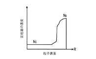
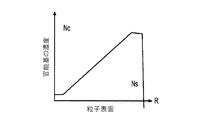
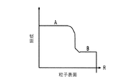
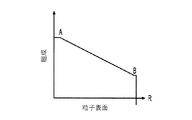
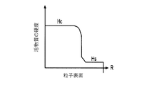
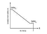
複合粒子を活用する電池電極組成物および製造方法を提供する。各複合粒子は、例えば、高容量の活物質と、多孔質の導電性骨格マトリクス材料とを含み得る。活物質は、電池作動中にイオンを貯蔵および放出することができ、また(i)正極活物質として少なくとも220mAh/gの比容量または(ii)負極活物質として少なくとも400mAh/gの比容量を示し得る。活物質は、骨格マトリクス材料の細孔中に配置されてもよい。様々な設計に応じて、各複合粒子は、骨格マトリクス材料の中心から周縁にかけて変化する少なくとも1つの材料特性を示し得る。 Provided are a battery electrode composition and a manufacturing method utilizing composite particles. Each composite particle may include, for example, a high volume active material and a porous conductive backbone matrix material. The active material is capable of storing and releasing ions during battery operation and also exhibits a specific volume of at least 220 mAh / g as the positive electrode active material or at least 400 mAh / g as the negative electrode active material (ii). obtain. The active material may be placed in the pores of the backbone matrix material. Depending on the various designs, each composite particle may exhibit at least one material property that varies from the center to the periphery of the backbone matrix material.
添付の図面は、本発明の実施形態の説明を補助するために提示されるものであり、単に該実施形態を例示するために提供され、実施形態を限定するものではない。 The accompanying drawings are presented to assist in the description of embodiments of the invention and are provided merely to illustrate the embodiments and are not intended to limit the embodiments.
本発明の態様を、以下の説明、および本発明の特定の実施形態を対象とする関連図面において開示する。「本発明の実施形態」という用語は、本発明のすべての実施形態に、論じられている特徴、利点、プロセスまたは作動モードが含まれることを必要とするわけではなく、また本発明の範囲から逸脱することなく代替的実施形態が考えられ得る。加えて、本発明の周知の要素は、詳しく説明されないか、またはより関連性のある他の詳細が曖昧にならない程度に省略される場合もある。 Aspects of the invention are disclosed in the following description and in related drawings for specific embodiments of the invention. The term "embodiment of the invention" does not require that all embodiments of the invention include the features, advantages, processes or modes of operation discussed, and within the scope of the invention. Alternative embodiments can be considered without deviation. In addition, well-known elements of the invention may not be described in detail or may be omitted to the extent that other more relevant details are not obscured.
現在、Liイオン技術が優勢で広く受け入れられていることから、以下の説明では、Liイオン電池を背景とする例をいくつか紹介する。しかし、そのような例は単に基礎的技法の理解と例示に役立つよう提示されるにすぎないこと、ならびにこれらの技法は他の様々な金属イオン電池(Naイオン、Caイオン、Kイオン、Mgイオンおよび他の金属イオン電池など)、異なるイオンを負極および正極に採用する様々な電池、固体電解質を使用する様々な電池(2つの電解質を有し、1つを負極に使用し、もう1つを正極に使用するものを含む)、液体電解質を使用する様々な電池(例えば、有機電解質、様々なpHの水性電解質、イオン性液体に基づく様々な液体電解質、あるいは上記の成分を含めた様々な成分の混合物を含む様々な液体電解質を使用する電池を含む)にも応用され得ることが理解される。 Since Li-ion technology is currently predominant and widely accepted, the following description will introduce some examples of Li-ion batteries in the background. However, such examples are only presented to help understand and illustrate the basic techniques, and these techniques are used in a variety of other metal ion batteries (Na ion, Ca ion, K ion, Mg ion). And other metal ion batteries, etc.), various batteries that use different ions for the negative and positive electrodes, various batteries that use solid electrolytes (having two electrolytes, one for the negative and one for the negative) Various batteries using liquid electrolytes (including those used for positive electrodes), various batteries using liquid electrolytes (eg, organic electrolytes, aqueous electrolytes of various pHs, various liquid electrolytes based on ionic liquids, or various components including the above components It is understood that it can also be applied to batteries that use various liquid electrolytes, including mixtures of.
また、本開示の一部の態様が他の分野にも適用され得ることも理解される。そのような応用の例として触媒粒子などの触媒作用が挙げられ、この場合、「活物質」は触媒粒子を指してもよく、また「骨格材料」は触媒担体を指してもよい。 It is also understood that some aspects of the disclosure may apply to other disciplines. An example of such an application is catalysis of catalyst particles and the like, in which case the "active material" may refer to the catalyst particles and the "skeleton material" may refer to the catalyst carrier.
本開示は、「容積変動性」、「高容量」および「高融点」の活物質をその中に組み入れた十分な導電性を有する「骨格」マトリクス材料を含む、電池電極用の先進的な複合粉末材料を提供するものである。複合粉末中の活物質の適切な割合は、約20重量%から約99重量%の範囲である。「高容量」活物質は、特定の材料の容量が負極材料の場合は約400mAh/gを超え、正極材料の場合は約220mAh/gを超える、活物質を指す。そのような活物質の大部分がいわゆる「変換」材料群に属し、活物質の化学構造は充電中および放電中に変化する。本明細書で使用されるとき、いわゆる「合金化」型負極材料は、より広範な区分での「変換」型の負極材料および正極材料の一部と見なされる。「高融点」の活物質は、融点が約250℃を超える活物質を指す。変換型活物質は様々なレベルでの充電中および放電中に異なる融点を示し得ることから、上記の「高融点」は、粒子合成過程での材料の状態を指す。「容積変動性」の活物質は、充電中または放電中に約8容積%を超える変化が生じる活物質を指す。骨格マトリクス材料は、セル内での複合電極の作動電圧(電位)範囲内で使用する場合に高容量活物質と比べ、大幅に(少なくとも50%)少ない容量または大幅に(少なくとも50%)少ないエネルギー密度を示し得る。 The present disclosure is an advanced composite for battery electrodes, including a sufficiently conductive "skeleton" matrix material incorporating "volume variable", "high capacity" and "high melting point" active materials therein. It provides a powder material. Suitable proportions of active material in the composite powder range from about 20% to about 99% by weight. A "high capacity" active material refers to an active material in which the capacity of a particular material exceeds about 400 mAh / g for a negative electrode material and more than about 220 mAh / g for a positive electrode material. The majority of such active materials belong to the so-called "conversion" material group, and the chemical structure of the active material changes during charging and discharging. As used herein, so-called "alloyed" negative electrode materials are considered to be part of "converted" negative and positive materials in a broader category. A "high melting point" active material refers to an active material having a melting point of more than about 250 ° C. The above "high melting point" refers to the state of the material during the particle synthesis process, as conversion active materials can exhibit different melting points during charging and discharging at various levels. “Volatility” active material refers to an active material that undergoes a change of more than about 8 volatility during charging or discharging. Skeletal matrix materials have significantly (at least 50%) less capacity or significantly (at least 50%) less energy than high-capacity active materials when used within the operating voltage (potential) range of the composite electrode in the cell. Can indicate density.
以下にてさらに詳しく論ずる通り、「高容量」および「高融点」の活物質を好ましくは固体の導電性骨格材料マトリクスに組み込むことにより、従来の設計と比べていくつかの利点がもたらされ得る。例えば、骨格マトリクスの内部に活物質を堆積させると(表面堆積とは対照的に)、望ましくないことが多い各活性粒子の凝集の回避に役立つ。骨格マトリクスの一部は、露出したままにしておいてもよいため、(ポリマー)バインダーの安定した付着に使用するか、または安定した固体電解質界面(SEI)の形成に役立ち得る。より安定した粒子−バインダー界面またはより安定したSEIは、より安定した電極性能に繋がり得る。 As discussed in more detail below, incorporating "high capacity" and "high melting point" active materials into a preferably solid conductive backbone material matrix can provide several advantages over conventional designs. .. For example, depositing the active material inside the skeletal matrix (as opposed to surface deposition) helps avoid agglomeration of each active particle, which is often undesirable. A portion of the skeletal matrix may be left exposed and can be used for stable adhesion of the (polymer) binder or to help form a stable solid electrolyte interface (SEI). A more stable particle-binder interface or a more stable SEI can lead to more stable electrode performance.
電解質と活物質との間の直接接触が望ましくない場合(例えば、活物質の(少なくとも)一部の溶解または電解質の分解などの、好ましくない反応の場合)、骨格マトリクスの外側表面域をイオン伝導性(かつ電解質溶媒不透過性)の外側シェルの堆積に使用することにより、骨格マトリクスの内部に堆積させた活物質を密閉し、望ましくないことが多い、活物質と電解質溶媒分子との接触を回避することもできる。 If direct contact between the electrolyte and the active material is not desirable (for example, in the case of an unfavorable reaction such as dissolution of (at least) part of the active material or decomposition of the electrolyte), ion conduction through the outer surface area of the skeletal matrix. By using it to deposit the outer shell of the sex (and electrolyte solvent impermeable), the active material deposited inside the skeletal matrix is sealed, often undesired contact between the active material and the electrolyte solvent molecules. It can also be avoided.
同様に、代替的構成において電解質と活物質との間の直接接触が望ましくない場合(例えば、Liイオン電池に使用する変換型または合金化型の高容量電極材料など)、骨格材料が活物質を完全に封入し、電解質と活物質との直接接触を防止し得る。この場合、骨格材料に十分なイオン伝導性および十分な導電性の両方を持たせて、(任意の用途について)適度に高速な充電および放電を可能にすることが有利となり得る。一部の構成では、充電中および放電中に小さい容積変化(好ましくは約8容積%未満)を示す一方で、骨格材料が付加的に電荷(イオン)を貯蔵し、「活性」であることが好適となり得る。 Similarly, if direct contact between the electrolyte and the active material is not desirable in the alternative configuration (eg, conversion or alloying high capacity electrode materials used in Li-ion batteries), the skeleton material will provide the active material. It can be completely encapsulated to prevent direct contact between the electrolyte and the active material. In this case, it may be advantageous to allow the scaffold material to have both sufficient ionic conductivity and sufficient conductivity to allow reasonably fast charging and discharging (for any application). Some configurations show a small volume change (preferably less than about 8% by volume) during charging and discharging, while the skeletal material additionally stores charge (ions) and is "active". Can be suitable.
活物質が粒子合成中の材料の状態からセル作動中にさらなる膨張を経る場合、「骨格材料−活物質」複合体の内部に、複合粒子の断裂を生じることなく、かかる容積膨張の約20容積%から約100容積%に適応できる十分な細孔容積を提供することが有利となり得る。骨格材料内で活物質の膨張に利用可能な容積が、必要な容積の100%に満たない場合、複合粒子の断裂を引き起こすことなく残りの容積に弾性的または塑性的に適応することに繋がる材料特性を骨格材料が示すことが有利となり得る。 If the active material undergoes further expansion from the state of the material during particle synthesis during cell operation, approximately 20 volumes of such volume expansion within the "skeleton material-active material" composite without causing rupture of the composite particles. It may be advantageous to provide sufficient pore volume that can be adapted from% to about 100% by volume. When the volume available for expansion of the active material in the skeletal material is less than 100% of the required volume, a material that leads to elastic or plastic adaptation to the remaining volume without causing rupture of the composite particles. It can be advantageous for the skeleton material to exhibit its properties.
電池サイクルによって高容量活物質の容積変化が誘発された際の断裂および破壊を防ぐため、骨格材料に十分な弾性係数、機械強度および靱性を持たせることも同様に有利となり得る。 It may also be advantageous for the backbone material to have sufficient modulus of elasticity, mechanical strength and toughness to prevent tearing and fracture when the battery cycle induces a volume change in the high capacity active material.
毎回のセル作動サイクル中に活物質がその初期容積を大幅に(例えば8容積%を超えて)超過するわけではない場合(例えば、活物質が既に最大量のLiを含有し、Liイオン電池に使用される場合)、「骨格材料−活物質」複合体の容積容量が最大となるよう、活物質に余分な細孔がほとんどまたは全く存在しないことが有利となり得る。 If the active material does not significantly exceed its initial volume (eg, by more than 8% by volume) during each cell actuation cycle (eg, the active material already contains the maximum amount of Li and is in the Li-ion battery. When used), it may be advantageous for the active material to have few or no extra pores so that the volume capacity of the "skeleton material-active material" complex is maximized.
骨格マトリクスは、各活性(ナノ)粒子の電気接続にも使用され得、電気接続は活性粒子を一層活用する上で重要となり得る。さらに、骨格マトリクスは、イオンの挿入および抽出中(充電中および放電中などの、電池作動中)に活性粒子の寸法が変化する場合であっても、そのような電気的接続性を維持する能力を有し得る。 The skeletal matrix can also be used for the electrical connection of each active (nano) particle, which can be important for further utilization of the active particle. In addition, the skeletal matrix is capable of maintaining such electrical connectivity even when the dimensions of the active particles change during ion insertion and extraction (during battery operation, such as during charging and discharging). Can have.
骨格マトリクス材料(または骨格マトリクス材料の少なくとも一部)が、単一の骨格マトリクス材料−活物質複合粒子内で単一体または単一固体粒子を形成する(例えば骨格マトリクス材料原子が化学結合を介して連結される状態)と、(単一複合粒子内での各骨格マトリクス材料粒子の弱い凝集とは対照的に)有利となり得る。この場合、複合体は、取り扱い中および電池作動中、(特に容積変動性活物質における容積変化によって)大幅に高い堅牢性を示し得る。 The skeletal matrix material (or at least part of the skeletal matrix material) forms a single or single solid particle within a single skeletal matrix material-active material composite particle (eg, skeletal matrix material atoms via chemical bonds). (Linked state) can be advantageous (as opposed to the weak aggregation of each backbone matrix material particle within a single composite particle). In this case, the complex can exhibit significantly higher robustness during handling and battery operation, especially due to volume changes in volume variable active materials.
前述の通り、骨格マトリクス材料は多孔質材料として選択され得る。このマトリクス内の細孔は高容量活物質で完全に満たされて(例えば、容積膨張のための付加的空間が全く必要ない)いても、または高容量活物質で部分的に満たされて(例えば、充電−放電のサイクル過程で容積膨張に適応するための付加的な細孔空間が必要である)いても、どちらであってもよい。 As mentioned above, the scaffold matrix material can be selected as the porous material. The pores in this matrix may be completely filled with high volume active material (eg, no additional space is required for volume expansion) or partially filled with high volume active material (eg,). , An additional pore space is required to adapt to volume expansion during the charge-discharge cycle process), or either.
骨格マトリクス内の細孔は、閉鎖状態または開放状態(相互接続状態)いずれであってもよい。電解質と活物質との間の直接接触が望ましくない場合(例えば、直接接触すると活物質の劣化に繋がる場合)、以下の構成が有利となり得る:(i)骨格マトリクス内の細孔のほとんどが閉鎖状態である、(ii)骨格マトリクス材料内の複数の相互接続状態/開放状態の細孔が一体的に閉鎖された状態である(一部の構成では、単一粒子内で相互接続状態の細孔がすべて、電解質不透過性であるが活性イオン透過性のシェル内に封入され得る)、または(iii)細孔が別の材料で塞がれ、この状態を使用して(骨格マトリクス材料中に浸透した)活物質(の少なくとも大部分)が電極と直接接触することを防ぐことができる。 The pores in the skeletal matrix may be in a closed state or an open state (interconnected state). If direct contact between the electrolyte and the active material is not desirable (eg, direct contact leads to deterioration of the active material), the following configurations may be advantageous: (i) Most of the pores in the backbone matrix are closed. The state, (ii), a state in which a plurality of interconnected / open pores in the skeletal matrix material are integrally closed (in some configurations, the interconnected state is fine within a single particle). All of the pores can be encapsulated in an electrolyte-impermeable but active ion-permeable shell), or (iii) the pores are closed with another material and this condition is used (in the skeletal matrix material). It is possible to prevent (at least most of) the active material (permeated into) from coming into direct contact with the electrodes.
骨格材料は、電荷貯蔵に参加する電解質イオン(Liイオン電池の場合のLiイオンなど)に対して十分に透過性であってもよい。この場合、たとえ(i)開放状態(相互接続状態)の細孔が骨格マトリクス材料内に全く存在しないか、(ii)細孔は相互接続状態であるが電解質へアクセス可能ではない(例えば、付加的なイオン透過性シェルにより、電解質が骨格中に浸透することができない場合、もしくは細孔が別の材料で塞がれている状態)か、または(iii)電荷貯蔵に参加する活性イオンについての活物質の拡散係数が低い(例えば約10−11cm2/S未満)であっても、電解質からのイオンが(任意の用途について)適度な充電率および放電率を十分に維持できる時間内に、マトリクスに封入された高容量活物質すべてに到達することが重要となり得る。これは前述の複合体から成る骨格マトリクスにおける最小限の十分なイオン移動性(拡散係数)およびイオン伝導性の決定要因となる。骨格マトリクスのイオン伝導性の最小値は、複合粒子のサイズ、骨格マトリクスの壁の厚さ、活物質/骨格マトリクス界面のイオン抵抗性および系のその他のパラメーターに依存する。ほとんどの実際的事例において、骨格マトリクスは放電率が「1C」(電極材料がその全容量を提供すると想定した場合に電極材料を1時間以内に放電させることができる電流密度に相当する)で複合体の最大放電容量の少なくとも50%を維持する、十分な伝導性を有することが望ましい。 The backbone material may be sufficiently permeable to electrolyte ions participating in charge storage (such as Li ions in the case of Li-ion batteries). In this case, even if (i) there are no open (interconnected) pores in the skeleton matrix material, or (ii) the pores are interconnected but not accessible to the electrolyte (eg, addition). For active ions that cannot penetrate into the skeleton due to a typical ion-permeable shell, or whose pores are blocked by another material), or (iii) participate in charge storage. Even if the diffusion coefficient of the active material is low (eg, less than about 10-11 cm 2 / S), within a time that the ions from the electrolyte can sufficiently maintain a reasonable charge and discharge rate (for any application). It can be important to reach all the high volume active materials encapsulated in the matrix. This is a determinant of the minimum sufficient ion mobility (diffusion coefficient) and ion conductivity in the above-mentioned complex skeletal matrix. The minimum ionic conductivity of the skeletal matrix depends on the size of the composite particles, the wall thickness of the skeletal matrix, the ionic resistance of the active material / skeletal matrix interface and other parameters of the system. In most practical cases, the skeletal matrix is composited with a discharge rate of "1C" (corresponding to the current density at which the electrode material can be discharged within an hour, assuming the electrode material provides its full capacity). It is desirable to have sufficient conductivity to maintain at least 50% of the body's maximum discharge capacity.
溶媒と高容量活物質との間で望ましくない反応が存在しない場合、(i)多孔質イオン伝導性骨格材料の壁は依然、電解質溶媒分子に対して透過性である(例えば、より高いイオン伝導性を骨格マトリクスに提供し、セルのレート特性向上を可能にする)か、または(ii)骨格マトリクスの細孔が開放状態(相互接続状態)であることにより、電解質で満たされた開放細孔を介してイオンが活物質にまで伝播し得る、いずれかの状態であり得る。 In the absence of undesired reactions between the solvent and the high volume active material, (i) the walls of the porous ionic conductive backbone material are still permeable to electrolyte solvent molecules (eg, higher ionic conductivity). (Ii) The pores of the skeletal matrix are in an open state (interconnected state) so that the properties are provided to the skeletal matrix to improve the rate characteristics of the cells. It can be in any state in which the ions can propagate to the active material via.
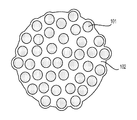
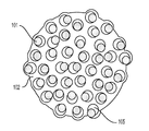
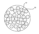
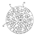
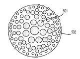
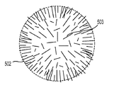
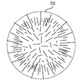
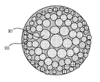
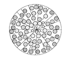
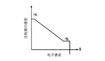
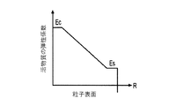
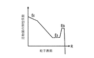
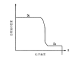
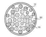
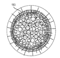
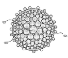
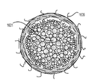
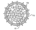
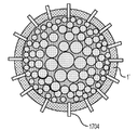
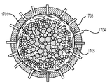
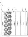
図1A〜1Dは、ある特定の実施形態例による、骨格マトリクス材料102、103、104および骨格マトリクス102、103、104内に閉じ込められた高容量活物質101を含む、複合粒子組成物の例を示す図である。一部の設計では、粒子組成物は細孔105を形成する一定の未充填空間を保持し得る。図1Aは、細孔が実質的に完全に高容量活物質101で満たされた、細孔閉鎖型骨格マトリクス粒子を示す図である。この場合、骨格マトリクス材料102は活性イオン(Liイオン電池の場合におけるLiイオンなど)に対して透過性である。図1Bは、細孔が部分的に高容量活物質101で満たされた(したがっていくつかの未充填細孔105を残す)、細孔閉鎖型骨格マトリクス粒子を示す図である。この場合、骨格マトリクス材料102はやはり活性イオン(Liイオン電池の場合におけるLiイオンなど)に対して透過性であるが、電気化学反応(電池サイクル)中に活物質101が膨張するための付加的な細孔容積が利用可能である。図1Cは、高容量活物質101で満たされた細孔閉鎖型骨格マトリクス粒子を示す図であるが、骨格マトリクス材料103が多孔質であり、電解質溶媒分子に対して透過性である。多孔質炭素(例えばポリマー前駆体の炭化によって製造されるもの)は、そのようなマトリクス材料の一例である。図1Dは、細孔105が部分的に高容量活物質101で満たされた、細孔開放型骨格マトリクス粒子を示す図である。この場合、骨格マトリクス材料104内の細孔は相互接続状態である。
1A-1D are examples of composite particle compositions comprising
Liイオン電池用途に適切な「容積変動性」、「高容量」および「高融点」の活物質としては、限定されるものではないが、以下のものが挙げられ:(i)変換型電極、例えば様々な金属フッ化物(リチウムフッ化物(例えばLiF)、フッ化鉄(FeF3またはFeF2)、フッ化マンガン(MnF3)、フッ化コバルト(CoF3またはCoF2)、フッ化銅(CuF2)、フッ化ニッケル(NiF2)、フッ化鉛(PbF2)、フッ化ビスマス(BiF3またはBiF5)、フッ化スズ(SnF2またはSnF4)、フッ化アンチモン(SbF3またはSbF5)、フッ化カドミウム(CdF2)、フッ化亜鉛(ZnF2)および他の金属フッ化物など)、様々な金属カルコゲン化物(硫化リチウム(Li2S)、リチウムセレニド(Li2Se)、リチウムテルリド(Li2Te)など)、(ii)様々な変換型金属塩化物(塩化リチウム(例えばLiCl)、塩化鉄(FeCl3またはFeCl2)、塩化マンガン(MnCl3)、塩化コバルト(CoCl3またはCoCl2)、塩化銅(CuCl2)、塩化ニッケル(NiCl2)、塩化鉛(PbCl2)、塩化ビスマス(BiCl3またはBiCl5)、塩化スズ(SnCl2またはSnCl4)、塩化アンチモン(SbCl3またはSbCl5)、塩化カドミウム(CdCl2)、塩化亜鉛(ZnCl2)および他の金属塩化物など)、(iii)変換型金属臭化物(臭化リチウム(LiBr)など)、(iv)変換型金属ヨウ化物(ヨウ化リチウム(LiI)など)、(iv)様々な変換型混合金属フッ化物、混合金属塩化物、混合金属臭化物、混合金属ヨウ化物、混合金属ハロゲン化物(CuF2とFeCl2またはCuF2とFeF3など、2種以上の金属ハロゲン化物の混合物)、(v)様々なオキシハロゲン化物、(vi)他の様々な変換型電極、これらの組合せおよび混合物(例えば硫化物、酸化物、窒化物、ハロゲン化物、リン化物、水素化物など)、(vii)インターカレーション型Liイオン電池活物質と変換型活物質との混合物および組合せ、ならびに(viii)様々な、融点の高い(前述の通り)、高容量(前述の通り)のインターカレーション型活物質。これらの変換型活物質を、リチウム不在または部分リチオ化もしくは完全リチオ化のいずれの状態でも活用できることが理解される。一部の事例において、部分リチオ化状態または完全リチオ化状態の活物質の使用が、選択される合成プロセスについて特に重要となり得る(例えば、特定の処理/合成経路について、リチオ化状態だけが十分に安定している場合)。部分リチオ化状態または完全リチオ化状態の変換型活物質は複合体であってもよいことが理解される。一部の例において、そのような複合体は金属を含み得る。例えば、金属ハロゲン化物(例えばCuF2またはFeF3など)は、完全リチオ化されると、リチウムハロゲン化物(例えば金属フッ化物の場合のLiF)と、該当する金属フッ化物の金属クラスター(またはナノ粒子)(例えば、Cu−Fe混合物の場合のCu、FeもしくはCuFe、FeF3、またはCuFe2−FeF3混合物)との混合物(複合体)となる。 Suitable "volume variability", "high capacity" and "high melting point" active materials for Li-ion battery applications include, but are not limited to: (i) convertible electrodes, For example, various metal fluorides (lithium fluoride (eg LiF), iron fluoride (FeF 3 or FeF 2 ), manganese fluoride (MnF 3 ), cobalt fluoride (CoF 3 or CoF 2 ), copper fluoride (CuF). 2 ), Nickel fluoride (NiF 2 ), Lead fluoride (PbF 2 ), Bismus fluoride (BiF 3 or BiF 5 ), Tin fluoride (SnF 2 or SnF 4 ), Antimon fluoride (SbF 3 or SbF 5) ), Cadmium fluoride (CdF 2 ), Zinc fluoride (ZnF 2 ) and other metal fluorides), various metal chalcogenides (lithium sulfide (Li 2 S), lithium selenide (Li 2 Se), lithium Telluride (Li 2 Te), etc.), (ii) Various convertible metal chlorides (lithium chloride (eg LiCl), iron chloride (FeCl 3 or FeCl 2 ), manganese chloride (MnCl 3 ), cobalt chloride (CoCl 3) Or CoCl 2 ), Copper Chloride (CuCl 2 ), Nickel Chloride (NiCl 2 ), Lead Chloride (PbCl 2 ), Bismus Chloride (BiCl 3 or BiCl 5 ), Tin Chloride (SnCl 2 or SnCl 4 ), Antimon Chloride (SbCl) 3 or SbCl 5 ), cadmium chloride (CdCl 2 ), zinc chloride (ZnCl 2 ) and other metal chlorides, etc.), (iii) Convertible metal bromide (such as Lithium bromide (LiBr)), (iv) Convertible Metal iodide (such as lithium iodide (LiI)), (iv) various conversion type mixed metal fluorides, mixed metal chlorides, mixed metal bromide, mixed metal iodide, mixed metal halides (CuF 2 and FeCl 2 or Mixtures of two or more metal halides such as CuF 2 and FeF 3 ), (v) various oxyhalides, (vi) various other convertible electrodes, combinations and mixtures thereof (eg, sulfides, oxides). , Nitrides, halides, phospholides, hydrides, etc.), (vii) mixtures and combinations of intercalation-type Li-ion battery active materials and conversion-type active materials, and (viii) various high melting point (described above). Intercalation type active material with high capacity (as described above). It is understood that these convertible active materials can be utilized in either the absence of lithium or in the state of partial lithium or full lithium. In some cases, the use of active material in a partially or fully lithium state may be particularly important for the synthetic process selected (eg, only the lithium state is sufficient for a particular treatment / synthesis pathway). If it is stable). It is understood that the converted active material in the partially or fully lithium state may be a complex. In some examples, such complexes may contain metals. For example, metal halides (such as CuF 2 or FeF 3 ), when fully lithiated, have lithium halides (eg LiF in the case of metal fluoride) and metal clusters (or nanoparticles) of the metal fluoride of interest. ) (for example, Cu in the case of CuFe mixture, Fe or CuFe, FeF 3 or CuFe 2 -FeF 3 mixture) and a mixture of a (complex).
Liイオン電池用途に適切な他の「容積変動性」、「高容量」および「高融点」の活物質としては、限定されるものではないが、以下のものが挙げられる:(i)シリコン(Si)、ゲルマニウム(Ge)、スズ(Sn)、アルミニウム(Al)、鉛(Pb)、アンチモン(An)、マグネシウム(Mg)など、様々な合金化型(Li挿入過程で、Liが電気化学的に負極と一緒に合金化する)負極材料(変換型電極材料の一バージョンと捉えてもよい)。これらの材料はドープ状態または高濃度ドープ状態または「超高濃度」ドープ状態であってもよいことが理解され、例えばSiの場合、高濃度ドープ状態または超高濃度ドープ状態のシリコンとして、(i)高含有量の、ホウ素(B)、アルミニウム(Al)、ガリウム(Ga)、インジウム(In)もしくはタリウム(Tl)などの第III族元素、または、高含有量の、窒素(N)、リン(P)、ヒ素(As)、アンチモン(Sb)もしくはビスマス(Bi)などの第V族元素でドープされた、シリコン(「高濃度ドープ状態」および「超高濃度ドープ状態」という場合は、ドーピング原子の含有量が典型的に組成物全体のうち3,000ppm(1ppmは100万分の1)から700,000ppm、または約0.3%から70%の範囲であると理解される)、(ii)Si(またはSn、Ge、Al、Mgなど)と他の金属との様々な二成分合金(または混合物)、(iii)Si(またはSn、Ge、Al、Mgなど)と金属との様々な三成分合金(または混合物)、ならびに(iv)Liとの合金を形成する他の金属および金属合金が挙げられる。より高容量の負極材料の形成に使用される第IV族元素として、Ge、Sn、Pb、およびこれらの混合物(例えば、様々な合金または機械的混合物)または複合体が挙げられ、混合物または複合体は、一般式Sia−Geb−Snc−Pbd−Ce−Df(式中、a、b、c、d、eおよびfはゼロまたは非ゼロであってもよく、Dは周期表の第III族または第V族から選択されるドーパントである)で表わされることが理解される。シリコンと金属との二成分合金(または混合物)の場合、シリコン含有率は約20%から99.7%の範囲であってもよい。そのような合金(または混合物)の例として以下が挙げられるが、これらに限定されない:Mg−Si、Al−Si、Ca−Si、Sc−Si、Ti−Si、V−Si、Cr−Si、Mn−Si、Fe−Si、Co−Si、Ni−Si、Cu−Si、Zn−Si、Sr−Si、Y−Si、Zr−Si、Nb−Si、Mo−Si、Tc−Si、Ru−Si、Rh−Si、Pd−Si、Ag−Si、Cd−Si、Ba−Si、Hf−Si、Ta−Si、およびW−Si。そのような二成分合金は付加的に、第III族元素および第V族元素でドープ(または高濃度ドープ)され得る。代替的に、シリコンの代わりに他の第IV族元素を使用して、金属との同様の合金または混合物を形成させてもよい。様々な第IV族元素の組合せを、金属とのそのような合金または混合物の形成に使用してもよい。三成分のシリコンと金属との合金(または混合物)の場合も、シリコン含有率は約20%から99.7%の範囲であってもよい。そのような三成分合金は、第III族元素および第V族元素でドープ(または高濃度ドープ)され得る。シリコンの代わりに他の第IV族元素を使用して、金属との同様の合金または混合物を形成させてもよい。様々な第IV族元素の組合せを、金属とのそのような合金または混合物の形成に使用してもよい。リチウムのとの合金を形成する他の金属および金属合金の例としてMg、Al、Ga、In、Ag、Zn、Cdなどのほか、これらの金属、これらの酸化物などから形成される様々な組合せが挙げられるが、これらに限定されない。 Other "volume variable", "high capacity" and "high melting point" active materials suitable for Li-ion battery applications include, but are not limited to: (i) silicon ( Various alloying types such as Si), germanium (Ge), tin (Sn), aluminum (Al), lead (Pb), antimony (An), magnesium (Mg), etc. (Li is electrochemical during the Li insertion process) Negative electrode material (which can be regarded as a version of the conversion type electrode material). It is understood that these materials may be in a doped state, a high concentration doping state, or an "ultra high concentration" doping state, for example, in the case of Si, as silicon in a high concentration doping state or an ultra high concentration doping state (i). ) High content of Group III elements such as boron (B), aluminum (Al), gallium (Ga), indium (In) or tallium (Tl), or high content of nitrogen (N), phosphorus Silicon ("high concentration doping state" and "ultra high concentration doping state") doped with Group V elements such as (P), arsenic (As), antimony (Sb) or bismuth (Bi) Atomic content is typically understood to range from 3,000 ppm (1 ppm is one millionth) to 700,000 ppm, or about 0.3% to 70% of the total composition), (ii). ) Si (or Sn, Ge, Al, Mg, etc.) and various binary alloys (or mixtures) with other metals, (iii) Si (or Sn, Ge, Al, Mg, etc.) and various metals. Included are ternary alloys (or mixtures), as well as other metals and metal alloys that form an alloy with (iv) Li. Group IV elements used in the formation of higher volume negative electrode materials include Ge, Sn, Pb, and mixtures or composites thereof (eg, various alloys or mechanical mixtures), mixtures or composites. Is the general formula Si a- Ge b- Sn c- Pb d- C e- D f (in the formula, a, b, c, d, e and f may be zero or non-zero, where D is the period. It is understood that it is represented by (a dopant selected from Group III or Group V in the table). In the case of a two-component alloy (or mixture) of silicon and metal, the silicon content may range from about 20% to 99.7%. Examples of such alloys (or mixtures) include, but are not limited to: Mg-Si, Al-Si, Ca-Si, Sc-Si, Ti-Si, V-Si, Cr-Si, Mn-Si, Fe-Si, Co-Si, Ni-Si, Cu-Si, Zn-Si, Sr-Si, Y-Si, Zr-Si, Nb-Si, Mo-Si, Tc-Si, Ru- Si, Rh-Si, Pd-Si, Ag-Si, Cd-Si, Ba-Si, Hf-Si, Ta-Si, and W-Si. Such binary alloys can additionally be doped (or highly doped) with Group III and Group V elements. Alternatively, other Group IV elements may be used in place of silicon to form similar alloys or mixtures with metals. Combinations of various Group IV elements may be used to form such alloys or mixtures with metals. In the case of an alloy (or mixture) of three components of silicon and a metal, the silicon content may also be in the range of about 20% to 99.7%. Such tricomponent alloys can be doped (or highly doped) with Group III and Group V elements. Other Group IV elements may be used instead of silicon to form similar alloys or mixtures with metals. Combinations of various Group IV elements may be used to form such alloys or mixtures with metals. Examples of other metals and metal alloys that form alloys with lithium include Mg, Al, Ga, In, Ag, Zn, Cd, as well as these metals, various combinations formed from their oxides, etc. However, the present invention is not limited to these.
これらの合金化型活物質を、リチウム不在または部分リチオ化または完全リチオ化のいずれの状態でも活用できることが理解される。 It is understood that these alloyed active materials can be utilized in either the absence of lithium or in the state of partial lithium or full lithium.
他の金属イオン(非Li)電池用途に適切な「容積変動性」、「高容量」および「高融点」の活物質としては、上記の材料と同様の材料が挙げられるが、Liの代わりに他の金属イオンが使用される。例えば、Naイオン電池の場合、LiBrの代わりにNaBrを、高容量、容積変動性、高融点の活物質として使用することができる。 Suitable "volume variable", "high capacity" and "high melting point" active materials for other metal ion (non-Li) battery applications include materials similar to those described above, but instead of Li. Other metal ions are used. For example, in the case of a Na ion battery, NaBr can be used as an active material having a high capacity, volume variation, and a high melting point instead of LiBr.
他の種類の電池の場合、他の「容積変動性」、「高容量」および「高融点」の材料を使用することができる。例えば、アルカリ電池の場合、様々な金属(Fe、Zn、Cd、Niもしくは他の金属など)、様々な金属酸化物、様々な金属水素化物、様々な金属水酸化物およびオキシ水酸化物、または他の既知の変換型活性電極材料を、高容量の負極材料または正極材料として使用することができる。 For other types of batteries, other "volume variable", "high capacity" and "high melting point" materials can be used. For example, in the case of alkaline batteries, different metals (such as Fe, Zn, Cd, Ni or other metals), different metal oxides, different metal hydrides, different metal hydroxides and oxyhydroxides, or Other known convertible active electrode materials can be used as high capacity negative electrode materials or positive electrode materials.
一部の構成では(例えば、様々な水性電池の場合)、設計の一部の態様(複合粒子の種類、骨格マトリクスの種類、電解質からの活物質の保護、粉末の機械的安定性または導電性の強化、電極または粉末の製造プロセスなど)を、相変化が発生しない活物質または非常に高い容量を有するわけではない(例えば、比容量が、正極の場合は90〜220mAh/g程度、または負極の場合は90〜440mAh/g程度しかない)活物質と併用することができる。 In some configurations (eg for various aqueous batteries), some aspects of the design (composite particle type, skeletal matrix type, protection of active material from electrolytes, mechanical stability or conductivity of the powder). Reinforcement, electrode or powder manufacturing process, etc.) does not have an active material that does not undergo phase change or a very high capacity (for example, the specific capacity is about 90 to 220 mAh / g for a positive electrode, or a negative electrode. In the case of, it can be used in combination with an active material (only about 90 to 440 mAh / g).
前述の通り、適切な骨格マトリクス材料の有利な特性として、高い導電性(例えば10−2S/m超)、良好な機械的強度および靱性係数、ならびに一部の事例における(前述の通り)イオン輸送向けの高い拡散係数(例えば10−9cm2/s超)が挙げられる。導電性が0.1mS/cm(=0.01mS/mm=0.01S/m)より高ければ特に有利となり得る。骨格マトリクス材料の曲げ強度および圧縮強度が1kPaより高ければ特に有利となり得る。骨格マトリクスの熱的特性に関する仕様は、一般的に複合体合成プロセスに依存する。骨格マトリクス内への活物質の浸透、または細孔の一部の事後処理もしくは密閉、または他の必要もしくは好適な製造ステップが昇温状態で行われるのであれば、例えば、骨格マトリクスはそのような処理に耐えられる十分な熱的安定性を有するべきである。 As mentioned above, the advantageous properties of suitable skeletal matrix materials are high conductivity (eg> 10-2 S / m), good mechanical strength and toughness coefficient, and in some cases (as mentioned above) ions. High diffusion coefficients for transport (eg, greater than 10-9 cm 2 / s) can be mentioned. It can be particularly advantageous if the conductivity is higher than 0.1 mS / cm (= 0.01 mS / mm = 0.01 S / m). It may be particularly advantageous if the bending strength and compressive strength of the skeleton matrix material are higher than 1 kPa. Specifications for the thermal properties of the skeletal matrix generally depend on the complex synthesis process. If the permeation of the active material into the skeletal matrix, or the post-treatment or sealing of some of the pores, or other necessary or suitable manufacturing steps are performed in a heated state, for example, the skeletal matrix is such. It should have sufficient thermal stability to withstand the process.
複数の一般的な区分の骨格マトリクス材料が、適切であると認められた。これらの材料として(i)炭素(ドープされた炭素を含む)、(ii)伝導性ポリマー(特に、セル作動中に伝導性を維持するもの)、および(iii)十分な伝導性を有するセラミック材料(混合または複合金属酸化物を含めた金属酸化物、リン酸塩、チタン酸塩、ケイ酸塩など)を含む材料が挙げられるが、これらに限定されない。一部の事例において、金属は骨格マトリクスとしても適切となり得る。しかし、金属は一般的に、腐食、遅いイオン輸送および限られた表面積に見舞われる。したがって、金属の使用は一定の用途に限定され得る。 Several general categories of skeletal matrix materials have been found to be suitable. These materials include (i) carbon (including doped carbon), (ii) conductive polymers (particularly those that maintain conductivity during cell operation), and (iii) ceramic materials with sufficient conductivity. Materials include, but are not limited to, metal oxides (including mixed or composite metal oxides, phosphates, titanates, silicates, etc.). In some cases, the metal may also be suitable as a skeletal matrix. However, metals generally suffer from corrosion, slow ion transport and limited surface area. Therefore, the use of metals can be limited to certain applications.
サイクル中のLi/Li+に対する平均電位が約4.0V未満であるLiイオン電池用の複合電極材料の場合、骨格マトリクスとしての炭素は、導電性が高く(主に、グラフェン、黒鉛、ナノチューブ、活性炭、炭素繊維、カーボンブラックおよび他の伝導性炭素材料などの、sp2結合炭素)、Liイオンに対する移動性が高く、強度が高く、密度が低く、(一部の事例において必要な場合に)熱的安定性に優れることから、特に魅力的となり得る。 In the case of composite electrode materials for Li-ion batteries where the average potential for Li / Li + during the cycle is less than about 4.0 V, carbon as the skeleton matrix is highly conductive (mainly graphene, graphite, nanotubes, activated carbon). High mobility to Li ions, high mobility, low density, heat (if required in some cases), sp 2- bonded carbon, such as carbon fiber, carbon black and other conductive carbon materials. It can be particularly attractive due to its excellent graphite stability.
フレーク状、楕円形または球形のほか、不規則な形状も含め、(活物質で満たされた骨格マトリクスで構成される)様々な形状の複合粒子が、設計の違いに応じて適切となり得る。しかし、本質的に楕円形またはほぼ球形(回転楕円体)の粒子は、圧縮された電極内の粒子間空間を介した迅速なイオン輸送を可能にすることから、そのような粒子の使用が有益となり得る。さらに、複合粒子が溶媒不透過性シェルを含有する場合、合成過程で狭い粒子サイズ分布を維持し、その結果、シェルの厚さに対する粒子直径の比率を狭い範囲で制御することが、有益となり得る。この場合、粒子の特性をより精密に最適化することができ、より高いエネルギー密度を同等の信頼性/サイクル寿命で達成することができる(またはより長いセルのサイクル寿命を同等のエネルギー密度レベルで達成することができる)。したがって、(D90−D10)/D50の比率を4未満(またはより一層好ましくは3未満)に維持することが有利となり得る。合成後、様々なサイズが混在する粒子を実際の電極に使用して、電極の充填密度および強度を強化することができる(例えば、より大型の粒子を付加的に、より小さい複数の粒子と接触させると、電極強度を高めることができる)。 Composite particles of various shapes (composed of a skeletal matrix filled with active material), including flakes, ellipses or spheres, as well as irregular shapes, can be suitable for different designs. However, the use of such particles is beneficial because particles that are essentially elliptical or nearly spherical (spheroid) allow rapid ion transport through the interparticle space within the compressed electrode. Can be. In addition, if the composite particles contain a solvent-impermeable shell, it may be beneficial to maintain a narrow particle size distribution during the synthesis process and, as a result, control the ratio of particle diameter to shell thickness over a narrow range. .. In this case, the properties of the particles can be optimized more precisely and higher energy densities can be achieved with comparable reliability / cycle lifetime (or longer cell cycle lifetimes at equivalent energy density levels). Can be achieved). Therefore, it may be advantageous to maintain the ratio of (D90-D10) / D50 to less than 4 (or even more preferably less than 3). After synthesis, mixed size particles can be used in the actual electrode to enhance the packing density and strength of the electrode (eg, larger particles are additionally contacted with multiple smaller particles). By doing so, the electrode strength can be increased).
本明細書に記載の様々な複合粒子は多様な形で形成され得ることが理解される。活物質融合型骨格マトリクスの製造方法の例のいくつかを、以下に記載する。これらの製造技法は、例えば融点が高いかまたは融点がない(材料が高温で簡単に分解すると想定される場合)、電気化学的に活性の高容量電池材料のナノ粒子を、効率的に制御された状態で、一例として炭素マトリクスなど多孔質骨格マトリクス内に組み込むことを可能にするものである。 It is understood that the various composite particles described herein can be formed in a variety of forms. Some examples of methods for producing the active material fusion skeleton matrix are described below. These manufacturing techniques efficiently control nanoparticles of electrochemically active high-capacity battery materials, for example, with high or no melting points (where the material is assumed to easily decompose at high temperatures). In this state, it can be incorporated into a porous skeleton matrix such as a carbon matrix as an example.
一例では、予め製造済みの多孔質骨格マトリクス(例えば炭素)粒子内へ、化学蒸着(CVD)または原子層堆積(ALD)または他の蒸着技法を介して活物質を導入することができる。多孔質炭素粒子は、ポリマー前駆体粒子の化学合成もしくは沈殿駆動型製造、または化学的方法と沈殿法との組合せ、熱分解(熱処理)および活性化(相互接続状態の細孔の容積を導入または増大させるための部分的酸化)によって製造することができる。細孔の望ましいサイズおよび分布は、例えばポリマー前駆体における多孔性と炭素活性化プロセスとの組合せによって達成され得る。多孔質炭素骨格を生成させる別の方法の例として、大型ポリマーモノリスを合成し、このモノリスを炭化させ、炭素モノリスを機械的研磨によって望ましい形状の粒子にするという方法が挙げられる。活性化プロセスには、酸素含有ガス(CO2、H2O、空気、O2など)との物理的酸化、化学的活性化(例えばKOH、KNO3、ZnCl2、Zn(NO3)2、Zn3(PO4)2、H3PO4、または他の適切な化学物質による活性化)、またはこれらのアプローチの組合せが関係し得る。活性化は熱処理中または熱処理後に行ってもよい。ミクロ細孔およびメソ細孔(前述の通り、一部の事例において有益となり得る)の両方を導入するため、炭素活性化を異なる温度(例えば約800℃および約1000℃)で行うか、または異なる活性化剤(例えばCO2およびH2O)を使用してもよい。一部の事例において、ポリマー前駆体粒子内で2つのポリマーまたはブロック・コポリマーの混合物(あるいは有機液体またはポロゲンとの炭素産出ポリマー混合物)の活用により、メソ細孔を多孔質炭素に導入することが有益となり得る。一部の事例において、有機液体はポリマーにとって非溶媒であってもよく、またはポリマーを有機液体中で膨張させてもよい。液体の性質が非溶媒または溶媒のどちらであるかが、細孔のサイズおよび分布を定義する。これらのポリマーのうち1つは、選択的抽出によってポリマー粒子合成後に除去されてもよく、あるいはこれらのポリマーのうち1つは、本質的に低い熱的安定性を示すものであってもよく、または炭化中もしくは活性化後、もしくは両方の段階での炭素産出量が非常に少ないものであってもよい。一部の事例において、細孔を高密度炭素粒子(合成黒鉛または人工黒鉛、メソカーボン・マイクロビーズなど)の表面に導入することができる。一例では、金属または他の無機ナノ粒子を炭素の表面に予め堆積させて、炭素内の細孔のエッチングまたは酸化の触媒の役割を果たさせることができる。別の例では、抽出可能な非炭化性粒子を、炭化の対象となる前駆体(例えばポリマー)粒子に導入することができる。一部の例では、そのようなナノ粒子は、金属塩、金属酸化物または金属を含み得る。一部の用途では、例えば金属ナノ粒子を多孔質炭素合成プロセスのどこかの時点で細孔鋳型向けに使用する場合、約100℃から700℃の範囲の融点を示す金属を使用することが有利となり得る。この金属が空気に曝露されても可燃性を帯びないものであれば、さらに有利となり得る。In、Sn、Cd、TeおよびZnが、適切な金属の例である。この金属が示す毒性が低ければ、さらに有利となり得る(したがってCdは好適度が低くなり得る)。一部の例では、そのような金属ナノ粒子は該当する金属塩の(例えば炭素による)還元後に形成され得る。一部の例では、この還元プロセスにより、ミクロ細孔(例えば2nmより小さい細孔)が炭素材料に導入され得る。金属に加え、金属塩、金属酸化物および他の鋳型も細孔形成に使用され得る。他の例では、無機材料から作製された高度に多孔質の骨格表面への炭素堆積(例えばCVD)により(場合によっては炭素堆積後にエッチングを施した上で)炭素多孔質骨格が作製され得る。シリカエアロゲルは、炭素堆積向けのそのような無機骨格の一例である。他の例では、多孔質炭素骨格マトリクスは、天然素材(いくつかの例を挙げると、木材、藁、堅果殻、天然多糖類、石炭、蔗糖、石油コークス、ピッチ、ピートおよびリグナイト)から生成された活性炭であってもよい。他の例では、多孔質炭素骨格マトリクスは、有機前駆体の熱水性炭化ならびにこれに続く焼鈍および活性化によって生成された活性炭であってもよい。さらに他の例では、多孔質炭素骨格マトリクスは、無機前駆体(カーバイドなど)から生成された多孔質炭素であってもよい。そのような多孔質炭素合成の一例は、カーバイドの塩素化が関係する。多孔質炭素に関して多様な他の既知の方法を活用することができる。 In one example, the active material can be introduced into prefabricated porous skeleton matrix (eg, carbon) particles via chemical vapor deposition (CVD) or atomic layer deposition (ALD) or other vapor deposition techniques. Porous carbon particles can be chemically synthesized or precipitate-driven production of polymer precursor particles, or a combination of chemical and precipitation methods, pyrolysis (heat treatment) and activation (introducing the volume of interconnected pores or It can be produced by partial oxidation) to increase. The desired size and distribution of pores can be achieved, for example, by a combination of porosity in the polymer precursor and a carbon activation process. Another example of a method for producing a porous carbon skeleton is to synthesize a large polymer monolith, carbonize the monolith, and mechanically polish the carbon monolith into particles of the desired shape. The activation process includes physical oxidation with oxygen-containing gases (CO 2 , H 2 O, air, O 2, etc.) and chemical activation (eg KOH, KNO 3 , ZnCl 2 , Zn (NO 3 ) 2 , Activation with Zn 3 (PO 4 ) 2 , H 3 PO 4 , or other suitable chemicals), or a combination of these approaches may be involved. The activation may be carried out during or after the heat treatment. To introduce both micropores and mesopores (which can be beneficial in some cases, as mentioned above), carbon activation may or may not be performed at different temperatures (eg, about 800 ° C and about 1000 ° C). Activators (eg CO 2 and H 2 O) may be used. In some cases, mesopores can be introduced into porous carbon by utilizing a mixture of two polymers or block copolymers (or a carbon-producing polymer mixture with an organic liquid or pologene) within the polymer precursor particles. Can be beneficial. In some cases, the organic liquid may be non-solvent to the polymer, or the polymer may be expanded in the organic liquid. The nature of the liquid, non-solvent or solvent, defines the size and distribution of the pores. One of these polymers may be removed after polymer particle synthesis by selective extraction, or one of these polymers may exhibit inherently low thermal stability. Alternatively, carbon production may be very low during carbonization, after activation, or at both stages. In some cases, pores can be introduced into the surface of high density carbon particles (synthetic or artificial graphite, mesocarbon microbeads, etc.). In one example, metal or other inorganic nanoparticles can be pre-deposited on the surface of the carbon to act as a catalyst for etching or oxidation of the pores within the carbon. In another example, extractable non-carbonized particles can be introduced into the precursor (eg, polymer) particles to be carbonized. In some examples, such nanoparticles may include metal salts, metal oxides or metals. In some applications, for example when metal nanoparticles are used for a pore template at some point in the porous carbon synthesis process, it is advantageous to use a metal that exhibits a melting point in the range of about 100 ° C to 700 ° C. Can be. It can be even more advantageous if the metal is not flammable when exposed to air. In, Sn, Cd, Te and Zn are examples of suitable metals. The lower the toxicity of this metal, the more advantageous it can be (and therefore Cd can be less suitable). In some examples, such metal nanoparticles may be formed after reduction of the metal salt in question (eg by carbon). In some examples, this reduction process can introduce micropores (eg, pores smaller than 2 nm) into the carbon material. In addition to metals, metal salts, metal oxides and other templates can also be used for pore formation. In another example, a carbon porous skeleton can be made by carbon deposition (eg CVD) on a highly porous skeleton surface made from an inorganic material (possibly after etching after carbon deposition). Silica airgel is an example of such an inorganic backbone for carbon deposition. In other examples, the porous carbon skeleton matrix is produced from natural materials (wood, straw, husks, natural polysaccharides, coal, sucrose, petroleum coke, pitch, peat and lignite, to name a few). It may be activated carbon. In another example, the porous carbon skeleton matrix may be activated carbon produced by hydrothermal carbonization of the organic precursor followed by annealing and activation. In yet another example, the porous carbon skeleton matrix may be porous carbon produced from an inorganic precursor (such as carbide). An example of such porous carbon synthesis involves the chlorination of carbides. A variety of other known methods for porous carbon can be utilized.
別の方法例によれば、蒸気浸透および/または毛管凝縮を介して、予め製造済みの多孔質炭素マトリクスに活性粒子を導入することができる。このアプローチは、適度に高温(例えば約1000℃未満)の条件で高い蒸気圧(例えば約0.1Pa超)を有する材料の場合、特に魅力的となり得る。 According to another method example, active particles can be introduced into a prefabricated porous carbon matrix via vapor permeation and / or capillary condensation. This approach can be particularly attractive for materials with high vapor pressures (eg, greater than about 0.1 Pa) under moderately high temperatures (eg, less than about 1000 ° C).
別の方法例によれば、(i)活性粒子または活性粒子前駆体を溶媒中に溶解させ、(ii)予め製造済みの多孔質炭素マトリクスの細孔に、常圧下、加圧下または真空下で溶液を浸透させ、(iii)溶媒を蒸発させ、(iv)(必要な場合は)(例えば加熱後または反応性の気体もしくは液体との反応後に)前駆体を活性粒子へと変換することにより、活性粒子を導入することができる。一部の事例において、上記ステップの一部を繰り返して、多孔質炭素マトリクスに導入される活物質ナノ粒子の総量を増やすことができる。 According to another method example, (i) the active particles or the active particle precursors are dissolved in a solvent and (ii) the pores of a prefabricated porous carbon matrix are formed under normal pressure, pressure or vacuum. By infiltrating the solution, (iii) evaporating the solvent, and (iv) (if necessary) converting the precursor into active particles (eg, after heating or after reaction with a reactive gas or liquid). Active particles can be introduced. In some cases, some of the above steps can be repeated to increase the total amount of active nanoparticlees introduced into the porous carbon matrix.
別の方法例によれば、(i)活性粒子または活性粒子前駆体を溶媒中に溶解させ、(ii)予め製造済みの多孔質炭素マトリクスの細孔に、常圧下、加圧下または真空下で溶液を浸透させ、(iii)例えば、非溶媒を添加すること、溶液のイオン強度もしくはpHを変化させること、または系の温度/圧力を変化させることによって、溶液から内側炭素表面上にナノ粒子を不均一に沈殿させ、(iv)(必要な場合は)前駆体を活性粒子へと変換することにより、活性粒子を導入することができる。一部の事例において、上記ステップの一部を繰り返すか、または組み合わせて、多孔質炭素マトリクスに導入される活物質ナノ粒子の総量を増やすことができる。 According to another method example, (i) the active particles or the active particle precursors are dissolved in a solvent and (ii) the pores of a prefabricated porous carbon matrix are formed under normal pressure, pressure or vacuum. Infiltrate the solution and (iii) remove the nanoparticles from the solution onto the inner carbon surface by, for example, adding a non-solvent, changing the ionic strength or pH of the solution, or changing the temperature / pressure of the system. Active particles can be introduced by heterogeneously precipitating and converting (iv) (if necessary) precursors into active particles. In some cases, some of the above steps can be repeated or combined to increase the total amount of active nanoparticlees introduced into the porous carbon matrix.
別の方法例によれば、常圧下、加圧下または真空下で懸濁浸透法を使用して、予め形成済みの多孔質炭素の細孔に活物質のナノ粒子を浸透させることにより、活性粒子を導入することができる。 According to another example of the method, active particles are obtained by infiltrating the nanoparticles of the active material into the pores of the preformed porous carbon using the suspension infiltration method under normal pressure, pressure or vacuum. Can be introduced.
別の方法例によれば、(i)まず、(例えば活性ナノ粒子の表面およびポリマー前駆体ナノ粒子の表面上で反対の電荷を導入することによって)炭素形成のためのポリマー前駆体ナノ粒子表面上に活性ナノ粒子を吸着させ、(ii)ポリマー前駆体の炭化と、活性ナノ粒子、炭素およびナノ細孔を含むナノ複合体の形成とを誘発する熱処理を行い、(iii)(任意選択で)細孔の容積を増やすための活性化を行うことができる。別の例では、ナノ粒子堆積後、粒子の表面電荷とは反対の表面電荷を有するポリマーの静電吸着により、別の炭素形成性ポリマー層または非炭素形成性ポリマー層で複合ポリマー粒子を覆うことができる。 According to another method example, (i) first, the surface of the polymer precursor nanoparticles for carbon formation (eg, by introducing opposite charges on the surface of the active nanoparticles and on the surface of the polymer precursor nanoparticles). Heat treatment is performed on which the active nanoparticles are adsorbed to induce (ii) carbonation of the polymer precursor and formation of nanocomplexes containing active nanoparticles, carbon and nanoparticles, and (iii) (optionally). ) Activation can be performed to increase the volume of the pores. In another example, after nanoparticle deposition, the composite polymer particles are covered with another carbon-forming polymer layer or non-carbon-forming polymer layer by electrostatic adsorption of a polymer that has a surface charge opposite to the surface charge of the particles. Can be done.
別の方法例によれば、(i)溶液/懸濁液から活性ナノ粒子およびポリマー前駆体ナノ粒子を不均一に凝固させて、より大きい複合前駆体粒子を形成し、(ii)炭素および細孔内にナノ粒子が均一に分布しているナノ複合体を形成するための熱焼鈍(または炭素マトリクスを生成させる場合は「炭化」)を行い、(iii)任意選択で細孔の容積を増やすための活性化を行うことができる。 According to another method example, (i) active nanoparticles and polymer precursor nanoparticles are heterogeneously coagulated from the solution / suspension to form larger composite precursor particles, and (ii) carbon and fine particles. Perform heat annealing (or "carbonization" if carbon matrix is generated) to form a nanocomplex in which nanoparticles are uniformly distributed in the pores, and (iii) optionally increase the volume of the pores. Can be activated for.
別の方法例によれば、以下の通り行うことができる:(i)まず、モノマーまたはポリマー溶液中で活性ナノ粒子を分散させることができ、(ii)生成された懸濁液を(例えば水中で)乳化して、水中で球状ナノ粒子ポリマーコロイドを生成させることができ、(iii)コロイド中のモノマーを重合させて(またはポリマー溶液から溶媒を抽出して)、活性ナノ粒子およびポリマーで構成される球状複合粒子を生成させることができ、(iv)水の蒸発後、複合粒子を炭化させることができ、(v)生成された炭素−活性ナノ粒子複合体を(任意選択で)活性化して細孔の容積を増やすことができる。別の例では、合成中のポリマーの非溶媒であるモノマーの非水溶媒中で重合を実施することができる。重合中、沈殿機構によってポリマー粒子が形成され得る。沈殿過程で、活性ナノ粒子の重合がポリマー粒子内に捕捉されるようになる。粒子が分離すると、複合粒子を炭化することができる。 According to another method example, it can be done as follows: (i) First, the active nanoparticles can be dispersed in a monomer or polymer solution, and (ii) the resulting suspension is (eg, in water). Can be emulsified to produce spherical nanoparticle polymer colloids in water, (iii) polymerize the monomers in the colloids (or extract the solvent from the polymer solution) and consist of active nanoparticles and polymers. Spherical composite particles to be produced can be generated, (iv) the composite particles can be carbonized after evaporation of water, and (v) the produced carbon-active nanoparticle composite is activated (optionally). The volume of the pores can be increased. In another example, the polymerization can be carried out in a non-aqueous solvent of the monomer, which is the non-solvent of the polymer being synthesized. During the polymerization, polymer particles can be formed by the precipitation mechanism. During the precipitation process, the polymerization of active nanoparticles becomes trapped within the polymer particles. Once the particles are separated, the composite particles can be carbonized.
別の方法例によれば、以下の通り行うことができる:(i)活性粒子前駆体を有する水をモノマー溶液中で乳化することができ、(ii)生成された混合物を再び水中で乳化して、モノマー溶液のコロイド(このコロイド中に活性粒子前駆体のコロイドが存在する)を生成させることができ、(iii)モノマーを重合させ、活性粒子の前駆体の分布を含む球形に近いポリマー粒子を生成させることができ、(iv)生成された乳液を乾燥させ、焼成/炭化して、活物質のナノ粒子が組み込まれた多孔質炭素粒子を生成させることができ、(v)生成された炭素−活性ナノ粒子複合体を(任意選択で)活性化して、細孔の容積を増やすことができる。前述の通り、非水媒体中で同様のアプローチを実現させることができる。 According to another method example, it can be done as follows: (i) water with active particle precursors can be emulsified in a monomer solution and (ii) the resulting mixture is emulsified again in water. The colloid of the monomer solution (the colloid of the active particle precursor is present in this colloid) can be produced, and the (iii) monomer is polymerized to form a nearly spherical polymer particle containing the distribution of the precursor of the active particle. Can be produced, (iv) the produced emulsion can be dried and fired / carbonized to produce porous carbon particles incorporating nanoparticles of the active material, (v) produced. The carbon-active nanoparticle complex can be activated (optionally) to increase the volume of the pores. As mentioned above, a similar approach can be achieved in non-aqueous media.
別の方法例によれば、以下の通り行うことができる:(i)有機溶媒中で活性粒子前駆体を適切な炭素形成性ポリマーと共に溶解させることができ、(ii)この均一溶液を、粒子前駆体およびポリマーについて過剰な非溶媒と混合することができ、かつ沈殿によって複合粒子を形成させることができ、(iii)生成された粒子を乾燥させ、焼成/炭化して、活物質のナノ粒子が組み込まれたる多孔質炭素粒子を生成させることができる。別の例では、溶液のイオン強度もしくはpHを変化させるか、または系の温度/圧力を変化させることにより、沈殿を実施することができる。 According to another method example, it can be done as follows: (i) the active particle precursor can be dissolved in an organic solvent with a suitable carbon-forming polymer, and (ii) this homogeneous solution can be mixed with the particles. The precursors and polymers can be mixed with excess non-solvent and can be precipitated to form composite particles, (iii) the resulting particles are dried, fired / charred and the active nanoparticle It is possible to generate porous carbon particles in which the solvent is incorporated. In another example, precipitation can be performed by varying the ionic strength or pH of the solution, or by varying the temperature / pressure of the system.
別の方法例によれば、骨格マトリクス材料−活物質複合粒子を以下の手順により生成すせることができる:(i)活性粒子または活性粒子前駆体を溶媒中で溶解させ、(ii)骨格マトリクス材料または骨格マトリクス材料前駆体を、活物質の溶解に使用したものと同じ溶媒中で溶解させ、(iii)2つの溶液を一緒に混合し、(iv)溶媒を蒸発させ、その結果、活物質(または活性粒子前駆体)の沈殿物を骨格マトリクス内(または骨格材料前駆体内)で形成させ、(v)(必要な場合は)活物質前駆体から活性粒子への変換および/または骨格材料前駆体から骨格材料への変換を(例えば不活性ガス中または真空中での熱処理により)行う。この例では、骨格材料−活物質前駆体溶液を(a)共同溶媒の蒸発によって粒子へと変換させ(多くの場合、粒子は凝集して大型顆粒となる)、続いて(任意選択で)機械的製粉加工によって望ましいサイズの複合粒子を産出させるか、または(b)噴霧乾燥によって望ましいサイズの粒子を形成させ、続いて(必要な場合は)活物質前駆体から活性粒子への変換および/または骨格材料前駆体から骨格材料への変換を(例えば不活性ガス中または真空中での熱処理により)行うことができる。 According to another method example, the skeletal matrix material-active material composite particles can be produced by the following procedure: (i) the active particles or the active particle precursors are dissolved in a solvent and (ii) the skeletal matrix. The material or skeletal matrix material precursor is dissolved in the same solvent used to dissolve the active material, (iii) the two solutions are mixed together and (iv) the solvent is evaporated, resulting in the active material. A precipitate of (or active particle precursor) is formed in the skeletal matrix (or in the skeletal material precursor) and (v) conversion of active material precursor to active particles and / or skeletal material precursor (if necessary). The conversion from the body to the skeletal material (eg by heat treatment in an inert gas or in vacuum). In this example, the skeletal material-active material precursor solution is (a) converted into particles by evaporation of the joint solvent (often the particles agglomerate into large particles), followed by the machine (optionally). The desired size of the composite particles is produced by the target milling process, or (b) the particles of the desired size are formed by spray drying, and then (if necessary) conversion of the active material precursor to the active particles and / or The conversion of skeletal material precursors to skeletal material can be carried out (eg by heat treatment in an inert gas or in vacuum).
炭素ベースの骨格マトリクス材料または炭素ベースの骨格マトリクス材料−活物質複合体を製造するための上記の方法の使用に加え、他の(非炭素または非純粋炭素)骨格マトリクス材料または骨格マトリクス材料−活物質複合体も、同様の技法または同様の技法からの単純な派生的方法によって製造することができる。 Carbon-based skeletal matrix material or carbon-based skeletal matrix material-In addition to the use of the above methods for producing active material composites, other (non-carbon or impure carbon) skeletal matrix materials or skeletal matrix materials-active The material complex can also be produced by a similar technique or a simple derivative of a similar technique.
前述の粒子組成物に戻ると、一部の設計では、骨格マトリクス材料の組成が複合粒子の中心から周縁にかけて変化し得る。一例では、骨格マトリクスは炭素(C)、酸素(O)、および水素(H)の原子を含み得る。一例では、複合粒子がC、OおよびHの原子の相対的含有率の勾配を示す場合、有利となり得る。一例では、マトリクスのコアがより多くのOおよびHを含有し得る(したがって、例えば活物質の一部に対して、より高い親和性を示す一方、サイクル中の活物質内での容積変化に適応する十分な柔軟性を保持する)一方、粒子の周縁付近の外側領域はほとんどがC原子を含むことにより、より高い導電性と、より高い弾性係数とを達成する。同様の骨格マトリクスの別の例では、骨格の最外層(粒子周縁付近)がバインダー材料と十分に結合する組成を有するか、または(例えばLiイオン電池電極の場合など、電解質の分解が発生し、これに伴って固体分解生成物が形成される場合)SEIと十分に結合し、その結果、サイクル中の複合電極の安定性を改善し得る。マトリクスの最外層は、高容量活物質に対する密着力が比較的弱い(あるいは界面エネルギーが高いか、湿潤が弱いか、または核形成時間がより長い)ことから、粒子が合成された後に粒子の周縁付近に位置する容積変動性活物質がより少なく、その結果、より安定性が高い、そのような粒子が生成され得る組成も有し得る。前述の通り、一部の設計では、イオン伝導性シェルによって複合粒子が電解質から隔離されると有利となり得る(その結果、例えば活物質と電解質との間の好ましくない相互作用が最小化または回避される)。骨格マトリクス組成の勾配を形成することにより、たとえ骨格マトリクス内の細孔が完全に活物質で満たされず、一部の細孔が空の状態を維持して、サイクル中における活物質の容積変化に適応する場合であっても、そのようなシェル層を堆積させやすくすることができる。一例では、マトリクスの最外層は活性イオン透過性シェル材料に対して比較的強い相互作用/密着力(低界面エネルギー)を有し(または活物質浸透向けに蒸着技法を使用する場合は活物質もしくは活物質前駆体について高い粘着係数および短い核形成時間を示し)、その結果、シェル材料が、短い距離(例えば粒子直径の10%未満)内で外側の細孔を密閉し、前述の活物質と電解質溶媒との望ましくない直接接触を防ぐことができる。 Returning to the particle composition described above, in some designs the composition of the skeletal matrix material can vary from the center to the periphery of the composite particle. In one example, the backbone matrix may contain atoms of carbon (C), oxygen (O), and hydrogen (H). In one example, it can be advantageous if the composite particles show a gradient of relative content of atoms of C, O and H. In one example, the core of the matrix may contain more O and H (thus, for example, showing higher affinity for some of the active material, while adapting to volume changes within the active material during the cycle. On the other hand, the outer region near the periphery of the particle mostly contains C atoms to achieve higher conductivity and higher modulus of elasticity. In another example of a similar skeletal matrix, the outermost layer of the skeleton (near the particle periphery) has a composition that binds well to the binder material, or electrolyte degradation occurs (eg, in the case of Li-ion battery electrodes). It binds well to the SEI (if a solid decomposition product is formed with this), and as a result can improve the stability of the composite electrode during the cycle. The outermost layer of the matrix has relatively weak adhesion to high volume active material (or high interfacial energy, weak wetting, or longer nucleation time), so that the periphery of the particle after the particle is synthesized. It may also have a composition in which such particles can be produced that have less volumetrically variable active material located in the vicinity and, as a result, are more stable. As mentioned above, in some designs it may be advantageous for the composite particles to be isolated from the electrolyte by an ionic conductive shell (as a result, for example, unwanted interactions between the active material and the electrolyte are minimized or avoided. ). By forming a gradient in the skeletal matrix composition, even if the pores in the skeletal matrix are not completely filled with the active material, some pores remain empty, resulting in volume changes in the active material during the cycle. Even if adapted, such shell layers can be facilitated to deposit. In one example, the outermost layer of the matrix has a relatively strong interaction / adhesion (low interfacial energy) with the active ion permeable shell material (or the active material if vapor deposition techniques are used for active material penetration). (Shows high adhesion coefficient and short nucleation time for the active material precursor), so that the shell material seals the outer pores within a short distance (eg less than 10% of the particle diameter) and with the active material described above. Undesirable direct contact with the electrolyte solvent can be prevented.
図2A〜2Eは、ある特定の実施形態例による、傾斜組成を有する骨格マトリクス材料202および骨格マトリクス202内に閉じ込められた高容量活物質201を含む、複合粒子組成物の例の様々な態様を示す図である。図2A〜2Bは、そのような粒子において、活性イオン透過性シェル203を有さない場合(図2A)と、有する場合(図2B)とを示す図である。図2C〜2Eは、ある特定の実施形態例による組成プロファイル例を示す図であり、図2Cおよび2Dでは組成が粒子の中心(コア)(領域「A」)から粒子の周縁(領域「B」)にかけて変化し、図2Eでは上部表面層(領域「C」)がさらに異なる組成を有する(例えば、図2Bに示される粒子の形成を補助するため、または電池セルに使用される場合の電極もしくは粒子の特性を改善するため)。
2A-2E show various aspects of an example of a composite particle composition, comprising a
一部の設計では、骨格マトリクス材料の機械特性が複合粒子の中心から周縁にかけて変化し得る。例えば、粒子の中心付近では骨格マトリクス材料がより低い弾性係数またはより低い硬度を示す結果、粒子の中心ではサイクル中における高容量材料の容積膨張に適応しやすくなる。同時に、例えば粒子の周縁付近では骨格マトリクス材料がより高い弾性係数およびより高い強度を示す結果、複合粒子は、サイクル中に活物質内で容積が大幅に変化するにもかかわらず(この変化は、例えばマトリクス材料の細孔および変形可能部分によって適応され得る)、小さい容積変化を示す能力を有し得る(この能力は形状およびサイズの保持に役立ち得る)。 In some designs, the mechanical properties of the scaffold matrix material can vary from the center to the periphery of the composite particle. For example, near the center of the particle, the skeletal matrix material exhibits a lower modulus or lower hardness, which makes it easier to adapt to the volume expansion of the high volume material during the cycle at the center of the particle. At the same time, as a result of the skeleton matrix material exhibiting higher modulus and higher strength, for example near the periphery of the particle, the composite particle has a significant change in volume within the active material during the cycle (this change is It may have the ability to exhibit small volume changes (which can be adapted, for example by the pores and deformable parts of the matrix material) (this ability can help retain shape and size).
図3A〜3Dは、ある特定の実施形態例による、(複合粒子組成物の)骨格マトリクス材料の選択された機械特性のプロファイル例を示す図である。図3Aおよび3Bは、骨格マトリクス材料のコア(「Hc」)から表面(「Hs」)に至る複合粒子の半径に沿った平均硬度(「H」)の変化のプロファイル例を示す図である。図3Cおよび3Dは、骨格マトリクス材料のコア(「Ec」)から表面(「Es」)を経て上部表面(「Ets」)に至る複合粒子の半径に沿った平均弾性係数(「E」)の変化のプロファイル例を示す図である。 3A-3D are diagrams showing profile examples of selected mechanical properties of the skeletal matrix material (composite particle composition) according to a particular embodiment. 3A and 3B are diagrams showing profile examples of changes in average hardness (“H”) along the radius of composite particles from the core (“Hc”) to the surface (“Hs”) of the backbone matrix material. 3C and 3D show the average elastic modulus (“E”) along the radius of the composite particles from the core (“Ec”) of the skeleton matrix material through the surface (“Es”) to the upper surface (“Ets”). It is a figure which shows the profile example of a change.
一部の設計では、骨格マトリクス材料内の欠陥濃度または不規則度が粒子の中心から周縁にかけて変化し得る。例えば、粒子の中心付近では骨格マトリクス材料がより高い欠陥濃度または特定の官能基の濃度を示す場合があり、これらが今度は、活物質がさらに浸透するための核形成部位の役割を果たし得る(骨格材料細孔内での活物質の堆積)。したがって、核形成誘発性の欠陥の濃度が高くなると、粒子の中心付近での容積変動性活物質の含有率も高くなり、今度は、所与の活物質重量分率についての複合粒子の総体的な容積変化が少なくなり、電極の安定性(サイクル寿命)の向上に繋がり得る。粒子の周縁付近では、骨格マトリクス材料は核形成誘発性欠陥の濃度の低下を示し得る。(前述の)イオン透過性シェル材料が骨格マトリクスに使用される材料と同等である場合(例えばいずれもほとんどが炭素原子で作製されている場合)、粒子の周縁付近でマトリクス内の核形成性欠陥の濃度が低下すると、(例えば粒子直径の10%未満など、短い距離内で外側の細孔を密閉するために)そのようなシェル層の迅速な堆積を補助し、前述の活物質と電解質溶媒との望ましくない直接接触を防ぐことができる。これは、均等エピタキシャル堆積の場合(不均等エピタキシャル堆積とは対照的に)、基質表面の欠陥濃度が低下すると、被堆積層の成長が速くなり、品質が向上する(空孔、穴などが減少する)結果となるからである。したがって、たとえ骨格マトリクス内の細孔が完全に活物質で満たされていない場合(例えば一部の細孔が空の状態を維持して、サイクル中における活物質の容積変化に適応する場合)であっても、骨格マトリクス−活物質複合粒子の薄い表面層内の細孔を密閉すれば、(活物質の容積変化に適応するよう)大きな容積の細孔をそのままの状態に保持しながら、溶媒と活物質との間の望ましくない相互作用を総じて防ぐことができる。 In some designs, defect concentrations or irregularities within the backbone matrix material can vary from the center to the periphery of the particles. For example, near the center of the particle, the scaffold matrix material may exhibit higher defect concentrations or concentrations of certain functional groups, which in turn can serve as nucleating sites for further penetration of the active material ( Accumulation of active material in the pores of the skeletal material). Therefore, as the concentration of nucleation-inducing defects increases, so does the content of the volume-variable active material near the center of the particle, which in turn increases the overall weight fraction of the composite particle for a given active material weight fraction. The volume change is reduced, which can lead to improvement in electrode stability (cycle life). Near the periphery of the particles, the scaffold matrix material may exhibit a reduced concentration of nucleation-inducing defects. If the ion-permeable shell material (described above) is equivalent to the material used for the skeleton matrix (eg, if both are made mostly of carbon atoms), a nucleating defect in the matrix near the periphery of the particle. When the concentration of is reduced, it assists in the rapid deposition of such shell layers (to seal the outer pores within a short distance, for example less than 10% of the particle diameter), and the active material and electrolyte solvents mentioned above. Undesirable direct contact with can be prevented. This is because in the case of evenly epitaxial deposits (as opposed to uneven epitaxial deposits), as the density of defects on the substrate surface decreases, the layer to be deposited grows faster and the quality improves (decreased pores, holes, etc.). This is because it results in. Thus, even if the pores in the skeletal matrix are not completely filled with the active material (eg, if some pores remain empty to adapt to changes in the active material volume during the cycle). Even if there is, if the pores in the thin surface layer of the skeletal matrix-active material composite particles are sealed, the solvent can be maintained while maintaining the large volume of pores (to adapt to the volume change of the active material). Undesirable interactions between the active material and the active material can be prevented as a whole.
一部の設計では、骨格マトリクス材料内の特定の官能基の濃度が粒子の中心から周縁にかけて変化し得る。活物質堆積のための核形成部位の役割を果たす官能基の場合、骨格マトリクス材料の中心での濃度が高くなると、最終の複合粒子の中心付近における容積変動性活物質の含有率上昇を達成する上で有利となり得る。対照的に、骨格マトリクス材料の細孔内での活物質の核形成を防ぐ官能基の場合、骨格マトリクス材料の周縁での濃度が高くなると、同様に、周縁部での核形成が遅延され得ることから、骨格マトリクス材料粒子の中心における活物質濃度が上昇する結果となり得る。 In some designs, the concentration of certain functional groups in the backbone matrix material can vary from the center to the periphery of the particles. In the case of functional groups that act as nucleation sites for active material deposition, higher concentrations at the center of the skeletal matrix material achieve an increase in the volume-variable active material content near the center of the final composite particle. Can be advantageous on. In contrast, in the case of functional groups that prevent nucleation of the active material in the pores of the scaffold matrix material, higher concentrations at the periphery of the scaffold matrix material can also delay nucleation at the periphery. Therefore, it may result in an increase in the active material concentration at the center of the skeletal matrix material particles.
一部の構成では、複合粒子表面上での活物質の堆積または他の処理(例えば熱処理、または密閉性シェル材料など別の材料の堆積)の後、骨格マトリクス材料内で特定の官能基が消失するか、または検出不能となり得る。したがって、特定の官能基の濃度の勾配が、合成過程において主として重要となり、骨格マトリクス−活物質複合粒子内での活物質濃度の勾配または他の適切な勾配を複合粒子に導入するための革新的な合成方法ステップを構成し得る。 In some configurations, certain functional groups disappear within the backbone matrix material after deposition of active material or other treatment on the surface of the composite particles (eg, heat treatment, or deposition of another material such as a hermetic shell material). Or can be undetectable. Therefore, the gradient of the concentration of a particular functional group is of primary importance in the synthetic process and is an innovation for introducing a gradient of active material concentration or other suitable gradient within the skeletal matrix-active material composite particle into the composite particle. Synthetic method steps can be constructed.
図4A〜4Dは、一部の実施形態例による、複合粒子の半径に沿った、骨格マトリクス材料の欠陥または官能基の平均濃度のプロファイル例を示す図である。図4Aおよび4Bは、骨格マトリクス材料のコア(「Nc」)から表面(「Ns」)に至る複合粒子の半径に沿った欠陥濃度(「N」)の変化のプロファイル例を示す図である。図4Cおよび4Dは、骨格マトリクス材料のコア(「Nc」)から表面(「Ns」)に至る複合粒子の半径に沿った平均官能基濃度(「N」)のプロファイル例を示す図である。 4A-4D are diagrams showing examples of profiles of the average concentration of defects or functional groups in the skeleton matrix material along the radius of the composite particles according to some embodiments. 4A and 4B are diagrams showing profile examples of changes in defect concentration (“N”) along the radius of composite particles from the core (“Nc”) to the surface (“Ns”) of the backbone matrix material. 4C and 4D are diagrams showing profile examples of the average functional group concentration (“N”) along the radius of the composite particles from the core (“Nc”) to the surface (“Ns”) of the skeleton matrix material.
一部の設計では、骨格マトリクス材料の細孔(完全または部分的に「容積変動性」、「高容量」および「高融点」の活物質で満たされ得る)の平均間隔またはサイズが、複合粒子の中心から周縁にかけて変化する。一例では、複合粒子のコア付近で骨格マトリクス材料が示す、活物質を充填するために利用可能な細孔がより大きくなり得る。これは、活性粒子の大型化と、場合によっては粒子の中心付近で高容量活物質が占める割合の増大に繋がり得る。この粒子構造は、サイクル中における粒子および電極の安定性を改善させることが認められている。残りの骨格細孔(および細孔内で分散した活物質のほとんど)を保護的なイオン透過性シェル材料層(前述の通り)で密閉することが望ましいと考えられる場合、粒子の周縁付近に存在するより小さい細孔が、短い距離(例えば粒子直径の10%未満)内でそのように密閉するのに役立ち得る。前述の通り、(骨格マトリクス−活物質)複合粒子の薄い表面層内の細孔を密閉すれば、(活物質の容積変化に適応するよう)大きな容積の細孔をそのままの状態に保持しながら、溶媒と活物質との間の望ましくない相互作用を総じて防ぐことができる。 In some designs, the average spacing or size of the pores of the skeletal matrix material (which can be completely or partially filled with "volume variable", "high volume" and "high melting point" active materials) is a composite particle. It changes from the center to the periphery of. In one example, the pores available for filling the active material, as indicated by the skeletal matrix material near the core of the composite particle, can be larger. This can lead to an increase in the size of the active particles and, in some cases, an increase in the proportion of high volume active material near the center of the particles. This particle structure has been found to improve the stability of the particles and electrodes during the cycle. If it is desirable to seal the remaining skeletal pores (and most of the active material dispersed within the pores) with a protective ion permeable shell material layer (as described above), it is present near the periphery of the particles. Smaller pores can help to so seal within a short distance (eg, less than 10% of the particle diameter). As mentioned above, by sealing the pores in the thin surface layer of the (skeleton matrix-active material) composite particles, the large volume of pores (to adapt to changes in the volume of the active material) can be retained. , Undesirable interactions between the solvent and the active material can be prevented as a whole.
別の例では、活物質の最外層が最大の細孔を示し得る。これらの大きな細孔は大抵、活物質に関して(または必要な場合は密閉性シェル材料に関して)空の状態を維持し、潜在的に例として以下のような多様な目的に役立ち得る:(i)シェルの堆積中/堆積後における粒子の一体的な焼結(接着)の防止(シェルを堆積させる場合)、(ii)粒子粗度の増大、および粒子−バインダーの結合強度、粒子間結合強度、または粒子−SEIの結合強度の改善(これらはすべて典型的に、そのような複合体で作製された電極のサイクル安定性および他の性能特性を改善する)、(iii)電極内の複合粒子の電気接続(骨格マトリクス材料が導電性である場合)、ならびに(iv)1つの電極において粒子が相互に均等に離れるようにすることへの貢献(これは特に、粒子が最初のサイクルと後続サイクルの間に膨張する場合に電極内での応力最小化に役立つ可能性があり、また電極容量負荷が約2mAh/cm2を超える場合および電極活物質が約8容積%を超えて膨張する場合は一層重要となり得る)。 In another example, the outermost layer of active material may show the largest pores. These large pores often remain empty with respect to the active material (or with respect to the hermetic shell material if necessary) and can potentially serve a variety of purposes, for example: (i) Shell. Prevention of integral sintering (adhesion) of particles during / after deposition (when depositing shells), (ii) increased particle roughness, and particle-binder bond strength, interparticle bond strength, or Improved particle-SEI binding strength (all typically improving the cycle stability and other performance characteristics of electrodes made of such composites), (iii) electricity of the composite particles within the electrodes. Contribution (if the skeleton matrix material is conductive), and (iv) to ensure that the particles are evenly separated from each other at one electrode, especially between the first and subsequent cycles of the particles. It may help minimize stress in the electrode when expanding to, and is even more important when the electrode capacitance load exceeds about 2 mAh / cm 2 and when the electrode active material expands by more than about 8% by volume. Can be).
一部の設計では、骨格マトリクスの細孔(完全または部分的に「容積変動性」、「高容量」および「高融点」の活物質で満たされ得る)の平均容積が、複合粒子の中心から周縁にかけて変化し得る。 In some designs, the average volume of the pores of the skeletal matrix (which can be completely or partially filled with "volume variable", "high volume" and "high melting point" active materials) is from the center of the composite particle. It can change toward the periphery.
図5A〜5Cは、ある特定の実施形態例による、骨格マトリクス材料502の平均細孔サイズが中心(コア)から周縁に至る粒子半径に沿って変化する、複合粒子および骨格マトリクス組成物の例を示す図である。図5Aは複合粒子を示す図であり、例えば骨格マトリクス502は高容量活物質501で満たされた閉鎖状態の細孔を有し、骨格細孔サイズが粒子の中心から周縁にかけて減少する。図5Bは、関連部分において、例えば開いた相互接続状態の細孔503を有する(複合粒子の)骨格マトリクス502のみを示す図であり、細孔サイズが粒子の中心から周縁にかけて減少する。図5Cは、関連部分において、例えば開いた相互接続状態の細孔503を有する(複合粒子の)骨格マトリクス502のみを示す図であり、細孔サイズが最初は粒子の中心から表面に近付くにつれ減少した後、粒子の表面(周縁)で再び増大する結果、最小の細孔サイズを有する「埋没層」を形成する。
5A-5C are examples of composite particles and skeletal matrix compositions in which the average pore size of the
一部の設計では、「表面層」の割合または「埋没層」の割合は、粒子の総容積の約1容積%から約50容積%の範囲であってもよい。 In some designs, the proportion of "surface layer" or "buried layer" may range from about 1 volume% to about 50 volume% of the total volume of the particles.
骨格マトリクスにおいて小さい細孔を有する層(「表面層」または「埋没層」など)の厚さは、複合粒子の化学および用途に応じて変動し得る。しかし、2nmから500nmの範囲の厚さが、多数の用途において良好に機能することが認められている。 The thickness of layers with small pores in the skeletal matrix (such as "surface layers" or "buried layers") can vary depending on the chemistry and application of the composite particles. However, thicknesses in the range of 2 nm to 500 nm have been found to work well in many applications.
図6A〜6Cは、ある特定の実施形態例による、骨格マトリクス組成物例の内部での粒子半径に沿った平均細孔サイズのプロファイル例を示す図である。図6Aおよび6Bは骨格マトリクスの平均細孔サイズのプロファイル例を示す図であり、細孔サイズが粒子の周縁に近付くにつれ小さくなる。適切な細孔サイズ(「D」)分布は複合体内における活物質の特定の化学およびイオン移動性に依存し得るが、典型的に粒子の中心での適切な平均細孔サイズ(「Dc」)は2から800nmの範囲であってもよい一方、表面層での適切な平均細孔サイズ(「Ds」)は0.3から100nmの範囲であってもよい。一部の実施形態では、Dcが少なくともDsの2倍の大きさであれば有利となり得る。図6Cは骨格マトリクスの平均細孔サイズのプロファイル例を示す図であり、骨格マトリクスの最上部表面層の細孔が「埋没した小さい細孔層」(骨格マトリクスの細孔が相互接続状態であり、活物質がこれらの細孔を完全に埋めるわけではない場合、シェル材料で密閉され得る)よりも大きい。粒子の上部表面層での平均細孔サイズ(「Dts」)は、例えば1.5から50nmの範囲であってもよく、これは多数の用途において良好に機能することが認められている。 6A-6C are views showing profile examples of average pore size along particle radii within an example of a skeletal matrix composition according to a particular example embodiment. 6A and 6B are diagrams showing an example of a profile of the average pore size of the skeleton matrix, which becomes smaller as the pore size approaches the periphery of the particles. The appropriate pore size (“D”) distribution may depend on the particular chemistry and ion mobility of the active material within the complex, but is typically the appropriate average pore size (“Dc”) at the center of the particle. May be in the range of 2 to 800 nm, while a suitable average pore size (“Ds”) in the surface layer may be in the range of 0.3 to 100 nm. In some embodiments, it may be advantageous if Dc is at least twice as large as Ds. FIG. 6C is a diagram showing a profile example of the average pore size of the skeleton matrix, in which the pores in the uppermost surface layer of the skeleton matrix are “buried small pore layers” (the pores of the skeleton matrix are interconnected). Larger than (which can be sealed with shell material if the active material does not completely fill these pores). The average pore size (“Dts”) in the upper surface layer of the particles may range, for example, from 1.5 to 50 nm, which has been found to work well in many applications.
図7A〜7Cは、ある特定の実施形態例による、骨格マトリクス組成物例の内部での粒子半径に沿った平均細孔容積のプロファイル例を示す図である。図7Aおよび7Bは骨格マトリクスの平均細孔容積のプロファイル例を示す図であり、細孔容積が粒子の周縁に近付くにつれ小さくなる。適切な細孔容積(「V」)分布は複合体内における活物質の特定の化学(および関連する容積膨張)およびイオン移動性に依存し得るが、典型的に粒子の中心での適切な平均細孔容積(「Vc」)は約0.2から約10cc/gの範囲であってもよく、これは一部の用途において良好に機能することが認められている一方、表面層での適切な平均細孔容積(「Vs」)は0.01から5cc/gの範囲であってもよく、これも一部の用途において良好に機能することが認められている。粒子の中心での細孔容積が0.2cc/gより小さいと、これらの細孔に十分な量の容積変動性材料を配置できない可能性があることから、複合体の容積容量の望ましくない減少に繋がるおそれがある。一部の実施形態では、Vcが少なくともVsの2倍の大きさであれば有利となり得る。図7Cは骨格マトリクスの平均細孔容積のプロファイル例を示す図であり、骨格マトリクスの最上部表面層では、「細孔容積がより小さい埋没層」(骨格マトリクスの細孔が相互接続状態であり、活物質がこれらの細孔を完全に埋めるわけではない場合、シェル材料で密閉され得る)と比べ、細孔数が多い(細孔容積が大きい)。粒子の上部表面層での平均細孔容積(「Vts」)は、約0.4から20cc/gの範囲であってもよく、これは多数の用途において良好に機能することが認められている。 7A-7C are diagrams showing a profile example of the average pore volume along the particle radius inside the skeleton matrix composition example according to a specific embodiment. 7A and 7B are diagrams showing profile examples of the average pore volume of the skeleton matrix, which become smaller as the pore volume approaches the periphery of the particles. A suitable pore volume (“V”) distribution may depend on the particular chemistry (and associated volume expansion) and ion mobility of the active material within the complex, but is typically a suitable average fineness at the center of the particle. The pore volume (“Vc”) may range from about 0.2 to about 10 cc / g, which has been found to work well in some applications, while being suitable for surface layers. The average pore volume (“Vs”) may range from 0.01 to 5 cc / g, which has also been found to work well in some applications. If the pore volume at the center of the particles is less than 0.2 cc / g, it may not be possible to place a sufficient amount of volume variable material in these pores, which is an undesired reduction in the volume volume of the complex. May lead to. In some embodiments, it can be advantageous if Vc is at least twice as large as Vs. FIG. 7C is a diagram showing a profile example of the average pore volume of the skeleton matrix. In the uppermost surface layer of the skeleton matrix, a “buried layer having a smaller pore volume” (the pores of the skeleton matrix are interconnected). , The number of pores is large (large pore volume) compared to the active material, which can be sealed with a shell material if it does not completely fill these pores. The average pore volume (“Vts”) in the upper surface layer of the particles may range from about 0.4 to 20 cc / g, which has been found to work well in many applications. ..
一部の設計では、骨格マトリクス材料の複数の特性(例えば前述の特性のうち複数)が複合粒子の中心から複合粒子の周縁にかけて変化し得る。一実施形態例では、骨格マトリクスが、例えば、粒子の中心から周縁にかけて細孔サイズの変化を示し得るのに加え、粒子の中心から周縁にかけて組成の変化も示し得る。これは、骨格を含む複合粒子が生成され電池に使用される場合に、特性が好ましい形で組み合わされることを促す。 In some designs, multiple properties of the backbone matrix material (eg, some of the properties described above) may vary from the center of the composite particle to the periphery of the composite particle. In one embodiment, the skeletal matrix may show, for example, a change in pore size from the center to the periphery of the particle, as well as a change in composition from the center to the periphery of the particle. This encourages the properties to be combined in a preferred manner when composite particles containing the skeleton are produced and used in batteries.
一部の設計では、複合粒子内の骨格材料細孔の配向が粒子の中心から粒子の周縁にかけて変化し得る。例えば、粒子の中心では、細孔が不規則な配向であるか、または半径方向に沿って好適な配向であってもよい一方、粒子の周縁(表面)付近では、細孔(例えばスリット状の細孔)が優先的に粒子表面と平行な(したがって半径方向に対して直角の)配向であってもよい。細孔配向のそのような変化は、多様な便益をもたらし得る。薄いシェル層内の内部細孔を密閉することが望ましいと考えられる場合、粒子の外側から粒子の中心へのシェル前駆体分子の輸送を減速させることが必要となり得る。スリット状の細孔の配向を表面と平行にすることにより、シェル前駆体分子の拡散経路を効率的に増やすことができる。言い換えれば、粒子表面付近でのそのように細孔を配向させると、粒子の中心へ向かう経路の屈曲度が増大する。そのようなシェル層が例えば蒸気相から堆積される場合、前駆体分子の分解(およびシェル材料の堆積)前の平均移動距離を超えるレベルにまで実際の経路を例えば1桁増やせば、直径の少ない割合(例えば約10%)の範囲内で内部粒子細孔を密閉することが可能となる。密閉性の「シェル」相が堆積される範囲内に存在するスリット状の(例えばより小さい)細孔相を、「密閉可能多孔質層」と称することができる。別の例では、前述の「密閉可能多孔質層」の外側の粒子の表面に、不規則な配向または放射状の配向の(例えばより大きい)細孔の相を設けることが望ましい場合がある。この多孔質層は、堆積された後、活物質および密閉性シェル材料がいずれもほとんど存在しない状態を維持してもよく、潜在的に(前述の通り)以下を含む多様な目的に役立ち得る:(i)「密閉可能多孔質層」内でのシェルの堆積中/堆積後における粒子の一体的な焼結(接着)の防止、(ii)粒子粗度の増大、および粒子−バインダーの結合強度、粒子間結合強度、または粒子−SEIの結合強度の改善、ならびに(iii)電極内の複合粒子の電気接続(多孔質の外側層が導電性である場合)。 In some designs, the orientation of the skeletal material pores within the composite particle can vary from the center of the particle to the periphery of the particle. For example, at the center of the particle, the pores may be irregularly oriented or may be preferably oriented along the radial direction, while near the periphery (surface) of the particle, the pores (eg, slit-like). The pores) may be preferentially oriented parallel to the particle surface (and thus perpendicular to the radial direction). Such changes in pore orientation can provide a variety of benefits. If it may be desirable to seal the internal pores within the thin shell layer, it may be necessary to slow the transport of shell precursor molecules from the outside of the particles to the center of the particles. By making the orientation of the slit-shaped pores parallel to the surface, the diffusion path of the shell precursor molecule can be efficiently increased. In other words, such orientation of the pores near the particle surface increases the tortuosity of the path towards the center of the particle. When such a shell layer is deposited, for example from the vapor phase, the actual path is increased by, for example, an order of magnitude to a level that exceeds the average travel distance before decomposition of the precursor molecules (and deposition of shell material), resulting in a smaller diameter. It is possible to seal the internal particle pores within a ratio (for example, about 10%). Slit-like (eg, smaller) pore phases that are present within the area where the hermetic "shell" phase is deposited can be referred to as the "encloseable porous layer". In another example, it may be desirable to provide a phase of irregularly or radially oriented (eg, larger) pores on the surface of the particles outside the "sealed porous layer" described above. This porous layer may remain in the absence of any active or hermetic shell material after deposition and can potentially serve a variety of purposes, including (as described above): (I) Prevention of integral sintering (adhesion) of particles during and after deposition of the shell in the "sealed porous layer", (ii) Increased particle roughness, and particle-binder bond strength. , Improvement of particle-particle bond strength, or particle-SEI bond strength, and (iii) electrical connection of composite particles within the electrode (if the porous outer layer is conductive).
図8A〜8Bは、ある特定の実施形態例による、骨格マトリクス材料802の細孔配向が中心(コア)から周縁に至る粒子半径に沿って変化する、複合粒子および骨格マトリクス組成物の例を示す図である。図8Aは(複合粒子の)骨格マトリクス802を示す図であり、骨格マトリクス粒子の中心(コア)のほとんどが不規則な配向(または球形)の細孔を示し、これらの細孔は徐々に向きを変えて半径方向に沿った配向となり、さらに向きを変えて骨格粒子の上部表面では半径方向に対して直角の配向となる。図8Bは(複合粒子の)骨格マトリクス802を示す図であり、骨格マトリクス粒子の中心(コア)は半径方向に沿った配向または不規則な配向のいずれかであり、これらの細孔は向きを変えて骨格粒子の表面付近で半径方向に対して直角の配向となり、粒子の上部表面では不規則な配向(または半径方向に沿った配向)となる。
8A-8B show examples of composite particles and skeletal matrix compositions in which the pore orientation of the
骨格マトリクスにおいて、半径方向に対して優先的に直角な配向の細孔を有する層の厚さは、複合粒子の化学および用途に応じて変動し得る。しかし、2nmから200nmの範囲の厚さが、多数の用途において良好に機能することが認められている。 In the skeletal matrix, the thickness of the layer with pores oriented preferentially perpendicular to the radial direction can vary depending on the chemistry and application of the composite particles. However, thicknesses in the range of 2 nm to 200 nm have been found to work well in many applications.
一部の設計では、骨格マトリクス材料が2種以上の材料を含む複合体であることが有利となり得る。そのような材料は異なる(例えば補完的な)機能性を提供し、電子的特性、イオン特性、熱的特性、化学的特性、機械特性または他の特性の違いを示し得る。例えば、複合体の成分のうち1つはより優れた機械的強度を示し得る一方、別の成分はより優れた導電性を示すか、または望ましくない活物質の副次的反応を防ぐ、より優れた保護を示すか、または複合体合成中の活物質にとって、より好ましい不均一な核形成部位を提供するか、または別の有用な機能もしくは複数の機能の組合せを提供し得る。一部の設計では、そのような複合骨格マトリクス材料の成分のうち少なくとも1つが、骨格マトリクス材料の中心から周縁にかけて、少なくとも1つの特性(密度、導電性、イオン伝導性、熱的安定性、化学組成、弾性係数、硬度、または別の特性)の漸進的変化を示すことが有利となり得る。 For some designs, it may be advantageous for the backbone matrix material to be a composite containing two or more materials. Such materials provide different (eg, complementary) functionality and can exhibit differences in electronic, ionic, thermal, chemical, mechanical or other properties. For example, one of the components of the complex may exhibit better mechanical strength, while the other component may exhibit better conductivity or prevent side reactions of undesired active material, better. It may exhibit protection or provide a more preferred heterogeneous nucleation site for the active material during complex synthesis, or provide another useful function or combination of functions. In some designs, at least one of the components of such a composite backbone matrix material has at least one property (density, conductivity, ionic conductivity, thermal stability, chemistry) from the center to the periphery of the backbone matrix material. It can be advantageous to show gradual changes in composition, modulus of elasticity, hardness, or other properties).
様々な方法を活用して、可変性の組成を有する骨格粒子を生成させることができる。複合粒子を形成するための一部の適切な方法によれば、組成が徐々に変化する骨格マトリクス粒子を最初に生成させ、続いて活物質と、任意選択で保護層(固体でも液体でもよい)および/または保護シェルとを浸透させることができる。複合粒子を形成するための他の方法によれば、可変性の組成を有する骨格マトリクスを複合粒子の形成と同時に生成させることができる。 Various methods can be utilized to generate skeletal particles with a variable composition. According to some suitable methods for forming composite particles, skeletal matrix particles with a gradual change in composition are first produced, followed by an active material and optionally a protective layer (which may be solid or liquid). And / or with a protective shell can be penetrated. According to other methods for forming composite particles, a skeletal matrix having a variable composition can be generated at the same time as the formation of composite particles.
骨格マトリクスが粒子の半径に沿って可変性の組成を示す場合の、骨格マトリクスを含む複合粒子の合成の適切な一方法は、例えば(i)マトリクス材料の前駆体のうち1つの組成物(骨格マトリクス前駆体の一種(以下、一般性を考慮して「タイプA」の骨格前駆体という)など)で被覆された活物質ナノ粒子の懸濁物を形成させるステップと、(ii)マトリクス材料の前駆体のうち別の組成物(別の種類の骨格マトリクス前駆体(以下、一般性を考慮して「タイプB」の骨格前駆体という)など)で被覆された活物質ナノ粒子の別の懸濁物を形成させるステップと、(iii)ナノ粒子懸濁物からタイプAの前駆体で被覆された活物質ナノ粒子の漸進的凝集を誘発するステップと、(iv)ナノ粒子懸濁物からタイプBの前駆体で被覆された活物質ナノ粒子の懸濁物を長時間にわたり添加することにより、ますます多くのタイプBの前駆体で被覆されたナノ粒子が凝集粒子の外側層に付着するようにするステップと、(v)任意選択で凝集粒子の外側層を別のナノ粒子(シェル層)またはタイプA,タイプB、もしくは別の(「タイプC」)前駆体マトリクス材料の層で被覆するステップと、(vi)形成された凝集粒子(骨格マトリクス前駆体の組成が中心から外側周縁にかけて徐々に変化する)を懸濁物中で安定化させ、溶媒から分離するステップと、(vii)マトリクスの前駆体材料を(例えば熱処理により)適切な骨格マトリクス材料へと変換する結果、骨格の組成が(粒子の中心から粒子の周縁にかけて)徐々に変化する凝集粒子を得るステップであって、複合凝集粒子それぞれの骨格マトリクス材料が活物質を構造的に支持し、活物質を電気的に相互接続し、活物質の容積が変化しても凝集粒子の容積変化の最小化を補助する状態となるステップとを含み得る。 When the skeletal matrix exhibits a variable composition along the radius of the particles, a suitable method for synthesizing composite particles containing the skeletal matrix is, for example, (i) one of the precursors of the matrix material (skeleton). The steps of forming a suspension of active material nanoparticles coated with a type of matrix precursor (hereinafter referred to as "type A" skeleton precursor in consideration of generality) and (ii) of the matrix material. Another suspension of active material nanoparticles coated with another composition of the precursors (such as another type of skeletal matrix precursor (hereinafter referred to as "type B" skeletal precursor for generality)). A step of forming turbidity, a step of inducing gradual aggregation of active material nanoparticles coated with a type A precursor from (iii) nanoparticle suspension, and a type of (iv) nanoparticle suspension. By adding a suspension of active material nanoparticles coated with the precursor of B over an extended period of time, more and more nanoparticles coated with the type B precursor will adhere to the outer layer of the agglomerated particles. And (v) optionally coat the outer layer of aggregated particles with another nanoparticle (shell layer) or a layer of type A, type B, or another (“type C”) precursor matrix material. A step and a step of stabilizing (vi) formed aggregated particles (the composition of the skeletal matrix precursor gradually changes from the center to the outer periphery) in a suspension and separating from the solvent, and a (vi) matrix. The step of converting the precursor material of the A step in which the skeleton matrix material of each particle structurally supports the active material, electrically interconnects the active materials, and assists in minimizing the volume change of the aggregated particles even if the volume of the active material changes. And can be included.
骨格マトリクスが粒子の半径に沿って可変性の組成を示す場合の、骨格マトリクスを含む複合粒子の合成の適切な別の方法例は、例えば(i)マトリクス材料の前駆体のうち1つの種類(以下、一般性を考慮して「タイプA」の骨格前駆体という)の溶液(またはナノクラスター懸濁物)を形成させるステップと、(ii)マトリクス材料の前駆体のうち別の種類(以下、一般性を考慮して「タイプB」の骨格前駆体という)の溶液(またはナノクラスター懸濁物)を形成させるステップと、(iii)タイプAの前駆体の漸進的凝集を誘発する結果、骨格マトリクス前駆体粒子の成長を引き起こすステップと、(iv)タイプBの前駆体の溶液(またはナノクラスター懸濁物)を長時間にわたり添加することにより、ますます多くのタイプBの前駆体を凝集粒子の外側層に付着させて外側層の組成を徐々に変えるステップと、(v)任意選択で凝集A−B複合前駆体凝集粒子の外側層を別の(「タイプC」)前駆体マトリクス材料から成る別のもの(シェル層)で被覆するステップと、(vi)形成された骨格マトリクス前駆体凝集粒子(骨格マトリクス前駆体の組成が中心から外側周縁にかけて徐々に変化する)を懸濁物中で安定化させ、溶媒から分離するステップと、(vii)マトリクスの前駆体材料を(例えば、活性化による多孔性増進を含み得る酸化および熱処理により)適切な骨格マトリクス材料へと変換する結果、骨格の組成が(粒子の中心から粒子の周縁にかけて)徐々に変化する凝集粒子を得るステップと、(viii)骨格マトリクス材料を活物質で満たし、任意選択で活物質の表面を保護層で被覆し、また任意選択で活物質が(貯蔵中またはスラリー製造中に)周囲の空気と反応すること、または(電池作動中に)電解質と反応することを防止または最小化するための保護層を形成させるステップとを含み得る。 Another suitable example of the synthesis of composite particles containing a skeleton matrix, where the skeleton matrix exhibits a variable composition along the radius of the particles, is, for example, one of the precursors of (i) matrix material (i). Hereinafter, the step of forming a solution (or nanocluster suspension) of a “type A” skeletal precursor in consideration of generality, and another type of (ii) precursor of the matrix material (hereinafter referred to as hereafter). As a result of the steps of forming a solution (or nanocluster suspension) of a "type B" skeletal precursor for general reasons and inducing gradual aggregation of (iii) type A precursors, the skeletal By adding a solution (or nanocluster suspension) of (iv) type B precursor over a long period of time with the steps that cause the growth of matrix precursor particles, more and more type B precursors are aggregated. The step of gradually changing the composition of the outer layer by adhering to the outer layer of the (v) and optionally the outer layer of the aggregated AB composite precursor aggregate particles from another (“type C”) precursor matrix material. A step of coating with another (shell layer) consisting of (vi) formed skeletal matrix precursor aggregated particles (the composition of the skeletal matrix precursor gradually changes from the center to the outer periphery) in the suspension. The step of stabilizing and separating from the solvent and the conversion of the (vii) matrix precursor material to a suitable skeleton matrix material (eg, by oxidation and heat treatment which may include increased porosity by activation) results in the skeleton. The step of obtaining aggregated particles whose composition gradually changes (from the center of the particle to the periphery of the particle), and (viii) filling the skeletal matrix material with the active material, optionally coating the surface of the active material with a protective layer, and also With the optional step of forming a protective layer to prevent or minimize the reaction of the active material with the ambient air (during storage or during suspension production) or with the electrolyte (during battery operation). Can include.
骨格マトリクスが粒子の半径に沿って可変性の組成を示す場合の、骨格マトリクスを含む複合粒子の合成の適切なさらに別の方法例は、例えば(i)マトリクス材料の前駆体のうち1つの種類(以下、一般性を考慮して「タイプA」の骨格前駆体という)から成る粒子を蒸着(CVDまたはALDなど)プロセスにより(例えば管状炉内で)核形成させるステップと、(ii)マトリクス材料の前駆体のうち別の種類(以下、一般性を考慮して「タイプB」の骨格前駆体という)を徐々に量を増やしながら反応装置に沿って導入し、同時の粒子成長および粒子組成の漸進的変化を引き起こすステップと、(iii)任意選択で凝集A−B複合前駆体凝集粒子の外側層を別の(「タイプC」)前駆体マトリクス材料から成る別のもの(シェル層)で被覆するステップと、(iv)マトリクスの前駆体材料を(例えば、活性化による多孔性増進を含み得る酸化および付加的な熱処理により)適切な骨格マトリクス材料へと変換する結果、骨格の組成が(粒子の中心から粒子の周縁にかけて)徐々に変化する凝集粒子を得るステップと、(v)骨格マトリクス材料を活物質で満たし、任意選択で活物質の表面を保護層で被覆し、また任意選択で活物質が(貯蔵中またはスラリー製造中に)周囲の空気と反応すること、または(電池作動中に)電解質と反応することを防止または最小化するための保護層を形成させるステップとを含み得る。骨格マトリクス材料を活物質で満たすステップを、骨格粒子が形成される反応装置内への活性粒子前駆体の供給によって骨格粒子形成と同時に実施してもよいことが理解される。 Yet another suitable example of the synthesis of a composite particle comprising a skeletal matrix, where the skeletal matrix exhibits a variable composition along the radius of the particles, is, for example, one of the precursors of (i) matrix material. A step of nucleating particles (hereinafter referred to as "type A" skeletal precursors for generality) by a vapor deposition (CVD or ALD, etc.) process (eg, in a tubular furnace) and (ii) matrix material. Another type of precursor (hereinafter referred to as "type B" skeletal precursor in consideration of generality) is introduced along the reactor while gradually increasing the amount of the simultaneous particle growth and particle composition. Steps to cause gradual change and (iii) optionally coat the outer layer of agglomerated AB composite precursor agglomerated particles with another (shell layer) consisting of another (“type C”) precursor matrix material. And the conversion of the (iv) matrix precursor material to a suitable skeletal matrix material (eg, by oxidation and additional heat treatment that may include increased porosity by activation) results in a skeletal composition (particles). Steps to obtain gradually changing aggregated particles (from the center of the particle to the periphery of the particles), and (v) fill the skeletal matrix material with the active material, optionally coat the surface of the active material with a protective layer, and optionally activate. It may include the step of forming a protective layer to prevent or minimize the reaction of the substance with the ambient air (during storage or slurry production) or with the electrolyte (during battery operation). It is understood that the step of filling the skeletal matrix material with the active material may be performed simultaneously with the skeletal particle formation by supplying the active particle precursor into the reactor in which the skeletal particles are formed.
骨格マトリクスの堅牢性、弾性係数、硬度または他の機械特性を(半径に沿って)調節可能な複合粒子を形成させる場合、骨格マトリクスの組成を調節可能な複合粒子を製造する場合と同様の方法を使用することができる。ただしこの場合、関心の的となる機械特性が前駆体組成の変動に応じて大幅に変動することが有益となり得る。 When forming composite particles whose robustness, elastic modulus, hardness or other mechanical properties of the skeletal matrix can be adjusted (along the radius), the same method as when producing composite particles whose composition of the skeletal matrix can be adjusted. Can be used. However, in this case, it may be beneficial that the mechanical properties of interest fluctuate significantly in response to fluctuations in the precursor composition.
骨格マトリクスの微細構造を(半径に沿って)調節可能な複合粒子を形成させる場合、骨格マトリクスの組成を調節可能な複合粒子を製造する場合と同様の方法を使用することができる。ただしこの場合、(たとえ骨格マトリクス材料の組成が同様の、例えばCHyOzNwSuPvCltFs(式中、y、z、w、u、v、tおよびsの数字は約0から約5の範囲であり、これらの数字はこの組成におけるCの原子分率により正規化される)であっても)骨格材料の微細構造が前駆体組成に変動に応じて大幅に変動することが有益となり得る。 When forming composite particles whose microstructure of the skeletal matrix can be adjusted (along the radius), the same method as when producing composite particles whose composition of the skeletal matrix can be adjusted can be used. However, in this case, (even if the composition of the skeleton matrix material is similar, for example, CH y Oz N w S u P v C t F s (in the formula, the numbers y, z, w, u, v, t and s are It ranges from about 0 to about 5, and these numbers are normalized by the atomic fraction of C in this composition), but the microstructure of the skeleton material varies significantly with variation in the precursor composition. Can be beneficial to do.
様々な方法を活用して、粒子の半径に沿って細孔の形状および配向が変化する骨格粒子を生成させることができる。これらの方法は骨格マトリクス材料の望ましい制御度および組成に応じて変動し得る。例えば、骨格マトリクスの大部分が炭素を含む場合、骨格マトリクス粒子は有機前駆体粒子の熱処理(特定の化学に応じて任意選択で酸化および活性化を行う、制御された環境での焼鈍)により製造され得る。骨格マトリクス粒子における細孔の形状および配向は、前駆体粒子の特性および構造的配向に依存することが多い。したがって、前駆体の組成および配向がコアから表面にかけて変化する前駆体粒子を最初に製造することにより、粒子の半径に沿って細孔の形状および配向が変化する骨格粒子を生成させることができる。さらに、多孔質炭素骨格前駆体を、例えばCVDによって生成された非多孔質炭素の活性化によって生成させることもできる。CVD堆積炭素(特に50トール未満の低圧または500℃超の高温で堆積させたもの)は典型的に、ある程度の粒子配向(規則化)を示す。そのようなCVD堆積炭素において活性化による細孔を誘発する場合、細孔はCVD炭素内の元来の粒子配向と平行な好ましい方向で生成させることができる。したがって、(i)まず炭化ポリマー粒子の表面に1つの層をCVD堆積させることにより、粒子表面とほぼ平行な粒子配向を有するCVD炭素被覆を生成させ、次いで(ii)CVD−C被覆粒子を(例えば物理的および化学的活性化により)活性化することにより、骨格粒子のこの表面層内で(表面と平行な)半径方向に対して総じて直角に配向された細孔を有する炭素骨格マトリクス粒子を生成させることができる。同時に、骨格マトリクスの大部分において、細孔は例えば不規則な配向であってもよい。 Various methods can be utilized to generate skeletal particles whose pore shape and orientation change along the radius of the particles. These methods may vary depending on the desired degree of control and composition of the backbone matrix material. For example, if the majority of the skeletal matrix contains carbon, the skeletal matrix particles are produced by heat treatment of the organic precursor particles (annealing in a controlled environment, optionally oxidizing and activating according to a particular chemistry). Can be done. The shape and orientation of the pores in the skeletal matrix particles often depends on the properties and structural orientation of the precursor particles. Therefore, by first producing the precursor particles in which the composition and orientation of the precursor changes from the core to the surface, it is possible to generate skeletal particles in which the shape and orientation of the pores change along the radius of the particles. Further, the porous carbon skeleton precursor can be generated, for example, by activating the non-porous carbon produced by CVD. CVD deposited carbons, especially those deposited at low pressures below 50 tolls or at high temperatures above 500 ° C., typically exhibit some degree of particle orientation (regularity). When inducing activation-induced pores in such a CVD deposited carbon, the pores can be generated in a preferred direction parallel to the original particle orientation within the CVD carbon. Therefore, (i) first, one layer is CVD-deposited on the surface of the carbide polymer particles to generate a CVD carbon coating having a particle orientation substantially parallel to the particle surface, and then (ii) CVD-C coated particles are formed (ii). By activating (eg, by physical and chemical activation), carbon skeleton matrix particles with pores oriented generally perpendicular to the radial direction (parallel to the surface) within this surface layer of the skeleton particles. Can be generated. At the same time, in most of the skeletal matrix, the pores may be, for example, irregularly oriented.
様々な方法を活用して、粒子の半径に沿って細孔のサイズ(または容積)が変化する骨格粒子を生成させることができる。これらの方法は骨格マトリクス材料の望ましい制御度および組成に応じて変動し得る。例えば、骨格マトリクスの大部分が炭素を含む場合、前述の通り、骨格マトリクス粒子は有機前駆体粒子の熱処理により製造され得る。骨格マトリクス粒子における細孔のサイズおよび容積は典型的に、(所定の熱処理条件についての)前駆体粒子の特性および構造的配向に依存する。例えば、前駆体材料の一部は大型細孔の形成を誘発し、一部はより小さい細孔の形成を誘発し、一部は特定の熱処理中にほぼ完全に消失し、一部はより大きい細孔容積を誘発し、一部はより小さい容積を誘発し得る。したがって、(前述の通り)前駆体の組成がコアから表面にかけて変化する骨格前駆体粒子を最初に製造することにより、粒子の半径に沿って細孔サイズおよび細孔容積が変化する骨格粒子を生成させることができる。別の適切な方法例では、(例えば適切なポリマーを炭素前駆体として使用する場合)炭素前駆体の炭化収率は、炭化(焼鈍)手順の前に実施される酸化に依存し得る。炭素前駆体粒子の中心から周縁にかけて(例えば前駆体粒子の周縁/表面から前駆体粒子の中心までの拡散距離の制御に使用され得る適切な液体または気体の酸化剤に対する前駆体粒子の曝露の時間および温度の制御により)酸化度に勾配を導入することにより、炭化後の炭素多孔性において望ましいレベルの勾配を達成することができる。付加的な活性化ステップにより、付加的な細孔容積を形成させることができる。 Various methods can be utilized to generate skeletal particles whose pore size (or volume) varies along the radius of the particles. These methods may vary depending on the desired degree of control and composition of the backbone matrix material. For example, if the majority of the skeletal matrix contains carbon, the skeletal matrix particles can be produced by heat treatment of the organic precursor particles, as described above. The size and volume of the pores in the skeletal matrix particles typically depend on the properties and structural orientation of the precursor particles (for certain heat treatment conditions). For example, some of the precursor material induces the formation of large pores, some induces the formation of smaller pores, some disappears almost completely during certain heat treatments, and some are larger. It induces pore volume, some of which can induce smaller volumes. Therefore, by first producing skeletal precursor particles whose precursor composition changes from core to surface (as described above), skeletal particles whose pore size and pore volume change along the radius of the particles are produced. Can be made to. In another suitable example of the method, the carbonization yield of a carbon precursor (eg, when a suitable polymer is used as the carbon precursor) may depend on the oxidation carried out prior to the carbonization (annealing) procedure. Time of exposure of the precursor particles to a suitable liquid or gaseous oxidant that can be used to control the diffusion distance from the center to the periphery of the carbon precursor particles (eg, from the periphery / surface of the precursor particles to the center of the precursor particles). By introducing a gradient into the degree of oxidation (and by controlling the temperature), a desired level of gradient can be achieved in the carbon porosity after carbonization. An additional activation step can result in the formation of an additional pore volume.
既に形成された炭素粒子の活性化により、付加的な多孔性を炭素粒子に導入する場合、様々な活性化プロセスの速度により、望ましい細孔サイズ分布を創出することができる。粒子を構成する炭素前駆体の化学的性質を変えることにより、活性化速度を調節することができる。 When introducing additional porosity into the carbon particles by activating the carbon particles already formed, the desired pore size distribution can be created by the rate of various activation processes. The activation rate can be adjusted by changing the chemical properties of the carbon precursors that make up the particles.
一部の設計では、高容量活物質の組成が複合粒子の中心から周縁にかけて変化し得る。この組成変化は、複合材料を電池に使用する場合に様々な利点をもたらす。 In some designs, the composition of the high volume active material can vary from the center to the periphery of the composite particle. This composition change brings various advantages when the composite material is used in the battery.
例えば、Liイオン電池材料では、様々な高容量材料は、(Li電池の操作および費用に関して重要となり得る)様々なパラメーターによって、いくつかの例を挙げると、容量、費用、Li挿入および抽出時の容積変化、Li挿入および抽出のための平均電位、ならびに液体電解質と接触する際の反応性(または溶解性)などによって、区別される。複合粒子は、例えば、(最大の容積変化を示す)より高容量の材料を粒子の中心により多く浸透させ、別の(より小さい容量変化を示す)より低容量の材料を複合粒子の表面層により多く浸透させる場合、有利となり得る。この場合、粒子の総体的安定性が改善され得る。例示的な一例において、金属フッ化物を骨格マトリクス内の高容量Liイオン正極材料として使用する場合、複合体のコアは例えば容積変化がより大きい(かつより高容量の)FeF3を豊富に含む一方、表面は例えば容積変化がより小さい(かつより低容量の)FeF2を豊富に含み得る。別の例では、より高容量(またはエネルギー密度がより高い)(しかし潜在的に電解質との反応性がより高い)材料が複合粒子のコアにより多く、電解質との反応性がより低い(または電解質中での溶解性がより低い)材料が表面付近により多い場合(たとえそのような材料がセルに提供する容量がより低いかまたはエネルギー密度がより低い場合であっても)、有利となり得る。この場合も同じく、総体的な電極および/またはセルの安定性が大幅に改善され得る。金属フッ化物を骨格マトリクス内の高容量Liイオン正極材料として使用する場合、複合体のコアは例えば高溶解性(かつエネルギー密度がより高い)CuF2(または完全リチオ化状態のフッ化銅を粒子の合成もしくは設計に使用する場合はCu−LiF複合体)を豊富に含む一方、表面は例えば溶解性が大幅に低い(かつより低容量の)FeF2またはFe−F−O(鉄オキシフッ化物)(または完全リチオ化状態のフッ化鉄を粒子の設計に使用する場合はFe−LiFもしくはFeO2−LiF−Li2O複合体)を豊富に含み得る。さらに別の例では、(一部の用途において)放電レベルがより低い条件で活性である材料を複合粒子のコアにより多く含み、放電レベルがより高い条件で活性である材料を表面付近により多く含む場合、有利となり得る。この場合、放電中、粒子のコアにおける活物質の容積が最初に変化する一方、粒子表面付近の活物質の容積は、放電レベルが上昇した場合に限り、大幅に変化する。浅い放電サイクルの数は深い放電サイクルより典型的に多いことから、複合粒子表面付近の活物質の大幅な容積変化の頻度が少なくなり、その結果、セルの安定性が高くなる。金属フッ化物を骨格マトリクス内の高容量Liイオン正極材料として使用する場合、複合体のコアは例えばCuF2(Liとの電気化学反応中の平均電位がより高い)(または完全リチオ化状態のフッ化銅を粒子の合成もしくは設計に使用する場合はCu−LiF複合体)を豊富に含む一方、表面は例えばBiF3またはBi−O−F(ビスマスオキシフッ化物)(平均電位がより低い)またはこれらを部分的もしくは完全にリチオ化させた類似物を豊富に含み得る。一部の例では、複合体内での異なる活性物質(例えば、金属フッ化物、あるいはフッ化物ベースの活物質を充電式のLiイオン電池など金属イオン電池またはLi電池など充電式の金属電池に使用する場合はLiF−金属混合物)の混合を、(固溶体中または固溶体およびクラスター化の混合物の場合と同様に)原子レベルで行ってもよい。高容量のフッ素含有活物質を使用する場合、一部の例では金属(例えばCuまたはFe)に対するLiFの相対分率が複合粒子の中心から周縁にかけて勾配することが、電池での用途向けに有利となり得る。高容量のLiイオン負極材料を骨格マトリクス内に閉じ込める場合、複合体のコアは例えばSi(リチオ化シリコンからのLi抽出物の平均電位が比較的低い)を豊富に含む一方、表面は例えばSi−O(部分酸化シリコン)、Sn、Sn−O(部分酸化スズ)、Si−Sn−O(部分酸化シリコン−スズ合金)、Si−Mg、P(リン)、As(ヒ素)、Bi(ビスマス)、またはその他のLi抽出物の平均電位が比較的高い高容量材料を豊富に含み得る。 For example, in Li-ion battery materials, various high-capacity materials have different parameters (which can be important in terms of operation and cost of Li batteries), to name a few examples, during capacity, cost, Li insertion and extraction. It is distinguished by volume change, average potential for Li insertion and extraction, and reactivity (or solubility) on contact with the liquid electrolyte. A composite particle may, for example, allow a higher volume material (showing the largest volume change) to penetrate more into the center of the particle and another lower volume material (showing a smaller volume change) by the surface layer of the composite particle. It can be advantageous if it is penetrated a lot. In this case, the overall stability of the particles can be improved. In an exemplary example, when metal fluoride is used as the high volume Li-ion positive electrode material in the backbone matrix, the core of the complex is rich in, for example, FeF 3 with a larger (and higher volume) volume change. The surface may be rich in FeF 2 , for example, with smaller (and lower volume) volume changes. In another example, the higher volume (or higher energy density) (but potentially more reactive with the electrolyte) material is in the core of the composite particle and less reactive with the electrolyte (or electrolyte). It can be advantageous if there is more material near the surface (less soluble in), even if the capacity provided to the cell by such material is lower or the energy density is lower. Again, the overall electrode and / or cell stability can be significantly improved. When metal fluoride is used as the high volume Li-ion positive electrode material in the skeleton matrix, the core of the complex is, for example, highly soluble (and higher energy density) CuF 2 (or fully lithiumated copper fluoride particles. While rich in Cu-LiF composites when used in the synthesis or design of, the surface is, for example, significantly less soluble (and lower volume) FeF 2 or Fe-FO (iron oxyfluoride). (or fully lithiated state when using the iron fluoride particle design Fe-LiF or FeO 2 -LiF-Li 2 O complex) may include a rich. In yet another example, the core of the composite particle contains more material that is active at lower discharge levels (in some applications) and more material near the surface that is active at higher discharge levels. If so, it can be advantageous. In this case, during the discharge, the volume of the active material in the core of the particle changes first, while the volume of the active material near the surface of the particle changes significantly only when the discharge level rises. Since the number of shallow discharge cycles is typically higher than that of deep discharge cycles, the frequency of significant volume changes in the active material near the surface of the composite particles is reduced, resulting in higher cell stability. When metal fluoride is used as the high-capacity Li-ion positive electrode material in the skeleton matrix, the core of the complex is, for example, CuF 2 (higher average potential during electrochemical reaction with Li) (or fully lithiated huth. The surface is, for example, BiF 3 or Bi-OF (bismuth oxyfluoride) (lower average potential) or, while it is rich in copper (Cu-LiF complex) when used in the synthesis or design of particles. It can be rich in analogs that are partially or completely fluorinated of these. In some examples, different active substances in the complex (eg, metal fluoride, or fluoride-based active material) are used in metal ion batteries such as rechargeable Li-ion batteries or rechargeable metal batteries such as Li batteries. In some cases, the LiF-metal mixture) may be mixed at the atomic level (as in the case of solid solutions or solid solution and clustered mixtures). When using a high capacity fluorine-containing active material, in some cases the relative fraction of LiF relative to the metal (eg Cu or Fe) gradients from the center to the periphery of the composite particle, which is advantageous for battery applications. Can be. When confining a high volume Li ion negative electrode material in a skeleton matrix, the core of the complex is rich in, for example, Si (the average potential of the Li extract from silicon thiolated is relatively low), while the surface is, for example, Si-. O (partial silicon oxide), Sn, Sn-O (partial tin oxide), Si-Sn-O (partial silicon oxide-tin alloy), Si-Mg, P (phosphorus), As (arsenic), Bi (bismuth) , Or other Li extracts may be rich in high volume materials with relatively high average potentials.
図9A〜9Dは、ある特定の実施形態例による、活物質の組成が中心(コア)から周縁に至る粒子半径に沿って変化する、骨格マトリクスの内部に閉じ込められた活物質の組成物の例を示す図である。例示では、様々な活物質の組成を陰影の違いで記号化している。図9Aおよび9Cは、骨格マトリクス902が均一である実施形態例を示す図である一方、図9Bおよび9Dは、骨格マトリクス903も粒子の中心から周縁にかけて変化する実施形態例を示す図である。図9Aおよび9Bは、活物質901が骨格細孔を完全に満たす実施形態例を示す図である一方、図9Cおよび9Dは、活物質901が骨格細孔の一部だけを満たし、電池作動中に活物質が膨張するための細孔904の容積を多少残す実施形態例を示す図である。
9A-9D are examples of active material compositions confined within a skeletal matrix in which the composition of the active material varies along the particle radius from the core to the periphery, according to a particular embodiment. It is a figure which shows. In the illustration, the composition of various active materials is symbolized by the difference in shading. 9A and 9C are diagrams showing an embodiment in which the
図10A〜10Cは、ある特定の実施形態例による、活物質が骨格マトリクスの内部に閉じ込められた状態での、中心(コア)から周縁に至る粒子半径に沿った活物質の平均的な組成の変化のプロファイル例を示す図である。図示の通り、組成は粒子のコア(「領域A」)から表面(領域「B」)を経て、さらに上部表面(領域「C」)部分に至るまで、様々な形で変化し得る。 10A-10C show the average composition of the active material along the particle radius from the center to the periphery, with the active material trapped inside the skeleton matrix, according to a particular embodiment. It is a figure which shows the profile example of a change. As shown, the composition can vary in a variety of ways, from the core of the particle (“region A”) through the surface (region “B”) to the upper surface (region “C”) portion.
一部の設計では、高容量活物質の硬度が複合粒子の中心から周縁にかけて変化し得る。この硬度変化(特に活物質が膨張した状態での硬度変化)は、複合材料を電池に使用する場合に様々な利点をもたらす。総体的に、高容量活物質が(特に膨張状態で)低い硬度を示す(軟質である)結果、膨張中に塑性変形することができ、骨格マトリクス材料細孔の形状に対して、より良好に適応できることが、有利となり得る。しかし、ほとんどの用途において、そのような高容量活物質が大幅な容積変化を示す場合、活物質が複合粒子のコアよりも表面付近で軟質であることが、より重要となり得る。実際、活物質が表面付近でより硬質であるほど(活物質の所与の細孔容積および分率について)表面付近での容量変化がより大きくなり、今度は、(例えばバインダーとの接触の分断が原因で)電極内での亀裂の形成および粒子の分離を誘発するおそれがある。 In some designs, the hardness of the high volume active material can vary from the center to the periphery of the composite particle. This change in hardness (especially the change in hardness when the active material is expanded) brings various advantages when the composite material is used for a battery. Overall, the high capacity active material exhibits low hardness (soft) (especially in the expanded state), resulting in plastic deformation during expansion, better for the shape of the skeletal matrix material pores. Being able to adapt can be an advantage. However, in most applications, it may be more important that the active material is softer near the surface than the core of the composite particles, where such high volume active material exhibits significant volume changes. In fact, the harder the active material near the surface (for a given pore volume and fraction of the active material), the greater the volume change near the surface, which in turn (eg, disruption of contact with the binder). (Due to) can induce crack formation and particle separation within the electrode.
一部の設計では、高容量活物質の弾性係数が複合粒子の中心から周縁にかけて変化し得る。活物質の弾性係数値が低くなると、弾性変形に対する複合体の抵抗性が低下する結果となり、これは電極の圧延(緻密化)および活物質膨張時の複合体容積変化の最小化の双方について重要となり得る。したがって、弾性係数値の低下は、電極容積容量の最大化(および結果的なセルエネルギー密度の最大化)およびサイクル中の電極安定性の最大化(および結果的なセルのサイクル寿命の最大化)の双方について重要となり得る。しかし、弾性係数がより低い材料が必ずしも、セルに使用される場合に最高のエネルギー密度を示すとは限らない。したがって、粒子表面付近での弾性係数平均値の低減が、コアでの低減よりも重要となり得る。したがって、一部の電池用途の場合、粒子表面付近での活物質の弾性係数がより低い複合粒子を活用することが有利となり得る。 In some designs, the elastic modulus of the high capacity active material can vary from the center to the periphery of the composite particle. Lower elastic coefficient values of the active material result in lower resistance of the complex to elastic deformation, which is important for both electrode rolling (densification) and minimization of complex volume change during active material expansion. Can be. Therefore, lower elastic coefficient values maximize electrode volume capacity (and consequent cell energy density maximization) and electrode stability during the cycle (and consequent cell cycle life maximization). Can be important for both. However, materials with lower modulus of elasticity do not always show the highest energy density when used in cells. Therefore, the reduction of the elastic modulus mean value near the particle surface may be more important than the reduction at the core. Therefore, for some battery applications, it may be advantageous to utilize composite particles with a lower elastic modulus of the active material near the particle surface.
図11A〜11Dは、ある特定の実施形態例による、活物質が骨格マトリクスの内部に閉じ込められた状態での、中心(コア)から周縁に至る粒子半径に沿った活物質の選択された機械特性(例えば図11Aおよび11Bでは硬度、ならびに図11Cおよび11Dでは係数)の変化のプロファイル例を示す図である。図11Aおよび11Bは、活物質のコア(「Hc」)から表面(「Hs」)に至る複合粒子の半径に沿った平均硬度(「H」)の変化のプロファイル例を示す。図11Cおよび11Dは、活物質のコア(「Ec」)から表面(「Es」)を経て上部表面(「Ets」)に至る複合粒子の半径に沿った平均弾性係数(「E」)の変化のプロファイル例を示す。 11A-11D show selected mechanical properties of the active material along the particle radius from the center to the periphery, with the active material trapped inside the skeleton matrix, according to a particular embodiment. It is a figure which shows the profile example of the change (for example, the hardness in FIGS. 11A and 11B, and the coefficient in FIGS. 11C and 11D). 11A and 11B show profile examples of changes in average hardness (“H”) along the radius of the composite particles from the core (“Hc”) to the surface (“Hs”) of the active material. 11C and 11D show changes in the average elastic modulus (“E”) along the radius of the composite particle from the core (“Ec”) of the active material through the surface (“Es”) to the upper surface (“Ets”). Profile example of.
一部の設計では、高容量活物質の密度が複合粒子の中心から複合粒子の周縁にかけて変化し得る。複合粒子のコアでの活物質密度がより高いと、複合粒子のコアの密度も上昇する結果となり得る。そのような粒子は、より均一な電極を得られ、今度は、典型的にセルの性能特性向上に繋がる。粒子の周縁付近での活物質密度の低下は、そのような活物質内での細孔の存在にも関連付けることができる。細孔の存在は、今度は活物質の硬度、弾性係数および総体的容量変化を低減させ、これは(前述の通り)複合粒子の中心よりも表面付近での最小化について重要となり得る。 In some designs, the density of high volume active material can vary from the center of the composite particle to the periphery of the composite particle. A higher density of active material in the core of a composite particle can result in an increase in the density of the core of the composite particle. Such particles provide a more uniform electrode, which in turn typically leads to improved cell performance characteristics. The decrease in active material density near the periphery of the particles can also be associated with the presence of pores in such active material. The presence of pores, in turn, reduces the hardness, modulus of elasticity and overall volume change of the active material, which can be important for minimization near the surface of the composite particles (as described above).
一部の設計では、複合粒子の密度が複合粒子の中心から周縁にかけて変化し得る。一例では、密度が複合粒子の中心付近で最高となり得る。電極へと加工が進むと、そのような粒子は、セルのより安定した性能をもたらし得る。 In some designs, the density of composite particles can vary from the center to the periphery of the composite particles. In one example, the density can be highest near the center of the composite particle. As the process progresses to the electrodes, such particles can provide more stable performance of the cell.
図12A〜12Bは、ある特定の実施形態例による、活物質が骨格マトリクスの内部に閉じ込められた状態での、中心(コア)から周縁に至る粒子半径に沿った活物質の密度の変化のプロファイル例を示す図である。図示の通り、密度(「d」)はコア(「dc」)から表面(「ds」)にかけて様々な形で変化し得る。 12A-12B are profiles of changes in the density of the active material along the particle radius from the center to the periphery, with the active material trapped inside the skeletal matrix, according to a particular embodiment. It is a figure which shows an example. As shown, the density (“d”) can vary from core (“dc”) to surface (“ds”) in various ways.
一部の設計では、高容量活物質の(複合体の総重量に対する)重量分率が複合粒子の中心から複合粒子の周縁にかけて変化し得る。複合粒子の周縁付近で高容量活物質の割合が低下し、骨格マトリクス材料の割合が上昇すると、典型的に、(例えば複合粒子の表面層内での容積変化の最小化により)サイクル中の粒子の安定性が向上する。一部の用途では、粒子のコア付近で高容量活物質の割合が上昇すると、そのような粒子に基づく電極のエネルギー密度が上昇する一方、典型的に、サイクル安定性がごくわずか低下する。 In some designs, the weight fraction (with respect to the total weight of the composite) of the high volume active material can vary from the center of the composite particle to the periphery of the composite particle. A decrease in the proportion of high volume active material near the periphery of the composite particle and an increase in the proportion of skeletal matrix material typically results in particles during the cycle (eg, by minimizing volume change within the surface layer of the composite particle). Stability is improved. In some applications, increasing the proportion of high volume active material near the core of the particle increases the energy density of the electrode based on such particle, while typically a very slight decrease in cycle stability.
図13A〜13Bは、ある特定の実施形態例による、活物質が骨格マトリクスの内部に閉じ込められた状態での、中心(コア)から周縁に至る粒子半径に沿った骨格マトリクス(「Wsm」)(または骨格マトリクス、ならびに複合体中に存在する場合は保護被覆および保護シェルまたは付加的な充填材料を含む、複合体の残り部分)と相対的な活物質(「Wa」)の相対重量分率(Wa/Wsm)の変化のプロファイル例を示す図である。適切な相対重量分率は、粒子のコア((Wa/Wsm)c)または表面付近((Wa/Wsm)s)において、用途および特定の化学に応じて変動し得る。しかし、多数の用途について、(Wa/Wsm)cは好ましくは0.5から30の範囲であってもよく、(Wa/Wsm)sは好ましくは0から5の範囲であってもよい。 13A-13B show the skeletal matrix (“Wsm”) along the particle radius from the center to the periphery, with the active material confined inside the skeletal matrix, according to a particular embodiment. Or the relative weight fraction (“Wa”) of the active material (“Wa”) relative to the skeletal matrix, and the rest of the composite, including the protective coating and shell or additional filler, if present in the composite). It is a figure which shows the profile example of the change of Wa / Wsm). Appropriate relative weight fractions may vary in the core ((Wa / Wsm) c ) or near the surface ((Wa / Wsm) s ) of the particles, depending on the application and the particular chemistry. However, for many applications, (Wa / Wsm) c may preferably be in the range 0.5 to 30, and (Wa / Wsm) s may preferably be in the range 0 to 5.
一部の設計では、高容量活物質の(複合体の総容積に対する)容積分率が複合粒子の中心から複合粒子の周縁にかけて変化し得る。複合粒子の周縁付近で高容量活物質の容積分率が低下すると、粒子表面付近でのサイクルに起因する応力が減少し、これによりサイクル中の電極の安定性が向上し、したがってセルのサイクル寿命が長くなる。例えば、Liイオン電池向けに高容量負極材料(例えばSi含有材料)を使用する場合、細孔容積と骨格マトリクス材料の占有容積とをいずれも増やすと、そのような複合電極粒子を含むセルのサイクル安定性が大幅に向上する。骨格および細孔におけるそのような相対容積増加は、活性粒子表面付近で、より重要となり得る。理論上のエネルギー密度が同一である均一な複合粒子と比べ、中心での活物質の容積分率がより高い複合粒子は一般的に、より優れたサイクル安定性など、より優れた性能特性を示す。 In some designs, the volume fraction (relative to the total volume of the composite) of the high volume active material can vary from the center of the composite particle to the periphery of the composite particle. When the volume fraction of the high volume active material decreases near the periphery of the composite particle, the stress caused by the cycle near the particle surface decreases, which improves the stability of the electrode during the cycle and thus the cycle life of the cell. Becomes longer. For example, when a high-capacity negative electrode material (for example, a Si-containing material) is used for a Li-ion battery, increasing both the pore volume and the occupied volume of the skeletal matrix material results in a cycle of cells containing such composite electrode particles. Greatly improved stability. Such relative volume increases in the skeleton and pores can be more important near the surface of the active particles. Composite particles with a higher volume fraction of the active material at the center generally exhibit better performance characteristics, such as better cycle stability, than uniform composite particles with the same theoretical energy density. ..
図14A〜14Bは、ある特定の実施形態例による、活物質が骨格マトリクスの内部に閉じ込められた状態での、中心(コア)から周縁に至る粒子半径に沿った複合体の総容積(「Vo」)と相対的な活物質(「Va」)の相対容積分率(Va/Vo)の変化のプロファイル例を示す図である。適切な相対容積分率は、粒子のコア((Va/Vo)c)または表面付近((Va/Vo)s)において、用途および特定の化学、ならびに活物質が既に膨張状態であるか否かに応じて変動し得る。しかし、多数の用途について、(Va/Vo)cは好ましくは0.1から60の範囲であってもよく、(Va/Vo)sは好ましくは0から6の範囲であってもよい。複合体内での活物質の相対容積分率の適切な平均値は、0.1超60未満であるべきである。活物質の平均容積分率が0.1未満だと、複合体ベースの電極の容積容量、およびそのような複合体を活用する電池セルの得られるエネルギー密度を大幅に制限するおそれがある。活物質の平均容積分率が60を超えると、典型的に複合粒子の安定性または速度性能を不満足なレベルにまで制限してしまう。 14A-14B show the total volume of the complex (“Vo”) along the particle radius from the center to the periphery, with the active material confined within the skeletal matrix, according to a particular embodiment. It is a figure which shows the profile example of the change of the relative volume fraction (Va / Vo) of the active material (“Va”) relative to (”). A suitable relative volume fraction is the application and specific chemistry, and whether the active material is already in an expanded state at the core of the particle ((Va / Vo) c ) or near the surface ((Va / Vo) s ). Can vary depending on. However, for many applications, (Va / Vo) c may preferably be in the range 0.1-60 and (Va / Vo) s preferably in the range 0-6. A reasonable mean of the relative volume fraction of the active material in the complex should be greater than 0.1 and less than 60. If the average volume fraction of the active material is less than 0.1, it can significantly limit the volume capacity of the complex-based electrodes and the energy density available to the battery cells that utilize such composites. If the average volume fraction of the active material exceeds 60, it typically limits the stability or velocity performance of the composite particles to unsatisfactory levels.
様々な方法を活用して、活物質の組成が粒子半径に沿って変化する活物質−骨格複合粒子を生成させることができる。一部の複合粒子形成方法では、骨格マトリクス粒子を最初に生成させ、続いて組成が変化する活物質を徐々に浸透させ、さらに任意選択で保護層および保護シェルを浸透させることができる。他の複合粒子形成方法では、組成が変化する活物質を複合粒子の形成と同時に生成させることができる。 Various methods can be utilized to generate active material-skeleton composite particles whose active material composition changes along the particle radius. In some composite particle forming methods, skeletal matrix particles can be generated first, followed by a gradual permeation of the active material of varying composition, and optionally a protective layer and shell. In other composite particle forming methods, an active material having a changing composition can be generated at the same time as the formation of composite particles.
活物質が粒子の半径に沿って可変性の組成を示す場合の、複合粒子を含む骨格マトリクスおよび活物質の合成の適切な一方法は、例えば(i)骨格マトリクス材料の前駆体(例えば骨格マトリクス前駆体の一種)で被覆された活物質「A」(または活物質Aの前駆体)のナノ粒子の懸濁物を形成させるステップと、(ii)マトリクス材料の前駆体で被覆された活物質「B」(または活物質Bの前駆体)のナノ粒子の懸濁物を別に形成させるステップと、(iii)ナノ粒子懸濁物からタイプAの活物質(またはその前駆体)のナノ粒子の漸進的凝集を誘発するステップと、(iv)タイプBの活物質(またはその前駆体)のナノ粒子の懸濁物を長時間にわたり添加することにより、ますます多くのタイプBで被覆されたナノ粒子が凝集粒子の外側層に付着するようにするステップと、(v)任意選択で凝集粒子の外側層を前駆体マトリクス材料から成る別のもの(シェル層)で被覆するステップと、(vi)形成された凝集粒子を懸濁物中で安定化させ、溶媒から分離するステップと、(vii)マトリクスの前駆体材料(および該当する場合は前駆体活物質)を(例えば熱処理により)活物質で満たされた適切な骨格マトリクス複合体へと変換する結果、活物質の組成が(粒子の中心から粒子の周縁にかけて)徐々に変化する凝集粒子を得るステップであって、複合凝集粒子それぞれの骨格マトリクス材料が活物質を構造的に支持し、活物質を電気的に相互接続し、活物質の容積が変化しても凝集粒子の容積変化の最小化を補助する状態となるステップとを含み得る。 When the active material exhibits a variable composition along the radius of the particles, a suitable method of synthesizing the skeletal matrix containing the composite particles and the active material is, for example, (i) a precursor of the skeletal matrix material (eg, the skeletal matrix). Steps to form a suspension of nanoparticles of active material "A" (or precursor of active material A) coated with (a type of precursor) and (ii) active material coated with a precursor of matrix material. The step of forming a separate suspension of "B" (or precursor of active material B) nanoparticles and from the (iii) nanoparticle suspension of type A active material (or precursor thereof) nanoparticles. Increasingly more Type B coated nanos by the step of inducing gradual aggregation and the long-term addition of suspensions of (iv) Type B active material (or precursors thereof) nanoparticles. A step of allowing the particles to adhere to the outer layer of the agglomerated particles, and (v) optionally coating the outer layer of the agglomerated particles with another (shell layer) made of a precursor matrix material, and (vi). The steps of stabilizing the formed aggregated particles in a suspension and separating them from the solvent, and the (vii) matrix precursor material (and precursor active material, if applicable) with the active material (eg by heat treatment). A step of obtaining aggregated particles in which the composition of the active material gradually changes (from the center of the particle to the periphery of the particle) as a result of conversion to a suitable filled skeletal matrix complex, the skeletal matrix of each composite aggregated particle. It may include steps in which the material structurally supports the active material, electrically interconnects the active material, and assists in minimizing the volume change of the aggregated particles as the volume of the active material changes.
活物質が粒子の半径に沿って可変性の組成を示す場合の、骨格マトリクスを含む複合粒子の合成の適切なさらに別の方法例は、例えば(i)骨格マトリクス材料粒子を形成させるステップと、(ii)骨格マトリクス材料を湿潤させる1種類(タイプ「A」)の活物質前駆体の溶液を形成させるステップと、(iii)別の種類(タイプ「B」)の活物質前駆体の溶液を形成させるステップと、(iv)溶液Aをマトリクス粒子のコアに浸透させ、この溶液を乾燥させるステップ(毛管凝縮作用により、活物質前駆体Aはほとんどが多孔質マトリクス粒子のコア内に沈殿する)と、(v)(例えば熱処理により)前駆体を活物質Aへと変換するステップと、(vi)ステップ(iv)および(v)を複数回繰り返し、前駆体溶液Aの少なくとも一部を徐々に前駆体溶液Bと入れ替える結果、(粒子の中心から粒子の周縁にかけて)組成が徐々に変化する活物質で満たされた骨格マトリクス粒子を生成させるステップと、(vii)任意選択で活物質の表面を保護層で被覆するステップと、(viii)任意選択で活物質が(電池作動中に)電解質と反応することを防止または最小化するための保護シェルを形成させるステップとを含み得る。 Yet another suitable example of the synthesis of a composite particle containing a skeletal matrix, where the active material exhibits a variable composition along the radius of the particles, is, for example, (i) the step of forming skeletal matrix material particles. (Ii) A step of forming a solution of one type (type "A") of active material precursor that wets the skeletal matrix material, and (iii) a solution of another type (type "B") of active material precursor. The step of forming and the step of infiltrating (iv) solution A into the core of the matrix particles and drying this solution (most of the active material precursor A is precipitated in the core of the porous matrix particles by the capillary condensing action). And (v) the step of converting the precursor to the active material A (for example, by heat treatment) and (vi) steps (iv) and (v) are repeated a plurality of times, and at least a part of the precursor solution A is gradually added. As a result of replacing with the precursor solution B, a step of generating a skeleton matrix particle filled with an active material whose composition gradually changes (from the center of the particle to the periphery of the particle) and (vii) optionally the surface of the active material. It may include coating with a protective layer and (viii) optionally forming a protective shell to prevent or minimize the reaction of the active material with the electrolyte (during battery operation).
活物質が粒子の半径に沿って可変性の組成を示す場合の、骨格マトリクスを含む複合粒子の合成の適切な別の方法例は、例えば(i)マトリクス材料の前駆体のうち1つの種類から成る粒子をCVDプロセスにより管状炉内で核形成させるか、または予め形成済みの骨格マトリクス材料粉末を炉内に導入するステップと、(ii)活物質前駆体(以下、一般性を考慮して「タイプA」の活物質前駆体という)を、骨格粒子が形成される反応装置に供給することにより、骨格に活物質A(またはその前駆体A)を浸透させるステップと、(iii)別の活物質前駆体(以下、一般性を考慮して「タイプB」の活物質前駆体という)を後の段階で反応装置に供給し、前駆体A(または活物質A)を予め浸透させた骨格粒子(例えばほとんどが粒子のコアに存在するもの)に後で活物質B(または前駆体B)を浸透させる結果、各複合粒子内に望ましい活物質勾配(A−B)を形成できるようにするステップと、(iv)任意選択でA−B−骨格材料複合粒子の外側層を別の(例えば「タイプC」)前駆体マトリクス材料から成るシェル層で被覆するステップと、(v)必要な場合はマトリクスの前駆体材料を適切な骨格マトリクス材料へと変換する結果、活物質の組成が(粒子の中心から周縁にかけて)徐々に変化する骨格マトリクス粒子を得るステップとを含み得る。 Another suitable example of the synthesis of composite particles, including skeletal matrices, when the active material exhibits a variable composition along the radius of the particles is, for example, from one of the precursors of (i) matrix material. The steps of nucleating the particles to be formed in a tubular furnace by a CVD process or introducing a preformed skeletal matrix material powder into the furnace, and (ii) an active material precursor (hereinafter, in consideration of generality, " A step of infiltrating active material A (or its precursor A) into the skeleton by supplying a "type A" active material precursor) to a reactor in which skeletal particles are formed, and (iii) another activity. Skeletal particles in which a substance precursor (hereinafter referred to as "type B" active material precursor in consideration of generality) is supplied to a reactor at a later stage and the precursor A (or active material A) is pre-impregnated. A step that allows later infiltration of active material B (or precursor B) into (eg, most of which is present in the core of the particle) to form the desired active material gradient (AB) within each composite particle. And (iv) optionally cover the outer layer of the AB-skeleton material composite particle with a shell layer of another (eg, "type C") precursor matrix material, and (v) if necessary. The conversion of the matrix precursor material to a suitable skeletal matrix material may include the step of obtaining skeletal matrix particles in which the composition of the active material gradually changes (from the center to the periphery of the particles).
活物質の硬度、弾性係数、または他の機械特性を(半径に沿って)調節可能な複合粒子を形成させる場合、活物質の組成を調節可能な複合粒子を製造する場合と同様の方法を使用することができる。ただしこの場合、選択される活物質の組成変動に応じて関心の的となる機械特性が大幅に変動することが有益となり得る。 When forming composite particles whose hardness, elastic modulus, or other mechanical properties of the active material can be adjusted (along the radius), the same method as when producing composite particles whose composition of the active material can be adjusted is used. can do. However, in this case, it may be beneficial that the mechanical properties of interest vary significantly depending on the composition variation of the active material selected.
様々な方法を活用して、活物質粒子のサイズが粒子半径に沿って変化する複合骨格マトリクス−活物質粒子を生成させることができる。これらの方法は骨格マトリクス材料および活物質双方の望ましい制御度および組成に応じて変動し得る。 Various methods can be utilized to generate a composite skeleton matrix-active material particles in which the size of the active material particles varies along the particle radius. These methods can vary depending on the desired degree of control and composition of both the scaffold matrix material and the active material.
一例では、骨格マトリクス粒子を最初に製造した後、表面化学または細孔サイズの特性を徐々に変化させることができる。この場合、(気相堆積または溶液化学浸透のいずれかを通じ、続いて任意選択で熱処理を行うことにより)骨格マトリクス粒子を活物質で満たすと、活物質粒子の望ましいサイズ勾配を誘発することができる。 In one example, the surface chemistry or pore size properties can be gradually altered after the skeletal matrix particles are first produced. In this case, filling the backbone matrix particles with the active material (either through either vapor deposition or solution chemical infiltration, followed by optional heat treatment) can induce the desired size gradient of the active material particles. ..
活物質が粒子の半径に沿って可変性の粒子サイズを示す場合の、複合粒子を含む骨格マトリクスおよび活物質の合成の別の方法例は、例えば(i)前駆体骨格マトリクス材料で被覆された活物質のサイズ「1」(例えば大きい)のナノ粒子の懸濁物を形成させるステップと、(ii)前駆体骨格マトリクス材料で被覆された活物質(またはその前駆体)のサイズ「2」(例えばより小さい)のナノ粒子の懸濁物を形成させるステップと、(iii)前駆体骨格マトリクス材料で被覆された活物質(またはその前駆体)のサイズ「3」(例えばさらに小さい)のナノ粒子の懸濁物を形成させるステップと、(iv)ナノ粒子懸濁物からサイズ1の活物質(またはその前駆体)のナノ粒子の漸進的凝集を誘発するステップと、(v)サイズ2の活物質(またはその前駆体)のナノ粒子の懸濁物を長時間にわたり添加することにより、ますます多くのサイズ2の被覆ナノ粒子が凝集粒子の外側層に付着するようにするステップと、(vi)サイズ3の活物質(またはその前駆体)のナノ粒子の懸濁物を長時間にわたり添加することにより、ますます多くのサイズ3の被覆ナノ粒子が凝集粒子の外側層に付着するようにするステップと、(vii)任意選択で凝集粒子の外側層を前駆体マトリクス材料から成る別のもの(シェル層)で被覆するステップと、(viii)形成された凝集粒子を懸濁物中で安定化させ、溶媒から分離するステップと、(ix)マトリクスの前駆体材料(および該当する場合は前駆体活物質)を(例えば熱処理により)活物質で満たされた骨格マトリクス複合体へと変換する結果、活物質のサイズが(粒子の中心から周縁にかけて)徐々に変化する凝集粒子を得るステップであり、複合凝集粒子それぞれの骨格マトリクス材料が活物質を構造的に支持し、活物質を電気的に相互接続し、活物質の容積が変化しても凝集粒子の容積変化の最小化を補助する状態となるステップとを含み得る。
Another example of a skeletal matrix containing composite particles and another method of synthesizing the active material, where the active material exhibits a variable particle size along the radius of the particles, is, for example, (i) coated with a precursor skeletal matrix material. The step of forming a suspension of nanoparticles of size "1" (eg large) of the active material and (ii) size "2" (or precursor thereof) of the active material (or precursor thereof) coated with the precursor skeleton matrix material. The step of forming a suspension of (eg smaller) nanoparticles and the size "3" (eg even smaller) nanoparticles of the active material (or precursor thereof) coated with (iii) precursor skeleton matrix material. A step of forming a suspension of (iv) a step of inducing gradual aggregation of nanoparticles of a
細孔サイズが徐々に変化する骨格粒子を最初に形成させる場合、活物質を懸濁物の形で粒子に浸透させることができる。(前述の通り)粒子サイズが1、2および3の活物質懸濁物を活用すると、骨格粒子内での望ましい活性粒子サイズ分布を達成する能力をもたらすことができる。
When the skeletal particles with gradually changing pore size are first formed, the active material can penetrate the particles in the form of a suspension. Utilization of active material suspensions with
様々な方法を活用して、活物質粒子の重量分率が粒子半径に沿って変化する複合骨格マトリクス−活物質粒子を生成させることができる。これらの方法は骨格マトリクス材料および活物質双方の望ましい制御度および組成に応じて変動し得る。 Various methods can be utilized to generate a composite skeleton matrix-active material particles in which the weight fraction of the active material particles varies along the particle radius. These methods can vary depending on the desired degree of control and composition of both the scaffold matrix material and the active material.
一例では、骨格マトリクス粒子を最初に製造した後、細孔のサイズまたは容積を徐々に変化させることができる。この場合、(気相堆積または溶液化学浸透のいずれかを通じ、続いて任意選択で熱処理を行うことにより)骨格マトリクス粒子を活物質で満たすと、粒子の半径方向に沿った活物質粒子の望ましい重量分率勾配を誘発することができる。 In one example, the size or volume of the pores can be gradually varied after the skeletal matrix particles are first produced. In this case, filling the skeletal matrix particles with the active material (either through either vapor deposition or solution chemical infiltration, followed by optional heat treatment) results in the desired weight of the active material particles along the radial direction of the particles. A fractional gradient can be induced.
活物質が粒子の半径に沿って可変性の重量分率を示す場合の、複合粒子を含む骨格マトリクスおよび活物質の合成の別の方法例は、例えば(i)所与の厚さの前駆体骨格マトリクス材料層で被覆された活物質のサイズ「1」のナノ粒子の懸濁物を形成させるステップと、(ii)サイズ1と同じ厚さの前駆体骨格マトリクス材料で被覆された活物質(またはその前駆体)のサイズ「2」のナノ粒子の懸濁物を形成させるステップと、(iii)ナノ粒子懸濁物からサイズ1の活物質(またはその前駆体)のナノ粒子の漸進的凝集を誘発するステップと、(iv)ナノ粒子懸濁物からサイズ2の活物質(またはその前駆体)のナノ粒子の懸濁物を長時間にわたり添加することにより、ますます多くのサイズ2の被覆ナノ粒子が凝集粒子の外側層に付着するようにする(骨格材料前駆体の厚さはいずれのサイズの粒子についても同じであってもよいことから、サイズ2の活物質ナノ粒子の漸進的添加により、活物質の重量分率が徐々に変化する結果となる)ステップと、(v)任意選択で凝集粒子の外側層を前駆体マトリクス材料から成る別のもの(シェル層)で被覆するステップと、(vi)形成された凝集粒子を懸濁物中で安定化させ、溶媒から分離するステップと、(vii)マトリクスの前駆体材料(および該当する場合は前駆体活物質)を(例えば熱処理により)活物質で満たされた骨格マトリクス複合体へと変換する結果、活物質の重量分率が(粒子の中心から粒子の周縁にかけて)徐々に変化する凝集粒子を得るステップであり、複合凝集粒子それぞれの骨格マトリクス材料が活物質を構造的に支持し、活物質を電気的に相互接続し、活物質の容積が変化しても凝集粒子の容積変化の最小化を補助する状態となるステップとを含み得る。
Another example of a skeletal matrix containing composite particles and the synthesis of the active material, where the active material exhibits a variable weight fraction along the radius of the particles, is, for example, (i) a precursor of a given thickness. The step of forming a suspension of nanoparticles of size "1" of the active material coated with the skeletal matrix material layer and (ii) the active material coated with the precursor skeletal matrix material of the same thickness as size 1 (ii). The step of forming a suspension of nanoparticles of size "2" (or its precursor) and the gradual aggregation of nanoparticles of the active material of size 1 (or its precursor) from the (iii) nanoparticle suspension. More and
活物質が粒子の半径に沿って可変性の重量分率を示す場合の、複合粒子を含む骨格マトリクスおよび活物質の合成の別の方法例は、例えば(i)厚さ「T1」の前駆体骨格マトリクス材料層で被覆された活物質のナノ粒子の懸濁物を形成させるステップと、(ii)異なる厚さ「T2」の前駆体骨格マトリクス材料で被覆された活物質(またはその前駆体)のナノ粒子の懸濁物を形成させるステップと、(iii)第1のナノ粒子懸濁物からサイズ1の活物質(またはその前駆体)のナノ粒子の漸進的凝集を誘発するステップと、(iv)活物質(またはその前駆体)のナノ粒子の第2の懸濁物を長時間にわたり添加することにより、ますます多くの異なる厚さの層の被覆ナノ粒子が凝集粒子の外側層に付着するようにする(骨格材料前駆体被覆の厚さは両方の懸濁物について異なり得ることから、第2の種類の活物質ナノ粒子の漸進的添加により、活物質の重量分率が徐々に変化する結果となる)ステップと、(v)任意選択で凝集粒子の外側層を前駆体マトリクス材料から成る別のもの(シェル層)で被覆するステップと、(vi)形成された凝集粒子を懸濁物中で安定化させ、溶媒から分離するステップと、(vii)マトリクスの前駆体材料(および該当する場合は前駆体活物質)を(例えば熱処理により)活物質で満たされた適切な骨格マトリクス複合体へと変換する結果、活物質の重量分率が(粒子の中心から粒子の周縁にかけて)徐々に変化する凝集粒子を得るステップであり、複合凝集粒子それぞれの骨格マトリクス材料が活物質を構造的に支持し、活物質を電気的に相互接続し、活物質の容積が変化しても凝集粒子の容積変化の最小化を補助する状態となるステップとを含み得る。
Another example of a method for synthesizing a skeletal matrix containing composite particles and an active material when the active material exhibits a variable weight fraction along the radius of the particles is, for example, (i) a precursor of thickness "T1". Steps to form a suspension of nanoparticles of active material coated with a skeletal matrix material layer and (ii) precursors of different thickness "T2" Active material (or precursors thereof) coated with skeletal matrix material And (iii) a step of inducing gradual aggregation of nanoparticles of
活物質が粒子の半径に沿って可変性の重量分率を示す場合の、骨格マトリクスを含む複合粒子の合成の別の方法例は、例えば(i)予め形成済みの骨格材料「A」の粒子を使用するか、または前駆体マトリクス材料のうち1つの種類から成る骨格粒子(以下、一般性を考慮して「タイプA」の骨格前駆体という)をCVDプロセスにより管状炉内で核形成させるかのいずれかのステップと、(ii)別の種類の前駆体マトリクス材料(以下、一般性を考慮して「タイプB」の骨格前駆体という)を増量して反応装置に沿って添加し、粒子組成の漸進的変化を引き起こすステップと、(iii)活物質前駆体を、骨格粒子が形成される反応装置に供給して、粒子における望ましい活物質重量分率分布を達成するステップと、(iv)任意選択で活物質で満たされた凝集A−B複合粒子の外側層を別の(例えば「タイプC」)前駆体マトリクス材料から成る別のもの(シェル層)で被覆するステップと、(v)マトリクスの前駆体材料を適切な骨格マトリクス材料へと変換する結果、活物質の重量分率が(粒子の中心から周縁にかけて)徐々に変化する骨格マトリクス粒子を得るステップとを含み得る。 Another example of a method for synthesizing a composite particle containing a skeletal matrix, where the active material exhibits a variable weight fraction along the radius of the particles, is, for example, (i) the particles of the preformed skeletal material "A". Or whether skeletal particles consisting of one of the precursor matrix materials (hereinafter referred to as "type A" skeletal precursors for generality) are nucleated in a tubular furnace by a CVD process. And (ii) another type of precursor matrix material (hereinafter referred to as "type B" skeletal precursor in consideration of generality) is added along the reactor in one of the steps of the above, and the particles are added. The step of causing a gradual change in composition, the step of feeding (iii) the active material precursor to the reactor in which the skeleton particles are formed, and the step of achieving the desired active material weight fraction distribution in the particles, and (iv). The step of coating the outer layer of the aggregated AB composite particles, optionally filled with the active material, with another (eg, “shell layer) of another (eg,“ type C ”) precursor matrix material, and (v). The conversion of the matrix precursor material to a suitable skeleton matrix material may include the step of obtaining skeleton matrix particles in which the weight fraction of the active material gradually changes (from the center to the periphery of the particles).
様々な方法を活用して、活物質粒子の容積分率が粒子半径に沿って変化する複合骨格マトリクス−活物質粒子を生成させることができる。これらの方法は骨格マトリクス材料および活物質双方の望ましい制御度および組成に応じて変動し得る。 Various methods can be utilized to generate a composite skeleton matrix-active material particles in which the volume fraction of the active material particles varies along the particle radius. These methods can vary depending on the desired degree of control and composition of both the scaffold matrix material and the active material.
一例では、骨格マトリクス粒子を最初に製造した後、細孔サイズを徐々に変化させるかまたは細孔容積を徐々に変化させることができる。この場合、制御下で(気相堆積または溶液化学浸透のいずれかを通じ、続いて任意選択で熱処理を行うことにより)骨格マトリクス粒子を活物質で満たすと、粒子の半径方向に沿った活物質粒子の望ましい容積分率勾配を誘発することができる。 In one example, the skeletal matrix particles can be first produced and then gradually varied in pore size or pore volume. In this case, when the skeletal matrix particles are filled with active material under control (either through either vapor deposition or solution chemical infiltration, followed by optional heat treatment), the active material particles are along the radial direction of the particles. Can induce the desired volume fraction gradient of.
活物質が粒子の半径に沿って可変性の容積分率を示す場合の、複合粒子を含む骨格マトリクスおよび活物質の合成の別の方法例は、例えば(i)変換後または熱処理後に得られる活物質の重量分率が異なる2つの活性材料前駆体(以下、一般性を考慮して前駆体「A」および「B」という)を特定するステップと、(ii)前駆体骨格マトリクス材料層で被覆されたタイプAの前駆体のナノ粒子の懸濁物を形成させるステップと、(iii)前駆体骨格マトリクス材料層で被覆されたタイプBの前駆体のナノ粒子の懸濁物を形成させるステップと、(iv)ナノ粒子懸濁物からタイプAの活物質前駆体ナノ粒子の漸進的凝集を誘発するステップと、(v)ナノ粒子懸濁物からタイプBの被覆活物質前駆体ナノ粒子の懸濁物を長時間にわたり添加することにより、ますます多くのタイプBの被覆ナノ粒子が凝集粒子の外側層に付着するようにするステップと、(vi)任意選択で凝集粒子の外側層を前駆体マトリクス材料から成る別のもの(シェル層)で被覆するステップと、(vii)形成された凝集粒子を懸濁物中で安定化させ、溶媒から分離するステップと、(viii)前駆体活物質AおよびBを(例えば熱処理により)活物質で満たされた適切な骨格マトリクス複合体へと変換するステップとを含み得る。異なる前駆体が容積分率の異なる活物質を産出することから、この方法で得られる凝集粒子は活物質の容積分率の(粒子の中心から粒子の周縁にかけての)漸進的変化を示し、複合凝集粒子それぞれの骨格マトリクス材料が活物質を構造的に支持し、活物質を電気的に相互接続し、活物質の容積が変化しても凝集粒子の容積変化の最小化を補助する。 Another example of a method for synthesizing a skeletal matrix containing composite particles and an active material when the active material exhibits a variable volume fraction along the radius of the particles is, for example (i) the activity obtained after conversion or heat treatment. A step of identifying two active material precursors (hereinafter referred to as precursors "A" and "B" in consideration of generality) having different weight fractions of substances, and (ii) coating with a precursor skeleton matrix material layer. A step of forming a suspension of type A precursor nanoparticles and a step of forming a suspension of type B precursor nanoparticles coated with (iii) precursor skeleton matrix material layer. , (Iv) Steps to induce gradual aggregation of type A active material precursor nanoparticles from the nanoparticle suspension, and (v) Suspension of type B coated active material precursor nanoparticles from the nanoparticle suspension. The step of allowing more and more Type B coated nanoparticles to adhere to the outer layer of the agglomerated particles by adding the turbidity over an extended period of time, and (vi) optionally precursor the outer layer of the agglomerated particles. A step of coating with another material (shell layer) made of matrix material, a step of stabilizing (vii) formed aggregated particles in a suspension and separating them from the solvent, and (viii) precursor active material A. And B may include the steps of converting (eg, by heat treatment) into a suitable skeletal matrix complex filled with active material. Since different precursors produce active materials with different volume fractions, the agglomerated particles obtained by this method show a gradual change in the volume fraction of the active material (from the center of the particle to the periphery of the particle) and are composite. The skeleton matrix material of each agglomerated particle structurally supports the active material, electrically interconnects the active material, and assists in minimizing the volume change of the agglomerated particles even if the volume of the active material changes.
活物質が粒子の半径に沿って可変性の容積分率を示す場合の、複合粒子を含む骨格マトリクスおよび活物質の合成の別の方法例は、例えば(i)骨格マトリクス材料と混和性のある細孔形成因子(例えば分解後に細孔を生成するか、または熱処理など特定の刺激を加えられると完全に分解するか、または骨格材料前駆体および活物質に溶解しない溶媒もしくは好ましくない影響を及ぼさない溶媒中で完全に溶解し得る材料)を特定するステップと、(ii)前駆体骨格マトリクス材料層で被覆された活物質ナノ粒子(または活物質前駆体ナノ粒子)の懸濁物を形成させるステップと、(iii)前駆体骨格マトリクス材料と細孔形成材料との混合物から成る層で被覆された活物質ナノ粒子(または活物質前駆体ナノ粒子)の懸濁物を形成させるステップと、(iv)前駆体骨格マトリクス材料と細孔形成材料との混合物から成る層で被覆された活物質ナノ粒子(または活物質前駆体ナノ粒子)の懸濁物から活物質(またはその前駆体)ナノ粒子の漸進的凝集を誘発するステップと、(v)通常のナノ粒子懸濁物から被覆活物質(または前駆体)ナノ粒子の懸濁物を長時間にわたり添加することにより、凝集粒子の外側層に組み込まれる細孔形成材料がますます少なくなるようにするステップと、(vi)任意選択で凝集粒子の外側層を前駆体マトリクス材料から成る別のもの(シェル層)で被覆するステップと、(vi)形成された凝集粒子を懸濁物中で安定化させ、溶媒から分離するステップと、(vii)前駆体材料を(例えば熱処理により)活物質で満たされた適切な骨格マトリクス複合体へと変換するステップとを含み得る。細孔形成因子は細孔容積を増大させることから、この方法で得られる凝集粒子は活物質の容積分率の(粒子の中心から粒子の周縁にかけての)漸進的変化を示し、複合凝集粒子それぞれの骨格マトリクス材料が活物質を構造的に支持し、活物質を電気的に相互接続し、活物質の容積が変化しても凝集粒子の容積変化の最小化を補助する。 Another method of synthesizing a skeletal matrix containing composite particles and the active material when the active material exhibits a variable volume fraction along the radius of the particles is, for example, (i) miscible with the skeletal matrix material. Pore forming factors (eg, forming pores after decomposition, or completely decomposing under certain stimuli such as heat treatment, or insoluble in skeletal material precursors and active materials or having no unfavorable effect A step of identifying (a material that can be completely dissolved in a solvent) and (ii) a step of forming a suspension of active material nanoparticles (or active material precursor nanoparticles) coated with a precursor skeleton matrix material layer. And (iii) a step of forming a suspension of active material nanoparticles (or active material precursor nanoparticles) coated with a layer consisting of a mixture of precursor skeleton matrix material and pore-forming material, and (iv). ) From a suspension of active material nanoparticles (or active material precursor nanoparticles) coated with a layer consisting of a mixture of precursor skeleton matrix material and pore-forming material to active material (or its precursor) nanoparticles Incorporation into the outer layer of agglomerated particles by the steps of inducing gradual agglomeration and (v) long-term addition of a suspension of coating active material (or precursor) nanoparticles from a normal nanoparticle suspension. A step of reducing the amount of pore-forming material to be used, and (vi) optionally coating the outer layer of aggregated particles with another (shell layer) of precursor matrix material, and (vi). The steps of stabilizing the formed aggregated particles in suspension and separating them from the solvent and converting the (vii) precursor material into a suitable skeletal matrix complex filled with active material (eg by heat treatment). Can include steps and. Since the pore-forming factor increases the pore volume, the aggregated particles obtained by this method show a gradual change in the volume fraction of the active material (from the center of the particle to the periphery of the particle), and each of the composite aggregated particles The skeletal matrix material structurally supports the active material, electrically interconnects the active material, and assists in minimizing the volume change of the agglomerated particles even if the volume of the active material changes.
同様に、骨格前駆体「A」および「B」を活用し、同時に活物質をCVD前駆体に供給するCVDプロセスもまた、複合粒子を含む骨格マトリクスおよび活物質の別の適切な合成方法であり得、活物質は粒子の半径に沿って可変性の容積分率を示す。 Similarly, a CVD process that utilizes the skeletal precursors "A" and "B" and simultaneously supplies the active material to the CVD precursor is also another suitable method of synthesizing the skeletal matrix containing the composite particles and the active material. Obtained, the active material exhibits a variable volume fraction along the radius of the particles.
一部の設計では、活物質の複数の特性(例えば前述の特性のうち複数)を、複合粒子の中心から周縁にかけて変化するように構成することができる。一例として、活物質は粒子の中心から周縁にかけて粒子サイズまたは粒子形状の変化を示し得るのに加え、粒子の中心から周縁にかけて組成の変化も示し得る。これは、活物質−骨格マトリクス複合粒子が生成され電池に使用される場合、様々な特性が好ましい形で組み合わされることを可能にする。 In some designs, the properties of the active material (eg, some of the properties described above) can be configured to vary from the center to the periphery of the composite particle. As an example, an active material can exhibit a change in particle size or shape from the center to the periphery of the particle, as well as a change in composition from the center to the periphery of the particle. This allows the various properties to be combined in a preferred manner when active material-skeleton matrix composite particles are produced and used in batteries.
一部の設計では、高容量活物質および骨格マトリクスの両方が、複合粒子の中心から周縁にかけて変化し得る。この場合、骨格マトリクスの特性(組成、構造、多孔性、細孔形状、細孔サイズ、細孔配向、細孔容積、弾性係数、密度、硬度など)のうち少なくとも1つが複合粒子の中心から複合粒子の周縁にかけて変化し得、また活物質の特性(組成、構造、多孔性、サイズ、弾性係数、密度、硬度など)のうち少なくとも1つが複合粒子の中心から複合粒子の周縁にかけて変化し得る。これは、そのような複合粒子が生成され電池に使用される場合、様々な特性が好ましい形で組み合わされることを可能にする。図9Bおよび9Dは、単一の複合粒子内で骨格マトリクスおよび活物質の特性がそのように同時に変化する2つの例を示す図である。 In some designs, both the high volume active material and the backbone matrix can vary from the center to the periphery of the composite particle. In this case, at least one of the characteristics of the skeleton matrix (composition, structure, porosity, pore shape, pore size, pore orientation, pore volume, elastic modulus, density, hardness, etc.) is composited from the center of the composite particle. It can vary from the periphery of the particle, and at least one of the properties of the active material (composition, structure, porosity, size, modulus of elasticity, density, hardness, etc.) can vary from the center of the composite particle to the periphery of the composite particle. This allows various properties to be combined in a preferred manner when such composite particles are produced and used in batteries. 9B and 9D are diagrams showing two examples in which the properties of the backbone matrix and active material change at the same time within a single composite particle.
一部の設計では、骨格マトリクス材料内に閉じ込められた(例えば浸透状態)の高容量活物質を、いわゆる「保護」材料から成る薄い、場合によっては共形の層で被覆することができる。そのような保護層の目的の範囲は、活物質と周囲空気との反応(酸化など)の防止から、活物質と電解質との好ましくない反応の防止にまで及び得る。保護層は、約0.2nmから約10nmの範囲の厚さであれば良好に機能することが認められている。保護層の組成は活物質およびセルの特定の化学に依存する。例えば、Si、Sn、Sb、Al、Fe、および他の金属ベースの活物質において、C原子および場合によってはH原子を含む保護層を使用する(例えばC原子が保護層組成の原子分率の少なくとも20%を占める)場合、良好に機能することが認められている。 In some designs, the high volume active material confined within the skeletal matrix material (eg, infiltrated) can be coated with a thin, sometimes conformal layer of so-called "protective" material. The scope of purpose of such a protective layer can range from preventing reactions (oxidation, etc.) between the active material and the ambient air to preventing unwanted reactions between the active material and the electrolyte. It has been found that the protective layer works well as long as it has a thickness in the range of about 0.2 nm to about 10 nm. The composition of the protective layer depends on the active material and the specific chemistry of the cell. For example, in Si, Sn, Sb, Al, Fe, and other metal-based active materials, a protective layer containing C and possibly H atoms is used (eg, C atom is the atomic fraction of the protective layer composition). It has been found to work well if it accounts for at least 20%).
前述の通り、関心の的となる一部の活物質の場合(例えばLiイオン電池の場合のシリコン負極または金属ハロゲン化物正極)、これらのイオン(例えばLiイオン電池におけるLiイオン)の保存および放出が原因で活物質の容積が大幅に変化し、これは従来型設計では不可逆的な機械的損傷に繋がり、究極的に個々の電極粒子間、または電極と下層の集電体との間の接触の喪失に至るおそれがある。さらに、そのような容積変動性粒子の周囲、特に負極表面でのSEIの連続的成長に繋がるおそれもある。SEI成長が今度はLiイオンを消費し、セル容量を低減させる。骨格−活物質複合体の形成は、これらの課題を克服するか、またはその影響を大幅に低減する。本明細書に記載の一部の設計では、電極の安定性を「シェル」被覆によってさらに増進させることができ、そのような被覆は活性イオン(例えば、Liイオン電池の場合のLiイオンなど金属イオン電池の場合の金属イオン)に対して透過性であるが、電解質溶媒に対しては不透過性である。そのようなシェルは、活物質と電解質との好ましくない相互作用を防止する。そのようなシェル層は、平均厚さが約1nmから約200nm(好ましくは3nmから60nm)の範囲であれば良好に機能することが認められている。 As mentioned above, in the case of some active materials of interest (eg silicon negative electrode or metal halide positive electrode in the case of Li-ion batteries), the storage and release of these ions (eg Li ions in Li-ion batteries) Due to the drastic changes in the volume of the active material, which leads to irreversible mechanical damage in conventional designs, ultimately between individual electrode particles or between the electrodes and the underlying current collector. It may lead to loss. In addition, it may lead to continuous growth of SEI around such volumetric particles, especially on the surface of the negative electrode. SEI growth in turn consumes Li ions, reducing cell capacity. The formation of a skeletal-active material complex overcomes these challenges or significantly reduces their effects. In some designs described herein, the stability of the electrode can be further enhanced by a "shell" coating, such a coating of active ions (eg, metal ions such as Li ions in the case of Li ion batteries). It is permeable to metal ions in the case of batteries), but impermeable to electrolyte solvents. Such a shell prevents unwanted interactions between the active material and the electrolyte. It has been found that such a shell layer works well if the average thickness is in the range of about 1 nm to about 200 nm (preferably 3 nm to 60 nm).
一部の設計では、このシェル層は複合粒子の近辺または表面に配置され得る。一部の構成では、そのようなシェル層が複合粒子の周縁付近の骨格マトリクス材料部分の範囲内に残っている空(細孔)のスペースを充填し得る。この場合、シェル層による近傍の複合粒子の望ましくない焼結(または接着)を、複合粒子の外側ではなく内部にシェル層を堆積させる際のシェル形成中に回避することができる。 In some designs, this shell layer may be located near or on the surface of the composite particle. In some configurations, such a shell layer may fill the empty (pore) spaces remaining within the skeletal matrix material portion near the periphery of the composite particle. In this case, unwanted sintering (or adhesion) of nearby composite particles by the shell layer can be avoided during shell formation when depositing the shell layer inside rather than outside the composite particles.
一部の設計では、骨格マトリクス材料がシェル材料を実質的に貫通し得る。例えば、この設計を骨格マトリクスに使用してシェルを強化することができる。別の例として、骨格マトリクスが高い電解質イオン伝導性を示す場合、この骨格マトリクスの貫通により、粒子の速度性能、およびそのような粒子を使用して生成された電極と一緒に組み立てられる該当するセルの速度性能が強化される。別の例として、骨格マトリクスが高い電解質イオン伝導性を示す一方で密閉性シェル層材料がより低い導電性を示す場合、骨格マトリクスによるシェル層のこの貫通により、粒子の容量利用度および速度性能の両方が強化される。一部の構成では(例えば骨格マトリクス材料の表面または全体のイオン伝導性が十分に高い場合)、シェル材料(複合粒子の周縁で骨格マトリクスと相互に貫通し合う)はイオン伝導性を帯びなくてもよい。一部の構成では、シェル材料は固体であってもよい。一部の構成では(例えばシェル材料が示す電解質との混和性が低い場合)、シェル材料は液体であってもよい。 In some designs, the skeletal matrix material can substantially penetrate the shell material. For example, this design can be used for skeletal matrices to strengthen the shell. As another example, if the skeletal matrix exhibits high electrolyte ionic conductivity, the penetration of this skeletal matrix allows for the velocity performance of the particles, and the corresponding cells assembled with the electrodes produced using such particles. Speed performance is enhanced. As another example, if the backbone matrix exhibits high electrolyte ionic conductivity while the hermetic shell layer material exhibits lower conductivity, this penetration of the shell layer by the backbone matrix results in particle capacity utilization and velocity performance. Both are strengthened. In some configurations (eg, if the surface or overall ionic conductivity of the skeletal matrix material is high enough), the shell material (penetrating each other with the skeletal matrix at the periphery of the composite particles) is not ionic conductive. May be good. In some configurations, the shell material may be solid. In some configurations (eg, where the shell material is less miscible with the electrolyte), the shell material may be liquid.
保護シェルは、骨格マトリクスの特定領域において有利に堆積させることができる。一部の設計では、保護「シェル」被覆は、粒子のコア内の細孔と比べ骨格材料の細孔が小さいことによって特徴付けられる複合粒子の表面または表面近辺領域内で多孔質骨格マトリクス(部分的に活物質粒子で事前に満たされたもの)を浸透させることができる。一部の設計では、保護シェル被覆は、骨格材料細孔が粒子表面と優先的に平行な配向であることによって特徴付けられる複合粒子の表面または表面近辺領域内で多孔質骨格マトリクス(部分的に活物質粒子で事前に満たされたもの)を浸透させることができる。一部の設計では、保護シェル被覆は、粒子のコアと比べ欠陥濃度が低いことによって特徴付けられる複合粒子の表面または表面近辺領域内で多孔質骨格マトリクス(部分的に活物質粒子で事前に満たされたもの)を浸透させることができる。 Protective shells can be advantageously deposited in specific areas of the skeletal matrix. In some designs, the protective "shell" coating is characterized by smaller pores in the skeletal material compared to the pores in the core of the particle, a porous skeletal matrix (partial) within the surface or near-surface region of the composite particle. It is possible to infiltrate (pre-filled with active material particles). In some designs, the protective shell coating is a porous skeletal matrix (partially) within the surface or near-surface region of the composite particle, characterized by the orientation of the skeletal material pores preferentially parallel to the particle surface. Pre-filled with active material particles) can be infiltrated. In some designs, the protective shell coating is pre-filled with a porous skeletal matrix (partially prefilled with active material particles) within the surface or near-surface region of the composite particle, which is characterized by a lower defect concentration compared to the core of the particle. Can be infiltrated.
一部の設計では、シェル材料は少なくとも部分的に、蒸着法を介して蒸気相から堆積させることができる。そのような方法の例として化学蒸着(CVD)(化学蒸気浸透を含む)、原子相堆積(ALD)、プラズマ強化ALD、プラズマ強化CVD、蒸気浸透などが挙げられるが、これらに限定されない。 In some designs, the shell material can be deposited from the vapor phase, at least in part, via a vapor deposition method. Examples of such methods include, but are not limited to, chemical vapor deposition (CVD) (including chemical vapor deposition), atomic phase deposition (ALD), plasma-enhanced ALD, plasma-enhanced CVD, vapor infiltration, and the like.
一部の設計では、シェル材料は少なくとも部分的に、溶液から堆積させることができる。そのような適切な方法の例としてゾル−ゲル、多層堆積、ポリマー吸着、表面開始型重合、ナノ粒子吸着による相形成などが挙げられる。 In some designs, the shell material can be deposited from solution, at least in part. Examples of such suitable methods include sol-gel, multi-layer deposition, polymer adsorption, surface-initiated polymerization, phase formation by nanoparticle adsorption and the like.
一部の設計では、シェル材料はポリマーを含み得る。一部の構成では、そのようなポリマーがイオン伝導性ポリマーであることが有利となり得る。骨格マトリクス材料(高容量活物質を浸透させたマトリクス材料を含む)の表面にそのようなポリマー材料を堆積させるため、多様な経路を活用することができる。例えば、標的ポリマーがグラフトされることになる多孔質粒子の表面に重合開始剤を付着させることにより、ポリマーの薄膜(または被覆)を形成させることができる。別の例として、ポリマーを溶液中で最初に製造した後、「表面グラフト」法を使用して粒子の表面に付着させることができる。ポリマー膜の厚さは、ポリマーの分子量の変更によって調節することができる。別の方法例では、CVD堆積経路を使用してポリマーを堆積させることができる。 In some designs, the shell material may include polymers. In some configurations, it may be advantageous for such a polymer to be an ionic conductive polymer. A variety of pathways can be utilized to deposit such polymeric materials on the surface of skeletal matrix materials (including matrix materials impregnated with high volume active material). For example, a thin film (or coating) of the polymer can be formed by adhering a polymerization initiator to the surface of the porous particles to which the target polymer will be grafted. As another example, the polymer can be first made in solution and then adhered to the surface of the particles using the "surface graft" method. The thickness of the polymer membrane can be adjusted by changing the molecular weight of the polymer. In another example method, the CVD deposition path can be used to deposit the polymer.
一部の設計では、シェルは例えばある閾値(例えば約60〜100℃)を超える昇温に対して反応し、そのような温度に達した後、複合粒子と他の粒子および集電体との電気的接続性、または複合粒子と電解質とのイオン接続性のいずれかを効果的に(例えばそのような伝導性を大幅に、例えば約2分の1〜約2,000,000,000,000分の1にまで)防止することができる、「スマート」複合体であってもよい。そのような特性は、低電位負極(例えばSi、C、Li、Sn、Sb、Alなど)を有するLiイオン電池など、熱暴走が発生し得る可燃性有機電解質を使用する電池の場合に特に有用となり得る。この場合、スマートシェルは粒子レベルの安全機構の役割を果たすことができ、セルが過熱状態になると電池セル内の電気化学反応を停止させる。 In some designs, the shell reacts, for example, to a temperature rise above a certain threshold (eg, about 60-100 ° C.), and after reaching such a temperature, the composite particle and other particles and the current collector Effectively either electrical connectivity or ionic connectivity between composite particles and electrolytes (eg, significantly such conductivity, eg about one-half to about 2,000,000,000,000). It may be a "smart" complex that can be prevented (up to a fraction). Such properties are particularly useful for batteries that use flammable organic electrolytes that can cause thermal runaway, such as Li-ion batteries with low potential negative electrodes (eg Si, C, Li, Sn, Sb, Al, etc.). Can be. In this case, the smart shell can act as a particle-level safety mechanism, stopping the electrochemical reaction inside the battery cell when the cell becomes overheated.
様々な機構を活用して、高温で導電性を低減するそのようなスマート複合体シェルを形成させることができる。例えば、そのようなシェルは導電性かつ熱応答性のポリマー「A」と電気的絶縁性および熱的安定性のある材料「B」(例えばセラミック粒子またはナノワイヤーまたは別のポリマー)とで構成される、高密度のブラシ型被覆を含んでいてもよく、Aの各ポリマー鎖が片方の端部から粒子表面に繋がれ、通常の状態で材料Bを超えて延伸する。周囲温度条件ではポリマーAを豊富に含む領域が導電性ワイヤーの役割を果たし、粒子相互および集電体を接続する。しかし、温度がある比較的高い値(例えば約80〜120℃)を超えて一旦上昇し、ポリマーAの長さが短くなる(収縮する)と、被覆の外側表面が絶縁性のBとなる結果、個々の粒子の電気接続を止め、電気化学反応を停止させる(または反応速度を激減させる)。 Various mechanisms can be utilized to form such smart composite shells that reduce conductivity at high temperatures. For example, such shells are composed of a conductive and thermally responsive polymer "A" and an electrically insulating and thermally stable material "B" (eg ceramic particles or nanowires or another polymer). It may include a dense brush-type coating, in which each polymer chain of A is connected from one end to the particle surface and stretches beyond material B under normal conditions. Under ambient temperature conditions, the polymer A-rich region acts as a conductive wire, connecting the particles to each other and the current collector. However, once the temperature rises above a certain relatively high value (eg about 80-120 ° C.) and the length of the polymer A becomes shorter (shrinks), the outer surface of the coating becomes an insulating B. , Stop the electrical connection of individual particles and stop the electrochemical reaction (or drastically reduce the reaction rate).
様々な機構を活用して、昇温条件でイオン伝導性を低減するそのようなスマート複合体シェルを形成させることもできる。例えば、そのようなシェルはA−B型ブロックポリマーを含み得、Aはイオン伝導性ポリマーであり、Bは非イオン伝導性ポリマーである。円柱形態(円柱がシェルに対して直角の配置)を得るための最適な比率を求めるため、ブロックAの容積比を約10%〜30%の範囲で調節することができる。そのような構造ではブロックAの円柱をブロックBのマトリクス内に配置することができる。これらの円柱は寸法が数十ナノメートルであり、粒子間のイオン転送用チャネルとして使用され得る。媒体の温度がブロック・コポリマーの秩序/無秩序温度を超えて一旦上昇すると、円柱形伝導性チャネルが分解状態となり、Bブロックと混合される結果、シェルのイオン伝導性を止めるか、または大幅に減少させる。 Various mechanisms can also be utilized to form such smart composite shells that reduce ionic conductivity under elevated conditions. For example, such a shell may comprise an AB block polymer, where A is an ionic conductive polymer and B is a nonionic conductive polymer. The volume ratio of the block A can be adjusted in the range of about 10% to 30% in order to obtain the optimum ratio for obtaining the cylindrical shape (arrangement of the cylinders at right angles to the shell). In such a structure, the cylinder of block A can be arranged in the matrix of block B. These cylinders are tens of nanometers in size and can be used as channels for ion transfer between particles. Once the temperature of the medium rises above the ordered / disordered temperature of the block copolymer, the cylindrical conductive channels are degraded and mixed with the B block, resulting in either abstinence or a significant decrease in the ionic conductivity of the shell. Let me.
図15A〜15Dは、ある特定の実施形態例による、骨格マトリクス材料1502と、骨格マトリクス1502の内部に閉じ込められた高容量活物質1501と、複合粒子を包囲し、電解質溶媒または周囲環境との好ましくない相互作用から活物質を保護する保護シェル1503とを含む、複合粒子組成物の例を示す図である。図15A〜15Cは、複合粒子の表面にシェル1503が堆積される複合粒子形成の例を示す図である。図15Dは、骨格マトリクス1502の外側部分の範囲内で複合粒子の表面下にシェル1503が堆積される複合粒子形成の例を示す図である。
15A-15D enclose the composite particles of the
一部の設計では、複合電極粒子の外側層が、高い粗度もしくは高い表面積または両方を示し得る。前述の通り、複合粒子(高容量、高容積変動性の材料を骨格マトリクスに浸透させたものを含む)は、高容量材料自体と比べ、セル作動中に容積変動の大幅な低減を示し得る。しかし、それらの複合粒子はインターカレーション型材料と比べ、やや大きい容積変化(また時々、平均粒子サイズの減少)に見舞われることもあり得る。保護シェルは、そのような粒子に加えられると、一体的に結合し、大きな凝集体を形成する傾向となることが多い。これらの望ましくない要因は、それらの望ましくないほど速い劣化、電力低下、および容積エネルギー貯蔵特性の低下に寄与し得る。そのような粒子表面における高い粗度の形成は、粒子の欠点の克服および電池セル内での性能改善に繋がり得る。例えば、高い粗度は、バインダーに対する粒子表面の結合、および場合によっては(表面層を形成する粒子表面で電解質が分解する場合)SEI層に対する粒子表面の結合を増進する。高い粗度は、シェル層堆積中の粒子の一体的接着、粉末凝集体の形成も防止し得る(または少なくともそのような接着を非常に弱くし、粒子に損傷を与えることなく分断しやすくする)。結合の弱い凝集体は、軽微な製粉加工事後処理によって分断することができる。一部の事例では、高い粗度により、電子の間隔が比較的狭い(約5〜10nm未満)場合、1つの粒子から隣の粒子への電子のトンネル移動がより容易になり得る。これは高い粗度が、丘陵の先端付近に電界集中領域を誘発する結果、真空エネルギーレベルを曲げ、トンネル移動の可能性を高め得るからである。粒子表面の0.5nm〜500nmの粗度高低差は、良好に機能することが認められている。上部層の高い表面積も同様に、バインダーまたはSEIとの粒子結合を増進し、場合によっては十分な粗度および電界集中を効果的に誘発して、電子トンネル移動を増進する結果、電極の伝導性(および速度性能)を強化し得る。内部表面積が複合粒子周縁の幾何学表面積の2倍〜200倍であれば、良好に機能することが認められている。平均細孔サイズが2〜50nmの多孔質材料被覆(例えば多孔質炭素被覆)は、良好に機能することが認められている。 In some designs, the outer layer of composite electrode particles may exhibit high roughness and / or high surface area. As mentioned above, composite particles (including those in which a high-capacity, high-volume-variable material is infiltrated into a skeletal matrix) can exhibit a significant reduction in volume variation during cell operation as compared to the high-capacity material itself. However, these composite particles can also experience slightly larger volume changes (and sometimes a decrease in average particle size) compared to intercalated materials. Protective shells, when added to such particles, often tend to bind together to form large aggregates. These undesired factors can contribute to their undesirably fast degradation, reduced power, and reduced volumetric energy storage properties. The formation of such high roughness on the particle surface can lead to overcoming the shortcomings of the particles and improving the performance in the battery cell. For example, high roughness enhances particle surface binding to the binder and, in some cases (when the electrolyte decomposes at the particle surface forming the surface layer), particle surface binding to the SEI layer. High roughness can also prevent the integral adhesion of particles during shell layer deposition, the formation of powder agglomerates (or at least very weakly such adhesions, making them easier to break without damaging the particles). .. Weakly bound aggregates can be fragmented by a minor post-milling process. In some cases, the high roughness can facilitate the tunneling of electrons from one particle to another if the electron spacing is relatively narrow (less than about 5-10 nm). This is because the high roughness induces an electric field concentration region near the tip of the hill, which can bend the vacuum energy level and increase the possibility of tunnel movement. It has been confirmed that the roughness height difference of 0.5 nm to 500 nm on the particle surface works well. The high surface area of the upper layer also enhances particle bonding with the binder or SEI, and in some cases effectively induces sufficient roughness and field concentration to enhance electron tunneling, resulting in electrode conductivity. (And speed performance) can be enhanced. It has been found that if the internal surface area is 2 to 200 times the geometric surface area of the periphery of the composite particle, it works well. Porous material coatings with an average pore size of 2 to 50 nm (eg, porous carbon coatings) have been found to work well.
一部の設計では、複合電極粒子の外側の粗い層または高表面積層が導電性であってもよい。粗い層の適切な材料の例としては、金属、炭素、伝導性ポリマー、および伝導性セラミック(伝導性の酸化物および窒化物など)が挙げられるが、これらに限定されない。Liイオン電池用の高容量複合負極材料の場合、この層の組成に電気陰性元素が含まれていなければ、最初のサイクル損失を最小化することができる。一部の設計では、複合電極粒子の外側の粗い層または高表面積層が極性表面を有し得る。この場合、そのような表面はSEIおよび典型的なLiイオン電池電極に使用されるバインダーのほとんどと良好に結合する。複合粒子向けの表面被覆を選定する場合、電子作動中に被覆材料が電解質または電解質イオンと(化学的または電気化学的に)好ましくない形で反応しないことを確保することが有益となり得る。例えば、AlはLiと電気化学的に反応することから、Liイオン電池での負極ではなく正極用の被覆材料として良好に機能する。同様に、CuまたはNi(特にCu)も一部のLiイオン電池負極向けに良好に機能し得るが、高電圧(約3〜3.5V超)正極に使用すると腐食(酸化)するおそれがある。 In some designs, the outer coarse layer or high surface laminate of the composite electrode particles may be conductive. Examples of suitable materials for the coarse layer include, but are not limited to, metals, carbon, conductive polymers, and conductive ceramics (such as conductive oxides and nitrides). For high-capacity composite negative electrode materials for Li-ion batteries, the initial cycle loss can be minimized if the composition of this layer does not contain electronegative elements. In some designs, the outer coarse layer or high surface laminate of the composite electrode particles may have a polar surface. In this case, such a surface binds well with most of the binders used in SEI and typical Li-ion battery electrodes. When choosing a surface coating for composite particles, it can be beneficial to ensure that the coating material does not react (chemically or electrochemically) with electrolytes or electrolyte ions in an unfavorable manner during electron operation. For example, since Al reacts electrochemically with Li, it functions well as a coating material for a positive electrode rather than a negative electrode in a Li-ion battery. Similarly, Cu or Ni (especially Cu) may work well for some Li-ion battery negative electrodes, but may corrode (oxidize) when used on high voltage (above about 3 to 3.5 V) positive electrodes. ..
図16A〜16Dは、ある特定の実施形態例による、骨格マトリクス材料1602および骨格マトリクス内に閉じ込められた高容量活物質1601(および任意選択で保護シェル)を含み、粗いまたは高表面積の外側表面を有する、複合粒子組成物の例を示す図である。図16Aは、多孔質(好ましくは導電性)表面層1603を有する複合粒子の例を示す図である。図16Bは、(好ましくは導電性の)ナノ粒子1604で被覆された複合粒子の例を示す図である。図16Cは、好ましくは導電性の材料1605の粗い表面被覆を示す複合粒子の、さらに別の例を示す図である。図16Dは、好ましくは導電性の材料1606のナノフレーク、ナノワイヤーまたはナノチューブで被覆された複合粒子の、さらに別の例を示す図である。
16A-16D include the
一部の設計では、複合粒子表面の保護シェル層(電解質と活物質との間での望ましくない相互作用を防ぐ)は電気遮蔽性もしくはイオン絶縁性(Liイオン電池の場合のLiイオンなど、活性イオンを伝導しない)、または両方を有し得る。電池作動中は(電気化学反応が進行できるよう)電子およびイオン双方へのアクセスが必要となり得る一方、そのような機能を、コア−シェル粒子の表面またはコアに堆積され、シェル材料層を貫通するナノワイヤー、ナノチューブ、またはナノシートが果たし得る。この場合、これらのワイヤー/チューブ/シート/粒子は(i)コア−シェル複合粒子の内側部分を電解質とイオン接続するか、(ii)複合粒子の内側部分を他の粒子および集電体と電気接続するか、または(iii)両方の機能を果たす(コア−シェル複合粒子の内側部分に至る電気およびイオンの経路を提供する)。シェル材料が電子もしくはイオンまたは両方について伝導性でない場合、これはそのような材料の選定における柔軟性を高める結果、コア−シェル複合体の費用を低減し、その機械特性を改善し得る。加えて、複合体を低電圧負極(例えばSi含有負極)に使用する場合、シェルの導電性を低減すると、形成される総SEIも低減される結果、セルの最初のサイクル損失も低減され得る。 In some designs, the protective shell layer on the surface of the composite particles (which prevents unwanted interactions between the electrolyte and the active material) is electrically shielding or ion-insulating (such as Li ions in the case of Li-ion batteries) and is active. Does not conduct ions), or may have both. While battery operation may require access to both electrons and ions (so that electrochemical reactions can proceed), such functions are deposited on the surface or core of core-shell particles and penetrate the shell material layer. Nanowires, nanotubes, or nanosheets can play. In this case, these wires / tubes / sheets / particles either (i) ionize the inner part of the core-shell composite particle with the electrolyte, or (ii) electrically connect the inner part of the composite particle with other particles and current collectors. It connects or (iii) serves both functions (provides electrical and ionic pathways to the inner part of the core-shell composite particle). If the shell material is not conductive with respect to electrons and / or ions, this may increase the flexibility in the selection of such material, resulting in a reduction in the cost of the core-shell composite and an improvement in its mechanical properties. In addition, when the composite is used for a low voltage negative electrode (eg, a Si-containing negative electrode), reducing the conductivity of the shell can also reduce the total SEI formed, resulting in a reduction in the initial cycle loss of the cell.
図17A〜17Cは、ある特定の実施形態例による、骨格マトリクス材料1702および骨格マトリクス内に閉じ込められた高容量活物質1701および保護シェル1703を含み、伝導性要素1704(例えばワイヤー、チューブ、シート、または粒子)が、細孔1705を有しないシェル層1703を貫通する場合(図17A〜17B)または細孔1705を有するシェル層1703を貫通する場合(図17C)の複合粒子組成物の例を示す図である。
17A-17C include a
一部の設計では、保護シェルは、100℃超に加熱されると導電性またはイオン伝導性のいずれかが変化する結果、電池(可燃性Liイオン電池など)向けに粒子レベルの安全機構を提供する応答性複合体であってもよい。 In some designs, the protective shell provides a particle-level safety mechanism for batteries (such as flammable Li-ion batteries) as a result of changes in either conductivity or ionic conductivity when heated above 100 ° C. It may be a responsive complex.
一部の設計では、活物質の少なくとも1つの特性が複合粒子の中心から複合粒子の周縁にかけて変化し得ると同時に、複合粒子が粗い表面または高表面積の表面を示し得る。複合粒子の全体および表面の特性のそのような組合せは、セル内での複合粒子の性能を増進させ得る。一例として、活物質は粒子の中心から周縁にかけて粒子サイズの変化を示し得るのに加え、(図16B、16Cおよび16Dに示す通り)粗い(好ましくは伝導性の)外側表面も示し得る。 In some designs, at least one property of the active material can vary from the center of the composite particle to the periphery of the composite particle, while the composite particle can exhibit a rough or high surface area surface. Such a combination of overall and surface properties of the composite particle can enhance the performance of the composite particle within the cell. As an example, in addition to the active material being able to show a change in particle size from the center to the periphery of the particles, it can also show a rough (preferably conductive) outer surface (as shown in FIGS. 16B, 16C and 16D).
一部の設計では、骨格マトリクス材料の少なくとも1つの特性が複合粒子の中心から周縁にかけて変化し得ると同時に、複合粒子が粗い表面または高表面積の表面を示し得る。複合粒子の全体および表面の特性のそのような組合せは、セル内での複合粒子の性能も同様に増進させ得る。一例として、骨格マトリクス材料は粒子の中心から周縁にかけて細孔サイズ、細孔配向、または細孔密度の変化を示し得るのに加え、(図16Bおよび16Dに示す通り)粗い(好ましくは伝導性の)外側表面も示し得る。 In some designs, at least one property of the skeleton matrix material can vary from the center to the periphery of the composite particle, while the composite particle can exhibit a rough or high surface area surface. Such a combination of overall and surface properties of the composite particle can enhance the performance of the composite particle in the cell as well. As an example, the skeletal matrix material can exhibit changes in pore size, pore orientation, or pore density from the center to the periphery of the particles, as well as being coarse (preferably conductive) (as shown in FIGS. 16B and 16D). ) The outer surface can also be shown.
一部の設計では、骨格マトリクス材料の少なくとも1つの特性が複合粒子の中心から周縁にかけて変化し得ると同時に、活物質の少なくとも1つの特性が複合粒子の中心から周縁にかけて変化し得る。複合粒子の全体および表面の特性のそのような組合せは、セル内での複合粒子の性能も同様に増進させ得る。 In some designs, at least one property of the skeleton matrix material can change from the center to the periphery of the composite particle, while at least one property of the active material can change from the center to the periphery of the composite particle. Such a combination of overall and surface properties of the composite particle can enhance the performance of the composite particle in the cell as well.
様々な方法を活用して、粒子に粗い表面を形成させることができる。例えば、多孔質骨格の外側部分を、様々な形状の粒子(粗い樹枝状粒子およびほぼ球形の粒子を含む)、繊維、ナノワイヤー、またはナノフレークで電着により被覆することができる。別の例として、多孔質骨格材料の外側部分を、触媒支援型CVD、プラズマ支援型CVDなどを含む化学蒸着(CVD)を含む様々な蒸着技法により、粒子、ナノファイバー、ナノワイヤー、ナノフレーク、または粗い樹枝状粒子で被覆することができる。 Various methods can be utilized to allow the particles to form a rough surface. For example, the outer portion of the porous skeleton can be electrodeposited with particles of various shapes (including coarse dendritic particles and nearly spherical particles), fibers, nanowires, or nanoflakes. As another example, the outer portion of the porous skeleton material is subjected to various vapor deposition techniques, including chemical vapor deposition (CVD), including catalyst-assisted CVD, plasma-assisted CVD, etc., to produce particles, nanofibers, nanowires, nanoflakes, etc. Alternatively, it can be coated with coarse dendritic particles.
様々な方法を活用して、複合粒子の表面に多孔質被覆層を形成させることができる。例えば、多孔質骨格の外側部分を電解質に曝露させてもよい。別の例として、導電性材料の多孔質層を、電着により蒸着させることができる。別の例として、ポリマー(またはポリマー混合物)層の堆積ならびにこれに続く焼鈍(および部分分解)ならびに任意選択での活性化により、多孔質層を生成させることができる。 Various methods can be utilized to form a porous coating layer on the surface of the composite particles. For example, the outer portion of the porous backbone may be exposed to the electrolyte. As another example, a porous layer of a conductive material can be deposited by electrodeposition. As another example, deposition of a polymer (or polymer mixture) layer followed by annealing (and partial decomposition) and optionally activation can result in the formation of a porous layer.
LiBrおよびLiIは従来、液体電解質を含むLiイオン電池の活性正極材料として使用されていないが、電解質溶媒中でのこれらの塩の高い溶解性と、低い導電性が理由である。しかし、そのような材料は、高い容量およびエネルギー密度を示す。加えて、LiBrは比較的廉価である。本明細書に記載の実施形態は、LiBr(およびLiI)特有の制限を克服し、高容量活性正極材料としてこれらを使用できるようにする目的で使用され得る。前述の通り、一部の設計では、骨格マトリクス−活物質複合体は、LiBrまたはLiIをLiイオン電池正極向けの高容量活物質として含み得る。この場合、骨格マトリクス内の細孔は(好ましくは電解質中でのBr2およびLiBrの溶解を避けるため)閉鎖状態であるか、もしくはセル組み立ての前に外部シェル材料層で密閉されるか、または両方に該当してもよい(両方に該当する場合、骨格マトリクスの閉鎖細孔内に閉じ込められたLiBrの周囲に外部シェルを堅牢性の強化、伝導性の強化またはスラリー中での分散もしくは他の機能の強化ために追加してもよい)。さらに、LiBr(またはLiI)を含む骨格材料複合体は空の状態の細孔を示さないことが好適となり得る。 LiBr and LiI have not conventionally been used as active positive electrode materials for Li-ion batteries containing liquid electrolytes, because of the high solubility and low conductivity of these salts in the electrolyte solvent. However, such materials exhibit high capacity and energy density. In addition, LiBr is relatively inexpensive. The embodiments described herein can be used to overcome the limitations specific to LiBr (and LiI) and to allow them to be used as high volume active positive electrode materials. As mentioned above, in some designs, the backbone matrix-active material complex may contain LiBr or LiI as a high capacity active material for the positive electrode of the Li ion battery. In this case, the pores in the backbone matrix are either closed (preferably to avoid dissolution of Br 2 and LiBr in the electrolyte) or sealed with an outer shell material layer prior to cell assembly. Both may be true (if both are true, an outer shell is placed around the LiBr confined in the closed pores of the skeletal matrix to enhance robustness, enhance conductivity or disperse in the slurry or other. May be added to enhance functionality). Furthermore, it may be preferable that the skeletal material composite containing LiBr (or LiI) does not show empty pores.
骨格マトリクス内にLiBr(またはLiI)を含む複合材料の場合、Liの抽出後に生成される液体Br2(またはI2)との望ましくない反応が骨格材料に一切関係しないことが有益となり得る。したがって、ほとんどの金属が骨格材料としては良好に機能しないと考えられる。代わりに、金属酸化物、伝導性炭素、および選択される伝導性ポリマーが良好に機能し得る。しかし、IおよびBrはほとんどの伝導性ポリマーに浸透するのに加え、場合によってはその伝導性が低減してしまい、これは望ましくない。伝導性炭素は、骨格材料としてもシェル材料としても良好に機能する。一部の用途では、複合粒子が金属酸化物を含む付加的シェルを有することが有利となり得る。そのような付加的シェル層は、従来のインターカレーション型正極材料も含み、好ましくはLiBr(またはLiI)の場合と同等の電圧範囲でのLi挿入および抽出を示し得る。リン酸鉄リチウムは、適切なインターカレーション型正極材料の一例である。この場合、IまたはBrが炭素層経由で電解質中に拡散する(および最終的に負極で不可逆的に還元される)確率を最小化することができる。 For composites containing LiBr (or LiI) in the backbone matrix, it can be beneficial that the undesired reaction with the liquid Br 2 (or I 2 ) produced after Li extraction is not related to the backbone material at all. Therefore, it is considered that most metals do not function well as skeletal materials. Instead, metal oxides, conductive carbons, and conductive polymers of choice may work well. However, in addition to penetrating most conductive polymers, I and Br also reduce their conductivity in some cases, which is not desirable. Conductive carbon functions well as both a skeletal material and a shell material. For some applications, it may be advantageous for the composite particles to have an additional shell containing metal oxides. Such an additional shell layer may also include conventional intercalation type positive electrode materials, preferably exhibiting Li insertion and extraction in the same voltage range as for LiBr (or LiI). Lithium iron phosphate is an example of a suitable intercalation type positive electrode material. In this case, the probability that I or Br diffuses into the electrolyte via the carbon layer (and is finally irreversibly reduced at the negative electrode) can be minimized.
強化された特性を有する複合粒子を含む電池電極組成物を製造するための様々な方法も提供される。 Various methods for producing battery electrode compositions comprising composite particles with enhanced properties are also provided.
一部の設計では、適切な方法は例えば(i)粒子の中心から粒子の周縁にかけて(物理的、ミクロ構造的、機械的または化学的)特性が変化する、多孔質、導電性の骨格マトリクス粒子(例えば多孔質炭素粒子)を形成させるステップと、(ii)骨格マトリクス粒子を部分的に、電池作動中にイオンを貯蔵および放出する活物質で満たすことにより、イオンの貯蔵および放出が活物質における実質的な容積変化を引き起こさせるステップであって、骨格マトリクスが活物質を構造的に支持し、活物質を電気的に相互接続し、活物質の容積が変化しても凝集粒子の容積変化の最小化を補助するステップと、(iii)複合粒子を(例えば化学蒸着法を使用することにより)保護層材料で被覆するステップと、(iv)生成された複合粒子をバインダー溶液および導電性添加剤と混合し、伝導性金属集電体上で成型するステップとを含み得る。 In some designs, suitable methods are, for example, (i) porous, conductive skeletal matrix particles whose properties change (physically, microstructurally, mechanically or chemically) from the center of the particle to the periphery of the particle. By forming (eg, porous carbon particles) and (ii) skeletal matrix particles partially filled with an active material that stores and releases ions during battery operation, the storage and release of ions in the active material. A step that causes a substantial volume change, in which the skeletal matrix structurally supports the active material, electrically interconnects the active material, and changes the volume of the agglomerated particles even if the volume of the active material changes. A step to assist in minimization, a step to coat the (iii) composite particles with a protective layer material (eg, by using a chemical deposition method), and (iv) a binder solution and a conductive additive to the resulting composite particles. May include a step of mixing with and molding on a conductive metal current collector.
別の適切な方法はまた、例えば(i)マトリクス材料前駆体で被覆された(例えば炭素マトリクス材料の前駆体としてのポリマー層で被覆された)活物質の均一ナノ粒子の懸濁物を複数形成させるステップと、(ii)ナノ粒子懸濁物から活物質の最大の被覆ナノ粒子の漸進的凝集を誘発するステップと、(iii)ますます小さくなる被覆ナノ粒子の懸濁物を長時間にわたり添加することにより、そのようなますます小さくなる粒子が凝集粒子の外側層に付着するようにするステップと、(iv)任意選択で凝集粒子の外側層をナノ粒子または前駆体マトリクス材料層で被覆するステップと、(v)形成された凝集粒子(ナノ粒子の基本的要素のサイズが中心から外側周縁にかけて変化する)を懸濁物中で安定化させ、溶媒から分離するステップと、(vi)マトリクスの前駆体材料を(例えば熱処理により)導電性骨格マトリクス材料へと変換する結果、(粒子の中心から周縁にかけて)特性が徐々に変化する凝集粒子を得るステップであり、複合凝集粒子それぞれの骨格マトリクス材料が活物質を構造的に支持し、活物質を電気的に相互接続し、活物質の容積が変化しても凝集粒子の容積変化の最小化を補助するステップと、(vii)任意選択で粒子の表面上(または上部層内)に蒸着技法(例えば化学蒸着)によって付加的な保護層を堆積させるステップと、(viii)生成された複合粒子をバインダー溶液および導電性添加剤と混合し、伝導性金属集電体上で成型するステップとを含み得る。 Another suitable method is also to form a plurality of suspensions of uniform nanoparticles of the active material, eg (i) coated with a matrix material precursor (eg, coated with a polymer layer as a precursor of a carbon matrix material). And (ii) a step of inducing gradual aggregation of the largest coated nanoparticles of the active material from the nanoparticle suspension, and (iii) adding smaller and smaller suspensions of coated nanoparticles over time. By doing so, the steps of allowing such smaller and smaller particles to adhere to the outer layer of the agglomerated particles and (iv) optionally coat the outer layer of the agglomerated particles with a nanoparticle or precursor matrix material layer. Steps and (v) stabilization of the formed aggregated particles (the size of the basic elements of the nanoparticles varies from the center to the outer periphery) in suspension and separation from the solvent, and (vi) matrix. As a result of converting the precursor material of (for example, by heat treatment) into a conductive skeleton matrix material, it is a step of obtaining agglomerated particles whose characteristics gradually change (from the center to the periphery of the particles), and the skeleton matrix of each of the composite agglomerated particles. The material structurally supports the active material, electrically interconnects the active material, and assists in minimizing the volume change of the agglomerated particles even if the volume of the active material changes, and (vii) optionally. The steps of depositing an additional protective layer on the surface (or within the top layer) of the particles by vapor deposition techniques (eg, chemical deposition) and (viii) the resulting composite particles are mixed with a binder solution and a conductive additive. It may include molding on a conductive metal current collector.
骨格マトリクス材料の有用な機能の一例として、複合粒子の寸法を定義することが挙げられる。骨格マトリクス粒子のサイズ分布を制御する結果、複合粒子のサイズ分布を制御することができる。そのような複合粒子を含む電極の容積容量を増やすには、電極中の複合粒子の充填密度を増やすよう、異なるサイズの粒子を活用することが有利となり得る。例えば、より小さい複合粒子を、より大きい粒子の格子間位置にある電極に配置してもよい。より小さい粒子は、拡散距離がより短い状況での電流パルス需要に対する電極の応答を加速させることもできる。電極により小さい粒子を添加すると、電極の機械的強度および弾性も増進し得る。より小さい骨格マトリクス粒子およびより大きい骨格マトリクス粒子に使用する材料が示す特性が異なる(例えば小さい粒子のほうが剛性または伝導性が高い)ことも有利となり得る。より小さい骨格マトリクス粒子およびより大きい骨格マトリクス粒子に使用する材料が示す特性または組成が異なる(例えばより小さい粒子とより大きい粒子において活物質が異なるか、または分率が異なる)ことも、セル(または電極)レベルで最も好ましい性能が達成されるために有利となり得る。一方法例では、より好ましい特性を有する電極を、(i)平均サイズ「1」(一般性を考慮)の骨格マトリクス材料粉末を生成させ、(ii)平均サイズ「2」の骨格マトリクス材料粉末を生成させ、(iii)平均サイズ1の骨格マトリクス材料粉末から複合粒子Aを生成させ、(iv)平均サイズ2の骨格マトリクス材料粉末から複合粒子Bを生成させ、(v)複合粒子/粉末AおよびBの混合物から電極を生成させることにより、生成させることができる。
One example of a useful function of the skeletal matrix material is to define the dimensions of composite particles. As a result of controlling the size distribution of the skeletal matrix particles, the size distribution of the composite particles can be controlled. In order to increase the volume capacity of the electrode containing such composite particles, it may be advantageous to utilize particles of different sizes so as to increase the packing density of the composite particles in the electrode. For example, smaller composite particles may be placed on electrodes at interstitial positions of larger particles. Smaller particles can also accelerate the electrode's response to current pulse demand in situations where the diffusion distance is shorter. Adding smaller particles to the electrode can also increase the mechanical strength and elasticity of the electrode. It can also be advantageous that the materials used for the smaller skeletal matrix particles and the larger skeletal matrix particles have different properties (eg, smaller particles are more rigid or conductive). Different properties or compositions exhibited by the materials used for the smaller and larger skeletal matrix particles (eg, different active materials or different fractions in the smaller and larger particles) can also be cells (or different fractions). It can be advantageous to achieve the most favorable performance at the electrode) level. In one method example, electrodes with more favorable properties are used to (i) produce a skeletal matrix material powder of average size "1" (considering generality) and (ii) skeletal matrix material powder of average size "2". It is generated to generate composite particles A from (iii) skeletal matrix material powder of
一部の構成では、電極のうち少なくとも1つに、その電極に適合する(室温で)固体の電解質を浸透させることにより、液体電解質と電極活物質との間での望ましくない副次的反応(副次的反応のいくつかの例を挙げると、サイクル中の活物質溶解または不可逆的な溶媒もしくは塩の分解など)を防ぐことができる。 In some configurations, at least one of the electrodes is impregnated with a solid electrolyte (at room temperature) that is compatible with the electrode, resulting in an undesired side reaction (at room temperature) between the liquid electrolyte and the electrode active material. Some examples of side reactions can prevent active material dissolution or irreversible solvent or salt decomposition during the cycle).
図18および19は、2つの異なる電解質がそれぞれ負極および正極に使用され、少なくとも1つの電解質が固体であり、電極の各粒子間の細孔に浸透する、電池(例えばLiイオン電池)の基本的要素の例を示す図である。図18の基本的要素の例1800には、(i)正極粒子1802で構成される電極で被覆し、適切な固体電解質1803を浸透させた正極集電体1801、および(ii)負極粒子1805で構成される電極で被覆し、適切な固体または液体の電解質1804を浸透させた負極集電体1806が含まれる。別の例では、正極粒子1802で構成される電極で被覆した正極集電体1801に適切な液体電解質を浸透させることができる一方、負極粒子1805で構成される電極で被覆した負極集電体1806に適切な固体電解質1804を浸透させることができる。図19の基本的要素の例1900には、(i)正極粒子1902で構成される電極で被覆し、適切な固体電解質1903を浸透させた正極集電体1901、および(ii)金属負極層1905で被覆し、適切な固体電解質1904を浸透させた負極集電体1906が含まれる。別の例では、正極粒子1902で構成される電極で被覆した正極集電体1901に適切な液体電解質を浸透させることができる一方、金属負極層1905で被覆した負極集電体1906を、適切な液体電解質1904を浸透させた分離膜で被覆することができる。
18 and 19 show the basics of a battery (eg, a Li-ion battery) in which two different electrolytes are used for the negative and positive electrodes, respectively, and at least one electrolyte is solid and penetrates the pores between the particles of the electrode. It is a figure which shows the example of an element. Example 1800 of the basic elements of FIG. 18 includes (i) a positive electrode
活物質と固体電解質との間での良好な適合性は、活物質の損傷防止、ならびに幅広いセル作動温度範囲にわたる電極レベルまたはセルレベルでの好ましい性能の達成、および広範囲に及ぶ電極操作の潜在性の達成に役立ち得る。適切な一例では、ハロゲン化物ベースの変換正極(例えばフッ化物ベースの正極)に、ハロゲン化物ベース(またはオキシハロゲン化物ベース)の固体電解質を溶解浸透(または蒸気浸透)させることができる。ハロゲン化物電解質の組成は、融点範囲が約100℃から約600℃の範囲となるよう(例えばハロゲン化物電解質の共晶組成の選択により)選択され得る。固体電解質も、約0℃から約100℃の温度範囲で十分に高いLiイオン伝導性(例えば0.005mS/cm超)を示すよう好ましくは選択され得る。別の適切な例では、ハロゲン化物ベースの変換正極(例えばフッ化物ベースの正極)に、硝酸塩ベースの固体電解質を溶解浸透(または蒸気浸透)させることができる。硝酸塩電解質の組成は、融点が約100℃から約500℃の範囲となるよう選択され得る。同様に、固体電解質も、好ましくは、約0℃から約100℃の温度範囲で十分に高いLiイオン伝導性(例えば0.005mS/cm超)を示すよう選択され得る。さらに別の例では、硫化物ベースの変換正極に、硫化物ベースの固体電極を浸透させることができる。そのような浸透は、一連の蒸気および液体の浸透ステップを介して行うことができ、続いて電解質の組成に応じて約80℃から約600℃の温度範囲で電極の焼鈍を行うことができる。さらに別の例では、約140から約340mAh/gの範囲の比容量を示す、高電圧インターカレーション型正極(例えば平均作動電位がLi/Li+に対して約3.9から約5.5Vの範囲である正極)に、融点が約100℃から約600℃の範囲であるハロゲン化物ベース(またはオキシハロゲン化物ベース)の固体電解質を溶解浸透させることができる。固体電解質は、好ましくは、約0℃から約100℃の温度範囲で十分に高いLiイオン伝導性(例えば0.005mS/cm超)を示すよう選択され得る。 Good compatibility between the active material and the solid electrolyte prevents damage to the active material, as well as achieving favorable performance at the electrode or cell level over a wide cell operating temperature range, and the potential for a wide range of electrode operations. Can help achieve. In a suitable example, a halide-based conversion positive electrode (eg, a fluoride-based positive electrode) can be allowed to dissolve and permeate (or vapor permeate) a halide-based (or oxyhalide-based) solid electrolyte. The composition of the halide electrolyte can be selected so that the melting point range is in the range of about 100 ° C to about 600 ° C (eg, by selecting the eutectic composition of the halide electrolyte). The solid electrolyte may also be preferably selected to exhibit sufficiently high Li ion conductivity (eg, greater than 0.005 mS / cm) in the temperature range of about 0 ° C to about 100 ° C. In another suitable example, a halide-based conversion positive electrode (eg, a fluoride-based positive electrode) can be dissolved and permeated (or vapor permeated) with a nitrate-based solid electrolyte. The composition of the nitrate electrolyte can be selected so that the melting point ranges from about 100 ° C to about 500 ° C. Similarly, solid electrolytes may also be preferably selected to exhibit sufficiently high Li ion conductivity (eg, greater than 0.005 mS / cm) in the temperature range of about 0 ° C to about 100 ° C. In yet another example, the sulfide-based conversion positive electrode can be impregnated with a sulfide-based solid electrode. Such permeation can be performed via a series of vapor and liquid permeation steps, followed by annealing of the electrodes in a temperature range of about 80 ° C to about 600 ° C, depending on the composition of the electrolyte. In yet another example, a high voltage intercalating positive electrode (eg, with an average working potential of about 3.9 to about 5.5 V relative to Li / Li +) showing a specific capacitance in the range of about 140 to about 340 mAh / g. A halide-based (or oxyhalide-based) solid electrolyte having a melting point in the range of about 100 ° C. to about 600 ° C. can be dissolved and permeated into the positive electrode) in the range of. The solid electrolyte may preferably be selected to exhibit sufficiently high Li ion conductivity (eg, greater than 0.005 mS / cm) in the temperature range of about 0 ° C to about 100 ° C.
前述の電解質の一部は既に調査済みと考えられる(例えばLi、Liイオン、Fイオン、Clイオンおよび他の種類の電池の場合)一方、これらを前述の高エネルギー正極材料と組み合わせ、溶解浸透ステップまたは蒸気浸透ステップを実施すれば、セルの安定性およびエネルギー密度の大幅な改善に繋がる。さらに、本開示はそのような電解質および低電位(例えばLi/Li+に対して0〜1.5V)負極を含む多数のセルに特有の制限を、セルの負極側に適切な液体または適切な固体の電解質を活用することによって克服する手段を提供するものである。 Some of the electrolytes mentioned above are considered to have already been investigated (eg for Li, Li ions, F ions, Cl ions and other types of batteries), while they are combined with the high energy positive electrode materials described above to dissolve and permeate steps. Alternatively, performing a steam infiltration step can lead to significant improvements in cell stability and energy density. In addition, the present disclosure imposes limitations specific to a large number of cells, including such electrolytes and low potential (eg 0-1.5 V vs. Li / Li +) negatives, with the right liquid or suitable solid on the negative side of the cell. It provides a means to overcome by utilizing the electrolyte of.
負極に(固体電解質を浸透させた正極と組み合わせて)使用するための適切な液体電解質の選定は、関連する負極および固体電解質の化学に依存する。以下に挙げるのは、多数のLiイオン電池、Naイオン電池、充電式Li電池および充電式Na電池について(固体電解質を浸透させた正極と組み合わせて)良好に機能する適切な液体電解質の要素となり得る区分の溶媒の具体例である:(i)エステル、(ii)スルホン、(iii)スルホキシド、(iv)ニトリル、(v)リンベースの溶媒、(vi)シリコンベースの溶媒、(vii)エーテルベースの溶媒、および(viii)炭酸塩ベースの溶媒。エステル、エーテルベースの溶媒、および炭酸塩ベースの溶媒は、低電位(Li/Li+に対して0〜1.5V)負極に使用する電解質の場合、特に魅力的と考えられる。そのような負極の具体例としていくつか挙げると、Si、Al、Snおよび他の合金化型負極材料、C(例えば黒鉛)およびLi(例えばLiまたはLi合金として)を含む負極が挙げられる。エーテルまたはエーテルベースの化合物を含む溶媒は、Liを含む負極を有する電池セルの場合、特に魅力的と考えられる。Liイオン電池、Naイオン電池、充電式Li電池および充電式Na電池について(固体電解質を浸透させた正極と組み合わせて)適切な液体電解質の要素となり得る塩の具体例として以下のいくつかの適切なLi塩(および類似のNa塩)が挙げられる:LiPF6、LiBF4、LiClO4、リチウムイミド(例えばCF3SO2N−(Li+)SO2CF3、CF3CF2SO2N−(Li+)SO2CF3、CF3CF2SO2N−(Li+)SO2CF2CF3、CF3SO2N−(Li+)SO2CF2OCF3、CF3OCF2SO2N−(Li+)SO2CF2OCF3、C6F5SO2N−(Li+)SO2CF3、C6F5SO2N−(Li+)SO2C6F5またはCF3SO2N−(Li+)SO2PhCF3など)、リチウムハロゲン化物(例えばLiF、LiI、LiCl、LiBr)、他のリン酸リチウム(例えばリチウムトリス[1,2−ベンゼンジオラート(2−)−O,O’]ホスフェート、リチウムトリス[3−フルオロ−1,2,2−ベンゼンジオラート(2−)−O,O’]ホスフェート、リチウムトリス(オキサレート)ホスフェート、リチウムテトラフルオロオキサラートホスフェートなど)、他のホウ酸リチウム(例えばリチウムパーフルオロエチルトリフルオロボレート、リチウム(マロネートオキサラート)ボレート、リチウムビス(ポリフルオロジオラート)ボレート、リチウムジフルオロ(オキサレート)ボレート、リチウムテトラシアノボレート、ジリチウムドデカフルオロドデカボレートなど)、アルミン酸リチウム(例えばリチウムテトラ(1,1,1,3,3,3−ヘキサフルオロ−イソ−プロピル)アルミネート、リチウムテトラ(1,1,1,3,3,3−ヘキサフルオロ−2−ブチル)アルミネート、リチウムテトラ(1,1,1,3,3,3−ヘキサフルオロ−2−プロピルフェニル)アルミネート、リチウムテトラ(パーフルオロブチル)アルミネートなど)、およびこれらの組合せ。LiPF6、LiBF4、LiClO4、リチウムイミドまたはリチウムハロゲン化物を含む塩は、Li(Naを含む負極の場合は類似のNa塩)を含む負極を有する電池セルの場合、特に魅力的と考えられる。従来のLiイオン電池または充電式Li電池では、Liベースの塩のみ(大抵はLiPF6)を活用する。しかし、Liと非Li塩との混合物(例えば(i)La、Y、Sc、Ceなど希土類元素の塩、(ii)Mg、Ca、Sr、Cs、Baなど適切なアルカリ金属の一部の塩、および(iii)Zr、Hf、Ta、Cuなど適切な遷移金属の一部の塩)は、本開示の一部の態様について有利となり得る。これはNaイオン電池または充電式Na電池にも当てはまると考えられる。従来のLiイオン電池、Naイオン電池または充電式Li電池もしくは充電式Na電池では、液体電解質塩濃度は典型的に約0.8Mから約1.2Mの範囲である。しかし、より高い塩濃度(例えば約1.5Mから約6Mの範囲)は、本開示の一部の態様について有利となり得る。 The choice of a suitable liquid electrolyte for use in the negative electrode (in combination with the positive electrode impregnated with the solid electrolyte) depends on the chemistry of the associated negative electrode and solid electrolyte. Listed below can be suitable liquid electrolyte elements that work well (in combination with a positive electrode impregnated with solid electrolyte) for a large number of Li-ion batteries, Na-ion batteries, rechargeable Li batteries and rechargeable Na batteries. Specific examples of the solvent of the classification are: (i) ester, (ii) sulfone, (iii) sulfoxide, (iv) nitrile, (v) phosphorus-based solvent, (vi) silicon-based solvent, (vii) ether-based. And (viii) carbonate-based solvents. Esters, ether-based solvents, and carbonate-based solvents are considered particularly attractive for electrolytes used in low potential (0 to 1.5 V vs. Li / Li +) negatives. Specific examples of such negative electrodes include negative electrodes containing Si, Al, Sn and other alloyed negative electrode materials, C (eg graphite) and Li (eg as Li or Li alloys). Solvents containing ethers or ether-based compounds are considered particularly attractive for battery cells with negative electrodes containing Li. For Li-ion batteries, Na-ion batteries, rechargeable Li-cells and rechargeable Na-cells, some suitable examples of salts that can be elements of a suitable liquid electrolyte (in combination with a positive electrode impregnated with solid electrolyte) include: Examples include Li salts (and similar Na salts): LiPF 6 , LiBF 4 , LiClO 4 , Lithiumimide (eg CF 3 SO 2 N − (Li + ) SO 2 CF 3 , CF 3 CF 2 SO 2 N − (eg CF 3 SO 2 N − (Li + )) Li +) SO 2 CF 3, CF 3 CF 2 SO 2 N - (Li +) SO 2 CF 2 CF 3, CF 3 SO 2 N - (Li +) SO 2 CF 2 OCF 3, CF 3 OCF 2 SO 2 N − (Li + ) SO 2 CF 2 OCF 3 , C 6 F 5 SO 2 N − (Li + ) SO 2 CF 3 , C 6 F 5 SO 2 N − (Li + ) SO 2 C 6 F 5 or CF 3 SO 2 N − (Li + ) SO 2 PhCF 3 etc.), Lithium halides (eg LiF, LiI, LiCl, LiBr), other lithium phosphates (eg Lithium Tris [1,2-benzenediolate (2-)) ) -O, O'] phosphate, lithium tris [3-fluoro-1,2,2-benzenediolate (2-) -O, O'] phosphate, lithium tris (oxalate) phosphate, lithium tetrafluorooxalate phosphate Lithium borate (eg lithium perfluoroethyl trifluoroborate, lithium (malonate oxalate) borate, lithium bis (polyfluorodiolate) borate, lithium difluoro (oxalate) borate, lithium tetracyanoborate, di Lithium dodecafluorododecaborate, etc.), lithium aluminate (eg lithium tetra (1,1,1,3,3,3-hexafluoro-iso-propyl) aluminate, lithium tetra (1,1,1,3,3) , 3-Hexafluoro-2-butyl) aluminate, lithium tetra (1,1,1,3,3,3-hexafluoro-2-propylphenyl) aluminate, lithium tetra (perfluorobutyl) aluminate, etc.) , And a combination of these. Salts containing LiPF 6 , LiBF 4 , LiClO 4 , lithium imide or lithium halides are considered particularly attractive for battery cells with negative electrodes containing Li (similar Na salts in the case of negatives containing Na). .. Conventional Li-ion batteries or rechargeable Li batteries utilize only Li-based salts (usually LiPF 6 ). However, a mixture of Li and non-Li salts (eg, salts of rare earth elements such as (i) La, Y, Sc, Ce, and some salts of suitable alkali metals such as (ii) Mg, Ca, Sr, Cs, Ba). , And (iii) some salts of suitable transition metals such as Zr, Hf, Ta, Cu) may be advantageous for some aspects of the present disclosure. This would also apply to Na ion or rechargeable Na batteries. In conventional Li-ion batteries, Na-ion batteries or rechargeable Li batteries or rechargeable Na batteries, the liquid electrolyte salt concentration typically ranges from about 0.8 M to about 1.2 M. However, higher salt concentrations (eg, in the range of about 1.5M to about 6M) can be advantageous for some aspects of the disclosure.
一部の構成では、低電位(Li/Li+に対して0〜1.5V)負極(例えばSi、Al、Sn、または他の合金化型負極材料、C(例えば黒鉛)またはLi(例えばLiまたはLi合金)など)向けに、液体電解質の代わりにポリマー電解質を使用してもよい。一部の構成では、ポリマー電解質の浸透が液相中で進行し得る。 In some configurations, a low potential (0 to 1.5 V vs. Li / Li +) negative electrode (eg Si, Al, Sn, or other alloyed negative electrode material, C (eg graphite) or Li (eg Li or A polymer electrolyte may be used instead of the liquid electrolyte for (Li alloy) and the like. In some configurations, penetration of the polymer electrolyte may proceed in the liquid phase.
正極に(固体電解質を浸透させた負極または固体電解質で被覆した負極と組み合わせて)使用するための適切な液体電解質の選定は、関連する負極、正極および固体電解質の化学に依存する。以下に挙げるのは、多数のLiイオン電池、Naイオン電池、充電式Li電池および充電式Na電池について(固体電解質を浸透させた負極、または固体電解質で被覆した負極と組み合わせて)良好に機能する適切な液体電解質の要素となり得る区分の溶媒の具体例である:(i)エステル、(ii)スルホン、(iii)スルホキシド、(iv)ニトリル、(v)リンベースの溶媒、(vi)シリコンベースの溶媒、(vii)エーテルベースの溶媒、(viii)炭酸塩ベースの溶媒、(ix)これらの溶媒のフッ素化類縁体、およびこれらの組合せ。エステル、エーテルベースの溶媒、および炭酸塩ベースの溶媒は、中電位(Li/Li+に対して1.5〜4.0V)正極(例えばフッ化物ベースまたは硫化物ベースの正極)に使用する電解質の場合、良好に機能すると考えられる。ニトリルおよび一部のフッ素化溶媒は、高電位(Li/Li+に対して4.0〜5.5V)正極(例えばポリアニオンベースの正極)に使用する電解質の場合、特に良好に機能すると考えられる。Liイオン電池、Naイオン電池、充電式Li電池および充電式Na電池について(固体電解質を浸透させた負極、または固体電解質で被覆された負極と組み合わせて)適切な液体電解質の要素となり得る塩の具体例として以下のいくつかの適切なLi塩(および類似のNa塩)が挙げられる:LiPF6、LiBF4、LiClO4、リチウムイミド(例えばCF3SO2N−(Li+)SO2CF3、CF3CF2SO2N−(Li+)SO2CF3、CF3CF2SO2N−(Li+)SO2CF2CF3、CF3SO2N−(Li+)SO2CF2OCF3、CF3OCF2SO2N−(Li+)SO2CF2OCF3、C6F5SO2N−(Li+)SO2CF3、C6F5SO2N−(Li+)SO2C6F5またはCF3SO2N−(Li+)SO2PhCF3など)、リチウムハロゲン化物(例えばLiF、LiI、LiCl、LiBr)、他のリン酸リチウム(例えばリチウムトリス[1,2−ベンゼンジオラート(2−)−O,O’]ホスフェート、リチウムトリス[3−フルオロ−1,2,2−ベンゼンジオラート(2−)−O,O’]ホスフェート、リチウムトリス(オキサレート)ホスフェート、リチウムテトラフルオロオキサラートホスフェートなど)、他のホウ酸リチウム(例えばリチウムパーフルオロエチルトリフルオロボレート、リチウム(マロネートオキサラート)ボレート、リチウムビス(ポリフルオロジオラート)ボレート、リチウムジフルオロ(オキサレート)ボレート、リチウムテトラシアノボレート、ジリチウムドデカフルオロドデカボレートなど)、アルミン酸リチウム(例えばリチウムテトラ(1,1,1,3,3,3−ヘキサフルオロ−イソ−プロピル)アルミネート、リチウムテトラ(1,1,1,3,3,3−ヘキサフルオロ−2−ブチル)アルミネート、リチウムテトラ(1,1,1,3,3,3−ヘキサフルオロ−2−プロピルフェニル)アルミネート、リチウムテトラ(パーフルオロブチル)アルミネートなど)およびこれらの組合せ。LiPF6、LiBF4またはリチウムイミドを含む塩は、高電圧(Li/Li+に対して4〜5.5V)正極(およびNaイオン電池および充電式Na電池の場合は類似のNa塩)を含む負極を有する電池セルの場合、特に魅力的と考えられる。従来のLiイオン電池または充電式Li電池では、Liベースの塩のみ(大抵はLiPF6)を活用する。しかし、Liと非Li塩との混合物(例えば(i)La、Y、Sc、Ceなど希土類元素の塩、(ii)Mg、Ca、Sr、Cs、Baなど適切なアルカリ金属の一部の塩、および(iii)Zr、Hf、Ta、Cuなど適切な遷移金属の一部の塩)は、本開示の一部の態様について有利となり得る。これはNaイオン電池または充電式Na電池にも当てはまると考えられる。従来のLiイオン電池、Naイオン電池または充電式Li電池もしくは充電式Na電池では、液体電解質塩濃度は典型的に約0.8Mから約1.2Mの範囲である。しかし、より高い塩濃度(例えば約1.5Mから約6Mの範囲)は、本開示の一部の態様について有利となり得る。 The choice of a suitable liquid electrolyte for use in the positive electrode (in combination with a negative electrode impregnated with solid electrolyte or a negative electrode coated with solid electrolyte) depends on the chemistry of the associated negative electrode, positive electrode and solid electrolyte. Listed below work well with a large number of Li-ion batteries, Na-ion batteries, rechargeable Li batteries and rechargeable Na batteries (in combination with a negative electrode impregnated with solid electrolyte or a negative electrode coated with solid electrolyte). Specific examples of solvents in the categories that can be elements of suitable liquid electrolytes: (i) ester, (ii) sulfone, (iii) sulfoxide, (iv) nitrile, (v) phosphorus-based solvent, (vi) silicon-based. Solvents, (vii) ether-based solvents, (viii) carbonate-based solvents, (ix) fluorinated analogs of these solvents, and combinations thereof. Esters, ether-based solvents, and carbonate-based solvents are the electrolytes used for medium potential (1.5-4.0 V vs. Li / Li +) positive electrodes (eg, fluoride-based or sulfide-based positive electrodes). If so, it is considered to work well. Nitriles and some fluorinated solvents are believed to work particularly well in the case of electrolytes used for high potential (4.0-5.5 V vs. Li / Li +) positive electrodes (eg, polyanion-based positive electrodes). Specifics of salts that can be elements of suitable liquid electrolytes for Li-ion batteries, Na-ion batteries, rechargeable Li batteries and rechargeable Na batteries (in combination with a negative electrode impregnated with solid electrolyte or a negative electrode coated with solid electrolyte) Examples include several suitable Li salts (and similar Na salts) as follows: LiPF 6 , LiBF 4 , LiClO 4 , Lithiumimide (eg CF 3 SO 2 N − (Li + ) SO 2 CF 3 , CF 3 CF 2 SO 2 N - (Li +) SO 2 CF 3, CF 3 CF 2 SO 2 N - (Li +) SO 2 CF 2 CF 3, CF 3 SO 2 N - (Li +) SO 2 CF 2 OCF 3 , CF 3 OCF 2 SO 2 N − (Li + ) SO 2 CF 2 OCF 3 , C 6 F 5 SO 2 N − (Li + ) SO 2 CF 3 , C 6 F 5 SO 2 N − (Li +) ) SO 2 C 6 F 5 or CF 3 SO 2 N − (Li + ) SO 2 PhCF 3 etc.), Lithium halides (eg LiF, LiI, LiCl, LiBr), other lithium phosphates (eg Lithium Tris [1] , 2-benzenediolate (2-) -O, O'] phosphate, lithium tris [3-fluoro-1,2,2-benzenediolate (2-) -O, O'] phosphate, lithium tris (oxalate) ) Phosphate, lithium tetrafluorooxalate phosphate, etc.), other lithium borates (eg lithium perfluoroethyl trifluoroborate, lithium (malonate oxalate) borate, lithium bis (polyfluorodiolate) borate, lithium difluoro (oxalate) ) Borate, lithium tetracyanoborate, dilithium dodecafluorododecaborate, etc.), lithium aluminate (eg lithium tetra (1,1,1,3,3,3-hexafluoro-iso-propyl) aluminate, lithium tetra ( 1,1,1,3,3,3-hexafluoro-2-butyl) aluminate, lithium tetra (1,1,1,3,3,3-hexafluoro-2-propylphenyl) aluminate, lithium tetra (Perfluorobutyl) aluminate, etc.) and combinations thereof. Salts containing LiPF 6 , LiBF 4 or lithium imide are negatives containing high voltage ( 4 to 5.5 V vs. Li / Li +) positive (and similar Na in the case of Na ion and rechargeable Na batteries). In the case of a battery cell having, it is considered to be particularly attractive. Conventional Li-ion batteries or rechargeable Li batteries utilize only Li-based salts (usually LiPF 6 ). However, a mixture of Li and non-Li salts (eg, salts of rare earth elements such as (i) La, Y, Sc, Ce, and some salts of suitable alkali metals such as (ii) Mg, Ca, Sr, Cs, Ba). , And (iii) some salts of suitable transition metals such as Zr, Hf, Ta, Cu) may be advantageous for some aspects of the present disclosure. This would also apply to Na ion or rechargeable Na batteries. In conventional Li-ion batteries, Na-ion batteries or rechargeable Li batteries or rechargeable Na batteries, the liquid electrolyte salt concentration typically ranges from about 0.8 M to about 1.2 M. However, higher salt concentrations (eg, in the range of about 1.5M to about 6M) can be advantageous for some aspects of the disclosure.
一部の構成では、セルを組み立てる前に電極のうち1つに固体電解質を浸透(充填)させることができる一方、別の電極には第2の種類の電解質(固体でも液体でもよい)をセルスタックの組み立て後、ただし最終密閉処理の前に浸透させる。 In some configurations, one of the electrodes can be infiltrated (filled) with a solid electrolyte prior to assembling the cell, while another electrode is filled with a second type of electrolyte (which may be solid or liquid). Infiltrate after assembling the stack, but before the final sealing process.
1つの検討事項は、2種類の電解質間で好ましくない相互作用が生じないことである。負極および正極に異なる電解質を組み合わせて使用することの論拠は、これらの電解質の適合性に関連すると考えられる。例えば、ハロゲン化物またはオキシハロゲン化物(および場合によっては硝酸塩、亜硝酸塩、および窒化物)の電解質の使用は、変換型正極(例えば金属フッ化物ベースの正極)および場合によっては(例えば多数のハロゲン化物またはオキシハロゲン化物の電極の場合)高電圧ポリアニオン・インターカレーション型正極(特に平均Li抽出電位がLi/Li+に対して約3.9から約5.5Vのもの)の場合に有利となり得るが、該当する電圧範囲(例えばLi/Li+に対して約2から約5.5V)におけるほとんどのハロゲン化物電解質の安定性が理由である。硝酸塩ベースの電解質は一般的にLi/Li+に対して約4〜4.5Vの範囲の電圧に対して安定性がある。 One consideration is that unfavorable interactions do not occur between the two electrolytes. The rationale for using different electrolytes in combination for the negative and positive electrodes is believed to be related to the compatibility of these electrolytes. For example, the use of electrolytes for halides or oxyhalides (and in some cases nitrates, nitrites, and nitrides) can be used in convertible positive electrodes (eg metal fluoride-based positive electrodes) and in some cases (eg multiple halides). Or in the case of an oxyhalide electrode) High voltage polyanion intercalation type positive electrode (especially one with an average Li extraction potential of about 3.9 to about 5.5 V with respect to Li / Li +) may be advantageous. The reason is the stability of most halide electrolytes in the applicable voltage range (eg, about 2 to about 5.5 V for Li / Li +). Nitrate-based electrolytes are generally stable for voltages in the range of about 4 to 4.5 V relative to Li / Li +.
多数のハロゲン化物、オキシハロゲン化物、硝酸塩、亜硝酸塩、窒化物および他の電解質を溶解浸透させ、その結果、高い容積容量を電極に与えることができる。しかし、一部のハロゲン化物ベースの電解質および一部のポリマー電解質は、一部の負極の低電位(例えばLi/Li+に対して約0から約1.5V)の場合に安定性を欠き、これが原因でセル内でのそのような負極との直接の電気的接触が妨げられるおそれがある。対照的に、多数の既知の液体電解質および一部の固体(例えばポリマーベース、硝酸塩、亜硝酸塩および窒化物)の電解質は低電位負極材料(例えばサイクル中にLi/Li+に対して約0から約2Vの電圧範囲で作動するもの)との適合性を、少なくともこれらの負極表面にいわゆる固体電解質界面(SEI)層を形成させた後、有し得る。しかし、これらの電解質は高電位(例えばLi/Li+に対して約4V超)で酸化する結果、気体をセルに導入するか、または正極活物質との望ましくない相互作用(例えばそのような活物質の少なくとも一部の溶解、または望ましくない相間種の形成)を誘発するおそれがある。 A large number of halides, oxyhalides, nitrates, nitrites, nitrides and other electrolytes can be dissolved and permeated, resulting in a high volumetric capacity for the electrode. However, some halide-based electrolytes and some polymer electrolytes lack stability at low potentials of some negative electrodes (eg, about 0 to about 1.5 V with respect to Li / Li +). This can prevent direct electrical contact with such a negative electrode in the cell. In contrast, many known liquid electrolytes and some solid electrolytes (eg polymer bases, nitrates, nitrites and nitrides) have low potential negative electrode materials (eg from about 0 to about 0 to about Li / Li + during the cycle. Compatibility with those operating in the voltage range of 2 V) may be present after at least forming a so-called solid electrolyte interface (SEI) layer on the surface of these negative electrodes. However, these electrolytes oxidize at high potentials (eg, above about 4 V for Li / Li +), resulting in the introduction of gas into the cell or unwanted interactions with positive electrode active materials (eg such active materials). May induce dissolution of at least some of the, or formation of unwanted interphase species).
別の例では、所与の固体電解質を電極の多孔質構造中へ、その容積容量を減らすことなく浸透させることが困難となり得る。一部の構成では、そのような電解質を平坦な金属負極(例えばLiセルの場合のLi金属またはLi含有負極)と併用し、また(例えばそのような電解質を液体状態に浸透させることができる場合)正極の容積容量を減らすことなく正極中へ首尾よく効率的に浸透させることができる別の電解質を使用(そのような負極との併用は有用でない)することが好ましい場合がある。他の例では、2種類の固体電解質を負極および正極それぞれに効果的に溶解浸透させることができる(例えばハロゲン化物電解質を高電圧または変換型の正極に浸透させる場合や、Li3Nを合金化型負極に浸透させる場合)。そのような構成はすべて、充電式金属セルおよび金属イオンセル(Liイオンセルおよび充電式Liセル)向けに特に有用となり得る。 In another example, it can be difficult to allow a given solid electrolyte to penetrate into the porous structure of the electrode without reducing its volume capacity. In some configurations, such electrolytes may be used in combination with flat metal negatives (eg, Li metal or Li-containing negatives in the case of Li cells) and (eg, where such electrolytes can penetrate into the liquid state). It may be preferable to use another electrolyte that can be successfully and efficiently penetrated into the positive electrode without reducing the volume capacity of the positive electrode (combination with such a negative electrode is not useful). In another example, two types of solid electrolyte can be effectively dissolved penetrate the respective anode and cathode (for example, when infiltrating a halide electrolyte at a high voltage or conversion type positive electrode, alloyed Li 3 N When penetrating into the mold negative electrode). All such configurations can be particularly useful for rechargeable metal cells and metal ion cells (Li ion cells and rechargeable Li cells).
図20は、本明細書に記載の成分、材料、方法および他の技法、またはこれらの組合せが様々な実施形態に応じて応用され得る金属イオン(例えばLiイオン)電池の例を示す図である。この図には例示目的で円柱形電池が示されているが、角柱型または袋型(積層型)電池を含め、他の種類の配列も、所望により使用することができる。例示の電池2000は、負の負極2002、正の正極2003、負極2002と正極2003との間に挿入されたセパレーター2004、セパレーター2004に浸透する電解質(図示せず)、電池ケース2005、および電池ケース2005を密閉する密閉部材2006を含む。
FIG. 20 is a diagram showing an example of a metal ion (eg, Li ion) battery to which the components, materials, methods and other techniques described herein, or combinations thereof, can be applied according to various embodiments. .. Cylindrical batteries are shown in this figure for illustrative purposes, but other types of arrangements, including prismatic or bag-type (laminated) batteries, can also be used if desired. The illustrated
一部の設計では、電池電極組成物が提供され、電極の特性(例えば組成、機械特性、微細構造、密度、多孔性、平均細孔サイズなど)が電極表面から集電体(金属箔など)との界面にかけて変化する。一部の構成では、電極レベルでの勾配の生成を、粒子レベルでの特性勾配と有利に組み合わせることができる。 In some designs, a battery electrode composition is provided and the electrode properties (eg composition, mechanical properties, microstructure, density, porosity, average pore size, etc.) are collected from the electrode surface (such as metal foil). It changes toward the interface with. In some configurations, the generation of gradients at the electrode level can be advantageously combined with the characteristic gradients at the particle level.
一部の設計では、本明細書に記載の電極特性の変化を粒子ベースの電極中で達成することができ、例えば異なる粒子(例えば異なるサイズ、異なる特性、異なる密度の粒子など)、異なる量(または相対分率または組成)のバインダー、または異なる量(または相対分率または組成)の伝導性添加剤を、電極の厚さ全体にわたり使用することができる。そのようなアプローチは電極製造を少し複雑化し得るが、多様な便益をもたらす。例えば、電極表面付近で多孔率がより高い(各粒子間の開放空間がより大きい)と、内側の(より深い)電極領域への電解質のアクセスが改善される結果、電極の速度性能が向上し得る。密度が同じだが均質な電極と比べ、勾配特性を合理的に最適化された電極はより高い速度を示し得るだけでなく、サイクル寿命も長く、これはサイクル中に電極粒子に掛かる応力(充電−放電)がより均等であるからである(例えばLiイオン電池の場合、より均等にリチオ化および脱リチオ化される)。高容量材料の過充電または過放電は、劣化の加速を誘発することが既知である。したがって、電極粒子の一部(例えば電極の上部/表面層の近辺)が劣化すると、セル全体が急速に衰弱し得る。個々の高容量粒子内での容積変化が約8%を超えると、集電体(例えば低電位Liイオン電池負極の場合のCu、またはLiイオン電池の正極の場合のAl)との界面に著しい応力を誘発する結果、集電体の塑性変形または断裂、あるいは電極/集電体界面の破壊が生じ得る。したがって、そのような界面付近で示す容積変化がより少ない電極を提供すれば、セルの安定性を大幅に改善することができる。 In some designs, the changes in electrode properties described herein can be achieved in particle-based electrodes, eg, different particles (eg, particles of different sizes, different properties, different densities, etc.), different quantities (, etc.). Alternatively, a binder of relative fraction or composition), or a different amount (or relative fraction or composition) of conductive additive can be used over the entire thickness of the electrode. Such an approach can complicate electrode manufacturing a bit, but it offers a variety of benefits. For example, higher porosity near the electrode surface (larger open space between each particle) improves electrolyte access to the inner (deeper) electrode region, resulting in improved electrode velocity performance. obtain. Compared to electrodes of the same density but homogeneous, electrodes with reasonably optimized gradient characteristics can not only exhibit higher speeds, but also have longer cycle life, which is the stress (charging-) on the electrode particles during the cycle. This is because the discharge) is more even (for example, in the case of a Li-ion battery, it is more evenly lithiated and delithiated). Overcharging or overdischarging of high capacity materials is known to induce accelerated deterioration. Therefore, if some of the electrode particles (eg, the top of the electrode / near the surface layer) deteriorate, the entire cell can rapidly weaken. When the volume change in each high-capacity particle exceeds about 8%, the interface with the current collector (for example, Cu in the case of the negative electrode of a low-potential Li-ion battery or Al in the case of the positive electrode of a Li-ion battery) is remarkable. As a result of inducing stress, plastic deformation or rupture of the current collector or destruction of the electrode / current collector interface can occur. Therefore, providing an electrode with less volume change near such an interface can significantly improve cell stability.
電極の厚さの範囲内で様々なプロファイルを、複数の(より薄い)層中での電極成型(各層を、制御された組成の別々のスラリーから成型することができる)または複数の層(各層は別々のスラリー・コンテナから押出成型される)を組み込むことができる特別設計の押出成型装置を使用した成型を含む、様々なアプローチによって生成させることができる。第1のアプローチ(望ましい厚さの単一の電極を成型し、続いて電極組成物から成る複数の、より薄い層を塗布し乾燥させる)は、スラリー溶媒乾燥時間の短縮と、そのような乾燥プロセスの途中で発生する電極内での応力の最小化という付加的な利点がある。乾燥時間の短縮は、電極製造費用の大幅な低減に繋がり得る。結果として、より厚い電極(厚さ全体にわたり組成が変化する)は、より優れた特性を示すと同時に、より低コストで生成させることができる。 Various profiles within the thickness of the electrodes can be molded into multiple (thinner) layers (each layer can be molded from a separate slurry with a controlled composition) or multiple layers (each layer). Can be generated by a variety of approaches, including molding using a specially designed extrusion machine that can incorporate (extruded from separate slurry containers). The first approach (molding a single electrode of the desired thickness, followed by applying and drying multiple, thinner layers of electrode composition) reduces the slurry solvent drying time and such drying. There is an additional advantage of minimizing the stress in the electrodes that occurs during the process. Reducing the drying time can lead to a significant reduction in electrode manufacturing costs. As a result, thicker electrodes (which vary in composition over thickness) can exhibit better properties and at the same time be produced at lower cost.
一部の設計では、前述の電極の厚さ全体にわたる電極特性(密度、多孔性、組成など)の変化を、ポリマー結合された個々の粒子に基づくのではなく、一体型である電極中で達成することができる。この場合、電極を単一の大型シート状複合粒子と捉えることができる。 In some designs, the aforementioned changes in electrode properties (density, porosity, composition, etc.) across the thickness of the electrode are achieved in an electrode that is integral rather than based on individual polymer-bonded particles. can do. In this case, the electrode can be regarded as a single large sheet-like composite particle.
上記の説明は、当業者であれば誰でも本発明の実施形態を実施または使用することができるよう記載されている。しかしながら、これらの実施形態の様々な修正が当業者にとって容易に明らかであり、本発明は本明細書で開示される特定の定式化、プロセスステップおよび材料に限定されないことが、理解される。すなわち、本明細書で定義される一般原則を、本発明の精神または範囲から逸脱することなく他の実施形態にも適用することができる。
The above description is described so that any person skilled in the art can implement or use embodiments of the present invention. However, it will be appreciated that various modifications of these embodiments will be readily apparent to those of skill in the art and that the invention is not limited to the particular formulations, process steps and materials disclosed herein. That is, the general principles defined herein can be applied to other embodiments without departing from the spirit or scope of the invention.
Claims (18)
各前記複合粒子が、
電池作動中にイオンを貯蔵および放出するように設けられ、(i)正極活物質として少なくとも220mAh/gの比容量、または(ii)負極活物質として少なくとも400mAh/gの比容量を示す、高容量活物質と、
前記活物質が配置される細孔を有する、多孔質の導電性骨格マトリクス材料と、
前記活物質および前記骨格マトリクス材料を少なくとも部分的に包囲するシェルと、
を含み、
前記骨格マトリクス材料が、(i)炭素、(ii)伝導性ポリマー、または(iii)セラミック材料のうちの少なくとも1つを含み、
各前記複合粒子が、前記骨格マトリクス材料中において、前記骨格マトリクス材料の中心から周縁にかけて変化している少なくとも1つの平均材料特性を示し、
前記平均材料特性が以下のものを含み、
(i)前記骨格マトリクス材料の材料組成;
(ii)前記骨格マトリクス材料の、機械的強度、機械的安定性、靱性、硬度を含む機械特性;
(iii)前記中心から前記周縁に向かって低下する、前記骨格マトリクス材料内の欠陥の濃度または不規則度;
(iv)前記骨格マトリクス材料の平均細孔サイズ;
(v)前記骨格マトリクス材料の細孔配向;
(vi)前記骨格マトリクス材料に対する前記活物質の容積分率;
(vii)前記活物質の材料組成;
(viii)前記複合粒子の密度;
前記(iii)においては、前記欠陥の濃度が高い部分で前記活物質の堆積による核形成が促進される、電池電極組成物。 A battery electrode composition containing composite particles.
Each of the composite particles
High capacity provided to store and release ions during battery operation, exhibiting (i) a specific volume of at least 220 mAh / g as the positive electrode active material, or (ii) a specific volume of at least 400 mAh / g as the negative electrode active material. With active material
A porous conductive skeleton matrix material having pores in which the active material is arranged, and
With a shell that at least partially surrounds the active material and the skeletal matrix material.
Including
The skeletal matrix material comprises at least one of (i) carbon, (ii) conductive polymer, or (iii) ceramic material.
Each of the composite particles exhibits at least one average material property in the backbone matrix material that varies from the center to the periphery of the backbone matrix material.
The average material properties include:
(I) Material composition of the skeleton matrix material;
(Ii) Mechanical properties of the skeletal matrix material, including mechanical strength, mechanical stability, toughness, and hardness;
(Iii) The concentration or irregularity of defects in the backbone matrix material that decreases from the center to the periphery;
(Iv) Average pore size of the skeletal matrix material;
(V) Pore orientation of the skeletal matrix material;
(Vi) Volume fraction of the active material to the skeletal matrix material;
(Vii) Material composition of the active material;
(Viii) Density of the composite particles;
In (iii), the battery electrode composition in which nucleation is promoted by the deposition of the active material in the portion where the concentration of the defect is high.
前記第1の活物質が前記第2の活物質より高いエネルギー密度を有する、請求項1に記載の電池電極組成物。 A first active material in which the material composition is more concentrated near the center of the skeleton matrix material than on the periphery of the skeleton matrix material, and on the periphery of the skeleton matrix material than on the center of the skeleton matrix material. Contains a second active material that concentrates more near
The battery electrode composition according to claim 1, wherein the first active material has a higher energy density than the second active material.
前記負極電極および正極電極をイオン的につなぐ電解質と、
前記負極電極および正極電極を電気的に分離するセパレーターと
を含む金属イオン電池。 An electrode comprising an ion-permeable negative electrode and a positive electrode, wherein at least one of the electrodes contains the battery electrode composition according to claim 1.
An electrolyte that ionically connects the negative electrode and the positive electrode,
A metal ion battery including the negative electrode and a separator that electrically separates the positive electrode.
電池作動中にイオンを貯蔵および放出するための高容量活物質であり、該活物質が(i)正極活物質として少なくとも220mAh/gの比容量、または、(ii)負極活物質として少なくとも400mAh/gの比容量を示す高容量活物質を、用意するステップと、
前記活物質が配置される細孔を有する、多孔質の導電性骨格マトリクス材料を形成するステップと、
前記活物質および前記骨格マトリクス材料を少なくとも部分的に包囲するシェルを形成するステップと、を含み、
各前記複合粒子が、前記骨格マトリクス材料中において、前記骨格マトリクス材料の中心から周縁にかけて変化する少なくとも1つの平均材料特性を伴って形成され、
前記骨格マトリクス材料の中心から周縁にかけて変化する前記平均材料特性が、以下のものを含み、
(i)前記骨格マトリクス材料の材料組成;
(ii)前記骨格マトリクス材料の機械特性;
(iii)前記中心から前記周縁に向かって低下する、前記骨格マトリクス材料内の欠陥の濃度または不規則度;
(iv)前記骨格マトリクス材料の平均細孔サイズ;
(v)前記骨格マトリクス材料の細孔配向;
(vi)前記骨格マトリクス材料に対する前記活物質の容積分率;
(vii)前記活物質の材料組成;
(viii)前記複合粒子の密度、
前記(iii)においては、前記欠陥の濃度が高い部分で前記活物質の堆積による核形成が促進される、方法。 A method for producing a battery electrode composition containing composite particles.
A high-capacity active material for storing and releasing ions during battery operation, the active material having (i) a specific capacity of at least 220 mAh / g as the positive electrode active material, or (ii) at least 400 mAh / as the negative electrode active material. Steps to prepare a high-capacity active material showing a specific capacity of g,
A step of forming a porous conductive skeleton matrix material having pores on which the active material is placed,
Including the step of forming a shell that at least partially surrounds the active material and the skeletal matrix material.
Each of the composite particles is formed in the backbone matrix material with at least one average material property that varies from the center to the periphery of the backbone matrix material.
The average material properties that vary from the center to the periphery of the skeletal matrix material include:
(I) Material composition of the skeleton matrix material;
(Ii) Mechanical properties of the skeletal matrix material;
(Iii) The concentration or irregularity of defects in the backbone matrix material that decreases from the center to the periphery;
(Iv) Average pore size of the skeletal matrix material;
(V) Pore orientation of the skeletal matrix material;
(Vi) Volume fraction of the active material to the skeletal matrix material;
(Vii) Material composition of the active material;
(Viii) Density of the composite particles,
In (iii), a method in which nucleation is promoted by deposition of the active material in a portion where the concentration of the defect is high.
16. The method of claim 16, wherein the step of forming the skeletal matrix material comprises the step of infiltrating the active material into the skeletal matrix material.
Applications Claiming Priority (4)
| Application Number | Priority Date | Filing Date | Title |
|---|---|---|---|
| US201462063493P | 2014-10-14 | 2014-10-14 | |
| US62/063,493 | 2014-10-14 | ||
| US14/882,166 | 2015-10-13 | ||
| US14/882,166 US10340520B2 (en) | 2014-10-14 | 2015-10-13 | Nanocomposite battery electrode particles with changing properties |
Related Parent Applications (1)
| Application Number | Title | Priority Date | Filing Date |
|---|---|---|---|
| JP2017520972A Division JP2017531907A (en) | 2014-10-14 | 2015-10-14 | Nanocomposite battery electrode particles with changing properties |
Publications (2)
| Publication Number | Publication Date |
|---|---|
| JP2020194792A true JP2020194792A (en) | 2020-12-03 |
| JP7185668B2 JP7185668B2 (en) | 2022-12-07 |
Family
ID=55662378
Family Applications (2)
| Application Number | Title | Priority Date | Filing Date |
|---|---|---|---|
| JP2017520972A Pending JP2017531907A (en) | 2014-10-14 | 2015-10-14 | Nanocomposite battery electrode particles with changing properties |
| JP2020139694A Active JP7185668B2 (en) | 2014-10-14 | 2020-08-20 | Nanocomposite battery electrode particles with changing properties |
Family Applications Before (1)
| Application Number | Title | Priority Date | Filing Date |
|---|---|---|---|
| JP2017520972A Pending JP2017531907A (en) | 2014-10-14 | 2015-10-14 | Nanocomposite battery electrode particles with changing properties |
Country Status (6)
| Country | Link |
|---|---|
| US (4) | US10340520B2 (en) |
| EP (2) | EP3207580B1 (en) |
| JP (2) | JP2017531907A (en) |
| KR (2) | KR102591003B1 (en) |
| CN (2) | CN113381002A (en) |
| WO (1) | WO2016061216A1 (en) |
Cited By (4)
| Publication number | Priority date | Publication date | Assignee | Title |
|---|---|---|---|---|
| WO2023004060A3 (en) * | 2021-07-23 | 2023-04-13 | Lyten, Inc. | Lithium-sulfur battery cathode formed from multiple carbonaceous regions |
| US11735745B2 (en) | 2021-06-16 | 2023-08-22 | Lyten, Inc. | Lithium-air battery |
| US11735740B2 (en) | 2019-10-25 | 2023-08-22 | Lyten, Inc. | Protective carbon layer for lithium (Li) metal anodes |
| US11901580B2 (en) | 2020-01-10 | 2024-02-13 | Lyten, Inc. | Selectively activated metal-air battery |
Families Citing this family (81)
| Publication number | Priority date | Publication date | Assignee | Title |
|---|---|---|---|---|
| US7835136B2 (en) | 2006-11-15 | 2010-11-16 | Energ2, Inc. | Electric double layer capacitance device |
| KR101830879B1 (en) | 2009-07-01 | 2018-02-21 | 바스프 에스이 | Ultrapure synthetic carbon materials |
| US11710854B2 (en) * | 2020-10-30 | 2023-07-25 | Enevate Corporation | Functional epoxides in catalyst-based electrolyte compositions for Li-ion batteries |
| US20120262127A1 (en) | 2011-04-15 | 2012-10-18 | Energ2 Technologies, Inc. | Flow ultracapacitor |
| US10522836B2 (en) | 2011-06-03 | 2019-12-31 | Basf Se | Carbon-lead blends for use in hybrid energy storage devices |
| US9409777B2 (en) | 2012-02-09 | 2016-08-09 | Basf Se | Preparation of polymeric resins and carbon materials |
| WO2014143213A1 (en) | 2013-03-14 | 2014-09-18 | Energ2 Technologies, Inc. | Composite carbon materials comprising lithium alloying electrochemical modifiers |
| US10195583B2 (en) | 2013-11-05 | 2019-02-05 | Group 14 Technologies, Inc. | Carbon-based compositions with highly efficient volumetric gas sorption |
| WO2015137980A1 (en) | 2014-03-14 | 2015-09-17 | Energ2 Technologies, Inc. | Novel methods for sol-gel polymerization in absence of solvent and creation of tunable carbon structure from same |
| US10110036B2 (en) | 2016-12-15 | 2018-10-23 | StoreDot Ltd. | Supercapacitor-emulating fast-charging batteries and devices |
| US10549650B2 (en) * | 2014-04-08 | 2020-02-04 | StoreDot Ltd. | Internally adjustable modular single battery systems for power systems |
| US10293704B2 (en) | 2014-04-08 | 2019-05-21 | StoreDot Ltd. | Electric vehicles with adaptive fast-charging, utilizing supercapacitor-emulating batteries |
| US11128152B2 (en) | 2014-04-08 | 2021-09-21 | StoreDot Ltd. | Systems and methods for adaptive fast-charging for mobile devices and devices having sporadic power-source connection |
| US10199646B2 (en) | 2014-07-30 | 2019-02-05 | StoreDot Ltd. | Anodes for lithium-ion devices |
| WO2016052098A1 (en) * | 2014-09-30 | 2016-04-07 | 日本電気株式会社 | Material for negative electrode active material for lithium ion secondary battery, method for producing said material, negative electrode, and lithium ion secondary battery |
| JP6868335B2 (en) * | 2015-01-12 | 2021-05-12 | アイメック・ヴェーゼットウェーImec Vzw | Solid battery and manufacturing method |
| CN108431997A (en) | 2015-07-13 | 2018-08-21 | 新罗纳米技术有限公司 | The fluorination lithium based cathodes of stabilization for metal and metal ion battery |
| US20190097222A1 (en) | 2015-08-14 | 2019-03-28 | Energ2 Technologies, Inc. | Composites of porous nano-featured silicon materials and carbon materials |
| KR102637617B1 (en) | 2015-08-28 | 2024-02-19 | 그룹14 테크놀로지스, 인코포레이티드 | Novel materials with extremely durable intercalation of lithium and manufacturing methods thereof |
| DE102015218189A1 (en) * | 2015-09-22 | 2017-03-23 | Bayerische Motoren Werke Aktiengesellschaft | Lithium-ion cell |
| EP3360184A4 (en) | 2015-10-05 | 2019-04-24 | Sila Nanotechnologies Inc. | Protection of battery electrodes against side reactions |
| WO2017146978A1 (en) * | 2016-02-23 | 2017-08-31 | Maxwell Technologies, Inc. | Elemental metal and carbon mixtures for energy storage devices |
| US10680289B2 (en) | 2016-04-07 | 2020-06-09 | StoreDot Ltd. | Buffering zone for preventing lithium metallization on the anode of lithium ion batteries |
| US11594757B2 (en) | 2016-04-07 | 2023-02-28 | StoreDot Ltd. | Partly immobilized ionic liquid electrolyte additives for lithium ion batteries |
| US11205796B2 (en) | 2016-04-07 | 2021-12-21 | StoreDot Ltd. | Electrolyte additives in lithium-ion batteries |
| JP2019511103A (en) | 2016-04-07 | 2019-04-18 | ストアドット リミテッド | Lithium ion cell and anode therefor |
| US10454101B2 (en) | 2017-01-25 | 2019-10-22 | StoreDot Ltd. | Composite anode material made of core-shell particles |
| US10818919B2 (en) | 2016-04-07 | 2020-10-27 | StoreDot Ltd. | Polymer coatings and anode material pre-lithiation |
| US10367191B2 (en) | 2016-04-07 | 2019-07-30 | StoreDot Ltd. | Tin silicon anode active material |
| US10355271B2 (en) | 2016-04-07 | 2019-07-16 | StoreDot Ltd. | Lithium borates and phosphates coatings |
| US10916811B2 (en) | 2016-04-07 | 2021-02-09 | StoreDot Ltd. | Semi-solid electrolytes with flexible particle coatings |
| US10367192B2 (en) | 2016-04-07 | 2019-07-30 | StoreDot Ltd. | Aluminum anode active material |
| US11746206B2 (en) | 2016-08-05 | 2023-09-05 | Amtek Research International Llc | Solidified, conformable porous composites and related devices, methods, and uses |
| DE102016217017A1 (en) | 2016-09-07 | 2018-03-08 | Bayerische Motoren Werke Aktiengesellschaft | conversion material |
| US10707531B1 (en) | 2016-09-27 | 2020-07-07 | New Dominion Enterprises Inc. | All-inorganic solvents for electrolytes |
| DE102016221782A1 (en) | 2016-11-07 | 2018-05-09 | Wacker Chemie Ag | Carbon coated silicon particles for lithium ion batteries |
| MX2019006454A (en) | 2016-12-02 | 2019-08-01 | Fastcap Systems Corp | Composite electrode. |
| WO2018136564A1 (en) * | 2017-01-17 | 2018-07-26 | Sila Nanotechnologies Inc. | Electrolytes for improved performance of cells with high-capacity anodes based on micron-scale moderate volume-changing particles |
| PL3586387T3 (en) | 2017-02-21 | 2024-03-18 | Tesla, Inc. | Prelithiated energy storage device |
| KR102571014B1 (en) | 2017-03-09 | 2023-08-25 | 그룹14 테크놀로지스, 인코포레이티드 | Degradation of silicon-containing precursors on porous scaffold materials |
| JP6946902B2 (en) * | 2017-09-27 | 2021-10-13 | トヨタ自動車株式会社 | Manufacturing method of metal negative electrode secondary battery |
| WO2019126196A1 (en) * | 2017-12-22 | 2019-06-27 | Lyten, Inc. | Structured composite materials |
| US11374227B2 (en) * | 2018-02-02 | 2022-06-28 | Amtek Research International Llc | Dry process electrically conductive composite formation |
| US11515540B2 (en) * | 2018-04-09 | 2022-11-29 | Global Graphene Group, Inc. | Alkali metal-selenium secondary battery containing a graphene foam-protected selenium cathode |
| JP6947119B2 (en) * | 2018-05-14 | 2021-10-13 | トヨタ自動車株式会社 | Positive electrode active material and fluoride ion battery |
| KR20210057791A (en) * | 2018-09-14 | 2021-05-21 | 실라 나노테크놀로지스 인코포레이티드 | Battery electrode composition containing biomass-derived carbon |
| US11611097B2 (en) | 2018-11-06 | 2023-03-21 | Utility Global, Inc. | Method of making an electrochemical reactor via sintering inorganic dry particles |
| US11761100B2 (en) | 2018-11-06 | 2023-09-19 | Utility Global, Inc. | Electrochemical device and method of making |
| US11603324B2 (en) | 2018-11-06 | 2023-03-14 | Utility Global, Inc. | Channeled electrodes and method of making |
| US11539053B2 (en) | 2018-11-12 | 2022-12-27 | Utility Global, Inc. | Method of making copper electrode |
| US11557784B2 (en) | 2018-11-06 | 2023-01-17 | Utility Global, Inc. | Method of making a fuel cell and treating a component thereof |
| GB201818232D0 (en) | 2018-11-08 | 2018-12-26 | Nexeon Ltd | Electroactive materials for metal-ion batteries |
| GB201818235D0 (en) | 2018-11-08 | 2018-12-26 | Nexeon Ltd | Electroactive materials for metal-ion batteries |
| GB2580033B (en) | 2018-12-19 | 2021-03-10 | Nexeon Ltd | Electroactive materials for metal-Ion batteries |
| WO2020102140A1 (en) * | 2018-11-12 | 2020-05-22 | Utility Global, Inc. | Manufacturing method with particle size control |
| US11905593B2 (en) | 2018-12-21 | 2024-02-20 | Nexeon Limited | Process for preparing electroactive materials for metal-ion batteries |
| US10508335B1 (en) | 2019-02-13 | 2019-12-17 | Nexeon Limited | Process for preparing electroactive materials for metal-ion batteries |
| US11552328B2 (en) * | 2019-01-18 | 2023-01-10 | Sila Nanotechnologies, Inc. | Lithium battery cell including cathode having metal fluoride core-shell particle |
| US10608463B1 (en) | 2019-01-23 | 2020-03-31 | StoreDot Ltd. | Direct charging of battery cell stacks |
| AU2020229361A1 (en) | 2019-02-27 | 2021-09-16 | Aspen Aerogels, Inc. | Carbon aerogel-based electrode materials and methods of manufacture thereof |
| AU2020245362A1 (en) | 2019-03-22 | 2021-10-14 | Aspen Aerogels, Inc. | Carbon aerogel-based cathodes for lithium-air batteries |
| CA3134235A1 (en) | 2019-03-22 | 2020-10-01 | Aspen Aerogels, Inc. | Carbon aerogel-based cathodes for lithium-sulfur batteries |
| CN111799437B (en) * | 2019-04-08 | 2021-07-09 | 宁德时代新能源科技股份有限公司 | Positive pole piece and sodium ion battery |
| US11831012B2 (en) | 2019-04-25 | 2023-11-28 | StoreDot Ltd. | Passivated silicon-based anode material particles |
| US11961998B2 (en) * | 2019-05-06 | 2024-04-16 | Honeycomb Battery Company | Method of producing protected anode active material particles for rechargeable lithium batteries |
| CN110348054B (en) * | 2019-06-11 | 2020-11-06 | 河海大学 | Method for calculating electric conductivity of particle reinforced material containing hard core-soft shell structure |
| US11557765B2 (en) | 2019-07-05 | 2023-01-17 | Fastcap Systems Corporation | Electrodes for energy storage devices |
| CN112331906B (en) * | 2019-08-05 | 2022-08-05 | 辉能科技股份有限公司 | Active material ball layer structure |
| TWI735017B (en) | 2019-08-05 | 2021-08-01 | 輝能科技股份有限公司 | Active materials ball composite layer |
| CN112331820B (en) * | 2019-08-05 | 2022-03-04 | 辉能科技股份有限公司 | Active material ball composite layer |
| TWI756556B (en) * | 2019-08-05 | 2022-03-01 | 輝能科技股份有限公司 | Active materials ball electrode layer structure |
| US11367863B2 (en) | 2019-11-15 | 2022-06-21 | International Business Machines Corporation | Porous silicon anode for rechargeable metal halide battery |
| US11677282B2 (en) * | 2020-02-27 | 2023-06-13 | Accelerated Systems Inc. | Composite material for thermal management in an electric motor |
| US10964940B1 (en) | 2020-09-17 | 2021-03-30 | Nexeon Limited | Electroactive materials for metal-ion batteries |
| DE112020006912A5 (en) | 2020-03-18 | 2022-12-29 | Wacker Chemie Ag | Process for producing carbon-coated silicon particles |
| CN115769394A (en) | 2020-07-02 | 2023-03-07 | 瓦克化学股份公司 | Method for producing carbon-coated silicon particles for lithium ion batteries |
| US11639292B2 (en) | 2020-08-18 | 2023-05-02 | Group14 Technologies, Inc. | Particulate composite materials |
| US11335903B2 (en) | 2020-08-18 | 2022-05-17 | Group14 Technologies, Inc. | Highly efficient manufacturing of silicon-carbon composites materials comprising ultra low z |
| US11174167B1 (en) | 2020-08-18 | 2021-11-16 | Group14 Technologies, Inc. | Silicon carbon composites comprising ultra low Z |
| CN116114085A (en) | 2020-10-08 | 2023-05-12 | 尤米科尔公司 | Powder containing carbon matrix particles and composite powder comprising such powder for use in a negative electrode of a battery |
| CN117693830A (en) * | 2022-03-29 | 2024-03-12 | 宁德新能源科技有限公司 | Electrochemical device and electronic apparatus |
Citations (7)
| Publication number | Priority date | Publication date | Assignee | Title |
|---|---|---|---|---|
| JP2010129545A (en) * | 2008-12-01 | 2010-06-10 | Samsung Sdi Co Ltd | Negative electrode active material, negative electrode and lithium secondary battery |
| JP2012124116A (en) * | 2010-12-10 | 2012-06-28 | Hitachi Chem Co Ltd | Negative electrode material for lithium ion secondary battery, method for manufacturing the same, negative electrode for lithium ion secondary battery, and lithium ion secondary battery |
| JP2012124115A (en) * | 2010-12-10 | 2012-06-28 | Hitachi Chem Co Ltd | Negative electrode material for lithium ion secondary battery, method for manufacturing the same, negative electrode for lithium ion secondary battery, and lithium ion secondary battery |
| JP2012124121A (en) * | 2010-12-10 | 2012-06-28 | Hitachi Chem Co Ltd | Method for manufacturing negative electrode material for lithium secondary battery |
| WO2013117192A1 (en) * | 2012-02-08 | 2013-08-15 | Studiengesellschaft Kohle Mbh | Use of mesoporous graphite particles for electrochemical applications |
| WO2013192205A1 (en) * | 2012-06-18 | 2013-12-27 | Sila Nanotechnologies Inc. | Multi-shell structures for battery active materials with expansion properties |
| WO2014031929A1 (en) * | 2012-08-24 | 2014-02-27 | Sila Nanotechnologies Inc. | Scaffolding matrix with internal nanoparticles |
Family Cites Families (29)
| Publication number | Priority date | Publication date | Assignee | Title |
|---|---|---|---|---|
| US5780164A (en) | 1994-12-12 | 1998-07-14 | The Dow Chemical Company | Computer disk substrate, the process for making same, and the material made therefrom |
| JP3352316B2 (en) | 1995-03-17 | 2002-12-03 | キヤノン株式会社 | Lithium secondary battery, electrode for lithium secondary battery, and method for producing the same |
| DE69710787T2 (en) | 1996-05-22 | 2002-11-21 | Moltech Corp | COMPOSITE CATHODES, ELECTROCHEMICAL CELLS WITH COMPOSITE CATHODES AND METHOD FOR THE PRODUCTION THEREOF |
| KR20090045431A (en) | 2000-10-20 | 2009-05-07 | 매사츄세츠 인스티튜트 오브 테크놀러지 | Bipolar device |
| KR100776912B1 (en) * | 2003-06-25 | 2007-11-15 | 주식회사 엘지화학 | Anode material for lithium secondary cell with high capacity |
| WO2008027571A2 (en) | 2006-08-30 | 2008-03-06 | Liquidia Technologies, Inc. | Nanoparticles having functional additives for self and directed assembly and methods of fabricating same |
| JP5376894B2 (en) * | 2008-10-20 | 2013-12-25 | 古河電池株式会社 | Multi-component phosphoric acid lithium compound particles having an olivine structure, a method for producing the same, and a lithium secondary battery using the same as a positive electrode material |
| US8450012B2 (en) | 2009-05-27 | 2013-05-28 | Amprius, Inc. | Interconnected hollow nanostructures containing high capacity active materials for use in rechargeable batteries |
| JP5752696B2 (en) | 2009-09-29 | 2015-07-22 | ジョージア テック リサーチ コーポレイション | Electrode, lithium ion battery and method for making and using the same |
| US8236452B2 (en) | 2009-11-02 | 2012-08-07 | Nanotek Instruments, Inc. | Nano-structured anode compositions for lithium metal and lithium metal-air secondary batteries |
| WO2011060024A2 (en) | 2009-11-11 | 2011-05-19 | Amprius, Inc. | Open structures in substrates for electrodes |
| CN102122708A (en) * | 2010-01-08 | 2011-07-13 | 中国科学院物理研究所 | Negative pole material for lithium-ion secondary battery, negative pole containing negative pole material, preparation method of negative pole and battery containing negative pole |
| WO2011085327A2 (en) | 2010-01-11 | 2011-07-14 | Amprius Inc. | Variable capacity cell assembly |
| WO2012054766A2 (en) | 2010-10-22 | 2012-04-26 | Amprius Inc. | Composite structures containing high capacity porous active materials constrained in shells |
| US9786947B2 (en) | 2011-02-07 | 2017-10-10 | Sila Nanotechnologies Inc. | Stabilization of Li-ion battery anodes |
| US10256458B2 (en) | 2011-04-01 | 2019-04-09 | Georgia Tech Research Corporation | Curved two-dimensional nanocomposites for battery electrodes |
| US9394165B2 (en) | 2011-06-15 | 2016-07-19 | Georgia Tech Research Corporation | Carbon nanotube array bonding |
| US8932764B2 (en) | 2012-02-28 | 2015-01-13 | Sila Nanotechnologies, Inc. | Core-shell composites for sulfur-based cathodes in metal-ion batteries |
| EP2859603B1 (en) | 2012-06-07 | 2017-12-20 | Robert Bosch GmbH | Metal/oxygen battery with internal oxygen reservoir |
| JP5941437B2 (en) * | 2012-06-29 | 2016-06-29 | Jfeケミカル株式会社 | Composite particles for negative electrode of lithium ion secondary battery and method for producing the same, negative electrode for lithium ion secondary battery, and lithium ion secondary battery |
| JP5993337B2 (en) * | 2012-07-03 | 2016-09-14 | Jfeケミカル株式会社 | Negative electrode material for lithium ion secondary battery, method for producing the same, negative electrode for lithium ion secondary battery using the same, and lithium ion secondary battery |
| US10263279B2 (en) * | 2012-12-14 | 2019-04-16 | Sila Nanotechnologies Inc. | Electrodes for energy storage devices with solid electrolytes and methods of fabricating the same |
| WO2014153536A1 (en) | 2013-03-21 | 2014-09-25 | Sila Nanotechnologies Inc. | Electrochemical energy storage devices and components |
| US11721831B2 (en) | 2013-08-30 | 2023-08-08 | Sila Nanotechnologies, Inc. | Electrolyte or electrode additives for increasing metal content in metal-ion batteries |
| US10224537B2 (en) | 2013-11-29 | 2019-03-05 | Sila Nanotechnologies, Inc. | Fluorides in nanoporous, electrically-conductive scaffolding matrix for metal and metal-ion batteries |
| CN103715402B (en) * | 2013-12-18 | 2015-08-05 | 湘潭大学 | A kind of lithium sulfur battery anode material based on volcanic rock and methods for making and using same thereof |
| JP6156190B2 (en) * | 2014-02-27 | 2017-07-05 | ソニー株式会社 | Negative electrode active material, battery, battery pack, electronic device, electric vehicle, power storage device, and power system |
| US20150318530A1 (en) | 2014-05-01 | 2015-11-05 | Sila Nanotechnologies, Inc. | Aqueous electrochemical energy storage devices and components |
| KR102331721B1 (en) * | 2014-12-31 | 2021-11-26 | 삼성전자 주식회사 | Composite anode active material, preparing method thereof, anode and lithium secondary battery comprising the same |
-
2015
- 2015-10-13 US US14/882,166 patent/US10340520B2/en active Active
- 2015-10-14 CN CN202110391187.2A patent/CN113381002A/en active Pending
- 2015-10-14 KR KR1020237007704A patent/KR102591003B1/en active IP Right Grant
- 2015-10-14 EP EP15850603.0A patent/EP3207580B1/en active Active
- 2015-10-14 KR KR1020177012942A patent/KR102508429B1/en active IP Right Grant
- 2015-10-14 CN CN201580056096.6A patent/CN107078287A/en active Pending
- 2015-10-14 WO PCT/US2015/055518 patent/WO2016061216A1/en active Application Filing
- 2015-10-14 EP EP21154047.1A patent/EP3866229B1/en active Active
- 2015-10-14 JP JP2017520972A patent/JP2017531907A/en active Pending
-
2019
- 2019-06-28 US US16/457,701 patent/US11233235B2/en active Active
-
2020
- 2020-08-20 JP JP2020139694A patent/JP7185668B2/en active Active
-
2021
- 2021-11-15 US US17/454,962 patent/US11575129B2/en active Active
-
2023
- 2023-01-13 US US18/154,368 patent/US11855280B2/en active Active
Patent Citations (7)
| Publication number | Priority date | Publication date | Assignee | Title |
|---|---|---|---|---|
| JP2010129545A (en) * | 2008-12-01 | 2010-06-10 | Samsung Sdi Co Ltd | Negative electrode active material, negative electrode and lithium secondary battery |
| JP2012124116A (en) * | 2010-12-10 | 2012-06-28 | Hitachi Chem Co Ltd | Negative electrode material for lithium ion secondary battery, method for manufacturing the same, negative electrode for lithium ion secondary battery, and lithium ion secondary battery |
| JP2012124115A (en) * | 2010-12-10 | 2012-06-28 | Hitachi Chem Co Ltd | Negative electrode material for lithium ion secondary battery, method for manufacturing the same, negative electrode for lithium ion secondary battery, and lithium ion secondary battery |
| JP2012124121A (en) * | 2010-12-10 | 2012-06-28 | Hitachi Chem Co Ltd | Method for manufacturing negative electrode material for lithium secondary battery |
| WO2013117192A1 (en) * | 2012-02-08 | 2013-08-15 | Studiengesellschaft Kohle Mbh | Use of mesoporous graphite particles for electrochemical applications |
| WO2013192205A1 (en) * | 2012-06-18 | 2013-12-27 | Sila Nanotechnologies Inc. | Multi-shell structures for battery active materials with expansion properties |
| WO2014031929A1 (en) * | 2012-08-24 | 2014-02-27 | Sila Nanotechnologies Inc. | Scaffolding matrix with internal nanoparticles |
Non-Patent Citations (1)
| Title |
|---|
| MIYUKI, TAKUHIRO ET AL., ELECTROCHEMISTRY, vol. 80(6), JPN6022026250, 2012, pages 401 - 404, ISSN: 0004812484 * |
Cited By (4)
| Publication number | Priority date | Publication date | Assignee | Title |
|---|---|---|---|---|
| US11735740B2 (en) | 2019-10-25 | 2023-08-22 | Lyten, Inc. | Protective carbon layer for lithium (Li) metal anodes |
| US11901580B2 (en) | 2020-01-10 | 2024-02-13 | Lyten, Inc. | Selectively activated metal-air battery |
| US11735745B2 (en) | 2021-06-16 | 2023-08-22 | Lyten, Inc. | Lithium-air battery |
| WO2023004060A3 (en) * | 2021-07-23 | 2023-04-13 | Lyten, Inc. | Lithium-sulfur battery cathode formed from multiple carbonaceous regions |
Also Published As
| Publication number | Publication date |
|---|---|
| US20220077462A1 (en) | 2022-03-10 |
| US20160104882A1 (en) | 2016-04-14 |
| KR102591003B1 (en) | 2023-10-17 |
| CN113381002A (en) | 2021-09-10 |
| US20190341607A1 (en) | 2019-11-07 |
| US11575129B2 (en) | 2023-02-07 |
| US20230163286A1 (en) | 2023-05-25 |
| EP3207580A4 (en) | 2018-04-18 |
| JP7185668B2 (en) | 2022-12-07 |
| US11233235B2 (en) | 2022-01-25 |
| US10340520B2 (en) | 2019-07-02 |
| EP3207580A1 (en) | 2017-08-23 |
| EP3866229A1 (en) | 2021-08-18 |
| US11855280B2 (en) | 2023-12-26 |
| KR102508429B1 (en) | 2023-03-08 |
| JP2017531907A (en) | 2017-10-26 |
| CN107078287A (en) | 2017-08-18 |
| KR20230039754A (en) | 2023-03-21 |
| WO2016061216A1 (en) | 2016-04-21 |
| KR20170067878A (en) | 2017-06-16 |
| EP3207580B1 (en) | 2021-03-10 |
| EP3866229B1 (en) | 2023-11-29 |
Similar Documents
| Publication | Publication Date | Title |
|---|---|---|
| JP7185668B2 (en) | Nanocomposite battery electrode particles with changing properties | |
| JP6770565B2 (en) | Skeleton matrix with internal nanoparticles | |
| US20220181597A1 (en) | Curved two-dimensional nanocomposites for battery electrodes | |
| US11522176B2 (en) | Electrodes, lithium-ion batteries, and methods of making and using same | |
| JP6715877B2 (en) | Multi-shell structure for battery active material with expansive properties | |
| JP2021082599A (en) | Stable lithium fluoride-based cathodes for metal and metal-ion batteries | |
| CN108370060A (en) | solid electrolyte for safe metal and metal ion battery |
Legal Events
| Date | Code | Title | Description |
|---|---|---|---|
| A621 | Written request for application examination |
Free format text: JAPANESE INTERMEDIATE CODE: A621 Effective date: 20200918 |
|
| A131 | Notification of reasons for refusal |
Free format text: JAPANESE INTERMEDIATE CODE: A131 Effective date: 20211019 |
|
| A601 | Written request for extension of time |
Free format text: JAPANESE INTERMEDIATE CODE: A601 Effective date: 20220119 |
|
| A521 | Request for written amendment filed |
Free format text: JAPANESE INTERMEDIATE CODE: A523 Effective date: 20220316 |
|
| A131 | Notification of reasons for refusal |
Free format text: JAPANESE INTERMEDIATE CODE: A131 Effective date: 20220628 |
|
| A521 | Request for written amendment filed |
Free format text: JAPANESE INTERMEDIATE CODE: A523 Effective date: 20220823 |
|
| TRDD | Decision of grant or rejection written | ||
| A01 | Written decision to grant a patent or to grant a registration (utility model) |
Free format text: JAPANESE INTERMEDIATE CODE: A01 Effective date: 20221108 |
|
| A61 | First payment of annual fees (during grant procedure) |
Free format text: JAPANESE INTERMEDIATE CODE: A61 Effective date: 20221125 |
|
| R150 | Certificate of patent or registration of utility model |
Ref document number: 7185668 Country of ref document: JP Free format text: JAPANESE INTERMEDIATE CODE: R150 |