JP2020188349A - Imaging device, imaging method, computer program, and storage medium - Google Patents
Imaging device, imaging method, computer program, and storage medium Download PDFInfo
- Publication number
- JP2020188349A JP2020188349A JP2019091101A JP2019091101A JP2020188349A JP 2020188349 A JP2020188349 A JP 2020188349A JP 2019091101 A JP2019091101 A JP 2019091101A JP 2019091101 A JP2019091101 A JP 2019091101A JP 2020188349 A JP2020188349 A JP 2020188349A
- Authority
- JP
- Japan
- Prior art keywords
- imaging
- imaging unit
- wide
- range
- angle image
- Prior art date
- Legal status (The legal status is an assumption and is not a legal conclusion. Google has not performed a legal analysis and makes no representation as to the accuracy of the status listed.)
- Ceased
Links
- 238000003384 imaging method Methods 0.000 title claims abstract description 305
- 238000004590 computer program Methods 0.000 title claims description 6
- 238000003860 storage Methods 0.000 title claims description 4
- 238000012545 processing Methods 0.000 claims abstract description 20
- 230000008859 change Effects 0.000 claims description 20
- 238000000034 method Methods 0.000 claims description 18
- 230000003287 optical effect Effects 0.000 claims description 15
- 230000015572 biosynthetic process Effects 0.000 claims description 14
- 238000003786 synthesis reaction Methods 0.000 claims description 14
- 239000002131 composite material Substances 0.000 abstract 1
- 230000004044 response Effects 0.000 description 46
- 230000007246 mechanism Effects 0.000 description 43
- 230000008569 process Effects 0.000 description 16
- 230000006870 function Effects 0.000 description 12
- 230000005540 biological transmission Effects 0.000 description 7
- 238000010586 diagram Methods 0.000 description 7
- 230000002194 synthesizing effect Effects 0.000 description 3
- 238000001514 detection method Methods 0.000 description 1
- 238000007429 general method Methods 0.000 description 1
- 238000012986 modification Methods 0.000 description 1
- 230000004048 modification Effects 0.000 description 1
- 238000012544 monitoring process Methods 0.000 description 1
Images


Classifications
-
- H—ELECTRICITY
- H04—ELECTRIC COMMUNICATION TECHNIQUE
- H04N—PICTORIAL COMMUNICATION, e.g. TELEVISION
- H04N25/00—Circuitry of solid-state image sensors [SSIS]; Control thereof
- H04N25/40—Extracting pixel data from image sensors by controlling scanning circuits, e.g. by modifying the number of pixels sampled or to be sampled
- H04N25/41—Extracting pixel data from a plurality of image sensors simultaneously picking up an image, e.g. for increasing the field of view by combining the outputs of a plurality of sensors
-
- G—PHYSICS
- G03—PHOTOGRAPHY; CINEMATOGRAPHY; ANALOGOUS TECHNIQUES USING WAVES OTHER THAN OPTICAL WAVES; ELECTROGRAPHY; HOLOGRAPHY
- G03B—APPARATUS OR ARRANGEMENTS FOR TAKING PHOTOGRAPHS OR FOR PROJECTING OR VIEWING THEM; APPARATUS OR ARRANGEMENTS EMPLOYING ANALOGOUS TECHNIQUES USING WAVES OTHER THAN OPTICAL WAVES; ACCESSORIES THEREFOR
- G03B37/00—Panoramic or wide-screen photography; Photographing extended surfaces, e.g. for surveying; Photographing internal surfaces, e.g. of pipe
- G03B37/04—Panoramic or wide-screen photography; Photographing extended surfaces, e.g. for surveying; Photographing internal surfaces, e.g. of pipe with cameras or projectors providing touching or overlapping fields of view
-
- H—ELECTRICITY
- H04—ELECTRIC COMMUNICATION TECHNIQUE
- H04N—PICTORIAL COMMUNICATION, e.g. TELEVISION
- H04N23/00—Cameras or camera modules comprising electronic image sensors; Control thereof
- H04N23/95—Computational photography systems, e.g. light-field imaging systems
- H04N23/951—Computational photography systems, e.g. light-field imaging systems by using two or more images to influence resolution, frame rate or aspect ratio
-
- G—PHYSICS
- G06—COMPUTING; CALCULATING OR COUNTING
- G06T—IMAGE DATA PROCESSING OR GENERATION, IN GENERAL
- G06T5/00—Image enhancement or restoration
- G06T5/50—Image enhancement or restoration by the use of more than one image, e.g. averaging, subtraction
-
- H—ELECTRICITY
- H04—ELECTRIC COMMUNICATION TECHNIQUE
- H04N—PICTORIAL COMMUNICATION, e.g. TELEVISION
- H04N23/00—Cameras or camera modules comprising electronic image sensors; Control thereof
- H04N23/45—Cameras or camera modules comprising electronic image sensors; Control thereof for generating image signals from two or more image sensors being of different type or operating in different modes, e.g. with a CMOS sensor for moving images in combination with a charge-coupled device [CCD] for still images
-
- H—ELECTRICITY
- H04—ELECTRIC COMMUNICATION TECHNIQUE
- H04N—PICTORIAL COMMUNICATION, e.g. TELEVISION
- H04N23/00—Cameras or camera modules comprising electronic image sensors; Control thereof
- H04N23/60—Control of cameras or camera modules
- H04N23/62—Control of parameters via user interfaces
-
- H—ELECTRICITY
- H04—ELECTRIC COMMUNICATION TECHNIQUE
- H04N—PICTORIAL COMMUNICATION, e.g. TELEVISION
- H04N23/00—Cameras or camera modules comprising electronic image sensors; Control thereof
- H04N23/60—Control of cameras or camera modules
- H04N23/66—Remote control of cameras or camera parts, e.g. by remote control devices
-
- H—ELECTRICITY
- H04—ELECTRIC COMMUNICATION TECHNIQUE
- H04N—PICTORIAL COMMUNICATION, e.g. TELEVISION
- H04N23/00—Cameras or camera modules comprising electronic image sensors; Control thereof
- H04N23/60—Control of cameras or camera modules
- H04N23/667—Camera operation mode switching, e.g. between still and video, sport and normal or high- and low-resolution modes
-
- H—ELECTRICITY
- H04—ELECTRIC COMMUNICATION TECHNIQUE
- H04N—PICTORIAL COMMUNICATION, e.g. TELEVISION
- H04N23/00—Cameras or camera modules comprising electronic image sensors; Control thereof
- H04N23/60—Control of cameras or camera modules
- H04N23/69—Control of means for changing angle of the field of view, e.g. optical zoom objectives or electronic zooming
-
- H—ELECTRICITY
- H04—ELECTRIC COMMUNICATION TECHNIQUE
- H04N—PICTORIAL COMMUNICATION, e.g. TELEVISION
- H04N23/00—Cameras or camera modules comprising electronic image sensors; Control thereof
- H04N23/60—Control of cameras or camera modules
- H04N23/695—Control of camera direction for changing a field of view, e.g. pan, tilt or based on tracking of objects
-
- H—ELECTRICITY
- H04—ELECTRIC COMMUNICATION TECHNIQUE
- H04N—PICTORIAL COMMUNICATION, e.g. TELEVISION
- H04N23/00—Cameras or camera modules comprising electronic image sensors; Control thereof
- H04N23/60—Control of cameras or camera modules
- H04N23/698—Control of cameras or camera modules for achieving an enlarged field of view, e.g. panoramic image capture
-
- H—ELECTRICITY
- H04—ELECTRIC COMMUNICATION TECHNIQUE
- H04N—PICTORIAL COMMUNICATION, e.g. TELEVISION
- H04N23/00—Cameras or camera modules comprising electronic image sensors; Control thereof
- H04N23/90—Arrangement of cameras or camera modules, e.g. multiple cameras in TV studios or sports stadiums
-
- H—ELECTRICITY
- H04—ELECTRIC COMMUNICATION TECHNIQUE
- H04N—PICTORIAL COMMUNICATION, e.g. TELEVISION
- H04N5/00—Details of television systems
- H04N5/222—Studio circuitry; Studio devices; Studio equipment
- H04N5/262—Studio circuits, e.g. for mixing, switching-over, change of character of image, other special effects ; Cameras specially adapted for the electronic generation of special effects
- H04N5/265—Mixing
-
- G—PHYSICS
- G06—COMPUTING; CALCULATING OR COUNTING
- G06T—IMAGE DATA PROCESSING OR GENERATION, IN GENERAL
- G06T2207/00—Indexing scheme for image analysis or image enhancement
- G06T2207/20—Special algorithmic details
- G06T2207/20212—Image combination
- G06T2207/20221—Image fusion; Image merging
Abstract
Description
本発明は、監視などの用途に使用される撮像装置に関するものである。 The present invention relates to an imaging device used for applications such as surveillance.
近年、複数のカメラ(以下、多眼カメラ)で撮影した画像を合成することで、単一のカメラを使用した場合よりも広い撮影範囲の画像(以下、広角画像)を取得することができる撮像装置が提案されている。
特許文献1には、多眼カメラの各々のカメラで撮影した画像をずらしながらマッチング処理を行うことによって、複数の画像間のズレ量を求め、広角画像を生成する撮像装置が提案されている。
また、撮像装置の設置後に、ユーザーが監視したい方向を変更したい場合などに使用される撮像装置として、撮影方向を制御可能な所謂PTZ(Pan Tilt Zoom)機能を有する撮像装置が提案されている。
In recent years, by synthesizing images taken by a plurality of cameras (hereinafter, multi-lens camera), it is possible to acquire an image having a wider shooting range (hereinafter, wide-angle image) than when using a single camera. A device has been proposed.
Further, as an imaging device used when the user wants to change the direction to be monitored after installing the imaging device, an imaging device having a so-called PTZ (Pan Til Zoom) function capable of controlling the photographing direction has been proposed.
特許文献1に示す撮像装置では、複数のカメラの相対的な位置が固定されている。それに対し、多眼カメラの各々のカメラの撮影方向を制御する機構を追加すれば、ユーザーが監視したい場所をより自由に変更することができる。
しかしながら、多眼カメラの各々のカメラの撮影方向を制御した結果、隣接する多眼カメラの各々のカメラ間の撮影範囲の重なりが少ない場合、マッチング処理の精度が低下し、生成される広角画像の品質が低下してしまう。
そこで、本発明は、複数の撮像部を有する撮像装置において、複数の撮像部の撮影範囲の制御に応じて、広角画像を生成するか否かを適切に制御することができる撮像装置を提案することを目的とする。
In the image pickup apparatus shown in
However, as a result of controlling the shooting direction of each camera of the multi-lens camera, if the overlapping of the shooting ranges between the cameras of the adjacent multi-lens cameras is small, the accuracy of the matching process is lowered and the generated wide-angle image The quality will deteriorate.
Therefore, the present invention proposes an image pickup device having a plurality of image pickup units, which can appropriately control whether or not to generate a wide-angle image according to the control of the shooting range of the plurality of image pickup units. The purpose is.
本発明の撮像装置は、
第1の撮像部及び第2の撮像部と、
前記第1の撮像部と前記第2の撮像部の内の少なくとも一方の撮影方向または撮影範囲を制御可能な駆動手段と、
前記第1の撮像部で取得した第1の画像と、前記第2の撮像部で取得した第2の画像とを合成して広角画像を生成するための合成処理部と、
前記第1の撮像部の撮影範囲と、前記第2の撮像部の撮影範囲の重なり範囲が、第1の閾値以上である場合には前記合成処理部において広角画像を生成し、前記重なり範囲が前記第1の閾値未満である場合には合成処理部において広角画像を生成しないように制御する制御手段と、を有することを特徴とする。
The imaging device of the present invention
The first imaging unit, the second imaging unit, and
A driving means capable of controlling at least one shooting direction or shooting range of the first imaging unit and the second imaging unit.
A synthesis processing unit for generating a wide-angle image by synthesizing a first image acquired by the first imaging unit and a second image acquired by the second imaging unit.
When the overlapping range of the imaging range of the first imaging unit and the imaging range of the second imaging unit is equal to or greater than the first threshold value, the synthesis processing unit generates a wide-angle image and the overlapping range is set. It is characterized by having a control means for controlling the synthesis processing unit so as not to generate a wide-angle image when the threshold value is less than the first threshold value.
本発明によれば、複数の撮像部を有する撮像装置において、複数の撮像部の撮影範囲の制御に応じて、広角画像を生成するか否かを適切に制御することができる。 According to the present invention, in an imaging apparatus having a plurality of imaging units, it is possible to appropriately control whether or not to generate a wide-angle image according to the control of the photographing range of the plurality of imaging units.
以下、図を用いて、本発明の実施形態に係る撮像装置の実施例を説明する。その際、図において同一の機能を有するものは同一の数字を付け、その繰り返しの説明は省略する。
なお、実施例においては、撮像装置としてネットワークカメラに適用した例について説明する。しかし、撮像装置は複数の撮像部を有する、デジタルスチルカメラ、デジタルムービーカメラ、カメラ付きのスマートフォン、カメラ付きのタブレットコンピュータなどの電子機器を含む。
(実施例1)
Hereinafter, examples of the imaging device according to the embodiment of the present invention will be described with reference to the drawings. At that time, those having the same function in the figure are given the same number, and the repeated description is omitted.
In the embodiment, an example applied to a network camera as an imaging device will be described. However, the imaging device includes electronic devices having a plurality of imaging units, such as a digital still camera, a digital movie camera, a smartphone with a camera, and a tablet computer with a camera.
(Example 1)
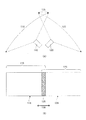
本実施例における撮像装置、およびそれを用いた監視システムを図1に示す。図1は撮像装置100を上側(+Z軸側)から見た配置図、図2は内部の機能ブロック図である。撮像装置100は、第1の撮像部110および第2の撮像部120、第1の駆動機構111、第2の駆動機構121、制御部130、合成処理部140、第1の送受信部150を備えている。
The image pickup apparatus in this embodiment and the monitoring system using the imaging apparatus are shown in FIG. FIG. 1 is a layout diagram of the
第1の駆動機構111、第2の駆動機構121は、駆動手段として機能し、各々、第1の撮像部110、第2の撮像部120の撮影方向または撮影範囲を、少なくとも同じ平面内(図1中のXY平面内)で制御できるようになっている。本実施例の撮像装置では、パン方向に撮影方向を制御できるように構成されている。具体的には、図2に示す第1の駆動機構111、第2の駆動機構121はモーターとギアを備え、モーターを駆動する電力を制御することで、第1の撮像部110、第2の撮像部120を、図1の軸101を回転軸として回転可能な構成となっている。モーターを駆動する電力は、制御部130によって制御されている。
The
即ち、撮像装置100は、第1の撮像部110、第2の撮像部120をそれぞれXY平面内で撮影方向を変更可能な構成になっている。なお、本実施例では両方がそれぞれ撮影方向を変更可能としているが、少なくとも一方の撮影方向を制御可能な駆動機構を備え、それによって第1の撮像部と前記第2の撮像部の撮影方向を、相対的に変更可能とするだけでも良い。
That is, the
第1の撮像部110、第2の撮像部120は、各々結像光学系112、122、固体撮像素子113、123を有しており、結像光学系112、122を介して被写体像を固体撮像素子113、123上にそれぞれ結像させることで、画像を取得している。各々の固体撮像素子113、123の駆動と信号読み出しは、制御部130によって制御されている。なお制御部130にはコンピュータとしてのCPUが内蔵されており、不図示のメモリに記憶されたコンピュータプログラムに基づき装置全体の各種動作を実行する制御手段として機能する。
The first
合成処理部140は、合成手段として機能し、第1の撮像部110で取得した第1の画像信号114および第2の撮像部120で取得した第2の画像信号124を合成して、広角画像(パノラマ画像)信号134を生成するためのものである。具体的には、画像の重複部分をずらしながら相関係数を求める、所謂パターンマッチングの技術を適用することで、複数の画像間の位置ずらし量を求め、広角画像信号134を生成する。更に、本実施例では、第1の撮像部110の撮影範囲115と、第2の撮像部120の撮影範囲125の重なり範囲(重なり量)を調べる。そして重なり範囲(重なり量)が、第1の閾値未満の場合には広角画像信号134を生成せず、第1の閾値以上の場合には広角画像信号134を生成する。詳細については後述する。なお、合成処理部140において、広角画像信号134を生成しない場合には、第1の画像信号114、第2の画像信号124を合成せずに第1の送受信部150に送る。
The
第1の送受信部150は、合成処理部140から送られてきた画像信号(第1の画像信号114、第2の画像信号124、または広角画像信号134)を、有線又は無線などのネットワークを介して、外部の不図示のクライアント装置180に転送する。
外部のクライアント装置180は、撮像装置100を制御するコマンドを、第2の送受信部181とネットワークを介して第1の送受信部150に送信し、それを受けて、撮像装置100は、コマンドに対するレスポンスをクライアント装置180に返信する。コマンドとは、例えば第1の駆動機構111、第2の駆動機構121の制御である。即ち、ユーザーは、外部のクライアント装置180から、ネットワークを介して、第1の撮像部110、第2の撮像部120の向きを制御できるようになっている。
The first transmission /
The
クライアント装置は例えばPCなどの外部機器であり、ネットワークは、有線LAN、無線LAN等により構成されている。また、ネットワークを介して撮像装置100に電源を供給する構成となっていても良い。
なお、182はクライアント装置180内部の制御を行うための制御部であってCPU等のコンピュータを内蔵している。また制御部182は不図示のメモリを内蔵し、メモリには制御部内のCPUの動作を制御するためのコンピュータプログラムが記憶されている。183は表示手段としての表示部であって、撮像装置100から送られてきた画像信号などを表示するためのものである。184は操作部であって、各種のスイッチやタッチパネル等の入力部を含む。ユーザーが操作部を操作することによって撮像装置100に対して各種の指示をすることができる。
The client device is an external device such as a PC, and the network is composed of a wired LAN, a wireless LAN, and the like. Further, the
なお実施例においては、合成処理部140は撮像装置100の内部に設けられているが、クライアント装置180内に設けても良い。また、撮像装置100とクライアント装置180によって撮像システムが構成されている。
なお、図2に示す実施例1では、撮像装置100が第1の送受信部150を備え、画像をクライアント装置180側に転送するとともに、クライアント装置180側からの命令で動作している例を示した。即ち、表示部183や制御部182や操作部184は撮像装置とは別体の例を示した。しかし、撮像装置100が画像データを保存するメモリと、画像を表示する表示部183およびユーザーの支持を受け付けるスイッチ等の操作部184などの一部を一体的に有していても良い。即ち、撮像装置100自身がクライアント装置180の機能を一体的に内蔵していても良い。
In the embodiment, the
In the first embodiment shown in FIG. 2, an example is shown in which the
前述したように、本実施例に示す撮像装置100は、第1の撮像部110の撮影範囲115と、第2の撮像部120の撮影範囲125の重なり範囲(重なり量)135の大きさが、第1の閾値以上の場合には広角画像信号134を生成する。そして、重なり範囲135の大きさが第1の閾値未満の場合には広角画像信号134を生成しないように構成している。このような構成とすることで、第1の撮像部110、第2の撮像部120の撮影方向によらず、被写体の視認性に優れた画像を提供することができる。以下で、説明を行う。
As described above, in the
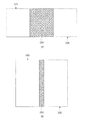
図3、図4は、第1の撮像部110の第1の撮影範囲115、第2の撮像部120の第2の撮影範囲125および、その重なり範囲135を示す図である。図3(A)、(B)は、重なり範囲(重なり量)135が第1の閾値136以上の場合、図4(A)、(B)は、重なり範囲135が第1の閾値136未満の場合を示す図である。図3において、重なり範囲135はハッチングした領域である。
3 and 4 are diagrams showing a first photographing
なお、広角画像信号134を生成するためには、第1の画像信号114と第2の画像信号124の間の位置ズレ量を求めれば良い。位置ズレ量を求めるためには、特許文献1に開示されているような、一般的な手法を用いることができる。例えば、第1の画像信号114と第2の画像信号124をずらしつつ、SSD(Sum of Squared Difference)やSAD(Sum of Absolute Difference)といった相関係数を計算し、相関係数が最も高くなる位置ズレ量を求めればよい。
In order to generate the wide-angle image signal 134, the amount of positional deviation between the
一般に、SSDやSADによって相関係数を求める際、位置ズレ量を計算するために用いる画素信号の数が多いほど、精度の高い相関係数を求めることができる。図3よりわかるように、重なり範囲135が大きいほど、位置ズレ量を計算するために用いる画素信号の数が多い。従って、重なり範囲135が大きいほど、精度の高い位置ズレ量を求めることができ、品質の高い広角画像を生成することができる。一方、重なり範囲135が小さいほど、位置ズレ量の検出が低下するため、品質の高い広角画像を生成することが難しい。
Generally, when the correlation coefficient is obtained by SSD or SAD, the larger the number of pixel signals used for calculating the amount of positional deviation, the higher the accuracy of the correlation coefficient can be obtained. As can be seen from FIG. 3, the larger the overlapping
品質の高い広角画像信号134が生成できる場合には、第1の画像信号114、第2の画像信号124それぞれ単独で観察するよりも、両者を合成して広角画像信号134とした方が、重なり範囲135の被写体の視認性が高い。一方、品質の高い広角画像信号134を生成することが難しい場合には、広角画像信号134を生成したとしても、誤った位置ズレ量で広角画像信号134を生成している可能性がある。即ち、広角画像生成時に、第1の画像信号114、第2の画像信号124が有する情報が失われている可能性がある。従って、品質の高い広角画像信号134を生成することが難しい場合には、広角画像信号134よりも、第1の画像信号114、第2の画像信号124をそれぞれ別々に表示した方が、被写体の視認性の面で優れている。
When a high-quality wide-angle image signal 134 can be generated, it is better to combine the
そこで、本実施例の撮像装置100では、重なり範囲135が第1の閾値136以上であり、品質の高い広角画像信号を生成することができる時には、合成処理部140において広角画像信号134を生成している。一方、重なり範囲135が第1の閾値136未満であり、品質の高い広角画像信号を生成することが難しい時には、合成処理部140において広角画像信号を生成しない。そして、第1の画像信号114、第2の画像信号124をそのまま転送し別々に表示させるようにしている。このような構成とすることで、第1の撮像部110、第2の撮像部120の撮影方向によらず、被写体の視認性に優れた画像を提供することができる。
Therefore, in the
なお、図3よりわかるように、第1の撮像部110の撮影方向と、第2の撮像部120の撮影方向のずれが小さいほど、重なり範囲135が大きい。従って、実施例1の撮像装置100では、第1の撮像部110の撮影方向と第2の撮像部120の撮影方向のずれが、所定の閾値以下である場合は広角画像信号を生成し、前記所定の閾値よりも大きい場合には広角画像信号を生成しないようにすることもできる。ここで、撮像部の撮影方向とは、撮像部の結像光学系の光軸の方向を意味する。
As can be seen from FIG. 3, the smaller the deviation between the shooting direction of the
また、第1の閾値136は、重なり範囲135中の画素数によって決めることもできる。具体的には、第1の画像信号114と第2の画像信号124の内、重なり範囲136に含まれる画像信号114と、第2の画像信号124中の画素数がそれぞれ100個以上であれば好ましく、1000個以上であることが更に望ましい。
また、第1の閾値136を、第1の撮影範囲115や第2の撮影範囲125に対する相対的な比で定義しても良い。具体的には、第1の撮影範囲115と第2の撮影範囲125のうち、相対的に狭い方の撮影範囲に対して、重なり範囲が5%以上であれば好ましく、20%以上であることが更に望ましい。
The
Further, the
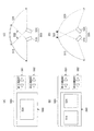
なお、図1では、撮像装置100が、第1の撮像部110と第2の撮像部120の2つの撮像部から構成されている場合を示したが、3つ以上の撮像部から構成されていても良い。3つ以上の撮像部から構成されている場合、各々の撮像部間の撮影範囲の重なり範囲によって、合成して広角画像信号を生成するか否かを切り替える構成とすることが好ましい。具体的には、隣接する撮像部間の撮影範囲の重なり範囲が第1の閾値以上である場合に、それらの撮像部で取得した各々の画像信号を合成して広角画像信号を生成する。一方、第1の閾値未満である場合には、それらの撮像部で取得した各々の画像信号は合成しない構成とする。
Note that FIG. 1 shows a case where the
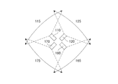
図5に、撮像装置100が、この順番に右回りに並べられた、撮像部110、120、160、170の4つの撮像部から構成されている例を示す。各々の撮像部の撮影範囲は、115、125、165、175とする。
図5のように、各々の撮像部の撮影範囲の重なり範囲が全て第1の閾値以上である場合には、各々の撮像部で撮影しそれぞれ得られた画像信号114、124、164、174を全て合成して一つの広角画像信号134を生成する。
FIG. 5 shows an example in which the
As shown in FIG. 5, when the overlapping range of the imaging ranges of each imaging unit is all equal to or greater than the first threshold value, the image signals 114, 124, 164, and 174 obtained by photographing with each imaging unit are taken. All are combined to generate one wide-angle image signal 134.
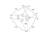
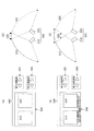
一方、図6は、撮像部110と120間、120と160間の重なり範囲が第1の閾値136以上であって、撮像部170と110間、160と170間の重なり範囲が第1の閾値136未満の場合である。この時には、撮像部110、120、160からの画像信号114、124、164を合成して広角画像信号134を生成し、撮像部170で撮影した画像信号174は他の画像信号と合成しない。
図7は、撮像部110と120間、160と170間の重なり範囲が第1の閾値136以上であって、撮像部170と110間、撮像部120と撮像部160間の重なり範囲が第1の閾値136未満の場合である。
On the other hand, in FIG. 6, the overlapping range between the
In FIG. 7, the overlapping range between the
この時には、撮像部110、120からの画像信号114と画像信号124を合成し、撮像部160、170からの画像信号164と画像信号174とを合成することで、二つの広角画像信号134Aと、134Bを生成する。
そして、図8のように、各々の撮像部の撮影範囲の重なり範囲が全て第1の閾値136未満である場合には、各々の撮像部で撮影した画像信号114、124、164、174のいずれも他の画像信号とは合成しない。
(実施例2)
At this time, the image signals 114 and the image signals 124 from the
Then, as shown in FIG. 8, when the overlapping range of the imaging ranges of each imaging unit is all less than the
(Example 2)
実施例2の撮像装置200(不図示)は、実施例1に示す撮像装置100に対し、第1の駆動機構、第2の駆動機構の機能のみが異なる。実施例2の撮像装置200では、第1の駆動機構211(不図示)、第2の駆動機構212(不図示)は、各々、第1の撮像部210(不図示)、第2の撮像部220(不図示)の撮影方向を、互いに直交する2つの方向に回転できるようになっている。具体的には、Z軸を中心とした回転機構(所謂パン駆動機構)の他に、Z軸に対する角度を制御可能な回転機構(所謂チルト駆動機構)を有している。
The image pickup device 200 (not shown) of the second embodiment differs from the
そして、図9(A)に示すように、第1の撮像部210の撮影範囲215と、第2の撮像部220の撮影範囲225の重なり範囲235の大きさ(面積)が、第1の閾値(面積値)以上の場合には広角画像信号234を生成する。そして、図9(B)に示すように、第1の閾値未満の場合には広角画像信号234を生成しない。
即ち、図9は、第1の撮像部210の第1の撮影範囲215、第2の撮像部220の第2の撮影範囲225および、その重なり範囲235を示す図である。図9(A)は、重なり範囲235が大きい場合、図9(B)は、重なり範囲235が小さい場合を示す。図9(A)、(B)において、重なり範囲235はハッチングした領域である。
Then, as shown in FIG. 9A, the size (area) of the overlapping
That is, FIG. 9 is a diagram showing a first photographing
図9よりわかるように、第1の撮像部110の撮影方向と、第2の撮像部120の撮影方向の、XY平面内(図1参照)でのずれが小さいほど、重なり範囲235のパン方向(図9の横方向)の大きさが大きい。また、Z方向(図1参照)でのずれが小さいほど、重なり範囲235のチルト方向(図9の縦方向)の大きさが大きい。
従って、実施例2の撮像装置200では、第1の撮像部210の撮影方向と第2の撮像部220の撮影方向のパン方向のずれと、チルト方向のずれの積によって、広角画像信号を生成するか否かを決定すればよい。
As can be seen from FIG. 9, the smaller the deviation between the shooting direction of the
Therefore, in the image pickup apparatus 200 of the second embodiment, a wide-angle image signal is generated by the product of the pan-direction deviation of the shooting direction of the first imaging unit 210 and the shooting direction of the second imaging unit 220 and the tilt direction deviation. You just have to decide whether or not to do it.
具体的には、パン方向とチルト方向のずれの積が、第1の閾値以下である場合は広角画像信号を生成し、第1の閾値よりも大きい場合には広角画像信号を生成しないようにする。そしてその場合には、第1の撮像部210と第2の撮像部220の撮像信号を合成せずにそのまま出力し別々に表示する。
なお、パン駆動機構とチルト駆動機構の両方を有する撮像装置ではなく、チルト駆動機構のみを有する撮像装置に対して、本実施例を適用しても良い。
(実施例3)
Specifically, when the product of the deviations in the pan direction and the tilt direction is equal to or less than the first threshold value, a wide-angle image signal is generated, and when it is larger than the first threshold value, a wide-angle image signal is not generated. To do. In that case, the imaging signals of the first imaging unit 210 and the second imaging unit 220 are output as they are without being combined and displayed separately.
It should be noted that this embodiment may be applied to an image pickup device having only a tilt drive mechanism instead of an image pickup device having both a pan drive mechanism and a tilt drive mechanism.
(Example 3)
図10は実施例3を説明するための図である。実施例3の撮像装置300(不図示)は、実施例2に示す撮像装置200に対し、第1の駆動機構、第2の駆動機構の機能のみが異なる。撮像装置300では、第1の撮像部310(不図示)、第2の撮像部320(不図示)の撮影方向を制御できることに加え、各々の撮像部の光軸を中心に撮像部を回転可能な回転機構(所謂ローテーション機構)を有している。
そして、第1の撮像部310の撮影範囲315と、第2の撮像部320の撮影範囲325の重なり範囲335の大きさ(面積)が、第1の閾値以上の場合には広角画像信号334を生成し、第1の閾値未満の場合には広角画像信号334を生成しない。
FIG. 10 is a diagram for explaining the third embodiment. The image pickup device 300 (not shown) of the third embodiment differs from the image pickup device 200 shown in the second embodiment only in the functions of the first drive mechanism and the second drive mechanism. In the image pickup apparatus 300, in addition to being able to control the shooting directions of the first image pickup unit 310 (not shown) and the second image pickup unit 320 (not shown), the image pickup unit can be rotated around the optical axis of each image pickup unit. It has a rotating mechanism (so-called rotation mechanism).
Then, when the size (area) of the overlapping
図10では、第1の撮像部310の第1の撮影範囲315、第2の撮像部320の第2の撮影範囲325および、その重なり範囲335を示している。図10(A)は、重なり範囲335が大きい場合、図10(B)は、図10(A)の状態から、各々の撮像部の撮影方向を保ったまま、各々の撮像部を右に90度回転した場合である。図10において、重なり範囲135はハッチングした領域である。
FIG. 10 shows a first photographing
一般に、監視用途などに使用される撮像部中の固体撮像素子は、横方向の長さが、縦方向の長さよりも長いことが多い。従って、撮像部を光軸の周りに回転した場合、撮像部の撮影範囲が変化する。そのため、図10のように、撮像部の回転角度に応じて、重なり範囲335の大きさが変化する。なお、本実施例では第1の駆動機構、第2の駆動機構ともに、パン駆動機構、チルト駆動機構、ローテーション駆動機構の3つの機能全てを有するが、第1の駆動機構、第2の駆動機構はそれぞれ上記3つの機能の一部を有するものであっても良い。すなわち、例えばローテーション機能に関しては、第1の撮像部と前記第2の撮像部の少なくとも一方の光軸を中心に前記第1の撮像部と前記第2の撮像部の対応する一方を回転させる回転手段を有するものであっても良い。
(実施例4)
In general, a solid-state image sensor in an image pickup unit used for surveillance purposes often has a length in the horizontal direction longer than a length in the vertical direction. Therefore, when the imaging unit is rotated around the optical axis, the imaging range of the imaging unit changes. Therefore, as shown in FIG. 10, the size of the overlapping
(Example 4)
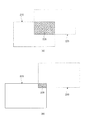
実施例4の撮像装置400を図11、図12に示す。実施例1に示す撮像装置100に対し、第1の駆動機構、第2の駆動機構の構成および、第1の撮像部、第2の撮像部の構成が異なる。実施例4の撮像装置400では、第1の撮像部410、第2の撮像部420の撮影方向だけでなく、ズームにより撮影範囲が制御できるような構成となっている。具体的には、各々の撮像部中の結像光学系が、光軸方向に移動可能なズームレンズを有しており、第1の駆動機構411(不図示)、第2の駆動機構412(不図示)が、ズームレンズを駆動することで、撮像部の撮影範囲を可変制御する。
The
そして、第1の撮像部410の撮影範囲415と、第2の撮像部420の撮影範囲425の重なり範囲435の大きさ(面積)が、第1の閾値以上の場合には広角画像信号434を生成し、第1の閾値未満の場合には広角画像信号434を生成しない。
図11、図12は、第1の撮像部410の第1の撮影範囲415、第2の撮像部420の第2の撮影範囲425および、その重なり範囲435を示す図である。図11(A)、(B)は、重なり範囲435が第1の閾値436以上の場合、図12(A)、(B)は、重なり範囲435が第1の閾値436未満の場合である。図11、図12において、重なり範囲135はハッチングした領域である。
Then, when the size (area) of the overlapping
11 and 12 are views showing a first photographing
図11、図12よりわかるように、第1の撮像部410の撮影範囲(画角)415、第2の撮像部420の撮影範囲(画角)425が広いほど、重なり範囲435が大きい。具体的には、第1の撮像部410の光軸から、第2の撮像部420の光軸に向かう回転方向に沿った、撮影範囲の長さが長いほど(画角が大きいほど)、重なり範囲435が大きい。
従って、実施例4の撮像装置400では、第1の撮像部410の光軸から、第2の撮像部420の光軸に向かう回転方向に沿った、第1の撮像部410の撮影範囲の長さと、第2の撮像部420の撮影範囲の長さの和を求める。それによって、広角画像信号を生成するか否かを決定すればよい。
As can be seen from FIGS. 11 and 12, the wider the shooting range (angle of view) 415 of the
Therefore, in the
具体的には、撮影範囲の長さの和が例えば所定の閾値以下である場合は広角画像信号を生成し、前記所定の閾値よりも大きい場合には広角画像信号を生成しなければよい。即ち、第1の撮像部410と第2の撮像部420のパン方向の向きがそれぞれ固定されていると仮定した場合、第1の撮像部410と第2の撮像部420のそれぞれの画角の合計が所定値以上であれば重なり範囲が大きい。従ってその場合には広角画像信号を生成し、前記所定値より小さければ重なり範囲が少なくなるので広角画像信号を生成しない。
なお、ズーム駆動機構に加え、実施例1〜3と同様に、第1の駆動機構、第2の駆動機構はパン駆動機構、チルト駆動機構、ローテーション駆動機構の内の一部だけを有していても良い。即ち、第1の撮像部と前記第2の撮像部の少なくとも一方の撮影範囲を変更するためのズーム手段を含むものであれば良い。
(実施例5)
Specifically, when the sum of the lengths of the photographing ranges is, for example, equal to or less than a predetermined threshold value, a wide-angle image signal may not be generated, and when it is larger than the predetermined threshold value, a wide-angle image signal may not be generated. That is, assuming that the pan-direction orientations of the
In addition to the zoom drive mechanism, as in the first to third embodiments, the first drive mechanism and the second drive mechanism have only a part of the pan drive mechanism, the tilt drive mechanism, and the rotation drive mechanism. You may. That is, it may include a zoom means for changing the photographing range of at least one of the first imaging unit and the second imaging unit.
(Example 5)
実施例5では、撮像装置の中の第1の撮像部、第2の撮像部の撮影方向または撮影範囲を制御するためのユーザーインターフェースについて説明する。以下では、実施例1に示す撮像装置のように、撮像装置の撮影方向をパン方向に制御する場合を例にとって説明するが、パン方向以外の場合も同様のユーザーインターフェースを使用できる。
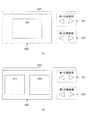
図13は、実施例5に示す撮像装置500のユーザーインターフェース580を説明する図である。ユーザーインターフェース580は、図14の撮像装置500中の第1の撮像部510、第2の撮像部520の撮影方向を制御するためのカーソル581、582および、各々の撮像部で取得した画像信号を表示するための表示部590を有している。なお、ユーザーインターフェース580はクライアント装置180側に別体として設けていても良いし、撮像装置100内に一体的に設けても良い。
In the fifth embodiment, a user interface for controlling the shooting direction or shooting range of the first imaging unit and the second imaging unit in the imaging device will be described. In the following, a case where the shooting direction of the imaging device is controlled in the pan direction as in the imaging device shown in the first embodiment will be described as an example, but the same user interface can be used in cases other than the pan direction.
FIG. 13 is a diagram illustrating a
なお、撮影方向の制御はカーソルだけではなく、撮影したい範囲をマウスやタッチパネルでドラッグしたり、キーボードなどの文字入力インターフェースを用い、文字や数字で指定したりすることによって行うようにしても良い。
第1の撮像部510の撮影範囲515と、第2の撮像部520の撮影範囲525の重なり範囲535の大きさが、第1の閾値以上の場合には、図13(A)のように、表示部590に広角画像信号534が表示される。
The shooting direction may be controlled not only by the cursor but also by dragging the range to be shot with a mouse or a touch panel, or by using a character input interface such as a keyboard and specifying by characters or numbers.
When the size of the overlapping
一方、重なり範囲535の大きさが、第1の未満の場合には、図13(B)のように、第1の画像信号514、第2の画像信号524が各々独立して並んで表示される(以下、非広角画像表示と呼ぶ)。なお、表示部において、第1の画像信号514が右側、第2の画像信号524が左側に表示されていても良い。また、左右ではなく、上下方向にずれて配置されていても良い。但し、第1の画像信号514、第2の画像信号524は第1の撮像部510と第2の撮像部520の撮影方向に合わせて同じ順番で並んで表示されていた方が好ましい。つまり第1の撮像部510が左側に向いていて第2の撮像部520が右に向いている場合には、表示部590上において第1の画像信号514が左側、第2の画像信号524は右側というように同じ順番に並んで配置される。
なお、非広角画像表示モードにおいて、第1の撮像部510と第2の撮像部520とは合成はしないが、隙間を空けずに隣接して並べて配置して表示しても良い。あるいは隙間を空けて配置しても良い。
On the other hand, when the size of the overlapping
In the non-wide-angle image display mode, the first
まず、表示部590に広角画像信号534が表示されている状態で、ユーザーが第1の撮像部510または第2の撮像部520の撮影方向を変化させ、重なり範囲535の大きさが、第1の閾値未満になったとする。この時、撮像装置500は、以下のいずれかの応答を返すことが好ましい。
1つ目の応答は、図14のように、ユーザーの指示通りに、撮像部の向きを変更する応答である。この応答を行うことで、ユーザーの意図通りに撮像部の向きを変更することができる。図14(A)、(B)にはユーザーインターフェース、図14(C)、(D)にはその時の各々の撮像部510、520の撮影方向と撮影範囲515、525を示した。
First, in a state where the wide-
The first response is a response for changing the orientation of the imaging unit as instructed by the user, as shown in FIG. By performing this response, the orientation of the imaging unit can be changed as the user intends. 14 (A) and 14 (B) show the user interface, and FIGS. 14 (C) and 14 (D) show the shooting directions and
しかしながら、この応答を行った場合、撮像部の向きを変更する前後で、表示部に表示される画像の種類が変化してしまう。即ち、撮像部の向きを変更する前は、広角画像信号534が表示されていたのに対し、撮像部の向きを変更した後は、非広角画像信号が表示される。そのため、ユーザーに違和感を与えてしまう可能性がある。
そこで、2つ目の応答として、図15のように、撮像部の向きを変更する前に、広角画像信号534から非広角画像信号に移行して良いかどうかを、ダイアログ等を表示して尋ねる応答がある。図15(A)、(B)にはユーザーインターフェース、図15(C)、(D)にはその時の各々の撮像部510、520の撮影方向と撮影範囲515、525を示した。
However, when this response is made, the type of image displayed on the display unit changes before and after the orientation of the imaging unit is changed. That is, the wide-
Therefore, as a second response, as shown in FIG. 15, before changing the orientation of the imaging unit, a dialog or the like is displayed to ask whether or not the wide-
ユーザーに尋ねた結果、非広角画像に移行して良い、というユーザーからの応答があった場合には、撮像部の向きを変更するとともに、表示部590に表示する画像を、広角画像信号から非広角画像信号に変更する。一方、広角画像信号から非広角画像信号に移行してはならない、というユーザーからの応答があった場合には、撮像部の向きを変更せず、広角画像信号を表示したままとする。上記のような2つ目の応答を使用することで、広角画像信号から非広角画像信号に変化することの違和感を解消することができる。
As a result of asking the user, if there is a response from the user that it is okay to shift to a non-wide-angle image, the orientation of the imaging unit is changed and the image displayed on the
更に、3つ目の応答として、広角画像信号が表示できる範囲内だけ、撮像部の向きを変更可能にする、という応答がある。即ち、図16のように、重なり範囲535の大きさが第1の閾値になるまで撮像部の向きを変更可能とする。図16(A)、(B)にはユーザーインターフェース、図16(C)、(D)にはその時の各々の撮像部510、520の撮影方向と撮影範囲515、525を示した。
この時、重なり範囲535の大きさは第1の閾値以上であるため、表示部590の表示される画像は広角画像のままである。3つ目の応答を使用することでも、広角画像から非広角画像に変化することの違和感を解消することができる。
Further, as a third response, there is a response that the orientation of the imaging unit can be changed only within the range in which the wide-angle image signal can be displayed. That is, as shown in FIG. 16, the orientation of the imaging unit can be changed until the size of the overlapping
At this time, since the size of the overlapping
なお、3つ目の応答を使用した場合、2つ目の応答と併用することが更に好ましい。即ち、重なり範囲535の大きさが第1の閾値になるまで撮像部の向きを変更したのち、それ以上撮像部の向きを変更するか否かを、ダイアログ等を表示してユーザーの指示を求める、という応答である。広角画像のままで撮影方向を変更したいユーザーに対して、可能な限り撮影方向を変更するとともに、非広角画像に移行してでも撮影方向を変更したいユーザーに対して、所望の撮影方向に変更することができる。
4つ目の応答として、精度の低い広角画像を表示するか、非広角画像を表示させるかを、ユーザーに選択させる、という応答がある。即ち、ユーザーが、精度の低い広角画像信号を表示することを選択した場合には、撮像部の向きを変更した後も広角画像信号を表示し続け、非広角画像信号に移行することを選択した場合には、撮像部の向きを変更すると同時に、非広角画像信号を表示する。図17(A)、(B)にはユーザーインターフェース、図17(C)、(D)にはその時の各々の撮像部510、520の撮影方向と撮影範囲515、525を示した。
When the third response is used, it is more preferable to use it together with the second response. That is, after changing the orientation of the imaging unit until the size of the overlapping
As a fourth response, there is a response that allows the user to select whether to display a wide-angle image with low accuracy or a non-wide-angle image. That is, when the user chooses to display a wide-angle image signal with low accuracy, he / she chooses to continue displaying the wide-angle image signal even after changing the orientation of the imaging unit and shift to the non-wide-angle image signal. In this case, the non-wide-angle image signal is displayed at the same time as the orientation of the imaging unit is changed. 17 (A) and 17 (B) show the user interface, and FIGS. 17 (C) and 17 (D) show the shooting directions and
前述したように、重なり範囲535の大きさが第1の閾値未満である場合、精度の高い位置ズレ量を求めることが難しいため、品質の高い広角画像信号を得ることが難しい。しかしながら、位置ズレ量の精度が低いことを許容できるユーザーにとっては、精度が低くても広角画像信号を表示して欲しい場合がある。このような場合、4つ目の応答を使用した方が好ましい。
なお、重なり範囲535の大きさがほぼゼロ、即ち、第1の撮像部の撮影範囲と第2の撮像部の撮影範囲が重ならなくなってしまった場合には、位置ズレ量を求めることが不可能になる。
As described above, when the magnitude of the overlapping
When the size of the overlapping
この場合には、広角画像信号を表示することができないため、4つ目の応答であっても、非広角画像表示に移行することが必要となる。この際、ユーザーから、広角画像表示から非広角画像表示に移行してはならない、というユーザーからの禁止を指示する応答があった場合には、撮像部の向きを、重なり範囲がゼロになるまでだけ変更可能とする方が好ましい。
更に、3つ目の応答と4つ目の応答を組み合わせて、精度の高い広角画像信号が得られる範囲まで撮像部の向きを変更するか、精度の低い広角画像信号も許容して撮像部の向きを変更するか、をユーザーにダイアログ等を用いて選択させると、更に好ましい。この場合、ユーザーの選択に応じて、許容される重なり範囲の大きさが変わることとなる。
In this case, since the wide-angle image signal cannot be displayed, it is necessary to shift to the non-wide-angle image display even for the fourth response. At this time, if there is a response from the user instructing the user not to shift from the wide-angle image display to the non-wide-angle image display, the orientation of the imaging unit is set until the overlapping range becomes zero. It is preferable to be able to change only.
Furthermore, by combining the third response and the fourth response, the orientation of the imaging unit is changed to the extent that a highly accurate wide-angle image signal can be obtained, or a low-accuracy wide-angle image signal is allowed in the imaging unit. It is more preferable to let the user select whether to change the orientation by using a dialog or the like. In this case, the size of the allowable overlap range changes according to the user's selection.
次に、表示部590に、非広角画像が表示されている状態で、第1の撮像部510または第2の撮像部520の撮影方向を変化した場合について説明を行う。
表示部590に非広角画像が表示されている状態で、ユーザーが重なり範囲535の大きさが、第1の閾値以上になるような駆動を行ったとする。
この時、撮像装置500は、以下のいずれかの応答を返すことが好ましい。
Next, a case where the shooting direction of the
It is assumed that the user drives the
At this time, the
1つ目の応答は、図18のように、ユーザーの指示通りに、撮像部の向きを変更する応答である。この応答を行うことで、ユーザーの意図通りに撮像部の向きを変更することができる。図18(A)、(B)にはユーザーインターフェース、図18(C)、(D)にはその時の各々の撮像部510、520の撮影方向と撮影範囲515、525を示した。
しかしながら、この応答を行った場合、撮像部の向きを変更する前後で、表示部に表示される画像の種類が変化してしまう。即ち、撮像部の向きを変更する前は、非広角画像信号が表示されていたのに対し、撮像部の向きを変更した後は、広角画像信号534が表示される。そのため、ユーザーに違和感を与えてしまう可能性がある。
The first response is a response for changing the orientation of the imaging unit as instructed by the user, as shown in FIG. By performing this response, the orientation of the imaging unit can be changed as the user intends. 18 (A) and 18 (B) show the user interface, and FIGS. 18 (C) and 18 (D) show the shooting directions and
However, when this response is made, the type of image displayed on the display unit changes before and after the orientation of the imaging unit is changed. That is, the non-wide-angle image signal was displayed before the orientation of the imaging unit was changed, whereas the wide-
そこで、2つ目の応答として、図19のように、撮像部の向きを変更する前に、非広角画像表示モードから広角画像表示モードに移行して良いかどうかをダイアログ等で尋ねる応答がある。図19(A)、(B)にはユーザーインターフェース、図19(C)、(D)にはその時の各々の撮像部510、520の撮影方向と撮影範囲515、525を示した。
ユーザーに尋ねた結果、広角画像表示に移行して良い、というユーザーからの応答があった場合には、撮像部の向きを変更するとともに、表示部590に表示する画像を、非広角画像表示モードから広角画像表示モードに変更する。
Therefore, as the second response, as shown in FIG. 19, there is a response asking in a dialog or the like whether or not to shift from the non-wide-angle image display mode to the wide-angle image display mode before changing the orientation of the imaging unit. .. 19 (A) and 19 (B) show the user interface, and FIGS. 19 (C) and 19 (D) show the shooting directions and
As a result of asking the user, if there is a response from the user that it is okay to shift to the wide-angle image display, the orientation of the imaging unit is changed and the image displayed on the
一方、非広角画像表示モードから広角画像表示モードに移行してはならない、というユーザーからの応答があった場合には、撮像部の向きを変更せず、非広角画像を表示したままとする。2つ目の応答を使用することで、非広角画像表示モードから広角画像表示モードに変化する際の違和感を解消することができる。
なお、非広角画像表示モードから広角画像表示モードに移行してはならない、というユーザーからの応答(禁止の指示)があった場合に、撮像部の向きを変更しつつ、非広角画像を表示したままとしても良い。
なぜならば、重なり範囲が第1の閾値以上である場合、重なり範囲の視認性を重視した場合には広角画像を表示した方が好ましいが、非広角画像を表示することもできるためである。
On the other hand, when there is a response from the user that the non-wide-angle image display mode should not be changed to the wide-angle image display mode, the orientation of the imaging unit is not changed and the non-wide-angle image is still displayed. By using the second response, it is possible to eliminate the discomfort when changing from the non-wide-angle image display mode to the wide-angle image display mode.
When there was a response (prohibition instruction) from the user that the non-wide-angle image display mode should not be switched to the wide-angle image display mode, the non-wide-angle image was displayed while changing the orientation of the imaging unit. You can leave it as it is.
This is because when the overlapping range is equal to or larger than the first threshold value, it is preferable to display a wide-angle image when the visibility of the overlapping range is emphasized, but a non-wide-angle image can also be displayed.
続いて、表示部590に非広角画像が表示されている場合に対し、ユーザーが重なり範囲535の大きさが、第1の閾値よりも小さく、第2の閾値以上になるような駆動を行ったとする。なお、第2の閾値は第1の閾値より小さいが、例えば第1の閾値の半分以上であるのが好ましい。
Subsequently, when a non-wide-angle image is displayed on the
この時、撮像装置500は、以下のいずれかの応答を返すことが好ましい。
1つ目の応答は、図18のように、ユーザーの指示通りに、撮像部の向きを変更する応答である。この応答を行うことで、ユーザーの意図通りに撮像部の向きを変更することができる。この場合、重なり範囲は第1の閾値よりも小さいままであるため、撮像部の向きを変更する前後で、表示部に表示される画像の種類が変化してしまう、という問題は発生しない。
At this time, the
The first response is a response for changing the orientation of the imaging unit as instructed by the user, as shown in FIG. By performing this response, the orientation of the imaging unit can be changed as the user intends. In this case, since the overlapping range remains smaller than the first threshold value, there is no problem that the type of the image displayed on the display unit changes before and after the orientation of the imaging unit is changed.
しかしながら、前述したように、重なり範囲の視認性を重視した場合には広角画像を表示した方が好ましい。そこで、ユーザーに、広角画像信号を表示するための選択肢を与える方が好ましい。即ち、2つ目の応答は、図20のように、撮像部の向きをユーザーの指示通りに変更しつつ、ユーザーに対して、「撮像部の向きをもう少し近づければ広角画像を表示することができます。撮像部を近づけますか?」という趣旨の表示を行う応答である。図20(A)、(B)にはユーザーインターフェース、図20(C)、(D)にはその時の各々の撮像部510、520の撮影方向と撮影範囲515、525を示した。
However, as described above, it is preferable to display a wide-angle image when the visibility of the overlapping range is emphasized. Therefore, it is preferable to give the user an option for displaying the wide-angle image signal. That is, the second response is, as shown in FIG. 20, while changing the orientation of the imaging unit as instructed by the user, "displaying a wide-angle image if the orientation of the imaging unit is brought a little closer" to the user. This is a response that displays the message "Do you want to bring the image pickup unit closer?" 20 (A) and 20 (B) show the user interface, and FIGS. 20 (C) and 20 (D) show the shooting directions and
ユーザーが、広角画像を表示して欲しい、という応答を返した場合には、重なり範囲が第1の閾値以上になるまで、撮像部の向きをさらに変更しつつ、広角画像を表示し続ける。一方、ユーザーが、非広角画像のままで良い、という応答を返した場合には、撮像部の向きはそのままにして、非広角画像を表示する。
なお、この時、ユーザーが重なり範囲が大きくなるように、撮像部の向きの変更を行ったか、小さくなるように変更を行ったか、によって、1つ目の応答か、2つ目の応答かを変更しても良い。
When the user returns a response requesting that the wide-angle image be displayed, the wide-angle image is continuously displayed while the orientation of the imaging unit is further changed until the overlapping range becomes equal to or larger than the first threshold value. On the other hand, when the user returns a response that the non-wide-angle image can be left as it is, the non-wide-angle image is displayed while keeping the orientation of the imaging unit as it is.
At this time, depending on whether the orientation of the imaging unit is changed so that the overlap range becomes large or the user changes the direction so that the overlapping range becomes small, the first response or the second response is determined. You may change it.
ユーザーが重なり範囲が大きくなるように、撮像部の向きの変更を行った場合、ユーザーは第1の撮像部と第2の撮像部で近い撮影範囲を撮影したいと予測されるため、2つ目の応答を行い、広角画像を表示できる選択肢を提示する。
一方、ユーザーが重なり範囲が小さくなるように、撮像部の向きの変更を行った場合、ユーザーは第1の撮像部と第2の撮像部で別々の撮影範囲を撮影したいと予測されるため、1つ目の応答を行う。
If the user changes the orientation of the imaging unit so that the overlapping range becomes large, it is predicted that the user wants to shoot a close shooting range with the first imaging unit and the second imaging unit. And present options that can display wide-angle images.
On the other hand, when the user changes the orientation of the imaging unit so that the overlapping range becomes smaller, it is predicted that the user wants to shoot different shooting ranges in the first imaging unit and the second imaging unit. Make the first response.
次に図21に上記のような実施例の動作例を示すフローチャートを示す。
図21において、ステップS1において、第1の撮像部と第2の撮像部の撮影範囲の重なり範囲が第1の閾V1より小さいか判断し、Noの場合には、ステップS2で広角画像を生成し表示する。
その後、ステップS3で第1の撮像部と第2の撮像部の少なくとも一方の向きを変更する操作がなされたかを判別する。Noの場合には、ステップS3に戻る。Yesの場合には、ステップS4において重なり範囲が第1の閾値V1より小さいか判別し、NoであればステップS5に進んで広角画像のまま撮影方向の変更を実行する。
Next, FIG. 21 shows a flowchart showing an operation example of the above embodiment.
In FIG. 21, in step S1, it is determined whether the overlapping range of the imaging ranges of the first imaging unit and the second imaging unit is smaller than the first threshold V1, and if No, a wide-angle image is generated in step S2. And display.
After that, in step S3, it is determined whether or not the operation of changing the orientation of at least one of the first imaging unit and the second imaging unit has been performed. If No, the process returns to step S3. In the case of Yes, it is determined in step S4 whether the overlapping range is smaller than the first threshold value V1, and if No, the process proceeds to step S5 to change the shooting direction with the wide-angle image as it is.
ステップS4でYesの場合には、ステップS6に進み広角画像のまま重なり範囲が閾値V1になるように第1の撮像部と第2の撮像部の少なくとも一方の向きを変更する。そしてステップS7で「画質変更しても向きを離しますか?」というダイアログを表示し、その結果離す指示をうけたか否かを判別する。そしてステップS7でNoの場合にはステップS7に戻る。Yesの場合には、ステップS8に進み、重なり範囲が第3の閾値V3より小さいか判断する。ここでV3は広角画像を生成するのが困難となる、例えばゼロに近い閾値である。ステップS8でNoの場合にはステップS9に進み広角画像を表示したまま第1の撮像部と第2の撮像部の少なくとも一方の向きを変更する。ステップS8でYesの場合にはステップS10に進み非広角画像を表示し第1の撮像部と第2の撮像部の少なくとも一方の向きを変更する。 If Yes in step S4, the process proceeds to step S6, and the orientation of at least one of the first imaging unit and the second imaging unit is changed so that the overlapping range becomes the threshold value V1 while maintaining the wide-angle image. Then, in step S7, the dialog "Do you want to release the orientation even if the image quality is changed?" Is displayed, and as a result, it is determined whether or not the instruction to release is received. Then, if No in step S7, the process returns to step S7. In the case of Yes, the process proceeds to step S8, and it is determined whether the overlapping range is smaller than the third threshold value V3. Here, V3 is a threshold value close to zero, for example, which makes it difficult to generate a wide-angle image. If No in step S8, the process proceeds to step S9 to change the orientation of at least one of the first imaging unit and the second imaging unit while displaying the wide-angle image. If Yes in step S8, the process proceeds to step S10 to display a non-wide-angle image and change the orientation of at least one of the first imaging unit and the second imaging unit.
一方ステップS1でYesの場合には、ステップS11に進み、非広角画像を生成し表示する。そしてステップS12で第1の撮像部と第2の撮像部の少なくとも一方の向きを変更する操作がなされたかを判別する。Noの場合には、ステップS12に戻る。Yesの場合には、ステップS13において重なり範囲が第1の閾値V1より小さいか判別し、NoであればステップS14に進んで広角画像に移行するかダイアログで問い合わせる。ステップS14でNoの場合には、ステップS11に戻る。ステップS14でYesの場合には、ステップS15に進んで第1の撮像部と第2の撮像部の少なくとも一方の向きを変更し、広角画像表示に移行する。 On the other hand, if Yes in step S1, the process proceeds to step S11 to generate and display a non-wide-angle image. Then, in step S12, it is determined whether or not the operation of changing the orientation of at least one of the first imaging unit and the second imaging unit has been performed. If No, the process returns to step S12. In the case of Yes, it is determined in step S13 whether the overlapping range is smaller than the first threshold value V1, and if No, the process proceeds to step S14 to inquire in a dialog whether to shift to the wide-angle image. If No in step S14, the process returns to step S11. In the case of Yes in step S14, the process proceeds to step S15 to change the orientation of at least one of the first imaging unit and the second imaging unit, and shift to wide-angle image display.
ステップS13でYesの場合には、ステップS16に進み、非広角画像のまま第1の撮像部と第2の撮像部の少なくとも一方の向きを変更する。そしてステップS17で重なり範囲が前記第2の閾値V2より小さいか判別し、YesであればステップS16に戻る。ステップS17でNoの場合には、ステップS18に進んで「撮像部の向きを更に近づけて広角画像にしますか?」というダイアログを表示し、その結果Noの指示が来た場合には、ステップS16に戻る。ステップS18でYesの指示が来た場合には、ステップS19で第1の撮像部と第2の撮像部の少なくとも一方の向きを近づけるように変更して広角画像表示に切り替える。 In the case of Yes in step S13, the process proceeds to step S16, and the orientation of at least one of the first imaging unit and the second imaging unit is changed while maintaining the non-wide-angle image. Then, in step S17, it is determined whether the overlapping range is smaller than the second threshold value V2, and if Yes, the process returns to step S16. If No in step S17, the process proceeds to step S18 to display a dialog asking "Do you want to make the image pickup unit closer to a wide-angle image?", And if No is instructed as a result, step S16 Return to. When the Yes instruction is received in step S18, the direction of at least one of the first imaging unit and the second imaging unit is changed so as to be close to each other in step S19 to switch to the wide-angle image display.
以上説明したように実施例によれば、第1の撮像部から得られた画像と第2の撮像部から得られた画像の重なりの範囲(量)に応じて、広角画像表示モードと非広角画像表示モードとを適切に切り替えているのでユーザーフレンドリーな表示が得られる。もちろん撮像部が3つ以上の場合であっても本実施例は適用でき、その場合には非広角画像表示モードでは複数の撮像部の画像を合成せずに並べて配置するので、やはりユーザーにとって違和感のない画像表示が可能になるものである。 As described above, according to the embodiment, the wide-angle image display mode and the non-wide-angle image are displayed according to the overlap range (amount) of the image obtained from the first imaging unit and the image obtained from the second imaging unit. Since the image display mode is switched appropriately, a user-friendly display can be obtained. Of course, this embodiment can be applied even when there are three or more imaging units. In that case, in the non-wide-angle image display mode, the images of the plurality of imaging units are arranged side by side without being combined, which is also uncomfortable for the user. It is possible to display an image without a problem.
以上、本発明をその好適な実施例に基づいて詳述してきたが、本発明は上記実施例に限定されるものではなく、本発明の主旨に基づき種々の変形が可能であり、それらを本発明の範囲から除外するものではない。
また、本実施例における制御の一部または全部を上述した実施例の機能を実現するコンピュータプログラムをネットワーク又は各種記憶媒体を介して撮像装置に供給するようにしてもよい。そしてその撮像装置におけるコンピュータ(又はCPUやMPU等)がプログラムを読み出して実行するようにしてもよい。その場合、そのプログラム、及び該プログラムを記憶した記憶媒体は本発明を構成することとなる。
Although the present invention has been described in detail based on the preferred examples thereof, the present invention is not limited to the above examples, and various modifications can be made based on the gist of the present invention. It is not excluded from the scope of the invention.
In addition, a computer program that realizes the functions of the above-described embodiment may be supplied to the image pickup apparatus via a network or various storage media with a part or all of the control in the present embodiment. Then, the computer (or CPU, MPU, etc.) in the image pickup apparatus may read and execute the program. In that case, the program and the storage medium that stores the program constitute the present invention.
100:撮像装置
110:第1の撮像部
120:第2の撮像部
111、121:駆動機構
112、122:結像光学系
113、123:固体撮像素子
114、124、134、164、174:画像信号
115、125:撮影範囲
135:重なり範囲
130:合成処理部
136:第1の閾値
140:制御部
150:第1の送受信部
580:ユーザーインターフェース
590:表示部
100: Image pickup device 110: First image pickup unit 120: Second
Claims (17)
前記第1の撮像部と前記第2の撮像部の内の少なくとも一方の撮影方向または撮影範囲を制御可能な駆動手段と、
前記第1の撮像部で取得した第1の画像と、前記第2の撮像部で取得した第2の画像とを合成して広角画像を生成するための合成処理手段と、
前記第1の撮像部の撮影範囲と、前記第2の撮像部の撮影範囲の重なり範囲が、第1の閾値以上である場合には前記合成処理手段において広角画像を生成し、前記重なり範囲が前記第1の閾値未満である場合には合成処理手段において広角画像を生成しないように制御する制御手段と、を有することを特徴とする撮像装置。 The first imaging unit, the second imaging unit, and
A driving means capable of controlling at least one shooting direction or shooting range of the first imaging unit and the second imaging unit.
A compositing processing means for generating a wide-angle image by compositing a first image acquired by the first imaging unit and a second image acquired by the second imaging unit.
When the overlapping range of the imaging range of the first imaging unit and the imaging range of the second imaging unit is equal to or greater than the first threshold value, the synthesis processing means generates a wide-angle image, and the overlapping range is set. An image pickup apparatus comprising: a control means for controlling the synthesis processing means so as not to generate a wide-angle image when the threshold value is less than the first threshold value.
前記第1の撮像部と前記第2の撮像部の内の少なくとも一方の撮影方向または撮影範囲を制御する駆動ステップと、
前記第1の撮像部で取得した第1の画像と、前記第2の撮像部で取得した第2の画像とを合成して広角画像を生成するための合成処理ステップと、
前記第1の撮像部の撮影範囲と、前記第2の撮像部の撮影範囲の重なり範囲が、第1の閾値以上である場合には前記合成処理部において広角画像を生成し、前記重なり範囲が前記第1の閾値未満である場合には合成処理部において広角画像を生成しないように制御する制御ステップと、を有することを特徴とする撮像方法。 An imaging step in which imaging is performed by the first imaging unit and the second imaging unit, and
A drive step for controlling at least one shooting direction or shooting range of the first imaging unit and the second imaging unit, and
A compositing process step for compositing the first image acquired by the first imaging unit and the second image acquired by the second imaging unit to generate a wide-angle image.
When the overlapping range of the imaging range of the first imaging unit and the imaging range of the second imaging unit is equal to or greater than the first threshold value, the synthesis processing unit generates a wide-angle image and the overlapping range is set. An imaging method comprising: a control step for controlling the synthesis processing unit so as not to generate a wide-angle image when the threshold value is less than the first threshold value.
A computer-readable storage medium that stores the computer program according to claim 16.
Priority Applications (5)
| Application Number | Priority Date | Filing Date | Title |
|---|---|---|---|
| JP2019091101A JP2020188349A (en) | 2019-05-14 | 2019-05-14 | Imaging device, imaging method, computer program, and storage medium |
| US16/860,398 US11240446B2 (en) | 2019-05-14 | 2020-04-28 | Imaging device, control apparatus, imaging method, and storage medium |
| EP20173281.5A EP3739867A1 (en) | 2019-05-14 | 2020-05-06 | Imaging device, control apparatus, imaging method, and storage medium |
| KR1020200053682A KR20200131744A (en) | 2019-05-14 | 2020-05-06 | Imaging device, control apparatus, imaging method, and storage medium |
| CN202010400199.2A CN111953890A (en) | 2019-05-14 | 2020-05-13 | Image pickup apparatus, control device, image pickup method, and storage medium |
Applications Claiming Priority (1)
| Application Number | Priority Date | Filing Date | Title |
|---|---|---|---|
| JP2019091101A JP2020188349A (en) | 2019-05-14 | 2019-05-14 | Imaging device, imaging method, computer program, and storage medium |
Publications (2)
| Publication Number | Publication Date |
|---|---|
| JP2020188349A true JP2020188349A (en) | 2020-11-19 |
| JP2020188349A5 JP2020188349A5 (en) | 2022-05-17 |
Family
ID=70613661
Family Applications (1)
| Application Number | Title | Priority Date | Filing Date |
|---|---|---|---|
| JP2019091101A Ceased JP2020188349A (en) | 2019-05-14 | 2019-05-14 | Imaging device, imaging method, computer program, and storage medium |
Country Status (5)
| Country | Link |
|---|---|
| US (1) | US11240446B2 (en) |
| EP (1) | EP3739867A1 (en) |
| JP (1) | JP2020188349A (en) |
| KR (1) | KR20200131744A (en) |
| CN (1) | CN111953890A (en) |
Families Citing this family (6)
| Publication number | Priority date | Publication date | Assignee | Title |
|---|---|---|---|---|
| US11115604B2 (en) * | 2018-01-02 | 2021-09-07 | Insitu, Inc. | Camera apparatus for generating machine vision data and related methods |
| JP7286412B2 (en) | 2019-05-22 | 2023-06-05 | キヤノン株式会社 | IMAGE PROCESSING DEVICE AND CONTROL METHOD THEREOF, IMAGING DEVICE, MONITORING SYSTEM |
| JP2020202503A (en) | 2019-06-11 | 2020-12-17 | キヤノン株式会社 | Imaging device, computer program, and recording medium |
| JP2021019228A (en) | 2019-07-17 | 2021-02-15 | キヤノン株式会社 | Imaging apparatus, computer program, and recording medium |
| CN113784023B (en) * | 2021-08-09 | 2023-06-30 | 深圳市天视通视觉有限公司 | Position determining method, device, image pickup equipment and storage medium |
| KR20230071408A (en) * | 2021-11-16 | 2023-05-23 | 삼성전자주식회사 | A method for providing preview image and an electronic device therefor |
Family Cites Families (21)
| Publication number | Priority date | Publication date | Assignee | Title |
|---|---|---|---|---|
| JP2004118786A (en) | 2002-09-30 | 2004-04-15 | Sony Corp | Image processing apparatus and method for processing image, recording medium, as well as program |
| US10585344B1 (en) * | 2008-05-19 | 2020-03-10 | Spatial Cam Llc | Camera system with a plurality of image sensors |
| US20100097444A1 (en) * | 2008-10-16 | 2010-04-22 | Peter Lablans | Camera System for Creating an Image From a Plurality of Images |
| US8947502B2 (en) * | 2011-04-06 | 2015-02-03 | Qualcomm Technologies, Inc. | In camera implementation of selecting and stitching frames for panoramic imagery |
| US8754961B2 (en) * | 2011-08-17 | 2014-06-17 | Nokia Corporation | Apparatus and method for generating image data from overlapping regions of images |
| US9602720B2 (en) * | 2012-12-10 | 2017-03-21 | Samsung Electronics Co., Ltd. | Photographing apparatus |
| US20160077422A1 (en) | 2014-09-12 | 2016-03-17 | Adobe Systems Incorporated | Collaborative synchronized multi-device photography |
| US20160295108A1 (en) * | 2015-04-01 | 2016-10-06 | Cheng Cao | System and method for panoramic imaging |
| CN108028889B (en) * | 2015-09-18 | 2021-07-02 | 索尼公司 | Image processing apparatus, image processing method, program, and imaging system |
| CN105635579B (en) * | 2015-12-31 | 2018-01-09 | 宇龙计算机通信科技(深圳)有限公司 | A kind of method for displaying image and device |
| US10051180B1 (en) * | 2016-03-04 | 2018-08-14 | Scott Zhihao Chen | Method and system for removing an obstructing object in a panoramic image |
| CN106572313B (en) | 2016-10-31 | 2019-01-08 | 腾讯科技(深圳)有限公司 | Video capture box and video capture method and apparatus |
| CN107040719A (en) * | 2017-03-21 | 2017-08-11 | 宇龙计算机通信科技(深圳)有限公司 | Filming control method and imaging control device based on double screen terminal |
| JP6816853B2 (en) | 2017-11-10 | 2021-01-20 | 株式会社 ゆうちょ銀行 | Automatic teller machines, information processing methods and information processing programs |
| TWI672670B (en) * | 2018-03-12 | 2019-09-21 | Acer Incorporated | Image stitching method and electronic device using the same |
| CN108900764A (en) | 2018-06-06 | 2018-11-27 | 三星电子(中国)研发中心 | Image pickup method and electronic device and filming control method and server |
| JP7182935B2 (en) | 2018-07-30 | 2022-12-05 | キヤノン株式会社 | IMAGING DEVICE, CONTROL METHOD AND PROGRAM |
| JP7210199B2 (en) | 2018-09-20 | 2023-01-23 | キヤノン株式会社 | IMAGING DEVICE, CONTROL METHOD, COMPUTER PROGRAM, AND STORAGE MEDIUM |
| JP7271132B2 (en) | 2018-10-26 | 2023-05-11 | キヤノン株式会社 | Imaging device and surveillance system |
| JP7250483B2 (en) | 2018-11-12 | 2023-04-03 | キヤノン株式会社 | Imaging device, computer program, and storage medium |
| JP7316809B2 (en) | 2019-03-11 | 2023-07-28 | キヤノン株式会社 | Image processing device, image processing device control method, system, and program |
-
2019
- 2019-05-14 JP JP2019091101A patent/JP2020188349A/en not_active Ceased
-
2020
- 2020-04-28 US US16/860,398 patent/US11240446B2/en active Active
- 2020-05-06 KR KR1020200053682A patent/KR20200131744A/en active IP Right Grant
- 2020-05-06 EP EP20173281.5A patent/EP3739867A1/en not_active Withdrawn
- 2020-05-13 CN CN202010400199.2A patent/CN111953890A/en active Pending
Also Published As
| Publication number | Publication date |
|---|---|
| KR20200131744A (en) | 2020-11-24 |
| EP3739867A1 (en) | 2020-11-18 |
| CN111953890A (en) | 2020-11-17 |
| US11240446B2 (en) | 2022-02-01 |
| US20200366854A1 (en) | 2020-11-19 |
Similar Documents
| Publication | Publication Date | Title |
|---|---|---|
| JP2020188349A (en) | Imaging device, imaging method, computer program, and storage medium | |
| JP3618891B2 (en) | Camera control apparatus and camera control information display method | |
| KR101739318B1 (en) | Display control apparatus, imaging system, display control method, and recording medium | |
| JP2007088584A (en) | Monitor camera system, remote control monitor apparatus, control method, and control program thereof | |
| KR20120012397A (en) | Camera device, camera system, control device and program | |
| JP6312046B2 (en) | Image processing system, image processing method, and program | |
| JP2006245793A (en) | Imaging system | |
| US9906710B2 (en) | Camera pan-tilt-zoom (PTZ) control apparatus | |
| JP2019054369A (en) | Imaging device, control method of imaging device, and program | |
| JP2006191411A (en) | Camera control apparatus, image display apparatus, method for controlling camera, method for displaying image, and program | |
| JP2009049798A (en) | Camera control method, camera control device, camera control program, and camera system | |
| JP5847591B2 (en) | Information processing apparatus, information processing method and program for information processing apparatus | |
| JP2012119971A (en) | Monitoring video display unit | |
| JP2000341574A (en) | Camera device and camera control system | |
| CN112073630B (en) | Image pickup apparatus, control method of image pickup apparatus, and recording medium | |
| JP2016096482A (en) | Image processing apparatus, image processing method, and program | |
| JP4998522B2 (en) | Control device, camera system, and program | |
| KR20170055455A (en) | Camera system for compensating distortion of lens using super wide angle camera and Transport Video Interface Apparatus used in it | |
| US11516390B2 (en) | Imaging apparatus and non-transitory storage medium | |
| JP6836306B2 (en) | Imaging control device, its control method, program and recording medium | |
| JP2000083245A (en) | Remote controller for image pickup device and image pickup system and remote control method for image pickup device | |
| WO2021131325A1 (en) | Image processing device, image processing method, and program | |
| CN114205532B (en) | Shooting method, device, equipment and medium of virtual camera | |
| JP2023016580A (en) | Imaging system, imaging method, and computer program | |
| KR200481796Y1 (en) | Pan-Tilt-Zoom Camera Controller |
Legal Events
| Date | Code | Title | Description |
|---|---|---|---|
| A521 | Request for written amendment filed |
Free format text: JAPANESE INTERMEDIATE CODE: A523 Effective date: 20220509 |
|
| A621 | Written request for application examination |
Free format text: JAPANESE INTERMEDIATE CODE: A621 Effective date: 20220509 |
|
| A977 | Report on retrieval |
Free format text: JAPANESE INTERMEDIATE CODE: A971007 Effective date: 20230608 |
|
| A131 | Notification of reasons for refusal |
Free format text: JAPANESE INTERMEDIATE CODE: A131 Effective date: 20230613 |
|
| A521 | Request for written amendment filed |
Free format text: JAPANESE INTERMEDIATE CODE: A523 Effective date: 20230804 |
|
| A01 | Written decision to grant a patent or to grant a registration (utility model) |
Free format text: JAPANESE INTERMEDIATE CODE: A01 Effective date: 20230822 |
|
| A045 | Written measure of dismissal of application [lapsed due to lack of payment] |
Free format text: JAPANESE INTERMEDIATE CODE: A045 Effective date: 20231219 |