JP2020184895A - Device for conveying soybean curd - Google Patents
Device for conveying soybean curd Download PDFInfo
- Publication number
- JP2020184895A JP2020184895A JP2019089898A JP2019089898A JP2020184895A JP 2020184895 A JP2020184895 A JP 2020184895A JP 2019089898 A JP2019089898 A JP 2019089898A JP 2019089898 A JP2019089898 A JP 2019089898A JP 2020184895 A JP2020184895 A JP 2020184895A
- Authority
- JP
- Japan
- Prior art keywords
- tofu
- support member
- conveyor
- endless conveyor
- transport device
- Prior art date
- Legal status (The legal status is an assumption and is not a legal conclusion. Google has not performed a legal analysis and makes no representation as to the accuracy of the status listed.)
- Ceased
Links
- 235000013527 bean curd Nutrition 0.000 title claims abstract description 126
- 238000004140 cleaning Methods 0.000 claims description 61
- 239000007788 liquid Substances 0.000 claims description 26
- 230000003028 elevating effect Effects 0.000 claims description 12
- 239000011347 resin Substances 0.000 claims description 4
- 229920005989 resin Polymers 0.000 claims description 4
- 238000012423 maintenance Methods 0.000 abstract description 17
- 235000013305 food Nutrition 0.000 abstract description 4
- XLYOFNOQVPJJNP-UHFFFAOYSA-N water Substances O XLYOFNOQVPJJNP-UHFFFAOYSA-N 0.000 description 13
- 239000004744 fabric Substances 0.000 description 7
- 238000010438 heat treatment Methods 0.000 description 6
- 239000000463 material Substances 0.000 description 6
- 238000000465 moulding Methods 0.000 description 6
- 239000000047 product Substances 0.000 description 6
- 238000000034 method Methods 0.000 description 5
- 230000008569 process Effects 0.000 description 5
- 230000006872 improvement Effects 0.000 description 4
- 238000005406 washing Methods 0.000 description 4
- 229910000831 Steel Inorganic materials 0.000 description 3
- 238000011109 contamination Methods 0.000 description 3
- 239000003599 detergent Substances 0.000 description 3
- 239000010959 steel Substances 0.000 description 3
- 230000009471 action Effects 0.000 description 2
- 244000052616 bacterial pathogen Species 0.000 description 2
- 238000003825 pressing Methods 0.000 description 2
- 235000013322 soy milk Nutrition 0.000 description 2
- 208000010470 Ageusia Diseases 0.000 description 1
- 241000894006 Bacteria Species 0.000 description 1
- 229920000742 Cotton Polymers 0.000 description 1
- 230000002378 acidificating effect Effects 0.000 description 1
- 238000007664 blowing Methods 0.000 description 1
- 239000000645 desinfectant Substances 0.000 description 1
- 238000007599 discharging Methods 0.000 description 1
- 239000003640 drug residue Substances 0.000 description 1
- 238000011059 hazard and critical control points analysis Methods 0.000 description 1
- 230000007246 mechanism Effects 0.000 description 1
- 244000005700 microbiome Species 0.000 description 1
- 238000004806 packaging method and process Methods 0.000 description 1
- 239000012466 permeate Substances 0.000 description 1
- 239000002994 raw material Substances 0.000 description 1
- 230000007480 spreading Effects 0.000 description 1
- 230000001954 sterilising effect Effects 0.000 description 1
- 238000004659 sterilization and disinfection Methods 0.000 description 1
Images
Landscapes
- Framework For Endless Conveyors (AREA)
- Beans For Foods Or Fodder (AREA)
Abstract
Description
本発明は豆腐の搬送装置に関する。 The present invention relates to a tofu transport device.
豆腐類の成型工程において、凝固物を搬送するコンベア、特に連続成型機では凝固物の圧搾時に放出される搾り水(シミズ、とも呼ぶ)の処理が重要な課題である。このような水は、周回駆動する布ベルトやコンベアの如き搬送部材の下方へ流れ、搬送部材と摺動する摺動部材との隙間等に染み込み、汚れ、菌の発生の原因となる。 In the process of molding tofu, it is an important issue to treat the squeezed water (also called shimizu) released when the coagulated product is squeezed in a conveyor that conveys the coagulated product, particularly in a continuous molding machine. Such water flows downward of a transport member such as a cloth belt or a conveyor that is driven in a circular manner, permeates into a gap between the transport member and a sliding member, and causes stains and bacteria.
また、凝固物を搬送するコンベアを一定の形状(直線状や水平レベル)に維持することは、高品質な豆腐類を製造するために重要な要素である。 In addition, maintaining a constant shape (straight or horizontal level) of the conveyor that conveys the coagulated product is an important factor for producing high-quality tofu.
特許文献1は豆腐類の連続成型装置を開示している。当該装置は、外側を周回する無端状の濾布ベルトと内側を周回する無端状の搬送コンベアとが上下に各1対設けられ、豆乳凝固物を上下の濾布ベルト及び搬送コンベアにより挟持しながら搬送して圧搾成型する。濾布ベルトの周回軌道のうち、豆乳凝固物が挟持される搬送路の終端部から再び搬送路の始端部に戻されるまでの戻り工程において、戻り工程内の所定範囲を加熱して殺菌する加熱部を備える。
特許文献2は無端状のコンベアを使用した豆腐類の自動成型装置を開示している。当該装置は、基台に沿うように駆動する下部側の無端状のコンベアと、基台に沿うように駆動する上部側の無端状のコンベアと、下部側の無端状のコンベアに沿うように駆動する上部側の無端状の濾過布と、上部側の無端状のコンベアに沿うように駆動する下部側の無端状の濾過布と備え、上部側の無端状のコンベアの下方側の内側に、弛む部分に荷重支持部材を配置するとともに、上部側の無端状のコンベアに荷重支持部材に掛止し滑走する掛止部材が取り付けられている。 Patent Document 2 discloses an automatic tofu molding apparatus using an endless conveyor. The device is driven along a lower endless conveyor that is driven along the base, an upper endless conveyor that is driven along the base, and a lower endless conveyor that is driven along the lower base. It is equipped with an endless filter cloth on the upper side and an endless filter cloth on the lower side that drives along the endless conveyor on the upper side, and loosens inside the lower side of the endless conveyor on the upper side. A load support member is arranged in the portion, and a hook member that hooks and slides on the load support member is attached to an endless conveyor on the upper side.
特許文献1の装置は戻り工程内の所定範囲を加熱して殺菌可能であり、特許文献2の装置は無端状のコンベアの内側に配置された荷重支持部材と掛止部材により、コンベアを支持するものである。いずれも特に下の搬送コンベアまたは下部側の無端状のコンベアを支持するレールには剛性のあるレール部材に摺動部材がネジ止めで固定されているものであった。
The device of
最近、食品の賞味期限が延長傾向にあるとともに衛生面の一層の向上が求められており、最終製品の一般生菌数のみでなく、HACCP等の衛生管理が広がりつつある中、中間工程における二次汚染を問題視されるようになり、従来の装置はこのような要求に十分に応えられてはいない。 Recently, the expiration date of foods has been extended and further improvement in hygiene is required. Not only the general viable cell count of final products but also hygiene control such as HACCP is spreading, and the second step in the intermediate process. Next pollution has become a problem, and conventional equipment has not fully met such demands.
本発明は、衛生面に一層の配慮をした豆腐の搬送装置に関する。 The present invention relates to a tofu transport device with further consideration for hygiene.
本発明の豆腐の搬送装置は、載置された豆腐を移送するコンベアと、前記コンベアの少なくとも豆腐を載置した部分を下方から支持する支持部材と、前記支持部材を昇降させる昇降装置と、を備える。 The tofu transport device of the present invention includes a conveyor for transporting the placed tofu, a support member for supporting at least the portion of the conveyor on which the tofu is placed from below, and an elevating device for raising and lowering the support member. Be prepared.
本発明の豆腐の搬送装置においては、例えば前記コンベアは周回する無端状のコンベアであり、前記支持部材は、前記無端状のコンベアにおいて、載置した豆腐を次の工程に送る送り部に設けられる。上下一対の無端状のコンベアから成る豆腐の搬送装置の場合、主として下部側の無端状のコンベアの送り部に設けられる。 In the tofu transporting device of the present invention, for example, the conveyor is an endless conveyor that goes around, and the support member is provided in a feeding unit that sends the placed tofu to the next step in the endless conveyor. .. In the case of a tofu transporting device composed of a pair of upper and lower endless conveyors, it is mainly provided in the feeding portion of the lower endless conveyor.
本発明の豆腐の搬送装置においては、例えば前記昇降装置は、前記支持部材を所定の位置に固定する定位置固定装置を備える。 In the tofu transport device of the present invention, for example, the elevating device includes a fixed position fixing device for fixing the support member at a predetermined position.
本発明の豆腐の搬送装置においては、例えば前記支持部材が、基台と、当該基台に着脱可能に取り付けられ前記コンベアに接触する摺動面を含む摺動部材とを含む。 In the tofu transport device of the present invention, for example, the support member includes a base and a sliding member including a sliding surface that is detachably attached to the base and comes into contact with the conveyor.
本発明の豆腐の搬送装置においては、例えば前記昇降装置が所定の位置に停止した状態で、前記摺動部材が取り外し可能である。 In the tofu transport device of the present invention, for example, the sliding member can be removed while the lifting device is stopped at a predetermined position.
本発明の豆腐の搬送装置においては、例えば前記摺動面が摩擦抵抗の少ない材質、例えば平滑な樹脂製の面や多数のローラーを備えた面である。 In the tofu transporting device of the present invention, for example, the sliding surface is a material having low frictional resistance, for example, a surface made of smooth resin or a surface provided with a large number of rollers.
本発明の豆腐の搬送装置においては、例えば前記基台と前記摺動部材は、互いに所定の相対位置で位置決め可能な構造を有する。 In the tofu transport device of the present invention, for example, the base and the sliding member have a structure capable of being positioned relative to each other.
本発明の豆腐の搬送装置においては、例えば前記支持部材が排水構造を備える。 In the tofu transport device of the present invention, for example, the support member has a drainage structure.
本発明の豆腐の搬送装置においては、例えば前記支持部材は排水構造を備え、前記排水構造は、前記基台と前記摺動部材を互いに所定の相対位置で位置決めする位置決め構造を兼ねる。 In the tofu transporting device of the present invention, for example, the support member has a drainage structure, and the drainage structure also serves as a positioning structure for positioning the base and the sliding member at predetermined relative positions.
本発明の豆腐の搬送装置においては、例えば前記摺動部材を洗浄する洗浄液を貯留した洗浄槽を更に備え、前記昇降装置が前記支持部材を下降させた際に、少なくとも前記摺動部材を洗浄液に浸漬可能である。 The tofu transport device of the present invention further includes, for example, a cleaning tank that stores a cleaning liquid for cleaning the sliding member, and when the lifting device lowers the support member, at least the sliding member is used as the cleaning liquid. It can be immersed.
本発明の豆腐の搬送装置においては、例えば前記昇降装置が前記支持部材を下降させた際に、前記コンベアおよび前記摺動部材を洗浄液に浸漬可能であり、前記コンベアが前記洗浄液に浸漬した状態で走行可能である。 In the tofu transport device of the present invention, for example, when the elevating device lowers the support member, the conveyor and the sliding member can be immersed in the cleaning liquid, and the conveyor is immersed in the cleaning liquid. It is possible to drive.
本発明の豆腐の搬送装置においては、例えば前記無端状のコンベアは、前記支持部材によって下方から支持され得る第1の無端状のコンベアと、当該第1の無端状のコンベアの上方に位置し、当該第1の無端状のコンベアと同期して周回する第2の無端状のコンベアとを含み、前記第1の無端状のコンベアおよび前記第2の無端状のコンベアの間に豆腐が配置される。 In the tofu conveyor of the present invention, for example, the endless conveyor is located above the first endless conveyor that can be supported from below by the support member and the first endless conveyor. The tofu is arranged between the first endless conveyor and the second endless conveyor, including a second endless conveyor that orbits in synchronization with the first endless conveyor. ..
本発明の豆腐の搬送装置においては、例えば前記第1の無端状のコンベアと前記第2の無端状のコンベアは、周回する方向に沿って互いの間隔が小さくなるように配置される。 In the tofu transporting device of the present invention, for example, the first endless conveyor and the second endless conveyor are arranged so as to be closely spaced from each other along the orbiting direction.
本発明の豆腐の搬送装置においては、例えば前記第1の無端状のコンベアと前記第2の無端状のコンベアは、周回する方向に沿って豆腐を挟む圧力が大きくなるように配置される。 In the tofu transporting device of the present invention, for example, the first endless conveyor and the second endless conveyor are arranged so that the pressure for sandwiching the tofu increases along the orbiting direction.
本発明の豆腐の搬送装置においては、例えば前記第1の無端状のコンベアと、前記第2の無端状のコンベアと、前記支持部材を洗浄する洗浄液を貯留した洗浄槽を更に備え、前記昇降装置が前記支持部材を下降させた際に、前記第1の無端状のコンベアと、前記第2の無端状のコンベアと、前記支持部材を洗浄液に浸漬可能であり、前記第1の無端状のコンベアおよび前記第2の無端状のコンベアが、前記洗浄液に浸漬した状態で周回可能である。 The tofu transport device of the present invention further includes, for example, the first endless conveyor, the second endless conveyor, and a cleaning tank storing a cleaning liquid for cleaning the support member, and the elevating device. When the support member is lowered, the first endless conveyor, the second endless conveyor, and the support member can be immersed in the cleaning liquid, and the first endless conveyor can be immersed in the cleaning liquid. And the second endless conveyor can orbit in a state of being immersed in the cleaning liquid.
本発明の豆腐の搬送装置においては、搬送装置のメンテナンスが全体的に容易となるため、二次汚染のリスクを軽減して、衛生面が向上するともに、食品として必須な安全性、信頼性を向上させることが可能となる。 In the tofu transport device of the present invention, maintenance of the transport device is facilitated as a whole, so that the risk of secondary contamination is reduced, hygiene is improved, and the safety and reliability essential for food are improved. It is possible to improve.
以下、発明を実施するための形態について、図面を用いて詳細に説明する。 Hereinafter, embodiments for carrying out the invention will be described in detail with reference to the drawings.
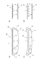
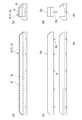
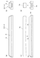
図1は、本発明の第1実施形態の豆腐の搬送装置を示す。豆腐の搬送装置100は、絹、木綿、油揚生地等から豆腐類である豆腐を成型する一工程において、豆腐を載置した状態で搬送するために用いられる装置である。本装置は、シート状、ベルト状、細帯状、ブロック状、一丁単位等各種の形状を持つ豆腐に適用され、豆腐の形状は限定されない。豆腐の原料、種類等も特に限定されない。
FIG. 1 shows a tofu transport device according to a first embodiment of the present invention. The
豆腐の搬送装置100は、載置された豆腐Fを移送するコンベア10と、コンベア10の少なくとも豆腐Fを載置した部分を下方から支持する支持部材30と、支持部材30を昇降させる昇降装置50と、を備える。
The
本実施形態において、コンベア10は特に端部がなく、回転するローラー21、22等に掛け回された状態で周回する無端状のコンベアの形状を呈しているが、コンベア10は必ずしも無端状である必要はない。コンベア10は、樹脂製ベルト、布ベルト、キャタピラ(登録商標;両端にチェーンを備えるフラットバーコンベア)、スチールベルト等により直接的または間接的に豆腐を載置した状態で、豆腐を搬送する。
In the present embodiment, the
無端状のコンベア10の少なくとも豆腐Fを載置した部分(本例では上部)は、載置した豆腐を次の工程に送る送り部60により構成され、支持部材30は、無端状のコンベア10において、送り部60を下から支えるように設けられている。このような支持部材30の支持により、豆腐Fを安定的に搬送することができる。無端状のコンベア10の送り部10以外の部分(本例では下部)は、豆腐Fを搬送した後、再び豆腐Fを載置する場所に戻る戻り部70を構成し、本実施形態では戻り部70には支持部材は設けられていない。尚、支持部材30は、基台と、当該基台に着脱可能に取り付けられコンベア10に接触する摺動面を含む摺動部材とを含むが、その詳細は後述する。なお、摺動部材を円滑に回転するローラー等の回転部材に一部または全てを置き換えた形態であってもよい。
At least the portion (upper part in this example) on which the tofu F is placed on the
昇降装置50は、支持部材30を図1に示すように所定の位置に固定する定位置固定装置を備えている。昇降装置50の作用により、支持部材30は上下に移動し、これに伴いコンベア10も変形する。尚、他の図では昇降装置50の図示は省略している(図4を除く)。
The elevating
具体的には図1(a)、(b)に示すように、支持部材30の上昇に伴い、コンベア10の送り部60も矢印Aで示すように支持部材30によって押し上げられて上昇し、豆腐Fは円滑に搬送される。戻り部70は矢印Bで示すように垂れ下がっている。一方、図1(c)、(d)に示すように、支持部材30の下降に伴い、コンベア10の送り部60は支持部材30の支持を失い(または支持が弱くなり)、自重により矢印Cで示すように垂れ下がる。戻り部70は送り部60の垂れ下がりに伴い、矢印Dで示すように若干上昇する。図1(c)、(d)の状態では、少なくともコンベア10と支持部材30の間に隙間が生ずるため、各種のメンテナンス、特に人手による洗浄も洗浄ノズル等による自動洗浄も容易となり、洗浄の仕上がりも向上する。
Specifically, as shown in FIGS. 1 (a) and 1 (b), as the
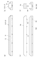
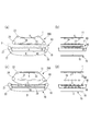
図2は、本発明の第2実施形態の豆腐の搬送装置100を示す。本実施形態は、第1実施形態と異なり、支持部材が、送り部60を支持する支持部材31のみならず、戻り部70を下から支持する支持部材32をも含む。そして、支持部材31と支持部材32は、互いに上下逆方向に移動する。すなわち、図2(a)、(b)に示すように、支持部材31の上昇に伴い、コンベア10の送り部60も矢印Aで示すように支持部材31によって押し上げられて上昇し、豆腐Fは円滑に搬送される。一方、支持部材32は矢印Bで示すように下降するため、コンベア10の戻り部70は支持部材32の支持を失い(または支持が弱くなり)、自重により矢印Bで示すように垂れ下がり弛む。
FIG. 2 shows a
一方、図2(c)、(d)に示すように、支持部材31の下降に伴い、コンベア10の送り部60は支持部材31の支持を失い(または支持が弱くなり)、自重により矢印Cで示すように垂れ下がる。支持部材31の下降と逆に支持部材32は上昇するため、コンベア10の戻り部70は矢印Dで示すように上昇する。この結果、送り部60の側においてはさらに弛みが助長され、各種のメンテナンス、特に洗浄が容易となる。
On the other hand, as shown in FIGS. 2C and 2D, as the
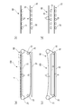
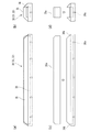
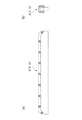
図3は、本発明の第3実施形態の豆腐の搬送装置100を示す。本実施形態は、第2実施形態と類似するが、送り部60を支持する支持部材31のみが昇降し、戻り部70を支持する支持部材32は所定位置に固定されている。すなわち、図3(a)、(b)に示すように、支持部材31の上昇に伴い、コンベア10の送り部60も矢印Aで示すように支持部材31によって押し上げられて上昇し、豆腐Fは円滑に搬送される。一方、支持部材32は所定の位置に固定されており、コンベア10の戻り部70は、支持部材32の上面に接触した状態にある。
FIG. 3 shows a
一方、図3(c)、(d)に示すように、支持部材31の下降に伴い、コンベア10の送り部60は支持部材31の支持を失い(または支持が弱くなり)、自重により矢印Cで示すように垂れ下がる。このとき支持部材32は所定の位置に固定されているが、送り部60に弛みが生じた分、戻り部70の弛みが少なくなり、持ち上がった状態になる。このため送り部60と戻り部70の双方共に支持部材との隙間が大きくなり、洗浄を含むメンテナンスが容易となる。
On the other hand, as shown in FIGS. 3C and 3D, as the
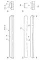
図4は、本発明の第4実施形態の豆腐の搬送装置100を示す。本実施形態は、第1実施形態と類似するが、昇降装置50が、送り部60の支持部材30を上方から吊り下げた状態で昇降させる形式のものであり、昇降装置50にはエアシリンダー等の機構が使用される。図4(a)、(b)に示すように、支持部材30の上昇に伴い、コンベア10の送り部60も矢印Aで示すように支持部材30によって押し上げられて上昇し、豆腐Fは円滑に搬送される。戻り部70は垂れ下がり弛みをもっている。一方、図4(c)、(d)に示すように、支持部材30の下降に伴い、コンベア10の送り部60は支持部材30の支持を失い(または支持が弱くなり)、自重により矢印Cで示すように垂れ下がる。図1(c)、(d)の状態では、少なくともコンベア10と支持部材30の間に隙間が生ずるため、各種のメンテナンス、特に人手による洗浄も洗浄ノズル等による自動洗浄も容易となり、洗浄の仕上がりも向上する。
FIG. 4 shows a
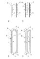
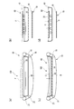
図5から図10は、支持部材の種々の実施例を示し、図11は従来の支持部材を示す。図5は実施例1の支持部材30(31、32)を示し、支持部材は、基台36と、基台36に着脱可能に取り付けられ、コンベア10に接触する摺動面を含む摺動部材35とを含む。基台36は支持部材の土台部分を構成し、図5(b)に示すようにその凹部に摺動部材35が着脱可能に取り付けられる。摺動部材35は、コンベア10に接触する摺動面35aを備えている。基台36と摺動部材35の材質は特に限定されないが、少なくとも摺動部材35の摺動面35aの部分はコンベア10との摩擦抵抗を抑えることが可能な材質で形成することが好ましく、例えば摺動面35aは摩擦抵抗の少ない材質、例えば平滑な樹脂製の面であることが好ましい。円滑に回転するローラー等の回転部材を多数備えたローラー式支持部材であってもよい。昇降装置50が所定の位置に停止した状態で、作業者は摺動部材35を基台36から取り外すことが可能である。
5 to 10 show various embodiments of the support member, and FIG. 11 shows a conventional support member. FIG. 5 shows the support members 30 (31, 32) of the first embodiment, and the support members are detachably attached to the
図5(a)、(b)に示すように、豆腐の搬送装置100の使用時には基台36の凹部に摺動部材35が嵌め込まれて収まっている。洗浄を含むメンテナンス時には、図5(c)、(d)に示すように、摺動部材35が基台36から取り外される。このような構造によりメンテナンスが容易となる。一方、図11の従来例の支持部材では、基台36と摺動部材35が互いにボルトやネジ等の手段を用いて固定されており、用意に着脱することができない。よって、基台36と摺動部材35の間の隙間に入り込んだ搾り水、汚れ、洗浄液等を清掃することが見逃されやすく、雑菌の二次汚染源に成り得るため衛生面から課題がある。
As shown in FIGS. 5A and 5B, when the
豆腐の搬送装置100の使用時において発生する水(搾り水を含む)は、摺動部材35に設けられた図示せぬ開口(切り欠き部)から入り込んで、摺動部材35の下面に設けられた凸状の通路35bを通過し、基台36に設けられた通路36aを通過して支持部材から排出される。凸状の通路35bと凹状の通路36aは、このような排水構造としての役割を果たす。さらに通路35bと通路36aは互いに嵌まり込み合っており、コンベア10との摺動による摺動部材35と基台36の位置ずれを防止することができる。すなわち、通路35bと凹状の通路36aによる排水構造は、基台36と摺動部材35を互いに所定の相対位置で位置決めする位置決め構造を兼ねるものである。尚、摺動部材35の側に凹状の通路を設け、基台36の側に凸状の通路を設けてもよい。
Water (including squeezed water) generated when the
図6は実施例2の支持部材30(31、32)を示している。基台36には、基台36の下面まで貫通する通路36a1と、基台36の途中(基台36の一部)で止まる通路36a2が設けられている。このような構成によれば洗浄時に液だまりができにくく、排液がスムーズになる。全て基台36の下面まで貫通する通路36a1にするとさらに良い。基台36の凹部には排液しやすいように傾斜が設けられてもよい。
FIG. 6 shows the support members 30 (31, 32) of the second embodiment. The
図7は実施例3の支持部材30(31、32)を示している。基台36の両端に壁36bが設けられており、この壁により摺動部材35と基台36の位置ずれをより確実に防止することができる。
FIG. 7 shows the support members 30 (31, 32) of the third embodiment.
図8は実施例4の支持部材30(31、32)を示している。摺動部材35の下面には傾斜した傾斜面35cが設けられるとともに、基台36にも傾斜面35cの形状に合致した傾斜面36cが設けられている。このような構成によれば、発生した水が支持部材の両端に向かって下降する傾斜面35cに沿って流れ、基台36の両端に設けられた通路36aを通ってスムーズに排出される。
FIG. 8 shows the support members 30 (31, 32) of the fourth embodiment. The lower surface of the sliding
図9は実施例5の支持部材30(31、32)を示している。実施例4は実施例3と類似しているが、通路36aの代わりに、水平方向に延びて基台36の両側面に露出す水平通路36dが設けられている。このような構成においても、発生した水が支持部材の両端に向かって下降する傾斜面35cに沿って流れ、水平通路36dを通ってスムーズに排出される。
FIG. 9 shows the support members 30 (31, 32) of the fifth embodiment. The fourth embodiment is similar to the third embodiment, but instead of the
図10は実施例6の支持部材30(31、32)を示している。摺動部材35の摺動面35aには回転可能な摺動ローラー35dが複数設けられており、走行するコンベア10と接触した際に摺動ローラー35dが回転し、コンベア10との摩擦を抑えることができる。特にコンベア10がスチールベルトのような硬い素材により構成されている場合、本実施例の支持部材は有用である。摺動ローラーは、図示しないが、ベアリングを介して回転軸に取り付けられて、その軸の周りを滑らかに回転する円柱状ローラーのほか、球状ボールローラー等であってもよい。
FIG. 10 shows the support members 30 (31, 32) of the sixth embodiment. A plurality of rotatable sliding
以上、図5から図10を用いて支持部材の種々の実施例を説明したが、支持部材の構成は特に限定されない。例えば摺動部材35と基台36の双方に凹部を設け、双方の凹部に中空筒状のピンを嵌め込むことにより、水を排出する通路を設けてもよい。
Although various examples of the support member have been described above with reference to FIGS. 5 to 10, the configuration of the support member is not particularly limited. For example, recesses may be provided in both the sliding
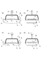
図12は、本発明の第5実施形態の豆腐の搬送装置100を示す。本実施形態は、第1実施形態と異なり、支持部材30の摺動部材35を洗浄する洗浄液を貯留した洗浄槽40を更に備えている。そして、昇降装置50が支持部材30を下降させた際に、少なくとも摺動部材35を洗浄液に浸漬可能である。すなわち、図12(a)、(b)に示すように、使用時において支持部材30は洗浄槽40の上方に位置しており、洗浄槽40内に位置していない。一方、図12(c)、(d)に示すように、昇降装置50が支持部材30を下降させた際に、コンベア10および支持部材30の全体、少なくとも摺動部材35を洗浄液に浸漬可能である。そして、コンベア10が洗浄槽40内の洗浄液に浸漬した状態で走行可能である。これにより、コンベア10および支持部材30の洗浄が容易なものとなる。
FIG. 12 shows a
従来の装置においては、複数のローラーを別途設け、コンベアをローラーにより別の位置に折り返して洗浄槽に漬け込むような構成を設けていたが、そのような構成は複雑なものとなる。本実施形態においては、昇降装置50による支持部材30の移動先(本例では支持部材30の下方)に洗浄槽が設けられており、簡単な構成で支持部材を洗浄することができる。スチールベルトのような硬いコンベアでも、その自重を利用して垂れ下がった部分に設けた洗浄槽に周回しながら漬け込むことにより、自動周回洗浄を行うことができる。
In the conventional apparatus, a plurality of rollers are separately provided, and the conveyor is folded back to a different position by the rollers and immersed in the washing tank, but such a configuration is complicated. In the present embodiment, a cleaning tank is provided at a destination (below the
洗浄槽40の形態は特に限定されない。洗浄槽40内の洗浄液は、例えばお湯(例えば60〜100℃)、洗剤剤(アルカリ性洗剤、酸性洗剤、除菌剤等)、種々のものを利用することができる。洗浄槽40には必要に応じて加熱手段、温度制御手段等を設けることもできる。
The form of the
洗浄槽40を昇降させる昇降装置を設けてもよい。また、本実施形態においては、洗浄槽40は送り部60が浸漬する位置に設けられているが、別の洗浄槽を戻り部70が浸漬する位置に設けてもよい。また、熱湯を貯留した洗浄槽40に加熱蒸気を吹き込む装置を設け、豆腐の搬送装置100の使用中にコンベア10により搬送される豆腐Fを加温または保温して、豆腐の弾力や結着を向上させ、微生物の増加を抑制して衛生的環境を保持することも可能である。
An elevating device for raising and lowering the
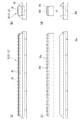
図13は、本発明の第6実施形態の豆腐の搬送装置100を示す。本実施形態は、第6実施形態と異なり、上方に別に無端状のコンベア11を設け、豆腐Fを連続的に圧縮(プレス)する形態であり、連続成型機としての役割をも果たすものである。すなわち、本実施形態において無端状のコンベアは、支持部材30によって下方から支持され得る第1の無端状のコンベア10と、第1の無端状のコンベア10の上方に位置し、ローラー23、24に掛け回された状態で、第1の無端状のコンベア10と同期して周回する第2の無端状のコンベア11とを含んでいる。そして、第1の無端状のコンベア10および第2の無端状のコンベア11の間に豆腐Fが配置される。
FIG. 13 shows a
さらに上方の第2の無端状のコンベア11の豆腐Fに接触する送り部には、上から下方向に豆腐Fを抑え圧搾を促進する他の支持部材34が設けられている。第2の無端状のコンベア11の戻り部にも下方から支持する支持部材33が設けられており、支持部材34は所定の位置に固定されているが、支持部材33は上下方向に昇降可能である。
Further, the feeding portion in contact with the tofu F of the second
図13(a)、(b)に示すように、使用時において支持部材33は下降しており、第2の無端状のコンベア11の戻り部が垂れ下がって弛みを生じさせている。一方、図13(c)、(d)に示すように、洗浄を含むメンテナンス時においては、支持部材33は上昇しており、第2の無端状のコンベア11の戻り部の弛みを抑制する。この結果、第2の無端状のコンベア11の送り部が弛むとともに垂れ下がり、第1の無端状のコンベア10とともに洗浄槽40に浸漬するため、二つのコンベアを同時に洗浄することができる。すなわち、昇降装置50が支持部材30を下降させた際に、第1の無端状のコンベア10と、第2の無端状のコンベア11と、支持部材30の摺動部材35を洗浄液に浸漬可能であり、第1の無端状のコンベア10および第2の無端状のコンベア11が、洗浄液に浸漬した状態で周回可能となっている。
As shown in FIGS. 13 (a) and 13 (b), the
また、第1の無端状のコンベア10と第2の無端状のコンベア11は、周回する方向に沿って互いの間隔が小さくなるように、かつ周回する方向に沿って豆腐Fを挟む圧力が大きくなるように配置される。このため、豆腐Fの圧搾作用をより向上させることができる。
Further, the first
生の豆腐を搬送するコンベアにおいて、豆腐の圧搾時に放出される搾り水の処理が衛生面の観点から重要となる。本発明の搬送装置によれば、非使用時において、コンベアを支持する支持部材をコンベアから引き離し、両者の間に隙間を設けることができる。よって、洗浄を含む各種のメンテナンスが容易となり、衛生面の向上が期待できる。 In the conveyor for transporting raw tofu, the treatment of the squeezed water released when the tofu is squeezed is important from the viewpoint of hygiene. According to the transfer device of the present invention, when not in use, the support member that supports the conveyor can be separated from the conveyor, and a gap can be provided between the two. Therefore, various maintenance including cleaning becomes easy, and improvement in hygiene can be expected.
また、本発明の搬送装置に使用される支持部材は、コンベアに接触する摺動部材と、摺動部材を支える基台が、容易に取り外し可能な構造を有する。よって、摺動部材と基台の間に入り込みやすい、搾り水、汚れ、洗浄液等の清掃がより容易となり、さらに衛生面の向上が期待できる。 Further, the support member used in the transport device of the present invention has a structure in which the sliding member in contact with the conveyor and the base supporting the sliding member can be easily removed. Therefore, it becomes easier to clean the squeezed water, dirt, cleaning liquid, etc. that easily enter between the sliding member and the base, and further improvement in hygiene can be expected.
以上のような工夫により、搬送装置のメンテナンスが全体的に容易となるため、衛生面が向上し、例えば雑菌繁殖等を抑制することができる。更に豆腐の二次汚染リスクを軽減するとともに、薬剤残留のリスクも軽減し、食品として必須な安全性、信頼性を向上させ、豆腐の日持ちも向上することが期待される(例えば賞味期限延長ないしは保証信頼性向上)。また、豆腐の日持ちが良くなるとともに、豆腐包装後の熱湯殺菌条件を緩和でき(加熱温度を下げ、加熱時間を短くする)、豆腐の味抜けが抑制されて、美味しい豆腐の提供に繋がることが期待される。 With the above-mentioned measures, the maintenance of the transport device becomes easy as a whole, so that the hygiene aspect can be improved and, for example, the propagation of various germs can be suppressed. Furthermore, it is expected that the risk of secondary contamination of tofu will be reduced, the risk of drug residue will be reduced, the safety and reliability essential for food will be improved, and the shelf life of tofu will be improved (for example, the expiration date will be extended or the shelf life will be improved. Guarantee reliability improvement). In addition, the shelf life of tofu is improved, and the hot water sterilization conditions after packaging the tofu can be relaxed (the heating temperature is lowered and the heating time is shortened), and the taste loss of the tofu is suppressed, leading to the provision of delicious tofu. Be expected.
尚、本発明は、上述した実施形態に限定されるものではなく、適宜、変形、改良、等が
可能である。その他、上述した実施形態における各構成要素の材質、形状、寸法、数値、
形態、数、配置箇所、等は本発明を達成できるものであれば任意であり、限定されない。
The present invention is not limited to the above-described embodiment, and can be appropriately modified, improved, and the like. In addition, the material, shape, dimensions, numerical values of each component in the above-described embodiment,
The form, number, arrangement location, etc. are arbitrary as long as the present invention can be achieved, and are not limited.
10 コンベア
30 支持部材
31 支持部材
32 支持部材
35 摺動部材
36 基台
50 昇降装置
60 送り部
70 戻り部
100 搬送装置
F 豆腐
10
Claims (15)
前記コンベアの少なくとも豆腐を載置した部分を下方から支持する支持部材と、
前記支持部材を昇降させる昇降装置と、
を備える豆腐の搬送装置。 A conveyor that transfers the placed tofu,
A support member that supports at least the portion of the conveyor on which tofu is placed from below, and
An elevating device that elevates and elevates the support member,
Tofu transport device equipped with.
前記コンベアは周回する無端状のコンベアであり、
前記支持部材は、前記無端状のコンベアにおいて、載置した豆腐を次の工程に送る送り部に設けられる、
豆腐の搬送装置。 The tofu transporting device according to claim 1.
The conveyor is an endless conveyor that orbits.
The support member is provided in a feeding portion for sending the placed tofu to the next step on the endless conveyor.
Tofu transport device.
前記昇降装置は、前記支持部材を所定の位置に固定する定位置固定装置を備える、
豆腐の搬送装置。 The tofu transporting device according to claim 1.
The elevating device includes a fixed position fixing device for fixing the support member in a predetermined position.
Tofu transport device.
前記支持部材が、基台と、当該基台に着脱可能に取り付けられ前記コンベアに接触する摺動面を含む摺動部材とを含む、
豆腐の搬送装置。 The tofu transporting device according to claim 1.
The support member includes a base and a sliding member that is detachably attached to the base and includes a sliding surface that contacts the conveyor.
Tofu transport device.
前記昇降装置が所定の位置に停止した状態で、前記摺動部材が取り外し可能である、
豆腐の搬送装置。 The tofu transporting device according to claim 4.
The sliding member can be removed while the lifting device is stopped at a predetermined position.
Tofu transport device.
前記摺動面が平滑な樹脂製の面である、
豆腐の搬送装置。 The tofu transporting device according to claim 4.
The sliding surface is a smooth resin surface.
Tofu transport device.
前記基台と前記摺動部材は、互いに所定の相対位置で位置決め可能な構造を有する、
豆腐の搬送装置。 The tofu transporting device according to claim 4.
The base and the sliding member have a structure capable of being positioned relative to each other.
Tofu transport device.
前記支持部材が排水構造を備える、
豆腐の搬送装置。 The tofu transporting device according to claim 4.
The support member comprises a drainage structure.
Tofu transport device.
前記支持部材は排水構造を備え、前記排水構造は、前記基台と前記摺動部材を互いに所定の相対位置で位置決めする位置決め構造を兼ねる、
豆腐の搬送装置。 The tofu transporting device according to claim 4.
The support member includes a drainage structure, and the drainage structure also serves as a positioning structure for positioning the base and the sliding member at predetermined relative positions.
Tofu transport device.
前記摺動部材を洗浄する洗浄液を貯留した洗浄槽を更に備え、
前記昇降装置が前記支持部材を下降させた際に、少なくとも前記摺動部材を洗浄液に浸漬可能である、
豆腐の搬送装置。 The tofu transporting device according to claim 4.
Further provided with a cleaning tank for storing a cleaning liquid for cleaning the sliding member is provided.
When the lifting device lowers the support member, at least the sliding member can be immersed in the cleaning liquid.
Tofu transport device.
前記昇降装置が前記支持部材を下降させた際に、前記コンベアおよび前記摺動部材を洗浄液に浸漬可能であり、
前記コンベアが前記洗浄液に浸漬した状態で走行可能である、
豆腐の搬送装置。 The tofu transporting device according to claim 10.
When the lifting device lowers the support member, the conveyor and the sliding member can be immersed in the cleaning liquid.
The conveyor can run in a state of being immersed in the cleaning liquid.
Tofu transport device.
前記無端状のコンベアは、
前記支持部材によって下方から支持され得る第1の無端状のコンベアと、当該第1の無端状のコンベアの上方に位置し、当該第1の無端状のコンベアと同期して周回する第2の無端状のコンベアとを含み、
前記第1の無端状のコンベアおよび前記第2の無端状のコンベアの間に豆腐が配置される、
豆腐の搬送装置。 The tofu transporting device according to claim 2.
The endless conveyor
A first endless conveyor that can be supported from below by the support member and a second endless conveyor that is located above the first endless conveyor and orbits in synchronization with the first endless conveyor. Including a conveyor
Tofu is placed between the first endless conveyor and the second endless conveyor.
Tofu transport device.
前記第1の無端状のコンベアと前記第2の無端状のコンベアは、周回する方向に沿って互いの間隔が小さくなるように配置される、
豆腐の搬送装置。 The tofu transporting device according to claim 12.
The first endless conveyor and the second endless conveyor are arranged so that the distance between them is small along the orbiting direction.
Tofu transport device.
前記第1の無端状のコンベアと前記第2の無端状のコンベアは、周回する方向に沿って豆腐を挟む圧力が大きくなるように配置される、
豆腐の搬送装置。 The tofu transporting device according to claim 12.
The first endless conveyor and the second endless conveyor are arranged so that the pressure for sandwiching the tofu increases along the orbiting direction.
Tofu transport device.
前記第1の無端状のコンベアと、前記第2の無端状のコンベアと、前記支持部材を洗浄する洗浄液を貯留した洗浄槽を更に備え、
前記昇降装置が前記支持部材を下降させた際に、前記第1の無端状のコンベアと、前記第2の無端状のコンベアと、前記支持部材を洗浄液に浸漬可能であり、
前記第1の無端状のコンベアおよび前記第2の無端状のコンベアが、前記洗浄液に浸漬した状態で周回可能である、
豆腐の搬送装置。 The tofu transporting device according to claim 12.
Further provided with the first endless conveyor, the second endless conveyor, and a cleaning tank storing a cleaning liquid for cleaning the support member.
When the lifting device lowers the support member, the first endless conveyor, the second endless conveyor, and the support member can be immersed in the cleaning liquid.
The first endless conveyor and the second endless conveyor can orbit in a state of being immersed in the cleaning liquid.
Tofu transport device.
Priority Applications (1)
| Application Number | Priority Date | Filing Date | Title |
|---|---|---|---|
| JP2019089898A JP2020184895A (en) | 2019-05-10 | 2019-05-10 | Device for conveying soybean curd |
Applications Claiming Priority (1)
| Application Number | Priority Date | Filing Date | Title |
|---|---|---|---|
| JP2019089898A JP2020184895A (en) | 2019-05-10 | 2019-05-10 | Device for conveying soybean curd |
Publications (1)
| Publication Number | Publication Date |
|---|---|
| JP2020184895A true JP2020184895A (en) | 2020-11-19 |
Family
ID=73220578
Family Applications (1)
| Application Number | Title | Priority Date | Filing Date |
|---|---|---|---|
| JP2019089898A Ceased JP2020184895A (en) | 2019-05-10 | 2019-05-10 | Device for conveying soybean curd |
Country Status (1)
| Country | Link |
|---|---|
| JP (1) | JP2020184895A (en) |
Citations (5)
| Publication number | Priority date | Publication date | Assignee | Title |
|---|---|---|---|---|
| JP2005261369A (en) * | 2004-03-19 | 2005-09-29 | Takai Seisakusho:Kk | Device for automatically forming bean curds |
| JP2010273653A (en) * | 2009-05-29 | 2010-12-09 | Takai Seisakusho:Kk | Endless conveyor, and automatically molding apparatus for tofu using the endless conveyor |
| JP2016019488A (en) * | 2014-07-14 | 2016-02-04 | 株式会社高井製作所 | Continuous molding device for soybean curds |
| WO2017056280A1 (en) * | 2015-09-30 | 2017-04-06 | 株式会社高井製作所 | Device for continuous molding of soybean curd |
| JP2019014554A (en) * | 2017-07-04 | 2019-01-31 | 日本クッカリー株式会社 | Belt washer |
-
2019
- 2019-05-10 JP JP2019089898A patent/JP2020184895A/en not_active Ceased
Patent Citations (5)
| Publication number | Priority date | Publication date | Assignee | Title |
|---|---|---|---|---|
| JP2005261369A (en) * | 2004-03-19 | 2005-09-29 | Takai Seisakusho:Kk | Device for automatically forming bean curds |
| JP2010273653A (en) * | 2009-05-29 | 2010-12-09 | Takai Seisakusho:Kk | Endless conveyor, and automatically molding apparatus for tofu using the endless conveyor |
| JP2016019488A (en) * | 2014-07-14 | 2016-02-04 | 株式会社高井製作所 | Continuous molding device for soybean curds |
| WO2017056280A1 (en) * | 2015-09-30 | 2017-04-06 | 株式会社高井製作所 | Device for continuous molding of soybean curd |
| JP2019014554A (en) * | 2017-07-04 | 2019-01-31 | 日本クッカリー株式会社 | Belt washer |
Similar Documents
| Publication | Publication Date | Title |
|---|---|---|
| US2112309A (en) | Grill for tortillas and the like | |
| US5588354A (en) | Apparatus for conveyorized griddle-like cooking of food products | |
| US5458051A (en) | Belt cooking apparatus | |
| KR101652587B1 (en) | Automatic donut production apparatus | |
| US3589274A (en) | Continuous feed toaster | |
| US2148552A (en) | Barrel plating machine | |
| KR102254460B1 (en) | Dumpling Automated Molding machine | |
| US3861289A (en) | Taco shell fryer | |
| JP2020184895A (en) | Device for conveying soybean curd | |
| US3641923A (en) | Apparatus for deep fat frying of foodstuffs | |
| KR102038148B1 (en) | Cleaning apparatus of baking tray | |
| US20230117987A1 (en) | Tofu conveying machine | |
| US4198902A (en) | Antijamming mechanism for conveyor | |
| US3552300A (en) | Apparatus for proofing and frying bakery goods | |
| JP3582787B2 (en) | Fried rice cracker manufacturing equipment | |
| JP3888206B2 (en) | Stir fry production equipment | |
| US3805687A (en) | Means for continuous and automated frying of cut or sliced products on a frying surface | |
| JP2005168604A (en) | Foodstuff heating apparatus and foodstuff heating method using the same | |
| US3107391A (en) | Platen assembly for deboning machine | |
| CN211270561U (en) | Automatic cleaning device for baking appliance | |
| FI80994C (en) | Methods for frying food products and device for carrying them out of the way | |
| EP3599874B1 (en) | Device for cleaning chicken feet | |
| CN224169990U (en) | Can carry out food selling machine cutlery box transfer structure of lid trompil | |
| CN219750821U (en) | Food machinery conveyer belt | |
| CN110680256A (en) | Automatic cleaning device for baking appliance |
Legal Events
| Date | Code | Title | Description |
|---|---|---|---|
| A621 | Written request for application examination |
Free format text: JAPANESE INTERMEDIATE CODE: A621 Effective date: 20220302 |
|
| A977 | Report on retrieval |
Free format text: JAPANESE INTERMEDIATE CODE: A971007 Effective date: 20230126 |
|
| A131 | Notification of reasons for refusal |
Free format text: JAPANESE INTERMEDIATE CODE: A131 Effective date: 20230221 |
|
| A521 | Request for written amendment filed |
Free format text: JAPANESE INTERMEDIATE CODE: A523 Effective date: 20230320 |
|
| A01 | Written decision to grant a patent or to grant a registration (utility model) |
Free format text: JAPANESE INTERMEDIATE CODE: A01 Effective date: 20230627 |
|
| A045 | Written measure of dismissal of application [lapsed due to lack of payment] |
Free format text: JAPANESE INTERMEDIATE CODE: A045 Effective date: 20231031 |