JP2020184872A - Braking method for permanent magnet synchronous motors - Google Patents
Braking method for permanent magnet synchronous motors Download PDFInfo
- Publication number
- JP2020184872A JP2020184872A JP2020036409A JP2020036409A JP2020184872A JP 2020184872 A JP2020184872 A JP 2020184872A JP 2020036409 A JP2020036409 A JP 2020036409A JP 2020036409 A JP2020036409 A JP 2020036409A JP 2020184872 A JP2020184872 A JP 2020184872A
- Authority
- JP
- Japan
- Prior art keywords
- braking
- voltage vector
- permanent magnet
- magnet synchronous
- rotational
- Prior art date
- Legal status (The legal status is an assumption and is not a legal conclusion. Google has not performed a legal analysis and makes no representation as to the accuracy of the status listed.)
- Granted
Links
Images


Classifications
-
- H—ELECTRICITY
- H02—GENERATION; CONVERSION OR DISTRIBUTION OF ELECTRIC POWER
- H02P—CONTROL OR REGULATION OF ELECTRIC MOTORS, ELECTRIC GENERATORS OR DYNAMO-ELECTRIC CONVERTERS; CONTROLLING TRANSFORMERS, REACTORS OR CHOKE COILS
- H02P3/00—Arrangements for stopping or slowing electric motors, generators, or dynamo-electric converters
-
- H—ELECTRICITY
- H02—GENERATION; CONVERSION OR DISTRIBUTION OF ELECTRIC POWER
- H02P—CONTROL OR REGULATION OF ELECTRIC MOTORS, ELECTRIC GENERATORS OR DYNAMO-ELECTRIC CONVERTERS; CONTROLLING TRANSFORMERS, REACTORS OR CHOKE COILS
- H02P21/00—Arrangements or methods for the control of electric machines by vector control, e.g. by control of field orientation
-
- H—ELECTRICITY
- H02—GENERATION; CONVERSION OR DISTRIBUTION OF ELECTRIC POWER
- H02P—CONTROL OR REGULATION OF ELECTRIC MOTORS, ELECTRIC GENERATORS OR DYNAMO-ELECTRIC CONVERTERS; CONTROLLING TRANSFORMERS, REACTORS OR CHOKE COILS
- H02P3/00—Arrangements for stopping or slowing electric motors, generators, or dynamo-electric converters
- H02P3/06—Arrangements for stopping or slowing electric motors, generators, or dynamo-electric converters for stopping or slowing an individual dynamo-electric motor or dynamo-electric converter
- H02P3/18—Arrangements for stopping or slowing electric motors, generators, or dynamo-electric converters for stopping or slowing an individual dynamo-electric motor or dynamo-electric converter for stopping or slowing an AC motor
Landscapes
- Engineering & Computer Science (AREA)
- Power Engineering (AREA)
- Non-Positive Displacement Air Blowers (AREA)
- Control Of Ac Motors In General (AREA)
- Stopping Of Electric Motors (AREA)
Abstract
【課題】モータ又はポンプのスイッチを切った後、速く停止に至ることができる、センサレス永久磁石同期モータの制動方法を提供する。【解決手段】開放制御回路の場合で制動するために、永久磁石同期モータが、回転電圧ベクトルによってのみ制御される。その際、この制動方法が同期ステップ(この同期ステップでは、永久磁石同期モータが一定振幅及び一定回転周波数の回転同期電圧ベクトルで制御されている)と時間的に続く制動ステップ(この制動ステップでは、回転制動電圧ベクトルを有する永久磁石同期モータが、値ゼロまで時間的に減少する回転周波数で制御されている)とを含む。パルス幅変調に基づくセンサレス永久磁石同期モータを制御するための装置も提供されている。特に、制動方法及び装置は、真空ポンプ、好ましくはターボ分子ポンプのそれぞれの駆動の為に適応可能である。【選択図】図9PROBLEM TO BE SOLVED: To provide a braking method of a sensorless permanent magnet synchronous motor capable of quickly stopping after switching off a motor or a pump. A permanent magnet synchronous motor is controlled only by a rotational voltage vector for braking in the case of an open control circuit. At that time, this braking method is followed by a synchronous step (in this synchronous step, the permanent magnet synchronous motor is controlled by a rotation synchronous voltage vector having a constant amplitude and a constant rotation frequency) and a braking step (in this synchronous step, the braking step is controlled). A permanent magnet synchronous motor with a rotational braking voltage vector is controlled at a rotational frequency that decreases over time to a value of zero). Devices for controlling sensorless permanent magnet synchronous motors based on pulse width modulation are also provided. In particular, braking methods and devices are adaptable for each drive of vacuum pumps, preferably turbo molecular pumps. [Selection diagram] FIG. 9
Description
本発明は、パルス幅変調に基づく空間ベクトル変調によって操作可能なセンサレス永久磁石同期モータ、特に真空ポンプ、好ましくはターボ分子ポンプの永久磁石同期モータを制動するための方法に関する。更に、本発明は、パルス幅変調に基づくセンサレス永久磁石同期モータを制御するための装置、並びに一つのそのような装置によって制御可能なセンサレス永久磁石同期モータを有する真空ポンプ、特にターボ分子ポンプに関する。 The present invention relates to a method for braking a sensorless permanent magnet synchronous motor, particularly a vacuum pump, preferably a turbo molecular pump permanent magnet synchronous motor, which can be operated by spatial vector modulation based on pulse width modulation. Furthermore, the present invention relates to a device for controlling a sensorless permanent magnet synchronous motor based on pulse width modulation, and a vacuum pump having a sensorless permanent magnet synchronous motor controllable by one such device, particularly a turbo molecular pump.
例えばターボ分子ポンプのような真空ポンプは、それぞれのプロセスのために必要な真空を提供するために、様々な分野の技術で使用される。ターボ分子ポンプは、ロータ軸線の方向に前後して配置されている複数のステータディスクを有する1つのステータと、ステータに対して相対的にロータ軸線を中心として回転可能に支承されている1つのロータとを含む。このロータは、1つのロータシャフトと、このロータシャフト上に配置され、軸方向に連続し且つステータディスク間に配置された複数のロータディスクとを含む。その際、これらのステータディスクとこれらのロータディスクとは、それぞれのポンプ作用構造を有する。 Vacuum pumps, such as turbo molecular pumps, are used in various disciplines to provide the vacuum required for each process. The turbo molecular pump consists of one stator having a plurality of stator discs arranged in the front-rear direction in the direction of the rotor axis, and one rotor rotatably supported about the rotor axis relative to the stator. And include. The rotor includes one rotor shaft and a plurality of rotor discs arranged on the rotor shaft, axially continuous and arranged between the stator discs. At that time, these stator discs and these rotor discs have their respective pumping structures.
空間ベクトル変調とは、パワーエレクトロニクスにおいて、パルス幅変調に基づく回転電気機械を制御するための方法である。この変調方式に基づいて、多相交流システムが、三相交流機の技術分野のために必要になるような複数の電子経路を模倣することが可能である。空間ベクトル表示により、機械内の磁束密度の分布を設定するためには、2つの変数である空間ベクトルの角度とこの空間ベクトルの絶対値又は実数部及び/又は虚数部とで十分である。三相システムを模倣するために、1つのハーフブリッジが、3つの相のそれぞれの相に必要とされる。このハーフブリッジによって、U,V,W相の出力電圧が、正の及び負の中間回路電位に印加される。 Spatial vector modulation is a method for controlling rotating electromechanical machines based on pulse width modulation in power electronics. Based on this modulation scheme, it is possible for a multi-phase AC system to mimic multiple electronic paths as required for the technical field of three-phase AC machines. In order to set the distribution of the magnetic flux density in the machine by the space vector display, the angle of the space vector, which is two variables, and the absolute value or the real part and / or the imaginary part of the space vector are sufficient. To mimic a three-phase system, one half bridge is required for each phase of the three phases. This half-bridge applies U, V, W phase output voltages to positive and negative intermediate circuit potentials.
センサレスモータ制御は、ロータの一定の回転数以上のみ機能する。ロータ停止までの低回転数域内において、モータはスイッチを切った場合に制御されない。非常に小さな逆起電力(EMK:起電力(独語:ElektroMotorische Kraft))を考慮すると、三相短絡は役に立たない。モータは注気なしで運転し続けるが、主に二つの欠点を伴う:まず一方で、モータのロータが停止に至るまでに非常に長い時間がかかる。他方で、その間にモータ若しくはポンプの電源を再投入するようなことがあれば、ロータが回転しているので速度上昇(独語:Hochschleppen)又は起動が、確実にできないという問題が発生する。場合によっては、ロータが許容回転数まで正常に速度上昇するまで、いくつかのトライを実施しなければならない。 Sensorless motor control works only above a certain number of revolutions of the rotor. In the low rpm range until the rotor stops, the motor is not controlled when the switch is turned off. Given the very small back electromotive force (EMK: electromotive force (German: Electric: ElectroMotorische Craft)), a three-phase short circuit is useless. The motor continues to operate without attention, but with two main drawbacks: First of all, it takes a very long time for the motor rotor to stop. On the other hand, if the power of the motor or the pump is turned on again in the meantime, there arises a problem that the speed cannot be increased (German: Hochskleppen) or the start cannot be surely performed because the rotor is rotating. In some cases, some tries must be performed until the rotor speeds up normally to the permissible speed.
本発明は、前述の欠点を排除した、冒頭で述べた種類の真空ポンプと、制御装置と、制動方法とを提供することを課題とする。その際、センサレス永久磁石同期モータのロータは、モータ若しくはポンプのそれぞれのスイッチを切った後、速く停止に至り、及びそれぞれのスイッチを再び入れた後にモータ若しくはポンプの誤った速度上昇の危険が最小限に縮小されるということが、可能なかぎり簡単な且つ信頼できる方法で、特に達成されるべきである。 An object of the present invention is to provide a vacuum pump of the type described at the beginning, a control device, and a braking method, which eliminates the above-mentioned drawbacks. At that time, the rotor of the sensorless permanent magnet synchronous motor stops quickly after turning off each switch of the motor or pump, and the risk of erroneous speed increase of the motor or pump after turning on each switch is minimized. Reducing to the limit should be specifically achieved in the simplest and most reliable way possible.
本発明によれば、この課題は、請求項1に記載の特徴を有する方法、請求項11に記載の特徴を有する装置、及び請求項12に記載の特徴を有する真空ポンプによって解決される。本発明による方法の好ましい実施形態は、従属請求項、本明細書及び図面に記載されている。 According to the present invention, this problem is solved by the method having the characteristics according to claim 1, the apparatus having the characteristics according to claim 11, and the vacuum pump having the characteristics according to claim 12. Preferred embodiments of the method according to the invention are described in the dependent claims, the present specification and the drawings.
パルス幅変調に基づく空間ベクトル変調によって操作可能なセンサレス永久磁石同期モータ、特に真空ポンプ、好ましくはターボ分子ポンプの永久磁石同期モータを制動するための本発明による方法は、開放制御回路の場合で制動するために永久磁石同期モータが回転電圧ベクトルによってのみ制御され、及び制動方法は同期ステップ(この同期ステップでは、永久磁石同期モータが一定振幅及び一定回転周波数の回転同期電圧ベクトルで制御されている)と、時間的に後続の制動ステップ(この制動ステップでは、永久磁石同期モータが回転制動電圧ベクトルによって、値ゼロまで時間的に減少する回転周波数で制御されている)とを含むことを特徴とする。 The method according to the invention for braking a sensorless permanent magnet synchronous motor, particularly a vacuum pump, preferably a turbo molecular pump permanent magnet synchronous motor, which can be operated by spatial vector modulation based on pulse width modulation, is braking in the case of an open control circuit. The permanent magnet synchronous motor is controlled only by the rotational voltage vector, and the braking method is controlled by the synchronous step (in this synchronous step, the permanent magnet synchronous motor is controlled by the rotational synchronous voltage vector of constant amplitude and constant rotational frequency). And a temporally subsequent braking step (in this braking step, the permanent magnet synchronous motor is controlled by a rotational braking voltage vector at a rotational frequency that decreases temporally to a value of zero). ..
この方法の形態に基づいて、センサレス永久磁石同期モータのロータは、モータ又はポンプのスイッチを切った後、速く停止に至ることが、簡単な、信頼できる方法で達成される。それによって、特に、モータ若しくはポンプのそれぞれのスイッチを再び入れた後でのモータ若しくはポンプの誤った速度上昇の危険も、最小限に縮小される。同期ステップは、磁界方向制御と制動プロセスの間の遷移として使用する。その同期ステップの間の一定回転電圧ベクトルは、ロータ回転が電圧ベクトルと同期するために使用する。それから、あらかじめ定義した時間の後、制動ステップが開始し、この制動ステップの場合には、電圧ベクトルの回転周波数が値ゼロまで減少する。 Based on this form of method, the rotor of a sensorless permanent magnet synchronous motor is achieved in a simple and reliable way to reach a fast stop after switching off the motor or pump. This also minimizes the risk of erroneous speed increase of the motor or pump, especially after each switch of the motor or pump is turned on again. Synchronous steps are used as a transition between magnetic field direction control and the braking process. The constant rotational voltage vector during that synchronization step is used by the rotor rotation to synchronize with the voltage vector. Then, after a predefined time, the braking step begins, and in the case of this braking step, the rotational frequency of the voltage vector is reduced to a value of zero.
制動ステップの間、回転制動電圧ベクトルの振幅は、最終値>0Vまで時間的に、好ましくは直線的に減少する。 During the braking step, the amplitude of the rotational braking voltage vector decreases temporally, preferably linearly, until the final value> 0V.
回転制動電圧ベクトルの回転周波数は、制動ステップの間、好ましくは、少なくとも基本的に、回転同期電圧ベクトルの回転周波数から出発して、値ゼロまで時間的に減少する。 The rotational frequency of the rotational braking voltage vector preferably starts from the rotational frequency of the rotationally synchronized voltage vector and decreases over time to a value of zero during the braking step, at least basically.
回転制動電圧ベクトルの振幅は、制動ステップの間、好ましくは、少なくとも基本的に、回転同期電圧ベクトルの振幅から出発して、最終値>0Vまで時間的に直線的に減少する。 The amplitude of the rotational braking voltage vector preferably starts from the amplitude of the rotationally synchronized voltage vector and decreases linearly in time from the final value> 0V during the braking step, at least basically.
好ましくは、同期ステップは、永久磁石同期モータのロータが、回転同期電圧ベクトルと同期して回転するのに十分大きい、所定の同期時間周期に渡って、永久磁石同期モータの磁界方向制御と制動プロセスとの間の遷移ステップとして実施される。 Preferably, the synchronization step is a magnetic field direction control and braking process of the permanent magnet synchronous motor over a predetermined synchronization time period, which is large enough for the rotor of the permanent magnet synchronous motor to rotate in synchronization with the rotation synchronous voltage vector. It is implemented as a transition step between and.
それ故に、制動プロセスが開始する前に、ロータ速度が同期電圧ベクトルの回転周波数と同期されるということが保証されている。 Therefore, it is guaranteed that the rotor speed is synchronized with the rotation frequency of the synchronous voltage vector before the braking process begins.
本発明による制動方法の適切で実践的な一つの実施例は、回転制動電圧ベクトルの回転周波数が、制動ステップの間に、値ゼロまで時間的に直線的に減少することを特徴とする。 One suitable and practical embodiment of the braking method according to the invention is characterized in that the rotational frequency of the rotational braking voltage vector decreases linearly in time to a value of zero during the braking step.
本発明による方法の代替的に有利な実施例に従って、回転制動電圧ベクトルの回転周波数は、制動ステップの間、時間セグメントにおいて、値ゼロまで時間的に減少する。その際、回転周波数はセグメントからセグメントへ徐々に縮小し、若しくは減少割合が縮小する。 According to an alternative advantageous embodiment of the method according to the invention, the rotational frequency of the rotational braking voltage vector is temporally reduced to a value of zero in the time segment during the braking step. At that time, the rotation frequency gradually decreases from segment to segment, or the rate of decrease decreases.
その際、制動電圧ベクトルの回転周波数が、それぞれの時間セグメントにおいて、時間的に直線的に減少する時、特に有利である。 At that time, it is particularly advantageous when the rotation frequency of the braking voltage vector decreases linearly in time in each time segment.
本発明による制動方法の、好ましい実践的な一つの実施例に従って、回転制動電圧ベクトルの回転周波数は、制動ステップの間、二つの連続した時間セグメントにおいて、値ゼロまで時間的に減少する。その際、この回転周波数が、時間的に同期ステップの直後の第一セグメントにおいて、後続のセグメントよりも速く減少する。 According to one preferred practical embodiment of the braking method according to the invention, the rotational frequency of the rotational braking voltage vector is temporally reduced to a value of zero in two consecutive time segments during the braking step. At that time, the rotation frequency decreases faster in the first segment immediately after the synchronization step than in the subsequent segments in terms of time.
本発明による制動方法の代替的で適切な一つの実施例に従って、回転制動電圧ベクトルの回転周波数は、制動ステップの間、三つの連続した時間セグメントにおいて、値ゼロまで時間的に減少する。その際、この回転周波数は時間的に同期ステップの直後の第一のセグメントにおいて、後続の第二セグメントよりも速く減少し、及び第二セグメントにおいて、後続の第三セグメントよりも速く減少し、この第三セグメントにおいて、最終的に値ゼロに達する。 According to one alternative and appropriate embodiment of the braking method according to the invention, the rotational frequency of the rotational braking voltage vector is temporally reduced to a value of zero in three consecutive time segments during the braking step. At that time, this rotation frequency decreases faster than the subsequent second segment in the first segment immediately after the synchronization step, and decreases faster than the subsequent third segment in the second segment. In the third segment, the value finally reaches zero.
パルス幅変調に基づくセンサレス永久磁石同期モータを制御するための、特に真空ポンプ、好ましくは、ターボ分子ポンプのセンサレス永久磁石同期モータを制御するための本発明による装置は、これが三相インバータ、特に2レベル三相インバータ及び制御装置を含み、並びにセンサレス永久磁石同期モータを制動するために、三相インバータが、本発明による制御方法に応じて、制御装置によって制御可能であることを特徴とする。 A device according to the invention for controlling a sensorless permanent magnet synchronous motor based on pulse width modulation, especially a vacuum pump, preferably a turbo molecular pump sensorless permanent magnet synchronous motor, is a three-phase inverter, especially 2 It comprises a level three-phase inverter and a control device, and is characterized in that the three-phase inverter can be controlled by the control device according to the control method according to the present invention in order to brake the sensorless permanent magnet synchronous motor.
一つのステータ及びステータに対して相対的にロータ軸線を中心として回転可能に支承されている一つのロータ並びに少なくとも一つの駆動装置を含む本発明による真空ポンプ、特にターボ分子ポンプは、駆動装置がセンサレス永久磁石同期モータを含み、この永久磁石同期モータが、本発明による装置によって及び/又は本発明による制動方法に応じて制御可能であることを特徴とする。 The vacuum pump according to the present invention, particularly the turbo molecular pump, which includes one stator and one rotor rotatably supported about the rotor axis relative to the stator and at least one drive device, has a sensorless drive device. It comprises a permanent magnet synchronous motor, which is controllable by the apparatus according to the invention and / or according to the braking method according to the invention.
本発明は、以下で添付の図面を参照しつつ一例に過ぎない有利な実施例に基づいて説明される。 The present invention will be described below with reference to the accompanying drawings and based on an advantageous embodiment which is merely an example.
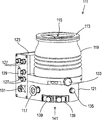
図1に示されたターボ分子ポンプ111は、インレットフランジ113に取り囲まれたポンプインレット115を有する。そのポンプインレットには、既知の方法で図示されていないレシーバーを接続することができる。レシーバーからのガスは、ポンプインレット115を介してレシーバーから吸引し得、及びポンプを通ってポンプアウトレット117へと搬送することができる。ポンプアウトレットに、例えばロータリーベーンポンプのような予真空ポンプを接続することができる。
The turbo
インレットフランジ113は、図1の真空ポンプの向きにおいては真空ポンプ111のハウジング119の上側の端部を形成する。ハウジング119は、下部分121を含み、その側面にエレクトロニクスハウジング123が配置されている。エレクトロニクスハウジング123内には、例えば真空ポンプに配置されている電動モータ125を駆動するための、真空ポンプ111の電子的及び/又は電気的コンポーネントが収容されている。エレクトロニクスハウジング123には、アクセサリの為の複数の接続部127が設けられている。その上、例えばRS485スタンダードに従うデータインターフェース129、及び電源供給接続部131がエレクトロニクスハウジング123に配置されている。
The
ターボ分子ンポンプ111のハウジング119には、特にフローバルブの形式のフローインレット133が設けられており、これを介して真空ポンプ111をフローすることができる。その上、下部分121の領域内には、シールガスコネクタ135(このシールガスコネクタは、フラッシュガスコネクタとも称される)が配置されている。これを介して、フラッシュガスが、ポンプが搬送するガスに対する電動モータ125(例えば図3参照)を保護するために、モータ室137(この中に真空ポンプ111の電動モータ125が組み込まれている)内へと運ぶことができる。下部分121内には、更に二つの冷却媒体コネクタ139が配置されている。その際、この冷却媒体コネクタの一方は、冷却媒体の為のインレットとして、そして他方の冷却媒体コネクタは冷却媒体の為のアウトレットとして設けられている。この冷却媒体は、冷却目的のために真空ポンプ内に導くことができる。
The
真空ポンプの下面141は、起立面として使用することができるので、真空ポンプ111が下側141で起立して作動することができる。しかし、真空ポンプ111は、インレットフランジ113を介してレシーバーに固定することもでき、それ故にいわば吊架されて作動することもできる。その上、真空ポンプ111は、図1に示されたものと異なった向きとされているときにも、作動することもできるよう形成することができる。下面141は下向きではなく、横向き、又は上向きに配置することができる場合の真空ポンプの実施例もまた実現可能である。
Since the
図2に図示されている下面141には、更にいくつかのねじ143が配置されており、これらによってここでは別に特定されていない真空ポンプの構造部材が互いに固定されている。例えば軸受カバー145は、下面141に固定されている。
Further, some
その上、下面141には、複数の固定孔部147が配置されており、これらを介してポンプ11が例えば載置面に固定することができる。
Further, a plurality of fixing
図2から5には、冷却媒体導管148が図示されており、この中では冷却媒体コネクタ139を介して導入及び導出される冷却媒体が循環し得る。
2 to 5 show a cooling
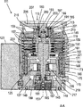
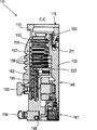
図3から5の断面図が示すように、真空ポンプは、ポンプインレット115に存在するプロセスガスをポンプアウトレット177へ搬送する為の複数のプロセスガスポンプ段を有する。
As the cross-sectional views of FIGS. 3 to 5 show, the vacuum pump has a plurality of process gas pump stages for transporting the process gas present at the
ハウジング119内にはロータ149が配置されており、これは、回転軸線151を中心として回転可能なロータシャフト153を有する。
A
ターボ分子ポンプ111は、ポンプ作用を奏する、互いに直列に接続された複数のターボ分子ポンプ段を有する。これは、ロータシャフト153に固定された半径方向の複数のロータディス155を有し、ロータディスク155間に配置され、ハウジング119内に固定されたステータディスク157を有する。この場合、一つのロータディスク155と隣接する一つのステータディスク157は、各々一つのターボ分子的ポンプ段を形成する。ステータディスク157は、スペーサリング159によって互いに所望の軸方向間隔に保持されている。
The turbo
その上、真空ポンプは半径方向において互いに入れ子式に配置され、及びポンプ作用を奏する、互いに直列に接続された複数のホルベックポンプ段を有する。ホルベックポンプ段のロータは、ロータシャフト153に配置されたロータハブ161とロータハブ161に固定され、そしてこれによって担持されるシリンダー側面形状の二つのホルベックロータスリーブ163,165を有する。これらは、回転軸線151に対して同軸に向けられており、及び半径方向において互いに入れ子式に接続されている。更に、シリンダー側面形状の二つのホルベックステータスリーブ167,169が設けられている。これらは同様に回転軸線151に対して同軸に向けられており、半径方向でみて入れ子式に接続されている。
Moreover, the vacuum pumps are radially spaced from each other and have multiple Holbeck pump stages connected in series with each other to act as a pump. The rotor of the Holbeck pump stage has two Holbeck rotor sleeves 163,165 in a cylinder side shape fixed to and supported by a
ホルベックポンプ段のポンプ作用表面は、カバー面によって、つまりホルベックロータスリーブ163,165とホルベックステータスリーブ167,169の半径方向内側面及び/又は外側面によって形成されている。外側のホルベックステータスリーブ167の半径方向内側面は、外側のホルベックロータスリーブ163の半径方向外側面と、半径方向のホルベック間隙171を形成しつつ向き合っており、そしてこれと共にターボ分子ポンプに続く第一のホルベックポンプ段を形成する。外側のホルベックロータスリーブ163の半径方向内側面は、内側のホルベックステータスリーブ169の半径方向外側面と、半径方向のホルベック間隙173を形成しつつ向かい合っており、そしてこれと共に第二のホルベックポンプ段を形成する。内側のホルベックステータスリーブ169の半径方向内側面は、内側のホルベックロータスリーブ165の半径方向外側面と、半径方向のホルベック間隙175を形成しつつ向き合っており、そしてこれと第三のホルベックポンプ段を形成する。
The pumping surface of the Holbeck pump stage is formed by a covering surface, i.e., the radial inner and / or outer surfaces of the Holbeck rotor sleeves 163,165 and the Holbeck stator sleeves 167,169. The radial inner surface of the outer
ホルベックロータスリーブ163の下側の端部には、半径方向に延びるチャネルを設けることができる。これを介して半径方向外側に位置するホルベック間隙171が中央のホルベック間隙173と接続されている。更に、内側のホルベックステータスリーブ169の上側の端部には、半径方向に延びるチャネルを設けることができる。これを介して中央のホルベック間隙173が半径方向内側に位置するホルベック間隙175と接続されている。これによって、入れ子式に接続された複数のホルベックポンプ段が直列に互いに接続される。半径方向内側のホルベックロータスリーブ165の下側の端部には、更に、アウトレット117への接続チャネル179を設けることができる。
A radial extending channel can be provided at the lower end of the
ホルベックステータスリーブ163,165の上述したポンプ作用表面は、各々、スパイラル形状に回転軸線151の周りを軸方向へと推移する複数のホルベック溝を有している。他方で、ホルベックロータスリーブ163,165の向き合った側面形状は滑らかに形成されており、そしてガスが真空ポンプ111を作動するために、ホルベック溝内で前進させる。
Each of the above-mentioned pumping surfaces of the
ロータシャフト153の回転可能に支承するのため、ポンプアウトレット117の領域に転がり軸受181が、そしてポンプインレット115の領域に永久磁石軸受183が設けられている。
転がり軸受181の領域には、ロータシャフト153に、転がり軸受181の方に向かって増加する外直径を有する円すい形のスプラッシュナット185が設けられている。スプラッシュナット185は、作動媒体貯蔵部の少なくとも一つのスキマーと滑らかに接触している。作動媒体貯蔵部は、互いに積重ねられた吸収性の複数のディスク187を有している。これらは、転がり軸受181の為の作動媒体、例えば潤滑媒体を染み込ませられている。
In the region of the rolling
真空ポンプ111の作動中には、作動媒体が毛細管作用によって作動媒体貯蔵部からスキマーを介して回転するスプラッシュナット185へと伝達され、及び遠心力によってスプラッシュナット185に沿って、スプラッシュナット185の大きくなる外直径の方向へ、転がり軸受181に向かって搬送され、そこで例えば潤滑機能を発揮する。転がり軸受181と作動媒体貯蔵部は、槽形状のインサート189と軸受カバー145によって真空ポンプ内にはめ込まれている。
During operation of the
永久磁石軸受183は、ロータ側の軸受半部191とステータ側の軸受半部193を有する。これらは、軸方向に互いに積層されたいくつかの永久磁石の複数のリング195,197からなる各一つのリング積層部を有する。リングマグネット195,197は、半径方向の軸受間隙199を形成しつつ向かい合っており、その際、ロータ側のリングマグネット195は半径方向外側に、及びステータ側のリングマグネット197は半径方向内側に配置されている。軸受間隙199内に存在する磁場は、ロータシャフト153の半径方向の支承を行うリングマグネット195,197の間に磁気的反発力を引き起こす。ロータ側のリングマグネット195は、リングマグネット195を半径方向外側で取り囲んでいるロータシャフト153の担持部分201によって担持されている。ステータ側のリングマグネット197は、リングマグネット197を通って延在しており、及びハウジング119の半径方向の支柱205に懸架されているステータ側の担持部分203によって担持されている。回転軸線151に対して平行に、ロータ側のリングマグネット195は、担持部分203と連結されたカバー要素207によって固定されている。ステータ側のリングマグネット197は、回転軸線151に対して平行に、一方の方向では、担持部分203と接続された固定リング209並びに担持部分203と接続された固定リング211によって固定されている。固定リング211とリングマグネット197の間には、更に、さらばね213を設けることができる。
The
磁石軸受の内部には、ロータ149の為の半径方向のストッパーを形成するために、真空ポンプ111の通常の作動では非接触で空転し、及びロータ149がステータに対して過剰に半径方向に変位した際に干渉する緊急用若しくは安全用軸受215が設けられている。その場合に、ロータ側の構造がステータ側の構造と衝突するのが防止される。安全用軸受215は非潤滑式の転がり軸受として形成されており、並びにロータ149及び/又はステータと半径方向の間隙を形成する。この間隔は、安全用軸受215が通常のポンプ作動中は作用しないことに供する。安全用軸受215が作用するに至る半径方向の変位は、安全用軸受215が真空ポンプの通常の作動中、干渉が発生しないよう十分大きく寸法どられており、そして同時に、ロータ側の構造のステータ側の構造との衝突があらゆる状況で防止されるよう十分小さく寸法どられている。
Inside the magnetic bearing, in order to form a radial stopper for the
真空ポンプ111は、ロータ149を回転駆動するための電動モータ125を有する。電動モータ125のアンカーは、ロータ149によって形成されており、そのロータシャフト153は、モータステータ217を通って延びている。モータステータ217を通って延在するロータシャフト153の部分には、永久磁石装置が半径方向外側に、又は埋め込まれて設けることができる。モータステータ217とモータステータ217を通って延在するロータ149の部分の間には、半径方向のモータ間隙を有する中間空間219が配置されており、モータ間隙を介してモータステータ217と永久磁石装置が、駆動トルクを伝達するために磁気的に影響し得る。
The
モータステータ217は、ハウジング内において、電動モータ125の為に設けられたモータ空間137の内部に固定されている。シールガスコネクタ135を介してシールガス(これはフラッシュガスとも称され、及び空気又は窒素であることが可能である)がモータ室137に至ることが可能である。シールガスを介して電動モータ125はプロセスガス、例えば腐食作用のプロセスガスの部分から保護することができる。モータ室137は、ポンプアウトレット117を介しても真空引きされることができ、即ちモータ室137内は少なくとも近似的に、ポンプアウトレット117に接続される予真空ポンプによって引き起こされる真空圧となる。
The
その上、ロータハブ161とモータ室137を画成する壁部221の間には、特に、半径方向外側に位置するホルベックポンプ段に対するモータ室217のより良好なシールを達成するために、それ自体公知のいわゆるラビリンスシール223を設けることができる。
Moreover, between the
次に説明する本発明の実施例は、例えば、前述の図1から5に基づいて記載されているような真空ポンプと接続して使用することができる。 The embodiments of the present invention described below can be used, for example, in connection with a vacuum pump as described based on FIGS. 1 to 5 above.
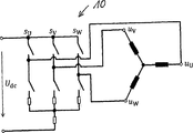
図6は、それぞれU,V,W相の出力電圧uV,uU,uWを、正又は負の中間回路電位Udcに印加することができるように、3つの相ζ=U,V,Wのそれぞれの相に対して1つのハーフブリッジを有する例示的な三相インバータ10を概略図で示す。切替状態sζ=Hであるときに、それぞれの相ζの電圧電位uζが、値Udcをとり、切替状態sζ=Lであるときに、それぞれの相ζの電圧電位uζが、値0をとる。所定のデューティ比λζε[0,1]の場合、電圧uζ=λζ×Udcが、それぞれのζ相に対して生じる。 FIG. 6 shows the three phases ζ = U, V so that the output voltages u V , u U , u W of the U, V, W phases can be applied to the positive or negative intermediate circuit potential U dc , respectively. An exemplary three-phase inverter 10 having one half bridge for each of the phases, and W is shown schematically. When a switching state s zeta = H, the voltage potential u zeta each phase zeta is takes values U dc, when a switching state s zeta = L, the voltage potential u zeta of each phase zeta, Takes a value of 0. In the case of a predetermined duty ratio λ ζ ε [0,1], a voltage u ζ = λ ζ × U dc is generated for each ζ phase.
図7は、空間ベクトル変調のための例示的な有効電圧ベクトルを概略図で示す。この場合、これらの電圧ベクトル
![]()
![]()
![]()
![]()
![]()
![]()
![]()
![]()
![]()
![]()
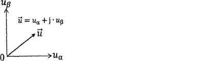
図8は、直交座標系で示され、電圧ベクトルによって表される例示的な任意の電圧
![]()
![]()
![]()
![]()
![]()
![]()
本発明による制動方法の場合では、開放制御回路の場合に制動するために、パルス幅変調に基づく操作可能なセンサレス永久磁石同期モータのための例えば図6に記載されている3相インバータ10、特に2レベル三相インバータが、回転電圧ベクトルによってのみ制御され、それは例えば、関係式
![]()
![]()
永久磁石同期モータは、開放制御回路の場合で制動するために、関係式
![]()
![]()
その際、回転制動電圧ベクトルの振幅uvecは、制動ステップBの間、最終値uend>0Vまで時間的に直線的に減少し得る(図10参照)。 At that time, the amplitude wave of the rotational braking voltage vector may decrease linearly in time until the final value window > 0V during the braking step B (see FIG. 10).
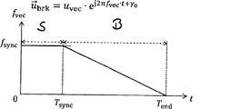
図9,11及び12からわかるように、制動電圧ベクトルの回転周波数fvecは、制動ステップBの間、同期電圧ベクトルの回転周波数fyncから出発して値ゼロまで時間的に減少し得る。 Figure 9, 11 and as can be seen from 12, the rotation frequency f vec braking voltage vector, the braking step during B, may be decreased by up to a value zero temporally starting from the rotation frequency f YNC synchronization voltage vector.
同期ステップSはそれぞれ時刻Tsyncで終了し、制動ステップBはそれぞれ時刻Tendで終了する。 Synchronization Step S respectively ends at time T sync, ends each braking step B at time T end The.
制動ステップBの間に実施される回転制動電圧ベクトルの振幅Uvecは、同期ステップSの間に実施される同期電圧ベクトルの振幅Usyncから出発して最終値Uend>0まで時間的に直線的に減少し得る(図10参照)。 The amplitude Uvec of the rotational braking voltage vector performed during the braking step B starts from the amplitude Usync of the synchronous voltage vector performed during the synchronization step S and is linear in time to the final value End > 0. (See FIG. 10).
同期ステップSは、永久磁石同期モータのロータが回転同期電圧ベクトルと同期して回転するのに十分大きい、所定の同期時間周期Tsyncに渡って、永久磁石同期モータの磁界方向制御と制動プロセスの間の遷移ステップとして実施される。 Synchronous step S is a process of controlling the magnetic field direction of the permanent magnet synchronous motor and braking process over a predetermined synchronous time period T sync, which is large enough for the rotor of the permanent magnet synchronous motor to rotate in synchronization with the rotational synchronous voltage vector. It is carried out as a transition step between.
図9からわかるように、回転制動電圧ベクトルの回転周波数fvecは、制動ステップBの間、値ゼロまで時間的に直線的に減少し得る。 As can be seen from FIG. 9, the rotational frequency f vc of the rotational braking voltage vector can decrease linearly in time to a value of zero during the braking step B.
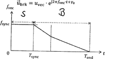
これに対して、図11と図12は、本発明による制動方法の例示的な実施形態を示している。これらの場合では、回転制動電圧ベクトルの回転周波数fvecは、制動ステップBの間で、それぞれの時間セグメントにおいて、値ゼロまで時間的に減少する。その際、この回転周波数は、セグメントからセグメントへ徐々に縮小し、若しくは減少割合が縮小する。この場合、回転制動電圧ベクトルの回転周波数fvecは、それぞれの時間セグメントにおいて時間的に直線的に減少する。 On the other hand, FIGS. 11 and 12 show exemplary embodiments of the braking method according to the present invention. In these cases, the rotational frequency f vc of the rotational braking voltage vector decreases temporally to a value of zero in each time segment during braking step B. At that time, the rotation frequency is gradually reduced from segment to segment, or the rate of decrease is reduced. In this case, the rotation frequency f vc of the rotation braking voltage vector decreases linearly in time in each time segment.
その際、図11に記載されている実施例の場合において、回転制動電圧ベクトルの回転周波数fvecは、制動ステップBの間、二つの連続した時間セグメントにおいて値ゼロまで時間的に減少する。その際、この回転周波数は同期ステップSの直後に続く第一のセグメントにおいて、後続のセグメントよりも速く減少する。 At that time, in the case of the embodiment shown in FIG. 11, the rotation frequency f vc of the rotation braking voltage vector is temporally decreased to a value of zero in two consecutive time segments during the braking step B. At that time, the rotation frequency decreases faster in the first segment immediately after the synchronization step S than in the subsequent segments.
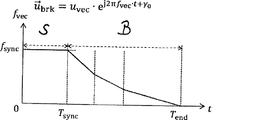
それに対して、図12は本発明による制動方法の別の変形例を示す。これによれば、回転制動電圧ベクトルの回転周波数fvecは、制動ステップBの間に、三つの連続した時間セグメントにおいて、値ゼロまで時間的に減少する。その際、この回転周波数は、同期ステップSの次にくる、時間的に直後の第一セグメントにおいて、後続の第二セグメントよりも速く減少し、及び第二セグメントにおいて、後続の第三セグメントよりも速く減少し、この第三セグメントでは、それが最終的に値ゼロに至る。 On the other hand, FIG. 12 shows another modification of the braking method according to the present invention. According to this, the rotational frequency f vc of the rotational braking voltage vector decreases temporally to a value of zero in three consecutive time segments during the braking step B. At that time, this rotation frequency decreases faster than the subsequent second segment in the first segment immediately after the synchronization step S, and in the second segment, than the subsequent third segment. It decreases rapidly, and in this third segment it eventually reaches a value of zero.
パルス幅変調に基づく一つのセンサレス永久磁石同期モータを制御するための本発明による一つの装置は、三相インバータ10、特に2レベル三相インバータと制御装置とを含む。その際、本発明による装置の三相インバータ10は、例えば図6に記載されている種類のインバータであることが可能である。本発明による装置の制御装置によって、三相インバータ10が本発明による制動方法に応じて制御可能である。 One device according to the invention for controlling one sensorless permanent magnet synchronous motor based on pulse width modulation includes a three-phase inverter 10, particularly a two-level three-phase inverter and a control device. At that time, the three-phase inverter 10 of the apparatus according to the present invention can be, for example, the type of inverter shown in FIG. By the control device of the device according to the present invention, the three-phase inverter 10 can be controlled according to the braking method according to the present invention.
特に、本発明による制動方法及び本発明による装置は、真空ポンプ、特にターボ分子ポンプのそれぞれの駆動ユニットを制御するために、例えば図1〜図5に記載されている種類の真空ポンプ、特にターボ分子ポンプを制御するために使用可能である。 In particular, the braking method according to the present invention and the apparatus according to the present invention are used to control each drive unit of a vacuum pump, particularly a turbo molecular pump, for example, the types of vacuum pumps shown in FIGS. It can be used to control a molecular pump.
本発明による真空ポンプ、特にターボ分子ポンプは、一つのステータと、ステータに対して相対的にロータ軸線を中心として回転可能に支承された一つのロータと、少なくとも一つの駆動ユニットとを含む。その際、駆動ユニットは、特にセンサレス永久磁石同期モータを含み得、この永久磁石同期モータは本発明による装置によって及び本発明による制動方法に応じて制御可能である。その際、真空ポンプ、特にターボ分子ポンプが例えば図1〜5に記載されている様式で実施することができる。 The vacuum pump according to the present invention, particularly the turbo molecular pump, includes one stator, one rotor rotatably supported about the rotor axis relative to the stator, and at least one drive unit. The drive unit may then include, in particular, a sensorless permanent magnet synchronous motor, which can be controlled by the apparatus according to the invention and according to the braking method according to the invention. At that time, a vacuum pump, particularly a turbo molecular pump, can be carried out, for example, in the manner shown in FIGS. 1-5.
10 三相交流インバータ
111 ターボ分子ポンプ
113 インレットフランジ
115 ポンプインレット
117 ポンプアウトレット
119 ハウジング
121 下部分
123 エレクトロニクスハウジング
125 電動モータ
127 アクセサリ接続部
129 データインターフェース
131 電源供給接続部
133 フローインレット
135 シールガス接続部
137 モータ室
139 冷却媒体接続部
141 下面
143 スクリュー
145 軸受カバー
147 固定穴
148 冷却媒体配管
149 ロータ
151 回転軸線
153 ロータシャフト
155 ロータディスク
157 ステータディスク
159 スペーサリング
161 ロータハブ
163 ホルベックロータスリーブ
165 ホルベックロータスリーブ
167 ホルベックステータスリーブ
169 ホルベックステータスリーブ
171 ホルベック間隙
173 ホルベック間隙
175 ホルベック間隙
179 接続チャネル
181 転がり軸受
183 永久磁石軸受
185 スプラッシュナット
187 ディスク
189 インサート
191 ロータ側の軸受半部
193 ステータ側の軸受半部
195 リングマグネット
197 リングマグネット
199 軸受間隙
201 キャリア部分
203 キャリア部分
205 半径方向の支柱
207 カバー要素
209 支持リング
211 固定リング
213 さらばね
215 緊急用又は安全用軸受
217 モータステータ
219 中間空間
221 壁部
223 ラビリンスシール
fsync 回転同期電圧ベクトルの一定回転周波数
fvec 回転電圧ベクトルの回転周波数
usync 回転同期電圧ベクトルの一定振幅
uvec 回転電圧ベクトルの振幅
B 制御ステップ
S 同期ステップ
Tend 同期ステップの終了時間
Tsync 同期時間周期
10 Three-
Claims (12)
開放制御ループの場合で制動するために、永久磁石同期モータが、回転電圧ベクトル
制動方法は、永久磁石同期モータが一定振幅(usync)及び一定回転周波数(fsync)の回転同期電圧ベクトルで制御されている、同期ステップ(S)と、及び永久磁石同期電動機が、値ゼロまで時間的に減少する回転周波数(fvec)の回転制動電圧ベクトルで制御されている、時間的に後続の制動ステップ(B)とを含む、当該方法。 In a method for braking a sensorless permanent magnet synchronous motor, particularly a vacuum pump, preferably a turbo molecular pump permanent magnet synchronous motor, which can be operated by spatial vector modulation based on pulse width modulation.
Permanent magnet synchronous motor, rotational voltage vector to brake in the case of open control loop
The braking method is the synchronization step (S) in which the permanent magnet synchronous motor is controlled by the rotation synchronous voltage vector of a constant amplitude (u sync ) and the constant rotation frequency (f sync ), and the value of the permanent magnet synchronous motor is zero. The method comprising a temporally subsequent braking step (B), controlled by a rotational braking voltage vector of rotational frequency (f vc ) that decreases in time to.
Applications Claiming Priority (2)
| Application Number | Priority Date | Filing Date | Title |
|---|---|---|---|
| EP19172846.8A EP3582387B1 (en) | 2019-05-06 | 2019-05-06 | Breaking method for a permanent magnet synchronous motor |
| EP19172846 | 2019-05-06 |
Publications (3)
| Publication Number | Publication Date |
|---|---|
| JP2020184872A true JP2020184872A (en) | 2020-11-12 |
| JP2020184872A5 JP2020184872A5 (en) | 2022-02-07 |
| JP7273751B2 JP7273751B2 (en) | 2023-05-15 |
Family
ID=66439905
Family Applications (1)
| Application Number | Title | Priority Date | Filing Date |
|---|---|---|---|
| JP2020036409A Active JP7273751B2 (en) | 2019-05-06 | 2020-03-04 | Braking method for permanent magnet synchronous motor |
Country Status (2)
| Country | Link |
|---|---|
| EP (1) | EP3582387B1 (en) |
| JP (1) | JP7273751B2 (en) |
Families Citing this family (1)
| Publication number | Priority date | Publication date | Assignee | Title |
|---|---|---|---|---|
| EP3651347B1 (en) * | 2019-12-31 | 2021-12-01 | Pfeiffer Vacuum GmbH | Method for controlling a permanent magnet synchronous motor, control device and vacuum apparatus |
Citations (5)
| Publication number | Priority date | Publication date | Assignee | Title |
|---|---|---|---|---|
| JP2010028996A (en) * | 2008-07-22 | 2010-02-04 | Sinfonia Technology Co Ltd | Reciprocal mechanism, control method therefor, ticket cutting device equipped with reciprocal mechanism, and sheet processing device |
| JP2012205350A (en) * | 2011-03-24 | 2012-10-22 | Toshiba Mitsubishi-Electric Industrial System Corp | Motor drive system and motor drive method |
| JP2017123763A (en) * | 2016-01-08 | 2017-07-13 | Dmg森精機株式会社 | Motor drive control device and machine tool equipped with the same |
| JP2017131097A (en) * | 2016-01-15 | 2017-07-27 | パナソニックIpマネジメント株式会社 | Turbo compressor device |
| JP2019013140A (en) * | 2017-06-30 | 2019-01-24 | プファイファー・ヴァキューム・ゲーエムベーハー | Modulation method for three-phase inverter |
-
2019
- 2019-05-06 EP EP19172846.8A patent/EP3582387B1/en active Active
-
2020
- 2020-03-04 JP JP2020036409A patent/JP7273751B2/en active Active
Patent Citations (5)
| Publication number | Priority date | Publication date | Assignee | Title |
|---|---|---|---|---|
| JP2010028996A (en) * | 2008-07-22 | 2010-02-04 | Sinfonia Technology Co Ltd | Reciprocal mechanism, control method therefor, ticket cutting device equipped with reciprocal mechanism, and sheet processing device |
| JP2012205350A (en) * | 2011-03-24 | 2012-10-22 | Toshiba Mitsubishi-Electric Industrial System Corp | Motor drive system and motor drive method |
| JP2017123763A (en) * | 2016-01-08 | 2017-07-13 | Dmg森精機株式会社 | Motor drive control device and machine tool equipped with the same |
| JP2017131097A (en) * | 2016-01-15 | 2017-07-27 | パナソニックIpマネジメント株式会社 | Turbo compressor device |
| JP2019013140A (en) * | 2017-06-30 | 2019-01-24 | プファイファー・ヴァキューム・ゲーエムベーハー | Modulation method for three-phase inverter |
Also Published As
| Publication number | Publication date |
|---|---|
| JP7273751B2 (en) | 2023-05-15 |
| EP3582387A1 (en) | 2019-12-18 |
| EP3582387B1 (en) | 2021-03-17 |
Similar Documents
| Publication | Publication Date | Title |
|---|---|---|
| KR100712673B1 (en) | Control circuit of brush-less motor, control circuit of sensor-less brush-less motor, brush-less motor apparatus, sensor-less brush-less motor apparatus and vacuum pump apparatus | |
| JP6086001B2 (en) | Vacuum pump | |
| US6489692B1 (en) | Method and apparatus for controlling rotation of magnetic rotor | |
| CA2233998A1 (en) | Rotodynamic machine for the forwarding of a fluid | |
| JP2955221B2 (en) | Rotating assembly | |
| US11384770B2 (en) | Vacuum pump, and control device of vacuum pump | |
| JP4927000B2 (en) | Sensorless brushless motor control circuit, sensorless brushless motor device, and vacuum pump device | |
| WO1999045632A1 (en) | Motor conroller | |
| JP2020184872A (en) | Braking method for permanent magnet synchronous motors | |
| JP2011231760A (en) | Magnetic levitation vacuum pump and method of starting rotation of the same | |
| JP3820479B2 (en) | Flywheel equipment | |
| JP2020184872A5 (en) | ||
| JP6892843B2 (en) | Modulation method for three-phase inverter | |
| US20180245596A1 (en) | Integrated electric motor and pump assembly | |
| US6473562B1 (en) | Method for low-speed operation of brushless DC motors | |
| JPH1084694A (en) | Turbo-molecular pump with dynamic magnetic bearing | |
| JP4127758B2 (en) | Molecular pump control device and molecular pump device | |
| JP6479127B2 (en) | Vacuum pump | |
| KR102506960B1 (en) | magnetic levitation pump | |
| WO2016158185A1 (en) | Centrifugal pump device | |
| WO2016158186A1 (en) | Centrifugal pump device | |
| JP2017203458A (en) | Vacuum pump and electric motor | |
| JPH0369819A (en) | Bearing device for electric motor | |
| JP2015061372A (en) | Motor drive device and vacuum pump | |
| JPS62282192A (en) | Turbo molecular pump |
Legal Events
| Date | Code | Title | Description |
|---|---|---|---|
| A621 | Written request for application examination |
Free format text: JAPANESE INTERMEDIATE CODE: A621 Effective date: 20200603 |
|
| RD04 | Notification of resignation of power of attorney |
Free format text: JAPANESE INTERMEDIATE CODE: A7424 Effective date: 20200707 |
|
| A131 | Notification of reasons for refusal |
Free format text: JAPANESE INTERMEDIATE CODE: A131 Effective date: 20210804 |
|
| A601 | Written request for extension of time |
Free format text: JAPANESE INTERMEDIATE CODE: A601 Effective date: 20211029 |
|
| A601 | Written request for extension of time |
Free format text: JAPANESE INTERMEDIATE CODE: A601 Effective date: 20211223 |
|
| A524 | Written submission of copy of amendment under article 19 pct |
Free format text: JAPANESE INTERMEDIATE CODE: A524 Effective date: 20220125 |
|
| A521 | Request for written amendment filed |
Free format text: JAPANESE INTERMEDIATE CODE: A523 Effective date: 20220126 |
|
| A131 | Notification of reasons for refusal |
Free format text: JAPANESE INTERMEDIATE CODE: A131 Effective date: 20220615 |
|
| A521 | Request for written amendment filed |
Free format text: JAPANESE INTERMEDIATE CODE: A523 Effective date: 20220826 |
|
| A131 | Notification of reasons for refusal |
Free format text: JAPANESE INTERMEDIATE CODE: A131 Effective date: 20221130 |
|
| A521 | Request for written amendment filed |
Free format text: JAPANESE INTERMEDIATE CODE: A523 Effective date: 20230217 |
|
| TRDD | Decision of grant or rejection written | ||
| A01 | Written decision to grant a patent or to grant a registration (utility model) |
Free format text: JAPANESE INTERMEDIATE CODE: A01 Effective date: 20230405 |
|
| A61 | First payment of annual fees (during grant procedure) |
Free format text: JAPANESE INTERMEDIATE CODE: A61 Effective date: 20230428 |
|
| R150 | Certificate of patent or registration of utility model |
Ref document number: 7273751 Country of ref document: JP Free format text: JAPANESE INTERMEDIATE CODE: R150 |