JP2020184850A - Coil cooling device of stator of rotary electric machine - Google Patents
Coil cooling device of stator of rotary electric machine Download PDFInfo
- Publication number
- JP2020184850A JP2020184850A JP2019088794A JP2019088794A JP2020184850A JP 2020184850 A JP2020184850 A JP 2020184850A JP 2019088794 A JP2019088794 A JP 2019088794A JP 2019088794 A JP2019088794 A JP 2019088794A JP 2020184850 A JP2020184850 A JP 2020184850A
- Authority
- JP
- Japan
- Prior art keywords
- stator
- coil
- electric machine
- cooling device
- rotary electric
- Prior art date
- Legal status (The legal status is an assumption and is not a legal conclusion. Google has not performed a legal analysis and makes no representation as to the accuracy of the status listed.)
- Granted
Links
Images


Landscapes
- Motor Or Generator Cooling System (AREA)
Abstract
【課題】回転電機のステータのコイルを効率よく冷却することができる回転電機のステータのコイル冷却器具を提供する。【解決手段】環状をなすステータコア11のヨーク部11aの内周に周方向に沿って複数突設されたティース部11bにコイル12をそれぞれ装着されたステータ10のコイル12を冷却する回転電機のステータ10のコイル冷却器具20であって、ステータ10の軸方向一端側に配設されて内部に冷却液1を送給される供給マニホールド21と、供給マニホールド21に基端側を連結されて隣り合うコイル12の間に先端側を位置させるように挿入されると共にコイル12へ向けて冷却液1を噴射する噴射孔22a,22bを周面に形成されて先端を閉塞されたノズル管22とを備えている。【選択図】図1PROBLEM TO BE SOLVED: To provide a coil cooling device for a stator of a rotary electric machine capable of efficiently cooling the coil of the stator of a rotary electric machine. SOLUTION: A stator of a rotary electric machine for cooling a coil 12 of a stator 10 in which a coil 12 is mounted on a plurality of teeth portions 11b projecting along the inner circumference of a yoke portion 11a of an annular stator core 11 along the circumferential direction. The coil cooling device 20 of the 10 is adjacent to the supply manifold 21 which is arranged on one end side in the axial direction of the stator 10 and is supplied with the coolant 1 inside, and the base end side is connected to the supply manifold 21 and adjacent to each other. It is provided with a nozzle tube 22 having injection holes 22a and 22b formed on the peripheral surface and having the tip closed by being inserted between the coils 12 so as to position the tip side and injecting the coolant 1 toward the coil 12. ing. [Selection diagram] Fig. 1
Description
本発明は、電動機や発電機等の回転電機のステータのコイルを冷却する回転電機のステータのコイル冷却器具に関する。 The present invention relates to a coil cooling device for a stator of a rotating electric machine that cools the coil of the stator of a rotating electric machine such as an electric motor or a generator.
電動機や発電機等の回転電機のステータのコイルを冷却液で冷却する冷却構造としては、例えば、下記特許文献1に記載されているものがある。この構造は、環状をなすステータコアのヨーク部の内周に周方向に沿って複数突設されたティース部にコイルをそれぞれ装着されたステータの軸方向一端側から、当該コイルの角部分へ向けて冷却液を噴き付けることにより、当該コイルの、当該ステータの軸方向及び周方向の両方の外面へ冷却液を送給して、当該コイルを冷却するようにしている。
As a cooling structure for cooling the coil of the stator of a rotary electric machine such as an electric motor or a generator with a coolant, for example, there is one described in
前記特許文献1に記載されている構造においては、前記コイルの角部分へ向けて冷却液を噴き付けることにより、当該コイルの、前記ステータの軸方向及び周方向の両方の外面へ冷却液を送給するようにしていることから、冷却液が、コイルの角部分へ衝突することにより送給力の低下を生じて、当該コイルの、当該ステータの軸方向の奥の外面まで到達しにくくなってしまい、当該コイルの冷却効率の低下を招いてしまっていた。
In the structure described in
このようなことから、本発明は、回転電機のステータのコイルを効率よく冷却することができる回転電機のステータのコイル冷却器具を提供することを目的とする。 Therefore, an object of the present invention is to provide a coil cooling device for a stator of a rotary electric machine, which can efficiently cool the coil of the stator of a rotary electric machine.
前述した課題を解決するための、本発明に係る回転電機のステータのコイル冷却器具は、環状をなすステータコアのヨーク部の内周に周方向に沿って複数突設されたティース部にコイルをそれぞれ装着されたステータの当該コイルを冷却する回転電機のステータのコイル冷却器具であって、前記ステータの軸方向一端側に配設されて内部に冷却液を送給される供給マニホールドと、前記供給マニホールドに基端側を連結されて隣り合う前記コイルの間に先端側を位置させるように挿入されると共に当該コイルへ向けて冷却液を噴射する噴射孔を周面に形成されて先端を閉塞されたノズル管とを備えていることを特徴とする。 In order to solve the above-mentioned problems, the coil cooling device for the stator of the rotary electric machine according to the present invention has a coil on each of the teeth portions protruding along the circumferential direction on the inner circumference of the yoke portion of the annular stator core. A coil cooling device for the stator of a rotary electric machine that cools the coil of the mounted stator, and a supply manifold disposed on one end side in the axial direction of the stator to supply coolant to the inside, and the supply manifold. The base end side is connected to the coil and inserted so as to position the tip side between the adjacent coils, and an injection hole for injecting a coolant toward the coil is formed on the peripheral surface to close the tip. It is characterized by having a nozzle tube.
また、本発明に係る回転電機のステータのコイル冷却器具は、上述した回転電機のステータのコイル冷却器具であって、前記コイルの、前記ステータの軸方向全長にわたって対向する長さを前記ノズル管が有していることを特徴とする。 Further, the coil cooling device for the stator of the rotary electric machine according to the present invention is the coil cooling device for the stator of the rotary electric machine described above, and the nozzle tube has a length of the coil facing the entire axial length of the stator. It is characterized by having.
また、本発明に係る回転電機のステータのコイル冷却器具は、上述した回転電機のステータのコイル冷却器具であって、すべての隣り合う前記コイルの間に前記ノズル管が挿入され、前記ステータの軸心位置よりも上方に位置する前記コイルの外面に対向する前記ノズル管の前記噴射孔が、当該ステータの径方向外側位置へ向けて冷却液を噴射するように形成されると共に、前記ステータの軸心位置よりも下方に位置する前記コイルの外面に対向する前記ノズル管の前記噴射孔が、当該ステータの径方向内側位置へ向けて冷却液を噴射するように形成されていることを特徴とする。 Further, the coil cooling device for the stator of the rotary electric machine according to the present invention is the coil cooling device for the stator of the rotary electric machine described above, and the nozzle tube is inserted between all the adjacent coils, and the shaft of the stator is inserted. The injection hole of the nozzle tube facing the outer surface of the coil located above the center position is formed so as to inject the coolant toward the radial outer position of the stator, and the shaft of the stator. The injection hole of the nozzle tube facing the outer surface of the coil located below the center position is formed so as to inject the coolant toward the radially inner position of the stator. ..
本発明に係る回転電機のステータのコイル冷却器具によれば、供給マニホールドに冷却液を送給すると、コイルの、ステータの軸方向に沿った外面に対して、ノズル管の噴射孔から冷却液を噴き掛けることができるので、当該コイルを効率よく冷却することができる。 According to the coil cooling device of the stator of the rotary electric machine according to the present invention, when the coolant is supplied to the supply manifold, the coolant is supplied from the injection hole of the nozzle tube to the outer surface of the coil along the axial direction of the stator. Since it can be sprayed, the coil can be cooled efficiently.
本発明に係る回転電機のステータのコイル冷却器具の実施形態を図面に基づいて説明するが、本発明は図面に基づいて説明する以下の実施形態のみに限定されるものではない。 An embodiment of a coil cooling device for a stator of a rotary electric machine according to the present invention will be described with reference to the drawings, but the present invention is not limited to the following embodiments described based on the drawings.
〈主な実施形態〉
本発明に係る回転電機のステータのコイル冷却器具の主な実施形態を図1〜3に基づいて説明する。
<Main embodiment>
A main embodiment of the coil cooling device for the stator of the rotary electric machine according to the present invention will be described with reference to FIGS.
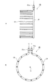
図1に示すように、環状をなすステータ10のステータコア11のヨーク部11aの内周には、径方向内側へ向かって突出するティース部11bが周方向に沿って複数設けられている。前記ステータコア11の前記ティース部11bには、コイル12がそれぞれ装着されている。
As shown in FIG. 1, a plurality of
前記ステータ10の軸方向一端側(図1A中、紙面手前側、図1B中、紙面奥側)には、コイル冷却器具20の環状に曲折された管からなる供給マニホールド21が当該ステータ10と同軸をなすようにして配設されている。
On one end side in the axial direction of the stator 10 (in FIG. 1A, the front side of the paper surface, in FIG. 1B, the back side of the paper surface), a
図1〜3に示すように、前記供給マニホールド21の、前記ステータ10との対向面側には、当該ステータ10の軸方向(図1中、紙面垂直方向)に沿って長手方向を向けて隣り合う前記コイル12の間に先端側(図2A中、左端側)を位置させるように当該間にそれぞれ挿入された複数のノズル管22の基端側(図2A中、右端側)が当該供給マニホールド21の周方向に沿って規定の間隔で連結されており、当該ノズル管22は、先端を閉塞されると共に、当該コイル12の、当該ステータ10の軸方向全長にわたって対向する長さを有している。
As shown in FIGS. 1 to 3, the
前記供給マニホールド21の軸心位置、すなわち、前記ステータ10の軸心位置Cよりも上方に位置する前記コイル12の外面に対向する前記ノズル管22の周面には、当該コイル12の当該外面の、当該ステータ10の径方向外側位置へ向けて冷却液1を噴射する噴射孔22aが軸方向に沿って規定の間隔で複数形成されている。
The axial position of the
他方、前記ステータ10の軸心位置Cよりも下方に位置する前記コイル12の外面に対向する前記ノズル管22の周面には、当該コイル12の当該外面の、当該ステータ10の径方向内側位置へ向けて冷却液1を噴射する噴射孔22bが軸方向に沿って規定の間隔で複数形成されている。
On the other hand, on the peripheral surface of the
このような本実施形態に係るコイル冷却器具20においては、前記供給マニホールド21に供給口21aから冷却液1を送給すると、冷却液1が、各前記ノズル管22へそれぞれ分配送給されて、各前記噴射孔22a,22bから、前記ステータ10の軸方向に沿った前記コイル12の外面の当該軸方向全長にわたって噴射される。
In the
このとき、前記ステータ10の軸心位置Cよりも上方に位置する前記コイル12の外面には、前記ノズル管22の前記噴射孔22aから当該ステータ10の径方向外側位置へ向けて冷却液1が噴き掛けられることから、噴き掛けられた冷却液1が、自重によって、当該コイル12の当該外面を当該径方向全長にわたって流下するようになる。
At this time, on the outer surface of the
他方、前記ステータ10の軸心位置Cよりも下方に位置する前記コイル12の外面には、前記ノズル管22の前記噴射孔22bから当該ステータ10の径方向内側位置へ向けて冷却液1が噴き掛けられることから、噴き掛けられた冷却液1が、自重によって、当該コイル12の当該外面を当該径方向全長にわたって流下するようになる。
On the other hand, the
このため、すべての隣り合う前記コイル12の間の外面には、前記ステータ10の軸方向及び径方向の全長にわたって冷却液1が流通するようになるので、前記コイル12は、すべてが全体を冷却液1によって冷却される。
Therefore, the
したがって、本実施形態に係るコイル冷却器具20によれば、前記ステータ10の前記コイル12を効率よく冷却することができる。
Therefore, according to the
また、前記ノズル管22が、前記コイル12の、前記ステータ10の軸方向全長にわたって対向する長さを有していることから、当該コイル12の当該軸方向全長にわたって冷却液1を噴き掛けることが確実にできるので、当該コイル12を効率よく冷却することが容易にできる。
Further, since the
また、前記ノズル管22が、すべての隣り合う前記コイル12の間に挿入され、前記ステータ10の軸心位置Cよりも上方に位置する前記コイル12の外面に対向する前記ノズル管22の前記噴射孔22aが、当該ステータ10の径方向外側位置へ向けて冷却液1を噴射するように形成されると共に、前記ステータ10の軸心位置Cよりも下方に位置する前記コイル12の外面に対向する前記ノズル管22の前記噴射孔22bが、当該ステータ10の径方向内側位置へ向けて冷却液1を噴射するように形成されていることから、すべての前記コイル12の前記軸方向の外面に対して冷却液1を前記径方向全長にわたって噴き掛けることが確実にできるので、当該コイル12を効率よく冷却することが容易にできる。
Further, the
本発明に係る回転電機のステータのコイル冷却器具は、コイルを効率よく冷却することができるので、産業上、極めて有益に利用することができる。 Since the coil cooling device of the stator of the rotary electric machine according to the present invention can efficiently cool the coil, it can be used extremely beneficially in industry.
1 冷却液
10 ステータ
11 ステータコア
11a ヨーク部
11b ティース部
12 コイル
20 コイル冷却器具
21 供給マニホールド
21a 供給口
22 ノズル管
22a,22b 噴射孔
1 Coolant 10
Claims (3)
前記ステータの軸方向一端側に配設されて内部に冷却液を送給される供給マニホールドと、
前記供給マニホールドに基端側を連結されて隣り合う前記コイルの間に先端側を位置させるように挿入されると共に当該コイルへ向けて冷却液を噴射する噴射孔を周面に形成されて先端を閉塞されたノズル管と
を備えていることを特徴とする回転電機のステータのコイル冷却器具。 A coil cooling device for a stator of a rotary electric machine that cools the coil of a stator in which coils are mounted on teeth portions protruding along the circumferential direction on the inner circumference of the yoke portion of the annular stator core.
A supply manifold that is disposed on one end side in the axial direction of the stator and supplies coolant to the inside.
The base end side is connected to the supply manifold and inserted so as to position the tip end side between the adjacent coils, and an injection hole for injecting a coolant toward the coil is formed on the peripheral surface to form the tip end. A coil cooling device for the stator of a rotating electric machine, which is characterized by having a closed nozzle tube.
前記コイルの、前記ステータの軸方向全長にわたって対向する長さを前記ノズル管が有している
ことを特徴とする回転電機のステータのコイル冷却器具。 The coil cooling device for the stator of a rotary electric machine according to claim 1.
A coil cooling device for a stator of a rotary electric machine, characterized in that the nozzle tube has a length of the coil facing the entire axial length of the stator.
すべての隣り合う前記コイルの間に前記ノズル管が挿入され、
前記ステータの軸心位置よりも上方に位置する前記コイルの外面に対向する前記ノズル管の前記噴射孔が、当該ステータの径方向外側位置へ向けて冷却液を噴射するように形成されると共に、
前記ステータの軸心位置よりも下方に位置する前記コイルの外面に対向する前記ノズル管の前記噴射孔が、当該ステータの径方向内側位置へ向けて冷却液を噴射するように形成されている
ことを特徴とする回転電機のステータのコイル冷却器具。 The coil cooling device for the stator of the rotary electric machine according to claim 1 or 2.
The nozzle tube is inserted between all the adjacent coils
The injection hole of the nozzle tube facing the outer surface of the coil located above the axial position of the stator is formed so as to inject the coolant toward the radial outer position of the stator.
The injection hole of the nozzle tube facing the outer surface of the coil located below the axial position of the stator is formed so as to inject the coolant toward the radial inner position of the stator. A coil cooling device for the stator of a rotating electric machine.
Priority Applications (1)
| Application Number | Priority Date | Filing Date | Title |
|---|---|---|---|
| JP2019088794A JP7156165B2 (en) | 2019-05-09 | 2019-05-09 | Rotating electrical machine stator coil cooler |
Applications Claiming Priority (1)
| Application Number | Priority Date | Filing Date | Title |
|---|---|---|---|
| JP2019088794A JP7156165B2 (en) | 2019-05-09 | 2019-05-09 | Rotating electrical machine stator coil cooler |
Publications (2)
| Publication Number | Publication Date |
|---|---|
| JP2020184850A true JP2020184850A (en) | 2020-11-12 |
| JP7156165B2 JP7156165B2 (en) | 2022-10-19 |
Family
ID=73045576
Family Applications (1)
| Application Number | Title | Priority Date | Filing Date |
|---|---|---|---|
| JP2019088794A Active JP7156165B2 (en) | 2019-05-09 | 2019-05-09 | Rotating electrical machine stator coil cooler |
Country Status (1)
| Country | Link |
|---|---|
| JP (1) | JP7156165B2 (en) |
Cited By (2)
| Publication number | Priority date | Publication date | Assignee | Title |
|---|---|---|---|---|
| JPWO2022195920A1 (en) * | 2021-03-18 | 2022-09-22 | ||
| KR20250027007A (en) * | 2023-08-18 | 2025-02-25 | 주식회사 코렌스이엠 | apparatus for cooling motor and motor comprising thereof |
Citations (2)
| Publication number | Priority date | Publication date | Assignee | Title |
|---|---|---|---|---|
| JP2005168265A (en) * | 2003-12-05 | 2005-06-23 | Nissan Motor Co Ltd | Cooling structure of rotating electric machine |
| JP2019041487A (en) * | 2017-08-25 | 2019-03-14 | 株式会社明電舎 | Cooling structure of stator of rotary electric machine |
-
2019
- 2019-05-09 JP JP2019088794A patent/JP7156165B2/en active Active
Patent Citations (2)
| Publication number | Priority date | Publication date | Assignee | Title |
|---|---|---|---|---|
| JP2005168265A (en) * | 2003-12-05 | 2005-06-23 | Nissan Motor Co Ltd | Cooling structure of rotating electric machine |
| JP2019041487A (en) * | 2017-08-25 | 2019-03-14 | 株式会社明電舎 | Cooling structure of stator of rotary electric machine |
Cited By (4)
| Publication number | Priority date | Publication date | Assignee | Title |
|---|---|---|---|---|
| JPWO2022195920A1 (en) * | 2021-03-18 | 2022-09-22 | ||
| WO2022195920A1 (en) * | 2021-03-18 | 2022-09-22 | 日立Astemo株式会社 | Dynamo-electrical machine |
| KR20250027007A (en) * | 2023-08-18 | 2025-02-25 | 주식회사 코렌스이엠 | apparatus for cooling motor and motor comprising thereof |
| KR102817196B1 (en) * | 2023-08-18 | 2025-06-09 | 주식회사 코렌스이엠 | apparatus for cooling motor and motor comprising thereof |
Also Published As
| Publication number | Publication date |
|---|---|
| JP7156165B2 (en) | 2022-10-19 |
Similar Documents
| Publication | Publication Date | Title |
|---|---|---|
| JP7071845B2 (en) | Rotating electric machine | |
| KR20130114147A (en) | Electric machine cooling system and method | |
| JP2020184850A (en) | Coil cooling device of stator of rotary electric machine | |
| WO2019039243A1 (en) | Cooling structure of stator of rotating electrical machine | |
| US11075561B2 (en) | Wound rotor synchronous electric machine | |
| CN108886281A (en) | The rotor portion of motor | |
| JP2008012296A5 (en) | ||
| JP6624223B2 (en) | Rotating electric machine | |
| JP2015204650A (en) | Rotating electric machine cooling device | |
| US11418080B2 (en) | Rotary electric machine | |
| JP2019060320A (en) | Axial flow fan | |
| JP2015076984A (en) | Varnish infiltration apparatus for stator coil | |
| WO2020105467A1 (en) | Motor oil cooling structure | |
| JP2019060321A (en) | Axial fan | |
| JPWO2007094350A1 (en) | Cooling structure of rotating electric machine | |
| JP2018152957A (en) | Rotary electric machine | |
| US20220247273A1 (en) | Electric machine | |
| US11362568B2 (en) | Liquid cooling structure of rotating electric machine | |
| JP2015012792A (en) | Stator for rotary electric machine | |
| TW201632749A (en) | Bearing assembly | |
| CN209627150U (en) | Rotating electric machine and the vehicle for carrying this rotating electric machine | |
| JP5430180B2 (en) | Induction hardening coil device | |
| JP5013751B2 (en) | Electric motor | |
| WO2008004286A1 (en) | Rotating electric machine and shaft for rotating electric machine | |
| JP2019201521A (en) | Rotary machine |
Legal Events
| Date | Code | Title | Description |
|---|---|---|---|
| RD02 | Notification of acceptance of power of attorney |
Free format text: JAPANESE INTERMEDIATE CODE: A7422 Effective date: 20190531 |
|
| RD04 | Notification of resignation of power of attorney |
Free format text: JAPANESE INTERMEDIATE CODE: A7424 Effective date: 20190529 |
|
| A621 | Written request for application examination |
Free format text: JAPANESE INTERMEDIATE CODE: A621 Effective date: 20210805 |
|
| A977 | Report on retrieval |
Free format text: JAPANESE INTERMEDIATE CODE: A971007 Effective date: 20220624 |
|
| A131 | Notification of reasons for refusal |
Free format text: JAPANESE INTERMEDIATE CODE: A131 Effective date: 20220628 |
|
| A521 | Request for written amendment filed |
Free format text: JAPANESE INTERMEDIATE CODE: A523 Effective date: 20220825 |
|
| TRDD | Decision of grant or rejection written | ||
| A01 | Written decision to grant a patent or to grant a registration (utility model) |
Free format text: JAPANESE INTERMEDIATE CODE: A01 Effective date: 20220906 |
|
| A61 | First payment of annual fees (during grant procedure) |
Free format text: JAPANESE INTERMEDIATE CODE: A61 Effective date: 20220919 |
|
| R150 | Certificate of patent or registration of utility model |
Ref document number: 7156165 Country of ref document: JP Free format text: JAPANESE INTERMEDIATE CODE: R150 |