JP2020184839A - Overhead power line connection type power reception apparatus - Google Patents
Overhead power line connection type power reception apparatus Download PDFInfo
- Publication number
- JP2020184839A JP2020184839A JP2019088370A JP2019088370A JP2020184839A JP 2020184839 A JP2020184839 A JP 2020184839A JP 2019088370 A JP2019088370 A JP 2019088370A JP 2019088370 A JP2019088370 A JP 2019088370A JP 2020184839 A JP2020184839 A JP 2020184839A
- Authority
- JP
- Japan
- Prior art keywords
- overhead wire
- rod
- power receiving
- connection type
- receiving device
- Prior art date
- Legal status (The legal status is an assumption and is not a legal conclusion. Google has not performed a legal analysis and makes no representation as to the accuracy of the status listed.)
- Pending
Links
Images
Classifications
-
- Y—GENERAL TAGGING OF NEW TECHNOLOGICAL DEVELOPMENTS; GENERAL TAGGING OF CROSS-SECTIONAL TECHNOLOGIES SPANNING OVER SEVERAL SECTIONS OF THE IPC; TECHNICAL SUBJECTS COVERED BY FORMER USPC CROSS-REFERENCE ART COLLECTIONS [XRACs] AND DIGESTS
- Y02—TECHNOLOGIES OR APPLICATIONS FOR MITIGATION OR ADAPTATION AGAINST CLIMATE CHANGE
- Y02T—CLIMATE CHANGE MITIGATION TECHNOLOGIES RELATED TO TRANSPORTATION
- Y02T90/00—Enabling technologies or technologies with a potential or indirect contribution to GHG emissions mitigation
- Y02T90/10—Technologies relating to charging of electric vehicles
- Y02T90/14—Plug-in electric vehicles
Landscapes
- Current-Collector Devices For Electrically Propelled Vehicles (AREA)
- Electric Propulsion And Braking For Vehicles (AREA)
Abstract
【課題】電動車両が受電操作者の頭上空中に架設された架線(給電線)から電力を安全に受電できる架線接続式の受電装置を提供する。【解決手段】架線式の受電装置は、受電操作者の頭上空中に架設された架線から電力を受電し、該電力を電動車両に搭載された駆動用バッテリーに供給する架線接続式の受電装置であって、電動車両のルーフの上に設置され、架線に向けて伸長される、電気的絶縁物で構成されたロッドと、ロッドの先端に設置され、架線から受電可能に接続される電極端子と、電極端子に一端が接続され、他端がロッドの基端側の領域を通り駆動用バッテリーに接続される、電気的絶縁物で被覆された被覆電線とを備える。【選択図】 図1PROBLEM TO BE SOLVED: To provide an overhead wire connection type power receiving device capable of safely receiving electric power from an overhead wire (feeding line) installed in the air above a power receiving operator. An overhead wire type power receiving device is an overhead wire connection type power receiving device that receives electric power from an overhead wire erected in the air above a power receiving operator and supplies the electric power to a drive battery mounted on an electric vehicle. There is a rod made of electrical insulation that is installed on the roof of the electric vehicle and extends toward the overhead wire, and an electrode terminal that is installed at the tip of the rod and is connected so that power can be received from the overhead wire. It comprises a covered wire coated with an electrical insulator, one end connected to the electrode terminal and the other end passing through a region on the base end side of the rod and connected to a drive battery. [Selection diagram] Fig. 1
Description
本開示は、架線接続式の受電装置に関する。 The present disclosure relates to an overhead wire connection type power receiving device.
特許文献1には、架線式電気自動車が開示されている。かかる架線式電気自動車は、車体を移動させるための電気駆動部と、電気駆動部に給電する蓄電池を備えた蓄電部と、車体の上部に車幅方向に並べて設けられ上下動可能な2個の電極を備えた架線接続部と、架線接続部の2個の電極を電力供給用の2本の架線にそれぞれ接続および離脱させるための制御をする架線接続制御部と、架線接続部の電極から架線を介して受電する受電部と、架線接続部の位置情報を取得する位置検出手段とを有し、架線接続制御部は、位置検出手段によって取得した位置データに基づいて架線の位置を認識し、受電部により受電する場合には架線接続部を上昇させて架線に接触させて給電を受けるように制御する。
特許文献1が開示する架線式電気自動車では、架線と接触する電極としての架線接続端子を備える架線接続部が外部に露出しているので、地上から屋根までの高さが低い架線式電気自動車では、地上の操作者が容易に架線接続端子に触れることができ、地上の受電操作者が感電する虞がある。
In the overhead wire type electric vehicle disclosed in
上述の事情に鑑みて、本発明の少なくとも一実施形態は、電動車両が受電操作者の頭上空中に架設された架線(給電線)から電力を安全に受電できる架線接続式の受電装置を提供することを目的とする。 In view of the above circumstances, at least one embodiment of the present invention provides an overhead wire connection type power receiving device capable of safely receiving electric power from an overhead wire (feeding line) installed in the air above the power receiving operator. The purpose is.
(1)本発明の少なくとも一実施形態に係る架線接続式の受電装置は、受電操作者の頭上空中に架設された架線から電力を受電し、該電力を電動車両に搭載された駆動用バッテリーに供給する架線接続式の受電装置であって、前記電動車両のルーフの上に設置され、前記架線に向けて伸長される、電気的絶縁物で構成されたロッドと、前記ロッドの先端に設置され、前記架線から受電可能に接続される電極端子と、前記電極端子に一端が接続され、他端が前記ロッドの基端側の領域を通り前記駆動用バッテリーに接続される、電気的絶縁物で被覆された被覆電線とを備える。 (1) The overhead wire connection type power receiving device according to at least one embodiment of the present invention receives electric power from an overhead wire erected in the air above the power receiving operator, and transfers the electric power to a drive battery mounted on an electric vehicle. An overhead wire connection type power receiving device to be supplied, which is installed on the roof of the electric vehicle and extends toward the overhead wire, and is installed at the tip of the rod and a rod made of an electric insulator. An electrical insulator that is connected to an electrode terminal that can receive power from the overhead wire, one end that is connected to the electrode terminal, and the other end that passes through a region on the base end side of the rod and is connected to the drive battery. It is provided with a covered electric wire.
上記(1)の構成によれば、電気的絶縁物で構成されたロッドが、電動車両のルーフの上に設置され、架線に向けて伸長される。また、電極端子がロッドの先端に設置され、架線から受電可能に接続される。更に、電気的絶縁物で被覆された被覆電線が、電極端子に一端が接続され、他端がロッドの基端側の領域(ルーフ)を通り駆動用バッテリーに接続される。これにより、電動車両が受電操作者の頭上空中に架設された架線(給電線)から電力を安全に受電できる。 According to the configuration of (1) above, a rod made of an electric insulator is installed on the roof of an electric vehicle and extends toward an overhead wire. In addition, an electrode terminal is installed at the tip of the rod and is connected so that power can be received from the overhead wire. Further, a coated electric wire coated with an electric insulator is connected to the driving battery at one end connected to the electrode terminal and the other end passing through a region (roof) on the base end side of the rod. As a result, the electric vehicle can safely receive electric power from the overhead wire (feeding line) erected in the air above the power receiving operator.
(2)一実施形態では、上記(1)の構成において、前記電極端子と前記駆動用バッテリーとの間に設けられ、前記電極端子が前記架線に受電可能に接続された場合に回路を閉じ、前記電極端子が前記架線から受電不能に離脱された場合に回路を開く接触器を更に備える。 (2) In one embodiment, in the configuration of (1) above, the circuit is closed when the electrode terminal is provided between the electrode terminal and the drive battery and the electrode terminal is connected to the overhead wire so as to be able to receive power. A contactor that opens a circuit when the electrode terminal is disconnected from the overhead wire in a power receiving manner is further provided.
上記(2)の構成によれば、電極端子と駆動用バッテリーとの間に設けられた接触器が、電極端子が架線に受電可能に接続された場合に回路を閉じ、電極端子が架線から受電不能に離脱された場合に回路を開くので、電極端子が架線から受電不能に離脱された場合に電極端子に電気が流れることがなく、受電操作者が感電する虞をほぼ無くすことができる。 According to the configuration of (2) above, the contactor provided between the electrode terminal and the drive battery closes the circuit when the electrode terminal is connected to the overhead wire so as to be able to receive power, and the electrode terminal receives power from the overhead wire. Since the circuit is opened when the electrode terminal is disconnected from the overhead wire, electricity does not flow to the electrode terminal when the electrode terminal is disconnected from the overhead wire, and the risk of electric shock to the power receiving operator can be almost eliminated.
(3)一実施形態では、上記(1)又は(2)の構成において、前記被覆電線は、前記ロッドの周りに巻回される。 (3) In one embodiment, in the configuration of (1) or (2) above, the covered electric wire is wound around the rod.
上記(3)の構成によれば、被覆電線は、ロッドの周りに巻回されるので、伸長されたロッドが元の位置に戻っても被覆電線が余ることがなく、被覆電線が断線する虞を小さくできる。 According to the configuration of (3) above, since the covered electric wire is wound around the rod, even if the extended rod returns to the original position, the coated electric wire does not remain and the coated electric wire may be broken. Can be made smaller.
(4)一実施形態では、上記(1)から(3)のいずれか一つの構成において、前記ロッドは、芯が鞘となる筒体から引き出される芯鞘構造を有する。 (4) In one embodiment, in any one of the above (1) to (3), the rod has a core-sheath structure drawn out from a cylinder having a core as a sheath.
上記(4)の構成によれば、ロッドは、芯鞘構造によって、芯が鞘となる筒体から引き出されるので、ロッドが架線に向けて伸長可能である。 According to the configuration of (4) above, the rod is pulled out from the cylinder whose core is the sheath by the core-sheath structure, so that the rod can be extended toward the overhead wire.
(5)一実施形態では、上記(2)の構成において、前記ロッドが伸長されたか否かを検出するスイッチを備え、前記接触器は、前記スイッチが前記ロッドが伸長されたことを検出した場合に、前記回路を閉じる。 (5) In one embodiment, in the configuration of (2) above, the contactor includes a switch for detecting whether or not the rod has been extended, and the contactor detects that the rod has been extended. The circuit is closed.
上記(5)の構成によれば、接触器は、スイッチがロッドが伸長されたことを検出した場合に、回路を閉じるので、ロッドが縮んだ状態で接触器が回路を閉じることがなく、受電操作者が感電する虞を小さくできる。 According to the configuration of (5) above, the contactor closes the circuit when the switch detects that the rod is extended, so that the contactor does not close the circuit when the rod is contracted and receives power. The risk of electric shock to the operator can be reduced.
本発明の少なくとも一実施形態によれば、電動車両が受電操作者の頭所空中に架設された架線(給電線)から電力を安全に受電できる。 According to at least one embodiment of the present invention, the electric vehicle can safely receive electric power from an overhead wire (feeding line) erected in the air above the head of the power receiving operator.
以下、添付図面を参照して本発明の幾つかの実施形態について説明する。ただし、実施形態として記載されている又は図面に示されている構成部品の寸法、材質、形状、その相対的配置等は、本発明の範囲をこれに限定する趣旨ではなく、単なる説明例にすぎない。 Hereinafter, some embodiments of the present invention will be described with reference to the accompanying drawings. However, the dimensions, materials, shapes, relative arrangements, etc. of the components described as embodiments or shown in the drawings are not intended to limit the scope of the present invention to this, but are merely explanatory examples. Absent.
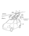
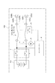
図1は、本発明の幾つかの実施形態に係る架線接続式の受電装置1を搭載した電動車両100を概略的に示す図である。図2は、図1に示した架線接続式の受電装置1の電気的構成を概略的に示すブロック図である。ここでは、架線接続式の受電装置1を搭載した乗用車型の電動車両100を例に説明するが、架線接続式の受電装置1を搭載する電動車両100は、乗用車型の電動車両100に限られるものではない。
FIG. 1 is a diagram schematically showing an
図1に示すように、本発明の幾つかの実施形態に係る架線接続式の受電装置1は、空中高くに架設された架線WRの直下に停車した電動車両100が架線WRから電力を受電し、該電力を電動車両100に搭載された駆動用バッテリー110に供給するためのものである。
As shown in FIG. 1, in the overhead wire connection type
空中高くに架設された架線WRは、電動車両100に電力を供給可能であって、地上の受電操作者から触手範囲外(アウトオブリーチ)となる高さに設けられる。地上高くに架設された架線WRは、例えば、直流の電力を供給可能であって、例えば、一対(二本)の架線WR1,WR2で構成され、一方の架線WR1に正極(プラス)の電力が供給され、他方の架線WR2に負極の電力が供給される。
The overhead wire WR erected high in the air is provided at a height that can supply electric power to the
本発明の幾つかの実施形態に係る架線接続式の受電装置1は、電動車両100に搭載される。本発明の幾つかの実施形態に係る架線接続式の受電装置1が搭載される電動車両100は、外部(架線WR)から供給された電力によって電動車両100に搭載された駆動用バッテリー110を充電可能である。本発明の幾つかの実施形態に係る架線接続式の受電装置1が搭載される電動車両100は、例えば、電気自動車(EV(Electric Vehicle))又はプラグインハイブリッド自動車(PHV(Plug−in Hybrid Vehicle),PHEV(Plug−in Hybrid Electric Vehicle))である。
The overhead wire connection type
[実施形態1]
図1に示すように、本発明の実施形態1に係る架線接続式の受電装置1Aは、ロッド2、電極端子3及び被覆電線4を備えている。
[Embodiment 1]
As shown in FIG. 1, the overhead wire connection type
ロッド2は、電気的絶縁物で構成される。ロッド2は、例えば、樹脂材料等の電気的絶縁物で構成されるが、電気的絶縁物は樹脂材料に限られるものではなくセラミックス等の電気的絶縁物であってもよい。また、電気的絶縁物は、導電性を有する金属等を電気的絶縁物で被覆したものであってもよい。
The
また、ロッド2は、電動車両100のルーフ101の上に設置され、架線WRに向けて伸長可能である。ロッド2は、例えば、伸長可能な多段式のロッド2であって、架線WRに向けて伸長可能である。伸長可能な多段式のロッド2は、例えば、二段階に進出可能なロッド2であって、外筒21、内筒22及び芯23の三つから構成される。また、ロッド2は、例えば、モーター5によって駆動され、ロッド2は架線WRに向けて伸長され、架線WRに向けて伸長されたロッド2は元の位置に戻される。
Further, the
例えば、架線WRが一対の架線WR1,WR2で構成される場合に、ロッド2も一対(二本)のロッド2L,2Rで構成され、ロッド2Lとロッド2Rとの間には適切な間隔を維持するためのガイド6が設置される。
For example, when the overhead wire WR is composed of a pair of overhead wires WR1 and WR2, the
電極端子3は、ロッド2の先端に設置され、架線WRから受電可能に接続される。電極端子3は、例えば、車両前方から後方を見た場合に凹型をなし、架線WRと対向する面に架線WRを受け入れるための溝31(凹部)を有する。
The
例えば、架線WRが一対の架線WR1,WR2で構成され、ロッド2が一対のロッド2L,2Rで構成される場合に、電極端子3も一対(二つ)の電極端子3L,3Rで構成され、各ロッド2L,2Rの先端に設置される。
For example, when the overhead wire WR is composed of a pair of overhead wires WR1 and WR2 and the
被覆電線4は、電気的絶縁物で被覆された電線である。被覆電線4は、電極端子3に一端が接続され、ロッド2の基端側の領域(ルーフ101)を通り駆動用バッテリー110に接続される。
The coated
例えば、電極端子3が一対の電極端子3L,3Rで構成される場合に、被覆電線4も一対(二本)の被覆電線4L,4Rで構成され、それぞれ一端が電極端子3に接続され、ロッド2の基端側の領域(ルーフ101)を通り他端が駆動用バッテリー110に接続される。
For example, when the
上述した本発明の実施形態1に係る架線接続式の受電装置1Aによれば、電気的絶縁物で構成されたロッド2が、電動車両100のルーフ101の上に設置され、架線WRに向けて伸長される。また、電極端子3がロッド2の先端に設置され、架線WRから受電可能に接続される。更に、電気的絶縁物で被覆された被覆電線4が、電極端子3に一端に接続され、他端がロッド2の基端側の領域(ルーフ101)を通り駆動用バッテリー110に接続される。これにより、電動車両100が受電操作者の頭上空中に架設された架線WR(給電線)から電力を安全に受電できる。
According to the overhead wire connection type
[実施形態2]
本発明の実施形態2に係る架線接続式の受電装置1Bは、上述した本発明の実施形態1に係る架線接続式の受電装置1Aにおいて、更に、接触器7を備える。接触器7は、電極端子3と駆動用バッテリー110との間に設けられ、電極端子3が架線WRに受電可能に接続された場合に回路を閉じ、電極端子3が架線WRから受電不能に離脱された場合に回路を開くように構成される。接触器7は、例えば、コントローラー9によって制御され、コントローラー9に電極端子3が架線WRに受電可能に接続された旨の入力があった場合に接触器7の回路を閉じ、電極端子3が架線WRから受電不能に離脱された旨の入力があった場合に接触器7の回路を開くように制御される。
[Embodiment 2]
The overhead wire connection type
上述した本発明の実施形態2に係る架線接続式の受電装置1Bによれば、電極端子3と駆動用バッテリー110との間に設けられた接触器7が、電極端子3が架線WRに受電可能に接続された場合に回路を閉じ、電極端子3が架線WRから受電不能に離脱された場合に回路を開くので、電極端子3が架線WRから受電不能に離脱された場合に電極端子3に電気が流れることがなく、受電操作者が感電する虞を小さくできる。
According to the overhead wire connection type
[実施形態3]
本発明の実施形態3に係る架線接続式の受電装置1Cは、上述した本発明の実施形態1又は2に係る架線接続式の受電装置1A,1Bにおいて、被覆電線4は、ロッド2の周りに巻回される。
[Embodiment 3]
In the overhead wire connection type
上述した本発明の実施形態3に係る架線接続式の受電装置1Cによれば、被覆電線4は、ロッド2の周りに巻回されるので、架線WRに向けて伸長されたロッド2が元の位置に戻っても被覆電線4が余ることがなく、被覆電線4が断線する虞を小さくできる。
According to the overhead wire connection type
[実施形態4]
本発明の実施形態4に係る架線接続式の受電装置1Dは、上述した本発明の実施形態1から3のいずれか一つに係る架線接続式の受電装置1A,1B,1Cにおいて、ロッド2は、芯23が鞘となる筒体から引き出される芯鞘構造を有する。例えば、ロッド2は、二段階に進出可能な芯鞘構造であって、基端側に設けられる外筒21、外筒21から引き出される内筒22、及び、内筒22から引き出される芯23の三つから構成される。
[Embodiment 4]
The overhead wire connection type
上述した本発明の実施形態4に係る架線接続式の受電装置1Dによれば、ロッド2は、芯鞘構造によって、芯23が鞘となる筒体から引き出されるので、ロッド2が架線WRに向けて伸長可能である。
According to the overhead wire connection type
[実施形態5]
本発明の実施形態5に係る架線接続式の受電装置1Eは、上述した本発明の実施形態2に係る架線接続式の受電装置1Bにおいて、ロッド2が伸長されたか否かを検出するスイッチ8を備え、接触器7は、スイッチ8がロッド2が伸長されたことを検出した場合に回路を閉じる。
[Embodiment 5]
The overhead wire connection type
上述した本発明の実施形態5に係る架線接続式の受電装置1Eによれば、スイッチ8がロッド2が伸長されたことを検出した場合に回路を閉じるので、ロッド2が縮んだ状態で回路を閉じることが無く、受電操作者が感電する虞を小さくできる。
According to the overhead wire connection type
[実施形態6]
本発明の実施形態6に係る架線接続式の受電装置1Fは、上述した本発明の実施形態2に係る架線接続式の受電装置1Bにおいて、受電操作者の充電開始操作によって、コントローラー9が、ロッド2の伸長及び受電の開始の一連の接続工程を実行する。
[Embodiment 6]
In the overhead wire connection type
例えば、本発明の実施形態6に係る架線接続式の受電装置1Fでは、本発明の実施形態6に係る架線接続式の受電装置1Fが搭載された電動車両100が架線WRの直下に停車した状態で、受電操作者が充電操作を行う。受電操作者が充電操作を行うと、コントローラー9がロッド2を伸長させるモーター5に指示を与える。コントローラー9から指示を与えられたモーター5は、スイッチ8がロッド2が伸長されたことを検出するまで作動する。これにより、電極端子3が架線WRに接続される。そして、スイッチ8がロッド2が伸長され、電極端子3が架線WRに接続されたことを検出すると、コントローラー9は、接触器7に回路を閉じるように指示する。これにより、接触器7は、回路を閉じ、架線WRから受電を開始する。
For example, in the overhead wire connection type
また、例えば、本発明の実施形態6に係る架線接続式の受電装置1Fでは、充電終了又は充電中断後に、コントローラー9が受電終了及びロッド2の収納の一連の離脱工程を実行する。
Further, for example, in the overhead wire connection type
例えば、本発明の実施形態6に係る架線接続式の受電装置1Fでは、充電終了又は充電中断後に、コントローラー9は、接触器7に回路を開くように指示する。接触器7が回路を開くと、コントローラー9から指示を与えられたモーター5は、ロッド2が元の位置に戻るまで作動する。これにより、接触器7は回路を開き、ロッド2が収納される。
For example, in the overhead wire connection type
上述した本発明の実施形態6に係る架線接続式の受電装置1Fは、受電操作者の受電開始操作によって、コントローラー9が、ロッド2の伸長及び受電開始の一連の接続工程を実行するので、受電操作者がロッド2の伸長及び受電開始の一連の接続工程を実行する必要がなくなり、受電操作者が感電する虞を小さくできる。
In the overhead wire connection type
[実施形態7]
本発明の実施形態7に係る架線接続式の受電装置1Gは、上述した本発明の実施形態5に係る架線接続式の受電装置1Fにおいて、電動車両100の走行中はロッド2が収納された状態であり、ロッド2が収納された状態でスイッチ8がロッド2が収納された状態であることを検出する。そして、コントローラー9は、スイッチ8がロッド2が収納された状態であることを検出すると、接触器7が回路を開くことで、電極端子3が非活電状態を維持する。
[Embodiment 7]
The overhead wire connection type
尚、本発明の実施形態7に係る架線接続式の受電装置1Gでは、ロッド2が収納された状態で電極端子3が風雨に晒されないように、電極端子3をカバー(図示せず)で覆うようにしてもよい。
In the overhead wire connection type
電動車両100が架線WRから電力を受電し、電動車両100に搭載された駆動用バッテリー110に充電する場合には、架線WRの直下に電動車両100を停車した状態で受電操作者が充電操作を行う。受電操作者が充電操作を開始すると、コントローラー9がロッド2を伸長させるモーター5に指示を与える。コントローラー9から指示を与えられたモーター5は、スイッチ8がロッド2が伸長されたこと検出するまで作動する。これにより、電極端子3が架線WRに接続される。そして、スイッチ8がロッド2が伸長され、電極端子3が架線WRに接続されたことを検出すると、コントローラー9は、接触器7に回路を閉じるように指示する。これにより、接触器7は、回路を閉じ、架線WRから受電を開始する。これにより、コントローラー9は、架線WRと電極端子3の接続を完了する。そして、架線WRから電動車両100に搭載された駆動用バッテリー110に充電が可能となる。
When the
尚、本発明の実施形態7に係る架線接続式の受電装置1Gでは、ロッド2は、その基端部にロッド2の伸長方向を微調整可能な可動機構を備え、ロッド2の伸長方向を微調整できるようにしてもよい。
In the overhead wire connection type
上述した本発明の実施形態7に係る架線接続式の受電装置1Gによれば、電極端子3が架線WRに接続された状態で、電極端子3が活電状態となるが、地上の受電操作者からは被覆電線4に手が届くだけで、電極端子3には手が届かないので、地上の受電操作者が感電する虞を小さくできる。
According to the overhead wire connection type
尚、本発明の実施形態1から7に係る架線接続式の受電装置1A〜1Gは、プリチャージ回路(図示せず)を備えてもよい。プリチャージ回路は、接触器7が回路を閉じる際に、架線WRと駆動用電池との間に電位差があることで生じうるラッシュ電流を軽減するものであり、接触器7がプリチャージ回路を備えるものとしてもよい。
The overhead wire connection type
また、図2に示す例では、一対のロッド2L,2Rのうち一方にスイッチ8を備える構成としたが、一対のロッド2L,2Rのそれぞれにスイッチを備え、スイッチの論理積によって、ロッド2L,2Rの伸長を検出するものとしてもよい。また、ロッド2が上方に向けて突出することを検知するスイッチ(図示せず)を設け、電極端子3が受電操作者から届かない位置にあることを検出してから接触器7が回路を閉じるようにしてもよい。
Further, in the example shown in FIG. 2, one of the pair of
また、本発明の実施形態1から7に係る架線接続式の受電装置1A〜1Gでは、電動車両100が前後に移動することも可能であり、電極端子3が架線WRに接続された状態で電動車両100が前後に移動するものとしてもよい。
Further, in the overhead wire connection type
上述した本発明の実施形態1から7に係る架線接続式の受電装置1A〜1Gは、一対の架線WRに直流の電力が流れるものとしたが、架線WRに交流電流が流れるものとしてもよい。この場合に、接触器7の位置に交流から直流に変換し電力制御できるコンバーター式電源装置を備えて交流給電としてもよい。
In the overhead wire connection type
本発明は上述した実施形態に限定されることはなく、上述した実施形態に変形を加えた形態や、これらの形態を適宜組み合わせた形態も含む。 The present invention is not limited to the above-described embodiment, and includes a modified form of the above-described embodiment and a combination of these embodiments as appropriate.
1,1A,1B,1C,1D,1E,1F,1G 架線接続式の受電装置
2,2L,2R ロッド
21 外筒
22 内筒
23 芯
3,3L,3R 電極端子
31 溝
4,4L,4R 被覆電線
5 モーター
6 ガイド
7 接触器
8 スイッチ
9 コントローラー
100 電動車両
101 ルーフ
110 駆動用バッテリー
WR,WR1,WR2 架線
1,1A, 1B, 1C, 1D, 1E, 1F, 1G Overhead line connection type
Claims (5)
前記電動車両のルーフの上に設置され、前記架線に向けて伸長される、電気的絶縁物で構成されたロッドと、
前記ロッドの先端に設置され、前記架線から受電可能に接続される電極端子と、
前記電極端子に一端が接続され、他端が前記ロッドの基端側の領域を通り前記駆動用バッテリーに接続される、電気的絶縁物で被覆された被覆電線と
を備えることを特徴とする架線接続式の受電装置。 It is an overhead wire connection type power receiving device that receives electric power from an overhead wire erected in the air above the power receiving operator and supplies the electric power to a drive battery mounted on an electric vehicle.
A rod made of electrical insulation that is installed on the roof of the electric vehicle and extends toward the overhead wire.
An electrode terminal installed at the tip of the rod and connected so as to receive power from the overhead wire,
An overhead wire having one end connected to the electrode terminal and the other end passing through a region on the base end side of the rod and being connected to the drive battery, provided with a covered electric wire coated with an electric insulator. Connectable power receiving device.
前記接触器は、前記スイッチが前記ロッドが伸長されたこと検出した場合に、前記回路を閉じることを特徴とする請求項2に記載の架線接続式の受電装置。 A switch for detecting whether or not the rod is extended is provided.
The overhead wire connection type power receiving device according to claim 2, wherein the contactor closes the circuit when the switch detects that the rod is extended.
Priority Applications (1)
| Application Number | Priority Date | Filing Date | Title |
|---|---|---|---|
| JP2019088370A JP2020184839A (en) | 2019-05-08 | 2019-05-08 | Overhead power line connection type power reception apparatus |
Applications Claiming Priority (1)
| Application Number | Priority Date | Filing Date | Title |
|---|---|---|---|
| JP2019088370A JP2020184839A (en) | 2019-05-08 | 2019-05-08 | Overhead power line connection type power reception apparatus |
Publications (1)
| Publication Number | Publication Date |
|---|---|
| JP2020184839A true JP2020184839A (en) | 2020-11-12 |
Family
ID=73044748
Family Applications (1)
| Application Number | Title | Priority Date | Filing Date |
|---|---|---|---|
| JP2019088370A Pending JP2020184839A (en) | 2019-05-08 | 2019-05-08 | Overhead power line connection type power reception apparatus |
Country Status (1)
| Country | Link |
|---|---|
| JP (1) | JP2020184839A (en) |
-
2019
- 2019-05-08 JP JP2019088370A patent/JP2020184839A/en active Pending
Similar Documents
| Publication | Publication Date | Title |
|---|---|---|
| CN106132767B (en) | External powering device and vehicle method of supplying power to | |
| JP4516581B2 (en) | Circuit device and vehicle operation system | |
| JP5741635B2 (en) | Auxiliary battery power supply device | |
| CN101292408B (en) | Recharging station and related electric vehicle | |
| US20130012044A1 (en) | Contact-making apparatus | |
| JP6064657B2 (en) | Rotating electric machine drive | |
| JP6114642B2 (en) | Switchgear | |
| JP2009095157A (en) | Electric vehicle charging device | |
| EP2848451B1 (en) | Connection system for charging batteries of a vehicle, particularly an electric bus | |
| JP7168912B2 (en) | vehicle power system | |
| JP2012090407A (en) | Vehicle charger | |
| JP5749423B2 (en) | Vehicle power supply | |
| CN108702010B (en) | Contact charging system, power supply device, power receiving device, and contact charging method | |
| JP2010213503A (en) | Power supply apparatus and method | |
| JP2002252937A (en) | Power supply device | |
| CN112117787A (en) | An electric vehicle charging system, an electric vehicle and a control method for vehicle charging | |
| JP2013056646A (en) | Apparatus for vehicle and power supply method | |
| CN216101966U (en) | Power electricity taking device for all-terrain vehicle | |
| CN1734832A (en) | Accumulator charger with charging cable | |
| KR101207633B1 (en) | Charging apparatus for electric vehicle and charging system including the same | |
| JP5183778B2 (en) | Vehicle charging system | |
| CN108891270B (en) | New energy automobile protector that charges | |
| CN106218413A (en) | The electric power system of pure electric automobile and method | |
| KR20170112816A (en) | A charger for electric vehicle | |
| JPH0630783Y2 (en) | Charging device for aerial work vehicles |