JP2020174952A - Transformable toy - Google Patents
Transformable toy Download PDFInfo
- Publication number
- JP2020174952A JP2020174952A JP2019080074A JP2019080074A JP2020174952A JP 2020174952 A JP2020174952 A JP 2020174952A JP 2019080074 A JP2019080074 A JP 2019080074A JP 2019080074 A JP2019080074 A JP 2019080074A JP 2020174952 A JP2020174952 A JP 2020174952A
- Authority
- JP
- Japan
- Prior art keywords
- state
- toy
- opening
- head
- crank
- Prior art date
- Legal status (The legal status is an assumption and is not a legal conclusion. Google has not performed a legal analysis and makes no representation as to the accuracy of the status listed.)
- Granted
Links
- 239000000463 material Substances 0.000 claims abstract description 58
- 230000002093 peripheral effect Effects 0.000 claims description 11
- 230000009466 transformation Effects 0.000 abstract 1
- 210000003128 head Anatomy 0.000 description 45
- 230000007246 mechanism Effects 0.000 description 23
- 230000004660 morphological change Effects 0.000 description 19
- 210000003625 skull Anatomy 0.000 description 15
- 230000008859 change Effects 0.000 description 4
- 230000009467 reduction Effects 0.000 description 4
- 210000005252 bulbus oculi Anatomy 0.000 description 3
- 238000001514 detection method Methods 0.000 description 2
- 210000005069 ears Anatomy 0.000 description 2
- 230000001681 protective effect Effects 0.000 description 2
- 230000004308 accommodation Effects 0.000 description 1
- 238000010586 diagram Methods 0.000 description 1
- 230000000694 effects Effects 0.000 description 1
- 210000001508 eye Anatomy 0.000 description 1
- 230000003287 optical effect Effects 0.000 description 1
- 239000002243 precursor Substances 0.000 description 1
- 238000010079 rubber tapping Methods 0.000 description 1
- 239000000126 substance Substances 0.000 description 1
Images


Classifications
-
- A—HUMAN NECESSITIES
- A63—SPORTS; GAMES; AMUSEMENTS
- A63H—TOYS, e.g. TOPS, DOLLS, HOOPS OR BUILDING BLOCKS
- A63H33/00—Other toys
- A63H33/003—Convertible toys, e.g. robots convertible into rockets or vehicles convertible into planes
-
- A—HUMAN NECESSITIES
- A63—SPORTS; GAMES; AMUSEMENTS
- A63H—TOYS, e.g. TOPS, DOLLS, HOOPS OR BUILDING BLOCKS
- A63H13/00—Toy figures with self-moving parts, with or without movement of the toy as a whole
-
- A—HUMAN NECESSITIES
- A63—SPORTS; GAMES; AMUSEMENTS
- A63H—TOYS, e.g. TOPS, DOLLS, HOOPS OR BUILDING BLOCKS
- A63H3/00—Dolls
- A63H3/02—Dolls made of fabrics or stuffed
-
- A—HUMAN NECESSITIES
- A63—SPORTS; GAMES; AMUSEMENTS
- A63H—TOYS, e.g. TOPS, DOLLS, HOOPS OR BUILDING BLOCKS
- A63H31/00—Gearing for toys
- A63H31/08—Gear-control mechanisms; Gears for imparting a reciprocating motion
-
- A—HUMAN NECESSITIES
- A63—SPORTS; GAMES; AMUSEMENTS
- A63H—TOYS, e.g. TOPS, DOLLS, HOOPS OR BUILDING BLOCKS
- A63H29/00—Drive mechanisms for toys in general
- A63H29/22—Electric drives
-
- A—HUMAN NECESSITIES
- A63—SPORTS; GAMES; AMUSEMENTS
- A63H—TOYS, e.g. TOPS, DOLLS, HOOPS OR BUILDING BLOCKS
- A63H3/00—Dolls
- A63H3/04—Dolls with deformable framework
Abstract
Description
本発明は形態変化玩具に関する。 The present invention relates to a form-changing toy.
従来、動物の形状をしている着ぐるみで、手足を左右及び上下に動かすようにした玩具が知られている(例えば、特許文献1参照)。 Conventionally, toys in which the limbs are moved left and right and up and down in a costume in the shape of an animal are known (see, for example, Patent Document 1).
しかしながら、このような形態変化玩具の場合、手や足は最初から突出しており、手や足が動くことは予想ができてしまうという問題がある。
本発明は、かかる課題に鑑みなされたもので、意外性がある形態変化を行う形態変化玩具を提供することを目的としている。
However, in the case of such a shape-changing toy, there is a problem that the hands and feet are protruding from the beginning, and it is possible to predict that the hands and feet will move.
The present invention has been made in view of such a problem, and an object of the present invention is to provide a morphological change toy that performs a morphological change unexpectedly.
第1の手段は、
玩具本体と、前記玩具本体に被せられる着ぐるみとを備えた形態変化玩具であって、
前記着ぐるみの少なくとの一部は起毛材によって形成され、
前記玩具本体には、収容凹部と、外方に突出した第1状態と前記収容凹部に収容された第2状態とを取る動作部品と、が設けられ、
前記第2状態で、前記収容凹部の開口部において互いに隣設された部分を被覆する前記起毛材の突き合せによって前記動作部品が外部から隠されることを特徴とする。
ここで、「隠される」とは周囲と同化して隠される場合と、他の部材によって被覆されて隠される場合とを含む。なお、この場合の動作部品の動作は、動作装置を通じて行ってもよいし、手動で行ってもよい。
The first means is
A form-changing toy having a toy body and a costume that covers the toy body.
A part of the costume is made of brushed material,
The toy body is provided with a storage recess and an operating component that takes a first state protruding outward and a second state housed in the storage recess.
In the second state, the moving parts are hidden from the outside by abutting of the raised materials that cover the portions adjacent to each other in the opening of the accommodating recess.
Here, "hidden" includes a case where it is assimilated with the surroundings and hidden, and a case where it is covered with another member and hidden. The operation of the operating component in this case may be performed through the operating device or may be performed manually.
第2の手段は、第1の手段であって、前記動作部品の外面及び前記収容凹部の周辺部は前記起毛材で被覆され、前記第2状態で前記動作部品の外面の前記起毛材と前記収容凹部の周辺部の前記起毛材とは面一となり、前記動作部品の外面の前記起毛材と前記収容凹部の周辺部の前記起毛材との突き合せによって前記動作部品が外部から隠されることを特徴とする。 The second means is the first means, in which the outer surface of the moving component and the peripheral portion of the accommodating recess are covered with the raised material, and in the second state, the raised material and the raised material on the outer surface of the moving component are described. The brushed material on the peripheral portion of the accommodating recess is flush with the raised material, and the operating component is hidden from the outside by abutting the brushed material on the outer surface of the operating component with the brushed material on the peripheral portion of the accommodating recess. It is a feature.
第3の手段は、第1の手段であって、観音開き構造の一対の開閉部材を備え、前記一対の開閉部材は前記起毛材で被覆され、前記動作部品は、前記第2状態で、前記一対の開閉部材の間の前記起毛材を押し込むようにして前記一対の開閉部材の内側の前記収容凹部に収容され、前記一対の開閉部材が閉じた際に、前記一対の開閉部材の縁部分の前記起毛材を互いに突き合せることによって前記動作部品が外部から隠されることを特徴とする。
観音開き構造の一対の開閉部材の間に動作部品がある場合には、動作部品の起毛材と開閉部材の起毛材を突き合わせるようにしてもよい。なお、片開き構造の開閉部材の場合にも適用できることは勿論である。要は、動作部品が隠れることである。
また、この場合の一対の開閉部材の開閉は、動作装置を通じて行ってもよいし、手動で行ってもよい。
The third means is the first means, which includes a pair of opening / closing members having a double door structure, the pair of opening / closing members are covered with the raised material, and the moving parts are in the second state. The raised material is pushed into the opening / closing member, and is housed in the storage recess inside the pair of opening / closing members. When the pair of opening / closing members are closed, the edge portion of the pair of opening / closing members It is characterized in that the moving parts are hidden from the outside by abutting the brushed materials against each other.
When there is an operating component between a pair of opening / closing members having a double door structure, the raised material of the operating component and the raised material of the opening / closing member may be butted against each other. Of course, it can also be applied to an opening / closing member having a single-sided opening structure. The point is that the moving parts are hidden.
Further, the opening / closing of the pair of opening / closing members in this case may be performed through the operating device or may be performed manually.
第1の手段によれば、第2状態で、互いに隣設された部分を被覆する起毛材の突き合せによって動作部品が外部から識別できないように隠されるので、どの部分が突出するのか予想ができず、興趣性の高い形態変化玩具が実現できる。 According to the first means, in the second state, the moving parts are hidden from the outside by the butting of the brushed materials covering the adjacent parts, so that it is possible to predict which part will protrude. It is possible to realize a highly interesting form-changing toy.
第2の手段によれば、着ぐるみで被覆された状態で、第2状態にあるとき収容凹部の周辺部と動作部品の外面とが面一であり、しかも、収容凹部の周辺部の起毛材と動作部品の起毛材とが突き合わされるので、動作部品が効果的に隠されることになる。 According to the second means, in the state of being covered with the costume, when in the second state, the peripheral portion of the accommodating recess and the outer surface of the operating component are flush with each other, and moreover, with the brushed material of the peripheral portion of the accommodating recess. Since the brushed material of the moving parts is abutted against each other, the moving parts are effectively hidden.
第3の手段によれば、一対の開閉部材が閉じた際に、一対の開閉部材の縁部分の起毛材が互いに突き合わされるので、動作部品が効果的に隠されることになる。 According to the third means, when the pair of opening / closing members are closed, the raised materials at the edges of the pair of opening / closing members are abutted against each other, so that the moving parts are effectively hidden.
以下、本発明の形態変化玩具を図面に示した実施形態に基づいて説明する。 Hereinafter, the form-changing toy of the present invention will be described based on the embodiment shown in the drawings.
《全体構成》
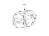
図1は、本実施形態の形態変化玩具100の形態変化の様子を示した斜視図である。
この形態変化玩具100は、団子状の第1形態100Aと、第1形態100Aから尾部80が突出した第2形態100Bと、仮想動物の姿態を持つ第3形態100Cとに順に段階的に形態変化する。形態変化の契機はいわゆる対話である。具体的には、形態変化玩具100を撫でる又は軽く叩く、或いは、形態変化玩具100に話しかけたり、音楽を聴かせたりすることにより、形態変化玩具100は段階的に成長し形態を変化させる。実施形態の形態変化玩具100では、例えば、形態変化によって段階的に身体が大きくなる。
なお、この形態変化玩具100は、形態変化の前兆として、後述の足部60を小刻みに動作させることによって、上下及び左右に揺動させる。
"overall structure"
FIG. 1 is a perspective view showing a state of morphological change of the
The
The
(細部構成)
1.形態変化玩具100の構成要素
この形態変化玩具100は、大別すると、メカニカルな部分で形態変化玩具100の外観の基本的な骨格を構成する玩具本体1(図2〜図5)と、玩具本体1を包み込み形態変化玩具100の外郭を構成する着ぐるみ2(図1)とを備えている。
(Detailed composition)
1. 1. Components of the
2.玩具本体1
(1)全体
図2は、第1形態100Aの玩具本体1の外観を、図3は、第1形態100Aの玩具本体1の別の角度の外観を、図4は、第2形態100Bの玩具本体1の外観を、図5は、第3形態100Cの玩具本体1の外観を示している。
この形態変化玩具100の玩具本体1は、図5に示すように、動作部品として、頭部10、胴部30、足部60及び尾部80を備えている。
2.
(1) Overall FIG. 2 shows the appearance of the
As shown in FIG. 5, the
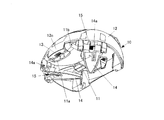
(2)頭部10
図5に示すように、頭部10は、顔部11及び頭蓋部12を備えている。
顔部11は湾曲板から構成されている。顔部11の左右には、着ぐるみ2に固定された目玉2cの裏の鋲を嵌め込む受け口11cが1つずつ形成されている。
顔部11の上縁には係合凹部11aが形成されている。
(2)
As shown in FIG. 5, the
The
An
図6は、顔部11及び耳部14を折り畳んだ状態の頭部10を下方から見た斜視図である。
同図に示すように、頭蓋部12は椀状部材から構成されている。頭蓋部12の前端下縁には、顔部11の係合凹部11aに嵌合する係合凸部12cが形成されている。そして、頭蓋部12と顔部11とは、係合凹部11aと係合凸部12cとの嵌合部分で軸11bを介して互いに連結されている。そして、顔部11は、頭蓋部12の内側に折り畳まれる折畳み状態(図6)と、頭蓋部12の前端から垂れ下がる展開状態(図5)とを取る。
軸11bには捩りコイルばね13が巻回されている。捩りコイルばね13の一端は顔部11に掛けられ、他端は頭蓋部12に掛けられている。そして、顔部11は展開状態に向けて付勢されている。この顔部11は、出荷の際に頭部10を胴部30に対して予め折り畳む際に、頭部10と胴部30の間に形成される収容凹部内に折り畳まれる。
FIG. 6 is a perspective view of the
As shown in the figure, the
A
頭蓋部12には、顔部11の左右に三角形状の耳部14が1つずつ取り付けられている。各耳部14は軸14aを介して頭蓋部12に支持されている。そして、耳部14は、頭蓋部12の内側に折り畳まれる折畳み状態(図6)と、頭蓋部12から突出する展開状態(図5)とを取る。
軸14aには捩りコイルばね15が巻回されている。捩りコイルばね15の一端は耳部14に掛けられ、他端は頭蓋部12に掛けられている。そして、耳部14は展開状態に向けて付勢されている。この耳部14は、出荷の際に頭部10を胴部30に対して予め折り畳んでおく際に折り畳まれる。
A
A
(3)頭部10の取付け構造と頭部動作装置33
図7は、頭部10の半部を示した斜視図である。
胴部30の天板には軸支部31が設けられている。軸支部31には、頭蓋部12に取り付けられた軸12aが支持されており、頭部10は、胴部30に当接する折畳み状態と、胴部30から離間した展開状態とを取る。
軸12aには捩りコイルばね32が巻回されており、捩りコイルばね32の一端は頭蓋部12に掛けられ、他端は後述のレバー36に掛けられている。この頭部10は後述のモータ37によってレバー36を介して動作されるが、捩りコイルばね32は、頭部10を展開させる際に遊戯者が頭部10を押さえつけた際の保護クラッチとして機能する。
(3) Mounting structure of
FIG. 7 is a perspective view showing a half portion of the
A
A
また、胴部30には頭部動作装置33が設けられている。頭部動作装置33は、偏心ピン34aを有するクランク(回動部品)34と、偏心ピン34aに係合しクランク34の回動によって前後方向に往復動作するスライド板35と、スライド板35の後端部に連結されたレバー36とを備える。クランク34とスライド板35とは両スライダクランク機構の一部を構成する。
クランク34は駆動装置に連結されている。すなわち、クランク34は、モータ37によって減速歯車列38を介して回動されるように構成されている。クランク34は、減速歯車列38の出力歯車38aと一体的に設けられている。
スライド板35の前端部には左右方向に長尺な長孔35aが形成され、長孔35aには偏心ピン34aが挿入されている。レバー36の上下方向の中間部は軸12aに支持されている。このレバー36は、捩りコイルばね32を介して、頭蓋部12に付設された突起12bに係合されている。また、レバー36の下端部は、スライド板35の後端部に付設された軸支部35bにピン36aを介して取り付けられている。
これによって、クランク34と頭部10とは連結されている。
Further, the
The
An
As a result, the
この頭部動作装置33は、頭部10を折畳み状態に保持するとともに折畳み状態に保持された頭部10の保持を解除する保持機構を備えている。この頭部動作装置33の保持機構は、顔部11や耳部14の保持機構としても機能している。
保持機構は、モータ37によりクランク34を一方向に回動させて展開状態にある頭部10を折り畳んで折畳み状態に保持するとともに、モータ37によりクランク34を他方向に回動させることで頭部10の折畳み状態の保持を解除する。
The
In the holding mechanism, the
次に、頭部10の保持位置について説明する。
図8において、クランク34の偏心ピン34aがA領域(変曲点D1近傍)にあるとき頭部10は展開状態となり、偏心ピン34aがB領域(変曲点D2近傍)にあるとき頭部10は折畳み状態となる。「変曲点」はスライド板35ひいては頭部10の動作方向が変更される点である。ここでの「変曲点」は思案点でもあり死点でもある。
実施形態の形態変化玩具100では、頭部10が展開状態のときに偏心ピン34aがA領域内のA1に、頭部10が折畳み状態で保持されているときに偏心ピン34aがB領域内のB1に来るように設定されている。
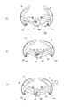
実施形態の形態変化玩具100では、モータ37によりクランク34が時計方向に回動して展開状態の頭部10を折り畳むようにすると、偏心ピン34aが変曲点D1を経ることなく直ちに変曲点D2に向かうように構成されている(図9(A)から図9(B))。そして、偏心ピン34aがB領域内のB2を経て変曲点D2を超えたB領域内のB1に導かれる(図9(B)から図9(C))。クランク34の偏心ピン34aが変曲点D2を超えたB領域内にあるときに頭部10は折畳み状態に保持される。この場合、遊戯者が無理矢理に頭部10を展開させようとしても、クランク34に付設の当接部(図示せず)が固定のストッパ40に突き当たり、それ以上のクランク34の回動が阻止される。勿論この位置でも、頭部10は折畳み状態に保持されている。
Next, the holding position of the
In FIG. 8, when the
In the form-changing
In the form-changing
(4)胴部30
図10は、ハッチ41及びハッチ動作装置43を示した斜視図である。
胴部30には、左右にハッチ41が1つずつ設けられている。左右のハッチ41,41は左右対称に形成されているので、同一構成要素については同一符号を用いて説明する。
各ハッチ41は、平面視円弧状で、仮想動物の左脇腹及び左背中、又は、右脇腹及び右背中を構成している。
左右のハッチ41,41は観音開き構造で、各ハッチ41は、軸41aを介して胴部本体に支持され、胴部本体に対して開放状態と閉塞状態とを取る。
(4)
FIG. 10 is a perspective view showing the
The
Each
The left and
(5)ハッチ動作装置43
また、胴部30にはハッチ動作装置43が設けられている。ハッチ動作装置43は左右のてこクランク機構を備えている。左右のクランク機構は略左右対称なので、同一構成要素については同一符号を用いて説明する。
てこクランク機構は、偏心ピン48aを有するクランク(回動部品)44と、クランク44の回動によって動作するリンク(回動部品)45とを含んで構成されている。
クランク44は、上記頭部動作装置33と同様の構成の駆動装置に連結されている。
左右のクランク44,44は1つの回動板47の上下に構成されている。左側のリンク45の一端は当該回動板の上側の偏心ピン48aに連結され、他端は左のハッチ41の中程に軸49を介して連結されている。また、右側のリンク45の一端は上記回動板の下側の偏心ピン48aに連結され、他端は右のハッチ41の中程に軸49を介して連結されている。
このハッチ動作装置43は、ハッチ41を閉塞状態に保持するとともに、閉塞状態に保持されたハッチ41の保持を解除する保持機構とを備えている。このハッチ動作機構43の保持機構は、後述の尾部80の保持機構としても機能している。
保持機構は、モータ46によりクランク44を一方向に回動させることで開放状態にあるハッチ41を閉じ、そのハッチ41を閉塞状態に保持するとともに。モータ46によりクランク44を他方向に回動させることでハッチ41の閉塞状態の保持を解除する。
(5)
A
The lever crank mechanism includes a crank (rotating part) 44 having an
The
The left and right cranks 44, 44 are configured above and below one rotating plate 47. One end of the
The
The holding mechanism closes the
次に、ハッチ41の保持位置について説明する。
クランク44は、反時計方向の回動によってハッチ41の動作方向が開く方向から閉じる方向に変わる第1変曲点と、閉じる方向から開く方向に変わる第2変曲点を有している。
そして、偏心ピン48aが第1変曲点近傍にあるときハッチ41は開放状態となり、偏心ピン48aが第2変曲点近傍にあるときハッチ41は閉塞状態となる。
実施形態の形態変化玩具100では、モータ46によりクランク44を反時計方向に回動させ開放状態のハッチ41を閉じると、偏心ピン48aが第1変曲点を経ることなく直ちに第2変曲点に向かうように構成されている(図11(A)から図11(B))。そして、クランク44が第2変曲点を超え、且つ、ハッチ41が閉塞状態を維持している所でハッチ41が保持される(図11(B)から図11(C))。この場合、遊戯者が無理矢理にハッチ41をこじ開けて展開させようとしても、クランク44の軸(ストッパ)44aにリンク45が突き当たり、それ以上のクランク34の回動が阻止される。勿論この位置でも、ハッチ41が閉塞状態に保持されている。なお、リンク45の軸(ストッパ)44aへの当接部は、偏心ピン48aが変曲点を超えられるように湾曲して形成されている。
Next, the holding position of the
The
Then, when the
In the form-changing
(6)尾部80
尾部80は胴部30の後部下端に軸81を介して支持されている。尾部80は胴部30に寄り添う折畳み状態(図2)と胴部30から離間する展開状態(図4)とを取る。また、軸81には捩りコイルばね82が巻回され、捩りコイルばね82の一端は尾部80に掛けられ、他端は胴部本体に掛けられている(図2及び図4)。そして、尾部80は展開方向に付勢されている。この尾部80は、出荷の際にハッチ41を予め閉じておくときに、ハッチ41の内側に形成される収容凹部内に折り畳まれる。これによって、尾部80はハッチ41によって折畳み状態に保持される。
(6)
The
(7)足部60
図12は、右側の足部60及び足部動作装置64を示した斜視図である。
胴部30の前側左右には上下方向に延在する収容凹部30aが1つずつ設けられている(図5)。各収容凹部30aの下端部底壁には軸支部61が設けられ、軸支部61には軸62を介して足板63が取り付けられている。足板63は胴部30に寄り添う折畳み状態と胴部30から離間する展開状態とを取る。
(7)
FIG. 12 is a perspective view showing the
One
(8)足部動作装置64
足部動作装置64は左右にてこクランク機構を備えている。左右のてこクランク機構は略左右対称となっているので、同一構成要素については同一符号を用いて説明する。
各てこクランク機構は、偏心ピン65aが付設されたクランク(回動部品)65と、偏心ピン65aに係合しクランク65の回動によって動作するリンク(揺動部品)66とを含んで構成されている。
(8)
The
Each lever crank mechanism includes a crank (rotating part) 65 to which an
右側のクランク65は、駆動装置に連結されている。すなわち、クランク65は、正逆転可能なモータ67によって減速歯車列68を介して回動されるように構成されている。クランク65は、減速歯車列68の出力歯車68aと一体的に設けられている。右側のクランク65は傘歯車69a,69bを介して左側のクランク65に連結されている。クランク65の軸にはコイルばね65bが巻回され、これによってクランク65と傘歯車69aが連結され、一体的に動作する。この場合のコイルばね65bは、足板63を展開させる際に遊戯者が足板63を押さえつけた際の保護クラッチとして機能する。
The crank 65 on the right side is connected to the drive device. That is, the
図13に示すように、リンク66の一端はクランク65に連結され、他端は足板63の軸62から離れた部分にピン66aを介して連結されている。
ただし、左側の足部60のピン66aは足板63の長孔63aに挿入されている。また、リンク66の先端にはスライド部材71が設置され、スライド部材71は足板63の上面に沿って動作可能に構成されている。このスライド部材71はコイルばね(図示せず)によって後端部がリンク66に当接する方向に付勢されている。
As shown in FIG. 13, one end of the
However, the
右側の足板63はモータ67により動作され地面を蹴ることができるように構成されている。一方、左側の足板63を動作させるリンク66には内縁に大きな突起66cが形成され、動作途中で突起66cが固定部に当たるように構成されている。これによって、右側の足板63が地面を蹴るとき左側の足板63が固定部に当たって少し上動するようになっている。一方、形態変化玩具100の下面は中央部が下方に膨らむように孤状に湾曲している。これによって、右側の足板63が地面を蹴ったときに、形態変化玩具100が左右に揺動し、その際に、左側の足板63が反対方向に少しばかり上動するので、恰も、足踏みをして踊っているかのようなイメージが醸し出される。
The
次に、足板63の保持位置について説明する。
クランク65は、一方向の回動によって足板63の動作方向が展開される方向から折り畳む方向に変わる第1変曲点、足板63の動作方向が折り畳む方向から展開される方向に変わる第2変曲点を持つ。
そして、偏心ピン65aが第1変曲点近傍にあるとき足板63は展開状態となり、偏心ピン65aが第2変曲点近傍にあるとき足板63は折畳み状態となる。
実施形態の形態変化玩具100では、モータ67によりクランク65が一方向に回動し、展開状態の足板63が折り畳まれると、偏心ピン65aが第1変曲点を経ることなく直ちに第2変曲点に向かうように構成されている。そして、クランク65が第2変曲点を超え、且つ、足板63が折畳み状態を維持している所で足板63は保持される。この場合、遊戯者が無理矢理に足板63を展開させようとしても、クランク65の軸にリンク66が突き当たり、それ以上のクランク65の回動が阻止される。勿論この位置でも、足板63が折畳み状態に保持されている。なお、リンク65の軸(ストッパ)への当接部66dは、偏心ピン65aが変曲点を超えられるように湾曲して形成されている。
Next, the holding position of the
The
When the
In the form-changing
3.着ぐるみ2
着ぐるみ2は袋状に構成され、形態変化玩具100の頭部10側から被せることができる。この着ぐるみ2はファー又はボア等の起毛材によって形成されており、形態変化玩具100の口部や顔部11に相当する部分は起毛のない素材によって形成されている。口部や顔部11に相当する部分は頭部10を折り畳む際に頭部10と胴部30の間に入り込む。
そして、頭部10を折り畳んだ際に、頭部10の着ぐるみ2の起毛材と胴部30の起毛材とが突き合わされて着ぐるみ2のうちの口部や、動作部品である顔部11及び耳部14に相当する部分は見えなくなる。
3. 3.
The
Then, when the
着ぐるみ2には、図1に示すように、形態変化玩具100の足板63に対応して足袋2aが付設され、足板63に足袋2aを履かせることができる。また、尾部80に対応して尾袋2bが付設され、尾部80に尾袋2bを履かせることができる。この場合、尾部80は長尺なので上手く入らないときには、尾袋2bに適宜にスリットを設けておき、尾部80を包み込んでテープやボタン等を使用して尾部80を被覆するようにしてもよい。この着ぐるみ2によって、形態変化玩具100の底壁を除いた部分が包まれる。また、耳部14に対応して耳袋2eが付設され、耳部14に耳袋2eを被せることができる。
なお、着ぐるみ2は、形態変化玩具100の各種動作を許容するように大きめに形成されている。また、着ぐるみ2には、目玉2c及び手部2dが設けられている。目玉2c及び手部2dは玩具本体1側に設けられていてもよい。
As shown in FIG. 1, the
The
この着ぐるみ2は、収容凹部30a及び足板63を着ぐるみ2の起毛材で覆っている。この収容凹部30aを覆う起毛材は、収容凹部30aに足板63を収容する前には膨らんで収容凹部30aの底面から浮き上がって収容凹部30aの口を塞いでおり、収容凹部30aに足板63を収容するときには、口を塞いでいる起毛材が足板63に押されて収容凹部30a内に押し込まれる。
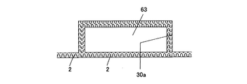
また、収容凹部30aの周辺も起毛材となっている。そして、着ぐるみ2を着せた状態では、図14に示すように、収容凹部30aに足板63を収容したときに収容凹部30aの周辺と、足板63の外面とが面一となるように形成されている。また、着ぐるみ2を着せた状態で、外方から見た収容凹部30aの縁と足板63との隙間は、足板63の起毛材と収容凹部30aを覆う起毛材が突き合わさることで覆い隠されている。
このようにすることで、視覚上で、動作部品である足板63の存在を隠すことができ、より興趣性の高い形態変化玩具100が実現できる。
In this
Further, the periphery of the
By doing so, it is possible to visually hide the existence of the
また、着ぐるみ2は玩具本体1に着せたとき、着ぐるみ2が袋状となっているため左右のハッチ41,41が覆い隠される。したがって、左右のハッチ41,41の隙間は着ぐるみ2によって外部から視認できず、左右のハッチ41,41が開閉動作する際に着ぐるみ2の下で動くだけである。この左右のハッチ41,41も着ぐるみ2の起毛材で覆われ、尾部80を押し込む際には、起毛材が尾部80に押されて押し込まれる。そして、左右のハッチ41,41が閉じたときには、図15に示すように、左右のハッチ41,41の縁の起毛部分が突き合わさることで左右のハッチ41,41の隙間が覆い隠され、動作部品である内部の尾部80は外部からは視認できない。
Further, when the
《制御構成》
図16は形態変化玩具100の制御構成を示している。
形態変化玩具100は制御構成として、中央処理装置90、主記憶装置91、補助記憶装置92を備えている。
<< Control configuration >>
FIG. 16 shows a control configuration of the
The
中央処理装置90は制御装置90aと演算装置90bとを備えている。
補助記憶装置92には所定のプログラムや、各種データが格納され、中央処理装置90は、そのプログラムや各種データを適宜に読み出して制御及び演算を実行する。主記憶装置91はワークエリアとなる部分であり、必要に応じてプログラムや各種データを一時的に記憶する。
The central processing unit 90 includes a control device 90a and an arithmetic unit 90b.
A predetermined program and various data are stored in the auxiliary storage device 92, and the central processing unit 90 appropriately reads the program and various data and executes control and calculation. The main storage device 91 is a part that serves as a work area, and temporarily stores programs and various data as needed.
また、形態変化玩具100は、入力装置として、電源スイッチ93と、マイクロフォン94と、タッチセンサ95と、ポテンショメータ96a〜96cを備えている。
例えば、マイクロフォン94及びタッチセンサ95は頭部10に設けられている。マイクロフォン94は外部の音をピックアップする。また、タッチセンサ95は遊戯者が形態変化玩具100に触れたことを検出する。
ポテンショメータ96aはモータ37とでサーボ機構を構成し、ポテンショメータ96bはモータ46とでサーボ機構を構成し、ポテンショメータ96cはモータ67とでサーボ機構を構成している。これらのサーボ機構によって対応の部品の動作量が制御される。
Further, the
For example, the microphone 94 and the touch sensor 95 are provided on the
The potentiometer 96a constitutes a servo mechanism with a
また、形態変化玩具100は、出力装置として、音出力部97と、モータ37,46,67と、光出力部98とを備えている。モータ37、46、67はサーボモータである。音出力部97は、効果音や言葉等を出力する。モータ37は頭部10を、モータ46はハッチ41を、モータ67は足板63を動作させる。
Further, the form-changing
《遊び方及び作用》
最初には、頭部10、尾部80及び足板63が折り畳まれた状態で、ハッチ41が閉じた状態にある。
《How to play and how it works》
Initially, the
この状態が第1形態100Aである。第1形態100Aでは頭部10の後ろにある光出力部98である左右の2つの発光ダイオード(図1)が着ぐるみ下で点灯乃至点滅する。左右の発光ダイオード98a,98aは第1形態100Aの目の位置にあるので、第1形態100Aは無機物ではなく生き物のようなイメージを惹起させることになる。
This state is the
この状態で、形態変化玩具100を撫でたり、音楽を聴かせたりすると、第1形態100Aの足板63が動作することによって上下左右に振動する。そして、ハッチ41が開かれ中から尾部80が突出して第2形態100Bとなる。
In this state, when the form-changing
次に、形態変化玩具100を撫でたり、音楽を聴かせたりすると、第2形態100Bの足板63が動作することによって上下左右に振動する。また、ハッチ41が開閉動作を行う。そして、足板63が展開され、その反動で形態変化玩具100が起立するとともに、頭部10が展開され、顔部11や耳部も展開され第3形態100Cとなる。
Next, when the form-changing
また、第3形態100Cで撫でたり、音楽を聴かせたりすると、足板63が動くことで身体を左右に揺する。
In addition, when stroking or listening to music in the
《本実施形態の変形例》
以上、本発明の実施形態について説明したが、本発明は、かかる実施形態に限定されるものではなく、その要旨を逸脱しない範囲で、種々変形が可能であることは言うまでもない。
<< Modified example of this embodiment >>
Although the embodiments of the present invention have been described above, it goes without saying that the present invention is not limited to such embodiments and can be variously modified without departing from the gist thereof.
例えば、上記実施形態では、サーボ機構をモータとポテンショメータとを含んで構成したが、ポテンショメータに代わりにエンコーダを設けてもよい。 For example, in the above embodiment, the servo mechanism is configured to include a motor and a potentiometer, but an encoder may be provided instead of the potentiometer.
また、頭部10、ハッチ41及び足部63を出荷時に第1状態とするようにしたが、リセットボタンを設けて、遊戯者がリセットボタンを押したときに頭部10、ハッチ41及び足部63を第1状態に戻せるように構成してもよい。
Further, although the
さらに、遊戯者が手動によって頭部10や足板63をある程度折り畳んだり、ハッチ41をある程度閉じたりしたことを検出スイッチ等で検出し、検出したときにモータを作動させ、モータにより頭部10や足板63やハッチ41を保持位置まで動作させるようにしてもよい。この場合、保持機構は、第1状態に向けてばねによって付勢される動作部品を第2状態に保持するとともに、動作部品の第2状態への保持を解除するまでとし、解除後は、ばねによって第1状態まで動作させるようにしてもよい。
Further, it is detected by a detection switch or the like that the player manually folds the
また、上記実施形態のような保持機構を設けずに、単に、第1状態と第2状態との間で動作部品を動作させる形態変化玩具にも適用できる。 Further, it can be applied to a form-changing toy that simply operates an operating component between a first state and a second state without providing a holding mechanism as in the above embodiment.
また、収容凹部が動作部品よりも大きく、収容凹部の起毛材と動作部品の起毛材とを上手く付き合わせできない場合には、必要に応じて、着ぐるみの裏側に収容凹部と動作部品との間に介装可能で外面に起毛材が形成されたパッドを設けておき、このパッドの起毛材と動作部品の起毛材とを突き合わせることによって収容凹部と動作部品との隙間を目立たなくしてもよい。 In addition, if the accommodating recess is larger than the operating component and the raised material of the accommodating recess and the raised material of the operating component cannot be properly aligned, if necessary, between the accommodating recess and the operating component on the back side of the costume. A pad that can be intervened and has a raised material formed on the outer surface may be provided, and the gap between the accommodating recess and the moving component may be made inconspicuous by abutting the raised material of the pad with the raised material of the moving component.
1 玩具本体
2 着ぐるみ
30a 収容凹部
33 頭部動作装置
34 クランク
37,46,67 モータ
40 ストッパ
41 ハッチ
43 ハッチ動作装置
44 クランク
45 リンク
64 足部動作装置
65 クランク
100 形態変化玩具
100A 第1形態
100B 第2形態
100C 第3形態
1
第1の手段は、
玩具本体と、前記玩具本体に被せられる着ぐるみとを備え、
前記着ぐるみの少なくとも一部は起毛材によって形成され、
前記玩具本体には、収容凹部と、外方に突出した第1状態と前記収容凹部に収容された第2状態とを取る動作部品と、が設けられ、
前記第2状態で、前記収容凹部の開口部において互いに隣設された部分を被覆する前記起毛材の突き合わせによって前記動作部品が外部から隠される形態変化玩具であって、
前記動作部品は、動作装置によって所定の軸を中心に回動可能に構成され、回動によって、前記第1状態と前記第2状態を取るように構成され、
前記動作部品及び前記収容凹部は前記動作部品の動作を許容するような緩み部分を持つ前記着ぐるみで被覆され、前記収容凹部は前記着ぐるみによって前記第1状態及び前記第2状態で外部に露出しないように構成され、前記第1状態では前記緩み部分は収容凹部の底面から浮き上がっており、前記動作部品を前記第1状態から前記第2状態に動作するときに前記着ぐるみの前記緩み部分を前記収容凹部に張った状態で押し込む押し込み部品を有し、さらに、前記互いに隣設された部分の一方である前記動作部品の自由端の前記起毛材と前記互いに隣設された部分の他方である前記自由端に対向する部分の前記起毛材との少なくとも一方は前記緩み部分に形成され、前記第2状態では、前記動作部品の自由端の前記起毛材と前記自由端に対向する部分の前記起毛材とが突き合わされて前記動作部品の外面と前記自由端に対向する部分の外面が面一となり、前記動作部品が外部から隠されることを特徴とする。
ここで、「隠される」とは周囲と同化して隠される場合と、他の部材によって被覆されて隠される場合とを含む。この場合の動作部品の動作は、動作装置を通じて行ってもよいし、手動で行ってもよい。
The first means is
It is equipped with a toy body and a costume that covers the toy body .
Least a part of the costume is formed by raising member,
The toy body is provided with a storage recess and an operating component that takes a first state protruding outward and a second state housed in the storage recess.
A form-changing toy in which the moving parts are hidden from the outside by abutting of the brushed materials covering the portions adjacent to each other in the opening of the accommodating recess in the second state.
The operating component is configured to be rotatable about a predetermined axis by an operating device, and is configured to take the first state and the second state by rotation.
The operating component and the accommodating recess are covered with the costume having a loose portion that allows the operating component to operate, and the accommodating recess is not exposed to the outside by the costume in the first state and the second state. In the first state, the loosened portion is raised from the bottom surface of the accommodating recess, and when the operating component is operated from the first state to the second state, the loosened portion of the costume is moved to the accommodating recess. It has a pushing part that is pushed in in a stretched state, and further, the brushed material at the free end of the moving part, which is one of the portions adjacent to each other, and the free end, which is the other of the portions adjacent to each other. At least one of the raised material of the portion facing the free end is formed in the loosened portion, and in the second state, the raised material of the free end of the moving component and the raised material of the portion facing the free end are formed. It is characterized in that the outer surface of the moving component and the outer surface of the portion facing the free end are flush with each other and the moving component is hidden from the outside .
Here, "hidden" includes a case where it is assimilated with the surroundings and hidden, and a case where it is covered with another member and hidden. The operation of the operating component in this case may be performed through the operating device or may be performed manually.
第2の手段は、第1の手段であって、
前記動作部品と前記収容凹部は別個の着ぐるみ部分で覆われ、前記収容凹部を覆う着ぐるみ部分に前記緩み部分が形成され、前記互いに隣設された部分の一方は前記動作部品であり、他方は前記収容凹部の周辺部であり、前記動作部品は前記押し込み部品としても機能し、前記動作部品の外面及び前記収容凹部の周辺部は前記起毛材で被覆され、前記動作部品が前記第1状態から前記第2状態に動作する際に前記動作部品によって前記緩み部分が前記収容凹部に押し込まれて、前記動作部品の外面の前記起毛材と前記収容凹部の周辺部の外面の前記起毛材とが突き合わされて面一となり、前記動作部品が外部から隠されることを特徴とする。
The second means is the first means,
The operating component and the accommodating recess are covered with separate costume portions, the loose portion is formed in the costume portion covering the accommodating recess, one of the portions adjacent to each other is the operating component, and the other is the said. It is a peripheral portion of the accommodating recess, and the operating component also functions as the pushing component, the outer surface of the operating component and the peripheral portion of the accommodating recess are covered with the raised material, and the operating component is described from the first state. When operating in the second state, the loosened portion is pushed into the accommodating recess by the operating component, and the raised material on the outer surface of the operating component and the raised material on the outer surface of the peripheral portion of the accommodating recess are abutted against each other. The moving parts are flush with each other and are hidden from the outside .
第3の手段は、第1の手段であって、
前記動作部品は観音開き構造の一対の開閉部材であり、前記一対の開閉部材の各々は前記互いに隣設された部分を構成し、前記一対の開閉部材と前記収容凹部は前記一対の開閉部材の周りを被覆する着ぐるみ部分で覆われ、前記着ぐるみ部分に前記緩み部分が形成され、
前記一対の開閉部材が閉じられて前記第2の状態にあるときに前記一対の開閉部材の内側の前記収容凹部に収容され且つ前記一対の開閉部材が開かれて前記第1状態にあるときに前記収容凹部内から突出する他の動作部品である前記押し込み部品が設けられ、
前記一対の開閉部材が前記第1状態から前記第2状態に動作する際に前記押し込み部品によって前記一対の開閉部材の間の前記緩み部分が前記収容凹部に押し込まれて、前記一対の開閉部材の外面の前記起毛材同士が突き合わされて面一となり、前記一対の開閉部材及び前記押し込み部品が隠されることを特徴とする。
観音開き構造の一対の開閉部材の間に動作部品がある場合には、動作部品の起毛材と開閉部材の起毛材を突き合わせるようにしてもよい。なお、片開き構造の開閉部材の場合にも適用できることは勿論である。要は、動作部品が隠れることである。
また、この場合の一対の開閉部材の開閉は、動作装置を通じて行ってもよいし、手動で行ってもよい。
The third means is the first means,
The operating component is a pair of opening / closing members having a double door structure, each of the pair of opening / closing members constitutes a portion adjacent to each other, and the pair of opening / closing members and the accommodating recess are around the pair of opening / closing members. It is covered with a costume portion that covers the body, and the loose portion is formed on the costume portion.
When the pair of opening / closing members are closed and in the second state, they are housed in the storage recess inside the pair of opening / closing members, and when the pair of opening / closing members are opened and in the first state. The push-in part, which is another operating part protruding from the housing recess, is provided.
When the pair of opening / closing members operate from the first state to the second state, the loosened portion between the pair of opening / closing members is pushed into the accommodating recess by the pushing component, and the pair of opening / closing members The brushed materials on the outer surface are butted against each other to be flush with each other, and the pair of opening / closing members and the pushing component are hidden .
When there is an operating component between a pair of opening / closing members having a double door structure, the raised material of the operating component and the raised material of the opening / closing member may be butted against each other. Of course, it can also be applied to an opening / closing member having a single-sided opening structure. The point is that the moving parts are hidden.
Further, the opening / closing of the pair of opening / closing members in this case may be performed through the operating device or may be performed manually.
Claims (3)
前記着ぐるみの少なくとの一部は起毛材によって形成され、
前記玩具本体には、収容凹部と、外方に突出した第1状態と前記収容凹部に収容された第2状態とを取る動作部品と、が設けられ、
前記第2状態で、前記収容凹部の開口部において互いに隣設された部分を被覆する前記起毛材の突き合せによって前記動作部品が外部から隠されることを特徴とする形態変化玩具。 A form-changing toy having a toy body and a costume that covers the toy body.
A part of the costume is made of brushed material,
The toy body is provided with a storage recess and an operating component that takes a first state protruding outward and a second state housed in the storage recess.
A form-changing toy characterized in that, in the second state, the moving parts are hidden from the outside by abutting of the brushed materials that cover the portions adjacent to each other in the opening of the accommodating recess.
前記動作部品の外面の前記起毛材と前記収容凹部の周辺部の前記起毛材との突き合せによって前記動作部品が外部から隠されることを特徴とする請求項1に記載の形態変化玩具。 The outer surface of the moving component and the peripheral portion of the accommodating recess are covered with the raised material, and in the second state, the raised material on the outer surface of the operating component and the raised material on the peripheral portion of the accommodating recess are flush with each other. ,
The form-changing toy according to claim 1, wherein the moving part is hidden from the outside by abutting the raised material on the outer surface of the moving part with the raised material in the peripheral portion of the accommodating recess.
前記動作部品は前記一対の開閉部材の間の前記起毛材を押し込むようにして前記一対の開閉部材の内側の前記収容凹部に収容され、前記一対の開閉部材が閉じた際に、前記一対の開閉部材の縁部分の前記起毛材を互いに突き合せることによって前記動作部品が外部から隠されることを特徴とする請求項1に記載の形態変化玩具。 A pair of opening / closing members having a double door structure are provided, and the pair of opening / closing members are covered with the raised material.
The moving component is housed in the accommodating recess inside the pair of opening / closing members by pushing the raised material between the pair of opening / closing members, and when the pair of opening / closing members are closed, the pair of opening / closing members is opened / closed. The form-changing toy according to claim 1, wherein the moving parts are hidden from the outside by abutting the raised materials on the edge portions of the members against each other.
Priority Applications (2)
| Application Number | Priority Date | Filing Date | Title |
|---|---|---|---|
| JP2019080074A JP6675719B1 (en) | 2019-04-19 | 2019-04-19 | Shape change toys |
| US16/529,267 US20200330891A1 (en) | 2019-04-19 | 2019-08-01 | Form changing toy |
Applications Claiming Priority (1)
| Application Number | Priority Date | Filing Date | Title |
|---|---|---|---|
| JP2019080074A JP6675719B1 (en) | 2019-04-19 | 2019-04-19 | Shape change toys |
Publications (2)
| Publication Number | Publication Date |
|---|---|
| JP6675719B1 JP6675719B1 (en) | 2020-04-01 |
| JP2020174952A true JP2020174952A (en) | 2020-10-29 |
Family
ID=70001030
Family Applications (1)
| Application Number | Title | Priority Date | Filing Date |
|---|---|---|---|
| JP2019080074A Active JP6675719B1 (en) | 2019-04-19 | 2019-04-19 | Shape change toys |
Country Status (2)
| Country | Link |
|---|---|
| US (1) | US20200330891A1 (en) |
| JP (1) | JP6675719B1 (en) |
Families Citing this family (1)
| Publication number | Priority date | Publication date | Assignee | Title |
|---|---|---|---|---|
| US11957991B2 (en) * | 2020-03-06 | 2024-04-16 | Moose Creative Management Pty Limited | Balloon toy |
Citations (6)
| Publication number | Priority date | Publication date | Assignee | Title |
|---|---|---|---|---|
| JPS62177777U (en) * | 1986-05-01 | 1987-11-11 | ||
| JPS6456295U (en) * | 1987-10-06 | 1989-04-07 | ||
| JP2001009168A (en) * | 1999-06-29 | 2001-01-16 | Yasuko Izuno | Metamorphosable stuffed toy |
| JP3082267U (en) * | 2001-05-30 | 2001-12-07 | 忠義 山南 | A stuffed toy that can change shape |
| JP2014144211A (en) * | 2013-01-30 | 2014-08-14 | Vstone Kk | Shape changing robot toy |
| US20180311593A1 (en) * | 2015-11-20 | 2018-11-01 | Jong-Ill CHOI | Detachable toy |
-
2019
- 2019-04-19 JP JP2019080074A patent/JP6675719B1/en active Active
- 2019-08-01 US US16/529,267 patent/US20200330891A1/en not_active Abandoned
Patent Citations (6)
| Publication number | Priority date | Publication date | Assignee | Title |
|---|---|---|---|---|
| JPS62177777U (en) * | 1986-05-01 | 1987-11-11 | ||
| JPS6456295U (en) * | 1987-10-06 | 1989-04-07 | ||
| JP2001009168A (en) * | 1999-06-29 | 2001-01-16 | Yasuko Izuno | Metamorphosable stuffed toy |
| JP3082267U (en) * | 2001-05-30 | 2001-12-07 | 忠義 山南 | A stuffed toy that can change shape |
| JP2014144211A (en) * | 2013-01-30 | 2014-08-14 | Vstone Kk | Shape changing robot toy |
| US20180311593A1 (en) * | 2015-11-20 | 2018-11-01 | Jong-Ill CHOI | Detachable toy |
Also Published As
| Publication number | Publication date |
|---|---|
| JP6675719B1 (en) | 2020-04-01 |
| US20200330891A1 (en) | 2020-10-22 |
Similar Documents
| Publication | Publication Date | Title |
|---|---|---|
| JP3192453U (en) | Combined deformation toy | |
| US4402158A (en) | Toy employing governor to control rate of movement of movable member | |
| JP2006289508A (en) | Robot device and its facial expression control method | |
| WO2005122327A3 (en) | Expression mechanism for a toy, such as a doll, having fixed or movable eyes | |
| JP6059786B1 (en) | Doll body shoulder joint structure | |
| ITTO20070297A1 (en) | TOY VEHICLE WITH ANIMATED FUNCTION IMPROVED IN PARTICULAR TRANSFORMER | |
| JP6675719B1 (en) | Shape change toys | |
| US6110001A (en) | Animated toy doll | |
| JP2519125Y2 (en) | String-type mainspring toy | |
| JP7138608B2 (en) | Doll body shoulder joint structure | |
| JP6570024B1 (en) | Swing toys | |
| JP6664756B1 (en) | Shape change toys | |
| US10449463B2 (en) | Interactive robotic toy | |
| JP2006289507A (en) | Robot device and its control method | |
| TWI540948B (en) | Portable electronic device and cover mechanism thereof | |
| US10421027B2 (en) | Interactive robotic toy | |
| US4695265A (en) | Puppet apparatus | |
| CA3003530A1 (en) | Interactive robotic toy | |
| JP6562894B2 (en) | Doll body shoulder joint structure | |
| JP2007083334A (en) | Pet robot | |
| JP6857164B2 (en) | costume | |
| JP3176633U (en) | Grand piano keyboard cover | |
| KR102414466B1 (en) | Teaching aid for reproducing of predatory activity in vertebrate | |
| US1041095A (en) | Surprise and alarm device. | |
| JP7454732B1 (en) | transforming toys |
Legal Events
| Date | Code | Title | Description |
|---|---|---|---|
| A621 | Written request for application examination |
Free format text: JAPANESE INTERMEDIATE CODE: A621 Effective date: 20190424 |
|
| A871 | Explanation of circumstances concerning accelerated examination |
Free format text: JAPANESE INTERMEDIATE CODE: A871 Effective date: 20190516 |
|
| A975 | Report on accelerated examination |
Free format text: JAPANESE INTERMEDIATE CODE: A971005 Effective date: 20190612 |
|
| A977 | Report on retrieval |
Free format text: JAPANESE INTERMEDIATE CODE: A971007 Effective date: 20190927 |
|
| A131 | Notification of reasons for refusal |
Free format text: JAPANESE INTERMEDIATE CODE: A131 Effective date: 20191023 |
|
| A521 | Request for written amendment filed |
Free format text: JAPANESE INTERMEDIATE CODE: A523 Effective date: 20191223 |
|
| TRDD | Decision of grant or rejection written | ||
| A01 | Written decision to grant a patent or to grant a registration (utility model) |
Free format text: JAPANESE INTERMEDIATE CODE: A01 Effective date: 20200218 |
|
| A61 | First payment of annual fees (during grant procedure) |
Free format text: JAPANESE INTERMEDIATE CODE: A61 Effective date: 20200302 |
|
| R150 | Certificate of patent or registration of utility model |
Ref document number: 6675719 Country of ref document: JP Free format text: JAPANESE INTERMEDIATE CODE: R150 |
|
| R250 | Receipt of annual fees |
Free format text: JAPANESE INTERMEDIATE CODE: R250 |
|
| R250 | Receipt of annual fees |
Free format text: JAPANESE INTERMEDIATE CODE: R250 |