JP2020173972A - Hydrogen-using power supply system and hydrogen using power supply method - Google Patents
Hydrogen-using power supply system and hydrogen using power supply method Download PDFInfo
- Publication number
- JP2020173972A JP2020173972A JP2019075095A JP2019075095A JP2020173972A JP 2020173972 A JP2020173972 A JP 2020173972A JP 2019075095 A JP2019075095 A JP 2019075095A JP 2019075095 A JP2019075095 A JP 2019075095A JP 2020173972 A JP2020173972 A JP 2020173972A
- Authority
- JP
- Japan
- Prior art keywords
- hydrogen
- fuel cell
- power supply
- temperature
- control device
- Prior art date
- Legal status (The legal status is an assumption and is not a legal conclusion. Google has not performed a legal analysis and makes no representation as to the accuracy of the status listed.)
- Granted
Links
Images


Classifications
-
- Y—GENERAL TAGGING OF NEW TECHNOLOGICAL DEVELOPMENTS; GENERAL TAGGING OF CROSS-SECTIONAL TECHNOLOGIES SPANNING OVER SEVERAL SECTIONS OF THE IPC; TECHNICAL SUBJECTS COVERED BY FORMER USPC CROSS-REFERENCE ART COLLECTIONS [XRACs] AND DIGESTS
- Y02—TECHNOLOGIES OR APPLICATIONS FOR MITIGATION OR ADAPTATION AGAINST CLIMATE CHANGE
- Y02E—REDUCTION OF GREENHOUSE GAS [GHG] EMISSIONS, RELATED TO ENERGY GENERATION, TRANSMISSION OR DISTRIBUTION
- Y02E60/00—Enabling technologies; Technologies with a potential or indirect contribution to GHG emissions mitigation
- Y02E60/30—Hydrogen technology
- Y02E60/36—Hydrogen production from non-carbon containing sources, e.g. by water electrolysis
-
- Y—GENERAL TAGGING OF NEW TECHNOLOGICAL DEVELOPMENTS; GENERAL TAGGING OF CROSS-SECTIONAL TECHNOLOGIES SPANNING OVER SEVERAL SECTIONS OF THE IPC; TECHNICAL SUBJECTS COVERED BY FORMER USPC CROSS-REFERENCE ART COLLECTIONS [XRACs] AND DIGESTS
- Y02—TECHNOLOGIES OR APPLICATIONS FOR MITIGATION OR ADAPTATION AGAINST CLIMATE CHANGE
- Y02E—REDUCTION OF GREENHOUSE GAS [GHG] EMISSIONS, RELATED TO ENERGY GENERATION, TRANSMISSION OR DISTRIBUTION
- Y02E60/00—Enabling technologies; Technologies with a potential or indirect contribution to GHG emissions mitigation
- Y02E60/30—Hydrogen technology
- Y02E60/50—Fuel cells
-
- Y—GENERAL TAGGING OF NEW TECHNOLOGICAL DEVELOPMENTS; GENERAL TAGGING OF CROSS-SECTIONAL TECHNOLOGIES SPANNING OVER SEVERAL SECTIONS OF THE IPC; TECHNICAL SUBJECTS COVERED BY FORMER USPC CROSS-REFERENCE ART COLLECTIONS [XRACs] AND DIGESTS
- Y02—TECHNOLOGIES OR APPLICATIONS FOR MITIGATION OR ADAPTATION AGAINST CLIMATE CHANGE
- Y02E—REDUCTION OF GREENHOUSE GAS [GHG] EMISSIONS, RELATED TO ENERGY GENERATION, TRANSMISSION OR DISTRIBUTION
- Y02E70/00—Other energy conversion or management systems reducing GHG emissions
- Y02E70/30—Systems combining energy storage with energy generation of non-fossil origin
Abstract
Description
本発明は、水素利用電力供給システム及び水素利用電力供給方法に関する。 The present invention relates to a hydrogen-utilized power supply system and a hydrogen-utilized power supply method.
2014年4月に閣議決定されたエネルギー基本計画において、水素を日常の生活や産業活動で利活用する「水素社会」の実現に向け取り組みを加速することが定められ、国や東京都では2020年東京五輪での水素の積極活用、その後の水素社会普及に向けた動きが活発化している。2012年7月の再生可能エネルギーの固定価格買取制度(FIT)の導入は、非住宅用の太陽光発電市場(公共・産業分野)を大きく変えることとなった。JPEA PV OUTLOOK 2030によると、国内総出荷に占める非住宅用の割合は、2012年度で(国内総出荷量3.8GWに対し)50%、2013年度で(同8.4GWに対し)73%、2014年度上半期で(上期国内総出荷量4.3GWに対し)77%と大幅に伸張している。 The Basic Energy Plan, which was approved by the Cabinet in April 2014, stipulates that efforts to accelerate efforts toward the realization of a "hydrogen society" that utilizes hydrogen in daily life and industrial activities will be accelerated. The active utilization of hydrogen at the Tokyo Olympics and the subsequent movement toward the spread of hydrogen society are becoming active. The introduction of the feed-in tariff (FIT) for renewable energy in July 2012 has significantly changed the non-residential photovoltaic power generation market (public / industrial sector). According to JPEA PV OUTLOOK 2030, the ratio of non-residential use to the total domestic shipment was 50% in 2012 (relative to the total domestic shipment of 3.8 GW) and 73% in 2013 (relative to 8.4 GW). In the first half of 2014 (compared to the total domestic shipment of 4.3 GW in the first half), it increased significantly to 77%.
太陽光発電の大量の設備認定量に伴い、それらが全て稼動した場合、電力需要の小さい軽負荷期に太陽光発電の供給電力量が需要電力量を上回る懸念が出てきたため、指定電気事業者において「無制限・無補償の出力抑制」を条件として系統接続を行うこととなった。今後、更なる太陽光発電の系統接続量の増加に伴い、電力需給調整を目的とした出力抑制実施は現実のものとなる。 With the large amount of certified equipment for photovoltaic power generation, if all of them are in operation, there is a concern that the amount of power supplied by photovoltaic power generation will exceed the amount of power demand during the light load period when power demand is low, so designated electric power companies In, it was decided to make a grid connection on the condition of "unlimited and uncompensated output suppression". In the future, with the further increase in the amount of photovoltaic power generation grid connections, the implementation of output curtailment for the purpose of adjusting the supply and demand of electricity will become a reality.
出力抑制が実施されると、その分の再生可能エネルギーは捨てられてしまうため、エネルギーの効率的な利用という観点から見ると、蓄電池等を用いて捨てる分のエネルギー(以下、余剰電力と呼ぶ)は貯蔵しておくことが望ましい。余剰電力の貯蔵手段として、近年注目されているのが水素である。蓄電池による貯蔵に比べると、電気から水素への変換、また水素から電気への変換に伴う効率低下が大きいというデメリットはあるが、大容量、長期的なエネルギー貯蔵に適している。なお、電力を使用して水素を製造・貯蔵・利用(発電)するシステムとしては、例えば特許文献1及び特許文献2に記載されている。
When output suppression is implemented, that amount of renewable energy is discarded, so from the perspective of efficient use of energy, the amount of energy that is discarded using storage batteries, etc. (hereinafter referred to as surplus power). Is desirable to store. Hydrogen has been attracting attention in recent years as a means of storing surplus electricity. Compared to storage using a storage battery, it has the disadvantage of a large decrease in efficiency due to the conversion of electricity to hydrogen and the conversion of hydrogen to electricity, but it is suitable for large-capacity, long-term energy storage. Note that, for example,
余剰水素をコンパクトかつ安全に貯蔵するために、水素吸蔵合金を利用することも挙げられている。しかしながら、一般的な水素吸蔵合金は着火すると燃えるため、消防法上の危険物に該当する。そこで、消防法上の危険物に該当しない水素吸蔵合金として、チタン・鉄系の水素吸蔵合金を用いることが考えられる。ところが、チタン・鉄系の水素吸蔵合金では、PCT(Pressure Composition Temperature)線図上で圧力がプラトーになる領域が少なく、また吸放出時の圧力ヒステリシスも大きい。このため、省エネルギーで水素の吸放出を行うためには、広い温度帯の管理と熱の有効利用が必要となる。 It is also mentioned that a hydrogen storage alloy is used to store excess hydrogen compactly and safely. However, since a general hydrogen storage alloy burns when ignited, it falls under the category of dangerous goods under the Fire Service Act. Therefore, it is conceivable to use a titanium / iron-based hydrogen storage alloy as a hydrogen storage alloy that does not fall under the dangerous goods under the Fire Service Act. However, in the titanium-iron hydrogen storage alloy, there are few regions where the pressure becomes a plateau on the PCT (Pressure Composition Temperature) diagram, and the pressure hysteresis at the time of absorption and release is also large. Therefore, in order to absorb and release hydrogen with energy saving, it is necessary to manage a wide temperature range and effectively use heat.
上述の課題を鑑み、本発明は、システムの各部を有効に温度管理できる水素利用電力供給システム及び水素利用電力供給方法を提供することを目的とする。 In view of the above problems, an object of the present invention is to provide a hydrogen-utilized power supply system and a hydrogen-utilized power supply method capable of effectively controlling the temperature of each part of the system.
本発明の一態様に係る水素利用電力供給システムは、負荷に対して供給する少なくとも一部の電力として水素を利用して発電された電力を供給する水素利用電力供給システムであって、再生可能エネルギーによって得られる電源または商用電源からの電力により電解槽に蓄積された水を電気分解して水素を製造する水素製造装置と、前記製造された水素を水素吸蔵合金が封入された合金タンクに貯蔵する水素貯蔵装置と、前記水素貯蔵装置に貯蔵された水素を用いて発電する燃料電池と、冷却装置と、前記電解槽、前記合金タンク、前記燃料電池のいずれかの温度または圧力が基準温度または基準圧力を越えたか否かを判定し、基準温度または基準圧力を越えた場合に、前記基準温度または基準圧力を越えた前記電解槽、前記合金タンク、前記燃料電池のいずれかを対象として前記冷却装置によって冷却させる制御装置とを有する。 The hydrogen-utilizing power supply system according to one aspect of the present invention is a hydrogen-utilizing power supply system that supplies power generated by using hydrogen as at least a part of power supplied to a load, and is a renewable energy. A hydrogen production device that electrolyzes water stored in an electrolytic tank with electric power obtained from a power source or a commercial power source to produce hydrogen, and the produced hydrogen is stored in an alloy tank filled with a hydrogen storage alloy. The temperature or pressure of the hydrogen storage device, the fuel cell that generates electricity using the hydrogen stored in the hydrogen storage device, the cooling device, the electrolytic tank, the alloy tank, or the fuel cell is the reference temperature or reference. It is determined whether or not the pressure has been exceeded, and when the reference temperature or the reference pressure is exceeded, the cooling device is targeted at any of the electrolytic tank, the alloy tank, and the fuel cell that exceeds the reference temperature or the reference pressure. It has a control device to be cooled by.
本発明の一態様に係る水素利用電力供給方法は、負荷に対して供給する少なくとも一部の電力として水素を利用して発電された電力を供給する水素利用電力供給方法であって、再生可能エネルギーによって得られる電源または商用電源からの電力により電解槽に蓄積された水を電気分解して水素を製造する工程と、前記製造された水素を水素吸蔵合金が封入された合金タンクに貯蔵する工程と、前記貯蔵された水素を用いて燃料電池で発電する工程と、前記電解槽、前記合金タンク、前記燃料電池のいずれかの温度または圧力が基準温度または基準圧力を越えたか否かを判定し、基準温度または基準圧力を越えた場合に、前記基準温度または基準圧力を越えた前記電解槽、前記合金タンク、前記燃料電池のいずれかを対象として冷却装置によって冷却させる工程とを有する。 The hydrogen-utilizing power supply method according to one aspect of the present invention is a hydrogen-utilizing power supply method that supplies power generated by using hydrogen as at least a part of power to be supplied to a load, and is a renewable energy. A step of electrolyzing the water stored in the electrolytic tank with the electric power obtained from the power source or a commercial power source to produce hydrogen, and a step of storing the produced hydrogen in an alloy tank filled with a hydrogen storage alloy. It is determined whether or not the temperature or pressure of any of the electrolytic tank, the alloy tank, and the fuel cell exceeds the reference temperature or the reference pressure in the step of generating electricity with the fuel cell using the stored hydrogen. When the reference temperature or the reference pressure is exceeded, any one of the electrolytic tank, the alloy tank, and the fuel cell that exceeds the reference temperature or the reference pressure is cooled by a cooling device.
本発明によれば、電解槽、水素吸蔵合金、燃料電池等、各部の温度を冷却装置によって放熱して冷却できる。これにより、システムの各部を有効に温度管理できる。 According to the present invention, the temperature of each part of the electrolytic cell, hydrogen storage alloy, fuel cell, etc. can be radiated and cooled by the cooling device. As a result, the temperature of each part of the system can be effectively controlled.
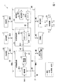
以下、本発明の実施の形態について図面を参照しながら説明する。図1は、本発明の実施形態に係る水素利用システム1の構成の概要を示すブロック図である。
Hereinafter, embodiments of the present invention will be described with reference to the drawings. FIG. 1 is a block diagram showing an outline of the configuration of the
図1に示すように、本発明の実施形態に係る水素利用システム1は、再生可能エネルギー電源11と、蓄電池12と、電力負荷13と、水素製造装置14と、水素貯蔵装置15と、燃料電池16と、加熱装置17と、冷却装置18と、熱負荷19と、制御装置20とから構成される。
As shown in FIG. 1, the
再生可能エネルギー電源11は、太陽光発電や風力発電等の再生可能エネルギーを用いて発電を行う。蓄電池12は、電力の充放電を行い、再生可能エネルギー電源11の不安定な発電量の変動成分を補う。電力負荷13は、照明機器、空調機器、各種電気・電子機器等、電力を消費して利用する建物内の負荷設備である。
The renewable
水素製造装置14は、再生可能エネルギー電源11や商用電源31から水素を製造する。水素製造装置14としては、例えば固体高分子(PEM)形水電解により水素を製造するものが用いられる。固体高分子形水電解は、高温で電解しやすく、電解効率が高く、起動停止が容易であるという特徴がある。水素製造装置14は、電解槽21と再生型除湿器22を備えている。電解槽21には純水が蓄積されている。電解槽21では、固体高分子電解質膜を水素イオンが移動して水が電気分解され、水素が生成される。本実施形態では、高圧ガス適用除外となる0.9MPaG以下の圧力で電解を行い、電解電流は再生可能エネルギーの発電量に合わせてコントロール可能としている。生成した水素ガスに含まれる水分は、再生型除湿器22により除去される。また、再生型除湿器22は、除湿剤の加熱再生時に発生する高湿な水素ガスを再利用することで、定常運転時の水素排出を極力削減するようにしている。また、電解槽21の排熱は、熱媒路50に回収され、巡回されて、熱源として利用される。
The
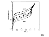
水素貯蔵装置15は、水素吸蔵合金を用いて水素を貯蔵する。水素貯蔵装置15は、水素吸蔵合金が封入された合金タンク23を備えている。水素吸蔵合金としては、例えばチタン・鉄系合金等、消防法上の危険物に該当しない合金であればよく、チタン・鉄系合金以外の合金を用いるようにしてもよい。また、合金タンク23は、高圧ガス保安法の適用外となる圧力0.9MPaG以下での運用が可能とされている。水素吸蔵合金の特性は、PCT線図で示される。図2は、チタン・鉄系の水素吸蔵合金の一例のPCT線図である。図2において、横軸は水素組成(水素原子Hと金属原子Mの比)を示し、縦軸は平衡水素圧を示す。図2に示すように、チタン・鉄系の水素吸蔵合金では、PCT線図上で圧力がプラトーになる領域が少なく、また吸放出時の圧力ヒステリシスも大きい。合金タンク23の冷却や加温は、熱媒路50からの熱媒を使って行われる。この例では、合金タンク23は、吸蔵時には摂氏20度程度まで冷却し、放出時には摂氏60度程度まで加温し、その温度帯域が20〜60℃となるように、合金組成の調整を行う。
The
燃料電池16は、水素を利用して発電を行う。燃料電池16としては、例えば固体高分子形燃料電池(PEFC)が用いられる。固体高分子形燃料電池は、起動停止が容易で、変動する建物の電力需要に対応しやすいという特徴がある。燃料電池16は、スタック24と熱交換器25とを有する。スタック24では、水素貯蔵装置15から送られてきた水素により電力が生成される。また、燃料電池16の発電時に得られる熱は、熱交換器25により熱媒路50に回収され、建物内の熱負荷19に供給されるとともに、その一部は水素貯蔵装置15に供給され、合金タンク23が加温される。これにより、水素が放出され、合金タンク23から発電に必要な水素を安定かつ継続的に取得できる。
The
加熱装置17は、装置の各部の加熱を行う熱源である。また、水素貯蔵装置15の合金タンク23での水素の放出では、加熱装置17を用いて熱媒路50を巡回して合金タンク23に送られる熱媒の加温が行われる。冷却装置18は、システム内の各部を冷却する。熱負荷19は、給湯器や空調器等、熱を負荷として消費する建物内の設備である。
The
商用電源31からの電力線30には、再生可能エネルギー電源11、蓄電池12、電力負荷13、水素製造装置14、及び燃料電池16が接続されている。商用電源31の入り口には、計測器M1が設けられる。水素製造装置14の入り口には、計測器M2が設けられる。再生可能エネルギー電源11の入り口には、計測器M3が設けられる。蓄電池12の入り口には、計測器M4が設けられる。電力負荷13の入り口には、計測器M5が設けられる。燃料電池16の出口には、計測器M6が設けられる。これらの計測器M1〜M6は、電流、電圧、電力、積算電力等を監視する計測器である。これらの計測器M1〜M6の計測値は、制御装置20に送られる。
A renewable
水素製造装置14と水素貯蔵装置15との間の水素の供給パイプには、水素放出弁41が設けられる。また、水素貯蔵装置15と燃料電池16との間の水素の供給パイプには、水素放出弁42が設けられる。水素放出弁41及び42の開閉は、制御装置20により制御できる。また、水素製造装置14には、再生型除湿器22に水素ガスを戻すポンプ43が設けられる。ポンプ43は、制御装置20により制御できる。また、水素製造装置14の水素の入り口側には、計測器M11が設けられる。また、水素貯蔵装置15の水素の出口側には、計測器M12が設けられる。計測器M11及びM12は、水素量や水素圧を監視する計測器である。これらの計測器M11及びM12の計測値は、制御装置20に送られる。
A
水素製造装置14、水素貯蔵装置15、及び燃料電池16等、水素利用システム1の各部の温度を調整するために、熱媒路50が設けられる。熱媒路50には、熱媒として温水や冷水が循環される。水素製造装置14の電解槽21の熱媒の温度は、計測器M21で計測される。水素貯蔵装置15の合金タンク23の熱媒の温度は、計測器M22で計測される。燃料電池16の熱交換器25の熱媒の温度は、計測器M23で計測される。加熱装置17の熱媒の温度は、計測器M24で計測される。冷却装置18の熱媒の温度は、計測器M25で計測される。熱負荷19の熱媒の温度は、計測器M26で計測される。これらの計測器M21〜M26の計測値は、制御装置20に送られる。また、冷却装置18の動作による冷却の設定、水素製造装置14での電解電流の設定、加熱装置17の設定による水素貯蔵装置15での水素の吸蔵や放出、及び燃料電池16の発電量の設定は、制御装置20により、前日に立案された運転計に基づいて、あるいはリアルタイムに制御できる。
A
制御装置20は、各状態において、計測器の計測値に応じて、以下のような制御を行う。
In each state, the
水素製造装置14の起動処理を行う際には、制御装置20は、起動時間の短縮および除湿性能を高めるために、水素圧力1MPa以下で、できるだけ圧力が高くなるように、電解槽21に電解電流を設定する。そして、制御装置20は、水素放出弁41が開状態になる前に、ブライン運転を稼働し、熱交換を開始し、合金タンク23を冷却し、水素を吸着できるようにしておく。そして、制御装置20は、水素放出弁41が開状態になったら、電解電流を出力計画値に設定して、電解槽21から水素を生成させる。
When starting the
水素製造装置14の除湿器の再生運転を行う際には、制御装置20は、再生型除湿器22の累積運転時間を計測する。そして、制御装置20は、再生型除湿器22の累積運転時間が所定の時間を越えたら、もう一方の再生済み除湿器のラインに切り替えて、生成した水素ガスの除湿を行う。そして、制御装置20は、ポンプ43を稼働させて、ヒータにより再生する除湿剤を加熱して再生する。そして、制御装置20は、再生が完了したら、ポンプ43を停止させる。また、制御装置20は、複数ある除湿器のうち、ある除湿器について加熱再生をしている場合において水素ガスの除湿をする場合には、再生中の除湿器とは異なる除湿器のうち、再生済みの除湿器に切り替えることで、水素ガスの除湿をする。
When the dehumidifier of the
燃料電池16の起動処理を行う際には、制御装置20は、水素貯蔵装置15のブライン運転を稼働して、合金タンク23を加温して、水素を放出させる。そして、制御装置20は、水素放出弁42を開状態にして、燃料電池16を起動させる。そして、制御装置20は、有効電力出力指令を出力計画値に設定して、燃料電池16から計画値の電源を出力させる。
When starting the
冷却装置18の起動・停止を行う際には、制御装置20は、計測器M23により、燃料電池16の入り口の熱媒の温度を監視し、あるいは、計測器M21により、電解槽21の熱媒の温度を監視し、熱媒の温度が所定の温度を越えたら、冷却装置18を起動して、冷却を行う。また、燃料電池16の熱媒の温度、あるいは、電解槽21の熱媒の温度が所定の温度を下回った時には、冷却装置18を停止する。
When starting / stopping the
図3Aは、本発明の実施形態に係る水素利用システムにおける冷却装置18の運転の説明図である。図3Aにおいて、横軸は燃料電池16の入り口の熱媒の温度あるいは電解槽21の熱媒の温度あるいは合金タンク23のタンク圧力を示し、縦軸は、冷却装置18の設定状態(ONまたはOFF)を示す。図3Aに示すように、冷却装置18の起動開始時の温度または圧力は冷却装置18の停止時の温度または圧力より高く設定されており、冷却装置18の起動開始時の温度または圧力と冷却装置18の停止時の温度または圧力とで、ヒステリシス特性を持つようにしている。
図3Bは、本発明の実施形態に係る水素利用システムにおける加熱装置17の運転の説明図である。図3Bにおいて、横軸は合金タンク23のタンク圧力を示し、縦軸は、加熱装置17の設定状態(ONまたはOFF)を示す。図3Bに示すように、加熱装置17の起動開始時の合金タンク23のタンク圧力は加熱装置17の停止時のタンク圧力より低く設定されており、加熱装置17の起動開始時の圧力と加熱装置17の停止時の圧力とで、ヒステリシス特性を持つようにしている。
FIG. 3A is an explanatory diagram of the operation of the
FIG. 3B is an explanatory diagram of the operation of the
合金タンク23の吸蔵時には、制御装置20は、合金タンク23の入り口温度を計測器M22で監視し、所定の温度を越えたら、冷却装置18を起動して、冷却を行う。また、合金タンク23の熱媒の温度が所定の温度を下回った時には、制御装置20は冷却装置18を停止する。
At the time of occlusion of the
また、合金タンク23の放出時には、制御装置20は、合金タンク23の入り口温度を計測器M22で監視し、所定の温度を下回ったら、加熱装置17を起動して、加温を行う。また、合金タンク23の熱媒の温度が所定の温度を上回った時には、制御装置20は、加熱装置17を停止し、さらに、冷却装置18を起動して冷却する。
また、制御装置20は、建物の電力需要に応じて、再生可能エネルギー電源から建物内の負荷設備への電力供給または再生可能エネルギー電源から供給される電力の充電の制御をする。例えば、制御装置20は、再生可能エネルギー電源11の発電量が、建物内の負荷設備の電力需要に対して変動が生じたとしても、蓄電池12から放電または充電することで、再生可能エネルギー電源11の発電量の変動成分を補うことができる。
Further, when the
Further, the
次に、本発明の実施形態に係る水素利用システム1でのエネルギー管理について説明する。本発明の実施形態に係る水素利用システム1では、翌日についての再生可能エネルギーに基づく電力発電量と需要予測とを、前日に行って運転計画を立案する。運転計画は、前日行っているので、実際に当日になったときには、天候が予想通りにはならなかった場合には、太陽光・風力等の発電が計画通りにならなかったり、あるいは電力需要予測をしたが、電力需要が予想通りにはならない場合がある。予想との誤差に対処するために、リアルタイム制御が行われる。なお、本実施形態では、建物のエネルギー管理システムであるスマートBEMS(Building Energy Management System)を用いて、他の建築設備同様に統合的に、監視や制御が行われる。
Next, the energy management in the
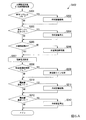
図4は、本発明の実施形態に係る水素利用システムにおける運転計画立案処理を示すフローチャートである。
(ステップS1)まず、オペレータは、建物の最大デマンド電力の目標値を制御装置20に設定して、処理をステップS2に進める。
(ステップS2)次に、オペレータは、最適化条件を制御装置20に設定して、処理をステップS3に進める。最適化条件は「エネルギーコスト最小」、「一次エネルギー最小」、「CO2排出量最小」が選択可能とする。
(ステップS3)制御装置20は、天気予報データ、過去の建物の電力/熱需要の実績データを取得して、処理をステップS4に進める。
(ステップS4)制御装置20は、任意の時間帯に対して、天気予報データ、過去の建物の電力/熱需要の実績データを用いて、再生可能エネルギー電源11の発電予測、電力負荷13の需要予測、及び熱負荷19の需要予測を行い、処理をステップS5に進める。任意の時間帯としては例えば、前日夜、当日朝、当日昼の日3回、30分単位48時間分の計96時間帯が想定される。
(ステップS5)制御装置20は、発電予測及び需要予測結果を基に、設定した最適化条件を用いて、各時間帯における各設備の運転出力計画を立案する。
(ステップS6)制御装置20は、各設備の運転出力計画が最適化されているかを検証し、最適化されていなければ(ステップS6:No)、ステップS4に処理を戻し、各時間帯における各設備の運転出力計画を立て直す。
(ステップS7)ステップS4からステップS6の処理を繰り返すことで、最適化された運転計画が作成されたら(ステップS6:Yes)、後日、制御装置20は、この運転計画に従って各部の制御を行う。
FIG. 4 is a flowchart showing an operation planning process in the hydrogen utilization system according to the embodiment of the present invention.
(Step S1) First, the operator sets the target value of the maximum demand power of the building in the
(Step S2) Next, the operator sets the optimization condition in the
(Step S3) The
(Step S4) The
(Step S5) The
(Step S6) The
(Step S7) When the optimized operation plan is created by repeating the processes of steps S4 to S6 (step S6: Yes), the
図5は、本発明の実施形態に係る水素利用システムの全体における運転制御の概要を示すフローチャートである。
(ステップS101)制御装置20は、電力が余剰あるいは余剰になることが予想され、水素を製造するか否かを判定する。水素製造処理を行う場合には(ステップS101:Yes)、処理をステップS102に進め、水素製造処理を行わない場合には(ステップS101:No)、水素製造停止処理を行って(ステップS105)、処理をステップS103に進める。
(ステップS102)制御装置20は、水素製造処理および水素貯蔵処理を行って、処理をステップS103に進める。
(ステップS103)制御装置20は、電力が不足あるいは不足することが予想され、水素発電を行うか否かを判定する。水素発電を行う場合には(ステップS103:Yes)、処理をステップS104に進め、水素発電を行わない場合には(ステップS103:No)、水素発電停止処理を行って(ステップS106)、処理をステップS101にリターンする。
(ステップS104)制御装置20は、水素放出処理および水素発電処理を行って、処理をステップS101にリターンする。
FIG. 5 is a flowchart showing an outline of operation control in the entire hydrogen utilization system according to the embodiment of the present invention.
(Step S101) The
(Step S102) The
(Step S103) The
(Step S104) The
リアルタイム制御では、運転計画より、電力が余剰になる場合や、電力が不足する場合が生じる。水素製造処理および水素貯蔵処理(ステップS102)では、電力が余剰あるいは余剰になることが予想される場合に、水素製造装置14で水素を製造し、製造された水素を、水素貯蔵装置15の合金タンク23に貯蔵する。また、水素放出処理および水素発電処理(ステップS104)では、電力が不足あるいは不足することが予想される場合に、合金タンク23から水素を放出し、この水素を用いて燃料電池16を駆動して、発電を行う。
In real-time control, there are cases where the power is surplus or power is insufficient according to the operation plan. In the hydrogen production process and the hydrogen storage process (step S102), when the electric power is expected to be surplus or surplus, hydrogen is produced by the
図6は、本発明の実施形態に係る水素利用システムにおいて、ステップS102における水素製造処理および水素貯蔵処理を示すフローチャートである。図6Aは、水素製造処理および水素貯蔵処理を説明するフローチャートである。図6Bは、水素製造停止処理を説明するフローチャートである。
なお、所定の温度T1及びT2は、水素製造装置14で水素製造を行うのに適当な電解槽21の温度に対応する温度範囲である。所定の圧力P1及びP2は、水素を吸蔵させるのに適当な合金タンク23の圧力の対応する圧力範囲である。温度T1及びT2、圧力P1及びP2は、実験やシミュレーション等を行うことで、予め最適に設定される。
FIG. 6 is a flowchart showing a hydrogen production process and a hydrogen storage process in step S102 in the hydrogen utilization system according to the embodiment of the present invention. FIG. 6A is a flowchart illustrating a hydrogen production process and a hydrogen storage process. FIG. 6B is a flowchart illustrating a hydrogen production stop process.
The predetermined temperatures T1 and T2 are temperature ranges corresponding to the temperature of the
まず、図6Aのフローチャートを参照して説明する。
(ステップS201)制御装置20は、水素貯蔵装置15の合金タンク23の圧力が所定の圧力P1を越えているか否かを判定する。合金タンク23の圧力が所定の圧力P1を越えている場合には(ステップS201:Yes)、処理をステップS202に進め、合金タンク23の圧力が所定の圧力P1を越えていない場合には(ステップS201:No)、処理をステップS203に進める。
(ステップS202)制御装置20は、冷却装置18を起動して合金タンク内を冷却し、処理をステップS213に進める。
(ステップS203)制御装置20は、水素貯蔵装置15の合金タンク23の圧力が所定の圧力P2を下回ったか否かを判定する。水素貯蔵装置15の合金タンク23の圧力が所定の圧力P2を下回った場合には(ステップS203:Yes)、処理をステップS204に進め、水素貯蔵装置15の合金タンク23の圧力が所定の圧力P2を下回っていない場合には(ステップS203:No)、処理をステップS205に進める。
(ステップS214)制御装置20は、冷却装置18を停止し、処理をステップS205に進める。
First, it will be described with reference to the flowchart of FIG. 6A.
(Step S201) The
(Step S202) The
(Step S203) The
(Step S214) The
(ステップS205)制御装置20は、水素製造装置14が起動中か否かを判断する。水素製造装置14が起動中でなければ(ステップS205:No)、処理をステップS206に進め、水素製造装置14が起動中なら(ステップS202:Yes)、処理をステップS207に進める。
(ステップS206)制御装置20は、水素製造装置14の起動を実施して、処理をステップS207に進める。
(ステップS207)制御装置20は、水素製造装置14の電解槽21の電解電流を設定して、水電解運転を行い、処理をステップS208に進める。
(ステップS208)制御装置20は、水素製造装置14の再生型除湿器22の累積の運転時間が所定の閾値t0を越えているかを判定する。なお、閾値t0は、最適な運転を行える累積の運転時間の値として予め設定されている。累積の運転時間が所定の閾値t0を越えていたら(ステップS208:Yes)、処理をステップS209に進め、所定の閾値を越えていなければ(ステップS208:No)、処理をステップS210に進める。
(ステップS209)制御装置20は、別ラインの除湿器に切り替えるとともに除湿器の再生運転を実施して、処理をステップS207に進める。
(ステップS210)制御装置20は、電解槽21の温度が所定の温度T1を越えているか否かを判定する。電解槽21の温度が所定の温度T1を越えている場合には(ステップS210:Yes)、処理をステップS211に進め、所定の温度T1を越えていない場合には(ステップS210:No)、処理をステップS212に進める。
(ステップS211)制御装置20は、冷却装置18を起動してシステム内を冷却し、処理をステップS212に進める。
(ステップS212)制御装置20は、電解槽21の温度が所定の温度T2を下回ったか否かを判定する。電解槽21の温度が所定の温度T2を下回っている場合には(ステップS212:Yes)、処理をステップS213に進め、電解槽21の温度が所定の温度T2を下回っていない場合には(ステップS212:No)、水素製造処理および水素貯蔵処理を抜けて、メイン処理に復帰する。
(ステップS213)制御装置20は、冷却装置18を停止し、水素製造処理および水素貯蔵処理を抜けて、メイン処理に復帰する。
(Step S205) The
(Step S206) The
(Step S207) The
(Step S208) The
(Step S209) The
(Step S210) The
(Step S211) The
(Step S212) The
(Step S213) The
次に、図6Bのフローチャートを参照して水素製造停止処理について説明する。
(ステップS215)制御装置20は、水素製造装置14で水電解運転が起動中か否かを判定する。水素製造装置14で水電解運転が起動中の場合には(ステップS215:Yes)、処理をステップS216に進める。水電解運転が起動中でない場合には(ステップS215:No)、水素製造停止処理を抜けて、メイン処理に復帰する。
(ステップS216)制御装置20は、水電解運転が起動中なら、水電解運転を停止する。そして、水素製造停止処理を抜けて、メイン処理に復帰する。
Next, the hydrogen production stop processing will be described with reference to the flowchart of FIG. 6B.
(Step S215) The
(Step S216) If the water electrolysis operation is in operation, the
図7は、本発明の実施形態に係る水素利用システムにおいて、ステップS104における水素放出処理および水素発電処理を示すフローチャートである。
図7Aは、水素放出処理及び水素発電処理を説明するフローチャートである。図7Bは、水素発電停止処理を説明するフローチャートである。
なお、所定の温度T5及びT6は、燃料電池16で発電の運転が効率的に行える燃料電池の温度に対応する温度範囲である。所定の圧力P3及びP4は、水素を放出させるのに適当な合金タンク23の圧力の対応する圧力範囲である。温度T5及びT6、圧力P3及びP4は、実験やシミュレーション等を行うことで、予め最適に設定される。
FIG. 7 is a flowchart showing a hydrogen release process and a hydrogen power generation process in step S104 in the hydrogen utilization system according to the embodiment of the present invention.
FIG. 7A is a flowchart illustrating a hydrogen release process and a hydrogen power generation process. FIG. 7B is a flowchart illustrating the hydrogen power generation stop processing.
The predetermined temperatures T5 and T6 are temperature ranges corresponding to the temperature of the fuel cell in which the
まず、図7Aのフローチャートを参照して説明する。
(ステップS301)制御装置20は、合金タンク23の圧力が所定の圧力P3を下回ったか否かを判定する。合金タンク23の圧力が所定の圧力P3を下回った場合には(ステップS301:Yes)、処理をステップS302に進め、合金タンク23の圧力が所定の圧力P3を下回っていない場合には(ステップS301:No)、処理をステップS303に進める。
(ステップS302)制御装置20は、加熱装置17を動作(起動)させ、熱媒を加温して、処理をステップS303に進める。
(ステップS303)制御装置20は、合金タンク23の圧力が所定の圧力P4を越えたか否かを判定する。合金タンク23の圧力が所定の圧力P4を越えた場合には、処理をステップS304に進める。合金タンク23の圧力が所定の圧力P4を越えていない場合には(ステップS303:No)、処理をステップS305に進める。
(ステップS304)制御装置20は、加熱装置17による加温を停止し、処理をステップS305に進める。
First, it will be described with reference to the flowchart of FIG. 7A.
(Step S301) The
(Step S302) The
(Step S303) The
(Step S304) The
(ステップS305)制御装置20は、燃料電池16が起動中かどうかを判断する。燃料電池16が起動中でなければ(ステップS305:No)、処理をステップS306に進め、燃料電池16が起動中なら(ステップS305:Yes)、処理をステップS307に進める。
(ステップS306)制御装置20は、燃料電池16の起動を実施して、処理をステップS307に進める。
(ステップS307)制御装置20は、燃料電池16の電力出力を設定して、燃料電池16の運転して発電を行い、処理をステップS308に進める。
(ステップS308)制御装置20は、燃料電池16の熱媒温度が所定の温度T5を越えたか否かを判定する。燃料電池16の熱媒温度が所定の温度T5を越えた場合には(ステップS309:Yes)、処理をステップS306に進め、燃料電池16の熱媒温度が所定の温度T5を越えていない場合には(ステップS308:No)、処理をステップS310に進める。
(Step S305) The
(Step S306) The
(Step S307) The
(Step S308) The
(ステップS309)制御装置20は、冷却装置18を起動して冷却する。
(ステップS310)制御装置20は、燃料電池16の熱媒温度が所定の温度T6を下回ったか否かを判定する。燃料電池16の熱媒温度が所定の温度T6を下回った場合には(ステップS310:Yes)、処理をステップS311に進め、燃料電池16の熱媒温度が所定の温度T6を下回っていない場合には(ステップS310:No)、水素放出処理及び水素発電処理を抜けて、メイン処理に復帰する。
(ステップS311)制御装置20は、冷却装置18を停止する。そして水素放出処理および水素発電処理を抜けて、メイン処理に復帰する。
次に、図7Bのフローチャートを参照して水素発電停止処理について説明する。
(ステップS315)制御装置20は、燃料電池16が起動中か否かを判定する。燃料電池16が起動中の場合には(ステップS315:Yes)、処理をステップS316に進める。燃料電池16が起動中でない場合には(ステップS315:No)、水素発電停止処理を抜けて、メイン処理に復帰する。
(ステップS316)燃料電池16が起動中なら、燃料電池16の運転を停止する。そして、水素発電停止処理を抜けて、メイン処理に復帰する。
(Step S309) The
(Step S310) The
(Step S311) The
Next, the hydrogen power generation stop processing will be described with reference to the flowchart of FIG. 7B.
(Step S315) The
(Step S316) If the
以上説明したように、本発明の実施形態に係る水素利用システム1では、消防法上の危険物に該当しないチタン・鉄系の水素吸蔵合金を用いて水素を貯蔵することができ、建物内や敷地内で、安全・かつコンパクトに水素を製造・貯蔵・利用することができる。また、システム全体を最適制御にて運用することが可能となり、再生可能エネルギーの余剰電力を高効率で運用できる。また、冷却装置18を設けることで、エネルギーを使わずに、有効に温度帯の管理を行うことができる。
As described above, in the
以上、この発明の実施形態について図面を参照して詳述してきたが、具体的な構成はこの実施形態に限られるものではなく、この発明の要旨を逸脱しない範囲の設計等も含まれる。 Although the embodiments of the present invention have been described in detail with reference to the drawings, the specific configuration is not limited to this embodiment, and the design and the like within a range not deviating from the gist of the present invention are also included.
11…再生可能エネルギー電源、12…蓄電池、13…電力負荷、14…水素製造装置、15…水素貯蔵装置、16…燃料電池、17…加熱装置、18…冷却装置、19…熱負荷、20…制御装置 11 ... Renewable energy power source, 12 ... Storage battery, 13 ... Power load, 14 ... Hydrogen production device, 15 ... Hydrogen storage device, 16 ... Fuel cell, 17 ... Heating device, 18 ... Cooling device, 19 ... Heat load, 20 ... Control device
Claims (7)
再生可能エネルギーによって得られる電源または商用電源からの電力により電解槽に蓄積された水を電気分解して水素を製造する水素製造装置と、
前記製造された水素を水素吸蔵合金が封入された合金タンクに貯蔵する水素貯蔵装置と、
前記水素貯蔵装置に貯蔵された水素を用いて発電する燃料電池と、
冷却装置と、
前記電解槽、前記合金タンク、前記燃料電池のいずれかの温度または圧力が基準温度または基準圧力を越えたか否かを判定し、基準温度または基準圧力を越えた場合に、前記基準温度または基準圧力を越えた前記電解槽、前記合金タンク、前記燃料電池のいずれかを対象として前記冷却装置によって冷却させる制御装置と、
を有する水素利用電力供給システム。 It is a hydrogen-based power supply system that supplies power generated by using hydrogen as at least a part of the power supplied to the load.
A hydrogen production device that produces hydrogen by electrolyzing the water stored in the electrolytic cell with the power source obtained from renewable energy or the power source from a commercial power source.
A hydrogen storage device that stores the produced hydrogen in an alloy tank filled with a hydrogen storage alloy, and
A fuel cell that generates electricity using hydrogen stored in the hydrogen storage device,
Cooling device and
It is determined whether or not the temperature or pressure of any of the electrolytic cell, the alloy tank, and the fuel cell exceeds the reference temperature or the reference pressure, and when the temperature or the reference pressure is exceeded, the reference temperature or the reference pressure is exceeded. A control device that cools any of the electrolytic cell, the alloy tank, and the fuel cell beyond the above by the cooling device.
Hydrogen utilization power supply system with.
前記制御装置は、前記合金タンクから水素を放出する場合に、前記加熱装置または燃料電池の排熱によって前記合金タンクを加熱する
請求項1記載の水素利用電力供給システム。 The hydrogen utilization power supply system further includes a heating device.
The hydrogen utilization power supply system according to claim 1, wherein the control device heats the alloy tank by exhaust heat of the heating device or the fuel cell when hydrogen is discharged from the alloy tank.
建物設備との熱交換が可能な熱負荷装置を有し、
前記制御装置は、前記熱負荷装置との熱交換によって、前記電解槽、前記合金タンク、前記燃料電池のいずれかを対象として加熱または冷却する、
請求項1または請求項2記載の水素利用電力供給システム。 The hydrogen utilization power supply system is
It has a heat load device that can exchange heat with building equipment.
The control device heats or cools any of the electrolytic cell, the alloy tank, and the fuel cell by heat exchange with the heat load device.
The hydrogen-utilizing power supply system according to claim 1 or 2.
前記制御装置は、建物の電力需要に応じて、再生可能エネルギー電源から前記建物内の負荷設備への電力供給または再生可能エネルギー電源から供給される電力の充電の制御をする
請求項1から請求項3記載のうちいずれか1項に記載の水素利用電力供給システム。 The hydrogen-utilizing power supply system has a storage battery for charging and discharging electric power.
The control device controls the supply of electric power from the renewable energy power source to the load equipment in the building or the charging of the electric power supplied from the renewable energy power source according to the electric power demand of the building. The hydrogen-utilizing power supply system according to any one of the three items.
請求項1から請求項4記載のうちいずれか1項に記載の水素利用電力供給システム。 The hydrogen utilization power supply system has the regenerative dehumidifier of a plurality of lines in the hydrogen production apparatus, dehumidifies the moisture of hydrogen gas generated from the electrolytic tank, and regenerates the dehumidifier when the dehumidifier is heated and regenerated. Dehumidify hydrogen by switching to a regenerated dehumidifier that is different from the dehumidifier,
The hydrogen-utilizing power supply system according to any one of claims 1 to 4.
再生可能エネルギーによって得られる電源または商用電源からの電力により電解槽に蓄積された水を電気分解して水素を製造する工程と、
前記製造された水素を水素吸蔵合金が封入された合金タンクに貯蔵する工程と、
前記貯蔵された水素を用いて燃料電池で発電する工程と、
前記電解槽、前記合金タンク、前記燃料電池のいずれかの温度または圧力が基準温度または基準圧力を越えたか否かを判定し、基準温度または基準圧力を越えた場合に、前記基準温度または基準圧力を越えた前記電解槽、前記合金タンク、前記燃料電池のいずれかを対象として冷却装置によって冷却させる工程と、
を有する水素利用電力供給方法。 It is a hydrogen-based power supply method that supplies power generated by using hydrogen as at least a part of the power supplied to the load.
The process of producing hydrogen by electrolyzing the water stored in the electrolytic cell with the power obtained from renewable energy or the power from a commercial power source.
The process of storing the produced hydrogen in an alloy tank filled with a hydrogen storage alloy, and
The process of generating electricity with a fuel cell using the stored hydrogen and
It is determined whether or not the temperature or pressure of any of the electrolytic cell, the alloy tank, and the fuel cell exceeds the reference temperature or the reference pressure, and when the temperature or the reference pressure is exceeded, the reference temperature or the reference pressure is exceeded. A step of cooling any of the electrolytic cell, the alloy tank, and the fuel cell beyond the above by a cooling device.
Hydrogen utilization power supply method having.
を有する請求項6に記載の水素利用電力供給方法。 The sixth aspect of claim 6, further comprising a step of determining whether or not the pressure of the alloy tank has fallen below the reference pressure, and heating the alloy tank by the exhaust heat of a heating device or a fuel cell when the pressure falls below the reference pressure. Hydrogen utilization power supply method.
Priority Applications (1)
| Application Number | Priority Date | Filing Date | Title |
|---|---|---|---|
| JP2019075095A JP7364182B2 (en) | 2019-04-10 | 2019-04-10 | Hydrogen-based power supply system and hydrogen-based power supply method |
Applications Claiming Priority (1)
| Application Number | Priority Date | Filing Date | Title |
|---|---|---|---|
| JP2019075095A JP7364182B2 (en) | 2019-04-10 | 2019-04-10 | Hydrogen-based power supply system and hydrogen-based power supply method |
Publications (2)
| Publication Number | Publication Date |
|---|---|
| JP2020173972A true JP2020173972A (en) | 2020-10-22 |
| JP7364182B2 JP7364182B2 (en) | 2023-10-18 |
Family
ID=72831591
Family Applications (1)
| Application Number | Title | Priority Date | Filing Date |
|---|---|---|---|
| JP2019075095A Active JP7364182B2 (en) | 2019-04-10 | 2019-04-10 | Hydrogen-based power supply system and hydrogen-based power supply method |
Country Status (1)
| Country | Link |
|---|---|
| JP (1) | JP7364182B2 (en) |
Cited By (3)
| Publication number | Priority date | Publication date | Assignee | Title |
|---|---|---|---|---|
| CN115011970A (en) * | 2022-06-07 | 2022-09-06 | 哈尔滨工业大学 | Container type integrated electricity-hydrogen co-production device with heat management and working method |
| WO2023190553A1 (en) * | 2022-03-31 | 2023-10-05 | 旭化成株式会社 | Information processing device, electrolysis device, plan creation method, and program |
| JP7416041B2 (en) | 2021-12-09 | 2024-01-17 | 株式会社Ihi | Operation plan creation device, operation plan creation method, and operation plan creation program |
Citations (8)
| Publication number | Priority date | Publication date | Assignee | Title |
|---|---|---|---|---|
| JPH06178408A (en) * | 1992-09-01 | 1994-06-24 | Takeo Kagitani | Power plant |
| JP2000054174A (en) * | 1998-08-07 | 2000-02-22 | Matsushita Electric Ind Co Ltd | Water electrolyzing device and water electrolysis storage battery |
| JP2000345273A (en) * | 1999-03-29 | 2000-12-12 | Tohoku Techno Arch Co Ltd | Hydrogen storage alloy, method for absorbing and discharging hydrogen using the alloy and hydrogen fuel battery using the method |
| JP2002269633A (en) * | 2001-03-12 | 2002-09-20 | Matsushita Electric Ind Co Ltd | Hydrogen automatic vending device |
| JP2003086213A (en) * | 2001-09-07 | 2003-03-20 | Toyota Motor Corp | Fuel cell system |
| JP2003277963A (en) * | 2002-03-19 | 2003-10-02 | Mitsubishi Corp | Apparatus and method for manufacturing high-pressure hydrogen |
| JP2006236741A (en) * | 2005-02-24 | 2006-09-07 | Sanesu Denki Tsushin Kk | Power generation system effectively utilizing natural energy |
| JP2008223931A (en) * | 2007-03-14 | 2008-09-25 | Toyota Motor Corp | Gas storage system |
-
2019
- 2019-04-10 JP JP2019075095A patent/JP7364182B2/en active Active
Patent Citations (8)
| Publication number | Priority date | Publication date | Assignee | Title |
|---|---|---|---|---|
| JPH06178408A (en) * | 1992-09-01 | 1994-06-24 | Takeo Kagitani | Power plant |
| JP2000054174A (en) * | 1998-08-07 | 2000-02-22 | Matsushita Electric Ind Co Ltd | Water electrolyzing device and water electrolysis storage battery |
| JP2000345273A (en) * | 1999-03-29 | 2000-12-12 | Tohoku Techno Arch Co Ltd | Hydrogen storage alloy, method for absorbing and discharging hydrogen using the alloy and hydrogen fuel battery using the method |
| JP2002269633A (en) * | 2001-03-12 | 2002-09-20 | Matsushita Electric Ind Co Ltd | Hydrogen automatic vending device |
| JP2003086213A (en) * | 2001-09-07 | 2003-03-20 | Toyota Motor Corp | Fuel cell system |
| JP2003277963A (en) * | 2002-03-19 | 2003-10-02 | Mitsubishi Corp | Apparatus and method for manufacturing high-pressure hydrogen |
| JP2006236741A (en) * | 2005-02-24 | 2006-09-07 | Sanesu Denki Tsushin Kk | Power generation system effectively utilizing natural energy |
| JP2008223931A (en) * | 2007-03-14 | 2008-09-25 | Toyota Motor Corp | Gas storage system |
Cited By (3)
| Publication number | Priority date | Publication date | Assignee | Title |
|---|---|---|---|---|
| JP7416041B2 (en) | 2021-12-09 | 2024-01-17 | 株式会社Ihi | Operation plan creation device, operation plan creation method, and operation plan creation program |
| WO2023190553A1 (en) * | 2022-03-31 | 2023-10-05 | 旭化成株式会社 | Information processing device, electrolysis device, plan creation method, and program |
| CN115011970A (en) * | 2022-06-07 | 2022-09-06 | 哈尔滨工业大学 | Container type integrated electricity-hydrogen co-production device with heat management and working method |
Also Published As
| Publication number | Publication date |
|---|---|
| JP7364182B2 (en) | 2023-10-18 |
Similar Documents
| Publication | Publication Date | Title |
|---|---|---|
| CN108496288B (en) | Household energy device and operation method for operating household energy device | |
| Assaf et al. | Multi-objective sizing optimisation of a solar-thermal system integrated with a solar-hydrogen combined heat and power system, using genetic algorithm | |
| US10770742B2 (en) | Electrical power distribution system and method for a grid-tied reversible solid oxide fuel cell system | |
| JP2020173972A (en) | Hydrogen-using power supply system and hydrogen using power supply method | |
| Fong et al. | Investigation on zero grid-electricity design strategies of solid oxide fuel cell trigeneration system for high-rise building in hot and humid climate | |
| JP2009071959A (en) | Power supply system | |
| JP5976950B1 (en) | Power supply system and control method thereof | |
| Morin et al. | Evaluation of performance improvement by model predictive control in a renewable energy system with hydrogen storage | |
| JP6839760B2 (en) | Power generation system, energy management device, and power generation control method | |
| CN114583725A (en) | Hydrogen-based near-zero carbon emission comprehensive energy system and operation optimization method thereof | |
| JP2020058168A (en) | Hydrogen supply system and hydrogen supply method | |
| JP2011217590A (en) | Air conditioning system | |
| Luo et al. | A two-stage energy management strategy for CCHP microgrid considering house characteristics | |
| Mohseni et al. | A multi-agent approach to optimal sizing of a combined heating and power microgrid | |
| CN116960396B (en) | Hydrogen fuel cell power generation and heat supply system for chemical production and control method thereof | |
| JP2017027936A (en) | Power supply system and control method of the same | |
| JP2021023028A (en) | Power supply system and hydrogen utilization system | |
| CN112615030B (en) | Control system and control method of fixed fuel cell unit for power generation | |
| JPWO2018225602A1 (en) | Heat storage system and method of operating heat storage system | |
| JP7008297B2 (en) | Power supply system and control method of power supply system | |
| JP6094360B2 (en) | Power generation system | |
| Obaro et al. | Energy dispatch of decentralized hybrid power system | |
| JP2002034161A (en) | Building equipped with fuel cell | |
| RU2792410C1 (en) | Autonomous modular power plant | |
| JP2023026234A (en) | Energy storage system and method for controlling the same |
Legal Events
| Date | Code | Title | Description |
|---|---|---|---|
| A521 | Request for written amendment filed |
Free format text: JAPANESE INTERMEDIATE CODE: A523 Effective date: 20190517 |
|
| A621 | Written request for application examination |
Free format text: JAPANESE INTERMEDIATE CODE: A621 Effective date: 20220208 |
|
| A977 | Report on retrieval |
Free format text: JAPANESE INTERMEDIATE CODE: A971007 Effective date: 20221116 |
|
| A131 | Notification of reasons for refusal |
Free format text: JAPANESE INTERMEDIATE CODE: A131 Effective date: 20221206 |
|
| A521 | Request for written amendment filed |
Free format text: JAPANESE INTERMEDIATE CODE: A523 Effective date: 20230203 |
|
| A131 | Notification of reasons for refusal |
Free format text: JAPANESE INTERMEDIATE CODE: A131 Effective date: 20230530 |
|
| A521 | Request for written amendment filed |
Free format text: JAPANESE INTERMEDIATE CODE: A523 Effective date: 20230727 |
|
| TRDD | Decision of grant or rejection written | ||
| A01 | Written decision to grant a patent or to grant a registration (utility model) |
Free format text: JAPANESE INTERMEDIATE CODE: A01 Effective date: 20230829 |
|
| A61 | First payment of annual fees (during grant procedure) |
Free format text: JAPANESE INTERMEDIATE CODE: A61 Effective date: 20230927 |
|
| R150 | Certificate of patent or registration of utility model |
Ref document number: 7364182 Country of ref document: JP Free format text: JAPANESE INTERMEDIATE CODE: R150 |