JP2020157504A - Image formation apparatus - Google Patents
Image formation apparatus Download PDFInfo
- Publication number
- JP2020157504A JP2020157504A JP2019056909A JP2019056909A JP2020157504A JP 2020157504 A JP2020157504 A JP 2020157504A JP 2019056909 A JP2019056909 A JP 2019056909A JP 2019056909 A JP2019056909 A JP 2019056909A JP 2020157504 A JP2020157504 A JP 2020157504A
- Authority
- JP
- Japan
- Prior art keywords
- ink
- hollow member
- tube
- hollow
- image forming
- Prior art date
- Legal status (The legal status is an assumption and is not a legal conclusion. Google has not performed a legal analysis and makes no representation as to the accuracy of the status listed.)
- Granted
Links
Images

Classifications
-
- B—PERFORMING OPERATIONS; TRANSPORTING
- B41—PRINTING; LINING MACHINES; TYPEWRITERS; STAMPS
- B41J—TYPEWRITERS; SELECTIVE PRINTING MECHANISMS, i.e. MECHANISMS PRINTING OTHERWISE THAN FROM A FORME; CORRECTION OF TYPOGRAPHICAL ERRORS
- B41J2/00—Typewriters or selective printing mechanisms characterised by the printing or marking process for which they are designed
- B41J2/005—Typewriters or selective printing mechanisms characterised by the printing or marking process for which they are designed characterised by bringing liquid or particles selectively into contact with a printing material
- B41J2/01—Ink jet
- B41J2/17—Ink jet characterised by ink handling
- B41J2/175—Ink supply systems ; Circuit parts therefor
- B41J2/17503—Ink cartridges
- B41J2/1752—Mounting within the printer
- B41J2/17523—Ink connection
-
- B—PERFORMING OPERATIONS; TRANSPORTING
- B41—PRINTING; LINING MACHINES; TYPEWRITERS; STAMPS
- B41J—TYPEWRITERS; SELECTIVE PRINTING MECHANISMS, i.e. MECHANISMS PRINTING OTHERWISE THAN FROM A FORME; CORRECTION OF TYPOGRAPHICAL ERRORS
- B41J2/00—Typewriters or selective printing mechanisms characterised by the printing or marking process for which they are designed
- B41J2/005—Typewriters or selective printing mechanisms characterised by the printing or marking process for which they are designed characterised by bringing liquid or particles selectively into contact with a printing material
- B41J2/01—Ink jet
- B41J2/17—Ink jet characterised by ink handling
- B41J2/1707—Conditioning of the inside of ink supply circuits, e.g. flushing during start-up or shut-down
-
- B—PERFORMING OPERATIONS; TRANSPORTING
- B41—PRINTING; LINING MACHINES; TYPEWRITERS; STAMPS
- B41J—TYPEWRITERS; SELECTIVE PRINTING MECHANISMS, i.e. MECHANISMS PRINTING OTHERWISE THAN FROM A FORME; CORRECTION OF TYPOGRAPHICAL ERRORS
- B41J2/00—Typewriters or selective printing mechanisms characterised by the printing or marking process for which they are designed
- B41J2/005—Typewriters or selective printing mechanisms characterised by the printing or marking process for which they are designed characterised by bringing liquid or particles selectively into contact with a printing material
- B41J2/01—Ink jet
- B41J2/17—Ink jet characterised by ink handling
- B41J2/175—Ink supply systems ; Circuit parts therefor
- B41J2/17503—Ink cartridges
- B41J2/17506—Refilling of the cartridge
- B41J2/17509—Whilst mounted in the printer
-
- B—PERFORMING OPERATIONS; TRANSPORTING
- B41—PRINTING; LINING MACHINES; TYPEWRITERS; STAMPS
- B41J—TYPEWRITERS; SELECTIVE PRINTING MECHANISMS, i.e. MECHANISMS PRINTING OTHERWISE THAN FROM A FORME; CORRECTION OF TYPOGRAPHICAL ERRORS
- B41J2/00—Typewriters or selective printing mechanisms characterised by the printing or marking process for which they are designed
- B41J2/005—Typewriters or selective printing mechanisms characterised by the printing or marking process for which they are designed characterised by bringing liquid or particles selectively into contact with a printing material
- B41J2/01—Ink jet
- B41J2/17—Ink jet characterised by ink handling
- B41J2/175—Ink supply systems ; Circuit parts therefor
- B41J2/17503—Ink cartridges
- B41J2/17513—Inner structure
-
- B—PERFORMING OPERATIONS; TRANSPORTING
- B41—PRINTING; LINING MACHINES; TYPEWRITERS; STAMPS
- B41J—TYPEWRITERS; SELECTIVE PRINTING MECHANISMS, i.e. MECHANISMS PRINTING OTHERWISE THAN FROM A FORME; CORRECTION OF TYPOGRAPHICAL ERRORS
- B41J2/00—Typewriters or selective printing mechanisms characterised by the printing or marking process for which they are designed
- B41J2/005—Typewriters or selective printing mechanisms characterised by the printing or marking process for which they are designed characterised by bringing liquid or particles selectively into contact with a printing material
- B41J2/01—Ink jet
- B41J2/17—Ink jet characterised by ink handling
- B41J2/175—Ink supply systems ; Circuit parts therefor
- B41J2/17503—Ink cartridges
- B41J2/17543—Cartridge presence detection or type identification
- B41J2/17546—Cartridge presence detection or type identification electronically
-
- B—PERFORMING OPERATIONS; TRANSPORTING
- B41—PRINTING; LINING MACHINES; TYPEWRITERS; STAMPS
- B41J—TYPEWRITERS; SELECTIVE PRINTING MECHANISMS, i.e. MECHANISMS PRINTING OTHERWISE THAN FROM A FORME; CORRECTION OF TYPOGRAPHICAL ERRORS
- B41J2/00—Typewriters or selective printing mechanisms characterised by the printing or marking process for which they are designed
- B41J2/005—Typewriters or selective printing mechanisms characterised by the printing or marking process for which they are designed characterised by bringing liquid or particles selectively into contact with a printing material
- B41J2/01—Ink jet
- B41J2/17—Ink jet characterised by ink handling
- B41J2/175—Ink supply systems ; Circuit parts therefor
- B41J2/17503—Ink cartridges
- B41J2/17553—Outer structure
-
- B—PERFORMING OPERATIONS; TRANSPORTING
- B41—PRINTING; LINING MACHINES; TYPEWRITERS; STAMPS
- B41J—TYPEWRITERS; SELECTIVE PRINTING MECHANISMS, i.e. MECHANISMS PRINTING OTHERWISE THAN FROM A FORME; CORRECTION OF TYPOGRAPHICAL ERRORS
- B41J2/00—Typewriters or selective printing mechanisms characterised by the printing or marking process for which they are designed
- B41J2/005—Typewriters or selective printing mechanisms characterised by the printing or marking process for which they are designed characterised by bringing liquid or particles selectively into contact with a printing material
- B41J2/01—Ink jet
- B41J2/17—Ink jet characterised by ink handling
- B41J2/175—Ink supply systems ; Circuit parts therefor
- B41J2/17566—Ink level or ink residue control
-
- B—PERFORMING OPERATIONS; TRANSPORTING
- B41—PRINTING; LINING MACHINES; TYPEWRITERS; STAMPS
- B41J—TYPEWRITERS; SELECTIVE PRINTING MECHANISMS, i.e. MECHANISMS PRINTING OTHERWISE THAN FROM A FORME; CORRECTION OF TYPOGRAPHICAL ERRORS
- B41J2/00—Typewriters or selective printing mechanisms characterised by the printing or marking process for which they are designed
- B41J2/005—Typewriters or selective printing mechanisms characterised by the printing or marking process for which they are designed characterised by bringing liquid or particles selectively into contact with a printing material
- B41J2/01—Ink jet
- B41J2/17—Ink jet characterised by ink handling
- B41J2/175—Ink supply systems ; Circuit parts therefor
- B41J2/17596—Ink pumps, ink valves
-
- B—PERFORMING OPERATIONS; TRANSPORTING
- B41—PRINTING; LINING MACHINES; TYPEWRITERS; STAMPS
- B41J—TYPEWRITERS; SELECTIVE PRINTING MECHANISMS, i.e. MECHANISMS PRINTING OTHERWISE THAN FROM A FORME; CORRECTION OF TYPOGRAPHICAL ERRORS
- B41J2/00—Typewriters or selective printing mechanisms characterised by the printing or marking process for which they are designed
- B41J2/005—Typewriters or selective printing mechanisms characterised by the printing or marking process for which they are designed characterised by bringing liquid or particles selectively into contact with a printing material
- B41J2/01—Ink jet
- B41J2/17—Ink jet characterised by ink handling
- B41J2/18—Ink recirculation systems
-
- B—PERFORMING OPERATIONS; TRANSPORTING
- B41—PRINTING; LINING MACHINES; TYPEWRITERS; STAMPS
- B41J—TYPEWRITERS; SELECTIVE PRINTING MECHANISMS, i.e. MECHANISMS PRINTING OTHERWISE THAN FROM A FORME; CORRECTION OF TYPOGRAPHICAL ERRORS
- B41J2/00—Typewriters or selective printing mechanisms characterised by the printing or marking process for which they are designed
- B41J2/005—Typewriters or selective printing mechanisms characterised by the printing or marking process for which they are designed characterised by bringing liquid or particles selectively into contact with a printing material
- B41J2/01—Ink jet
- B41J2/17—Ink jet characterised by ink handling
- B41J2/195—Ink jet characterised by ink handling for monitoring ink quality
-
- B—PERFORMING OPERATIONS; TRANSPORTING
- B41—PRINTING; LINING MACHINES; TYPEWRITERS; STAMPS
- B41J—TYPEWRITERS; SELECTIVE PRINTING MECHANISMS, i.e. MECHANISMS PRINTING OTHERWISE THAN FROM A FORME; CORRECTION OF TYPOGRAPHICAL ERRORS
- B41J29/00—Details of, or accessories for, typewriters or selective printing mechanisms not otherwise provided for
- B41J29/02—Framework
-
- B—PERFORMING OPERATIONS; TRANSPORTING
- B41—PRINTING; LINING MACHINES; TYPEWRITERS; STAMPS
- B41J—TYPEWRITERS; SELECTIVE PRINTING MECHANISMS, i.e. MECHANISMS PRINTING OTHERWISE THAN FROM A FORME; CORRECTION OF TYPOGRAPHICAL ERRORS
- B41J29/00—Details of, or accessories for, typewriters or selective printing mechanisms not otherwise provided for
- B41J29/38—Drives, motors, controls or automatic cut-off devices for the entire printing mechanism
Landscapes
- Engineering & Computer Science (AREA)
- Quality & Reliability (AREA)
- Ink Jet (AREA)
Abstract
【課題】インクの残量を検知するための検出素子の劣化を防ぎ、且つセンシング不良を抑制できる画像形成装置を提供する。【解決手段】印刷装置は、メインタンク30、中空部材58、圧力検出素子42、ポンプ、CPUを備える。メインタンク30は、インク68を貯留する。中空部材58は、メインタンク30の内部に配置され、上下方向に伸展する中空を有し、下方側21において中空の開口部21Aを有し、且つ中空をガスバリア性の素材で構成する。圧力検出素子42は、中空部材58の上方側の中空に配置され、中空内の圧力を検出する。密封部材24は、中空部材58と圧力検出素子42との間を密封する。ポンプは、メインタンク30のインク68を、メインタンク30の外部へ移動させる。CPUは、圧力検出素子42の検出した圧力に応じて、インク68の残量を検知し、ポンプの制御を行う。【選択図】図3PROBLEM TO BE SOLVED: To provide an image forming apparatus capable of preventing deterioration of a detection element for detecting the remaining amount of ink and suppressing sensing failure. A printing device includes a main tank 30, a hollow member 58, a pressure detecting element 42, a pump, and a CPU. The main tank 30 stores the ink 68. The hollow member 58 is arranged inside the main tank 30 and has a hollow extending in the vertical direction, has a hollow opening 21A on the lower side 21, and the hollow is made of a gas barrier material. The pressure detecting element 42 is arranged in the hollow on the upper side of the hollow member 58, and detects the pressure in the hollow. The sealing member 24 seals between the hollow member 58 and the pressure detecting element 42. The pump moves the ink 68 of the main tank 30 to the outside of the main tank 30. The CPU detects the remaining amount of ink 68 according to the pressure detected by the pressure detecting element 42, and controls the pump. [Selection diagram] Fig. 3
Description
本発明は、画像形成装置に関する。 The present invention relates to an image forming apparatus.
インクの残量を検知するインクジェットプリンタが知られている。例えば、特許文献1に記載のインクジェットプリンタは、インクタンク、浸漬電極を備える。インクタンクはインクを収容する。浸漬電極は、インクタンク内に設けられ、電極がインクに浸った状態で、インクタンクに収容されたインクの残量を検知する。
Inkjet printers that detect the remaining amount of ink are known. For example, the inkjet printer described in
また、インクの漏れを検知するインクジェット記録装置が知られている。例えば、特許文献2に記載のインクジェット記録装置は、バッファタンク、オーバーフロータンク、フロートセンサを備える。バッファタンクは、インクを収容する。オーバーフロータンクは、バッファタンクから流入したインクを収容する。フロートセンサは、オーバーフロータンク内に設けられ、オーバーフロータンク内のインクの漏れを検知する。
In addition, an inkjet recording device that detects ink leakage is known. For example, the inkjet recording device described in
上記インクジェットプリンタにおいて、浸漬電極は、電極がインクに浸っているため、電極表面にインクが固着し、電極の導電性が悪化する可能性がある。また、上記インクジェット記録装置において、フロートセンサは、浮きと軸の間にインクが固着し、浮きが動かなくなり、センシング不良となる可能性がある。 In the above-mentioned inkjet printer, since the electrode of the immersion electrode is immersed in ink, the ink may adhere to the surface of the electrode and the conductivity of the electrode may deteriorate. Further, in the above-mentioned inkjet recording device, the float sensor may have ink stuck between the float and the shaft, and the float may not move, resulting in poor sensing.
本発明の目的は、インクの残量を検知するための検出素子の劣化を防ぎ、且つセンシング不良を抑制できる画像形成装置を提供することである。 An object of the present invention is to provide an image forming apparatus capable of preventing deterioration of a detection element for detecting the remaining amount of ink and suppressing sensing defects.
本発明の第一態様の画像形成装置は、インクを用いて画像を形成する画像形成装置において、前記インクを貯留する貯留部と、前記貯留部の内部に配置され、上下方向に伸展する中空を有し、下方側において前記中空の開口部を有し、且つ前記中空をガスバリア性の素材で構成する中空部材と、前記中空部材の上方側の前記中空に配置され、前記中空内の圧力を検出する圧力検出素子と、前記中空部材と前記圧力検出素子との間を密封する密封部材と、前記貯留部の前記インクを、前記貯留部の外部へ移動させるポンプと、前記画像形成装置の制御を行う制御装置とを備え、前記制御装置は、前記圧力検出素子の検出した前記圧力に応じて、前記インクの残量を検知し、前記ポンプの制御を行うことを特徴とする。 The image forming apparatus according to the first aspect of the present invention is an image forming apparatus that forms an image using ink, and has a storage portion that stores the ink and a hollow that is arranged inside the storage portion and extends in the vertical direction. A hollow member having the hollow opening on the lower side and the hollow is made of a gas barrier material, and the hollow member on the upper side of the hollow member are arranged to detect the pressure in the hollow. Control of the pressure detecting element, the sealing member that seals between the hollow member and the pressure detecting element, the pump that moves the ink of the storage portion to the outside of the storage portion, and the image forming apparatus. The control device includes a control device for performing the operation, and the control device detects the remaining amount of the ink according to the pressure detected by the pressure detecting element and controls the pump.
この場合、画像形成装置は、圧力検出素子が中空部材の上方側の中空に配置されているので、圧力検出素子がインクとは離れて設けられている。従って、画像形成装置は、インクにより圧力検出素子が劣化する可能性を低減できる。故に、画像形成装置は、圧力検出素子の劣化を防ぎ、且つセンシング不良を抑制できる。 In this case, in the image forming apparatus, since the pressure detecting element is arranged in the hollow on the upper side of the hollow member, the pressure detecting element is provided apart from the ink. Therefore, the image forming apparatus can reduce the possibility that the pressure detecting element is deteriorated by the ink. Therefore, the image forming apparatus can prevent deterioration of the pressure detecting element and suppress sensing failure.
また、前記中空部材の前記下方側は、前記上下方向と直交する水平方向の成分を含む方向に伸展し、且つ前記中空部材の前記開口部は、前記水平方向に向けて開口してもよい。この場合、画像形成装置では、インクと中空部材の中空内の気体との境界が中空部材の下方側に位置する。画像形成装置は、気体の温度が変化して中空部材が膨張又は収縮したとしても、インクの液面から下方側までの深さが変わらない。故に、画像形成装置は、気体の温度変化による圧力検出素子への影響を低減できる。 Further, the lower side of the hollow member may extend in a direction including a component in a horizontal direction orthogonal to the vertical direction, and the opening of the hollow member may be opened in the horizontal direction. In this case, in the image forming apparatus, the boundary between the ink and the gas in the hollow of the hollow member is located on the lower side of the hollow member. In the image forming apparatus, even if the temperature of the gas changes and the hollow member expands or contracts, the depth from the liquid surface of the ink to the lower side does not change. Therefore, the image forming apparatus can reduce the influence of the temperature change of the gas on the pressure detecting element.
また、前記貯留部に設けられ、前記貯留部に前記インクを供給可能なインク供給部を備え、前記中空部材の前記開口部は、前記インク供給部とは反対側の前記貯留部の側面側に配置されてもよい。この場合、画像形成装置は、貯留部にインク供給部を備え、中空部材の開口部がインク供給部とは反対側の前記貯留部の側面側に配置されている。従って、画像形成装置は、中空部材の開口部がインク供給部側に配置されている場合に比べて、インク供給部から供給されたインクが中空部材の開口部に直撃する可能性が低くなる。故に、画像形成装置は、衝撃による中空部材の劣化を抑制できる。 Further, an ink supply unit provided in the storage unit and capable of supplying the ink to the storage unit is provided, and the opening of the hollow member is located on a side surface side of the storage unit on the side opposite to the ink supply unit. It may be arranged. In this case, the image forming apparatus is provided with an ink supply unit in the storage unit, and the opening of the hollow member is arranged on the side surface side of the storage unit on the side opposite to the ink supply unit. Therefore, in the image forming apparatus, the possibility that the ink supplied from the ink supply unit directly hits the opening of the hollow member is lower than that in the case where the opening of the hollow member is arranged on the ink supply unit side. Therefore, the image forming apparatus can suppress the deterioration of the hollow member due to the impact.
また、前記貯留部から前記貯留部の前記外部に前記インクを流出させる第一チューブを備え、前記中空部材の前記開口部は、前記第一チューブの下端よりも上方に配置され、前記制御装置は、前記ポンプを制御して、前記第一チューブの前記インクを前記貯留部の前記外部に流出させ、前記圧力検出素子が検出した前記圧力に応じて、前記ポンプの稼働を停止してもよい。この場合、画像形成装置は、貯留部におけるインクの残量を正確に認識し、圧力検出素子の出力に応じてポンプの稼働を制御する。例えば、画像形成装置は、インクの残量が所定値以下になっているにも関わらず、ポンプを稼働させてしまいインクに気泡が含まれる可能性を低減できる。 Further, a first tube for discharging the ink from the storage unit to the outside of the storage unit is provided, the opening of the hollow member is arranged above the lower end of the first tube, and the control device is provided. , The pump may be controlled to cause the ink in the first tube to flow out to the outside of the storage portion, and the operation of the pump may be stopped according to the pressure detected by the pressure detecting element. In this case, the image forming apparatus accurately recognizes the remaining amount of ink in the storage unit and controls the operation of the pump according to the output of the pressure detecting element. For example, the image forming apparatus can reduce the possibility that the ink contains air bubbles by operating the pump even though the remaining amount of ink is equal to or less than a predetermined value.
また、前記インクの量に関するデータを記憶したメモリを着脱自在に装着可能なメモリ装着部と、前記制御装置は、前記中空部材の前記中空内の前記圧力が所定圧増加した場合、前記メモリ装着部に装着された前記メモリの前記データを参照してもよい。この場合、画像形成装置は、インクが貯留部に注入されたことに起因して中空部材の中空内の圧力が所定圧分増加した場合に、メモリ装着部に装着されたメモリのインクの量に関するデータを参照して、インクの残量を検出できる。 In addition, a memory mounting unit to which a memory storing data relating to the amount of ink can be detachably mounted and the control device are provided with the memory mounting portion when the pressure in the hollow of the hollow member increases by a predetermined pressure. You may refer to the data of the memory mounted on the. In this case, the image forming apparatus relates to the amount of ink in the memory mounted in the memory mounting portion when the pressure in the hollow of the hollow member increases by a predetermined pressure due to the ink being injected into the storage portion. The remaining amount of ink can be detected by referring to the data.
また、前記中空部材の前記下方側は、前記上下方向に対して直交する水平方向の成分を含む方向に伸展し、且つ前記中空部材の前記開口部は、前記水平方向に向けて開口し、前記中空部材の前記下方側の前記少なくとも一部の前記中空における気体と前記インクとの境界は、前記中空部材の前記中空内の気体の伸縮に応じて移動してもよい。この場合、画像形成装置は、中空部材の中空内の気体の温度が変化し、中空部材が膨張又は収縮する場合がある。このような場合でも、気体とインクとの境界が、中空部材の下方側の少なくとも一部の中空を移動することにより、温度上昇による圧力の変化を緩和する。これにより、圧力検出素子は、少なくとも一部の中空が水平方向に伸展しない場合に比べて、貯留部におけるインクの残量を正確に認識できる。 Further, the lower side of the hollow member extends in a direction including a horizontal component orthogonal to the vertical direction, and the opening of the hollow member opens in the horizontal direction. The boundary between the gas and the ink in at least a part of the hollow on the lower side of the hollow member may move according to the expansion and contraction of the gas in the hollow of the hollow member. In this case, in the image forming apparatus, the temperature of the gas in the hollow of the hollow member may change, and the hollow member may expand or contract. Even in such a case, the boundary between the gas and the ink moves in at least a part of the hollow on the lower side of the hollow member to alleviate the change in pressure due to the temperature rise. As a result, the pressure detecting element can accurately recognize the remaining amount of ink in the storage portion as compared with the case where at least a part of the hollow does not extend in the horizontal direction.
また、前記貯留部に設けられ、前記中空部材の少なくとも一部の位置を固定する位置決め部材を備えてもよい。この場合、画像形成装置は、中空部材の少なくとも一部の位置が固定されているので、中空部材が全く固定されていない場合に比べて、中空部材が不測の位置に移動する可能性が低くなる。故に、画像形成装置は、圧力検出素子の検出する圧力に影響が出ることを抑制できる。 Further, a positioning member provided in the storage portion and fixing the position of at least a part of the hollow member may be provided. In this case, since the position of at least a part of the hollow member is fixed in the image forming apparatus, the possibility that the hollow member moves to an unexpected position is low as compared with the case where the hollow member is not fixed at all. .. Therefore, the image forming apparatus can suppress the influence of the pressure detected by the pressure detecting element.
また、前記中空部材は、弾性体で形成され、前記位置決め部材は、前記弾性体の少なくとも一部の位置を固定してもよい。この場合、画像形成装置では、位置決め部材が弾性体で形成された中空部材の少なくとも一部の位置を固定するので、中空部材が他の部材に絡む可能性を低減できる。故に、画像形成装置は、圧力検出素子の出力に影響が出ることを抑制できる。 Further, the hollow member may be formed of an elastic body, and the positioning member may fix the position of at least a part of the elastic body. In this case, in the image forming apparatus, since the positioning member fixes the position of at least a part of the hollow member formed of the elastic body, the possibility that the hollow member is entangled with other members can be reduced. Therefore, the image forming apparatus can suppress the influence on the output of the pressure detecting element.
また、前記貯留部に設けられ、前記貯留部に前記インクを供給可能なインク供給部と、前記貯留部から前記貯留部の前記外部に前記インクを流出させる第一チューブと、前記貯留部の前記外部から前記貯留部に前記インクを流入させる第二チューブと、前記貯留部の前記内部に設けられ、前記中空部材の少なくとも一部の位置を固定する位置決め部材とを備え、前記位置決め部材は、前記インク供給部側とは反対側の前記貯留部の側面側で、前記中空部材の少なくとも一部の位置を固定し、前記位置決め部材、前記第一チューブ、及び前記第二チューブの少なくとも何れか一つは、前記中空部材と前記インク供給部との間に配置されてもよい。この場合、画像形成装置では、中空部材の少なくとも一部がインク供給部とは反対側の前記貯留部の側面側で位置を固定される。位置決め部材、第一チューブ、第二チューブの少なくとも何れか一つが中空部材とインク供給部の間に配置される。従って、画像形成装置は、インク供給部と中空部材の間に何も配置されていない場合に比べて、中空部材がインク供給部からのインクの直撃を受ける可能性が低くなる。故に、画像形成装置は、中空部材の劣化を抑制することができる。 In addition, an ink supply unit provided in the storage unit and capable of supplying the ink to the storage unit, a first tube for discharging the ink from the storage unit to the outside of the storage unit, and the storage unit. A second tube for allowing the ink to flow into the storage portion from the outside and a positioning member provided inside the storage portion to fix the position of at least a part of the hollow member are provided, and the positioning member is the positioning member. At least a part of the hollow member is fixed on the side surface side of the storage section opposite to the ink supply section side, and at least one of the positioning member, the first tube, and the second tube. May be arranged between the hollow member and the ink supply unit. In this case, in the image forming apparatus, at least a part of the hollow member is fixed in position on the side surface side of the storage portion on the side opposite to the ink supply portion. At least one of the positioning member, the first tube, and the second tube is arranged between the hollow member and the ink supply unit. Therefore, in the image forming apparatus, the possibility that the hollow member is directly hit by the ink from the ink supply unit is lower than that in the case where nothing is arranged between the ink supply unit and the hollow member. Therefore, the image forming apparatus can suppress the deterioration of the hollow member.
また、前記貯留部から前記貯留部の前記外部に前記インクを流出させる第一チューブと、前記貯留部の前記外部から前記貯留部に前記インクを流入させる第二チューブと、前記貯留部の前記内部に設けられ、前記中空部材の少なくとも一部の位置を固定する位置決め部材とを備え、前記位置決め部材は、前記第一チューブ、及び前記第二チューブの少なくとも何れか一つと前記中空部材の少なくとも一部を、前記貯留部の前記内部で固定してもよい。この場合、画像形成装置は、位置決め部材が第一チューブ、第二チューブの少なくとも何れか一つと、中空部材の少なくとも一部とを貯留部の内部で固定する。従って、画像形成装置は、第一チューブ、第二チューブ、及び中空部材を別途固定する位置決め部材が設けられるよりも、貯留部の内部の空間を位置決め部材が占める割合を低減できる。故に、画像形成装置は貯留部を小型化できる。 Further, a first tube for flowing the ink from the storage unit to the outside of the storage unit, a second tube for flowing the ink from the outside of the storage unit to the storage unit, and the inside of the storage unit. The positioning member is provided in the above and is provided with a positioning member for fixing the position of at least a part of the hollow member, and the positioning member includes at least one of the first tube and the second tube and at least a part of the hollow member. May be fixed inside the reservoir. In this case, the image forming apparatus fixes at least one of the first tube and the second tube as the positioning member and at least a part of the hollow member inside the storage portion. Therefore, the image forming apparatus can reduce the proportion of the positioning member occupying the space inside the storage portion, as compared with the case where the positioning member for separately fixing the first tube, the second tube, and the hollow member is provided. Therefore, the image forming apparatus can reduce the size of the storage unit.
また、前記第一チューブ、前記第二チューブ、及び前記中空部材は、弾性体で形成され、前記位置決め部材は、前記弾性体で形成された第一チューブ、第二チューブ、及び中空部材の各々の少なくとも一部を、前記貯留部の前記内部で固定してもよい。この場合、画像形成装置では、位置決め部材が弾性体で形成された第一チューブ、第二チューブ、中空部材の各々の少なくとも一部を貯留部の内部で固定する。従って、画像形成装置は、第一チューブ、第二チューブが、中空部材に絡むことが低減され、圧力検出素子の出力に影響が出るのを抑制できる。 Further, the first tube, the second tube, and the hollow member are formed of an elastic body, and the positioning member is each of the first tube, the second tube, and the hollow member formed of the elastic body. At least a part may be fixed inside the reservoir. In this case, in the image forming apparatus, at least a part of each of the first tube, the second tube, and the hollow member whose positioning member is formed of an elastic body is fixed inside the storage portion. Therefore, the image forming apparatus can reduce the entanglement of the first tube and the second tube with the hollow member, and can suppress the influence on the output of the pressure detecting element.
また、前記中空部材は、前記上下方向に伸展し、且つ前記中空部材の前記開口部が下方に向けて開口してもよい。この場合、画像形成装置は、中空部材は、上下方向に伸展し、且つ中空部材の開口部が下方に向けて開口するので、中空部材を貯留部に簡単に取り付けできる。 Further, the hollow member may be extended in the vertical direction, and the opening of the hollow member may be opened downward. In this case, in the image forming apparatus, since the hollow member extends in the vertical direction and the opening of the hollow member opens downward, the hollow member can be easily attached to the storage portion.
また、前記貯留部の前記内部に設けられ、前記インクを撹拌する攪拌翼を備え、前記中空部材の前記開口部は、前記攪拌翼の上方に位置し、前記制御装置は、前記攪拌翼を制御することで、前記貯留部の前記内部の前記インクを撹拌し、前記圧力検出素子の出力に応じて、前記攪拌翼を停止してもよい。この場合、画像形成装置は、貯留部におけるインクの残量を正確に認識し、圧力検出素子の出力に応じて、攪拌翼を停止させることで、インクに気泡が含まれるのを抑制できる。例えば、画像形成装置は、インクが所定値以下である場合に、攪拌翼を停止させる。 Further, a stirring blade provided inside the storage portion for stirring the ink is provided, the opening of the hollow member is located above the stirring blade, and the control device controls the stirring blade. By doing so, the ink inside the storage unit may be agitated, and the stirring blade may be stopped according to the output of the pressure detecting element. In this case, the image forming apparatus can accurately recognize the remaining amount of ink in the storage unit and stop the stirring blade according to the output of the pressure detecting element to suppress the inclusion of air bubbles in the ink. For example, the image forming apparatus stops the stirring blade when the ink is equal to or less than a predetermined value.
また、前記攪拌翼は、一方向にのみ回転可能であり、前記中空部材の前記下方側は、前記攪拌翼が回転する回転方向に沿って延び、且つ前記中空部材の前記開口部は、前記一方向に向かって開口してもよい。この場合、画像形成装置は、中空部材の下方側は、攪拌翼が回転する回転方向に沿って延び、且つ中空部材の開口部が一方向に向かって開口する。故に、画像形成装置は、インクが気泡を含んだとしても、中空部材の内部に気泡が入る可能性を低減できる。 Further, the stirring blade can rotate only in one direction, the lower side of the hollow member extends along the rotation direction in which the stirring blade rotates, and the opening of the hollow member is the one. It may open in the direction. In this case, in the image forming apparatus, the lower side of the hollow member extends along the rotation direction in which the stirring blade rotates, and the opening of the hollow member opens in one direction. Therefore, the image forming apparatus can reduce the possibility of bubbles entering the hollow member even if the ink contains bubbles.
また、前記圧力検出素子は、大気圧の変動を補正可能なゲージ圧を検出する素子であってもよい。この場合、画像形成装置の圧力検出素子は、大気圧の変動に関わらず、中空部材の内部の圧力を正確に検出できる。 Further, the pressure detecting element may be an element that detects a gauge pressure capable of correcting fluctuations in atmospheric pressure. In this case, the pressure detecting element of the image forming apparatus can accurately detect the pressure inside the hollow member regardless of the fluctuation of the atmospheric pressure.
また、前記インクが、特性アニオン系及びノニオン系の少なくとも一方の表面活性剤を含み、表面張力が20以上36未満[mN/m]であって、前記中空部材の軸線方向に直交する断面が円形であり、中空部材の内径が3〜4mmであってもよい。この場合、このインクに対して、中空部材内の気体の温度変化による影響が少ない。
Further, the ink contains at least one of a characteristic anion-based and nonionic-based surface active agent, has a surface tension of 20 or more and less than 36 [mN / m], and has a circular cross section orthogonal to the axial direction of the hollow member. The inner diameter of the hollow member may be 3 to 4 mm. In this case, the influence of the temperature change of the gas in the hollow member on the ink is small.
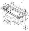
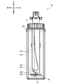
以下、本発明の液体収容装置、及び画像形成装置の一例としての印刷装置1について、図面を参照して説明する。図1を参照し、印刷装置1の概要について説明する。図1の上方、下方、左下方、右上方、右下方、及び左上方が、各々、印刷装置1の上方、下方、前方、後方、右方、及び左方である。
Hereinafter, the liquid storage device of the present invention and the
印刷装置1は、Tシャツ等の布帛、紙等の被記録媒体に、インク68(図2参照)をヘッド部67(図2参照)のノズルから吐出して印刷を行うインクジェットプリンタである。印刷装置1は、例えば、互いに異なる5種のインク68(ホワイト(W)、ブラック(K)、イエロー(Y)、シアン(C)、及びマゼンタ(M))を下方へ向けて吐出することで、被記録媒体にカラー画像を印刷する。以下の説明では、5種のインク68のうち、ホワイトのインク68を白インクといい、ブラック、シアン、イエロー、及びマゼンタの4色のインク68を総称する場合はカラーインクという。白インクは、カラーインクよりも沈降性の高いインクである。
The
図1に示すように、印刷装置1は、筐体2、プラテン駆動機構6、一対のガイドレール(図示せず)、プラテン5、トレイ4、枠体10、ガイドシャフト9、レール7、キャリッジ20、ヘッドユニット100,200、駆動ベルト101、及び駆動モータ19を備える。筐体2の右側前方の位置には、印刷装置1の操作を行うための操作ボタン501(図8参照)が設けられている。操作ボタン501は、作業者が印刷装置1の各種動作に関する指示を入力する際に操作される。
As shown in FIG. 1, the
枠体10は、平面視略長方形状の枠状であり、筐体2の上部に設置される。枠体10は、前方側にガイドシャフト9を、後方側にレール7を夫々支持する。ガイドシャフト9は、枠体10内側において左右方向に延びる。レール7は、ガイドシャフト9に対向して配置され、左右方向に延びる。
The
キャリッジ20は、ガイドシャフト9に沿って左右方向に搬送可能に支持されている。ヘッドユニット100,200は、前後方向に並べられてキャリッジ20に搭載されている。ヘッドユニット100は、ヘッドユニット200よりも後方に位置する。ヘッドユニット100,200は、夫々、ヘッド部67(図2参照)を下部に備える。ヘッドユニット100のヘッド部67は、白インクを吐出する。ヘッドユニット200のヘッド部67は、カラーインクを吐出する。ヘッド部67は、インク68を下方に吐出可能な微細なノズル(図示せず)を複数有する面を備えている。
The
図1に示すように、駆動ベルト101は、枠体10の内側において、左右方向に沿って架け渡される。駆動モータ19は、駆動ベルト101を介して、キャリッジ20と連結されている。駆動モータ19が駆動ベルト101を駆動することにより、ガイドシャフト9に沿ってキャリッジ20が左右方向に往復移動される。
As shown in FIG. 1, the
プラテン駆動機構6は、一対のガイドレール(図示せず)及びプラテン支持台(図示せず)を備える。一対のガイドレールは、プラテン駆動機構6の内側を前後方向に延び、プラテン支持台を前後方向に移動可能に支持する。プラテン支持台は、上部においてプラテン5を支持する。プラテン5は、被記録媒体を支持する。プラテン5の下方には、トレイ4が設けられている。トレイ4は、作業者がTシャツ等をプラテン5に載置する際に、Tシャツのそで等を受けることで、このそで等が筐体2内部の他の部品に接触しないように保護する。プラテン駆動機構6は、副走査駆動部63(図8参照)によって駆動され、プラテン支持台及びプラテン5を、一対のガイドレールに沿って、前後方向に移動する。プラテン5が、被記録媒体を前後方向(副走査方向)に搬送し、左右方向(主走査方向)に往復移動するヘッド部67からインク68が吐出されることで、印刷装置1による被記録媒体への印刷が行われる。
The
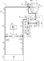
図2に示すように、印刷装置1は、制御装置であるCPU11、及びインク供給部700を備える。図2は、印刷装置1の構成の概略を示す図であるので、後述する第一チューブ53及び第二チューブ54の配置は、図3〜図7と異なる。CPU11は、制御プログラムに従って、印刷装置1を制御する。インク供給部700は、白色のインク68をヘッドユニット100のヘッド部67に供給する。ヘッド部67は、インクジェットヘッドを備える。ヘッドユニット200のヘッド部67に他の4色のインク68を供給するインク供給部(図示せず)も図2と同様の構造であってもよい。以下では白色のインク68に関わる構成を挙げて印刷装置1を説明する。
As shown in FIG. 2, the
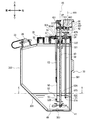
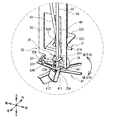
図2〜図7に示すように、印刷装置1は、メインタンク30、シャフト40、攪拌翼41、第一チューブ53、第二チューブ54、固定部材52、圧力検出素子42、中空部材58、及び攪拌モータ44を備える。メインタンク30は、インク68を収容する。メインタンク30に収容されたインク68はインク供給部700に供給され、インク供給部700から戻るインク68は再びメインタンク30に収容される。メインタンク30の収容可能量は、後述するサブパウチ8の収容可能量より多い。攪拌モータ44はシャフト40を回転する。シャフト40の回転により攪拌翼41が回転してインク68が攪拌される。第一チューブ53、第二チューブ54は、一体の部品である。第一チューブ53は、後述する第一供給流路711に接続され、メインタンク30内のインク68をヘッド部67に供給する。第一チューブ53は、メインタンク30に取り付ける前の状態では、図5の一点鎖線で示すような一直線状である。第一チューブ53は、メインタンク30に取り付けられた状態では、図5の実線で示すような曲線状となるように、後述の固定部材52によって固定される。このように、第一チューブ53がメインタンク30に取り付けられた状態では、第一チューブ53は湾曲しているので、第一チューブ53の先端部の伸長方向が変更している。しかし、第一チューブ53がメインタンク30から取り外されると、第一チューブ53は湾曲が多少は残るが、ほぼ一直線状の形状に復帰するような材質で構成されている。即ち、第一チューブ53の先端部の伸長方向が変更する部分の形状は、固定化されていない。第二チューブ54は、後述する第一循環流路721に接続され、インク68をメインタンク30に戻す。図6に示すように、第一チューブ53の下端部29の開口部29Aは、下端部29の軸線に対して垂直に交差する。第二チューブ54の下端部25の開口部25Aは、下端部25の軸線に対して垂直に交差する。固定部材52は第一チューブ53、第二チューブ54、及び中空部材58の位置を固定する。圧力検出素子42は中空部材48内の圧力を検出する。なお、図5においては、図4のメインタンク30内の部品の一部を省略している。
As shown in FIGS. 2 to 7, the
<メインタンク30>
図3に示すように、メインタンク30は、上部300、底部303、右側面301、左側面302、及び傾斜面304を備える。左側面302は、上下方向において右側面301より短く、左側面302の下端部の位置は、右側面301の下端部の位置より高い。傾斜面304は、左側面302の下端部と底部303の左端部を接続する。また、図4に示すように、メインタンク30は、前面305、及び後面306を備える。従って、メインタンク30は、インク68の有無に関わらず、一定の形状で構成される。メインタンク30内のインク68がメインタンク30外に供給されると、メインタンク30内の液面が下方に下がる。メインタンク30は、一定の形状で構成されるので、形状が変化しない。故に、メインタンク30は、インク68の液面の上方に気体を有する空間を維持する。
<
As shown in FIG. 3, the
図3に示すように、上部300には、開口である容器開口部31、容器開口部32、及び容器開口部33が設けられる。容器開口部31、容器開口部32、及び容器開口部33は、蓋34、蓋35、及び蓋36により夫々閉じられている。メインタンク30にインク68が補充される場合、蓋36が外され、容器開口部33からインク68がメインタンク30内に供給される。
As shown in FIG. 3, the
蓋34には、挿通孔321、挿通孔322、及び挿通孔(図示せず)が設けられる。挿通孔321からメインタンク30の内部にシャフト40が挿通される。挿通孔322には、圧力検出素子42を支持する中空部材58が固定される。挿通孔には、隔壁固定部材324が設けられる。隔壁固定部材324は、内部に図示しない貫通孔を備え、上部にねじ部324Aが形成される。隔壁固定部材324は、ねじ部324Aにより蓋34に固定されている。隔壁固定部材324は、第一チューブ53、及び第二チューブ54を内部の貫通孔により固定し、且つ、メインタンク30の内部に挿通する。
The
<シャフト40及び攪拌翼41>
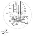
図3に示すように、シャフト40は、上下方向に延びる円柱状の回転軸であり、軸線45を中心に回転する。シャフト40の下端部に攪拌翼41が接続される。従って、攪拌翼41は、メインタンク30の内部の底部303側、すなわちメインタンク30の下方側に設けられる。図6、図7に示すように、攪拌翼41は、シャフト40から等間隔で延びる複数の軸部411と、各軸部411に夫々固定された翼部412を備えている。翼部412の形状は、シャフト40の回転により、インク68をメインタンク30の上部300方向に送る形状を有しているのが望ましい。この形状の一例が傾斜である。
<
As shown in FIG. 3, the
図3に示すように、蓋34の上部には、枠37が設けられる。枠37は、上壁371、下壁372、及び左壁373を備える。上壁371と下壁372とは、上下方向に所定間隔を隔てて平行に延び、左壁373により接続される。枠37は、シャフト40を回転可能に支持する。上壁371には、モータ支持台38が設けられる。モータ支持台38は攪拌モータ44を支持する。攪拌モータ44の回転軸441は、モータ支持台38を貫通して下方に突出する。回転軸441には、ギア442が固定される。シャフト40の上部にも、ギア401が固定される。ギア442とギア401との間には、ギア443が配置され、ギア442、401と歯合する。従って、CPU11の制御によって、攪拌モータ44の回転軸441が回転するとシャフト40が回転する。シャフト40の回転により攪拌翼41が回転する。攪拌翼41は、一方向に、すなわち順方向である平面視時計回り方向に回転可能である。攪拌翼41が回転すると、メインタンク30の底部303側に溜まったインク68は、上部300に向けて移動する。従って、インク68が攪拌される。従って、メインタンク30においてインク68の成分が沈降する可能性を低減できる。
As shown in FIG. 3, a
<中空部材58>
図3〜図7に示すように、中空部材58は、メインタンク30の内部に配置される。中空部材58は、上方側と下方側21で構成され、略L字状である(図6参照)。中空部材58の上方側は上下方向に伸展し、下方側21は前後方向に延びる。中空部材58の下方側21は、上下方向と直交する水平方向の成分を含む方向、すなわち前後方向に伸展する。中空部材58は、内部を伸展する中空を有する。中空部材58の中空は、ガスバリア性の素材で構成される。中空部材58は、下方側21において中空の開口部21Aを有する。
<
As shown in FIGS. 3 to 7, the
<固定部材52>
図6に示すように、固定部材52は、第一チューブ53の下端部29の位置と、第二チューブ54の下端部25と、中空部材58の下方側21の位置を固定可能である。固定部材52は、板状部50、位置決め部材52A、52B、52Cを備える。板状部50は、長方形状であり、シャフト40に沿って長辺が上下方向、短辺が前後方向に延びる。図6に示すように、板状部50は、シャフト40と、第一チューブ53及び第二チューブ54との間に配置される。板状部50の上端部は蓋34に、隔壁固定部材324のねじ部324Aにより蓋34に固定される。
<Fixing
As shown in FIG. 6, the fixing
図4及び図6に示すように、固定部材52の位置決め部材52Aは、長方形状であり、板状部50の下端部の前方、且つ下方から左方向に折れ曲げられて延びる。位置決め部材52Aは、上下方向に貫通する楕円形の開口521を有する。位置決め部材52Aの開口521に、第一チューブ53の下端部29と第二チューブ54の下端部25が挿入される。位置決め部材52Aの開口521は、第一チューブ53の下端部29の上端側の位置を固定する。
As shown in FIGS. 4 and 6, the positioning
固定部材52の位置決め部材52Bは、位置決め部材52Aよりも下方側且つ後方側に位置する。位置決め部材52Bは、長方形状であり、板状部50の下端部の下方且つ後方から左方向に折れ曲げられて延びる。位置決め部材52Bは、円形の前後方向に貫通する開口522を有する。第一チューブ53の下端531が位置決め部材52Bの開口522に挿入されている。すなわち、位置決め部材52Bの開口522は、第一チューブ53の上端側とは別に、下端部29の下端531側を固定する。これにより、第一チューブ53の下端部29は、上下方向に対して交差する方向に、すなわち後方且つ下方に伸長する。第一チューブ53の下端部29の開口部29Aは、後方に向けて開口する。第二チューブ54の下端部25の開口部25Aは、下方に向けて開口する。図4に示すように、第一チューブ53の下端531は、第二チューブ54の下端541よりも上方に位置する。第一チューブ53の下端部29は、第二チューブ54の下端部25から離れる方向に伸長する。
The positioning
固定部材52の位置決め部材52Cは、メインタンク30の内部に設けられる。
位置決め部材52Cは、長方形状であり、板状部50の下端部に設けられる。位置決め部材52Cは、板状部50の下端部において、位置決め部材52Aの上方且つ後方から右方に折れ曲げられて延びる。位置決め部材52Cは、上下方向に貫通する円形の開口523、524を有する。開口523、524は、左右方向に並ぶ。位置決め部材52Cの開口523に、中空部材58の下方側21が挿入される。開口523は、中空部材58の位置を固定する。また、シャフト40は、位置決め部材52Cの開口524に回転可能に挿通される。
The positioning
The positioning
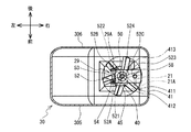
図4〜図7を参照して、第一チューブ53、第二チューブ54、中空部材58、固定部材52の位置関係について説明する。図7に示すように、固定部材52は、上下方向において攪拌翼41の回転領域413と重なるように配置されている。例えば、攪拌翼41の回転領域413は、シャフト40の軸線45から攪拌翼41の最外周までの距離を半径とする円内の領域である。固定部材52は、上下方向から見た場合において、回転領域413内に入る位置に配置される。
The positional relationship between the
第一チューブ53の下端部29は、攪拌翼41よりも上方に配置される。また、第二チューブ54の下端部25は、攪拌翼41よりも上方に配置される。第一チューブ53の開口部29Aは、攪拌翼41の上方に配置される。第二チューブ54の開口部25Aは、攪拌翼41の上方に配置される。
The
第一チューブ53の下端部29は、攪拌翼41が回転する回転方向である平面視時計回り方向に沿って延び、且つ下端部29の開口部29Aは、回転方向である後向に向かって開口する。第二チューブ54の下端部25の開口部25Aは、下方に向けて開口する。
The
図7に示すように、中空部材58の下方側21は、攪拌翼41よりも上方に配置され、且つ中空部材58の開口部21Aは、攪拌翼41の上方に位置する。中空部材58の下方側21は、攪拌翼41が一方向に回転する回転方向に沿って延び、且つ中空部材58の開口部21Aは、前方に向かって開口する。従って、開口部21Aは、インク68が攪拌される方向に向かって伸びている。故に、中空部材58は、インク68が気泡を含んだとしても、中空部材58の内部に気泡が入る可能性を低減できる。
As shown in FIG. 7, the
図3に示すように、固定部材52、第一チューブ53、及び第二チューブ54は、中空部材58と容器開口部33との間に配置される。固定部材52の位置決め部材52A、52B、52Cは、第一チューブ53、第二チューブ54、中空部材58を、メインタンク30の内部で固定する。固定部材52の位置決め部材52Cは、容器開口部33側とは反対側のメインタンク30の右側面301側で、中空部材58の位置を固定する。具体的には、中空部材58の開口部21Aは、容器開口部33とは反対側のメインタンク30の右側面301側に配置されている。従って、容器開口部33から供給されたインク68が中空部材58の開口部21Aに直撃する可能性が低くなる。故に液体収容装置は、衝撃による中空部材58の劣化を抑制できる。
As shown in FIG. 3, the fixing
<圧力検出素子42>
図3に示すように、圧力検出素子42は、中空部材58の上端に配置される。圧力検出素子42は、ケース42Aを備え、圧力を検出するための検出素子(図示せず)がケース42Aに格納されている。検出素子は、中空部材58の中空の上端に配置される。圧力検出素子42はメインタンク30内のインク68とは離れて設けられている。圧力検出素子42は、中空内の圧力を検出する。圧力検出素子42は、大気圧の変動を補正可能なゲージ圧を検出する。中空部材58と圧力検出素子42との間は、密閉部材24により密封されている(図3参照)。密閉部材24は、一例としてパッキン等のシール部材である。
<
As shown in FIG. 3, the
密閉部材24は、このように密閉されることで、中空部材58によって構成される空間が、中空部材58の一方側(下方側21)が開口し、上方側(他方側)が密閉されている。すなわち、中空部材58によって構成される空間は、液体や気体が中空部材58の一方側から上方側又はその逆に通過することができない。言い換えると、中空部材58の上方側は、袋小路のようになっている。そのため、中空部材58には、液体の特性によって、液体が侵入する場合としない場合がある。
By sealing the sealing
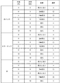
中空部材58の白インク、カラーインク、水に対する特性の適否について実験を行った。実験の結果は、図14に示す。実験に用いた中空部材58の条件は以下である。中空部材58の軸線方向に直交する断面は、円形である。中空部材58の壁厚が1mmである。中空部材58の外径が4〜12mmである。中空部材58の内径が2〜10mmである。中空部材58の下端部21は、実験時に水平となる部分が50mmである。中空部材58は樹脂である。実験においては、特性アニオン系及びノニオン系の少なくとも一方の表面活性剤を含み、表面張力が20以上36未満[mN/m]である白インク及びカラーインクを用いた。白インクやカラーインクに対する比較例として水(水の表面張力は一般に73[mN/m])を用いた。
An experiment was conducted on the suitability of the characteristics of the
中空部材58の適否としては、液体(インク)と中空部材58内の気体との境界が中空部材58の下方側21の水平部分に存在することが必要である。図14に示すように、「流入」との記載は、液体が中空部材58の下方側21の水平部分の全てを満たした状態であり、液体と中空部材58内の気体との境界が中空部材58の下方側21の水平部分に存在しないことを示す。図14に示すように、「流入しない」との記載は、中空部材58の下方側21の水平部分に液体が入っていないものであり、液体と中空部材58内の気体との境界が、中空部材58の下方側21の水平部分に存在しないことを示す。「流入」、「流入しない」、「1mm流入」は、上記特性の液体(インク)に関して中空部材58に対して温度変化などを想定すると不適な寸法である(図14参照)。なお、液体の1mm以下の流入は不安定なため不適とした。図14に示すように、中空部材58の内径は、3〜4mmが適当であることが分かる。中空部材58の樹脂としては、ポリエチレン、フッ素樹脂等がある。ポリエチレンに比べ、フッ素樹脂は水との接触角が大きい。液体(インク)の特性に応じて、中空部材58の下方側21の水平部分に液体(インク)の境界が存在するように、中空部材58の樹脂の種類を使い分けてもよい。
As for the suitability of the
中空部材58とインク68との位置関係を説明する。例えば、メインタンク30内にインク68が所定値以上供給されている場合に、中空部材58の中空にインク68が侵入する。所定値とは、例えば、図3に示す高さにインク68がある場合をいう。この場合、インク68と中空における気体との境界は、中空部材58の下方側21に位置する。
The positional relationship between the
中空部材58の下方側21の中空における気体とインク68との境界は、中空部材58の中空内の気体の伸縮に応じて移動する。この場合においても、インク68と中空部材58の中空内の気体との境界は、中空部材58の下方側21に位置する。印刷装置1は、気体の温度が変化して中空部材58が膨張又は収縮したとしても、インク68の液面から下方側21までの深さが変わらない。故に、印刷装置1は、気体の温度変化による圧力検出素子42への影響を低減できる。
The boundary between the gas and the
<インク供給部700>
図2に示すように、インク供給部700は、インク68をヘッド部67に供給し、また、インク68が循環する部位である。インク供給部700は、第一供給流路711、第二供給流路712、第一循環流路721、第二循環流路722、第一接続流路731、第二接続流路732、サブパウチ8、脱気モジュール60、ポンプ751、及び電磁弁761,762,763,764,765,766、及びフィルタ771を備える。
<
As shown in FIG. 2, the
サブパウチ8は、袋状であり、メインタンク30から供給されたインク68を収容する。また、サブパウチ8は、ヘッド部67にインク68を供給する。ヘッド部67は、サブパウチ8から供給されたインク68を吐出して、印刷対象物に印刷を行う。サブパウチ8には、残量センサ899が装着される。
The
第一供給流路711、第二供給流路712、第一循環流路721、第二循環流路722、第一接続流路731、第二接続流路732は、例えば、中空状のチューブによって形成されている。第一供給流路711は、第一チューブ53とサブパウチ8とに接続し、メインタンク30からサブパウチ8にインク68を供給する流路である。
The first
第二供給流路712は、サブパウチ8とヘッド部67とに接続し、サブパウチ8からヘッド部67にインク68を供給する流路である。第一供給流路711と第二供給流路712とは、第一接続部791において合流する。第一接続流路731は、第一接続部791とサブパウチ8との間の流路である。すなわち、第一接続流路731は、第一供給流路711の一部であり、第二供給流路712の一部でもある。
The second
第一循環流路721は、第二チューブ54とサブパウチ8とに接続し、サブパウチ8からメインタンク30にインク68を循環させる流路である。第二循環流路722は、ヘッド部67とサブパウチ8とに接続し、ヘッド部67からサブパウチ8にインク68を循環させる流路である。第一循環流路721と第二循環流路722とは、第二接続部792おいて合流する。第二接続流路732は、第二接続部792とサブパウチ8との間の流路である。すなわち、第二接続流路732は、第一循環流路721の一部であり、第二循環流路722の一部でもある。
The first
電磁弁761は、第一供給流路711に設けられる。電磁弁761は、後述する脱気部601よりも、サブパウチ8側に位置している。電磁弁761は、CPU11によって制御され、第一供給流路711を開閉する。電磁弁762は、第一接続流路731に設けられる。電磁弁762は、CPU11によって制御され、第一接続流路731を開閉する。電磁弁763は、第二供給流路712に設けられる。電磁弁763は、CPU11によって制御され、第二供給流路712を開閉する。
The
電磁弁764は、第一循環流路721に設けられる。電磁弁764は、CPU11によって制御され、第一循環流路721を開閉する。電磁弁765は、第二接続流路732に設けられる。電磁弁765は、CPU11によって制御され、第二接続流路732を開閉する。電磁弁766は、第二循環流路722に設けられる。電磁弁766は、CPU11によって制御され、第二循環流路722を開閉する。
The
フィルタ771は、第一供給流路711に設けられる。フィルタ771は、第一供給流路711を流れるインク68に含まれる異物を除去する。ポンプ751は、第一供給流路711に設けられている。ポンプ751は、フィルタ771よりもサブパウチ8側に設けられている。ポンプ751は、メインタンク30からインク68を吸い上げ、下流側であるサブパウチ8側に流す。
The
脱気モジュール60は、第一供給流路711に設けられている。脱気モジュール60は、脱気部601、真空フィルタ602、減圧ポンプ603、電磁弁604、吸気フィルタ605、経路606、経路608、及び経路609を備えている。脱気部601は、第一供給流路711に設けられている。脱気部601は、ポンプ751と電磁弁761との間に位置している。真空フィルタ602は、経路606を介して、脱気部601と接続されている。経路606は、接続部607において経路608と接続されている。吸気フィルタ605は、経路608に接続されている。電磁弁604は、経路608に設けられている。減圧ポンプ603は、経路609を介して真空フィルタ602に接続されている。
The
減圧ポンプ603は、CPU11の制御によって動作し、真空フィルタ602を介して経路606を減圧する。従って、脱気部601を流れるインク68に含まれる気泡が減少する。経路606が減圧される場合、電磁弁604は、CPU11の制御によって、経路608を閉じる。経路606を減圧しない場合、電磁弁604は、CPU11の制御によって経路608を開く。経路608が開かれると、吸気フィルタ605及び経路606を介して、外気が経路606に供給される。従って、経路606の減圧状態が解消される。吸気フィルタ605は、経路608側に流れる外気から異物を除去する。
The
<電気的構成>
図8を参照して印刷装置1の電気的構成を説明する。図8に示すように、印刷装置1は、印刷装置1の制御を司る制御装置としてのCPU11を備える。CPU11は、ROM12、RAM13、EEPROM59、77、ヘッド駆動部61、主走査駆動部62、副走査駆動部63、攪拌モータ駆動部64、ポンプ駆動部65、圧力検出素子42、温度センサ66、及び操作処理部57と、バス55を介して電気的に接続する。
<Electrical configuration>
The electrical configuration of the
CPU11は、例えば、制御プログラムを実行することにより、メインタンク30から供給されるインク68により被記録媒体に画像を形成する。ROM12は、CPU11が印刷装置1の動作を制御するための制御プログラム及び初期値等を記憶する。RAM13は、制御プログラムで用いられる各種データを一時的に記憶する。EEPROM59は、印刷装置1の電源のON/OFFによらずデータを保持して記憶する。ヘッド駆動部61は、インク68を吐出するヘッド部67に電気的に接続されており、ヘッド部67の各吐出チャンネルに設けられた圧電素子を駆動してノズルからインク68を吐出させる。
The
主走査駆動部62は、駆動モータ19(図1参照)を含み、キャリッジ20を左右方向(主走査方向)に移動させる。副走査駆動部63は、図示しないモータ及びギア等を含み、プラテン駆動機構6(図1参照)を駆動してプラテン5(図1参照)を前後方向(副走査方向)に移動させる。
The main
攪拌モータ駆動部64は、攪拌モータ44を駆動する。ポンプ駆動部65は、ポンプ751を駆動する。操作処理部57は、操作ボタン501に対する操作入力をCPU11に出力する。圧力検出素子42は、中空部材58の中空内の圧力を検知してCPU11に出力する。温度センサ66は、メインタンク30内の温度を検知しCPU11に出力する。
The stirring
EEPROM77は、メインタンク30内のインク68の残量に関するデータを記憶している。EEPROM77に記憶されたインク68の残量に関するデータは、中空部材58の中空内の圧力と関連付けられている。CPU11は、圧力検出素子42によって出力された圧力に基づき、メインタンク30におけるインク68の残量を検出する。なお、EEPROM77(図8参照)は、図示しないメモリ装着部(図示せず)に装着される。メモリ装着部は、EEPROM77を着脱自在に装着可能である。
The
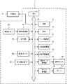
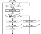
図9、図10を参照して、メイン処理、及び残量検出処理の一例を説明する。制御装置であるCPU11は、例えば、電源が投入された場合、ROM12に記憶された制御プログラムを読み出して実行する。なお、制御プログラムは、メインタンク30内のインク68が消費された場合に実行されてもよい。例えば、制御プログラムは、メンテナンスを行う場合等や、所定の周期毎に実行されてもよい。CPU11は、制御プログラムが実行されるとメイン処理を実行する。CPU11は、操作ボタン501の操作による印刷指示があったか否か判断する(S1)。CPU11は、印刷指示が無いと判断した場合(S1:NO)、処理をS1に戻して印刷指示を待つ。CPU11は、印刷指示があると判断した場合(S1:YES)、残量取得処理を行う(S3)。
An example of the main process and the remaining amount detection process will be described with reference to FIGS. 9 and 10. The
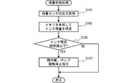
図10に示すように、残量取得処理では、CPU11は、圧力検出素子42により中空部材58の中空内の圧力を取得する(S101)。CPU11は、EEPROM77を参照し、取得した圧力に基づきメインタンク30内のインク68の残量を特定する(S103)。CPU11は、圧力検出素子42の出力に基づき特定されたインク68の残量が所定値以下か否か判断する(S105)。CPU11は、インク68の残量が所定値より多いと判断した場合(S105:NO)、インク68の残量に問題が無いとして、処理を戻す。CPU11は処理をS5に進める。CPU11は、インク68の残量(図4の線Dを参照)が所定値以下であると判断した場合(S105:YES)、攪拌翼41、ポンプ751の駆動停止指示を行う(S107)。CPU11は、処理をS5に進める。
As shown in FIG. 10, in the remaining amount acquisition process, the
図10に示すように、CPU11は、攪拌翼41、ポンプ751の駆動停止指示があるか否か判断する(S5)。CPU11は、攪拌翼41、ポンプ751の駆動停止指示が無いと判断した場合(S5:NO)、攪拌モータ44を駆動開始に伴う回転速度が徐々に増した後の所定時間、一定の回転速度で平面視反時計回りに駆動することで、攪拌翼41を駆動する(S7)。これにより、メインタンク30内のインク68が攪拌される。次いで、CPU11は、ポンプ751を稼働する(S9)。CPU11は、ポンプ751を制御して、第一チューブ53のインク68をメインタンク30の外部に流出させる。すなわち、CPU11は、圧力検出素子42により検出された圧力に応じて、ポンプ751を稼働する。CPU11は、印刷処理を実行する(S11)。CPU11は処理をS1に戻す。
As shown in FIG. 10, the
一方、CPU11は、攪拌翼41、ポンプ751の駆動停止指示があると判断した場合(S5:YES)、攪拌モータ44を制御して、攪拌翼41の駆動を停止する(S13)。CPU11は、攪拌翼41を制御することで、メインタンク30の内部のインク68を撹拌し、圧力検出素子42の出力に応じて、攪拌翼41を停止する。CPU11は、圧力検出素子42の出力に応じて、攪拌翼41を停止させることで、インク68に気泡が含まれるのを抑制できる。次いで、CPU11は、ポンプ751の稼働を停止する(S15)。すなわち、CPU11は、圧力検出素子42により検出された圧力に応じて、ポンプ751を停止する。これにより、CPU11は、メインタンク30内のインク68の残量が少ないにもかかわらず、ポンプ751を駆動することを防ぎ、第一チューブ53内に気泡が侵入する可能性を低減できる。CPU11は処理をS1に戻す。この場合、作業者は、メインタンク30内にインク68を補充し、印刷装置1が印刷可能な状態にするのが望ましい。
On the other hand, when the
上記実施形態の印刷装置1では、圧力検出素子42は、中空部材58の上方側の中空に配置されている。従って、圧力検出素子42がインク68とは離れて設けられている。故に、印刷装置1は、インク68により圧力検出素子42が劣化する可能性を低減できる。故に、印刷装置1は、圧力検出素子42の劣化を防ぎ、且つセンシング不良を抑制できる。
In the
容器開口部33は、メインタンク30に設けられ、メインタンク30にインク68を供給可能である。中空部材58の開口部21Aは、容器開口部33とは反対側のメインタンク30の右側面301側に配置されている。従って、印刷装置1、中空部材58の開口部21Aが容器開口部33側に配置されている場合に比べて、容器開口部33から供給されたインク68が中空部材58の開口部21Aに直撃する可能性が低くなる。故に、印刷装置1は、衝撃による中空部材58の劣化を抑制できる。
The
第一チューブ53は、メインタンク30からメインタンク30の外部にインク68を流出させる。中空部材58の開口部21Aは、第一チューブ53の下端531よりも上方に配置される。CPU11は、ポンプ751を制御して、第一チューブ53のインク68をメインタンク30の外部に流出させ、圧力検出素子42が検出した圧力に応じて、ポンプ751の稼働を停止する。印刷装置1は、メインタンク30におけるインク68の残量を正確に認識し、圧力検出素子42の出力に応じてポンプ751の稼働を制御する。例えば、印刷装置1は、インク68の残量が所定値以下になっているにも関わらず、ポンプ751を稼働させてしまいインク68に気泡が含まれる可能性を低減できる。
The
中空部材58の下方側21は、上下方向に対して直交する水平方向の成分を含む方向に伸展し、且つ中空部材58の開口部21Aは、水平方向に向けて開口し、中空部材58の下方側21の一部の中空における気体とインク68との境界は、中空部材58の中空内の気体の伸縮に応じて移動する。印刷装置1は、中空部材58の中空内の気体の温度が変化し、中空部材58が膨張又は収縮する場合がある。このような場合でも、気体とインク68との境界が、中空部材58の下方側21の少なくとも一部の中空を移動することにより、温度上昇による圧力の変化を緩和する。これにより、圧力検出素子42は、少なくとも一部の中空が水平方向に伸展しない場合に比べて、メインタンク30におけるインク68の残量を正確に認識できる。
The
位置決め部材52Cは、メインタンク30に設けられ、中空部材58の一部の位置を固定する。印刷装置1は、中空部材58の一部の位置が固定されているので、中空部材58が全く固定されていない場合に比べて、中空部材58が不測の位置に移動する可能性が低くなる。故に、印刷装置1は、圧力検出素子42の検出する圧力に影響が出ることを抑制できる。
The positioning
攪拌翼41は、メインタンク30の内部に設けられ、インク68を撹拌する。中空部材58の開口部21Aは、攪拌翼41の上方に位置する。CPU11は、攪拌翼41を制御することで、メインタンク30の内部のインク68を撹拌する。CPU11は、圧力検出素子42の出力に応じて、攪拌翼41を停止する。印刷装置1は、メインタンク30におけるインク68の残量を正確に認識し、圧力検出素子42の出力に応じて、攪拌翼41を停止させることで、インク68に気泡が含まれるのを抑制できる。例えば、印刷装置1は、インク68が所定値以下である場合に、攪拌翼41を停止させる。
The stirring
攪拌翼41は、一方向にのみ回転可能であり、中空部材58の下方側21は、攪拌翼41が回転する回転方向に沿って延び、且つ中空部材58の開口部21Aは、一方向に向かって開口する。印刷装置1は、中空部材58の下方側21は、攪拌翼41が回転する回転方向に沿って延び、且つ中空部材58の開口部21Aが一方向に向かって開口する。故に、印刷装置1は、インク68が気泡を含んだとしても、中空部材58の内部に気泡が入る可能性を低減できる。なお、「中空部材58の下方側21は、攪拌翼41が回転する回転方向に沿って延び、または中空部材58の開口部21Aは、一方向に向かって開口する」とは、攪拌翼41が回転する回転領域413を円柱状と想定して、中空部材58の下方側21がその円柱の上面に対して平行であることを意味する。即ち、中空部材58の下方側21がその円柱の上面に対して平行に伸展するのではなく、中空部材58の下方側21がその円柱の上面に対して交差する方向に伸展している構成に比べて、中空部材58の下方側21に気泡が侵入する可能性を抑制できる。更に、図6に示すように、開口部21Aの向きが前方向であるとともに、開口部21Aが攪拌翼41の軸線45(シャフト40の中心線)の右側にあり、攪拌翼41の回転方向が順方向である。開口部21Aが攪拌翼41による流れに背を向けているので、開口部21Aの向きを後方向にした構成に比べて、開口部21Aに気泡が侵入する可能性を抑制できる。なお、後方向は、図6の開口部21Aの向きに対して水平方向において180度反転させた方向である。
The stirring
同様に、攪拌翼41が回転する回転領域413を円柱状と想定して、第一チューブ53の下端部29がその円柱の上面に対して平行に伸展している。第一チューブ53の下端部29がその円柱の上面に対して平行に伸展ではなく、その円柱の上面に対して交差する方向に伸展している構成に比べて、開口部29Aに気泡が侵入する可能性を抑制できる。更に、図6に示すように、開口部29Aの向きが後方向であるとともに、開口部21Aが攪拌翼41の軸線45の左側にあり、攪拌翼41の回転方向が順方向である。開口部29Aが攪拌翼41による流れに背を向けているので、開口部29Aの向きを前方向にした構成に比べて、開口部29Aに気泡が侵入する可能性を抑制できる。なお、前方向は、図6の開口部29Aの向きに対して水平方向において180度反転させた方向である。
Similarly, assuming that the
圧力検出素子42は、大気圧の変動を補正可能なゲージ圧を検出する素子である。印刷装置1の圧力検出素子42は、大気圧の変動に関わらず、中空部材58の内部の圧力を正確に検出できる。
The
インク68は、特性アニオン系及びノニオン系の少なくとも一方の表面活性剤を含む。表面張力は、20以上36未満[mN/m]である。中空部材58の軸線方向に直交する断面が円形であり、中空部材58の内径が3〜4mmが適当である。故に、中空部材58は、インク68に対して、中空部材58内の気体の温度変化による影響が少ない。
なお、本発明は上記実施形態に限定されることなく、種々の変更が可能である。例えば、上記実施形態の印刷装置1では、第一チューブ53は一体の部品であったがこれに限らない。第一チューブ53は、先端部と、本体部との2つ以上の部品で構成されていてもよい。この場合、先端部は、第一チューブ53の下端部29の一部を含む。本体部は、先端部とは別体に設けられ、先端部と接続する。これにより、第一チューブ53は、先端部のみ交換できる。また、第一チューブ53は、先端部を取り外した状態の本体部のみでも使用できる。
The present invention is not limited to the above embodiment, and various modifications can be made. For example, in the
第一チューブ53は、先端部と本体部の伸長方向が変更する部分の形状がメインタンク30に取り付けられる前から、図5の実線で示すように固定化されていてもよい。この場合、メインタンク30内の第一チューブ53は、第一チューブ53の下端部29を構成する本体部が伸長方向に伸長してもよい。また、第一チューブ53は、本体部以外の第一チューブ53の下端部29を構成する先端部が伸長方向に対して交差する方向に伸長してもよい。印刷装置1は、伸長方向が変更する部分の形状が固定化されていることにより、第一チューブ53内の流路が安定する。これにより、印刷装置1は、インク68を円滑にヘッド部67に供給できる。従って、印刷装置1は、インク68がヘッド部67から吐出されず、印刷がかすれる可能性を低減できる。
The
上記実施形態の印刷装置1では、第一チューブ53の開口部29Aは、後方に向けて開口していたがこれに限らない。図11(a)に示すように、第一チューブ53の下端部29の開口部29Aは、上下方向に交差する方向のうち、斜め上方に向けて開口してもよい。印刷装置1は、インク68に含まれた気泡が上方へ移動しやすいので、開口部29Aが斜め上方に向けて開口することにより、第一チューブ53に気泡が侵入する可能性を低減できる。従って、印刷装置1は、インク68がヘッド部67から吐出されず、印刷がかすれる可能性を低減できる。
In the
また、図11(b)に示すように、第一チューブ53の下端部29の開口部29Aの下側に張り出し部17を備えてもよい。印刷装置1は、インク68に含まれた気泡が上方に移動することがある。第一チューブ53は、開口部29Aの下側に張り出し部17を備えることにより、第一チューブ53に気泡が侵入する可能性を低減できる。従って、印刷装置1は、インク68がヘッド部67から吐出されず、印刷がかすれる可能性を低減できる。
Further, as shown in FIG. 11B, an overhanging
第一チューブ53の下端部29は、上下方向に対して直交する方向に伸長してもよい。印刷装置1では、第一チューブ53の下端部29が上下方向に対して直交する。従って、印刷装置1は、メインタンク30内のインク68が気泡を含んだ場合も、第一チューブ53の下端部29が斜め下方に伸長した場合に比べて、第一チューブ53内に気泡が侵入する可能性を低減できる。従って、印刷装置1は、インク68がヘッド部67から吐出されず、印刷がかすれる可能性を低減できる。また、第一チューブ53の下端部29の開口部29Aは、第一チューブ53の軸線に対して垂直に交差する方向に、すなわち後方に向けて開口しなくてもよい。
The
第一チューブ53の下端部29の少なくとも一部が上下方向に交差する方向に延びていればよい。このような場合においても、上記実施形態と同様の効果を得ることができる。
At least a part of the
攪拌翼41は、回転することによりインク68を攪拌したがこれに限らない。撹拌部材が、上下方向に往復移動することによりインク68を撹拌してもよい。攪拌翼41の形状は、上記の形状及び枚数に限られない。インク68を攪拌できる形状及び枚数であればよい。攪拌翼41は、図6に矢印で示す順方向である平面視時計回りにのみ回転したがこれに限らず、逆方向である平面視反時計回りに回転してもよい。この場合、攪拌翼41のシャフト40(回転軸)が上下方向に伸展する直線状であり、第一チューブ53の下端部29の下端531(最先端部)がシャフト40に直交する方向に延びるとよい。従って、印刷装置1は、第一チューブ53の下端部29の下端531が攪拌翼41のシャフト40に直交以外で交差する方向やシャフト40に平行な上下方向に伸展している場合に比べて、第一チューブ53に気泡が侵入する可能性を低減できる。従って、印刷装置1は、インク68がヘッド部67から吐出されず、印刷がかすれる可能性を低減できる。同様に、中空部材58の下方側21は、上下方向に直交する方向、且つシャフト40に直交する方向に延びるとよい。これにより、インク68が開口部21Aに対して逆流して気泡が侵入するのを防ぐことができる。特に、攪拌翼41が順方向及び逆方向に回転する場合において、第一チューブ53の下端部29の下端531(最先端部)がシャフト40に直交する方向に延びることや、中空部材58の下方側21が上下方向に直交する方向に延び、且つシャフト40に直交する方向に延びることは、開口部21A、29Aへの気泡の侵入の低減に寄与する。なお、中空部材58の下方側21は、攪拌翼41の回転方向や、シャフト40との位置関係、インク68の粘性などの特性を考慮して、上下方向に直交ではなく、交差する方向に延びてもよい。
The stirring
上記構成においては、図6に示すように、位置決め部材52Aの開口521は水平な面を上下方向に貫通して形成されるとともに、位置決め部材52Bの開口522が垂直な面を前後方向に貫通して形成されている。以下、水平な面とは、前後左右方向に対して平行な面であり、垂直な面とは、上下左右方向に対して平行な面を意味する。第一チューブ53の水平方向位置を位置決め部材52Aによって規定されている。その第一チューブ53が位置決め部材52Aによって規定された位置よりも、更に先端側(下端531)が、第一チューブ53の上下方向位置を位置決め部材52Bによって規定されている。つまり、固定部材52は、第一チューブ53の下端部29の上端側の位置を固定し、且つ第一チューブ53の下端部29が上下方向に交差する方向に延びるように、第一チューブ53の下端部29の上端側とは別に、下端部29の先端側を固定する部材である。即ち、固定部材52は、2か所で第一チューブ53の下端部29を固定している。図5に示すように、第一チューブ53の先端部の伸長方向が変更する部分の形状が固定化されていなくても、位置決め部材52Aの開口521によって、第一チューブ53の水平位置を規定しており、水平ではない面で規定する場合と比べて、水平方向における位置決めの作業が簡単に行える。同様に、第一チューブ53の先端部の伸長方向が変更する部分の形状が固定化されていなくても、位置決め部材52Bの開口522によって第一チューブ53の垂直位置を規定しており、垂直ではない面で規定する場合と比べて、垂直方向における位置決めの作業が簡単に行える。
In the above configuration, as shown in FIG. 6, the
図6に示す構成は、上記のような作業が簡単となる利点がある。しかしながら、図6に示す構成は、後述する図12、図13に示す変形例の構成よりも、加工が簡単であるが、以下に説明する可能性が懸念される。 The configuration shown in FIG. 6 has an advantage that the above-mentioned work is simplified. However, although the configuration shown in FIG. 6 is simpler to process than the configuration of the modified examples shown in FIGS. 12 and 13 described later, there is a concern that it may be described below.
図6に示す構成は、位置決め部材52Aの開口521が水平な面に形成されている。位置決め部材52Bの開口522は垂直な面に形成されており、その垂直な面の上端は水平な面である。位置決め部材52Cの開口523,524が水平な面に形成されている。それら水平な面とメインタンク30の内天井との間には、インク68が存在し、且つ上下方向に伸展する第一チューブ53、第二チューブ54、中空部材58が配置されている。メインタンク30内のインク68の組成が、位置決め部材52A、52B、52Cの水平な面に堆積する可能性がある。インク68の組成は、例えば、顔料であり、特に白インクの場合においては、酸化チタンに関わる顔料である。位置決め部材52A、52B、52Cの水平な面は攪拌翼41よりも上方にあり、その堆積したインク68の組成は攪拌翼41よりも上方に位置する。攪拌翼41が回転しても、その堆積したインク68の組成が攪拌翼41によって攪拌されず、その結果、攪拌翼41によってインク68の組成が適切に攪拌されない可能性がある。従って、図6のような構成では、インク68がヘッド部67から吐出されず、印刷がかすれる可能性ある。
In the configuration shown in FIG. 6, the
以下に説明する変形例においては、インク68の組成が堆積することに起因する問題点を低減するために、以下の構成を有する。特に明記や図示しない構成については、図1〜図10に関わる構成と同じである。
The modified example described below has the following configuration in order to reduce problems caused by the accumulation of the composition of the
図12に示す構成は、インク68の組成が堆積することに起因する問題点を低減する1つ目の変形例である。図12の変形例の印刷装置1においては、上記実施形態の固定部材52の代わりに、固定部材252が設けられる点で異なる。固定部材252は、板状部50A、位置決め部材252A、252B、252C、傾斜部115A、115B、115C、開口521A、523A、524A等が設けられている。
The configuration shown in FIG. 12 is a first modification that reduces the problems caused by the accumulation of the composition of the
図12に示すように、固定部材252の位置決め部材252A、252B、252Cは、板状部50Aに設けられ、攪拌翼41よりも上方に配置されている。位置決め部材252Aの開口521Aが、水平方向に対して先端側(左側)が下降して傾斜した面である傾斜部115Aに形成されている。位置決め部材252Bの開口522は垂直な面に形成され、その垂直な面の上端の傾斜部115Bは、水平方向に対して、先端側(左側)が下降して傾斜した面である。位置決め部材252Cの開口523A,524Aが、水平方向に対して先端側(右側)が下降して傾斜した面である傾斜部115Cに形成されている。開口521A、522,523A,524Aは傾斜部115A、115B、115Cの面に対して直交する方向に貫通している。
As shown in FIG. 12, the
傾斜部115A、115B、115Cとメインタンク30の内天井の間には、インク68が存在し、且つ上下方向に伸展する第一チューブ53、第二チューブ54、中空部材58が配置されている。メインタンク30内のインク68の組成が、位置決め部材252A、252B、252Cの傾斜部115A、115B、115Cに堆積する可能性がある。位置決め部材252A、252B、252Cの傾斜部115A、115B、115Cの面は攪拌翼41よりも上方にあり、その堆積したインク68の組成は攪拌翼41よりも上方に位置する。しかし、第一チューブ53、第二チューブ54、中空部材58を位置決めしている部分が傾斜部115A、115B、115Cの開口521A、522、523Aであるので、傾斜部115A、115B、115Cに堆積したインク68の組成の自重によって、堆積したインク68の組成が落下する可能性がある。または、攪拌翼41が回転すると、位置決め部材252A、252B、252Cの面が水平な面である場合よりも(図6参照)、傾斜部115A、115B、115Cからインク68の組成が落下する可能性が高くなる。位置決め部材252A、252B、252Cに堆積したインク68の組成が攪拌翼41によって攪拌されず、その結果、攪拌翼41によってインク68の組成が適切に攪拌されない可能性が低減されている。従って、図6のような構成に比べて、インク68がヘッド部67から吐出されず、印刷がかすれる可能性が低減されている。
図13に示す構成は、インク68の組成が堆積することに起因する問題点を低減する2つ目の変形例である。図13の変形例の印刷装置1においては、上記実施形態の固定部材52の代わりに、固定部材352を備える点で異なる。固定部材352は、板状部50B、位置決め部材352A、252B、353B等を備える。位置決め部材352Aは、水平部215A、傾斜部315Aを備える。位置決め部材352Cは、水平部215B、傾斜部315Bを備える。水平部215A、215Bは、図6に示す位置決め部材52A、52Cと夫々同様の形状ある。なお、位置決め部材252Bは、図12の変形例の位置決め部材252Bと同一である。
The configuration shown in FIG. 13 is a second modification that reduces the problems caused by the accumulation of the composition of the
図13に示すように、位置決め部材352Aは攪拌翼41よりも上方に配置されている。位置決め部材52Aは、開口521が形成されている水平な水平部215Aと、水平部215Aの左端から上方且つ右方に伸展し、右側から左側に向けて下降して傾斜する傾斜部315Aとを有する。水平部215A及び傾斜部315Aは板状部50Bの下端部の前側を折り曲げられ、一体に形成されている。傾斜部315Aの上端側は2股に分かれており、その2股の間には、第一チューブ53及び第二チューブ54が挿通されている。開口521は水平部215Aに対して直交するように貫通している。
As shown in FIG. 13, the positioning
図13に示すように、位置決め部材252Bの開口522は垂直な面に形成され、その垂直な面の上端は、水平方向に対して、先端側(左側)が下降して傾斜した面である傾斜部115Bである。なお、図13の傾斜部115Bは、図12に示す変形例の傾斜部115Bと同一である。
As shown in FIG. 13, the
図13に示すように、位置決め部材352Cは攪拌翼41よりも上方に配置されている。位置決め部材352Cは、開口523,524が形成されている水平な水平部215Bと、水平部215Bの右端から上方且つ左方に伸展し、左側から右側に下降して傾斜する傾斜部315Bを有する。水平部215B及び傾斜部315Bは板状部50Bを折り曲げられ、一体に形成されている。傾斜部315Bの上端側は2股に分かれており、その2股の間には、中空部材58とシャフト40が挿通されている。開口523,524は水平部215Bに対して直交するように貫通している。
As shown in FIG. 13, the positioning
上述した図6の構成と同様に、第一チューブ53の下端部29が水平方向位置を位置決め部材352Aの水平部215Aの開口521によって規定されている。その第一チューブ53の位置決め部材352Aの水平部215Aによって規定された位置よりも更に先端側(下側)が、上下方向位置を位置決め部材252Bによって規定されている。図5に示すように、第一チューブ53の先端部の伸長方向が変更する部分の形状が固定化されていなくても、位置決め部材352Aの水平部215Aの開口521の断面によって水平位置を規定しており、水平ではない面で規定する場合と比べて、水平方向における位置決めの作業が簡単に行える。同様に、第一チューブ53の先端部の伸長方向が変更する部分の形状が固定化されていなくても、位置決め部材252Bの垂直な面の開口522の断面によって垂直位置を規定しており、垂直ではない面で規定する場合と比べて、垂直方向における位置決めの作業が簡単に行える。
Similar to the configuration of FIG. 6 described above, the
更に、上述した図12の構成と同様に、第一チューブ53、第二チューブ54、中空部材58を位置決めしている開口521、522、523の上方に、傾斜した面である傾斜部315A,115B,315Bが配置されている。仮に、インク68の組成が傾斜部315A,115B,315Bに堆積したとしても、堆積したインク68の組成の自重によって、傾斜している面にインク68の組成が落下する可能性がある。または、攪拌翼41が回転すると、堆積した面が水平な面である場合よりも、傾斜している面に堆積したインク68の組成が落下する可能性が高くなる。その堆積したインク68の組成が攪拌翼41によって攪拌されず、その結果、攪拌翼41によってインク68の組成が適切に攪拌されない可能性が低減されている。従って、図6のような構成に比べて、インク68がヘッド部67から吐出されず、印刷がかすれる可能性が低減されている。
Further, similarly to the configuration of FIG. 12 described above, the
また、第一チューブ53の下端部29の一部は、攪拌翼41が回転する一方向に直交する方向に延びてもよい。従って、印刷装置1は、第一チューブ53の下端部29の一部が攪拌翼41の回転する方向の一方向に沿って伸長する場合に比べて、第一チューブ53に気泡が侵入する可能性を低減できる。従って、印刷装置1は、インク68がヘッド部67から吐出されず、印刷がかすれる可能性を低減できる。
Further, a part of the
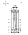
中空部材58は、下方側21が前後方向に延びたがこれに限らない。中空部材58の下方側21は設けられなくてもよい。この場合、中空部材58は、上下方向に伸展し、且つ中空部材58の開口部21Aが下方に向けて開口する。故に、中空部材58をメインタンク30に簡単に取り付けできる。中空部材58の下方側21は、上下方向と直交する水平方向の成分を含む方向に伸展し、且つ中空部材58の開口部21Aは、水平方向に向けて開口してもよい。
The
中空部材58は、弾性体で形成されてもよい。この場合、位置決め部材52Cは、弾性体の少なくとも一部の位置を固定すればよい。印刷装置1では、位置決め部材52Cが弾性体で形成された中空部材58の少なくとも一部の位置を固定する。故に、中空部材58が他の部材に絡む可能性を低減できる。故に、印刷装置1は、圧力検出素子42の出力に影響が出ることを抑制できる。また、中空部材58の下方側21の少なくとも一部が水平方向成分を含む方向、すなわち上下方向に交わる方向に交差してもよい。このような場合においても、上記実施形態と同様の効果を得ることができる。
The
第一チューブ53、第二チューブ54、及び中空部材58は、弾性体で形成されてもよい。この場合、位置決め部材52A、52B、52Cは、弾性体で形成された第一チューブ53、第二チューブ54、及び中空部材58の各々の少なくとも一部を、メインタンク30の内部で固定すればよい。従って、印刷装置1は、第一チューブ53、第二チューブ54が、中空部材58に絡むことが低減され、圧力検出素子42の出力に影響が出るのを抑制できる。
The
固定部材52の位置決め部材52Cは、容器開口部33側とは反対側のメインタンク30の右側面301側で、中空部材58の少なくとも一部の位置を固定してもよい。この場合、位置決め部材52A、52B、52C、第一チューブ53、第二チューブ54の少なくとも何れか一つが中空部材58と容器開口部33の間に配置される。従って、印刷装置1は、容器開口部33と中空部材58の間に何も配置されていない場合に比べて、中空部材58が容器開口部33からのインク68の直撃を受ける可能性が低くなる。故に、印刷装置1は、中空部材58の劣化を抑制することができる。
The positioning
固定部材52は、第一チューブ53、及び第二チューブ54の少なくとも何れか一つと中空部材58の少なくとも一部を、メインタンク30の内部で固定してもよい。この場合においても、印刷装置1は、第一チューブ53、第二チューブ54、及び中空部材58を別途固定する位置決め部材が設けられるよりも、メインタンク30の内部の空間を固定部材52が占める割合を低減できる。故に、印刷装置1はメインタンク30を小型化できる。
The fixing
攪拌モータ44は、CPU11により、インク68の量に応じて一定の動作速度で駆動されたがこれに限らない。CPU11は、攪拌モータ44の回転速度を可変にして駆動してもよい。また、例えば、CPU11は、メインタンク30内のインク68の量に関わらず、攪拌翼41を一定の動作速度で駆動してもよい。これにより、印刷装置1は、一定の動作速度よりも低速で攪拌翼41が動作する場合に比べて、インク68の量に関わらずインク68を一定の動作速度で撹拌できる。従って、印刷装置1は、ヘッド部67へのインク68の供給が低下する可能性が低減される。
The stirring
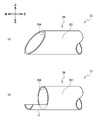
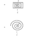
CPU11は、メイン処理を実行することにより圧力検出素子42の出力から、メインタンク30のインク68の残量を特定したがこれに限らない。CPU11は、インク68がメインタンク30に注入されたことに起因して中空部材58の中空内の圧力が所定圧分増加する場合がある。この場合に、CPU11は、メモリ装着部に装着されたEEPROM77のインク68の量に関するデータを参照してもよい。印刷装置1は、インク68がメインタンク30に注入されたことに起因して中空部材58の中空内の圧力が所定圧分増加した場合に、メモリ装着部に装着されたEEPROM77のインク68の量に関するデータを参照して、インク68の残量を検出できる。そのほか、メインタンク30のインク68の残量の検出は、所定時間ごとに割り込み処理で行っても良い。インク68が、特性アニオン系及びノニオン系の少なくとも一方の表面活性剤を含み、表面張力が20以上36未満[mN/m]であれば、中空部材58の軸線方向に直交する断面が円形であり、中空部材58の内径が3〜4mmである構成において、インク68と中空部材58内の気体との境目が、中空部材58の下方側21の水平部分に存在する。従って、所定範囲において中空部材58内の気体の温度変化によって、インク68と中空部材58内の気体との境目に対するインク68の液面からの距離が変わらないので、中空部材58内の気体の温度変化に対する影響を圧力検出素子42が受けにくい。中空部材58内の気体の温度変化に対する影響が大きい場合には、図15(a)、図15(b)に示すように、渦巻きのように、中空部材58の下方側21の水平部分を長くしてもよい。中空部材58の下方側21の水平部分に液体を導入しやすくするために、開口部21Aを内側の流路に比べて広げてもよい。
The
例えば、メインタンク30は、印刷装置1以外にも、被記録媒体に液体記録材を例えばスプレーなどで吐出する吐出部を有する液体収容装置に設けられてもよい。特にこの液体記録材が沈降性を有する場合に、本発明は有効である。液体記録材は、インクに限られず、抜染剤、前処理剤等でもよい。また、圧力検出素子42は、圧力を検出する素子に限られず、電極式、静電容量式、光式等の液体のレベルを検出できるものであればよい。また、一例として、圧力検出素子42は、液面をフロートの上下動により検出するフロートセンサでもよい。この場合、圧力検出素子42は、メインタンク30内で、インク68の残量を検出する所定の高さに設けられる。
For example, the
メインタンク30は、上記の形状に限られず、インク68を収容できるものであればよい。また、脱気モジュール60の構成は、上記実施形態と異なる構成であってもよい。また、脱気モジュール60が設けられなくてもよい。また、フィルタ771が設けられなくてもよい。
The
<その他>
上記実施形態例において、ヘッド部67は、本発明の「インクジェットヘッド」の一例である。メインタンク30は、本発明の「貯留部」の一例である。回転領域413は、本発明の「動作範囲」の一例である。容器開口部33は、「インク供給部」の一例である。固定部材52、252、352、位置決め部材52A、52B、52C、252A、252B、252C、352A、352Bは、本発明の「位置決め部材」の一例である。図9のS7、S9、S13、S15、及び図10のS103の処理を行うCPU11は、本発明の「制御装置」の一例である。
<Others>
In the above embodiment, the
1 印刷装置
11 CPU
12 ROM
21 下方側
29 下端部
29A 開口部
30 メインタンク
33 容器開口部
40 シャフト
41 攪拌翼
42 圧力検出素子
50、50A、50B 板状部
52、252、352 固定部材
52A、52B、52C、252A、252B、252C、352A、352B 位置決め部材
53 第一チューブ
54 第二チューブ
58 中空部材
68 インク
77 EEPROM
413 回転領域
751 ポンプ
1
12 ROM
21
413
Claims (16)
前記インクを貯留する貯留部と、
前記貯留部の内部に配置され、上下方向に伸展する中空を有し、下方側において前記中空の開口部を有し、且つ前記中空をガスバリア性の素材で構成する中空部材と、
前記中空部材の上方側の前記中空に配置され、前記中空内の圧力を検出する圧力検出素子と、
前記中空部材と前記圧力検出素子との間を密封する密封部材と、
前記貯留部の前記インクを、前記貯留部の外部へ移動させるポンプと、
前記画像形成装置の制御を行う制御装置と
を備え、
前記制御装置は、
前記圧力検出素子の検出した前記圧力に応じて、前記インクの残量を検知し、前記ポンプの制御を行うこと
を特徴とする画像形成装置。 In an image forming apparatus that forms an image using ink,
A storage unit that stores the ink and
A hollow member arranged inside the storage portion, having a hollow extending in the vertical direction, having the hollow opening on the lower side, and having the hollow made of a gas barrier material.
A pressure detecting element arranged in the hollow on the upper side of the hollow member and detecting the pressure in the hollow, and
A sealing member that seals between the hollow member and the pressure detecting element,
A pump that moves the ink in the storage unit to the outside of the storage unit,
A control device for controlling the image forming device is provided.
The control device is
An image forming apparatus characterized in that the remaining amount of the ink is detected according to the pressure detected by the pressure detecting element and the pump is controlled.
を特徴とする請求項1に記載の画像形成装置。 A claim characterized in that the lower side of the hollow member extends in a direction including a horizontal component orthogonal to the vertical direction, and the opening of the hollow member opens in the horizontal direction. Item 1. The image forming apparatus according to item 1.
を備え、
前記中空部材の前記開口部は、前記インク供給部とは反対側の前記貯留部の側面側に配置されている
ことを特徴とする請求項1又は2の何れか一つに記載の画像形成装置。 An ink supply unit provided in the storage unit and capable of supplying the ink to the storage unit is provided.
The image forming apparatus according to any one of claims 1 or 2, wherein the opening of the hollow member is arranged on a side surface side of the storage portion on the side opposite to the ink supply portion. ..
を備え、
前記中空部材の前記開口部は、前記第一チューブの下端よりも上方に配置され、
前記制御装置は、
前記ポンプを制御して、前記第一チューブの前記インクを前記貯留部の前記外部に流出させ、
前記圧力検出素子が検出した前記圧力に応じて、前記ポンプの稼働を停止する
ことを特徴とする請求項1〜3の何れか一つに記載の画像形成装置。 A first tube for draining the ink from the storage unit to the outside of the storage unit is provided.
The opening of the hollow member is arranged above the lower end of the first tube.
The control device is
The pump is controlled to allow the ink in the first tube to flow out of the reservoir.
The image forming apparatus according to any one of claims 1 to 3, wherein the operation of the pump is stopped according to the pressure detected by the pressure detecting element.
前記制御装置は、
前記中空部材の前記中空内の前記圧力が所定圧増加した場合、前記メモリ装着部に装着された前記メモリの前記データを参照する
ことを特徴とする請求項1〜4の何れか一つに記載の画像形成装置。 A memory mounting unit to which a memory storing data related to the amount of ink can be detachably mounted and
The control device is
The invention according to any one of claims 1 to 4, wherein when the pressure in the hollow of the hollow member increases by a predetermined pressure, the data of the memory mounted on the memory mounting portion is referred to. Image forming device.
前記中空部材の前記下方側の前記少なくとも一部の前記中空における気体と前記インクとの境界は、前記中空部材の前記中空内の気体の伸縮に応じて移動する
ことを特徴とする請求項4又は5の何れかに記載の画像形成装置。 The lower side of the hollow member extends in a direction containing a horizontal component orthogonal to the vertical direction, and the opening of the hollow member opens in the horizontal direction.
4. The boundary between the gas and the ink in the hollow, which is at least a part of the lower side of the hollow member, moves according to the expansion and contraction of the gas in the hollow of the hollow member. The image forming apparatus according to any one of 5.
を備える
ことを特徴とする請求項1〜6の何れか一つに記載の画像形成装置。 The image forming apparatus according to any one of claims 1 to 6, further comprising a positioning member provided in the storage portion and fixing a position of at least a part of the hollow member.
前記位置決め部材は、前記弾性体の少なくとも一部の位置を固定すること
を特徴とする請求項7に記載の画像形成装置。 The hollow member is formed of an elastic body and is formed of an elastic body.
The image forming apparatus according to claim 7, wherein the positioning member fixes the position of at least a part of the elastic body.
前記貯留部から前記貯留部の前記外部に前記インクを流出させる第一チューブと、
前記貯留部の前記外部から前記貯留部に前記インクを流入させる第二チューブと、
前記貯留部の前記内部に設けられ、前記中空部材の少なくとも一部の位置を固定する位置決め部材と
を備え、
前記位置決め部材は、前記インク供給部側とは反対側の前記貯留部の側面側で、前記中空部材の少なくとも一部の位置を固定し、
前記位置決め部材、前記第一チューブ、及び前記第二チューブの少なくとも何れか一つは、前記中空部材と前記インク供給部との間に配置される
ことを特徴とする請求項7又は8の何れかに記載の画像形成装置。 An ink supply unit provided in the storage unit and capable of supplying the ink to the storage unit,
A first tube for discharging the ink from the storage unit to the outside of the storage unit,
A second tube for allowing the ink to flow into the storage from the outside of the storage.
A positioning member provided inside the storage portion and fixing the position of at least a part of the hollow member is provided.
The positioning member fixes the position of at least a part of the hollow member on the side surface side of the storage portion on the side opposite to the ink supply portion side.
Any one of claims 7 or 8, wherein at least one of the positioning member, the first tube, and the second tube is arranged between the hollow member and the ink supply unit. The image forming apparatus according to.
前記貯留部の前記外部から前記貯留部に前記インクを流入させる第二チューブと、
前記貯留部の前記内部に設けられ、前記中空部材の少なくとも一部の位置を固定する位置決め部材と
を備え、
前記位置決め部材は、前記第一チューブ、及び前記第二チューブの少なくとも何れか一つと前記中空部材の少なくとも一部を、前記貯留部の前記内部で固定する
ことを特徴とする請求項1〜9の何れか一つに記載の画像形成装置。 A first tube for discharging the ink from the storage unit to the outside of the storage unit,
A second tube for allowing the ink to flow into the storage from the outside of the storage.
A positioning member provided inside the storage portion and fixing the position of at least a part of the hollow member is provided.
The positioning member according to claim 1 to 9, wherein at least one of the first tube and the second tube and at least a part of the hollow member are fixed inside the storage portion. The image forming apparatus according to any one.
前記位置決め部材は、前記弾性体で形成された第一チューブ、第二チューブ、及び中空部材の各々の少なくとも一部を、前記貯留部の前記内部で固定する
ことを特徴とする請求項10に記載の画像形成装置。 The first tube, the second tube, and the hollow member are formed of an elastic body.
The tenth aspect of the present invention, wherein the positioning member fixes at least a part of each of the first tube, the second tube, and the hollow member formed of the elastic body inside the storage portion. Image forming device.
ことを特徴とする請求項1、3〜5、7〜11の何れか一つに記載の画像形成装置。 The invention according to any one of claims 1, 3 to 5, 7 to 11, wherein the hollow member extends in the vertical direction, and the opening of the hollow member opens downward. Image forming device.
を備え、
前記中空部材の前記開口部は、前記攪拌翼の上方に位置し、
前記制御装置は、
前記攪拌翼を制御することで、前記貯留部の前記内部の前記インクを撹拌し、
前記圧力検出素子の出力に応じて、前記攪拌翼を停止する
ことを特徴とする請求項1〜12の何れか一つに記載の画像形成装置。 A stirring blade provided inside the storage portion to stir the ink is provided.
The opening of the hollow member is located above the stirring blade.
The control device is
By controlling the stirring blade, the ink inside the storage portion is stirred.
The image forming apparatus according to any one of claims 1 to 12, wherein the stirring blade is stopped according to the output of the pressure detecting element.
前記中空部材の前記下方側は、前記攪拌翼が回転する回転方向に沿って延び、且つ前記中空部材の前記開口部は、前記一方向に向かって開口する
ことを特徴とする請求項13に記載の画像形成装置。 The stirring blade can only rotate in one direction and
13. The thirteenth aspect of the present invention, wherein the lower side of the hollow member extends along a rotation direction in which the stirring blade rotates, and the opening of the hollow member opens in one direction. Image forming device.
を特徴とする請求項1〜14の何れか1つに記載の画像形成装置。 The image forming apparatus according to any one of claims 1 to 14, wherein the pressure detecting element is an element that detects a gauge pressure capable of correcting fluctuations in atmospheric pressure.
前記中空部材の軸線方向に直交する断面が円形であり、中空部材の内径が3〜4mmであることを特徴とする請求項2に記載の画像形成装置。 The ink contains at least one of the characteristic anionic and nonionic surfactants and has a surface tension of 20 or more and less than 36 [mN / m].
The image forming apparatus according to claim 2, wherein the hollow member has a circular cross section orthogonal to the axial direction, and the inner diameter of the hollow member is 3 to 4 mm.
Priority Applications (3)
| Application Number | Priority Date | Filing Date | Title |
|---|---|---|---|
| JP2019056909A JP7031632B2 (en) | 2019-03-25 | 2019-03-25 | Image forming device |
| US16/828,363 US11427009B2 (en) | 2019-03-25 | 2020-03-24 | Image formation device |
| US17/872,610 US11780234B2 (en) | 2019-03-25 | 2022-07-25 | Image formation device |
Applications Claiming Priority (1)
| Application Number | Priority Date | Filing Date | Title |
|---|---|---|---|
| JP2019056909A JP7031632B2 (en) | 2019-03-25 | 2019-03-25 | Image forming device |
Publications (2)
| Publication Number | Publication Date |
|---|---|
| JP2020157504A true JP2020157504A (en) | 2020-10-01 |
| JP7031632B2 JP7031632B2 (en) | 2022-03-08 |
Family
ID=72603896
Family Applications (1)
| Application Number | Title | Priority Date | Filing Date |
|---|---|---|---|
| JP2019056909A Active JP7031632B2 (en) | 2019-03-25 | 2019-03-25 | Image forming device |
Country Status (2)
| Country | Link |
|---|---|
| US (2) | US11427009B2 (en) |
| JP (1) | JP7031632B2 (en) |
Cited By (3)
| Publication number | Priority date | Publication date | Assignee | Title |
|---|---|---|---|---|
| JP2023087397A (en) * | 2021-12-13 | 2023-06-23 | ブラザー工業株式会社 | Liquid supply device |
| JP2023087392A (en) * | 2021-12-13 | 2023-06-23 | ブラザー工業株式会社 | LIQUID SUPPLY SYSTEM, CONTROL METHOD, CONTROL PROGRAM, AND LIQUID SUPPLY DEVICE |
| JP2023159583A (en) * | 2022-04-20 | 2023-11-01 | キヤノン株式会社 | Liquid storage containers, liquid consumption devices, and recording devices |
Families Citing this family (2)
| Publication number | Priority date | Publication date | Assignee | Title |
|---|---|---|---|---|
| US20220126585A1 (en) * | 2020-10-27 | 2022-04-28 | Brother Kogyo Kabushiki Kaisha | Printing device |
| JP7799237B2 (en) * | 2021-12-13 | 2026-01-15 | ブラザー工業株式会社 | Liquid supply system, control method, control program, and liquid supply device |
Citations (3)
| Publication number | Priority date | Publication date | Assignee | Title |
|---|---|---|---|---|
| JP2003512212A (en) * | 1999-10-29 | 2003-04-02 | ヴィデオジェット テクノロジーズ インコーポレイテッド | Circulation system and method for mixing inkjet inks |
| US20040041871A1 (en) * | 2002-09-04 | 2004-03-04 | Davis Jeremy A. | Pen maintenance system and method for operating same |
| JP2013515625A (en) * | 2009-12-23 | 2013-05-09 | マーケム−イマージュ | Fluid circuit measurement system for continuous ink jet printer, fluid circuit, and block configured to perform the measurement system |
Family Cites Families (22)
| Publication number | Priority date | Publication date | Assignee | Title |
|---|---|---|---|---|
| JPS59232734A (en) | 1983-06-13 | 1984-12-27 | Mitsubishi Electric Corp | Liquid level detecting device |
| FR2652540B1 (en) | 1989-10-02 | 1995-06-02 | Imaje Sa | INK CIRCUIT, IN PARTICULAR FOR PRESSURIZING A PIGMENT INK FOR AN INK JET PRINTER. |
| JPH04191972A (en) | 1990-11-26 | 1992-07-10 | Hitachi Ltd | Editing system for character attribute |
| JP3180401B2 (en) * | 1991-12-24 | 2001-06-25 | セイコーエプソン株式会社 | Ink ejection recovery device for inkjet printer |
| US6224201B1 (en) * | 1997-07-28 | 2001-05-01 | Canon Kabushiki Kaisha | Ink jet recording apparatus provided with an improved ink supply route |
| JPH1142795A (en) | 1997-07-28 | 1999-02-16 | Canon Inc | Ink jet recording device and color filter manufacturing device |
| JP4191972B2 (en) | 2002-10-04 | 2008-12-03 | 株式会社リコー | Ink liquid mixing apparatus, ink liquid manufacturing apparatus, manufacturing method, cleaning method, ink manufactured by the manufacturing method, ink cartridge storing the ink, ink jet apparatus, image forming method, and image formed product |
| JP2005067122A (en) | 2003-08-27 | 2005-03-17 | Fuji Photo Film Co Ltd | Inkjet recorder |
| JP2006327097A (en) | 2005-05-27 | 2006-12-07 | Olympus Corp | Ink jet recording device |
| JP5083063B2 (en) | 2008-01-29 | 2012-11-28 | セイコーエプソン株式会社 | Liquid storage device and liquid storage cartridge |
| JP2010240509A (en) | 2009-04-01 | 2010-10-28 | Sharp Corp | Gas-liquid separator, ink jet device using the same, and waste liquid method of ink jet device |
| JP5552778B2 (en) | 2009-09-02 | 2014-07-16 | セイコーエプソン株式会社 | Liquid supply method |
| US20120262523A1 (en) | 2011-04-14 | 2012-10-18 | Levi Yaakov | Ink tank system |
| JP2013086440A (en) | 2011-10-21 | 2013-05-13 | Canon Inc | Inkjet recording apparatus |
| US10029483B2 (en) * | 2012-04-25 | 2018-07-24 | Seiko Epson Corporation | Ink jet recording method, ultraviolet-ray curable ink, and ink jet recording apparatus |
| JP2014091241A (en) | 2012-11-01 | 2014-05-19 | Mimaki Engineering Co Ltd | Pressure absorption damper |
| JP2014097616A (en) | 2012-11-14 | 2014-05-29 | Mimaki Engineering Co Ltd | Ink tank of ink jet printer and circulation system of the same |
| JP2015112724A (en) | 2013-12-09 | 2015-06-22 | セイコーエプソン株式会社 | Ink supply mechanism and ink supply method, and liquid droplet discharge device |
| WO2017184156A1 (en) * | 2016-04-21 | 2017-10-26 | Hewlett-Packard Development Company, L.P. | A rocker valve |
| JP6888427B2 (en) * | 2017-05-31 | 2021-06-16 | ブラザー工業株式会社 | Liquid supply device |
| JP7106860B2 (en) * | 2017-12-27 | 2022-07-27 | ブラザー工業株式会社 | Liquid containment device |
| JP7124778B2 (en) * | 2019-03-25 | 2022-08-24 | ブラザー工業株式会社 | LIQUID CONTAINING DEVICE AND IMAGE FORMING APPARATUS |
-
2019
- 2019-03-25 JP JP2019056909A patent/JP7031632B2/en active Active
-
2020
- 2020-03-24 US US16/828,363 patent/US11427009B2/en active Active
-
2022
- 2022-07-25 US US17/872,610 patent/US11780234B2/en active Active
Patent Citations (3)
| Publication number | Priority date | Publication date | Assignee | Title |
|---|---|---|---|---|
| JP2003512212A (en) * | 1999-10-29 | 2003-04-02 | ヴィデオジェット テクノロジーズ インコーポレイテッド | Circulation system and method for mixing inkjet inks |
| US20040041871A1 (en) * | 2002-09-04 | 2004-03-04 | Davis Jeremy A. | Pen maintenance system and method for operating same |
| JP2013515625A (en) * | 2009-12-23 | 2013-05-09 | マーケム−イマージュ | Fluid circuit measurement system for continuous ink jet printer, fluid circuit, and block configured to perform the measurement system |
Cited By (5)
| Publication number | Priority date | Publication date | Assignee | Title |
|---|---|---|---|---|
| JP2023087397A (en) * | 2021-12-13 | 2023-06-23 | ブラザー工業株式会社 | Liquid supply device |
| JP2023087392A (en) * | 2021-12-13 | 2023-06-23 | ブラザー工業株式会社 | LIQUID SUPPLY SYSTEM, CONTROL METHOD, CONTROL PROGRAM, AND LIQUID SUPPLY DEVICE |
| JP7799236B2 (en) | 2021-12-13 | 2026-01-15 | ブラザー工業株式会社 | Liquid supply system, control method, control program, and liquid supply device |
| JP7800101B2 (en) | 2021-12-13 | 2026-01-16 | ブラザー工業株式会社 | liquid supply device |
| JP2023159583A (en) * | 2022-04-20 | 2023-11-01 | キヤノン株式会社 | Liquid storage containers, liquid consumption devices, and recording devices |
Also Published As
| Publication number | Publication date |
|---|---|
| US20200307231A1 (en) | 2020-10-01 |
| US11780234B2 (en) | 2023-10-10 |
| JP7031632B2 (en) | 2022-03-08 |
| US20220355594A1 (en) | 2022-11-10 |
| US11427009B2 (en) | 2022-08-30 |
Similar Documents
| Publication | Publication Date | Title |
|---|---|---|
| JP7031632B2 (en) | Image forming device | |
| JP7124778B2 (en) | LIQUID CONTAINING DEVICE AND IMAGE FORMING APPARATUS | |
| JP4877011B2 (en) | Droplet ejector | |
| JP6567186B2 (en) | Inkjet recording device | |
| EP2216178A1 (en) | Inkjet print head and ink storage apparatus | |
| US10625509B2 (en) | Liquid storage device | |
| JP2011005782A (en) | Liquid discharging head unit and image forming apparatus | |
| JP2017177769A (en) | Printer | |
| JP7121594B2 (en) | Inkjet printer and method of controlling an inkjet printer | |
| JP6708297B2 (en) | Recording head recovery system, inkjet recording apparatus including the same, and recording head recovery method | |
| JP5617176B2 (en) | Droplet discharge head, droplet discharge apparatus including the same, and image forming apparatus | |
| JP2013078872A (en) | Liquid injection device | |
| JP3372844B2 (en) | Ink container and inkjet recording device | |
| JP6834518B2 (en) | Image recording device | |
| JP2019116052A (en) | Liquid storage device | |
| JPH07125242A (en) | Inkjet recording device | |
| JP7069712B2 (en) | Liquid storage device | |
| JP2009045930A (en) | Ink supply apparatus and image forming apparatus | |
| JP5024440B2 (en) | ink cartridge | |
| JP2009262496A (en) | Waste liquid receiving container | |
| JP2020001168A (en) | Liquid discharge device | |
| JP4631482B2 (en) | ink cartridge | |
| JP7587763B2 (en) | Liquid ejection device | |
| JP2006015536A (en) | Liquid container and liquid ejecting apparatus | |
| JP2019064058A (en) | Ink jet recording apparatus, viscosity estimation method, and storage medium |
Legal Events
| Date | Code | Title | Description |
|---|---|---|---|
| A621 | Written request for application examination |
Free format text: JAPANESE INTERMEDIATE CODE: A621 Effective date: 20210316 |
|
| TRDD | Decision of grant or rejection written | ||
| A977 | Report on retrieval |
Free format text: JAPANESE INTERMEDIATE CODE: A971007 Effective date: 20220119 |
|
| A01 | Written decision to grant a patent or to grant a registration (utility model) |
Free format text: JAPANESE INTERMEDIATE CODE: A01 Effective date: 20220125 |
|
| A61 | First payment of annual fees (during grant procedure) |
Free format text: JAPANESE INTERMEDIATE CODE: A61 Effective date: 20220207 |
|
| R150 | Certificate of patent or registration of utility model |
Ref document number: 7031632 Country of ref document: JP Free format text: JAPANESE INTERMEDIATE CODE: R150 |