JP2020148068A - Buckling prevention member and reinforcement structure of column - Google Patents
Buckling prevention member and reinforcement structure of column Download PDFInfo
- Publication number
- JP2020148068A JP2020148068A JP2019048705A JP2019048705A JP2020148068A JP 2020148068 A JP2020148068 A JP 2020148068A JP 2019048705 A JP2019048705 A JP 2019048705A JP 2019048705 A JP2019048705 A JP 2019048705A JP 2020148068 A JP2020148068 A JP 2020148068A
- Authority
- JP
- Japan
- Prior art keywords
- column
- reinforcing
- buckling prevention
- pillar
- vertical
- Prior art date
- Legal status (The legal status is an assumption and is not a legal conclusion. Google has not performed a legal analysis and makes no representation as to the accuracy of the status listed.)
- Pending
Links
Images


Abstract
Description
本発明は、例えば耐震補強のための座屈防止部材及び柱の補強構造に関するものである。 The present invention relates to, for example, a buckling prevention member for seismic reinforcement and a reinforcing structure of columns.
地震による構造体の倒壊等を防ぐため、柱等の構造体に対しては、所定以上の耐震強度が要求されている。しかし、現在の耐震基準となる前に建設された構造体には、現在のような厳しい耐震強度が要求されていなかったため、古い構造体は、現在の耐震基準を満たしていない場合がある。 In order to prevent the structure from collapsing due to an earthquake, the structure such as columns is required to have a seismic strength higher than a predetermined value. However, old structures may not meet the current seismic standards, as structures constructed before the current seismic standards were not required to have the strict seismic strengths of today.
しかし、柱等の構造体のすべてを新たに再構築するのは時間もコストもかかる。このため、既存の柱を補強する方法がとられる。 However, it takes time and cost to newly reconstruct all the structures such as columns. Therefore, a method of reinforcing existing columns is adopted.
このような既存の柱を補強する方法としては、既存柱の柱脚部の周囲にコンクリートを打設して、鉄筋コンクリート根巻き部を構築する方法がある(例えば特許文献1)。 As a method of reinforcing such an existing column, there is a method of placing concrete around the column base portion of the existing column to construct a reinforced concrete root winding portion (for example, Patent Document 1).
また、鋼材柱の外周を鋼板で覆い、鋼材柱と鋼板との間に鉄筋が配置されてグラウト材が充填された補強構造がある(例えば特許文献2)。 Further, there is a reinforcing structure in which the outer periphery of the steel column is covered with a steel plate, reinforcing bars are arranged between the steel column and the steel plate, and the grout material is filled (for example, Patent Document 2).
しかし、特許文献1のように、柱脚部の補強を行ったのみでは、柱の座屈を抑制することはできない。例えば、トラス柱やラチス柱などの組立柱では、柱脚部を補強しても、上下方向に強い荷重が付与されると、柱の座屈の恐れがあり、座屈に対しても補強が必要である。 However, as in Patent Document 1, it is not possible to suppress the buckling of the column only by reinforcing the column base. For example, in assembled columns such as truss columns and lattice columns, even if the column base is reinforced, if a strong load is applied in the vertical direction, the column may buckle, and the column is also reinforced against buckling. is necessary.
しかし、特許文献2のように、全体を鋼板とグラウト材で覆う方法は、構造が大掛かりとなり、柱が大型化するため、周囲のスペースが狭くなる。また、例えば組立柱のような柱に適用すると、鋼板等によって完全に組立柱が埋設されるため、視界が遮られ、既存柱の向こう側を視認することができなくなる。 However, as in Patent Document 2, the method of covering the entire surface with a steel plate and a grout material has a large structure and a large pillar, so that the surrounding space is narrowed. Further, when applied to a pillar such as an assembly pillar, the assembly pillar is completely buried by a steel plate or the like, so that the field of view is obstructed and the other side of the existing pillar cannot be visually recognized.
本発明は、このような問題に鑑みてなされたもので、既存柱にも適用が可能であり、効率よく柱を補強することが可能な座屈防止部材及び柱の補強構造を提供することを目的とする。 The present invention has been made in view of such a problem, and provides an anti-buckling member and a column reinforcing structure that can be applied to existing columns and can efficiently reinforce columns. The purpose.
前述した目的を達成するため、第1の発明は、柱を補強するための座屈防止部材であって、柱の上下方向に沿って配置される補強縦部材と、少なくとも、前記補強縦部材の長手方向の両端部近傍及び中央部近傍において配置され、柱の外面に固定される固定部材と、前記補強縦部材の長手方向の略中央部に起立する起立部材と、前記補強縦部材の両端部近傍と前記起立部材の端部とを連結する補強斜材と、を具備することを特徴とする座屈防止部材である。 In order to achieve the above-mentioned object, the first invention is a buckling prevention member for reinforcing a column, the reinforcing vertical member arranged along the vertical direction of the column, and at least the reinforcing vertical member. A fixing member arranged near both ends and the center in the longitudinal direction and fixed to the outer surface of the column, an upright member standing substantially in the center in the longitudinal direction of the reinforcing vertical member, and both ends of the reinforcing vertical member. The buckling prevention member is provided with a reinforcing diagonal member that connects the vicinity and the end portion of the upright member.
第1の発明によれば、補強縦部材の略中央部において起立する起立部材に補強斜材が配置されるため、補強縦部材が、起立部材側に変形することが抑制される。このため、補強縦部材を柱に沿って配置することで、柱の変形を効率よく抑制することができる。このため、柱に圧縮力が付与された際に、柱が座屈することを抑制することができる。 According to the first invention, since the reinforcing diagonal member is arranged on the standing member that stands up at the substantially central portion of the reinforcing vertical member, the reinforcing vertical member is suppressed from being deformed to the standing member side. Therefore, by arranging the reinforcing vertical members along the columns, deformation of the columns can be efficiently suppressed. Therefore, it is possible to prevent the column from buckling when a compressive force is applied to the column.
第2の発明は、第1の座屈防止部材を用いた柱の補強構造であって、前記起立部材が、前記柱とは逆側に向くように、前記柱の長手方向に沿って、前記柱の外面に座屈防止部材が配置されることを特徴とする柱の補強構造である。 The second invention is a structure for reinforcing a column using a first buckling prevention member, wherein the upright member faces the opposite side of the column along the longitudinal direction of the column. It is a column reinforcement structure characterized in that a buckling prevention member is arranged on the outer surface of the column.
前記柱は、縦材と、前記縦材同士を連結する斜材とを有する組立柱であり、前記固定部材の端部は、前記縦材に固定されてもよい。 The pillar is an assembly pillar having a vertical member and a diagonal member connecting the vertical members, and the end portion of the fixing member may be fixed to the vertical member.
前記柱の前記縦材と前記座屈防止部材の前記固定部材との固定部には、前記固定部材とは一体又は別体でスペーサが配置され、前記座屈防止部材と前記柱との間には隙間が形成されることが望ましい。 A spacer is arranged integrally or separately from the fixing member at the fixing portion between the vertical member of the pillar and the fixing member of the buckling prevention member, and is provided between the buckling prevention member and the pillar. It is desirable that a gap is formed.
上下方向の両端の前記固定部材には孔が形成され、前記補強縦部材の両端部が前記孔に挿入され、上下方向の両端の前記固定部材と前記補強縦部材とが縁切りされていてもよい。 Holes may be formed in the fixing members at both ends in the vertical direction, both ends of the reinforcing vertical member may be inserted into the holes, and the fixing members at both ends in the vertical direction and the reinforcing vertical member may be trimmed. ..
前記座屈防止部材が、前記柱の長手方向に、互いの一部が重なり合うように複数配置され、複数の前記座屈防止部材の前記起立部材の端部同士が接続されてもよい。 A plurality of the buckling prevention members may be arranged in the longitudinal direction of the pillar so that some of them overlap each other, and the ends of the standing members of the plurality of buckling prevention members may be connected to each other.
前記座屈防止部材が、前記柱の外周面の4面に配置されることが望ましい。 It is desirable that the buckling prevention member is arranged on four surfaces of the outer peripheral surface of the pillar.
第2の発明によれば、柱を外周側から効率良く押さえることができ、柱が座屈することを抑制することができる。 According to the second invention, the pillar can be efficiently pressed from the outer peripheral side, and the pillar can be prevented from buckling.
また、柱が組立柱の場合にも適用が容易であり、この際、柱の外周をコンクリートや鋼板等で覆うことがないため、視界を遮ることもない。 Further, it is easy to apply even when the pillar is an assembled pillar, and at this time, since the outer circumference of the pillar is not covered with concrete, a steel plate or the like, the field of view is not obstructed.
また、スペーサによって、柱と座屈防止部材との間に隙間が形成されるため、柱の外周部に配管等が設置される場合でも、座屈防止部材と配管等とが干渉することがない。 Further, since the spacer forms a gap between the column and the buckling prevention member, the buckling prevention member and the piping do not interfere with each other even when the piping or the like is installed on the outer peripheral portion of the column. ..
また、上下方向の両端の固定部材と補強縦部材とが縁切りされていることで、柱にかかる圧縮力が補強縦部材に伝達されることがなく、補強縦部材が座屈することを抑制することができる。 Further, since the fixing members at both ends in the vertical direction and the reinforcing vertical member are edge-cut, the compressive force applied to the column is not transmitted to the reinforcing vertical member, and the reinforcing vertical member is prevented from buckling. Can be done.
また、複数の座屈防止部材を、座屈防止部材同士が長手方向に互いの一部が重なり合うように配置し、起立部材の端部同士を接続することで、座屈防止部材の全長を短くすることができる。 In addition, a plurality of buckling prevention members are arranged so that the buckling prevention members overlap each other in the longitudinal direction, and the ends of the standing members are connected to each other to shorten the total length of the buckling prevention members. can do.
また、座屈防止部材を柱の外周面の4面に配置することで、柱の全ての方向に対する座屈による変形を防止することができる。 Further, by arranging the buckling prevention members on the four outer peripheral surfaces of the column, deformation due to buckling in all directions of the column can be prevented.
本発明によれば、既存柱にも適用が可能であり、効率よく柱を補強することが可能な座屈防止部材及び柱の補強構造を提供することができる。 According to the present invention, it is possible to provide a buckling prevention member and a column reinforcing structure that can be applied to existing columns and can efficiently reinforce the columns.
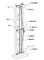
以下、本発明の実施の形態にかかる柱の補強構造1について説明する。図1は、柱の補強構造1を示す斜視図であり、図2は、柱の補強構造1の正面図、図3は、図2のA−A線断面図である。なお、図1〜図3においては、柱の一面のみを示し、他の面の図示を省略する。 Hereinafter, the column reinforcing structure 1 according to the embodiment of the present invention will be described. 1 is a perspective view showing the reinforcing structure 1 of the column, FIG. 2 is a front view of the reinforcing structure 1 of the column, and FIG. 3 is a sectional view taken along line AA of FIG. In FIGS. 1 to 3, only one surface of the pillar is shown, and the other surface is omitted.
柱の補強構造1は、柱3と座屈防止部材10等から構成される。柱3は、縦材5と、縦材5の間に斜めに配置される斜材7とを有する。柱3は、例えば複数のトラスによって構成される組立柱である。すなわち、柱3は、4本の縦材5(図では2本のみ示す)が配置され、それぞれの縦材5の間に、縦材5同士を連結するように複数の斜材7が配置される。 The column reinforcing structure 1 is composed of a column 3, a buckling prevention member 10, and the like. The pillar 3 has a vertical member 5 and a diagonal member 7 obliquely arranged between the vertical members 5. The pillar 3 is, for example, an assembly pillar composed of a plurality of trusses. That is, in the pillar 3, four vertical members 5 (only two are shown in the figure) are arranged, and a plurality of diagonal members 7 are arranged between the vertical members 5 so as to connect the vertical members 5 to each other. The pillar.
なお、柱3は、組立柱ではなく、角柱やH鋼柱であってもよい。柱3が組立柱である場合には、座屈防止部材10が取り付けられた柱3の背面側も視認することができる。また、柱の補強構造1は、既設の柱3に対する補強であってもよく、柱3を新設する際に適用されてもよい。 The column 3 may be a prism or an H steel column instead of an assembled column. When the pillar 3 is an assembled pillar, the back side of the pillar 3 to which the buckling prevention member 10 is attached can also be visually recognized. Further, the column reinforcement structure 1 may be a reinforcement for the existing column 3, or may be applied when the column 3 is newly installed.
柱3の長手方向に沿って、柱3の外面には座屈防止部材10が配置される。座屈防止部材10は、柱3の全長にわたって配置される。 A buckling prevention member 10 is arranged on the outer surface of the pillar 3 along the longitudinal direction of the pillar 3. The buckling prevention member 10 is arranged over the entire length of the pillar 3.
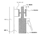
座屈防止部材10は、主に、補強縦部材15、固定部材11a、11b、起立部材19、補強斜材17等から構成される。補強縦部材15は、柱3の上下方向に沿って柱3の略全長にわたって配置される。補強縦部材15の長手方向の両端部近傍には固定部材11aが配置され、補強縦部材15の長手方向の中央部近傍には固定部材11bが配置される。固定部材11a、11bは、柱3の外面に固定される。より詳細には、固定部材11a、11bは、一対の縦材5にまたがるように柱3の幅方向に配置され、固定部材11a、11bの端部が縦材5に接合される。 The buckling prevention member 10 is mainly composed of a reinforcing vertical member 15, fixing members 11a and 11b, an upright member 19, a reinforcing diagonal member 17, and the like. The reinforcing vertical member 15 is arranged along the vertical direction of the column 3 over substantially the entire length of the column 3. The fixing members 11a are arranged near both ends of the reinforcing vertical member 15 in the longitudinal direction, and the fixing members 11b are arranged near the central portion of the reinforcing vertical member 15 in the longitudinal direction. The fixing members 11a and 11b are fixed to the outer surface of the pillar 3. More specifically, the fixing members 11a and 11b are arranged in the width direction of the pillar 3 so as to straddle the pair of vertical members 5, and the ends of the fixing members 11a and 11b are joined to the vertical members 5.
ここで、図3に示すように、固定部材11a、11bと柱3(縦材5)との間には、スペーサ13が配置される。すなわち、柱3の縦材5と座屈防止部材10の固定部材11a、11bとの固定部にはスペーサ13が配置され、固定部材11a、11bは、スペーサ13を介して縦材5と接合される。なお、スペーサ13は、固定部材11a、11bと一体であってもよいし、別体であってもよい。 Here, as shown in FIG. 3, a spacer 13 is arranged between the fixing members 11a and 11b and the pillar 3 (vertical member 5). That is, a spacer 13 is arranged at the fixing portion between the vertical member 5 of the pillar 3 and the fixing members 11a and 11b of the buckling prevention member 10, and the fixing members 11a and 11b are joined to the vertical member 5 via the spacer 13. To. The spacer 13 may be integrated with the fixing members 11a and 11b, or may be a separate body.
このように、柱3と座屈防止部材10の間にスペーサ13を配置することで、座屈防止部材10と柱3との間に、スペーサ13の厚みに応じた隙間9を形成することができる。柱3と座屈防止部材10との間に隙間9を形成することで、柱3の外周に配管等を配置する場合でも、配管等と座屈防止部材10とが干渉することがない。 By arranging the spacer 13 between the pillar 3 and the buckling prevention member 10 in this way, a gap 9 corresponding to the thickness of the spacer 13 can be formed between the buckling prevention member 10 and the pillar 3. it can. By forming the gap 9 between the pillar 3 and the buckling prevention member 10, even when the piping or the like is arranged on the outer periphery of the pillar 3, the piping or the like and the buckling prevention member 10 do not interfere with each other.
なお、固定部材11a、11bとスペーサ13と縦材5とは、それぞれ溶接で接合されてもよく、または、ボルト等で接合されてもよい。 The fixing members 11a and 11b, the spacer 13 and the vertical member 5 may be joined by welding, or may be joined by bolts or the like.
補強縦部材15の長手方向の略中央部には、柱3とは逆側に向くように起立する起立部材19が配置される。なお、固定部材11a、11b、補強縦部材15及び起立部材19は、例えばH形鋼などの鋼材である。 An upright member 19 that stands up so as to face the side opposite to the column 3 is arranged at a substantially central portion in the longitudinal direction of the reinforcing vertical member 15. The fixing members 11a and 11b, the reinforcing vertical member 15 and the upright member 19 are steel materials such as H-shaped steel.
補強縦部材15の上下方向の両端部近傍と起立部材19の端部とは、補強斜材17によって連結される。すなわち、補強斜材17は、補強縦部材15に対して斜めに配置され、補強縦部材15の両端部近傍から起立部材19の頂部にわたって配置される。補強斜材17は、例えば鋼線(鋼棒)などの長尺体が使用される。なお、補強斜材17には、所定の張力が付与されてもよい。 The vicinity of both ends of the reinforcing vertical member 15 in the vertical direction and the ends of the standing member 19 are connected by the reinforcing diagonal member 17. That is, the reinforcing diagonal member 17 is arranged obliquely with respect to the reinforcing vertical member 15, and is arranged from the vicinity of both ends of the reinforcing vertical member 15 to the top of the standing member 19. As the reinforcing diagonal member 17, a long body such as a steel wire (steel rod) is used. A predetermined tension may be applied to the reinforcing diagonal member 17.
図4は、図3のB部拡大図である。上下方向の両端の固定部材11aにはそれぞれ孔21が形成される。補強縦部材15の両端部には、他の部位よりも外径の小さな縮径部15aが形成される。縮径部15aは孔21に挿入される。なお、縮径部15aは、補強縦部材15の端部の一部を切り欠いて形成してもよく、または、鋼棒等を溶接してもよい。すなわち、補強縦部材15の上下方向の両端部に配置される固定部材11aは、補強縦部材15とは接合されない。なお、補強縦部材15は、長手方向中央部に位置する固定部材11bとのみと接合される。
FIG. 4 is an enlarged view of part B of FIG.
補強縦部材15の縮径部15aを除く部位の長さは、柱3の上下の両端部近傍に配置された固定部材11aの間隔よりもわずかに短い。このように、補強縦部材15と固定部材11aとが縁切りされており、補強縦部材15と固定部材11aとの間にはクリアランスが形成されるため、柱3に圧縮力(固定部材11a同士が近づく方向の力)が付与された際にも、圧縮応力が補強縦部材15に伝達されることがない。このため、柱3にかかる圧縮力が補強縦部材15に伝達されることにより、補強縦部材15が座屈することを抑制することができる。 The length of the portion of the reinforcing vertical member 15 excluding the reduced diameter portion 15a is slightly shorter than the distance between the fixing members 11a arranged near the upper and lower ends of the column 3. In this way, the reinforcing vertical member 15 and the fixing member 11a are edge-cut, and a clearance is formed between the reinforcing vertical member 15 and the fixing member 11a. Therefore, a compressive force (fixing members 11a to each other) is formed on the column 3. Even when a force in the approaching direction is applied, the compressive stress is not transmitted to the reinforcing vertical member 15. Therefore, the compressive force applied to the column 3 is transmitted to the reinforcing vertical member 15, so that the reinforcing vertical member 15 can be prevented from buckling.
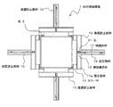
図5は、柱の補強構造1の平面図である。前述したように、柱3は、略矩形であり、図示した例では、柱3は、略正方形の断面形状である。この場合、座屈防止部材10は、柱3の外周面の4面にそれぞれ配置される。 FIG. 5 is a plan view of the reinforcing structure 1 of the column. As described above, the pillar 3 has a substantially rectangular shape, and in the illustrated example, the pillar 3 has a substantially square cross-sectional shape. In this case, the buckling prevention member 10 is arranged on each of the four outer peripheral surfaces of the pillar 3.
柱3に圧縮力が付与され、柱3が座屈する際には、柱3は、少なくとも一方の方向に膨らむように変形する。しかし、柱3の外周部には座屈防止部材10が配置され、柱3は、補強縦部材15及び固定部材11a、11bによって外周側から押さえられる。また、補強斜材17によって補強縦部材15は、略中央部が外周側から押さえられているため、補強縦部材15の変形が抑制される。このように、柱3の各方向に座屈防止部材10が配置されることで、柱3は、いずれの方向に対しても変形が抑制される。このため、柱3の座屈が抑制される。 When a compressive force is applied to the column 3 and the column 3 buckles, the column 3 is deformed so as to bulge in at least one direction. However, a buckling prevention member 10 is arranged on the outer peripheral portion of the column 3, and the column 3 is pressed from the outer peripheral side by the reinforcing vertical member 15 and the fixing members 11a and 11b. Further, since the substantially central portion of the reinforcing vertical member 15 is pressed from the outer peripheral side by the reinforcing diagonal member 17, the deformation of the reinforcing vertical member 15 is suppressed. By arranging the buckling prevention member 10 in each direction of the pillar 3 in this way, the pillar 3 is suppressed from being deformed in any direction. Therefore, the buckling of the pillar 3 is suppressed.
なお、柱3の4面の全てに座屈防止部材10を配置する例を示したが、本発明はこれには限られない。図6は、柱の補強構造1aを示す平面図である。柱の補強構造1aでは、柱3が、略正方形ではなく長方形となる。この場合には、柱3の長辺側の外周部に、一対の座屈防止部材10を配置してもよい。すなわち、短辺側の外周部には座屈防止部材10を配置せず、長辺側の互いに対向する位置にのみ座屈防止部材10を配置してもよい。 Although an example in which the buckling prevention member 10 is arranged on all four surfaces of the pillar 3, the present invention is not limited to this. FIG. 6 is a plan view showing the reinforcing structure 1a of the column. In the column reinforcing structure 1a, the column 3 is not a substantially square but a rectangle. In this case, a pair of buckling prevention members 10 may be arranged on the outer peripheral portion on the long side side of the pillar 3. That is, the buckling prevention member 10 may not be arranged on the outer peripheral portion on the short side, and the buckling prevention member 10 may be arranged only on the long side facing each other.
柱3が長方形である場合には、柱3の断面係数によって、柱3は長辺の中心を中立軸とした曲がりに対して、短辺の中心を中立軸とした方向へ曲がりやすい。このため、柱3の曲がりやすい方向に対してのみ座屈防止部材10を配置することで、効率よく柱3の変形を抑制し、座屈を抑制することができる。 When the pillar 3 is rectangular, the cross-sectional coefficient of the pillar 3 makes it easy for the pillar 3 to bend in the direction in which the center of the short side is the neutral axis, as opposed to the bending in which the center of the long side is the neutral axis. Therefore, by arranging the buckling prevention member 10 only in the direction in which the pillar 3 is easily bent, the deformation of the pillar 3 can be efficiently suppressed and the buckling can be suppressed.
以上、本実施の形態によれば、柱3の外周部に座屈防止部材10を配置することで、柱3が圧縮力を受けた際に、柱3が座屈することを効率よく抑制することができる。この際、補強縦部材15は、補強斜材17によって外方から押さえられているため、補強縦部材15自体が変形することを抑制することができる。 As described above, according to the present embodiment, by arranging the buckling prevention member 10 on the outer peripheral portion of the pillar 3, it is possible to efficiently suppress the buckling of the pillar 3 when the pillar 3 receives a compressive force. Can be done. At this time, since the reinforcing vertical member 15 is pressed from the outside by the reinforcing diagonal member 17, it is possible to prevent the reinforcing vertical member 15 itself from being deformed.
また、柱3と座屈防止部材10の間にスペーサ13を配置することで、座屈防止部材10と柱3との間に隙間9を形成することができる。このため、柱3の外周に配管等を配置する場合でも、配管等と座屈防止部材10とが干渉することがない。 Further, by arranging the spacer 13 between the pillar 3 and the buckling prevention member 10, a gap 9 can be formed between the buckling prevention member 10 and the pillar 3. Therefore, even when the pipe or the like is arranged on the outer periphery of the pillar 3, the pipe or the like does not interfere with the buckling prevention member 10.
また、補強縦部材15の両端部が固定部材11aと接合されずに、縁が切れているため、柱3に圧縮力が付与された際に、補強縦部材15に圧縮力が伝達されることがない。このため、柱3に対する圧縮力によって補強縦部材15が座屈することがない。 Further, since both ends of the reinforcing vertical member 15 are not joined to the fixing member 11a and the edges are cut, the compressive force is transmitted to the reinforcing vertical member 15 when the compressive force is applied to the column 3. There is no. Therefore, the reinforcing vertical member 15 does not buckle due to the compressive force on the column 3.
このように、本実施形態の座屈防止部材10は、既設の柱3に対しても容易に取り付けることが可能である。また、柱の全体を覆うものと比較して、施工が容易であり、柱3が組立柱の場合には、座屈防止部材10を配置しても、ほとんど視界を遮ることがない。 As described above, the buckling prevention member 10 of the present embodiment can be easily attached to the existing pillar 3. Further, the construction is easier than that covering the entire column, and when the column 3 is an assembled column, even if the buckling prevention member 10 is arranged, the view is hardly obstructed.
なお、柱3から座屈防止部材10への力は、固定部材11a、11bの位置のみで伝達されるが、固定部材11a、11bの間であって補強縦部材15の内側にスペーサ部材等を接合して、スペーサ部材等を柱3の縦材5又は斜材7に接触させてもよい。このようにすることで、柱3からの力を、固定部材11a、11bのみではなく、当該スペーサ部材の位置においても補強縦部材15へ伝達することができる。 The force from the column 3 to the buckling prevention member 10 is transmitted only at the positions of the fixing members 11a and 11b, but a spacer member or the like is placed inside the reinforcing vertical member 15 between the fixing members 11a and 11b. The spacer member or the like may be joined and brought into contact with the vertical member 5 or the diagonal member 7 of the column 3. By doing so, the force from the column 3 can be transmitted not only to the fixing members 11a and 11b but also to the reinforcing vertical member 15 at the position of the spacer member.
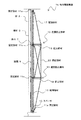
また、座屈防止部材10は、柱3の全長にわたって配置する必要があるが、必ずしも補強縦部材15が柱3と同じ長さでなくてもよい。例えば、図7に示す柱の補強構造1bのように、複数の座屈防止部材10を柱3の全長にわたって配置してもよい。 Further, the buckling prevention member 10 needs to be arranged over the entire length of the column 3, but the reinforcing vertical member 15 does not necessarily have to have the same length as the column 3. For example, as in the column reinforcing structure 1b shown in FIG. 7, a plurality of buckling prevention members 10 may be arranged over the entire length of the column 3.
この場合には、座屈防止部材10が、柱3の長手方向に、互いの一部が重なり合うように複数配置される。なお、座屈防止部材10のそれぞれの補強縦部材15は、互いが干渉しないように、柱3の幅方向に対してずらして配置される。また、複数の座屈防止部材10をちょうど長さの半分だけずらして配置することで、互いの固定部材を共有することができる。 In this case, a plurality of buckling prevention members 10 are arranged in the longitudinal direction of the pillar 3 so that some of them overlap each other. The reinforcing vertical members 15 of the buckling prevention member 10 are arranged so as to be offset from each other in the width direction of the column 3 so as not to interfere with each other. Further, by arranging the plurality of buckling prevention members 10 so as to be offset by exactly half the length, the fixing members can be shared with each other.
例えば、最も上方に位置する固定部材11aは、上方の座屈防止部材10の固定部材としてのみ機能し、最も下方に位置する固定部材11aは、下方の座屈防止部材10の固定部材としてのみ機能する。一方、それぞれの座屈防止部材10の中央部には、固定部材11bに代えて、固定部材11cが配置される。 For example, the uppermost fixing member 11a functions only as a fixing member of the upper buckling prevention member 10, and the lowermost fixing member 11a functions only as a fixing member of the lower buckling prevention member 10. To do. On the other hand, a fixing member 11c is arranged in place of the fixing member 11b at the center of each buckling prevention member 10.
固定部材11cは、一方の座屈防止部材10の補強縦部材15と接合されるが、他方の座屈防止部材10の補強縦部材15とは接合されずに縁切りされる。例えば、上方の固定部材11c(図中上から2番目の固定部材)は、上方の座屈防止部材10の補強縦部材15と接合されるが、下方の座屈防止部材10の補強縦部材15の位置には、孔21が形成され、補強縦部材15の端部が孔21に挿入される。同様に、下方の固定部材11c(図中上から3番目の固定部材)は、下方の座屈防止部材10の補強縦部材15と接合されるが、上方の座屈防止部材10の補強縦部材15の位置には、孔21が形成され、補強縦部材15の端部が孔21に挿入される。
The fixing member 11c is joined to the reinforcing vertical member 15 of one buckling prevention member 10, but is cut off without being joined to the reinforcing vertical member 15 of the other buckling prevention member 10. For example, the upper fixing member 11c (the second fixing member from the top in the drawing) is joined to the reinforcing vertical member 15 of the upper buckling prevention member 10, but the reinforcing vertical member 15 of the lower buckling prevention member 10 is joined. A
それぞれの座屈防止部材10の起立部材19の端部同士は、連結部材23で接続される。このようにすることで、座屈防止部材10同士の間で応力が伝達され、柱3の全長にわたって座屈を防止することができる。 The ends of the upright members 19 of the buckling prevention members 10 are connected by a connecting member 23. By doing so, stress is transmitted between the buckling prevention members 10, and buckling can be prevented over the entire length of the column 3.
以上、添付図を参照しながら、本発明の実施の形態を説明したが、本発明の技術的範囲は、前述した実施の形態に左右されない。当業者であれば、特許請求の範囲に記載された技術的思想の範疇内において各種の変更例または修正例に想到し得ることは明らかであり、それらについても当然に本発明の技術的範囲に属するものと了解される。 Although the embodiment of the present invention has been described above with reference to the attached drawings, the technical scope of the present invention does not depend on the above-described embodiment. It is clear that a person skilled in the art can come up with various modifications or modifications within the scope of the technical ideas described in the claims, and these are naturally within the technical scope of the present invention. It is understood that it belongs.
1、1a、1b………柱の補強構造
3………柱
5………縦材
7………斜材
9………隙間
10………座屈防止部材
11a、11b、11c………固定部材
13………スペーサ
15………補強縦部材
15a………縮径部
17………補強斜材
19………起立部材
21………孔
23………連結部材
1, 1a, 1b ………… Column reinforcement structure 3 ………… Column 5 ………… Vertical member 7 ………… Slanted member 9 ………… Gap 10 ………… Buckling prevention members 11a, 11b, 11c ………… Fixing member 13 ………… Spacer 15 ………… Reinforcing vertical member 15a ………… Reduced diameter portion 17 ………… Reinforcing diagonal member 19 ………… Standing
Claims (7)
柱の上下方向に沿って配置される補強縦部材と、
少なくとも、前記補強縦部材の長手方向の両端部近傍及び中央部近傍において配置され、柱の外面に固定される固定部材と、
前記補強縦部材の長手方向の略中央部に起立する起立部材と、
前記補強縦部材の両端部近傍と前記起立部材の端部とを連結する補強斜材と、
を具備することを特徴とする座屈防止部材。 A buckling prevention member for reinforcing columns
Reinforcing vertical members arranged along the vertical direction of the columns,
At least, a fixing member that is arranged near both ends and the center of the reinforcing vertical member in the longitudinal direction and fixed to the outer surface of the column.
An upright member that stands up at a substantially central portion in the longitudinal direction of the reinforcing vertical member,
A reinforcing diagonal member that connects the vicinity of both ends of the reinforcing vertical member and the end of the standing member,
A buckling prevention member characterized by comprising.
前記起立部材が、前記柱とは逆側に向くように、前記柱の長手方向に沿って、前記柱の外面に座屈防止部材が配置されることを特徴とする柱の補強構造。 A column reinforcing structure using the buckling prevention member according to claim 1.
A column reinforcing structure, characterized in that a buckling prevention member is arranged on an outer surface of the column along the longitudinal direction of the column so that the upright member faces the opposite side of the column.
前記固定部材の端部は、前記縦材に固定されることを特徴とする請求項2記載の柱の補強構造。 The pillar is an assembly pillar having a vertical member and a diagonal member connecting the vertical members to each other.
The column reinforcing structure according to claim 2, wherein the end portion of the fixing member is fixed to the vertical member.
複数の前記座屈防止部材の前記起立部材の端部同士が接続されることを特徴とする請求項2から請求項5のいずれかに記載の柱の補強構造。 A plurality of the buckling prevention members are arranged in the longitudinal direction of the pillar so that some of them overlap each other.
The column reinforcing structure according to any one of claims 2 to 5, wherein the ends of the standing members of the plurality of buckling prevention members are connected to each other.
Priority Applications (1)
| Application Number | Priority Date | Filing Date | Title |
|---|---|---|---|
| JP2019048705A JP2020148068A (en) | 2019-03-15 | 2019-03-15 | Buckling prevention member and reinforcement structure of column |
Applications Claiming Priority (1)
| Application Number | Priority Date | Filing Date | Title |
|---|---|---|---|
| JP2019048705A JP2020148068A (en) | 2019-03-15 | 2019-03-15 | Buckling prevention member and reinforcement structure of column |
Publications (1)
| Publication Number | Publication Date |
|---|---|
| JP2020148068A true JP2020148068A (en) | 2020-09-17 |
Family
ID=72431856
Family Applications (1)
| Application Number | Title | Priority Date | Filing Date |
|---|---|---|---|
| JP2019048705A Pending JP2020148068A (en) | 2019-03-15 | 2019-03-15 | Buckling prevention member and reinforcement structure of column |
Country Status (1)
| Country | Link |
|---|---|
| JP (1) | JP2020148068A (en) |
Cited By (2)
| Publication number | Priority date | Publication date | Assignee | Title |
|---|---|---|---|---|
| KR102337874B1 (en) * | 2020-11-26 | 2021-12-10 | 부산대학교 산학협력단 | Rapid reinforcement support for H-beam columns in earthquake-damaged buildings |
| KR102337872B1 (en) * | 2020-11-26 | 2021-12-10 | 부산대학교 산학협력단 | H-beam steel reinforcing member to prevent secondary deformation of Local Buckling Occurred H-beam steel |
-
2019
- 2019-03-15 JP JP2019048705A patent/JP2020148068A/en active Pending
Cited By (2)
| Publication number | Priority date | Publication date | Assignee | Title |
|---|---|---|---|---|
| KR102337874B1 (en) * | 2020-11-26 | 2021-12-10 | 부산대학교 산학협력단 | Rapid reinforcement support for H-beam columns in earthquake-damaged buildings |
| KR102337872B1 (en) * | 2020-11-26 | 2021-12-10 | 부산대학교 산학협력단 | H-beam steel reinforcing member to prevent secondary deformation of Local Buckling Occurred H-beam steel |
Similar Documents
| Publication | Publication Date | Title |
|---|---|---|
| KR101364922B1 (en) | Buckling-Restrained Braces | |
| JP2005351078A (en) | Construction method of steel frame reinforced concrete column | |
| KR101364787B1 (en) | Buckling-Restrained Braces | |
| JP2020148068A (en) | Buckling prevention member and reinforcement structure of column | |
| JP5575561B2 (en) | Seismic structure of buildings | |
| JP6227452B2 (en) | Wall pillar structure | |
| JP5231836B2 (en) | Connection structure | |
| JPH0972108A (en) | Reinforcing method of existing column body | |
| JP6181369B2 (en) | Reinforcement bracket and reinforced concrete perforated beam provided with the reinforcement bracket | |
| JP4802111B2 (en) | Long structure and steel rebar members | |
| JP5992263B2 (en) | X type compression brace | |
| WO2017170732A1 (en) | Beam-to-column connection structure and steel reinforced concrete column | |
| JP6466196B2 (en) | Reinforcement structure and reinforcement method for existing columns | |
| JP2020153081A (en) | Column reinforcement structure | |
| JP6567368B2 (en) | Reinforcement structure and reinforcement method for existing columns | |
| JP2007023712A (en) | Columnar structure using shape steel, pier or foundation pile and its manufacturing method | |
| JP3938718B2 (en) | Reinforced concrete beam structure | |
| JP2005155058A (en) | Beam member of rc structure | |
| JP2004068304A (en) | End fixed construction of constituent in reinforced concrete building | |
| JP6570306B2 (en) | Reinforcement structure of building | |
| JP2004092156A (en) | Vibration control construction of structure | |
| JP4044835B2 (en) | Junction structure | |
| JP7082413B2 (en) | Composite studs, floor structures and floor structure construction methods | |
| JP7137978B2 (en) | Plate-shaped member for pillar | |
| JP2011179317A (en) | Method for designing composite structural beam |