JP2020125091A - Steering device and sailing body - Google Patents
Steering device and sailing body Download PDFInfo
- Publication number
- JP2020125091A JP2020125091A JP2019020059A JP2019020059A JP2020125091A JP 2020125091 A JP2020125091 A JP 2020125091A JP 2019020059 A JP2019020059 A JP 2019020059A JP 2019020059 A JP2019020059 A JP 2019020059A JP 2020125091 A JP2020125091 A JP 2020125091A
- Authority
- JP
- Japan
- Prior art keywords
- space
- pressure
- connecting rod
- cylinder
- rudder blade
- Prior art date
- Legal status (The legal status is an assumption and is not a legal conclusion. Google has not performed a legal analysis and makes no representation as to the accuracy of the status listed.)
- Granted
Links
Images


Landscapes
- Transmission Devices (AREA)
Abstract
Description
本発明は、操舵装置、及び航走体に関する。 The present invention relates to a steering device and a vehicle.
船舶等の航走体は、後部に設けられた操舵装置で舵板の向きを変えることで、進行方向を変える。この種の操舵装置の具体例として、下記特許文献1に記載されたものが知られている。特許文献1に係る操舵装置は、舵板と一体に設けられたチラーを舵軸回りに回動させる油圧アクチュエータを備えている。油圧アクチュエータは、チラーを押す油圧シリンダと、油圧を発生させる油圧ポンプと、各油圧シリンダへの油圧の供給状態を変化させる斜板ポンプと、を有している。斜板ポンプ内の斜板の姿勢を変化させることで、油圧シリンダの動作が制御され、チラーの回動方向や角度を制御することができるとされている。
A traveling body such as a ship changes its traveling direction by changing the direction of a rudder blade with a steering device provided at the rear. As a specific example of this type of steering device, the one described in
しかしながら、上記特許文献1に記載された操舵装置では、油圧シリンダが発生する油圧によって舵板(チラー)を直接的に動作させることで操舵が行われる。したがって、油圧の供給状態によっては、油圧シリンダによって舵板が急激に押されてしまう。その結果、舵板の姿勢が急激に変化し、航走体の航走に影響を及ぼす可能性がある。
However, in the steering device described in
本発明は上記課題を解決するためになされたものであって、より円滑に操舵を行うことが可能な操舵装置、及びこれを備える航走体を提供することを目的とする。 The present invention has been made to solve the above problems, and an object of the present invention is to provide a steering device capable of performing a smoother steering operation, and a navigation body including the steering device.
本発明の一態様に係る航走体は、航走体に軸線回りに回転可能に支持された舵軸と、該舵軸に一体に固定された舵板と、前記舵板に連結されて、進退移動することで前記舵板にトルクを与えて該舵板を前記軸線回りに回転させる連結棒と、前記航走体の耐圧構造内に設けられて、駆動されることで前記連結棒を進退させる電動機を有する直動機構と、を備える。 The running body according to one aspect of the present invention is a rudder shaft rotatably supported on the running body around an axis, a rudder plate integrally fixed to the rudder shaft, and a rudder plate, The connecting rod is provided inside the pressure-resistant structure of the navigation body and is driven to move the connecting rod forward and backward by providing a torque to the rudder plate by moving it forward and backward to rotate the rudder plate around the axis. And a direct-acting mechanism having an electric motor.
上記構成によれば、直動機構によって連結棒を進退させることによって舵板にトルクが与えられ、このトルクによって舵板が軸線回りに回転する。さらに、直動機構は電動機によって連結棒を進退させる。したがって、例えば油圧によって直接的に舵板を回転させる構成に比べて、舵板が回転し始める際、及び回転し終わる際の加速度が小さくなる。これにより、舵板が急激に回転してしまう可能性を低減することができる。つまり、舵板をより円滑に回転させることができる。 According to the above configuration, torque is applied to the rudder blade by advancing and retracting the connecting rod by the linear motion mechanism, and this torque causes the rudder blade to rotate around the axis. Further, the linear motion mechanism advances and retracts the connecting rod by the electric motor. Therefore, as compared with a configuration in which the rudder blade is directly rotated by hydraulic pressure, for example, the acceleration when the rudder blade starts to rotate and when the rudder blade ends to rotate becomes smaller. This can reduce the possibility that the rudder blade will rotate rapidly. That is, the rudder blade can be rotated more smoothly.
上記航走体では、前記直動機構は、前記電動機に接続され、自身の中心軸回りに回転可能な送りねじ部と、該送りねじ部に噛み合うことで進退するナットと、該ナットと前記連結棒とを接続するブラケットと、を有してもよい。 In the above-mentioned navigation vehicle, the linear motion mechanism is connected to the electric motor, and has a feed screw portion rotatable about its own central axis, a nut that advances and retreats by engaging with the feed screw portion, and the nut and the connection. And a bracket for connecting to the rod.
上記構成によれば、ブラケットによってナットと連結棒が接続され、当該ナットは送りねじの回転によって進退する。これにより、連結棒をより緩やか、かつ円滑に進退させることができる。特に、例えば油圧によって直接的に舵板を回転させる構成に比べて、舵板が回転し始める際、及び回転し終わる際の加速度が小さくなる。これにより、舵板が急激に回転してしまう可能性を低減することができる。つまり、舵板をより円滑に回転させることができる。 According to the above configuration, the nut and the connecting rod are connected by the bracket, and the nut moves forward and backward by the rotation of the feed screw. Thereby, the connecting rod can be moved back and forth more gently and smoothly. In particular, as compared with a configuration in which the rudder blade is directly rotated by hydraulic pressure, for example, the acceleration when the rudder blade starts to rotate and when the rudder blade ends to rotate becomes smaller. This can reduce the possibility that the rudder blade will rotate rapidly. That is, the rudder blade can be rotated more smoothly.
上記航走体では、固定子と、該固定子の外側を覆うとともに、電磁誘導により該固定子に対して進退可能な可動子と、を有し、前記可動子の一端は前記連結棒に接続されていてもよい。 The above-mentioned navigation body has a stator and a mover that covers the outside of the stator and can move back and forth with respect to the stator by electromagnetic induction, and one end of the mover is connected to the connecting rod. It may have been done.
上記構成によれば、可動子の一端が連結棒に接続されるとともに、当該可動子は電磁誘導によって固定子に対して進退可能とされている。これにより、可動子の進退に伴って、連結棒を円滑に進退させることができる。特に、例えば油圧によって直接的に舵板を回転させる構成に比べて、舵板が回転し始める際、及び回転し終わる際の加速度が小さくなる。これにより、舵板が急激に回転してしまう可能性を低減することができる。つまり、舵板をより円滑に回転させることができる。 According to the above configuration, one end of the mover is connected to the connecting rod, and the mover is movable back and forth with respect to the stator by electromagnetic induction. Accordingly, the connecting rod can be smoothly moved back and forth as the mover is moved back and forth. In particular, as compared with a configuration in which the rudder blade is directly rotated by hydraulic pressure, for example, the acceleration when the rudder blade starts to rotate and when the rudder blade ends to rotate becomes smaller. This can reduce the possibility that the rudder blade will rotate rapidly. That is, the rudder blade can be rotated more smoothly.
上記航走体では、前記耐圧構造は、耐圧構造本体と、該耐圧構造本体の外面を覆うとともに、前記外面との間に前記直動機構を収容する収容空間を形成する耐圧容器と、を有してもよい。 In the above-mentioned watercraft, the pressure-resistant structure includes a pressure-resistant structure body and a pressure-resistant container that covers an outer surface of the pressure-resistant structure body and that forms a housing space for housing the linear motion mechanism with the outer surface. You may.
上記構成によれば、直動機構が耐圧容器の収容空間内に収容されている。したがって、耐圧構造本体内に直動機構を設けた場合に比べて、耐圧構造内のスペースを削減することができる。 According to the above configuration, the linear motion mechanism is housed in the housing space of the pressure resistant container. Therefore, the space in the pressure resistant structure can be reduced as compared with the case where the linear motion mechanism is provided in the pressure resistant structure body.
上記航走体では、前記直動機構は、第一空間と第二空間とが形成されたシリンダ、及び前記連結棒に連結され、前記シリンダ内で摺動することで前記第一空間と前記第二空間の容積を変化させるピストンを有するシリンダユニットと、前記電動機によって駆動されることで、前記第一空間、及び前記第二空間に選択的に作動流体を供給する供給ユニットと、を有してもよい。 In the above-mentioned navigation vehicle, the linear motion mechanism is connected to a cylinder in which a first space and a second space are formed, and the connecting rod, and slides in the cylinder to cause the first space and the first space to move. A cylinder unit having a piston that changes the volume of the two spaces; and a supply unit that is driven by the electric motor to selectively supply the working fluid to the first space and the second space. Good.
上記構成によれば、電動機によって供給ユニットを駆動することで、シリンダユニットの第一空間、及び第二空間に選択的に作動流体が供給される。これにより、ピストンがシリンダ内で摺動し、第一空間、及び第二空間の容積が変化する。その結果、ピストンに連結された連結棒が進退する。供給ユニットが電動機で駆動されることから、第一空間、及び第二空間に対する作動流体の供給は緩やか、かつ円滑に行われる。したがって、例えば油圧によって直接的に舵板を回転させる構成に比べて、舵板が回転し始める際、及び回転し終わる際の加速度が小さくなる。これにより、舵板が急激に回転してしまう可能性を低減することができる。つまり、舵板をより円滑に回転させることができる。 According to the above configuration, by driving the supply unit with the electric motor, the working fluid is selectively supplied to the first space and the second space of the cylinder unit. As a result, the piston slides in the cylinder, and the volumes of the first space and the second space change. As a result, the connecting rod connected to the piston moves back and forth. Since the supply unit is driven by the electric motor, the supply of the working fluid to the first space and the second space is performed gently and smoothly. Therefore, as compared with a configuration in which the rudder blade is directly rotated by hydraulic pressure, for example, the acceleration when the rudder blade starts to rotate and when the rudder blade ends to rotate becomes smaller. This can reduce the possibility that the rudder blade will rotate rapidly. That is, the rudder blade can be rotated more smoothly.
上記航走体では、前記耐圧構造は、耐圧構造本体と、該耐圧構造本体の外面を覆うとともに、前記外面との間に前記シリンダユニットを収容する収容空間を形成する耐圧容器と、を有してもよい。 In the above-mentioned watercraft, the pressure-resistant structure includes a pressure-resistant structure body, and a pressure-resistant container that covers an outer surface of the pressure-resistant structure body and forms a housing space for housing the cylinder unit between the outer surface and the pressure-resistant container. May be.
上記構成によれば、シリンダユニットが耐圧容器の収容空間内に収容されている。したがって、耐圧構造本体内にシリンダユニットを設けた場合に比べて、耐圧構造内のスペースを削減することができる。 According to the above configuration, the cylinder unit is housed in the housing space of the pressure resistant container. Therefore, the space in the pressure resistant structure can be reduced as compared with the case where the cylinder unit is provided in the pressure resistant structure body.
本発明の一態様に係る航走体は、航走体本体と、該航走体本体に設けられた上記のいずれか一態様に係る操舵装置と、を備える。 A traveling body according to one aspect of the present invention includes a traveling body main body, and the steering device according to any one of the above aspects, which is provided in the traveling body main body.
上記構成によれば、円滑に操舵することが可能な操舵装置を備える航走体を実現することができる。 According to the above configuration, it is possible to realize a running body including a steering device capable of smoothly steering.
本発明によれば、より円滑に操舵を行うことが可能な操舵装置、及びこれを備える航走体を提供することができる。 ADVANTAGE OF THE INVENTION According to this invention, the steering device which can carry out steering more smoothly and a navigation body provided with this can be provided.
[第一実施形態]
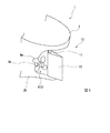
本発明の第一実施形態について、図1と図2を参照して説明する。本実施形態に係る航走体1は、航走体本体2と、推進装置3と、操舵装置10と、を備えている。推進装置3は、例えばプロペラ4であり、航走体本体2の後部2bに設けられている。プロペラ4は、後部2bから延びるプロペラ軸4sと、プロペラ軸4sの端部に設けられた複数の翼4wと、を有している。プロペラ軸4sは、航走体本体2内に設けられた不図示の駆動源によって自身の中心軸回りに回転する。プロペラ軸4sの回転に伴って4つの翼4wが旋回することで、航走体本体2に推進力が与えられる。
[First embodiment]
A first embodiment of the present invention will be described with reference to FIGS. 1 and 2. The
操舵装置10は、航走体本体2の後部2bであって、プロペラ4のさらに後方に設けられている。図1及び図2に示すように、操舵装置10は、航走体本体2に回動可能に支持された舵軸11と、舵軸11と一体に設けられた舵板12と、舵板12にトルクを与える連結棒74と、連結棒74と舵板12とを連結するプッシュロッド5、及びガイド筒20と、連結棒74を制動するブレーキユニット6と、連結棒74を進退させる直動機構7と、を有している。
The
舵軸11は、航走体本体2の内外を貫通し、一端が航走体本体2の内部で軸線O回りに回動可能に支持されている。舵軸11は、航走体本体2から水中に向かって延び、その先端部が舵板12に一体に固定されている。
The
舵板12は、軸線O方向から見て紡錘形をなしており、前方側の端部は曲面状に湾曲し、後方側の端部は後方側に向かって尖っている。舵板12の前方側の端部には、プッシュロッド5の一端が回動可能に接続されている。プッシュロッド5は、後述する連結棒74によって伝達された直動機構7のトルクを舵板12に作用させるために設けられている。なお、詳しくは図示しないが、プッシュロッド5が、舵板12に併設されたチラーと呼ばれる部材を介して舵板12にトルクを与える構成を採ることも可能である。
The
プッシュロッド5の他端は、ガイド筒20に接続されている。ガイド筒20は、筒状のガイド筒本体21と、このガイド筒本体21内で進退するガイドコマ22と、を有している。プッシュロッド5の他端はガイドコマ22の一端側に回動可能に接続されている。ガイドコマ22の他端側には連結棒74の一端が接続されている。連結棒74が進退した場合、ガイドコマ22がガイド筒本体21内で摺動し、これに伴ってプッシュロッド5がガイドコマ22に対して回動しつつ、舵板12に連結棒74の進退運動を伝達する。
The other end of the push rod 5 is connected to the
連結棒74は、シール部材Sを介して、航走体本体2の壁部(耐圧構造W)の内外を貫通している。シール部材Sは、連結棒74の周囲における水の浸入を防ぐために設けられている。上記のように、連結棒74の一端はガイド筒20のガイドコマ22に接続されている。一方で、連結棒74の他端側にはブレーキユニット6が設けられている。ブレーキユニット6は、ブレーキシリンダ61と、ブレーキピストン62と、電磁比例弁63と、を有している。
The connecting
ブレーキシリンダ61は連結棒74を外側から囲む筒状をなしている。ブレーキピストン62は連結棒74に一体に固定されている。ブレーキピストン62はブレーキシリンダ61の内部で、連結棒74の延びる方向に進退可能とされている。ブレーキシリンダ61内におけるブレーキピストン62の進退方向両側には2つの空間が形成されている。これらの空間同士は、電磁比例弁63(比例制御電磁弁)を介して流路64によって接続されている。電磁比例弁63は、流路64中を流れる流体の流量(又は圧力)が、予め定められた一定の値となるように開度を自律的に制御することが可能である。これにより、ブレーキピストン62、及び連結棒74の急激な進退動作が回避される。
The
連結棒74におけるブレーキユニット6よりもさらに他方側の端部には、カップリングCを介して直動機構7が接続されている。直動機構7は、連結棒74を進退させるための装置である。直動機構7は、電動機71(モータ)と、送りねじ部72と、ブラケット73と、を有している。送りねじ部72は、連結棒と同一の方向に延びる棒状をなしており、その外周面には雄ねじが切られている。より具体的には、送りねじ部72として、ボールねじ、台形ねじ、及びローラねじが好適に用いられる。送りねじ部72はカップリングCを介して電動機71に接続されている。つまり、電動機71を駆動することによって、送りねじ部72は自身の中心軸回りに回転する。なお、電動機71としては、回転数や回転速度を外部から制御することが可能なものが好適に用いられる。また、電動機71は電磁力に基づいて、回転を制動するブレーキ力を発生させることが可能である。具体的には、電動機71として、サーボモータや、ステッピングモータが好適に用いられる。
The
ブラケット73は、カップリングCを介して連結棒74に接続されたブラケット本体73Bと、送りねじ部72に噛み合うナット73Nと、を有している。電動機71によって送りねじ部72が回転することにより、ナット73N、及びブラケット本体73Bはこの送りねじ部72に沿って進退する。このブラケット73の進退運動は連結棒74に伝達される。連結棒74の進退運動は、上述のブレーキユニット6、及びガイド筒20を介して、舵板12に伝わり、舵軸11回りのトルクを舵板12に与える。
The
ここで、従来の操舵装置では、上述のプッシュロッド5を、油圧シリンダが発生する油圧によって直接的に動作させる構成を採る構成が採られていた。しかしながら、この構成では、油圧の供給状態によっては、油圧によって舵板12が急激に回動してしまう。その結果、舵板12の姿勢が急激に変化し、航走体1の航走に影響を及ぼす可能性がある。これに対して、本実施形態では、直動機構7によって連結棒74を進退させることによって舵板12にトルクが与えられ、このトルクによって舵板12が軸線O回りに回転する。さらに、直動機構7は電動機71によって連結棒74を進退させる。したがって、例えば油圧によって直接的に舵板12を回転させる構成(即ち、ポンプで作動油の量を増減することで油圧を発生させる構成)に比べて、舵板12が回転し始める際、及び回転し終わる際の加速度が小さくなる。これにより、舵板12が急激に回転してしまう可能性を低減することができる。つまり、舵板12をより円滑に回転させることができる。
Here, in the conventional steering apparatus, the push rod 5 is directly operated by the hydraulic pressure generated by the hydraulic cylinder. However, in this configuration, the
さらに、上記の構成によれば、ブラケット73によってナット73Nと連結棒74が接続され、当該ナット73Nは送りねじ部72の回転によって進退する。これにより、連結棒74をより緩やか、かつ円滑に進退させることができる。
Furthermore, according to the above configuration, the
以上、本発明の第一実施形態について説明した。なお、本発明の要旨を逸脱しない限りにおいて、上記の構成に種々の変更や改修を施すことが可能である。例えば、上記実施形態では、連結棒74の中途にブレーキユニット6が設けられている構成について説明した。しかしながら、電動機71自体の発生するブレーキ力(ブレーキ容量)が十分に大きい場合には、ブレーキユニット6を備えない構成を採ることも可能である。
The first embodiment of the present invention has been described above. Note that various changes and modifications can be made to the above configuration without departing from the gist of the present invention. For example, in the above embodiment, the configuration in which the brake unit 6 is provided in the middle of the connecting
[第二実施形態]
次に、本発明の第二実施形態について、図3を参照して説明する。なお、上記第一実施形態と同様の構成については同一の符号を付し、詳細な説明を省略する。図3に示すように、本実施形態では、直動機構7Bの構成が上記第一実施形態と異なっている。この直動機構7Bは、電磁誘導(電磁力)によって駆動するリニアモータ75を有している。リニアモータ75は、固定子75aと、固定子75aに対して摺動可能な可動子75bと、可動子75bに一体に取り付けられたガイド76、及びブレーキ77と、ガイド76を案内するレール78と、可動子75bと連結棒74とを接続する接続部79と、を有している。
[Second embodiment]
Next, a second embodiment of the present invention will be described with reference to FIG. The same components as those in the first embodiment are designated by the same reference numerals, and detailed description thereof will be omitted. As shown in FIG. 3, in this embodiment, the structure of the
固定子75aは、フェライト磁石やネオジム磁石を含む永久磁石によって一体に形成された棒状をなしている。固定子75aは、図示しない固定手段によって航走体本体2の内部に固定されている。可動子75bは、固定子75aの外側を覆う筒状をなしている。可動子75bは、線材を巻回することによって形成されたコイルである。したがって、可動子75bに電流を流すことにより、固定子75aと可動子75bとの間には電磁誘導による力が発生する。この力によって、可動子75bは固定子75aに対して、固定子75aが延びる方向(即ち、連結棒74が延びる方向)に進退可能である。可動子75bの一端は、接続部79を介して連結棒74に接続されている。可動子75bの外周面には、複数のガイド76、及びブレーキ77が設けられている。ガイド76は、可動子75bの外側に設けられたレール78に沿って摺動可能に支持されている。レール78は、連結棒74と同一の方向に延びている。ブレーキ77は、可動子75bを制動することで連結棒74の急激な動作を抑制する。
The
上記の構成によれば、可動子75bの一端が連結棒74に接続されるとともに、当該可動子75bは電磁誘導によって固定子75aに対して摺動可能とされている。これにより、可動子75bの摺動に伴って、連結棒74を円滑に進退させることができる。特に、例えば油圧によって直接的に舵板12を回転させる構成(即ち、ポンプで作動油の量を増減することで油圧を発生させる構成)に比べて、舵板12が回転し始める際、及び回転し終わる際の加速度が小さくなる。これにより、舵板12が急激に回転してしまう可能性を低減することができる。つまり、舵板12をより円滑に回転させることができる。
According to the above configuration, one end of the
以上、本発明の第二実施形態について説明した。なお、本発明の要旨を逸脱しない限りにおいて、上記の構成に種々の変更や改修を施すことが可能である。例えば、上記実施形態では、連結棒74の中途にブレーキユニット6が設けられている構成について説明した。しかしながら、リニアモータ75自体の発生するブレーキ力(ブレーキ容量)が十分に大きい場合には、ブレーキユニット6を備えない構成を採ることも可能である。
The second embodiment of the present invention has been described above. Note that various changes and modifications can be made to the above configuration without departing from the gist of the present invention. For example, in the above embodiment, the configuration in which the brake unit 6 is provided midway in the connecting
[第三実施形態]
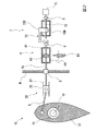
続いて、本発明の第三実施形態について、図4を参照して説明する。なお、上記の各実施形態と同様の構成については同一の符号を付し、詳細な説明を省略する。図4に示すように、本実施形態では、直動機構7Cの構成が上記の各実施形態とは異なっている。この直動機構7Cは、連結棒74を油圧によって進退させる第一シリンダユニット6Bと、第一シリンダユニット6Bに供給される作動流体(油)の量を調節する供給ユニット8と、を有している。
[Third embodiment]
Subsequently, a third embodiment of the present invention will be described with reference to FIG. The same components as those in the above-described embodiments are designated by the same reference numerals, and detailed description thereof will be omitted. As shown in FIG. 4, in the present embodiment, the structure of the
第一シリンダユニット6Bは、筒状の第一シリンダ61B(シリンダ)と、この第一シリンダ61B内で摺動する第一ピストン62B(ピストン)と、を有している。第一ピストン62Bは連結棒74に固定されている。第一シリンダ61Bの内部は、第一ピストン62Bによって2つの空間に区画されている。第一シリンダ61Bの内部における第一ピストン62Bよりも連結棒74側の空間は第一空間V1とされている。第一ピストン62Bを挟んで第一空間V1とは反対側の空間は第二空間V2とされている。
The
供給ユニット8は、上記の第一空間V1、及び第二空間V2に流れ込む作動流体(油)の量を調節する。供給ユニット8は、第二シリンダユニット9Aと、この第二シリンダユニット9Aを駆動する駆動部9Bと、を有している。第二シリンダユニット9Aは、シリンダロッド91と、シリンダロッド91が挿通された筒状の第二シリンダ92と、シリンダロッド91の中途位置に設けられた第二ピストン93と、を有している。第二ピストン93によって第二シリンダ92の内部は2つの空間に区画されている。第二シリンダ92の内部における第二ピストン93の一方側の空間は第一空間V1´とされている。第二ピストン93の他方側の空間は第二空間V2´とされている。第一空間V1´は、第一流路P1によって、上記第一シリンダユニット6Bの第一空間V1と連通されている。第二空間V2´は、第二流路P2によって、上記第一シリンダユニット6Bの第二空間V2と連通されている。
The
シリンダロッド91は、駆動部9Bによって駆動されることで、自身の延びる方向に進退可能とされている。駆動部9Bは、電動機81と、この電動機81によって回転する送りねじ部82と、送りねじ部82に噛み合うナット83と、ナット83に一体に設けられ、シリンダロッド91とナット83とを接続する接続部84と、を有している。送りねじ部82としては、上記第一実施形態と同様に、ボールネジや台形ねじ、ローラねじが好適に用いられる。電動機81としては、回転数や回転速度を外部から制御することが可能なものが好適に用いられる。また、電動機81は電磁力に基づいて、回転を制動するブレーキ力を発生させることが可能である。具体的には、電動機81として、サーボモータや、ステッピングモータが好適に用いられる。
The
電動機81を駆動することによって送りねじ部82が回転する。送りねじ部82の回転に伴って、ナット83及び接続部84が、送りねじ部82の延びる方向に進退する。これにより、接続部84に接続されたシリンダロッド91、及び第二ピストン93が第二シリンダ92の内部で進退する。その結果、第二シリンダ92における第一空間V1´、及び第二空間V2´の容積がそれぞれ変化する。第二ピストン93が第一空間V1´側に移動した場合(即ち、第一第一空間V1´の容積が小さくなる方向に変化した場合)、当該第一空間V1´内の作動流体は、第一シリンダユニット6Bの第一空間V1内に流れ込む。これにより、第一空間V1の容積が大きくなる方向に第一シリンダユニット6Bの第一ピストン62Bが変位する。同時に、第一シリンダユニット6Bの第二空間V2内の作動流体は、第二シリンダユニット9Aの第二空間V2´内に流れ込む。その結果、舵板12に舵軸11回りのトルクが与えられ、舵板12は軸線O回りに回動する。
By driving the
このように、本実施形態の構成によれば、駆動部9Bの電動機81によって供給ユニット8を駆動することで、第一シリンダユニット6Bの第一空間V1、及び第二空間V2に選択的に作動流体が供給される。これにより、第一ピストン62Bが第一シリンダ61B内で摺動し、第一空間V1、及び第二空間V2の容積が変化する。その結果、第一ピストン62Bに連結された連結棒74が進退する。供給ユニット8が電動機81で駆動されることから、第一空間V1、及び第二空間V2に対する作動流体の供給は緩やか、かつ円滑に行われる。したがって、例えば油圧によって直接的に舵板12を回転させる構成(即ち、ポンプで作動油の量を増減することで油圧を発生させる構成)に比べて、舵板12が回転し始める際、及び回転し終わる際の加速度が小さくなる。これにより、舵板12が急激に回転してしまう可能性を低減することができる。つまり、舵板12をより円滑に回転させることができる。
As described above, according to the configuration of the present embodiment, by driving the
以上、本発明の第三実施形態について説明した。なお、本発明の要旨を逸脱しない限りにおいて、上記の構成に種々の変更や改修を施すことが可能である。例えば、上記実施形態の構成に加えて、第一実施形態、及び第二実施形態で説明したブレーキユニット6を設けることも可能である。 The third embodiment of the present invention has been described above. Note that various changes and modifications can be made to the above configuration without departing from the gist of the present invention. For example, in addition to the configuration of the above embodiment, it is possible to provide the brake unit 6 described in the first and second embodiments.
[第四実施形態]
次に、本発明の第四実施形態について、図5を参照して説明する。なお、上記の各実施形態と同様の構成については同一の符号を付し、詳細な説明を省略する。本実施形態では、直動機構7Dが、耐圧容器Wbによって形成された収容空間R内に収容されている。耐圧容器Wbは、耐圧構造Wの一部であり、航走体本体2の外殻をなす耐圧構造本体Waの外面に固定されている。直動機構7Dは、第一実施形態で説明したものと同様の構成を有している。即ち、直動機構7Dは、電動機71と、カップリングCを介して電動機71によって回転力を与えられる送りねじ部72と、送りねじ部72に噛み合った状態で進退するブラケット73と、を有している。ブラケット73は、送りねじ部72に噛み合うナット73Nと、ナット73Nに一体に設けられ、連結棒74に接続されたブラケット本体73Bと、を有している。
[Fourth Embodiment]
Next, a fourth embodiment of the present invention will be described with reference to FIG. The same components as those in the above-described embodiments are designated by the same reference numerals, and detailed description thereof will be omitted. In this embodiment, the
上記の構成によれば、直動機構7Dが耐圧容器Wbによって形成される収容空間R内に収容されている。したがって、耐圧構造本体Wa内に直動機構7Dを設けた場合に比べて、耐圧構造W内のスペースを削減することができる。
According to the above configuration, the
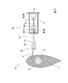
以上、本発明の第四実施形態について説明した。なお、本発明の要旨を逸脱しない限りにおいて、上記の構成に種々の変更や改修を施すことが可能である。例えば、図6に示すように、上記の第二実施形態で説明したリニアモータ75を用いた直動機構7Eを耐圧容器Wbの収容空間R内に収容する構成を採ることも可能である。さらに、図7に示すように、上記の第三実施形態で説明した構成において、第一シリンダユニット6Bのみを耐圧構造本体Waの外側に配置し、供給ユニット8を耐圧構造本体Waの内側に配置する構成を採ることも可能である。
The fourth embodiment of the present invention has been described above. Note that various changes and modifications can be made to the above configuration without departing from the gist of the present invention. For example, as shown in FIG. 6, it is possible to adopt a configuration in which the
また、図5に示すブラケット73の形状を、上述の第一実施形態に適用することも可能である。
Further, the shape of the
1 航走体
2 航走体本体
2b 後部
3 推進装置
4 プロペラ
4s プロペラ軸
4w 翼
10 操舵装置
11 舵軸
12 舵板
20 ガイド筒
21 ガイド筒本体
22 ガイドコマ
5 プッシュロッド
6 ブレーキユニット
6B 第一シリンダユニット
61 ブレーキシリンダ
61B 第一シリンダ(シリンダ)
62 ブレーキピストン
62B 第一ピストン(ピストン)
63 電磁比例弁
64 流路
7,7B,7C,7D,7E,7F 直動機構
71 電動機
72 送りねじ部
73 ブラケット
73B ブラケット本体
73N ナット
74 連結棒
75 リニアモータ
75a 固定子
75b 可動子
76 ガイド
77 ブレーキ
78 レール
79 接続部
8 供給ユニット
81 電動機
82 送りねじ部
83 ナット
84 接続部
9A 第二シリンダユニット
91 シリンダロッド
92 第二シリンダ
93 第二ピストン
9B 駆動部
C カップリング
O 軸線
R 収容空間
S シール部材
V1,V1´ 第一空間
V2,V2´ 第二空間
W 耐圧構造
Wa 耐圧構造本体
Wb 耐圧容器
1
62
63 Electromagnetic
Claims (7)
該舵軸に一体に固定された舵板と、
前記舵板に連結されて、進退移動することで前記舵板にトルクを与えて該舵板を前記軸線回りに回転させる連結棒と、
前記航走体の耐圧構造内に設けられて、駆動されることで前記連結棒を進退させる電動機を有する直動機構と、
を備える操舵装置。 A rudder shaft supported by the navigation body so as to be rotatable around the axis,
A rudder plate integrally fixed to the rudder shaft,
A connecting rod that is connected to the rudder blade and applies a torque to the rudder blade by moving back and forth to rotate the rudder blade around the axis.
A linear motion mechanism provided in the pressure-resistant structure of the navigation body, having a motor for moving the connecting rod forward and backward when driven,
A steering device including.
前記電動機に接続され、自身の中心軸回りに回転可能な送りねじ部と、
該送りねじ部に噛み合うことで進退するナットと、
該ナットと前記連結棒とを接続するブラケットと、
を有する請求項1に記載の操舵装置。 The linear motion mechanism is
A feed screw portion connected to the electric motor and rotatable about its own central axis,
A nut that advances and retreats by meshing with the feed screw portion,
A bracket connecting the nut and the connecting rod,
The steering apparatus according to claim 1, further comprising:
固定子と、
該固定子の外側を覆うとともに、電磁誘導により該固定子に対して進退可能な可動子と、
を有し、
前記可動子の一端は前記連結棒に接続されている請求項1又は2に記載の操舵装置。 The electric motor is
With the stator,
A mover that covers the outside of the stator and is movable back and forth with respect to the stator by electromagnetic induction,
Have
The steering apparatus according to claim 1, wherein one end of the mover is connected to the connecting rod.
耐圧構造本体と、
該耐圧構造本体の外面を覆うとともに、前記外面との間に前記直動機構を収容する収容空間を形成する耐圧容器と、
を有する請求項1から3のいずれか一項に記載の操舵装置。 The pressure resistant structure is
Withstand pressure structure body,
A pressure-resistant container that covers the outer surface of the pressure-resistant structure body and forms a housing space for housing the linear motion mechanism between the outer surface and the outer surface;
The steering apparatus according to any one of claims 1 to 3, further comprising:
第一空間と第二空間とが形成されたシリンダ、及び前記連結棒に連結され、前記シリンダ内で摺動することで前記第一空間と前記第二空間の容積を変化させるピストンを有するシリンダユニットと、
前記電動機によって駆動されることで、前記第一空間、及び前記第二空間に選択的に作動流体を供給する供給ユニットと、
を有する請求項1から3のいずれか一項に記載の操舵装置。 The linear motion mechanism is
A cylinder unit having a cylinder in which a first space and a second space are formed, and a piston that is connected to the connecting rod and that changes the volumes of the first space and the second space by sliding in the cylinder. When,
By being driven by the electric motor, a supply unit that selectively supplies a working fluid to the first space and the second space,
The steering apparatus according to any one of claims 1 to 3, further comprising:
耐圧構造本体と、
該耐圧構造本体の外面を覆うとともに、前記外面との間に前記シリンダユニットを収容する収容空間を形成する耐圧容器と、
を有する請求項5に記載の操舵装置。 The pressure resistant structure is
Withstand pressure structure body,
A pressure-resistant container that covers the outer surface of the pressure-resistant structure body and forms a housing space for housing the cylinder unit between the outer surface and the outer surface;
The steering apparatus according to claim 5, further comprising:
該航走体本体に設けられた請求項1から6のいずれか一項に記載の操舵装置と、
を備える航走体。 The body of the vessel,
The steering device according to any one of claims 1 to 6, which is provided on the main body of the navigation body.
A flying body equipped with.
Priority Applications (1)
| Application Number | Priority Date | Filing Date | Title |
|---|---|---|---|
| JP2019020059A JP7241559B2 (en) | 2019-02-06 | 2019-02-06 | Steering system and vehicle |
Applications Claiming Priority (1)
| Application Number | Priority Date | Filing Date | Title |
|---|---|---|---|
| JP2019020059A JP7241559B2 (en) | 2019-02-06 | 2019-02-06 | Steering system and vehicle |
Publications (2)
| Publication Number | Publication Date |
|---|---|
| JP2020125091A true JP2020125091A (en) | 2020-08-20 |
| JP7241559B2 JP7241559B2 (en) | 2023-03-17 |
Family
ID=72083437
Family Applications (1)
| Application Number | Title | Priority Date | Filing Date |
|---|---|---|---|
| JP2019020059A Active JP7241559B2 (en) | 2019-02-06 | 2019-02-06 | Steering system and vehicle |
Country Status (1)
| Country | Link |
|---|---|
| JP (1) | JP7241559B2 (en) |
Cited By (1)
| Publication number | Priority date | Publication date | Assignee | Title |
|---|---|---|---|---|
| CN115158627A (en) * | 2022-07-06 | 2022-10-11 | 中国舰船研究设计中心 | Electric rudder drive mechanism of rotation swing cylinder coupling |
Citations (7)
| Publication number | Priority date | Publication date | Assignee | Title |
|---|---|---|---|---|
| JPS4881596U (en) * | 1971-12-30 | 1973-10-05 | ||
| JPS589899U (en) * | 1981-07-14 | 1983-01-22 | 三菱重工業株式会社 | steering gear |
| JPS58102522A (en) * | 1981-12-14 | 1983-06-18 | Nippon Telegr & Teleph Corp <Ntt> | Sample transfer apparatus |
| JPH11311315A (en) * | 1998-04-24 | 1999-11-09 | Hitachi Ltd | Control device for automatic transmission |
| US20100212568A1 (en) * | 2007-10-05 | 2010-08-26 | Zf Friedrichshafen Ag | Steering actuator for a steer-by-wire ship's control system and method for operating said steering actuator |
| KR101373680B1 (en) * | 2013-10-08 | 2014-03-13 | 엘아이지넥스원 주식회사 | Control apparatus of rudder angle |
| JP2016147550A (en) * | 2015-02-10 | 2016-08-18 | 三菱重工業株式会社 | Steering machine, steering gear, rudder plate control method |
-
2019
- 2019-02-06 JP JP2019020059A patent/JP7241559B2/en active Active
Patent Citations (7)
| Publication number | Priority date | Publication date | Assignee | Title |
|---|---|---|---|---|
| JPS4881596U (en) * | 1971-12-30 | 1973-10-05 | ||
| JPS589899U (en) * | 1981-07-14 | 1983-01-22 | 三菱重工業株式会社 | steering gear |
| JPS58102522A (en) * | 1981-12-14 | 1983-06-18 | Nippon Telegr & Teleph Corp <Ntt> | Sample transfer apparatus |
| JPH11311315A (en) * | 1998-04-24 | 1999-11-09 | Hitachi Ltd | Control device for automatic transmission |
| US20100212568A1 (en) * | 2007-10-05 | 2010-08-26 | Zf Friedrichshafen Ag | Steering actuator for a steer-by-wire ship's control system and method for operating said steering actuator |
| KR101373680B1 (en) * | 2013-10-08 | 2014-03-13 | 엘아이지넥스원 주식회사 | Control apparatus of rudder angle |
| JP2016147550A (en) * | 2015-02-10 | 2016-08-18 | 三菱重工業株式会社 | Steering machine, steering gear, rudder plate control method |
Cited By (2)
| Publication number | Priority date | Publication date | Assignee | Title |
|---|---|---|---|---|
| CN115158627A (en) * | 2022-07-06 | 2022-10-11 | 中国舰船研究设计中心 | Electric rudder drive mechanism of rotation swing cylinder coupling |
| CN115158627B (en) * | 2022-07-06 | 2024-02-13 | 中国舰船研究设计中心 | Rotary swing cylinder coupling electric rudder driving mechanism |
Also Published As
| Publication number | Publication date |
|---|---|
| JP7241559B2 (en) | 2023-03-17 |
Similar Documents
| Publication | Publication Date | Title |
|---|---|---|
| US7131385B1 (en) | Method for braking a vessel with two marine propulsion devices | |
| JP5236236B2 (en) | Marine electric steering system | |
| US10850820B1 (en) | Control system for multiple trolling motors | |
| CN108910008B (en) | A kind of deep-sea wheel rim propeller with rudder | |
| US9849957B1 (en) | Systems and steering actuators for steering outboard marine engines | |
| JP7241559B2 (en) | Steering system and vehicle | |
| KR20030063214A (en) | Ship and operating method therefor | |
| CN102392926B (en) | Pipe robot | |
| JPWO2003002408A1 (en) | Steering gear | |
| JPH0633077B2 (en) | Steering device for ship propulsion | |
| JP6590146B2 (en) | Steering device, sailing body | |
| JP2021062712A (en) | Steering gear for ship | |
| US10518858B1 (en) | Systems and steering actuators for steering outboard marine engines | |
| KR101373680B1 (en) | Control apparatus of rudder angle | |
| BR112013016824B1 (en) | portable machining device, particularly for drilling | |
| RU201229U1 (en) | MARINE STEERING UNIT | |
| EP3089906B1 (en) | Hydraulically assisted steering system for motor vehicles | |
| JP7127798B2 (en) | Ship maneuvering method for shortening stopping distance and ship maneuvering device for shortening stopping distance | |
| US20230415871A1 (en) | Propulsion device for marine vessel and outboard motor | |
| KR102628927B1 (en) | Vehicle propelling apparatus | |
| US2422138A (en) | Swivelling bladed adjustable pitch propeller | |
| JP5575548B2 (en) | Outdrive device | |
| JP4119934B2 (en) | Ship and ship operation method | |
| JP5174787B2 (en) | Outboard motor steering system | |
| KR20160028184A (en) | Underwater propulsion apparatus |
Legal Events
| Date | Code | Title | Description |
|---|---|---|---|
| A621 | Written request for application examination |
Free format text: JAPANESE INTERMEDIATE CODE: A621 Effective date: 20210309 |
|
| A977 | Report on retrieval |
Free format text: JAPANESE INTERMEDIATE CODE: A971007 Effective date: 20220120 |
|
| A131 | Notification of reasons for refusal |
Free format text: JAPANESE INTERMEDIATE CODE: A131 Effective date: 20220201 |
|
| A521 | Request for written amendment filed |
Free format text: JAPANESE INTERMEDIATE CODE: A523 Effective date: 20220401 |
|
| A131 | Notification of reasons for refusal |
Free format text: JAPANESE INTERMEDIATE CODE: A131 Effective date: 20220809 |
|
| A521 | Request for written amendment filed |
Free format text: JAPANESE INTERMEDIATE CODE: A523 Effective date: 20221011 |
|
| TRDD | Decision of grant or rejection written | ||
| A01 | Written decision to grant a patent or to grant a registration (utility model) |
Free format text: JAPANESE INTERMEDIATE CODE: A01 Effective date: 20230207 |
|
| A61 | First payment of annual fees (during grant procedure) |
Free format text: JAPANESE INTERMEDIATE CODE: A61 Effective date: 20230307 |
|
| R150 | Certificate of patent or registration of utility model |
Ref document number: 7241559 Country of ref document: JP Free format text: JAPANESE INTERMEDIATE CODE: R150 |