JP2020121614A - Travel support method and travel support device - Google Patents

Travel support method and travel support device Download PDF

Info

Publication number
JP2020121614A
JP2020121614A JP2019013830A JP2019013830A JP2020121614A JP 2020121614 A JP2020121614 A JP 2020121614A JP 2019013830 A JP2019013830 A JP 2019013830A JP 2019013830 A JP2019013830 A JP 2019013830A JP 2020121614 A JP2020121614 A JP 2020121614A
Authority
JP
Japan
Prior art keywords
sensor
vehicle
obstacle
travel
line segment
Prior art date
Legal status (The legal status is an assumption and is not a legal conclusion. Google has not performed a legal analysis and makes no representation as to the accuracy of the status listed.)
Granted
Application number
JP2019013830A
Other languages
Japanese (ja)
Other versions
JP7236279B2 (en
Inventor
祐輝 田中
Yuki Tanaka
祐輝 田中
孝志 福重
Takashi Fukushige
孝志 福重
田家 智
Satoshi Taya
智 田家
Current Assignee (The listed assignees may be inaccurate. Google has not performed a legal analysis and makes no representation or warranty as to the accuracy of the list.)
Renault SAS
Nissan Motor Co Ltd
Original Assignee
Renault SAS
Nissan Motor Co Ltd
Priority date (The priority date is an assumption and is not a legal conclusion. Google has not performed a legal analysis and makes no representation as to the accuracy of the date listed.)
Filing date
Publication date
Application filed by Renault SAS, Nissan Motor Co Ltd filed Critical Renault SAS
Priority to JP2019013830A priority Critical patent/JP7236279B2/en
Publication of JP2020121614A publication Critical patent/JP2020121614A/en
Application granted granted Critical
Publication of JP7236279B2 publication Critical patent/JP7236279B2/en
Active legal-status Critical Current
Anticipated expiration legal-status Critical

Links

Images

Abstract

To provide a travel support method and a travel support device capable of generating an efficient route when there exists an obstacle in the front of a vehicle.SOLUTION: A travel support device 1 includes a sensor 10 that is mounted on a vehicle and detects a position of an object in the front of the vehicle, and a controller 20 which sets a travel route of the vehicle on the basis of the position of an object detected by the sensor 10. The controller 20 detects the obstacle from the position of the object detected using the sensor 10, sets a travel possible area excluding the obstacle in the travel route, sets a plurality of segments connecting points on a boundary line between the sensor and the travel possible area, selects the longest segment among the plurality of set segments, classifies whether there is on the right side or left side with respect to the selected longest segment in a vehicle width direction when viewed from the sensor, resets the travel possible area on the basis of the classified result, and generates the travel route of the vehicle in the reset travel possible area.SELECTED DRAWING: Figure 1

Description

本発明は、走行支援方法及び走行支援装置に関する。 The present invention relates to a driving support method and a driving support device.

自車両の前方に障害物が存在する場合、自車両が走行路を走行できるか否かを判定する方法が知られている(特許文献1)。特許文献1に記載された発明は、走行路の境界を表わす検出点と障害物を表わす検出点とから、想定経路の形状を特徴付ける特徴点を抽出し、特徴点と想定経路との距離を算出し、算出した距離に基づいて自車両が走行路を走行できるか否かを判定する。 There is known a method of determining whether or not an own vehicle can travel on a traveling path when an obstacle exists in front of the own vehicle (Patent Document 1). The invention described in Patent Document 1 extracts feature points that characterize the shape of the assumed route from the detection points that represent the boundaries of the traveling road and the detection points that represent obstacles, and calculates the distance between the feature points and the assumed route. Then, based on the calculated distance, it is determined whether or not the host vehicle can travel on the traveling road.

特開2015−36842号公報JP, 2015-36842, A

複数の想定経路が生成される場合、特許文献1に記載された発明は、想定経路と特徴点との距離を比較し、距離が最大となる想定経路を選択する。しかしながら、距離が最大となる想定経路が必ずしも効率のよい経路とはいえない。 When a plurality of assumed routes are generated, the invention described in Patent Document 1 compares the distance between the assumed route and the feature points and selects the assumed route having the maximum distance. However, the assumed route with the maximum distance is not always an efficient route.

本発明は、上記問題に鑑みて成されたものであり、その目的は、自車両の前方に障害物が存在する場合において、効率のよい経路を生成することができる走行支援方法及び走行支援装置を提供することである。 The present invention has been made in view of the above problems, and an object thereof is a travel support method and a travel support device capable of generating an efficient route when an obstacle exists in front of the host vehicle. Is to provide.

本発明の一態様に係る走行支援方法は、障害物を検出し、障害物を除いた走行可能領域を走路内に設定し、センサと走行可能領域の境界線上の点を結ぶ複数の線分を設定し、設定した複数の線分の中から、最も長い線分を選択し、選択した最も長い線分に対し、障害物がセンサから見て車両幅方向で左右のどちらに居るか分類し、分類した結果に基づいて、走行可能領域を再設定し、再設定された走行可能領域内に、車両の走行経路を生成する。 A travel support method according to one aspect of the present invention detects an obstacle, sets a travelable area excluding the obstacle in a track, and forms a plurality of line segments connecting a sensor and a point on a boundary line of the travelable area. Set, select the longest line segment from the set multiple line segments, classify whether the obstacle is on the left or right in the vehicle width direction as seen from the sensor for the selected longest line segment, Based on the classified result, the travelable area is reset, and the travel route of the vehicle is generated in the resettable travelable area.

本発明によれば、自車両の前方に障害物が存在する場合において、効率のよい経路を生成することができる。 According to the present invention, an efficient route can be generated when an obstacle exists in front of the host vehicle.

図1は、本発明の実施形態に係る走行支援装置の概略構成図である。FIG. 1 is a schematic configuration diagram of a traveling support device according to an embodiment of the present invention. 図2は、本発明の実施形態に係る走行可能領域の一例を説明する図である。FIG. 2 is a diagram illustrating an example of a travelable area according to the embodiment of the present invention. 図3は、本発明の実施形態に係る走行シーンの一例を説明する図である。FIG. 3 is a diagram illustrating an example of a traveling scene according to the embodiment of the present invention. 図4は、本発明の実施形態に係る障害物の分類方法の一例を説明する図である。FIG. 4 is a diagram illustrating an example of an obstacle classification method according to the embodiment of the present invention. 図5は、本発明の実施形態に係る障害物の分類方法の一例を説明する図である。FIG. 5 is a diagram illustrating an example of an obstacle classification method according to the embodiment of the present invention. 図6は、本発明の実施形態に係る走行可能領域の再設定方法の一例を説明する図である。FIG. 6 is a diagram illustrating an example of a travelable area resetting method according to the embodiment of the present invention. 図7は、本発明の実施形態に係る走行支援装置の一動作例を説明するフローチャートである。FIG. 7 is a flowchart illustrating an operation example of the driving support device according to the embodiment of the present invention. 図8は、本発明の他の実施形態に係る走行シーンの一例を説明する図である。FIG. 8 is a diagram illustrating an example of a traveling scene according to another embodiment of the present invention. 図9は、本発明の他の実施形態に係る走行可能領域の再設定方法の一例を説明する図である。FIG. 9 is a diagram illustrating an example of a travelable area resetting method according to another embodiment of the present invention. 図10は、本発明の実施形態に係る検出点の格納方法の一例を説明する図である。FIG. 10 is a diagram illustrating an example of a detection point storage method according to the embodiment of the present invention. 図11は、本発明の他の実施形態に係る走行シーンの一例を説明する図である。FIG. 11 is a diagram illustrating an example of a driving scene according to another embodiment of the present invention. 図12は、本発明の他の実施形態に係る障害物の分類方法の一例を説明する図である。FIG. 12 is a diagram illustrating an example of an obstacle classification method according to another embodiment of the present invention. 図13は、本発明の他の実施形態に係る走行可能領域の再設定方法の一例を説明する図である。FIG. 13 is a diagram illustrating an example of a travelable area resetting method according to another embodiment of the present invention.

以下、本発明の実施形態について、図面を参照して説明する。図面の記載において同一部分には同一符号を付して説明を省略する。 Embodiments of the present invention will be described below with reference to the drawings. In the description of the drawings, the same parts are designated by the same reference numerals and the description thereof is omitted.

(走行支援装置1の構成例)
図1を参照して、走行支援装置1の構成例を説明する。図1に示すように、走行支援装置1は、センサ10と、カメラ11と、GPS受信機12と、地図データベース13と、コントローラ20と、を備える。
(Example of configuration of driving support device 1)
An example of the configuration of the driving support device 1 will be described with reference to FIG. As shown in FIG. 1, the driving assistance device 1 includes a sensor 10, a camera 11, a GPS receiver 12, a map database 13, and a controller 20.

走行支援装置1は、自動運転機能を有する車両に搭載されてもよく、自動運転機能を有しない車両に搭載されてもよい。また、走行支援装置1は、自動運転と手動運転とを切り替えることが可能な車両に搭載されてもよい。なお、本実施形態における自動運転とは、例えば、ブレーキ、アクセル、ステアリングなどのアクチュエータの内、少なくとも何れかのアクチュエータが乗員の操作なしに制御されている状態を指す。そのため、その他のアクチュエータが乗員の操作により作動していたとしても構わない。また、自動運転とは、加減速制御、横位置制御などのいずれかの制御が実行されている状態であればよい。また、本実施形態における手動運転とは、例えば、ブレーキ、アクセル、ステアリングを乗員が操作している状態を指す。 The driving assistance device 1 may be mounted on a vehicle having an automatic driving function or may be mounted on a vehicle having no automatic driving function. Further, the driving assistance device 1 may be mounted on a vehicle capable of switching between automatic driving and manual driving. In addition, the automatic driving in the present embodiment refers to a state in which at least one of the actuators such as the brake, the accelerator, and the steering is controlled without an occupant's operation. Therefore, other actuators may be operated by the operation of the occupant. Further, the automatic operation may be a state in which any control such as acceleration/deceleration control and lateral position control is being executed. Further, the manual driving in the present embodiment refers to a state in which an occupant is operating the brake, accelerator, and steering, for example.

センサ10は、自車両に搭載され、自車両の周囲の物体を検出する装置である。センサ10は、レーザレーダ、ミリ波レーダ、レーザレンジファインダ、ソナーなどを含む。センサ10は、自車両の周囲の物体として、他車両、バイク、自転車、歩行者を含む移動物体、及び、障害物、落下物、駐車車両を含む静止物体を検出する。また、センサ10は、移動物体及び静止物体の自車両に対する位置、姿勢(ヨー角)、大きさ、速度、加速度、減速度、ヨーレートを検出する。また、センサ10は、車輪速センサ、操舵角センサ、及びジャイロセンサなどを含んでもよい。センサ10は、検出した情報をコントローラ20に出力する。 The sensor 10 is a device that is mounted on the host vehicle and detects an object around the host vehicle. The sensor 10 includes a laser radar, a millimeter wave radar, a laser range finder, a sonar, and the like. The sensor 10 detects moving objects including other vehicles, motorcycles, bicycles, and pedestrians, and stationary objects including obstacles, falling objects, and parked vehicles as objects around the vehicle. Further, the sensor 10 detects the position, posture (yaw angle), size, speed, acceleration, deceleration, and yaw rate of the moving object and the stationary object with respect to the host vehicle. Further, the sensor 10 may include a wheel speed sensor, a steering angle sensor, a gyro sensor, and the like. The sensor 10 outputs the detected information to the controller 20.

カメラ11は、自車両に搭載され、自車両の周囲を撮影する。カメラ11は、CCD(charge−coupled device)やCMOS(complementary metal oxide semiconductor)などの撮像素子を有する。カメラ11は、画像処理機能を有しており、撮像した画像(カメラ画像)から白線、道路境界線、道路端、物標などを検出する。物標とは、道路、歩道に設けられる物体であり、例えば信号機、電柱、交通標識などである。カメラ11は、撮像した画像、画像の解析結果などをコントローラ20に出力する。なお、カメラ11もセンサ10と同様に、自車両の周囲の障害物を検出できる。以下では、カメラ11は、センサ10に含まれるものとして説明する。 The camera 11 is mounted on the own vehicle and takes an image of the surroundings of the own vehicle. The camera 11 has an image sensor such as a CCD (charge-coupled device) or a CMOS (complementary metal oxide semiconductor). The camera 11 has an image processing function, and detects a white line, a road boundary line, a road edge, a target object, etc. from the captured image (camera image). The target is an object provided on a road or a sidewalk, such as a traffic light, a telephone pole, or a traffic sign. The camera 11 outputs the captured image, the analysis result of the image, and the like to the controller 20. The camera 11 can also detect obstacles around the host vehicle, like the sensor 10. Hereinafter, the camera 11 will be described as being included in the sensor 10.

GPS受信機12は、人工衛星からの電波を受信することにより、地上における自車両の位置(以下、自己位置と称する場合がある)を検出する。GPS受信機12は、検出した自車両の位置情報をコントローラ20に出力する。 The GPS receiver 12 detects the position of the own vehicle on the ground (hereinafter sometimes referred to as the own position) by receiving the radio wave from the artificial satellite. The GPS receiver 12 outputs the detected position information of the own vehicle to the controller 20.

地図データベース13は、カーナビゲーション装置などに記憶されているデータベースであって、道路情報、施設情報など経路案内に必要となる各種データが記憶されている。また、地図データベース13には、道路の車線数、道路境界線、物標などの情報が記憶されている。地図データベース13は、コントローラ20の要求に応じて地図情報をコントローラ20に出力する。なお、道路情報、物標情報などの各種データは必ずしも地図データベース13から取得されるものに限定されず、センサ10により取得されてもよく、また車車間通信、路車間通信を用いて取得されてもよい。また、道路情報、物標情報などの各種データが外部に設置されたサーバに記憶されている場合、コントローラ20は、通信により随時これらのデータをサーバから取得してもよい。また、コントローラ20は、外部に設置されたサーバから定期的に最新の地図情報を入手して、保有する地図情報を更新してもよい。 The map database 13 is a database stored in a car navigation device or the like, and stores various data necessary for route guidance such as road information and facility information. The map database 13 also stores information such as the number of lanes on the road, road boundaries, and targets. The map database 13 outputs map information to the controller 20 in response to a request from the controller 20. Various data such as road information and target information is not necessarily acquired from the map database 13, and may be acquired by the sensor 10 or by using vehicle-to-vehicle communication or road-to-vehicle communication. Good. In addition, when various data such as road information and target information is stored in an externally installed server, the controller 20 may obtain these data from the server at any time through communication. Further, the controller 20 may periodically obtain the latest map information from an externally installed server and update the stored map information.

コントローラ20は、CPU(中央処理装置)、メモリ、及び入出力部を備える汎用のマイクロコンピュータである。マイクロコンピュータには、走行支援装置1として機能させるためのコンピュータプログラムがインストールされている。コンピュータプログラムを実行することにより、マイクロコンピュータは、走行支援装置1が備える複数の情報処理回路として機能する。なお、ここでは、ソフトウェアによって走行支援装置1が備える複数の情報処理回路を実現する例を示すが、もちろん、以下に示す各情報処理を実行するための専用のハードウェアを用意して、情報処理回路を構成することも可能である。また、複数の情報処理回路が個別のハードウェアにより構成されてもよい。コントローラ20は、複数の情報処理回路として、静止物体認識部21と、自己位置推定部22と、道路境界線取得部23と、走行可能領域設定部24と、遠方点設定部25と、左右分類部26と、走行可能領域再設定部27と、目標経路生成部28と、車両制御部29と、を備える。 The controller 20 is a general-purpose microcomputer including a CPU (central processing unit), a memory, and an input/output unit. A computer program for causing the driving support device 1 to function is installed in the microcomputer. By executing the computer program, the microcomputer functions as a plurality of information processing circuits included in the travel support device 1. Here, an example in which a plurality of information processing circuits included in the driving support device 1 are realized by software is shown. However, of course, dedicated hardware for executing each information processing described below is prepared to perform information processing. It is also possible to configure a circuit. Further, the plurality of information processing circuits may be configured by individual hardware. The controller 20, as a plurality of information processing circuits, includes a stationary object recognition unit 21, a self-position estimation unit 22, a road boundary line acquisition unit 23, a drivable area setting unit 24, a far point setting unit 25, and left and right classification. The unit 26, a travelable area resetting unit 27, a target route generating unit 28, and a vehicle control unit 29 are provided.

静止物体認識部21は、センサ10から取得した情報に基づいて、車両周囲の物体を認識する。ここでいう物体とは、静止している物体(以下単に静止物体という)である。静止物体には、駐車車両、電柱、落下物などが含まれる。また、静止物体には、工事現場が含まれてもよい。 The stationary object recognition unit 21 recognizes an object around the vehicle based on the information acquired from the sensor 10. The object here is a stationary object (hereinafter simply referred to as a stationary object). Stationary objects include parked vehicles, telephone poles, falling objects, and the like. Further, the stationary object may include a construction site.

自己位置推定部22は、GPS受信機12から取得した情報に基づいて、地図上における自己位置を推定する。道路境界線取得部23は、地図データベース13、またはセンサ10から道路境界線を取得する。道路境界線とは、車道を区分する走行区分線であり、主に白線である。 The self-position estimation unit 22 estimates the self-position on the map based on the information acquired from the GPS receiver 12. The road boundary line acquisition unit 23 acquires a road boundary line from the map database 13 or the sensor 10. The road boundary line is a travel division line that divides a road, and is mainly a white line.

走行可能領域設定部24は、車両が走行可能な走行可能領域を設定する。走行可能領域の詳細は後述する。遠方点設定部25は、走行可能領域内において、センサ10からの距離が最も遠い空間に仮想点を設定する。左右分類部26は、自車両の前方の障害物がセンサ10から見て左右のどちらに居るか分類する。 The drivable area setting unit 24 sets a drivable area in which the vehicle can travel. Details of the travelable area will be described later. The far point setting unit 25 sets a virtual point in a space where the distance from the sensor 10 is the longest in the travelable area. The left/right classification unit 26 classifies whether the obstacle ahead of the vehicle is on the left or right as viewed from the sensor 10.

走行可能領域再設定部27は、左右分類部26によって分類された結果に基づいて、走行可能領域を再設定する。目標経路生成部28は、走行可能領域再設定部27によって再設定された走行可能領域において、自車両の経路を生成する。車両制御部29は、目標経路生成部28によって設定された経路を通過するようにアクチュエータ40を制御する。なお、アクチュエータ40には、ブレーキアクチュエータ、アクセルアクチュエータ、ステアリングアクチュエータなどが含まれる。 The drivable area resetting unit 27 resets the drivable area based on the result of classification by the left and right classification unit 26. The target route generation unit 28 generates a route of the host vehicle in the travelable area reset by the travelable area resetting unit 27. The vehicle control unit 29 controls the actuator 40 so as to pass through the route set by the target route generation unit 28. The actuator 40 includes a brake actuator, an accelerator actuator, a steering actuator and the like.

次に、図2を参照して、本実施形態における走行可能領域について説明する。図2に示すように、本実施形態における走行可能領域Rは、例えば車道上などの車両が走行可能な走路上の領域であって、自車両50を中心とした、所定の領域である。なお、走路とは車道や駐車場の走行路等の車両が走行可能な通路を意味するが、以下では車道を例に挙げて説明する。所定の領域は、センサ10の性能(分解能)によって、設定されてもよく、初期値が設定されていてもよい。本実施形態では、走行可能領域Rは、センサ10の性能によって設定されるものとして説明する。例えば、センサ10の検出距離が、200mである場合、自車両50を中心とした半径200mの円に含まれる車道が、走行可能領域Rとなる。なお、走行可能領域Rは円形に限定されず、自車両50を中心とした方形状でもよく、多角形状でもよい。図2に示す60は、走行可能領域Rを形成する境界線である。 Next, the travelable area in this embodiment will be described with reference to FIG. As shown in FIG. 2, the travelable region R in the present embodiment is a region on the road where a vehicle can travel, such as on a roadway, and is a predetermined region centered on the host vehicle 50. The running path means a path on which a vehicle can travel, such as a roadway or a running path in a parking lot, but the following description will be given by taking the roadway as an example. The predetermined area may be set depending on the performance (resolution) of the sensor 10 or may be set to an initial value. In the present embodiment, the travelable region R will be described as being set according to the performance of the sensor 10. For example, when the detection distance of the sensor 10 is 200 m, the road that is included in a circle having a radius of 200 m with the host vehicle 50 as the center is the travelable region R. The travelable region R is not limited to a circular shape, and may be a rectangular shape centering on the host vehicle 50 or a polygonal shape. Reference numeral 60 shown in FIG. 2 is a boundary line that forms the travelable region R.

次に、図3を参照して、本実施形態の走行シーンの一例について説明する。 Next, with reference to FIG. 3, an example of the traveling scene of the present embodiment will be described.

図3に示すように、自車両50の前方に2つの障害物70、71が存在する。障害物には、落下物、駐車車両などが含まれる。本実施形態では障害物70は落下物であり、障害物71は駐車車両である。また、障害物70、71は、自車両50が走行する車道上にある物体である。 As shown in FIG. 3, two obstacles 70 and 71 exist in front of the host vehicle 50. Obstacles include falling objects and parked vehicles. In this embodiment, the obstacle 70 is a falling object and the obstacle 71 is a parked vehicle. The obstacles 70 and 71 are objects on the road on which the vehicle 50 travels.

図3に示すように障害物70は、車道の中央付近に存在し、障害物71は、車道端に存在する。より詳しくは、障害物70は、車道の中央に対し少し左側に存在する。換言すれば、障害物70から道路境界線90までの距離L1は、障害物70から道路境界線91までの距離L2より短い。また、距離L1、L2は、自車両50の車幅より長い。なお、図3における左右は、自車両50の進行方向を前方とした場合の左右と定義される。なお、以下の説明では左右とは、進行方向を前方とした場合の左右方向を意味する。 As shown in FIG. 3, the obstacle 70 exists near the center of the road, and the obstacle 71 exists at the end of the road. More specifically, the obstacle 70 exists slightly to the left of the center of the roadway. In other words, the distance L1 from the obstacle 70 to the road boundary line 90 is shorter than the distance L2 from the obstacle 70 to the road boundary line 91. The distances L1 and L2 are longer than the vehicle width of the host vehicle 50. The left and right in FIG. 3 are defined as the left and right when the traveling direction of the host vehicle 50 is the front. In the following description, “left and right” means the left and right direction when the traveling direction is the front.

図3に示す走行シーンにおいて、自車両50が走行可能な経路は、2つある。一つは、障害物70の左側を通過する経路80である。もう一つは、障害物70の右側を通過し、その後、障害物70と障害物71との間を通過する経路81である。 In the traveling scene shown in FIG. 3, there are two routes on which the vehicle 50 can travel. One is a path 80 passing through the left side of the obstacle 70. The other is a path 81 that passes the right side of the obstacle 70 and then passes between the obstacle 70 and the obstacle 71.

経路81は、経路80と比較して、走行距離が長く、かつステアリング操作量も多いため、効率が悪い。そこで、本実施形態に係る走行支援装置1は、障害物70、71が、最も長い線分(後述)に対し、センサ10から見て最も長い線分100に対して左右どちらに居るか分類し、効率の良い経路を生成する。詳細について、図4〜図6を参照して説明する。 The route 81 has a long traveling distance and a large steering operation amount as compared with the route 80, and thus is inefficient. Therefore, the driving assistance device 1 according to the present embodiment classifies whether the obstacles 70 and 71 are on the left or right with respect to the longest line segment (described later) with respect to the longest line segment 100 viewed from the sensor 10. , Generate efficient routes. Details will be described with reference to FIGS. 4 to 6.

なお、図4以降において、センサ10は、自車両50のフロント部分に搭載される。また、センサ10は、車両進行方向前方に向けて放射状に電波を射出して物体からの反射波を用いて物体の位置を検出する装置として説明する。 Note that in FIG. 4 and subsequent figures, the sensor 10 is mounted on the front portion of the host vehicle 50. Further, the sensor 10 will be described as a device that emits radio waves radially toward the front in the vehicle traveling direction and detects the position of the object using the reflected wave from the object.

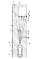
まず図4を参照して、最も長い線分の一例について説明する。図4に示すように、遠方点設定部25は、センサ10から走行可能領域Rの境界線60に向けて放射状に延びる複数の線分200を設定し、設定した複数の線分の中から、最も長い線分100を選択する。図4に示すように、複数の線分200には、障害物70の複数の検出点120〜121とセンサ10とを結ぶ線分が含まれる。また、複数の線分200には、障害物71の複数の検出点122〜125とセンサ10とを結ぶ線分が含まれる。また、図4に示すように、最も長い線分100とは、例えば、走行可能領域R内においてセンサ10から最も遠い最遠点110と、センサ10とを結ぶ線分である。最遠点110とは、物体の位置を示すものではなく、空間上に設定される仮想点である。遠方点設定部25は、走行可能領域R内において、センサ10からの距離が最も遠い空間に最遠点110を設定する。また、最も長い線分100は、障害物70、71に遮られない線分である。本実施形態においては、走行可能領域Rがセンサ10の検出距離に基づいて設定されているため、最も長い線分100の長さはセンサ10の検出距離と同一距離となる。なお、図4に示す例においては障害物71の左方の領域において走行可能領域R内に他の障害物が存在しないため、最遠点110はセンサ10からの距離が最も遠い空間に設定した点となっているが、最遠点110は障害物の検出点で有っても良い。すなわち、図4に示す例において、障害物71の左方の領域で且つ障害物71よりも遠方に他の障害物が存在する場合には、他の障害物の検出点が最遠点となる。なお、図4において、走行可能領域Rは、障害物70、71を除いた領域である。 First, an example of the longest line segment will be described with reference to FIG. As shown in FIG. 4, the far point setting unit 25 sets a plurality of line segments 200 radially extending from the sensor 10 toward the boundary line 60 of the travelable region R, and from the set plurality of line segments, Select the longest line segment 100. As shown in FIG. 4, the plurality of line segments 200 include line segments that connect the plurality of detection points 120 to 121 of the obstacle 70 and the sensor 10. Further, the plurality of line segments 200 include a line segment that connects the plurality of detection points 122 to 125 of the obstacle 71 and the sensor 10. Further, as shown in FIG. 4, the longest line segment 100 is, for example, a line segment connecting the sensor 10 and the farthest point 110 farthest from the sensor 10 in the travelable region R. The farthest point 110 does not indicate the position of the object, but is a virtual point set in space. The distant point setting unit 25 sets the farthest point 110 in the travelable region R in a space farthest from the sensor 10. The longest line segment 100 is a line segment that is not blocked by the obstacles 70 and 71. In the present embodiment, since the travelable region R is set based on the detection distance of the sensor 10, the length of the longest line segment 100 is the same as the detection distance of the sensor 10. In the example shown in FIG. 4, since there is no other obstacle in the travelable area R in the area on the left side of the obstacle 71, the farthest point 110 is set to the space farthest from the sensor 10. However, the farthest point 110 may be a detection point of an obstacle. That is, in the example shown in FIG. 4, when another obstacle exists in the area on the left side of the obstacle 71 and farther than the obstacle 71, the detection point of the other obstacle becomes the farthest point. .. In FIG. 4, the travelable region R is a region excluding the obstacles 70 and 71.

次に図5を参照して、障害物70、71の分類方法の一例について説明する。 Next, an example of a method of classifying the obstacles 70 and 71 will be described with reference to FIG.

左右分類部26は、センサ10と障害物(検出点120〜125)とを結んだ線分と、最も長い線分100とがなす角度の正負に基づいて、障害物がセンサ10から見て最も長い線分100に対して左右のどちらに居るか分類する。 The right/left classification unit 26 determines that the obstacle is the most visible from the sensor 10 based on the positive/negative of the angle formed by the line segment connecting the sensor 10 and the obstacle (detection points 120 to 125) and the longest line segment 100. The long line segment 100 is classified as to whether it is on the left or right.

最も長い線分100を基準として、時計回り方向の角度を正、反時計回り方向の角度を負と仮定する。そして、角度が正の場合、検出点はセンサ10から見て最も長い線分100に対して右に居ると仮定し、角度が負の場合、検出点はセンサ10から見て最も長い線分100に対して左に居ると仮定する。図5に示すように、センサ10と障害物70の検出点120を結んだ線分と、最も長い線分100とがなす角度θ1は、正である。また、センサ10と障害物70の検出点121を結んだ線分と、最も長い線分100とがなす角度θ3も、正である。この結果に基づいて、左右分類部26は、障害物70がセンサ10から見て最も長い線分100に対して右に居ると分類する。 Based on the longest line segment 100, it is assumed that the clockwise angle is positive and the counterclockwise angle is negative. When the angle is positive, it is assumed that the detection point is on the right side of the longest line segment 100 viewed from the sensor 10, and when the angle is negative, the detection point is the longest line segment 100 viewed from the sensor 10. Suppose you are on the left. As shown in FIG. 5, the angle θ1 formed by the line segment connecting the sensor 10 and the detection point 120 of the obstacle 70 and the longest line segment 100 is positive. The angle θ3 formed by the line segment connecting the sensor 10 and the detection point 121 of the obstacle 70 and the longest line segment 100 is also positive. Based on this result, the left/right classification unit 26 classifies that the obstacle 70 is on the right of the longest line segment 100 when viewed from the sensor 10.

また、図5に示すように、センサ10と障害物71の検出点122を結んだ線分と、最も長い線分100とがなす角度θ2は、正である。また、センサ10と障害物71の検出点123を結んだ線分と、最も長い線分100とがなす角度θ4も、正である。同様に、センサ10と障害物71の検出点124を結んだ線分と、最も長い線分100とがなす角度θ5も、正である。同様に、センサ10と障害物71の検出点125を結んだ線分と、最も長い線分100とがなす角度θ6も、正である。この結果に基づいて、左右分類部26は、障害物70がセンサ10から見て最も長い線分100に対して右に居ると分類する。 Further, as shown in FIG. 5, the angle θ2 formed by the line segment connecting the sensor 10 and the detection point 122 of the obstacle 71 and the longest line segment 100 is positive. Further, the angle θ4 formed by the line segment connecting the sensor 10 and the detection point 123 of the obstacle 71 and the longest line segment 100 is also positive. Similarly, the angle θ5 formed by the line segment connecting the sensor 10 and the detection point 124 of the obstacle 71 and the longest line segment 100 is also positive. Similarly, the angle θ6 formed by the line segment connecting the sensor 10 and the detection point 125 of the obstacle 71 and the longest line segment 100 is also positive. Based on this result, the left/right classification unit 26 classifies that the obstacle 70 is on the right of the longest line segment 100 when viewed from the sensor 10.

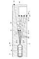
次に図6を参照して、左右に分類された障害物70、71を用いた走行可能領域の再設定方法の一例を説明する。障害物70、71は、センサ10から見て最も長い線分100に対して右に居ると分類されているため、障害物70、71を含む右側の領域を除いて走行可能領域が再設定される。すなわち、障害物70、71及び障害物70、71から右側は走行可能領域ではないと判定して、障害物70、71の左側に走行可能領域を設定する。 Next, with reference to FIG. 6, an example of a method of resetting the travelable area using the obstacles 70 and 71 classified into the left and right will be described. Since the obstacles 70 and 71 are classified as being on the right of the longest line segment 100 as viewed from the sensor 10, the travelable area is reset except for the right area including the obstacles 70 and 71. It That is, it is determined that the obstacles 70, 71 and the right side of the obstacles 70, 71 are not the travelable area, and the travelable area is set on the left side of the obstacles 70, 71.

図6に示すように走行可能領域再設定部27は、障害物70の検出点のうち、最も長い線分100との距離が最も短い検出点120と、車道を形成する道路境界線91とを結び、走行可能領域を再設定する。図6に示すR2は、再設定後の走行可能領域である。なお、図6に示す例では、走行可能領域再設定部27は、検出点120と検出点122も結んでいる。 As shown in FIG. 6, the drivable area resetting unit 27 sets a detection point 120 that is the shortest distance from the longest line segment 100 among the detection points of the obstacle 70 and a road boundary line 91 that forms a roadway. Tie and reset the travelable area. R2 shown in FIG. 6 is a travelable area after resetting. In the example shown in FIG. 6, the travelable area resetting unit 27 also connects the detection points 120 and 122.

そして、図6に示すように、目標経路生成部28は、再設定された走行可能領域R2内に、自車両50の走行経路(経路80)を生成する。これにより、図3に示す経路81は生成されないため、効率の良い経路80のみが生成される。 Then, as shown in FIG. 6, the target route generation unit 28 generates the traveling route (route 80) of the host vehicle 50 within the resettable travelable region R2. As a result, the route 81 shown in FIG. 3 is not generated, and only the efficient route 80 is generated.

次に、図7のフローチャートを参照して、走行支援装置1の一動作例を説明する。 Next, an operation example of the travel support device 1 will be described with reference to the flowchart in FIG. 7.

ステップS101において、自己位置推定部22は、GPS受信機12から取得した情報に基づいて、地図上における自己位置を推定する。処理はステップS103に進み、地図データベース13は、自車両50が走行する道路の構造を示す地図情報を取得する。道路境界線取得部23は、地図情報に基づいて道路境界線を取得する。なお、道路境界線は、センサ10によって取得されてもよい。 In step S101, the self-position estimation unit 22 estimates the self-position on the map based on the information acquired from the GPS receiver 12. The process proceeds to step S103, and the map database 13 acquires map information indicating the structure of the road on which the vehicle 50 travels. The road boundary line acquisition unit 23 acquires a road boundary line based on map information. The road boundary line may be acquired by the sensor 10.

処理はステップS105に進み、走行可能領域設定部24は、走行可能領域Rを設定する(図2参照)。処理はステップS107に進み、センサ10は、自車両50の前方の障害物70、71を検出する(図4参照)。 The process proceeds to step S105, and the travelable area setting unit 24 sets the travelable area R (see FIG. 2). The process proceeds to step S107, and the sensor 10 detects obstacles 70 and 71 in front of the host vehicle 50 (see FIG. 4).

処理はステップS109に進み、遠方点設定部25は、走行可能領域R内において、センサ10からの距離が最も遠い空間に最遠点110を設定する。また、遠方点設定部25は、センサ10から走行可能領域Rの境界線60に向けて放射状に延びる複数の線分200を設定し、設定した複数の線分の中から、最も長い線分100を選択する。最も長い線分100とは、最遠点110と、センサ10とを結ぶ線分である。処理は、ステップS111に進み、左右分類部26は、センサ10と障害物(検出点120〜125)とを結んだ線分と、最も長い線分100とがなす角度の正負に基づいて、障害物がセンサ10から見て最も長い線分100に対して左右のどちらに居るか分類する(図5参照)。 The process proceeds to step S109, and the far point setting unit 25 sets the farthest point 110 in the travelable region R in the space farthest from the sensor 10. Further, the far point setting unit 25 sets a plurality of line segments 200 extending radially from the sensor 10 toward the boundary line 60 of the travelable region R, and the longest line segment 100 is set from the set plurality of line segments. Select. The longest line segment 100 is a line segment connecting the farthest point 110 and the sensor 10. The process proceeds to step S111, and the right-and-left classification unit 26 determines whether or not the line segment connecting the sensor 10 and the obstacle (detection points 120 to 125) and the longest line segment 100 make an obstacle. The object is classified on the left or right with respect to the longest line segment 100 viewed from the sensor 10 (see FIG. 5).

処理はステップS113に進み、走行可能領域再設定部27は、障害物70の検出点のうち、最も長い線分100との距離が最も短い検出点120と、車道を形成する道路境界線91とを結び、走行可能領域を再設定する(図6参照)。処理はステップS115に進み、目標経路生成部28は、再設定された走行可能領域R2内に、自車両50の経路80を生成する(図6参照)。処理はステップS117に進み、車両制御部29は、目標経路生成部28によって設定された経路80を通過するようにアクチュエータ40を制御する。 The process proceeds to step S113, and the drivable area resetting unit 27 determines, among the detection points of the obstacle 70, the detection point 120 having the shortest distance to the longest line segment 100, and the road boundary line 91 forming the roadway. And the travelable area is reset (see FIG. 6). The process proceeds to step S115, and the target route generation unit 28 generates the route 80 of the host vehicle 50 within the resettable travelable region R2 (see FIG. 6). The process proceeds to step S117, and the vehicle control unit 29 controls the actuator 40 so as to pass the route 80 set by the target route generation unit 28.

以上説明したように、本実施形態に係る走行支援装置1によれば、以下の作用効果が得られる。 As described above, according to the travel support device 1 according to the present embodiment, the following operational effects can be obtained.

自車両50が走行する走路上において、自車両50の前方に障害物(障害物70)が検出された場合、走行支援装置1は、センサ10と走行可能領域Rの境界線60上の点を結ぶ複数の線分200を設定し、設定した複数の線分の中から、最も長い線分100を選択する。走行支援装置1は、選択した最も長い線分100に対し、障害物がセンサ10から見て車両幅方向で最も長い線分100に対して左右のどちらに居るか分類し、分類した結果に基づいて、走行可能領域を再設定する。そして、走行支援装置1は、再設定した走行可能領域R2内に、自車両50の走行経路(経路80)を生成する。これにより、図3に示す経路81は生成されないため、効率の良い経路80のみが生成される。 When an obstacle (obstacle 70) is detected in front of the host vehicle 50 on the road on which the host vehicle 50 travels, the travel support device 1 moves the sensor 10 and a point on the boundary line 60 between the travelable regions R to each other. A plurality of line segments 200 to be connected are set, and the longest line segment 100 is selected from the set plurality of line segments. The traveling support device 1 classifies the selected longest line segment 100 on the left or right of the longest line segment 100 in the vehicle width direction as viewed from the sensor 10, and based on the classified result. To reset the travelable area. Then, the travel assistance device 1 generates the travel route (route 80) of the host vehicle 50 within the resettable travelable region R2. As a result, the route 81 shown in FIG. 3 is not generated, and only the efficient route 80 is generated.

また、走行支援装置1は、障害物の検出点のうち、最も長い線分100との距離が最も短い検出点(検出点120)と、車道を形成する道路境界線91とを結び、走行可能領域を再設定する。これにより、図6に示すように、障害物70を含む右側の領域を除いて走行可能領域が再設定される。 Further, the traveling support device 1 can travel by connecting the detection point (detection point 120) having the shortest distance to the longest line segment 100 among the detection points of the obstacle and the road boundary line 91 forming the roadway. Reset the area. As a result, as shown in FIG. 6, the drivable area is reset except for the area on the right side including the obstacle 70.

また、走行支援装置1は、センサ10と障害物(検出点120〜125)とを結んだ線分と、最も長い線分100とがなす角度の正負に基づいて、障害物がセンサ10から見て最も長い線分100に対して左右のどちらに居るか分類する。これにより、2次元で表現される左右の位置が1次元の情報で分類されるため、左右を分類する時の処理負荷は低減する。 In addition, the traveling support device 1 detects an obstacle from the sensor 10 based on the positive/negative of the angle formed by the line segment connecting the sensor 10 and the obstacle (detection points 120 to 125) and the longest line segment 100. The longest line segment 100 is classified to be on the left or right. As a result, the left and right positions expressed in two dimensions are classified by one-dimensional information, so the processing load when classifying the left and right is reduced.

上述の実施形態に記載される各機能は、1または複数の処理回路により実装され得る。処理回路は、電気回路を含む処理装置等のプログラムされた処理装置を含む。処理回路は、また、記載された機能を実行するようにアレンジされた特定用途向け集積回路(ASIC)や回路部品等の装置を含む。また、走行支援装置1は、コンピュータの機能を改善しうる。 Each function described in the above embodiments may be implemented by one or more processing circuits. The processing circuit includes a programmed processing device such as a processing device including an electrical circuit. Processing circuitry also includes devices such as application specific integrated circuits (ASICs) and circuit components that are arranged to perform the described functions. Further, the driving support device 1 can improve the function of the computer.

上記のように、本発明の実施形態を記載したが、この開示の一部をなす論述及び図面はこの発明を限定するものであると理解すべきではない。この開示から当業者には様々な代替実施の形態、実施例及び運用技術が明らかとなろう。 Although the embodiments of the present invention have been described as above, it should not be understood that the descriptions and drawings forming a part of this disclosure limit the present invention. From this disclosure, various alternative embodiments, examples, and operation techniques will be apparent to those skilled in the art.

本発明は、直線道路だけでなく、カーブに適用されてもよい。例えば、図8〜9に示すように、1つの障害物70がカーブ上に存在する場合、自車両50が走行可能な経路は、2つある。一つは、障害物70の左側を通過する経路80である。もう一つは、障害物70の右側を通過する経路81である。経路81は、経路80と比較して、走行距離が長く、かつステアリング操作量も多いため、効率が悪い。そこで、走行支援装置1は、図4〜6で説明した方法と同様の方法を用いて、図9に示すように、経路80のみを生成する。これにより、図8に示す経路81は生成されないため、効率の良い経路80のみが生成される。このように、本発明は、自車両50の前方に1つの障害物のみが存在する場合にも適用される。もちろん、図4〜6で説明したように、本発明は、自車両50の前方に複数の障害物が存在する場合にも適用される。 The invention may be applied to curves as well as straight roads. For example, as shown in FIGS. 8 to 9, when one obstacle 70 exists on a curve, there are two routes on which the vehicle 50 can travel. One is a path 80 passing through the left side of the obstacle 70. The other is a route 81 passing through the right side of the obstacle 70. The route 81 has a long traveling distance and a large steering operation amount as compared with the route 80, and thus is inefficient. Therefore, the driving support device 1 generates only the route 80 as shown in FIG. 9 by using the method similar to the method described in FIGS. As a result, the route 81 shown in FIG. 8 is not generated, and only the efficient route 80 is generated. As described above, the present invention is also applied to the case where there is only one obstacle in front of the host vehicle 50. Of course, as described with reference to FIGS. 4 to 6, the present invention is also applied when there are a plurality of obstacles ahead of the host vehicle 50.

上述したように、センサ10は、放射状に電波を射出して物体からの反射波を用いて物体の位置を検出する。図10に示すように、センサ10が複数の障害物を検出した場合、障害物の検出点の位置は、障害物の検出点が検出された順に記憶装置に格納されてもよい。図10に示すn+1番目に検出された障害物の検出点が、n番目に検出された検出点から見て右に居ると分類された場合、n+2番目に検出された障害物の検出点、n+3番目に検出された障害物の検出点、及びn+4番目に検出された障害物の検出点も自動的にn番目に検出された検出点から見て右に居ると分類される。なお、n+2番目に検出された障害物の検出点、n+3番目に検出された障害物の検出点、及びn+4番目に検出された障害物の検出点は、残りの障害物の検出点に相当する。このように検出点が検出された順番に対応して記憶装置に格納されることにより、障害物の位置が一括して分類されるため、左右を分類する時の処理負荷は低減する。すなわち、検出点が検出された順番を記憶装置に格納しておけば、最も長い線分100が決定された順番以降の順番で記憶された検出点は、自ずと最も長い線分100よりも右側に存在する検出点であると判定することかでき、左右を分類する時の処理負荷は低減する。 As described above, the sensor 10 emits radio waves radially and detects the position of the object by using the reflected wave from the object. As shown in FIG. 10, when the sensor 10 detects a plurality of obstacles, the positions of the obstacle detection points may be stored in the storage device in the order in which the obstacle detection points are detected. If the n+1-th detected obstacle detection point shown in FIG. 10 is classified as being on the right side of the n-th detected detection point, the n+2-th detected obstacle detection point is n+3. The detection point of the obstacle detected at the th position and the detection point of the obstacle detected at the (n+4)th position are also automatically classified as being on the right side from the detection point detected at the nth position. The detection point of the obstacle detected at the (n+2)th, the detection point of the obstacle detected at the (n+3)th, and the detection point of the obstacle detected at the (n+4)th correspond to the detection points of the remaining obstacles. .. By thus storing the detection points in the storage device in the order in which they are detected, the positions of the obstacles are collectively classified, so that the processing load when classifying the left and right is reduced. That is, if the order in which the detection points are detected is stored in the storage device, the detection points stored in the order after the determination of the longest line segment 100 are naturally located on the right side of the longest line segment 100. It can be determined that the detection point exists, and the processing load when classifying left and right is reduced.

なお、障害物が左右に分類された結果、自車両50が通過できない経路が生成される可能性がある。例えば、図11に示す例では、自車両50の経路は、複数存在すると考えられる。一つは、障害物70の左側を通過する経路80である。もう一つは、障害物70の右側を通過する経路81である。図4〜6で説明した方法によれば、図11に示す障害物70、71は、センサ10から見て最も長い線分100に対して右に居ると分類される。その結果、経路80が生成される。しかし、図11に示す距離L3が、自車両50の車幅より短い場合、自車両50は障害物70の左側を通過できない。このように分類した結果に基づく経路80が自車両50の車幅より短く、自車両50が通過不可である場合、走行支援装置1は、図12に示すように走行可能領域Rを小さくしてもよい。そして、走行支援装置1は、小さくした後の走行可能領域Rにおいて、図4〜6で説明した方法を用いて再度、障害物70がセンサ10から見て最も長い線分100に対して左右どちらに居るか分類する。図12に示す例では、障害物70はセンサ10から見て、最も長い線分100に対して左に居ると分類される。この結果に基づいて、図13に示すように、走行支援装置1は、走行可能領域を再設定する。図13に示すR2は、再設定後の走行可能領域である。そして、図13に示すように、走行支援装置1は、再設定された走行可能領域R2内に、自車両50の走行経路(経路81)を設定する。これにより、自車両50が通過可能な経路が生成される。 As a result of the obstacles being classified into left and right, there is a possibility that a route in which the vehicle 50 cannot pass is generated. For example, in the example shown in FIG. 11, it is considered that there are a plurality of routes for the vehicle 50. One is a path 80 passing through the left side of the obstacle 70. The other is a path 81 passing through the right side of the obstacle 70. According to the method described in FIGS. 4 to 6, the obstacles 70 and 71 shown in FIG. 11 are classified as being on the right side with respect to the longest line segment 100 when viewed from the sensor 10. As a result, the route 80 is generated. However, when the distance L3 shown in FIG. 11 is shorter than the vehicle width of the host vehicle 50, the host vehicle 50 cannot pass the left side of the obstacle 70. When the route 80 based on the result of the classification as described above is shorter than the vehicle width of the host vehicle 50 and the host vehicle 50 cannot pass, the traveling support device 1 reduces the travelable region R as shown in FIG. Good. Then, the travel support device 1 uses the method described with reference to FIGS. 4 to 6 again in the travelable region R after making the obstacle 70 left or right with respect to the longest line segment 100 viewed from the sensor 10. Classify if you are in In the example shown in FIG. 12, the obstacle 70 is classified as being on the left of the longest line segment 100 when viewed from the sensor 10. Based on this result, the driving assistance device 1 resets the travelable area, as shown in FIG. R2 shown in FIG. 13 is a travelable area after resetting. Then, as shown in FIG. 13, the travel assistance device 1 sets the travel route (route 81) of the host vehicle 50 within the resettable travelable region R2. As a result, a route through which the vehicle 50 can pass is generated.

1 走行支援装置
10 センサ
11 カメラ
12 受信機
13 地図データベース
20 コントローラ
21 静止物体認識部
22 自己位置推定部
23 道路境界線取得部
24 走行可能領域設定部
25 遠方点設定部
26 左右分類部
27 走行可能領域再設定部
28 目標経路生成部
29 車両制御部
40 アクチュエータ
1 Driving Support Device 10 Sensor 11 Camera 12 Receiver 13 Map Database 20 Controller 21 Stationary Object Recognition Unit 22 Self Position Estimation Unit 23 Road Boundary Acquisition Unit 24 Travelable Area Setting Unit 25 Far Point Setting Unit 26 Left/Right Classification Unit 27 Travelable Region resetting unit 28 Target route generating unit 29 Vehicle control unit 40 Actuator

Claims (6)

車両に搭載され、前記車両の前方にある物体の位置を検出するセンサと、前記センサにより検出された物体の位置に基づいて前記車両の走行経路を設定するコントローラとを備える走行支援装置の走行支援方法であって、
前記センサを用いて検出した物体の位置から、前記車両が走行する走路上にある障害物を検出し、
前記障害物の位置に基づいて、前記車両が走行可能な、前記障害物を除いた走行可能領域を走路内に設定し、
前記センサと前記走行可能領域の境界線上の点を結ぶ複数の線分を設定し、設定した複数の線分の中から、最も長い線分を選択し、
選択した最も長い線分に対し、前記障害物が前記センサから見て車両幅方向で左右のどちらに居るか分類し、
分類した結果に基づいて、前記走行可能領域を再設定し、
再設定された走行可能領域内に、前記車両の走行経路を生成する
ことを特徴とする走行支援方法。
A travel assistance of a travel assistance device that is mounted on a vehicle and includes a sensor that detects a position of an object in front of the vehicle, and a controller that sets a travel route of the vehicle based on a position of the object detected by the sensor Method,
From the position of the object detected using the sensor, to detect an obstacle on the road on which the vehicle is traveling,
Based on the position of the obstacle, the vehicle is capable of traveling, the travelable area excluding the obstacle is set in the track,
Setting a plurality of line segments that connect points on the boundary line between the sensor and the travelable area, and select the longest line segment from the set plurality of line segments,
For the selected longest line segment, classify whether the obstacle is on the left or right in the vehicle width direction as viewed from the sensor,
Based on the classified result, reset the travelable area,
A travel assistance method comprising: generating a travel route of the vehicle within a resettable travelable area.
前記障害物の検出点のうち、前記最も長い線分との距離が最も短い検出点と、前記走路を形成する道路境界線とを結び、前記走行可能領域を再設定する
ことを特徴とする請求項1に記載の走行支援方法。
Among the detection points of the obstacle, the detection point having the shortest distance to the longest line segment and the road boundary line forming the track are connected to reset the travelable area. The driving support method according to Item 1.
前記センサと前記障害物とを結んだ線分と、前記最も長い線分とがなす角度の正負に基づいて、前記障害物が前記センサから見て左右のどちらに居るか分類する
ことを特徴とする請求項1または2に記載の走行支援方法。
A line segment connecting the sensor and the obstacle and a positive or negative angle formed by the longest line segment are used to classify whether the obstacle is on the left or right as viewed from the sensor. The driving support method according to claim 1 or 2.
前記センサは、放射状に電波を射出して物体からの反射波を用いて前記物体の位置を検出する装置であり、
前記センサが複数の障害物を検出した場合、前記障害物の位置を前記障害物を検出した順に格納し、
一つの障害物が前記センサから見て左右のどちらに居るか分類された結果に基づいて、残りの障害物を分類する
ことを特徴とする請求項1〜3のいずれか1項に記載の走行支援方法。
The sensor is a device that emits radio waves radially and detects the position of the object using a reflected wave from the object,
When the sensor detects a plurality of obstacles, the positions of the obstacles are stored in the order in which the obstacles are detected,
The remaining obstacle is classified based on a result of classification whether one obstacle is on the left or right side of the sensor, The traveling according to claim 1. How to help.
前記走行可能領域内において、前記車両の走行経路が複数存在し、かつ前記分類した結果に基づく走行経路が前記車両の車幅より短く、前記車両が通過不可である場合、前記走行可能領域を小さくし、
小さくした後の走行可能領域において、再度、前記障害物が前記センサから見て左右のどちらに居るか分類し、
分類した結果に基づいて、前記障害物が含まれない走行可能領域を再設定し、
再設定された走行可能領域内に、前記車両の走行経路を設定する
ことを特徴とする請求項1〜4のいずれか1項に記載の走行支援方法。
If there are a plurality of travel routes for the vehicle within the travelable region, and the travel route based on the classified result is shorter than the vehicle width of the vehicle and the vehicle cannot pass, the travelable region is reduced. Then
In the drivable area after making it smaller, again, classify whether the obstacle is on the left or right as viewed from the sensor,
Based on the result of classification, resettable travelable area that does not include the obstacle,
The travel support method according to any one of claims 1 to 4, wherein the travel route of the vehicle is set within the resettable travelable area.
車両に搭載され、前記車両の前方にある物体の位置を検出するセンサと、
前記センサにより検出された物体の位置に基づいて前記車両の走行経路を設定するコントローラとを備え、
前記コントローラは、
前記センサを用いて検出した物体の位置から、前記車両が走行する走路上にある障害物を検出し、
前記障害物の位置に基づいて、前記車両が走行可能な、前記障害物を除いた走行可能領域を走路内に設定し、
前記センサと前記走行可能領域の境界線上の点を結ぶ複数の線分を設定し、設定した複数の線分の中から、最も長い線分を選択し、
選択した最も長い線分に対し、前記障害物が前記センサから見て車両幅方向で左右のどちらに居るか分類し、
分類した結果に基づいて、前記走行可能領域を再設定し、
再設定された走行可能領域内に、前記車両の走行経路を生成する
ことを特徴とする走行支援装置。
A sensor mounted on the vehicle for detecting the position of an object in front of the vehicle;
A controller that sets the traveling route of the vehicle based on the position of the object detected by the sensor,
The controller is
From the position of the object detected using the sensor, to detect an obstacle on the road on which the vehicle is traveling,
Based on the position of the obstacle, the vehicle is capable of traveling, the travelable area excluding the obstacle is set in the track,
Setting a plurality of line segments connecting the sensor and the points on the boundary line of the travelable area, from the set plurality of line segments, select the longest line segment,
For the selected longest line segment, classify whether the obstacle is on the left or right in the vehicle width direction as viewed from the sensor,
Based on the classified result, reset the travelable area,
A travel assistance device, wherein a travel route of the vehicle is generated within a resettable travelable area.
JP2019013830A 2019-01-30 2019-01-30 Driving support method and driving support device Active JP7236279B2 (en)

Priority Applications (1)

Application Number Priority Date Filing Date Title
JP2019013830A JP7236279B2 (en) 2019-01-30 2019-01-30 Driving support method and driving support device

Applications Claiming Priority (1)

Application Number Priority Date Filing Date Title
JP2019013830A JP7236279B2 (en) 2019-01-30 2019-01-30 Driving support method and driving support device

Publications (2)

Publication Number Publication Date
JP2020121614A true JP2020121614A (en) 2020-08-13
JP7236279B2 JP7236279B2 (en) 2023-03-09

Family

ID=71991938

Family Applications (1)

Application Number Title Priority Date Filing Date
JP2019013830A Active JP7236279B2 (en) 2019-01-30 2019-01-30 Driving support method and driving support device

Country Status (1)

Country Link
JP (1) JP7236279B2 (en)

Citations (5)

* Cited by examiner, † Cited by third party
Publication number Priority date Publication date Assignee Title
JP2012118909A (en) * 2010-12-03 2012-06-21 Nissan Motor Co Ltd Travel support device
WO2013051081A1 (en) * 2011-10-03 2013-04-11 トヨタ自動車株式会社 Vehicle driving support system
JP2013186767A (en) * 2012-03-09 2013-09-19 Hitachi Ltd Warning device for vehicle
KR101417659B1 (en) * 2013-07-11 2014-07-09 현대자동차주식회사 Apparatus for detecting narrow road on the front of vehicle and method thereof
JP2015036842A (en) * 2013-08-12 2015-02-23 株式会社日本自動車部品総合研究所 Traveling propriety determination device

Patent Citations (5)

* Cited by examiner, † Cited by third party
Publication number Priority date Publication date Assignee Title
JP2012118909A (en) * 2010-12-03 2012-06-21 Nissan Motor Co Ltd Travel support device
WO2013051081A1 (en) * 2011-10-03 2013-04-11 トヨタ自動車株式会社 Vehicle driving support system
JP2013186767A (en) * 2012-03-09 2013-09-19 Hitachi Ltd Warning device for vehicle
KR101417659B1 (en) * 2013-07-11 2014-07-09 현대자동차주식회사 Apparatus for detecting narrow road on the front of vehicle and method thereof
JP2015036842A (en) * 2013-08-12 2015-02-23 株式会社日本自動車部品総合研究所 Traveling propriety determination device

Also Published As

Publication number Publication date
JP7236279B2 (en) 2023-03-09

Similar Documents

Publication Publication Date Title
CN109313856B (en) Object detection method and object detection device
KR102137933B1 (en) Method for controlling cornering of vehicle and apparatus thereof
JP6269552B2 (en) Vehicle travel control device
US11247692B2 (en) Prediction device, prediction method, and storage medium
WO2021070451A1 (en) Vehicle control device, vehicle control method, autonomous driving device, and autonomous driving method
JP6574224B2 (en) Vehicle control apparatus, vehicle, vehicle control method, and program
JP6809611B2 (en) Driving support method and driving support device
CN112513955A (en) Travel track generation method and travel track generation device
JP6669640B2 (en) Trajectory evaluation device, trajectory evaluation method, and trajectory evaluation program
JP7334795B2 (en) Vehicle control method and vehicle control device
JP7037956B2 (en) Vehicle course prediction method, vehicle travel support method, and vehicle course prediction device
EP3912877B1 (en) Driving assistance method and driving assistance device
RU2767653C1 (en) Vehicle control method and vehicle control device
JP6721054B2 (en) Vehicle protrusion determination method and vehicle protrusion determination device
WO2016170683A1 (en) Travel control device and data structure
JP2020129331A (en) Reverse run determination system, reverse run determination method, and reverse run determination program
JP2019045985A (en) Vehicle control device, vehicle, vehicle control method, and program
JP7334107B2 (en) Vehicle control method and vehicle control device
JP7236279B2 (en) Driving support method and driving support device
JP7336861B2 (en) Behavior prediction method and behavior prediction device
JP2018185156A (en) Target position estimation method and target position estimation device
WO2021048583A1 (en) Action deciding method of traveling support device, and traveling support device
JP2021060941A (en) Object recognition method and object recognition system
JP7458743B2 (en) Vehicle control method and vehicle control device
JP7458797B2 (en) Driving support method and driving support device

Legal Events

Date Code Title Description
A621 Written request for application examination

Free format text: JAPANESE INTERMEDIATE CODE: A621

Effective date: 20211109

A977 Report on retrieval

Free format text: JAPANESE INTERMEDIATE CODE: A971007

Effective date: 20220822

A131 Notification of reasons for refusal

Free format text: JAPANESE INTERMEDIATE CODE: A131

Effective date: 20220830

TRDD Decision of grant or rejection written
A01 Written decision to grant a patent or to grant a registration (utility model)

Free format text: JAPANESE INTERMEDIATE CODE: A01

Effective date: 20230131

A61 First payment of annual fees (during grant procedure)

Free format text: JAPANESE INTERMEDIATE CODE: A61

Effective date: 20230227

R150 Certificate of patent or registration of utility model

Ref document number: 7236279

Country of ref document: JP

Free format text: JAPANESE INTERMEDIATE CODE: R150