JP7334795B2 - Vehicle control method and vehicle control device - Google Patents
Vehicle control method and vehicle control device Download PDFInfo
- Publication number
- JP7334795B2 JP7334795B2 JP2021555895A JP2021555895A JP7334795B2 JP 7334795 B2 JP7334795 B2 JP 7334795B2 JP 2021555895 A JP2021555895 A JP 2021555895A JP 2021555895 A JP2021555895 A JP 2021555895A JP 7334795 B2 JP7334795 B2 JP 7334795B2
- Authority
- JP
- Japan
- Prior art keywords
- vehicle
- camera
- traffic
- traffic light
- lane
- Prior art date
- Legal status (The legal status is an assumption and is not a legal conclusion. Google has not performed a legal analysis and makes no representation as to the accuracy of the status listed.)
- Active
Links
- 238000000034 method Methods 0.000 title claims description 33
- 238000009434 installation Methods 0.000 claims description 19
- 238000003384 imaging method Methods 0.000 claims description 9
- 238000001514 detection method Methods 0.000 description 41
- 238000004364 calculation method Methods 0.000 description 29
- 238000004891 communication Methods 0.000 description 12
- 238000010586 diagram Methods 0.000 description 11
- 230000008569 process Effects 0.000 description 11
- 230000003287 optical effect Effects 0.000 description 9
- 238000012545 processing Methods 0.000 description 7
- 230000010354 integration Effects 0.000 description 6
- 230000006399 behavior Effects 0.000 description 5
- 230000008859 change Effects 0.000 description 5
- 230000001133 acceleration Effects 0.000 description 3
- 230000015654 memory Effects 0.000 description 3
- 230000006870 function Effects 0.000 description 2
- 239000004065 semiconductor Substances 0.000 description 2
- 230000000903 blocking effect Effects 0.000 description 1
- 238000004590 computer program Methods 0.000 description 1
- 238000006073 displacement reaction Methods 0.000 description 1
- 230000000694 effects Effects 0.000 description 1
- 230000004927 fusion Effects 0.000 description 1
- 230000010365 information processing Effects 0.000 description 1
- 238000005259 measurement Methods 0.000 description 1
- 238000012986 modification Methods 0.000 description 1
- 230000004048 modification Effects 0.000 description 1
- 230000002093 peripheral effect Effects 0.000 description 1
- 238000006467 substitution reaction Methods 0.000 description 1
Images


Classifications
-
- B—PERFORMING OPERATIONS; TRANSPORTING
- B60—VEHICLES IN GENERAL
- B60W—CONJOINT CONTROL OF VEHICLE SUB-UNITS OF DIFFERENT TYPE OR DIFFERENT FUNCTION; CONTROL SYSTEMS SPECIALLY ADAPTED FOR HYBRID VEHICLES; ROAD VEHICLE DRIVE CONTROL SYSTEMS FOR PURPOSES NOT RELATED TO THE CONTROL OF A PARTICULAR SUB-UNIT
- B60W30/00—Purposes of road vehicle drive control systems not related to the control of a particular sub-unit, e.g. of systems using conjoint control of vehicle sub-units, or advanced driver assistance systems for ensuring comfort, stability and safety or drive control systems for propelling or retarding the vehicle
- B60W30/14—Adaptive cruise control
- B60W30/16—Control of distance between vehicles, e.g. keeping a distance to preceding vehicle
- B60W30/165—Automatically following the path of a preceding lead vehicle, e.g. "electronic tow-bar"
-
- B—PERFORMING OPERATIONS; TRANSPORTING
- B60—VEHICLES IN GENERAL
- B60W—CONJOINT CONTROL OF VEHICLE SUB-UNITS OF DIFFERENT TYPE OR DIFFERENT FUNCTION; CONTROL SYSTEMS SPECIALLY ADAPTED FOR HYBRID VEHICLES; ROAD VEHICLE DRIVE CONTROL SYSTEMS FOR PURPOSES NOT RELATED TO THE CONTROL OF A PARTICULAR SUB-UNIT
- B60W30/00—Purposes of road vehicle drive control systems not related to the control of a particular sub-unit, e.g. of systems using conjoint control of vehicle sub-units, or advanced driver assistance systems for ensuring comfort, stability and safety or drive control systems for propelling or retarding the vehicle
- B60W30/14—Adaptive cruise control
- B60W30/16—Control of distance between vehicles, e.g. keeping a distance to preceding vehicle
-
- G—PHYSICS
- G06—COMPUTING; CALCULATING OR COUNTING
- G06V—IMAGE OR VIDEO RECOGNITION OR UNDERSTANDING
- G06V20/00—Scenes; Scene-specific elements
- G06V20/50—Context or environment of the image
- G06V20/56—Context or environment of the image exterior to a vehicle by using sensors mounted on the vehicle
- G06V20/58—Recognition of moving objects or obstacles, e.g. vehicles or pedestrians; Recognition of traffic objects, e.g. traffic signs, traffic lights or roads
- G06V20/584—Recognition of moving objects or obstacles, e.g. vehicles or pedestrians; Recognition of traffic objects, e.g. traffic signs, traffic lights or roads of vehicle lights or traffic lights
-
- B—PERFORMING OPERATIONS; TRANSPORTING
- B60—VEHICLES IN GENERAL
- B60W—CONJOINT CONTROL OF VEHICLE SUB-UNITS OF DIFFERENT TYPE OR DIFFERENT FUNCTION; CONTROL SYSTEMS SPECIALLY ADAPTED FOR HYBRID VEHICLES; ROAD VEHICLE DRIVE CONTROL SYSTEMS FOR PURPOSES NOT RELATED TO THE CONTROL OF A PARTICULAR SUB-UNIT
- B60W2420/00—Indexing codes relating to the type of sensors based on the principle of their operation
- B60W2420/40—Photo or light sensitive means, e.g. infrared sensors
- B60W2420/403—Image sensing, e.g. optical camera
-
- B—PERFORMING OPERATIONS; TRANSPORTING
- B60—VEHICLES IN GENERAL
- B60W—CONJOINT CONTROL OF VEHICLE SUB-UNITS OF DIFFERENT TYPE OR DIFFERENT FUNCTION; CONTROL SYSTEMS SPECIALLY ADAPTED FOR HYBRID VEHICLES; ROAD VEHICLE DRIVE CONTROL SYSTEMS FOR PURPOSES NOT RELATED TO THE CONTROL OF A PARTICULAR SUB-UNIT
- B60W2552/00—Input parameters relating to infrastructure
- B60W2552/10—Number of lanes
-
- B—PERFORMING OPERATIONS; TRANSPORTING
- B60—VEHICLES IN GENERAL
- B60W—CONJOINT CONTROL OF VEHICLE SUB-UNITS OF DIFFERENT TYPE OR DIFFERENT FUNCTION; CONTROL SYSTEMS SPECIALLY ADAPTED FOR HYBRID VEHICLES; ROAD VEHICLE DRIVE CONTROL SYSTEMS FOR PURPOSES NOT RELATED TO THE CONTROL OF A PARTICULAR SUB-UNIT
- B60W2554/00—Input parameters relating to objects
- B60W2554/40—Dynamic objects, e.g. animals, windblown objects
- B60W2554/404—Characteristics
- B60W2554/4041—Position
-
- B—PERFORMING OPERATIONS; TRANSPORTING
- B60—VEHICLES IN GENERAL
- B60W—CONJOINT CONTROL OF VEHICLE SUB-UNITS OF DIFFERENT TYPE OR DIFFERENT FUNCTION; CONTROL SYSTEMS SPECIALLY ADAPTED FOR HYBRID VEHICLES; ROAD VEHICLE DRIVE CONTROL SYSTEMS FOR PURPOSES NOT RELATED TO THE CONTROL OF A PARTICULAR SUB-UNIT
- B60W2554/00—Input parameters relating to objects
- B60W2554/40—Dynamic objects, e.g. animals, windblown objects
- B60W2554/404—Characteristics
- B60W2554/4048—Field of view, e.g. obstructed view or direction of gaze
-
- B—PERFORMING OPERATIONS; TRANSPORTING
- B60—VEHICLES IN GENERAL
- B60W—CONJOINT CONTROL OF VEHICLE SUB-UNITS OF DIFFERENT TYPE OR DIFFERENT FUNCTION; CONTROL SYSTEMS SPECIALLY ADAPTED FOR HYBRID VEHICLES; ROAD VEHICLE DRIVE CONTROL SYSTEMS FOR PURPOSES NOT RELATED TO THE CONTROL OF A PARTICULAR SUB-UNIT
- B60W2554/00—Input parameters relating to objects
- B60W2554/80—Spatial relation or speed relative to objects
- B60W2554/801—Lateral distance
-
- B—PERFORMING OPERATIONS; TRANSPORTING
- B60—VEHICLES IN GENERAL
- B60W—CONJOINT CONTROL OF VEHICLE SUB-UNITS OF DIFFERENT TYPE OR DIFFERENT FUNCTION; CONTROL SYSTEMS SPECIALLY ADAPTED FOR HYBRID VEHICLES; ROAD VEHICLE DRIVE CONTROL SYSTEMS FOR PURPOSES NOT RELATED TO THE CONTROL OF A PARTICULAR SUB-UNIT
- B60W2554/00—Input parameters relating to objects
- B60W2554/80—Spatial relation or speed relative to objects
- B60W2554/802—Longitudinal distance
-
- B—PERFORMING OPERATIONS; TRANSPORTING
- B60—VEHICLES IN GENERAL
- B60W—CONJOINT CONTROL OF VEHICLE SUB-UNITS OF DIFFERENT TYPE OR DIFFERENT FUNCTION; CONTROL SYSTEMS SPECIALLY ADAPTED FOR HYBRID VEHICLES; ROAD VEHICLE DRIVE CONTROL SYSTEMS FOR PURPOSES NOT RELATED TO THE CONTROL OF A PARTICULAR SUB-UNIT
- B60W2555/00—Input parameters relating to exterior conditions, not covered by groups B60W2552/00, B60W2554/00
- B60W2555/60—Traffic rules, e.g. speed limits or right of way
-
- B—PERFORMING OPERATIONS; TRANSPORTING
- B60—VEHICLES IN GENERAL
- B60W—CONJOINT CONTROL OF VEHICLE SUB-UNITS OF DIFFERENT TYPE OR DIFFERENT FUNCTION; CONTROL SYSTEMS SPECIALLY ADAPTED FOR HYBRID VEHICLES; ROAD VEHICLE DRIVE CONTROL SYSTEMS FOR PURPOSES NOT RELATED TO THE CONTROL OF A PARTICULAR SUB-UNIT
- B60W2556/00—Input parameters relating to data
- B60W2556/40—High definition maps
-
- B—PERFORMING OPERATIONS; TRANSPORTING
- B60—VEHICLES IN GENERAL
- B60W—CONJOINT CONTROL OF VEHICLE SUB-UNITS OF DIFFERENT TYPE OR DIFFERENT FUNCTION; CONTROL SYSTEMS SPECIALLY ADAPTED FOR HYBRID VEHICLES; ROAD VEHICLE DRIVE CONTROL SYSTEMS FOR PURPOSES NOT RELATED TO THE CONTROL OF A PARTICULAR SUB-UNIT
- B60W2754/00—Output or target parameters relating to objects
- B60W2754/10—Spatial relation or speed relative to objects
- B60W2754/20—Lateral distance
-
- B—PERFORMING OPERATIONS; TRANSPORTING
- B60—VEHICLES IN GENERAL
- B60W—CONJOINT CONTROL OF VEHICLE SUB-UNITS OF DIFFERENT TYPE OR DIFFERENT FUNCTION; CONTROL SYSTEMS SPECIALLY ADAPTED FOR HYBRID VEHICLES; ROAD VEHICLE DRIVE CONTROL SYSTEMS FOR PURPOSES NOT RELATED TO THE CONTROL OF A PARTICULAR SUB-UNIT
- B60W2754/00—Output or target parameters relating to objects
- B60W2754/10—Spatial relation or speed relative to objects
- B60W2754/30—Longitudinal distance
Description
本発明は、車両制御方法及び車両制御装置に関する。 The present invention relates to a vehicle control method and a vehicle control device.
下記特許文献1には、自車両の前方を撮影した画像を解析して信号機を特定するとともに信号機の点灯色を判定し、判定結果に基づいて自車両の自動運転を制御する技術が記載されている。
しかしながら、自車両の前方を走行する先行車両が存在すると、撮像手段の画角範囲(撮像範囲)が先行車両によって遮られることにより、撮像画像から信号機を認識できなくなることがある。
一方で、信号機が撮像手段の画角範囲から遮蔽されるのを防止するために、自車両と先行車両との間の車間距離を常に十分に確保するよう自車両を制御すると、不必要に車間距離が長くなり自車両の乗員に違和感を与える恐れがある。
本発明は、撮像画像による信号機の認識結果に基づく自動運転において、先行車両によって信号機がカメラの画角範囲から遮蔽されるのを回避する制御が不必要に行われるのを軽減することを目的とする。However, if there is a preceding vehicle traveling in front of the own vehicle, the view angle range (imaging range) of the imaging means may be blocked by the preceding vehicle, making it impossible to recognize the traffic light from the captured image.
On the other hand, if the own vehicle is controlled to always secure a sufficient inter-vehicle distance between the own vehicle and the preceding vehicle in order to prevent the traffic signal from being blocked from the view angle range of the imaging means, the distance between the own vehicle and the preceding vehicle may be unnecessarily increased. The distance becomes long, and there is a possibility that the occupant of the own vehicle feels uncomfortable.
An object of the present invention is to reduce unnecessary control for avoiding blocking of a traffic signal from the view angle range of a camera by a preceding vehicle in automatic driving based on the recognition result of the traffic signal from a captured image. do.
本発明の一態様によれば、自車両前方の所定画角範囲を撮像するカメラを搭載し、前記カメラによって撮像した画像に基づいて信号機を認識する車両制御方法が与えられる。車両制御方法では、信号機の設置位置の情報及び信号機によって規制される車線の情報を含む地図情報と、自車両に搭載されたカメラの画角範囲と、に基づいて、カメラによって車線上で信号機を撮像できる撮像可能領域を算出し、自車両が撮像可能領域内に位置しているか否かを判定し、自車両が撮像可能領域内に位置している場合には、自車両の先行車両によって信号機がカメラの画角範囲から遮蔽されないように自車両を制御する。 According to one aspect of the present invention, there is provided a vehicle control method that mounts a camera that captures an image of a predetermined angle of view in front of the vehicle, and recognizes a traffic light based on the image captured by the camera. In the vehicle control method, a traffic signal is activated on a lane by a camera based on map information including information on the installation position of the traffic signal and information on lanes restricted by the traffic signal, and the angle of view range of a camera mounted on the vehicle. An imageable area that can be imaged is calculated, and it is determined whether or not the own vehicle is positioned within the imageable area. control the own vehicle so that is not blocked from the angle of view of the camera.
本発明の一形態によれば、撮像画像による信号機の認識結果に基づく自動運転において、先行車両によって信号機がカメラの画角範囲から遮蔽されるのを回避する制御が不必要に行われるのを軽減できる。
本発明の目的及び利点は、特許請求の範囲に示した要素及びその組合せを用いて具現化され達成される。前述の一般的な記述及び以下の詳細な記述の両方は、単なる例示及び説明であり、特許請求の範囲のように本発明を限定するものでないと解するべきである。According to one aspect of the present invention, in automatic driving based on the recognition result of the traffic light from the captured image, unnecessary control to avoid the traffic light from being shielded from the view angle range of the camera by the preceding vehicle is reduced. can.
The objects and advantages of the invention may be realized and attained by means of the elements and combinations pointed out in the appended claims. It is to be understood that both the foregoing general description and the following detailed description are exemplary and explanatory only and are not restrictive of the invention as claimed.
以下、本発明の実施形態について、図面を参照しつつ説明する。
(構成)
自車両1は、自車両1の走行を自動的に制御する車両制御装置10を備える。車両制御装置10は、自車両1の現在位置である自己位置を検出し、検出した自己位置に基づいて自車両1の走行を制御することにより、自車両1の運転を支援する。
例えば、車両制御装置10は、検出した自己位置と周囲の走行環境とに基づいて、運転者が関与せずに自車両1を自動で運転する自律走行制御を行うことによって運転を支援する。BEST MODE FOR CARRYING OUT THE INVENTION Hereinafter, embodiments of the present invention will be described with reference to the drawings.
(composition)
The
For example, the
車両制御装置10は、推定した自己位置と周囲の走行環境に基づいて加減速のみを制御することによって運転を支援してもよい。例えば、車両制御装置10は、先行車両が存在しない場合には設定速度を維持して走行し、設定速度未満の速度で走行する先行車両が存在する場合には先行車両に追従するように走行する定速走行制御を行ってよい。車両制御装置10は、先行車両との車間距離を自車両1の車速に応じて制御してよい。
車両制御装置10は、物体センサ11と、車両センサ12と、測位装置13と、地図データベース14と、通信装置15と、ナビゲーションシステム17と、コントローラ18と、アクチュエータ19を備える。図面において地図データベースを「地図DB」と表記する。The
物体センサ11は、自車両1の周囲の物体を検出する複数の異なる種類のセンサを備える。
例えば物体センサ11は、自車両1に搭載されたカメラ20を備える。カメラ20は、自車両1の前方の所定の画角範囲(撮像範囲)の画像を撮像し、撮像画像をコントローラ18へ出力する。なお、以下では「撮像」を「撮影」とも記載し、本明細書においては同一の意味を表すものとして扱う。
また物体センサ11は、レーザレーダやミリ波レーダ、LIDAR(Light Detection and Ranging、Laser Imaging Detection and Ranging)などの測距センサを備えてもよい。The
For example, the
The
車両センサ12は、自車両1に搭載され、自車両1から得られる様々な情報(車両信号)を検出する。車両センサ12には、例えば、自車両1の走行速度(車速)を検出する車速センサ、自車両1が備える各タイヤの回転速度を検出する車輪速センサ、自車両1の3軸方向の加速度(減速度を含む)を検出する3軸加速度センサ(Gセンサ)、操舵角(転舵角を含む)を検出する操舵角センサ、自車両1に生じる角速度を検出するジャイロセンサ、ヨーレートを検出するヨーレートセンサ、自車両のアクセル開度を検出するアクセルセンサと、運転者によるブレーキ操作量を検出するブレーキセンサが含まれる。 The
測位装置13は、全地球型測位システム(GNSS)受信機を備え、複数の航法衛星から電波を受信して自車両1の現在位置を測定する。GNSS受信機は、例えば地球測位システム(GPS)受信機等であってよい。測位装置13は、例えば慣性航法装置であってもよい。
地図データベース14は、自動運転用の地図情報として好適な高精度地図データ(以下、単に「高精度地図」という。)を記憶してよい。高精度地図は、ナビゲーション用の地図データ(以下、単に「ナビ地図」という。)よりも高精度の地図データであり、道路単位の情報よりも詳細な車線単位の情報を含む。以下、高精度地図データに含まれる車線単位の情報を「車線情報」と表記することがある。The
The
例えば、高精度地図は、車線情報として、車線基準線(例えば車線内の中央の線)上の基準点を示す車線ノードの情報と、車線ノード間の車線の区間態様を示す車線リンクの情報を含む。
車線ノードの情報は、その車線ノードの識別番号、位置座標、接続される車線リンク数、接続される車線リンクの識別番号を含む。車線リンクの情報は、その車線リンクの識別番号、車線の種類、車線の幅員、車線境界線の種類、車線の形状、車線の勾配、車線区分線の形状、車線基準線の形状を含む。
高精度地図は更に、車線上又はその近傍に存在する停止線、標識、建物、電柱、縁石、横断歩道等の地物の種類及び位置座標と、地物の位置座標に対応する車線ノードの識別番号及び車線リンクの識別番号等の地物の情報を含む。For example, a high-definition map includes, as lane information, lane node information that indicates a reference point on a lane reference line (for example, a central line within a lane), and lane link information that indicates a section of a lane between lane nodes. include.
The lane node information includes the identification number of the lane node, the position coordinates, the number of connected lane links, and the identification number of the connected lane link. The lane link information includes the lane link identification number, lane type, lane width, lane boundary line type, lane shape, lane gradient, lane marking line shape, and lane reference line shape.
The high-precision map further identifies the types and position coordinates of features such as stop lines, signs, buildings, utility poles, curbs, crosswalks, etc. that exist on or near lanes, and lane nodes corresponding to the position coordinates of the features. Includes feature information such as number and lane link identification number.
高精度地図は更に、車線上又はその近傍に存在する信号機の情報を含む。高精度地図データに含まれる信号機の情報を「信号機情報」と表記することがある。
信号機情報は、各信号機の設置位置の情報と、信号機に対応する停止線の識別情報を含む。信号機情報は、信号機に対応する停止線の識別情報を介して、この信号機によって交通が規制される車線を特定する。
信号機に対応する停止線が存在しない場合、信号機情報は、例えば信号機が設けられた交差点の車線ノードの情報や、信号機が設けられた横断歩道の情報を含んでよい。信号機情報は、これらの情報を介して、この信号機によって交通が規制される車線を特定する。The high-definition map also includes information about traffic lights on or near the lane. Information on traffic lights included in the high-definition map data may be referred to as "traffic light information".
The traffic light information includes information on the installation position of each traffic light and identification information of the stop line corresponding to the traffic light. The traffic light information specifies, via the identification information of the stop line corresponding to the traffic light, the lane to which traffic is restricted by this traffic light.
If there is no stop line corresponding to the traffic light, the traffic light information may include, for example, lane node information at the intersection where the traffic light is installed, and information on the pedestrian crossing where the traffic light is installed. The traffic light information specifies, through these pieces of information, the lanes whose traffic is restricted by this traffic light.
ここで「信号機によって交通が規制される車線」とは、当該信号機に対応して設けられた停止線よりも先に進行することが、当該信号機の表示によって許可又は禁止される車線、又は当該信号機が設けられた交差点もしくは横断歩道へ進入することが、当該信号機の表示によって許可又は禁止される車線である。
信号機の設置位置の情報は、少なくとも信号機が設置される位置の地図座標系(もしくは世界座標系)の2次元座標を含む。信号機の設置位置の情報は、信号機が設置される位置の2次元座標に加えて、信号機の高さ情報を含んでもよい。但し、信号機の設置高さは法規により所定範囲に定められているため、信号機の高さは必ずしも高精度地図データに含まれる必要は無い。Here, "lane where traffic is restricted by a traffic signal" means a lane that is permitted or prohibited by the display of the traffic signal to advance beyond the stop line that is provided corresponding to the traffic signal, or A lane that allows or prohibits entry into an intersection or a pedestrian crossing with a traffic light.
The information on the installation position of the traffic light includes at least the two-dimensional coordinates of the position where the traffic light is installed in the map coordinate system (or the world coordinate system). The information on the installation position of the traffic signal may include the height information of the traffic signal in addition to the two-dimensional coordinates of the position where the traffic signal is installed. However, since the installation height of the traffic signal is set within a predetermined range by law, the height of the traffic signal does not necessarily need to be included in the high-precision map data.
通信装置15は、自車両1の外部の通信装置との間で無線通信を行う。通信装置15による通信方式は、例えば公衆携帯電話網による無線通信や、車車間通信、路車間通信、又は衛星通信であってよい。 The
ナビゲーションシステム17は、測位装置13により自車両1の現在位置を認識し、その現在位置における地図情報を地図データベース14から取得する。ナビゲーションシステム17は、乗員が入力した目的地までの走行経路を設定し、この走行経路に従って乗員に経路案内を行う。
またナビゲーションシステム17は、設定した走行経路の情報をコントローラ18へ出力する。自律走行制御を行う際に、コントローラ18は、ナビゲーションシステム17が設定した走行経路に沿って走行するように自車両1を自動で運転する。The
The
コントローラ18は、自車両1の車両制御を行う電子制御ユニット(ECU:Electronic Control Unit)である。コントローラ18は、プロセッサ21と、記憶装置22等の周辺部品とを含む。プロセッサ21は、例えばCPU(Central Processing Unit)やMPU(Micro-Processing Unit)であってよい。
記憶装置22は、半導体記憶装置や、磁気記憶装置、光学記憶装置等を備えてよい。記憶装置22は、レジスタ、キャッシュメモリ、主記憶装置として使用されるROM(Read Only Memory)及びRAM(Random Access Memory)等のメモリを含んでよい。
以下に説明するコントローラ18の機能は、例えばプロセッサ21が、記憶装置22に格納されたコンピュータプログラムを実行することにより実現される。The
The
The functions of the
なお、コントローラ18を、以下に説明する各情報処理を実行するための専用のハードウエアにより形成してもよい。
例えば、コントローラ18は、汎用の半導体集積回路中に設定される機能的な論理回路を備えてもよい。例えばコントローラ18はフィールド・プログラマブル・ゲート・アレイ(FPGA:Field-Programmable Gate Array)等のプログラマブル・ロジック・デバイス(PLD:Programmable Logic Device)等を有していてもよい。Note that the
For example,
アクチュエータ19は、コントローラ18からの制御信号に応じて、自車両1のステアリングホイール、アクセル開度及びブレーキ装置を操作して、自車両1の車両挙動を発生させる。アクチュエータ19は、ステアリングアクチュエータと、アクセル開度アクチュエータと、ブレーキ制御アクチュエータを備える。ステアリングアクチュエータは、自車両1のステアリングの操舵方向及び操舵量を制御する。アクセル開度アクチュエータは、自車両1のアクセル開度を制御する。ブレーキ制御アクチュエータは、自車両1のブレーキ装置の制動動作を制御する。 The
次に、コントローラ18による自車両1の走行制御の一例を説明する。コントローラ18は、カメラ20による撮像画像から、自車両1が走行する車線の交通を規制する信号機を認識する。コントローラ18は、認識した信号機の現示にしたがって自車両1を走行させ又は停止する。
上記のとおり、自車両1の前方を走行する先行車両によってカメラ20の画角範囲が遮られると、撮像画像から信号機を認識できなくなることがある。Next, an example of travel control of the
As described above, when the view angle range of the
一方で、信号機が画角範囲から遮蔽されるのを防止するために、自車両1と先行車両との間の車間距離を常に十分に確保するよう自車両を制御すると、不必要に車間距離が長くなり自車両1の乗員に違和感を与える恐れがある。
そこでコントローラ18は、カメラ20の光学情報(例えばカメラ20の画角情報)と、カメラ20の設置情報(例えば自車両1へのカメラの搭載位置と光学系の配向)とに基づいて、カメラ20の画角範囲(撮影範囲)を算出する。カメラ20の光学情報と設置情報は、例えば予め設定して記憶装置22に格納しておく。なお、カメラ20の設置情報(自車両1に対するカメラの搭載位置と光学系の配向等)が変化しない場合、すなわち自車両1に対するカメラの設置状態が固定である場合は、自車両に対するカメラ20の画角範囲は固定であるため、カメラ20の設置情報は必ずしも必要では無い。
コントローラ18は、カメラ20の画角範囲と地図情報とに基づいて、先行車両が存在しない場合にカメラ20によって車線上で信号機を撮影できる撮像可能領域を算出する。On the other hand, if the own vehicle is controlled so as to always secure a sufficient inter-vehicle distance between the
Therefore, based on the optical information of the camera 20 (for example, the angle of view information of the camera 20) and the installation information of the camera 20 (for example, the mounting position of the camera on the
Based on the angle of view range of the
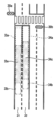
図2を参照する。いま、自車両1の前方に信号機30が存在する場合を想定する。信号機30は、複数の車線31及び32の交通を規制する信号機である。車線31及び32の通行方向は同じであり、車線31は自車両1の走行車線、車線32は車線31の隣接車線である。
コントローラ18は、信号機30の信号機情報と、車線31の車線情報と、カメラ20の画角範囲とに基づいて、道路上に他車両が存在しない場合にカメラ20によって車線31上で信号機30を撮影できる撮像可能領域33を算出する。Please refer to FIG. Assume now that a
The
この撮像可能領域33は、先行車両2によってカメラ20の画角範囲が遮られなければ車線31上でカメラ20により信号機30を撮影できることが期待できる領域である。反対に、撮像可能領域33の外側の車線31上の領域は、カメラ20の画角範囲が遮られなくても信号機30を撮影できない領域である。
コントローラ18は、車線32についても同様に撮像可能領域34を算出する。すなわち、コントローラ18は、信号機30の信号機情報と、車線32の車線情報と、カメラ20の画角範囲とに基づいて、道路上に他車両が存在しない場合にカメラ20によって車線32上で信号機30を撮影できる撮像可能領域34を算出する。This
The
コントローラ18は、自車両1が撮像可能領域33又は34内に位置しているか否かを判定する。
自車両1が撮像可能領域33又は34内に位置している場合には、先行車両によってカメラ20の画角範囲が遮られなければ信号機30を撮影できることが期待できる。したがってこの場合にコントローラ18は、先行車両2によって信号機30がカメラ20の画角範囲から遮蔽されないように自車両1を制御する。The
When the
例えば、カメラ20の撮像画像から信号機30が認識されていない場合には、コントローラ18は、先行車両2により信号機30が遮蔽されない車間距離を算出し、車間距離に応じて自車両1を減速することにより、先行車両2と自車両1との車間距離を増大する。
これに加えて又はこれに代えて、コントローラ18は、車線31の中央から信号機30が偏位する方向へ、自車両1と先行車両2との横位置の偏差を増加させるように前記自車両を操舵してもよい。For example, when the
Additionally or alternatively, the
一方で、カメラ20の撮像画像から信号機30が認識されている場合には、コントローラ18は、先行車両2と自車両1との車間距離を、先行車両2により信号機30が遮蔽されない車間距離に維持するように、自車両1の速度を制御する。
このように先行車両2によって信号機30がカメラ20の画角範囲から遮蔽されるのを回避する自車両1の走行制御を、以下「遮蔽回避制御」と表記する。On the other hand, when the
The travel control of the
反対に、自車両1が撮像可能領域33及び34のいずれの中にも位置していない場合には、カメラ20の画角範囲が遮られなくても、そもそも信号機30を撮影できない。したがってこの場合には、上記の遮蔽回避制御を抑制する。
これにより、そもそも信号機30を撮影できない領域で、不要に遮蔽回避制御が実行されるのを防止できる。この結果、不要な遮蔽回避制御によって自車両1の乗員に違和感を与えるのを抑制できる。Conversely, if the
As a result, it is possible to prevent the shielding avoidance control from being unnecessarily executed in an area where the
例えば、上記の自律走行制御や定速走行制御において、コントローラ18は、先行車両2により信号機30がカメラ20の画角範囲から遮蔽されるか否かに関わらずに定めた目標値となるように、先行車両2と自車両1の車間距離を制御する。例えば、コントローラ18は、自車両1の車速に応じて先行車両との車間距離の目標値を定めてよい。
また、コントローラ18は、自車両1の走行車線である車線31内における自車両1の横位置が、予め定めた初期値(例えば車線中央)となるように、自車両1の横位置を制御してよい。For example, in the above-described autonomous driving control and constant-speed driving control, the
Further, the
以下、コントローラ18の機能を詳しく説明する。図3を参照する。コントローラ18は、物体検出部40と、自車両位置推定部41と、地図取得部42と、検出統合部43と、物体追跡部44と、先行車両検出部45と、地図内位置演算部46と、信号認識部47と、遮蔽回避制御部48と、自車両経路生成部49と、車両制御部50を備える。 The functions of the
物体検出部40は、物体センサ11の検出信号に基づいて、自車両1の周囲の物体、例えば車両やバイク、歩行者、障害物などの位置、姿勢、大きさ、速度などを検出する。物体検出部40は、例えば自車両1を空中から眺める天頂図(平面図ともいう)において、物体の2次元位置、姿勢、大きさ、速度などを表現する検出結果を出力する。
自車両位置推定部41は、測位装置13による測定結果や、車両センサ12からの検出結果を用いたオドメトリに基づいて、自車両1の絶対位置、すなわち、所定の基準点に対する自車両1の位置、姿勢及び速度を計測する。Based on the detection signal from the
The
地図取得部42は、地図データベース14から自車両1が走行する道路の地図情報を取得する。地図取得部42は、通信装置15により外部の地図データサーバから地図情報を取得してもよい。
地図取得部42により取得される地図情報には、自車両1の進路前方に存在する信号機の信号機情報と、この信号機によって交通が規制される車線の車線情報と、車線上又はその近傍に存在する地物の情報と、を含む。The
The map information acquired by the
検出統合部43は、複数の物体検出センサの各々から物体検出部40が得た複数の検出結果を統合して、各物体に対して一つの2次元位置、姿勢、大きさ、速度などを出力する。具体的には、物体検出センサの各々から得られた物体の挙動から、各物体検出センサの誤差特性などを考慮した上で最も誤差が少なくなる最も合理的な物体の挙動を算出する。
具体的には、既知のセンサ・フュージョン技術を用いることにより、複数種類のセンサで取得した検出結果を総合的に評価して、より正確な検出結果を得る。A
Specifically, by using a known sensor fusion technique, detection results obtained by a plurality of types of sensors are comprehensively evaluated to obtain more accurate detection results.
物体追跡部44は、物体検出部40によって検出された物体を追跡する。具体的には、検出統合部43により統合された検出結果に基づいて、異なる時刻に出力された物体の挙動から、異なる時刻間における物体の同一性の検証(対応付け)を行い、かつ、その対応付けを基に、物体の速度などの挙動を予測する。
先行車両検出部45は、検出統合部43及び物体追跡部44により検出された自車両1の周囲に存在する物体の中から、自車両1の前方の先行車両を検出し、検出結果を遮蔽回避制御部48へ出力する。The
The preceding
地図内位置演算部46は、自車両位置推定部41により得られた自車両1の絶対位置、及び地図取得部42により取得された地図情報から、地図上における自車両1の位置及び姿勢を推定する。
また、地図内位置演算部46は、自車両1が走行している道路、さらに当該道路のうちで自車両1が走行する車線を特定する。地図内位置演算部46は、地図上における自車両1の位置及び姿勢、自車両1が走行する車線の情報を遮蔽回避制御部48へ出力する。
信号認識部47は、カメラ20による撮像画像を解析して信号機とその点灯色を認識する。信号認識部47は、信号機の認識結果を遮蔽回避制御部48へ出力する。The in-map
Further, the in-map
The
遮蔽回避制御部48は、地図取得部42が取得した地図情報、先行車両検出部45の検出結果、地図内位置演算部46が特定した自車両1の位置、信号認識部47の認識結果に基づいて、先行車両によって自車両1の前方の信号機がカメラ20の画角範囲から遮蔽されるのを回避する遮蔽回避制御を実行する。
遮蔽回避制御部48は、撮像可能領域算出部51と、撮影可否判定部52と、制御量設定部53を備える。The shielding
The shielding
撮像可能領域算出部51は、カメラ20の光学情報及び設置情報と地図情報とに基づいて、自車両1の前方の信号機を、この信号機により規制される車線上からカメラ20で撮影できる撮像可能領域を算出する。
図4を参照する。自車両1の前方に信号機30a及び30bが存在する場合を想定する。信号機30a及び30bは、複数の車線31及び32の交通を規制する信号機である。車線31及び32の通行方向は同一の互いに隣接する車線である。Based on the optical information and installation information of the
Please refer to FIG. Assume that there are
撮像可能領域算出部51は、複数の車線31及び32の各々について撮像可能領域を算出する。まず、車線31上の撮像可能領域の算出について説明する。
まず、撮像可能領域算出部51は、複数の信号機30a及び30bのうち信号機30aを撮影できる撮像可能領域33aを算出する。
撮像可能領域算出部51は、信号機30aの設置位置及び高さ情報と、車線31の道路構造及び勾配と、カメラ20の光学情報及び設置情報に基づいて、撮像可能領域33aを算出する。The imageable
First, the imageable
The imageable
例えば撮像可能領域算出部51は、車線31上で信号機30aを撮影可能な地点を探索することにより撮像可能領域33aを算出してよい。
このとき、撮像可能領域算出部51は、カメラ20の上下方向及び水平方向の画角範囲の両方に信号機30aが位置する場合に、カメラ20が信号機30aを撮影できると判定し、上下方向及び水平方向の画角範囲のいずれかから信号機30aが外れる場合に、カメラ20が信号機30aを撮影できないと判定してよい。
図5Aを参照する。撮像可能領域算出部51は、例えば次式(1)及び(2)を満足する場合に、カメラ20の上下方向の画角範囲に信号機30aが位置すると判断する。For example, the imageable
At this time, when the
See FIG. 5A. The imageable
(xb+x0)tanθ1 > ys1-yc …(1)
(xb+x0)tanθ2 < ys2-yc …(2)
xbは自車両1から信号機30aまでの水平距離であり、x0は自車両1の前端からカメラ20の搭載位置までの前後方向距離であり、ycはカメラ20の搭載位置の高さであり、ys1か信号機30aの上端の高さであり、ys2は信号機30aの下端の高さである。(xb+x0)tanθ1>ys1−yc (1)
(xb+x0) tan θ2 < ys2-yc (2)
xb is the horizontal distance from the
θ1はカメラ20の画角範囲の上限35の仰角であり、θ2はカメラ20の画角範囲の下限36の仰角である。
なお、地図情報に信号機30aの高さ情報がない場合には、行政機関等によって定められた設置基準に基づいて一般的な信号機の高さとして仮定される値を、信号機30aの高さとして用いてもよい。例えば、ys1を5.7mと仮定し、ys2を4.7mと仮定してよい。
なおここで、カメラ20が自車両1に対して固定である場合には、自車両1の前端からカメラ20の搭載位置までの前後方向距離(x0)、はカメラ20の搭載位置の高さ(yc)、カメラ20の画角範囲の上限35の仰角(θ1)、カメラ20の画角範囲の下限36の仰角(θ2)は変化しない。すなわち、カメラ20が自車両1に対して固定である場合には自車両1に対するカメラ20の上下方向画角範囲は変化しないため、予め自車両1に対するカメラ20の上下方向画角範囲を記憶しておけば、自車両1から信号機30aまでの水平距離(xb)のみを検出する事でカメラ20の上下方向の画角範囲に信号機30aが位置すると判断することができる。但し、カメラ20が自車両1に対して固定でなく可動である場合や、自車両1のピッチング動作による画角範囲の変化などを考慮する場合は当然に、実際の自車両1の前端からカメラ20の搭載位置までの前後方向距離(x0)、カメラ20の搭載位置の高さ(yc)、カメラ20の画角範囲の上限35の仰角(θ1)、カメラ20の画角範囲の下限36の仰角(θ2)を検出し、上記(1)及び(2)式を用いて、カメラ20の上下方向の画角範囲に信号機30aが位置するか否かを判定しても良い。
If there is no height information for the
Here, when the
図5Bを参照する。撮像可能領域算出部51は、カメラ20の光学中心20cに対する信号機30aの横方向の偏位と、カメラ20から信号機30aまでの水平距離(xb+x0)と、カメラ20の水平画角θhに基づいて、カメラ20の水平方向の画角範囲に信号機30aが位置するか否かを判定する。
このとき、自車両1が車線31の中央に位置すると仮定してもよい。また、地図情報に含まれる信号機30aの設置位置情報が、信号機30aの支柱37の2次元座標である場合には、支柱37の座標を信号機30aの座標として使用してもよい。See FIG. 5B. Based on the lateral displacement of the
At this time, it may be assumed that the
図4を参照する。以下、撮像可能領域内で信号機に最も近い点を撮像可能領域の「近端」と表記し、撮像可能領域内で信号機に最も遠い点を撮像可能領域の「遠端」と表記する。撮像可能領域33aの近端を参照符号33cで示し、撮像可能領域33aの遠端を参照符号33dで示す。
撮像可能領域33aの遠端33dと信号機30aとの間の距離の上限を、カメラ20の光学系の性能を考慮して決定してもよい。例えば、撮像画像上で信号機30aを認識するのに必要な最小画素数に応じて遠端33dを設定してもよい。または、信号機30aから遠端33dまでの距離が閾値以下となるように遠端33dを設定してもよい。Please refer to FIG. Hereinafter, the point closest to the traffic light within the imageable area is referred to as the "near end" of the imageable area, and the point furthest from the traffic light within the imageable area is referred to as the "far end" of the imageable area. The near end of the
The upper limit of the distance between the
撮像可能領域算出部51は、信号機30bについても同様に、車線31上で信号機30bを撮影できる撮像可能領域33bを算出する。
このように撮像可能領域算出部51は、車線31を規制する全ての信号機30a及び30bの各々について、車線31上で信号機30a及び30bを撮影できる撮像可能領域33a及び33bをそれぞれ算出する。Similarly, for the
In this way, the imageable
そして、撮像可能領域算出部51は、撮像可能領域33a及び33bの和領域(すなわち、撮像可能領域33a又は33bの少なくともいずれかに含まれる領域)を、車線31を規制する信号機30a又は30bの少なくとも一方を車線31上で撮影できる撮像可能領域として算出する。
また、撮像可能領域算出部51は、撮像可能領域33a及び33bの重複領域33eを算出する。Then, the imageable
Also, the imageable
図6を参照する。次に、撮像可能領域算出部51は、車線31の隣接車線32上の撮像可能領域を算出する。
車線31の場合と同様に、撮像可能領域算出部51は、車線32上で信号機30aを撮影できる撮像可能領域34aと、車線32上で信号機30bを撮影できる撮像可能領域34bを算出する。Please refer to FIG. Next, the imageable
As in the
撮像可能領域算出部51は、撮像可能領域34a及び34bの和領域を、車線32を規制する信号機30a又は30bの少なくとも一方を車線32上で撮影できる撮像可能領域として算出する。
また、撮像可能領域算出部51は、撮像可能領域34a及び34bの重複領域34cを算出する。The
In addition, the imageable
図3を参照する。撮影可否判定部52は、撮像可能領域算出部51が算出した撮像可能領域内に自車両1が位置するか否か(例えば自車両1が撮像可能領域内を走行中であるか否か)を判定する。
図4及び図6の例では、撮影可否判定部52は、自車両1が撮像可能領域33a及び33bの和領域、又は撮像可能領域34a及び34bの和領域のいずれかに位置するか否かを判定する。すなわち、撮影可否判定部52は、撮像可能領域33a、33b、34a又は34bのいずれかに自車両1が位置するか否かを判定する。Please refer to FIG. The photographable/
In the examples of FIGS. 4 and 6 , the photographing
自車両1が撮像可能領域内に位置すると判定した場合、制御量設定部53は、信号認識部47による信号機の認識状態と、先行車両検出部45による先行車両の検出結果とに応じて、遮蔽回避制御のための自車両1の走行制御の目標制御量を設定する。
制御量設定部53は、目標制御量として例えば自車両1と先行車両との間の目標車間距離、又は走行車線内における自車両1の目標横位置を設定する。
図7を参照する。撮像可能領域内に自車両1が位置すると撮影可否判定部52が判定し、先行車両検出部45が先行車両2を検出している場合を想定する。When it is determined that the
The control
Please refer to FIG. It is assumed that the image capturing
制御量設定部53は、信号認識部47が信号機30a又は30bを認識しているか否かを判定する。信号認識部47が信号機30a又は30bを認識していると判定した場合には、制御量設定部53は、現在の車間距離が、信号機30a又は30bの少なくとも一方は先行車両2によってカメラ20の画角範囲から遮蔽されない車間距離であると判断し、現在の車間距離を目標車間距離に設定する。 The control
信号認識部47が信号機30aも信号機30bも認識していないと判定した場合に、制御量設定部53は、信号機30a又は30bの少なくとも一方が先行車両2によってカメラ20の画角範囲から遮蔽されなくなるように、目標制御量を設定する。
例えば自車両1が撮像可能領域33a内に位置すると判定した場合、制御量設定部53は、先行車両2により信号機30aが遮蔽されない車間距離を算出し、目標車間距離に設定する。すなわち、先行車両2が存在し、且つ自車両1が撮影可能領域撮像可能領域内に位置するにも拘らず信号認識部47が信号機30aも信号機30bも認識していない場合は、先行車両2と自車両1との車間距離が短く、先行車両2により信号機30aが遮蔽されていると判定して、先行車両2と自車両1の車間距離を、先行車両2により信号機30aが遮蔽されない車間距離に増大する。When the
For example, when it is determined that the
図8を参照する。例えば制御量設定部53は、次式(3)によって信号機30aが先行車両2により遮蔽されない車間距離x1を算出する。
x1=(xb+x0)×(yt-yc)/(ys-yc)-x0 …(3)
ytは先行車両2の高さを示し、ysは信号機30aの高さを示す。Please refer to FIG. For example, the control
x1=(xb+x0)×(yt−yc)/(ys−yc)−x0 (3)
yt indicates the height of the preceding
同様に、自車両1が撮像可能領域33b内に位置すると判定した場合、制御量設定部53は、先行車両2により信号機30bが遮蔽されない車間距離を算出し、目標車間距離に設定する。 Similarly, when it is determined that the
自車両1が撮像可能領域33a及び33bの重複領域33e内に位置すると判定した場合、制御量設定部53は、信号機30aが先行車両2により遮蔽されない車間距離と、信号機30bが先行車両2により遮蔽されない車間距離のいずれかを算出して、目標車間距離に設定してもよい。
制御量設定部53は、信号機30aが先行車両2により遮蔽されない車間距離と、信号機30bが先行車両2により遮蔽されない車間距離の両方を算出し、これらの車間距離うちより短い車間距離を目標車間距離に設定してもよく、より長い車間距離を目標車間距離に設定してもよい。When it is determined that the
The control
図9を参照する。制御量設定部53は、走行車線31内の自車両1の目標横位置を設定してもよい。すなわち、制御量設定部53は、自車両1と先行車両2の横位置の偏差を増大させる走行車線31内の横位置を、目標横位置として設定してもよい。
例えば、自車両1が撮像可能領域33a内に位置すると判定した場合、制御量設定部53は、信号機30aが車線31の中央からずれているか否かを判定する。See FIG. The control
For example, when it is determined that the
信号機30aが車線31の中央から偏位している場合(すなわち信号機30aの車幅方向位置が車線31の中央からずれている場合)、制御量設定部53は、信号機30aが車線31の中央から偏位する方向へ、自車両1と先行車両2との横位置の偏差Δが増加するように目標横位置を設定する。
信号機30aは、車線31の中央から左方向に偏位しているので、制御量設定部53は、左方向へ偏差Δが増大するように目標横位置を設定する。When the
Since the
同様に、自車両1が撮像可能領域33b内に位置すると判定した場合、制御量設定部53は、信号機30bが車線31の中央からずれているか否かを判定する。
信号機30bが車線31の中央から偏位している場合、制御量設定部53は、信号機30bが車線31の中央から偏位する方向へ、自車両1と先行車両2との横位置の偏差Δを増加するように目標横位置を設定する。Similarly, when determining that the
When the
信号機30bは、車線31の中央から右方向に偏位しているので、制御量設定部53は、右方向へ偏差Δが増大するように目標横位置を設定する。
自車両1が撮像可能領域33a及び33bの重複領域33e内に位置すると判定した場合、制御量設定部53は、左方向へ偏差Δが増大するように目標横位置を設定してもよく、道方向へ偏差Δが増大するように目標横位置を設定してもよい。Since the
When it is determined that the
次に図10を参照する。撮像可能領域内に自車両1が位置すると撮影可否判定部52が判定し、先行車両検出部45が先行車両2を検出していない場合を想定する。
このような場合でも、太陽光線の方向などの撮影条件や、カメラ20の装置状態によっては、信号認識部47が信号機30a又は30bを認識できないことがある。このため、制御量設定部53は、信号認識部47が信号機30a又は30bを認識しているか否かを判定する。Reference is now made to FIG. Assume a case where the photographing
Even in such a case, the
信号認識部47が信号機30a又は30bを認識していないと判定した場合には、信号機30a又は30bの点灯色が不明なため、信号機30a又は30bに対応する停止線38より前方へ進めない。また、撮像可能領域33aの近端33cよりも信号機30aに近づくと、撮影条件や装置状態が好転しても、カメラ20は信号機30a又は30bを撮影できない。
このため、制御量設定部53は、停止線38又は撮像可能領域33aの近端33cのうち信号機30aから遠い方の位置を目標停止位置に設定する。When the
Therefore, the control
図11を参照する。自車両1が撮像可能領域内に位置しないと判定した場合、制御量設定部53は、上記の遮蔽回避制御を抑制する。
例えば、制御量設定部53は、信号認識部47が信号機30aも信号機30bも認識していないと判定しても、自律走行制御や定速走行制御において、先行車両2により信号機30a又は30bがカメラ20の画角範囲から遮蔽されるか否かに関わらずに定められた目標車間距離や目標横位置を変更しない。Please refer to FIG. When it is determined that the
For example, even if the
以上、自車両1が車線31を走行する場合について説明を行ったが、自車両1が車線32を走行する場合についても同様に、撮像可能領域34a及び34bと重複領域34cとを用いて、遮蔽回避制御のための目標制御量を設定できる。 The case where the
図3を参照する。自車両経路生成部49は、検出統合部43及び物体追跡部44による自車両1の周囲の物体の検出結果と、車両センサ12からの車両信号とに基づいて、自車両1の走行車線に沿って他車両と衝突せずに交通規則に従って走行するように、自車両1の目標走行軌道と速度プロファイルを生成する。
このとき、自車両経路生成部49は、自車両1及び先行車両との車間距離が、遮蔽回避制御部48が設定した目標車間距離となるように速度プロファイルを生成する。Please refer to FIG. Based on the results of detection of objects around the
At this time, the host vehicle
これにより、先行車両により信号機がカメラ20の画角範囲から遮蔽されていた場合には、自車両1及び先行車両との車間距離が目標車間距離以上に増大するように減速する速度プロファイルが生成される。
また、先行車両により信号機がカメラ20の画角範囲から遮蔽されていなかった場合には、自車両1及び先行車両との車間距離を維持する速度プロファイルが生成される。As a result, when the traffic light is blocked from the view angle range of the
Further, when the traffic light is not blocked from the view angle range of the
また、自車両経路生成部49は、自車両1の車線内の横位置を、遮蔽回避制御部48が設定した目標横位置へ変化させる目標走行軌道を生成する。
これにより、先行車両により信号機がカメラ20の画角範囲から遮蔽されていた場合には、自車両1の走行車線の中央から信号機が偏位する方向へ自車両1と先行車両との横位置の偏差を増加させる目標走行軌道が生成される。
また、自車両経路生成部49は、遮蔽回避制御部48が設定した目標停止位置に自車両を停止させる目標走行軌道と速度プロファイルを生成する。Further, the own vehicle
As a result, when the traffic signal is blocked from the view angle range of the
In addition, the own vehicle
車両制御部50は、自車両経路生成部49が生成した速度プロファイルに従う速度で自車両1が目標走行軌道を走行するようにアクチュエータ19を駆動する。
これにより例えば、自車両1及び先行車両との車間距離が、遮蔽回避制御部48が設定した目標車間距離よりも長い場合は、車両制御部50は、ブレーキ制御アクチュエータを制御して自車両1を減速する。The
As a result, for example, when the inter-vehicle distance between the
また、自車両1及び先行車両との車間距離と目標車間距離とが等しい場合には、車両制御部50は、アクセル開度アクチュエータとブレーキ制御アクチュエータを制御して、先行車両との車間距離を維持する。
遮蔽回避制御部48が目標横位置を設定した場合には、車両制御部50は、ステアリングアクチュエータを制御して自車両1を操舵し、設定された目標横位置まで自車両1の横位置を変化させる。
遮蔽回避制御部48が目標停止位置を設定した場合には、車両制御部50は、設定された目標停止位置に自車両を停止させる。Further, when the inter-vehicle distance between the
When the shielding
When the shielding
その後、車両制御部50による自車両1の減速によって、自車両1及び先行車両との車間距離が、遮蔽回避制御部48が設定した目標車間距離となったときに、制御量設定部53は、信号認識部47が信号機を認識しているか否かを判定する。
自車両1及び先行車両との車間距離が目標車間距離となっても、信号認識部47が信号機を認識していないと判定した場合には、先行車両以外の要因(例えば撮影条件やカメラ20の装置状態)のために信号機を認識できないと考えられる。Thereafter, when the inter-vehicle distance between the
Even if the inter-vehicle distance between the
したがって、先行車両2を検出していない場合(図10)と同様に、制御量設定部53は、停止線38又は撮像可能領域33aの近端33cのうち信号機30aから遠い方の位置を目標停止位置に設定する。
自車両1と先行車両2との横位置の偏差Δが増大した結果、自車両1の横位置が最大許容横位置になっても信号認識部47が信号機30a又は30bを認識できない場合も同様である。Therefore, similarly to the case where the preceding
The same applies when the
(動作)
次に、図12を参照して実施形態の車両制御方法の一例を説明する。
ステップS1においてコントローラ18は、自律走行制御や定速走行制御における目標車間距離と目標横位置を設定する。例えばコントローラ18は、自車両1の車速に応じて目標車間距離を設定してよい。また例えばコントローラ18は、自車両1の走行車線の中央を目標横位置に設定してよい。(motion)
Next, an example of the vehicle control method of the embodiment will be described with reference to FIG.
In step S1, the
ステップS2において地図取得部42は、自車両1が走行する道路の地図情報を取得する。
ステップS3において信号認識部47は、カメラ20による撮像画像を取得する。信号認識部47は、カメラ20による撮像画像を解析して信号機とその点灯色を認識する。
ステップS4において自車両位置推定部41は、自車両1の現在位置を推定する。
ステップS5において先行車両検出部45は、自車両1の前方の先行車両を検出する。In step S2, the
In step S<b>3 , the
In step S<b>4 , the own vehicle
In step S<b>5 , the preceding
ステップS6において撮像可能領域算出部51は、カメラ20によって車線上で信号機を撮像できる撮像可能領域を算出する。
ステップS7において撮影可否判定部52は、自車両1が撮像可能領域に位置するか否かを判定する。自車両1が撮像可能領域に位置しないと判定した場合(ステップS7:N)に処理はステップS8へ進む。In step S6, the imageable
In step S<b>7 , the photographing
ステップS8において自車両経路生成部49と車両制御部50は、ステップS1で設定された目標車間距離と目標横位置に応じて、自車両の走行を制御する。このため、遮蔽回避制御部48による遮蔽回避制御が抑制される。その後に処理は終了する。
一方で、ステップS7において自車両1が撮像可能領域に位置すると判定した場合(ステップS7:Y)に処理はステップS9へ進む。In step S8, the own vehicle
On the other hand, if it is determined in step S7 that the
ステップS9において制御量設定部53は、信号認識部47が信号機を認識しているか否かを判定する。信号認識部47が信号機を認識していると判定した場合(ステップS9:Y)に処理はステップS10へ進む。信号認識部47が信号機を認識していないと判定した場合(ステップS9:N)に処理はステップS12へ進む。
ステップS10において制御量設定部53は、先行車両検出部45が先行車両2を検出しているか否かを判定する。In step S9, the control
In step S<b>10 , the control
先行車両検出部45が先行車両2を検出していると判定した場合(ステップS10:Y)に処理はステップS11へ進む。ステップS11において制御量設定部53は、現在の車間距離が、先行車両によって信号機がカメラ20の画角範囲から遮蔽されない車間距離であると判断し、現在の車間距離を維持するように目標車間距離として設定する。その後に処理はステップS8へ進む。
ステップS8において自車両経路生成部49と車両制御部50は、目標車間距離として設定された現在の車間距離を維持するように、自車両1の車速を制御する。その後に処理は終了する。If it is determined that the preceding
In step S8, the host
一方で、ステップS10において先行車両検出部45が先行車両2を検出していないと判定した場合(ステップS10:N)に処理はステップS8へ進む。
ステップS8において自車両経路生成部49と車両制御部50は、ステップS1で設定された目標車間距離と目標横位置に応じて、自車両の走行を制御する。その後に処理は終了する。On the other hand, if it is determined in step S10 that the preceding
In step S8, the own vehicle
ステップS12において制御量設定部53は、先行車両検出部45が先行車両2を検出しているか否かを判定する。先行車両検出部45が先行車両2を検出していると判定した場合(ステップS12:Y)に処理はステップS13へ進む。
ステップS13において制御量設定部53は、信号機が先行車両により遮蔽されない車間距離を算出し、目標車間距離に設定する。これにより目標車間距離が増加する。
In step S<b>12 , the control
In step S13, the control
また制御量設定部53は、自車両と先行車両の横位置の偏差を増加させる目標横位置を設定する。その後に処理はステップS8へ進む。
ステップS8において自車両経路生成部49と車両制御部50は、自車両1と先行車両との車間距離が、制御量設定部53が設定した目標車間距離となるように自車両1を減速させる。
または、自車両経路生成部49と車両制御部50は、自車両1の横位置が目標横位置へ変化するように自車両1を操舵する。その後に処理は終了する。The control
In step S<b>8 , the host vehicle
Alternatively, the vehicle
一方で、ステップS12において先行車両検出部45が先行車両2を検出していないと判定した場合(ステップS12:N)に処理はステップS14へ進む。
ステップS14において制御量設定部53は、撮像可能領域の近端又は停止線のうち信号機から遠い方の位置を目標停止位置に設定する。その後に処理はステップS8へ進む。
ステップS8において自車両経路生成部49と車両制御部50は、自車両1を目標停止位置に停止させる。その後に処理は終了する。On the other hand, if it is determined in step S12 that the preceding
In step S14, the control
In step S8, the own vehicle
(実施形態の効果)
(1)信号認識部47は、自車両1の前方の所定画角範囲を撮像するカメラ20によって撮像した画像に基づいて信号機を認識する。地図取得部42は、信号機の設置位置の情報とこの信号機によって規制される車線の情報とを含む地図情報を取得する。撮像可能領域算出部51は、自車両1に搭載されたカメラ20の画角範囲と地図情報とに基づいて、カメラ20によって車線上で信号機を撮像できる撮像可能領域を算出する。撮影可否判定部52は、自車両1が撮像可能領域内に位置しているか否かを判定する。(Effect of Embodiment)
(1) The
自車両1が撮像可能領域内に位置している場合には、制御量設定部53、自車両経路生成部49及び車両制御部50は、自車両1の先行車両によって信号機がカメラ20の画角範囲から遮蔽されないように自車両1を制御する。
これにより、車線上に他車両が存在しなくてもそもそもカメラ20で信号機を撮影できない領域で、不要に遮蔽回避制御が実行されるのを防止できる。この結果、不要に遮蔽回避制御によって自車両1の乗員に違和感を与えるのを抑制できる。When the
As a result, it is possible to prevent unnecessary shielding avoidance control from being executed in a region in which the
(2)制御量設定部53は、カメラ20の撮像画像から信号機が認識されているか否かを判定し、撮像画像から信号機が認識されている場合に自車両経路生成部49及び車両制御部50は、先行車両と自車両との車間距離を、先行車両により信号機が遮蔽されない車間距離に維持するように自車両を制御する。
これにより、先行車両によって信号機が遮蔽されないように、自車両1を制御することが可能になる。(2) The control
This makes it possible to control the
(3)制御量設定部53は、カメラ20の撮像画像から信号機が認識されているか否かを判定し、先行車両が存在するか否かを判定する。自車両1が撮影可能領域内に位置している場合であって、撮像画像から信号機が認識されておらず、且つ先行車両が存在する場合に、制御量設定部53、自車両経路生成部49及び車両制御部50は、先行車両と自車両1との車間距離を増大するように自車両1を制御する。
これにより、先行車両によって信号機が遮蔽されないように、自車両1を制御することが可能になる。(3) The control
This makes it possible to control the
(4)制御量設定部53は、先行車両により信号機が遮蔽されない車間距離を算出する。自車両経路生成部49及び車両制御部50は、この車間距離に応じて自車両1を減速することによって、先行車両と自車両との車間距離を増大する。
これにより、先行車両によって信号機が遮蔽されないように、自車両1の速度を制御することが可能になる。(4) The control
This makes it possible to control the speed of the
(5)制御量設定部53、自車両経路生成部49及び車両制御部50は、車線の中央から信号機が偏位する方向へ、自車両1と先行車両との横位置の偏差を増加させるように自車両1を操舵する。
これにより、先行車両によって信号機が遮蔽されないように自車両1を操舵することが可能になる。(5) The control
This makes it possible to steer the
(6)先行車両に対する自車両1の相対位置を制御しても撮像画像から信号機が認識できない場合、制御量設定部53、自車両経路生成部49及び車両制御部50は、信号機に対応する停止線又は撮像可能領域内で信号機に最も近い点のうち、信号機からより遠い方の位置に自車両1を停止させる。
これにより、撮影条件や装置状態といった先行車両以外の要因で信号機が認識できない場合に、停止線を越えない範囲で、カメラ20の画角範囲内に信号機が位置する地点に自車両1を停車できる。これにより、状況が好転したときに信号機を撮影できる位置に自車両1を停車させることができる。(6) When the traffic signal cannot be recognized from the captured image even if the relative position of the
As a result, when the traffic signal cannot be recognized due to factors other than the preceding vehicle, such as photographing conditions and equipment conditions, the
(7)制御量設定部53は、カメラ20の撮像画像から信号機が認識されているか否かを判定し、先行車両が存在するか否かを判定する。撮像画像から信号機が認識されておらず、先行車両が存在しない場合に、制御量設定部53、自車両経路生成部49及び車両制御部50は、信号機に対応する停止線又は撮像可能領域内で信号機に最も近い点のうち、信号機からより遠い方の位置に自車両1を停止させる。
これにより、撮影条件や装置状態といった先行車両以外の要因で信号機が認識できない場合に、停止線を越えない範囲で、カメラ20の画角範囲内に信号機が位置する地点に自車両1を停車できる。これにより、状況が好転したときに信号機を撮影できる位置に自車両1を停車させることができる。(7) The control
As a result, when the traffic signal cannot be recognized due to factors other than the preceding vehicle, such as photographing conditions and equipment conditions, the
(8)地図取得部42は、車線を規制する複数の信号機の設置位置の情報を地図情報から取得する。撮像可能領域算出部51は、複数の信号機の各々について撮像可能領域をそれぞれ算出する。制御量設定部53、自車両経路生成部49及び車両制御部50は、これらの撮像可能領域のいずれかに自車両1が位置している場合には、先行車両によって信号機がカメラ20の画角範囲から遮蔽されないように自車両1を制御する。
複数の信号機のいずれかが遮蔽されなくなるように自車両1を制御すれば足りるので、自車両1の走行制御における選択肢が増える。(8) The
Since it is sufficient to control the
(9)撮像可能領域算出部51は、信号機によって制御される複数の車線の各々について撮像可能領域を算出する。
複数の車線のいずれかにおいて信号機が遮蔽されなくなるように自車両1を制御すれば足りるので、自車両1の走行制御における選択肢が増える。(9) The imageable
Since it is sufficient to control the
ここに記載されている全ての例及び条件的な用語は、読者が、本発明と技術の進展のために発明者により与えられる概念とを理解する際の助けとなるように、教育的な目的を意図したものであり、具体的に記載されている上記の例及び条件、並びに本発明の優位性及び劣等性を示すことに関する本明細書における例の構成に限定されることなく解釈されるべきものである。本発明の実施例は詳細に説明されているが、本発明の精神及び範囲から外れることなく、様々な変更、置換及び修正をこれに加えることが可能であると解すべきである。 All examples and conditional terms set forth herein are intended for educational purposes to aid the reader in understanding the invention and concepts provided by the inventors for the advancement of the art. and should be construed without limitation to the above examples and conditions specifically set forth and the configuration of the examples herein to demonstrate superiority and inferiority of the present invention. It is a thing. Although embodiments of the invention have been described in detail, it should be understood that various changes, substitutions and modifications can be made thereto without departing from the spirit and scope of the invention.
1…自車両、2…先行車両、3…信号機、10…車両制御装置、11…物体センサ、12…車両センサ、13…測位装置、14…地図データベース、15…通信装置、17…ナビゲーションシステム、18…コントローラ、19…アクチュエータ、20…カメラ、21…プロセッサ、22…記憶装置、40…物体検出部、41…自車両位置推定部、42…地図取得部、43…検出統合部、44…物体追跡部、45…先行車両検出部、46…地図内位置演算部、47…信号認識部、48…遮蔽回避制御部、49…自車両経路生成部、50…車両制御部、51…撮像可能領域算出部、52…撮影可否判定部、53…制御量設定部
Claims (10)
前記信号機の設置位置の情報及び前記信号機によって規制される車線の情報を含む地図情報と、自車両に搭載された前記カメラの上下方向及び左右方向の画角範囲と、に基づいて、前記カメラによって前記車線上で前記信号機を撮像できる撮像可能領域を算出し、
前記自車両が前記撮像可能領域内に位置しているか否かを判定し、
前記自車両が前記撮像可能領域内に位置している場合には、前記自車両の先行車両によって前記信号機が前記カメラの画角範囲から遮蔽されないように前記自車両を制御する、
ことを特徴とする車両制御方法。 A vehicle control method for recognizing a traffic signal based on an image captured by a camera mounted with a camera that captures a predetermined angle of view in front of the vehicle,
Based on map information including information on the installation position of the traffic signal and information on lanes restricted by the traffic signal, and the vertical and horizontal view angle ranges of the camera mounted on the vehicle, the camera calculating an imageable area in which the traffic light can be imaged on the lane;
Determining whether or not the own vehicle is positioned within the imageable area,
When the own vehicle is positioned within the imageable area, controlling the own vehicle so that the preceding vehicle of the own vehicle does not shield the traffic light from the angle range of the camera;
A vehicle control method characterized by:
前記撮像画像から前記信号機が認識されている場合に前記先行車両と自車両との車間距離を、前記先行車両により前記信号機が遮蔽されない車間距離に維持するように前記自車両を制御する、
ことを特徴とする請求項1に記載の車両制御方法。 Determining whether the traffic light is recognized from the captured image of the camera,
controlling the host vehicle so as to maintain the inter-vehicle distance between the preceding vehicle and the host vehicle when the traffic light is recognized from the captured image, such that the preceding vehicle does not shield the traffic light;
The vehicle control method according to claim 1, characterized by:
前記先行車両が存在するか否かを判定し、
前記自車両が前記撮影可能領域内に位置している場合であって、前記撮像画像から前記信号機が認識されておらず、且つ前記先行車両が存在する場合に、前記先行車両と前記自車両との車間距離を増大するように前記自車両を制御する、
ことを特徴とする請求項1に記載の車両制御方法。 Determining whether the traffic light is recognized from the captured image of the camera,
determining whether or not the preceding vehicle exists;
When the own vehicle is positioned within the photographable area, the traffic light is not recognized from the captured image, and the preceding vehicle is present, the preceding vehicle and the own vehicle controlling the own vehicle to increase the inter-vehicle distance of
The vehicle control method according to claim 1, characterized by:
前記先行車両が存在するか否かを判定し、
前記撮像画像から前記信号機が認識されておらず、前記先行車両が存在しない場合に、前記信号機に対応する停止線又は前記撮像可能領域内で前記信号機に最も近い点のうち、前記信号機からより遠い方の位置に前記自車両を停止させる、
ことを特徴とする請求項1に記載の車両制御方法。 Determining whether the traffic light is recognized from the captured image of the camera,
determining whether or not the preceding vehicle exists;
When the traffic signal is not recognized from the captured image and the preceding vehicle does not exist, the point closest to the traffic signal in the stop line corresponding to the traffic signal or the imageable area is farther from the traffic signal. stopping the own vehicle at the position of
The vehicle control method according to claim 1, characterized by:
これら撮像可能領域のいずれかに前記自車両が位置している場合には、前記先行車両によって前記信号機が前記カメラの画角範囲から遮蔽されないように前記自車両を制御する、
することを特徴とする請求項1~7のいずれか一項に記載の車両制御方法。 calculating the imageable area for each of a plurality of traffic lights that regulate the lane;
When the own vehicle is located in any of these imageable areas, the own vehicle is controlled so that the preceding vehicle does not block the traffic light from the angle range of the camera.
The vehicle control method according to any one of claims 1 to 7, characterized in that:
信号機の設置位置の情報及び前記信号機によって規制される車線の情報を含む地図情報と、前記カメラの上下方向及び左右方向の画角範囲と、に基づいて、前記カメラによって前記車線上で前記信号機を撮像できる撮像可能領域を算出し、前記自車両が前記撮像可能領域内に位置しているか否かを判定し、前記自車両が前記撮像可能領域内に位置している場合には、前記自車両の先行車両によって前記信号機が前記カメラの画角範囲から遮蔽されないように前記自車両を制御し、前記カメラによって撮像した画像に基づいて信号機を認識するコントローラと、
を備えることを特徴とする車両制御装置。 a camera mounted on the own vehicle for imaging a predetermined angle of view range in front of the own vehicle;
Based on map information including information on installation positions of traffic lights and information on lanes restricted by the traffic lights, and on the vertical and horizontal view angle ranges of the camera, the traffic lights are detected on the lanes by the cameras. calculating an imageable area that can be imaged, determining whether or not the own vehicle is positioned within the imageable area, and if the own vehicle is positioned within the imageable area, the own vehicle a controller that controls the own vehicle so that the preceding vehicle does not block the traffic light from the angle of view of the camera, and recognizes the traffic light based on the image captured by the camera;
A vehicle control device comprising:
Applications Claiming Priority (1)
| Application Number | Priority Date | Filing Date | Title |
|---|---|---|---|
| PCT/IB2019/001272 WO2021094802A1 (en) | 2019-11-15 | 2019-11-15 | Method for controlling vehicle and device for controlling vehicle |
Publications (3)
| Publication Number | Publication Date |
|---|---|
| JPWO2021094802A1 JPWO2021094802A1 (en) | 2021-05-20 |
| JPWO2021094802A5 JPWO2021094802A5 (en) | 2022-07-29 |
| JP7334795B2 true JP7334795B2 (en) | 2023-08-29 |
Family
ID=75912060
Family Applications (1)
| Application Number | Title | Priority Date | Filing Date |
|---|---|---|---|
| JP2021555895A Active JP7334795B2 (en) | 2019-11-15 | 2019-11-15 | Vehicle control method and vehicle control device |
Country Status (7)
| Country | Link |
|---|---|
| US (1) | US20220402492A1 (en) |
| EP (1) | EP4059795B1 (en) |
| JP (1) | JP7334795B2 (en) |
| CN (1) | CN114728657A (en) |
| BR (1) | BR112022009416A2 (en) |
| MX (1) | MX2022005699A (en) |
| WO (1) | WO2021094802A1 (en) |
Families Citing this family (3)
| Publication number | Priority date | Publication date | Assignee | Title |
|---|---|---|---|---|
| JP7431108B2 (en) * | 2020-06-02 | 2024-02-14 | 株式会社Soken | image recognition device |
| US20220204032A1 (en) * | 2020-12-31 | 2022-06-30 | Waymo Llc | Traffic light viewsheds |
| DE102021005311A1 (en) * | 2021-10-26 | 2023-04-27 | Mercedes-Benz Group AG | Method for automatic control of a longitudinal movement of a vehicle |
Citations (9)
| Publication number | Priority date | Publication date | Assignee | Title |
|---|---|---|---|---|
| JP2007320458A (en) | 2006-06-01 | 2007-12-13 | Toyota Motor Corp | Intervehicular distance controller |
| JP2009001245A (en) | 2007-06-25 | 2009-01-08 | Hitachi Ltd | Vehicle traveling assist control device |
| JP2015125708A (en) | 2013-12-27 | 2015-07-06 | 富士重工業株式会社 | Traffic light recognition device |
| JP2016049933A (en) | 2014-09-02 | 2016-04-11 | アイシン・エィ・ダブリュ株式会社 | Travel support system, travel support method, and computer program |
| WO2016194228A1 (en) | 2015-06-05 | 2016-12-08 | 日産自動車株式会社 | Traffic signal detection device and traffic signal detection method |
| JP2017154512A (en) | 2016-02-29 | 2017-09-07 | 日立オートモティブシステムズ株式会社 | Vehicle control device |
| JP2016501408A5 (en) | 2013-10-21 | 2018-01-25 | ||
| JP2019046136A (en) | 2017-09-01 | 2019-03-22 | 株式会社デンソー | Collision avoidance support device |
| JP2019079398A (en) | 2017-10-26 | 2019-05-23 | トヨタ自動車株式会社 | Cruise controller |
Family Cites Families (3)
| Publication number | Priority date | Publication date | Assignee | Title |
|---|---|---|---|---|
| US8793046B2 (en) * | 2012-06-01 | 2014-07-29 | Google Inc. | Inferring state of traffic signal and other aspects of a vehicle's environment based on surrogate data |
| DE102012111740A1 (en) * | 2012-12-03 | 2014-06-05 | Continental Teves Ag & Co. Ohg | Method for supporting a traffic light phase assistant detecting a traffic light of a vehicle |
| EP3590781B1 (en) * | 2017-03-03 | 2023-12-27 | Hitachi Astemo, Ltd. | Apparatus and method for supporting travel of moving object |
-
2019
- 2019-11-15 WO PCT/IB2019/001272 patent/WO2021094802A1/en unknown
- 2019-11-15 MX MX2022005699A patent/MX2022005699A/en unknown
- 2019-11-15 BR BR112022009416A patent/BR112022009416A2/en unknown
- 2019-11-15 US US17/776,489 patent/US20220402492A1/en active Pending
- 2019-11-15 CN CN201980102251.1A patent/CN114728657A/en active Pending
- 2019-11-15 JP JP2021555895A patent/JP7334795B2/en active Active
- 2019-11-15 EP EP19952758.1A patent/EP4059795B1/en active Active
Patent Citations (9)
| Publication number | Priority date | Publication date | Assignee | Title |
|---|---|---|---|---|
| JP2007320458A (en) | 2006-06-01 | 2007-12-13 | Toyota Motor Corp | Intervehicular distance controller |
| JP2009001245A (en) | 2007-06-25 | 2009-01-08 | Hitachi Ltd | Vehicle traveling assist control device |
| JP2016501408A5 (en) | 2013-10-21 | 2018-01-25 | ||
| JP2015125708A (en) | 2013-12-27 | 2015-07-06 | 富士重工業株式会社 | Traffic light recognition device |
| JP2016049933A (en) | 2014-09-02 | 2016-04-11 | アイシン・エィ・ダブリュ株式会社 | Travel support system, travel support method, and computer program |
| WO2016194228A1 (en) | 2015-06-05 | 2016-12-08 | 日産自動車株式会社 | Traffic signal detection device and traffic signal detection method |
| JP2017154512A (en) | 2016-02-29 | 2017-09-07 | 日立オートモティブシステムズ株式会社 | Vehicle control device |
| JP2019046136A (en) | 2017-09-01 | 2019-03-22 | 株式会社デンソー | Collision avoidance support device |
| JP2019079398A (en) | 2017-10-26 | 2019-05-23 | トヨタ自動車株式会社 | Cruise controller |
Also Published As
| Publication number | Publication date |
|---|---|
| EP4059795A1 (en) | 2022-09-21 |
| MX2022005699A (en) | 2022-06-08 |
| US20220402492A1 (en) | 2022-12-22 |
| WO2021094802A1 (en) | 2021-05-20 |
| EP4059795A4 (en) | 2022-12-21 |
| EP4059795B1 (en) | 2024-01-10 |
| CN114728657A (en) | 2022-07-08 |
| JPWO2021094802A1 (en) | 2021-05-20 |
| BR112022009416A2 (en) | 2022-08-09 |
Similar Documents
| Publication | Publication Date | Title |
|---|---|---|
| US11313976B2 (en) | Host vehicle position estimation device | |
| US11157751B2 (en) | Traffic guide object recognition device, traffic guide object recognition method, and storage medium | |
| US11247692B2 (en) | Prediction device, prediction method, and storage medium | |
| KR20190008292A (en) | Object detection method and object detection apparatus | |
| JP7334795B2 (en) | Vehicle control method and vehicle control device | |
| JP7251611B2 (en) | Mobile object behavior prediction method, behavior prediction device, and vehicle | |
| US20210221367A1 (en) | Driving Support Method and Driving Support Device | |
| US11761787B2 (en) | Map information correction method, driving assistance method, and map information correction device | |
| JP7458908B2 (en) | Vehicle driving support method and vehicle driving support system | |
| EP3912877B1 (en) | Driving assistance method and driving assistance device | |
| JP2021196874A (en) | Driving support method and driving support device | |
| JP7435513B2 (en) | Vehicle control device and vehicle control method | |
| WO2021166425A1 (en) | Travel assistance device, travel assistance method, and travel assistance program | |
| JP7334107B2 (en) | Vehicle control method and vehicle control device | |
| JP2018185156A (en) | Target position estimation method and target position estimation device | |
| RU2788556C1 (en) | Vehicle control method and vehicle control device | |
| JP7336861B2 (en) | Behavior prediction method and behavior prediction device | |
| JP7458743B2 (en) | Vehicle control method and vehicle control device | |
| JP7458797B2 (en) | Driving support method and driving support device | |
| JP7236279B2 (en) | Driving support method and driving support device | |
| WO2021074659A1 (en) | Driving assistance method and driving assistance device | |
| RU2773761C1 (en) | Behavior prediction method and behavior prediction device for mobile subject and vehicle | |
| JP7149171B2 (en) | Object recognition method and object recognition device | |
| RU2774521C1 (en) | Driving assistance method and driving assistance device | |
| JP2022129177A (en) | Driving support method and driving support device |
Legal Events
| Date | Code | Title | Description |
|---|---|---|---|
| A521 | Request for written amendment filed |
Free format text: JAPANESE INTERMEDIATE CODE: A523 Effective date: 20220420 |
|
| A621 | Written request for application examination |
Free format text: JAPANESE INTERMEDIATE CODE: A621 Effective date: 20220420 |
|
| A131 | Notification of reasons for refusal |
Free format text: JAPANESE INTERMEDIATE CODE: A131 Effective date: 20230207 |
|
| A521 | Request for written amendment filed |
Free format text: JAPANESE INTERMEDIATE CODE: A523 Effective date: 20230324 |
|
| TRDD | Decision of grant or rejection written | ||
| A01 | Written decision to grant a patent or to grant a registration (utility model) |
Free format text: JAPANESE INTERMEDIATE CODE: A01 Effective date: 20230718 |
|
| A61 | First payment of annual fees (during grant procedure) |
Free format text: JAPANESE INTERMEDIATE CODE: A61 Effective date: 20230731 |
|
| R151 | Written notification of patent or utility model registration |
Ref document number: 7334795 Country of ref document: JP Free format text: JAPANESE INTERMEDIATE CODE: R151 |