JP2020119082A - Operation detection device - Google Patents
Operation detection device Download PDFInfo
- Publication number
- JP2020119082A JP2020119082A JP2019007805A JP2019007805A JP2020119082A JP 2020119082 A JP2020119082 A JP 2020119082A JP 2019007805 A JP2019007805 A JP 2019007805A JP 2019007805 A JP2019007805 A JP 2019007805A JP 2020119082 A JP2020119082 A JP 2020119082A
- Authority
- JP
- Japan
- Prior art keywords
- load
- panel
- substrate
- load sensor
- cover
- Prior art date
- Legal status (The legal status is an assumption and is not a legal conclusion. Google has not performed a legal analysis and makes no representation as to the accuracy of the status listed.)
- Pending
Links
Images


Abstract
Description
本発明は、操作検出装置に関する。 The present invention relates to an operation detection device.
従来の技術として、スイッチケースと、スイッチケースに対して軸方向に押圧操作可能に支持された操作ノブと、スイッチケース内に操作ノブの外周部に対応して基板上の円周方向に並んで複数個が設けられた圧力センサと、操作ノブと中間プレートの間に介在され、操作ノブの非操作状態で中間プレートを介して各圧力センサに予圧を与えるための複数の第1の板ばね部を円周上に均等配置してなるプリロード用ばねプレートと、を備えた操作検出装置が知られている(例えば、特許文献1参照。)。 As a conventional technique, a switch case, an operation knob that is supported so as to be able to be pressed in the axial direction with respect to the switch case, and a switch case are arranged in a circumferential direction on the substrate corresponding to the outer peripheral portion of the operation knob. A plurality of pressure sensors, and a plurality of first leaf spring portions interposed between the operation knob and the intermediate plate for applying a preload to each pressure sensor via the intermediate plate when the operation knob is not operated. There is known an operation detecting device including a preloading spring plate in which are evenly arranged on the circumference (for example, refer to Patent Document 1).
この操作検出装置は、プリロード用ばねプレートの複数の第1の板ばね部によって、中間プレートを介して各圧力センサに均等に予圧をかけるプリロード機構を備えている。 This operation detecting device includes a preload mechanism that uniformly preloads each pressure sensor via the intermediate plate by the plurality of first leaf spring portions of the preload spring plate.
しかし、従来の操作検出装置において、圧力センサは基板上に複数配置されて実装されている。このため、例えば、圧力センサが複数の場合においてプリロード用ばねプレートにより予圧をかけても十分にプリロード荷重がかからず、プリロード機構が成立しない場合がある、という問題があった。 However, in the conventional operation detecting device, a plurality of pressure sensors are arranged and mounted on the substrate. Therefore, for example, in the case where there are a plurality of pressure sensors, there is a problem that even if a preload is applied by the preload spring plate, a sufficient preload load is not applied and the preload mechanism is not established.
従って本発明の目的は、小さな荷重でプリロード機構を成立させることができる操作検出装置を提供することにある。 Therefore, an object of the present invention is to provide an operation detecting device that can establish a preload mechanism with a small load.
[1]上記目的を達成するため、押圧操作されるパネルと、前記パネルに対して組み付けられるカバーと、前記パネルと前記カバーの間に挟まれ、前記押圧操作による荷重を検出する複数の荷重検出部と、前記複数の荷重検出部を配置して実装する基板と、前記荷重検出部に接触し、前記パネルからの前記荷重を前記荷重検出部に伝達する接触板と、を有し、前記基板は、前記荷重検出部の配置された部分が前記荷重により撓むように、切り欠きを備えている、操作検出装置を提供する。
[2]前記パネルと前記カバーの間に、前記荷重検出部に予圧を付与する弾性部材を備えている、上記[1]に記載の操作検出装置であってもよい。
[3]また、前記基板は矩形であり、前記切り欠きは、前記矩形の四隅に配置された前記それぞれの荷重検出部の間に形成されている、上記[1]又は[2]に記載の操作検出装置であってもよい。
[1] In order to achieve the above object, a panel that is pressed, a cover that is assembled to the panel, and a plurality of load detectors that are sandwiched between the panel and the cover and that detect a load by the pressing operation. Section, a board on which the plurality of load detection sections are arranged and mounted, and a contact plate that contacts the load detection section and transmits the load from the panel to the load detection section, the board Provides an operation detection device including a notch so that a portion where the load detection unit is arranged is bent by the load.
[2] The operation detection device according to the above [1], wherein an elastic member that applies a preload to the load detection unit is provided between the panel and the cover.
[3] Further, the substrate is rectangular, and the cutouts are formed between the respective load detection portions arranged at the four corners of the rectangle. [1] or [2] It may be an operation detection device.
本発明によれば、小さな荷重でプリロード機構を成立させることができる。 According to the present invention, the preload mechanism can be established with a small load.
(本発明の実施の形態)
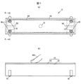
図1(a)は、本実施の形態に係る操作検出装置の上平面図であり、図1(b)は、操作検出装置の正面図である。また、図2は、図1(a)のA−A断面を示す断面図である。本実施の形態に係る操作検出装置1は、押圧操作されるパネル10と、パネル10に対して組み付けられるカバー20と、パネル10とカバー20の間に挟まれ、押圧操作による荷重を検出する複数の荷重検出部としての荷重センサ30と、複数の荷重センサ30を配置して実装する基板50と、荷重センサ30に接触し、パネル10からの荷重を荷重センサ30に伝達する接触板40と、を有し、基板50は、荷重センサ30の配置された部分が荷重により撓むように、切り欠き52を備えて構成されている。
(Embodiment of the present invention)
1A is a top plan view of the operation detecting device according to the present embodiment, and FIG. 1B is a front view of the operation detecting device. Further, FIG. 2 is a cross-sectional view showing an AA cross section of FIG. The operation detecting device 1 according to the present embodiment includes a
本実施の形態に係る操作検出装置1は、上記のような構成とされ、荷重センサ30が実装される基板において、荷重センサ30の配置された部分が荷重により撓むように、切り欠き52を備えて構成されている。このような構成により、カバー20とパネル10を、荷重センサ30を実装した基板50を挟んで組み付けるだけで、基板50の荷重センサ30が実装された部分が撓むことができ、小さな荷重でプリロード(予圧、初期荷重)機構を成立させることができる。
The operation detection device 1 according to the present embodiment is configured as described above, and is provided with the
なお、本実施の形態では、図2に示すように、センサ30にプリロードを付与するためのばね25を備える。ばね25により、接触板40を介して、複数の荷重センサ30にプリロードを付与することができる。また、センサ30が複数の場合に、基板50の荷重センサ30が実装された部分がそれぞれ撓むことができるので、すべてのセンサ30にプリロードがかかりやすくなる。これにより、より小さな荷重でプリロード機構を成立させることができる。
In this embodiment, as shown in FIG. 2, the
(パネル10)
パネル10は、筐体としてのパネル本体12と、例えば、パネル本体の表面、上面に装着されてタッチ、なぞり等の操作を受け付けるタッチパネル14を有して構成されている。パネル10は、例えば、ABS(アクリロニトリル・ブタジエン・スチレン)などの樹脂材料を用いて形成されている。
(Panel 10)
The
パネル本体12は、図1(a)、(b)、図2に示すように、箱状の筐体とされている。パネル本体12の上部12aにはタッチパネル14が装着される。また、パネル本体12の脚部12bには、例えば、カバー20を係止するための係止用ねじ部12cが形成されている。
As shown in FIGS. 1A, 1B, and 2, the
タッチパネル14は、図1(b)に示すように、操作者の指200がタッチ操作した位置または押圧操作した位置を検出する操作検出部として機能する。
As shown in FIG. 1B, the
タッチパネル14は、例えば、静電容量方式のタッチセンサであり、マルチタッチを検出するように構成されている。具体的にはタッチパネル14は、複数の駆動電極及び検出電極が絶縁性を保ちながら交差して基板上に設けられている。タッチパネル14は、複数の駆動電極と複数の検出電極の全ての組み合わせの静電容量を読み出し、1周期分の静電容量を静電容量S1として制御部100に出力する。
The
パネル本体12は、図2に示すように、箱状の筐体の内部に、空間部12dを有している。この空間部12dには、ばね25、接触板40、荷重センサ30を実装した基板50等が収容される。また、パネル本体12の空間部12dと基板50との間隙をなくし、押圧操作による荷重を基板50に伝達するためのボス15が、パネル本体12の内部にパネル本体と一体になって設けられている。ボス15は、図1(a)に示すように、パネル本体12の中央部と、荷重センサ30に対応する計5カ所に設けられている。
As shown in FIG. 2, the
(カバー20)
カバー20は、図2に示すように、パネル本体12の係止用ねじ部12cにねじ75で固定されるねじ穴22備え、パネル本体12の底部12eに当て付けて固定される、板状のものである。カバー20は、例えば、ABS(アクリロニトリル・ブタジエン・スチレン)などの樹脂材料、金属等を用いて形成することができる。
(Cover 20)
As shown in FIG. 2, the
(ばね25)
ばね25は、図1(a)、図2に示すように、例えば、荷重センサ30に対応した4カ所に配置される。ばね25は、本実施の形態では、コイルばねであり、圧縮された状態でカバー20と接触板40の間に挟まれて組み付けられる。ばね25は、ばね用ステンレス、ばね鋼等により形成される。
(Spring 25)
As shown in FIGS. 1A and 2, the
なお、ばね25は、予圧を付与する弾性部材である。ばね25は、プリロード機構を成立させるための弾性力を発生させるものの一例であり、コイル形状以外のばねや、ゴム等の弾性部材で形成されるものでもよい。
The
(荷重センサ30)
荷重検出部としての荷重センサ30は、複数の荷重センサで構成される。本実施の形態では、図1(a)に示すように、パネル10の四隅付近に、4つの荷重センサ30を備えた構成とされている。
(Load sensor 30)
The
荷重センサ30は、例えば、ピエゾ抵抗方式や静電容量方式のMEMS(Micro Electro Mechanical Systems)である。本実施の形態の荷重センサ30は、一例として、静電容量方式のセンサであり、4つのゲージによってブリッジ回路が組まれている。
The
この荷重センサ30は、荷重が付加されることにより、内部のゲージの抵抗値が変わってブリッジ回路の出力が変化するように構成されている。4つの荷重センサ30は、基板50の下面50aに実装され、接触板40と接触、当接する。
The
4つの荷重センサ30は、荷重信号S2〜荷重信号S5を制御部100に出力する。制御部100は、例えば、この荷重信号S2〜荷重信号S5を荷重に変換し、押圧操作の有無を判定することができる。
The four
なお、後述するように、操作検出装置1が組み付けられた状態では、ばね25の弾性力及び基板50のたわみにより、荷重センサ30にはプリロードが付与されている。これにより、複数の荷重センサ30は、押圧操作がない状態においても接触板40と接触、当接しており、荷重はゼロ以上となっている。したがって、押圧操作がない状態において、荷重信号S2〜荷重信号S5はゼロ以上の初期値を有する。後述する制御部100において、これらの荷重信号S2〜荷重信号S5の初期値を基準として、これらの値からの差分に基づいて荷重値の算出処理が実行される。
As will be described later, when the operation detecting device 1 is assembled, the
(接触板40)
接触板40は、パネル10が押圧操作されたときの荷重を荷重センサ30へ伝達するための板状部材である。また、ばね25の弾性力により荷重センサ30へプリロードを付与するための機能も有する。このために、接触板40は、パネル10への押圧操作等によっても変形しにくい材料で形成され、例えば、金属、硬質の樹脂等である。
(Contact plate 40)
The
接触板40は、上記の機能を発揮させるために、プリロードを付与された状態において、図2に示すように、接触板40の下面40aは、ばね25と接触、当接している。また、上面40bは、複数の荷重センサ30と接触、当接している。
As shown in FIG. 2, the
(基板50)
基板50は、荷重センサ30が実装され、必要な電気配線、他の電気部品が実装された回路基板である。基板50は、例えば、エポキシ基板、ガラス入りエポキシ基板等により形成される。
(Substrate 50)
The
基板50は、図2に示すように、片面(下面50a)に荷重センサ30が4カ所に実装され、上面50b側がボス15に当接するように配置される。
As shown in FIG. 2, the
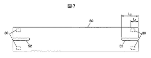
図3は、基板50の平面図である。本実施の形態では、基板50は矩形とされ、基板50の四隅に荷重センサ30が実装される。基板50には、図3に示すように、切り欠き52を備えている。これは、荷重センサ30の配置された部分が荷重により撓むように、あるいは、撓みやすくするためである。
FIG. 3 is a plan view of the
切り欠き52は、図3に示すように、荷重センサ30の間に形成されている。図3において、右側に配置された2つの荷重センサ30の間に、切り欠き溝として切り欠き52が形成されている。この切り欠き52の溝長さL2は、荷重センサ30の配置寸法L1よりも大きく設定されている。これにより、基板50に配置された荷重センサ30の部分の基板がより撓みやすくなる。
The
(制御部100)
図4は、本実施の形態に係る操作検出装置の構成を示す構成ブロック図である。制御部100は、例えば、記憶されたプログラムに従って、取得したデータに演算、加工などを行うCPU(Central Processing Unit)、半導体メモリであるRAM(Random Access Memory)及びROM(Read Only Memory)などから構成されるマイクロコンピュータである。このROMには、例えば、制御部100が動作するためのプログラムと、静電閾値と、荷重閾値等、が格納されている。RAMは、例えば、一時的に演算結果などを格納する記憶領域として用いられる。
(Control unit 100)
FIG. 4 is a configuration block diagram showing the configuration of the operation detection device according to the present embodiment. The
制御部100は、例えば、タッチパネル14へのタッチ位置を検出する。また、制御部100は、タッチパネル14が荷重閾値以上の荷重で押圧操作された場合に押圧操作を受け付けたものとして検出する。制御部100は、操作が検出された点の座標値、押圧操作の有無などの情報を含む操作情報S8を生成して制御対象装置に出力する。
The
この制御対象装置とは、例えば、車両に搭載されたナビゲーション装置、音楽及び映像再生装置、空調装置などである。 The control target device is, for example, a navigation device mounted on a vehicle, a music/video reproducing device, an air conditioner, or the like.
具体的には、制御部100は、タッチパネル14から周期的に静電容量S1を取得して静電閾値と比較する。制御部100は、例えば、静電閾値以上の静電容量が存在した場合、この静電容量の分布に基づいてタッチ操作がされたタッチパネル14上の検出点を算出する。この算出は、一例として、分布した静電容量値の加重平均などによって行われる。
Specifically, the
また制御部100は、荷重センサ30からの荷重信号S2〜荷重信号S5に基づく荷重と荷重閾値とを比較する。制御部100は、荷重閾値以上の荷重が検出された場合、プッシュ操作がなされたと判定する。例えば、荷重信号S2〜荷重信号S5の平均値、あるいは、最大値が荷重閾値以上の場合に、荷重が検出されたと判定することができる。
Further, the
(操作検出装置1の組み付け)
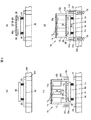
図5は、操作検出装置の組み付けの工程を順に示す図であり、図5(a)は、ばね、接触板、カバーを準備した図であり、図5(b)は、接触板の上に荷重センサ30を実装した基板を乗せ、荷重センサが接触板の上面に接触、当接するように、接触板の上に載置した図であり、図5(c)は、さらにパネルを上から組み付けている状態を示す図であり、図5(d)は、パネル本体をさらに図5(c)で示すB方向(下方向)に押し込んで、パネル本体とカバーをねじ締結して組み付けが完了した図である。
(Assembly of operation detection device 1)
FIG. 5 is a diagram showing the steps of assembling the operation detection device in order, FIG. 5(a) is a diagram in which a spring, a contact plate, and a cover are prepared, and FIG. FIG. 5C is a diagram in which the substrate on which the
図5(a)に示すように、カバー20、ばね25、接触板40を順に上方向に積んで、組み立てベース300上に載置する。組み立てベース300は、図5(a)に示すように、最終の組み付け工程において、カバー20とパネル本体12をねじ締結するために、ねじ75を通すための貫通穴301を備えている。なお、図5(a)において図示は省略するが、カバー20、ばね25、接触板40のそれぞれの位置決めをおこなう位置決め部をカバー20、ばね25、接触板40に備えていてもよい。これにより、組み付け作業の容易化、効率化を向上させることができる。
As shown in FIG. 5A, the
次に、図5(b)に示すように、荷重センサ30を実装した基板50を、荷重センサ30が接触板40の上面40bに接触、当接するように、接触板40の上に載置する。図5(b)において図示は省略するが、基板50(または荷重センサ30)と接触板40との位置決めをおこなう位置決め部を基板50(または荷重センサ30)、接触板40に備えていてもよい。これにより、組み付け作業の容易化、効率化を向上させることができる。
Next, as shown in FIG. 5B, the
次に、図5(c)に示すように、パネル10を、パネル本体12の係止用ねじ部12cが下位置となる方向に用意して、図5(c)で示すB方向(下方向)に組み付け移動させる。図5(c)において図示は省略するが、パネル本体12と接触板40、または、パネル本体12とカバー20との位置決めをおこなう位置決め部を備えていることが好ましい。本実施の形態では、パネル本体12の係止用ねじ部12cとカバー20のねじ穴22が位置決め部として機能する。
Next, as shown in FIG. 5C, the
図5(c)において、ボス15の下面15aが基板50の上面50bに接触、当接するまで図5(c)で示すB方向(下方向)に移動させる。
In FIG. 5C, the
図5(d)に示すように、パネル本体12をさらに図5(c)で示すB方向(下方向)に押し込んで、パネル本体12の底部12eがカバー20の上面20aに当て付ける。この状態において、ばね25は圧縮されて弾性力により、接触板40を介して複数の荷重センサ30にそれぞれプリロードが付与される。
As shown in FIG. 5D, the
また、複数の荷重センサ30の配置された荷重センサ30の部分は、基板50に形成された切り欠き52により、小さな荷重でも撓みやすくなっている。このため、複数の荷重センサ30のそれぞれに、この撓みにより生じるプリロードが付与される。
Further, the portion of the
パネル本体12の底部12eがカバー20の上面20aに当て付いた状態で、貫通穴301からねじ75により、パネル本体12とカバー20を締結する。これにより、操作検出装置1の組み付け作業が完了する。
With the
(別実施例1)
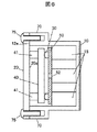
図6は、ばね25を使用しない実施形態を示す図2相当図である。前述したように、基板50は、図3に示すように、切り欠き52を備えている。これにより、荷重センサ30の配置された部分が荷重により撓む、あるいは、撓みやすくなる。したがって、図6に示すように、ばね25を使用せずに、接触板40から突出して設けられた突出部41に置き換えた構成でもよい。また、接触板40、または、突出部41を省略して、カバー20の上面20aによりそれぞれの荷重センサ30にプリロードを付与してもよい。荷重センサ30には、基板50の撓みにより、プリロードが付与される。
(Other Example 1)
FIG. 6 is a view corresponding to FIG. 2 showing an embodiment in which the
(別実施例2)
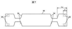
図7は、基板の変形例を示す平面図である。図7で示す切り欠き54は、左右に配置された荷重センサ30の間に形成されている。図7において、右側に配置された荷重センサ30と左側に配置された荷重センサ30の間に、切り欠き溝として切り欠き55が形成されている。この切り欠き54の端部位置L3は、荷重センサ30の配置寸法L1よりも大きく設定されている。これにより、基板50に配置された荷重センサ30の部分の基板がより撓みやすくなる。
(Other Example 2)
FIG. 7 is a plan view showing a modified example of the substrate. The
また、図3で示した切り欠き52と、図7で示した切り欠き54を組み合わせた構成であってもよい。その他の構成でも、荷重センサ30の配置された部分が荷重により撓むように、あるいは、撓みやすくなる構成であれば、本実施の形態に適用可能である。
Alternatively, the
(本発明の実施の形態の効果)
(1)本実施の形態に係る操作検出装置1は、押圧操作されるパネル10と、パネル10に対して組み付けられるカバー20と、パネル10とカバー20の間に挟まれ、押圧操作による荷重を検出する複数の荷重検出部としての荷重センサ30と、複数の荷重センサ30を配置して実装する基板50と、荷重センサ30に接触し、パネル10からの荷重を荷重センサ30に伝達する接触板40と、を有し、基板50は、荷重センサ30の配置された部分が荷重により撓むように、切り欠き52を備えて構成されている。本実施の形態に係る操作検出装置1は、上記のような構成とされ、荷重センサ30が実装される基板において、荷重センサ30の配置された部分が荷重により撓むように、切り欠き52を備えて構成されている。このような構成により、カバー20とパネル10を、荷重センサ30を実装した基板50を挟んで組み付けるだけで、基板50の荷重センサ30が実装された部分が撓むことができ、より小さな荷重でプリロード(予圧、初期荷重)機構を成立させることができる。
(2)本実施の形態では、荷重センサ30に予圧を付与する弾性部材として、ばね25を備えている。これにより、ばね25の弾性力と、基板50の荷重センサ30が実装された部分の撓みにより発生する弾性力により、それぞれの荷重センサ30にプリロードが付与される構成とすることができる。
(3)基板50は、荷重センサ30の配置された部分が荷重により撓むように、あるいは、撓みやすくするための切り欠き52を備えている。これによりプリロード(予圧、初期荷重)機構が成立するので、ばね25の小型化、あるいは、ばね25の省略化が可能となり、プリロード機構の小型化が可能になる。
(4)さらに、基板50は、荷重センサ30の配置された部分が荷重により撓むように、あるいは、撓みやすくするための切り欠き52を備えているので、プリロードによる基板の過度な負荷の低減が望めるという効果も有する。
(Effects of the embodiment of the present invention)
(1) The operation detection device 1 according to the present embodiment is sandwiched between the
(2) In the present embodiment, the
(3) The
(4) Further, since the
以上、本発明のいくつかの実施の形態及び変形例を説明したが、これらの実施の形態及び変形例は、一例に過ぎず、特許請求の範囲に係る発明を限定するものではない。これら新規な実施の形態及び変形例は、その他の様々な形態で実施されることが可能であり、本発明の要旨を逸脱しない範囲で、種々の省略、置き換え、変更などを行うことができる。また、これら実施の形態及び変形例の中で説明した特徴の組合せの全てが発明の課題を解決するための手段に必須であるとは限らない。さらに、これら実施の形態及び変形例は、発明の範囲及び要旨に含まれると共に、特許請求の範囲に記載された発明とその均等の範囲に含まれる。 Although some embodiments and modifications of the present invention have been described above, these embodiments and modifications are merely examples and do not limit the invention according to the claims. These new embodiments and modified examples can be implemented in various other forms, and various omissions, replacements, and changes can be made without departing from the scope of the present invention. Further, not all of the combinations of characteristics described in the embodiments and the modifications are essential to the means for solving the problems of the invention. Furthermore, these embodiments and modifications are included in the scope and gist of the invention, and are also included in the invention described in the claims and the scope equivalent thereto.
1…操作検出装置
10…パネル、12…パネル本体、12a…上部、12b…脚部、12c…係止用ねじ部、12d…空間部、12e…底部、14…タッチパネル、15…ボス、15a…下面
20…カバー、20a…上面、22…ねじ穴、25…ばね(弾性部材)
30…荷重センサ(荷重検出部)
40…接触板、40a…下面、40b…上面、41…突出部
50…基板、50a…下面、50b…上面、52、54…切り欠き
75…ねじ
100…制御部
200…指
300…ベース、301…貫通穴
S1…静電容量
S2-S5…荷重信号
S8…操作情報
L1…配置寸法、L2…溝長さ、L3…端部位置
DESCRIPTION OF SYMBOLS 1...
30... Load sensor (load detection unit)
40... Contact plate, 40a... Bottom surface, 40b... Top surface, 41...
Claims (3)
前記パネルに対して組み付けられるカバーと、
前記パネルと前記カバーの間に挟まれ、前記押圧操作による荷重を検出する複数の荷重検出部と、
前記複数の荷重検出部を配置して実装する基板と、
前記荷重検出部に接触し、前記パネルからの前記荷重を前記荷重検出部に伝達する接触板と、を有し、
前記基板は、前記荷重検出部の配置された部分が前記荷重により撓むように、切り欠きを備えている、操作検出装置。 A panel that is pressed
A cover assembled to the panel,
A plurality of load detection units that are sandwiched between the panel and the cover and that detect a load by the pressing operation,
A board on which the plurality of load detection units are arranged and mounted,
A contact plate that is in contact with the load detection unit and that transmits the load from the panel to the load detection unit,
The operation detecting device, wherein the substrate is provided with a notch so that a portion where the load detecting unit is arranged is bent by the load.
The operation detection device according to claim 1, wherein the substrate has a rectangular shape, and the notches are formed between the respective load detection units arranged at the four corners of the rectangle.
Priority Applications (1)
| Application Number | Priority Date | Filing Date | Title |
|---|---|---|---|
| JP2019007805A JP2020119082A (en) | 2019-01-21 | 2019-01-21 | Operation detection device |
Applications Claiming Priority (1)
| Application Number | Priority Date | Filing Date | Title |
|---|---|---|---|
| JP2019007805A JP2020119082A (en) | 2019-01-21 | 2019-01-21 | Operation detection device |
Publications (1)
| Publication Number | Publication Date |
|---|---|
| JP2020119082A true JP2020119082A (en) | 2020-08-06 |
Family
ID=71892059
Family Applications (1)
| Application Number | Title | Priority Date | Filing Date |
|---|---|---|---|
| JP2019007805A Pending JP2020119082A (en) | 2019-01-21 | 2019-01-21 | Operation detection device |
Country Status (1)
| Country | Link |
|---|---|
| JP (1) | JP2020119082A (en) |
-
2019
- 2019-01-21 JP JP2019007805A patent/JP2020119082A/en active Pending
Similar Documents
| Publication | Publication Date | Title |
|---|---|---|
| JP6080265B2 (en) | Touchpad input device | |
| US6508137B2 (en) | Capacitance change-based input device and detection device | |
| JP6433500B2 (en) | Operating devices for electrical equipment, especially for vehicle parts | |
| US11016570B2 (en) | Input device | |
| US20200319722A1 (en) | Input device with movable handle on a capacitive detection surface and capacitive coupling devices | |
| JP2018018159A (en) | Input device | |
| US11194412B2 (en) | Operation detection device | |
| JP6300027B2 (en) | Input device | |
| JP2020119082A (en) | Operation detection device | |
| CN213814621U (en) | Device for measuring force and position | |
| JP3378922B2 (en) | Capacitive sensor | |
| JP2015197881A (en) | touch sensor module | |
| JP2013012005A (en) | Switch device | |
| JP2020119083A (en) | Operation detection device | |
| JP2013004456A (en) | Switching device | |
| JP6284946B2 (en) | Capacitive sensor for detecting the relative movement of two adjacent bodies | |
| CN110879664B (en) | Keyboard with keyboard body | |
| JP2006294303A (en) | Multidirectional input device | |
| WO2022059256A1 (en) | Input device, input system, and detection method | |
| JP6581924B2 (en) | Touchpad input device | |
| JP2019106280A (en) | Switching device | |
| JP2005078864A (en) | Input device | |
| WO2023171259A1 (en) | Multidirectional input device | |
| KR100581400B1 (en) | The sound effector which uses a moving detection sensor module and moving detection sensor module | |
| JPH09280982A (en) | Three-dimensional load sensor |