JP2020102130A - Data collection and reproduction system - Google Patents
Data collection and reproduction system Download PDFInfo
- Publication number
- JP2020102130A JP2020102130A JP2018241379A JP2018241379A JP2020102130A JP 2020102130 A JP2020102130 A JP 2020102130A JP 2018241379 A JP2018241379 A JP 2018241379A JP 2018241379 A JP2018241379 A JP 2018241379A JP 2020102130 A JP2020102130 A JP 2020102130A
- Authority
- JP
- Japan
- Prior art keywords
- process data
- data collection
- still image
- camera
- unit
- Prior art date
- Legal status (The legal status is an assumption and is not a legal conclusion. Google has not performed a legal analysis and makes no representation as to the accuracy of the status listed.)
- Granted
Links
- 238000013480 data collection Methods 0.000 title claims abstract description 63
- 238000000034 method Methods 0.000 claims abstract description 77
- 230000008569 process Effects 0.000 claims abstract description 75
- 238000005070 sampling Methods 0.000 claims abstract description 23
- 239000000463 material Substances 0.000 claims abstract description 17
- 230000000737 periodic effect Effects 0.000 claims abstract description 16
- 230000001360 synchronised effect Effects 0.000 claims abstract description 13
- 239000003550 marker Substances 0.000 claims description 23
- 238000003860 storage Methods 0.000 claims description 21
- 238000013500 data storage Methods 0.000 claims description 16
- 238000012545 processing Methods 0.000 claims description 11
- 230000005540 biological transmission Effects 0.000 claims description 3
- 230000005856 abnormality Effects 0.000 abstract description 25
- 238000003384 imaging method Methods 0.000 abstract 2
- 241000196324 Embryophyta Species 0.000 description 25
- 238000010586 diagram Methods 0.000 description 10
- 230000006870 function Effects 0.000 description 6
- 238000012544 monitoring process Methods 0.000 description 6
- 230000007547 defect Effects 0.000 description 5
- 229910000831 Steel Inorganic materials 0.000 description 3
- 238000004458 analytical method Methods 0.000 description 3
- 230000008859 change Effects 0.000 description 3
- 239000010959 steel Substances 0.000 description 3
- 230000006872 improvement Effects 0.000 description 2
- 238000007689 inspection Methods 0.000 description 2
- 101100190617 Arabidopsis thaliana PLC2 gene Proteins 0.000 description 1
- 101100408456 Arabidopsis thaliana PLC8 gene Proteins 0.000 description 1
- 101100520231 Caenorhabditis elegans plc-3 gene Proteins 0.000 description 1
- 101100464304 Caenorhabditis elegans plk-3 gene Proteins 0.000 description 1
- 244000256297 Euphorbia tirucalli Species 0.000 description 1
- 101100093534 Saccharomyces cerevisiae (strain ATCC 204508 / S288c) RPS1B gene Proteins 0.000 description 1
- 230000006399 behavior Effects 0.000 description 1
- 238000004364 calculation method Methods 0.000 description 1
- 238000007405 data analysis Methods 0.000 description 1
- 230000000694 effects Effects 0.000 description 1
- 230000014759 maintenance of location Effects 0.000 description 1
- 238000004519 manufacturing process Methods 0.000 description 1
- 238000012986 modification Methods 0.000 description 1
- 230000004048 modification Effects 0.000 description 1
- 238000007747 plating Methods 0.000 description 1
- 238000010248 power generation Methods 0.000 description 1
- 239000000126 substance Substances 0.000 description 1
- 238000012360 testing method Methods 0.000 description 1
- 238000003466 welding Methods 0.000 description 1
Images


Classifications
-
- G—PHYSICS
- G05—CONTROLLING; REGULATING
- G05B—CONTROL OR REGULATING SYSTEMS IN GENERAL; FUNCTIONAL ELEMENTS OF SUCH SYSTEMS; MONITORING OR TESTING ARRANGEMENTS FOR SUCH SYSTEMS OR ELEMENTS
- G05B19/00—Programme-control systems
- G05B19/02—Programme-control systems electric
- G05B19/418—Total factory control, i.e. centrally controlling a plurality of machines, e.g. direct or distributed numerical control [DNC], flexible manufacturing systems [FMS], integrated manufacturing systems [IMS], computer integrated manufacturing [CIM]
- G05B19/4183—Total factory control, i.e. centrally controlling a plurality of machines, e.g. direct or distributed numerical control [DNC], flexible manufacturing systems [FMS], integrated manufacturing systems [IMS], computer integrated manufacturing [CIM] characterised by data acquisition, e.g. workpiece identification
-
- G—PHYSICS
- G05—CONTROLLING; REGULATING
- G05B—CONTROL OR REGULATING SYSTEMS IN GENERAL; FUNCTIONAL ELEMENTS OF SUCH SYSTEMS; MONITORING OR TESTING ARRANGEMENTS FOR SUCH SYSTEMS OR ELEMENTS
- G05B23/00—Testing or monitoring of control systems or parts thereof
- G05B23/02—Electric testing or monitoring
- G05B23/0205—Electric testing or monitoring by means of a monitoring system capable of detecting and responding to faults
- G05B23/0208—Electric testing or monitoring by means of a monitoring system capable of detecting and responding to faults characterized by the configuration of the monitoring system
-
- G—PHYSICS
- G05—CONTROLLING; REGULATING
- G05B—CONTROL OR REGULATING SYSTEMS IN GENERAL; FUNCTIONAL ELEMENTS OF SUCH SYSTEMS; MONITORING OR TESTING ARRANGEMENTS FOR SUCH SYSTEMS OR ELEMENTS
- G05B2219/00—Program-control systems
- G05B2219/30—Nc systems
- G05B2219/37—Measurements
- G05B2219/37532—Synchronized data acquisition
-
- G—PHYSICS
- G05—CONTROLLING; REGULATING
- G05B—CONTROL OR REGULATING SYSTEMS IN GENERAL; FUNCTIONAL ELEMENTS OF SUCH SYSTEMS; MONITORING OR TESTING ARRANGEMENTS FOR SUCH SYSTEMS OR ELEMENTS
- G05B2219/00—Program-control systems
- G05B2219/30—Nc systems
- G05B2219/37—Measurements
- G05B2219/37533—Real time processing of data acquisition, monitoring
Abstract
Description
本発明は、産業プラントのためのデータ収集再生システムに関する。 The present invention relates to a data collection/reproduction system for an industrial plant.
工業活動に必要な素材や資源を生産する産業プラント(製紙プラント、鉄鋼プラント、発電プラント、石油プラント、化学プラント等)が知られている。産業プラントのプラント監視制御システムは、制御用ネットワークを介して、プラントを構成する多数のフィールド機器(アクチュエータやセンサを含む)が接続された入出力装置(I/O)や、多数のフィールド機器を制御するプログラマブルロジックコントローラ(以下、PLCと記す)が相互に接続された構成を備える。 There are known industrial plants (papermaking plants, steel plants, power generation plants, petroleum plants, chemical plants, etc.) that produce materials and resources necessary for industrial activities. A plant monitoring control system for an industrial plant is configured to connect an input/output device (I/O) to which a large number of field devices (including actuators and sensors) that make up the plant are connected via a control network and a large number of field devices. The programmable logic controller (henceforth PLC) which controls is provided with the structure mutually connected.
PLCや入出力装置の入出力信号をプロセスデータと称する。大規模プラントでは入出力点が数千、数万に及び、多種多様なプロセスデータが存在する。これらのプロセスデータは、データ収集機能やデータ再生機能を有するデータ収集再生装置に収集され、試験時、調整時、操業時、障害時におけるデータ解析に用いられる。 Input/output signals of the PLC and the input/output device are called process data. A large-scale plant has thousands and tens of thousands of input/output points, and various kinds of process data exist. These process data are collected by a data collecting/reproducing apparatus having a data collecting function and a data reproducing function, and used for data analysis at the time of test, adjustment, operation, and failure.
従来のプラント監視制御システムのデータ収集再生装置(例えば、特許文献1)は、制御用ネットワークに接続し、PLCが入出力するプロセスデータを収集する。オペレータは、画面に表示されるプロセスデータを参照して、産業プラントの状態を把握することができる。 A conventional data collection/reproduction device of a plant monitoring control system (for example, Patent Document 1) is connected to a control network and collects process data input/output by a PLC. The operator can grasp the state of the industrial plant by referring to the process data displayed on the screen.
ところで、製造物の異常、具体的には、紙、フィルム、鋼板などのシート状物の表面に生じた異常(キズや欠陥)を発見し原因を解析するために、プロセスデータとともにシート状物を撮影した画像を確認したい場合がある。これらのシート状物は、全長が数十メートルから数十キロメートルと長く、全体を一度に撮影することはできない。 By the way, in order to find and analyze the cause of defects in products such as papers, films, steel sheets and other surface defects (scratches or defects), we analyze the cause with the process data. You may want to check the captured image. The length of these sheet-like objects is as long as several tens of meters to several tens of kilometers, and it is not possible to take a picture of the whole at once.
1つの手法として、搬送されるシート状物をエリアスキャンカメラで撮影した映像を再生することが考えられる。しかし、映像の再生により表示されるのはカメラ視野内の1フレーム毎の画像である。そのため、オペレータは、再生時刻を前に戻したり先に進めたりして異常発生前後の映像を記憶し、記憶の中の映像を元に原因を類推する。オペレータの記憶に頼った手法では、異常発生前後の挙動が把握しにくく、精度の高い解析は困難である。 As one method, it is conceivable to reproduce an image obtained by shooting an conveyed sheet-like material with an area scan camera. However, what is displayed by reproducing the video is an image for each frame within the field of view of the camera. Therefore, the operator memorizes the images before and after the occurrence of the abnormality by moving the reproduction time forward or forward, and estimates the cause based on the images in the memory. With the method that relies on the memory of the operator, it is difficult to grasp the behavior before and after the occurrence of an abnormality, and it is difficult to perform highly accurate analysis.
また、シート状物が高速に搬送される製紙プラントや鉄鋼プラントでは、映像を確認するオペレータがシート状物の表面の異常を見過ごしてしまうおそれがある。また、プロセスデータのサンプリングタイミングは、エリアスキャンカメラのフレームレートに比して高速であるため、映像上で異常を発見した際に、異常に関連するプロセスデータを十分に絞り込めず、原因の解析が難しい。また、カメラで静止画を連続撮影する場合に、プロセスデータのサンプリング周期とカメラの撮影周期とが一致しておらず、これらのデータを同時再生した場合にカメラのシャッタータイミング分だけ誤差が生じる。 Further, in a paper manufacturing plant or a steel plant in which a sheet-like material is conveyed at high speed, an operator who confirms an image may overlook an abnormality on the surface of the sheet-like material. In addition, since the process data sampling timing is faster than the frame rate of the area scan camera, when an abnormality is found in the image, the process data related to the abnormality cannot be narrowed down sufficiently and the cause is analyzed. Is difficult. Moreover, when still images are continuously shot by the camera, the sampling cycle of the process data and the shooting cycle of the camera do not match, and when these pieces of data are reproduced simultaneously, an error corresponding to the shutter timing of the camera occurs.
本発明は、上述のような課題を解決するためになされたもので、異常発生前後の画像とプロセスデータとを時間的誤差なく確認でき、異常の原因を解析するのに適したデータ収集再生システムを提供することを目的とする。 The present invention has been made in order to solve the above problems, and a data collection/reproduction system suitable for analyzing the cause of an abnormality, in which images before and after an abnormality and process data can be confirmed without a time error. The purpose is to provide.
上記目的の達成のため、本発明に係るデータ収集再生システムは以下のように構成される。 To achieve the above object, the data collection/reproduction system according to the present invention is configured as follows.
本発明に係るデータ収集再生システムは、搬送されるシート状物に作用する機器を備える産業プラントに適用される。 The data collection/reproduction system according to the present invention is applied to an industrial plant equipped with a device that acts on a conveyed sheet-shaped material.
データ収集再生システムは、カメラと、プロセスデータ収集部と、カメラ制御部と、プロセスデータ記憶部と、静止画記憶部と、同期表示部とを備える。 The data collection/reproduction system includes a camera, a process data collection unit, a camera control unit, a process data storage unit, a still image storage unit, and a synchronous display unit.
カメラは、シート状物の一部を撮影範囲に含み、連続的に静止画を撮影する。好ましくは、カメラは、シート状物を幅方向に亘り撮影するラインスキャンカメラである。ラインスキャンカメラは、1ラインの撮像素子の並ぶ方向がシート状物の搬送方向と直交するように、シート状物の上方に設置される。 The camera includes a part of the sheet-like material in the shooting range and continuously shoots still images. Preferably, the camera is a line scan camera that captures an image of the sheet-shaped object in the width direction. The line scan camera is installed above the sheet-shaped material such that the direction in which the image pickup elements of one line are arranged is orthogonal to the conveyance direction of the sheet-shaped material.
プロセスデータ収集部は、周期的なサンプリングタイミングで、機器のプロセスデータを収集する。サンプリング周期は例えば1ミリ秒〜数十ミリ秒である。 The process data collection unit collects process data of a device at periodic sampling timings. The sampling period is, for example, 1 millisecond to several tens of milliseconds.
カメラ制御部は、カメラの周期的な撮影タイミングを、プロセスデータ収集部の周期的なサンプリングタイミングに合わせる。 The camera control unit matches the periodic shooting timing of the camera with the periodic sampling timing of the process data collection unit.
プロセスデータ記憶部は、収集されたプロセスデータを時間情報に関連付けて記憶する。 The process data storage unit stores the collected process data in association with time information.
静止画記憶部は、カメラにて撮影された静止画を時間情報に関連付けて記憶する。 The still image storage unit stores the still image captured by the camera in association with the time information.
同期表示部は、時間情報に基づいて、プロセスデータ収集部により収集された各時刻のプロセスデータを表すグラフと、カメラにより撮影された各時刻の静止画を連結した帯状静止画と、を同期させて表示する。グラフの横軸は時間、縦軸はデータ値である。帯状静止画は、撮影時刻順に連結した静止画であり、帯状静止画の長さ方向(搬送方向)をグラフの横軸と対応させて表示する。 The synchronous display unit synchronizes the graph showing the process data at each time collected by the process data collecting unit and the strip-shaped still image obtained by connecting the still images at each time captured by the camera, based on the time information. To display. The horizontal axis of the graph is time, and the vertical axis is the data value. The strip-shaped still image is a still image that is connected in order of shooting time, and the length direction (conveyance direction) of the strip-shaped still image is displayed in association with the horizontal axis of the graph.
1つの実施態様では、産業プラントは、コモンメモリを有するノードを複数有し、複数のノード間での周期的な同報伝送によりコモンメモリ上のプロセスデータを同期する制御用ネットワークを備える。機器は、ノードの1つに接続し、プロセスデータを送受信する。プロセスデータ収集部は、ノードの1つに接続し、コモンメモリからサンプリングタイミング毎にプロセスデータを収集する。 In one embodiment, the industrial plant includes a plurality of nodes each having a common memory, and includes a control network that synchronizes process data on the common memory by periodic broadcast transmission between the plurality of nodes. The device connects to one of the nodes and sends and receives process data. The process data collection unit is connected to one of the nodes and collects process data from the common memory at each sampling timing.
他の実施態様では、データ収集再生システムは、マーカー処理部を備える。マーカー処理部は、帯状静止画またはグラフ上で指定された位置をテーブルに記憶し、該テーブルから任意の位置が選択された場合に、該選択された位置が画面内に含まれるように帯状静止画およびグラフを表示する。これによれば、帯状静止画およびグラフの表示範囲を、テーブルから選択された位置(時刻)にジャンプさせることができる。そのため、記憶した情報を即座に表示し直すことができる。 In another embodiment, the data collection/reproduction system includes a marker processing unit. The marker processing unit stores, in a table, a position designated on a strip still image or a graph, and when an arbitrary position is selected from the table, the strip still image is included so that the selected position is included in the screen. Display pictures and graphs. According to this, the display range of the strip-shaped still image and the graph can be jumped to the position (time) selected from the table. Therefore, the stored information can be immediately displayed again.
本発明によれば、カメラの撮影タイミングをプロセスデータのサンプリングタイミングに合わせるため、各時刻の静止画と各時刻のプロセスデータとを関連付けることができる。そのため、静止画から異常を発見した場合に、異常発生前後のプロセスデータを容易に絞り込むことができ、異常原因の解析を効率化できる。 According to the present invention, since the photographing timing of the camera is matched with the sampling timing of the process data, it is possible to associate the still image at each time with the process data at each time. Therefore, when an abnormality is found in the still image, the process data before and after the occurrence of the abnormality can be easily narrowed down, and the analysis of the cause of the abnormality can be made efficient.
また、各時刻の静止画を連結した帯状静止画によれば、エリアスキャンカメラによる撮影範囲よりも広い範囲を一度に表示でき、シート状物の異常(キズや欠陥)を発見しやすい。さらに、各時刻の静止画で構成される帯状静止画はその長さ方向が時間方向を意味するため(搬送方向下流ほど過去の静止画)、グラフの時間軸と同期する。そのため、帯状静止画を用いて異常を発見するとともに、異常が発生した前後の時刻のプロセスデータの変化もグラフから確認できる。そのため、産業プラントで生産される製品のキズや汚れなどの発生原因の特定、および異常発生の兆候を容易に把握でき、製品の品質向上に寄与することができる。また、オンライン中に早期に異常を発見できるため、その後の検査工程におけるコストを低減できる。 Further, according to the strip-shaped still image in which the still images at each time are connected, a wider range than the shooting range of the area scan camera can be displayed at one time, and it is easy to find an abnormality (a scratch or a defect) in the sheet-like material. Further, the strip-shaped still image composed of the still images at each time point is synchronized with the time axis of the graph because the length direction thereof means the time direction (the still images in the past in the transport direction are the past still images). Therefore, it is possible to detect the abnormality using the strip-shaped still image and also to confirm the change in the process data before and after the abnormality occurs from the graph. Therefore, it is possible to easily identify the cause of occurrence of scratches or stains on the product produced in the industrial plant, and to easily grasp the sign of the occurrence of abnormality, which can contribute to the improvement of product quality. Further, since an abnormality can be detected early on-line, the cost in the subsequent inspection process can be reduced.
以下、図面を参照して本発明の実施の形態について詳細に説明する。但し、以下に示す実施の形態において各要素の個数、数量、量、範囲等の数に言及した場合、特に明示した場合や原理的に明らかにその数に特定される場合を除いて、その言及した数にこの発明が限定されるものではない。また、以下に示す実施の形態において説明する構造等は、特に明示した場合や明らかに原理的にそれに特定される場合を除いて、この発明に必ずしも必須のものではない。尚、各図において共通する要素には、同一の符号を付して重複する説明を省略する。 Hereinafter, embodiments of the present invention will be described in detail with reference to the drawings. However, in the following embodiments, the number of each element, the number, the amount, the range, etc. are referred to, unless otherwise specified or the principle is clearly specified to the number. The present invention is not limited to the number. Further, the structures and the like described in the embodiments below are not necessarily essential to the present invention, unless otherwise specified or clearly specified in principle. It should be noted that common elements in each drawing are denoted by the same reference numerals, and redundant description will be omitted.
実施の形態1.
(システム構成)
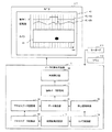
図1は、実施の形態1に係る産業プラントのプラント監視制御システムの構成を示す概略図である。
(System configuration)
FIG. 1 is a schematic diagram showing the configuration of a plant monitoring control system for an industrial plant according to the first embodiment.
データ収集再生装置1は、制御用ネットワーク5を介して、産業プラントを構成する機器群(アクチュエータやセンサを含む)に接続する入出力装置(I/O)3と、機器群を制御するプログラマブルロジックコントローラ(PLC)2と、オペレータが産業プラントの運転および監視に使用する監視制御装置であるヒューマンマシンインターフェース(HMI)4とに接続している。
The data collection/
制御用ネットワーク5は、コモンメモリを有するノードを複数有し、複数のノード間での周期的な同報伝送によりコモンメモリ上のプロセスデータを同期する。これにより、ノードA5aに接続するデータ収集再生装置1と、ノードB5bに接続するPLC2と、ノードC5cに接続する入出力装置3と、ノードD5dに接続するHMI4との間で仮想的に同一メモリ空間が共有される。コモンメモリには各データの記憶領域(アドレス)が割り付けられている。各ノードに接続された装置は、コモンメモリへの書き込みとコモンメモリからの読み込みとによってプロセスデータを送受信できる。
The
カメラ6は、撮影対象であるシート状物を撮影した静止画データを、画像用ネットワーク7を介してデータ収集再生装置1へ送信する。
The camera 6 transmits the still image data obtained by photographing the sheet-shaped object, which is a photographing target, to the data collection/
図2は、プラント監視制御システムの一部であるデータ収集再生システムの概念図である。 FIG. 2 is a conceptual diagram of a data collection and reproduction system which is a part of the plant monitoring control system.
カメラ6は、搬送されるシート状物8の一部を撮影範囲に含み、連続的に静止画を撮影する。好ましくは、カメラ6は、シート状物8を幅方向に亘り撮影するラインスキャンカメラである。ラインスキャンカメラは、1ラインの撮像素子の並ぶ方向がシート状物8の搬送方向と直交するように、シート状物8の上方に設置される。撮影タイミングはデータ収集再生装置1により制御される。ラインスキャンカメラは1スキャン毎に、撮影した静止画をデータ収集再生装置1へ送信する。また、PLC2は、サンプリングタイミング毎にプロセスデータをデータ収集再生装置1へ送信する。
The camera 6 includes a part of the conveyed sheet-
データ収集再生装置1は、カメラの撮影タイミングを、プロセスデータのサンプリングタイミングに合わせる。また、データ収集再生装置1は、各時刻の静止画を連結した帯状静止画と、各時刻のプロセスデータを表すグラフとを生成する。そして、データ収集再生装置1は、帯状静止画およびグラフを同期させて画面に表示する。帯状静止画によれば一目でシート状物8の黒ずみ9を検出しやすい。また、帯状静止画と同期したプロセスデータのグラフを参照することで、黒ずみ9の発生前後のプロセスデータの変化を確認でき、黒ずみ9の原因解析が容易となる。
The data collection/
(データ収集再生装置)
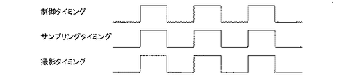
図3と図4を参照して、実施の形態1に係るデータ収集再生装置1の詳細機能について説明する。図3は、実施の形態1に係るデータ収集再生装置1の機能ブロック図である。図4は、制御タイミングと、サンプリングタイミングと、撮影タイミングについて説明するためのタイミングチャートである。
(Data collection and playback device)
Detailed functions of the data collection/
データ収集再生装置1は、制御周期決定部11、プロセスデータ収集部12、プロセスデータ記憶部13、カメラ制御部14、静止画記憶部15、データ結合部16、結合データ記憶部17、同期表示部18を備える。
The data collection/
制御周期決定部11は、図4に示す周期的な制御タイミングを決定する。制御タイミングは、データ収集再生装置1のハードウェアクロック又はシステムクロックに基づき管理される。後述するプロセスデータ収集部12およびカメラ制御部14は、この制御タイミングに従って動作する。制御周期は、例えば1ミリ秒〜数十ミリ秒である。
The control
プロセスデータ収集部12は、図4に示すように、決定された制御タイミングをサンプリングタイミングとし、周期的なサンプリングタイミングで、機器のプロセスデータを収集する。
As shown in FIG. 4, the process
プロセスデータ記憶部13は、サンプリングタイミング毎に収集されるプロセスデータにカウント値(時間情報)を関連付けて記憶する。カウント値は制御タイミング毎にインクリメントされる。なお、プロセスデータ記憶部13は、データ収集開始時刻を記憶しておくことで、カウント値に基づいて、各時刻を算出できる。
The process
カメラ制御部14は、図4に示すように、決定された制御タイミングを撮影タイミングとしてカメラ6を制御する。すなわち、カメラ制御部14は、カメラ6の周期的な撮影タイミングを、周期的なサンプリングタイミングに合わせる。カメラ6は、撮影タイミング毎に静止画を撮影し、データ収集再生装置1へ送信する。なお、撮影タイミングはプロセスデータのサンプリングタイミングと同期するのが好ましく、サンプリングタイミングより早い必要はない。
As shown in FIG. 4, the
静止画記憶部15は、カメラ6から静止画を受信しカウント値を関連付けて記憶する。カウント値は制御タイミング毎にインクリメントされる。なお、静止画記憶部15は、データ収集開始時刻を記憶しておくことで、カウント値に基づいて、各時刻を算出できる。
The still
データ結合部16は、プロセスデータ記憶部13に記憶されたプロセスデータと、静止画記憶部15に記憶された静止画とについて、同一のカウント値を有するプロセスデータと静止画とを関連付けた結合データを生成する。また、データ結合部16は、カメラ6に撮影された各時刻の静止画を連結した帯状静止画41を生成する。撮影した静止画が搬送方向に所定の幅を有し、隣り合う静止画の一部が重複する場合は、搬送速度に基づき重複部分を考慮して静止画を結合する。また、データ結合部16は、各時刻のプロセスデータを表すグラフ42(42a、42b)を生成する。グラフ42の横軸は時間、縦軸はデータ値とする。帯状静止画41は、撮影時刻順に連結した静止画であり、帯状静止画41の長さ方向をグラフの横軸(時間軸)と対応させて表示する。
The
結合データ記憶部17は、データ結合部16により生成された結合データ、帯状静止画41、グラフ42を記憶する。
The combined
同期表示部18は、同一カウント値で同期したプロセスデータのグラフ42と帯状静止画41とを結合した結合データを出力する。同期表示部18は、プロセスデータ収集部12により収集された各時刻のプロセスデータを表すグラフ42と、カメラ6により撮影された各時刻の静止画を連結した帯状静止画41と、を同期させて表示する。これらは、モニタ117の表示領域40に表示される。
The
以上説明したように、実施の形態1に係るデータ収集再生装置1によれば、カメラの撮影タイミングをプロセスデータのサンプリングタイミングに合わせるため、各時刻の静止画と各時刻のプロセスデータとを関連付けることができる。そのため、静止画から異常を発見した場合に、異常発生前後のプロセスデータを容易に絞り込むことができ、異常原因の解析を効率化できる。
As described above, according to the data collection/
また、各時刻の静止画を連結した帯状静止画41によれば、エリアスキャンカメラにより撮影した映像を再生するよりも広い範囲を一度に表示でき、シート状物8の異常(溶接、めっき開始、キズ、欠陥の部位)を発見しやすい。さらに、各時刻の静止画で構成される帯状静止画41はその長さ方向が時間方向を意味するため、グラフ42の時間軸と同期する。そのため、帯状静止画41を用いて異常を発見するとともに、異常が発生した前後の時刻のプロセスデータの変化もグラフ42から確認できる。そのため、産業プラントで生産される製品のキズや汚れなどの発生原因の特定、および異常発生の兆候を容易に把握でき、製品の品質向上に寄与することができる。また、オンライン中に早期に異常を発見できるため、その後の検査工程におけるコストを低減できる。
Further, according to the strip-shaped still
(ハードウェア構成例)
データ収集再生装置1のハードウェア構成について図5を参照して説明する。図5は、データ収集再生装置1が有する処理回路のハードウェア構成例を示すブロック図である。図3に示すデータ収集再生装置1の各部は、データ収集再生装置1が有する機能の一部を示し、各機能は処理回路により実現される。例えば、処理回路は、CPU111と、メモリ112と、HDDや大容量メモリ等のストレージ113と、外部機器I/F(インターフェース)部114と、制御用ネットワークI/F部115aと、画像用ネットワークI/F部115bとが、内部バス116を介して接続して構成されている。
(Example of hardware configuration)
The hardware configuration of the data collection/
CPU111は、ストレージ113のプログラム記憶部113aに記憶された各種アプリケーションプログラムを実行することにより、図4の各部の機能を実現する。
The CPU 111 realizes the functions of the respective units of FIG. 4 by executing various application programs stored in the
メモリ112は、CPU111が各種アプリケーションプログラムを実行する際にデータを一時記憶したり展開したりする演算エリアとして使用される。
The
ストレージ113は、プログラム記憶部113aと、データ記憶部113bとを有する。プログラム記憶部113aは、OS(オペレーティングシステム)や、各種アプリケーションプログラムを格納している。また、データ記憶部113bは、収集されたプロセスデータ、静止画データを記憶する。
The
なお、図5に示す例では、1つのストレージ113の中に、プログラム記憶部113aとデータ記憶部113bとを設けているが、複数のストレージにプログラム記憶部113aとデータ記憶部113bを分けて配置してもよい。
In the example shown in FIG. 5, the
外部機器I/F部114は、モニタ117、キーボード118、マウス119等の外部機器とデータ収集再生装置1とを接続するためのインターフェースである。
The external device I/
制御用ネットワークI/F部115aは、制御用ネットワーク5とデータ収集再生装置1を接続するためのインターフェースである。また、画像用ネットワークI/F部115bは、画像用ネットワーク7とデータ収集再生装置1を接続するためのインターフェースである。
The control network I/F unit 115a is an interface for connecting the
ところで、上述した実施の形態1のデータ収集再生装置1には、図5に示すモニタ117、キーボード118、マウス119を含めていないが、これらをデータ収集再生装置1に含めてもよい。なお、この点は以下の実施の形態でも同様である。
By the way, although the
実施の形態2.
次に、図6と図7を参照して実施の形態2について説明する。上述した実施の形態1のデータ収集再生システムによれば、プロセスデータのグラフと帯状静止画とを同期させて表示することができる。実施の形態2では、帯状静止画またはグラフ上で指定された位置をテーブルに記憶し、該テーブルから任意の位置が選択された場合に、該選択された位置が画面内に含まれるように帯状静止画およびグラフを表示する。これにより、帯状静止画およびグラフの表示範囲を、テーブルから選択された位置(時刻)にジャンプさせることができる。そのため、記憶した情報を即座に表示し直すことができる。
Next, a second embodiment will be described with reference to FIGS. 6 and 7. According to the data collection/reproduction system of the first embodiment described above, the process data graph and the strip-shaped still image can be displayed in synchronization with each other. In the second embodiment, the position specified on the strip-shaped still image or graph is stored in a table, and when an arbitrary position is selected from the table, the selected position is included in the screen. Display still images and graphs. Thereby, the display range of the strip-shaped still image and the graph can be jumped to the position (time) selected from the table. Therefore, the stored information can be immediately displayed again.
図6は、実施の形態2に係るデータ収集再生装置1の機能ブロック図である。図6に示すデータ収集再生装置1は、図3に示す構成に加えてマーカー処理部19を備える。
FIG. 6 is a functional block diagram of the data collection/
マーカー処理部19は、表示領域40上のオペレータに指定された位置(カーソル60)について、マーカーを付与する。図7は、マーカー情報格納テーブル70の一例である。図7の各行がマーカーを示す。マーカーは、図7に示す通りマーカー情報格納テーブル70へ格納され、マーカー番号71に対して、グラフ名72と時刻73とコメント74とを関連付けて記録する。時刻73には、カーソル60が指し示す時刻が入力される。
The marker processing unit 19 attaches a marker to the position (cursor 60) designated by the operator on the
次に動作について説明する。マーカー処理部19は、表示領域40内に表示されるカーソル60が示す位置(時刻)についてのマーカーをマーカー情報格納テーブル70へ記録する。マーカー情報格納テーブル70の情報は、テーブル表示領域61内に表示される。
Next, the operation will be described. The marker processing unit 19 records the marker at the position (time) indicated by the cursor 60 displayed in the
オペレータがキーボード又はマウスを操作し、マーカー情報格納テーブル70内の1つのマーカーを選択すると、選択されたマーカーのグラフ名72に基づき、グラフ42および帯状静止画41が表示領域40に表示される。このとき、時刻74に記録されている時刻にカーソル60が移動する。これによりマーカーで指定した時刻のグラフ42と帯状静止画41を容易に表示することができる。
When the operator operates the keyboard or mouse to select one marker in the marker information storage table 70, the graph 42 and the strip-shaped still
実施の形態2によれば、帯状静止画およびグラフの表示範囲を、テーブルから選択された位置(時刻)にジャンプさせることができる。そのため、記憶した情報を即座に表示し直すことができる。 According to the second embodiment, the display range of the strip-shaped still image and the graph can be jumped to the position (time) selected from the table. Therefore, the stored information can be immediately displayed again.
以上、本発明の実施の形態について説明したが、本発明は、上記の実施の形態に限定されるものではなく、本発明の趣旨を逸脱しない範囲で種々変形して実施することができる。 Although the embodiments of the present invention have been described above, the present invention is not limited to the above embodiments, and various modifications can be made without departing from the spirit of the present invention.
1 データ収集再生装置
2 PLC
3 入出力装置
4 HMI
5 制御用ネットワーク
6 カメラ
7 画像用ネットワーク
8 シート状物
9 黒ずみ
11 制御周期決定部
12 プロセスデータ収集部
13 プロセスデータ記憶部
14 カメラ制御部
15 静止画記憶部
16 データ結合部
17 結合データ記憶部
18 同期表示部
19 マーカー処理部
40 表示領域
41 帯状静止画
42 グラフ
60 カーソル
61 テーブル表示領域
70 マーカー情報格納テーブル
71 マーカー番号
72 グラフ名
73 時刻
74 コメント
111 CPU
112 メモリ
113,113a,113b ストレージ,プログラム記憶部,データ記憶部
114 外部機器I/F部
115a,115b 制御用ネットワークI/F部,画像用ネットワークI/F部
116 内部バス
117 モニタ
118 キーボード
119 マウス
1 Data collection/
3 I/O device 4 HMI
5 Control Network 6
112
Claims (4)
前記シート状物の一部を撮影範囲に含み、静止画を撮影するカメラと、
周期的なサンプリングタイミングで、前記機器のプロセスデータを収集するプロセスデータ収集部と、
前記カメラの周期的な撮影タイミングを、周期的な前記サンプリングタイミングに合わせるカメラ制御部と、
収集された前記プロセスデータを時間情報に関連付けて記憶するプロセスデータ記憶部と、
前記カメラにて撮影された静止画を前記時間情報に関連付けて記憶する静止画記憶部と、
前記時間情報に基づいて、前記プロセスデータ収集部により収集された各時刻のプロセスデータを表すグラフと、前記カメラにより撮影された各時刻の静止画を連結した帯状静止画と、を同期させて表示する同期表示部と、
を備えることを特徴とするデータ収集再生システム。 A data collection and reproduction system for an industrial plant, which is equipped with a device that acts on a conveyed sheet-like object,
A camera that includes a part of the sheet-like material in a shooting range and shoots a still image,
A process data collection unit that collects process data of the device at a periodic sampling timing,
A camera control unit that adjusts the periodic shooting timing of the camera to the periodic sampling timing;
A process data storage unit that stores the collected process data in association with time information;
A still image storage unit that stores a still image captured by the camera in association with the time information;
Based on the time information, a graph representing the process data at each time collected by the process data collecting unit and a strip-shaped still image obtained by connecting still images at each time captured by the camera are displayed in synchronization with each other. Synchronous display section,
A data collection/reproduction system comprising:
を特徴とする請求項1記載のデータ収集再生システム。 The camera is a line scan camera that captures the sheet-shaped object in the width direction,
The data collection/reproduction system according to claim 1.
前記機器は、前記ノードの1つに接続し、プロセスデータを送受信し、
前記プロセスデータ収集部は、前記ノードの1つに接続し、前記コモンメモリからサンプリングタイミング毎にプロセスデータを収集すること、
を特徴とする請求項1又は2記載のデータ収集再生システム。 The industrial plant has a plurality of nodes having a common memory, and includes a control network for synchronizing process data on the common memory by periodic broadcast transmission between the plurality of nodes,
The device connects to one of the nodes to send and receive process data,
The process data collection unit is connected to one of the nodes and collects process data from the common memory at each sampling timing;
The data collection and reproduction system according to claim 1 or 2.
を備えることを特徴とする請求項1乃至3のいずれか1項に記載のデータ収集再生システム。 The band-shaped still image or the position designated on the graph is stored in a table, and when the arbitrary position is selected from the table, the band-shaped still image and the band-shaped still image are included so that the selected position is included in the screen. A marker processing unit that displays the graph,
The data collection and reproduction system according to any one of claims 1 to 3, further comprising:
Priority Applications (3)
| Application Number | Priority Date | Filing Date | Title |
|---|---|---|---|
| JP2018241379A JP7020392B2 (en) | 2018-12-25 | 2018-12-25 | Data collection and playback system |
| TW108112490A TWI699638B (en) | 2018-12-25 | 2019-04-10 | Data collection and reproduction system |
| CN201910428688.6A CN111367240A (en) | 2018-12-25 | 2019-05-22 | Data collection and reproduction system |
Applications Claiming Priority (1)
| Application Number | Priority Date | Filing Date | Title |
|---|---|---|---|
| JP2018241379A JP7020392B2 (en) | 2018-12-25 | 2018-12-25 | Data collection and playback system |
Publications (2)
| Publication Number | Publication Date |
|---|---|
| JP2020102130A true JP2020102130A (en) | 2020-07-02 |
| JP7020392B2 JP7020392B2 (en) | 2022-02-16 |
Family
ID=71141292
Family Applications (1)
| Application Number | Title | Priority Date | Filing Date |
|---|---|---|---|
| JP2018241379A Active JP7020392B2 (en) | 2018-12-25 | 2018-12-25 | Data collection and playback system |
Country Status (3)
| Country | Link |
|---|---|
| JP (1) | JP7020392B2 (en) |
| CN (1) | CN111367240A (en) |
| TW (1) | TWI699638B (en) |
Cited By (1)
| Publication number | Priority date | Publication date | Assignee | Title |
|---|---|---|---|---|
| WO2023127748A1 (en) * | 2021-12-27 | 2023-07-06 | 株式会社ダイセル | Abnormality detection device, abnormality detection method, and abnormality detection program |
Families Citing this family (1)
| Publication number | Priority date | Publication date | Assignee | Title |
|---|---|---|---|---|
| EP4105748A1 (en) * | 2021-06-04 | 2022-12-21 | GE Aviation Systems LLC | Flight recorder system and method |
Citations (15)
| Publication number | Priority date | Publication date | Assignee | Title |
|---|---|---|---|---|
| JPH0579951A (en) * | 1991-09-18 | 1993-03-30 | Hitachi Ltd | Monitoring system |
| JP2001183302A (en) * | 1999-12-27 | 2001-07-06 | Sumitomo Metal Ind Ltd | Apparatus for inspecting surface of steel strip |
| JP2003157113A (en) * | 2002-12-02 | 2003-05-30 | Hitachi Ltd | System and method for displaying recording information |
| TW540315U (en) * | 2002-02-25 | 2003-07-01 | Jin-Tung Yu | Structure improvement of device for filling cigarette |
| JP2006308473A (en) * | 2005-04-28 | 2006-11-09 | Nippon Steel Corp | Method for inspecting periodic defect, and device |
| JP2011257967A (en) * | 2010-06-09 | 2011-12-22 | Hitachi Ltd | Rolling plant monitoring device, rolling plant monitoring system and rolling plant monitoring method |
| JP2012027834A (en) * | 2010-07-27 | 2012-02-09 | Hitachi Ltd | Production plant monitoring device and system, rolling plant monitoring device and system, production plant remote monitoring method, and rolling plant remote monitoring method |
| WO2012140715A1 (en) * | 2011-04-11 | 2012-10-18 | 東芝三菱電機産業システム株式会社 | Data synchronization and reproduction device, data synchronization and reproduction method, and data synchronization control program |
| WO2013136406A1 (en) * | 2012-03-12 | 2013-09-19 | 東芝三菱電機産業システム株式会社 | Synchronized data playback apparatus, synchronized data playback method, and data synchronization control program |
| WO2014002176A1 (en) * | 2012-06-26 | 2014-01-03 | 東芝三菱電機産業システム株式会社 | Data management device, data management method, and data management program |
| CN203499974U (en) * | 2013-09-18 | 2014-03-26 | 李庆明 | Coal mine air compressor set on-line monitoring system |
| WO2014112653A1 (en) * | 2013-01-16 | 2014-07-24 | 住友化学株式会社 | Image generation device, defect inspection device, and defect inspection method |
| JP2015114827A (en) * | 2013-12-11 | 2015-06-22 | 東芝三菱電機産業システム株式会社 | Data analysis device |
| US20170160733A1 (en) * | 2015-12-08 | 2017-06-08 | Sight Machine, Inc. | System and method for monitoring manufacturing |
| JP2018010430A (en) * | 2016-07-12 | 2018-01-18 | 富士電機株式会社 | Device and system for remotely monitoring control system |
Family Cites Families (13)
| Publication number | Priority date | Publication date | Assignee | Title |
|---|---|---|---|---|
| JP3986866B2 (en) * | 2002-03-29 | 2007-10-03 | 松下電器産業株式会社 | Image processing apparatus and ultrasonic diagnostic apparatus |
| JP2007536634A (en) * | 2004-05-04 | 2007-12-13 | フィッシャー−ローズマウント・システムズ・インコーポレーテッド | Service-oriented architecture for process control systems |
| US20060129257A1 (en) * | 2004-12-13 | 2006-06-15 | Taiwan Semiconductor Manufacturing Co., Ltd. | Novel method and apparatus for integrating fault detection and real-time virtual metrology in an advanced process control framework |
| US20060143244A1 (en) * | 2004-12-28 | 2006-06-29 | Taiwan Semiconductor Manufacturing Co., Ltd. | Semiconductor data archiving management systems and methods |
| US8229587B2 (en) * | 2008-02-22 | 2012-07-24 | Muratec Automation Co., Ltd. | Semiconductor fabrication facility visualization system with performance optimization |
| US8623672B2 (en) * | 2010-02-19 | 2014-01-07 | Applied Materials, Inc. | Prediction and scheduling server |
| JP5897273B2 (en) * | 2010-07-22 | 2016-03-30 | 株式会社東芝 | Medical image display apparatus and X-ray computed tomography apparatus |
| TW201204482A (en) * | 2010-07-30 | 2012-02-01 | China Steel Corp | Method for detecting abnormal rolling at tail end of steel strip |
| JP2013033375A (en) * | 2011-08-02 | 2013-02-14 | Sony Corp | Information processing apparatus, information processing method, and program |
| US8607169B2 (en) * | 2011-12-28 | 2013-12-10 | Elitetech Technology Co., Ltd. | Intelligent defect diagnosis method |
| KR101461364B1 (en) * | 2012-06-26 | 2014-11-13 | 도시바 미쓰비시덴키 산교시스템 가부시키가이샤 | Data collection device and recording medium for data collection program |
| WO2014027354A1 (en) * | 2012-08-15 | 2014-02-20 | Nova Measuring Instruments Ltd. | Optical metrology for in-situ measurements |
| TWM540315U (en) * | 2016-12-23 | 2017-04-21 | Synpower Co Ltd | Process parameter monitoring system |
-
2018
- 2018-12-25 JP JP2018241379A patent/JP7020392B2/en active Active
-
2019
- 2019-04-10 TW TW108112490A patent/TWI699638B/en active
- 2019-05-22 CN CN201910428688.6A patent/CN111367240A/en active Pending
Patent Citations (15)
| Publication number | Priority date | Publication date | Assignee | Title |
|---|---|---|---|---|
| JPH0579951A (en) * | 1991-09-18 | 1993-03-30 | Hitachi Ltd | Monitoring system |
| JP2001183302A (en) * | 1999-12-27 | 2001-07-06 | Sumitomo Metal Ind Ltd | Apparatus for inspecting surface of steel strip |
| TW540315U (en) * | 2002-02-25 | 2003-07-01 | Jin-Tung Yu | Structure improvement of device for filling cigarette |
| JP2003157113A (en) * | 2002-12-02 | 2003-05-30 | Hitachi Ltd | System and method for displaying recording information |
| JP2006308473A (en) * | 2005-04-28 | 2006-11-09 | Nippon Steel Corp | Method for inspecting periodic defect, and device |
| JP2011257967A (en) * | 2010-06-09 | 2011-12-22 | Hitachi Ltd | Rolling plant monitoring device, rolling plant monitoring system and rolling plant monitoring method |
| JP2012027834A (en) * | 2010-07-27 | 2012-02-09 | Hitachi Ltd | Production plant monitoring device and system, rolling plant monitoring device and system, production plant remote monitoring method, and rolling plant remote monitoring method |
| WO2012140715A1 (en) * | 2011-04-11 | 2012-10-18 | 東芝三菱電機産業システム株式会社 | Data synchronization and reproduction device, data synchronization and reproduction method, and data synchronization control program |
| WO2013136406A1 (en) * | 2012-03-12 | 2013-09-19 | 東芝三菱電機産業システム株式会社 | Synchronized data playback apparatus, synchronized data playback method, and data synchronization control program |
| WO2014002176A1 (en) * | 2012-06-26 | 2014-01-03 | 東芝三菱電機産業システム株式会社 | Data management device, data management method, and data management program |
| WO2014112653A1 (en) * | 2013-01-16 | 2014-07-24 | 住友化学株式会社 | Image generation device, defect inspection device, and defect inspection method |
| CN203499974U (en) * | 2013-09-18 | 2014-03-26 | 李庆明 | Coal mine air compressor set on-line monitoring system |
| JP2015114827A (en) * | 2013-12-11 | 2015-06-22 | 東芝三菱電機産業システム株式会社 | Data analysis device |
| US20170160733A1 (en) * | 2015-12-08 | 2017-06-08 | Sight Machine, Inc. | System and method for monitoring manufacturing |
| JP2018010430A (en) * | 2016-07-12 | 2018-01-18 | 富士電機株式会社 | Device and system for remotely monitoring control system |
Cited By (1)
| Publication number | Priority date | Publication date | Assignee | Title |
|---|---|---|---|---|
| WO2023127748A1 (en) * | 2021-12-27 | 2023-07-06 | 株式会社ダイセル | Abnormality detection device, abnormality detection method, and abnormality detection program |
Also Published As
| Publication number | Publication date |
|---|---|
| CN111367240A (en) | 2020-07-03 |
| JP7020392B2 (en) | 2022-02-16 |
| TWI699638B (en) | 2020-07-21 |
| TW202024828A (en) | 2020-07-01 |
Similar Documents
| Publication | Publication Date | Title |
|---|---|---|
| JP6190003B2 (en) | Distributed vision system with multi-phase synchronization | |
| JP6171908B2 (en) | Data analysis device | |
| JP7020392B2 (en) | Data collection and playback system | |
| EP3482267B1 (en) | System and method for diagnosing automation systems | |
| JP2020202449A (en) | Control apparatus | |
| WO2021019821A1 (en) | Information management system and information management method | |
| JPH11331766A (en) | Equipment logging device | |
| JP2000047707A (en) | Information managing device and its control method | |
| JP2016532099A (en) | Synchronize imaging | |
| JP3554128B2 (en) | Recording information display system and recording information display method | |
| JP2001268509A (en) | Image recording device and system | |
| JP2015219909A (en) | Method and apparatus for sequencing metadata events | |
| Hurd et al. | Quality assurance in additive manufacturing through mobile computing | |
| JP6849150B2 (en) | Industrial plant monitoring and control system | |
| JP2020198037A (en) | Control device | |
| JP7221463B1 (en) | Control system and programmable logic controller | |
| WO2022239123A1 (en) | Production line monitoring device, production line monitoring system, and production line monitoring method | |
| JP2015055990A (en) | Line monitoring system | |
| JP6856168B2 (en) | Abnormal sound detection device and abnormal sound detection method | |
| US11790508B2 (en) | Computer vision predictions for non-destructive testing | |
| TW201925940A (en) | Data reproducing apparatus for industrial plant | |
| JP2020204798A (en) | Data collection device | |
| JP2006172350A (en) | Image recording system and recorded image displaying method | |
| JP2020117829A (en) | Image processing apparatus |
Legal Events
| Date | Code | Title | Description |
|---|---|---|---|
| A621 | Written request for application examination |
Free format text: JAPANESE INTERMEDIATE CODE: A621 Effective date: 20210218 |
|
| A977 | Report on retrieval |
Free format text: JAPANESE INTERMEDIATE CODE: A971007 Effective date: 20211217 |
|
| TRDD | Decision of grant or rejection written | ||
| A01 | Written decision to grant a patent or to grant a registration (utility model) |
Free format text: JAPANESE INTERMEDIATE CODE: A01 Effective date: 20220104 |
|
| A61 | First payment of annual fees (during grant procedure) |
Free format text: JAPANESE INTERMEDIATE CODE: A61 Effective date: 20220117 |
|
| R150 | Certificate of patent or registration of utility model |
Ref document number: 7020392 Country of ref document: JP Free format text: JAPANESE INTERMEDIATE CODE: R150 |