JP2020100338A - Wiper structure for resin glass and wiper rubber - Google Patents
Wiper structure for resin glass and wiper rubber Download PDFInfo
- Publication number
- JP2020100338A JP2020100338A JP2018240946A JP2018240946A JP2020100338A JP 2020100338 A JP2020100338 A JP 2020100338A JP 2018240946 A JP2018240946 A JP 2018240946A JP 2018240946 A JP2018240946 A JP 2018240946A JP 2020100338 A JP2020100338 A JP 2020100338A
- Authority
- JP
- Japan
- Prior art keywords
- wiper
- resin glass
- lip
- end side
- glass
- Prior art date
- Legal status (The legal status is an assumption and is not a legal conclusion. Google has not performed a legal analysis and makes no representation as to the accuracy of the status listed.)
- Pending
Links
Images


Classifications
-
- B—PERFORMING OPERATIONS; TRANSPORTING
- B60—VEHICLES IN GENERAL
- B60S—SERVICING, CLEANING, REPAIRING, SUPPORTING, LIFTING, OR MANOEUVRING OF VEHICLES, NOT OTHERWISE PROVIDED FOR
- B60S1/00—Cleaning of vehicles
- B60S1/02—Cleaning windscreens, windows or optical devices
- B60S1/04—Wipers or the like, e.g. scrapers
- B60S1/32—Wipers or the like, e.g. scrapers characterised by constructional features of wiper blade arms or blades
- B60S1/38—Wiper blades
- B60S1/3801—Wiper blades characterised by a blade support harness consisting of several articulated elements
-
- B—PERFORMING OPERATIONS; TRANSPORTING
- B60—VEHICLES IN GENERAL
- B60S—SERVICING, CLEANING, REPAIRING, SUPPORTING, LIFTING, OR MANOEUVRING OF VEHICLES, NOT OTHERWISE PROVIDED FOR
- B60S1/00—Cleaning of vehicles
- B60S1/02—Cleaning windscreens, windows or optical devices
- B60S1/56—Cleaning windscreens, windows or optical devices specially adapted for cleaning other parts or devices than front windows or windscreens
- B60S1/58—Cleaning windscreens, windows or optical devices specially adapted for cleaning other parts or devices than front windows or windscreens for rear windows
- B60S1/583—Cleaning windscreens, windows or optical devices specially adapted for cleaning other parts or devices than front windows or windscreens for rear windows including wiping devices
-
- B—PERFORMING OPERATIONS; TRANSPORTING
- B60—VEHICLES IN GENERAL
- B60S—SERVICING, CLEANING, REPAIRING, SUPPORTING, LIFTING, OR MANOEUVRING OF VEHICLES, NOT OTHERWISE PROVIDED FOR
- B60S1/00—Cleaning of vehicles
- B60S1/02—Cleaning windscreens, windows or optical devices
- B60S1/04—Wipers or the like, e.g. scrapers
- B60S1/32—Wipers or the like, e.g. scrapers characterised by constructional features of wiper blade arms or blades
- B60S1/38—Wiper blades
- B60S2001/3812—Means of supporting or holding the squeegee or blade rubber
- B60S2001/3817—Means of supporting or holding the squeegee or blade rubber chacterised by a backing strip to aid mounting of squeegee in support
-
- B—PERFORMING OPERATIONS; TRANSPORTING
- B60—VEHICLES IN GENERAL
- B60S—SERVICING, CLEANING, REPAIRING, SUPPORTING, LIFTING, OR MANOEUVRING OF VEHICLES, NOT OTHERWISE PROVIDED FOR
- B60S1/00—Cleaning of vehicles
- B60S1/02—Cleaning windscreens, windows or optical devices
- B60S1/04—Wipers or the like, e.g. scrapers
- B60S1/32—Wipers or the like, e.g. scrapers characterised by constructional features of wiper blade arms or blades
- B60S1/38—Wiper blades
- B60S2001/3827—Wiper blades characterised by the squeegee or blade rubber or wiping element
- B60S2001/3836—Wiper blades characterised by the squeegee or blade rubber or wiping element characterised by cross-sectional shape
Landscapes
- Engineering & Computer Science (AREA)
- Mechanical Engineering (AREA)
- Window Of Vehicle (AREA)
- Ink Jet (AREA)
Abstract
Description
本発明は、樹脂ガラス用ワイパ構造及びワイパラバーに関する。 The present invention relates to a wiper structure for resin glass and a wiper bar.
車両には、リアウィンドガラスにワイパを有するものがある。そして近年の車両には、リアウィンドガラスに、無機ガラスではなく樹脂ガラスを用いている車両がある。なお、ワイパは、長尺状のゴム等の弾性体のワイパラバーを、ガラスに押圧しながらガラス表面に沿って往復揺動させて、ガラス表面の雨水や汚れ等を払拭している。 Some vehicles have a wiper on the rear windshield. In recent years, some vehicles use resin glass instead of inorganic glass for the rear window glass. The wiper wipes away rainwater, dirt, and the like on the glass surface by swinging a long elastic wiper bar such as rubber back and forth along the glass surface while pressing it against the glass.
ワイパを比較的長期間、作動させなかった場合、ワイパラバー表面及びガラス表面には、砂埃等の微細なダストが溜まり易い。このダストが溜まっている状態でワイパを作動させると、当該ダストがワイパラバーによってガラスに押し付けられ(こすりつけられ)、ガラス表面を傷つけてしまう場合がある。なお、ガラスが無機ガラスの場合では、樹脂ガラスと比較して、表面硬度が高く、かつ、ワイパ動作時における動摩擦係数が小さくワイパラバーが無機ガラス表面を軽く滑るので、表面に目立つ傷が付きにくい。しかし、ガラスが樹脂ガラスの場合では、無機ガラスと比較して、表面硬度が低く、かつ、ワイパ動作時における動摩擦係数が大きくワイパラバーが無機ガラスほど軽く滑らないので、表面に目立つ傷(ダストによる傷)が付き易い。このため、傷付きにくい樹脂ガラス用ワイパ構造、ワイパラバーが望まれている。 If the wiper is not operated for a relatively long period of time, fine dust such as sand is likely to accumulate on the surface of the wiper bar and the glass surface. If the wiper is operated while the dust is accumulated, the dust may be pressed (rubbed) by the wiper bar to damage the glass surface. When the glass is inorganic glass, the surface hardness is higher than that of resin glass, and the coefficient of dynamic friction during wiper operation is small, and the wiper bar slides on the surface of the inorganic glass lightly, so that the surface is less likely to be scratched. However, when the glass is resin glass, the surface hardness is lower than that of inorganic glass, and the dynamic friction coefficient during wiper operation is large, and the wiper bar does not slide lightly as much as inorganic glass, so scratches that are noticeable on the surface (scratches due to dust) ) Is easy to attach. For this reason, a wiper structure and a wiper bar for resin glass that are not easily scratched are desired.
例えば特許文献1には、生成されたワイパブレードモデルに対してワイパブレード(ワイパラバーに相当)の滑り解析を行い、特性値が最適条件を満たすときの設計パラメータの値を求めて設計する、ワイパブレードの設計方法及びワイパブレードが開示されている。その結果、ワイパブレードにおけるネック部の厚さに対するネック部の高さの比率(ネック高さ/ネック厚さ)を、2.7〜3.7の範囲に設定し、ワイパブレードの先端部(リップ部)の厚さに対する先端部の高さの比率(リップ高さ/リップ厚さ)を、2.9〜3.6の範囲に設定すると、特性値が最適条件を満たす、としている。
For example, in
また特許文献2には、略水平姿勢となったワイパの作動停止時におけるリップ部の上方近傍部分に、ワイパの作動時にリップ部が乗り越え可能な突出高さを有する突条部が一体的に形成された、車両用ウィンドガラス(樹脂ガラス)が開示されている。
Further, in
また特許文献3には、ワイパブレード(ワイパラバーに相当)のリップ部の長さを、ワイパの揺動軸から最も離れた先端部で最も短くなるように設定し、ワイパの揺動軸に近づくに従って徐々に長くする、車両用ワイパ装置が開示されている。
Further, in
特許文献1に記載のワイパブレードの設計方法及びワイパブレードは、無機ガラスを対象としており、樹脂ガラスについて記載も示唆も見受けられない。ワイパブレード(ワイパラバーに相当)のリップ部の形状比率(リップ高さ/リップ厚さ)を2.9〜3.6の範囲に設定した場合、ガラスが樹脂ガラスの場合では、目立つ傷が付く場合がある。
The wiper blade designing method and the wiper blade described in
また特許文献2に記載の車両用ウィンドガラスでは、樹脂ガラスを対象としており、ワイパブレード表面に溜まっているダストを、ワイパ動作開始時に、突条部を乗り越えさせたワイパブレードによって飛散させている。これにより、突条部を乗り越えた先の樹脂ガラス表面領域において、樹脂ガラス表面がダストで傷付くことを抑制できる。しかし、ワイパ停止位置から突条部までの領域では、ダストを保持しているので樹脂ガラス表面に目立つ傷が付く場合がある。また、ダストを飛散させる方向には、ワイパの払拭領域が含まれているので、飛散させたダストが払拭領域内に留まっていた場合、樹脂ガラス表面に目立つ傷が付く可能性がある。
Further, the vehicle window glass described in
また特許文献3に記載の車両用ワイパ装置では、無機ガラスを対象としており、樹脂ガラスについて記載も示唆も見受けられない。そして、ワイパ揺動軸に近い側では、遠い側よりもワイパブレードのリップ部の長さを長く、ワイパ揺動軸から遠い側では、近い側よりもワイパブレードのリップ部の長さを短くしている。しかし、ガラスが樹脂ガラスの場合、リップ部の長さを具体的な適切な長さに設定しなければ、樹脂ガラス表面に目立つ傷が付く可能性がある。
In addition, the vehicle wiper device described in
本発明は、このような点に鑑みて創案されたものであり、樹脂ガラスと、当該樹脂ガラスの表面の一部を払拭するワイパとを有する樹脂ガラス用ワイパ構造、及びワイパラバーにおいて、樹脂ガラスの表面に目立つ傷が付くことをより抑制することができる、樹脂ガラス用ワイパ構造及びワイパラバーを提供することを課題とする。 The present invention was devised in view of such a point, a resin glass, a wiper structure for resin glass having a wiper for wiping a part of the surface of the resin glass, and a wiper bar, in the resin glass An object of the present invention is to provide a wiper structure for resin glass and a wiper bar, which can further prevent the surface from being markedly scratched.
上記課題を解決するため、本発明の第1の発明は、表面にコーティング層が形成された樹脂ガラスと、当該樹脂ガラスの一部の表面を払拭するワイパと、を有する樹脂ガラス用ワイパ構造において、前記ワイパは、前記樹脂ガラスに接触するように保持された弾性体のワイパラバーと、前記ワイパラバーを保持するワイパホルダと、前記ワイパラバーを保持した前記ワイパホルダを前記樹脂ガラスに向けて押圧しながら前記樹脂ガラスの表面に沿って往復揺動させるワイパアームと、を有しており、前記ワイパラバーは、前記ワイパラバーの長手方向に直交する断面形状において、前記ワイパホルダに保持される保持基部と、前記樹脂ガラスの表面に沿う方向のラバー厚さがリップ厚さに設定されて、前記樹脂ガラスの表面に向かう方向のラバー長さがリップ長さに設定されて、一方端の側が前記樹脂ガラスに接触するリップ部と、一方端の側が前記リップ部の他方端の側に接続されて、他方端の側に向かって前記ラバー厚さが厚くなる胴体部と、前記ラバー厚さがネック厚さに設定されて、前記ラバー長さがネック長さに設定されて、一方端の側が前記胴体部の他方端の側に接続され、他方端の側が前記保持基部の一方端の側に接続されるネック部と、を有しており、前記ネック厚さは、前記胴体部の他方端の側の前記ラバー厚さ、及び前記保持基部の一方端の側の前記ラバー厚さ、と比較して薄く設定されており、前記リップ厚さに対する前記リップ長さの比率が、0より大きく、かつ、2.3以下に設定されている、樹脂ガラス用ワイパ構造である。 In order to solve the above-mentioned problems, a first invention of the present invention is a resin glass wiper structure including: a resin glass having a coating layer formed on a surface thereof; and a wiper for wiping a part of the surface of the resin glass. The wiper is an elastic wiper bar held in contact with the resin glass, a wiper holder holding the wiper bar, and the resin glass while pressing the wiper holder holding the wiper bar toward the resin glass. And a wiper arm that reciprocally swings along the surface of the wiper bar, wherein the wiper bar has a cross-sectional shape orthogonal to the longitudinal direction of the wiper bar, a holding base part held by the wiper holder, and a surface of the resin glass. The rubber thickness along the direction is set to the lip thickness, the rubber length in the direction toward the surface of the resin glass is set to the lip length, and a lip portion whose one end side is in contact with the resin glass, A body portion in which one end side is connected to the other end side of the lip portion and the rubber thickness increases toward the other end side, and the rubber thickness is set to a neck thickness, The length is set to the neck length, one end side is connected to the other end side of the body portion, the other end side is connected to the one end side of the holding base, The neck thickness is set to be thinner than the rubber thickness on the other end side of the body portion and the rubber thickness on the one end side of the holding base portion. In the resin glass wiper structure, the ratio of the lip length to the thickness is set to be larger than 0 and 2.3 or less.
次に、本発明の第2の発明は、上記第1の発明に係る樹脂ガラス用ワイパ構造であって、前記コーティング層の動摩擦係数が、0.3〜0.6の範囲とされている、樹脂ガラス用ワイパ構造である。 Next, a second invention of the present invention is the wiper structure for resin glass according to the first invention, wherein the coating layer has a dynamic friction coefficient of 0.3 to 0.6. It is a wiper structure for resin glass.
次に、本発明の第3の発明は、表面にコーティング層が形成された樹脂ガラスの一部の表面を払拭するワイパに用いられ、ワイパアームに支持されたワイパホルダに保持されて前記樹脂ガラスに向けて押圧されながら前記樹脂ガラスの表面に沿って往復揺動されるワイパラバーにおいて、前記ワイパラバーは、長手方向に直交する断面形状において、前記ワイパホルダに保持される保持基部と、前記樹脂ガラスの表面に沿う方向のラバー厚さがリップ厚さに設定されて、前記樹脂ガラスの表面に向かう方向のラバー長さがリップ長さに設定されて、一方端の側が前記樹脂ガラスに接触するリップ部と、一方端の側が前記リップ部の他方端の側に接続されて、他方端の側に向かって前記ラバー厚さが厚くなる胴体部と、前記ラバー厚さがネック厚さに設定されて、前記ラバー長さがネック長さに設定されて、一方端の側が前記胴体部の他方端の側に接続され、他方端の側が前記保持基部の一方端の側に接続されるネック部と、を有しており、前記リップ厚さに対する前記リップ長さの比率が、0より大きく、かつ、2.3以下に設定されている、ワイパラバーである。 Next, a third invention of the present invention is used for a wiper for wiping a part of the surface of resin glass having a coating layer formed thereon, and is held by a wiper holder supported by a wiper arm and directed toward the resin glass. In a wiper bar that is reciprocally rocked along the surface of the resin glass while being pressed by, the wiper bar has a holding base portion held by the wiper holder and a surface of the resin glass in a cross-sectional shape orthogonal to the longitudinal direction. The rubber thickness in the direction is set to the lip thickness, the rubber length in the direction toward the surface of the resin glass is set to the lip length, and one end side is a lip portion in contact with the resin glass, A body part whose end side is connected to the other end side of the lip part and the rubber thickness increases toward the other end side, and the rubber thickness is set to the neck thickness, and the rubber length is set. Is set to the neck length, one end side is connected to the other end side of the body portion, the other end side is connected to the one end side of the holding base portion, and a neck portion, And the ratio of the lip length to the lip thickness is greater than 0 and is set to 2.3 or less.
第1の発明では、ワイパラバーの長手方向に直交する断面形状において、リップ厚さに対するリップ長さの比率が、0より大きく、かつ、2.3以下に設定されていることで、リップ部の長さが具体的な適切な長さに設定されている。これにより、ワイパ動作時の払拭方向においてリップ部が樹脂ガラス表面に接触している個所の長さ(接触幅)を適切な短い長さに設定し、リップ部によってダストを樹脂ガラス表面に押し付ける(こすりつける)期間及び距離が短くなるので、樹脂ガラスの表面に目立つ傷が付くことをより抑制することができる。 In the first aspect of the invention, in the cross-sectional shape orthogonal to the longitudinal direction of the wiper bar, the ratio of the lip length to the lip thickness is set to be larger than 0 and 2.3 or less, so that the length of the lip portion is Is set to a specific appropriate length. Thereby, the length (contact width) of the portion where the lip portion is in contact with the resin glass surface in the wiping direction during wiper operation is set to an appropriate short length, and dust is pressed against the resin glass surface by the lip portion ( Since the rubbing period and the distance are shortened, it is possible to further prevent the surface of the resin glass from being markedly scratched.
第2の発明では、無機ガラスの動摩擦係数(約0.1前後)に対して、動摩擦係数が大きな(0.3〜0.6)樹脂ガラスにおいて、リップ厚さに対するリップ長さの比率が適切な値に設定されるので、樹脂ガラスの表面に目立つ傷が付くことをより抑制することができる、樹脂ガラス用ワイパ構造を提供することができる。 In the second invention, the ratio of the lip length to the lip thickness is appropriate in the resin glass having a large dynamic friction coefficient (0.3 to 0.6) with respect to the dynamic friction coefficient (about 0.1) of the inorganic glass. Since it is set to such a value, it is possible to provide a wiper structure for resin glass, which can further prevent the surface of the resin glass from being significantly scratched.
第3の発明では、ワイパラバーの長手方向に直交する断面形状において、リップ厚さに対するリップ長さの比率が、0より大きく、かつ、2.3以下に設定されていることで、リップ部の長さが具体的な適切な長さに設定されている。これにより、ワイパ動作時の払拭方向においてリップ部が樹脂ガラス表面に接触している個所の長さ(接触幅)を適切な短い長さに設定し、リップ部によってダストを樹脂ガラス表面に押し付ける(こすりつける)期間及び距離が短くなるので、樹脂ガラスの表面に目立つ傷が付くことをより抑制することができる。 In the third invention, in the cross-sectional shape orthogonal to the longitudinal direction of the wiper bar, the ratio of the lip length to the lip thickness is set to be larger than 0 and 2.3 or less, so that the length of the lip portion is Is set to a specific appropriate length. Thereby, the length (contact width) of the portion where the lip portion is in contact with the resin glass surface in the wiping direction during wiper operation is set to an appropriate short length, and dust is pressed against the resin glass surface by the lip portion ( Since the rubbing period and the distance are shortened, it is possible to further prevent the surface of the resin glass from being markedly scratched.
●[車両のリアウィンドガラス(樹脂ガラス10)とワイパ20の配置例等(図1〜図4)]
以下に本明細書の開示技術である、樹脂ガラス用ワイパ構造及びワイパラバー、を実施するための形態を図面を用いて説明する。まず図1を用いて、車両1のリアウィンドガラス(以下、樹脂ガラス10と記載する)とワイパ20の配置等について説明する。図1の例に示す車両1のリアウィンドガラスは樹脂製の樹脂ガラス10であり、当該樹脂ガラス10に対して、ワイパ20が配置されている。
● [Vehicle rear window glass (resin glass 10) and
Hereinafter, modes for carrying out the wiper structure for resin glass and the wiper bar, which are the techniques disclosed in the present specification, will be described with reference to the drawings. First, the arrangement of the rear window glass (hereinafter referred to as resin glass 10) and the
ワイパ20は、図2に示すように、(実線にて示す)ワイパ停止位置においてワイパラバー23(図3参照)が略水平方向に保持されている。ワイパ20の動作時には、ワイパ20は、ワイパ揺動軸20J回りに、角度φにて往復揺動し、樹脂ガラス10の一部の表面を払拭する。
As shown in FIG. 2, the
ワイパ20は、図3に示すように、ワイパラバー23、ワイパホルダ22、ワイパアーム21等を有している。また図4は、図3におけるIV−IV断面図であり、説明のため、ワイパラバー23を樹脂ガラス10の側に押し付ける押圧力Fzがゼロ、ワイパラバー23を樹脂ガラス10の表面に沿って移動させる移動速度V1がゼロ、の状態の例を示している。
As shown in FIG. 3, the
ワイパラバー23(ワイパブレードともいう)は、樹脂ガラス10に接触するように保持された弾性体である。なお、ワイパラバー23におけるプレート差込溝23H1(図5参照)には、例えば金属製のプレート24(図4参照)が差し込まれている。ワイパホルダ22は、図4に示すように、ワイパラバー23が樹脂ガラス10に接触するようにワイパラバー23を保持する。ワイパアーム21は、図3に示すように、ワイパホルダ22を支持し、支持したワイパホルダ22を樹脂ガラス10の側に所定の押圧力Fzにて押し付けている。そしてワイパアーム21は、ワイパ動作時には、ワイパラバー23を保持したワイパホルダ22を、樹脂ガラス10に向けて押圧しながら樹脂ガラス10の表面に沿って往復揺動させる。
The wiper bar 23 (also referred to as a wiper blade) is an elastic body held in contact with the
図2に示すように、例えばワイパ20が角速度ω1で揺動し、ワイパ揺動軸20Jからワイパ20の先端部までの距離を距離N1とした場合、ワイパ20における最も大きな移動速度は、ワイパ20の先端部の移動速度V1であり、V1=ω1*N1にて表される。例えば、図2において、ワイパ動作時の角度φは約90[°]、ワイパ動作時の角速度ω1は約90[°]/1[sec]、距離N1は約50[cm]である。また、ワイパラバー23の面圧(押圧力Fzに相当)は、約5〜40[N/m]にてガラス面に押圧される。
As shown in FIG. 2, for example, when the
また樹脂ガラス10は、図4に示すように、樹脂基部10Aとコーティング層10Bとを有している。コーティング層10Bは、樹脂ガラス10におけるワイパ20の側の表面に形成されており、主に表面硬度を向上させる目的にて、例えば、化学蒸着法(CVD法)にて形成されている。例えばプラズマCVD法により得られるSiOx膜は、原材料(原料ともいう)である珪素化合物、分解ガスである酸素、分解温度、投入電などの条件を選ぶことで、様々な特性を備えることができる。
The
ワイパ20を比較的長期間、使用しなかった場合、樹脂ガラス10の表面、及びワイパラバー23(図3参照)の表面には、砂埃等のダストが溜まっている場合がある。このようなダストが溜まっている状態でワイパ20を動作させると、図2に示すように、ワイパ20の先端部近傍の揺動軌跡に沿って、樹脂ガラス10の表面に、目立つ傷K1が付く場合がある。
When the
●[ワイパラバー23の概略形状と構造等(図5)]
次に、ワイパラバー23の概略形状と構造等について説明する。図5に示すワイパラバー23の正面形状は、ワイパラバー23の長手方向に直交する断面形状である。ワイパラバー23は、樹脂ガラス10に近い側から順に(図4参照)、リップ部23A、胴体部23D、ネック部23E、保持基部23J等を有している。なお、ワイパラバー23の材質は、例えば、天然ゴム、または天然ゴムとクロロブレンゴムをブレンドしたものである。なお、以下の説明において、「一方端の側」は、図4における樹脂ガラス10に近い側であり、「他方端の側」は、図4における樹脂ガラス10から遠い側である。
● [Schematic shape and structure of the wiper bar 23 (Fig. 5)]
Next, the general shape and structure of the
リップ部23Aは、図5に示すように、ワイパラバー23の長手方向に直交する断面形状において、樹脂ガラス10の表面に沿う方向(X軸方向であり、図4参照)のラバー厚さがリップ厚さWに設定されている。またリップ部23Aは、樹脂ガラス10の表面に向かう方向(Z軸方向に対して反対の方向であり、図4参照)のラバー長さがリップ長さLに設定されて、一方端の側が樹脂ガラス10に接触する(図4参照)。また、本実施の形態にて説明するワイパラバー23は、リップ長さLに亘って一定のリップ厚さWが設定され、リップ厚さWに対するリップ長さLの比率(L/W)が、0より大きく、かつ、2.3以下に設定されており、本実施の形態の説明では、リップ長さL/リップ厚さW≒1.7に設定した場合の例を図示している。なお、この範囲に設定する根拠については後述する。
As shown in FIG. 5, in the
胴体部23Dは、図5に示すように、リップ部23Aに近い側から、胴体下部23Bと胴体上部23Cとを有している。ワイパラバー23の長手方向に直交する断面形状において、胴体部23Dの一方端の側は、リップ部23Aの他方端の側に接続され、胴体部23Dの他方端の側は、ネック部23Eの一方端の側に接続されている。胴体下部23Bは、他方端の側に向かってラバー厚さが厚くなるよう、テーパ状に形成されており、リップ部23Aの他方端の側に接続されている胴体部23Dのラバー厚さは、リップ部23Aのラバー厚さ(リップ厚さW)と、ほぼ同じとされている。胴体上部23Cのラバー厚さは、胴体下部23Bのラバー厚さよりも厚く設定されている。
As shown in FIG. 5, the
ネック部23Eは、図5に示すように、ワイパラバー23の長手方向に直交する断面形状において、前記ラバー厚さがネック厚さWNに設定されて、前記ラバー長さがネック長さLNに設定されている。またネック厚さWNは、胴体部23Dの他方端の側の前記ラバー厚さと比較して薄く設定され、保持基部23Jの一方端の側の前記ラバー厚さと比較して薄く設定されている。そしてネック部23Eの一方端の側は、胴体部23Dの他方端の側に接続され、ネック部23Eの他方端の側は、保持基部23Jの一方端の側に接続されている。
As shown in FIG. 5, in the
保持基部23Jは、図5に示すように、ワイパラバー23の長手方向に直交する断面形状において、リップ部23Aに近い側から、底部23F、連結部23G、頭部23Hを有している。底部23Fの前記ラバー厚さは、胴体上部23Cの前記ラバー厚さよりも厚くなるように設定されている。底部23Fと頭部23Hとの間となる連結部23Gは、ワイパラバー23の長手方向に延びるホルダ挿通溝23G1を形成しており、当該ホルダ挿通溝23G1には、図4に示すように、ワイパホルダ22の先端部が挿通される。頭部23Hには、ワイパラバー23の長手方向に沿って延びるプレート差込溝23H1が形成されており、当該プレート差込溝23H1には、図4に示すように、金属等のプレート24が差し込まれる。そして保持基部23Jの頭部23Hは、図4に示すように、ワイパホルダ22に保持される。
As shown in FIG. 5, the holding
●[無機ガラスの動摩擦係数μbと、樹脂ガラスの動摩擦係数μa(図6)]
まず、図6を用いて、無機ガラスの動摩擦係数μbと、樹脂ガラスの動摩擦係数μaについて説明する。図6は、ワイパの払拭速度と動摩擦係数との関係を示す、払拭速度・動摩擦係数特性を示している。一般的なリアワイパの動作速度及び押圧力(ワイパをガラスに押し付ける力)の場合、無機ガラスの動摩擦係数μbは、0.1前後であり、樹脂ガラスの動摩擦係数μaは、約0.3〜約0.6の範囲である。つまり、無機ガラスの動摩擦係数μbに対して、樹脂ガラスの動摩擦係数μaは、約3倍〜6倍もある。なお、この場合の樹脂ガラスは、ワイパ側の表面に、化学蒸着法(CVD法)にて形成された高硬度のコーティング層(上述したコーティング層)を有している。
● [Dynamic friction coefficient μb of inorganic glass and resin glass μa (Fig. 6)]
First, the dynamic friction coefficient μb of inorganic glass and the dynamic friction coefficient μa of resin glass will be described with reference to FIG. FIG. 6 shows the wiping speed/dynamic friction coefficient characteristics showing the relationship between the wiping speed of the wiper and the dynamic friction coefficient. In the case of a general rear wiper operating speed and pressing force (force of pressing the wiper against glass), the dynamic friction coefficient μb of the inorganic glass is around 0.1, and the dynamic friction coefficient μa of the resin glass is about 0.3 to about. The range is 0.6. That is, the dynamic friction coefficient μa of the resin glass is about 3 to 6 times the dynamic friction coefficient μb of the inorganic glass. The resin glass in this case has a high-hardness coating layer (the above-mentioned coating layer) formed by the chemical vapor deposition method (CVD method) on the surface on the wiper side.
●[無機ガラス210+リップ部のL/W≒2.5のワイパラバー123の場合の払拭状態(図11、図12)]
次に図11及び図12を用いて、無機ガラス210(動摩擦係数μbが約0.1)とリップ部のL/W(L,Wは図5参照)≒2.5のワイパラバー123とを組み合わせた場合について説明する。この場合、無機ガラス210の表面には、目立つ傷が付きにくい。なお、図11及び図12に示すワイパラバー123は、本実施の形態にて説明するワイパラバー23(図5〜図10参照。リップ長さL/リップ厚さW≒1.7の例)に対して、リップ部123Aのリップ厚さ(図5に示すリップ厚さWを参照)に対するリップ長さ(図5に示すリップ長さLを参照)の比率(L/W)が、約2.5である点が異なっている。また、ワイパラバー123を無機ガラス210に向けて押し付ける押圧力Fz、ワイパラバー123を無機ガラス210の表面に沿って移動させる移動速度V1は、本実施の形態にて後述するワイパラバー23(図9、図10参照)の場合の押圧力Fz、移動速度V1、と同じである。
● [
Next, referring to FIG. 11 and FIG. 12, a combination of an inorganic glass 210 (having a dynamic friction coefficient μb of about 0.1) and a lip portion L/W (see FIG. 5 for L and W) ≈2.5 is combined. The case will be described. In this case, the surface of the
図11及び図12に示すワイパラバー123は、リップ長さL/リップ厚さW(L、Wは図5参照)が約2.5であり、無機ガラス210の動摩擦係数μbが約0.1である。このため、図11及び図12に示すように、ワイパラバー123を、押圧力Fzにて無機ガラス210に向けて押し付けながら移動速度V1にて無機ガラス210の表面に沿って移動させた場合、ワイパラバー123のリップ部123Aは比較的滑らかに無機ガラス210の表面に沿って移動する。その際、リップ部123Aにおける無機ガラス210の表面との接触個所の近傍と、無機ガラス210の表面と、の角度である接触角度θbは、例えば約30[°]であり、リップ部123Aにおける無機ガラス210との接触個所の長さ(移動方向の長さ)である接触幅Dbは、例えば約1〜2[mm]である。この場合、図12に示すように、リップ部123Aの移動方向におけるリップ部123Aと無機ガラス210の表面との間にダスト80が有っても、接触幅Dbが比較的短く、ダスト80が無機ガラス210に押し付けられる期間及び距離が短く、かつ、無機ガラス210の表面硬度も比較的高いので、無機ガラス210の表面に目立つ傷が付きにくい。
The
●[樹脂ガラス110+リップ部のL/W≒2.5のワイパラバー123の場合の払拭状態(図13、図14)]
次に図13及び図14を用いて、樹脂ガラス110(動摩擦係数μaが約0.3〜約0.6)とリップ部のL/W(L、Wは図5参照)≒2.5のワイパラバー123とを組み合わせた場合について説明する。この場合、樹脂ガラス110の表面には、目立つ傷が付き易い。なお、図13及び図14に示すワイパラバー123は、図11及び図12に示すワイパラバー123と同じものを用いているが、図13及び図14ではガラスが無機ガラスではなく樹脂ガラス110である点が異なる。また、図13及び図14における押圧力Fzと移動速度V1は、図11及び図12における押圧力Fzと移動速度V1と同じである。この場合、樹脂ガラス110の動摩擦係数μa(約0.3〜約0.6)が、無機ガラス210の動摩擦係数μb(約0.1)よりも大きいので、図11及び図12と同じワイパラバー123であっても、リップ部123Aが移動方向とは反対側により大きな力で引っ張られ、リップ部123Aのたわみ量が大きくなり、接触角度θaがより小さくなる。
● [Wipe state when
Next, referring to FIGS. 13 and 14, the resin glass 110 (having a dynamic friction coefficient μa of about 0.3 to about 0.6) and L/W of the lip portion (see FIG. 5 for L and W)≈2.5 A case where the
図13及び図14に示すように、樹脂ガラス110は、樹脂基部110Aと、コーティング層110Bと、を有している。コーティング層110Bにおけるワイパラバー123の側の表面の動摩擦係数μaは、約0.3〜約0.6である。リップ長さL/リップ厚さW(L、Wは図5参照)が約2.5に設定されたワイパラバー123を、押圧力Fzで樹脂ガラス110に押し付けながら、移動速度V1で樹脂ガラス110の表面を移動させた場合、ワイパラバー123のリップ部123Aは、無機ガラス210(動摩擦係数μbが約0.1)の場合ほど滑らかに移動しない。このため、図13及び図14に示す接触角度θaは、無機ガラス210の場合の接触角度θb(図11、図12参照)よりもかなり小さく、ほぼゼロに近い角度となる。また、図13及び図14に示す接触幅Daは、無機ガラス210の場合の接触幅Db(図11、図12参照)と比較してかなり長くなる。この場合、図14に示すように、リップ部123Aの移動方向におけるリップ部123Aと樹脂ガラス110の表面との間にダスト80が有ると、接触幅Daが、無機ガラス210の場合の接触幅Db(図12参照)と比較してかなり長いので、ダスト80が樹脂ガラス110に押し付けられる期間及び距離が、無機ガラス210の場合と比較してかなり長くなる。さらに、樹脂ガラス110の表面硬度は、無機ガラスと比較して低いので、樹脂ガラス110の表面に目立つ傷が付き易い。
As shown in FIGS. 13 and 14, the
以降に説明する本実施の形態にて説明するワイパラバー23+樹脂ガラス10(樹脂ガラス用ワイパ構造)、及びワイパラバー23は、樹脂ガラス10へ、上述した目立つ傷が付くことを抑制することができる。
The
●[樹脂ガラス10に目立つ傷を付けないための接触幅と、当該接触幅とするための条件の選定(図7、図8)]
対象とする樹脂ガラス10は、図9及び図10に示すように、樹脂基部10Aと、コーティング層10Bと、を有している。コーティング層10Bは、上述したように、化学蒸着法(CVD法)にて形成されて、樹脂基部10Aよりも硬度が高められている。なお、コーティング層10Bの表面の動摩擦係数は、約0.3〜約0.6である。
● [Selection of contact width to prevent noticeable scratches on the
The
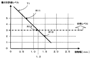
図7は、上記の樹脂ガラス10に対して、上述した押圧力Fzかつ移動速度V1にて、ワイパラバーを移動させた場合において、リップ部23Aが樹脂ガラス10に接触している個所の移動方向の長さである接触幅D1(図10参照)と、傷付き評価レベルと、の関係である接触幅・傷付き評価レベル特性について、実験にて得られた結果を示している。なお、傷付き評価レベル0〜5は、単位面積中における目視で確認可能な傷の本数に基づいて設定されている。例えば傷付き評価レベル5は、単位面積中の傷の本数が最も少ないことを示しており、傷付き評価レベル3以上を、合格レベル(樹脂ガラスへ目立つ傷が付きにくい、とみなす)と設定する。実験にて得られたデータR11〜R13から回帰直線T1を求めた結果、上述した押圧力Fzかつ移動速度V1の場合、接触幅が1.2[mm]以下であれば、合格レベルである傷付き評価レベル3以上となることを確認した。
FIG. 7 shows the moving direction of the portion where the
図8は、図7の結果を踏まえて、上記の樹脂ガラス10に対して、上述した押圧力Fzかつ移動速度V1にて、ワイパラバーを移動させた場合において、リップ部23Aのリップ長さL/リップ厚さW(L、Wは図5参照)と、接触幅と、の関係であるリップ部L/W・接触幅特性について、実験にて得られた結果を示している。実験にて得られたデータR21〜R23から回帰直線T2を求めた結果、上述した押圧力Fzかつ移動速度V1の場合に、図7にて得られた接触幅1.2[mm]以下とするためには、リップ部L/Wを2.3以下にすればよいことを確認した。すなわち、リップ部L/Wを0より大きく、かつ、2.3以下に設定すれば、接触幅を1.2[mm]以下とすることが可能となり、傷付き評価レベル3以上を確保できることを確認した。
8 is based on the result of FIG. 7, and when the wiper bar is moved to the
●[樹脂ガラス10+リップ部のL/W≒1.7のワイパラバー23の場合の払拭状態(図9、図10)]
次に図9及び図10を用いて、樹脂ガラス10(動摩擦係数μ1が約0.3〜約0.6)とリップ部23AのL/W(L、Wは図5参照)≒1.7のワイパラバー23を組み合わせた場合について説明する。この場合、樹脂ガラス10の表面には、目立つ傷が付きにくい。なお、図9及び図10における押圧力Fzと移動速度V1は、図11〜図14における押圧力Fzと移動速度V1と同じである。図7及び図8の結果より、リップ部L/Wを0より大きく、かつ、2.3以下に設定すればよいので、リップ部L/W≒1.7に設定した場合の例について説明する。また樹脂ガラス10の表面には、上述したコーティング層10Bが形成されている。
● [Wipe state when
Next, referring to FIGS. 9 and 10, the resin glass 10 (having a dynamic friction coefficient μ1 of about 0.3 to about 0.6) and L/W of the
図9及び図10に示すように、リップ部L/W(リップ長さL/リップ厚さW)が約1.7に設定されたワイパラバー23を、押圧力Fzにて樹脂ガラス10に押し付けながら、移動速度V1にて樹脂ガラス10の表面を移動させた場合、ワイパラバー23のリップ部23Aは、無機ガラス210(図11、図12参照)の場合と同様に、滑らかに移動する。そして図9及び図10に示す接触角度θ1は、無機ガラス210の場合の接触角度θb(図11、図12参照)と同等の角度となる。これにより、図9及び図10に示す接触幅D1は、1.2[mm]以下となる。この場合、図10に示すように、リップ部23Aの移動方向におけるリップ部23Aと樹脂ガラス10の表面との間にダスト80が有っても、接触幅D1が1.2[mm]以下であるので、ダスト80が樹脂ガラス10に押し付けられる期間及び距離が短くなる。この結果、樹脂ガラス10の表面には、目立つ傷が付きにくい。
As shown in FIGS. 9 and 10, the
なお、リップ部L/Wは、0より大きく、かつ、2.3以下であればよく、リップ部L/Wを、2.3から0に向けて小さくしていくと、図9及び図10に示す接触角度θ1が徐々に大きくなっていくので、接触幅D1も徐々に小さくなっていく(図8参照)。従って、図7に示すように、傷付き評価レベルも徐々に高くなるので、リップ部L/Wを、2.3から0に向けて小さくしていくと、樹脂ガラス10の表面には、目立つ傷が、より付きにくくなる。
It should be noted that the lip portion L/W may be larger than 0 and not more than 2.3, and if the lip portion L/W is made smaller from 2.3 to 0, FIG. 9 and FIG. Since the contact angle θ1 indicated by is gradually increased, the contact width D1 is also gradually decreased (see FIG. 8). Therefore, as shown in FIG. 7, the scratch evaluation level also gradually increases. Therefore, when the lip portion L/W is reduced from 2.3 to 0, the surface of the
本発明の樹脂ガラス用ワイパ構造及びワイパラバー23は、本実施の形態で説明した構成、構造、外観、形状、材質等に限定されず、本発明の要旨を変更しない範囲で種々の変更、追加、削除が可能である。
The wiper structure for resin glass and the
1 車両
10、110 樹脂ガラス
10A 樹脂基部
10B コーティング層
20 ワイパ
20J ワイパ揺動軸
21 ワイパアーム
22 ワイパホルダ
23 ワイパラバー
23A リップ部
23B 胴体下部
23C 胴体上部
23D 胴体部
23E ネック部
23F 底部
23G 連結部
23G1 ホルダ挿通溝
23H 頭部
23H1 プレート差込溝
23J 保持基部
24 プレート
80 ダスト
210 無機ガラス
D1、Da、Db 接触幅
K1 傷
L リップ長さ
W リップ厚さ
LN ネック長さ
WN ネック厚さ
θ1、θa、θb 接触角度
μ1、μa、μb 動摩擦係数
1 Vehicle 10,110
Claims (3)
前記ワイパは、
前記樹脂ガラスに接触するように保持された弾性体のワイパラバーと、
前記ワイパラバーを保持するワイパホルダと、
前記ワイパラバーを保持した前記ワイパホルダを前記樹脂ガラスに向けて押圧しながら前記樹脂ガラスの表面に沿って往復揺動させるワイパアームと、
を有しており、
前記ワイパラバーは、
前記ワイパラバーの長手方向に直交する断面形状において、
前記ワイパホルダに保持される保持基部と、
前記樹脂ガラスの表面に沿う方向のラバー厚さがリップ厚さに設定されて、前記樹脂ガラスの表面に向かう方向のラバー長さがリップ長さに設定されて、一方端の側が前記樹脂ガラスに接触するリップ部と、
一方端の側が前記リップ部の他方端の側に接続されて、他方端の側に向かって前記ラバー厚さが厚くなる胴体部と、
前記ラバー厚さがネック厚さに設定されて、前記ラバー長さがネック長さに設定されて、一方端の側が前記胴体部の他方端の側に接続され、他方端の側が前記保持基部の一方端の側に接続されるネック部と、
を有しており、
前記ネック厚さは、前記胴体部の他方端の側の前記ラバー厚さ、及び前記保持基部の一方端の側の前記ラバー厚さ、と比較して薄く設定されており、
前記リップ厚さに対する前記リップ長さの比率が、0より大きく、かつ、2.3以下に設定されている、
樹脂ガラス用ワイパ構造。 A resin glass wiper structure having a resin glass having a coating layer formed on a surface thereof and a wiper for wiping a part of the surface of the resin glass,
The wiper is
An elastic wiper bar held in contact with the resin glass,
A wiper holder for holding the wiper bar,
A wiper arm that reciprocally swings along the surface of the resin glass while pressing the wiper holder holding the wiper bar toward the resin glass,
Has
The Waipara bar is
In the cross-sectional shape orthogonal to the longitudinal direction of the wiper bar,
A holding base held by the wiper holder,
The rubber thickness in the direction along the surface of the resin glass is set to the lip thickness, the rubber length in the direction toward the surface of the resin glass is set to the lip length, and one end side is the resin glass. With the lip part that contacts
A body portion in which one end side is connected to the other end side of the lip portion, and the rubber thickness increases toward the other end side,
The rubber thickness is set to the neck thickness, the rubber length is set to the neck length, one end side is connected to the other end side of the body portion, and the other end side is the holding base portion. A neck part connected to one end side,
Has
The neck thickness is set thinner than the rubber thickness on the other end side of the body portion, and the rubber thickness on the one end side of the holding base portion,
The ratio of the lip length to the lip thickness is set to be greater than 0 and 2.3 or less,
Wiper structure for resin glass.
前記コーティング層の動摩擦係数が、0.3〜0.6の範囲とされている、
樹脂ガラス用ワイパ構造。 The wiper structure for resin glass according to claim 1,
The dynamic friction coefficient of the coating layer is in the range of 0.3 to 0.6,
Wiper structure for resin glass.
前記ワイパラバーは、
長手方向に直交する断面形状において、
前記ワイパホルダに保持される保持基部と、
前記樹脂ガラスの表面に沿う方向のラバー厚さがリップ厚さに設定されて、前記樹脂ガラスの表面に向かう方向のラバー長さがリップ長さに設定されて、一方端の側が前記樹脂ガラスに接触するリップ部と、
一方端の側が前記リップ部の他方端の側に接続されて、他方端の側に向かって前記ラバー厚さが厚くなる胴体部と、
前記ラバー厚さがネック厚さに設定されて、前記ラバー長さがネック長さに設定されて、一方端の側が前記胴体部の他方端の側に接続され、他方端の側が前記保持基部の一方端の側に接続されるネック部と、
を有しており、
前記リップ厚さに対する前記リップ長さの比率が、0より大きく、かつ、2.3以下に設定されている、
ワイパラバー。 Used for a wiper that wipes a part of the surface of the resin glass having a coating layer formed on the surface, along the surface of the resin glass while being held by a wiper holder supported by a wiper arm and being pressed toward the resin glass. In the Waipara bar that is reciprocally rocked,
The Waipara bar is
In the cross-sectional shape orthogonal to the longitudinal direction,
A holding base held by the wiper holder,
The rubber thickness in the direction along the surface of the resin glass is set to the lip thickness, the rubber length in the direction toward the surface of the resin glass is set to the lip length, and one end side is the resin glass. With the lip part that contacts
A body portion in which one end side is connected to the other end side of the lip portion, and the rubber thickness increases toward the other end side,
The rubber thickness is set to the neck thickness, the rubber length is set to the neck length, one end side is connected to the other end side of the body portion, and the other end side is the holding base portion. A neck part connected to one end side,
Has
The ratio of the lip length to the lip thickness is set to be greater than 0 and 2.3 or less,
Waipara Bar.
Priority Applications (5)
| Application Number | Priority Date | Filing Date | Title |
|---|---|---|---|
| JP2018240946A JP2020100338A (en) | 2018-12-25 | 2018-12-25 | Wiper structure for resin glass and wiper rubber |
| DE112019006506.8T DE112019006506T5 (en) | 2018-12-25 | 2019-12-02 | Wiper structure for a resin window and rubber wiper |
| US17/417,158 US20220073034A1 (en) | 2018-12-25 | 2019-12-02 | Wiper structure for resin window and wiper rubber |
| CN201980085710.XA CN113226866A (en) | 2018-12-25 | 2019-12-02 | Wiper structure for resin window and wiper blade |
| PCT/JP2019/047003 WO2020137369A1 (en) | 2018-12-25 | 2019-12-02 | Wiper structure for resin window and wiper rubber |
Applications Claiming Priority (1)
| Application Number | Priority Date | Filing Date | Title |
|---|---|---|---|
| JP2018240946A JP2020100338A (en) | 2018-12-25 | 2018-12-25 | Wiper structure for resin glass and wiper rubber |
Publications (2)
| Publication Number | Publication Date |
|---|---|
| JP2020100338A true JP2020100338A (en) | 2020-07-02 |
| JP2020100338A5 JP2020100338A5 (en) | 2021-07-26 |
Family
ID=71125830
Family Applications (1)
| Application Number | Title | Priority Date | Filing Date |
|---|---|---|---|
| JP2018240946A Pending JP2020100338A (en) | 2018-12-25 | 2018-12-25 | Wiper structure for resin glass and wiper rubber |
Country Status (5)
| Country | Link |
|---|---|
| US (1) | US20220073034A1 (en) |
| JP (1) | JP2020100338A (en) |
| CN (1) | CN113226866A (en) |
| DE (1) | DE112019006506T5 (en) |
| WO (1) | WO2020137369A1 (en) |
Cited By (1)
| Publication number | Priority date | Publication date | Assignee | Title |
|---|---|---|---|---|
| WO2023120633A1 (en) * | 2021-12-24 | 2023-06-29 | キヤノン株式会社 | Wiper device |
Citations (16)
| Publication number | Priority date | Publication date | Assignee | Title |
|---|---|---|---|---|
| JPS58188739A (en) * | 1982-04-28 | 1983-11-04 | Honda Motor Co Ltd | Wiper device in motorcycle |
| JPH02227226A (en) * | 1989-02-28 | 1990-09-10 | Hashimoto Forming Ind Co Ltd | Manufacture of synthetic resin window |
| JPH0577691A (en) * | 1991-09-17 | 1993-03-30 | Asmo Co Ltd | Wiper blade rubber and its manufacture |
| JPH06135300A (en) * | 1992-10-29 | 1994-05-17 | Nissan Motor Co Ltd | Wiper device |
| JPH0769176A (en) * | 1994-06-17 | 1995-03-14 | Jidosha Denki Kogyo Co Ltd | Wiper blade |
| JP2001206200A (en) * | 2000-01-26 | 2001-07-31 | Denso Corp | Water repellent coated windshield |
| JP2003253214A (en) * | 2002-03-05 | 2003-09-10 | Akurosu Kk | Coating composition and wiper blade |
| JP2003341482A (en) * | 2002-05-29 | 2003-12-03 | Toyota Industries Corp | Wiper device and wiping method |
| JP2005145166A (en) * | 2003-11-12 | 2005-06-09 | Shin Etsu Polymer Co Ltd | Wiper blade |
| JP2006117105A (en) * | 2004-10-21 | 2006-05-11 | Jidosha Denki Kogyo Co Ltd | Wiper blade |
| JP2009056925A (en) * | 2007-08-31 | 2009-03-19 | Daikyo Nishikawa Kk | Window glass for vehicle |
| JP2012091670A (en) * | 2010-10-27 | 2012-05-17 | Honda Motor Co Ltd | Vehicle wiper |
| JP2014218103A (en) * | 2013-05-02 | 2014-11-20 | 株式会社レニアス | Resin glass for vehicle having heating layer, and method of manufacturing the same |
| JP2015140135A (en) * | 2014-01-30 | 2015-08-03 | 株式会社ミツバ | wiper blade |
| JP2017109683A (en) * | 2015-12-18 | 2017-06-22 | 株式会社小糸製作所 | Resin glass for car window equipped with electrical heating element |
| JP2017149380A (en) * | 2016-02-26 | 2017-08-31 | イビデン株式会社 | Resin rear window and resin window |
Family Cites Families (7)
| Publication number | Priority date | Publication date | Assignee | Title |
|---|---|---|---|---|
| JPH0831924B2 (en) | 1986-10-14 | 1996-03-27 | キヤノン株式会社 | Communication device |
| US5251357A (en) * | 1991-05-03 | 1993-10-12 | Alberee Ltd., Inc. | Windshield wiper blade with deformable internal cavity |
| JPH07246916A (en) * | 1994-03-11 | 1995-09-26 | Nissan Motor Co Ltd | Wiper device |
| JP2004243917A (en) | 2003-02-14 | 2004-09-02 | Yokohama Rubber Co Ltd:The | Design method for wiper blade, and wiper blade |
| US8443483B2 (en) * | 2010-08-30 | 2013-05-21 | GM Global Technology Operations LLC | Wiper blade for vehicle window wiper |
| DE102013201093B4 (en) * | 2013-01-24 | 2020-10-22 | Robert Bosch Gmbh | Squeegee rubber with replacement notice |
| CN103612618A (en) * | 2013-12-03 | 2014-03-05 | 贵阳万江航空机电有限公司 | Car wiper wiping piece adhesive tape with novel structure |
-
2018
- 2018-12-25 JP JP2018240946A patent/JP2020100338A/en active Pending
-
2019
- 2019-12-02 DE DE112019006506.8T patent/DE112019006506T5/en not_active Ceased
- 2019-12-02 CN CN201980085710.XA patent/CN113226866A/en active Pending
- 2019-12-02 US US17/417,158 patent/US20220073034A1/en not_active Abandoned
- 2019-12-02 WO PCT/JP2019/047003 patent/WO2020137369A1/en active Application Filing
Patent Citations (16)
| Publication number | Priority date | Publication date | Assignee | Title |
|---|---|---|---|---|
| JPS58188739A (en) * | 1982-04-28 | 1983-11-04 | Honda Motor Co Ltd | Wiper device in motorcycle |
| JPH02227226A (en) * | 1989-02-28 | 1990-09-10 | Hashimoto Forming Ind Co Ltd | Manufacture of synthetic resin window |
| JPH0577691A (en) * | 1991-09-17 | 1993-03-30 | Asmo Co Ltd | Wiper blade rubber and its manufacture |
| JPH06135300A (en) * | 1992-10-29 | 1994-05-17 | Nissan Motor Co Ltd | Wiper device |
| JPH0769176A (en) * | 1994-06-17 | 1995-03-14 | Jidosha Denki Kogyo Co Ltd | Wiper blade |
| JP2001206200A (en) * | 2000-01-26 | 2001-07-31 | Denso Corp | Water repellent coated windshield |
| JP2003253214A (en) * | 2002-03-05 | 2003-09-10 | Akurosu Kk | Coating composition and wiper blade |
| JP2003341482A (en) * | 2002-05-29 | 2003-12-03 | Toyota Industries Corp | Wiper device and wiping method |
| JP2005145166A (en) * | 2003-11-12 | 2005-06-09 | Shin Etsu Polymer Co Ltd | Wiper blade |
| JP2006117105A (en) * | 2004-10-21 | 2006-05-11 | Jidosha Denki Kogyo Co Ltd | Wiper blade |
| JP2009056925A (en) * | 2007-08-31 | 2009-03-19 | Daikyo Nishikawa Kk | Window glass for vehicle |
| JP2012091670A (en) * | 2010-10-27 | 2012-05-17 | Honda Motor Co Ltd | Vehicle wiper |
| JP2014218103A (en) * | 2013-05-02 | 2014-11-20 | 株式会社レニアス | Resin glass for vehicle having heating layer, and method of manufacturing the same |
| JP2015140135A (en) * | 2014-01-30 | 2015-08-03 | 株式会社ミツバ | wiper blade |
| JP2017109683A (en) * | 2015-12-18 | 2017-06-22 | 株式会社小糸製作所 | Resin glass for car window equipped with electrical heating element |
| JP2017149380A (en) * | 2016-02-26 | 2017-08-31 | イビデン株式会社 | Resin rear window and resin window |
Cited By (1)
| Publication number | Priority date | Publication date | Assignee | Title |
|---|---|---|---|---|
| WO2023120633A1 (en) * | 2021-12-24 | 2023-06-29 | キヤノン株式会社 | Wiper device |
Also Published As
| Publication number | Publication date |
|---|---|
| US20220073034A1 (en) | 2022-03-10 |
| DE112019006506T5 (en) | 2021-09-23 |
| WO2020137369A1 (en) | 2020-07-02 |
| CN113226866A (en) | 2021-08-06 |
Similar Documents
| Publication | Publication Date | Title |
|---|---|---|
| JP2011235808A (en) | Wiper blade | |
| JP5373009B2 (en) | Auto body structure | |
| JP2020100338A (en) | Wiper structure for resin glass and wiper rubber | |
| JP6514658B2 (en) | Cowl top garnish | |
| JP2008168796A (en) | Wiper system for vehicle | |
| US2230596A (en) | Windshield cleaner | |
| JP2016203713A (en) | Wiper device | |
| JP7207075B2 (en) | Hinge device and vehicle | |
| JP2019031141A (en) | Wiper blade | |
| JP2008254626A (en) | Wiper blade | |
| KR20150068041A (en) | Structure of wiper for vehicle | |
| JP2007283957A (en) | Guiding structure for on-vehicle electronic equipment and on-vehicle electronic equipment | |
| JP2021049899A (en) | Wiper arm | |
| JP6833256B2 (en) | Vehicle belt mall | |
| JP2019031142A (en) | Wiper blade | |
| US11247640B2 (en) | Wiper apparatus having arrangement structure between wiper arm tip and vertebra | |
| KR20190052499A (en) | Hood strip mounting structure of car | |
| JP2009113737A (en) | Vehicular wiper device | |
| JP2015101314A (en) | Register | |
| JP2013086730A (en) | Wiper blade | |
| JP2009056925A (en) | Window glass for vehicle | |
| JP6824925B2 (en) | cover | |
| KR100655405B1 (en) | Glass damper structure of outside mirror for a vehicle | |
| JP2019206202A (en) | Attachment structure of vehicular door trim | |
| JP4494914B2 (en) | Hinge device for vehicle display |
Legal Events
| Date | Code | Title | Description |
|---|---|---|---|
| A521 | Request for written amendment filed |
Free format text: JAPANESE INTERMEDIATE CODE: A523 Effective date: 20210527 |
|
| A621 | Written request for application examination |
Free format text: JAPANESE INTERMEDIATE CODE: A621 Effective date: 20210527 |
|
| A131 | Notification of reasons for refusal |
Free format text: JAPANESE INTERMEDIATE CODE: A131 Effective date: 20220705 |
|
| A521 | Request for written amendment filed |
Free format text: JAPANESE INTERMEDIATE CODE: A523 Effective date: 20220831 |
|
| A131 | Notification of reasons for refusal |
Free format text: JAPANESE INTERMEDIATE CODE: A131 Effective date: 20221220 |
|
| A02 | Decision of refusal |
Free format text: JAPANESE INTERMEDIATE CODE: A02 Effective date: 20230613 |