JP2020096426A - Rotary electric machine - Google Patents
Rotary electric machine Download PDFInfo
- Publication number
- JP2020096426A JP2020096426A JP2018231735A JP2018231735A JP2020096426A JP 2020096426 A JP2020096426 A JP 2020096426A JP 2018231735 A JP2018231735 A JP 2018231735A JP 2018231735 A JP2018231735 A JP 2018231735A JP 2020096426 A JP2020096426 A JP 2020096426A
- Authority
- JP
- Japan
- Prior art keywords
- rotor core
- field
- pole
- magnet
- field coil
- Prior art date
- Legal status (The legal status is an assumption and is not a legal conclusion. Google has not performed a legal analysis and makes no representation as to the accuracy of the status listed.)
- Pending
Links
Images


Abstract
Description
本発明は、回転電機に関する。 The present invention relates to a rotary electric machine.
特許文献1には、回転可能な回転シャフトと、筒状に形成されたステータコアと、回転シャフトに固設されたロータコアと、異なる磁性の一組の磁極が、ロータコアの径方向に並ぶようにロータコアに設定された磁石と、ステータコアの外周に設けられた界磁ヨークと、界磁ヨークとロータコアとの間に磁気回路を形成することで、ロータコアとステータコアとの間の磁束密度を制御可能な巻線とを備えた回転電動機が記載されている。また、磁石をV字に配置する構成が記載されている。
図15は、特許文献1に記載されたロータの断面図を示す。ロータ40はロータコア43を有し、ロータコア43は、円筒状に形成された積層ロータコア43aと、積層ロータコア43aの内周に設けられた圧粉ロータコア43bを有している。ロータ40内には、2つの磁石44A,44Aからなる磁石対49Aと、磁石対49Aに対して周方向に間隔を隔てて配置され、2つの磁石44B、44Bからなる磁石対49Bが設けられている。磁石44A、44Bは、ロータ40に形成された磁石挿入用穴部内に挿入されている。このように構成されたロータ40においては、磁石をV字に配置にし、もともと突極のあった部分(磁極2)のV字磁石の間を開けて鉄にし、磁極1に対して磁気抵抗を下げることで、界磁電流磁束が磁極2のd軸磁路の中心を通るようにして、界磁電流トルクを発生させる。磁極2の磁石を小さくして左右に鉄を配置したことで、q軸のインダクタンスを増加させて、リラクタンストルクを発生させる。マグネットトルクと界磁電流トルクに加えて、リラクタンストルクも用いる構成である。
FIG. 15 shows a cross-sectional view of the rotor described in
特許文献1において、磁極2のd軸中心部(V字磁石の間の鉄を配置した部分)のインダクタンスを上げて、この部分に界磁電流磁束を流すようにして、界磁電流トルクを発生させようとすると、このインダクタンスの増加によって、q軸インダクタンスとd軸インダクタンスの差(Lq−Ld)に依存したリラクタンストルクが減少してしまう。
In
また、磁極2のq軸方向(V字磁石の両サイドの鉄を配置した部分)のインダクタンスを上げて、(Lq−Ld)に依存したリラクタンストルクを増加させようとすると、界磁巻線に電流を流すことで、q軸方向にも界磁電流磁束が流れるようになり、q軸を磁気飽和させてしまうため、q軸のインダクタンスが減少してしまい、リラクタンストルクが減少してしまう。
In addition, when the inductance of the
その結果、磁石トルクと界磁電流トルクとリラクタンストルクの3つを同時に、有効的に利用できない課題がある。 As a result, there is a problem that the magnet torque, the field current torque, and the reluctance torque cannot be effectively utilized at the same time.
本発明は、磁石トルクと界磁電流トルクとリラクタンストルクの3つを同時に、有効的に利用し得る回転電機を提供することにある。 An object of the present invention is to provide a rotary electric machine that can effectively utilize three of the magnet torque, the field current torque, and the reluctance torque at the same time.
本発明は、回転可能なシャフトと、前記シャフトに固設されたロータコアと、筒状に形成されたステータコアと、前記ステータコアの外側に設けられた界磁ヨークと、前記界磁ヨークの、前記ロータコアの軸方向端部に対向する位置に設けられ、前記界磁ヨークと前記ロータコアとの間に磁気回路を形成する界磁コイルと、互いに異なる第1極と第2極が周方向に交互に離間して配置されるように前記ロータコアに設けられる磁石とを備え、前記ロータコアの前記界磁コイルに対向する面内の前記磁石で囲まれた領域のうち、前記第1極と前記第2極のいずれか一方の極の領域に、前記界磁コイルに流れる電流により界磁電流磁束が生成され、いずれか他方の極の領域には生成されない回転電機である。 The present invention provides a rotatable shaft, a rotor core fixed to the shaft, a cylindrical stator core, a field yoke provided outside the stator core, and the rotor core of the field yoke. Of a field coil that is provided at a position facing the axial end of the field coil and that forms a magnetic circuit between the field yoke and the rotor core, and first poles and second poles that are different from each other are alternately separated in the circumferential direction. And a magnet provided in the rotor core so as to be arranged in the same manner, and in the area surrounded by the magnet in the surface of the rotor core facing the field coil, the first pole and the second pole In the rotating electric machine, a field current magnetic flux is generated in one of the pole regions by the current flowing in the field coil, and is not generated in the other pole region.
本発明の1つの実施形態では、前記ロータコアの前記いずれか一方の極の領域に設けられ、前記界磁コイルの方向に突出する追加ロータコアと、前記界磁ヨークの前記追加ロータコアに対向する位置に設けられ、前記界磁コイルが巻回される界磁ヨークとを備える。 In one embodiment of the present invention, an additional rotor core that is provided in the area of one of the poles of the rotor core and projects in the direction of the field coil, and a position of the field yoke that faces the additional rotor core. And a field yoke around which the field coil is wound.
本発明の他の実施形態では、前記磁石は、前記第1極を構成する第1磁石と、前記第2極を構成する第2磁石を備え、前記第1極の前記第1磁石で囲まれた領域と、前記第2極の前記第2磁石で囲まれた領域は同一である。 In another embodiment of the present invention, the magnet includes a first magnet that constitutes the first pole and a second magnet that constitutes the second pole, and is surrounded by the first magnet of the first pole. The region surrounded by the second magnet of the second pole is the same as the region surrounded by the second magnet.
本発明のさらに他の実施形態では、前記ロータは、前記第1磁石及び前記第2磁石により、q軸インダクタンスがd軸インダクタンスに対して高いq軸磁路を複数有し、複数の前記q軸磁路のうちの少なくとも1つの磁路は、前記界磁電流磁束と干渉しない。 In still another embodiment of the present invention, the rotor includes a plurality of q-axis magnetic paths having a q-axis inductance higher than a d-axis inductance due to the first magnet and the second magnet. At least one of the magnetic paths does not interfere with the field current flux.
本発明のさらに他の実施形態では、前記界磁コイルは、前記ロータコアの軸方向端部に対向する位置にそれぞれ設けられ、前記界磁ヨークと前記ロータコアとの間に磁気回路を形成する第1界磁コイル及び第2界磁コイルから構成され、前記ロータコアの前記第1界磁コイルに対向する第1面内の前記磁石で囲まれた領域のうち、前記第1極と前記第2極のいずれか一方の極の領域に、前記第1界磁コイルに流れる電流により界磁電流磁束が生成され、いずれか他方の極の領域には生成されず、前記ロータコアの前記第2界磁コイルに対向する第2面内の前記磁石で囲まれた領域のうち、前記第1極と前記第2極のいずれか他方の極の領域に、前記第2界磁コイルに流れる電流により界磁電流磁束が生成され、いずれか一方の極の領域には生成されない。あるいは、前記界磁コイルは、前記ロータコアの軸方向端部に対向する位置にそれぞれ設けられ、前記界磁ヨークと前記ロータコアとの間に磁気回路を形成する第1界磁コイル及び第2界磁コイルから構成され、前記ロータコアの前記第1界磁コイルに対向する第1面内の前記磁石で囲まれた領域のうち、前記第1極と前記第2極のいずれか一方の極の領域に、前記第1界磁コイルに流れる電流により界磁電流磁束が生成され、いずれか他方の極の領域には生成されず、前記ロータコアの前記第2界磁コイルに対向する第2面内の前記磁石で囲まれた領域のうち、前記一方の極の領域に、前記第2界磁コイルに流れる電流により界磁電流磁束が生成され、前記いずれか他方の極の領域には生成されない。 In still another embodiment of the present invention, the field coil is provided at a position facing an axial end of the rotor core, and forms a magnetic circuit between the field yoke and the rotor core. Of the region surrounded by the magnet in the first surface of the rotor core facing the first field coil, which is composed of a field coil and a second field coil, of the first pole and the second pole. A field current magnetic flux is generated in the area of one of the poles by the current flowing through the first field coil, and is not generated in the area of the other pole of the other, and is generated in the second field coil of the rotor core. A field current magnetic flux generated by a current flowing through the second field coil in a region of the other pole of the first pole and the second pole in a region surrounded by the magnets in the opposing second surface. Is generated, and is not generated in the area of either pole. Alternatively, the field coil is provided at a position facing an axial end of the rotor core, and forms a magnetic circuit between the field yoke and the rotor core. A region of one of the first pole and the second pole of a region surrounded by the magnet in the first surface of the rotor core that faces the first field coil of the rotor core. A field current magnetic flux is generated by the current flowing through the first field coil, is not generated in the area of the other pole, and is in the second surface of the rotor core facing the second field coil. A field current magnetic flux is generated by the current flowing through the second field coil in the one pole region of the region surrounded by the magnets, and is not generated in any one of the other pole regions.
本発明によれば、磁石トルクと界磁電流トルクとリラクタンストルクの3つを同時に、有効的に利用することができる。特に、本発明によれば、q軸磁路のq軸インダクタンスLqとd軸磁路のd軸インダクタンスLdの差(Lq−Ld)を確保することで、(Lq−Ld)に比例するリラクタンストルクを確保できる。 According to the present invention, the magnet torque, the field current torque, and the reluctance torque can be effectively utilized at the same time. Particularly, according to the present invention, by ensuring the difference (Lq-Ld) between the q-axis inductance Lq of the q-axis magnetic path and the d-axis inductance Ld of the d-axis magnetic path, the reluctance torque proportional to (Lq-Ld). Can be secured.
以下、図面に基づき本発明の実施形態について説明する。 Embodiments of the present invention will be described below with reference to the drawings.
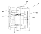
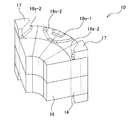
図1は、本実施形態における回転電機のロータ10の斜視図を示す。また、図2は、図1に示すロータ10の一部拡大図、より詳しくはロータ10のシャフト12を除く1/4カットの斜視図を示す。さらに、図3は、本実施形態における回転電機の一部斜視図を示す。
FIG. 1 shows a perspective view of a
まず、ステータについて説明する。 First, the stator will be described.
図3に示すように、ロータ10の外周側にロータ10との間にギャップを形成して配置されるステータ50は、ステータコアと、ステータコアの内表面に形成され、ステータコアの径方向に向けて突出する複数のステータティースと、ステータティースに巻回されたステータコイルを備える。ステータティースは、周方向に等間隔に離間して形成される。ステータコイルはU相コイル、V相コイル、W相コイルを構成し、ステータコイルの一端が端子とされ、他端が中性点とされる。端子にはインバータの三相ケーブルのU相ケーブル、V相ケーブル、W相ケーブルのいずれかが接続され、中性点は1点に共通接続される。三相ケーブルには、制御装置からトルク指令値に応じた制御電流が供給される。
As shown in FIG. 3, the
また、ステータの外側に界磁ヨーク及び界磁コイルを備える。界磁ヨークは、ステータ50及びロータ10の両端部から軸方向に離間した位置に配置された天板部50aと、天板部50aの周縁部に形成された円筒状の側壁部50bと、天板部50aに形成された円筒状の突部50cを備える。天板部50aの中央部には貫通穴が形成され、この貫通穴にロータ10のシャフト12が挿入される。また、側壁部50bはステータコアの外表面に固設される。天板部50aに形成された円筒状の突部50cは、天板部50aの内表面に形成され、ロータ10の軸方向端部に向けて突出する。突部50cとロータ10の端部との間は、磁力線が途切れない程度に、突部50cとロータ10の端部とが近接する。
A field yoke and a field coil are provided outside the stator. The field yoke includes a
界磁コイルは、突部50cの外表面に巻回される。界磁コイルに界磁電流を流すことにより、突部50cは界磁コアとして機能し、突部50cの端部側に例えばS極の磁性を誘起するとともに側壁部50bにN極の磁性を誘起させることができる。具体的には、界磁コイルに界磁電流を流すことで、界磁ヨークの天板部50aを通り、側壁部50bからステータコア内に入り込み、ギャップを介してロータ10のロータコア内に入り込み、ロータコア内を軸方向に進み、ロータコアの軸方向端部から突部50cを介して界磁ヨークに入り込むような磁気回路が形成される。界磁コイルは、ロータ10の軸方向両端部に対向する位置にそれぞれ配置される。
The field coil is wound around the outer surface of the
界磁コアとして機能する突部50cは、天板部50aの内表面に形成され、ロータ10の軸方向端部に向けて突出するが、より詳しくは、図3に示すように、ロータ10のロータコアの外周側の端部に向けて突出する。後述するように、ロータ10のロータコアは、外周側の筒状の第1ロータコア14と内周側の第2ロータコア16から構成されているが、界磁コイルとして突部50cは、第1ロータコア14に向けて突出している。
The
次に、ロータについて説明する。 Next, the rotor will be described.
図1及び図2において、ロータ10は、回転軸としてのシャフト12の外周に筒状に配置されたロータコアと、ロータコアの外周側にその磁極が互いに相違するように順次配置された磁石18n、18sを含む。磁石18n、18sは、それぞれ所定距離だけ離間してV字型に配置された2個の磁石から構成される。なお、V字型配置は例示であり、本発明は必ずしもV字型配置に限定されない。
1 and 2, the
ロータコアは、外周側の筒状の第1ロータコア14と、内周側の第2ロータコア16から構成される。第1ロータコア14は、磁石18n、18sにより第1ロータコア14nと第1ロータコア14sに周方向に分割される。ここで、符号に付されたn及びsは、それぞれ磁極のN極及びS極を意味する。磁気抵抗に関しては、磁石18n、18sが配置された領域は、磁気抵抗が相対的に大きい領域であり、磁石18n、18sが配置されていない領域、具体的には磁石18n、18sで囲まれた領域は、磁気抵抗が相対的に小さい領域である。
The rotor core includes a cylindrical
磁石18n、18sは、それぞれ2つの磁石がV字型に配置されて構成されるが、磁石18nを構成する2つの磁石と、磁石18sを構成する2つの磁石のサイズは同一である。また、磁石18nを構成する2つの磁石の間の距離と、磁石18sを構成する2つの磁石の間の距離も同一である。
Each of the
図15に示されるように、従来のロータ構成では、V字型に配置された磁石49Aと磁石49Bではそのサイズが異なっており、磁極1を構成する磁石49Aよりも磁極2を構成する磁石49Bの方が小さく、磁石49AのV字型配置の間隔よりも磁石49BのV字型配置の間隔の方が大きい。これに対し、本実施形態の磁石18n、18sは、そのサイズが同一であり、かつ、磁石18nのV字型配置の間隔と磁石18sのV字型配置の間隔は同一である。
As shown in FIG. 15, in the conventional rotor configuration, the
第1ロータコア14n、14sは、周方向に交互にN極、S極が配置されるが、第1ロータコア14n、14sのうちのいずれか一方の極、例えばS極の第1ロータコア14sに関しては、V字配置された一対の磁石18sで囲まれた外周側領域に軸方向に追加ロータコア17が追加されて軸方向に延長される。すなわち、第1ロータコア14sについては、磁気抵抗が相対的に大きい磁石18sで囲まれた、磁気抵抗が相対的に小さい領域に図中軸方向の上方向に追加ロータコア17が追加されて軸方向の上方向に延長され、第1ロータコア14nについては、磁石18nで囲まれた領域には図中軸方向の上方向に追加ロータコア17は追加されない。ロータ10の両端面のうち、図中軸方向の上方向に位置する端面を第1面とすると、第1面では周方向に配置された第1ロータコア14sにのみ追加ロータコア17が追加され、第1ロータコア14nには追加ロータコア17は追加されないため、追加ロータコア17が追加されたことにより周方向に交互に軸方向に沿って凹凸が形成されることになる。同様に、第1ロータコア14sについては、磁気抵抗が相対的に大きい磁石18sで囲まれた、磁気抵抗が相対的に小さい領域に図中軸方向の下方向に追加ロータコア17が追加されて軸方向の下方向に延長され、第1ロータコア14nについては、磁石18nで囲まれた領域には図中軸方向の下方向に追加ロータコア17は追加されない。ロータ10の両端面のうち、図中軸方向の上方向に位置する端面を第2面とすると、第2面においても第1面と同じように周方向に配置された第1ロータコア14sにのみ追加ロータコア17が追加され、第1ロータコア14nには追加ロータコア17は追加されないため、追加ロータコア17が追加されたことにより周方向に交互に軸方向に沿って凹凸が形成されることになる。
The
既述したように、ロータ10の第1面には界磁ヨークの突部50cに巻回された界磁コイル(第1界磁コイル)が対向しており、突部50cは第1面のうち第1ロータコア14に向けて突出しているから、第1界磁コイルと第1面の第1ロータコア14n、14sとの関係では、追加ロータコア17が追加された分だけ第1界磁コイルと第1ロータコア14sと間の軸方向の磁気抵抗が小さくなり、第1界磁コイルで生じた磁束は第1ロータコア14sを選択的に流れることになる。同様に、ロータ10の第2面には界磁ヨークの突部50cに巻回された界磁コイル(第2界磁コイル)が対向しており、突部50cは第2面のうち第1ロータコア14に向けて突出しているから、第2界磁コイルと第2面の第1ロータコア14n、14sとの関係では、追加ロータコア17が追加された分だけ第2界磁コイルと第1ロータコア14sとの間の軸方向の磁気抵抗が小さくなり、第2界磁コイルで生じた磁束は第1ロータコア14sを選択的に流れることになる。従って、第1界磁コイルと第2界磁コイルに互いに逆向きの電流を通電することで、第1面及び第2面において界磁磁束は第1ロータコア14sを選択的に流れる。
As described above, the field coil (first field coil) wound around the
本実施形態は、追加ロータコア17が追加されているため界磁コイルで生じた磁束(界磁電流磁束)は第1ロータコア14sを選択的に流れるので、磁石18sのV字型配置の間隔の間、すなわちS極のd軸磁路を選択的に流れる。このことは、本実施形態では、従来技術のように一方の磁極(例えばS極)のV字型配置の間隔を他方(N極)よりも空けて磁気抵抗を相対的に小さくし、界磁電流磁束がS極のd軸磁路の中心を通るようにして界磁電流トルクを発生させる必要がないことを意味する。S極のV字型配置の磁気抵抗を下げることでd軸インダクタンスが増加するから、従来技術ではq軸インダクタンスとd軸インダクタンスの差(Lq−Ld)に依存するリラクタンストルクが減少してしまうが、本実施形態ではd軸インダクタンスを増大させる必要がないことから、q軸インダクタンスとd軸インダクタンスの差(Lq−Ld)に依存するリラクタンストルクが確保される。
In the present embodiment, since the
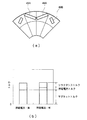
図4は、特許文献1に示された従来技術の構成におけるトルクを示す。図4(a)は従来技術の磁石配置を示す上面図であり、図4(b)は界磁電流の有無とトルク値との関係である。
FIG. 4 shows torque in the configuration of the related art shown in
磁石49Aと磁石49Bのサイズは異なっており、磁石49BのV字型配置の間隔は相対的に大きく、磁気抵抗が相対的に小さい。界磁電流を流した場合、トータルのトルク値は増大するものの、リラクタンストルク値は界磁電流を流すことで大きく減少している。これは、磁石49BのV字型配置の磁気抵抗を下げることでd軸インダクタンスLdが増加し、q軸インダクタンスとd軸インダクタンスの差(Lq−Ld)が減少するためである。
The
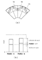
他方、図5は、本実施形態におけるトルクを示す。図5(a)は実施形態の磁石配置を示す上面図であり、図5(b)は界磁電流の有無とトルク値との関係である。 On the other hand, FIG. 5 shows the torque in this embodiment. FIG. 5A is a top view showing the magnet arrangement of the embodiment, and FIG. 5B shows the relationship between the presence or absence of the field current and the torque value.
磁石18nと磁石18sのサイズは同一であり、磁石18nのV字型配置の間隔と磁石18sのV字型配置の間隔は等しい。界磁電流を流した場合、トータルのトルク値は増大している。さらに、リラクタンストルク値は界磁電流を流すことで減少しているものの、その減少幅は大幅に抑制されている。このようにリラクタンストルクの減少が抑制されているのは、磁石18sのV字型配置の間隔が磁石18nのそれと同一でd軸インダクタンスLdが増加せず、q軸インダクタンスとd軸インダクタンスの差(Lq−Ld)が確保されているためである。リラクタンストルクは(Lq−Ld)に比例し、(Lq−Ld)が確保されることでリラクタンストルクが確保される。なお、従来技術では界磁電流磁束が第1極に流れないようにq軸磁路にも磁石が配置されており、Lqがあまり増加しないが、本実施形態では界磁電流が第1極に流れないようにq軸磁路に磁石を配置する必要がないため、Lqを相対的に大きく設定し得ることも寄与している。
The
本実施形態では、ロータ10の第1面に対向する突部50cに第1界磁コイルを巻回し、ロータ10の第1面の第1ロータ14sに追加ロータコア17を追加するとともに、ロータ10の第2面に対向する突部50cに第2界磁コイルを巻回し、ロータ10の第2面の第1ロータ14sに追加ロータコア17を追加して、第1界磁コイルと第2界磁コイルに互いに逆向きの電流を通電しているが、ロータの第2面に対向する突部50cに第2界磁コイルを巻回し、ロータ10の第2面の第1ロータ14sではなく第1ロータ14nに追加ロータコア17を追加して軸方向に延長し、第1界磁コイルと第2界磁コイルに互いに同方向の電流を流してもよい。
In the present embodiment, the first field coil is wound around the
図6は、この場合の構成を示す。ロータ10の第1面には、図3と同様に第1ロータコア14sのみに追加ロータコア17が追加されており、ロータ10の第2面には第1ロータコア14nのみに追加ロータコア17が追加される。第1面では追加ロータコア17により第1界磁コイルで生じた磁束を選択的に第1ロータコア14sに流し、第2面では追加ロータコア17により第2界磁コイルで生じた磁束を選択的に第1ロータコア14nに流すので、周方向に交互に向きの異なる界磁電流磁束が生じる。第1ロータコア14nに流れる磁石磁束と界磁電流磁束は同じ向きであり、かつ、第1ロータコア14sに流れる磁石磁束と界磁電流磁束は同じ向きとなる。従って、界磁電流磁束により磁石磁束を強めることができる。
FIG. 6 shows the configuration in this case. Similar to FIG. 3, the
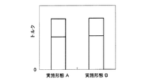
図7は、図3の構成と図6の構成における界磁電流を流した場合のトルク値を示す。図3の構成を実施形態A、図7の構成を実施形態Bとすると、実施形態Bでは磁石トルクが増大したことにより、トータルのトルク値が増大している。 FIG. 7 shows torque values when a field current is applied in the configurations of FIG. 3 and FIG. Assuming that the configuration of FIG. 3 is the embodiment A and the configuration of FIG. 7 is the embodiment B, the total torque value is increased in the embodiment B because the magnet torque is increased.
以上のように、本実施形態の回転電機では、追加ロータコア17により第1ロータコア14n、14sのうち、いずれか一方に選択的に界磁電流磁束を生成するようにしたので、磁石配置を特定の配置としていずれか一方に選択的に界磁電流を流す必要がなくなり、このためq軸磁路のインダクタンスLqとd軸磁路のインダクタンスLdの差(Lq−Ld)を確保し、磁石トルクと界磁電流トルクに加え、リラクタンストルクも有効に利用することができる。
As described above, in the rotary electric machine according to the present embodiment, the
また、ロータ10の軸方向に沿った2つの端面である第1面及び第2面のいずれにも追加ロータコア17を追加することで、磁石トルクをさらに増大させることができる。
Further, the magnet torque can be further increased by adding the
本実施形態では、ロータ面内において磁気抵抗の相対的に大きい領域である磁石18sあるいは磁石18nに囲まれた領域に追加ロータコア17を軸方向に追加し、これにより軸方向の磁気抵抗差を利用して界磁電流磁束を選択的に流しているが、軸方向の磁気抵抗差に加え、径方向の磁気抵抗差を利用してもよい。
In the present embodiment, the
図8は、径方向の磁気抵抗差を利用する回転電機の構成を示す。ロータ10の第1面及び第2面に追加ロータコア17が第1ロータコア14sに軸方向に追加されるが、この追加ロータコア17は、図6の場合よりもさらに軸方向に延長され、界磁ヨークの天板部50a近傍に達する。従って、軸方向にさらに延長された追加ロータコア17によって、界磁ヨークの天板部50aにおいて径方向に磁気抵抗差が生じ、追加ロータコア17が追加された部位では他の部位に比べて磁気抵抗が小さくなる。すなわち、追加ロータコア17を追加することで軸方向に加えて径方向にも磁気抵抗差が生じることになり、界磁電流磁束は追加ロータコア17、第1ロータコア14sを選択的に流れる。追加ロータコア17を追加することで軸方向に加えて径方向にも磁気抵抗差が生じることになり、界磁電流磁束は追加ロータコア17、第1ロータコア14nを選択的に流れるようになる。
FIG. 8 shows a configuration of a rotary electric machine that utilizes a magnetic resistance difference in the radial direction. The
また、本実施形態では、追加ロータコア17は、第1面及び第2面において周方向に互いに離間して配置されているが、磁気抵抗差が確保できる範囲内で、追加ロータコア17は周方向に互いに結合されていてもよい。
In addition, in the present embodiment, the
図9は、この場合の追加ロータコア17の構成を示す。追加ロータコア17は、周方向に互いに離間して配置されており、かつ、その軸方向端部、すなわち界磁ヨークの突部50c側の端部が円環状コア19により周方向に結合される。これにより、磁気抵抗差を維持しつつも追加ロータコア17の機械強度を向上させることができる。
FIG. 9 shows the configuration of the
また、本実施形態では、第1ロータコア14に磁石18n、18sをV字型に配置しているが、界磁電流磁束を軸方向から流す部分は、これに限られない。例えば、V字型配置された磁石を径方向に複数組配置してもよい。
Further, in the present embodiment, the
図10は、図1等に示された磁石18n、18sのV字型配置であり、V字型配置された磁石18n、18sを境にしてその外周側及び内周側にそれぞれq軸磁路が形成される。
FIG. 10 shows the V-shaped arrangement of the
図11は、V字型配置された磁石18n、18sを径方向に2組配置した構成である。磁石18nについては、外周側の磁石18n−1と内周側の磁石18n−2がV字型に配置される。外周側の磁石18n−1で囲まれた領域、磁石18n−1と磁石18n−2に囲まれた領域、さらに内周側の磁石18n−2の内周側の領域にそれぞれq軸磁路が形成される。同様に、磁石18sについても、外周側の磁石18s−1と内周側の磁石18s−2がV字型に配置される。外周側の磁石18s−1で囲まれた領域、磁石18s−1と磁石18s−2に囲まれた領域、さらに内周側の磁石18s−2の内周側の領域にそれぞれq軸磁路が形成される。
FIG. 11 shows a configuration in which two sets of V-shaped
追加ロータコア17は、ロータ10の第1面については、磁石18sを構成する磁石18s−1及び磁石18s−2のうち、外周側の磁石18s−1で囲まれた領域のみに追加される。ロータ10の第2面についても、磁石18sを構成する磁石18s−1及び磁石18s−2のうち、外周側の磁石18s−1で囲まれた領域のみに追加され得る。
Regarding the first surface of the
図12は、図11と同様に、磁石18nについては、外周側の磁石18n−1と内周側の磁石18n−2がV字型に配置され、磁石18sについても、外周側の磁石18s−1と内周側の磁石18s−2がV字型に配置される構成において、追加ロータコア17は、ロータ10の第1面については、磁石18sを構成する磁石18s−1及び磁石18s−2のうち、内周側の磁石18s−2で囲まれた領域に追加される。ロータ10の第2面についても、磁石18sを構成する磁石18s−1及び磁石18s−2のうち、内周側の磁石18s−2で囲まれた領域に追加され得る。
In FIG. 12, similarly to FIG. 11, with respect to the
さらに、図13は、図11と同様に、磁石18nについては、外周側の磁石18n−1と内周側の磁石18n−2がV字型に配置され、磁石18sについても、外周側の磁石18s−1と内周側の磁石18s−2がV字型に配置される構成において、追加ロータコア17は、ロータ10の第1面については、磁石18sを構成する磁石18s−1及び磁石18s−2で囲まれた領域にのみ追加される。ロータ10の第2面についても、磁石18sを構成する磁石18s−1及び磁石18s−2で囲まれた領域にのみ追加され得る。
Further, in FIG. 13, similarly to FIG. 11, with respect to the
図10〜図13の構成のいずれも可能であるが、複数のq軸磁路のうちの少なくとも1つのq軸磁路には、界磁電流磁束が流れないようにするのが望ましい。リラクタンストルクと界磁電流トルクの干渉をできるだけ低減するためである。 Although any of the configurations of FIGS. 10 to 13 is possible, it is desirable that the field current magnetic flux does not flow in at least one q-axis magnetic path of the plurality of q-axis magnetic paths. This is to reduce the interference between the reluctance torque and the field current torque as much as possible.
また、既述したように、磁石のV字型配置は例示であり、必ずしもV字型配置に限定されない。図14には、V字型配置以外の磁石配置の構成を示す。図14(a)は、平板磁石18n、18sとその両端に空隙20を有する配置であり、図14(b)は、円弧状の磁石18n、18sを有する配置である。図14(a)の磁石配置では、磁石18nとその両端の空隙20で囲まれた領域、あるいは磁石18sとその両端の空隙20で囲まれた領域に追加ロータコア17が軸方向に追加され得る。図14(b)の磁石配置では、円弧状の磁石18nで囲まれた領域、あるいは円弧状の磁石18sで囲まれた領域に追加ロータコア17が軸方向に追加され得る。
Further, as described above, the V-shaped arrangement of the magnets is an example, and the magnet is not necessarily limited to the V-shaped arrangement. FIG. 14 shows a configuration of magnet arrangements other than the V-shaped arrangement. FIG. 14A shows an arrangement having
以上、本発明の実施形態について説明したが、本実施形態の追加ロータコア17は、多層フラックスバリアの構造においても同様に適用可能である。
Although the embodiment of the present invention has been described above, the
また、図8〜図13の構成では、図3に示す構成、すなわちロータの第1面については追加ロータコア17が第1ロータコア14sに軸方向上方向に追加され、ロータの第2面については追加ロータコア17が第1ロータコア14sに軸方向下方向に追加される構成を前提として説明しているが(第1界磁コイルと第2界磁コイルは互いに逆向きに通電)、図6に示す構成、すなわちロータの第1面については追加ロータコア17が第1ロータコア14sに軸方向上方向に追加され、ロータの第2面については追加ロータコア17が第1ロータコア14nに軸方向下方向に追加される構成を前提としてもよい(第1界磁コイルと第2界磁コイルは互いに同じ向きに通電)。なお、図3の場合には第1面と第2面で同じ第1ロータコア14sに界磁電流磁束が流れるので磁気飽和しやすくなるが、図6の場合には第1面と第2面で異なる第1ロータコア14s、14nにそれぞれ界磁電流磁束が流れるので磁気飽和が緩和され、結果としてトータルトルクが増大し得る。
In addition, in the configurations shown in FIGS. 8 to 13, the
さらに、本実施形態では、ロータの第1面及び第2面に追加ロータコア17を軸方向に追加しているが、第1面と第2面のいずれか、例えば第1面のみに追加ロータコア17を第1ロータコア14sに軸方向上向きに追加する構成、あるいは第2面のみに追加ロータコア17を第1ロータコア14nに軸方向下向きに追加する構成としてもよい。第1面のみに追加ロータコア17を追加する構成は、図2において第2面側(図中下側の面)の追加ロータコア17を削除した構成に相当する。要するに、追加ロータコアは、ロータの第1面と第2面の少なくともいずれかに軸方向に追加し得る。
Further, in the present embodiment, the
10 ロータ、12 シャフト、14,14n,14s 第1ロータコア、16 第2ロータコア、17 追加ロータコア、18,18n,18s 磁石、50a 天板部、50b 側壁部、50c 突部。 10 rotor, 12 shaft, 14, 14n, 14s 1st rotor core, 16 2nd rotor core, 17 additional rotor core, 18, 18n, 18s magnet, 50a top plate part, 50b side wall part, 50c projection part.
Claims (8)
前記シャフトに固設されたロータコアと、
筒状に形成されたステータコアと、
前記ステータコアの外側に設けられた界磁ヨークと、
前記界磁ヨークの、前記ロータコアの軸方向端部に対向する位置に設けられ、前記界磁ヨークと前記ロータコアとの間に磁気回路を形成する界磁コイルと、
互いに異なる第1極と第2極が周方向に交互に離間して配置されるように前記ロータコアに設けられる磁石と、
を備え、
前記ロータコアの前記界磁コイルに対向する面内の前記磁石で囲まれた領域のうち、前記第1極と前記第2極のいずれか一方の極の領域に、前記界磁コイルに流れる電流により界磁電流磁束が生成され、いずれか他方の極の領域には生成されない
回転電機。 With a rotatable shaft,
A rotor core fixed to the shaft;
A stator core formed in a tubular shape,
A field yoke provided outside the stator core,
A field coil that is provided at a position of the field yoke that faces an axial end portion of the rotor core, and that forms a magnetic circuit between the field yoke and the rotor core.
A magnet provided in the rotor core such that first poles and second poles that are different from each other are alternately spaced apart in the circumferential direction;
Equipped with
Of the region surrounded by the magnets in the surface of the rotor core that faces the field coil, the current flowing in the field coil causes the region of either one of the first pole and the second pole to move. A field electric current magnetic flux is generated, and is not generated in the area of the other pole.
前記界磁ヨークの前記追加ロータコアに対向する位置に設けられ、前記界磁コイルが巻回される界磁ヨークと、
を備える請求項1に記載の回転電機。 An additional rotor core that is provided in the area of one of the poles of the rotor core and projects in the direction of the field coil,
A field yoke provided at a position of the field yoke that faces the additional rotor core, and around which the field coil is wound;
The rotary electric machine according to claim 1, further comprising:
前記第1極の前記第1磁石で囲まれた領域と、前記第2極の前記第2磁石で囲まれた領域は同一である、
請求項2に記載の回転電機。 The magnet includes a first magnet forming the first pole and a second magnet forming the second pole,
The region of the first pole surrounded by the first magnet and the region of the second pole surrounded by the second magnet are the same.
The rotary electric machine according to claim 2.
複数の前記q軸磁路のうちの少なくとも1つの磁路は、前記界磁電流磁束と干渉しない
請求項3に記載の回転電機。 The rotor has a plurality of q-axis magnetic paths in which the q-axis inductance is higher than the d-axis inductance due to the first magnet and the second magnet.
The rotary electric machine according to claim 3, wherein at least one magnetic path of the plurality of q-axis magnetic paths does not interfere with the field current magnetic flux.
前記ロータコアの前記第1界磁コイルに対向する第1面内の前記磁石で囲まれた領域のうち、前記第1極と前記第2極のいずれか一方の極の領域に、前記第1界磁コイルに流れる電流により界磁電流磁束が生成され、いずれか他方の極の領域には生成されず、
前記ロータコアの前記第2界磁コイルに対向する第2面内の前記磁石で囲まれた領域のうち、前記第1極と前記第2極のいずれか他方の極の領域に、前記第2界磁コイルに流れる電流により界磁電流磁束が生成され、いずれか一方の極の領域には生成されない
請求項1に記載の回転電機。 The field coil includes a first field coil and a second field coil that are provided at positions facing the axial end of the rotor core and that form a magnetic circuit between the field yoke and the rotor core. Composed,
In the area surrounded by the magnet in the first surface of the rotor core facing the first field coil, the first field is provided in the area of one of the first pole and the second pole. A field current magnetic flux is generated by the current flowing through the magnetic coil, and is not generated in the area of either pole,
In the area surrounded by the magnet in the second surface of the rotor core facing the second field coil, the second field is formed in the area of the other pole of the first pole and the second pole. The rotating electric machine according to claim 1, wherein a field current magnetic flux is generated by a current flowing through the magnetic coil, and is not generated in one of the pole regions.
請求項5に記載の回転電機。 The first field coil and the second field coil are supplied with currents in the same direction.
The rotary electric machine according to claim 5.
前記ロータコアの前記第1界磁コイルに対向する第1面内の前記磁石で囲まれた領域のうち、前記第1極と前記第2極のいずれか一方の極の領域に、前記第1界磁コイルに流れる電流により界磁電流磁束が生成され、いずれか他方の極の領域には生成されず、
前記ロータコアの前記第2界磁コイルに対向する第2面内の前記磁石で囲まれた領域のうち、前記一方の極の領域に、前記第2界磁コイルに流れる電流により界磁電流磁束が生成され、前記いずれか他方の極の領域には生成されない
請求項1に記載の回転電機。 The field coil includes a first field coil and a second field coil that are provided at positions facing the axial end of the rotor core and that form a magnetic circuit between the field yoke and the rotor core. Composed,
In the area surrounded by the magnet in the first surface of the rotor core facing the first field coil, the first field is provided in the area of one of the first pole and the second pole. A field current magnetic flux is generated by the current flowing through the magnetic coil, and is not generated in the area of either pole,
Of the region surrounded by the magnet in the second surface of the rotor core facing the second field coil, a field current magnetic flux is generated in a region of the one pole by a current flowing through the second field coil. The rotary electric machine according to claim 1, wherein the rotary electric machine is generated and is not generated in the area of the other pole.
請求項7に記載の回転電機。
Currents in opposite directions are applied to the first field coil and the second field coil,
The rotating electric machine according to claim 7.
Priority Applications (1)
| Application Number | Priority Date | Filing Date | Title |
|---|---|---|---|
| JP2018231735A JP2020096426A (en) | 2018-12-11 | 2018-12-11 | Rotary electric machine |
Applications Claiming Priority (1)
| Application Number | Priority Date | Filing Date | Title |
|---|---|---|---|
| JP2018231735A JP2020096426A (en) | 2018-12-11 | 2018-12-11 | Rotary electric machine |
Publications (1)
| Publication Number | Publication Date |
|---|---|
| JP2020096426A true JP2020096426A (en) | 2020-06-18 |
Family
ID=71085172
Family Applications (1)
| Application Number | Title | Priority Date | Filing Date |
|---|---|---|---|
| JP2018231735A Pending JP2020096426A (en) | 2018-12-11 | 2018-12-11 | Rotary electric machine |
Country Status (1)
| Country | Link |
|---|---|
| JP (1) | JP2020096426A (en) |
Cited By (3)
| Publication number | Priority date | Publication date | Assignee | Title |
|---|---|---|---|---|
| CN112713683A (en) * | 2020-12-11 | 2021-04-27 | 珠海格力电器股份有限公司 | Composite magnetic field permanent magnet rotor, manufacturing method thereof, motor rotor and motor |
| JP2022150298A (en) * | 2021-03-26 | 2022-10-07 | 本田技研工業株式会社 | Rotary electric machine rotor and rotary electric machine |
| JP7349036B2 (en) | 2022-01-14 | 2023-09-21 | 浙江吉利控股集団有限公司 | Salient pole type hybrid excitation motor |
Citations (8)
| Publication number | Priority date | Publication date | Assignee | Title |
|---|---|---|---|---|
| JP2008043099A (en) * | 2006-08-08 | 2008-02-21 | Toyota Motor Corp | Rotating motor |
| JP2009296691A (en) * | 2008-06-02 | 2009-12-17 | Denso Corp | Hybrid exciting synchronous machine |
| JP2011067048A (en) * | 2009-09-18 | 2011-03-31 | Sanyo Electric Co Ltd | Permanent magnet synchronous motor |
| JP2012165540A (en) * | 2011-02-04 | 2012-08-30 | Toyota Motor Corp | Rotary electric machine |
| JP2012165614A (en) * | 2011-02-09 | 2012-08-30 | Toyota Motor Corp | Rotary electric machine |
| JP2014525232A (en) * | 2011-08-05 | 2014-09-25 | グリー エレクトリック アプライアンシーズ インク オブ ズーハイ | Motor and its rotor |
| JP2015149830A (en) * | 2014-02-06 | 2015-08-20 | トヨタ自動車株式会社 | Dynamo-electric machine |
| JP2018170818A (en) * | 2017-03-29 | 2018-11-01 | 日野自動車株式会社 | Power generator |
-
2018
- 2018-12-11 JP JP2018231735A patent/JP2020096426A/en active Pending
Patent Citations (8)
| Publication number | Priority date | Publication date | Assignee | Title |
|---|---|---|---|---|
| JP2008043099A (en) * | 2006-08-08 | 2008-02-21 | Toyota Motor Corp | Rotating motor |
| JP2009296691A (en) * | 2008-06-02 | 2009-12-17 | Denso Corp | Hybrid exciting synchronous machine |
| JP2011067048A (en) * | 2009-09-18 | 2011-03-31 | Sanyo Electric Co Ltd | Permanent magnet synchronous motor |
| JP2012165540A (en) * | 2011-02-04 | 2012-08-30 | Toyota Motor Corp | Rotary electric machine |
| JP2012165614A (en) * | 2011-02-09 | 2012-08-30 | Toyota Motor Corp | Rotary electric machine |
| JP2014525232A (en) * | 2011-08-05 | 2014-09-25 | グリー エレクトリック アプライアンシーズ インク オブ ズーハイ | Motor and its rotor |
| JP2015149830A (en) * | 2014-02-06 | 2015-08-20 | トヨタ自動車株式会社 | Dynamo-electric machine |
| JP2018170818A (en) * | 2017-03-29 | 2018-11-01 | 日野自動車株式会社 | Power generator |
Cited By (4)
| Publication number | Priority date | Publication date | Assignee | Title |
|---|---|---|---|---|
| CN112713683A (en) * | 2020-12-11 | 2021-04-27 | 珠海格力电器股份有限公司 | Composite magnetic field permanent magnet rotor, manufacturing method thereof, motor rotor and motor |
| JP2022150298A (en) * | 2021-03-26 | 2022-10-07 | 本田技研工業株式会社 | Rotary electric machine rotor and rotary electric machine |
| US11843284B2 (en) | 2021-03-26 | 2023-12-12 | Honda Motor Co., Ltd. | Rotor of rotary electric machine and rotary electric machine |
| JP7349036B2 (en) | 2022-01-14 | 2023-09-21 | 浙江吉利控股集団有限公司 | Salient pole type hybrid excitation motor |
Similar Documents
| Publication | Publication Date | Title |
|---|---|---|
| JP6592234B2 (en) | Single phase brushless motor | |
| CN112838693B (en) | Rotary electric machine | |
| JP4654756B2 (en) | AC motor | |
| JP5742804B2 (en) | Rotating electric machine rotor and rotating electric machine | |
| US10404146B2 (en) | Rotary electric machine | |
| JP4900132B2 (en) | Rotor and rotating electric machine | |
| JP6540038B2 (en) | Outer rotor type rotating electric machine | |
| JP6048191B2 (en) | Multi-gap rotating electric machine | |
| JP2020096426A (en) | Rotary electric machine | |
| CN107240999A (en) | Synchronous magnetic resistance motor | |
| WO2004114501A1 (en) | Three-phase synchronous reluctance motor | |
| JP2013132124A (en) | Core for field element | |
| JP7461967B2 (en) | Rotating electric machines, rotors and electromagnetic steel sheets | |
| JP6589721B2 (en) | Rotating electric machine | |
| JP7116667B2 (en) | Rotating electric machine | |
| JP5884463B2 (en) | Rotating electric machine | |
| JP6727108B2 (en) | motor | |
| KR102652587B1 (en) | rotating electric machine | |
| JP2019115205A (en) | Rotor of dynamo-electric machine | |
| JP5884464B2 (en) | Rotating electric machine | |
| JP6733568B2 (en) | Rotating electric machine | |
| JP6645352B2 (en) | Rotating electric machine | |
| JP2016021820A (en) | Embedded permanent magnet rotary machine | |
| JP2019140789A (en) | Rotary electric machine | |
| JP2014176137A (en) | Double stator type switched reluctance rotating machine |
Legal Events
| Date | Code | Title | Description |
|---|---|---|---|
| A621 | Written request for application examination |
Free format text: JAPANESE INTERMEDIATE CODE: A621 Effective date: 20210706 |
|
| A131 | Notification of reasons for refusal |
Free format text: JAPANESE INTERMEDIATE CODE: A131 Effective date: 20220524 |
|
| A977 | Report on retrieval |
Free format text: JAPANESE INTERMEDIATE CODE: A971007 Effective date: 20220526 |
|
| A521 | Request for written amendment filed |
Free format text: JAPANESE INTERMEDIATE CODE: A523 Effective date: 20220714 |
|
| A02 | Decision of refusal |
Free format text: JAPANESE INTERMEDIATE CODE: A02 Effective date: 20221004 |