JP2020093017A - Game machine - Google Patents
Game machine Download PDFInfo
- Publication number
- JP2020093017A JP2020093017A JP2018234998A JP2018234998A JP2020093017A JP 2020093017 A JP2020093017 A JP 2020093017A JP 2018234998 A JP2018234998 A JP 2018234998A JP 2018234998 A JP2018234998 A JP 2018234998A JP 2020093017 A JP2020093017 A JP 2020093017A
- Authority
- JP
- Japan
- Prior art keywords
- shows
- game
- opening
- game ball
- winning
- Prior art date
- Legal status (The legal status is an assumption and is not a legal conclusion. Google has not performed a legal analysis and makes no representation as to the accuracy of the status listed.)
- Withdrawn
Links
- 230000007704 transition Effects 0.000 claims abstract description 196
- 238000000034 method Methods 0.000 description 2747
- 230000008569 process Effects 0.000 description 2740
- 238000012545 processing Methods 0.000 description 955
- 230000000694 effects Effects 0.000 description 898
- 238000003860 storage Methods 0.000 description 459
- 230000000875 corresponding effect Effects 0.000 description 298
- 230000001960 triggered effect Effects 0.000 description 212
- 239000004973 liquid crystal related substance Substances 0.000 description 166
- 238000004519 manufacturing process Methods 0.000 description 148
- 230000007246 mechanism Effects 0.000 description 108
- 238000009826 distribution Methods 0.000 description 101
- 238000012986 modification Methods 0.000 description 84
- 230000004048 modification Effects 0.000 description 84
- 238000010586 diagram Methods 0.000 description 80
- 238000010304 firing Methods 0.000 description 59
- 238000013461 design Methods 0.000 description 49
- 230000008859 change Effects 0.000 description 45
- 238000001514 detection method Methods 0.000 description 39
- 230000001550 time effect Effects 0.000 description 37
- 238000005259 measurement Methods 0.000 description 25
- 230000001276 controlling effect Effects 0.000 description 23
- 230000006870 function Effects 0.000 description 21
- 230000001976 improved effect Effects 0.000 description 19
- 230000004044 response Effects 0.000 description 19
- 230000008093 supporting effect Effects 0.000 description 19
- 239000000725 suspension Substances 0.000 description 16
- 230000004397 blinking Effects 0.000 description 15
- 239000011521 glass Substances 0.000 description 12
- 230000002093 peripheral effect Effects 0.000 description 12
- 230000000052 comparative effect Effects 0.000 description 8
- 230000007423 decrease Effects 0.000 description 8
- 230000005856 abnormality Effects 0.000 description 7
- 230000005540 biological transmission Effects 0.000 description 7
- 238000003825 pressing Methods 0.000 description 7
- 230000002250 progressing effect Effects 0.000 description 7
- 239000002184 metal Substances 0.000 description 6
- 238000012544 monitoring process Methods 0.000 description 6
- 230000002829 reductive effect Effects 0.000 description 6
- 230000009471 action Effects 0.000 description 5
- 230000008901 benefit Effects 0.000 description 5
- 238000012790 confirmation Methods 0.000 description 5
- 208000019901 Anxiety disease Diseases 0.000 description 4
- 102100028680 Protein patched homolog 1 Human genes 0.000 description 4
- 101710161390 Protein patched homolog 1 Proteins 0.000 description 4
- 102100036894 Protein patched homolog 2 Human genes 0.000 description 4
- 101710161395 Protein patched homolog 2 Proteins 0.000 description 4
- 230000036506 anxiety Effects 0.000 description 4
- 230000001174 ascending effect Effects 0.000 description 4
- 230000001965 increasing effect Effects 0.000 description 4
- 238000012423 maintenance Methods 0.000 description 4
- 230000009467 reduction Effects 0.000 description 4
- 230000001360 synchronised effect Effects 0.000 description 4
- 238000007599 discharging Methods 0.000 description 3
- 230000002708 enhancing effect Effects 0.000 description 3
- 230000014509 gene expression Effects 0.000 description 3
- 238000005286 illumination Methods 0.000 description 3
- 230000006872 improvement Effects 0.000 description 3
- 230000033001 locomotion Effects 0.000 description 3
- 239000011159 matrix material Substances 0.000 description 3
- 238000005192 partition Methods 0.000 description 3
- 239000011120 plywood Substances 0.000 description 3
- 239000011347 resin Substances 0.000 description 3
- 229920005989 resin Polymers 0.000 description 3
- 230000002123 temporal effect Effects 0.000 description 3
- 238000011144 upstream manufacturing Methods 0.000 description 3
- 244000208734 Pisonia aculeata Species 0.000 description 2
- 239000012141 concentrate Substances 0.000 description 2
- 230000003247 decreasing effect Effects 0.000 description 2
- 230000007547 defect Effects 0.000 description 2
- 238000011161 development Methods 0.000 description 2
- 230000018109 developmental process Effects 0.000 description 2
- 230000014759 maintenance of location Effects 0.000 description 2
- 230000000149 penetrating effect Effects 0.000 description 2
- 230000002441 reversible effect Effects 0.000 description 2
- 238000012546 transfer Methods 0.000 description 2
- 238000010924 continuous production Methods 0.000 description 1
- 230000005611 electricity Effects 0.000 description 1
- 238000005516 engineering process Methods 0.000 description 1
- 238000007667 floating Methods 0.000 description 1
- 239000012530 fluid Substances 0.000 description 1
- 230000007794 irritation Effects 0.000 description 1
- 230000003287 optical effect Effects 0.000 description 1
- 230000000737 periodic effect Effects 0.000 description 1
- 238000004088 simulation Methods 0.000 description 1
- 230000004936 stimulating effect Effects 0.000 description 1
- 230000001629 suppression Effects 0.000 description 1
Images


Classifications
-
- Y—GENERAL TAGGING OF NEW TECHNOLOGICAL DEVELOPMENTS; GENERAL TAGGING OF CROSS-SECTIONAL TECHNOLOGIES SPANNING OVER SEVERAL SECTIONS OF THE IPC; TECHNICAL SUBJECTS COVERED BY FORMER USPC CROSS-REFERENCE ART COLLECTIONS [XRACs] AND DIGESTS
- Y02—TECHNOLOGIES OR APPLICATIONS FOR MITIGATION OR ADAPTATION AGAINST CLIMATE CHANGE
- Y02E—REDUCTION OF GREENHOUSE GAS [GHG] EMISSIONS, RELATED TO ENERGY GENERATION, TRANSMISSION OR DISTRIBUTION
- Y02E60/00—Enabling technologies; Technologies with a potential or indirect contribution to GHG emissions mitigation
- Y02E60/10—Energy storage using batteries
Abstract
Description
本発明は、遊技機に関するものである。 The present invention relates to a gaming machine.
パチンコ遊技機やスロットマシン等の遊技機においては、遊技の興趣向上や、遊技機の処理負荷の低減、処理の最適化、制御の簡易化、構造の簡素化等を目的として、構造、制御、演出等の様々な観点から技術的な改良が行われている(例えば、特許文献1)。 In gaming machines such as pachinko gaming machines and slot machines, the structure, control, Technical improvements have been made from various viewpoints such as production (for example, Patent Document 1).
また、遊技者による不正な行為や遊技機に対する不正な改造の発見や抑止といった遊技の健全性の向上を目的とした様々な技術的な改良も行われている。 In addition, various technical improvements have been made for the purpose of improving the soundness of the game, such as the detection and suppression of illegal acts by the player and illegal modifications to the gaming machine.
上記のような遊技機においては、遊技の興趣向上や、遊技機の処理負荷の低減、処理の最適化、制御の簡易化、構造の簡素化、より健全な遊技の提供等を目的として、さらなる技術の向上が望まれている。 In the gaming machine as described above, for the purpose of improving the interest of the game, reducing the processing load of the gaming machine, optimizing the processing, simplifying the control, simplifying the structure, providing a healthier game, etc. Improvement of technology is desired.
本発明は、上述の課題の少なくとも一部を解決するためになされたものであり、以下の形態として実現することが可能である。 The present invention has been made to solve at least a part of the problems described above, and can be realized as the following modes.
[形態](本形態は、主に、下記の第13実施形態に基づく)
遊技球が入球可能な第1の入球手段と、
遊技球が前記第1の入球手段に入球したことに基づいて第1の所定情報を取得する第1所定情報取得手段と、
前記第1の所定情報が第1の条件を満たすか否かの判定である第1の判定を実行する第1判定手段と、
遊技球が入球可能な第2の入球手段と、
遊技球が前記第2の入球手段に入球することが不可能又は困難な入球不可状態と、遊技球が前記第2の入球手段に入球することが可能又は容易な入球可能状態との間で遷移可能な第1状態遷移手段と、
前記第1の所定情報が前記第1の条件を満たすと判定された場合に、前記第1状態遷移手段を前記入球不可状態と前記入球可能状態との間で遷移させる第1遷移モードを実行する第1遷移モード実行手段と、
遊技球が前記第2の入球手段に入球したことに基づいて第2の所定情報を取得する第2所定情報取得手段と、
前記第2の所定情報が第2の条件を満たすか否かの判定である第2の判定を実行する第2判定手段と、
遊技球が入球可能な第3の入球手段と、
遊技球が前記第3の入球手段に入球することが不可能又は困難な入球不可状態と、遊技球が前記第3の入球手段に入球することが可能又は容易な入球可能状態との間で遷移可能な第2状態遷移手段と、
前記第2の所定情報が前記第2の条件を満たすと判定された場合に、前記第2状態遷移手段を前記入球不可状態と前記入球可能状態との間で遷移させる第2遷移モードを実行する第2遷移モード実行手段と、
前記第3の入球手段に入球した遊技球が入球可能な第4の入球手段と、
遊技球が入球可能な第5の入球手段と、
遊技球が前記第5の入球手段に入球することが不可能又は困難な入球不可状態と、遊技球が前記第5の入球手段に入球することが可能又は容易な入球可能状態との間で遷移可能な第3状態遷移手段と、
遊技球が前記第4の入球手段に入球した場合に、前記第3状態遷移手段を前記入球不可状態と前記入球可能状態との間で遷移させる第3遷移モードを実行する第3遷移モード実行手段と、
遊技球が前記第5の入球手段に入球した場合に賞球として遊技球を払い出す払出手段と、
を備える遊技機であって、
前記第1遷移モード実行手段は、
前記第1遷移モードの開始から終了までに要する時間を、
前記第2遷移モードの開始から終了までに要する時間と、前記第3遷移モードの開始から終了までに要する時間と、を合算した時間よりも長い時間に設定可能な手段を備える
ことを特徴とする遊技機。
[Mode] (This mode is mainly based on the following thirteenth embodiment)
First ball entering means into which game balls can enter,
First predetermined information acquisition means for acquiring first predetermined information based on that a game ball has entered the first entrance means,
First determination means for performing a first determination, which is a determination as to whether or not the first predetermined information satisfies a first condition,
A second ball entering means into which a game ball can enter,
It is impossible or difficult for the game ball to enter the second ball entering means, and it is possible or easy for the game ball to enter the second ball entering means. First state transition means capable of transitioning to and from a state,
When it is determined that the first predetermined information satisfies the first condition, a first transition mode in which the first state transition means transits between the entry impossible state and the entry possible state First transition mode executing means for executing,
Second predetermined information acquisition means for acquiring second predetermined information based on the fact that the game ball has entered the second entrance means,
Second determination means for performing a second determination which is a determination as to whether or not the second predetermined information satisfies a second condition;
A third ball entering means into which a game ball can enter,
It is impossible or difficult for the game ball to enter the third ball entering means, and it is possible or easy for the game ball to enter the third ball entering means. Second state transition means capable of transitioning to and from a state,
A second transition mode for transitioning the second state transition means between the non-enterable state and the enterable state when it is determined that the second predetermined information satisfies the second condition. Second transition mode executing means for executing;
A fourth ball entering means capable of entering the game ball entered in the third ball entering means,
Fifth entering means for allowing game balls to enter,
It is impossible or difficult for the game ball to enter the fifth ball entering means, and it is possible or easy for the game ball to enter the fifth ball entering means. Third state transition means capable of transitioning to and from the state,
A third transition mode for executing a third transition mode for transitioning the third state transition means between the non-enterable state and the enterable state when a game ball enters the fourth entering means. Transition mode execution means,
A payout means for paying out the game ball as a prize ball when the game ball enters the fifth ball entering means.
A gaming machine comprising:
The first transition mode execution means,
The time required from the start to the end of the first transition mode is
It is provided with a unit that can be set to a time longer than a total time of a time required from the start to the end of the second transition mode and a time required from the start to the end of the third transition mode. Amusement machine.
上記形態の遊技機によれば、遊技の興趣向上を図ることができる。 According to the gaming machine of the above aspect, it is possible to improve the interest of the game.
本発明にかかる遊技機の実施形態について、図面を参照しながら以下の順序で説明する。
《A》第1実施形態(主に、下記の《Z》における特徴aA群〜特徴aK群に対応):
《B》第2実施形態(主に、下記の《Z》における特徴bA群〜特徴bN群に対応):
《C》第3実施形態(主に、下記の《Z》における特徴cA群〜特徴cG群に対応):
《D》第4実施形態(主に、下記の《Z》における特徴dA群〜特徴dG群に対応):
《E》第5実施形態(主に、下記の《Z》における特徴eA群〜特徴eG群に対応):
《F》第6実施形態(主に、下記の《Z》における特徴fA群〜特徴fF群に対応):
《G》第7実施形態(主に、下記の《Z》における特徴gA群〜特徴gP群に対応):
《H》第8実施形態(主に、下記の《Z》における特徴hA群〜特徴hF群に対応):
《I》第9実施形態(主に、下記の《Z》における特徴iA群〜特徴iH群に対応):
《J》第10実施形態(主に、下記の《Z》における特徴jA群〜特徴jO群に対応):
《K》第11実施形態(主に、下記の《Z》における特徴kA群〜特徴kW群に対応):
《L》第12実施形態(主に、下記の《Z》における特徴lA群〜特徴lH群に対応):
《M》第13実施形態(主に、下記の《Z》における特徴mA群〜特徴mR群に対応):
《Y》他の構成への適用:
《Z》上記各実施形態等から抽出される特徴群について:
An embodiment of a gaming machine according to the present invention will be described in the following order with reference to the drawings.
<<A>> First embodiment (mainly corresponds to the characteristic aA group to the characteristic aK group in the following <<Z>>):
<<B>> Second embodiment (mainly corresponds to the characteristic bA group to the characteristic bN group in the following <<Z>>):
<<C>> Third embodiment (mainly corresponding to the characteristic cA group to the characteristic cG group in the following <<Z>>):
<<D>> Fourth embodiment (mainly corresponds to the characteristic dA group to the characteristic dG group in the following <<Z>>):
<<E>> Fifth embodiment (mainly corresponding to the characteristic eA group to the characteristic eG group in the following <<Z>>):
<<F>> Sixth embodiment (mainly corresponds to the characteristic fA group to the characteristic fF group in the following <<Z>>):
<<G>> Seventh embodiment (mainly corresponding to the characteristic gA group to the characteristic gP group in the following <<Z>>):
<<H>> Eighth embodiment (mainly corresponds to the characteristic hA group to the characteristic hF group in the following <<Z>>):
<<I>> 9th embodiment (mainly corresponds to the characteristic iA group to the characteristic iH group in the following <<Z>>):
<<J>> Tenth embodiment (mainly corresponds to the characteristic jA group to the characteristic jO group in the following <<Z>>):
<<K>> Eleventh embodiment (mainly corresponds to the characteristic kA group to the characteristic kW group in the following <<Z>>):
<<L>> Twelfth embodiment (mainly corresponds to the characteristic 1A group to the characteristic 1H group in the following <<Z>>):
<<M>> Thirteenth embodiment (mainly corresponds to the characteristic mA group to the characteristic mR group in the following <<Z>>):
<<Y>> Application to other configurations:
<<Z>> Regarding the feature groups extracted from the above embodiments and the like:
《A》第1実施形態α:
《A1》遊技機の構造:
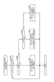
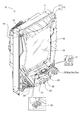
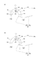
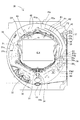
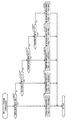
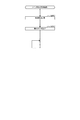
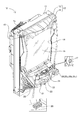
図1は、第1実施形態αにおけるパチンコ機10の斜視図である。パチンコ機10は、略矩形に組み合わされた木製の外枠11を備えている。パチンコ機10を遊技ホールに設置する際には、この外枠11が遊技ホールの島設備に固定される。また、パチンコ機10は、外枠11に回動可能に支持されたパチンコ機本体12を備えている。パチンコ機本体12は、内枠13と、内枠13の前面に配置された前扉枠14とを備えている。内枠13は、外枠11に対して金属製のヒンジ15によって回動可能に支持されている。前扉枠14は、内枠13に対して金属製のヒンジ16によって回動可能に支持されている。内枠13の背面には、主制御装置、音声発光制御装置、表示制御装置など、パチンコ機本体12を制御する制御機器が配置されている。これら制御機器の詳細については後述する。さらに、パチンコ機10には、シリンダ錠17が設けられている。シリンダ錠17は、内枠13を外枠11に対して開放不能に施錠する機能と、前扉枠14を内枠13に対して開放不能に施錠する機能とを有する。各施錠は、シリンダ錠17に対して専用の鍵を用いた所定の操作が行われることによって解錠される。
<<A>> First embodiment α:
<<A1>> Structure of the gaming machine:
FIG. 1 is a perspective view of a
前扉枠14の略中央部には、開口された窓部18が形成されている。前扉枠14の窓部18の周囲には、パチンコ機10を装飾するための樹脂部品や電飾部品が設けられている。電飾部品は、LEDなどの各種ランプからなる発光手段によって構成されている。発光手段は、パチンコ機10によって行われる当たり抽選時、大当たり当選時、リーチ発生時などに点灯又は点滅することによって、演出効果を高める役割を果たす。また、前扉枠14の裏側には、2枚の板ガラスからなるガラスユニット19が配置されており、開口された窓部18がガラスユニット19によって封じられている。内枠13には、後述する遊技盤が着脱可能に取り付けられており、パチンコ機10の遊技者は、パチンコ機10の正面からガラスユニット19を介して遊技盤を視認することができる。遊技盤の詳細については後述する。
An
前扉枠14には、遊技球を貯留するための上皿20と下皿21とが設けられている。上皿20は、上面が開放した箱状に形成されており、図示しない貸出機から貸し出された貸出球やパチンコ機本体12から排出された賞球などの遊技球を貯留する。上皿20に貯留された遊技球は、パチンコ機本体12が備える遊技球発射機構に供給される。遊技球発射機構は、遊技者による操作ハンドル25の操作によって駆動し、上皿20から供給された遊技球を遊技盤の前面に発射する。下皿21は、上皿20の下方に配置されており、上面が開放した箱状に形成されている。下皿21は、上皿20で貯留しきれなかった遊技球を貯留する。下皿21の底面には、下皿21に貯留された遊技球を排出するための排出口22が形成されている。排出口22の下方にはレバー23が設けられており、遊技者がレバー23を操作することによって、排出口22の閉状態と開状態とを切り替えることが可能である。遊技者がレバー23を操作して排出口22を開状態にすると、排出口22から遊技球が落下し、遊技球は下皿21から外部に排出される。
The
上皿20の周縁部の前方には、操作受入手段としての演出操作ボタン24が設けられている。演出操作ボタン24は、パチンコ機10によって行われる遊技演出に対して、遊技者が入力操作を行うための操作部である。パチンコ機10によって用意された所定のタイミングで遊技者が演出操作ボタン24を操作することによって、当該操作が反映された遊技演出がパチンコ機10によって行われる。
An
さらに、前扉枠14の正面視右側には、遊技者が操作するための操作ハンドル25が設けられている。遊技者が操作ハンドル25を操作(回動操作)すると、当該操作に連動して、遊技球発射機構から遊技盤の前面に遊技球が発射される。操作ハンドル25の内部には、遊技球発射機構の駆動を許可するためのタッチセンサー25aと、遊技者による押下操作によって遊技球発射機構による遊技球の発射を停止させるウェイトボタン25bと、操作ハンドル25の回動操作量を電気抵抗の変化により検出する可変抵抗器25cとが設けられている。遊技者が操作ハンドル25を握ると、タッチセンサー25aがオンになり、遊技者が操作ハンドル25を右回りに回動操作すると、可変抵抗器25cの抵抗値が回動操作量に対応して変化し、可変抵抗器25cの抵抗値に対応した強さで遊技球発射機構から遊技盤の前面に遊技球が発射される。
Further, an
また、上皿20の周縁部の正面視左側には、遊技者が操作するための遊技球発射ボタン26が設けられている。遊技球発射ボタン26は、遊技者によって操作されることによって、遊技者の操作ハンドル25の回動操作量にかかわらず、所定の発射強度で、遊技盤の前面に遊技球が発射される。具体的には、遊技者が遊技球発射ボタン26を操作すると、操作ハンドル25の回動操作量が最大である場合と同じ発射強度で遊技球が遊技盤の前面に発射される。本実施形態の場合、遊技球発射ボタン26が操作されることによって遊技球が発射されると、遊技球は遊技盤の正面視右側に流れるとともに、遊技盤の右側を流下する。すなわち、遊技球発射ボタン26を操作することによって、遊技者はいわゆる「右打ち」をすることができる。なお、本実施形態のパチンコ機10においては、遊技球発射ボタン26が操作された場合、タッチセンサー25aがオンであることを条件として、遊技球が遊技盤に発射されるように構成されている。すなわち、遊技者は、操作ハンドル25を握ることによって少なくともタッチセンサー25aをオンにした上で、遊技球発射ボタン26を操作することで、遊技球発射ボタン26の操作を契機とした遊技球の発射を実現することができる。
On the left side of the peripheral portion of the
なお、本実施形態においては、遊技球発射ボタン26は、上皿20の周縁部の正面視左側に配置される構成を採用したが、遊技球発射ボタン26が他の位置に配置される構成を採用してもよい。例えば、遊技球発射ボタン26を、ウェイトボタン25bと同様に、操作ハンドル25の内部(周縁部)に配置する構成を採用してもよい。このようにすることで、遊技者が、操作ハンドル25、ウェイトボタン25b、遊技球発射ボタン26を、右手のみで操作することを可能にする。
In the present embodiment, the game
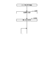
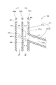
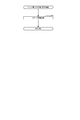
図2は、遊技盤30の正面図である。遊技盤30は、合板によって構成されており、その前面には遊技領域PAが形成されている。遊技盤30には、遊技領域PAの外縁の一部を区画するようにして内レール部31aと、外レール部31bとが取り付けられている。内レール部31aと外レール部31bとの間には、遊技球を誘導するための誘導レール31が形成されている。遊技球発射機構から発射された遊技球は、誘導レール31に誘導されて遊技領域PAの上部に放出され、その後、遊技領域PAを流下する。遊技領域PAには、遊技盤30に対して略垂直に複数の釘42が植設されるとともに、風車等の各役物が配設されている。これら釘42や風車は、遊技領域PAを流下する遊技球の落下方向を分散、整理する。
FIG. 2 is a front view of the
遊技盤30には、一般入賞口32、第1始動口33、第2始動口34、スルーゲート35、種別決定ゲート202及び、可変入賞装置36が設けられている。また、遊技盤30には、V入賞機構210が設けられている。さらに、遊技盤30には、可変表示ユニット40及びメイン表示部45が設けられている。メイン表示部45は、特図ユニット37と、普図ユニット38と、ラウンド表示部39とを有している。
The
一般入賞口32は、遊技球が入球可能な入球口であり、遊技盤30上に複数設けられている。本実施形態では、一般入賞口32に遊技球が入球すると、10個の遊技球が賞球として払出装置71から払い出される。
The general winning
第1始動口33は、遊技球が入球可能な入球口である。第1始動口33は、遊技盤30の中央下方に設けられている。本実施形態では、第1始動口33に遊技球が入球すると、3個の遊技球が賞球として払い出されるとともに、後述する当たり抽選が実行される。
The first starting opening 33 is a ball entrance into which a game ball can enter. The
第2始動口34は、遊技球が入球可能な入球口であり、遊技盤30の右側に設けられている。本実施形態では、第2始動口34に遊技球が入球すると、3個の遊技球が賞球として払い出されるとともに、後述する当たり抽選が実行される。また、第2始動口34には、電動役物34aが設けられている。
The
スルーゲート35は、縦方向に貫通した貫通孔を備えている。スルーゲート35は、電動役物34aを開放状態とするための抽選を実行するための契機となるスルーゲートである。具体的には、遊技球がスルーゲート35を通過すると、主制御装置60は、当該通過を契機として内部抽選(電動役物開放抽選)を行う。内部抽選の結果、電役開放に当選すると、電動役物34aは、所定の態様で開放状態となる電役開放状態へと移行する。スルーゲート35は、遊技球の流下方向に対して第2始動口34よりも上流側に配置されているため、スルーゲート35を通過した遊技球は、通過後に遊技領域PAを流下して第2始動口34へ入球することが可能となっている。なお、本実施形態では、スルーゲート35を遊技球が通過しても、賞球の払い出しは実行されない。
The through
可変入賞装置36は、遊技盤30の背面側へと通じる第1大入賞口36aと、当該第1大入賞口36aを開閉する第1開閉扉36bとを備えている。第1開閉扉36bは、通常は遊技球が第1大入賞口36aに入球できない閉鎖状態となっている。第1始動口33又は第2始動口34に遊技球が入球すると、主制御装置60は、当たり抽選(内部抽選)を実行する。当たり抽選の結果、大当たり又は小当たりに当選すると、パチンコ機10は、開閉実行モードに移行する。開閉実行モードとは、可変入賞装置36の第1開閉扉36bおよび、後述するV入賞機構210が備える第2開閉扉213の開閉処理を実行するモードである。具体的には、可変入賞装置36の第1開閉扉36bは、開閉実行モードに移行すると、遊技球が入球できない閉鎖状態から遊技球が入球可能な開放状態に遷移するとともに、所定の条件が満たされた後に、再び、閉鎖状態に遷移する。本実施形態では、可変入賞装置36の第1大入賞口36aに遊技球が入球すると、払出装置71によって15個の遊技球が賞球として払い出される。
The variable winning a
種別決定ゲート202は当たり抽選の結果、大当たりに当選した場合に、当該大当たりの種別を決定するために用いられる入球口である。具体的には、所定の遊技回における当たり抽選において大当たりに当選し、当該遊技回の終了後に、開閉実行モードが開始される。本実施形態のパチンコ機10は、開閉実行モードが開始されると、遊技球を遊技盤30の右側に向けて発射するように遊技者を案内する演出(右打ち示唆演出)が実行される。当該右打ち示唆演出に従って遊技者が操作ハンドル25を操作して遊技盤30の右側に遊技球を発射させ、種別決定ゲート202に遊技球が入球すると、当該遊技球の入球を契機として大当たりの種別を決定する種別決定処理が主制御装置60によって実行される。そして、当該種別決定処理によって、大当たりの種別が決定される。なお、主制御装置60によって実行される種別決定処理、および、パチンコ機10において設定されている大当たり種別については後述する。
The
遊技盤30の最下部にはアウト口43が設けられており、各種入球口に入球しなかった遊技球は、アウト口43を通って遊技領域PAから排出される。
An
特図ユニット37は、第1図柄表示部37aと、第2図柄表示部37bとを備えている。第1図柄表示部37a及び第2図柄表示部37bは、それぞれ、複数のセグメント発光部が所定の態様で配列されたセグメント表示器によって構成されている。
The
第1図柄表示部37aは第1の図柄を表示するための表示部である。第1の図柄とは、第1始動口33への遊技球の入球を契機とした当たり抽選に基づいて変動表示または停止表示される図柄をいう。第1図柄表示部37aは、第1始動口33への遊技球の入球を契機とした当たり抽選が行われると、セグメント表示器に、抽選結果に対応した表示を行なわせるまでの表示態様として、第1の図柄の変動表示又は所定の表示を行なわせる。抽選が終了した際には、第1図柄表示部37aは、セグメント表示器に、抽選結果に対応した第1の図柄の停止表示を行なわせる。以下、第1始動口33への遊技球の入球を契機として当たり抽選が実行される遊技回を第1始動口用遊技回とも呼ぶ。
The first
第2図柄表示部37bは第2の図柄を表示するための表示部である。第2の図柄とは、第2始動口34への遊技球の入球を契機とした当たり抽選に基づいて変動表示または停止表示される図柄をいう。第2図柄表示部37bは、第2始動口34への遊技球の入球を契機とした当たり抽選が行われると、セグメント表示器に、抽選結果に対応した表示を行なわせるまでの表示態様として、第2の図柄の変動表示又は所定の表示を行なわせる。抽選が終了した際には、第2図柄表示部37bは、第2図柄表示部37bは、セグメント表示器に、抽選結果に対応した第2の図柄の停止表示を行なわせる。以下、第2始動口34への遊技球の入球を契機として当たり抽選が実行される遊技回を第2始動口用遊技回とも呼ぶ。
The second
ここで、第1図柄表示部37aに表示される第1の図柄、または、第2図柄表示部37bに表示される第2の図柄の変動表示が開始されてから停止表示されるまでの時間を変動時間とも呼ぶ。具体的には、第1図柄表示部37aに表示される第1の図柄の変動表示が開始されてから停止表示されるまでの時間を第1の変動時間とも呼び、第2図柄表示部37bに表示される第2の図柄の変動表示が開始されてから停止表示されるまでの時間を第2の変動時間とも呼ぶ。
Here, the first symbol displayed on the first
特図ユニット37は、さらに、第1図柄表示部37a及び第2図柄表示部37bに隣接した位置に、LEDランプからなる第1保留表示部37cおよび第2保留表示部37dを備えている。
The
第1保留表示部37cは、点灯させるLEDランプの色や組み合わせによって、第1始動口33の保留個数を表示する。本実施形態では、第1始動口33に入球した遊技球は、最大4個まで保留される。
The 1st hold|
第2保留表示部37dは、点灯させるLEDランプの色や組み合わせによって、第2始動口34の保留個数を表示する。本実施形態では、第2始動口34に入球した遊技球は、最大4個まで保留される。
The second
普図ユニット38は、複数のLEDランプが所定の態様で配列された発光表示部によって構成されている。普図ユニット38は、スルーゲート35の通過を契機とした電動役物開放抽選が行われると、発光表示器の表示態様として点灯表示、点滅表示又は所定の態様の表示をさせる。電動役物開放抽選が終了した際には、普図ユニット38は、抽選結果に対応した所定の態様の表示を行う。
The
ラウンド表示部39は、複数のLEDランプ(以下、ラウンドランプとも呼ぶ)が所定の態様で配列された発光表示部によって構成されており、開閉実行モードにおいて発生するラウンド遊技の回数の表示、又は、それに対応した表示をする。ラウンド遊技とは、予め定められた上限継続時間が経過すること、又は、予め定められた上限個数の遊技球が可変入賞装置36に入球することのいずれか一方の条件が満たされるまで、第1開閉扉36bまたは第2開閉扉213の開放状態を継続する遊技のことである。ラウンド遊技の回数は、その移行の契機となった大当たり当選の種類に応じて異なる。ラウンド表示部39は、開閉実行モードが開始され、種別決定ゲート202に遊技球が入球したことを契機として実行された種別決定処理において大当たり種別が決定した場合に、当該決定した大当たり種別に対応したラウンド遊技の回数の表示を開始し、開閉実行モードが終了した場合に終了する。換言すれば、開閉実行モードが開始された場合であっても、開閉実行モードの開始後に種別決定ゲート202に遊技球が入球していない期間は、種別決定処理が開始されず、大当たり種別(ラウンド遊技の回数を含む)が決定されないので、ラウンド表示部39へのラウンド遊技の回数の表示はされない。その後、種別決定ゲート202に遊技球が入球した場合には、種別決定処理が開始され、大当たり種別(ラウンド遊技の回数を含む)が決定されるので、ラウンド表示部39にラウンド遊技の回数が表示される。
The
なお、特図ユニット37、普図ユニット38、及びラウンド表示部39は、セグメント表示器やLEDランプによる発光表示器によって構成されることに限定されず、例えば、液晶表示装置、有機EL表示装置、CRT又はドットマトリックス表示器など、抽選中及び抽選結果を示すことが可能な種々の表示装置によって構成されてもよい。
Note that the
可変表示ユニット40は、遊技領域PAの略中央に配置されている。可変表示ユニット40は、図柄表示装置41を備える。図柄表示装置41は、液晶ディスプレイを備えている。図柄表示装置41は、表示制御装置100によって表示内容が制御される。なお、可変表示ユニット40が備える表示装置の構成は、図柄表示装置41に限定されず、例えば、プラズマディスプレイ装置、有機EL表示装置又はCRTなど、種々の表示装置によって構成されてもよい。
The
図柄表示装置41は、第1始動口33への遊技球の入球に基づいて第1図柄表示部37aが変動表示又は所定の表示をする場合に、それに合わせて図柄の変動表示又は抽選結果の予告等に基づく所定の表示を行う。また、図柄表示装置41は、第2始動口34への遊技球の入球に基づいて第2図柄表示部37bが変動表示又は所定の表示をする場合に、それに合わせて図柄の変動表示又は所定の表示を行う。図柄表示装置41は、第1始動口33又は第2始動口34への遊技球の入球を契機とした図柄の変動表示又は所定の表示をすることに限らず、大当たり当選となった場合に移行する開閉実行モード中の演出表示なども行なう。以下、図柄表示装置41の詳細について説明する。
The
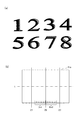
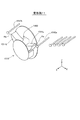
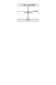
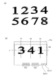
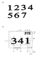
図3は、図柄表示装置41において変動表示される図柄及び表示面41aを示す説明図である。図3(a)は、図柄表示装置41において変動表示される液晶用図柄を示す説明図である。液晶用図柄は、図柄表示装置41に表示される画像であって、第1図柄表示部37aに表示される第1の図柄および第2図柄表示部37bに表示される第2の図柄に対応した図柄である。第1始動口33への遊技球の入球を契機とした遊技回が実行されている場合には、第1図柄表示部37aに表示される第1の図柄に対応した液晶用図柄が表示面41aに表示され、第2始動口34への遊技球の入球を契機とした遊技回が実行されている場合には、第2図柄表示部37bに表示される第2の図柄に対応した液晶用図柄が表示面41aに表示される。
FIG. 3 is an explanatory diagram showing the symbols and the
図3(a)に示すように、図柄表示装置41には、液晶用図柄として、数字の1〜8を示す図柄が変動表示される。なお、変動表示される図柄として、数字の1〜8を示す各図柄に、キャラクターなどの図柄が付された図柄を採用してもよい。
As shown in FIG. 3( a ), as the liquid crystal symbols,
図3(b)は、図柄表示装置41の表示面41aを示す説明図である。図示するように、表示面41aには、メイン表示領域MAが表示される。メイン表示領域MAには、左、中、右の3つの図柄列Z1、Z2、Z3が表示される。各図柄列Z1〜Z3には、図3(a)に示した数字1〜8の図柄が、数字の昇順又は降順に配列されるとともに、各図柄列が周期性をもって上から下へ又は下から上へとスクロールする変動表示が行われる。図3(b)に示すように、スクロールによる変動表示の後、各図柄列毎に1個の図柄が、有効ラインL上に停止した状態で表示される。具体的には、第1始動口33又は第2始動口34へ遊技球が入球すると、各図柄列Z1〜Z3の図柄が周期性をもって所定の向きにスクロールする変動表示が開始される。そして、スクロールする各図柄が、図柄列Z1、図柄列Z3、図柄列Z2の順に、変動表示から待機表示に切り替わり、最終的に各図柄列Z1〜Z3に所定の図柄が停止表示した状態となる。図柄の変動表示が終了して停止表示した状態となる場合、主制御装置60による当たり抽選の結果が大当たり当選であった場合には、予め定められた所定の図柄の組み合わせが有効ラインL上に形成される。例えば、同一の図柄の組み合わせが有効ラインL上に形成される。なお、図柄表示装置41における図柄の変動表示の態様は、上述の態様に限定されることなく、図柄列の数、有効ラインの数、図柄列における図柄の変動表示の方向、各図柄列の図柄数など、図柄の変動表示の態様は種々の態様を採用可能である。
FIG. 3B is an explanatory diagram showing the
ここで、遊技回とは、第1図柄表示部37aまたは第2図柄表示部37bの変動表示が開始されてから、変動表示が終了して停止表示となり、当該停止表示が終了するまでを言い、第1始動口33又は第2始動口34のいずれかの入球に基づいて取得された特別情報についての当たり抽選の抽選結果を、遊技者に報知する処理の1単位である。換言すれば、パチンコ機10は、1遊技回毎に、1回の当たり抽選の抽選結果を遊技者に告知する。本実施形態のパチンコ機10は、第1始動口33又は第2始動口34への遊技球の入球に基づいて特別情報を取得すると、1遊技回毎に、第1図柄表示部37a又は第2図柄表示部37bのいずれか一方において、セグメント表示器を変動表示させた後に、当該取得した特別情報の抽選結果に対応した表示となるようにセグメント表示器を停止表示させる。また、本実施形態のパチンコ機10は、第1始動口33又は第2始動口34への遊技球の入球に基づいて特別情報を取得すると、1遊技回毎に、図柄表示装置41において、第1液晶用図柄または第2液晶用図柄として図柄列を変動表示させた後に、当該取得した特別情報の抽選結果に対応した表示となるように図柄列を停止表示させる。また、1回の遊技回に要する時間を単位遊技時間とも呼ぶ。単位遊技時間は、変動表示が開始されてから所定の抽選結果が停止表示されるまでの時間である変動時間と、所定の抽選結果が停止表示されている時間である停止時間とによって構成されている。
Here, the game times means from the start of the variable display of the first
図3(b)に示すように、図柄表示装置41の表示面41aには、第1保留表示領域Ds1と、第2保留表示領域Ds2とが表示される。第1保留表示領域Ds1には、第1始動口33への入球に基づく保留遊技回の数に対応した表示がされる。第2保留表示領域Ds2には、第2始動口34への入球に基づく保留遊技回の数に対応した表示がされる。保留遊技回とは、未実行の遊技回であって、第1始動口33または第2始動口34への入球に基づいて取得された特別情報について、当たり抽選の抽選結果を報知するための変動表示が開始されていない遊技回を言う。第1始動口33への入球に基づいて保留可能な保留遊技回の数は4つである。従って、図示するように、第1保留表示領域Ds1には4つの保留遊技回に対応した保留表示(以下、第1保留遊技回表示とも呼ぶ)が表示可能である。また、第2始動口34への入球に基づいて保留可能な保留遊技回の数は4つである。従って、図示するように、第2保留表示領域Ds2には4つの保留遊技回に対応した保留表示(以下、第2保留遊技回表示とも呼ぶ)が表示可能である。
As shown in FIG. 3B, a first reserved display area Ds1 and a second reserved display area Ds2 are displayed on the
また、図3(b)に示すように、表示面41aには、特図ユニット37の第1図柄表示部37aに表示される第1の図柄の変動表示および停止表示に同期した点滅表示および点灯表示を行う第1同期表示部Sync1と、特図ユニット37の第2図柄表示部37bに表示される第2の図柄の変動表示および停止表示に同期した点滅表示および点灯表示を行う第2同期表示部Sync2とを備える。具体的には、第1図柄表示部37aが変動表示をしている場合には第1同期表示部Sync1は点滅表示をし、第1図柄表示部37aが停止表示をしている場合には第1同期表示部Sync1は点灯表示をする。また、第2図柄表示部37bが変動表示をしている場合には第2同期表示部Sync2は点滅表示をし、第2図柄表示部37bが停止表示をしている場合には第2同期表示部Sync2は点灯表示をする。
Further, as shown in FIG. 3(b), on the
なお、本実施形態においては、表示面41aは、メイン表示領域MA、第1保留表示領域Ds1、第2保留表示領域Ds2、第1同期表示部Sync1、および、第2同期表示部Sync2を表示する構成としたが、表示面41aがこれらの表示の一部または全部を表示しない構成を採用してもよい。
In addition, in the present embodiment, the
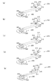
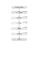
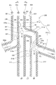
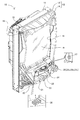
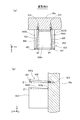
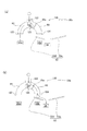
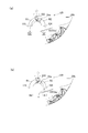
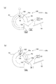
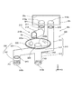
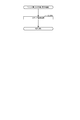
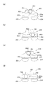
図4は、V入賞機構210を説明する説明図である。図4(a)に示すように、V入賞機構210は、クルーン220と、遊技盤30の右側を流下する遊技球をクルーン220まで流通させる流路211と、遊技盤30の右側を流下する遊技球が流路211へ流入するための第2大入賞口212の開閉を行う第2開閉扉213と、第2大入賞口212から遊技球が流入したことを検出する検出センサー214と、遊技領域の背面側に連通する排出口215と、第2大入賞口212から流入した遊技球を流路211の貯留部218に一時的に貯留させる貯留弁216と、当該貯留弁216を駆動させる貯留弁駆動機構217とを備える。また、クルーン220は、V入賞口222を1つ、非V入賞口224を5つ備える。V入賞口222は、遊技球が入球すると大当たりとなる入賞口である。非V入賞口224は、遊技球が入球しても大当たりとはならず、遊技領域から遊技球を排出する。
FIG. 4 is an explanatory diagram illustrating the
次に、V入賞機構210の動作について説明する。遊技回における当たり抽選において特定の種別の大当たり、または、小当たりに当選し、当該遊技回の終了後に開閉実行モードが開始された場合、第2開閉扉213の開放条件が成立することによって、図4(a)に示すように第2開閉扉213が開放する。
Next, the operation of the
遊技者が操作ハンドル25を操作することによって遊技盤30の右側に遊技球を発射させ、第2開閉扉213の開放中に当該第2開閉扉213の近傍を遊技球が流通すると、図4(b)に示すように、開放した第2開閉扉213に案内されて遊技球が第2大入賞口212から流路211に流入する。第2開閉扉213の開放後に最初に流路211に流入した遊技球は、閉鎖された貯留弁216によって貯留部218に貯留される。また、本実施形態においては、貯留部218に貯留可能な遊技球の数は1つである。なお、変形例として、貯留部218に複数個の遊技球を貯留可能な構成を採用してもよい。
When the player operates the operation handle 25 to shoot a game ball to the right side of the
図4(c)に示すように、貯留部218に遊技球が1つ貯留された状態において、第2大入賞口212から遊技球が流入した場合には、当該遊技球は、先に貯留部218に貯留されている遊技球によって当該貯留部218への流通が阻止され、流路211における排出口215の方向に流通し、排出口215から遊技領域の背面側に排出される。
As shown in FIG. 4C, when one game ball is stored in the
図4(d)に示すように、第2開閉扉213の閉鎖条件が成立すると、第2開閉扉213は閉鎖される。閉鎖条件の詳細については後述する。その後、図4(e)に示すように、貯留弁駆動機構217が貯留弁216を開放方向に駆動させ、貯留部218に貯留されていた遊技球は、流路211におけるクルーン220の方向へ流通する。そして、流路211から排出された遊技球は、クルーン220の上面を流通し、その後、V入賞口222または非V入賞口224に入球する。上述のように、V入賞口222に遊技球が入球すると大当たりとなり、非V入賞口224に遊技球が入球すると、大当たりとはならず遊技領域から排出される。
As shown in FIG. 4D, when the closing condition of the second opening/
また、本実施形態では、V入賞機構210の第2大入賞口212に遊技球が1個入球(流入)する毎に、払出装置71によって15個の遊技球が賞球として払い出される。第2大入賞口212への遊技球の入球は、検出センサー214によって検出される。
In addition, in the present embodiment, every time one game ball enters (inflows) into the second special winning
なお、上述したように、変形例として、貯留部218に複数個の遊技球を貯留可能な構成を採用した場合、貯留弁216が開放されることによって、複数個の遊技球がクルーン220の上面を流通するため、遊技球がV入賞口222に入球する確率を向上させることができ、遊技者の期待感を向上させることができる。この場合において、仮にV入賞口222に2個の遊技球が入球した場合であっても、最初にV入賞口222に入球した遊技球のみに基づいて大当たりとして扱い、V入賞口222への2個目の遊技球の入球については大当たりとして取り扱わず、非V入賞口224への遊技球の入球と同様に、遊技領域の背面に排出される。
As described above, as a modified example, when a configuration in which a plurality of game balls can be stored in the
《A2》遊技機の電気的構成:
次に、パチンコ機10の電気的構成について説明する。本説明においては、パチンコ機10の電気的構成をブロック図を用いて説明する。
<<A2>> Electrical configuration of the gaming machine:
Next, the electrical configuration of the
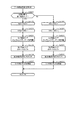
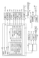
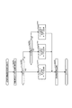
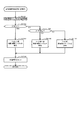
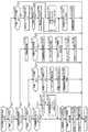
図5は、パチンコ機10の電気的構成を示すブロック図である。パチンコ機10は、主に、主制御装置60を中心に構成されるとともに、音声発光制御装置90と、表示制御装置100とを備えている。主制御装置60は、遊技の主たる制御を司る主制御基板61を備えている。主制御基板61は、複数の機能を有する素子によって構成されるMPU62を備えている。MPU62は、各種制御プログラムや固定値データを記録したROM63と、ROM63内に記録されているプログラムを実行する際に各種データ等を一時的に記憶するためのメモリであるRAM64とを備えている。MPU62は、その他、割込回路、タイマー回路、データ入出力回路、乱数発生器としてのカウンタ回路を備えている。なお、MPU62が有する機能の一部を、別の素子が備えていてもよい。また、ROM63やRAM64に設けられている各種エリアの詳細については後述する。
FIG. 5 is a block diagram showing an electrical configuration of the
主制御基板61には、入力ポート及び出力ポートがそれぞれ設けられている。主制御基板61の入力側には、払出制御装置70と、電源装置85に設けられた停電監視回路86とが接続されている。主制御基板61は、停電監視回路86を介して、電源装置85から直流安定24Vの電源の供給を受ける。電源装置85は、外部電源としての商用電源に接続されており、商用電源から供給される外部電力を、主制御装置60や払出制御装置70等が必要な動作電力に変換して、各装置に電力を供給する。また、主制御基板61の入力側には、一般入賞口32、第1始動口33、第2始動口34、スルーゲート35、可変入賞装置36などの各種の入球口やスルーゲートに設けられた各種検出センサーが接続されている。主制御基板61のMPU62は、これらの検出センサーからの信号に基づいて、遊技領域PAを流下する遊技球が各入球口へ入球したか否かの判定や、遊技球がスルーゲートを通過したか否かの判定を行う。さらに、MPU62は、第1始動口33、第2始動口34への遊技球の入球に基づいて当たり抽選を実行する。
The
主制御基板61の出力側には、可変入賞装置36の第1開閉扉36bを開閉動作させる第1開閉扉駆動部36cと、第2始動口34の電動役物34aを開閉動作させる電動役物駆動部34bと、第2開閉扉213を開閉動作させる第2開閉扉駆動部213bと、貯留弁216を駆動させる貯留弁駆動機構217と、メイン表示部45とが接続されている。主制御基板61には各種ドライバ回路が設けられており、MPU62は、当該ドライバ回路を通じて各種駆動部の駆動制御を実行する。
On the output side of the
具体的には、MPU62は、開閉実行モードにおいては、第1開閉扉36bが開閉されるように第1開閉扉駆動部36cを駆動制御し、第2開閉扉213が開閉されるように第2開閉扉駆動部213bを駆動制御する。特定の大当たりおよび小当たりを契機とした開閉実行モードにおいては、MPU62は、貯留弁216が開閉されるように貯留弁駆動機構217を駆動制御する。また、電動役物開放抽選の結果、電役開放に当選した場合には、MPU62は、電動役物34aが開放されるように電動役物駆動部44bの駆動制御を実行する。さらに、各遊技回においては、MPU62は、メイン表示部45における第1図柄表示部37a又は第2図柄表示部37bの表示制御を実行する。また、開閉実行モードにおいて大当たり種別が決定され開閉実行モードにおいて実行されるラウンド遊技の回数が決定した場合には、メイン表示部45におけるラウンド表示部39の表示制御を実行する。
Specifically, in the opening/closing execution mode, the
また、主制御基板61の送信側には、払出制御装置70と、音声発光制御装置90とが接続されている。払出制御装置70には、例えば、主制御装置60から入球判定結果に基づいて賞球コマンドが送信される。主制御装置60が賞球コマンドを送信する際には、主制御基板61のMPU62は、ROM63のコマンド情報記憶エリア63fを参照する。具体的には、一般入賞口32への遊技球の入球を特定した場合には10個の遊技球の払い出しに対応した賞球コマンドが主制御装置60から送信され、第1始動口33への遊技球の入球を特定した場合には3個の遊技球の払い出しに対応した賞球コマンドが主制御装置60から送信され、第2始動口34への遊技球の入球を特定した場合には3個の遊技球の払い出しに対応した賞球コマンドが主制御装置60から送信される。払出制御装置70は、主制御装置60から受信した賞球コマンドに基づいて、払出装置71を制御して賞球の払出を行う。
A
払出制御装置70には、発射制御装置80が接続されている。発射制御装置80は、遊技球発射機構81の発射制御を行う。遊技球発射機構81は、所定の発射条件が整っている場合に駆動される。また、発射制御装置80には、操作ハンドル25が接続されている。上述のように、操作ハンドル25は、タッチセンサー25aと、ウェイトボタン25bと、可変抵抗器25cとを備える。遊技者が操作ハンドル25を握ることによって、タッチセンサー25aがオンになり、遊技者が操作ハンドル25を回動操作すると、可変抵抗器25cの抵抗値が回動操作量に対応して変化し、可変抵抗器25cの抵抗値に対応した強さで遊技球発射機構から遊技盤の前面に遊技球が発射される。さらに、発射制御装置80には、遊技球発射ボタン26が接続されている。遊技者によって遊技球発射ボタン26が操作された場合、タッチセンサー25aがオンであることを条件として、遊技球が遊技盤に発射されるように構成されている。
A
音声発光制御装置90は、主制御装置60から送信された各種コマンドを受信し、受信した各種コマンドに対応した処理を実行する。主制御装置60が各種コマンドを送信する際には、ROM63のコマンド情報記憶エリア63fを参照する。これら各種コマンドの詳細については後述する
The voice
その他、音声発光制御装置90は、主制御装置60から受信した各種コマンドに基づいて、前扉枠14に配置されたLEDなどの発光手段からなる各種ランプ47の駆動制御や、スピーカー46の駆動制御を行うとともに、表示制御装置100の制御を行う。また、音声発光制御装置90には、演出操作ボタン24が接続されており、所定のタイミングで遊技者によって演出操作ボタン24が操作された場合には、当該操作を反映した遊技演出を行うように各種ランプ47、スピーカー46、表示制御装置100等の制御を行う。
In addition, the sound
表示制御装置100は、音声発光制御装置90から受信した各種コマンドに基づいて、図柄表示装置41の表示制御を実行する。具体的には、表示制御装置100は、音声発光制御装置90から受信した各種コマンドに基づいて、図柄表示装置41における図柄の変動時間及び最終的に停止表示させる図柄の組み合わせの種類を把握するとともに、リーチの発生の有無、リーチ演出の内容、及び、第1液晶用図柄や第2液晶用図柄が変動表示をしている間に実行される演出の内容等を把握する。なお、本実施形態においては、第1液晶用図柄または第2液晶用図柄が停止表示している時間である停止時間は一定ある。従って、変動時間が決定されることによって、1遊技回に要する時間である単位遊技回時間は一意に決定される。以上、パチンコ機10の電気的構成について説明した。
The
図6は、当たり抽選などに用いられる各種カウンタの内容を示す説明図である。各種カウンタ情報は、MPU62が当たり抽選、大当たり種別の振分け、メイン表示部45の表示の設定、及び、図柄表示装置41の図柄表示の設定などを行う際に用いられる。具体的には、当たり抽選には当たり乱数カウンタC1が用いられる。大当たり種別を振り分ける際には大当たり種別カウンタC2が用いられる。図柄表示装置41に表示させる図柄列を外れ変動させる際にリーチを発生させるか否かのリーチ判定にはリーチ乱数カウンタC3が用いられる。
FIG. 6 is an explanatory diagram showing the contents of various counters used for winning lottery and the like. The various counter information is used when the
当たり乱数カウンタC1の初期値設定には乱数初期値カウンタCINIが用いられる。また、メイン表示部45の第1図柄表示部37a及び第2図柄表示部37b、並びに図柄表示装置41における変動時間を決定する際には変動種別カウンタCSが用いられる。さらに、第2始動口34の電動役物34aを開放状態とするか否かの電動役物開放抽選には電動役物開放カウンタC4が用いられる。
The random number initial value counter CINI is used to set the initial value of the hit random number counter C1. Further, when determining the variation time in the first
各カウンタC1〜C3、CINI、CS、C4は、その更新の都度、カウンタ値に1が加算され、最大値に達した後に0に戻るループカウンタである。各カウンタは短時間の間隔で更新され、その更新値がRAM64の所定領域に設定された抽選カウンタ用バッファ64aに適宜記憶される。
Each of the counters C1 to C3, CINI, CS, and C4 is a loop counter in which 1 is added to the counter value each time it is updated, and the counter value returns to 0 after reaching the maximum value. Each counter is updated at short time intervals, and the updated value is appropriately stored in the
また、RAM64には保留情報記憶エリア64bと、判定処理実行エリア64cと、種別判定処理実行エリア64iとが設けられている。保留情報記憶エリア64bには、第1保留エリアRaと第2保留エリアRbとが設けられている。本実施形態では、第1始動口33に遊技球が入球すると、入球のタイミングにおける当たり乱数カウンタC1、リーチ乱数カウンタC3および変動種別カウンタCSの各値が保留情報記憶エリア64bの第1保留エリアRaに時系列的に記憶される。また、第2始動口34に遊技球が入球すると、入球のタイミングにおける当たり乱数カウンタC1、リーチ乱数カウンタC3および変動種別カウンタCSの各値が保留情報記憶エリア64bの第2保留エリアRbに時系列的に記憶される。
Further, the
当たり乱数カウンタC1の詳細について説明する。当たり乱数カウンタC1は、上述のように当たり抽選に用いられる。当たり乱数カウンタC1は、例えば、0〜1199の範囲内で順に1ずつ加算され、最大値に達した後0に戻るように構成されている。また、当たり乱数カウンタC1が1周すると、その時点の乱数初期値カウンタCINIの値が当該当たり乱数カウンタC1の初期値として読み込まれる。なお、乱数初期値カウンタCINIは、当たり乱数カウンタC1と同様のループカウンタである(値=0〜1199)。 The details of the hit random number counter C1 will be described. The hit random number counter C1 is used in the hit lottery as described above. The hit random number counter C1 is configured to be incremented by 1 in the range of 0 to 1199, for example, and return to 0 after reaching the maximum value. When the hit random number counter C1 makes one round, the value of the random number initial value counter CINI at that time is read as the initial value of the hit random number counter C1. The random number initial value counter CINI is a loop counter similar to the winning random number counter C1 (value=0 to 1199).
当たり乱数カウンタC1は定期的に更新され、その更新値は、第1始動口33に遊技球が入球した場合には、当該入球のタイミングで保留情報記憶エリア64bの第1保留エリアRaに記憶され、第2始動口34に遊技球が入球した場合には、当該入球のタイミングで保留情報記憶エリア64bの第2保留エリアRbに記憶される。
The hit random number counter C1 is regularly updated, and when the game ball enters the first starting
第1保留エリアRaに記憶された当たり乱数カウンタC1の値は、判定処理実行エリア64cの実行エリアAEに移動し、ROM63の当否テーブル記憶エリア63aに記憶されている当否テーブルと照合され、大当たりとなるか否かが判定される。また、第2保留エリアRbに記憶された当たり乱数カウンタC1の値は、判定処理実行エリア64cの実行エリアAEに移動し、ROM63の当否テーブル記憶エリア63aに記憶されている当否テーブルと照合され、大当たりとなるか否かが判定される。
The value of the hit random number counter C1 stored in the first holding area Ra moves to the execution area AE of the determination
本実施形態のパチンコ機10においては、第1保留エリアRaまたは第2保留エリアRbに記憶された当たり乱数カウンタC1の値は、第1始動口33または第2始動口34に遊技球が入球することによって取得された順番に判定処理実行エリア64cの実行エリアAEに移動する。そして、実行エリアAEに移動した当たり乱数カウンタC1は、ROM63の当否テーブル記憶エリア63aに記憶されている当否テーブルと照合され、大当たりとなるか否かが判定される。
In the
次に、大当たり種別カウンタC2の詳細について説明する。大当たり種別カウンタC2は、大当たり種別を判定する際に用いられる。大当たり種別カウンタC2は、0〜99の範囲内で順に1ずつ加算され、最大値に達した後0に戻るように構成されている。 Next, the details of the jackpot type counter C2 will be described. The jackpot type counter C2 is used when determining the jackpot type. The jackpot type counter C2 is configured to be incremented by 1 in the range of 0 to 99, and return to 0 after reaching the maximum value.
大当たり種別カウンタC2は定期的に更新され、その更新値は、開閉実行モード中に種別決定ゲート202に遊技球が入球したタイミング、または、V入賞口222に遊技球が入球したタイミングで、保留情報記憶エリア64dに記憶される。
The jackpot type counter C2 is regularly updated, and the updated value is the timing when the game ball enters the
上述したように、MPU62は、判定処理実行エリア64cに記憶されている当たり乱数カウンタC1の値を用いて当たり抽選を行なう。さらに、MPU62は、これらの当たり乱数カウンタC1の値を用いて第1図柄表示部37a及び第2図柄表示部37bに停止表示させるセグメント表示器の表示態様を決定する。その決定に際しては、ROM63の停止結果テーブル記憶エリア63eに記憶されている停止結果テーブルが参照される。また、当たり抽選の結果が大当たりである場合には、開閉実行モードの開始後に種別決定ゲート202に遊技球が入球したことを契機として取得され種別判定処理実行エリア64iに記憶されている大当たり種別カウンタC2の値を用いて大当たり種別を判定する。種別判定処理によって決定された大当たり種別(ラウンド遊技回の実行回数)は、ラウンド表示部39に表示される。
As described above, the
次に、リーチ乱数カウンタC3の詳細について説明する。リーチ乱数カウンタC3は、当たり抽選の結果が大当たりではない場合においてリーチが発生するか否かを判定する際に用いられる。リーチ乱数カウンタC3は、例えば0〜238の範囲内で順に1ずつ加算され、最大値に達した後0に戻るように構成されている。 Next, details of the reach random number counter C3 will be described. The reach random number counter C3 is used when determining whether or not a reach occurs when the result of the winning lottery is not a big hit. The reach random number counter C3 is configured to add one by one in order within the range of 0 to 238, and return to 0 after reaching the maximum value.
リーチ乱数カウンタC3は定期的に更新され、その更新値は、第1始動口33に遊技球が入球したタイミングで保留情報記憶エリア64bの第1保留エリアRaに記憶され、第2始動口34に遊技球が入球したタイミングで保留情報記憶エリア64bの第2保留エリアRbに記憶される。第1保留エリアRaに記憶されたリーチ乱数カウンタC3の値は、判定処理実行エリア64cに移動した後、ROM63のリーチ判定用テーブル記憶エリア63cに記憶されているリーチ判定用テーブルと照合され、リーチが発生するか否かが判定される。第2保留エリアRbに記憶されたリーチ乱数カウンタC3の値は、判定処理実行エリア64cに移動した後、ROM63のリーチ判定用テーブル記憶エリア63cに記憶されているリーチ判定用テーブルと照合され、リーチが発生するか否かが判定される。ただし、当たり抽選の結果が大当たりとなり、開閉実行モードに移行する場合には、MPU62は、リーチ乱数カウンタC3の値に関係なくリーチ発生が決定される。
The reach random number counter C3 is regularly updated, and the updated value is stored in the first holding area Ra of the holding
リーチとは、図柄表示装置41の表示画面に表示される複数の図柄列のうち一部の図柄列について、大当たりに対応した図柄の組み合わせが成立する可能性がある図柄の一部の組み合わせが停止表示され、その状態で残りの図柄列において図柄の変動表示を行う表示状態のことを言う。なお、本実施形態のパチンコ機10において大当たりに対応した図柄の組み合わせとは、所定の有効ラインにおける同一の図柄の組み合わせのことをいう。具体例としては、図3(b)の表示面41aのメイン表示領域MAにおいて、最初に図柄列Z1において図柄が停止表示され、次に図柄列Z3においてZ1と同じ図柄が停止表示されることでリーチラインが形成され、当該リーチラインが形成されている状況化において図柄列Z2において図柄の変動表示が行われることでリーチとなる。そして、大当たりが発生する場合には、リーチラインを形成している図柄と同一の図柄が図柄列Z2に停止表示される。
Reach means that for some of the plurality of symbol strings displayed on the display screen of the
また、リーチには、リーチラインが形成された状態で、残りの図柄列において図柄の変動表示を行うとともに、その背景画面において所定のキャラクターなどを動画として表示することによりリーチ演出を行うものや、リーチラインが形成された図柄の組み合わせを縮小表示させる又は非表示とした上で、表示面41aの略全体において所定のキャラクターなどを動画として表示することによりリーチ演出を行うものが含まれる。また、リーチ演出が行われている場合又はリーチ表示の前に所定のキャラクターといった所定画像を用いた予告表示を行うか否かの決定を、リーチ乱数カウンタC3やその他のカウンタを用いて行うようにしてもよい。
Further, in the reach, while the reach line is formed, while performing the variable display of the symbols in the remaining symbol rows, and performing the reach effect by displaying a predetermined character or the like as a moving image on the background screen, A combination of symbols in which reach lines are formed is displayed in a reduced size or hidden, and then a predetermined character or the like is displayed as a moving image on substantially the
次に、変動種別カウンタCSの詳細について説明する。変動種別カウンタCSは、第1図柄表示部37a及び第2図柄表示部37bにおける変動時間と、図柄表示装置41における図柄の変動時間とを、MPU62において決定する際に用いられる。変動種別カウンタCSは、例えば0〜198の範囲内で順に1ずつ加算され、最大値に達した後0に戻るように構成されている。
Next, details of the fluctuation type counter CS will be described. The variation type counter CS is used when the
変動種別カウンタCSは、後述する通常処理が1回実行される毎に1回更新され、当該通常処理内の残余時間内でも繰り返し更新される。そして、第1図柄表示部37a又は第2図柄表示部37bにおける変動表示の開始時及び図柄表示装置41による図柄の変動開始時における変動パターンの決定に際して変動種別カウンタCSのバッファ値が取得される。第1図柄表示部37a及び第2図柄表示部37bにおける変動時間の決定に際しては、ROM63の変動時間テーブル記憶エリア63dに記憶されている変動時間テーブルが用いられる。
The variation type counter CS is updated once every time a normal process described below is executed once, and is repeatedly updated within the remaining time in the normal process. Then, the buffer value of the variation type counter CS is acquired when determining the variation pattern at the start of variation display on the first
次に、電動役物開放カウンタC4の詳細について説明する。電動役物開放カウンタC4は、例えば、0〜465の範囲内で順に1ずつ加算され、最大値に達した後0に戻る構成である。電動役物開放カウンタC4は定期的に更新され、スルーゲート35に遊技球が入球したタイミングでRAM64の電役保留エリア64dに記憶される。そして、所定のタイミングで、電役保留エリア64dに記憶されている電動役物開放カウンタC4の値が電役実行エリア64eに移動した後、電役実行エリア64eにおいて電動役物開放カウンタC4の値を用いて電動役物34aを開放状態に制御するか否かの抽選が行われる。例えば、C4=0,1であれば、電動役物34aを開放状態に制御し、C4=2〜465であれば、電動役物34aを閉鎖状態に維持する。
Next, details of the electric accessory release counter C4 will be described. The electric accessory release counter C4 is configured to be incremented by 1 in the range of 0 to 465, for example, and return to 0 after reaching the maximum value. The electric accessory release counter C4 is regularly updated and is stored in the electric
なお、取得された当たり乱数カウンタC1の値、大当たり種別カウンタC2の値、リーチ乱数カウンタC3の値、電動役物開放カウンタC4の値および変動種別カウンタCSの値の少なくとも一つが本発明における特別情報に相当する。また、第1保留エリアRaおよび第2保留エリアRbに記憶された当たり乱数カウンタC1の値、大当たり種別カウンタC2の値、リーチ乱数カウンタC3の値および変動種別カウンタCSの値の少なくとも一つを保留情報とも呼ぶ。 In addition, at least one of the value of the hit random number counter C1, the value of the big hit type counter C2, the value of the reach random number counter C3, the value of the electric accessory release counter C4, and the value of the fluctuation type counter CS is special information in the present invention. Equivalent to. Further, at least one of the value of the hit random number counter C1, the value of the jackpot type counter C2, the value of the reach random number counter C3, and the value of the fluctuation type counter CS stored in the first holding area Ra and the second holding area Rb is held. Also called information.
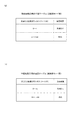
次に、当否テーブルについて説明する。当否テーブルは、当たり乱数カウンタC1に基づいて当たり抽選を行う際に、当該当たり乱数カウンタC1と照合するためのテーブルデータである。パチンコ機10には、当たり抽選の抽選モードとして、低確率モードと高確率モードとが設定されており、低確率モード時における当たり抽選の際には低確率モード用の当否テーブルが参照され、高確率モード時における当たり抽選の際には高確率モード用の当否テーブルが参照される。また、本実施形態においては、パチンコ機10は、第1始動口33に遊技球が入球したタイミングで保留情報記憶エリア64bの第1保留エリアRaに記憶された当たり乱数カウンタC1と照合するための当否テーブルと、第2始動口34に遊技球が入球したタイミングで判定処理実行エリア64cに記憶された当たり乱数カウンタC1と照合するための当否テーブルとを、それぞれ別のテーブルデータとして記憶している。具体的には、パチンコ機10は、第1始動口用の当否テーブル(低確率モード用)、第1始動口用の当否テーブル(高確率モード用)、第2始動口用の当否テーブル(低確率モード用)、第2始動口用の当否テーブル(高確率モード用)の4つの当否テーブルを、ROM63の当否テーブル記憶エリア63aに記憶している。
Next, the hit/miss table will be described. The hit/miss table is table data for collating with the hit random number counter C1 when the hit lottery is performed based on the hit random number counter C1. In the
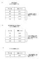
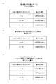
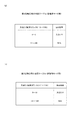
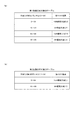
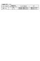
図7は、第1始動口用の当否テーブルの内容を示す説明図である。図示するように、第1始動口用の当否テーブルには、大当たりとなる当たり乱数カウンタC1の値として、0〜4の5個の値が設定されている。0〜1199の値のうち、5〜9の5個の値は、小当たり(外れ)として設定されている。小当たり(外れ)については後述する。そして、0〜9の10個の値以外の値(10〜1199)が通常の外れである。
FIG. 7 is an explanatory diagram showing the contents of the hit/miss table for the first starting opening. As shown in the drawing, in the hit/miss table for the first starting opening, five
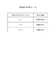
図8は、第2始動口用の当否テーブルの内容を示す説明図である。図示するように、第2始動口用の当否テーブルには、大当たりとなる当たり乱数カウンタC1の値として、0〜4の5個の値が設定されている。そして、0〜1199の値のうち、0〜4の5個の値以外の値(5〜1199)が小当たり(外れ)である。
FIG. 8 is an explanatory diagram showing the contents of the win/fail table for the second starting opening. As shown in the drawing, in the hit/miss table for the second starting opening, five
ここで、小当たり(外れ)とは、第1開閉扉36bまたは第2開閉扉213の開閉が実行される開閉実行モードへの移行契機とはなるが、サポートモードについて、移行契機とならない当否結果である。これに対して、通常の外れは、開閉実行モードの移行契機とはならず、さらに、サポートモードについても移行契機とならない当否結果である。なお、以降の説明においては、小当たり(外れ)を、単に「小当たり」とも呼び、通常の外れを単に「外れ」とも呼ぶ。
Here, the small hit (disengagement) is a trigger for shifting to the opening/closing execution mode in which the opening/closing of the first opening/
次に、大当たり種別について説明する。パチンコ機10には、複数種類の大当たりを設定することができる。具体的には、例えば、以下の3つの態様又はモードに差異を設けることにより、複数種類の大当たりを設定することができる。
(1)開閉実行モードにおける第1開閉扉36bおよび第2開閉扉213の開閉回数(ラウンド数)
(2)開閉実行モードにおける第1開閉扉36bおよび第2開閉扉213の開閉制御の態様
(3)開閉実行モード終了後の第2始動口34の電動役物34aのサポートモードの態様
Next, the jackpot type will be described. A plurality of types of jackpots can be set on the
(1) Number of times the first opening/
(2) Mode of opening/closing control of the first opening/
上記の(2)開閉実行モードにおける第1開閉扉36bおよび第2開閉扉213の開閉制御の態様として、開閉実行モードが開始されてから終了するまでの間における第1開閉扉36bおよび第2開閉扉213への遊技球の入球(入賞)の発生頻度が相対的に高低となるように高頻度入賞モードと低頻度入賞モードとを設定することができる。例えば、高頻度入賞モードでは、開閉実行モードにおける第1開閉扉36bの1回の開放は30秒が経過するまで又は第1開閉扉36bへの遊技球の入球個数が10個となるまで継続するように設定することができる。一方、低頻度入賞モードでは、開閉実行モードにおける第1開閉扉36bの1回の開放が1.6秒が経過するまで又は第1開閉扉36bへの入球個数が10個となるまで継続するよう設定することができる。
As a mode of the opening/closing control of the first opening/
第1開閉扉36bおよび第2開閉扉213の1回の開放に対する開放限度時間、及び1回の開放に対する開放限度個数は、開閉実行モードが開始されてから終了するまでの間における可変入賞装置36またはV入賞機構210への入球の発生頻度が、高頻度入賞モードの方が低頻度入賞モードよりも高くなるのであれば、第1開閉扉36bおよび第2開閉扉213の開放態様は任意である。具体的には、高頻度入賞モードの方が低頻度入賞モードよりも、1回の開放に対する開放限度時間が長い又は1回の開放に対する開放限度個数が多く設定されていればよい。高頻度入賞モードと低頻度入賞モードとの差異を明確にする上では、低頻度入賞モードの開閉実行モードでは、実質的に可変入賞装置36およびV入賞機構210への入球が発生しない構成としてもよい。
The opening limit time for one opening of the first opening/
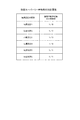
本実施形態では、当たり抽選の結果大当たりとなり当該大当たりを契機として実行される開閉実行モード中に種別決定ゲート202に遊技球が入球した場合、または、V入賞口222に遊技球が入球した場合に、大当たり種別カウンタC2を用いて、大当たり種別を振り分ける。大当たり種別カウンタC2の値に対応する大当たり種別の振り分けは、ROM63の振分テーブル記憶エリア63bに振分テーブルとして記憶されている。
In the present embodiment, when a game ball enters the
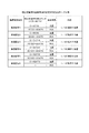
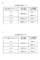
図9は、振分テーブルの内容を示す説明図である。図9(a)には、第1始動口用の振り分けテーブル(大当たり当選時)を示した。当該振り分けテーブルは、第1始動口への入球を契機として実行された遊技回における当たり抽選において大当たりに当選した場合に参照される。 FIG. 9 is an explanatory diagram showing the contents of the distribution table. FIG. 9A shows a distribution table for the first starting opening (at the time of jackpot winning). The distribution table is referred to when the jackpot is won in the winning lottery in the game times executed when the first starting opening is entered.
図9(b)には、第1始動口への入球を契機としたV入賞時の振分テーブルを示した。当該振り分けテーブルは、第1始動口への入球を契機として実行された遊技回において小当たりとなり、当該小当たりを契機として実行された開閉実行モード中にV入賞口222に入球し大当たりとなった場合に参照される。
FIG. 9B shows a distribution table at the time of V winning when a ball is entered into the first starting opening. The distribution table is a small hit in the game time executed when the ball is entered into the first starting opening, and enters the
図9(c)には、第2始動口用の振り分けテーブル(大当たり当選時および第2始動口への入球を契機としたV入賞時)を示した。当該振り分けテーブルは、第2始動口への入球を契機として実行された遊技回における当たり抽選において大当たりに当選した場合、および、第2始動口への入球を契機として実行された遊技回において小当たりとなり、当該小当たりを契機として実行された開閉実行モード中にV入賞口222に入球し大当たりとなった場合に参照される。
FIG. 9C shows a distribution table for the second starting opening (at the time of jackpot winning and at the time of winning the V prize upon the entry into the second starting opening). In the distribution table, when the jackpot is won in the winning lottery in the game times executed when the ball is entered into the second starting opening, and in the game times when the ball is entered into the second starting opening It is a small hit, and is referred to when a big hit is made by entering the
図9(a)の第1始動口用の振分テーブルに示すように、本実施形態のパチンコ機10では、第1始動口への入球を契機として実行された遊技回における当たり抽選において大当たりに当選した場合の大当たり種別として、5R第1種大当たり、5R第2種大当たり、10R通常大当たりが設定されている。
As shown in the distribution table for the first starting opening of FIG. 9A, in the
5R第1種大当たりは、開閉実行モード中に実行されるラウンド遊技の実行回数が5回であり、開閉実行モードの終了後のサポートモードが高頻度サポートモードである大当たりである。但し、本実施形態における第1種大当たりは、開閉実行モードの終了後の高頻度サポートモードにおいて実行可能な遊技回の回数が90回に制限される。すなわち、高頻度サポートモードにおいて遊技回が90回実行された後には、低頻度サポートモードに移行する。 The 5R first-class jackpot is a jackpot in which the number of round games executed in the opening/closing execution mode is 5, and the support mode after the opening/closing execution mode is the high-frequency support mode. However, in the first-class jackpot in the present embodiment, the number of game times that can be executed in the high-frequency support mode after the end of the opening/closing execution mode is limited to 90 times. That is, after 90 game plays have been executed in the high frequency support mode, the low frequency support mode is entered.
5R第2種大当たりは、開閉実行モード中に実行されるラウンド遊技の実行回数が5回であり、開閉実行モードの終了後のサポートモードが高頻度サポートモードである大当たりである。但し、本実施形態における第2種大当たりは、開閉実行モードの終了後の高頻度サポートモードにおいて実行可能な遊技回の回数が5回に制限される。すなわち、高頻度サポートモードにおいて遊技回が5回実行された後には、低頻度サポートモードに移行する。 The 5R second-class jackpot is a jackpot in which the number of round games executed in the opening/closing execution mode is 5, and the support mode after the opening/closing execution mode is the high-frequency support mode. However, in the second-class jackpot in the present embodiment, the number of game times that can be executed in the high-frequency support mode after the end of the opening/closing execution mode is limited to five. That is, after the game times have been executed five times in the high frequency support mode, the low frequency support mode is entered.
10R通常大当たりは、開閉実行モード中に実行されるラウンド遊技の実行回数が10回であり、開閉実行モードの終了後のサポートモードが低頻度サポートモードである大当たりである。 The 10R normal jackpot is a jackpot in which the number of round games executed in the opening/closing execution mode is 10, and the support mode after the opening/closing execution mode is the low frequency support mode.
第1始動口用の振分テーブルでは、「0〜99」の大当たり種別カウンタC2の値のうち、「0〜44」が5R第1種大当たりに対応しており、「45〜60」が5R第2種大当たりに対応しており、「61〜99」が10R通常大当たりに対応している。
In the distribution table for the first starting opening, among the values of the jackpot type counter C2 of "0 to 99", "0 to 44" correspond to the
図9(b)の第1始動口への入球を契機としたV入賞時の振分テーブルに示すように、本実施形態のパチンコ機10では、第1始動口への入球を契機として実行された遊技回において小当たりとなり、当該小当たりを契機として実行された開閉実行モード中にV入賞口222に入球し大当たりとなった場合の大当たり種別として、5R第1種大当たり、10R通常大当たりが設定されている。
As shown in the distribution table at the time of V winning when the ball is entered into the first starting opening in FIG. 9B, the
5R第1種大当たり、および10R通常大当たりについては、上記の図9(a)の第1始動口用の振分テーブルにおいて説明したので、説明を省略する。 The 5R first-class big jackpot and the 10R normal big jackpot have been described in the distribution table for the first starting port of FIG. 9A, and thus description thereof will be omitted.
第1始動口への入球を契機としたV入賞時の振分テーブルでは、「0〜99」の大当たり種別カウンタC2の値のうち、「0〜64」が5R第1種大当たりに対応しており、「65〜99」が10R通常大当たりに対応している。
In the distribution table at the time of winning the V prize when the ball is entered into the first starting opening, among the values of the jackpot type counter C2 of "0 to 99", "0 to 64" corresponds to the
図9(c)の第2始動口用の振り分けテーブルに示すように、本実施形態のパチンコ機10では、第2始動口への入球を契機として実行された遊技回における当たり抽選において大当たりに当選した場合、および、第2始動口への入球を契機として実行された遊技回において小当たりとなり、当該小当たりを契機として実行された開閉実行モード中にV入賞口222に入球し大当たりとなった場合の大当たり種別として、15R第1種大当たり、4R第1種大当たり、4R第2種大当たりが設定されている。
As shown in the distribution table for the second starting opening in FIG. 9C, in the
15R第1種大当たりは、開閉実行モード中に実行されるラウンド遊技の実行回数が15回であり、開閉実行モードの終了後のサポートモードが高頻度サポートモードである大当たりである。但し、本実施形態における第1種大当たりは、開閉実行モードの終了後の高頻度サポートモードにおいて実行可能な遊技回の回数が90回に制限される。すなわち、高頻度サポートモードにおいて遊技回が90回実行された後には、低頻度サポートモードに移行する。 The 15R first-class jackpot is a jackpot in which the number of round games executed in the opening/closing execution mode is 15, and the support mode after the opening/closing execution mode is the high-frequency support mode. However, in the first-class jackpot in the present embodiment, the number of game times that can be executed in the high-frequency support mode after the end of the opening/closing execution mode is limited to 90 times. That is, after 90 game plays have been executed in the high frequency support mode, the low frequency support mode is entered.
4R第1種大当たりは、開閉実行モード中に実行されるラウンド遊技の実行回数が4回であり、開閉実行モードの終了後のサポートモードが高頻度サポートモードである大当たりである。但し、本実施形態における第1種大当たりは、開閉実行モードの終了後の高頻度サポートモードにおいて実行可能な遊技回の回数が90回に制限される。すなわち、高頻度サポートモードにおいて遊技回が90回実行された後には、低頻度サポートモードに移行する。 The 4R first-class jackpot is a jackpot in which the number of round games executed in the opening/closing execution mode is 4, and the support mode after the opening/closing execution mode is the high-frequency support mode. However, in the first-class jackpot in the present embodiment, the number of game times that can be executed in the high-frequency support mode after the end of the opening/closing execution mode is limited to 90 times. That is, after 90 game plays have been executed in the high frequency support mode, the low frequency support mode is entered.
4R第2種大当たりは、開閉実行モード中に実行されるラウンド遊技の実行回数が4回であり、開閉実行モードの終了後のサポートモードが高頻度サポートモードである大当たりである。但し、本実施形態における第2種大当たりは、開閉実行モードの終了後の高頻度サポートモードにおいて実行可能な遊技回の回数が5回に制限される。すなわち、高頻度サポートモードにおいて遊技回が5回実行された後には、低頻度サポートモードに移行する。 The 4R second-class jackpot is a jackpot in which the number of round games executed in the opening/closing execution mode is 4, and the support mode after the opening/closing execution mode is the high-frequency support mode. However, in the second-class jackpot in the present embodiment, the number of game times that can be executed in the high-frequency support mode after the end of the opening/closing execution mode is limited to five. That is, after the game times have been executed five times in the high frequency support mode, the low frequency support mode is entered.
第2始動口用の振り分けテーブルでは、「0〜99」の大当たり種別カウンタC2の値のうち、「0〜49」が15R第1種大当たりに対応しており、「50〜57」が4R第1種大当たりに対応しており、「58〜99」が4R第2種大当たりに対応している。
In the distribution table for the second starting opening, among the values of the jackpot type counter C2 of “0 to 99”, “0 to 49” correspond to the
このように、本実施形態のパチンコ機10では、大当たりとなった場合の大当たり種別の振分態様は、第1始動口への入球を契機として実行された遊技回における当たり抽選において大当たりに当選した場合と、第1始動口への入球を契機として実行された遊技回において小当たりとなり、当該小当たりを契機として実行された開閉実行モード中にV入賞口222に入球し大当たりとなった場合と、第2始動口への入球を契機として実行された遊技回における当たり抽選において大当たりに当選した場合、および、第2始動口への入球を契機として実行された遊技回において小当たりとなり、当該小当たりを契機として実行された開閉実行モード中にV入賞口222に入球し大当たりとなった場合とで異なっているとともに、遊技者にとっての有利性に明確な差異が設けられている。
As described above, in the
上述のように、MPU62は、実行エリアAEに記憶されている当たり乱数カウンタC1の値を用いて当たり抽選を行なうとともに、種別判定処理実行エリア64iに記憶されている大当たり種別カウンタC2の値を用いて大当たり種別を判定するが、さらに、MPU62は、これらの当たり乱数カウンタC1の値を用いて第1図柄表示部37a及び第2図柄表示部37bに停止表示させるセグメント表示器の表示態様を決定するとともに、大当たり種別カウンタC2の値を用いてラウンド表示部39の表示態様を決定する。第1図柄表示部37a及び第2図柄表示部37bに停止表示させるセグメント表示器の表示態様の決定に際しては、ROM63の停止結果テーブル記憶エリア63eに記憶されている停止結果テーブルが参照される。
As described above, the
パチンコ機10には、上記の(3)開閉実行モード終了後の第2始動口34の電動役物34aのサポートモードの態様として、遊技領域PAに対して遊技球の発射が同様の態様で継続されている状況で比較した場合に、第2始動口34の電動役物34aが単位時間当たりに開放状態となる頻度が相対的に高低となるように、高頻度サポートモードと低頻度サポートモードとを設定することができる。
In the
具体的には、本実施形態におけるパチンコ機10は、高頻度サポートモードと低頻度サポートモードとでは、電動役物開放カウンタC4を用いた電動役物開放抽選における電役開放当選となる確率が異なる。高頻度サポートモードでは低頻度サポートモードよりも、電動役物開放抽選における電役開放当選となる確率を高くする。また、高頻度サポートモードでは低頻度サポートモードよりも、電役開放当選となった際に電動役物34aの1回の開放時間が長く設定されている。
Specifically, in the
なお、本実施形態においては採用していないが、高頻度サポートモードで電役開放当選となり電動役物34aの開放状態が複数回発生する場合において、1回の開放状態が終了してから次の開放状態が開始されるまでの閉鎖時間は、1回の開放時間よりも短く設定されてもよい。さらに、高頻度サポートモードでは低頻度サポートモードよりも、1回の電動役物開放抽選が行われてから次の電動役物開放抽選が行われるまでに確保される時間が相対的に短く設定されてもよい。
Although not adopted in the present embodiment, in the high-frequency support mode, when the electric role is released and the electric auditors'
上記のように高頻度サポートモードでは、低頻度サポートモードよりも第2始動口34への遊技球の入球が発生する確率が高くなる。すなわち、高頻度サポートモードは、特別情報の取得条件の成立を補助する補助遊技状態として機能する。 As described above, in the high frequency support mode, the probability that a game ball will enter the second starting opening 34 will be higher than in the low frequency support mode. That is, the high frequency support mode functions as an auxiliary game state that assists the establishment of the special information acquisition condition.
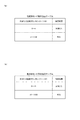
図10は、電動役物開放抽選を実行する際に用いられる当否テーブル(電動役物開放抽選用当否テーブル)の内容を示す説明図である。 FIG. 10 is an explanatory diagram showing the contents of a win/loss table (electric win/loft lottery win/loss table) used when executing the electric auditors open lottery.
図10(a)は、低頻度サポートモード時に用いられる電動役物開放抽選用当否テーブル(低頻度サポートモード用)を示している。図10(a)に示すように、電動役物開放抽選用当否テーブル(低頻度サポートモード用)には、電役開放当選となる電動役物開放カウンタC4の値として0、1の2個の値が設定されている。外れとなる電動役物開放カウンタC4の値として2〜465の464個の値が設定されている。すなわち、低頻度サポートモード時に遊技球がスルーゲート35を通過し電動役物開放抽選が実行された場合には、1/233の確率で電役開放当選となる。本実施形態のパチンコ機10においては、低頻度サポートモード時に電役開放当選となった場合には、電動役物34aが1回開放し、その開放時間は1.4秒である。
FIG. 10A shows a win/loss table (for low frequency support mode) for electric accessory release lottery used in the low frequency support mode. As shown in FIG. 10A, in the winning/discarding table for the electric accessory opening lottery (for the low frequency support mode), two
図10(b)は、高頻度サポートモード時に用いられる電動役物開放抽選用当否テーブル(高頻度サポートモード用)を示している。図10(b)に示すように、電動役物開放抽選用当否テーブル(高頻度サポートモード用)には、電役開放当選となる電動役物開放カウンタC4の値として0〜461の462個の値が設定されている。外れとなる電動役物開放カウンタC4の値として462〜465の4個の値が設定されている。すなわち、高頻度サポートモード時に遊技球がスルーゲート35を通過し電動役物開放抽選が実行された場合には、231/233の確率で電役開放当選となる。本実施形態のパチンコ機10においては、高頻度サポートモード時に電役開放当選となった場合には、電動役物34aが1回開放し、その開放時間は1.6秒である。
FIG.10(b) has shown the winning/missing table (for high frequency support modes) for electric auditors thing open lottery used at the time of high frequency support mode. As shown in FIG. 10B, in the winning/discarding table for electric accessory release lottery (for high-frequency support mode), there are 462 values of 0-461 as the value of the electric accessory release counter C4 that is to win the electric role. The value is set. Four values of 462 to 465 are set as the values of the electric accessory release counter C4 which is disengaged. That is, in the high frequency support mode, when the game ball passes through the through
このように、電動役物開放抽選用当否テーブルによって、高頻度サポートモードが低頻度サポートモードよりも第2始動口34への遊技球の入球が発生する確率が高くなるように設定されている。 In this way, the high frequency support mode is set by the electric accessory release lottery win/loss table so that the probability of the game ball entering the second starting opening 34 is higher than that of the low frequency support mode. ..
《A3》遊技の流れ:
次に、本実施形態における遊技機の遊技の大凡の流れについて図2を用いて説明をする。
<<A3>> Flow of game:
Next, the general flow of the game of the gaming machine in this embodiment will be described with reference to FIG.
遊技者が遊技を開始すると、操作ハンドル25を操作して、遊技球を遊技盤30の左側に向けて発射させる。以下、遊技球を遊技盤30の左側に向けて発射させることを「左打ち」とも呼び、遊技球を遊技盤30の右側に向けて発射させることを「右打ち」とも呼ぶ。
When the player starts the game, the operation handle 25 is operated to shoot the game ball toward the left side of the
遊技者が左打ちを開始し、遊技球を第1始動口33に入球させると、第1始動口33への入球を契機とした当たり抽選の抽選結果を報知するための遊技回が開始される。当該当たり抽選において大当たりに当選した場合には、当該遊技回の終了後に、開閉実行モードが開始される。ここで、本実施形態における遊技機においては、当たり抽選において大当たりに当選した時点においては、大当たりの種別(図9参照)は決定していない。大当たりの種別は、当該当たり抽選に当選した遊技回の終了後に実行される開閉実行モードにおいて決定される。
When the player starts left-handing and enters the game ball into the first starting
大当たりに当選した遊技回が終了すると、開閉実行モードが開始される。開閉実行モードが開始されると、遊技者に対して、遊技球を遊技盤30の右側に向けて発射(右打ち)させることを示唆する演出(右打ち示唆演出)が実行される。遊技者が当該右打ち示唆演出を認識し、遊技球を遊技盤30の右側へ向けて発射させ、遊技球が種別決定ゲート202に入球(通過)すると、開閉実行モードの開始後における種別決定ゲート202への遊技球の最初の入球(通過)を契機として種別決定処理が実行される。種別決定処理は、大当たり種別を決定するための処理である。種別決定処理の詳細については、後述する。
When the game times won for the jackpot are over, the opening/closing execution mode is started. When the opening/closing execution mode is started, an effect (right hitting suggestion effect) that suggests that the player shoots the game ball toward the right side of the game board 30 (right hitting) is executed. When the player recognizes the right-handed suggestion effect, shoots the game ball toward the right side of the
種別決定処理が実行されることによって大当たり種別が決定すると、当該大当たり種別毎に設定された開閉シナリオに基づいて第1開閉扉36bおよび第2開閉扉213が開閉動作を実行するラウンド遊技が開始される。開閉シナリオは、第1開閉扉36bおよび第2開閉扉213の開閉動作のパターンを予め定めたプログラムである。開閉シナリオの詳細は後述する。
When the jackpot type is determined by executing the type determination process, the round game in which the first opening/
ラウンド遊技が実行されている期間(以下、開閉処理期間とも呼ぶ)に遊技者が右打ちした遊技球が第1大入賞口36aまたは第2大入賞口212に入球すると、各大入賞口に設定された個数の遊技球が特典(賞球)として遊技者に付与される。
When a game ball hit by the player to the right in the period during which the round game is executed (hereinafter, also referred to as opening/closing processing period) enters the first big winning
本実施形態においては、特定の場合のみ、第2開閉扉213が開放する開閉シナリオが設定され、第2大入賞口212に遊技球を入球させることができる。そして、図4において説明したように、第2大入賞口212に遊技球が入球すると、第2大入賞口212に入球した遊技球のうち1個の遊技球が貯留部218に貯留され、その後、貯留弁216が開放した後に、流路211からクルーン220へと流通する(図4(e)参照)。そして、クルーン220を流通する遊技球がV入賞口222に入球した場合には、新たな大当たりが確定する。V入賞口222に遊技球が入球したことを契機として新たな大当たりが確定すると、実行中の開閉実行モードは中断し、V入賞口222への遊技球の入球に基づいた新たな開閉実行モードが開始される。なお、上述したように、第1始動口33に遊技球が入球したことを契機とした当たり抽選において大当たりに当選した場合には、当該大当たりに当選した遊技回の終了後の開閉実行モード中に種別決定ゲート202に遊技球が入球することによって大当たり種別が決定されたが、本実施形態においては、V入賞口222に遊技球が入球したことを契機として大当たりとなった場合には、大当たりの確定とともに大当たりの種別が決定される。
In this embodiment, an opening/closing scenario in which the second opening/
図9において説明したように、第1始動口33への遊技球の入球を契機とする大当たりにおける大当たり種別の振り分け(図4(a))と、第1始動口への入球を契機としたV入賞時の大当たりにおける大当たり種別の振り分け(図4(b))とは異なる。本実施形態においては、第1始動口への入球を契機としたV入賞時の大当たりにおける大当たり種別の振り分けの方が、遊技者に付与される特典が多くなる可能性が高い。従って、遊技者は、第1始動口33への遊技球の入球を契機とする大当たりが確定していても、ラウンド遊技中に第2開閉扉213が開放する場合には、遊技球を第2大入賞口212に入球させ、さらに、V入賞口222への遊技球の入球を望む。従って、ラウンド遊技中においても、遊技者の期待感を向上させることができる。
As described with reference to FIG. 9, the jackpot type distribution in the jackpot triggered by the game ball entering the first starting opening 33 (FIG. 4A), and the entry into the first starting opening as a trigger. Different from the jackpot classification (FIG. 4B) in the jackpot at the time of the V winning. In the present embodiment, it is more likely that the bonus given to the player will be larger if the jackpot type is distributed in the jackpot at the time of V winning when the ball is thrown into the first starting opening. Therefore, even if the jackpot triggered by the entry of the game ball into the first starting
仮に、第2開閉扉213が開放し第2大入賞口212に遊技球を入球させることができたにもかかわらず、遊技球をV入賞口222に入球させることができなかった場合には、そのまま、第1始動口33への遊技球の入球を契機とした大当たりに基づくラウンド遊技が継続される。
If the second opening/
ラウンド遊技が終了し、その後開閉実行モードが終了すると、当該開閉実行モードの実行の契機となった大当たりの種別に高頻度サポートモードが設定されている場合には、開閉実行モードの終了後に実行される遊技回におけるサポートモードが高頻度サポートモードとなる。この場合、遊技者は、右打ちをして遊技球をスルーゲート35に入球させ、電動役物開放抽選を実行させる。電動役物開放抽選に当選した場合には、電動役物34aが開放し第2始動口34に遊技球を入球させることができ、その結果、第2始動口34への遊技球の入球を契機とした当たり抽選が実行される。
When the round game ends and then the opening/closing execution mode ends, if the high frequency support mode is set for the type of jackpot that triggered the execution of the opening/closing execution mode, it is executed after the opening/closing execution mode ends. The support mode in the game time becomes the high frequency support mode. In this case, the player makes a right hit to enter the game ball into the through
第2始動口34への遊技球の入球を契機とした当たり抽選における当否結果は、大当たり又は小当たりとなる。大当たりに当選した場合には、第1始動口33への遊技球の入球を契機とした当たり抽選において大当たりに当選した場合と同様に、当該大当たりに当選した遊技回が終了した後に実行される開閉実行モード中に種別決定ゲート202に遊技球を入球させることによって、大当たりの種別が決定される。そして決定した大当たり種別に設定されたラウンド遊技が実行される。
The win/no win result in the winning lottery when the game ball enters the second starting opening 34 is a big hit or a small hit. When the jackpot is won, as in the case where the jackpot is selected in the hit lottery triggered by the entry of the game ball into the first starting
一方、第2始動口34への遊技球の入球を契機とした当たり抽選において小当たりに当選した場合には、当該小当たりに当選した遊技回の終了後に第2開閉扉213が1回開放する開閉実行モードが実行される。そして、第2開閉扉213の開放中に第2大入賞口212に遊技球を入球させ、その後にV入賞口222に遊技球が入球した場合には、大当たりが確定し、当該大当たりを契機とした開閉実行モードが開始される。開閉実行モードにおいては、当該大当たりの種別に設定されているラウンド遊技が実行されることによって遊技者に特典が付与される。
On the other hand, when the small hit is won in the hit lottery triggered by the entry of the game ball into the second starting opening 34, the second opening/
次に、遊技者が遊技を開始し、左打ちをすることによって遊技球を第1始動口33に入球させ、第1始動口33への入球を契機とした当たり抽選において小当たりに当選した場合について説明する。
Next, the player starts the game and enters the game ball into the first starting opening 33 by left-handing, and wins the small hit in the winning lottery triggered by the entering the first starting
第1始動口33への遊技球の入球を契機とした当たり抽選において小当たりに当選した場合には、当該小当たりに当選した遊技回の終了後に第2開閉扉213が1回開放する開閉実行モードが実行される。開閉実行モードの開始後に、遊技者に対して右打ちをすることを示唆する右打ち示唆演出が実行される。遊技者が、当該右打ち示唆演出に従って右打ちを実行し、第2開閉扉213の開放中に第2大入賞口212に遊技球を入球させ、その後にV入賞口222に遊技球が入球した場合には、大当たりが確定し、当該大当たりを契機とした開閉実行モードが開始される。開閉実行モードにおいては、当該大当たりの種別に設定されているラウンド遊技が実行されることによって遊技者に特典が付与される。以上、本実施形態における遊技機の遊技の大凡の流れについて説明をした。
When a small hit is won in the hit lottery triggered by the entry of a game ball into the first start opening 33, the second opening/
《A4》遊技機による処理の概要:
次に、本実施形態のパチンコ機10が実行する処理の概要について説明する。
<<A4>> Outline of processing by game machine:
Next, an outline of processing executed by the
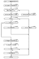
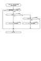
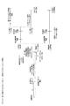
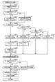
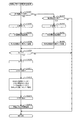
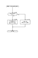
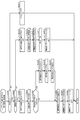
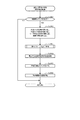
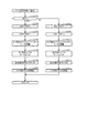
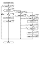
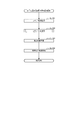
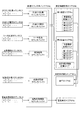
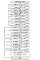
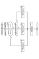
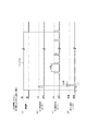
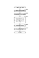
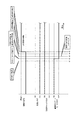
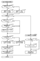
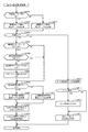
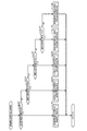
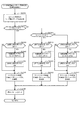
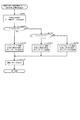
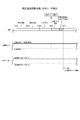
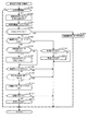
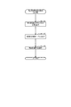
図11は、ケース1として、第1始動口33への遊技球の入球を契機とした当たり抽選において大当たりに当選した場合について説明をするタイムチャートである。また、以下に説明する処理の概要は、第1始動口33への遊技球の入球を契機とした当たり抽選に大当たりに当選した全ての場合に実行されるのではなく、特定の場合にのみ実行される。
FIG. 11 is a time chart for explaining a
遊技者が左打ちを実行し、遊技球が第1始動口33に入球したことを契機として遊技回U1が開始されると、第1図柄表示部37aの図柄の変動が開始する。このとき、遊技回U1においては所定の演出が実行される。その後、当該第1図柄表示部37aにおける図柄の変動が停止する。このとき、第1図柄表示部37aには、大当たりを示す図柄のパターンは表示されるが、図柄表示装置41への画像の表示や音声の出力によって大当たりに当選したことを明確に示唆する演出は実行されず、大当たりに当選したか小当たりに当選したかが遊技者にとって識別しにくい演出が実行される。従って、図柄表示装置41への画像の表示や音声の出力によって当たり抽選の抽選結果を認識している遊技者は、遊技回U1に対応する当たり抽選において大当たりに当選していることを認識することができない。
When the player executes a left-handed stroke and the game time U1 is started by the fact that the game ball has entered the first starting
当たり抽選に当選した遊技回U1が終了した後、開閉実行モードが開始される。上述のように、第1始動口33への入球を契機とした当たり抽選において大当たりに当選した場合には、当たり抽選において大当たりに当選した時点において大当たりの種別は決定していない。大当たりの種別は、開閉実行モードの開始後に遊技球が種別決定ゲート202に入球することによって決定される。従って、当たり抽選に当選した遊技回が終了した時点においてもラウンド表示部39に、開閉実行モードにおいて実行されるラウンド遊技の実行回数を示す表示はされない。なお、本実施形態においては、開閉実行モードの開始した時点から大当たりの種別が決定するまでの期間を「待機期間」とも呼ぶ。
The opening/closing execution mode is started after the game times U1 won in the winning lottery are completed. As described above, when the jackpot is won in the winning lottery triggered by the entry into the first starting
当たり抽選に当選した遊技回U1が終了した後、開閉実行モードが開始されると同時に、右打ちを示唆する演出(右打ち示唆演出)が実行されるとともに、遊技者に特典が付与される可能性があることを示す演出、より具体的には、大当たりに当選するための機会(チャンス)が2回分用意されていることを示唆する演出(以下「Wチャンス演出」とも呼ぶ)が実行される。 After the game times U1 won in the winning lottery are finished, the opening/closing execution mode is started, and at the same time, the effect suggesting right-handedness (right-handedness suggested effect) is executed and the privilege can be given to the player. There is an effect that indicates that there is a nature, more specifically, an effect that suggests that two opportunities for winning the jackpot are prepared (hereinafter also referred to as "W chance effect") is executed. ..
右打ち示唆演出およびWチャンス演出が実行されたことを認識した遊技者が右打ちを実行し、種別決定ゲート202に遊技球が入球すると、種別決定処理が実行され、大当たり種別が決定される。大当たり種別が決定されると待機期間は終了し、オープニング期間が開始される。オープニング期間においても右打ち示唆演出が実行される。オープニング期間の終了後、開閉処理期間が開始される。開閉処理期間においては、決定された大当たり種別に対応した回数のラウンド遊技が実行される。このとき、大当たり種別に対応した回数のラウンド遊技の1回目のラウンド遊技(1R目)に、第2開閉扉213が開放するラウンド遊技が実行される。また、開閉処理期間が開始されると、用意されている2回分の大当たりに当選するための機会(チャンス)のうちの1回目が開始されたことを示唆する演出(以下、1回目チャンス演出とも呼ぶ)が実行される。
When the player who recognizes that the right-hit suggestion effect and the W chance effect have been executed, performs a right-hit, and a game ball enters the
より具体的には、1回目チャンス演出において、遊技者に右打ちを促すとともに、第2大入賞口212に遊技球を入球させ、さらに、V入賞口222に遊技球を入球させることを促す演出が実行される。
More specifically, in the first chance production, the player is urged to hit the right side, the game ball is inserted into the second special winning
実行される1回目チャンス演出を遊技者が認識して右打ちを実行し、第2開閉扉213が開放しているタイミングで遊技球を第2大入賞口212に入球させることができ、貯留部218(図4参照)に遊技球を貯留させることができた場合(タイムチャートに示した[貯留部に貯留]に進む)、第2開閉扉213が閉鎖後に、貯留弁216が開閉動作を1回実行する。このとき、貯留部218に貯留されていた1個の遊技球は、流路211を流通しクルーン220に流入する。
The player recognizes the first chance effect to be executed, right-handedly executes, and at the timing when the second opening/
クルーン220を流通する遊技球は、V入賞口222または非V入賞口224に入球する。クルーン220を流通する遊技球がV入賞口222に入球した場合(タイムチャートに示した[V入賞口に入球]に進む)、処理上は、遊技回U1での当たり抽選において大当たりに当選したことを契機として実行されているラウンド遊技が継続され、V入賞口222に遊技球が入球したことを契機とした大当たりは確定せず、V入賞口222への遊技球の入球に基づく新たな開閉実行モードも開始されない。さらに、V入賞口222への遊技球の入球によって遊技者に対してなんらかの特典が付与されることや、遊技状態が変更されることはない。
The game ball circulating through the
しかしながら、本実施形態においては、V入賞口222に遊技球が入球したことを契機としてV入賞大当たり演出を実行する。V入賞大当たり演出は、V入賞口222に遊技球が入球したことを示唆するとともに、大当たりを示唆する演出である。本実施形態においては、表示面41aに「V」の文字を表示するとともに、「大当たり」の文字を表示する。
However, in the present embodiment, the V winning jackpot effect is executed when the game ball enters the
V入賞口222に遊技球が入球したことを契機としてV入賞大当たり演出を実行することによって、遊技者に対して、V入賞口222に遊技球が入球したことにより新たな大当たりが確定したかのように認識させることができるとともに期待感を付与することができる。また、V入賞口222への遊技球の入球に基づく開閉実行モードが開始されたかのように遊技者に認識させることができる。
By executing the V winning jackpot production when the game ball enters the
そして、V入賞大当たり演出が実行された後に、遊技回U1での当たり抽選において大当たりに当選したことを契機として実行されているラウンド遊技の1R目が終了し、2ラウンド目(2R目)が開始される。2ラウンド目以降においては、新たな開閉実行モードが開始されたことを示唆する演出を実行する。このようにすることで、V入賞口222への遊技球の入球に基づく新たな開閉実行モードが開始されたかのように遊技者を認識させることができ、遊技者に対して期待感を付与することができる。すなわち、実質的には遊技回U1での当たり抽選において大当たりに当選したことを契機として実行されているラウンド遊技中に、遊技者に対して、新たな期待感を付与することができる。
Then, after the V winning jackpot production is executed, the first round of the round game that is executed with the fact that the big hit is won in the winning lottery in the game round U1 is ended, and the second round (second round) is started. To be done. In the second and subsequent rounds, an effect indicating that a new opening/closing execution mode has started is executed. By doing so, the player can be recognized as if a new opening/closing execution mode based on the entry of the game ball into the
一方、クルーン220を流通する遊技球が非V入賞口224に入球した場合(タイムチャートに示した[V入賞口に非入球]に進む)、用意されている2回分の大当たりに当選するための機会(チャンス)のうちの2回目が開始されたことを示唆する演出(以下、2回目チャンス演出とも呼ぶ)が実行される。2回目チャンス演出は、演出操作ボタン24を操作することを遊技者に促す演出であり、所定期間以内に遊技者が演出操作ボタン24を操作した場合には、遊技者によって演出操作ボタン24が操作されたタイミングで大当たりが確定したことを示す演出を実行する。また、演出操作ボタン24を操作することを遊技者に促す演出を実行後の所定期間以内に遊技者によって演出操作ボタン24が操作されなかった場合には、所定期間の経過後に大当たりが確定したことを示す演出を実行する。この場合も、処理上は、遊技回U1での当たり抽選において大当たりに当選したことを契機として実行されているラウンド遊技が継続され、2回目チャンス演出において演出操作ボタン24が操作されたことを契機として大当たりは確定せず、新たな開閉実行モードも開始されない。さらに、2回目チャンス演出において演出操作ボタン24が操作されたことを契機として遊技者に対してなんらかの特典が付与されることや、遊技状態が変更されることはない。
On the other hand, when a game ball circulating through the
しかしながら、本実施形態においては、2回目チャンス演出において演出操作ボタン24が操作されたことを契機として、大当たりを示唆する大当たり演出を実行する。または、演出操作ボタン24を操作することを遊技者に促す演出を実行後の所定期間以内に遊技者によって演出操作ボタン24が操作されなかった場合には、所定期間の経過後に大当たりが確定したことを示す演出を実行する。このように2回目チャンス演出の実行後に大当たり演出を実行することによって、遊技者に対して、2回目チャンス演出によって新たな大当たりが確定したかのように認識させることができるとともに、期待感を付与することができる。
However, in the present embodiment, when the
そして、大当たり演出が実行された後に、遊技回U1での当たり抽選において大当たりに当選したことを契機として実行されているラウンド遊技の1R目が終了し、2ラウンド目(2R目)が開始される。2ラウンド目以降においては、新たな開閉実行モードが開始されたことを示唆する演出を実行する。このようにすることで、2回目チャンス演出よる大当たりに基づく新たな開閉実行モードが開始されたかのように遊技者を認識させることができ、遊技者に対して期待感を付与することができる。すなわち、実質的には遊技回U1での当たり抽選において大当たりに当選したことを契機として実行されているラウンド遊技中に、遊技者に対して、新たな期待感を付与することができる。 Then, after the jackpot production is executed, the first round of the round game that is being executed in response to winning the jackpot in the winning lottery in the game round U1 is ended, and the second round (second round) is started. .. In the second and subsequent rounds, an effect indicating that a new opening/closing execution mode has started is executed. By doing so, the player can be recognized as if a new opening/closing execution mode based on the big hit by the second chance effect was started, and an expectation can be given to the player. That is, it is possible to give a new sense of expectation to the player during the round game which is substantially executed when the big hit is won in the winning lottery in the game cycle U1.
なお、クルーン220を流通する遊技球がV入賞口222に入球した場合の2R目以降のラウンド遊技中に実行する演出と、クルーン220を流通する遊技球が非V入賞口224に入球した場合の2R目以降のラウンド遊技中に実行する演出とを異なる演出に設定するように構成してもよい。例えば、クルーン220を流通する遊技球がV入賞口222に入球した場合には、2R目以降のラウンド遊技中の演出として、V入賞口222への遊技球の入球に基づく開閉実行モードが実行されていることを示唆する演出を実行し、クルーン220を流通する遊技球が非V入賞口224に入球し2回目チャンス演出によって大当たり演出が実行された場合に、2R目以降のラウンド遊技中の演出として、2回目チャンス演出による新たな大当たりに基づく開閉実行モードが実行されていることを示唆する演出を実行する。このように、いずれの場合も、実質的には、実質的には遊技回U1での当たり抽選において大当たりに当選したことを契機として実行されている同じラウンド遊技中であるものの、2R目以降のラウンド遊技中の演出を異なる演出にすることで、遊技者に対して異なる期待感を付与することができ、遊技性の幅を広げることができ、遊技の興趣向上を図ることができる。
In addition, when the game ball flowing through the
次に、1回目チャンス演出を遊技者が認識をして右打ちを実行したにも関わらず、第2開閉扉213が開放しているタイミングで遊技球を第2大入賞口212に入球させることができず、貯留部218に遊技球を貯留させることができなかった場合(タイムチャートに示した[貯留部に非貯留]に進む)について説明する。この場合、第2開閉扉213が閉鎖後に、2回目チャンス演出が実行される。この場合の2回目チャンス演出も、演出操作ボタン24を操作することを遊技者に促す演出であり、所定期間以内に遊技者が演出操作ボタン24を操作した場合には、遊技者によって演出操作ボタン24が操作されたタイミングで大当たりが確定したことを示す演出を実行する。また、演出操作ボタン24を操作することを遊技者に促す演出を実行後の所定期間以内に遊技者によって演出操作ボタン24が操作されなかった場合には、所定期間の経過後に大当たりが確定したことを示す演出を実行する。この場合も、タイムチャートに示した[V入賞口に非入球]に進んだ場合と同様に、処理上は、遊技回U1での当たり抽選において大当たりに当選したことを契機として実行されているラウンド遊技が継続され、2回目チャンス演出において演出操作ボタン24が操作されたことを契機として大当たりは確定せず、新たな開閉実行モードも開始されない。さらに、2回目チャンス演出において演出操作ボタン24が操作されたことを契機として遊技者に対してなんらかの特典が付与されることや、遊技状態が変更されることはない。
Next, despite the player recognizing the first chance production and performing a right-handed stroke, the game ball is inserted into the second special winning
しかしながら、本実施形態においては、2回目チャンス演出において演出操作ボタン24が操作されたことを契機として、大当たりを示唆する大当たり演出を実行する。または、演出操作ボタン24を操作することを遊技者に促す演出を実行後の所定期間以内に遊技者によって演出操作ボタン24が操作されなかった場合には、所定期間の経過後に大当たりが確定したことを示す演出を実行する。このように2回目チャンス演出の実行後に大当たり演出を実行することによって、遊技者に対して、2回目チャンス演出によって新たな大当たりが確定したかのように認識させることができるとともに、期待感を付与することができる。
However, in the present embodiment, when the
そして、大当たり演出が実行された後に、遊技回U1での当たり抽選において大当たりに当選したことを契機として実行されているラウンド遊技の1R目が終了し、2ラウンド目(2R目)が開始される。2ラウンド目以降においては、新たな開閉実行モードが開始されたことを示唆する演出を実行する。このようにすることで、2回目チャンス演出よる大当たりに基づく新たな開閉実行モードが開始されたかのように遊技者を認識させることができ、遊技者に対して期待感を付与することができる。すなわち、実質的には遊技回U1での当たり抽選において大当たりに当選したことを契機として実行されているラウンド遊技中に、遊技者に対して、新たな期待感を付与することができる。以上、ケース1について説明した。
Then, after the jackpot production is executed, the first round of the round game that is being executed in response to winning the jackpot in the winning lottery in the game round U1 is ended, and the second round (second round) is started. .. In the second and subsequent rounds, an effect indicating that a new opening/closing execution mode has started is executed. By doing so, the player can be recognized as if a new opening/closing execution mode based on the big hit by the second chance effect was started, and an expectation can be given to the player. That is, it is possible to give a new sense of expectation to the player during the round game which is substantially executed when the big hit is won in the winning lottery in the game cycle U1. The
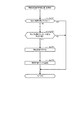
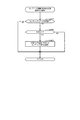
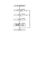
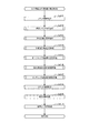
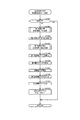
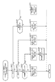
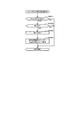
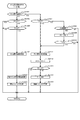
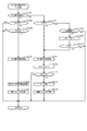
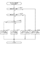
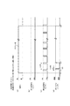
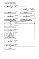
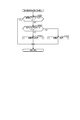
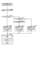
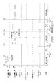
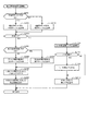
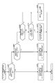
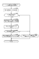
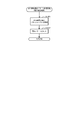
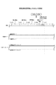
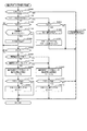
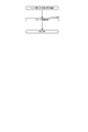
図12は、ケース2として、第1始動口33への遊技球の入球を契機とした当たり抽選において小当たりに当選した場合について説明をするタイムチャートである。本実施形態においては、第1始動口33への遊技球の入球を契機とした当たり抽選において小当たりに当選した全ての場合において、以下に説明をする処理が実行される。
FIG. 12 is a time chart for explaining a
遊技者が左打ちを実行し、遊技球が第1始動口33に入球したことを契機として遊技回U2が開始されると、第1図柄表示部37aの図柄の変動が開始する。このとき、遊技回U2においては所定の演出が実行される。その後、当該第1図柄表示部37aにおける図柄の変動が停止する。このとき、第1図柄表示部37aには、小当たりを示す図柄のパターンは表示されるが、図柄表示装置41への画像の表示や音声の出力によって小当たりに当選したことを明確に示唆する演出は実行されず、大当たりに当選したか小当たりに当選したかが遊技者にとって識別しにくい演出が実行される。従って、図柄表示装置41への画像の表示や音声の出力によって当たり抽選の抽選結果を認識している遊技者は、遊技回U1に対応する当たり抽選において小当たりに当選していることを認識することができない。
When the player performs a left-handed stroke and the game turn U2 is triggered by the fact that the game ball has entered the first starting
小当たりに当選した遊技回U2が終了した後、開閉実行モードが開始される。第1始動口33への入球を契機とした当たり抽選において小当たりに当選した場合には、開閉実行モードが開始される。そして、開閉実行モードにおけるオープニング期間において、右打ち示唆演出が実行されるとともに、遊技者に特典が付与される可能性があることを示す演出、より具体的には、大当たりに当選するための機会(チャンス)が2回分用意されていることを示唆する演出(以下「Wチャンス演出」とも呼ぶ)が実行される。
After the game time U2 that wins the small hit ends, the opening/closing execution mode is started. When the small hit is won in the winning lottery triggered by the ball entering the first starting
そして、オープニング期間が終了した後、開閉処理期間が開始される。開閉処理期間においては、第2開閉扉213が1回のみ開放するラウンド遊技が実行される。また、開閉処理期間が開始されると、用意されている2回分の大当たりに当選するための機会(チャンス)のうちの1回目が開始されたことを示唆する演出(以下、1回目チャンス演出とも呼ぶ)が実行される。
Then, after the opening period ends, the opening/closing processing period starts. In the opening/closing processing period, a round game in which the second opening/
より具体的には、1回目チャンス演出において、遊技者に右打ちを促すとともに、第2大入賞口212に遊技球を入球させ、さらに、V入賞口222に遊技球を入球させて大当たりを確定させることを促す演出が実行される。
More specifically, in the first chance production, the player is urged to hit the right side, the game ball is inserted into the second special winning
実行される1回目チャンス演出を遊技者が認識をして右打ちを実行し、第2開閉扉213が開放しているタイミングで遊技球を第2大入賞口212に入球させることができ、貯留部218(図4参照)に遊技球を貯留させることができた場合(タイムチャートに示した[貯留部に貯留]に進む)、第2開閉扉213が閉鎖後に、貯留弁216が開閉動作を1回実行する。このとき、貯留部218に貯留されていた1個の遊技球は、流路211を流通しクルーン220に流入する。
The player recognizes the first chance effect to be executed, right-handedly executes, and the game ball can enter the second big winning
クルーン220を流通する遊技球は、V入賞口222または非V入賞口224に入球する。クルーン220を流通する遊技球がV入賞口222に入球した場合(タイムチャートに示した[V入賞口に入球]に進む)、大当たりが確定する。そして、大当たりが確定したことを契機として、V入賞大当たり演出が実行される。V入賞大当たり演出は、V入賞口222に遊技球が入球したことを示唆するとともに、大当たりを示唆する演出である。本実施形態においては、表示面41aに「V」の文字を表示するとともに、「大当たり」の文字を表示する。なお、ケース1において実行されるV入賞大当たり演出と、ケース2において実行されるV入賞大当たり演出とが同一または類似した内容の演出であってもよいし、全く異なる演出であってもよい。本実施形態においては、ケース1において実行されるV入賞大当たり演出と、ケース2において実行されるV入賞大当たり演出とが同一または類似した内容の演出である。このようにすることで、遊技者に対して、実行中の遊技の進行状態が、ケース1であるのかケース2であのかを判定しにくくすることができ、遊技者に種々の推測をさせ、期待感を付与することができる。
The game ball circulating through the
その後、第1始動口33への入球を契機とした当たり抽選において小当たりに当選したことを契機とする開閉実行モードは終了する。そして、V入賞口222への遊技球の入球に基づいた大当たりを契機とする新たな開閉実行モードが開始される。なお、V入賞口222に遊技球が入球したことを契機として大当たりとなった場合には、大当たりの確定とともに大当たりの種別が決定される。
After that, the opening/closing execution mode triggered by winning the small hit in the winning lottery triggered by entering the first start opening 33 is terminated. Then, a new opening/closing execution mode triggered by a big hit based on the entry of the game ball into the
また、ケース1においてV入賞口222に遊技球が入球した場合に実行する大当たり演出と、ケース2においてV入賞口222に遊技球が入球した場合に実行する大当たり演出とを、同一または類似の演出とする構成を採用してもよい。このような構成を採用することによって、V入賞口222への遊技球の入球によって大当たりが確定したのかしていないのかを遊技者に判定しにくくし、遊技者に種々の推測をさせることができるとともに、遊技者に期待感を付与することができる。
In addition, the jackpot effect executed when the game ball enters the
一方、クルーン220を流通する遊技球が非V入賞口224に入球した場合(タイムチャートに示した[V入賞口に非入球]に進む)、用意されている2回分の大当たりに当選するための機会(チャンス)のうちの2回目が開始されたことを示唆する演出(以下、2回目チャンス演出とも呼ぶ)が実行される。2回目チャンス演出は、演出操作ボタン24を操作することを遊技者に促す演出であり、所定期間以内に遊技者が演出操作ボタン24を操作した場合には、遊技者によって演出操作ボタン24が操作されたタイミングで外れが確定したことを示す演出を実行する。また、演出操作ボタン24を操作することを遊技者に促す演出を実行後の所定期間以内に遊技者によって演出操作ボタン24が操作されなかった場合には、所定期間の経過後に外れが確定したことを示す演出を実行する。なお、2回目チャンス演出において示唆する外れの確定は、遊技回U2における当たり抽選において外れとなったこと(または、外れであったこと)を示唆する内容である。
On the other hand, when a game ball circulating through the
2回目チャンス演出を実行した後、遊技回U2での当たり抽選において小当たりに当選したことを契機として実行されているラウンド遊技は終了し、その後、開閉実行モードは終了する。そして、遊技者に対して、左打ちをするよう促す演出(左打ち示唆演出)を実行する。遊技者は、左打ちを実行し、再度、第1始動口33に遊技球を入球させることを試みる。 After executing the second chance production, the round game which is executed in response to winning the small hit in the winning lottery in the game time U2 ends, and then the opening/closing execution mode ends. Then, an effect (left effect suggestion effect) that urges the player to make a left hit is executed. The player executes a left-handed stroke and tries to insert a game ball into the first starting opening 33 again.
次に、1回目チャンス演出を遊技者が認識をして右打ちを実行したにも関わらず、第2開閉扉213が開放しているタイミングで遊技球を第2大入賞口212に入球させることができず、貯留部218に遊技球を貯留させることができなかった場合(タイムチャートに示した[貯留部に非貯留]に進む)について説明する。この場合、第2開閉扉213が閉鎖後に、2回目チャンス演出が実行される。この場合の2回目チャンス演出も、演出操作ボタン24を操作することを遊技者に促す演出であり、所定期間以内に遊技者が演出操作ボタン24を操作した場合には、遊技者によって演出操作ボタン24が操作されたタイミングで外れが確定したことを示す演出を実行する。また、演出操作ボタン24を操作することを遊技者に促す演出を実行後の所定期間以内に遊技者によって演出操作ボタン24が操作されなかった場合には、所定期間の経過後に外れが確定したことを示す演出を実行する。
Next, despite the player recognizing the first chance production and performing a right-handed stroke, the game ball is inserted into the second special winning
2回目チャンス演出を実行した後、遊技回U2での当たり抽選において小当たりに当選したことを契機として実行されているラウンド遊技は終了し、その後、開閉実行モードは終了する。そして、遊技者に対して、左打ちをするよう促す演出(左打ち示唆演出)を実行する。遊技者は、左打ちを実行し、再度、第1始動口33に遊技球を入球させることを試みる。 After executing the second chance production, the round game which is executed in response to winning the small hit in the winning lottery in the game time U2 ends, and then the opening/closing execution mode ends. Then, an effect (left effect suggestion effect) that urges the player to make a left hit is executed. The player executes a left-handed stroke and tries to insert a game ball into the first starting opening 33 again.
以上説明したように、遊技球が第1始動口33に入球したことを契機として実行された当たり抽選において大当たりに当選した場合(ケース1の場合)も、小当たりに当選した場合(ケース2の場合)も、第1図柄表示部37aには、当たり抽選の結果を示す図柄のパターンは表示されるが、図柄表示装置41への画像の表示や音声の出力による当たり抽選の抽選結果を示唆する演出は実行されない。よって、図柄表示装置41への画像の表示や音声の出力によって当たり抽選の抽選結果を認識している遊技者は、遊技回の終了した時点において当該遊技回における抽選結果を認識できない。その結果、仮に、小当たりに当選していたとしても、大当たりに当選したのではないかといった期待感を遊技者に付与することができる。
As described above, when the jackpot is executed in the winning lottery executed when the game ball enters the first starting opening 33 (case 1) and when the jackpot is won (case 2) In the case of), although the pattern of the symbol showing the result of the winning lottery is displayed on the first
さらに、遊技回が終了した後に、ケース1の場合も、ケース2の場合も、右打ち示唆演出、Wチャンス示唆演出を実行するので、遊技回が終了した後に当該演出が実行されている期間中も、当たり抽選において小当たりではなく大当たりに当選しているのではないかといった期待感を付与することができる。
Further, after the game time is over, in both
また、本実施形態のパチンコ機10においては、第1始動口33への入球を契機とした当たり抽選において大当たりに当選した場合には、当たり抽選において大当たりに当選した時点において大当たりの種別は決定されず、開閉実行モードの実行中に遊技球が種別決定ゲート202に入球することによって決定される。そして、大当たり種別が決定すると、ラウンド表示部39のラウンドランプが、大当たりの種別に対応したラウンド遊技の実行回数に応じた表示で点灯する。一方、小当たりに当選している場合は、ラウンドランプは点灯しない。すなわち、大当たりに当選している場合であっても小当たりに当選している場合であっても、遊技回の終了直後にはラウンドランプは点灯しないので、遊技回の終了後において、ラウンドランプに基づいて当該遊技回において大当たりに当選しているのか小当たりに当選しているのかを遊技者が識別することを回避することができる。
Further, in the
その結果、遊技回の終了後に、遊技者が右打ちをして、種別決定ゲート202に遊技球を入球させるまでは、遊技者に、当該当たり抽選の抽選結果を認識させず、遊技者に対して、比較的長い期間、小当たりではなく大当たりに当選しているのではないかといった期待感を付与することができる。すなわち、遊技回が終了し、大当たりまたは小当たりに基づく開閉実行モードが開始された後の期間においても、比較的長い期間に亘って遊技者に期待感を付与することができ、遊技に対して注目させることができる。また、大当たり種別の決定に際し、遊技者に右打ちをさせて、種別決定ゲート202に遊技球を入球させるので、大当たり種別の決定に関して遊技者に積極的に関与させることとなり、遊技者に対して、開閉実行モードの期間においてさら遊技に注目させることができる。
As a result, the player does not recognize the lottery result of the winning lottery until the player makes a right hit and enters the game ball into the
また、ケース1においては、遊技回U1での当たり抽選において大当たりに当選し、その後に遊技球がV入賞口222に入球したにも関わらず、遊技回U1での当たり抽選において大当たりに当選したことを契機として実行されているラウンド遊技が継続され、V入賞口222に遊技球が入球したことを契機とした大当たりは確定せず、V入賞口222への遊技球の入球に基づく新たな開閉実行モードも開始されない。さらに、V入賞口222への遊技球の入球によって遊技者に対してなんらかの特典が付与されることや、遊技状態が変更されることはない。一方、ケース2においては、遊技回U2での当たり抽選において小当たりに当選し、その後に遊技球がV入賞口222に入球すると、大当たりが確定し、遊技回U2における当たり抽選において小当たりに当選したことを契機とする開閉実行モードが終了した後に、V入賞口222への遊技球の入球に基づいた大当たりを契機とする新たな開閉実行モードが開始される。すなわち、遊技球がV入賞口222に入球したことを契機として遊技者に特典が付与される場合と付与されない場合とがあるので、遊技中に遊技球がV入賞口222に入球した場合に、特典が付与されるのか付与されないのかを遊技者に推測させるとともに、特典が付与されるのではないかといった期待感を遊技者に付与することができる。
In
さらに、遊技球がV入賞口222に入球した場合に、V入賞口222に遊技球が入球する契機となった遊技回における当たり抽選の結果が大当たりであるのか小当たりであるのかを遊技者に推測させ、遊技者により一層大きな期待感を付与することができる。
Furthermore, when a game ball enters the
また、ケース1においては、遊技球がV入賞口222に入球した場合に、当該V入賞口222への遊技球の入球を契機とする特典が付与されないにも関わらず、遊技球がV入賞口222に入球したことを契機としてV入賞大当たり演出を実行する。ケース2においては、遊技球がV入賞口222に入球した場合に、当該V入賞口222への遊技球の入球を契機とする特典が付与されるとともに、遊技球がV入賞口222に入球したことを契機としてV入賞大当たり演出を実行する。よって、V入賞口222への遊技球の入球を契機とする特典が付与されない場合であっても、V入賞大当たりが実行されたことを認識した遊技者に対して、特典が付与されるのではないかといった期待感を付与することができる。
Further, in
ケース1の場合には、遊技球がV入賞口222に入球しても当該入球を契機とする特典が付与されないにも関わらず、1回目チャンス演出においてV入賞口222に遊技球を入球させることを促す演出を実行するので、当該演出が実行されたことを認識した遊技者に対して、特典が付与されるかもしれないと言った期待感を付与することができる、さらに、V入賞口222に遊技球が入球する態様での遊技球の発射を促すことができる。
In the case of
さらに、ケース1において、遊技球がV入賞口222に入球した場合に、遊技回U1での当たり抽選において大当たりに当選したことを契機として実行されているラウンド遊技の1R目が終了し、2ラウンド目(2R目)が開始されるにも関わらず、2ラウンド目以降においては、新たな開閉実行モードが開始されたことを示唆する演出を実行する。このようにすることで、V入賞口222への遊技球の入球に基づく新たな開閉実行モードが開始されたかのように遊技者を認識させることができ、遊技者に対して期待感を付与することができる。すなわち、実質的には遊技回U1での当たり抽選において大当たりに当選したことを契機として実行されているラウンド遊技中に、遊技者に対して、新たな期待感を付与することができる。
Further, in
《A5》主制御装置において実行される各種処理:
次に、本実施形態のパチンコ機10において実行される具体的な処理の一例を説明する。先に主制御装置60において実行される処理について説明し、その後、音声発光制御装置90及び表示制御装置100において実行される処理について説明する。
<<A5>> Various processes executed in the main control unit:
Next, an example of specific processing executed in the
<タイマ割込み処理>
図13は、タイマ割込み処理を示すフローチャートである。上述のように、タイマ割込み処理は、主制御装置60のMPU62によって定期的(例えば2msec周期)に起動される。
<Timer interrupt processing>
FIG. 13 is a flowchart showing the timer interrupt processing. As described above, the timer interrupt process is regularly (for example, 2 msec cycle) activated by the
ステップSa0101では、各種検知センサの読み込み処理を実行する。すなわち、主制御装置60に接続されている各種検知センサの状態を読み込み、当該センサの状態を判定して検出情報(入球検知情報)を保存する。その後、ステップSa0102に進む。
In step Sa0101, reading processing of various detection sensors is executed. That is, the states of various detection sensors connected to the
ステップSa0102では、乱数初期値カウンタCINIの更新を実行する。具体的には、乱数初期値カウンタCINIに1を加算すると共に、カウンタ値が最大値に達した場合には0にクリアする。そして、乱数初期値カウンタCINIの更新値を、RAM64の該当するバッファ領域に記憶する。その後、ステップSa0103に進む。
In step Sa0102, the random number initial value counter CINI is updated. Specifically, the random number initial value counter CINI is incremented by 1, and is cleared to 0 when the counter value reaches the maximum value. Then, the updated value of the random number initial value counter CINI is stored in the corresponding buffer area of the
ステップSa0103では、当たり乱数カウンタC1、大当たり種別カウンタC2、リーチ乱数カウンタC3および電動役物開放カウンタC4の値の更新を実行する。具体的には、当たり乱数カウンタC1、大当たり種別カウンタC2、リーチ乱数カウンタC3および電動役物開放カウンタC4にそれぞれ1を加算すると共に、それらの各カウンタ値が最大値に達した場合には、それぞれ0にクリアする。そして、各カウンタC1〜C4の更新値を、RAM64の該当するバッファ領域に記憶する。その後、ステップSa0104に進む。なお、変動種別カウンタCSは、後述する通常処理(図22)において、その値を更新する。
In step Sa0103, the values of the hit random number counter C1, the big hit type counter C2, the reach random number counter C3, and the electric accessory release counter C4 are updated. Specifically, the winning random number counter C1, the big hit type counter C2, the reach random number counter C3, and the electric accessory opening counter C4 are each incremented by 1, and when the respective counter values reach the maximum value, Clear to 0. Then, the updated values of the counters C1 to C4 are stored in the corresponding buffer areas of the
ステップSa0104では、第1始動口33及び第2始動口34への遊技球の入球に伴う始動口用の入球処理を実行する。ステップSa0104の始動口用の入球処理の詳細については後述する。ステップSa0104を実行した後、ステップSa0105に進む。
In step Sa0104, a ball entering process for the starting opening accompanying the entering of the game ball into the first starting
ステップSa0105では、スルーゲート35への遊技球の入球(通過)に伴うスルー用の入球処理を実行する。ステップSa0105におけるスルー用の入球処理の詳細については後述する。ステップSa0105を実行した後、ステップSa0106に進む。
In step Sa0105, a through-ball entry process associated with the entry (passing) of a game ball into the through
ステップSa0106では、種別決定ゲートへの遊技球の入球に伴う種別決定ゲート用の入球処理を実行する。ステップSa0106における種別決定ゲート用の入球処理の詳細については後述する。ステップSa0106を実行した後、ステップSa0107に進む。 In step Sa0106, a ball entry process for the type determination gate accompanying the game ball entering the type determination gate is executed. Details of the ball entering process for the type determination gate in step Sa0106 will be described later. After executing step Sa0106, the process proceeds to step Sa0107.
ステップSa0107では、大入賞口への遊技球の入球に伴う大入賞口用の入球処理を実行する。ステップSa0107における大入賞口用の入球処理の詳細については後述する。ステップSa0107を実行した後、ステップSa0108に進む。 In step Sa0107, a winning process for the special winning opening is executed in association with the entry of the game ball into the special winning opening. Details of the ball winning process for the special winning opening in step Sa0107 will be described later. After executing step Sa0107, the process proceeds to step Sa0108.
ステップSa0108では、クルーンへの遊技球の入球に伴うクルーン用の入球処理を実行する。ステップSa0108におけるクルーン用の入球処理の詳細については後述する。ステップSa0108を実行した後、MPU62はタイマ割込み処理を終了する。
In step Sa0108, a ball entry process for the clune accompanying the entry of the game ball into the clune is executed. Details of the clown entering process in step Sa0108 will be described later. After executing Step Sa0108, the
<始動口用の入球処理>
次に、始動口用の入球処理について説明する。始動口用の入球処理は、タイマ割込み処理のサブルーチン(図13:Sa0104)として主制御装置60のMPU62によって実行される。
<Entering ball for starting opening>
Next, the ball entry process for the starting opening will be described. The ball entry process for the starting opening is executed by the
図14は、始動口用の入球処理を示すフローチャートである。ステップSa0201では、遊技球が第1始動口33に入球(始動入賞)したか否かを、第1始動口33に対応した検知センサの検知状態により判定する。ステップSa0201において、遊技球が第1始動口33に入球したと判定した場合には(Sa0201:YES)、ステップSa0202に進み、払出制御装置70に遊技球を3個払い出させるための賞球コマンドをセットする。その後、ステップSa0203に進む。
FIG. 14 is a flowchart showing a ball entry process for the starting opening. In step Sa0201, it is determined whether or not the game ball has entered the first starting opening 33 (start winning) by the detection state of the detection sensor corresponding to the first starting
ステップSa0203では、第1始動口33に遊技球が入球したことを遊技ホール側の管理制御装置に対して信号出力するために外部信号設定処理を行う。その後、ステップSa0204に進む。
In step Sa0203, an external signal setting process is performed to output a signal to the management control device on the game hall side that the game ball has entered the first starting
ステップSa0204では、第1保留エリアRaの保留個数記憶エリアに記憶された値である始動保留個数RaN(以下、第1始動保留個数RaNともいう)を読み出し、当該第1始動保留個数RaNを後述する処理の対象として設定する。第1始動保留個数RaNは、第1始動口33への入球に基づく保留個数を示す。その後、ステップSa0209に進む。 In step Sa0204, the startup hold number RaN (hereinafter, also referred to as the first start hold number RaN) which is the value stored in the hold number storage area of the first hold area Ra is read, and the first start hold number RaN will be described later. Set as a processing target. The first start hold number RaN indicates the hold number based on the ball entering the first start opening 33. Then, it progresses to step Sa0209.
ステップSa0201において、遊技球が第1始動口33に入球していないと判定した場合には(Sa0201:NO)、ステップSa0205に進み、遊技球が第2始動口34に入球したか否かを第2始動口34に対応した検知センサの検知状態により判定する。
When it is determined in step Sa0201 that the game ball has not entered the first starting opening 33 (Sa0201: NO), the process proceeds to step Sa0205 and whether or not the game ball has entered the second starting opening 34. Is determined by the detection state of the detection sensor corresponding to the
ステップSa0205において、遊技球が第2始動口34に入球したと判定した場合には(Sa0205:YES)、ステップSa0206に進み、払出制御装置70に遊技球を3個払い出させるための賞球コマンドをセットする。その後、ステップSa0207に進む。一方、ステップSa0205において、遊技球が第2始動口34に入球していないと判定した場合には(Sa0205:NO)、本始動口用の入球処理を終了する。
When it is determined in step Sa0205 that the game ball has entered the second starting opening 34 (Sa0205: YES), the process proceeds to step Sa0206, and the
ステップSa0207では、第2始動口34に遊技球が入球したことを遊技ホール側の管理制御装置に対して信号出力するために、外部信号設定処理を行う。その後、ステップSa0208に進む。 In step Sa0207, an external signal setting process is performed in order to output a signal to the management control device on the game hall side that the game ball has entered the second starting opening 34. Then, it progresses to step Sa0208.
ステップSa0208では、第2保留エリアRbの保留個数記憶エリアに記憶された値である始動保留個数RbN(以下、第2始動保留個数RbNともいう)を読み出し、当該第2始動保留個数RbNを後述する処理の対象として設定する。第2始動保留個数RbNは、第2始動口34への入球に基づく保留個数を示す。その後、ステップSa0209に進む。 In step Sa0208, the startup hold number RbN (hereinafter also referred to as the second start hold number RbN), which is the value stored in the hold number storage area of the second hold area Rb, is read, and the second start hold number RbN will be described later. Set as a processing target. The second start hold number RbN indicates the hold number based on the ball entering the second start opening 34. Then, it progresses to step Sa0209.
ステップSa0209では、上述したステップSa0204又はステップSa0208において設定された始動保留個数N(RaN又はRbN)が上限値(本実施形態では4)未満であるか否かを判定する。ステップSa0209において、始動保留個数Nが上限値未満でない場合には(Sa0209:NO)、本始動口用の入球処理を終了する。 In step Sa0209, it is determined whether or not the number N (RaN or RbN) of starting suspensions set in step Sa0204 or step Sa0208 described above is less than the upper limit value (4 in the present embodiment). In step Sa0209, when the start pending number N is not less than the upper limit value (Sa0209: NO), the ball entry processing for the starting opening is ended.
一方、ステップSa0209において、始動保留個数Nが上限値未満である場合には(Sa0209:YES)、ステップSa0210に進み、対応する保留エリアの始動保留個数Nに1を加算した後、ステップSa0211に進み、合計保留個数記憶エリアに記憶された値(以下、合計保留個数CRNと言う)に1を加算する。合計保留個数CRNは、第1始動保留個数RaNと第2始動保留個数RbNとの合計値を示す。その後、ステップSa0212に進む。 On the other hand, in step Sa0209, when the number N of starting suspensions is less than the upper limit value (Sa0209: YES), the process proceeds to step Sa0210, where 1 is added to the number N of starting suspensions of the corresponding holding area, and then the process proceeds to step Sa0211. , 1 is added to the value stored in the total reserved quantity storage area (hereinafter referred to as total reserved quantity CRN). The total pending quantity CRN indicates the total value of the first starting pending quantity RaN and the second starting pending quantity RbN. Then, it progresses to step Sa0212.
ステップSa0212では、ステップSa0103(図13)において更新した当たり乱数カウンタC1、リーチ乱数カウンタC3、および、通常処理(図22)において更新している変動種別カウンタCSの各値を、対応する保留エリアの空き記憶エリアのうち最初の記憶エリア、すなわち、ステップSa0210において1を加算した保留個数と対応する記憶エリアに記憶する。具体的には、第1始動保留個数RaNが処理の対象として設定されている場合には、ステップSa0103(図13)にて更新した当たり乱数カウンタC1、リーチ乱数カウンタC3、および変動種別カウンタCSの各値を、第1保留エリアRaの空き記憶エリアのうち最初の記憶エリア、すなわちステップSa0210において1を加算した第1始動保留個数RaNと対応する記憶エリアに記憶する。また、第2始動保留個数RbNが処理の対象として設定されている場合には、ステップSa0103(図13)にて更新した当たり乱数カウンタC1、リーチ乱数カウンタC3、および変動種別カウンタCSの各値を、第2保留エリアRbの空き記憶エリアのうち最初の記憶エリア、すなわちステップSa0210において1を加算した第2始動保留個数RbNと対応する記憶エリアに記憶する。ステップSa0212を実行した後、ステップSa0213に進む。 In step Sa0212, the respective values of the hit random number counter C1, the reach random number counter C3 updated in step Sa0103 (FIG. 13), and the variation type counter CS updated in the normal process (FIG. 22) are stored in the corresponding holding area. The data is stored in the first storage area of the empty storage areas, that is, the storage area corresponding to the number of reservations to which 1 is added in step Sa0210. Specifically, when the first starting suspension number RaN is set as the processing target, the hit random number counter C1, the reach random number counter C3, and the variation type counter CS updated in step Sa0103 (FIG. 13) are set. Each value is stored in the first storage area of the empty storage areas of the first suspension area Ra, that is, a storage area corresponding to the first startup suspension number RaN to which 1 is added in step Sa0210. Further, when the second starting pending number RbN is set as the processing target, the respective values of the hit random number counter C1, the reach random number counter C3, and the fluctuation type counter CS updated in step Sa0103 (FIG. 13) are set. , The first storage area of the free storage areas of the second holding area Rb, that is, the storage area corresponding to the second starting hold number RbN to which 1 is added in step Sa0210. After executing Step Sa0212, the process proceeds to Step Sa0213.
ステップSa0213では、先判定処理を実行する。先判定処理は、当たり乱数カウンタC1、大当たり種別カウンタC2、リーチ乱数カウンタC3、および変動種別カウンタCSの各値の情報(保留情報)に基づいて、当たり抽選の当否判定結果(抽選結果)、大当たりの種別、リーチの発生の有無、遊技回の変動時間などの判定を、当該保留情報が主制御装置60による当たり抽選の対象となるよりも前に実行する処理である。先判定処理の詳細については後述する。ステップSa0213を実行した後、ステップSa0214に進む。
In step Sa0213, a destination determination process is executed. The destination determination process is based on the information (holding information) of each value of the winning random number counter C1, the jackpot type counter C2, the reach random number counter C3, and the variation type counter CS, and the winning lottery determination result (lottery result), the jackpot. It is a process of determining the type, presence/absence of reach, variation time of game times, and the like before the holding information is targeted for the winning lottery by the
ステップSa0214では、保留コマンドを設定する処理を実行する。具体的には、当たり乱数カウンタC1、リーチ乱数カウンタC3、および変動種別カウンタCSの各値の情報(保留情報)に基づいて実行された先判定処理の判定結果(先判定情報)を保留コマンドとして設定する。 In step Sa0214, processing for setting a hold command is executed. Specifically, the judgment result (preliminary judgment information) of the preliminary judgment processing executed based on the information (retention information) of each value of the hit random number counter C1, the reach random number counter C3, and the fluctuation type counter CS is set as a suspension command. Set.
保留コマンドは、第1始動口33又は第2始動口34への入球が発生したこと及び当該入球に基づいて取得された保留情報に基づく先判定処理による判定結果(先判定情報)を、当該保留情報が主制御装置60による当たり抽選の対象となるよりも前に、サブ側の制御装置に認識させるためのコマンドである。保留コマンドは、後述する通常処理のコマンド出力処理(図22:ステップSa1003)において音声発光制御装置90に送信される。
The hold command indicates the determination result (first determination information) by the first determination process based on the occurrence of the ball entering the first starting opening 33 or the second starting opening 34 and the holding information acquired based on the entering ball. It is a command for causing the sub-side control device to recognize the holding information before the
また、音声発光制御装置90は、第1始動口33への入球に基づいて送信された保留コマンドを受信した場合には、図柄表示装置41の第1保留表示領域Ds1における表示を保留個数の増加に対応させて変更させるためのコマンドを表示制御装置100に送信する。当該コマンドを受信した表示制御装置100は、図柄表示装置41の第1保留表示領域Ds1における表示を保留個数の増加に対応させて変更する。一方、第2始動口34への入球に基づいて送信された保留コマンドを受信した場合には、音声発光制御装置90は、図柄表示装置41の第2保留表示領域Ds2における表示を保留個数の増加に対応させて変更させるためのコマンドを表示制御装置100に送信する。当該コマンドを受信した表示制御装置100は、図柄表示装置41の第2保留表示領域Ds2における表示を保留個数の増加に対応させて変更する。
In addition, when the voice
主側MPU62は、ステップSa0214を実行した後、本始動口用の入球処理を終了する。
After executing Step Sa0214, the
<先判定処理>
次に、先判定処理について説明する。先判定処理は、始動口用の入球処理のサブルーチン(図14:Sa0213)として主制御装置60のMPU62によって実行される。
<First judgment processing>
Next, the destination determination process will be described. The destination determination process is executed by the
図15は、先判定処理を示すフローチャートである。上述のように先判定処理は、保留情報に基づいて、当たり抽選の当否判定、大当たりの種別の判定、リーチの発生の有無の判定、遊技回の変動時間の判定などを、当該保留情報が主制御装置60による当たり抽選の対象となるよりも前に実行する処理である。
FIG. 15 is a flowchart showing the destination determination process. As described above, the prior determination process is based on the hold information, and the hold information is mainly used for determining whether or not the winning lottery is hit, determining the type of jackpot, determining whether a reach has occurred, determining the variation time of the game times, etc. This is a process to be executed before being subject to the winning lottery by the
ステップSa0301では、大当たり・リーチ情報取得処理を実行する。当該処理は、当たり抽選の当否判定、大当たりの種別の判定、リーチの発生の有無の判定を行う処理である。大当たり・リーチ情報取得処理の詳細については後述する。ステップSa0301を実行した後、ステップSa0302に進む。 In step Sa0301, a jackpot/reach information acquisition process is executed. This process is a process of determining whether or not the winning lottery is successful, determining the type of jackpot, and determining whether or not reach has occurred. Details of the jackpot/reach information acquisition process will be described later. After executing Step Sa0301, the process proceeds to Step Sa0302.
ステップSa0302では、変動時間情報取得処理を実行する。当該処理は、遊技回の変動時間の判定を行う処理である。変動時間情報取得処理の詳細については後述する。 In step Sa0302, a variable time information acquisition process is executed. The process is a process of determining the variation time of the game times. The details of the variable time information acquisition process will be described later.
ステップSa0302を実行した後、本先判定処理を終了する。 After executing step Sa0302, the present destination determination processing is ended.
<大当たり・リーチ情報取得処理>
次に、大当たり・リーチ情報取得処理について説明する。大当たり・リーチ情報取得処理は、先判定処理のサブルーチン(図15:Sa0301)として主制御装置60のMPU62によって実行される。
<Big hit/reach information acquisition process>
Next, the jackpot/reach information acquisition process will be described. The jackpot/reach information acquisition processing is executed by the
図16は、大当たり・リーチ情報取得処理を示すフローチャートである。ステップSa0401では、始動口用の入球処理(図14)における始動口への入球によって記憶エリア(保留エリア)に記憶された当たり乱数カウンタC1の値を読み出す。その後、ステップSa0402に進む。 FIG. 16 is a flowchart showing the jackpot/reach information acquisition process. In step Sa0401, the value of the hit random number counter C1 stored in the storage area (holding area) due to the ball entering the starting opening in the entrance processing for the starting opening (FIG. 14) is read. Then, it progresses to step Sa0402.
ステップSa0402では、読み出した当たり乱数カウンタC1の値が第1保留エリアRaに基づくものであるか否かを判定する。すなわち、先判定処理を実行する対象となる保留情報が、第1始動口33への遊技球の入球を契機として取得された情報か、第2始動口34への遊技球の入球を契機として取得された情報かを判定する。ステップSa0402において、読み出した保留エリアが第1保留エリアRaに基づくものであると判定した場合には(Sa0402:YES)、ステップSa0403に進み第1始動口用の当否テーブルを参照する。その後、ステップSa0405に進む。 In step Sa0402, it is determined whether or not the value of the read random number counter C1 is based on the first holding area Ra. That is, the pending information for which the destination determination process is executed is information acquired when the game ball enters the first starting opening 33 as a trigger, or the game ball enters the second starting opening 34 as a trigger. It is determined whether the information is acquired as. When it is determined in step Sa0402 that the read reserved area is based on the first reserved area Ra (Sa0402: YES), the process proceeds to step Sa0403 and the first start port hit/fail table is referred to. Then, it progresses to step Sa0405.
一方、ステップSa0402において、読み出した保留エリアが第1保留エリアRaに基づくものではないと判定した場合、すなわち読み出した保留エリアが第2保留エリアRbに基づくものである場合には(Sa0402:NO)、ステップSa0404に進み、第1始動口用の当否テーブルを参照する。その後、ステップSa0405に進む。 On the other hand, when it is determined in step Sa0402 that the read reserved area is not based on the first reserved area Ra, that is, when the read reserved area is based on the second reserved area Rb (Sa0402: NO). , Proceeds to step Sa0404, and refers to the hit/miss table for the first starting port. Then, it progresses to step Sa0405.
ステップSa0405では、読み出した当たり乱数カウンタC1の値が当たり抽選において大当たりに当選しているか否かを判定する。ステップSa0405において、読み出した当たり乱数カウンタC1の値が当たり抽選において大当たりに当選していると判定した場合には(Sa0405:YES)、ステップSa0406に進む。 In step Sa0405, it is determined whether or not the value of the read random number counter C1 is a big hit in the winning lottery. When it is determined in step Sa0405 that the value of the read random number counter C1 is a big hit in the winning lottery (Sa0405: YES), the process proceeds to step Sa0406.
ステップSa0406では、大当たり情報を先判定処理結果記憶エリア64hに記憶させる。その後、大当たり・リーチ情報取得処理を終了する。
In step Sa0406, the big hit information is stored in the previous determination processing
一方、ステップSa0405において、読み出した当たり乱数カウンタC1の値が当たり抽選において大当たりに当選していないと判定した場合には(Sa0405:NO)、ステップSa0407に進む。 On the other hand, when it is determined in step Sa0405 that the value of the read random number counter C1 is not a big hit in the winning lottery (Sa0405: NO), the process proceeds to step Sa0407.
ステップSa0407では、読み出した当たり乱数カウンタC1の値が当たり抽選において小当たりに当選しているか否かを判定する。ステップSa0407において、読み出した当たり乱数カウンタC1の値が当たり抽選において小当たりに当選していると判定した場合には(Sa0407:YES)、ステップSa0408に進む。 In step Sa0407, it is determined whether or not the read value of the hit random number counter C1 is a small hit in the winning lottery. When it is determined in step Sa0407 that the read value of the hit random number counter C1 is a small hit in the winning lottery (Sa0407: YES), the process proceeds to step Sa0408.
ステップSa0408では、小当たり情報を先判定処理結果記憶エリア64hに記憶させる。その後、大当たり・リーチ情報取得処理を終了する。
In step Sa0408, the small hit information is stored in the previous determination processing
ステップSa0407において、読み出した当たり乱数カウンタC1の値が当たり抽選において小当たりに当選していないと判定した場合には(Sa0407:NO)、ステップSa0409に進む。 When it is determined in step Sa0407 that the read value of the hit random number counter C1 is not a small hit in the winning lottery (Sa0407: NO), the process proceeds to step Sa0409.
ステップSa0409では、今回の始動口への入球によって記憶エリアに記憶されたリーチ乱数カウンタC3の値を読み出す。その後、ステップSa0410に進み、リーチ判定用テーブル記憶エリア63cに記憶されているリーチ判定用テーブルを参照する。その後、ステップSa0411に進み、リーチ判定用テーブルを参照した結果、今回読み出したリーチ乱数カウンタC3の値が、リーチ発生に対応しているか否かを判定する。
In step Sa0409, the value of the reach random number counter C3 stored in the storage area by the ball entering the starting opening this time is read. Then, the process proceeds to step Sa0410, and the reach determination table stored in the reach determination
ステップSa0411において、リーチ発生に対応していると判定した場合には(Sa0411:YES)、ステップSa0412に進み、先判定処理結果記憶エリア64hにリーチ発生情報を記憶させる。その後、大当たり・リーチ情報取得処理を終了する。一方、ステップSa0411において、リーチ発生に対応していないと判定した場合には(Sa0411:NO)、そのまま大当たり・リーチ情報取得処理を終了する。
When it is determined in step Sa0411 that the occurrence of the reach is supported (Sa0411: YES), the process proceeds to step Sa0412 and the reach occurrence information is stored in the previous determination processing
<変動時間情報取得処理>
次に、変動時間情報取得処理について説明する。変動時間情報取得処理は、先判定処理のサブルーチン(図15:Sa0302)として主制御装置60のMPU62によって実行される。
<Variable time information acquisition process>
Next, the variable time information acquisition process will be described. The variable time information acquisition process is executed by the
図17は、変動時間情報取得処理を示すフローチャートである。ステップSa0501では、始動口用の入球処理(図14)における始動口への入球によって記憶エリアに記憶された変動種別カウンタCSの値を取得する。その後、ステップSa0502に進む。 FIG. 17 is a flowchart showing the variable time information acquisition process. In step Sa0501, the value of the variation type counter CS stored in the storage area is obtained by the ball entering the starting opening in the starting entrance ball processing (FIG. 14). Then, it progresses to step Sa0502.
ステップSa0502では、今回の遊技回に係る当たり抽選が当選であるか否かを判定する。具体的には、大当たり・リーチ情報取得処理によって判定した当たり抽選の抽選結果に基づいて大当たりの有無を判定し、大当たりである場合には(Sa0502:YES)、ステップSa0503に進む。 In step Sa0502, it is determined whether or not the winning lottery related to the current game time is a win. Specifically, the presence/absence of a big hit is determined based on the lottery result of the winning lottery determined by the big hit/reach information acquisition process, and if it is a big hit (Sa0502: YES), the process proceeds to step Sa0503.
ステップSa0503では、ROM63の変動時間テーブル記憶エリア63dに記憶されている大当たり用変動時間テーブルを参照して、今回の変動種別カウンタCSの値に対応した変動時間情報を取得する。ステップSa0503を実行した後、ステップSa0509に進む。
In step Sa0503, the variation time table corresponding to the value of the variation type counter CS of this time is acquired by referring to the variation time table for jackpot stored in the variation time
ステップSa0509では、取得した変動時間情報をRAM64の先判定処理結果記憶エリア64hに記憶する。その後、本変動時間情報取得処理を終了する。
In step Sa0509, the acquired variation time information is stored in the previous determination processing
ステップSa0502において、当たり抽選の抽選結果が大当たりではないと判定した場合には(ステップSa0502:NO)、ステップSa0504に進み、今回の遊技回に係る当たり抽選において小当たりに当選しているか否かを判定する。ステップSa0504において、小当たりに当選していると判定した場合には(Sa0504:YES)、ステップSa0505に進む。 When it is determined in step Sa0502 that the lottery result of the winning lottery is not a big hit (step Sa0502: NO), the process proceeds to step Sa0504, and it is determined whether or not a small hit is won in the winning lottery related to the current game time. judge. When it is determined in step Sa0504 that the small hit is won (Sa0504: YES), the process proceeds to step Sa0505.
ステップSa0505では、ROM63の変動時間テーブル記憶エリア63dに記憶されている小当たり用変動時間テーブルを参照して、今回の変動種別カウンタCSの値に対応した変動時間情報を取得する。ステップSa0505を実行した後、ステップSa0509に進む。
In step Sa0505, the variation time table corresponding to the value of the variation type counter CS of this time is acquired by referring to the variation time table for small hits stored in the variation time
ステップSa0509では、取得した変動時間情報をRAM64の先判定処理結果記憶エリア64hに記憶する。その後、本変動時間情報取得処理を終了する。
In step Sa0509, the acquired variation time information is stored in the previous determination processing
ステップSa0504において、今回の遊技回に係る当たり抽選において小当たりに当選していないと判定した場合には(Sa0504:NO)、ステップSa0506に進み、リーチが発生するか否かを判定する。ステップSa0506において、リーチが発生すると判定した場合には(Sa0506:YES)、ステップSa0507に進む。 When it is determined in step Sa0504 that the small hit is not won in the hit lottery related to the current game (Sa0504: NO), the process proceeds to step Sa0506 and it is determined whether a reach occurs. When it is determined in step Sa0506 that reach is generated (Sa0506: YES), the process proceeds to step Sa0507.
ステップSa0507では、ROM63の変動時間テーブル記憶エリア63dに記憶されているリーチ発生用変動時間テーブルを参照して、今回の変動種別カウンタCSの値に対応した変動時間情報を取得する。その後、ステップSa0509に進み、取得した変動時間情報をRAM64の先判定処理結果記憶エリア64hに記憶した後、本変動時間情報取得処理を終了する。
In step Sa0507, the variation time table for reach generation stored in the variation time
ステップSa0506において、今回の遊技回においてリーチが発生しないと判定した場合には(ステップSa0506:NO)、ステップSa0508に進み、変動時間テーブル記憶エリア63dに記憶されているリーチ非発生用変動時間テーブルを参照して、今回の変動種別カウンタCSの値に対応した変動時間を取得する。その後、ステップSa0509に進み、取得した変動時間情報をRAM64の先判定処理結果記憶エリア64hに記憶した後、本変動時間情報取得処理を終了する。
When it is determined in step Sa0506 that the reach does not occur in the current game time (step Sa0506: NO), the process proceeds to step Sa0508, and the reach non-occurrence variation time table stored in the variation time
<スルー用の入球処理>
次に、スルー用の入球処理について説明する。スルー用の入球処理は、タイマ割込み処理のサブルーチン(図13:ステップSa0105)として主制御装置60のMPU62によって実行される。
<Through ball entry processing>
Next, the through ball entering process will be described. The through-ball entering process is executed by the
図18は、スルー用の入球処理を示すフローチャートである。ステップSa0601では、遊技球がスルーゲート35に入球したか否かを判定する。ステップSa0601において、遊技球がスルーゲート35に入球したと判定した場合には(Sa0601:YES)、ステップSa0602に進み、役物保留個数SNが上限値(本実施形態では4)未満であるか否かを判定する。なお、役物保留個数SNは、電動役物開放抽選を行うために保留されているスルーゲート35への入球数を示す値である。本実施形態では、役物保留個数SNの最大値は4である。一方、ステップSa0601において、スルーゲート35に遊技球が入球しなかったと判定した場合には(Sa0601:NO)、本スルー用の入球処理を終了する。
FIG. 18 is a flowchart showing a through-ball entry process. In step Sa0601, it is determined whether or not the game ball has entered the through
ステップSa0602において、役物保留個数SNの上限値未満(4未満)であると判定した場合には(Sa0602:YES)、ステップSa0603に進み、役物保留個数SNに1を加算する。その後、ステップSa0604に進む。 If it is determined in step Sa0602 that the number is less than the upper limit value (less than 4) of the accessory holding number SN (Sa0602: YES), the process proceeds to step Sa0603, and 1 is added to the accessory holding number SN. Then, it progresses to step Sa0604.
ステップSa0604では、ステップSa0103(図13)において更新した電動役物開放カウンタC4の値をRAM64の電役保留エリア64cの空き記憶エリアのうち最初の記憶エリアに記憶する。その後、スルー用の入球処理を終了する。
In step Sa0604, the value of the electric auditors product release counter C4 updated in step Sa0103 (FIG. 13) is stored in the first storage area of the empty storage areas of the electric
一方、ステップSa0602において、役物保留個数SNの値が上限値未満でないと判定した場合(Sa0602:NO)、すなわち、役物保留個数SNの値が上限値であると判定した場合には、電動役物開放カウンタC4の値を記憶することなく、スルー用の入球処理を終了する。 On the other hand, when it is determined in step Sa0602 that the value of the accessory holding number SN is not less than the upper limit value (Sa0602: NO), that is, when the value of the accessory holding number SN is the upper limit value, the electric The through-ball entry process is terminated without storing the value of the accessory release counter C4.
<種別決定ゲート用の入球処理>
次に、種別決定ゲート用の入球処理について説明する。種別決定ゲート用の入球処理は、タイマ割込み処理のサブルーチン(図13:ステップSa0106)として主制御装置60のMPU62によって実行される。
<Entering process for type determination gate>
Next, a ball entry process for the type determination gate will be described. The ball entry process for the type determination gate is executed by the
図19は、種別決定ゲート用の入球処理を示すフローチャートである。ステップSa0701では、遊技球が種別決定ゲート202に入球したか否かを判定する。ステップSa0701において、遊技球が種別決定ゲート202に入球したと判定した場合には(Sa0701:YES)、ステップSa0702に進む。一方、ステップSa0701において、遊技球が種別決定ゲート202に入球していないと判定した場合には(Sa0701:NO)、そのまま種別決定ゲート用の入球処理を終了する。
FIG. 19 is a flowchart showing a ball entry process for the type determination gate. In step Sa0701, it is determined whether or not a game ball has entered the
ステップSa0702では、種別決定許可フラグがONであるか否かを判定する。種別決定許可フラグは、当たり抽選において大当たりに当選したことを契機として開閉実行モードが開始され種別決定処理(図29参照)が実行された場合にONにされ、本種別決定ゲート用の入球処理において、大当たり種別を決定するための大当たり種別カウンタC2の値を記憶エリアに記憶させた後にOFFにされる(Sa0705)。 In step Sa0702, it is determined whether the type determination permission flag is ON. The type determination permission flag is set to ON when the opening/closing execution mode is started and the type determination process (see FIG. 29) is executed triggered by winning the big hit in the winning lottery, and the ball entry process for the type determination gate. In, the value of the jackpot type counter C2 for determining the jackpot type is stored in the storage area and then turned off (Sa0705).
ステップSa0702において、種別決定許可フラグがONであると判定した場合には(Sa0702:YES)、ステップSa0703に進む。ステップSa0702において、種別決定許可フラグがONではないと判定した場合には(Sa0702:NO)、そのまま種別決定ゲート用の入球処理を終了する。 If it is determined in step Sa0702 that the type determination permission flag is ON (Sa0702: YES), the flow proceeds to step Sa0703. When it is determined in step Sa0702 that the type determination permission flag is not ON (Sa0702: NO), the ball entering process for the type determination gate is ended as it is.
ステップSa0703では、大当たり種別カウンタC2の値を、対応する記憶エリア(種別判定処理実行エリア64i)に記憶する。その後、ステップSa0704に進む。
In step Sa0703, the value of the jackpot type counter C2 is stored in the corresponding storage area (type determination
ステップSa0704では、大当たり種別カウンタ記憶完了フラグをONにする。大当たり種別カウンタ記憶完了フラグは、大当たり種別カウンタC2の値が種別判定処理実行エリア64iに記憶された場合にONにされ、後述する種別決定処理(図29参照)において大当たり種別が決定した場合にOFFにされる。ステップSa0704を実行した後、ステップSa0705に進む。
In step Sa0704, the jackpot type counter storage completion flag is turned on. The jackpot type counter storage completion flag is turned on when the value of the jackpot type counter C2 is stored in the type determination
ステップSa0705では、種別決定許可フラグをOFFにする。その後、種別決定ゲート用の入球処理を終了する。 In step Sa0705, the type determination permission flag is turned off. After that, the ball entry process for the type determination gate ends.
<大入賞口用の入球処理>
次に、大入賞口用の入球処理について説明する。大入賞口用の入球処理は、タイマ割込み処理のサブルーチン(図13:ステップSa0107)として主制御装置60のMPU62によって実行される。
<Ball processing for the special winning opening>
Next, the winning process for the special winning opening will be described. The winning process for the special winning opening is executed by the
図20は、大入賞口用の入球処理を示すフローチャートである。ステップSa0801では、遊技球が第1大入賞口36aに入球したか否かを判定する。ステップSa0801において、遊技球が第1大入賞口36aに入球したと判定した場合には(Sa0801:YES)、ステップSa0802に進む。一方、ステップSa0801において、遊技球が第1大入賞口36aに入球したと判定しなかった場合には(Sa0801:NO)、ステップSa0804に進む。
FIG. 20 is a flowchart showing a winning process for a special winning opening. In step Sa0801, it is determined whether or not the game ball has entered the first big winning
ステップSa0802では、第1大入賞口36aに入球したことに基づいて払い出される賞球の数を設定する。本実施形態においては、第1大入賞口36aに1個の遊技球が入球した場合には、15個の遊技球が賞球として払い出される。ステップSa0802を実行した後、ステップSa0803に進む。
In step Sa0802, the number of prize balls to be paid out based on having entered the first special winning
ステップSa0803では、第1大入賞口入球コマンドを設定する。第1大入賞口入球コマンドは、第1大入賞口36aに遊技球が入球したことをサブ側の制御装置に認識させるためのコマンドである。第1大入賞口入球コマンドは、後述する通常処理のコマンド出力処理(図22:ステップSa1003)において音声発光制御装置90に送信される。ステップSa0803を実行した後、ステップSa0804に進む。
In step Sa0803, a first special winning opening entry command is set. The first special winning opening winning command is a command for causing the control device on the sub side to recognize that the game ball has entered the first special winning
ステップSa0804では、遊技球が第2大入賞口212に入球したか否かを判定する。ステップSa0804において、遊技球が第2大入賞口212に入球したと判定した場合には(Sa0804:YES)、ステップSa0805に進む。一方、ステップSa0804において、遊技球が第2大入賞口212に入球していないと判定した場合には(Sa0804:NO)、そのまま大入賞口用の入球処理を終了する。
In step Sa0804, it is determined whether or not the game ball has entered the second special winning
ステップSa0805では、第2大入賞口212に入球したことに基づいて払い出される賞球の数を設定する。本実施形態においては、第2大入賞口212に1個の遊技球が入球した場合には、15個の遊技球が賞球として払い出される。ステップSa0805を実行した後、ステップSa0806に進む。
In step Sa0805, the number of prize balls to be paid out based on having entered the second special winning
ステップSa0806では、第2大入賞口入球コマンドを設定する。第2大入賞口入球コマンドは、第2大入賞口212に遊技球が入球したことをサブ側の制御装置に認識させるためのコマンドである。第2大入賞口入球コマンドは、後述する通常処理のコマンド出力処理(図22:ステップSa1003)において音声発光制御装置90に送信される。ステップSa0806を実行した後、大入賞口用の入球処理を終了する。
In step Sa0806, a second special winning opening ball entering command is set. The second special winning opening winning command is a command for causing the sub-side control device to recognize that the game ball has entered the second special winning
<クルーン用の入球処理>
次に、クルーン用の入球処理について説明する。クルーン用の入球処理は、タイマ割込み処理のサブルーチン(図13:ステップSa0108)として主制御装置60のMPU62によって実行される。
<Entering ball for clune>
Next, a ball entry process for clune will be described. The clown entry process is executed by the
図21は、クルーン用の入球処理を示すフローチャートである。ステップSa0901では、クルーン入球許可フラグがONであるか否かを判定する。クルーン入球許可フラグは、大入賞口開閉処理(図32)において貯留弁216を開放した場合にONにされ、クルーン220が備えるV入賞口222または非V入賞口224に遊技球が入球した場合にOFFにされる(図21:Sa0910)。このようにすることで、貯留弁216が開放動作を実行していないにも関わらず、貯留弁駆動機構217や貯留弁216の損傷や異常によって、意図せずクルーンに遊技球が流通し、V入賞口222に入球して大当たりとなってしまうことを回避することができる。ステップSa0901において、クルーン入球許可フラグがONであると判定した場合には(Sa0901:YES)、ステップSa0902に進む。一方、ステップSa0901において、クルーン入球許可フラグがONではないと判定した場合には(Sa0901:NO)、そのままクルーン用の入球処理を終了する。
FIG. 21 is a flowchart showing a ball entry process for clune. In step Sa0901, it is determined whether or not the clune entry permission flag is ON. The clune entry permission flag is turned on when the
ステップSa0902では、V入賞口222に遊技球が入球したか否かを判定する。ステップSa0902において、V入賞口222に遊技球が入球したと判定した場合には(Sa0902:YES)、ステップSa0903に進む。
In step Sa0902, it is determined whether or not a game ball has entered the
ステップSa0903では、小当りフラグがONであるか否かを判定する。すなわち、本処理においては、遊技球がV入賞口222に入球した契機が、当たり抽選において小当りに当選したことであるのか、または、当たり抽選において大当たりに当選したことであるのかを判定している。図11のケース1において説明したように、当たり抽選における小当りに当選したことを契機としてV入賞口222に遊技球が入球した場合には大当たりが確定するが、当たり抽選における大当りに当選したことを契機としてV入賞口222に遊技球が入球した場合には、遊技回での当たり抽選において大当たりに当選したことを契機として実行されているラウンド遊技が継続され、V入賞口222に遊技球が入球したことを契機とした大当たりは確定せず、V入賞口222への遊技球の入球に基づく新たな開閉実行モードも開始されない。さらに、V入賞口222への遊技球の入球によって遊技者に対してなんらかの特典が付与されることや、遊技状態が変更されることはない。よって、ステップSa0903では、遊技球がV入賞口222に入球した契機が、当たり抽選において小当りに当選したことであるのか、または、当たり抽選において大当たりに当選したことであるのかを判定することによって、大当たりを確定するのかしないのかを判定する。ステップSa0903において、小当りフラグがONであると判定した場合には(Sa0903:YES)、ステップSa0904に進む。
In Step Sa0903, it is determined whether or not the small hit flag is ON. That is, in this process, it is determined whether the opportunity for the game ball to enter the
ステップSa0904では、大当たり種別カウンタC2の値を、対応する記憶エリア(種別判定処理実行エリア64i)に記憶する。上述したように、本実施形態においては、第1始動口33または第2始動口34への遊技球の入球を契機として実行された当たり抽選において大当たりに当選した場合には、開閉実行モードの実行中に種別決定ゲート202に遊技球が入球したことを契機として、種別決定ゲート用の入球処理において大当たり種別カウンタC2の値を対応する記憶エリア(種別判定処理実行エリア64i)に記憶させたが、V入賞口222への遊技球の入球を契機とする大当たりの場合には、V入賞口222への遊技球の入球によって大当たり種別カウンタC2の値を対応する記憶エリア(種別判定処理実行エリア64i)に記憶させる。ステップSa0904を実行した後、ステップSa0905に進む。
In step Sa0904, the value of the jackpot type counter C2 is stored in the corresponding storage area (type determination
ステップSa0905では、V入賞大当たりフラグをONにする。V入賞大当たりフラグは、遊技球がV入賞口222に入球した場合にONにされ、V入賞による大当たりによる開閉実行モードのオープニング時間の設定が完了した後にOFFにされる(図32:Sa1910)。ステップSa0905を実行した後、ステップSa0906に進む。
In Step Sa0905, the V winning jackpot flag is turned ON. The V winning jackpot flag is turned ON when the game ball enters the
ステップSa0906では、V入賞コマンドを設定する。V入賞コマンドは、当たり抽選における小当りを契機としてV入賞口222に遊技球が入球したことをサブ側の制御装置に認識させるためのコマンドである。V入賞コマンドは、後述する通常処理のコマンド出力処理(図22:ステップSa1003)において音声発光制御装置90に送信される。ステップSa0906を実行した後、ステップSa0910に進む。
In step Sa0906, a V winning command is set. The V winning command is a command for causing the control device on the sub side to recognize that the game ball has entered the
一方、ステップSa0903において、小当りフラグがONではない判定した場合には(Sa0903:NO)、ステップSa0907に進む。 On the other hand, when it is determined in step Sa0903 that the small hit flag is not ON (Sa0903: NO), the process proceeds to step Sa0907.
ステップSa0907では、ダミーV入賞コマンドを設定する。ダミーV入賞コマンドは、当たり抽選における大当りを契機としてV入賞口222に遊技球が入球したことをサブ側の制御装置に認識させるためのコマンドである。ダミーV入賞コマンドは、後述する通常処理のコマンド出力処理(図22:ステップSa1003)において音声発光制御装置90に送信される。ステップSa0907を実行した後、ステップSa0910に進む。
In step Sa0907, a dummy V winning command is set. The dummy V winning command is a command for causing the control device on the sub side to recognize that a game ball has entered the
ステップSa0902において、V入賞口222に遊技球が入球していないと判定した場合には(Sa0902:NO)、ステップSa0908に進む。 When it is determined in step Sa0902 that the game ball has not entered the V winning opening 222 (Sa0902: NO), the process proceeds to step Sa0908.
ステップSa0908では、非V入賞口224に遊技球が入球したか否かを判定する。ステップSa0908において、非V入賞口224に遊技球が入球したと判定した場合には(Sa0908:YES)、ステップSa0909に進む。一方、ステップSa0908において、非V入賞口224に遊技球が入球していないと判定した場合には(Sa0908:NO)、そのままクルーン用の入球処理を終了する。
In step Sa0908, it is determined whether or not a game ball has entered the
ステップSa0909では、非V入賞コマンドを設定する。非V入賞コマンドは、非V入賞口224に遊技球が入球したことをサブ側の制御装置に認識させるためのコマンドである。非V入賞コマンドは、後述する通常処理のコマンド出力処理(図22:ステップSa1003)において音声発光制御装置90に送信される。ステップSa0909を実行した後、ステップSa0910に進む。
In step Sa0909, a non-V winning command is set. The non-V winning command is a command for causing the control device on the sub side to recognize that the game ball has entered the
ステップSa0910では、クルーン入球許可フラグをOFFにする。その後、クルーン用の入球処理を終了する。 In step Sa0910, the clune entry permission flag is turned off. Then, the ball entry process for the clune is completed.
<通常処理>
次に、通常処理について説明する。通常処理は、電源投入に伴い主制御装置60のMPU62によって開始される処理である。通常処理においては、遊技の主要な処理が実行される。
<Normal processing>
Next, the normal processing will be described. The normal process is a process started by the
図22は、通常処理を示すフローチャートである。ステップSa1001では、立ち上げ処理を実行する。具体的には、電源投入に伴う各制御装置の初期設定や、RAM64に記憶保持されたデータの有効性の判定などが実行される。その後、ステップSa1002に進む。
FIG. 22 is a flowchart showing normal processing. In step Sa1001, a startup process is executed. Specifically, the initialization of each control device when the power is turned on, the determination of the validity of the data stored and held in the
ステップSa1002では、立ち上げコマンドを設定する。立ち上げコマンドは、電源投入に伴ってサブ側の各制御装置に対してデモ動画を開始させるためのコマンドである。その後、ステップSa1003に進む。 In step Sa1002, a startup command is set. The start-up command is a command for causing each control device on the sub side to start a demo moving image when the power is turned on. Then, it progresses to step Sa1003.
ステップSa1003では、ステップSa1002において設定された立ち上げコマンドや、タイマ割込み処理又は前回に実行した通常処理で設定されたコマンド等の出力データを、サブ側の各制御装置に送信する。具体的には、賞球コマンドの有無を判定し、賞球コマンドが設定されていればそれを払出制御装置70に対して送信する。また、立ち上げコマンド、変動用コマンド、変動種別コマンド、保留コマンド等の演出に関するコマンドが設定されている場合には、それらを音声発光制御装置90に対して送信する。ステップSa1003を実行した後、ステップSa1004に進む。
In step Sa1003, output data such as the start-up command set in step Sa1002 and the command set in the timer interrupt process or the previously executed normal process is transmitted to each sub-side control device. Specifically, the presence/absence of a prize ball command is determined, and if the prize ball command is set, it is transmitted to the
ステップSa1004では、変動種別カウンタCSの更新を実行する。具体的には、変動種別カウンタCSに1を加算すると共に、カウンタ値が最大値に達した際にはカウンタ値を0にクリアする。そして、変動種別カウンタCSの更新値を、RAM64の該当するバッファ領域に記憶する。その後、ステップSa1005に進む。
In step Sa1004, the fluctuation type counter CS is updated. Specifically, 1 is added to the fluctuation type counter CS, and the counter value is cleared to 0 when the counter value reaches the maximum value. Then, the updated value of the fluctuation type counter CS is stored in the corresponding buffer area of the
ステップSa1005では、払出制御装置70から受信した賞球計数信号や払出異常信号を読み込み、ステップSa1006に進む。ステップSa1006では、各遊技回における遊技を制御するための遊技回制御処理を実行する。遊技回制御処理では、当たり抽選、図柄表示装置41による図柄の変動表示の設定、第1図柄表示部37a,第2図柄表示部37bの表示制御などを行う。遊技回制御処理の詳細は後述する。ステップSa1006を実行した後、ステップSa1007に進む。
In step Sa1005, the prize ball counting signal and the payout abnormality signal received from the
ステップSa1007では、遊技状態を移行させるための遊技状態移行処理を実行する。遊技状態移行処理を実行することにより、遊技状態が開閉実行モード、高確率モード、高頻度サポートモードなどに移行する。遊技状態移行処理の詳細は後述する。その後、ステップSa1008に進む。 In step Sa1007, a game state transition process for shifting the game state is executed. By executing the game state shift processing, the game state shifts to the open/close execution mode, the high probability mode, the high frequency support mode, or the like. Details of the game state transition processing will be described later. Then, it progresses to step Sa1008.
ステップSa1008では、第2始動口34に設けられた電動役物34aを駆動制御するための電役サポート用処理を実行する。電役サポート用処理では、電動役物34aを開放状態とするか否かの判定を行う。電役サポート用処理の詳細は後述する。その後、ステップSa1009に進む。
In step Sa1008, an electric power support process for driving and controlling the
ステップSa1009では、今回の通常処理の開始(厳密には、ステップSa1003のコマンド出力処理の開始)から所定時間(本実施形態では4msec)が経過したか否かを判定する。すなわち、次の通常処理の実行タイミングに至ったか否かを判定する。ステップSa1009において、今回の通常処理の開始から所定時間(4msec)が経過していないと判定した場合には(Sa1009:NO)、ステップSa1010及びステップSa1011において、次の通常処理の実行タイミングに至るまでの残余時間内で、乱数初期値カウンタCINI及び変動種別カウンタCSの更新を繰り返し実行する。具体的には、ステップSa1010において、乱数初期値カウンタCINIに1を加算するとともに、そのカウンタ値が最大値に達した際には0にクリアする。そして、乱数初期値カウンタCINIの更新値を、RAM64の該当するバッファ領域に記憶する。また、ステップSa1011において、変動種別カウンタCSに1を加算するとともに、そのカウンタ値が最大値に達した際には0にクリアする。そして、変動種別カウンタCSの更新値を、RAM64の該当するバッファ領域に記憶する。一方、ステップSa1009において、今回の通常処理の開始から所定時間(4msec)が経過していると判定した場合には(Sa1009:YES)、ステップSa1003に戻り、ステップSa1003からステップSa1008までの各処理を実行する。
In step Sa1009, it is determined whether or not a predetermined time (4 msec in the present embodiment) has elapsed from the start of the current normal processing (strictly speaking, the start of the command output processing in step Sa1003). That is, it is determined whether or not the next normal processing execution timing has come. When it is determined in step Sa1009 that the predetermined time (4 msec) has not elapsed from the start of the current normal processing (Sa1009: NO), the execution timing of the next normal processing is reached in steps Sa1010 and Sa1011. Within the remaining time, the random number initial value counter CINI and the variation type counter CS are repeatedly updated. Specifically, in step Sa1010, 1 is added to the random number initial value counter CINI, and when the counter value reaches the maximum value, it is cleared to 0. Then, the updated value of the random number initial value counter CINI is stored in the corresponding buffer area of the
なお、ステップSa1003からステップSa1008の各処理の実行時間は遊技の状態に応じて変化するため、次の通常処理の実行タイミングに至るまでの残余時間は一定でなく変動する。したがって、かかる残余時間を使用して乱数初期値カウンタCINI及び変動種別カウンタCSの更新を繰り返し実行することにより、これらのカウンタの値をランダムに更新することができる。 Since the execution time of each process from step Sa1003 to step Sa1008 changes according to the state of the game, the remaining time until the execution timing of the next normal process is not constant but fluctuates. Therefore, by repeatedly updating the random number initial value counter CINI and the variation type counter CS using the remaining time, the values of these counters can be updated at random.
<遊技回制御処理>
次に、遊技回制御処理について説明する。遊技回制御処理は、通常処理のサブルーチン(図22:Sa1006)として主制御装置60のMPU62によって実行される。
<Game time control processing>
Next, the game number control process will be described. The game time control process is executed by the
図23は、遊技回制御処理を示すフローチャートである。ステップSa1101では、特別遊技状態中か否かを判定する。具体的には、RAM64の各種フラグ記憶エリア64gの開閉実行モードフラグがONであるか否かを判定する。開閉実行モードフラグは、当たり抽選において大当たりに当選、または小当たりに当選した遊技回における図柄の変動が終了した場合にONにされ(Sa1112)、遊技状態移行処理(図28)において開閉実行モードを終了させる場合にOFFにされる(図28:Sa1629)。
FIG. 23 is a flowchart showing the game number control process. In step Sa1101, it is determined whether or not it is in the special game state. Specifically, it is determined whether or not the open/close execution mode flag in the various
ステップSa1101において開閉実行モードフラグがONであると判定した場合には(Sa1101:YES)、特別遊技状態中であると判定し、ステップSa1102以降の処理のいずれも実行することなく、本遊技回制御処理を終了する。すなわち、特別遊技状態中である場合には、第1始動口33又は第2始動口34への入球が発生しているか否かに関係なく、遊技回が開始されることはない。一方、ステップSa1101において、開閉実行モードフラグがONではないと判定した場合、すなわち、特別遊技状態中でないと判定した場合には(Sa1101:NO)、ステップSa1102に進む。 When it is determined in step Sa1101 that the opening/closing execution mode flag is ON (Sa1101: YES), it is determined that the game is in the special game state, and this game time control is performed without executing any of the processing after step Sa1102. The process ends. That is, in the special game state, the game time is not started regardless of whether or not a ball has entered the first starting opening 33 or the second starting opening 34. On the other hand, when it is determined in step Sa1101 that the opening/closing execution mode flag is not ON, that is, when it is determined that the special game state is not in progress (Sa1101: NO), the process proceeds to step Sa1102.
ステップSa1102では、メイン表示部45が変動表示中であるか否かを判定する。具体的には、第1図柄表示部37a又は第2図柄表示部37bのいずれか一方が変動表示中であるか否かを判定する。この判定は、RAM64の各種フラグ記憶エリア64gにおける変動表示中フラグ記憶エリアの変動表示中フラグがONであるか否かを判定することにより行われる。変動表示中フラグは、第1図柄表示部37a又は第2図柄表示部37bのいずれか一方について変動表示を開始させる場合にONにされ、その変動表示が終了する場合にOFFにされる。
In step Sa1102, it is determined whether or not the
ステップSa1102において、メイン表示部45が変動表示中でないと判定した場合には(Sa1102:NO)、ステップSa1103〜ステップSa1107の遊技回開始用の処理に進む。ステップSa1103では、合計保留個数CRNが「0」であるか否かを判定する。合計保留個数CRNが「0」である場合とは、第1始動口33及び第2始動口34のいずれについても始動保留個数が「0」であることを意味する。したがって、ステップSa1103において、合計保留個数CRNが「0」であると判定した場合には(Sa1103:YES)、本遊技回制御処理を終了する。一方、ステップSa1103において、合計保留個数CRNが「0」でないと判定した場合には(Sa1103:NO)、ステップSa1104に進む。
In step Sa1102, when it is determined that the
ステップSa1104では、第1保留エリアRa又は第2保留エリアRbに記憶されているデータを変動開始後の状態に設定するためのデータ設定処理を実行し、ステップSa1105に進む。データ設定処理の詳細は後述する。 In step Sa1104, a data setting process for setting the data stored in the first holding area Ra or the second holding area Rb to the state after the start of fluctuation is executed, and the process proceeds to step Sa1105. Details of the data setting process will be described later.
ステップSa1105では、メイン表示部45における変動表示及び図柄表示装置41における変動表示を開始させるための変動開始処理を実行する。なお、変動開始処理の詳細は後述する。その後、ステップSa1106に進む。
In step Sa1105, a variation start process for starting the variation display on the
ステップSa1106では、PNCカウントフラグがONであるか否かを判定する。PNCカウントフラグは、高頻度サポートモードが設定された大当たりを契機として実行された開閉実行モードが終了する場合にONにされ(図35参照)、高頻度サポートモードが終了する場合にOFFにされる(図34参照)。PNCカウントフラグは、高頻度サポートモード中の遊技回の実行回数のカウントを開始するタイミングを確認するために設定されている。ステップSa1106において、PNCカウントフラグがONであると判定した場合には(Sa1106:YES)、ステップSa1107に進む。 In step Sa1106, it is determined whether the PNC count flag is ON. The PNC count flag is turned on when the open/close execution mode executed by the jackpot in which the high frequency support mode is set is terminated (see FIG. 35), and is turned off when the high frequency support mode is terminated. (See Figure 34). The PNC count flag is set to confirm the timing to start counting the number of executions of the game game in the high frequency support mode. When it is determined in step Sa1106 that the PNC count flag is ON (Sa1106: YES), the process proceeds to step Sa1107.
ステップSa1107では、遊技回数カウンタPNCの値を1減算する。遊技回数カウンタPNCは、高頻度サポートモードにおいて実行された遊技回の数をカウントするためのカウンタである。ステップSa1107を実行した後、本遊技回制御処理を終了する。一方、ステップSa1106において、PNCカウントフラグがONではないと判定した場合には(Sa1106:NO)、そのまま遊技回制御処理を終了する。 In step Sa1107, 1 is subtracted from the value of the game number counter PNC. The game frequency counter PNC is a counter for counting the number of game times executed in the high frequency support mode. After executing step Sa1107, the present game time control processing is ended. On the other hand, when it is determined in step Sa1106 that the PNC count flag is not ON (Sa1106: NO), the game time control processing is ended as it is.
ステップSa1102において、メイン表示部45が変動表示中であると判定した場合には(Sa1102:YES)、ステップSa1108〜ステップSa1113の遊技回進行用の処理を実行する。
In step Sa1102, when it is determined that the
ステップSa1108では、今回の遊技回の変動時間が経過したか否かを判定する。変動時間とは、上述したように、図柄列が変動を開始してから全ての図柄列が停止するまでの時間であり、単位遊技時間の一部である。具体的には、ステップSa1108では、RAM64の変動時間カウンタエリア(各種カウンタエリア64f)に記憶されている変動時間情報の値が「0」となったか否かを判定する。当該変動時間情報の値は、後述する変動時間の設定処理(図27)において設定される。この設定された変動時間情報の値は、タイマ割込み処理が起動される度に1減算される。
In Step Sa1108, it is determined whether or not the variation time of the current game time has elapsed. The variation time is, as described above, the time from the start of variation of the symbol row to the stop of all the symbol rows, which is a part of the unit game time. Specifically, in step Sa1108, it is determined whether or not the value of the fluctuation time information stored in the fluctuation time counter area (
ステップSa1108において、変動時間が経過していないと判定した場合には(Sa1108:NO)、ステップSa1109に進み、変動表示用処理を実行する。変動表示用処理は、今回の遊技回に係る図柄表示部における表示態様を変更する処理である。ステップSa1109を実行した後、遊技回制御処理を終了する。 When it is determined in step Sa1108 that the variation time has not elapsed (Sa1108: NO), the process proceeds to step Sa1109 and the variation display process is executed. The variable display process is a process of changing the display mode in the symbol display unit related to the current game time. After executing step Sa1109, the game number control process is ended.
ステップSa1108において、変動時間が経過していると判定した場合には(Sa1108:YES)、ステップSa1110に進み、変動終了処理を実行する。変動終了処理は、後述する変動開始処理(図25)において決定された図柄表示部に表示させる図柄の態様が、今回の遊技回に係る図柄表示部にて表示されるように当該図柄表示部を表示制御する。ステップSa1110を実行した後、ステップSa1111に進む。 When it is determined in step Sa1108 that the variation time has elapsed (Sa1108: YES), the process proceeds to step Sa1110, and variation end processing is executed. The variation end process is performed by changing the symbol display section so that the pattern display section determined in the variation start process (FIG. 25) described later and displayed in the symbol display section is displayed in the symbol display section related to the current game time. Display control. After executing step Sa1110, the process proceeds to step Sa1111.
ステップSa1111では、大当たりフラグまたは小当たりフラグのいずれかがONであるか否かを判定する。大当たりフラグは、後述する変動開始処理(図25)において、当たり抽選の抽選結果が大当たりである場合にONにされる。小当たりフラグは、後述する変動開始処理(図25)において、当たり抽選の抽選結果が小当たりである場合にONにされる。また、大当たりフラグおよび小当たりフラグは、後述するエンディング期間終了時の移行処理(図35)におけるフラグ消去処理においてOFFにされる。 In step Sa1111, it is determined whether either the big hit flag or the small hit flag is ON. The jackpot flag is turned ON when the lottery result of the winning lottery is a jackpot in the variation start process (FIG. 25) described later. The small hit flag is turned ON when the lottery result of the winning lottery is a small hit in the variation start process (FIG. 25) described later. Further, the big hit flag and the small hit flag are turned off in the flag erasing process in the transition process (FIG. 35) at the end of the ending period described later.
ステップSa1111において、大当たりフラグまたは小当たりフラグのいずれかがONであると判定した場合には(Sa1111:YES)、ステップSa1112に進み、開閉実行モードフラグをONにする。その後、ステップSa1113に進み、開閉実行モード開始コマンドを設定する。開閉実行モード開始コマンドは、開閉実行モードが開始されることをサブ側の制御装置に認識させるためのコマンドである。開閉実行モード開始コマンドは、後述する通常処理のコマンド出力処理(図22:ステップSa1003)において音声発光制御装置90に送信される。ステップSa1113を実行した後、遊技回制御処理を終了する。
When it is determined in step Sa1111 that either the big hit flag or the small hit flag is ON (Sa1111: YES), the process proceeds to step Sa1112, and the opening/closing execution mode flag is turned ON. Then, the process proceeds to step Sa1113 to set the open/close execution mode start command. The opening/closing execution mode start command is a command for causing the sub-side control device to recognize that the opening/closing execution mode is started. The opening/closing execution mode start command is transmitted to the sound
一方、ステップSa1111において、大当たりフラグまたは小当たりフラグのいずれかがONではないと判定した場合には(Sa1111:NO)、そのまま遊技回制御処理を終了する。 On the other hand, when it is determined in step Sa1111 that either the big hit flag or the small hit flag is not ON (Sa1111: NO), the game time control processing is ended as it is.
<データ設定処理>
次に、データ設定処理について説明する。データ設定処理は、遊技回制御処理のサブルーチン(図23:Sa1104)として主制御装置60のMPU62によって実行される。
<Data setting process>
Next, the data setting process will be described. The data setting process is executed by the
図24は、データ設定処理を示すフローチャートである。ステップSa1201では、データ設定処理を実行する処理対象である保留エリアが第1保留エリアRaであるか否かを判定する。具体的には、第1保留エリアRa(図6)に時系列的に記憶された保留情報のうち最も先に記憶された保留情報(第1保留エリアRaの第1エリアに記憶されている保留情報)の方が、第2保留エリアRb(図6)に時系列的に記憶された保留情報のうち最も先に記憶された保留情報(第2保留エリアRbの第1エリアに記憶されている保留情報)よりも先に保留エリアに記憶されている場合には、処理対象である保留エリアを第1保留エリアRaであると判定する。一方、第1保留エリアRaに時系列的に記憶された保留情報のうち最も先に記憶された保留情報よりも、第2保留エリアRbに時系列的に記憶された保留情報のうち最も先に記憶された保留情報の方が先に保留エリアに記憶されている場合には、処理対象である保留エリアを第2保留エリアRbであると判定する。すなわち、ステップSa1201の処理を実行することにより、第1保留エリアRaまたは第2保留エリアRbに記憶された順に、保留情報を処理対象とすることができる。 FIG. 24 is a flowchart showing the data setting process. In step Sa1201, it is determined whether or not the holding area that is the processing target for executing the data setting processing is the first holding area Ra. Specifically, the hold information stored first (the hold stored in the first area of the first hold area Ra) among the hold information stored in time series in the first hold area Ra (FIG. 6). The information) is stored in the first reserved area (first reserved area of the second reserved area Rb) stored first in the reserved information stored in the second reserved area Rb (FIG. 6) in time series. (Holding information), the holding area to be processed is determined to be the first holding area Ra if the holding area is stored before the holding information). On the other hand, the holding information stored first in the holding information stored in time series in the first holding area Ra is the earliest holding information stored in time in the second holding area Rb. When the stored hold information is stored in the hold area first, the hold area to be processed is determined to be the second hold area Rb. That is, by executing the processing of step Sa1201, the reservation information can be processed in the order stored in the first reservation area Ra or the second reservation area Rb.
ステップSa1201において、処理対象の保留エリアが第1保留エリアRaであると判定した場合には(ステップSa1201:YES)、ステップSa1202〜ステップSa1207の第1保留エリア用のデータ設定処理を実行する。一方、ステップSa1201において、処理対象の保留エリアが第1保留エリアRaではないと判定した場合、すなわち、処理対象の保留エリアが第2保留エリアRbであると判定した場合には(ステップSa1201:NO)、ステップSa1208〜ステップSa1213の第2保留エリア用のデータ設定処理を実行する。 When it is determined in step Sa1201 that the holding area to be processed is the first holding area Ra (step Sa1201: YES), data setting processing for the first holding area in steps Sa1202 to Sa1207 is executed. On the other hand, when it is determined in step Sa1201 that the processing target holding area is not the first holding area Ra, that is, when the processing target holding area is the second holding area Rb (step Sa1201: NO). ), the data setting process for the second holding area in steps Sa1208 to Sa1213 is executed.
ステップSa1202では、第1保留エリアRaの第1始動保留個数RaNを1減算した後、ステップSa1203に進み、合計保留個数CRNを1減算する。その後、ステップSa1204に進む。ステップSa1204では、第1保留エリアRaの第1エリアに記憶されているデータを実行エリアAEに移動させる。その後、ステップSa1205に進む。 In step Sa1202, the first startup hold number RaN of the first hold area Ra is decremented by 1, and then the process proceeds to step Sa1203, in which the total hold number CRN is decremented by 1. Then, it progresses to step Sa1204. In step Sa1204, the data stored in the first area of the first holding area Ra is moved to the execution area AE. Then, it progresses to step Sa1205.
ステップSa1205では、第1保留エリアRaの記憶エリアに記憶されているデータをシフトさせる処理を実行する。このデータシフト処理は、第1〜第4エリアに記憶されているデータを下位エリア側に順にシフトさせる処理である。具体的には、第1エリアのデータをクリアすると共に、第2エリア→第1エリア、第3エリア→第2エリア、第4エリア→第3エリアといった具合に各エリア内のデータをシフトさせる。ステップSa1205を実行した後、ステップSa1206に進む。 In step Sa1205, a process of shifting the data stored in the storage area of the first holding area Ra is executed. The data shift process is a process of sequentially shifting the data stored in the first to fourth areas to the lower area side. Specifically, while clearing the data in the first area, the data in each area is shifted in the order of second area→first area, third area→second area, fourth area→third area. After executing step Sa1205, the process proceeds to step Sa1206.
ステップSa1206では、各種フラグ記憶エリア64gの第2図柄表示部フラグがONである場合には当該フラグをOFFにし、ONではない場合にはその状態を維持する。第2図柄表示部フラグは、今回の変動表示の開始の対象が第1図柄表示部37a又は第2図柄表示部37bのいずれであるかを特定するための情報である。その後、ステップSa1207へ進む。
In step Sa1206, if the second symbol display portion flag of the various
ステップSa1207では、シフト時コマンドを設定する。シフト時コマンドは、保留エリアのデータのシフトが行われたことをサブ側の制御装置である音声発光制御装置90に認識させるための情報を含むコマンドである。この場合、ROM63のコマンド情報記憶エリア63fから、今回のデータのシフトの対象となった保留エリアが、第1保留エリアRaに対応していることの情報、すなわち第1始動口33に対応していることの情報を含むシフト時コマンドを選定し、その選定したシフト時コマンドを音声発光制御装置90への送信対象のコマンドとして設定する。その後、データ設定処理を終了する。
In step Sa1207, a shift command is set. The shift command is a command including information for causing the audio
ステップSa1207において設定されたシフト時コマンドは、通常処理(図22)におけるステップSa1003において、音声発光制御装置90に送信される。音声発光制御装置90は、受信したシフト時コマンドに基づいて、図柄表示装置41の第1保留表示領域Ds1における表示を保留個数の減少に対応させて変更させるためのコマンドを表示制御装置100に送信する。当該コマンドを受信した表示制御装置100は、図柄表示装置41の第1保留表示領域Ds1における表示を保留個数の減少に対応させて変更する。
The shift command set in step Sa1207 is transmitted to the sound
ステップSa1201において、処理対象の保留エリアが第1保留エリアRaではないと判定した場合、すなわち、処理対象の保留エリアが第2保留エリアRbであると判定した場合には(ステップSa1201:NO)、ステップSa1208に進む。 When it is determined in step Sa1201 that the processing target holding area is not the first holding area Ra, that is, when the processing target holding area is the second holding area Rb (step Sa1201: NO), It proceeds to step Sa1208.
ステップSa1208では、第2保留エリアRbの第2始動保留個数RbNを1減算する。その後、ステップSa1209に進む。ステップSa1209では、合計保留個数CRNを1減算し、ステップSa1210に進み、第2保留エリアRbの第1エリアに記憶されているデータを実行エリアAEに移動させる。その後、ステップSa1211に進む。 At step Sa1208, the second start pending quantity RbN in the second pending area Rb is decremented by one. Then, it progresses to step Sa1209. In step Sa1209, the total reserved number CRN is decremented by 1, and in step Sa1210, the data stored in the first area of the second reserved area Rb is moved to the execution area AE. Then, it progresses to step Sa1211.
ステップSa1211では、第2保留エリアRbの記憶エリアに記憶されているデータをシフトさせる処理を実行する。このデータシフト処理は、第1〜第4エリアに記憶されているデータを下位エリア側に順にシフトさせる処理である。具体的には、第1エリアのデータをクリアすると共に、第2エリア→第1エリア、第3エリア→第2エリア、第4エリア→第3エリアといった具合に各エリア内のデータをシフトさせる。ステップSa1211を実行した後、ステップSa1212に進む。 In step Sa1211, the process of shifting the data stored in the storage area of the second holding area Rb is executed. The data shift process is a process of sequentially shifting the data stored in the first to fourth areas to the lower area side. Specifically, while clearing the data in the first area, the data in each area is shifted in the order of second area→first area, third area→second area, fourth area→third area. After executing Step Sa1211, the process proceeds to Step Sa1212.
ステップSa1212では、各種フラグ記憶エリア64gの第2図柄表示部フラグがONではない場合には当該フラグをONにし、ONである場合にはその状態を維持する。その後、ステップSa1213に進む。
In step Sa1212, if the second symbol display portion flag of the various
ステップSa1213では、シフト時コマンドを設定する。シフト時コマンドは、保留エリアのデータのシフトが行われたことをサブ側の制御装置である音声発光制御装置90に認識させるための情報を含むコマンドである。この場合、ROM63のコマンド情報記憶エリア63fから、今回のデータのシフトの対象となった保留エリアが、第2保留エリアRbに対応していることの情報、すなわち第2始動口34に対応していることの情報を含むシフト時コマンドを選定し、その選定したシフト時コマンドを音声発光制御装置90への送信対象のコマンドとして設定する。その後、本データ設定処理を終了する。
In step Sa1213, a shift command is set. The shift command is a command including information for causing the audio
ステップSa1213において設定されたシフト時コマンドは、通常処理(図22)におけるステップSa1003において、音声発光制御装置90に送信される。音声発光制御装置90は、受信したシフト時コマンドに基づいて、図柄表示装置41の第2保留表示領域Ds2における表示を、保留個数の減少に対応させて変更させるためのコマンドを表示制御装置100に送信する。当該コマンドを受信した表示制御装置100は、図柄表示装置41の第2保留表示領域Ds2における表示を保留個数の減少に対応させて変更する。
The shift command set in step Sa1213 is transmitted to the sound
<変動開始処理>
次に、変動開始処理について説明する。変動開始処理は、遊技回制御処理のサブルーチン(図23:Sa1105)として主制御装置60のMPU62によって実行される。
<Variation start processing>
Next, the fluctuation start process will be described. The fluctuation start process is executed by the
図25は、変動開始処理を示すフローチャートである。ステップSa1301では、始動口用の入球処理(図14)における始動口への入球によって記憶エリア(保留エリア)に記憶された当たり乱数カウンタC1の値を読み出す。その後、ステップSa1302に進む。 FIG. 25 is a flowchart showing the fluctuation start process. In step Sa1301, the value of the hit random number counter C1 stored in the storage area (holding area) by the ball entering the starting opening in the starting entrance ball processing (FIG. 14) is read. Then, it progresses to step Sa1302.
ステップSa1302では、第2図柄表示部フラグがONであるか否かを判定する。すなわち、処理対象となっている当たり乱数カウンタC1の値が、第1始動口33への遊技球の入球を契機として取得された情報か、第2始動口34への遊技球の入球を契機として取得された情報かを判定する。
In Step Sa1302, it is determined whether or not the second symbol display portion flag is ON. That is, the value of the hit random number counter C1 to be processed is the information acquired when the game ball enters the first starting
ステップSa1302において、第2図柄表示部フラグがONではないと判定した場合には(Sa1302:NO)、ステップSa1303に進む。ステップSa1303では、第1始動口用の当否テーブルを参照し、その後、ステップSa1305に進む。 When it is determined in step Sa1302 that the second symbol display portion flag is not ON (Sa1302: NO), the process proceeds to step Sa1303. In step Sa1303, the hit/miss table for the first starting port is referred to, and then the process proceeds to step Sa1305.
ステップSa1302において、第2図柄表示部フラグがONであると判定した場合には(Sa1302:YES)、ステップSa1304に進む。ステップSa1304では、第2始動口用の当否テーブルを参照し、その後、ステップSa1305に進む。 When it is determined in step Sa1302 that the second symbol display portion flag is ON (Sa1302: YES), the process proceeds to step Sa1304. In step Sa1304, the hit/miss table for the second starting opening is referred to, and then the process proceeds to step Sa1305.
ステップSa1305では、読み出した当たり乱数カウンタC1の値が当たり抽選において大当たりに当選しているか否かを判定する。ステップSa1305において、読み出した当たり乱数カウンタC1の値が当たり抽選において大当たりに当選していると判定した場合には(Sa1305:YES)、ステップSa1306に進む。 In step Sa1305, it is determined whether or not the read value of the hit random number counter C1 is a big hit in the win lottery. When it is determined in step Sa1305 that the value of the read random number counter C1 is a big hit in the winning lottery (Sa1305: YES), the process proceeds to step Sa1306.
ステップSa1306では、大当たり用の停止結果設定処理を実行する。大当たり用の停止結果設定処理とは、大当たりに当選することとなる今回の遊技回において、第1図柄表示部37a又は第2図柄表示部37bに、いずれの停止結果を表示した状態で変動表示を終了させるかを設定するための処理である。具体的には、停止結果テーブル記憶エリア63eに記憶されている大当たり用の停止結果テーブルを参照することで大当たりに対応した停止結果データのアドレス情報を取得し、そのアドレス情報をRAM64の停止結果アドレス記憶エリアに記憶する。ステップSa1306を実行した後、ステップSa1307に進む。
In step Sa1306, a jackpot stop result setting process is executed. With the stop result setting process for the big hit, in the current game time when the big hit is won, the variable display is displayed in a state where any of the stop results is displayed on the first
ステップSa1307では、大当たりフラグをONにする。その後、ステップSa1308に進み、特定処理実行判定処理を実行する。特定処理実行判定処理は、大当たりに当選した遊技回の終了後に実行される開閉実行モードにおいて、図11において説明した処理、すなわち、Wチャンス示唆演出の実行を含む処理を実行するか否かを決定するための処理である。特定処理実行判定処理の詳細は後述する。ステップSa1308を実行した後、ステップSa1315に進む。 In step Sa1307, the jackpot flag is turned on. Then, it progresses to step Sa1308 and performs specific process execution determination processing. The specific process execution determination process determines whether or not to execute the process described in FIG. 11, that is, the process including the execution of the W chance suggestive effect, in the opening/closing execution mode executed after the end of the game number of the jackpot. This is a process for doing. Details of the specific process execution determination process will be described later. After executing step Sa1308, the process proceeds to step Sa1315.
一方、ステップSa1305において、読み出した当たり乱数カウンタC1の値が当たり抽選において大当たりに当選していないと判定した場合には(Sa1305:NO)、ステップSa1309に進む。 On the other hand, when it is determined in step Sa1305 that the read value of the hit random number counter C1 is not a big hit in the winning lottery (Sa1305: NO), the process proceeds to step Sa1309.
ステップSa1309では、読み出した当たり乱数カウンタC1の値が当たり抽選において小当たりに当選しているか否かを判定する。ステップSa1309おいて、読み出した当たり乱数カウンタC1の値が当たり抽選において小当たりに当選していると判定した場合には(Sa1309:YES)、ステップSa1310に進む。 In step Sa1309, it is determined whether or not the value of the read random number counter C1 is a small hit in the winning lottery. When it is determined in step Sa1309 that the read value of the hit random number counter C1 is a small hit in the winning lottery (Sa1309: YES), the process proceeds to step Sa1310.
ステップSa1310では、小当たり用の停止結果設定処理を実行する。小当たり用の停止結果設定処理とは、小当たりに当選することとなる今回の遊技回において、第1図柄表示部37a又は第2図柄表示部37bに、いずれの停止結果を表示した状態で変動表示を終了させるかを設定するための処理である。ステップSa1310を実行した後、ステップSa1311に進む。
In step Sa1310, a small hit stop result setting process is executed. With the stop result setting process for small hits, in the current game time when the small hit is won, the first
ステップSa1311では、小当たりフラグをONにする。ステップSa1311を実行した後、ステップSa1315に進む。 In step Sa1311, the small hit flag is turned on. After executing step Sa1311, the process proceeds to step Sa1315.
ステップSa1309において、読み出した当たり乱数カウンタC1の値が当たり抽選において小当たりに当選していないと判定した場合には(Sa1309:NO)、ステップSa1312に進む。 When it is determined in step Sa1309 that the read value of the hit random number counter C1 is not a small hit in the winning lottery (Sa1309: NO), the process proceeds to step Sa1312.
ステップSa1312では、実行される今回の遊技回においてリーチが発生するか否かを判定する。具体的には、今回の始動口への入球によって記憶エリアに記憶されたリーチ乱数カウンタC3の値を読み出す。そして、リーチ判定用テーブル記憶エリア63cに記憶されているリーチ判定用テーブルを参照する。その後、リーチ判定用テーブルを参照した結果、今回読み出したリーチ乱数カウンタC3の値が、リーチ発生に対応しているか否かを判定する。
In step Sa1312, it is determined whether or not a reach occurs in the current game time to be executed. Specifically, the value of the reach random number counter C3 stored in the storage area by the ball entering the starting opening this time is read. Then, the reach determination table stored in the reach determination
ステップSa1312において、実行される今回の遊技回においてリーチが発生すると判定した場合には(Sa1312:YES)、ステップSa1313に進む。 In step Sa1312, when it is determined that the reach occurs in the current game time to be executed (Sa1312: YES), the process proceeds to step Sa1313.
ステップSa1313では、リーチ用の停止結果設定処理を実行する。具体的には、リーチ用の停止結果となる今回の遊技回において、第1図柄表示部37a又は第2図柄表示部37bに、いずれの停止結果を表示した状態で変動表示を終了させるかを設定するための処理を実行する。より具体的には、停止結果テーブル記憶エリア63eにおけるリーチ用の停止結果テーブルを参照することで、実行エリアAEに記憶されているリーチ乱数カウンタC3の値に対応した停止結果データのアドレス情報を取得し、そのアドレス情報をRAM64の停止結果アドレス記憶エリアに記憶する。ステップSa1313を実行した後、ステップSa1315に進む。
In step Sa1313, a stop result setting process for reach is executed. Specifically, in the current game time that is the stop result for reach, set which stop result is displayed in the first
ステップSa1312において、実行される今回の遊技回においてリーチが発生しないと判定した場合には(Sa1312:NO)、ステップSa1314に進む。 In step Sa1312, when it is determined that the reach does not occur in the executed game time (Sa1312: NO), the process proceeds to step Sa1314.
ステップSa1314では、外れ用の停止結果設定処理を実行する。外れ用の停止結果設定処理とは、外れ結果となる今回の遊技回において、第1図柄表示部37a又は第2図柄表示部37bに、いずれの停止結果を表示した状態で変動表示を終了させるかを設定するための処理である。具体的には、停止結果テーブル記憶エリア63eにおける外れ用の停止結果テーブルを参照することで、実行エリアAEに記憶されている当たり乱数カウンタC1の値に対応した停止結果データのアドレス情報を取得し、そのアドレス情報をRAM64の停止結果アドレス記憶エリアに記憶する。ステップSa1314を実行した後、ステップSa1315に進む。
In step Sa1314, a stop result setting process for disconnection is executed. With the stop result setting process for disengagement, in the current game time that is the disengagement result, whether the variable display is ended in the state in which the stop result is displayed on the first
ステップSa1315では、変動時間の設定処理を実行する。変動時間の設定処理とは、大当たりの有無やリーチの発生の有無に基づいて、第1図柄表示部37a又は第2図柄表示部37bにおける今回の遊技回に要する時間である変動時間を設定するための処理である。変動時間の設定処理の詳細については後述する。ステップSa1315を実行した後、ステップSa1316に進む。
In step Sa1315, variable time setting processing is executed. The variable time setting process is to set the variable time, which is the time required for the current game in the first
ステップSa1316では、RAM64の第2図柄表示部フラグがONであるか否かを判定する。ステップSa1316において、RAM64の第2図柄表示部フラグがONではないと判定した場合には(Sa1316:NO)、ステップSa1317に進み、第1変動用コマンドを設定する。第1変動用コマンドには、今回の遊技回が第1始動口33への入球に基づいて取得された保留情報に係るものであることを示す情報が含まれているとともに、リーチの発生の有無の情報及びステップSa1315で設定された変動時間の情報が含まれている。
In step Sa1316, it is determined whether or not the second symbol display portion flag of the
一方、ステップSa1316において、第2図柄表示部フラグがONであると判定した場合には(Sa1316:YES)、ステップSa1318に進み、第2変動用コマンドを設定する。第2変動用コマンドには、今回の遊技回が第2始動口34への入球に基づいて取得された保留情報に係るものであることを示す情報が含まれているとともに、リーチの発生の有無の情報及びステップSa1315で設定された変動時間の情報が含まれている。ステップSa1317又はステップSa1318を実行した後、ステップSa1319に進む。 On the other hand, if it is determined in step Sa1316 that the second symbol display portion flag is ON (Sa1316: YES), the process proceeds to step Sa1318 to set the second variation command. The second variation command includes information indicating that the current game time is related to the hold information acquired based on the entry into the second starting opening 34, and the occurrence of the reach is also included. The information on the presence/absence and the information on the variation time set in step Sa1315 are included. After executing step Sa1317 or step Sa1318, the process proceeds to step Sa1319.
ステップSa1319では、変動種別コマンドを設定する。変動種別コマンドには、大当たりの有無、リーチ発生の有無、特定処理の実行の有無の情報が含まれる。 In step Sa1319, the fluctuation type command is set. The variation type command includes information on whether or not a big hit, whether or not a reach has occurred, and whether or not a specific process is executed.
ステップSa1317〜ステップSa1319にて設定された変動用コマンド及び変動種別コマンドは、通常処理(図22)におけるステップSa1003によって、音声発光制御装置90に送信される。音声発光制御装置90は、受信した変動用コマンド及び変動種別コマンドに基づいて、その遊技回における演出の内容を決定し、その決定した演出の内容が実行されるように各種機器を制御する。ステップSa1319を実行後、ステップSa1320に進む。
The variation command and variation type command set in steps Sa1317 to Sa1319 are transmitted to the sound
ステップSa1320では、第1図柄表示部37a及び第2図柄表示部37bのうち今回の遊技回に対応した図柄表示部に、図柄の変動表示を開始させる。具体的には、RAM64の第2図柄表示部フラグがONではない場合には、今回の遊技回に対応した図柄表示部が第1図柄表示部37aであると特定して変動表示を開始させ、第2図柄表示部フラグがONである場合には、今回の遊技回に対応した図柄表示部が第2図柄表示部37bであると特定して変動表示を開始させる。ステップSa1320を実行した後、本変動開始処理を終了する。
In Step Sa1320, the variable display of the symbols is started on the symbol display unit corresponding to the current game time among the first
<特定処理実行判定処理>
次に、特定処理実行判定処理について説明する。特定処理実行判定処理は、変動開始処理のサブルーチン(図25:Sa1308)として主制御装置60のMPU62によって実行される。ここで、特定処理は、図11で説明した一連の処理を意味する。特定処理実行判定処理は、特定処理を実行するか否かを決定(判定)するための処理である。
<Specific process execution determination process>
Next, the specific process execution determination process will be described. The specific process execution determination process is executed by the
図26は、特定処理実行判定処理を示すフローチャートである。ステップSa1401では、第2図柄表示部フラグがONであるか否かを判定する。上述したように、図11で説明した処理は、当該遊技回が第1始動口33への遊技球の入球を契機として実行される当たり抽選において大当たりに当選している場合に実行する。従って、処理対象である遊技回が第1始動口33への遊技球の入球を契機として実行されるのか、第2始動口34への遊技球の入球を契機として実行されるのかを判定するために、第2図柄表示部フラグがONであるか否かを判定する。
FIG. 26 is a flowchart showing the specific process execution determination process. In step Sa1401, it is determined whether or not the second symbol display portion flag is ON. As described above, the process described in FIG. 11 is executed when the game time is a big hit in the winning lottery executed when the game ball enters the first starting
ステップSa1401において、第2図柄表示部フラグがONではないと判定した場合には(Sa1401:NO)、ステップSa1402に進む。一方、ステップSa1401において、第2図柄表示部フラグがONであると判定した場合には(Sa1401:YES)、そのまま特定処理実行判定処理を終了する。 When it is determined in step Sa1401 that the second symbol display portion flag is not ON (Sa1401: NO), the process proceeds to step Sa1402. On the other hand, when it is determined in step Sa1401 that the second symbol display portion flag is ON (Sa1401: YES), the specific process execution determination process is ended as it is.
ステップSa1402では、当たり抽選において大当たりに当選することとなる当該遊技回における当たり乱数カウンタC1の値が、予め定められた特定の値であるかを判定する。図11において説明したように、当該図11で示した処理は、第1始動口33への遊技球の入球を契機として実行される当たり抽選において大当たりに当選している全ての場合において実行するのではなく、特定の場合にのみ実行する。従って、当該遊技回における当たり乱数カウンタC1の値が、予め定められた特定の値であるか否かを判定し、特定の値である場合には、特定処理の実行を決定する。本実施形態においては、特定の値は、図7に示した第1始動口用の当否テーブルにおいて大当たりとなる当たり乱数カウンタC1の値「0〜4」のうち、2つの値「0、1」に設定されている。従って、ステップSa1402においては、当たり抽選において大当たりに当選することとなる当該遊技回における当たり乱数カウンタC1の値が、「0」または「1」であるかを判定する。ステップSa1402において、当たり乱数カウンタC1の値が特定の値であると判定した場合には(Sa1402:YES)、ステップSa1403に進む。一方、ステップSa1402において、当たり乱数カウンタC1の値が特定の値ではないと判定した場合には(Sa1402:NO)、そのまま特定処理実行判定処理を終了する。
In step Sa1402, it is determined whether or not the value of the winning random number counter C1 in the game times, which is a big win in the winning lottery, is a predetermined specific value. As described in FIG. 11, the processing shown in FIG. 11 is executed in all cases where the jackpot is selected in the winning lottery executed when the game ball enters the first starting
ステップSa1403では、特定処理フラグをONにする。図11において説明した処理においては、開閉実行モードにおける開閉処理期間において、第2開閉扉213が開放する開閉シナリオ(開放パターン)が設定される必要がある。特定処理フラグは、開閉シナリオを決定する処理(図30:開閉シナリオ設定処理)において、特定処理が実行されるか否かを識別するために設けられている。ステップSa1403を実行した後、ステップSSa1404に進む。
In step Sa1403, the specific processing flag is turned on. In the processing described with reference to FIG. 11, it is necessary to set an opening/closing scenario (opening pattern) in which the second opening/
ステップSa1404では、特定処理コマンドを設定する。特定処理コマンドは、特定処理が実行されることをサブ側の制御装置に認識させるためのコマンドである。特定処理コマンドは、後述する通常処理のコマンド出力処理(図22:ステップSa1003)において音声発光制御装置90に送信される。ステップSa1404を実行した後、特定処理実行判定処理を終了する。
In step Sa1404, a specific processing command is set. The specific processing command is a command for causing the sub-side control device to recognize that the specific processing is executed. The specific process command is transmitted to the sound
<変動時間の設定処理>
次に、変動時間の設定処理について説明する。変動時間の設定処理は、変動開始処理のサブルーチン(図25:Sa1015)として主制御装置60のMPU62によって実行される。
<Variation time setting process>
Next, the variable time setting process will be described. The variation time setting process is executed by the
図27は、変動時間の設定処理を示すフローチャートである。ステップSa1501では、実行エリアAEに格納されている変動種別カウンタCSの値を取得する。その後、ステップSa1502に進む。 FIG. 27 is a flowchart showing the variable time setting process. In step Sa1501, the value of the fluctuation type counter CS stored in the execution area AE is acquired. Then, it progresses to step Sa1502.
ステップSa1502では、今回の遊技回に係る当たり抽選において大当たりに当選しているか否かを判定する。具体的には、RAM64の、大当たりフラグがONであるか否かを判定し、大当たりフラグがONである場合には(Sa1502:YES)、ステップSa1503に進む。
In Step Sa1502, it is determined whether or not the jackpot is won in the winning lottery related to the current game time. Specifically, it is determined whether or not the jackpot flag of the
ステップSa1503では、ROM63の変動時間テーブル記憶エリア63dに記憶されている大当たり用変動時間テーブルを参照して、今回の変動種別カウンタCSの値に対応した変動時間情報を取得する。その後、ステップSa1509に進み、取得した変動時間情報をRAM64の各種カウンタエリア64fに設けられた変動時間カウンタエリアにセットする。その後、変動時間の設定処理を終了する。
In step Sa1503, the variation time table corresponding to the current value of the variation type counter CS is acquired by referring to the variation time table for big hits stored in the variation time
ステップSa1502において、今回の遊技回に係る当たり抽選において大当たりに当選していないと判定した場合には(Sa1502:NO)、ステップSa1504に進み、今回の遊技回に係る当たり抽選において小当たりに当選しているか否かを判定する。具体的には、RAM64の、小当たりフラグがONであるか否かを判定し、小当たりフラグがONである場合には(Sa1504:YES)、ステップSa1505に進む。
When it is determined in step Sa1502 that the big hit has not been won in the winning lottery related to the current game time (Sa1502: NO), the process proceeds to step Sa1504 and the small hit is won in the hit lottery related to the current game time Is determined. Specifically, it is determined whether or not the small hit flag of the
ステップSa1505では、ROM63の変動時間テーブル記憶エリア63dに記憶されている小当たり用変動時間テーブルを参照して、今回の変動種別カウンタCSの値に対応した変動時間情報を取得する。その後、ステップSa1509に進み、取得した変動時間情報をRAM64の各種カウンタエリア64fに設けられた変動時間カウンタエリアにセットする。その後、変動時間の設定処理を終了する。
In step Sa1505, the variation time table corresponding to the value of the variation type counter CS of this time is acquired by referring to the variation time table for small hits stored in the variation time
ステップSa1504において、今回の遊技回に係る当たり抽選において小当たりに当選していないと判定した場合には(Sa1504:NO)、ステップSa1506に進む。 When it is determined in step Sa1504 that the small hit is not won in the hit lottery related to the current game (Sa1504: NO), the process proceeds to step Sa1506.
ステップSa1506では、今回の遊技回においてリーチが発生するか否かを判定する。上記ステップSa1502において今回の遊技回に係る当たり抽選において大当たりに当選していない場合および小当たりに当選していない場合に本処理(Sa1506)を実行することから、ステップSa1506においては、当たり抽選において大当たりおよび小当たりに当選していない遊技回のうちリーチが発生する遊技回であるか否の判定を行う。具体的には、実行エリアAEに記憶されているリーチ乱数カウンタC3の値がリーチの発生に対応した値である場合に、リーチが発生すると判定して(Sa1506:YES)、ステップSa1507に進む。なお、リーチ乱数カウンタC3の値を用いたリーチの発生の有無の特定に際しては、ROM63のリーチ判定用テーブル記憶エリアに記憶されているリーチ判定用テーブルを参照する。
In step Sa1506, it is determined whether or not a reach occurs in this game time. In the step Sa1502, when the big hit in the winning lottery related to the current game time is not won and the small hit is not won, this process (Sa1506) is executed. And, it is determined whether or not the game times in which the reach occurs among the game times not won for the small hit. Specifically, when the value of the reach random number counter C3 stored in the execution area AE is a value corresponding to the occurrence of the reach, it is determined that the reach occurs (Sa1506: YES), and the process proceeds to step Sa1507. When the presence/absence of reach is determined using the value of the reach random number counter C3, the reach determination table stored in the reach determination table storage area of the
ステップSa1507では、ROM63の変動時間テーブル記憶エリア63dに記憶されているリーチ発生用変動時間テーブルを参照して、今回の変動種別カウンタCSの値に対応した変動時間情報を取得する。本実施形態のパチンコ機10においては、リーチ発生用の変動時間は一定である。その後、ステップSa1509に進み、取得した変動時間情報をRAM64の各種カウンタエリア64fに設けられた変動時間カウンタエリアにセットする。その後、変動時間の設定処理を終了する。
In step Sa1507, the variation time table for reach generation stored in the variation time
ステップSa1506において、今回の遊技回においてリーチが発生しないと判定した場合には(Sa1506:NO)、ステップSa1508に進み、変動時間テーブル記憶エリア63dに記憶されているリーチ非発生用変動時間テーブルを参照して、今回の変動種別カウンタCSの値に対応した変動時間を取得する。その後、ステップSa1509に進み、取得した変動時間情報をRAM64の各種カウンタエリア64dに設けられた変動時間カウンタエリアにセットする。その後、変動時間の設定処理を終了する。
When it is determined in step Sa1506 that the reach does not occur in the current game (Sa1506: NO), the process proceeds to step Sa1508, and the reach non-occurrence variation time table stored in the variation time
なお、上述のように、本実施形態のパチンコ機10では、変動時間テーブルに記憶されている変動時間情報は、第1始動保留個数RaNおよび第2始動保留個数RbNの値が大きいほど変動時間が短くなるように設定されている。すなわち、変動種別カウンタCSの値が同じであっても、当該遊技回の変動時間を決定するときの第1始動保留個数RaNおよび第2始動保留個数RbNの値によって、参照する変動時間テーブルのデータが異なる。
As described above, in the
また、本実施形態のパチンコ機10では、変動時間テーブルに記憶されている変動時間情報は、第1始動保留個数RaNおよび第2始動保留個数RbNの値が大きいほど変動時間が短くなるように設定される構成としたが、その他、例えば、合計保留個数CRNの値が大きいほど、変動時間が短くなるように設定される構成としてもよい。また、これに限定されることはなく、例えば、合計保留個数CRNの数に依存しない構成としてもよく、合計保留個数CRNの数が少ないほど変動時間が短くなるように設定されていてもよい。また、第2始動保留個数RbNが「0」である場合には、第1始動保留個数RaNの数が多いほど変動時間が短くなり、第2始動保留個数RbNが「1」以上である場合には、第2始動保留個数RbNの数が多いほど変動時間が短くなるように設定されていてもよい。また、第2始動保留個数RbNが「0」である場合には、第1始動保留個数RaNの数が多いほど変動時間が長くなり、第2始動保留個数RbNが「1」以上である場合には、第2始動保留個数RbNの数が多いほど変動時間が長くなる又は各保留個数RaN,RbNに依存することなく一定となるように設定されていてもよい。
Further, in the
また、サポートモードが高頻度サポートモードである状況においては低頻度サポートモードである状況よりも、保留情報の数が同一である場合で比較して、短い変動時間が選択されるようにリーチ非発生用変動時間テーブルが設定されていてもよい。ただし、これに限定されることはなく、選択される変動時間が同一であってもよく、上記の関係とは逆であってもよい。 In addition, when the support mode is the high-frequency support mode, the reach non-occurrence occurs so that a shorter variable time is selected than in the case of the low-frequency support mode when the number of pending information is the same. A variable time table for use may be set. However, the present invention is not limited to this, and the selected fluctuation times may be the same or may be the reverse of the above relationship.
さらには、リーチ発生時における変動時間に対して、上記構成を適用してもよく、大当たり当選時と外れリーチ時とで選択され易い変動時間と選択され難い変動時間とが異なっている構成としてもよい。また、確変大当たり用の変動時間テーブル、通常大当たり用の変動時間テーブル、外れリーチ用の変動時間テーブル及び完全外れ用の変動時間テーブルがそれぞれ個別に設定されている構成としてもよい。 Furthermore, the above configuration may be applied to the variation time when the reach occurs, and the variation time that is easily selected and the variation time that is difficult to be selected may be different between the jackpot winning time and the outlying reach. Good. Further, the variation time table for the probability variation big hit, the variation time table for the normal big hit, the variation time table for the out-reach, and the variation time table for the complete out-of-range may be individually set.
<遊技状態移行処理>
次に、遊技状態移行処理について説明する。遊技状態移行処理は、通常処理のサブルーチン(図22:Sa1007)として主制御装置60のMPU62によって実行される。
<Game state transition processing>
Next, the game state transition processing will be described. The game state transition process is executed by the
図28は、遊技状態移行処理を示すフローチャートである。ステップSa1601では、エンディング期間フラグがONであるか否かを判定する。エンディング期間フラグは、特別遊技状態における開閉処理期間の終了時(エンディング期間の開始時)にONにされ、エンディング期間の終了時にOFFにされる。エンディング期間は、特別遊技状態においてエンディング演出を実行するための期間である。 FIG. 28 is a flowchart showing the game state transition processing. In step Sa1601, it is determined whether the ending period flag is ON. The ending period flag is turned on at the end of the opening/closing processing period in the special gaming state (at the start of the ending period), and turned off at the end of the ending period. The ending period is a period for executing the ending effect in the special game state.
ステップSa1601において、エンディング期間フラグがONではないと判定した場合には(Sa1601:NO)、ステップSa1602に進み、開閉処理期間フラグがONであるか否かを判定する。上述のように、開閉処理期間フラグは、遊技状態を開閉処理期間に移行させる場合にONにされ、開閉処理期間を終了させる場合にOFFにされる。 When it is determined in step Sa1601 that the ending period flag is not ON (Sa1601: NO), the process proceeds to step Sa1602, and it is determined whether the opening/closing process period flag is ON. As described above, the opening/closing processing period flag is turned ON when the game state is shifted to the opening/closing processing period, and is turned OFF when the opening/closing processing period is ended.
ステップSa1602において、開閉処理期間フラグがONではないと判定した場合には(Sa1602:NO)、ステップSa1603に進み、オープニング期間フラグがONであるか否かを判定する。オープニング期間フラグは、オープニング期間の開始時にONにされ、オープニング期間の終了時にOFFにされる。 When it is determined in step Sa1602 that the opening/closing processing period flag is not ON (Sa1602: NO), the process proceeds to step Sa1603, and it is determined whether the opening period flag is ON. The opening period flag is turned on at the start of the opening period and turned off at the end of the opening period.
ステップSa1603において、オープニング期間フラグがONではないと判定した場合には(Sa1603:NO)、ステップSa1604に進み、第1図柄表示部37a又は第2図柄表示部37bにおける図柄の変動表示が終了したタイミングであるか否かを判定する。ステップSa1604において、変動表示が終了したタイミングではないと判定した場合には(Sa1604:NO)、そのまま本遊技状態移行処理を終了する。
In step Sa1603, when it is determined that the opening period flag is not ON (Sa1603: NO), the process proceeds to step Sa1604, and the timing at which the variable display of the symbols on the first
ステップSa1604において、変動表示が終了したタイミングであると判定した場合には(Sa1604:YES)、ステップSa1605に進み、開閉実行モードフラグがONであるか否かを判定する。開閉実行モードフラグは、開閉実行モードが開始される契機となった遊技回が終了する場合にONにされ(図23:Sa1112)、開閉実行モードが終了する場合にOFFにされる(図28:Sa1629)。 When it is determined in step Sa1604 that it is the timing at which the variable display ends (Sa1604: YES), the process proceeds to step Sa1605, and it is determined whether the opening/closing execution mode flag is ON. The opening/closing execution mode flag is turned ON when the game time that triggered the opening/closing execution mode ends (FIG. 23: Sa1112), and is turned OFF when the opening/closing execution mode ends (FIG. 28:). Sa1629).
ステップSa1605において、開閉実行モードフラグがONであると判定した場合には(Sa1605:YES)、ステップSa1606に進む。一方、ステップSa1605において、開閉実行モードフラグがONではないと判定した場合には(Sa1605:NO)、そのまま遊技状態移行処理を終了する。 When it is determined in step Sa1605 that the opening/closing execution mode flag is ON (Sa1605: YES), the process proceeds to step Sa1606. On the other hand, when it is determined in step Sa1605 that the opening/closing execution mode flag is not ON (Sa1605: NO), the game state transition processing is ended as it is.
ステップSa1606では、今回の遊技回の遊技結果(当たり抽選の結果)が小当たりであるか否かを判定する。具体的には、小当たりフラグがONであるか否かを判定する。ステップSa1606において、今回の遊技回の遊技結果(当たり抽選の結果)が小当たりではないと判定した場合には(Sa1606:NO)、ステップSa1607に進む。 In step Sa1606, it is determined whether or not the game result of this game time (the result of the winning lottery) is a small hit. Specifically, it is determined whether or not the small hit flag is ON. When it is determined in step Sa1606 that the game result of this game time (hit lottery result) is not a small hit (Sa1606: NO), the process proceeds to step Sa1607.
ステップSa1607では、高頻度サポートモードフラグをOFFにする。ステップSa1606において、今回の遊技回の遊技結果(当たり抽選の結果)が小当たりではないと判定されているため、今回の遊技回における当たり抽選の結果は大当たりである。大当たりに当選したことを契機として実行される開閉実行モードの実行中のサポートモードを低頻度サポートモードにするため、高頻度サポートモードフラグをOFFにする。ステップSa1607を実行した後、ステップSa1608に進む。 In step Sa1607, the high frequency support mode flag is turned off. Since it is determined in step Sa1606 that the game result of this game time (the result of the winning lottery) is not a small hit, the result of the winning lottery in this game time is a big hit. The high-frequency support mode flag is set to OFF in order to change the support mode in execution of the open/close execution mode, which is executed when the jackpot is won, to the low-frequency support mode. After executing step Sa1607, the process proceeds to step Sa1608.
ステップSa1608では、種別決定完了フラグがONであるか否かを判定する。種別決定完了フラグは、大当たり種別が決定しているか否かを判定するためのフラグであり、大当たり種別を決定する種別決定処理において大当たり種別が決定した場合にONにされ(図29:Sa1709)、開閉シナリオ設定処理が実行される直前にOFFにされる(Sa1610)。ステップSa1608において、種別決定完了フラグがONではないと判定した場合には(Sa1608:NO)、ステップSa1609に進む。 In step Sa1608, it is determined whether the type determination completion flag is ON. The type determination completion flag is a flag for determining whether or not the jackpot type has been determined, and is turned ON when the jackpot type is determined in the type determination process for determining the jackpot type (FIG. 29: Sa1709), It is turned off immediately before the opening/closing scenario setting process is executed (Sa1610). When it is determined in step Sa1608 that the type determination completion flag is not ON (Sa1608: NO), the process proceeds to step Sa1609.
ステップSa1609では、種別決定処理を実行する。種別決定処理については、後述する。 In step Sa1609, type determination processing is executed. The type determination process will be described later.
ステップSa1608において、種別決定完了フラグがONであると判定した場合には(Sa1608:YES)、ステップSa1610に進み、種別決定完了フラグをOFFにする。その後、ステップSa1611に進む。 When it is determined in step Sa1608 that the type determination completion flag is ON (Sa1608: YES), the process proceeds to step Sa1610 and the type determination completion flag is turned OFF. Then, it progresses to step Sa1611.
また、ステップSa1606において、今回の遊技回の遊技結果(当たり抽選の結果)が小当たりであると判定した場合にも(Sa1606:YES)、ステップSa1611に進む。 Further, when it is determined in step Sa1606 that the game result of this game time (hit lottery result) is a small hit (Sa1606: YES), the process proceeds to step Sa1611.
ステップSa1611では、開閉シナリオ設定処理を実行する。上述のように、開閉シナリオ設定処理は、ラウンド遊技における第1開閉扉36bおよび第2開閉扉213の開放パターンが設定された開閉シナリオを設定するための処理である。開閉シナリオ設定処理については後述する。ステップSa1611を実行した後、ステップSa1612に進む。
In step Sa1611, opening/closing scenario setting processing is executed. As described above, the opening/closing scenario setting process is a process for setting the opening/closing scenario in which the opening patterns of the first opening/
ステップSa1612では、オープニング時間設定処理を実行する。オープニング時間設定処理は、特別遊技状態におけるオープニング期間の時間的長さ(以下、オープニング時間とも呼ぶ)を設定する処理である。オープニング時間設定処理については後述する。ステップSa1612を実行した後、ステップSa1613に進む。 In step Sa1612, an opening time setting process is executed. The opening time setting process is a process of setting the time length of the opening period in the special game state (hereinafter, also referred to as opening time). The opening time setting process will be described later. After executing step Sa1612, the process proceeds to step Sa1613.
ステップSa1613では、オープニングコマンドを設定する。設定されたオープニングコマンドは、通常処理(図22)におけるステップSa1003にて、音声発光制御装置90に送信される。このオープニングコマンドには、設定したオープニング時間の情報、大当たり種別の情報、および、今回の開閉実行モードが実行される契機となった大当たりまたは小当たりに関する情報が含まれる。大当たりまたは小当たりに関する情報とは、第1始動口33への遊技球の入球によって実行された当たり抽選によって大当たりに当選したのか、または小当たりに当選したのか、または、当該大当たりまたは小当たりによって実行されたラウンド遊技中にV入賞口222に遊技球が入球することによって新たに大当たりに当選したのか、または、第2始動口34への遊技球の入球によって実行された当たり抽選によって大当たりに当選したのか、または小当たりに当選したのか、または、当該大当たりまたは小当たりによって実行されたラウンド遊技中にV入賞口222に遊技球が入球することによって新たに大当たりに当選したのかといった情報である。音声発光制御装置90では、受信したオープニングコマンドに基づいて、オープニング時間および開閉実行モードに対応した演出の内容を決定し、その決定した内容が実行されるように各種機器を制御する。ステップSa1613を実行した後、ステップSa1614に進み、オープニング期間フラグをONにする。その後、本遊技状態移行処理を終了する。
In step Sa1613, an opening command is set. The set opening command is transmitted to the sound
ステップSa1603において、オープニング期間フラグがONであると判定した場合には(Sa1603:YES)、ステップSa1615に進む。 When it is determined in step Sa1603 that the opening period flag is ON (Sa1603: YES), the process proceeds to step Sa1615.
ステップSa1615では、オープニング期間が終了したか否かを判定する。具体的には、第3タイマカウンタエリアT3の値が「0」であるか否かを判定する。ステップSa1615において、オープニング期間が終了したと判定した場合には(Sa1615:YES)、ステップSa1616に進み、オープニング期間フラグをOFFにする。その後、ステップSa1617に進む。 In step Sa1615, it is determined whether the opening period has ended. Specifically, it is determined whether the value of the third timer counter area T3 is "0". If it is determined in step Sa1615 that the opening period has ended (Sa1615: YES), the flow proceeds to step Sa1616 to turn off the opening period flag. Then, it progresses to step Sa1617.
ステップSa1617では、今回の開閉実行モードの種別を報知するためのラウンド表示の開始処理を実行する。具体的には、種別決定処理によって大当たり種別が決定した場合には、当該決定した大当たり種別に設定されているラウンド遊技の実行回数を示す表示をラウンド表示部39に表示させ、V入賞口222に遊技球が入球することによって大当たりが確定した場合には、当該大当たりの確定によって決定された大当たり種別に設定されているラウンド遊技の実行回数を示す表示をラウンド表示部39に表示させる。ステップSa1617を実行した後、ステップSa1618に進む。
In step Sa1617, round display start processing for notifying the type of the opening/closing execution mode this time is executed. Specifically, when the jackpot type is determined by the type determination process, a display indicating the number of times the round game has been executed that is set for the determined jackpot type is displayed on the
ステップSa1618では、開閉処理期間フラグをONにする。その後、本遊技状態移行処理を終了する。 In step Sa1618, the open/close processing period flag is turned on. After that, this game state transition processing ends.
ステップSa1602において、開閉処理期間フラグがONであると判定した場合には(Sa1602:YES)、ステップSa1619に進み、大入賞口開閉処理を実行する。大入賞口開閉処理については後述する。ステップSa1619を実行した後、ステップSa1620に進む。 When it is determined in step Sa1602 that the opening/closing process period flag is ON (Sa1602: YES), the process proceeds to step Sa1619, and the special winning opening/closing process is executed. The special winning opening/closing process will be described later. After executing step Sa1619, the process proceeds to step Sa1620.
ステップSa1620では、大入賞口開閉処理が終了したか否かを判定し、大入賞口開閉処理が終了したと判定した場合には(Sa1620:YES)、ステップSa1621に進む。一方、ステップSa1620において、大入賞口開閉処理が終了していないと判定した場合には(Sa1620:NO)、そのまま大入賞口開閉処理を終了する。 In step Sa1620, it is determined whether or not the special winning opening opening/closing process is completed. When it is determined that the special winning opening opening/closing process is completed (Sa1620: YES), the process proceeds to step Sa1621. On the other hand, if it is determined in step Sa1620 that the special winning opening opening/closing processing has not ended (Sa1620: NO), the special winning opening opening/closing processing is ended as it is.
ステップSa1621では、開閉処理期間フラグをOFFにし、その後、ステップSa1622に進む。 In step Sa1621, the opening/closing processing period flag is turned off, and then the process proceeds to step Sa1622.
ステップSa1622では、ラウンド表示の終了処理を実行する。当該処理では、メイン表示部45におけるラウンド表示部39が消灯されるように当該ラウンド表示部39の表示制御を終了する。ステップSa1622を実行した後、ステップSa1623に進む。
In step Sa1622, a round display ending process is executed. In the process, the display control of the
ステップSa1623では、エンディング時間設定処理を実行する。エンディング時間設定処理は、開閉実行モードにおけるエンディング期間の時間的長さ(以下、エンディング時間とも呼ぶ)を設定する処理である。ステップSa1623を実行した後、ステップSa1624に進む。 In step Sa1623, ending time setting processing is executed. The ending time setting process is a process of setting the temporal length of the ending period in the opening/closing execution mode (hereinafter, also referred to as ending time). After executing step Sa1623, the process proceeds to step Sa1624.
ステップSa1624では、エンディングコマンドを設定する。設定されたエンディングコマンドは、通常処理(図22)におけるステップSa1003にて、音声発光制御装置90に送信される。音声発光制御装置90では、エンディングコマンドを受信することに基づいて、当該エンディング期間に対応した演出を開始させる。ステップSa1624を実行した後、ステップSa1625に進む。
In step Sa1624, an ending command is set. The set ending command is transmitted to the sound
ステップSa1625では、エンディング期間フラグをONにする。その後、本遊技状態移行処理を終了する。 In step Sa1625, the ending period flag is turned on. After that, this game state transition processing ends.
ステップSa1601において、エンディング期間フラグがONであると判定した場合には(Sa1601:YES)、ステップSa1626に進む。 When it is determined in step Sa1601 that the ending period flag is ON (Sa1601: YES), the process proceeds to step Sa1626.
ステップSa1626では、エンディング期間が終了したか否かの判定を行う。具体的には、エンディング時間設定処理(Sa1623)において、エンディング時間として設定した第4タイマカウンタエリアT4の値が「0」であるか否かを判定する。ステップSa1626において、エンディング時間として設定した第4タイマカウンタエリアT4の値が「0」であると判定した場合には(Sa1626:YES)、ステップSa1627に進む。 In step Sa1626, it is determined whether the ending period has ended. Specifically, in the ending time setting process (Sa1623), it is determined whether or not the value of the fourth timer counter area T4 set as the ending time is "0". When it is determined in step Sa1626 that the value of the fourth timer counter area T4 set as the ending time is “0” (Sa1626: YES), the process proceeds to step Sa1627.
ステップSa1627では、エンディング期間フラグをOFFにする。その後、ステップSa1628に進み、エンディング期間終了時の移行処理を実行する。エンディング期間終了時の移行処理は、今回のエンディング期間が終了した後の遊技回の各種モードを設定するための処理である。エンディング期間終了時の移行処理の詳細は後述する。ステップSa1628を実行した後、ステップSa1629に進み、開閉実行モードフラグをOFFにする。その後、本遊技状態移行処理を終了する。 In step Sa1627, the ending period flag is turned off. Then, the process proceeds to step Sa1628, and the transition process at the end of the ending period is executed. The transition process at the end of the ending period is a process for setting various modes of game times after the ending period of this time is finished. Details of the transition process at the end of the ending period will be described later. After executing step Sa1628, the process proceeds to step Sa1629 to turn off the open/close execution mode flag. After that, this game state transition processing ends.
一方、ステップSa1626において、エンディング時間として設定した第4タイマカウンタエリアT4の値が「0」ではないと判定した場合には(Sa1626:NO)、そのまま本遊技状態移行処理を終了する。 On the other hand, in step Sa1626, when it is determined that the value of the fourth timer counter area T4 set as the ending time is not “0” (Sa1626: NO), this game state transition processing is ended as it is.
なお、図28において、「A」の文字が付された図形から延びる矢印からステップSa1611へ進む処理が表示されているが、「A」の文字が付された図形は、図34に表示された「A」の文字が付された図形に対応している。すなわち、エンディング期間終了時の移行処理(図34)におけるステップSa2112から、遊技状態移行処理(図28)におけるステップSa1611へ処理が進むことを示している。以上、遊技状態移行処理について説明した。 Note that in FIG. 28, the process of advancing to the step Sa1611 from the arrow extending from the figure with the letter “A” is displayed, but the figure with the letter “A” is displayed in FIG. 34. It corresponds to the figure with the letter "A". That is, it indicates that the process proceeds from step Sa2112 in the transition process (FIG. 34) at the end of the ending period to step Sa1611 in the game state transition process (FIG. 28). The game state transition processing has been described above.
<種別決定処理>
次に、種別決定処理について説明する。種別決定処理は、遊技状態移行処理のサブルーチン(図28:Sa1609)として主制御装置60のMPU62によって実行される。
<Type determination process>
Next, the type determination process will be described. The type determination process is executed by the
図29は、種別決定処理を示すフローチャートである。ステップSa1701では、大当たり種別カウンタ記憶完了フラグがONであるか否かを判定する。大当たり種別カウンタ記憶完了フラグは、大当たり種別カウンタC2の値が種別判定処理実行エリア64iに記憶された場合にONにされ、大当たり種別が決定した場合にOFFにされる。
FIG. 29 is a flowchart showing the type determination process. In step Sa1701, it is determined whether or not the jackpot type counter storage completion flag is ON. The jackpot type counter storage completion flag is turned on when the value of the jackpot type counter C2 is stored in the type determination
ステップSa1701において、大当たり種別カウンタ記憶完了フラグがONではないと判定した場合には(Sa1701:NO)、ステップSa1702に進む。 When it is determined in step Sa1701 that the jackpot type counter storage completion flag is not ON (Sa1701: NO), the process proceeds to step Sa1702.
ステップSa1702では、種別決定許可フラグがONであるか否かを判定する。種別決定許可フラグは、当たり抽選において大当たりに当選したことを契機として開閉実行モードが開始され種別決定処理が実行された場合にONにされ、種別決定ゲート用の入球処理(図19)において、大当たり種別を決定するための大当たり種別カウンタC2の値を記憶エリアに記憶させた後にOFFにされる(図19:Sa0705)。 In step Sa1702, it is determined whether the type determination permission flag is ON. The type determination permission flag is turned ON when the opening/closing execution mode is started and the type determination process is executed in response to winning the jackpot in the winning lottery, and in the ball entry process (FIG. 19) for the type determination gate, After the value of the jackpot type counter C2 for determining the jackpot type is stored in the storage area, it is turned off (FIG. 19: Sa0705).
ステップSa1702において、種別決定許可フラグがONではないと判定した場合には(Sa1702:NO)、ステップSa1703に進み、種別決定許可フラグをONにして、その後、種別決定処理を終了する。一方、ステップSa1702において、種別決定許可フラグがONであると判定した場合には(Sa1702:YES)、そのまま種別決定処理を終了する。 When it is determined in step Sa1702 that the type determination permission flag is not ON (Sa1702: NO), the process proceeds to step Sa1703, the type determination permission flag is turned ON, and then the type determination process ends. On the other hand, when it is determined in step Sa1702 that the type determination permission flag is ON (Sa1702: YES), the type determination process is ended as it is.
ステップSa1701において、大当たり種別カウンタ記憶完了フラグがONであると判定した場合には(Sa1701:YES)、ステップSa1704に進む。 When it is determined in step Sa1701 that the jackpot type counter storage completion flag is ON (Sa1701: YES), the process proceeds to step Sa1704.
ステップSa1704では、第2図柄表示部フラグがONであるか否かを判定する。 In step Sa1704, it is determined whether or not the second symbol display portion flag is ON.
ステップSa1704において、第2図柄表示部フラグがONではないと判定した場合には(Sa1704:NO)、ステップSa1705に進み、第1始動口用の振り分けテーブルを参照し、取得した大当たり種別カウンタC2の値に対応する大当たり種別(振り分け結果)を特定する。その後、ステップSa1707に進む。 When it is determined in step Sa1704 that the second symbol display portion flag is not ON (Sa1704: NO), the process proceeds to step Sa1705, the distribution table for the first starting opening is referenced, and the obtained jackpot type counter C2 is displayed. The jackpot type (sorting result) corresponding to the value is specified. Then, it progresses to step Sa1707.
ステップSa1704において、第2図柄表示部フラグがONであると判定した場合には(Sa1704:YES)、ステップSa1706に進み、第2始動口用の振り分けテーブルを参照し、取得した大当たり種別カウンタC2の値に対応する大当たり種別(振り分け結果)を特定する。その後、ステップSa1707に進む。 When it is determined in step Sa1704 that the second symbol display unit flag is ON (Sa1704: YES), the process proceeds to step Sa1706, the distribution table for the second starting opening is referenced, and the obtained jackpot type counter C2 is displayed. The jackpot type (sorting result) corresponding to the value is specified. Then, it progresses to step Sa1707.
ステップSa1707では、ステップSa1705またはステップSa1706において特定した大当たり種別を、今回の大当たりにおける大当たり種別に設定する。ステップSa1707を実行した後、ステップSa1708に進む。 In step Sa1707, the jackpot type specified in step Sa1705 or step Sa1706 is set as the jackpot type in this jackpot. After executing step Sa1707, the process proceeds to step Sa1708.
ステップSa1708では、種別決定完了フラグをONにし、その後、ステップSa1709に進む。ステップSa1709では、大当たり種別カウンタ記憶完了フラグをOFFにする。その後、種別決定処理を終了する。 In step Sa1708, the type determination completion flag is turned ON, and then the process proceeds to step Sa1709. In step Sa1709, the jackpot type counter storage completion flag is turned off. After that, the type determination process ends.
<開閉シナリオ設定処理>
次に、開閉シナリオ設定処理について説明する。開閉シナリオ設定処理は、遊技状態移行処理のサブルーチン(図28:Sa1611)として主制御装置60のMPU62によって実行される。
<Open/close scenario setting process>
Next, the opening/closing scenario setting process will be described. The opening/closing scenario setting process is executed by the
図30は、開閉シナリオ設定処理を示すフローチャートである。ステップSa1801では、大当たりフラグがONであるか否かを判定する。ステップSa1801において、大当たりフラグがONであると判定した場合には(Sa1801:YES)、ステップSa1802に進む。 FIG. 30 is a flowchart showing the opening/closing scenario setting process. In step Sa1801, it is determined whether or not the jackpot flag is ON. When it is determined in step Sa1801 that the jackpot flag is ON (Sa1801: YES), the process proceeds to step Sa1802.
ステップSa1802では、特定処理フラグがONであるか否かを判定する。ステップSSa1802において、特定処理フラグがONではないと判定した場合には(Sa1802:NO)、ステップSa1803に進む。 In step Sa1802, it is determined whether the specific processing flag is ON. When it is determined in step SSa1802 that the specific processing flag is not ON (Sa1802: NO), the process proceeds to step Sa1803.
ステップSa1803では、大当たりの種別に応じた通常の場合(特定処理を実行しない場合)の大当たりの開閉シナリオに設定する。 In step Sa1803, a big hit opening/closing scenario is set according to the type of big hit in the normal case (when the specific process is not executed).
図31は、本実施形態における開閉シナリオについて説明する説明図である。本実施形態においては、開閉シナリオは、大きく3つに分類して設定されている。 FIG. 31 is an explanatory diagram illustrating an opening/closing scenario according to this embodiment. In the present embodiment, the opening/closing scenarios are roughly classified into three categories and set.
1つ目は、図31(a)に示した、通常の場合の大当たりの開閉シナリオである。通常の場合の大当たりの開閉シナリオとは、大当たりとなった場合に、特定処理を実行しない開閉実行モードにおける第1開閉扉36bおよび第2開閉扉213の開閉パターンが設定された開閉シナリオである。図示するように、本実施形態における大当たり種別に設定されたラウンド遊技の実行回数(4R、5R、10R、15R)毎に開閉シナリオは設定されている。本実施形態においては、通常の場合の大当たりの開閉シナリオとして設定されている各開閉シナリオには、ラウンド遊技として第1開閉扉36bのみが開閉する開閉パターンが設定されている。
The first is the jackpot opening/closing scenario in the normal case shown in FIG. The jackpot opening/closing scenario in the normal case is an opening/closing scenario in which the opening/closing patterns of the first opening/
2つ目は、図31(b)に示した、特定処理が実行される場合の大当たりの開閉シナリオである。特定処理が実行される場合の大当たりの開閉シナリオとは、大当たりとなった場合であって特定処理をする開閉実行モードにおける第1開閉扉36bおよび第2開閉扉213の開閉パターンが設定された開閉シナリオである。図示するように、本実施形態における大当たり種別に設定されたラウンド遊技の実行回数(4R、5R、10R、15R)毎に開閉シナリオは設定されている。本実施形態においては、特定処理が実行される場合の大当たりの開閉シナリオとして設定されている各開閉シナリオには、ラウンド遊技として1ラウンド目(1R目)に第2開閉扉213が1回開閉し、それ以降のラウンド遊技においては、第1開閉扉36bのみが開閉する開閉パターンが設定されている。より具体的には、1ラウンド目に、図4で説明した第2開閉扉213および貯留弁216の動作が実行される。
The second is the jackpot opening/closing scenario shown in FIG. 31B when the specific process is executed. The jackpot opening/closing scenario when the specific processing is executed means opening/closing in which the opening/closing pattern of the first opening/
3つ目は、図31(c)に示した、小当たりの開閉シナリオである。本実施形態においては、小当たりの開閉シナリオとは、小当たりとなった場合の開閉実行モードにおける第1開閉扉36bおよび第2開閉扉213の開閉パターンが設定された開閉シナリオである。本実施形態においては、小当たりの開閉シナリオとして設定されている各開閉シナリオには、ラウンド遊技として1ラウンド目(1R目)に第2開閉扉が1回のみ開閉する開閉パターンが設定されている。
The third is a small hit opening/closing scenario shown in FIG. 31(c). In the present embodiment, the small hit opening/closing scenario is an opening/closing scenario in which the opening/closing patterns of the first opening/
説明を図30に戻す。ステップSa1803において、大当たりの種別に応じた通常の場合の大当たりの開閉シナリオ(図31(a))が設定されると、その後、開閉シナリオ設定処理を終了する。 The description returns to FIG. In step Sa1803, when the normal big jackpot opening/closing scenario (FIG. 31(a)) corresponding to the jackpot type is set, then the opening/closing scenario setting process ends.
ステップSa1802において、特定処理フラグがONであると判定した場合には(Sa1802:YES)、ステップSa1804に進む。 When it is determined in step Sa1802 that the specific processing flag is ON (Sa1802: YES), the process proceeds to step Sa1804.
ステップSa1804では、大当たりの種別に応じた特定処理が実行される場合の大当たりの開閉シナリオ(図31(b))に設定する。その後、開閉シナリオ設定処理を終了する。 In step Sa1804, a big hit opening/closing scenario (FIG. 31(b)) when a specific process corresponding to the big hit type is executed is set. Then, the opening/closing scenario setting process is ended.
ステップSa1801において、大当たりフラグがONではないと判定した場合には(Sa1801:NO)、ステップSa1805に進む。 When it is determined in step Sa1801 that the jackpot flag is not ON (Sa1801: NO), the process proceeds to step Sa1805.
ステップSa1805では、小当たりの場合の開閉シナリオ(図31(c))に設定する。その後、開閉シナリオ設定処理を終了する。 In step Sa1805, an opening/closing scenario (FIG. 31(c)) for a small hit is set. Then, the opening/closing scenario setting process is ended.
<オープニング時間設定処理>
次に、オープニング時間設定処理について説明する。オープニング時間設定処理は、遊技状態移行処理のサブルーチン(図28:Sa1612)として主制御装置60のMPU62によって実行される。
<Opening time setting process>
Next, the opening time setting process will be described. The opening time setting process is executed by the
図32は、オープニング時間設定処理を示すフローチャートである。ステップSa1901では、大当たりフラグがONであるか否かを判定する。ステップSa1901において、大当たりフラグがONであると判定した場合には(Sa1901:YES)、ステップSa1902に進む。 FIG. 32 is a flowchart showing the opening time setting process. In step Sa1901, it is determined whether the jackpot flag is ON. When it is determined in step Sa1901 that the jackpot flag is ON (Sa1901: YES), the process proceeds to step Sa1902.
ステップSa1902では、第2図柄表示部フラグがONであるか否かを判定する。ステップSa1902において、第2図柄表示部フラグがONではないと判定した場合には(Sa1902:NO)、ステップSa1903に進む。 In step Sa1902, it is determined whether or not the second symbol display portion flag is ON. When it is determined in step Sa1902 that the second symbol display portion flag is not ON (Sa1902: NO), the process proceeds to step Sa1903.
ステップSa1903では、特定処理フラグがONであるか否かを判定する。ステップSa1903において、特定処理フラグがONであると判定した場合には(Sa1903:YES)、ステップSa1904に進む。 In step Sa1903, it is determined whether the specific processing flag is ON. When it is determined in step Sa1903 that the specific processing flag is ON (Sa1903: YES), the process proceeds to step Sa1904.
ステップSa1904では、特定処理に対応したオープニング時間を設定する。具体的には、図11において説明した特定処理におけるオープニング期間に対応した時間を設定する。当該オープニング期間においては、図11において説明したように、右打ち示唆演出が実行される。従って、右打ち示唆演出が実行可能な時間が、オープニング時間として設定される。ステップSa1904を実行した後、ステップSa1905に進み、特定処理フラグをOFFにする。その後、オープニング時間設定処理を終了する。 In step Sa1904, the opening time corresponding to the specific process is set. Specifically, the time corresponding to the opening period in the specific process described in FIG. 11 is set. In the opening period, the rightward suggestion effect is executed as described in FIG. 11. Therefore, the time during which the right-handed suggestion effect can be executed is set as the opening time. After executing step Sa1904, the process proceeds to step Sa1905 to turn off the specific processing flag. Then, the opening time setting process ends.
ステップSa1903において、特定処理フラグがONではないと判定した場合には(Sa1903:NO)、ステップSa1906に進む。 When it is determined in step Sa1903 that the specific processing flag is not ON (Sa1903: NO), the process proceeds to step Sa1906.
ステップSa1906では、第1始動口用の大当たり種別に対応したオープニング時間を設定する。当該オープニング期間においては右打ち示唆演出が実行される。従って、右打ち示唆演出が実行可能な時間が、オープニング時間として設定される。その後、オープニング時間設定処理を終了する。 In step Sa1906, the opening time corresponding to the jackpot type for the first starting opening is set. In the opening period, the right-handed suggestion effect is executed. Therefore, the time during which the right-handed suggestion effect can be executed is set as the opening time. Then, the opening time setting process ends.
ステップSa1902において、第2図柄表示部フラグがONであると判定した場合には(Sa1902:YES)、ステップSa1907に進む。 When it is determined in step Sa1902 that the second symbol display portion flag is ON (Sa1902: YES), the process proceeds to step Sa1907.
ステップSa1907では、第2始動口用の大当たり種別に対応したオープニング時間を設定する。当該オープニング期間においては右打ち示唆演出が実行される。従って、右打ち示唆演出が実行可能な時間が、オープニング時間として設定される。その後、オープニング時間設定処理を終了する。 In step Sa1907, the opening time corresponding to the jackpot type for the second starting opening is set. In the opening period, the right-handed suggestion effect is executed. Therefore, the time during which the right-handed suggestion effect can be executed is set as the opening time. Then, the opening time setting process ends.
ステップSa1901において、大当たりフラグがONではないと判定した場合には(Sa1901:NO)、ステップSa1908に進む。 When it is determined in step Sa1901 that the jackpot flag is not ON (Sa1901: NO), the process proceeds to step Sa1908.
ステップSa1908では、V入賞大当たりフラグがONであるか否かを判定する。ステップSa1908において、V入賞大当たりフラグがONであると判定した場合には(Sa1908:YES)、ステップSa1909に進む。 In step Sa1908, it is determined whether or not the V winning jackpot flag is ON. When it is determined in step Sa1908 that the V winning jackpot flag is ON (Sa1908: YES), the process proceeds to step Sa1909.
ステップSa1909では、V入賞大当たりに対応したオープニング時間を設定する。当該オープニング期間においては、V入賞口222に遊技球が入球し大当たりとなったことを示唆する演出(V入賞報知演出)、および、右打ち示唆演出が実行される。従って、V入賞報知演出および右打ち示唆演出が実行可能な時間が、オープニング時間として設定される。ステップSa1909を実行した後、ステップSa1910に進み、V入賞大当たりフラグをOFFにする。その後、オープニング時間設定処理を終了する。
In step Sa1909, the opening time corresponding to the V winning jackpot is set. In the opening period, an effect that suggests that a game ball has entered the
ステップSa1908において、V入賞大当たりフラグがONではないと判定した場合には(Sa1908:NO)、ステップSa1911に進む。 If it is determined in step Sa1908 that the V winning jackpot flag is not ON (Sa1908: NO), the process proceeds to step Sa1911.
ステップSa1911では、第2図柄表示部フラグがONであるか否かを判定する。ステップSa1911において、第2図柄表示部フラグがONではないと判定した場合には(Sa1911:NO)、ステップSa1912に進む。 In step Sa1911, it is determined whether or not the second symbol display portion flag is ON. When it is determined in step Sa1911 that the second symbol display portion flag is not ON (Sa1911: NO), the process proceeds to step Sa1912.
ステップSa1912では、第1始動口用の小当たりに対応したオープニング時間に設定する。第1始動口33への遊技球の入球を契機として実行された当たり抽選において小当たりに当選した場合には、図12で説明した処理を実行する。図12に示したように、オープニング期間おいては、右打ち示唆演出、および、Wチャンス示唆演出が実行される。従って、右打ち示唆演出、および、Wチャンス示唆演出が実行可能な時間が、オープニング時間として設定される。その後、オープニング時間設定処理を終了する。
In step Sa1912, the opening time corresponding to the small hit for the first starting opening is set. When a small hit is won in the winning lottery executed when the game ball enters the first starting
ステップSa1911において、第2図柄表示部フラグがONであると判定した場合には(Sa1911:YES)、ステップSa1913に進む。 When it is determined in step Sa1911 that the second symbol display portion flag is ON (Sa1911: YES), the process proceeds to step Sa1913.
ステップSa1913では、第2始動口用の小当たりに対応したオープニング時間を設定する。当該オープニング期間においては右打ち示唆演出、および、V入賞口222に遊技球を入球させることを促す演出が実行される。従って、右打ち示唆演出、および、V入賞口222に遊技球を入球させることを促す演出が実行可能な時間が、オープニング時間として設定される。その後、オープニング時間設定処理を終了する。
In step Sa1913, the opening time corresponding to the small hit for the second starting opening is set. In the opening period, a right-handed suggestion effect and an effect that prompts the player to enter a game ball into the
<大入賞口開閉処理>
次に、大入賞口開閉処理について説明する。大入賞口開閉処理は、遊技状態移行処理のサブルーチン(図28:Sa1619)として主制御装置60のMPU62によって実行される。
<Winning prize opening and closing processing>
Next, the special winning opening opening/closing process will be described. The special winning opening opening/closing process is executed by the
図33は、大入賞口開閉処理を示すフローチャートである。本大入賞口開閉処理は、大きく3つの制御処理から構成されている。具体的には、ステップSa2001〜ステップSa2007が第1開閉扉36bの開閉制御処理、ステップSa2008〜ステップSa2014が第2開閉扉213の開閉制御処理、ステップSa2015〜ステップSa2022が貯留弁216の開閉制御処理である。
FIG. 33 is a flowchart showing the special winning opening opening/closing process. The main winning opening/closing process is mainly composed of three control processes. Specifically, steps Sa2001 to Sa2007 are opening/closing control processing for the first opening/
ステップSa2001では、第1開閉扉36bは開放中であるか否かを判定する。ステップSa2001において、第1開閉扉36bは開放中ではないと判定した場合には(Sa2001:NO)、ステップSa2002に進む。
In step Sa2001, it is determined whether the first opening/
ステップSa2002では、第1開閉扉36bの開放条件が成立したか否かを判定する。具体的には、開閉シナリオ設定処理によって設定された開閉シナリオを読み込み、第1開閉扉36bの開放のタイミングであるか否かを判定する。ステップSa2002において、第1開閉扉36bの開放条件が成立したと判定した場合には(Sa2002:YES)、ステップSa2003に進む。
In step Sa2002, it is determined whether the opening condition of the first opening/
ステップSa2003では、第1開閉扉36bを開放する。その後、ステップSa2004に進む。
In step Sa2003, the first opening/
ステップSa2004では、第1開閉扉開放コマンドを設定する。第1開閉扉開放コマンドは、第1開閉扉36bが開放したことをサブ側の制御装置に認識させるためのコマンドである。第1開閉扉開放コマンドは、通常処理のコマンド出力処理(図22:ステップSa1003)において音声発光制御装置90に送信される。ステップSa2004を実行した後、ステップSa2008に進む。
In step Sa2004, the first opening/closing door opening command is set. The first opening/closing door opening command is a command for causing the sub-side control device to recognize that the first opening/
ステップSa2002において、第1開閉扉36bの開放条件が成立していないと判定した場合には(Sa2002:NO)、そのままステップSa2008に進む。
When it is determined in step Sa2002 that the opening condition of the first opening/
ステップSa2001において、第1開閉扉36bは開放中であると判定した場合には(Sa2001:YES)、ステップSa2005に進む。
When it is determined in step Sa2001 that the first opening/
ステップSa2005では、第1開閉扉36bの閉鎖条件が成立したか否かを判定する。第1開閉扉36bの閉鎖条件は、開閉シナリオに設定された第1開閉扉36bの継続開放時間(例えば15秒)が経過したか、または、第1大入賞口36aに予め設定された数の遊技球が入球したことが検出された場合に成立する。ステップSa2005において、第1開閉扉36bの閉鎖条件が成立したと判定した場合には(Sa2005:YES)、ステップSa2006に進む。
In step Sa2005, it is determined whether or not the closing condition for the first opening/
ステップSa2006では、第1開閉扉36bを閉鎖する。その後、ステップSa2007に進む。
In step Sa2006, the first opening/
ステップSa2007では、第1開閉扉閉鎖コマンドを設定する。第1開閉扉閉鎖コマンドは、第1開閉扉36bが閉鎖したことをサブ側の制御装置に認識させるためのコマンドである。第1開閉扉閉鎖コマンドは、通常処理のコマンド出力処理(図22:ステップSa1003)において音声発光制御装置90に送信される。ステップSa2007を実行した後、ステップSa2008に進む。
In step Sa2007, the first opening/closing door closing command is set. The first opening/closing door closing command is a command for causing the sub-side control device to recognize that the first opening/
ステップSa2005において、第1開閉扉36bの閉鎖条件が成立していないと判定した場合には(Sa2005:NO)、そのままステップSa2008に進む。
When it is determined in step Sa2005 that the closing condition of the first opening/
ステップSa2008では、第2開閉扉213は開放中であるか否かを判定する。ステップSa2008において、第2開閉扉213は開放中ではないと判定した場合には(Sa2008:NO)、ステップSa2009に進む。
In step Sa2008, it is determined whether the second opening/
ステップSa2009では、第2開閉扉213の開放条件が成立したか否かを判定する。具体的には、開閉シナリオ設定処理によって設定された開閉シナリオを読み込み、第2開閉扉213の開放のタイミングであるか否かを判定する。ステップSa2009において、第2開閉扉213の開放条件が成立したと判定した場合には(Sa2009:YES)、ステップSa2010に進む。
In step Sa2009, it is determined whether the opening condition of the second opening/
ステップSa2010では、第2開閉扉213を開放する。その後、ステップSa2011に進む。
In step Sa2010, the second opening/
ステップSa2011では、第2開閉扉開放コマンドを設定する。第2開閉扉開放コマンドは、第2開閉扉213が開放したことをサブ側の制御装置に認識させるためのコマンドである。第2開閉扉開放コマンドは、通常処理のコマンド出力処理(図22:ステップSa1003)において音声発光制御装置90に送信される。ステップSa2011を実行した後、ステップSa2015に進む。
In step Sa2011, the second opening/closing door opening command is set. The second opening/closing door opening command is a command for causing the sub-side control device to recognize that the second opening/
ステップSa2009において、第2開閉扉213の開放条件が成立していないと判定した場合には(Sa2009:NO)、そのままステップSa2015に進む。
When it is determined in step Sa2009 that the opening condition of the second opening/
ステップSa2008において、第2開閉扉213は開放中であると判定した場合には(Sa2008:YES)、ステップSa2012に進む。
When it is determined in step Sa2008 that the second opening/
ステップSa2012では、第2開閉扉213の閉鎖条件が成立したか否かを判定する。第2開閉扉213の閉鎖条件は、開閉シナリオに設定された第2開閉扉213の継続開放時間(例えば、15秒)が経過したか、または、第2大入賞口212に予め設定された数の遊技球が入球したことが検出された場合に成立する。ステップSa2012において、第2開閉扉213の閉鎖条件が成立したと判定した場合には(Sa2012:YES)、ステップSa2013に進む。
In step Sa2012, it is determined whether or not the closing condition for the second opening/
ステップSa2013では、第2開閉扉213を閉鎖する。その後、ステップSa2014に進む。
In step Sa2013, the second opening/
ステップSa2014では、第2開閉扉閉鎖コマンドを設定する。第2開閉扉閉鎖コマンドは、第2開閉扉213が閉鎖したことをサブ側の制御装置に認識させるためのコマンドである。第2開閉扉閉鎖コマンドは、通常処理のコマンド出力処理(図22:ステップSa1003)において音声発光制御装置90に送信される。ステップSa2014を実行した後、ステップSa2015に進む。
In step Sa2014, the second opening/closing door closing command is set. The second opening/closing door closing command is a command for causing the sub-side control device to recognize that the second opening/
ステップSa2012において、第2開閉扉213の閉鎖条件が成立していないと判定した場合には(Sa2012:NO)、そのままステップSa2015に進む。
When it is determined in step Sa2012 that the closing condition of the second opening/
ステップSa2015では、貯留弁216は開放中であるか否かを判定する。ステップSa2015において、貯留弁216は開放中ではないと判定した場合には(Sa2015:NO)、ステップSa2016に進む。
In step Sa2015, it is determined whether the
ステップSa2016では、貯留弁216の開放条件が成立したか否かを判定する。具体的には、開閉シナリオ設定処理によって設定された開閉シナリオを読み込み、貯留弁216の開放のタイミングであるか否かを判定する。ステップSa2016において、貯留弁216の開放条件が成立したと判定した場合には(Sa2016:YES)、ステップSa2017に進む。
In step Sa2016, it is determined whether the opening condition of the
ステップSa2017では、貯留弁216を開放する。その後、ステップSa2018に進む。
In step Sa2017, the
ステップSa2018では、クルーン入球許可フラグをONにする。クルーン入球許可フラグは、貯留弁216の構造に欠損や異常が生じ、意図せず貯留部218から遊技球が流路211を介してクルーン220に流通しV入賞口222に入球した場合であっても、V入賞による大当たりとならないようにするために設けられたフラグである。クルーン入球許可フラグは、大入賞口開閉処理において貯留弁216を開放した場合にONにされ、クルーン220が備えるV入賞口222または非V入賞口224に遊技球が入球した場合にOFFにされる。ステップSa2018を実行した後、ステップSa2019に進む。
In step Sa2018, the clune entry permission flag is turned ON. The clune entry permission flag is used when a defect or abnormality occurs in the structure of the
ステップSa2019では、貯留弁開放コマンドを設定する。貯留弁開放コマンドは、貯留弁216が開放したことをサブ側の制御装置に認識させるためのコマンドである。貯留弁開放コマンドは、通常処理のコマンド出力処理(図22:ステップSa1003)において音声発光制御装置90に送信される。ステップSa2019を実行した後、大入賞口開閉処理を終了する。
In step Sa2019, a storage valve opening command is set. The storage valve opening command is a command for causing the sub-side control device to recognize that the
ステップSa2016において、貯留弁216の開放条件が成立していないと判定した場合には(Sa2016:NO)、そのまま大入賞口開閉処理を終了する。
When it is determined in step Sa2016 that the opening condition of the
ステップSa2015において、貯留弁216は開放中であると判定した場合には(Sa2015:YES)、ステップSa2020に進む。
When it is determined in step Sa2015 that the
ステップSa2020では、貯留弁216の閉鎖条件が成立したか否かを判定する。貯留弁216の閉鎖条件は、開閉シナリオに設定された貯留弁216の継続開放時間(例えば、2秒)が経過したことが検出された場合に成立する。ステップSa2020において、第2開閉扉213の閉鎖条件が成立したと判定した場合には(Sa2020:YES)、ステップSa2021に進む。
In step Sa2020, it is determined whether the closing condition of the
ステップSa2021では、貯留弁216を閉鎖する。その後、ステップSa2022に進む。
In step Sa2021, the
ステップSa2022では、貯留弁閉鎖コマンドを設定する。貯留弁閉鎖コマンドは、貯留弁216が閉鎖したことをサブ側の制御装置に認識させるためのコマンドである。貯留弁閉鎖コマンドは、通常処理のコマンド出力処理(図22:ステップSa1003)において音声発光制御装置90に送信される。ステップSa2022を実行した後、大入賞口開閉処理を終了する。
In step Sa2022, a storage valve closing command is set. The storage valve closing command is a command for causing the sub-side control device to recognize that the
ステップSa2020において、貯留弁216の閉鎖条件が成立していないと判定した場合には(Sa2020:NO)、そのまま大入賞口開閉処理を終了する。
When it is determined in step Sa2020 that the closing condition of the
<エンディング期間終了時の移行処理>
次に、エンディング期間終了時の移行処理について説明する。エンディング期間終了時の移行処理は、遊技状態移行処理のサブルーチン(図28:Sa1628)として主制御装置60のMPU62によって実行される。
<Transition process at the end of the ending period>
Next, the transition process at the end of the ending period will be described. The transition process at the end of the ending period is executed by the
図34は、エンディング期間終了時の移行処理を示すフローチャートである。ステップSa2101では、V入賞大当たりフラグがONであるか否かを判定する。図12の[ケース2]において、遊技回U2において小当たりとなり、その後、開閉実行モード中にV入賞口222に遊技球が入球した場合、新たな大当たりが確定し、当該開閉実行モードの終了後に、新たな大当たりに基づく開閉実行モードが開始される。本ステップSa2101では、そのような処理を進行するのか否かを判定するために、エンディング期間終了時の移行処理において、V入賞大当たりフラグがONであるか否かを判定する。
FIG. 34 is a flowchart showing the transition processing at the end of the ending period. In step Sa2101, it is determined whether or not the V winning jackpot flag is ON. In [Case 2] of FIG. 12, if a game ball enters the
ステップSa2101において、V入賞大当たりフラグがONではないと判定した場合には(Sa2101:NO)、ステップSa2102に進む。 When it is determined in step Sa2101 that the V winning jackpot flag is not ON (Sa2101: NO), the process proceeds to step Sa2102.
ステップSa2102では、今回の大当たりが高頻度サポートモード付きの大当たりであるか否かを判定する。ステップSa2102において、今回の大当たりが高頻度サポートモード付きの大当たりであると判定した場合には(Sa2102:YES)、ステップSa2103に進む。 In step Sa2102, it is determined whether or not the big hit this time is a big hit with the high-frequency support mode. When it is determined in step Sa2102 that this big hit is the big hit with the high-frequency support mode (Sa2102: YES), the process proceeds to step Sa2103.
ステップSa2103では、大当たり種別に対応した遊技回数カウンタPNCの値を設定する。すなわち、高頻度サポートにおいて実行可能な遊技回の回数を遊技回数カウンタPNCに設定する。高頻度サポートにおいて実行可能な遊技回の回数は、各大当たり種別に設定されている。各大当たり種別に設定されている高頻度サポートにおいて実行可能な遊技回の回数は、図9において説明をしたので、ここでは説明を省略する。 In step Sa2103, the value of the game number counter PNC corresponding to the jackpot type is set. That is, the number of game times that can be executed in the high frequency support is set in the game number counter PNC. The number of game times that can be executed in the high-frequency support is set for each jackpot type. The number of game times that can be executed in the high-frequency support set for each jackpot type has been described with reference to FIG. 9, so description thereof will be omitted here.
ステップSa2103を実行した後、ステップSa2104に進み、PNCカウントフラグをONにする。その後、ステップSa2105に進む。 After executing step Sa2103, the process proceeds to step Sa2104 to turn on the PNC count flag. Then, it progresses to step Sa2105.
ステップSa2105では、高頻度サポートモードコマンドを設定する。高頻度サポートモードコマンドは、高頻度サポートにおいて実行可能な遊技回の回数に関する情報をサブ側の制御装置に認識させるためのコマンドである。高頻度サポートモードコマンドは、通常処理のコマンド出力処理(図22:ステップSa1003)において音声発光制御装置90に送信される。ステップSa2105を実行した後、ステップSa2106に進む。
In step Sa2105, a high frequency support mode command is set. The high frequency support mode command is a command for causing the control device on the sub side to recognize information regarding the number of game times that can be executed in high frequency support. The high frequency support mode command is transmitted to the sound
ステップSa2106では、フラグ消去処理を実行する。具体的には、大当たりフラグ、第2図柄表示部フラグをOFFにする。ステップSa2106を実行した後、ステップSa2107に進む。 In step Sa2106, a flag erasing process is executed. Specifically, the jackpot flag and the second symbol display portion flag are turned off. After executing step Sa2106, the process proceeds to step Sa2107.
ステップSa2107では、高頻度サポートモードフラグをONにする。その後、エンディング期間終了時の移行処理を終了する。 In step Sa2107, the high frequency support mode flag is turned on. After that, the transition process at the end of the ending period is ended.
ステップSa2102において、今回の大当たりが高頻度サポートモード付きの大当たりではないと判定した場合には(Sa2102:NO)、ステップSa2108に進む。 When it is determined in step Sa2102 that the big hit this time is not the big hit with the high-frequency support mode (Sa2102: NO), the process proceeds to step Sa2108.
ステップSa2108では、フラグ消去処理を実行する。具体的には、大当たりフラグ、V入賞大当たりフラグ、第2図柄表示部フラグをOFFにする。その後、エンディング期間終了時の移行処理を終了する。 In step Sa2108, a flag erasing process is executed. Specifically, the jackpot flag, the V winning jackpot flag, and the second symbol display portion flag are turned off. After that, the transition process at the end of the ending period is ended.
一方、ステップSa2101において、V入賞大当たりフラグがONであると判定した場合には(Sa2101:YES)、ステップSa2109に進む。 On the other hand, when it is determined in step Sa2101 that the V winning jackpot flag is ON (Sa2101: YES), the process proceeds to step Sa2109.
ステップSa2109では、V入賞処理を実行する。V入賞処理については後述する。ステップSa2109を実行した後、ステップSa2110。ステップSa2110では、高頻度サポートモードコマンドを設定する。上述したように、高頻度サポートモードコマンドは、通常処理のコマンド出力処理(図22:ステップSa1003)において音声発光制御装置90に送信される。ステップSa2110を実行した後、ステップSa2111に進む。
In Step Sa2109, a V winning process is executed. The V winning process will be described later. After executing step Sa2109, step Sa2110. In step Sa2110, a high frequency support mode command is set. As described above, the high frequency support mode command is transmitted to the sound
ステップSa2111では、開閉実行モード開始コマンドを設定する。上述したように、開閉実行モード開始コマンドは、開閉実行モードが開始されることをサブ側の制御装置に認識させるためのコマンドである。開閉実行モード開始コマンドは、通常処理のコマンド出力処理(図22:ステップSa1003)において音声発光制御装置90に送信される。ステップSa2111を実行した後、ステップSa2112に進む。
In step Sa2111, an opening/closing execution mode start command is set. As described above, the opening/closing execution mode start command is a command for causing the sub-side control device to recognize that the opening/closing execution mode is started. The opening/closing execution mode start command is transmitted to the sound
ステップSa2112では、V入賞大当たりフラグをOFFにする。ステップSa2112を実行した後、処理を遊技状態移行処理(図28)におけるステップSa1611に進める。上述のように、図12の[ケース2]において、遊技回U2において小当たりとなり、その後、開閉実行モード中にV入賞口222に遊技球が入球した場合、新たな大当たりが確定し、当該開閉実行モードの終了後に、新たな大当たりに基づく開閉実行モードが開始される。このような理由から、ステップSa2112を実行した後、処理を遊技状態移行処理(図28)におけるステップSa1611に進める。遊技状態移行処理(図28)については既に説明をしたので、説明は省略する。以上、エンディング期間終了時の移行処理について説明をした。
In Step Sa2112, the V winning jackpot flag is turned off. After executing step Sa2112, the process proceeds to step Sa1611 in the game state transition process (FIG. 28). As described above, in [Case 2] of FIG. 12, when the game ball enters the
<V入賞処理>
次に、V入賞処理について説明する。V入賞処理は、エンディング期間終了時の移行処理のサブルーチン(図34:Sa2109)として主制御装置60のMPU62によって実行される。
<V winning process>
Next, the V winning process will be described. The V winning process is executed by the
図35は、V入賞処理を示すフローチャートである。ステップSa2201では、第2図柄表示部フラグがONであるか否かを判定する。ステップSa2201において、第2図柄表示部フラグがONではないと判定した場合には(Sa2201:NO)、ステップSa2202に進む。 FIG. 35 is a flowchart showing the V winning process. In Step Sa2201, it is determined whether or not the second symbol display unit flag is ON. When it is determined in step Sa2201 that the second symbol display portion flag is not ON (Sa2201: NO), the process proceeds to step Sa2202.
ステップSa2202では、第1始動口への入球を契機としたV入賞時の振分テーブル(図9(b))を参照し、クルーン用の入球処理(図21)において記憶した大当たり種別カウンタC2の値に基づいて、V入賞大当たりにおける大当たり種別を特定する。ステップSa2202を実行した後、ステップSa2204に進む。 In step Sa2202, the jackpot type counter stored in the ball entering process for clune (FIG. 21) is referred to with reference to the distribution table at the time of V winning (FIG. 9B) triggered by the ball entering the first starting opening. The jackpot type in the V winning jackpot is specified based on the value of C2. After executing step Sa2202, the process proceeds to step Sa2204.
一方、ステップSa2201において、第2図柄表示部フラグがONであると判定した場合には(Sa2201:YES)、ステップSa2203に進む。 On the other hand, when it is determined in step Sa2201 that the second symbol display portion flag is ON (Sa2201: YES), the process proceeds to step Sa2203.
ステップSa2203では、第2始動口用の振り分けテーブル(図9(c))を参照し、クルーン用の入球処理(図21)において記憶した大当たり種別カウンタC2の値に基づいて、V入賞大当たりにおける大当たり種別を特定する。ステップSa2203を実行した後、ステップSa2204に進む。 In Step Sa2203, with reference to the distribution table for the second starting opening (FIG. 9C), based on the value of the jackpot type counter C2 stored in the ball entry process for clune (FIG. 21), the V winning jackpot is won. Identify the jackpot type. After executing step Sa2203, the process proceeds to step Sa2204.
ステップSa2202とステップSa2203とから分かるように、遊技球が同じV入賞口222に入球しV入賞大当たりになった場合であっても、第1始動口33への遊技球の入球によって小当たりとなり、その結果、第2開閉扉213が開放し遊技球がV入賞口222に入球しV入賞大当たりとなった場合と、第2始動口34への遊技球の入球によって小当たりとなり、その結果、第2開閉扉213が開放し遊技球がV入賞口222に入球しV入賞大当たりとなった場合とでは、参照する振り分けテーブルが異なる。
As can be seen from step Sa2202 and step Sa2203, even if the game ball enters the same
ステップSa2204では、ステップSa2202またはステップSa2203で特定した大当たり種別を、V入賞大当たりにおける大当たり種別に設定する。ステップSa2204を実行した後、V入賞処理を終了する。 In step Sa2204, the jackpot type specified in step Sa2202 or step Sa2203 is set as the jackpot type in the V winning jackpot. After executing Step Sa2204, the V winning process is ended.
<電役サポート用処理>
次に、電役サポート用処理について説明する。電役サポート用処理は、通常処理のサブルーチン(図22:Sa1008)として主制御装置60のMPU62によって実行される。
<Processing for electric power support>
Next, a process for supporting electric power combination will be described. The electric power combination support process is executed by the
図36は、電役サポート用処理を示すフローチャートである。ステップSa2301では、サポート中であるか否かを判定する。具体的には、RAM64の各種フラグ記憶エリア64eのサポート中フラグがONであるか否かを判定する。サポート中フラグは、第2始動口34の電動役物34aを開放状態にさせる場合にONにされ、閉鎖状態に復帰させる場合にOFFにされるフラグである。ステップSa2301において、サポート中フラグがONではないと判定した場合には(Sa2301:NO)、ステップSa2302に進む。
FIG. 36 is a flowchart showing the electric power combination support processing. In step Sa2301, it is determined whether or not it is being supported. Specifically, it is determined whether or not the in-support flag of each
ステップSa2302では、RAM64の各種フラグ記憶エリア64eのサポート当選フラグがONであるか否かを判定する。サポート当選フラグは、電動役物34aを開放状態とするか否かの電動役物開放抽選において開放状態当選となった場合にONにされ、サポート中フラグがONである場合にOFFにされるフラグである。ステップSa2302において、サポート当選フラグがONではないと判定した場合には(Sa2302:NO)、ステップSa2303に進む。
In step Sa2302, it is determined whether or not the support winning flag in the various
ステップSa2303では、RAM64の各種カウンタエリア64dに設けられた第2タイマカウンタエリアT2の値が「0」であるか否かを判定する。この場合、第2タイマカウンタエリアT2は、普図ユニット38の変動時間を計測するためのパラメーターとして用いられる。第2タイマカウンタエリアT2にセットされたカウント値は、タイマ割込み処理が起動される都度、すなわち2msec周期で1減算される。
In step Sa2303, it is determined whether or not the value of the second timer counter area T2 provided in the
ステップSa2303において、第2タイマカウンタエリアT2の値が「0」でないと判定した場合には(Sa2303:NO)、そのまま本電役サポート用処理を終了する。一方、第2タイマカウンタエリアT2の値が「0」であると判定した場合には(Sa2303:YES)、ステップSa2304に進む。 If it is determined in step Sa2303 that the value of the second timer counter area T2 is not “0” (Sa2303: NO), the main power supporting support process is ended as it is. On the other hand, when it is determined that the value of the second timer counter area T2 is “0” (Sa2303: YES), the process proceeds to step Sa2304.
ステップSa2304では、普図ユニット38における図柄の変動表示の終了タイミングであるか否かを判定する。ステップSa2304において、変動表示の終了タイミングであると判定した場合には(Sa2304:YES)、ステップSa2305に進み、外れ表示を設定した後、本電役サポート用処理を終了する。外れ表示が設定されることにより、外れ表示を停止表示した状態で普図ユニット38における図柄の変動表示が終了される。一方、ステップSa2304において、変動表示の終了タイミングでないと判定した場合には(Sa2304:NO)、ステップSa2306に進む。
In step Sa2304, it is determined whether or not it is the end timing of the variable display of symbols in the
ステップSa2306では、役物保留個数SNの値が「0」より大きいか否かを判定する。ステップSa2306において、役物保留個数SNの値が「0」であると判定した場合には(Sa2306:NO)、そのまま本電役サポート用処理を終了する。一方、ステップSa2306において、役物保留個数SNの値が「0」より大きいと判定した場合には(Sa2306:YES)、ステップSa2307に進む。 In step Sa2306, it is determined whether or not the value of the number of reserved accessory parts SN is larger than "0". When it is determined in step Sa2306 that the value of the number of reserved accessory products SN is "0" (Sa2306: NO), the processing for main electric power support is directly ended. On the other hand, if it is determined in step Sa2306 that the value of the number of reserved accessory pieces SN is larger than “0” (Sa2306: YES), the process proceeds to step Sa2307.
ステップSa2307では、高頻度サポートモード中であるか否かを判定する。具体的には、高頻度サポートモードフラグがONであるか否かを判定する。 In step Sa2307, it is determined whether the high frequency support mode is in progress. Specifically, it is determined whether the high frequency support mode flag is ON.
ステップSa2307において、高頻度サポートモード中であると判定した場合には(Sa2307:YES)、ステップSa2308に進む。 When it is determined in step Sa2307 that the high-frequency support mode is in progress (Sa2307: YES), the process proceeds to step Sa2308.
ステップSa2308では、電動役物開放抽選を行う。具体的には、電役保留エリア64cに記憶されている値をシフトし、実行エリアにシフトされた電動役物開放カウンタC4の値が0〜461であった場合に、電動役物開放抽選に当選となる(図10(b)参照)。また、電動役物開放抽選と同時に第2タイマカウンタエリアT2に「750」(すなわち1.5sec)をセットする。第2タイマカウンタエリアT2は、タイマ割込み処理が起動される度に1減算される。その後、ステップSa2309に進む。
In step Sa2308, electric lottery open lottery is performed. Specifically, when the value stored in the power
ステップSa2309では、ステップSa2308の電動役物開放抽選の結果がサポート当選であるか否かを判定する。ステップSa2309において、電動役物開放抽選の結果がサポート当選であると判定した場合には(Sa2309:YES)、ステップSa2310に進み、サポート当選フラグをONにするとともに、RAM64の各種カウンタエリア64dに設けられた第2ラウンドカウンタエリアRC2に「3」をセットする。第2ラウンドカウンタエリアRC2は、電動役物34aが開放された回数をカウントするためのカウンタエリアである。その後、ステップSa2311に進む。
In step Sa2309, it is determined whether or not the result of the electric accessory release lottery in step Sa2308 is support win. When it is determined in step Sa2309 that the result of the electric accessory release lottery is support winning (Sa2309: YES), the process proceeds to step Sa2310, the support winning flag is turned ON, and the
一方、ステップSa2309において、電動役物開放抽選の結果がサポート当選でないと判定した場合には(Sa2309:NO)、ステップSa2310の処理を実行することなく、ステップSa2311に進む。 On the other hand, when it is determined in step Sa2309 that the result of the electric accessory release lottery is not the support winning (Sa2309: NO), the process of step Sa2310 is not executed and the process proceeds to step Sa2311.
ステップSa2311では、遊技回数カウンタエリアが「0」となっているか否かを判定する。遊技回数カウンタは、高頻度サポートモードである場合に1の遊技回が終了する度に1減算される。ステップSa2311において、遊技回数カウンタエリアが「0」でないと判定した場合には(Sa2311:NO)、そのまま本電役サポート用処理を終了する。一方、ステップSa2311において、遊技回数カウンタエリアが「0」であると判定した場合には、ステップSa2312に進み、高頻度サポートモードフラグをOFFにする。ステップSa2312を実行した後、ステップSa2313に進む。 In step Sa2311, it is determined whether or not the game number counter area is "0". The game number counter is decremented by 1 each time one game time is completed in the high frequency support mode. When it is determined in step Sa2311 that the number-of-games counter area is not "0" (Sa2311: NO), the main power combination support processing is ended as it is. On the other hand, if it is determined in step Sa2311 that the number-of-games counter area is “0”, the process proceeds to step Sa2312, and the high frequency support mode flag is turned off. After executing Step Sa2312, the process proceeds to Step Sa2313.
ステップSa2313では、PNCカウントフラグをOFFにする。その後、ステップSa2314に進む。 In step Sa2313, the PNC count flag is turned off. Then, it progresses to step Sa2314.
ステップSa2314では、サポートモードが低頻度サポートモードであることをサブ側の制御装置に認識させるための情報を含むコマンドである低頻度サポートモードコマンドを、音声発光制御装置90への送信対象のコマンドとして設定する。その後、電役サポート用処理を終了する。
In step Sa2314, a low-frequency support mode command, which is a command including information for causing the sub-side control device to recognize that the support mode is the low-frequency support mode, is set as a command to be transmitted to the voice light
ステップSa2314にて設定された低頻度サポートモードコマンドは、通常処理の外部出力処理(図22:ステップSa1003)にて、音声発光制御装置90に送信される。音声発光制御装置90では、低頻度サポートモードコマンドを受信することに基づいて、サポートモードが低頻度サポートモードであることを特定し、それに対応した処理を実行する。
The low frequency support mode command set in step Sa2314 is transmitted to the sound
ステップSa2307において高頻度サポートモードでないと判定した場合には(Sa2307:NO)、ステップSa2315に進み、電動役物開放抽選を行う。具体的には、電役保留エリア64cに記憶されている値をシフトし、実行エリアにシフトされた電動役物開放カウンタC4の値が0〜190であった場合に、電動役物開放抽選に当選となる。また、電動役物開放抽選と同時に第2タイマカウンタエリアT2に「14750」(すなわち29.5sec)をセットする。その後、ステップSa2316に進む。
When it is determined in step Sa2307 that the high frequency support mode is not set (Sa2307: NO), the process proceeds to step Sa2315, and the electric accessory release lottery is performed. Specifically, when the value stored in the power
ステップSa2316では、ステップSa2315の電動役物開放抽選の結果がサポート当選であるか否かを判定する。ステップSa2316において、サポート当選でないと判定した場合には(Sa2316:NO)、そのまま本電役サポート用処理を終了する。一方、ステップSa2316において、サポート当選であると判定した場合には(Sa2316:YES)、ステップSa2317に進み、サポート当選フラグをONにするとともに、第2ラウンドカウンタエリアRC2に「1」をセットした後に、本電役サポート用処理を終了する。 In step Sa2316, it is determined whether or not the result of the electric accessory release lottery in step Sa2315 is support win. When it is determined in step Sa2316 that the support is not won (Sa2316: NO), the main power supporting support process is ended as it is. On the other hand, if it is determined in step Sa2316 that the support is won (Sa2316: YES), the process proceeds to step Sa2317, the support winning flag is turned ON, and "1" is set in the second round counter area RC2. , The process for main electric power support is ended.
ステップSa2302において、サポート当選フラグがONであると判定した場合には(Sa2302:YES)、ステップSa2318に進み、第2タイマカウンタエリアT2の値が「0」であるか否かを判定する。この場合、第2タイマカウンタエリアT2は、普図ユニット38の変動時間を計測するためのパラメーターとして用いられる。ステップSa2318において、第2タイマカウンタエリアT2の値が「0」でないと判定した場合には(Sa2318:NO)、普図ユニット38における図柄の変動表示中であるため、そのまま本電役サポート用処理を終了する。一方、ステップSa2318において、第2タイマカウンタエリアT2の値が「0」であると判定した場合には(Sa2318:YES)、ステップSa2319に進む。
When it is determined in step Sa2302 that the support winning flag is ON (Sa2302: YES), the process proceeds to step Sa2318, and it is determined whether the value of the second timer counter area T2 is “0”. In this case, the second timer counter area T2 is used as a parameter for measuring the fluctuation time of the
ステップSa2319では、当たり表示を設定する。これにより、当たり表示を停止表示した状態で普図ユニット38における図柄の変動表示が終了される。その後、ステップSa2320に進み、サポート中フラグをONにするとともに、サポート当選フラグをOFFにする。その後、本電役サポート用処理を終了する。
In step Sa2319, a hit display is set. As a result, the variable display of the symbols in the
ステップSa2301において、サポート中フラグがONであると判定した場合には(Sa2301:YES)、ステップSa2321に進み、電動役物34aを開閉制御するための電役開閉制御処理を実行する。電役開閉制御処理については後述する。ステップSa2321を実行した後、本電役サポート用処理を終了する。
If it is determined in step Sa2301 that the in-support flag is ON (Sa2301: YES), the flow proceeds to step Sa2321 to execute electric role opening/closing control processing for opening/closing controlling the
<電役開閉制御処理>
次に、電役開閉制御処理について説明する。電役開閉制御処理は、電役サポート用処理のサブルーチン(図36:Sa2321)として主制御装置60のMPU62によって実行される。
<Power combination opening/closing control process>
Next, a power combination opening/closing control process will be described. The electric power combination opening/closing control process is executed by the
図37は、電役開閉制御処理を示すフローチャートである。ステップSa2401では、電動役物34aが開放中であるか否かを判定する。電動役物34aが開放中であるか否かは、電動役物駆動部34bが駆動状態であるか否かによって判定する。電動役物34aが開放されていると判定した場合には(Sa2401:YES)、ステップSa2402に進む。
FIG. 37 is a flowchart showing a power combination opening/closing control process. In step Sa2401, it is determined whether or not the
ステップSa2402では、第2タイマカウンタエリアT2の値が「0」であるか否かを判定する。この場合、第2タイマカウンタエリアT2は、電動役物34aの開放継続時間を計測するためのパラメーターとして用いられる。ステップSa2402において、第2タイマカウンタエリアT2の値が「0」でないと判定した場合には(Sa2402:NO)、そのまま本電役開閉制御処理を終了する。すなわち、電動役物34aの開放継続時間が終了していない場合は、本電役開閉制御処理を終了する。
In step Sa2402, it is determined whether the value of the second timer counter area T2 is "0". In this case, the second timer counter area T2 is used as a parameter for measuring the opening duration of the
ステップSa2402において、第2タイマカウンタエリアT2の値が「0」であると判定した場合には(Sa2402:YES)、ステップSa2403に進み、電動役物34aを閉鎖状態に制御する閉鎖処理を行い、第2タイマカウンタエリアT2に「250」(すなわち0.5sec)をセットする。すなわち、電動役物34aの開放継続時間の計測手段としての第2タイマカウンタエリアT2が「0」である場合には、電動役物34aを閉鎖するとともに、今度は第2タイマカウンタエリアT2を電動役物34aの閉鎖継続時間を計測するためのパラメーターとして用い、第2タイマカウンタエリアT2に「250」をセットする。ステップSa2403を実行した後、ステップSa2404に進む。
When it is determined in step Sa2402 that the value of the second timer counter area T2 is “0” (Sa2402: YES), the process proceeds to step Sa2403, and a closing process is performed to control the
ステップSa2404では、第2ラウンドカウンタエリアRC2の値を1減算した後に、ステップSa2405に進み、第2ラウンドカウンタエリアRC2の値が「0」であるか否かを判定する。ステップSa2405において、第2ラウンドカウンタエリアRC2の値が「0」でないと判定した場合には(Sa2405:NO)、そのまま本電役開閉制御処理を終了する。一方、ステップSa2405において、第2ラウンドカウンタエリアRC2の値が「0」であると判定した場合には(Sa2405:YES)、ステップSa2406に進み、サポート中フラグをOFFにする。その後、本電役開閉制御処理を終了する。 In step Sa2404, the value of the second round counter area RC2 is decremented by 1, and then the process proceeds to step Sa2405 to determine whether the value of the second round counter area RC2 is “0”. When it is determined in step Sa2405 that the value of the second round counter area RC2 is not "0" (Sa2405: NO), the main power combination opening/closing control process is ended as it is. On the other hand, when it is determined in step Sa2405 that the value of the second round counter area RC2 is “0” (Sa2405: YES), the process proceeds to step Sa2406 and the in-support flag is turned off. Then, this electric power combination opening/closing control process is complete|finished.
ステップSa2401において、電動役物34aが開放中でないと判定した場合には(Sa2401:NO)、ステップSa2407に進み、第2タイマカウンタエリアT2が「0」であるか否かを判定する。この場合、第2タイマカウンタエリアT2は、電動役物34aの閉鎖継続時間を計測するためのパラメーターとして用いられる。ステップSa2407において、第2タイマカウンタエリアT2が「0」でないと判定した場合には(Sa2407:NO)、そのまま本電役開閉制御処理を終了する。一方、ステップSa1507において、第2タイマカウンタエリアT2が「0」であると判定した場合には(Sa2407:YES)、ステップSa2408に進み、電動役物34aを開放状態に制御する開放処理を実行する。その後、ステップSa2409に進む。
When it is determined in step Sa2401 that the
ステップSa2409では、開閉実行モード中であるか否かを判定し、開閉実行モード中でないと判定した場合には(Sa2409:NO)、ステップSa2410に進み、高頻度サポートモードであるか否かを判定する。 In step Sa2409, it is determined whether or not the opening/closing execution mode is in progress. If it is determined that the opening/closing execution mode is not in progress (Sa2409: NO), the flow proceeds to step Sa2410 to determine whether or not the high frequency support mode is in effect. To do.
ステップSa2410において、高頻度サポートモード中であると判定した場合には(Sa2410:YES)、ステップSa2411に進み、第2タイマカウンタエリアT2に「800」(すなわち1.6sec)をセットする。その後、本電役開閉制御処理を終了する。 If it is determined in step Sa2410 that the high frequency support mode is in progress (Sa2410: YES), the flow proceeds to step Sa2411 and "800" (that is, 1.6 sec) is set in the second timer counter area T2. Then, this electric power combination opening/closing control process is complete|finished.
一方、ステップSa2409において開閉実行モードであると判定した場合(Sa2409:YES)、又は、ステップSa2410において高頻度サポートモードではないと判定した場合には(Sa2410:NO)、ステップSa2412に進み、第2タイマカウンタエリアT2に「100」(すなわち0.2sec)をセットする。その後、本電役開閉制御処理を終了する。 On the other hand, if it is determined in step Sa2409 that it is the open/close execution mode (Sa2409: YES), or if it is determined that it is not in the high frequency support mode in step Sa2410 (Sa2410: NO), the flow proceeds to step Sa2412 and the second "100" (that is, 0.2 sec) is set in the timer counter area T2. Then, this electric power combination opening/closing control process is complete|finished.
《A6》音声発光制御装置及び表示制御装置の電気的構成:
次に、音声発光制御装置90及び表示制御装置100の電気的構成について説明する。
<<A6>> Electrical configuration of audio emission control device and display control device:
Next, the electrical configurations of the sound
図38は、音声発光制御装置90及び表示制御装置100の電気的構成を中心として示すブロック図である。なお、電源装置85等の一部の構成は省略されている。音声発光制御装置90に設けられた音声発光制御基板91には、MPU92が搭載されている。MPU92は、ROM93、RAM94、割込回路、タイマ回路、データ入出力回路などが内蔵された素子である。
FIG. 38 is a block diagram mainly showing an electrical configuration of the sound
ROM93には、MPU92により実行される各種の制御プログラムや固定値データ、テーブル等が記憶されている。例えば、ROM93のエリアの一部には、演出パターンテーブル記憶エリア93a、変動表示パターンテーブル記憶エリア93b等が設けられている。
The
RAM94は、ROM93内に記憶されている制御プログラムの実行の際に各種データ等を一時的に記憶するためのメモリである。例えば、RAM94のエリアの一部には、各種大当たりフラグ記憶エリア94a、各種カウンタエリア94b、抽選用カウンタエリア94c等が設けられている。なお、MPU92に対してROM93及びRAM94が1チップ化されていることは必須の構成ではなく、それぞれが個別にチップ化された構成としてもよい。
The
MPU92には、入力ポート及び出力ポートがそれぞれ設けられている。MPU92の入力側には主制御装置60が接続されている。主制御装置60からは、各種コマンドを受信する。MPU92の出力側には、演出操作ボタン24、スピーカー46、各種ランプ47が接続されているとともに、表示制御装置100が接続されている。
The
表示制御装置100に設けられた表示制御基板101には、プログラムROM103及びワークRAM104が複合的にチップ化された素子であるMPU102と、ビデオディスプレイプロセッサ(VDP)105と、キャラクタROM106と、ビデオRAM107とが搭載されている。なお、MPU102に対してプログラムROM103及びワークRAM104が1チップ化されていることは必須の構成ではなく、それぞれが個別にチップ化された構成としてもよい。
A
MPU102は、音声発光制御装置90から受信した各種コマンドを解析し又は受信した各種コマンドに基づいて所定の演算処理を行って、VDP105の制御(具体的にはVDP105に対する内部コマンドの生成)を実施する。
The
プログラムROM103は、MPU102により実行される各種の制御プログラムや固定値データを記憶するためのメモリであり、背景画像用のJPEG形式画像データも併せて記憶されている。
The
ワークRAM104は、MPU102による各種プログラムの実行時に使用されるワークデータやフラグ等を一時的に記憶するためのメモリである。
The
VDP105は、一種の描画回路であり、図柄表示装置41に組み込まれた液晶表示部ドライバとしての画像処理デバイスを直接操作する。VDP105は、ICチップ化されているため「描画チップ」とも呼ばれ、描画処理専用のファームウェアを内蔵した一種のマイコンチップである。VDP105は、MPU102、ビデオRAM107等のそれぞれのタイミングを調整してデータの読み書きに介在するとともに、ビデオRAM107に記憶させる画像データを、キャラクタROM106から所定のタイミングで読み出して図柄表示装置41に表示させる。
The
キャラクタROM106は、図柄表示装置41に表示される図柄などのキャラクタデータを記憶するための画像データライブラリとしての役割を担うものである。このキャラクタROM106には、各種の表示図柄のビットマップ形式画像データ、ビットマップ画像の各ドットでの表現色を決定する際に参照される色パレットテーブル等が記憶されている。なお、キャラクタROM106を複数設け、各キャラクタROM106に分担して画像データ等を記憶させておくことも可能である。また、プログラムROM103に記憶した背景画像用のJPEG形式画像データをキャラクタROM106に記憶する構成とすることも可能である。
The
ビデオRAM107は、図柄表示装置41に表示させる表示データを記憶するためのメモリであり、ビデオRAM107の内容を書き替えることにより図柄表示装置41の表示内容が変更される。
The
以下では、主制御装置60のMPU62、ROM63、RAM64をそれぞれ主側MPU62、主側ROM63、主側RAM64とも呼び、音声発光制御装置90のMPU92、ROM93、RAM94をそれぞれ音光側MPU92、音光側ROM93、音光側RAM94とも呼び、表示制御装置100のMPU102を表示側MPU102とも呼ぶ。
Hereinafter, the
《A7》音声発光制御装置及び表示制御装置において実行される各種処理:
<タイマ割込み処理>
最初に、音光側MPU92によって実行されるタイマ割込み処理について説明する。
<<A7>> Various processes executed in the sound emission control device and the display control device:
<Timer interrupt processing>
First, the timer interrupt processing executed by the sound-
図39は、音光側MPU92において実行されるタイマ割込み処理を示すフローチャートである。タイマ割込み処理は、比較的短い周期(例えば2msec)で繰り返し実行される。以下、タイマ割込み処理において実行される各ステップの処理について説明する。
FIG. 39 is a flowchart showing the timer interrupt processing executed in the sound-
ステップSa3101では、コマンド記憶処理を実行する。コマンド記憶処理は、主側MPU62からコマンドを受信した場合に、受信したコマンドを音光側RAM94に記憶するための処理である。音光側RAM94には、主側MPU62から受信したコマンドの記憶及び読み出しを可能とするためのリングバッファが設けられており、主側MPU62から受信したコマンドは、当該リングバッファに順次記憶されるとともに、記憶された順序に従って順次読み出される。ステップSa3101を実行した後、ステップSa3102に進む。
In step Sa3101, a command storage process is executed. The command storing process is a process for storing the received command in the sound/
ステップSa3102では、保留コマンド対応処理を実行する。保留コマンド対応処理では、主側MPU62から保留コマンドを受信したか否かを判定し、保留コマンドを受信していると判定した場合に、当該保留コマンドに対応した処理を実行する。保留コマンド対応処理の詳細については後述する。ステップSa3102を実行した後、ステップSa3103に進む。
In step Sa3102, a pending command handling process is executed. In the hold command handling process, it is determined whether or not a hold command is received from the
ステップSa3103では、遊技回演出設定処理を実行する。遊技回演出設定処理では、主側MPU62から変動用コマンド及び変動種別コマンドを受信しているか否かを判定し、これらのコマンドを受信していると判定した場合に、遊技回において実行する演出の内容(種別)を決定し、決定した演出を当該遊技回において実行するように設定する。遊技回演出設定処理の詳細については後述する。ステップSa3103を実行した後、ステップSa3104に進む。
In step Sa3103, a game game effect setting process is executed. In the game time effect setting process, it is determined whether or not the variation command and the variation type command are received from the
ステップSa3104では、待機期間演出設定処理を実行する。待機期間演出設定処理では、上述した待機期間において実行する演出の内容(種別)を決定し、決定した演出を当該待機期間において実行するように設定する。待機期間演出設定処理の詳細については後述する。ステップSa3104を実行した後、ステップSa3105に進む。 In step Sa3104, a standby period effect setting process is executed. In the standby period effect setting process, the content (type) of the effect to be executed in the standby period described above is determined, and the determined effect is set to be executed in the standby period. The details of the standby period effect setting process will be described later. After executing Step Sa3104, the process proceeds to Step Sa3105.
ステップSa3105では、オープニング期間演出設定処理を実行する。オープニング期間演出設定処理では、主側MPU62からオープニングコマンドを受信したか否かを判定し、オープニングコマンドを受信していると判定した場合に、オープニング期間において実行する演出の内容(種別)を決定し、決定した演出を当該オープニング期間において実行するように設定する。オープニング期間演出設定処理の詳細については後述する。ステップSa3105を実行した後、ステップSa3106に進む。
In step Sa3105, an opening period effect setting process is executed. In the opening period effect setting process, it is determined whether or not the opening command is received from the
ステップSa3106では、開閉処理期間演出設定処理を実行する。開閉処理期間演出設定処理では、開閉処理期間において実行する演出の内容(種別)を決定し、決定した演出を当該開閉処理期間において実行するように設定する。開閉処理期間演出設定処理の詳細については後述する。ステップSa3106を実行した後、ステップSa3107に進む。 In step Sa3106, the opening/closing process period effect setting process is executed. In the opening/closing process period effect setting process, the content (type) of the effect to be executed in the opening/closing process period is determined, and the determined effect is set to be executed in the opening/closing process period. Details of the opening/closing processing period effect setting processing will be described later. After executing step Sa3106, the process proceeds to step Sa3107.
ステップSa3107では、エンディング期間演出設定処理を実行する。エンディング期間演出設定処理では、主側MPU62からエンディングコマンドを受信したか否かを判定し、エンディングコマンドを受信していると判定した場合に、エンディング期間において実行する演出の内容(種別)を決定し、決定した演出を当該エンディング期間において実行するように設定する。エンディング期間演出設定処理の詳細については後述する。ステップSa3107を実行した後、ステップSa3108に進む。
In step Sa3107, ending period effect setting processing is executed. In the ending period effect setting process, it is determined whether the ending command is received from the
ステップSa3108では、コマンド送信処理を実行する。コマンド送信処理では、上述した各種の演出設定処理において設定された演出に対応した動画を表示させるための各種演出コマンドを表示制御装置100に対して送信する。ステップSa3108を実行した後、ステップSa3109に進む。
In step Sa3108, command transmission processing is executed. In the command transmission process, various effect commands for displaying a moving image corresponding to the effect set in the various effect setting processes described above are transmitted to the
ステップSa3109では、各種ランプ47の発光制御を行うための発光制御処理を実行する。発光制御処理では、上記ステップSa3102からステップSa3107の処理において読み出された発光データに基づいて、各種ランプ47の発光制御を行う。すなわち、上記ステップSa3102からステップSa3107において設定された演出に対応した発光態様となるように、各種ランプ47の発光制御を行う。ステップSa3109を実行した後、ステップSa3110に進む。
In step Sa3109, a light emission control process for controlling light emission of the
ステップSa3110では、スピーカー46の音声出力制御を行うための音声出力制御処理を実行する。音声出力制御処理では、上記ステップSa3102からステップSa3107の処理において読み出された音声出力データに基づいて、スピーカー46の音声出力制御を行う。すなわち、上記ステップSa3102からステップSa3107において設定された演出に対応した音声が出力されるように、スピーカー46の音声出力制御を行う。ステップSa3110を実行した後、本タイマ割込み処理を終了する。
In step Sa3110, a voice output control process for controlling the voice output of the
<保留コマンド対応処理>
次に、保留コマンド対応処理について説明する。保留コマンド対応処理は、タイマ割込み処理のサブルーチン(図39:Sa3102)として音声発光制御装置90のMPU92によって実行される。
<Hold command handling>
Next, the pending command handling process will be described. The hold command handling process is executed by the
図40は、保留コマンド対応処理を示すフローチャートである。ステップSa3201では、主側MPU62から保留コマンドを受信したか否かを判定する。ステップSa3201において、保留コマンドを受信していると判定した場合には(Sa3201:YES)、ステップSa3202に進む。一方、ステップSa3201において、保留コマンドを受信していないと判定した場合には(Sa3201:NO)、本保留コマンド対応処理を終了する。
FIG. 40 is a flowchart showing the hold command handling process. In step Sa3201, it is determined whether a hold command has been received from the
ステップSa3202では、入球時の更新処理を実行する。入球時の更新処理では、第1始動口33への遊技球の入球に基づいて取得された保留情報の個数と、第2始動口34への遊技球の入球に基づいて取得された保留情報の個数と、これらの保留情報の合計個数とを音光側MPU92において特定可能とするための処理を実行する。ステップSa3202の入球時の更新処理の詳細については後述する。以下では、第1始動口33への遊技球の入球に基づいて取得された保留情報の個数を「第1保留個数」とも呼び、第2始動口34への遊技球の入球に基づいて取得された保留情報の個数を「第2保留個数」とも呼び、第1保留個数と第2保留個数との合計数を「合計保留個数」とも呼ぶ。ステップSa3202を実行した後、ステップSa3203に進む。
In step Sa3202, update processing at the time of entering the ball is executed. In the update process at the time of entering the ball, the number of pieces of holding information acquired based on the entry of the game ball into the first starting
ステップSa3203では、保留表示制御処理を実行する。具体的には、ステップSa3202において特定された第1始動口33への遊技球の入球に基づいて取得された保留情報の個数と、第2始動口34への遊技球の入球に基づいて取得された保留情報の個数とに基づいて、第1保留表示領域Ds1および第2保留表示領域Ds2の表示態様を制御する。ステップSa3203を実行した後、本保留コマンド対応処理を終了する。 In step Sa3203, a hold display control process is executed. Specifically, based on the number of pieces of reservation information acquired based on the entry of the game ball into the first starting opening 33 identified in step Sa3202, and the entry of the game ball into the second starting opening 34. The display mode of the first hold display area Ds1 and the second hold display area Ds2 is controlled based on the acquired number of hold information. After executing Step Sa3203, the present hold command handling process is ended.
<入球時の更新処理>
次に、入球時の更新処理について説明する。入球時の更新処理は、保留コマンド対応処理のサブルーチン(図40:Sa3202)として音声発光制御装置90のMPU92によって実行される。
<Update processing when entering the ball>
Next, the update process at the time of entering the ball will be described. The update process at the time of entering the ball is executed by the
図41は、入球時の更新処理を示すフローチャートである。ステップSa3301では、今回のタイマ割込み処理において読み出し対象となった保留コマンドが第1始動口33への遊技球の入球に基づいて送信されたものであるか否かを判定する。ステップSa3301において、今回のタイマ割込み処理において読み出し対象となった保留コマンドが第1始動口33への遊技球の入球に基づいて送信されたものであると判定した場合には(Sa3301:YES)、ステップSa3302に進み、音光側RAM94の各種カウンタエリア94bに設けられた第1保留個数カウンタエリアの更新処理を実行する。第1保留個数カウンタエリアは、第1始動口33への遊技球の入球に基づいて取得された保留情報の個数を音光側MPU92において特定するためのカウンタエリアである。第1保留個数カウンタエリアの更新処理では、第1保留個数カウンタエリアの情報を、今回のタイマ割込み処理において読み出し対象となった保留コマンドに含まれる保留個数の情報に更新する。ステップSa3302を実行した後、後述するステップSa3304に進む。
FIG. 41 is a flowchart showing an update process at the time of entering a ball. In step Sa3301, it is determined whether or not the hold command to be read in the current timer interrupt process is transmitted based on the entry of the game ball into the first starting
ステップSa3301において、今回のタイマ割込み処理において読み出し対象となった保留コマンドが第1始動口33への遊技球の入球に基づいて送信されたものでないと判定した場合(Sa3301:NO)、すなわち、当該保留コマンドが第2始動口34への遊技球の入球に基づいて送信されたものであると判定した場合には、ステップSa3303に進み、音光側RAM94の各種カウンタエリア94bに設けられた第2保留個数カウンタエリアの更新処理を実行する。第2保留個数カウンタエリアは、第2始動口34への遊技球の入球に基づいて取得された保留情報の個数を音光側MPU92において特定するためのカウンタエリアである。第2保留個数カウンタエリアの更新処理では、第2保留個数カウンタエリアの情報を、今回のタイマ割込み処理において読み出し対象となったコマンドに含まれる保留個数の情報に更新する。ステップSa3303を実行した後、ステップSa3304に進む。
When it is determined in step Sa3301 that the hold command which is the read target in the timer interrupt process this time is not transmitted based on the entry of the game ball into the first starting opening 33 (Sa3301: NO), that is, When it is determined that the hold command is transmitted based on the entry of the game ball into the second starting opening 34, the process proceeds to step Sa3303, and the
ステップSa3302及びステップSa3303の処理を上記のようにした理由について説明する。本実施形態では、パチンコ機10の電源遮断中において、主制御装置60のRAM64に対してはバックアップ電力が供給されるのに対して、音声発光制御装置90のRAM94に対してはバックアップ電力が供給されない。このため、第1始動口33又は第2始動口34への遊技球の入球に係る保留情報が主制御装置60のRAM64に記憶されている状況において電源が遮断されると、主制御装置60では保留情報が記憶保持されるのに対して、音声発光制御装置90では保留情報が0個であると把握される。この場合に、仮に、音声発光制御装置90において保留コマンドを受信する度に第1保留個数カウンタエリア又は第2保留個数カウンタエリアをカウントアップする構成を採用すると、主制御装置60において実際に保留記憶されている保留情報の数と、音声発光制御装置90において把握している保留情報の数とが一致しなくなるといった不都合が生じ得る。これに対して、上記の本実施形態のように、主制御装置60は、保留個数の情報を含めて保留コマンドを送信するとともに、音声発光制御装置90では保留コマンドを受信する度にそのコマンドに含まれる保留個数の情報を第1保留個数カウンタエリア又は第2保留個数カウンタエリアに設定する構成を採用することによって、上記のような不都合の発生を抑制することができる。
The reason why the processing in steps Sa3302 and Sa3303 is performed as described above will be described. In the present embodiment, while the
ステップSa3304では、音光側RAM94の各種カウンタエリア94bに設けられた合計保留個数カウンタエリアの更新処理を実行する。合計保留個数カウンタエリアは、第1始動口33への遊技球の入球に基づいて取得された保留情報の個数と第2始動口34への遊技球の入球に基づいて取得された保留情報の個数との和を音光側MPU92において特定するためのカウンタエリアである。当該更新処理では、合計保留個数カウンタエリアの情報を、第1保留個数カウンタエリアにおいて計測されている保留個数の情報と第2保留個数カウンタエリアにおいて計測されている保留個数の情報との和の情報に更新する。ステップSa3304を実行した後、本入球時の更新処理を終了する。
In step Sa3304, the update processing of the total reserved number counter area provided in the
<遊技回演出設定処理>
次に、遊技回演出設定処理について説明する。遊技回演出設定処理は、タイマ割込み処理のサブルーチン(図39:Sa3103)として音声発光制御装置90のMPU92によって実行される。
<Game time performance setting process>
Next, the game time effect setting process will be described. The game game effect setting process is executed by the
図42は、遊技回演出設定処理を示すフローチャートである。ステップSa3401では、主側MPU62から変動用コマンド及び変動種別コマンドを受信しているか否かを判定する。ステップSa3401において、変動用コマンド及び変動種別コマンドを受信していないと判定した場合には(Sa3401:NO)、本遊技回演出設定処理を終了する。一方、ステップSa3401において、変動用コマンド及び変動種別コマンドを受信していると判定した場合には(Sa3401:YES)、ステップSa3402に進む。
FIG. 42 is a flowchart showing the game game effect setting process. In step Sa3401, it is determined whether or not the variation command and the variation type command are received from the
ステップSa3402では、受信した変動用コマンド及び変動種別コマンドに含まれている情報を読み出して記憶する。具体的には、開始される遊技回が第1始動口33への遊技球の入球に基づくものであるのか第2始動口34への遊技球の入球に基づくものであるのか、当該遊技回における当たり抽選の結果である大当たりの有無、小当たりの有無、リーチ発生の有無及び当該遊技回における変動時間を読み出して記憶する。その後、ステップSa3403に進む。 In step Sa3402, the information contained in the received variation command and variation type command is read and stored. Specifically, whether the game time to be started is based on the entry of the game ball into the first starting opening 33 or the entry of the game ball into the second starting opening 34, the game concerned. The presence/absence of a big hit, the presence/absence of a small hit, the presence/absence of a reach, and the variation time in the game time are read and stored as the result of the winning lottery in the game. Then, it progresses to step Sa3403.
ステップSa3403では、主側MPU62から特定処理コマンドを受信しているか否かを判定する。上述したように、特定処理コマンドは、遊技回における当たり抽選の結果が大当たりであり、かつ、上述したケース1に示した特定処理を実行すると判定した場合に主側MPU62から送信されるコマンドである。ステップSa3403において、主側MPU62から特定処理コマンドを受信していると判定した場合には(Sa3403:YES)、ステップSa3404に進み、特定処理(ケース1に示した処理)を実行する遊技回に対応した演出パターンを、当該遊技回において実行するように設定する。その後、本遊技回演出設定処理を終了する。
In step Sa3403, it is determined whether the specific processing command is received from the
一方、ステップSa3403において、主側MPU62から特定処理コマンドを受信していないと判定した場合には(Sa3403:NO)、ステップSa3405に進み、今回の遊技回の当たり抽選の結果が第1始動口33への遊技球の入球に基づいた小当たりであるか否かを判定する。本実施形態では、第1始動口33への遊技球の入球に基づいて当選した小当たりを「特1小当たり」とも呼び、第2始動口34への遊技球の入球に基づいて当選した小当たりを「特2小当たり」とも呼ぶ。
On the other hand, when it is determined in step Sa3403 that the specific processing command has not been received from the main MPU 62 (Sa3403: NO), the process proceeds to step Sa3405, and the result of the winning lottery of the current game is the first start opening 33. It is determined whether or not it is a small hit based on the entry of a game ball into. In the present embodiment, the small hit that is won based on the entry of the game ball into the first starting
ステップSa3405において、今回の遊技回の当たり抽選の結果が特1小当たりであると判定した場合には(Sa3405:YES)、ステップSa3406に進み、特1小当たりに対応した演出パターンを当該遊技回において実行するように設定する。なお、特1小当たりに対応した演出パターンは、上述したケース2に示した遊技回において実行する演出を含む演出パターンである。その後、本遊技回演出設定処理を終了する。
In step Sa3405, when it is determined that the result of the winning lottery of the current game time is the special 1 small hit (Sa 3405: YES), the process proceeds to step Sa3406, and the effect pattern corresponding to the special 1 small hit is set. Set to run in. The effect pattern corresponding to the special 1 small hit is an effect pattern including an effect executed in the game game shown in the above-mentioned
一方、ステップSa3405において、今回の遊技回の当たり抽選の結果が特1小当たりではないと判定した場合には(Sa3405:NO)、ステップSa3407に進み、当たり抽選のその他の結果(特定処理を実行しない大当たりや、特1小当たりではない小当たり、外れ等)に対応した演出パターンを当該遊技回において実行するように設定する。その後、本遊技回演出設定処理を終了する。 On the other hand, in step Sa3405, when it is determined that the result of the winning lottery of this game time is not the special 1 small hit (Sa3405: NO), the process proceeds to step Sa3407, and other results of the winning lottery (specific process is executed. It is set to execute an effect pattern corresponding to a big hit that does not occur, a small hit that is not the special 1 small hit, a miss, etc. in the game time. Then, the game game effect setting process is ended.
<待機期間演出設定処理>
次に、待機期間演出設定処理について説明する。待機期間演出設定処理は、タイマ割込み処理のサブルーチン(図39:Sa3104)として音声発光制御装置90のMPU92によって実行される。
<Standby period effect setting process>
Next, the standby period effect setting process will be described. The standby period effect setting process is executed by the
図43は、待機期間演出設定処理を示すフローチャートである。ステップSa3501では、主側MPU62から特定処理コマンドを受信しているか否かを判定する。ステップSa3501において、主側MPU62から特定処理コマンドを受信していると判定した場合には(Sa3501:YES)、ステップSa3502に進み、音光用特定処理フラグをONにする。音光用特定処理フラグは、音光側RAM94に記憶されているフラグであり、上述した特定処理(ケース1)に対応した演出を開閉実行モードにおいて実行するか否かを音声発光制御装置90において判定するためのフラグである。したがって、音光用特定処理フラグがONの状態で開閉実行モードが開始された場合には、当該開閉実行モードにおいて上述した特定処理(ケース1)に対応した演出が実行されることになる。ステップSa3502を実行した後、ステップSa3503に進む。一方、ステップSa3501において、主側MPU62から特定処理コマンドを受信していないと判定した場合には(Sa3501:NO)、ステップSa3502を実行せずに、ステップSa3503に進む。
FIG. 43 is a flowchart showing the standby period effect setting process. In step Sa3501, it is determined whether the specific processing command is received from the
ステップSa3503では、主側MPU62から開閉実行モード開始コマンドを受信しているか否かを判定する。ステップSa3503において、主側MPU62から開閉実行モード開始コマンドを受信していないと判定した場合には(Sa3503:NO)、そのまま本待機期間演出設定処理を終了する。一方、ステップSa3503において、主側MPU62から開閉実行モード開始コマンドを受信していると判定した場合には(Sa3503:YES)、ステップSa3504に進み、上述した音光用特定処理フラグがONであるか否かを判定する。
In step Sa3503, it is determined whether the open/close execution mode start command is received from the
ステップSa3504において、音光用特定処理フラグがONであると判定した場合、すなわち、上述したケース1に該当する場合には(Sa3504:YES)、ステップSa3505に進み、待機期間において右打ち示唆演出及びWチャンス示唆演出を実行するように設定する。その後、本待機期間演出設定処理を終了する。一方、ステップSa3504において、音光用特定処理フラグがONではないと判定した場合には(Sa3504:NO)、ステップSa3506に進み、待機期間において右打ち示唆演出を実行するように設定する。その後、本待機期間演出設定処理を終了する。
When it is determined in step Sa3504 that the sound/light specific processing flag is ON, that is, when
<オープニング期間演出設定処理>
次に、オープニング期間演出設定処理について説明する。オープニング期間演出設定処理は、タイマ割込み処理のサブルーチン(図39:Sa3105)として音声発光制御装置90のMPU92によって実行される。
<Opening period performance setting process>
Next, the opening period effect setting process will be described. The opening period effect setting process is executed by the
図44は、オープニング期間演出設定処理を示すフローチャートである。ステップSa3601では、主側MPU62からオープニングコマンドを受信しているか否かを判定する。なお、本実施形態では、上述したように、オープニングコマンドには、今回の開閉実行モードへの移行(オープニング期間の開始)の契機となった当たり抽選の結果(大当たり、小当たり等)が含まれている。したがって、音声発光制御装置90は、受信したオープニングコマンドに含まれる情報に基づいて、今回の開閉実行モードへの移行(オープニング期間の開始)の契機となった当たり抽選の結果(大当たり、小当たり等)を把握することができる。ステップSa3601において、主側MPU62からオープニングコマンドを受信していないと判定した場合には(Sa3601:NO)、本オープニング期間演出設定処理を終了する。一方、ステップSa3601において、主側MPU62からオープニングコマンドを受信していると判定した場合には(Sa3601:YES)、ステップSa3602に進む。
FIG. 44 is a flowchart showing the opening period effect setting process. In step Sa3601, it is determined whether the opening command is received from the
ステップSa3602では、受信したオープニングコマンドに含まれる情報に基づいて、今回の開閉実行モードへの移行の契機となった当たり抽選の結果が大当たりであるか否かを判定する。ステップSa3602において、今回の開閉実行モードへの移行の契機となった当たり抽選の結果が大当たりであると判定した場合には(Sa3602:YES)、ステップSa3603に進み、大当たりの種別に対応したオープニング演出をオープニング期間において実行するように設定する。具体的には、本実施形態では、右打ち示唆演出をオープニング期間において実行するように設定する。その後、本オープニング期間演出設定処理を終了する。一方、ステップSa3602において、今回の開閉実行モードへの移行の契機となった当たり抽選の結果が大当たりではないと判定した場合(Sa3602:NO)、すなわち、今回の開閉実行モードへの移行の契機となった当たり抽選の結果が小当たりである場合には、ステップSa3604に進む。 In step Sa3602, based on the information contained in the received opening command, it is determined whether or not the result of the winning lottery that triggered the shift to the opening/closing execution mode this time is a big hit. In step Sa3602, when it is determined that the result of the winning lottery that triggered the shift to the opening/closing execution mode this time is a big hit (Sa3602: YES), the process proceeds to step Sa3603 and the opening effect corresponding to the type of the big hit. Is set to be executed during the opening period. Specifically, in this embodiment, the right-handed suggestion effect is set to be executed in the opening period. Then, the opening period effect setting process is ended. On the other hand, in step Sa3602, when it is determined that the result of the winning lottery that triggered the shift to the open/close execution mode this time is not a big hit (Sa3602: NO), that is, the trigger to shift to the open/close execution mode this time is set. If the result of the random hit lottery is a small hit, the process proceeds to step Sa3604.
ステップSa3604では、今回の開閉実行モードへの移行の契機となった当たり抽選の結果が特1小当たりであるか否かを判定する。ステップSa3604において、今回の開閉実行モードへの移行の契機となった当たり抽選の結果が特1小当たりであると判定した場合には(Sa3604:YES)、ステップSa3605に進み、特1小当たりに対応したオープニング演出をオープニング期間において実行するように設定する。具体的には、本実施形態では、上述したケース1に示したように、右打ち示唆演出及びWチャンス示唆演出をオープニング期間において実行するように設定する。その後、本オープニング期間演出設定処理を終了する。一方、ステップSa3604において、今回の開閉実行モードへの移行の契機となった当たり抽選の結果が特1小当たりではないと判定した場合(Sa3604:NO)、すなわち、今回の開閉実行モードへの移行の契機となった当たり抽選の結果が特2小当たりである場合には、ステップSa3606に進み、特2小当たりに対応したオープニング演出をオープニング期間において実行するように設定する。具体的には、本実施形態では、右打ち示唆演出をオープニング期間において実行するように設定する。その後、本オープニング期間演出設定処理を終了する。
In step Sa3604, it is determined whether or not the result of the winning lottery that triggered the shift to the opening/closing execution mode this time is a special 1 small hit. In step Sa3604, when it is determined that the result of the winning lottery that triggered the shift to the opening/closing execution mode this time is a special small hit (Sa3604: YES), the process proceeds to step Sa3605, and the special small hit is made. The corresponding opening effect is set to be executed during the opening period. Specifically, in the present embodiment, as shown in
<開閉処理期間演出設定処理>
次に、開閉処理期間演出設定処理について説明する。開閉処理期間演出設定処理は、タイマ割込み処理のサブルーチン(図39:Sa3106)として音声発光制御装置90のMPU92によって実行される。
<Opening/closing process period effect setting process>
Next, the opening/closing processing period effect setting processing will be described. The opening/closing process period effect setting process is executed by the
図45は、開閉処理期間演出設定処理を示すフローチャートである。ステップSa3701では、1回目チャンス演出設定処理を実行する。1回目チャンス演出設定処理では、上述したケース1及びケース2における1回目チャンス演出の設定に関する処理を実行する。1回目チャンス演出設定処理の詳細については後述する。ステップSa3701を実行した後、ステップSa3702に進む。
FIG. 45 is a flowchart showing the opening/closing processing period effect setting processing. In step Sa3701, the first chance effect setting process is executed. In the first chance effect setting process, the process relating to the setting of the first chance effect in
ステップSa3702では、非貯留時2回目チャンス演出設定処理を実行する。非貯留時2回目チャンス演出設定処理では、上述したケース1及びケース2において貯留部218に遊技球が貯留されたか否かを判定し、遊技球が貯留部218に貯留されなかった場合に、2回目チャンス演出を実行するように設定する。非貯留時2回目チャンス演出設定処理の詳細については後述する。ステップSa3702を実行した後、ステップSa3703に進む。
In step Sa3702, a second chance effect setting process during non-storage is executed. In the non-reserved second chance effect setting process, it is determined whether or not the game ball is stored in the
ステップSa3703では、V入賞演出設定処理を実行する。V入賞演出設定処理では、V入賞口222に遊技球が貯留したか否かを判定し、V入賞口222に遊技球が入球した場合に、V入賞演出を実行するように設定する。V入賞演出設定処理の詳細については後述する。ステップSa3703を実行した後、ステップSa3704に進む。
In step Sa3703, V winning effect setting processing is executed. In the V winning effect setting process, it is determined whether or not the game balls are stored in the
ステップSa3704では、V非入賞時2回目チャンス演出設定処理を実行する。V非入賞時2回目チャンス演出設定処理では、上述したケース1及びケース2において貯留部218に遊技球が貯留されたが、V入賞口222に遊技球が入球せず、非V入賞口224に遊技球が入球した場合に、2回目チャンス演出を実行するように設定する。V非入賞時2回目チャンス演出設定処理の詳細については後述する。ステップSa3704を実行した後、ステップSa3705に進む。
In step Sa3704, the second chance effect setting process for V non-winning prize is executed. In the second non-winning prize effect setting process, the game ball is stored in the
ステップSa3705では、他の大当たり種別に対応した開閉処理期間用の演出を実行するように設定する。具体的には、開閉実行モードへの移行の契機となった当たり抽選の結果が、第2開閉扉213が開放しない開閉シナリオが選択される大当たり種別であった場合に、当該開閉実行モードの開閉処理期間において実行する演出を設定する。ステップSa3705を実行した後、本開閉処理期間演出設定処理を終了する。
In step Sa3705, it is set to execute an effect for the opening/closing processing period corresponding to another jackpot type. Specifically, when the result of the winning lottery that triggered the transition to the opening/closing execution mode is the jackpot type in which the opening/closing scenario in which the second opening/
<1回目チャンス演出設定処理>
次に、1回目チャンス演出設定処理について説明する。1回目チャンス演出設定処理は、開閉処理期間演出設定処理のサブルーチン(図45:Sa3701)として音声発光制御装置90のMPU92によって実行される。
<First chance performance setting process>
Next, the first chance effect setting process will be described. The first chance effect setting process is executed by the
図46は、1回目チャンス演出設定処理を示すフローチャートである。ステップSa3801では、主側MPU62から第2開閉扉開放コマンドを受信しているか否かを判定する。本実施形態では、第2開閉扉213は、当たり抽選において、特定処理を実行する大当たりに当選した場合及び小当たりに当選した場合に開放する。また、第2開閉扉開放コマンドには、第2開閉扉231の開放の契機となった当たり抽選の結果(大当たり、小当たり等)が含まれている。したがって、音声発光制御装置90は、受信した第2開閉扉開放コマンドに含まれる情報に基づいて、第2開閉扉231の開放の契機となった当たり抽選の結果(大当たり、小当たり等)を把握することができる。ステップSa3801において、主側MPU62から第2開閉扉開放コマンドを受信していないと判定した場合には(Sa3801:NO)、本1回目チャンス演出設定処理を終了する。一方、ステップSa3801において、主側MPU62から第2開閉扉開放コマンドを受信していると判定した場合には(Sa3801:YES)、ステップSa3802に進む。
FIG. 46 is a flowchart showing the first chance effect setting process. In Step Sa3801, it is determined whether or not the second opening/closing door opening command is received from the
ステップSa3802では、第2開閉扉213の開放の契機となった当たり抽選の結果が大当たりであるか否かを判定する。ステップSa3802において、第2開閉扉213の開放の契機となった当たり抽選の結果が大当たりであると判定した場合(Sa3802:YES)、すなわち、第2開閉扉213の開放の契機となった当たり抽選の結果が特定処理を実行する大当たりである場合には、ステップSa3803に進み、上述したケース1における1回目チャンス演出を実行するように設定する。ステップSa3803を実行した後、本1回目チャンス演出設定処理を終了する。一方、ステップSa3802において、第2開閉扉213の開放の契機となった当たり抽選の結果が大当たりではないと判定した場合には(Sa3802:NO)、ステップSa3804に進む。
In step Sa3802, it is determined whether or not the result of the winning lottery that triggered the opening of the second opening/
ステップSa3804では、第2開閉扉213の開放の契機となった当たり抽選の結果が特1小当たりであるか否かを判定する。ステップSa3804において、第2開閉扉213の開放の契機となった当たり抽選の結果が特1小当たりであると判定した場合には(Sa3804:YES)、ステップSa3805に進み、上述したケース2における1回目チャンス演出を実行するように設定する。ステップSa3805を実行した後、本1回目チャンス演出設定処理を終了する。一方、ステップSa3804において、第2開閉扉213の開放の契機となった当たり抽選の結果が特1小当たりではないと判定した場合には(Sa3804:NO)、そのまま本1回目チャンス演出設定処理を終了する。
In step Sa3804, it is determined whether or not the result of the winning lottery that triggered the opening of the second opening/
<非貯留時2回目チャンス演出設定処理>
次に、非貯留時2回目チャンス演出設定処理について説明する。非貯留時2回目チャンス演出設定処理は、開閉処理期間演出設定処理のサブルーチン(図45:Sa3702)として音声発光制御装置90のMPU92によって実行される。
<Second chance effect setting process when not storing>
Next, the second chance effect setting process during non-storage will be described. The non-storage second chance effect setting process is executed by the
図47は、非貯留時2回目チャンス演出設定処理を示すフローチャートである。ステップSa3901では、主側MPU62から第2大入賞口入球コマンドを受信しているか否かを判定する。ステップSa3901において、主側MPU62から第2大入賞口入球コマンドを受信していないと判定した場合には(Sa3901:NO)、後述するステップSa3904に進む。一方、ステップSa3901において、主側MPU62から第2大入賞口入球コマンドを受信していると判定した場合には(Sa3901:YES)、ステップSa3902に進み、音光用第2大入賞口入球フラグがONであるか否かを判定する。音光用第2大入賞口入球フラグは、音光側RAM94に記憶されているフラグであり、第2大入賞口212に遊技球が入球したか否か、すなわち、遊技球が貯留部218に貯留されたか否かを音声発光制御装置90において判定するためのフラグである。
FIG. 47 is a flowchart showing the second chance effect setting process during non-storage. In Step Sa3901, it is determined whether or not the second special winning opening entry command is received from the
ステップSa3902において、音光用第2大入賞口入球フラグがONではないと判定した場合には(Sa3902:NO)、ステップSa3903に進み、音光用第2大入賞口入球フラグをONにする。その後、ステップSa3904に進む。一方、ステップSa3902において、音光用第2大入賞口入球フラグがONであると判定した場合には(Sa3902:YES)、そのままステップSa3904に進む。すなわち、遊技球が第2大入賞口212に入球した場合であって、音光用第2大入賞口入球フラグがONになっていない場合に限り、当該音光用第2大入賞口入球フラグをONにする。
When it is determined in step Sa3902 that the sound/light second big winning opening ball flag is not ON (Sa3902: NO), the process proceeds to step Sa3903, and the sound/light second big winning opening ball flag is turned ON. To do. Then, it progresses to step Sa3904. On the other hand, in step Sa3902, when it is determined that the second big winning opening for sound light entrance flag is ON (Sa3902: YES), the process directly proceeds to step Sa3904. That is, only when the game ball has entered the second special winning
ステップSa3904では、主側MPU62から第2開閉扉閉鎖コマンドを受信しているか否かを判定する。ステップSa3904において、主側MPU62から第2開閉扉閉鎖コマンドを受信していないと判定した場合には(Sa3904:NO)、本非貯留時2回目チャンス演出設定処理を終了する。一方、ステップSa3904において、主側MPU62から第2開閉扉閉鎖コマンドを受信していると判定した場合には(Sa3904:YES)、ステップSa3905に進む。
In Step Sa3904, it is determined whether or not the second opening/closing door closing command is received from the
ステップSa3905では、音光用第2大入賞口入球フラグがONであるか否か、すなわち、遊技球が第2大入賞口212に入球して貯留部218に貯留されたか否かを判定する。ステップSa3905において、音光用第2大入賞口入球フラグがONであると判定した場合には(Sa3905:YES)、本非貯留時2回目チャンス演出設定処理を終了する。一方、ステップSa3905において、音光用第2大入賞口入球フラグがONではないと判定した場合には(Sa3905:NO)、ステップSa3906に進む。
In Step Sa3905, it is determined whether or not the second big winning opening for sound/light entering ball flag is ON, that is, whether the game ball has entered the second big winning
ステップSa3906では、第2開閉扉213の開放の契機となった当たり抽選の結果が大当たりであるか否かを判定する。ステップSa3906において、第2開閉扉213の開放の契機となった当たり抽選の結果が大当たりであると判定した場合(Sa3906:YES)、すなわち、第2開閉扉213の開放の契機となった当たり抽選の結果が特定処理を実行する大当たりである場合には、ステップSa3907に進み、上述したケース1における2回目チャンス演出及び大当たり告知演出を開閉処理期間の2R目が開始するまでに実行するように設定する。その後、ステップSa3908に進み、2R目以降の開閉処理期間において実行する演出を設定する。その後、本非貯留時2回目チャンス演出設定処理を終了する。
In step Sa3906, it is determined whether or not the result of the winning lottery that triggered the opening of the second opening/
ステップSa3906において、第2開閉扉213の開放の契機となった当たり抽選の結果が大当たりではないと判定した場合には(Sa3906:NO)、ステップSa3909に進み、第2開閉扉213の開放の契機となった当たり抽選の結果が特1小当たりであるか否かを判定する。ステップSa3909において、第2開閉扉213の開放の契機となった当たり抽選の結果が特1小当たりであると判定した場合には(Sa3909:YES)、ステップSa3910に進み、上述したケース2における2回目チャンス演出及び外れ告知演出を実行するように設定する。その後、本非貯留時2回目チャンス演出設定処理を終了する。
In step Sa3906, when it is determined that the result of the winning lottery that triggered the opening of the second opening/
<V入賞演出設定処理>
次に、V入賞演出設定処理について説明する。V入賞演出設定処理は、開閉処理期間演出設定処理のサブルーチン(図45:Sa3703)として音声発光制御装置90のMPU92によって実行される。
<V winning performance setting process>
Next, the V winning effect setting process will be described. The V winning effect setting process is executed by the
図48は、V入賞演出設定処理を示すフローチャートである。ステップSa4001では、主側MPU62からV入賞コマンドを受信しているか否かを判定する。V入賞コマンドは、当たり抽選における小当りを契機としてV入賞口222に遊技球が入球した場合に主側MPU62から送信されるコマンドである。
FIG. 48 is a flowchart showing the V winning effect setting process. In step Sa4001, it is determined whether or not the V winning command is received from the
ステップSa4001において、主側MPU62からV入賞コマンドを受信していると判定した場合には(Sa4001:YES)、ステップSa4002に進み、V入賞大当たり演出を実行するように設定する。上述のように、V入賞大当たり演出は、V入賞口222に遊技球が入球したことを示唆するとともに、大当たりを示唆する演出である。ステップSa4002を実行した後、ステップSa4005に進む。
When it is determined in step Sa4001 that the V winning command is received from the main MPU 62 (Sa4001: YES), the process proceeds to step Sa4002, and the V winning jackpot effect is set to be executed. As described above, the V winning jackpot effect is an effect that suggests that a game ball has entered the
一方、ステップSa4001において、主側MPU62からV入賞コマンドを受信していないと判定した場合には(Sa4001:NO)、ステップSa4003に進む。 On the other hand, when it is determined in step Sa4001 that the V winning command has not been received from the main MPU 62 (Sa4001: NO), the process proceeds to step Sa4003.
ステップSa4003では、主側MPU62からダミーV入賞コマンドを受信しているか否かを判定する。ダミーV入賞コマンドは、当たり抽選における大当りを契機としてV入賞口222に遊技球が入球した場合に主側MPU62から送信されるコマンドである。
In step Sa4003, it is determined whether or not a dummy V winning command is received from the
ステップSa4003において、主側MPU62からダミーV入賞コマンドを受信していると判定した場合には(Sa4003:YES)、ステップSa4004に進み、V入賞大当たり演出を実行するように設定する。上述のように、V入賞大当たり演出は、V入賞口222に遊技球が入球したことを示唆するとともに、大当たりを示唆する演出である。なお、上述したように、本実施形態においては、ステップSa4002において実行するように設定したV入賞大当たり演出と、ステップSa4004において実行するように設定したV入賞大当たり演出とは同一または類似した内容の演出である。ステップSa4004を実行した後、ステップSa4005に進む。
When it is determined in step Sa4003 that the dummy V winning command is received from the main MPU 62 (Sa4003: YES), the process proceeds to step Sa4004, and the V winning jackpot effect is set to be executed. As described above, the V winning jackpot effect is an effect that suggests that a game ball has entered the
ステップSa4005では、上述した音光用第2大入賞口入球フラグをOFFにする。その後、本V入賞演出設定処理を終了する。 In step Sa4005, the above-mentioned second big winning opening for sound and light entrance flag is turned off. After that, this V winning performance setting processing ends.
<V非入賞時2回目チャンス演出設定処理>
次に、V非入賞時2回目チャンス演出設定処理について説明する。V非入賞時2回目チャンス演出設定処理は、開閉処理期間演出設定処理のサブルーチン(図45:Sa3704)として音声発光制御装置90のMPU92によって実行される。
<Second chance performance setting process when V is not winning>
Next, the second chance effect setting process when there is no V winning will be described. The second chance effect setting process at the time of non-winning V is executed by the
図49は、V非入賞時2回目チャンス演出設定処理を示すフローチャートである。ステップSa4101では、主側MPU62からV非入賞コマンドを受信しているか否かを判定する。V非入賞コマンドは、遊技球が非V入賞口224に入球した場合に主側MPU62から送信されるコマンドである。ステップSa4101において、主側MPU62からV非入賞コマンドを受信していないと判定した場合には(Sa4101:NO)、本V非入賞時2回目チャンス演出設定処理を終了する。一方、ステップSa4101において、主側MPU62からV非入賞コマンドを受信していると判定した場合には(Sa4101:YES)、ステップSa4102に進む。
FIG. 49 is a flowchart showing the second chance effect setting process when there is no V winning. In Step Sa4101, it is determined whether or not the V non-winning command is received from the
ステップSa4102では、第2開閉扉213の開放の契機となった当たり抽選の結果が大当たりであるか否かを判定する。ステップSa4102において、第2開閉扉213の開放の契機となった当たり抽選の結果が大当たりであると判定した場合(Sa4102:YES)、すなわち、第2開閉扉213の開放の契機となった当たり抽選の結果が特定処理を実行する大当たりである場合には、ステップSa4103に進み、上述したケース1における2回目チャンス演出及び大当たり告知演出を実行するように設定する。ステップSa4103を実行した後、ステップSa4104に進み、上述した音光用第2大入賞口入球フラグをOFFにする。その後、本V非入賞時2回目チャンス演出設定処理を終了する。一方、ステップSa4102において、第2開閉扉213の開放の契機となった当たり抽選の結果が大当たりではないと判定した場合には(Sa4102:NO)、ステップSa4105に進む。
In step Sa4102, it is determined whether or not the result of the winning lottery that triggered the opening of the second opening/
ステップSa4105では、第2開閉扉213の開放の契機となった当たり抽選の結果が特1小当たりであるか否かを判定する。ステップSa4105において、第2開閉扉213の開放の契機となった当たり抽選の結果が特1小当たりであると判定した場合には(Sa4105:YES)、ステップSa4106に進み、上述したケース2における2回目チャンス演出及び外れ告知演出を実行するように設定する。その後、上述したステップSa3804に進み、音光用第2大入賞口入球フラグをOFFにする。その後、本V非入賞時2回目チャンス演出設定処理を終了する。一方、ステップSa4105において、第2開閉扉213の開放の契機となった当たり抽選の結果が特1小当たりではないと判定した場合には(Sa4105:NO)、上述したステップSa3804に進み、音光用第2大入賞口入球フラグをOFFにする。その後、本V非入賞時2回目チャンス演出設定処理を終了する。
In step Sa4105, it is determined whether or not the result of the winning lottery that triggered the opening of the second opening/
<エンディング期間演出設定処理>
次に、エンディング期間演出設定処理について説明する。エンディング期間演出設定処理は、タイマ割込み処理のサブルーチン(図39:Sa3107)として音声発光制御装置90のMPU92によって実行される。
<Ending period performance setting process>
Next, the ending period effect setting process will be described. The ending period effect setting process is executed by the
図50は、エンディング期間演出設定処理を示すフローチャートである。ステップSa4201では、主側MPU62からエンディングコマンドを受信しているか否かを判定する。なお、本実施形態では、エンディングコマンドには、今回の開閉実行モードへの移行(エンディング期間の開始)の契機となった当たり抽選の結果(大当たり、小当たり等)が含まれている。したがって、音声発光制御装置90は、受信したエンディングコマンドに含まれる情報に基づいて、今回の開閉実行モードへの移行(エンディング期間の開始)の契機となった当たり抽選の結果(大当たり、小当たり等)を把握することができる。ステップSa4201において、主側MPU62からエンディングコマンドを受信していないと判定した場合には(Sa4201:NO)、本エンディング期間演出設定処理を終了する。一方、ステップSa4201において、主側MPU62からエンディングコマンドを受信していると判定した場合には(Sa4201:YES)、ステップSa4202に進む。
FIG. 50 is a flowchart showing the ending period effect setting process. In step Sa4201, it is determined whether the ending command is received from the
ステップSa4202では、受信したエンディングコマンドに含まれる情報に基づいて、今回の開閉実行モードへの移行の契機となった当たり抽選の結果が大当たりであるか否かを判定する。ステップSa4202において、今回の開閉実行モードへの移行の契機となった当たり抽選の結果が大当たりであると判定した場合には(Sa4202:YES)、ステップSa4203に進み、大当たりの種別に対応したエンディング演出をエンディング期間において実行するように設定する。その後、本エンディング期間演出設定処理を終了する。一方、ステップSa4202において、今回の開閉実行モードへの移行の契機となった当たり抽選の結果が大当たりではないと判定した場合(Sa4202:NO)、すなわち、今回の開閉実行モードへの移行の契機となった当たり抽選の結果が小当たりである場合には、そのまま本エンディング期間演出設定処理を終了する。 In step Sa4202, based on the information included in the received ending command, it is determined whether or not the result of the winning lottery that triggered the shift to the opening/closing execution mode this time is a big hit. If it is determined in step Sa4202 that the result of the winning lottery that triggered the shift to the opening/closing execution mode this time is a big hit (Sa4202: YES), the process proceeds to step Sa4203 and the ending effect corresponding to the type of the big hit. Is set to be executed in the ending period. Then, the ending period effect setting process is ended. On the other hand, when it is determined in step Sa4202 that the result of the winning lottery that triggered the shift to the opening/closing execution mode this time is not a big hit (Sa4202: NO), that is, the trigger to shift to the opening/closing execution mode this time is set. If the result of the hit lottery is a small hit, the ending period effect setting process is ended as it is.
<表示制御装置において実行される各種処理>
次に、表示制御装置100のMPU102において実行される処理について説明する。
<Various processing executed in the display control device>
Next, a process executed by the
表示制御装置100のMPU102において実行される処理としては、主に、電源投入後から電源が遮断されるまで繰り返し実行されるメイン処理と、音声発光制御装置90からコマンドを受信した場合に実行されるコマンド割込み処理と、VDP105から送信されるV割込み信号を検出した場合に実行されるV割込み処理とがある。V割込み信号は、1フレーム分の画像の描画処理が完了する20ミリ秒毎にVDP105からMPU102に対して送信される信号である。
The processing executed by the
MPU102は、電源投入後にメイン処理を実行し、コマンドの受信やV割込み信号の検出に合わせて、コマンド割込み処理やV割込み処理を実行する。なお、コマンドの受信とV割込み信号の検出とが同時に行われた場合には、コマンド割込み処理を優先的に実行する。したがって、音声発光制御装置90から受信したコマンドの内容を素早く反映して、V割込み処理を実行することができる。
The
<メイン処理>
次に、表示制御装置100のMPU102によって実行されるメイン処理について説明する。
<Main processing>
Next, main processing executed by the
図51は、表示制御装置100のMPU102において実行されるメイン処理を示すフローチャートである。上述したように、メイン処理は、電源が投入された場合に実行され、電源が切断されるまでそのまま実行され続ける処理である。以下、メイン処理において実行される各ステップの処理について説明する。
FIG. 51 is a flowchart showing main processing executed by the
ステップSa4301では、初期設定処理を実行する。具体的には、まず、MPU102を初期設定し、ワークRAM104及びビデオRAM107の記憶をクリアする処理が行われる。そして、キャラクタROM106に記憶された圧縮形式のキャラクタ情報を読み出し、読み出したキャラクタ情報を解凍して、解凍後のキャラクタ情報をビデオRAM107のキャラクタ領域に記憶する。更に、初期画面を表示するために、ビデオRAM107に書き込まれたキャラクタ情報から初期画面に対応した情報を抽出し、ビデオRAM107のフレームバッファ領域に、抽出したキャラクタ情報を書き込む。また、その他の初期化に必要な設定を行う。その後、ステップSa4302に進む。
In step Sa4301, initial setting processing is executed. Specifically, first, a process of initializing the
ステップSa4302では、割込み許可設定を実行する。割込み許可設定が実行されると、以後、メイン処理では、電源が切断されるまで無限ループ処理を実行する。これにより、割込み許可が設定されて以降、コマンドの受信及びV割込信号の検出に合わせて、以下で説明するコマンド割込み処理及びV割込み処理を実行する。 In step Sa4302, interrupt permission setting is executed. When the interrupt permission setting is executed, in the main process thereafter, an infinite loop process is executed until the power is turned off. As a result, after the interrupt permission is set, the command interrupt processing and the V interrupt processing described below are executed in accordance with the reception of the command and the detection of the V interrupt signal.
<コマンド割込み処理>
次に、表示制御装置100のMPU102において実行されるコマンド割込み処理について説明する。上述したように、コマンド割込み処理は、音声発光制御装置90からコマンドを受信する毎に実行される処理である。
<Command interrupt processing>
Next, the command interrupt process executed by the
図52は、表示制御装置100のMPU102において実行されるコマンド割込み処理を示すフローチャートである。ステップSa4401では、コマンド記憶処理を実行する。コマンド記憶処理では、受信したコマンドデータを抽出し、ワークRAM104に設けられたコマンド記憶エリアに、その抽出したコマンドデータを記憶する。コマンド記憶処理によってコマンド記憶エリアに記憶された各種コマンドは、後述するV割込み処理のコマンド判定処理によって読み出され、そのコマンドに対応した処理が実行される。
FIG. 52 is a flowchart showing command interrupt processing executed by the
<V割込み処理>
次に、表示制御装置100のMPU102において実行されるV割込み処理について説明する。
<V interrupt processing>
Next, the V interrupt process executed by the
図53は、表示制御装置100のMPU102において実行されるV割込み処理を示すフローチャートである。上述したように、V割込み処理は、VDP105からのV割込み信号が検出されることによって実行される処理である。V割込み処理では、コマンド割込み処理によってコマンド記憶領域に記憶されたコマンドに対応する各種処理を実行するとともに、図柄表示装置41に表示させる画像を特定した上で、VDP105に対してその画像の描画及び表示の指示を実行する。
FIG. 53 is a flowchart showing the V interrupt process executed by the
上述したように、V割込み信号は、VDP105において、1フレーム分の画像の描画処理が完了する20ミリ秒毎に生成されるとともに、MPU102に対して送信される信号である。したがって、MPU102がこのV割込み信号に同期してV割込み処理を実行することにより、VDP105に対する描画指示が、1フレーム分の画像の描画処理が完了する20ミリ秒毎に行われることになる。このため、VDP105は、画像の描画処理や表示処理が終了していない段階で、次の画像の描画指示を受け取ることがないので、画像の描画途中で新たな画像の描画を開始したり、表示中の画像情報が記憶されているフレームバッファ領域に、新たな描画指示に伴った画像が展開されたりすることを抑制することができる。以下、V割込み処理の各ステップの処理の詳細について説明する。
As described above, the V interrupt signal is a signal that is generated in the
ステップSa4501では、コマンド対応処理を実行する。コマンド対応処理では、コマンド割込み処理(図52)によってコマンド記憶エリアに記憶されたコマンドの内容を解析するとともに、そのコマンドに対応した処理を実行する。具体的には、例えば、演出コマンドが記憶されていた場合には、その演出コマンドによって指定された演出態様が図柄表示装置41に表示されるように、画像の描画及び表示の制御を開始する。
In step Sa4501, command corresponding processing is executed. In the command handling process, the contents of the command stored in the command storage area are analyzed by the command interrupt process (FIG. 52), and the process corresponding to the command is executed. Specifically, for example, when the effect command is stored, the control of drawing and displaying the image is started so that the effect mode designated by the effect command is displayed on the
演出操作コマンドが記憶されていた場合には、演出操作ボタン24の押下の受付期間であるか否かを判定し、演出操作ボタン24の押下の受付期間であると判定した場合には、演出操作ボタン24の押下に対応した演出態様が図柄表示装置41に表示されるように、画像の描画及び表示の制御を開始する。一方、演出操作ボタン24の押下の受付期間でないと判定した場合には、処理を実行することなく、次のコマンドの内容を解析する。
When the effect operation command is stored, it is determined whether or not it is the acceptance period of the
なお、コマンド対応処理(Sa4501)では、その時点でコマンド記憶エリアに記憶されている全てのコマンドを解析するとともに、当該解析した全てのコマンドに対応した処理を実行する。この理由について説明する。コマンド判定処理は、V割込み処理の実行される20ミリ秒間隔で行われるため、その20ミリ秒の間に複数のコマンドがコマンド記憶エリアに記憶されている可能性が高いためである。特に、音声発光制御装置90によって演出の内容が設定され、演出が開始される場合、当該演出の内容を特定するための各種のコマンドが同時にコマンド記憶エリアに記憶されている可能性が高い。したがって、これらのコマンドを一度に解析して実行することによって、音声発光制御装置90によって設定された予告演出や液晶用図柄等の演出の態様を素早く把握し、その態様に応じた演出画像を図柄表示装置41に表示させるように、画像の描画を制御することができる。
In the command handling process (Sa4501), all the commands stored in the command storage area at that time are analyzed, and the process corresponding to all the analyzed commands is executed. The reason for this will be described. This is because the command determination processing is performed at 20 millisecond intervals during which the V interrupt processing is executed, and thus it is highly possible that a plurality of commands are stored in the command storage area during the 20 millisecond. In particular, when the content of the effect is set by the sound
ステップSa4502では、表示設定処理を実行する。表示設定処理では、コマンド対応処理(Sa4501)などによって設定された図柄表示装置41に表示すべき画面の種別に基づき、図柄表示装置41において次に表示すべき1フレーム分の画像の内容を特定する。その後、ステップSa4503に進む。
In step Sa4502, display setting processing is executed. In the display setting process, the content of the image for one frame to be displayed next on the
ステップSa4503では、タスク処理を実行する。タスク処理では、表示設定処理(Sa4502)によって特定された、図柄表示装置41に表示すべき次の1フレーム分の画像の内容に基づき、その画像を構成するキャラクター(スプライト、表示物)の種別を特定すると共に、各キャラクター(スプライト)毎に、表示座標位置や拡大率、回転角度等の描画に必要な各種パラメーターを決定する。その後、ステップSa4504に進む。
In step Sa4503, task processing is executed. In the task process, based on the content of the image for the next one frame to be displayed on the
ステップSa4504では、描画処理を実行する。描画処理では、タスク処理(Sa4503)によって決定された、1フレームを構成する各種キャラクターの種別やそれぞれのキャラクターの描画に必要なパラメーターを、VDP105に対して送信する。VDP105は、これらの情報に基づいて画像の描画処理を実行すると共に、1つ前のV割込み処理時に受信した情報に基づいて描画した画像を図柄表示装置41に表示させるべく、駆動信号とあわせてその画像データを図柄表示装置41へ送信する。その後、ステップSa4505に進み、その他の処理を実行した後、V割込み処理を終了する。
In step Sa4504, drawing processing is executed. In the drawing process, the types of various characters forming one frame and the parameters necessary for drawing each character determined by the task process (Sa4503) are transmitted to the
以上説明したように、遊技球が第1始動口33に入球したことを契機として実行された当たり抽選において大当たりに当選した場合(ケース1の場合)も、小当たりに当選した場合(ケース2の場合)も、第1図柄表示部37aには、当たり抽選の結果を示す図柄のパターンは表示されるが、図柄表示装置41への画像の表示や音声の出力による当たり抽選の抽選結果を示唆する演出は実行されない。よって、図柄表示装置41への画像の表示や音声の出力によって当たり抽選の抽選結果を認識している遊技者は、遊技回の終了した時点において当該遊技回における抽選結果を認識できない。その結果、仮に、小当たりに当選していたとしても、大当たりに当選したのではないかといった期待感を遊技者に付与することができる。
As described above, when the jackpot is executed in the winning lottery executed when the game ball enters the first starting opening 33 (case 1) and when the jackpot is won (case 2) In the case of), although the pattern of the symbol showing the result of the winning lottery is displayed on the first
さらに、遊技回が終了した後に、ケース1の場合も、ケース2の場合も、右打ち示唆演出、Wチャンス示唆演出を実行するので、遊技回が終了した後に当該演出が実行されている期間中も、当たり抽選において小当たりではなく大当たりに当選しているのではないかといった期待感を付与することができる。
Further, after the game time is over, in both
また、本実施形態のパチンコ機10においては、第1始動口33への入球を契機とした当たり抽選において大当たりに当選した場合には、当たり抽選において大当たりに当選した時点において大当たりの種別は決定されず、開閉実行モードの実行中に遊技球が種別決定ゲート202に入球することによって決定される。そして、大当たり種別が決定すると、ラウンド表示部39のラウンドランプが、大当たりの種別に対応したラウンド遊技の実行回数に応じた表示で点灯する。一方、小当たりに当選している場合は、ラウンドランプは点灯しない。すなわち、大当たりに当選している場合であっても小当たりに当選している場合であっても、遊技回の終了直後にはラウンドランプは点灯しないので、遊技回の終了後において、ラウンドランプに基づいて当該遊技回において大当たりに当選しているのか小当たりに当選しているのかを遊技者が識別することを回避することができる。
Further, in the
その結果、遊技回の終了後に、遊技者が右打ちをして、種別決定ゲート202に遊技球を入球させるまでは、遊技者に、当該当たり抽選の抽選結果を認識させず、遊技者に対して、比較的長い期間、小当たりではなく大当たりに当選しているのではないかといった期待感を付与することができる。すなわち、遊技回が終了し、大当たりまたは小当たりに基づく開閉実行モードが開始された後の期間においても、比較的長い期間に亘って遊技者に期待感を付与することができ、遊技に対して注目させることができる。また、大当たり種別の決定に際し、遊技者に右打ちをさせて、種別決定ゲート202に遊技球を入球させるので、大当たり種別の決定に関して遊技者に積極的に関与させることとなり、遊技者に対して、開閉実行モードの期間においてさら遊技に注目させることができる。
As a result, the player does not recognize the lottery result of the winning lottery until the player makes a right hit and enters the game ball into the
さらに、本実施形態におけるパチンコ機10は、遊技球がV入賞口222に入球したことを契機として大当たりが確定した場合には、当該V入賞口222に遊技球が入球したことを契機として、V入賞口222に入球したことを契機とする大当たりの種別を決定する。従ってV入賞口222に遊技球が入球した場合の遊技の進行に関して遊技者にスピード感を付与することができ、遊技の興趣向上を図ることができる。
Further, in the
また、遊技球が第1始動口33に入球したことを契機として実行された当たり抽選において大当たりに当選した場合には、種別決定ゲート202に遊技球を入球させることによって大当たり種別を決定し、ラウンド遊技が開始されるまでの遊技の進行に関して比較的スピード感がない。結果として、遊技球が第1始動口33に入球したことを契機として実行された当たり抽選において大当たりに当選した場合と、遊技球がV入賞口222に入球したことを契機として大当たりが確定した場合とで、遊技の進行に緩急をつけることができ、遊技者の遊技に対する期待感に抑揚を付与することができ、遊技の興趣向上を図ることができる。
In addition, when the big hit in the hit lottery executed when the game ball enters the first start opening 33, the big hit type is determined by entering the game ball in the
ケース1においては、遊技回U1での当たり抽選において大当たりに当選し、その後に遊技球がV入賞口222に入球したにも関わらず、遊技回U1での当たり抽選において大当たりに当選したことを契機として実行されているラウンド遊技が継続され、V入賞口222に遊技球が入球したことを契機とした大当たりは確定せず、V入賞口222への遊技球の入球に基づく新たな開閉実行モードも開始されない。さらに、V入賞口222への遊技球の入球によって遊技者に対してなんらかの特典が付与されることや、遊技状態が変更されることはない。一方、ケース2においては、遊技回U2での当たり抽選において小当たりに当選し、その後に遊技球がV入賞口222に入球すると、大当たりが確定し、遊技回U2における当たり抽選において小当たりに当選したことを契機とする開閉実行モードが終了した後に、V入賞口222への遊技球の入球に基づいた大当たりを契機とする新たな開閉実行モードが開始される。すなわち、遊技球がV入賞口222に入球したことを契機として遊技者に特典が付与される場合と付与されない場合とがあるので、遊技中に遊技球がV入賞口222に入球した場合に、特典が付与されるのか付与されないのかを遊技者に推測させるとともに、特典が付与されるのではないかといった期待感を遊技者に付与することができる。
In
さらに、遊技球がV入賞口222に入球した場合に、V入賞口222に遊技球が入球する契機となった遊技回における当たり抽選の結果が大当たりであるのか小当たりであるのかを遊技者に推測させ、遊技者により一層大きな期待感を付与することができる。
Furthermore, when a game ball enters the
また、ケース1においては、遊技球がV入賞口222に入球した場合に、当該V入賞口222への遊技球の入球を契機とする特典が付与されないにも関わらず、遊技球がV入賞口222に入球したことを契機としてV入賞大当たり演出を実行する。ケース2においては、遊技球がV入賞口222に入球した場合に、当該V入賞口222への遊技球の入球を契機とする特典が付与されるとともに、遊技球がV入賞口222に入球したことを契機としてV入賞大当たり演出を実行する。よって、V入賞口222への遊技球の入球を契機とする特典が付与されない場合であっても、V入賞大当たりが実行されたことを認識した遊技者に対して、特典が付与されるのではないかといった期待感を付与することができる。
Further, in
ケース1の場合には、遊技球がV入賞口222に入球しても当該入球を契機とする特典が付与されないにも関わらず、1回目チャンス演出においてV入賞口222に遊技球を入球させることを促す演出を実行するので、当該演出が実行されたことを認識した遊技者に対して、特典が付与されるかもしれないと言った期待感を付与することができる、さらに、V入賞口222に遊技球が入球する態様での遊技球の発射を促すことができる。
In the case of
さらに、ケース1において、遊技球がV入賞口222に入球した場合に、遊技回U1での当たり抽選において大当たりに当選したことを契機として実行されているラウンド遊技の1R目が終了し、2ラウンド目(2R目)が開始されるにも関わらず、2ラウンド目以降においては、新たな開閉実行モードが開始されたことを示唆する演出を実行する。このようにすることで、V入賞口222への遊技球の入球に基づく新たな開閉実行モードが開始されたかのように遊技者を認識させることができ、遊技者に対して期待感を付与することができる。すなわち、実質的には遊技回U1での当たり抽選において大当たりに当選したことを契機として実行されているラウンド遊技中に、遊技者に対して、新たな期待感を付与することができる。
Further, in
また、本実施形態におけるパチンコ機10は、遊技球が第1始動口33に入球したことを契機として実行された当たり抽選において大当たりに当選した場合、特定処理実行判定処理によって特定処理の実行の有無を決定して、その後、当該大当たりに対応するラウンド遊技の実行回数を決定する。すなわち、ラウンド遊技として第2開閉扉213を開閉するか否かと、ラウンド遊技の実行回数とを別に決定するので、第2開閉扉213の開閉の有無とラウンド遊技の実行回数との組み合わせ方によってラウンド遊技における第1開閉扉36bおよび第2開閉扉213の様々な動作態様を実現することが可能となり、遊技の興趣向上を図ることができる。
Further, in the
《A8》第1実施形態αの変形例:
本発明は上記の実施形態に限られるものではなく、その要旨を逸脱しない範囲において種々の態様において実施することが可能であり、例えば次のような変形も可能である。なお、以下で説明する変形例では、上記の実施形態と同一の構成、処理及び効果については、説明を省略する。
<<A8>> Modification of First Embodiment α:
The present invention is not limited to the above-described embodiment, and can be implemented in various modes without departing from the scope of the invention, and the following modifications are possible, for example. In the modified example described below, the description of the same configurations, processes, and effects as those of the above embodiment will be omitted.
《A8−1》変形例1:
上記第1実施形態αにおいて、ケース1の場合に実行される遊技回において実行する演出、すなわち、遊技球が第1始動口33に入球したことを契機として実行された遊技回における当たり抽選において大当たりに当選し、かつ、特定処理実行判定処理において、特定処理を実行することを決定した場合の当該遊技回において実行する演出と、上記ケース2の場合に実行される遊技回において実行する演出、すなわち、遊技球が第1始動口33に入球したことを契機として実行された遊技回における当たり抽選において小当たりに当選した場合の当該遊技回において実行する演出とを、同じ演出パターンに設定する構成としてもよい。ケース1の場合およびケース2の場合に同じ演出パターンに設定することで、ケース1の場合であるのかケース2の場合であるのかの遊技者の判断をさらにしにくくし、当該遊技回が当たり抽選に当選しているのではないかという期待感を遊技者により一層付与することができる。
<<A8-1>> Modification 1:
In the above-described first embodiment α, in the effect performed in the game time executed in the
その他、ケース1の場合およびケース2の場合に用いる専用の演出パターンが遊技回の変動時間に対応して複数設定された演出パターンテーブルを設け、当該演出パターンテーブルから当該遊技回の変動時間に応じた演出パターンを選択する構成としてもよい。ケース1の場合およびケース2の場合に同じ演出パターンテーブルから演出パターンを選択することによって、ケース1の場合であるのかケース2の場合であるのかの遊技者の判断をしにくくし、当該遊技回が当たり抽選に当選しているのではないかという期待感を遊技者に付与することができる。
In addition, an effect pattern table in which a plurality of special effect patterns used in the
《A8−2》変形例2:
上記第1実施形態αにおいては、遊技球がV入賞口222に入球したことを契機として大当たりが確定した場合には、当該V入賞口222に遊技球が入球したことを契機として大当たりの種別を決定する構成を採用したが、遊技球が第1始動口33に入球したことを契機として実行された遊技回における当たり抽選において大当たりに当選した場合と同様に、遊技球がV入賞口222に入球して大当たりが確定した後に、種別決定ゲート202に遊技球を入球させることによって大当たり種別が決定する構成を採用してもよい。このようにすることで、遊技球が第1始動口33に入球したことを契機として実行された遊技回における当たり抽選において大当たりに当選した場合と、遊技球が第2始動口34に入球したことを契機として実行された遊技回における当たり抽選において大当たりに当選した場合と、遊技球がV入賞口222に入球して大当たりが確定した場合との3つの場合において、大当たりの種別を決定する処理を統一することができ、処理を簡易化することができる。
<<A8-2>> Modification 2:
In the first embodiment α, when the jackpot is confirmed when the game ball enters the V winning opening 222, the jackpot is triggered when the game ball enters the V winning opening 222. Although the structure for determining the type is adopted, as in the case where the jackpot is won in the winning lottery in the game times executed when the gaming ball enters the first starting opening 33, the gaming ball is the V winning opening. A configuration may be adopted in which the jackpot type is determined by entering a game ball in the
また、遊技球がV入賞口222に入球したことを契機とした大当たりの種別を決定するための専用の入球部(V入賞大当たり用種別決定ゲート)を設ける構成を採用してもよい。そして、V入賞大当たり用種別決定ゲートをV入賞口222より遊技球の流通方向に対して下流に配置する構成を採用してもよい。この場合、V入賞大当たり用種別決定ゲートに遊技球が入球したことを契機として実行する大当たり種別の決定を、上記第1実施形態αにおける種別決定処理と同じ処理を用いて行うことで、処理の簡易化を実現することができる。
Further, a configuration may be adopted in which a dedicated ball-in portion (V-winning jackpot type determining gate) for determining the jackpot type triggered by the game ball entering the V-winning
その他、V入賞大当たり用種別決定ゲートをV入賞口222より遊技球の流通方向に対して下流ではない位置に配置する構成を採用してもよい。例えば、遊技球がV入賞口222に入球したことを契機として大当たりが確定した場合に、遊技球を発射させる態様を変更させないと入球しない位置にV入賞大当たり用種別決定ゲートを配置する。このようにすることで、操作ハンドル25の操作態様を種々に変化させて遊技を遊技者に実行させることとなり、遊技の流れを頻繁に変化させることができ、遊技への遊技者の積極的な関与を促進し、遊技者の期待感に抑揚を付与することができる。
In addition, a configuration may be adopted in which the V winning jackpot type determination gate is arranged at a position that is not downstream from the
《A8−3》変形例3:
上記第1実施形態αにおいては、遊技球が第1始動口33に入球したことを契機として実行された遊技回における当たり抽選において大当たりに当選した場合には、当該遊技回の終了後に遊技球を種別決定ゲート202に入球させたことを契機として種別決定処理を実行し大当たり種別を決定する構成を採用したが、他の構成を採用することができる。例えば、遊技球が第1始動口33に入球したことを契機として大当たり種別カウンタC2を取得し、当該遊技回における変動開始処理において大当たり種別を判定する構成を採用してもよい。すなわち、遊技回が終了する前に大当たり種別を決定する。そして、当該遊技回が大当たりである場合、当該遊技回が終了した場合には決定した大当たり種別に対応した表示態様でラウンドランプを点灯させるが、当該点灯のタイミングを、開閉実行モードにおけるオープニング期間の終了時点(開閉処理期間の開始直前)とし、かつ、オープニング期間を通常より長くするように設定する。このようにすることで、ラウンドランプが点灯するまでは、当該当たり抽選の抽選結果を認識させず、遊技者に対して、比較的長い期間、大当たりに当選しているのではないかといった期待感を付与することができる。すなわち、遊技回が終了し、大当たりまたは小当たりに基づく開閉実行モードが開始された後の期間においても、比較的長い期間に亘って遊技者に期待感を付与することができ、遊技に対して注目させることができる。なお、上記第1実施形態αにおいては、ラウンドランプを点灯させるタイミングは、オープニング期間の終了時であったが、オープニング期間の開始時に点灯させる構成を採用してもよい。
<<A8-3>> Modification 3:
In the first embodiment α, when a big hit is won in the winning lottery in the game time executed when the game ball enters the first starting opening 33, the game ball after the end of the game time. Although a configuration for executing the type determination process and determining the jackpot type is adopted when the player enters the
《A8−4》変形例4:
上記第1実施形態αにおいては、ケース1の場合、および、ケース2の場合に実行する開閉処理においては、第2開閉扉213が1回のみ開閉する開閉シナリオに設定したが、第2開閉扉213が複数回開閉する開閉シナリオを採用してもよい。このようにすることで、遊技球がV入賞口222に入球する確率が向上し、遊技者の期待感を向上させることができる。
<<A8-4>> Modification 4:
In the first embodiment α described above, in the opening/closing process executed in the
《A8−5》変形例5:
上記第1実施形態αにおいては、特定処理実行判定処理は、遊技球が第1始動口33に入球したことによって実行される遊技回の変動開始時、より具体的には、変動開始処理(図25)において実行したが、当該遊技回が終了して待機期間が開始されるまでであれば、他のタイミングで実行してもよい。例えば、遊技状態移行処理において実行してもよい。このようにすることで、例えば、遊技球が第1始動口33に入球したことによって実行される遊技回中に遊技者に演出操作ボタン24を操作させる演出を実行し、当該演出の実行に応じて遊技者が演出操作ボタン24を操作したか否かに基づいて特定処理を実行するか否かの判定をする特定処理実行判定処理を行う構成を採用してもよい。また、例えば、遊技球が1始動口33に入球したことによって実行される遊技回中に特定の入球口に遊技球が入球したか否かに基づいて特定処理を実行するか否かの判定をする特定処理実行判定処理を行う構成を採用してもよい。すなわち、遊技球が第1始動口33に入球したことを契機として実行された遊技回における当たり抽選において大当たりに当選している場合に、当該遊技回中における遊技の進行の態様に応じて、当該遊技回の終了後に実行される開閉実行モードにおける処理の態様を決定する構成を採用してもよい。このような構成を採用することによって、大当たりに当選した場合に、当該遊技回の終了後の開閉実行モードにおいても遊技者を遊技に集中させることができる。
<<A8-5>> Modification 5:
In the above-described first embodiment α, the specific process execution determination process is performed when the variation of the game number is started when the game ball enters the first starting
《A8−6》変形例6:
上記第1実施形態αにおいて、保留されている遊技回における当たり抽選の抽選結果を先判定処理によって判定し、先判定処理の結果、当該保留遊技回の当たり抽選において大当たりに当選している場合に、当該先判定処理における処理として特定処理実行判定処理を実行し、保留遊技回が遊技回として実行されるよりも前に、ケース1に示したような特定処理を実行するか否かを判定してもよい。そして、当該保留遊技回が遊技回として実行されるよりも前に実行される遊技回において、後に特定処理が実行されることを示唆する演出(特定処理実行示唆演出)を実行してもよい。このようにすることで、遊技者に、後に実行される保留遊技回についての期待感を付与することができる。また、保留遊技回においてケース2の場合に該当するかを先判定処理によって判定し、同じように、特定処理実行示唆演出を実行してもよい。このようにすることで、遊技者が、保留遊技回が遊技回として実行された際の帰趨についての推測の幅が広がり、遊技の興趣向上を図ることができる。
<<A8-6>> Modification 6:
In the first embodiment α, when the lottery result of the winning lottery in the suspended game times is determined by the first determination process, and as a result of the first determination process, the jackpot is won in the winning lottery of the held game times. The specific process execution determination process is executed as the process in the destination determination process, and it is determined whether or not to execute the specific process as shown in
《A8−7》変形例7:
上記第1実施形態αにおいて、当たり抽選において大当たりに当選し、当該当たり抽選において大当たりに当選した遊技回の終了した時点からオープニング期間が開始するまでの期間である待機期間(図11参照)に実行する右打ち示唆演出を、待機期間の時間の経過とともに段階的に変化させる構成を採用してもよい。待機期間は、当たり抽選において大当たりに当選した遊技回の終了した時点を始点として種別決定ゲート202に遊技球が入球するまで継続される。換言すれば、種別決定ゲート202に遊技球が入球しないとオープニング期間は開始されない。遊技者が右打ちをしなければならないことを認識せず、左打ちをしている場合には、遊技は、意図したように進行せず、遊技者の期待感を低下させてしまう。
<<A8-7>> Modification 7:
In the first embodiment α described above, the jackpot is won in the winning lottery, and the waiting period (see FIG. 11) is the period from the end of the game time in which the jackpot is won in the winning lottery to the start of the opening period. You may employ|adopt the structure which changes the right-handed suggestion production which changes to stepwise with progress of time of a waiting period. The waiting period is continued until the game ball enters the
そこで、当たり抽選において大当たりに当選した遊技回の終了した時点からの待機期間の時間が経過するにつれて、遊技者に対する右打ちの示唆を段階的に強くする構成を採用してもよい。例えば、待機期間の経過時間が0秒〜5秒までに実行する右打ち示唆演出と比較して、待機期間の経過時間が5秒〜10秒までに実行する右打ち示唆演出の方が遊技者に対して強く右打ちを促す内容であり、さらに、待機期間の経過時間が5秒〜10秒までに実行する右打ち示唆演出と比較して、待機期間の経過時間が10秒〜15秒までに実行する右打ち示唆演出の方が遊技者に対して強く右打ちを促す内容である構成を採用してもよい。
Therefore, a configuration may be adopted in which the suggestion of right-handing to the player is gradually strengthened as the waiting period elapses from the time when the game number of the big hit in the winning lottery is over. For example, as compared with the right hit suggestion effect that is executed by the elapsed time of the waiting period from 0 second to 5 seconds, the right hit suggestion effect that is executed by the elapsed time of the waiting period is from 5 seconds to 10 seconds is more player. It is a content that strongly urges the player to make a right-handed stroke, and compared with a right-handed suggestion effect that the elapsed time of the waiting period is executed by 5 seconds to 10 seconds, the elapsed time of the waiting period is 10 seconds to 15 seconds. Alternatively, the right-handing suggestion effect executed in
待機期間に実行する右打ち示唆演出として、例えば、待機期間の時間が経過するにつれて右打ちを示唆する音声を段階的に大きくする(または小さくする)ことによって、遊技者に対して右打ちを促す態様を段階的に強くしてもよいし、待機期間の時間が経過するにつれて右打ちを示す画像(例えば右向きの矢印の画像)の大きさを段階的に大きくすることによって、遊技者に対して右打ちを促す態様を段階的に強くしてもよいし、待機期間の時間が経過するにつれて右打ちを示す画像の輝度、明度、色彩等を段階的に変化させる(例えば、大きくする、または小さくする)ことによって、遊技者に対して右打ちを促す態様を段階的に強くする構成を採用してもよいし、待機期間の時間が経過するにつれて右打ちを案内する音声案内の口調を段階的に強くすることによって、遊技者に対して右打ちを促す態様を段階的に強くする構成を採用してもよい。 As a right-handing suggestion effect to be executed in the waiting period, for example, by increasing (or decreasing) the sound suggesting right-handing stepwise as the waiting period elapses, the player is prompted to make a right-handing. The mode may be strengthened stepwise, and by gradually increasing the size of the image showing right hitting (for example, the image of the arrow pointing to the right) as the waiting period elapses, The mode of urging right-handing may be strengthened stepwise, or the brightness, brightness, color, etc. of the image showing right-handing may be changed stepwise as the waiting period elapses (for example, increase or decrease). By so doing, it is possible to adopt a configuration in which the mode of urging the player to make a right-handed stroke is gradually strengthened, or the tone of the voice guidance for guiding the right-handed player as the waiting period elapses stepwise. It is also possible to adopt a configuration in which the mode of urging the player to make a right-handed stroke is strengthened in a stepwise manner.
このような構成を採用することによって、待機期間中において、遊技者に対して右打ちをすることを認識させやすくなり、遊技の円滑な進行を促すことができる。その結果、遊技者の期待感の低下を抑制することができ、遊技の興趣向上を図ることができる。 By adopting such a configuration, it becomes easier for the player to recognize that the player is making a right hit during the waiting period, and it is possible to promote the smooth progress of the game. As a result, it is possible to suppress a decrease in the player's expectation and improve the interest of the game.
《A8−8》変形例8:
上記第1実施形態αにおいては、パチンコ機10は種別決定ゲートを1つ備える構成であったが、種別決定ゲートを複数備える構成を採用してもよい。例えば、左打ちをしている場合に遊技球が入球しやすい位置(例えば遊技盤30の左側)に種別決定ゲート(以下、左側種別決定ゲートとも呼ぶ)を1つ設け、右打ちをしている場合に遊技球が入球しやすい位置(例えば遊技盤30の右側)に種別決定ゲート(以下、右側種別決定ゲート)を1つ設ける構成を採用してもよい。そして、第1始動口用の当否テーブル(図7参照)において大当たりに当選するように設定されている当たり乱数カウンタC1の各値に対して、大当たりに当選した後に、左側種別決定ゲートまたは右側種別決定ゲートのいずれの種別決定ゲートへの遊技球の入球によって大当たり種別を決定するかを予め設定しておく。そして、大当たりに当選した遊技回の終了後に、大当たりとなった当たり乱数カウンタC1の値に応じで左打ちをするように示唆する演出(左打ち示唆演出)を実行するか、右打ち示唆演出を実行するかを判定し、判定の結果に応じた示唆演出を実行する。このようにすることによって、大当たりに当選した遊技回の終了後において、遊技者が操作ハンドル25の操作方法を判断する必要があり、遊技者を積極的に遊技に関与させることができ、その結果、遊技者を遊技に注目させることができる。
<<A8-8>> Modification 8:
In the above-described first embodiment α, the
また、第1始動口用の当否テーブル(図7参照)において大当たりに当選するように設定されている当たり乱数カウンタC1の各値に対して、左側種別決定ゲートへの遊技球の入球によって大当たり種別を決定する値、右側種別決定ゲートへの遊技球の入球によって大当たり種別を決定する値、左側種別決定ゲートまたは右側種別決定ゲートのいずれか一方への遊技球の入球によって大当たり種別を決定する値が設定されている構成としてもよい。 Also, for each value of the hit random number counter C1 that is set to win the jackpot in the winning/losing table for the first starting opening (see FIG. 7), the jackpot of the game ball into the left side type determination gate causes a jackpot. A value that determines the type, a value that determines the jackpot type by entering the game ball into the right side type determination gate, a jackpot type that is determined by entering the game ball into either the left side type determination gate or the right side type determination gate It may be configured such that the value to be set is set.
《A8−9》変形例9:
上記第1実施形態αでは、ケース1における待機期間、および、ケース2におけるオープニング期間に、各々、大当たりに当選するための機会(チャンス)が2回分用意されていることを示唆する演出(Wチャンス演出)を実行する構成であったが、大当たりに当選するための機会(チャンス)が1回分用意されていることを示唆する演出(シングルチャンス演出)を実行する構成を採用してもよい。この場合、各ケースにおいて、2回目チャンス演出を省略することができるので、当該2回目チャンス演出を実行するために必要な処理を省略することができ、処理を簡易化することができる。
<<A8-9>> Modification 9:
In the first embodiment α, an effect (W chance) suggesting that two opportunities (chances) for winning the jackpot are prepared for each of the waiting period in
また、ケース1およびケース2において、Wチャンス演出を実行する場合とシングルチャンス演出を実行する場合とを組み合わせた構成を採用してもよい。このようにすることで、遊技回が終了した後の期間において、より一層、遊技者を遊技に注目させることができる。
Further, in
《A8−10》変形例10:
上記第1実施形態αにおいては、当たり抽選において大当たりに当選したことを契機として実行されている開閉実行モード中のV入賞口222への入球は実質的に無効であり、当たり抽選において小当たりに当選したことを契機として実行されている開閉実行モード中のV入賞口222への入球のみ実質的に有効となる構成である。そこで当たり抽選において大当たりに当選したことを契機として実行されている開閉実行モード中のみV入賞口222への遊技球の入球を補助する動作機構(以下、V入賞補助機構とも呼ぶ)を備える構成を採用してもよい。
<<A8-10>> Modification 10:
In the above-described first embodiment α, entering the
V入賞補助機構として、例えば、クルーン220に設けられたV入賞口222と非V入賞口224のうち、非V入賞口224のみ一時的に閉鎖する機構(以下、非V入賞口閉鎖機構とも呼ぶ)を採用してもよい。この場合、非V入賞口閉鎖機構は、当たり抽選において大当たりに当選したことを契機として実行されている開閉実行モード中のV入賞口222への入球が実質的に無効である場合のみ、V入賞口222への遊技球の入球を補助するので、非V入賞口閉鎖機構の動作は遊技の進行状態に実質的に影響を与えない。
As the V winning assistance mechanism, for example, of the
しかしながら、非V入賞口閉鎖機構が動作することによって、V入賞口222への遊技球の入球が補助され、遊技球がV入賞口222に入球したことを認識した遊技者の期待感を向上させることができる。すなわち、非V入賞口閉鎖機構を動作させることによって、遊技の進行状態に実質的に影響を与えずに、遊技者に期待感を付与することができ、遊技の興趣向上を図ることができる。
However, by operating the non-V winning opening closing mechanism, the entry of the game ball into the
さらに、V入賞補助機構の動作の制御を、主制御装置60以外の制御手段(例えば、音声発光制御装置90)が実行する構成を採用してもよい。例えば、ケース1の場合において、音声発光制御装置90が特定処理コマンドを受信することによってV入賞補助機構を動作させることを決定し、開閉処理期間の開始とともにV入賞補助機構の動作を制御することによって非V入賞口224を閉鎖する構成を採用してもよいし、遊技球が貯留部218に貯留された場合であって、貯留弁216を開放するタイミングで、非V入賞口224を閉鎖する構成を採用してもよい。このような構成を採用すると、V入賞補助機構の動作の制御を主制御装置60以外の制御手段によって行うので、主制御装置60による処理の負担を軽減することができる。
Further, a configuration may be adopted in which the control of the operation of the V winning assistance mechanism is executed by control means other than the main control device 60 (for example, the sound emission control device 90). For example, in
なお、V入賞補助機構としては、上記説明した非V入賞口閉鎖機構に限定されることなく、V入賞口222への遊技球の入球を補助する機構であれば、他の機構を採用してもよい。例えば、流路211のうちクルーン220へ遊技球を流出させる流出口がV入賞口222の真上に位置するように流路211を移動させる機構を採用してもよい。また、V入賞口222の近傍に一時的に磁石を配置させる機構を採用してもよい。
The V winning assistance mechanism is not limited to the non-V winning opening closing mechanism described above, and any other mechanism may be used as long as it is a mechanism for assisting the game ball to enter the
《B》第1実施形態β:
次に第1実施形態βについて説明する。第1実施形態βと上記第1実施形態αとの主な差異点は、第1実施形態βにおいては、遊技球が第1始動口33に入球したことを契機として実行された遊技回における当たり抽選にいおて大当たりとなった場合に、当該大当たりと契機として実行されるラウンド遊技中に遊技球がV入賞口222に入球した場合には、V入賞口222への遊技球の入球に基づく大当たりが確定し、実行中のラウンド遊技を中断して、V入賞口222への遊技球の入球によって新たに確定した大当たりに基づくラウンド遊技が実行される点である。以下、詳細に説明する。
<<B>> First embodiment β:
Next, the first embodiment β will be described. The main difference between the first embodiment β and the first embodiment α is that in the first embodiment β, in the game times executed when the game ball enters the first starting
《B1》遊技機の構造:
図54は、第1実施形態βにおけるパチンコ機10の斜視図である。パチンコ機10は、略矩形に組み合わされた木製の外枠11を備えている。パチンコ機10を遊技ホールに設置する際には、この外枠11が遊技ホールの島設備に固定される。また、パチンコ機10は、外枠11に回動可能に支持されたパチンコ機本体12を備えている。パチンコ機本体12は、内枠13と、内枠13の前面に配置された前扉枠14とを備えている。内枠13は、外枠11に対して金属製のヒンジ15によって回動可能に支持されている。前扉枠14は、内枠13に対して金属製のヒンジ16によって回動可能に支持されている。内枠13の背面には、主制御装置、音声発光制御装置、表示制御装置など、パチンコ機本体12を制御する制御機器が配置されている。これら制御機器の詳細については後述する。さらに、パチンコ機10には、シリンダ錠17が設けられている。シリンダ錠17は、内枠13を外枠11に対して開放不能に施錠する機能と、前扉枠14を内枠13に対して開放不能に施錠する機能とを有する。各施錠は、シリンダ錠17に対して専用の鍵を用いた所定の操作が行われることによって解錠される。
<<B1>> Structure of the gaming machine:
FIG. 54 is a perspective view of the
前扉枠14の略中央部には、開口された窓部18が形成されている。前扉枠14の窓部18の周囲には、パチンコ機10を装飾するための樹脂部品や電飾部品が設けられている。電飾部品は、LEDなどの各種ランプからなる発光手段によって構成されている。発光手段は、パチンコ機10によって行われる当たり抽選時、大当たり当選時、リーチ発生時などに点灯又は点滅することによって、演出効果を高める役割を果たす。また、前扉枠14の裏側には、2枚の板ガラスからなるガラスユニット19が配置されており、開口された窓部18がガラスユニット19によって封じられている。内枠13には、後述する遊技盤が着脱可能に取り付けられており、パチンコ機10の遊技者は、パチンコ機10の正面からガラスユニット19を介して遊技盤を視認することができる。遊技盤の詳細については後述する。
An
前扉枠14には、遊技球を貯留するための上皿20と下皿21とが設けられている。上皿20は、上面が開放した箱状に形成されており、図示しない貸出機から貸し出された貸出球やパチンコ機本体12から排出された賞球などの遊技球を貯留する。上皿20に貯留された遊技球は、パチンコ機本体12が備える遊技球発射機構に供給される。遊技球発射機構は、遊技者による操作ハンドル25の操作によって駆動し、上皿20から供給された遊技球を遊技盤の前面に発射する。下皿21は、上皿20の下方に配置されており、上面が開放した箱状に形成されている。下皿21は、上皿20で貯留しきれなかった遊技球を貯留する。下皿21の底面には、下皿21に貯留された遊技球を排出するための排出口22が形成されている。排出口22の下方にはレバー23が設けられており、遊技者がレバー23を操作することによって、排出口22の閉状態と開状態とを切り替えることが可能である。遊技者がレバー23を操作して排出口22を開状態にすると、排出口22から遊技球が落下し、遊技球は下皿21から外部に排出される。
The
上皿20の周縁部の前方には、操作受入手段としての演出操作ボタン24が設けられている。演出操作ボタン24は、パチンコ機10によって行われる遊技演出に対して、遊技者が入力操作を行うための操作部である。パチンコ機10によって用意された所定のタイミングで遊技者が演出操作ボタン24を操作することによって、当該操作が反映された遊技演出がパチンコ機10によって行われる。
An
さらに、前扉枠14の正面視右側には、遊技者が操作するための操作ハンドル25が設けられている。遊技者が操作ハンドル25を操作(回動操作)すると、当該操作に連動して、遊技球発射機構から遊技盤の前面に遊技球が発射される。操作ハンドル25の内部には、遊技球発射機構の駆動を許可するためのタッチセンサー25aと、遊技者による押下操作によって遊技球発射機構による遊技球の発射を停止させるウェイトボタン25bと、操作ハンドル25の回動操作量を電気抵抗の変化により検出する可変抵抗器25cとが設けられている。遊技者が操作ハンドル25を握ると、タッチセンサー25aがオンになり、遊技者が操作ハンドル25を右回りに回動操作すると、可変抵抗器25cの抵抗値が回動操作量に対応して変化し、可変抵抗器25cの抵抗値に対応した強さで遊技球発射機構から遊技盤の前面に遊技球が発射される。
Further, an
また、上皿20の周縁部の正面視左側には、遊技者が操作するための遊技球発射ボタン26が設けられている。遊技球発射ボタン26は、遊技者によって操作されることによって、遊技者の操作ハンドル25の回動操作量にかかわらず、所定の発射強度で、遊技盤の前面に遊技球が発射される。具体的には、遊技者が遊技球発射ボタン26を操作すると、操作ハンドル25の回動操作量が最大である場合と同じ発射強度で遊技球が遊技盤の前面に発射される。本実施形態の場合、遊技球発射ボタン26が操作されることによって遊技球が発射されると、遊技球は遊技盤の正面視右側に流れるとともに、遊技盤の右側を流下する。すなわち、遊技球発射ボタン26を操作することによって、遊技者はいわゆる「右打ち」をすることができる。なお、本実施形態のパチンコ機10においては、遊技球発射ボタン26が操作された場合、タッチセンサー25aがオンであることを条件として、遊技球が遊技盤に発射されるように構成されている。すなわち、遊技者は、操作ハンドル25を握ることによって少なくともタッチセンサー25aをオンにした上で、遊技球発射ボタン26を操作することで、遊技球発射ボタン26の操作を契機とした遊技球の発射を実現することができる。
On the left side of the peripheral portion of the
なお、本実施形態においては、遊技球発射ボタン26は、上皿20の周縁部の正面視左側に配置される構成を採用したが、遊技球発射ボタン26が他の位置に配置される構成を採用してもよい。例えば、遊技球発射ボタン26を、ウェイトボタン25bと同様に、操作ハンドル25の内部(周縁部)に配置する構成を採用してもよい。このようにすることで、遊技者が、操作ハンドル25、ウェイトボタン25b、遊技球発射ボタン26を、右手のみで操作することを可能にする。
In the present embodiment, the game
図55は、遊技盤30の正面図である。遊技盤30は、合板によって構成されており、その前面には遊技領域PAが形成されている。遊技盤30には、遊技領域PAの外縁の一部を区画するようにして内レール部31aと、外レール部31bとが取り付けられている。内レール部31aと外レール部31bとの間には、遊技球を誘導するための誘導レール31が形成されている。遊技球発射機構から発射された遊技球は、誘導レール31に誘導されて遊技領域PAの上部に放出され、その後、遊技領域PAを流下する。遊技領域PAには、遊技盤30に対して略垂直に複数の釘42が植設されるとともに、風車等の各役物が配設されている。これら釘42や風車は、遊技領域PAを流下する遊技球の落下方向を分散、整理する。
FIG. 55 is a front view of the
遊技盤30には、一般入賞口32、第1始動口33、第2始動口34、スルーゲート35、種別決定ゲート202及び、可変入賞装置36が設けられている。また、遊技盤30には、V入賞機構210が設けられている。さらに、遊技盤30には、可変表示ユニット40及びメイン表示部45が設けられている。メイン表示部45は、特図ユニット37と、普図ユニット38と、ラウンド表示部39とを有している。
The
一般入賞口32は、遊技球が入球可能な入球口であり、遊技盤30上に複数設けられている。本実施形態では、一般入賞口32に遊技球が入球すると、10個の遊技球が賞球として払出装置71から払い出される。
The general winning
第1始動口33は、遊技球が入球可能な入球口である。第1始動口33は、遊技盤30の中央下方に設けられている。本実施形態では、第1始動口33に遊技球が入球すると、3個の遊技球が賞球として払い出されるとともに、後述する当たり抽選が実行される。
The first starting opening 33 is a ball entrance into which a game ball can enter. The
第2始動口34は、遊技球が入球可能な入球口であり、遊技盤30の右側に設けられている。本実施形態では、第2始動口34に遊技球が入球すると、3個の遊技球が賞球として払い出されるとともに、後述する当たり抽選が実行される。また、第2始動口34には、電動役物34aが設けられている。
The
スルーゲート35は、縦方向に貫通した貫通孔を備えている。スルーゲート35は、電動役物34aを開放状態とするための抽選を実行するための契機となるスルーゲートである。具体的には、遊技球がスルーゲート35を通過すると、主制御装置60は、当該通過を契機として内部抽選(電動役物開放抽選)を行う。内部抽選の結果、電役開放に当選すると、電動役物34aは、所定の態様で開放状態となる電役開放状態へと移行する。スルーゲート35は、遊技球の流下方向に対して第2始動口34よりも上流側に配置されているため、スルーゲート35を通過した遊技球は、通過後に遊技領域PAを流下して第2始動口34へ入球することが可能となっている。なお、本実施形態では、スルーゲート35を遊技球が通過しても、賞球の払い出しは実行されない。
The through
可変入賞装置36は、遊技盤30の背面側へと通じる第1大入賞口36aと、当該第1大入賞口36aを開閉する第1開閉扉36bとを備えている。第1開閉扉36bは、通常は遊技球が第1大入賞口36aに入球できない閉鎖状態となっている。第1始動口33又は第2始動口34に遊技球が入球すると、主制御装置60は、当たり抽選(内部抽選)を実行する。当たり抽選の結果、大当たり又は小当たりに当選すると、パチンコ機10は、開閉実行モードに移行する。開閉実行モードとは、可変入賞装置36の第1開閉扉36bおよび、後述するV入賞機構210が備える第2開閉扉213の開閉処理を実行するモードである。具体的には、可変入賞装置36の第1開閉扉36bは、開閉実行モードに移行すると、遊技球が入球できない閉鎖状態から遊技球が入球可能な開放状態に遷移するとともに、所定の条件が満たされた後に、再び、閉鎖状態に遷移する。本実施形態では、可変入賞装置36の第1大入賞口36aに遊技球が入球すると、払出装置71によって15個の遊技球が賞球として払い出される。
The variable winning a
種別決定ゲート202は当たり抽選の結果、大当たりに当選した場合に、当該大当たりの種別を決定するために用いられる入球口である。具体的には、所定の遊技回における当たり抽選において大当たりに当選し、当該遊技回の終了後に、開閉実行モードが開始される。本実施形態のパチンコ機10は、開閉実行モードが開始されると、遊技球を遊技盤30の右側に向けて発射するように遊技者を案内する演出(右打ち示唆演出)が実行される。当該右打ち示唆演出に従って遊技者が操作ハンドル25を操作して遊技盤30の右側に遊技球を発射させ、種別決定ゲート202に遊技球が入球すると、当該遊技球の入球を契機として大当たりの種別を決定する種別決定処理が主制御装置60によって実行される。そして、当該種別決定処理によって、大当たりの種別が決定される。なお、主制御装置60によって実行される種別決定処理、および、パチンコ機10において設定されている大当たり種別については後述する。
The
遊技盤30の最下部にはアウト口43が設けられており、各種入球口に入球しなかった遊技球は、アウト口43を通って遊技領域PAから排出される。
An
特図ユニット37は、第1図柄表示部37aと、第2図柄表示部37bとを備えている。第1図柄表示部37a及び第2図柄表示部37bは、それぞれ、複数のセグメント発光部が所定の態様で配列されたセグメント表示器によって構成されている。
The
第1図柄表示部37aは第1の図柄を表示するための表示部である。第1の図柄とは、第1始動口33への遊技球の入球を契機とした当たり抽選に基づいて変動表示または停止表示される図柄をいう。第1図柄表示部37aは、第1始動口33への遊技球の入球を契機とした当たり抽選が行われると、セグメント表示器に、抽選結果に対応した表示を行なわせるまでの表示態様として、第1の図柄の変動表示又は所定の表示を行なわせる。抽選が終了した際には、第1図柄表示部37aは、セグメント表示器に、抽選結果に対応した第1の図柄の停止表示を行なわせる。以下、第1始動口33への遊技球の入球を契機として当たり抽選が実行される遊技回を第1始動口用遊技回とも呼ぶ。
The first
第2図柄表示部37bは第2の図柄を表示するための表示部である。第2の図柄とは、第2始動口34への遊技球の入球を契機とした当たり抽選に基づいて変動表示または停止表示される図柄をいう。第2図柄表示部37bは、第2始動口34への遊技球の入球を契機とした当たり抽選が行われると、セグメント表示器に、抽選結果に対応した表示を行なわせるまでの表示態様として、第2の図柄の変動表示又は所定の表示を行なわせる。抽選が終了した際には、第2図柄表示部37bは、第2図柄表示部37bは、セグメント表示器に、抽選結果に対応した第2の図柄の停止表示を行なわせる。以下、第2始動口34への遊技球の入球を契機として当たり抽選が実行される遊技回を第2始動口用遊技回とも呼ぶ。
The second
ここで、第1図柄表示部37aに表示される第1の図柄、または、第2図柄表示部37bに表示される第2の図柄の変動表示が開始されてから停止表示されるまでの時間を変動時間とも呼ぶ。具体的には、第1図柄表示部37aに表示される第1の図柄の変動表示が開始されてから停止表示されるまでの時間を第1の変動時間とも呼び、第2図柄表示部37bに表示される第2の図柄の変動表示が開始されてから停止表示されるまでの時間を第2の変動時間とも呼ぶ。
Here, the first symbol displayed on the first
特図ユニット37は、さらに、第1図柄表示部37a及び第2図柄表示部37bに隣接した位置に、LEDランプからなる第1保留表示部37cおよび第2保留表示部37dを備えている。
The
第1保留表示部37cは、点灯させるLEDランプの色や組み合わせによって、第1始動口33の保留個数を表示する。本実施形態では、第1始動口33に入球した遊技球は、最大4個まで保留される。
The 1st hold|
第2保留表示部37dは、点灯させるLEDランプの色や組み合わせによって、第2始動口34の保留個数を表示する。本実施形態では、第2始動口34に入球した遊技球は、最大4個まで保留される。
The second
普図ユニット38は、複数のLEDランプが所定の態様で配列された発光表示部によって構成されている。普図ユニット38は、スルーゲート35の通過を契機とした電動役物開放抽選が行われると、発光表示器の表示態様として点灯表示、点滅表示又は所定の態様の表示をさせる。電動役物開放抽選が終了した際には、普図ユニット38は、抽選結果に対応した所定の態様の表示を行う。
The
ラウンド表示部39は、複数のLEDランプ(以下、ラウンドランプとも呼ぶ)が所定の態様で配列された発光表示部によって構成されており、開閉実行モードにおいて発生するラウンド遊技の回数の表示、又は、それに対応した表示をする。ラウンド遊技とは、予め定められた上限継続時間が経過すること、又は、予め定められた上限個数の遊技球が可変入賞装置36に入球することのいずれか一方の条件が満たされるまで、第1開閉扉36bまたは第2開閉扉213の開放状態を継続する遊技のことである。ラウンド遊技の回数は、その移行の契機となった大当たり当選の種類に応じて異なる。ラウンド表示部39は、開閉実行モードが開始され、種別決定ゲート202に遊技球が入球したことを契機として実行された種別決定処理において大当たり種別が決定した場合に、当該決定した大当たり種別に対応したラウンド遊技の回数の表示を開始し、開閉実行モードが終了した場合に終了する。換言すれば、開閉実行モードが開始された場合であっても、開閉実行モードの開始後に種別決定ゲート202に遊技球が入球していない期間は、種別決定処理が開始されず、大当たり種別(ラウンド遊技の回数を含む)が決定されないので、ラウンド表示部39へのラウンド遊技の回数の表示はされない。その後、種別決定ゲート202に遊技球が入球した場合には、種別決定処理が開始され、大当たり種別(ラウンド遊技の回数を含む)が決定されるので、ラウンド表示部39にラウンド遊技の回数が表示される。
The
なお、特図ユニット37、普図ユニット38、及びラウンド表示部39は、セグメント表示器やLEDランプによる発光表示器によって構成されることに限定されず、例えば、液晶表示装置、有機EL表示装置、CRT又はドットマトリックス表示器など、抽選中及び抽選結果を示すことが可能な種々の表示装置によって構成されてもよい。
Note that the
可変表示ユニット40は、遊技領域PAの略中央に配置されている。可変表示ユニット40は、図柄表示装置41を備える。図柄表示装置41は、液晶ディスプレイを備えている。図柄表示装置41は、表示制御装置100によって表示内容が制御される。なお、可変表示ユニット40が備える表示装置の構成は、図柄表示装置41に限定されず、例えば、プラズマディスプレイ装置、有機EL表示装置又はCRTなど、種々の表示装置によって構成されてもよい。
The
図柄表示装置41は、第1始動口33への遊技球の入球に基づいて第1図柄表示部37aが変動表示又は所定の表示をする場合に、それに合わせて図柄の変動表示又は抽選結果の予告等に基づく所定の表示を行う。また、図柄表示装置41は、第2始動口34への遊技球の入球に基づいて第2図柄表示部37bが変動表示又は所定の表示をする場合に、それに合わせて図柄の変動表示又は所定の表示を行う。図柄表示装置41は、第1始動口33又は第2始動口34への遊技球の入球を契機とした図柄の変動表示又は所定の表示をすることに限らず、大当たり当選となった場合に移行する開閉実行モード中の演出表示なども行なう。以下、図柄表示装置41の詳細について説明する。
The
図56は、図柄表示装置41において変動表示される図柄及び表示面41aを示す説明図である。図56(a)は、図柄表示装置41において変動表示される液晶用図柄を示す説明図である。液晶用図柄は、図柄表示装置41に表示される画像であって、第1図柄表示部37aに表示される第1の図柄および第2図柄表示部37bに表示される第2の図柄に対応した図柄である。第1始動口33への遊技球の入球を契機とした遊技回が実行されている場合には、第1図柄表示部37aに表示される第1の図柄に対応した液晶用図柄が表示面41aに表示され、第2始動口34への遊技球の入球を契機とした遊技回が実行されている場合には、第2図柄表示部37bに表示される第2の図柄に対応した液晶用図柄が表示面41aに表示される。
FIG. 56 is an explanatory diagram showing the symbols and the
図56(a)に示すように、図柄表示装置41には、液晶用図柄として、数字の1〜8を示す図柄が変動表示される。なお、変動表示される図柄として、数字の1〜8を示す各図柄に、キャラクターなどの図柄が付された図柄を採用してもよい。
As shown in FIG. 56(a), the symbols indicating the
図56(b)は、図柄表示装置41の表示面41aを示す説明図である。図示するように、表示面41aには、メイン表示領域MAが表示される。メイン表示領域MAには、左、中、右の3つの図柄列Z1、Z2、Z3が表示される。各図柄列Z1〜Z3には、図56(a)に示した数字1〜8の図柄が、数字の昇順又は降順に配列されるとともに、各図柄列が周期性をもって上から下へ又は下から上へとスクロールする変動表示が行われる。図56(b)に示すように、スクロールによる変動表示の後、各図柄列毎に1個の図柄が、有効ラインL上に停止した状態で表示される。具体的には、第1始動口33又は第2始動口34へ遊技球が入球すると、各図柄列Z1〜Z3の図柄が周期性をもって所定の向きにスクロールする変動表示が開始される。そして、スクロールする各図柄が、図柄列Z1、図柄列Z3、図柄列Z2の順に、変動表示から待機表示に切り替わり、最終的に各図柄列Z1〜Z3に所定の図柄が停止表示した状態となる。図柄の変動表示が終了して停止表示した状態となる場合、主制御装置60による当たり抽選の結果が大当たり当選であった場合には、予め定められた所定の図柄の組み合わせが有効ラインL上に形成される。例えば、同一の図柄の組み合わせが有効ラインL上に形成される。なお、図柄表示装置41における図柄の変動表示の態様は、上述の態様に限定されることなく、図柄列の数、有効ラインの数、図柄列における図柄の変動表示の方向、各図柄列の図柄数など、図柄の変動表示の態様は種々の態様を採用可能である。
FIG. 56( b) is an explanatory view showing the
ここで、遊技回とは、第1図柄表示部37aまたは第2図柄表示部37bの変動表示が開始されてから、変動表示が終了して停止表示となり、当該停止表示が終了するまでを言い、第1始動口33又は第2始動口34のいずれかの入球に基づいて取得された特別情報についての当たり抽選の抽選結果を、遊技者に報知する処理の1単位である。換言すれば、パチンコ機10は、1遊技回毎に、1回の当たり抽選の抽選結果を遊技者に告知する。本実施形態のパチンコ機10は、第1始動口33又は第2始動口34への遊技球の入球に基づいて特別情報を取得すると、1遊技回毎に、第1図柄表示部37a又は第2図柄表示部37bのいずれか一方において、セグメント表示器を変動表示させた後に、当該取得した特別情報の抽選結果に対応した表示となるようにセグメント表示器を停止表示させる。また、本実施形態のパチンコ機10は、第1始動口33又は第2始動口34への遊技球の入球に基づいて特別情報を取得すると、1遊技回毎に、図柄表示装置41において、第1液晶用図柄または第2液晶用図柄として図柄列を変動表示させた後に、当該取得した特別情報の抽選結果に対応した表示となるように図柄列を停止表示させる。また、1回の遊技回に要する時間を単位遊技時間とも呼ぶ。単位遊技時間は、変動表示が開始されてから所定の抽選結果が停止表示されるまでの時間である変動時間と、所定の抽選結果が停止表示されている時間である停止時間とによって構成されている。
Here, the game times means from the start of the variable display of the first
図56(b)に示すように、図柄表示装置41の表示面41aには、第1保留表示領域Ds1と、第2保留表示領域Ds2とが表示される。第1保留表示領域Ds1には、第1始動口33への入球に基づく保留遊技回の数に対応した表示がされる。第2保留表示領域Ds2には、第2始動口34への入球に基づく保留遊技回の数に対応した表示がされる。保留遊技回とは、未実行の遊技回であって、第1始動口33または第2始動口34への入球に基づいて取得された特別情報について、当たり抽選の抽選結果を報知するための変動表示が開始されていない遊技回を言う。第1始動口33への入球に基づいて保留可能な保留遊技回の数は4つである。従って、図示するように、第1保留表示領域Ds1には4つの保留遊技回に対応した保留表示(以下、第1保留遊技回表示とも呼ぶ)が表示可能である。また、第2始動口34への入球に基づいて保留可能な保留遊技回の数は4つである。従って、図示するように、第2保留表示領域Ds2には4つの保留遊技回に対応した保留表示(以下、第2保留遊技回表示とも呼ぶ)が表示可能である。
As shown in FIG. 56(b), the
また、図56(b)に示すように、表示面41aには、特図ユニット37の第1図柄表示部37aに表示される第1の図柄の変動表示および停止表示に同期した点滅表示および点灯表示を行う第1同期表示部Sync1と、特図ユニット37の第2図柄表示部37bに表示される第2の図柄の変動表示および停止表示に同期した点滅表示および点灯表示を行う第2同期表示部Sync2とを備える。具体的には、第1図柄表示部37aが変動表示をしている場合には第1同期表示部Sync1は点滅表示をし、第1図柄表示部37aが停止表示をしている場合には第1同期表示部Sync1は点灯表示をする。また、第2図柄表示部37bが変動表示をしている場合には第2同期表示部Sync2は点滅表示をし、第2図柄表示部37bが停止表示をしている場合には第2同期表示部Sync2は点灯表示をする。
Further, as shown in FIG. 56(b), on the
なお、本実施形態においては、表示面41aは、メイン表示領域MA、第1保留表示領域Ds1、第2保留表示領域Ds2、第1同期表示部Sync1、および、第2同期表示部Sync2を表示する構成としたが、表示面41aがこれらの表示の一部または全部を表示しない構成を採用してもよい。
In addition, in the present embodiment, the
図57は、V入賞機構210を説明する説明図である。図57(a)に示すように、V入賞機構210は、クルーン220と、遊技盤30の右側を流下する遊技球をクルーン220まで流通させる流路211と、遊技盤30の右側を流下する遊技球が流路211へ流入するための第2大入賞口212の開閉を行う第2開閉扉213と、第2大入賞口212から遊技球が流入したことを検出する検出センサー214と、遊技領域の背面側に連通する排出口215と、第2大入賞口212から流入した遊技球を流路211の貯留部218に一時的に貯留させる貯留弁216と、当該貯留弁216を駆動させる貯留弁駆動機構217とを備える。また、クルーン220は、V入賞口222を1つ、非V入賞口224を5つ備える。V入賞口222は、遊技球が入球すると大当たりとなる入賞口である。非V入賞口224は、遊技球が入球しても大当たりとはならず、遊技領域から遊技球を排出する。
FIG. 57 is an explanatory diagram illustrating the
次に、V入賞機構210の動作について説明する。遊技回における当たり抽選において特定の種別の大当たり、または、小当たりに当選し、当該遊技回の終了後に開閉実行モードが開始された場合、第2開閉扉213の開放条件が成立することによって、図57(a)に示すように第2開閉扉213が開放する。
Next, the operation of the
遊技者が操作ハンドル25を操作することによって遊技盤30の右側に遊技球を発射させ、第2開閉扉213の開放中に当該第2開閉扉213の近傍を遊技球が流通すると、図57(b)に示すように、開放した第2開閉扉213に案内されて遊技球が第2大入賞口212から流路211に流入する。第2開閉扉213の開放後に最初に流路211に流入した遊技球は、閉鎖された貯留弁216によって貯留部218に貯留される。また、本実施形態においては、貯留部218に貯留可能な遊技球の数は1つである。なお、変形例として、貯留部218に複数個の遊技球を貯留可能な構成を採用してもよい。
When the player operates the operation handle 25 to shoot a game ball to the right side of the
図57(c)に示すように、貯留部218に遊技球が1つ貯留された状態において、第2大入賞口212から遊技球が流入した場合には、当該遊技球は、先に貯留部218に貯留されている遊技球によって当該貯留部218への流通が阻止され、流路211における排出口215の方向に流通し、排出口215から遊技領域の背面側に排出される。
As shown in FIG. 57(c), when one game ball is stored in the
図57(d)に示すように、第2開閉扉213の閉鎖条件が成立すると、第2開閉扉213は閉鎖される。閉鎖条件の詳細については後述する。その後、図57(e)に示すように、貯留弁駆動機構217が貯留弁216を開放方向に駆動させ、貯留部218に貯留されていた遊技球は、流路211におけるクルーン220の方向へ流通する。そして、流路211から排出された遊技球は、クルーン220の上面を流通し、その後、V入賞口222または非V入賞口224に入球する。上述のように、V入賞口222に遊技球が入球すると大当たりとなり、非V入賞口224に遊技球が入球すると、大当たりとはならず遊技領域から排出される。
As shown in FIG. 57D, when the closing condition of the second opening/
また、本実施形態では、V入賞機構210の第2大入賞口212に遊技球が1個入球(流入)する毎に、払出装置71によって15個の遊技球が賞球として払い出される。第2大入賞口212への遊技球の入球は、検出センサー214によって検出される。
In addition, in the present embodiment, every time one game ball enters (inflows) into the second special winning
なお、上述したように、変形例として、貯留部218に複数個の遊技球を貯留可能な構成を採用した場合、貯留弁216が開放されることによって、複数個の遊技球がクルーン220の上面を流通するため、遊技球がV入賞口222に入球する確率を向上させることができ、遊技者の期待感を向上させることができる。この場合において、仮にV入賞口222に2個の遊技球が入球した場合であっても、最初にV入賞口222に入球した遊技球のみに基づいて大当たりとして扱い、V入賞口222への2個目の遊技球の入球については大当たりとして取り扱わず、非V入賞口224への遊技球の入球と同様に、遊技領域の背面に排出される。
As described above, as a modified example, when a configuration in which a plurality of game balls can be stored in the
《B2》遊技機の電気的構成:
次に、パチンコ機10の電気的構成について説明する。本説明においては、パチンコ機10の電気的構成をブロック図を用いて説明する。
<<B2>> Electrical configuration of the gaming machine:
Next, the electrical configuration of the
図58は、パチンコ機10の電気的構成を示すブロック図である。パチンコ機10は、主に、主制御装置60を中心に構成されるとともに、音声発光制御装置90と、表示制御装置100とを備えている。主制御装置60は、遊技の主たる制御を司る主制御基板61を備えている。主制御基板61は、複数の機能を有する素子によって構成されるMPU62を備えている。MPU62は、各種制御プログラムや固定値データを記録したROM63と、ROM63内に記録されているプログラムを実行する際に各種データ等を一時的に記憶するためのメモリであるRAM64とを備えている。MPU62は、その他、割込回路、タイマー回路、データ入出力回路、乱数発生器としてのカウンタ回路を備えている。なお、MPU62が有する機能の一部を、別の素子が備えていてもよい。また、ROM63やRAM64に設けられている各種エリアの詳細については後述する。
FIG. 58 is a block diagram showing an electrical configuration of the
主制御基板61には、入力ポート及び出力ポートがそれぞれ設けられている。主制御基板61の入力側には、払出制御装置70と、電源装置85に設けられた停電監視回路86とが接続されている。主制御基板61は、停電監視回路86を介して、電源装置85から直流安定24Vの電源の供給を受ける。電源装置85は、外部電源としての商用電源に接続されており、商用電源から供給される外部電力を、主制御装置60や払出制御装置70等が必要な動作電力に変換して、各装置に電力を供給する。また、主制御基板61の入力側には、一般入賞口32、第1始動口33、第2始動口34、スルーゲート35、可変入賞装置36などの各種の入球口やスルーゲートに設けられた各種検出センサーが接続されている。主制御基板61のMPU62は、これらの検出センサーからの信号に基づいて、遊技領域PAを流下する遊技球が各入球口へ入球したか否かの判定や、遊技球がスルーゲートを通過したか否かの判定を行う。さらに、MPU62は、第1始動口33、第2始動口34への遊技球の入球に基づいて当たり抽選を実行する。
The
主制御基板61の出力側には、可変入賞装置36の第1開閉扉36bを開閉動作させる第1開閉扉駆動部36cと、第2始動口34の電動役物34aを開閉動作させる電動役物駆動部34bと、第2開閉扉213を開閉動作させる第2開閉扉駆動部213bと、貯留弁216を駆動させる貯留弁駆動機構217と、メイン表示部45とが接続されている。主制御基板61には各種ドライバ回路が設けられており、MPU62は、当該ドライバ回路を通じて各種駆動部の駆動制御を実行する。
On the output side of the
具体的には、MPU62は、開閉実行モードにおいては、第1開閉扉36bが開閉されるように第1開閉扉駆動部36cを駆動制御し、第2開閉扉213が開閉されるように第2開閉扉駆動部213bを駆動制御する。特定の大当たりおよび小当たりを契機とした開閉実行モードにおいては、MPU62は、貯留弁216が開閉されるように貯留弁駆動機構217を駆動制御する。また、電動役物開放抽選の結果、電役開放に当選した場合には、MPU62は、電動役物34aが開放されるように電動役物駆動部44bの駆動制御を実行する。さらに、各遊技回においては、MPU62は、メイン表示部45における第1図柄表示部37a又は第2図柄表示部37bの表示制御を実行する。また、開閉実行モードにおいて大当たり種別が決定され開閉実行モードにおいて実行されるラウンド遊技の回数が決定した場合には、メイン表示部45におけるラウンド表示部39の表示制御を実行する。
Specifically, in the opening/closing execution mode, the
また、主制御基板61の送信側には、払出制御装置70と、音声発光制御装置90とが接続されている。払出制御装置70には、例えば、主制御装置60から入球判定結果に基づいて賞球コマンドが送信される。主制御装置60が賞球コマンドを送信する際には、主制御基板61のMPU62は、ROM63のコマンド情報記憶エリア63fを参照する。具体的には、一般入賞口32への遊技球の入球を特定した場合には10個の遊技球の払い出しに対応した賞球コマンドが主制御装置60から送信され、第1始動口33への遊技球の入球を特定した場合には3個の遊技球の払い出しに対応した賞球コマンドが主制御装置60から送信され、第2始動口34への遊技球の入球を特定した場合には3個の遊技球の払い出しに対応した賞球コマンドが主制御装置60から送信される。払出制御装置70は、主制御装置60から受信した賞球コマンドに基づいて、払出装置71を制御して賞球の払出を行う。
A
払出制御装置70には、発射制御装置80が接続されている。発射制御装置80は、遊技球発射機構81の発射制御を行う。遊技球発射機構81は、所定の発射条件が整っている場合に駆動される。また、発射制御装置80には、操作ハンドル25が接続されている。上述のように、操作ハンドル25は、タッチセンサー25aと、ウェイトボタン25bと、可変抵抗器25cとを備える。遊技者が操作ハンドル25を握ることによって、タッチセンサー25aがオンになり、遊技者が操作ハンドル25を回動操作すると、可変抵抗器25cの抵抗値が回動操作量に対応して変化し、可変抵抗器25cの抵抗値に対応した強さで遊技球発射機構から遊技盤の前面に遊技球が発射される。さらに、発射制御装置80には、遊技球発射ボタン26が接続されている。遊技者によって遊技球発射ボタン26が操作された場合、タッチセンサー25aがオンであることを条件として、遊技球が遊技盤に発射されるように構成されている。
A
音声発光制御装置90は、主制御装置60から送信された各種コマンドを受信し、受信した各種コマンドに対応した処理を実行する。主制御装置60が各種コマンドを送信する際には、ROM63のコマンド情報記憶エリア63fを参照する。これら各種コマンドの詳細については後述する
The voice
その他、音声発光制御装置90は、主制御装置60から受信した各種コマンドに基づいて、前扉枠14に配置されたLEDなどの発光手段からなる各種ランプ47の駆動制御や、スピーカー46の駆動制御を行うとともに、表示制御装置100の制御を行う。また、音声発光制御装置90には、演出操作ボタン24が接続されており、所定のタイミングで遊技者によって演出操作ボタン24が操作された場合には、当該操作を反映した遊技演出を行うように各種ランプ47、スピーカー46、表示制御装置100等の制御を行う。
In addition, the sound
表示制御装置100は、音声発光制御装置90から受信した各種コマンドに基づいて、図柄表示装置41の表示制御を実行する。具体的には、表示制御装置100は、音声発光制御装置90から受信した各種コマンドに基づいて、図柄表示装置41における図柄の変動時間及び最終的に停止表示させる図柄の組み合わせの種類を把握するとともに、リーチの発生の有無、リーチ演出の内容、及び、第1液晶用図柄や第2液晶用図柄が変動表示をしている間に実行される演出の内容等を把握する。なお、本実施形態においては、第1液晶用図柄または第2液晶用図柄が停止表示している時間である停止時間は一定ある。従って、変動時間が決定されることによって、1遊技回に要する時間である単位遊技回時間は一意に決定される。以上、パチンコ機10の電気的構成について説明した。
The
図59は、当たり抽選などに用いられる各種カウンタの内容を示す説明図である。各種カウンタ情報は、MPU62が当たり抽選、大当たり種別の振分け、メイン表示部45の表示の設定、及び、図柄表示装置41の図柄表示の設定などを行う際に用いられる。具体的には、当たり抽選には当たり乱数カウンタC1が用いられる。大当たり種別を振り分ける際には大当たり種別カウンタC2が用いられる。図柄表示装置41に表示させる図柄列を外れ変動させる際にリーチを発生させるか否かのリーチ判定にはリーチ乱数カウンタC3が用いられる。
FIG. 59 is an explanatory diagram showing the contents of various counters used in a winning lottery or the like. The various counter information is used when the
当たり乱数カウンタC1の初期値設定には乱数初期値カウンタCINIが用いられる。また、メイン表示部45の第1図柄表示部37a及び第2図柄表示部37b、並びに図柄表示装置41における変動時間を決定する際には変動種別カウンタCSが用いられる。さらに、第2始動口34の電動役物34aを開放状態とするか否かの電動役物開放抽選には電動役物開放カウンタC4が用いられる。
The random number initial value counter CINI is used to set the initial value of the hit random number counter C1. Further, when determining the variation time in the first
各カウンタC1〜C3、CINI、CS、C4は、その更新の都度、カウンタ値に1が加算され、最大値に達した後に0に戻るループカウンタである。各カウンタは短時間の間隔で更新され、その更新値がRAM64の所定領域に設定された抽選カウンタ用バッファ64aに適宜記憶される。
Each of the counters C1 to C3, CINI, CS, and C4 is a loop counter in which 1 is added to the counter value each time it is updated, and the counter value returns to 0 after reaching the maximum value. Each counter is updated at short time intervals, and the updated value is appropriately stored in the
また、RAM64には保留情報記憶エリア64bと、判定処理実行エリア64cと、種別判定処理実行エリア64iとが設けられている。保留情報記憶エリア64bには、第1保留エリアRaと第2保留エリアRbとが設けられている。本実施形態では、第1始動口33に遊技球が入球すると、入球のタイミングにおける当たり乱数カウンタC1、リーチ乱数カウンタC3および変動種別カウンタCSの各値が保留情報記憶エリア64bの第1保留エリアRaに時系列的に記憶される。また、第2始動口34に遊技球が入球すると、入球のタイミングにおける当たり乱数カウンタC1、リーチ乱数カウンタC3および変動種別カウンタCSの各値が保留情報記憶エリア64bの第2保留エリアRbに時系列的に記憶される。
Further, the
当たり乱数カウンタC1の詳細について説明する。当たり乱数カウンタC1は、上述のように当たり抽選に用いられる。当たり乱数カウンタC1は、例えば、0〜1199の範囲内で順に1ずつ加算され、最大値に達した後0に戻るように構成されている。また、当たり乱数カウンタC1が1周すると、その時点の乱数初期値カウンタCINIの値が当該当たり乱数カウンタC1の初期値として読み込まれる。なお、乱数初期値カウンタCINIは、当たり乱数カウンタC1と同様のループカウンタである(値=0〜1199)。 The details of the hit random number counter C1 will be described. The hit random number counter C1 is used in the hit lottery as described above. The hit random number counter C1 is configured to be incremented by 1 in the range of 0 to 1199, for example, and return to 0 after reaching the maximum value. When the hit random number counter C1 makes one round, the value of the random number initial value counter CINI at that time is read as the initial value of the hit random number counter C1. The random number initial value counter CINI is a loop counter similar to the winning random number counter C1 (value=0 to 1199).
当たり乱数カウンタC1は定期的に更新され、その更新値は、第1始動口33に遊技球が入球した場合には、当該入球のタイミングで保留情報記憶エリア64bの第1保留エリアRaに記憶され、第2始動口34に遊技球が入球した場合には、当該入球のタイミングで保留情報記憶エリア64bの第2保留エリアRbに記憶される。
The hit random number counter C1 is regularly updated, and when the game ball enters the first starting
第1保留エリアRaに記憶された当たり乱数カウンタC1の値は、判定処理実行エリア64cの実行エリアAEに移動し、ROM63の当否テーブル記憶エリア63aに記憶されている当否テーブルと照合され、大当たりとなるか否かが判定される。また、第2保留エリアRbに記憶された当たり乱数カウンタC1の値は、判定処理実行エリア64cの実行エリアAEに移動し、ROM63の当否テーブル記憶エリア63aに記憶されている当否テーブルと照合され、大当たりとなるか否かが判定される。
The value of the hit random number counter C1 stored in the first holding area Ra moves to the execution area AE of the determination
本実施形態のパチンコ機10においては、第1保留エリアRaまたは第2保留エリアRbに記憶された当たり乱数カウンタC1の値は、第1始動口33または第2始動口34に遊技球が入球することによって取得された順番に判定処理実行エリア64cの実行エリアAEに移動する。そして、実行エリアAEに移動した当たり乱数カウンタC1は、ROM63の当否テーブル記憶エリア63aに記憶されている当否テーブルと照合され、大当たりとなるか否かが判定される。
In the
次に、大当たり種別カウンタC2の詳細について説明する。大当たり種別カウンタC2は、大当たり種別を判定する際に用いられる。大当たり種別カウンタC2は、0〜99の範囲内で順に1ずつ加算され、最大値に達した後0に戻るように構成されている。 Next, the details of the jackpot type counter C2 will be described. The jackpot type counter C2 is used when determining the jackpot type. The jackpot type counter C2 is configured to be incremented by 1 in the range of 0 to 99, and return to 0 after reaching the maximum value.
大当たり種別カウンタC2は定期的に更新され、その更新値は、開閉実行モード中に種別決定ゲート202に遊技球が入球したタイミング、または、V入賞口222に遊技球が入球したタイミングで、保留情報記憶エリア64dに記憶される。
The jackpot type counter C2 is regularly updated, and the updated value is the timing when the game ball enters the
上述したように、MPU62は、判定処理実行エリア64cに記憶されている当たり乱数カウンタC1の値を用いて当たり抽選を行なう。さらに、MPU62は、これらの当たり乱数カウンタC1の値を用いて第1図柄表示部37a及び第2図柄表示部37bに停止表示させるセグメント表示器の表示態様を決定する。その決定に際しては、ROM63の停止結果テーブル記憶エリア63eに記憶されている停止結果テーブルが参照される。また、当たり抽選の結果が大当たりである場合には、開閉実行モードの開始後に種別決定ゲート202に遊技球が入球したことを契機として取得され種別判定処理実行エリア64iに記憶されている大当たり種別カウンタC2の値を用いて大当たり種別を判定する。種別判定処理によって決定された大当たり種別(ラウンド遊技回の実行回数)は、ラウンド表示部39に表示される。
As described above, the
次に、リーチ乱数カウンタC3の詳細について説明する。リーチ乱数カウンタC3は、当たり抽選の結果が大当たりではない場合においてリーチが発生するか否かを判定する際に用いられる。リーチ乱数カウンタC3は、例えば0〜238の範囲内で順に1ずつ加算され、最大値に達した後0に戻るように構成されている。 Next, details of the reach random number counter C3 will be described. The reach random number counter C3 is used when determining whether or not a reach occurs when the result of the winning lottery is not a big hit. The reach random number counter C3 is configured to add one by one in order within the range of 0 to 238, and return to 0 after reaching the maximum value.
リーチ乱数カウンタC3は定期的に更新され、その更新値は、第1始動口33に遊技球が入球したタイミングで保留情報記憶エリア64bの第1保留エリアRaに記憶され、第2始動口34に遊技球が入球したタイミングで保留情報記憶エリア64bの第2保留エリアRbに記憶される。第1保留エリアRaに記憶されたリーチ乱数カウンタC3の値は、判定処理実行エリア64cに移動した後、ROM63のリーチ判定用テーブル記憶エリア63cに記憶されているリーチ判定用テーブルと照合され、リーチが発生するか否かが判定される。第2保留エリアRbに記憶されたリーチ乱数カウンタC3の値は、判定処理実行エリア64cに移動した後、ROM63のリーチ判定用テーブル記憶エリア63cに記憶されているリーチ判定用テーブルと照合され、リーチが発生するか否かが判定される。ただし、当たり抽選の結果が大当たりとなり、開閉実行モードに移行する場合には、MPU62は、リーチ乱数カウンタC3の値に関係なくリーチ発生が決定される。
The reach random number counter C3 is regularly updated, and the updated value is stored in the first holding area Ra of the holding
リーチとは、図柄表示装置41の表示画面に表示される複数の図柄列のうち一部の図柄列について、大当たりに対応した図柄の組み合わせが成立する可能性がある図柄の一部の組み合わせが停止表示され、その状態で残りの図柄列において図柄の変動表示を行う表示状態のことを言う。なお、本実施形態のパチンコ機10において大当たりに対応した図柄の組み合わせとは、所定の有効ラインにおける同一の図柄の組み合わせのことをいう。具体例としては、図56(b)の表示面41aのメイン表示領域MAにおいて、最初に図柄列Z1において図柄が停止表示され、次に図柄列Z3においてZ1と同じ図柄が停止表示されることでリーチラインが形成され、当該リーチラインが形成されている状況化において図柄列Z2において図柄の変動表示が行われることでリーチとなる。そして、大当たりが発生する場合には、リーチラインを形成している図柄と同一の図柄が図柄列Z2に停止表示される。
Reach means that for some of the plurality of symbol strings displayed on the display screen of the
また、リーチには、リーチラインが形成された状態で、残りの図柄列において図柄の変動表示を行うとともに、その背景画面において所定のキャラクターなどを動画として表示することによりリーチ演出を行うものや、リーチラインが形成された図柄の組み合わせを縮小表示させる又は非表示とした上で、表示面41aの略全体において所定のキャラクターなどを動画として表示することによりリーチ演出を行うものが含まれる。また、リーチ演出が行われている場合又はリーチ表示の前に所定のキャラクターといった所定画像を用いた予告表示を行うか否かの決定を、リーチ乱数カウンタC3やその他のカウンタを用いて行うようにしてもよい。
Further, in the reach, while the reach line is formed, while performing the variable display of the symbols in the remaining symbol rows, and performing the reach effect by displaying a predetermined character or the like as a moving image on the background screen, A combination of symbols in which reach lines are formed is displayed in a reduced size or hidden, and then a predetermined character or the like is displayed as a moving image on substantially the
次に、変動種別カウンタCSの詳細について説明する。変動種別カウンタCSは、第1図柄表示部37a及び第2図柄表示部37bにおける変動時間と、図柄表示装置41における図柄の変動時間とを、MPU62において決定する際に用いられる。変動種別カウンタCSは、例えば0〜198の範囲内で順に1ずつ加算され、最大値に達した後0に戻るように構成されている。
Next, details of the fluctuation type counter CS will be described. The variation type counter CS is used when the
変動種別カウンタCSは、後述する通常処理が1回実行される毎に1回更新され、当該通常処理内の残余時間内でも繰り返し更新される。そして、第1図柄表示部37a又は第2図柄表示部37bにおける変動表示の開始時及び図柄表示装置41による図柄の変動開始時における変動パターンの決定に際して変動種別カウンタCSのバッファ値が取得される。第1図柄表示部37a及び第2図柄表示部37bにおける変動時間の決定に際しては、ROM63の変動時間テーブル記憶エリア63dに記憶されている変動時間テーブルが用いられる。
The variation type counter CS is updated once every time a normal process described below is executed once, and is repeatedly updated within the remaining time in the normal process. Then, the buffer value of the variation type counter CS is acquired when determining the variation pattern at the start of variation display on the first
次に、電動役物開放カウンタC4の詳細について説明する。電動役物開放カウンタC4は、例えば、0〜465の範囲内で順に1ずつ加算され、最大値に達した後0に戻る構成である。電動役物開放カウンタC4は定期的に更新され、スルーゲート35に遊技球が入球したタイミングでRAM64の電役保留エリア64dに記憶される。そして、所定のタイミングで、電役保留エリア64dに記憶されている電動役物開放カウンタC4の値が電役実行エリア64eに移動した後、電役実行エリア64eにおいて電動役物開放カウンタC4の値を用いて電動役物34aを開放状態に制御するか否かの抽選が行われる。例えば、C4=0,1であれば、電動役物34aを開放状態に制御し、C4=2〜465であれば、電動役物34aを閉鎖状態に維持する。
Next, details of the electric accessory release counter C4 will be described. The electric accessory release counter C4 is configured to be incremented by 1 in the range of 0 to 465, for example, and return to 0 after reaching the maximum value. The electric accessory release counter C4 is regularly updated and is stored in the electric
なお、取得された当たり乱数カウンタC1の値、大当たり種別カウンタC2の値、リーチ乱数カウンタC3の値、電動役物開放カウンタC4の値および変動種別カウンタCSの値の少なくとも一つが本発明における特別情報に相当する。また、第1保留エリアRaおよび第2保留エリアRbに記憶された当たり乱数カウンタC1の値、大当たり種別カウンタC2の値、リーチ乱数カウンタC3の値および変動種別カウンタCSの値の少なくとも一つを保留情報とも呼ぶ。 In addition, at least one of the value of the hit random number counter C1, the value of the big hit type counter C2, the value of the reach random number counter C3, the value of the electric accessory release counter C4, and the value of the fluctuation type counter CS is special information in the present invention. Equivalent to. Further, at least one of the value of the hit random number counter C1, the value of the jackpot type counter C2, the value of the reach random number counter C3, and the value of the fluctuation type counter CS stored in the first holding area Ra and the second holding area Rb is held. Also called information.
次に、当否テーブルについて説明する。当否テーブルは、当たり乱数カウンタC1に基づいて当たり抽選を行う際に、当該当たり乱数カウンタC1と照合するためのテーブルデータである。パチンコ機10には、当たり抽選の抽選モードとして、低確率モードと高確率モードとが設定されており、低確率モード時における当たり抽選の際には低確率モード用の当否テーブルが参照され、高確率モード時における当たり抽選の際には高確率モード用の当否テーブルが参照される。また、本実施形態においては、パチンコ機10は、第1始動口33に遊技球が入球したタイミングで保留情報記憶エリア64bの第1保留エリアRaに記憶された当たり乱数カウンタC1と照合するための当否テーブルと、第2始動口34に遊技球が入球したタイミングで判定処理実行エリア64cに記憶された当たり乱数カウンタC1と照合するための当否テーブルとを、それぞれ別のテーブルデータとして記憶している。具体的には、パチンコ機10は、第1始動口用の当否テーブル(低確率モード用)、第1始動口用の当否テーブル(高確率モード用)、第2始動口用の当否テーブル(低確率モード用)、第2始動口用の当否テーブル(高確率モード用)の4つの当否テーブルを、ROM63の当否テーブル記憶エリア63aに記憶している。
Next, the hit/miss table will be described. The hit/miss table is table data for collating with the hit random number counter C1 when the hit lottery is performed based on the hit random number counter C1. In the
図60は、第1始動口用の当否テーブルの内容を示す説明図である。図示するように、第1始動口用の当否テーブルには、大当たりとなる当たり乱数カウンタC1の値として、0〜4の5個の値が設定されている。0〜1199の値のうち、5〜9の5個の値は、小当たり(外れ)として設定されている。小当たり(外れ)については後述する。そして、0〜9の10個の値以外の値(10〜1199)が通常の外れである。
FIG. 60 is an explanatory diagram showing the contents of the hit/miss table for the first starting opening. As shown in the drawing, in the hit/miss table for the first starting opening, five
図61は、第2始動口用の当否テーブルの内容を示す説明図である。図示するように、第2始動口用の当否テーブルには、大当たりとなる当たり乱数カウンタC1の値として、0〜4の5個の値が設定されている。そして、0〜1199の値のうち、0〜4の5個の値以外の値(5〜1199)が小当たり(外れ)である。
FIG. 61 is an explanatory diagram showing the contents of the win/fail table for the second starting opening. As shown in the drawing, in the hit/miss table for the second starting opening, five
ここで、小当たり(外れ)とは、第1開閉扉36bまたは第2開閉扉213の開閉が実行される開閉実行モードへの移行契機とはなるが、サポートモードについて、移行契機とならない当否結果である。これに対して、通常の外れは、開閉実行モードの移行契機とはならず、さらに、サポートモードについても移行契機とならない当否結果である。なお、以降の説明においては、小当たり(外れ)を、単に「小当たり」とも呼び、通常の外れを単に「外れ」とも呼ぶ。
Here, the small hit (disengagement) is a trigger for shifting to the opening/closing execution mode in which the opening/closing of the first opening/
次に、大当たり種別について説明する。パチンコ機10には、複数種類の大当たりを設定することができる。具体的には、例えば、以下の3つの態様又はモードに差異を設けることにより、複数種類の大当たりを設定することができる。
(1)開閉実行モードにおける第1開閉扉36bおよび第2開閉扉213の開閉回数(ラウンド数)
(2)開閉実行モードにおける第1開閉扉36bおよび第2開閉扉213の開閉制御の態様
(3)開閉実行モード終了後の第2始動口34の電動役物34aのサポートモードの態様
Next, the jackpot type will be described. A plurality of types of jackpots can be set on the
(1) Number of times the first opening/
(2) Mode of opening/closing control of the first opening/
上記の(2)開閉実行モードにおける第1開閉扉36bおよび第2開閉扉213の開閉制御の態様として、開閉実行モードが開始されてから終了するまでの間における第1開閉扉36bおよび第2開閉扉213への遊技球の入球(入賞)の発生頻度が相対的に高低となるように高頻度入賞モードと低頻度入賞モードとを設定することができる。例えば、高頻度入賞モードでは、開閉実行モードにおける第1開閉扉36bの1回の開放は30秒が経過するまで又は第1開閉扉36bへの遊技球の入球個数が10個となるまで継続するように設定することができる。一方、低頻度入賞モードでは、開閉実行モードにおける第1開閉扉36bの1回の開放が1.6秒が経過するまで又は第1開閉扉36bへの入球個数が10個となるまで継続するよう設定することができる。
As a mode of the opening/closing control of the first opening/
第1開閉扉36bおよび第2開閉扉213の1回の開放に対する開放限度時間、及び1回の開放に対する開放限度個数は、開閉実行モードが開始されてから終了するまでの間における可変入賞装置36またはV入賞機構210への入球の発生頻度が、高頻度入賞モードの方が低頻度入賞モードよりも高くなるのであれば、第1開閉扉36bおよび第2開閉扉213の開放態様は任意である。具体的には、高頻度入賞モードの方が低頻度入賞モードよりも、1回の開放に対する開放限度時間が長い又は1回の開放に対する開放限度個数が多く設定されていればよい。高頻度入賞モードと低頻度入賞モードとの差異を明確にする上では、低頻度入賞モードの開閉実行モードでは、実質的に可変入賞装置36およびV入賞機構210への入球が発生しない構成としてもよい。
The opening limit time for one opening of the first opening/
本実施形態では、当たり抽選の結果大当たりとなり当該大当たりを契機として実行される開閉実行モード中に種別決定ゲート202に遊技球が入球した場合、または、V入賞口222に遊技球が入球した場合に、大当たり種別カウンタC2を用いて、大当たり種別を振り分ける。大当たり種別カウンタC2の値に対応する大当たり種別の振り分けは、ROM63の振分テーブル記憶エリア63bに振分テーブルとして記憶されている。
In the present embodiment, when a game ball enters the
図62は、振分テーブルの内容を示す説明図である。図62(a)には、第1始動口用の振り分けテーブル(大当たり当選時)を示した。当該振り分けテーブルは、第1始動口への入球を契機として実行された遊技回における当たり抽選において大当たりに当選した場合に参照される。 FIG. 62 is an explanatory diagram showing the contents of the distribution table. FIG. 62A shows a distribution table for the first starting opening (at the time of jackpot winning). The distribution table is referred to when the jackpot is won in the winning lottery in the game times executed when the first starting opening is entered.
図62(b)には、第1始動口への入球を契機としたV入賞時の振分テーブルを示した。当該振り分けテーブルは、第1始動口への入球を契機として実行された遊技回において小当たりとなり、当該小当たりを契機として実行された開閉実行モード中にV入賞口222に入球し大当たりとなった場合に参照される。
FIG. 62B shows a distribution table at the time of winning the V prize, which is triggered by the ball entering the first starting opening. The distribution table is a small hit in the game time executed when the ball is entered into the first starting opening, and enters the
図62(c)には、第2始動口用の振り分けテーブル(大当たり当選時および第2始動口への入球を契機としたV入賞時)を示した。当該振り分けテーブルは、第2始動口への入球を契機として実行された遊技回における当たり抽選において大当たりに当選した場合、および、第2始動口への入球を契機として実行された遊技回において小当たりとなり、当該小当たりを契機として実行された開閉実行モード中にV入賞口222に入球し大当たりとなった場合に参照される。
FIG. 62C shows a distribution table for the second starting opening (at the time of jackpot winning and at the time of V winning when the ball is entered at the second starting opening). In the distribution table, when the jackpot is won in the winning lottery in the game times executed when the ball is entered into the second starting opening, and in the game times when the ball is entered into the second starting opening It is a small hit, and is referred to when a big hit is made by entering the
図62(a)の第1始動口用の振分テーブルに示すように、本実施形態のパチンコ機10では、第1始動口への入球を契機として実行された遊技回における当たり抽選において大当たりに当選した場合の大当たり種別として、5R第1種大当たり、5R第2種大当たり、10R通常大当たりが設定されている。
As shown in the distribution table for the first starting opening of FIG. 62(a), in the
5R第1種大当たりは、開閉実行モード中に実行されるラウンド遊技の実行回数が5回であり、開閉実行モードの終了後のサポートモードが高頻度サポートモードである大当たりである。但し、本実施形態における第1種大当たりは、開閉実行モードの終了後の高頻度サポートモードにおいて実行可能な遊技回の回数が90回に制限される。すなわち、高頻度サポートモードにおいて遊技回が90回実行された後には、低頻度サポートモードに移行する。 The 5R first-class jackpot is a jackpot in which the number of round games executed in the opening/closing execution mode is 5, and the support mode after the opening/closing execution mode is the high-frequency support mode. However, in the first-class jackpot in the present embodiment, the number of game times that can be executed in the high-frequency support mode after the end of the opening/closing execution mode is limited to 90 times. That is, after 90 game plays have been executed in the high frequency support mode, the low frequency support mode is entered.
5R第2種大当たりは、開閉実行モード中に実行されるラウンド遊技の実行回数が5回であり、開閉実行モードの終了後のサポートモードが高頻度サポートモードである大当たりである。但し、本実施形態における第2種大当たりは、開閉実行モードの終了後の高頻度サポートモードにおいて実行可能な遊技回の回数が5回に制限される。すなわち、高頻度サポートモードにおいて遊技回が5回実行された後には、低頻度サポートモードに移行する。 The 5R second-class jackpot is a jackpot in which the number of round games executed in the opening/closing execution mode is 5, and the support mode after the opening/closing execution mode is the high-frequency support mode. However, in the second-class jackpot in the present embodiment, the number of game times that can be executed in the high-frequency support mode after the end of the opening/closing execution mode is limited to five. That is, after the game times have been executed five times in the high frequency support mode, the low frequency support mode is entered.
10R通常大当たりは、開閉実行モード中に実行されるラウンド遊技の実行回数が10回であり、開閉実行モードの終了後のサポートモードが低頻度サポートモードである大当たりである。 The 10R normal jackpot is a jackpot in which the number of round games executed in the opening/closing execution mode is 10, and the support mode after the opening/closing execution mode is the low frequency support mode.
第1始動口用の振分テーブルでは、「0〜99」の大当たり種別カウンタC2の値のうち、「0〜44」が5R第1種大当たりに対応しており、「45〜60」が5R第2種大当たりに対応しており、「61〜99」が10R通常大当たりに対応している。
In the distribution table for the first starting opening, among the values of the jackpot type counter C2 of "0 to 99", "0 to 44" correspond to the
図62(b)の第1始動口への入球を契機としたV入賞時の振分テーブルに示すように、本実施形態のパチンコ機10では、第1始動口への入球を契機として実行された遊技回において小当たりとなり、当該小当たりを契機として実行された開閉実行モード中にV入賞口222に入球し大当たりとなった場合の大当たり種別として、5R第1種大当たり、10R通常大当たりが設定されている。
In the
5R第1種大当たり、および10R通常大当たりについては、上記の図62(a)の第1始動口用の振分テーブルにおいて説明したので、説明を省略する。 The 5R first-class jackpot and the 10R normal jackpot have been described in the distribution table for the first starting port of FIG. 62(a), and thus the description thereof will be omitted.
第1始動口への入球を契機としたV入賞時の振分テーブルでは、「0〜99」の大当たり種別カウンタC2の値のうち、「0〜64」が5R第1種大当たりに対応しており、「65〜99」が10R通常大当たりに対応している。
In the distribution table at the time of winning the V prize when the ball is entered into the first starting opening, among the values of the jackpot type counter C2 of "0 to 99", "0 to 64" corresponds to the
図62(c)の第2始動口用の振り分けテーブルに示すように、本実施形態のパチンコ機10では、第2始動口への入球を契機として実行された遊技回における当たり抽選において大当たりに当選した場合、および、第2始動口への入球を契機として実行された遊技回において小当たりとなり、当該小当たりを契機として実行された開閉実行モード中にV入賞口222に入球し大当たりとなった場合の大当たり種別として、15R第1種大当たり、4R第1種大当たり、4R第2種大当たりが設定されている。
As shown in the distribution table for the second starting opening in FIG. 62(c), in the
15R第1種大当たりは、開閉実行モード中に実行されるラウンド遊技の実行回数が15回であり、開閉実行モードの終了後のサポートモードが高頻度サポートモードである大当たりである。但し、本実施形態における第1種大当たりは、開閉実行モードの終了後の高頻度サポートモードにおいて実行可能な遊技回の回数が90回に制限される。すなわち、高頻度サポートモードにおいて遊技回が90回実行された後には、低頻度サポートモードに移行する。 The 15R first-class jackpot is a jackpot in which the number of round games executed in the opening/closing execution mode is 15, and the support mode after the opening/closing execution mode is the high-frequency support mode. However, in the first-class jackpot in the present embodiment, the number of game times that can be executed in the high-frequency support mode after the end of the opening/closing execution mode is limited to 90 times. That is, after 90 game plays have been executed in the high frequency support mode, the low frequency support mode is entered.
4R第1種大当たりは、開閉実行モード中に実行されるラウンド遊技の実行回数が4回であり、開閉実行モードの終了後のサポートモードが高頻度サポートモードである大当たりである。但し、本実施形態における第1種大当たりは、開閉実行モードの終了後の高頻度サポートモードにおいて実行可能な遊技回の回数が90回に制限される。すなわち、高頻度サポートモードにおいて遊技回が90回実行された後には、低頻度サポートモードに移行する。 The 4R first-class jackpot is a jackpot in which the number of round games executed in the opening/closing execution mode is 4, and the support mode after the opening/closing execution mode is the high-frequency support mode. However, in the first-class jackpot in the present embodiment, the number of game times that can be executed in the high-frequency support mode after the end of the opening/closing execution mode is limited to 90 times. That is, after 90 game plays have been executed in the high frequency support mode, the low frequency support mode is entered.
4R第2種大当たりは、開閉実行モード中に実行されるラウンド遊技の実行回数が4回であり、開閉実行モードの終了後のサポートモードが高頻度サポートモードである大当たりである。但し、本実施形態における第2種大当たりは、開閉実行モードの終了後の高頻度サポートモードにおいて実行可能な遊技回の回数が5回に制限される。すなわち、高頻度サポートモードにおいて遊技回が5回実行された後には、低頻度サポートモードに移行する。 The 4R second-class jackpot is a jackpot in which the number of round games executed in the opening/closing execution mode is 4, and the support mode after the opening/closing execution mode is the high-frequency support mode. However, in the second-class jackpot in the present embodiment, the number of game times that can be executed in the high-frequency support mode after the end of the opening/closing execution mode is limited to five. That is, after the game times have been executed five times in the high frequency support mode, the low frequency support mode is entered.
第2始動口用の振り分けテーブルでは、「0〜99」の大当たり種別カウンタC2の値のうち、「0〜49」が15R第1種大当たりに対応しており、「50〜57」が4R第1種大当たりに対応しており、「58〜99」が4R第2種大当たりに対応している。
In the distribution table for the second starting opening, among the values of the jackpot type counter C2 of “0 to 99”, “0 to 49” correspond to the
このように、本実施形態のパチンコ機10では、大当たりとなった場合の大当たり種別の振分態様は、第1始動口への入球を契機として実行された遊技回における当たり抽選において大当たりに当選した場合と、第1始動口への入球を契機として実行された遊技回において小当たりとなり、当該小当たりを契機として実行された開閉実行モード中にV入賞口222に入球し大当たりとなった場合と、第2始動口への入球を契機として実行された遊技回における当たり抽選において大当たりに当選した場合、および、第2始動口への入球を契機として実行された遊技回において小当たりとなり、当該小当たりを契機として実行された開閉実行モード中にV入賞口222に入球し大当たりとなった場合とで異なっているとともに、遊技者にとっての有利性に明確な差異が設けられている。
As described above, in the
上述のように、MPU62は、実行エリアAEに記憶されている当たり乱数カウンタC1の値を用いて当たり抽選を行なうとともに、種別判定処理実行エリア64iに記憶されている大当たり種別カウンタC2の値を用いて大当たり種別を判定するが、さらに、MPU62は、これらの当たり乱数カウンタC1の値を用いて第1図柄表示部37a及び第2図柄表示部37bに停止表示させるセグメント表示器の表示態様を決定するとともに、大当たり種別カウンタC2の値を用いてラウンド表示部39の表示態様を決定する。第1図柄表示部37a及び第2図柄表示部37bに停止表示させるセグメント表示器の表示態様の決定に際しては、ROM63の停止結果テーブル記憶エリア63eに記憶されている停止結果テーブルが参照される。
As described above, the
パチンコ機10には、上記の(3)開閉実行モード終了後の第2始動口34の電動役物34aのサポートモードの態様として、遊技領域PAに対して遊技球の発射が同様の態様で継続されている状況で比較した場合に、第2始動口34の電動役物34aが単位時間当たりに開放状態となる頻度が相対的に高低となるように、高頻度サポートモードと低頻度サポートモードとを設定することができる。
In the
具体的には、本実施形態におけるパチンコ機10は、高頻度サポートモードと低頻度サポートモードとでは、電動役物開放カウンタC4を用いた電動役物開放抽選における電役開放当選となる確率が異なる。高頻度サポートモードでは低頻度サポートモードよりも、電動役物開放抽選における電役開放当選となる確率を高くする。また、高頻度サポートモードでは低頻度サポートモードよりも、電役開放当選となった際に電動役物34aの1回の開放時間が長く設定されている。
Specifically, in the
なお、本実施形態においては採用していないが、高頻度サポートモードで電役開放当選となり電動役物34aの開放状態が複数回発生する場合において、1回の開放状態が終了してから次の開放状態が開始されるまでの閉鎖時間は、1回の開放時間よりも短く設定されてもよい。さらに、高頻度サポートモードでは低頻度サポートモードよりも、1回の電動役物開放抽選が行われてから次の電動役物開放抽選が行われるまでに確保される時間が相対的に短く設定されてもよい。
Although not adopted in the present embodiment, in the high-frequency support mode, when the electric role is released and the electric auditors'
上記のように高頻度サポートモードでは、低頻度サポートモードよりも第2始動口34への遊技球の入球が発生する確率が高くなる。すなわち、高頻度サポートモードは、特別情報の取得条件の成立を補助する補助遊技状態として機能する。 As described above, in the high frequency support mode, the probability that a game ball will enter the second starting opening 34 will be higher than in the low frequency support mode. That is, the high frequency support mode functions as an auxiliary game state that assists the establishment of the special information acquisition condition.
図63は、電動役物開放抽選を実行する際に用いられる当否テーブル(電動役物開放抽選用当否テーブル)の内容を示す説明図である。 FIG. 63 is an explanatory diagram showing the contents of a win/loss table (power win/loft lottery win/loss table) that is used when executing the power auditors open lottery.
図63(a)は、低頻度サポートモード時に用いられる電動役物開放抽選用当否テーブル(低頻度サポートモード用)を示している。図63(a)に示すように、電動役物開放抽選用当否テーブル(低頻度サポートモード用)には、電役開放当選となる電動役物開放カウンタC4の値として0、1の2個の値が設定されている。外れとなる電動役物開放カウンタC4の値として2〜465の464個の値が設定されている。すなわち、低頻度サポートモード時に遊技球がスルーゲート35を通過し電動役物開放抽選が実行された場合には、1/233の確率で電役開放当選となる。本実施形態のパチンコ機10においては、低頻度サポートモード時に電役開放当選となった場合には、電動役物34aが1回開放し、その開放時間は1.4秒である。
FIG. 63(a) shows a win/loss table (for low frequency support mode) for electric accessory release lottery used in the low frequency support mode. As shown in FIG. 63(a), in the winning/discarding table for electric accessory release lottery (for low-frequency support mode), two
図63(b)は、高頻度サポートモード時に用いられる電動役物開放抽選用当否テーブル(高頻度サポートモード用)を示している。図63(b)に示すように、電動役物開放抽選用当否テーブル(高頻度サポートモード用)には、電役開放当選となる電動役物開放カウンタC4の値として0〜461の462個の値が設定されている。外れとなる電動役物開放カウンタC4の値として462〜465の4個の値が設定されている。すなわち、高頻度サポートモード時に遊技球がスルーゲート35を通過し電動役物開放抽選が実行された場合には、231/233の確率で電役開放当選となる。本実施形態のパチンコ機10においては、高頻度サポートモード時に電役開放当選となった場合には、電動役物34aが1回開放し、その開放時間は1.6秒である。
FIG. 63(b) shows a win/loss table (for high frequency support mode) for electric accessory release lottery used in the high frequency support mode. As shown in FIG. 63(b), in the winning/disabling table for electric accessory release lottery (for high-frequency support mode), there are 462 0 to 461 electric accessory release counters C4 that are elected to win electric roles. The value is set. Four values of 462 to 465 are set as the values of the electric accessory release counter C4 which is disengaged. That is, in the high frequency support mode, when the game ball passes through the through
このように、電動役物開放抽選用当否テーブルによって、高頻度サポートモードが低頻度サポートモードよりも第2始動口34への遊技球の入球が発生する確率が高くなるように設定されている。 In this way, the high frequency support mode is set by the electric accessory release lottery win/loss table so that the probability of the game ball entering the second starting opening 34 is higher than that of the low frequency support mode. ..
《B3》遊技の流れ:
次に、本実施形態における遊技機の遊技の大凡の流れについて図55を用いて説明をする。
<<B3>> Game flow:
Next, the general flow of the game of the gaming machine in this embodiment will be described with reference to FIG.
遊技者が遊技を開始すると、操作ハンドル25を操作して、遊技球を遊技盤30の左側に向けて発射させる。以下、遊技球を遊技盤30の左側に向けて発射させることを「左打ち」とも呼び、遊技球を遊技盤30の右側に向けて発射させることを「右打ち」とも呼ぶ。
When the player starts the game, the operation handle 25 is operated to shoot the game ball toward the left side of the
遊技者が左打ちを開始し、遊技球を第1始動口33に入球させると、第1始動口33への入球を契機とした当たり抽選の抽選結果を報知するための遊技回が開始される。当該当たり抽選において大当たりに当選した場合には、当該遊技回の終了後に、開閉実行モードが開始される。ここで、本実施形態における遊技機においては、当たり抽選において大当たりに当選した時点においては、大当たりの種別(図62参照)は決定していない。大当たりの種別は、当該当たり抽選に当選した遊技回の終了後に実行される開閉実行モードにおいて決定される。
When the player starts left-handing and enters the game ball into the first starting
大当たりに当選した遊技回が終了すると、開閉実行モードが開始される。開閉実行モードが開始されると、遊技者に対して、遊技球を遊技盤30の右側に向けて発射(右打ち)させることを示唆する演出(右打ち示唆演出)が実行される。遊技者が当該右打ち示唆演出を認識し、遊技球を遊技盤30の右側へ向けて発射させ、遊技球が種別決定ゲート202に入球(通過)すると、開閉実行モードの開始後における種別決定ゲート202への遊技球の最初の入球(通過)を契機として種別決定処理が実行される。種別決定処理は、大当たり種別を決定するための処理である。種別決定処理の詳細については、後述する。
When the game times won for the jackpot are over, the opening/closing execution mode is started. When the opening/closing execution mode is started, an effect (right hitting suggestion effect) that suggests that the player shoots the game ball toward the right side of the game board 30 (right hitting) is executed. When the player recognizes the right-handed suggestion effect, shoots the game ball toward the right side of the
種別決定処理が実行されることによって大当たり種別が決定すると、当該大当たり種別毎に設定された開閉シナリオに基づいて第1開閉扉36bおよび第2開閉扉213が開閉動作を実行するラウンド遊技が開始される。開閉シナリオは、第1開閉扉36bおよび第2開閉扉213の開閉動作のパターンを予め定めたプログラムである。開閉シナリオの詳細は後述する。
When the jackpot type is determined by executing the type determination process, the round game in which the first opening/
ラウンド遊技が実行されている期間(以下、開閉処理期間とも呼ぶ)に遊技者が右打ちした遊技球が第1大入賞口36aまたは第2大入賞口212に入球すると、各大入賞口に設定された個数の遊技球が特典(賞球)として遊技者に付与される。
When a game ball hit by the player to the right in the period during which the round game is executed (hereinafter, also referred to as opening/closing processing period) enters the first big winning
本実施形態においては、特定の場合のみ、第2開閉扉213が開放する開閉シナリオが設定され、第2大入賞口212に遊技球を入球させることができる。そして、図57において説明したように、第2大入賞口212に遊技球が入球すると、第2大入賞口212に入球した遊技球のうち1個の遊技球が貯留部218に貯留され、その後、貯留弁216が開放した後に、流路211からクルーン220へと流通する(図57(e)参照)。そして、クルーン220を流通する遊技球がV入賞口222に入球した場合には、新たな大当たりが確定する。V入賞口222に遊技球が入球したことを契機として新たな大当たりが確定すると、実行中の開閉実行モードは中断し、V入賞口222への遊技球の入球に基づいた新たな開閉実行モードが開始される。なお、上述したように、第1始動口33に遊技球が入球したことを契機とした当たり抽選において大当たりに当選した場合には、当該大当たりに当選した遊技回の終了後の開閉実行モード中に種別決定ゲート202に遊技球が入球することによって大当たり種別が決定されたが、本実施形態においては、V入賞口222に遊技球が入球したことを契機として大当たりとなった場合には、大当たりの確定とともに大当たりの種別が決定される。
In this embodiment, an opening/closing scenario in which the second opening/
図62において説明したように、第1始動口33への遊技球の入球を契機とする大当たりにおける大当たり種別の振り分け(図57(a))と、第1始動口への入球を契機としたV入賞時の大当たりにおける大当たり種別の振り分け(図57(b))とは異なる。本実施形態においては、第1始動口への入球を契機としたV入賞時の大当たりにおける大当たり種別の振り分けの方が、遊技者に付与される特典が多くなる可能性が高い。従って、遊技者は、第1始動口33への遊技球の入球を契機とする大当たりが確定していても、ラウンド遊技中に第2開閉扉213が開放する場合には、遊技球を第2大入賞口212に入球させ、さらに、V入賞口222への遊技球の入球を望む。従って、ラウンド遊技中においても、遊技者の期待感を向上させることができる。
As described in FIG. 62, the jackpot type distribution in the jackpot triggered by the entry of the game ball into the first starting opening 33 (FIG. 57(a)) and the entry into the first starting opening as a trigger. This is different from the jackpot classification (FIG. 57(b)) in the jackpot when the V winning is made. In the present embodiment, it is more likely that the bonus given to the player will be larger if the jackpot type is distributed in the jackpot at the time of V winning when the ball is thrown into the first starting opening. Therefore, even if the jackpot triggered by the entry of the game ball into the first starting
仮に、第2開閉扉213が開放し第2大入賞口212に遊技球を入球させることができたにもかかわらず、遊技球をV入賞口222に入球させることができなかった場合には、そのまま、第1始動口33への遊技球の入球を契機とした大当たりに基づくラウンド遊技が継続される。
If the second opening/
ラウンド遊技が終了し、その後開閉実行モードが終了すると、当該開閉実行モードの実行の契機となった大当たりの種別に高頻度サポートモードが設定されている場合には、開閉実行モードの終了後に実行される遊技回におけるサポートモードが高頻度サポートモードとなる。この場合、遊技者は、右打ちをして遊技球をスルーゲート35に入球させ、電動役物開放抽選を実行させる。電動役物開放抽選に当選した場合には、電動役物34aが開放し第2始動口34に遊技球を入球させることができ、その結果、第2始動口34への遊技球の入球を契機とした当たり抽選が実行される。
When the round game ends and then the opening/closing execution mode ends, if the high frequency support mode is set for the type of jackpot that triggered the execution of the opening/closing execution mode, it is executed after the opening/closing execution mode ends. The support mode in the game time becomes the high frequency support mode. In this case, the player makes a right hit to enter the game ball into the through
第2始動口34への遊技球の入球を契機とした当たり抽選における当否結果は、大当たり又は小当たりとなる。大当たりに当選した場合には、第1始動口33への遊技球の入球を契機とした当たり抽選において大当たりに当選した場合と同様に、当該大当たりに当選した遊技回が終了した後に実行される開閉実行モード中に種別決定ゲート202に遊技球を入球させることによって、大当たりの種別が決定される。そして決定した大当たり種別に設定されたラウンド遊技が実行される。
The win/no win result in the winning lottery when the game ball enters the second starting opening 34 is a big hit or a small hit. When the jackpot is won, as in the case where the jackpot is selected in the hit lottery triggered by the entry of the game ball into the first starting
一方、第2始動口34への遊技球の入球を契機とした当たり抽選において小当たりに当選した場合には、当該小当たりに当選した遊技回の終了後に第2開閉扉213が1回開放する開閉実行モードが実行される。そして、第2開閉扉213の開放中に第2大入賞口212に遊技球を入球させ、その後にV入賞口222に遊技球が入球した場合には、大当たりが確定し、当該大当たりを契機とした開閉実行モードが開始される。開閉実行モードにおいては、当該大当たりの種別に設定されているラウンド遊技が実行されることによって遊技者に特典が付与される。
On the other hand, when the small hit is won in the hit lottery triggered by the entry of the game ball into the second starting opening 34, the second opening/
次に、遊技者が遊技を開始し、左打ちをすることによって遊技球を第1始動口33に入球させ、第1始動口33への入球を契機とした当たり抽選において小当たりに当選した場合について説明する。
Next, the player starts the game and enters the game ball into the first starting opening 33 by left-handing, and wins the small hit in the winning lottery triggered by the entering the first starting
第1始動口33への遊技球の入球を契機とした当たり抽選において小当たりに当選した場合には、当該小当たりに当選した遊技回の終了後に第2開閉扉213が1回開放する開閉実行モードが実行される。開閉実行モードの開始後に、遊技者に対して右打ちをすることを示唆する右打ち示唆演出が実行される。遊技者が、当該右打ち示唆演出に従って右打ちを実行し、第2開閉扉213の開放中に第2大入賞口212に遊技球を入球させ、その後にV入賞口222に遊技球が入球した場合には、大当たりが確定し、当該大当たりを契機とした開閉実行モードが開始される。開閉実行モードにおいては、当該大当たりの種別に設定されているラウンド遊技が実行されることによって遊技者に特典が付与される。以上、本実施形態における遊技機の遊技の大凡の流れについて説明をした。
When a small hit is won in the hit lottery triggered by the entry of a game ball into the first start opening 33, the second opening/
《B4》遊技機による処理の概要:
次に、本実施形態のパチンコ機10が実行する処理の概要について説明する。
<<B4>> Outline of processing by game machine:
Next, an outline of processing executed by the
図64は、ケース1として、第1始動口33への遊技球の入球を契機とした当たり抽選において大当たりに当選した場合について説明をするタイムチャートである。また、以下に説明する処理の概要は、第1始動口33への遊技球の入球を契機とした当たり抽選に大当たりに当選した全ての場合に実行されるのではなく、特定の場合にのみ実行される。
FIG. 64 is a time chart for explaining a
遊技者が左打ちを実行し、遊技球が第1始動口33に入球したことを契機として遊技回U1が開始されると、第1図柄表示部37aの図柄の変動が開始する。このとき、遊技回U1においては所定の演出が実行される。その後、当該第1図柄表示部37aにおける図柄の変動が停止する。このとき、第1図柄表示部37aには、大当たりを示す図柄のパターンは表示されるが、図柄表示装置41への画像の表示や音声の出力によって大当たりに当選したことを明確に示唆する演出は実行されず、大当たりに当選したか小当たりに当選したかが遊技者にとって識別しにくい演出が実行される。従って、図柄表示装置41への画像の表示や音声の出力によって当たり抽選の抽選結果を認識している遊技者は、遊技回U1に対応する当たり抽選において大当たりに当選していることを認識することができない。
When the player executes a left-handed stroke and the game time U1 is started by the fact that the game ball has entered the first starting
当たり抽選に当選した遊技回U1が終了した後、開閉実行モードが開始される。上述のように、第1始動口33への入球を契機とした当たり抽選において大当たりに当選した場合には、当たり抽選において大当たりに当選した時点において大当たりの種別は決定していない。大当たりの種別は、開閉実行モードの実行後に遊技球が種別決定ゲート202に入球することによって決定される。従って、当たり抽選に当選した遊技回が終了した時点においてもラウンド表示部39に、開閉実行モードにおいて実行されるラウンド遊技の実行回数を示す表示はされない。なお、本実施形態においては、開閉実行モードの開始した時点から大当たりの種別が決定するまでの期間を「待機期間」とも呼ぶ。
The opening/closing execution mode is started after the game times U1 won in the winning lottery are completed. As described above, when the jackpot is won in the winning lottery triggered by the entry into the first starting
当たり抽選に当選した遊技回U1が終了した後、開閉実行モードが開始されると同時に、右打ちを示唆する演出(右打ち示唆演出)が実行されるとともに、遊技者に特典が付与される可能性があることを示す演出、より具体的には、大当たりに当選するための機会(チャンス)が2回分用意されていることを示唆する演出(以下「Wチャンス演出」とも呼ぶ)が実行される。 After the game times U1 won in the winning lottery are finished, the opening/closing execution mode is started, and at the same time, the effect suggesting right-handedness (right-handedness suggested effect) is executed and the privilege can be given to the player. There is an effect that indicates that there is a nature, more specifically, an effect that suggests that two opportunities for winning the jackpot are prepared (hereinafter also referred to as "W chance effect") is executed. ..
右打ち示唆演出およびWチャンス演出が実行されたことを認識した遊技者が右打ちを実行し、種別決定ゲート202に遊技球が入球すると、種別決定処理が実行され、大当たり種別が決定される。大当たり種別が決定されると待機期間は終了し、オープニング期間が開始される。オープニング期間においても右打ち示唆演出が実行される。オープニング期間の終了後、開閉処理期間が開始される。開閉処理期間においては、決定された大当たり種別に対応した回数のラウンド遊技が実行される。このとき、大当たり種別に対応した回数のラウンド遊技の1回目のラウンド遊技(1R目)に、第2開閉扉213が開放するラウンド遊技が実行される。また、開閉処理期間が開始されると、用意されている2回分の大当たりに当選するための機会(チャンス)のうちの1回目が開始されたことを示唆する演出(以下、1回目チャンス演出とも呼ぶ)が実行される。
When the player who recognizes that the right-hit suggestion effect and the W chance effect have been executed, performs a right-hit, and a game ball enters the
より具体的には、1回目チャンス演出において、遊技者に右打ちを促すとともに、第2大入賞口212に遊技球を入球させ、さらに、V入賞口222に遊技球を入球させて大当たりを確定させることを促す演出が実行される。
More specifically, in the first chance production, the player is urged to hit the right side, the game ball is inserted into the second special winning
実行される1回目チャンス演出を遊技者が認識して右打ちを実行し、第2開閉扉213が開放しているタイミングで遊技球を第2大入賞口212に入球させることができ、貯留部218(図57参照)に遊技球を貯留させることができた場合(タイムチャートに示した[貯留部に貯留]に進む)、第2開閉扉213が閉鎖後に、貯留弁216が開閉動作を1回実行する。このとき、貯留部218に貯留されていた1個の遊技球は、流路211を流通しクルーン220に流入する。
The player recognizes the first chance effect to be executed, right-handedly executes, and at the timing when the second opening/
クルーン220を流通する遊技球は、V入賞口222または非V入賞口224に入球する。クルーン220を流通する遊技球がV入賞口222に入球した場合(タイムチャートに示した[V入賞口に入球]に進む)、新たに大当たりが確定する。V入賞口222に遊技球が入球したことを契機として新たな大当たりが確定すると、実行中の開閉実行モードは中断し、V入賞口222への遊技球の入球に基づいた新たな開閉実行モードが開始される。なお、上述したように、第1始動口33に遊技球が入球したことを契機とした当たり抽選において大当たりに当選した場合には、当該大当たりに当選した遊技回の終了後の開閉実行モード中に種別決定ゲート202に遊技球が入球することによって大当たり種別が決定されたが、本実施形態においては、V入賞口222に遊技球が入球したことを契機として大当たりとなった場合には、大当たりの確定とともに大当たりの種別が決定される。
The game ball circulating through the
一方、クルーン220を流通する遊技球が非V入賞口224に入球した場合(タイムチャートに示した[V入賞口に非入球]に進む)、用意されている2回分の大当たりに当選するための機会(チャンス)のうちの2回目が開始されたことを示唆する演出(以下、2回目チャンス演出とも呼ぶ)が実行される。2回目チャンス演出は、演出操作ボタン24を操作することを遊技者に促す演出であり、所定期間以内に遊技者が演出操作ボタン24を操作した場合には、遊技者によって演出操作ボタン24が操作されたタイミングで大当たりが確定したことを示す演出を実行する。また、演出操作ボタン24を操作することを遊技者に促す演出を実行後の所定期間以内に遊技者によって演出操作ボタン24が操作されなかった場合には、所定期間の経過後に大当たりが確定したことを示す演出を実行する。なお、2回目チャンス演出において示唆する大当たりの確定は、遊技回U1における当たり抽選において大当たりに当選したこと(または、当選していたこと)を示唆する内容である。
On the other hand, when a game ball circulating through the
2回目チャンス演出を実行した後、遊技回U1での当たり抽選において大当たりに当選したことを契機として実行されているラウンド遊技の1R目が終了し、2ラウンド目(2R目)が開始される。 After executing the second chance effect, the first round of the round game that is being executed by the fact that the big hit in the winning lottery in the game time U1 is won is finished, and the second round (second round) is started.
次に、1回目チャンス演出を遊技者が認識をして右打ちを実行したにも関わらず、第2開閉扉213が開放しているタイミングで遊技球を第2大入賞口212に入球させることができず、貯留部218に遊技球を貯留させることができなかった場合(タイムチャートに示した[貯留部に非貯留]に進む)について説明する。この場合、第2開閉扉213が閉鎖後に、2回目チャンス演出が実行される。この場合の2回目チャンス演出も、演出操作ボタン24を操作することを遊技者に促す演出であり、所定期間以内に遊技者が演出操作ボタン24を操作した場合には、遊技者によって演出操作ボタン24が操作されたタイミングで大当たりが確定したことを示す演出を実行する。また、演出操作ボタン24を操作することを遊技者に促す演出を実行後の所定期間以内に遊技者によって演出操作ボタン24が操作されなかった場合には、所定期間の経過後に大当たりが確定したことを示す演出を実行する。
Next, despite the player recognizing the first chance production and performing a right-handed stroke, the game ball is inserted into the second special winning
2回目チャンス演出を実行した後、遊技回U1での当たり抽選において大当たりに当選したことを契機として実行されているラウンド遊技の1R目が終了し、2ラウンド目(2R目)が開始される。以上、ケース1について説明した。
After executing the second chance effect, the first round of the round game that is being executed by the fact that the big hit in the winning lottery in the game time U1 is won is finished, and the second round (second round) is started. The
図65は、ケース2として、第1始動口33への遊技球の入球を契機とした当たり抽選において小当たりに当選した場合について説明をするタイムチャートである。本実施形態においては、第1始動口33への遊技球の入球を契機とした当たり抽選において小当たりに当選した全ての場合において、以下に説明をする処理が実行される。
FIG. 65 is a time chart for explaining a
遊技者が左打ちを実行し、遊技球が第1始動口33に入球したことを契機として遊技回U2が開始されると、第1図柄表示部37aの図柄の変動が開始する。このとき、遊技回U2においては所定の演出が実行される。その後、当該第1図柄表示部37aにおける図柄の変動が停止する。このとき、第1図柄表示部37aには、小当たりを示す図柄のパターンは表示されるが、図柄表示装置41への画像の表示や音声の出力によって小当たりに当選したことを明確に示唆する演出は実行されず、大当たりに当選したか小当たりに当選したかが遊技者にとって識別しにくい演出が実行される。従って、図柄表示装置41への画像の表示や音声の出力によって当たり抽選の抽選結果を認識している遊技者は、遊技回U1に対応する当たり抽選において小当たりに当選していることを認識することができない。
When the player performs a left-handed stroke and the game turn U2 is triggered by the fact that the game ball has entered the first starting
小当たりに当選した遊技回U2が終了した後、開閉実行モードが開始される。第1始動口33への入球を契機とした当たり抽選において小当たりに当選した場合には、開閉実行モードが開始される。そして、開閉実行モードにおけるオープニング期間において、右打ち示唆演出が実行されるとともに、遊技者に特典が付与される可能性があることを示す演出、より具体的には、大当たりに当選するための機会(チャンス)が2回分用意されていることを示唆する演出(以下「Wチャンス演出」とも呼ぶ)が実行される。
After the game time U2 that wins the small hit ends, the opening/closing execution mode is started. When the small hit is won in the winning lottery triggered by the ball entering the first starting
そして、オープニング期間が終了した後、開閉処理期間が開始される。開閉処理期間においては、第2開閉扉213が1回のみ開放するラウンド遊技が実行される。また、開閉処理期間が開始されると、用意されている2回分の大当たりに当選するための機会(チャンス)のうちの1回目が開始されたことを示唆する演出(以下、1回目チャンス演出とも呼ぶ)が実行される。
Then, after the opening period ends, the opening/closing processing period starts. In the opening/closing processing period, a round game in which the second opening/
より具体的には、1回目チャンス演出において、遊技者に右打ちを促すとともに、第2大入賞口212に遊技球を入球させ、さらに、V入賞口222に遊技球を入球させて大当たりを確定させることを促す演出が実行される。
More specifically, in the first chance production, the player is urged to hit the right side, the game ball is inserted into the second special winning
実行される1回目チャンス演出を遊技者が認識をして右打ちを実行し、第2開閉扉213が開放しているタイミングで遊技球を第2大入賞口212に入球させることができ、貯留部218(図57参照)に遊技球を貯留させることができた場合(タイムチャートに示した[貯留部に貯留]に進む)、第2開閉扉213が閉鎖後に、貯留弁216が開閉動作を1回実行する。このとき、貯留部218に貯留されていた1個の遊技球は、流路211を流通しクルーン220に流入する。
The player recognizes the first chance effect to be executed, right-handedly executes, and the game ball can enter the second big winning
クルーン220を流通する遊技球は、V入賞口222または非V入賞口224に入球する。クルーン220を流通する遊技球がV入賞口222に入球した場合(タイムチャートに示した[V入賞口に入球]に進む)、大当たりが確定する。V入賞口222に遊技球が入球したことを契機として大当たりが確定すると、実行中の開閉実行モードは中断し、V入賞口222への遊技球の入球に基づいた新たな開閉実行モードが開始される。なお、V入賞口222に遊技球が入球したことを契機として大当たりとなった場合には、大当たりの確定とともに大当たりの種別が決定される。
The game ball circulating through the
一方、クルーン220を流通する遊技球が非V入賞口224に入球した場合(タイムチャートに示した[V入賞口に非入球]に進む)、用意されている2回分の大当たりに当選するための機会(チャンス)のうちの2回目が開始されたことを示唆する演出(以下、2回目チャンス演出とも呼ぶ)が実行される。2回目チャンス演出は、演出操作ボタン24を操作することを遊技者に促す演出であり、所定期間以内に遊技者が演出操作ボタン24を操作した場合には、遊技者によって演出操作ボタン24が操作されたタイミングで外れが確定したことを示す演出を実行する。また、演出操作ボタン24を操作することを遊技者に促す演出を実行後の所定期間以内に遊技者によって演出操作ボタン24が操作されなかった場合には、所定期間の経過後に外れが確定したことを示す演出を実行する。なお、2回目チャンス演出において示唆する外れの確定は、遊技回U2における当たり抽選において外れとなったこと(または、外れであったこと)を示唆する内容である。
On the other hand, when a game ball circulating through the
2回目チャンス演出を実行した後、遊技回U2での当たり抽選において小当たりに当選したことを契機として実行されているラウンド遊技は終了し、その後、開閉実行モードは終了する。そして、遊技者に対して、左打ちをするよう促す演出(左打ち示唆演出)を実行する。遊技者は、左打ちを実行し、再度、第1始動口33に遊技球を入球させることを試みる。 After executing the second chance production, the round game which is executed in response to winning the small hit in the winning lottery in the game time U2 ends, and then the opening/closing execution mode ends. Then, an effect (left effect suggestion effect) that urges the player to make a left hit is executed. The player executes a left-handed stroke and tries to insert a game ball into the first starting opening 33 again.
次に、1回目チャンス演出を遊技者が認識をして右打ちを実行したにも関わらず、第2開閉扉213が開放しているタイミングで遊技球を第2大入賞口212に入球させることができず、貯留部218に遊技球を貯留させることができなかった場合(タイムチャートに示した[貯留部に非貯留]に進む)について説明する。この場合、第2開閉扉213が閉鎖後に、2回目チャンス演出が実行される。この場合の2回目チャンス演出も、演出操作ボタン24を操作することを遊技者に促す演出であり、所定期間以内に遊技者が演出操作ボタン24を操作した場合には、遊技者によって演出操作ボタン24が操作されたタイミングで外れが確定したことを示す演出を実行する。また、演出操作ボタン24を操作することを遊技者に促す演出を実行後の所定期間以内に遊技者によって演出操作ボタン24が操作されなかった場合には、所定期間の経過後に外れが確定したことを示す演出を実行する。
Next, despite the player recognizing the first chance production and performing a right-handed stroke, the game ball is inserted into the second special winning
2回目チャンス演出を実行した後、遊技回U2での当たり抽選において小当たりに当選したことを契機として実行されているラウンド遊技は終了し、その後、開閉実行モードは終了する。そして、遊技者に対して、左打ちをするよう促す演出(左打ち示唆演出)を実行する。遊技者は、左打ちを実行し、再度、第1始動口33に遊技球を入球させることを試みる。 After executing the second chance production, the round game which is executed in response to winning the small hit in the winning lottery in the game time U2 ends, and then the opening/closing execution mode ends. Then, an effect (left effect suggestion effect) that urges the player to make a left hit is executed. The player executes a left-handed stroke and tries to insert a game ball into the first starting opening 33 again.
以上説明したように、遊技球が第1始動口33に入球したことを契機として実行された当たり抽選において大当たりに当選した場合(ケース1の場合)も、小当たりに当選した場合(ケース2の場合)も、第1図柄表示部37aには、当たり抽選の結果を示す図柄のパターンは表示されるが、図柄表示装置41への画像の表示や音声の出力による当たり抽選の抽選結果を示唆する演出は実行されない。よって、図柄表示装置41への画像の表示や音声の出力によって当たり抽選の抽選結果を認識している遊技者は、遊技回の終了した時点において当該遊技回における抽選結果を認識できない。その結果、仮に、小当たりに当選していたとしても、大当たりに当選したのではないかといった期待感を遊技者に付与することができる。
As described above, when the jackpot is executed in the winning lottery executed when the game ball enters the first starting opening 33 (case 1) and when the jackpot is won (case 2) In the case of), although the pattern of the symbol showing the result of the winning lottery is displayed on the first
さらに、遊技回が終了した後に、ケース1の場合も、ケース2の場合も、右打ち示唆演出、Wチャンス示唆演出を実行するので、遊技回が終了した後に当該演出が実行されている期間中も、当たり抽選において小当たりではなく大当たりに当選しているのではないかといった期待感を付与することができる。
Further, after the game time is over, in both
また、本実施形態のパチンコ機10においては、第1始動口33への入球を契機とした当たり抽選において大当たりに当選した場合には、当たり抽選において大当たりに当選した時点において大当たりの種別は決定されず、開閉実行モードの実行中に遊技球が種別決定ゲート202に入球することによって決定される。そして、大当たり種別が決定すると、ラウンド表示部39のラウンドランプが、大当たりの種別に対応したラウンド遊技の実行回数に応じた表示で点灯する。一方、小当たりに当選している場合は、ラウンドランプは点灯しない。すなわち、大当たりに当選している場合であっても小当たりに当選している場合であっても、遊技回の終了直後にはラウンドランプは点灯しないので、遊技回の終了後において、ラウンドランプに基づいて当該遊技回において大当たりに当選しているのか小当たりに当選しているのかを遊技者が識別することを回避することができる。
Further, in the
その結果、遊技回の終了後に、遊技者が右打ちをして、種別決定ゲート202に遊技球を入球させるまでは、遊技者に、当該当たり抽選の抽選結果を認識させず、遊技者に対して、比較的長い期間、小当たりではなく大当たりに当選しているのではないかといった期待感を付与することができる。すなわち、遊技回が終了し、大当たりまたは小当たりに基づく開閉実行モードが開始された後の期間においても、比較的長い期間に亘って遊技者に期待感を付与することができ、遊技に対して注目させることができる。また、大当たり種別の決定に際し、遊技者に右打ちをさせて、種別決定ゲート202に遊技球を入球させるので、大当たり種別の決定に関して遊技者に積極的に関与させることとなり、遊技者に対して、開閉実行モードの期間においてさら遊技に注目させることができる。
As a result, the player does not recognize the lottery result of the winning lottery until the player makes a right hit and enters the game ball into the
《B5》主制御装置において実行される各種処理:
次に、本実施形態のパチンコ機10において実行される具体的な処理の一例を説明する。先に主制御装置60において実行される処理について説明し、その後、音声発光制御装置90及び表示制御装置100において実行される処理について説明する。
<<B5>> Various processes executed in the main controller:
Next, an example of specific processing executed in the
<タイマ割込み処理>
図66は、タイマ割込み処理を示すフローチャートである。上述のように、タイマ割込み処理は、主制御装置60のMPU62によって定期的(例えば2msec周期)に起動される。
<Timer interrupt processing>
FIG. 66 is a flowchart showing the timer interrupt processing. As described above, the timer interrupt process is regularly (for example, 2 msec cycle) activated by the
ステップSa5101では、各種検知センサの読み込み処理を実行する。すなわち、主制御装置60に接続されている各種検知センサの状態を読み込み、当該センサの状態を判定して検出情報(入球検知情報)を保存する。その後、ステップSa5102に進む。
In step Sa5101, reading processing of various detection sensors is executed. That is, the states of various detection sensors connected to the
ステップSa5102では、乱数初期値カウンタCINIの更新を実行する。具体的には、乱数初期値カウンタCINIに1を加算すると共に、カウンタ値が最大値に達した場合には0にクリアする。そして、乱数初期値カウンタCINIの更新値を、RAM64の該当するバッファ領域に記憶する。その後、ステップSa5103に進む。
In step Sa5102, the random number initial value counter CINI is updated. Specifically, the random number initial value counter CINI is incremented by 1, and is cleared to 0 when the counter value reaches the maximum value. Then, the updated value of the random number initial value counter CINI is stored in the corresponding buffer area of the
ステップSa5103では、当たり乱数カウンタC1、大当たり種別カウンタC2、リーチ乱数カウンタC3および電動役物開放カウンタC4の値の更新を実行する。具体的には、当たり乱数カウンタC1、大当たり種別カウンタC2、リーチ乱数カウンタC3および電動役物開放カウンタC4にそれぞれ1を加算すると共に、それらの各カウンタ値が最大値に達した場合には、それぞれ0にクリアする。そして、各カウンタC1〜C4の更新値を、RAM64の該当するバッファ領域に記憶する。その後、ステップSa5104に進む。なお、変動種別カウンタCSは、後述する通常処理(図75)において、その値を更新する。
In step Sa5103, the values of the hit random number counter C1, the big hit type counter C2, the reach random number counter C3, and the electric accessory release counter C4 are updated. Specifically, the winning random number counter C1, the big hit type counter C2, the reach random number counter C3, and the electric accessory opening counter C4 are each incremented by 1, and when the respective counter values reach the maximum value, Clear to 0. Then, the updated values of the counters C1 to C4 are stored in the corresponding buffer areas of the
ステップSa5104では、第1始動口33及び第2始動口34への遊技球の入球に伴う始動口用の入球処理を実行する。ステップSa5104の始動口用の入球処理の詳細については後述する。ステップSa5104を実行した後、ステップSa5105に進む。
In step Sa5104, a ball entering process for the starting opening accompanying the entering of the game ball into the first starting
ステップSa5105では、スルーゲート35への遊技球の入球(通過)に伴うスルー用の入球処理を実行する。ステップSa5105におけるスルー用の入球処理の詳細については後述する。ステップSa5105を実行した後、ステップSa5106に進む。
In step Sa5105, a through-ball entry process accompanying the entry (passing) of a game ball into the through
ステップSa5106では、種別決定ゲートへの遊技球の入球に伴う種別決定ゲート用の入球処理を実行する。ステップSa5106における種別決定ゲート用の入球処理の詳細については後述する。ステップSa5106を実行した後、ステップSa5107に進む。 In step Sa5106, a ball entry process for the type determination gate accompanying the game ball entering the type determination gate is executed. Details of the ball entering process for the type determination gate in step Sa5106 will be described later. After executing step Sa5106, the process proceeds to step Sa5107.
ステップSa5107では、大入賞口への遊技球の入球に伴う大入賞口用の入球処理を実行する。ステップSa5107における大入賞口用の入球処理の詳細については後述する。ステップSa5107を実行した後、ステップSa5108に進む。 At Step Sa5107, a winning process for the special winning opening is executed in association with the entry of the game ball into the special winning opening. The details of the winning process for the special winning opening in step Sa5107 will be described later. After executing step Sa5107, the process proceeds to step Sa5108.
ステップSa5108では、クルーンへの遊技球の入球に伴うクルーン用の入球処理を実行する。ステップSa5108におけるクルーン用の入球処理の詳細については後述する。ステップSa5108を実行した後、MPU62はタイマ割込み処理を終了する。
In step Sa5108, the ball entry process for the clune accompanying the entry of the game ball into the clune is executed. Details of the clown entering process in step Sa5108 will be described later. After executing Step Sa5108, the
<始動口用の入球処理>
次に、始動口用の入球処理について説明する。始動口用の入球処理は、タイマ割込み処理のサブルーチン(図66:Sa5104)として主制御装置60のMPU62によって実行される。
<Entering ball for starting opening>
Next, the ball entry process for the starting opening will be described. The entrance process for the starting opening is executed by the
図67は、始動口用の入球処理を示すフローチャートである。ステップSa5201では、遊技球が第1始動口33に入球(始動入賞)したか否かを、第1始動口33に対応した検知センサの検知状態により判定する。ステップSa5201において、遊技球が第1始動口33に入球したと判定した場合には(Sa5201:YES)、ステップSa5202に進み、払出制御装置70に遊技球を3個払い出させるための賞球コマンドをセットする。その後、ステップSa5203に進む。
FIG. 67 is a flowchart showing a ball entry process for the starting opening. In step Sa5201, it is determined whether or not the game ball has entered the first starting opening 33 (start winning) by the detection state of the detection sensor corresponding to the first starting
ステップSa5203では、第1始動口33に遊技球が入球したことを遊技ホール側の管理制御装置に対して信号出力するために外部信号設定処理を行う。その後、ステップSa5204に進む。
In step Sa5203, an external signal setting process is performed to output a signal to the management control device on the game hall side that the game ball has entered the first starting
ステップSa5204では、第1保留エリアRaの保留個数記憶エリアに記憶された値である始動保留個数RaN(以下、第1始動保留個数RaNともいう)を読み出し、当該第1始動保留個数RaNを後述する処理の対象として設定する。第1始動保留個数RaNは、第1始動口33への入球に基づく保留個数を示す。その後、ステップSa5209に進む。 In step Sa5204, the starting hold number RaN (hereinafter, also referred to as the first start hold number RaN) which is the value stored in the hold number storage area of the first hold area Ra is read, and the first start hold number RaN will be described later. Set as a processing target. The first start hold number RaN indicates the hold number based on the ball entering the first start opening 33. Then, it progresses to step Sa5209.
ステップSa5201において、遊技球が第1始動口33に入球していないと判定した場合には(Sa5201:NO)、ステップSa5205に進み、遊技球が第2始動口34に入球したか否かを第2始動口34に対応した検知センサの検知状態により判定する。
When it is determined in step Sa5201 that the game ball has not entered the first starting port 33 (Sa5201: NO), the process proceeds to step Sa5205 and whether or not the game ball has entered the
ステップSa5205において、遊技球が第2始動口34に入球したと判定した場合には(Sa5205:YES)、ステップSa5206に進み、払出制御装置70に遊技球を3個払い出させるための賞球コマンドをセットする。その後、ステップSa5207に進む。一方、ステップSa5205において、遊技球が第2始動口34に入球していないと判定した場合には(Sa5205:NO)、本始動口用の入球処理を終了する。
When it is determined in step Sa5205 that the game ball has entered the second starting opening 34 (Sa5205: YES), the flow proceeds to step Sa5206, and the
ステップSa5207では、第2始動口34に遊技球が入球したことを遊技ホール側の管理制御装置に対して信号出力するために、外部信号設定処理を行う。その後、ステップSa5208に進む。 In step Sa5207, an external signal setting process is performed in order to output a signal to the management control device on the game hall side that the game ball has entered the second starting opening 34. Then, it progresses to step Sa5208.
ステップSa5208では、第2保留エリアRbの保留個数記憶エリアに記憶された値である始動保留個数RbN(以下、第2始動保留個数RbNともいう)を読み出し、当該第2始動保留個数RbNを後述する処理の対象として設定する。第2始動保留個数RbNは、第2始動口34への入球に基づく保留個数を示す。その後、ステップSa5209に進む。 In step Sa5208, the startup hold number RbN (hereinafter also referred to as the second start hold number RbN) that is the value stored in the hold number storage area of the second hold area Rb is read, and the second start hold number RbN will be described later. Set as a processing target. The second start hold number RbN indicates the hold number based on the ball entering the second start opening 34. Then, it progresses to step Sa5209.
ステップSa5209では、上述したステップSa5204又はステップSa5208において設定された始動保留個数N(RaN又はRbN)が上限値(本実施形態では4)未満であるか否かを判定する。ステップSa5209において、始動保留個数Nが上限値未満でない場合には(Sa5209:NO)、本始動口用の入球処理を終了する。 In step Sa5209, it is determined whether or not the number N (RaN or RbN) of starting suspensions set in step Sa5204 or step Sa5208 described above is less than the upper limit value (4 in the present embodiment). In step Sa5209, when the number N of starting pending is not less than the upper limit value (Sa5209: NO), the ball entering process for the starting opening is ended.
一方、ステップSa5209において、始動保留個数Nが上限値未満である場合には(Sa5209:YES)、ステップSa5210に進み、対応する保留エリアの始動保留個数Nに1を加算した後、ステップSa5211に進み、合計保留個数記憶エリアに記憶された値(以下、合計保留個数CRNと言う)に1を加算する。合計保留個数CRNは、第1始動保留個数RaNと第2始動保留個数RbNとの合計値を示す。その後、ステップSa5212に進む。 On the other hand, in step Sa5209, when the start pending number N is less than the upper limit value (Sa5209: YES), the process proceeds to step Sa5210, 1 is added to the start pending number N of the corresponding holding area, and then the process proceeds to step Sa5211. , 1 is added to the value stored in the total reserved quantity storage area (hereinafter referred to as total reserved quantity CRN). The total pending quantity CRN indicates the total value of the first starting pending quantity RaN and the second starting pending quantity RbN. Then, it progresses to step Sa5212.
ステップSa5212では、ステップSa5103(図66)において更新した当たり乱数カウンタC1、リーチ乱数カウンタC3、および、通常処理(図75)において更新している変動種別カウンタCSの各値を、対応する保留エリアの空き記憶エリアのうち最初の記憶エリア、すなわち、ステップSa5210において1を加算した保留個数と対応する記憶エリアに記憶する。具体的には、第1始動保留個数RaNが処理の対象として設定されている場合には、ステップSa5103(図66)にて更新した当たり乱数カウンタC1、リーチ乱数カウンタC3、および変動種別カウンタCSの各値を、第1保留エリアRaの空き記憶エリアのうち最初の記憶エリア、すなわちステップSa5210において1を加算した第1始動保留個数RaNと対応する記憶エリアに記憶する。また、第2始動保留個数RbNが処理の対象として設定されている場合には、ステップSa5103(図66)にて更新した当たり乱数カウンタC1、リーチ乱数カウンタC3、および変動種別カウンタCSの各値を、第2保留エリアRbの空き記憶エリアのうち最初の記憶エリア、すなわちステップSa5210において1を加算した第2始動保留個数RbNと対応する記憶エリアに記憶する。ステップSa5212を実行した後、ステップSa5213に進む。 In step Sa5212, the respective values of the hit random number counter C1, the reach random number counter C3 updated in step Sa5103 (FIG. 66), and the variation type counter CS updated in the normal process (FIG. 75) are stored in the corresponding holding area. The data is stored in the first storage area of the empty storage areas, that is, the storage area corresponding to the number of reservations to which 1 is added in step Sa5210. Specifically, when the first starting suspension number RaN is set as the processing target, the hit random number counter C1, the reach random number counter C3, and the variation type counter CS updated in step Sa5103 (FIG. 66) are selected. Each value is stored in the first storage area of the empty storage areas of the first holding area Ra, that is, in the storage area corresponding to the first startup holding number RaN obtained by adding 1 in step Sa5210. Further, when the second starting pending number RbN is set as the processing target, the respective values of the hit random number counter C1, the reach random number counter C3, and the fluctuation type counter CS updated in step Sa5103 (FIG. 66) are set. , The first storage area of the free storage areas of the second holding area Rb, that is, the storage area corresponding to the second starting hold number RbN to which 1 is added in step Sa5210. After executing Step Sa5212, the process proceeds to Step Sa5213.
ステップSa5213では、先判定処理を実行する。先判定処理は、当たり乱数カウンタC1、大当たり種別カウンタC2、リーチ乱数カウンタC3、および変動種別カウンタCSの各値の情報(保留情報)に基づいて、当たり抽選の当否判定結果(抽選結果)、大当たりの種別、リーチの発生の有無、遊技回の変動時間などの判定を、当該保留情報が主制御装置60による当たり抽選の対象となるよりも前に実行する処理である。先判定処理の詳細については後述する。ステップSa5213を実行した後、ステップSa5214に進む。
In step Sa5213, a destination determination process is executed. The destination determination process is based on the information (holding information) of each value of the winning random number counter C1, the jackpot type counter C2, the reach random number counter C3, and the variation type counter CS, and the winning lottery determination result (lottery result), the jackpot. It is a process of determining the type, presence/absence of reach, variation time of game times, and the like before the holding information is targeted for the winning lottery by the
ステップSa5214では、保留コマンドを設定する処理を実行する。具体的には、当たり乱数カウンタC1、リーチ乱数カウンタC3、および変動種別カウンタCSの各値の情報(保留情報)に基づいて実行された先判定処理の判定結果(先判定情報)を保留コマンドとして設定する。 In step Sa5214, processing for setting a hold command is executed. Specifically, the judgment result (preliminary judgment information) of the preliminary judgment processing executed based on the information (retention information) of each value of the hit random number counter C1, the reach random number counter C3, and the fluctuation type counter CS is set as a suspension command. Set.
保留コマンドは、第1始動口33又は第2始動口34への入球が発生したこと及び当該入球に基づいて取得された保留情報に基づく先判定処理による判定結果(先判定情報)を、当該保留情報が主制御装置60による当たり抽選の対象となるよりも前に、サブ側の制御装置に認識させるためのコマンドである。保留コマンドは、後述する通常処理のコマンド出力処理(図75:ステップSa6003)において音声発光制御装置90に送信される。
The hold command indicates the determination result (first determination information) by the first determination process based on the occurrence of the ball entering the first starting opening 33 or the second starting opening 34 and the holding information acquired based on the entering ball. It is a command for causing the sub-side control device to recognize the holding information before the
また、音声発光制御装置90は、第1始動口33への入球に基づいて送信された保留コマンドを受信した場合には、図柄表示装置41の第1保留表示領域Ds1における表示を保留個数の増加に対応させて変更させるためのコマンドを表示制御装置100に送信する。当該コマンドを受信した表示制御装置100は、図柄表示装置41の第1保留表示領域Ds1における表示を保留個数の増加に対応させて変更する。一方、第2始動口34への入球に基づいて送信された保留コマンドを受信した場合には、音声発光制御装置90は、図柄表示装置41の第2保留表示領域Ds2における表示を保留個数の増加に対応させて変更させるためのコマンドを表示制御装置100に送信する。当該コマンドを受信した表示制御装置100は、図柄表示装置41の第2保留表示領域Ds2における表示を保留個数の増加に対応させて変更する。
In addition, when the voice
主側MPU62は、ステップSa5214を実行した後、本始動口用の入球処理を終了する。
After executing Step Sa5214, the
<先判定処理>
次に、先判定処理について説明する。先判定処理は、始動口用の入球処理のサブルーチン(図67:Sa5213)として主制御装置60のMPU62によって実行される。
<First judgment processing>
Next, the destination determination process will be described. The destination determination processing is executed by the
図68は、先判定処理を示すフローチャートである。上述のように先判定処理は、保留情報に基づいて、当たり抽選の当否判定、大当たりの種別の判定、リーチの発生の有無の判定、遊技回の変動時間の判定などを、当該保留情報が主制御装置60による当たり抽選の対象となるよりも前に実行する処理である。
FIG. 68 is a flowchart showing the destination determination process. As described above, the prior determination process is based on the hold information, and the hold information is mainly used for determining whether or not the winning lottery is hit, determining the type of jackpot, determining whether a reach has occurred, determining the variation time of the game times, etc. This is a process to be executed before being subject to the winning lottery by the
ステップSa5301では、大当たり・リーチ情報取得処理を実行する。当該処理は、当たり抽選の当否判定、大当たりの種別の判定、リーチの発生の有無の判定を行う処理である。大当たり・リーチ情報取得処理の詳細については後述する。ステップSa5301を実行した後、ステップSa5302に進む。 In step Sa5301, a jackpot/reach information acquisition process is executed. This process is a process of determining whether or not the winning lottery is successful, determining the type of jackpot, and determining whether or not reach has occurred. Details of the jackpot/reach information acquisition process will be described later. After executing Step Sa5301, the process proceeds to Step Sa5302.
ステップSa5302では、変動時間情報取得処理を実行する。当該処理は、遊技回の変動時間の判定を行う処理である。変動時間情報取得処理の詳細については後述する。 In step Sa5302, a variable time information acquisition process is executed. The process is a process of determining the variation time of the game times. The details of the variable time information acquisition process will be described later.
ステップSa5302を実行した後、本先判定処理を終了する。 After executing Step Sa5302, the destination determination process ends.
<大当たり・リーチ情報取得処理>
次に、大当たり・リーチ情報取得処理について説明する。大当たり・リーチ情報取得処理は、先判定処理のサブルーチン(図68:Sa5301)として主制御装置60のMPU62によって実行される。
<Big hit/reach information acquisition process>
Next, the jackpot/reach information acquisition process will be described. The jackpot/reach information acquisition processing is executed by the
図69は、大当たり・リーチ情報取得処理を示すフローチャートである。ステップSa5401では、始動口用の入球処理(図67)における始動口への入球によって記憶エリア(保留エリア)に記憶された当たり乱数カウンタC1の値を読み出す。その後、ステップSa5402に進む。 FIG. 69 is a flowchart showing the jackpot/reach information acquisition processing. In step Sa5401, the value of the hit random number counter C1 stored in the storage area (holding area) by the ball entering the starting opening in the entrance processing for the starting opening (FIG. 67) is read. Then, it progresses to step Sa5402.
ステップSa5402では、読み出した当たり乱数カウンタC1の値が第1保留エリアRaに基づくものであるか否かを判定する。すなわち、先判定処理を実行する対象となる保留情報が、第1始動口33への遊技球の入球を契機として取得された情報か、第2始動口34への遊技球の入球を契機として取得された情報かを判定する。ステップSa5402において、読み出した保留エリアが第1保留エリアRaに基づくものであると判定した場合には(Sa5402:YES)、ステップSa5403に進み第1始動口用の当否テーブルを参照する。その後、ステップSa5405に進む。 In Step Sa5402, it is determined whether or not the value of the read random number counter C1 is based on the first holding area Ra. That is, the pending information for which the destination determination process is executed is information acquired when the game ball enters the first starting opening 33 as a trigger, or the game ball enters the second starting opening 34 as a trigger. It is determined whether the information is acquired as. If it is determined in step Sa5402 that the read reserved area is based on the first reserved area Ra (Sa5402: YES), the flow proceeds to step Sa5403 and refers to the hit table for the first starting opening. Then, it progresses to step Sa5405.
一方、ステップSa5402において、読み出した保留エリアが第1保留エリアRaに基づくものではないと判定した場合、すなわち読み出した保留エリアが第2保留エリアRbに基づくものである場合には(Sa5402:NO)、ステップSa5404に進み、第1始動口用の当否テーブルを参照する。その後、ステップSa5405に進む。 On the other hand, if it is determined in step Sa5402 that the read reserved area is not based on the first reserved area Ra, that is, if the read reserved area is based on the second reserved area Rb (Sa5402: NO). , Proceeds to Step Sa5404, and refers to the hit/miss table for the first starting opening. Then, it progresses to step Sa5405.
ステップSa5405では、読み出した当たり乱数カウンタC1の値が当たり抽選において大当たりに当選しているか否かを判定する。ステップSa5405において、読み出した当たり乱数カウンタC1の値が当たり抽選において大当たりに当選していると判定した場合には(Sa5405:YES)、ステップSa5406に進む。 In step Sa5405, it is determined whether or not the value of the hit random number counter C1 that has been read is a big hit in the win lottery. When it is determined in step Sa5405 that the read value of the hit random number counter C1 is a big hit in the winning lottery (Sa5405: YES), the process proceeds to step Sa5406.
ステップSa5406では、大当たり情報を先判定処理結果記憶エリア64hに記憶させる。その後、大当たり・リーチ情報取得処理を終了する。
In step Sa5406, the big hit information is stored in the first determination processing
一方、ステップSa5405において、読み出した当たり乱数カウンタC1の値が当たり抽選において大当たりに当選していないと判定した場合には(Sa5405:NO)、ステップSa5407に進む。 On the other hand, when it is determined in step Sa5405 that the value of the read random number counter C1 is not a big hit in the winning lottery (Sa5405: NO), the process proceeds to step Sa5407.
ステップSa5407では、読み出した当たり乱数カウンタC1の値が当たり抽選において小当たりに当選しているか否かを判定する。ステップSa5407において、読み出した当たり乱数カウンタC1の値が当たり抽選において小当たりに当選していると判定した場合には(Sa5407:YES)、ステップSa5408に進む。 In Step Sa5407, it is determined whether or not the value of the read random number counter C1 is a small hit in the winning lottery. If it is determined in step Sa5407 that the read value of the hit random number counter C1 is a small hit in the winning lottery (Sa5407: YES), the flow proceeds to step Sa5408.
ステップSa5408では、小当たり情報を先判定処理結果記憶エリア64hに記憶させる。その後、大当たり・リーチ情報取得処理を終了する。
In step Sa5408, the small hit information is stored in the previous determination processing
ステップSa5407において、読み出した当たり乱数カウンタC1の値が当たり抽選において小当たりに当選していないと判定した場合には(Sa5407:NO)、ステップSa5409に進む。 When it is determined in step Sa5407 that the read value of the hit random number counter C1 is not a small hit in the winning lottery (Sa5407: NO), the process proceeds to step Sa5409.
ステップSa5409では、今回の始動口への入球によって記憶エリアに記憶されたリーチ乱数カウンタC3の値を読み出す。その後、ステップSa5410に進み、リーチ判定用テーブル記憶エリア63cに記憶されているリーチ判定用テーブルを参照する。その後、ステップSa5411に進み、リーチ判定用テーブルを参照した結果、今回読み出したリーチ乱数カウンタC3の値が、リーチ発生に対応しているか否かを判定する。
In step Sa5409, the value of the reach random number counter C3 stored in the storage area by the ball entering the starting opening this time is read. Then, the process proceeds to step Sa5410, and the reach determination table stored in the reach determination
ステップSa5411において、リーチ発生に対応していると判定した場合には(Sa5411:YES)、ステップSa5412に進み、先判定処理結果記憶エリア64hにリーチ発生情報を記憶させる。その後、大当たり・リーチ情報取得処理を終了する。一方、ステップSa5411において、リーチ発生に対応していないと判定した場合には(Sa5411:NO)、そのまま大当たり・リーチ情報取得処理を終了する。
When it is determined in step Sa5411 that the occurrence of reach is supported (Sa5411: YES), the process proceeds to step Sa5412 to store the reach occurrence information in the previous determination process
<変動時間情報取得処理>
次に、変動時間情報取得処理について説明する。変動時間情報取得処理は、先判定処理のサブルーチン(図68:Sa5302)として主制御装置60のMPU62によって実行される。
<Variable time information acquisition process>
Next, the variable time information acquisition process will be described. The variable time information acquisition process is executed by the
図70は、変動時間情報取得処理を示すフローチャートである。ステップSa5501では、始動口用の入球処理(図67)における始動口への入球によって記憶エリアに記憶された変動種別カウンタCSの値を取得する。その後、ステップSa5502に進む。 FIG. 70 is a flowchart showing the variable time information acquisition process. In step Sa5501, the value of the variation type counter CS stored in the storage area due to the entry into the starting opening in the entry processing for the starting opening (FIG. 67) is acquired. Then, it progresses to step Sa5502.
ステップSa5502では、今回の遊技回に係る当たり抽選が当選であるか否かを判定する。具体的には、大当たり・リーチ情報取得処理によって判定した当たり抽選の抽選結果に基づいて大当たりの有無を判定し、大当たりである場合には(Sa5502:YES)、ステップSa5503に進む。 In Step Sa5502, it is determined whether or not the winning lottery related to the current game time is a win. Specifically, the presence or absence of a big hit is determined based on the lottery result of the winning lottery determined by the big hit/reach information acquisition process, and if it is a big hit (Sa5502: YES), the process proceeds to step Sa5503.
ステップSa5503では、ROM63の変動時間テーブル記憶エリア63dに記憶されている大当たり用変動時間テーブルを参照して、今回の変動種別カウンタCSの値に対応した変動時間情報を取得する。ステップSa5503を実行した後、ステップSa5509に進む。
In step Sa5503, the variation time table corresponding to the value of the variation type counter CS this time is acquired by referring to the variation time table for jackpot stored in the variation time
ステップSa5509では、取得した変動時間情報をRAM64の先判定処理結果記憶エリア64hに記憶する。その後、本変動時間情報取得処理を終了する。
In step Sa5509, the acquired variation time information is stored in the pre-determination processing
ステップSa5502において、当たり抽選の抽選結果が大当たりではないと判定した場合には(ステップSa5502:NO)、ステップSa5504に進み、今回の遊技回に係る当たり抽選において小当たりに当選しているか否かを判定する。ステップSa5504において、小当たりに当選していると判定した場合には(Sa5504:YES)、ステップSa5505に進む。 When it is determined in step Sa5502 that the lottery result of the winning lottery is not a big hit (step Sa5502: NO), the process proceeds to step Sa5504, and it is determined whether or not a small win is won in the winning lottery related to the current game time. judge. When it is determined in step Sa5504 that the small hit is won (Sa5504: YES), the process proceeds to step Sa5505.
ステップSa5505では、ROM63の変動時間テーブル記憶エリア63dに記憶されている小当たり用変動時間テーブルを参照して、今回の変動種別カウンタCSの値に対応した変動時間情報を取得する。ステップSa5505を実行した後、ステップSa5509に進む。
In step Sa5505, the small hitting variation time table stored in the variation time
ステップSa5509では、取得した変動時間情報をRAM64の先判定処理結果記憶エリア64hに記憶する。その後、本変動時間情報取得処理を終了する。
In step Sa5509, the acquired variation time information is stored in the pre-determination processing
ステップSa5504において、今回の遊技回に係る当たり抽選において小当たりに当選していないと判定した場合には(Sa5504:NO)、ステップSa5506に進み、リーチが発生するか否かを判定する。ステップSa5506において、リーチが発生すると判定した場合には(Sa5506:YES)、ステップSa5507に進む。 When it is determined in step Sa5504 that the small hit is not won in the hit lottery related to the current game time (Sa5504: NO), the process proceeds to step Sa5506, and it is determined whether a reach occurs. If it is determined in step Sa5506 that reach is generated (Sa5506: YES), the process proceeds to step Sa5507.
ステップSa5507では、ROM63の変動時間テーブル記憶エリア63dに記憶されているリーチ発生用変動時間テーブルを参照して、今回の変動種別カウンタCSの値に対応した変動時間情報を取得する。その後、ステップSa5509に進み、取得した変動時間情報をRAM64の先判定処理結果記憶エリア64hに記憶した後、本変動時間情報取得処理を終了する。
In step Sa5507, the variation time table for reach generation stored in the variation time
ステップSa5506において、今回の遊技回においてリーチが発生しないと判定した場合には(ステップSa5506:NO)、ステップSa5508に進み、変動時間テーブル記憶エリア63dに記憶されているリーチ非発生用変動時間テーブルを参照して、今回の変動種別カウンタCSの値に対応した変動時間を取得する。その後、ステップSa5509に進み、取得した変動時間情報をRAM64の先判定処理結果記憶エリア64hに記憶した後、本変動時間情報取得処理を終了する。
When it is determined in step Sa5506 that the reach does not occur in the current game time (step Sa5506: NO), the process proceeds to step Sa5508 and the reach non-occurrence variation time table stored in the variation time
<スルー用の入球処理>
次に、スルー用の入球処理について説明する。スルー用の入球処理は、タイマ割込み処理のサブルーチン(図66:ステップSa5105)として主制御装置60のMPU62によって実行される。
<Through ball entry processing>
Next, the through ball entering process will be described. The through ball entering process is executed by the
図71は、スルー用の入球処理を示すフローチャートである。ステップSa5601では、遊技球がスルーゲート35に入球したか否かを判定する。ステップSa5601において、遊技球がスルーゲート35に入球したと判定した場合には(Sa5601:YES)、ステップSa5602に進み、役物保留個数SNが上限値(本実施形態では4)未満であるか否かを判定する。なお、役物保留個数SNは、電動役物開放抽選を行うために保留されているスルーゲート35への入球数を示す値である。本実施形態では、役物保留個数SNの最大値は4である。一方、ステップSa5601において、スルーゲート35に遊技球が入球しなかったと判定した場合には(Sa5601:NO)、本スルー用の入球処理を終了する。
FIG. 71 is a flowchart showing a through-ball entry process. In step Sa5601, it is determined whether or not the game ball has entered the through
ステップSa5602において、役物保留個数SNの上限値未満(4未満)であると判定した場合には(Sa5602:YES)、ステップSa5603に進み、役物保留個数SNに1を加算する。その後、ステップSa5604に進む。 When it is determined in step Sa5602 that the number is less than the upper limit value (less than 4) of the accessory holding number SN (Sa5602: YES), the process proceeds to step Sa5603, and 1 is added to the accessory holding number SN. Then, it progresses to step Sa5604.
ステップSa5604では、ステップSa5103(図66)において更新した電動役物開放カウンタC4の値をRAM64の電役保留エリア64cの空き記憶エリアのうち最初の記憶エリアに記憶する。その後、スルー用の入球処理を終了する。
In step Sa5604, the value of the electric accessory release counter C4 updated in step Sa5103 (FIG. 66) is stored in the first storage area of the
一方、ステップSa5602において、役物保留個数SNの値が上限値未満でないと判定した場合(Sa5602:NO)、すなわち、役物保留個数SNの値が上限値であると判定した場合には、電動役物開放カウンタC4の値を記憶することなく、スルー用の入球処理を終了する。 On the other hand, if it is determined in step Sa5602 that the value of the accessory holding number SN is not less than the upper limit value (Sa5602: NO), that is, if the value of the accessory holding number SN is the upper limit value, the electric The through-ball entry process is terminated without storing the value of the accessory release counter C4.
<種別決定ゲート用の入球処理>
次に、種別決定ゲート用の入球処理について説明する。種別決定ゲート用の入球処理は、タイマ割込み処理のサブルーチン(図66:ステップSa5106)として主制御装置60のMPU62によって実行される。
<Entering process for type determination gate>
Next, a ball entry process for the type determination gate will be described. The ball entry process for the type determination gate is executed by the
図72は、種別決定ゲート用の入球処理を示すフローチャートである。ステップSa5701では、遊技球が種別決定ゲート202に入球したか否かを判定する。ステップSa5701において、遊技球が種別決定ゲート202に入球したと判定した場合には(Sa5701:YES)、ステップSa5702に進む。一方、ステップSa5701において、遊技球が種別決定ゲート202に入球していないと判定した場合には(Sa5701:NO)、そのまま種別決定ゲート用の入球処理を終了する。
FIG. 72 is a flowchart showing a ball entry process for the type determination gate. In step Sa5701, it is determined whether or not a game ball has entered the
ステップSa5702では、種別決定許可フラグがONであるか否かを判定する。種別決定許可フラグは、当たり抽選において大当たりに当選したことを契機として開閉実行モードが開始され種別決定処理(図82参照)が実行された場合にONにされ、本種別決定ゲート用の入球処理において、大当たり種別を決定するための大当たり種別カウンタC2の値を記憶エリアに記憶させた後にOFFにされる(Sa5705)。 In step Sa5702, it is determined whether the type determination permission flag is ON. The type determination permission flag is turned ON when the opening/closing execution mode is started and the type determination process (see FIG. 82) is executed triggered by winning the jackpot in the winning lottery, and the ball entry process for the type determination gate is performed. In, the value of the jackpot type counter C2 for determining the jackpot type is stored in the storage area and then turned off (Sa5705).
ステップSa5702において、種別決定許可フラグがONであると判定した場合には(Sa5702:YES)、ステップSa5703に進む。ステップSa5702において、種別決定許可フラグがONではないと判定した場合には(Sa5702:NO)、そのまま種別決定ゲート用の入球処理を終了する。 If it is determined in step Sa5702 that the type determination permission flag is ON (Sa5702: YES), the process proceeds to step Sa5703. When it is determined in step Sa5702 that the type determination permission flag is not ON (Sa5702: NO), the ball entering process for the type determination gate is ended as it is.
ステップSa5703では、大当たり種別カウンタC2の値を、対応する記憶エリア(種別判定処理実行エリア64i)に記憶する。その後、ステップSa5704に進む。
In step Sa5703, the value of the jackpot type counter C2 is stored in the corresponding storage area (type determination
ステップSa5704では、大当たり種別カウンタ記憶完了フラグをONにする。大当たり種別カウンタ記憶完了フラグは、大当たり種別カウンタC2の値が種別判定処理実行エリア64iに記憶された場合にONにされ、後述する種別決定処理(図82参照)において大当たり種別が決定した場合にOFFにされる。ステップSa5704を実行した後、ステップSa5705に進む。
In step Sa5704, the jackpot type counter storage completion flag is turned on. The jackpot type counter storage completion flag is turned on when the value of the jackpot type counter C2 is stored in the type determination
ステップSa5705では、種別決定許可フラグをOFFにする。その後、種別決定ゲート用の入球処理を終了する。 In step Sa5705, the type determination permission flag is turned off. After that, the ball entry process for the type determination gate ends.
<大入賞口用の入球処理>
次に、大入賞口用の入球処理について説明する。大入賞口用の入球処理は、タイマ割込み処理のサブルーチン(図66:ステップSa5107)として主制御装置60のMPU62によって実行される。
<Ball processing for the special winning opening>
Next, the winning process for the special winning opening will be described. The winning process for the special winning opening is executed by the
図73は、大入賞口用の入球処理を示すフローチャートである。ステップSa5801では、遊技球が第1大入賞口36aに入球したか否かを判定する。ステップSa5801において、遊技球が第1大入賞口36aに入球したと判定した場合には(Sa5801:YES)、ステップSa5802に進む。一方、ステップSa5801において、遊技球が第1大入賞口36aに入球したと判定しなかった場合には(Sa5801:NO)、ステップSa5804に進む。
FIG. 73 is a flowchart showing a ball winning process for a special winning opening. In step Sa5801, it is determined whether or not the game ball has entered the first big winning
ステップSa5802では、第1大入賞口36aに入球したことに基づいて払い出される賞球の数を設定する。本実施形態においては、第1大入賞口36aに1個の遊技球が入球した場合には、15個の遊技球が賞球として払い出される。ステップSa5802を実行した後、ステップSa5803に進む。
In step Sa5802, the number of prize balls to be paid out based on having entered the first big winning
ステップSa5803では、第1大入賞口入球コマンドを設定する。第1大入賞口入球コマンドは、第1大入賞口36aに遊技球が入球したことをサブ側の制御装置に認識させるためのコマンドである。第1大入賞口入球コマンドは、後述する通常処理のコマンド出力処理(図75:ステップSa6003)において音声発光制御装置90に送信される。ステップSa5803を実行した後、ステップSa5804に進む。
In Step Sa5803, a first special winning opening winning command is set. The first special winning opening winning command is a command for causing the control device on the sub side to recognize that the game ball has entered the first special winning
ステップSa5804では、遊技球が第2大入賞口212に入球したか否かを判定する。ステップSa5804において、遊技球が第2大入賞口212に入球したと判定した場合には(Sa5804:YES)、ステップSa5805に進む。一方、ステップSa5804において、遊技球が第2大入賞口212に入球していないと判定した場合には(Sa5804:NO)、そのまま大入賞口用の入球処理を終了する。
In step Sa5804, it is determined whether or not the game ball has entered the second special winning
ステップSa5805では、第2大入賞口212に入球したことに基づいて払い出される賞球の数を設定する。本実施形態においては、第2大入賞口212に1個の遊技球が入球した場合には、15個の遊技球が賞球として払い出される。ステップSa5805を実行した後、ステップSa5806に進む。
In step Sa5805, the number of prize balls to be paid out based on having entered the second special winning
ステップSa5806では、第2大入賞口入球コマンドを設定する。第2大入賞口入球コマンドは、第2大入賞口212に遊技球が入球したことをサブ側の制御装置に認識させるためのコマンドである。第2大入賞口入球コマンドは、後述する通常処理のコマンド出力処理(図75:ステップSa6003)において音声発光制御装置90に送信される。ステップSa5806を実行した後、大入賞口用の入球処理を終了する。
In step Sa5806, a second special winning opening entry command is set. The second special winning opening winning command is a command for causing the sub-side control device to recognize that the game ball has entered the second special winning
<クルーン用の入球処理>
次に、クルーン用の入球処理について説明する。クルーン用の入球処理は、タイマ割込み処理のサブルーチン(図66:ステップSa5108)として主制御装置60のMPU62によって実行される。
<Entering ball for clune>
Next, a ball entry process for clune will be described. The clown entry processing is executed by the
図74は、クルーン用の入球処理を示すフローチャートである。ステップSa5901では、クルーン入球許可フラグがONであるか否かを判定する。クルーン入球許可フラグは、大入賞口開閉処理(図85)において貯留弁216を開放した場合にONにされ、クルーン220が備えるV入賞口222または非V入賞口224に遊技球が入球した場合にOFFにされる(図74:Sa5908)。このようにすることで、貯留弁216が開放動作を実行していないにも関わらず、貯留弁駆動機構217や貯留弁216の損傷や異常によって、意図せずクルーンに遊技球が流通し、V入賞口222に入球して大当たりとなってしまうことを回避することができる。ステップSa5901において、クルーン入球許可フラグがONであると判定した場合には(Sa5901:YES)、ステップSa5902に進む。一方、ステップSa5901において、クルーン入球許可フラグがONではないと判定した場合には(Sa5901:NO)、そのままクルーン用の入球処理を終了する。
FIG. 74 is a flowchart showing a ball entry process for clune. In step Sa5901, it is determined whether or not the clune entry permission flag is ON. The clune entry permission flag is turned on when the
ステップSa5902では、V入賞口222に遊技球が入球したか否かを判定する。ステップSa5902において、V入賞口222に遊技球が入球したと判定した場合には(Sa5902:YES)、ステップSa5903に進む。
In step Sa5902, it is determined whether or not a game ball has entered the
ステップSa5903では、大当たり種別カウンタC2の値を、対応する記憶エリア(種別判定処理実行エリア64i)に記憶する。上述したように、本実施形態においては、第1始動口33または第2始動口34への遊技球の入球を契機として実行された当たり抽選において大当たりに当選した場合には、開閉実行モードの実行中に種別決定ゲート202に遊技球が入球したことを契機として、種別決定ゲート用の入球処理において大当たり種別カウンタC2の値を対応する記憶エリア(種別判定処理実行エリア64i)に記憶させたが、V入賞口222への遊技球の入球を契機とする大当たりの場合には、V入賞口222への遊技球の入球によって大当たり種別カウンタC2の値を対応する記憶エリア(種別判定処理実行エリア64i)に記憶させる。ステップSa5903を実行した後、ステップSa5904に進む。
In step Sa5903, the value of the jackpot type counter C2 is stored in the corresponding storage area (type determination
ステップSa5904では、V入賞大当たりフラグをONにする。V入賞大当たりフラグは、遊技球がV入賞口222に入球した場合にONにされ、V入賞による大当たりによる開閉実行モードのオープニング時間の設定が完了した後にOFFにされる(図85:Sa6910)。ステップSa5904を実行した後、ステップSa5905に進む。
In Step Sa5904, the V winning jackpot flag is turned on. The V winning jackpot flag is turned ON when the game ball enters the
ステップSa5905では、V入賞コマンドを設定する。V入賞コマンドは、V入賞口222に遊技球が入球したことをサブ側の制御装置に認識させるためのコマンドである。V入賞コマンドは、後述する通常処理のコマンド出力処理(図75:ステップSa6003)において音声発光制御装置90に送信される。ステップSa5905を実行した後、ステップSa5908に進む。
In step Sa5905, a V winning command is set. The V winning command is a command for causing the control device on the sub side to recognize that the game ball has entered the
一方、ステップSa5902において、V入賞口222に遊技球が入球していないと判定した場合には(Sa5902:NO)、ステップSa5906に進む。 On the other hand, when it is determined in step Sa5902 that the game ball has not entered the V winning opening 222 (Sa5902: NO), the process proceeds to step Sa5906.
ステップSa5906では、非V入賞口224に遊技球が入球したか否かを判定する。ステップSa5906において、非V入賞口224に遊技球が入球したと判定した場合には(Sa5906:YES)、ステップSa5907に進む。一方、ステップSa5906において、非V入賞口224に遊技球が入球していないと判定した場合には(Sa5906:NO)、そのままクルーン用の入球処理を終了する。
In step Sa5906, it is determined whether or not a game ball has entered the
ステップSa5907では、非V入賞コマンドを設定する。非V入賞コマンドは、非V入賞口224に遊技球が入球したことをサブ側の制御装置に認識させるためのコマンドである。非V入賞コマンドは、後述する通常処理のコマンド出力処理(図75:ステップSa6003)において音声発光制御装置90に送信される。ステップSa5907を実行した後、ステップSa5908に進む。
In Step Sa5907, a non-V winning command is set. The non-V winning command is a command for causing the control device on the sub side to recognize that the game ball has entered the
ステップSa5908では、クルーン入球許可フラグをOFFにする。その後、クルーン用の入球処理を終了する。 In step Sa5908, the clune entry permission flag is turned off. Then, the ball entry process for the clune is completed.
<通常処理>
次に、通常処理について説明する。通常処理は、電源投入に伴い主制御装置60のMPU62によって開始される処理である。通常処理においては、遊技の主要な処理が実行される。
<Normal processing>
Next, the normal processing will be described. The normal process is a process started by the
図75は、通常処理を示すフローチャートである。ステップSa6001では、立ち上げ処理を実行する。具体的には、電源投入に伴う各制御装置の初期設定や、RAM64に記憶保持されたデータの有効性の判定などが実行される。その後、ステップSa6002に進む。
FIG. 75 is a flowchart showing normal processing. In step Sa6001, a startup process is executed. Specifically, the initialization of each control device when the power is turned on, the determination of the validity of the data stored and held in the
ステップSa6002では、立ち上げコマンドを設定する。立ち上げコマンドは、電源投入に伴ってサブ側の各制御装置に対してデモ動画を開始させるためのコマンドである。その後、ステップSa6003に進む。 In step Sa6002, a startup command is set. The start-up command is a command for causing each control device on the sub side to start a demo moving image when the power is turned on. Then, it progresses to step Sa6003.
ステップSa6003では、ステップSa6002において設定された立ち上げコマンドや、タイマ割込み処理又は前回に実行した通常処理で設定されたコマンド等の出力データを、サブ側の各制御装置に送信する。具体的には、賞球コマンドの有無を判定し、賞球コマンドが設定されていればそれを払出制御装置70に対して送信する。また、立ち上げコマンド、変動用コマンド、変動種別コマンド、保留コマンド等の演出に関するコマンドが設定されている場合には、それらを音声発光制御装置90に対して送信する。ステップSa6003を実行した後、ステップSa6004に進む。
In step Sa6003, output data such as the start-up command set in step Sa6002 and the command set in the timer interrupt process or the previously executed normal process is transmitted to each sub-side control device. Specifically, the presence/absence of a prize ball command is determined, and if the prize ball command is set, it is transmitted to the
ステップSa6004では、変動種別カウンタCSの更新を実行する。具体的には、変動種別カウンタCSに1を加算すると共に、カウンタ値が最大値に達した際にはカウンタ値を0にクリアする。そして、変動種別カウンタCSの更新値を、RAM64の該当するバッファ領域に記憶する。その後、ステップSa6005に進む。
In step Sa6004, the fluctuation type counter CS is updated. Specifically, 1 is added to the fluctuation type counter CS, and the counter value is cleared to 0 when the counter value reaches the maximum value. Then, the updated value of the fluctuation type counter CS is stored in the corresponding buffer area of the
ステップSa6005では、払出制御装置70から受信した賞球計数信号や払出異常信号を読み込み、ステップSa6006に進む。ステップSa6006では、各遊技回における遊技を制御するための遊技回制御処理を実行する。遊技回制御処理では、当たり抽選、図柄表示装置41による図柄の変動表示の設定、第1図柄表示部37a,第2図柄表示部37bの表示制御などを行う。遊技回制御処理の詳細は後述する。ステップSa6006を実行した後、ステップSa6007に進む。
In step Sa6005, the prize ball counting signal and the payout abnormality signal received from the
ステップSa6007では、遊技状態を移行させるための遊技状態移行処理を実行する。遊技状態移行処理を実行することにより、遊技状態が開閉実行モード、高確率モード、高頻度サポートモードなどに移行する。遊技状態移行処理の詳細は後述する。その後、ステップSa6008に進む。 In step Sa6007, a game state transition process for shifting the game state is executed. By executing the game state shift processing, the game state shifts to the open/close execution mode, the high probability mode, the high frequency support mode, or the like. Details of the game state transition processing will be described later. Then, it progresses to step Sa6008.
ステップSa6008では、第2始動口34に設けられた電動役物34aを駆動制御するための電役サポート用処理を実行する。電役サポート用処理では、電動役物34aを開放状態とするか否かの判定を行う。電役サポート用処理の詳細は後述する。その後、ステップSa6009に進む。
In step Sa6008, an electric power support process for driving and controlling the
ステップSa6009では、今回の通常処理の開始(厳密には、ステップSa6003のコマンド出力処理の開始)から所定時間(本実施形態では4msec)が経過したか否かを判定する。すなわち、次の通常処理の実行タイミングに至ったか否かを判定する。ステップSa6009において、今回の通常処理の開始から所定時間(4msec)が経過していないと判定した場合には(Sa6009:NO)、ステップSa6010及びステップSa6011において、次の通常処理の実行タイミングに至るまでの残余時間内で、乱数初期値カウンタCINI及び変動種別カウンタCSの更新を繰り返し実行する。具体的には、ステップSa6010において、乱数初期値カウンタCINIに1を加算するとともに、そのカウンタ値が最大値に達した際には0にクリアする。そして、乱数初期値カウンタCINIの更新値を、RAM64の該当するバッファ領域に記憶する。また、ステップSa6011において、変動種別カウンタCSに1を加算するとともに、そのカウンタ値が最大値に達した際には0にクリアする。そして、変動種別カウンタCSの更新値を、RAM64の該当するバッファ領域に記憶する。一方、ステップSa6009において、今回の通常処理の開始から所定時間(4msec)が経過していると判定した場合には(Sa6009:YES)、ステップSa6003に戻り、ステップSa6003からステップSa6008までの各処理を実行する。
In step Sa6009, it is determined whether or not a predetermined time (4 msec in the present embodiment) has elapsed from the start of the current normal processing (strictly speaking, the start of the command output processing in step Sa6003). That is, it is determined whether or not the next normal processing execution timing has come. When it is determined in step Sa6009 that the predetermined time (4 msec) has not elapsed from the start of the current normal processing (Sa6009: NO), the execution timing of the next normal processing is reached in steps Sa6010 and Sa6011. Within the remaining time of, the random number initial value counter CINI and the variation type counter CS are repeatedly updated. Specifically, in step Sa6010, 1 is added to the random number initial value counter CINI, and when the counter value reaches the maximum value, it is cleared to 0. Then, the updated value of the random number initial value counter CINI is stored in the corresponding buffer area of the
なお、ステップSa6003からステップSa6008の各処理の実行時間は遊技の状態に応じて変化するため、次の通常処理の実行タイミングに至るまでの残余時間は一定でなく変動する。したがって、かかる残余時間を使用して乱数初期値カウンタCINI及び変動種別カウンタCSの更新を繰り返し実行することにより、これらのカウンタの値をランダムに更新することができる。 Since the execution time of each process from step Sa6003 to step Sa6008 changes according to the state of the game, the remaining time up to the execution timing of the next normal process is not constant but fluctuates. Therefore, by repeatedly updating the random number initial value counter CINI and the variation type counter CS using the remaining time, the values of these counters can be updated at random.
<遊技回制御処理>
次に、遊技回制御処理について説明する。遊技回制御処理は、通常処理のサブルーチン(図75:Sa6006)として主制御装置60のMPU62によって実行される。
<Game time control processing>
Next, the game number control process will be described. The game time control process is executed by the
図76は、遊技回制御処理を示すフローチャートである。ステップSa6101では、特別遊技状態中か否かを判定する。具体的には、RAM64の各種フラグ記憶エリア64gの開閉実行モードフラグがONであるか否かを判定する。開閉実行モードフラグは、当たり抽選において大当たりに当選、または小当たりに当選した遊技回における図柄の変動が終了した場合にONにされ(Sa6112)、遊技状態移行処理(図81)において開閉実行モードを終了させる場合にOFFにされる(図81:Sa6631)。
FIG. 76 is a flow chart showing the game number control processing. In step Sa6101, it is determined whether or not it is in the special game state. Specifically, it is determined whether or not the open/close execution mode flag in the various
ステップSa6101において開閉実行モードフラグがONであると判定した場合には(Sa6101:YES)、特別遊技状態中であると判定し、ステップSa6102以降の処理のいずれも実行することなく、本遊技回制御処理を終了する。すなわち、特別遊技状態中である場合には、第1始動口33又は第2始動口34への入球が発生しているか否かに関係なく、遊技回が開始されることはない。一方、ステップSa6101において、開閉実行モードフラグがONではないと判定した場合、すなわち、特別遊技状態中でないと判定した場合には(Sa6101:NO)、ステップSa6102に進む。 When it is determined in step Sa6101 that the opening/closing execution mode flag is ON (Sa6101: YES), it is determined that the game is in the special game state, and this game time control is performed without executing any of the processing after step Sa6102. The process ends. That is, in the special game state, the game time is not started regardless of whether or not a ball has entered the first starting opening 33 or the second starting opening 34. On the other hand, if it is determined in step Sa6101 that the opening/closing execution mode flag is not ON, that is, if it is determined that the special game state is not in progress (Sa6101: NO), the process proceeds to step Sa6102.
ステップSa6102では、メイン表示部45が変動表示中であるか否かを判定する。具体的には、第1図柄表示部37a又は第2図柄表示部37bのいずれか一方が変動表示中であるか否かを判定する。この判定は、RAM64の各種フラグ記憶エリア64gにおける変動表示中フラグ記憶エリアの変動表示中フラグがONであるか否かを判定することにより行われる。変動表示中フラグは、第1図柄表示部37a又は第2図柄表示部37bのいずれか一方について変動表示を開始させる場合にONにされ、その変動表示が終了する場合にOFFにされる。
In step Sa6102, it is determined whether or not the
ステップSa6102において、メイン表示部45が変動表示中でないと判定した場合には(Sa6102:NO)、ステップSa6103〜ステップSa6107の遊技回開始用の処理に進む。ステップSa6103では、合計保留個数CRNが「0」であるか否かを判定する。合計保留個数CRNが「0」である場合とは、第1始動口33及び第2始動口34のいずれについても始動保留個数が「0」であることを意味する。したがって、ステップSa6103において、合計保留個数CRNが「0」であると判定した場合には(Sa6103:YES)、本遊技回制御処理を終了する。一方、ステップSa6103において、合計保留個数CRNが「0」でないと判定した場合には(Sa6103:NO)、ステップSa6104に進む。
In step Sa6102, when it is determined that the
ステップSa6104では、第1保留エリアRa又は第2保留エリアRbに記憶されているデータを変動開始後の状態に設定するためのデータ設定処理を実行し、ステップSa6105に進む。データ設定処理の詳細は後述する。 In step Sa6104, a data setting process for setting the data stored in the first holding area Ra or the second holding area Rb to the state after the start of fluctuation is performed, and the process proceeds to step Sa6105. Details of the data setting process will be described later.
ステップSa6105では、メイン表示部45における変動表示及び図柄表示装置41における変動表示を開始させるための変動開始処理を実行する。なお、変動開始処理の詳細は後述する。その後、ステップSa6106に進む。
In step Sa6105, a variation start process for starting the variation display on the
ステップSa6106では、PNCカウントフラグがONであるか否かを判定する。PNCカウントフラグは、高頻度サポートモードが設定された大当たりを契機として実行された開閉実行モードが終了する場合にONにされ(図87参照)、高頻度サポートモードが終了する場合にOFFにされる(図88参照)。PNCカウントフラグは、高頻度サポートモード中の遊技回の実行回数のカウントを開始するタイミングを確認するために設定されている。ステップSa6106において、PNCカウントフラグがONであると判定した場合には(Sa6106:YES)、ステップSa6107に進む。 In step Sa6106, it is determined whether the PNC count flag is ON. The PNC count flag is turned on when the open/close execution mode executed by the jackpot in which the high frequency support mode is set is terminated (see FIG. 87), and is turned off when the high frequency support mode is terminated. (See Figure 88). The PNC count flag is set to confirm the timing to start counting the number of executions of the game game in the high frequency support mode. If it is determined in step Sa6106 that the PNC count flag is ON (Sa6106: YES), the process proceeds to step Sa6107.
ステップSa6107では、遊技回数カウンタPNCの値を1減算する。遊技回数カウンタPNCは、高頻度サポートモードにおいて実行された遊技回の数をカウントするためのカウンタである。ステップSa6107を実行した後、本遊技回制御処理を終了する。一方、ステップSa6106において、PNCカウントフラグがONではないと判定した場合には(Sa6106:NO)、そのまま遊技回制御処理を終了する。 At step Sa6107, the value of the game number counter PNC is decremented by 1. The game frequency counter PNC is a counter for counting the number of game times executed in the high frequency support mode. After executing Step Sa6107, the present game time control processing is ended. On the other hand, when it is determined in step Sa6106 that the PNC count flag is not ON (Sa6106: NO), the game time control processing is ended as it is.
ステップSa6102において、メイン表示部45が変動表示中であると判定した場合には(Sa6102:YES)、ステップSa6108〜ステップSa6113の遊技回進行用の処理を実行する。
When it is determined in step Sa6102 that the
ステップSa6108では、今回の遊技回の変動時間が経過したか否かを判定する。変動時間とは、上述したように、図柄列が変動を開始してから全ての図柄列が停止するまでの時間であり、単位遊技時間の一部である。具体的には、ステップSa6108では、RAM64の変動時間カウンタエリア(各種カウンタエリア64f)に記憶されている変動時間情報の値が「0」となったか否かを判定する。当該変動時間情報の値は、後述する変動時間の設定処理(図80)において設定される。この設定された変動時間情報の値は、タイマ割込み処理が起動される度に1減算される。
In Step Sa6108, it is determined whether or not the variation time of the current game time has elapsed. The variation time is, as described above, the time from the start of variation of the symbol row to the stop of all the symbol rows, which is a part of the unit game time. Specifically, in step Sa6108, it is determined whether or not the value of the fluctuation time information stored in the fluctuation time counter area (
ステップSa6108において、変動時間が経過していないと判定した場合には(Sa6108:NO)、ステップSa6109に進み、変動表示用処理を実行する。変動表示用処理は、今回の遊技回に係る図柄表示部における表示態様を変更する処理である。ステップSa6109を実行した後、遊技回制御処理を終了する。 If it is determined in step Sa6108 that the fluctuation time has not elapsed (Sa6108: NO), the flow proceeds to step Sa6109 to execute fluctuation display processing. The variable display process is a process of changing the display mode in the symbol display unit related to the current game time. After executing Step Sa6109, the game time control processing is ended.
ステップSa6108において、変動時間が経過していると判定した場合には(Sa6108:YES)、ステップSa6110に進み、変動終了処理を実行する。変動終了処理は、後述する変動開始処理(図78)において決定された図柄表示部に表示させる図柄の態様が、今回の遊技回に係る図柄表示部にて表示されるように当該図柄表示部を表示制御する。ステップSa6110を実行した後、ステップSa6111に進む。 When it is determined in step Sa6108 that the variation time has elapsed (Sa6108: YES), the process proceeds to step Sa6110, and variation end processing is executed. The fluctuation ending process is performed by changing the symbol display unit so that the symbol display mode determined in the fluctuation starting process (FIG. 78) described later and displayed in the symbol display unit is displayed in the symbol display unit related to the current game time. Display control. After executing Step Sa6110, the process proceeds to Step Sa6111.
ステップSa6111では、大当たりフラグまたは小当たりフラグのいずれかがONであるか否かを判定する。大当たりフラグは、後述する変動開始処理(図78)において、当たり抽選の抽選結果が大当たりである場合にONにされる。小当たりフラグは、後述する変動開始処理(図78)において、当たり抽選の抽選結果が小当たりである場合にONにされる。また、大当たりフラグおよび小当たりフラグは、後述するエンディング期間終了時の移行処理(図87)におけるフラグ消去処理においてOFFにされる。 In step Sa6111, it is determined whether either the big hit flag or the small hit flag is ON. The jackpot flag is turned ON when the lottery result of the winning lottery is a jackpot in the variation start process (FIG. 78) described later. The small hit flag is turned ON when the lottery result of the winning lottery is a small hit in the variation start process (FIG. 78) described later. The big hit flag and the small hit flag are turned off in the flag erasing process in the transition process (FIG. 87) at the end of the ending period, which will be described later.
ステップSa6111において、大当たりフラグまたは小当たりフラグのいずれかがONであると判定した場合には(Sa6111:YES)、ステップSa6112に進み、開閉実行モードフラグをONにする。その後、ステップSa6113に進み、開閉実行モード開始コマンドを設定する。開閉実行モード開始コマンドは、開閉実行モードが開始されることをサブ側の制御装置に認識させるためのコマンドである。開閉実行モード開始コマンドは、後述する通常処理のコマンド出力処理(図75:ステップSa6003)において音声発光制御装置90に送信される。ステップSa6113を実行した後、遊技回制御処理を終了する。
When it is determined in step Sa6111 that either the big hit flag or the small hit flag is ON (Sa6111: YES), the process proceeds to step Sa6112, and the opening/closing execution mode flag is turned ON. After that, the flow advances to step Sa6113 to set the open/close execution mode start command. The opening/closing execution mode start command is a command for causing the sub-side control device to recognize that the opening/closing execution mode is started. The opening/closing execution mode start command is transmitted to the sound
一方、ステップSa6111において、大当たりフラグまたは小当たりフラグのいずれかがONではないと判定した場合には(Sa6111:NO)、そのまま遊技回制御処理を終了する。 On the other hand, when it is determined in step Sa6111 that either the big hit flag or the small hit flag is not ON (Sa6111: NO), the game time control processing is ended as it is.
<データ設定処理>
次に、データ設定処理について説明する。データ設定処理は、遊技回制御処理のサブルーチン(図76:Sa6104)として主制御装置60のMPU62によって実行される。
<Data setting process>
Next, the data setting process will be described. The data setting process is executed by the
図77は、データ設定処理を示すフローチャートである。ステップSa6201では、データ設定処理を実行する処理対象である保留エリアが第1保留エリアRaであるか否かを判定する。具体的には、第1保留エリアRa(図59)に時系列的に記憶された保留情報のうち最も先に記憶された保留情報(第1保留エリアRaの第1エリアに記憶されている保留情報)の方が、第2保留エリアRb(図59)に時系列的に記憶された保留情報のうち最も先に記憶された保留情報(第2保留エリアRbの第1エリアに記憶されている保留情報)よりも先に保留エリアに記憶されている場合には、処理対象である保留エリアを第1保留エリアRaであると判定する。一方、第1保留エリアRaに時系列的に記憶された保留情報のうち最も先に記憶された保留情報よりも、第2保留エリアRbに時系列的に記憶された保留情報のうち最も先に記憶された保留情報の方が先に保留エリアに記憶されている場合には、処理対象である保留エリアを第2保留エリアRbであると判定する。すなわち、ステップSa6201の処理を実行することにより、第1保留エリアRaまたは第2保留エリアRbに記憶された順に、保留情報を処理対象とすることができる。 FIG. 77 is a flowchart showing the data setting process. In step Sa6201, it is determined whether or not the holding area that is the processing target for executing the data setting processing is the first holding area Ra. Specifically, the hold information stored first in the hold information stored in time series in the first hold area Ra (FIG. 59) (the hold information stored in the first area of the first hold area Ra). Information) is stored in the first reserved area (first reserved area of the second reserved area Rb) stored first in the reserved information stored in the second reserved area Rb (FIG. 59) in time series. (Holding information), the holding area to be processed is determined to be the first holding area Ra if the holding area is stored before the holding information). On the other hand, the holding information stored first in the holding information stored in time series in the first holding area Ra is the earliest holding information stored in time in the second holding area Rb. When the stored hold information is stored in the hold area first, the hold area to be processed is determined to be the second hold area Rb. That is, by executing the process of step Sa6201, the reservation information can be processed in the order stored in the first reservation area Ra or the second reservation area Rb.
ステップSa6201において、処理対象の保留エリアが第1保留エリアRaであると判定した場合には(ステップSa6201:YES)、ステップSa6202〜ステップSa6207の第1保留エリア用のデータ設定処理を実行する。一方、ステップSa6201において、処理対象の保留エリアが第1保留エリアRaではないと判定した場合、すなわち、処理対象の保留エリアが第2保留エリアRbであると判定した場合には(ステップSa6201:NO)、ステップSa6208〜ステップSa6213の第2保留エリア用のデータ設定処理を実行する。 If it is determined in step Sa6201 that the holding area to be processed is the first holding area Ra (step Sa6201: YES), the data setting processing for the first holding area in steps Sa6202 to Sa6207 is executed. On the other hand, if it is determined in step Sa6201 that the processing target holding area is not the first holding area Ra, that is, if it is determined that the processing target holding area is the second holding area Rb (step Sa6201: NO). ), and the data setting process for the second holding area in steps Sa6208 to Sa6213 is executed.
ステップSa6202では、第1保留エリアRaの第1始動保留個数RaNを1減算した後、ステップSa6203に進み、合計保留個数CRNを1減算する。その後、ステップSa6204に進む。ステップSa6204では、第1保留エリアRaの第1エリアに記憶されているデータを実行エリアAEに移動させる。その後、ステップSa6205に進む。 In Step Sa6202, the first startup hold number RaN of the first hold area Ra is decremented by 1, and then the flow proceeds to Step Sa6203 to decrement the total reserved number CRN by 1. Then, it progresses to step Sa6204. In Step Sa6204, the data stored in the first area of the first holding area Ra is moved to the execution area AE. Then, it progresses to step Sa6205.
ステップSa6205では、第1保留エリアRaの記憶エリアに記憶されているデータをシフトさせる処理を実行する。このデータシフト処理は、第1〜第4エリアに記憶されているデータを下位エリア側に順にシフトさせる処理である。具体的には、第1エリアのデータをクリアすると共に、第2エリア→第1エリア、第3エリア→第2エリア、第4エリア→第3エリアといった具合に各エリア内のデータをシフトさせる。ステップSa6205を実行した後、ステップSa6206に進む。 In Step Sa6205, a process of shifting the data stored in the storage area of the first holding area Ra is executed. The data shift process is a process of sequentially shifting the data stored in the first to fourth areas to the lower area side. Specifically, while clearing the data in the first area, the data in each area is shifted in the order of second area→first area, third area→second area, fourth area→third area. After executing Step Sa6205, the process proceeds to Step Sa6206.
ステップSa6206では、各種フラグ記憶エリア64gの第2図柄表示部フラグがONである場合には当該フラグをOFFにし、ONではない場合にはその状態を維持する。第2図柄表示部フラグは、今回の変動表示の開始の対象が第1図柄表示部37a又は第2図柄表示部37bのいずれであるかを特定するための情報である。その後、ステップSa6207へ進む。
In step Sa6206, if the second symbol display portion flag of the various
ステップSa6207では、シフト時コマンドを設定する。シフト時コマンドは、保留エリアのデータのシフトが行われたことをサブ側の制御装置である音声発光制御装置90に認識させるための情報を含むコマンドである。この場合、ROM63のコマンド情報記憶エリア63fから、今回のデータのシフトの対象となった保留エリアが、第1保留エリアRaに対応していることの情報、すなわち第1始動口33に対応していることの情報を含むシフト時コマンドを選定し、その選定したシフト時コマンドを音声発光制御装置90への送信対象のコマンドとして設定する。その後、データ設定処理を終了する。
In step Sa6207, a shift command is set. The shift command is a command including information for causing the audio
ステップSa6207において設定されたシフト時コマンドは、通常処理(図75)におけるステップSa6003において、音声発光制御装置90に送信される。音声発光制御装置90は、受信したシフト時コマンドに基づいて、図柄表示装置41の第1保留表示領域Ds1における表示を保留個数の減少に対応させて変更させるためのコマンドを表示制御装置100に送信する。当該コマンドを受信した表示制御装置100は、図柄表示装置41の第1保留表示領域Ds1における表示を保留個数の減少に対応させて変更する。
The shift command set in step Sa6207 is transmitted to the sound
ステップSa6201において、処理対象の保留エリアが第1保留エリアRaではないと判定した場合、すなわち、処理対象の保留エリアが第2保留エリアRbであると判定した場合には(ステップSa6201:NO)、ステップSa6208に進む。 When it is determined in step Sa6201 that the holding area to be processed is not the first holding area Ra, that is, when the holding area to be processed is the second holding area Rb (step Sa6201: NO), It proceeds to step Sa6208.
ステップSa6208では、第2保留エリアRbの第2始動保留個数RbNを1減算する。その後、ステップSa6209に進む。ステップSa6209では、合計保留個数CRNを1減算し、ステップSa6210に進み、第2保留エリアRbの第1エリアに記憶されているデータを実行エリアAEに移動させる。その後、ステップSa6211に進む。 In Step Sa6208, the second starting reservation number RbN in the second reservation area Rb is decremented by one. Then, it progresses to step Sa6209. In step Sa6209, the total reserved number CRN is decremented by 1, and in step Sa6210, the data stored in the first area of the second reserved area Rb is moved to the execution area AE. Then, it progresses to step Sa6211.
ステップSa6211では、第2保留エリアRbの記憶エリアに記憶されているデータをシフトさせる処理を実行する。このデータシフト処理は、第1〜第4エリアに記憶されているデータを下位エリア側に順にシフトさせる処理である。具体的には、第1エリアのデータをクリアすると共に、第2エリア→第1エリア、第3エリア→第2エリア、第4エリア→第3エリアといった具合に各エリア内のデータをシフトさせる。ステップSa6211を実行した後、ステップSa6212に進む。 In step Sa6211, a process of shifting the data stored in the storage area of the second holding area Rb is executed. The data shift process is a process of sequentially shifting the data stored in the first to fourth areas to the lower area side. Specifically, while clearing the data in the first area, the data in each area is shifted in the order of second area→first area, third area→second area, fourth area→third area. After executing Step Sa6211, the process proceeds to Step Sa6212.
ステップSa6212では、各種フラグ記憶エリア64gの第2図柄表示部フラグがONではない場合には当該フラグをONにし、ONである場合にはその状態を維持する。その後、ステップSa6213に進む。
In step Sa6212, if the second symbol display portion flag of the various
ステップSa6213では、シフト時コマンドを設定する。シフト時コマンドは、保留エリアのデータのシフトが行われたことをサブ側の制御装置である音声発光制御装置90に認識させるための情報を含むコマンドである。この場合、ROM63のコマンド情報記憶エリア63fから、今回のデータのシフトの対象となった保留エリアが、第2保留エリアRbに対応していることの情報、すなわち第2始動口34に対応していることの情報を含むシフト時コマンドを選定し、その選定したシフト時コマンドを音声発光制御装置90への送信対象のコマンドとして設定する。その後、本データ設定処理を終了する。
In step Sa6213, a shift command is set. The shift command is a command including information for causing the audio
ステップSa6213において設定されたシフト時コマンドは、通常処理(図75)におけるステップSa6003において、音声発光制御装置90に送信される。音声発光制御装置90は、受信したシフト時コマンドに基づいて、図柄表示装置41の第2保留表示領域Ds2における表示を、保留個数の減少に対応させて変更させるためのコマンドを表示制御装置100に送信する。当該コマンドを受信した表示制御装置100は、図柄表示装置41の第2保留表示領域Ds2における表示を保留個数の減少に対応させて変更する。
The shift command set in step Sa6213 is transmitted to the sound
<変動開始処理>
次に、変動開始処理について説明する。変動開始処理は、遊技回制御処理のサブルーチン(図76:Sa6105)として主制御装置60のMPU62によって実行される。
<Variation start processing>
Next, the fluctuation start process will be described. The variation start process is executed by the
図78は、変動開始処理を示すフローチャートである。ステップSa6301では、始動口用の入球処理(図67)における始動口への入球によって記憶エリア(保留エリア)に記憶された当たり乱数カウンタC1の値を読み出す。その後、ステップSa6302に進む。 FIG. 78 is a flowchart showing the fluctuation start process. In step Sa6301, the value of the hit random number counter C1 stored in the storage area (holding area) due to the ball entering the starting opening in the starting entrance ball processing (FIG. 67) is read. Then, it progresses to step Sa6302.
ステップSa6302では、第2図柄表示部フラグがONであるか否かを判定する。すなわち、処理対象となっている当たり乱数カウンタC1の値が、第1始動口33への遊技球の入球を契機として取得された情報か、第2始動口34への遊技球の入球を契機として取得された情報かを判定する。
In Step Sa6302, it is determined whether or not the second symbol display portion flag is ON. That is, the value of the hit random number counter C1 to be processed is the information acquired when the game ball enters the first starting
ステップSa6302において、第2図柄表示部フラグがONではないと判定した場合には(Sa6302:NO)、ステップSa6303に進む。ステップSa6303では、第1始動口用の当否テーブルを参照し、その後、ステップSa6305に進む。 When it is determined in step Sa6302 that the second symbol display portion flag is not ON (Sa6302: NO), the process proceeds to step Sa6303. In step Sa6303, the hit/miss table for the first starting port is referred to, and then the process proceeds to step Sa6305.
ステップSa6302において、第2図柄表示部フラグがONであると判定した場合には(Sa6302:YES)、ステップSa6304に進む。ステップSa6304では、第2始動口用の当否テーブルを参照し、その後、ステップSa6305に進む。 When it is determined in step Sa6302 that the second symbol display portion flag is ON (Sa6302: YES), the process proceeds to step Sa6304. In step Sa6304, the win/fail table for the second starting opening is referred to, and then the process proceeds to step Sa6305.
ステップSa6305では、読み出した当たり乱数カウンタC1の値が当たり抽選において大当たりに当選しているか否かを判定する。ステップSa6305において、読み出した当たり乱数カウンタC1の値が当たり抽選において大当たりに当選していると判定した場合には(Sa6305:YES)、ステップSa6306に進む。 In step Sa6305, it is determined whether or not the value of the read random number counter C1 is a big hit in the winning lottery. When it is determined in step Sa6305 that the value of the read random number counter C1 is a big hit in the winning lottery (Sa6305: YES), the process proceeds to step Sa6306.
ステップSa6306では、大当たり用の停止結果設定処理を実行する。大当たり用の停止結果設定処理とは、大当たりに当選することとなる今回の遊技回において、第1図柄表示部37a又は第2図柄表示部37bに、いずれの停止結果を表示した状態で変動表示を終了させるかを設定するための処理である。具体的には、停止結果テーブル記憶エリア63eに記憶されている大当たり用の停止結果テーブルを参照することで大当たりに対応した停止結果データのアドレス情報を取得し、そのアドレス情報をRAM64の停止結果アドレス記憶エリアに記憶する。ステップSa6306を実行した後、ステップSa6307に進む。
In Step Sa6306, a jackpot stop result setting process is executed. With the stop result setting process for the big hit, in the current game time when the big hit is won, the variable display is displayed in a state where any of the stop results is displayed on the first
ステップSa6307では、大当たりフラグをONにする。その後、ステップSa6308に進み、特定処理実行判定処理を実行する。特定処理実行判定処理は、大当たりに当選した遊技回の終了後に実行される開閉実行モードにおいて、図64において説明した処理、すなわち、Wチャンス示唆演出の実行を含む処理を実行するか否かを決定するための処理である。特定処理実行判定処理の詳細は後述する。ステップSa6308を実行した後、ステップSa6315に進む。 In step Sa6307, the jackpot flag is turned on. After that, the process advances to step Sa6308, and the specific process execution determination process is executed. The specific process execution determination process determines whether or not to execute the process described in FIG. 64, that is, the process including the execution of the W chance suggestive effect, in the open/close execution mode executed after the end of the game time when the jackpot is won. This is a process for doing. Details of the specific process execution determination process will be described later. After executing Step Sa6308, the process proceeds to Step Sa6315.
一方、ステップSa6305において、読み出した当たり乱数カウンタC1の値が当たり抽選において大当たりに当選していないと判定した場合には(Sa6305:NO)、ステップSa6309に進む。 On the other hand, if it is determined in step Sa6305 that the value of the read random number counter C1 is not a big hit in the winning lottery (Sa6305: NO), the process proceeds to step Sa6309.
ステップSa6309では、読み出した当たり乱数カウンタC1の値が当たり抽選において小当たりに当選しているか否かを判定する。ステップSa6309おいて、読み出した当たり乱数カウンタC1の値が当たり抽選において小当たりに当選していると判定した場合には(Sa6309:YES)、ステップSa6310に進む。 In Step Sa6309, it is determined whether or not the value of the read random number counter C1 is a small hit in the winning lottery. If it is determined in step Sa6309 that the value of the read random number counter C1 is a small hit in the winning lottery (Sa6309: YES), the process proceeds to step Sa6310.
ステップSa6310では、小当たり用の停止結果設定処理を実行する。小当たり用の停止結果設定処理とは、小当たりに当選することとなる今回の遊技回において、第1図柄表示部37a又は第2図柄表示部37bに、いずれの停止結果を表示した状態で変動表示を終了させるかを設定するための処理である。ステップSa6310を実行した後、ステップSa6311に進む。
In step Sa6310, a small hit stop result setting process is executed. With the stop result setting process for small hits, in the current game time when the small hit is won, the first
ステップSa6311では、小当たりフラグをONにする。ステップSa6311を実行した後、ステップSa6315に進む。 In step Sa6311, the small hit flag is turned on. After executing Step Sa6311, the process proceeds to Step Sa6315.
ステップSa6309において、読み出した当たり乱数カウンタC1の値が当たり抽選において小当たりに当選していないと判定した場合には(Sa6309:NO)、ステップSa6312に進む。 When it is determined in step Sa6309 that the read value of the hit random number counter C1 is not a small hit in the winning lottery (Sa6309: NO), the process proceeds to step Sa6312.
ステップSa6312では、実行される今回の遊技回においてリーチが発生するか否かを判定する。具体的には、今回の始動口への入球によって記憶エリアに記憶されたリーチ乱数カウンタC3の値を読み出す。そして、リーチ判定用テーブル記憶エリア63cに記憶されているリーチ判定用テーブルを参照する。その後、リーチ判定用テーブルを参照した結果、今回読み出したリーチ乱数カウンタC3の値が、リーチ発生に対応しているか否かを判定する。
In step Sa6312, it is determined whether or not a reach occurs in the current game time to be executed. Specifically, the value of the reach random number counter C3 stored in the storage area by the ball entering the starting opening this time is read. Then, the reach determination table stored in the reach determination
ステップSa6312において、実行される今回の遊技回においてリーチが発生すると判定した場合には(Sa6312:YES)、ステップSa6313に進む。 When it is determined in step Sa6312 that the reach is generated in the current game time to be executed (Sa6312: YES), the process proceeds to step Sa6313.
ステップSa6313では、リーチ用の停止結果設定処理を実行する。具体的には、リーチ用の停止結果となる今回の遊技回において、第1図柄表示部37a又は第2図柄表示部37bに、いずれの停止結果を表示した状態で変動表示を終了させるかを設定するための処理を実行する。より具体的には、停止結果テーブル記憶エリア63eにおけるリーチ用の停止結果テーブルを参照することで、実行エリアAEに記憶されているリーチ乱数カウンタC3の値に対応した停止結果データのアドレス情報を取得し、そのアドレス情報をRAM64の停止結果アドレス記憶エリアに記憶する。ステップSa6313を実行した後、ステップSa6315に進む。
In step Sa6313, a stop result setting process for reach is executed. Specifically, in the current game time that is the stop result for reach, set which stop result is displayed in the first
ステップSa6312において、実行される今回の遊技回においてリーチが発生しないと判定した場合には(Sa6312:NO)、ステップSa6314に進む。 If it is determined in step Sa6312 that the reach will not occur in the current game time to be executed (Sa6312: NO), the process proceeds to step Sa6314.
ステップSa6314では、外れ用の停止結果設定処理を実行する。外れ用の停止結果設定処理とは、外れ結果となる今回の遊技回において、第1図柄表示部37a又は第2図柄表示部37bに、いずれの停止結果を表示した状態で変動表示を終了させるかを設定するための処理である。具体的には、停止結果テーブル記憶エリア63eにおける外れ用の停止結果テーブルを参照することで、実行エリアAEに記憶されている当たり乱数カウンタC1の値に対応した停止結果データのアドレス情報を取得し、そのアドレス情報をRAM64の停止結果アドレス記憶エリアに記憶する。ステップSa6314を実行した後、ステップSa6315に進む。
In step Sa6314, a disconnection stop result setting process is executed. With the stop result setting process for disengagement, in the current game time that is the disengagement result, whether the variable display is ended in the state in which the stop result is displayed on the first
ステップSa6315では、変動時間の設定処理を実行する。変動時間の設定処理とは、大当たりの有無やリーチの発生の有無に基づいて、第1図柄表示部37a又は第2図柄表示部37bにおける今回の遊技回に要する時間である変動時間を設定するための処理である。変動時間の設定処理の詳細については後述する。ステップSa6315を実行した後、ステップSa6316に進む。
In Step Sa6315, variable time setting processing is executed. The variable time setting process is to set the variable time, which is the time required for the current game in the first
ステップSa6316では、RAM64の第2図柄表示部フラグがONであるか否かを判定する。ステップSa6316において、RAM64の第2図柄表示部フラグがONではないと判定した場合には(Sa6316:NO)、ステップSa6317に進み、第1変動用コマンドを設定する。第1変動用コマンドには、今回の遊技回が第1始動口33への入球に基づいて取得された保留情報に係るものであることを示す情報が含まれているとともに、リーチの発生の有無の情報及びステップSa6315で設定された変動時間の情報が含まれている。
In Step Sa6316, it is determined whether or not the second symbol display portion flag of the
一方、ステップSa6316において、第2図柄表示部フラグがONであると判定した場合には(Sa6316:YES)、ステップSa6318に進み、第2変動用コマンドを設定する。第2変動用コマンドには、今回の遊技回が第2始動口34への入球に基づいて取得された保留情報に係るものであることを示す情報が含まれているとともに、リーチの発生の有無の情報及びステップSa6315で設定された変動時間の情報が含まれている。ステップSa6317又はステップSa6318を実行した後、ステップSa6319に進む。 On the other hand, if it is determined in step Sa6316 that the second symbol display portion flag is ON (Sa6316: YES), the flow proceeds to step Sa6318 to set the second variation command. The second variation command includes information indicating that the current game time is related to the hold information acquired based on the entry into the second starting opening 34, and the occurrence of the reach is also included. The information on the presence/absence and the information on the variation time set in step Sa6315 are included. After executing Step Sa6317 or Step Sa6318, the process proceeds to Step Sa6319.
ステップSa6319では、変動種別コマンドを設定する。変動種別コマンドには、大当たりの有無、リーチ発生の有無、特定処理の実行の有無の情報が含まれる。 In step Sa6319, a variation type command is set. The variation type command includes information on whether or not a big hit, whether or not a reach has occurred, and whether or not a specific process is executed.
ステップSa6317〜ステップSa6319にて設定された変動用コマンド及び変動種別コマンドは、通常処理(図75)におけるステップSa6003によって、音声発光制御装置90に送信される。音声発光制御装置90は、受信した変動用コマンド及び変動種別コマンドに基づいて、その遊技回における演出の内容を決定し、その決定した演出の内容が実行されるように各種機器を制御する。ステップSa6319を実行後、ステップSa6320に進む。
The variation command and variation type command set in steps Sa6317 to Sa6319 are transmitted to the sound
ステップSa6320では、第1図柄表示部37a及び第2図柄表示部37bのうち今回の遊技回に対応した図柄表示部に、図柄の変動表示を開始させる。具体的には、RAM64の第2図柄表示部フラグがONではない場合には、今回の遊技回に対応した図柄表示部が第1図柄表示部37aであると特定して変動表示を開始させ、第2図柄表示部フラグがONである場合には、今回の遊技回に対応した図柄表示部が第2図柄表示部37bであると特定して変動表示を開始させる。ステップSa6320を実行した後、本変動開始処理を終了する。
In step Sa6320, the variable display of the symbols is started on the symbol display part corresponding to the current game time among the first
<特定処理実行判定処理>
次に、特定処理実行判定処理について説明する。特定処理実行判定処理は、変動開始処理のサブルーチン(図78:Sa6308)として主制御装置60のMPU62によって実行される。ここで、特定処理は、図64で説明した一連の処理を意味する。特定処理実行判定処理は、特定処理を実行するか否かを決定(判定)するための処理である。
<Specific process execution determination process>
Next, the specific process execution determination process will be described. The specific process execution determination process is executed by the
図79は、特定処理実行判定処理を示すフローチャートである。ステップSa6401では、第2図柄表示部フラグがONであるか否かを判定する。上述したように、図64で説明した処理は、当該遊技回が第1始動口33への遊技球の入球を契機として実行される当たり抽選において大当たりに当選している場合に実行する。従って、処理対象である遊技回が第1始動口33への遊技球の入球を契機として実行されるのか、第2始動口34への遊技球の入球を契機として実行されるのかを判定するために、第2図柄表示部フラグがONであるか否かを判定する。
FIG. 79 is a flowchart showing the specific process execution determination process. In Step Sa6401, it is determined whether or not the second symbol display portion flag is ON. As described above, the processing described with reference to FIG. 64 is executed when the jackpot is selected in the winning lottery executed when the game time is triggered by the entry of the game ball into the first starting
ステップSa6401において、第2図柄表示部フラグがONではないと判定した場合には(Sa6401:NO)、ステップSa6402に進む。一方、ステップSa6401において、第2図柄表示部フラグがONであると判定した場合には(Sa6401:YES)、そのまま特定処理実行判定処理を終了する。 When it is determined in step Sa6401 that the second symbol display portion flag is not ON (Sa6401: NO), the process proceeds to step Sa6402. On the other hand, if it is determined in step Sa6401 that the second symbol display portion flag is ON (Sa6401: YES), the specific process execution determination process is ended as it is.
ステップSa6402では、当たり抽選において大当たりに当選することとなる当該遊技回における当たり乱数カウンタC1の値が、予め定められた特定の値であるかを判定する。図64において説明したように、当該図64で示した処理は、第1始動口33への遊技球の入球を契機として実行される当たり抽選において大当たりに当選している全ての場合において実行するのではなく、特定の場合にのみ実行する。従って、当該遊技回における当たり乱数カウンタC1の値が、予め定められた特定の値であるか否かを判定し、特定の値である場合には、特定処理の実行を決定する。本実施形態においては、特定の値は、図60に示した第1始動口用の当否テーブルにおいて大当たりとなる当たり乱数カウンタC1の値「0〜4」のうち、2つの値「0、1」に設定されている。従って、ステップSa6402においては、当たり抽選において大当たりに当選することとなる当該遊技回における当たり乱数カウンタC1の値が、「0」または「1」であるかを判定する。ステップSa6402において、当たり乱数カウンタC1の値が特定の値であると判定した場合には(Sa6402:YES)、ステップSa6403に進む。一方、ステップSa6402において、当たり乱数カウンタC1の値が特定の値ではないと判定した場合には(Sa6402:NO)、そのまま特定処理実行判定処理を終了する。
In step Sa6402, it is determined whether or not the value of the winning random number counter C1 in the game times, which is a big win in the winning lottery, is a predetermined specific value. As described in FIG. 64, the processing shown in FIG. 64 is executed in all cases where the jackpot is won in the winning lottery executed when the game ball enters the first starting
ステップSa6403では、特定処理フラグをONにする。図64において説明した処理においては、開閉実行モードにおける開閉処理期間において、第2開閉扉213が開放する開閉シナリオ(開放パターン)が設定される必要がある。特定処理フラグは、開閉シナリオを決定する処理(図83:開閉シナリオ設定処理)において、特定処理が実行されるか否かを識別するために設けられている。ステップSa6403を実行した後、ステップSSa6404に進む。
In step Sa6403, the specific processing flag is turned on. In the processing described with reference to FIG. 64, it is necessary to set an opening/closing scenario (opening pattern) in which the second opening/
ステップSa6404では、特定処理コマンドを設定する。特定処理コマンドは、特定処理が実行されることをサブ側の制御装置に認識させるためのコマンドである。特定処理コマンドは、後述する通常処理のコマンド出力処理(図75:ステップSa6003)において音声発光制御装置90に送信される。ステップSa6404を実行した後、特定処理実行判定処理を終了する。
In step Sa6404, a specific processing command is set. The specific processing command is a command for causing the sub-side control device to recognize that the specific processing is executed. The specific process command is transmitted to the sound
<変動時間の設定処理>
次に、変動時間の設定処理について説明する。変動時間の設定処理は、変動開始処理のサブルーチン(図78:Sa6015)として主制御装置60のMPU62によって実行される。
<Variation time setting process>
Next, the variable time setting process will be described. The variation time setting process is executed by the
図80は、変動時間の設定処理を示すフローチャートである。ステップSa6501では、実行エリアAEに格納されている変動種別カウンタCSの値を取得する。その後、ステップSa6502に進む。 FIG. 80 is a flowchart showing the variable time setting process. In step Sa6501, the value of the fluctuation type counter CS stored in the execution area AE is acquired. Then, it progresses to step Sa6502.
ステップSa6502では、今回の遊技回に係る当たり抽選において大当たりに当選しているか否かを判定する。具体的には、RAM64の、大当たりフラグがONであるか否かを判定し、大当たりフラグがONである場合には(Sa6502:YES)、ステップSa6503に進む。
In step Sa6502, it is determined whether or not the jackpot is won in the winning lottery related to the current game. Specifically, it is determined whether or not the jackpot flag in the
ステップSa6503では、ROM63の変動時間テーブル記憶エリア63dに記憶されている大当たり用変動時間テーブルを参照して、今回の変動種別カウンタCSの値に対応した変動時間情報を取得する。その後、ステップSa6509に進み、取得した変動時間情報をRAM64の各種カウンタエリア64fに設けられた変動時間カウンタエリアにセットする。その後、変動時間の設定処理を終了する。
In step Sa6503, the variation time table corresponding to the value of the variation type counter CS of this time is acquired by referring to the variation time table for jackpot stored in the variation time
ステップSa6502において、今回の遊技回に係る当たり抽選において大当たりに当選していないと判定した場合には(Sa6502:NO)、ステップSa6504に進み、今回の遊技回に係る当たり抽選において小当たりに当選しているか否かを判定する。具体的には、RAM64の、小当たりフラグがONであるか否かを判定し、小当たりフラグがONである場合には(Sa6504:YES)、ステップSa6505に進む。
When it is determined in step Sa6502 that the big hit has not been won in the winning lottery related to the current game time (Sa6502: NO), the process proceeds to step Sa6504, and a small hit is won in the hit lottery related to the current game time. Is determined. Specifically, it is determined whether the small hit flag of the
ステップSa6505では、ROM63の変動時間テーブル記憶エリア63dに記憶されている小当たり用変動時間テーブルを参照して、今回の変動種別カウンタCSの値に対応した変動時間情報を取得する。その後、ステップSa6509に進み、取得した変動時間情報をRAM64の各種カウンタエリア64fに設けられた変動時間カウンタエリアにセットする。その後、変動時間の設定処理を終了する。
In step Sa6505, the fluctuation time table for small hits stored in the fluctuation time
ステップSa6504において、今回の遊技回に係る当たり抽選において小当たりに当選していないと判定した場合には(Sa6504:NO)、ステップSa6506に進む。 When it is determined in step Sa6504 that the small hit is not won in the hit lottery related to the current game (Sa6504: NO), the process proceeds to step Sa6506.
ステップSa6506では、今回の遊技回においてリーチが発生するか否かを判定する。上記ステップSa6502において今回の遊技回に係る当たり抽選において大当たりに当選していない場合および小当たりに当選していない場合に本処理(Sa6506)を実行することから、ステップSa6506においては、当たり抽選において大当たりおよび小当たりに当選していない遊技回のうちリーチが発生する遊技回であるか否の判定を行う。具体的には、実行エリアAEに記憶されているリーチ乱数カウンタC3の値がリーチの発生に対応した値である場合に、リーチが発生すると判定して(Sa6506:YES)、ステップSa6507に進む。なお、リーチ乱数カウンタC3の値を用いたリーチの発生の有無の特定に際しては、ROM63のリーチ判定用テーブル記憶エリアに記憶されているリーチ判定用テーブルを参照する。
In step Sa6506, it is determined whether or not a reach occurs in the current game time. In the step Sa6502, since the present process (Sa6506) is executed when the big hit is not won and the small hit is not won in the winning lottery related to the current game time, the big hit in the winning lottery is executed in the step Sa6506. And, it is determined whether or not the game times in which the reach occurs among the game times not won for the small hit. Specifically, when the value of the reach random number counter C3 stored in the execution area AE is a value corresponding to the occurrence of the reach, it is determined that the reach is generated (Sa6506: YES), and the process proceeds to step Sa6507. When the presence/absence of reach is determined using the value of the reach random number counter C3, the reach determination table stored in the reach determination table storage area of the
ステップSa6507では、ROM63の変動時間テーブル記憶エリア63dに記憶されているリーチ発生用変動時間テーブルを参照して、今回の変動種別カウンタCSの値に対応した変動時間情報を取得する。本実施形態のパチンコ機10においては、リーチ発生用の変動時間は一定である。その後、ステップSa6509に進み、取得した変動時間情報をRAM64の各種カウンタエリア64fに設けられた変動時間カウンタエリアにセットする。その後、変動時間の設定処理を終了する。
In step Sa6507, the variation time table for reach generation stored in the variation time
ステップSa6506において、今回の遊技回においてリーチが発生しないと判定した場合には(Sa6506:NO)、ステップSa6508に進み、変動時間テーブル記憶エリア63dに記憶されているリーチ非発生用変動時間テーブルを参照して、今回の変動種別カウンタCSの値に対応した変動時間を取得する。その後、ステップSa6509に進み、取得した変動時間情報をRAM64の各種カウンタエリア64dに設けられた変動時間カウンタエリアにセットする。その後、変動時間の設定処理を終了する。
When it is determined in step Sa6506 that the reach does not occur in the current game time (Sa6506: NO), the process proceeds to step Sa6508, and the reach non-occurrence variable time table stored in the variable time
なお、上述のように、本実施形態のパチンコ機10では、変動時間テーブルに記憶されている変動時間情報は、第1始動保留個数RaNおよび第2始動保留個数RbNの値が大きいほど変動時間が短くなるように設定されている。すなわち、変動種別カウンタCSの値が同じであっても、当該遊技回の変動時間を決定するときの第1始動保留個数RaNおよび第2始動保留個数RbNの値によって、参照する変動時間テーブルのデータが異なる。
As described above, in the
また、本実施形態のパチンコ機10では、変動時間テーブルに記憶されている変動時間情報は、第1始動保留個数RaNおよび第2始動保留個数RbNの値が大きいほど変動時間が短くなるように設定される構成としたが、その他、例えば、合計保留個数CRNの値が大きいほど、変動時間が短くなるように設定される構成としてもよい。また、これに限定されることはなく、例えば、合計保留個数CRNの数に依存しない構成としてもよく、合計保留個数CRNの数が少ないほど変動時間が短くなるように設定されていてもよい。また、第2始動保留個数RbNが「0」である場合には、第1始動保留個数RaNの数が多いほど変動時間が短くなり、第2始動保留個数RbNが「1」以上である場合には、第2始動保留個数RbNの数が多いほど変動時間が短くなるように設定されていてもよい。また、第2始動保留個数RbNが「0」である場合には、第1始動保留個数RaNの数が多いほど変動時間が長くなり、第2始動保留個数RbNが「1」以上である場合には、第2始動保留個数RbNの数が多いほど変動時間が長くなる又は各保留個数RaN,RbNに依存することなく一定となるように設定されていてもよい。
Further, in the
また、サポートモードが高頻度サポートモードである状況においては低頻度サポートモードである状況よりも、保留情報の数が同一である場合で比較して、短い変動時間が選択されるようにリーチ非発生用変動時間テーブルが設定されていてもよい。ただし、これに限定されることはなく、選択される変動時間が同一であってもよく、上記の関係とは逆であってもよい。 In addition, when the support mode is the high-frequency support mode, the reach non-occurrence occurs so that a shorter variable time is selected than in the case of the low-frequency support mode when the number of pending information is the same. A variable time table for use may be set. However, the present invention is not limited to this, and the selected fluctuation times may be the same or may be the reverse of the above relationship.
さらには、リーチ発生時における変動時間に対して、上記構成を適用してもよく、大当たり当選時と外れリーチ時とで選択され易い変動時間と選択され難い変動時間とが異なっている構成としてもよい。また、確変大当たり用の変動時間テーブル、通常大当たり用の変動時間テーブル、外れリーチ用の変動時間テーブル及び完全外れ用の変動時間テーブルがそれぞれ個別に設定されている構成としてもよい。 Furthermore, the above configuration may be applied to the variation time when the reach occurs, and the variation time that is easily selected and the variation time that is difficult to be selected may be different between the jackpot winning time and the outlying reach. Good. Further, the variation time table for the probability variation big hit, the variation time table for the normal big hit, the variation time table for the out-reach, and the variation time table for the complete out-of-range may be individually set.
<遊技状態移行処理>
次に、遊技状態移行処理について説明する。遊技状態移行処理は、通常処理のサブルーチン(図75:Sa6007)として主制御装置60のMPU62によって実行される。
<Game state transition processing>
Next, the game state transition processing will be described. The game state transition processing is executed by the
図81は、遊技状態移行処理を示すフローチャートである。ステップSa6601では、エンディング期間フラグがONであるか否かを判定する。エンディング期間フラグは、特別遊技状態における開閉処理期間の終了時(エンディング期間の開始時)にONにされ、エンディング期間の終了時にOFFにされる。エンディング期間は、特別遊技状態においてエンディング演出を実行するための期間である。 FIG. 81 is a flowchart showing the game state transition processing. In Step Sa6601, it is determined whether the ending period flag is ON. The ending period flag is turned on at the end of the opening/closing processing period in the special gaming state (at the start of the ending period), and turned off at the end of the ending period. The ending period is a period for executing the ending effect in the special game state.
ステップSa6601において、エンディング期間フラグがONではないと判定した場合には(Sa6601:NO)、ステップSa6602に進み、開閉処理期間フラグがONであるか否かを判定する。上述のように、開閉処理期間フラグは、遊技状態を開閉処理期間に移行させる場合にONにされ、開閉処理期間を終了させる場合にOFFにされる。 When it is determined in step Sa6601 that the ending period flag is not ON (Sa6601: NO), the process proceeds to step Sa6602, and it is determined whether the opening/closing process period flag is ON. As described above, the opening/closing processing period flag is turned ON when the game state is shifted to the opening/closing processing period, and is turned OFF when the opening/closing processing period is ended.
ステップSa6602において、開閉処理期間フラグがONではないと判定した場合には(Sa6602:NO)、ステップSa6603に進み、オープニング期間フラグがONであるか否かを判定する。オープニング期間フラグは、オープニング期間の開始時にONにされ、オープニング期間の終了時にOFFにされる。 When it is determined in step Sa6602 that the opening/closing process period flag is not ON (Sa6602: NO), the process proceeds to step Sa6603, and it is determined whether the opening period flag is ON. The opening period flag is turned on at the start of the opening period and turned off at the end of the opening period.
ステップSa6603において、オープニング期間フラグがONではないと判定した場合には(Sa6603:NO)、ステップSa6604に進み、第1図柄表示部37a又は第2図柄表示部37bにおける図柄の変動表示が終了したタイミングであるか否かを判定する。ステップSa6604において、変動表示が終了したタイミングではないと判定した場合には(Sa6604:NO)、そのまま本遊技状態移行処理を終了する。
In step Sa6603, when it is determined that the opening period flag is not ON (Sa6603: NO), the process proceeds to step Sa6604 and the timing at which the variable display of the symbols on the first
ステップSa6604において、変動表示が終了したタイミングであると判定した場合には(Sa6604:YES)、ステップSa6605に進み、開閉実行モードフラグがONであるか否かを判定する。開閉実行モードフラグは、開閉実行モードが開始される契機となった遊技回が終了する場合にONにされ(図76:Sa6112)、開閉実行モードが終了する場合にOFFにされる(図81:Sa6631)。 If it is determined in step Sa6604 that it is the timing at which the variable display ends (Sa6604: YES), the process proceeds to step Sa6605, and it is determined whether the open/close execution mode flag is ON. The opening/closing execution mode flag is turned ON when the game time that triggered the opening/closing execution mode ends (FIG. 76: Sa6112), and turned OFF when the opening/closing execution mode ends (FIG. 81: Sa6631).
ステップSa6605において、開閉実行モードフラグがONであると判定した場合には(Sa6605:YES)、ステップSa6606に進む。一方、ステップSa6605において、開閉実行モードフラグがONではないと判定した場合には(Sa6605:NO)、そのまま遊技状態移行処理を終了する。 If it is determined in step Sa6605 that the open/close execution mode flag is ON (Sa6605: YES), the flow proceeds to step Sa6606. On the other hand, when it is determined in step Sa6605 that the opening/closing execution mode flag is not ON (Sa6605: NO), the game state transition processing is ended as it is.
ステップSa6606では、今回の遊技回の遊技結果(当たり抽選の結果)が小当たりであるか否かを判定する。具体的には、小当たりフラグがONであるか否かを判定する。ステップSa6606において、今回の遊技回の遊技結果(当たり抽選の結果)が小当たりではないと判定した場合には(Sa6606:NO)、ステップSa6607に進む。 In Step Sa6606, it is determined whether or not the game result of this game time (the result of the winning lottery) is a small hit. Specifically, it is determined whether or not the small hit flag is ON. When it is determined in step Sa6606 that the game result of this game time (hit lottery result) is not a small hit (Sa6606: NO), the process proceeds to step Sa6607.
ステップSa6607では、高頻度サポートモードフラグをOFFにする。ステップSa6606において、今回の遊技回の遊技結果(当たり抽選の結果)が小当たりではないと判定されているため、今回の遊技回における当たり抽選の結果は大当たりである。大当たりに当選したことを契機として実行される開閉実行モードの実行中のサポートモードを低頻度サポートモードにするため、高頻度サポートモードフラグをOFFにする。ステップSa6607を実行した後、ステップSa6608に進む。 In step Sa6607, the high frequency support mode flag is turned off. In step Sa6606, it is determined that the game result of this game time (the result of the winning lottery) is not a small hit, so the result of the winning lottery in this game time is a big hit. The high-frequency support mode flag is set to OFF in order to change the support mode in execution of the open/close execution mode, which is executed when the jackpot is won, to the low-frequency support mode. After executing Step Sa6607, the process proceeds to Step Sa6608.
ステップSa6608では、種別決定完了フラグがONであるか否かを判定する。種別決定完了フラグは、大当たり種別が決定しているか否かを判定するためのフラグであり、大当たり種別を決定する種別決定処理において大当たり種別が決定した場合にONにされ(図82:Sa6709)、開閉シナリオ設定処理が実行される直前にOFFにされる(Sa6610)。ステップSa6608において、種別決定完了フラグがONではないと判定した場合には(Sa6608:NO)、ステップSa6609に進む。 In step Sa6608, it is determined whether the type determination completion flag is ON. The type determination completion flag is a flag for determining whether or not the jackpot type has been determined, and is turned ON when the jackpot type is determined in the type determination process for determining the jackpot type (FIG. 82: Sa6709), It is turned off immediately before the opening/closing scenario setting process is executed (Sa6610). If it is determined in step Sa6608 that the type determination completion flag is not ON (Sa6608: NO), the process proceeds to step Sa6609.
ステップSa6609では、種別決定処理を実行する。種別決定処理については、後述する。 In step Sa6609, type determination processing is executed. The type determination process will be described later.
ステップSa6608において、種別決定完了フラグがONであると判定した場合には(Sa6608:YES)、ステップSa6610に進み、種別決定完了フラグをOFFにする。その後、ステップSa6611に進む。 If it is determined in step Sa6608 that the type determination completion flag is ON (Sa6608: YES), the flow proceeds to step Sa6610 to turn off the type determination completion flag. Then, it progresses to step Sa6611.
また、ステップSa6606において、今回の遊技回の遊技結果(当たり抽選の結果)が小当たりであると判定した場合にも(Sa6606:YES)、ステップSa6611に進む。 Also, when it is determined in step Sa6606 that the game result of this game time (hit lottery result) is a small hit (Sa6606: YES), the process proceeds to step Sa6611.
ステップSa6611では、開閉シナリオ設定処理を実行する。上述のように、開閉シナリオ設定処理は、ラウンド遊技における第1開閉扉36bおよび第2開閉扉213の開放パターンが設定された開閉シナリオを設定するための処理である。開閉シナリオ設定処理については後述する。ステップSa6611を実行した後、ステップSa6612に進む。
In step Sa6611, an opening/closing scenario setting process is executed. As described above, the opening/closing scenario setting process is a process for setting the opening/closing scenario in which the opening patterns of the first opening/
ステップSa6612では、オープニング時間設定処理を実行する。オープニング時間設定処理は、特別遊技状態におけるオープニング期間の時間的長さ(以下、オープニング時間とも呼ぶ)を設定する処理である。オープニング時間設定処理については後述する。ステップSa6612を実行した後、ステップSa6613に進む。 In step Sa6612, opening time setting processing is executed. The opening time setting process is a process of setting the time length of the opening period in the special game state (hereinafter, also referred to as opening time). The opening time setting process will be described later. After executing Step Sa6612, the process proceeds to Step Sa6613.
ステップSa6613では、オープニングコマンドを設定する。設定されたオープニングコマンドは、通常処理(図75)におけるステップSa6003にて、音声発光制御装置90に送信される。このオープニングコマンドには、設定したオープニング時間の情報、大当たり種別の情報、および、今回の開閉実行モードが実行される契機となった大当たりまたは小当たりに関する情報が含まれる。大当たりまたは小当たりに関する情報とは、第1始動口33への遊技球の入球によって実行された当たり抽選によって大当たりに当選したのか、または小当たりに当選したのか、または、当該大当たりまたは小当たりによって実行されたラウンド遊技中にV入賞口222に遊技球が入球することによって新たに大当たりに当選したのか、または、第2始動口34への遊技球の入球によって実行された当たり抽選によって大当たりに当選したのか、または小当たりに当選したのか、または、当該大当たりまたは小当たりによって実行されたラウンド遊技中にV入賞口222に遊技球が入球することによって新たに大当たりに当選したのかといった情報である。音声発光制御装置90では、受信したオープニングコマンドに基づいて、オープニング時間および開閉実行モードに対応した演出の内容を決定し、その決定した内容が実行されるように各種機器を制御する。ステップSa6613を実行した後、ステップSa6614に進み、オープニング期間フラグをONにする。その後、本遊技状態移行処理を終了する。
In step Sa6613, an opening command is set. The set opening command is transmitted to the sound
ステップSa6603において、オープニング期間フラグがONであると判定した場合には(Sa6603:YES)、ステップSa6615に進む。 If it is determined in step Sa6603 that the opening period flag is ON (Sa6603: YES), the process proceeds to step Sa6615.
ステップSa6615では、オープニング期間が終了したか否かを判定する。具体的には、第3タイマカウンタエリアT3の値が「0」であるか否かを判定する。ステップSa6615において、オープニング期間が終了したと判定した場合には(Sa6615:YES)、ステップSa6616に進み、オープニング期間フラグをOFFにする。その後、ステップSa6617に進む。 In step Sa6615, it is determined whether the opening period has ended. Specifically, it is determined whether the value of the third timer counter area T3 is "0". If it is determined in step Sa6615 that the opening period has ended (Sa6615: YES), the flow proceeds to step Sa6616 to turn off the opening period flag. Then, it progresses to step Sa6617.
ステップSa6617では、今回の開閉実行モードの種別を報知するためのラウンド表示の開始処理を実行する。具体的には、種別決定処理によって大当たり種別が決定した場合には、当該決定した大当たり種別に設定されているラウンド遊技の実行回数を示す表示をラウンド表示部39に表示させ、V入賞口222に遊技球が入球することによって大当たりが確定した場合には、当該大当たりの確定によって決定された大当たり種別に設定されているラウンド遊技の実行回数を示す表示をラウンド表示部39に表示させる。ステップSa6617を実行した後、ステップSa6618に進む。
In step Sa6617, round display start processing for notifying the type of the current open/close execution mode is executed. Specifically, when the jackpot type is determined by the type determination process, a display indicating the number of times the round game has been executed that is set for the determined jackpot type is displayed on the
ステップSa6618では、開閉処理期間フラグをONにする。その後、本遊技状態移行処理を終了する。 In step Sa6618, the open/close processing period flag is turned on. After that, this game state transition processing ends.
ステップSa6602において、開閉処理期間フラグがONであると判定した場合には(Sa6602:YES)、ステップSa6619に進み、大入賞口開閉処理を実行する。大入賞口開閉処理については後述する。ステップSa6619を実行した後、ステップSa6620に進む。 When it is determined in step Sa6602 that the opening/closing process period flag is ON (Sa6602: YES), the process proceeds to step Sa6619, and the special winning opening/closing process is executed. The special winning opening/closing process will be described later. After executing Step Sa6619, the process proceeds to Step Sa6620.
ステップSa6620では、V入賞大当たりフラグがONであるか否かを判定する。V入賞大当たりフラグは、遊技球がV入賞口222に入球した場合にONにされ、V入賞による大当たりによる開閉実行モードのオープニング時間の設定が完了した後にOFFにされる(図85:Sa6910)。
In Step Sa6620, it is determined whether or not the V winning jackpot flag is ON. The V winning jackpot flag is turned ON when the game ball enters the
ステップSa6620において、V入賞大当たりフラグがONであると判定した場合には(Sa6620:YES)、ステップSa6621に進み、V入賞処理を実行する。V入賞処理については後述する。 When it is determined in step Sa6620 that the V winning jackpot flag is ON (Sa6620: YES), the process proceeds to step Sa6621 and the V winning process is executed. The V winning process will be described later.
ステップSa6621において、V入賞処理を実行した後、本遊技状態移行処理を終了する。 In Step Sa6621, after the V winning process is executed, the game state transition process is ended.
一方、ステップSa6620において、V入賞大当たりフラグがONではないと判定した場合には(Sa6620:NO)、ステップSa6622に進む。 On the other hand, if it is determined in step Sa6620 that the V winning jackpot flag is not ON (Sa6620: NO), the process proceeds to step Sa6622.
ステップSa6622では、大入賞口開閉処理が終了したか否かを判定し、大入賞口開閉処理が終了したと判定した場合には(Sa6622:YES)、ステップSa6623に進む。一方、ステップSa6622において、大入賞口開閉処理が終了していないと判定した場合には(Sa6622:NO)、そのまま大入賞口開閉処理を終了する。 In step Sa6622, it is determined whether or not the special winning opening opening/closing process is completed. When it is determined that the special winning opening opening/closing process is completed (Sa6622: YES), the process proceeds to step Sa6623. On the other hand, if it is determined in step Sa6622 that the special winning opening opening/closing process is not completed (Sa6622: NO), the special winning opening opening/closing process is ended as it is.
ステップSa6623では、開閉処理期間フラグをOFFにし、その後、ステップSa6624に進む。 In Step Sa6623, the opening/closing processing period flag is turned off, and then the process proceeds to Step Sa6624.
ステップSa6624では、ラウンド表示の終了処理を実行する。当該処理では、メイン表示部45におけるラウンド表示部39が消灯されるように当該ラウンド表示部39の表示制御を終了する。ステップSa6624を実行した後、ステップSa6625に進む。
In step Sa6624, a round display ending process is executed. In the process, the display control of the
ステップSa6625では、エンディング時間設定処理を実行する。エンディング時間設定処理は、開閉実行モードにおけるエンディング期間の時間的長さ(以下、エンディング時間とも呼ぶ)を設定する処理である。ステップSa6625を実行した後、ステップSa6626に進む。 In step Sa6625, ending time setting processing is executed. The ending time setting process is a process of setting the temporal length of the ending period in the opening/closing execution mode (hereinafter, also referred to as ending time). After executing Step Sa6625, proceed to Step Sa6626.
ステップSa6626では、エンディングコマンドを設定する。設定されたエンディングコマンドは、通常処理(図75)におけるステップSa6003にて、音声発光制御装置90に送信される。音声発光制御装置90では、エンディングコマンドを受信することに基づいて、当該エンディング期間に対応した演出を開始させる。ステップSa6626を実行した後、ステップSa6627に進む。
At step Sa6626, an ending command is set. The set ending command is transmitted to the sound
ステップSa6627では、エンディング期間フラグをONにする。その後、本遊技状態移行処理を終了する。 In step Sa6627, the ending period flag is turned on. After that, this game state transition processing ends.
ステップSa6601において、エンディング期間フラグがONであると判定した場合には(Sa6601:YES)、ステップSa6628に進む。 If it is determined in step Sa6601 that the ending period flag is ON (Sa6601: YES), the process proceeds to step Sa6628.
ステップSa6628では、エンディング期間が終了したか否かの判定を行う。具体的には、エンディング時間設定処理(Sa6625)において、エンディング時間として設定した第4タイマカウンタエリアT4の値が「0」であるか否かを判定する。ステップSa6628において、エンディング時間として設定した第4タイマカウンタエリアT4の値が「0」であると判定した場合には(Sa6628:YES)、ステップSa6629に進む。 In Step Sa6628, it is determined whether the ending period has ended. Specifically, in the ending time setting process (Sa6625), it is determined whether or not the value of the fourth timer counter area T4 set as the ending time is "0". If it is determined in step Sa6628 that the value of the fourth timer counter area T4 set as the ending time is “0” (Sa6628: YES), the process proceeds to step Sa6629.
ステップSa6629では、エンディング期間フラグをOFFにする。その後、ステップSa6630に進み、エンディング期間終了時の移行処理を実行する。エンディング期間終了時の移行処理は、今回のエンディング期間が終了した後の遊技回の各種モードを設定するための処理である。エンディング期間終了時の移行処理の詳細は後述する。ステップSa6630を実行した後、ステップSa6631に進み、開閉実行モードフラグをOFFにする。その後、本遊技状態移行処理を終了する。 In Step Sa6629, the ending period flag is turned off. Then, the process proceeds to step Sa6630, and the transition process at the end of the ending period is executed. The transition process at the end of the ending period is a process for setting various modes of game times after the ending period of this time is finished. Details of the transition process at the end of the ending period will be described later. After executing Step Sa6630, the flow proceeds to Step Sa6631, and the open/close execution mode flag is turned off. After that, this game state transition processing ends.
一方、ステップSa6628において、エンディング時間として設定した第4タイマカウンタエリアT4の値が「0」ではないと判定した場合には(Sa6628:NO)、そのまま本遊技状態移行処理を終了する。 On the other hand, if it is determined in step Sa6628 that the value of the fourth timer counter area T4 set as the ending time is not "0" (Sa6628: NO), then the main game state transition processing is ended.
<種別決定処理>
次に、種別決定処理について説明する。種別決定処理は、遊技状態移行処理のサブルーチン(図81:Sa6609)として主制御装置60のMPU62によって実行される。
<Type determination process>
Next, the type determination process will be described. The type determination process is executed by the
図82は、種別決定処理を示すフローチャートである。ステップSa6701では、大当たり種別カウンタ記憶完了フラグがONであるか否かを判定する。大当たり種別カウンタ記憶完了フラグは、大当たり種別カウンタC2の値が種別判定処理実行エリア64iに記憶された場合にONにされ、大当たり種別が決定した場合にOFFにされる。
FIG. 82 is a flowchart showing the type determination process. In Step Sa6701, it is determined whether or not the jackpot type counter storage completion flag is ON. The jackpot type counter storage completion flag is turned on when the value of the jackpot type counter C2 is stored in the type determination
ステップSa6701において、大当たり種別カウンタ記憶完了フラグがONではないと判定した場合には(Sa6701:NO)、ステップSa6702に進む。 When it is determined in step Sa6701 that the jackpot type counter storage completion flag is not ON (Sa6701: NO), the process proceeds to step Sa6702.
ステップSa6702では、種別決定許可フラグがONであるか否かを判定する。種別決定許可フラグは、当たり抽選において大当たりに当選したことを契機として開閉実行モードが開始され種別決定処理が実行された場合にONにされ、種別決定ゲート用の入球処理(図72)において、大当たり種別を決定するための大当たり種別カウンタC2の値を記憶エリアに記憶させた後にOFFにされる(図72:Sa5705)。 In step Sa6702, it is determined whether the type determination permission flag is ON. The type determination permission flag is turned ON when the opening/closing execution mode is started and the type determination process is executed when the jackpot is won in the winning lottery, and in the ball entry process (FIG. 72) for the type determination gate, After the value of the jackpot type counter C2 for determining the jackpot type is stored in the storage area, it is turned off (FIG. 72: Sa5705).
ステップSa6702において、種別決定許可フラグがONではないと判定した場合には(Sa6702:NO)、ステップSa6703に進み、種別決定許可フラグをONにして、その後、種別決定処理を終了する。一方、ステップSa6702において、種別決定許可フラグがONであると判定した場合には(Sa6702:YES)、そのまま種別決定処理を終了する。 If it is determined in step Sa6702 that the type determination permission flag is not ON (Sa6702: NO), the process proceeds to step Sa6703, the type determination permission flag is turned ON, and then the type determination process is ended. On the other hand, if it is determined in step Sa6702 that the type determination permission flag is ON (Sa6702: YES), the type determination processing is ended.
ステップSa6701において、大当たり種別カウンタ記憶完了フラグがONであると判定した場合には(Sa6701:YES)、ステップSa6704に進む。 When it is determined in step Sa6701 that the big hit type counter storage completion flag is ON (Sa6701: YES), the process proceeds to step Sa6704.
ステップSa6704では、第2図柄表示部フラグがONであるか否かを判定する。 In Step Sa6704, it is determined whether or not the second symbol display unit flag is ON.
ステップSa6704において、第2図柄表示部フラグがONではないと判定した場合には(Sa6704:NO)、ステップSa6705に進み、第1始動口用の振り分けテーブルを参照し、取得した大当たり種別カウンタC2の値に対応する大当たり種別(振り分け結果)を特定する。その後、ステップSa6707に進む。 In step Sa6704, when it is determined that the second symbol display portion flag is not ON (Sa6704: NO), the process proceeds to step Sa6705, the first starting port allocation table is referred, and the obtained jackpot type counter C2 is displayed. The jackpot type (sorting result) corresponding to the value is specified. Then, it progresses to step Sa6707.
ステップSa6704において、第2図柄表示部フラグがONであると判定した場合には(Sa6704:YES)、ステップSa6706に進み、第2始動口用の振り分けテーブルを参照し、取得した大当たり種別カウンタC2の値に対応する大当たり種別(振り分け結果)を特定する。その後、ステップSa6707に進む。 If it is determined in step Sa6704 that the second symbol display portion flag is ON (Sa6704: YES), the flow proceeds to step Sa6706, refers to the second starting port allocation table, and acquires the jackpot type counter C2. The jackpot type (sorting result) corresponding to the value is specified. Then, it progresses to step Sa6707.
ステップSa6707では、ステップSa6705またはステップSa6706において特定した大当たり種別を、今回の大当たりにおける大当たり種別に設定する。ステップSa6707を実行した後、ステップSa6708に進む。 In step Sa6707, the jackpot type specified in step Sa6705 or step Sa6706 is set as the jackpot type in the jackpot this time. After executing Step Sa6707, the process proceeds to Step Sa6708.
ステップSa6708では、種別決定完了フラグをONにし、その後、ステップSa6709に進む。ステップSa6709では、大当たり種別カウンタ記憶完了フラグをOFFにする。その後、種別決定処理を終了する。 In Step Sa6708, the type determination completion flag is turned ON, and then the process proceeds to Step Sa6709. In Step Sa6709, the jackpot type counter storage completion flag is turned off. After that, the type determination process ends.
<開閉シナリオ設定処理>
次に、開閉シナリオ設定処理について説明する。開閉シナリオ設定処理は、遊技状態移行処理のサブルーチン(図81:Sa6611)として主制御装置60のMPU62によって実行される。
<Open/close scenario setting process>
Next, the opening/closing scenario setting process will be described. The opening/closing scenario setting process is executed by the
図83は、開閉シナリオ設定処理を示すフローチャートである。ステップSa6801では、大当たりフラグがONであるか否かを判定する。ステップSa6801において、大当たりフラグがONであると判定した場合には(Sa6801:YES)、ステップSa6802に進む。 FIG. 83 is a flowchart showing the opening/closing scenario setting process. In Step Sa6801, it is determined whether or not the jackpot flag is ON. When it is determined in step Sa6801 that the jackpot flag is ON (Sa6801: YES), the process proceeds to step Sa6802.
ステップSa6802では、特定処理フラグがONであるか否かを判定する。ステップSSa6802において、特定処理フラグがONではないと判定した場合には(Sa6802:NO)、ステップSa6803に進む。 In Step Sa6802, it is determined whether or not the specific processing flag is ON. If it is determined in step SSa6802 that the specific processing flag is not ON (Sa6802: NO), the process proceeds to step Sa6803.
ステップSa6803では、大当たりの種別に応じた通常の場合(特定処理を実行しない場合)の大当たりの開閉シナリオに設定する。 In step Sa6803, a big hit opening/closing scenario in a normal case (when the specific process is not executed) corresponding to the big hit type is set.
図84は、本実施形態における開閉シナリオについて説明する説明図である。本実施形態においては、開閉シナリオは、大きく3つに分類して設定されている。 FIG. 84 is an explanatory diagram illustrating an opening/closing scenario according to this embodiment. In the present embodiment, the opening/closing scenarios are roughly classified into three categories and set.
1つ目は、図84(a)に示した、通常の場合の大当たりの開閉シナリオである。通常の場合の大当たりの開閉シナリオとは、大当たりとなった場合に、特定処理を実行しない開閉実行モードにおける第1開閉扉36bおよび第2開閉扉213の開閉パターンが設定された開閉シナリオである。図示するように、本実施形態における大当たり種別に設定されたラウンド遊技の実行回数(4R、5R、10R、15R)毎に開閉シナリオは設定されている。本実施形態においては、通常の場合の大当たりの開閉シナリオとして設定されている各開閉シナリオには、ラウンド遊技として第1開閉扉36bのみが開閉する開閉パターンが設定されている。
The first is the jackpot opening/closing scenario in the normal case shown in FIG. 84(a). The jackpot opening/closing scenario in the normal case is an opening/closing scenario in which the opening/closing patterns of the first opening/
2つ目は、図84(b)に示した、特定処理が実行される場合の大当たりの開閉シナリオである。特定処理が実行される場合の大当たりの開閉シナリオとは、大当たりとなった場合であって特定処理をする開閉実行モードにおける第1開閉扉36bおよび第2開閉扉213の開閉パターンが設定された開閉シナリオである。図示するように、本実施形態における大当たり種別に設定されたラウンド遊技の実行回数(4R、5R、10R、15R)毎に開閉シナリオは設定されている。本実施形態においては、特定処理が実行される場合の大当たりの開閉シナリオとして設定されている各開閉シナリオには、ラウンド遊技として1ラウンド目(1R目)に第2開閉扉213が1回開閉し、それ以降のラウンド遊技においては、第1開閉扉36bのみが開閉する開閉パターンが設定されている。より具体的には、1ラウンド目に、図57で説明した第2開閉扉213および貯留弁216の動作が実行される。
The second is the jackpot opening/closing scenario shown in FIG. 84(b) when the specific process is executed. The jackpot opening/closing scenario when the specific processing is executed means opening/closing in which the opening/closing pattern of the first opening/
3つ目は、図84(c)に示した、小当たりの開閉シナリオである。本実施形態においては、小当たりの開閉シナリオとは、小当たりとなった場合の開閉実行モードにおける第1開閉扉36bおよび第2開閉扉213の開閉パターンが設定された開閉シナリオである。本実施形態においては、小当たりの開閉シナリオとして設定されている各開閉シナリオには、ラウンド遊技として1ラウンド目(1R目)に第2開閉扉が1回のみ開閉する開閉パターンが設定されている。
The third is the small opening/closing scenario shown in FIG. 84(c). In the present embodiment, the small hit opening/closing scenario is an opening/closing scenario in which the opening/closing patterns of the first opening/
説明を図83に戻す。ステップSa6803において、大当たりの種別に応じた通常の場合の大当たりの開閉シナリオ(図84(a))が設定されると、その後、開閉シナリオ設定処理を終了する。 The description returns to FIG. 83. In step Sa6803, when the normal big hit opening/closing scenario (FIG. 84(a)) corresponding to the kind of big hit is set, the opening/closing scenario setting process is ended thereafter.
ステップSa6802において、特定処理フラグがONであると判定した場合には(Sa6802:YES)、ステップSa6804に進む。 If it is determined in step Sa6802 that the specific processing flag is ON (Sa6802: YES), the process proceeds to step Sa6804.
ステップSa6804では、大当たりの種別に応じた特定処理が実行される場合の大当たりの開閉シナリオ(図84(b))に設定する。その後、開閉シナリオ設定処理を終了する。 In step Sa6804, a jackpot opening/closing scenario (FIG. 84(b)) when the specific processing corresponding to the jackpot type is executed is set. Then, the opening/closing scenario setting process is ended.
ステップSa6801において、大当たりフラグがONではないと判定した場合には(Sa6801:NO)、ステップSa6805に進む。 When it is determined in step Sa6801 that the jackpot flag is not ON (Sa6801: NO), the process proceeds to step Sa6805.
ステップSa6805では、小当たりの場合の開閉シナリオ(図84(c))に設定する。その後、開閉シナリオ設定処理を終了する。 In step Sa6805, an opening/closing scenario for a small hit (FIG. 84(c)) is set. Then, the opening/closing scenario setting process is ended.
<オープニング時間設定処理>
次に、オープニング時間設定処理について説明する。オープニング時間設定処理は、遊技状態移行処理のサブルーチン(図81:Sa6612)として主制御装置60のMPU62によって実行される。
<Opening time setting process>
Next, the opening time setting process will be described. The opening time setting process is executed by the
図85は、オープニング時間設定処理を示すフローチャートである。ステップSa6901では、大当たりフラグがONであるか否かを判定する。ステップSa6901において、大当たりフラグがONであると判定した場合には(Sa6901:YES)、ステップSa6902に進む。 FIG. 85 is a flowchart showing the opening time setting process. In Step Sa6901, it is determined whether or not the jackpot flag is ON. When it is determined in step Sa6901 that the jackpot flag is ON (Sa6901: YES), the process proceeds to step Sa6902.
ステップSa6902では、第2図柄表示部フラグがONであるか否かを判定する。ステップSa6902において、第2図柄表示部フラグがONではないと判定した場合には(Sa6902:NO)、ステップSa6903に進む。 In Step Sa6902, it is determined whether or not the second symbol display portion flag is ON. When it is determined in step Sa6902 that the second symbol display portion flag is not ON (Sa6902: NO), the process proceeds to step Sa6903.
ステップSa6903では、特定処理フラグがONであるか否かを判定する。ステップSa6903において、特定処理フラグがONであると判定した場合には(Sa6903:YES)、ステップSa6904に進む。 In Step Sa6903, it is determined whether the specific processing flag is ON. If it is determined in step Sa6903 that the specific processing flag is ON (Sa6903: YES), the process proceeds to step Sa6904.
ステップSa6904では、特定処理に対応したオープニング時間を設定する。具体的には、図64において説明した特定処理におけるオープニング期間に対応した時間を設定する。当該オープニング期間においては、図64において説明したように、右打ち示唆演出が実行される。従って、右打ち示唆演出が実行可能な時間が、オープニング時間として設定される。ステップSa6904を実行した後、ステップSa6905に進み、特定処理フラグをOFFにする。その後、オープニング時間設定処理を終了する。 In Step Sa6904, the opening time corresponding to the specific process is set. Specifically, the time corresponding to the opening period in the specific process described in FIG. 64 is set. In the opening period, as shown in FIG. 64, the right-handed suggestion effect is executed. Therefore, the time during which the right-handed suggestion effect can be executed is set as the opening time. After executing Step Sa6904, the process proceeds to Step Sa6905, and the specific processing flag is turned off. Then, the opening time setting process ends.
ステップSa6903において、特定処理フラグがONではないと判定した場合には(Sa6903:NO)、ステップSa6906に進む。 If it is determined in step Sa6903 that the specific processing flag is not ON (Sa6903: NO), the process proceeds to step Sa6906.
ステップSa6906では、第1始動口用の大当たり種別に対応したオープニング時間を設定する。当該オープニング期間においては右打ち示唆演出が実行される。従って、右打ち示唆演出が実行可能な時間が、オープニング時間として設定される。その後、オープニング時間設定処理を終了する。 In Step Sa6906, the opening time corresponding to the jackpot type for the first starting opening is set. In the opening period, the right-handed suggestion effect is executed. Therefore, the time during which the right-handed suggestion effect can be executed is set as the opening time. Then, the opening time setting process ends.
ステップSa6902において、第2図柄表示部フラグがONであると判定した場合には(Sa6902:YES)、ステップSa6907に進む。 When it is determined in step Sa6902 that the second symbol display portion flag is ON (Sa6902: YES), the process proceeds to step Sa6907.
ステップSa6907では、第2始動口用の大当たり種別に対応したオープニング時間を設定する。当該オープニング期間においては右打ち示唆演出が実行される。従って、右打ち示唆演出が実行可能な時間が、オープニング時間として設定される。その後、オープニング時間設定処理を終了する。 In Step Sa6907, the opening time corresponding to the jackpot type for the second starting opening is set. In the opening period, the right-handed suggestion effect is executed. Therefore, the time during which the right-handed suggestion effect can be executed is set as the opening time. Then, the opening time setting process ends.
ステップSa6901において、大当たりフラグがONではないと判定した場合には(Sa6901:NO)、ステップSa6908に進む。 When it is determined in step Sa6901 that the jackpot flag is not ON (Sa6901: NO), the process proceeds to step Sa6908.
ステップSa6908では、V入賞大当たりフラグがONであるか否かを判定する。ステップSa6908において、V入賞大当たりフラグがONであると判定した場合には(Sa6908:YES)、ステップSa6909に進む。 In Step Sa6908, it is determined whether or not the V winning jackpot flag is ON. If it is determined in step Sa6908 that the V winning jackpot flag is ON (Sa6908: YES), the process proceeds to step Sa6909.
ステップSa6909では、V入賞大当たりに対応したオープニング時間を設定する。当該オープニング期間においては、V入賞口222に遊技球が入球し大当たりとなったことを示唆する演出(V入賞報知演出)、および、右打ち示唆演出が実行される。従って、V入賞報知演出および右打ち示唆演出が実行可能な時間が、オープニング時間として設定される。ステップSa6909を実行した後、ステップSa6910に進み、V入賞大当たりフラグをOFFにする。その後、オープニング時間設定処理を終了する。
In Step Sa6909, the opening time corresponding to the V winning jackpot is set. In the opening period, an effect that suggests that a game ball has entered the
ステップSa6908において、V入賞大当たりフラグがONではないと判定した場合には(Sa6908:NO)、ステップSa6911に進む。 If it is determined in step Sa6908 that the V prize jackpot flag is not ON (Sa6908: NO), the process proceeds to step Sa6911.
ステップSa6911では、第2図柄表示部フラグがONであるか否かを判定する。ステップSa6911において、第2図柄表示部フラグがONではないと判定した場合には(Sa6911:NO)、ステップSa6912に進む。 In Step Sa6911, it is determined whether or not the second symbol display portion flag is ON. When it is determined in step Sa6911 that the second symbol display portion flag is not ON (Sa6911: NO), the process proceeds to step Sa6912.
ステップSa6912では、第1始動口用の小当たりに対応したオープニング時間に設定する。第1始動口33への遊技球の入球を契機として実行された当たり抽選において小当たりに当選した場合には、図65で説明した処理を実行する。図65に示したように、オープニング期間おいては、右打ち示唆演出、および、Wチャンス示唆演出が実行される。従って、右打ち示唆演出、および、Wチャンス示唆演出が実行可能な時間が、オープニング時間として設定される。その後、オープニング時間設定処理を終了する。
In Step Sa6912, the opening time corresponding to the small hit for the first starting opening is set. When a small hit is won in the hit lottery executed when the game ball enters the first starting
ステップSa6911において、第2図柄表示部フラグがONであると判定した場合には(Sa6911:YES)、ステップSa6913に進む。 When it is determined in step Sa6911 that the second symbol display portion flag is ON (Sa6911: YES), the process proceeds to step Sa6913.
ステップSa6913では、第2始動口用の小当たりに対応したオープニング時間を設定する。当該オープニング期間においては右打ち示唆演出、および、V入賞口222に遊技球を入球させることを促す演出が実行される。従って、右打ち示唆演出、および、V入賞口222に遊技球を入球させることを促す演出が実行可能な時間が、オープニング時間として設定される。その後、オープニング時間設定処理を終了する。
In Step Sa6913, the opening time corresponding to the small hit for the second starting opening is set. In the opening period, a right-handed suggestion effect and an effect that prompts the player to enter a game ball into the
<大入賞口開閉処理>
次に、大入賞口開閉処理について説明する。大入賞口開閉処理は、遊技状態移行処理のサブルーチン(図81:Sa6619)として主制御装置60のMPU62によって実行される。
<Winning prize opening and closing processing>
Next, the special winning opening opening/closing process will be described. The special winning opening opening/closing process is executed by the
図86は、大入賞口開閉処理を示すフローチャートである。本大入賞口開閉処理は、大きく3つの制御処理から構成されている。具体的には、ステップSa7001〜ステップSa7007が第1開閉扉36bの開閉制御処理、ステップSa7008〜ステップSa7014が第2開閉扉213の開閉制御処理、ステップSa7015〜ステップSa7022が貯留弁216の開閉制御処理である。
FIG. 86 is a flowchart showing the special winning opening/closing processing. The main winning opening/closing process is mainly composed of three control processes. Specifically, steps Sa7001 to Sa7007 are opening/closing control processing of the first opening/
ステップSa7001では、第1開閉扉36bは開放中であるか否かを判定する。ステップSa7001において、第1開閉扉36bは開放中ではないと判定した場合には(Sa7001:NO)、ステップSa7002に進む。
In step Sa7001, it is determined whether the first opening/
ステップSa7002では、第1開閉扉36bの開放条件が成立したか否かを判定する。具体的には、開閉シナリオ設定処理によって設定された開閉シナリオを読み込み、第1開閉扉36bの開放のタイミングであるか否かを判定する。ステップSa7002において、第1開閉扉36bの開放条件が成立したと判定した場合には(Sa7002:YES)、ステップSa7003に進む。
In step Sa7002, it is determined whether the opening condition of the first opening/
ステップSa7003では、第1開閉扉36bを開放する。その後、ステップSa7004に進む。
In step Sa7003, the first opening/
ステップSa7004では、第1開閉扉開放コマンドを設定する。第1開閉扉開放コマンドは、第1開閉扉36bが開放したことをサブ側の制御装置に認識させるためのコマンドである。第1開閉扉開放コマンドは、通常処理のコマンド出力処理(図75:ステップSa6003)において音声発光制御装置90に送信される。ステップSa7004を実行した後、ステップSa7008に進む。
In step Sa7004, a first opening/closing door opening command is set. The first opening/closing door opening command is a command for causing the sub-side control device to recognize that the first opening/
ステップSa7002において、第1開閉扉36bの開放条件が成立していないと判定した場合には(Sa7002:NO)、そのままステップSa7008に進む。
When it is determined in step Sa7002 that the opening condition of the first opening/
ステップSa7001において、第1開閉扉36bは開放中であると判定した場合には(Sa7001:YES)、ステップSa7005に進む。
When it is determined in step Sa7001 that the first opening/
ステップSa7005では、第1開閉扉36bの閉鎖条件が成立したか否かを判定する。第1開閉扉36bの閉鎖条件は、開閉シナリオに設定された第1開閉扉36bの継続開放時間(例えば15秒)が経過したか、または、第1大入賞口36aに予め設定された数の遊技球が入球したことが検出された場合に成立する。ステップSa7005において、第1開閉扉36bの閉鎖条件が成立したと判定した場合には(Sa7005:YES)、ステップSa7006に進む。
In step Sa7005, it is determined whether or not the closing condition for the first opening/
ステップSa7006では、第1開閉扉36bを閉鎖する。その後、ステップSa7007に進む。
In step Sa7006, the first opening/
ステップSa7007では、第1開閉扉閉鎖コマンドを設定する。第1開閉扉閉鎖コマンドは、第1開閉扉36bが閉鎖したことをサブ側の制御装置に認識させるためのコマンドである。第1開閉扉閉鎖コマンドは、通常処理のコマンド出力処理(図75:ステップSa6003)において音声発光制御装置90に送信される。ステップSa7007を実行した後、ステップSa7008に進む。
In step Sa7007, a first opening/closing door closing command is set. The first opening/closing door closing command is a command for causing the sub-side control device to recognize that the first opening/
ステップSa7005において、第1開閉扉36bの閉鎖条件が成立していないと判定した場合には(Sa7005:NO)、そのままステップSa7008に進む。
When it is determined in step Sa7005 that the closing condition of the first opening/
ステップSa7008では、第2開閉扉213は開放中であるか否かを判定する。ステップSa7008において、第2開閉扉213は開放中ではないと判定した場合には(Sa7008:NO)、ステップSa7009に進む。
In step Sa7008, it is determined whether the second opening/
ステップSa7009では、第2開閉扉213の開放条件が成立したか否かを判定する。具体的には、開閉シナリオ設定処理によって設定された開閉シナリオを読み込み、第2開閉扉213の開放のタイミングであるか否かを判定する。ステップSa7009において、第2開閉扉213の開放条件が成立したと判定した場合には(Sa7009:YES)、ステップSa7010に進む。
In step Sa7009, it is determined whether the opening condition of the second opening/
ステップSa7010では、第2開閉扉213を開放する。その後、ステップSa7011に進む。
In step Sa7010, the second opening/
ステップSa7011では、第2開閉扉開放コマンドを設定する。第2開閉扉開放コマンドは、第2開閉扉213が開放したことをサブ側の制御装置に認識させるためのコマンドである。第2開閉扉開放コマンドは、通常処理のコマンド出力処理(図75:ステップSa6003)において音声発光制御装置90に送信される。ステップSa7011を実行した後、ステップSa7015に進む。
In step Sa7011, the second opening/closing door opening command is set. The second opening/closing door opening command is a command for causing the sub-side control device to recognize that the second opening/
ステップSa7009において、第2開閉扉213の開放条件が成立していないと判定した場合には(Sa7009:NO)、そのままステップSa7015に進む。
When it is determined in step Sa7009 that the opening condition of the second opening/
ステップSa7008において、第2開閉扉213は開放中であると判定した場合には(Sa7008:YES)、ステップSa7012に進む。
If it is determined in step Sa7008 that the second opening/
ステップSa7012では、第2開閉扉213の閉鎖条件が成立したか否かを判定する。第2開閉扉213の閉鎖条件は、開閉シナリオに設定された第2開閉扉213の継続開放時間(例えば、15秒)が経過したか、または、第2大入賞口212に予め設定された数の遊技球が入球したことが検出された場合に成立する。ステップSa7012において、第2開閉扉213の閉鎖条件が成立したと判定した場合には(Sa7012:YES)、ステップSa7013に進む。
In step Sa7012, it is determined whether or not the closing condition for the second opening/
ステップSa7013では、第2開閉扉213を閉鎖する。その後、ステップSa7014に進む。
In step Sa7013, the second opening/
ステップSa7014では、第2開閉扉閉鎖コマンドを設定する。第2開閉扉閉鎖コマンドは、第2開閉扉213が閉鎖したことをサブ側の制御装置に認識させるためのコマンドである。第2開閉扉閉鎖コマンドは、通常処理のコマンド出力処理(図75:ステップSa6003)において音声発光制御装置90に送信される。ステップSa7014を実行した後、ステップSa7015に進む。
In Step Sa7014, a second opening/closing door closing command is set. The second opening/closing door closing command is a command for causing the sub-side control device to recognize that the second opening/
ステップSa7012において、第2開閉扉213の閉鎖条件が成立していないと判定した場合には(Sa7012:NO)、そのままステップSa7015に進む。
When it is determined in step Sa7012 that the closing condition of the second opening/
ステップSa7015では、貯留弁216は開放中であるか否かを判定する。ステップSa7015において、貯留弁216は開放中ではないと判定した場合には(Sa7015:NO)、ステップSa7016に進む。
In step Sa7015, it is determined whether the
ステップSa7016では、貯留弁216の開放条件が成立したか否かを判定する。具体的には、開閉シナリオ設定処理によって設定された開閉シナリオを読み込み、貯留弁216の開放のタイミングであるか否かを判定する。ステップSa7016において、貯留弁216の開放条件が成立したと判定した場合には(Sa7016:YES)、ステップSa7017に進む。
In step Sa7016, it is determined whether the opening condition of the
ステップSa7017では、貯留弁216を開放する。その後、ステップSa7018に進む。
In step Sa7017, the
ステップSa7018では、クルーン入球許可フラグをONにする。クルーン入球許可フラグは、貯留弁216の構造に欠損や異常が生じ、意図せず貯留部218から遊技球が流路211を介してクルーン220に流通しV入賞口222に入球した場合であっても、V入賞による大当たりとならないようにするために設けられたフラグである。クルーン入球許可フラグは、大入賞口開閉処理において貯留弁216を開放した場合にONにされ、クルーン220が備えるV入賞口222または非V入賞口224に遊技球が入球した場合にOFFにされる。ステップSa7018を実行した後、ステップSa7019に進む。
In step Sa7018, the clune entry permission flag is turned ON. The clune entry permission flag is used when a defect or abnormality occurs in the structure of the
ステップSa7019では、貯留弁開放コマンドを設定する。貯留弁開放コマンドは、貯留弁216が開放したことをサブ側の制御装置に認識させるためのコマンドである。貯留弁開放コマンドは、通常処理のコマンド出力処理(図75:ステップSa6003)において音声発光制御装置90に送信される。ステップSa7019を実行した後、大入賞口開閉処理を終了する。
In step Sa7019, a storage valve opening command is set. The storage valve opening command is a command for causing the sub-side control device to recognize that the
ステップSa7016において、貯留弁216の開放条件が成立していないと判定した場合には(Sa7016:NO)、そのまま大入賞口開閉処理を終了する。
When it is determined in step Sa7016 that the opening condition of the
ステップSa7015において、貯留弁216は開放中であると判定した場合には(Sa7015:YES)、ステップSa7020に進む。
When it is determined in step Sa7015 that the
ステップSa7020では、貯留弁216の閉鎖条件が成立したか否かを判定する。貯留弁216の閉鎖条件は、開閉シナリオに設定された貯留弁216の継続開放時間(例えば、2秒)が経過したことが検出された場合に成立する。ステップSa7020において、第2開閉扉213の閉鎖条件が成立したと判定した場合には(Sa7020:YES)、ステップSa7021に進む。
In step Sa7020, it is determined whether the closing condition of the
ステップSa7021では、貯留弁216を閉鎖する。その後、ステップSa7022に進む。
In step Sa7021, the
ステップSa7022では、貯留弁閉鎖コマンドを設定する。貯留弁閉鎖コマンドは、貯留弁216が閉鎖したことをサブ側の制御装置に認識させるためのコマンドである。貯留弁閉鎖コマンドは、通常処理のコマンド出力処理(図75:ステップSa6003)において音声発光制御装置90に送信される。ステップSa7022を実行した後、大入賞口開閉処理を終了する。
In step Sa7022, a storage valve closing command is set. The storage valve closing command is a command for causing the sub-side control device to recognize that the
ステップSa7020において、貯留弁216の閉鎖条件が成立していないと判定した場合には(Sa7020:NO)、そのまま大入賞口開閉処理を終了する。
When it is determined in step Sa7020 that the closing condition of the
<V入賞処理>
次に、V入賞処理について説明する。V入賞処理は、遊技状態移行処理のサブルーチン(図81:Sa6621)として主制御装置60のMPU62によって実行される。図81に示すように、V入賞処理は、クルーン用の入球処理(図74)においてV入賞口222に遊技球が入球したことが検出されてV入賞大当たりフラグがONとなった場合に(図74:Sa5904)、当該V入賞大当たりフラグがONであることを判定して(図81:Sa6620:YES)実行される。
<V winning process>
Next, the V winning process will be described. The V winning process is executed by the
図87は、V入賞処理を示すフローチャートである。ステップSa7101では、第2図柄表示部フラグがONであるか否かを判定する。ステップSa7101において、第2図柄表示部フラグがONではないと判定した場合には(Sa7101:NO)、ステップSa7102に進む。 FIG. 87 is a flowchart showing the V winning process. In Step Sa7101, it is determined whether or not the second symbol display portion flag is ON. If it is determined in step Sa7101 that the second symbol display portion flag is not ON (Sa7101: NO), the process proceeds to step Sa7102.
ステップSa7102では、第1始動口への入球を契機としたV入賞時の振分テーブル(図62(b))を参照し、クルーン用の入球処理(図74)において記憶した大当たり種別カウンタC2の値に基づいて、V入賞大当たりにおける大当たり種別を特定する。ステップSa7102を実行した後、ステップSa7104に進む。 In Step Sa7102, the jackpot type counter stored in the ball entry process for clune (FIG. 74) is referred to with reference to the V distribution table (FIG. 62(b)) triggered by the entry into the first starting opening. The jackpot type in the V winning jackpot is specified based on the value of C2. After executing Step Sa7102, the process proceeds to Step Sa7104.
一方、ステップSa7101において、第2図柄表示部フラグがONであると判定した場合には(Sa7101:YES)、ステップSa7103に進む。 On the other hand, if it is determined in step Sa7101 that the second symbol display portion flag is ON (Sa7101: YES), the process proceeds to step Sa7103.
ステップSa7103では、第2始動口用の振り分けテーブル(図62(c))を参照し、クルーン用の入球処理(図74)において記憶した大当たり種別カウンタC2の値に基づいて、V入賞大当たりにおける大当たり種別を特定する。ステップSa7103を実行した後、ステップSa7104に進む。 In Step Sa7103, with reference to the distribution table for the second starting opening (FIG. 62(c)), based on the value of the jackpot type counter C2 stored in the ball entry process for clune (FIG. 74), the V winning jackpot is won. Identify the jackpot type. After executing Step Sa7103, the process proceeds to Step Sa7104.
ステップSa7102とステップSa7103とから分かるように、遊技球が同じV入賞口222に入球しV入賞大当たりになった場合であっても、第1始動口33への遊技球の入球によって小当たりとなり、その結果、第2開閉扉213が開放し遊技球がV入賞口222に入球しV入賞大当たりとなった場合と、第2始動口34への遊技球の入球によって小当たりとなり、その結果、第2開閉扉213が開放し遊技球がV入賞口222に入球しV入賞大当たりとなった場合とでは、参照する振り分けテーブルが異なる。
As can be seen from step Sa7102 and step Sa7103, even if the game ball enters the same
ステップSa7104では、ステップSa7102またはステップSa7103で特定した大当たり種別を、V入賞大当たりにおける大当たり種別に設定する。その後、ステップSa7105に進む。 In step Sa7104, the jackpot type specified in step Sa7102 or step Sa7103 is set as the jackpot type in the V winning jackpot. Then, it progresses to step Sa7105.
ステップSa7105では、種別決定完了フラグをONにする。その後、ステップSa7106に進み、開閉処理期間フラグをOFFにする。図81のステップSa6602から分かるように、開閉処理期間フラグをOFFにすることで、実行中であった開閉実行モードを終了し、V入賞大当たりを契機とした新たな開閉実行モードを開始させることができる。ステップSa7106を実行した後、V入賞処理を終了する。 In step Sa7105, the type determination completion flag is turned ON. After that, the process advances to step Sa7106 to turn off the opening/closing processing period flag. As can be seen from step Sa6602 of FIG. 81, by turning off the opening/closing processing period flag, the opening/closing execution mode that was being executed can be ended and a new opening/closing execution mode triggered by the V winning jackpot can be started. it can. After executing Step Sa7106, the V winning process is ended.
<エンディング期間終了時の移行処理>
次に、エンディング期間終了時の移行処理について説明する。エンディング期間終了時の移行処理は、遊技状態移行処理のサブルーチン(図81:Sa6630)として主制御装置60のMPU62によって実行される。
<Transition process at the end of the ending period>
Next, the transition process at the end of the ending period will be described. The transition process at the end of the ending period is executed by the
図88は、エンディング期間終了時の移行処理を示すフローチャートである。ステップSa7201では、今回の大当たりが高頻度サポートモード付きの大当たりであるか否かを判定する。ステップSa7201において、今回の大当たりが高頻度サポートモード付きの大当たりであると判定した場合には(Sa7201:YES)、ステップSa7202に進む。 FIG. 88 is a flowchart showing the transition processing at the end of the ending period. In Step Sa7201, it is determined whether or not the big hit this time is a big hit with a high-frequency support mode. If it is determined in step Sa7201 that the big hit this time is the big hit with the high-frequency support mode (Sa7201: YES), the process proceeds to step Sa7202.
ステップSa7202では、大当たり種別に対応した遊技回数カウンタPNCの値を設定する。すなわち、高頻度サポートにおいて実行可能な遊技回の回数を遊技回数カウンタPNCに設定する。高頻度サポートにおいて実行可能な遊技回の回数は、各大当たり種別に設定されている。各大当たり種別に設定されている高頻度サポートにおいて実行可能な遊技回の回数は、図62において説明をしたので、ここでは説明を省略する。 In Step Sa7202, the value of the game number counter PNC corresponding to the jackpot type is set. That is, the number of game times that can be executed in the high frequency support is set in the game number counter PNC. The number of game times that can be executed in the high-frequency support is set for each jackpot type. The number of game times that can be executed in the high-frequency support set for each jackpot type has been described with reference to FIG.
ステップSa7202を実行した後、ステップSa7203に進み、PNCカウントフラグをONにする。その後、ステップSa7204に進む。 After executing Step Sa7202, the process proceeds to Step Sa7203 and turns on the PNC count flag. Then, it progresses to step Sa7204.
ステップSa7204では、高頻度サポートモードコマンドを設定する。高頻度サポートモードコマンドは、高頻度サポートにおいて実行可能な遊技回の回数に関する情報をサブ側の制御装置に認識させるためのコマンドである。高頻度サポートモードコマンドは、通常処理のコマンド出力処理(図75:ステップSa6003)において音声発光制御装置90に送信される。ステップSa7204を実行した後、ステップSa7205に進む。
In step Sa7204, a high frequency support mode command is set. The high frequency support mode command is a command for causing the control device on the sub side to recognize information regarding the number of game times that can be executed in high frequency support. The high frequency support mode command is transmitted to the sound
ステップSa7205では、フラグ消去処理を実行する。具体的には、大当たりフラグ、V入賞大当たりフラグ、第2図柄表示部フラグをOFFにする。ステップSa7205を実行した後、ステップSa7206に進む。 In step Sa7205, a flag erasing process is executed. Specifically, the jackpot flag, the V winning jackpot flag, and the second symbol display portion flag are turned off. After executing Step Sa7205, the process proceeds to Step Sa7206.
ステップSa7206では、高頻度サポートモードフラグをONにする。その後、エンディング期間終了時の移行処理を終了する。 In step Sa7206, the high frequency support mode flag is turned on. After that, the transition process at the end of the ending period is ended.
一方、ステップSa7201において、今回の大当たりが高頻度サポートモード付きの大当たりではないと判定した場合には(Sa7201:NO)、ステップSa7207に進む。 On the other hand, if it is determined in step Sa7201 that the current big hit is not the big hit with the high frequency support mode (Sa7201: NO), the process proceeds to step Sa7207.
ステップSa7207では、フラグ消去処理を実行する。具体的には、大当たりフラグ、V入賞大当たりフラグ、第2図柄表示部フラグをOFFにする。その後、エンディング期間終了時の移行処理を終了する。 In step Sa7207, a flag erasing process is executed. Specifically, the jackpot flag, the V winning jackpot flag, and the second symbol display portion flag are turned off. After that, the transition process at the end of the ending period is ended.
<電役サポート用処理>
次に、電役サポート用処理について説明する。電役サポート用処理は、通常処理のサブルーチン(図75:Sa6008)として主制御装置60のMPU62によって実行される。
<Processing for electric power support>
Next, a process for supporting electric power combination will be described. The electric power combination support process is executed by the
図89は、電役サポート用処理を示すフローチャートである。ステップSa7301では、サポート中であるか否かを判定する。具体的には、RAM64の各種フラグ記憶エリア64eのサポート中フラグがONであるか否かを判定する。サポート中フラグは、第2始動口34の電動役物34aを開放状態にさせる場合にONにされ、閉鎖状態に復帰させる場合にOFFにされるフラグである。ステップSa7301において、サポート中フラグがONではないと判定した場合には(Sa7301:NO)、ステップSa7302に進む。
FIG. 89 is a flowchart showing the electric power combination support processing. In step Sa7301 it is determined whether or not support is in progress. Specifically, it is determined whether or not the in-support flag of each
ステップSa7302では、RAM64の各種フラグ記憶エリア64eのサポート当選フラグがONであるか否かを判定する。サポート当選フラグは、電動役物34aを開放状態とするか否かの電動役物開放抽選において開放状態当選となった場合にONにされ、サポート中フラグがONである場合にOFFにされるフラグである。ステップSa7302において、サポート当選フラグがONではないと判定した場合には(Sa7302:NO)、ステップSa7303に進む。
In step Sa7302, it is determined whether or not the support win flag of each
ステップSa7303では、RAM64の各種カウンタエリア64dに設けられた第2タイマカウンタエリアT2の値が「0」であるか否かを判定する。この場合、第2タイマカウンタエリアT2は、普図ユニット38の変動時間を計測するためのパラメーターとして用いられる。第2タイマカウンタエリアT2にセットされたカウント値は、タイマ割込み処理が起動される都度、すなわち2msec周期で1減算される。
In Step Sa7303, it is determined whether or not the value of the second timer counter area T2 provided in the
ステップSa7303において、第2タイマカウンタエリアT2の値が「0」でないと判定した場合には(Sa7303:NO)、そのまま本電役サポート用処理を終了する。一方、第2タイマカウンタエリアT2の値が「0」であると判定した場合には(Sa7303:YES)、ステップSa7304に進む。 If it is determined in step Sa7303 that the value of the second timer counter area T2 is not "0" (Sa7303: NO), the main power supporting support process is ended as it is. On the other hand, when it is determined that the value of the second timer counter area T2 is “0” (Sa7303: YES), the process proceeds to step Sa7304.
ステップSa7304では、普図ユニット38における図柄の変動表示の終了タイミングであるか否かを判定する。ステップSa7304において、変動表示の終了タイミングであると判定した場合には(Sa7304:YES)、ステップSa7305に進み、外れ表示を設定した後、本電役サポート用処理を終了する。外れ表示が設定されることにより、外れ表示を停止表示した状態で普図ユニット38における図柄の変動表示が終了される。一方、ステップSa7304において、変動表示の終了タイミングでないと判定した場合には(Sa7304:NO)、ステップSa7306に進む。
In Step Sa7304, it is determined whether or not it is the end timing of variable display of symbols in the
ステップSa7306では、役物保留個数SNの値が「0」より大きいか否かを判定する。ステップSa7306において、役物保留個数SNの値が「0」であると判定した場合には(Sa7306:NO)、そのまま本電役サポート用処理を終了する。一方、ステップSa7306において、役物保留個数SNの値が「0」より大きいと判定した場合には(Sa7306:YES)、ステップSa7307に進む。 In Step Sa7306, it is determined whether or not the value of the number of reserved accessory parts SN is larger than "0". When it is determined in step Sa7306 that the value of the number of reserved accessory parts SN is “0” (Sa7306: NO), the processing for main electric power support is directly ended. On the other hand, when it is determined in step Sa7306 that the value of the number of reserved accessory pieces SN is larger than “0” (Sa7306: YES), the process proceeds to step Sa7307.
ステップSa7307では、高頻度サポートモード中であるか否かを判定する。具体的には、高頻度サポートモードフラグがONであるか否かを判定する。 In Step Sa7307, it is determined whether or not the high frequency support mode is in progress. Specifically, it is determined whether the high frequency support mode flag is ON.
ステップSa7307において、高頻度サポートモード中であると判定した場合には(Sa7307:YES)、ステップSa7308に進む。 If it is determined in step Sa7307 that the high frequency support mode is being performed (Sa7307: YES), the process proceeds to step Sa7308.
ステップSa7308では、電動役物開放抽選を行う。具体的には、電役保留エリア64cに記憶されている値をシフトし、実行エリアにシフトされた電動役物開放カウンタC4の値が0〜461であった場合に、電動役物開放抽選に当選となる(図63(b)参照)。また、電動役物開放抽選と同時に第2タイマカウンタエリアT2に「750」(すなわち1.5sec)をセットする。第2タイマカウンタエリアT2は、タイマ割込み処理が起動される度に1減算される。その後、ステップSa7309に進む。
In Step Sa7308, an electric accessory release lottery is performed. Specifically, when the value stored in the power
ステップSa7309では、ステップSa7308の電動役物開放抽選の結果がサポート当選であるか否かを判定する。ステップSa7309において、電動役物開放抽選の結果がサポート当選であると判定した場合には(Sa7309:YES)、ステップSa7310に進み、サポート当選フラグをONにするとともに、RAM64の各種カウンタエリア64dに設けられた第2ラウンドカウンタエリアRC2に「3」をセットする。第2ラウンドカウンタエリアRC2は、電動役物34aが開放された回数をカウントするためのカウンタエリアである。その後、ステップSa7311に進む。
In Step Sa7309, it is determined whether or not the result of the electric accessory release lottery in Step Sa7308 is support win. If it is determined in step Sa7309 that the result of the electric accessory release lottery is support winning (Sa7309: YES), the process proceeds to step Sa7310, the support winning flag is set to ON, and
一方、ステップSa7309において、電動役物開放抽選の結果がサポート当選でないと判定した場合には(Sa7309:NO)、ステップSa7310の処理を実行することなく、ステップSa7311に進む。 On the other hand, when it is determined in step Sa7309 that the result of the electric accessory release lottery is not the support winning (Sa7309: NO), the process of step Sa7310 is not executed and the process proceeds to step Sa7311.
ステップSa7311では、遊技回数カウンタエリアが「0」となっているか否かを判定する。遊技回数カウンタは、高頻度サポートモードである場合に1の遊技回が終了する度に1減算される。ステップSa7311において、遊技回数カウンタエリアが「0」でないと判定した場合には(Sa7311:NO)、そのまま本電役サポート用処理を終了する。一方、ステップSa7311において、遊技回数カウンタエリアが「0」であると判定した場合には、ステップSa7312に進み、高頻度サポートモードフラグをOFFにする。ステップSa7312を実行した後、ステップSa7313に進む。 In step Sa7311, it is determined whether or not the game number counter area is "0". The game number counter is decremented by 1 each time one game time is completed in the high frequency support mode. If it is determined in step Sa7311 that the number-of-games counter area is not "0" (Sa7311: NO), the main power combination support processing is ended as it is. On the other hand, if it is determined in step Sa7311 that the number-of-games counter area is “0”, the process proceeds to step Sa7312, and the high frequency support mode flag is turned off. After executing Step Sa7312, the process proceeds to Step Sa7313.
ステップSa7313では、PNCカウントフラグをOFFにする。その後、ステップSa7314に進む。 In Step Sa7313, the PNC count flag is turned off. Then, it progresses to step Sa7314.
ステップSa7314では、サポートモードが低頻度サポートモードであることをサブ側の制御装置に認識させるための情報を含むコマンドである低頻度サポートモードコマンドを、音声発光制御装置90への送信対象のコマンドとして設定する。その後、電役サポート用処理を終了する。
In step Sa7314, a low-frequency support mode command, which is a command including information for causing the sub-side control device to recognize that the support mode is the low-frequency support mode, is set as a command to be transmitted to the sound
ステップSa7314にて設定された低頻度サポートモードコマンドは、通常処理の外部出力処理(図75:ステップSa6003)にて、音声発光制御装置90に送信される。音声発光制御装置90では、低頻度サポートモードコマンドを受信することに基づいて、サポートモードが低頻度サポートモードであることを特定し、それに対応した処理を実行する。
The low frequency support mode command set in step Sa7314 is transmitted to the sound
ステップSa7307において高頻度サポートモードでないと判定した場合には(Sa7307:NO)、ステップSa7315に進み、電動役物開放抽選を行う。具体的には、電役保留エリア64cに記憶されている値をシフトし、実行エリアにシフトされた電動役物開放カウンタC4の値が0〜190であった場合に、電動役物開放抽選に当選となる。また、電動役物開放抽選と同時に第2タイマカウンタエリアT2に「14750」(すなわち29.5sec)をセットする。その後、ステップSa7316に進む。
When it is determined in step Sa7307 that the high frequency support mode is not set (Sa7307: NO), the process proceeds to step Sa7315, and the electric accessory release lottery is performed. Specifically, when the value stored in the power
ステップSa7316では、ステップSa7315の電動役物開放抽選の結果がサポート当選であるか否かを判定する。ステップSa7316において、サポート当選でないと判定した場合には(Sa7316:NO)、そのまま本電役サポート用処理を終了する。一方、ステップSa7316において、サポート当選であると判定した場合には(Sa7316:YES)、ステップSa7317に進み、サポート当選フラグをONにするとともに、第2ラウンドカウンタエリアRC2に「1」をセットした後に、本電役サポート用処理を終了する。 In Step Sa7316, it is determined whether or not the result of the electric accessory release lottery in Step Sa7315 is support winning. In step Sa7316, when it is determined that the support is not won (Sa7316: NO), the processing for main electric power support is directly ended. On the other hand, if it is determined in step Sa7316 that the support is won (Sa7316: YES), the process proceeds to step Sa7317, after which the support winning flag is turned ON and “1” is set in the second round counter area RC2. , The process for main electric power support is ended.
ステップSa7302において、サポート当選フラグがONであると判定した場合には(Sa7302:YES)、ステップSa7318に進み、第2タイマカウンタエリアT2の値が「0」であるか否かを判定する。この場合、第2タイマカウンタエリアT2は、普図ユニット38の変動時間を計測するためのパラメーターとして用いられる。ステップSa7318において、第2タイマカウンタエリアT2の値が「0」でないと判定した場合には(Sa7318:NO)、普図ユニット38における図柄の変動表示中であるため、そのまま本電役サポート用処理を終了する。一方、ステップSa7318において、第2タイマカウンタエリアT2の値が「0」であると判定した場合には(Sa7318:YES)、ステップSa7319に進む。
If it is determined in step Sa7302 that the support winning flag is ON (Sa7302: YES), the process proceeds to step Sa7318 and it is determined whether the value of the second timer counter area T2 is “0”. In this case, the second timer counter area T2 is used as a parameter for measuring the fluctuation time of the
ステップSa7319では、当たり表示を設定する。これにより、当たり表示を停止表示した状態で普図ユニット38における図柄の変動表示が終了される。その後、ステップSa7320に進み、サポート中フラグをONにするとともに、サポート当選フラグをOFFにする。その後、本電役サポート用処理を終了する。
In step Sa7319, a hit display is set. As a result, the variable display of the symbols in the
ステップSa7301において、サポート中フラグがONであると判定した場合には(Sa7301:YES)、ステップSa7321に進み、電動役物34aを開閉制御するための電役開閉制御処理を実行する。電役開閉制御処理については後述する。ステップSa7321を実行した後、本電役サポート用処理を終了する。
If it is determined in step Sa7301 that the in-support flag is ON (Sa7301: YES), the flow proceeds to step Sa7321 to execute electric role opening/closing control processing for opening/closing controlling the
<電役開閉制御処理>
次に、電役開閉制御処理について説明する。電役開閉制御処理は、電役サポート用処理のサブルーチン(図89:Sa7321)として主制御装置60のMPU62によって実行される。
<Power combination opening/closing control process>
Next, a power combination opening/closing control process will be described. The electric role opening/closing control process is executed by the
図90は、電役開閉制御処理を示すフローチャートである。ステップSa7401では、電動役物34aが開放中であるか否かを判定する。電動役物34aが開放中であるか否かは、電動役物駆動部34bが駆動状態であるか否かによって判定する。電動役物34aが開放されていると判定した場合には(Sa7401:YES)、ステップSa7402に進む。
FIG. 90 is a flowchart showing a power combination opening/closing control process. In Step Sa7401, it is determined whether or not the
ステップSa7402では、第2タイマカウンタエリアT2の値が「0」であるか否かを判定する。この場合、第2タイマカウンタエリアT2は、電動役物34aの開放継続時間を計測するためのパラメーターとして用いられる。ステップSa7402において、第2タイマカウンタエリアT2の値が「0」でないと判定した場合には(Sa7402:NO)、そのまま本電役開閉制御処理を終了する。すなわち、電動役物34aの開放継続時間が終了していない場合は、本電役開閉制御処理を終了する。
In Step Sa7402, it is determined whether or not the value of the second timer counter area T2 is "0". In this case, the second timer counter area T2 is used as a parameter for measuring the opening duration of the
ステップSa7402において、第2タイマカウンタエリアT2の値が「0」であると判定した場合には(Sa7402:YES)、ステップSa7403に進み、電動役物34aを閉鎖状態に制御する閉鎖処理を行い、第2タイマカウンタエリアT2に「250」(すなわち0.5sec)をセットする。すなわち、電動役物34aの開放継続時間の計測手段としての第2タイマカウンタエリアT2が「0」である場合には、電動役物34aを閉鎖するとともに、今度は第2タイマカウンタエリアT2を電動役物34aの閉鎖継続時間を計測するためのパラメーターとして用い、第2タイマカウンタエリアT2に「250」をセットする。ステップSa7403を実行した後、ステップSa7404に進む。
When it is determined in step Sa7402 that the value of the second timer counter area T2 is “0” (Sa7402: YES), the process proceeds to step Sa7403, and a closing process for controlling the
ステップSa7404では、第2ラウンドカウンタエリアRC2の値を1減算した後に、ステップSa7405に進み、第2ラウンドカウンタエリアRC2の値が「0」であるか否かを判定する。ステップSa7405において、第2ラウンドカウンタエリアRC2の値が「0」でないと判定した場合には(Sa7405:NO)、そのまま本電役開閉制御処理を終了する。一方、ステップSa7405において、第2ラウンドカウンタエリアRC2の値が「0」であると判定した場合には(Sa7405:YES)、ステップSa7406に進み、サポート中フラグをOFFにする。その後、本電役開閉制御処理を終了する。 In step Sa7404, the value of the second round counter area RC2 is decremented by 1, and then the process proceeds to step Sa7405 to determine whether the value of the second round counter area RC2 is “0”. If it is determined in step Sa7405 that the value of the second round counter area RC2 is not "0" (Sa7405: NO), the main electric power combination opening/closing control process is directly terminated. On the other hand, if it is determined in step Sa7405 that the value of the second round counter area RC2 is “0” (Sa7405: YES), the process proceeds to step Sa7406 and the in-support flag is turned off. Then, this electric power combination opening/closing control process is complete|finished.
ステップSa7401において、電動役物34aが開放中でないと判定した場合には(Sa7401:NO)、ステップSa7407に進み、第2タイマカウンタエリアT2が「0」であるか否かを判定する。この場合、第2タイマカウンタエリアT2は、電動役物34aの閉鎖継続時間を計測するためのパラメーターとして用いられる。ステップSa7407において、第2タイマカウンタエリアT2が「0」でないと判定した場合には(Sa7407:NO)、そのまま本電役開閉制御処理を終了する。一方、ステップSa7407において、第2タイマカウンタエリアT2が「0」であると判定した場合には(Sa7407:YES)、ステップSa7408に進み、電動役物34aを開放状態に制御する開放処理を実行する。その後、ステップSa7409に進む。
If it is determined in step Sa7401 that the
ステップSa7409では、開閉実行モード中であるか否かを判定し、開閉実行モード中でないと判定した場合には(Sa7409:NO)、ステップSa7410に進み、高頻度サポートモードであるか否かを判定する。 In Step Sa7409, it is determined whether or not the open/close execution mode is in effect. If it is determined that the open/close execution mode is not in effect (Sa7409: NO), the flow proceeds to Step Sa7410 to determine whether or not the high frequency support mode is in effect. To do.
ステップSa7410において、高頻度サポートモード中であると判定した場合には(Sa7410:YES)、ステップSa7411に進み、第2タイマカウンタエリアT2に「800」(すなわち1.6sec)をセットする。その後、本電役開閉制御処理を終了する。 If it is determined in step Sa7410 that the high frequency support mode is in progress (Sa7410: YES), the process proceeds to step Sa7411 and "800" (that is, 1.6 sec) is set in the second timer counter area T2. Then, this electric power combination opening/closing control process is complete|finished.
一方、ステップSa7409において開閉実行モードであると判定した場合(Sa7409:YES)、又は、ステップSa7410において高頻度サポートモードではないと判定した場合には(Sa7410:NO)、ステップSa7412に進み、第2タイマカウンタエリアT2に「100」(すなわち0.2sec)をセットする。その後、本電役開閉制御処理を終了する。 On the other hand, if it is determined in step Sa7409 that the mode is the open/close execution mode (Sa7409: YES), or if it is determined in step Sa7410 that it is not the high frequency support mode (Sa7410: NO), the process proceeds to step Sa7412 and the second "100" (that is, 0.2 sec) is set in the timer counter area T2. Then, this electric power combination opening/closing control process is complete|finished.
《B6》音声発光制御装置及び表示制御装置の電気的構成:
次に、音声発光制御装置90及び表示制御装置100の電気的構成について説明する。
<<B6>> Electrical configuration of audio emission control device and display control device:
Next, the electrical configurations of the sound
図91は、音声発光制御装置90及び表示制御装置100の電気的構成を中心として示すブロック図である。なお、電源装置85等の一部の構成は省略されている。音声発光制御装置90に設けられた音声発光制御基板91には、MPU92が搭載されている。MPU92は、ROM93、RAM94、割込回路、タイマ回路、データ入出力回路などが内蔵された素子である。
FIG. 91 is a block diagram mainly showing the electrical configurations of the sound
ROM93には、MPU92により実行される各種の制御プログラムや固定値データ、テーブル等が記憶されている。例えば、ROM93のエリアの一部には、演出パターンテーブル記憶エリア93a、変動表示パターンテーブル記憶エリア93b等が設けられている。
The
RAM94は、ROM93内に記憶されている制御プログラムの実行の際に各種データ等を一時的に記憶するためのメモリである。例えば、RAM94のエリアの一部には、各種大当たりフラグ記憶エリア94a、各種カウンタエリア94b、抽選用カウンタエリア94c等が設けられている。なお、MPU92に対してROM93及びRAM94が1チップ化されていることは必須の構成ではなく、それぞれが個別にチップ化された構成としてもよい。
The
MPU92には、入力ポート及び出力ポートがそれぞれ設けられている。MPU92の入力側には主制御装置60が接続されている。主制御装置60からは、各種コマンドを受信する。MPU92の出力側には、演出操作ボタン24、スピーカー46、各種ランプ47が接続されているとともに、表示制御装置100が接続されている。
The
表示制御装置100に設けられた表示制御基板101には、プログラムROM103及びワークRAM104が複合的にチップ化された素子であるMPU102と、ビデオディスプレイプロセッサ(VDP)105と、キャラクタROM106と、ビデオRAM107とが搭載されている。なお、MPU102に対してプログラムROM103及びワークRAM104が1チップ化されていることは必須の構成ではなく、それぞれが個別にチップ化された構成としてもよい。
A
MPU102は、音声発光制御装置90から受信した各種コマンドを解析し又は受信した各種コマンドに基づいて所定の演算処理を行って、VDP105の制御(具体的にはVDP105に対する内部コマンドの生成)を実施する。
The
プログラムROM103は、MPU102により実行される各種の制御プログラムや固定値データを記憶するためのメモリであり、背景画像用のJPEG形式画像データも併せて記憶されている。
The
ワークRAM104は、MPU102による各種プログラムの実行時に使用されるワークデータやフラグ等を一時的に記憶するためのメモリである。
The
VDP105は、一種の描画回路であり、図柄表示装置41に組み込まれた液晶表示部ドライバとしての画像処理デバイスを直接操作する。VDP105は、ICチップ化されているため「描画チップ」とも呼ばれ、描画処理専用のファームウェアを内蔵した一種のマイコンチップである。VDP105は、MPU102、ビデオRAM107等のそれぞれのタイミングを調整してデータの読み書きに介在するとともに、ビデオRAM107に記憶させる画像データを、キャラクタROM106から所定のタイミングで読み出して図柄表示装置41に表示させる。
The
キャラクタROM106は、図柄表示装置41に表示される図柄などのキャラクタデータを記憶するための画像データライブラリとしての役割を担うものである。このキャラクタROM106には、各種の表示図柄のビットマップ形式画像データ、ビットマップ画像の各ドットでの表現色を決定する際に参照される色パレットテーブル等が記憶されている。なお、キャラクタROM106を複数設け、各キャラクタROM106に分担して画像データ等を記憶させておくことも可能である。また、プログラムROM103に記憶した背景画像用のJPEG形式画像データをキャラクタROM106に記憶する構成とすることも可能である。
The
ビデオRAM107は、図柄表示装置41に表示させる表示データを記憶するためのメモリであり、ビデオRAM107の内容を書き替えることにより図柄表示装置41の表示内容が変更される。
The
以下では、主制御装置60のMPU62、ROM63、RAM64をそれぞれ主側MPU62、主側ROM63、主側RAM64とも呼び、音声発光制御装置90のMPU92、ROM93、RAM94をそれぞれ音光側MPU92、音光側ROM93、音光側RAM94とも呼び、表示制御装置100のMPU102を表示側MPU102とも呼ぶ。
Hereinafter, the
《B7》音声発光制御装置及び表示制御装置において実行される各種処理:
<タイマ割込み処理>
最初に、音光側MPU92によって実行されるタイマ割込み処理について説明する。
<<B7>> Various processes executed in the sound emission control device and the display control device:
<Timer interrupt processing>
First, the timer interrupt processing executed by the sound-
図92は、音光側MPU92において実行されるタイマ割込み処理を示すフローチャートである。タイマ割込み処理は、比較的短い周期(例えば2msec)で繰り返し実行される。以下、タイマ割込み処理において実行される各ステップの処理について説明する。
FIG. 92 is a flowchart showing the timer interrupt processing executed in the sound-
ステップSa8101では、コマンド記憶処理を実行する。コマンド記憶処理は、主側MPU62からコマンドを受信した場合に、受信したコマンドを音光側RAM94に記憶するための処理である。音光側RAM94には、主側MPU62から受信したコマンドの記憶及び読み出しを可能とするためのリングバッファが設けられており、主側MPU62から受信したコマンドは、当該リングバッファに順次記憶されるとともに、記憶された順序に従って順次読み出される。ステップSa8101を実行した後、ステップSa8102に進む。
In step Sa8101, command storage processing is executed. The command storing process is a process for storing the received command in the sound/
ステップSa8102では、保留コマンド対応処理を実行する。保留コマンド対応処理では、主側MPU62から保留コマンドを受信したか否かを判定し、保留コマンドを受信していると判定した場合に、当該保留コマンドに対応した処理を実行する。保留コマンド対応処理の詳細については後述する。ステップSa8102を実行した後、ステップSa8103に進む。
In step Sa8102, a pending command handling process is executed. In the hold command handling process, it is determined whether or not a hold command is received from the
ステップSa8103では、遊技回演出設定処理を実行する。遊技回演出設定処理では、主側MPU62から変動用コマンド及び変動種別コマンドを受信しているか否かを判定し、これらのコマンドを受信していると判定した場合に、遊技回において実行する演出の内容(種別)を決定し、決定した演出を当該遊技回において実行するように設定する。遊技回演出設定処理の詳細については後述する。ステップSa8103を実行した後、ステップSa8104に進む。
In step Sa8103, a game game effect setting process is executed. In the game time effect setting process, it is determined whether or not the variation command and the variation type command are received from the
ステップSa8104では、待機期間演出設定処理を実行する。待機期間演出設定処理では、上述した待機期間において実行する演出の内容(種別)を決定し、決定した演出を当該待機期間において実行するように設定する。待機期間演出設定処理の詳細については後述する。ステップSa8104を実行した後、ステップSa8105に進む。 In step Sa8104, a standby period effect setting process is executed. In the standby period effect setting process, the content (type) of the effect to be executed in the standby period described above is determined, and the determined effect is set to be executed in the standby period. The details of the standby period effect setting process will be described later. After executing step Sa8104, the process proceeds to step Sa8105.
ステップSa8105では、オープニング期間演出設定処理を実行する。オープニング期間演出設定処理では、主側MPU62からオープニングコマンドを受信したか否かを判定し、オープニングコマンドを受信していると判定した場合に、オープニング期間において実行する演出の内容(種別)を決定し、決定した演出を当該オープニング期間において実行するように設定する。オープニング期間演出設定処理の詳細については後述する。ステップSa8105を実行した後、ステップSa8106に進む。
In Step Sa8105, opening period effect setting processing is executed. In the opening period effect setting process, it is determined whether or not the opening command is received from the
ステップSa8106では、開閉処理期間演出設定処理を実行する。開閉処理期間演出設定処理では、開閉処理期間において実行する演出の内容(種別)を決定し、決定した演出を当該開閉処理期間において実行するように設定する。開閉処理期間演出設定処理の詳細については後述する。ステップSa8106を実行した後、ステップSa8107に進む。 In step Sa8106, opening/closing processing period effect setting processing is executed. In the opening/closing process period effect setting process, the content (type) of the effect to be executed in the opening/closing process period is determined, and the determined effect is set to be executed in the opening/closing process period. Details of the opening/closing processing period effect setting processing will be described later. After executing step Sa8106, the process proceeds to step Sa8107.
ステップSa8107では、エンディング期間演出設定処理を実行する。エンディング期間演出設定処理では、主側MPU62からエンディングコマンドを受信したか否かを判定し、エンディングコマンドを受信していると判定した場合に、エンディング期間において実行する演出の内容(種別)を決定し、決定した演出を当該エンディング期間において実行するように設定する。エンディング期間演出設定処理の詳細については後述する。ステップSa8107を実行した後、ステップSa8108に進む。
In Step Sa8107, ending period effect setting processing is executed. In the ending period effect setting process, it is determined whether the ending command is received from the
ステップSa8108では、コマンド送信処理を実行する。コマンド送信処理では、上述した各種の演出設定処理において設定された演出に対応した動画を表示させるための各種演出コマンドを表示制御装置100に対して送信する。ステップSa8108を実行した後、ステップSa8109に進む。
In step Sa8108, command transmission processing is executed. In the command transmission process, various effect commands for displaying a moving image corresponding to the effect set in the various effect setting processes described above are transmitted to the
ステップSa8109では、各種ランプ47の発光制御を行うための発光制御処理を実行する。発光制御処理では、上記ステップSa8102からステップSa8107の処理において読み出された発光データに基づいて、各種ランプ47の発光制御を行う。すなわち、上記ステップSa8102からステップSa8107において設定された演出に対応した発光態様となるように、各種ランプ47の発光制御を行う。ステップSa8109を実行した後、ステップSa8110に進む。
In step Sa8109, light emission control processing for performing light emission control of
ステップSa8110では、スピーカー46の音声出力制御を行うための音声出力制御処理を実行する。音声出力制御処理では、上記ステップSa8102からステップSa8107の処理において読み出された音声出力データに基づいて、スピーカー46の音声出力制御を行う。すなわち、上記ステップSa8102からステップSa8107において設定された演出に対応した音声が出力されるように、スピーカー46の音声出力制御を行う。ステップSa8110を実行した後、本タイマ割込み処理を終了する。
In step Sa8110, a voice output control process for controlling the voice output of the
<保留コマンド対応処理>
次に、保留コマンド対応処理について説明する。保留コマンド対応処理は、タイマ割込み処理のサブルーチン(図92:Sa8102)として音声発光制御装置90のMPU92によって実行される。
<Hold command handling>
Next, the pending command handling process will be described. The hold command handling process is executed by the
図93は、保留コマンド対応処理を示すフローチャートである。ステップSa8201では、主側MPU62から保留コマンドを受信したか否かを判定する。ステップSa8201において、保留コマンドを受信していると判定した場合には(Sa8201:YES)、ステップSa8202に進む。一方、ステップSa8201において、保留コマンドを受信していないと判定した場合には(Sa8201:NO)、本保留コマンド対応処理を終了する。
FIG. 93 is a flowchart showing the hold command handling process. In Step Sa8201, it is determined whether or not a hold command is received from the
ステップSa8202では、入球時の更新処理を実行する。入球時の更新処理では、第1始動口33への遊技球の入球に基づいて取得された保留情報の個数と、第2始動口34への遊技球の入球に基づいて取得された保留情報の個数と、これらの保留情報の合計個数とを音光側MPU92において特定可能とするための処理を実行する。ステップSa8202の入球時の更新処理の詳細については後述する。以下では、第1始動口33への遊技球の入球に基づいて取得された保留情報の個数を「第1保留個数」とも呼び、第2始動口34への遊技球の入球に基づいて取得された保留情報の個数を「第2保留個数」とも呼び、第1保留個数と第2保留個数との合計数を「合計保留個数」とも呼ぶ。ステップSa8202を実行した後、ステップSa8203に進む。
In step Sa8202, an update process at the time of entering a ball is executed. In the update process at the time of entering the ball, the number of pieces of holding information acquired based on the entry of the game ball into the first starting
ステップSa8203では、保留表示制御処理を実行する。具体的には、ステップSa8202において特定された第1始動口33への遊技球の入球に基づいて取得された保留情報の個数と、第2始動口34への遊技球の入球に基づいて取得された保留情報の個数とに基づいて、第1保留表示領域Ds1および第2保留表示領域Ds2の表示態様を制御する。ステップSa8203を実行した後、本保留コマンド対応処理を終了する。 In step Sa8203, a hold display control process is executed. Specifically, based on the number of holding information acquired based on the entry of the game ball into the first starting opening 33 identified in step Sa8202, and the entry of the game ball into the second starting opening 34. The display mode of the first hold display area Ds1 and the second hold display area Ds2 is controlled based on the acquired number of hold information. After executing Step Sa8203, the present hold command handling process is ended.
<入球時の更新処理>
次に、入球時の更新処理について説明する。入球時の更新処理は、保留コマンド対応処理のサブルーチン(図93:Sa8202)として音声発光制御装置90のMPU92によって実行される。
<Update processing when entering the ball>
Next, the update process at the time of entering the ball will be described. The update process at the time of entering the ball is executed by the
図94は、入球時の更新処理を示すフローチャートである。ステップSa8301では、今回のタイマ割込み処理において読み出し対象となった保留コマンドが第1始動口33への遊技球の入球に基づいて送信されたものであるか否かを判定する。ステップSa8301において、今回のタイマ割込み処理において読み出し対象となった保留コマンドが第1始動口33への遊技球の入球に基づいて送信されたものであると判定した場合には(Sa8301:YES)、ステップSa8302に進み、音光側RAM94の各種カウンタエリア94bに設けられた第1保留個数カウンタエリアの更新処理を実行する。第1保留個数カウンタエリアは、第1始動口33への遊技球の入球に基づいて取得された保留情報の個数を音光側MPU92において特定するためのカウンタエリアである。第1保留個数カウンタエリアの更新処理では、第1保留個数カウンタエリアの情報を、今回のタイマ割込み処理において読み出し対象となった保留コマンドに含まれる保留個数の情報に更新する。ステップSa8302を実行した後、後述するステップSa8304に進む。
FIG. 94 is a flowchart showing an update process at the time of entering a ball. In step Sa8301, it is determined whether or not the hold command which is the read target in the timer interrupt process this time is transmitted based on the entry of the game ball into the first starting
ステップSa8301において、今回のタイマ割込み処理において読み出し対象となった保留コマンドが第1始動口33への遊技球の入球に基づいて送信されたものでないと判定した場合(Sa8301:NO)、すなわち、当該保留コマンドが第2始動口34への遊技球の入球に基づいて送信されたものであると判定した場合には、ステップSa8303に進み、音光側RAM94の各種カウンタエリア94bに設けられた第2保留個数カウンタエリアの更新処理を実行する。第2保留個数カウンタエリアは、第2始動口34への遊技球の入球に基づいて取得された保留情報の個数を音光側MPU92において特定するためのカウンタエリアである。第2保留個数カウンタエリアの更新処理では、第2保留個数カウンタエリアの情報を、今回のタイマ割込み処理において読み出し対象となったコマンドに含まれる保留個数の情報に更新する。ステップSa8303を実行した後、ステップSa8304に進む。
In step Sa8301, when it is determined that the hold command that is the read target in the timer interrupt process this time is not transmitted based on the entry of the game ball into the first starting opening 33 (Sa8301: NO), that is, When it is determined that the hold command is transmitted based on the entry of the game ball into the second starting opening 34, the process proceeds to step Sa8303, and the
ステップSa8302及びステップSa8303の処理を上記のようにした理由について説明する。本実施形態では、パチンコ機10の電源遮断中において、主制御装置60のRAM64に対してはバックアップ電力が供給されるのに対して、音声発光制御装置90のRAM94に対してはバックアップ電力が供給されない。このため、第1始動口33又は第2始動口34への遊技球の入球に係る保留情報が主制御装置60のRAM64に記憶されている状況において電源が遮断されると、主制御装置60では保留情報が記憶保持されるのに対して、音声発光制御装置90では保留情報が0個であると把握される。この場合に、仮に、音声発光制御装置90において保留コマンドを受信する度に第1保留個数カウンタエリア又は第2保留個数カウンタエリアをカウントアップする構成を採用すると、主制御装置60において実際に保留記憶されている保留情報の数と、音声発光制御装置90において把握している保留情報の数とが一致しなくなるといった不都合が生じ得る。これに対して、上記の本実施形態のように、主制御装置60は、保留個数の情報を含めて保留コマンドを送信するとともに、音声発光制御装置90では保留コマンドを受信する度にそのコマンドに含まれる保留個数の情報を第1保留個数カウンタエリア又は第2保留個数カウンタエリアに設定する構成を採用することによって、上記のような不都合の発生を抑制することができる。
The reason why the processing in steps Sa8302 and Sa8303 is performed as described above will be described. In the present embodiment, while the
ステップSa8304では、音光側RAM94の各種カウンタエリア94bに設けられた合計保留個数カウンタエリアの更新処理を実行する。合計保留個数カウンタエリアは、第1始動口33への遊技球の入球に基づいて取得された保留情報の個数と第2始動口34への遊技球の入球に基づいて取得された保留情報の個数との和を音光側MPU92において特定するためのカウンタエリアである。当該更新処理では、合計保留個数カウンタエリアの情報を、第1保留個数カウンタエリアにおいて計測されている保留個数の情報と第2保留個数カウンタエリアにおいて計測されている保留個数の情報との和の情報に更新する。ステップSa8304を実行した後、本入球時の更新処理を終了する。
In Step Sa8304, the update processing of the total reserved number counter area provided in the
<遊技回演出設定処理>
次に、遊技回演出設定処理について説明する。遊技回演出設定処理は、タイマ割込み処理のサブルーチン(図92:Sa8103)として音声発光制御装置90のMPU92によって実行される。
<Game time performance setting process>
Next, the game time effect setting process will be described. The game time effect setting process is executed by the
図95は、遊技回演出設定処理を示すフローチャートである。ステップSa8401では、主側MPU62から変動用コマンド及び変動種別コマンドを受信しているか否かを判定する。ステップSa8401において、変動用コマンド及び変動種別コマンドを受信していないと判定した場合には(Sa8401:NO)、本遊技回演出設定処理を終了する。一方、ステップSa8401において、変動用コマンド及び変動種別コマンドを受信していると判定した場合には(Sa8401:YES)、ステップSa8402に進む。
FIG. 95 is a flowchart showing the game game effect setting process. In Step Sa8401, it is determined whether or not the fluctuation command and the fluctuation type command are received from the
ステップSa8402では、受信した変動用コマンド及び変動種別コマンドに含まれている情報を読み出して記憶する。具体的には、開始される遊技回が第1始動口33への遊技球の入球に基づくものであるのか第2始動口34への遊技球の入球に基づくものであるのか、当該遊技回における当たり抽選の結果である大当たりの有無、小当たりの有無、リーチ発生の有無及び当該遊技回における変動時間を読み出して記憶する。その後、ステップSa8403に進む。 In step Sa8402, the information contained in the received variation command and variation type command is read and stored. Specifically, whether the game time to be started is based on the entry of the game ball into the first starting opening 33 or the entry of the game ball into the second starting opening 34, the game concerned. The presence/absence of a big hit, the presence/absence of a small hit, the presence/absence of a reach, and the variation time in the game time are read and stored as the result of the winning lottery in the game. After that, it proceeds to step Sa8403.
ステップSa8403では、主側MPU62から特定処理コマンドを受信しているか否かを判定する。上述したように、特定処理コマンドは、遊技回における当たり抽選の結果が大当たりであり、かつ、上述したケース1に示した特定処理を実行すると判定した場合に主側MPU62から送信されるコマンドである。ステップSa8403において、主側MPU62から特定処理コマンドを受信していると判定した場合には(Sa8403:YES)、ステップSa8404に進み、特定処理(ケース1に示した処理)を実行する遊技回に対応した演出パターンを、当該遊技回において実行するように設定する。その後、本遊技回演出設定処理を終了する。
In Step Sa8403, it is determined whether the specific processing command is received from the
一方、ステップSa8403において、主側MPU62から特定処理コマンドを受信していないと判定した場合には(Sa8403:NO)、ステップSa8405に進み、今回の遊技回の当たり抽選の結果が第1始動口33への遊技球の入球に基づいた小当たりであるか否かを判定する。本実施形態では、第1始動口33への遊技球の入球に基づいて当選した小当たりを「特1小当たり」とも呼び、第2始動口34への遊技球の入球に基づいて当選した小当たりを「特2小当たり」とも呼ぶ。
On the other hand, when it is determined in step Sa8403 that the specific processing command has not been received from the main MPU 62 (Sa8403: NO), the process proceeds to step Sa8405 and the result of the winning lottery of the current game is the first start opening 33. It is determined whether or not it is a small hit based on the entry of a game ball into. In the present embodiment, the small hit that is won based on the entry of the game ball into the first starting
ステップSa8405において、今回の遊技回の当たり抽選の結果が特1小当たりであると判定した場合には(Sa8405:YES)、ステップSa8406に進み、特1小当たりに対応した演出パターンを当該遊技回において実行するように設定する。なお、特1小当たりに対応した演出パターンは、上述したケース2に示した遊技回において実行する演出を含む演出パターンである。その後、本遊技回演出設定処理を終了する。
In step Sa8405, when it is determined that the result of the winning lottery of this game time is the special 1 small hit (Sa 8405: YES), the process proceeds to step Sa8406, and the effect pattern corresponding to the special 1 small hit is given to the game time. Set to run in. The effect pattern corresponding to the special 1 small hit is an effect pattern including an effect executed in the game game shown in the above-mentioned
一方、ステップSa8405において、今回の遊技回の当たり抽選の結果が特1小当たりではないと判定した場合には(Sa8405:NO)、ステップSa8407に進み、当たり抽選のその他の結果(特定処理を実行しない大当たりや、特1小当たりではない小当たり、外れ等)に対応した演出パターンを当該遊技回において実行するように設定する。その後、本遊技回演出設定処理を終了する。 On the other hand, in step Sa8405, when it is determined that the result of the winning lottery of this game time is not the special 1 small hit (Sa8405: NO), the process proceeds to step Sa8407 and the other results of the winning lottery (specific process is executed. It is set to execute an effect pattern corresponding to a big hit that does not occur, a small hit that is not the special 1 small hit, a miss, etc. in the game time. Then, the game game effect setting process is ended.
<待機期間演出設定処理>
次に、待機期間演出設定処理について説明する。待機期間演出設定処理は、タイマ割込み処理のサブルーチン(図92:Sa8104)として音声発光制御装置90のMPU92によって実行される。
<Standby period effect setting process>
Next, the standby period effect setting process will be described. The standby period effect setting process is executed by the
図96は、待機期間演出設定処理を示すフローチャートである。ステップSa8501では、主側MPU62から特定処理コマンドを受信しているか否かを判定する。ステップSa8501において、主側MPU62から特定処理コマンドを受信していると判定した場合には(Sa8501:YES)、ステップSa8502に進み、音光用特定処理フラグをONにする。音光用特定処理フラグは、音光側RAM94に記憶されているフラグであり、上述した特定処理(ケース1)に対応した演出を開閉実行モードにおいて実行するか否かを音声発光制御装置90において判定するためのフラグである。したがって、音光用特定処理フラグがONの状態で開閉実行モードが開始された場合には、当該開閉実行モードにおいて上述した特定処理(ケース1)に対応した演出が実行されることになる。ステップSa8502を実行した後、ステップSa8503に進む。一方、ステップSa8501において、主側MPU62から特定処理コマンドを受信していないと判定した場合には(Sa8501:NO)、ステップSa8502を実行せずに、ステップSa8503に進む。
FIG. 96 is a flowchart showing the standby period effect setting process. In Step Sa8501, it is determined whether or not the specific processing command is received from the
ステップSa8503では、主側MPU62から開閉実行モード開始コマンドを受信しているか否かを判定する。ステップSa8503において、主側MPU62から開閉実行モード開始コマンドを受信していないと判定した場合には(Sa8503:NO)、そのまま本待機期間演出設定処理を終了する。一方、ステップSa8503において、主側MPU62から開閉実行モード開始コマンドを受信していると判定した場合には(Sa8503:YES)、ステップSa8504に進み、上述した音光用特定処理フラグがONであるか否かを判定する。
In step Sa8503, it is determined whether the open/close execution mode start command is received from the
ステップSa8504において、音光用特定処理フラグがONであると判定した場合、すなわち、上述したケース1に該当する場合には(Sa8504:YES)、ステップSa8505に進み、待機期間において右打ち示唆演出及びWチャンス示唆演出を実行するように設定する。その後、本待機期間演出設定処理を終了する。一方、ステップSa8504において、音光用特定処理フラグがONではないと判定した場合には(Sa8504:NO)、ステップSa8506に進み、待機期間において右打ち示唆演出を実行するように設定する。その後、本待機期間演出設定処理を終了する。
If it is determined in step Sa8504 that the sound/light specific processing flag is ON, that is, if
<オープニング期間演出設定処理>
次に、オープニング期間演出設定処理について説明する。オープニング期間演出設定処理は、タイマ割込み処理のサブルーチン(図92:Sa8105)として音声発光制御装置90のMPU92によって実行される。
<Opening period performance setting process>
Next, the opening period effect setting process will be described. The opening period effect setting process is executed by the
図97は、オープニング期間演出設定処理を示すフローチャートである。ステップSa8601では、主側MPU62からオープニングコマンドを受信しているか否かを判定する。なお、本実施形態では、上述したように、オープニングコマンドには、今回の開閉実行モードへの移行(オープニング期間の開始)の契機となった当たり抽選の結果(大当たり、小当たり等)が含まれている。したがって、音声発光制御装置90は、受信したオープニングコマンドに含まれる情報に基づいて、今回の開閉実行モードへの移行(オープニング期間の開始)の契機となった当たり抽選の結果(大当たり、小当たり等)を把握することができる。ステップSa8601において、主側MPU62からオープニングコマンドを受信していないと判定した場合には(Sa8601:NO)、本オープニング期間演出設定処理を終了する。一方、ステップSa8601において、主側MPU62からオープニングコマンドを受信していると判定した場合には(Sa8601:YES)、ステップSa8602に進む。
FIG. 97 is a flowchart showing the opening period effect setting process. In Step Sa8601, it is determined whether or not the opening command is received from the
ステップSa8602では、受信したオープニングコマンドに含まれる情報に基づいて、今回の開閉実行モードへの移行の契機となった当たり抽選の結果が大当たりであるか否かを判定する。ステップSa8602において、今回の開閉実行モードへの移行の契機となった当たり抽選の結果が大当たりであると判定した場合には(Sa8602:YES)、ステップSa8603に進み、大当たりの種別に対応したオープニング演出をオープニング期間において実行するように設定する。具体的には、本実施形態では、右打ち示唆演出をオープニング期間において実行するように設定する。その後、本オープニング期間演出設定処理を終了する。一方、ステップSa8602において、今回の開閉実行モードへの移行の契機となった当たり抽選の結果が大当たりではないと判定した場合(Sa8602:NO)、すなわち、今回の開閉実行モードへの移行の契機となった当たり抽選の結果が小当たりである場合には、ステップSa8604に進む。 In step Sa8602, it is determined based on the information included in the received opening command whether or not the result of the winning lottery that triggered the shift to the opening/closing execution mode this time is a big hit. In step Sa8602, when it is determined that the result of the winning lottery that triggered the shift to the opening/closing execution mode this time is a big hit (Sa8602: YES), the process proceeds to step Sa8603 and the opening effect corresponding to the type of big hit. Is set to be executed during the opening period. Specifically, in this embodiment, the right-handed suggestion effect is set to be executed in the opening period. Then, the opening period effect setting process is ended. On the other hand, in step Sa8602, when it is determined that the result of the winning lottery that triggered the shift to the opening/closing execution mode this time is not a big hit (Sa8602: NO), that is, when the shift to the opening/closing execution mode this time is triggered. If the result of the hit lottery is a small hit, the process proceeds to step Sa8604.
ステップSa8604では、今回の開閉実行モードへの移行の契機となった当たり抽選の結果が特1小当たりであるか否かを判定する。ステップSa8604において、今回の開閉実行モードへの移行の契機となった当たり抽選の結果が特1小当たりであると判定した場合には(Sa8604:YES)、ステップSa8605に進み、特1小当たりに対応したオープニング演出をオープニング期間において実行するように設定する。具体的には、本実施形態では、上述したケース1に示したように、右打ち示唆演出及びWチャンス示唆演出をオープニング期間において実行するように設定する。その後、本オープニング期間演出設定処理を終了する。一方、ステップSa8604において、今回の開閉実行モードへの移行の契機となった当たり抽選の結果が特1小当たりではないと判定した場合(Sa8604:NO)、すなわち、今回の開閉実行モードへの移行の契機となった当たり抽選の結果が特2小当たりである場合には、ステップSa8606に進み、特2小当たりに対応したオープニング演出をオープニング期間において実行するように設定する。具体的には、本実施形態では、右打ち示唆演出をオープニング期間において実行するように設定する。その後、本オープニング期間演出設定処理を終了する。
In Step Sa8604, it is determined whether or not the result of the winning lottery that triggered the shift to the opening/closing execution mode this time is a special 1 small hit. In step Sa8604, when it is determined that the result of the winning lottery that triggered the shift to the opening/closing execution mode this time is the special small hit (Sa8604: YES), the process proceeds to step Sa8605, and the special small hit is won. The corresponding opening effect is set to be executed during the opening period. Specifically, in the present embodiment, as shown in
<開閉処理期間演出設定処理>
次に、開閉処理期間演出設定処理について説明する。開閉処理期間演出設定処理は、タイマ割込み処理のサブルーチン(図92:Sa8106)として音声発光制御装置90のMPU92によって実行される。
<Opening/closing process period effect setting process>
Next, the opening/closing processing period effect setting processing will be described. The opening/closing process period effect setting process is executed by the
図98は、開閉処理期間演出設定処理を示すフローチャートである。ステップSa8701では、1回目チャンス演出設定処理を実行する。1回目チャンス演出設定処理では、上述したケース1及びケース2における1回目チャンス演出の設定に関する処理を実行する。1回目チャンス演出設定処理の詳細については後述する。ステップSa8701を実行した後、ステップSa8702に進む。
FIG. 98 is a flowchart showing the opening/closing processing period effect setting processing. In step Sa8701, the first chance effect setting process is executed. In the first chance effect setting process, the process relating to the setting of the first chance effect in
ステップSa8702では、非貯留時2回目チャンス演出設定処理を実行する。非貯留時2回目チャンス演出設定処理では、上述したケース1及びケース2において貯留部218に遊技球が貯留されたか否かを判定し、遊技球が貯留部218に貯留されなかった場合に、2回目チャンス演出を実行するように設定する。非貯留時2回目チャンス演出設定処理の詳細については後述する。ステップSa8702を実行した後、ステップSa8703に進む。
In step Sa8702, a second chance effect setting process during non-storage is executed. In the non-reserved second chance effect setting process, it is determined whether or not the game ball is stored in the
ステップSa8703では、V入賞演出設定処理を実行する。V入賞演出設定処理では、V入賞口222に遊技球が貯留したか否かを判定し、V入賞口222に遊技球が入球した場合に、V入賞演出を実行するように設定する。V入賞演出設定処理の詳細については後述する。ステップSa8703を実行した後、ステップSa8704に進む。
In step Sa8703, V winning effect setting processing is executed. In the V winning effect setting process, it is determined whether or not the game balls are stored in the
ステップSa8704では、V非入賞時2回目チャンス演出設定処理を実行する。V非入賞時2回目チャンス演出設定処理では、上述したケース1及びケース2において貯留部218に遊技球が貯留されたが、V入賞口222に遊技球が入球せず、非V入賞口224に遊技球が入球した場合に、2回目チャンス演出を実行するように設定する。V非入賞時2回目チャンス演出設定処理の詳細については後述する。ステップSa8704を実行した後、ステップSa8705に進む。
In step Sa8704, a second chance effect setting process at the time of non-winning V is executed. In the second non-winning prize effect setting process, the game ball is stored in the
ステップSa8705では、他の大当たり種別に対応した開閉処理期間用の演出を実行するように設定する。具体的には、開閉実行モードへの移行の契機となった当たり抽選の結果が、第2開閉扉213が開放しない開閉シナリオが選択される大当たり種別であった場合に、当該開閉実行モードの開閉処理期間において実行する演出を設定する。ステップSa8705を実行した後、本開閉処理期間演出設定処理を終了する。
In step Sa8705, it is set to execute the effect for the opening/closing processing period corresponding to another jackpot type. Specifically, when the result of the winning lottery that triggered the transition to the opening/closing execution mode is the jackpot type in which the opening/closing scenario in which the second opening/
<1回目チャンス演出設定処理>
次に、1回目チャンス演出設定処理について説明する。1回目チャンス演出設定処理は、開閉処理期間演出設定処理のサブルーチン(図98:Sa8701)として音声発光制御装置90のMPU92によって実行される。
<First chance performance setting process>
Next, the first chance effect setting process will be described. The first chance effect setting process is executed by the
図99は、1回目チャンス演出設定処理を示すフローチャートである。ステップSa8801では、主側MPU62から第2開閉扉開放コマンドを受信しているか否かを判定する。本実施形態では、第2開閉扉213は、当たり抽選において、特定処理を実行する大当たりに当選した場合及び小当たりに当選した場合に開放する。また、第2開閉扉開放コマンドには、第2開閉扉231の開放の契機となった当たり抽選の結果(大当たり、小当たり等)が含まれている。したがって、音声発光制御装置90は、受信した第2開閉扉開放コマンドに含まれる情報に基づいて、第2開閉扉231の開放の契機となった当たり抽選の結果(大当たり、小当たり等)を把握することができる。ステップSa8801において、主側MPU62から第2開閉扉開放コマンドを受信していないと判定した場合には(Sa8801:NO)、本1回目チャンス演出設定処理を終了する。一方、ステップSa8801において、主側MPU62から第2開閉扉開放コマンドを受信していると判定した場合には(Sa8801:YES)、ステップSa8802に進む。
FIG. 99 is a flowchart showing the first chance effect setting process. In Step Sa8801, it is determined whether or not the second opening/closing door opening command is received from the
ステップSa8802では、第2開閉扉213の開放の契機となった当たり抽選の結果が大当たりであるか否かを判定する。ステップSa8802において、第2開閉扉213の開放の契機となった当たり抽選の結果が大当たりであると判定した場合(Sa8802:YES)、すなわち、第2開閉扉213の開放の契機となった当たり抽選の結果が特定処理を実行する大当たりである場合には、ステップSa8803に進み、上述したケース1における1回目チャンス演出を実行するように設定する。ステップSa8803を実行した後、本1回目チャンス演出設定処理を終了する。一方、ステップSa8802において、第2開閉扉213の開放の契機となった当たり抽選の結果が大当たりではないと判定した場合には(Sa8802:NO)、ステップSa8804に進む。
In step Sa8802, it is determined whether or not the result of the winning lottery that triggered the opening of the second opening/
ステップSa8804では、第2開閉扉213の開放の契機となった当たり抽選の結果が特1小当たりであるか否かを判定する。ステップSa8804において、第2開閉扉213の開放の契機となった当たり抽選の結果が特1小当たりであると判定した場合には(Sa8804:YES)、ステップSa8805に進み、上述したケース2における1回目チャンス演出を実行するように設定する。ステップSa8805を実行した後、本1回目チャンス演出設定処理を終了する。一方、ステップSa8804において、第2開閉扉213の開放の契機となった当たり抽選の結果が特1小当たりではないと判定した場合には(Sa8804:NO)、そのまま本1回目チャンス演出設定処理を終了する。
In Step Sa8804, it is determined whether or not the result of the winning lottery that triggered the opening of the second opening/
<非貯留時2回目チャンス演出設定処理>
次に、非貯留時2回目チャンス演出設定処理について説明する。非貯留時2回目チャンス演出設定処理は、開閉処理期間演出設定処理のサブルーチン(図98:Sa8702)として音声発光制御装置90のMPU92によって実行される。
<Second chance effect setting process when not storing>
Next, the second chance effect setting process during non-storage will be described. The non-storage second chance effect setting process is executed by the
図100は、非貯留時2回目チャンス演出設定処理を示すフローチャートである。ステップSa8901では、主側MPU62から第2大入賞口入球コマンドを受信しているか否かを判定する。ステップSa8901において、主側MPU62から第2大入賞口入球コマンドを受信していないと判定した場合には(Sa8901:NO)、後述するステップSa8904に進む。一方、ステップSa8901において、主側MPU62から第2大入賞口入球コマンドを受信していると判定した場合には(Sa8901:YES)、ステップSa8902に進み、音光用第2大入賞口入球フラグがONであるか否かを判定する。音光用第2大入賞口入球フラグは、音光側RAM94に記憶されているフラグであり、第2大入賞口212に遊技球が入球したか否か、すなわち、遊技球が貯留部218に貯留されたか否かを音声発光制御装置90において判定するためのフラグである。
FIG. 100 is a flowchart showing the second chance effect setting process during non-storage. In Step Sa8901, it is determined whether or not the second special winning opening entry command is received from the
ステップSa8902において、音光用第2大入賞口入球フラグがONではないと判定した場合には(Sa8902:NO)、ステップSa8903に進み、音光用第2大入賞口入球フラグをONにする。その後、ステップSa8904に進む。一方、ステップSa8902において、音光用第2大入賞口入球フラグがONであると判定した場合には(Sa8902:YES)、そのままステップSa8904に進む。すなわち、遊技球が第2大入賞口212に入球した場合であって、音光用第2大入賞口入球フラグがONになっていない場合に限り、当該音光用第2大入賞口入球フラグをONにする。
If it is determined in step Sa8902 that the sound/light second big winning opening ball flag is not ON (Sa8902: NO), the process proceeds to step Sa8903, and the sound/light second big winning opening ball flag is turned ON. To do. Then, it progresses to step Sa8904. On the other hand, if it is determined in step Sa8902 that the second big winning opening for sound light entrance flag is ON (Sa8902: YES), the process directly proceeds to step Sa8904. That is, only when the game ball has entered the second special winning
ステップSa8904では、主側MPU62から第2開閉扉閉鎖コマンドを受信しているか否かを判定する。ステップSa8904において、主側MPU62から第2開閉扉閉鎖コマンドを受信していないと判定した場合には(Sa8904:NO)、本非貯留時2回目チャンス演出設定処理を終了する。一方、ステップSa8904において、主側MPU62から第2開閉扉閉鎖コマンドを受信していると判定した場合には(Sa8904:YES)、ステップSa8905に進む。
In Step Sa8904, it is determined whether or not the second opening/closing door closing command is received from the
ステップSa8905では、音光用第2大入賞口入球フラグがONであるか否か、すなわち、遊技球が第2大入賞口212に入球して貯留部218に貯留されたか否かを判定する。ステップSa8905において、音光用第2大入賞口入球フラグがONであると判定した場合には(Sa8905:YES)、本非貯留時2回目チャンス演出設定処理を終了する。一方、ステップSa8905において、音光用第2大入賞口入球フラグがONではないと判定した場合には(Sa8905:NO)、ステップSa8906に進む。
In Step Sa8905, it is determined whether or not the second big winning opening for sound/light entering ball flag is ON, that is, whether or not the game ball has entered the second big winning
ステップSa8906では、第2開閉扉213の開放の契機となった当たり抽選の結果が大当たりであるか否かを判定する。ステップSa8906において、第2開閉扉213の開放の契機となった当たり抽選の結果が大当たりであると判定した場合(Sa8906:YES)、すなわち、第2開閉扉213の開放の契機となった当たり抽選の結果が特定処理を実行する大当たりである場合には、ステップSa8907に進み、上述したケース1における2回目チャンス演出及び大当たり告知演出を開閉処理期間の2R目が開始するまでに実行するように設定する。その後、ステップSa8908に進み、2R目以降の開閉処理期間において実行する演出を設定する。その後、本非貯留時2回目チャンス演出設定処理を終了する。
In Step Sa8906, it is determined whether or not the result of the winning lottery that triggered the opening of the second opening/
ステップSa8906において、第2開閉扉213の開放の契機となった当たり抽選の結果が大当たりではないと判定した場合には(Sa8906:NO)、ステップSa8909に進み、第2開閉扉213の開放の契機となった当たり抽選の結果が特1小当たりであるか否かを判定する。ステップSa8909において、第2開閉扉213の開放の契機となった当たり抽選の結果が特1小当たりであると判定した場合には(Sa8909:YES)、ステップSa8910に進み、上述したケース2における2回目チャンス演出及び外れ告知演出を実行するように設定する。その後、本非貯留時2回目チャンス演出設定処理を終了する。
In step Sa8906, when it is determined that the result of the winning lottery that triggered the opening of the second opening/
<V入賞演出設定処理>
次に、V入賞演出設定処理について説明する。V入賞演出設定処理は、開閉処理期間演出設定処理のサブルーチン(図98:Sa8703)として音声発光制御装置90のMPU92によって実行される。
<V winning performance setting process>
Next, the V winning effect setting process will be described. The V winning effect setting process is executed by the
図101は、V入賞演出設定処理を示すフローチャートである。ステップSa9001では、主側MPU62からV入賞コマンドを受信しているか否かを判定する。V入賞コマンドは、遊技球がV入賞口222に入球した場合に主側MPU62から送信されるコマンドである。ステップSa9001において、主側MPU62からV入賞コマンドを受信していないと判定した場合には(Sa9001:NO)、そのまま本V入賞演出設定処理を終了する。一方、ステップSa9001において、主側MPU62からV入賞コマンドを受信していると判定した場合には(Sa9001:YES)、ステップSa9002に進み、V入賞口222に遊技球が入球したことを示す演出であるV入賞演出を実行するように設定する。その後、ステップSa9003に進み、上述した音光用第2大入賞口入球フラグをOFFにする。その後、本V入賞演出設定処理を終了する。
FIG. 101 is a flowchart showing the V winning effect setting process. In Step Sa9001, it is determined whether or not the V winning command is received from the
<V非入賞時2回目チャンス演出設定処理>
次に、V非入賞時2回目チャンス演出設定処理について説明する。V非入賞時2回目チャンス演出設定処理は、開閉処理期間演出設定処理のサブルーチン(図98:Sa8704)として音声発光制御装置90のMPU92によって実行される。
<Second chance performance setting process when V is not winning>
Next, the second chance effect setting process when there is no V winning will be described. The VCH non-winning second chance effect setting process is executed by the
図102は、V非入賞時2回目チャンス演出設定処理を示すフローチャートである。ステップSa9101では、主側MPU62から非V入賞コマンドを受信しているか否かを判定する。非V入賞コマンドは、遊技球が非V入賞口224に入球した場合に主側MPU62から送信されるコマンドである。ステップSa9101において、主側MPU62から非V入賞コマンドを受信していないと判定した場合には(Sa9101:NO)、本V非入賞時2回目チャンス演出設定処理を終了する。一方、ステップSa9101において、主側MPU62から非V入賞コマンドを受信していると判定した場合には(Sa9101:YES)、ステップSa9102に進む。
FIG. 102 is a flowchart showing the second chance effect setting process when there is no V winning. In Step Sa9101, it is determined whether or not a non-V winning command is received from the
ステップSa9102では、第2開閉扉213の開放の契機となった当たり抽選の結果が大当たりであるか否かを判定する。ステップSa9102において、第2開閉扉213の開放の契機となった当たり抽選の結果が大当たりであると判定した場合(Sa9102:YES)、すなわち、第2開閉扉213の開放の契機となった当たり抽選の結果が特定処理を実行する大当たりである場合には、ステップSa9103に進み、上述したケース1における2回目チャンス演出及び大当たり告知演出を実行するように設定する。ステップSa9103を実行した後、ステップSa9104に進み、上述した音光用第2大入賞口入球フラグをOFFにする。その後、本V非入賞時2回目チャンス演出設定処理を終了する。一方、ステップSa9102において、第2開閉扉213の開放の契機となった当たり抽選の結果が大当たりではないと判定した場合には(Sa9102:NO)、ステップSa9105に進む。
In Step Sa9102, it is determined whether or not the result of the winning lottery that triggered the opening of the second opening/
ステップSa9105では、第2開閉扉213の開放の契機となった当たり抽選の結果が特1小当たりであるか否かを判定する。ステップSa9105において、第2開閉扉213の開放の契機となった当たり抽選の結果が特1小当たりであると判定した場合には(Sa9105:YES)、ステップSa9106に進み、上述したケース2における2回目チャンス演出及び外れ告知演出を実行するように設定する。その後、上述したステップSa8804に進み、音光用第2大入賞口入球フラグをOFFにする。その後、本V非入賞時2回目チャンス演出設定処理を終了する。一方、ステップSa9105において、第2開閉扉213の開放の契機となった当たり抽選の結果が特1小当たりではないと判定した場合には(Sa9105:NO)、上述したステップSa8804に進み、音光用第2大入賞口入球フラグをOFFにする。その後、本V非入賞時2回目チャンス演出設定処理を終了する。
In Step Sa9105, it is determined whether or not the result of the winning lottery that triggered the opening of the second opening/
<エンディング期間演出設定処理>
次に、エンディング期間演出設定処理について説明する。エンディング期間演出設定処理は、タイマ割込み処理のサブルーチン(図92:Sa8107)として音声発光制御装置90のMPU92によって実行される。
<Ending period performance setting process>
Next, the ending period effect setting process will be described. The ending period effect setting process is executed by the
図103は、エンディング期間演出設定処理を示すフローチャートである。ステップSa9201では、主側MPU62からエンディングコマンドを受信しているか否かを判定する。なお、本実施形態では、エンディングコマンドには、今回の開閉実行モードへの移行(エンディング期間の開始)の契機となった当たり抽選の結果(大当たり、小当たり等)が含まれている。したがって、音声発光制御装置90は、受信したエンディングコマンドに含まれる情報に基づいて、今回の開閉実行モードへの移行(エンディング期間の開始)の契機となった当たり抽選の結果(大当たり、小当たり等)を把握することができる。ステップSa9201において、主側MPU62からエンディングコマンドを受信していないと判定した場合には(Sa9201:NO)、本エンディング期間演出設定処理を終了する。一方、ステップSa9201において、主側MPU62からエンディングコマンドを受信していると判定した場合には(Sa9201:YES)、ステップSa9202に進む。
FIG. 103 is a flowchart showing the ending period effect setting process. In Step Sa9201, it is determined whether the ending command is received from the
ステップSa9202では、受信したエンディングコマンドに含まれる情報に基づいて、今回の開閉実行モードへの移行の契機となった当たり抽選の結果が大当たりであるか否かを判定する。ステップSa9202において、今回の開閉実行モードへの移行の契機となった当たり抽選の結果が大当たりであると判定した場合には(Sa9202:YES)、ステップSa9203に進み、大当たりの種別に対応したエンディング演出をエンディング期間において実行するように設定する。その後、本エンディング期間演出設定処理を終了する。一方、ステップSa9202において、今回の開閉実行モードへの移行の契機となった当たり抽選の結果が大当たりではないと判定した場合(Sa9202:NO)、すなわち、今回の開閉実行モードへの移行の契機となった当たり抽選の結果が小当たりである場合には、そのまま本エンディング期間演出設定処理を終了する。 In step Sa9202, based on the information included in the received ending command, it is determined whether or not the result of the winning lottery that triggered the shift to the opening/closing execution mode this time is a big hit. When it is determined in step Sa9202 that the result of the winning lottery that triggered the shift to the opening/closing execution mode this time is a big hit (Sa9202: YES), the process proceeds to step Sa9203, and an ending effect corresponding to the type of the big hit. Is set to be executed in the ending period. Then, the ending period effect setting process is ended. On the other hand, if it is determined in step Sa9202 that the result of the winning lottery that triggered the shift to the open/close execution mode this time is not a big hit (Sa9202: NO), that is, the trigger to shift to the open/close execution mode this time is set. If the result of the hit lottery is a small hit, the ending period effect setting process is ended as it is.
<表示制御装置において実行される各種処理>
次に、表示制御装置100のMPU102において実行される処理について説明する。
<Various processing executed in the display control device>
Next, a process executed by the
表示制御装置100のMPU102において実行される処理としては、主に、電源投入後から電源が遮断されるまで繰り返し実行されるメイン処理と、音声発光制御装置90からコマンドを受信した場合に実行されるコマンド割込み処理と、VDP105から送信されるV割込み信号を検出した場合に実行されるV割込み処理とがある。V割込み信号は、1フレーム分の画像の描画処理が完了する20ミリ秒毎にVDP105からMPU102に対して送信される信号である。
The processing executed by the
MPU102は、電源投入後にメイン処理を実行し、コマンドの受信やV割込み信号の検出に合わせて、コマンド割込み処理やV割込み処理を実行する。なお、コマンドの受信とV割込み信号の検出とが同時に行われた場合には、コマンド割込み処理を優先的に実行する。したがって、音声発光制御装置90から受信したコマンドの内容を素早く反映して、V割込み処理を実行することができる。
The
<メイン処理>
次に、表示制御装置100のMPU102によって実行されるメイン処理について説明する。
<Main processing>
Next, main processing executed by the
図104は、表示制御装置100のMPU102において実行されるメイン処理を示すフローチャートである。上述したように、メイン処理は、電源が投入された場合に実行され、電源が切断されるまでそのまま実行され続ける処理である。以下、メイン処理において実行される各ステップの処理について説明する。
FIG. 104 is a flowchart showing main processing executed by the
ステップSa9301では、初期設定処理を実行する。具体的には、まず、MPU102を初期設定し、ワークRAM104及びビデオRAM107の記憶をクリアする処理が行われる。そして、キャラクタROM106に記憶された圧縮形式のキャラクタ情報を読み出し、読み出したキャラクタ情報を解凍して、解凍後のキャラクタ情報をビデオRAM107のキャラクタ領域に記憶する。更に、初期画面を表示するために、ビデオRAM107に書き込まれたキャラクタ情報から初期画面に対応した情報を抽出し、ビデオRAM107のフレームバッファ領域に、抽出したキャラクタ情報を書き込む。また、その他の初期化に必要な設定を行う。その後、ステップSa9302に進む。
In step Sa9301, initial setting processing is executed. Specifically, first, a process of initializing the
ステップSa9302では、割込み許可設定を実行する。割込み許可設定が実行されると、以後、メイン処理では、電源が切断されるまで無限ループ処理を実行する。これにより、割込み許可が設定されて以降、コマンドの受信及びV割込信号の検出に合わせて、以下で説明するコマンド割込み処理及びV割込み処理を実行する。 In step Sa9302, interrupt permission setting is executed. When the interrupt permission setting is executed, in the main process thereafter, an infinite loop process is executed until the power is turned off. As a result, after the interrupt permission is set, the command interrupt processing and the V interrupt processing described below are executed in accordance with the reception of the command and the detection of the V interrupt signal.
<コマンド割込み処理>
次に、表示制御装置100のMPU102において実行されるコマンド割込み処理について説明する。上述したように、コマンド割込み処理は、音声発光制御装置90からコマンドを受信する毎に実行される処理である。
<Command interrupt processing>
Next, the command interrupt process executed by the
図105は、表示制御装置100のMPU102において実行されるコマンド割込み処理を示すフローチャートである。ステップSa9401では、コマンド記憶処理を実行する。コマンド記憶処理では、受信したコマンドデータを抽出し、ワークRAM104に設けられたコマンド記憶エリアに、その抽出したコマンドデータを記憶する。コマンド記憶処理によってコマンド記憶エリアに記憶された各種コマンドは、後述するV割込み処理のコマンド判定処理によって読み出され、そのコマンドに対応した処理が実行される。
FIG. 105 is a flowchart showing command interrupt processing executed by the
<V割込み処理>
次に、表示制御装置100のMPU102において実行されるV割込み処理について説明する。
<V interrupt processing>
Next, the V interrupt process executed by the
図106は、表示制御装置100のMPU102において実行されるV割込み処理を示すフローチャートである。上述したように、V割込み処理は、VDP105からのV割込み信号が検出されることによって実行される処理である。V割込み処理では、コマンド割込み処理によってコマンド記憶領域に記憶されたコマンドに対応する各種処理を実行するとともに、図柄表示装置41に表示させる画像を特定した上で、VDP105に対してその画像の描画及び表示の指示を実行する。
FIG. 106 is a flowchart showing V interrupt processing executed by the
上述したように、V割込み信号は、VDP105において、1フレーム分の画像の描画処理が完了する20ミリ秒毎に生成されるとともに、MPU102に対して送信される信号である。したがって、MPU102がこのV割込み信号に同期してV割込み処理を実行することにより、VDP105に対する描画指示が、1フレーム分の画像の描画処理が完了する20ミリ秒毎に行われることになる。このため、VDP105は、画像の描画処理や表示処理が終了していない段階で、次の画像の描画指示を受け取ることがないので、画像の描画途中で新たな画像の描画を開始したり、表示中の画像情報が記憶されているフレームバッファ領域に、新たな描画指示に伴った画像が展開されたりすることを抑制することができる。以下、V割込み処理の各ステップの処理の詳細について説明する。
As described above, the V interrupt signal is a signal that is generated in the
ステップSa9501では、コマンド対応処理を実行する。コマンド対応処理では、コマンド割込み処理(図105)によってコマンド記憶エリアに記憶されたコマンドの内容を解析するとともに、そのコマンドに対応した処理を実行する。具体的には、例えば、演出コマンドが記憶されていた場合には、その演出コマンドによって指定された演出態様が図柄表示装置41に表示されるように、画像の描画及び表示の制御を開始する。
In step Sa9501, command corresponding processing is executed. In the command handling process, the content of the command stored in the command storage area is analyzed by the command interrupt process (FIG. 105), and the process corresponding to the command is executed. Specifically, for example, when the effect command is stored, the control of drawing and displaying the image is started so that the effect mode designated by the effect command is displayed on the
演出操作コマンドが記憶されていた場合には、演出操作ボタン24の押下の受付期間であるか否かを判定し、演出操作ボタン24の押下の受付期間であると判定した場合には、演出操作ボタン24の押下に対応した演出態様が図柄表示装置41に表示されるように、画像の描画及び表示の制御を開始する。一方、演出操作ボタン24の押下の受付期間でないと判定した場合には、処理を実行することなく、次のコマンドの内容を解析する。
When the effect operation command is stored, it is determined whether or not it is the acceptance period of the
なお、コマンド対応処理(Sa9501)では、その時点でコマンド記憶エリアに記憶されている全てのコマンドを解析するとともに、当該解析した全てのコマンドに対応した処理を実行する。この理由について説明する。コマンド判定処理は、V割込み処理の実行される20ミリ秒間隔で行われるため、その20ミリ秒の間に複数のコマンドがコマンド記憶エリアに記憶されている可能性が高いためである。特に、音声発光制御装置90によって演出の内容が設定され、演出が開始される場合、当該演出の内容を特定するための各種のコマンドが同時にコマンド記憶エリアに記憶されている可能性が高い。したがって、これらのコマンドを一度に解析して実行することによって、音声発光制御装置90によって設定された予告演出や液晶用図柄等の演出の態様を素早く把握し、その態様に応じた演出画像を図柄表示装置41に表示させるように、画像の描画を制御することができる。
In the command handling process (Sa9501), all the commands stored in the command storage area at that time are analyzed, and the process corresponding to all the analyzed commands is executed. The reason for this will be described. This is because the command determination processing is performed at 20 millisecond intervals during which the V interrupt processing is executed, and thus it is highly possible that a plurality of commands are stored in the command storage area during the 20 millisecond. In particular, when the content of the effect is set by the sound
ステップSa9502では、表示設定処理を実行する。表示設定処理では、コマンド対応処理(Sa9501)などによって設定された図柄表示装置41に表示すべき画面の種別に基づき、図柄表示装置41において次に表示すべき1フレーム分の画像の内容を特定する。その後、ステップSa9503に進む。
In step Sa9502, display setting processing is executed. In the display setting process, the content of the image for one frame to be displayed next on the
ステップSa9503では、タスク処理を実行する。タスク処理では、表示設定処理(Sa9502)によって特定された、図柄表示装置41に表示すべき次の1フレーム分の画像の内容に基づき、その画像を構成するキャラクター(スプライト、表示物)の種別を特定すると共に、各キャラクター(スプライト)毎に、表示座標位置や拡大率、回転角度等の描画に必要な各種パラメーターを決定する。その後、ステップSa9504に進む。
In step Sa9503, task processing is executed. In the task process, based on the content of the image for the next one frame to be displayed on the
ステップSa9504では、描画処理を実行する。描画処理では、タスク処理(Sa9503)によって決定された、1フレームを構成する各種キャラクターの種別やそれぞれのキャラクターの描画に必要なパラメーターを、VDP105に対して送信する。VDP105は、これらの情報に基づいて画像の描画処理を実行すると共に、1つ前のV割込み処理時に受信した情報に基づいて描画した画像を図柄表示装置41に表示させるべく、駆動信号とあわせてその画像データを図柄表示装置41へ送信する。その後、ステップSa9505に進み、その他の処理を実行した後、V割込み処理を終了する。
In step Sa9504, drawing processing is executed. In the drawing process, the types of various characters forming one frame and the parameters necessary for drawing each character, which are determined by the task process (Sa9503), are transmitted to the
以上説明したように、遊技球が第1始動口33に入球したことを契機として実行された当たり抽選において大当たりに当選した場合(ケース1の場合)も、小当たりに当選した場合(ケース2の場合)も、第1図柄表示部37aには、当たり抽選の結果を示す図柄のパターンは表示されるが、図柄表示装置41への画像の表示や音声の出力による当たり抽選の抽選結果を示唆する演出は実行されない。よって、図柄表示装置41への画像の表示や音声の出力によって当たり抽選の抽選結果を認識している遊技者は、遊技回の終了した時点において当該遊技回における抽選結果を認識できない。その結果、仮に、小当たりに当選していたとしても、大当たりに当選したのではないかといった期待感を遊技者に付与することができる。
As described above, when the jackpot is executed in the winning lottery executed when the game ball enters the first starting opening 33 (case 1) and when the jackpot is won (case 2) In the case of), although the pattern of the symbol showing the result of the winning lottery is displayed on the first
さらに、遊技回が終了した後に、ケース1の場合も、ケース2の場合も、右打ち示唆演出、Wチャンス示唆演出を実行するので、遊技回が終了した後に当該演出が実行されている期間中も、当たり抽選において小当たりではなく大当たりに当選しているのではないかといった期待感を付与することができる。
Further, after the game time is over, in both
また、本実施形態のパチンコ機10においては、第1始動口33への入球を契機とした当たり抽選において大当たりに当選した場合には、当たり抽選において大当たりに当選した時点において大当たりの種別は決定されず、開閉実行モードの実行中に遊技球が種別決定ゲート202に入球することによって決定される。そして、大当たり種別が決定すると、ラウンド表示部39のラウンドランプが、大当たりの種別に対応したラウンド遊技の実行回数に応じた表示で点灯する。一方、小当たりに当選している場合は、ラウンドランプは点灯しない。すなわち、大当たりに当選している場合であっても小当たりに当選している場合であっても、遊技回の終了直後にはラウンドランプは点灯しないので、遊技回の終了後において、ラウンドランプに基づいて当該遊技回において大当たりに当選しているのか小当たりに当選しているのかを遊技者が識別することを回避することができる。
Further, in the
その結果、遊技回の終了後に、遊技者が右打ちをして、種別決定ゲート202に遊技球を入球させるまでは、遊技者に、当該当たり抽選の抽選結果を認識させず、遊技者に対して、比較的長い期間、小当たりではなく大当たりに当選しているのではないかといった期待感を付与することができる。すなわち、遊技回が終了し、大当たりまたは小当たりに基づく開閉実行モードが開始された後の期間においても、比較的長い期間に亘って遊技者に期待感を付与することができ、遊技に対して注目させることができる。また、大当たり種別の決定に際し、遊技者に右打ちをさせて、種別決定ゲート202に遊技球を入球させるので、大当たり種別の決定に関して遊技者に積極的に関与させることとなり、遊技者に対して、開閉実行モードの期間においてさら遊技に注目させることができる。
As a result, the player does not recognize the lottery result of the winning lottery until the player makes a right hit and enters the game ball into the
さらに、本実施形態におけるパチンコ機10は、遊技球がV入賞口222に入球したことを契機として大当たりが確定した場合には、当該V入賞口222に遊技球が入球したことを契機として、V入賞口222に入球したことを契機とする大当たりの種別を決定する。従ってV入賞口222に遊技球が入球した場合の遊技の進行に関して遊技者にスピード感を付与することができ、遊技の興趣向上を図ることができる。
Further, in the
また、遊技球が第1始動口33に入球したことを契機として実行された当たり抽選において大当たりに当選した場合には、種別決定ゲート202に遊技球を入球させることによって大当たり種別を決定し、ラウンド遊技が開始されるまでの遊技の進行に関して比較的スピード感がない。結果として、遊技球が第1始動口33に入球したことを契機として実行された当たり抽選において大当たりに当選した場合と、遊技球がV入賞口222に入球したことを契機として大当たりが確定した場合とで、遊技の進行に緩急をつけることができ、遊技者の遊技に対する期待感に抑揚を付与することができ、遊技の興趣向上を図ることができる。
In addition, when the big hit in the hit lottery executed when the game ball enters the first start opening 33, the big hit type is determined by entering the game ball in the
また、本実施形態におけるパチンコ機10は、遊技球が第1始動口33に入球したことを契機として実行された当たり抽選において大当たりに当選したことを契機として実行されているラウンド遊技中に、V入賞口222に遊技球が入球して新たな大当たりが確定した場合、第1始動口33に遊技球が入球したことを契機として実行された当たり抽選において大当たりに当選したことを契機として実行されているラウンド遊技は停止されるが、V入賞口222に遊技球が入球したことによる大当たりを契機とした新たなラウンド遊技が開始されるので、新たなラウンド遊技に対する期待感を遊技者に付与することができる。
In addition, the
また、この場合、第1始動口33に遊技球が入球したことを契機として実行された当たり抽選において大当たりに当選した場合に振り分けられていた大当たり種別よりも、V入賞口222に遊技球が入球して新たな大当たりが確定した場合に振り分けられる大当たり種別の方が不利になってしまうのではないかといった不安を遊技者が抱くことが想定される。
In addition, in this case, the game ball is at the
しかしながら、本実施形態におけるパチンコ機10は、図62に示したように、遊技球が第1始動口33に入球したことを契機として実行された当たり抽選において大当たりに当選した場合の大当たり種別の振り分け(図62(a))と、第1始動口33への遊技球の入球を契機としたV入賞口222への遊技球の入球によって大当たりが確定した場合の大当たり種別の振り分け(図62:(b))とを比較した場合、遊技者にとって最も有利な特典が付与される振り分け結果である5R第1種大当たりに振り分けられる確率は、第1始動口33への遊技球の入球を契機としたV入賞口222への遊技球の入球によって大当たりが確定した場合の方が高い。従って、上記のような遊技者の不安を低減することができるとともに、遊技者に対して、より一層大きな期待感を付与することができる。
However, the
また、本実施形態におけるパチンコ機10は、遊技盤30における遊技球が流通する方向に対して種別決定ゲート202の下流にV入賞口222が配置されている。さらに、第2大入賞口212の下流にV入賞口222が配置されている。従って、上記ケース1の場合において、遊技者が種別決定ゲート202へ向けて遊技球を発射した場合、種別決定ゲート202へ遊技球が入球したことを契機として大当たり種別が決定し開閉処理期間に突入し第2開閉扉213が開放した場合、種別決定ゲート202へ向けて遊技球を発射した遊技球がV入賞口222へ入球しやすい。よって、第1始動口33に入球したことを契機として実行された当たり抽選において大当たりに当選した場合にラウンド遊技が開始した後に、自然な流れで第2大入賞口212に遊技球が入球して、その後、V入賞口222に遊技球が入球し、V入賞口222に遊技球が入球したことを契機とするラウンド遊技へと移行させることができる。よって、遊技の進行を円滑に進行させることができる。結果として、第1始動口33に入球したことを契機として実行された当たり抽選において大当たりに当選した場合に振り分けられていた大当たり種別よりも、V入賞口222に遊技球が入球して新たな大当たりが確定した場合に振り分けられる大当たり種別の方が不利になってしまうのではないかといった不安を遊技者が抱く間を作らず、または、そのような遊技者の不安を低減することができる。そして、遊技者に対して、より一層大きな期待感を付与することができる。
Further, in the
また、本実施形態におけるパチンコ機10は、遊技球が第1始動口33に入球したことを契機として実行された当たり抽選において大当たりに当選した場合、特定処理実行判定処理によって特定処理の実行の有無を決定して、その後、当該大当たりに対応するラウンド遊技の実行回数を決定する。すなわち、ラウンド遊技として第2開閉扉213を開閉するか否かと、ラウンド遊技の実行回数とを別に決定するので、第2開閉扉213の開閉の有無とラウンド遊技の実行回数との組み合わせ方によってラウンド遊技における第1開閉扉36bおよび第2開閉扉213の様々な動作態様を実現することが可能となり、遊技の興趣向上を図ることができる。
Further, in the
《B8》第1実施形態βの変形例:
本発明は上記の実施形態に限られるものではなく、その要旨を逸脱しない範囲において種々の態様において実施することが可能であり、例えば次のような変形も可能である。なお、以下で説明する変形例では、上記の実施形態と同一の構成、処理及び効果については、説明を省略する。
<<B8>> Modification of First Embodiment β:
The present invention is not limited to the above-described embodiment, and can be implemented in various modes without departing from the scope of the invention, and the following modifications are possible, for example. In the modified example described below, the description of the same configurations, processes, and effects as those of the above embodiment will be omitted.
《B8−1》変形例1:
上記第1実施形態βにおいて、ケース1の場合に実行される遊技回において実行する演出、すなわち、遊技球が第1始動口33に入球したことを契機として実行された遊技回における当たり抽選において大当たりに当選し、かつ、特定処理実行判定処理において、特定処理を実行することを決定した場合の当該遊技回において実行する演出と、上記ケース2の場合に実行される遊技回において実行する演出、すなわち、遊技球が第1始動口33に入球したことを契機として実行された遊技回における当たり抽選において小当たりに当選した場合の当該遊技回において実行する演出とを、同じ演出パターンに設定する構成としてもよい。ケース1の場合およびケース2の場合に同じ演出パターンに設定することで、ケース1の場合であるのかケース2の場合であるのかの遊技者の判断をさらにしにくくし、当該遊技回が当たり抽選に当選しているのではないかという期待感を遊技者により一層付与することができる。
<<B8-1>> Modification 1:
In the above-described first embodiment β, in the effect executed in the game time executed in the
その他、ケース1の場合およびケース2の場合に用いる専用の演出パターンが遊技回の変動時間に対応して複数設定された演出パターンテーブルを設け、当該演出パターンテーブルから当該遊技回の変動時間に応じた演出パターンを選択する構成としてもよい。ケース1の場合およびケース2の場合に同じ演出パターンテーブルから演出パターンを選択することによって、ケース1の場合であるのかケース2の場合であるのかの遊技者の判断をしにくくし、当該遊技回が当たり抽選に当選しているのではないかという期待感を遊技者に付与することができる。
In addition, an effect pattern table in which a plurality of special effect patterns used in the
《B8−2》変形例2:
上記第1実施形態βにおいては、遊技球がV入賞口222に入球したことを契機として大当たりが確定した場合には、当該V入賞口222に遊技球が入球したことを契機として大当たりの種別を決定する構成を採用したが、遊技球が第1始動口33に入球したことを契機として実行された遊技回における当たり抽選において大当たりに当選した場合と同様に、遊技球がV入賞口222に入球して大当たりが確定した後に、種別決定ゲート202に遊技球を入球させることによって大当たり種別が決定する構成を採用してもよい。このようにすることで、遊技球が第1始動口33に入球したことを契機として実行された遊技回における当たり抽選において大当たりに当選した場合と、遊技球が第2始動口34に入球したことを契機として実行された遊技回における当たり抽選において大当たりに当選した場合と、遊技球がV入賞口222に入球して大当たりが確定した場合との3つの場合において、大当たりの種別を決定する処理を統一することができ、処理を簡易化することができる。
<<B8-2>> Modification 2:
In the above-described first embodiment β, when the jackpot is settled when the game ball enters the
また、遊技球がV入賞口222に入球したことを契機とした大当たりの種別を決定するための専用の入球部(V入賞大当たり用種別決定ゲート)を設ける構成を採用してもよい。そして、V入賞大当たり用種別決定ゲートをV入賞口222より遊技球の流通方向に対して下流に配置する構成を採用してもよい。この場合、V入賞大当たり用種別決定ゲートに遊技球が入球したことを契機として実行する大当たり種別の決定を、上記第1実施形態βにおける種別決定処理と同じ処理を用いて行うことで、処理の簡易化を実現することができる。
Further, a configuration may be adopted in which a dedicated ball-in portion (V-winning jackpot type determining gate) for determining the jackpot type triggered by the game ball entering the V-winning
その他、V入賞大当たり用種別決定ゲートをV入賞口222より遊技球の流通方向に対して下流ではない位置に配置する構成を採用してもよい。例えば、遊技球がV入賞口222に入球したことを契機として大当たりが確定した場合に、遊技球を発射させる態様を変更させないと入球しない位置にV入賞大当たり用種別決定ゲートを配置する。このようにすることで、操作ハンドル25の操作態様を種々に変化させて遊技を遊技者に実行させることとなり、遊技の流れを頻繁に変化させることができ、遊技への遊技者の積極的な関与を促進し、遊技者の期待感に抑揚を付与することができる。
In addition, a configuration may be adopted in which the V winning jackpot type determination gate is arranged at a position that is not downstream from the
《B8−3》変形例3:
上記第1実施形態βにおいては、遊技球が第1始動口33に入球したことを契機として実行された遊技回における当たり抽選において大当たりに当選した場合には、当該遊技回の終了後に遊技球を種別決定ゲート202に入球させたことを契機として種別決定処理を実行し大当たり種別を決定する構成を採用したが、他の構成を採用することができる。例えば、遊技球が第1始動口33に入球したことを契機として大当たり種別カウンタC2を取得し、当該遊技回における変動開始処理において大当たり種別を判定する構成を採用してもよい。すなわち、遊技回が終了する前に大当たり種別を決定する。そして、当該遊技回が大当たりである場合、当該遊技回が終了した場合には決定した大当たり種別に対応した表示態様でラウンドランプを点灯させるが、当該点灯のタイミングを、開閉実行モードにおけるオープニング期間の終了時点(開閉処理期間の開始直前)とし、かつ、オープニング期間を通常より長くするように設定する。このようにすることで、ラウンドランプが点灯するまでは、当該当たり抽選の抽選結果を認識させず、遊技者に対して、比較的長い期間、大当たりに当選しているのではないかといった期待感を付与することができる。すなわち、遊技回が終了し、大当たりまたは小当たりに基づく開閉実行モードが開始された後の期間においても、比較的長い期間に亘って遊技者に期待感を付与することができ、遊技に対して注目させることができる。なお、上記第1実施形態βにおいては、ラウンドランプを点灯させるタイミングは、オープニング期間の終了時であったが、オープニング期間の開始時に点灯させる構成を採用してもよい。
<<B8-3>> Modification 3:
In the first embodiment β, when a big hit is won in the winning lottery in the game time executed when the game ball enters the first starting
《B8−4》変形例4:
上記第1実施形態βにおいては、ケース1の場合、および、ケース2の場合に実行する開閉処理においては、第2開閉扉213が1回のみ開閉する開閉シナリオに設定したが、第2開閉扉213が複数回開閉する開閉シナリオを採用してもよい。このようにすることで、遊技球がV入賞口222に入球する確率が向上し、遊技者の期待感を向上させることができる。
<<B8-4>> Modification 4:
In the first embodiment β described above, in the opening/closing process executed in the
《B8−5》変形例5:
上記第1実施形態βにおいては、特定処理実行判定処理は、遊技球が第1始動口33に入球したことによって実行される遊技回の変動開始時、より具体的には、変動開始処理(図78)において実行したが、当該遊技回が終了して待機期間が開始されるまでであれば、他のタイミングで実行してもよい。例えば、遊技状態移行処理において実行してもよい。このようにすることで、例えば、遊技球が第1始動口33に入球したことによって実行される遊技回中に遊技者に演出操作ボタン24を操作させる演出を実行し、当該演出の実行に応じて遊技者が演出操作ボタン24を操作したか否かに基づいて特定処理を実行するか否かの判定をする特定処理実行判定処理を行う構成を採用してもよい。また、例えば、遊技球が1始動口33に入球したことによって実行される遊技回中に特定の入球口に遊技球が入球したか否かに基づいて特定処理を実行するか否かの判定をする特定処理実行判定処理を行う構成を採用してもよい。すなわち、遊技球が第1始動口33に入球したことを契機として実行された遊技回における当たり抽選において大当たりに当選している場合に、当該遊技回中における遊技の進行の態様に応じて、当該遊技回の終了後に実行される開閉実行モードにおける処理の態様を決定する構成を採用してもよい。このような構成を採用することによって、大当たりに当選した場合に、当該遊技回の終了後の開閉実行モードにおいても遊技者を遊技に集中させることができる。
<<B8-5>> Modification 5:
In the above-described first embodiment β, the specific process execution determination process is performed when the variation of the game number is started when the game ball enters the first starting
《B8−6》変形例6:
上記第1実施形態βにおいて、保留されている遊技回における当たり抽選の抽選結果を先判定処理によって判定し、先判定処理の結果、当該保留遊技回の当たり抽選において大当たりに当選している場合に、当該先判定処理における処理として特定処理実行判定処理を実行し、保留遊技回が遊技回として実行されるよりも前に、ケース1に示したような特定処理を実行するか否かを判定してもよい。そして、当該保留遊技回が遊技回として実行されるよりも前に実行される遊技回において、後に特定処理が実行されることを示唆する演出(特定処理実行示唆演出)を実行してもよい。このようにすることで、遊技者に、後に実行される保留遊技回についての期待感を付与することができる。また、保留遊技回においてケース2の場合に該当するかを先判定処理によって判定し、同じように、特定処理実行示唆演出を実行してもよい。このようにすることで、遊技者が、保留遊技回が遊技回として実行された際の帰趨についての推測の幅が広がり、遊技の興趣向上を図ることができる。
<<B8-6>> Modification 6:
In the first embodiment β, when the lottery result of the winning lottery in the suspended game times is determined by the first determination process, and as a result of the first determination process, when the jackpot is won in the winning lottery of the held game times, The specific process execution determination process is executed as the process in the destination determination process, and it is determined whether or not to execute the specific process as shown in
《B8−7》変形例7:
上記第1実施形態βにおいて、当たり抽選において大当たりに当選し、当該当たり抽選において大当たりに当選した遊技回の終了した時点からオープニング期間が開始するまでの期間である待機期間(図64参照)に実行する右打ち示唆演出を、待機期間の時間の経過とともに段階的に変化させる構成を採用してもよい。待機期間は、当たり抽選において大当たりに当選した遊技回の終了した時点を始点として種別決定ゲート202に遊技球が入球するまで継続される。換言すれば、種別決定ゲート202に遊技球が入球しないとオープニング期間は開始されない。遊技者が右打ちをしなければならないことを認識せず、左打ちをしている場合には、遊技は、意図したように進行せず、遊技者の期待感を低下させてしまう。
<<B8-7>> Modification 7:
In the first embodiment β, the jackpot is won in the winning lottery, and the waiting period (see FIG. 64) is a period from the end of the game time in which the jackpot is won in the winning lottery to the start of the opening period. You may employ|adopt the structure which changes the right-handed suggestion production which changes to stepwise with progress of time of a waiting period. The waiting period is continued until the game ball enters the
そこで、当たり抽選において大当たりに当選した遊技回の終了した時点からの待機期間の時間が経過するにつれて、遊技者に対する右打ちの示唆を段階的に強くする構成を採用してもよい。例えば、待機期間の経過時間が0秒〜5秒までに実行する右打ち示唆演出と比較して、待機期間の経過時間が5秒〜10秒までに実行する右打ち示唆演出の方が遊技者に対して強く右打ちを促す内容であり、さらに、待機期間の経過時間が5秒〜10秒までに実行する右打ち示唆演出と比較して、待機期間の経過時間が10秒〜15秒までに実行する右打ち示唆演出の方が遊技者に対して強く右打ちを促す内容である構成を採用してもよい。
Therefore, a configuration may be adopted in which the suggestion of right-handing to the player is gradually strengthened as the waiting period elapses from the time when the game number of the big hit in the winning lottery is over. For example, as compared with the right hit suggestion effect that is executed by the elapsed time of the waiting period from 0 second to 5 seconds, the right hit suggestion effect that is executed by the elapsed time of the waiting period is from 5 seconds to 10 seconds is more player. It is a content that strongly urges the player to make a right-handed stroke, and compared with a right-handed suggestion effect that the elapsed time of the waiting period is executed by 5 seconds to 10 seconds, the elapsed time of the waiting period is 10 seconds to 15 seconds. Alternatively, the right-handing suggestion effect executed in
待機期間に実行する右打ち示唆演出として、例えば、待機期間の時間が経過するにつれて右打ちを示唆する音声を段階的に大きくする(または小さくする)ことによって、遊技者に対して右打ちを促す態様を段階的に強くしてもよいし、待機期間の時間が経過するにつれて右打ちを示す画像(例えば右向きの矢印の画像)の大きさを段階的に大きくすることによって、遊技者に対して右打ちを促す態様を段階的に強くしてもよいし、待機期間の時間が経過するにつれて右打ちを示す画像の輝度、明度、色彩等を段階的に変化させる(例えば、大きくする、または小さくする)ことによって、遊技者に対して右打ちを促す態様を段階的に強くする構成を採用してもよいし、待機期間の時間が経過するにつれて右打ちを案内する音声案内の口調を段階的に強くすることによって、遊技者に対して右打ちを促す態様を段階的に強くする構成を採用してもよい。 As a right-handing suggestion effect to be executed in the waiting period, for example, by increasing (or decreasing) the sound suggesting right-handing stepwise as the waiting period elapses, the player is prompted to make a right-handing. The mode may be strengthened stepwise, and by gradually increasing the size of the image showing right hitting (for example, the image of the arrow pointing to the right) as the waiting period elapses, The mode of urging right-handing may be strengthened stepwise, or the brightness, brightness, color, etc. of the image showing right-handing may be changed stepwise as the waiting period elapses (for example, increase or decrease). By so doing, it is possible to adopt a configuration in which the mode of urging the player to make a right-handed stroke is gradually strengthened, or the tone of the voice guidance for guiding the right-handed player as the waiting period elapses stepwise. It is also possible to adopt a configuration in which the mode of urging the player to make a right-handed stroke is strengthened in a stepwise manner.
このような構成を採用することによって、待機期間中において、遊技者に対して右打ちをすることを認識させやすくなり、遊技の円滑な進行を促すことができる。その結果、遊技者の期待感の低下を抑制することができ、遊技の興趣向上を図ることができる。 By adopting such a configuration, it becomes easier for the player to recognize that the player is making a right hit during the waiting period, and it is possible to promote the smooth progress of the game. As a result, it is possible to suppress a decrease in the player's expectation and improve the interest of the game.
《B8−8》変形例8:
上記第1実施形態βにおいては、パチンコ機10は種別決定ゲートを1つ備える構成であったが、種別決定ゲートを複数備える構成を採用してもよい。例えば、左打ちをしている場合に遊技球が入球しやすい位置(例えば遊技盤30の左側)に種別決定ゲート(以下、左側種別決定ゲートとも呼ぶ)を1つ設け、右打ちをしている場合に遊技球が入球しやすい位置(例えば遊技盤30の右側)に種別決定ゲート(以下、右側種別決定ゲート)を1つ設ける構成を採用してもよい。そして、第1始動口用の当否テーブル(図60参照)において大当たりに当選するように設定されている当たり乱数カウンタC1の各値に対して、大当たりに当選した後に、左側種別決定ゲートまたは右側種別決定ゲートのいずれの種別決定ゲートへの遊技球の入球によって大当たり種別を決定するかを予め設定しておく。そして、大当たりに当選した遊技回の終了後に、大当たりとなった当たり乱数カウンタC1の値に応じで左打ちをするように示唆する演出(左打ち示唆演出)を実行するか、右打ち示唆演出を実行するかを判定し、判定の結果に応じた示唆演出を実行する。このようにすることによって、大当たりに当選した遊技回の終了後において、遊技者が操作ハンドル25の操作方法を判断する必要があり、遊技者を積極的に遊技に関与させることができ、その結果、遊技者を遊技に注目させることができる。
<<B8-8>> Modification 8:
In the above-described first embodiment β, the
また、第1始動口用の当否テーブル(図60参照)において大当たりに当選するように設定されている当たり乱数カウンタC1の各値に対して、左側種別決定ゲートへの遊技球の入球によって大当たり種別を決定する値、右側種別決定ゲートへの遊技球の入球によって大当たり種別を決定する値、左側種別決定ゲートまたは右側種別決定ゲートのいずれか一方への遊技球の入球によって大当たり種別を決定する値が設定されている構成としてもよい。 Also, for each value of the hit random number counter C1 that is set to win the big hit in the win/loss table for the first starting opening (see FIG. 60), a big hit is made by entering a game ball into the left type determination gate. A value that determines the type, a value that determines the jackpot type by entering the game ball into the right side type determination gate, a jackpot type that is determined by entering the game ball into either the left side type determination gate or the right side type determination gate It may be configured such that the value to be set is set.
《B8−9》変形例9:
上記第1実施形態βでは、ケース1における待機期間、および、ケース2におけるオープニング期間に、各々、大当たりに当選するための機会(チャンス)が2回分用意されていることを示唆する演出(Wチャンス演出)を実行する構成であったが、大当たりに当選するための機会(チャンス)が1回分用意されていることを示唆する演出(シングルチャンス演出)を実行する構成を採用してもよい。この場合、各ケースにおいて、2回目チャンス演出を省略することができるので、当該2回目チャンス演出を実行するために必要な処理を省略することができ、処理を簡易化することができる。
<<B8-9>> Modification 9:
In the first embodiment β described above, an effect (W chance) suggesting that two opportunities are provided for winning the jackpot each in the waiting period in
また、ケース1およびケース2において、Wチャンス演出を実行する場合とシングルチャンス演出を実行する場合とを組み合わせた構成を採用してもよい。このようにすることで、遊技回が終了した後の期間において、より一層、遊技者を遊技に注目させることができる。
Further, in
《B8−10》変形例10:
上記第1実施形態βにおいては、当たり抽選において大当たりに当選したことを契機として実行されているラウンド遊技中に、遊技球がV入賞口222に入球した場合には、当該ラウンド遊技を中断し、V入賞口222への遊技球の入球を契機とするラウンド遊技を実行する構成を採用したが、他の構成を採用してもよい。
<<B8-10>> Modification 10:
In the first embodiment β described above, when a game ball enters the
例えば、当たり抽選において大当たりに当選したことを契機として実行されているラウンド遊技中に、遊技球がV入賞口222に入球した場合には、当該V入賞口222への遊技球の入球によって遊技の進行状態は変化せず、当たり抽選において大当たりに当選したことを契機として実行されているラウンド遊技が最後まで実行される構成を採用してもよい。この場合、当該V入賞口222への遊技球の入球を契機とするラウンド遊技は実行されない。すなわち、当たり抽選において大当たりに当選したことを契機として実行されている開閉実行モード中のV入賞口222への入球は実質的に無効であり、当たり抽選において小当たりに当選したことを契機として実行されている開閉実行モード中のV入賞口222への入球のみ実質的に有効となる。
For example, when a game ball enters the
このような構成を採用することによって、当たり抽選において大当たりに当選したことを契機として実行されているラウンド遊技中に、遊技球がV入賞口222に入球した場合であっても、遊技の進行状態を維持することができる。よって、大当たりに当選したことを契機とする開閉実行モードを中断する処理を回避することができ、処理を簡易化することができる。
By adopting such a configuration, even when the game ball enters the
さらに、当たり抽選において大当たりに当選したことを契機として実行されている開閉実行モード中のV入賞口222への入球は実質的に無効であり、当たり抽選において小当たりに当選したことを契機として実行されている開閉実行モード中のV入賞口222への入球のみ実質的に有効となる構成において、当たり抽選において大当たりに当選したことを契機として実行されている開閉実行モード中のみV入賞口222への遊技球の入球を補助する動作機構(以下、V入賞補助機構とも呼ぶ)を備える構成を採用してもよい。
Furthermore, the entry into the
V入賞補助機構として、例えば、クルーン220に設けられたV入賞口222と非V入賞口224のうち、非V入賞口224のみ一時的に閉鎖する機構(以下、非V入賞口閉鎖機構とも呼ぶ)を採用してもよい。この場合、非V入賞口閉鎖機構は、当たり抽選において大当たりに当選したことを契機として実行されている開閉実行モード中のV入賞口222への入球が実質的に無効である場合のみ、V入賞口222への遊技球の入球を補助するので、非V入賞口閉鎖機構の動作は遊技の進行状態に実質的に影響を与えない。
As the V winning assistance mechanism, for example, of the
しかしながら、非V入賞口閉鎖機構が動作することによって、V入賞口222への遊技球の入球が補助され、遊技球がV入賞口222に入球したことを認識した遊技者の期待感を向上させることができる。すなわち、非V入賞口閉鎖機構を動作させることによって、遊技の進行状態に実質的に影響を与えずに、遊技者に期待感を付与することができ、遊技の興趣向上を図ることができる。
However, by operating the non-V winning opening closing mechanism, the entry of the game ball into the
さらに、V入賞補助機構の動作の制御を、主制御装置60以外の制御手段(例えば、音声発光制御装置90)が実行する構成を採用してもよい。例えば、ケース1の場合において、音声発光制御装置90が特定処理コマンドを受信することによってV入賞補助機構を動作させることを決定し、開閉処理期間の開始とともにV入賞補助機構の動作を制御することによって非V入賞口224を閉鎖する構成を採用してもよいし、遊技球が貯留部218に貯留された場合であって、貯留弁216を開放するタイミングで、非V入賞口224を閉鎖する構成を採用してもよい。このような構成を採用すると、V入賞補助機構の動作の制御を主制御装置60以外の制御手段によって行うので、主制御装置60による処理の負担を軽減することができる。
Further, a configuration may be adopted in which the control of the operation of the V winning assistance mechanism is executed by control means other than the main control device 60 (for example, the sound emission control device 90). For example, in
なお、V入賞補助機構としては、上記説明した非V入賞口閉鎖機構に限定されることなく、V入賞口222への遊技球の入球を補助する機構であれば、他の機構を採用してもよい。例えば、流路211のうちクルーン220へ遊技球を流出させる流出口がV入賞口222の真上に位置するように流路211を移動させる機構を採用してもよい。また、V入賞口222の近傍に一時的に磁石を配置させる機構を採用してもよい。
The V winning assistance mechanism is not limited to the non-V winning opening closing mechanism described above, and any other mechanism may be used as long as it is a mechanism for assisting the game ball to enter the
《B》第2実施形態:
《B1》遊技機の構造:
本実施形態における遊技機の構造について説明する。なお、上記実施形態と同じ機能を備える構成要素には同じ符号を用いて説明する。
<<B>> Second embodiment:
<<B1>> Structure of the gaming machine:
The structure of the gaming machine in this embodiment will be described. It should be noted that components having the same functions as those in the above embodiment will be described using the same reference numerals.
図107は、第2実施形態におけるパチンコ機10の斜視図である。パチンコ機10は、略矩形に組み合わされた木製の外枠11を備えている。パチンコ機10を遊技ホールに設置する際には、この外枠11が遊技ホールの島設備に固定される。また、パチンコ機10は、外枠11に回動可能に支持されたパチンコ機本体12を備えている。パチンコ機本体12は、内枠13と、内枠13の前面に配置された前扉枠14とを備えている。内枠13は、外枠11に対して金属製のヒンジ15によって回動可能に支持されている。前扉枠14は、内枠13に対して金属製のヒンジ16によって回動可能に支持されている。内枠13の背面には、主制御装置、音声発光制御装置、表示制御装置など、パチンコ機本体12を制御する制御機器が配置されている。これら制御機器の詳細については後述する。さらに、パチンコ機10には、シリンダ錠17が設けられている。シリンダ錠17は、内枠13を外枠11に対して開放不能に施錠する機能と、前扉枠14を内枠13に対して開放不能に施錠する機能とを有する。各施錠は、シリンダ錠17に対して専用の鍵を用いた所定の操作が行われることによって解錠される。
FIG. 107 is a perspective view of the
前扉枠14の略中央部には、開口された窓部18が形成されている。前扉枠14の窓部18の周囲には、パチンコ機10を装飾するための樹脂部品や電飾部品が設けられている。電飾部品は、LEDなどの各種ランプからなる発光手段によって構成されている。発光手段は、パチンコ機10によって行われる当たり抽選時、当たり当選時、リーチ発生時などに点灯又は点滅することによって、演出効果を高める役割を果たす。また、前扉枠14の裏側には、2枚の板ガラスからなるガラスユニット19が配置されており、開口された窓部18がガラスユニット19によって封じられている。内枠13には、後述する遊技盤が着脱可能に取り付けられており、パチンコ機10の遊技者は、パチンコ機10の正面からガラスユニット19を介して遊技盤を視認することができる。遊技盤の詳細については後述する。
An
前扉枠14には、遊技球を貯留するための上皿20と下皿21とが設けられている。上皿20は、上面が開放した箱状に形成されており、図示しない貸出機から貸し出された貸出球やパチンコ機本体12から排出された賞球などの遊技球を貯留する。上皿20に貯留された遊技球は、パチンコ機本体12が備える遊技球発射機構に供給される。遊技球発射機構は、遊技者による操作ハンドル25の操作によって駆動し、上皿20から供給された遊技球を遊技盤の前面に発射する。下皿21は、上皿20の下方に配置されており、上面が開放した箱状に形成されている。下皿21は、上皿20で貯留しきれなかった遊技球を貯留する。下皿21の底面には、下皿21に貯留された遊技球を排出するための排出口22が形成されている。排出口22の下方にはレバー23が設けられており、遊技者がレバー23を操作することによって、排出口22の閉状態と開状態とを切り替えることが可能である。遊技者がレバー23を操作して排出口22を開状態にすると、排出口22から遊技球が落下し、遊技球は下皿21から外部に排出される。
The
上皿20の周縁部の前方には、操作受入手段としての演出操作ボタン24が設けられている。演出操作ボタン24は、パチンコ機10によって行われる遊技演出に対して、遊技者が入力操作を行うための操作部である。パチンコ機10によって用意された所定のタイミングで遊技者が演出操作ボタン24を操作することによって、当該操作が反映された遊技演出がパチンコ機10によって行われる。
An
さらに、前扉枠14の正面視右側には、遊技者が操作するための操作ハンドル25が設けられている。遊技者が操作ハンドル25を操作(回動操作)すると、当該操作に連動して、遊技球発射機構から遊技盤の前面に遊技球が発射される。操作ハンドル25の内部には、遊技球発射機構の駆動を許可するためのタッチセンサー25aと、遊技者による押下操作によって遊技球発射機構による遊技球の発射を停止させるウェイトボタン25bと、操作ハンドル25の回動操作量を電気抵抗の変化により検出する可変抵抗器25cとが設けられている。遊技者が操作ハンドル25を握ると、タッチセンサー25aがオンになり、遊技者が操作ハンドル25を右回りに回動操作すると、可変抵抗器25cの抵抗値が回動操作量に対応して変化し、可変抵抗器25cの抵抗値に対応した強さで遊技球発射機構から遊技盤の前面に遊技球が発射される。
Further, an
また、上皿20の周縁部の正面視左側には、遊技者が操作するための遊技球発射ボタン26が設けられている。遊技球発射ボタン26は、遊技者によって操作されることによって、遊技者の操作ハンドル25の回動操作量にかかわらず、所定の発射強度で、遊技盤の前面に遊技球が発射される。具体的には、遊技者が遊技球発射ボタン26を操作すると、操作ハンドル25の回動操作量が最大である場合と同じ発射強度で遊技球が遊技盤の前面に発射される。本実施形態の場合、遊技球発射ボタン26が操作されることによって遊技球が発射されると、遊技球は遊技盤の正面視右側に流れるとともに、遊技盤の右側を流下する。すなわち、遊技球発射ボタン26を操作することによって、遊技者はいわゆる「右打ち」をすることができる。また、以降の説明においては、操作ハンドル25が操作されることによって遊技球が発射され、遊技球が遊技盤の正面視左側に流れるとともに遊技盤の左側を流下する場合を、遊技者が「左打ち」をすると表現する場合がある。なお、本実施形態のパチンコ機10においては、遊技球発射ボタン26が操作された場合、タッチセンサー25aがオンであることを条件として、遊技球が遊技盤に発射されるように構成されている。すなわち、遊技者は、操作ハンドル25を握ることによって少なくともタッチセンサー25aをオンにした上で、遊技球発射ボタン26を操作することで、遊技球発射ボタン26の操作を契機とした遊技球の発射を実現することができる。
On the left side of the peripheral portion of the
なお、本実施形態においては、遊技球発射ボタン26は、上皿20の周縁部の正面視左側に配置される構成を採用したが、遊技球発射ボタン26が他の位置に配置される構成を採用してもよい。例えば、遊技球発射ボタン26を、ウェイトボタン25bと同様に、操作ハンドル25の内部(周縁部)に配置する構成を採用してもよい。このようにすることで、遊技者が、操作ハンドル25、ウェイトボタン25b、遊技球発射ボタン26を、右手のみで操作することを可能にする。
In the present embodiment, the game
図108は、遊技盤30の正面図である。遊技盤30は、合板によって構成されており、その前面には遊技領域PAが形成されている。遊技盤30には、遊技領域PAの外縁の一部を区画するようにして内レール部31aと、外レール部31bとが取り付けられている。内レール部31aと外レール部31bとの間には、遊技球を誘導するための誘導レール31が形成されている。遊技球発射機構から発射された遊技球は、誘導レール31に誘導されて遊技領域PAの上部に放出され、その後、遊技領域PAを流下する。遊技領域PAには、遊技盤30に対して略垂直に複数の釘42が植設されるとともに、風車等の各役物が配設されている。これら釘42や風車は、遊技領域PAを流下する遊技球の落下方向を分散、整理する。
FIG. 108 is a front view of the
遊技盤30には、一般入賞口32、上側第1始動口33(以下、単に第1始動口33とも呼ぶ)、下側第1始動口44(以下、単に第1始動口44とも呼ぶ)、第2始動口34、スルーゲート35、及び、可変入賞装置36が設けられている。また、遊技盤30には、可変表示ユニット40及びメイン表示部45が設けられている。メイン表示部45は、特図ユニット37と、普図ユニット38と、ラウンド表示部39とを有している。
In the
一般入賞口32は、遊技球が入球可能な入球口であり、遊技盤30上に複数設けられている。本実施形態では、一般入賞口32に遊技球が入球すると、10個の遊技球が賞球として払出装置71から払い出される。
The general winning
上側第1始動口33、および、下側第1始動口44は、遊技球が入球可能な入球口である。上側第1始動口33は、遊技盤30の中央上方に設けられており、下側第1始動口44は、遊技盤30の中央下方に設けられている。本実施形態では、上側第1始動口33、または、下側第1始動口44に遊技球が入球すると、3個の遊技球が賞球として払い出されるとともに、後述する当たり抽選が実行される。また、下側第1始動口44には、左右一対の可動片よりなる電動役物44aが設けられている。電動役物44aが閉鎖状態のときには、遊技球は下側第1始動口44に入球することはできない。一方、電動役物44aが開放状態のときには、遊技球は下側第1始動口44に入球することができる。電動役物44aは、スルーゲート35に遊技球が通過することを契機として実行される抽選に当選した場合に、所定の期間、開放状態となるように構成されている。
The upper first starting
第2始動口34は、遊技球が入球可能な入球口であり、遊技盤30の右側上方に設けられている。よって、第2始動口34は、遊技者が操作ハンドル25を操作することによって右打ちをした場合に遊技球が入球する位置に設けられている。本実施形態では、第2始動口34に遊技球が入球すると、1個の遊技球が賞球として払い出されるとともに、後述する当たり抽選が実行される。
The
スルーゲート35は、電動役物44aを開放状態とするための抽選を実行するための契機となるスルーゲートである。具多的には、遊技球がスルーゲート35を通過すると、主制御装置60は、当該通過を契機として内部抽選(電動役物開放抽選)を行なう。内部抽選の結果、電役開放に当選すると、電動役物44aは、所定の態様で開放状態となる電役開放状態へと移行する。スルーゲート35は、遊技球の流下方向に対して下側第1始動口44よりも上流側に配置されているため、スルーゲート35を通過した遊技球は、通過後に遊技領域PAを流下して下側第1始動口44へ入球することが可能となっている。なお、本実施形態では、スルーゲート35を遊技球が通過しても、賞球の払い出しは実行されない。
The through
可変入賞装置36は、遊技盤30の背面側へと通じる大入賞口36aと、当該大入賞口36aを開閉する開閉扉36bとを備えている。開閉扉36bは、通常は遊技球が大入賞口36aに入球できない閉鎖状態となっている。上述したように、上側第1始動口33、下側第1始動口44又は第2始動口34に遊技球が入球すると、主制御装置60は、当たり抽選(内部抽選)を実行する。当たり抽選の結果、大当たり又は小当たりに当選すると、パチンコ機10は、開閉実行モードに移行する。開閉実行モードとは、可変入賞装置36の開閉扉36bの開閉処理を実行するモードである。具体的には、可変入賞装置36の開閉扉36bは、開閉実行モードに移行すると、遊技球が入球できない閉鎖状態から遊技球が入球可能な開放状態に遷移するとともに、所定の条件が満たされた後に、再び、閉鎖状態に遷移する。本実施形態では、可変入賞装置36の大入賞口36aに遊技球が入球すると、払出装置71によって15個の遊技球が賞球として払い出される。
The variable winning a
遊技盤30の最下部にはアウト口43が設けられており、各種入球口に入球しなかった遊技球は、アウト口43を通って遊技領域PAから排出される。
An
特図ユニット37は、第1図柄表示部37aと、第2図柄表示部37bとを備えている。第1図柄表示部37a及び第2図柄表示部37bは、それぞれ、複数のセグメント発光部が所定の態様で配列されたセグメント表示器によって構成されている。
The
第1図柄表示部37aは第1の図柄を表示するための表示部である。第1の図柄とは、上側第1始動口33または下側第1始動口44への遊技球の入球を契機とした当たり抽選に基づいて変動表示または停止表示される図柄をいう。第1図柄表示部37aは、上側第1始動口33または下側第1始動口44への遊技球の入球を契機とした当たり抽選が行われると、セグメント表示器に、抽選結果に対応した表示を行なわせるまでの表示態様として、第1の図柄の変動表示又は所定の表示を行なわせる。抽選が終了した際には、第1図柄表示部37aは、セグメント表示器に、抽選結果に対応した第1の図柄の停止表示を行なわせる。
The first
第2図柄表示部37bは第2の図柄を表示するための表示部である。第2の図柄とは、第2始動口34への遊技球の入球を契機とした当たり抽選に基づいて変動表示または停止表示される図柄をいう。第2図柄表示部37bは、第2始動口34への遊技球の入球を契機とした当たり抽選が行われると、セグメント表示器に、抽選結果に対応した表示を行なわせるまでの表示態様として、第2の図柄の変動表示又は所定の表示を行なわせる。抽選が終了した際には、第2図柄表示部37bは、第2図柄表示部37bは、セグメント表示器に、抽選結果に対応した第2の図柄の停止表示を行なわせる。
The second
ここで、第1図柄表示部37aに表示される第1の図柄、または、第2図柄表示部37bに表示される第2の図柄の変動表示が開始されてから停止表示されるまでの時間を変動時間という。具体的には、第1図柄表示部37aに表示される第1の図柄の変動表示が開始されてから停止表示されるまでの時間を第1の変動時間といい、第2図柄表示部37bに表示される第2の図柄の変動表示が開始されてから停止表示されるまでの時間を第2の変動時間という。
Here, the first symbol displayed on the first
特図ユニット37は、さらに、第1図柄表示部37a及び第2図柄表示部37bに隣接した位置に、LEDランプからなる第1保留表示部37cと第2保留表示部37dとを備えている。
The
第1保留表示部37cは、点灯させるLEDランプの色や組み合わせによって、第1始動口(上側第1始動口33と下側第1始動口44)の保留個数を表示する。本実施形態では、上側第1始動口33または下側第1始動口44に入球した遊技球は、当該2つの第1始動口の合計として最大4個まで保留される。
The 1st
第2保留表示部37dは、点灯させるLEDランプの色や組み合わせによって、第2始動口34の保留個数を表示する。本実施形態では、第2始動口34に入球した遊技球は、最大4個まで保留される。
The second
普図ユニット38は、複数のLEDランプが所定の態様で配列された発光表示部によって構成されている。普図ユニット38は、スルーゲート35を遊技球が通過したことを契機とした電動役物開放抽選が行われると、発光表示器の表示態様として点灯表示、点滅表示又は所定の態様の表示をさせる。電動役物開放抽選が終了した際には、普図ユニット38は、抽選結果に対応した所定の態様の表示を行う。
The
ラウンド表示部39は、複数のLEDランプが所定の態様で配列された発光表示部によって構成されており、開閉実行モードにおいて発生するラウンド遊技の回数の表示、又は、それに対応した表示をする。ラウンド遊技とは、予め定められた上限継続時間が経過すること、又は、予め定められた上限個数の遊技球が可変入賞装置36に入球することのいずれか一方の条件が満たされるまで、開閉扉36bの開放状態を継続する遊技のことである。ラウンド遊技の回数は、その移行の契機となった大当たり当選の種類に応じて異なる。ラウンド表示部39は、開閉実行モードが開始される場合にラウンド遊技の回数の表示を開始し、開閉実行モードが終了した場合に終了する。
The
なお、特図ユニット37、普図ユニット38、及びラウンド表示部39は、セグメント表示器やLEDランプによる発光表示器によって構成されることに限定されず、例えば、液晶表示装置、有機EL表示装置、CRT又はドットマトリックス表示器など、抽選中及び抽選結果を示すことが可能な種々の表示装置によって構成されてもよい。
Note that the
可変表示ユニット40は、遊技領域PAの略中央に配置されている。可変表示ユニット40は、液晶表示装置41を備える。液晶表示装置41は、液晶ディスプレイを備えている。液晶表示装置41は、表示制御装置100によって表示内容が制御される。なお、可変表示ユニット40が備える表示装置の構成は、液晶表示装置41に限定されず、例えば、プラズマディスプレイ装置、有機EL表示装置又はCRTなど、種々の表示装置によって構成されてもよい。
The
液晶表示装置41は、上側第1始動口33または下側第1始動口44への遊技球の入球に基づいて第1図柄表示部37aが変動表示又は所定の表示をする場合に、それに合わせて図柄の変動表示又は所定の表示を行う。また、液晶表示装置41は、第2始動口34への遊技球の入球に基づいて第2図柄表示部37bが変動表示又は所定の表示をする場合に、それに合わせて図柄の変動表示又は所定の表示を行う。液晶表示装置41は、上側第1始動口33、下側第1始動口44又は第2始動口34への遊技球の入球を契機とした図柄の変動表示又は所定の表示をすることに限らず、大当たり当選となった場合に移行する開閉実行モード中の演出表示なども行なう。以下、液晶表示装置41の詳細について説明する。
The liquid
図109は、液晶表示装置41において変動表示される図柄及び表示面41aを示す説明図である。図109(a)は、液晶表示装置41において変動表示される第1液晶用図柄または第2液晶用図柄を示す説明図である。第1液晶用図柄は、液晶表示装置41に表示される画像であって、第1図柄表示部37aに表示される第1の図柄に対応した図柄である。第2液晶用図柄は、液晶表示装置41に表示される画像であって、第2図柄表示部37bに表示される第1の図柄に対応した図柄である。
FIG. 109 is an explanatory diagram showing symbols and a
図109(a)に示すように、液晶表示装置41には、第1液晶用図柄または第2液晶用図柄として、数字の1〜8を示す図柄が変動表示される。なお、変動表示される図柄として、数字の1〜8を示す各図柄に、キャラクターなどの絵柄が付された図柄を採用してもよい。
As shown in FIG. 109(a), the liquid
図109(b)は、液晶表示装置41の表示面41aを示す説明図である。図示するように、表示面41aには、メイン表示領域MAと、サブ表示領域SAとが表示される。メイン表示領域MAには、第1液晶用図柄の画像が表示される場合と、第2液晶用図柄の画像が表示される場合とがある。同様に、サブ表示領域SAには、メイン表示領域MAと同様に、第1液晶用図柄の画像が表示される場合と、第2液晶用図柄の画像が表示される場合とがある。メイン表示領域MAに第1液晶用図柄の画像が表示される場合には、サブ表示領域SAに第1液晶用図柄の画像が表示され、メイン表示領域MAに第2液晶用図柄の画像が表示される場合には、サブ表示領域SAに第1液晶用図柄の画像が表示される。メイン表示領域MAおよびサブ表示領域SAに、第1液晶用図柄および第2液晶用図柄のいずれが表示されるかは、遊技の状態によって決定される。
FIG. 109( b) is an explanatory diagram showing the
メイン表示領域MAには、左、中、右の3つの図柄列Z1、Z2、Z3が表示される。各図柄列Z1〜Z3には、図109(a)に示した第1液晶用図柄または第2液晶用図柄として数字1〜8の図柄が、数字の昇順又は降順に配列されるとともに、各図柄列が周期性をもって上から下へ又は下から上へとスクロールする変動表示が行われる。図109(b)に示すように、スクロールによる変動表示の後、各図柄列毎に1個の図柄が、有効ラインL1上に停止した状態で表示される。
In the main display area MA, three symbol rows Z1, Z2, Z3 of left, middle and right are displayed. In each of the symbol columns Z1 to Z3, the symbols of the
具体的には、第1始動口(上側第1始動口33、下側第1始動口44)又は第2始動口34に遊技球が入球すると、各図柄列Z1〜Z3の図柄が周期性をもって所定の向きにスクロールする変動表示が開始される。そして、スクロールする各図柄が、図柄列Z1、図柄列Z3、図柄列Z2の順に、変動表示から待機表示に切り替わり、最終的に各図柄列Z1〜Z3に所定の図柄が停止表示した状態となる。図柄の変動表示が終了して停止表示した状態となる場合、主制御装置60による当たり抽選の結果が大当たり当選であった場合には、予め定められた所定の図柄の組み合わせが有効ラインL1上に形成される。例えば、同一の図柄の組み合わせが有効ラインL1上に形成される。なお、メイン表示領域MAにおける第1液晶用図柄および第2液晶用図柄の態様は、上述の態様に限定されることはない。例えば、メイン表示領域MAにおける図柄列の数、有効ラインの数、図柄列における図柄の変動表示の方向、各図柄列の図柄数など、第1液晶用図柄および第2液晶用図柄の表示の態様は種々の態様を採用可能である。
Specifically, when a game ball enters the first starting opening (upper first starting
サブ表示領域SAには、左、中、右の3つの図柄列Z4、Z5、Z6が表示される。各図柄列Z4〜Z6には、図109(a)に示した第1液晶用図柄または第2液晶用図柄として数字1〜8の図柄が、数字の昇順又は降順に配列されるとともに、各図柄列が周期性をもって上から下へ又は下から上へとスクロールする変動表示が行われる。図109(b)に示すように、スクロールによる変動表示の後、各図柄列毎に1個の図柄が、有効ラインL2上に停止した状態で表示される。
In the sub display area SA, three symbol columns Z4, Z5, Z6 on the left, center, and right are displayed. In each of the symbol columns Z4 to Z6, the symbols of the
具体的には、第1始動口(上側第1始動口33、下側第1始動口44)に遊技球が入球すると、各図柄列Z4〜Z6の図柄が周期性をもって所定の向きにスクロールする変動表示が開始される。そして、スクロールする各図柄が、図柄列Z4、図柄列Z6、図柄列Z5の順に、変動表示から待機表示に切り替わり、最終的に各図柄列Z4〜Z6に所定の図柄が停止表示した状態となる。図柄の変動表示が終了して停止表示した状態となる場合、主制御装置60による当たり抽選の結果が大当たり当選であった場合には、予め定められた所定の図柄の組み合わせが有効ラインL2上に形成される。例えば、同一の図柄の組み合わせが有効ラインL2上に形成される。なお、サブ表示領域SAにおける第1液晶用図柄および第2液晶用図柄の態様は、上述の態様に限定されることはない。例えば、サブ表示領域SAにおける図柄列の数、有効ラインの数、図柄列における図柄の変動表示の方向、各図柄列の図柄数など、第1液晶用図柄および第2液晶用図柄の表示の態様は種々の態様を採用可能である。
Specifically, when a game ball enters the first starting opening (upper first starting
さらに、図109(b)に示すように、液晶表示装置41の表示面41aには、第1保留表示領域Ds1と、第2保留表示領域Ds2とが表示される。第1保留表示領域Ds1には、第1始動口(上側第1始動口33、下側第1始動口44)への入賞に基づく保留個数が表示される。第2保留表示領域Ds2には、第2始動口34への入賞に基づく保留個数が表示される。なお、上述したように、本実施形態では、第1始動口(上側第1始動口33、下側第1始動口44)及び第2始動口34に入賞した遊技球の保留個数は、それぞれ最大4つまでである。
Further, as shown in FIG. 109(b), a first reserved display area Ds1 and a second reserved display area Ds2 are displayed on the
また、図109(b)に示すように、表示面41aには、特図ユニット37の第1図柄表示部37aに表示される第1の図柄の変動表示および停止表示に同期した点滅表示および点灯表示を行う第1同期表示部Sync1と、特図ユニット37の第2図柄表示部37bに表示される第2の図柄の変動表示および停止表示に同期した点滅表示および点灯表示を行う第2同期表示部Sync2とを備える。具体的には、第1図柄表示部37aが変動表示をしている場合には第1同期表示部Sync1は点滅表示をし、第1図柄表示部37aが停止表示をしている場合には第1同期表示部Sync1は点灯表示をする。また、第2図柄表示部37bが変動表示をしている場合には第2同期表示部Sync2は点滅表示をし、第2図柄表示部37bが停止表示をしている場合には第2同期表示部Sync2は点灯表示をする。
Further, as shown in FIG. 109(b), on the
なお、本実施形態においては、表示面41aは、メイン表示領域MA、サブ表示領域SA、第1同期表示部Sync1、および、第2同期表示部Sync2を表示する構成としたが、表示面41aがこれらの表示の一部または全部を表示しない構成を採用してもよい。
In addition, in the present embodiment, the
《B2》遊技機の電気的構成:
次に、パチンコ機10の電気的構成について説明する。本説明においては、パチンコ機10の電気的構成をブロック図を用いて説明する。
<<B2>> Electrical configuration of the gaming machine:
Next, the electrical configuration of the
図110は、パチンコ機10の電気的構成を示すブロック図である。パチンコ機10は、主に、主制御装置60を中心に構成されるとともに、音声発光制御装置90と、表示制御装置100とを備えている。主制御装置60は、遊技の主たる制御を司る主制御基板61を備えている。主制御基板61は、複数の機能を有する素子によって構成されるMPU62を備えている。MPU62は、各種制御プログラムや固定値データを記録したROM63と、ROM63内に記録されているプログラムを実行する際に各種データ等を一時的に記憶するためのメモリであるRAM64とを備えている。MPU62は、その他、割込回路、タイマー回路、データ入出力回路、乱数発生器としてのカウンタ回路を備えている。なお、MPU62が有する機能の一部を、別の素子が備えていてもよい。また、ROM63やRAM64に設けられている各種エリアの詳細については後述する。
FIG. 110 is a block diagram showing an electrical configuration of the
主制御基板61には、入力ポート及び出力ポートがそれぞれ設けられている。主制御基板61の入力側には、払出制御装置70と、電源装置85に設けられた停電監視回路86とが接続されている。主制御基板61は、停電監視回路86を介して、電源装置85から直流安定24Vの電源の供給を受ける。電源装置85は、外部電源としての商用電源に接続されており、商用電源から供給される外部電力を、主制御装置60や払出制御装置70等が必要な動作電力に変換して、各装置に電力を供給する。また、主制御基板61の入力側には、一般入賞口32、第1始動口(上側第1始動口33、下側第1始動口44)、第2始動口34、スルーゲート35、可変入賞装置36などの各種の入球口やスルーゲートに設けられた各種検出センサーが接続されている。主制御基板61のMPU62は、これらの検出センサーからの信号に基づいて、遊技領域PAを流下する遊技球が各入球口へ入球したか否かの判定や、遊技球がスルーゲートを通過したか否かの判定を行う。さらに、MPU62は、第1始動口(上側第1始動口33、下側第1始動口44)、第2始動口34への遊技球の入球に基づいて当たり抽選を実行する。
The
主制御基板61の出力側には、可変入賞装置36の開閉扉36bを開閉動作させる可変入賞駆動部36cと、下側第1始動口44の電動役物44aを開閉動作させる電動役物駆動部44bと、開閉扉48aを開閉動作させる開閉扉駆動部48bと、メイン表示部45とが接続されている。主制御基板61には各種ドライバ回路が設けられており、MPU62は、当該ドライバ回路を通じて各種駆動部の駆動制御を実行する。
On the output side of the
具体的には、MPU62は、開閉実行モードにおいては、開閉扉36bが開閉されるように可変入賞駆動部36cの駆動制御を実行する。また、電動役物開放抽選の結果、電役開放に当選した場合には、MPU62は、電動役物44aが開放されるように電動役物駆動部44bの駆動制御を実行する。さらに、各遊技回においては、MPU62は、メイン表示部45における第1図柄表示部37a又は第2図柄表示部37bの表示制御を実行するとともに、開閉実行モードにおいては、メイン表示部45におけるラウンド表示部39の表示制御を実行する。
Specifically, in the opening/closing execution mode, the
また、主制御基板61の送信側には、払出制御装置70と、音声発光制御装置90とが接続されている。払出制御装置70には、例えば、主制御装置60から入球判定結果に基づいて賞球コマンドが送信される。主制御装置60が賞球コマンドを送信する際には、主制御基板61のMPU62は、ROM63のコマンド情報記憶エリア63fを参照する。具体的には、一般入賞口32への遊技球の入球を特定した場合には10個の遊技球の払い出しに対応した賞球コマンドが主制御装置60から送信され、第1始動口(上側第1始動口33、下側第1始動口44)への遊技球の入球を特定した場合には3個の遊技球の払い出しに対応した賞球コマンドが主制御装置60から送信され、第2始動口34への遊技球の入球を特定した場合には1個の遊技球の払い出しに対応した賞球コマンドが主制御装置60から送信される。払出制御装置70は、主制御装置60から受信した賞球コマンドに基づいて、払出装置71を制御して賞球の払出を行う。
A
払出制御装置70には、発射制御装置80が接続されている。発射制御装置80は、遊技球発射機構81の発射制御を行う。遊技球発射機構81は、所定の発射条件が整っている場合に駆動される。また、発射制御装置80には、操作ハンドル25が接続されている。上述のように、操作ハンドル25は、タッチセンサー25aと、ウェイトボタン25bと、可変抵抗器25cとを備える。遊技者が操作ハンドル25を握ることによって、タッチセンサー25aがオンになり、遊技者が操作ハンドル25を回動操作すると、可変抵抗器25cの抵抗値が回動操作量に対応して変化し、可変抵抗器25cの抵抗値に対応した強さで遊技球発射機構から遊技盤の前面に遊技球が発射される。さらに、発射制御装置80には、遊技球発射ボタン26が接続されている。遊技者によって遊技球発射ボタン26が操作された場合、タッチセンサー25aがオンであることを条件として、遊技球が遊技盤に発射されるように構成されている。
A
音声発光制御装置90は、主制御装置60から送信された各種コマンドを受信し、受信した各種コマンドに対応した処理を実行する。主制御装置60が各種コマンドを送信する際には、ROM63のコマンド情報記憶エリア63fを参照する。これら各種コマンドの詳細については後述する
The voice
その他、音声発光制御装置90は、主制御装置60から受信した各種コマンドに基づいて、前扉枠14に配置されたLEDなどの発光手段からなる各種ランプ47の駆動制御や、スピーカー46の駆動制御を行うとともに、表示制御装置100の制御を行う。また、音声発光制御装置90には、演出操作ボタン24が接続されており、所定のタイミングで遊技者によって演出操作ボタン24が操作された場合には、当該操作を反映した遊技演出を行うように各種ランプ47、スピーカー46、表示制御装置100等の制御を行う。
In addition, the sound
表示制御装置100は、音声発光制御装置90から受信した各種コマンドに基づいて、液晶表示装置41の表示制御を実行する。具体的には、表示制御装置100は、音声発光制御装置90から受信した各種コマンドに基づいて、液晶表示装置41における図柄の変動時間及び最終的に停止表示させる図柄の組み合わせの種類を把握するとともに、リーチの発生の有無、リーチ演出の内容、及び、第1液晶用図柄や第2液晶用図柄が変動表示をしている間に実行される演出の内容等を把握する。以上、パチンコ機10の電気的構成について説明した。
The
図111は、当たり抽選などに用いられる各種カウンタの内容を示す説明図である。各種カウンタ情報は、MPU62が当たり抽選、メイン表示部45の表示の設定、及び、液晶表示装置41の図柄表示の設定などを行う際に用いられる。具体的には、当たり抽選には大当たり乱数カウンタC1が用いられる。大当たり種別を振り分ける際には大当たり種別カウンタC2が用いられる。液晶表示装置41に表示させる図柄列を外れ変動させる際にリーチを発生させるか否かのリーチ判定にはリーチ乱数カウンタC3が用いられる。
FIG. 111 is an explanatory diagram showing the contents of various counters used for winning lottery and the like. The various counter information is used when the
大当たり乱数カウンタC1の初期値設定には乱数初期値カウンタCINIが用いられる。また、メイン表示部45の第1図柄表示部37a及び第2図柄表示部37b、並びに液晶表示装置41における変動時間を決定する際には変動種別カウンタCSが用いられる。さらに、第2始動口34の電動役物44aを開放状態とするか否かの電動役物開放抽選には電動役物開放カウンタC4が用いられる。
The random number initial value counter CINI is used for setting the initial value of the jackpot random number counter C1. The fluctuation type counter CS is used when determining the fluctuation time in the first
各カウンタC1〜C3、CINI、CS、C4は、その更新の都度、カウンタ値に1が加算され、最大値に達した後に0に戻るループカウンタである。各カウンタは短時間の間隔で更新され、その更新値がRAM64の所定領域に設定された抽選カウンタ用バッファ64aに適宜記憶される。
Each of the counters C1 to C3, CINI, CS, and C4 is a loop counter in which 1 is added to the counter value each time it is updated, and the counter value returns to 0 after reaching the maximum value. Each counter is updated at short time intervals, and the updated value is appropriately stored in the
また、RAM64には保留情報記憶エリア64bと、判定処理実行エリア64cとが設けられている。保留情報記憶エリア64bには、第1保留エリアRaと第2保留エリアRbとが設けられている。本実施形態では、上側第1始動口33または下側第1始動口44に遊技球が入球すると、入球のタイミングにおける大当たり乱数カウンタC1、大当たり種別カウンタC2及びリーチ乱数カウンタC3の各値が保留情報記憶エリア64bの第1保留エリアRaに時系列的に記憶される。また、第2始動口34に遊技球が入球すると、入球のタイミングにおける大当たり乱数カウンタC1、大当たり種別カウンタC2及びリーチ乱数カウンタC3の各値が保留情報記憶エリア64bの第2保留エリアRbに時系列的に記憶される。
Further, the
大当たり乱数カウンタC1の詳細について説明する。大当たり乱数カウンタC1は、上述のように当たり抽選に用いられる。大当たり乱数カウンタC1は、例えば、0〜1199の範囲内で順に1ずつ加算され、最大値に達した後0に戻るように構成されている。また、大当たり乱数カウンタC1が1周すると、その時点の乱数初期値カウンタCINIの値が当該大当たり乱数カウンタC1の初期値として読み込まれる。なお、乱数初期値カウンタCINIは、大当たり乱数カウンタC1と同様のループカウンタである(値=0〜1199)。 Details of the jackpot random number counter C1 will be described. The jackpot random number counter C1 is used in the winning lottery as described above. The jackpot random number counter C1 is configured, for example, to be sequentially incremented by 1 within a range of 0 to 1199, and then returned to 0 after reaching the maximum value. When the jackpot random number counter C1 makes one round, the value of the random number initial value counter CINI at that time is read as the initial value of the jackpot random number counter C1. The random number initial value counter CINI is a loop counter similar to the jackpot random number counter C1 (value=0 to 1199).
大当たり乱数カウンタC1は定期的に更新され、その更新値は、第1始動口(上側第1始動口33と下側第1始動口44)に遊技球が入球した場合には、当該入球のタイミングで保留情報記憶エリア64bの第1保留エリアRaに記憶され、第2始動口34に遊技球が入球した場合には、当該入球のタイミングで保留情報記憶エリア64bの第2保留エリアRbに記憶される。
The big hit random number counter C1 is updated regularly, and the updated value is the entered ball when the game ball enters the first starting opening (upper first starting
第1保留エリアRaに記憶された大当たり乱数カウンタC1の値は、判定処理実行エリア64cの第1実行エリアに移動し、ROM63の当否テーブル記憶エリア63aに記憶されている当否テーブルと照合され、大当たりとなるか否かが判定される。また、第2保留エリアRbに記憶された大当たり乱数カウンタC1の値は、判定処理実行エリア64cの第2実行エリアに移動し、ROM63の当否テーブル記憶エリア63aに記憶されている当否テーブルと照合され、大当たりとなるか否かが判定される。
The value of the jackpot random number counter C1 stored in the first holding area Ra moves to the first execution area of the determination
本実施形態のパチンコ機10においては、第1始動口(上側第1始動口33と下側第1始動口44)に遊技球が入球した場合に、第1保留エリアRaに記憶された大当たり乱数カウンタC1の値を、判定処理実行エリア64cの第1実行エリアに移動して、ROM63の当否テーブル記憶エリア63aに記憶されている当否テーブルと照合し、大当たりとなるか否かの判定を行う処理と、第2始動口34に遊技球が入球した場合に、第2保留エリアRbに記憶された大当たり乱数カウンタC1の値を、判定処理実行エリア64cの第2実行エリアに移動して、ROM63の当否テーブル記憶エリア63aに記憶されている当否テーブルと照合し、大当たりとなるか否かの判定を行う処理とを、並列的に実行する。以下では、第1始動口(上側第1始動口33と下側第1始動口44)への遊技球の入球を契機とした大当たりとなるか否かの判定処理と、第2始動口34への遊技球の入球を契機とした大当たりとなるか否かの判定処理とを並列的に実行するとともに、第1図柄表示部37aの変動表示と第2図柄表示部37bの変動表示とを並列的に実行することが可能なパチンコ機を同時変動機とも呼ぶ。
In the
なお、以降の説明において、第1始動口(上側第1始動口33と下側第1始動口44)への遊技球の入球を契機として実行される遊技(遊技回とも呼ぶ)を第1始動口用遊技回と表現し、第2始動口34への遊技球の入球を契機として実行される遊技(遊技回とも呼ぶ)を第2始動口用遊技回と表現する場合がある。
In the following description, a game (also referred to as a game time) executed when a game ball enters the first starting opening (the upper first starting
次に、大当たり種別カウンタC2の詳細について説明する。大当たり種別カウンタC2は、大当たり種別を判定する際に用いられる。大当たり種別カウンタC2は、0〜39の範囲内で順に1ずつ加算され、最大値に達した後0に戻るように構成されている。 Next, the details of the jackpot type counter C2 will be described. The jackpot type counter C2 is used when determining the jackpot type. The jackpot type counter C2 is configured to be incremented by 1 in the range of 0 to 39, and return to 0 after reaching the maximum value.
大当たり種別カウンタC2は定期的に更新され、その更新値は、第1始動口33に遊技球が入球した場合には当該入球のタイミングで保留情報記憶エリア64bの第1保留エリアRaに記憶され、第2始動口34に遊技球が入球した場合には当該入球のタイミングで保留情報記憶エリア64bの第2保留エリアRbに記憶される。
The jackpot type counter C2 is regularly updated, and when the game ball enters the first starting
上述したように、MPU62は、判定処理実行エリア64cに記憶されている大当たり乱数カウンタC1の値を用いて当たり抽選を行なうとともに、当たり抽選の結果が大当たりである場合には、判定処理実行エリア64cに記憶されている大当たり種別カウンタC2の値を用いて大当たり種別を判定する。さらに、MPU62は、これらの大当たり乱数カウンタC1の値及び大当たり種別カウンタC2の値を用いて、第1図柄表示部37a及び第2図柄表示部37bに停止表示させるセグメント表示器の表示態様を決定する。その決定に際しては、ROM63の停止結果テーブル記憶エリア63eに記憶されている停止結果テーブルが参照される。
As described above, the
次に、リーチ乱数カウンタC3の詳細について説明する。リーチ乱数カウンタC3は、当たり抽選の結果が大当たりではない場合においてリーチが発生するか否かを判定する際に用いられる。リーチ乱数カウンタC3は、例えば0〜238の範囲内で順に1ずつ加算され、最大値に達した後0に戻るように構成されている。 Next, details of the reach random number counter C3 will be described. The reach random number counter C3 is used when determining whether or not a reach occurs when the result of the winning lottery is not a big hit. The reach random number counter C3 is configured to add one by one in order within the range of 0 to 238, and return to 0 after reaching the maximum value.
リーチ乱数カウンタC3は定期的に更新され、その更新値は、第1始動口(上側第1始動口33と下側第1始動口44)に遊技球が入球したタイミングで保留情報記憶エリア64bの第1保留エリアRaに記憶され、第2始動口34に遊技球が入球したタイミングで保留情報記憶エリア64bの第2保留エリアRbに記憶される。第1保留エリアRaに記憶されたリーチ乱数カウンタC3の値は、判定処理実行エリア64cに移動した後、ROM63のリーチ判定用テーブル記憶エリア63cに記憶されているリーチ判定用テーブルと照合され、リーチが発生するか否かが判定される。第2保留エリアRbに記憶されたリーチ乱数カウンタC3の値は、判定処理実行エリア64cに移動した後、ROM63のリーチ判定用テーブル記憶エリア63cに記憶されているリーチ判定用テーブルと照合され、リーチが発生するか否かが判定される。ただし、当たり抽選の結果が大当たりとなり、開閉実行モードに移行する場合には、MPU62は、リーチ乱数カウンタC3の値に関係なくリーチ発生が決定される。
The reach random number counter C3 is updated regularly, and the updated value is the reserved
リーチとは、液晶表示装置41の表示画面に表示される複数の図柄列のうち一部の図柄列について、大当たりに対応した図柄の組み合わせが成立する可能性がある図柄の一部の組み合わせが停止表示され、その状態で残りの図柄列において図柄の変動表示を行う表示状態のことを言う。なお、本実施形態のパチンコ機10において大当たりに対応した図柄の組み合わせとは、所定の有効ラインにおける同一の図柄の組み合わせのことをいう。具体例としては、図109(b)の表示面41aのメイン表示領域MAにおいて、最初に図柄列Z1において図柄が停止表示され、次に図柄列Z3においてZ1と同じ図柄が停止表示されることでリーチラインが形成され、当該リーチラインが形成されている状況化において図柄列Z2において図柄の変動表示が行われることでリーチとなる。そして、大当たりが発生する場合には、リーチラインを形成している図柄と同一の図柄が図柄列Z2に停止表示される。
Reach means that for some of the plurality of symbol strings displayed on the display screen of the liquid
その他の具体例としては、図109(b)の表示面41aのサブ表示領域SAにおいて、最初に図柄列Z4において図柄が停止表示され、次に図柄列Z6においてZ4と同じ図柄が停止表示されることでリーチラインが形成され、当該リーチラインが形成されている状況化において図柄列Z5において図柄の変動表示が行われることでリーチとなる。そして、大当たりが発生する場合には、リーチラインを形成している図柄と同一の図柄が図柄列Z5に停止表示される。
As another specific example, in the sub display area SA of the
また、リーチには、リーチラインが形成された状態で、残りの図柄列において図柄の変動表示を行うとともに、その背景画面において所定のキャラクターなどを動画として表示することによりリーチ演出を行うものや、リーチラインが形成された図柄の組み合わせを縮小表示させる又は非表示とした上で、表示面41aの略全体において所定のキャラクターなどを動画として表示することによりリーチ演出を行うものが含まれる。また、リーチ演出が行われている場合又はリーチ表示の前に所定のキャラクターといった所定画像を用いた予告表示を行うか否かの決定を、リーチ乱数カウンタC3やその他のカウンタを用いて行うようにしてもよい。
Further, in the reach, while the reach line is formed, while performing the variable display of the symbols in the remaining symbol rows, and performing the reach effect by displaying a predetermined character or the like as a moving image on the background screen, A combination of symbols in which reach lines are formed is displayed in a reduced size or hidden, and then a predetermined character or the like is displayed as a moving image on substantially the
次に、変動種別カウンタCSの詳細について説明する。変動種別カウンタCSは、第1図柄表示部37a及び第2図柄表示部37bにおける変動時間と、液晶表示装置41における図柄の変動時間とをMPU62において決定する際に用いられる。変動種別カウンタCSは、例えば0〜198の範囲内で順に1ずつ加算され、最大値に達した後0に戻るように構成されている。
Next, details of the fluctuation type counter CS will be described. The variation type counter CS is used when the
変動種別カウンタCSは、後述する通常処理が1回実行される毎に1回更新され、当該通常処理内の残余時間内でも繰り返し更新される。そして、第1図柄表示部37a又は第2図柄表示部37bにおける変動表示の開始時及び液晶表示装置41による図柄の変動開始時における変動パターンの決定に際して変動種別カウンタCSのバッファ値が取得される。第1図柄表示部37a及び第2図柄表示部37bにおける変動時間の決定に際しては、ROM63の変動時間テーブル記憶エリア63dに記憶されている変動時間テーブルが用いられる。
The variation type counter CS is updated once every time a normal process described below is executed once, and is repeatedly updated within the remaining time in the normal process. Then, the buffer value of the fluctuation type counter CS is acquired when the fluctuation pattern is determined at the start of fluctuation display on the first
次に、電動役物開放カウンタC4の詳細について説明する。電動役物開放カウンタC4は、例えば、0〜465の範囲内で順に1ずつ加算され、最大値に達した後0に戻る構成である。電動役物開放カウンタC4は定期的に更新され、スルーゲート35に遊技球が入球したタイミングでRAM64の電役保留エリア64dに記憶される。そして、所定のタイミングで、電役保留エリア64dに記憶されている電動役物開放カウンタC4の値が電動役物用実行エリア64eに移動した後、電動役物用実行エリア64eにおいて電動役物開放カウンタC4の値を用いて電動役物44aを開放状態に制御するか否かの抽選が行われる。例えば、C4=0〜463であれば、電動役物44aを開放状態に制御し、C4=464,465であれば、電動役物44aを閉鎖状態に維持する。
Next, details of the electric accessory release counter C4 will be described. The electric accessory release counter C4 is configured to be incremented by 1 in the range of 0 to 465, for example, and return to 0 after reaching the maximum value. The electric accessory release counter C4 is regularly updated and is stored in the electric
なお、取得された大当たり乱数カウンタC1の値、大当たり種別カウンタC2の値、リーチ乱数カウンタC3の値及び電動役物開放カウンタC4の値の少なくとも一つが本発明における特別情報に相当する。また、第1保留エリアRaおよび第2保留エリアRbに記憶された大当たり乱数カウンタC1の値、大当たり種別カウンタC2の値およびリーチ乱数カウンタC3の値を保留情報とも呼ぶ。 At least one of the obtained value of the jackpot random number counter C1, the value of the jackpot type counter C2, the value of the reach random number counter C3, and the value of the electric accessory release counter C4 corresponds to the special information in the present invention. The value of the jackpot random number counter C1, the value of the jackpot type counter C2, and the value of the reach random number counter C3 stored in the first holding area Ra and the second holding area Rb are also referred to as holding information.
次に、当否テーブルについて説明する。当否テーブルは、大当たり乱数カウンタC1に基づいて当たり抽選を行う際に、当該大当たり乱数カウンタC1と照合するためのテーブルデータである。パチンコ機10には、当たり抽選の抽選モードとして、低確率モードと高確率モードとが設定されており、低確率モード時における当たり抽選の際には低確率モード用の当否テーブルが参照され、高確率モード時における当たり抽選の際には高確率モード用の当否テーブルが参照される。また、本実施形態においては、パチンコ機10は、第1始動口(上側第1始動口33と下側第1始動口44)に遊技球が入球したタイミングで保留情報記憶エリア64bの第1保留エリアRaに記憶された大当たり乱数カウンタC1と照合するための当否テーブルと、第2始動口34に遊技球が入球したタイミングで判定処理実行エリア64cに記憶された大当たり乱数カウンタC1と照合するための当否テーブルとを、それぞれ別のテーブルデータとして記憶している。具体的には、パチンコ機10は、第1始動口用の当否テーブル(低確率モード用)、第1始動口用の当否テーブル(高確率モード用)、第2始動口用の当否テーブル(低確率モード用)、第2始動口用の当否テーブル(高確率モード用)の4つの当否テーブルを、ROM63の当否テーブル記憶エリア63aに記憶している。
Next, the hit/miss table will be described. The hit/miss table is table data for collating with the jackpot random number counter C1 when performing the lottery based on the jackpot random number counter C1. In the
図112は、第1始動口用の当否テーブルの内容を示す説明図である。図112(a)は第1始動口用の当否テーブル(低確率モード用)を示し、図112(b)は第1始動口用の当否テーブル(高確率モード用)を示している。 FIG. 112 is an explanatory diagram showing the contents of the hit/miss table for the first starting opening. FIG. 112(a) shows a win/loss table for the first starting port (for low probability mode), and FIG. 112(b) shows a win/loss table for the first starting port (for high probability mode).
図112(a)に示すように、第1始動口用の当否テーブル(低確率モード用)には、大当たりとなる大当たり乱数カウンタC1の値として、0〜3の4個の値が設定されている。そして、0〜1199の値のうち、0〜3の4個の値以外の値(4〜1199)が外れである。一方、図112(b)に示すように、第1始動口用の当否テーブル(高確率モード用)には、大当たりとなる大当たり乱数カウンタC1の値として、0〜19の20個の値が設定されている。そして、0〜1199の値のうち、0〜19の20個の値以外の値が外れである。このように、高確率モードは、低確率モードに比べて、当たり抽選において大当たりに当選する確率が高くなっている。
As shown in FIG. 112(a), in the hit/failure table for the first starting opening (for low probability mode), four
また、本実施形態では、低確率モード用の当否テーブルに大当たりとして設定されている大当たり乱数カウンタC1の値群は、高確率モード用の当否テーブルに大当たりとして設定されている大当たり乱数カウンタC1の値群に含まれている。ただし、当たり抽選の結果、低確率モードよりも高確率モードの方が大当たりとなる確率が高くなるのであれば、大当たりとして設定されている乱数の数及び値は任意である。 Further, in the present embodiment, the value group of the jackpot random number counter C1 set as the jackpot in the hit table for the low probability mode is the value of the jackpot random number counter C1 set as the jackpot in the hit table for the high probability mode. Included in the group. However, as a result of the winning lottery, the number and value of the random numbers set as the jackpot are arbitrary as long as the probability of the jackpot in the high-probability mode is higher than that in the low-probability mode.
図113は、第2始動口用の当否テーブルの内容を示す説明図である。図113(a)は第2始動口用の当否テーブル(低確率モード用)を示し、図113(b)は第2始動口用の当否テーブル(高確率モード用)を示している。 FIG. 113 is an explanatory diagram showing the contents of the win/fail table for the second starting opening. FIG. 113(a) shows a win/loss table for the second starting port (for low probability mode), and FIG. 113(b) shows a win/loss table for the second starting port (for high probability mode).
図113(a)に示すように、第2始動口用の当否テーブル(低確率モード用)には、大当たりとなる大当たり乱数カウンタC1の値として0〜3の4個の値が設定されている。また、小当たりとなる大当たり乱数カウンタC1の値として4〜1195の1192個の値が設定され、外れとなる大当たり乱数カウンタC1の値として1196〜1199の4個の値が設定されている。
As shown in FIG. 113(a), four
ここで、「小当たり」とは、可変入賞装置36の開閉が実行される開閉実行モードへの移行契機とはなるが、後述する抽選モードおよびサポートモードの両方について、移行契機とならない当否結果である。これに対して、「外れ」は、開閉実行モードの移行契機とはならず、さらに、抽選モードおよびサポートモードについても移行契機とならない当否結果である。また、本実施形態においては、小当たりは、開閉実行モードとして、開放期間が1.6secの可変入賞装置36の開放が1回発生する。
Here, the "small hit" is a trigger for shifting to the opening/closing execution mode in which the variable winning
図113(b)に示すように、第2始動口用の当否テーブル(高確率モード用)には、大当たりとなる大当たり乱数カウンタC1の値として0〜19の20個の値が設定されている。また、小当たりとなる大当たり乱数カウンタC1の値として20〜1195の1176個の値が設定され、外れとなる大当たり乱数カウンタC1の値として1196〜1199の4個の値が設定されている。 As shown in FIG. 113(b), 20 values of 0 to 19 are set as the values of the jackpot random number counter C1 which is a jackpot, in the hit/miss table for the second starting opening (for the high probability mode). .. Further, 1176 values of 20 to 1195 are set as the values of the big hit random number counter C1 which is a small hit, and four values of 1196 to 1199 are set as the values of the big hit random number counter C1 which is a hit.
このように、第2始動口用の当否テーブルにおいても、第1始動口用の当否テーブルと同様に、高確率モードは、低確率モードに比べて、当たり抽選において大当たりに当選する確率が高くなっている。さらに、第2始動口用の当否テーブルにおいては、低確率モード用の当否テーブルおよび高確率モード用の当否テーブルのいずれにおいても、小当たりとなる大当たり乱数カウンタC1の値が設定されており、第2始動口に遊技球が入球したことを契機として当たり抽選が実行された場合には、所定の確率で小当たりとなるように設定されている。 In this way, also in the win/loss table for the second starting opening, the probability of winning the jackpot in the winning lottery is higher in the high-probability mode than in the low-probability mode, similarly to the win/loss table for the first starting opening. ing. Further, in the hit/damage table for the second starting opening, the value of the jackpot random number counter C1 which is a small hit is set in both the hit/miss table for the low probability mode and the hit/miss table for the high probability mode. 2 When the winning lottery is executed when the game ball enters the starting port, the winning lottery is set with a predetermined probability.
次に、大当たり種別について説明する。パチンコ機10には、複数種類の大当たりを設定することができる。具体的には、例えば、以下の3つの態様又はモードに差異を設けることにより、複数種類の大当たりを設定することができる。
(1)開閉実行モードにおける可変入賞装置36の開閉扉36bの開閉回数(ラウンド数)
(2)開閉実行モードにおける可変入賞装置36の開閉制御の態様
(3)開閉実行モード終了後の当たり抽選の抽選モード(低確率モード又は高確率モード)
Next, the jackpot type will be described. A plurality of types of jackpots can be set on the
(1) Number of times of opening/closing of the opening/
(2) Mode of open/close control of the variable winning
上記の(2)開閉実行モードにおける可変入賞装置36の開閉制御の態様として、開閉実行モードが開始されてから終了するまでの間における可変入賞装置36への遊技球の入球(入賞)の発生頻度が相対的に高低となるように高頻度入賞モードと低頻度入賞モードとを設定することができる。
As a mode of the opening/closing control of the variable winning
上記の(1)から(3)のほか、当選した場合に特定の処理の実行を伴う大当たりを設定することもできる。後述するように、本実施形態においては、「特定確変大当たり」という大当たり種別を設定する。特定確変大当たりは、当選した場合に、特定の処理の実行を伴う。詳細は後述する。 In addition to the above (1) to (3), it is also possible to set a jackpot that involves the execution of a specific process when the player wins. As will be described later, in the present embodiment, a jackpot type “specific probability variable jackpot” is set. The specific probability variation jackpot involves the execution of specific processing when the player wins. Details will be described later.
本実施形態では、当たり抽選の結果、大当たりとなった場合には、大当たり種別カウンタC2を用いて、大当たり種別を振り分ける。大当たり種別カウンタC2の値に対応する大当たり種別の振り分けは、ROM63の振分テーブル記憶エリア63bに振分テーブルとして記憶されている。
In the present embodiment, when the jackpot lottery results in a jackpot, the jackpot type counter C2 is used to sort the jackpot types. The jackpot type distribution corresponding to the value of the jackpot type counter C2 is stored as a distribution table in the distribution
図114は、振分テーブルの内容を示す説明図である。図114(a)は第1始動口用の振分テーブルを示し、図114(b)は第2始動口用の振分テーブルを示している。第1始動口用の振分テーブルは、第1始動口(上側第1始動口33と下側第1始動口44)への遊技球の入球に基づく当たり抽選の際に参照され、第2始動口用の振分テーブルは、第2始動口34への遊技球の入球に基づく当たり抽選の際に参照される。
FIG. 114 is an explanatory diagram showing the contents of the distribution table. FIG. 114(a) shows the distribution table for the first starting port, and FIG. 114(b) shows the distribution table for the second starting port. The distribution table for the first starting opening is referred to in a lottery based on the entry of the game ball into the first starting opening (the upper first starting
図114(a)に示すように、第1始動口用の振分テーブルには、第1始動口(上側第1始動口33と下側第1始動口44)への遊技球の入球に基づく大当たり種別として、10R確変大当たり、10R特定確変大当たり、8R通常大当たりが設定されている。
As shown in FIG. 114(a), in the distribution table for the first starting port, for entering the game ball into the first starting port (upper first starting
10R確変大当たりは、開閉実行モードにおける可変入賞装置36の開閉扉36bの開放回数が10回(10ラウンド)であり、開閉実行モードにおける可変入賞装置36の開閉制御の態様が高頻度入賞モードである。また、10R確変大当たりは、開閉実行モード終了後の当たり抽選の抽選モードが高確率モードであり、その後に実行される当たり抽選において大当たりに当選するまで、高確率モードは継続する。さらに、10R確変大当たりは、開閉実行モード終了後に、後述する高頻度サポートモードの状態となり、低頻度サポートモードの状態より電動役物44aが開放しやすい状態となる。10R確変大当たりの場合、その後に実行される当たり抽選において大当たりに当選するまで、高頻度サポートモードは継続する。高頻度サポートモードおよび低頻度サポートモードの詳細は後述する。
In the 10R probability variation jackpot, the number of times the opening/
10R特定確変大当たりは、開閉実行モードにおける可変入賞装置36の開閉扉36bの開放回数が10回(10ラウンド)であり、開閉実行モードにおける可変入賞装置36の開閉制御の態様が高頻度入賞モードである。また、10R特定確変大当たりは、開閉実行モード終了後の当たり抽選の抽選モードが高確率モードであり、その後に実行される当たり抽選において大当たりに当選するまで、高確率モードは継続する。さらに、10R特定確変大当たりは、開閉実行モード終了後に、高頻度サポートモードの状態となり、低頻度サポートモードの状態より電動役物44aが開放しやすい状態となる。10R特定確変大当たりの場合、その後に実行される当たり抽選において大当たりに当選するまで、高頻度サポートモードは継続する。
In the 10R specific probability variation jackpot, the number of times the opening/
また、10R特定確変大当たりは、上述したように、当選した場合に、特定の処理の実行を伴う。詳細は後述する。 In addition, the 10R specific probability variation jackpot involves execution of specific processing when the player wins, as described above. Details will be described later.
8R通常大当たりは、開閉実行モードにおける可変入賞装置36の開閉扉36bの開放回数が8回(8ラウンド)であり、開閉実行モードにおける可変入賞装置36の開閉制御の態様が高頻度入賞モードである。また、8R通常大当たりは、開閉実行モード終了後の当たり抽選の抽選モードが低確率モードである。また、8R通常大当たりは、開閉実行モード終了後に、高頻度サポートモードの状態となり、低頻度サポートモードの状態より電動役物44aが開放しやすい状態となる。但し、8R通常大当たりの場合、高頻度サポートモードにおいて実行される遊技回の回数は100回に制限されており、高頻度サポートモードにおいて実行される遊技回の実行回数の合計が100回に達すると、サポートモードが高頻度サポートモードから低頻度サポートモードに移行する。
In the 8R regular jackpot, the number of times the opening/
第1始動口用の振分テーブルでは、「0〜39」の大当たり種別カウンタC2の値のうち、「0〜11」が10R確変大当たりに対応し、「12〜19」が10R特定確変大当たりに対応し、「20〜39」が8R通常大当たりに対応するように設定されている。 In the distribution table for the first starting opening, among the values of the jackpot type counter C2 of "0 to 39", "0 to 11" correspond to the 10R certainty variation jackpot and "12 to 19" correspond to the 10R specific certainty variation jackpot. Correspondingly, "20 to 39" is set to correspond to the 8R normal jackpot.
図114(b)に示すように、第2始動口用の振分テーブルには、第2始動口34への遊技球の入球に基づく大当たり種別として、2R確変大当たり、及び、2R通常大当たりが設定されている。
As shown in FIG. 114(b), in the distribution table for the second starting port, 2R certainty variation jackpots and 2R normal jackpots are available as jackpot types based on the entry of game balls into the
2R確変大当たりは、開閉実行モードにおける可変入賞装置36の開閉扉36bの開放回数が2回(2ラウンド)であり、開閉実行モードにおける可変入賞装置36の開閉制御の態様が高頻度入賞モードである。また、2R確変大当たりは、開閉実行モード終了後の当たり抽選の抽選モードが高確率モードであり、その後に実行される当たり抽選において大当たりに当選するまで、高確率モードは継続する。さらに、2R確変大当たりは、開閉実行モード終了後に、後述する高頻度サポートモードの状態となり、低頻度サポートモードの状態より電動役物44aが開放しやすい状態となる。2R確変大当たりの場合、その後に実行される当たり抽選において大当たりに当選するまで、高頻度サポートモードは継続する。高頻度サポートモードおよび低頻度サポートモードの詳細は後述する。
In the 2R probability variable jackpot, the number of times the opening/
2R通常大当たりは、開閉実行モードにおける可変入賞装置36の開閉扉36bの開放回数が2回(2ラウンド)であり、開閉実行モードにおける可変入賞装置36の開閉制御の態様が高頻度入賞モードである。また、2R通常大当たりは、開閉実行モード終了後の当たり抽選の抽選モードが低確率モードである。また、2R通常大当たりは、開閉実行モード終了後に、高頻度サポートモードの状態となり、低頻度サポートモードの状態より電動役物44aが開放しやすい状態となる。但し、2R通常大当たりの場合、高頻度サポートモードにおいて実行される遊技回の回数は100回に制限されており、高頻度サポートモードにおいて実行される遊技回の実行回数の合計が100回に達すると、サポートモードが高頻度サポートモードから低頻度サポートモードに移行する。
In the 2R normal jackpot, the number of times the opening/
第2始動口用の振分テーブルでは、「0〜39」の大当たり種別カウンタC2の値のうち、「0〜19」が2R確変大当たりに対応し、「20〜39」が2R通常大当たりに対応するように設定されている。 In the distribution table for the second starting opening, among the values of the jackpot type counter C2 of "0 to 39", "0 to 19" correspond to the 2R probability variable jackpot and "20 to 39" correspond to the 2R normal jackpot. Is set to.
このように、本実施形態のパチンコ機10では、大当たりとなった場合の大当たり種別の振分態様は、第1始動口(上側第1始動口33と下側第1始動口44)への遊技球の入球に基づいて大当たりとなった場合と、第2始動口34への遊技球の入球に基づいて大当たりとなった場合とで異なっているとともに、遊技者にとっての有利性に明確な差異が設けられている。
In this way, in the
パチンコ機10には、上記の(3)開閉実行モード終了後の下側第1始動口44の電動役物44aのサポートモードの態様として、遊技領域PAに対して遊技球の発射が同様の態様で継続されている状況で比較した場合に、下側第1始動口44の電動役物44aが単位時間当たりに開放状態となる頻度が相対的に高低となるように、高頻度サポートモードと低頻度サポートモードとを設定することができる。
In the
具体的には、本実施形態におけるパチンコ機10は、高頻度サポートモードと低頻度サポートモードとでは、電動役物開放カウンタC4を用いた電動役物開放抽選における電役開放当選となる確率が異なる。高頻度サポートモードでは低頻度サポートモードよりも、電動役物開放抽選における電役開放当選となる確率を高くする。また、高頻度サポートモードでは低頻度サポートモードよりも、電役開放当選となった際に電動役物44aの1回の開放時間が長く設定されている。
Specifically, in the
なお、本実施形態においては採用していないが、高頻度サポートモードで電役開放当選となり電動役物44aの開放状態が複数回発生する場合において、1回の開放状態が終了してから次の開放状態が開始されるまでの閉鎖時間は、1回の開放時間よりも短く設定されてもよい。さらに、高頻度サポートモードでは低頻度サポートモードよりも、1回の電動役物開放抽選が行われてから次の電動役物開放抽選が行われる上で最低限確保される確保時間が短く設定されてもよい。
Although not adopted in the present embodiment, in the high-frequency support mode, when the electric role is released and the
上記のように高頻度サポートモードでは、低頻度サポートモードよりも下側第1始動口44への遊技球の入球が発生する確率が高くなり、遊技球が下側第1始動口44へ入球しやすくなる。すなわち、高頻度サポートモードは、特別情報の取得条件の成立を補助する補助遊技状態として機能する。
As described above, in the high frequency support mode, the probability of the game ball entering the lower first starting opening 44 is higher than in the low frequency support mode, and the game ball enters the lower
図115は、電動役物開放抽選を実行する際に用いられる当否テーブル(電動役物開放抽選用当否テーブル)の内容を示す説明図である。 FIG. 115 is an explanatory diagram showing the contents of a win/loss table (electric win/win lottery win/loss table) that is used when executing the power auditors open lottery.
図115(a)は、低頻度サポートモード時に用いられる電動役物開放抽選用当否テーブル(低頻度サポートモード用)を示している。図115(a)に示すように、電動役物開放抽選用当否テーブル(低頻度サポートモード用)には、電役開放当選となる電動役物開放カウンタC4の値として0、1の2個の値が設定されている。外れとなる電動役物開放カウンタC4の値として2〜465の464個の値が設定されている。すなわち、低頻度サポートモード時に遊技球がスルーゲート35を通過し電動役物開放抽選が実行された場合には、1/233の確率で電役開放当選となる。本実施形態のパチンコ機10においては、低頻度サポートモード時に電役開放当選となった場合には、電動役物44aが1回開放し、その開放時間は1.4秒である。
FIG. 115(a) shows a win/loss table for electric auditors product open lottery (for low frequency support mode) used in the low frequency support mode. As shown in FIG. 115(a), in the winning/disabling table for the electric accessory release lottery (for the low frequency support mode), two
図115(b)は、高頻度サポートモード時に用いられる電動役物開放抽選用当否テーブル(高頻度サポートモード用)を示している。図115(b)に示すように、電動役物開放抽選用当否テーブル(高頻度サポートモード用)には、電役開放当選となる電動役物開放カウンタC4の値として0〜461の462個の値が設定されている。外れとなる電動役物開放カウンタC4の値として462〜465の4個の値が設定されている。すなわち、高頻度サポートモード時に遊技球がスルーゲート35を通過し電動役物開放抽選が実行された場合には、231/233の確率で電役開放当選となる。本実施形態のパチンコ機10においては、高頻度サポートモード時に電役開放当選となった場合には、電動役物44aが1回開放し、その開放時間は1.6秒である。
FIG. 115(b) shows a win/loss table for electric auditors product open lottery (for high frequency support mode) used in the high frequency support mode. As shown in FIG. 115(b), in the winning/disabling table for electric accessory release lottery (for high-frequency support mode), there are 462 values of 0 to 461 as the value of the electric accessory release counter C4 that is to win the electric role. The value is set. Four values of 462 to 465 are set as the values of the electric accessory release counter C4 which is disengaged. That is, in the high frequency support mode, when the game ball passes through the through
このように、電動役物開放抽選用当否テーブルによって、高頻度サポートモードが低頻度サポートモードよりも第2始動口34への遊技球の入球が発生する確率が高くなるように設定されている。 In this way, the high frequency support mode is set by the electric accessory release lottery win/loss table so that the probability of the game ball entering the second starting opening 34 is higher than that of the low frequency support mode. ..
《B3》遊技の流れ:
次に、本実施形態における遊技機の遊技の大凡の流れについて図116を用いて説明をする。
<<B3>> Game flow:
Next, the general flow of the game of the gaming machine in this embodiment will be described with reference to FIG.
図116は、遊技機における遊技の流れを示す説明図である。 FIG. 116 is an explanatory diagram showing the flow of the game on the gaming machine.
遊技を開始すると、ステップF101において、遊技者に左打ちをさせ、遊技領域PAの左側に遊技球を流下させ、上側第1始動口33に遊技球を入球させる。このとき、抽選モードは低確率モードであり、サポートモードは低頻度サポートモードである。上側第1始動口33に遊技球が入球すると第1始動口用遊技回が実行され当たり抽選が行われる。
When the game is started, in step F101, the player makes a left-hand hit, causes the game ball to flow down to the left side of the game area PA, and causes the game ball to enter the upper first start opening 33. At this time, the lottery mode is the low-probability mode and the support mode is the low-frequency support mode. When a game ball enters the upper first starting
第1始動口用遊技回における当たり抽選が外れの場合には(F101:NO)、繰り返し上側第1始動口33に遊技球を入球させ第1始動口用遊技回を実行させる。
If the winning lottery in the first starting mouth game times is out (F101: NO), the game balls are repeatedly inserted into the upper first starting
第1始動口用遊技回で実行される当たり抽選において大当たりに当選した場合(F102:YES)、当選した大当たりの種別が通常大当たりである場合には(F103:NO)、第1始動口用遊技回の終了後に遊技者に付与される特典としてラウンド遊技が実行される(F104)。具体的には、遊技者に対して右打ちを促す示唆演出を実行する。遊技者は当該示唆演出に従って第1始動口用遊技回の終了後に右打ちを実行し、大入賞口36aに遊技球を入球させ賞球を得る。
When the jackpot is won in the winning lottery executed in the first starting mouth game times (F102: YES), when the type of the winning jackpot is the normal jackpot (F103: NO), the first starting mouth game A round game is executed as a privilege given to the player after the end of the round (F104). Specifically, a suggestion effect that urges the player to hit the right is executed. According to the suggestion effect, the player performs a right-handed stroke after the first starting opening game times are finished, and enters a game ball into the special winning
ラウンド遊技が終了すると、抽選モードは低確率モード、サポートモードは高頻度サポートモード(遊技回100回限定)となる。遊技者に対して左打ちを促す示唆演出が実行され、遊技者は左打ちを行い、第1始動口(上側第1始動口33と下側第1始動口44)に遊技球を入球させ第1始動口用遊技回を実行させる(F105)。
When the round game is over, the lottery mode becomes the low probability mode, and the support mode becomes the high frequency support mode (limited to 100 game times). A suggestive effect that urges the player to left-handed is executed, the player performs left-handedness, and causes the game ball to enter the first starting opening (upper first starting
高頻度サポートモードは遊技回が100回実行されるまで継続され(F106:NO→F107:NO)、100回以内に大当たりに当選した場合には(F106:YES)、ステップF103から遊技が進行する。 The high-frequency support mode is continued until the game is executed 100 times (F106:NO→F107:NO), and if the jackpot is won within 100 times (F106:YES), the game proceeds from step F103. ..
一方、高頻度サポートモードにおける遊技回100回以内に大当たりに当選しなかった場合には(F106:NO→F107:YES)、ステップF101から遊技が進行する。 On the other hand, if the jackpot is not won within 100 game plays in the high frequency support mode (F106:NO→F107:YES), the game proceeds from step F101.
説明をステップF103に戻す。ステップF103において、当選した大当たりの大当たり種別が確変大当たりであった場合であって(F103:YES)、特定確変大当たりではない場合には(F108:NO)、第1始動口用遊技回の終了後に遊技者に付与される特典としてラウンド遊技が実行される(F109)。具体的には、遊技者に対して右打ちを促す示唆演出を実行する。遊技者は当該示唆演出に従って第1始動口用遊技回の終了後に右打ちを実行し、大入賞口36aに遊技球を入球させ賞球を得る。
The description returns to step F103. In step F103, if the jackpot type of the jackpot that was won is the probability variation jackpot (F103: YES), and if it is not the specific probability variation jackpot (F108: NO), after the end of the first starting mouth game times A round game is executed as a privilege given to the player (F109). Specifically, a suggestion effect that urges the player to hit the right is executed. According to the suggestion effect, the player performs a right-handed stroke after the first starting opening game times are finished, and enters a game ball into the special winning
ラウンド遊技が終了すると、抽選モードは高確率モード、サポートモードは高頻度サポートモード(次回大当たり当選まで)となる。遊技者に対して左打ちを促す示唆演出が実行され、遊技者は左打ちを行い、第1始動口(上側第1始動口33と下側第1始動口44)に遊技球を入球させ第1始動口用遊技回を実行させる(F110)。
When the round game ends, the lottery mode becomes the high probability mode, and the support mode becomes the high frequency support mode (until the next big hit). A suggestive effect that urges the player to left-handed is executed, the player performs left-handedness, and causes the game ball to enter the first starting opening (upper first starting
高頻度サポートモードは当たり抽選において大当たりに当選するまで継続される(F110→F111:NO)。 The high frequency support mode is continued until the big hit is won in the winning lottery (F110→F111: NO).
第1始動口用遊技回を実行し、大当たりに当選した場合には(F110→F111:YES)、ステップF103から遊技が進行する。 When the first starting opening game time is executed and the jackpot is won (F110→F111: YES), the game proceeds from step F103.
説明をステップF108に戻す。ステップF108において、当選した大当たりの大当たり種別が特定確変大当たりであった場合には(F108:YES)、第1始動口用遊技回の終了後に遊技者に付与される特典としてラウンド遊技が実行される(F112)。具体的には、遊技者に対して右打ちを促す示唆演出を実行する。遊技者は当該示唆演出に従って第1始動口用遊技回の終了後に右打ちを実行し、大入賞口36aに遊技球を入球させ賞球を得る。
The description returns to step F108. In step F108, if the jackpot type of the jackpot that has been won is the specific probability variation jackpot (F108: YES), the round game is executed as a privilege to be given to the player after the end of the first starting opening game times. (F112). Specifically, a suggestion effect that urges the player to hit the right is executed. According to the suggestion effect, the player performs a right-handed stroke after the first starting opening game times are finished, and enters a game ball into the special winning
ラウンド遊技が終了すると、抽選モードは高確率モード、サポートモードは高頻度サポートモードとなる。遊技者に対して左打ちを促す示唆演出が実行され、遊技者は左打ちを行い、第1始動口(上側第1始動口33と下側第1始動口44)に遊技球を入球させ第1始動口用遊技回を実行させる(F113)。
When the round game ends, the lottery mode becomes the high-probability mode and the support mode becomes the high-frequency support mode. A suggestive effect that urges the player to left-handed is executed, the player performs left-handedness, and causes the game ball to enter the first starting opening (upper first starting
第1始動口用遊技回を実行し、実行される第1始動口用遊技回における当たり抽選において大当たりに当選している場合には(F114:YES)、当該第1始動口用遊技回の開始時に、サポートモードが高頻度サポートモードから低頻度ポートモードに移行する(F115)。通常の遊技機においては実行される第1始動口用遊技回における当たり抽選において大当たりに当選している場合には、当該第1始動口用遊技回の終了後に高頻度サポートモードから低頻度ポートモードに移行するが、本実施形態のパチンコ機10においては、当該第1始動口用遊技回の開始時に、サポートモードが高頻度サポートモードから低頻度ポートモードに移行する。
When the first starting opening game times are executed and the jackpot in the executed first starting opening game times is a big hit (F114: YES), the first starting opening game times are started. At times, the support mode shifts from the high frequency support mode to the low frequency port mode (F115). In the case of winning a big hit in the winning lottery in the first starting opening game times that is executed in a normal gaming machine, the high-frequency support mode to the low-frequency port mode after the end of the first starting opening game times. However, in the
またこのとき、当該第1始動口用遊技回の開始時に、遊技者に対して右打ちを促す示唆演出が実行される。 Further, at this time, at the start of the first game opening for the starting mouth, a suggestive effect for prompting the player to right-hand is executed.
当たり抽選において大当たりに当選している第1始動口用遊技回が実行されている期間に、遊技者は、右打ちを促す示唆演出に従って右打ちを行い、第2始動口34に遊技球を入球させ、第2始動口用遊技回を実行させる(F116)。このとき、抽選モードは高確率モードであり、サポートモードは低頻度サポートモードである。
During the period when the first starting mouth game times, which is a big hit in the winning lottery, is being executed, the player makes a right hit according to the suggestive effect of prompting a right hit, and inserts the game ball into the
当たり抽選において大当たりに当選している第1始動口用遊技回が実行されている期間(以下、第1始動口用当選遊技回実行期間とも呼ぶ)に実行される第2始動口用遊技回において小当たりに当選すると(F117:YES)、小当たりに対する特典として1ラウンドのラウンド遊技が実行される(F118)。遊技者は、大入賞口36aに遊技球を入球させ賞球を得る。
In the second starting mouth game times executed during the period during which the first starting mouth game times that are won in the winning lottery are executed (hereinafter also referred to as the first starting mouth winning game times execution period) If the small hit is won (F117: YES), one round game is executed as a privilege for the small hit (F118). The player inserts a game ball into the special winning
一方、実行される第2始動口用遊技回において小当たりに当選しなかった場合であっても(F117:NO)、第2始動口34に遊技球が入球すれば、再び、第2始動口用遊技回が実行される。 On the other hand, even when the small hit is not won in the second starting opening game times to be executed (F117: NO), if the game ball enters the second starting opening 34, the second starting is performed again. The mouth game times are executed.
当該第1始動口用当選遊技回実行期間においては、第2始動口用遊技回の遊技時間の平均値が、他の期間における第2始動口用遊技回の遊技時間の平均値と比較して短くなるように設定されており、第1始動口用当選遊技回実行期間に複数回の第2始動口用遊技回が実行可能である。また、図113(b)の第2始動口用の当否テーブル(高確率モード用)からもわかるように、第2始動口用遊技回が実行された場合には、高い確率で小当たりに当選する。よって、第1始動口用当選遊技回実行期間に第2始動口用遊技回を複数回実行し、小当たりに複数回当選することが可能であり、遊技者は、小当たりによって付与される特典を複数回取得することが可能である。以下、第1始動口用当選遊技回実行期間に第2始動口用遊技回による小当たり当選によって遊技者に特典を付与する処理を「特別ボーナス処理」とも呼ぶ。 In the first starting mouth winning game times execution period, the average value of the game times of the second starting mouth game times is compared with the average value of the game times of the second starting mouth game times in other periods. It is set to be short, and a plurality of second starting opening game times can be executed during the first starting opening winning game execution time period. Further, as can be seen from the win/loss table for the second starting opening (for high probability mode) in FIG. 113(b), when the game opening for the second starting opening is executed, there is a high probability that the small hit is won. To do. Therefore, it is possible to execute the second starting mouth game times a plurality of times during the first starting mouth winning game times execution period to win a plurality of small hits, and the player is provided with a bonus for the small hits. Can be acquired multiple times. Hereinafter, the process of giving a bonus to the player by the small hit prize by the second starting mouth game time during the first starting mouth winning game time execution period is also referred to as “special bonus process”.
特別ボーナス処理は、第1始動口用当選遊技回実行期間が終了するまで実行される。すなわち、ステップF114において開始された大当たりに当選している第1始動口用遊技回が終了するまで実行される(F119:NO)。大当たりに当選している第1始動口用遊技回が終了すると(F119:YES)、ステップF103から遊技が進行する。すなわち、当該大当たりに当選している第1始動口用遊技回の大当たりの種別が、通常大当たりであるか、確変大当たりであるか、特定確変大当たりであるかによって、異なる方向へ遊技が進行する。以下、特別ボーナス処理についてタイムチャートを用いて説明する。 The special bonus process is executed until the first starting mouth winning game time execution period ends. That is, the process is executed until the first start opening game times that is won in the jackpot started in step F114 is completed (F119: NO). When the first start opening game times that has been won for the jackpot are over (F119: YES), the game proceeds from step F103. That is, the game progresses in different directions depending on whether the type of jackpot of the first starting opening game times that is won for the jackpot is a normal jackpot, a probability variation jackpot, or a certain probability variation jackpot. Hereinafter, the special bonus process will be described using a time chart.
図117は、特別ボーナス処理を説明するタイムチャートである。 FIG. 117 is a time chart explaining the special bonus process.
図117においては、時刻T0から遊技者が遊技を開始し、特別ボーナス処理が終了するまでを示している。図示した時刻T0は、図116におけるステップF101の遊技の進行状態に対応する。遊技者が時刻T0において遊技を開始し、上側第1始動口33に遊技球を入球させ第1始動口用遊技回を実行させる。このとき、図117に示すように、液晶表示装置41における表示面41a(図109(b)参照)のメイン表示領域MAには第1始動口用遊技回に対応する演出画像(以下、第1始動口用演出画像とも呼ぶ)が表示され、サブ表示領域SAには第2始動口用遊技回に対応する演出画像(以下、第2始動口用演出画像とも呼ぶ)が表示される。
In FIG. 117, it is shown from time T0 until the player starts the game and the special bonus process ends. The illustrated time T0 corresponds to the progress state of the game in step F101 in FIG. The player starts the game at time T0, inserts a game ball into the upper first starting
時刻T1において第1始動口用遊技回において8R特定確変大当たりに当選すると(図116のF108:YESに対応)、8R特定確変大当たりに当選した第1始動口用遊技回の終了後に(時刻T2)、ラウンド遊技が実行される(図116のF112に対応)。主制御装置60による内部処理としては、ラウンド遊技を実行することを示す開閉実行モードフラグがONになる。このとき、液晶表示装置41には第1始動口用遊技回の大当たりを契機とするラウンド演出画像が表示される。
At the time T1, if the 8R specific certainty variation jackpot is won in the first starting mouth game round (corresponding to F108: YES in FIG. 116), after the end of the first starting mouth game round won for the 8R specific certainty variation jackpot (time T2). , A round game is executed (corresponding to F112 in FIG. 116). As the internal processing by the
時刻T3において、開閉実行モードフラグがOFFとなりラウンド遊技が終了すると、主制御装置60による内部処理としては高頻度サポートモードであることを示す高頻度サポートモードフラグがONになる。また、主制御装置60による内部処理としては高確率モードであることを示す高確率モードフラグがONになる。なお、図117における時刻T3の状態は、図116におけるステップF113の遊技進行状態に対応する。
At time T3, when the opening/closing execution mode flag is turned off and the round game is completed, the high frequency support mode flag indicating the high frequency support mode is turned on as the internal processing by the
高頻度サポートモードおよび高確率モードの状態において、遊技者が左打ちをして第1始動口(上側第1始動口33、下側第1始動口44)に遊技球を入球させると、第1始動口用遊技回が実行される。このとき実行される第1始動口用遊技回は、他の期間と比較して遊技回の遊技時間の平均値が短い。
In the high-frequency support mode and the high-probability mode, when the player hits left and enters the game ball into the first starting opening (upper first starting
その後、時刻T4において大当たりに当選している第1始動口用遊技回が開始されると、特別ボーナス処理が開始される。具体的には、大当たりに当選している第1始動口用遊技回が開始されると、高頻度サポートモードフラグがOFFとなる。また、第1始動口用当選遊技回実行期間においては、第2始動口用遊技回の遊技時間の平均値が、他の期間における第2始動口用遊技回の遊技時間の平均値と比較して短くなるように設定される。また、遊技者に右打ちをするように促す示唆演出が実行される。なお、図117における時刻T4における処理は、図116におけるステップF114およびステップF115に対応する。さらに、図117の液晶表示装置の欄に示すように、特別ボーナス処理が開始されると、メイン表示領域MAに第2始動口用演出画像が表示され、サブ表示領域SAに第1始動口用演出画像が表示される。 After that, at the time T4, when the first start opening game time which is a big hit is started, the special bonus process is started. Specifically, the high-frequency support mode flag is turned off when the first start opening game time that is a big hit is started. Further, in the first starting mouth winning game times execution period, the average value of the game time of the second starting mouth game times is compared with the average value of the game times of the second starting mouth game times in other periods. Is set to be shorter. In addition, a suggestion effect that prompts the player to make a right hit is executed. The process at time T4 in FIG. 117 corresponds to step F114 and step F115 in FIG. Further, as shown in the column of the liquid crystal display device in FIG. 117, when the special bonus process is started, the second starting mouth effect image is displayed in the main display area MA and the first starting mouth effect image is displayed in the sub display area SA. The effect image is displayed.
遊技者が、右打ちを行い第2始動口34に遊技球を入球させ第2始動口用遊技回を実行し小当たりに当選すると、小当たりに当選した各第2始動口用遊技回の終了後に1ラウンドのラウンド遊技が実行され、主制御装置60における内部処理として、各小当たりとなった第2始動口用遊技回の終了後に開閉実行モードフラグがONとなり、ラウンド遊技の終了後にOFFとなる。
When the player hits the right and enters the game ball into the second starting opening 34 and executes the second starting opening game time and wins the small hit, each of the second starting opening game times won for the small hit A round game of one round is executed after the end, and as an internal process in the
このとき、図117に示すように第1始動口用遊技回は実行中であるが、第2始動口用遊技回の小当たりに伴ってラウンド遊技が実行されている期間は、主制御装置60の内部処理として、第1始動口用遊技回の遊技時間の計測を中断する。第1始動口用遊技回の遊技時間の計測が中断されている期間を、図117における第1始動口用遊技回を示すチャートに斜線で示した。図示するように、第1始動口用当選遊技回実行期間において第2始動口用遊技回の小当たりに伴って開閉実行モードフラグがONになっている期間は、第1始動口用遊技回の実行時間の計測は中断される。
At this time, as shown in FIG. 117, the first starting opening game time is being executed, but during the period when the round game is being executed due to the small hit of the second starting opening game time,
そして、内部処理によって計測されていた第1始動口用遊技回の遊技時間が、あらかじめ定められた所定時間を経過すると、時刻T5において、第1始動口用遊技回は終了し、特別ボーナス処理は終了する。 Then, when the game time of the first starting mouth game times measured by the internal processing has passed a predetermined time, at time T5, the first starting mouth game times ends and the special bonus processing is performed. finish.
第1始動口用遊技回の遊技時間が、あらかじめ定められた所定時間を経過すると、大当たりに当選していた第1始動口用遊技回に対応するラウンド遊技が時刻T5〜時刻T6の期間において実行され、開閉実行モードフラグが時刻T5でONになり、時刻T6でOFFになる。 When the game time of the first starting mouth game times has passed a predetermined time, a round game corresponding to the first starting mouth game times that was won in the jackpot is executed in a period from time T5 to time T6. The open/close execution mode flag is turned on at time T5 and turned off at time T6.
なお、時刻T5以降は、第2始動口用遊技回に設定される遊技時間は5分〜10分の間の値に設定される。よって、遊技者が右打ちをして第2始動口用遊技回を実行させ小当たりに当選させても、1回の遊技時間が非常に長いため遊技者に不利な状態となる。このようにすることで、パチンコ機10の正当な遊技の流れに沿わない遊技者の行為を抑制することができる。
In addition, after the time T5, the game time set for the second start opening game time is set to a value between 5 minutes and 10 minutes. Therefore, even if the player hits the right and executes the second starting mouth game time to win the small hit, the game time for one time is extremely long, which is a disadvantage to the player. By doing so, it is possible to suppress the action of the player who does not follow the legitimate game flow of the
以上説明したように、本実施形態におけるパチンコ機10は、大当たりに当選している第1始動口用遊技回の実行中に特典を付与する処理である特別ボーナス処理を実行するので、遊技者に対して、大当たりに当選している遊技回の終了後に付与される特典としてのラウンド遊技(開閉実行モード)についての期待感を付与するだけでなく、さらに、大当たりに当選している遊技回の実行中にも期待感を付与することができる。
As described above, the
また、特別ボーナス処理が実行される期間においては、大当たりに当選している第1始動口用遊技回の実行中に、第2始動口用遊技回において小当たりに当選したことを契機として特別ボーナスとしての特典(1Rのラウンド遊技)が付与されるので、第1始動口用遊技回において大当たりに当選した場合であっても、さらに、第2始動口用遊技回を実行させ、かつ、小当たりに当選させることによる、より一層大きな期待感を付与することができる。 In addition, during the period when the special bonus process is executed, the special bonus is triggered by the fact that the small win is won in the second starting mouth game times while the first starting mouth game times that are winning the big hits are being executed. As a privilege (round game of 1R) is given, even if the big win is won in the first starting mouth game times, the second starting mouth game times are further executed and the small hits are made. It is possible to give an even greater sense of expectation by winning.
さらに、特別ボーナス処理が実行される第1始動口用遊技回の終了後には、当該第1始動口用遊技回における大当たり当選に対応してラウンド遊技が実行されるので、さらに大きな期待感を遊技者に付与することができる。 Furthermore, after the end of the first start opening game time in which the special bonus process is executed, a round game is executed corresponding to the jackpot winning in the first starting opening game operation, so that a greater expectation is achieved. Can be given to a person.
さらに、本実施形態におけるパチンコ機10は、特別ボーナス処理が実行される第1始動口用遊技回の開始時に、サポートモードを高頻度サポートモードから低頻度サポートモードに切り替えるので、特別ボーナス処理が実行される場合に、遊技者に過度に有利な状態になることを抑制することができる。
Furthermore, since the
また、本実施形態においては、特別ボーナス処理において第2始動口遊技回の実行可能な回数の上限は、特別ボーナス処理の期間に対応する第1始動口用遊技回の遊技時間に基づく。換言すれば、特定確変大当たりに当選した後、次に大当たりに当選する遊技回の遊技時間を制御することによって、特別ボーナス処理によって遊技者に付与する特典の上限を制御することができる。 Further, in the present embodiment, the upper limit of the number of times the second starting opening game times can be executed in the special bonus processing is based on the game time of the first starting opening game times corresponding to the period of the special bonus processing. In other words, after the specific probability variation jackpot is won, the upper limit of the privilege given to the player by the special bonus process can be controlled by controlling the game time of the game time in which the next jackpot is won.
なお、図116に示した時刻T1における大当たりの種別が特定確変大当たりであれば、時刻T4における大当たりの大当たり種別に関係無く、時刻T1における大当たり当選の第1始動口遊技回の開始を契機として特別ボーナス処理は開始される。 If the type of jackpot at the time T1 shown in FIG. 116 is a certain probability variable jackpot, regardless of the jackpot type of the jackpot at time T4, a special start is made at the start of the first starting mouth game time of jackpot winning at the time T1. The bonus process is started.
《B4》主制御装置において実行される各種処理:
次に、本実施形態のパチンコ機10において実行される具体的な処理の一例を説明する。先に主制御装置60において実行される処理について説明し、その後、音声発光制御装置90及び表示制御装置100において実行される処理について説明する。
<<B4>> Various processes executed in the main control unit:
Next, an example of specific processing executed in the
<タイマ割込み処理>
図118は、タイマ割込み処理を示すフローチャートである。タイマ割込み処理は、主制御装置60のMPU62によって定期的(例えば2msec周期)に起動される。
<Timer interrupt processing>
FIG. 118 is a flowchart showing the timer interrupt processing. The timer interrupt process is regularly (for example, 2 msec cycle) activated by the
ステップSb0101では、各種検知センサの読み込み処理を実行する。すなわち、主制御装置60に接続されている各種検知センサの状態を読み込み、当該センサの状態を判定して検出情報(入球検知情報)を保存する。その後、ステップSb0102に進む。
In step Sb0101, reading processing of various detection sensors is executed. That is, the states of various detection sensors connected to the
ステップSb0102では、乱数初期値カウンタCINIの更新を実行する。具体的には、乱数初期値カウンタCINIに1を加算すると共に、カウンタ値が最大値に達した場合には0にクリアする。そして、乱数初期値カウンタCINIの更新値を、RAM64の該当するバッファ領域に記憶する。その後、ステップSb0103に進む。
In step Sb0102, the random number initial value counter CINI is updated. Specifically, the random number initial value counter CINI is incremented by 1, and is cleared to 0 when the counter value reaches the maximum value. Then, the updated value of the random number initial value counter CINI is stored in the corresponding buffer area of the
ステップSb0103では、大当たり乱数カウンタC1、大当たり種別カウンタC2、リーチ乱数カウンタC3および電動役物開放カウンタC4の値の更新を実行する。具体的には、大当たり乱数カウンタC1、大当たり種別カウンタC2、リーチ乱数カウンタC3および電動役物開放カウンタC4にそれぞれ1を加算すると共に、それらの各カウンタ値が最大値に達した場合には、それぞれ0にクリアする。そして、各カウンタC1〜C4の更新値を、RAM64の該当するバッファ領域に記憶する。その後、ステップSb0104に進む。なお、変動種別カウンタCSは、後述する通常処理(図120)において、その値を更新する。
In step Sb0103, the jackpot random number counter C1, the jackpot type counter C2, the reach random number counter C3, and the electric accessory release counter C4 are updated. Specifically, the jackpot random number counter C1, the jackpot type counter C2, the reach random number counter C3 and the electric accessory release counter C4 are each incremented by 1, and when the respective counter values reach the maximum value, Clear to 0. Then, the updated values of the counters C1 to C4 are stored in the corresponding buffer areas of the
ステップSb0104では第1始動口(上側第1始動口33、下側第1始動口44)及び第2始動口34への遊技球の入球に伴う始動口用の入球処理を実行する。ステップSb0104の始動口用の入球処理の詳細については後述する。ステップSb0104を実行した後、MPU62はタイマ割込み処理を終了する。
In step Sb0104, a ball entry process for the starting port associated with the entry of the game ball into the first starting port (upper first starting
<始動口用の入球処理>
次に、始動口用の入球処理について説明する。始動口用の入球処理は、タイマ割込み処理のサブルーチン(図118:Sb0104)として主制御装置60のMPU62によって実行される。
<Entering ball for starting opening>
Next, the ball entry process for the starting opening will be described. The entrance process for the starting opening is executed by the
図119は、始動口用の入球処理を示すフローチャートである。ステップSb0201では、遊技球が第1始動口(上側第1始動口33、下側第1始動口44)に入球(始動入賞)したか否かを、第1始動口(上側第1始動口33、下側第1始動口44)に対応した検知センサの検知状態により判定する。ステップSb0201において、遊技球が第1始動口(上側第1始動口33、下側第1始動口44)に入球したと判定した場合には(Sb0201:YES)、ステップSb0202に進み、払出制御装置70に遊技球を3個払い出させるための賞球コマンドをセットする。その後、ステップSb0203に進む。
FIG. 119 is a flowchart showing a ball entry process for the starting opening. In step Sb0201, it is determined whether or not the game ball has entered the first starting opening (upper first starting
ステップSb0203では、第1始動口(上側第1始動口33、下側第1始動口44)に遊技球が入球したことを遊技ホール側の管理制御装置に対して信号出力するために外部信号設定処理を行う。その後、ステップSb0204に進む。
In step Sb0203, an external signal for outputting a signal to the management control device on the game hall side that the game ball has entered the first starting opening (upper first starting
ステップSb0204では、第1保留エリアRaの保留個数記憶エリアに記憶された値である始動保留個数RaN(以下、第1始動保留個数RaNともいう)を読み出し、当該第1始動保留個数RaNを後述する処理の対象として設定する。第1始動保留個数RaNは、第1始動口(上側第1始動口33、下側第1始動口44)への入球に基づく保留個数を示す。その後、ステップSb0209に進む。 In step Sb0204, the startup hold number RaN (hereinafter, also referred to as the first start hold number RaN) that is the value stored in the hold number storage area of the first hold area Ra is read, and the first start hold number RaN will be described later. Set as a processing target. The first start hold number RaN indicates a hold number based on a ball entering the first start opening (upper first start opening 33, lower first start opening 44). Then, it progresses to step Sb0209.
ステップSb0201において、遊技球が第1始動口(上側第1始動口33、下側第1始動口44)に入球していないと判定した場合には(Sb0201:NO)、ステップSb0205に進み、遊技球が第2始動口34に入球したか否かを第2始動口34に対応した検知センサの検知状態により判定する。
When it is determined in step Sb0201 that the game ball has not entered the first starting opening (upper first starting
ステップSb0205において、遊技球が第2始動口34に入球したと判定した場合には(Sb0205:YES)、ステップSb0206に進み、払出制御装置70に遊技球を1個払い出させるための賞球コマンドをセットする。その後、ステップSb0207に進む。一方、ステップSb0205において、遊技球が第2始動口34に入球していないと判定した場合には(Sb0205:NO)、本始動口用の入球処理を終了する。
When it is determined in step Sb0205 that the game ball has entered the second starting port 34 (Sb0205: YES), the process proceeds to step Sb0206, and the
ステップSb0207では、第2始動口34に遊技球が入球したことを遊技ホール側の管理制御装置に対して信号出力するために、外部信号設定処理を行う。その後、ステップSb0208に進む。 In step Sb0207, an external signal setting process is performed in order to output a signal to the management control device on the game hall side that the game ball has entered the second starting opening 34. Then, it progresses to step Sb0208.
ステップSb0208では、第2保留エリアRbの保留個数記憶エリアに記憶された値である始動保留個数RbN(以下、第2始動保留個数RbNともいう)を読み出し、当該第2始動保留個数RbNを後述する処理の対象として設定する。第2始動保留個数RbNは、第2始動口34への入球に基づく保留個数を示す。その後、ステップSb0209に進む。 In step Sb0208, the startup hold number RbN (hereinafter, also referred to as the second start hold number RbN) that is the value stored in the hold number storage area of the second hold area Rb is read, and the second start hold number RbN will be described later. Set as a processing target. The second start hold number RbN indicates the hold number based on the ball entering the second start opening 34. Then, it progresses to step Sb0209.
ステップSb0209では、上述したステップSb0204又はステップSb0208において設定された始動保留個数N(RaN又はRbN)が上限値(本実施形態では4)未満であるか否かを判定する。ステップSb0209において、始動保留個数Nが上限値未満でない場合には(Sb0209:NO)、本始動口用の入球処理を終了する。 In step Sb0209, it is determined whether or not the number N (RaN or RbN) of starting suspensions set in step Sb0204 or step Sb0208 described above is less than the upper limit value (4 in this embodiment). In step Sb0209, when the start pending number N is not less than the upper limit value (Sb0209: NO), the ball entry processing for the starting opening is ended.
一方、ステップSb0209において、始動保留個数Nが上限値未満である場合には(Sb0209:YES)、ステップSb0210に進み、対応する保留エリアの始動保留個数Nに1を加算した後、ステップSb0211に進み、合計保留個数記憶エリアに記憶された値(以下、合計保留個数CRNと言う)に1を加算する。合計保留個数CRNは、第1始動保留個数RaNと第2始動保留個数RbNとの合計値を示す。その後、ステップSb0212に進む。 On the other hand, in step Sb0209, when the number N of starting suspensions is less than the upper limit value (Sb0209: YES), the process proceeds to step Sb0210, after adding 1 to the number N of starting suspensions of the corresponding holding area, the process proceeds to step Sb0211. , 1 is added to the value stored in the total reserved quantity storage area (hereinafter referred to as total reserved quantity CRN). The total pending quantity CRN indicates the total value of the first starting pending quantity RaN and the second starting pending quantity RbN. Then, it progresses to step Sb0212.
ステップSb0212では、ステップSb0103(図118)において更新した大当たり乱数カウンタC1、大当たり種別カウンタC2、リーチ乱数カウンタC3の各値を、対応する保留エリアの空き記憶エリアのうち最初の記憶エリア、すなわち、ステップSb0210において1を加算した保留個数と対応する記憶エリアに記憶する。具体的には、第1始動保留個数RaNが処理の対象として設定されている場合には、ステップSb0103(図118)にて更新した大当たり乱数カウンタC1、大当たり種別カウンタC2、リーチ乱数カウンタC3の各値を、第1保留エリアRaの空き記憶エリアのうち最初の記憶エリア、すなわちステップSb0210において1を加算した第1始動保留個数RaNと対応する記憶エリアに記憶する。また、第2始動保留個数RbNが処理の対象として設定されている場合には、ステップSb0103(図118)にて更新した大当たり乱数カウンタC1、大当たり種別カウンタC2、リーチ乱数カウンタC3の各値を、第2保留エリアRbの空き記憶エリアのうち最初の記憶エリア、すなわちステップSb0210において1を加算した第2始動保留個数RbNと対応する記憶エリアに記憶する。ステップSb0212を実行した後、ステップSb0213に進む。 In step Sb0212, the respective values of the jackpot random number counter C1, the jackpot type counter C2, and the reach random number counter C3 updated in step Sb0103 (FIG. 118) are set to the first free storage area of the corresponding reserved areas, that is, the step Sb0210 stores in the storage area corresponding to the number of reservations to which 1 is added. Specifically, when the first starting pending number RaN is set as a processing target, each of the jackpot random number counter C1, the jackpot type counter C2, and the reach random number counter C3 updated in step Sb0103 (FIG. 118). The value is stored in the first storage area of the free storage areas of the first suspension area Ra, that is, the storage area corresponding to the first startup suspension number RaN obtained by adding 1 in step Sb0210. When the second starting pending number RbN is set as the processing target, the jackpot random number counter C1, the jackpot type counter C2, and the reach random number counter C3 updated in step Sb0103 (FIG. 118) are set to It is stored in the first storage area of the free storage areas of the second holding area Rb, that is, in the storage area corresponding to the second starting hold number RbN obtained by adding 1 in step Sb0210. After executing Step Sb0212, the process proceeds to Step Sb0213.
ステップSb0213では、先判定処理を実行する。先判定処理は、大当たり乱数カウンタC1、大当たり種別カウンタC2、リーチ乱数カウンタC3の各値の情報(保留情報)に基づいて、当たり抽選の当否判定結果(抽選結果)、大当たりの種別、リーチの発生の有無などの判定を、当該保留情報が主制御装置60による当たり抽選の対象となるよりも前に実行する処理である。ステップSb0213を実行した後、ステップSb0214に進む。
In step Sb0213, a destination determination process is executed. The destination determination process is based on the information (holding information) of the values of the jackpot random number counter C1, the jackpot type counter C2, and the reach random number counter C3 (holding information), the result of the lottery hit (lottery result), the jackpot type, and the occurrence of reach. It is a process of determining whether or not the holding information is present before the holding information is targeted for the winning lottery by the
ステップSb0214では、保留コマンドを設定する処理を実行する。具体的には、大当たり乱数カウンタC1、大当たり種別カウンタC2、リーチ乱数カウンタC3の各値の情報(保留情報)に基づいて実行された先判定処理の判定結果(先判定情報)を保留コマンドとして設定する。 In step Sb0214, processing for setting a hold command is executed. Specifically, the determination result (destination determination information) of the destination determination processing executed based on the information (hold information) of the values of the jackpot random number counter C1, the jackpot type counter C2, and the reach random number counter C3 is set as a hold command. To do.
保留コマンドは、第1始動口(上側第1始動口33、下側第1始動口44)又は第2始動口34への入球が発生したこと及び当該入球に基づいて取得された保留情報に基づく先判定処理による判定結果(先判定情報)を、当該保留情報が主制御装置60による当たり抽選の対象となるよりも前に、サブ側の制御装置に認識させるためのコマンドである。保留コマンドは、後述する通常処理のコマンド出力処理(図120:ステップSb0302)において音声発光制御装置90に送信される。
The hold command is used to indicate that a ball has entered the first starting opening (upper first starting
また、音声発光制御装置90は、第1始動口(上側第1始動口33、下側第1始動口44)への入球に基づいて送信された保留コマンドを受信した場合には、液晶表示装置41の第1保留表示領域Ds1における表示を保留個数の増加に対応させて変更させるためのコマンドを表示制御装置100に送信する。当該コマンドを受信した表示制御装置100は、液晶表示装置41の第1保留表示領域Ds1における表示を保留個数の増加に対応させて変更する。一方、第2始動口34への入球に基づいて送信された保留コマンドを受信した場合には、音声発光制御装置90は、液晶表示装置41の第2保留表示領域Ds2における表示を保留個数の増加に対応させて変更させるためのコマンドを表示制御装置100に送信する。当該コマンドを受信した表示制御装置100は、液晶表示装置41の第2保留表示領域Ds2における表示を保留個数の増加に対応させて変更する。
Further, when the voice
主側MPU62は、ステップSb0214を実行した後、本始動口用の入球処理を終了する。
After executing Step Sb0214, the
<通常処理>
次に、通常処理について説明する。通常処理は、電源投入に伴い主制御装置60のMPU62によって開始される処理である。通常処理においては、遊技の主要な処理が実行される。
<Normal processing>
Next, the normal processing will be described. The normal process is a process started by the MPU 62 of the
図120は、通常処理を示すフローチャートである。ステップSb0301では、立ち上げ処理を実行する。具体的には、電源投入に伴う各制御装置の初期設定や、RAM64に記憶保持されたデータの有効性の判定などが実行される。その後、ステップSb0302に進む。
FIG. 120 is a flowchart showing normal processing. In step Sb0301, a startup process is executed. Specifically, the initialization of each control device when the power is turned on, the determination of the validity of the data stored and held in the
ステップSb0302では、タイマー割込み処理又は前回に実行した通常処理で設定されたコマンド等の出力データを、サブ側の各制御装置に送信する。具体的には、賞球コマンドの有無を判定し、賞球コマンドが設定されていればそれを払出制御装置70に対して送信する。また、変動用コマンド、種別コマンド、保留コマンド等の演出に関するコマンドが設定されている場合には、それらを音声発光制御装置90に対して送信する。ステップSb0302を実行した後、ステップSb0303に進む。
In step Sb0302, the output data such as the command set in the timer interrupt process or the normal process executed last time is transmitted to each control device on the sub side. Specifically, the presence/absence of a prize ball command is determined, and if the prize ball command is set, it is transmitted to the
ステップSb0303では、変動種別カウンタCSの更新を実行する。具体的には、変動種別カウンタCSに1を加算すると共に、カウンタ値が最大値に達した際にはカウンタ値を0にクリアする。そして、変動種別カウンタCSの更新値を、RAM64の該当するバッファ領域に記憶する。その後、ステップSb0304に進む。
In step Sb0303, the variation type counter CS is updated. Specifically, 1 is added to the fluctuation type counter CS, and the counter value is cleared to 0 when the counter value reaches the maximum value. Then, the updated value of the fluctuation type counter CS is stored in the corresponding buffer area of the
ステップSb0304では、払出制御装置70から受信した賞球計数信号や払出異常信号を読み込み、ステップSb0305に進む。ステップSb0305では、各遊技回における遊技を制御するための遊技回制御処理を実行する。遊技回制御処理では、当たり抽選、液晶表示装置41による図柄の変動表示の設定、第1図柄表示部37a,第2図柄表示部37bの表示制御などを行う。遊技回制御処理の詳細は後述する。ステップSb0305を実行した後、ステップSb0306に進む。
In step Sb0304, the prize ball counting signal and the payout abnormality signal received from the
ステップSb0306では、遊技状態を移行させるための遊技状態移行処理を実行する。遊技状態移行処理を実行することにより、遊技状態が開閉実行モード、高確率モード、高頻度サポートモードなどに移行する。遊技状態移行処理の詳細は後述する。その後、ステップSb0307に進む。 In step Sb0306, a game state transition process for shifting the game state is executed. By executing the game state shift processing, the game state shifts to the open/close execution mode, the high probability mode, the high frequency support mode, or the like. Details of the game state transition processing will be described later. Then, it progresses to step Sb0307.
ステップSb0307では、右側第1始動口44に設けられた電動役物44aを駆動制御するための電役サポート用処理を実行する。電役サポート用処理では、電動役物44aを開放状態とするか否かの判定を行う。電役サポート用処理の詳細は後述する。その後、ステップSb0308に進む。
In step Sb0307, an electric power support process for driving and controlling the
ステップSb0308では、今回の通常処理の開始(2巡目以降では、ステップSb0302のコマンド出力処理の開始)から所定時間(本実施形態では4msec)が経過したか否かを判定する。すなわち、次の通常処理の実行タイミングに至ったか否かを判定する。 In step Sb0308, it is determined whether or not a predetermined time (4 msec in the present embodiment) has elapsed from the start of the current normal process (start of the command output process of step Sb0302 in the second and subsequent cycles). That is, it is determined whether or not the next normal processing execution timing has come.
ステップSb0308において、今回の通常処理の開始から所定時間(4msec)が経過していないと判定した場合には(Sb0308:NO)、ステップSb0309及びステップSb0310において、次の通常処理の実行タイミングに至るまでの残余時間内で、乱数初期値カウンタCINI及び変動種別カウンタCSの更新を繰り返し実行する。具体的には、ステップSb0309において、乱数初期値カウンタCINIに1を加算するとともに、そのカウンタ値が最大値に達した際には0にクリアする。そして、乱数初期値カウンタCINIの更新値を、RAM64の該当するバッファ領域に記憶する。また、ステップSb0310おいて、変動種別カウンタCSに1を加算するとともに、そのカウンタ値が最大値に達した際には0にクリアする。そして、変動種別カウンタCSの更新値を、RAM64の該当するバッファ領域に記憶する。
When it is determined in step Sb0308 that the predetermined time (4 msec) has not elapsed from the start of this normal processing (Sb0308: NO), the execution timing of the next normal processing is reached in steps Sb0309 and Sb0310. Within the remaining time, the random number initial value counter CINI and the variation type counter CS are repeatedly updated. Specifically, in step Sb0309, 1 is added to the random number initial value counter CINI, and when the counter value reaches the maximum value, it is cleared to 0. Then, the updated value of the random number initial value counter CINI is stored in the corresponding buffer area of the
一方、ステップSb0308において、今回の通常処理の開始から所定時間(4msec)が経過していると判定した場合には(Sb0308:YES)、ステップSb0302に戻り、ステップSb0302からステップSb0307までの各処理を実行する。 On the other hand, when it is determined in step Sb0308 that the predetermined time (4 msec) has elapsed from the start of the normal processing this time (Sb0308: YES), the process returns to step Sb0302, and each processing from step Sb0302 to step Sb0307 is performed. Execute.
なお、ステップSb0302からステップSb0307の各処理の実行時間は遊技の状態に応じて変化するため、次の通常処理の実行タイミングに至るまでの残余時間は一定でなく変動する。したがって、かかる残余時間を使用して乱数初期値カウンタCINI及び変動種別カウンタCSの更新を繰り返し実行することにより、これらのカウンタの値をランダムに更新することができる。 Since the execution time of each process from step Sb0302 to step Sb0307 changes according to the state of the game, the remaining time until the execution timing of the next normal process is not constant and fluctuates. Therefore, by repeatedly updating the random number initial value counter CINI and the variation type counter CS using the remaining time, the values of these counters can be updated at random.
<遊技回制御処理>
次に、遊技回制御処理について説明する。遊技回制御処理は、通常処理のサブルーチン(図120:Sb0305)として主制御装置60のMPU62によって実行される。
<Game time control processing>
Next, the game number control process will be described. The game time control process is executed by the MPU 62 of the
図121は、遊技回制御処理を示すフローチャートである。ステップSb0401では、開閉実行モード中か否かを判定する。具体的には、RAM64の各種フラグ記憶エリア64gの開閉実行モードフラグがONであるか否かを判定する。開閉実行モードフラグは、後述するように、大当たりに当選した遊技回における図柄の変動が終了し、開閉実行モードに移行するタイミングでONにされ、開閉実行モードが終了するタイミングでOFFにされる。ステップSb0401において開閉実行モードが実行されているか否かを判定することによって、以下の2つの機能を実現する。1つ目の機能として、開閉実行モードが実行されている期間にステップSb0403(およびステップSb0406)を実行しないようにすることによって、開閉実行モードが実行されている期間に遊技回を開始しないようにすることができる。また、2つ目の機能として、遊技回の実行中に開閉実行モードが実行された場合に、後述するステップSb0404(およびステップSb0407)を実行しないようにすることによって、開閉実行モードが実行されている期間に当該実行中の遊技回の変動時間の計測を中断するようにすることができる。以下、詳細を説明する。
FIG. 121 is a flow chart showing the game number control processing. In step Sb0401, it is determined whether the open/close execution mode is in effect. Specifically, it is determined whether or not the open/close execution mode flag in the various
ステップSb0401において、開閉実行モードフラグがONであると判定した場合には(Sb0401:YES)、開閉実行モード中であると判定し、ステップSb0402以降の処理のいずれも実行することなく、本遊技回制御処理を終了する。すなわち、開閉実行モード中である場合には、第1始動口(上側第1始動口33と下側第1始動口44)又は第2始動口34への遊技球の入球が発生しているか否かに関係なく、遊技回が開始されることはない。一方、ステップSb0401において、開閉実行モード中ではないと判定した場合には(Sb0401:NO)、ステップSb0402に進む。
When it is determined in step Sb0401 that the opening/closing execution mode flag is ON (Sb0401: YES), it is determined that the opening/closing execution mode is in progress, and the present game time is executed without executing any of the processing from step Sb0402. The control process ends. That is, in the opening/closing execution mode, is the game ball entering the first starting opening (the upper first starting
ステップSb0402では、第1遊技実行中フラグがONであるか否かを判定する。第1遊技実行中フラグは、第1始動口用遊技回が開始されるとONになり、第1始動口用遊技回が終了するとOFFになるフラグである。ステップSb0402において、第1遊技実行中フラグがONではないと判定した場合には(Sb0402:NO)、ステップSb0403に進む。 In step Sb0402, it is determined whether or not the first game execution flag is ON. The first game in-execution flag is a flag that is turned on when the first starting mouth game time is started and turned off when the first starting mouth game time is ended. When it is determined in step Sb0402 that the first game execution flag is not ON (Sb0402: NO), the process proceeds to step Sb0403.
ステップSb0403では、第1始動口用の変動開始処理を実行する。第1始動口用の変動開始処理は、第1始動口用遊技回を開始するための処理である。第1始動口用の変動開始処理の詳細は後述する。ステップSb0403を実行した後、ステップSb0405に進む。 In step Sb0403, a variation start process for the first starting port is executed. The variation start process for the first starting opening is a process for starting the game opening for the first starting opening. The details of the variation start process for the first starting port will be described later. After executing Step Sb0403, the process proceeds to Step Sb0405.
一方、ステップSb0402において、第1遊技実行中フラグがONである判定した場合には(Sb0402:YES)、ステップSb0404に進む。 On the other hand, if it is determined in step Sb0402 that the first game execution flag is ON (Sb0402: YES), the flow proceeds to step Sb0404.
ステップSb0404では、第1変動停止処理を実行する。第1変動停止処理は、開始された第1始動口用遊技回の図柄の変動を停止させるための処理である。第1変動停止処理の詳細は後述する。ステップSb0404を実行した後、ステップSb0405に進む。 In step Sb0404, the first fluctuation stop process is executed. The first variation stop process is a process for stopping the variation of the symbols of the first game opening for the starting opening. Details of the first fluctuation stop processing will be described later. After executing Step Sb0404, the process proceeds to Step Sb0405.
ステップSb0405では、第2遊技実行中フラグがONであるか否かを判定する。第2遊技実行中フラグは、第2始動口用遊技回が開始されるとONになり、第2始動口用遊技回が終了するとOFFになるフラグである。ステップSb0405において、第2遊技実行中フラグがONではないと判定した場合には(Sb0405:NO)、ステップSb0406に進む。 In step Sb0405, it is determined whether or not the second game execution flag is ON. The second game in-execution flag is a flag that is turned on when the second starting mouth game time is started and turned off when the second starting mouth game time is ended. When it is determined in step Sb0405 that the second game execution flag is not ON (Sb0405: NO), the process proceeds to step Sb0406.
ステップSb0406では、第2始動口用の変動開始処理を実行する。第2始動口用の変動開始処理は、第2始動口用遊技回を開始するための処理である。第2始動口用の変動開始処理の詳細は後述する。ステップSb0406を実行した後、本遊技回制御処理を終了する。 In step Sb0406, a variation start process for the second starting port is executed. The variation start process for the second starting opening is a process for starting the game opening for the second starting opening. The details of the fluctuation start process for the second starting port will be described later. After executing step Sb0406, the present game time control processing is ended.
一方、ステップSb0405において、第2遊技実行中フラグがONであると判定した場合には(Sb0405:YES)、ステップSb0407に進む。 On the other hand, when it is determined in step Sb0405 that the second game execution flag is ON (Sb0405: YES), the process proceeds to step Sb0407.
ステップSb0407では、第2変動停止処理を実行する。第2変動停止処理は、開始された第2始動口用遊技回の図柄の変動を停止させるための処理である。第2変動停止処理の詳細は後述する。ステップSb0407を実行した後、本遊技回制御処理を終了する。 In step Sb0407, the second fluctuation stop process is executed. The second variation stop process is a process for stopping the variation of the symbols of the started second game opening for starting mouth. Details of the second fluctuation stop processing will be described later. After executing step Sb0407, the present game number control processing is ended.
<第1始動口用の変動開始処理>
次に、第1始動口用の変動開始処理について説明する。第1始動口用の変動開始処理は、遊技回制御処理のサブルーチン(図121:Sb0403)として主制御装置60のMPU62によって実行される。
<Variation start process for the first starting port>
Next, the fluctuation start process for the first starting port will be described. The variation start process for the first starting opening is executed by the
図122は、第1始動口用の変動開始処理を示すフローチャートである。ステップSb0501では、第1始動保留個数RaN=0であるか否かを判定する。ステップSb0501において、第1始動保留個数RaN=0ではないと判定した場合には(Sb0501:NO)、ステップSb0502に進む。一方、ステップSb0501において、第1始動保留個数RaN=0であると判定した場合には(Sb0501:YES)、本第1始動口用の変動開始処理を終了する。 FIG. 122 is a flowchart showing a variation start process for the first starting port. In step Sb0501, it is determined whether or not the first startup hold number RaN=0. If it is determined in step Sb0501 that the first startup hold number RaN is not 0 (Sb0501: NO), the process proceeds to step Sb0502. On the other hand, if it is determined in step Sb0501 that the first startup hold number RaN=0 (Sb0501: YES), the fluctuation start process for the first start opening ends.
ステップSb0502では、第1始動口用保留情報シフト処理を実行する。第1始動口用保留情報シフト処理では、第1保留エリアRaに記憶された保留情報をシフトさせる。第1始動口用保留情報シフト処理の詳細については後述する。ステップSb0502を実行した後、ステップSb0503に進む。 In step Sb0502, the first starting opening reserved information shift processing is executed. In the first starting opening reserved information shift processing, the reserved information stored in the first reserved area Ra is shifted. Details of the first starting opening reserved information shift processing will be described later. After executing Step Sb0502, the process proceeds to Step Sb0503.
ステップSb0503では、第1始動口用の判定処理を実行する。第1始動口用の判定処理では、判定処理実行エリア64cに記憶された特別情報に基づいて当たり抽選を実行する。具体的には、判定処理実行エリア64cに記憶された大当たり乱数カウンタC1や大当たり種別カウンタC2、リーチ乱数カウンタC3の値に基づいて、大当たりや小当たりの有無を判定する当否判定、大当たり種別を振り分ける振分判定、リーチ発生の有無を判定するリーチ判定を行なう。第1始動口用の判定処理の詳細については後述する。ステップSb0503を実行した後、ステップSb0504に進む。
In step Sb0503, the determination process for the first starting port is executed. In the determination process for the first starting opening, the winning lottery is executed based on the special information stored in the determination
ステップSb0504では、第1始動口用の変動時間の設定処理を実行する。第1始動口用の変動時間の設定処理では、図柄が変動を開始してから停止するまでの時間である変動時間を設定する。第1始動口用の変動時間の設定処理の詳細については後述する。ステップSb0504を実行した後、ステップSb0505に進む。 In step Sb0504, a variable time setting process for the first starting port is executed. In the variable time setting process for the first starting opening, the variable time, which is the time from when the symbol starts to change to when it stops, is set. The details of the setting process of the variation time for the first starting port will be described later. After executing Step Sb0504, the process proceeds to Step Sb0505.
ステップSb0505では、第1変動用コマンドを設定する。第1変動用コマンドには、今回の遊技回が第1始動口(上側第1始動口33、下側第1始動口44)への遊技球の入球に基づいて取得された特別情報に係るものであることを示す情報が含まれているとともに、リーチ発生の有無の情報及びステップSb0504において設定された変動時間の情報が含まれている。ステップSb0505を実行した後、ステップSb0506に進む。
In step Sb0505, the first variation command is set. The first variation command relates to special information obtained this time based on the entry of the game ball into the first starting opening (upper first starting
ステップSb0506では、第1種別コマンドを設定する。第1種別コマンドには、大当たりの有無の情報及び大当たり種別の情報が含まれている。具体的には、第1種別コマンドには、10R確変大当たりの情報、10R特定確変大当たりの情報、8R通常大当たりの情報、または外れの情報が含まれる。 In step Sb0506, the first type command is set. The first type command includes information on whether or not there is a jackpot and information on the jackpot type. Specifically, the first-type command includes 10R certainty variation jackpot information, 10R specific certainty variation jackpot information, 8R normal jackpot information, or out-of-range information.
ステップSb0505及びステップSb0506において設定された変動用コマンド及び第1種別コマンドは、通常処理(図120)におけるステップSb0302によって、音声発光制御装置90に送信される。音声発光制御装置90は、受信した変動用コマンド及び第1種別コマンドに基づいて、その遊技回における演出の内容を決定し、その決定した演出の内容が実行されるように各種機器を制御する。ステップSb0506を実行後、ステップSb0507に進む。
The variation command and the first type command set in steps Sb0505 and Sb0506 are transmitted to the sound
ステップSb0507では、第1図柄表示部37aにおける変動表示を開始させ、ステップSb0508に進み、第1遊技実行中フラグをONにする。その後、ステップSb0509に進み、第1変動中フラグをONにする。
In step Sb0507, the variable display on the first
第1遊技実行中フラグは、第1始動口用遊技回が開始される場合にONにされ、第1図柄表示部37aにおける変動表示が停止表示となり、図柄の表示が停止している期間である第1図柄表示停止時間が終了した場合にOFFにされるフラグである。一方、第1変動中フラグは、第1始動口用遊技回が開始される場合にONにされ、第1図柄表示部37aにおける変動表示が停止表示となった場合にOFFにされるフラグである。
The first game in-execution flag is turned ON when the first start opening game time is started, the variable display in the first
ステップSb0509を実行した後、ステップSb0510に進む。 After executing Step Sb0509, the process proceeds to Step Sb0510.
ステップSb0510では、遊技回数カウンタPNCの値を1減算する。遊技回数カウンタPNCは、高頻度サポートモードが開始された場合に、遊技回数カウンタPNCに値が設定され、遊技回が実行される毎にカウンタ値が1減算される。ステップSb0510を実行した後、本第1始動口用の変動開始処理を終了する。 In step Sb0510, the value of the game number counter PNC is decremented by 1. The game number counter PNC is set to a value in the game number counter PNC when the high frequency support mode is started, and the counter value is decremented by 1 each time the game number is executed. After executing Step Sb0510, the fluctuation start process for the first starting port is ended.
<第1始動口用保留情報シフト処理>
次に、第1始動口用保留情報シフト処理について説明する。第1始動口用保留情報シフト処理は、第1始動口用の変動開始処理のサブルーチン(図122:Sb0502)として主制御装置60のMPU62によって実行される。
<First start port reserved information shift process>
Next, the first starting opening reserved information shift processing will be described. The first starting opening reserved information shift processing is executed by the
図123は、第1始動口用保留情報シフト処理を示すフローチャートである。ステップSb0601では、第1保留エリアRaの第1始動保留個数RaNを1減算する。その後、ステップSb0602に進む。 FIG. 123 is a flowchart showing the first starting opening reserved information shift processing. In step Sb0601, the first start reserve quantity RaN in the first reserve area Ra is decremented by one. Then, it progresses to step Sb0602.
ステップSb0602では、第1保留エリアRaの第1エリアに記憶されているデータ(保留情報)を判定処理実行エリア64cの第1実行エリアに移動させる。その後、ステップSb0603に進む。
In step Sb0602, the data (hold information) stored in the first area of the first holding area Ra is moved to the first execution area of the determination
ステップSb0603では、第1保留エリアRaの記憶エリアに記憶されているデータをシフトさせる処理を実行する。このデータシフト処理は、第1〜第4エリアに記憶されているデータを下位エリア側に順にシフトさせる処理である。具体的には、第1エリアのデータをクリアすると共に、第2エリア→第1エリア、第3エリア→第2エリア、第4エリア→第3エリアといった具合に各エリア内のデータをシフトさせる。ステップSb0603を実行した後、本保留情報シフト処理を終了する。 In step Sb0603, a process of shifting the data stored in the storage area of the first holding area Ra is executed. The data shift process is a process of sequentially shifting the data stored in the first to fourth areas to the lower area side. Specifically, while clearing the data in the first area, the data in each area is shifted in the order of second area→first area, third area→second area, fourth area→third area. After executing step Sb0603, the on-hold information shift process ends.
<第1始動口用の判定処理>
次に、第1始動口用の判定処理について説明する。第1始動口用の判定処理は、第1始動口用の変動開始処理のサブルーチン(図122:Sb0503)として主制御装置60のMPU62によって実行される。
<Determination processing for the first starting opening>
Next, the determination process for the first starting port will be described. The determination process for the first starting port is executed by the
図124は、第1始動口用の判定処理を示すフローチャートである。ステップSb0701では、当否抽選モードが高確率モードであるか否かを判定する。具体的には、RAM64の各種フラグ記憶エリア64gの高確率モードフラグがONであるか否かを判定する。高確率モードフラグは、当否抽選モードが高確率モードであるか否かをMPU62にて特定するためのフラグであり、本実施形態では、確変大当たりの当選に係る開閉実行モードの終了に際してONにされ、次回の大当たりの当選に係る開閉実行モードの開始に際してOFFにされる。ステップSb0701において、高確率モードであると判定した場合には(Sb0701:YES)、ステップSb0702に進む。
FIG. 124 is a flowchart showing the determination process for the first starting opening. In step Sb0701, it is determined whether or not the winning/winning lottery mode is the high-probability mode. Specifically, it is determined whether or not the high probability mode flag in the various
ステップSb0702では、第1始動口用の当否テーブル(高確率モード用)を参照して当否判定を行う。具体的には、判定処理実行エリア64cに記憶されている大当たり乱数カウンタC1の値が、図112(b)に示す第1始動口用の当否テーブル(高確率モード用)において大当たりとして設定されている値と一致しているか否かを判定する。その後、ステップSb0704に進む。一方、ステップSb0701において高確率モードではないと判定した場合には(Sb0701:NO)、ステップSb0703に進む。
In step Sb0702, the win/loss determination is performed by referring to the win/loss table for the first starting opening (for high probability mode). Specifically, the value of the jackpot random number counter C1 stored in the determination
ステップSb0703では、第1始動口用の当否テーブル(低確率モード用)を参照して当否判定を行う。具体的には、判定処理実行エリア64cに記憶されている大当たり乱数カウンタC1の値が、図112(a)に示す第1始動口用の当否テーブル(低確率モード用)において大当たりとして設定されている値と一致しているか否かを判定する。その後、ステップSb0704に進む。
In step Sb0703, the win/loss determination is performed by referring to the win/loss table for the first starting opening (for low probability mode). Specifically, the value of the jackpot random number counter C1 stored in the determination
ステップSb0704では、ステップSb0702又はステップSb0703における当否判定の結果が大当たりであるか否かを判定する。ステップSb0704において、当否判定の結果が大当たりであると判定した場合には(Sb0704:YES)、ステップSb0705に進む。 In step Sb0704, it is determined whether or not the result of the hit/miss determination in step Sb0702 or step Sb0703 is a big hit. When it is determined in step Sb0704 that the result of the hit/no hit determination is a big hit (Sb0704: YES), the process proceeds to step Sb0705.
ステップSb0705では、第2始動口用の確変または通常の大当たりフラグがONであるか否かを判定する。ステップSb0705において、第2始動口用の確変または通常の大当たりフラグがONであると判定した場合には(Sb0705:YES)、ステップSb0722に進み、第1始動口用遊技回の抽選結果を示す停止図柄を外れ用の停止図柄に設定する。その後、本第1始動口用の判定処理を終了する。すなわち、第1始動口用遊技回の変動の開始時に、大当たり当選した第2始動口用遊技回が実行中の場合には、第1始動口用遊技回の停止図柄を開閉実行モードが実行されない図柄の組み合わせに設定する。 In step Sb0705, it is determined whether the probability variation or the normal jackpot flag for the second starting opening is ON. In step Sb0705, when it is determined that the probability variation or the normal jackpot flag for the second starting opening is ON (Sb0705: YES), the processing proceeds to step Sb0722, and the stop showing the lottery result of the first starting opening game time is stopped. Set the symbol as a stop symbol for disengagement. Then, the determination process for the first starting port is ended. That is, at the start of the variation of the first starting mouth game times, when the jackpot winning second starting mouth game times is being executed, the stop symbol opening/closing execution mode of the first starting mouth game times is not executed. Set to a combination of symbols.
一方、ステップSb0705において、第2始動口用の確変または通常の大当たりフラグがONではないと判定した場合には(Sb0705:NO)、ステップSb0706に進み、特定処理フラグがONであるか否かを判定する。特定処理フラグは、判定対象となっている第1始動口用の遊技回よりも前に実行された遊技回において、特定確変大当たりに当選している場合にONにされ、当該特定確変大当たりに対して特別ボーナス処理が実行された場合にOFFにされるフラグである。ステップSb0706において、特定処理フラグがONであると判定した場合には(Sb0706:YES)、ステップSb0707に進む。 On the other hand, if it is determined in step Sb0705 that the probability variation or normal jackpot flag for the second starting opening is not ON (Sb0705: NO), the flow proceeds to step Sb0706 to check whether the specific processing flag is ON. judge. The specific processing flag is set to ON when a specific probability variation jackpot is won in the game number executed before the game opening for the first starting opening which is the determination target, and for the specific probability variation jackpot. This flag is turned off when the special bonus process is executed. When it is determined in step Sb0706 that the specific processing flag is ON (Sb0706: YES), the process proceeds to step Sb0707.
ステップSb0707では、高頻度サポートモードフラグをOFFにする。すなわち、特別ボーナス処理に対応する処理を実行する。ステップSb0707を実行した後、ステップSb0708に進む。 In step Sb0707, the high frequency support mode flag is turned off. That is, the process corresponding to the special bonus process is executed. After executing Step Sb0707, the process proceeds to Step Sb0708.
ステップSb0708では、特別ボーナス開始コマンドを設定する。特別ボーナス開始コマンドは、音声発光制御装置90に、特別ボーナス処理が開始されることを通知するためのコマンドである。当該コマンドは、通常処理(図120)のコマンド出力処理(Sb0302)によって、音声発光制御装置90に送信される。ステップSb0708を実行した後、ステップSb0709に進む。
In step Sb0708, a special bonus start command is set. The special bonus start command is a command for notifying the sound
ステップSb0709では、特定処理フラグをOFFにする。その後、ステップSb0710に進む。 In step Sb0709, the specific processing flag is turned off. Then, it progresses to step Sb0710.
一方、ステップSb0706において、特定処理フラグがONではないと判定した場合には(Sb0706:NO)、そのままステップSb0710に進む。 On the other hand, when it is determined in step Sb0706 that the specific processing flag is not ON (Sb0706: NO), the process directly proceeds to step Sb0710.
ステップSb0710では、では、第1始動口用の振分テーブル(図114(a)参照)を参照して振分判定を行う。具体的には、判定処理実行エリア64cに記憶されている大当たり種別カウンタC2の値が、いずれの大当たり種別の数値範囲に含まれているかを判定する。ステップSb0710を実行した後、ステップSb0711に進む。
In step Sb0710, in step Sb0710, the distribution determination is performed by referring to the distribution table for the first starting opening (see FIG. 114(a)). Specifically, it is determined which of the jackpot types the numerical range of the jackpot type counter C2 stored in the determination
ステップSb0711では、ステップSb0710における振分判定の結果(大当たり種別)が確変大当たりであるか否かを判定する。ステップSb0711において、振り分けた大当たり種別が確変大当たりであると判定した場合には(Sb0711:YES)、ステップSb0712に進む。 In step Sb0711, it is determined whether or not the result of the distribution determination (big hit type) in step Sb0710 is a probability variation big hit. When it is determined in step Sb0711 that the sorted jackpot type is the probability varying jackpot (Sb0711: YES), the process proceeds to step Sb0712.
ステップSb0712では、ステップSb0711において振り分けた大当たり種別に対応した確変大当たりフラグ(大当たり種別フラグ)をONにする。ステップSb0712を実行した後、ステップSb0713に進む。 In step Sb0712, the probability variation jackpot flag (jackpot type flag) corresponding to the jackpot type assigned in step Sb0711 is turned on. After executing Step Sb0712, the process proceeds to Step Sb0713.
ステップSb0713では、当該確変大当たりが特定確変大当たりであるか否かを判定する。ステップSb0713において、当該確変大当たりが特定確変大当たりであると判定した場合には(ステップSb0713:YES)、ステップSb0714に進む。 In step Sb0713, it is determined whether or not the certainty variation jackpot is the particular certainty variation jackpot. When it is determined in step Sb0713 that the certainty variation jackpot is the specific certainty variation jackpot (step Sb0713: YES), the process proceeds to step Sb0714.
ステップSb0714では、特定確変大当たりフラグをONにする。その後、ステップSb0715に進み、特定確変大当たりコマンドを設定する。特定確変大当たりコマンドは、判定対象の第1始動口用遊技回において特定確変大当たりに当選したことを音声発光制御装置90に通知するためのコマンドである。当該コマンドは、通常処理(図120)のコマンド出力処理(Sb0302)によって、音声発光制御装置90に送信される。ステップSb0715を実行した後、ステップSb0716に進む。
In step Sb0714, the specific probability variation jackpot flag is turned on. Then, it progresses to step Sb0715 and sets a specific probability variation jackpot command. The specific probability variation jackpot command is a command for notifying the voice light
一方、ステップSb0713において、当該確変大当たりが特定確変大当たりではないと判定した場合には(ステップSb0713:NO)、そのままステップSb0716に進む。 On the other hand, if it is determined in step Sb0713 that the certainty variation jackpot is not the particular certainty variation jackpot (step Sb0713: NO), the process directly proceeds to step Sb0716.
ステップSb0716では、確変大当たり用の停止図柄設定処理を実行する。確変大当たり用の停止図柄設定処理では、確変大当たりとなる今回の遊技回において、第1図柄表示部37aに、いずれの停止結果を表示した状態で変動表示を終了(停止表示)させるかを設定するための処理を実行する。具体的には、停止結果テーブル記憶エリア63eに記憶されている確変大当たり用の停止結果テーブルを参照することによって、ステップSb0711において振り分けた大当たり種別に対応した停止結果データのアドレス情報を取得し、そのアドレス情報をRAM64の停止結果アドレス記憶エリアに記憶する。ステップSb0716を実行した後、本第1始動口用の判定処理を終了する。
In step Sb0716, a stop symbol setting process for probability variation jackpot is executed. In the stop symbol setting process for the probability variation jackpot, at the current game time when the probability variation jackpot is set, the first
ステップSb0711において、振り分けた大当たり種別が確変大当たりではないと判定した場合には(Sb0711:NO)、すなわち、振り分けた大当たり種別が通常大当たりである場合には、ステップSb0717に進む。 When it is determined in step Sb0711 that the sorted jackpot type is not the probability-change jackpot (Sb0711: NO), that is, when the sorted jackpot type is the normal jackpot, the process proceeds to step Sb0717.
ステップSb0717では、ステップSb0711において振り分けた大当たり種別に対応した通常大当たりフラグ(大当たり種別フラグ)をONにする。ステップSb0717を実行した後、ステップSb0718に進む。 In step Sb0717, the normal jackpot flag (jackpot type flag) corresponding to the jackpot type assigned in step Sb0711 is turned on. After executing Step Sb0717, the process proceeds to Step Sb0718.
ステップSb0718では、通常大当たり用の停止図柄設定処理を実行する。通常大当たり用の停止図柄設定処理では、通常大当たりとなる今回の遊技回において、第1図柄表示部37aに、いずれの停止結果を表示した状態で変動表示を終了(停止表示)させるかを設定するための処理を実行する。具体的には、停止結果テーブル記憶エリア63eに記憶されている通常大当たり用の停止結果テーブルを参照することによって、ステップSb0711において振り分けた大当たり種別に対応した停止結果データのアドレス情報を取得し、そのアドレス情報をRAM64の停止結果アドレス記憶エリアに記憶する。ステップSb0718を実行した後、本第1始動口用の判定処理を終了する。
In step Sb0718, a normal jackpot stop symbol setting process is executed. In the stop symbol setting process for the normal jackpot, at the current game time when the jackpot is normally hit, the first
ステップSb0704において、ステップSb0702又はステップSb0703における当否判定の結果が大当たりではないと判定した場合には(Sb0704:NO)、ステップSb0719に進み、ROM63のリーチ判定用テーブル記憶エリア63cに記憶されているリーチ判定用テーブルを参照して、リーチが発生するか否かのリーチ判定を行なう。具体的には、判定処理実行エリア64cに記憶されているリーチ乱数カウンタC3の値が、参照したリーチ判定用テーブルにおいてリーチ発生として設定されている値と一致しているか否かを判定する。このステップSb0719の処理は、上記ステップSb0704における当否判定(当たり抽選)の結果が大当たりでない場合に実行される。すなわち、ステップSb0719においては、当否判定の結果が大当たりではない遊技回のうち、リーチが発生する遊技回であるか否かの判定を行う。ステップSb0719を実行した後、ステップSb0720に進む。
If it is determined in step Sb0704 that the result of the hit determination in step Sb0702 or step Sb0703 is not a big hit (Sb0704: NO), the process proceeds to step Sb0719 and the reach determination
ステップSb0720では、ステップSb0719におけるリーチ判定の結果がリーチ発生であるか否かを判定する。ステップSb0720において、リーチ発生であると判定した場合には(Sb0720:YES)、ステップSb0721に進み、RAM64の各種フラグ記憶エリア64gのリーチ発生フラグをONにする。ステップSb0721を実行した後、ステップSb0722に進む。
In step Sb0720, it is determined whether or not the result of the reach determination in step Sb0719 is reach generation. If it is determined in step Sb0720 that reach has been generated (Sb0720: YES), the flow proceeds to step Sb0721 to turn on the reach generation flag of the various
ステップSb0722では、外れ用の停止図柄設定処理を実行する。外れ用の停止図柄設定処理では、外れとなる今回の遊技回において、第1図柄表示部37aに、いずれの停止結果を表示した状態で変動表示を終了(停止表示)させるかを設定するための処理を実行する。具体的には、停止結果テーブル記憶エリア63eにおける外れ用の停止結果テーブルを参照することによって、判定処理実行エリア64cに記憶されている大当たり乱数カウンタC1の値に対応した停止結果データのアドレス情報を取得し、そのアドレス情報をRAM64の停止結果アドレス記憶エリアに記憶する。ステップSb0722を実行した後、本第1始動口用の判定処理を終了する。
In step Sb0722, a stop symbol setting process for detachment is executed. In the stop symbol setting process for disengagement, in the current game time that is disengaged, to set which stop result is displayed (stop display) in the state in which the stop result is displayed on the first
<第1始動口用の変動時間の設定処理>
次に、第1始動口用の変動時間の設定処理について説明する。第1始動口用の変動時間の設定処理は、第1始動口用の変動開始処理のサブルーチン(図122:Sb0504)として主制御装置60のMPU62によって実行される。
<Variation time setting process for the first starting port>
Next, the process of setting the variable time for the first starting port will be described. The setting process of the variation time for the first starting port is executed by the
図125は、第1始動口用の変動時間の設定処理を示すフローチャートである。ステップSb0801では、RAM64の抽選カウンタ用バッファ64aにおける変動種別カウンタバッファに記憶されている変動種別カウンタCSの値を取得する。その後、ステップSb0802に進む。
FIG. 125 is a flowchart showing the process of setting the variable time for the first starting port. In step Sb0801, the value of the fluctuation type counter CS stored in the fluctuation type counter buffer in the
ステップSb0802では、今回の遊技回に係る当否判定の結果が大当たりであるか否かを判定する。具体的には、確変大当たりフラグ又は通常大当たりフラグがONであるか否かを判定し、いずれかのフラグがONである場合には(Sb0802:YES)、ステップSb0803に進む。 In step Sb0802, it is determined whether or not the result of the hit/no hit determination related to the current game time is a big hit. Specifically, it is determined whether the probability variation big hit flag or the normal big hit flag is ON, and if either flag is ON (Sb0802: YES), the process proceeds to step Sb0803.
ステップSb0803では、ROM63の変動時間テーブル記憶エリア63dに記憶されている大当たり用変動時間テーブルを参照して、今回の変動種別カウンタCSの値に対応した変動時間情報を取得する。ステップSb0803を実行した後、ステップSb0807に進み、取得した変動時間情報をRAM64の各種カウンタエリア64fに設けられた変動時間カウンタエリアにセットする。その後、本第1始動口用の変動時間の設定処理を終了する。
In step Sb0803, the fluctuation time information corresponding to the current value of the fluctuation type counter CS is acquired by referring to the fluctuation time table for big hits stored in the fluctuation time
ステップSb0802において、今回の遊技回に係る当否判定の結果が大当たりではないと判定した場合には(Sb0802:NO)、ステップSb0804に進み、今回の遊技回に係るリーチ判定の結果がリーチ発生であるか否かを判定する。具体的には、リーチ発生フラグがONであるか否かを判定し、リーチ発生フラグがONであると判定した場合には(Sb0804:YES)、ステップSb0805に進む。 When it is determined in step Sb0802 that the result of the hit/no hit determination for the current game round is not a big hit (Sb0802: NO), the process proceeds to step Sb0804, and the result of the reach determination for the current game round is reach occurrence. Or not. Specifically, it is determined whether or not the reach generation flag is ON, and when it is determined that the reach generation flag is ON (Sb0804: YES), the process proceeds to step Sb0805.
ステップSb0805では、ROM63の変動時間テーブル記憶エリア63dに記憶されているリーチ発生用変動時間テーブルを参照して、今回の変動種別カウンタCSの値に対応した変動時間情報を取得する。ステップSb0805を実行した後、ステップSb0807に進み、取得した変動時間情報をRAM64の各種カウンタエリア64fに設けられた変動時間カウンタエリアにセットする。その後、本第1始動口用の変動時間の設定処理を終了する。
In step Sb0805, the fluctuation time table for reach generation stored in the fluctuation time
ステップSb0804において、今回の遊技回に係るリーチ判定の結果がリーチ発生ではないと判定した場合には(Sb0804:NO)、ステップSb0806に進み、変動時間テーブル記憶エリア63dに記憶されているリーチ非発生用変動時間テーブルを参照して、今回の変動種別カウンタCSの値に対応した変動時間を取得する。ステップSb0806を実行した後、ステップSb0807に進み、取得した変動時間情報をRAM64の各種カウンタエリア64fに設けられた変動時間カウンタエリアにセットする。その後、本第1始動口用の変動時間の設定処理を終了する。
When it is determined in step Sb0804 that the reach determination result related to the current game times is not the reach occurrence (Sb0804: NO), the process proceeds to step Sb0806 and the reach non-occurrence stored in the variable time
なお、本実施形態のパチンコ機10では、リーチ非発生用変動時間テーブルに記憶されている変動時間情報は、第1始動保留個数RaNの数が多いほど変動時間が短くなるように設定されている。但し、これに限定されることはなく、例えば、第1始動保留個数RaNの数に依存しない構成としてもよく、第1始動保留個数RaNの数が少ないほど変動時間が短くなるように設定されていてもよい。
In the
さらには、リーチ発生時における変動時間に対して、上記構成を適用してもよく、大当たり当選時と外れリーチ時とで選択され易い変動時間と選択され難い変動時間とが異なっている構成としてもよい。また、確変大当たり用の変動時間テーブル、通常大当たり用の変動時間テーブルがそれぞれ個別に設定されている構成としてもよい。 Furthermore, the above configuration may be applied to the variation time when the reach occurs, and the variation time that is easily selected and the variation time that is difficult to be selected may be different between the jackpot winning time and the outlying reach. Good. Further, the variation time table for the probability variation big hit and the variation time table for the normal big hit may be individually set.
<第1変動停止処理>
次に、第1変動停止処理について説明する。第1変動停止処理は、遊技回制御処理のサブルーチン(図121:Sb0404)として主制御装置60の主側MPU62によって実行される。
<First fluctuation stop processing>
Next, the first fluctuation stop processing will be described. The first variation stop processing is executed by the
図126は、第1変動停止処理を示すフローチャートである。ステップSb0901では、第1変動中フラグがONであるか否かを判定する。ステップSb0901において、第1変動中フラグがONであると判定した場合には(Sb0901:YES)、ステップSb0902に進む。 FIG. 126 is a flowchart showing the first fluctuation stop processing. In step Sb0901, it is determined whether or not the first changing flag is ON. When it is determined in step Sb0901 that the first changing flag is ON (Sb0901: YES), the process proceeds to step Sb0902.
ステップSb0902では、第1変動時間計測処理を実行する。具体的には、第1始動口用遊技回の変動時間(第1図柄表示部の変動時間)を計測するための第1変動時間用カウンタPTC1をダウンカウントする。当該処理は、ステップSb0902のスレッドを通る度に第1変動時間用カウンタPTC1の値をダウンカウントする。すなわち、ステップSb0902のスレッドを通ったときのみ、第1変動時間用カウンタPTC1の値をダウンカウントする。ステップSb0902を実行した後、ステップSb0903に進む。 In step Sb0902, the first fluctuation time measurement process is executed. Specifically, it counts down the first variation time counter PTC1 for measuring the variation time of the first start game time (variation time of the first symbol display portion). In this process, the value of the first variable time counter PTC1 is down-counted every time the thread of step Sb0902 is passed. That is, the value of the first fluctuation time counter PTC1 is down-counted only when the thread of step Sb0902 has passed. After executing Step Sb0902, the process proceeds to Step Sb0903.
ステップSb0903では、第1図柄表示部の変動時間が終了したか否かを判定する。具体的には、ステップSb0902の処理によってダウンカウントされる第1変動時間用カウンタPTC1が0になったか否かを判定する。ステップSb0903において、第1図柄表示部の変動時間が終了したと判定した場合には(Sb0903:YES)、ステップSb0904に進み、第1図柄表示部の変動を停止する。その後、ステップSb0905に進む。 In step Sb0903, it is determined whether or not the variation time of the first symbol display portion has ended. Specifically, it is determined whether the first fluctuation time counter PTC1 down-counted by the process of step Sb0902 has reached 0. In step Sb0903, when it is determined that the variation time of the first symbol display portion has ended (Sb0903: YES), the flow proceeds to step Sb0904, and the variation of the first symbol display portion is stopped. Then, it progresses to step Sb0905.
ステップSb0905では、第1変動中フラグをOFFにする。その後、ステップSb0906に進む。 In step Sb0905, the first changing flag is turned off. Then, it progresses to step Sb0906.
一方、ステップSb0903において、第1図柄表示部の変動時間が終了していないと判定した場合には(Sb0903:NO)、そのまま本第1変動停止処理を終了する。 On the other hand, when it is determined in step Sb0903 that the variation time of the first symbol display portion has not ended (Sb0903: NO), the first variation stop processing is ended as it is.
ステップSb0901において、第1変動中フラグがONではないと判定した場合には(Sb0901:NO)、そのままステップSb0906に進む。 When it is determined in step Sb0901 that the first changing flag is not ON (Sb0901: NO), the process directly proceeds to step Sb0906.
ステップSb0906では、第1図柄停止表示時間設定処理を実行する。第1図柄停止表示時間は、第1図柄が停止表示している時間である。ステップSb0906では、第1図柄停止表示時間を設定する。但し、既に第1図柄停止表示時間が設定されている場合には、当該設定は行わない。本実施形態においては、全ての第1始動口用遊技回の第1図柄停止表示時間を同じ長さの時間に設定する。ステップSb0906を実行した後、ステップSb0907を実行する。 In step Sb0906, a first symbol stop display time setting process is executed. The first symbol stop display time is the time when the first symbol is stopped and displayed. In step Sb0906, the first symbol stop display time is set. However, if the first symbol stop display time is already set, the setting is not performed. In the present embodiment, the first symbol stop display time of all first starting game times is set to the same length of time. After executing step Sb0906, step Sb0907 is executed.
ステップSb0907では、第1図柄停止表示時間計測処理を実行する。具体的には、第1図柄停止表示時間を計測するためのカウンタのダウンカウントを行う。当該処理は、ステップSb0907のスレッドを通る度に第1図柄停止表示時間を計測するためのカウンタの値をダウンカウントする。ステップSb0907を実行した後、ステップSb0908に進む。 In step Sb0907, a first symbol stop display time measuring process is executed. Specifically, the counter for counting the first symbol stop display time is down-counted. This process down-counts the value of the counter for measuring the first symbol stop display time each time the thread of step Sb0907 is passed. After executing Step Sb0907, the process proceeds to Step Sb0908.
ステップSb0908では、第1図柄停止表示時間が終了したか否かを判定する。具体的には、第1図柄停止表示時間を計測するためのカウンタの値が0になったか否かを判定する。ステップSb0908において。第1図柄停止表示時間が終了したと判定した場合には(Sb0908:YES)、ステップSb0909に進む。一方、ステップSb0908において。第1図柄停止表示時間が終了していないと判定した場合には(Sb0908:NO)、そのまま本第1変動停止処理を終了する。 In step Sb0908, it is determined whether or not the first symbol stop display time has ended. Specifically, it is determined whether or not the value of the counter for measuring the first symbol stop display time has become zero. In step Sb0908. When it is determined that the first symbol stop display time has ended (Sb0908: YES), the process proceeds to step Sb0909. On the other hand, in step Sb0908. When it is determined that the first symbol stop display time has not ended (Sb0908: NO), the first variation stop processing is ended as it is.
ステップSb0909では、第1遊技実行中フラグをOFFにする。その後、ステップSb0910に進む。 In step Sb0909, the first game execution flag is turned off. Then, it progresses to step Sb0910.
ステップSb0910では、大当たりフラグ(各大当たり種別に応じた大当たりフラグ)または小当たりフラグがONであるか否かを判定する。ステップSb0910において、大当たりフラグまたは小当たりフラグがONであると判定した場合には(Sb0910:YES)、ステップSb0911に進む。一方、ステップSb0910において、大当たりフラグおよび小当たりフラグのいずれもONではないと判定した場合には(Sb0910:NO)、そのまま本第1変動停止処理を終了する。 In step Sb0910, it is determined whether the big hit flag (big hit flag according to each big hit type) or the small hit flag is ON. When it is determined in step Sb0910 that the big hit flag or the small hit flag is ON (Sb0910: YES), the process proceeds to step Sb0911. On the other hand, when it is determined in step Sb0910 that neither the big hit flag nor the small hit flag is ON (Sb0910: NO), the first variation stop process is ended as it is.
ステップSb0911では、開閉実行モードフラグをONにする。その後、ステップSb0912に進み、開閉実行モード開始コマンドを設定した後、本第1変動停止処理を終了する。 In step Sb0911, the open/close execution mode flag is turned on. Then, the process proceeds to step Sb0912, and after the opening/closing execution mode start command is set, the first fluctuation stop process is ended.
<第2始動口用の変動開始処理>
次に、第2始動口用の変動開始処理について説明する。第2始動口用の変動開始処理は、遊技回制御処理のサブルーチン(図121:Sb0406)として主制御装置60のMPU62によって実行される。
<Variation start process for the second starting port>
Next, the fluctuation start process for the second starting port will be described. The variation start process for the second starting opening is executed by the
図127は、第2始動口用の変動開始処理を示すフローチャートである。ステップSb1001では、第2始動保留個数RbN=0であるか否かを判定する。ステップSb1001において、第2始動保留個数RbN=0ではないと判定した場合には(Sb1001:NO)、ステップSb1002に進む。一方、ステップSb1001において、第2始動保留個数RbN=0であると判定した場合には(Sb1001:YES)、本第2始動口用の変動開始処理を終了する。 FIG. 127 is a flowchart showing the variation start process for the second starting port. In step Sb1001, it is determined whether or not the second start pending number RbN=0. When it is determined in step Sb1001 that the second number RbN of second starting suspensions is not 0 (Sb1001: NO), the process proceeds to step Sb1002. On the other hand, when it is determined in step Sb1001 that the second startup hold number RbN=0 (Sb1001: YES), the variation start process for the second start opening ends.
ステップSb1002では、第2始動口用保留情報シフト処理を実行する。第2始動口用保留情報シフト処理では、第2保留エリアRbに記憶された保留情報をシフトさせる。第2始動口用保留情報シフト処理の詳細については後述する。ステップSb1002を実行した後、ステップSb1003に進む。 In step Sb1002, the second starting opening reservation information shift process is executed. In the second starting opening reserved information shift processing, the reserved information stored in the second reserved area Rb is shifted. The details of the second starting opening reserved information shift processing will be described later. After executing step Sb1002, the process proceeds to step Sb1003.
ステップSb1003では、第2始動口用の判定処理を実行する。第2始動口用の判定処理では、判定処理実行エリア64cに記憶された特別情報に基づいて当たり抽選を実行する。具体的には、判定処理実行エリア64cに記憶された大当たり乱数カウンタC1や大当たり種別カウンタC2、リーチ乱数カウンタC3の値に基づいて、大当たりや小当たりの有無を判定する当否判定、大当たり種別を振り分ける振分判定、リーチ発生の有無を判定するリーチ判定を行なう。第2始動口用の判定処理の詳細については後述する。ステップSb1003を実行した後、ステップSb1004に進む。
In step Sb1003, the determination process for the second starting opening is executed. In the determination process for the second starting opening, the winning lottery is executed based on the special information stored in the determination
ステップSb1004では、第2始動口用の変動時間の設定処理を実行する。第2始動口用の変動時間の設定処理では、図柄が変動を開始してから停止するまでの時間である変動時間を設定する。第2始動口用の変動時間の設定処理の詳細については後述する。ステップSb1004を実行した後、ステップSb1005に進む。 In step Sb1004, the setting process of the variation time for the second starting port is executed. In the setting process of the variation time for the second starting opening, the variation time, which is the time from when the symbol starts varying to when it stops, is set. Details of the setting process of the variation time for the second starting port will be described later. After executing step Sb1004, the process proceeds to step Sb1005.
ステップSb1005では、第2変動用コマンドを設定する。第2変動用コマンドには、今回の遊技回が第2始動口34への遊技球の入球に基づいて取得された特別情報に係るものであることを示す情報が含まれているとともに、リーチ発生の有無の情報及びステップSb1004において設定された変動時間の情報が含まれている。ステップSb1005を実行した後、ステップSb1006に進む。 In step Sb1005, the second variation command is set. The second variation command includes information indicating that the current game time is related to the special information acquired based on the entry of the game ball into the second starting opening 34, and the reach The information on the presence/absence of occurrence and the information on the variation time set in step Sb1004 are included. After executing step Sb1005, the process proceeds to step Sb1006.
ステップSb1006では、第2種別コマンドを設定する。第2種別コマンドには、大当たりの有無の情報及び大当たり種別の情報が含まれている。具体的には、第2種別コマンドには、2R確変大当たりの情報、2R通常大当たりの情報、小当たりの情報、または外れの情報が含まれる。 In step Sb1006, the second type command is set. The second type command includes information on whether or not there is a jackpot and information on the jackpot type. Specifically, the second type command includes 2R probability variation big hit information, 2R normal big hit information, small hit information, or miss information.
ステップSb1005及びステップSb1006において設定された変動用コマンド及び第2種別コマンドは、通常処理(図120)におけるステップSb0302によって、音声発光制御装置90に送信される。音声発光制御装置90は、受信した変動用コマンド及び第2種別コマンドに基づいて、その遊技回における演出の内容を決定し、その決定した演出の内容が実行されるように各種機器を制御する。ステップSb1006を実行後、ステップSb1007に進む。
The variation command and the second type command set in steps Sb1005 and Sb1006 are transmitted to the sound
ステップSb1007では、第2図柄表示部37bにおける変動表示を開始させ、ステップSb1008に進み、第2遊技実行中フラグをONにする。その後、ステップSb1009に進み、第2変動中フラグをONにする。
In step Sb1007, the variable display in the second
第2遊技実行中フラグは、第2始動口用遊技回が開始される場合にONにされ、第2図柄表示部37bにおける変動表示が停止表示となり、図柄の表示が停止している期間である第2図柄表示停止時間が終了した場合にOFFにされるフラグである。一方、第2変動中フラグは、第2始動口用遊技回が開始される場合にONにされ、第2図柄表示部37bにおける変動表示が停止表示となった場合にOFFにされるフラグである。
The second game in-execution flag is turned on when the second starting opening game time is started, and the variable display in the second
ステップSb1009を実行した後、ステップSb1010に進む。 After executing step Sb1009, the process proceeds to step Sb1010.
ステップSb1010では、遊技回数カウンタPNCの値を1減算する。遊技回数カウンタPNCは、高頻度サポートモードが開始された場合に、遊技回数カウンタPNCに値が設定され、遊技回が実行される毎にカウンタ値が1減算される。ステップSb1010を実行した後、本第2始動口用の変動開始処理を終了する。 In step Sb1010, the value of the game number counter PNC is decremented by 1. The game number counter PNC is set to a value in the game number counter PNC when the high frequency support mode is started, and the counter value is decremented by 1 each time the game number is executed. After executing step Sb1010, the variation start process for the second start opening is terminated.
<第2始動口用保留情報シフト処理>
次に、第2始動口用保留情報シフト処理について説明する。第2始動口用保留情報シフト処理は、第2始動口用の変動開始処理のサブルーチン(図127:Sb1002)として主制御装置60のMPU62によって実行される。
<Second starting opening reserved information shift processing>
Next, the second starting opening reserved information shift process will be described. The second starting opening reserved information shift processing is executed by the
図128は、第2始動口用保留情報シフト処理を示すフローチャートである。ステップSb1101では、第2保留エリアRbの第2始動保留個数RbNを1減算する。その後、ステップSb1102に進む。 FIG. 128 is a flowchart showing the second starting opening reserved information shift processing. In step Sb1101, 1 is subtracted from the second starting reservation number RbN in the second reservation area Rb. Then, it progresses to step Sb1102.
ステップSb1102では、第2保留エリアRbの第1エリアに記憶されているデータ(保留情報)を判定処理実行エリア64cの第2実行エリアに移動させる。その後、ステップSb1103に進む。
In step Sb1102, the data (holding information) stored in the first area of the second holding area Rb is moved to the second execution area of the determination
ステップSb1103では、第2保留エリアRbの記憶エリアに記憶されているデータをシフトさせる処理を実行する。このデータシフト処理は、第1〜第4エリアに記憶されているデータを下位エリア側に順にシフトさせる処理である。具体的には、第1エリアのデータをクリアすると共に、第2エリア→第1エリア、第3エリア→第2エリア、第4エリア→第3エリアといった具合に各エリア内のデータをシフトさせる。ステップSb1103を実行した後、本保留情報シフト処理を終了する。 In step Sb1103, a process of shifting the data stored in the storage area of the second holding area Rb is executed. The data shift process is a process of sequentially shifting the data stored in the first to fourth areas to the lower area side. Specifically, while clearing the data in the first area, the data in each area is shifted in the order of second area→first area, third area→second area, fourth area→third area. After executing step Sb1103, the on-hold information shift process ends.
<第2始動口用の判定処理>
次に、第2始動口用の判定処理について説明する。第2始動口用の判定処理は、第2始動口用の変動開始処理のサブルーチン(図127:Sb1003)として主制御装置60のMPU62によって実行される。
<Determination process for the second starting opening>
Next, the determination process for the second starting port will be described. The determination process for the second starting port is executed by the
図129は、第2始動口用の判定処理を示すフローチャートである。ステップSb1201では、当否抽選モードが高確率モードであるか否かを判定する。具体的には、RAM64の各種フラグ記憶エリア64gの高確率モードフラグがONであるか否かを判定する。高確率モードフラグは、当否抽選モードが高確率モードであるか否かをMPU62にて特定するためのフラグであり、本実施形態では、確変大当たりの当選に係る開閉実行モードの終了に際してONにされ、通常大当たりの当選に係る開閉実行モードの終了に際してOFFにされる。ステップSb1201において、高確率モードであると判定した場合には(Sb1201:YES)、ステップSb1202に進む。
FIG. 129 is a flowchart showing the determination process for the second starting opening. In step Sb1201, it is determined whether or not the winning/winning lottery mode is the high-probability mode. Specifically, it is determined whether or not the high probability mode flag in the various
ステップSb1202では、第2始動口用の当否テーブル(高確率モード用)を参照して当否判定を行う。具体的には、判定処理実行エリア64cに記憶されている大当たり乱数カウンタC1の値が、図113(b)に示す第2始動口用の当否テーブル(高確率モード用)において大当たりとして設定されている値と一致しているか否かを判定する。その後、ステップSb1204に進む。一方、ステップSb1201において高確率モードではないと判定した場合には(Sb1201:NO)、ステップSb1203に進む。
In step Sb1202, the win/loss determination is performed by referring to the win/loss table for the second starting opening (for high probability mode). Specifically, the value of the jackpot random number counter C1 stored in the determination
ステップSb1203では、第2始動口用の当否テーブル(低確率モード用)を参照して当否判定を行う。具体的には、判定処理実行エリア64cに記憶されている大当たり乱数カウンタC1の値が、図113(a)に示す第2始動口用の当否テーブル(低確率モード用)において大当たりとして設定されている値と一致しているか否かを判定する。その後、ステップSb1204に進む。
In step Sb1203, the win/loss determination is performed by referring to the win/loss table for the second starting opening (for low probability mode). Specifically, the value of the jackpot random number counter C1 stored in the determination
ステップSb1204では、ステップSb1202又はステップSb1203における当否判定の結果が大当たりであるか否かを判定する。ステップSb1204において、当否判定の結果が大当たりであると判定した場合には(Sb1204:YES)、ステップSb1205に進む。 In step Sb1204, it is determined whether the result of the hit determination in step Sb1202 or step Sb1203 is a big hit. If it is determined in step Sb1204 that the result of the hit determination is a big hit (Sb1204: YES), the process proceeds to step Sb1205.
ステップSb1205では、第1始動口用の確変または通常の大当たりフラグがONであるか否かを判定する。ステップSb1205において、第1始動口用の確変または通常の大当たりフラグがONであると判定した場合には(Sb1205:YES)、ステップSb1218に進み、第2始動口用遊技回の抽選結果を示す停止図柄を外れ用の停止図柄に設定する。その後、本第2始動口用の判定処理を終了する。すなわち、第2始動口用遊技回の変動の開始時に、大当たり当選した第1始動口用遊技回が実行中の場合には、第2始動口用遊技回の停止図柄を開閉実行モードが実行されない図柄の組み合わせに設定する。 In step Sb1205, it is determined whether the probability variation or normal jackpot flag for the first starting opening is ON. In step Sb1205, when it is determined that the probability variation or the normal jackpot flag for the first starting opening is ON (Sb1205: YES), the process proceeds to step Sb1218, and the stop indicating the lottery result of the second starting opening game time is stopped. Set the symbol as a stop symbol for disengagement. Then, the determination process for the second starting opening is finished. That is, at the start of the variation of the second starting mouth game times, when the jackpot winning first starting mouth game times are being executed, the stop symbol of the second starting mouth game times is not opened/closed execution mode is executed. Set to a combination of symbols.
一方、ステップSb1205において、第1始動口用の確変または通常の大当たりフラグがONではないと判定した場合には(Sb1205:NO)、ステップSb1206に進む。 On the other hand, when it is determined in step Sb1205 that the probability variation or normal jackpot flag for the first starting opening is not ON (Sb1205: NO), the process proceeds to step Sb1206.
ステップSb1206では、では、第2始動口用の振分テーブル(図114(b)参照)を参照して振分判定を行う。具体的には、判定処理実行エリア64cに記憶されている大当たり種別カウンタC2の値が、いずれの大当たり種別の数値範囲に含まれているかを判定する。ステップSb1206を実行した後、ステップSb1207に進む。
In step Sb1206, in step Sb1206, the distribution determination is performed by referring to the distribution table for the second starting opening (see FIG. 114(b)). Specifically, it is determined which of the jackpot types the numerical range of the jackpot type counter C2 stored in the determination
ステップSb1207では、ステップSb1206における振分判定の結果(大当たり種別)が確変大当たりであるか否かを判定する。ステップSb1207において、振り分けた大当たり種別が確変大当たりであると判定した場合には(Sb1207:YES)、ステップSb1208に進む。 In step Sb1207, it is determined whether or not the result of the distribution determination (big hit type) in step Sb1206 is a probability variation big hit. When it is determined in step Sb1207 that the sorted jackpot type is the probability variation jackpot (Sb1207: YES), the process proceeds to step Sb1208.
ステップSb1208では、ステップSb1206において振り分けた大当たり種別に対応した確変大当たりフラグ(大当たり種別フラグ)をONにする。ステップSb1208を実行した後、ステップSb1209に進む。 In step Sb1208, the probability variation jackpot flag (jackpot type flag) corresponding to the jackpot type distributed in step Sb1206 is turned on. After executing step Sb1208, the process proceeds to step Sb1209.
ステップSb1209では、確変大当たり用の停止図柄設定処理を実行する。確変大当たり用の停止図柄設定処理では、確変大当たりとなる今回の遊技回において、第2図柄表示部37bに、いずれの停止結果を表示した状態で変動表示を終了(停止表示)させるかを設定するための処理を実行する。具体的には、停止結果テーブル記憶エリア63eに記憶されている確変大当たり用の停止結果テーブルを参照することによって、ステップSb1206において振り分けた大当たり種別に対応した停止結果データのアドレス情報を取得し、そのアドレス情報をRAM64の停止結果アドレス記憶エリアに記憶する。ステップSb1209を実行した後、本第2始動口用の判定処理を終了する。
In step Sb1209, a stop symbol setting process for probability variation jackpot is executed. In the stop symbol setting process for the probability variation jackpot, in the current game times to be the probability variation jackpot, the second
ステップSb1207において、振り分けた大当たり種別が確変大当たりではないと判定した場合には(Sb1207:NO)、すなわち、振り分けた大当たり種別が通常大当たりである場合には、ステップSb1210に進む。 When it is determined in step Sb1207 that the sorted jackpot type is not the probability-change jackpot (Sb1207: NO), that is, when the sorted jackpot type is the normal jackpot, the process proceeds to step Sb1210.
ステップSb1210では、ステップSb1206において振り分けた大当たり種別に対応した通常大当たりフラグ(大当たり種別フラグ)をONにする。ステップSb1210を実行した後、ステップSb1211に進む。 In step Sb1210, the normal jackpot flag (jackpot type flag) corresponding to the jackpot type assigned in step Sb1206 is turned on. After executing Step Sb1210, the process proceeds to Step Sb1211.
ステップSb1211では、通常大当たり用の停止図柄設定処理を実行する。通常大当たり用の停止図柄設定処理では、通常大当たりとなる今回の遊技回において、第2図柄表示部37bに、いずれの停止結果を表示した状態で変動表示を終了(停止表示)させるかを設定するための処理を実行する。具体的には、停止結果テーブル記憶エリア63eに記憶されている通常大当たり用の停止結果テーブルを参照することによって、ステップSb1206において振り分けた大当たり種別に対応した停止結果データのアドレス情報を取得し、そのアドレス情報をRAM64の停止結果アドレス記憶エリアに記憶する。ステップSb1211を実行した後、本第2始動口用の判定処理を終了する。
In step Sb1211, a normal jackpot stop symbol setting process is executed. In the stop symbol setting process for normal jackpot, in the current game time when it is a normal jackpot, it is set in the second
ステップSb1204において、ステップSb1202又はステップSb1203における当否判定の結果が大当たりではないと判定した場合には(Sb1204:NO)、ステップSb1212に進む。 When it is determined in step Sb1204 that the result of the hit determination in step Sb1202 or step Sb1203 is not a big hit (Sb1204: NO), the process proceeds to step Sb1212.
ステップSb1212では、ステップSb1202又はステップSb1203における当否判定の結果が小当たりであるか否かを判定する。ステップSb1212において、当否判定の結果が小当たりであると判定した場合には(Sb1212:YES)、ステップSb1213に進む。 In step Sb1212, it is determined whether or not the result of the hit determination in step Sb1202 or step Sb1203 is a small hit. When it is determined in step Sb1212 that the result of the hit/no hit determination is a small hit (Sb1212: YES), the process proceeds to step Sb1213.
ステップSb1213では、小当たりフラグをONにする。ステップSb1213を実行した後、ステップSb1214に進む。 In step Sb1213, the small hit flag is turned on. After executing step Sb1213, the process proceeds to step Sb1214.
ステップSb1214では、小当たり用の停止図柄設定処理を実行する。小当たり用の停止図柄設定処理では、小当たりとなる今回の遊技回において、第2図柄表示部37bに、いずれの停止結果を表示した状態で変動表示を終了(停止表示)させるかを設定するための処理を実行する。具体的には、停止結果テーブル記憶エリア63eに記憶されている小当たり用の停止結果テーブルを参照することによって、小当たりに対応した停止結果データのアドレス情報を取得し、そのアドレス情報をRAM64の停止結果アドレス記憶エリアに記憶する。ステップSb1214を実行した後、本第2始動口の判定処理を終了する。
In step Sb1214, a stop symbol setting process for small hits is executed. In the stop symbol setting process for small hits, at the current game time when the small hits are set, the second
ステップSb1212において、当否判定の結果が小当たりではないと判定した場合には(Sb1212:NO)、ステップSb1215に進む。 When it is determined in step Sb1212 that the result of the hit/no hit determination is not a small hit (Sb1212: NO), the process proceeds to step Sb1215.
ステップSb1215では、ROM63のリーチ判定用テーブル記憶エリア63cに記憶されているリーチ判定用テーブルを参照して、リーチが発生するか否かのリーチ判定を行なう。具体的には、判定処理実行エリア64cに記憶されているリーチ乱数カウンタC3の値が、参照したリーチ判定用テーブルにおいてリーチ発生として設定されている値と一致しているか否かを判定する。このステップSb1215の処理は、上記ステップSb1204における当否判定(当たり抽選)の結果が大当たりでない場合に実行される。すなわち、ステップSb1215においては、当否判定の結果が大当たりではない遊技回のうち、リーチが発生する遊技回であるか否かの判定を行う。ステップSb1215を実行した後、ステップSb1216に進む。
In step Sb1215, the reach determination table stored in the reach determination
ステップSb1216では、ステップSb1215におけるリーチ判定の結果がリーチ発生であるか否かを判定する。ステップSb1216において、リーチ発生であると判定した場合には(Sb1216:YES)、ステップSb1217に進み、RAM64の各種フラグ記憶エリア64gのリーチ発生フラグをONにする。ステップSb1217を実行した後、ステップSb1218に進む。
In step Sb1216, it is determined whether the result of the reach determination in step Sb1215 is reach generation. If it is determined in step Sb1216 that the reach has occurred (Sb1216: YES), the process proceeds to step Sb1217 to turn on the reach generation flag of the various
ステップSb1218では、外れ用の停止図柄設定処理を実行する。外れ用の停止図柄設定処理では、外れとなる今回の遊技回において、第2図柄表示部37bに、いずれの停止結果を表示した状態で変動表示を終了(停止表示)させるかを設定するための処理を実行する。具体的には、停止結果テーブル記憶エリア63eにおける外れ用の停止結果テーブルを参照することによって、判定処理実行エリア64cに記憶されている大当たり乱数カウンタC1の値に対応した停止結果データのアドレス情報を取得し、そのアドレス情報をRAM64の停止結果アドレス記憶エリアに記憶する。ステップSb1218を実行した後、本第2始動口用の判定処理を終了する。
In step Sb1218, a stop symbol setting process for detachment is executed. In the stop symbol setting process for disengagement, in the current game time that is disengaged, for setting which stop result is displayed (stop display) in the state in which the second
<第2始動口用の変動時間の設定処理>
次に、第2始動口用の変動時間の設定処理について説明する。第2始動口用の変動時間の設定処理は、第2始動口用の変動開始処理のサブルーチン(図127:Sb1004)として主制御装置60のMPU62によって実行される。
<Variation time setting process for the second starting opening>
Next, the process of setting the variation time for the second starting port will be described. The setting process of the variation time for the second starting port is executed by the
図130は、第2始動口用の変動時間の設定処理を示すフローチャートである。ステップSb1301では、RAM64の抽選カウンタ用バッファ64aにおける変動種別カウンタバッファに記憶されている変動種別カウンタCSの値を取得する。その後、ステップSb1302に進む。
FIG. 130 is a flowchart showing a process for setting the variation time for the second starting opening. In step Sb1301, the value of the fluctuation type counter CS stored in the fluctuation type counter buffer in the
ステップSb1302では、高確率モードフラグがONであるか否かを判定する。ステップSb1302において、高確率モードフラグがONではないと判定した場合には(Sb1302:NO)、ステップSb1303に進む。 In step Sb1302, it is determined whether the high probability mode flag is ON. When it is determined in step Sb1302 that the high probability mode flag is not ON (Sb1302: NO), the process proceeds to step Sb1303.
ステップSb1303では、低確時変動時間情報取得処理を実行する。低確時変動時間情報取得処理は、抽選モードが低確率モードの時に第2始動口用遊技回が実行される場合に、当該第2始動口用遊技回の変動時間情報を取得する処理である。具体的には、図116におけるステップF101の遊技の進行状態のとき、および、ステップF105の遊技の進行状態のときに、第2始動口用遊技回が実行される場合に、当該第2始動口用遊技回の変動時間情報を取得する処理である。低確時変動時間情報取得処理の詳細は後述する。ステップSb1303を実行した後、ステップSb1307に進む。 In step Sb1303, a low-probability time variation time information acquisition process is executed. The low-probability time variable time information acquisition process is a process of acquiring the variable time information of the second starting mouth game time when the second starting mouth game time is executed when the lottery mode is the low probability mode. .. Specifically, when the game is in the progressing state of step F101 in FIG. 116, and when the game is in the progressing state of step F105, when the second starting mouth game times are executed, the second starting mouth. It is a process of acquiring the variation time information of the game times. Details of the low-probability time variation time information acquisition processing will be described later. After executing step Sb1303, the process proceeds to step Sb1307.
一方、ステップSb1302において、高確率モードフラグがONであると判定した場合には(Sb1302:YES)、ステップSb1304に進む。 On the other hand, when it is determined in step Sb1302 that the high probability mode flag is ON (Sb1302: YES), the process proceeds to step Sb1304.
ステップSb1304では、高頻度サポートモードフラグがONであるか否かを判定する。ステップSb1304において、高頻度サポートモードフラグがONであると判定した場合には(Sb1304:YES)、ステップSb1305に進む。 In step Sb1304, it is determined whether the high frequency support mode flag is ON. When it is determined in step Sb1304 that the high frequency support mode flag is ON (Sb1304: YES), the process proceeds to step Sb1305.
ステップSb1305では高確高頻度時変動時間情報取得処理を実行する。高確高頻度時変動時間情報取得処理は、抽選モードが高確率モードであってサポートモードが高頻度サポートモードの時に第2始動口用遊技回が実行される場合に、当該第2始動口用遊技回の変動時間情報を取得する処理である。具体的には、図116におけるステップF110の遊技の進行状態のとき、および、ステップF113の遊技の進行状態のときに、第2始動口用遊技回が実行される場合に、当該第2始動口用遊技回の変動時間情報を取得する処理である。高確高頻度時変動時間情報取得処理の詳細は後述する。ステップSb1305を実行した後、ステップSb1307に進む。 In step Sb1305, a highly accurate and high frequency time-varying time information acquisition process is executed. The high-probability high-frequency time-varying time information acquisition process is for the second starting mouth when the lottery mode is the high-probability mode and the support mode is the high-frequency support mode, when the second starting mouth game time is executed. This is the process of acquiring the variation time information of the game times. Specifically, when the game is in the progressing state of step F110 in FIG. 116, and when the game is in the progressing state of step F113, when the second starting opening game time is executed, the second starting opening It is a process of acquiring the variation time information of the game times. Details of the highly accurate and high frequency time-varying time information acquisition process will be described later. After executing step Sb1305, the process proceeds to step Sb1307.
一方、ステップSb1304において、高頻度サポートモードフラグがONではないと判定した場合には(Sb1304:NO)、ステップSb1306に進む。 On the other hand, when it is determined in step Sb1304 that the high frequency support mode flag is not ON (Sb1304: NO), the process proceeds to step Sb1306.
ステップSb1306では高確低頻度時変動時間情報取得処理を実行する。高確低頻度時変動時間情報取得処理は、抽選モードが高確率モードであってサポートモードが低頻度サポートモードの時に第2始動口用遊技回が実行される場合に、当該第2始動口用遊技回の変動時間情報を取得する処理である。具体的には、図116におけるステップF116の遊技の進行状態のときに、第2始動口用遊技回が実行される場合に、当該第2始動口用遊技回の変動時間情報を取得する処理である。高確低頻度時変動時間情報取得処理の詳細は後述する。ステップSb1306を実行した後、ステップSb1307に進む。 In step Sb1306, a highly accurate low frequency time variation time information acquisition process is executed. The high-accuracy low-frequency time-varying time information acquisition process is for the second starting mouth when the lottery mode is the high-probability mode and the support mode is the low-frequency support mode when the second starting mouth game time is executed. This is the process of acquiring the variation time information of the game times. Specifically, in the process of the game progressing state of step F116 in FIG. 116, when the second starting mouth game times are executed, it is a process of acquiring the variation time information of the second starting mouth game times. is there. Details of the highly accurate low frequency time variation time information acquisition process will be described later. After executing Step Sb1306, the process proceeds to Step Sb1307.
ステップSb1307では、ステップSb1303、ステップSb1305、ステップSb1306の各処理で取得した変動時間情報を、RAM64の各種カウンタエリア64fに設けられた変動時間カウンタエリアにセットする。その後、本第2始動口用の変動時間の設定処理を終了する。
In step Sb1307, the variation time information acquired in each processing of step Sb1303, step Sb1305, and step Sb1306 is set in the variation time counter area provided in
<低確時変動時間情報取得処理>
次に、低確時変動時間情報取得処理について説明する。低確時変動時間情報取得処理は、第2始動口用の変動時間の設定処理のサブルーチン(図130:Sb1303)として主制御装置60のMPU62によって実行される。
<Low accuracy time variation information acquisition process>
Next, the low-probability time variation time information acquisition process will be described. The low-probability time variation time information acquisition processing is executed by the
上述したように、低確時変動時間情報取得処理は、図116におけるステップF101の遊技の進行状態のとき、および、ステップF105の遊技の進行状態のときに、第2始動口用遊技回が実行される場合に、当該第2始動口用遊技回の変動時間情報を取得する処理である。すなわち、本来なら左打ちをして第1始動口(上側第1始動口33、下側第1始動口44)に遊技球を入球させて第1始動口用遊技回が実行されるべき期間に、右打ちをして第2始動口34に遊技球を入球させ第2始動口用遊技回が実行された場合に実行される処理であり、遊技者が第2始動口用遊技回を実行させ小当たり当選によって本来なら得るべきではない期間に特典を得ようとする行為が行われている可能性があるので、当該行為を防ぐために、低確時変動時間情報取得処理において取得される変動時間情報(変動時間)は比較的長い時間に設定されている。以下、本低確時変動時間情報取得処理について説明する。
As described above, the low-probability time variation information acquisition process is executed by the second start mouth game time when the game is in the progressing state of step F101 in FIG. 116 and when the game is in the progressing state of step F105. When it is done, it is the processing which acquires the fluctuation time information of the aforementioned game opening for the 2nd starting mouth. That is, a period in which the player should normally hit the left and insert the game ball into the first starting opening (upper first starting
図131は、低確時変動時間情報取得処理を示すフローチャートである。ステップSb1401では、今回の遊技回に係る当否判定の結果が大当たりであるか否かを判定する。具体的には、確変大当たりフラグ又は通常大当たりフラグがONであるか否かを判定し、いずれかのフラグがONである場合には(Sb1401:YES)、ステップSb1402に進む。 FIG. 131 is a flowchart showing the low-probability time variation time information acquisition processing. In step Sb1401, it is determined whether or not the result of the hit/no hit determination related to the current game is a big hit. Specifically, it is determined whether the probability variation big hit flag or the normal big hit flag is ON, and if any of the flags is ON (Sb1401: YES), the process proceeds to step Sb1402.
ステップSb1402では、ROM63の変動時間テーブル記憶エリア63dに記憶されている低確時大当たり用変動時間テーブルを参照して、今回の変動種別カウンタCSの値に対応した変動時間情報を取得する。本実施形態においては低確時大当たり用変動時間テーブルに設定されている変動時間は5分〜10分の間の値であり、変動時間として取得される値の平均値は7分である。ステップSb1402を実行した後、本低確時変動時間情報取得処理を終了する。
In step Sb1402, the fluctuation time information for the current fluctuation type counter CS is acquired by referring to the fluctuation time table for low accuracy time jackpot stored in the fluctuation time
ステップSb1401において、今回の遊技回に係る当否判定の結果が大当たりではないと判定した場合には(ステップSb1401:NO)、ステップSb1403に進む。 When it is determined in step Sb1401 that the result of the hit/non-win determination regarding the current game time is not a big hit (step Sb1401: NO), the process proceeds to step Sb1403.
ステップSb1403では、今回の遊技回でリーチが発生するか否かを判定する。ステップSb1403において、今回の遊技回でリーチが発生すると判定した場合には(ステップSb1403:YES)、ステップSb1404に進む。 In step Sb1403, it is determined whether or not reach is generated in the current game. When it is determined in step Sb1403 that the reach is generated in the current game time (step Sb1403: YES), the process proceeds to step Sb1404.
ステップSb1404では、ROM63の変動時間テーブル記憶エリア63dに記憶されている低確時リーチ発生用変動時間テーブルを参照して、今回の変動種別カウンタCSの値に対応した変動時間情報を取得する。本実施形態においては低確時リーチ発生用変動時間テーブルに設定されている変動時間は5分〜10分の間の値であり、変動時間として取得される値の平均値は7分である。ステップSb1404を実行した後、本低確時変動時間情報取得処理を終了する。
In step Sb1404, the variable time information corresponding to the current value of the fluctuation type counter CS is acquired by referring to the low accuracy time reach generation variable time table stored in the variable time
ステップSb1403において、今回の遊技回でリーチが発生しないと判定した場合には(ステップSb1403:NO)、ステップSb1405に進む。 When it is determined in step Sb1403 that the reach does not occur in the current game (step Sb1403: NO), the process proceeds to step Sb1405.
ステップSb1405では、ROM63の変動時間テーブル記憶エリア63dに記憶されている低確時リーチ非発生用変動時間テーブルを参照して、今回の変動種別カウンタCSの値に対応した変動時間情報を取得する。本実施形態においては低確時リーチ非発生用変動時間テーブルに設定されている変動時間は5分〜10分の間の値であり、変動時間として取得された値の平均値は7分である。ステップSb1405を実行した後、本低確時変動時間情報取得処理を終了する。
In step Sb1405, the variable time information corresponding to the value of the current fluctuation type counter CS is acquired by referring to the low accuracy time reach non-occurrence variable time table stored in the variable time
このように、低確時変動時間情報取得処理において取得される変動時間情報は比較的長い時間に設定されている。 In this way, the fluctuation time information acquired in the low-probability time fluctuation time information acquisition process is set to a relatively long time.
<高確高頻度時変動時間情報取得処理>
次に、高確高頻度時変動時間情報取得処理について説明する。高確高頻度時変動時間情報取得処理は、第2始動口用の変動時間の設定処理のサブルーチン(図130:Sb1305)として主制御装置60のMPU62によって実行される。
<High-accuracy and high-frequency time-varying time information acquisition processing>
Next, the highly accurate and high frequency time-varying time information acquisition process will be described. The highly accurate high frequency time variation time information acquisition process is executed by the
上述したように、高確高頻度時変動時間情報取得処理は、図116におけるステップF110の遊技の進行状態のとき、および、ステップF113の遊技の進行状態のときに、第2始動口用遊技回が実行される場合に、当該第2始動口用遊技回の変動時間情報を取得する処理である。すなわち、本来なら左打ちをして第1始動口(上側第1始動口33、下側第1始動口44)に遊技球を入球させて第1始動口用遊技回が実行されるべき期間に、右打ちをして第2始動口34に遊技球を入球させ第2始動口用遊技回が実行された場合に実行される処理であり、遊技者が第2始動口用遊技回を実行させ小当たり当選によって本来なら得るべきではない期間に特典を得ようとする行為が行われている可能性があるので、当該行為を防ぐために、高確高頻度時変動時間情報取得処理において取得される変動時間情報(変動時間)は比較的長い時間に設定されている。なお、高確高頻度時変動時間情報取得処理において取得される変動時間の平均値は、低確時変動時間情報取得処理において取得される変動時間の平均値よりも短い値に設定されている。これは、低確時変動時間情報取得処理が実行されれる期間と比較した場合、高確高頻度時変動時間情報取得処理が実行される期間の方が遊技者に有利な状態であるので、低確時変動時間情報取得処理の場合ほど、遊技者が第2始動口用遊技回を実行させ小当たり当選によって利益を得る行為の不当性が大きくないことを理由とする。以下、本高確高頻度時変動時間情報取得処理について説明する。
As described above, the high-accuracy high-frequency time-varying time information acquisition process is performed in the second starting opening game time in the progress state of the game in step F110 in FIG. 116 and in the progress state of the game in step F113. When is executed, it is a process of acquiring the variable time information of the game opening for the second starting opening. That is, a period in which the player should normally hit the left and insert the game ball into the first starting opening (upper first starting
図132は、高確高頻度時変動時間情報取得処理を示すフローチャートである。ステップSb1501では、今回の遊技回に係る当否判定の結果が大当たりであるか否かを判定する。具体的には、確変大当たりフラグ又は通常大当たりフラグがONであるか否かを判定し、いずれかのフラグがONである場合には(Sb1501:YES)、ステップSb1502に進む。 FIG. 132 is a flowchart showing the highly accurate and high frequency time-varying time information acquisition processing. In step Sb1501, it is determined whether or not the result of the hit/non-judgment related to the current game time is a big hit. Specifically, it is determined whether the probability variation big hit flag or the normal big hit flag is ON, and if either flag is ON (Sb1501: YES), the process proceeds to step Sb1502.
ステップSb1502では、ROM63の変動時間テーブル記憶エリア63dに記憶されている高確高頻度時大当たり用変動時間テーブルを参照して、今回の変動種別カウンタCSの値に対応した変動時間情報を取得する。本実施形態においては高確高頻度時大当たり用変動時間テーブルに設定されている変動時間は2分〜5分の間の値であり、変動時間として取得された値の平均値は3分である。ステップSb1502を実行した後、本高確高頻度時変動時間情報取得処理を終了する。
In step Sb1502, the variable time information corresponding to the current value of the fluctuation type counter CS is acquired by referring to the variable time table for high-accuracy high-frequency big hits stored in the variable time
ステップSb1501において、今回の遊技回に係る当否判定の結果が大当たりではないと判定した場合には(ステップSb1501:NO)、ステップSb1503に進む。 When it is determined in step Sb1501 that the result of the hit/non-win determination relating to the current game number is not a big hit (step Sb1501: NO), the process proceeds to step Sb1503.
ステップSb1503では、今回の遊技回でリーチが発生するか否かを判定する。ステップSb1503において、今回の遊技回でリーチが発生すると判定した場合には(ステップSb1503:YES)、ステップSb1504に進む。 In step Sb1503, it is determined whether or not a reach occurs in the current game. When it is determined in step Sb1503 that the reach is generated in the current game (step Sb1503: YES), the process proceeds to step Sb1504.
ステップSb1504では、ROM63の変動時間テーブル記憶エリア63dに記憶されている高確高頻度時リーチ発生用変動時間テーブルを参照して、今回の変動種別カウンタCSの値に対応した変動時間情報を取得する。本実施形態においては高確高頻度時リーチ発生用変動時間テーブルに設定されている変動時間は2分〜5分の間の値であり、変動時間として取得された値の平均値は3分である。ステップSb1504を実行した後、本高確高頻度時変動時間情報取得処理を終了する。
In step Sb1504, the variation time table for high-accuracy and high-frequency reach generation stored in the variation time
ステップSb1503において、今回の遊技回でリーチが発生しないと判定した場合には(ステップSb1503:NO)、ステップSb1505に進む。 When it is determined in step Sb1503 that the reach does not occur in the current game (step Sb1503: NO), the process proceeds to step Sb1505.
ステップSb1505では、ROM63の変動時間テーブル記憶エリア63dに記憶されている高確高頻度時リーチ非発生用変動時間テーブルを参照して、今回の変動種別カウンタCSの値に対応した変動時間情報を取得する。本実施形態においては高確高頻度時リーチ非発生用変動時間テーブルに設定されている変動時間は2分〜5分の間の値であり、変動時間として取得された値の平均値は3分である。ステップSb1505を実行した後、本高確高頻度時変動時間情報取得処理を終了する。
In step Sb1505, the variable time information corresponding to the current value of the fluctuation type counter CS is acquired by referring to the highly accurate and high frequency reach non-occurrence variable time table stored in the variable time
このように、高確高頻度時変動時間情報取得処理において取得される変動時間情報は比較的長い時間に設定されているが、高確高頻度時変動時間情報取得処理において取得される変動時間の平均値は、低確時変動時間情報取得処理において取得される変動時間の平均値よりも短い値に設定されている。 In this way, the fluctuation time information acquired in the high-accuracy high-frequency time fluctuation time information acquisition process is set to a relatively long time, but The average value is set to a value shorter than the average value of the fluctuation times acquired in the low-probability-time fluctuation time information acquisition processing.
<高確低頻度時変動時間情報取得処理>
次に、高確低頻度時変動時間情報取得処理について説明する。高確低頻度時変動時間情報取得処理は、第2始動口用の変動時間の設定処理のサブルーチン(図130:Sb1306)として主制御装置60のMPU62によって実行される。
<High-accuracy low-frequency time-varying time information acquisition process>
Next, the high-accuracy low-frequency time-varying time information acquisition process will be described. The highly accurate low frequency variable time information acquisition process is executed by the
上述したように、高確低頻度時変動時間情報取得処理は、図116におけるステップF116の遊技の進行状態のときに、第2始動口用遊技回が実行される場合に、当該第2始動口用遊技回の変動時間情報を取得する処理である。すなわち、特別ボーナス処理が実行されている期間に、右打ちをして第2始動口34に遊技球を入球させ第2始動口用遊技回が実行された場合に実行される処理であるので、本来の遊技の流れに沿った処理である。高確低頻度時変動時間情報取得処理において取得される変動時間情報(変動時間)は非常に短い時間に設定されている。以下、本高確低頻度時変動時間情報取得処理について説明する。 As described above, the high-accuracy low-frequency time-varying time information acquisition process is performed when the second starting-port game time is executed when the game is in the progress state of step F116 in FIG. It is a process of acquiring the variation time information of the game times. That is, while the special bonus process is being executed, it is a process that is executed when the player makes a right hit to enter the game ball into the second starting opening 34 and the second starting opening game time is executed. , Is a process that follows the original flow of the game. The fluctuation time information (fluctuation time) acquired in the highly accurate low frequency time fluctuation time information acquisition process is set to a very short time. Hereinafter, the present highly accurate low frequency time variation time information acquisition process will be described.
図133は、高確低頻度時変動時間情報取得処理を示すフローチャートである。ステップSb1601では、今回の遊技回に係る当否判定の結果が小当たりであるか否かを判定する。具体的には、小当たりフラグがONであるか否かを判定し、小当たりフラグがONである場合には(Sb1601:YES)、ステップSb1602に進む。なお、本高確低頻度時変動時間情報取得処理が実行される特別ボーナス処理の期間は、第2始動口用遊技回の変動の開始時に、大当たり当選した第1始動口用遊技回が実行中であるので、第2始動口用遊技回の図柄を開閉実行モードが実行されない図柄の組み合わせで停止表示させる(図129/Sb1205:NOを参照)。よって、本高確低頻度時変動時間情報取得処理が実行される特別ボーナス処理の期間には第2始動口用遊技回が大当たり当選をすることがないので、図130および図131の処理と異なり、大当たり当選しているか否かの判定処理がない。 FIG. 133 is a flowchart showing the highly accurate low frequency time variation time information acquisition process. In step Sb1601, it is determined whether or not the result of the hit/non-win determination relating to the current game time is a small hit. Specifically, it is determined whether or not the small hit flag is ON, and when the small hit flag is ON (Sb1601: YES), the process proceeds to step Sb1602. In addition, during the period of the special bonus process in which the high-accuracy low-frequency time-varying time information acquisition process is executed, at the start of the fluctuation of the second starting mouth game times, the jackpot-winning first starting mouth game times are being executed. Therefore, the symbols of the second starting mouth game times are stopped and displayed in a combination of symbols in which the opening/closing execution mode is not executed (see FIG. 129/Sb1205: NO). Therefore, during the period of the special bonus process in which the high-accuracy low-frequency time-varying time information acquisition process is executed, the second starting opening game time does not win the jackpot, which is different from the processes of FIGS. 130 and 131. , There is no processing for determining whether or not a jackpot is won.
ステップSb1602では、ROM63の変動時間テーブル記憶エリア63dに記憶されている高確低頻度時小当たり用変動時間テーブルを参照して、今回の変動種別カウンタCSの値に対応した変動時間情報を取得する。本実施形態においては高確低頻度時小当たり用変動時間テーブルに設定されている変動時間は2秒〜5秒の間の値であり、変動時間として取得された値の平均値は3秒である。ステップSb1502を実行した後、本高確低頻度時変動時間情報取得処理を終了する。
In step Sb1602, the variation time table for the highly accurate low frequency small hitting time stored in the variation time
ステップSb1601において、今回の遊技回に係る当否判定の結果が小当たりではないと判定した場合には(ステップSb1601:NO)、ステップSb1603に進む。 When it is determined in step Sb1601 that the result of the hit/non-win determination for the current game is not a small hit (step Sb1601: NO), the process proceeds to step Sb1603.
ステップSb1603では、ROM63の変動時間テーブル記憶エリア63dに記憶されている高確低頻度時非小当たり用変動時間テーブルを参照して、今回の変動種別カウンタCSの値に対応した変動時間情報を取得する。本実施形態においては高確低頻度時非小当たり用変動時間テーブルに設定されている変動時間は1秒〜3秒の間の値であり、変動時間として取得された値の平均値は2秒である。ステップSb1603を実行した後、本高確低頻度時変動時間情報取得処理を終了する。
In step Sb1603, the variable time information corresponding to the value of the current variation type counter CS is acquired by referring to the highly accurate low frequency non-small hitting variation time table stored in the variation time
このように、高確低頻度時変動時間情報取得処理において取得される変動時間情報(変動時間)は非常に短い時間に設定されている。そのため、特別ボーナス処理の実行期間中、すなわち、大当たり当選している第1始動口用遊技回が実行されている期間に複数回の第2始動口遊技回を実行することができる。その結果、複数回の小当たりへの当選によって、第1始動口用遊技回の実行中に遊技者は特典を取得することができる。 As described above, the variation time information (variation time) acquired in the highly accurate low frequency variation time information acquisition process is set to a very short time. Therefore, during the execution period of the special bonus process, that is, during the period when the first start opening game time which is a big hit is being executed, a plurality of second starting opening game times can be executed. As a result, the player can acquire the privilege during the execution of the first starting opening game times by winning the small hits a plurality of times.
<第2変動停止処理>
次に、第2変動停止処理について説明する。第2変動停止処理は、遊技回制御処理のサブルーチン(図121:Sb0407)として主制御装置60の主側MPU62によって実行される。
<Second fluctuation stop processing>
Next, the second fluctuation stop processing will be described. The second fluctuation stop process is executed by the
図134は、第2変動停止処理を示すフローチャートである。ステップSb1701では、第2変動中フラグがONであるか否かを判定する。ステップSb1701において、第2変動中フラグがONであると判定した場合には(Sb1701:YES)、ステップSb1702に進む。 FIG. 134 is a flowchart showing the second fluctuation stop processing. In step Sb1701, it is determined whether the second changing flag is ON. When it is determined in step Sb1701 that the second changing flag is ON (Sb1701: YES), the process proceeds to step Sb1702.
ステップSb1702では、第2変動時間計測処理を実行する。具体的には、第2始動口用遊技回の変動時間(第2図柄表示部の変動時間)を計測するための第2変動時間用カウンタPTC2をダウンカウントする。当該処理は、ステップSb1702のスレッドを通る度に第2変動時間用カウンタPTC2の値をダウンカウントする。すなわち、ステップSb1702のスレッドを通った後に継続的にダウンカウントを行うのではなく、当該スレッドを通ったときのみ、第2変動時間用カウンタPTC2の値をダウンカウントする。ステップSb1702を実行した後、ステップSb1703に進む。 In step Sb1702, a second variable time measurement process is executed. Specifically, the second variation time counter PTC2 for measuring the variation time of the game opening for the second starting opening (variation time of the second symbol display portion) is counted down. In this processing, the value of the second variable time counter PTC2 is down-counted every time the thread of step Sb1702 is passed. That is, the value of the second variable time counter PTC2 is down-counted only when the thread is passed, instead of continuously down-counting after the thread of step Sb1702 is passed. After executing step Sb1702, the process proceeds to step Sb1703.
ステップSb1703では、第2図柄表示部の変動時間が終了したか否かを判定する。具体的には、ステップSb1702の処理によってダウンカウントされる第2変動時間用カウンタPTC2が0になったか否かを判定する。ステップSb1703において、第2図柄表示部の変動時間が終了したと判定した場合には(Sb1703:YES)、ステップSb1704に進み、第2図柄表示部の変動を停止する。その後、ステップSb1705に進む。 In step Sb1703, it is determined whether or not the variation time of the second symbol display portion has ended. Specifically, it is determined whether or not the second variable time counter PTC2 down-counted by the process of step Sb1702 has reached 0. In step Sb1703, when it is determined that the variation time of the second symbol display portion has ended (Sb1703: YES), the process proceeds to step Sb1704 and the variation of the second symbol display portion is stopped. Then, it progresses to step Sb1705.
ステップSb1705では、第2変動中フラグをOFFにする。その後、ステップSb1706に進む。 In step Sb1705, the second changing flag is turned off. Then, it progresses to step Sb1706.
一方、ステップSb1703において、第2図柄表示部の変動時間が終了していないと判定した場合には(Sb1703:NO)、そのまま本第2変動停止処理を終了する。 On the other hand, when it is determined in step Sb1703 that the variation time of the second symbol display portion has not ended (Sb1703: NO), the second variation stop processing is ended as it is.
ステップSb1701において、第2変動中フラグがONではないと判定した場合には(Sb1701:NO)、そのままステップSb1706に進む。 If it is determined in step Sb1701 that the second changing flag is not ON (Sb1701: NO), the process directly proceeds to step Sb1706.
ステップSb1706では、第2図柄停止表示時間設定処理を実行する。第2図柄停止表示時間は、第2図柄が停止表示している時間である。ステップSb1706では、第2図柄停止表示時間を設定する。但し、既に第2図柄停止表示時間が設定されている場合には、当該設定は行わない。本実施形態においては、全ての第2始動口用遊技回の第2図柄停止表示時間を同じ長さの時間に設定する。ステップSb1706を実行した後、ステップSb1707を実行する。 In step Sb1706, a second symbol stop display time setting process is executed. The second symbol stop display time is the time when the second symbol is stopped and displayed. In step Sb1706, the second symbol stop display time is set. However, when the second symbol stop display time is already set, the setting is not performed. In the present embodiment, the second symbol stop display time for all the second starting game times is set to the same length of time. After executing step Sb1706, step Sb1707 is executed.
ステップSb1707では、第2図柄停止表示時間計測処理を実行する。具体的には、第2図柄停止表示時間を計測するためのカウンタのダウンカウントを行う。当該処理は、ステップSb1707のスレッドを通る度に第2図柄停止表示時間を計測するためのカウンタの値をダウンカウントする。ステップSb1707を実行した後、ステップSb1708に進む。 In step Sb1707, a second symbol stop display time measuring process is executed. Specifically, the down count of the counter for measuring the second symbol stop display time is performed. The process counts down the value of the counter for measuring the second symbol stop display time each time the thread of step Sb1707 is passed. After executing step Sb1707, the process advances to step Sb1708.
ステップSb1708では、第2図柄停止表示時間が終了したか否かを判定する。具体的には、第2図柄停止表示時間を計測するためのカウンタの値が0になったか否かを判定する。ステップSb1708において。第2図柄停止表示時間が終了したと判定した場合には(Sb1708:YES)、ステップSb1709に進む。一方、ステップSb1708において。第2図柄停止表示時間が終了していないと判定した場合には(Sb1708:NO)、そのまま本第2変動停止処理を終了する。 In step Sb1708, it is determined whether or not the second symbol stop display time has ended. Specifically, it is determined whether or not the value of the counter for measuring the second symbol stop display time is 0. In step Sb1708. When it is determined that the second symbol stop display time has ended (Sb1708: YES), the process proceeds to step Sb1709. On the other hand, in step Sb1708. When it is determined that the second symbol stop display time has not ended (Sb1708: NO), the second variation stop processing is ended as it is.
ステップSb1709では、第2遊技実行中フラグをOFFにする。その後、ステップSb1710に進む。 In step Sb1709, the second game execution flag is turned off. Then, it progresses to step Sb1710.
ステップSb1710では、大当たりフラグ(各大当たり種別に応じた大当たりフラグ)または小当たりフラグがONであるか否かを判定する。ステップSb1710において、大当たりフラグまたは小当たりフラグがONであると判定した場合には(Sb1710:YES)、ステップSb1711に進む。一方、ステップSb1710において、大当たりフラグおよび小当たりフラグのいずれもONではないと判定した場合には(Sb1710:NO)、そのまま本第2変動停止処理を終了する。 In step Sb1710, it is determined whether the big hit flag (big hit flag according to each big hit type) or the small hit flag is ON. When it is determined in step Sb1710 that the big hit flag or the small hit flag is ON (Sb1710: YES), the process proceeds to step Sb1711. On the other hand, when it is determined in step Sb1710 that neither the big hit flag nor the small hit flag is ON (Sb1710: NO), the second variation stop process is ended as it is.
ステップSb1711では、開閉実行モードフラグをONにする。その後、ステップSb1712に進み、開閉実行モード開始コマンドを設定した後、本第2変動停止処理を終了する。 In step Sb1711, the open/close execution mode flag is turned on. After that, the process advances to step Sb1712, the opening/closing execution mode start command is set, and then the second variation stop process ends.
<遊技状態移行処理>
次に、遊技状態移行処理について説明する。遊技状態移行処理は、通常処理のサブルーチン(図120:Sb0306)として主制御装置60のMPU62によって実行される。
<Game state transition processing>
Next, the game state transition processing will be described. The game state transition processing is executed by the
図135は、遊技状態移行処理を示すフローチャートである。ステップSb1801では、エンディング期間フラグがONであるか否かを判定する。エンディング期間フラグは、開閉実行モードにおける開閉処理期間の終了時(エンディング期間の開始時)にONにされ、エンディング期間の終了時にOFFにされる。エンディング期間は、開閉実行モードにおいてエンディング演出を実行するための期間である。 FIG. 135 is a flowchart showing the game state transition processing. In step Sb1801, it is determined whether the ending period flag is ON. The ending period flag is turned on at the end of the opening/closing processing period in the opening/closing execution mode (at the beginning of the ending period) and turned off at the end of the ending period. The ending period is a period for executing the ending effect in the opening/closing execution mode.
ステップSb1801において、エンディング期間フラグがONではないと判定した場合には(Sb1801:NO)、ステップSb1802に進み、開閉処理期間フラグがONであるか否かを判定する。上述のように、開閉処理期間フラグは、遊技状態を開閉処理期間に移行させる場合にONにされ、開閉処理期間を終了させる場合にOFFにされる。 When it is determined in step Sb1801 that the ending period flag is not ON (Sb1801: NO), the process proceeds to step Sb1802, and it is determined whether the opening/closing process period flag is ON. As described above, the opening/closing processing period flag is turned ON when the game state is shifted to the opening/closing processing period, and is turned OFF when the opening/closing processing period is ended.
ステップSb1802において、開閉処理期間フラグがONではないと判定した場合には(Sb1802:NO)、ステップSb1803に進み、オープニング期間フラグがONであるか否かを判定する。オープニング期間フラグは、オープニング期間の開始時にONにされ、オープニング期間の終了時にOFFにされる。 When it is determined in step Sb1802 that the opening/closing processing period flag is not ON (Sb1802: NO), the process proceeds to step Sb1803, and it is determined whether the opening period flag is ON. The opening period flag is turned on at the start of the opening period and turned off at the end of the opening period.
ステップSb1803において、オープニング期間フラグがONではないと判定した場合には(Sb1803:NO)、ステップSb1804に進み、開閉実行モードフラグがONであるか否かを判定する。開閉実行モードフラグは、開閉実行モードが開始される契機となった遊技回が終了する場合にONにされ、開閉実行モードが終了する場合にOFFにされる。 When it is determined in step Sb1803 that the opening period flag is not ON (Sb1803: NO), the flow proceeds to step Sb1804, and it is determined whether the opening/closing execution mode flag is ON. The opening/closing execution mode flag is turned ON when the game time that triggered the opening/closing execution mode ends, and turned OFF when the opening/closing execution mode ends.
ステップSb1804において、開閉実行モードフラグがONであると判定した場合には(Sb1804:YES)、ステップSb1805に進む。一方、ステップSb1804において、開閉実行モードフラグがONではないと判定した場合には(Sb1804:NO)、そのまま遊技状態移行処理を終了する。 When it is determined in step Sb1804 that the opening/closing execution mode flag is ON (Sb1804: YES), the process proceeds to step Sb1805. On the other hand, when it is determined in step Sb1804 that the opening/closing execution mode flag is not ON (Sb1804: NO), the game state transition processing is ended as it is.
ステップSb1805では、小当たりであるか否かを判定する。具体的には、小当たりフラグがONであるか否かを判定することにより、開閉実行モードが開始される契機が小当たりの当選であるか否かを判定する。ステップSb1805において、小当たりではないと判定した場合には(Sb1805:NO)、ステップSb1806に進む。 In step Sb1805, it is determined whether or not it is a small hit. Specifically, by determining whether or not the small hit flag is ON, it is determined whether or not the trigger for starting the opening/closing execution mode is the winning of the small hit. When it is determined in step Sb1805 that it is not a small hit (Sb1805: NO), the process proceeds to step Sb1806.
ステップSb1806では、高確率モードフラグをOFFにする。ステップSb1805において、今回の遊技回の遊技結果(当たり抽選の結果)が小当たりではないと判定されているため、今回の遊技回における当たり抽選の結果は大当たりである。大当たりに当選したことを契機として実行される開閉実行モードの実行中の抽選モードを低確率モードにするため、高確率モードフラグをOFFにする。ステップSb1806を実行した後、ステップSb1807に進む。 In step Sb1806, the high probability mode flag is turned off. In step Sb1805, since it is determined that the game result of this game time (the result of the winning lottery) is not a small hit, the result of the winning lottery in this game time is a big hit. The high-probability mode flag is set to OFF in order to change the lottery mode in execution of the opening/closing execution mode, which is executed when the jackpot is won, to the low-probability mode. After executing step Sb1806, the process advances to step Sb1807.
ステップSb1807では、高頻度サポートモードフラグをOFFにする。ステップSb1805において、今回の遊技回の遊技結果(当たり抽選の結果)が小当たりではないと判定されているため、今回の遊技回における当たり抽選の結果は大当たりである。大当たりに当選したことを契機として実行される開閉実行モードの実行中のサポートモードを低頻度サポートモードにするため、高頻度サポートモードフラグをOFFにする。ステップSb1807を実行した後、ステップSb1808に進む。 In step Sb1807, the high frequency support mode flag is turned off. In step Sb1805, since it is determined that the game result of this game time (the result of the winning lottery) is not a small hit, the result of the winning lottery in this game time is a big hit. The high-frequency support mode flag is set to OFF in order to change the support mode in execution of the open/close execution mode, which is executed when the jackpot is won, to the low-frequency support mode. After executing Step Sb1807, the process proceeds to Step Sb1808.
ステップSb1808では、大当たり開閉実行モードコマンドを設定する。大当たり開閉実行モードコマンドは、大当たり当選を契機として開閉実行モードが開始されることを音声発光制御装置90に通知するためのコマンドである。大当たり開閉実行モードコマンドは、通常処理のコマンド出力処理(図120:ステップSb0302)において音声発光制御装置90に送信される。ステップSb1808を実行した後、ステップSb1809に進む。
In step Sb1808, a jackpot opening/closing execution mode command is set. The jackpot opening/closing execution mode command is a command for notifying the sound
ステップSb1809では、開閉実行モード開始コマンドを設定する。開閉実行モード開始コマンドは、大当たり当選を契機として、または、小当たりを契機として開閉実行モードが開始されることを音声発光制御装置90に通知するためのコマンドである。すなわち、開閉実行モード開始コマンドは、大当たりまたは小当たりに関係無く開閉実行モードが開始された場合に設定される。開閉実行モード開始コマンドは、通常処理のコマンド出力処理(図120:ステップSb0302)において音声発光制御装置90に送信される。ステップSb1809を実行した後、ステップSb1810に進む。
In step Sb1809, an opening/closing execution mode start command is set. The opening/closing execution mode start command is a command for notifying the voice light
ステップSb1810では、開閉シナリオ設定処理を実行する。開閉シナリオ設定処理は、ラウンド遊技における開閉扉36bの開放パターンが設定された開閉シナリオを設定するための処理である。開閉シナリオ設定処理については後述する。ステップSb1810を実行した後、ステップSb1811に進む。
In step Sb1810, opening/closing scenario setting processing is executed. The opening/closing scenario setting process is a process for setting the opening/closing scenario in which the opening pattern of the opening/
ステップSb1811では、オープニング時間設定処理を実行する。オープニング時間設定処理は、特別遊技状態におけるオープニング期間の時間的長さ(以下、オープニング時間とも呼ぶ)を設定する処理である。具体的には、オープニング時間として第3タイマカウンタエリアT3に所定の値を設定する。オープニング時間設定処理については後述する。ステップSb1811を実行した後、ステップSb1812に進む。 In step Sb1811, an opening time setting process is executed. The opening time setting process is a process of setting the time length of the opening period in the special game state (hereinafter, also referred to as opening time). Specifically, a predetermined value is set in the third timer counter area T3 as the opening time. The opening time setting process will be described later. After executing Step Sb1811, the process proceeds to Step Sb1812.
ステップSb1812では、オープニングコマンドを設定する。設定されたオープニングコマンドは、通常処理(図120)におけるステップSb0302にて、音声発光制御装置90に送信される。このオープニングコマンドには、設定したオープニング時間の情報、大当たり種別の情報、および、今回の開閉実行モードが実行される契機となった大当たりまたは小当たりに関する情報が含まれる。音声発光制御装置90では、受信したオープニングコマンドに基づいて、オープニング時間および開閉実行モードに対応した演出の内容を決定し、その決定した内容が実行されるように各種機器を制御する。ステップSb1812を実行した後、ステップSb1813に進み、オープニング期間フラグをONにする。その後、本遊技状態移行処理を終了する。
In step Sb1812, an opening command is set. The set opening command is transmitted to the sound
ステップSb1803において、オープニング期間フラグがONであると判定した場合には(Sb1803:YES)、ステップSb1814に進む。 When it is determined in step Sb1803 that the opening period flag is ON (Sb1803: YES), the process proceeds to step Sb1814.
ステップSb1814では、オープニング期間が終了したか否かを判定する。具体的には、オープニング時間設定処理において設定した第3タイマカウンタエリアT3の値が「0」であるか否かを判定する。ステップSb1814において、オープニング期間が終了したと判定した場合には(Sb1814:YES)、ステップSb1815に進み、オープニング期間フラグをOFFにする。その後、ステップSb1816に進む。 In step Sb1814, it is determined whether the opening period has ended. Specifically, it is determined whether or not the value of the third timer counter area T3 set in the opening time setting process is "0". If it is determined in step Sb1814 that the opening period has ended (Sb1814: YES), the flow proceeds to step Sb1815 to turn off the opening period flag. Then, it progresses to step Sb1816.
ステップSb1816では、今回の開閉実行モードの種別を報知するためのラウンド表示の開始処理を実行する。具体的には、大当たり種別をラウンド表示部39に表示させる。ステップSb1816を実行した後、ステップSb1817に進む。
In step Sb1816, round display start processing for notifying the type of the current open/close execution mode is executed. Specifically, the jackpot type is displayed on the
ステップSb1817では、開閉処理期間フラグをONにする。その後、本遊技状態移行処理を終了する。 In step Sb1817, the open/close processing period flag is turned on. After that, this game state transition processing ends.
ステップSb1802において、開閉処理期間フラグがONであると判定した場合には(Sb1802:YES)、ステップSb1818に進み、大入賞口開閉処理を実行する。大入賞口開閉処理については後述する。ステップSb1818を実行した後、ステップSb1819に進む。 When it is determined in step Sb1802 that the opening/closing process period flag is ON (Sb1802: YES), the process proceeds to step Sb1818 to execute the special winning opening/closing process. The special winning opening/closing process will be described later. After executing step Sb1818, the process proceeds to step Sb1819.
ステップSb1819では、大入賞口開閉処理が終了したか否かを判定し、大入賞口開閉処理が終了したと判定した場合には(Sb1819:YES)、ステップSb1820に進む。一方、ステップSb1819において、大入賞口開閉処理が終了していないと判定した場合には(Sb1819:NO)、そのまま本遊技状態移行処理を終了する。 In step Sb1819, it is determined whether or not the special winning opening opening/closing process is completed. When it is determined that the special winning opening opening/closing process is completed (Sb1819: YES), the process proceeds to step Sb1820. On the other hand, if it is determined in step Sb1819 that the special winning opening/closing processing has not ended (Sb1819: NO), the main game state transition processing ends.
ステップSb1820では、開閉処理期間フラグをOFFにし、その後、ステップSb1821に進む。 In step Sb1820, the open/close processing period flag is turned off, and then the process proceeds to step Sb1821.
ステップSb1821では、ラウンド表示の終了処理を実行する。当該処理では、メイン表示部45におけるラウンド表示部39が消灯されるように当該ラウンド表示部39の表示制御を終了する。ステップSb1821を実行した後、ステップSb1822に進む。
In step Sb1821, a round display ending process is executed. In the process, the display control of the
ステップSb1822では、エンディング時間設定処理を実行する。エンディング時間設定処理は、開閉実行モードにおけるエンディング期間の時間的長さ(以下、エンディング時間とも呼ぶ)を設定する処理である。具体的には、エンディング時間として第4タイマカウンタエリアT4に所定の値を設定する。ステップSb1822を実行した後、ステップSb1823に進む。 In step Sb1822, ending time setting processing is executed. The ending time setting process is a process of setting the temporal length of the ending period in the opening/closing execution mode (hereinafter, also referred to as ending time). Specifically, a predetermined value is set in the fourth timer counter area T4 as the ending time. After executing Step Sb1822, the process proceeds to Step Sb1823.
ステップSb1823では、エンディングコマンドを設定する。設定されたエンディングコマンドは、通常処理(図120)におけるステップSb0302にて、音声発光制御装置90に送信される。音声発光制御装置90では、エンディングコマンドを受信することに基づいて、当該エンディング期間に対応した演出を開始させる。ステップSb1823を実行した後、ステップSb1824に進む。
In step Sb1823, the ending command is set. The set ending command is transmitted to the sound
ステップSb1824では、エンディング期間フラグをONにする。その後、本遊技状態移行処理を終了する。 In step Sb1824, the ending period flag is turned on. After that, this game state transition processing ends.
ステップSb1801において、エンディング期間フラグがONであると判定した場合には(Sb1801:YES)、ステップSb1825に進む。 When it is determined in step Sb1801 that the ending period flag is ON (Sb1801: YES), the process proceeds to step Sb1825.
ステップSb1825では、エンディング期間が終了したか否かの判定を行う。具体的には、エンディング時間設定処理(Sb1822)において、エンディング時間として設定した第4タイマカウンタエリアT4の値が「0」であるか否かを判定する。ステップSb1825において、エンディング時間として設定した第4タイマカウンタエリアT4の値が「0」であると判定した場合には(Sb1825:YES)、ステップSb1826に進む。 In step Sb1825, it is determined whether the ending period has ended. Specifically, in the ending time setting process (Sb1822), it is determined whether or not the value of the fourth timer counter area T4 set as the ending time is "0". When it is determined in step Sb1825 that the value of the fourth timer counter area T4 set as the ending time is “0” (Sb1825: YES), the process proceeds to step Sb1826.
ステップSb1826では、エンディング期間フラグをOFFにする。その後、ステップSb1827に進み、エンディング期間終了時の移行処理を実行する。エンディング期間終了時の移行処理は、今回のエンディング期間が終了した後の遊技回の各種モードを設定するための処理である。エンディング期間終了時の移行処理の詳細は後述する。ステップSb1827を実行した後、ステップSb1828に進み、開閉実行モードフラグをOFFにする。その後、ステップSb1829に進み、開閉実行モード終了コマンドを設定する。開閉実行モード終了コマンドは、開閉実行モードが終了したことを音声発光制御装置90に通知するためのコマンドである。開閉実行モード終了コマンドは、通常処理(図120)におけるステップSb0302にて、音声発光制御装置90に送信される。その後、本遊技状態移行処理を終了する。
In step Sb1826, the ending period flag is turned off. After that, the process advances to step Sb1827, and the transition process at the end of the ending period is executed. The transition process at the end of the ending period is a process for setting various modes of game times after the ending period of this time is finished. Details of the transition process at the end of the ending period will be described later. After executing step Sb1827, the flow advances to step Sb1828 to turn off the open/close execution mode flag. After that, the process advances to step Sb1829, and the open/close execution mode end command is set. The open/close execution mode end command is a command for notifying the sound
一方、ステップSb1825において、エンディング時間として設定した第4タイマカウンタエリアT4の値が「0」ではないと判定した場合には(Sb1825:NO)、そのまま本遊技状態移行処理を終了する。 On the other hand, when it is determined in step Sb1825 that the value of the fourth timer counter area T4 set as the ending time is not "0" (Sb1825: NO), the main game state transition processing is ended as it is.
<開閉シナリオ設定処理>
次に、開閉シナリオ設定処理について説明する。開閉シナリオ設定処理は、遊技状態移行処理のサブルーチン(図135:Sb1810)として主制御装置60のMPU62によって実行される。
<Open/close scenario setting process>
Next, the opening/closing scenario setting process will be described. The opening/closing scenario setting process is executed by the
図136は、開閉シナリオ設定処理を示すフローチャートである。ステップSb1901では、大当たりフラグがONであるか否かを判定する。ステップSb1901において、大当たりフラグがONであると判定した場合には(Sb1901:YES)、ステップSb1902に進む。 FIG. 136 is a flowchart showing the opening/closing scenario setting process. In step Sb1901, it is determined whether or not the jackpot flag is ON. When it is determined in step Sb1901 that the jackpot flag is ON (Sb1901: YES), the process proceeds to step Sb1902.
ステップSb1902では、大当たりの種別に応じた大当たり用開閉シナリオに設定する。なお、開閉シナリオは、ラウンド遊技における開閉扉36bの開放パターンが設定されたプログラムである。ステップSb1902を実行した後、本開閉シナリオ設定処理を終了する。
In step Sb1902, a jackpot opening/closing scenario is set according to the type of jackpot. The opening/closing scenario is a program in which the opening pattern of the opening/
ステップSb1901において、大当たりフラグがONではないと判定した場合には(Sb1901:NO)、ステップSb1903に進む。 When it is determined in step Sb1901 that the jackpot flag is not ON (Sb1901: NO), the process proceeds to step Sb1903.
ステップSb1903では、小当たり用開閉シナリオに設定する。なお、本実施形態においては、小当たり用開閉シナリオには、ラウンド遊技において開閉扉36bが1回開閉する開閉パターンが設定されている。ステップSb1903を実行した後、本開閉シナリオ設定処理を終了する。
In step Sb1903, a small hit opening/closing scenario is set. In this embodiment, the opening/closing pattern for opening/closing the
<オープニング時間設定処理>
次に、オープニング時間設定処理について説明する。オープニング時間設定処理は、遊技状態移行処理のサブルーチン(図135:Sb1811)として主制御装置60のMPU62によって実行される。
<Opening time setting process>
Next, the opening time setting process will be described. The opening time setting process is executed by the
図137は、オープニング時間設定処理を示すフローチャートである。ステップSb2001では、今回の開閉実行モードの契機が大当たり当選であるか否かを判定する。具体的には、大当たりフラグがONであるか否かを判定する。 FIG. 137 is a flowchart showing the opening time setting process. In step Sb2001, it is determined whether or not the opening/closing execution mode this time is a big hit. Specifically, it is determined whether or not the jackpot flag is ON.
ステップSb2001において、今回の開閉実行モードの契機が大当たり当選であると判定した場合には(Sb2001:YES)、ステップSb2002に進む。 When it is determined in step Sb2001 that the opening/closing execution mode this time is a big hit (Sb2001: YES), the process proceeds to step Sb2002.
ステップSb2002では、オープニング時間として第3タイマカウンタエリアT3に3000(約6.0sec)を設定する。その後、本オープニング時間設定処理を終了する。 In step Sb2002, 3000 (about 6.0 sec) is set in the third timer counter area T3 as the opening time. Then, this opening time setting process is ended.
一方、ステップSb2001において、今回の開閉実行モードの契機が大当たり当選ではないと判定した場合、すなわち、今回の開閉実行モードの契機が小当たりであると判定した場合には(Sb2001:NO)、ステップSb2003に進む。 On the other hand, if it is determined in step Sb2001 that the opening/closing execution mode of this time is not a big hit, that is, if the opening/closing execution mode of this time is a small hit (Sb2001: NO), Proceed to Sb2003.
ステップSb2003では、オープニング時間として第3タイマカウンタエリアT3に0(0sec)を設定する。その後、本オープニング時間設定処理を終了する。 In step Sb2003, 0 (0 sec) is set in the third timer counter area T3 as the opening time. Then, this opening time setting process is ended.
<大入賞口開閉処理>
次に、大入賞口開閉処理について説明する。大入賞口開閉処理は、遊技状態移行処理のサブルーチン(図135:Sb1818)として主制御装置60のMPU62によって実行される。
<Winning prize opening and closing processing>
Next, the special winning opening opening/closing process will be described. The special winning opening/closing process is executed by the
図138は、大入賞口開閉処理を示すフローチャートである。ステップSb2101では、開閉扉36bは開放中であるか否かを判定する。ステップSb2101において、開閉扉36bは開放中ではないと判定した場合には(Sb2101:NO)、ステップSb2102に進む。
FIG. 138 is a flowchart showing the special winning opening opening/closing processing. In step Sb2101, it is determined whether the open/
ステップSb2102では、開閉扉36bの開放条件が成立したか否かを判定する。具体的には、開閉シナリオ設定処理によって設定された開閉シナリオを読み込み、開閉扉36bの開放のタイミングであるか否かを判定する。ステップSb2102において、開閉扉36bの開放条件が成立したと判定した場合には(Sb2102:YES)、ステップSb2103に進む。
In step Sb2102, it is determined whether the opening condition of the opening/
ステップSb2103では、開閉扉36bを開放する。その後、ステップSb2104に進む。
In step Sb2103, the opening/
ステップSb2104では、開閉扉開放コマンドを設定する。開閉扉開放コマンドは、開閉扉36bが開放したことをサブ側の制御装置に認識させるためのコマンドである。開閉扉開放コマンドは、通常処理のコマンド出力処理(図120:Sb0302)において音声発光制御装置90に送信される。ステップSb2104を実行した後、本大入賞口開閉処理を終了する。
In step Sb2104, an opening/closing door opening command is set. The open/close door open command is a command for causing the sub-side control device to recognize that the open/
ステップSb2102において、開閉扉36bの開放条件が成立していないと判定した場合には(Sb2102:NO)、そのまま本大入賞口開閉処理を終了する。
When it is determined in step Sb2102 that the opening condition of the opening/
ステップSb2101において、開閉扉36bは開放中であると判定した場合には(Sb2101:YES)、ステップSb2105に進む。
When it is determined in step Sb2101 that the opening/
ステップSb2105では、開閉扉36bの閉鎖条件が成立したか否かを判定する。開閉扉36bの閉鎖条件は、開閉シナリオに設定された開閉扉36bの継続開放時間が経過したか、または、大入賞口36aに予め設定された数の遊技球が入球したことが検出された場合に成立する。ステップSb2105において、開閉扉36bの閉鎖条件が成立したと判定した場合には(Sb2105:YES)、ステップSb2106に進む。
In step Sb2105, it is determined whether or not the closing condition of the opening/
ステップSb2106では、開閉扉36bを閉鎖する。その後、ステップSb2107に進む。
In step Sb2106, the opening/
ステップSb2107では、開閉扉閉鎖コマンドを設定する。開閉扉閉鎖コマンドは、開閉扉36bが閉鎖したことをサブ側の制御装置に認識させるためのコマンドである。開閉扉閉鎖コマンドは、通常処理のコマンド出力処理(図120:Sb0302)において音声発光制御装置90に送信される。ステップSb2107を実行した後、本大入賞口開閉処理を終了する。
In step Sb2107, an opening/closing door closing command is set. The opening/closing door closing command is a command for causing the sub-side control device to recognize that the opening/
ステップSb2105において、開閉扉36bの閉鎖条件が成立していないと判定した場合には(Sb2105:NO)、そのまま本大入賞口開閉処理を終了する。
When it is determined in step Sb2105 that the closing condition of the opening/
<エンディング期間終了時の移行処理>
次に、エンディング期間終了時の移行処理について説明する。エンディング期間終了時の移行処理は、遊技状態移行処理のサブルーチン(図135:Sb1827)として主制御装置60のMPU62によって実行される。
<Transition process at the end of the ending period>
Next, the transition process at the end of the ending period will be described. The transition process at the end of the ending period is executed by the
図139は、エンディング期間終了時の移行処理を示すフローチャートである。ステップSb2201では、今回の開閉実行モードへの移行の契機が大当たりであるか否かを判定する。具体的には、RAM64に記憶されている大当たり種別フラグのいずれかがONである場合には、今回の開閉実行モードへの移行の契機が大当たりであると判定する。
FIG. 139 is a flowchart showing the transition processing at the end of the ending period. In step Sb2201, it is determined whether or not the trigger for the shift to the open/close execution mode this time is a big hit. Specifically, when any of the jackpot type flags stored in the
ステップSb2201において、今回の開閉実行モードへの移行の契機が大当たりであると判定した場合には(Sb2201:YES)、ステップSb2202に進み、今回の開閉実行モードへの移行の契機が確変大当たりであるか否かを判定する。具体的には、RAM64に記憶されている確変大当たりフラグがONである場合には、今回の開閉実行モードへの移行の契機が確変大当たりであると判定する。
When it is determined in step Sb2201 that the trigger for the shift to the open/close execution mode this time is a jackpot (Sb2201: YES), the process proceeds to step Sb2202, and the trigger for the shift to the open/close execution mode this time is a definite jackpot. Or not. Specifically, when the probability variation jackpot flag stored in the
ステップSb2202において、今回の開閉実行モードへの移行の契機が確変大当たりであると判定した場合には(Sb2202:YES)、ステップSb2203に進む。一方、ステップSb2202において、今回の開閉実行モードへの移行の契機が確変大当たりではないと判定した場合には(Sb2202:NO)、ステップSb2212に進む。 When it is determined in step Sb2202 that the trigger for the shift to the opening/closing execution mode this time is the probability variation jackpot (Sb2202: YES), the process proceeds to step Sb2203. On the other hand, if it is determined in step Sb2202 that the trigger for the shift to the open/close execution mode this time is not the probability variation jackpot (Sb2202: NO), the flow proceeds to step Sb2212.
ステップSb2203では、対応する確変大当たりフラグをOFFにする。具体的には、10R確変大当たりフラグ、2R確変フラグのうち、ONになっているフラグをOFFにする処理を実行する。ステップSb2203を実行した後、ステップSb2204に進む。 In step Sb2203, the corresponding probability variation jackpot flag is turned off. Specifically, the process of turning off the flag that is ON among the 10R certainty variation jackpot flag and the 2R certainty variation flag is executed. After executing step Sb2203, the process proceeds to step Sb2204.
ステップSb2204では、RAM64に記憶されている高確率モードフラグをONにする。これにより、開閉実行モードを終了した後に、当否抽選モードが高確率モードに移行する。ステップSb2204を実行した後、ステップSb2205に進む。
In step Sb2204, the high probability mode flag stored in the
ステップSb2205では、特定確変大当たりフラグがONであるか否かを判定する。ステップSb2205において、特定確変大当たりフラグがONであると判定した場合には(Sb2205:YES)、ステップSb2209に進む。 In step Sb2205, it is determined whether the specific probability variation jackpot flag is ON. When it is determined in step Sb2205 that the specific probability variation jackpot flag is ON (Sb2205: YES), the process proceeds to step Sb2209.
ステップSb2209では、特定確変大当たりフラグをOFFにする。その後、ステップSb2210において、特定処理フラグをONにする。ステップSb2210を実行した後、ステップSb2211に進み、特定処理コマンドを設定する。特定処理コマンドは、特定処理(特別ボーナス処理)が実行されることを音声発光制御装置90に通知するためのコマンドである。特定処理コマンドは、通常処理(図120)におけるステップSb0302にて、音声発光制御装置90に送信される。ステップSb2211を実行した後、ステップSb2206に進む。
In step Sb2209, the specific probability variation jackpot flag is turned off. Then, in step Sb2210, the specific processing flag is turned on. After executing step Sb2210, the process proceeds to step Sb2211, and a specific processing command is set. The specific processing command is a command for notifying the sound
一方、ステップSb2205において、特定確変大当たりフラグがONではないと判定した場合には(Sb2205:NO)、そのままステップSb2206に進む。 On the other hand, when it is determined in step Sb2205 that the specific probability variation jackpot flag is not ON (Sb2205: NO), the process directly proceeds to step Sb2206.
ステップSb2206では、高確率モードコマンドを、音声発光制御装置90への送信対象のコマンドとして設定する。高確率モードコマンドは、開閉実行モードの終了後の当否抽選モードが高確率モードであることをサブ側の制御装置に認識させるためのコマンドである。ステップ06を実行した後、ステップ07に進む。
In step Sb2206, the high probability mode command is set as a command to be transmitted to the voice light
ステップSb2207では、高頻度サポートモードフラグをONにする。その後、ステップSb2208に進み、高頻度サポートモードコマンドを設定する。高頻度サポートモードコマンドは、開閉実行モードの終了後のサポートモードが高頻度サポートモードであることを音声発光制御装置90に通知するためのコマンドである。高頻度サポートモードコマンドは、通常処理(図120)におけるステップSb0302にて、音声発光制御装置90に送信される。その後、本エンディング期間終了時の移行処理を終了する。
In step Sb2207, the high frequency support mode flag is turned on. After that, the process advances to step Sb2208 to set a high frequency support mode command. The high frequency support mode command is a command for notifying the voice light
ステップSb2202において、今回の開閉実行モードへの移行の契機が確変大当たりではないと判定した場合には(Sb2202:NO)、ステップSb2212に進み、対応する通常大当たりフラグをOFFにする。ステップSb2212を実行した後、ステップSb2213に進む。 When it is determined in step Sb2202 that the trigger for the shift to the opening/closing execution mode this time is not the probability variation jackpot (Sb2202: NO), the process proceeds to step Sb2212, and the corresponding normal jackpot flag is turned off. After executing Step Sb2212, the process proceeds to Step Sb2213.
ステップSb2213では、低確率モードコマンドを、音声発光制御装置90への送信対象のコマンドとして設定する。低確率モードコマンドは、開閉実行モードの終了後の当否抽選モードが低確率モードであることをサブ側の制御装置に認識させるための情報を含むコマンドである。ステップSb2213を実行した後、ステップSb2214に進む。
In step Sb2213, the low-probability mode command is set as a command to be transmitted to the sound
ステップSb2214では、高頻度サポートモードフラグをONにする。その後、ステップSb2215に進み、遊技回数カウンタPNCにカウンタ値として100を設定する。ステップSb2215を実行した後、ステップSb2216に進む。 In step Sb2214, the high frequency support mode flag is turned on. After that, the process advances to step Sb2215, and 100 is set as a counter value in the game number counter PNC. After executing step Sb2215, the process proceeds to step Sb2216.
ステップSb2216では、高頻度サポートモードコマンドを設定する。高頻度サポートモードコマンドは、開閉実行モードの終了後のサポートモードが高頻度サポートモードであることを音声発光制御装置90に通知するためのコマンドである。高頻度サポートモードコマンドは、通常処理(図120)におけるステップSb0302にて、音声発光制御装置90に送信される。その後、本エンディング期間終了時の移行処理を終了する。
In step Sb2216, a high frequency support mode command is set. The high frequency support mode command is a command for notifying the voice light
ステップSb2201において、今回の開閉実行モードへの移行の契機が大当たりではないと判定した場合(Sb2201:NO)、すなわち、今回の開閉実行モードへの移行の契機が小当たりである場合には、ステップSb2217に進み、小当たりフラグをOFFにする。ステップSb2217を実行した後、本エンディング期間終了時の移行処理を終了する。 When it is determined in step Sb2201 that the trigger for shifting to the opening/closing execution mode this time is not a big hit (Sb2201: NO), that is, when the trigger for shifting to the opening/closing execution mode this time is a small hit, Proceeding to Sb2217, the small hit flag is turned off. After executing step Sb2217, the transition process at the end of the present ending period is ended.
<電役サポート用処理>
次に、電役サポート用処理について説明する。電役サポート用処理は、通常処理のサブルーチン(図120:Sb0307)として主制御装置60のMPU62によって実行される。
<Processing for electric power support>
Next, a process for supporting electric power combination will be described. The power combination support process is executed by the
図140は、電役サポート用処理を示すフローチャートである。ステップSb2301では、サポート中であるか否かを判定する。具体的には、RAM64の各種フラグ記憶エリア64gのサポート中フラグがONであるか否かを判定する。サポート中フラグは、下側第1始動口44の電動役物44aを開放状態にさせる場合にONにされ、閉鎖状態に復帰させる場合にOFFにされるフラグである。ステップSb2301において、サポート中フラグがONではないと判定した場合には(Sb2301:NO)、ステップSb2302に進む。
FIG. 140 is a flowchart showing the electric power combination support processing. In step Sb2301, it is determined whether or not it is being supported. Specifically, it is determined whether or not the in-support flag of each
ステップSb2302では、RAM64の各種フラグ記憶エリア64gのサポート当選フラグがONであるか否かを判定する。サポート当選フラグは、電動役物44aを開放状態とするか否かの電動役物開放抽選において開放状態当選となった場合にONにされ、サポート中フラグがONである場合にOFFにされるフラグである。ステップSb2302において、サポート当選フラグがONではないと判定した場合には(Sb2302:NO)、ステップSb2303に進む。
In step Sb2302, it is determined whether the support winning flag of the various
ステップSb2303では、RAM64の各種カウンタエリア64fに設けられた第2タイマーカウンタエリアT2の値が「0」であるか否かを判定する。この場合、第2タイマーカウンタエリアT2は、普図ユニット38の変動時間を計測するためのパラメーターとして用いられる。第2タイマーカウンタエリアT2にセットされたカウント値は、タイマー割込み処理が起動される都度、すなわち2msec周期で1減算される。
In step Sb2303, it is determined whether or not the value of the second timer counter area T2 provided in the
ステップSb2303において、第2タイマーカウンタエリアT2の値が「0」でないと判定した場合には(Sb2303:NO)、そのまま本電役サポート用処理を終了する。一方、第2タイマーカウンタエリアT2の値が「0」であると判定した場合には(Sb2303:YES)、ステップSb2304に進む。 When it is determined in step Sb2303 that the value of the second timer counter area T2 is not “0” (Sb2303: NO), the main power supporting support process is ended as it is. On the other hand, when it is determined that the value of the second timer counter area T2 is “0” (Sb2303: YES), the process proceeds to step Sb2304.
ステップSb2304では、普図ユニット38における図柄の変動表示の終了タイミングであるか否かを判定する。ステップSb2304において、変動表示の終了タイミングであると判定した場合には(Sb2304:YES)、ステップSb2305に進み、外れ表示を設定した後、本電役サポート用処理を終了する。外れ表示が設定されることにより、外れ表示を停止表示した状態で普図ユニット38における図柄の変動表示が終了される。一方、ステップSb2304において、変動表示の終了タイミングでないと判定した場合には(Sb2304:NO)、ステップSb2306に進む。
In step Sb2304, it is determined whether it is the end timing of the variable display of symbols in the
ステップSb2306では、役物保留個数SNの値が「0」より大きいか否かを判定する。ステップSb2306において、役物保留個数SNの値が「0」であると判定した場合には(Sb2306:NO)、そのまま本電役サポート用処理を終了する。一方、ステップSb2306において、役物保留個数SNの値が「0」より大きいと判定した場合には(Sb2306:YES)、ステップSb2307に進む。 In step Sb2306, it is determined whether or not the value of the number of reserved accessory pieces SN is larger than "0". When it is determined in step Sb2306 that the value of the number of reserved accessory parts SN is "0" (Sb2306: NO), the processing for main electric power support is directly ended. On the other hand, when it is determined in step Sb2306 that the value of the number of reserved accessory parts SN is larger than “0” (Sb2306: YES), the process proceeds to step Sb2307.
ステップSb2307では、開閉実行モード中であるか否かを判定し、その後、ステップSb2308に進み、高頻度サポートモードであるか否かを判定する。ステップSb2307において開閉実行モードではなく(Sb2307:NO)、且つ、ステップSb2308において高頻度サポートモードである場合には(Sb2308:YES)、ステップSb2309に進み、電動役物開放抽選を行う。具体的には、電役保留エリア64dに記憶されている値をシフトし、実行エリアにシフトされた電動役物開放カウンタC4の値が0〜190であった場合に、電動役物開放抽選に当選となる。また、電動役物開放抽選と同時に第2タイマーカウンタエリアT2に「750」(すなわち1.5sec)をセットする。第2タイマーカウンタエリアT2は、タイマー割込み処理が起動される度に1減算される。その後、ステップSb2310に進む。
In step Sb2307, it is determined whether or not the open/close execution mode is in progress, and then the process proceeds to step Sb2308 to determine whether or not the high frequency support mode is in effect. If the open/close execution mode is not set in step Sb2307 (Sb2307: NO) and the high-frequency support mode is set in step Sb2308 (Sb2308: YES), the flow advances to step Sb2309 to perform the electric accessory release lottery. Specifically, when the value stored in the electric
ステップSb2310では、ステップSb2309の電動役物開放抽選の結果がサポート当選であるか否かを判定する。ステップSb2310において、電動役物開放抽選の結果がサポート当選であると判定した場合には(Sb2310:YES)、ステップSb2311に進み、サポート当選フラグをONにするとともに、RAM64の各種カウンタエリア64fに設けられた第2ラウンドカウンタエリアRC2に「3」をセットする。第2ラウンドカウンタエリアRC2は、電動役物44aが開放された回数をカウントするためのカウンタエリアである。その後、ステップSb2312に進む。一方、ステップSb2310において、電動役物開放抽選の結果がサポート当選でないと判定した場合には(Sb2310:NO)、ステップSb2311の処理を実行することなく、ステップSb2312に進む。
In step Sb2310, it is determined whether or not the result of the electric accessory release lottery in step Sb2309 is support win. When it is determined in step Sb2310 that the result of the electric accessory release lottery is support winning (Sb2310: YES), the process proceeds to step Sb2311, the support winning flag is turned on, and the
ステップSb2312では、当否抽選モードが低確率モードであるか否かを判定する。ステップSb2312において、当否抽選モードが低確率モードであると判定した場合には(Sb2312:YES)、ステップSb2313に進む。一方、ステップSb2312において、当否抽選モードが低確率モードでないと判定した場合には(Sb2312:NO)、そのまま本電役サポート用処理を終了する。 In step Sb2312, it is determined whether or not the winning/winning lottery mode is the low probability mode. When it is determined in step Sb2312 that the winning/winning lottery mode is the low probability mode (Sb2312: YES), the process proceeds to step Sb2313. On the other hand, if it is determined in step Sb2312 that the winning/winning lottery mode is not the low-probability mode (Sb2312: NO), the electric power combination supporting process is ended as it is.
ステップSb2313では、遊技回数カウンタエリアが「0」となっているか否かを判定する。遊技回数カウンタは、低確率モードであって高頻度サポートモードである場合に1の遊技回が終了する度に1減算される。ステップSb2313において、遊技回数カウンタエリアが「0」でないと判定した場合には(Sb2313:NO)、そのまま本電役サポート用処理を終了する。一方、ステップSb2313において、遊技回数カウンタエリアが「0」であると判定した場合には、ステップSb2314に進み、高頻度サポートモードフラグをOFFにする。その後、ステップSb2315に進む。 In step Sb2313, it is determined whether the number-of-games counter area is "0". The game number counter is decremented by 1 each time one game time is completed in the low probability mode and the high frequency support mode. If it is determined in step Sb2313 that the number-of-games counter area is not "0" (Sb2313: NO), the electric power combination supporting process is ended as it is. On the other hand, when it is determined in step Sb2313 that the game number counter area is "0", the process proceeds to step Sb2314, and the high frequency support mode flag is turned off. Then, it progresses to step Sb2315.
ステップSb2315では、サポートモードが低頻度サポートモードであることをサブ側の制御装置に認識させるための情報を含むコマンドである低頻度サポートコマンドを、音声発光制御装置90への送信対象のコマンドとして設定する。その後、電役サポート用処理を終了する。
In step Sb2315, a low-frequency support command, which is a command including information for causing the sub-side control device to recognize that the support mode is the low-frequency support mode, is set as a command to be transmitted to the sound
ステップSb2315にて設定された低頻度サポートコマンドは、通常処理のコマンド出力処理(図120:Sb0302)にて、音声発光制御装置90に送信される。音声発光制御装置90では、低頻度サポートコマンドを受信することに基づいて、サポートモードが低頻度サポートモードであることを特定し、それに対応した処理を実行する。
The low frequency support command set in step Sb2315 is transmitted to the sound
ステップSb2307において開閉実行モードであると判定した場合(Sb2307:YES)、又は、ステップSb2308において高頻度サポートモードでないと判定した場合には(Sb2308:NO)、ステップSb2316に進み、電動役物開放抽選を行う。具体的には、電役保留エリア64dに記憶されている値をシフトし、実行エリアにシフトされた電動役物開放カウンタC4の値が0〜190であった場合に、電動役物開放抽選に当選となる。また、電動役物開放抽選と同時に第2タイマーカウンタエリアT2に「14750」(すなわち29.5sec)をセットする。その後、ステップSb2317に進む。
If it is determined in step Sb2307 that it is the opening/closing execution mode (Sb2307: YES), or if it is determined that it is not in the high-frequency support mode in step Sb2308 (Sb2308: NO), the process proceeds to step Sb2316, and the electric accessory release lottery is performed. I do. Specifically, when the value stored in the electric
ステップSb2317では、ステップSb2316の電動役物開放抽選の結果がサポート当選であるか否かを判定する。ステップSb2317において、サポート当選でないと判定した場合には(Sb2317:NO)、そのまま本電役サポート用処理を終了する。一方、ステップSb2317において、サポート当選であると判定した場合には(Sb2317:YES)、ステップSb2318に進み、サポート当選フラグをONにするとともに、第2ラウンドカウンタエリアRC2に「1」をセットした後に、本電役サポート用処理を終了する。 In step Sb2317, it is determined whether or not the result of the electric accessory release lottery in step Sb2316 is support win. If it is determined in step Sb2317 that the support is not won (Sb2317: NO), the main power combination support process is ended as it is. On the other hand, in step Sb2317, when it is determined that the support is won (Sb2317: YES), the process proceeds to step Sb2318, the support winning flag is turned ON, and "1" is set in the second round counter area RC2. , The process for main electric power support is ended.
ステップSb2302において、サポート当選フラグがONであると判定した場合には(Sb2302:YES)、ステップSb2319に進み、第2タイマーカウンタエリアT2の値が「0」であるか否かを判定する。この場合、第2タイマーカウンタエリアT2は、普図ユニット38の変動時間を計測するためのパラメーターとして用いられる。ステップSb2319において、第2タイマーカウンタエリアT2の値が「0」でないと判定した場合には(Sb2319:NO)、普図ユニット38における絵柄の変動表示中であるため、そのまま本電役サポート用処理を終了する。一方、ステップSb2319において、第2タイマーカウンタエリアT2の値が「0」であると判定した場合には(Sb2319:YES)、ステップSb2320に進む。
If it is determined in step Sb2302 that the support winning flag is ON (Sb2302: YES), the flow advances to step Sb2319 to determine whether the value of the second timer counter area T2 is “0”. In this case, the second timer counter area T2 is used as a parameter for measuring the fluctuation time of the
ステップSb2320では、当たり表示を設定する。これにより、当たり表示を停止表示した状態で普図ユニット38における絵柄の変動表示が終了される。その後、ステップSb2321に進み、サポート中フラグをONにするとともに、サポート当選フラグをOFFにする。その後、本電役サポート用処理を終了する。
In step Sb2320, a hit display is set. As a result, the variable display of the picture in the universal
ステップSb2301において、サポート中フラグがONであると判定した場合には(Sb2301:YES)、ステップSb2322に進み、電動役物44aを開閉制御するための電役開閉処理を実行する。その後、本電役サポート用処理を終了する。
If it is determined in step Sb2301 that the in-support flag is ON (Sb2301: YES), the flow advances to step Sb2322 to execute an electric role opening/closing process for controlling the opening/closing of the
<電役開閉処理>
次に、電役開閉処理について説明する。電役開閉処理は、電役サポート用処理のサブルーチン(図140:Sb2322)として主制御装置60のMPU62によって実行される。
<Opening/closing electric power>
Next, the power combination opening/closing process will be described. The electric power combination opening/closing process is executed by the
図141は、電役開閉処理を示すフローチャートである。ステップSb2401では、電動役物44aが開放中であるか否かを判定する。電動役物44aが開放中であるか否かは、電動役物駆動部44bが駆動状態であるか否かによって判定する。電動役物44aが開放されていると判定した場合には(Sb2401:YES)、ステップSb2402に進む。
FIG. 141 is a flowchart showing a power combination opening/closing process. In step Sb2401, it is determined whether or not the
ステップSb2402では、第2タイマーカウンタエリアT2の値が「0」であるか否かを判定する。この場合、第2タイマーカウンタエリアT2は、電動役物44aの開放継続時間を計測するためのパラメーターとして用いられる。ステップSb2402において、第2タイマーカウンタエリアT2の値が「0」でないと判定した場合には(Sb2402:NO)、そのまま本電役開閉処理を終了する。すなわち、電動役物44aの開放継続時間が終了していない場合は、本電役開閉処理を終了する。
In step Sb2402, it is determined whether the value of the second timer counter area T2 is “0”. In this case, the second timer counter area T2 is used as a parameter for measuring the opening duration of the
ステップSb2402において、第2タイマーカウンタエリアT2の値が「0」であると判定した場合には(Sb2402:YES)、ステップSb2403に進み、電動役物44aを閉鎖状態に制御する閉鎖処理を行い、第2タイマーカウンタエリアT2に「250」(すなわち0.5sec)をセットする。すなわち、電動役物44aの開放継続時間の計測手段としての第2タイマーカウンタエリアT2が「0」である場合には、電動役物44aを閉鎖するとともに、今度は第2タイマーカウンタエリアT2を電動役物44aの閉鎖継続時間を計測するためのパラメーターとして用い、第2タイマーカウンタエリアT2に「250」をセットする。ステップSb2403を実行した後、ステップSb2404に進む。
When it is determined in step Sb2402 that the value of the second timer counter area T2 is “0” (Sb2402: YES), the process proceeds to step Sb2403, and a closing process for controlling the
ステップSb2404では、第2ラウンドカウンタエリアRC2の値を1減算した後に、ステップSb2405に進み、第2ラウンドカウンタエリアRC2の値が「0」であるか否かを判定する。ステップSb2405において、第2ラウンドカウンタエリアRC2の値が「0」でないと判定した場合には(Sb2405:NO)、そのまま本電役開閉処理を終了する。一方、ステップSb2405において、第2ラウンドカウンタエリアRC2の値が「0」であると判定した場合には(Sb2405:YES)、ステップSb2406に進み、サポート中フラグをOFFにする。その後、本電役開閉処理を終了する。 In step Sb2404, after subtracting 1 from the value of the second round counter area RC2, the process proceeds to step Sb2405, and it is determined whether or not the value of the second round counter area RC2 is “0”. When it is determined in step Sb2405 that the value of the second round counter area RC2 is not "0" (Sb2405: NO), the main power combination opening/closing process is ended as it is. On the other hand, when it is determined in step Sb2405 that the value of the second round counter area RC2 is “0” (Sb2405: YES), the process proceeds to step Sb2406 and the in-support flag is turned off. After that, the main power combination opening/closing process is ended.
ステップSb2401において、電動役物44aが開放中でないと判定した場合には(Sb2401:NO)、ステップSb2407に進み、第2タイマーカウンタエリアT2が「0」であるか否かを判定する。この場合、第2タイマーカウンタエリアT2は、電動役物44aの閉鎖継続時間を計測するためのパラメーターとして用いられる。ステップSb2407において、第2タイマーカウンタエリアT2が「0」でないと判定した場合には(Sb2407:NO)、そのまま本電役開閉処理を終了する。一方、ステップSb2407において、第2タイマーカウンタエリアT2が「0」であると判定した場合には(Sb2407:YES)、ステップSb2408に進み、電動役物44aを開放状態に制御する開放処理を実行する。その後、ステップSb2409に進む。
When it is determined in step Sb2401 that the
ステップSb2409では、開閉実行モード中であるか否かを判定し、開閉実行モード中でないと判定した場合には(Sb2409:NO)、ステップSb2410に進み、高頻度サポートモードであるか否かを判定する。 In step Sb2409, it is determined whether or not the open/close execution mode is in effect. If it is determined that the open/close execution mode is not in effect (Sb2409: NO), the flow proceeds to step Sb2410 to determine whether or not the high frequency support mode is set. To do.
ステップSb2410において、高頻度サポートモード中であると判定した場合には(Sb2410:YES)、ステップSb2411に進み、第2タイマーカウンタエリアT2に「800」(すなわち1.6sec)をセットする。その後、本電役開閉処理を終了する。 If it is determined in step Sb2410 that the high frequency support mode is in progress (Sb2410: YES), the flow advances to step Sb2411 to set "800" (that is, 1.6 sec) in the second timer counter area T2. After that, the main power combination opening/closing process is ended.
一方、ステップSb2409において開閉実行モードであると判定した場合(Sb2409:YES)、又は、ステップSb2410において高頻度サポートモードではないと判定した場合には(Sb2410:NO)、ステップSb2412に進み、第2タイマーカウンタエリアT2に「100」(すなわち0.2sec)をセットする。その後、本電役開閉処理を終了する。 On the other hand, if it is determined in step Sb2409 that it is the open/close execution mode (Sb2409: YES), or if it is determined that it is not the high frequency support mode in step Sb2410 (Sb2410: NO), the flow proceeds to step Sb2412, and the second "100" (that is, 0.2 sec) is set in the timer counter area T2. After that, the main power combination opening/closing process is ended.
《B5》音声発光制御装置及び表示制御装置の電気的構成:
次に、音声発光制御装置90及び表示制御装置100の電気的構成について説明する。
<<B5>> Electrical configuration of audio emission control device and display control device:
Next, the electrical configurations of the sound
図142は、音声発光制御装置90及び表示制御装置100の電気的構成を中心として示すブロック図である。なお、電源装置85等の一部の構成は省略されている。
FIG. 142 is a block diagram mainly showing an electrical configuration of the sound
音声発光制御装置90に設けられた音声発光制御基板91には、MPU92が搭載されている。MPU92は、ROM93、RAM94、割込回路、タイマ回路、データ入出力回路などが内蔵された素子である。
An
ROM93には、MPU92により実行される各種の制御プログラムや固定値データ、テーブル等が記憶されている。例えば、ROM93のエリアの一部には、演出パターンテーブル記憶エリア93a、変動表示パターンテーブル記憶エリア93b等が設けられている。
The
RAM94は、ROM93内に記憶されている制御プログラムの実行の際に各種データ等を一時的に記憶するためのメモリである。例えば、RAM94のエリアの一部には、各種フラグ記憶エリア94a、各種カウンタエリア94b、抽選用カウンタエリア94c等が設けられている。なお、MPU92に対してROM93及びRAM94が1チップ化されていることは必須の構成ではなく、それぞれが個別にチップ化された構成としてもよい。
The
MPU92には、入力ポート及び出力ポートがそれぞれ設けられている。MPU92の入力側には主制御装置60、演出操作ボタン24が接続されている。主制御装置60からは、各種コマンドを受信する。MPU92の出力側には、スピーカー46、各種ランプ47が接続されているとともに、表示制御装置100が接続されている。
The
表示制御装置100に設けられた表示制御基板101には、プログラムROM103及びワークRAM104が複合的にチップ化された素子であるMPU102と、ビデオディスプレイプロセッサ(VDP)105と、キャラクタROM106と、ビデオRAM107とが搭載されている。なお、MPU102に対してプログラムROM103及びワークRAM104が1チップ化されていることは必須の構成ではなく、それぞれが個別にチップ化された構成としてもよい。
A
MPU102は、音声発光制御装置90から受信した各種コマンドを解析し又は受信した各種コマンドに基づいて所定の演算処理を行って、VDP105の制御(具体的にはVDP105に対する内部コマンドの生成)を実施する。
The
プログラムROM103は、MPU102により実行される各種の制御プログラムや固定値データを記憶するためのメモリであり、背景画像用のJPEG形式画像データも併せて記憶されている。
The
ワークRAM104は、MPU102による各種プログラムの実行時に使用されるワークデータやフラグ等を一時的に記憶するためのメモリである。
The
VDP105は、一種の描画回路であり、液晶表示装置41に組み込まれた液晶表示部ドライバとしての画像処理デバイスを直接操作する。VDP105は、ICチップ化されているため「描画チップ」とも呼ばれ、描画処理専用のファームウェアを内蔵した一種のマイコンチップである。VDP105は、MPU102、ビデオRAM107等のそれぞれのタイミングを調整してデータの読み書きに介在するとともに、ビデオRAM107に記憶させる画像データを、キャラクタROM106から所定のタイミングで読み出して液晶表示装置41に表示させる。
The
キャラクタROM106は、液晶表示装置41に表示される図柄などのキャラクタデータを記憶するための画像データライブラリとしての役割を担うものである。このキャラクタROM106には、各種の表示図柄のビットマップ形式画像データ、ビットマップ画像の各ドットでの表現色を決定する際に参照される色パレットテーブル等が記憶されている。なお、キャラクタROM106を複数設け、各キャラクタROM106に分担して画像データ等を記憶させておくことも可能である。また、プログラムROM103に記憶した背景画像用のJPEG形式画像データをキャラクタROM106に記憶する構成とすることも可能である。
The
ビデオRAM107は、液晶表示装置41に表示させる表示データを記憶するためのメモリであり、ビデオRAM107の内容を書き替えることにより液晶表示装置41の表示内容が変更される。
The
以下では、主制御装置60のMPU62、ROM63、RAM64をそれぞれ主側MPU62、主側ROM63、主側RAM64とも呼び、音声発光制御装置90のMPU92、ROM93、RAM94をそれぞれ音光側MPU92、音光側ROM93、音光側RAM94とも呼び、表示制御装置100のMPU102を表示側MPU102とも呼ぶ。
Hereinafter, the
《B6》音声発光制御装置及び表示制御装置において実行される各種処理:
次に、音声発光制御装置及び表示制御装置において実行される具体的な制御の一例を説明する。先に音声発光制御装置90において実行される処理について説明し、その後、表示制御装置100において実行される処理について説明する。
<<B6>> Various processes executed in the sound emission control device and the display control device:
Next, an example of specific control executed in the sound emission control device and the display control device will be described. The process executed by the sound
<音声発光制御装置において実行される各種処理>
<タイマ割込み処理>
最初に、音声発光制御装置90のMPU92において実行されるタイマ割込み処理について説明する。
<Various processes executed in the voice emission control device>
<Timer interrupt processing>
First, the timer interrupt process executed by the
図143は、音声発光制御装置90のMPU92において実行されるタイマ割込み処理を示すフローチャートである。タイマ割込み処理は、比較的短い周期(例えば2msec)で繰り返し実行される。以下、タイマ割込み処理において実行される各ステップの処理について説明する。
FIG. 143 is a flowchart showing a timer interrupt process executed by the
ステップSb3101では、コマンド記憶処理を実行する。コマンド記憶処理は、主側MPU62からコマンドを受信した場合に、受信したコマンドを音光側RAM94に記憶するための処理である。音光側RAM94には、主側MPU62から受信したコマンドの記憶及び読み出しを可能とするためのリングバッファが設けられており、主側MPU62から受信したコマンドは、当該リングバッファに順次記憶されるとともに、記憶された順序に従って順次読み出される。ステップSb3101を実行した後、ステップSb3102に進む。
In step Sb3101, a command storage process is executed. The command storing process is a process for storing the received command in the sound/
ステップSb3102では、状態記憶処理を実行する。状態記憶処理は、主側MPU62から受信したコマンドに基づいて、実行中の遊技の状態をフラグを用いて記憶する処理である。フラグとして記憶された遊技の状態は、実行する演出の決定に用いられる。状態記憶処理の詳細については後述する。ステップSb3102を実行した後、ステップSb3103に進む。
In step Sb3102, state storage processing is executed. The state storage process is a process of storing the state of the game being executed by using a flag based on the command received from the
ステップSb3103では、表示態様切替処理を実行する。表示態様切替処理は、第1始動口用演出画像と第2始動口用演出画像とを表示する領域を切り替える処理である。具体的には、メイン表示領域MAに第1始動口用演出画像を表示してサブ表示領域SAに第2始動口用演出画像を表示する場合と、メイン表示領域MAに第2始動口用演出画像を表示してサブ表示領域SAに第1始動口用演出画像を表示する場合とを切り替える処理を実行する。なお、第1始動口用演出画像には第1液晶用図柄が含まれ、第2始動口用演出画像には第2液晶用図柄が含まれる。表示態様切替処理の詳細については後述する。ステップSb3103を実行した後、ステップSb3104に進む。 In step Sb3103, a display mode switching process is executed. The display mode switching process is a process of switching the area in which the first start-port effect image and the second start-port effect image are displayed. Specifically, a case where the first starting mouth effect image is displayed in the main display area MA and the second starting mouth effect image is displayed in the sub display area SA, and a case where the second starting mouth effect image is displayed in the main display area MA. A process of switching between displaying an image and displaying the first starting mouth effect image in the sub display area SA is executed. It should be noted that the first starting port effect image includes the first liquid crystal design, and the second starting port effect image includes the second liquid crystal pattern. Details of the display mode switching process will be described later. After executing step Sb3103, the process advances to step Sb3104.
ステップSb3104では、特1用遊技回演出用処理を実行する。特1用遊技回演出用処理は、第1始動口用遊技回に対応する演出の設定および実行を行う処理である。特1用遊技回演出用処理の詳細については後述する。ステップSb3104を実行した後、ステップSb3105に進む。 In step Sb3104, processing for special game play effect is executed. The special 1 game time effect process is a process of setting and executing an effect corresponding to the first start opening game time. Details of the special game play effect processing will be described later. After executing step Sb3104, the process proceeds to step Sb3105.
ステップSb3105では、特2用遊技回演出用処理を実行する。特2用遊技回演出用処理は、第2始動口用遊技回に対応する演出の設定および実行を行う処理である。特2用遊技回演出用処理の詳細については後述する。ステップSb3105を実行した後、ステップSb3106に進む。 In step Sb3105, a special game play effect process is executed. The special 2 game time effect process is a process of setting and executing an effect corresponding to the second start opening game time. Details of the special 2 game time effect processing will be described later. After executing step Sb3105, the process proceeds to step Sb3106.
ステップSb3106では、特別ボーナス演出設定処理を実行する。特別ボーナス演出設定処理は、特別ボーナス処理が実行されている期間に実行する演出を設定するための処理である。特別ボーナス演出設定処理の詳細については後述する。ステップSb3106を実行した後、ステップSb3107に進む。 In step Sb3106, special bonus effect setting processing is executed. The special bonus effect setting process is a process for setting an effect to be executed during the period in which the special bonus process is being executed. The details of the special bonus effect setting process will be described later. After executing step Sb3106, the process proceeds to step Sb3107.
ステップSb3107では、その他の表示用処理を実行する。その他の表示用処理は、主側MPU62から受信した種々のコマンドに基づいて、表示に関する種々の設定等を実行する処理である。例えば、主側MPU62から保留コマンドを受信した場合に、第1保留表示領域Ds1および第2保留表示領域Ds2に表示している保留の個数を更新するための処理を行う。ステップSb3107を実行した後、ステップSb3108に進む。
In step Sb3107, other display processing is executed. The other display process is a process of executing various settings related to display based on various commands received from the
ステップSb3108では、各種ランプ47の発光制御を行うための発光制御処理を実行する。発光制御処理では、上記ステップSb3103からステップSb3107の処理において読み出された発光データに基づいて、各種ランプ47の発光制御を行う。すなわち、上記ステップSb3103からステップSb3107において設定された演出に対応した発光態様となるように、各種ランプ47の発光制御を行う。ステップSb3108を実行した後、ステップSb3109に進む。
In step Sb3108, a light emission control process for controlling light emission of the
ステップSb3109では、スピーカー46の音声出力制御を行うための音声出力制御処理を実行する。音声出力制御処理では、上記ステップSb3103からステップSb3107の処理において読み出された音声出力データに基づいて、スピーカー46の音声出力制御を行う。すなわち、上記ステップSb3103からステップSb3107において設定された演出に対応した音声が出力されるように、スピーカー46の音声出力制御を行う。ステップSb3109を実行した後、本タイマ割込み処理を終了する。
In step Sb3109, a voice output control process for controlling the voice output of the
<状態記憶処理>
次に、状態記憶処理について説明する。状態処理は、タイマ割込み処理のサブルーチン(図143:Sb3102)として音声発光制御装置90の音光側MPU92によって実行される。
<State storage process>
Next, the state storage process will be described. The state process is executed by the sound-
図144は、状態記憶処理を示すフローチャートである。ステップSb3201では、主側MPU62から特定確変大当たりコマンドを受信したか否かを判定する。特定確変大当たりコマンドは、特定確変大当たりに当選した遊技回の開始時に、主側MPU62から送信される。ステップSb3201において、主側MPU62から特定確変大当たりコマンドを受信したと判定した場合には(Sb3201:YES)、ステップSb3202に進み、音光側特定確変大当たりフラグをONにする。ステップSb3202を実行した後、ステップSb3203に進む。
FIG. 144 is a flowchart showing the state storing process. In step Sb3201, it is determined whether a specific probability variation jackpot command has been received from the
一方、ステップSb3201において、主側MPU62から特定確変大当たりコマンドを受信していないと判定した場合には(Sb3201:NO)、そのままステップSb3203に進む。 On the other hand, when it is determined in step Sb3201 that the specific probability variation jackpot command has not been received from the main MPU 62 (Sb3201: NO), the process directly proceeds to step Sb3203.
ステップSb3203では、主側MPU62から特定処理コマンドを受信したか否かを判定する。特定処理コマンドは、特定確変大当たりに当選した遊技回が終了し、当該特定確変大当たり当選に対応する開閉実行モードの終了時に、主側MPU62から送信される。ステップSb3203において、主側MPU62から特定処理コマンドを受信したと判定した場合には(Sb3203:YES)、ステップSb3204に進み、音光側特定処理フラグをONにする。ステップSb3204を実行した後、ステップSb3205に進む。
In step Sb3203, it is determined whether a specific processing command has been received from the
一方、ステップSb3203において、主側MPU62から特定処理コマンドを受信していないと判定した場合には(Sb3203:NO)、そのままステップSb3205に進む。 On the other hand, when it is determined in step Sb3203 that the specific processing command has not been received from the main MPU 62 (Sb3203: NO), the process directly proceeds to step Sb3205.
ステップSb3205では、主側MPU62から特別ボーナス開始コマンドを受信したか否かを判定する。特別ボーナス開始コマンドは、特定確変大当たりに当選した後、その後の遊技回において大当たりに当選した場合に、当該遊技回の開始時に主側MPU62から送信される。ステップSb3205において、主側MPU62から特別ボーナス開始コマンドを受信したと判定した場合には(Sb3205:YES)、ステップSb3206に進み、音光側特定処理フラグをOFFにする。その後、ステップSb3207に進み、特別ボーナス開始フラグをONにする。ステップSb3207を実行した後、ステップSb3208に進む。
In step Sb3205, it is determined whether a special bonus start command has been received from the
一方、ステップSb3205において、主側MPU62から特別ボーナス開始コマンドを受信していないと判定した場合には(Sb3205:NO)、そのままステップSb3208に進む。 On the other hand, when it is determined in step Sb3205 that the special bonus start command has not been received from the main MPU 62 (Sb3205: NO), the process directly proceeds to step Sb3208.
ステップSb3208では、主側MPU62から大当たり開閉実行モードコマンドを受信したか否かを判定する。大当たり開閉実行モードコマンドは、大当たり当選を契機とした開閉実行モードの開始時に主側MPU62から送信される。ステップSb3208において、主側MPU62から大当たり開閉実行モードコマンドを受信したと判定した場合には(Sb3208:YES)、ステップSb3209に進む。
In step Sb3208, it is determined whether or not a jackpot opening/closing execution mode command has been received from the
ステップSb3209では、特別ボーナス開始フラグがONであるか否かを判定する。ステップSb3209において、特別ボーナス開始フラグがONであると判定した場合には(Sb3209:YES)、ステップSb3210に進む。ステップSb3210では、特別ボーナス開始フラグをOFFにする。その後、本状態記憶処理を終了する。 In step Sb3209, it is determined whether the special bonus start flag is ON. When it is determined in step Sb3209 that the special bonus start flag is ON (Sb3209: YES), the process proceeds to step Sb3210. In step Sb3210, the special bonus start flag is turned off. Then, this state storage process is completed.
一方、ステップSb3208において主側MPU62から大当たり開閉実行モードコマンドを受信していないと判定した場合(Sb3208:NO)、および、ステップSb3209において特別ボーナス開始フラグがONではないと判定した場合には(Sb3209:NO)、そのまま本状態記憶処理を終了する。 On the other hand, if it is determined in step Sb3208 that the jackpot opening/closing execution mode command has not been received from the main MPU 62 (Sb3208: NO), and if it is determined in step Sb3209 that the special bonus start flag is not ON (Sb3209). : NO), and this state storage process is ended as it is.
<表示態様切替処理>
次に、表示態様切替処理について説明する。表示態様切替処理は、タイマ割込み処理のサブルーチン(図143:Sb3103)として音声発光制御装置90の音光側MPU92によって実行される。
<Display mode switching process>
Next, the display mode switching process will be described. The display mode switching process is executed by the sound-
図145は、表示態様切替処理を示すフローチャートである。ステップSb3301では、特別ボーナス開始コマンドを受信したか否かを判定する。ステップSb3301において、特別ボーナス開始コマンドを受信したと判定した場合には(Sb3301:YES)、Sb3302に進む。ステップSb3302では、特2メイン表示フラグをONにする。特2メイン表示フラグは、第1液晶用図柄を含む第1始動口用演出画像を液晶表示装置41のメイン表示領域MAに表示するとともに第2液晶用図柄を含む第2始動口用演出画像を液晶表示装置41のサブ表示領域SAに表示する場合にはOFFにされ、第2液晶用図柄を含む第2始動口用演出画像を液晶表示装置41のメイン表示領域MAに表示するとともに、第1液晶用図柄を含む第1始動口用演出画像を液晶表示装置41のサブ表示領域SAに表示する場合にはONにされるフラグである。ステップSb3302においては、特別ボーナス処理が開始される場合に、特2メイン表示フラグをONにする。図117に示すように、特別ボーナス処理が実行されている期間は、第2始動口用遊技回が複数回実行され、遊技者にとっても第2始動口用遊技回における抽選結果が小当たりであるかに注目しているため、本実施形態においては、特別ボーナス処理が開始される場合に、特2メイン表示フラグをONにする。ステップSb3302を実行した後、ステップSb3303に進む。
FIG. 145 is a flowchart showing the display mode switching process. In step Sb3301, it is determined whether a special bonus start command has been received. When it is determined in step Sb3301 that the special bonus start command has been received (Sb3301: YES), the process proceeds to Sb3302. In step Sb3302, the special 2 main display flag is turned on. The special 2 main display flag displays the first starting mouth effect image including the first liquid crystal design in the main display area MA of the liquid
ステップSb3303では、特2メイン表示コマンドを表示制御装置100に送信する。特2メイン表示コマンドを受信した表示制御装置100は、液晶表示装置41の表示制御をすることによって、第2始動口用演出画像を液晶表示装置41のメイン表示領域MAに表示するとともに、第1液晶用図柄を含む第1始動口用演出画像を液晶表示装置41のサブ表示領域SAに表示する。ステップSb3303を実行した後、ステップSb3304に進む。
In step Sb3303, the special 2 main display command is transmitted to the
一方、ステップSb3301において、特別ボーナス開始コマンドを受信していないと判定した場合には(Sb3301:NO)、そのままステップSb3304に進む。 On the other hand, when it is determined in step Sb3301 that the special bonus start command has not been received (Sb3301: NO), the process directly proceeds to step Sb3304.
ステップSb3304では、大当たり開閉実行モードコマンドを受信したか否かを判定する。ステップSb3304において、大当たり開閉実行モードコマンドを受信したと判定した場合には(Sb3304:YES)、ステップSb3305に進む。 In step Sb3304, it is determined whether a jackpot opening/closing execution mode command has been received. When it is determined in step Sb3304 that the big hit opening/closing execution mode command has been received (Sb3304: YES), the process proceeds to step Sb3305.
ステップSb3305では、特2メイン表示フラグがONであるか否かを判定する。ステップSb3305において、特2メイン表示フラグがONであると判定した場合には(Sb3305:YES)、Sb3306に進み、特2メイン表示フラグをOFFにする。その後、ステップSb3307に進み、特1メイン表示コマンドを表示制御装置100に送信する。すなわち、大当たり当選を契機として開閉実行モードが開始された場合には、第1液晶用図柄を含む第1始動口用演出画像を液晶表示装置41のメイン表示領域MAに表示するとともに第2液晶用図柄を含む第2始動口用演出画像を液晶表示装置41のサブ表示領域SAに表示する表示態様にする。
In step Sb3305, it is determined whether the special 2 main display flag is ON. When it is determined in step Sb3305 that the special 2 main display flag is ON (Sb3305: YES), the process proceeds to Sb3306 and the special 2 main display flag is turned OFF. Then, it progresses to step Sb3307 and transmits the special 1 main display command to the
本実施形態においては、正当な遊技の流れに沿って遊技を実行した場合、第2始動口用遊技回における当たり抽選で大当たりに当選する確率は低く、大当たり当選を契機として実行された開閉実行モードは、高い確率で第1始動口用遊技回における大当たりに当選である。したがって、大当たり当選に起因して開閉実行モードが実行される場合には、第1液晶用図柄を含む第1始動口用演出画像を液晶表示装置41のメイン表示領域MAに表示する。
In the present embodiment, when the game is executed along the legitimate game flow, the probability of winning the jackpot in the winning lottery in the second starting opening game times is low, and the opening/closing execution mode executed when the jackpot winning is triggered. Has a high probability of winning the jackpot in the first starting mouth game times. Therefore, when the opening/closing execution mode is executed due to the big hit, the first starting port effect image including the first liquid crystal design is displayed in the main display area MA of the liquid
ステップSb3307では、上述したように、特1メイン表示コマンドを表示制御装置100に送信する。特1メイン表示コマンドを受信した表示制御装置100は、液晶表示装置41の表示制御をすることによって、第1始動口用演出画像を液晶表示装置41のメイン表示領域MAに表示するとともに、第2液晶用図柄を含む第2始動口用演出画像を液晶表示装置41のサブ表示領域SAに表示する。ステップSb3307を実行した後、本表示態様切替処理を終了する。
In step Sb3307, as described above, the special 1 main display command is transmitted to the
一方、ステップSb3304において大当たり開閉実行モードコマンドを受信していないと判定した場合(Sb3304:NO)、および、ステップSb3305において特2メイン表示フラグがONではないと判定した場合には(Sb3305:NO)、そのまま本表示態様切替処理を終了する。 On the other hand, if it is determined in step Sb3304 that the big hit opening/closing execution mode command has not been received (Sb3304: NO), and if it is determined in step Sb3305 that the special 2 main display flag is not ON (Sb3305: NO). The display mode switching process is ended as it is.
<特1用遊技回演出用処理>
次に、特1用遊技回演出用処理について説明する。特1用遊技回演出用処理は、タイマ割込み処理のサブルーチン(図143:Sb3104)として音声発光制御装置90のMPU92によって実行される。
<Processing for special 1 game times>
Next, the special 1 game time performance processing will be described. The special game play effect process is executed by the
図146は、特1用遊技回演出用処理を示すフローチャートである。ステップSb3401では、主側MPU62から特1変動用コマンドを受信しているか否かを判定する。ステップSb3401において、特1変動用コマンドを受信していると判定した場合には(Sb3401:YES)、ステップSb3402に進む。
FIG. 146 is a flowchart showing the special game play effect processing. In step Sb3401, it is determined whether the special 1 variation command is received from the
ステップSb3402では、今回受信した特1変動用コマンドを読み出し、当該コマンドから、大当たりの有無、大当たりの種別、リーチ発生の有無、および、変動時間の情報を読み出す。そして、読み出した情報を音光側MPU92のレジスタに記憶する。その後、ステップSb3403に進む。
In step Sb3402, the special 1 variation command received this time is read, and from this command, the information on the presence/absence of a big hit, the type of the big hit, the presence/absence of a reach, and the change time are read. Then, the read information is stored in the register of the sound-
ステップSb3403では、特2メイン表示フラグがONであるか否かを判定する。ステップSb3403において、特2メイン表示フラグがONではないと判定した場合には(Sb3403:NO)、ステップSb3404に進み、メイン表示領域用の特1演出パターンの設定処理を実行する。メイン表示領域用の特1演出パターンの設定処理は、ステップSb3402において読み出した情報に基づいて、メイン表示領域MAに表示する予告演出およびリーチ演出の内容を設定する処理である。メイン表示領域用の特1演出パターンの設定処理の詳細は後述する。ステップSb3404を実行した後、ステップSb3406に進む。 In step Sb3403, it is determined whether the special 2 main display flag is ON. If it is determined in step Sb3403 that the special 2 main display flag is not ON (Sb3403: NO), the flow advances to step Sb3404 to execute a special 1 effect pattern setting process for the main display area. The setting process of the special first effect pattern for the main display area is a process of setting the contents of the notice effect and the reach effect displayed in the main display area MA based on the information read in step Sb3402. The details of the setting process of the special first effect pattern for the main display area will be described later. After executing Step Sb3404, the process proceeds to Step Sb3406.
一方、ステップSb3403において、特2メイン表示フラグがONであると判定した場合には(Sb3403:YES)、ステップSb3405に進み、サブ表示領域用の特1演出パターンの設定処理を実行する。具体的には、ステップSb3402において読み出した情報に基づいて、サブ表示領域SAに表示する予告演出およびリーチ演出の内容を設定する。 On the other hand, when it is determined in step Sb3403 that the special 2 main display flag is ON (Sb3403: YES), the process proceeds to step Sb3405, and special 1 effect pattern setting processing for the sub display area is executed. Specifically, the contents of the notice effect and the reach effect displayed in the sub display area SA are set based on the information read in step Sb3402.
ここで、ステップSb3405の処理、つまり、サブ表示領域用の特1演出パターンの設定処理を実行するのは、特別ボーナス処理が実行されている期間である。つまり、特別ボーナス処理を実行して期間に、サブ表示領域SAに第1始動口用演出画像を表示する。図117において説明したように、特別ボーナス処理を実行している期間は、大当たり当選している第1始動口用遊技回の実行中に、第2始動口用遊技回が実行され高い確率で小当たりに当選し1ラウンドのラウンド遊技が実行される。そして、第2始動口用遊技回の小当たりに伴ってラウンド遊技が実行されている期間は、主制御装置60の内部処理として、第1始動口用遊技回の遊技時間の計測を中断する。従って、この期間にサブ表示領域SAに表示する第1始動口用演出画像の表示時間は、可変的であり、サブ表示領域SAに第1始動口用演出画像の表示を開始した時点では特定できない。そこで、サブ表示領域SAに表示する第1始動口用演出画像として、どのようなタイミングで表示が終了しても遊技者に違和感を与えないような画像を設定する。例えば、物語性がなく第1液晶用図柄が単調に変化している画像や、所定のキャラクターが単調な動作を繰り返しているような画像を設定する。このようにすることで、表示時間が可変的であるサブ表示領域SAの第1始動口用演出画像の表示を、遊技者に違和感のない表示にすることが可能である。
Here, the process of step Sb3405, that is, the process of setting the special 1 effect pattern for the sub display area is executed during the period when the special bonus process is executed. That is, the special bonus process is executed, and the first starting port effect image is displayed in the sub display area SA during the period. As described with reference to FIG. 117, during the period in which the special bonus process is executed, the second starting mouth game times are executed during the execution of the first starting mouth game times that is a big hit, and the probability is high and small. A winning round is won and a round game of one round is executed. Then, while the round game is being executed in association with the small hit of the second starting mouth game times, the measurement of the game time of the first starting mouth game times is interrupted as an internal process of the
ステップSb3405を実行した後、ステップSb3406に進む。 After executing step Sb3405, the process advances to step Sb3406.
ステップSb3406では、停止する液晶用図柄の設定処理を実行する。液晶用図柄の設定処理では、今回の遊技回の当たり抽選の結果が、大当たりである場合には、有効ラインL(L1またはL2)上に同一の図柄の組合せが成立する停止結果に対応した情報を、今回の液晶用図柄の情報として設定する。また、今回の遊技回の当たり抽選の結果が、外れである場合には、特1変動用コマンドの内容からリーチ発生の有無を判定する。リーチ発生に対応していると判定した場合には、有効ラインL(L1またはL2)上に同一の図柄の組合せが成立しない停止結果であって、有効ラインL(L1またはL2)上にリーチ図柄の組合せが成立する停止結果に対応した情報を、今回の停止結果の情報として決定する。一方、リーチ発生に対応していないと判定した場合には、有効ラインL(L1またはL2)上に同一の図柄の組合せが成立しない停止結果であって、有効ラインL(L1またはL2)上にリーチ図柄の組合せが成立しない停止結果に対応した情報を、今回の液晶用図柄の情報として設定する。ステップSb3406を実行した後、ステップSb3407に進む。 In step Sb3406, a process for setting the liquid crystal symbols to be stopped is executed. In the liquid crystal symbol setting process, if the result of the hit lottery of the current game is a big hit, information corresponding to the stop result in which the same symbol combination is established on the activated line L (L1 or L2). Is set as the information of the liquid crystal design this time. If the result of the winning lottery of the current game is out of alignment, the presence or absence of the reach is determined from the contents of the special 1 variation command. When it is determined that it corresponds to the reach occurrence, it is the stop result that the same combination of symbols does not hold on the effective line L (L1 or L2), and the reach symbol on the effective line L (L1 or L2). The information corresponding to the stop result for which the combination is established is determined as the information of the current stop result. On the other hand, when it is determined that the reach is not generated, the stop result is that the same symbol combination is not established on the activated line L (L1 or L2), and the activated line L (L1 or L2) is set. The information corresponding to the stop result in which the reach symbol combination is not established is set as the liquid crystal symbol information of this time. After executing Step Sb3406, the process proceeds to Step Sb3407.
ステップSb3407では、今回の遊技回の変動表示パターンを決定するための処理を実行する。当該処理では、今回受信している特1変動用コマンドの内容から今回の遊技回の変動時間の情報を特定するとともに、当該変動時間の情報、及び、上記ステップSb3406において特定した液晶用図柄の情報の組合せに対応した変動表示パターンを選択する。この変動表示パターンの選択に際しては、音光側ROM93の変動表示パターンテーブル記憶エリア93bに記憶されている変動表示パターンテーブルが参照される。ステップSb3407を実行した後、ステップSb3408に進む。
In step Sb3407, processing for determining the variable display pattern of the current game time is executed. In the process, the information of the variation time of the current game time is specified from the content of the special 1 variation command received this time, the information of the variation time, and the liquid crystal symbol information identified in step Sb3406. The variable display pattern corresponding to the combination of is selected. When selecting the variable display pattern, the variable display pattern table stored in the variable display pattern
ステップSb3408では、保留情報の更新処理を実行する。保留情報の更新処理では、音光側RAM94の第1保留個数カウンタエリアに記憶されている第1保留個数が1減算されるように、当該第1保留個数カウンタエリアの情報を更新する。ステップSb3408を実行した後、ステップSb3409に進む。
In step Sb3408, the pending information update process is executed. In the update processing of the reservation information, the information of the first reservation number counter area is updated so that the first reservation number stored in the first reservation number counter area of the sound-
ステップSb3409では、特1演出設定フラグをONにする。特1演出設定フラグは、第1始動口用遊技回における演出パターン、停止液晶図柄、変動表示パターン等が設定されたことを示すフラグである。ステップSb3409を実行した後、ステップSb3410に進む。 In step Sb3409, the special 1 effect setting flag is turned ON. The special 1 effect setting flag is a flag indicating that the effect pattern, the stop liquid crystal design, the variable display pattern, etc. in the first starting mouth game time have been set. After executing Step Sb3409, the process proceeds to Step Sb3410.
一方、ステップSb3401において、特1変動用コマンドを受信していないと判定した場合には、そのままステップSb3410に進む。 On the other hand, if it is determined in step Sb3401 that the special 1 variation command has not been received, the process directly proceeds to step Sb3410.
ステップSb3410では、特1用遊技回演出実行処理を実行する。特1用遊技回演出実行処理は、第1始動口用遊技回に対応する液晶用図柄の変動の開始や変動の終了を制御する処理である。特1用遊技回演出実行処理の詳細については後述する。ステップSb3410を実行した後、ステップSb3411に進む。 In step Sb3410, special 1 game time effect execution processing is executed. The special 1 game time effect execution process is a process for controlling the start and end of the fluctuation of the liquid crystal symbols corresponding to the first start opening game time. Details of the special 1 game time effect execution processing will be described later. After executing Step Sb3410, the process proceeds to Step Sb3411.
ステップSb3411では、特1変動用時間計測処理を実行する。特1変動用時間計測処理は、第1始動口用遊技回の液晶用図柄を変動表示させる時間を計測する処理である。特1変動用時間計測処理の詳細については後述する。ステップSb3411を実行した後、本特1用遊技回演出用処理を終了する。 In step Sb3411, a special 1 variation time measurement process is executed. The special 1 variation time measurement process is a process of measuring the time for which the liquid crystal design of the first starting game game times is variably displayed. Details of the special 1 time measurement process for fluctuation will be described later. After executing step Sb3411, the game time effect processing for this special 1 is ended.
<メイン表示領域用の特1演出パターンの設定処理>
次に、メイン表示領域用の特1演出パターンの設定処理について説明する。メイン表示領域用の特1演出パターンの設定処理は、特1用遊技回演出用処理のサブルーチン(図146:Sb3404)として音声発光制御装置90のMPU92によって実行される。
<Setting process of special effect pattern for main display area>
Next, the setting process of the special first effect pattern for the main display area will be described. The setting process of the special 1 effect pattern for the main display area is executed by the
図147は、メイン表示領域用の特1演出パターンの設定処理を示すフローチャートである。ステップSb3501では、受信した特1変動用コマンドに基づいて、処理対象である遊技回が大当たりに当選した遊技回であるか否かを判定する。ステップSb3501において、処理対象である遊技回が大当たり当選した遊技回であると判定した場合には(Sb3501:YES)、ステップSb3502に進む。 FIG. 147 is a flowchart showing the setting process of the special effect pattern for the main display area. In step Sb3501, based on the received special 1 variation command, it is determined whether or not the game number to be processed is the game number that was won in the jackpot. When it is determined in step Sb3501 that the game number to be processed is the jackpot-winning game number (Sb3501: YES), the process proceeds to step Sb3502.
ステップSb3502では、受信した特1変動用コマンドに基づいて、処理対象である遊技回が確変大当たりに当選した遊技回であるか否かを判定する。ステップSb3502において、処理対象である遊技回が確変大当たりに当選した遊技回であると判定した場合には(Sb3502:YES)、ステップSb3503に進む。 In step Sb3502, based on the received special 1 variation command, it is determined whether or not the game time to be processed is the game time that was won for the probability variation jackpot. When it is determined in step Sb3502 that the game time to be processed is the game time that has been won in the probability variation jackpot (Sb3502: YES), the process proceeds to step Sb3503.
ステップSb3503では、音光側特定確変大当たりフラグがONであるか否かを判定する。ステップSb3503において、音光側特定確変大当たりフラグがONではないと判定した場合、すなわち、10R確変大当たりであると判定した場合には(ステップSb3503:NO)、ステップSb3504に進む。 In step Sb3503, it is determined whether the sound-light-side specific certainty variation jackpot flag is ON. When it is determined in step Sb3503 that the sound-light-side specific certainty variation jackpot flag is not ON, that is, when it is determined that it is the 10R certainty variation jackpot (step Sb3503: NO), the process proceeds to step Sb3504.
ステップSb3504では、メイン表示領域MAに表示する特1演出パターン(第1始動口用演出画像)として、確変大当たり用の演出パターンを設定する。その後、本メイン表示領域用の特1演出パターンの設定処理を終了する。 In step Sb3504, a positive variation jackpot effect pattern is set as the special first effect pattern (first starting mouth effect image) displayed in the main display area MA. After that, the setting process of the special first effect pattern for the main display area is ended.
ステップSb3503において、音光側特定確変大当たりフラグがONであると判定した場合には(Sb3503:YES)、ステップSb3505に進む。ステップSb3505では、メイン表示領域MAに表示する特1演出パターン(第1始動口用演出画像)として、特定確変大当たり用の演出パターンを設定する。ステップSb3505を実行した後、ステップSb3506に進む。 If it is determined in step Sb3503 that the sound-light side specific certainty variation jackpot flag is ON (Sb3503: YES), the flow proceeds to step Sb3505. In step Sb3505, a specific probability variation jackpot effect pattern is set as the special first effect pattern (first starting mouth effect image) displayed in the main display area MA. After executing step Sb3505, the process advances to step Sb3506.
ステップSb3506では、音光側特定確変大当たりフラグをOFFにする。その後、本メイン表示領域用の特1演出パターンの設定処理を終了する。 In step Sb3506, the sound-light-side specific certainty variation jackpot flag is turned off. After that, the setting process of the special first effect pattern for the main display area is ended.
なお、ステップSb3504で設定する確変大当たり用の演出パターンと、ステップSb3506で設定する特定確変大当たり用の演出パターンとを、同じまたは類似した演出パターンにする構成を採用してもよい。このようにすることで、今回の大当たりが確変大当たりであるのか特定確変大当たりであるのかを識別しにくいようにして、いずれの種別の大当たりであるのかといった期待感を遊技者に対して付与することができる。 In addition, you may employ|adopt the structure which makes the production pattern for probability variation big hits set at step Sb3504, and the production pattern for specific probability variation big hits set at step Sb3506 the same or similar production pattern. By doing this, it is difficult to distinguish whether the big hit this time is a probability big hit or a certain probability big hit, and to give the player an expectation as to which kind of big hit it is. You can
ステップSb3502において、処理対象である遊技回が確変大当たりに当選した遊技回ではないと判定した場合には(Sb3502:NO)、ステップSb3507に進む。 When it is determined in step Sb3502 that the game time to be processed is not the game time that was won for the probability variation jackpot (Sb3502: NO), the process proceeds to step Sb3507.
ステップSb3507では、メイン表示領域MAに表示する特1演出パターン(第1始動口用演出画像)として、通常大当たり用の演出パターンを設定する。その後、本メイン表示領域用の特1演出パターンの設定処理を終了する。 In step Sb3507, as a special first effect pattern (first starting mouth effect image) to be displayed in the main display area MA, a normal big hit effect pattern is set. After that, the setting process of the special first effect pattern for the main display area is ended.
ステップSb3501において、処理対象である遊技回が大当たりに当選した遊技回ではないと判定した場合には(Sb3501:NO)、ステップSb3508に進む。 When it is determined in step Sb3501 that the game number to be processed is not the game number that was won in the jackpot (Sb3501: NO), the process proceeds to step Sb3508.
ステップSb3508では、音光側特定処理フラグがONであるか否かを判定する。ステップSb3508において、音光側特定処理フラグがONではないと判定した場合には(Sb3508:NO)、ステップSb3509に進む。 In step Sb3508, it is determined whether the sound-light side specific processing flag is ON. When it is determined in step Sb3508 that the sound-light side specific processing flag is not ON (Sb3508: NO), the process proceeds to step Sb3509.
ステップSb3509では、メイン表示領域MAに表示する特1演出パターン(第1始動口用演出画像)として、外れ用の演出パターンを設定する。その後、本メイン表示領域用の特1演出パターンの設定処理を終了する。 In step Sb3509, the effect pattern for detachment is set as the special first effect pattern (first starting port effect image) displayed in the main display area MA. After that, the setting process of the special first effect pattern for the main display area is ended.
ステップSb3508において、音光側特定処理フラグがONであると判定した場合には(Sb3508:YES)、ステップSb3510に進む。 When it is determined in step Sb3508 that the sound-light side specific processing flag is ON (Sb3508: YES), the process proceeds to step Sb3510.
ステップSb3510では、特定処理用の外れ用の演出パターンの設定処理を実行する。当該処理が実行されるのは、第1始動口用遊技回において特定確変大当たりに当選し、当該当選に対応する開閉実行モードが終了した後に、第1始動口用遊技回が実行される場合である。すなわち、当該処理は、図117の時刻T3〜時刻T4の期間に実行される第1始動口用遊技回における外れ用の演出パターンを設定する処理である。本実施形態においては、当該期間に実行される第1始動口用遊技回における外れ用の演出パターンとして、次に大当たりに当選した場合には特別ボーナス処理が開始されることを示唆する演出パターンを採用する。このようにすることで、遊技者に対して、期待感を付与することができる。その後、本メイン表示領域用の特1演出パターンの設定処理を終了する。 In step Sb3510, a process for setting the effect pattern for the specific process, which is for removal, is executed. The processing is executed when the first starting mouth game time is executed after the specific probability variation jackpot is won in the first starting mouth game time and the opening/closing execution mode corresponding to the winning is finished. is there. That is, the process is a process of setting an effect pattern for disengagement in the first starting opening game time executed in the period from time T3 to time T4 in FIG. 117. In the present embodiment, a production pattern that suggests that the special bonus process will be started when the jackpot is won next time is used as the production pattern for the disengagement in the first starting opening game times executed in the period. adopt. By doing so, a sense of expectation can be given to the player. After that, the setting process of the special first effect pattern for the main display area is ended.
<特1用遊技回演出実行処理>
次に、特1用遊技回演出実行処理について説明する。特1用遊技回演出実行処理は、特1用遊技回演出用処理のサブルーチン(図146:Sb3410)として音声発光制御装置90のMPU92によって実行される。
<Special game play effect execution process>
Next, the special 1 game time effect execution process will be described. The special 1 game time effect execution process is executed by the
図148は、特1用遊技回演出実行処理を示すフローチャートである。ステップSb3601では、特1演出設定フラグがONであるか否かを判定する。ステップSb3601において、特1演出設定フラグがONであると判定した場合には(ステップSb3601:YES)、ステップSb3602に進む。一方、ステップSb3601において、特1演出設定フラグがONではないと判定した場合には(ステップSb3601:NO)、そのまま本特1用遊技回演出実行処理を終了する。 FIG. 148 is a flowchart showing a special 1 game time effect execution process. In step Sb3601, it is determined whether the special 1 effect setting flag is ON. When it is determined in step Sb3601 that the special 1 effect setting flag is ON (step Sb3601: YES), the process proceeds to step Sb3602. On the other hand, if it is determined in step Sb3601 that the special 1 effect setting flag is not ON (step Sb 3601: NO), the special special 1 game time effect execution processing is ended as it is.
ステップSb3602では、特1変動表示開始フラグがONであるか否かを判定する。ステップSb3602において、特1変動表示開始フラグがONではないと判定した場合には(Sb3602:NO)、ステップSb3603に進む。 In step Sb3602, it is determined whether the special 1 variable display start flag is ON. When it is determined in step Sb3602 that the special 1 variable display start flag is not ON (Sb3602: NO), the process proceeds to step Sb3603.
ステップSb3603では、第1液晶用図柄の変動を開始する処理を実行する。具体的には、特1用遊技回演出用処理のステップSb3404からステップSb3408において設定した今回の遊技回の演出パターン、停止液晶用図柄、変動表示パターンに基づいて、スピーカー46、各種ランプ47、表示制御装置100などの動作内容の設定を行う。ステップSb3603を実行した後、ステップSb3604に進む。
In step Sb3603, a process of starting the variation of the first liquid crystal symbol is executed. Specifically, the
ステップSb3604では、第1液晶用図柄変動開始コマンドを表示制御装置100に送信する。具体的には、今回の遊技回において設定された演出パターン、停止液晶用図柄、変動表示パターンの情報を第1液晶用図柄変動開始コマンドに設定し、表示制御装置100に送信する。当該コマンドを受信した表示制御装置100は、第1液晶用図柄変動開始コマンドの内容に基づいた演出パターン、停止液晶用図柄、変動表示パターンを、第1始動口用演出画像として液晶表示装置41の表示面41aに表示する。ステップSb3604を実行した後、ステップSb3605に進む。
In step Sb3604, the first liquid crystal design variation start command is transmitted to the
ステップSb3605では、特1変動表示開始フラグをONにする。その後、本特1用遊技回演出実行処理を終了する。 In step Sb3605, the special 1 variable display start flag is turned on. Then, the game time effect execution process for this special 1 is ended.
ステップSb3602において、特1変動表示開始フラグがONであると判定した場合には(Sb3602:YES)、ステップSb3606に進む。 When it is determined in step Sb3602 that the special 1 variable display start flag is ON (Sb3602: YES), the process proceeds to step Sb3606.
ステップSb3606では、音光側変動時間カウンタSPTC1の値が0であるか否かを判定する。音光側変動時間カウンタSPTC1は、第1始動口用遊技回における変動時間を計測するためのカウンタである。音光側変動時間カウンタSPTC1は、後述する特1用変動時間計測処理においてダウンカウントされ、音光側変動時間カウンタSPTC1が0となるタイミングを認識することで、音光側MPU92は、第1始動口用遊技回における変動時間の終了するタイミングを特定する。ステップSb3606において、音光側変動時間カウンタSPTC1の値が0であると判定した場合には(Sb3606:YES)、ステップSb3607に進む。一方、ステップSb3606において、音光側変動時間カウンタSPTC1の値が0ではないと判定した場合には(Sb3606:NO)、そのまま本特1用遊技回演出実行処理を終了する。
In step Sb3606, it is determined whether the value of the sound-light side variation time counter SPTC1 is 0. The sound and light side fluctuation time counter SPTC1 is a counter for measuring the fluctuation time in the first starting opening game time. The sound-light side fluctuation time counter SPTC1 is down-counted in the special-purpose fluctuation time counter processing described later, and the sound-
ステップSb3607では、第1液晶用図柄の変動を終了する処理を実行する。具体的には、第1液晶用図柄の変動を終了(停止図柄を表示)するためのスピーカー46、各種ランプ47、表示制御装置100などの動作内容の設定を行う。ステップSb3603を実行した後、ステップSb3608に進む。
In step Sb3607, a process of ending the variation of the first liquid crystal symbol is executed. Specifically, the operation contents of the
ステップSb3608では、第1液晶用図柄変動終了コマンドを表示制御装置100に送信する。当該コマンドを受信した表示制御装置100は、第1液晶用図柄変動開始コマンドの内容に基づいて、液晶表示装置41の表示面41aに表示している第1液晶用図柄を停止させる。ステップSb3608を実行した後、ステップSb3609に進む。
In step Sb3608, the first liquid crystal design variation end command is transmitted to the
ステップSb3609では、特1演出設定フラグおよび特1変動表示開始フラグをOFFにする。その後、本特1用遊技回演出実行処理を終了する。 In step Sb3609, the special 1 effect setting flag and the special 1 variable display start flag are turned off. Then, the game time effect execution process for this special 1 is ended.
<特1用変動時間計測処理>
次に、特1用変動時間計測処理について説明する。特1用変動時間計測処理は、特1用遊技回演出用処理のサブルーチン(図146:Sb3411)として音声発光制御装置90のMPU92によって実行される。
<Special 1 variable time measurement processing>
Next, the special 1 variable time measuring process will be described. The special 1 variable time measuring process is executed by the
本特1用変動時間計測処理は、第1始動口用遊技回の変動時間を計測する処理である。また、本処理は、開閉実行モードが実行されている期間には変動時間の計測を中断する機能を備える。 The variation time measurement process for the present special 1 is a process for measuring the variation time of the first start opening game time. In addition, this processing has a function of interrupting the measurement of the fluctuation time during the period when the open/close execution mode is being executed.
図149は、特1用変動時間計測処理を示すフローチャートである。ステップSb3701では、特1変動表示開始フラグがONであるか否かを判定する。ステップSb3701において、特1変動表示開始フラグがONであると判定した場合には(Sb3701:YES)、ステップSb3702に進む。一方、ステップSb3701において、特1変動表示開始フラグがONではないと判定した場合には(Sb3701:NO)、そのまま本特1用変動時間計測処理を終了する。
FIG. 149 is a flowchart showing the special-purpose variable time measurement process. In step Sb3701, it is determined whether or not the special 1 variable display start flag is ON. When it is determined in step Sb3701 that the special 1 variable display start flag is ON (Sb3701: YES), the process proceeds to step Sb3702. On the other hand, when it is determined in step Sb3701 that the
ステップSb3702では、開閉実行モード開始コマンドを受信したか否かを判定する。ステップSb3702において、開閉実行モード開始コマンドを受信したと判定した場合には(Sb3702:YES)、ステップSb3703に進む。 In step Sb3702, it is determined whether the open/close execution mode start command has been received. If it is determined in step Sb3702 that the open/close execution mode start command has been received (Sb3702: YES), the flow proceeds to step Sb3703.
ステップSb3703では、特1用カウント停止フラグをONにする。その後、ステップSb3706に進む。 In step Sb3703, the special 1 count stop flag is turned on. Then, it progresses to step Sb3706.
一方、ステップSb3702において、開閉実行モード開始コマンドを受信していないと判定した場合には(Sb3702:NO)、ステップSb3704に進む。 On the other hand, if it is determined in step Sb3702 that the open/close execution mode start command has not been received (Sb3702: NO), the flow proceeds to step Sb3704.
ステップSb3704では、開閉実行モード終了コマンドを受信したか否かを判定する。ステップSb3704において、開閉実行モード終了コマンドを受信したと判定した場合には(Sb3704:YES)、ステップSb3705に進み、特1用カウント停止フラグをOFFにする。ステップSb3705を実行した後、ステップSb3706に進む。一方、ステップSb3704において、開閉実行モード終了コマンドを受信していないと判定した場合には(Sb3704:NO)、そのままステップSb3706に進む。 In step Sb3704, it is determined whether the open/close execution mode end command has been received. If it is determined in step Sb3704 that the open/close execution mode end command has been received (Sb3704: YES), the flow advances to step Sb3705 to turn off the special 1 count stop flag. After executing step Sb3705, the process advances to step Sb3706. On the other hand, if it is determined in step Sb3704 that the open/close execution mode end command has not been received (Sb3704: NO), the process directly proceeds to step Sb3706.
ステップSb3706では、特1用カウント停止フラグがONであるか否かを判定する。ステップSb3706において、特1用カウント停止フラグがONではないと判定した場合には(Sb3706:NO)、ステップSb3707に進む。 In step Sb3706, it is determined whether or not the special 1 count stop flag is ON. When it is determined in step Sb3706 that the special 1 count stop flag is not ON (Sb3706: NO), the process proceeds to step Sb3707.
ステップSb3707では、音光側変動時間カウンタSPTC1をダウンカウントする。当該処理は、ステップSb3707のスレッドを通る度に音光側変動時間カウンタSPTC1の値をダウンカウントする。すなわち、ステップSb3707のスレッドを通ったときのみ、音光側変動時間カウンタSPTC1の値をダウンカウントする。ステップSb3707を実行した後、本特1用変動時間計測処理を終了する。
In step Sb3707, the sound light side fluctuation time counter SPTC1 is down-counted. In this process, the value of the sound-light side fluctuation time counter SPTC1 is down-counted every time the thread of step Sb3707 is passed. That is, the value of the sound-light side variation time counter SPTC1 is down-counted only when the thread of step Sb3707 is passed. After executing Step Sb3707, the variable time measuring process for
一方、ステップSb3706において、特1用カウント停止フラグがONである判定した場合には(Sb3706:YES)、そのまま本特1用変動時間計測処理を終了する。 On the other hand, when it is determined in step Sb3706 that the special 1 count stop flag is ON (Sb3706: YES), the special special 1 variable time measuring process is ended as it is.
このような処理を実行することによって、本特1用変動時間計測処理は、開閉実行モードが実行されている期間に変動時間の計測を中断する機能を備えた第1始動口用遊技回の変動時間の計測を実現することができる。 By performing such a process, the variation time measurement process for the first special feature is the variation of the first starting opening game time provided with the function of interrupting the measurement of the variation time during the period when the open/close execution mode is executed. Time measurement can be realized.
このように、遊技回の実行中に開閉実行モードの開始を示す開閉実行モード開始コマンドを主側MPU62から受信することによって、音光側MPU92における遊技回の変動時間の計測を中断し、遊技回の実行中に開閉実行モードの終了を示す開閉実行モード終了コマンドを主側MPU62から受信することによって、中断していた音光側MPU92における遊技回の変動時間の計測を再開する。このような処理を実行した場合、例えば、特別ボーナス処理が実行されている期間など、頻繁に変動時間の計測の停止と再開が繰り返されると、主側MPU62において計測している変動時間と、音光側MPU92において計測している変動時間とにズレが生じてしまう可能性もある。従って、例えば、主側MPU62が送信する開閉実行モード開始コマンドや、開閉実行モード終了コマンドに、主側MPU62で計測している変動時間の現在の値に関する情報を含める構成を採用してもよい。音光側MPU92は、受信した開閉実行モード開始コマンドおよび開閉実行モード終了コマンドに含まれる主側MPU62で計測している変動時間の現在の値に関する情報に基づいて、音光側MPU92で計測している変動時間の値を補正する構成を採用してもよい。その他、主側MPU62で計測している変動時間と比較して音光側MPU92で計測している変動時間に誤差が生じることが分かっている場合には、予めその誤差の値、または誤差の値の平均値を特定し、音光側MPU92において変動時間の計測を実行する場合に、その誤差の値を補正する構成を採用してもよい。このようにすることで、主側MPU62と音光側MPU92との間で、変動時間の計測について精度良く同期させることができる。
Thus, by receiving the opening/closing execution mode start command indicating the start of the opening/closing execution mode from the
<特2用遊技回演出用処理>
次に、特2用遊技回演出用処理について説明する。特2用遊技回演出用処理は、タイマ割込み処理のサブルーチン(図143:Sb3105)として音声発光制御装置90のMPU92によって実行される。
<Special 2 game time performance processing>
Next, the special 2 game time effect processing will be described. The special 2 game time effect process is executed by the
図150は、特2用遊技回演出用処理を示すフローチャートである。ステップSb3801では、主側MPU62から特2変動用コマンドを受信しているか否かを判定する。ステップSb3801において、特2変動用コマンドを受信していると判定した場合には(Sb3801:YES)、ステップSb3802に進む。
FIG. 150 is a flowchart showing the special 2 game time effect processing. In step Sb3801, it is determined whether or not the special 2 variation command is received from the
ステップSb3802では、今回受信した特2変動用コマンドを読み出し、当該コマンドから、大当たりの有無、大当たりの種別、小当たりの有無、および、変動時間の情報を読み出す。そして、読み出した情報を音光側MPU92のレジスタに記憶する。その後、ステップSb3803に進む。
In step Sb3802, the special 2 variation command received this time is read, and from this command, the information on the presence/absence of a jackpot, the type of a jackpot, the presence/absence of a jackpot, and the variation time are read. Then, the read information is stored in the register of the sound-
ステップSb3803では、特2メイン表示フラグがONであるか否かを判定する。ステップSb3803において、特2メイン表示フラグがONではないと判定した場合には(Sb3803:NO)、ステップSb3804に進み、メイン表示領域用の特2演出パターンの設定処理を実行する。メイン表示領域用の特2演出パターンの設定処理は、ステップSb3802において読み出した情報に基づいて、メイン表示領域MAに表示する予告演出およびリーチ演出の内容を設定する処理である。メイン表示領域用の特2演出パターンの設定処理の詳細は後述する。ステップSb3804を実行した後、ステップSb3806に進む。 In step Sb3803, it is determined whether the special 2 main display flag is ON. When it is determined in step Sb3803 that the special 2 main display flag is not ON (Sb3803: NO), the process proceeds to step Sb3804, and the special 2 effect pattern setting process for the main display area is executed. The special second effect pattern setting process for the main display area is a process of setting the contents of the notice effect and the reach effect displayed in the main display area MA based on the information read in step Sb3802. Details of the setting process of the special second effect pattern for the main display area will be described later. After executing step Sb3804, the process advances to step Sb3806.
一方、ステップSb3803において、特2メイン表示フラグがONであると判定した場合には(Sb3803:YES)、ステップSb3805に進み、サブ表示領域用の特2演出パターンの設定処理を実行する。具体的には、ステップSb3802において読み出した情報に基づいて、サブ表示領域SAに表示する予告演出およびリーチ演出の内容を設定する。 On the other hand, when it is determined in step Sb3803 that the special 2 main display flag is ON (Sb3803: YES), the process proceeds to step Sb3805, and the special 2 effect pattern setting process for the sub display area is executed. Specifically, the contents of the notice effect and the reach effect displayed in the sub display area SA are set based on the information read in step Sb3802.
ステップSb3805を実行した後、ステップSb3806に進む。 After executing step Sb3805, the process advances to step Sb3806.
ステップSb3806では、停止する液晶用図柄の設定処理を実行する。液晶用図柄の設定処理では、今回の遊技回の当たり抽選の結果が、大当たりである場合には、有効ラインL(L1またはL2)上に同一の図柄の組合せが成立する停止結果に対応した情報を、今回の液晶用図柄の情報として設定する。また、今回の遊技回の当たり抽選の結果が、外れである場合には、特2変動用コマンドの内容からリーチ発生の有無を判定する。リーチ発生に対応していると判定した場合には、有効ラインL(L1またはL2)上に同一の図柄の組合せが成立しない停止結果であって、有効ラインL(L1またはL2)上にリーチ図柄の組合せが成立する停止結果に対応した情報を、今回の停止結果の情報として決定する。一方、リーチ発生に対応していないと判定した場合には、有効ラインL(L1またはL2)上に同一の図柄の組合せが成立しない停止結果であって、有効ラインL(L1またはL2)上にリーチ図柄の組合せが成立しない停止結果に対応した情報を、今回の液晶用図柄の情報として設定する。ステップSb3806を実行した後、ステップSb3807に進む。 In step Sb3806, a liquid crystal symbol setting process to be stopped is executed. In the liquid crystal symbol setting process, if the result of the hit lottery of the current game is a big hit, information corresponding to the stop result in which the same symbol combination is established on the activated line L (L1 or L2). Is set as the information of the liquid crystal design this time. Further, if the result of the winning lottery of the game time this time is out, it is determined whether or not the reach has occurred based on the contents of the special 2 variation command. When it is determined that it corresponds to the reach occurrence, it is the stop result that the same combination of symbols does not hold on the effective line L (L1 or L2), and the reach symbol on the effective line L (L1 or L2). The information corresponding to the stop result for which the combination is established is determined as the information of the current stop result. On the other hand, when it is determined that the reach is not generated, the stop result is that the same symbol combination is not established on the activated line L (L1 or L2), and the activated line L (L1 or L2) is set. The information corresponding to the stop result in which the reach symbol combination is not established is set as the liquid crystal symbol information of this time. After executing step Sb3806, the process advances to step Sb3807.
ステップSb3807では、今回の遊技回の変動表示パターンを決定するための処理を実行する。当該処理では、今回受信している特2変動用コマンドの内容から今回の遊技回の変動時間の情報を特定するとともに、当該変動時間の情報、及び、上記ステップSb3806において特定した液晶用図柄の情報の組合せに対応した変動表示パターンを選択する。この変動表示パターンの選択に際しては、音光側ROM93の変動表示パターンテーブル記憶エリア93bに記憶されている変動表示パターンテーブルが参照される。ステップSb3807を実行した後、ステップSb3808に進む。
In step Sb3807, processing for determining the variation display pattern of the current game time is executed. In the process, the information of the variation time of the current game time is specified from the content of the special 2 variation command received this time, the information of the variation time, and the information of the liquid crystal symbol specified in step Sb3806. The variable display pattern corresponding to the combination of is selected. When selecting the variable display pattern, the variable display pattern table stored in the variable display pattern
ステップSb3808では、保留情報の更新処理を実行する。保留情報の更新処理では、音光側RAM94の第2保留個数カウンタエリアに記憶されている第2保留個数が1減算されるように、当該第2保留個数カウンタエリアの情報を更新する。ステップSb3808を実行した後、ステップSb3809に進む。
In step Sb3808, the pending information update process is executed. In the update processing of the hold information, the information of the second hold number counter area is updated so that the second hold number stored in the second hold number counter area of the sound-
ステップSb3809では、特2演出設定フラグをONにする。特2演出設定フラグは、第2始動口用遊技回における演出パターン、停止液晶図柄、変動表示パターン等が設定されたことを示すフラグである。ステップSb3809を実行した後、ステップSb3810に進む。 In step Sb3809, the special 2 effect setting flag is turned on. The special 2 effect setting flag is a flag indicating that the effect pattern, the stop liquid crystal pattern, the variable display pattern, etc. in the second starting mouth game time are set. After executing Step Sb3809, the process proceeds to Step Sb3810.
一方、ステップSb3801において、特2変動用コマンドを受信していないと判定した場合には、そのままステップSb3810に進む。 On the other hand, if it is determined in step Sb3801 that the special 2 variation command has not been received, the process directly proceeds to step Sb3810.
ステップSb3810では、特2用遊技回演出実行処理を実行する。第2始動口用遊技回に対応する液晶用図柄の変動の開始や変動の終了を制御する処理である。特2用遊技回演出実行処理の詳細については後述する。ステップSb3810を実行した後、ステップSb3811に進む。 In step Sb3810, special 2 game time effect execution processing is executed. It is a process of controlling the start and end of the fluctuation of the liquid crystal symbol corresponding to the second starting mouth game times. Details of the special 2 game time effect execution process will be described later. After executing Step Sb3810, the process proceeds to Step Sb3811.
ステップSb3811では、特2変動用時間計測処理を実行する。特2変動用時間計測処理は、第2始動口用遊技回の液晶用図柄を変動表示させる時間を計測する処理である。特2変動用時間計測処理の詳細については後述する。ステップSb3811を実行した後、本特2用遊技回演出用処理を終了する。 In step Sb3811, the special 2 variation time measurement process is executed. The special 2 variation time measurement process is a process of measuring the time for which the liquid crystal design of the second starting opening game time is variably displayed. Details of the special 2 variation time measurement process will be described later. After executing step Sb3811, the processing for game time effect for special 2 is ended.
<メイン表示領域用の特2演出パターンの設定処理>
次に、メイン表示領域用の特2演出パターンの設定処理について説明する。メイン表示領域用の特2演出パターンの設定処理は、特2用遊技回演出用処理のサブルーチン(図150:Sb3804)として音声発光制御装置90のMPU92によって実行される。
<Setting process of special 2 effect pattern for main display area>
Next, the setting process of the special second effect pattern for the main display area will be described. The special 2 effect pattern setting process for the main display area is executed by the
図151は、メイン表示領域用の特2演出パターンの設定処理を示すフローチャートである。ステップSb3901では、受信した特2変動用コマンドに基づいて、処理対象である遊技回が大当たりに当選した遊技回であるか否かを判定する。ステップSb3901において、処理対象である遊技回が大当たりに当選した遊技回であると判定した場合には(Sb3901:YES)、ステップSb3902に進む。 FIG. 151 is a flowchart showing the setting process of the special second effect pattern for the main display area. In step Sb3901, based on the received special 2 variation command, it is determined whether or not the game time to be processed is the game time that was won in the jackpot. When it is determined in step Sb3901 that the game number to be processed is the game number that was won in the jackpot (Sb3901: YES), the process proceeds to step Sb3902.
ステップSb3902では、確変大当たりおよび通常大当たりを含む大当たり用の演出パターンの設定をする。その後、本メイン表示領域用の特2演出パターンの設定処理を終了する。 In step Sb3902, an effect pattern for big hits including probability variation big hits and normal big hits is set. Then, the setting process of the special second effect pattern for the main display area is ended.
ステップSb3901において、処理対象である遊技回が大当たりに当選した遊技回ではないと判定した場合には(Sb3901:NO)、ステップSb3903に進む。 When it is determined in step Sb3901 that the game number to be processed is not the game number that was won in the jackpot (Sb3901: NO), the process proceeds to step Sb3903.
ステップSb3903では、特別ボーナス開始フラグがONであるか否かを判定する。ステップSb3903において、特別ボーナス開始フラグがONではないと判定した場合には(Sb3903:NO)、ステップSb3904に進む。 In step Sb3903, it is determined whether the special bonus start flag is ON. When it is determined in step Sb3903 that the special bonus start flag is not ON (Sb3903: NO), the process proceeds to step Sb3904.
ステップSb3904では、受信した特2変動用コマンドに基づいて、処理対象である遊技回が小当たりに当選した遊技回であるか否かを判定する。ステップSb3904において、受信した特2変動用コマンドに基づいて、処理対象である遊技回が小当たりに当選した遊技回であると判定した場合には(Sb3904:YES)、ステップSb3905に進む。 In step Sb3904, based on the received special 2 variation command, it is determined whether or not the game time to be processed is the game time that was won for the small hit. When it is determined in step Sb3904 that the game number to be processed is the game number that was won for the small hit based on the received special 2 variation command (Sb3904: YES), the process proceeds to step Sb3905.
ステップSb3905では、通常時(特別ボーナス時ではない時)の小当たり用の演出パターンの設定をする。その後、本メイン表示領域用の特2演出パターンの設定処理を終了する。 In step Sb3905, an effect pattern for a small hit in a normal time (when not a special bonus time) is set. Then, the setting process of the special second effect pattern for the main display area is ended.
ステップSb3904において、受信した特2変動用コマンドに基づいて、処理対象である遊技回が小当たりに当選した遊技回ではないと判定した場合には(Sb3904:NO)、ステップSb3906に進む。 When it is determined in step Sb3904 that the game number to be processed is not the game number that was won in the small hit based on the received special 2 variation command (Sb3904: NO), the process proceeds to step Sb3906.
ステップSb3906では、通常時(特別ボーナス時ではない時)の外れ用の演出パターンの設定をする。その後、本メイン表示領域用の特2演出パターンの設定処理を終了する。 In step Sb3906, an effect pattern for a normal time (when not a special bonus time) is set. Then, the setting process of the special second effect pattern for the main display area is ended.
ステップSb3903において、特別ボーナス開始フラグがONであると判定した場合には(Sb3903:YES)、ステップSb3907に進む。 When it is determined in step Sb3903 that the special bonus start flag is ON (Sb3903: YES), the process proceeds to step Sb3907.
ステップSb3907では、受信した特2変動用コマンドに基づいて、処理対象である遊技回が小当たりに当選した遊技回であるか否かを判定する。ステップSb3907において、受信した特2変動用コマンドに基づいて、処理対象である遊技回が小当たりに当選した遊技回であると判定した場合には(Sb3907:YES)、ステップSb3908に進む。 In step Sb3907, based on the received special 2 variation command, it is determined whether or not the game time to be processed is the game time that was won for the small hit. When it is determined in step Sb3907 that the game time to be processed is the game time that was won for the small hit based on the received special 2 variation command (Sb3907: YES), the process proceeds to step Sb3908.
ステップSb3908では、特別ボーナス時の小当たり用の演出パターンの設定をする。特別ボーナス時の小当たり用の演出パターンの設定は、当該処理の実行時の遊技の状態に応じて設定方法が異なる。特別ボーナス時の小当たり用の演出パターンの設定処理の詳細については後述する。ステップSb3908を実行した後、本メイン表示領域用の特2演出パターンの設定処理を終了する。 In step Sb3908, an effect pattern for a small hit at the time of a special bonus is set. The setting method of the effect pattern for the small hit at the time of the special bonus differs depending on the state of the game at the time of executing the processing. Details of the setting process of the effect pattern for the small hit at the time of the special bonus will be described later. After executing step Sb3908, the setting process of the special second effect pattern for the main display area is ended.
ステップSb3907において、受信した特2変動用コマンドに基づいて、処理対象である遊技回が小当たりに当選した遊技回ではないと判定した場合には(Sb3907:NO)、ステップSb3909に進む。 When it is determined in step Sb3907 that the game time to be processed is not the game time that was won for the small hit based on the received special 2 variation command (Sb3907: NO), the process proceeds to step Sb3909.
ステップSb3909では、特別ボーナス時の外れ用の演出パターンの設定をする。その後、本メイン表示領域用の特2演出パターンの設定処理を終了する。 In step Sb3909, an effect pattern for removal during a special bonus is set. Then, the setting process of the special second effect pattern for the main display area is ended.
図152は、ステップSb3908における特別ボーナス時の小当たり用の演出パターンの設定処理を説明する説明図である。 FIG. 152 is an explanatory diagram for explaining the setting process of the effect pattern for the small hit at the time of the special bonus in step Sb3908.
特別ボーナス時の小当たり用の演出パターンの設定処理では、当該処理対象である遊技回の変動時間と演出パターンとを対応付けた演出パターンテーブルデータ(TB1〜TB9)を参照して演出パターンを設定する。図152は、特別ボーナス時の小当たり用の演出パターンの設定処理の実行時の遊技の状態ごとに、参照する演出パターンテーブルデータを対応付けた対応表である。 In the setting process of the effect pattern for the small hit at the time of the special bonus, the effect pattern is set with reference to the effect pattern table data (TB1 to TB9) in which the variation time of the game times that is the processing target and the effect pattern are associated with each other. To do. FIG. 152 is a correspondence table in which the effect pattern table data to be referred to is associated with each state of the game at the time of executing the effect pattern setting process for the small hit at the time of the special bonus.
図示するように、特別ボーナス処理の開始の契機となった第1始動口用遊技回の大当たりの種別(図117の時刻T4における第1始動口用遊技回の大当たりの種別)と、当該大当たりとなった第1始動口用遊技回の変動が開始されてからの残時間RTごとに、特別ボーナス処理が実行されている期間に実行される第2始動口用遊技回の演出の設定に用いられる演出パターンテーブルデータが対応付けて設定されている。 As shown in the figure, the type of jackpot of the first starting mouth game times (type of jackpot of the first starting mouth game times at time T4 in FIG. 117) that triggered the start of the special bonus process, and the jackpot. It is used to set the effect of the second starting mouth game times executed during the period when the special bonus process is executed, for each remaining time RT after the fluctuation of the first starting mouth game times has started. The effect pattern table data is set in association with each other.
例えば、特別ボーナス処理の開始の契機となった第1始動口用遊技回の大当たりの種別(図117の時刻T4における第1始動口用遊技回の大当たりの種別)が10R特定確変大当たりである場合であって、第2始動口用遊技回の演出を設定するタイミングにおける第1始動口用遊技回の変動時間の残時間RTが30秒以上であって60秒未満の場合には、演出パターンテーブルデータTB2を参照して小当たりとなった第2始動口用遊技回の演出パターンを決定する。 For example, if the type of jackpot of the first starting mouth game times (the type of jackpots of the first starting mouth game times at time T4 in FIG. 117) that triggered the start of the special bonus process is the 10R specific probability variation jackpot. In the case where the remaining time RT of the variation time of the first starting mouth game times at the timing of setting the effect of the second starting mouth game times is 30 seconds or more and less than 60 seconds, the effect pattern table By referring to the data TB2, the effect pattern of the second start opening game time which is a small hit is determined.
図示するように、各演出パターンテーブルデータは、第2始動口用遊技回の変動時間UTごとに演出パターンが対応付けて設定されており、当該変動時間に応じた演出パターンが選択され設定される。 As shown in the figure, in each effect pattern table data, an effect pattern is set in association with each variation time UT of the second starting mouth game times, and an effect pattern corresponding to the variation time is selected and set. ..
このように、特別ボーナス時における第2始動口用遊技回の演出パターンの設定方法を、当該演出パターンを設定するときの遊技の状態によって決定することで、遊技者に対して種々の示唆演出を実行することができる。 In this way, by setting the method of setting the effect pattern of the second starting mouth game times at the time of the special bonus depending on the state of the game when setting the effect pattern, various suggestion effects can be given to the player. Can be executed.
例えば、特別ボーナス処理が実行されている期間における第1始動口用遊技回の残時間RTが少なくなった場合に、特別ボーナス処理の残時間が少ないことを示唆する演出を実行し、遊技者に焦燥感を付与することができる。その他、第1始動口用遊技回の残時間RTが十分にある場合に、特別ボーナス処理の残時間が少ないことを示唆する演出を実行し、その後、特別ボーナス処理の残時間が十分に残っていことを示唆する演出を実行することで、遊技者に期待感を付与することができる。 For example, when the remaining time RT of the first starting mouth game times during the period in which the special bonus process is being executed is short, an effect is suggested to indicate that the remaining time of the special bonus process is short, and the player is informed. A feeling of irritation can be imparted. In addition, when the remaining time RT of the first starting opening game times is sufficient, an effect is suggested to indicate that the remaining time of the special bonus processing is short, and thereafter, the remaining time of the special bonus processing is sufficiently left. By executing the effect suggesting that, it is possible to give the player a sense of expectation.
また、特別ボーナス処理の開始の契機となった第1始動口用遊技回の大当たりの種別毎に、演出パターンの設定方法を変えることによって、当該第1始動口用遊技回の大当たりの種別を示唆する演出を実行することができる。 In addition, by changing the method of setting the effect pattern for each type of jackpot of the first starting mouth game times that triggered the start of the special bonus process, the type of jackpot of the first starting mouth game times is suggested. It is possible to execute the effect.
<特2用遊技回演出実行処理>
次に、特2用遊技回演出実行処理について説明する。特2用遊技回演出実行処理は、特2用遊技回演出用処理のサブルーチン(図150:Sb3810)として音声発光制御装置90のMPU92によって実行される。
<Special 2 game time performance execution processing>
Next, the special 2 game time effect execution process will be described. The special 2 game time effect execution process is executed by the
図153は、特2用遊技回演出実行処理を示すフローチャートである。ステップSb4001では、特2演出設定フラグがONであるか否かを判定する。ステップSb4001において、特2演出設定フラグがONであると判定した場合には(ステップSb4001:YES)、ステップSb4002に進む。一方、ステップSb4001において、特2演出設定フラグがONではないと判定した場合には(ステップSb4001:NO)、そのまま本特2用遊技回演出実行処理を終了する。 FIG. 153 is a flowchart showing a special 2 game time effect execution process. In step Sb4001, it is determined whether the special 2 effect setting flag is ON. When it is determined in step Sb4001 that the special 2 effect setting flag is ON (step Sb4001: YES), the process proceeds to step Sb4002. On the other hand, if it is determined in step Sb4001 that the special 2 effect setting flag is not ON (step Sb4001: NO), the main special 2 game time effect execution processing is ended.
ステップSb4002では、特2変動表示開始フラグがONであるか否かを判定する。ステップSb4002において、特2変動表示開始フラグがONではないと判定した場合には(Sb4002:NO)、ステップSb4003に進む。 In step Sb4002, it is determined whether or not the special 2 variable display start flag is ON. When it is determined in step Sb4002 that the special 2 variable display start flag is not ON (Sb4002: NO), the process proceeds to step Sb4003.
ステップSb4003では、第2液晶用図柄の変動を開始する処理を実行する。具体的には、特2用遊技回演出用処理のステップSb3404からステップSb3408において設定した今回の遊技回の演出パターン、停止液晶用図柄、変動表示パターンに基づいて、スピーカー46、各種ランプ47、表示制御装置100などの動作内容の設定を行う。ステップSb4003を実行した後、ステップSb4004に進む。
In step Sb4003, a process of starting the variation of the second liquid crystal symbol is executed. Specifically, the
ステップSb4004では、第2液晶用図柄変動開始コマンドを表示制御装置100に送信する。具体的には、今回の遊技回において設定された演出パターン、停止液晶用図柄、変動表示パターンの情報を第2液晶用図柄変動開始コマンドに設定し、表示制御装置100に送信する。当該コマンドを受信した表示制御装置100は、第2液晶用図柄変動開始コマンドの内容に基づいた演出パターン、停止液晶用図柄、変動表示パターンを、第2始動口用演出画像として液晶表示装置41の表示面41aに表示する。ステップSb4004を実行した後、ステップSb4005に進む。
In step Sb4004, the second liquid crystal symbol variation start command is transmitted to the
ステップSb4005では、特2変動表示開始フラグをONにする。その後、本特1用遊技回演出実行処理を終了する。 In step Sb4005, the special 2 variable display start flag is turned on. Then, the game time effect execution process for this special 1 is ended.
ステップSb4002において、特2変動表示開始フラグがONであると判定した場合には(Sb4002:YES)、ステップSb4006に進む。 When it is determined in step Sb4002 that the special 2 variable display start flag is ON (Sb4002: YES), the process proceeds to step Sb4006.
ステップSb4006では、音光側変動時間カウンタSPTC2の値が0であるか否かを判定する。音光側変動時間カウンタSPTC2は、第2始動口用遊技回における変動時間を計測するためのカウンタである。音光側変動時間カウンタSPTC2は、後述する特2用変動時間計測処理においてダウンカウントされ、音光側変動時間カウンタSPTC2が0となるタイミングを認識することで、音光側MPU92は、第2始動口用遊技回における変動時間の終了するタイミングを特定する。ステップSb4006において、音光側変動時間カウンタSPTC2の値が0であると判定した場合には(Sb4006:YES)、ステップSb4007に進む。一方、ステップSb4006において、音光側変動時間カウンタSPTC2の値が0ではないと判定した場合には(Sb4006:NO)、そのまま本特2用遊技回演出実行処理を終了する。
In step Sb4006, it is determined whether the value of the sound-light side variation time counter SPTC2 is 0. The sound-light side fluctuation time counter SPTC2 is a counter for measuring the fluctuation time in the second starting opening game time. The sound-light side fluctuation time counter SPTC2 is down-counted in the special 2 fluctuation time measuring process described later, and when the sound-light side fluctuation time counter SPTC2 becomes 0, the sound-
ステップSb4007では、第2液晶用図柄の変動を終了する処理を実行する。具体的には、第2液晶用図柄の変動を終了(停止図柄を表示)するためのスピーカー46、各種ランプ47、表示制御装置100などの動作内容の設定を行う。ステップSb4003を実行した後、ステップSb4008に進む。
In step Sb4007, a process of ending the variation of the second liquid crystal symbol is executed. Specifically, the operation contents of the
ステップSb4008では、第2液晶用図柄変動終了コマンドを表示制御装置100に送信する。当該コマンドを受信した表示制御装置100は、第2液晶用図柄変動開始コマンドの内容に基づいて、液晶表示装置41の表示面41aに表示している第2液晶用図柄を停止させる。ステップSb4008を実行した後、ステップSb4009に進む。
In step Sb4008, the second liquid crystal design variation end command is transmitted to the
ステップSb4009では、特2演出設定フラグおよび特2変動表示開始フラグをOFFにする。その後、本特2用遊技回演出実行処理を終了する。 In step Sb4009, the special 2 effect setting flag and the special 2 variable display start flag are turned off. Then, the game time effect execution process for this special 2 is ended.
<特2用変動時間計測処理>
次に、特2用変動時間計測処理について説明する。特2用変動時間計測処理は、特2用遊技回演出用処理のサブルーチン(図150:Sb3811)として音声発光制御装置90のMPU92によって実行される。
<Special 2 variable time measurement processing>
Next, the special 2 variable time measuring process will be described. The special 2 variable time measurement process is executed by the
本特2用変動時間計測処理は、第2始動口用遊技回の変動時間を計測する処理である。また、本処理は、開閉実行モードが実行されている期間には変動時間の計測を中断する機能を備える。 The variation time measuring process for this special 2 is a process of measuring the variation time of the game times for the second starting opening. In addition, this processing has a function of interrupting the measurement of the fluctuation time during the period when the open/close execution mode is being executed.
図154は、特2用変動時間計測処理を示すフローチャートである。ステップSb4101では、特2変動表示開始フラグがONであるか否かを判定する。ステップSb4101において、特2変動表示開始フラグがONであると判定した場合には(Sb4101:YES)、ステップSb4102に進む。一方、ステップSb4101において、特2変動表示開始フラグがONではないと判定した場合には(Sb4101:NO)、そのまま本特2用変動時間計測処理を終了する。 FIG. 154 is a flowchart showing the special 2 variable time measuring process. In step Sb4101, it is determined whether the special 2 variable display start flag is ON. When it is determined in step Sb4101 that the special 2 variable display start flag is ON (Sb4101: YES), the process proceeds to step Sb4102. On the other hand, when it is determined in step Sb4101 that the special 2 variation display start flag is not ON (Sb4101: NO), the special 2 variation time measuring process is ended as it is.
ステップSb4102では、開閉実行モード開始コマンドを受信したか否かを判定する。ステップSb4102において、開閉実行モード開始コマンドを受信したと判定した場合には(Sb4102:YES)、ステップSb4103に進む。 In step Sb4102, it is determined whether the open/close execution mode start command has been received. When it is determined in step Sb4102 that the open/close execution mode start command has been received (Sb4102: YES), the process proceeds to step Sb4103.
ステップSb4103では、特2用カウント停止フラグをONにする。その後、ステップSb4106に進む。 In step Sb4103, the special 2 count stop flag is turned on. Then, it progresses to step Sb4106.
一方、ステップSb4102において、開閉実行モード開始コマンドを受信していないと判定した場合には(Sb4102:NO)、ステップSb4104に進む。 On the other hand, if it is determined in step Sb4102 that the open/close execution mode start command has not been received (Sb4102: NO), the flow proceeds to step Sb4104.
ステップSb4104では、開閉実行モード終了コマンドを受信したか否かを判定する。ステップSb4104において、開閉実行モード終了コマンドを受信したと判定した場合には(Sb4104:YES)、ステップSb4105に進み、特2用カウント停止フラグをOFFにする。ステップSb4105を実行した後、ステップSb4106に進む。一方、ステップSb4104において、開閉実行モード終了コマンドを受信していないと判定した場合には(Sb4104:NO)、そのままステップSb4106に進む。 In step Sb4104, it is determined whether the open/close execution mode end command has been received. If it is determined in step Sb4104 that the open/close execution mode end command has been received (Sb4104: YES), the flow advances to step Sb4105 to turn off the special 2 count stop flag. After executing step Sb4105, the process advances to step Sb4106. On the other hand, if it is determined in step Sb4104 that the open/close execution mode end command has not been received (Sb4104: NO), the process directly proceeds to step Sb4106.
ステップSb4106では、特2用カウント停止フラグがONであるか否かを判定する。ステップSb4106において、特2用カウント停止フラグがONではないと判定した場合には(Sb4106:NO)、ステップSb4107に進む。 In step Sb4106, it is determined whether the special 2 count stop flag is ON. When it is determined in step Sb4106 that the special 2 count stop flag is not ON (Sb4106: NO), the process proceeds to step Sb4107.
ステップSb4107では、音光側変動時間カウンタSPTC2をダウンカウントする。当該処理は、ステップSb4107のスレッドを通る度に音光側変動時間カウンタSPTC2の値をダウンカウントする。すなわち、ステップSb4107のスレッドを通ったときのみ、音光側変動時間カウンタSPTC2の値をダウンカウントする。ステップSb4107を実行した後、本特2用変動時間計測処理を終了する。
In step Sb4107, the sound light side fluctuation time counter SPTC2 is down-counted. In this processing, the value of the sound-light side variation time counter SPTC2 is down-counted every time the thread of step Sb4107 is passed. That is, the value of the sound-light side fluctuation time counter SPTC2 is down-counted only when the thread of step Sb4107 is passed. After executing step Sb4107, the variable time measuring process for
一方、ステップSb4106において、特2用カウント停止フラグがONである判定した場合には(Sb4106:YES)、そのまま本特2用変動時間計測処理を終了する。 On the other hand, when it is determined in step Sb4106 that the special 2 count stop flag is ON (Sb4106: YES), the main special 2 variable time measuring process is ended as it is.
このような処理を実行することによって、本特2用変動時間計測処理は、開閉実行モードが実行されている期間に変動時間の計測を中断する機能を備えた第2始動口用遊技回の変動時間の計測を実現することができる。 By performing such a process, the variable time measuring process for the present special 2 has a function of interrupting the measurement of the variable time during the period in which the opening/closing execution mode is executed. Time measurement can be realized.
<特別ボーナス演出設定処理>
次に、特別ボーナス演出設定処理について説明する。特別ボーナス演出設定処理は、タイマ割込み処理のサブルーチン(図143:Sb3106)として音声発光制御装置90のMPU92によって実行される。
<Special bonus effect setting process>
Next, the special bonus effect setting process will be described. The special bonus effect setting process is executed by the
図155は、特別ボーナス演出設定処理を示すフローチャートである。ステップSb4201では、特別ボーナス開始コマンドを受信したか否かを判定する。ステップSb4201において、特別ボーナス開始コマンドを受信したと判定した場合には(Sb4201:YES)、ステップSb4202に進む。 FIG. 155 is a flowchart showing the special bonus effect setting process. In step Sb4201, it is determined whether a special bonus start command has been received. When it is determined in step Sb4201 that the special bonus start command is received (Sb4201: YES), the process proceeds to step Sb4202.
ステップSb4202では、特別ボーナス用演出を設定する。特別ボーナス用演出は、特別ボーナス処理の実行されている期間に、表示面41aのメイン表示領域MAおよびサブ表示領域SA以外の領域において特別ボーナス処理の期間用の画像の表示、音声の出力、ランプの点灯等を実行するための設定処理である。ステップSb4202を実行した後、本特別ボーナス演出設定処理を終了する。
In step Sb4202, a special bonus effect is set. The special bonus effect is displayed in a region other than the main display area MA and the sub display area SA of the
一方、ステップSb4201において、特別ボーナス開始コマンドを受信していないと判定した場合には(Sb4201:NO)、そのまま本特別ボーナス演出設定処理を終了する。 On the other hand, if it is determined in step Sb4201 that the special bonus start command has not been received (Sb4201: NO), the special bonus effect setting process is ended as it is.
<表示制御装置において実行される各種処理>
次に、表示制御装置100のMPU102において実行される処理について説明する。
<Various processing executed in the display control device>
Next, a process executed by the
表示制御装置100のMPU102において実行される処理としては、主に、電源投入後から電源が遮断されるまで繰り返し実行されるメイン処理と、音声発光制御装置90からコマンドを受信した場合に実行されるコマンド割込み処理と、VDP105から送信されるV割込み信号を検出した場合に実行されるV割込み処理とがある。V割込み信号は、1フレーム分の画像の描画処理が完了する20ミリ秒毎にVDP105からMPU102に対して送信される信号である。
The processing executed by the
MPU102は、電源投入後にメイン処理を実行し、コマンドの受信やV割込み信号の検出に合わせて、コマンド割込み処理やV割込み処理を実行する。なお、コマンドの受信とV割込み信号の検出とが同時に行われた場合には、コマンド割込み処理を優先的に実行する。したがって、音声発光制御装置90から受信したコマンドの内容を素早く反映して、V割込み処理を実行することができる。
The
<メイン処理>
次に、表示制御装置100のMPU102によって実行されるメイン処理について説明する。
<Main processing>
Next, main processing executed by the
図156は、表示制御装置100のMPU102において実行されるメイン処理を示すフローチャートである。上述したように、メイン処理は、電源が投入された場合に実行され、電源が切断されるまでそのまま実行され続ける処理である。以下、メイン処理において実行される各ステップの処理について説明する。
FIG. 156 is a flowchart showing main processing executed by the
ステップSb4301では、初期設定処理を実行する。具体的には、まず、MPU102を初期設定し、ワークRAM104及びビデオRAM107の記憶をクリアする処理が行われる。そして、キャラクタROM106に記憶された圧縮形式のキャラクタ情報を読み出し、読み出したキャラクタ情報を解凍して、解凍後のキャラクタ情報をビデオRAM107のキャラクタ領域に記憶する。更に、初期画面を表示するために、ビデオRAM107に書き込まれたキャラクタ情報から初期画面に対応した情報を抽出し、ビデオRAM107のフレームバッファ領域に、抽出したキャラクタ情報を書き込む。また、その他の初期化に必要な設定を行う。その後、ステップSb4302に進む。
In step Sb4301, initial setting processing is executed. Specifically, first, a process of initializing the
ステップSb4302では、割込み許可設定を実行する。割込み許可設定が実行されると、以後、メイン処理では、電源が切断されるまで無限ループ処理を実行する。これにより、割込み許可が設定されて以降、コマンドの受信及びV割込信号の検出に合わせて、以下で説明するコマンド割込み処理及びV割込み処理を実行する。 In step Sb4302, interrupt permission setting is executed. When the interrupt permission setting is executed, in the main process thereafter, an infinite loop process is executed until the power is turned off. As a result, after the interrupt permission is set, the command interrupt processing and the V interrupt processing described below are executed in accordance with the reception of the command and the detection of the V interrupt signal.
<コマンド割込み処理>
次に、表示制御装置100のMPU102において実行されるコマンド割込み処理について説明する。上述したように、コマンド割込み処理は、音声発光制御装置90からコマンドを受信する毎に実行される処理である。
<Command interrupt processing>
Next, the command interrupt process executed by the
図157は、表示制御装置100のMPU102において実行されるコマンド割込み処理を示すフローチャートである。ステップSb4401では、コマンド記憶処理を実行する。コマンド記憶処理では、受信したコマンドデータを抽出し、ワークRAM104に設けられたコマンド記憶エリアに、その抽出したコマンドデータを記憶する。コマンド記憶処理によってコマンド記憶エリアに記憶された各種コマンドは、後述するV割込み処理のコマンド判定処理によって読み出され、そのコマンドに対応した処理が実行される。
FIG. 157 is a flowchart showing command interrupt processing executed by the
<V割込み処理>
次に、表示制御装置100のMPU102において実行されるV割込み処理について説明する。
<V interrupt processing>
Next, the V interrupt process executed by the
図158は、表示制御装置100のMPU102において実行されるV割込み処理を示すフローチャートである。上述したように、V割込み処理は、VDP105からのV割込み信号が検出されることによって実行される処理である。V割込み処理では、コマンド割込み処理によってコマンド記憶領域に記憶されたコマンドに対応する各種処理を実行するとともに、図柄表示装置41に表示させる画像を特定した上で、VDP105に対してその画像の描画及び表示の指示を実行する。
FIG. 158 is a flowchart showing V interrupt processing executed by the
上述したように、V割込み信号は、VDP105において、1フレーム分の画像の描画処理が完了する20ミリ秒毎に生成されるとともに、MPU102に対して送信される信号である。したがって、MPU102がこのV割込み信号に同期してV割込み処理を実行することにより、VDP105に対する描画指示が、1フレーム分の画像の描画処理が完了する20ミリ秒毎に行われることになる。このため、VDP105は、画像の描画処理や表示処理が終了していない段階で、次の画像の描画指示を受け取ることがないので、画像の描画途中で新たな画像の描画を開始したり、表示中の画像情報が記憶されているフレームバッファ領域に、新たな描画指示に伴った画像が展開されたりすることを抑制することができる。以下、V割込み処理の各ステップの処理の詳細について説明する。
As described above, the V interrupt signal is a signal that is generated in the
ステップSb4501では、コマンド対応処理を実行する。コマンド対応処理では、コマンド割込み処理(図157)によってコマンド記憶エリアに記憶されたコマンドの内容を解析するとともに、そのコマンドに対応した処理を実行する。具体的には、例えば、演出コマンドが記憶されていた場合には、その演出コマンドによって指定された演出態様が図柄表示装置41に表示されるように、画像の描画及び表示の制御を開始する。
In step Sb4501, command corresponding processing is executed. In the command handling process, the content of the command stored in the command storage area is analyzed by the command interrupt process (FIG. 157), and the process corresponding to the command is executed. Specifically, for example, when the effect command is stored, the control of drawing and displaying the image is started so that the effect mode designated by the effect command is displayed on the
演出操作コマンドが記憶されていた場合には、演出操作ボタン24の押下の受付期間であるか否かを判定し、演出操作ボタン24の押下の受付期間であると判定した場合には、演出操作ボタン24の押下に対応した演出態様が図柄表示装置41に表示されるように、画像の描画及び表示の制御を開始する。一方、演出操作ボタン24の押下の受付期間でないと判定した場合には、処理を実行することなく、次のコマンドの内容を解析する。
When the effect operation command is stored, it is determined whether or not it is the acceptance period of the
なお、コマンド対応処理(Sb4501)では、その時点でコマンド記憶エリアに記憶されている全てのコマンドを解析するとともに、当該解析した全てのコマンドに対応した処理を実行する。この理由について説明する。コマンド判定処理は、V割込み処理の実行される20ミリ秒間隔で行われるため、その20ミリ秒の間に複数のコマンドがコマンド記憶エリアに記憶されている可能性が高いためである。特に、音声発光制御装置90によって演出の内容が設定され、演出が開始される場合、当該演出の内容を特定するための各種のコマンドが同時にコマンド記憶エリアに記憶されている可能性が高い。したがって、これらのコマンドを一度に解析して実行することによって、音声発光制御装置90によって設定された予告演出や液晶用図柄等の演出の態様を素早く把握し、その態様に応じた演出画像を図柄表示装置41に表示させるように、画像の描画を制御することができる。
In the command handling process (Sb4501), all the commands stored in the command storage area at that time are analyzed, and the process corresponding to all the analyzed commands is executed. The reason for this will be described. This is because the command determination processing is performed at 20 millisecond intervals during which the V interrupt processing is executed, and thus it is highly possible that a plurality of commands are stored in the command storage area during the 20 millisecond. In particular, when the content of the effect is set by the sound
ステップSb4502では、表示設定処理を実行する。表示設定処理では、コマンド対応処理(Sb4501)などによって設定された図柄表示装置41に表示すべき画面の種別に基づき、図柄表示装置41において次に表示すべき1フレーム分の画像の内容を特定する。その後、ステップSb4503に進む。
In step Sb4502, display setting processing is executed. In the display setting process, the content of the image for one frame to be displayed next on the
ステップSb4503では、タスク処理を実行する。タスク処理では、表示設定処理(Sb4502)によって特定された、図柄表示装置41に表示すべき次の1フレーム分の画像の内容に基づき、その画像を構成するキャラクター(スプライト、表示物)の種別を特定すると共に、各キャラクター(スプライト)毎に、表示座標位置や拡大率、回転角度等の描画に必要な各種パラメーターを決定する。その後、ステップSb4504に進む。
In step Sb4503, task processing is executed. In the task process, based on the content of the image for the next one frame to be displayed on the
ステップSb4504では、描画処理を実行する。描画処理では、タスク処理(Sb4503)によって決定された、1フレームを構成する各種キャラクターの種別やそれぞれのキャラクターの描画に必要なパラメーターを、VDP105に対して送信する。VDP105は、これらの情報に基づいて画像の描画処理を実行すると共に、1つ前のV割込み処理時に受信した情報に基づいて描画した画像を図柄表示装置41に表示させるべく、駆動信号とあわせてその画像データを図柄表示装置41へ送信する。その後、ステップSb4505に進み、その他の処理を実行した後、V割込み処理を終了する。
In step Sb4504, drawing processing is executed. In the drawing process, the types of various characters that make up one frame and the parameters necessary for drawing each character determined by the task process (Sb4503) are transmitted to the
以上説明したように、本実施形態におけるパチンコ機10は、大当たりに当選している第1始動口用遊技回の実行中に特典を付与する処理である特別ボーナス処理を実行するので、遊技者に対して、大当たりに当選している遊技回の終了後に付与される特典としてのラウンド遊技(開閉実行モード)についての期待感を付与するだけでなく、さらに、大当たりに当選している遊技回の実行中にも期待感を付与することができる。
As described above, the
また、第1始動口用遊技回において大当たりに当選している場合であっても、当該遊技回の実行中に特別ボーナス処理が実行される場合と実行されない場合とがあるので、大当たりに当選している第1始動口用遊技回が開始された場合に、特別ボーナス処理が実行されるのか否かといった緊迫感を遊技者に付与することができる。 Further, even when the jackpot is won in the first starting mouth game times, there are cases where the special bonus process is executed during the execution of the game times and cases where it is not executed, so the jackpot is won. It is possible to give the player a sense of urgency such as whether or not the special bonus process is executed when the first starting opening game time is started.
また、特別ボーナス処理が実行される期間においては、大当たりに当選している第1始動口用遊技回の実行中に、第2始動口用遊技回において小当たりに当選したことを契機として特別ボーナスとしての特典(1Rのラウンド遊技)が付与されるので、第1始動口用遊技回において大当たりに当選した場合であっても、さらに、第2始動口用遊技回を実行させ、かつ、小当たりに当選させることによる、より一層大きな期待感を付与することができる。 In addition, during the period when the special bonus process is executed, the special bonus is triggered by the fact that the small win is won in the second starting mouth game times while the first starting mouth game times that are winning the big hits are being executed. As a privilege (round game of 1R) is given, even if the big win is won in the first starting mouth game times, the second starting mouth game times are further executed and the small hits are made. It is possible to give an even greater sense of expectation by winning.
さらに、特別ボーナス処理が実行される第1始動口用遊技回の終了後には、当該第1始動口用遊技回における大当たり当選に対応してラウンド遊技が実行されるので、さらに大きな期待感を遊技者に付与することができる。 Furthermore, after the end of the first start opening game time in which the special bonus process is executed, a round game is executed corresponding to the jackpot winning in the first starting opening game operation, so that a greater expectation is achieved. Can be given to a person.
また、特別ボーナス処理が実行されている期間に実行可能な第2始動口用遊技回の実行回数の上限値は、当該期間に実行中である第1始動口用遊技回が実行されている時間に依存する。すなわち、特別ボーナスとして付与される特典の量の上限値は、当該期間に実行中である第1始動口遊技回が実行されている時間によって決定される。従って、遊技者に対して、特別ボーナス処理が実行されている期間に実行中の第1始動口用遊技回がより長く続いて欲しいといった期待感を付与することができる。また、当該第1始動口用遊技回の終了が近づくにつれて特別ボーナスとしての特典を少しでも多く獲得したい、すなわち、第2始動口用遊技回を実行し小当たりに少しでも多く当選させたいといった期待感や、第1始動口用遊技回の終了時期に関する焦燥感を付与することができ、る、遊技者の感情に抑揚を付与することができる。 In addition, the upper limit of the number of times of execution of the second starting mouth game times that can be executed during the period when the special bonus process is executed is the time when the first starting mouth game times that are being executed during the period are being executed. Depends on. That is, the upper limit value of the amount of privilege given as the special bonus is determined by the time during which the first starting opening game time being executed during the period is being executed. Therefore, it is possible to give the player an expectation that the player wants the first starting opening game times being executed to continue for a longer period during the period in which the special bonus process is being executed. In addition, as the end of the first starting mouth game times is approaching, it is hoped that more bonuses as special bonuses will be acquired, that is, the second starting mouth game times will be executed and the small hits will be won as much as possible. It is possible to give a feeling and a feeling of frustration regarding the end time of the first starting mouth game times, and it is possible to give intonation to the player's emotion.
さらに、本実施形態におけるパチンコ機10は、特別ボーナス処理が実行される第1始動口用遊技回の開始時に、サポートモードを高頻度サポートモードから低頻度サポートモードに切り替えるので、特別ボーナス処理が実行される場合に、遊技者に過度に有利な状態になることを抑制することができる。
Furthermore, since the
また、当たり抽選に当選した第1始動口用遊技回において、特別ボーナス処理を実行するか否かは、特別ボーナス処理が実行される当該第1始動口用遊技回よりも先に実行され大当たりに当選した第1始動口用遊技回に対応する大当たり種別に基づいて決定する。具体的には、本実施形態においては、特別ボーナス処理が実行される当該第1始動口用遊技回よりも先に実行され大当たりに当選した第1始動口用遊技回に対応する大当たり種別が特定確変大当たりである場合に、その後に大当たりに当選した第1始動口用遊技回において特別ボーナス処理が実行される。すなわち、特別ボーナス処理が実行されるよりも前に予め、次に第1始動口用遊技回において大当たりに当選した場合には特別ボーナス処理が実行されることを特定することができる。その結果、例えば、特定確変大当たりに当選した第1始動口用遊技回の実行中に、次に第1始動口用遊技回で大当たりに当選したら特別ボーナス処理が実行されることを予告(示唆)する演出を実行したり、特定確変大当たりに当選した第1始動口用遊技回の実行後から特別ボーナス処理が実行される第1始動口用遊技回の開始時までの間に、特別ボーナス処理が実行されることを予告(示唆)する演出を実行することができる。その他、第1始動口用遊技回において特定確変大当たりに当選したことを、次に第1始動口用遊技回において大当たりに当選した場合にサポートモードを高頻度サポートモードから低頻度サポートモードに切り替える条件の一つとすることができる。このように、当たり抽選に当選した第1始動口用遊技回において、特別ボーナス処理を実行するか否かの判定を、特別ボーナス処理が実行される当該第1始動口用遊技回よりも先に実行され大当たりに当選した第1始動口用遊技回に対応する大当たり種別に基づいて決定することで、特別ボーナス処理が実行されることに対する種々の対応処理を実行することができる。 In addition, in the first starting mouth game times which is won in the winning lottery, whether or not to execute the special bonus process is executed before the first starting mouth game times in which the special bonus process is executed and the jackpot is a big hit. It is determined based on the jackpot type corresponding to the winning first start game time. Specifically, in the present embodiment, the jackpot type corresponding to the first starting mouth game time that is executed before the first starting mouth game time in which the special bonus process is executed and wins the jackpot is specified. If it is a probability variation jackpot, then a special bonus process is executed in the first start opening game times that was won for the jackpot. That is, before the special bonus process is executed, it is possible to specify in advance that the special bonus process will be executed when the jackpot is won in the first starting mouth game times. As a result, for example, during the execution of the first starting mouth game times that was won for the certain probability variation jackpot, the advance warning that the special bonus process will be executed if the jackpot is won next at the first starting mouth game times (indication) The special bonus process is performed between the time when the first start opening game time when the special bonus processing is executed and the start of the first starting opening game time when the special bonus processing is executed is executed. It is possible to execute an effect that gives advance notice (suggestion) of being executed. In addition, the condition to switch the support mode from the high-frequency support mode to the low-frequency support mode when the specific probability variation jackpot is won in the first starting mouth game round, and the jackpot is won next in the first starting mouth game round Can be one of In this way, in the first starting opening game times that wins the winning lottery, it is determined whether or not to execute the special bonus processing before the first starting opening game times in which the special bonus processing is executed. By determining based on the jackpot type corresponding to the first start opening game times that is executed and won the jackpot, it is possible to execute various corresponding processes for the special bonus process being executed.
また、本実施形態におけるパチンコ機10は、特別ボーナス処理を実行する期間と、それ以外の期間とで、第2始動口用遊技回の変動時間の設定方法を切り替える。より具体的には、特別ボーナス処理を実行する期間に設定される第2始動口用遊技回の変動時間の平均値は、他の期間に設定される第2始動口用遊技回の変動時間の平均値よりも短い。従って、特別ボーナス処理を実行する期間を、遊技者に有利な状態にすることができる。またこのような処理を実行する場合、遊技者に過度に有利になってしまう虞があるが、本実施形態においては、特別ボーナス処理を実行する期間は、サポートモードを高頻度サポートモードから低頻度サポートモードに切り替えるので、遊技者に過度に有利な状態になることを抑制することができる。
In addition, the
さらに本実施形態のパチンコ機10は、特別ボーナス処理が実行される期間に実行される第1始動口用遊技回の大当たり種別に基づいて、当該期間に実行される第2始動口用遊技回の演出パターンを決定する。よって、第2始動口用遊技回の演出を介して間接的に第1始動口用遊技回の抽選結果(大当たり種別)について遊技者に推測させることできる。すなわち、第2始動口用遊技回において実行する演出を利用して第1始動口用遊技回に対する期待感を付与することができる。また、特別ボーナス処理が実行される期間に実行される第1始動口用遊技回の終了後の抽選モード(高確率モードまたは低確率モード)に基づいて、特別ボーナス処理が実行される期間に実行される第2始動口用遊技回の演出パターンを決定する。従って、第2始動口用遊技回において実行する演出を利用して、第1始動口用遊技回の終了後の抽選モードについて遊技者に期待感を付与することができる。
Further, the
また、本実施形態のパチンコ機10は、特別ボーナス処理が実行される期間に実行される第2始動口用遊技回の演出の設定について、当該演出の設定をするタイミングにおける第1始動口用遊技回の経過時間に基づいて当該第2始動口用遊技回の演出パターンの設定を行う。よって、実行された第2始動口用遊技回に対応する演出を認識した遊技者に対して、第1第1始動口用遊技回が実行されてからの経過時間や第1始動口用遊技回が終了するまでの残時間を推測させ、第2始動口用特別情報遊技回に対応する演出を介して間接的に第1始動口用特別情報遊技回に対する期待感を付与することができる。また、このような処理、すなわち、第1始動口用遊技回の経過時間に基づいて当該第2始動口用遊技回の演出パターンの設定を行う処理を実行する条件の一つとして、当該第1始動口用遊技回が大当たりに当選していることが条件となっている。従って、仮に第1始動口用遊技回の実行中に第2始動口用遊技回を実行し、第2始動口用遊技回の演出が第1始動口用遊技回の経過時間に基づいているか否かを遊技者に推測させることによって、第1始動口用遊技回が大当たりに当選しているか否かを推測させることができる。すなわち、第2始動口用遊技回の演出を介して第1始動口用遊技回の当たり抽選の当否について期待感を付与することができる。また、このような処理、すなわち、第1始動口用遊技回の経過時間に基づいて当該第2始動口用遊技回の演出パターンの設定を行う処理を実行する条件の一つとして、当該第1始動口用遊技回より先に実行された第1始動口用遊技回において特定確変大当たりに当選していることが条件となっている。従って、仮に第1始動口用遊技回の実行中に第2始動口用遊技回を実行し、第2始動口用遊技回の演出が第1始動口用遊技回の経過時間に基づいているか否かを遊技者に推測させることによって、当該第1始動口用遊技回より先に実行された第1始動口用遊技回において特定確変大当たりに当選していたか否か、すなわち、当該実行中の第1始動口用遊技回において特別ボーナス処理が実行されるのかを推測させることができ、遊技者に大きな期待感を付与することができる。
Further, in the
さらに、本実施形態のパチンコ機10は、第1始動口用遊技回において大当たりに当選した場合であっても、当該第1始動口用遊技回が実行された状態によって、第1液晶用図柄を表示する表示領域と第2液晶用図柄を表示する表示領域とを入れ替える処理が実行される場合と実行されない場合とがある。具体的には、大当たりに当選した第1始動口用遊技回が実行されるより先に、特定確変大当たりに当選していた状態の場合、大当たりに当選した第1始動口用遊技回が開始されたことを契機として第1液晶用図柄と第2液晶用図柄を表示する表示領域を入れ替える処理を行う。一方、大当たりに当選した第1始動口用遊技回が実行されるより先に、特定確変大当たり以外の大当たりに当選していた状態の場合、大当たりに当選した第1始動口用遊技回が開始されたことを契機として第1液晶用図柄と第2液晶用図柄を表示する表示領域を入れ替える処理は行われない。従って、表示領域の入れ替えが実行されたか否かを遊技者に認識させることによって、当該第1始動口用遊技回が実行された状態が、特定確変大当たりに当選した遊技回の後であるのか、または、特定確変大当たり以外の大当たりに当選した遊技回の後であるのかを推測させることができる。結果として、表示領域の入れ替えが実行されたか否かを遊技者に認識させることによって、特別ボーナス処理が実行されるのか否かを遊技者に推測させ、大きな期待感を付与することができる。また、表示領域の入れ替えの可否を利用した演出を実行することによって、遊技者に、特別ボーナス処理が実行されるのか否かといった期待感をより一層付与することができる。
Further, the
《B7》第2実施形態の変形例:
本発明は上記の実施形態に限られるものではなく、その要旨を逸脱しない範囲において種々の態様において実施することが可能であり、例えば次のような変形も可能である。なお、以下で説明する変形例では、上記の実施形態と同一の構成、処理及び効果については、説明を省略する。
<<B7>> Modification of Second Embodiment:
The present invention is not limited to the above-described embodiment, and can be implemented in various modes without departing from the scope of the invention, and the following modifications are possible, for example. In the modified example described below, the description of the same configurations, processes, and effects as those of the above embodiment will be omitted.
《B7−1》変形例1:
上記第2実施形態において、大当たりに当選した第1始動口用遊技回において特別ボーナス処理を実行するか否かの判定を、当該特別ボーナス処理を実行する第1始動口用遊技回の開始時に抽選よって行ってもよいし、当該第1始動口用遊技回における大当たり種別に基づいて行ってもよい。すなわち、上記実施形態においては、大当たりに当選した第1始動口用遊技回において特別ボーナス処理を実行するか否かの判定は、当該大当たりに当選した第1始動口用遊技回(後実行第1始動口用遊技回)より先に実行された大当たりに当選した第1始動口用遊技回(先実行第1始動口用遊技回)において特定確変大当たりに当選しているか否かに基づいて決定したが、本変形例においては、先実行第1始動口用遊技回における大当たり種別は参照せず、後実行第1始動口用遊技回における大当たり種別による判定や、後実行第1始動口用遊技回の開始時に抽選による判定を行う。このようにすることで、先に実行され大当たりに当選した第1始動口用遊技回の大当たり種別を記憶しておく処理(例えば、フラグによる記憶)を実行する必要がなく、処理負荷の軽減を図ることができる。
<<B7-1>> Modification 1:
In the second embodiment, it is determined whether or not to execute the special bonus process in the first starting mouth game time that is won in the jackpot, at the start of the first starting mouth game time when the special bonus process is executed. Therefore, it may be performed, or may be performed based on the jackpot type in the first starting mouth game times. That is, in the above-described embodiment, it is determined whether or not to execute the special bonus process in the first starting mouth game times that is won for the big hit, by determining the first starting mouth game times (after-run first It was decided based on whether or not the specific probability variation jackpot was won in the first starting mouth game times (previously executed first starting mouth game times) that was won in the jackpot executed before the starting mouth game times). However, in the present modification, the jackpot type in the pre-execution first starting mouth game times is not referred to, the determination is made based on the jackpot type in the post-execution first starting mouth game times, and the post-execution first starting mouth game times At the start of, a determination is made by lottery. By doing so, it is not necessary to execute a process of storing the jackpot type of the first starting opening game times that was previously executed and won the jackpot (for example, storage by a flag), and the processing load can be reduced. Can be planned.
その他、大当たり種別の種類として確変大当たりと通常大当たりが設定可能であり、第1始動口用遊技回において確変大当たりに当選した場合には、次に第1始動口用遊技回において確変大当たりまたは通常大当たりに当選したタイミングで特別ボーナス処理を実行する構成を採用してもよい。このようにすることで、特定確変大当たりといった大当たり種別の設定および特定確変大当たりフラグの設定が不要となり、処理を簡易化することができる。 In addition, the probability variation jackpot and the normal jackpot can be set as the types of jackpot types, and if the probability variation jackpot is won in the first starting mouth game time, the probability variation jackpot or the normal jackpot is next in the first starting mouth game time. A configuration may be adopted in which the special bonus process is executed at the timing when the player wins. By doing so, it is not necessary to set a jackpot type such as a specific probability variable jackpot and a specific probability variable jackpot flag, and the process can be simplified.
その他、大当たり種別として、高頻度サポートモードに種類を設け、大当たりに当選し開閉実行モードが終了した後に実行される遊技回において設定される高頻度サポートモードが特定の高頻度サポートモードである場合であって、当該特定の高頻度サポートモードの実行中に第1始動口用遊技回において大当たりに当選した場合に、特別ボーナス処理を実行する構成を採用してもよい。具体的には、大当たり種別として、電動役物44aの開放パターンがパターンAである高頻度サポートモードAが実行される10R確変大当たりAと、電動役物44aの開放パターンがパターンBである高頻度サポートモードBが実行される10R確変大当たりBとが設定可能な構成を採用する。そして、例えば、当該高頻度サポートモードBの実行中に第1始動口用遊技回において大当たりに当選した場合に、特別ボーナス処理を実行するといった構成を採用する。
In addition, as a jackpot type, if there is a type in the high frequency support mode, the high frequency support mode set in the game times executed after winning the jackpot and ending the opening and closing execution mode is a specific high frequency support mode. Therefore, when the jackpot is won in the first starting mouth game time during the execution of the specific high frequency support mode, the special bonus process may be executed. Specifically, as the jackpot type, the 10R probability variation jackpot A in which the high frequency support mode A in which the opening pattern of the
より具体的には、高頻度サポートモードの種類に応じた高頻度サポートモードフラグを用意する。そして、10R確変大当たりBに当選した場合に、当該大当たりに対応するラウンド遊技(開閉実行モード)の終了時に実行されるエンディング期間終了時の移行処理:図139)において、高頻度サポートモードBに対応する高頻度サポートモードフラグ(以下、パターンB用高頻度サポートモードフラグ)をONにする。その後、電動役物44aの開放パターンがパターンBである高頻度サポートモードBの実行中に、第1始動口用遊技回が実行され大当たりの当否の判定を行い大当たりに当選していると判定した場合には、パターンB用高頻度サポートモードフラグがONであるか否かを判定し、当該フラグがONであると判定した場合には、特別ボーナス処理を実行することを決定する。すなわち、大当たりに当選している第1始動口用遊技回の開始時にパターンB用高頻度サポートモードフラグをOFFにする。なお、第1始動口用遊技回における大当たりの当否の判定を行ってからパターンB用高頻度サポートモードフラグがONであるか否かを判定する構成を採用してもよいし、パターンB用高頻度サポートモードフラグがONであるか否かを判定してから第1始動口用遊技回における大当たりの当否の判定を行う構成を採用してもよく、高頻度サポートモードBの実行中に、第1始動口用遊技回において大当りに当選したことが認識可能な処理であれば、種々の処理の態様を採用することができる。
More specifically, a high frequency support mode flag corresponding to the type of high frequency support mode is prepared. Then, when winning the 10R probability variable jackpot B, in the transition process at the end of the ending period executed at the end of the round game (opening/closing execution mode) corresponding to the jackpot: in the high frequency support mode B The high-frequency support mode flag (hereinafter, high-frequency support mode flag for pattern B) is turned on. After that, while the high frequency support mode B in which the opening pattern of the
このような構成を採用することによって、特定確変大当たりに当選した後の遊技回において、特定処理フラグを用いずに、先の遊技回において特定確変大当たりに当選していたことを認識することができる。すなわち、高頻度サポートモードを複数種類設け、高頻度サポートモードが特定の高頻度サポートモードであるか否か(上記の例では、高頻度サポートモードBであるか否か)を判定することによって、先の遊技回において特定確変大当たりに当選していたことを認識することができる。 By adopting such a configuration, it is possible to recognize that the player has won the specific probability variation jackpot in the previous game time without using the specific processing flag in the game number after winning the specific probability variation jackpot. .. That is, by providing a plurality of types of high-frequency support modes and determining whether the high-frequency support mode is a specific high-frequency support mode (in the above example, it is the high-frequency support mode B), It is possible to recognize that the specific probability variation jackpot has been won in the previous game.
また、このような構成を採用した場合、遊技者に実行される高頻度サポートモードの種類に注目させることができる。そして、特定の高頻度サポートモード(上記の例では、高頻度サポートモードB)が実行されている場合には、遊技者に対して、第1始動口用遊技回の開始時に、当該遊技回における大当たりの当否結果についてより一層大きな期待感を付与することができる。すなわち、特定の高頻度サポートモードの実行中の第1始動口用遊技回において大当たりに当選した場合には、特別ボーナス処理が実行されるので、特定の高頻度サポートモードが実行されていない場合に実行される第1始動口用遊技回の大当たりの当否と比較して、遊技者により一層大きな期待感を付与することができる。 Further, when such a configuration is adopted, it is possible to make the player pay attention to the type of the high frequency support mode executed. Then, when a specific high frequency support mode (in the above example, the high frequency support mode B) is being executed, when the player starts the first starting opening game time, the It is possible to give a greater sense of expectation about the result of winning or losing the jackpot. That is, when the jackpot is won in the first starting mouth game time during execution of the specific high-frequency support mode, a special bonus process is executed, so when the specific high-frequency support mode is not executed. It is possible to give a greater sense of expectation to the player, as compared with the success or failure of the jackpot of the first starting opening game times executed.
さらに、特定の高頻度サポートモード(上記の例では、高頻度サポートモードB)の実行中に第1始動口用遊技回において大当たりに当選し特別ボーナス処理が実行される場合には、高頻度サポートモードフラグ(パターンB用高頻度サポートモードフラグ)がOFFになり、サポートモードが切り替わる。具体的には、低頻度サポートモードに切り替わる。よって、特定の高頻度サポートモードの実行中にサポートモードが切り替わるか否かといった期待感を遊技者に付与することができる。また、特定の高頻度サポートモード(上記の例では、高頻度サポートモードB)の実行中に第1始動口用遊技回において大当たりに当選し特別ボーナス処理が実行された場合には、第2始動口用遊技回の変動時間の設定方法が切り替わる(図117、図130参照)。従って、特定の高頻度サポートモードの実行中に第2始動口用遊技回の変動時間の設定方法が切り替わるか否かといった期待感を遊技者に付与することができる。 Furthermore, in the case where the special bonus process is executed when the jackpot is won in the first starting mouth game times while the specific high frequency support mode (in the above example, the high frequency support mode B) is being executed, the high frequency support is performed. The mode flag (high frequency support mode flag for pattern B) is turned off, and the support mode is switched. Specifically, it switches to the low frequency support mode. Therefore, it is possible to give the player an expectation as to whether or not the support mode is switched during the execution of the specific high frequency support mode. In addition, when a special jackpot process is executed and a special bonus process is executed in the first starting mouth game time during execution of a specific high frequency support mode (in the above example, high frequency support mode B), a second start is performed. The method of setting the variation time of the game times for the mouth is switched (see FIGS. 117 and 130). Therefore, it is possible to give the player a sense of expectation as to whether or not the method of setting the variation time of the second start opening game times is switched during the execution of the specific high frequency support mode.
なお、高頻度サポートモードとして1種類のみ実行可能であり、高頻度サポートモードの実行中に第1始動口用遊技回において大当たりに当選した場合に、特別ボーナス処理を実行するといった構成を採用してもよい。具体的には、高頻度サポートモードの実行中に第1始動口用遊技回において大当たりに当選した場合に、当該大当たりとなった第1始動口用遊技回の開始時に高頻度サポートモードを低頻度サポートモードに切り替える。また、高頻度サポートモードの実行中に第1始動口用遊技回において大当たりに当選した場合に、当該大当たりとなった第1始動口用遊技回の開始時に、第2始動口用遊技回の変動時間の設定方法を切り替える。このような構成を採用してもよい。 It should be noted that only one type can be executed as the high frequency support mode, and when the jackpot is won in the first starting mouth game times while the high frequency support mode is being executed, a special bonus process is executed. Good. Specifically, when the jackpot is won in the first start mouth game times while the high frequency support mode is being executed, the high frequency support mode is set to the low frequency at the start of the first start mouth game times which is the big hit. Switch to support mode. Further, when the jackpot is won in the first starting mouth game times during execution of the high-frequency support mode, the fluctuation of the second starting mouth game times at the start of the first starting mouth game times, which has become the jackpot. Switch the time setting method. Such a configuration may be adopted.
《B7−2》変形例2:
上記実施形態においては、第1始動口用遊技回の開始時にサポートモードを高頻度サポートモードから低頻度サポートモードに切り替える構成を採用したが、第1始動口用遊技回の開始時にサポートモードを低頻度サポートモードから高頻度サポートモードに切り替える処理を実行する構成を採用してもよい。このような構成を採用することで、第1始動口用遊技回の実行中に、過度に遊技者が不利になることを抑制することができる。
<<B7-2>> Modification 2:
In the above embodiment, the support mode is switched from the high-frequency support mode to the low-frequency support mode at the start of the first starting mouth game round, but the support mode is set low at the start of the first starting mouth game round. A configuration may be adopted in which the process of switching from the frequency support mode to the high frequency support mode is executed. By adopting such a configuration, it is possible to prevent the player from being disadvantaged excessively during the execution of the first starting mouth game times.
《B7−3》変形例3:
上記実施形態においては、特別ボーナス処理を、大当たりに当選した第1始動口用遊技回の第1の図柄の変動開始時に開始したが、変形例として、大当たりに当選した第1始動口用遊技回の第1の図柄の変動表示が終了し、第1の図柄が停止した時点から開始する構成を採用してもよい。すなわち、大当たりに当選した第1始動口用遊技回の第1の図柄の変動が停止した時点から当該停止した第1の図柄の表示が終了するまでの期間(以下、停止表示期間とも呼ぶ)において、特別ボーナス処理を実行する構成を採用してもよい。具体的には、停止表示期間の開始時に第2始動口用遊技回の変動時間の設定方法を変更し、変動時間として比較的長い時間(5分〜10分)が設定される設定方法から、比較的短い時間(2秒〜5秒)が設定される設定方法に切り替える。そして、停止表示期間の開始時に、サポートモードを高頻度サポートモードから低頻度サポートモードに切り替える。また、特別ボーナス処理を実行する場合の停止表示期間を30秒〜1分といった比較的長い時間に設定する。このようにすることで、当該変形例の構成を実現することができる。
<<B7-3>> Modification 3:
In the above embodiment, the special bonus process is started at the start of the variation of the first symbol of the first starting mouth game times that was won for the jackpot, but as a modified example, the first starting mouth game times that is won for the jackpot. A configuration may be adopted in which the variable display of the first symbol ends and the first symbol starts when the first symbol stops. That is, in the period from the time when the fluctuation of the first symbol of the first starting mouth game times won for the jackpot to the end of the display of the stopped first symbol (hereinafter, also referred to as a stop display period) Alternatively, a configuration for executing the special bonus process may be adopted. Specifically, at the start of the stop display period, the setting method of the variation time of the second start opening game time is changed, and a relatively long time (5 minutes to 10 minutes) is set as the variation time. Switch to a setting method in which a relatively short time (2 to 5 seconds) is set. Then, at the start of the stop display period, the support mode is switched from the high frequency support mode to the low frequency support mode. Further, the stop display period when executing the special bonus process is set to a relatively long time such as 30 seconds to 1 minute. By doing so, the configuration of the modified example can be realized.
B6−4.変形例4:
上記実施形態においては、確変大当たりに当選した場合には、当該当選した遊技回の後に実行される開閉実行モードの終了時から抽選モードが高確率モードとなり、次に大当たりに当選するまで高確率モードが維持されたが、このような構成に限定されず、変形例として、確変大当たりに当選した場合に、当該当選した遊技回の後に実行される開閉実行モードの終了時から抽選モードが高確率モードとなり、所定回数の遊技回が実行された後に低確率モードに移行する構成を採用してもよい。すなわち高確率モードで実行される遊技回の回数に制限が設けられている構成である。このようにすることで、例えば、特定確変大当たりに当選した場合に、その後に大当たりに当選すれば特別ボーナス処理が実行されるが、本変形例の構成は、高確率モードで実行可能な遊技回の回数に制限があるため、制限回数の遊技回が実行されるまでに大当たりに当選しなければ特別ボーナス処理が実行されない。よって、特定確変大当たりに当選し、その後に高確率モードで遊技回が実行されている期間に、遊技者に緊迫感や焦燥感を付与することができ、感情に抑揚を付与することができる。
B6-4. Modification 4:
In the above embodiment, when the probability variation jackpot is won, the lottery mode becomes the high probability mode from the end of the opening/closing execution mode executed after the winning game times, and the high probability mode until the next jackpot is won. However, the present invention is not limited to such a configuration, and as a modified example, when the probability variation jackpot is won, the lottery mode is a high-probability mode from the end of the opening/closing execution mode executed after the winning game times. Therefore, a configuration may be adopted in which the game mode is shifted to the low probability mode after a predetermined number of game times have been executed. That is, this is a configuration in which the number of game times executed in the high-probability mode is limited. By doing this, for example, when a specific probability variation jackpot is won, if the jackpot is subsequently won, a special bonus process is executed. However, the configuration of this modification is a game game that can be executed in a high probability mode. Since the number of times is limited, the special bonus process is not executed unless the jackpot is won before the limited number of game times are executed. Therefore, it is possible to give the player a feeling of tenseness and frustration during the period in which the specific probability variation jackpot is won and then the game times are executed in the high-probability mode.
《B7−5》変形例5:
上記実施形態においては、第1始動口用遊技回においていずれの大当たり種別の大当たりに当選しても、その後に、高頻度サポートモードが実行される。従って、高頻度サポートモードを実行している期間に、当該高頻度サポートモードが実行される契機となった大当たりの大当たり種別を示唆する演出を実行することによって、高頻度サポートモード中に遊技者に期待感を付与することができる。例えば、高頻度サポートモードを実行している期間に、当該当選した大当たりの大当たり種別が10R特定確変大当たり又は10R確変大当たりであることを示唆する演出を実行した場合、当該演出を認識した遊技者に対して、次に大当たりに当選した場合に特別ボーナス処理が開始される可能性があるといった期待感を付与することができる。
<<B7-5>> Modification 5:
In the above-mentioned embodiment, even if the jackpot of any jackpot type is won in the first starting mouth game time, the high-frequency support mode is executed thereafter. Therefore, while the high-frequency support mode is being executed, the player is suggested during the high-frequency support mode by executing an effect that suggests the jackpot type of the jackpot that triggered the execution of the high-frequency support mode. Expectation can be added. For example, in the period in which the high-frequency support mode is being executed, when an effect that suggests that the jackpot type of the selected jackpot is the 10R specific certainty variation jackpot or the 10R certainty variation jackpot is given to the player who has recognized the attraction. On the other hand, it is possible to give a sense of expectation that the special bonus process may be started when the next jackpot is won.
また、高頻度サポートモードを実行している期間に、当該高頻度サポートモードが実行される契機となった大当たりの大当たり種別が10R特定確変大当たり又は8R通常大当たりのいずれであるのかを遊技者に推測させる演出を実行した場合、第1始動口用遊技回の開始時に高頻度サポートモードから低頻度サポートモードに移行したことを認識した遊技者は、当該サポートモードの移行が、特別ボーナス処理が開始されたことに起因するものであるのか、高頻度サポートモードとして実行される遊技回数(100回)が終了したことに起因するのかを判別しにくく、遊技者に期待感や緊迫感を付与することができる。 Also, while the high frequency support mode is being executed, the player is inferred whether the jackpot type of the jackpot that triggered the execution of the high frequency support mode is the 10R specific probability variation jackpot or the 8R regular jackpot. When performing the effect, the player who recognizes that the high-frequency support mode has transitioned to the low-frequency support mode at the start of the first starting mouth game times, the transition to the support mode, the special bonus process is started. It is difficult to determine whether it is caused by the fact that it is caused by the end of the number of games (100 times) executed as the high frequency support mode, and it is possible to give the player a sense of expectation and a sense of urgency. it can.
《B7−6》変形例6:
上記実施形態においては、先に大当たりに当選した第1始動口用遊技回における大当たり種別が特定確変大当たりであった場合に、後に実行された第1始動口用遊技回において大当たりに当選したことを契機として、当該第1始動口用遊技回の開始時に高頻度サポートモードを低頻度サポートモードに切り替えたが、そのような構成に限らず、他の構成を採用してもよい。例えば、先に大当たりに当選した第1始動口用遊技回における大当たり種別に関わりなく、実行された第1始動口用遊技回において大当たりに当選したこと、または、特定の大当たり種別の大当たりに当選したことを契機として、当該第1始動口用遊技回の開始時に高頻度サポートモードを低頻度サポートモードに切り替える構成を採用してもよい。このようにすることで、高頻度サポートモードが低頻度サポートモードに切り替わったことを認識した遊技者に、その後の遊技の進行に対する期待感を付与することができる。
<<B7-6>> Modification 6:
In the above-described embodiment, when the jackpot type in the first starting mouth game times that was won first in the jackpot was the specific probability variation jackpot, the jackpot was won in the first starting mouth game times that was executed later. As a trigger, the high-frequency support mode is switched to the low-frequency support mode at the start of the first starting mouth game time, but the present invention is not limited to such a configuration, and another configuration may be adopted. For example, regardless of the jackpot type in the first starting mouth game times that was previously won the jackpot, the jackpot was won in the executed first starting mouth game times, or the jackpot of a particular jackpot type was won With this as an opportunity, a configuration may be adopted in which the high-frequency support mode is switched to the low-frequency support mode at the start of the first start opening game time. By doing so, the player who recognizes that the high-frequency support mode has been switched to the low-frequency support mode can be given a sense of expectation for the subsequent progress of the game.
B6−7.変形例7:
上記実施形態では、大当たりに当選した第1始動口用遊技回の開始時の処理は先に大当たりに当選した第1始動口用遊技回における大当たり種別が特定確変大当たりであるか否かによって、後に大当たりに当選した第1始動口用遊技回の開始時に特別ボーナス処理が開始されるか否かが決定されたが、このような構成に限らず、先に大当たりに当選した遊技回における大当たり種別に基づいて、後に大当たりに当選した遊技回の開始時の処理を決定する構成であれば他の構成を採用してもよい。例えば、先に大当たりに当選した遊技回における大当たり種別が確変大当たりである場合には、後に大当たりに当選した遊技回の開始時に、特定の演出を開始する構成や、高頻度サポートモードを低頻度サポートモードに切り替える構成や、低頻度サポートモードを高頻度サポートモードに切り替える構成や、遊技回の変動時間の設定方法を変更する構成など、種々の構成を採用してもよい。
B6-7. Modification 7:
In the above-described embodiment, the process at the start of the first start mouth game times that is won for the big hit depends on whether or not the jackpot type in the first start mouth game times that was won for the big hit is the certain probability variable jackpot. It was determined whether or not the special bonus process is started at the start of the first starting mouth game times that was won for the jackpot, but it is not limited to such a configuration, and the jackpot type in the game times that was previously won for the jackpot is determined. Based on the configuration, another configuration may be adopted as long as it is a configuration that determines the process at the time of starting the game number that is subsequently won as a jackpot. For example, when the jackpot type in the game times that was won first in the jackpot is a probable variation jackpot, a configuration that starts a specific performance at the start of the game times that was later won in the jackpot, and a high frequency support mode with low frequency support Various configurations such as a configuration for switching to a mode, a configuration for switching a low-frequency support mode to a high-frequency support mode, and a configuration for changing the setting method of the variation time of the game times may be adopted.
《B7−8》変形例8:
本実施形態においては、特別ボーナス処理の開始を契機として、第2始動口用遊技回の変動時間は他の期間と比較して設定された変動時間の平均値が短くなるにも関わらず、高頻度サポートモードを低頻度サポートに切り替えたが、そのような構成に限定されず、特定の契機に基づいて設定される遊技回の変動時間の平均値が短くなるにも関わらず高頻度サポートモードを低頻度サポートに切り替える構成であれば他の構成を採用してもよい。例えば、高確率モードから低確率モードに移行したことを契機として、設定される遊技回の変動時間の平均値が短くなるように変動時間の設定方法を切り替え、かつ、高頻度サポートモードを低頻度サポートに切り替える構成を採用してもよい。このような構成を採用しても、遊技者に過度に有利な状態になることを抑制することができる。
<<B7-8>> Modification 8:
In the present embodiment, when the special bonus process is started, the variation time of the second starting opening game times is high even though the average value of the variation times set as compared with other periods is short. The frequency support mode was switched to low frequency support, but it is not limited to such a configuration, and the high frequency support mode is set in spite of the fact that the average value of the variation time of the game times set based on a specific trigger becomes short. Other configurations may be adopted as long as the configuration switches to low frequency support. For example, with the transition from the high-probability mode to the low-probability mode as a trigger, the method of setting the fluctuation time is switched so that the average value of the fluctuation times of the set game times becomes short, and the high-frequency support mode is set to low frequency. A configuration for switching to support may be adopted. Even if such a configuration is adopted, it is possible to prevent an excessively advantageous state for the player.
《B7−9》変形例9:
上記実施形態においては、第1始動口用遊技回において大当たりに当選した場合、特に、第1始動口用遊技回において大当たりに当選し特別ボーナス処理が実行される場合には、当該第1始動口用遊技回が実行されている期間に実行される第2始動口用遊技回は、他の期間に実行される第2始動口用遊技回に対して第2始動口用遊技回において実行する演出の決定方法が異なる構成であったが、そのような構成に限定されず、1回の第1始動口用遊技回が開始されてから終了するまでの期間に実行される第2始動口用遊技回において実行する演出を、当該1回の第1始動口用遊技回に対応する図柄(抽選結果)に基づいて決定する構成であれば他の構成を採用してもよい。例えば、当該1回の第1始動口用遊技回に対応する抽選結果が確変大当たりである場合と通常大当たりである場合とで、当該1回の第1始動口用遊技回が開始されてから終了するまでの期間に実行される第2始動口用遊技回において実行する演出(または演出の設定方法)が異なる構成を採用してもよい。このようにしても、第2始動口用遊技回において実行する演出を利用して第1始動口用遊技回に対する期待感を付与することができる。
<<B7-9>> Modification 9:
In the above embodiment, when the jackpot is won in the first starting mouth game times, particularly when the jackpot is won in the first starting mouth game times and the special bonus process is executed, the first starting mouth The second starting mouth game times executed during the period for which the game times are executed are executed in the second starting mouth game times relative to the second starting mouth game times executed during other periods. Although the determination method is different, the invention is not limited to such a configuration, and the second start-port game executed in the period from the start to the end of one first start-port game time. Other configurations may be adopted as long as the effect to be executed in the game is determined based on the symbol (lottery result) corresponding to the one game opening for the first starting opening. For example, depending on whether the lottery result corresponding to the one first starting mouth game time is a probability variation big hit or a normal big hit, the first starting mouth game time is started and then ended. You may employ|adopt the structure which the effect (or the setting method of an effect) performed in the 2nd starting mouth game time performed in the period until it does differs. Even in this way, it is possible to give an expectation to the first starting mouth game time by using the effect executed in the second starting mouth game time.
《B7−10》変形例10:
上記実施形態においては、大当たりに当選している第1始動口用遊技回が実行されている期間に、特別ボーナス処理という形態で遊技者に特典が付与される構成を採用したが、大当たりに当選している遊技回が実行されている期間に遊技者に特典が付与される構成であれば他の構成を採用してもよい。例えば、大当たりに当選している第1始動口用遊技回の実行中に、低頻度サポートモードから高頻度サポートモードに切り替わり遊技者に特典が付与される構成を採用してもよい。その他、本実施形態におけるパチンコ機は、第1始動口用遊技回と第2始動口用遊技回とが並行して実行されるいわゆる同時変動機のパチンコ機であったが、第1始動口用遊技回と第2始動口用遊技回とが排他的に実行されるパチンコ機を採用してもよい。この場合において、大当たりに当選している第1始動口用遊技回の実行中に、低頻度サポートモードから高頻度サポートモードに切り替わり、第2始動口に遊技球が入球しやすくなり、特典として当該第2始動口に遊技球が入球することによって賞球を払い出す構成を採用してもよい。
<<B7-10>> Modification 10:
In the above-described embodiment, a configuration is adopted in which the bonus is given to the player in the form of a special bonus process during the period in which the first start opening game times, which is a big hit, is executed. Other configurations may be adopted as long as the bonus is given to the player during the period in which the game times are performed. For example, it is possible to adopt a configuration in which the player is provided with a privilege by switching from the low frequency support mode to the high frequency support mode during the execution of the first starting mouth game times that is won as a jackpot. In addition, the pachinko machine in the present embodiment is a so-called simultaneous variation pachinko machine in which the first start opening game times and the second starting opening game times are executed in parallel, but for the first starting opening A pachinko machine in which the game times and the second start opening game times are exclusively executed may be adopted. In this case, during the execution of the first start mouth game times that is a big hit, it switches from the low frequency support mode to the high frequency support mode, and it becomes easier for the game ball to enter the second start mouth. You may employ|adopt the structure which pays out a prize ball by the game ball entering the said 2nd starting opening.
《B7−11》変形例11:
上記実施形態において、第1始動口用遊技回が開始されてから所定のタイミングまでの経過時間に関する情報である経過時間情報、または、第1始動口用遊技回の残時間に関する情報(残時間RT)を取得し、当該経過時間情報に基づいて、当該経過時間情報の取得対象である第1始動口用遊技回が実行されている期間に実行される第2始動口用遊技回に対応する演出を設定する構成であれば、他の構成を採用してもよい。例えば、第1始動口用遊技回の残時間に基づいて、第1始動口用遊技回が実行されている期間に実行される第2始動口用遊技回において残時間に対応する情報を表示したり、実際の第1始動口用遊技回の残時間よりも多くの時間が残時間として残っていることを示唆する演出を当該実際の残時間に基づいて実行する構成を採用してもよい。このようにしても、実行された第2始動口用遊技回に対応する演出を認識した遊技者に対して、第1始動口用遊技回が実行されてからの経過時間や第1始動口用遊技回が終了するまでの残時間を推測させ、第2始動口用遊技回に対応する演出を介して間接的に第1始動口用遊技回に対する期待感を付与することができる。
<<B7-11>> Modification 11:
In the above-described embodiment, elapsed time information that is information about the elapsed time from the start of the first starting opening game times to a predetermined timing, or information about the remaining time of the first starting opening game times (remaining time RT ) Is acquired, and based on the elapsed time information, the effect corresponding to the second starting mouth game time executed during the period in which the first starting mouth game time, which is the acquisition target of the elapsed time information, is being executed. Other configurations may be adopted as long as they are set. For example, based on the remaining time of the first starting mouth game times, the information corresponding to the remaining time is displayed in the second starting mouth game times executed during the period in which the first starting mouth game times are executed. Alternatively, a configuration may be adopted in which an effect that suggests that more time than the actual remaining time of the first starting mouth game times remains as the remaining time is executed based on the actual remaining time. Even in this way, for the player who has recognized the effect corresponding to the executed second starting mouth game times, the elapsed time from the execution of the first starting mouth game times and the first starting mouth use times It is possible to estimate the remaining time until the game time is over, and indirectly give an expectation to the first game opening game time through the effect corresponding to the second game opening game time.
《B7−12》変形例12:
上記実施形態において、特別ボーナス処理が実行されている期間中に、大当たりに当選している第1始動口用遊技回の図柄の変動を、第2始動口用遊技回において特定の小当たりに当選したことを契機として停止させる構成を採用してもよい。例えば、第2始動口用当否テーブル(図113参照)に、小当たりとして第1小当たりと、第2小当たりの2種類が設定されている構成を採用する。そして、特別ボーナス処理が実行されている期間中、すなわち、大当たりに当選している第1始動口用遊技回の図柄が変動中に、第2始動口用遊技回が実行され、抽選結果が第2小当たりであった場合には、上記実施形態と同様に、第1始動口用遊技回の変動は停止せずに、変動が継続される。一方、大当たりに当選している第1始動口用遊技回の図柄が変動中に、第2始動口用遊技回が実行され、抽選結果が第1小当たりであった場合には、当該第2始動口用遊技回の図柄の変動が停止するタイミングで、第1始動口用遊技回の図柄の変動も停止させる。このとき、第1始動口用遊技回の図柄は外れを示す図柄で停止させる。すなわち、第1始動口用遊技回が終了し、特別ボーナス処理は終了する。また、このとき、第1始動口用遊技回の図柄は外れを示す図柄で停止するので、当該第1始動口用遊技回の終了後に、開閉実行モードは実行されず、特別ボーナス処理としての第1始動口用遊技回が終了した後のサポートモードも、低頻度サポートモードとなる。
<<B7-12>> Modification 12:
In the above-described embodiment, during the period in which the special bonus process is being executed, the variation of the symbol of the first starting mouth game times, which is a big hit, is won to a specific small hit in the second starting mouth game times. You may employ|adopt the structure stopped on the basis of what was done. For example, a configuration in which two types of small hits, that is, a first small hit and a second small hit are set in the second starting port hit/miss table (see FIG. 113) is adopted. Then, during the period in which the special bonus process is being executed, that is, while the symbols of the first starting mouth game times that are won for the jackpot are changing, the second starting mouth game times are executed and the lottery result is If it is two small hits, as in the above embodiment, the fluctuation of the first starting opening game time is not stopped, but the fluctuation is continued. On the other hand, while the symbols of the first starting mouth game times that have been won for the jackpot are changing, the second starting mouth game times are executed, and when the lottery result is the first small hit, the second At the timing when the variation of the symbol of the starting mouth game times is stopped, the variation of the symbol of the first starting mouth game times is also stopped. At this time, the design of the first starting opening game time is stopped by the design indicating the detachment. That is, the first start opening game time ends, and the special bonus process ends. Further, at this time, since the symbol of the first starting mouth game times is stopped by the symbol indicating the deviation, the opening/closing execution mode is not executed after the end of the first starting mouth game times, and the special bonus process is performed. The support mode after the game start for 1 start opening is also the low frequency support mode.
つまり、このような構成を採用することによって、特別ボーナス処理が実行されている期間中、すなわち、大当たりに当選している第1始動口用遊技回の図柄が変動中の第2始動口用遊技回の抽選結果が第1小当たりであった場合には、遊技者に付与される特典が、抽選結果が第1小当たりとならなかった場合と比較して減少してしまう。よって、遊技者に対して、特別ボーナス処理が実行されている期間中、すなわち、大当たりに当選している第1始動口用遊技回の図柄が変動中であっても、緊迫感や期待感を付与することができ、遊技の興趣向上を図ることができる。 That is, by adopting such a configuration, during the period during which the special bonus process is being executed, that is, the second starting opening game in which the symbols of the first starting opening game times that have been won for the jackpot are changing. When the result of the lottery is the first small hit, the privilege given to the player is reduced as compared with the case where the result of the lottery is not the first small hit. Therefore, even during the period when the special bonus process is executed, that is, even when the symbol of the first starting opening game times that is won in the jackpot is changing, the player feels a sense of tension and expectation. It can be given, and the interest of the game can be improved.
なお、本変形例においても、上記実施形態と同様に、特別ボーナス処理が実行されている期間中、すなわち、大当たりに当選している第1始動口用遊技回の図柄が変動中の第2始動口用遊技回の抽選結果が大当たりとならない構成を採用することができる。 In this modified example as well, as in the above embodiment, during the period in which the special bonus process is being executed, that is, the second start in which the symbols of the first starting opening game times that have been won for the jackpot are changing. It is possible to adopt a configuration in which the lottery result of the mouth game times is not a big hit.
《B7−13》変形例13:
上記実施形態においては、大当たりに当選している第1始動口用遊技回の変動中に第2始動口用遊技回が実行された場合、当該第2始動口用遊技回が大当たりに当選していた場合には大当たりに当選していないことを示す図柄で停止するように設定されているにも関わらず、小当たりに当選していた場合には小当たりに当選していることを示す図柄で停止する構成であったが、特定の小当たりに当選している場合のみ当該小当たりに当選していることを示す図柄で停止し、それ以外の小当たりに当選していたとしても小当たりに当選していないことを示す図柄で停止するように設定される構成を採用してもよい。
<<B7-13>> Modification 13:
In the above-described embodiment, when the second starting opening game times are executed while the first starting opening game times that are winning the big hits are changing, the second starting opening game times are winning the jackpot. If it is set to stop with a symbol that indicates that you have not won the big jackpot, if you have won the small jackpot, it is a symbol that shows that you have won the small jackpot Although it was a configuration to stop, it will stop with a design showing that you have won the particular small hit only if you have won a specific small hit, even if you have won other small hits You may employ|adopt the structure set to stop with the symbol which shows that it is not winning.
《B7−14》変形例14:
上記実施形態においては、先に当選した第1始動口用遊技回において特定確変大当たりに当選している状態において、第1始動口用遊技回において大当たりに当選した場合、すなわち、特別ボーナス処理が実行される場合には、第1液晶用図柄と第2液晶用図柄が表示される表示領域が切り替わる構成を採用したが、そのような構成に限らず他の構成を採用してもよい。例えば、高確率モードの状態において大当たりに当選する遊技回が実行された場合に、第1液晶用図柄と第2液晶用図柄が表示される表示領域が切り替わる構成を採用してもよいし、高頻度サポートモードの状態において大当たりに当選する遊技回が実行された場合に、第1液晶用図柄と第2液晶用図柄が表示される表示領域が切り替わる構成を採用してもよい。その他、先に実行された遊技回において特定の小当たりに当選していた状態において大当たりに当選する遊技回が実行された場合に、第1液晶用図柄と第2液晶用図柄が表示される表示領域が切り替わる構成を採用してもよい。また、表示領域が切り替わる図柄の対象は、第1液晶用図柄と第2液晶用図柄に限定されず、第1液晶用図柄と電役開放抽選用の図柄や、第2液晶用図柄と電役開放抽選用の図柄であってもよい。このようにしても、表示領域の入れ替えが実行されたか否かを遊技者に認識させることによって、遊技者に種々の推測をさせ、遊技者に期待感を付与することができる。
<<B7-14>> Modification 14:
In the above-described embodiment, when the jackpot is won in the first starting mouth game time, that is, the special bonus process is executed in the state where the specific probability variation jackpot is won in the first starting mouth game time that was previously won. In such a case, the configuration in which the display area in which the first liquid crystal symbol and the second liquid crystal symbol are displayed is switched is adopted, but the present invention is not limited to such a configuration and other configurations may be adopted. For example, in the high probability mode, when the game times of winning the jackpot are executed, a configuration may be adopted in which the display area in which the first liquid crystal design and the second liquid crystal design are displayed is switched, A configuration may be adopted in which the display area in which the first liquid crystal symbol and the second liquid crystal symbol are displayed is switched when the game time of winning the jackpot in the state of the frequency support mode is executed. In addition, the display for displaying the first liquid crystal design and the second liquid crystal design when the game time of winning the big hit is executed in the state where the specific small hit has been won in the previously executed game time. A configuration in which the areas are switched may be adopted. Further, the target of the symbols whose display areas are switched is not limited to the first liquid crystal symbol and the second liquid crystal symbol, and the first liquid crystal symbol and the symbol for the electric-role opening lottery or the second liquid crystal symbol and the electrical symbol. It may be a design for open lottery. Even in this case, by making the player recognize whether or not the display areas have been exchanged, the player can make various guesses and give the player a sense of expectation.
その他、大当たりに当選した先の第1始動口用遊技回における大当たり種別に関係無く、各第1始動口用遊技回において大当りに当選した場合には、当該遊技回における大当たり種別に基づいて、メイン表示領域MAとサブ表示領域SAに表示する演出画像の入れ替えを実行する構成を採用してもよいし、大当たりに当選していない場合であっても、例えば、リーチが発生する遊技回において、当該遊技回の開始時にメイン表示領域MAとサブ表示領域SAに表示する演出画像の入れ替えを実行する構成を採用してもよい。また、これらの構成を組み合わせてもよい。組み合わせることによって、メイン表示領域MAとサブ表示領域SAに表示する演出画像の入れ替えを認識した遊技者に対して、開始された遊技回における種々の推測を促し、期待感を付与することができる。 In addition, regardless of the jackpot type in the first starting mouth game times that was won for the jackpot, when the jackpot is won in each of the first starting mouth game times, the main jackpot is based on the jackpot type in the game times. A configuration may be adopted in which the effect images displayed in the display area MA and the sub display area SA are exchanged, or even if the jackpot is not won, for example, in a game time when a reach occurs, A configuration may be adopted in which the effect images displayed in the main display area MA and the sub display area SA are exchanged at the start of the game game. Also, these configurations may be combined. By combining them, it is possible to prompt the player who recognizes the replacement of the effect images displayed in the main display area MA and the sub display area SA to various guesses in the started game times, and to give a sense of expectation.
《B7−15》変形例15:
上記実施形態においては、特別ボーナス処理が実行される期間には、特典として付与される特典の量の上限値、すなわち、小当たりに当選することができる第2始動口用遊技回の実行可能回数は、特別ボーナス処理に対応する第1始動口用遊技回の変動時間の長さに基づいて決定される構成であったが、特典の量の上限値が、特定の条件を満たす遊技回の変動時間の長さに基づいて決定されていれば、他の構成を採用してもよい。例えば、第1始動口用遊技回の実行中に第2始動口に入球可能な遊技球の個数の上限値が、当該第1始動口用遊技回の変動時間の長さに基づいて決定される構成を採用してもよい。このようにしても、遊技者に対して、遊技回の終了が近づくにつれて特典を少しでも多く取得したいといった期待感や、当該遊技回の終了時期に関する焦燥感を付与することができ、遊技者の感情に抑揚を付与することができる。
<<B7-15>> Modification 15:
In the above-described embodiment, during the period in which the special bonus process is executed, the upper limit value of the amount of privilege given as a privilege, that is, the number of executable times of the second starting opening game times that can be won in the small hit Has been configured to be determined based on the length of the variation time of the first starting opening game times corresponding to the special bonus process, but the upper limit value of the amount of privilege is variation of the game times satisfying a specific condition. Other configurations may be adopted as long as they are determined based on the length of time. For example, the upper limit of the number of game balls that can enter the second starting opening during the execution of the first starting opening game time is determined based on the length of the variation time of the first starting opening game time. The configuration may be adopted. Even in this way, it is possible to give the player the expectation that he or she will want to obtain as many privileges as possible as the game time ends, and the frustration regarding the end time of the game time. Inflection can be added to emotions.
《B7−16》変形例16:
上記実施形態においては、大当たりに当選している第1始動口用遊技回の開始時に、高頻度サポートモードフラグをONからOFFにする構成を採用したが、さらに、第1始動口用遊技回の当たり抽選を実行する前に転落抽選を実行する構成を採用してもよい。ここで転落抽選とは、抽選モードが高確率モードである場合に、低確率モードにするか否かを決定する抽選である。本変形例においては、転落抽選は、遊技回における当たり抽選の前に実行する。既に高頻度サポートモードにおいて遊技回が100回以上実行された後である場合には、第1始動口用遊技回において転落抽選に当選すると、当該遊技回の開始時に、抽選モードが高確率モードから低確率モードに移行するとともに、高頻度サポートモードフラグがONからOFFになる。
<<B7-16>> Modification 16:
In the above-described embodiment, at the start of the first start opening game times which is a big hit, the high frequency support mode flag is changed from ON to OFF. A configuration may be adopted in which the falling lottery is executed before the winning lottery is executed. Here, the falling lottery is a lottery for deciding whether or not to set the low probability mode when the lottery mode is the high probability mode. In this modification, the falling lottery is executed before the winning lottery in the game. If the game times have already been executed 100 times or more in the high frequency support mode, if the falling lottery is won in the first starting mouth game times, the lottery mode is changed from the high probability mode at the start of the game times. While shifting to the low probability mode, the high frequency support mode flag is turned from ON to OFF.
このような構成を採用すると、先に実行された第1始動口用遊技回において特定確変大当たりに当選しており、次に第1始動口用遊技回において大当たりに当選すれば特別ボーナス処理が実行される状態であって、かつ、既に高頻度サポートモードにおいて遊技回が100回以上実行されている状態において、第1始動口用遊技回が開始されたと同時にサポートモードが高頻度サポートモードから低頻度サポートモードに移行した場合には、遊技者に対して、大当たりに当選して特別ボーナス処理が開始されたことに起因してサポートモードが高頻度サポートモードから低頻度サポートモードに移行したのか、転落抽選に当選して高確率モードから低確率モードに移行したことに起因してサポートモードが高頻度サポートモードから低頻度サポートモードに移行したのかといった推測をさせることができ、遊技者に大きな緊迫感を付与することができ、遊技の興趣向上を図ることができる。
If such a configuration is adopted, the specific probability variation jackpot is won in the first starting mouth game time executed earlier, and the special bonus process is executed if the jackpot is won in the first starting mouth game time. In a state where the game times are already executed in the high
《B7−17》変形例17:
上記実施形態において、第1始動口用遊技回において大当たりに当選した場合に、当該遊技回において、先に大当たりに当選した第1始動口用遊技回における当該大当たりの種別に関する情報を示唆する演出を実行してもよい。すなわち、大当たりに当選した第1始動口用遊技回において実行する演出を、当該第1始動口用遊技回よりも先に大当たりに当選した第1始動口用遊技回における大当たりの種別に基づいて決定する。
<<B7-17>> Modification 17:
In the above-described embodiment, when the jackpot is won in the first starting mouth game times, an effect that suggests information about the type of the jackpot in the first starting mouth game times that was previously won for the jackpot in the game times is produced. You may execute. That is, the effect to be executed in the first starting mouth game times won for the jackpot is determined based on the type of jackpot in the first starting mouth game times that was won for the jackpot prior to the first starting mouth game times. To do.
例えば、第1始動口用遊技回において大当たりに当選した場合に一つ前に大当たりに当選した第1始動口用遊技回における当該大当たりの種別が特定確変大当たりであったことを示唆する演出を実行した場合、現在実行中である第1始動口用遊技回は、特別ボーナス処理が実行される対象である遊技回であることを遊技者に認識させることができ、遊技者に期待感を付与することができる。その他、先に大当たりに当選した第1始動口用遊技回における当該大当たりの種別が特定確変大当たりであった場合に、後に大当たりに当選した第1始動口用遊技回において、先に大当たりに当選した第1始動口用遊技回における当該大当たりの種別が、特定確変大当たりであったのか、または、通常大当たりであったのかを遊技者に推測させるような演出を実行してもよい。このような演出を実行することによって、遊技者に対して、現在実行中である第1始動口用遊技回は、特別ボーナス処理が実行される対象である遊技回であるのか否かを推測させることができ、遊技者に期待感や緊迫感を付与することができる。 For example, when the jackpot is won in the first starting mouth game time, a performance is suggested which suggests that the type of the jackpot in the first starting mouth game time that was won the previous jackpot was a certain probability variation jackpot. In this case, it is possible to make the player recognize that the first starting mouth game time currently being executed is the game time at which the special bonus process is executed, and give the player an expectation. be able to. In addition, when the type of the jackpot in the first starting mouth game times that was previously won the jackpot was a certain probability variation jackpot, the jackpot was won first in the first starting mouth game times that was later won the jackpot You may perform the effect|action which makes a player guess whether the classification of the said big hit in the 1st starting mouth game time was a specific probability change big hit, or was a normal big hit. By executing such an effect, the player is made to infer whether or not the first starting opening game time currently being executed is the game time for which the special bonus process is executed. It is possible to give the player a sense of expectation and a sense of urgency.
《B7−18》変形例18:
上記実施形態においては、特別ボーナス処理の開始時に、第2始動口用遊技回の変動時間の設定方法を切り替える構成を採用した。具体的には、高確高頻度変動時間情報取得処理(図130:Sb1305)から、高確低頻度時変動時間取得処理(図130:Sb1306)に処理を移行し、特別ボーナス処理として実行される第1始動口用遊技回が実行されている期間における第2始動口用遊技回に対して設定される変動時間の平均値が、特別ボーナス処理が実行される前に第2始動口用遊技回に対して設定される変動時間の平均値より短くなる構成であったが、さらに、特別ボーナス処理として実行される第1始動口用遊技回が実行されている期間における第2始動口用遊技回の変動時間の設定方法を複数種類有する構成を採用してもよい。
<<B7-18>> Modification 18:
In the above-described embodiment, a configuration is adopted in which the method of setting the variation time of the second start opening game times is switched at the start of the special bonus process. Specifically, the process shifts from the high-accuracy high-frequency fluctuation time information acquisition process (FIG. 130: Sb1305) to the high-accuracy low-frequency time fluctuation time acquisition process (FIG. 130: Sb1306), which is executed as a special bonus process. The average value of the fluctuation times set for the second starting mouth game times during the period in which the first starting mouth game times are executed is the second starting mouth game times before the special bonus process is executed. It was configured to be shorter than the average value of the fluctuation time set for, but further, the second starting mouth game times in the period in which the first starting mouth game times executed as special bonus processing is being executed. You may employ|adopt the structure which has two or more types of the setting methods of the fluctuation time.
具体的には、高確低頻度時変動時間取得処理(図133参照)において、小当たりであった場合に選択される高確低頻度時小当たり用変動時間テーブルを複数種類備える。各高確低頻度時小当たり用変動時間テーブルは、第2始動口用遊技回に設定される変動時間の平均値が互いに異なる。例えば、第1高確低頻度時小当たり用変動時間テーブル、第2高確低頻度時小当たり用変動時間テーブル、第3高確低頻度時小当たり用変動時間テーブルを備える。第1高確低頻度時小当たり用変動時間テーブルの方が第2高確低頻度時小当たり用変動時間テーブルよりも第2始動口用遊技回に設定される変動時間の平均値が短く、第2高確低頻度時小当たり用変動時間テーブルの方が第3高確低頻度時小当たり用変動時間テーブルよりも第2始動口用遊技回に設定される変動時間の平均値が短い。そして、特別ボーナス処理として実行される第1始動口用遊技回が実行されている期間における第2始動口用遊技回において当たり抽選の結果が小当たりとなる場合には、当該小当たりとなる第2始動口用遊技回における変動時間を設定するための変動時間テーブルは、当該特別ボーナス処理に対応する第1始動口用遊技回の大当たり種別や、変動時間など、当該第1始動口用遊技回において取得された所定のパラメーター(大当たり種別カウンタC2、変動種別カウンタCS)に基づいて決定する。 Specifically, in the high-accuracy low-frequency time variation time acquisition process (see FIG. 133), a plurality of types of high-accuracy low-frequency time small hit variation time tables that are selected when a small hit is provided. The high-probability low-frequency time small hitting variation time tables are different from each other in the average value of the variation times set in the second starting opening game times. For example, it includes a first high-accuracy low-frequency hour small hit variation time table, a second high-accuracy low-frequency hour small hit variation time table, and a third high-accuracy low-frequency hour small hit variation time table. The first high-accuracy low-frequency small hitting variation time table is shorter than the second high-accuracy low-frequency small hitting variation time table, and the average value of the variation times set in the second starting opening game times is shorter, The second high-accuracy low-frequency small hitting variation time table has a shorter average value of the fluctuation times set in the second starting opening game times than the third high-accuracy low-frequency small hitting variation time table. Then, when the result of the winning lottery is a small hit in the second starting mouth game times during the period in which the first starting mouth game times executed as the special bonus process are executed, the small hits are made. 2 The variation time table for setting the variation time in the starting mouth game times, the jackpot type of the first starting mouth game times corresponding to the special bonus process, the variation time, etc., the first starting mouth game times It is determined based on the predetermined parameters (big hit type counter C2, variation type counter CS) acquired in.
例えば、特別ボーナス処理として実行される第1始動口用遊技回の大当たり種別が、10R確変大当たりである場合には、当該特別ボーナス処理として実行される第1始動口用遊技回が実行されている期間における第2始動口用遊技回において当たり抽選の結果が小当たりとなる場合の当該第2始動口用遊技回の変動時間を、第1高確低頻度時小当たり用変動時間テーブルに基づいて決定する。また、特別ボーナス処理として実行される第1始動口用遊技回の大当たり種別が10R特定確変大当たりである場合には、当該特別ボーナス処理として実行される第1始動口用遊技回が実行されている期間における第2始動口用遊技回において当たり抽選の結果が小当たりとなる場合の当該第2始動口用遊技回の変動時間を、第2高確低頻度時小当たり用変動時間テーブルに基づいて決定する。さらに、特別ボーナス処理として実行される第1始動口用遊技回の大当たり種別が8R通常大当たりである場合には、当該特別ボーナス処理として実行される第1始動口用遊技回が実行されている期間における第2始動口用遊技回において当たり抽選の結果が小当たりとなる場合の当該第2始動口用遊技回の変動時間を、第3高確低頻度時小当たり用変動時間テーブルに基づいて決定する。 For example, when the jackpot type of the first starting mouth game times executed as the special bonus processing is the 10R probability variation jackpot, the first starting mouth game times executed as the special bonus processing is executed. The variation time of the second starting opening game times when the result of the winning lottery is a small hit in the second starting opening game times in the period, based on the first high-accuracy low-frequency time small hitting variation time table. decide. Further, when the jackpot type of the first starting opening game times executed as the special bonus processing is the 10R specific probability variation big hit, the first starting opening game times executed as the special bonus processing is executed. The variation time of the second starting opening game times when the result of the winning lottery is a small hit in the second starting opening game times in the period, based on the second high-precision low-frequency time small hitting variation time table. decide. Further, when the jackpot type of the first starting opening game times executed as the special bonus processing is the 8R normal big hit, the period during which the first starting opening game times executed as the special bonus processing is executed. In the second starting mouth game times in, the variation time of the second starting mouth game times when the result of the winning lottery is a small hit is determined based on the third highly accurate low frequency time small hit variation time table. To do.
このような構成を採用すると、選択される高確低頻度時小当たり用変動時間テーブルの種類によって、特別ボーナス処理が実行されている期間中の第2始動口用遊技回の実行回数の上限値が異なることとなる。よって、特別ボーナス処理が開始されたことに対する期待感とは別に、遊技者に対して、特別ボーナス処理期間中の第2始動口用遊技回の変動時間の設定方法について期待感を付与することができる。 If such a configuration is adopted, the upper limit value of the number of times of execution of the second starting opening game times during the period in which the special bonus process is executed depends on the type of the variable time table for high-accuracy low-frequency time small hits selected. Will be different. Therefore, apart from the expectation that the special bonus process has started, it is possible to give the player an expectation about the method for setting the variation time of the second start opening game times during the special bonus process period. it can.
《B7−19》変形例19:
上記実施形態において、特別ボーナス処理の開始時には、高頻度サポートモードフラグがONからOFFとなり、サポートモードが高頻度サポートモードから低頻度サポートモードへと移行する。高頻度サポートモードフラグがONからOFFとなった時点から、電動役物44aの動作が低頻度サポートモードの動作態様で動作する時点までの期間(以下、サポートモード移行期間とも呼ぶ)における電動役物44aの動作の態様は、種々の態様を採用することができる。例えば、上記実施形態の場合、高頻度サポートモード中における1回の電役開放当選で電動役物44aが3回開閉動作を実行する。1回の電役開放当選に対する電動役物44aの開閉回数は第2ラウンドカウンタエリアRC2(図141:電役開閉処理参照)の値によって決定される。すなわち、上記実施形態においては、高頻度サポートモード中に電役開放抽選に当選すると第2ラウンドカウンタエリアRC2に値「3」が設定される。
<<B7-19>> Modification 19:
In the above embodiment, at the start of the special bonus process, the high frequency support mode flag is changed from ON to OFF, and the support mode is changed from the high frequency support mode to the low frequency support mode. The electric accessory in the period from the time when the high-frequency support mode flag is changed from ON to the time when the operation of the
上記実施形態の電役開閉処理(図141)の処理態様の場合、仮に高頻度サポートモードでの3回の電動役物44aの開放動作が実行されている途中に、高頻度サポートモードフラグがOFFとなった場合、残りの開閉回数分は、低頻度サポートモードが設定された場合の電動役物44aの開放時間で開閉処理が実行される。例えば、高頻度サポートモード中に電役開放抽選に当選して、電動役物44aが1回開閉動作をした時点で、高頻度サポートモードフラグがOFFとなった場合、残りの開放回数(以下、残開放回数とも呼ぶ)2回分の電動役物44aの開放動作は、開放時間が低頻度サポートモードが設定された場合の電動役物44aの開放時間で実行される。以下、サポートモード移行期間における電動役物44aのこのような動作態様を第1動作態様とも呼ぶ。すなわち、高頻度サポートモードフラグがOFFになった時点で、残開放回数が「0」ではない場合に、残開放回数分の電動役物44aの開放動作を、開放時間が低頻度サポートモードが設定された場合の電動役物44aの開放時間で実行する。この場合、高頻度サポートモードフラグがOFFとなったと同時、または直後に、電動役物44aの動作が急に変更される。したがって、電動役物44aの動作が急に変更されたことを認識した遊技者は、特別ボーナス処理が開始されたことを認識し、すぐに右打ちを開始する。
In the case of the electric opening/closing process (FIG. 141) of the above-described embodiment, the high frequency support mode flag is turned OFF while the opening operation of the
しかし上記実施形態の構成に限らず、例えば、高頻度サポートモードフラグがONからOFFとなった時点で、残開放回数すなわち第2ラウンドカウンタエリアRC2の値が「0」ではない場合、残開放回数分の電動役物44aの動作を、高頻度サポートモードが設定されている場合の開放時間で実行する構成を採用してもよい。以下、サポートモード移行期間における電動役物44aのこのような動作態様を第2動作態様とも呼ぶ。このようにすることで、高頻度サポートモードフラグがONからOFFになっても、電動役物44aの動作が急に変更されることがなく、遊技者に、高頻度サポートモードフラグがONからOFFになったことを認識させるまでの時間を遅らせることができ、その結果、特別ボーナス処理が開始されたことを遊技者に認識させるまでの時間を遅らせることができる。よって、特別ボーナス処理が開始されてから遊技者が右打ちを開始するまでの時間を遅らせることができる。結果として、特別ボーナス処理によって遊技者が得ることができる特典の量を抑制(減少)させることができる。なお、特別ボーナス処理によって遊技者が得ることができる特典の量は減少するが、特別ボーナス処理の開始後も、電動役物44aの残回数分は高頻度サポートモードにおける開放時間で開閉処理を実行するので、第1始動口44に遊技球を入球させることによって遊技者は特典を得ることができる。
However, not limited to the configuration of the above-described embodiment, for example, when the high frequency support mode flag is changed from ON to OFF, the remaining open count, that is, the value of the second round counter area RC2 is not “0”, the remaining open count is set. A configuration may be employed in which the operation of the minute
さらに、上記実施形態の構成と、本変形例に示した構成を組み合わせてもよい。すなわち、電動役物44aがサポートモード移行期間において第1動作態様で動作する場合と、第2動作態様で動作する場合がある。例えば、特別ボーナス処理に対応する第1始動口用遊技回の大当たり種別に基づいて、サポートモード移行期間において、電動役物44aを、第1動作態様で動作させるか、または、第2動作態様で動作させるかを決定してもよい。より具体的には、特別ボーナス処理に対応する第1始動口用遊技回の大当たり種別が10R確変大当たり、または、10R特定確変大当たりの場合には、サポートモード移行期間において、電動役物44aを、第1動作態様で動作させ、特別ボーナス処理に対応する第1始動口用遊技回の大当たり種別が8R通常大当たりの場合には、サポートモード移行期間において、電動役物44aを、第2動作態様で動作させるなどの構成を採用してもよい。このように、サポートモード移行期間における電動役物44aの動作態様を制御することによって、特別ボーナス処理期間において、遊技者が取得することができる特典の量を制御することができる。
Furthermore, the configuration of the above embodiment and the configuration shown in this modification may be combined. That is, the
その他、サポートモード移行期間における電動役物44aの動作態様として、第1動作態様、第2動作態様の他に、さらに異なる動作態様を実行可能であるとしてもよい。そして、例えば、特別ボーナス処理に対応する第1始動口用遊技回の大当たり種別に基づいて、サポートモード移行期間において、電動役物44aを、第1動作態様で動作させるか、第2動作態様で動作させるか、または、他の動作態様で動作させるのかを決定する構成を採用してもよい。このように、サポートモード移行期間における電動役物44aの動作態様を制御することによって、特別ボーナス処理期間において、遊技者が取得することができる特典の量を制御することができる。さらに、サポートモード移行期間における電動役物44aを認識した遊技者に対して種々の推測をさせ、遊技者に期待感を付与することができる。
In addition, as the operation mode of the
《C》第3実施形態:
《C1》遊技機の構造:
本実施形態における遊技機の構造について説明する。なお、上記実施形態と同じ機能を備える構成要素には同じ符号を用いて説明する。
<<C>> Third embodiment:
<<C1>> Structure of game machine:
The structure of the gaming machine in this embodiment will be described. It should be noted that components having the same functions as those in the above embodiment will be described using the same reference numerals.
図159は、第3実施形態におけるパチンコ機10の斜視図である。パチンコ機10は、略矩形に組み合わされた木製の外枠11を備えている。パチンコ機10を遊技ホールに設置する際には、この外枠11が遊技ホールの島設備に固定される。また、パチンコ機10は、外枠11に回動可能に支持されたパチンコ機本体12を備えている。パチンコ機本体12は、内枠13と、内枠13の前面に配置された前扉枠14とを備えている。内枠13は、外枠11に対して金属製のヒンジ15によって回動可能に支持されている。前扉枠14は、内枠13に対して金属製のヒンジ16によって回動可能に支持されている。内枠13の背面には、主制御装置、音声発光制御装置、表示制御装置など、パチンコ機本体12を制御する制御機器が配置されている。これら制御機器の詳細については後述する。さらに、パチンコ機10には、シリンダ錠17が設けられている。シリンダ錠17は、内枠13を外枠11に対して開放不能に施錠する機能と、前扉枠14を内枠13に対して開放不能に施錠する機能とを有する。各施錠は、シリンダ錠17に対して専用の鍵を用いた所定の操作が行われることによって解錠される。
FIG. 159 is a perspective view of the
前扉枠14の略中央部には、開口された窓部18が形成されている。前扉枠14の窓部18の周囲には、パチンコ機10を装飾するための樹脂部品や電飾部品が設けられている。電飾部品は、LEDなどの各種ランプからなる発光手段によって構成されている。発光手段は、パチンコ機10によって行われる当たり抽選時、当たり当選時、リーチ発生時などに点灯又は点滅することによって、演出効果を高める役割を果たす。また、前扉枠14の裏側には、2枚の板ガラスからなるガラスユニット19が配置されており、開口された窓部18がガラスユニット19によって封じられている。内枠13には、後述する遊技盤が着脱可能に取り付けられており、パチンコ機10の遊技者は、パチンコ機10の正面からガラスユニット19を介して遊技盤を視認することができる。遊技盤の詳細については後述する。
An
前扉枠14には、遊技球を貯留するための上皿20と下皿21とが設けられている。上皿20は、上面が開放した箱状に形成されており、図示しない貸出機から貸し出された貸出球やパチンコ機本体12から排出された賞球などの遊技球を貯留する。上皿20に貯留された遊技球は、パチンコ機本体12が備える遊技球発射機構に供給される。遊技球発射機構は、遊技者による操作ハンドル25の操作によって駆動し、上皿20から供給された遊技球を遊技盤の前面に発射する。下皿21は、上皿20の下方に配置されており、上面が開放した箱状に形成されている。下皿21は、上皿20で貯留しきれなかった遊技球を貯留する。下皿21の底面には、下皿21に貯留された遊技球を排出するための排出口22が形成されている。排出口22の下方にはレバー23が設けられており、遊技者がレバー23を操作することによって、排出口22の閉状態と開状態とを切り替えることが可能である。遊技者がレバー23を操作して排出口22を開状態にすると、排出口22から遊技球が落下し、遊技球は下皿21から外部に排出される。
The
上皿20の周縁部の前方には、操作受入手段としての演出操作ボタン24が設けられている。演出操作ボタン24は、パチンコ機10によって行われる遊技演出に対して、遊技者が入力操作を行うための操作部である。パチンコ機10によって用意された所定のタイミングで遊技者が演出操作ボタン24を操作することによって、当該操作が反映された遊技演出がパチンコ機10によって行われる。
An
さらに、前扉枠14の正面視右側には、遊技者が操作するための操作ハンドル25が設けられている。遊技者が操作ハンドル25を操作(回動操作)すると、当該操作に連動して、遊技球発射機構から遊技盤の前面に遊技球が発射される。操作ハンドル25の内部には、遊技球発射機構の駆動を許可するためのタッチセンサ25aと、遊技者による押下操作によって遊技球発射機構による遊技球の発射を停止させるウェイトボタン25bと、操作ハンドル25の回動操作量を電気抵抗の変化により検出する可変抵抗器25cとが設けられている。遊技者が操作ハンドル25を握ると、タッチセンサ25aがオンになり、遊技者が操作ハンドル25を右回りに回動操作すると、可変抵抗器25cの抵抗値が回動操作量に対応して変化し、可変抵抗器25cの抵抗値に対応した強さで遊技球発射機構から遊技盤の前面に遊技球が発射される。
Further, an
また、上皿20の周縁部の正面視左側には、遊技者が操作するための遊技球発射ボタン26が設けられている。遊技球発射ボタン26は、遊技者によって操作されることによって、遊技者の操作ハンドル25の回動操作量にかかわらず、所定の発射強度で、遊技盤の前面に遊技球が発射される。具体的には、遊技者が遊技球発射ボタン26を操作すると、操作ハンドル25の回動操作量が最大である場合と同じ発射強度で遊技球が遊技盤の前面に発射される。本実施形態の場合、遊技球発射ボタン26が操作されることによって遊技球が発射されると、遊技球は遊技盤の正面視右側に流れるとともに、遊技盤の右側を流下する。すなわち、遊技球発射ボタン26を操作することによって、遊技者はいわゆる「右打ち」をすることができる。また、以降の説明においては、操作ハンドル25が操作されることによって遊技球が発射され、遊技球が遊技盤の正面視左側に流れるとともに遊技盤の左側を流下する場合を、遊技者が「左打ち」をすると表現する場合がある。なお、本実施形態のパチンコ機10においては、遊技球発射ボタン26が操作された場合、タッチセンサ25aがオンであることを条件として、遊技球が遊技盤に発射されるように構成されている。すなわち、遊技者は、操作ハンドル25を握ることによって少なくともタッチセンサ25aをオンにした上で、遊技球発射ボタン26を操作することで、遊技球発射ボタン26の操作を契機とした遊技球の発射を実現することができる。
On the left side of the peripheral portion of the
なお、本実施形態においては、遊技球発射ボタン26は、上皿20の周縁部の正面視左側に配置される構成を採用したが、遊技球発射ボタン26が他の位置に配置される構成を採用してもよい。例えば、遊技球発射ボタン26を、ウェイトボタン25bと同様に、操作ハンドル25の内部(周縁部)に配置する構成を採用してもよい。このようにすることで、遊技者が、操作ハンドル25、ウェイトボタン25b、遊技球発射ボタン26を、右手のみで操作することを可能にする。
In the present embodiment, the game
図160は、遊技盤30の正面図である。遊技盤30は、合板によって構成されており、その前面には遊技領域PAが形成されている。遊技盤30には、遊技領域PAの外縁の一部を区画するようにして内レール部31aと、外レール部31bとが取り付けられている。内レール部31aと外レール部31bとの間には、遊技球を誘導するための誘導レール31が形成されている。遊技球発射機構から発射された遊技球は、誘導レール31に誘導されて遊技領域PAの上部に放出され、その後、遊技領域PAを流下する。遊技領域PAには、遊技盤30に対して略垂直に複数の釘42が植設されるとともに、風車等の各役物が配設されている。これら釘42や風車は、遊技領域PAを流下する遊技球の落下方向を分散、整理する。
FIG. 160 is a front view of the
遊技盤30には、一般入賞口32、スルーゲート35、特図始動口51、特電始動口52、普通電動役物53、第1可変入賞装置54、第2可変入賞装置55が設けられている。また、遊技盤30には、可変表示ユニット40及びメイン表示部45が設けられている。メイン表示部45は、特図ユニット37と、普図ユニット38と、ラウンド表示部39とを有している。
The
一般入賞口32は、遊技球が入球可能な入球口であり、遊技盤30上に複数設けられている。本実施形態では、一般入賞口32に遊技球が入球すると、10個の遊技球が賞球として払出装置71から払い出される。
The general winning
特図始動口51は、遊技球が入球可能な入球口である。特図始動口51は、遊技盤30の中央の下部に設けられている。本実施形態では、特図始動口51に遊技球が入球すると、3個の遊技球が賞球として払い出されるとともに、後述する当たり抽選が実行される。
The special
第1可変入賞装置54は、遊技盤30の背面側へと通じる第1大入賞口54aと、当該第1大入賞口54aを開閉する第1開閉扉54bとを備えている。第1開閉扉54bは、通常は遊技球が第1大入賞口54aに入球できない閉鎖状態となっている。特図始動口51に遊技球が入球すると、主制御装置60は、当たり抽選(内部抽選)を実行する。当たり抽選の結果、大当たりに当選すると、パチンコ機10は、開閉実行モードに移行する。開閉実行モードとは、第1可変入賞装置54の第1開閉扉54bの開閉処理を実行するモードである。具体的には、第1可変入賞装置54の第1開閉扉54bは、開閉実行モードに移行すると、遊技球が入球できない閉鎖状態から遊技球が入球可能な開放状態に遷移するとともに、所定の条件が満たされた後に、再び、閉鎖状態に遷移する。本実施形態では、第1可変入賞装置54の第1大入賞口54aに遊技球が入球すると、払出装置71によって15個の遊技球が賞球として払い出される。
The first variable winning
スルーゲート35は、普通電動役物53を動作させるための抽選を実行するための契機となるスルーゲートである。具体的には、遊技球がスルーゲート35を通過すると、主制御装置60は、当該通過を契機として内部抽選(電動役物開放抽選)を行なう。内部抽選の結果、電役開放に当選すると、普通電動役物53は、所定の態様で動作する電役開放状態へと移行する。なお、スルーゲート35を通過した遊技球は、最大4つまで保留される。
The through
普通電動役物53は、可動片53aと、可動片53aに配置される凸部53b、および、可動片駆動部53cとを備える。以下、普通電動役物53の動作態様について説明する。
The ordinary
図161は、普通電動役物53の動作態様を説明する説明図である。図161(a)には、閉鎖状態の普通電動役物53を示した。遊技球がスルーゲート35を通過したことを契機として実行された電動役物開放抽選において電役開放に当選すると、図161(b)に示すように、可動片53aが遊技盤30の手前側に向かって突出(以下、開放とも呼ぶ)する。図161(c)に示すように、突出した可動片53aは遊技球が特電始動口52に入球するのを補助する。また、可動片53aの上面には凸部53bが配置されており、可動片53aの上面を流通する遊技球の速度を調整する。
FIG. 161 is an explanatory diagram illustrating an operation mode of the ordinary
特電始動口52は、遊技球が入球可能な入球口である。特電始動口52は、遊技盤30の中央の特図始動口51より下方に設けられている。特電始動口52に遊技球が入球すると所定の動作パターンで第2可変入賞装置55が作動する。特電始動口52に遊技球が入球した場合における第2可変入賞装置55の動作パターンについては後述する。また、本実施形態では、特電始動口52に遊技球が入球すると、1個の遊技球が賞球として払い出される。
The special electric starting opening 52 is a ball entrance into which a game ball can enter. The special electric starting opening 52 is provided below the special
第2可変入賞装置55は、遊技盤30の背面側へと通じる第2大入賞口55aと、当該第2大入賞口55aを開閉する第2開閉扉55bとを備えている。第2開閉扉55bは、通常は遊技球が第2大入賞口55aに入球できない閉鎖状態となっている。特電始動口52に遊技球が入球すると、主制御装置60は、第2可変入賞装置55の第2開閉扉55bの開閉処理を実行する。具体的には、第2可変入賞装置55の第2開閉扉55bは、遊技球が入球できない閉鎖状態から遊技球が入球可能な開放状態に遷移するとともに、所定の条件が満たされた後に、再び、閉鎖状態に遷移する。本実施形態では、第2可変入賞装置55の第2大入賞口55aに遊技球が入球すると、払出装置71によって15個の遊技球が賞球として払い出される。
The second variable winning a
遊技盤30の最下部にはアウト口43が設けられており、各種入球口に入球しなかった遊技球は、アウト口43を通って遊技領域PAから排出される。
An
特図ユニット37は、特別図柄表示部37aを備えている。特別図柄表示部37aは、複数のセグメント発光部が所定の態様で配列されたセグメント表示器によって構成されている。
The
特別図柄表示部37aは特別図柄を表示するための表示部である。特別図柄とは、特図始動口51への遊技球の入球を契機とした当たり抽選に基づいて変動表示または停止表示される図柄をいう。特別図柄表示部37aは、特図始動口51への遊技球の入球を契機とした当たり抽選が行われると、セグメント表示器に、抽選結果に対応した表示を行なわせるまでの表示態様として、特別図柄の変動表示又は所定の表示を行なわせる。抽選が終了した際には、特別図柄表示部37aは、セグメント表示器に、抽選結果に対応した特別図柄の停止表示を行なわせる。
The special
ここで、特別図柄表示部37aに表示される特別図柄の変動表示が開始されてから停止表示されるまでの時間を変動時間という。具体的には、特別図柄表示部37aに表示される特別図柄の変動表示が開始されてから停止表示されるまでの時間を変動時間という。
Here, the time from the start of variable display of the special symbol displayed on the special
特図ユニット37は、さらに、特別図柄表示部37aに隣接した位置に、LEDランプからなる保留表示部37cを備えている。
The
保留表示部37cは、点灯させるLEDランプの色や組み合わせによって、特図始動口51の保留個数を表示する。本実施形態では、特図始動口51に入球した遊技球は、最大4個まで保留される。
The
普図ユニット38は、複数のLEDランプが所定の態様で配列された発光表示部によって構成されている。普図ユニット38は、スルーゲート35を遊技球が通過したことを契機とした電動役物開放抽選が行われると、発光表示器の表示態様として点灯表示、点滅表示又は所定の態様の表示をさせる。電動役物開放抽選が終了した際には、普図ユニット38は、抽選結果に対応した所定の態様の表示を行う。
The
ラウンド表示部39は、複数のLEDランプが所定の態様で配列された発光表示部によって構成されており、開閉実行モードにおいて発生するラウンド遊技の回数の表示、又は、それに対応した表示をする。ラウンド遊技とは、予め定められた上限継続時間が経過すること、又は、予め定められた上限個数の遊技球が第1大入賞口54aに入球することのいずれか一方の条件が満たされるまで、第1開閉扉54bの開放状態を継続する遊技のことである。ラウンド遊技の回数は、その移行の契機となった大当たり当選の種類に応じて異なる。ラウンド表示部39は、開閉実行モードが開始される場合にラウンド遊技の回数の表示を開始し、開閉実行モードが終了した場合に終了する。
The
なお、特図ユニット37、普図ユニット38、及びラウンド表示部39は、セグメント表示器やLEDランプによる発光表示器によって構成されることに限定されず、例えば、液晶表示装置、有機EL表示装置、CRT又はドットマトリックス表示器など、抽選中及び抽選結果を示すことが可能な種々の表示装置によって構成されてもよい。
Note that the
可変表示ユニット40は、遊技領域PAの略中央に配置されている。可変表示ユニット40は、液晶表示装置41を備える。液晶表示装置41は、液晶ディスプレイを備えている。液晶表示装置41は、表示制御装置100によって表示内容が制御される。なお、可変表示ユニット40が備える表示装置の構成は、液晶表示装置41に限定されず、例えば、プラズマディスプレイ装置、有機EL表示装置又はCRTなど、種々の表示装置によって構成されてもよい。
The
液晶表示装置41は、特図始動口51への遊技球の入球に基づいて特別図柄表示部37aが変動表示又は所定の表示をする場合に、それに合わせて図柄の変動表示又は所定の表示を行う。液晶表示装置41は、特図始動口51への遊技球の入球を契機とした図柄の変動表示又は所定の表示をすることに限らず、大当たり当選となった場合に移行する開閉実行モード中の演出表示なども行なう。以下、液晶表示装置41の詳細について説明する。
The liquid
図162は、液晶表示装置41において変動表示される図柄及び表示面41aを示す説明図である。図162(a)は、液晶表示装置41において変動表示される液晶用図柄を示す説明図である。液晶用図柄は、液晶表示装置41に表示される画像であって、特別図柄表示部37aに表示される特別図柄に対応した図柄である。
FIG. 162 is an explanatory diagram showing symbols and the
図162(a)に示すように、液晶表示装置41には、液晶用図柄として、数字の1〜8を示す図柄が変動表示される。なお、変動表示される図柄として、数字の1〜8を示す各図柄に、キャラクターなどの絵柄が付された図柄を採用してもよい。
As shown in FIG. 162(a), the liquid
図162(b)は、液晶表示装置41の表示面41aを示す説明図である。図示するように、表示面41aには、メイン表示領域MAが表示される。メイン表示領域MAには、液晶用図柄の画像が表示される。
FIG. 162( b) is an explanatory diagram showing the
メイン表示領域MAには、左、中、右の3つの図柄列Z1、Z2、Z3が表示される。各図柄列Z1〜Z3には、図162(a)に示した液晶用図柄として数字1〜8の図柄が、数字の昇順又は降順に配列されるとともに、各図柄列が周期性をもって上から下へ又は下から上へとスクロールする変動表示が行われる。図162(b)に示すように、スクロールによる変動表示の後、各図柄列毎に1個の図柄が、有効ラインL1上に停止した状態で表示される。
In the main display area MA, three symbol rows Z1, Z2, Z3 of left, middle and right are displayed. In each of the symbol columns Z1 to Z3, the symbols of
具体的には、特図始動口51に遊技球が入球すると、各図柄列Z1〜Z3の図柄が周期性をもって所定の向きにスクロールする変動表示が開始される。そして、スクロールする各図柄が、図柄列Z1、図柄列Z3、図柄列Z2の順に、変動表示から待機表示に切り替わり、最終的に各図柄列Z1〜Z3に所定の図柄が停止表示した状態となる。図柄の変動表示が終了して停止表示した状態となる場合、主制御装置60による当たり抽選の結果が大当たり当選であった場合には、予め定められた所定の図柄の組み合わせが有効ラインL1上に形成される。例えば、同一の図柄の組み合わせが有効ラインL1上に形成される。なお、メイン表示領域MAにおける液晶用図柄の態様は、上述の態様に限定されることはない。例えば、メイン表示領域MAにおける図柄列の数、有効ラインの数、図柄列における図柄の変動表示の方向、各図柄列の図柄数など、液晶用図柄の表示の態様は種々の態様を採用可能である。
Specifically, when a game ball enters the special
さらに、図162(b)に示すように、液晶表示装置41の表示面41aには、保留表示領域Dsが表示される。保留表示領域Dsには、特図始動口51への入球に基づく保留個数が表示される。なお、本実施形態では、特図始動口51に入球した遊技球の保留個数は、最大4つまでである。
Further, as shown in FIG. 162( b ), the hold display area Ds is displayed on the
また、図162(b)に示すように、表示面41aには、特図ユニット37の特別図柄表示部37aに表示される特別図柄の変動表示および停止表示に同期した点滅表示および点灯表示を行う同期表示部Syncを備える。具体的には、特別図柄表示部37aが変動表示をしている場合には同期表示部Syncは点滅表示をし、特別図柄表示部37aが停止表示をしている場合には同期表示部Syncは点灯表示をする。
Also, as shown in FIG. 162(b), on the
なお、本実施形態においては、表示面41aは、メイン表示領域MA、同期表示部Syncを表示する構成としたが、表示面41aがこれらの表示の一部または全部を表示しない構成を採用してもよい。
In addition, in the present embodiment, the
《C2》遊技機の電気的構成:
次に、パチンコ機10の電気的構成について説明する。本説明においては、パチンコ機10の電気的構成をブロック図を用いて説明する。
<<C2>> Electrical configuration of the gaming machine:
Next, the electrical configuration of the
図163は、パチンコ機10の電気的構成を示すブロック図である。パチンコ機10は、主に、主制御装置60を中心に構成されるとともに、音声発光制御装置90と、表示制御装置100とを備えている。主制御装置60は、遊技の主たる制御を司る主制御基板61を備えている。主制御基板61は、複数の機能を有する素子によって構成されるMPU62を備えている。MPU62は、各種制御プログラムや固定値データを記録したROM63と、ROM63内に記録されているプログラムを実行する際に各種データ等を一時的に記憶するためのメモリであるRAM64とを備えている。MPU62は、その他、割込回路、タイマー回路、データ入出力回路、乱数発生器としてのカウンタ回路を備えている。なお、MPU62が有する機能の一部を、別の素子が備えていてもよい。また、ROM63やRAM64に設けられている各種エリアの詳細については後述する。
FIG. 163 is a block diagram showing an electrical configuration of the
主制御基板61には、入力ポート及び出力ポートがそれぞれ設けられている。主制御基板61の入力側には、払出制御装置70と、電源装置85に設けられた停電監視回路86とが接続されている。主制御基板61は、停電監視回路86を介して、電源装置85から直流安定24Vの電源の供給を受ける。電源装置85は、外部電源としての商用電源に接続されており、商用電源から供給される外部電力を、主制御装置60や払出制御装置70等が必要な動作電力に変換して、各装置に電力を供給する。また、主制御基板61の入力側には、一般入賞口32、スルーゲート35、特図始動口51、特電始動口52、第1可変入賞装置54、第2可変入賞装置55などの各種の入球口やスルーゲートに設けられた各種検出センサが接続されている。主制御基板61のMPU62は、これらの検出センサからの信号に基づいて、遊技領域PAを流下する遊技球が各入球口へ入球したか否かの判定や、遊技球がスルーゲートを通過したか否かの判定を行う。さらに、MPU62は、特図始動口51への遊技球の入球に基づいて当たり抽選を実行する。
The
主制御基板61の出力側には、第1可変入賞装置54の第1開閉扉54bを開閉動作させる第1可変入賞駆動部54cと、第2可変入賞装置55の第2開閉扉55bを開閉動作させる第2可変入賞駆動部55cと、メイン表示部45とが接続されている。主制御基板61には各種ドライバ回路が設けられており、MPU62は、当該ドライバ回路を通じて各種駆動部の駆動制御を実行する。
On the output side of the
具体的には、MPU62は、開閉実行モードにおいては、第1開閉扉54bが開閉されるように第1可変入賞駆動部54cの駆動制御を実行する。また、特電始動口52に遊技球が入球したことを検知した場合には、第2開閉扉55bが開閉されるように第2可変入賞駆動部55cの駆動制御を実行する。さらに、電動役物開放抽選の結果、電役開放に当選した場合には、MPU62は、普通電動役物53が動作(開放)するように普通電動役物駆動部53cの駆動制御を実行する。また、各遊技回においては、MPU62は、メイン表示部45における特別図柄表示部37aの表示制御を実行するとともに、開閉実行モードにおいては、メイン表示部45におけるラウンド表示部39の表示制御を実行する。
Specifically, in the opening/closing execution mode, the
また、主制御基板61の送信側には、払出制御装置70と、音声発光制御装置90とが接続されている。払出制御装置70には、例えば、主制御装置60から入球判定結果に基づいて賞球コマンドが送信される。主制御装置60が賞球コマンドを送信する際には、主制御基板61のMPU62は、ROM63のコマンド情報記憶エリア63fを参照する。具体的には、一般入賞口32への遊技球の入球を特定した場合には10個の遊技球の払い出しに対応した賞球コマンドが主制御装置60から送信され、特図始動口51への遊技球の入球を特定した場合には3個の遊技球の払い出しに対応した賞球コマンドが主制御装置60から送信され、特電始動口52への遊技球の入球を特定した場合には1個の遊技球の払い出しに対応した賞球コマンドが主制御装置60から送信され、第1大入賞口54aおよび第2大入賞口55aへの遊技球の入球を特定した場合には15個の遊技球の払い出しに対応した賞球コマンドが主制御装置60から送信される。払出制御装置70は、主制御装置60から受信した賞球コマンドに基づいて、払出装置71を制御して賞球の払出を行う。
A
払出制御装置70には、発射制御装置80が接続されている。発射制御装置80は、遊技球発射機構81の発射制御を行う。遊技球発射機構81は、所定の発射条件が整っている場合に駆動される。また、発射制御装置80には、操作ハンドル25が接続されている。上述のように、操作ハンドル25は、タッチセンサ25aと、ウェイトボタン25bと、可変抵抗器25cとを備える。遊技者が操作ハンドル25を握ることによって、タッチセンサ25aがオンになり、遊技者が操作ハンドル25を回動操作すると、可変抵抗器25cの抵抗値が回動操作量に対応して変化し、可変抵抗器25cの抵抗値に対応した強さで遊技球発射機構から遊技盤の前面に遊技球が発射される。さらに、発射制御装置80には、遊技球発射ボタン26が接続されている。遊技者によって遊技球発射ボタン26が操作された場合、タッチセンサ25aがオンであることを条件として、遊技球が遊技盤に発射されるように構成されている。
A
音声発光制御装置90は、主制御装置60から送信された各種コマンドを受信し、受信した各種コマンドに対応した処理を実行する。主制御装置60が各種コマンドを送信する際には、ROM63のコマンド情報記憶エリア63fを参照する。これら各種コマンドの詳細については後述する
The voice
その他、音声発光制御装置90は、主制御装置60から受信した各種コマンドに基づいて、前扉枠14に配置されたLEDなどの発光手段からなる各種ランプ47の駆動制御や、スピーカー46の駆動制御を行うとともに、表示制御装置100の制御を行う。また、音声発光制御装置90には、演出操作ボタン24が接続されており、所定のタイミングで遊技者によって演出操作ボタン24が操作された場合には、当該操作を反映した遊技演出を行うように各種ランプ47、スピーカー46、表示制御装置100等の制御を行う。
In addition, the sound
表示制御装置100は、音声発光制御装置90から受信した各種コマンドに基づいて、液晶表示装置41の表示制御を実行する。具体的には、表示制御装置100は、音声発光制御装置90から受信した各種コマンドに基づいて、液晶表示装置41における図柄の変動時間及び最終的に停止表示させる図柄の組み合わせの種類を把握するとともに、リーチの発生の有無、リーチ演出の内容、及び、液晶用図柄が変動表示をしている間に実行される演出の内容等を把握する。以上、パチンコ機10の電気的構成について説明した。
The
図164は、当たり抽選などに用いられる各種カウンタの内容を示す説明図である。各種カウンタ情報は、MPU62が当たり抽選、メイン表示部45の表示の設定、及び、液晶表示装置41の図柄表示の設定などを行う際に用いられる。具体的には、当たり抽選には大当たり乱数カウンタC1が用いられる。大当たり種別を振り分ける際には大当たり種別カウンタC2が用いられる。液晶表示装置41に表示させる図柄列を外れ変動させる際にリーチを発生させるか否かのリーチ判定にはリーチ乱数カウンタC3が用いられる。
FIG. 164 is an explanatory diagram showing the contents of various counters used for a winning lottery or the like. The various counter information is used when the
大当たり乱数カウンタC1の初期値設定には乱数初期値カウンタCINIが用いられる。また、メイン表示部45の特別図柄表示部37a並びに液晶表示装置41における変動時間を決定する際には変動種別カウンタCSが用いられる。さらに、普通電動役物53を開放状態とするか否かの電動役物開放抽選には電動役物開放カウンタC4が用いられる。
The random number initial value counter CINI is used for setting the initial value of the jackpot random number counter C1. Further, when determining the variation time in the special
各カウンタC1〜C3、CINI、CS、C4は、その更新の都度、カウンタ値に1が加算され、最大値に達した後に0に戻るループカウンタである。各カウンタは短時間の間隔で更新され、その更新値がRAM64の所定領域に設定された抽選カウンタ用バッファ64aに適宜記憶される。
Each of the counters C1 to C3, CINI, CS, and C4 is a loop counter in which 1 is added to the counter value each time it is updated, and the counter value returns to 0 after reaching the maximum value. Each counter is updated at short time intervals, and the updated value is appropriately stored in the
また、RAM64には保留情報記憶エリア64bと、判定処理実行エリア64cとが設けられている。保留情報記憶エリア64bには、保留エリアRaが設けられている。本実施形態では、特図始動口51に遊技球が入球すると、入球のタイミングにおける大当たり乱数カウンタC1、大当たり種別カウンタC2及びリーチ乱数カウンタC3の各値が保留情報記憶エリア64bの保留エリアRaに時系列的に記憶される。
Further, the
大当たり乱数カウンタC1の詳細について説明する。大当たり乱数カウンタC1は、上述のように当たり抽選に用いられる。大当たり乱数カウンタC1は、例えば、0〜1199の範囲内で順に1ずつ加算され、最大値に達した後0に戻るように構成されている。また、大当たり乱数カウンタC1が1周すると、その時点の乱数初期値カウンタCINIの値が当該大当たり乱数カウンタC1の初期値として読み込まれる。なお、乱数初期値カウンタCINIは、大当たり乱数カウンタC1と同様のループカウンタである(値=0〜1199)。 Details of the jackpot random number counter C1 will be described. The jackpot random number counter C1 is used in the winning lottery as described above. The jackpot random number counter C1 is configured, for example, to be sequentially incremented by 1 within a range of 0 to 1199, and then returned to 0 after reaching the maximum value. When the jackpot random number counter C1 makes one round, the value of the random number initial value counter CINI at that time is read as the initial value of the jackpot random number counter C1. The random number initial value counter CINI is a loop counter similar to the jackpot random number counter C1 (value=0 to 1199).
大当たり乱数カウンタC1は定期的に更新され、その更新値は、特図始動口51に遊技球が入球した場合には、当該入球のタイミングで保留情報記憶エリア64bの保留エリアRaに記憶される。
The jackpot random number counter C1 is regularly updated, and when the game ball enters the special
保留エリアRaに記憶された大当たり乱数カウンタC1の値は、判定処理実行エリア64cの実行エリアAEに移動し、ROM63の当否テーブル記憶エリア63aに記憶されている当否テーブルと照合され、大当たりとなるか否かが判定される。
The value of the jackpot random number counter C1 stored in the holding area Ra moves to the execution area AE of the determination
なお、以降の説明において、特図始動口51への遊技球の入球を契機として実行される遊技を遊技回と呼ぶ。遊技回とは、特図始動口51への遊技球の入球に基づいて取得された特別情報としての大当たり乱数カウンタC1についての当たり抽選の抽選結果を、遊技者に告知する処理の1単位である。換言すれば、パチンコ機10は、1遊技回毎に、1つの特別情報(大当たり乱数カウンタC1)についての当たり抽選の抽選結果を遊技者に告知する。本実施形態のパチンコ機10は、特図始動口51への遊技球の入球に基づいて特別情報(大当たり乱数カウンタC1)を取得すると、1遊技回毎に、特別図柄表示部37aにおいて、セグメント表示器を変動表示させた後に、当該取得した特別情報(大当たり乱数カウンタC1)の抽選結果に対応した表示となるようにセグメント表示器を停止表示させる。また、本実施形態のパチンコ機10は、特図始動口51への遊技球の入球に基づいて特別情報(大当たり乱数カウンタC1)を取得すると、1遊技回毎に、液晶表示装置41において、所定の図柄列を変動表示させた後に、当該取得した特別情報の抽選結果に対応した表示となるように図柄列を停止表示させる。また、1回の遊技回に要する時間を単位遊技時間とも呼ぶ。単位遊技時間は、変動表示が開始されてから所定の抽選結果が停止表示されるまでの時間である変動時間と、所定の抽選結果が停止表示されている時間である停止時間とによって構成されている。なお、特別情報には、大当たり乱数カウンタC1に限らず、大当たり種別カウンタC2、リーチ乱数カウンタC3、変動種別カウンタCSが含まれる。
In the following description, a game executed when a game ball enters the special
次に、大当たり種別カウンタC2の詳細について説明する。大当たり種別カウンタC2は、大当たり種別を判定する際に用いられる。大当たり種別カウンタC2は、0〜39の範囲内で順に1ずつ加算され、最大値に達した後0に戻るように構成されている。 Next, the details of the jackpot type counter C2 will be described. The jackpot type counter C2 is used when determining the jackpot type. The jackpot type counter C2 is configured to be incremented by 1 in the range of 0 to 39, and return to 0 after reaching the maximum value.
大当たり種別カウンタC2は定期的に更新され、その更新値は、特図始動口51に遊技球が入球した場合には当該入球のタイミングで保留情報記憶エリア64bの保留エリアRaに記憶される。
The jackpot type counter C2 is regularly updated, and when the game ball enters the special
上述したように、MPU62は、判定処理実行エリア64cに記憶されている大当たり乱数カウンタC1の値を用いて当たり抽選を行なうとともに、当たり抽選の結果が大当たりである場合には、判定処理実行エリア64cに記憶されている大当たり種別カウンタC2の値を用いて大当たり種別を判定する。さらに、MPU62は、これらの大当たり乱数カウンタC1の値及び大当たり種別カウンタC2の値を用いて、特別図柄表示部37aに停止表示させるセグメント表示器の表示態様を決定する。その決定に際しては、ROM63の停止結果テーブル記憶エリア63eに記憶されている停止結果テーブルが参照される。
As described above, the
次に、リーチ乱数カウンタC3の詳細について説明する。リーチ乱数カウンタC3は、当たり抽選の結果が大当たりではない場合においてリーチが発生するか否かを判定する際に用いられる。リーチ乱数カウンタC3は、例えば0〜238の範囲内で順に1ずつ加算され、最大値に達した後0に戻るように構成されている。 Next, details of the reach random number counter C3 will be described. The reach random number counter C3 is used when determining whether or not a reach occurs when the result of the winning lottery is not a big hit. The reach random number counter C3 is configured to add one by one in order within the range of 0 to 238, and return to 0 after reaching the maximum value.
リーチ乱数カウンタC3は定期的に更新され、その更新値は、特図始動口51に遊技球が入球したタイミングで保留情報記憶エリア64bの保留エリアRaに記憶される。保留エリアRaに記憶されたリーチ乱数カウンタC3の値は、判定処理実行エリア64cに移動した後、ROM63のリーチ判定用テーブル記憶エリア63cに記憶されているリーチ判定用テーブルと照合され、リーチが発生するか否かが判定される。ただし、当たり抽選の結果が大当たりとなり、開閉実行モードに移行する場合には、MPU62は、リーチ乱数カウンタC3の値に関係なくリーチ発生が決定される。
The reach random number counter C3 is regularly updated, and the updated value is stored in the holding area Ra of the holding
リーチとは、液晶表示装置41の表示画面に表示される複数の図柄列のうち一部の図柄列について、大当たりに対応した図柄の組み合わせが成立する可能性がある図柄の一部の組み合わせが停止表示され、その状態で残りの図柄列において図柄の変動表示を行う表示状態のことを言う。なお、本実施形態のパチンコ機10において大当たりに対応した図柄の組み合わせとは、所定の有効ラインにおける同一の図柄の組み合わせのことをいう。具体例としては、図162(b)の表示面41aのメイン表示領域MAにおいて、最初に図柄列Z1において図柄が停止表示され、次に図柄列Z3においてZ1と同じ図柄が停止表示されることでリーチラインが形成され、当該リーチラインが形成されている状況化において図柄列Z2において図柄の変動表示が行われることでリーチとなる。そして、大当たりが発生する場合には、リーチラインを形成している図柄と同一の図柄が図柄列Z2に停止表示される。
Reach means that for some of the plurality of symbol strings displayed on the display screen of the liquid
また、リーチには、リーチラインが形成された状態で、残りの図柄列において図柄の変動表示を行うとともに、その背景画面において所定のキャラクターなどを動画として表示することによりリーチ演出を行うものや、リーチラインが形成された図柄の組み合わせを縮小表示させる又は非表示とした上で、表示面41aの略全体において所定のキャラクターなどを動画として表示することによりリーチ演出を行うものが含まれる。また、リーチ演出が行われている場合又はリーチ表示の前に所定のキャラクターといった所定画像を用いた予告表示を行うか否かの決定を、リーチ乱数カウンタC3やその他のカウンタを用いて行うようにしてもよい。
Further, in the reach, while the reach line is formed, while performing the variable display of the symbols in the remaining symbol rows, and performing the reach effect by displaying a predetermined character or the like as a moving image on the background screen, A combination of symbols in which reach lines are formed is displayed in a reduced size or hidden, and then a predetermined character or the like is displayed as a moving image on substantially the
次に、変動種別カウンタCSの詳細について説明する。変動種別カウンタCSは、特別図柄表示部37aにおける変動時間と、液晶表示装置41における図柄の変動時間とをMPU62において決定する際に用いられる。変動種別カウンタCSは、例えば0〜198の範囲内で順に1ずつ加算され、最大値に達した後0に戻るように構成されている。
Next, details of the fluctuation type counter CS will be described. The variation type counter CS is used when the
変動種別カウンタCSは、後述する通常処理が1回実行される毎に1回更新され、当該通常処理内の残余時間内でも繰り返し更新される。そして、特別図柄表示部37aにおける変動表示の開始時及び液晶表示装置41による図柄の変動開始時における変動パターンの決定に際して変動種別カウンタCSのバッファ値が取得される。特別図柄表示部37aにおける変動時間の決定に際しては、ROM63の変動時間テーブル記憶エリア63dに記憶されている変動時間テーブルが用いられる。
The variation type counter CS is updated once every time a normal process described below is executed once, and is repeatedly updated within the remaining time in the normal process. Then, the buffer value of the variation type counter CS is acquired when the variation display is started on the special
次に、電動役物開放カウンタC4の詳細について説明する。電動役物開放カウンタC4は、例えば、0〜465の範囲内で順に1ずつ加算され、最大値に達した後0に戻る構成である。電動役物開放カウンタC4は定期的に更新され、スルーゲート35に遊技球が入球したタイミングでRAM64の電役保留エリア64dに記憶される。そして、所定のタイミングで、電役保留エリア64dに記憶されている電動役物開放カウンタC4の値が電動役物用実行エリア64eに移動した後、電動役物用実行エリア64eにおいて電動役物開放カウンタC4の値を用いて普通電動役物53を開放状態に制御するか否かの抽選が行われる。例えば、C4=0〜461であれば、普通電動役物53を開放状態に制御し、C4=462〜465であれば、普通電動役物53を閉鎖状態に維持する。
Next, details of the electric accessory release counter C4 will be described. The electric accessory release counter C4 is configured to be incremented by 1 in the range of 0 to 465, for example, and return to 0 after reaching the maximum value. The electric accessory release counter C4 is regularly updated and is stored in the electric
なお、上述したように、取得された大当たり乱数カウンタC1の値、大当たり種別カウンタC2の値、リーチ乱数カウンタC3の値及び電動役物開放カウンタC4の値の少なくとも一つが本発明における特別情報に相当する。また、保留エリアRaに記憶された大当たり乱数カウンタC1の値、大当たり種別カウンタC2の値およびリーチ乱数カウンタC3の値を保留情報とも呼ぶ。 As described above, at least one of the value of the jackpot random number counter C1, the value of the jackpot type counter C2, the value of the reach random number counter C3, and the value of the electric auditors opening counter C4 corresponds to the special information in the present invention. To do. The value of the jackpot random number counter C1, the value of the jackpot type counter C2, and the value of the reach random number counter C3 stored in the holding area Ra are also called holding information.
次に、当否テーブルについて説明する。当否テーブルは、大当たり乱数カウンタC1に基づいて当たり抽選を行う際に、当該大当たり乱数カウンタC1と照合するためのテーブルデータである。パチンコ機10には、当たり抽選の抽選モードとして、低確率モードと高確率モードとが設定されており、低確率モード時における当たり抽選の際には低確率モード用の当否テーブルが参照され、高確率モード時における当たり抽選の際には高確率モード用の当否テーブルが参照される。具体的には、パチンコ機10は、特図始動口用の当否テーブル(低確率モード用)、特図始動口用の当否テーブル(高確率モード用)の2つの当否テーブルを、ROM63の当否テーブル記憶エリア63aに記憶している。
Next, the hit/miss table will be described. The hit/miss table is table data for collating with the jackpot random number counter C1 when performing the lottery based on the jackpot random number counter C1. In the
図165は、特図始動口用の当否テーブルの内容を示す説明図である。図165(a)は特図始動口用の当否テーブル(低確率モード用)を示し、図165(b)は特図始動口用の当否テーブル(高確率モード用)を示している。 FIG. 165 is an explanatory diagram showing the contents of the hit/miss table for the special figure starting port. FIG. 165(a) shows a win/loss table (for low probability mode) for the special figure starting port, and FIG. 165(b) shows a win/loss table (for high probability mode) for the special figure starting port.
図165(a)に示すように、第1始動口用の当否テーブル(低確率モード用)には、大当たりとなる大当たり乱数カウンタC1の値として、0〜4の5個の値が設定されている。そして、0〜1199の値のうち、0〜4の5個の値以外の値(5〜1199)が外れである。一方、図165(b)に示すように、第1始動口用の当否テーブル(高確率モード用)には、大当たりとなる大当たり乱数カウンタC1の値として、0〜15の16個の値が設定されている。そして、0〜1199の値のうち、0〜15の16個の値以外の値が外れである。このように、高確率モードは、低確率モードに比べて、当たり抽選において大当たりに当選する確率が高くなっている。
As shown in FIG. 165(a), in the hit/miss table for the first starting opening (for the low probability mode), five
また、本実施形態では、低確率モード用の当否テーブルに大当たりとして設定されている大当たり乱数カウンタC1の値群は、高確率モード用の当否テーブルに大当たりとして設定されている大当たり乱数カウンタC1の値群に含まれている。ただし、当たり抽選の結果、低確率モードよりも高確率モードの方が大当たりとなる確率が高くなるのであれば、大当たりとして設定されている乱数の数及び値は任意である。 Further, in the present embodiment, the value group of the jackpot random number counter C1 set as the jackpot in the hit table for the low probability mode is the value of the jackpot random number counter C1 set as the jackpot in the hit table for the high probability mode. Included in the group. However, as a result of the winning lottery, the number and value of the random numbers set as the jackpot are arbitrary as long as the probability of the jackpot in the high-probability mode is higher than that in the low-probability mode.
次に、大当たり種別について説明する。パチンコ機10には、複数種類の大当たりを設定することができる。具体的には、例えば、以下の3つの態様又はモードに差異を設けることにより、複数種類の大当たりを設定することができる。
(1)開閉実行モードにおける第1可変入賞装置54の第1開閉扉54bの開閉回数(ラウンド数)
(2)開閉実行モードにおける第1可変入賞装置54の開閉制御の態様
(3)開閉実行モード終了後の当たり抽選の抽選モード(低確率モード又は高確率モード)
Next, the jackpot type will be described. A plurality of types of jackpots can be set on the
(1) Number of times the first opening/
(2) Mode of opening/closing control of the first variable winning
上記の(2)開閉実行モードにおける第1可変入賞装置54の開閉制御の態様として、開閉実行モードが開始されてから終了するまでの間における第1可変入賞装置54への遊技球の入球(入賞)の発生頻度が相対的に高低となるように高頻度入賞モードと低頻度入賞モードとを設定することができる。
As a mode of the opening and closing control of the first variable winning
上記の(1)から(3)のほか、当選した場合に特定の処理の実行を伴う大当たりを設定することもできる。本実施形態においても、大当たりに当選した場合に、ラウンド遊技としての特典以外に遊技者に特典を付与する大当たりが設定されている。本実施形態においては、ラウンド遊技としての特典以外に遊技者に付与する特典を「特別ボーナス」とも呼ぶ。特別ボーナスの詳細は後述する。 In addition to the above (1) to (3), it is also possible to set a jackpot that involves the execution of a specific process when the player wins. Also in the present embodiment, when the jackpot is won, a jackpot which gives the player a bonus in addition to the bonus as the round game is set. In the present embodiment, in addition to the bonus as the round game, the bonus given to the player is also referred to as “special bonus”. Details of the special bonus will be described later.
本実施形態では、当たり抽選の結果、大当たりとなった場合には、大当たり種別カウンタC2を用いて、大当たり種別を振り分ける。大当たり種別カウンタC2の値に対応する大当たり種別の振り分けは、ROM63の振分テーブル記憶エリア63bに振分テーブルとして記憶されている。
In the present embodiment, when the jackpot lottery results in a jackpot, the jackpot type counter C2 is used to sort the jackpot types. The jackpot type distribution corresponding to the value of the jackpot type counter C2 is stored as a distribution table in the distribution
図166は、特図始動口用の振分テーブルの内容を示す説明図である。特図始動口用の振分テーブルは、特図始動口51への遊技球の入球に基づく当たり抽選の際に参照される。
FIG. 166 is an explanatory diagram showing the contents of the distribution table for the special figure starting port. The distribution table for the special figure starting port is referred to in the hit lottery based on the entry of the game ball into the special
図166に示すように、特図始動口用の振分テーブルには、特図始動口51への遊技球の入球に基づく大当たり種別として、16R確変大当たり、8R確変大当たり、8R通常大当たりが設定されている。
As shown in FIG. 166, in the sorting table for the special figure starting port, 16R certainty variation jackpot, 8R certainty variation jackpot, and 8R normal jackpot are set as jackpot types based on the entry of game balls into the special
16R確変大当たりは、開閉実行モードにおける第1可変入賞装置54の第1開閉扉54bの開放回数が16回(16ラウンド)であり、開閉実行モードにおける第1可変入賞装置54の開閉制御の態様が高頻度入賞モードである。また、16R確変大当たりは、開閉実行モード終了後の当たり抽選の抽選モードが高確率モードであり、その後に実行される当たり抽選において大当たりに当選するまで、高確率モードは継続する。さらに、16R確変大当たりは、開閉実行モード終了後に、後述する高頻度サポートモードの状態となり、低頻度サポートモードの状態より普通電動役物53が開放しやすい状態となる。16R確変大当たりの場合、その後に実行される当たり抽選において大当たりに当選するまで、高頻度サポートモードは継続する。高頻度サポートモードおよび低頻度サポートモードの詳細は後述する。
In the 16R probability variable jackpot, the number of times the first opening/
8R確変大当たりは、開閉実行モードにおける第1可変入賞装置54の第1開閉扉54bの開放回数が8回(8ラウンド)であり、開閉実行モードにおける第1可変入賞装置54の開閉制御の態様が高頻度入賞モードである。また、8R確変大当たりは、開閉実行モード終了後の当たり抽選の抽選モードが高確率モードであり、その後に実行される当たり抽選において大当たりに当選するまで、高確率モードは継続する。さらに、8R確変大当たりは、開閉実行モード終了後に、後述する高頻度サポートモードの状態となり、低頻度サポートモードの状態より普通電動役物53が開放しやすい状態となる。8R確変大当たりの場合、その後に実行される当たり抽選において大当たりに当選するまで、高頻度サポートモードは継続する。高頻度サポートモードおよび低頻度サポートモードの詳細は後述する。
In the 8R probability variable jackpot, the number of times the first opening/
8R通常大当たりは、開閉実行モードにおける第1可変入賞装置54の第1開閉扉54bの開放回数が8回(8ラウンド)であり、開閉実行モードにおける第1可変入賞装置54の開閉制御の態様が高頻度入賞モードである。また、8R通常大当たりは、開閉実行モード終了後の当たり抽選の抽選モードが低確率モードである。また、8R通常大当たりは、開閉実行モード終了後に、高頻度サポートモードの状態となり、低頻度サポートモードの状態より普通電動役物53が開放しやすい状態となる。但し、8R通常大当たりの場合、高頻度サポートモードにおいて実行される遊技回の回数は50回に制限されており、高頻度サポートモードにおいて実行される遊技回の実行回数の合計が50回に達すると、サポートモードが高頻度サポートモードから低頻度サポートモードに移行する。
In the 8R normal jackpot, the number of times the first opening/
特図始動口用の振分テーブルでは、「0〜39」の大当たり種別カウンタC2の値のうち、「0〜7」が16R確変大当たりに対応し、「7〜19」が8R確変大当たりに対応し、「20〜39」が8R通常大当たりに対応するように設定されている。 In the distribution table for the special figure starting port, among the values of the jackpot type counter C2 of "0 to 39", "0 to 7" correspond to the 16R probability variation jackpot and "7 to 19" correspond to the 8R probability variation jackpot. However, “20 to 39” is set to correspond to the 8R normal jackpot.
パチンコ機10には、上記の(3)開閉実行モード終了後の普通電動役物53のサポートモードの態様として、遊技領域PAに対して遊技球の発射が同様の態様で継続されている状況で比較した場合に、普通電動役物53が単位時間当たりに開放状態となる頻度が相対的に高低となるように、高頻度サポートモードと低頻度サポートモードとを設定することができる。
In the
具体的には、本実施形態におけるパチンコ機10は、高頻度サポートモードと低頻度サポートモードとでは、電動役物開放カウンタC4を用いた電動役物開放抽選における電役開放当選となる確率が異なる。高頻度サポートモードでは低頻度サポートモードよりも、電動役物開放抽選における電役開放当選となる確率を高くする。また、高頻度サポートモードでは低頻度サポートモードよりも、電役開放当選となった際に普通電動役物53の1回の開放時間が長く設定されている。
Specifically, in the
なお、本実施形態においては採用していないが、高頻度サポートモードで電役開放当選となり普通電動役物53の開放状態が複数回発生する場合において、1回の開放状態が終了してから次の開放状態が開始されるまでの閉鎖時間は、1回の開放時間よりも短く設定されてもよい。さらに、高頻度サポートモードでは低頻度サポートモードよりも、1回の電動役物開放抽選が行われてから次の電動役物開放抽選が行われる上で最低限確保される確保時間が短く設定されてもよい。
Although not adopted in this embodiment, in the high frequency support mode, when the electric power release is won and the open state of the ordinary
上記のように高頻度サポートモードでは、低頻度サポートモードよりも特電始動口52への遊技球の入球が発生する確率が高くなり、遊技球が特電始動口52へ入球しやすくなる。すなわち、高頻度サポートモードは、特電始動口52への遊技球の入球を補助する手段として機能する。
As described above, in the high frequency support mode, the probability that a game ball will enter the special
図167は、電動役物開放抽選を実行する際に用いられる当否テーブル(電動役物開放抽選用当否テーブル)の内容を示す説明図である。 FIG. 167 is an explanatory view showing the contents of a win/loss table (electric win/loft lottery win/loss table) that is used when executing the electric Auditor open lottery.
図167(a)は、低頻度サポートモード時に用いられる電動役物開放抽選用当否テーブル(低頻度サポートモード用)を示している。図167(a)に示すように、電動役物開放抽選用当否テーブル(低頻度サポートモード用)には、電役開放当選となる電動役物開放カウンタC4の値として0〜461の462個の値が設定されている。外れとなる電動役物開放カウンタC4の値として462〜456の4個の値が設定されている。すなわち、低頻度サポートモード時に遊技球がスルーゲート35を通過し電動役物開放抽選が実行された場合には、231/233の確率で電役開放当選となる。本実施形態のパチンコ機10においては、低頻度サポートモード時に電役開放当選となった場合には、普通電動役物53が1回開放し、その開放時間は0.5秒である。
FIG. 167(a) shows a win/loss table (for low frequency support mode) for electric accessory release lottery used in the low frequency support mode. As shown in FIG. 167(a), in the winning/discarding table for electric accessory release lottery (for low-frequency support mode), there are 462 values of 0-461 as the value of the electric accessory releasing counter C4 that is to win the electric accessory. The value is set. Four
図167(b)は、高頻度サポートモード時に用いられる電動役物開放抽選用当否テーブル(高頻度サポートモード用)を示している。図167(b)に示すように、電動役物開放抽選用当否テーブル(高頻度サポートモード用)には、電役開放当選となる電動役物開放カウンタC4の値として0〜463の464個の値が設定されている。外れとなる電動役物開放カウンタC4の値として464〜465の2個の値が設定されている。すなわち、高頻度サポートモード時に遊技球がスルーゲート35を通過し電動役物開放抽選が実行された場合には、232/233の確率で電役開放当選となる。本実施形態のパチンコ機10においては、高頻度サポートモード時に電役開放当選となった場合には、普通電動役物53が1回開放し、その開放時間は1.0秒である。
FIG. 167(b) shows a win/loss table (for high-frequency support mode) for electric accessory release lottery used in the high-frequency support mode. As shown in FIG. 167(b), in the winning/disabling table for electric role opening lottery (for high-frequency support mode), the values of the electric role releasing counter C4 for opening the electric role are 0 to 463, that is, 464 pieces. The value is set. Two
このように、電動役物開放抽選用当否テーブルによって、高頻度サポートモードが低頻度サポートモードよりも特電始動口52への遊技球の入球が発生する確率が高くなるように設定されている。
As described above, the high-frequency support mode is set to have a higher probability that the game ball will enter the special
《C3》遊技の流れ:
次に、本実施形態における遊技機の遊技の大凡の流れについて図168を用いて説明をする。
<<C3>> Flow of game:
Next, the general flow of the game of the gaming machine in this embodiment will be described with reference to FIG. 168.
図168は、遊技者が遊技を実行した場合にパチンコ機10が実行する処理の一例を示すタイムチャートである。本タイムチャートには、遊技回、開閉実行モードフラグ、開閉処理期間フラグ、高頻度サポートモードフラグ、高確率モードフラグおよび第1開閉扉の各状態を示した。遊技回は、特図始動口51への遊技球の入球によって実行される。開閉実行モードフラグは、開閉実行モードの実行を特定するためのフラグであり、開閉実行モードが実行される場合にONとなり、開閉実行モードが終了する場合にOFFとなる。開閉処理期間フラグは、開閉実行モードが開始され、実際に第1開閉扉54bを所定の開閉パターンで開閉処理を行う場合にONとなり、開閉処理が終了する場合にOFFとなる。高頻度サポートモードフラグは、サポートモードが高頻度サポートモードに移行する場合にONとなり、サポートモードが低頻度サポートモードと移行する場合にOFFとなる。高確率モードフラグは、抽選モードが高確率モードに移行する場合にONとなり、抽選モードが低確率モードに移行する場合にOFFとなる。第1開閉扉54bは、ラウンド遊技中に開閉処理が実行される。
FIG. 168 is a time chart showing an example of processing executed by the
遊技者は遊技を開始すると、操作ハンドル25を操作することによって遊技盤30に遊技球を発射させ、特図始動口51に遊技球を入球させる。特図始動口51に遊技球が入球するとパチンコ機10によって遊技回が実行される。図示した遊技回U1および遊技回U2は、当たり抽選において「外れ」となった遊技回を示している。時刻T1から開始された遊技回U3は、当たり抽選において大当たりに当選した遊技回を示している。遊技回U3においては、リーチ演出が実行された後、当たり抽選の抽選結果として大当たりに当選していることが遊技者に報知される。図168に示した例では、遊技回U3において8R確変大当たりに当選している。
When the player starts the game, he/she operates the operation handle 25 to shoot a game ball on the
時刻T2において8R確変大当たりに当選した遊技回U3が終了すると、開閉実行モードフラグがOFFからONとなる。すなわち、当たり抽選に当選した遊技回U3の終了後に、開閉実行モードが開始される。 At the time T2, when the game time U3 that wins the 8R probability variation jackpot ends, the opening/closing execution mode flag is turned from OFF to ON. That is, the opening/closing execution mode is started after the end of the game time U3 that is won in the winning lottery.
時刻T2において開閉実行モードが開始され、時刻T3から開閉処理期間フラグがONとなり、第1開閉扉54bの開閉処理が実行される。本実施形態においては、開閉実行モードが開始されてから、開閉処理期間が開始されるまでの期間、すなわち実際に第1可変入賞装置54の開閉扉が開閉動作を行うまでの期間をオープニング期間と呼ぶ。すなわち、時刻T2から時刻T3までがオープニング期間である。オープニング期間においては演出(以下、オープニング演出とも呼ぶ)が実行される。本実施形態においては、オープニング演出として、第1開閉扉54bが開閉するラウンド遊技が開始されることを示唆する演出が実行される。オープニング期間の終了後、時刻T3から、第1開閉扉54bの開閉処理を行うラウンド遊技が開始され、第1開閉扉54bが開閉動作を行い、遊技球が第1大入賞口54aに入球可能な状態となる。ラウンド遊技が実行されると、遊技者は第1開閉扉54bに遊技球を容易に入球させ賞球を得ることができる。すなわち、ラウンド遊技は大当たりに当選したことに起因する特典として位置付けられる。
The opening/closing execution mode is started at time T2, the opening/closing processing period flag is turned on from time T3, and the opening/closing processing of the first opening/
その後、開閉処理期間フラグがOFFとなりラウンド遊技が終了する。開閉処理期間フラグがOFFになった後、時刻T4において、開閉実行モードフラグがOFFになる。本実施形態においては、開閉処理期間フラグがOFFになってから、開閉実行モードフラグがOFFになるまでの期間をエンディング期間と呼ぶ。エンディング期間においては演出(以下、エンディング演出とも呼ぶ)が実行される。本実施形態においては、エンディング演出として、開閉実行モードが終了することを示唆する演出が実行される。 After that, the opening/closing processing period flag is turned off, and the round game ends. After the opening/closing processing period flag is turned off, the opening/closing execution mode flag is turned off at time T4. In the present embodiment, a period from when the opening/closing processing period flag is turned off to when the opening/closing execution mode flag is turned off is called an ending period. During the ending period, effects (hereinafter, also referred to as ending effects) are executed. In the present embodiment, an effect that suggests that the opening/closing execution mode ends is executed as the ending effect.
遊技回U3における当たり抽選においては8R確変大当たりに当選しているため、時刻T4から、高頻度サポートモードフラグがONとなり、また、高確率モードフラグがONとなる。すなわち、時刻T4から実行される遊技回の抽選モードは高確率モードである。本例においては図示するように、時刻T4から当たり抽選において「外れ」である遊技回が複数回(遊技回U4〜遊技回U7)実行された後、時刻T5から、当たり抽選に当選した遊技回U8が実行される。本例においては、遊技回U8における当たり抽選において8R確変大当たりに当選している。 In the winning lottery in the game game U3, since the 8R probability variation big hit is won, the high frequency support mode flag is turned ON and the high probability mode flag is turned ON from the time T4. That is, the lottery mode for the game times executed from time T4 is the high-probability mode. In the present example, as shown in the figure, after the time T4, a plurality of game times that are “out” in the winning lottery are executed (game times U4 to U7), and then from time T5, the winning winning game is won. U8 is executed. In this example, in the winning lottery in the game game U8, the 8R probability variation big hit is won.
時刻T6において8R確変大当たりに当選した遊技回U8が終了すると、開閉実行モードフラグがOFFからONとなる。すなわち、当たり抽選に当選した遊技回U8の終了後に、開閉実行モードが開始される。また、時刻T6において、高頻度サポートモードフラグがONからOFFとなる。しかしながら、本実施形態におけるパチンコ機10は、時刻T6において高確率モードフラグはONからOFFには切り替わらない。すなわち、時刻T6から、抽選モードは高確率モードであり、サポートモードが低頻度サポートモードである状態となる。高確率モードかつ低頻度サポートモードの状態は、高確率モードであることが外部から認識しにくい状態であることから潜伏確変状態とも呼ぶ。そして、高確率モードフラグは、開閉処理期間フラグがOFFからONとなる時刻T7においてONからOFFとなる。すなわち、本実施形態におけるパチンコ機10においては、オープニング期間、より具体的には、大当たりとなった遊技回の終了時からラウンド遊技が開始されるまでの期間に、潜伏確変状態に移行する場合がある。本実施形態において潜伏確変状態に移行するのは、高確率モードある状態で大当たりに当選し、当該大当たりに当選した遊技回(本例では遊技回U8)が終了した後のオープニング期間が開始された場合である。図168の最下部に示したように、本実施形態においては、潜伏確変状態であるオープニング期間を「特定期間」とも呼ぶ。また、特定期間以外の期間を「非特定期間」とも呼ぶ。本実施形態においては、特定期間において特定の処理(以下、特定処理とも呼ぶ)を実行する。特定期間に実行する特定処理の詳細は後述する。なお、本実施形態において「非特定期間」は、潜伏確変状態ではないオープニング期間、および、オープニング期間以外の期間のいずれをも含めた意味で用いるが、「非特定期間」をオープニング期間のうち潜伏確変状態ではないオープニング期間のみを意味するものとして用いてもよい。
At the time T6, when the game cycle U8 that wins the 8R probability variation jackpot ends, the opening/closing execution mode flag is turned from OFF to ON. That is, the opening/closing execution mode is started after the end of the game time U8 that is won in the winning lottery. Further, at time T6, the high frequency support mode flag is changed from ON to OFF. However, in the
時刻T7からは、高確率モードフラグはONからOFFとなるため、潜伏確変状態は終了する。そして、時刻T7から、開閉処理期間フラグがOFFからONとなり、第1開閉扉54bが開閉動作を行うラウンド遊技が開始される。
From time T7, the high-probability mode flag changes from ON to OFF, so the latent probability variation state ends. Then, from time T7, the opening/closing processing period flag is turned from OFF to ON, and the round game in which the first opening/
ラウンド遊技の終了後、時刻T8から高頻度サポートモードはOFFからONとなり、また、高確率モードフラグもOFFからONとなり、新たな遊技回(遊技回U9や遊技回U10)が開始される。 After the end of the round game, the high frequency support mode is changed from OFF to ON from time T8, the high probability mode flag is also changed from OFF to ON, and a new game time (game time U9 or game time U10) is started.
次に特定期間に実行する特定処理について説明する。先に、比較例として非特定期間における処理を説明した後に、特定期間における処理について説明する。 Next, the specific processing executed in the specific period will be described. First, the process in the non-specific period will be described as a comparative example, and then the process in the specific period will be described.
図169は、非特定期間にパチンコ機10が実行する処理の一例を示すタイムチャートである。本タイムチャートには、高頻度サポートモードフラグ、高確率モードフラグ、スルーゲート35の遊技球の通過の有無、普通電動役物53の動作、特電始動口52への遊技球の入球の有無、および、第2開閉扉55bの開閉動作について示した。
FIG. 169 is a time chart showing an example of processing executed by the
本説明においては、図示するように、高確率モードフラグがONであり、高頻度サポートモードフラグがONである場合、すなわち、高確率モードかつ高頻度サポートモードの状態の非特定期間における処理について説明する。 In the present description, as shown in the figure, the process in the case where the high-probability mode flag is ON and the high-frequency support mode flag is ON, that is, the process in the non-specific period in the high-probability mode and the high-frequency support mode is described. To do.
時刻T11においてスルーゲート35に遊技球が入球すると、主制御装置60において電役開放抽選が実行される。電役開放抽選において開放当選した場合、スルーゲート35への遊技球の入球から2.0秒後の時刻T12に普通電動役物53が動作(開放)し、1.0秒間、開放状態を維持し、特電始動口52への遊技球の入球を補助する。なお、本実施形態におけるパチンコ機10は、高頻度サポートモードの場合、スルーゲート35に遊技球が入球してから2.0秒後に普通電動役物53が1.0秒間開放する。低頻度サポートモードの場合には、スルーゲート35に遊技球が入球してから3.0秒後に普通電動役物53が0.5秒間開放する。
When a game ball enters the through
時刻T12において普通電動役物53が開放状態となり、特電始動口52に遊技球が入球しやすい状態となり、時刻T13において特電始動口52に遊技球が入球すると、特電始動口52の遊技球の入球から10秒後である時刻T17に第2開閉扉55bが開放される。第2開閉扉55bは、5秒間の経過または1個の遊技球の第2大入賞口55aへの入球を条件として閉鎖される。本実施形態においては、第2大入賞口55aに遊技球が1個入球すると、15個の遊技球が賞球として払い出される。
At time T12, the normal electric auditors object 53 is opened, and the game ball enters the special electric starting opening 52 easily at the special
また、本実施形態においては、特電始動口52には遊技球の入球が保留されない。すなわち、特電始動口52に遊技球が入球してから当該入球を契機として第2開閉扉55bの開放動作が終了するまでの間に、新たに遊技球が特電始動口52に入球したとしても、当該遊技球の入球を契機とした第2開閉扉55bの開放動作は実行されない。なお、特電始動口52に遊技球が入球したことによる賞球として1個の遊技球の払い出しは行われる。
In addition, in the present embodiment, the entry of game balls is not reserved in the special
次に特定期間に実行する特定処理について説明する。 Next, the specific processing executed in the specific period will be described.
図170は、特定期間にパチンコ機10が実行する処理の一例を示すタイムチャートである。上述のように、特定期間においては潜伏確変状態である。従って、図示するように、高頻度サポートモードフラグはOFFであり、高確率モードフラグはONである。本例において説明する特定期間は、図168における時刻T6から時刻T7の間の期間に相当する。すなわち、高確率モードの状態で当たり抽選に当選し、当該大当たりに当選した遊技回が終了した後の開閉実行モードが開始された時から、開閉処理期間(ラウンド遊技が実行される期間)が開始されるまでの間の期間である。
FIG. 170 is a time chart showing an example of processing executed by the
特定期間の時刻T21においてスルーゲート35に遊技球が入球すると、主制御装置60において電役開放抽選が実行される。電役開放抽選において開放当選した場合、スルーゲート35への遊技球の入球から3.0秒後の時刻T22に普通電動役物53が動作(開放)し、0.5秒間、開放状態を維持し、特電始動口52への遊技球の入球を補助する。特定期間は潜伏確変状態であり、サポートモードは低頻度サポートモードであるため、上述のようにスルーゲート35に遊技球が入球してから3.0秒後に普通電動役物53が0.5秒間開放する。
When the game ball enters the through
時刻T22において普通電動役物53が開放状態となり、特電始動口52に遊技球が入球しやすい状態となり、時刻T23において特電始動口52に遊技球が入球すると、特電始動口52への遊技球の入球から0.5秒後である時刻T24に第2開閉扉55bが開放される。図169の比較例である非特定期間においては、特電始動口52の遊技球の入球から10秒後に第2開閉扉55bが開放されるのに対し、特定期間においては、特電始動口52の遊技球の入球から0.5秒後に第2開閉扉55bが開放される。本実施形態におけるパチンコ機10が行う処理において、非特定期間の処理と特定期間の処理との大きな違いは、特電始動口52の遊技球から第2開閉扉55bが開放するまでの時間である。
At time T22, the normal electric auditors object 53 is opened, and the game ball enters the special
特定期間においては、特電始動口52への遊技球の入球から0.5秒後である時刻T24に第2開閉扉55bが開放されるので、特電始動口52が遊技球の入球を保留しなくても、次に特電始動口52に遊技球が入球したときには既に一つ前の特電始動口52への遊技球の入球を契機とした第2開閉扉55bの開閉動作は終了している可能性が高く、当該次の特電始動口52への遊技球の入球によって第2開閉扉55bが開放される可能性が高い。すなわち、特定期間においては、非特定期間と比較して、単位時間当たりに第2開閉扉55bの開閉動作が実行される回数が多く、遊技者に賞球としての遊技球が非特定期間よりも多く払い出される。この特定期間における第2開閉扉55bの開閉動作による遊技者への遊技球の払い出しは、大当たりに当選したことに起因する特典として位置付けられる。
In the specific period, the second opening/
特定期間において、特電始動口52への遊技球の入球から0.5秒後に第2開閉扉55bが開放される処理が特定処理であり、特定期間に遊技者に付与される特典を特別ボーナスとも呼ぶ。特定期間の時間的長さが長いほど、特電始動口52への遊技球の入球を契機として第2開閉扉55bが開放される回数が多くなる可能性が高く、その結果、遊技者に付与される特別ボーナスの量も多くなる。本実施形態におけるパチンコ機10においては、特定期間の開始直前の大当たりに当選した遊技回における大当たり種別ごとに特定期間の長さが設定されており、設定されている各特定期間の長さは各々異なる。本実施形態においては、特定期間の開始直前の大当たりに当選した遊技回において16R確変大当たりに当選した場合には特定期間は20秒であり、8R確変大当たりに当選した場合には特定期間は30秒であり、8R通常大当たりに当選した場合には特定期間は40秒である。すなわち、遊技者に有利な大当たり種別ほど、特定期間は短い。換言すれば、遊技者に有利ではない大当たり種別ほど特定期間は長く、特定期間において遊技者が獲得できる特別ボーナスの量も多くなる可能性が高い。特定期間の長さをこのように設定することによって、当たり抽選に当選した場合には、いずれの大当たり種別であっても遊技者に期待感を付与することができる。
In the specific period, the process in which the second opening/
なお、変形例として、大当たり種別にかかわらず、特定期間の長さを一定に設定する構成を採用してもよいし、大当たり種別が確変大当たりか通常大当たりかによって特定期間の長さを設定する構成を採用してもよい。 As a modified example, a configuration may be adopted in which the length of the specific period is set to be constant regardless of the type of jackpot, or the length of the specific period is set depending on whether the type of jackpot is a probability variation jackpot or a regular jackpot. May be adopted.
本実施形態におけるパチンコ機10における主制御装置60は、特電始動口52への遊技球の入球から第2開閉扉55bを開放させるまでの時間の制御を、特定期間であるか否か、すなわち、潜伏確変状態であるか否かの判定によって行っている。より具体的には、高確率モードフラグの状態と高頻度サポートモードフラグの状態とに基づいて、特電始動口52への遊技球の入球から第2開閉扉55bを開放させるまでの時間の制御を行っている。
The
このように、大当たりに当選した場合に、特典としてのラウンド遊技を実行することに加え、ラウンド遊技の前のオープニング期間に特典としての特別ボーナスを付与することによって、遊技者に、高確率モード状態時における大当たり当選に対するより一層の期待感を付与することができる。 In this way, when the jackpot is won, in addition to executing the round game as a privilege, by giving a special bonus as a privilege in the opening period before the round game, the player is in the high probability mode state. It is possible to give more expectation to the jackpot winning in time.
また、本実施形態においては、オープニング期間のうち、潜伏確変状態である特定期間においては、特定期間専用の演出(特別ボーナス用演出とも呼ぶ)が実行される。従って、特別ボーナスが付与されている期間に遊技者に対して優越感を付与することができ、遊技の興趣向上を図ることができる。 Further, in the present embodiment, during the opening period, during the specific period in which the latent probability changes, a special-purpose effect (also referred to as a special bonus effect) is executed. Therefore, a feeling of superiority can be given to the player during the period when the special bonus is given, and the interest of the game can be improved.
《C4》主制御装置において実行される各種処理:
次に、本実施形態のパチンコ機10において実行される具体的な処理の一例を説明する。先に主制御装置60において実行される処理について説明し、その後、音声発光制御装置90及び表示制御装置100において実行される処理について説明する。
<<C4>> Various processes executed in the main control unit:
Next, an example of specific processing executed in the
<タイマ割込み処理>
図171は、タイマ割込み処理を示すフローチャートである。上述のように、タイマ割込み処理は、主制御装置60のMPU62によって定期的(例えば2msec周期)に起動される。
<Timer interrupt processing>
FIG. 171 is a flowchart showing the timer interrupt processing. As described above, the timer interrupt process is regularly (for example, 2 msec cycle) activated by the
ステップSc0101では、各種検知センサの読み込み処理を実行する。すなわち、主制御装置60に接続されている各種検知センサの状態を読み込み、当該センサの状態を判定して検出情報(入球検知情報)を保存する。その後、ステップSc0102に進む。
In step Sc0101, reading processing of various detection sensors is executed. That is, the states of various detection sensors connected to the
ステップSc0102では、乱数初期値カウンタCINIの更新を実行する。具体的には、乱数初期値カウンタCINIに1を加算すると共に、カウンタ値が最大値に達した場合には0にクリアする。そして、乱数初期値カウンタCINIの更新値を、RAM64の該当するバッファ領域に記憶する。その後、ステップSc0103に進む。
In step Sc0102, the random number initial value counter CINI is updated. Specifically, the random number initial value counter CINI is incremented by 1, and is cleared to 0 when the counter value reaches the maximum value. Then, the updated value of the random number initial value counter CINI is stored in the corresponding buffer area of the
ステップSc0103では、大当たり乱数カウンタC1、大当たり種別カウンタC2、リーチ乱数カウンタC3および電動役物開放カウンタC4の値の更新を実行する。具体的には、大当たり乱数カウンタC1、大当たり種別カウンタC2、リーチ乱数カウンタC3および電動役物開放カウンタC4にそれぞれ1を加算すると共に、それらの各カウンタ値が最大値に達した場合には、それぞれ0にクリアする。そして、各カウンタC1〜C4の更新値を、RAM64の該当するバッファ領域に記憶する。その後、ステップSc0104に進む。なお、変動種別カウンタCSは、後述する通常処理(図178)において、その値を更新する。
In step Sc0103, the values of the jackpot random number counter C1, the jackpot type counter C2, the reach random number counter C3, and the electric accessory release counter C4 are updated. Specifically, the jackpot random number counter C1, the jackpot type counter C2, the reach random number counter C3 and the electric accessory release counter C4 are each incremented by 1, and when the respective counter values reach the maximum value, Clear to 0. Then, the updated values of the counters C1 to C4 are stored in the corresponding buffer areas of the
ステップSc0104では、特図始動口51への入球に伴う特図始動口用の入球処理を実行する。ステップSc0104の特図始動口用の入球処理の詳細については後述する。ステップSc0104を実行した後、ステップSc0105に進む。
In step Sc0104, a ball entering process for the special figure starting port associated with entering the special
ステップSc0105では、スルーゲート35への入球に伴うスルー用の入球処理を実行する。ステップSc0105におけるスルー用の入球処理の詳細については後述する。ステップSc0105を実行した後、ステップSc0106に進む。
In step Sc0105, a through-ball entry process accompanying the entry into the through
ステップSc0106では、特電始動口用の入球処理を実行する。ステップSc0106における特電始動口用の入球処理の詳細は後述する。ステップSc0106を実行した後、MPU62はタイマ割込み処理を終了する。
In step Sc0106, a ball entry process for the special electric starting port is executed. Details of the ball entry process for the special electric power starting port in step Sc0106 will be described later. After executing Step Sc0106, the
<始動口用の入球処理>
次に、特図始動口用の入球処理について説明する。特図始動口用の入球処理は、タイマ割込み処理のサブルーチン(図171:Sc0104)として主制御装置60のMPU62によって実行される。
<Entering ball for starting opening>
Next, a ball entry process for the special figure starting port will be described. The entrance process for the special figure starting port is executed by the
図172は、特図始動口用の入球処理を示すフローチャートである。ステップSc0201では、遊技球が特図始動口51に入球(始動入賞)したか否かを、特図始動口51に対応した検知センサの検知状態により判定する。ステップSc0201において、遊技球が特図始動口51に入球したと判定した場合には(Sc0201:YES)、ステップSc0202に進み、払出制御装置70に遊技球を3個払い出させるための賞球コマンドをセットする。その後、ステップSc0203に進む。一方、ステップSc0201において、遊技球が特図始動口51に入球していないと判定した場合には(Sc0201:NO)、そのまま特図始動口用の入球処理を終了する。
FIG. 172 is a flowchart showing a ball entering process for the special figure starting port. In step Sc0201, it is determined whether or not the game ball has entered the special figure starting port 51 (start winning) by the detection state of the detection sensor corresponding to the special
ステップSc0203では、特図始動口51に遊技球が入球したことを遊技ホール側の管理制御装置に対して信号出力するために外部信号設定処理を行う。その後、ステップSc0204に進む。
In step Sc0203, an external signal setting process is performed to output a signal to the management control device on the game hall side that the game ball has entered the special
ステップSc0204では、保留エリアRaの保留個数記憶エリアに記憶された値である始動保留個数RaNが上限値(本実施形態では4)未満であるか否かを判定する。ステップSc0204において、始動保留個数RaNが上限値未満でない場合には(Sc0204:NO)、本特図始動口用の入球処理を終了する。 In step Sc0204, it is determined whether or not the startup hold number RaN, which is the value stored in the hold number storage area of the hold area Ra, is less than the upper limit value (4 in this embodiment). In step Sc0204, when the start pending number RaN is not less than the upper limit value (Sc0204: NO), the ball entering process for the special figure starting port is ended.
一方、ステップSc0204において、始動保留個数RaNが上限値未満である場合には(Sc0204:YES)、ステップSc0205に進み、始動保留個数RaNに1を加算した後、ステップSc0206に進む。 On the other hand, in step Sc0204, when the start pending number RaN is less than the upper limit value (Sc0204: YES), the process proceeds to step Sc0205, 1 is added to the start pending number RaN, and then the process proceeds to step Sc0206.
ステップSc0206では、ステップSc0103(図171)において更新した大当たり乱数カウンタC1、大当たり種別カウンタC2、リーチ乱数カウンタC3、および、通常処理(図178)において更新している変動種別カウンタCSの各値を、保留エリアRaの空き記憶エリアのうち最初の記憶エリア、すなわち、ステップSc0205において1を加算した保留個数と対応する記憶エリアに記憶する。ステップSc0206を実行した後、ステップSc0207に進む。 In step Sc0206, the respective values of the jackpot random number counter C1, the jackpot type counter C2, the reach random number counter C3, and the variation type counter CS updated in the normal process (FIG. 178) updated in step Sc0103 (FIG. 171) are set as follows. It is stored in the first storage area of the free storage areas of the holding area Ra, that is, the storage area corresponding to the number of holdings obtained by adding 1 in step Sc0205. After executing Step Sc0206, the process proceeds to Step Sc0207.
ステップSc0207では、先判定処理を実行する。先判定処理は、大当たり乱数カウンタC1、大当たり種別カウンタC2、リーチ乱数カウンタC3、および変動種別カウンタCSの各値の情報(保留情報)に基づいて、当たり抽選の当否判定結果(抽選結果)、大当たりの種別、リーチの発生の有無、遊技回の変動時間などの判定を、当該保留情報が主制御装置60による当たり抽選の対象となるよりも前に実行する処理である。先判定処理の詳細については後述する。ステップSc0207を実行した後、ステップSc0208に進む。
In step Sc0207, a destination determination process is executed. The destination determination process is based on the information (holding information) of the respective values of the jackpot random number counter C1, the jackpot type counter C2, the reach random number counter C3, and the variation type counter CS (held information), the jackpot selection result (lottery result), and the jackpot. It is a process of determining the type, presence/absence of reach, variation time of game times, and the like before the holding information is targeted for the winning lottery by the
ステップSc0208では、保留コマンドを設定する処理を実行する。具体的には、大当たり乱数カウンタC1、大当たり種別カウンタC2、リーチ乱数カウンタC3、および変動種別カウンタCSの各値の情報(保留情報)に基づいて実行された先判定処理の判定結果(先判定情報)を保留コマンドとして設定する。 In step Sc0208, processing for setting a hold command is executed. Specifically, the determination result (first determination information) of the first determination process executed based on the information (holding information) of each value of the jackpot random number counter C1, the jackpot type counter C2, the reach random number counter C3, and the variation type counter CS. ) As a hold command.
保留コマンドは、特図始動口51への入球が発生したこと及び当該入球に基づいて取得された保留情報に基づく先判定処理による判定結果(先判定情報)を、当該保留情報が主制御装置60による当たり抽選の対象となるよりも前に、サブ側の制御装置に確認させるためのコマンドである。保留コマンドは、後述する通常処理のコマンド出力処理(図178:ステップSc0803)において音声発光制御装置90に送信される。
The on-hold command is a main control for the on-hold information indicating that a ball has entered the special
また、音声発光制御装置90は、特図始動口51への入球に基づいて送信された保留コマンドを受信した場合には、図柄表示装置41の保留表示領域Dsにおける表示を保留個数の増加に対応させて変更させるためのコマンドを表示制御装置100に送信する。当該コマンドを受信した表示制御装置100は、図柄表示装置41の保留表示領域Dsにおける表示を保留個数の増加に対応させて変更する。
Further, when the voice
主側MPU62は、ステップSc0208を実行した後、特図始動口用の入球処理を終了する。
After executing Step Sc0208, the
<先判定処理>
次に、先判定処理について説明する。先判定処理は、特図始動口用の入球処理のサブルーチン(図172:Sc0207)として主制御装置60のMPU62によって実行される。
<First judgment processing>
Next, the destination determination process will be described. The destination determination process is executed by the
図173は、先判定処理を示すフローチャートである。上述のように先判定処理は、保留情報に基づいて、当たり抽選の当否判定、大当たりの種別の判定、リーチの発生の有無の判定、遊技回の変動時間の判定などを、当該保留情報が主制御装置60による当たり抽選の対象となるよりも前に実行する処理である。
FIG. 173 is a flowchart showing the destination determination process. As described above, the prior determination process is based on the hold information, and the hold information is mainly used for determining whether or not the winning lottery is hit, determining the type of jackpot, determining whether a reach has occurred, determining the variation time of the game times, etc. This is a process to be executed before being subject to the winning lottery by the
ステップSc0301では、大当たり・リーチ情報取得処理を実行する。当該処理は、当たり抽選の当否判定、大当たりの種別の判定、リーチの発生の有無の判定を行う処理である。大当たり・リーチ情報取得処理の詳細については後述する。ステップSc0301を実行した後、ステップSc0302に進む。 In step Sc0301, a jackpot/reach information acquisition process is executed. This process is a process of determining whether or not the winning lottery is successful, determining the type of jackpot, and determining whether or not reach has occurred. Details of the jackpot/reach information acquisition process will be described later. After executing Step Sc0301, the process proceeds to Step Sc0302.
ステップSc0302では、変動時間情報取得処理を実行する。当該処理は、遊技回の変動時間の判定を行う処理である。変動時間情報取得処理の詳細については後述する。 In step Sc0302, a variable time information acquisition process is executed. The process is a process of determining the variation time of the game times. The details of the variable time information acquisition process will be described later.
ステップSc0302を実行した後、本先判定処理を終了する。 After executing step Sc0302, the present destination determination processing ends.
<大当たり・リーチ情報取得処理>
次に、大当たり・リーチ情報取得処理について説明する。大当たり・リーチ情報取得処理は、先判定処理のサブルーチン(図173:Sc0301)として主制御装置60のMPU62によって実行される。
<Big hit/reach information acquisition process>
Next, the jackpot/reach information acquisition process will be described. The jackpot/reach information acquisition processing is executed by the
図174は、大当たり・リーチ情報取得処理を示すフローチャートである。ステップSc0401では、特図始動口用の入球処理(図172)における特図始動口51への入球によって記憶エリアに記憶された大当たり乱数カウンタC1の値を読み出す。その後、ステップSc0402に進み、今回の入球による当たり抽選が遊技回として実行される時点での抽選モードを判定する。具体的には、今回の入球よりも前の入球によって実行された先判定処理の判定結果を該当する記憶エリアから読み出し、今回の入球による当たり抽選よりも前に実行される当たり抽選の抽選結果を判定することによって、今回の入球による当たり抽選が遊技回として実行される時点での抽選モードを判定する。
FIG. 174 is a flowchart showing the jackpot/reach information acquisition processing. In step Sc0401, the value of the jackpot random number counter C1 stored in the storage area by the ball entering the special
ステップSc0402において、今回の入球による当たり抽選が遊技回として実行される時点で、抽選モードが低確率モードであると判定した場合には、(Sc0402:YES)、ステップSc0403に進み、当否テーブル記憶エリア63aに記憶されている低確率モード用の当否テーブルを参照する。その後、ステップSc0405に進み、低確率モード用の当否テーブルを参照した結果、今回読み出した大当たり乱数カウンタC1の値の情報が、大当たりに対応しているか否かを判定する。
In step Sc0402, when it is determined that the lottery mode is the low-probability mode at the time when the winning lottery by the current entry is executed as the game time, if it is determined that the lottery mode is the low probability mode (Sc0402: YES), the process proceeds to step Sc0403, and the win/loss table storage The win/fail table for the low probability mode stored in the
一方、ステップSc0402において、今回の入球による当たり抽選が遊技回として実行される時点で、抽選モードが低確率モードでないと判定した場合には(Sc0402:NO)、ステップSc0404に進み、高確率モード用の当否テーブルを参照した結果、今回読み出した大当たり乱数カウンタC1の値が、大当たりに対応しているか否かを判定する。その後、ステップSc0405に進み、高確率モード用の当否テーブルを参照した結果、今回読み出した大当たり乱数カウンタC1の値が、大当たりに対応しているか否かを判定する。 On the other hand, in step Sc0402, when it is determined that the lottery mode is not the low-probability mode at the time when the winning lottery by the current ball entry is executed as the game time (Sc0402: NO), the process proceeds to step Sc0404, and the high-probability mode. As a result of referring to the hit/miss table for use, it is determined whether or not the value of the jackpot random number counter C1 read this time corresponds to the jackpot. After that, proceeding to step Sc0405, it is determined whether or not the value of the jackpot random number counter C1 read this time corresponds to the jackpot as a result of referring to the hit table for the high probability mode.
ステップSc0405において、今回読み出した大当たり乱数カウンタC1の値が大当たりに対応していると判定した場合には(Sc0405:YES)、ステップSc0406に進み、今回の特図始動口51への入球によって記憶エリアに記憶された大当たり種別カウンタC2の値を読み出す。その後、ステップSc0407に進み、振分テーブル記憶エリア63bに記憶されている振分テーブルを参照する。具体的には、特図始動口用振分テーブルを参照し、大当たり種別カウンタC2の値と照合することによって、今回の特図始動口51への入球によって記憶エリアに記憶された大当たり種別カウンタC2に対応する大当たり種別を特定する。ステップSc0407を実行した後、ステップSc0408に進む。
When it is determined in step Sc0405 that the value of the jackpot random number counter C1 read this time corresponds to the jackpot (Sc0405: YES), the process proceeds to step Sc0406, and is stored by entering the special
ステップSc0408では、振分テーブルを参照した結果、特定された大当たり種別を大当たり情報として先判定処理結果記憶エリア64fに記憶する。その後、先判定処理を終了する。
In step Sc0408, the jackpot type specified as a result of referring to the distribution table is stored as jackpot information in the previous determination processing
一方、ステップSc0405において、今回読み出した大当たり乱数カウンタC1の値が、大当たりに対応していないと判定した場合には(Sc0405:NO)、ステップSc0409に進み、今回の特図始動口51への入球によって記憶エリアに記憶されたリーチ乱数カウンタC3の値を読み出す。その後、ステップSc0410に進み、リーチ判定用テーブル記憶エリア63cに記憶されているリーチ判定用テーブルを参照する。その後、ステップSc0411に進み、リーチ判定用テーブルを参照した結果、今回読み出したリーチ乱数カウンタC3の値が、リーチ発生に対応しているか否かを判定する。
On the other hand, in step Sc0405, when it is determined that the value of the jackpot random number counter C1 read this time does not correspond to the jackpot (Sc0405: NO), the process proceeds to step Sc0409, and the special
ステップSc0411において、リーチ発生に対応していると判定した場合には(Sc0411:YES)、ステップSc0412に進み、先判定処理結果記憶エリア64hにリーチ発生情報を記憶させる。その後、先判定処理を終了する。一方、ステップSc0411において、リーチ発生に対応していないと判定した場合には(Sc0411:NO)、そのまま先判定処理を終了する。
When it is determined in step Sc0411 that the occurrence of reach is supported (Sc0411: YES), the process proceeds to step Sc0412 and the reach occurrence information is stored in the previous determination processing
<変動時間情報取得処理>
次に、変動時間情報取得処理について説明する。変動時間情報取得処理は、先判定処理のサブルーチン(図173:Sc0302)として主制御装置60のMPU62によって実行される。
<Variable time information acquisition process>
Next, the variable time information acquisition process will be described. The variable time information acquisition process is executed by the
図175は、変動時間情報取得処理を示すフローチャートである。ステップSc0501では、特図始動口用の入球処理(図172)における特図始動口への入球によって記憶エリアに記憶された変動種別カウンタCSの値を取得する。その後、ステップSc0502に進む。 FIG. 175 is a flowchart showing the variable time information acquisition process. In step Sc0501, the value of the variation type counter CS stored in the storage area by the ball entering the special figure starting opening in the special figure starting opening entering process (FIG. 172) is acquired. Then, it progresses to step Sc0502.
ステップSc0502では、今回の遊技回に係る当たり抽選が当選であるか否かを判定する。具体的には、大当たり・リーチ情報取得処理によって判定した当たり抽選の抽選結果に基づいて大当たりの有無を判定し、大当たりである場合には(Sc0502:YES)、ステップSc0503に進む。 In Step Sc0502, it is determined whether or not the winning lottery related to the current game time is a win. Specifically, the presence/absence of a big hit is determined based on the lottery result of the winning lottery determined by the big hit/reach information acquisition processing, and if the big hit (Sc0502: YES), the process proceeds to step Sc0503.
ステップSc0503では、ROM63の変動時間テーブル記憶エリア63dに記憶されている大当たり用変動時間テーブルを参照して、今回の変動種別カウンタCSの値に対応した変動時間情報を取得する。ステップSc0503を実行した後、ステップSc0507に進む。
In step Sc0503, the variation time table corresponding to the value of the variation type counter CS of this time is acquired by referring to the variation time table for big hits stored in the variation time
ステップSc0507では、取得した変動時間情報をRAM64の先判定処理結果記憶エリア64hに記憶する。その後、本変動時間情報取得処理を終了する。
In step Sc0507, the acquired variation time information is stored in the previous determination processing
ステップSc0502において、当たり抽選の抽選結果が大当たりではないと判定した場合には(ステップSc0502:NO)、ステップSc0504に進み、リーチが発生するか否かを判定する。ステップSc0504において、リーチが発生すると判定した場合には(Sc0504:YES)、ステップSc0505に進む。 When it is determined in step Sc0502 that the lottery result of the winning lottery is not a big hit (step Sc0502: NO), the process proceeds to step Sc0504 and it is determined whether a reach occurs. When it is determined in step Sc0504 that a reach occurs (Sc0504: YES), the process proceeds to step Sc0505.
ステップSc0505では、ROM63の変動時間テーブル記憶エリア63dに記憶されているリーチ発生用変動時間テーブルを参照して、今回の変動種別カウンタCSの値に対応した変動時間情報を取得する。その後、ステップSc0507に進み、取得した変動時間情報をRAM64の先判定処理結果記憶エリア64hに記憶した後、本変動時間情報取得処理を終了する。
In step Sc0505, the variation time table for reach generation stored in the variation time
ステップSc0504において、今回の遊技回においてリーチが発生しないと判定した場合には(ステップSc0504:NO)、ステップSc0506に進み、変動時間テーブル記憶エリア63dに記憶されているリーチ非発生用変動時間テーブルを参照して、今回の変動種別カウンタCSの値に対応した変動時間を取得する。その後、ステップSc0507に進み、取得した変動時間情報をRAM64の先判定処理結果記憶エリア64hに記憶した後、本変動時間情報取得処理を終了する。
When it is determined in step Sc0504 that the reach does not occur in the current game time (step Sc0504: NO), the process proceeds to step Sc0506, and the reach non-occurrence variation time table stored in the variation time
本実施形態のパチンコ機10では、変動時間テーブルに記憶されている変動時間情報は、始動保留個数RaNの値が大きいほど変動時間が短くなるように設定されている。すなわち、変動種別カウンタCSの値が同じであっても、当該遊技回の変動時間を決定するときの始動保留個数RaNの値によって、参照する変動時間テーブルのデータが異なる。
In the
なお、本実施形態のパチンコ機10では、変動時間テーブルに記憶されている変動時間情報は、始動保留個数RaNの値が大きいほど変動時間が短くなるように設定される構成としたが、これに限定されることはなく、例えば、始動保留個数RaNの数に依存しない構成としてもよく、始動保留個数RaNの数が少ないほど変動時間が短くなるように設定されていてもよい。
In the
また、サポートモードが高頻度サポートモードである状況においては低頻度サポートモードである状況よりも、保留情報の数が同一である場合で比較して、短い変動時間が選択されるようにリーチ非発生用変動時間テーブルが設定されていてもよい。ただし、これに限定されることはなく、選択される変動時間が同一であってもよく、上記の関係とは逆であってもよい。 In addition, when the support mode is the high-frequency support mode, the reach non-occurrence occurs so that a shorter variable time is selected than in the case of the low-frequency support mode when the number of pending information is the same. A variable time table for use may be set. However, the present invention is not limited to this, and the selected fluctuation times may be the same or may be the reverse of the above relationship.
さらには、リーチ発生時における変動時間に対して、上記構成を適用してもよく、大当たり当選時と外れリーチ時とで選択され易い変動時間と選択され難い変動時間とが異なっている構成としてもよい。 Furthermore, the above configuration may be applied to the variation time when the reach occurs, and the variation time that is easily selected and the variation time that is difficult to be selected may be different between the jackpot winning time and the outlying reach. Good.
<スルー用の入球処理>
次に、スルー用の入球処理について説明する。スルー用の入球処理は、タイマ割込み処理のサブルーチン(図171:ステップSc0105)として主制御装置60のMPU62によって実行される。
<Through ball entry processing>
Next, the through ball entering process will be described. The through-ball entering process is executed by the
図176は、スルー用の入球処理を示すフローチャートである。ステップSc0601では、遊技球がスルーゲート35に入球(通過)したか否かを判定する。ステップSc0601において、遊技球がスルーゲート35に入球したと判定した場合には(Sc0601:YES)、ステップSc0602に進み、役物保留個数SNが上限値(本実施形態では4)未満であるか否かを判定する。なお、役物保留個数SNは、電動役物開放抽選を行うために保留されているスルーゲート35への入球数を示す値である。本実施形態では、役物保留個数SNの最大値は4である。一方、ステップSc0601において、スルーゲート35に遊技球が入球しなかったと判定した場合には(Sc0601:NO)、本スルー用の入球処理を終了する。
FIG. 176 is a flowchart showing a through-ball entry process. In step Sc0601, it is determined whether or not the game ball has entered (passed through) the through
ステップSc0602において、役物保留個数SNの上限値未満(4未満)であると判定した場合には(Sc0602:YES)、ステップSc0603に進み、役物保留個数SNに1を加算する。その後、ステップSc0604に進む。 In step Sc0602, when it is determined that the number is less than the upper limit value (less than 4) of the accessory holding number SN (Sc0602: YES), the process proceeds to step Sc0603, and 1 is added to the accessory holding number SN. Then, it progresses to step Sc0604.
ステップSc0604では、ステップSc0103(図171)において更新した電動役物開放カウンタC4の値をRAM64の電役保留エリア64cの空き記憶エリアのうち最初の記憶エリアに記憶する。その後、スルー用の入球処理を終了する。
In step Sc0604, the value of the electric accessory release counter C4 updated in step Sc0103 (FIG. 171) is stored in the first storage area of the empty storage areas of the power
一方、ステップSc0602において、役物保留個数SNの値が上限値未満でないと判定した場合(Sc0602:NO)、すなわち、役物保留個数SNの値が上限値であると判定した場合には、電動役物開放カウンタC4の値を記憶することなく、スルー用の入球処理を終了する。 On the other hand, if it is determined in step Sc0602 that the value of the accessory holding number SN is not less than the upper limit value (Sc0602: NO), that is, if the value of the accessory holding number SN is the upper limit value, the electric The through-ball entry process is terminated without storing the value of the accessory release counter C4.
<特電始動口用の入球処理>
次に、特電始動口用の入球処理について説明する。特電始動口用の入球処理は、タイマ割込み処理のサブルーチン(図171:ステップSc0106)として主制御装置60のMPU62によって実行される。
<Entering ball for special electric starting port>
Next, a ball entry process for the special electric starting port will be described. The incoming ball process for the special electric starting port is executed by the
図177は、特電始動口用の入球処理を示すフローチャートである。ステップSc0701では、遊技球が特電始動口52に入球したか否かを、特電始動口52に対応した検知センサの検知状態により判定する。
FIG. 177 is a flowchart showing a ball entering process for the special electric power starting port. In step Sc0701, it is determined whether or not the game ball has entered the special electric
ステップSc0701において、遊技球が特電始動口52に入球したと判定した場合には(Sc0701:YES)、ステップSc0702に進み、払出制御装置70に遊技球を1個払い出させるための賞球コマンドをセットする。その後、ステップSc0703に進む。一方、ステップSc0701において、遊技球が特電始動口52に入球していないと判定した場合には(Sc0701:NO)、そのまま特電始動口用の入球処理を終了する。
When it is determined in step Sc0701 that the game ball has entered the special electric starting opening 52 (Sc0701: YES), the process proceeds to step Sc0702, and a prize ball command for causing the
ステップSc0703では、特電作動フラグがONであるか否かを判定する。特電作動フラグは、特電始動口52に遊技球が入球した場合にONになり、特電始動口52に遊技球が入球したことを契機とする第2可変入賞装置55の第2開閉扉55bの開閉動作が終了した場合にOFFとなるフラグである。本実施形態におけるパチンコ機10においては、特電始動口52への遊技球の入球を契機とした第2開閉扉55bの開閉動作が終了していない状態で、次の特電始動口52への遊技球の入球を契機とした第2開閉扉55bの開閉動作が実行されることを回避するために、特電作動フラグが設けられている。
In Step Sc0703, it is determined whether the special power operation flag is ON. The special electric operation flag is turned on when a game ball enters the special
ステップSc0703において、特電作動フラグがONではないと判定した場合には(Sc0703:NO)、ステップSc0704に進む。一方、ステップSc0703において、特電作動フラグがONであると判定した場合には(Sc0703:YES)、そのまま特電始動口用の入球処理を終了する。 When it is determined in step Sc0703 that the special electric operation flag is not ON (Sc0703: NO), the process proceeds to step Sc0704. On the other hand, when it is determined in step Sc0703 that the special electric operation flag is ON (Sc0703: YES), the special electric starting opening ball entering process is ended as it is.
ステップSc0704では、特電作動フラグをONにする。ステップSc0704を実行した後、ステップSc0705に進む。 In step Sc0704, the special power operation flag is turned ON. After executing Step Sc0704, the process proceeds to Step Sc0705.
ステップSc0705では、特電始動口入球コマンドを設定する。特電始動口入球コマンドは、後述する通常処理のコマンド出力処理(図178:ステップSc0803)において音声発光制御装置90に送信される。音声発光制御装置90は、特電始動口入球コマンドを受信すると、特電始動口52に遊技球が入球したことを遊技者に報知する演出を実行する。
In step Sc0705, the special electric starting entrance command is set. The special electric starting opening entrance command is transmitted to the sound
ステップSc0705を実行した後、特電始動口用の入球処理を終了する。 After executing Step Sc0705, the ball entry process for the special electric starting port is ended.
<通常処理>
次に、通常処理について説明する。通常処理は、電源投入に伴い主制御装置60のMPU62によって開始される処理である。通常処理においては、遊技の主要な処理が実行される。
<Normal processing>
Next, the normal processing will be described. The normal process is a process started by the
図178は、通常処理を示すフローチャートである。ステップSc0801では、立ち上げ処理を実行する。具体的には、電源投入に伴う各制御装置の初期設定や、RAM64に記憶保持されたデータの有効性の判定などが実行される。その後、ステップSc0802に進む。
FIG. 178 is a flowchart showing normal processing. In step Sc0801, start-up processing is executed. Specifically, the initialization of each control device when the power is turned on, the determination of the validity of the data stored and held in the
ステップSc0802では、立ち上げコマンドを設定する。立ち上げコマンドは、電源投入に伴ってサブ側の各制御装置に対してデモ動画を開始させるためのコマンドである。その後、ステップSc0803に進む。 In step Sc0802, a startup command is set. The start-up command is a command for causing each control device on the sub side to start a demo moving image when the power is turned on. Then, it progresses to step Sc0803.
ステップSc0803では、ステップSc0802において設定された立ち上げコマンドや、タイマ割込み処理又は前回に実行した通常処理で設定されたコマンド等の出力データを、サブ側の各制御装置に送信する。具体的には、賞球コマンドの有無を判定し、賞球コマンドが設定されていればそれを払出制御装置70に対して送信する。また、立ち上げコマンド、変動用コマンド、種別コマンド、保留コマンド等の演出に関するコマンドが設定されている場合には、それらを音声発光制御装置90に対して送信する。ステップSc0803を実行した後、ステップSc0804に進む。
In step Sc0803, output data such as the start-up command set in step Sc0802 and the command set in the timer interrupt process or the previously executed normal process is transmitted to each sub-side control device. Specifically, the presence/absence of a prize ball command is determined, and if the prize ball command is set, it is transmitted to the
ステップSc0804では、変動種別カウンタCSの更新を実行する。具体的には、変動種別カウンタCSに1を加算すると共に、カウンタ値が最大値に達した際にはカウンタ値を0にクリアする。そして、変動種別カウンタCSの更新値を、RAM64の該当するバッファ領域に記憶する。その後、ステップSc0805に進む。
In step Sc0804, the fluctuation type counter CS is updated. Specifically, 1 is added to the fluctuation type counter CS, and the counter value is cleared to 0 when the counter value reaches the maximum value. Then, the updated value of the fluctuation type counter CS is stored in the corresponding buffer area of the
ステップSc0805では、払出制御装置70から受信した賞球計数信号や払出異常信号を読み込み、ステップSc0806に進む。ステップSc0806では、各遊技回における遊技を制御するための遊技回制御処理を実行する。遊技回制御処理では、当たり抽選、図柄表示装置41による図柄の変動表示の設定、特別図柄表示部37aの表示制御などを行う。遊技回制御処理の詳細は後述する。ステップSc0806を実行した後、ステップSc0807に進む。
In step Sc0805, the prize ball counting signal and the payout abnormality signal received from the
ステップSc0807では、遊技状態を移行させるための遊技状態移行処理を実行する。遊技状態移行処理を実行することにより、遊技状態が開閉実行モード、高確率モード、高頻度サポートモードなどに移行する。遊技状態移行処理の詳細は後述する。その後、ステップSc0808に進む。 In step Sc0807, a game state transition process for shifting the game state is executed. By executing the game state shift processing, the game state shifts to the open/close execution mode, the high probability mode, the high frequency support mode, or the like. Details of the game state transition processing will be described later. Then, it progresses to step Sc0808.
ステップSc0808では、普通電動役物53を駆動制御するための電役サポート用処理を実行する。電役サポート用処理では、可動片53aを開放状態とするか否かの判定を行う。電役サポート用処理の詳細は後述する。その後、ステップSc0809に進む。
In step Sc0808, electric power supporting process for driving and controlling the ordinary
ステップSc0809では、第2大入賞口用処理を実行する。第2大入賞口用処理は、特電始動口52に遊技球が入球したことを契機として第2開閉扉55bを開閉動作させるための処理である。第2大入賞口用処理の詳細は後述する。ステップSc0809を実行した後、ステップSc0810に進む。
In Step Sc0809, the second special winning opening process is executed. The second special winning opening process is a process for opening and closing the second opening/
ステップSc0810では、今回の通常処理の開始(厳密には、ステップSc0803のコマンド出力処理の開始)から所定時間(本実施形態では4msec)が経過したか否かを判定する。すなわち、次の通常処理の実行タイミングに至ったか否かを判定する。ステップSc0810において、今回の通常処理の開始から所定時間(4msec)が経過していないと判定した場合には(Sc0810:NO)、ステップSc0811及びステップSc0812において、次の通常処理の実行タイミングに至るまでの残余時間内で、乱数初期値カウンタCINI及び変動種別カウンタCSの更新を繰り返し実行する。具体的には、ステップSc0811において、乱数初期値カウンタCINIに1を加算するとともに、そのカウンタ値が最大値に達した際には0にクリアする。そして、乱数初期値カウンタCINIの更新値を、RAM64の該当するバッファ領域に記憶する。また、ステップSc0812において、変動種別カウンタCSに1を加算するとともに、そのカウンタ値が最大値に達した際には0にクリアする。そして、変動種別カウンタCSの更新値を、RAM64の該当するバッファ領域に記憶する。一方、ステップSc0810において、今回の通常処理の開始から所定時間(4msec)が経過していると判定した場合には(Sc0810:YES)、ステップSc0803に戻り、ステップSc0803からステップSc0809までの各処理を実行する。
In step Sc0810, it is determined whether or not a predetermined time (4 msec in the present embodiment) has elapsed from the start of the current normal processing (strictly speaking, the start of the command output processing in step Sc0803). That is, it is determined whether or not the next normal processing execution timing has come. When it is determined in step Sc0810 that the predetermined time (4 msec) has not elapsed from the start of the current normal processing (Sc0810: NO), the execution timing of the next normal processing is reached in steps Sc0811 and Sc08812. Within the remaining time, the random number initial value counter CINI and the variation type counter CS are repeatedly updated. Specifically, in step Sc0811, 1 is added to the random number initial value counter CINI, and when the counter value reaches the maximum value, it is cleared to 0. Then, the updated value of the random number initial value counter CINI is stored in the corresponding buffer area of the
なお、ステップSc0803からステップSc0809の各処理の実行時間は遊技の状態に応じて変化するため、次の通常処理の実行タイミングに至るまでの残余時間は一定でなく変動する。したがって、かかる残余時間を使用して乱数初期値カウンタCINI及び変動種別カウンタCSの更新を繰り返し実行することにより、これらのカウンタの値をランダムに更新することができる。 Since the execution time of each process of steps Sc0803 to Sc0809 changes according to the state of the game, the remaining time until the execution timing of the next normal process is not constant but fluctuates. Therefore, by repeatedly updating the random number initial value counter CINI and the variation type counter CS using the remaining time, the values of these counters can be updated at random.
<遊技回制御処理>
次に、遊技回制御処理について説明する。遊技回制御処理は、通常処理のサブルーチン(図178:Sc0806)として主制御装置60のMPU62によって実行される。
<Game time control processing>
Next, the game number control process will be described. The game time control process is executed by the
図179は、遊技回制御処理を示すフローチャートである。ステップSc0901では、開閉実行モードフラグがONであるか否かを判定する。開閉実行モードフラグは、開閉実行モードの開始時にONにされ、開閉実行モードの終了時にOFFにされるフラグである。 FIG. 179 is a flow chart showing the game number control processing. In step Sc0901, it is determined whether the open/close execution mode flag is ON. The open/close execution mode flag is a flag that is turned on at the start of the open/close execution mode and turned off at the end of the open/close execution mode.
ステップSc0901において開閉実行モードフラグがONであると判定した場合には(Sc0901:YES)、開閉実行モード中であると判定し、ステップSc0902以降の処理のいずれも実行することなく、本遊技回制御処理を終了する。すなわち、開閉実行モード中である場合には、特図始動口51への入球が発生しているか否かに関係なく、遊技回が開始されることはない。一方、ステップSc0901において、開閉実行モード中でないと判定した場合には(Sc0901:NO)、ステップSc0902に進む。
When it is determined in step Sc0901 that the opening/closing execution mode flag is ON (Sc0901: YES), it is determined that the opening/closing execution mode is in effect, and this game time control is performed without executing any of the processing of step Sc0902 and thereafter. The process ends. That is, in the open/close execution mode, the game time is not started regardless of whether or not a ball has entered the special
ステップSc0902では、メイン表示部45が変動表示中であるか否かを判定する。具体的には、特別図柄表示部37aが変動表示中であるか否かを判定する。この判定は、RAM64の各種大当たりフラグ記憶エリア64gにおける変動表示中フラグ記憶エリアの変動表示中フラグがONであるか否かを判定することにより行われる。変動表示中フラグは、特別図柄表示部37aの変動表示を開始させる場合にONにされ、その変動表示が終了する場合にOFFにされる。
In step Sc0902, it is determined whether or not the
ステップSc0902において、メイン表示部45が変動表示中でないと判定した場合には(Sc0902:NO)、ステップSc0903〜ステップSc0905の遊技回開始用の処理に進む。ステップSc0903では、始動保留個数RaNが「0」であるか否かを判定する。始動保留個数RaNが「0」である場合とは、特図始動口51について保留個数が「0」であることを意味する。したがって、ステップSc0903において、始動保留個数RaNが「0」であると判定した場合には(Sc0903:YES)、本遊技回制御処理を終了する。一方、ステップSc0903において、始動保留個数RaNが「0」でないと判定した場合には(Sc0903:NO)、ステップSc0904に進む。
In step Sc0902, when it is determined that the
ステップSc0904では、保留エリアRaに記憶されているデータを変動開始後の状態に設定するためのデータ設定処理を実行し、ステップSc0905に進む。データ設定処理の詳細は後述する。 In step Sc0904, a data setting process for setting the data stored in the holding area Ra to the state after the start of fluctuation is executed, and the process proceeds to step Sc0905. Details of the data setting process will be described later.
ステップSc0905では、メイン表示部45における変動表示及び図柄表示装置41における変動表示を開始させるための変動開始処理を実行する。なお、変動開始処理の詳細は後述する。ステップSc0905を実行した後、本遊技回制御処理を終了する。
In step Sc0905, a fluctuation start process for starting the fluctuation display on the
ステップSc0902において、メイン表示部45が変動表示中であると判定した場合には(Sc0902:YES)、ステップSc0906〜ステップSc0915の遊技回進行用の処理を実行する。
When it is determined in step Sc0902 that the
ステップSc0906では、今回の遊技回の変動時間が経過したか否かを判定する。変動時間とは、上述したように、図柄列が変動を開始してから全ての図柄列が停止するまでの時間であり、単位遊技時間の一部である。具体的には、ステップSc0906では、RAM64の変動時間カウンタエリア(各種カウンタエリア64f)に記憶されている変動時間情報の値が「0」となったか否かを判定する。当該変動時間情報の値は、後述する変動時間の設定処理(図182)において設定される。この設定された変動時間情報の値は、タイマ割込み処理が起動される度に1減算される。
In Step Sc0906, it is determined whether or not the variation time of this game time has elapsed. The variation time is, as described above, the time from the start of variation of the symbol row to the stop of all the symbol rows, which is a part of the unit game time. Specifically, in step Sc0906, it is determined whether or not the value of the fluctuation time information stored in the fluctuation time counter area (
ステップSc0906において、変動時間が経過していないと判定した場合には(Sc0906:NO)、ステップSc0907に進み、変動表示用処理を実行する。変動表示用処理は、今回の遊技回に係る図柄表示部における表示態様を変更する処理である。ステップSc0907を実行した後、遊技回制御処理を終了する。 When it is determined in step Sc0906 that the variation time has not elapsed (Sc0906: NO), the process proceeds to step Sc0907 and the variation display process is executed. The variable display process is a process of changing the display mode in the symbol display unit related to the current game time. After executing Step Sc0907, the game number control process is ended.
ステップSc0906において、変動時間が経過していると判定した場合には(Sc0906:YES)、ステップSc0908に進み、変動終了処理を実行する。変動終了処理は、後述する変動開始処理(図181)において決定された図柄表示部に表示させる図柄の態様が、今回の遊技回に係る図柄表示部にて表示されるように当該図柄表示部を表示制御する。ステップSc0908を実行した後、ステップSc0909に進む。 When it is determined in step Sc0906 that the variation time has elapsed (Sc0906: YES), the process proceeds to step Sc0908 and variation end processing is executed. The variation end process is performed by changing the symbol display part so that the symbol display part determined in the variation start process (FIG. 181) described later and displayed in the symbol display part is displayed in the symbol display part related to the current game time. Display control. After executing Step Sc0908, the process proceeds to Step Sc0909.
ステップSc0909では、いずれかの大当たりフラグ(16R確変大当たりフラグ、8R確変大当たりフラグ、8R通常大当たりフラグ)がONであるか否かを判定する。ステップSc0909において、いずれかの大当たりフラグがONである場合には(Sc0909:YES)、ステップSc0910に進む。 In Step Sc0909, it is determined whether or not any of the jackpot flags (16R certainty variation jackpot flag, 8R certainty variation jackpot flag, 8R normal jackpot flag) is ON. In step Sc0909, when any of the big hit flags is ON (Sc0909: YES), the process proceeds to step Sc0910.
ステップSc0910では、開閉実行フラグをONにする。その後、本遊技回制御処理を終了する。一方、ステップSc0909において、いずれの大当たりフラグもONではない場合には(Sc0909:NO)、ステップSc0911に進む。 In step Sc0910, the opening/closing execution flag is turned on. Then, this game time control processing is ended. On the other hand, in step Sc0909, when none of the jackpot flags is ON (Sc0909: NO), the process proceeds to step Sc0911.
ステップSc0911では、遊技回数カウンタPNCの値を1減算する。遊技回数カウンタPNCにセットされる値は、遊技回数を限定して高頻度サポートモードを実行する際の、当該遊技回数を示す値である。ステップSc0911を実行した後、ステップSc0912に進む。 In step Sc0911, the value of the game number counter PNC is decremented by 1. The value set in the game number counter PNC is a value indicating the number of games when the high frequency support mode is executed by limiting the number of games. After executing Step Sc0911, the process proceeds to Step Sc0912.
ステップSc0912では、現在の抽選モードが低確率モードであるか否かを判定する。具体的には、高確率モードフラグがONであるか否かを判定する。ステップSc0912において、抽選モードが低確率モードではないと判定した場合には(Sc0912:NO)、そのまま遊技回制御処理を終了する。 In Step Sc0912, it is determined whether or not the current lottery mode is the low probability mode. Specifically, it is determined whether or not the high probability mode flag is ON. When it is determined in step Sc0912 that the lottery mode is not the low-probability mode (Sc0912: NO), the game number control process is ended as it is.
ステップSc0912において、抽選モードが低確率モードであると判定した場合には(Sc0912:YES)、ステップSc0913に進み、遊技回数カウンタPNCの値が0であるか否かを判定する。 When it is determined in step Sc0912 that the lottery mode is the low-probability mode (Sc0912: YES), the process proceeds to step Sc0913, and it is determined whether or not the value of the game number counter PNC is zero.
ステップSc0913において、遊技回数カウンタPNCの値が0ではないと判定した場合には(Sc0913:NO)、そのまま遊技回制御処理を終了する。ステップSc0913において、遊技回数カウンタPNCの値が0であると判定した場合には(Sc0913:YES)、ステップSc0914に進み、高頻度サポートモードフラグをOFFにする。その後、ステップSc0915に進み、低頻度サポートモードコマンドを設定する。低頻度サポートモードコマンドは、通常処理のコマンド出力処理(図178:ステップSc0803)において音声発光制御装置90に送信される。低頻度サポートモードコマンドを受信した音声発光制御装置90は、サポートモードが高頻度サポートモードから低頻度サポートモードに移行したことを認識するとともに、低頻度サポートモードに対応した演出を実行する。ステップSc0915を実行した後、遊技回制御処理を終了する。
When it is determined in step Sc0913 that the value of the game number counter PNC is not 0 (Sc0913: NO), the game number control process is ended as it is. When it is determined in step Sc0913 that the value of the game number counter PNC is 0 (Sc0913: YES), the process proceeds to step Sc0914, and the high frequency support mode flag is turned off. Then, it progresses to step Sc0915 and sets a low frequency support mode command. The low frequency support mode command is transmitted to the sound
<データ設定処理>
次に、データ設定処理について説明する。データ設定処理は、遊技回制御処理のサブルーチン(図179:Sc0904)として主制御装置60のMPU62によって実行される。
<Data setting process>
Next, the data setting process will be described. The data setting process is executed by the
図180は、データ設定処理を示すフローチャートである。ステップSc1001では、第1保留エリアRaの始動保留個数RaNを1減算した後、ステップSc1002に進む。 FIG. 180 is a flowchart showing the data setting process. In step Sc1001, the start reserve quantity RaN of the first reserve area Ra is decremented by 1, and then the process proceeds to step Sc1002.
ステップSc1002では、保留エリアRaの第1エリアに記憶されているデータを実行エリアAEに移動させる。その後、ステップSc1003に進む。 In step Sc1002, the data stored in the first area of the holding area Ra is moved to the execution area AE. Then, it progresses to step Sc1003.
ステップSc1003では、保留エリアRaの記憶エリアに記憶されているデータをシフトさせる処理を実行する。このデータシフト処理は、第1〜第4エリアに記憶されているデータを下位エリア側に順にシフトさせる処理である。具体的には、第1エリアのデータをクリアすると共に、第2エリア→第1エリア、第3エリア→第2エリア、第4エリア→第3エリアといった具合に各エリア内のデータをシフトさせる。ステップSc1003を実行した後、ステップSc1004に進む。 In step Sc1003, a process of shifting the data stored in the storage area of the holding area Ra is executed. The data shift process is a process of sequentially shifting the data stored in the first to fourth areas to the lower area side. Specifically, while clearing the data in the first area, the data in each area is shifted in the order of second area→first area, third area→second area, fourth area→third area. After executing Step Sc1003, the process proceeds to Step Sc1004.
ステップSc1004では、シフト時コマンドを設定する。シフト時コマンドは、保留エリアのデータのシフトが行われたことをサブ側の制御装置である音声発光制御装置90に認識させるための情報を含むコマンドである。
In step Sc1004, a shift command is set. The shift command is a command including information for causing the audio
ステップSc1004において設定されたシフト時コマンドは、通常処理(図178)におけるステップSc0803において、音声発光制御装置90に送信される。音声発光制御装置90は、受信したシフト時コマンドに基づいて、図柄表示装置41の保留表示領域Dsにおける表示を保留個数の減少に対応させて変更させるためのコマンドを表示制御装置100に送信する。当該コマンドを受信した表示制御装置100は、図柄表示装置41の保留表示領域Dsにおける表示を保留個数の減少に対応させて変更する。ステップSc1004を実行した後、データ設定処理を終了する。
The shift command set in step Sc1004 is transmitted to the sound
<変動開始処理>
次に、変動開始処理について説明する。変動開始処理は、遊技回制御処理のサブルーチン(図179:Sc0905)として主制御装置60のMPU62によって実行される。
<Variation start processing>
Next, the fluctuation start process will be described. The variation start processing is executed by the
図181は、変動開始処理を示すフローチャートである。ステップSc1101では、当否抽選モードが高確率モードであるか否かを判定する。具体的には、RAM64の各種大当たりフラグ記憶エリア64gの高確率モードフラグがONであるか否かを判定する。高確率モードフラグは、当否抽選モードが高確率モードであるか否かをMPU62にて特定するためのフラグである。ステップSc1101において、高確率モードであると判定した場合には(Sc1101:YES)、ステップSc1102に進む。
FIG. 181 is a flowchart showing the fluctuation start process. In step Sc1101, it is determined whether or not the winning/winning lottery mode is the high probability mode. Specifically, it is determined whether or not the high probability mode flag of the various jackpot
ステップSc1102では、高確率モード用の当否テーブルを参照して当否判定を行う。具体的には、図165(b)に示す特図始動口用の当否テーブル(高確率モード用)において大当たり当選として設定されている値と一致しているか否かを判定する。その後、ステップSc1104に進む。一方、ステップSc1101において高確率モードではないと判定した場合には(Sc1101:NO)、ステップSc1103に進む。 In step Sc1102, the win/loss determination is performed by referring to the win/loss table for the high probability mode. Specifically, it is determined whether or not the value matches the value set as the jackpot win in the win/loss table (for high probability mode) for the special figure starting port shown in FIG. 165(b). Then, it progresses to step Sc1104. On the other hand, when it is determined in step Sc1101 that the high probability mode is not set (Sc1101: NO), the process proceeds to step Sc1103.
ステップSc1103では、低確率モード用の当否テーブルを参照して当否判定を行う。具体的には、実行エリアAEに記憶されている大当たり乱数カウンタC1の値が、図165(a)に示す特図始動口用の当否テーブル(低確率モード用)において大当たり当選として設定されている値と一致しているか否かを判定する。その後、ステップSc1104に進む。 In step Sc1103, the win/loss determination is performed by referring to the win/loss table for the low probability mode. Specifically, the value of the jackpot random number counter C1 stored in the execution area AE is set as the jackpot win in the win/loss table (for the low probability mode) for the special figure starting port shown in FIG. 165(a). It is determined whether or not the value matches. Then, it progresses to step Sc1104.
ステップSc1104では、ステップSc1102又はステップSc1103における当否判定(当たり抽選)の結果が大当たり当選であるか否かを判定する。ステップSc1104において、当否判定の結果が大当たり当選である場合には(Sc1104:YES)、ステップSc1105に進む。 In step Sc1104, it is determined whether or not the result of the win/no win determination (winning lottery) in step Sc1102 or step Sc1103 is a big win. In step Sc1104, if the result of the win/no win determination is a big hit (Sc1104: YES), the process proceeds to step Sc1105.
ステップSc1105では、特図始動口用の振分テーブル(図166)を参照して振分判定を行う。具体的には、実行エリアAEに記憶されている大当たり種別カウンタC2の値が、16R確変大当たりの数値範囲、8R確変大当たりの数値範囲、8R通常大当たりの数値範囲のいずれに含まれているかを判定する。ステップSc1105を実行した後、ステップSc1106に進む。 In step Sc1105, the distribution determination is performed by referring to the distribution table for the special figure starting port (FIG. 166). Specifically, it is determined whether the value of the jackpot type counter C2 stored in the execution area AE is included in the numerical range of the 16R certainty jackpot, the numerical range of the 8R certainty jackpot, or the numerical range of the 8R regular jackpot. To do. After executing step Sc1105, the process proceeds to step Sc1106.
ステップSc1106では、対応する大当たり用の停止結果設定処理を実行する。具体的には、大当たりに当選することとなる今回の遊技回において、特別図柄表示部37aにいずれの停止結果を表示した状態で変動表示を終了させるかを設定するための処理である。具体的には、停止結果テーブル記憶エリア63eに記憶されている大当たり用の停止結果テーブルを参照することで、ステップSc1105において振り分けた大当たりの種別に対応した停止結果データのアドレス情報を取得し、そのアドレス情報をRAM64の停止結果アドレス記憶エリアに記憶する。ステップSc1106を実行した後、ステップSc1107に進む。
In step Sc1106, the corresponding jackpot stop result setting process is executed. Specifically, this is a process for setting whether to end the variable display in the state where any stop result is displayed on the special
ステップSc1107では、ステップSc1105において振り分けた大当たりの種別に対応したフラグ(大当たり種別フラグ)をONにする。具体的には、16R確変大当たりである場合には16R確変大当たりフラグをONにし、8R確変大当たりである場合には8R確変大当たりフラグをONにし、8R通常大当たりである場合には8R通常大当たりフラグをONにする。その後、ステップSc1110に進む。 In step Sc1107, the flag (big hit type flag) corresponding to the kind of big hit distributed in step Sc1105 is turned ON. Specifically, if it is a 16R certainty variation jackpot, turn on the 16R certainty variation jackpot flag, turn on the 8R certainty variation jackpot flag if it is 8R certainty variation jackpot, and turn on the 8R regular jackpot flag if it is 8R regular jackpot. Turn it on. Then, it progresses to step Sc1110.
一方、ステップSc1104において、ステップSc1102又はステップSc1103における当たり抽選の結果が大当たり当選でない場合には(Sc1104:NO)、ステップSc1108に進み、当該遊技回においてリーチが発生するか否かの判定をする。具体的には、実行エリアAEに記憶されているリーチ乱数カウンタC3の値が、リーチ判定用テーブル記憶エリア63cに記憶されているリーチ判定用テーブルにおいて、リーチが発生として設定されている値と一致しているか否かを判定する。
On the other hand, in step Sc1104, if the result of the winning lottery in step Sc1102 or step Sc1103 is not a big hit (Sc1104: NO), the process proceeds to step Sc1108, and it is determined whether a reach occurs in the game time. Specifically, the value of the reach random number counter C3 stored in the execution area AE is equal to the value set as the occurrence of reach in the reach determination table stored in the reach determination
ステップSc1108において、当該遊技回においてリーチが発生すると判定した場合には(Sc1108:YES)、ステップSc1109に進む。 When it is determined in step Sc1108 that the reach occurs in the game time (Sc1108: YES), the process proceeds to step Sc1109.
ステップSc1109では、リーチ用の停止結果設定処理を実行する。リーチ用の停止結果となる今回の遊技回において、特別図柄表示部37aにいずれの停止結果を表示した状態で変動表示を終了させるかを設定するための処理である。具体的には、停止結果テーブル記憶エリア63eにおけるリーチ用の停止結果テーブルを参照することで、実行エリアAEに記憶されているリーチ乱数カウンタC3の値に対応した停止結果データのアドレス情報を取得し、そのアドレス情報をRAM64の停止結果アドレス記憶エリアに記憶する。ステップSc1109を実行した後、ステップSc1111に進む。
In step Sc1109, a stop result setting process for reach is executed. This is a process for setting whether to end the variable display in the state where any of the stop results is displayed on the special
ステップSc1108において、当該遊技回においてリーチが発生しないと判定した場合には(Sc1108:NO)、ステップSc1110に進む。 When it is determined in step Sc1108 that the reach does not occur in the game time (Sc1108: NO), the process proceeds to step Sc1110.
ステップSc1110では、外れ用の停止結果設定処理を実行する。外れ時用の停止結果設定処理とは、外れ結果となる今回の遊技回において、特別図柄表示部37aにいずれの停止結果を表示した状態で変動表示を終了させるかを設定するための処理である。具体的には、停止結果テーブル記憶エリア63eにおける外れ時用の停止結果テーブルを参照することで、実行エリアAEに記憶されている大当たり乱数カウンタC1の値に対応した停止結果データのアドレス情報を取得し、そのアドレス情報をRAM64の停止結果アドレス記憶エリアに記憶する。ステップSc1110を実行した後、ステップSc1111に進む。
In step Sc1110, a stop result setting process for disconnection is executed. The stop result setting process for disengagement is a process for setting which stop result is displayed in the state where any stop result is displayed on the special
ステップSc1111では、変動時間の設定処理を実行する。変動時間の設定処理とは、大当たりの有無やリーチの発生の有無に基づいて、特別図柄表示部37aにおける今回の遊技回に要する時間である変動時間を設定するための処理である。変動時間の設定処理の詳細については後述する。ステップSc1110を実行した後、ステップSc1112に進む。
In step Sc1111, variable time setting processing is executed. The variable time setting process is a process for setting the variable time, which is the time required for the current game in the special
ステップSc1112では、変動用コマンドを設定する。変動用コマンドには、今回の遊技回が特図始動口51への入球に基づいて取得された保留情報に係るものであることを示す情報が含まれているとともに、リーチの発生の有無の情報及びステップSc1111で設定された変動時間の情報が含まれている。ステップSc1112を実行した後、ステップSc1113に進む。
In step Sc1112, the variation command is set. The variation command includes information indicating that the current game time is related to the hold information acquired based on the entry into the special
ステップSc1113では、種別コマンドを設定する。種別コマンドには、大当たりの有無及び振分け判定の結果、リーチ発生の有無の情報が含まれる。つまり、種別コマンドには、大当たりの種別の情報として、16R確変大当たりの情報、8R確変大当たりの情報、8R通常大当たりの情報、または、リーチ発生の有無の情報および外れ結果の情報が含まれている。 In step Sc1113, the type command is set. The type command includes the presence/absence of a big hit, the result of the distribution determination, and the presence/absence of a reach occurrence. That is, the type command includes, as the jackpot type information, 16R certainty variation jackpot information, 8R certainty variation jackpot information, 8R normal jackpot information, information on whether or not reach has occurred, and information on the result of loss. ..
ステップSc1112およびステップSc1113にて設定された変動用コマンド及び種別コマンドは、通常処理(図178)におけるステップSc0803によって、音声発光制御装置90に送信される。音声発光制御装置90は、受信した変動用コマンド及び種別コマンドに基づいて、その遊技回における演出の内容を決定し、その決定した演出の内容が実行されるように各種機器を制御する。ステップSc1113を実行後、ステップSc1114に進む。
The variation command and the type command set in steps Sc1112 and Sc1113 are transmitted to the sound
ステップSc1114では、特図図柄表示部37aに図柄の変動表示を開始させる。ステップSc1114を実行した後、本変動開始処理を終了する。
In step Sc1114, the special
<変動時間の設定処理>
次に、変動時間の設定処理について説明する。変動時間の設定処理は、変動開始処理のサブルーチン(図181:Sc1111)として主制御装置60のMPU62によって実行される。
<Variation time setting process>
Next, the variable time setting process will be described. The variation time setting process is executed by the
図182は、変動時間の設定処理を示すフローチャートである。ステップSc1201では、実行エリアAEに格納されている変動種別カウンタCSの値を取得する。その後、ステップSc1202に進む。 FIG. 182 is a flowchart showing a variable time setting process. In step Sc1201, the value of the fluctuation type counter CS stored in the execution area AE is acquired. Then, it progresses to step Sc1202.
ステップSc1202では、今回の遊技回に係る当たり抽選が大当たり当選であるか否かを判定する。具体的には、RAM64の、いずれかの大当たりフラグ(16R確変大当たりフラグ、8R確変大当たりフラグ、8R通常大当たりフラグ)がONであるか否かを判定し、いずれかのフラグがONである場合には(Sc1202:YES)、ステップSc1203に進む。
In Step Sc1202, it is determined whether or not the winning lottery related to the current game time is a big hit. Specifically, it is determined whether or not any of the jackpot flags (16R certainty variation jackpot flag, 8R certainty variation jackpot flag, 8R normal jackpot flag) of the
ステップSc1203では、ROM63の変動時間テーブル記憶エリア63dに記憶されている大当たり用変動時間テーブルを参照して、今回の変動種別カウンタCSの値に対応した変動時間情報を取得する。その後、ステップSc1207に進み、取得した変動時間情報をRAM64の各種カウンタエリア64fに設けられた変動時間カウンタエリアにセットする。その後、変動時間の設定処理を終了する。
In step Sc1203, the variation time table corresponding to the value of the variation type counter CS of this time is acquired by referring to the variation time table for big hits stored in the variation time
ステップSc1202において、今回の遊技回に係る当たり抽選が大当たり当選ではないと判定した場合には(Sc1202:NO)、ステップSc1204に進み、今回の遊技回においてリーチが発生するか否かを判定する。上記ステップSc1202において今回の遊技回に係る当たり抽選が大当たり当選していない場合に本処理(Sc1204)を実行することから、ステップSc1204においては、当たり抽選に大当たり当選していない遊技回のうちリーチが発生する遊技回であるか否の判定を行う。具体的には、実行エリアAEに記憶されているリーチ乱数カウンタC3の値がリーチの発生に対応した値である場合に、リーチが発生すると判定して(Sc1204:YES)、ステップSc1205に進む。なお、リーチ乱数カウンタC3の値を用いたリーチの発生の有無の特定に際しては、ROM63のリーチ判定用テーブル記憶エリアに記憶されているリーチ判定用テーブルを参照する。
When it is determined in step Sc1202 that the winning lottery related to the current game time is not a big hit (Sc1202: NO), the process proceeds to step Sc1204, and it is determined whether or not reach is generated in the current game time. In step Sc1202, since the present process (Sc1204) is executed when the winning lottery related to the current game time is not a big hit, in step Sc1204, the reach among the game times which are not a big hit in the winning lottery is reached. It is determined whether or not it is a game time that occurs. Specifically, when the value of the reach random number counter C3 stored in the execution area AE is a value corresponding to the occurrence of the reach, it is determined that the reach occurs (Sc1204: YES), and the process proceeds to Step Sc1205. When the presence/absence of reach is determined using the value of the reach random number counter C3, the reach determination table stored in the reach determination table storage area of the
ステップSc1205では、ROM63の変動時間テーブル記憶エリア63dに記憶されているリーチ発生用変動時間テーブルを参照して、今回の変動種別カウンタCSの値に対応した変動時間情報を取得する。本実施形態のパチンコ機10においては、リーチ発生用の変動時間は一定である。その後、ステップSc1207に進み、取得した変動時間情報をRAM64の各種カウンタエリア64fに設けられた変動時間カウンタエリアにセットする。その後、変動時間の設定処理を終了する。
In step Sc1205, the variation time table for reach generation stored in the variation time
ステップSc1204において、今回の遊技回においてリーチが発生しないと判定した場合には(Sc1204:NO)、ステップSc1206に進み、変動時間テーブル記憶エリア63dに記憶されているリーチ非発生用変動時間テーブルを参照して、今回の変動種別カウンタCSの値に対応した変動時間を取得する。その後、ステップSc1207に進み、取得した変動時間情報をRAM64の各種カウンタエリア64dに設けられた変動時間カウンタエリアにセットする。その後、変動時間の設定処理を終了する。
When it is determined in step Sc1204 that the reach does not occur in the current game time (Sc1204: NO), the process proceeds to step Sc1206, and the reach non-occurrence variable time table stored in the variable time
なお、上述のように、本実施形態のパチンコ機10では、変動時間テーブルに記憶されている変動時間情報は、始動保留個数RaNの値が大きいほど変動時間が短くなるように設定されている。すなわち、変動種別カウンタCSの値が同じであっても、当該遊技回の変動時間を決定するときの始動保留個数RaNの値によって、参照する変動時間テーブルのデータが異なる。
As described above, in the
また、本実施形態のパチンコ機10では、変動時間テーブルに記憶されている変動時間情報は、始動保留個数RaNの値が大きいほど変動時間が短くなるように設定される構成としたが、これに限定されることはなく、例えば、始動保留個数RaNの数に依存しない構成としてもよく、始動保留個数RaNの数が少ないほど変動時間が短くなるように設定されていてもよい。
Further, in the
また、サポートモードが高頻度サポートモードである状況においては低頻度サポートモードである状況よりも、保留情報の数が同一である場合で比較して、短い変動時間が選択されるようにリーチ非発生用変動時間テーブルが設定されていてもよい。ただし、これに限定されることはなく、選択される変動時間が同一であってもよく、上記の関係とは逆であってもよい。 In addition, when the support mode is the high-frequency support mode, the reach non-occurrence occurs so that a shorter variable time is selected than in the case of the low-frequency support mode when the number of pending information is the same. A variable time table for use may be set. However, the present invention is not limited to this, and the selected fluctuation times may be the same or may be the reverse of the above relationship.
さらには、リーチ発生時における変動時間に対して、上記構成を適用してもよく、大当たり当選時と外れリーチ時とで選択され易い変動時間と選択され難い変動時間とが異なっている構成としてもよい。 Furthermore, the above configuration may be applied to the variation time when the reach occurs, and the variation time that is easily selected and the variation time that is difficult to be selected may be different between the jackpot winning time and the outlying reach. Good.
<遊技状態移行処理>
次に、遊技状態移行処理について説明する。遊技状態移行処理は、通常処理のサブルーチン(図178:Sc0807)として主制御装置60のMPU62によって実行される。
<Game state transition processing>
Next, the game state transition processing will be described. The game state transition process is executed by the
図183は、遊技状態移行処理を示すフローチャートである。ステップSc1301では、エンディング期間フラグがONであるか否かを判定する。エンディング期間フラグは、開閉実行モードにおける開閉処理期間の終了時(エンディング期間の開始時)にONにされ、エンディング期間の終了時にOFFにされる。エンディング期間は、開閉実行モードにおいてエンディング演出を実行するための期間である。 FIG. 183 is a flowchart showing the game state transition processing. In step Sc1301, it is determined whether the ending period flag is ON. The ending period flag is turned on at the end of the opening/closing processing period in the opening/closing execution mode (at the beginning of the ending period) and turned off at the end of the ending period. The ending period is a period for executing the ending effect in the opening/closing execution mode.
ステップSc1301において、エンディング期間フラグがONではないと判定した場合には(Sc1301:NO)、ステップSc1302に進み、開閉処理期間フラグがONであるか否かを判定する。上述のように、開閉処理期間フラグは、遊技状態を開閉処理期間に移行させる場合にONにされ、開閉処理期間を終了させる場合にOFFにされる。 When it is determined in step Sc1301 that the ending period flag is not ON (Sc1301: NO), the process proceeds to step Sc1302, and it is determined whether the opening/closing process period flag is ON. As described above, the opening/closing processing period flag is turned ON when the game state is shifted to the opening/closing processing period, and is turned OFF when the opening/closing processing period is ended.
ステップSc1302において、開閉処理期間フラグがONではないと判定した場合には(Sc1302:NO)、ステップSc1303に進み、オープニング期間フラグがONであるか否かを判定する。オープニング期間フラグは、オープニング期間の開始時にONにされ、オープニング期間の終了時にOFFにされる。 When it is determined in step Sc1302 that the opening/closing processing period flag is not ON (Sc1302: NO), the process proceeds to step Sc1303, and it is determined whether the opening period flag is ON. The opening period flag is turned on at the start of the opening period and turned off at the end of the opening period.
ステップSc1303において、オープニング期間フラグがONではないと判定した場合には(Sc1303:NO)、ステップSc1304に進み、開閉実行モードフラグがONであるか否かを判定する。開閉実行モードフラグは、開閉実行モードが開始される契機となった遊技回が終了する場合にONにされ、開閉実行モードが終了する場合にOFFにされる。 When it is determined in step Sc1303 that the opening period flag is not ON (Sc1303: NO), the process proceeds to step Sc1304, and it is determined whether the opening/closing execution mode flag is ON. The opening/closing execution mode flag is turned ON when the game time that triggered the opening/closing execution mode ends, and turned OFF when the opening/closing execution mode ends.
ステップSc1304において、開閉実行モードフラグがONであると判定した場合には(Sc1304:YES)、ステップSc1305に進む。一方、ステップSc1304において、開閉実行モードフラグがONではないと判定した場合には(Sc1304:NO)、そのまま遊技状態移行処理を終了する。 When it is determined in step Sc1304 that the opening/closing execution mode flag is ON (Sc1304: YES), the process proceeds to step Sc1305. On the other hand, when it is determined in step Sc1304 that the opening/closing execution mode flag is not ON (Sc1304: NO), the game state transition processing is ended as it is.
ステップSc1305では、高頻度サポートモードフラグをOFFにする。大当たりに当選したことを契機として実行される開閉実行モードの実行中のサポートモードを低頻度サポートモードにするため、高頻度サポートモードフラグをOFFにする。ステップSc1305を実行した後、ステップSc1306に進む。 In step Sc1305, the high frequency support mode flag is turned off. The high-frequency support mode flag is set to OFF in order to change the support mode in execution of the open/close execution mode, which is executed when the jackpot is won, to the low-frequency support mode. After executing Step Sc1305, the process proceeds to Step Sc1306.
ステップSc1306では、低頻度サポートモードコマンドを設定する。低頻度サポートモードコマンドは、音声発光制御装置90に、サポートモードが低頻度サポートモードに移行したことを通知するコマンドである。ステップSc1306を実行した後、ステップSc1307に進む。
In step Sc1306, a low frequency support mode command is set. The low-frequency support mode command is a command that notifies the sound
ステップSc1307では、開閉実行モードコマンドを設定する。開閉実行モードコマンドは、大当たり当選を契機として開閉実行モードが開始されることを音声発光制御装置90に通知するためのコマンドである。開閉実行モードコマンドは、通常処理のコマンド出力処理(図178:ステップSc0803)において音声発光制御装置90に送信される。ステップSc1307を実行した後、ステップSc1308に進む。
In step Sc1307, the open/close execution mode command is set. The opening/closing execution mode command is a command for notifying the voice light
ステップSc1308では、第1大入賞口用開閉シナリオ設定処理を実行する。開閉シナリオ設定処理は、ラウンド遊技における第1開閉扉54bの開放パターンが設定された開閉シナリオを設定するための処理である。具体的には、16R確変大当たりに当選した場合には、第1開閉扉54bが16回の開閉動作をする開閉パターンが設定されている。8R確変大当たりに当選した場合、および、8R通常大当たりに当選した場合には、第1開閉扉54bが8回の開閉動作をする開閉パターンが設定されている。ステップSc1308を実行した後、ステップSc1309に進む。
In step Sc1308, a first special winning opening/closing scenario setting process is executed. The opening/closing scenario setting process is a process for setting an opening/closing scenario in which the opening pattern of the first opening/
ステップSc1309では、オープニング時間設定処理を実行する。オープニング時間設定処理は、開閉実行モードにおけるオープニング期間の時間的長さ(以下、オープニング時間とも呼ぶ)を設定する処理である。上述したように、本実施形態のパチンコ機10においては、設定されるオープニング時間は、大当たりの種別に基づいて決定される。オープニング時間設定処理については後述する。ステップSc1309を実行した後、ステップSc1310に進む。
In step Sc1309, an opening time setting process is executed. The opening time setting process is a process of setting the temporal length of the opening period in the opening/closing execution mode (hereinafter, also referred to as opening time). As described above, in the
ステップSc1310では、オープニングコマンドを設定する。設定されたオープニングコマンドは、通常処理(図178)におけるステップSc0803にて、音声発光制御装置90に送信される。このオープニングコマンドには、設定したオープニング時間の情報、大当たり種別の情報など、今回の開閉実行モードが実行される契機となった大当たりに関する情報が含まれる。音声発光制御装置90では、受信したオープニングコマンドに基づいて、オープニング時間および開閉実行モードに対応した演出の内容を決定し、その決定した内容が実行されるように各種機器を制御する。ステップSc1310を実行した後、ステップSc1311に進み、オープニング期間フラグをONにする。その後、本遊技状態移行処理を終了する。
In step Sc1310, an opening command is set. The set opening command is transmitted to the sound
一方、ステップSc1303において、オープニング期間フラグがONであると判定した場合には(Sc1303:YES)、ステップSc1312に進む。 On the other hand, when it is determined in step Sc1303 that the opening period flag is ON (Sc1303: YES), the process proceeds to step Sc1312.
ステップSc1312では、オープニング期間が終了したか否かを判定する。具体的には、オープニング時間設定処理において設定されるタイマカウンタの値が「0」であるか否かを判定する。ステップSc1312において、オープニング期間が終了したと判定した場合には(Sc1312:YES)、ステップSc1313に進み、オープニング期間フラグをOFFにする。その後、ステップSc1314に進む。一方、ステップSc1312においてオープニング期間が終了していないと判定した場合には、そのまま遊技状態移行処理を終了する。 In step Sc1312, it is determined whether the opening period has ended. Specifically, it is determined whether or not the value of the timer counter set in the opening time setting process is "0". If it is determined in step Sc1312 that the opening period has ended (Sc1312: YES), the flow proceeds to step Sc1313 to turn off the opening period flag. Then, it progresses to step Sc1314. On the other hand, if it is determined in step Sc1312 that the opening period has not ended, then the game state transition processing ends.
ステップSc1314では、今回の開閉実行モードの種別を報知するためのラウンド表示の開始処理を実行する。具体的には、大当たり種別をラウンド表示部39に表示させる。ステップSc1314を実行した後、ステップSc1315に進む。
In step Sc1314, round display start processing for notifying the type of the opening/closing execution mode this time is executed. Specifically, the jackpot type is displayed on the
ステップSc1315では、開閉処理期間フラグをONにする。その後、ステップSc1316に進む。 In step Sc1315, the open/close processing period flag is turned on. Then, it progresses to step Sc1316.
ステップSc1316では、高確率モードフラグをOFFにする。図168において説明したように、本実施形態のパチンコ機10は、開閉実行モードが実行される契機となった大当たり当選した遊技回において高確率モードフラグ及び高頻度サポートモードフラグがONであった場合には、高頻度サポートモードフラグをONからOFFにするタイミングより遅れて、高確率モードフラグをOFFにする。具体的には、高頻度サポートモードフラグは、開閉実行モードの開始時にステップSc1305によってONからOFFにするが、高確率モードフラグは、ステップSc1312においてオープニング期間が終了したと判定した後にステップSc1316においてONからOFFにする。本実施形態においては、このような処理を実行することによってオープニング期間を潜伏確変状態にし、特定期間としている。ステップSc1316を実行した後、本遊技状態移行処理を終了する。
In step Sc1316, the high probability mode flag is turned off. As described with reference to FIG. 168, in the
ステップSc1302において、開閉処理期間フラグがONであると判定した場合には(Sc1302:YES)、ステップSc1317に進み、第1大入賞口開閉処理を実行する。第1大入賞口開閉処理については後述する。ステップSc1317を実行した後、ステップSc1318に進む。 When it is determined in step Sc1302 that the opening/closing process period flag is ON (Sc1302: YES), the process proceeds to step Sc1317 to execute the first special winning opening/closing process. The first big winning opening opening/closing process will be described later. After executing Step Sc1317, the process proceeds to Step Sc1318.
ステップSc1318では、第1大入賞口開閉処理が終了したか否かを判定し、第1大入賞口開閉処理が終了したと判定した場合には(Sc1318:YES)、ステップSc1319に進む。一方、ステップSc1318において、第1大入賞口開閉処理が終了していないと判定した場合には(Sc1318:NO)、そのまま本遊技状態移行処理を終了する。 In Step Sc1318, it is determined whether or not the first special winning opening opening/closing process is completed. When it is determined that the first special winning opening opening/closing process is completed (Sc1318: YES), the process proceeds to Step Sc1319. On the other hand, when it is determined in step Sc1318 that the first special winning opening opening/closing process is not completed (Sc1318: NO), the main game state transition process is ended as it is.
ステップSc1319では、開閉処理期間フラグをOFFにし、その後、ステップSc1320に進む。 In step Sc1319, the opening/closing process period flag is turned off, and then the process proceeds to step Sc1320.
ステップSc1320では、ラウンド表示の終了処理を実行する。当該処理では、メイン表示部45におけるラウンド表示部39が消灯されるように当該ラウンド表示部39の表示制御を終了する。ステップSc1320を実行した後、ステップSc1321に進む。
In step Sc1320, a round display ending process is executed. In the process, the display control of the
ステップSc1321では、エンディング時間設定処理を実行する。エンディング時間設定処理は、開閉実行モードにおけるエンディング期間の時間的長さ(以下、エンディング時間とも呼ぶ)を設定する処理である。具体的には、エンディング時間をカウントするためのタイマカウンタに所定の値(本実施形態においては5秒)を設定する。ステップSc1321を実行した後、ステップSc1322に進む。 In step Sc1321, ending time setting processing is executed. The ending time setting process is a process of setting the temporal length of the ending period in the opening/closing execution mode (hereinafter, also referred to as ending time). Specifically, a timer counter for counting the ending time is set to a predetermined value (5 seconds in this embodiment). After executing Step Sc1321, the process proceeds to Step Sc1322.
ステップSc1322では、エンディングコマンドを設定する。設定されたエンディングコマンドは、通常処理(図184)におけるステップSc0803にて、音声発光制御装置90に送信される。音声発光制御装置90では、エンディングコマンドを受信することに基づいて、当該エンディング期間に対応した演出を開始させる。ステップSc1322を実行した後、ステップSc1323に進む。
In step Sc1322, an ending command is set. The set ending command is transmitted to the sound
ステップSc1323では、エンディング期間フラグをONにする。その後、本遊技状態移行処理を終了する。 In step Sc1323, the ending period flag is turned on. After that, this game state transition processing ends.
ステップSc1301において、エンディング期間フラグがONであると判定した場合には(Sc1301:YES)、ステップSc1324に進む。 When it is determined in step Sc1301 that the ending period flag is ON (Sc1301: YES), the process proceeds to step Sc1324.
ステップSc1324では、エンディング期間が終了したか否かの判定を行う。具体的には、エンディング時間設定処理(Sc1321)において、エンディング時間として設定したタイマカウンタの値が「0」であるか否かを判定する。ステップSc1324において、エンディング時間として設定したタイマカウンタの値が「0」であると判定した場合には(Sc1324:YES)、ステップSc1325に進む。 In step Sc1324, it is determined whether the ending period has ended. Specifically, in the ending time setting process (Sc1321), it is determined whether or not the value of the timer counter set as the ending time is "0". When it is determined in step Sc1324 that the value of the timer counter set as the ending time is “0” (Sc1324: YES), the process proceeds to step Sc1325.
ステップSc1325では、エンディング期間フラグをOFFにする。その後、ステップSc1326に進み、エンディング期間終了時の移行処理を実行する。エンディング期間終了時の移行処理は、今回のエンディング期間が終了した後の遊技回の各種モードを設定するための処理である。エンディング期間終了時の移行処理の詳細は後述する。ステップSc1326を実行した後、ステップSc1327に進み、開閉実行モードフラグをOFFにする。その後、ステップSc1328に進み、開閉実行モード終了コマンドを設定する。開閉実行モード終了コマンドは、開閉実行モードが終了したことを音声発光制御装置90に通知するためのコマンドである。開閉実行モード終了コマンドは、通常処理(図178)におけるステップSc0803にて、音声発光制御装置90に送信される。その後、本遊技状態移行処理を終了する。
In step Sc1325, the ending period flag is turned off. Then, the process proceeds to step Sc1326, and the transition process at the end of the ending period is executed. The transition process at the end of the ending period is a process for setting various modes of game times after the ending period of this time is finished. Details of the transition process at the end of the ending period will be described later. After executing Step Sc1326, the process proceeds to Step Sc1327, and the open/close execution mode flag is turned off. After that, the process advances to step Sc1328 to set the open/close execution mode end command. The open/close execution mode end command is a command for notifying the sound
一方、ステップSc1324において、エンディング時間として設定したタイマカウンタの値が「0」ではないと判定した場合には(Sc1324:NO)、そのまま本遊技状態移行処理を終了する。 On the other hand, in step Sc1324, when it is determined that the value of the timer counter set as the ending time is not “0” (Sc1324: NO), this game state transition processing is ended as it is.
<オープニング時間設定処理>
次に、オープニング時間設定処理について説明する。オープニング時間設定処理は、遊技状態移行処理のサブルーチン(図183:Sc1309)として主制御装置60のMPU62によって実行される。
<Opening time setting process>
Next, the opening time setting process will be described. The opening time setting process is executed by the
図184は、オープニング時間設定処理を示すフローチャートである。ステップSc1401では、高確率モードフラグがONであるか否かを判定する。本処理を実行するタイミングでは、ステップSc1305において既に高頻度サポートモードフラグはOFFにされ低頻度サポートモードとなっている。よって、ステップSc1401は、実行される開閉実行モードのオープニング期間が、低頻度サポートモードかつ高確率モードであるのか、低頻度サポートモードかつ低確率モードであるのかを判定している。換言すれば、潜伏確変状態であるか否かを判定している。 FIG. 184 is a flowchart showing the opening time setting process. In step Sc1401, it is determined whether the high probability mode flag is ON. At the timing of executing this process, the high frequency support mode flag is already turned off in step Sc1305, and the low frequency support mode is set. Therefore, step Sc1401 determines whether the opening period of the open/close execution mode to be executed is the low frequency support mode and high probability mode or the low frequency support mode and low probability mode. In other words, it is determined whether or not the latent probability change state is present.
ステップSc1401において、高確率モードフラグがONである、すなわち、潜伏確変状態であると判定した場合には(Sc1401:YES)、ステップSc1402に進む。 When it is determined in step Sc1401 that the high-probability mode flag is ON, that is, the latent probability variation state is set (Sc1401: YES), the process proceeds to step Sc1402.
ステップSc1402では、大当たり種別に応じた特別ボーナス用のオープニング時間を設定する。上述したように、本実施形態においては、潜伏確変状態であるオープニング期間は特定期間として、遊技者に特別ボーナスが付与される処理が実行される。従って、特別ボーナス用のオープニング時間を設定する。上述したように、本実施形態においては、特定期間の開始直前の大当たりに当選した遊技回において16R確変大当たりに当選した場合にはオープニング時間(特定期間)は20秒であり、8R確変大当たりに当選した場合にはオープニング時間は30秒であり、8R通常大当たりに当選した場合にはオープニング時間は40秒である。すなわち、遊技者に有利な大当たり種別ほど、特定期間は短い。換言すれば、遊技者に有利ではない大当たり種別ほど特定期間は長く、特定期間において遊技者が獲得できる特別ボーナスの量も多くなる可能性が高い。特定期間の長さをこのように設定することによって、当たり抽選に当選した場合には、いずれの大当たり種別であっても遊技者に期待感を付与することができる。 In step Sc1402, the opening time for the special bonus is set according to the jackpot type. As described above, in this embodiment, the opening period in which the latent latency is changed is a specific period, and the process of giving the player a special bonus is executed. Therefore, the opening time for the special bonus is set. As described above, in the present embodiment, when the 16R certainty variation jackpot is won in the game times when the jackpot is won just before the start of the certain period, the opening time (the specific period) is 20 seconds, and the 8R certainty variation jackpot is won. In the case of doing, the opening time is 30 seconds, and in the case of winning the 8R normal jackpot, the opening time is 40 seconds. That is, the jackpot type that is more advantageous to the player has a shorter specific period. In other words, the jackpot type that is not advantageous to the player has a longer specific period, and the amount of the special bonus that the player can obtain during the specific period is likely to increase. By setting the length of the specific period in this way, when the winning lottery is won, it is possible to give the player a sense of expectation regardless of which jackpot type.
ステップSc1402を実行した後、オープニング時間設定処理を終了する。 After executing Step Sc1402, the opening time setting process ends.
一方、ステップSc1401において、高確率モードフラグがONではない、すなわち、潜伏確変状態ではないと判定した場合には(Sc1401:NO)、ステップSc1403に進む。 On the other hand, when it is determined in step Sc1401 that the high-probability mode flag is not ON, that is, the latent probability variation state is not set (Sc1401: NO), the process proceeds to step Sc1403.
ステップSc1403では、非特別ボーナス用のオープニング時間を設定する。本実施形態においては、特別ボーナスを付与しないオープニング期間に設定するオープニング時間は、大当たり種別に関わらず一定であり20秒である。すなわち、オープニング期間の開始直前の大当たりに当選した遊技回において16R確変大当たりに当選した場合、8R確変大当たりに当選した場合、8R通常大当たりに当選した場合において、オープニング時間は20秒である。ステップSc1403を実行した後、オープニング時間設定処理を終了する。 In step Sc1403, the opening time for the non-special bonus is set. In the present embodiment, the opening time set in the opening period in which no special bonus is given is constant regardless of the type of jackpot and is 20 seconds. That is, the opening time is 20 seconds in the case of winning the 16R certainty variation jackpot, winning the 8R certainty variation jackpot, and winning the 8R regular jackpot in the game times immediately before the start of the opening period. After executing Step Sc1403, the opening time setting process ends.
<第1大入賞口開閉処理>
次に、第1大入賞口開閉処理について説明する。第1大入賞口開閉処理は、遊技状態移行処理のサブルーチン(図183:Sc1317)として主制御装置60のMPU62によって実行される。
<First prize opening/closing processing>
Next, the first special winning opening/closing process will be described. The first special winning opening opening/closing process is executed by the
図185は、第1大入賞口開閉処理を示すフローチャートである。ステップSc1501では、第1開閉扉54bが開放中であるか否かを判定する。ステップSc1501において、第1開閉扉54bが開放中ではないと判定した場合には(Sc1501:NO)、ステップSc1502に進む。
FIG. 185 is a flowchart showing the first special winning opening opening/closing process. In step Sc1501, it is determined whether the first opening/
ステップSc1502では、設定された開閉シナリオの開放条件が成立しているか否かの判定を行う。具体的には、実行されるラウンド数をカウントするとともに、実行中のラウンドにおいて第1開閉扉54bの閉鎖状態を維持する時間が経過し開放するタイミングに達したかをタイマカウンタでカウントすることによって、第1開閉扉54bを開放状態に移行する条件が成立したか否かを判定する。ステップSc1502において、開閉シナリオの開放条件が成立してないと判定した場合には(Sc1502:NO)、本第1大入賞口開閉処理を終了する。
In step Sc1502, it is determined whether or not the set opening condition of the opening/closing scenario is satisfied. Specifically, by counting the number of rounds to be executed, by counting with a timer counter whether or not the time for maintaining the closed state of the first opening/
一方、ステップSc1502において、開閉シナリオの開放条件が成立していると判定した場合には(Sc1502:YES)、ステップSc1503に進む。 On the other hand, when it is determined in step Sc1502 that the opening condition of the open/close scenario is satisfied (Sc1502: YES), the process proceeds to step Sc1503.
ステップSc1503では、第1開閉扉54bを開放状態にする。ステップSc1503を実行した後、ステップSc1504に進む。
In step Sc1503, the first opening/
ステップSc1504では、第1開閉扉開放コマンドを設定する。第1開閉扉開放コマンドは、通常処理のコマンド出力処理(図178:ステップSc0803)において音声発光制御装置90に送信される。第1開閉扉開放コマンドを受信した音声発光装置は、第1開閉扉開放用の演出を実行するための設定を実行する。その後、第1大入賞口開閉処理を終了する。
In step Sc1504, the first opening/closing door opening command is set. The first opening/closing door opening command is transmitted to the sound
一方、ステップSc1501において、第1開閉扉54bが開放中ではないと判定した場合には(Sc1501:YES)、ステップSc1505に進む。
On the other hand, when it is determined in step Sc1501 that the first opening/
ステップSc1505では、第1開閉扉54bの閉鎖条件が成立したか否かを判定する。第1開閉扉54bの閉鎖条件は、「開放状態の第1大入賞口54aに7個の遊技球が入球したこと」または「開放状態で10秒間が経過したこと」のいずれか一方が成立することである。ステップSc1505において、閉鎖条件が成立していないと判定した場合には(Sc1505:NO)、本第1大入賞口開閉処理を終了する。一方、ステップSc1505において、閉鎖条件が成立したと判定した場合には(Sc1505:YES)、ステップSc1506に進む。
In step Sc1505, it is determined whether or not the closing condition for the first opening/
ステップSc1506では、第1開閉扉54bを閉鎖状態にする。ステップSc1506を実行した後、ステップSc1507に進む。
In step Sc1506, the first opening/
ステップSc1507では、第1開閉扉閉鎖コマンドを設定する。第1開閉扉閉鎖コマンドは、通常処理のコマンド出力処理(図178:ステップSc0803)において音声発光制御装置90に送信される。第1開閉扉閉鎖コマンドを受信した音声発光装置は、第1開閉扉閉鎖用の演出を実行するための設定を実行する。その後、第1大入賞口開閉処理を終了する。
In step Sc1507, the first opening/closing door closing command is set. The first opening/closing door closing command is transmitted to the voice
<エンディング期間終了時の移行処理>
次に、エンディング期間終了時の移行処理について説明する。エンディング期間終了時の移行処理は、遊技状態移行処理のサブルーチン(図183:Sc1326)として主制御装置60のMPU62によって実行される。
<Transition process at the end of the ending period>
Next, the transition process at the end of the ending period will be described. The transition process at the end of the ending period is executed by the
図186は、エンディング期間終了時の移行処理を示すフローチャートである。ステップSc1601では、今回の開閉実行モードへの移行の契機が確変大当たりであるか否かを判定する。具体的には、RAM64に記憶されている確変大当たりフラグ(本実施形態においては、16R確変大当たりフラグまたは8R確変大当たりフラグ)がONである場合には、今回の開閉実行モードへの移行の契機が確変大当たりであると判定する。
FIG. 186 is a flowchart showing the transition processing at the end of the ending period. In Step Sc1601, it is determined whether or not the trigger for the shift to the open/close execution mode this time is the probability variation jackpot. Specifically, when the probability variation jackpot flag (16R probability variation jackpot flag or 8R probability variation jackpot flag in this embodiment) stored in the
ステップSc1601において、今回の開閉実行モードへの移行の契機が確変大当たりであると判定した場合には(Sc1601:YES)、ステップSc1602に進む。一方、ステップSc1601において、今回の開閉実行モードへの移行の契機が確変大当たりではないと判定した場合には(Sc1601:NO)、ステップSc1607に進む。 When it is determined in step Sc1601 that the trigger for the shift to the open/close execution mode this time is the probability variation jackpot (Sc1601: YES), the process proceeds to step Sc1602. On the other hand, when it is determined in step Sc1601 that the trigger for the shift to the open/close execution mode this time is not the probability variation jackpot (Sc1601: NO), the process proceeds to step Sc1607.
ステップSc1602では、対応する確変大当たりフラグをOFFにする。具体的には、16R確変大当たりフラグ、8R確変大当たりフラグのうち、ONになっているフラグをOFFにする処理を実行する。ステップSc1602を実行した後、ステップSc1603に進む。 In step Sc1602, the corresponding probability variation jackpot flag is turned off. Specifically, of the 16R probability variable jackpot flags and the 8R probability variable jackpot flags, the flag that is ON is turned OFF. After executing Step Sc1602, the process proceeds to Step Sc1603.
ステップSc1603では、RAM64に記憶されている高確率モードフラグをONにする。これにより、開閉実行モードを終了した後に、当否抽選モードが高確率モードに移行する。ステップSc1603を実行した後、ステップSc1604に進む。
In step Sc1603, the high probability mode flag stored in the
ステップSc1604では、高確率モードコマンドを、音声発光制御装置90への送信対象のコマンドとして設定する。高確率モードコマンドは、開閉実行モードの終了後の当否抽選モードが高確率モードであることをサブ側の制御装置に認識させるためのコマンドである。ステップSc1604を実行した後、ステップSc1605に進む。
In step Sc1604, the high-probability mode command is set as a command to be transmitted to the sound
ステップSc1605では、高頻度サポートモードフラグをONにする。その後、ステップSc1606に進み、高頻度サポートモードコマンドを設定する。高頻度サポートモードコマンドは、開閉実行モードの終了後のサポートモードが高頻度サポートモードであることを音声発光制御装置90に通知するためのコマンドである。高頻度サポートモードコマンドは、通常処理(図178)におけるステップSc0803にて、音声発光制御装置90に送信される。その後、本エンディング期間終了時の移行処理を終了する。
In step Sc1605, the high frequency support mode flag is turned on. Then, it progresses to step Sc1606 and sets a high frequency support mode command. The high frequency support mode command is a command for notifying the voice light
ステップSc1601において、今回の開閉実行モードへの移行の契機が確変大当たりではないと判定した場合には(Sc1601:NO)、ステップSc1607に進み、対応する通常大当たりフラグをOFFにする。ステップSc1607を実行した後、ステップSc1608に進む。 When it is determined in step Sc1601 that the trigger for the shift to the opening/closing execution mode this time is not the probability variation jackpot (Sc1601: NO), the process proceeds to step Sc1607, and the corresponding normal jackpot flag is turned off. After executing step Sc1607, the process proceeds to step Sc1608.
ステップSc1608では、低確率モードコマンドを、音声発光制御装置90への送信対象のコマンドとして設定する。低確率モードコマンドは、開閉実行モードの終了後の当否抽選モードが低確率モードであることをサブ側の制御装置に認識させるための情報を含むコマンドである。ステップSc1608を実行した後、ステップSc1609に進む。
In step Sc1608, the low-probability mode command is set as a command to be transmitted to the sound
ステップSc1609では、高頻度サポートモードフラグをONにする。その後、ステップSc1610に進み、遊技回数カウンタPNCにカウンタ値として50を設定する。ステップSc1610を実行した後、ステップSc1611に進む。 In step Sc1609, the high frequency support mode flag is turned on. Then, it progresses to step Sc1610 and sets 50 as a counter value to the game number counter PNC. After executing Step Sc1610, the process proceeds to Step Sc1611.
ステップSc1611では、高頻度サポートモードコマンドを設定する。高頻度サポートモードコマンドは、開閉実行モードの終了後のサポートモードが高頻度サポートモードであることを音声発光制御装置90に通知するためのコマンドである。高頻度サポートモードコマンドは、通常処理(図178)におけるステップSc0803にて、音声発光制御装置90に送信される。その後、本エンディング期間終了時の移行処理を終了する。
In step Sc1611, a high frequency support mode command is set. The high frequency support mode command is a command for notifying the voice light
<電役サポート用処理>
次に、電役サポート用処理について説明する。電役サポート用処理は、通常処理のサブルーチン(図178:Sc0808)として主制御装置60のMPU62によって実行される。
<Processing for electric power support>
Next, a process for supporting electric power combination will be described. The power combination support process is executed by the
図187は、電役サポート用処理を示すフローチャートである。ステップSc1701では、サポート中であるか否かを判定する。具体的には、RAM64の各種大当たりフラグ記憶エリア64eのサポート中フラグがONであるか否かを判定する。サポート中フラグは、普通電動役物53を開放状態にさせる場合にONにされ、閉鎖状態に復帰させる場合にOFFにされるフラグである。ステップSc1701において、サポート中フラグがONではないと判定した場合には(Sc1701:NO)、ステップSc1702に進む。
FIG. 187 is a flowchart showing the electric power combination support processing. In step Sc1701, it is determined whether or not it is being supported. Specifically, it is determined whether or not the in-support flag of each jackpot
ステップSc1702では、RAM64の各種大当たりフラグ記憶エリア64eのサポート当選フラグがONであるか否かを判定する。サポート当選フラグは、電動役物34aを開放状態とするか否かの電動役物開放抽選において開放状態当選となった場合にONにされ、サポート中フラグがONである場合にOFFにされるフラグである。ステップSc1702において、サポート当選フラグがONではないと判定した場合には(Sc1702:NO)、ステップSc1703に進む。
In step Sc1702, it is determined whether or not the support win flag of each jackpot
ステップSc1703では、RAM64の各種カウンタエリア64dに設けられた第2タイマカウンタエリアT2の値が「0」であるか否かを判定する。この場合、第2タイマカウンタエリアT2は、普図ユニット38の変動時間を計測するためのパラメーターとして用いられる。第2タイマカウンタエリアT2にセットされたカウント値は、タイマ割込み処理が起動される都度、すなわち2msec周期で1減算される。
In step Sc1703, it is determined whether or not the value of the second timer counter area T2 provided in the
ステップSc1703において、第2タイマカウンタエリアT2の値が「0」でないと判定した場合には(Sc1703:NO)、そのまま本電役サポート用処理を終了する。一方、第2タイマカウンタエリアT2の値が「0」であると判定した場合には(Sc1703:YES)、ステップSc1704に進む。 When it is determined in step Sc1703 that the value of the second timer counter area T2 is not "0" (Sc1703: NO), the main power supporting support process is ended as it is. On the other hand, when it is determined that the value of the second timer counter area T2 is “0” (Sc1703: YES), the process proceeds to step Sc1704.
ステップSc1704では、普図ユニット38における図柄の変動表示の終了タイミングであるか否かを判定する。ステップSc1704において、変動表示の終了タイミングであると判定した場合には(Sc1704:YES)、ステップSc1705に進み、外れ表示を設定した後、本電役サポート用処理を終了する。外れ表示が設定されることにより、外れ表示を停止表示した状態で普図ユニット38における図柄の変動表示が終了される。一方、ステップSc1704において、変動表示の終了タイミングでないと判定した場合には(Sc1704:NO)、ステップSc1706に進む。
In step Sc1704, it is determined whether it is the end timing of variable display of symbols in the
ステップSc1706では、役物保留個数SNの値が「0」より大きいか否かを判定する。ステップSc1706において、役物保留個数SNの値が「0」であると判定した場合には(Sc1706:NO)、そのまま本電役サポート用処理を終了する。一方、ステップSc1706において、役物保留個数SNの値が「0」より大きいと判定した場合には(Sc1706:YES)、ステップSc1707に進む。 In step Sc1706, it is determined whether or not the value of the number of reserved accessory pieces SN is larger than “0”. When it is determined in step Sc1706 that the value of the number of reserved accessory parts SN is “0” (Sc1706: NO), the processing for supporting the electric power combination is ended as it is. On the other hand, when it is determined in step Sc1706 that the value of the number of reserved accessory parts SN is larger than “0” (Sc1706: YES), the process proceeds to step Sc1707.
ステップSc1707では、開閉実行モード中であるか否かを判定し、その後、ステップSc1708に進み、高頻度サポートモードであるか否かを判定する。ステップSc1707において開閉実行モードではなく(Sc1707:NO)、且つ、ステップSc1708において高頻度サポートモードである場合には(Sc1708:YES)、ステップSc1709に進み、電動役物開放抽選を行う。具体的には、電役保留エリア64cに記憶されている値をシフトし、実行エリアにシフトされた電動役物開放カウンタC4の値が0〜463であった場合に、電動役物開放抽選に当選となる(図167(b)参照)。また、電動役物開放抽選と同時に第2タイマカウンタエリアT2に「1000」(すなわち2.0sec)をセットする。第2タイマカウンタエリアT2は、タイマ割込み処理が起動される度に1減算される。その後、ステップSc1710に進む。
In step Sc1707, it is determined whether or not the opening/closing execution mode is in progress, and then, in step Sc1708, it is determined whether or not the high frequency support mode is in effect. If the open/close execution mode is not set in step Sc1707 (Sc1707: NO) and the high-frequency support mode is set in step Sc1708 (Sc1708: YES), the process proceeds to step Sc1709 to perform the electric accessory release lottery. Specifically, when the value stored in the electric
ステップSc1710では、ステップSc1709の電動役物開放抽選の結果がサポート当選であるか否かを判定する。ステップSc1710において、電動役物開放抽選の結果がサポート当選であると判定した場合には(Sc1710:YES)、ステップSc1711に進み、サポート当選フラグをONにする。ステップSc1711を実行した後、ステップSc1712に進む。 In step Sc1710, it is determined whether or not the result of the electric accessory release lottery in step Sc1709 is support win. If it is determined in step Sc1710 that the result of the electric accessory release lottery is support winning (Sc1710: YES), the process proceeds to step Sc1711 to turn on the support winning flag. After executing Step Sc1711, the process proceeds to Step Sc1712.
ステップSc1712では、高頻度サポートモード用電役開閉シナリオ設定処理を実行する。本処理は、高頻度サポートモードにおいて電動役物開放抽選に当選した場合の普通電動役物53の開放パターンが設定された開閉シナリオを設定する処理である。具体的には、高頻度サポートモード中に電動役物開放抽選に当選した場合に当選した場合には、普通電動役物53の開閉動作を1回行うことが設定されるとともに、普通電動役物53の開放状態で1秒が経過することまたは特電始動口52に遊技球が1個入球することを条件として普通電動役物53を閉鎖することが開閉パターンとして設定される。なお、ステップSc1712を実行した後、電役サポート用処理を終了する。
In step Sc1712, a high-frequency support mode power combination opening/closing scenario setting process is executed. This process is a process of setting an opening/closing scenario in which an opening pattern of the normal
ステップSc1707において開閉実行モード中ではないと判定した場合(Sc1707:YES)、または、ステップSc1708において高頻度サポートモードではないと判定した場合(Sc1708:NO)には、ステップSc1713に進む。 If it is determined in step Sc1707 that the open/close execution mode is not in effect (Sc1707: YES), or if it is determined in step Sc1708 that the high-frequency support mode is not in effect (Sc1708: NO), the flow proceeds to step Sc1713.
ステップSc1713では、電動役物開放抽選を行う。具体的には、電役保留エリア64cに記憶されている値をシフトし、実行エリアにシフトされた電動役物開放カウンタC4の値が0〜461であった場合に、電動役物開放抽選に当選となる(図167(a)参照)。また、電動役物開放抽選と同時に第2タイマカウンタエリアT2に「1500」(すなわち3.0sec)をセットする。第2タイマカウンタエリアT2は、タイマ割込み処理が起動される度に1減算される。その後、ステップSc1714に進む。
In step Sc1713, an electric accessory release lottery is performed. Specifically, when the value stored in the power
ステップSc1714では、ステップSc1713の電動役物開放抽選の結果がサポート当選であるか否かを判定する。ステップSc1714において、サポート当選でないと判定した場合には(Sc1714:NO)、そのまま本電役サポート用処理を終了する。一方、ステップSc1714において、サポート当選であると判定した場合には(Sc1714:YES)、ステップSc1715に進み、サポート当選フラグをONにする。ステップSc1715を実行した後、ステップSc1716に進む。 In step Sc1714, it is determined whether or not the result of the electric accessory release lottery in step Sc1713 is support win. If it is determined in step Sc1714 that the support is not won (Sc1714: NO), the processing for main electric power support is directly ended. On the other hand, when it is determined in step Sc1714 that the support is won (Sc1714: YES), the process proceeds to step Sc1715, and the support winning flag is turned on. After executing Step Sc1715, the process proceeds to Step Sc1716.
ステップSc1716では、低頻度サポートモード用電役開閉シナリオ設定処理を実行する。本処理は、低頻度サポートモードにおいて電動役物開放抽選に当選した場合の普通電動役物53の開放パターンが設定された開閉シナリオを設定する処理である。具体的には、低頻度サポートモード中に電動役物開放抽選に当選した場合に当選した場合には、普通電動役物53の開閉動作を1回行うことが設定されるとともに、普通電動役物53の開放状態で0.5秒が経過することまたは特電始動口52に遊技球が1個入球することを条件として普通電動役物53を閉鎖することが開閉パターンとして設定される。なお、ステップSc1716を実行した後、電役サポート用処理を終了する。
In step Sc1716, a low-frequency support mode electric power combination opening/closing scenario setting process is executed. This process is a process of setting an opening/closing scenario in which an opening pattern of the normal
ステップSc1702において、サポート当選フラグがONであると判定した場合には(Sc1702:YES)、ステップSc1717に進み、第2タイマカウンタエリアT2の値が「0」であるか否かを判定する。この場合、第2タイマカウンタエリアT2は、普図ユニット38の変動時間を計測するためのパラメーターとして用いられる。ステップSc1717において、第2タイマカウンタエリアT2の値が「0」でないと判定した場合には(Sc1717:NO)、普図ユニット38における絵柄の変動表示中であるため、そのまま本電役サポート用処理を終了する。一方、ステップSc1717において、第2タイマカウンタエリアT2の値が「0」であると判定した場合には(Sc1717:YES)、ステップSc1718に進む。
When it is determined in step Sc1702 that the support winning flag is ON (Sc1702: YES), the process proceeds to step Sc1717, and it is determined whether the value of the second timer counter area T2 is “0”. In this case, the second timer counter area T2 is used as a parameter for measuring the fluctuation time of the
ステップSc1718では、当たり表示を設定する。これにより、当たり表示を停止表示した状態で普図ユニット38における絵柄の変動表示が終了される。その後、ステップSc1719に進み、サポート中フラグをONにするとともに、サポート当選フラグをOFFにする。その後、本電役サポート用処理を終了する。
In step Sc1718, the hit display is set. As a result, the variable display of the picture in the universal
ステップSc1701において、サポート中フラグがONであると判定した場合には(Sc1701:YES)、ステップSc1720に進み、普通電動役物53を開閉制御するための電役開閉処理を実行する。電役開閉処理の詳細は後述する。ステップSc1720を実行した後、ステップSc1721に進む。
When it is determined in step Sc1701 that the in-support flag is ON (Sc1701: YES), the process proceeds to step Sc1720, and an electric-role combination opening/closing process for controlling opening/closing of the ordinary
ステップSc1721では、電役開閉処理が終了したかを判定する。ステップSc1721において、電役開閉処理が終了していないと判定した場合には(Sc1721:NO)、そのまま電役サポート用処理を終了する。ステップSc1721において、電役開閉処理が終了したと判定した場合には(Sc1721:YES)、ステップSc1722に進み、サポート中フラグをOFFにする。その後、電役サポート用処理を終了する。 In Step Sc1721, it is determined whether or not the power combination opening/closing process has been completed. If it is determined in step Sc1721 that the electric power combination opening/closing process has not been completed (Sc1721: NO), the electric power combination support process is directly terminated. If it is determined in step Sc1721 that the power combination opening/closing process has been completed (Sc1721: YES), the process proceeds to step Sc1722 and the in-support flag is turned off. After that, the processing for supporting electric power roles ends.
<電役開閉処理>
次に、電役開閉処理について説明する。電役開閉処理は、電役サポート用処理のサブルーチン(図187:Sc1720)として主制御装置60のMPU62によって実行される。
<Opening/closing electric power>
Next, the power combination opening/closing process will be described. The electric power combination opening/closing process is executed by the
図188は、電役開閉処理を示すフローチャートである。ステップSc1801では、普通電動役物53が開放中であるか否かを判定する。ステップSc1801において、普通電動役物53が開放中ではないと判定した場合には(Sc1801:NO)、ステップSc1802に進む。
FIG. 188 is a flowchart showing a power combination opening/closing process. In step Sc1801, it is determined whether or not the normal
ステップSc1802では、設定された開閉シナリオの開放条件が成立しているか否かの判定を行う。具体的には、1回の電役開放抽選に当選した場合の普通電動役物53の開放回数をカウントするとともに、普通電動役物53の閉鎖状態を維持する時間が経過し開放するタイミングに達したかをタイマカウンタでカウントすることによって、普通電動役物53を開放状態に移行する条件が成立したか否かを判定する。ステップSc1802において、開閉シナリオの開放条件が成立していないと判定した場合には(Sc1802:NO)、電役開閉処理を終了する。
In step Sc1802, it is determined whether or not the opening condition of the set opening/closing scenario is satisfied. Specifically, the number of times the ordinary electric auditors object 53 is opened in the case of winning one electric role releasing lottery is counted, and the time for maintaining the closed state of the ordinary electric auditors object 53 elapses to reach the timing of opening. It is determined whether or not the condition for shifting the ordinary
一方、ステップSc1802において、開閉シナリオの開放条件が成立していると判定した場合には(Sc1802:YES)、ステップSc1803に進む。 On the other hand, when it is determined in step Sc1802 that the opening condition of the opening/closing scenario is satisfied (Sc1802: YES), the process proceeds to step Sc1803.
ステップSc1803では、普通電動役物53を開放状態にする。ステップSc1803を実行した後、ステップSc1804に進む。
In step Sc1803, the ordinary
ステップSc1804では、電役開放コマンドを設定する。電役開放コマンドは、通常処理のコマンド出力処理(図178:ステップSc0803)において音声発光制御装置90に送信される。電役開放コマンドを受信した音声発光装置は、電役開放用の演出を実行するための設定を実行する。その後、電役開閉処理を終了する。
In step Sc1804, a power combination release command is set. The power combination release command is transmitted to the sound
一方、ステップSc1801において、普通電動役物53が開放中ではないと判定した場合には(Sc1801:YES)、ステップSc1805に進む。
On the other hand, if it is determined in step Sc1801 that the ordinary
ステップSc1805では、普通電動役物53の閉鎖条件が成立したか否かを判定する。具体的には、高頻度サポートモード時における普通電動役物53の閉鎖条件は、「普通電動役物53が開放中に1個の遊技球が特電始動口52に入球したこと」または「開放状態で1秒間が経過したこと」のいずれか一方が成立することである。低頻度サポートモード時における普通電動役物53の閉鎖条件は、「普通電動役物53が開放中に1個の遊技球が特電始動口52に入球したこと」または「開放状態で0.5秒間が経過したこと」のいずれか一方が成立することである。ステップSc1805において、閉鎖条件が成立していないと判定した場合には(Sc1805:NO)、電役開閉処理を終了する。一方、ステップSc1805において、閉鎖条件が成立したと判定した場合には(Sc1805:YES)、ステップSc1806に進む。
In step Sc1805, it is determined whether or not the closing condition for the ordinary electric auditors'
ステップSc1806では、普通電動役物53を閉鎖状態にする。ステップSc1806を実行した後、ステップSc1807に進む。
In step Sc1806, the normal
ステップSc1807では、電役閉鎖コマンドを設定する。電役閉鎖コマンドは、通常処理のコマンド出力処理(図178:ステップSc0803)において音声発光制御装置90に送信される。電役閉鎖コマンドを受信した音声発光装置は、電役閉鎖用の演出を実行するための設定を実行する。その後、電役開閉処理を終了する。
In step Sc1807, a power combination closing command is set. The electric-role close command is transmitted to the sound
<第2大入賞口用処理>
次に、第2大入賞口用処理について説明する。第2大入賞口用処理は、通常処理のサブルーチン(図178:Sc0809)として主制御装置60のMPU62によって実行される。
<Processing for the 2nd prize winning opening>
Next, the process for the second special winning opening will be described. The second special winning opening process is executed by the
図189は、第2大入賞口用処理を示すフローチャートである。ステップSc1901では、特電作動フラグがONであるか否かを判定する。ステップSc1901において特電作動フラグがONであると判定した場合には(Sc1901:YES)、ステップSc1902に進む。ステップSc1901において特電作動フラグがONではないと判定した場合には(Sc1901:NO)、そのまま第2大入賞口用処理を終了する。 FIG. 189 is a flowchart showing processing for the second special winning opening. In Step Sc1901, it is determined whether or not the special power operation flag is ON. When it is determined in step Sc1901 that the special power operation flag is ON (Sc1901: YES), the process proceeds to step Sc1902. When it is determined in step Sc1901 that the special power operation flag is not ON (Sc1901: NO), the second special winning opening process is ended as it is.
ステップSc1902では、開閉シナリオ設定完了フラグがONであるか否かを判定する。開閉シナリオ設定完了フラグは、第2大入賞口用の開閉シナリオが設定された場合にONとなり、当該設定された開閉シナリオに従った第2大入賞口55aの開閉動作が終了した場合にOFFになるフラグである。ステップSc1902において、開閉シナリオ設定完了フラグがONではないと判定した場合には(Sc1902:NO)、ステップSc1903に進む。
In step Sc1902, it is determined whether the opening/closing scenario setting completion flag is ON. The opening/closing scenario setting completion flag is turned ON when the opening/closing scenario for the second special winning opening is set, and is turned OFF when the opening/closing operation of the second special winning
ステップSc1903では、第2入賞口用開閉シナリオ設定処理を実行する。第2入賞口用開閉シナリオ設定処理の詳細は後述する。ステップSc1903を実行した後、ステップSc1904に進む。 In step Sc1903, the opening/closing scenario setting process for the second winning opening is executed. The details of the second prize opening/closing scenario setting process will be described later. After executing Step Sc1903, the process proceeds to Step Sc1904.
ステップSc1902において、開閉シナリオ設定完了フラグがONであると判定した場合には(Sc1902:YES)、ステップSc1903を実行せずに、ステップSc1904に進む。 If it is determined in step Sc1902 that the opening/closing scenario setting completion flag is ON (Sc1902: YES), the process proceeds to step Sc1904 without executing step Sc1903.
ステップSc1904では、第2大入賞口開閉処理を実行する。第2大入賞口開閉処理の詳細は後述する。ステップSc1904を実行した後、ステップSc1905に進む。 In Step Sc1904, a second special winning opening opening/closing process is executed. The details of the second special winning opening/closing process will be described later. After executing Step Sc1904, the process proceeds to Step Sc1905.
ステップSc1905では、第2大入賞口開閉処理が終了したか否かを判定する。ステップSc1905において、第2大入賞口開閉処理が終了したと判定した場合には(Sc1905:YES)、ステップSc1906に進み、特電作動フラグをOFFにする。ステップSc1906を実行した後、ステップSc1907に進み、開閉シナリオ設定完了フラグをOFFにする。その後、第2大入賞口用処理を終了する。 In Step Sc1905, it is determined whether or not the second special winning opening opening/closing process is completed. When it is determined in step Sc1905 that the second special winning opening opening/closing process is completed (Sc1905: YES), the process proceeds to step Sc1906, and the special power operation flag is turned off. After executing step Sc1906, the process proceeds to step Sc1907, and the open/close scenario setting completion flag is turned off. After that, the second special winning opening process is ended.
ステップSc1905において、第2大入賞口開閉処理が終了していないと判定した場合には(Sc1905:NO)、第2大入賞口用処理を終了する。 If it is determined in step Sc1905 that the second special winning opening opening/closing process is not completed (Sc1905: NO), the second special winning opening process is ended.
<第2大入賞口用開閉シナリオ設定処理>
次に、第2大入賞口用開閉シナリオ設定処理について説明する。第2大入賞口用開閉シナリオ設定処理は、第2大入賞口用処理のサブルーチン(図189:Sc1903)として主制御装置60のMPU62によって実行される。
<Opening and closing scenario setting process for the 2nd prize winning opening>
Next, the opening/closing scenario setting process for the second special winning opening will be described. The opening/closing scenario setting processing for the second special winning opening is executed by the
図190は、第2大入賞口用開閉シナリオ設定処理を示すフローチャートである。ステップSc2001では、高確率モードフラグがONであるか否かを判定する。ステップSc2001において、高確率モードフラグがONであると判定した場合には(Sc2001:YES)、ステップSc2002に進む。 FIG. 190 is a flowchart showing the opening/closing scenario setting process for the second special winning opening. In step Sc2001, it is determined whether or not the high probability mode flag is ON. When it is determined in step Sc2001 that the high probability mode flag is ON (Sc2001: YES), the process proceeds to step Sc2002.
ステップSc2002では、高頻度サポートモードフラグがONであるか否かを判定する。ステップSc2002において、高頻度サポートモードフラグがONではないと判定した場合には(Sc2002:NO)、ステップSc2003に進む。具体的には、高確率モードかつ低頻度サポートモードである場合、すなわち、潜伏確変状態である場合にステップSc2003に進む。 In step Sc2002, it is determined whether the high frequency support mode flag is ON. When it is determined in step Sc2002 that the high frequency support mode flag is not ON (Sc2002: NO), the process proceeds to step Sc2003. Specifically, in the case of the high probability mode and the low frequency support mode, that is, in the latent probability change state, the process proceeds to step Sc2003.
ステップSc2003では、第2大入賞口用の開閉シナリオとして特別ボーナス用開閉シナリオを設定する。特別ボーナス用開閉シナリオは、開放条件として後述する第2大入賞口開閉処理が開始されてから0.5秒後に第2開閉扉55bを開放するという条件が設定されている。また、閉鎖条件として、開放状態で1個の遊技球が第2大入賞口55aに入球した場合または開放状態で5秒間が経過した場合に閉鎖するという条件が設定されている。さらに、特別ボーナス用開閉シナリオには、第1大入賞口用の開閉処理が実行されている場合には第2大入賞口55aは開閉しないという条件が設定されている。ステップSc2003を実行した後、ステップSc2005に進む。
In step Sc2003, a special bonus opening/closing scenario is set as an opening/closing scenario for the second special winning opening. In the special bonus opening/closing scenario, the opening condition is set such that the second opening/
一方、ステップSc2001において高確率モードフラグがONではないと判定した場合(Sc2001:NO)、または、ステップSc2002において高頻度サポートモードフラグがONであると判定した場合には(Sc2002:YES)、ステップSc2004に進む。すなわち、潜伏確変状態ではない場合(通常状態とも呼ぶ)には、ステップSc2004に進む。 On the other hand, when it is determined that the high probability mode flag is not ON in step Sc2001 (Sc2001: NO), or when it is determined that the high frequency support mode flag is ON in step Sc2002 (Sc2002: YES), step Proceed to Sc2004. That is, when the latent probability variation state is not set (also referred to as a normal state), the process proceeds to step Sc2004.
ステップSc2004では、第2大入賞口用の開閉シナリオとして通常用開閉シナリオを設定する。通常用開閉シナリオは、開放条件として後述する第2大入賞口開閉処理が開始されてから10秒後に第2開閉扉55bを開放するという条件が設定されている。また、閉鎖条件として、開放状態で1個の遊技球が第2大入賞口55aに入球した場合または開放状態で5秒間が経過した場合に閉鎖するという条件が設定されている。さらに、通常用開閉シナリオには、第1大入賞口用の開閉処理が実行されている場合には第2大入賞口55aは開閉しないという条件が設定されている。ステップSc2004を実行した後、ステップSc2005に進む。
In step Sc2004, a normal opening/closing scenario is set as the opening/closing scenario for the second special winning opening. In the normal opening/closing scenario, the opening condition is set such that the second opening/
ステップSc2005では、開閉シナリオ設定完了フラグをONにする。その後、第2大入賞口用開閉シナリオ設定処理を終了する。 In step Sc2005, the opening/closing scenario setting completion flag is turned on. Then, the opening/closing scenario setting process for the second special winning opening is ended.
<第2大入賞口開閉処理>
次に、第2大入賞口開閉処理について説明する。第2大入賞口開閉処理は、第2大入賞口用処理のサブルーチン(図189:Sc1904)として主制御装置60のMPU62によって実行される。
<2nd prize winning opening/closing processing>
Next, the second special winning opening/closing process will be described. The second special winning opening opening/closing processing is executed by the
図191は、第2大入賞口開閉処理を示すフローチャートである。ステップSc2101では、第2開閉扉55bが開放中であるか否かを判定する。ステップSc2101において、第2開閉扉55bが開放中ではないと判定した場合には(Sc2101:NO)、ステップSc2102に進む。
FIG. 191 is a flowchart showing the second special winning opening opening/closing process. In step Sc2101, it is determined whether the second opening/
ステップSc2102では、設定された開閉シナリオの開放条件が成立しているか否かの判定を行う。第2大入賞口用の開閉シナリオの開放条件の内容については図190において上述したので省略する。ステップSc2102において、開閉シナリオの開放条件が成立してないと判定した場合には(Sc2102:NO)、本第2大入賞口開閉処理を終了する。 In Step Sc2102, it is determined whether or not the opening condition of the set opening/closing scenario is satisfied. The content of the opening condition of the opening/closing scenario for the second special winning opening has been described above with reference to FIG. When it is determined in step Sc2102 that the opening condition of the opening/closing scenario is not satisfied (Sc2102: NO), the second big winning opening/closing process is ended.
一方、ステップSc2102において、開閉シナリオの開放条件が成立していると判定した場合には(Sc2102:YES)、ステップSc2103に進む。 On the other hand, when it is determined in step Sc2102 that the opening condition of the opening/closing scenario is satisfied (Sc2102: YES), the process proceeds to step Sc2103.
ステップSc2103では、第2開閉扉55bを開放状態にする。ステップSc2103を実行した後、ステップSc2104に進む。
In step Sc2103, the second opening/
ステップSc2104では、第2開閉扉開放コマンドを設定する。第2開閉扉開放コマンドは、通常処理のコマンド出力処理(図178:ステップSc0803)において音声発光制御装置90に送信される。第2開閉扉開放コマンドを受信した音声発光装置は、第2開閉扉開放用の演出を実行するための設定を実行する。その後、第2大入賞口開閉処理を終了する。
In step Sc2104, a second opening/closing door opening command is set. The second opening/closing door opening command is transmitted to the sound
一方、ステップSc2101において、第2開閉扉55bが開放中ではないと判定した場合には(Sc2101:YES)、ステップSc2105に進む。
On the other hand, in step Sc2101, when it is determined that the second opening/
ステップSc2105では、第2開閉扉55bの閉鎖条件が成立したか否かを判定する。第2大入賞口用の開閉シナリオの閉鎖条件の内容については図190において上述したので省略する。ステップSc2105において、閉鎖条件が成立していないと判定した場合には(Sc2105:NO)、本第2大入賞口開閉処理を終了する。一方、ステップSc2105において、閉鎖条件が成立したと判定した場合には(Sc2105:YES)、ステップSc2106に進む。
In step Sc2105, it is determined whether or not the closing condition for the second opening/
ステップSc2106では、第2開閉扉55bを閉鎖状態にする。ステップSc2106を実行した後、ステップSc2107に進む。
In step Sc2106, the second opening/
ステップSc2107では、第2開閉扉閉鎖コマンドを設定する。第2開閉扉閉鎖コマンドは、通常処理のコマンド出力処理(図178:ステップSc0803)において音声発光制御装置90に送信される。第2開閉扉閉鎖コマンドを受信した音声発光装置は、第2開閉扉閉鎖用の演出を実行するための設定を実行する。その後、第2大入賞口開閉処理を終了する。
In step Sc2107, the second opening/closing door closing command is set. The second opening/closing door closing command is transmitted to the sound
《C5》音声発光制御装置及び表示制御装置の電気的構成:
次に、音声発光制御装置90及び表示制御装置100の電気的構成について説明する。
<<C5>> Electrical configuration of the sound emission control device and the display control device:
Next, the electrical configurations of the sound
図192は、音声発光制御装置90及び表示制御装置100の電気的構成を中心として示すブロック図である。なお、電源装置85等の一部の構成は省略されている。
FIG. 192 is a block diagram mainly showing an electrical configuration of the sound
音声発光制御装置90に設けられた音声発光制御基板91には、MPU92が搭載されている。MPU92は、ROM93、RAM94、割込回路、タイマ回路、データ入出力回路などが内蔵された素子である。
An
ROM93には、MPU92により実行される各種の制御プログラムや固定値データ、テーブル等が記憶されている。例えば、ROM93のエリアの一部には、演出パターンテーブル記憶エリア93a、変動表示パターンテーブル記憶エリア93b等が設けられている。
The
RAM94は、ROM93内に記憶されている制御プログラムの実行の際に各種データ等を一時的に記憶するためのメモリである。例えば、RAM94のエリアの一部には、各種フラグ記憶エリア94a、各種カウンタエリア94b、抽選用カウンタエリア94c等が設けられている。なお、MPU92に対してROM93及びRAM94が1チップ化されていることは必須の構成ではなく、それぞれが個別にチップ化された構成としてもよい。
The
MPU92には、入力ポート及び出力ポートがそれぞれ設けられている。MPU92の入力側には主制御装置60、演出操作ボタン24が接続されている。主制御装置60からは、各種コマンドを受信する。MPU92の出力側には、スピーカー46、各種ランプ47が接続されているとともに、表示制御装置100が接続されている。
The
表示制御装置100に設けられた表示制御基板101には、プログラムROM103及びワークRAM104が複合的にチップ化された素子であるMPU102と、ビデオディスプレイプロセッサ(VDP)105と、キャラクタROM106と、ビデオRAM107とが搭載されている。なお、MPU102に対してプログラムROM103及びワークRAM104が1チップ化されていることは必須の構成ではなく、それぞれが個別にチップ化された構成としてもよい。
A
MPU102は、音声発光制御装置90から受信した各種コマンドを解析し又は受信した各種コマンドに基づいて所定の演算処理を行って、VDP105の制御(具体的にはVDP105に対する内部コマンドの生成)を実施する。
The
プログラムROM103は、MPU102により実行される各種の制御プログラムや固定値データを記憶するためのメモリであり、背景画像用のJPEG形式画像データも併せて記憶されている。
The
ワークRAM104は、MPU102による各種プログラムの実行時に使用されるワークデータやフラグ等を一時的に記憶するためのメモリである。
The
VDP105は、一種の描画回路であり、液晶表示装置41に組み込まれた液晶表示部ドライバとしての画像処理デバイスを直接操作する。VDP105は、ICチップ化されているため「描画チップ」とも呼ばれ、描画処理専用のファームウェアを内蔵した一種のマイコンチップである。VDP105は、MPU102、ビデオRAM107等のそれぞれのタイミングを調整してデータの読み書きに介在するとともに、ビデオRAM107に記憶させる画像データを、キャラクタROM106から所定のタイミングで読み出して液晶表示装置41に表示させる。
The
キャラクタROM106は、液晶表示装置41に表示される図柄などのキャラクタデータを記憶するための画像データライブラリとしての役割を担うものである。このキャラクタROM106には、各種の表示図柄のビットマップ形式画像データ、ビットマップ画像の各ドットでの表現色を決定する際に参照される色パレットテーブル等が記憶されている。なお、キャラクタROM106を複数設け、各キャラクタROM106に分担して画像データ等を記憶させておくことも可能である。また、プログラムROM103に記憶した背景画像用のJPEG形式画像データをキャラクタROM106に記憶する構成とすることも可能である。
The
ビデオRAM107は、液晶表示装置41に表示させる表示データを記憶するためのメモリであり、ビデオRAM107の内容を書き替えることにより液晶表示装置41の表示内容が変更される。
The
以下では、主制御装置60のMPU62、ROM63、RAM64をそれぞれ主側MPU62、主側ROM63、主側RAM64とも呼び、音声発光制御装置90のMPU92、ROM93、RAM94をそれぞれ音光側MPU92、音光側ROM93、音光側RAM94とも呼び、表示制御装置100のMPU102を表示側MPU102とも呼ぶ。
Hereinafter, the
《C6》音声発光制御装置及び表示制御装置において実行される各種処理:
次に、音声発光制御装置及び表示制御装置において実行される具体的な制御の一例を説明する。先に音声発光制御装置90において実行される処理について説明し、その後、表示制御装置100において実行される処理について説明する。
<<C6>> Various processes executed in the sound emission control device and the display control device:
Next, an example of specific control executed in the sound emission control device and the display control device will be described. The process executed by the sound
<音声発光制御装置において実行される各種処理>
<タイマ割込み処理>
最初に、音声発光制御装置90のMPU92において実行されるタイマ割込み処理について説明する。
<Various processes executed in the voice emission control device>
<Timer interrupt processing>
First, the timer interrupt process executed by the
図193は、音声発光制御装置90のMPU92において実行されるタイマ割込み処理を示すフローチャートである。タイマ割込み処理は、比較的短い周期(例えば2msec)で繰り返し実行される。以下、タイマ割込み処理において実行される各ステップの処理について説明する。
FIG. 193 is a flowchart showing a timer interrupt process executed by the
ステップSc2201では、コマンド記憶処理を実行する。コマンド記憶処理は、主側MPU62からコマンドを受信した場合に、受信したコマンドを音光側RAM94に記憶するための処理である。音光側RAM94には、主側MPU62から受信したコマンドの記憶及び読み出しを可能とするためのリングバッファが設けられており、主側MPU62から受信したコマンドは、当該リングバッファに順次記憶されるとともに、記憶された順序に従って順次読み出される。ステップSc2201を実行した後、ステップSc2202に進む。
In step Sc2201, a command storing process is executed. The command storing process is a process for storing the received command in the sound/
ステップSc2202では、状態記憶処理を実行する。状態記憶処理は、主側MPU62から受信したコマンドに基づいて、実行中の遊技の状態をフラグを用いて記憶する処理である。フラグとして記憶された遊技の状態は、実行する演出の決定に用いられる。状態記憶処理の詳細については後述する。ステップSc2202を実行した後、ステップSc2203に進む。
In step Sc2202, a state storage process is executed. The state storage process is a process of storing the state of the game being executed by using a flag based on the command received from the
ステップSc2203では、遊技回演出用処理を実行する。遊技回演出用処理は、遊技回における演出を設定するための処理である。遊技回演出用処理の詳細は後述する。ステップSc2203を実行した後、ステップSc2204に進む。 In step Sc2203, game time effect processing is executed. The game time effect process is a process for setting an effect in the game time. Details of the game game effect processing will be described later. After executing Step Sc2203, the process proceeds to Step Sc2204.
ステップSc2204では、オープニング演出用処理を実行する。オープニング演出用処理は、オープニング期間における演出を設定するための処理である。オープニング演出用処理の詳細は後述する。ステップSc2204を実行した後、ステップSc2205に進む。 In step Sc2204, an opening effect process is executed. The opening effect process is a process for setting an effect in the opening period. Details of the opening effect process will be described later. After executing Step Sc2204, the process proceeds to Step Sc2205.
ステップSc2205では、特電始動口入球演出用処理を実行する。特電始動口入球演出用処理は、特電始動口52に遊技球が入球したときに実行する演出(以下、特電始動口入球演出とも呼ぶ)を設定するための処理である。特電始動口入球演出用処理の詳細は後述する。ステップSc2205を実行した後、ステップSc2206に進む。 In step Sc2205, a special electric starting entrance entrance effect process is executed. The special electric starting opening ball entry process is a process for setting an effect to be executed when a game ball enters the special electric starting opening 52 (hereinafter, also referred to as special electric starting opening entrance effect). The details of the special electric starting opening entrance process will be described later. After executing Step Sc2205, the process proceeds to Step Sc2206.
ステップSc2206では、第2開閉扉開放演出用処理を実行する。第2開閉扉開放演出用処理は、第2開閉扉55bが開放したときに実行する演出(以下、第2開閉扉開放演出とも呼ぶ)を設定するための処理である。第2開閉扉開放演出用処理の詳細は後述する。ステップSc2206を実行した後、ステップSc2207に進む。
In Step Sc2206, the second opening/closing door opening effect process is executed. The second opening/closing door opening effect process is a process for setting an effect to be executed when the second opening/
ステップSc2207では、その他の表示用処理を実行する。その他の表示用処理は、主側MPU62から受信した種々のコマンドに基づいて、表示に関する種々の設定等を実行する処理である。例えば、主側MPU62から保留コマンドを受信した場合に、保留表示領域Dsに表示している保留の個数を更新するための処理を行う。ステップSc2207を実行した後、ステップSc2208に進む。
In step Sc2207, other display processing is executed. The other display process is a process of executing various settings related to display based on various commands received from the
ステップSc2208では、各種ランプ47の発光制御を行うための発光制御処理を実行する。発光制御処理では、上記ステップSc2203からステップSc2207の処理において読み出された発光データに基づいて、各種ランプ47の発光制御を行う。すなわち、上記ステップSc2203からステップSc2207において設定された演出に対応した発光態様となるように、各種ランプ47の発光制御を行う。ステップSc2208を実行した後、ステップSc2209に進む。
In step Sc2208, a light emission control process for controlling light emission of the
ステップSc2209では、スピーカー46の音声出力制御を行うための音声出力制御処理を実行する。音声出力制御処理では、上記ステップSc2203からステップSc2207の処理において読み出された音声出力データに基づいて、スピーカー46の音声出力制御を行う。すなわち、上記ステップSc2203からステップSc2207において設定された演出に対応した音声が出力されるように、スピーカー46の音声出力制御を行う。ステップSc2209を実行した後、本タイマ割込み処理を終了する。
In step Sc2209, a voice output control process for controlling the voice output of the
<状態記憶処理>
次に、状態記憶処理について説明する。状態記憶処理は、タイマ割込み処理のサブルーチン(図193:Sc2202)として音声発光制御装置90の音光側MPU92によって実行される。
<State storage process>
Next, the state storage process will be described. The state storage processing is executed by the sound-
図194は、状態記憶処理を示すフローチャートである。ステップSc2301では、高確率モードコマンドを受信したか否かを判定する。ステップSc2301において、高確率モードコマンドを受信したと判定した場合には(Sc2301:YES)、ステップSc2302に進み、音光側高確率モードフラグをONにする。その後、ステップSc2303に進む。一方、ステップSc2301において、高確率モードコマンドを受信していないと判定した場合には(Sc2301:NO)、ステップSc2302を実行せずにステップSc2303に進む。 FIG. 194 is a flowchart showing the state storing process. In step Sc2301, it is determined whether a high probability mode command has been received. If it is determined in step Sc2301 that the high-probability mode command has been received (Sc2301: YES), the flow advances to step Sc2302 to turn on the sound-light side high-probability mode flag. Then, it progresses to step Sc2303. On the other hand, if it is determined in step Sc2301 that the high-probability mode command is not received (Sc2301: NO), the process proceeds to step Sc2303 without executing step Sc2302.
ステップSc2303では、低確率モードコマンドを受信したか否かを判定する。ステップSc2303において、低確率モードコマンドを受信したと判定した場合には(Sc2303:YES)、ステップSc2304に進み、音光側高確率モードフラグをOFFにする。その後、ステップSc2305に進む。一方、ステップSc2303において、低確率モードコマンドを受信していないと判定した場合には(Sc2303:NO)、ステップSc2304を実行せずにステップSc2305に進む。 In step Sc2303, it is determined whether the low probability mode command has been received. If it is determined in step Sc2303 that the low-probability mode command has been received (Sc2303: YES), the flow advances to step Sc2304 to turn off the sound-light side high-probability mode flag. Then, it progresses to step Sc2305. On the other hand, if it is determined in step Sc2303 that the low-probability mode command has not been received (Sc2303: NO), step Sc2304 is not executed and the process proceeds to step Sc2305.
ステップSc2305では、高頻度サポートモードコマンドを受信したか否かを判定する。ステップSc2305において、高頻度サポートコマンドを受信したと判定した場合には(Sc2305:YES)、ステップSc2306に進み、音光側高頻度サポートモードフラグをONにする。その後、ステップSc2307に進む。一方、ステップSc2305において、高頻度サポートモードコマンドを受信していないと判定した場合には(Sc2305:NO)、ステップSc2306を実行せずにステップSc2307に進む。 In step Sc2305, it is determined whether a high frequency support mode command has been received. When it is determined in step Sc2305 that the high frequency support command is received (Sc2305: YES), the process proceeds to step Sc2306, and the sound/light side high frequency support mode flag is turned on. Then, it progresses to step Sc2307. On the other hand, if it is determined in step Sc2305 that the high frequency support mode command has not been received (Sc2305: NO), the process proceeds to step Sc2307 without executing step Sc2306.
ステップSc2307では、低頻度サポートモードコマンドを受信したか否かを判定する。ステップSc2307において、低頻度サポートモードコマンドを受信したと判定した場合には(Sc2307:YES)、ステップSc2308に進み、音光側高頻度サポートモードフラグをOFFにする。その後、ステップSc2309に進む。一方、ステップSc2307において、低頻度サポートモードコマンドを受信していないと判定した場合には(Sc2307:NO)、ステップSc2308を実行せずにステップSc2309に進む。 In step Sc2307, it is determined whether the low frequency support mode command has been received. When it is determined in step Sc2307 that the low frequency support mode command has been received (Sc2307: YES), the process proceeds to step Sc2308 and the sound/light side high frequency support mode flag is turned off. Then, it progresses to step Sc2309. On the other hand, if it is determined in step Sc2307 that the low frequency support mode command has not been received (Sc2307: NO), the process proceeds to step Sc2309 without executing step Sc2308.
ステップSc2309では、音光側高確率モードフラグがONであるか否かを判定する。ステップSc2309において、音光側高確率モードフラグがONであると判定した場合には(Sc2309:YES)、ステップSc2310に進む。 In Step Sc2309, it is determined whether or not the sound-light-side high probability mode flag is ON. When it is determined in step Sc2309 that the sound-light side high probability mode flag is ON (Sc2309: YES), the process proceeds to step Sc2310.
ステップSc2310では、音光側高頻度サポートモードフラグがOFFであるか否かを判定する。ステップSc1310において、音光側高頻度サポートモードフラグがOFFであると判定した場合には(Sc2310:YES)、ステップSc2311に進む。 In Step Sc2310, it is determined whether the sound light side high frequency support mode flag is OFF. When it is determined in step Sc1310 that the sound-light side high frequency support mode flag is OFF (Sc2310: YES), the process proceeds to step Sc2311.
ステップSc2311では、潜伏確変状態フラグをONにする。潜伏確変状態フラグは、遊技の状態が潜伏確変状態であることを特定するためのフラグである。その後、状態記憶処理を終了する。 In step Sc2311, the latent probability variation state flag is turned on. The latency probability variation state flag is a flag for specifying that the game state is the latency probability variation state. Then, the state storage process is ended.
一方、ステップSc2309において音光側高確率モードフラグがONではないと判定した場合(Sc2309:NO)、または、ステップSc1310において音光側高頻度サポートモードフラグがOFFではない判定した場合(Sc2310:NO)には、ステップSc2312に進む。ステップSc2312では、潜伏確変状態フラグをOFFにする。その後、状態記憶処理を終了する。 On the other hand, when it is determined that the sound light side high probability mode flag is not ON in step Sc2309 (Sc2309: NO), or when it is determined that the sound light side high frequency support mode flag is not OFF in step Sc1310 (Sc2310: NO). ), the process proceeds to step Sc2312. In step Sc2312, the latent probability variation state flag is turned off. Then, the state storage process is ended.
本処理においては、ステップSc2311およびステップSc2312からわかるように、主制御装置60において制御している遊技の状態が潜伏確変状態であるか否かを、音声発光制御装置90において常に特定する。
In this process, as can be seen from steps Sc2311 and Sc2312, the voice
<遊技回演出用処理>
次に、遊技回演出用処理について説明する。遊技回演出用処理は、タイマ割込み処理のサブルーチン(図193:Sc2203)として音声発光制御装置90のMPU92によって実行される。
<Processing for game times production>
Next, the game time effect processing will be described. The game time effect process is executed by the MPU 92 of the sound
図195は、遊技回演出用処理を示すフローチャートである。ステップSc2401では、主側MPU62から変動用コマンドを受信しているか否かを判定する。ステップSc2401において、変動用コマンドを受信していると判定した場合には(Sc2401:YES)、ステップSc2402に進む。
FIG. 195 is a flowchart showing the game game effect processing. In Step Sc2401, it is determined whether or not the fluctuation command is received from the
ステップSc2402では、今回受信した変動用コマンドを読み出し、当該コマンドから、大当たりの有無、大当たりの種別、リーチ発生の有無、および、変動時間の情報を読み出す。そして、読み出した情報を音光側MPU92のレジスタに記憶する。その後、ステップSc2403に進む。 In step Sc2402, the fluctuation command received this time is read, and from this command, information on the presence/absence of a big hit, the type of the big hit, the presence/absence of a reach occurrence, and the fluctuation time are read. Then, the read information is stored in the register of the sound-light side MPU 92. Then, it progresses to step Sc2403.
ステップSc2403では、演出パターンの設定処理を実行する。当該処理は、処理対象である遊技回における演出のパターンを設定する処理である。演出パターンの設定処理の詳細は後述する。ステップSc2403を実行した後、ステップSc2404に進む。 In step Sc2403, effect pattern setting processing is executed. The process is a process of setting a pattern of effect in the game game which is the processing target. Details of the effect pattern setting process will be described later. After executing Step Sc2403, the process proceeds to Step Sc2404.
ステップSc2404では、停止する液晶用図柄の設定処理を実行する。液晶用図柄の設定処理では、今回の遊技回の当たり抽選の結果が、大当たりである場合には、有効ラインL1上に同一の図柄の組合せが成立する停止結果に対応した情報を、今回の液晶用図柄の情報として設定する。また、今回の遊技回の当たり抽選の結果が、外れである場合には、変動用コマンドの内容からリーチ発生の有無を判定する。リーチ発生に対応していると判定した場合には、有効ラインL1上に同一の図柄の組合せが成立しない停止結果であって、有効ラインL1上にリーチ図柄の組合せが成立する停止結果に対応した情報を、今回の停止結果の情報として決定する。一方、リーチ発生に対応していないと判定した場合には、有効ラインL1上に同一の図柄の組合せが成立しない停止結果であって、有効ラインL1上にリーチ図柄の組合せが成立しない停止結果に対応した情報を、今回の液晶用図柄の情報として設定する。ステップSc2404を実行した後、ステップSc2405に進む。 In step Sc2404, the process for setting the liquid crystal symbols to be stopped is executed. In the liquid crystal symbol setting process, if the result of the winning lottery of this game time is a big hit, information corresponding to the stop result in which the same symbol combination is established on the activated line L1 is displayed in the liquid crystal of this time. Set as the information of the design. If the result of the winning lottery of the current game is out of alignment, the presence or absence of the reach is determined from the content of the variation command. When it is determined that it corresponds to the reach occurrence, it is a stop result in which the same symbol combination is not established on the activated line L1 and corresponds to a stop result in which the reach symbol combination is established on the activated line L1. The information is determined as the information of the current stop result. On the other hand, when it is determined that it does not correspond to the reach occurrence, the stop result is that the same symbol combination is not established on the activated line L1, and the reach symbol combination is not established on the activated line L1. The corresponding information is set as the information of the liquid crystal design this time. After executing Step Sc2404, the process proceeds to Step Sc2405.
ステップSc2405では、遊技回演出コマンドを表示制御装置100に送信する。遊技回演出コマンドは、ステップSc2403で設定した演出パターンおよびステップSc2404で設定した停止する液晶図柄の内容を含む情報である。遊技回演出コマンドを受信した表示制御装置100は、遊技回コマンドに含まれる情報に基づいて液晶表示装置41に演出用の画像や液晶用図柄の画像を表示させる。ステップSc2405を実行した後、ステップSc2406に進む。
In step Sc2405, a game-time production command is transmitted to the
ステップSc2406では、保留情報の更新処理を実行する。保留情報の更新処理では、音光側RAM94の保留個数カウンタエリアに記憶されている保留個数が1減算されるように、当該保留個数カウンタエリアの情報を更新する。ステップSc2408を実行した後、遊技回演出用処理を終了する。
In step Sc2406, the pending information update process is executed. In the update processing of the hold information, the information in the hold number counter area is updated so that the hold number stored in the hold number counter area of the sound-
<演出パターンの設定処理>
次に、演出パターンの設定処理について説明する。演出パターンの設定処理は、遊技回演出用処理のサブルーチン(図195:Sc2403)として音声発光制御装置90のMPU92によって実行される。
<Production pattern setting processing>
Next, the effect pattern setting process will be described. The effect pattern setting process is executed by the MPU 92 of the sound
図196は、演出パターンの設定処理を示すフローチャートである。ステップSc2501では、演出を設定する対象である遊技回が当たり抽選において大当たりに当選しているか否かを判定する。具体的には、受信した変動用コマンドに含まれる大当たりの有無に関する情報に基づいて判定する。ステップSc2501において、処理対象である遊技回が当たり抽選において大当たりに当選していると判定した場合には(Sc2501:YES)、ステップSc2502に進む。 FIG. 196 is a flowchart showing the effect pattern setting processing. In Step Sc2501, it is determined whether or not the game times for which the effect is set are a big hit in the winning lottery. Specifically, the determination is made based on the information on the presence/absence of a big hit included in the received variation command. When it is determined in step Sc2501 that the game number to be processed is a big hit in the winning lottery (Sc2501: YES), the process proceeds to step Sc2502.
ステップSc2502では、音光側高確率モードフラグがONであるか否かを判定する。ステップSc2502において、音光側高確率モードフラグがONであると判定した場合には(Sc2502:YES)、ステップSc2503に進む。 In step Sc2502, it is determined whether the sound-light-side high probability mode flag is ON. When it is determined in step Sc2502 that the sound-light side high probability mode flag is ON (Sc2502: YES), the process proceeds to step Sc2503.
ステップSc2503では、当該処理対象である大当たりに当選した遊技回の大当たり種別が確変大当たりであるか否かを判定する。ステップSc2503において、当該処理対象である大当たりに当選した遊技回の大当たり種別が確変大当たりであると判定した場合には(Sc2503:YES)、ステップSc2504に進む。 In Step Sc2503, it is determined whether or not the jackpot type of the game times that is won for the jackpot that is the processing target is the probability variation jackpot. When it is determined in step Sc2503 that the jackpot type of the game times won for the processing target jackpot is the probability variation jackpot (Sc2503: YES), the process proceeds to step Sc2504.
ステップSc2504では、特別ボーナス確変大当たり用の演出パターンの設定処理を実行する。上述したように、本処理は、音光側高確率モードフラグがONであり、当該処理対象遊技回で確変大当たりに当選している場合に実行する。音光側高確率モードフラグがONであるということは、当該処理対象の遊技回が高確率モードで実行されたことを示す。すなわち、高確率モード中に大当たりに当選しているので、当該遊技回が終了した後は、オープニング期間が潜伏確変状態となる特定期間となり、特別ボーナスが遊技者に付与される。よって、ステップSc2504では、遊技回において実行する演出の演出パターンとして、特別ボーナスが付与される可能性があることを示唆する内容および確変大当たりに当選する可能性があることを示唆する内容を含んだ演出パターンを設定する。ステップSc2504を実行した後、演出パターンの設定処理を終了する。 In Step Sc2504, the setting process of the effect pattern for the special bonus probability variation jackpot is executed. As described above, this processing is executed when the sound and light side high probability mode flag is ON and the probability variation jackpot is won in the processing object game time. The fact that the sound-light side high probability mode flag is ON indicates that the game time of the processing target is executed in the high probability mode. That is, since the jackpot is won in the high-probability mode, after the game cycle is finished, the opening period becomes a specific period in which the latent latency is changed, and a special bonus is given to the player. Therefore, in step Sc2504, as the effect pattern of the effect executed in the game time, the content suggesting that the special bonus may be given and the content suggesting that the probability variation jackpot may be won are included. Set the production pattern. After executing Step Sc2504, the effect pattern setting process ends.
ステップSc2503において、当該処理対象である大当たりに当選した遊技回の大当たり種別が確変大当たりではない、すなわち通常大当たりであると判定した場合には(Sc2503:NO)、ステップSc2505に進む。 In step Sc2503, when it is determined that the jackpot type of the game times won for the processing target jackpot is not the probability variation jackpot, that is, the regular jackpot (Sc2503: NO), the process proceeds to step Sc2505.
ステップSc2505では、特別ボーナス通常大当たり用の演出パターンの設定処理を実行する。上述したように、本処理は、音光側高確率モードフラグがONであり、当該処理対象遊技回で通常大当たりに当選している場合に実行する。上述のように、音光側高確率モードフラグがONであるということは、当該処理対象の遊技回が高確率モードで実行されたことを示す。すなわち、高確率モード中に大当たりに当選しているので、当該遊技回が終了した後は、オープニング期間が潜伏確変状態となる特定期間となり、特別ボーナスが遊技者に付与される。よって、ステップSc2505では、遊技回において実行する演出の演出パターンとして、特別ボーナスが付与される可能性があることを示唆する内容および通常大当たりに当選する可能性があることを示唆する内容を含んだ演出パターンを設定する。ステップSc2505を実行した後、演出パターンの設定処理を終了する。 In step Sc2505, the setting process of the effect pattern for the special bonus normal jackpot is executed. As described above, this processing is executed when the sound and light side high probability mode flag is ON and the normal jackpot is won in the processing object game time. As described above, the fact that the sound light side high probability mode flag is ON indicates that the game time of the processing target is executed in the high probability mode. That is, since the jackpot is won in the high-probability mode, after the game cycle is finished, the opening period becomes a specific period in which the latent latency is changed, and a special bonus is given to the player. Therefore, in step Sc2505, as the effect pattern of the effect executed in the game time, the content suggesting that the special bonus may be given and the content suggesting that the normal jackpot may be won may be included. Set the production pattern. After executing Step Sc2505, the effect pattern setting process ends.
ステップSc2502において、音光側高確率モードフラグがONではないと判定した場合には(Sc2502:NO)、ステップSc2506に進む。ステップSc2506では、当該処理対象である大当たりに当選した遊技回の大当たり種別が確変大当たりであるか否かを判定する。ステップSc2506において、当該処理対象である大当たりに当選した遊技回の大当たり種別が確変大当たりであると判定した場合には(Sc2506:YES)、ステップSc2507に進む。 When it is determined in step Sc2502 that the sound-light-side high probability mode flag is not ON (Sc2502: NO), the process proceeds to step Sc2506. In step Sc2506, it is determined whether or not the jackpot type of the game times that is won for the jackpot that is the processing target is the probability variation jackpot. In step Sc2506, when it is determined that the jackpot type of the game times that is won for the processing target jackpot is the probability variation jackpot (Sc2506: YES), the process proceeds to step Sc2507.
ステップSc2507では、確変大当たり用の演出パターン設定処理を実行する。本処理は、音光側高確率モードフラグがOFFであり、当該処理対象遊技回で確変大当たりに当選している場合に実行する。音光側高確率モードフラグがOFFであるということは、当該処理対象の遊技回が低確率モードで実行されたことを示す。すなわち、低確率モード中に大当たりに当選しているので、当該遊技回が終了した後は、オープニング期間が潜伏確変状態ではない状態(非潜伏確変状態)となる非特定期間となり、遊技者に特別ボーナスは付与されない。よって、ステップSc2507では、遊技回において実行する演出の演出パターンとして、確変大当たりに当選する可能性があることを示唆する内容を含んだ演出パターンを設定する。ステップSc2507を実行した後、演出パターンの設定処理を終了する。 In Step Sc2507, effect pattern setting processing for probability variation big hit is executed. This processing is executed when the sound and light side high probability mode flag is OFF and the probability variation jackpot is won in the processing object game time. The fact that the sound-light side high probability mode flag is OFF indicates that the game time of the processing target is executed in the low probability mode. That is, since the jackpot is won in the low probability mode, after the game times have ended, the opening period is a non-specific period in which the latent latency variation state is not (non-latent latency variation state), which is special for the player. No bonus is given. Therefore, in step Sc2507, as the effect pattern of the effect executed in the game time, the effect pattern including the content suggesting that the probability variation jackpot may be won is set. After executing Step Sc2507, the effect pattern setting process ends.
ステップSc2506において、当該処理対象である大当たりに当選した遊技回の大当たり種別が通常大当たりであると判定した場合には(Sc2506:NO)、ステップSc2508に進む。 When it is determined in step Sc2506 that the jackpot type of the game times won for the processing target jackpot is the normal jackpot (Sc2506: NO), the process proceeds to step Sc2508.
ステップSc2508では、通常大当たり用の演出パターン設定処理を実行する。本処理は、音光側高確率モードフラグがOFFであり、当該処理対象遊技回で通常大当たりに当選している場合に実行する。よって、ステップSc2508では、遊技回において実行する演出の演出パターンとして、通常大当たりに当選する可能性があることを示唆する内容を含んだ演出パターンを設定する。ステップSc2508を実行した後、演出パターンの設定処理を終了する。 In step Sc2508, a normal jackpot effect pattern setting process is executed. This processing is executed when the sound and light side high probability mode flag is OFF, and the normal jackpot is won in the processing target game time. Therefore, in step Sc2508, as the effect pattern of the effect to be executed in the game time, the effect pattern including the content suggesting that there is a possibility of winning the normal jackpot is set. After executing Step Sc2508, the effect pattern setting process ends.
ステップSc2501において、処理対象である遊技回が当たり抽選において大当たりに当選していない(外れ)と判定した場合には(Sc2501:NO)、ステップSc2509に進む。ステップSc2509では、外れ用の演出パターン設定処理を実行する。なお、当該処理には、処理対象である遊技回の当たり抽選がリーチ(外れ)である場合に演出パターンを設定する処理も含まれる。ステップSc2501を実行した後、演出パターンの設定処理を終了する。 When it is determined in step Sc2501 that the game number to be processed is not a big hit (miss) in the winning lottery (Sc2501: NO), the process proceeds to step Sc2509. In step Sc2509, effect pattern setting processing for detachment is executed. The process also includes a process of setting an effect pattern when the winning lottery of the game game to be processed is reach. After executing Step Sc2501, the effect pattern setting process ends.
<オープニング演出用処理>
次に、オープニング演出用処理について説明する。オープニング演出用処理は、タイマ割込み処理のサブルーチン(図193:Sc2204)として音声発光制御装置90のMPU92によって実行される。
<Opening production process>
Next, the opening effect process will be described. The opening effect process is executed by the
図197は、オープニング演出用処理を示すフローチャートである。ステップSc2601では、オープニングコマンドを受信しているか否かを判定する。ステップSc2601において、オープニングコマンドを受信していると判定した場合には(Sc2601:YES)、ステップSc2602に進む。 FIG. 197 is a flowchart showing the opening effect process. In step Sc2601, it is determined whether the opening command is received. When it is determined in step Sc2601 that the opening command is received (Sc2601: YES), the process proceeds to step Sc2602.
ステップSc2602では、オープニング時間の読み出しを実行する。具体的には、受信したオープニングコマンドに含まれるオープニング時間に関する情報を読み出す。ステップSc2602を実行した後、ステップSc2603に進む。 In step Sc2602, the opening time is read out. Specifically, the information about the opening time included in the received opening command is read. After executing Step Sc2602, the process proceeds to Step Sc2603.
ステップSc2603では、潜伏確変状態フラグがONであるか否かを判定する。ステップSc2603において、潜伏確変状態フラグがONであると判定した場合には(Sc2603:YES)、ステップSc2604に進む。 In step Sc2603, it is determined whether or not the latent probability variation state flag is ON. If it is determined in step Sc2603 that the latent probability variation state flag is ON (Sc2603: YES), the process proceeds to step Sc2604.
ステップSc2604では、オープニング時間に応じた特別ボーナス用のオープニング演出パターンに設定する。具体的には、潜伏確変状態であるオープニング期間には特別ボーナスが付与されるので、オープニング演出パターンとして、特別ボーナスが付与されること示唆する内容や、特電始動口52に遊技球を入球させ第2開閉扉55bを開放させて第2大入賞口55aに遊技球を入球させることを促す内容を含む演出パターンに設定する。また、本実施形態においては、オープニング演出を実行する契機となった大当たりに当選した遊技回における大当たり種別ごとにオープニング演出パターンが用意されており、大当たり種別に応じたオープニング演出パターンに設定する。その他、特別ボーナス用のオープニング演出として、オープニング期間の残時間をカウントダウンする演出を実行する構成を採用してもよい。また、オープニング時間が上乗せされたかのうような示唆を促す特別ボーナス用のオープニング演出を実行してもよい。具体的には、実際に設定されたオープニング時間より少ない残時間で、オープニング期間における残時間のカウントダウンを開始し、残時間が所定時間以下に達したタイミングで、残時間を増やす演出を実行する。その他、オープニング期間中に遊技者に特典として払い出した遊技球の個数をリアルタイムに表示するオープニング演出を実行してもよい。このような演出を実行することによって、遊技者に期待感を付与することができる。
In step Sc2604, an opening effect pattern for a special bonus is set according to the opening time. Specifically, since a special bonus is given during the opening period in which the latent latency is changed, the contents suggesting that the special bonus is given as the opening effect pattern, and the game ball is inserted into the special
このような特別ボーナス用のオープニング演出の演出パターンに設定した後、オープニング演出用処理を終了する。 After setting the effect pattern of the opening effect for such a special bonus, the opening effect process is ended.
ステップSc2603において、潜伏確変状態フラグがONではないと判定した場合には(Sc2603:NO)、ステップSc2605に進む。 When it is determined in step Sc2603 that the latent probability variation state flag is not ON (Sc2603: NO), the process proceeds to step Sc2605.
ステップSc2605では、オープニング時間に応じた通常用のオープニング演出パターンに設定する。具体的には、潜伏確変状態ではない通常状態であるオープニング期間には特別ボーナスは付与されないので、オープニング演出パターンとして、オープニング期間終了後にラウンド遊技が開始されることを示唆する内容を含む演出パターンに設定する。また、本実施形態においては、オープニング演出を実行する契機となった大当たりに当選した遊技回における大当たり種別ごとにオープニング演出パターンが用意されており、大当たり種別に応じたオープニング演出パターンに設定する。その後、オープニング演出用処理を終了する。 In step Sc2605, a normal opening effect pattern is set according to the opening time. Specifically, no special bonus is given to the opening period, which is a normal state that is not a latent probability change state, so as an opening effect pattern, an effect pattern that includes content that suggests that a round game will start after the opening period ends Set. Further, in the present embodiment, an opening effect pattern is prepared for each jackpot type in the game times in which the jackpot that has triggered the opening effect is executed, and the opening effect pattern is set according to the jackpot type. After that, the opening effect process is ended.
<特電始動口入球演出用処理>
次に、特電始動口入球演出用処理について説明する。特電始動口入球演出用処理は、タイマ割込み処理のサブルーチン(図193:Sc2205)として音声発光制御装置90のMPU92によって実行される。
<Processing for special electric starting entrance entrance>
Next, the special electric starting opening entrance process will be described. The special electric starting mouth entrance effect process is executed by the
特電始動口入球演出用処理は、特電始動口52に遊技球が入球した場合に実行する演出の演出パターンを設定する処理である。本実施形態においては、特定期間と、非特定期間とで、特電始動口52に遊技球が入球した場合に実行する演出が異なる。
The special electric starting opening entrance ball production process is a process of setting a production pattern of an effect executed when a game ball enters the special
図198は、特電始動口入球演出用処理を示すフローチャートである。ステップSc2701では、特電始動口入球コマンドを受信したか否かを判定する。ステップSc2701において、特電始動口入球コマンドを受信したと判定した場合には(Sc2701:YES)、ステップSc2702に進む。一方、ステップSc2701において、特電始動口入球コマンドを受信していないと判定した場合には(Sc2701:NO)、そのまま特電始動口入球演出用処理を終了する。 FIG. 198 is a flowchart showing a special electric starting opening entrance performance process. In Step Sc2701, it is determined whether or not a special electric starting entrance command has been received. When it is determined in step Sc2701 that the special electric starting opening ball entry command is received (Sc2701: YES), the process proceeds to step Sc2702. On the other hand, when it is determined in step Sc2701 that the special electric starting opening entrance ball command has not been received (S2701: NO), the special electric starting entrance entrance effect process is ended as it is.
ステップSc2702では、潜伏確変状態フラグがONであるか否かを判定する。ステップSc2702において、潜伏確変状態フラグがONであると判定した場合には(Sc2702:YES)、ステップSc2703に進む。 In Step Sc2702, it is determined whether or not the latent probability variation state flag is ON. When it is determined in step Sc2702 that the latent latent change state flag is ON (Sc2702: YES), the process proceeds to step Sc2703.
ステップSc2703では、特別ボーナス用の特電始動口入球演出パターンに設定する。具体的には、特電始動口52に遊技球が入球した時に実行する演出のパターンとして、すぐに(0.5秒後に)第2大入賞口55aが開放することを示唆する内容や、特典の付与を示唆する内容の演出パターンが設定される。ステップSc2703を実行した後、ステップSc2705に進む。
In step Sc2703, a special electric power starting opening entrance effect pattern for a special bonus is set. Specifically, as a pattern of the effect executed when the game ball enters the special
一方、32702において、潜伏確変状態フラグがONではないと判定した場合には(Sc2702:NO)、ステップSc2704に進む。ステップSc2704では、通常用の特電始動口入球演出パターンに設定する。具体的には、特電始動口52に遊技球が入球した時に実行する演出のパターンとして、10秒後に第2大入賞口55aが開放することを示唆する内容の演出パターンが設定される。ステップSc2704を実行した後、ステップSc2705に進む。
On the other hand, if it is determined at 32702 that the latent probability variation state flag is not ON (Sc2702: NO), the process proceeds to step Sc2704. In step Sc2704, the normal special electric starting entrance entrance effect pattern is set. Specifically, as a pattern of the effect executed when the game ball enters the special
ステップSc2705では、特電始動口入球演出用コマンドを表示制御装置100に送信する。特電始動口入球演出用コマンドには、ステップSc2703またはステップSc2704において設定された特電始動口入球演出の演出パターンに関する情報が含まれる。特電始動口入球演出用コマンドを受信した表示制御装置100は、設定された演出パターンに応じた映像を液晶表示装置41に表示させる。ステップSc2705を実行した後、特電始動口入球演出用処理を終了する。
In step Sc2705, the special electric starting entrance ball entry command is transmitted to the
<第2大入賞口開放演出用処理>
次に、第2大入賞口開放演出用処理について説明する。第2大入賞口開放演出用処理は、タイマ割込み処理のサブルーチン(図193:Sc2206)として音声発光制御装置90のMPU92によって実行される。
<Process for opening the second big winning opening>
Next, the process for the second special winning opening opening effect will be described. The second special winning opening opening effect process is executed by the
第2大入賞口開放演出用処理は、第2大入賞口55aが開放した場合に実行する演出の演出パターンを設定する処理である。本実施形態においては、特定期間と、非特定期間とで、第2大入賞口55aが開放した場合に実行する演出が異なる。
The second special winning opening opening effect processing is processing for setting an effect pattern of an effect executed when the second special winning
図199は、第2大入賞口開放演出用処理を示すフローチャートである。ステップSc2801では、第2開閉扉開放コマンドを受信したか否かを判定する。ステップSc2801において、第2開閉扉開放コマンドを受信したと判定した場合には(Sc2801:YES)、ステップSc2802に進む。一方、ステップSc2801において、第2開閉扉開放コマンドを受信していないと判定した場合には(Sc2801:NO)、そのまま第2大入賞口開放演出用処理を終了する。 FIG. 199 is a flowchart showing the second special winning opening opening effect processing. In Step Sc2801, it is determined whether or not the second opening/closing door opening command has been received. When it is determined in step Sc2801 that the second opening/closing door opening command is received (Sc2801: YES), the process proceeds to step Sc2802. On the other hand, when it is determined in step Sc2801 that the second opening/closing door opening command is not received (Sc2801: NO), the second special winning opening opening effect process is ended as it is.
ステップSc2802では、潜伏確変状態フラグがONであるか否かを判定する。ステップSc2802において、潜伏確変状態フラグがONであると判定した場合には(Sc2802:YES)、ステップSc2803に進む。 In Step Sc2802, it is determined whether or not the latent probability variation state flag is ON. When it is determined in step Sc2802 that the latent probability variation state flag is ON (Sc2802: YES), the process proceeds to step Sc2803.
ステップSc2803では、第2大入賞口開放演出パターンに設定する。具体的には、第2大入賞口55aが開放した時に実行する演出のパターンとして、第2大入賞口55aが開放したことを示唆する内容や、特典の付与を示唆する内容の演出パターンが設定される。ステップSc2803を実行した後、ステップSc2805に進む。
In Step Sc2803, the second special winning opening opening effect pattern is set. Specifically, as an effect pattern to be executed when the second special winning
一方、ステップSc2802において、潜伏確変状態フラグがONではないと判定した場合には(Sc2802:NO)、ステップSc2804に進む。ステップSc2804では、通常用の第2大入賞口開放演出パターンに設定する。具体的には、第2大入賞口55aが開放した時に実行する演出のパターンとして、第2大入賞口55aが開放したことを示唆する内容の演出パターンが設定される。ステップSc2804を実行した後、ステップSc2805に進む。
On the other hand, when it is determined in step Sc2802 that the latent latent change state flag is not ON (Sc2802: NO), the process proceeds to step Sc2804. In Step Sc2804, the normal second special winning opening opening effect pattern is set. Specifically, as the effect pattern to be executed when the second special winning
ステップSc2805では、第2大入賞口開放演出用コマンドを表示制御装置100に送信する。第2大入賞口開放演出用コマンドには、ステップSc2803またはステップSc2804において設定された第2大入賞口開放演出の演出パターンに関する情報が含まれる。第2大入賞口開放演出コマンドを受信した表示制御装置100は、設定された演出パターンに応じた映像を液晶表示装置41に表示させる。ステップSc2805を実行した後、第2大入賞口開放演出用処理を終了する。
In Step Sc2805, the second special winning opening opening effect command is transmitted to the
<表示制御装置において実行される各種処理>
次に、表示制御装置100のMPU102において実行される処理について説明する。
<Various processing executed in the display control device>
Next, a process executed by the
表示制御装置100のMPU102において実行される処理としては、主に、電源投入後から電源が遮断されるまで繰り返し実行されるメイン処理と、音声発光制御装置90からコマンドを受信した場合に実行されるコマンド割込み処理と、VDP105から送信されるV割込み信号を検出した場合に実行されるV割込み処理とがある。V割込み信号は、1フレーム分の画像の描画処理が完了する20ミリ秒毎にVDP105からMPU102に対して送信される信号である。
The processing executed by the
MPU102は、電源投入後にメイン処理を実行し、コマンドの受信やV割込み信号の検出に合わせて、コマンド割込み処理やV割込み処理を実行する。なお、コマンドの受信とV割込み信号の検出とが同時に行われた場合には、コマンド割込み処理を優先的に実行する。したがって、音声発光制御装置90から受信したコマンドの内容を素早く反映して、V割込み処理を実行することができる。
The
<メイン処理>
次に、表示制御装置100のMPU102によって実行されるメイン処理について説明する。
<Main processing>
Next, main processing executed by the
図200は、表示制御装置100のMPU102において実行されるメイン処理を示すフローチャートである。上述したように、メイン処理は、電源が投入された場合に実行され、電源が切断されるまでそのまま実行され続ける処理である。以下、メイン処理において実行される各ステップの処理について説明する。
FIG. 200 is a flowchart showing a main process executed by the
ステップSc2901では、初期設定処理を実行する。具体的には、まず、MPU102を初期設定し、ワークRAM104及びビデオRAM107の記憶をクリアする処理が行われる。そして、キャラクタROM106に記憶された圧縮形式のキャラクタ情報を読み出し、読み出したキャラクタ情報を解凍して、解凍後のキャラクタ情報をビデオRAM107のキャラクタ領域に記憶する。更に、初期画面を表示するために、ビデオRAM107に書き込まれたキャラクタ情報から初期画面に対応した情報を抽出し、ビデオRAM107のフレームバッファ領域に、抽出したキャラクタ情報を書き込む。また、その他の初期化に必要な設定を行う。その後、ステップSc2902に進む。
In step Sc2901, initial setting processing is executed. Specifically, first, a process of initializing the
ステップSc2902では、割込み許可設定を実行する。割込み許可設定が実行されると、以後、メイン処理では、電源が切断されるまで無限ループ処理を実行する。これにより、割込み許可が設定されて以降、コマンドの受信及びV割込信号の検出に合わせて、以下で説明するコマンド割込み処理及びV割込み処理を実行する。 In step Sc2902, interrupt permission setting is executed. When the interrupt permission setting is executed, in the main process thereafter, an infinite loop process is executed until the power is turned off. As a result, after the interrupt permission is set, the command interrupt processing and the V interrupt processing described below are executed in accordance with the reception of the command and the detection of the V interrupt signal.
<コマンド割込み処理>
次に、表示制御装置100のMPU102において実行されるコマンド割込み処理について説明する。上述したように、コマンド割込み処理は、音声発光制御装置90からコマンドを受信する毎に実行される処理である。
<Command interrupt processing>
Next, the command interrupt process executed by the
図201は、表示制御装置100のMPU102において実行されるコマンド割込み処理を示すフローチャートである。ステップSc3001では、コマンド記憶処理を実行する。コマンド記憶処理では、受信したコマンドデータを抽出し、ワークRAM104に設けられたコマンド記憶エリアに、その抽出したコマンドデータを記憶する。コマンド記憶処理によってコマンド記憶エリアに記憶された各種コマンドは、後述するV割込み処理のコマンド判定処理によって読み出され、そのコマンドに対応した処理が実行される。
FIG. 201 is a flowchart showing command interrupt processing executed by the
<V割込み処理>
次に、表示制御装置100のMPU102において実行されるV割込み処理について説明する。
<V interrupt processing>
Next, the V interrupt process executed by the
図202は、表示制御装置100のMPU102において実行されるV割込み処理を示すフローチャートである。上述したように、V割込み処理は、VDP105からのV割込み信号が検出されることによって実行される処理である。V割込み処理では、コマンド割込み処理によってコマンド記憶領域に記憶されたコマンドに対応する各種処理を実行するとともに、図柄表示装置41に表示させる画像を特定した上で、VDP105に対してその画像の描画及び表示の指示を実行する。
FIG. 202 is a flowchart showing V interrupt processing executed by the
上述したように、V割込み信号は、VDP105において、1フレーム分の画像の描画処理が完了する20ミリ秒毎に生成されるとともに、MPU102に対して送信される信号である。したがって、MPU102がこのV割込み信号に同期してV割込み処理を実行することにより、VDP105に対する描画指示が、1フレーム分の画像の描画処理が完了する20ミリ秒毎に行われることになる。このため、VDP105は、画像の描画処理や表示処理が終了していない段階で、次の画像の描画指示を受け取ることがないので、画像の描画途中で新たな画像の描画を開始したり、表示中の画像情報が記憶されているフレームバッファ領域に、新たな描画指示に伴った画像が展開されたりすることを抑制することができる。以下、V割込み処理の各ステップの処理の詳細について説明する。
As described above, the V interrupt signal is a signal that is generated in the
ステップSc3101では、コマンド対応処理を実行する。コマンド対応処理では、コマンド割込み処理(図157)によってコマンド記憶エリアに記憶されたコマンドの内容を解析するとともに、そのコマンドに対応した処理を実行する。具体的には、例えば、演出コマンドが記憶されていた場合には、その演出コマンドによって指定された演出態様が図柄表示装置41に表示されるように、画像の描画及び表示の制御を開始する。
In step Sc3101, command corresponding processing is executed. In the command handling process, the content of the command stored in the command storage area is analyzed by the command interrupt process (FIG. 157), and the process corresponding to the command is executed. Specifically, for example, when the effect command is stored, the control of drawing and displaying the image is started so that the effect mode designated by the effect command is displayed on the
演出操作コマンドが記憶されていた場合には、演出操作ボタン24の押下の受付期間であるか否かを判定し、演出操作ボタン24の押下の受付期間であると判定した場合には、演出操作ボタン24の押下に対応した演出態様が図柄表示装置41に表示されるように、画像の描画及び表示の制御を開始する。一方、演出操作ボタン24の押下の受付期間でないと判定した場合には、処理を実行することなく、次のコマンドの内容を解析する。
When the effect operation command is stored, it is determined whether or not it is the acceptance period of the
なお、コマンド対応処理(Sc3101)では、その時点でコマンド記憶エリアに記憶されている全てのコマンドを解析するとともに、当該解析した全てのコマンドに対応した処理を実行する。この理由について説明する。コマンド判定処理は、V割込み処理の実行される20ミリ秒間隔で行われるため、その20ミリ秒の間に複数のコマンドがコマンド記憶エリアに記憶されている可能性が高いためである。特に、音声発光制御装置90によって演出の内容が設定され、演出が開始される場合、当該演出の内容を特定するための各種のコマンドが同時にコマンド記憶エリアに記憶されている可能性が高い。したがって、これらのコマンドを一度に解析して実行することによって、音声発光制御装置90によって設定された予告演出や液晶用図柄等の演出の態様を素早く把握し、その態様に応じた演出画像を図柄表示装置41に表示させるように、画像の描画を制御することができる。
In the command handling process (Sc3101), all the commands stored in the command storage area at that time are analyzed, and the process corresponding to all the analyzed commands is executed. The reason for this will be described. This is because the command determination processing is performed at 20 millisecond intervals during which the V interrupt processing is executed, and thus it is highly possible that a plurality of commands are stored in the command storage area during the 20 millisecond. In particular, when the content of the effect is set by the sound
ステップSc3102では、表示設定処理を実行する。表示設定処理では、コマンド対応処理(Sc3101)などによって設定された図柄表示装置41に表示すべき画面の種別に基づき、図柄表示装置41において次に表示すべき1フレーム分の画像の内容を特定する。その後、ステップSc3103に進む。
In step Sc3102, display setting processing is executed. In the display setting process, the content of the image for one frame to be displayed next on the
ステップSc3103では、タスク処理を実行する。タスク処理では、表示設定処理(Sc3102)によって特定された、図柄表示装置41に表示すべき次の1フレーム分の画像の内容に基づき、その画像を構成するキャラクター(スプライト、表示物)の種別を特定すると共に、各キャラクター(スプライト)毎に、表示座標位置や拡大率、回転角度等の描画に必要な各種パラメーターを決定する。その後、ステップSc3104に進む。
In step Sc3103, task processing is executed. In the task process, based on the content of the image for the next one frame to be displayed on the
ステップSc3104では、描画処理を実行する。描画処理では、タスク処理(Sc3103)によって決定された、1フレームを構成する各種キャラクターの種別やそれぞれのキャラクターの描画に必要なパラメーターを、VDP105に対して送信する。VDP105は、これらの情報に基づいて画像の描画処理を実行すると共に、1つ前のV割込み処理時に受信した情報に基づいて描画した画像を図柄表示装置41に表示させるべく、駆動信号とあわせてその画像データを図柄表示装置41へ送信する。その後、ステップSc3105に進み、その他の処理を実行した後、V割込み処理を終了する。
In step Sc3104, drawing processing is executed. In the drawing process, the types of various characters forming one frame and the parameters necessary for drawing each character, which are determined by the task process (Sc3103), are transmitted to the
以上説明したように、本実施形態のパチンコ機10においては、大当たりに当選した遊技回の終了後のオープニング期間に、潜伏確変状態に移行するので、当該潜伏確変状態に移行することを利用して種々の処理を実行することができる。本実施形態におけるパチンコ機10においては、潜伏確変状態ではない非特定状態と、潜伏確変状態である特定期間とで、特電始動口52に遊技球が入球してから第2可変入賞装置55の第2開閉扉55bが開放するまでの時間を異なる時間に設定する。すなわち潜伏確変状態か否かに基づいて、処理の態様を変更することができる。
As described above, in the
高頻度サポートモードフラグと高確率モードフラグとを制御することによって潜伏確変状態に移行させたり、潜伏確変状態から他の状態に移行させたりすることができる。よって、オープニング期間に、高頻度サポートモードフラグを切り替えるタイミングと、高確率モードフラグを切り替えるタイミングとを制御することによって、潜伏確変状態(特定状態)の継続時間を制御することができる。換言すれば、特定期間に実行する処理の実行時間を高頻度サポートモードフラグを切り替えるタイミングと、高確率モードフラグを切り替えるタイミングとによって制御することができる。よって、簡易な処理によって、種々の処理の実行制御を行うことができる。 By controlling the high-frequency support mode flag and the high-probability mode flag, it is possible to shift to a latent latent change state or to shift from a latent latent change state to another state. Therefore, by controlling the timing of switching the high-frequency support mode flag and the timing of switching the high-probability mode flag during the opening period, it is possible to control the duration of the latent probability variation state (specific state). In other words, the execution time of the process executed in the specific period can be controlled by the timing of switching the high frequency support mode flag and the timing of switching the high probability mode flag. Therefore, the execution control of various processes can be performed by a simple process.
また、本実施形態のパチンコ機10は、高確率モードにおいて実行された遊技回において大当たりに当選した場合に、2種類の方法によって遊技者に特典を付与する。具体的には、オープニング期間の特定期間において特電始動口52に遊技球が入球してから第2開閉扉55bが開放するまでの時間を、非特定期間より短い時間(0.5秒)にすることで特典を付与する。そして、特定期間の終了後のラウンド遊技においてさらに特典を付与する。したがって、抽選モードが高確率モードである場合には、低確率モードである場合と比較して、大当たりに当選することへの期待感に加え、大当たりに当選した後の特典の付与についても期待感を遊技者に付与することができる。
In addition, the
また、特典の付与方法を2種類設けることによって、特典を付与する処理の態様が切り替わったことを認識した遊技者に対して、意外性を付与することができる。 In addition, by providing two types of privilege giving methods, it is possible to give a surprise to a player who recognizes that the mode of the process of granting a privilege has been switched.
さらに、本実施形態のパチンコ機10は、特定期間の長さは、当該特定期間が開始される契機となった大当たりに当選した遊技回における大当たり種別によって異なる。従って、大当たりに当選した場合に、遊技者に、より一層、大当たり種別に注目させることができる。本実施形態においては、特定期間の開始直前の大当たりに当選した遊技回において16R確変大当たりに当選した場合には特定期間は20秒であり、8R確変大当たりに当選した場合には特定期間は30秒であり、8R通常大当たりに当選した場合には特定期間は40秒である。すなわち、遊技者に有利な大当たり種別ほど、特定期間は短い。換言すれば、遊技者に有利ではない大当たり種別ほど特定期間は長く、特定期間において遊技者が獲得できる特別ボーナスの量も多くなる可能性が高い。特定期間の長さをこのように設定することによって、当たり抽選に当選した場合には、いずれの大当たり種別であっても遊技者に期待感を付与することができる。また、特定期間の長さを複数種類設けることによって、遊技者に特定期間の長さを推測させ、より一層の期待感や緊迫感を遊技者に付与することができ、遊技の興趣向上を図ることができる。換言すれば、遊技者に対して、大当たりに当選することの期待感に加え、特定期間の長さについても期待感を付与することができる。
Further, in the
また、本実施形態のパチンコ機10は、遊技の状態、具体的には潜伏確変状態か否か(特定状態か非特定状態か)に基づいて、特電始動口52に遊技球が入球してから第2開閉扉55bが開放するまでの時間を決定している。従って、第2開閉扉55bの開放を期待する遊技者に対して、遊技の状態について注目をさせることができる。また、逆に、遊技の状態(潜伏確変状態か否か)について把握をしようとする遊技者に対して、特電始動口52に遊技球が入球してから第2開閉扉55bが開放するまでの時間に注目をさせることができる。
Further, in the
また、本実施形態のパチンコ機10は、スルーゲート35への遊技球の入球→普通電動役物53が開放→特電始動口52への遊技球の入球→第2開閉扉55bの開放→第2大入賞口55aへの遊技球の入球といったように、種々の遊技の要素が関連しているので、種々の遊技要素について遊技者に注目をさせることができ、遊技の興趣向上を図ることができる。
Further, in the
本実施形態のパチンコ機10は、高確率モード時に大当たりに当選した場合と、低確率モード時に大当たりに当選した場合とで、特典が付与される方法が異なる。具体的には、高確率モード時に大当たりに当選した場合には、大当たりに当選した遊技回の終了後に、特典としての特別ボーナスが付与され、その後、特典としてのラウンド遊技が付与される。低確率モード時に大当たりに当選した場合には、大当たりに当選した遊技回の終了後に、特典としてのラウンド遊技のみが付与される。よって、遊技回が実行されている際の抽選モードについて遊技者により一層の注目をさせることができる。また、遊技者が抽選モードを把握することなく大当たりに当選した遊技回が終了し特典の付与が開始された場合に、特典が付与される態様を把握することによって、大当たりに当選した遊技回における抽選モードを推測する楽しみを遊技者に提供することができる。このように、大当たりに当選した遊技回における抽選モードと、大当たりに当選した遊技回の終了後における特典を付与する処理の方法とを関連させることによって、遊技の興趣向上を図ることができる。
In the
また、上述のように、本実施形態のパチンコ機10は、高確率モード時に大当たりに当選した場合と、低確率モード時に大当たりに当選した場合とで、特典が付与される方法が異なる。すなわち、当該大当たりに当選した遊技回より先に実行された大当たりに当選した遊技回(以下、先当選遊技回とも呼ぶ)における大当たり種別が確変大当たりであったのか、または、通常大当たりであったのかに基づいて、その後に実行され大当たりに当選した遊技回(以下、後当選遊技回とも呼ぶ)の終了後に付与される特典の付与方法が決定される。よって大当たりに当選した場合に、その大当たりに当選した遊技回の終了後の特典の付与方法について遊技者に期待感を付与することに加えて、その遊技回から見て後当選遊技回の終了後の特典の付与方法についても期待感を付与することができる。
Further, as described above, the
また、大当たりに当選した場合に、その大当たりに当選した遊技回の終了後の特典の付与方法について、遊技者に対して、その大当たりに当選した遊技回から見て先当選遊技回における大当たり種別に基づいて推測させることができる。従って、大当たりに当選した遊技回が実行された場合には、その大当たりに当選した遊技回から見て先当選遊技回における大当たり種別に基づいて、その大当たりに当選した遊技回の終了後の特典の付与方法の推測をさせることができ、また、その大当たりに当選した遊技回から見て後当選遊技回における特典の付与方法の推測をさせることができ、大当たりに当選した遊技回の1回の実行で、遊技者に対して種々の推測を促し、さらに、期待感を付与することができる。 In addition, when you win the jackpot, how to give the bonus after the game times that won the jackpot, to the player, from the game times that won the jackpot You can make a guess based on this. Therefore, when the game times won for the jackpot are executed, based on the jackpot type in the first-winning game times as seen from the game times won for the jackpot, the benefits after the game times won for the jackpot are finished. It is possible to infer the method of granting, and it is possible to guess the method of granting the privilege in the post-winning game times in view of the number of times of winning the jackpot, and to execute one of the game times of winning the jackpot. Thus, it is possible to prompt the player to make various guesses and to give a sense of expectation.
また、先当選遊技回において確変大当たりに当選した場合には、当該先当選遊技回の終了後に付与される特典について遊技者に期待感を付与することができることに加え、後当選遊技回の終了後に付与される特典についても遊技者に期待感を付与することができる。 In addition, in the case where a probability variation jackpot is won in the pre-winning game times, it is possible to give an expectation to the player about the benefits given after the end of the pre-winning game times, and also after the post-winning game times. It is possible to give the player a sense of expectation as to the privilege to be granted.
また、本実施形態のパチンコ機10においては、大当たりに当選した遊技回の終了後のオープニング期間の時間であるオープニング時間は、その大当たりに当選した遊技回の抽選モード(高確率モードであるか、低確率モードであるか)に基づいて決定される。すなわち、大当たりに当選した遊技回の終了後のオープニング期間の時間であるオープニング時間は、その大当たりに当選した遊技回から見て先当選遊技回における大当たり種別に基づいて決定されている。よって、その大当たりに当選した遊技回の終了後のオープニング期間のオープニング時間の長さを、先当選遊技回における大当たり種別に基づいて遊技者に推測させ、新たな遊技性を提供することができる。また、そのオープニング期間が特定期間となる場合には、より一層、先当選遊技回における大当たり種別に基づいてオープニング時間について遊技者に推測を促し、特別ボーナスについて、さらなる期待感を付与することができる。
In addition, in the
また、本実施形態のパチンコ機10は、大当たりに当選した遊技回の終了後のオープニング期間に実行するオープニング演出は、その大当たりに当選した遊技回の抽選モード(高確率モードであるか、低確率モードであるか)に基づいて決定される。すなわち、大当たりに当選した遊技回の終了後のオープニング期間におけるオープニング演出は、その大当たりに当選した遊技回から見て先当選遊技回における大当たり種別に基づいて決定されている。よって、その大当たりに当選した遊技回の終了後のオープニング期間におけるオープニング演出を、先当選遊技回における大当たり種別に基づいて遊技者に推測させ、新たな遊技性を提供することができる。逆に、その大当たりに当選した遊技回の終了後のオープニング期間におけるオープニング演出に基づいて、遊技者に対して、先当選遊技回における大当たり種別など先当選遊技回における各種情報を推測させ、新たな遊技性を提供することができる。
In addition, the
《C7》第3実施形態の変形例:
本発明は上記の実施形態に限られるものではなく、その要旨を逸脱しない範囲において種々の態様において実施することが可能であり、例えば次のような変形も可能である。なお、以下で説明する変形例では、上記の実施形態と同一の構成、処理及び効果については、説明を省略する。
<<C7>> Modification of Third Embodiment:
The present invention is not limited to the above-described embodiment, and can be implemented in various modes without departing from the scope of the invention, and the following modifications are possible, for example. In the modified example described below, the description of the same configurations, processes, and effects as those of the above embodiment will be omitted.
《C7−1》変形例1:
上記第3実施形態では、大当たりに当選した場合の大当たり種別である16R確変大当たり、および、8R確変大当たりは、抽選モードが高確率モードとなった後、次回に大当たりに当選するまで当該高確率モードが継続する構成を採用したが、他の構成を採用してもよい。具体的には、16R確変大当たり、および、8R確変大当たりなど、確変大当たりに当選した場合に、抽選モードが高確率モードとなった後、当該高確率モードでの遊技回の実行回数に制限がある構成を採用してもよい。
<<C7-1>> Modification 1:
In the third embodiment, when the jackpot is won, the 16R certainty variation jackpot and the 8R certainty variation jackpot are the high probability mode until the next jackpot is won after the lottery mode becomes the high probability mode. However, other configurations may be adopted. Specifically, when the probability variation jackpot such as the 16R probability variation jackpot and the 8R probability variation jackpot is won, after the lottery mode becomes the high probability mode, there is a limit to the number of times the game times can be executed in the high probability mode. A configuration may be adopted.
例えば、16R確変大当たり、または8R確変大当たりに当選した場合、抽選モードが高確率モードとなった後、当該高確率モードでの遊技回の実行回数が100回に達した後は、抽選モードが高確率モードから低確率モードに移行する。したがって、本例の構成の場合、高確率モードにおいて実行される遊技回の実行回数が100回に達する前に大当たりに当選した場合には、高確率モードにおいて大当りに当選しているので、当該大当たりとなった遊技回の終了後に潜伏確変状態となり、特典として特別ボーナスが付与される。しかしながら、高確率モードにおいて実行される遊技回の実行回数が100回に達した後は、抽選モードが低確率モードとなるため、大当たりに当選したとしても、当該大当たりとなった遊技回の終了後に潜伏確変状態とならず、特別ボーナスは付与されない。 For example, if the 16R probability variation jackpot or the 8R probability variation jackpot is won, after the lottery mode becomes the high probability mode, the lottery mode becomes high after the number of game executions in the high probability mode reaches 100 times. Transition from the probability mode to the low probability mode. Therefore, in the case of the configuration of this example, if the jackpot is won before the number of times the game times are executed in the high-probability mode reaches 100 times, the jackpot is won in the high-probability mode, and thus the jackpot. After the end of the game times that became, the latent change state is entered and a special bonus is given as a privilege. However, since the lottery mode becomes the low-probability mode after the number of times of the game times executed in the high-probability mode reaches 100 times, even if the jackpot is won, after the end of the game times that has become the jackpot. It will not be in latent change state and no special bonus will be given.
このような構成を採用することによって、確変大当たりに当選し、高確率モードで遊技回が実行されている場合に、遊技者に対して、100回の遊技回が実行される前に大当たりに当選したいと強く所望させることができ、高確率モードにおける1回1回の遊技回における当たり抽選結果に強く注目させることができ、遊技者に緊迫感や期待感を付与することができる。結果として、遊技の興趣向上を図ることができる。 By adopting such a configuration, if the probability variation jackpot is won and the game times are executed in the high probability mode, the jackpot is won to the player before 100 game times are executed. It is possible to strongly desire to do so, and it is possible to give a strong attention to the winning lottery result in each game play in the high probability mode, and to give the player a sense of tension and expectation. As a result, the enjoyment of the game can be improved.
《C7−2》変形例2:
上記第3実施形態においては、特定期間においては、普通電動役物53の開放動作中に、特電始動口52に遊技球が入球してから、第2開閉扉55bが開放するまでの時間を0.5秒に設定する構成を採用したが、他の構成を採用してもよい。
<<C7-2>> Modification 2:
In the third embodiment, in the specific period, the time from the game ball entering the special
図203は、変形例2としての一例を説明する説明図である。図143(a)の状態から、普通電動役物53が開放して図203(b)の状態となった場合に、普通電動役物53が閉鎖するタイミングで第2開閉扉55bが開放し、図203(c)に示したように、可動片53aの上面を流通していた複数の遊技球が第2大入賞口55aに入球する構成を採用する。具体的には、可動片53aの上面を遊技球が流通する速度を凸部53bの数等で調整することによって、可動片53aの上面を複数の遊技球が同時に流通し得る構成とする。そして、1個の遊技球が特電始動口52に入球したことを契機として、普通電動役物53は閉鎖し、第2開閉扉55bは開放するが、普通電動役物53の閉鎖のタイミングと第2開閉扉55bの開放するタイミングを調整し、図203(c)に示したように、可動片53aの上面を流通していた複数の遊技球が第2大入賞口55aに入球する構成とする。第2大入賞口55aに複数の遊技球が入球した場合には、入球した遊技球の数に応じた数の遊技球が賞球として払い出される。
FIG. 203 is an explanatory diagram illustrating an example of the second modification. When the ordinary
このような構成を採用することによって、特定期間中に、1回の特電始動口52への遊技球の入球で、多くの特典を遊技者に付与することができ、遊技者に対して特電始動口52への入球に注目させ、大きな期待感を付与することができる。
By adopting such a configuration, a lot of benefits can be given to the player by entering the game ball into the special electric
《C7−3》変形例3:
上記第3実施形態においては、特定期間であるオープニング期間(特別ボーナスが付与されるオープニング期間)には、特別ボーナス用のオープニング演出を実行したが、特定期間であるオープニング期間に通常用のオープニング演出(特別ボーナスが付与されないオープニング演出)を実行する構成を採用してもよい。
<<C7-3>> Modification 3:
In the third embodiment described above, the opening effect for the special bonus is executed in the opening period (the opening period in which the special bonus is given) which is the specific period, but the normal opening effect is performed in the opening period which is the specific period. You may employ|adopt the structure which performs (the opening production which a special bonus is not provided).
このような構成を採用した場合、特定期間であるオープニング期間に通常用のオープニング演出が実行されたことを認識した遊技者は、一時的に、特別ボーナスは付与されないものと認識しているにもかかわらず、実際には特別ボーナスが付与されるので、遊技者に意外性を付与することができ、遊技の興趣向上を図ることができる。 When such a configuration is adopted, the player who recognizes that the normal opening effect has been executed in the opening period which is the specific period also temporarily recognizes that the special bonus is not given. In spite of this, since the special bonus is actually given, the player can be given unexpectedness and the interest of the game can be improved.
《C7−4》変形例4:
上記第3実施形態において、オープニング期間におけるオープニング時間を、潜伏確変状態である場合(特定期間である場合)と、潜伏確変状態ではない場合(特定期間ではない場合)とで、同じにしてもよい。このようにすることで、状態に応じたオープニング時間を設定する処理(オープニング時間設定処理:図184参照)を簡略化することができ、処理負担の軽減を図ることができる。
C7−5.変形例5:
上記第3実施形態においては、高確率モード時に大当たりに当選した場合、その大当たりの大当たり種別が有利であるほど、特別ボーナスが付与されるオープニング期間の時間的長さを短くする構成を採用したが、その大当たりの大当たり種別が有利であるほど、特別ボーナスが付与されるオープニング期間の時間的長さを長くする構成を採用してもよい。このような構成を採用することによって、高確率モード時に大当たりに当選した場合、その大当たり種別が有利な大当たり種別であることを遊技者に、より一層強く所望させ、大当たり種別について遊技者に大きな期待感を付与することができる。
<<C7-4>> Modification 4:
In the above-described third embodiment, the opening time in the opening period may be the same in the case of the latent probability changing state (in the specific period) and in the case of the latent probability changing state (in the case other than the specific period). .. By doing so, the process of setting the opening time according to the state (opening time setting process: see FIG. 184) can be simplified, and the processing load can be reduced.
C7-5. Modification 5:
In the third embodiment, when the big hit is won in the high-probability mode, the longer the opening period in which the special bonus is given is shortened as the big hit type of the big hit is more advantageous. As the jackpot type of the jackpot is more advantageous, a configuration may be adopted in which the time length of the opening period to which the special bonus is given is lengthened. By adopting such a configuration, when the jackpot is won in the high-probability mode, the player is requested to strongly request that the jackpot type is an advantageous jackpot type, and the player has great expectations for the jackpot type. A feeling can be imparted.
《C7−6》変形例6:
上記第3実施形態において、オープニング時間を決定する抽選を別に実行する構成を採用してもよい。このようにすることで、特定期間の時間的長さを、遊技者が大当たり種別から推測することが困難となり、特別ボーナスが付与される場合に、特定期間の時間的長さについて遊技者に新たな期待感を付与することができる。その結果、遊技の興趣向上を図ることができる。
<<C7-6>> Modification 6:
In the third embodiment, a configuration may be adopted in which the lottery for determining the opening time is separately executed. By doing this, it becomes difficult for the player to guess the time length of the specific period from the jackpot type, and when a special bonus is given, the player can be newly informed about the time length of the specific period. It is possible to add a sense of expectation. As a result, the enjoyment of the game can be improved.
《C7−7》変形例7:
上記第3実施形態においては、スルーゲート35に遊技球が入球した場合に、電役開放抽選を実行し、電役開放抽選において開放当選した場合に普通電動役物53を電動で開放する構成を採用したが、普通電動役物53に換えて非電動役物を備える構成を採用してもよい。この場合、スルーゲート35と当該非電動役物とが電気を用いない機械的構造によって接続されており、スルーゲート35を遊技球が通過した場合に機械的構造を介して非電動役物が動作する。このような構成を採用することによって、電役開放抽選に関連する処理を省略することができ、処理の簡略化を図ることができる。
<<C7-7>> Modification 7:
In the third embodiment, when the game ball enters the through
《C7−8》変形例8:
上記第3実施形態では、オープニング期間が潜伏確変状態である場合に特別ボーナスを付与し、オープニング期間が潜伏確変状態ではない場合に特別ボーナスを付与しない構成を採用したが、その逆の処理を実行する構成を採用してもよい。すなわち、オープニング期間が潜伏確変状態である場合に特別ボーナスを付与せず、オープニング期間が潜伏確変状態ではない場合に特別ボーナスを付与する構成を採用する。このような構成を採用すると、抽選モードが低確率モードである場合に大当たりに当選すると、オープニング期間において特電始動口52への遊技球の入球から第2開閉扉55bの開放までの時間が0.5秒となり、特別ボーナスが付与される。通常、高確率モードである場合には大当たりに当選する確率が高いので遊技者に大きな期待感を付与することができ、低確率モードである場合には大当たりに当選する確率が低いので高確率モードである場合と比較して遊技者に期待感を付与しにくいが、本変形例の構成を採用した場合、低確率モードある場合には、大当たりに当選すると特別ボーナスが付与されるので、低確率モードである場合にも遊技者に大きな期待感を付与することができ、遊技の興趣向上を図ることができる。なお、この構成を採用する場合、オープニング期間フラグがON、高頻度サポートモードフラグがOFF、高確率モードフラグがOFFであることを条件として、特別ボーナスの付与を行うことで、本構成を実現することができる。
<<C7-8>> Modification 8:
In the third embodiment, the special bonus is given when the opening period is in the latent probability changing state, and the special bonus is not given when the opening period is not in the latent probability changing state, but the reverse process is executed. The configuration may be adopted. That is, a configuration is adopted in which the special bonus is not given when the opening period is in the latent probability changing state, and the special bonus is given when the opening period is not in the latent probability changing state. If such a configuration is adopted and the jackpot is won when the lottery mode is the low-probability mode, the time from entering the game ball into the special electric starting opening 52 to opening the second opening/
《C7−9》変形例9:
上記第3実施形態において、普通電動役物53が配置される位置が第2可変入賞装置55の上部でない構成を採用してもよい。例えば、特電始動口52の上部に、いわゆる電動チューリップ型の構造で配置される構成を採用してもよい。この場合、低頻度サポートモード時に特電始動口52に遊技球が入球しにくくすることができ、過度に賞球を付与することを抑制することができる。
<<C7-9>> Modification 9:
In the third embodiment, it may be possible to adopt a configuration in which the position where the ordinary electric auditors object 53 is arranged is not the upper part of the second variable winning
また、普通電動役物53を備えない構成を採用してもよい。この構成を採用した場合、構造を簡易化することができる。また、電役開放抽選の処理を省略することができるので、処理を簡易化することができる。
Moreover, you may employ|adopt the structure which is not equipped with the normal
《C7−10》変形例10:
上記第3実施形態においては、特電始動口52に遊技球が入球してから第2開閉扉55bが開放するまでの時間が、特定期間と非特定期間とで異なる構成を採用したが、特電始動口52に遊技球が入球してから第2開閉扉55bが開放するまでの時間が、特定期間と非特定期間とで同じである構成を採用してもよい。このような構成を採用することによって、特電始動口52に遊技球が入球してから第2開閉扉55bが開放するまでの時間を遊技の状態によって変更する処理を省略することができ、処理を簡略化することができる。
<<C7-10>> Modification 10:
In the third embodiment, the time from the entry of the game ball into the special electric starting opening 52 to the opening of the second opening/
《C7−11》変形例11:
上記第3実施形態においては、潜伏確変状態(特定期間)と潜伏確変状態ではない状態(非特定期間または非潜伏確変状態とも呼ぶ)とで、特電始動口52への遊技球の入球を契機とする第2開閉扉55bの制御処理を変更したが、潜伏確変状態と非潜伏確変状態とで他の処理を変更する構成を採用してもよい。例えば、潜伏確変状態と非潜伏確変状態とで、駆動役物の動作態様を変更する構成や、出力する音声の種類を変更する構成や、普通電動役物53の開放パターンを変更する構成など、潜伏確変状態と非潜伏確変状態とで、処理の態様を変更する構成であればどのような構成を採用してもよい。
<<C7-11>> Modification 11:
In the third embodiment, in the latent latent variation state (specific period) and in the non-latent latency variation state (also referred to as non-specific period or non-latent probability variation state), the entry of the game ball into the special
《C7−12》変形例12:
上記第3実施形態において、潜伏確変状態となる確変大当たり(以下、潜伏確変大当たりとも呼ぶ)を、大当たり種別として有する構成を採用してもよい。すなわち、当該潜伏確変大当たりに当選した場合には、その後の遊技回において、高確率モードかつ低頻度サポートモードとなる。よって、遊技者は、抽選モードが高確率モードであることを認識しにくい。従って、次に大当たりに当選した場合に、特別ボーナスが付与されるが、遊技者は特別ボーナスが付与されることを予期していないので、特別ボーナスの付与が開始されると、遊技者に意外性を付与することができるとともに、遊技者に突発的な期待感を付与することができ、遊技者の期待感に抑揚を付与することができる。結果として、遊技の興趣向上を図ることができる。
<<C7-12>> Modification 12:
In the third embodiment described above, a configuration may be adopted in which the probability variation jackpot that is in the latency probability variation state (hereinafter also referred to as the latency probability variation jackpot) is a jackpot type. That is, when the latent probability variation jackpot is won, in the subsequent game times, the high probability mode and the low frequency support mode are set. Therefore, it is difficult for the player to recognize that the lottery mode is the high probability mode. Therefore, the next time you win the jackpot, the special bonus will be awarded, but the player does not expect the special bonus to be awarded, so when the special bonus is started, the player will be surprised. It is possible to impart a sense of expectation to the player as well as imparting a character to the player's expectation. As a result, the enjoyment of the game can be improved.
《C7−13》変形例13:
上記第3実施形態においては、オープニング期間における時間的長さであるオープニング時間は、当該オープニング期間の直前に実行された遊技回における大当たり種別に基づいて決定される構成を採用したが、他の構成を採用してもよい。具体的には、大当たりに当選した遊技回の終了後の期間において遊技球が特定の入球部またはスルーゲート(以下、まとめて特定入球部とも呼ぶ)に入球することを、ラウンド遊技が開始される条件とする遊技機を採用する。すなわち、大当たりに当選した遊技回が終了した後であっても、その後に遊技球が特定入球に入球するまではラウンド遊技が開始されない。よって、大当たりに当選した遊技回が終了した後であって特定入球部に遊技球が入球するまでの期間をオープニング期間とすることができる。
<<C7-13>> Modification 13:
In the third embodiment described above, the opening time, which is the time length in the opening period, is determined based on the jackpot type in the game times executed immediately before the opening period, but another configuration is adopted. May be adopted. Specifically, the round game means that the game ball enters a specific ball entrance part or a through gate (collectively, also referred to as a specific ball entrance part) in the period after the end of the game times when the jackpot is won. Adopt a gaming machine that is the condition to be started. In other words, even after the game number of the jackpot is over, the round game is not started until the game ball enters the specific ball after that. Therefore, it is possible to set the opening period as a period after the game time of winning the jackpot is over and before the game ball enters the specific ball entering portion.
また、特定入球部を、特図始動口51や特電始動口52や第1可変入賞装置54や第2可変入賞装置55の近傍に配置する。さらに、特定入球部の入球口の周囲に釘42や役物を配置することによって、特定入球部に遊技球が比較的入球しにくいような構成とする。このようにすることで、オープニング時間を比較的長く確保することができる。また、遊技者は、特定入球部に遊技球が入らないことを所望するので、オープニング期間中、遊技者に緊迫感を付与することができる。
In addition, the specific winning portion is arranged near the special
さらに、特定入球部に遊技球が入球した場合に賞球を払い出す構成としてもよい。この場合、特定入球部に遊技球が入球しやすい構成とすると、特定入球部への遊技球の入球によって賞球を得ることができるが、オープニング期間は短くなる可能性が高く、特別ボーナスとしての賞球は獲得しにくくすることができる。また、逆に、特定入球部に遊技球が入球しにくい構成とすると、特定入球部への遊技球の入球による賞球は獲得しにくいが、オープニング期間が長くなる可能性があるので、特別ボーナスとしての賞球を獲得しやすくすることができる。このように、特定入球部を備える構成とすることで、種々の遊技性を創出することができる。 Further, a prize ball may be paid out when a game ball enters the specific ball entering portion. In this case, if the game ball can easily enter the specific ball entering section, a prize ball can be obtained by entering the game ball into the specific ball entering section, but the opening period is likely to be short, Prize balls as a special bonus can be hard to obtain. On the other hand, if the game ball is difficult to enter the specific ball entrance portion, it is difficult to obtain a prize ball by entering the game ball into the specific ball entrance portion, but the opening period may be long. Therefore, it is possible to easily obtain a prize ball as a special bonus. As described above, with the configuration including the specific ball entering portion, various game characteristics can be created.
《C7−14》変形例14:
低確率モード時に当たり抽選に当選した場合と、高確率モード時に当たり抽選に当選した場合とで、大当たり抽選に当選した遊技回の後に実行されるラウンド遊技における第1可変入賞装置54の動作態様(第1開閉扉54bの開放シナリオ)が異なる構成の遊技機を採用してもよい。具体的には、第1開閉シナリオ設定処理において、当たり抽選の当選時の判定モードを特定し、当該判定モードに基づいて、ラウンド遊技における第1開閉扉54bの開放シナリオを決定する。すなわち、当たり抽選に当選した遊技回の実行後に特典を付与する処理の方法を、当該特典を付与する契機となった大当たり当選した遊技回の実行時におけるに抽選モードに基づいて決定する。
<<C7-14>> Modification 14:
The operation mode of the first variable winning
《C7−15》変形例15:
上記第3実施形態において、開閉実行モードを実行する期間の時間的長さを、当該開閉実行モードを実行する契機となった大当たり当選となった遊技回の大当たり乱数カウンタC1や大当たり種別カウンタC2やリーチ乱数カウンタC3に基づいて決定してもよい。
<<C7-15>> Modification 15:
In the third embodiment, the time length of the period for executing the opening/closing execution mode is set to the jackpot random number counter C1 and the jackpot type counter C2 of the game times that are the jackpot winnings that trigger the execution of the opening/closing execution mode. It may be determined based on the reach random number counter C3.
《D》第4実施形態:
《D1》遊技機の構造:
図204は、本発明の第4実施形態としてのパチンコ遊技機(以下、「パチンコ機」ともいう)の斜視図である。パチンコ機10は、略矩形に組み合わされた木製の外枠11を備えている。パチンコ機10を遊技ホールに設置する際には、この外枠11が遊技ホールの島設備に固定される。また、パチンコ機10は、外枠11に回動可能に支持されたパチンコ機本体12を備えている。パチンコ機本体12は、内枠13と、内枠13の前面に配置された前扉枠14とを備えている。内枠13は、外枠11に対して金属製のヒンジ15によって回動可能に支持されている。前扉枠14は、内枠13に対して金属製のヒンジ16によって回動可能に支持されている。内枠13の背面には、主制御装置、音声発光制御装置、表示制御装置など、パチンコ機本体12を制御する制御機器が配置されている。これら制御機器の詳細については後述する。さらに、パチンコ機10には、シリンダ錠17が設けられている。シリンダ錠17は、内枠13を外枠11に対して開放不能に施錠する機能と、前扉枠14を内枠13に対して開放不能に施錠する機能とを有する。各施錠は、シリンダ錠17に対して専用の鍵を用いた所定の操作が行われることによって解錠される。
<<D>> Fourth embodiment:
<<D1>> Structure of game machine:
FIG. 204 is a perspective view of a pachinko gaming machine (hereinafter, also referred to as “pachinko machine”) as the fourth embodiment of the present invention. The
前扉枠14の略中央部には、開口された窓部18が形成されている。窓部18の周囲には、パチンコ機10を装飾するための樹脂部品や電飾部品が設けられている。電飾部品は、LEDなどの各種ランプからなる発光手段によって構成されている。発光手段は、パチンコ機10によって行われる各遊技回、大当たり当選時、リーチ発生時などに点灯又は点滅することによって、演出効果を高める役割を果たす。また、前扉枠14の裏側には、2枚の板ガラスからなるガラスユニット19が配置されており、開口された窓部18がガラスユニット19によって封じられている。内枠13には、後述する遊技盤が着脱可能に取り付けられており、パチンコ機10の遊技者は、パチンコ機10の正面からガラスユニット19を介して遊技盤を視認することができる。遊技盤の詳細については後述する。
An
前扉枠14には、遊技球を貯留するための上皿20と下皿21とが設けられている。上皿20は、上面が開放した箱状に形成されており、図示しない貸出機から貸し出された貸出球やパチンコ機本体12から排出された賞球などの遊技球を貯留する。上皿20に貯留された遊技球は、パチンコ機本体12が備える遊技球発射機構に供給される。遊技球発射機構は、遊技者による操作ハンドル25の操作によって駆動し、上皿20から供給された遊技球を遊技盤の前面に発射する。下皿21は、上皿20の下方に配置されており、上面が開放した箱状に形成されている。下皿21は、上皿20で貯留しきれなかった遊技球を貯留する。下皿21の底面には、下皿21に貯留された遊技球を排出するための排出口22が形成されている。排出口22の下方にはレバー23が設けられており、遊技者がレバー23を操作することによって、排出口22の閉状態と開状態とを切り替えることが可能である。遊技者がレバー23を操作して排出口22を開状態にすると、排出口22から遊技球が落下し、遊技球は下皿21から外部に排出される。
The
上皿20の周縁部の前方には、演出操作ボタン24が設けられている。演出操作ボタン24は、パチンコ機10によって行われる遊技演出に対して、遊技者が入力操作を行うための操作部である。パチンコ機10によって用意された所定のタイミングで遊技者が演出操作ボタン24を操作することによって、当該操作が反映された遊技演出がパチンコ機10によって行われる。
An
さらに、前扉枠14の正面視右側には、遊技者が操作するための操作ハンドル25が設けられている。遊技者が操作ハンドル25を操作すると、当該操作に連動して、遊技球発射機構から遊技盤の前面に遊技球が発射される。操作ハンドル25の内部には、遊技球発射機構の駆動を許可するためのタッチセンサーと、遊技者による押下操作によって遊技球発射機構による遊技球の発射を停止させるウェイトボタンと、操作ハンドル25の回動操作量を電気抵抗の変化により検出する可変抵抗器とが設けられている。遊技者が操作ハンドル25を握ると、タッチセンサーがオンになり、遊技者が操作ハンドル25を右回りに回動操作すると、可変抵抗器の抵抗値が回動操作量に対応して変化し、可変抵抗器の抵抗値に対応した強さで遊技球発射機構から遊技盤の前面に遊技球が発射される。
Further, an
次に、パチンコ機10の背面の構成について説明する。パチンコ機10の背面には、パチンコ機10の動作を制御するための制御機器が配置されている。
Next, the configuration of the back surface of the
図205は、パチンコ機10の背面図である。図示するように、パチンコ機10は、第1制御ユニット51と、第2制御ユニット52と、第3制御ユニット53と、電源ユニット58とを備えている。具体的には、これらユニットは、内枠13の背面に設けられている。
FIG. 205 is a rear view of the
第1制御ユニット51は、主制御装置60を備えている。主制御装置60は、遊技の主たる制御を司る機能を有する主制御基板を有している。主制御基板は、透明樹脂材料からなる基板ボックスに収容されている。
The
第2制御ユニット52は、音声発光制御装置90と、表示制御装置100とを備えている。音声発光制御装置90は、主制御装置60から送信されたコマンドに基づいて、パチンコ機10の前面に設けられたスピーカーや各種ランプ等の発光手段の制御を行う。表示制御装置100は、音声発光制御装置90から送信されたコマンドに基づいて、液晶表示装置を制御する。液晶表示装置は、図柄や演出用の映像を表示する液晶ディスプレイを備えている。
The
第3制御ユニット53は、払出制御装置70と、発射制御装置80とを備えている。払出制御装置70は、賞球の払い出しを行うための払出制御を行う。発射制御装置80は、主制御装置60から遊技球の発射の指示が入力された場合に、遊技者による操作ハンドル25の回動操作量に応じた強さの遊技球の発射を行うように遊技球発射機構を制御する。その他、内枠13の背面には、遊技ホールの島設備から供給される遊技球が逐次補給されるタンク54、タンク54の下方に連結され遊技球が下流側に流れるように緩やかに傾斜した斜面を有するタンクレール55、タンクレール55の下流側に鉛直方向に連結されたケースレール56、ケースレール56から遊技球の供給を受け払出制御装置70からの指示により所定数の遊技球の払い出しを行う払出装置71など、パチンコ機10の動作に必要な複数の機器が設けられている。
The
電源ユニット58は、電源装置85と、電源スイッチ88とを備えている。電源装置85は、パチンコ機10の動作に必要な電力を供給する。電源装置85には、電源スイッチ88が接続されている。電源スイッチ88のON/OFF操作により、パチンコ機10に電力が供給されている供給状態と、パチンコ機10に電力が供給されていない非供給状態とが切り換えられる。
The
次に、遊技盤について説明する。遊技盤は、内枠13の前面に着脱可能に取り付けられている。
Next, the game board will be described. The game board is detachably attached to the front surface of the
図206は、遊技盤30の正面図である。遊技盤30は、合板によって構成されており、その前面には遊技領域PAが形成されている。遊技盤30には、遊技領域PAの外縁の一部を区画するようにして内レール部31aと、外レール部31bとが取り付けられている。内レール部31aと外レール部31bとの間には、遊技球を誘導するための誘導レール31が形成されている。遊技球発射機構から発射された遊技球は、誘導レール31に誘導されて遊技領域PAの上部に放出され、その後、遊技領域PAを流下する。遊技領域PAには、遊技盤30に対して略垂直に複数の釘42が植設されるとともに、風車等の各役物が配設されている。これら釘42や風車は、遊技領域PAを流下する遊技球の落下方向を分散、整理する。
FIG. 206 is a front view of the
遊技盤30には、前後方向に貫通する複数の開口部が形成されている。各開口部には、一般入賞口32、第1始動口33、第2始動口34、スルーゲート35、及び、可変入賞装置36が設けられている。また、遊技盤30には、可変表示ユニット40及びメイン表示部45が設けられている。メイン表示部45は、特図ユニット37と、普図ユニット38と、ラウンド表示部39と、起動時表示部39aとを有している。
The
図示するように、一般入賞口32は、遊技盤30上に複数設けられている。本実施形態では、一般入賞口32に遊技球が入賞すると、10個の遊技球が賞球として払出装置71から払い出される。
As shown in the figure, a plurality of general winning
第1始動口33及び第2始動口34は、共に上向きに開放されており、第1始動口33が第2始動口34よりも上方となるように鉛直方向に並んで配置されている。本実施形態では、第1始動口33に遊技球が入賞すると3個の遊技球が賞球として払い出される。第2始動口34には、左右一対の可動片よりなる電動役物34aが設けられている。電動役物34aが閉鎖状態のときには、遊技球は第2始動口34に入賞することはできない。一方、電動役物34aが開放状態のときには、遊技球は第2始動口34に入賞することができる。本実施形態では、第2始動口34に遊技球が入賞すると4個の遊技球が賞球として払い出される。なお、遊技盤30の最下部にはアウト口43が設けられており、各種入賞口に入賞しなかった遊技球は、アウト口43を通って遊技領域PAから排出される。
Both the
スルーゲート35は、縦方向に貫通した貫通孔を備えている。遊技球がスルーゲート35へ入賞すると、すなわち、遊技球がスルーゲート35の貫通孔を通過すると、主制御装置60は、当該入賞をトリガとして内部抽選(電動役物開放抽選)を行う。内部抽選の結果、電役開放に当選すると、電動役物34aは、所定の態様で開放状態となる電役開放状態へと移行する。スルーゲート35は、遊技球の流下方向に対して第2始動口34よりも上流側に配置されているため、スルーゲート35に入賞した遊技球は、入賞後に遊技領域PAを流下して第2始動口34へ入賞することが可能となっている。なお、本実施形態では、スルーゲート35に遊技球が入賞しても、賞球の払い出しは実行されない。
The through
可変入賞装置36は、遊技盤30の背面側へと通じる大入賞口36aを備えるとともに、大入賞口36aを開閉する開閉扉36bを備えている。開閉扉36bは、通常は遊技球が大入賞口36aに入賞できない閉鎖状態になっている。主制御装置60による内部抽選(当たり抽選)の結果、大当たりに当選し、開閉実行モードに移行した場合には、開閉扉36bは、遊技球が入賞可能な開放状態と閉鎖状態とを繰り返す。開閉実行モードとは、第1始動口33又は第2始動口34への入賞をトリガとした主制御装置60による当たり抽選の結果、大当たりに当選した場合に移行し、開閉扉36bが開放状態と閉鎖状態とを繰り返すモードである。すなわち、第1始動口33への入賞に基づく当たり抽選の結果、大当たりに当選した場合には、可変入賞装置36の大入賞口36aへの入賞が可能になる開閉実行モードへ移行する。同様に、第2始動口34への入賞に基づく当たり抽選の結果、大当たりに当選した場合にも、可変入賞装置36の大入賞口36aへの入賞が可能な開閉実行モードへと移行する。本実施形態では、可変入賞装置36の大入賞口36aに遊技球が入賞すると、払出装置71によって15個の遊技球が賞球として払い出される。
The
特図ユニット37は、第1図柄表示部37aと、第2図柄表示部37bとを備えている。第1図柄表示部37a及び第2図柄表示部37bは、それぞれ、複数のセグメント発光部が所定の態様で配列されたセグメント表示器によって構成されている。第1図柄表示部37aは、第1始動口33への入賞をトリガとした当たり抽選が行われると、セグメント表示器に、抽選結果に対応した表示を行わせるまでの表示態様として、変動表示又は所定の表示を行わせる。抽選が終了した際には、第1図柄表示部37aは、セグメント表示器に、抽選結果に対応した所定の態様の表示を行わせる。
The
第2図柄表示部37bは、第2始動口34への入賞をトリガとした当たり抽選が行われると、セグメント表示器に、抽選結果に対応した表示を行わせるまでの表示態様として、変動表示又は所定の表示を行わせる。抽選が終了した際には、第2図柄表示部37bは、セグメント表示器に、抽選結果に対応した所定の態様の表示を行わせる。
The second
特図ユニット37は、さらに、第1図柄表示部37a及び第2図柄表示部37bに隣接した位置に、LEDランプからなる第1保留表示部37cと第2保留表示部37dとを備えている。本実施形態では、第1始動口33に入賞した遊技球は、最大4個まで保留される。第1保留表示部37cは、点灯させるLEDランプの色や組み合わせによって、第1始動口33の保留個数を表示する。また、本実施形態では、第2始動口34に入賞した遊技球は、最大4個まで保留される。第2保留表示部37dは、点灯させるLEDランプの色や組み合わせによって、第2始動口34の保留個数を表示する。
The
普図ユニット38は、複数のLEDランプが所定の態様で配列された発光表示部によって構成されている。普図ユニット38は、スルーゲート35への入賞をトリガとした電動役物開放抽選が行われると、発光表示器の表示態様として点灯表示、点滅表示又は所定の態様の表示をさせる。電動役物開放抽選が終了した際には、普図ユニット38は、抽選結果に対応した所定の態様の表示を行う。なお、特図ユニット37及び普図ユニット38は、セグメント表示器やLEDランプによる発光表示器によって構成されることに限定されず、例えば、液晶表示装置、有機EL表示装置、CRT又はドットマトリックス表示器など、抽選中及び抽選結果を示すことが可能な種々の表示装置によって構成されてもよい。
The
ラウンド表示部39は、複数のLEDランプが所定の態様で配列された発光表示部によって構成されており、開閉実行モードにおいて発生するラウンド遊技の回数の表示、又は、それに対応した表示をする。ラウンド遊技とは、予め定められた上限継続時間が経過すること、又は、予め定められた上限個数の遊技球が可変入賞装置36に入賞することのいずれか一方の条件が満たされるまで、開閉扉36bの開放状態を継続する遊技のことである。ラウンド遊技の回数は、その移行の契機となった大当たり当選の種類に応じて異なる。ラウンド表示部39は、開閉実行モードが開始される場合にラウンド遊技の回数の表示を開始し、開閉実行モードが終了し新たな遊技回が開始される場合に終了する。
The
起動時表示部39aは、1つのLEDランプによって構成されており、電源スイッチ88がオフ状態からオン状態に切り替えられた時(電源オン時)に、後述する高確率モードが引き継がれている場合に、点灯する。パチンコ機10の前回動作時に、高確率モードのままで電源スイッチ88がオン状態からオフ状態に切り替えられた場合、次の電源オン時には、高確率モードフラグの記憶内容が保持され、高確率モードが引き継がれる。なお、電源オン時に換えて、停電からの復旧時においても、高確率モードが引き継がれている場合に、同様に点灯する。
The start-up
可変表示ユニット40は、遊技領域PAの略中央に配置されている。可変表示ユニット40は、液晶表示装置41を備える。液晶表示装置41は、液晶ディスプレイを備えている。液晶表示装置41は、表示制御装置100によって表示内容が制御される。なお、液晶表示装置41は、例えば、プラズマディスプレイ装置、有機EL表示装置又はCRTなど、種々の表示装置に換えてもよい。
The
液晶表示装置41は、第1始動口33への入賞に基づいて第1図柄表示部37aが変動表示又は所定の表示をする場合に、それに合わせて図柄の変動表示又は所定の表示を行う。また、液晶表示装置41は、第2始動口34への入賞に基づいて第2図柄表示部37bが変動表示又は所定の表示をする場合に、それに合わせて図柄の変動表示又は所定の表示を行う。液晶表示装置41は、第1始動口33又は第2始動口34への入賞をトリガとした表示演出に限らず、大当たり当選となった場合に移行する開閉実行モード中の表示演出なども行う。以下、液晶表示装置41の詳細について説明する。
The liquid
図207は、液晶表示装置41において変動表示される図柄及び表示面41aを示す説明図である。図207(a)は、液晶表示装置41において変動表示される図柄を示す説明図である。図207(a)に示すように、液晶表示装置41には、数字の1〜8を示す図柄が変動表示される。なお、変動表示される図柄として、数字の1〜8を示す各図柄に、キャラクターなどの絵柄が付された図柄を採用してもよい。
FIG. 207 is an explanatory diagram showing the symbols and the
図207(b)は、液晶表示装置41の表示面41aを示す説明図である。図示するように、表示面41aには、左、中、右の3つの図柄列Z1、Z2、Z3が表示される。各図柄列Z1〜Z3には、図207(a)に示した数字1〜8の図柄が、数字の昇順又は降順に配列されるとともに、各図柄列が周期性をもって上から下へ又は下から上へとスクロールする変動表示が行われる。図207(b)に示すように、スクロールによる変動表示の後、各図柄列毎に1個の図柄が、有効ラインL上に停止した状態で表示される。具体的には、第1始動口33又は第2始動口34へ遊技球が入賞すると、各図柄列Z1〜Z3の図柄が周期性をもって所定の向きにスクロールする変動表示が開始される。そして、スクロールする各図柄が、図柄列Z1、図柄列Z3、図柄列Z2の順に、変動表示から待機表示に切り替わり、最終的に各図柄列Z1〜Z3に所定の図柄が停止表示した状態となる。図柄の変動表示が終了して停止表示した状態となる場合、主制御装置60による当たり抽選の結果が大当たり当選であった場合には、予め定められた所定の図柄の組み合わせが有効ラインL上に形成される。例えば、同一の図柄の組み合わせが有効ラインL上に形成される。なお、液晶表示装置41における図柄の変動表示の態様は、上述の態様に限定されることなく、図柄列の数、有効ラインの数、図柄列における図柄の変動表示の方向、各図柄列の図柄数など、図柄の変動表示の態様は種々の態様を採用可能である。
FIG. 207( b) is an explanatory diagram showing the
ここで、「遊技回」とは、第1図柄表示部37aまたは第2図柄表示部37bの変動表示が開始されてから、変動表示が終了して停止表示となり、当該停止表示が終了するまでを言い、第1始動口33又は第2始動口34のいずれかの入賞に基づいて取得された特別情報についての当たり抽選の抽選結果を、遊技者に告知する処理の1単位である。換言すれば、パチンコ機10は、1遊技回毎に、1つの特別情報についての1つの当たり抽選の抽選結果を遊技者に告知する。本実施形態のパチンコ機10は、第1始動口33又は第2始動口34のいずれかの入賞に基づいて特別情報を取得すると、1遊技回毎に、第1図柄表示部37a又は第2図柄表示部37bのいずれか一方において、セグメント表示器を変動表示させた後に、当該取得した特別情報の抽選結果に対応した表示となるようにセグメント表示器を停止表示させる。また、本実施形態のパチンコ機10は、第1始動口33又は第2始動口34のいずれかの入賞に基づいて特別情報を取得すると、1遊技回毎に、液晶表示装置41において、所定の図柄列を変動表示させた後に、当該取得した特別情報の抽選結果に対応した表示となるように図柄列を停止表示させる。また、1回の遊技回に要する時間を単位遊技時間とも呼ぶ。単位遊技時間は、変動表示が開始されてから所定の抽選結果が停止表示されるまでの時間である変動時間と、所定の抽選結果が停止表示されている時間である停止時間とによって構成されている。
Here, "game times" means that from the start of the variable display of the first
さらに、図207(b)に示すように、液晶表示装置41の表示面41aには、第1保留表示領域Ds1と、第2保留表示領域Ds2とが表示される。第1保留表示領域Ds1には、第1始動口33への入賞に基づく保留個数が表示される。第2保留表示領域Ds2には、第2始動口34への入賞に基づく保留個数が表示される。なお、本実施形態では、上述したように、第1始動口33及び第2始動口34に入賞した遊技球の保留個数は、それぞれ最大4つまでである。
Further, as shown in FIG. 207(b), a first reserved display area Ds1 and a second reserved display area Ds2 are displayed on the
《D2》遊技機の電気的構成:
次に、パチンコ機10の電気的構成について説明する。本説明においては、パチンコ機10の電気的構成をブロック図を用いて説明する。
<<D2>> Electrical configuration of the gaming machine:
Next, the electrical configuration of the
図208は、パチンコ機10の電気的構成を示すブロック図である。パチンコ機10は、主に、主制御装置60を中心に構成されるとともに、音声発光制御装置90と、表示制御装置100とを備えている。主制御装置60は、遊技の主たる制御を司る主制御基板61を備えている。主制御基板61は、複数の機能を有する素子によって構成されるMPU62を備えている。MPU62は、各種制御プログラムや固定値データを記録したROM63と、ROM63内に記録されているプログラムを実行する際に各種データ等を一時的に記憶するためのメモリであるRAM64とを備えている。MPU62は、その他、割込回路、タイマ回路、データ入出力回路、乱数発生器としてのカウンタ回路を備えている。なお、MPU62が有する機能の一部を、別の素子が備えていてもよい。ROM63やRAM64に設けられている各種エリアの詳細については後述する。
FIG. 208 is a block diagram showing an electrical configuration of the
MPU62には、入力ポート及び出力ポートがそれぞれ設けられている。MPU62の入力側には、各種検知センサ67a〜67eと、払出制御装置70と、電源装置85とが接続されている。MPU62は、電源装置85から直流安定24Vの電源の供給を受ける。電源装置85は、外部電源としての商用電源に接続されており、商用電源から供給される外部電力を、主制御装置60や払出制御装置70等が必要な動作電力に変換して、各装置に電力を供給する。
The
電源装置85は、停電監視回路86と、バックアップ電源回路87とを備える。停電監視回路86は、電源を監視することによって、停電発生時に停電情報信号を出力する。「停電発生時」とは、商用電源の停電が発生した時に限らず、電源スイッチ88がオン状態からオフ状態に切り替えられた時(電源オフ時)も含む。
The
バックアップ電源回路87は、コンデンサを備え、停電監視回路86から停電情報信号を受信した場合に、各装置への電力供給を継続する。具体的には、主制御装置60に備えられたRAM64に電力供給がなされ、RAM64の記憶情報の少なくとも一部を電源オフ後も保持し続ける。保持する情報としては、本実施形態では、後述する高確率モードフラグと高頻度サポートモードフラグと遊技回数カウンタPNCとを少なくとも含むもので、遊技状態の情報が該当する。
The backup
なお、本実施形態では、バックアップ電源回路87によって、停電発生時(例えば、電源スイッチ88がオフ状態にある時)でもRAM64に電力を供給し、上述した遊技状態の情報を保持し続けているが、これに換えて、停電発生時に、バックアップ電源回路87によって、所定の期間(例えば、10秒)だけ各装置への電力供給を継続し、その所定の期間に、遊技状態の情報をフラッシュメモリやハードディスクドライブ等の不揮発性メモリに退避し、その後、電源スイッチ88がオフ状態からオン状態に切り替えられた時に、待避した情報をRAM64に復元する構成としても良い。要は、パチンコ機10に電力が供給されている供給状態から非供給状態へ切り替わる直前に記憶している遊技状態の情報を、非供給状態から供給状態に切り替わったときに継続して記憶し得る構成であれば、いずれの構成としても良い。
In the present embodiment, the backup
また、MPU62は、各種検知センサ67a〜67eとして、一般入賞口32、第1始動口33、第2始動口34、スルーゲート35、可変入賞装置36などの各種の入賞口に設けられた複数の検知センサと接続されており、遊技中に遊技領域PAを流下する遊技球が各入賞口に入賞したか否かの入賞判定を行う。さらに、MPU62は、第1始動口33及び第2始動口34への入賞に基づいて当たり抽選を実行するとともに、スルーゲート35への入賞に基づいて電動役物開放抽選を実行する。
In addition, the
MPU62の出力側には、可変入賞装置36の開閉扉36bを開閉動作させる可変入賞駆動部36cと、第2始動口34の電動役物34aを開閉動作させる電動役物駆動部34bと、メイン表示部45とが接続されている。主制御基板61には各種ドライバ回路が設けられており、MPU62は、当該ドライバ回路を通じて各種駆動部の駆動制御を実行する。
On the output side of the
具体的には、MPU62は、開閉実行モードにおいては、開閉扉36bが開閉されるように可変入賞駆動部36cの駆動制御を実行する。また、電動役物開放抽選の結果、電役開放に当選した場合には、MPU62は、電動役物34aが開放されるように電動役物駆動部34bの駆動制御を実行する。各遊技回においては、MPU62は、メイン表示部45における第1図柄表示部37a又は第2図柄表示部37bの表示制御を実行するとともに、開閉実行モードにおいては、メイン表示部45におけるラウンド表示部39の表示制御を実行する。
Specifically, in the opening/closing execution mode, the
また、MPU62の送信側には、払出制御装置70と、音声発光制御装置90とが接続されている。払出制御装置70には、例えば、主制御装置60から入賞判定結果に基づいて賞球コマンドが送信される。主制御装置60が賞球コマンドを送信する際には、MPU62は、ROM63のコマンド情報記憶エリア63gを参照する。具体的には、一般入賞口32への入賞を特定した場合には10個の遊技球の払い出しに対応した賞球コマンドが主制御装置60から送信され、第1始動口33への入賞を特定した場合には3個の遊技球の払い出しに対応した賞球コマンドが主制御装置60から送信され、第2始動口34への入賞を特定した場合には1個の遊技球の払い出しに対応した賞球コマンドが主制御装置60から送信される。払出制御装置70は、主制御装置60から受信した賞球コマンドに基づいて、払出装置71を制御して賞球の払出を行う。払出制御装置70には、発射制御装置80が接続されている。発射制御装置80は、遊技球発射機構81の発射制御を行う。遊技球発射機構81は、所定の発射条件が整っている場合に駆動される。
A
音声発光制御装置90は、主制御装置60から送信された各種コマンドを受信し、受信した各種コマンドに対応した処理を実行する。主制御装置60が各種コマンドを送信する際には、ROM63のコマンド情報記憶エリア63gを参照する。これら各種コマンドの詳細については後述する
The voice
その他、音声発光制御装置90は、主制御装置60から受信した各種コマンドに基づいて、前扉枠14に配置されたLEDなどの発光手段からなる各種ランプ47の駆動制御や、スピーカー46の駆動制御を行うとともに、表示制御装置100の制御を行う。また、音声発光制御装置90には、演出操作ボタン24が接続されており、所定のタイミングで遊技者によって演出操作ボタン24が操作された場合には、当該操作を反映した遊技演出を行うように各種ランプ47、スピーカー46、表示制御装置100等の制御を行う。
In addition, the sound
表示制御装置100は、音声発光制御装置90から受信した各種コマンドに基づいて、液晶表示装置41の表示制御を実行する。具体的には、表示制御装置100は、音声発光制御装置90から受信した各種コマンドに基づいて、液晶表示装置41における図柄の変動時間及び最終的に停止表示させる図柄の組み合わせの種類を把握するとともに、リーチの発生の有無、リーチ演出の内容、及び、各遊技回において実行される予告演出の内容等を把握する。なお、本実施形態においては、図柄の組み合わせが停止表示している時間である停止時間は一定である。従って、変動時間が決定されることによって、1遊技回に要する時間である単位遊技時間は一意に決定される。以上、パチンコ機10の電気的構成について説明した。
The
図209は、当たり抽選などに用いられる各種カウンタの内容を説明する説明図である。各種カウンタ情報は、MPU62が当たり抽選、メイン表示部45の表示の設定、及び、液晶表示装置41の図柄表示の設定などを行う際に用いられる。具体的には、当たり抽選には大当たり乱数カウンタC1が用いられる。確変大当たり結果や通常大当たり結果等の大当たり種別を判定する際には大当たり種別カウンタC2が用いられる。液晶表示装置41に表示させる図柄列を外れ変動させる際にリーチを発生させるか否かのリーチ抽選にはリーチ乱数カウンタC3が用いられる。高確率モード(高確率遊技状態とも呼ぶ)を終了させるか否かの転落抽選には転落乱数カウンタC4が用いられる。なお、高確率モードは、確変大当たりに当選することによって開始される遊技状態であって、当たり抽選において大当たりに当選する確率が、低確率モードより相対的に高い遊技状態を言う。
FIG. 209 is an explanatory diagram illustrating the contents of various counters used in a winning lottery or the like. The various counter information is used when the
大当たり乱数カウンタC1の初期値設定には乱数初期値カウンタCINIが用いられる。また、メイン表示部45の第1図柄表示部37a及び第2図柄表示部37b、並びに液晶表示装置41における変動時間を決定する際には変動種別カウンタCSが用いられる。さらに、第2始動口34の電動役物34aを開放状態とするか否かの電動役物開放抽選には電動役物開放カウンタC5が用いられる。
The random number initial value counter CINI is used for setting the initial value of the jackpot random number counter C1. The fluctuation type counter CS is used when determining the fluctuation time in the first
各カウンタC1〜C4、CINI、CS、C5は、その更新の都度、カウンタ値に1が加算され、最大値に達した後に0に戻るループカウンタである。各カウンタは短時間の間隔で更新され、その更新値がRAM64の所定領域に設定された抽選カウンタ用バッファ64aに適宜格納される。
Each of the counters C1 to C4, CINI, CS, and C5 is a loop counter in which 1 is added to the counter value each time it is updated, and the counter value returns to 0 after reaching the maximum value. Each counter is updated at short time intervals, and the updated value is appropriately stored in the
RAM64には保留情報格納エリア64bが設けられている。保留情報格納エリア64bは、第1保留エリアRaと、第2保留エリアRbと、実行エリアAEと、合計保留個数記憶エリアとから構成されている。第1始動口33又は第2始動口34へ遊技球が順次入賞すると、入賞のタイミングにおける大当たり乱数カウンタC1、大当たり種別カウンタC2、リーチ乱数カウンタC3及び転落乱数カウンタC4の各値が保留情報格納エリア64bに時系列的に格納される。
A holding
大当たり乱数カウンタC1の詳細について説明する。大当たり乱数カウンタC1は、上述のように当たり抽選に用いられる。大当たり乱数カウンタC1は、例えば、0〜599の範囲内で順に1ずつ加算され、最大値に達した後0に戻るように構成されている。また、大当たり乱数カウンタC1が1周すると、その時点の乱数初期値カウンタCINIの値が当該大当たり乱数カウンタC1の初期値として読み込まれる。なお、乱数初期値カウンタCINIは、大当たり乱数カウンタC1と同様のループカウンタである(値=0〜599)。 Details of the jackpot random number counter C1 will be described. The jackpot random number counter C1 is used in the winning lottery as described above. The jackpot random number counter C1 is configured, for example, to be sequentially incremented by 1 within a range of 0 to 599, and after reaching the maximum value, returns to 0. When the jackpot random number counter C1 makes one round, the value of the random number initial value counter CINI at that time is read as the initial value of the jackpot random number counter C1. The random number initial value counter CINI is a loop counter similar to the jackpot random number counter C1 (value=0 to 599).
大当たり乱数カウンタC1は定期的に更新され、その更新値は、遊技球が第1始動口33又は第2始動口34に入賞したタイミングでRAM64の保留情報格納エリア64bに格納される。具体的には、大当たり乱数カウンタC1の更新値は、第1始動口33に遊技球が入賞したタイミングで保留情報格納エリア64bの第1保留エリアRaに格納され、第2始動口34に遊技球が入賞したタイミングで保留情報格納エリア64bの第2保留エリアRbに格納される。大当たり当選となる乱数の値は、ROM63の当否テーブル記憶エリア63a(図208)に当否テーブルとして記憶されている。
The big hit random number counter C1 is periodically updated, and the updated value is stored in the reserved
図210は、当否テーブル記憶エリア63aに格納されている当否テーブルについて説明する説明図である。パチンコ機10には、当たり抽選の抽選モードとして、低確率モードと高確率モードとが設定されている。図210(a)は低確率モード用の当否テーブルを示し、図210(b)は高確率用の当否テーブルを示している。図210(a)に示すように、当たり抽選に際して低確率モード用の当否テーブルが参照されることとなる遊技状態下では、大当たり当選となる乱数の値は2個である。一方、図210(b)に示すように、当たり抽選に際して高確率モード用の当否テーブルが参照されることとなる遊技状態下では、大当たり当選となる乱数の値は20個である。また、低確率モードで大当たり当選となる大当たり乱数カウンタC1の値群は、高確率モードで大当たり当選となる大当たり乱数カウンタC1の値群に含まれている。なお、低確率モードよりも高確率モードの方の当選確率が高くなるのであれば、当選となる乱数の数及び値は任意である。
FIG. 210 is an explanatory diagram illustrating a win/loss table stored in the win/loss
次に、大当たり種別カウンタC2の詳細について説明する。大当たり種別カウンタC2は、確変大当たりや通常大当たり等の大当たり種別を判定する際に用いられる。大当たり種別カウンタC2は、0〜29の範囲内で順に1ずつ加算され、最大値に達した後0に戻る構成である。大当たり種別カウンタC2は定期的に更新され、遊技球が第1始動口33又は第2始動口34に入賞したタイミングでRAM64の保留情報格納エリア64bに格納される。より詳しくは、第1始動口33に遊技球が入賞したタイミングで保留情報格納エリア64b(RAM64)の第1保留エリアRaに格納され、第2始動口34に遊技球が入賞したタイミングで保留情報格納エリア64b(RAM64)の第2保留エリアRbに格納される。
Next, the details of the jackpot type counter C2 will be described. The jackpot type counter C2 is used when determining a jackpot type such as a probability variation jackpot or a normal jackpot. The jackpot type counter C2 is configured to be sequentially incremented by 1 within a range of 0 to 29, and then returns to 0 after reaching the maximum value. The jackpot type counter C2 is regularly updated and is stored in the reserved
ここで、パチンコ機10における大当たり種別について説明する。パチンコ機10には、複数種類の大当たりを設定することができる。具体的には、例えば、以下の3つの態様又はモードに差異を設けることにより、複数種類の大当たりを設定することができる。
(1)開閉実行モードにおける可変入賞装置36の開閉制御の態様
(2)開閉実行モード終了後の当たり抽選の抽選モード
(3)開閉実行モード終了後の第2始動口34の電動役物34aのサポートモード
Here, the jackpot type in the
(1) Mode of open/close control of the variable winning
パチンコ機10には、上記の(1)開閉実行モードにおける可変入賞装置36の開閉制御の態様として、開閉実行モードが開始されてから終了するまでの間における可変入賞装置36への入賞の発生頻度が相対的に高低となるように高頻度入賞モードと低頻度入賞モードとを設定することができる。例えば、高頻度入賞モードでは、開閉実行モードの開始から終了までに、開閉扉36bの開閉が15回行われるとともに、1回の開放は30secが経過するまで又は開閉扉36bへの入賞個数が10個となるまで継続するように設定可能である。一方、低頻度入賞モードでは、開閉実行モードの開始から終了までに、開閉扉36bの開閉が2回行われるとともに、1回の開放は0.2secが経過するまで又は開閉扉36bへの入賞個数が6個となるまで継続するよう設定可能である。
In the
遊技者により操作ハンドル25が操作されている場合、0.6secに1個の遊技球が遊技領域PAに向けて発射されるように遊技球発射機構81が駆動制御される。上記具体例の場合、低頻度入賞モードでは、1回の開閉扉36bの開放時間は0.2secである。つまり、低頻度入賞モードでは、遊技球の発射周期よりも1回の開閉扉36bの開放時間が短くなっている。したがって、低頻度入賞モードにかかる開閉実行モードでは実質的に遊技球の入賞が発生しない。ただし、低頻度入賞モードにかかる開閉実行モードにおいても、遊技球の入賞が発生し得るように設定してもよい。
When the operation handle 25 is operated by the player, the game
なお、開閉扉36bの開閉回数、1回の開放に対する開放限度時間、及び1回の開放に対する開放限度個数は、開閉実行モードが開始されてから終了するまでの間における可変入賞装置36への入賞の発生頻度が、高頻度入賞モードの方が低頻度入賞モードよりも高くなるのであれば、開閉扉36bの開放態様は任意である。具体的には、高頻度入賞モードの方が低頻度入賞モードよりも、開閉回数が多い、1回の開放に対する開放限度時間が長い又は1回の開放に対する開放限度個数が多く設定されていればよい。高頻度入賞モードと低頻度入賞モードとの差異を明確にする上では、低頻度入賞モードの開閉実行モードでは、実質的に可変入賞装置36への入賞が発生しない構成としてもよい。
The number of times of opening and closing the open/
パチンコ機10には、上記の(2)開閉実行モード終了後の当たり抽選の抽選モードの態様として、当否テーブルとして高確率用の当否テーブルを用いて当たり抽選を行う確変抽選モードと、当否テーブルとして低確率用の当否テーブルを用いて当たり抽選を行う通常抽選モードとを設定することができる。図210を用いて説明したように、高確率用の当否テーブルを用いて当たり抽選を行う場合の方が、低確率用の当否テーブルを用いて当たり抽選を行う場合と比較して、大当たりに当選する確率が高い。
In the
パチンコ機10には、上記の(3)開閉実行モード終了後の第2始動口34の電動役物34aのサポートモードの態様として、遊技領域PAに対して同様の態様で遊技球の発射が継続されている状況で比較した場合に、第2始動口34の電動役物34aが単位時間当たりに開放状態となる頻度が相対的に高低となるように、高頻度サポートモードと低頻度サポートモードとを設定することができる。
In the
具体的には、高頻度サポートモードと低頻度サポートモードとでは、電動役物開放カウンタC5を用いた電動役物開放抽選における電役開放当選となる確率は同一であるが、高頻度サポートモードでは低頻度サポートモードよりも、電役開放当選となった際に電動役物34aが開放状態となる回数が多く設定され、さらに1回の開放時間が長く設定されてもよい。また、高頻度サポートモードで電役開放当選となり電動役物34aの開放状態が複数回発生する場合において、1回の開放状態が終了してから次の開放状態が開始されるまでの閉鎖時間は、1回の開放時間よりも短く設定されてもよい。さらに、高頻度サポートモードでは低頻度サポートモードよりも、1回の電動役物開放抽選が行われてから次の電動役物開放抽選が行われる上で最低限確保される確保時間が短く設定されてもよい。
Specifically, the high-frequency support mode and the low-frequency support mode have the same probability of winning the electric role in the electric accessory open lottery using the electric accessory open counter C5, but in the high-frequency support mode. The number of times the
上記のように高頻度サポートモードでは、低頻度サポートモードよりも第2始動口34への入賞が発生する確率が高くなる。すなわち、高頻度サポートモードは、特別情報の取得条件の成立を補助する補助遊技状態として機能する。 As described above, in the high frequency support mode, the probability of winning the second start opening 34 is higher than in the low frequency support mode. That is, the high frequency support mode functions as an auxiliary game state that assists the establishment of the special information acquisition condition.
低頻度サポートモードでは、第2始動口34よりも第1始動口33への入賞が発生する確率が高くなるが、高頻度サポートモードでは、第1始動口33よりも第2始動口34への入賞が発生する確率が高くなる。第2始動口34への入賞が発生した場合には、所定個数の遊技球の払出が実行されるため、高頻度サポートモードでは、遊技者は持ち球をあまり減らさないようにしながら遊技を行うことができる。 In the low frequency support mode, the probability of winning the first start opening 33 is higher than in the second start opening 34, but in the high frequency support mode, the second start opening 34 is more likely to be won than the first start opening 33. The probability of winning a prize increases. When a prize is paid to the second starting opening 34, a predetermined number of game balls are paid out, so in the high-frequency support mode, the player plays the game while not reducing the number of balls he holds. You can
なお、高頻度サポートモードを低頻度サポートモードよりも単位時間当たりに電役開放状態となる頻度を高くする構成は、上記のものに限定されることはなく、例えば、電動役物開放抽選における電役開放当選となる確率を高くする構成としてもよい。また、1回の電動役物開放抽選が行われてから次の電動役物開放抽選が行われる上で確保される確保時間が複数種類用意されている構成においては、高頻度サポートモードでは低頻度サポートモードよりも、短い確保時間が選択され易い又は平均の確保時間が短くなるように設定されていてもよい。さらには、開放回数を多くする、開放時間を長くする、1回の電動役物開放抽選が行われてから次の電動役物開放抽選が行われる上で確保される確保時間を短くする、係る確保時間の平均時間を短くする、及び当選確率を高くするのうち、いずれか1つ又は任意の組み合わせの条件を適用することで、低頻度サポートモードに対する高頻度サポートモードの有利性を高めてもよい。 The configuration in which the high-frequency support mode is more frequently in the electric role open state per unit time than the low-frequency support mode is not limited to the above-mentioned one. It may be configured to increase the probability of winning the winning combination. Further, in a configuration in which a plurality of types of securing time are secured for the next electric accessory release lottery after one electric accessory release lottery is performed, a low frequency is set in the high frequency support mode. It may be set such that a shorter securing time is more easily selected or an average securing time is shorter than in the support mode. Furthermore, the number of times of opening is increased, the time of opening is increased, and the securing time that is secured when the next electric accessory release lottery is performed after one electric accessory release lottery is performed is concerned. Even if the advantage of the high frequency support mode over the low frequency support mode is increased by applying the condition of any one or any combination of shortening the average time of securing time and increasing the winning probability. Good.
上述したように、パチンコ機10には、複数種類の大当たりを設定することが可能である。本実施形態では、当たり抽選において大当たりに当選した場合には、大当たり種別カウンタC2を用いて、複数種類の大当たりの種別を振分ける。大当たり種別カウンタC2の値に対応する大当たりの種別の振分先は、ROM63の振分テーブル記憶エリア63bに振分テーブルとして記憶されている。
As described above, it is possible to set a plurality of types of jackpots on the
図211は、パチンコ機10に設定されている振分テーブルの内容を説明する説明図である。図211(a)は第1始動口用の振分テーブルを示し、図211(b)は第2始動口用の振分テーブルを示している。
FIG. 211 is an explanatory diagram for explaining the contents of the distribution table set in the
図211(a)の第1始動口用の振分テーブルに示すように、本実施形態のパチンコ機10では、第1始動口33に基づく大当たり種別として、16R確変大当たり、8R確変大当たり、16R通常大当たり、8R通常大当たりが設定されている。
As shown in the distribution table for the first starting port of FIG. 211(a), in the
16R確変大当たり及び8R確変大当たりは、開閉実行モードにおける可変入賞装置36の開閉制御の態様が高頻度入賞モードであり、開閉実行モードの終了後の当たり抽選の抽選モード(以下、単に「抽選モード」とも呼ぶ)が高確率モードであり、開閉実行モードの終了後のサポートモードが高頻度サポートモードとなる大当たりである。
In the 16R probability jackpot and the 8R probability jackpot, the mode of the opening/closing control of the variable winning
16R通常大当たり及び8R通常大当たりは、開閉実行モードにおける可変入賞装置36の開閉制御の態様が高頻度入賞モードであり、開閉実行モードの終了後の抽選モードが低確率モードであり、開閉実行モードの終了後のサポートモードが高頻度サポートモードとなる大当たりである。
In the 16R normal jackpot and the 8R normal jackpot, the mode of the opening/closing control of the variable winning
第1始動口用の振分テーブルでは、「0〜39」の大当たり種別カウンタC2の値のうち、「0〜13」が16R確変大当たりに対応しており、「14〜27」が8R通常大当たりに対応しており、「28〜33」が16R通常大当たりに対応しており、「34〜39」が8R通常大当たりに対応している。 In the distribution table for the first starting opening, among the values of the jackpot type counter C2 of “0 to 39”, “0 to 13” correspond to the 16R probability variation jackpot, and “14 to 27” are the 8R normal jackpots. "28-33" corresponds to the 16R normal jackpot, and "34-39" corresponds to the 8R normal jackpot.
上記のように、本実施形態のパチンコ機10では、大当たりの種別として、4種類の大当たりが設定されている。したがって、大当たりの態様が多様化する。この4種類の大当たりを比較した場合、遊技者にとっての有利度合は、16R確変大当たりが最も高く、8R確変大当たりが次に高く、次に16R通常大当たり、最後に8R通常大当たりと続く。このように遊技者にとって有利度の異なる複数種類の大当たりが設定されていることにより、遊技の単調化が抑えられ、遊技への注目度を高めることが可能となる。
As described above, in the
次に、図211(b)の第2始動口用の振分テーブルに示すように、本実施形態のパチンコ機10では、第2始動口34に基づく大当たり種別として、16R確変大当たり、8R確変大当たりが設定されている。第2始動口用の振分テーブルでは、「0〜39」の大当たり種別カウンタC2の値のうち、「0〜27」が16R確変大当たりに対応しており、「28〜39」が8R確変大当たりに対応している。すなわち、本実施形態におけるパチンコ機10では、第2始動口34への入賞に基づく大当たりは、全て確変大当たりとなる。上記のように本実施形態のパチンコ機10では、大当たり当選となった場合の大当たりの種別の振分態様は、第1始動口33への入賞に基づいて大当たり当選となった場合と、第2始動口34への入賞に基づいて大当たり当選となった場合とで異なっている。
Next, as shown in the distribution table for the second starting port of FIG. 211(b), in the
このように、第1始動口33と第2始動口34との大当たり種別の振分態様は、遊技者にとっての有利性に明確な差異が設けられている。したがって、遊技者は、第1始動口33及び第2始動口34のうち、第2始動口34への入賞が発生することを期待しながら遊技を行うことになる。なお、当否抽選において外れ結果となった場合、開閉実行モードに移行することはなく、抽選モード及びサポートモードの変更も発生しない。
As described above, the jackpot type distribution mode of the first starting
上述のように、MPU62は、実行エリアAEに格納されている大当たり乱数カウンタC1の値を用いて当たり抽選を行うとともに、実行エリアAEに格納されている大当たり種別カウンタC2の値を用いて大当たり種別を判定するが、さらに、MPU62は、これらの大当たり乱数カウンタC1の値及び大当たり種別カウンタC2の値を用いて、第1図柄表示部37a及び第2図柄表示部37bに停止表示させるセグメント表示器の表示態様を決定する。その決定に際しては、ROM63の停止結果テーブル記憶エリア63fに格納されている停止結果テーブルが参照される。
As described above, the
次に、リーチ乱数カウンタC3の詳細について説明する。リーチ乱数カウンタC3は、例えば0〜238の範囲内で順に1ずつ加算され、最大値に達した後0に戻る構成である。リーチ乱数カウンタC3は定期的に更新され、遊技球が第1始動口33又は第2始動口34に入賞したタイミングでRAM64の保留情報格納エリア64bに格納される。具体的には、第1始動口33に遊技球が入賞したタイミングでリーチ乱数カウンタC3の更新値がRAM64の第1保留エリアRaに格納され、第2始動口34に遊技球が入賞したタイミングでリーチ乱数カウンタC3の更新値がRAM64の第2保留エリアRbに格納される。そして、第1保留エリアRa又は第2保留エリアRbに格納されたリーチ乱数カウンタC3の値は、実行エリアAEに移動した後、ROM63のリーチ判定用テーブル記憶エリア63cに記憶されているリーチ判定用テーブルと照合され、リーチを発生させるか否かが決定される。但し、当たり抽選の結果、大当たりに当選し、開閉実行モードに移行する場合には、MPU62は、リーチ乱数カウンタC3の値に関係なくリーチ発生の決定を行う。
Next, details of the reach random number counter C3 will be described. The reach random number counter C3 is configured such that the reach random number counter C3 is sequentially incremented by 1 within a range of 0 to 238, and after reaching the maximum value, returns to 0. The reach random number counter C3 is periodically updated and stored in the reserved
リーチとは、液晶表示装置41の表示画面に表示される複数の図柄列のうち一部の図柄列について、大当たりに対応した図柄の組み合わせが成立する可能性がある図柄の一部の組み合わせが停止表示され、その状態で残りの図柄列において図柄の変動表示を行う表示状態のことを言う。なお、本実施形態のパチンコ機10において大当たりに対応した図柄の組み合わせとは、所定の有効ラインにおける同一の図柄の組み合わせのことをいう。具体的には、図207(b)の表示面41aにおいて、最初に図柄列Z1において図柄が停止表示され、次に図柄列Z3においてZ1と同じ図柄が停止表示されることでリーチラインが形成され、当該リーチラインが形成されている状況化において図柄列Z2において図柄の変動表示が行われることでリーチとなる。そして、大当たりが発生する場合には、リーチラインを形成している図柄と同一の図柄が図柄列Z2に停止表示される。
Reach means that for some of the plurality of symbol strings displayed on the display screen of the liquid
また、リーチには、リーチラインが形成された状態で、残りの図柄列において図柄の変動表示を行うとともに、その背景画面において所定のキャラクターなどを動画として表示することによりリーチ演出を行うものや、リーチラインが形成された図柄の組み合わせを縮小表示させる又は非表示とした上で、表示面41aの略全体において所定のキャラクターなどを動画として表示することによりリーチ演出を行うものが含まれる。また、リーチ演出が行われている場合又はリーチ表示の前に所定のキャラクターといった所定画像を用いた予告表示を行うか否かの決定を、リーチ乱数カウンタC3やその他のカウンタを用いて行うようにしてもよい。
Further, in the reach, while the reach line is formed, while performing the variable display of the symbols in the remaining symbol rows, and performing the reach effect by displaying a predetermined character or the like as a moving image on the background screen, A combination of symbols in which reach lines are formed is displayed in a reduced size or hidden, and then a predetermined character or the like is displayed as a moving image on substantially the
次に、転落乱数カウンタC4の詳細について説明する。転落乱数カウンタC4は、抽選モードが高確率モードである遊技状態において、高確率モードを終了させるか否かの判定である転落抽選を実行する際に用いられる。転落抽選に当選すると、遊技回における抽選モードは、高確率モードから低確率モードに変更される。 Next, the details of the falling random number counter C4 will be described. The falling random number counter C4 is used when executing a falling lottery, which is a determination as to whether or not to end the high-probability mode in a gaming state where the lottery mode is the high-probability mode. When the falling lottery is won, the lottery mode in the game times is changed from the high probability mode to the low probability mode.
転落乱数カウンタC4は、例えば0〜119の範囲内で順に1ずつ加算され、最大に達した後0に戻る構成である。転落乱数カウンタC4は定期的に更新され、遊技球が第1始動口33又は第2始動口34に入賞したタイミングでRAM64の保留情報格納エリア64bに格納される。具体的には、第1始動口33に遊技球が入賞したタイミングで転落乱数カウンタC4の更新値がRAM64の第1保留エリアRaに格納され、第2始動口34に遊技球が入賞したタイミングで転落乱数カウンタC4の更新値がRAM64の第2保留エリアRbに格納される。そして、第1保留エリアRa又は第2保留エリアRbに格納された転落乱数カウンタC4の値は、実行エリアAEに移動した後、ROM63の転落当否判定テーブル記憶エリア63dに記憶されている転落当否判定テーブルと照合され、高確率モードを終了させるか否かが決定される。本実施形態におけるパチンコ機10においては、転落当否判定テーブルには、転落抽選に当選する乱数の値は2個記憶されている。すなわち、高確率モードの遊技回において、転落抽選に当選し高確率モードが終了し低確率モードとなる確率は1/60である。なお、本実施形態においては、転落抽選は、低確率モードの遊技回においては実行しない。
The falling random number counter C4 is configured to be incremented by 1 in the range of 0 to 119, for example, and after reaching the maximum, returns to 0. The falling random number counter C4 is periodically updated and is stored in the reserved
次に、変動種別カウンタCSの詳細について説明する。変動種別カウンタCSは、例えば0〜198の範囲内で順に1ずつ加算され、最大値に達した後0に戻る構成である。変動種別カウンタCSは、第1図柄表示部37a及び第2図柄表示部37bにおける変動時間と、液晶表示装置41における図柄の変動時間とをMPU62において決定する際に用いられる。変動種別カウンタCSは、後述する通常処理が1回実行される毎に1回更新され、当該通常処理内の残余時間内でも繰り返し更新される。そして、第1図柄表示部37a又は第2図柄表示部37bにおける変動表示の開始時及び液晶表示装置41による図柄の変動開始時における変動パターンの決定に際して変動種別カウンタCSのバッファ値が取得される。第1図柄表示部37a及び第2図柄表示部37bにおける変動時間の決定に際しては、ROM63の変動時間テーブル記憶エリア63eに記憶されている変動時間テーブルが用いられる。
Next, details of the fluctuation type counter CS will be described. The variation type counter CS is configured to be incremented by 1 in the range of 0 to 198, for example, and then returns to 0 after reaching the maximum value. The variation type counter CS is used when the
次に、電動役物開放カウンタC5の詳細について説明する。電動役物開放カウンタC5は、例えば、0〜249の範囲内で順に1ずつ加算され、最大値に達した後0に戻る構成である。電動役物開放カウンタC5は定期的に更新され、スルーゲート35に遊技球が入賞したタイミングでRAM64の電役保留エリア64cに格納される。そして、所定のタイミングで、その格納された電動役物開放カウンタC5の値を用いて電動役物34aを開放状態に制御するか否かの抽選が行われる。例えば、C5=0〜199であれば、電動役物34aを開放状態に制御し、C5=200〜249であれば、電動役物34aを閉鎖状態に制御する。
Next, details of the electric accessory release counter C5 will be described. The electric accessory release counter C5 is configured to be incremented by 1 in the range of 0 to 249, for example, and return to 0 after reaching the maximum value. The electric accessory release counter C5 is regularly updated, and is stored in the
なお、第1保留エリアRaに記憶された大当たり乱数カウンタC1、大当たり種別カウンタC2、リーチ乱数カウンタC3及び転落乱数カウンタC4の一組の組み合わせが、第1始動口33に係る保留情報に相当し、第2保留エリアRbに記憶された大当たり乱数カウンタC1、大当たり種別カウンタC2、リーチ乱数カウンタC3及び転落乱数カウンタC4の一組の組み合わせが、第2始動口34に係る保留情報に相当し、これらの保留情報が、本発明における特別情報に相当する。
A combination of one set of the jackpot random number counter C1, the jackpot type counter C2, the reach random number counter C3, and the falling random number counter C4 stored in the first holding area Ra corresponds to the holding information related to the first starting
《D3》音声発光制御装置及び表示制御装置の電気的構成:
次に、音声発光制御装置90及び表示制御装置100の電気的構成について説明する。
<<D3>> Electrical configuration of audio emission control device and display control device:
Next, the electrical configurations of the sound
図212は、音声発光制御装置90及び表示制御装置100の電気的構成を中心として示すブロック図である。なお、電源装置85(図208)等の一部の構成は省略されている。音声発光制御装置90に設けられた音声発光制御基板91には、MPU92が搭載されている。MPU92は、ROM93、RAM94、割込回路、タイマ回路、データ入出力回路などが内蔵された素子である。
FIG. 212 is a block diagram mainly showing an electrical configuration of the sound
ROM93には、MPU92により実行される各種の制御プログラムや固定値データ、テーブル等が記憶されている。例えば、ROM93のエリアの一部には、保留確認用テーブル記憶エリア93a、変動表示パターンテーブル記憶エリア93b等が設けられている。これらの詳細については後述する。
The
RAM94は、ROM93内に記憶されている制御プログラムの実行の際に各種データ等を一時的に記憶するためのメモリである。例えば、RAM94のエリアの一部には、各種フラグ記憶エリア94a、各種カウンタエリア94b、抽選用カウンタエリア94c等が設けられている。なお、MPU92に対してROM93及びRAM94が1チップ化されていることは必須の構成ではなく、それぞれが個別にチップ化された構成としてもよい。
The
MPU92には、入力ポート及び出力ポートがそれぞれ設けられている。MPU92の入力側には、主制御装置60と演出操作ボタン24が接続されている。主制御装置60からは、各種コマンドを受信する。MPU92の出力側には、スピーカー46や各種ランプ47が接続されているとともに、表示制御装置100が接続されている。
The
表示制御装置100に設けられた表示制御基板101には、プログラムROM103及びワークRAM104が複合的にチップ化された素子であるMPU102と、ビデオディスプレイプロセッサ(VDP)105と、キャラクタROM106と、ビデオRAM107とが搭載されている。なお、MPU102に対してプログラムROM103及びワークRAM104が1チップ化されていることは必須の構成ではなく、それぞれが個別にチップ化された構成としてもよい。
A
MPU102は、音声発光制御装置90から受信した各種コマンドを解析し又は受信した各種コマンドに基づいて所定の演算処理を行って、VDP105の制御(具体的にはVDP105に対する内部コマンドの生成)を実施する。
The
プログラムROM103は、MPU102により実行される各種の制御プログラムや固定値データを記憶するためのメモリであり、背景画像用のJPEG形式画像データも併せて記憶されている。
The
ワークRAM104は、MPU102による各種プログラムの実行時に使用されるワークデータやフラグ等を一時的に記憶するためのメモリである。
The
VDP105は、一種の描画回路であり、液晶表示装置41に組み込まれた液晶表示部ドライバとしての画像処理デバイスを直接操作する。VDP105は、ICチップ化されているため「描画チップ」とも呼ばれ、描画処理専用のファームウェアを内蔵した一種のマイコンチップである。VDP105は、MPU102、ビデオRAM107等のそれぞれのタイミングを調整してデータの読み書きに介在するとともに、ビデオRAM107に記憶させる画像データを、キャラクタROM106から所定のタイミングで読み出して液晶表示装置41に表示させる。
The
キャラクタROM106は、液晶表示装置41に表示される図柄などのキャラクタデータを記憶するための画像データライブラリとしての役割を担うものである。このキャラクタROM106には、各種の表示図柄のビットマップ形式画像データ、ビットマップ画像の各ドットでの表現色を決定する際に参照される色パレットテーブル等が記憶されている。なお、キャラクタROM106を複数設け、各キャラクタROM106に分担して画像データ等を記憶させておくことも可能である。また、プログラムROM103に記憶した背景画像用のJPEG形式画像データをキャラクタROM106に記憶する構成とすることも可能である。
The
ビデオRAM107は、液晶表示装置41に表示させる表示データを記憶するためのメモリであり、ビデオRAM107の内容を書き替えることにより液晶表示装置41の表示内容が変更される。
The
以下では、主制御装置60のMPU62、ROM63、RAM64をそれぞれ主側MPU62、主側ROM63、主側RAM64とも呼び、音声発光制御装置90のMPU92、ROM93、RAM94をそれぞれ音光側MPU92、音光側ROM93、音光側RAM94とも呼び、表示制御装置100のMPU102を表示側MPU102とも呼ぶ。
Hereinafter, the
《D4》遊技機による処理の概要:
次に、本実施形態のパチンコ機10が実行する処理の概要について説明する。本説明においては、本実施形態におけるパチンコ機10が実行する処理の特徴についての理解を容易にするため、先に、比較例としてのパチンコ機において実行されている処理の概要について説明し、その後、第4実施形態のパチンコ機10が実行する処理の概要について説明する。
<<D4>> Outline of processing by the gaming machine:
Next, an outline of processing executed by the
《D4−1》比較例:
図213は、比較例1のパチンコ機において転落抽選に当選した場合の処理の一例を説明するタイムチャートである。比較例1のパチンコ機としては、高頻度サポートモードに移行した後において、遊技回数が予め定めた保証遊技回数に達した場合に低頻度サポートモードに移行する構成のパチンコ機を用いた。「保証遊技回数」とは、高頻度サポートモードにおいて継続して実行されることが保証された遊技回数であり、本実施形態では100回である。但し、比較例1のパチンコ機は、高頻度サポートモードでの遊技回が継続して100回実行された場合であっても、その時点における抽選モードとして高確率モードが継続されている場合には、サポートモードとして高頻度サポートモードは継続される。比較例1のパチンコ機は、本実施形態のパチンコ機10と比較するための参考例である。
<<D4-1>> Comparative example:
FIG. 213 is a time chart illustrating an example of a process when the fallen lottery is won in the pachinko machine of Comparative Example 1. As the pachinko machine of Comparative Example 1, a pachinko machine configured to shift to the low frequency support mode when the number of games reaches a predetermined guaranteed game number after shifting to the high frequency support mode was used. The "guaranteed game count" is the number of games guaranteed to be continuously executed in the high frequency support mode, and is 100 in this embodiment. However, in the pachinko machine of Comparative Example 1, even when the game times in the high frequency support mode are continuously executed 100 times, if the high probability mode is continued as the lottery mode at that time, , The high frequency support mode is continued as the support mode. The pachinko machine of Comparative Example 1 is a reference example for comparison with the
図213(a)には、比較例1としてのパチンコ機における、抽選モードの状態とサポートモードの状態とが示されている。図213において、[ ]内に示した数字(例えば[1]、[60])は、高頻度サポートモードが開始されてからの遊技回の実行回数を示す。 FIG. 213(a) shows the state of the lottery mode and the state of the support mode in the pachinko machine as Comparative Example 1. In FIG. 213, the numbers in [] (for example, [1] and [60]) indicate the number of times the game has been executed since the high frequency support mode was started.
図213(a)は、当たり抽選によって確変大当たりに当選し、大当たりの終了後に、抽選モードが高確率モードに移行し、その後、高頻度サポートモードが開始されてから60回目に実行される遊技回で転落抽選に当選して、抽選モードが低確率モードに移行する場合を示している。また、比較例1のパチンコ機においては、転落抽選における抽選結果が、その遊技回における当たり抽選の抽選モードに反映される。すなわち、比較例1のパチンコ機の場合、高頻度サポートモードが開始されてから60回目に実行される遊技回において、転落抽選に当選し抽選モードが低確率モードに移行する。そして、高頻度サポートモードが開始されてから60回目に実行される遊技回から、低確率モードで当たり抽選が実行される。 FIG. 213(a) shows that the probability variation jackpot is won by a winning lottery, the lottery mode is switched to the high-probability mode after the jackpot is over, and then the high-frequency support mode is started at the 60th time. Shows a case where the falling lottery is won and the lottery mode shifts to the low probability mode. Further, in the pachinko machine of Comparative Example 1, the lottery result in the falling lottery is reflected in the lottery mode of the winning lottery in the game time. That is, in the case of the pachinko machine of Comparative Example 1, in the game time executed 60th time after the high-frequency support mode is started, the falling lottery is won and the lottery mode is shifted to the low-probability mode. Then, the winning lottery is executed in the low-probability mode from the game game executed 60th time after the high-frequency support mode is started.
一方、サポートモードについては、高頻度サポートモードが開始されてから60回目に実行される遊技回で転落抽選に当選し高確率モードが終了し低確率モードに移行した場合であっても、高頻度サポートモードに移行後の高頻度サポートモードが開始されてから100回目に実行される遊技回に達するまで、高頻度サポートモードは継続される。 On the other hand, regarding the support mode, even if the high probability mode ends and the high probability mode ends and shifts to the low probability mode at the 60th game time after the high frequency support mode is started, The high-frequency support mode is continued until the high-frequency support mode after the transition to the support mode is started and the 100th game time is reached.
図213(b)は、比較例1のパチンコ機が、転落抽選に当選した60回目の遊技回において実行する演出、抽選モード、サポートモードの各状態について示している。この例では、60回目の遊技回まで(1回〜59回)、転落抽選にも当たり抽選にも当選していないので、遊技回59回までは、各遊技回における当たり抽選の結果の予告や抽選結果を告知する通常の演出(通常演出とも呼ぶ)を実行する。そして、転落抽選に当選した60回目の遊技回においては、例えば、遊技者側キャラクターと敵側キャラクターとが対決する戦闘演出(以下、バトル演出とも呼ぶ)を実行する。バトル演出は、遊技者に有利な結果または不利な結果のいずれの結果となるかを遊技者に対して告知する前の演出である。本実施形態においては、バトル演出は、転落抽選に当選した場合、当たり抽選に当選(大当たり当選)した場合、そのいずれでもない場合(転落抽選および当たり抽選のいずれにも当選していない場合)の内のいずれかに該当することを示唆する演出である。 FIG. 213(b) shows each state of the production, the lottery mode, and the support mode, which the pachinko machine of Comparative Example 1 executes in the 60th game round that wins the falling lottery. In this example, neither the falling lottery nor the winning lottery has been won until the 60th game round (1 to 59 times). Therefore, up to the 59th game round, the result of the winning lottery in each game round is announced in advance. A normal effect (also called a normal effect) for notifying the lottery result is executed. Then, in the 60th game round that wins the falling lottery, for example, a battle effect (hereinafter, also referred to as a battle effect) in which the player-side character and the enemy-side character confront each other is executed. The battle effect is an effect before notifying the player of the result which is advantageous or disadvantageous to the player. In the present embodiment, the battle effect is the case of winning the falling lottery, the winning of the winning lottery (big hit), or the case where neither of the falling lottery and the winning lottery is won. It is a production that suggests that any of the above is applicable.
そして、バトル演出を実行後に、転落抽選および当たり抽選の抽選結果を告知する結果告知演出を実行する。結果告知演出においては、転落抽選および当たり抽選の抽選結果に対応した演出を実行する。具体的には、転落抽選に当選した場合は遊技者側キャラクターが敗北する敗北演出、当たり抽選に当選(本実施形態では大当たり当選)した場合は遊技者側キャラクターが勝利する勝利演出、そのいずれでもない場合は遊技者側キャラクターと敵側キャラクターとが引き分けとなる引き分け演出を実行する。比較例1の場合、60回目の遊技回において転落抽選に当選しているため、結果告知演出として敗北演出が実行される。 Then, after the battle effect has been executed, a result notification effect that notifies the lottery results of the falling lottery and the winning lottery is executed. In the result notification production, the production corresponding to the lottery results of the falling lottery and the winning lottery is executed. Specifically, if the winning character is lost in the falling lottery, the player character is defeated, and if the winning character is successful (the big jackpot in this embodiment), the player character wins. If not, a draw effect is executed in which the player character and the enemy character are drawn. In the case of Comparative Example 1, since the falling lottery is won in the 60th game round, the defeat production is executed as the result notification production.
なお、60回目に実行される遊技回で転落抽選に当選した結果、高確率モードから低確率モードに移行するタイミングは、転落抽選に当選した60回目の遊技回が開始されるタイミングと一致している。すなわち、60回目に実行される遊技回で転落抽選に当選した時、抽選モードは、直ちに高確率モードから低確率モードに移行する。サポートモードについては、前述したように、高頻度サポートモードが継続される。 As a result of winning the falling lottery in the 60th game time, the timing of transition from the high probability mode to the low probability mode coincides with the timing of starting the 60th game time winning the falling lottery. There is. That is, when the falling lottery is won in the 60th game run, the lottery mode immediately shifts from the high-probability mode to the low-probability mode. Regarding the support mode, as described above, the high frequency support mode is continued.
図214は、比較例1のパチンコ機において大当たり当選した場合の処理の一例を説明するタイムチャートである。具体的には、比較例1のパチンコ機において、当たり抽選によって確変大当たりに当選し、抽選モードが高確率モードに移行し、その後、高頻度サポートモードが開始されてから60回目に実行される遊技回で当たり抽選において大当たり当選して、開閉実行モードの開始時に抽選モードが低確率モードに移行する場合が、図214に示されている。すなわち、図213(b)で示した例示において、転落抽選に当選したことに換えて当たり抽選において大当たり当選した場合が、図214に示されている。 FIG. 214 is a time chart illustrating an example of a process when the jackpot is won in the pachinko machine of Comparative Example 1. Specifically, in the pachinko machine of Comparative Example 1, the probability variation jackpot is won by winning lottery, the lottery mode is shifted to the high probability mode, and then the game executed 60th time after the high frequency support mode is started. FIG. 214 shows the case where the big hit is won in the winning lottery by the times and the lottery mode shifts to the low probability mode at the start of the opening/closing execution mode. That is, in the example shown in FIG. 213(b), FIG. 214 shows a case where the jackpot is won in the winning lottery instead of the falling lottery.
当たり抽選において大当たり当選した60回目の遊技回においては、バトル演出を実行し、その後、遊技者側キャラクターが勝利する勝利演出を結果告知演出として実行する。そして、大当たり当選した60回目の遊技回が終了し、開閉実行モードが開始したタイミング(すなわち、勝利の結果告知演出が終了した直後のタイミング)でもって、抽選モードが高確率モードから低確率モードに移行すると共に、サポートモードが高頻度サポートモードから低頻度サポートモードに移行する。すなわち、大当たり当選した遊技回が終了し、開閉実行モードが開始したタイミングでもって、抽選モードとサポートモードとを共に低い側にリセットする。 In the 60th game time in which the big hit is won in the winning lottery, the battle effect is executed, and then the victory effect in which the player character wins is executed as the result notification effect. Then, the lottery mode is changed from the high-probability mode to the low-probability mode at the timing when the 60th game cycle in which the big hit is won is finished and the opening/closing execution mode is started (that is, the timing immediately after the presentation of the result of the victory is finished). With the shift, the support mode shifts from the high frequency support mode to the low frequency support mode. That is, both the lottery mode and the support mode are reset to the low side at the timing when the game number of the big hit is finished and the opening/closing execution mode is started.
図215は、バトル演出および結果告知演出の一例を示す説明図である。図215(a)はバトル演出を示し、図215(b)は結果告知演出としての敗北演出を示し、図215(c)は結果告知演出としての勝利演出を示している。図215(a)に示したバトル演出は、遊技者側の女性キャラクターと敵側の男性キャラクターとが対決する画像を液晶表示装置41に表示させるとともに、当該画像に伴った音声や光をスピーカー46や各種ランプ47に出力させる態様である。ただし、バトル演出は他の態様であってもよい。
FIG. 215 is an explanatory diagram showing an example of the battle effect and the result notification effect. 215(a) shows a battle effect, FIG. 215(b) shows a defeat effect as a result notification effect, and FIG. 215(c) shows a victory effect as a result notification effect. In the battle effect shown in FIG. 215(a), an image in which a female character on the player side and a male character on the enemy side are confronted is displayed on the liquid
また、図215(b)に示した敗北演出は、遊技者側の女性キャラクターが敗北で悲しむ画像を液晶表示装置41に表示させるとともに、当該画像に伴った音声や光をスピーカー46や各種ランプ47に出力させる態様である。ただし、結果告知演出としての敗北演出は他の態様であってもよい。
In addition, in the defeat production shown in FIG. 215(b), an image in which the female character on the player's side is sad due to the defeat is displayed on the liquid
図215(c)に示した勝利演出は、遊技者側の女性キャラクターが勝利に喜ぶ画像を液晶表示装置41に表示させるとともに、当該画像に伴った音声や光をスピーカー46や各種ランプ47に出力させる態様である。ただし、結果演出としての勝利演出は他の態様であってもよい。
In the victory effect shown in FIG. 215(c), an image in which the female character on the player side is pleased with the victory is displayed on the liquid
さらに、図示はしないが、遊技者側キャラクターと敵側キャラクターとが引き分けとなる引き分け演出を結果告知演出としてもよい。 Further, although not shown, a draw effect in which the player character and the enemy character are drawn may be used as the result notification effect.
図213(b)に示したように、60回目の遊技回において転落抽選に当選することによって、抽選モードは当該遊技回の開始とともに高確率モードから低確率モードに移行するが、その一方で、サポートモードは高頻度サポートモードが継続されているため、比較例1のパチンコ機の遊技者は、バトル演出が実行されている期間は、サポートモードの状態によって転落に当選したことを認識し得ない。したがって、遊技者は、バトル演出、および、その後に実行される結果告知演出によって、転落抽選および当たり抽選の結果に対して、期待感や緊迫感を抱くことができる。 As shown in FIG. 213(b), by winning the falling lottery in the 60th game round, the lottery mode shifts from the high-probability mode to the low-probability mode with the start of the game round, but on the other hand, Since the support mode continues to be the high-frequency support mode, the player of the pachinko machine of Comparative Example 1 cannot recognize that he/she has won the fall due to the state of the support mode while the battle effect is being executed. .. Therefore, the player can have an expectation and a sense of urgency with respect to the result of the falling lottery and the winning lottery by the battle effect and the result notification effect executed thereafter.
図216は、前述したバトル演出または結果告知演出が実行されているときの、液晶表示装置41の表示面41aの説明をする説明図である。図に示すように、バトル演出または結果告知演出が実行されるときには、表示面41aは、第1表示領域41aSと第2表示領域41aLとに区分される。そして、第1表示領域41aSでは、図柄の変動表示及び停止表示が実行される。具体的には、単位遊技時間のうち、変動時間においては図柄の変動表示が実行され、停止時間においては図柄の停止表示が実行される。一方、第2表示領域41aLでは、バトル演出または結果告知演出が実行される。
FIG. 216 is an explanatory diagram illustrating the
図217は、比較例1のパチンコ機において転落抽選に当選した場合の処理の他の例を説明するタイムチャートである。図213に示した例と図217に示した例との違いは、高頻度サポートモードが開始されてからの転落抽選に当選するまでに実行された遊技回の実行回数である。図213に示した例では、保証遊技回数に達する前である60回目の遊技回において転落抽選に当選した場合について説明したが、図217に示した例では、保証遊技回数に達した以降である120回目の遊技回において転落抽選に当選した場合を示している。 FIG. 217 is a time chart illustrating another example of the process when the fallen lottery is won in the pachinko machine of Comparative Example 1. The difference between the example shown in FIG. 213 and the example shown in FIG. 217 is the number of times the game times are executed before the falling lottery is won after the high-frequency support mode is started. In the example shown in FIG. 213, the case of winning the falling lottery in the 60th game time before reaching the guaranteed game number has been described, but in the example shown in FIG. 217, after the guaranteed game number has been reached. The case where the fall lottery is won in the 120th game time is shown.
図217(a)は、当たり抽選によって確変大当たりに当選し、大当たりの終了後に、抽選モードが高確率モードに移行し、その後、120回目の遊技回で転落抽選に当選して、抽選モードが低確率モードに移行した場合を示している。比較例1のパチンコ機においては、120回目の遊技回で転落抽選に当選した場合でも、60回目の遊技回において転落抽選に当選した場合と同様に、転落抽選における抽選結果が、その遊技回における当たり抽選の抽選モードに反映される。すなわち、図217(a)の例では、120回目の遊技回において、転落抽選に当選して抽選モードが低確率モードに移行する。そして、120回目の遊技回から、低確率モードで当たり抽選が実行される。 FIG. 217(a) shows that the probability variation jackpot is won by the winning lottery, the lottery mode is switched to the high-probability mode after the jackpot is over, and then the falling lottery is won at the 120th game time, and the lottery mode is low. It shows the case of transition to the probability mode. In the pachinko machine of Comparative Example 1, even if the player wins the falling lottery in the 120th game round, the lottery result in the falling lottery is the same as that in the 60th game round. It is reflected in the lottery mode of winning lottery. That is, in the example of FIG. 217(a), in the 120th game round, the falling lottery is won and the lottery mode is shifted to the low probability mode. Then, from the 120th game time, the winning lottery is executed in the low probability mode.
サポートモードについては、先に説明したように、高頻度サポートモードに移行した後において、遊技回数が保証遊技回数(具体的には100回)に達した場合に低頻度サポートモードに移行する。但し、高頻度サポートモードでの遊技回数が100回に達した場合であっても、その時点における抽選モードとして高確率モードが継続されている場合には、サポートモードとして高頻度サポートモードは継続される。したがって、図217(a)の例では、120回目の遊技回で転落抽選に当選した場合、120回目の遊技回に達するまでは、高確率モードが継続されているので、高頻度サポートモードが継続されている。そして、120回目の遊技回において転落抽選に当選し、抽選モードが高確率モードから低確率モードに移行したことに伴って、サポートモードも高頻度サポートモードから低頻度サポートモードに移行する。 Regarding the support mode, as described above, when the number of games reaches the guaranteed number of games (specifically, 100 times) after shifting to the high frequency support mode, the mode shifts to the low frequency support mode. However, even when the number of games in the high frequency support mode reaches 100 times, if the high probability mode is continued as the lottery mode at that time, the high frequency support mode is continued as the support mode. It Therefore, in the example of FIG. 217(a), when the fall lottery is won in the 120th game round, the high-probability mode is continued until the 120th game round is reached, so the high-frequency support mode is continued. Has been done. Then, in the 120th game round, the falling lottery is won, and the support mode also shifts from the high-frequency support mode to the low-frequency support mode in association with the shift of the lottery mode from the high-probability mode to the low-probability mode.
図217(b)は、比較例1のパチンコ機が、転落抽選に当選した120回目の遊技回において実行する演出、抽選モード、サポートモードの各状態について示している。この例では、120回目の遊技回まで(1回〜119回)、転落抽選にも当たり抽選にも当選していないので、120回目の遊技回までは通常演出を実行する。そして、転落抽選に当選した120回目の遊技回においては、例えば、先に説明したバトル演出(図215(a))と同一のバトル演出を実行する。バトル演出の実行後には、転落抽選の抽選結果を告知する結果告知演出を実行する。具体的には、120回目の遊技回において転落抽選に当選しているため、結果告知演出として敗北演出が実行される。 FIG. 217( b) shows each state of the production, the lottery mode, and the support mode executed by the pachinko machine of Comparative Example 1 in the 120th game time in which the falling lottery is won. In this example, until the 120th game time (1 to 119 times), neither the falling lottery nor the winning lottery has been won, so the normal effect is executed until the 120th game time. Then, in the 120th game time in the falling lottery, for example, the same battle effect as the battle effect (FIG. 215(a)) described above is executed. After the execution of the battle production, the result announcement production for announcing the lottery result of the falling lottery is executed. Specifically, since the player has won the falling lottery at the 120th game time, the defeat effect is executed as the result notification effect.
図217(b)に示したように、120回目の遊技回において転落抽選に当選した場合、抽選モードは当該遊技回が開始するタイミングで高確率モードから低確率モードに移行する。また、抽選モードが低確率モードに移行したことに伴って、サポートモードは高頻度サポートモードから低頻度サポートモードに移行する。サポートモードが低頻度サポートモードに移行するタイミングは、抽選モードが低確率モードに移行したタイミングと同時である。したがって、120回目の遊技回が開始されると同時に低頻度サポートモードに移行する。 As shown in FIG. 217(b), when the falling lottery is won in the 120th game round, the lottery mode shifts from the high probability mode to the low probability mode at the timing when the game round starts. In addition, the support mode shifts from the high-frequency support mode to the low-frequency support mode as the lottery mode shifts to the low-probability mode. The timing when the support mode shifts to the low frequency support mode is the same as the timing when the lottery mode shifts to the low probability mode. Therefore, at the same time when the 120th game time is started, the low frequency support mode is entered.
図218は、比較例1のパチンコ機において大当たり当選した場合の処理の他の例を説明するタイムチャートである。具体的には、比較例1のパチンコ機において、当たり抽選によって確変大当たりに当選し、抽選モードが高確率モードに移行し、その後、高頻度サポートモードが開始されてから120回目に実行される遊技回で当たり抽選において大当たり当選して、開閉実行モードの開始時に抽選モードが低確率モードに移行する場合が、図218に示されている。すなわち、図217(b)で示した例示において、転落抽選に当選したことに換えて当たり抽選において大当たり当選した場合が、図218に示されている。 FIG. 218 is a time chart illustrating another example of the process when the jackpot is won in the pachinko machine of Comparative Example 1. Specifically, in the pachinko machine of Comparative Example 1, the probability variation jackpot is won by a winning lottery, the lottery mode is shifted to the high probability mode, and then the 120th game executed after the high frequency support mode is started. FIG. 218 shows a case in which the big hit is won in the winning lottery by the times, and the lottery mode shifts to the low probability mode at the start of the opening/closing execution mode. That is, in the example shown in FIG. 217( b ), FIG. 218 shows a case where the jackpot is won in the winning lottery instead of the falling lottery.
当たり抽選において大当たり当選した120回目の遊技回においては、バトル演出を実行し、その後、遊技者側キャラクターが勝利する勝利演出を結果告知演出として実行する。そして、大当たり当選した120回目の遊技回が終了し、開閉実行モードが開始したタイミング(すなわち、勝利の結果告知演出が終了するタイミング)でもって、抽選モードが高確率モードから低確率モードに移行すると共に、サポートモードが高頻度サポートモードから低頻度サポートモードに移行する。すなわち、大当たり当選した遊技回が終了し、開閉実行モードが開始したタイミングでもって、抽選モードとサポートモードとを共に低い側にリセットする。 In the 120th game time in which the big hit is obtained in the winning lottery, the battle effect is executed, and then the victory effect in which the player character wins is executed as the result announcement effect. Then, the lottery mode shifts from the high-probability mode to the low-probability mode at the timing when the 120th game cycle in which the big hit is won is finished and the opening/closing execution mode is started (that is, the timing at which the presentation effect of the victory result is finished). At the same time, the support mode shifts from the high frequency support mode to the low frequency support mode. That is, both the lottery mode and the support mode are reset to the low side at the timing when the game number of the big hit is finished and the opening/closing execution mode is started.
図217(b)と図218とを比較すると、120回目の遊技回の開始から終了までの期間において、サポートモードの変化の態様が異なったものであることが判る。この期間では、大当たり当選の際には、図218に示すように高頻度サポートモードであるのに対し、転落当選の際には、図217(b)に示すように低頻度サポートモードとなっている。このため、遊技者は、結果告知演出が実行されるよりも前に、電動役物34a(図206)の開閉状態から高頻度サポートモードが終了し低頻度サポートモードに移行したか否かを判別することによって、120回目の遊技回の転落抽選および当たり抽選の結果を、結果告知演出を介さずに認識することができる。すなわち、遊技者は、バトル演出の実行中に、その後に実行される結果告知演出の種類(勝利演出か敗北演出か)を予測することが可能である。したがって、120回目の遊技回における転落抽選および当たり抽選の結果に対する期待感や緊迫感を、バトル演出および結果告知演出によって遊技者に付与できない場合がある。
Comparing FIG. 217(b) and FIG. 218, it can be seen that the change mode of the support mode is different in the period from the start to the end of the 120th game time. During this period, when the jackpot is won, the high-frequency support mode is shown as shown in FIG. 218, whereas when the falling is won, the low-frequency support mode is shown as shown in FIG. 217(b). There is. Therefore, the player determines whether or not the high frequency support mode ends and the low frequency support mode shifts from the open/closed state of the
まとめると次の通りとなる。比較例1のパチンコ機の場合、図213(b)および図214を用いて説明したように、抽選モードが高確率モードへ移行したことに伴ってサポートモードが高頻度サポートモードに移行した場合、保証遊技回数(本実施形態では100回)に達する前の遊技回で転落抽選に当選した場合には、高頻度サポートモードは継続されるため、転落抽選および当たり抽選の結果に対する期待感や緊迫感を付与する演出(本実施形態においてはバトル演出)および結果告知演出によって、遊技者に期待感や緊迫感を付与することが可能である。 The summary is as follows. In the case of the pachinko machine of Comparative Example 1, as described using FIG. 213(b) and FIG. 214, in the case where the support mode shifts to the high frequency support mode as the lottery mode shifts to the high probability mode, If the winning lottery is won in the game times before reaching the guaranteed number of games (100 times in the present embodiment), the high frequency support mode is continued, and therefore the expectation and the sense of urgency regarding the results of the falling lottery and the winning lottery. It is possible to give the player a sense of expectation and a sense of urgency by the effect of imparting (the battle effect in the present embodiment) and the result notification effect.
しかし、比較例1のパチンコ機の場合、図217(b)および図218を用いて説明したように、抽選モードが高確率モードへ移行したことに伴ってサポートモードが高頻度サポートモードに移行し、保証遊技回数に達した以後の遊技回で転落抽選に当選した場合には、当該遊技回の開始時に抽選モードが低確率モードに移行するのと同時にサポートモードが低頻度サポートモードに移行するため、遊技者が、結果告知演出が実行されるよりも前に高頻度サポートモードが終了したことを認識した場合には、当該遊技回の転落抽選および当たり抽選の結果を、結果告知演出を介さずに電動役物34aの動作状態から認識することが可能となる。この場合、バトル演出および結果告知演出によって遊技者に期待感や緊迫感を付与することができない。具体的には、高確率モードでの遊技回が100回以上継続している場合であって、かつ高頻度サポートモードである場合に、バトル演出が開始されると、遊技者側キャラクターと敵側キャラクターのいずれが勝利するのかは結果告知まで分からない(すなわち、当たり抽選に大当たり当選するのか転落抽選に当選するのかは結果告知までわからない)といった内容に演出的にはなっているが、遊技者は、バトル演出が実行されている期間に高頻度サポートが終了したことを認識することによって、今回のバトルは遊技者側キャラクターが負けてしまう(転落抽選に当選する)ということを、バトル演出中に予測できてしまう。このことが、比較例1の課題となっている。
However, in the case of the pachinko machine of Comparative Example 1, as explained using FIGS. 217(b) and 218, the support mode shifts to the high frequency support mode as the lottery mode shifts to the high probability mode. When the winning lottery is won in the game times after reaching the guaranteed game number, the lottery mode shifts to the low probability mode and the support mode shifts to the low frequency support mode at the start of the game round. , If the player recognizes that the high-frequency support mode has ended before the result notification effect is executed, the result of the falling lottery and the winning lottery of the game time is passed through the result notification effect. In addition, it is possible to recognize from the operating state of the
図219は、比較例2のパチンコ機において大当たり当選した場合の処理の一例を説明するタイムチャートである。具体的には、比較例2のパチンコ機において、当たり抽選によって確変大当たりに当選し、抽選モードが高確率モードに移行し、その後、高頻度サポートモードが開始されてから120回目に実行される遊技回で当たり抽選において大当たり当選して、開閉実行モードの開始時に抽選モードが低確率モードに移行する場合が、図219に示されている。比較例2のパチンコ機は、本実施形態のパチンコ機10と比較するための参考例である。
FIG. 219 is a time chart illustrating an example of processing when a jackpot is won in the pachinko machine of Comparative Example 2. Specifically, in the pachinko machine of Comparative Example 2, the probability variation jackpot is won by winning lottery, the lottery mode is switched to the high-probability mode, and then the 120th game executed after the high-frequency support mode is started. FIG. 219 shows a case where the big hit is won in the winning lottery by the times and the lottery mode shifts to the low probability mode at the start of the opening/closing execution mode. The pachinko machine of Comparative Example 2 is a reference example for comparison with the
当たり抽選において大当たり当選した120回目の遊技回においては、バトル演出を実行し、その後、遊技者側キャラクターが勝利する勝利演出を結果告知演出として実行する。大当たり当選した120回目の遊技回が開始するタイミングでもってサポートモードが高頻度サポートモードから低頻度サポートモードに移行し、大当たり当選した120回目の遊技回が終了し、開閉実行モードが開始したタイミング(すなわち、勝利の結果告知演出が終了した直後のタイミング)でもって、抽選モードが高確率モードから低確率モードに移行する。すなわち、高確率モードでの遊技回が保証遊技回数(100回)以上継続して実行されている場合であって、当たり抽選において大当たり当選した場合に、サポートモードが高頻度サポートモードから低頻度サポートモードに移行するタイミングが、比較例1のパチンコ機では、大当たり当選した遊技回が終了し、開閉実行モードが開始したタイミングである(図218参照)のに対して、比較例2のパチンコ機では、大当たり当選した遊技回が開始するタイミングとなっている点が相違する。 In the 120th game time in which the big hit is obtained in the winning lottery, the battle effect is executed, and then the victory effect in which the player character wins is executed as the result announcement effect. At the timing when the 120th game time when the big hit is started, the support mode shifts from the high frequency support mode to the low frequency support mode, when the 120th game time when the big hit is ended, and when the opening/closing execution mode is started ( That is, the lottery mode shifts from the high-probability mode to the low-probability mode at the timing (immediately after the notification effect is finished as a result of victory). In other words, when the number of games played in the high-probability mode is continuously executed more than the guaranteed number of games (100 times), and when the jackpot is won in the winning lottery, the support mode changes from the high-frequency support mode to the low-frequency support. In the pachinko machine of Comparative Example 1, the timing of transition to the mode is the timing when the jackpot winning game times are finished and the opening/closing execution mode is started (see FIG. 218). The difference is that it is the timing to start the game times when the jackpot is won.
比較例2のパチンコ機は、残余の点で比較例1のパチンコ機と同一である。すなわち、高確率モードでの遊技回が100回に達する前に転落抽選に当選した場合に、図213に示した動作と同じ動作を行い、高確率モードでの遊技回が100回に達する前に当たり抽選において大当たり当選した場合に、図214に示した動作と同じ動作を行い、高確率モードでの遊技回が100回以上継続している場合に転落抽選に当選した場合に、図217に示した動作と同じ動作を行う。 The pachinko machine of Comparative Example 2 is the same as the pachinko machine of Comparative Example 1 in terms of the rest. In other words, when the falling lottery is won before the number of game times in the high-probability mode reaches 100, the same operation as that shown in FIG. 213 is performed, and before the number of game times in the high-probability mode reaches 100. When the jackpot is won in the lottery, the same operation as that shown in FIG. 214 is performed, and when the falling lottery is won when the game times in the high-probability mode continue 100 times or more, it is shown in FIG. 217. Performs the same operation as the operation.
図217(b)と図219とを比較すると、120回目の遊技回の開始から終了までの期間において、サポートモードの変化の態様が同一であることが判る。このため、遊技者が、結果告知演出が実行されるよりも前に、電動役物34a(図206)の開閉状態から、120回目の遊技回の転落抽選および当たり抽選の結果を認識することはできない。すなわち、遊技者は、バトル演出の実行中に、その後に実行される結果告知演出の種類(勝利演出か敗北演出か)を予測することが不可能である。したがって、比較例2のパチンコ機によれば、比較例1の前述した課題を解決することができる。
Comparing FIG. 217(b) and FIG. 219, it can be seen that the change mode of the support mode is the same in the period from the start to the end of the 120th game time. For this reason, the player cannot recognize the result of the falling lottery and the winning lottery of the 120th game time from the open/closed state of the
《D4−2》パチンコ機10による処理の概要:
次に、本実施形態としてのパチンコ機10における処理の概要について説明する。本実施形態のパチンコ機10は、比較例2のパチンコ機に対して、メイン表示部45に起動時表示部39aを有し、起動時表示部39aを点灯/消灯する処理を行う点で相違し、残余の点で同一である。この起動時表示部39aを点灯/消灯する処理の概要について説明する。
<<D4-2>> Outline of processing by the pachinko machine 10:
Next, an outline of processing in the
図220は、本実施形態のパチンコ機10において、起動後に最初に転落抽選に当選した場合の処理の一例を説明するタイムチャートである。本実施形態のパチンコ機10によれば、前回動作時に、抽選モードが高確率モードのままで、電源スイッチ88がオン状態からオフ状態に切り替えられ(電源オフされ)た場合(タイミングt11)、その後、電源スイッチ88がオフ状態からオン状態に切り替えられ(電源オンされ)た時(タイミングt12)には、抽選モードとして高確率モードが引き継がれる。同様に、サポートモードについても、電源オフ時の状態が電源オン時に引き継がれる。また、保証遊技回数の残りの回数も引き継がれる。以下、抽選モード、サポートモード、および保証遊技回数の残りの回数が引き継がれることを、単に「遊技状態が引き継がれる」とも呼ぶ。そして、電源オン時に高確率モードが引き継がれている場合に、電源オンされたタイミングt12で、起動時表示部39aは点灯される。
FIG. 220 is a time chart illustrating an example of a process in the case where the
図220には、電源オン後、高頻度サポートモードが開始されてから60回目に実行される遊技回で転落抽選に当選して、抽選モードが低確率モードに移行する場合を示している。ここで言う「60回目」は、高頻度サポートモードが開始されてからの遊技回の実行回数であり、前回動作時からカウントが継続される後述する遊技回数カウンタPNCに基づくものである。転落抽選に当選した60回目の遊技回が開始されるタイミングt13で、起動時表示部39aは消灯される。
FIG. 220 shows a case where after the power is turned on, the high-frequency support mode is started and the falling lottery is won in the 60th game cycle executed, and the lottery mode shifts to the low probability mode. The “60th time” mentioned here is the number of times the game has been executed since the high-frequency support mode was started, and is based on a game number counter PNC, which will be described later and continues counting from the previous operation. At the timing t13 when the 60th game time that wins the falling lottery is started, the
さらに、タイミングt13では、抽選モードについては、直ちに高確率モードから低確率モードに移行し、サポートモードについては、高頻度サポートモードが継続される。図示はしないが、タイミングt13でもって、バトル演出が実行開始され、バトル演出の終了後、結果告知演出(敗北演出)が行われる。すなわち、60回目に実行される遊技回で転落抽選に当選したタイミングt13での演出、抽選モード、サポートモードについてのそれぞれの変化の態様は、図213(b)で示した比較例1の転落当選時と同一である。 Further, at the timing t13, the lottery mode immediately shifts from the high-probability mode to the low-probability mode, and the support mode continues to the high-frequency support mode. Although not shown, the battle effect is started to be executed at timing t13, and after the battle effect is finished, the result notification effect (defeat effect) is performed. That is, the manners of changes in the effect, the lottery mode, and the support mode at the timing t13 when the fall lottery is won in the 60th game executed are the fall prizes of Comparative Example 1 shown in FIG. 213(b). Same as time.
図221は、本実施形態のパチンコ機10において、起動後に最初に大当たり当選した場合の処理の一例を説明するタイムチャートである。具体的には、本実施形態のパチンコ機10において、図220の例示と同様に、電源オン時に遊技状態が引き継がれた場合が、図221に示されている。そして、図220の例示と同様に、電源オン時に高確率モードが引き継がれている場合に、電源オンされたタイミングt22で、起動時表示部39aが点灯される。
FIG. 221 is a time chart illustrating an example of processing when the jackpot is first won after the
図220で示した例示では、60回目に実行される遊技回で転落抽選に当選していたが、図221で示した例示では、60回目に実行される遊技回で当たり抽選で大当たり当選している。この大当たり当選した60回目の遊技回が開始されるタイミングt23で、起動時表示部39aは消灯される。ここで言う大当たり当選は、確変大当たりに当選した場合、普通大当たりに当選した場合のいずれであってもよい。
In the example shown in FIG. 220, the falling lottery was won in the 60th game round, but in the example shown in FIG. 221, the jackpot lottery was won in the 60th game round. There is. At the timing t23 when the 60th game time of the big hit is started, the
図示はしないが、このタイミングt23で、バトル演出を実行開始し、バトル演出の終了後、勝利演出を結果告知演出として実行する。そして、当たり抽選において大当たり当選した60回目の遊技回が終了し、開閉実行モードが開始したタイミング(すなわち、勝利の結果告知演出が終了した直後のタイミング)t24でもって、抽選モードが高確率モードから低確率モードに移行すると共に、サポートモードが高頻度サポートモードから低頻度サポートモードに移行する。すなわち、この60回目に実行される遊技回で大当たり当選した際の演出、抽選モード、サポートモードの変化の態様は、図214で示した比較例1の大当たり当選時と同一である。 Although not shown, at this timing t23, the battle effect is started to be executed, and after the battle effect is finished, the victory effect is executed as the result notification effect. The lottery mode is switched from the high-probability mode at a timing t24 when the opening and closing execution mode is started after the 60th game time in which the big hit is won in the winning lottery is finished (that is, the timing immediately after the presentation of the result of the victory is finished). Along with the transition to the low probability mode, the support mode transitions from the high frequency support mode to the low frequency support mode. That is, the manner of change in the effect, the lottery mode, and the support mode when the jackpot is won in the 60th game time is the same as that in the jackpot winning of Comparative Example 1 shown in FIG.
図222は、本実施形態のパチンコ機10において、起動後に最初に転落抽選に当選した場合の処理の他の例を説明するタイムチャートである。ここでは、本実施形態のパチンコ機10において、図220、図221の例示と同様に、電源オン時に遊技状態が引き継がれた場合が、図222に示されている。そして、図220、図221の例示と同様に、電源オン時に高確率モードが引き継がれている場合に、電源オンされたタイミングt32で、起動時表示部39aが点灯される。
FIG. 222 is a time chart illustrating another example of the process in the case where the
図220で示した例示では、保証遊技回数に達する前である60回目に実行される遊技回で転落抽選に当選していたが、図222で示した例示では、保証遊技回数に達した以後である120回目に実行される遊技回で転落抽選に当選している。この転落抽選に当選した120回目の遊技回が開始されるタイミングt33で、起動時表示部39aは消灯される。
In the example shown in FIG. 220, the falling lottery was won in the 60th game executed before reaching the guaranteed game count, but in the example shown in FIG. 222, after the guaranteed game count is reached. He has won the falling lottery at the 120th game run. At the timing t33 when the 120th game time that wins this falling lottery is started, the
図示はしないが、このタイミングt33で、バトル演出を実行を開始し、バトル演出の終了後、敗北演出を結果告知演出として実行する。また、このタイミングt33でもって、抽選モードが高確率モードから低確率モードに移行すると共に、サポートモードが高頻度サポートモードから低頻度サポートモードに移行する。すなわち、この120回目に実行される遊技回で転落抽選に当選した際の演出、抽選モード、サポートモードの変化の態様は、図217で示した転落当選時と同一である。 Although not shown, at this timing t33, the battle effect is started to be executed, and after the battle effect is finished, the defeat effect is executed as the result notification effect. Also, at this timing t33, the lottery mode shifts from the high-probability mode to the low-probability mode, and the support mode shifts from the high-frequency support mode to the low-frequency support mode. That is, the mode of change of the effect, the lottery mode, and the support mode when the fall lottery is won in the 120th game time executed is the same as that in the fall prize shown in FIG. 217.
図223は、本実施形態のパチンコ機10において、起動後に最初に大当たり当選した場合の処理の他の例を説明するタイムチャートである。ここでは、本実施形態のパチンコ機10において、図222の例示と同様に、電源オン時に遊技状態が引き継がれた場合が、図223に示されている。そして、図222の例示と同様に、電源オン時に高確率モードが引き継がれている場合に、電源オンされたタイミングt42で、起動時表示部39aが点灯される。
FIG. 223 is a time chart illustrating another example of the process when the jackpot is first won after the
図222で示した例示では120回目に実行される遊技回で転落抽選に当選していたが、図223で示した例示では、120回目に実行される遊技回で当たり抽選で大当たり当選している。この大当たり当選した120回目の遊技回が開始されるタイミングt43で、起動時表示部39aは消灯される。
In the example shown in FIG. 222, the falling lottery was won at the 120th game time, but in the example shown in FIG. 223, the jackpot lottery is won at the 120th game time. .. At the timing t43 when the 120th game time when the big hit is started, the
図示はしないが、このタイミングt43で、バトル演出を実行開始し、バトル演出の終了後、勝利演出を結果告知演出として実行する。また、このタイミングt43でもってサポートモードが高頻度サポートモードから低頻度サポートモードに移行し、当たり抽選において大当たり当選した120回目の遊技回が終了し、開閉実行モードが開始したタイミング(すなわち、勝利の結果告知演出が終了した直後のタイミング)t44でもって、抽選モードが高確率モードから低確率モードに移行する。すなわち、この120回目に実行される遊技回で当たり抽選で大当たり当選した際の演出、抽選モード、サポートモードの変化の態様は、図219で示した比較例2の大当たり当選時と同一である。 Although not shown, at this timing t43, the execution of the battle effect is started, and after the end of the battle effect, the victory effect is executed as the result notification effect. Further, at this timing t43, the support mode shifts from the high-frequency support mode to the low-frequency support mode, the 120th game cycle in which the jackpot is won in the winning lottery is finished, and the opening/closing execution mode is started (that is, the winning cycle). At time t44 immediately after the result notification presentation is finished) t44, the lottery mode shifts from the high-probability mode to the low-probability mode. That is, the manner of change in the effect, the lottery mode, and the support mode when the big hit is won in the winning lottery in the 120th game cycle is the same as that of the big hit in Comparative Example 2 shown in FIG. 219.
まとめると、上述した処理を実行するパチンコ機10によれば、電源オン時に前回動作時の遊技状態が引き継がれ、起動時表示部39aが点灯された以後に、転落抽選または当たり抽選に当選した場合に、その当選した遊技回が開始されるタイミングで直ちに起動時表示部39aは消灯される。このことは、保証遊技回数に達する前の遊技回での転落抽選または当たり抽選の当選、保証遊技回数に達した以後の遊技回での転落抽選または当たり抽選の当選のいずれの場合も同様であり、当選した遊技回が開始されるタイミングで直ちに起動時表示部39aは消灯される。このため、パチンコ機10によれば、電源オン時に起動時表示部39aが点灯された場合に、60回目の遊技回または120回目の遊技回における転落抽選または当たり抽選に当選した場合に、遊技者によって、起動時表示部39aが消灯されるタイミングから、バトル演出の実行中に、その後に実行される結果告知演出の種類(勝利演出か敗北演出か)が予測されることを抑制することができる。
In summary, according to the
上述した比較例2のパチンコ機によれば、図213(b)と図214との比較から判るように、60回目の遊技回の開始から終了までの期間において、転落抽選に当選した場合と当たり抽選において大当たり当選した場合とで、抽選モードの変化の態様が異なったものである。また、図217(b)と図219との比較から判るように、当選した遊技回である120回目の遊技回の開始から終了までの期間においても、転落抽選に当選した場合と当たり抽選において大当たり当選した場合とで、抽選モードの変化の態様が異なったものである。すなわち、当選した遊技回の開始から終了までの期間において、その当選が大当たり当選の際には高確率モードであるのに対して、転落当選の際には低確率モードとなっている。 According to the pachinko machine of Comparative Example 2 described above, as can be seen from the comparison between FIG. 213(b) and FIG. 214, in the period from the start to the end of the 60th game time, it is possible to win the fall lottery. The mode of change of the lottery mode is different from that when the jackpot is won in the lottery. In addition, as can be seen from a comparison between FIG. 217(b) and FIG. 219, even during the period from the start to the end of the 120th game cycle, which is the winning game cycle, the jackpot in the case where the falling lottery is won and the winning lottery The mode of change in the lottery mode is different from that in the case of winning. In other words, in the period from the start to the end of the winning game times, the win is in the high-probability mode when the jackpot is won, whereas it is in the low-probability mode when the fall is won.
加えて、比較例2のパチンコ機において、一般的ないわゆる朝一ランプを採用した場合、抽選モードが高確率モードから低確率モードに移行するタイミング(図220のタイミングt13、図221のタイミングt24,図222のタイミングt33,図223のタイミングt44)でもって、朝一ランプを消灯することが考えられる。この構成によれば、転落当選の際には、転落当選した遊技回が開始されるタイミングで朝一ランプが消灯され、大当たり当選の際には、大当たり当選した遊技回が終了するタイミングで朝一ランプが消灯されることになる。このため、遊技者が、結果告知演出が実行されるよりも前に、朝一ランプの点灯/消灯状態から高確率モードから低確率モードに移行したことを認識することが可能となる。すなわち、この構成によれば、遊技者は、バトル演出の実行中に、その後に実行される結果告知演出の種類(勝利演出か敗北演出か)を予測することが可能となる。したがって、比較例2のパチンコ機において単純に朝一ランプを設けた構成によれば、60回目の遊技回および120回目の遊技回における転落抽選および当たり抽選の結果に対する期待感や緊迫感を、バトル演出および結果告知演出によって遊技者に付与できない場合がある。 In addition, in the pachinko machine of Comparative Example 2, when a general so-called morning lamp is adopted, the timing of transition of the lottery mode from the high probability mode to the low probability mode (timing t13 of FIG. 220, timing t24 of FIG. 221, FIG. It is conceivable that the morning lamp is turned off at the timing t33 of 222 and the timing t44 of FIG. 223). According to this configuration, in the case of falling prize, the morning lamp is extinguished at the timing when the falling winning game times are started, and in the case of jackpot winning, the morning lamp is turned off at the timing when the jackpot winning game times are ended. It will be turned off. Therefore, it is possible for the player to recognize that the high-probability mode is switched to the low-probability mode from the lighting/extinguishing state of the first lamp in the morning before the result notification effect is executed. That is, according to this configuration, the player can predict the type of the result notification effect (whether the winning effect or the defeat effect) to be executed thereafter during the execution of the battle effect. Therefore, according to the configuration of the pachinko machine of Comparative Example 2 in which the first lamp is simply provided in the morning, an expectation and a tense feeling about the results of the falling lottery and the winning lottery in the 60th game time and the 120th game time, the battle production. In some cases, it may not be given to the player depending on the result notification effect.
これに対して本実施形態のパチンコ機10によれば、上述したように、保証遊技回数に達する前である60回目の遊技回、および、保証遊技回数に達した後である120回目の遊技回において、転落抽選に当選した場合および当たり抽選で大当たり当選した場合のいずれの場合であっても、その当選した遊技回が開始されるタイミングで起動時表示部39aが消灯されるため、起動時表示部39aの点灯/消灯状態から転落抽選に当選したのか当たり抽選において大当たり当選したのかを遊技者に予測されることを抑制し、転落抽選および当たり抽選の結果に対する期待感や緊迫感を付与する演出(本実施形態においてはバトル演出)および結果告知演出によって、遊技者に期待感や緊迫感を付与することが可能となる。
On the other hand, according to the
さらに、起動時表示部39aの点灯/消灯状態を介して転落抽選に当選したのか当たり抽選において大当たり当選したのかを遊技者が認識してしまう場合と比較して、演出を介して転落抽選に当選したのか当たり抽選において大当たり当選したのかを遊技者に認識させる場合には、当該演出に時間的な幅をもたせることによって、比較的長期に亘って遊技者に期待感や緊迫感を付与することが可能である。また、当該演出において、大当たりに当選している可能性が高いことを示唆する演出要素と、転落抽選に当選している可能性が高いことを示唆する演出要素とを適宜組み合わせて一連の演出として実行することで、遊技者の期待感に抑揚を付与することができる。この結果、本実施形態のパチンコ機10によれば、遊技に対する興趣向上を図ることができる。
Furthermore, as compared with the case where the player recognizes whether he or she has won the falling lottery or the big hit in the winning lottery through the lighting/unlit state of the start-up
《D5》主制御装置において実行される各種処理:
次に、本実施形態のパチンコ機10において上述した処理を実行するための具体的な制御の一例を説明する。先に主制御装置60において実行される処理について説明し、その後、音声発光制御装置90及び表示制御装置100において実行される処理について説明する。
<<D5>> Various processes executed in the main control unit:
Next, an example of specific control for executing the above-described processing in the
各遊技回の遊技を進行させるために、主制御装置60のMPU62は、タイマ割込み処理および通常処理を実行する。MPU62は、タイマ割込み処理及び通常処理の他に、停電信号の入力により起動されるNMI割込み処理を実行するが、これらの処理については説明を省略する。
In order to advance the game of each game time, the
<タイマ割込み処理>
図224は、タイマ割込み処理を示すフローチャートである。上述のように、タイマ割込み処理は、主制御装置60のMPU62によって定期的(例えば2msec周期)に起動される。
<Timer interrupt processing>
FIG. 224 is a flowchart showing timer interrupt processing. As described above, the timer interrupt process is regularly (for example, 2 msec cycle) activated by the
ステップSd0101では、各種検知センサ67a〜67eの読み込み処理を実行する。すなわち、主制御装置60に接続されている各種検知センサ67a〜67eの状態を読み込み、当該センサの状態を判定して検出情報(入球検知情報)を保存する。その後、ステップSd0102に進む。
In step Sd0101, reading processing of the
ステップSd0102では、乱数初期値カウンタCINIの更新を実行する。具体的には、乱数初期値カウンタCINIに1を加算すると共に、カウンタ値が最大値に達した場合には0にクリアする。そして、乱数初期値カウンタCINIの更新値を、RAM64の該当するバッファ領域に格納する。その後、ステップSd0103に進む。
In step Sd0102, the random number initial value counter CINI is updated. Specifically, the random number initial value counter CINI is incremented by 1, and is cleared to 0 when the counter value reaches the maximum value. Then, the updated value of the random number initial value counter CINI is stored in the corresponding buffer area of the
ステップSd0103では、大当たり乱数カウンタC1、大当たり種別カウンタC2、リーチ乱数カウンタC3、転落乱数カウンタC4および電動役物開放カウンタC5の値の更新を実行する。具体的には、大当たり乱数カウンタC1、大当たり種別カウンタC2、リーチ乱数カウンタC3、転落乱数カウンタC4および電動役物開放カウンタC5にそれぞれ1を加算すると共に、それらの各カウンタ値が最大値に達した場合には、それぞれ0にクリアする。そして、各カウンタC1〜C5の更新値を、RAM64の該当するバッファ領域に格納する。その後、ステップSd0104に進む。
In step Sd0103, the jackpot random number counter C1, the jackpot type counter C2, the reach random number counter C3, the falling random number counter C4, and the electric accessory release counter C5 are updated. Specifically, the jackpot random number counter C1, the jackpot type counter C2, the reach random number counter C3, the falling random number counter C4, and the electric accessory opening counter C5 are each incremented by 1, and the respective counter values have reached the maximum values. In each case, it is cleared to 0. Then, the updated values of the counters C1 to C5 are stored in the corresponding buffer areas of the
ステップSd0104では、第1始動口33及び第2始動口34への入球に伴う始動口用の入球処理を実行する。ステップSd0104の始動口用の入球処理の詳細については後述する。ステップSd0104を実行した後、ステップSd0105に進む。
In step Sd0104, a ball entering process for the starting opening associated with entering the first starting
ステップSd0105では、スルーゲート35への入球に伴うスルー用の入球処理を実行する。ステップSd0105のスルー用の入球処理の詳細については後述する。ステップSd0105を実行した後、MPU62はタイマ割込み処理を終了する。
In step Sd0105, a through-ball entry process accompanying the entry into the through
<始動口用の入球処理>
次に、始動口用の入球処理について説明する。始動口用の入球処理は、タイマ割込み処理のサブルーチン(図224:Sd0104)として主制御装置60のMPU62によって実行される。
<Entering ball for starting opening>
Next, the ball entry process for the starting opening will be described. The ball entry process for the starting opening is executed by the
図225は、始動口用の入球処理を示すフローチャートである。ステップSd0201では、遊技球が第1始動口33に入球(始動入球)したか否かを、第1始動口33に対応した検知センサの検知状態により判定する。ステップSd0201において、遊技球が第1始動口33に入球したと判定した場合には(Sd0201:YES)、ステップSd0202に進み、払出制御装置70に遊技球を3個払い出させるための賞球コマンドをセットする。その後、ステップSd0203に進む。
FIG. 225 is a flowchart showing a ball entry process for the starting opening. In step Sd0201, whether or not the game ball has entered the first starting opening 33 (starting entering ball) is determined by the detection state of the detection sensor corresponding to the first starting
ステップSd0203では、第1始動口33に遊技球が入球したことを遊技ホール側の管理制御装置に対して信号出力するために外部信号設定処理を行う。その後、ステップSd0204に進む。
In step Sd0203, an external signal setting process is performed in order to output a signal to the management control device on the game hall side that the game ball has entered the first starting
ステップSd0204では、第1保留エリアRaの保留個数記憶エリアに格納された値である始動保留個数RaN(以下、第1始動保留個数RaNともいう)を読み出し、当該第1始動保留個数RaNを後述する処理の対象として設定する。第1始動保留個数RaNは、第1始動口33への入球に基づく保留個数を示す。その後、ステップSd0209に進む。 In step Sd0204, the start hold number RaN (hereinafter, also referred to as the first start hold number RaN) that is the value stored in the hold number storage area of the first hold area Ra is read, and the first start hold number RaN will be described later. Set as a processing target. The first start hold number RaN indicates the hold number based on the ball entering the first start opening 33. Then, it progresses to step Sd0209.
ステップSd0201において、遊技球が第1始動口33に入球していないと判定した場合には(Sd0201:NO)、ステップSd0205に進み、遊技球が第2始動口34に入球したか否かを第2始動口34に対応した検知センサの検知状態により判定する。
When it is determined in step Sd0201 that the game ball has not entered the first starting opening 33 (Sd0201: NO), the process proceeds to step Sd0205 and whether the game ball has entered the second starting opening 34 or not. Is determined by the detection state of the detection sensor corresponding to the
ステップSd0205において、遊技球が第2始動口34に入球したと判定した場合には(Sd0205:YES)、ステップSd0206に進み、払出制御装置70に遊技球を4個払い出させるための賞球コマンドをセットする。その後、ステップSd0207に進む。一方、ステップSd0205において、遊技球が第2始動口34に入球していないと判定した場合には(Sd0205:NO)、本始動口用の入球処理を終了する。
When it is determined in step Sd0205 that the game ball has entered the second starting opening 34 (Sd0205: YES), the process proceeds to step Sd0206 and the
ステップSd0207では、第2始動口34に遊技球が入球したことを遊技ホール側の管理制御装置に対して信号出力するために、外部信号設定処理を行う。その後、ステップSd0208に進む。 In step Sd0207, an external signal setting process is performed in order to output a signal to the management control device on the game hall side that the game ball has entered the second starting opening 34. Then, it progresses to step Sd0208.
ステップSd0208では、第2保留エリアRbの保留個数記憶エリアに格納された値である始動保留個数RbN(以下、第2始動保留個数RbNともいう)を読み出し、当該第2始動保留個数RbNを後述する処理の対象として設定する。第2始動保留個数RbNは、第2始動口34への入球に基づく保留個数を示す。その後、ステップSd0209に進む。 In step Sd0208, the startup hold number RbN (hereinafter, also referred to as the second start hold number RbN) that is the value stored in the hold number storage area of the second hold area Rb is read, and the second start hold number RbN will be described later. Set as a processing target. The second start hold number RbN indicates the hold number based on the ball entering the second start opening 34. Then, it progresses to step Sd0209.
ステップSd0209では、上述したステップSd0204又はステップSd0208において設定された始動保留個数N(RaN又はRbN)が上限値(本実施形態では4)未満であるか否かを判定する。ステップSd0209において、始動保留個数Nが上限値未満でない場合には(Sd0209:NO)、本始動口用の入球処理を終了する。 In step Sd0209, it is determined whether or not the number N (RaN or RbN) of starting suspensions set in step Sd0204 or step Sd0208 is less than the upper limit value (4 in the present embodiment). In step Sd0209, when the start pending number N is not less than the upper limit value (Sd0209: NO), the ball entry process for the starting opening is ended.
一方、ステップSd0209において、始動保留個数Nが上限値未満である場合には(Sd0209:YES)、ステップSd0210に進み、対応する保留エリアの始動保留個数Nに1を加算した後、ステップSd0211に進み、合計保留個数記憶エリアに格納された値(以下、合計保留個数CRNと言う)に1を加算する。合計保留個数CRNは、第1始動保留個数RaNと第2始動保留個数RbNとの合計値を示す。その後、ステップSd0212に進む。 On the other hand, if it is determined in step Sd0209 that the startup pending number N is less than the upper limit value (Sd0209: YES), the process proceeds to step Sd0210, where 1 is added to the startup pending number N of the corresponding pending area, and then the process proceeds to step Sd0211. , 1 is added to the value stored in the total reserved quantity storage area (hereinafter referred to as total reserved quantity CRN). The total pending quantity CRN indicates the total value of the first starting pending quantity RaN and the second starting pending quantity RbN. Then, it progresses to step Sd0212.
ステップSd0212では、ステップSd0103(図224)において更新した大当たり乱数カウンタC1、大当たり種別カウンタC2、リーチ乱数カウンタC3および転落乱数カウンタC4の各値を、対応する保留エリアの空き記憶エリアのうち最初の記憶エリア、すなわち、ステップSd0210において1を加算した保留個数と対応する記憶エリアに格納する。具体的には、第1始動保留個数RaNが処理の対象として設定されている場合には、ステップSd0103にて更新した大当たり乱数カウンタC1、大当たり種別カウンタC2、リーチ乱数カウンタC3および転落乱数カウンタC4の各値を、第1保留エリアRaの空き記憶エリアのうち最初の記憶エリア、すなわちステップSd0210において1を加算した第1始動保留個数RaNと対応する記憶エリアに格納する。また、第2始動保留個数RbNが処理の対象として設定されている場合には、ステップSd0103にて更新した大当たり乱数カウンタC1、大当たり種別カウンタC2、リーチ乱数カウンタC3および転落乱数カウンタC4の各値を、第2保留エリアRbの空き記憶エリアのうち最初の記憶エリア、すなわちステップSd0210において1を加算した第2始動保留個数RbNと対応する記憶エリアに格納する。ステップSd0212を実行した後、ステップSd0213に進む。 In step Sd0212, the respective values of the jackpot random number counter C1, the jackpot type counter C2, the reach random number counter C3, and the falling random number counter C4 updated in step Sd0103 (FIG. 224) are stored in the first free storage area of the corresponding reserved area. The data is stored in the area, that is, the storage area corresponding to the number of reservations to which 1 is added in step Sd0210. Specifically, when the first startup pending number RaN is set as the processing target, the jackpot random number counter C1, the jackpot type counter C2, the reach random number counter C3, and the falling random number counter C4 updated in step Sd0103 are set. Each value is stored in the first storage area of the empty storage areas of the first suspension area Ra, that is, the storage area corresponding to the first startup suspension number RaN to which 1 is added in step Sd0210. When the second starting pending number RbN is set as the processing target, the jackpot random number counter C1, the jackpot type counter C2, the reach random number counter C3, and the falling random number counter C4 updated in step Sd0103 are set to the respective values. , The first storage area of the free storage areas of the second holding area Rb, that is, the storage area corresponding to the second starting hold number RbN to which 1 is added in step Sd0210. After executing Step Sd0212, the process proceeds to Step Sd0213.
ステップSd0213では、先判定処理を実行する。先判定処理は、大当たり乱数カウンタC1、大当たり種別カウンタC2、リーチ乱数カウンタC3および転落乱数カウンタC4の各値の情報(保留情報)に基づいて、当たり抽選の当否判定結果(抽選結果)、大当たりの種別、リーチの発生の有無、転落抽選の当否判定結果(抽選結果)などの判定を、当該保留情報が主制御装置60による当たり抽選の対象となるよりも前に実行する処理である。先判定処理の詳細については後述する。ステップSd0213を実行した後、ステップSd0214に進む。
In step Sd0213, a destination determination process is executed. The destination determination process is based on the information (holding information) of the respective values of the jackpot random number counter C1, the jackpot type counter C2, the reach random number counter C3, and the falling random number counter C4 (holding information), and the winning lottery determination result (lottery result) This is a process of performing a determination such as the type, whether or not a reach has occurred, and the result of determination of whether or not the lottery has fallen (lottery result), before the holding information is subject to the winning lottery by the
ステップSd0214では、保留コマンドを設定する処理を実行する。具体的には、大当たり乱数カウンタC1、大当たり種別カウンタC2、リーチ乱数カウンタC3、転落乱数カウンタC4の各値の情報(保留情報)に基づいて実行された先判定処理の判定結果を保留コマンドとして設定する。 In step Sd0214, processing for setting a hold command is executed. Specifically, the determination result of the destination determination process executed based on the information (hold information) of each value of the jackpot random number counter C1, the jackpot type counter C2, the reach random number counter C3, and the falling random number counter C4 is set as a hold command. To do.
保留コマンドは、第1始動口33又は第2始動口34への入球が発生したこと及び当該入球に基づいて取得された保留情報に基づく先判定処理による判定結果を、当該保留情報が主制御装置60による当たり抽選の対象となるよりも前に、サブ側の制御装置に確認させるためのコマンドである。保留コマンドは、後述する通常処理のコマンド出力処理(図228:ステップSd0505)において音声発光制御装置90に送信される。
The hold command is based on the hold information mainly indicating the occurrence of a ball entering the first starting opening 33 or the second starting opening 34 and the determination result based on the hold information acquired based on the entering ball. This is a command for causing the control device on the sub side to confirm before being targeted for the winning lottery by the
また、音声発光制御装置90は、第1始動口33への入球に基づいて送信された保留コマンドを受信した場合には、液晶表示装置41の第1保留表示領域Ds1における表示を保留個数の増加に対応させて変更させるためのコマンドを表示制御装置100に送信する。当該コマンドを受信した表示制御装置100は、液晶表示装置41の第1保留表示領域Ds1における表示を保留個数の増加に対応させて変更する。一方、第2始動口34への入球に基づいて送信された保留コマンドを受信した場合には、音声発光制御装置90は、液晶表示装置41の第2保留表示領域Ds2における表示を保留個数の増加に対応させて変更させるためのコマンドを表示制御装置100に送信する。当該コマンドを受信した表示制御装置100は、液晶表示装置41の第2保留表示領域Ds2における表示を保留個数の増加に対応させて変更する。
In addition, when the voice
主制御装置60のMPU62は、ステップSd0214を実行した後、本始動口用の入球処理を終了する。
After executing step Sd0214, the
<先判定処理>
次に、先判定処理について説明する。先判定処理は、始動口用の入球処理のサブルーチン(図225:Sd0213)として主制御装置60のMPU62によって実行される。
<First judgment processing>
Next, the destination determination process will be described. The destination determination process is executed by the
図226は、先判定処理を示すフローチャートである。上述のように先判定処理は、保留情報に基づいて、当たり抽選の当否判定、大当たりの種別の判定、リーチの発生の有無の判定、転落抽選の当否判定などの判定結果を、当該保留情報が主制御装置60による当たり抽選の対象となるよりも前に実行する処理である。
FIG. 226 is a flowchart showing the destination determination process. As described above, the prior determination process, based on the hold information, the determination result of the winning lottery determination, the jackpot type determination, the presence or absence of the reach, the falling lottery determination This is a process to be executed before the
ステップSd0301では、始動口用の入球処理(図225)における始動口への入球によって記憶エリアに格納された大当たり乱数カウンタC1の値を把握する。その後、ステップSd0302に進み、今回の入球による当たり抽選が遊技回として実行される時点での抽選モードを判定する。具体的には、今回の入球よりも前の入球によって実行された先判定処理の判定結果を該当する記憶エリアから読み出し、今回の入球による当たり抽選よりも前に発生する確変大当たりの有無や、転落抽選への当選の有無を把握することによって、今回の入球による当たり抽選が遊技回として実行される時点での抽選モードを判定する。 In step Sd0301, the value of the jackpot random number counter C1 stored in the storage area by the ball entering the starting opening in the entrance processing for the starting opening (FIG. 225) is grasped. After that, the process proceeds to step Sd0302, and the lottery mode at the time when the winning lottery by the current entry is executed as the game time is determined. Specifically, the judgment result of the previous judgment process executed by the ball before the current ball is read from the corresponding storage area, and whether there is a probability variation jackpot that occurs before the winning lottery by the current ball Alternatively, by grasping whether or not the falling lottery is won, the lottery mode at the time when the winning lottery by the current entry is executed as the game time is determined.
ステップSd0302において、今回の入球による当たり抽選が遊技回として実行される時点で、抽選モードが低確率モードであると判定した場合には、(Sd0302:YES)、ステップSd0303に進み、当否テーブル記憶エリア63aに記憶されている低確率モード用の当否テーブルを参照する。その後、ステップSd0308に進み、低確率モード用の当否テーブルを参照した結果、今回把握した大当たり乱数カウンタC1の値の情報が、大当たりに対応しているか否かを判定する。
In step Sd0302, when it is determined that the lottery mode is the low-probability mode at the time when the winning lottery due to the current entry is executed as the game time, if it is determined that the lottery mode is the low probability mode (Sd0302: YES), the process proceeds to step Sd0303, and the win/loss table is stored. The win/fail table for the low probability mode stored in the
一方、ステップSd0302において、今回の入球による当たり抽選が遊技回として実行される時点で、抽選モードが低確率モードでないと判定した場合には(Sd0302:NO)、ステップSd0304に進み、今回の入球によって記憶エリアに格納された転落乱数カウンタC4の値を把握する。その後、ステップSd0305に進み、転落当否判定テーブル記憶エリア63dに記憶されている転落当否判定テーブルを参照し、転落抽選に当選しているか否かの判定をする。
On the other hand, in step Sd0302, when it is determined that the lottery mode is not the low-probability mode at the time when the winning lottery by the current entry is executed as the game time (Sd0302: NO), the process proceeds to step Sd0304, and the current entry is performed. The value of the falling random number counter C4 stored in the storage area by the sphere is grasped. After that, the process proceeds to step Sd0305, and it is determined whether or not the player has won the falling lottery by referring to the falling hit determination table stored in the falling hit determination
ステップSd0305において、転落抽選に当選していると判定した場合には(Sd0305:YES)、ステップSd0306に進み、転落当選情報を先判定処理結果格納エリア64fに記憶し、ステップSd0303に進む。ステップSd0303では、上述のように、当否テーブル記憶エリア63aに記憶されている低確率モード用の当否テーブルを参照する。その後、ステップSd0308に進み、低確率モード用の当否テーブルを参照した結果、今回把握した大当たり乱数カウンタC1の値が、大当たりに対応しているか否かを判定する。
When it is determined in step Sd0305 that the player has won the falling lottery (Sd0305: YES), the process proceeds to step Sd0306, the falling winning information is stored in the previous determination processing
ステップSd0305において、転落抽選に当選していないと判定した場合には(Sd0305:NO)、ステップSd0307に進む。ステップSd0307では、高確率モード用の当否テーブルを参照した結果、今回把握した大当たり乱数カウンタC1の値が、大当たりに対応しているか否かを判定する。その後、ステップSd0308に進み、高確率モード用の当否テーブルを参照した結果、今回把握した大当たり乱数カウンタC1の値が、大当たりに対応しているか否かを判定する。 When it is determined in step Sd0305 that the falling lottery has not been won (Sd0305: NO), the process proceeds to step Sd0307. In step Sd0307, it is determined whether or not the value of the jackpot random number counter C1 grasped this time corresponds to the jackpot, as a result of referring to the hit table for the high probability mode. After that, the process proceeds to step Sd0308, and as a result of referring to the hit table for the high probability mode, it is determined whether or not the value of the jackpot random number counter C1 grasped this time corresponds to the jackpot.
ステップSd0308では、今回把握した大当たり乱数カウンタC1の値が大当たりに対応していると判定した場合には(Sd0308:YES)、ステップSd0309に進み、今回の始動口への入球によって記憶エリアに格納された大当たり種別カウンタC2の値を把握する。その後、ステップSd0310に進み、振分テーブル記憶エリア63bに記憶されている振分テーブルを参照する。具体的には、今回の振り分け対象となった大当たり種別カウンタC2が第1始動口33への入球に基づいて取得されたものである場合には、第1始動口用振分テーブルを参照し、第2始動口34への入球に基づいて取得されたものである場合には、第2始動口用振分テーブルを参照する。ステップSd0310を実行した後、ステップSd0311に進む。
In step Sd0308, when it is determined that the value of the jackpot random number counter C1 grasped this time corresponds to the jackpot (Sd0308: YES), the process proceeds to step Sd0309, and the value is stored in the storage area by entering the starting opening this time. The value of the hit jackpot type counter C2 is grasped. After that, the process advances to step Sd0310 to refer to the distribution table stored in the distribution
ステップSd0311では、振分テーブルを参照した結果、今回把握した大当たり種別カウンタC2の値が、確変大当たりに対応しているか否かを判定する。ステップSd0311において、確変大当たりに対応していると判定した場合には(Sd0311:YES)、ステップSd0312に進み、先判定処理結果格納エリア64fに確変大当たり情報を記憶する。その後、先判定処理を終了する。一方、ステップSd0311において、確変大当たりに対応していないと判定した場合には(Sd0311:NO)、ステップSd0313に進み、先判定処理結果格納エリア64fに通常大当たり情報を記憶する。その後、先判定処理を終了する。
In step Sd0311, as a result of referring to the distribution table, it is determined whether or not the value of the jackpot type counter C2 grasped this time corresponds to the probability variation jackpot. If it is determined in step Sd0311 that the probability variation jackpot is supported (Sd0311: YES), the process proceeds to step Sd0312 to store the probability variation jackpot information in the previous determination process
ステップSd0308において、今回把握した大当たり乱数カウンタC1の値が、大当たりに対応していないと判定した場合には(Sd0308:NO)、ステップSd0314に進み、今回の始動口への入球によって記憶エリアに格納されたリーチ乱数カウンタC3の値を把握する。その後、ステップSd0315に進み、リーチ判定用テーブル記憶エリア63cに記憶されているリーチ判定用テーブルを参照する。その後、ステップSd0316に進み、リーチ判定用テーブルを参照した結果、今回把握したリーチ乱数カウンタC3の値が、リーチ発生に対応しているか否かを判定する。
In step Sd0308, when it is determined that the value of the jackpot random number counter C1 grasped this time does not correspond to the jackpot (Sd0308: NO), the process proceeds to step Sd0314, and the player enters the storage area by entering the starting opening this time. The stored value of the reach random number counter C3 is grasped. After that, the process advances to step Sd0315 to refer to the reach determination table stored in the reach determination
ステップSd0316において、リーチ発生に対応していると判定した場合には(Sd0316:YES)、ステップSd0317に進み、先判定処理結果格納エリア64fにリーチ発生情報を記憶させる。その後、先判定処理を終了する。一方、ステップSd0316において、リーチ発生に対応していないと判定した場合には(Sd0316:NO)、そのまま先判定処理を終了する。
When it is determined in step Sd0316 that the occurrence of the reach is supported (Sd0316: YES), the process proceeds to step Sd0317, and the reach occurrence information is stored in the previous determination processing
<スルー用の入球処理>
次に、スルー用の入球処理について説明する。スルー用の入球処理は、タイマ割込み処理のサブルーチン(図224:Sd0105)として主制御装置60のMPU62によって実行される。
<Through ball entry processing>
Next, the through ball entering process will be described. The through-ball entering process is executed by the
図227は、スルー用の入球処理を示すフローチャートである。ステップSd0401では、遊技球がスルーゲート35に入球したか否かを判定する。ステップSd0401において、遊技球がスルーゲート35に入球したと判定した場合には(Sd0401:YES)、ステップSd0402に進み、役物保留個数SNが上限値(本実施形態では4)未満であるか否かを判定する。なお、役物保留個数SNは、電動役物開放抽選を行うために保留されているスルーゲート35への入球数を示す値である。本実施形態では、役物保留個数SNの最大値は4である。一方、ステップSd0401において、スルーゲート35に遊技球が入球しなかったと判定した場合には(Sd0401:NO)、本スルー用の入球処理を終了する。
FIG. 227 is a flowchart showing a through-ball entry process. In step Sd0401, it is determined whether or not the game ball has entered the through
ステップSd0402において、役物保留個数SNの上限値未満(4未満)であると判定した場合には(Sd0402:YES)、ステップSd0403に進み、役物保留個数SNに1を加算する。その後、ステップSd0404に進む。 When it is determined in step Sd0402 that the number is less than the upper limit value (less than 4) of the accessory holding number SN (Sd0402: YES), the process proceeds to step Sd0403, and 1 is added to the accessory holding number SN. Then, it progresses to step Sd0404.
ステップSd0404では、ステップSd0103(図224)において更新した電動役物開放カウンタC5の値をRAM64の電役保留エリア64cの空き記憶エリアのうち最初の記憶エリアに格納する。その後、スルー用の入球処理を終了する。
In step Sd0404, the value of the electric auditors product release counter C5 updated in step Sd0103 (FIG. 224) is stored in the first storage area of the empty storage areas of the power
一方、ステップSd0402において、役物保留個数SNの値が上限値未満でないと判定した場合(Sd0402:NO)、すなわち、役物保留個数SNの値が上限値以上であると判定した場合には、電動役物開放カウンタC5の値を格納することなく、スルー用の入球処理を終了する。 On the other hand, in step Sd0402, when it is determined that the value of the accessory holding number SN is not less than the upper limit value (Sd0402: NO), that is, when the value of the accessory holding number SN is equal to or more than the upper limit value, The through ball entering process is ended without storing the value of the electric accessory release counter C5.
<通常処理>
次に、通常処理について説明する。通常処理は、電源スイッチ88がオフ状態からオン状態に切り替えられたこと(以下、「電源投入」とも呼ぶ)に伴い主制御装置60のMPU62によって開始される処理である。通常処理においては、遊技の主要な処理が実行される。
<Normal processing>
Next, the normal processing will be described. The normal process is a process started by the
図228は、通常処理を示すフローチャートである。ステップSd0501では、立ち上げ処理を実行する。具体的には、電源投入に伴う各制御装置の初期設定や、RAM64に記憶保持されたデータの有効性の判定などが実行される。その後、ステップSd0502に進む。
FIG. 228 is a flowchart showing normal processing. In step Sd0501, a start-up process is executed. Specifically, the initialization of each control device when the power is turned on, the determination of the validity of the data stored and held in the
ステップSd0502では、抽選モードが高確率モードであるか否かを判定する。具体的には、RAM64の各種フラグ記憶エリア64eの高確率モードフラグがONであるか否かを判定する。高確率モードフラグは、抽選モードが高確率モードであるか否かをMPU62にて特定するためのフラグであり、RAM64の所定領域に設定された各種フラグ記憶エリア64eに格納される。高確率モードフラグがONであるとき、抽選モードは高確率モードである。高確率モードフラグがOFFであるとき、抽選モードは高確率モードではない、すなわち低確率モードである。高確率モードフラグは、本実施形態では、確変大当たりの当選に係る開閉実行モードの終了に際してONにされ、その後に通常大当たりに当選した場合、または、転落抽選に当選した場合にOFFにされる。
In step Sd0502, it is determined whether the lottery mode is the high probability mode. Specifically, it is determined whether or not the high probability mode flag in the various
ステップSd0502において、高確率モードであると判定した場合には(Sd0502:YES)、ステップSd0503に進み、メイン表示部45に設けられた起動時表示部39aを点灯する。その後、ステップSd0504に進み、起動時表示部フラグをONにする。起動時表示部フラグは、起動時表示部39aが点灯しているか否かをMPU62にて特定するためのフラグであり、RAM64の各種フラグ記憶エリア64eに格納される。ステップSd0503で起動時表示部39aが点灯されたことを受けて、ステップSd0504で起動時表示部フラグをオンにする。ステップSd0504を実行した後、ステップSd0505に進む。
If it is determined in step Sd0502 that the mode is the high-probability mode (Sd0502: YES), the process advances to step Sd0503 and the
一方、ステップSd0502において高確率モードではないと判定した場合には(Sd0502:NO)、直ちにステップSd0505に進む。 On the other hand, if it is determined in step Sd0502 that the high probability mode is not set (Sd0502: NO), the process immediately proceeds to step Sd0505.
ステップSd0505では、タイマ割込み処理又は前回に実行した通常処理で設定されたコマンド等の出力データを、サブ側の各制御装置に送信する。具体的には、賞球コマンドの有無を判定し、賞球コマンドが設定されていればそれを払出制御装置70に対して送信する。また、変動用コマンド、種別コマンド、保留コマンド等の演出に関するコマンドが設定されている場合には、それらを音声発光制御装置90に対して送信する。ステップSd0505を実行した後、ステップSd0506に進む。
In step Sd0505, output data such as a command set in the timer interrupt process or the normal process executed last time is transmitted to each sub-side control device. Specifically, the presence/absence of a prize ball command is determined, and if the prize ball command is set, it is transmitted to the
ステップSd0506では、変動種別カウンタCSの更新を実行する。具体的には、変動種別カウンタCSに1を加算すると共に、カウンタ値が最大値に達した際にはカウンタ値を0にクリアする。そして、変動種別カウンタCSの更新値を、RAM64の該当するバッファ領域に格納する。その後、ステップSd0507に進む。
In step Sd0506, the fluctuation type counter CS is updated. Specifically, 1 is added to the fluctuation type counter CS, and the counter value is cleared to 0 when the counter value reaches the maximum value. Then, the updated value of the fluctuation type counter CS is stored in the corresponding buffer area of the
ステップSd0507では、払出制御装置70から受信した賞球計数信号や払出異常信号を読み込み、ステップSd0508に進む。ステップSd0508では、各遊技回における遊技を制御するための遊技回制御処理を実行する。遊技回制御処理では、当たり抽選、液晶表示装置41による図柄の変動表示の設定、第1図柄表示部37a,第2図柄表示部37bの表示制御などを行う。遊技回制御処理の詳細は後述する。ステップSd0508を実行した後、ステップSd0509に進む。
In step Sd0507, the prize ball counting signal and the payout abnormality signal received from the
ステップSd0509では、遊技状態を移行させるための遊技状態移行処理を実行する。遊技状態移行処理を実行することにより、遊技状態が開閉実行モード、高確率モード、高頻度サポートモードなどに移行する。遊技状態移行処理の詳細は後述する。その後、ステップSd0510に進む。 In step Sd0509, game state transition processing for shifting the game state is executed. By executing the game state shift processing, the game state shifts to the open/close execution mode, the high probability mode, the high frequency support mode, or the like. Details of the game state transition processing will be described later. Then, it progresses to step Sd0510.
ステップSd0510では、第2始動口34に設けられた電動役物34aを駆動制御するための電役サポート用処理を実行する。電役サポート用処理では、電動役物34aを開放状態とするか否かの判定を行う。電役サポート用処理の詳細は後述する。その後、ステップSd0511に進む。
In step Sd0510, an electric power combination support process for driving and controlling the
ステップSd0511では、今回の通常処理の開始(厳密には、ステップSd0505のコマンド出力処理の開始)から所定時間(本実施形態では4msec)が経過したか否かを判定する。すなわち、次の通常処理の実行タイミングに至ったか否かを判定する。ステップSd0511において、今回の通常処理の開始から所定時間(4msec)が経過していないと判定した場合には(Sd0511:NO)、ステップSd0512及びステップSd0513において、次の通常処理の実行タイミングに至るまでの残余時間内で、乱数初期値カウンタCINI及び変動種別カウンタCSの更新を繰り返し実行する。具体的には、ステップSd0512において、乱数初期値カウンタCINIに1を加算するとともに、そのカウンタ値が最大値に達した際には0にクリアする。そして、乱数初期値カウンタCINIの更新値を、RAM64の該当するバッファ領域に格納する。また、ステップSd0513において、変動種別カウンタCSに1を加算するとともに、そのカウンタ値が最大値に達した際には0にクリアする。そして、変動種別カウンタCSの更新値を、RAM64の該当するバッファ領域に格納する。一方、ステップSd0511において、今回の通常処理の開始から所定時間(4msec)が経過していると判定した場合には(Sd0511:YES)、ステップSd0505に戻り、ステップSd0505からステップSd0510までの各処理を実行する。
In step Sd0511, it is determined whether or not a predetermined time (4 msec in the present embodiment) has elapsed from the start of the current normal process (strictly speaking, the start of the command output process in step Sd0505). That is, it is determined whether or not the next normal processing execution timing has come. When it is determined in step Sd0511 that the predetermined time (4 msec) has not elapsed from the start of this normal processing (Sd0511: NO), the execution timing of the next normal processing is reached in steps Sd0512 and Sd0513. Within the remaining time, the random number initial value counter CINI and the variation type counter CS are repeatedly updated. Specifically, in step Sd0512, 1 is added to the random number initial value counter CINI, and when the counter value reaches the maximum value, it is cleared to 0. Then, the updated value of the random number initial value counter CINI is stored in the corresponding buffer area of the
なお、ステップSd0505からステップSd0510の各処理の実行時間は遊技の状態に応じて変化するため、次の通常処理の実行タイミングに至るまでの残余時間は一定でなく変動する。したがって、かかる残余時間を使用して乱数初期値カウンタCINI及び変動種別カウンタCSの更新を繰り返し実行することにより、これらのカウンタの値をランダムに更新することができる。 Since the execution time of each process from step Sd0505 to step Sd0510 changes according to the state of the game, the remaining time until the execution timing of the next normal process is not constant and fluctuates. Therefore, by repeatedly updating the random number initial value counter CINI and the variation type counter CS using the remaining time, the values of these counters can be updated at random.
<遊技回制御処理>
次に、遊技回制御処理について説明する。遊技回制御処理は、通常処理のサブルーチン(図228:Sd0508)として主制御装置60のMPU62によって実行される。
<Game time control processing>
Next, the game number control process will be described. The game time control process is executed by the
図229は、遊技回制御処理を示すフローチャートである。ステップSd0601では、開閉実行モード中か否かを判定する。具体的には、RAM64の各種フラグ記憶エリア64eの開閉実行モードフラグがONであるか否かを判定する。開閉実行モードフラグは、後述する遊技状態移行処理において遊技状態を開閉実行モードに移行させる場合にONにされ、同じく遊技状態移行処理において開閉実行モードを終了させる場合にOFFにされる。
FIG. 229 is a flowchart showing the game number control processing. In step Sd0601, it is determined whether the open/close execution mode is in effect. Specifically, it is determined whether or not the open/close execution mode flag in the various
ステップSd0601において、開閉実行モード中であると判定した場合には(Sd0601:YES)、ステップSd0602以降の処理のいずれも実行することなく、本遊技回制御処理を終了する。すなわち、開閉実行モード中である場合には、第1始動口33又は第2始動口34への入球が発生しているか否かに関係なく、遊技回が開始されることはない。一方、ステップSd0601において、開閉実行モード中でないと判定した場合には(Sd0601:NO)、ステップSd0602に進む。 When it is determined in step Sd0601 that the opening/closing execution mode is in effect (Sd0601: YES), the present game number control processing is ended without executing any of the processing from step Sd0602. That is, in the opening/closing execution mode, the game time is not started regardless of whether or not a ball has entered the first starting opening 33 or the second starting opening 34. On the other hand, when it is determined in step Sd0601 that the opening/closing execution mode is not in progress (Sd0601: NO), the process proceeds to step Sd0602.
ステップSd0602では、メイン表示部45が変動表示中であるか否かを判定する。具体的には、第1図柄表示部37a又は第2図柄表示部37bのいずれか一方が変動表示中であるか否かを判定する。この判定は、RAM64の各種フラグ記憶エリア64eにおける変動表示中フラグ記憶エリアの変動表示中フラグがONであるか否かを判定することにより行われる。変動表示中フラグは、第1図柄表示部37a又は第2図柄表示部37bのいずれか一方について変動表示を開始させる場合にONにされ、その変動表示が終了する場合にOFFにされる。
In step Sd0602, it is determined whether or not the
ステップSd0602において、メイン表示部45が変動表示中でないと判定した場合には(Sd0602:NO)、ステップSd0603〜ステップSd0606の遊技回開始用処理に進む。ステップSd0603では、合計保留個数CRNが「0」であるか否かを判定する。合計保留個数CRNが「0」である場合とは、第1始動口33及び第2始動口34のいずれについても始動保留個数が「0」であることを意味する。したがって、ステップSd0603において、合計保留個数CRNが「0」であると判定した場合には(Sd0603:YES)、本遊技回制御処理を終了する。一方、ステップSd0603において、合計保留個数CRNが「0」でないと判定した場合には(Sd0603:NO)、ステップSd0604に進む。
In step Sd0602, when it is determined that the
ステップSd0604では、第1保留エリアRa又は第2保留エリアRbに記憶されているデータを変動開始後の状態に設定するためのデータ設定処理を実行し、ステップSd0605に進む。データ設定処理の詳細は後述する。 In step Sd0604, a data setting process for setting the data stored in the first holding area Ra or the second holding area Rb to the state after the start of fluctuation is executed, and the process proceeds to step Sd0605. Details of the data setting process will be described later.
ステップSd0605では、遊技状態を判定するための遊技状態判定処理を実行する。具体的には、抽選モードが高確率モードであり、且つサポートモードが高頻度サポートモードである遊技状態であるか否かの判定を、遊技状態判定処理にて行う。高確率モードであり、且つ高頻度サポートモードである遊技状態を、以下、「高確・高サポ状態」とも呼ぶ。後述するが、本実施形態のパチンコ機10では、高確・高サポ状態の遊技回において特定の演出を実行するため、高確・高サポ状態であるか否かの判定を行う。遊技状態判定処理の詳細は後述する。ステップSd0605を実行した後、ステップSd0606に進む。
In step Sd0605, a game state determination process for determining the game state is executed. Specifically, the game state determination processing determines whether or not the lottery mode is the high probability mode and the support mode is the high frequency support mode. The gaming state, which is the high-probability mode and the high-frequency support mode, is hereinafter also referred to as "high-probability/high-support state". As will be described later, in the
ステップSd0606では、メイン表示部45における変動表示及び液晶表示装置41における変動表示を開始させるための変動開始処理を実行する。なお、変動開始処理の詳細は後述する。ステップSd0606を実行した後、遊技回制御処理を終了する。
In step Sd0606, fluctuation start processing for starting variable display on the
一方、ステップSd0602において、メイン表示部45が変動表示中であると判定した場合には(Sd0602:YES)、ステップSd0607〜ステップSd0611の遊技回進行用処理に進む。
On the other hand, in step Sd0602, when it is determined that the
ステップSd0607では、今回の遊技回の変動時間が経過したか否かを判定する。変動時間とは、上述したように、図柄列が変動を開始してから全ての図柄列が停止するまでの時間であり、単位遊技時間の一部である。具体的には、ステップSd0607では、RAM64の変動時間カウンタエリア(各種カウンタエリア64d)に格納されている変動時間情報の値が「0」となったか否かを判定する。当該変動時間情報の値は、後述する変動時間の設定処理(図232:Sd0903)において設定される。この設定された変動時間情報の値は、タイマ割込み処理が起動される度に1減算される。
In step Sd0607, it is determined whether or not the variation time of the current game time has elapsed. The variation time is, as described above, the time from the start of variation of the symbol row to the stop of all the symbol rows, which is a part of the unit game time. Specifically, in step Sd0607, it is determined whether or not the value of the fluctuation time information stored in the fluctuation time counter area (
ステップSd0607において、変動時間が経過していないと判定した場合には(Sd0607:NO)、ステップSd0608に進み、変動表示用処理を実行する。変動表示用処理は、今回の遊技回に係る図柄表示部における表示態様を変更する処理である。ステップSd0608を実行した後、遊技回制御処理を終了する。 If it is determined in step Sd0607 that the fluctuation time has not elapsed (Sd0607: NO), the flow advances to step Sd0608 to execute fluctuation display processing. The variable display process is a process of changing the display mode in the symbol display unit related to the current game time. After executing step Sd0608, the game number control process is ended.
ステップSd0607において、変動時間が経過していると判定した場合には(Sd0607:YES)、ステップSd0609に進み、変動終了処理を実行する。変動終了処理は、後述する変動開始処理(図232)において決定された図柄表示部に表示させる図柄の態様が、今回の遊技回に係る図柄表示部にて表示されるように当該図柄表示部を表示制御する。その後、ステップSd0610に進む。 If it is determined in step Sd0607 that the fluctuation time has elapsed (Sd0607: YES), the flow advances to step Sd0609 to execute fluctuation end processing. The variation end process is performed by changing the symbol display unit so that the symbol display mode determined in the variation start process (FIG. 232) described later to be displayed on the symbol display unit is displayed on the symbol display unit related to the current game time. Display control. Then, it progresses to step Sd0610.
ステップSd0610では、サポートモードが高頻度サポートモードであるか否かを判定する。具体的には、RAM64の各種フラグ記憶エリア64eの高頻度サポートモードフラグがONであるか否かを判定する。高頻度サポートモードフラグは、サポートモードが高頻度サポートモードであるか否かをMPU62にて特定するためのフラグであり、RAM64の所定領域に設定された各種フラグ記憶エリア64eに格納される。高頻度サポートモードフラグがONであるとき、サポートモードは高頻度サポートモードである。高頻度サポートモードフラグがOFFであるとき、サポートモードは高頻度サポートモードではない、すなわち低頻度サポートモードである。高頻度サポートモードフラグは、後述する開閉実行モードの終了後にオンされる(図238のステップSd1504参照)。
In step Sd0610, it is determined whether the support mode is the high frequency support mode. Specifically, it is determined whether or not the high frequency support mode flag in the various
ステップSd0610において、高頻度サポートモードであると判定した場合には(Sd0610:YES)、ステップSd0611に進み、遊技回数カウンタPNCの値を1減算する。遊技回数カウンタPNCは、高頻度サポートモードにおいて保証された保証遊技回数の残りの回数をカウントするためのカウンタである。遊技回数カウンタPNCは、後述する図238のステップSd1505で値100が予めセットされている。ステップSd0611を実行した後、ステップSd0612に進む。一方、ステップSd0610において、高頻度サポートモードではないと判定した場合には(Sd0610:NO)、遊技回制御処理を終了する。 When it is determined in step Sd0610 that the high-frequency support mode is set (Sd0610: YES), the process proceeds to step Sd0611, and the value of the game number counter PNC is decremented by 1. The game number counter PNC is a counter for counting the remaining guaranteed game number guaranteed in the high frequency support mode. The game number counter PNC has a value of 100 set in advance in step Sd1505 of FIG. 238 described later. After executing Step Sd0611, the process proceeds to Step Sd0612. On the other hand, when it is determined in step Sd0610 that the high frequency support mode is not set (Sd0610: NO), the game number control process is ended.
ステップSd0612では、抽選モードが高確率モードであるか否かを判定する。具体的には、RAM64の各種フラグ記憶エリア64eの高確率モードフラグがONであるか否かを判定する。
In step Sd0612, it is determined whether the lottery mode is the high probability mode. Specifically, it is determined whether or not the high probability mode flag in the various
ステップSd0612において、高確率モードではないと判定した場合には(Sd0612:NO)、ステップSd0613に進み、高頻度サポートモードで継続して実行される遊技回の回数が保証遊技回数(例えば100回)に達する前(=保証遊技回数内)であるか否かを判定する。具体的には、保証遊技回数カウンタPNCの値が0を上回るか否かを判定する。上述したように、遊技回数カウンタPNCは保証遊技回数の残りの回数を示すものであることから、PNC>0であるか否かを判定することによって、高頻度サポートモードで継続して実行される遊技回の回数が保証遊技回数に達する前であるか否かを判定することができる。 When it is determined in step Sd0612 that the mode is not the high probability mode (Sd0612: NO), the process proceeds to step Sd0613, and the number of game times continuously executed in the high frequency support mode is the guaranteed game number (for example, 100 times). Is reached (= within the guaranteed number of games). Specifically, it is determined whether or not the value of the guaranteed game number counter PNC exceeds 0. As described above, since the game number counter PNC indicates the remaining number of guaranteed game numbers, it is continuously executed in the high frequency support mode by determining whether or not PNC>0. It is possible to determine whether or not the number of game times is before reaching the guaranteed game number.
ステップSd0613において、保証遊技回数カウンタPNCの値が0を上回っていないと判定した場合(ステップSd0613:NO)、すなわち、保証遊技回数内でないと判定した場合には、ステップSd0614に進み、高頻度サポートモードフラグをOFFする。ステップSd0614を実行した後、ステップSd0615に進む。 When it is determined in step Sd0613 that the value of the guaranteed game number counter PNC is not greater than 0 (step Sd0613: NO), that is, when it is determined that the value is not within the guaranteed game number, the process proceeds to step Sd0614 and high frequency support is performed. Turn off the mode flag. After executing Step Sd0614, the process proceeds to Step Sd0615.
ステップSd0615では、サポートモードが低頻度サポートモードであることをサブ側の制御装置に認識させるための情報を含むコマンドである低頻度サポートコマンドを、音声発光制御装置90への送信対象のコマンドとして設定する。ステップSd0615を実行した後、遊技回制御処理を終了する。
In step Sd0615, a low-frequency support command, which is a command including information for causing the sub-side control device to recognize that the support mode is the low-frequency support mode, is set as a command to be transmitted to the sound
一方、ステップSd0613において保証遊技回数内であると判定した場合(ステップSd0613:YES)には、ステップSd0614およびステップSd0615を実行することなく、直ちに遊技回制御処理を終了する。また、ステップSd0612において高確率モードであると判定した場合(Sd0612:YES)にも、直ちに遊技回制御処理を終了する。 On the other hand, if it is determined in step Sd0613 that it is within the guaranteed game count (step Sd0613: YES), the game count control process is immediately ended without executing steps Sd0614 and Sd0615. Also, when it is determined in step Sd0612 that the mode is the high-probability mode (Sd0612: YES), the game time control process is immediately ended.
上述したステップSd0612からステップSd0615までの処理によれば、高頻度サポートモードにおいて継続して実行された遊技回数が100回に達した場合に低頻度サポートモードに移行すること、しかし、遊技回数が100回に達した以後であっても、その時点における抽選モードとして高確率モードが継続されている場合には、サポートモードとして高頻度サポートモードは継続されること、が実現される。 According to the processing from step Sd0612 to step Sd0615 described above, when the number of games continuously executed in the high frequency support mode reaches 100 times, the mode is shifted to the low frequency support mode, but the number of games is 100. Even after reaching the number of times, if the high-probability mode is continued as the lottery mode at that time, it is realized that the high-frequency support mode is continued as the support mode.
<データ設定処理>
次に、データ設定処理について説明する。データ設定処理は、遊技回制御処理のサブルーチン(図229:Sd0604)として主制御装置60のMPU62によって実行される。
<Data setting process>
Next, the data setting process will be described. The data setting process is executed by the
図230は、データ設定処理を示すフローチャートである。ステップSd0701では、第2保留エリアRbに保留記憶されている第2始動保留個数RbNが「0」であるか否かを判定する。ステップSd0701において、第2始動保留個数RbNが「0」であると判定した場合には(Sd0701:YES)、ステップSd0702〜ステップSd0707の第1図柄表示部用のデータ設定処理を実行し、一方、第2始動保留個数RbNが「0」でないと判定した場合には(Sd0701:NO)、ステップSd0708〜ステップSd0713の第2図柄表示部用のデータ設定処理を実行する。 FIG. 230 is a flowchart showing the data setting process. In step Sd0701, it is determined whether or not the second startup hold quantity RbN held and stored in the second hold area Rb is “0”. When it is determined in step Sd0701 that the second start pending number RbN is “0” (Sd0701: YES), the data setting process for the first symbol display portion in steps Sd0702 to Sd0707 is executed, while When it is determined that the second start pending number RbN is not "0" (Sd0701: NO), the data setting process for the second symbol display unit of steps Sd0708 to Sd0713 is executed.
ここで、データ設定処理が実行される場合とは、図229で説明したように、合計保留個数CRNが1以上である場合である(図229:Sd0603参照)。この場合に、データ設定処理では、第2始動保留個数RbNが「0」であるか否かを判定し、「0」でない場合、すなわち第2図柄表示部37bについて変動表示用の保留情報が記憶されている場合には、第1始動保留個数RaNが1以上であるか否かに関わらず、第2保留エリアRbに記憶されているデータを本データ設定処理の対象とする。これにより、第1保留エリアRa及び第2保留エリアRbの両方に保留情報が記憶されている場合には、第2始動口34に対応した第2保留エリアRbに記憶されている保留情報が優先される。
Here, the case where the data setting process is executed is the case where the total reserved number CRN is 1 or more as described with reference to FIG. 229 (see FIG. 229: Sd0603). In this case, in the data setting process, it is determined whether or not the second startup hold number RbN is "0", and if it is not "0", that is, hold information for variable display is stored for the second
ステップSd0702では、第1保留エリアRaの第1始動保留個数RaNを1減算した後、ステップSd0703に進み、合計保留個数CRNを1減算する。その後、ステップSd0704に進む。ステップSd0704では、第1保留エリアRaの第1エリアに格納されているデータを実行エリアAEに移動させる。その後、ステップSd0705に進む。 In step Sd0702, the first startup hold number RaN of the first hold area Ra is decremented by 1, and then the process proceeds to step Sd0703, where the total hold number CRN is decremented by 1. Then, it progresses to step Sd0704. In step Sd0704, the data stored in the first area of the first holding area Ra is moved to the execution area AE. Then, it progresses to step Sd0705.
ステップSd0705では、第1保留エリアRaの記憶エリアに格納されているデータをシフトさせる処理を実行する。このデータシフト処理は、第1〜第4エリアに格納されているデータを下位エリア側に順にシフトさせる処理である。具体的には、第1エリアのデータをクリアすると共に、第2エリア→第1エリア、第3エリア→第2エリア、第4エリア→第3エリアといった具合に各エリア内のデータをシフトさせる。ステップSd0705を実行した後、ステップSd0706に進む。 In step Sd0705, a process of shifting the data stored in the storage area of the first holding area Ra is executed. The data shift process is a process of sequentially shifting the data stored in the first to fourth areas to the lower area side. Specifically, while clearing the data in the first area, the data in each area is shifted in the order of second area→first area, third area→second area, fourth area→third area. After executing step Sd0705, the process proceeds to step Sd0706.
ステップSd0706では、各種フラグ記憶エリア64eの第2結果表示部フラグがONである場合には当該フラグをOFFにし、ONではない場合にはその状態を維持する。第2結果表示部フラグは、今回の変動表示の開始の対象が第1図柄表示部37a又は第2図柄表示部37bのいずれであるかを特定するための情報である。その後、ステップSd0707へ進む。
In step Sd0706, if the second result display unit flag of the various
ステップSd0707では、シフト時コマンドを設定する。シフト時コマンドは、保留エリアのデータのシフトが行われたことをサブ側の制御装置である音声発光制御装置90に認識させるための情報を含むコマンドである。この場合、ROM63のコマンド情報記憶エリア63gから、今回のデータのシフトの対象となった保留エリアが、第1保留エリアRaに対応していることの情報、すなわち第1始動口33に対応していることの情報を含むシフト時コマンドを選定し、その選定したシフト時コマンドを音声発光制御装置90への送信対象のコマンドとして設定する。その後、データ設定処理を終了する。
In step Sd0707, a shift command is set. The shift command is a command including information for causing the audio
ステップSd0707において設定されたシフト時コマンドは、通常処理(図228)におけるステップSd0505において、音声発光制御装置90に送信される。音声発光制御装置90は、受信したシフト時コマンドに基づいて、液晶表示装置41の第1保留表示領域Ds1における表示を保留個数の減少に対応させて変更させるためのコマンドを表示制御装置100に送信する。当該コマンドを受信した表示制御装置100は、液晶表示装置41の第1保留表示領域Ds1における表示を保留個数の減少に対応させて変更する。
The shift command set in step Sd0707 is transmitted to the sound
ステップSd0701において、第2始動保留個数RbNが「0」でないと判定した場合には(Sd0701:NO)、上述のように、ステップSd0708〜ステップSd0713の第2図柄表示部用のデータ設定処理を実行する。 When it is determined in step Sd0701 that the second startup hold number RbN is not "0" (Sd0701: NO), as described above, the data setting process for the second symbol display portion in steps Sd0708 to Sd0713 is executed. To do.
ステップSd0708では、第2保留エリアRbの第2始動保留個数RbNを1減算する。その後、ステップSd0709に進む。ステップSd0709では、合計保留個数CRNを1減算し、ステップSd0710に進み、第2保留エリアRbの第1エリアに格納されているデータを実行エリアAEに移動させる。その後、ステップSd0711に進む。 In step Sd0708, 1 is subtracted from the second starting reservation number RbN in the second reservation area Rb. Then, it progresses to step Sd0709. In step Sd0709, the total reserved number CRN is decremented by 1, and in step Sd0710, the data stored in the first area of the second reserved area Rb is moved to the execution area AE. Then, it progresses to step Sd0711.
ステップSd0711では、第2保留エリアRbの記憶エリアに格納されているデータをシフトさせる処理を実行する。このデータシフト処理は、第1〜第4エリアに格納されているデータを下位エリア側に順にシフトさせる処理である。具体的には、第1エリアのデータをクリアすると共に、第2エリア→第1エリア、第3エリア→第2エリア、第4エリア→第3エリアといった具合に各エリア内のデータをシフトさせる。ステップSd0711を実行した後、ステップSd0712に進む。 In step Sd0711, a process of shifting the data stored in the storage area of the second holding area Rb is executed. The data shift process is a process of sequentially shifting the data stored in the first to fourth areas to the lower area side. Specifically, while clearing the data in the first area, the data in each area is shifted in the order of second area→first area, third area→second area, fourth area→third area. After executing step Sd0711, the process proceeds to step Sd0712.
ステップSd0712では、各種フラグ記憶エリア64eの第2図柄表示部フラグがONではない場合には当該フラグをONにし、ONである場合にはその状態を維持する。その後、ステップSd0713に進む。
In step Sd0712, if the second symbol display portion flag of the various
ステップSd0713では、シフト時コマンドを設定する。シフト時コマンドは、保留エリアのデータのシフトが行われたことをサブ側の制御装置である音声発光制御装置90に認識させるための情報を含むコマンドである。この場合、ROM63のコマンド情報記憶エリア63gから、今回のデータのシフトの対象となった保留エリアが、第2保留エリアRbに対応していることの情報、すなわち第2始動口34に対応していることの情報を含むシフト時コマンドを選定し、その選定したシフト時コマンドを音声発光制御装置90への送信対象のコマンドとして設定する。その後、本データ設定処理を終了する。
In step Sd0713, a shift command is set. The shift command is a command including information for causing the audio
ステップSd0713において設定されたシフト時コマンドは、通常処理(図228)におけるステップSd0505において、音声発光制御装置90に送信される。音声発光制御装置90は、受信したシフト時コマンドに基づいて、液晶表示装置41の第2保留表示領域Ds2における表示を、保留個数の減少に対応させて変更させるためのコマンドを表示制御装置100に送信する。当該コマンドを受信した表示制御装置100は、液晶表示装置41の第2保留表示領域Ds2における表示を保留個数の減少に対応させて変更する。
The shift command set in step Sd0713 is transmitted to the sound
<遊技状態判定処理>
次に、遊技状態判定処理について説明する。遊技状態判定処理は、遊技回制御処理のサブルーチン(図229:Sd0605)として主制御装置60のMPU62によって実行される。
<Game state determination processing>
Next, the game state determination processing will be described. The game state determination processing is executed by the
図231は、遊技状態判定処理を示すフローチャートである。ステップSd0801では、抽選モードが高確率モードであるか否かを判定する。具体的には、RAM64の各種フラグ記憶エリア64eの高確率モードフラグがONであるか否かを判定する。
FIG. 231 is a flowchart showing the game state determination processing. In step Sd0801, it is determined whether the lottery mode is the high probability mode. Specifically, it is determined whether or not the high probability mode flag in the various
ステップSd0801において、高確率モードであると判定した場合には(Sd0801:YES)、ステップSd0802に進み、サポートモードが高頻度サポートモードであるか否かを判定する。具体的には、RAM64の各種フラグ記憶エリア64eの高頻度サポートモードフラグがONであるか否かを判定する。
When it is determined in step Sd0801 that the mode is the high probability mode (Sd0801: YES), the process proceeds to step Sd0802, and it is determined whether the support mode is the high frequency support mode. Specifically, it is determined whether or not the high frequency support mode flag in the various
ステップSd0802において、高頻度サポートモードであると判定した場合には(Sd0802:YES)、ステップSd0803に進み、高確・高サポフラグをオンする。高確・高サポフラグは、抽選モードが高確率モードであり、且つサポートモードが高頻度サポートモードである遊技状態(高確・高サポ状態)であるか否かをMPU62にて特定するためのフラグであり、RAM64の各種フラグ記憶エリア64eに格納される。高確・高サポフラグがONであるとき、高確・高サポ状態である。高確・高サポフラグがOFFであるとき、高確・高サポ状態ではない。ステップSd0803によれば、この遊技状態判定処理の実行時において高確・高サポ状態であるか否かの判定結果をMPU62にて特定することが可能となる。ステップSd0803を実行した後、ステップSd0804に進む。
When it is determined in step Sd0802 that the high frequency support mode is set (Sd0802: YES), the process proceeds to step Sd0803, and the high accuracy/high support flag is turned on. The high-probability/high-support flag is a flag for specifying in the
ステップSd0804では、高確・高サポ状態であることをサブ側の制御装置に認識させるための情報を含むコマンドである高確・高サポコマンドを、音声発光制御装置90への送信対象のコマンドとして設定する。ステップSd0804を実行した後、遊技状態判定処理を終了する。
In step Sd0804, a high-accuracy/high-support command, which is a command including information for causing the sub-side control device to recognize that it is in the high-precision/high-support state, is set as a command to be transmitted to the sound
一方、ステップSd0801において高確率モードでないと判定した場合(Sd0801:NO)、またはステップSd0802において高頻度サポートモードでないと判定した場合には(Sd0802:NO)、ステップSd0803およびステップSd0804を実行することなく、遊技状態判定処理を終了する。 On the other hand, if it is determined in step Sd0801 that the high probability mode is not set (Sd0801:NO) or if it is determined that the high frequency support mode is not set in step Sd0802 (Sd0802:NO), steps Sd0803 and Sd0804 are not executed. , The game state determination process ends.
<変動開始処理>
次に、変動開始処理について説明する。変動開始処理は、遊技回制御処理のサブルーチン(図229:Sd0606)として主制御装置60のMPU62によって実行される。
<Variation start processing>
Next, the fluctuation start process will be described. The variation start processing is executed by the
図232は、変動開始処理を示すフローチャートである。ステップSd0901では、転落抽選に当選したときの処理を含む転落判定処理を行う。転落判定処理の詳細については後述する。次いで、ステップSd0902に進む。 FIG. 232 is a flowchart showing the fluctuation start process. In step Sd0901, a fall determination process including a process when the fall lottery is won is performed. Details of the fall determination process will be described later. Then, the process proceeds to step Sd0902.
ステップSd0902では、当たり抽選において大当たりに当選したときの処理を含む当たり判定処理を行う。当たり判定処理の詳細については後述する。ステップSd0902を実行した後、ステップSd0903に進む。 In step Sd0902, a winning determination process including a process when a big hit is won in the winning lottery is performed. The details of the hit determination process will be described later. After executing Step Sd0902, the process proceeds to Step Sd0903.
ステップSd0903では、変動時間の設定処理を実行する。変動時間の設定処理とは、大当たりの有無やリーチの発生の有無に基づいて、第1図柄表示部37a又は第2図柄表示部37bにおける今回の遊技回に要する時間である変動時間を設定するための処理である。変動時間の設定処理の詳細については後述する。ステップSd0903を実行した後、ステップSd0904に進む。
In step Sd0903, variable time setting processing is executed. The variable time setting process is to set the variable time, which is the time required for the current game in the first
ステップSd0904では、RAM64の第2図柄表示部フラグがONであるか否かを判定する。ステップSd0904において、RAM64の第2図柄表示部フラグがONではないと判定した場合には(Sd0904:NO)、ステップSd0905に進み、第1変動用コマンドを設定する。第1変動用コマンドには、今回の遊技回が第1始動口33への入球に基づいて取得された保留情報に係るものであることを示す情報が含まれているとともに、リーチの発生の有無の情報及びステップSd0903で設定された変動時間の情報が含まれている。一方、ステップSd0904において、第2図柄表示部フラグがONであると判定した場合には(Sd0904:YES)、ステップSd0906に進み、第2変動用コマンドを設定する。第2変動用コマンドには、今回の遊技回が第2始動口34への入球に基づいて取得された保留情報に係るものであることを示す情報が含まれているとともに、リーチの発生の有無の情報及びステップSd0903で設定された変動時間の情報が含まれている。ステップSd0905又はステップSd0906を実行した後、ステップSd0907に進む。
In step Sd0904, it is determined whether or not the second symbol display portion flag of the
ステップSd0907では、種別コマンドを設定する。種別コマンドには、大当たりの有無及び振分け判定の結果の情報が含まれる。つまり、種別コマンドには、大当たりの種別の情報として、16R確変大当たりの情報、8R確変大当たりの情報、16R通常大当たりの情報、8R通常大当たりの情報、又は、外れ結果の情報が含まれている。 In step Sd0907, the type command is set. The type command includes information on the presence or absence of a big hit and the result of the distribution determination. In other words, the type command includes, as the jackpot type information, 16R certainty variation jackpot information, 8R certainty variation jackpot information, 16R regular jackpot information, 8R regular jackpot information, or information on the result of deviation.
ステップSd0905〜ステップSd0907にて設定された変動用コマンド及び種別コマンドは、通常処理(図228)におけるステップSd0505によって、音声発光制御装置90に送信される。音声発光制御装置90は、受信した変動用コマンド及び種別コマンドに基づいて、その遊技回における演出の内容を決定し、その決定した演出の内容が実行されるように各種機器を制御する。ステップSd0907を実行後、ステップSd0908に進む。
The variation command and the type command set in steps Sd0905 to Sd0907 are transmitted to the sound
ステップSd0908では、第1図柄表示部37a及び第2図柄表示部37bのうち今回の遊技回に対応した図柄表示部に、図柄の変動表示を開始させる。具体的には、RAM64の第2図柄表示部フラグがONではない場合には、今回の遊技回に対応した図柄表示部が第1図柄表示部37aであると特定して変動表示を開始させ、第2図柄表示部フラグがONである場合には、今回の遊技回に対応した図柄表示部が第2図柄表示部37bであると特定して変動表示を開始させる。ステップSd0908を実行した後、本変動開始処理を終了する。
In step Sd0908, the variable display of the symbols is started on the symbol display unit corresponding to the current game time among the first
<転落判定処理>
次に、転落判定処理について説明する。転落判定処理は、変動開始処理のサブルーチン(図232:Sd0901)として主制御装置60のMPU62によって実行される。
<Fall determination processing>
Next, the fall determination process will be described. The fall determination process is executed by the
図233は、転落判定処理を示すフローチャートである。ステップSd1001では、抽選モードが高確率モードであるか否かを判定する。具体的には、RAM64の各種フラグ記憶エリア64eの高確率モードフラグがONであるか否かを判定する。
FIG. 233 is a flowchart showing the fall determination process. In step Sd1001, it is determined whether the lottery mode is the high probability mode. Specifically, it is determined whether or not the high probability mode flag in the various
ステップSd1001において、高確率モードであると判定した場合には(Sd1001:YES)、ステップSd1002に進み、転落抽選の当否判定を実行する。具体的には、実行エリアAEに格納されている転落乱数カウンタC4の値が、転落当否判定テーブル記憶エリア63dの転落当否判定テーブルにおける転落当選として設定されている値と一致しているか否かを判定する。ステップSd1002において、転落抽選に当選していると判定した場合には(Sd1002:YES)、ステップSd1003に進み、高確率モードフラグをOFFにする。その後、ステップSd1004に進む。
When it is determined in step Sd1001 that the mode is the high-probability mode (Sd1001: YES), the process proceeds to step Sd1002 to determine whether the lottery is falling. Specifically, it is determined whether or not the value of the falling random number counter C4 stored in the execution area AE matches the value set as the falling win in the falling hit judgment table of the falling hit judgment
ステップSd1004では、起動時表示部39aが点灯しているか否かを判定する。具体的には、各種フラグ記憶エリア64eの起動時表示部フラグがONされているか否かを判定する。
In step Sd1004, it is determined whether or not the
ステップSd1004において、起動時表示部フラグがONされていると判定した場合には(Sd1004:YES)、ステップSd1005に進み、メイン表示部45に設けられた起動時表示部39aを消灯する。その後、ステップSd1006に進み、起動時表示部フラグをOFFする。ステップSd1006を実行後、ステップSd1007に進む。一方、ステップSd1004において、起動時表示部フラグがOFFされていると判定した場合には(Sd1004:NO)、ステップSd1005およびステップSd1006を実行することなく、ステップSd1007に進む。
When it is determined in step Sd1004 that the startup display unit flag is ON (Sd1004: YES), the process proceeds to step Sd1005, and the
ステップSd1007では、高頻度サポートモードで継続して実行される遊技回の回数が保証遊技回数(例えば100回)に達する前(=保証遊技回数内)であるか否かを判定する。具体的には、保証遊技回数カウンタPNCの値が0を上回るか否かを判定する。ステップSd1007において、保証遊技回数カウンタPNCの値が0を上回っていないと判定した場合(ステップSd1007:NO)、すなわち、保証遊技回数内でないと判定した場合には、ステップSd1008に進み、高頻度サポートモードフラグをOFFする。続いて、ステップSd1009に進み、低頻度サポートコマンドを、音声発光制御装置90への送信対象のコマンドとして設定する。ステップSd1009を実行した後、転落判定処理を終了する。
In step Sd1007, it is determined whether or not the number of game times continuously executed in the high frequency support mode is before (=within the guaranteed game number) the guaranteed game number (for example, 100 times). Specifically, it is determined whether or not the value of the guaranteed game number counter PNC exceeds 0. If it is determined in step Sd1007 that the value of the guaranteed game count counter PNC is not greater than 0 (step Sd1007: NO), that is, if it is determined that the value is not within the guaranteed game count, the process proceeds to step Sd1008, and high frequency support is performed. Turn off the mode flag. Subsequently, the process proceeds to step Sd1009, and the low frequency support command is set as a command to be transmitted to the voice light
一方、ステップSd1007において、保証遊技回数内であると判定した場合(Sd1007:YES)には、直ちに転落判定処理を終了する。また、ステップSd1001において高確率モードでないと判定した場合(Sd1001:NO)、またはステップSd1002において転落抽選に当選していないと判定した場合(Sd1002:NO)には、直ちに遊技回制御処理を終了する。 On the other hand, in step Sd1007, if it is determined that the number of guaranteed games is not reached (Sd1007: YES), the fall determination process is immediately ended. If it is determined in step Sd1001 that the mode is not the high probability mode (Sd1001: NO), or if it is determined in step Sd1002 that the falling lottery is not won (Sd1002: NO), the game time control process is immediately ended. ..
以上のように構成された転落判定処理によって、図220のタイミングt13における抽選モード、サポートモード、および起動時表示部の点灯/消灯についての変動、および、図222のタイミングt33における抽選モード、サポートモード、および起動時表示部の点灯/消灯についての変動が実現される。特に、図220のタイミングt13において、転落当選したにもかかわらず高頻度サポートモードが継続されるのは、ステップSd1007において保証遊技回数内であると判定した場合に、ステップSd1008およびステップSd1009を実行しないことによって実現される。 By the fall determination process configured as described above, the lottery mode at timing t13 in FIG. 220, the support mode, and fluctuations in turning on/off of the startup display unit, and the lottery mode at time t33 in FIG. 222, the support mode. , And fluctuations in turning on/off of the display unit at startup are realized. In particular, at the timing t13 of FIG. 220, the high frequency support mode is continued even though the player has won the fall, and when it is determined in step Sd1007 that the guaranteed game count is not reached, steps Sd1008 and Sd1009 are not executed. It is realized by
<当たり判定処理>
次に、当たり判定処理について説明する。当たり判定処理は、変動開始処理のサブルーチン(図232:Sd0902)として主制御装置60のMPU62によって実行される。
<Hit determination process>
Next, the hit determination process will be described. The hit determination process is executed by the
図234は、当たり判定処理を示すフローチャートである。ステップSd1101では、抽選モードが高確率モードであるか否かを判定する。具体的には、RAM64の各種フラグ記憶エリア64eの高確率モードフラグがONであるか否かを判定する。
FIG. 234 is a flowchart showing the hit determination process. In step Sd1101, it is determined whether the lottery mode is the high probability mode. Specifically, it is determined whether or not the high probability mode flag in the various
ステップSd1101において、高確率モードであると判定した場合には(Sd1101:YES)、ステップSd1102に進み、高確率モード用の当否テーブルを参照して当否判定を行う。具体的には、実行エリアAEに格納されている大当たり乱数カウンタC1の値が、図210(b)に示す高確率モード用の当否テーブルにおいて大当たり当選として設定されている値と一致しているか否かを判定する。その後、ステップSd1104に進む。 When it is determined in step Sd1101 that the mode is the high-probability mode (Sd1101: YES), the process proceeds to step Sd1102, and the win/fail determination is performed by referring to the win/loss table for the high-probability mode. Specifically, it is determined whether or not the value of the jackpot random number counter C1 stored in the execution area AE matches the value set as the jackpot winning in the winning probability table for the high probability mode shown in FIG. 210(b). To determine. Then, it progresses to step Sd1104.
一方、ステップSd1101において高確率モードではないと判定した場合には(Sd1101:NO)、ステップSd1103に進み、低確率モード用の当否テーブルを参照して当否判定を行う。具体的には、実行エリアAEに格納されている大当たり乱数カウンタC1の値が、図210(a)に示す低確率モード用の当否テーブルにおいて大当たり当選として設定されている値と一致しているか否かを判定する。その後、ステップSd1104に進む。 On the other hand, when it is determined in step Sd1101 that the high probability mode is not set (Sd1101: NO), the process proceeds to step Sd1103, and the success/failure determination is performed by referring to the low probability mode win/loss table. Specifically, whether or not the value of the jackpot random number counter C1 stored in the execution area AE matches the value set as the jackpot win in the win/loss table for the low probability mode shown in FIG. 210(a). To determine. Then, it progresses to step Sd1104.
ステップSd1104では、ステップSd1102又はステップSd1103における当否判定(当たり抽選)の結果が大当たり当選であるか否かを判定する。ステップSd1104において、当否判定の結果が大当たり当選である場合には(Sd1104:YES)、ステップSd1105に進む。 In step Sd1104, it is determined whether or not the result of the win/no win determination (winning lottery) in step Sd1102 or step Sd1103 is a big win. In step Sd1104, if the result of the win/no win determination is a big hit (Sd1104: YES), the process proceeds to step Sd1105.
ステップSd1105では、起動時表示部39aが点灯しているか否かを判定する。具体的には、各種フラグ記憶エリア64eの起動時表示部フラグがONされているか否かを判定する。
In step Sd1105, it is determined whether or not the
ステップSd1105において、起動時表示部フラグがONされていると判定した場合には(Sd1105:YES)、ステップSd1106に進み、メイン表示部45に設けられた起動時表示部39aを消灯する。その後、ステップSd1107に進み、起動時表示部フラグをOFFする。ステップSd1107を実行後、ステップSd1108に進む。なお、ステップSd1105において、起動時表示部フラグがOFFされていると判定した場合には(Sd1105:NO)、ステップSd1106およびステップSd1107を実行することなく、ステップSd1108に進む。
When it is determined in step Sd1105 that the startup display unit flag is ON (Sd1105: YES), the process proceeds to step Sd1106, and the
ステップSd1108では、サポートモードが高頻度サポートモードであるか否かを判定する。具体的には、RAM64の各種フラグ記憶エリア64eの高頻度サポートモードフラグがONであるか否かを判定する。
In step Sd1108, it is determined whether the support mode is the high frequency support mode. Specifically, it is determined whether or not the high frequency support mode flag in the various
ステップSd1108において、高頻度サポートモードであると判定した場合には(Sd1108:YES)、ステップSd1109に進み、高頻度サポートモードで継続して実行される遊技回の回数が保証遊技回数(例えば100回)に達する前(=保証遊技回数内)であるか否かを判定する。具体的には、保証遊技回数カウンタPNCの値が0を上回るか否かを判定する。ステップSd1109において、保証遊技回数カウンタPNCの値が0を上回っていないと判定した場合(ステップSd1109:NO)、すなわち、保証遊技回数内でないと判定した場合には、ステップSd1110に進み、高頻度サポートモードフラグをOFFする。続いて、ステップSd1111に進み、低頻度サポートコマンドを、音声発光制御装置90への送信対象のコマンドとして設定する。ステップSd1111を実行した後、ステップSd1112に進む。
When it is determined in step Sd1108 that the high frequency support mode is set (Sd1108: YES), the process proceeds to step Sd1109, and the number of game times continuously executed in the high frequency support mode is the guaranteed game number (for example, 100 times). ) Is reached (= within the guaranteed game count). Specifically, it is determined whether or not the value of the guaranteed game number counter PNC exceeds 0. When it is determined in step Sd1109 that the value of the guaranteed game number counter PNC does not exceed 0 (step Sd1109: NO), that is, when it is determined that the value is not within the guaranteed game number, the process proceeds to step Sd1110 and high frequency support is performed. Turn off the mode flag. Subsequently, the process proceeds to step Sd1111, and the low frequency support command is set as a command to be transmitted to the voice light
一方、ステップSd1108において、高頻度サポートモードでないと判定した場合(Sd1108:NO)、またはステップSd1109において保証遊技回数内であると判定した場合(ステップSd1109:YES)には、直ちにステップSd1112に進む。 On the other hand, if it is determined in step Sd1108 that the mode is not the high frequency support mode (Sd1108: NO), or if it is determined in step Sd1109 that it is within the guaranteed game count (step Sd1109: YES), the process immediately proceeds to step Sd1112.
上述したステップSd1104からステップSd1111までの処理によって、図221のタイミングt23における抽選モード、サポートモード、および起動時表示部39aの点灯/消灯についての変動、および、図223のタイミングt43における抽選モード、サポートモード、および起動時表示部の点灯/消灯についての変動が実現される。すなわち、図221のタイミングt23、および図223のタイミングt43において、大当たり当選したのに起動時表示部39aが消灯されるのは、ステップSd1104〜ステップSd1107によって実現される。図223のタイミングt43において、大当たり当選したにもかかわらず低頻度サポートモードに移行されるのは、ステップSd1109において保証遊技回数内でないと判定した場合に、ステップSd1110およびステップSd1111を実行することによって実現される。
By the processes from step Sd1104 to step Sd1111 described above, the lottery mode at timing t23 in FIG. 221, the support mode, and fluctuations in turning on/off of the
続くステップSd1112からステップSd1119においては、大当たり当選である場合における遊技結果を設定するための処理及び停止結果を設定するための処理を実行する。 In subsequent steps Sd1112 to Sd1119, processing for setting a game result and processing for setting a stop result in the case of a jackpot win are executed.
ステップSd1112では、RAM64の第2図柄表示部フラグがONであるか否かを判定する。ステップSd1112において、第2図柄表示部フラグがONではないと判定した場合には(Sd1112:NO)、ステップSd1113に進み、第1始動口用の振分テーブル(図211(a)参照)を参照して振分判定を行う。具体的には、実行エリアAEに格納されている大当たり種別カウンタC2の値が、16R確変大当たりの数値範囲、8R確変大当たりの数値範囲、16R通常大当たりの数値範囲、8R通常大当たりの数値範囲のいずれに含まれているかを判定する。
In step Sd1112, it is determined whether or not the second symbol display flag of the
一方、ステップSd1112において、第2図柄表示部フラグがONであると判定した場合には(Sd1112:YES)、ステップSd1114に進み、第2始動口用の振分テーブル(図211(b)参照)を参照して振分判定を行う。具体的には、実行エリアAEに格納されている大当たり種別カウンタC2の値が、16R確変大当たりの数値範囲、8R確変大当たりの数値範囲のいずれに含まれているかを判定する。ステップSd1113又はステップSd1114の処理を実行した後、ステップSd1115に進む。 On the other hand, in step Sd1112, when it is determined that the second symbol display portion flag is ON (Sd1112: YES), the process proceeds to step Sd1114, and the distribution table for the second starting opening (see FIG. 211(b)). The distribution determination is performed with reference to. Specifically, it is determined whether the value of the jackpot type counter C2 stored in the execution area AE is included in the numerical range of the 16R certainty jackpot or the 8R certainty jackpot. After executing the processing of step Sd1113 or step Sd1114, the process proceeds to step Sd1115.
ステップSd1115では、ステップSd1113又はステップSd1114において振り分けた大当たりの種別が確変大当たりであるか否かを判定する。ステップSd1115において、遊技結果が確変大当たりであると判定した場合には(Sd1115:YES)、ステップSd1116に進む。 In step Sd1115, it is determined whether or not the type of jackpot distributed in step Sd1113 or step Sd1114 is a probability varying jackpot. When it is determined in step Sd1115 that the game result is a probability variation big hit (Sd1115: YES), the process proceeds to step Sd1116.
ステップSd1116では、確変大当たり用の停止結果設定処理を実行する。確変大当たり用の停止結果設定処理とは、確変大当たりに当選することとなる今回の遊技回において、第1図柄表示部37a又は第2図柄表示部37bに、いずれの停止結果を表示した状態で変動表示を終了させるかを設定するための処理である。具体的には、停止結果テーブル記憶エリア63fに記憶されている確変大当たり用の停止結果テーブルを参照することで、ステップSd1113又はステップSd1114において振り分けた大当たりの種別に対応した停止結果データのアドレス情報を取得し、そのアドレス情報をRAM64の停止結果アドレス記憶エリアに格納する。ステップSd1116を実行した後、ステップSd1117に進む。
In step Sd1116, a stop result setting process for probability variation big hit is executed. The stop result setting process for the probability variation jackpot, in the current game times that will be won for the probability variation jackpot, the first
ステップSd1117では、ステップSd1113又はステップSd1114において振り分けた大当たりの種別に対応したフラグ(大当たり種別フラグ)をONにする。具体的には、16R確変大当たりである場合には16R確変大当たりフラグをONにし、8R確変大当たりである場合には8R確変大当たりフラグをONにする。ステップSd1117を実行した後、当たり判定処理を終了する。 In step Sd1117, the flag (big hit type flag) corresponding to the kind of big hit distributed in step Sd1113 or step Sd1114 is turned ON. Specifically, the 16R certainty variation jackpot flag is turned on when the 16R certainty variation jackpot is set, and the 8R certainty variation jackpot flag is turned on when the 16R certainty variation jackpot is set. After executing step Sd1117, the hit determination process ends.
ステップSd1115において、ステップSd1113又はステップSd1114において振り分けた大当たりの種別が確変大当たりでないと判定した場合(Sd1115:NO)、すなわち、振り分けた大当たりの種別が通常大当たりである場合には、ステップSd1118に進む。 If it is determined in step Sd1115 that the type of jackpot distributed in step Sd1113 or step Sd1114 is not a probability variation jackpot (Sd1115: NO), that is, if the type of distributed jackpot is a normal jackpot, the process proceeds to step Sd1118.
ステップSd1118では、通常大当たり用の停止結果設定処理を実行する。通常大当たり用の停止結果設定処理とは、通常大当たりに当選することとなる今回の遊技回において、第1図柄表示部37a又は第2図柄表示部37bに、いずれの停止結果を表示した状態で変動表示を終了させるかを設定するための処理である。具体的には、停止結果テーブル記憶エリア63fに記憶されている通常大当たり用の停止結果テーブルを参照することで、ステップSd1113又はステップSd1114において振り分けた大当たりの種別に対応した停止結果データのアドレス情報を取得し、そのアドレス情報をRAM64の停止結果アドレス記憶エリアに格納する。ステップSd1118を実行した後、ステップSd1119に進む。
In step Sd1118, a normal jackpot stop result setting process is executed. The stop result setting process for the normal jackpot, in the current game time to win the normal jackpot, the first
ステップSd1119では、ステップSd1113又はステップSd1114において振り分けた大当たりの種別に対応したフラグ(大当たり種別フラグ)をONにする。具体的には、16R通常大当たりである場合には16R通常大当たりフラグをONにし、8R通常大当たりである場合には8R通常大当たりフラグをONにする。ステップSd1119を実行した後、当たり判定処理を終了する。 In step Sd1119, the flag (big hit type flag) corresponding to the kind of big hit distributed in step Sd1113 or step Sd1114 is turned on. Specifically, the 16R normal big hit flag is turned ON when the 16R normal big hit is made, and the 8R normal big hit flag is turned ON when the 8R normal big hit is made. After executing step Sd1119, the hit determination process ends.
ステップSd1104において、ステップSd1102又はステップSd1103における当たり抽選の結果が大当たり当選でない場合には(Sd1104:NO)、ステップSd1120に進み、外れ時用の停止結果設定処理を実行する。外れ時用の停止結果設定処理とは、外れ結果となる今回の遊技回において、第1図柄表示部37a又は第2図柄表示部37bに、いずれの停止結果を表示した状態で変動表示を終了させるかを設定するための処理である。具体的には、停止結果テーブル記憶エリア63fにおける外れ時用の停止結果テーブルを参照することで、実行エリアAEに格納されている大当たり乱数カウンタC1の値に対応した停止結果データのアドレス情報を取得し、そのアドレス情報をRAM64の停止結果アドレス記憶エリアに格納する。ステップSd1120を実行した後、当たり判定処理を終了する。
In step Sd1104, when the result of the winning lottery in step Sd1102 or step Sd1103 is not a big hit (Sd1104: NO), the process proceeds to step Sd1120, and a stop result setting process for out-of-range is executed. With the stop result setting process for the time of disengagement, in the current game time that is the disengagement result, the variable display is ended in a state in which any stop result is displayed on the first
<変動時間の設定処理>
次に、変動時間の設定処理について説明する。変動時間の設定処理は、変動開始処理のサブルーチン(図232:Sd0903)として主制御装置60のMPU62によって実行される。
<Variation time setting process>
Next, the variable time setting process will be described. The variation time setting process is executed by the
図235は、変動時間の設定処理を示すフローチャートである。ステップSd1201では、RAM64の抽選カウンタ用バッファ64aにおける変動種別カウンタ用バッファに格納されている変動種別カウンタCSの値を取得する。その後、ステップSd1202に進む。
FIG. 235 is a flowchart showing a variable time setting process. In step Sd1201, the value of the fluctuation type counter CS stored in the fluctuation type counter buffer in the
ステップSd1202では高確・高サポ状態であるか否かを判定する。具体的には、RAM64の各種フラグ記憶エリア64eに格納された高確・高サポフラグONであるか否かを判定する。上述のように、高確・高サポフラグは、図231のステップSd0803でONにされるフラグである。ステップSd1202において、高確・高サポフラグがONではないと判定した場合には(Sd1202:NO)、ステップSd1203に進む。
In step Sd1202, it is determined whether the high-accuracy/high-support state is established. Specifically, it is determined whether or not the high-accuracy/high-support flag stored in the various
ステップSd1203では、今回の遊技回においてリーチが発生するか否かを判定する。具体的には、RAM64の、確変大当たりフラグ又は通常大当たりフラグがONであるか否かを判定し、いずれかのフラグがONである場合には、リーチが発生すると判定して(Sd1203:YES)、ステップSd1204に進む。また、上記各フラグのいずれもがONではない場合であっても、実行エリアAEに格納されているリーチ乱数カウンタC3の値がリーチの発生に対応した値である場合には、リーチが発生すると判定して(Sd1203:YES)、ステップSd1204に進む。なお、リーチ乱数カウンタC3の値を用いたリーチの発生の有無の特定に際しては、ROM63のリーチ判定用テーブル記憶エリアに記憶されているリーチ判定用テーブルを参照する。
In step Sd1203, it is determined whether or not a reach occurs in this game time. Specifically, it is determined whether the probability variation big hit flag or the normal big hit flag of the
ステップSd1204では、ROM63の変動時間テーブル記憶エリア63eに記憶されているリーチ発生用変動時間テーブルを参照して、今回の変動種別カウンタCSの値に対応した変動時間情報を取得する。その後、ステップSd1210に進み、取得した変動時間情報をRAM64の各種カウンタエリア64dに設けられた変動時間カウンタエリアにセットする。その後、変動時間の設定処理を終了する。
In step Sd1204, the fluctuation time table for reach generation stored in the fluctuation time
ステップSd1203において、今回の遊技回においてリーチが発生しないと判定した場合には(Sd1203:NO)、ステップSd1205に進み、変動時間テーブル記憶エリア63eに記憶されているリーチ非発生用変動時間テーブルを参照して、今回の変動種別カウンタCSの値に対応した変動時間を取得する。その後、ステップSd1210に進み、取得した変動時間情報をRAM64の各種カウンタエリア64dに設けられた変動時間カウンタエリアにセットする。その後、変動時間の設定処理を終了する。
When it is determined in step Sd1203 that the reach does not occur in the current game time (Sd1203: NO), the process proceeds to step Sd1205 and the reach non-occurrence variable time table stored in the variable time
なお、本実施形態のパチンコ機10では、リーチ非発生用変動時間テーブルに記憶されている変動時間情報は、合計保留個数CRNの数が多いほど変動時間が短くなるように設定されている。但し、これに限定されることはなく、例えば、合計保留個数CRNの数に依存しない構成としてもよく、合計保留個数CRNの数が少ないほど変動時間が短くなるように設定されていてもよい。また、第2始動保留個数RbNが「0」である場合には、第1始動保留個数RaNの数が多いほど変動時間が短くなり、第2始動保留個数RbNが「1」以上である場合には、第2始動保留個数RbNの数が多いほど変動時間が短くなるように設定されていてもよい。また、第2始動保留個数RbNが「0」である場合には、第1始動保留個数RaNの数が多いほど変動時間が長くなり、第2始動保留個数RbNが「1」以上である場合には、第2始動保留個数RbNの数が多いほど変動時間が長くなる又は各保留個数RaN,RbNに依存することなく一定となるように設定されていてもよい。
In the
また、サポートモードが高頻度サポートモードである状況においては低頻度サポートモードである状況よりも、保留情報の数が同一である場合で比較して、短い変動時間が選択されるようにリーチ非発生用変動時間テーブルが設定されていてもよい。ただし、これに限定されることはなく、選択される変動時間が同一であってもよく、上記の関係とは逆であってもよい。さらには、リーチ発生時における変動時間に対して、上記構成を適用してもよく、大当たり当選時と外れリーチ時とで選択され易い変動時間と選択され難い変動時間とが異なっている構成としてもよい。 In addition, when the support mode is the high-frequency support mode, the reach non-occurrence occurs so that a shorter variable time is selected than in the case of the low-frequency support mode when the number of pending information is the same. A variable time table for use may be set. However, the present invention is not limited to this, and the selected fluctuation times may be the same or may be the reverse of the above relationship. Furthermore, the above configuration may be applied to the variation time when the reach occurs, and the variation time that is easily selected and the variation time that is difficult to be selected may be different between the jackpot winning time and the outlying reach. Good.
次に、ステップSd1202において、高確・高サポフラグがONであると判定した場合には(Sd1202:YES)、ステップSd1206に進む。 Next, when it is determined in step Sd1202 that the high accuracy/high support flag is ON (Sd1202: YES), the process proceeds to step Sd1206.
ステップSd1206では、今回の遊技回において当たり抽選に当選(大当たり当選)した場合、転落抽選に当選した場合、およびリーチが発生する場合、のうちの少なくとも一つに該当するか否かを判定する。具体的には、i)各種フラグ記憶エリア64eの確変大当たりフラグがONであること、ii)各種フラグ記憶エリア64eの通常大当たりフラグがONであること、iii)実行エリアAEに格納されている転落乱数カウンタC4の値が、転落当否判定テーブル記憶エリア63dの転落当否判定テーブルにおける転落当選として設定されている値と一致していること、iV)実行エリアAEに格納されているリーチ乱数カウンタC3の値がリーチの発生に対応した値であること、のうちの少なくとも一つを満たす場合に、ステップSd1206で肯定判定される。なお、本実施形態およびその変形例の説明において、「当たり抽選に当選」とは、当たり抽選において大当たりに当選することを意味する。
In step Sd1206, it is determined whether or not the winning lottery is won (big hit), the falling lottery is won, and a reach occurs in this game time. Specifically, i) the probability variation jackpot flag of each
ステップSd1206において、大当たり当選、転落当選、およびリーチ発生のうちの少なくとも一つに該当すると判定した場合には(Sd1206:YES)、ステップSd1207に進み、変動時間テーブル記憶エリア63eに記憶されているバトル結果告知演出用変動時間テーブルを参照して、変動時間を取得する。バトル結果告知演出用変動時間テーブルに記憶されている変動時間は、バトル演出と結果告知演出との両方を行うのに要する時間である。バトル演出は、図215(a)に例示した演出である。結果告知演出は、図215(b)に例示した敗北演出、図215(c)に例示した勝利演出、あるいは引き分け演出である。本実施形態では、バトル結果告知演出用変動時間テーブルに記憶されている変動時間は、一定の長さに設定されている。
When it is determined in step Sd1206 that at least one of the jackpot win, the fall win, and the reach occurrence (Sd1206: YES), the process proceeds to step Sd1207, and the battle stored in the variable time
なお、本実施形態の変形例として、結果告知演出として勝利演出を行う場合と敗北演出を行う場合と引き分け演出を行う場合とで、バトル結果告知演出用変動時間テーブルに記憶されている変動時間を異なるようにしてもよい。この場合、変動時間のうちの結果告知演出が占める時間を、勝利演出を行う場合と敗北演出を行う場合と引き分け演出を行う場合とで異なる構成とする。具体的には、勝利演出の場合は、敗北演出や引き分け演出の場合よりも、結果告知が占める時間が長くなるように変動時間を長くすることによって、勝利したことの感動を高めることができる。 As a modified example of the present embodiment, the variation time stored in the battle result announcement production variation time table is used in the case of performing the victory effect as the result announcement effect, the case of performing the defeat effect, and the case of performing the draw effect. It may be different. In this case, the time occupied by the result notification effect in the variable time is configured differently depending on whether the win effect is performed, the defeat effect is performed, or the draw effect is performed. Specifically, in the case of winning production, the excitement of winning can be enhanced by lengthening the variation time so that the time of the result notification occupies becomes longer than in the case of losing production or draw production.
ステップSd1207を実行した後、ステップSd1209に進み、各種フラグ記憶エリア64eの高確・高サポフラグをOFFする。その後、ステップSd1210に進み、ステップSd1207で取得した変動時間情報をRAM64の各種カウンタエリア64dに設けられた変動時間カウンタエリアにセットする。その後、変動時間の設定処理を終了する。
After executing step Sd1207, the process proceeds to step Sd1209, and the high-accuracy/high-support flag in the various
一方、ステップSd1206において、大当たり当選、転落当選、およびリーチ発生のいずれにも該当しないと判定した場合には(Sd1206:NO)、ステップSd1208に進み、変動時間テーブル記憶エリア63eに記憶されている外れ時演出用変動時間テーブルを参照して、変動時間を取得する。本実施形態では、外れ時演出用変動時間テーブルに記憶されている変動時間は、高確・高サポ状態でありながら、大当たり当選、転落当選、およびリーチ発生のいずれにも該当しない場合の演出を行うに要する時間であり、一定時間に設定されている。本実施形態においては、外れ時演出用変動時間テーブルに記憶されている変動時間は、バトル結果告知演出用変動時間テーブルに記憶されている変動時間より短くなるように設定されている。
On the other hand, when it is determined in step Sd1206 that none of the jackpot win, the fall win, and the reach occurrence (Sd1206: NO), the process proceeds to step Sd1208, and the deviation stored in the variable time
ステップSd1208を実行した後、ステップSd1209に進み、各種フラグ記憶エリア64eの高確・高サポフラグをOFFする。続いて、ステップSd1210に進み、ステップSd1208で取得した変動時間情報をRAM64の各種カウンタエリア64dに設けられた変動時間カウンタエリアにセットする。その後、変動時間の設定処理を終了する。
After executing step Sd1208, the process advances to step Sd1209 to turn off the high accuracy/high support flag of the various
<遊技状態移行処理>
次に、遊技状態移行処理について説明する。遊技状態移行処理は、通常処理のサブルーチン(図228:Sd0509)として主制御装置60のMPU62によって実行される。
<Game state transition processing>
Next, the game state transition processing will be described. The game state transition processing is executed by the
図236は、遊技状態移行処理を示す説明図である。ステップSd1301では、開閉実行モード中であるか否かを判定する。ステップSd1301において、開閉実行モード中でないと判定した場合には(Sd1301:NO)、ステップSd1302に進み、1の遊技回の第1図柄表示部37a又は第2図柄表示部37bにおける図柄の変動表示が終了したタイミングであるか否かを判定する。ステップSd1302において、変動表示が終了したタイミングでないと判定した場合には(Sd1302;NO)、そのまま本遊技状態移行処理を終了する。
FIG. 236 is an explanatory diagram showing a game state transition process. In step Sd1301, it is determined whether the open/close execution mode is in effect. In step Sd1301, when it is determined that it is not in the open/close execution mode (Sd1301: NO), the process proceeds to step Sd1302, and the variable display of the symbols in the first
ステップSd1302において、変動表示が終了したタイミングであると判定した場合には(Sd1302:YES)、ステップSd1303に進み、今回の遊技回の遊技結果(当たり抽選の結果)が開閉実行モードへの移行に対応したものであるか否かを判定する。具体的には、RAM64の、16R確変大当たりフラグ、8R確変大当たりフラグ、16R通常大当たりフラグ、8R通常大当たりフラグのいずれかがONであるか否かを判定する。上記各フラグのいずれもがONではないと判定した場合には(Sd1303:NO)、本遊技状態移行処理を終了する。
In step Sd1302, when it is determined that it is the timing when the variable display ends (Sd1302: YES), the process proceeds to step Sd1303, and the game result of this game time (the result of the winning lottery) is transferred to the opening/closing execution mode. It is determined whether or not it corresponds. Specifically, it is determined whether or not any of the 16R certainty variation jackpot flag, the 8R certainty variation jackpot flag, the 16R regular jackpot flag, and the 8R regular jackpot flag of the
ステップSd1303において、上記各フラグのいずれかがONであると判定した場合には(Sd1303:YES)、ステップSd1304に進み、今回の開閉実行モードの種別を報知するためのラウンド表示の開始処理を実行する。具体的には、RAM64の停止結果アドレス記憶エリアに格納されているアドレス情報を確認する。そして、確認したアドレス情報に基づいて、ROM63に記憶されている停止結果データ群の中から、上記アドレス情報に対応した停止結果データを特定するとともに、その特定した停止結果データからラウンド回数の内容を確認する。その後、その確認したラウンド回数の内容を、メイン表示部45におけるラウンド表示部39に出力する。これにより、ラウンド表示部39では上記出力に係るラウンドの情報が表示される。ステップSd1304を実行した後、ステップSd1305に進む。
If it is determined in step Sd1303 that any of the above flags is ON (Sd1303: YES), the flow advances to step Sd1304 to execute round display start processing for notifying the type of the current open/close execution mode. To do. Specifically, the address information stored in the stop result address storage area of the
ステップSd1305では、今回の開閉実行モードのラウンド数を判定する。具体的には、RAM64に記憶されている大当たり種別フラグ(16R確変大当たりフラグ、8R確変大当たりフラグ、16R通常大当たりフラグ、8R確変大当たりフラグ)を確認する。ステップSd1305において、RAM64に記憶されている大当たり種別フラグが16R確変大当たりフラグ又は16R通常大当たりフラグであると判定した場合には(Sd1305:YES)、ステップSd1306に進み、RAM64の各種カウンタエリア64dに設けられた第1ラウンドカウンタエリアRC1に「16」をセットする。第1ラウンドカウンタエリアRC1は、開閉扉36bが開放された回数をカウントするためのカウンタエリアである。一方、ステップSd1305において、RAM64に記憶されている大当たり種別フラグが8R確変大当たりフラグ又は8R通常大当たりフラグであると判定した場合には(Sd1305:NO)、ステップSd1307に進み、RAM64の各種カウンタエリア64dに設けられた第1ラウンドカウンタエリアRC1に「8」をセットする。ステップSd1306又はステップSd1307を実行した後、ステップSd1308に進む。
In step Sd1305, the number of rounds in the current open/close execution mode is determined. Specifically, the jackpot type flags (16R probability variation jackpot flag, 8R probability variation jackpot flag, 16R normal jackpot flag, 8R probability variation jackpot flag) stored in the
ステップSd1308では、RAM64の各種フラグ記憶エリア64eの高確率モードフラグをOFFする。その後、ステップSd1309に進み、RAM64の各種フラグ記憶エリア64eの高頻度サポートモードフラグをOFFする。
In step Sd1308, the high-probability mode flags in the various
ステップSd1309を実行した後、ステップSd1310に進み、オープニングコマンドを設定する。設定されたオープニングコマンドは、通常処理(図228)におけるステップSd0505にて、音声発光制御装置90に送信される。このオープニングコマンドには、今回の開閉実行モードのラウンド数の情報が含まれる。音声発光制御装置90では、受信したオープニングコマンドに基づいて、開閉実行モードに対応した演出の内容を決定し、その決定した演出の内容が実行されるように各種機器を制御する。ステップSd1310を実行した後、本遊技状態移行処理を終了する。
After executing step Sd1309, the flow advances to step Sd1310 to set an opening command. The set opening command is transmitted to the sound
ステップSd1301において、開閉実行モード中であると判定した場合には(Sd1301:YES)、ステップSd1311に進み、大入賞口開閉処理を実行する。具体的には、大入賞口36aが閉鎖中である場合には、第1ラウンドカウンタエリアRC1が「1」以上であることを条件として、可変入賞駆動部36cを駆動状態とすることで大入賞口36aを開放させる。また、大入賞口36aが開放中である場合には、当該大入賞口36aの開放から開放限度時間が経過していること又は開放限度個数が入球していることを条件として、可変入賞駆動部36cの駆動状態を停止し、大入賞口36aを閉鎖させる。大入賞口開閉処理の詳細は後述する。ステップSd1311を実行した後、ステップSd1312に進む。
If it is determined in step Sd1301 that the opening/closing execution mode is in effect (Sd1301: YES), the flow proceeds to step Sd1311, and the special winning opening/closing processing is executed. Specifically, when the special winning
ステップSd1312では、第1ラウンドカウンタエリアRC1の値が「0」であるか否かを判定する。第1ラウンドカウンタエリアRC1の値が「0」でないと判定した場合には(Sd1312:NO)、そのまま本遊技状態移行処理を終了する。一方、第1ラウンドカウンタエリアRC1の値が「0」であると判定した場合には(Sd1312:YES)、ステップSd1313に進み、エンディングコマンドを設定する。この設定されたエンディングコマンドは、通常処理(図228)におけるステップSd0505において、音声発光制御装置90に送信される。音声発光制御装置90では、エンディングコマンドを受信することに基づいて、開閉実行モードに対応した演出を終了させる。ステップSd1313を実行した後、ステップSd1314に進む。
In step Sd1312, it is determined whether the value of the first round counter area RC1 is “0”. When it is determined that the value of the first round counter area RC1 is not "0" (Sd1312: NO), the main game state transition processing is ended as it is. On the other hand, when it is determined that the value of the first round counter area RC1 is “0” (Sd1312: YES), the process proceeds to step Sd1313 and the ending command is set. The ending command thus set is transmitted to the sound
ステップSd1314では、開閉実行モード終了時の移行処理を実行する。開閉実行モード終了時の移行処理は、今回の開閉実行モードが終了した後の遊技回の各種モードを設定するための処理である。開閉実行モード終了時の移行処理の詳細は後述する。ステップSd1314を実行した後、ステップSd1315に進む。 In step Sd1314, a transition process at the end of the open/close execution mode is executed. The transition process at the time of ending the opening/closing execution mode is a process for setting various modes of game times after the current opening/closing execution mode is ended. Details of the transition process at the end of the open/close execution mode will be described later. After executing Step Sd1314, the process proceeds to Step Sd1315.
ステップSd1315では、ラウンド表示の終了処理を実行する。当該処理では、メイン表示部45におけるラウンド表示部39が消灯されるように当該ラウンド表示部39の表示制御を終了する。その後、ステップSd1316に進み、開閉実行モードの終了処理を実行する。具体的には、16R確変大当たりフラグ、8R確変大当たりフラグ、16通常大当たりフラグ、8R通常大当たりフラグがONである場合にはこれらのフラグをOFFにし、これらのフラグがONではない場合にはその状態を維持する。ステップSd1316を実行した後、本遊技状態移行処理を終了する。
In step Sd1315, round display end processing is executed. In the process, the display control of the
<大入賞口開閉処理>
次に、大入賞口開閉処理について説明する。大入賞口開閉処理は、遊技状態移行処理のサブルーチン(図236:Sd1311)として主制御装置60のMPU62によって実行される。
<Winning prize opening and closing processing>
Next, the special winning opening opening/closing process will be described. The special winning opening opening/closing process is executed by the
図237は、大入賞口開閉処理を示すフローチャートである。ステップSd1401では、大入賞口36aを開放中であるか否かを判定する。具体的には、可変入賞駆動部36cの駆動状態に基づいて判定を行う。ステップSd1401において、大入賞口36aが開放中でないと判定した場合には(Sd1401:NO)、ステップSd1402に進み、第1ラウンドカウンタエリアRC1の値が「0」であるか否かを判定する。ステップSd1402において、第1ラウンドカウンタエリアRC1の値が「0」であると判定した場合には(Sd1402:YES)、そのまま本大入賞口開閉処理を終了する。一方、ステップS1402において、第1ラウンドカウンタエリアRC1の値が「0」でないと判定した場合には(Sd1402:NO)、ステップSd1403に進む。
FIG. 237 is a flowchart showing the special winning opening/closing process. In step Sd1401, it is determined whether or not the special winning
ステップSd1403では、RAM64の各種カウンタエリア64dに設けられた第1タイマカウンタエリアT1の値が「0」であるか否かを判定する。この場合、第1タイマカウンタエリアT1は、大入賞口36aの閉鎖継続時間を計測するためのパラメーターとして用いられる。ステップSd1403において、第1タイマカウンタエリアT1の値が「0」でないと判定した場合には(Sd1403:NO)、そのまま本大入賞口開閉処理を終了する。一方、ステップSd1403において、第1タイマカウンタエリアT1の値が「0」であると判定した場合には(Sd1403:YES)、ステップSd1404に進み、大入賞口36aを開放するために可変入賞駆動部36cを駆動状態とする。その後、ステップSd1405に進む。
In step Sd1403, it is determined whether or not the value of the first timer counter area T1 provided in the
ステップSd1405では、各ラウンド用の設定処理を実行する。本実施形態におけるパチンコ機10の場合、設定されている入賞モードは全て高頻度入賞モードであるので、第1タイマカウンタエリアT1に「15000」(すなわち30sec)をセットする。さらに、大入賞口36aへの遊技球の入球数をカウントするために、RAM64の各種カウンタエリア64dに設けられた入球カウンタエリアPCに「10」をセットする。第1タイマカウンタエリアT1にセットされたカウント値は、タイマ割込み処理が起動される都度、すなわち2msec周期で1減算される。なお、仮にパチンコ機10に低頻度入球モードが設定されている場合には、例えば、第1タイマカウンタエリアT1に「100」(すなわち0.2sec)をセットするとともに、入球カウンタエリアPCに「6」をセットしてもよい。ステップSd1405を実行した後、ステップSd1406に進む。
In step Sd1405, setting processing for each round is executed. In the case of the
ステップSd1406では、開放コマンドを設定する。その後、本大入賞口開閉処理を終了する。なお、開放コマンドは、大入賞口36aの開放が開始されたことをサブ側の制御装置である音声発光制御装置90及び表示制御装置100に認識させるための情報を含むコマンドであり、通常処理のコマンド出力処理(図228:ステップSd0505)によって、音声発光制御装置90に送信される。音声発光制御装置90は、受信した開放コマンドに基づいて、1ラウンド分の大入賞口36aの開放が開始されたことを特定するとともに、各種ランプ47やスピーカー46における演出内容を、大入賞口36aの開放が開始されたことに対応する内容に更新する。また、音声発光制御装置90は、上記開放コマンドをその情報形態を維持したまま表示制御装置100に送信する。表示制御装置100は、受信した開放コマンドに基づいて、1ラウンド分の大入賞口36aの開放が開始されたことを特定するとともに、液晶表示装置41における演出内容を、大入賞口36aの開放が開始されたことに対応する内容に更新する。
In step Sd1406, a release command is set. After that, the main prize opening/closing processing is ended. The opening command is a command including information for causing the audio
ステップSd1401において、大入賞口36aが開放中であると判定した場合には(ステップSd1401:YES)、ステップSd1407に進み、第1タイマカウンタエリアT1の値が「0」であるか否かを判定する。この場合、第1タイマカウンタエリアT1は、大入賞口36aの開放継続時間を計測するためのパラメータとして用いられる。ステップSd1407において、第1タイマカウンタエリアT1の値が「0」でないと判定した場合には(Sd1407:NO)、ステップSd1408に進む。
When it is determined in step Sd1401 that the special winning
ステップSd1408では、大入賞口36aに遊技球が入球したか否かを、可変入賞装置36に対応した検知センサの検知状態により判定する。ステップSd1408において、入球が発生していないと判定した場合には(Sd1408:NO)、そのまま本大入賞口開閉処理を終了する。一方、ステップSd1408において、入球が発生していると判定した場合には(Sd1408:YES)、ステップSd1409に進み、入球カウンタエリアPCの値を1減算する。その後、ステップSd1410に進む。
In step Sd1408, whether or not a game ball has entered the special winning
ステップSd1410では、入球カウンタエリアPCの値が「0」であるか否かを判定する。ステップSd1410において、入球カウンタエリアPCの値が「0」でないと判定した場合には(Sd1410:NO)、そのまま本大入賞口開閉処理を終了する。 In step Sd1410, it is determined whether or not the value of the entry counter area PC is "0". When it is determined in step Sd1410 that the value of the ball entry counter area PC is not "0" (Sd1410: NO), the main winning opening/closing processing is ended as it is.
ステップSd1407において第1タイマカウンタエリアT1の値が「0」であると判定した場合(Sd1407:YES)、又は、ステップSd1410において入球カウンタエリアPCの値が「0」であると判定した場合には(Sd1410:YES)、ステップSd1411に進み、大入賞口閉鎖処理を実行する。具体的には、大入賞口36aを閉鎖するために可変入賞駆動部36cを非駆動状態とする。その後、ステップSd1412に進む。
When it is determined in step Sd1407 that the value of the first timer counter area T1 is “0” (Sd1407: YES), or when it is determined in step Sd1410 that the value of the entrance counter area PC is “0”. (Sd1410: YES), proceeds to step Sd1411, and executes a special winning opening closing process. Specifically, in order to close the special winning
ステップSd1412では、第1ラウンドカウンタエリアRC1の値を1減算する。その後、ステップSd1413に進み、第1ラウンドカウンタエリアRC1の値が「0」であるか否かを判定する。ステップSd1413において、第1ラウンドカウンタエリアRC1の値が「0」であると判定した場合には(Sd1413:YES)、そのまま本大入賞口開閉処理を終了する。一方、ステップSd1413において、第1ラウンドカウンタエリアRC1の値が「0」でないと判定した場合には(Sd1413:NO)、第1タイマカウンタエリアT1に「1000」(すなわち2sec)をセットする。この場合、第1タイマカウンタエリアT1は、大入賞口36aの閉鎖継続時間を計測するためのパラメータとして用いられる。ステップSd1414を実行した後、ステップSd1415に進み、閉鎖コマンドを設定する。その後、大入賞口開閉処理を終了する。
In step Sd1412, the value of the first round counter area RC1 is decremented by 1. Then, it progresses to step Sd1413, and it is determined whether the value of the 1st round counter area RC1 is "0". When it is determined in step Sd1413 that the value of the first round counter area RC1 is “0” (Sd1413: YES), the main winning opening/closing processing is ended as it is. On the other hand, when it is determined in step Sd1413 that the value of the first round counter area RC1 is not "0" (Sd1413: NO), "1000" (that is, 2 sec) is set in the first timer counter area T1. In this case, the first timer counter area T1 is used as a parameter for measuring the closing duration time of the special winning
この設定された閉鎖コマンドは、大入賞口36aの開放が終了したことをサブ側の制御装置である音声発光制御装置90及び表示制御装置100に認識させるための情報を含むコマンドであり、通常処理のコマンド出力処理(図228:ステップSd0505)において、音声発光制御装置90に送信される。音声発光制御装置90は、受信した閉鎖コマンドに基づいて、1ラウンド分の大入賞口36aの開放が終了したことを特定するとともに、各種ランプ47やスピーカー46における演出内容を、大入賞口36aの開放が終了したことに対応する内容に更新する。また、音声発光制御装置90は、上記閉鎖コマンドをその情報形態を維持したまま表示制御装置100に送信する。表示制御装置100は、受信した閉鎖コマンドに基づいて、1ラウンド分の大入賞口36aの開放が終了したことを特定するとともに、液晶表示装置41における演出内容を、大入賞口36aの開放が終了したことに対応する内容に更新する。
The set closing command is a command including information for causing the sound
<開閉実行モード終了時の移行処理>
次に、開閉実行モード終了時の移行処理について説明する。開閉実行モード終了時の移行処理は、遊技状態移行処理のサブルーチン(図236:Sd1314)として主制御装置60のMPU62によって実行される。
<Transition process when the open/close execution mode ends>
Next, the transition process at the end of the open/close execution mode will be described. The transition process at the end of the opening/closing execution mode is executed by the
図238は、開閉実行モード終了時の移行処理を示すフローチャートである。ステップSd1501では、RAM64に、大当たり種別フラグとして確変大当たりに対応するフラグがONにされているか否かを判定する。すなわち、RAM64の16R確変大当たりフラグ又は8R確変大当たりフラグがONであるか否かを判定する。
FIG. 238 is a flowchart showing the transition processing when the open/close execution mode ends. In step Sd1501, it is determined whether the flag corresponding to the probability variation big hit is turned on in the
ステップSd1501において、RAM64の16R確変大当たりフラグ又は8R確変大当たりフラグがONであると判定した場合には(Sd1501:YES)、ステップSd1502に進み、フラグ消去処理を実行する。フラグ消去処理とは、遊技状態を特定するための情報を消去する処理である。具体的には、開閉実行モードフラグ、高確率モードフラグ、高頻度サポートモードフラグがONである場合には、それらをOFFにするとともに、これらのフラグがONではない場合には、その状態を維持する。ステップSd1502を実行した後、ステップSd1503に進む。
When it is determined in step Sd1501 that the 16R certainty variation jackpot flag or the 8R certainty variation jackpot flag of the
ステップSd1503では、高確率モードフラグをONにし、その後、ステップSd1504に進み、高頻度サポートモードフラグをONにする。これにより、開閉実行モードを終了した後に、抽選モードが高確率モードであり、且つ、サポートモードが高頻度サポートモードである遊技状態に移行する。なお、これら高確率モード及び高頻度サポートモードは少なくとも大当たり当選が次回発生するまで維持される。その後、ステップSd1505に進む。 In step Sd1503, the high-probability mode flag is turned ON, and then in step Sd1504, the high-frequency support mode flag is turned ON. As a result, after ending the opening/closing execution mode, the lottery mode is the high-probability mode and the support mode is the high-frequency support mode. The high probability mode and the high frequency support mode are maintained at least until the next big win. Then, it progresses to step Sd1505.
ステップSd1505では、RAM64の各種カウンタエリア64dに設けられた遊技回数カウンタPNCに100をセットする。遊技回数カウンタPNCにセットされる値は、遊技回数を限定して高頻度サポートモードを実行する際の、当該遊技回数を示す値である。その後、ステップSd1506に進む。
In step Sd1505, 100 is set in the game number counter PNC provided in
ステップSd1506では、抽選モードが高確率モードであることをサブ側の制御装置に認識させるための情報を含むコマンドである高確率モードコマンドを、音声発光制御装置90への送信対象のコマンドとして設定する。その後、ステップSd1510に進む。
In step Sd1506, a high-probability mode command, which is a command including information for causing the sub-side control device to recognize that the lottery mode is the high-probability mode, is set as a command to be transmitted to the sound
一方、ステップSd1501において、RAM64に、16R通常大当たりフラグ又は8R通常大当たりフラグがONであると判定した場合には(Sd1501:NO)、ステップSd1507に進み、上記フラグ消去処理を実行する。その後、ステップSd1508に進む。 On the other hand, when it is determined in step Sd1501 that the 16R normal jackpot flag or the 8R normal jackpot flag is ON in the RAM 64 (Sd1501: NO), the process proceeds to step Sd1507, and the flag erasing process is executed. Then, it progresses to step Sd1508.
ステップSd1508では、高頻度サポートモードフラグをONにした後、ステップSd1509に進み、RAM64の各種カウンタエリア64dに設けられた遊技回数カウンタPNCに100をセットする。その後、ステップSd1510に進む。
In step Sd1508, after turning on the high frequency support mode flag, the process proceeds to step Sd1509, and 100 is set in the game number counter PNC provided in
ステップSd1510では、サポートモードが高頻度サポートモードであることをサブ側の制御装置に認識させるための情報を含むコマンドである高頻度サポートモードコマンドを、音声発光制御装置90への送信対象のコマンドとして設定する。その後、開閉実行モード終了時の移行処理を終了する。
In step Sd1510, a high-frequency support mode command, which is a command including information for causing the sub-side control device to recognize that the support mode is the high-frequency support mode, is set as a command to be transmitted to the voice light
<電役サポート用処理>
次に、電役サポート用処理について説明する。電役サポート用処理は、通常処理のサブルーチン(図228:Sd0510)として主制御装置60のMPU62によって実行される。
<Processing for electric power support>
Next, a process for supporting electric power combination will be described. The electric power support support process is executed by the
図239は、電役サポート用処理を示すフローチャートである。ステップSd1601では、サポート中であるか否かを判定する。具体的には、RAM64の各種フラグ記憶エリア64eのサポート中フラグがONであるか否かを判定する。サポート中フラグは、第2始動口34の電動役物34aを開放状態にさせる場合にONにされ、閉鎖状態に復帰させる場合にOFFにされるフラグである。ステップSd1601において、サポート中フラグがONではないと判定した場合には(Sd1601:NO)、ステップSd1602に進む。
FIG. 239 is a flowchart showing the electric power combination support processing. In step Sd1601, it is determined whether or not it is supported. Specifically, it is determined whether or not the in-support flag of each
ステップSd1602では、RAM64の各種フラグ記憶エリア64eのサポート当選フラグがONであるか否かを判定する。サポート当選フラグは、電動役物34aを開放状態とするか否かの電動役物開放抽選において開放状態当選となった場合にONにされ、サポート中フラグがONである場合にOFFにされるフラグである。ステップSd1602において、サポート当選フラグがONではないと判定した場合には(Sd1602:NO)、ステップSd1603に進む。
In step Sd1602, it is determined whether or not the support winning flag in the various
ステップSd1603では、RAM64の各種カウンタエリア64dに設けられた第2タイマカウンタエリアT2の値が「0」であるか否かを判定する。この場合、第2タイマカウンタエリアT2は、普図ユニット38の変動時間を計測するためのパラメーターとして用いられる。第2タイマカウンタエリアT2にセットされたカウント値は、タイマ割込み処理が起動される都度、すなわち2msec周期で1減算される。
In step Sd1603, it is determined whether or not the value of the second timer counter area T2 provided in the
ステップSd1603において、第2タイマカウンタエリアT2の値が「0」でないと判定した場合には(Sd1603:NO)、そのまま本電役サポート用処理を終了する。一方、第2タイマカウンタエリアT2の値が「0」であると判定した場合には(Sd1603:YES)、ステップSd1604に進む。 When it is determined in step Sd1603 that the value of the second timer counter area T2 is not "0" (Sd1603: NO), the main power supporting support process is ended as it is. On the other hand, when it is determined that the value of the second timer counter area T2 is “0” (Sd1603: YES), the process proceeds to step Sd1604.
ステップSd1604では、普図ユニット38における図柄の変動表示の終了タイミングであるか否かを判定する。ステップSd1604において、変動表示の終了タイミングであると判定した場合には(Sd1604:YES)、ステップSd1605に進み、外れ表示を設定した後、本電役サポート用処理を終了する。外れ表示が設定されることにより、外れ表示を停止表示した状態で普図ユニット38における図柄の変動表示が終了される。一方、ステップSd1604において、変動表示の終了タイミングでないと判定した場合には(Sd1604:NO)、ステップSd1606に進む。
In step Sd1604, it is determined whether it is the end timing of the variable display of symbols in the
ステップSd1606では、役物保留個数SNの値が「0」より大きいか否かを判定する。ステップSd1606において、役物保留個数SNの値が「0」であると判定した場合には(Sd1606:NO)、そのまま本電役サポート用処理を終了する。一方、ステップSd1606において、役物保留個数SNの値が「0」より大きいと判定した場合には(Sd1606:YES)、ステップSd1607に進む。 In step Sd1606, it is determined whether or not the value of the number of reserved accessory pieces SN is larger than "0". When it is determined in step Sd1606 that the value of the number of reserved accessory pieces SN is “0” (Sd1606: NO), the processing for main electric power support is ended as it is. On the other hand, when it is determined in step Sd1606 that the value of the number of reserved accessory pieces SN is larger than “0” (Sd1606: YES), the process proceeds to step Sd1607.
ステップSd1607では、開閉実行モード中であるか否かを判定し、その後、ステップSd1608に進み、高頻度サポートモードであるか否かを判定する。ステップSd1607において開閉実行モードではなく(Sd1607:NO)、且つ、ステップSd1608において高頻度サポートモードである場合には(Sd1608:YES)、ステップSd1609に進み、電動役物開放抽選を行う。具体的には、電役保留エリア64cに記憶されている値をシフトし、実行エリアにシフトされた電動役物開放カウンタC5の値が0〜190であった場合に、電動役物開放抽選に当選となる。また、電動役物開放抽選と同時に第2タイマカウンタエリアT2に「750」(すなわち1.5sec)をセットする。第2タイマカウンタエリアT2は、タイマ割込み処理が起動される度に1減算される。その後、ステップSd1610に進む。
In step Sd1607, it is determined whether or not the opening/closing execution mode is in progress, and thereafter, the process proceeds to step Sd1608 and it is determined whether or not it is in the high frequency support mode. If the open/close execution mode is not set in step Sd1607 (Sd1607: NO) and the high-frequency support mode is set in step Sd1608 (Sd1608: YES), the flow advances to step Sd1609 to perform the electric accessory release lottery. Specifically, when the value stored in the power
ステップSd1610では、ステップSd1609の電動役物開放抽選の結果がサポート当選であるか否かを判定する。ステップSd1610において、電動役物開放抽選の結果がサポート当選であると判定した場合には(Sd1610:YES)、ステップSd1611に進み、サポート当選フラグをONにするとともに、RAM64の各種カウンタエリア64dに設けられた第2ラウンドカウンタエリアRC2に「3」をセットする。第2ラウンドカウンタエリアRC2は、電動役物34aが開放された回数をカウントするためのカウンタエリアである。その後、電役サポート用処理を終了する。
In step Sd1610, it is determined whether or not the result of the electric accessory release lottery in step Sd1609 is support win. When it is determined in step Sd1610 that the result of the electric accessory release lottery is support winning (Sd1610: YES), the process proceeds to step Sd1611, the support winning flag is turned on, and the
一方、ステップSd1610において、電動役物開放抽選の結果がサポート当選でないと判定した場合には(Sd1610:NO)、ステップSd1611の処理を実行することなく、電役サポート用処理を終了する。 On the other hand, if it is determined in step Sd1610 that the result of the electric accessory release lottery is not a support win (Sd1610: NO), the process for supporting electric power is ended without executing the process of step Sd1611.
ステップSd1607において開閉実行モードであると判定した場合(Sd1607:YES)、又は、ステップSd1608において高頻度サポートモードでないと判定した場合には(Sd1608:NO)、ステップSd1612に進み、電動役物開放抽選を行う。具体的には、電役保留エリア64cに記憶されている値をシフトし、実行エリアにシフトされた電動役物開放カウンタC5の値が0〜190であった場合に、電動役物開放抽選に当選となる。また、電動役物開放抽選と同時に第2タイマカウンタエリアT2に「14750」(すなわち29.5sec)をセットする。その後、ステップSd1613に進む。
When it is determined in step Sd1607 that it is the opening/closing execution mode (Sd1607: YES), or when it is determined that it is not in the high frequency support mode in step Sd1608 (Sd1608: NO), the process proceeds to step Sd1612 and the electric auditors item release lottery is performed. I do. Specifically, when the value stored in the power
ステップSd1613では、ステップSd1612の電動役物開放抽選の結果がサポート当選であるか否かを判定する。ステップSd1613において、サポート当選でないと判定した場合には(Sd1613:NO)、そのまま本電役サポート用処理を終了する。一方、ステップSd1613において、サポート当選であると判定した場合には(Sd1613:YES)、ステップSd1614に進み、サポート当選フラグをONにするとともに、第2ラウンドカウンタエリアRC2に「1」をセットした後に、本電役サポート用処理を終了する。 In step Sd1613, it is determined whether or not the result of the electric accessory release lottery in step Sd1612 is support win. When it is determined in step Sd1613 that the support is not won (Sd1613: NO), the processing for main electric power support is directly ended. On the other hand, when it is determined in step Sd1613 that the support is won (Sd1613: YES), the process proceeds to step Sd1614, the support winning flag is turned ON, and "1" is set in the second round counter area RC2. , The processing for main electric power support is ended.
ステップSd1602において、サポート当選フラグがONであると判定した場合には(Sd1602:YES)、ステップSd1615に進み、第2タイマカウンタエリアT2の値が「0」であるか否かを判定する。この場合、第2タイマカウンタエリアT2は、普図ユニット38の変動時間を計測するためのパラメーターとして用いられる。ステップSd1615において、第2タイマカウンタエリアT2の値が「0」でないと判定した場合には(Sd1615:NO)、普図ユニット38における絵柄の変動表示中であるため、そのまま本電役サポート用処理を終了する。一方、ステップSd1615において、第2タイマカウンタエリアT2の値が「0」であると判定した場合には(Sd1615:YES)、ステップSd1616に進む。
When it is determined in step Sd1602 that the support winning flag is ON (Sd1602: YES), the process proceeds to step Sd1615, and it is determined whether the value of the second timer counter area T2 is “0”. In this case, the second timer counter area T2 is used as a parameter for measuring the fluctuation time of the
ステップSd1616では、当たり表示を設定する。これにより、当たり表示を停止表示した状態で普図ユニット38における絵柄の変動表示が終了される。その後、ステップSd1617に進み、サポート中フラグをONにするとともに、サポート当選フラグをOFFにする。その後、本電役サポート用処理を終了する。
In step Sd1616, the hit display is set. As a result, the variable display of the picture in the universal
ステップSd1601において、サポート中フラグがONであると判定した場合には(Sd1601:YES)、ステップSd1618に進み、電動役物34aを開閉制御するための電役開閉制御処理を実行する。その後、本電役サポート用処理を終了する。
If it is determined in step Sd1601 that the in-support flag is ON (Sd1601: YES), the flow advances to step Sd1618 to execute electric role opening/closing control processing for opening/closing controlling the
<電役開閉制御処理>
次に、電役開閉制御処理について説明する。電役開閉制御処理は、電役サポート用処理のサブルーチン(図239:Sd1618)として主制御装置60のMPU62によって実行される。
<Power combination opening/closing control process>
Next, a power combination opening/closing control process will be described. The electric-role combination opening/closing control process is executed by the
図240は、電役開閉制御処理を示すフローチャートである。ステップSd1701では、電動役物34aが開放中であるか否かを判定する。電動役物34aが開放中であるか否かは、電動役物駆動部34bが駆動状態であるか否かによって判定する。電動役物34aが開放されていると判定した場合には(Sd1701:YES)、ステップSd1702に進む。
FIG. 240 is a flow chart showing a power combination opening/closing control process. In step Sd1701, it is determined whether or not the
ステップSd1702では、第2タイマカウンタエリアT2の値が「0」であるか否かを判定する。この場合、第2タイマカウンタエリアT2は、電動役物34aの開放継続時間を計測するためのパラメーターとして用いられる。ステップSd1702において、第2タイマカウンタエリアT2の値が「0」でないと判定した場合には(Sd1702:NO)、そのまま本電役開閉制御処理を終了する。すなわち、電動役物34aの開放継続時間が終了していない場合は、本電役開閉制御処理を終了する。
In step Sd1702, it is determined whether the value of the second timer counter area T2 is "0". In this case, the second timer counter area T2 is used as a parameter for measuring the opening duration of the
ステップSd1702において、第2タイマカウンタエリアT2の値が「0」であると判定した場合には(Sd1702:YES)、ステップSd1703に進み、電動役物34aを閉鎖状態に制御する閉鎖処理を行い、第2タイマカウンタエリアT2に「250」(すなわち0.5sec)をセットする。すなわち、電動役物34aの開放継続時間の計測手段としての第2タイマカウンタエリアT2が「0」である場合には、電動役物34aを閉鎖するとともに、今度は第2タイマカウンタエリアT2を電動役物34aの閉鎖継続時間を計測するためのパラメーターとして用い、第2タイマカウンタエリアT2に「250」をセットする。ステップSd1703を実行した後、ステップSd1704に進む。
When it is determined in step Sd1702 that the value of the second timer counter area T2 is “0” (Sd1702: YES), the process proceeds to step Sd1703, and a closing process is performed to control the
ステップSd1704では、第2ラウンドカウンタエリアRC2の値を1減算した後に、ステップSd1705に進み、第2ラウンドカウンタエリアRC2の値が「0」であるか否かを判定する。ステップSd1705において、第2ラウンドカウンタエリアRC2の値が「0」でないと判定した場合には(Sd1705:NO)、そのまま本電役開閉制御処理を終了する。一方、ステップSd1705において、第2ラウンドカウンタエリアRC2の値が「0」であると判定した場合には(Sd1705:YES)、ステップSd1706に進み、サポート中フラグをOFFにする。その後、本電役開閉制御処理を終了する。 In step Sd1704, after subtracting 1 from the value of the second round counter area RC2, the process proceeds to step Sd1705, and it is determined whether or not the value of the second round counter area RC2 is “0”. When it is determined in step Sd1705 that the value of the second round counter area RC2 is not “0” (Sd1705: NO), the main electric power combination opening/closing control process is directly terminated. On the other hand, if it is determined in step Sd1705 that the value of the second round counter area RC2 is “0” (Sd1705: YES), the process proceeds to step Sd1706 to turn off the support flag. Then, this electric power combination opening/closing control process is complete|finished.
ステップSd1701において、電動役物34aが開放中でないと判定した場合には(Sd1701:NO)、ステップSd1707に進み、第2タイマカウンタエリアT2が「0」であるか否かを判定する。この場合、第2タイマカウンタエリアT2は、電動役物34aの閉鎖継続時間を計測するためのパラメーターとして用いられる。ステップSd1707において、第2タイマカウンタエリアT2が「0」でないと判定した場合には(Sd1707:NO)、そのまま本電役開閉制御処理を終了する。一方、ステップSd1707において、第2タイマカウンタエリアT2が「0」であると判定した場合には(Sd1707:YES)、ステップSd1708に進み、電動役物34aを開放状態に制御する開放処理を実行する。その後、ステップSd1709に進む。
When it is determined in step Sd1701 that the
ステップSd1709では、開閉実行モード中であるか否かを判定し、開閉実行モード中でないと判定した場合には(Sd1709:NO)、ステップSd1710に進み、高頻度サポートモードであるか否かを判定する。 In step Sd1709, it is determined whether the open/close execution mode is in progress. If it is determined that the open/close execution mode is not in progress (Sd1709: NO), the flow proceeds to step Sd1710 to determine whether the high frequency support mode is in effect. To do.
ステップSd1710において、高頻度サポートモード中であると判定した場合には(Sd1710:YES)、ステップSd1711に進み、第2タイマカウンタエリアT2に「800」(すなわち1.6sec)をセットする。その後、本電役開閉制御処理を終了する。 If it is determined in step Sd1710 that the high frequency support mode is in progress (Sd1710: YES), the flow proceeds to step Sd1711 to set "800" (that is, 1.6 sec) in the second timer counter area T2. Then, this electric power combination opening/closing control process is complete|finished.
一方、ステップSd1709において開閉実行モードであると判定した場合(Sd1709:YES)、又は、ステップSd1710において高頻度サポートモードではないと判定した場合には(Sd1710:NO)、ステップSd1712に進み、第2タイマカウンタエリアT2に「100」(すなわち0.2sec)をセットする。その後、本電役開閉制御処理を終了する。 On the other hand, when it is determined in step Sd1709 that it is the open/close execution mode (Sd1709: YES), or when it is determined that it is not the high frequency support mode in step Sd1710 (Sd1710: NO), the process proceeds to step Sd1712 and the second "100" (that is, 0.2 sec) is set in the timer counter area T2. Then, this electric power combination opening/closing control process is complete|finished.
《D6》音声発光制御装置及び表示制御装置において実行される各種処理:
次に、バトル演出および結果告知演出を実行するために、音声発光制御装置及び表示制御装置において実行される具体的な制御の一例を説明する。先に音声発光制御装置90において実行される処理について説明し、その後、表示制御装置100において実行される処理について説明する。
<<D6>> Various processes executed in the sound emission control device and the display control device:
Next, an example of specific control executed in the sound emission control device and the display control device in order to execute the battle effect and the result notification effect will be described. The process executed by the sound
<音声発光制御装置において実行される各種処理>
<タイマ割込み処理>
最初に、音光側MPU92によって実行されるタイマ割込み処理について説明する。
<Various processes executed in the voice emission control device>
<Timer interrupt processing>
First, the timer interrupt processing executed by the sound-
図241は、音光側MPU92において実行されるタイマ割込み処理を示すフローチャートである。タイマ割込み処理は、比較的短い周期(例えば4msec)で繰り返し実行される。以下、タイマ割込み処理において実行される各ステップの処理について説明する。
FIG. 241 is a flowchart showing the timer interrupt processing executed in the sound-
ステップSd1801では、コマンド格納処理を実行する。コマンド格納処理は、主側MPU62からコマンドを受信した場合に、受信したコマンドを音光側RAM94に格納するための処理である。音光側RAM94には、主側MPU62から受信したコマンドの格納及び読み出しを可能とするためのリングバッファが設けられており、主側MPU62から受信したコマンドは、当該リングバッファに順次格納されるとともに、格納された順序に従って順次読み出される。ステップSd1801を実行した後、ステップSd1802に進む。
In step Sd1801, command storage processing is executed. The command storing process is a process for storing the received command in the sound/
ステップSd1802では、受信したコマンドに対応した処理を行うためのコマンド対応処理を実行する。コマンド対応処理の詳細については後述する。ステップSd1802を実行した後、ステップSd1803に進む。 In step Sd1802, a command corresponding process for performing a process corresponding to the received command is executed. Details of the command handling process will be described later. After executing step Sd1802, the process proceeds to step Sd1803.
ステップSd1803では、各種ランプ47の発光制御を行うための発光制御処理を実行する。発光制御処理では、上記ステップSd1802のコマンド対応処理において読み出された発光データに基づいて、各種ランプ47の発光制御を行う。ステップSd1803を実行した後、ステップSd1804に進む。
In step Sd1803, a light emission control process for controlling light emission of the
ステップSd1804では、スピーカー46の音声出力制御を行うための音声出力制御処理を実行する。音声出力制御処理では、上記ステップSd1802のコマンド対応処理において読み出された音声出力データに基づいて、スピーカー46の音声出力制御を行う。ステップSd1804を実行した後、本タイマ割込み処理を終了する。
In step Sd1804, a voice output control process for controlling the voice output of the
<コマンド対応処理>
次に、コマンド対応処理について説明する。コマンド対応処理は、タイマ割込み処理のサブルーチン(図241:Sd1802)として音声発光制御装置90のMPU92によって実行される。
<Command processing>
Next, the command handling process will be described. The command response process is executed by the
図242は、コマンド対応処理を示すフローチャートである。上述したように、コマンド対応処理では、主側MPU62から受信したコマンドに対応した処理を実行する。以下、コマンド対応処理において実行される各ステップの処理について説明する。
FIG. 242 is a flowchart showing the command handling process. As described above, in the command handling process, the process corresponding to the command received from the
ステップSd1901では、主側MPU62から保留コマンドを受信しているか否かを判定する。ステップSd1901において、主側MPU62から保留コマンドを受信していると判定した場合には(Sd1901:YES)、ステップSd1902に進み、保留コマンド対応処理を実行する。保留コマンド対応処理の詳細については後述する。ステップSd1902を実行した後、ステップSd1903に進む。一方、ステップSd1901において、主側MPU62から保留コマンドを受信していないと判定した場合には(Sd1901:NO)、ステップSd1902を実行することなく、ステップSd1903に進む。
In step Sd1901, it is determined whether or not a hold command is received from the
ステップSd1903では、主側MPU62から高頻度サポートコマンドを受信しているか否かを判定する。ステップSd1903において、主側MPU62から高頻度サポートコマンドを受信していると判定した場合には(Sd1903:YES)、ステップSd1904に進み、音光側高頻度サポートモードフラグをONにする。音光側高頻度サポートモードフラグは、サポートモードが高頻度サポートモードであるか否かを音声発光制御装置90(図212参照)のMPU92にて特定するためのフラグであり、RAM94の所定領域に設定された各種フラグ記憶エリア94eに格納される。その後、ステップSd1907に進む。
In step Sd1903, it is determined whether the high frequency support command is received from the
ステップSd1903において、主側MPU62から高頻度サポートコマンドを受信していないと判定した場合には(Sd1903:NO)、ステップSd1905に進み、主側MPU62から低頻度サポートコマンドを受信しているか否かを判定する。ステップSd1905において、主側MPU62から低頻度サポートコマンドを受信していると判定した場合には(Sd1905:YES)、ステップSd1906に進み、音光側高頻度サポートモードフラグをOFFにする。その後、ステップSd1907に進む。ステップSd1905において、主側MPU62から低頻度サポートコマンドを受信していないと判定した場合には(Sd1905:NO)、そのまま、ステップSd1907に進む。
If it is determined in step Sd1903 that the high-frequency support command has not been received from the main MPU 62 (Sd1903: NO), the flow advances to step Sd1905 to check whether the low-frequency support command is received from the
ステップSd1907では、主側MPU62から変動用コマンド及び種別コマンドを受信しているか否かを判定する。ステップSd1907において、変動用コマンド及び種別コマンドを受信していると判定した場合には(Sd1907:YES)、ステップSd1908に進む。一方、ステップSd1907において、変動用コマンド及び種別コマンドを受信していないと判定した場合には(Sd1907:NO)、ステップSステップSd1909に進む。
In step Sd1907, it is determined whether the variation command and the type command are received from the
ステップSd1908では、演出設定処理を実行する。演出設定処理では、今回の遊技回において実行されるバトル演出や、結果告知演出、停止図柄、変動表示パターン等を設定する。演出設定処理の詳細については後述する。ステップSd1908を実行した後、ステップSd1909に進む。 In step Sd1908, effect setting processing is executed. In the effect setting process, a battle effect executed in the current game, a result notification effect, a stop design, a variable display pattern, etc. are set. Details of the effect setting process will be described later. After executing step Sd1908, the process proceeds to step Sd1909.
ステップSd1909では、主側MPU62からオープニングコマンドを受信しているか否かを判定する。ステップSd1909において、主側MPU62からオープニングコマンドを受信していると判定した場合には(Sd1909:YES)、ステップSd1910に進みオープニング演出設定処理を実行する。オープニング演出設定処理では、今回受信したオープニングコマンドに含まれている大当たりの種別を特定し、その大当たりの種別に対応したオープニング演出の内容を設定するとともに、当該演出内容に対応した情報が設定されたオープニング演出コマンドを表示側MPU102に送信する。その後、ステップSd1911に進む。一方、ステップSd1909において、主側MPU62からオープニングコマンドを受信していないと判定した場合には(Sd1909:NO)、ステップSd1910を実行することなく、ステップSd1911に進む。
In step Sd1909, it is determined whether the opening command is received from the
ステップSd1911では、エンディングコマンドを受信しているか否かを判定する。ステップSd1911おいて、エンディングコマンドを受信していると判定した場合には(Sd1911:YES)、ステップSd1912に進み、エンディング演出設定処理を実行する。エンディング演出設定処理では、今回受信したエンディングコマンドに含まれている開閉実行モード後の遊技状態の内容を特定し、その遊技状態の内容に対応したエンディング演出の内容を設定するとともに、当該演出内容に対応した情報が設定されたエンディング演出コマンドを表示側MPU102に送信する。その後、ステップSd1913に進む。一方、ステップSd1911において、主側MPU62からエンディングコマンドを受信していないと判定した場合には(Sd1911:NO)、ステップSd1912を実行することなく、ステップSd1913に進む。
In step Sd1911, it is determined whether the ending command is received. If it is determined in step Sd1911 that the ending command is received (Sd1911: YES), the process advances to step Sd1912 to execute the ending effect setting process. In the ending effect setting process, the content of the game state after the opening/closing execution mode included in the ending command received this time is specified, the content of the ending effect corresponding to the content of the game state is set, and An ending effect command in which corresponding information is set is transmitted to the display-
ステップSd1913では、その他の設定処理を実行する。その他の設定処理では、例えば、開放コマンドに対応した演出内容の設定及び閉鎖コマンドに対応した演出内容の設定を行う。また、演出操作ボタン24が押下された場合には、演出操作ボタン24が押下されたことを認識させるための演出操作コマンドを表示側MPU102に送信する。
In step Sd1913, other setting processing is executed. In the other setting process, for example, the effect contents corresponding to the opening command and the effect contents corresponding to the closing command are set. When the
<保留コマンド対応処理>
次に、保留コマンド対応処理について説明する。保留コマンド対応処理は、コマンド対応処理のサブルーチン(図242:Sd1902)として音声発光制御装置90のMPU92によって実行される。
<Hold command handling>
Next, the pending command handling process will be described. The hold command handling process is executed by the
図243は、保留コマンド対応処理を示すフローチャートである。上述したように、保留コマンド対応処理は、主側MPU62から保留コマンドを受信している場合に実行される処理である。以下、保留コマンド対応処理において実行される各ステップの処理について説明する。
FIG. 243 is a flowchart showing the hold command handling process. As described above, the hold command handling process is a process executed when the hold command is received from the
ステップSd2001では、入球時の更新処理を実行する。入球時の更新処理では、第1始動口33への入球に基づいて取得された保留情報の個数と、第2始動口34への入球に基づいて取得された保留情報の個数と、これらの保留情報の合計個数とを音光側MPU92において特定可能とするための処理を実行する。ステップSd2001の入球時の更新処理の詳細については後述する。以下では、第1始動口33への入球に基づいて取得された保留情報の個数を「第1保留個数」とも呼び、第2始動口34への入球に基づいて取得された保留情報の個数を「第2保留個数」とも呼び、第1保留個数と第2保留個数との合計数を「合計保留個数」とも呼ぶ。ステップSd2001を実行した後、ステップSd2002に進む。
In step Sd2001, update processing at the time of entering a ball is executed. In the update process at the time of entering the ball, the number of pieces of holding information acquired based on entering the first starting
ステップSd2002では、保留表示制御処理を実行する。具体的には、ステップSd2001において特定された第1始動口33への入球に基づいて取得された保留情報の個数と、第2始動口34への入球に基づいて取得された保留情報の個数とに基づいて、第1保留表示部37cおよび第2保留表示部37dの表示態様(点灯させるLEDランプの色や組み合わせ)を制御する。ステップSd2002を実行した後、保留コマンド対応処理を終了する。
In step Sd2002, a hold display control process is executed. Specifically, the number of pieces of the hold information acquired based on the ball entering the first starting opening 33 identified in step Sd2001 and the hold information acquired based on the ball entering the second starting opening 34 The display mode (color and combination of LED lamps to be turned on) of the first
<入球時の更新処理>
次に、入球時の更新処理について説明する。入球時の更新処理は、保留コマンド対応処理のサブルーチン(図243:Sd2001)として音声発光制御装置90のMPU92によって実行される。
<Update processing when entering the ball>
Next, the update process at the time of entering the ball will be described. The update process at the time of entering the ball is executed by the
図244は入球時の更新処理を示すフローチャートである。ステップSd2101では、今回の読み出し対象となった保留コマンドが第1始動口33への入球に基づいて送信されたものであるか否かを判定する。ステップSd2101において、今回の読み出し対象となった保留コマンドが第1始動口33への入球に基づいて送信されたものであると判定した場合には(Sd2101:YES)、ステップSd2102に進み、音光側RAM94の各種カウンタエリア94bに設けられた第1保留個数カウンタエリアの更新処理を実行する。第1保留個数カウンタエリアは、第1始動口33への入球に基づいて取得された保留情報の個数を音光側MPU92において特定するためのカウンタエリアである。第1保留個数カウンタエリアの更新処理では、第1保留個数カウンタエリアの情報を、今回の読み出し対象となった保留コマンドに含まれる保留個数の情報に更新する。ステップSd2102を実行した後、ステップSd2104に進む。
FIG. 244 is a flowchart showing the update processing at the time of entering a ball. In step Sd2101, it is determined whether or not the hold command which is the current read target is transmitted based on the entry into the first starting
ステップSd2101において、今回の読み出し対象となった保留コマンドが第1始動口33への入球に基づいて送信されたものでないと判定した場合(Sd2101:NO)、すなわち、当該保留コマンドが第2始動口34への入球に基づいて送信されたものであると判定した場合には、ステップSd2103に進み、音光側RAM94の各種カウンタエリア94bに設けられた第2保留個数カウンタエリアの更新処理を実行する。第2保留個数カウンタエリアは、第2始動口34への入球に基づいて取得された保留情報の個数を音光側MPU92において特定するためのカウンタエリアである。第2保留個数カウンタエリアの更新処理では、第2保留個数カウンタエリアの情報を、今回の読み出し対象となったコマンドに含まれる保留個数の情報に更新する。ステップSd2103を実行した後、ステップSd2104に進む。
In step Sd2101, when it is determined that the hold command that is the current read target is not transmitted based on the ball entering the first starting opening 33 (Sd2101: NO), that is, the hold command is the second start. When it is determined that the data is transmitted based on the ball entering the
ステップSd2102及びステップSd2103の処理を上記のようにした理由について説明する。本実施形態では、パチンコ機10の電源遮断中において、主制御装置60のRAM64に対してはバックアップ電力が供給されるのに対して、音声発光制御装置90のRAM94に対してはバックアップ電力が供給されない。このため、第1始動口33又は第2始動口34への入球に係る保留情報が主制御装置60のRAM64に記憶されている状況において電源が遮断されると、主制御装置60では保留情報が記憶保持されるのに対して、音声発光制御装置90では保留情報が0個であると把握される。この場合に、仮に、音声発光制御装置90において保留コマンドを受信する度に第1保留個数カウンタエリア又は第2保留個数カウンタエリアをカウントアップする構成を採用すると、主制御装置60において実際に保留記憶されている保留情報の数と、音声発光制御装置90において把握している保留情報の数とが一致しなくなるといった不都合が生じ得る。これに対して、上記の本実施形態のように、主制御装置60は、保留個数の情報を含めて保留コマンドを送信するとともに、音声発光制御装置90では保留コマンドを受信する度にそのコマンドに含まれる保留個数の情報を第1保留個数カウンタエリア又は第2保留個数カウンタエリアに設定する構成を採用することによって、上記のような不都合の発生を抑制することができる。
The reason why the processing in steps Sd2102 and Sd2103 is performed as described above will be described. In the present embodiment, while the
ステップSd2104では、音光側RAM94の各種カウンタエリア94bに設けられた合計保留個数カウンタエリアの更新処理を実行する。合計保留個数カウンタエリアは、第1始動口33への入球に基づいて取得された保留情報の個数と第2始動口34への入球に基づいて取得された保留情報の個数との和を音光側MPU92において特定するためのカウンタエリアである。当該更新処理では、合計保留個数カウンタエリアの情報を、第1保留個数カウンタエリアにおいて計測されている保留個数の情報と第2保留個数カウンタエリアにおいて計測されている保留個数の情報との和の情報に更新する。ステップSd2104を実行した後、本入球時の更新処理を終了する。
In step Sd2104, the update processing of the total reserved number counter area provided in the
<演出設定処理>
次に、演出設定処理について説明する。演出設定処理は、コマンド対応処理のサブルーチン(図242:Sd1908)として音声発光制御装置90のMPU92によって実行される。
<Production setting processing>
Next, the effect setting process will be described. The effect setting process is executed by the
図245は、演出設定処理を示すフローチャートである。上述したように、演出設定処理は、変動用コマンド及び種別コマンドを受信したと判定した場合に実行される処理であり、今回の遊技回において実行される演出の内容を設定するための処理である。以下、演出設定処理の具体的な処理について説明する。 FIG. 245 is a flowchart showing the effect setting process. As described above, the effect setting process is a process executed when it is determined that the variation command and the type command are received, and is a process for setting the content of the effect executed in the current game time. .. Hereinafter, a specific process of the effect setting process will be described.
ステップSd2201では、今回受信した変動用コマンドを読み出し、当該コマンドから、大当たりの有無、大当たり種別、転落当選の有無、リーチ発生の有無、および、変動時間の情報を把握する。そして、把握した情報を音光側MPU92のレジスタに記憶する。その後、ステップSd2202に進む。
In step Sd2201, the fluctuation command received this time is read out, and information on the presence/absence of a big hit, the type of big hit, the presence/absence of a falling win, the presence/absence of a reach, and the fluctuation time are grasped from the command. Then, the grasped information is stored in the register of the sound-
ステップSd2202では、主側MPU62から高確・高サポコマンドを受信したか否かを判定する。ステップSd2202において、主側MPU62から高確・高サポコマンドを受信したと判定した場合には(Sd2202:YES)、ステップSd2203に進み、高確・高サポ時演出設定処理を実行する。高確・高サポ時演出設定処理の詳細については後述する。ステップSd2203を実行した後、ステップSd2205に進む。
In step Sd2202, it is determined whether a high-accuracy/high-support command has been received from the
一方、ステップSd2202において、主側MPU62から高確・高サポコマンドを受信していないと判定した場合には(Sd2202:NO)、ステップSd2204に進む。 On the other hand, when it is determined in step Sd2202 that the high-accuracy/high-support command has not been received from the main MPU 62 (Sd2202: NO), the process proceeds to step Sd2204.
ステップSd2204では、通常時における演出設定処理を実行する。具体的には、高確・高サポ状態以外の状態の遊技回における、大当たり演出や、リーチ演出、外れ演出を、遊技回の変動時間に応じて設定する。ステップSd2204を実行した後、ステップSd2205に進む。 In step Sd2204, a normal effect setting process is executed. Specifically, the jackpot effect, the reach effect, and the off effect in the game times in states other than the high-accuracy/high-support state are set according to the variation time of the game times. After executing step Sd2204, the process proceeds to step Sd2205.
ステップSd2205では、停止図柄の設定処理を実行する。停止図柄の設定処理では、今回の遊技回の当たり抽選の結果が、16R確変大当たり、8R確変大当たり、16R通常大当たり、又は、8R通常大当たりである場合には、有効ラインL(図207参照)上に同一の図柄の組合せが成立する停止結果に対応した情報を、今回の停止図柄の情報として設定する。具体的には、今回の遊技回の当たり抽選の結果が、16R確変大当たり又は8R確変大当たりである場合には、同一の図柄の組合せとして、同一の奇数図柄の組合せが選択され得るとともに、同一の偶数図柄の組合せが選択され得る。本実施形態のパチンコ機10では、この選択率は、同一の奇数図柄の組合せと、同一の偶数図柄の組合せとで同一となっているが、これに代えて、前者の方が後者よりも選択率が高い構成としてもよく、後者の方が前者よりも選択率が高い構成としてもよい。また、「7」図柄の組合せは、16R確変大当たりの場合にのみ選択される。また、今回の遊技回の当たり抽選の結果が、16R通常大当たり又は8R通常大当たりである場合には、同一の図柄の組合せとして、同一の偶数図柄の組合せが選択される。
In step Sd2205, a stop symbol setting process is executed. In the process of setting the stop symbol, if the result of the winning lottery of the current game is 16R certainty jackpot, 8R certainty jackpot, 16R normal jackpot, or 8R regular jackpot, on the effective line L (see FIG. 207) The information corresponding to the stop result in which the same symbol combination is established is set as the information of the current stop symbol. Specifically, when the result of the winning lottery of the game time this time is 16R certainty variation jackpot or 8R certainty variation jackpot, the same odd symbol combination can be selected as the same symbol combination and the same. A combination of even symbols may be selected. In the
今回の遊技回の当たり抽選の結果が、外れ結果であれば、変動用コマンドの内容からリーチ発生の有無を判定する。リーチ発生に対応していると判定した場合には、有効ラインL上に同一の図柄の組合せが成立しない停止結果であって、有効ラインL上にリーチ図柄の組合せが成立する停止結果に対応した情報を、今回の停止結果の情報として決定する。一方、リーチ発生に対応していないと判定した場合には、有効ラインL上に同一の図柄の組合せが成立しない停止結果であって、有効ラインL上にリーチ図柄の組合せが成立しない停止結果に対応した情報を、今回の停止図柄の情報として設定する。ステップSd2205を実行した後、ステップSd2206に進む。 If the result of the winning lottery of the game time this time is a miss result, it is determined whether or not the reach has occurred based on the contents of the variation command. When it is determined that it corresponds to the reach occurrence, it is a stop result in which the same symbol combination is not established on the activated line L, and corresponds to a stop result in which the reach symbol combination is established on the activated line L. The information is determined as the information of the current stop result. On the other hand, when it is determined that the reach is not generated, the stop result is that the same symbol combination is not established on the activated line L, and the reach symbol combination is not established on the activated line L. Corresponding information is set as the information of the stop design this time. After executing step Sd2205, the process proceeds to step Sd2206.
ステップSd2206では、今回の遊技回の変動表示パターンを決定するための処理を実行する。当該処理では、今回受信している変動用コマンドの内容から今回の遊技回の変動時間の情報を特定するとともに、当該変動時間の情報、及び、上記ステップSd2205において特定した停止図柄の情報の組合せに対応した変動表示パターンを選択する。この変動表示パターンの選択に際しては、音光側ROM93の変動表示パターンテーブル記憶エリア93bに記憶されている変動表示パターンテーブルが参照される。その後、ステップSd2207に進む。
In step Sd2206, a process for determining the variation display pattern of the current game time is executed. In the process, while identifying the information of the variation time of the current game time from the content of the variation command received this time, the combination of the information of the variation time and the information of the stop symbol identified in step Sd2205 is set. Select the corresponding variable display pattern. When selecting the variable display pattern, the variable display pattern table stored in the variable display pattern
ステップSd2207では、今回の遊技回においてステップSd2203またはSd2204で設定された演出の種類情報、ステップSd2205で設定された停止図柄の種類情報、及びステップSd2206で設定された変動表示パターンの種類情報を、演出コマンドに設定する。その後、ステップSd2208に進み、当該演出コマンドを表示側MPU102に送信する。表示側MPU102は、受信した演出コマンドに対応した演出内容を液晶表示装置41に表示させる処理を実行する。ステップSd2208を実行した後、ステップSd2209に進み、変動開始時の更新処理を実行した後、演出設定処理を終了する。変動開始時の更新処理の詳細については後述する。
In step Sd2207, the type information of the effect set in step Sd2203 or Sd2204 in the current game, the type information of the stop symbol set in step Sd2205, and the type information of the variable display pattern set in step Sd2206 are produced. Set in command. After that, the process proceeds to step Sd2208, and the effect command is transmitted to the display-
<高確・高サポ時演出設定処理>
次に、高確・高サポ時演出設定処理について説明する。高確・高サポ時演出設定処理は、演出設定処理のサブルーチン(図245:Sd2203)として音声発光制御装置90のMPU92によって実行される。
<High-definition/high-support production effect setting processing>
Next, the high-accuracy/high-support-time production setting process will be described. The high-probability/high-support-time production setting process is executed by the
図246は、高確・高サポ時演出設定処理を示すフローチャートである。ステップSd2301では、今回の遊技回による当たり抽選において確変大当たりに当選したか否かを判定する。この判定は、図245のステップSd2201によって把握した大当たりの有無の情報および大当たり種別の情報を用いて行う。ステップSd2301では、16R確変大当たり、8R確変大当たりに当選した場合に肯定判定される。ステップSd2301において、今回の遊技回による当たり抽選において確変大当たりに当選したと判定された場合には(Sd2301:YES)、ステップSd2302に進む。 FIG. 246 is a flowchart showing the high precision/high support effect production setting process. In step Sd2301, it is determined whether or not the probability variation jackpot is won in the winning lottery by the current game. This determination is performed using the information on the presence/absence of a jackpot and the information on the jackpot type, which is grasped in step Sd2201 in FIG. 245. In step Sd2301, an affirmative determination is made when the 16R probability variation jackpot and the 8R probability variation jackpot are won. When it is determined in step Sd2301 that the probability variation big hit is won in the winning lottery by the current game (Sd2301: YES), the process proceeds to step Sd2302.
ステップSd2302では、バトル演出・結果告知演出設定処理を実行する。具体的には、今回の遊技回において、図215(a)に例示したバトル演出と、図215(c)に例示した勝利演出と、を併せて実行するように設定する。バトル演出の後に勝利演出を連続して実行する。この設定の際には、図235においてバトル結果告知演出用変動時間テーブルを用いて主制御装置60側で取得した変動時間に従って演出を定める。ステップSd2302を実行した後、高確・高サポ時演出設定処理を終了する。
In step Sd2302, battle effect/result notification effect setting processing is executed. Specifically, in this game time, the battle effect illustrated in FIG. 215(a) and the victory effect illustrated in FIG. 215(c) are set to be executed together. After the battle production, the victory production is continuously executed. At the time of this setting, the effect is determined according to the variation time acquired on the
ステップSd2301において、今回の遊技回による確変大当たりに当選しなかった場合には(Sd2301:NO)、ステップSd2303に進む。 When it is determined in step Sd2301 that the probability variation jackpot due to the current game is not won (Sd2301: NO), the process proceeds to step Sd2303.
ステップSd2303では、今回の遊技回における通常大当たり又は転落抽選に当選したか否かを判定する。この判定は、図245のステップSd2201によって把握した大当たりの有無の情報、大当たり種別の情報、および転落当選の有無の情報を用いて行う。ステップSd2304では、16R通常大当たり、8R通常大当たり、および転落抽選のうちのいずれかに当選した場合に肯定判定される。ステップSd2303において、今回の遊技回において通常大当たり又は転落抽選に当選したと判定した場合には(Sd2303:YES)、ステップSd2304に進む。 In step Sd2303, it is determined whether or not a regular jackpot or a falling lottery has been won in the current game. This determination is performed using the information on the presence/absence of a big jackpot, the information on the jackpot type, and the information on the presence/absence of a falling win, which are grasped in step Sd2201 of FIG. 245. In step Sd2304, an affirmative determination is made when one of the 16R regular jackpot, the 8R regular jackpot, and the falling lottery is won. When it is determined in step Sd2303 that the normal jackpot or the falling lottery is won in the current game (Sd2303: YES), the process proceeds to step Sd2304.
ステップSd2304では、バトル演出・結果告知演出設定処理を実行する。具体的には、今回の遊技回において、図215(a)に例示したバトル演出と、図215(b)に例示した敗北演出と、を併せて実行するように設定する。バトル演出の後に敗北演出を連続して実行する。この設定の際には、図235においてバトル結果告知演出用変動時間テーブルを用いて主制御装置60側で取得した変動時間に従って演出を定める。ステップSd2304の処理は、ステップSd2302と同様の処理であり、ステップSd2302では勝利演出であるのに対して、敗北演出である点が相違する。ステップSd2304を実行した後、高確・高サポ時演出設定処理を終了する。
In step Sd2304, battle effect/result notification effect setting processing is executed. Specifically, in the current game, the battle effect illustrated in FIG. 215(a) and the defeat effect illustrated in FIG. 215(b) are set to be executed together. After the battle production, the defeat production is executed continuously. At the time of this setting, the effect is determined according to the variation time acquired on the
ステップSd2303において、今回の遊技回において通常大当たり又は転落抽選に当選していないと判定した場合には(Sd2303:NO)、ステップSd2305に進む。 When it is determined in step Sd2303 that the normal jackpot or the falling lottery has not been won in the current game time (Sd2303: NO), the process proceeds to step Sd2305.
ステップSd2305では、今回の遊技回においてリーチ発生となったか否かを判定する。この判定は、図245のステップSd2201によって把握したリーチ発生の有無の情報を用いて行う。ステップSd2305において、今回の遊技回においてリーチ発生となったと判定した場合には(Sd2305:YES)、ステップSd2306に進む。 In step Sd2305, it is determined whether or not the reach has occurred in the current game. This determination is performed using the information on the presence or absence of the reach occurrence, which is grasped in step Sd2201 of FIG. 245. When it is determined in step Sd2305 that the reach has occurred in the current game time (Sd2305: YES), the process proceeds to step Sd2306.
ステップSd2306では、バトル演出・結果告知設定処理を実行する。具体的には、今回の遊技回において、図215(a)に例示したバトル演出と引き分け演出とを実行するように設定する。バトル演出の後に引き分け演出を連続して実行する。引き分け演出は、遊技者側キャラクターと敵側キャラクターとが引き分けとなる引き分け演出を実行するように設定する。この設定の際には、図235においてバトル結果告知演出用変動時間テーブルを用いて主制御装置60側で取得した変動時間に従って演出を定める。ステップSd2306を実行した後、高確・高サポ時演出設定処理を終了する。
In step Sd2306, battle effect/result notification setting processing is executed. Specifically, in the current game, the battle effect and the draw effect illustrated in FIG. 215(a) are set to be executed. After the battle production, the draw production is continuously executed. The draw effect is set to execute a draw effect in which the player character and the enemy character are drawn. At the time of this setting, the effect is determined according to the variation time acquired on the
一方、ステップSd2305において、今回の遊技回においてリーチ発生となっていなと判定した場合には(Sd2305:NO)、ステップSd2307に進み、外れ時用演出設定処理を実行する。具体的には、大当たり当選、転落当選、およびリーチ発生のいずれにも該当しない場合の演出を実行するように設定する。この設定の際には、図235において外れ時演出用変動時間テーブルを用いて主制御装置60側で取得した変動時間に従って演出時間を定める。ステップSd2307を実行した後、高確・高サポ時演出設定処理を終了する。
On the other hand, in step Sd2305, when it is determined that the reach has not occurred in the current game time (Sd2305: NO), the process proceeds to step Sd2307, and the off-time production setting process is executed. Specifically, it is set to execute an effect when none of the jackpot win, the fall win, and the reach occurrence. At the time of this setting, the effect time is determined according to the change time acquired on the
<変動開始時の更新処理>
次に、変動開始時の更新処理について説明する。変動開始時の更新処理は、演出設定処理のサブルーチン(図245:Sd2215)として音声発光制御装置90のMPU92によって実行される。
<Update process at the start of fluctuation>
Next, the update process at the start of fluctuation will be described. The updating process at the start of the change is executed by the
図247は、変動開始時の更新処理を示すフローチャートである。ステップSd2401では、今回受信した変動用コマンドが第1変動用コマンドであるか否かを判定する。ステップSd2401において、今回受信した変動用コマンドが第1変動用コマンドであると判定した場合には(Sd2401:YES)、ステップSd2402に進み、音光側RAM94の合計保留個数カウンタエリアに記憶されている合計保留個数が1減算されるように、当該合計保留個数カウンタエリアの情報を更新する。その後、変動開始時の更新処理を終了する。
FIG. 247 is a flowchart showing the update processing at the start of fluctuation. In step Sd2401, it is determined whether or not the variation command received this time is the first variation command. When it is determined in step Sd2401 that the variation command received this time is the first variation command (Sd2401: YES), the process proceeds to step Sd2402 and is stored in the total reserved number counter area of the sound-
一方、ステップSd2401において、今回受信した変動用コマンドが第1変動用コマンドではないと判定した場合には(Sd2401:NO)、ステップSd2403に進み、音光側RAM94の合計保留個数カウンタエリアに記憶されている合計保留個数が1減算されるように、当該合計保留個数カウンタエリアの情報を更新する。その後、変動開始時の更新処理を終了する。
On the other hand, when it is determined in step Sd2401 that the variation command received this time is not the first variation command (Sd2401: NO), the process proceeds to step Sd2403 and is stored in the total reserved number counter area of the sound-
<表示制御装置において実行される各種処理>
次に、表示制御装置100のMPU102において実行される処理について説明する。
<Various processing executed in the display control device>
Next, a process executed by the
表示制御装置100のMPU102において実行される処理としては、主に、電源投入後から電源が遮断されるまで繰り返し実行されるメイン処理と、音声発光制御装置90からコマンドを受信した場合に実行されるコマンド割込み処理と、VDP105から送信されるV割込み信号を検出した場合に実行されるV割込み処理とがある。V割込み信号は、1フレーム分の画像の描画処理が完了する20ミリ秒毎にVDP105からMPU102に対して送信される信号である。
The processing executed by the
MPU102は、電源投入後にメイン処理を実行し、コマンドの受信やV割込み信号の検出に合わせて、コマンド割込み処理やV割込み処理を実行する。なお、コマンドの受信とV割込み信号の検出とが同時に行われた場合には、コマンド割込み処理を優先的に実行する。したがって、音声発光制御装置90から受信したコマンドの内容を素早く反映して、V割込み処理を実行することができる。
The
<メイン処理>
次に、表示制御装置100のMPU102によって実行されるメイン処理について説明する。
<Main processing>
Next, main processing executed by the
図248は、表示制御装置100のMPU102において実行されるメイン処理を示すフローチャートである。上述したように、メイン処理は、電源が投入された場合に実行され、電源が切断されるまでそのまま実行され続ける処理である。以下、メイン処理において実行される各ステップの処理について説明する。
FIG. 248 is a flowchart showing main processing executed by the
ステップSd2501では、初期設定処理を実行する。具体的には、まず、MPU102を初期設定し、ワークRAM104及びビデオRAM107の記憶をクリアする処理が行われる。そして、キャラクタROM106に記憶された圧縮形式のキャラクタ情報を読み出し、読み出したキャラクタ情報を解凍して、解凍後のキャラクタ情報をビデオRAM107のキャラクタ領域に記憶する。更に、初期画面を表示するために、ビデオRAM107に書き込まれたキャラクタ情報から初期画面に対応した情報を抽出し、ビデオRAM107のフレームバッファ領域に、抽出したキャラクタ情報を書き込む。また、その他の初期化に必要な設定を行う。その後、ステップSd2502に進む。
In step Sd2501, initial setting processing is executed. Specifically, first, a process of initializing the
ステップSd2502では、割込み許可設定を実行する。割込み許可設定が実行されると、以後、メイン処理では、電源が切断されるまで無限ループ処理を実行する。これにより、割込み許可が設定されて以降、コマンドの受信及びV割込信号の検出に合わせて、以下で説明するコマンド割込み処理及びV割込み処理を実行する。 In step Sd2502, interrupt permission setting is executed. When the interrupt permission setting is executed, in the main process thereafter, an infinite loop process is executed until the power is turned off. As a result, after the interrupt permission is set, the command interrupt processing and the V interrupt processing described below are executed in accordance with the reception of the command and the detection of the V interrupt signal.
<コマンド割込み処理>
次に、表示制御装置100のMPU102において実行されるコマンド割込み処理について説明する。上述したように、コマンド割込み処理は、音声発光制御装置90からコマンドを受信する毎に実行される処理である。
<Command interrupt processing>
Next, the command interrupt process executed by the
図249は、表示制御装置100のMPU102において実行されるコマンド割込み処理を示すフローチャートである。ステップSd2601では、コマンド格納処理を実行する。コマンド格納処理では、受信したコマンドデータを抽出し、ワークRAM104に設けられたコマンド格納エリアに、その抽出したコマンドデータを格納する。コマンド格納処理によってコマンド格納エリアに格納された各種コマンドは、後述するV割込み処理のコマンド判定処理によって読み出され、そのコマンドに対応した処理が実行される。
FIG. 249 is a flowchart showing command interrupt processing executed by the
<V割込み処理>
次に、表示制御装置100のMPU102において実行されるV割込み処理について説明する。
<V interrupt processing>
Next, the V interrupt process executed by the
図250は、表示制御装置100のMPU102において実行されるV割込み処理を示すフローチャートである。上述したように、V割込み処理は、VDP105からのV割込み信号が検出されることによって実行される処理である。V割込み処理では、コマンド割込み処理によってコマンド格納領域に格納されたコマンドに対応する各種処理を実行するとともに、液晶表示装置41に表示させる画像を特定した上で、VDP105に対してその画像の描画及び表示の指示を実行する。
FIG. 250 is a flowchart showing V interrupt processing executed by the
上述したように、V割込み信号は、VDP105において、1フレーム分の画像の描画処理が完了する20ミリ秒毎に生成されるとともに、MPU102に対して送信される信号である。したがって、MPU102がこのV割込み信号に同期してV割込み処理を実行することにより、VDP105に対する描画指示が、1フレーム分の画像の描画処理が完了する20ミリ秒毎に行われることになる。このため、VDP105は、画像の描画処理や表示処理が終了していない段階で、次の画像の描画指示を受け取ることがないので、画像の描画途中で新たな画像の描画を開始したり、表示中の画像情報が格納されているフレームバッファ領域に、新たな描画指示に伴った画像が展開されたりすることを抑制することができる。以下、V割込み処理の各ステップの処理の詳細について説明する。
As described above, the V interrupt signal is a signal that is generated in the
ステップSd2701では、コマンド対応処理を実行する。コマンド対応処理では、コマンド割込み処理(図249)によってコマンド格納エリアに格納されたコマンドの内容を解析するとともに、そのコマンドに対応した処理を実行する。具体的には、例えば、演出コマンドが格納されていた場合には、その演出コマンドによって指定された演出態様が液晶表示装置41に表示されるように、画像の描画及び表示の制御を開始する。
In step Sd2701, command corresponding processing is executed. In the command handling process, the contents of the command stored in the command storage area are analyzed by the command interrupt process (FIG. 249), and the process corresponding to the command is executed. Specifically, for example, when the effect command is stored, the control of drawing and displaying the image is started so that the effect mode designated by the effect command is displayed on the liquid
演出操作コマンドが格納されていた場合には、演出操作ボタン24の押下の受付期間であるか否かを判定し、演出操作ボタン24の押下の受付期間であると判定した場合には、演出操作ボタン24の押下に対応した演出態様が液晶表示装置41に表示されるように、画像の描画及び表示の制御を開始する。一方、演出操作ボタン24の押下の受付期間でないと判定した場合には、処理を実行することなく、次のコマンドの内容を解析する。
When the effect operation command is stored, it is determined whether or not it is the acceptance period of the
なお、コマンド対応処理(Sd2701)では、その時点でコマンド格納エリアに格納されている全てのコマンドを解析するとともに、当該解析した全てのコマンドに対応した処理を実行する。この理由について説明する。コマンド判定処理は、V割込み処理の実行される20ミリ秒間隔で行われるため、その20ミリ秒の間に複数のコマンドがコマンド格納エリアに格納されている可能性が高いためである。特に、音声発光制御装置90によって演出の内容が設定され、演出が開始される場合、当該演出の内容を特定するための各種のコマンドが同時にコマンド格納エリアに格納されている可能性が高い。したがって、これらのコマンドを一度に解析して実行することによって、音声発光制御装置90によって設定された予告演出や停止図柄等の演出の態様を素早く把握し、その態様に応じた演出画像を液晶表示装置41に表示させるように、画像の描画を制御することができる。
In the command correspondence process (Sd2701), all the commands stored in the command storage area at that time are analyzed, and the processes corresponding to all the analyzed commands are executed. The reason for this will be described. This is because the command determination processing is performed at intervals of 20 milliseconds in which the V interrupt processing is executed, and thus it is highly possible that a plurality of commands are stored in the command storage area during the 20 milliseconds. In particular, when the content of the effect is set by the sound
ステップSd2702では、表示設定処理を実行する。表示設定処理では、コマンド対応処理(Sd2701)などによって設定された液晶表示装置41に表示すべき画面の種別に基づき、液晶表示装置41において次に表示すべき1フレーム分の画像の内容を特定する。その後、ステップSd2703に進む。
In step Sd2702, display setting processing is executed. In the display setting process, the content of the image for one frame to be displayed next on the liquid
ステップSd2703では、タスク処理を実行する。タスク処理では、表示設定処理(Sd2702)によって特定された、液晶表示装置41に表示すべき次の1フレーム分の画像の内容に基づき、その画像を構成するキャラクター(スプライト、表示物)の種別を特定すると共に、各キャラクター(スプライト)毎に、表示座標位置や拡大率、回転角度等の描画に必要な各種パラメーターを決定する。その後、ステップSd2704に進む。
In step Sd2703, task processing is executed. In the task process, based on the content of the image for the next one frame to be displayed on the liquid
ステップSd2704では、描画処理を実行する。描画処理では、タスク処理(Sd2703)によって決定された、1フレームを構成する各種キャラクターの種別やそれぞれのキャラクターの描画に必要なパラメーターを、VDP105に対して送信する。VDP105は、これらの情報に基づいて画像の描画処理を実行すると共に、1つ前のV割込み処理時に受信した情報に基づいて描画した画像を液晶表示装置41に表示させるべく、駆動信号とあわせてその画像データを液晶表示装置41へ送信する。その後、ステップSd2705に進み、その他の処理を実行した後、V割込み処理を終了する。以上、パチンコ機10においてバトル演出および結果告知演出を実行するための具体的な制御の一例を説明した。
In step Sd2704, drawing processing is executed. In the drawing process, the types of various characters forming one frame and the parameters necessary for drawing each character, which are determined by the task process (Sd2703), are transmitted to the
以上説明したように、本実施形態のパチンコ機10によれば、前回動作時に、抽選モードが高確率モードのままで、電源スイッチ88がオン状態からオフ状態に切り替えられた場合、その後、電源スイッチ88がオフ状態からオン状態に切り替えられた時に、抽選モードとして高確率モードが引き継がれる。この高確率モードが引き継がれた状態で、電源スイッチ88がオフ状態からオン状態に切り替えられた時に、起動時表示部39aは点灯する。このため、起動時表示部39aが消灯した場合には、抽選モードが高確率モードから低確率モードに移行したと遊技者に推測させることができる。しかしながら、パチンコ機10においては、当たり抽選で大当たり当選した遊技回の開始時に、起動時表示部39aは消灯するので、遊技者の推測を覆すことができる。具体的には、消灯したことで、遊技者は低確率モードに移行したと推測して落胆してしまうが、当たり抽選において大当たり当選した遊技回では、実際は低確率モードに移行することがないことから、その落胆する遊技者の推測を覆すことができる。したがって、遊技者に意外性を付与することができ、その結果、遊技の興趣向上を図ることができる。
As described above, according to the
本実施形態のパチンコ機10によれば、当たり抽選に当選(大当たり当選)した遊技回、転落抽選に当選した遊技回、のいずれの場合であっても、その当選した遊技回の開始時に、起動時表示部39aは点灯状態から消灯状態に切り替わるので、起動時表示部39aの点灯/消灯状態から、当たり抽選に当選した遊技回か、転落抽選に当選した遊技回か、を遊技者に推測されてしまうことを抑制できる。したがって、パチンコ機10によれば、遊技者に期待感や緊迫感を付与することができ、その結果、遊技の興趣向上をよりいっそう図ることができる。
According to the
本実施形態のパチンコ機10によれば、転落抽選に当選した遊技回において、図215(b)に例示した結果告知演出(敗北演出)の前に図215(a)に例示した、特定の演出としてのバトル演出を実行し、当たり抽選に当選(大当たり当選)した遊技回において、図215(c)に例示した結果告知演出(勝利演出)の前に、転落抽選に当選した場合と同じ図215(a)に例示したバトル演出を実行することから、バトル演出によって上記のいずれの場合かを遊技者に推測されてしまうことを抑制できる。その上、先に説明したように、遊技回の開始時に、起動時表示部39aの点灯/消灯状態から、当たり抽選に当選した遊技回か、転落抽選に当選した遊技回かを遊技者に推測されてしまうことも抑制できる。したがって、パチンコ機10によれば、バトル演出によって時間的な幅を持って遊技者に期待感や緊迫感を付与することができる。
According to the
さらに、起動時表示部39aの点灯/消灯状態を介して転落抽選に当選したのか当たり抽選に当選(大当たり当選)したのかを遊技者が認識してしまう場合と比較して、演出を介して転落抽選に当選したのか当たり抽選に当選したのかを遊技者に認識させる場合には、当該演出に時間的な幅をもたせることによって、比較的長期に亘って遊技者に期待感や緊迫感を付与することが可能である。また、当該演出において、大当たりに当選している可能性が高いことを示唆する演出要素と、転落抽選に当選している可能性が高いことを示唆する演出要素とを適宜組み合わせて一連の演出として実行することで、遊技者の期待感に抑揚を付与することができる。この結果、本実施形態のパチンコ機10によれば、遊技に対する興趣向上を図ることができる。
Furthermore, compared to the case where the player recognizes whether the winning lottery is won or the winning lottery is won (big hit) through the lighting/lighting-out state of the
本実施形態のパチンコ機10によれば、電源スイッチ88がオフ状態からオン状態に切り替わったときに、RAM64の各種フラグ記憶エリア64eの高確率モードフラグがONである場合に、起動時表示部39aは点灯する。このため、起動時表示部39aの点灯/消灯状態が高確率モードか否かを特定する抽選モードに関連していると遊技者に推測させることができる。また、特定の演出であるバトル演出が開始される時に、起動時表示部39aは消灯するので、バトル演出が実行されたことと起動時表示部39aの点灯/消灯状態が関連していると遊技者に推測させることができる。両推測から、パチンコ機10によれば、特定の演出の実行と抽選モードとが関連していると遊技者に推測させることができる。したがって、パチンコ機10によれば、バトル演出の実行を認識した遊技者に対して、抽選モードが高確率モードから低確率モードに移行することの有無についての期待感や緊迫感を付与することができ、その結果、遊技の興趣向上を図ることができる。
According to the
本実施形態のパチンコ機10によれば、電源スイッチ88がオフ状態からオン状態に切り替わったときに、RAM64の各種フラグ記憶エリア64eの高確率モードフラグがONである場合に、起動時表示部39aは点灯する。このため、起動時表示部39aが消灯した場合には、抽選モードが高確率モードから低確率モードに移行したと遊技者に推測させることができる。しかしながら、パチンコ機10においては、当たり抽選に当選(大当たり当選)する保留情報に対応する遊技回の開始時に起動時表示部39aが消灯されるにも拘わらず、当該遊技回に対応する当たり抽選を高確率モードで実行するので、遊技者の推測を覆すことができる。したがって、パチンコ機10によれば、遊技者に意外性を付与することができ、その結果、遊技の興趣向上を図ることができる。
According to the
本実施形態のパチンコ機10によれば、図220に対する図221、および図222に対する図223に示すように、抽選モードが高確率モードから低確率モードに切り替わるタイミングが、転落抽選に当選した遊技回と当たり抽選に当選(大当たり当選)した遊技回とで相違するのに対して、起動時表示部39aが点灯状態から消灯状態へ切り替わるタイミングは、転落抽選に当選した遊技回と当たり抽選に当選した遊技回とで一致する。このために、起動時表示部39aの点灯/消灯状態から、転落抽選に当選した遊技回か、当たり抽選に当選した遊技回か、を遊技者に推測されてしまうことを抑制できる。したがって、パチンコ機10によれば、遊技者に期待感や緊迫感を付与することができ、その結果、遊技の興趣向上を図ることができる。
According to the
本実施形態のパチンコ機10によれば、電源スイッチ88がオフ状態からオン状態に切り替わったときに、抽選モードが高確率モードである場合に、起動時表示部39aは点灯する。このため、起動時表示部39aが消灯した場合には、抽選モードが高確率モードから低確率モードに移行したと遊技者に推測させることができる。また、本実施形態のパチンコ機10によれば、高頻度サポートモードで継続して実行される遊技回の回数が保証遊技回数(例えば100回)に達した以後に、抽選モードが低確率モードに移行したことを契機に、電動役物34aは低頻度サポートモードに移行する。このため、電動役物34aが高頻度サポートモードから低頻度サポートモードに移行した場合には、抽選モードが高確率モードから低確率モードに移行したと、遊技者に推測させることができる。即ち、起動時表示部39aが消灯したこと、電動役物34aが低頻度サポートモードに移行したことの双方から、抽選モードが高確率モードから低確率モードに移行したと、遊技者に推測させることができる。しかしながら、本実施形態のパチンコ機10によれば、高頻度サポートモードで継続して実行される遊技回の回数が保証遊技回数に達した以後の、当たり抽選において大当たり当選したと判定がなされた遊技回の開始時において、遊技者の上記の推測を覆すことができる。具体的には、起動時表示部39aが消灯したこと、電動役物34aが低頻度サポートモードに切り替わったこととで、遊技者は低確率モードに移行したと推測して落胆してしまうが、大当たり当選した遊技回では、実際は低確率モードに移行することがないことから、その落胆する遊技者の推測を覆すことができる。したがって、遊技者に意外性を付与することができ、その結果、遊技の興趣向上を図ることができる。
According to the
本実施形態のパチンコ機10によれば、起動時表示部39aが点灯中であって、高頻度サポートモードで継続して実行される遊技回の回数が保証遊技回数に達する前(=保証遊技回数内)において、当たり抽選において大当たり当選したと判定された場合、転落抽選に当選した場合のいずれであっても、起動時表示部39aは、大当たり当選または転落当選したその遊技回の開始時に、同じ挙動(点灯/消灯の動作)をする。このため、起動時表示部39aの表示の態様から、大当たり当選、転落当選のいずれとなったかを遊技者に推測されてしまうことを抑制できる。さらに、本実施形態のパチンコ機10によれば、大当たり当選、転落当選のいずれであっても、遊技回の開始時から少なくとも遊技回が終了するまで、サポートモードとして高頻度サポートモードを維持する。このため、遊技回における電動役物34aの挙動から、大当たり当選、転落当選のいずれとなったかを遊技者に推測されてしまうことを抑制できる。したがって、保証遊技回数内における遊技回の開始時から遊技回が終了するまでの間において、起動時表示部39aの表示態様と電動役物34aの挙動から、大当たり当選、転落当選のいずれとなったかを遊技者に推測されてしまうことを抑制できる。したがって、本実施形態のパチンコ機10によれば、保証遊技回数内における大当たり当選または転落当選時に、比較的長期に亘って遊技者に期待感や緊迫感を付与することができ、その結果、遊技の興趣向上を図ることができる。また、電源スイッチ88がオフ状態からオン状態に切り替わったときに、抽選モードが高確率モードである場合に、起動時表示部39aは点灯する。このため、起動時表示部39aが消灯した場合には、抽選モードが高確率モードから低確率モードに移行したと遊技者に推測させることができる。しかしながら、本実施形態のパチンコ機10においては、当たり抽選において大当たり当選した遊技回の開始時に、起動時表示部39aは点灯状態から消灯状態に切り替えるので、遊技者の推測を覆すことができる。したがって、遊技者に意外性を付与することができ、その結果、遊技の興趣向上をよりいっそう図ることができる。
According to the
《D7》第4実施形態の変形例:
本発明は上記の実施形態に限られるものではなく、その要旨を逸脱しない範囲において種々の態様において実施することが可能であり、例えば次のような変形も可能である。なお、以下で説明する変形例では、上記の実施形態と同一の構成、処理及び効果については、説明を省略する。
<<D7>> Modification of Fourth Embodiment:
The present invention is not limited to the above-described embodiment, and can be implemented in various modes without departing from the scope of the invention, and the following modifications are possible, for example. In the modified example described below, the description of the same configurations, processes, and effects as those of the above embodiment will be omitted.
《D7−1》変形例1:
<変形例1における処理の概要>
変形例1におけるパチンコ機による処理の概要を、第4実施形態との相違点を示しながら先に説明する。なお、変形例1におけるパチンコ機のハードウェア構成は、第4実施形態のパチンコ機10と同一であることから、第4実施形態と同じ部品については同一の名称と符号を付けて、処理の概要の説明を行う。
<<D7-1>> Modification 1:
<Outline of Processing in
The outline of the processing by the pachinko machine in the first modification will be described first while showing the differences from the fourth embodiment. Since the hardware configuration of the pachinko machine in the modified example 1 is the same as that of the
図251は、変形例1のパチンコ機において、起動後に最初に大当たり当選した場合の処理の一例を説明するタイムチャートである。図251は、第4実施形態の図221に対応するタイムチャートであり、図221と同様に、電源オン時に遊技状態が引き継がれた場合を示している。そして、図221と同様に、電源オン時に高確率モードが引き継がれている場合に、電源オンされたタイミングt22で、起動時表示部39aが点灯される。
FIG. 251 is a time chart illustrating an example of a process when the jackpot is first won after activation in the pachinko machine of the first modification. FIG. 251 is a time chart corresponding to FIG. 221 of the fourth embodiment, and similarly to FIG. 221, shows a case where the game state is taken over when the power is turned on. Then, as in FIG. 221, when the high probability mode is taken over when the power is turned on, the
図251の例示では、60回目に実行される遊技回で当たり抽選において大当たり当選している。この大当たり当選した60回目の遊技回が開始されるタイミングt23で、起動時表示部39aは消灯される。これは、第4実施形態における図221と同じである。
In the example of FIG. 251, the big hit is won in the winning lottery in the 60th game time. At the timing t23 when the 60th game time of the big hit is started, the
図示はしないが、このタイミングt23で、バトル演出を実行開始し、バトル演出の終了後、勝利演出を結果告知演出として実行する。また、このタイミングt23で、抽選モードが高確率モードから低確率モードに移行する。すなわち、当たり抽選において大当たり当選した60回目の遊技回が開始される時(タイミングt23)に、起動時表示部39aが消灯されると共に、抽選モードが高確率モードから低確率モードに移行する。このタイミングt23で、抽選モードが高確率モードから低確率モードに移行する点が、第4実施形態と相違する。
Although not shown, at this timing t23, the battle effect is started to be executed, and after the battle effect is finished, the victory effect is executed as the result notification effect. Further, at this timing t23, the lottery mode shifts from the high probability mode to the low probability mode. That is, when the 60th game time in which the big hit is won in the winning lottery is started (timing t23), the start-up
図252は、変形例1のパチンコ機において、起動後に最初に大当たり当選した場合の処理の他の例を説明するタイムチャートである。図252は、第4実施形態における図223に対応するタイムチャートであり、図223と同様に、電源オン時に遊技状態が引き継がれた場合を示している。そして、図223と同様に、電源オン時に高確率モードが引き継がれている場合に、電源オンされたタイミングt42で、起動時表示部39aが点灯される。
FIG. 252 is a time chart illustrating another example of the processing when the jackpot is first won after the pachinko machine of the first modification is activated. FIG. 252 is a time chart corresponding to FIG. 223 in the fourth embodiment, and like FIG. 223, shows a case where the game state is taken over when the power is turned on. Then, as in FIG. 223, when the high probability mode is taken over when the power is turned on, the
図252の例示では、120回目に実行される遊技回で当たり抽選において大当たり当選している。この大当たり当選した120回目の遊技回が開始されるタイミングt43で、起動時表示部39aは消灯される。これは、第4実施形態における図223と同じである。
In the example of FIG. 252, the jackpot is won in the winning lottery in the 120th game time. At the timing t43 when the 120th game time when the big hit is started, the
図示はしないが、このタイミングt43で、バトル演出を実行開始し、バトル演出の終了後、勝利演出を結果告知演出として実行する。また、このタイミングt43で、抽選モードが高確率モードから低確率モードに移行する。すなわち、120回目に実行される遊技回で当たり抽選において大当たり当選した場合も、その大当たり当選した遊技回が開始される時(タイミングt43)に、起動時表示部39aが消灯されると共に、抽選モードが高確率モードから低確率モードに移行する。このタイミングt43で、抽選モードが高確率モードから低確率モードに移行する点が、第4実施形態と相違する。
Although not shown, at this timing t43, the execution of the battle effect is started, and after the end of the battle effect, the victory effect is executed as the result notification effect. Further, at this timing t43, the lottery mode shifts from the high probability mode to the low probability mode. That is, even when a big hit is won in the winning lottery at the 120th game time, the start-up
なお、変形例1のパチンコ機において、起動後に最初に転落抽選に当選した場合の処理は、第4実施形態と同一である。すなわち、電源オン後、高頻度サポートモードが開始されてから60回目に実行される遊技回で転落抽選に当選した場合は、第4実施形態の図220のタイムチャートと同様の処理を実行する。電源オン後、高頻度サポートモードが開始されてから120回目に実行される遊技回で転落抽選に当選した場合は、第4実施形態の図222のタイムチャートと同様の処理を実行する。 In addition, in the pachinko machine of the modified example 1, the processing when the first falling lottery is won after starting is the same as that of the fourth embodiment. That is, when the falling lottery is won in the 60th game time after the high frequency support mode is started after the power is turned on, the same process as the time chart of FIG. 220 of the fourth embodiment is executed. After the power is turned on, when the falling lottery is won in the 120th game cycle executed after the high-frequency support mode is started, the same process as the time chart of FIG. 222 of the fourth embodiment is executed.
上記の処理の概要から判るように、変形例1のパチンコ機では、電源オン時に高確率モードが引き継がれている場合に、転落抽選に当選した遊技回、当たり抽選において大当たり当選した遊技回のいずれの遊技回でも、遊技回の開始時に抽選モードが高確率モードから低確率モードに移行される。この点が第4実施形態と相違する。そして、変形例1のパチンコ機では、この低確率モードへの移行のタイミングに伴って、起動時表示部39aは消灯する。このように処理することで、起動時表示部39aの制御を、抽選モードに連動して制御することができる。
As can be seen from the outline of the above processing, in the pachinko machine of the modified example 1, when the high-probability mode is inherited when the power is turned on, the number of games won in the falling lottery and the number of games won in the lottery Also in the game times, the lottery mode is shifted from the high probability mode to the low probability mode at the start of the game times. This point is different from the fourth embodiment. Then, in the pachinko machine of the first modification, the
次に、変形例1のパチンコ機において上述した処理を実行するための具体的な制御の一例を説明する。その具体的な制御は、第4実施形態における具体的な制御と比較して、主制御装置60のMPU62によって実行される後述する図253〜図256で示す処理が相違するだけで、主制御装置60のMPU62によって実行される残余の処理、音声発光制御装置90において実行される各種処理、表示制御装置100において実行される各種処理は同一である。
Next, an example of specific control for executing the above-described processing in the pachinko machine of the first modification will be described. The specific control is different from the specific control in the fourth embodiment only in the processing executed by the
<変動開始処理>
図253は、変形例1における変動開始処理を示すフローチャートである。この変動開始処理において、ステップSd2801〜Sd2802は第4実施形態の変動開始処理(図232)のステップSd0901〜Sd0902と同一であり、ステップSd2804〜Sd2809は第4実施形態の変動開始処理(図232)のステップSd0903〜Sd0908と同一である。変形例1における変動開始処理において、第4実施形態の変動開始処理と相違するのは、ステップSd2802とステップSd2804との間に、起動時表示部制御処理(ステップSd2803)が追加されている点だけである。起動時表示部制御処理の詳細については、後述する。
<Variation start processing>
FIG. 253 is a flowchart showing the variation start process in the first modification. In this fluctuation start processing, steps Sd2801 to Sd2802 are the same as steps Sd0901 to Sd0902 of the fluctuation start processing of the fourth embodiment (FIG. 232), and steps Sd2804 to Sd2809 are fluctuation start processing of the fourth embodiment (FIG. 232). The same as steps Sd0903 to Sd0908. The variation start process of the first modification differs from the variation start process of the fourth embodiment only in that a startup display control process (step Sd2803) is added between steps Sd2802 and Sd2804. Is. Details of the startup display unit control processing will be described later.
<転落判定処理>
図254は、変形例1における転落判定処理を示すフローチャートである。この転落判定処理において、ステップSd2901〜Sd2903は第4実施形態の転落判定処理(図233)のステップSd1001〜Sd1003と同一であり、ステップSd2904〜Sd2906は第4実施形態の変動開始処理(図233)のステップSd1007〜Sy1009と同一である。この転落判定処理において、第4実施形態の転落判定処理(図233)に対して相違するのは、第4実施形態の転落判定処理のステップSd1004〜Sd1006が削除されている点であり、残余の点では同一である。即ち、変形例1における転落判定処理では、起動表示部部39aを消灯することは行わない。
<Fall determination processing>
FIG. 254 is a flowchart showing a fall determination process in the first modification. In this fall determination processing, steps Sd2901 to Sd2903 are the same as steps Sd1001 to Sd1003 of the fall determination processing (FIG. 233) of the fourth embodiment, and steps Sd2904 to Sd2906 are variation start processing of the fourth embodiment (FIG. 233). The same as steps Sd1007 to Sy1009. This fall determination process differs from the fall determination process (FIG. 233) of the fourth embodiment in that steps Sd1004 to Sd1006 of the fall determination process of the fourth embodiment are deleted, and the remaining The points are the same. That is, in the fall determination process of the first modification, the
<当たり判定処理>
図255は、変形例1における当たり判定処理を示すフローチャートである。この当たり判定処理において、ステップSd3001〜Sd3005は第4実施形態の当たり判定処理(図234)のステップSd1101〜Sd1105と同一であり、ステップSd3007〜Sd3019は第4実施形態の当たり判定処理(図234)のステップSd1108〜Sd1120と同一である。この当たり判定処理において、第4実施形態の当たり判定処理(図234)に対して相違するのは、第4実施形態の当たり判定処理のステップSd1106が削除され、第4実施形態の当たり判定処理のステップSd1107に換えて、ステップSd3006の処理が実行される点である。すなわち、当たり抽選において大当たり当選し(Sd3004:YES)、かつ、起動時表示部フラグがONされていると判定した場合には(Sd3005:YES)、ステップSd3006に進み、RAM64の各種フラグ記憶エリア64eの高確率モードフラグをOFFにする。ステップSd3006の実行後、ステップSd3007に進む。
<Hit determination process>
FIG. 255 is a flowchart showing the hit determination process in the first modification. In this hit determination processing, steps Sd3001 to Sd3005 are the same as steps Sd1101 to Sd1105 of the hit determination processing (FIG. 234) of the fourth embodiment, and steps Sd3007 to Sd3019 are hit determination processing of the fourth embodiment (FIG. 234). The same as steps Sd1108 to Sd1120. This hit determination process differs from the hit determination process (FIG. 234) of the fourth embodiment in that step Sd1106 of the hit determination process of the fourth embodiment is deleted and that of the hit determination process of the fourth embodiment is deleted. The point is that the process of step Sd3006 is executed instead of step Sd1107. That is, when it is determined that the big hit has been won in the winning lottery (Sd3004: YES) and the startup display unit flag is ON (Sd3005: YES), the process proceeds to step Sd3006, and various
<起動時表示部制御処理>
図256は、変形例1における起動時表示部制御処理を示すフローチャートである。起動時表示部制御処理は、変動開始処理のサブルーチン(図253:Sd2803)として主制御装置60のMPU62によって実行される。ステップSd3101では、起動時表示部39aが点灯しているか否かを判定する。具体的には、各種フラグ記憶エリア64eの起動時表示部フラグがONされているか否かを判定する。
<Startup display control processing>
FIG. 256 is a flowchart showing the startup display unit control processing in the first modification. The startup display unit control processing is executed by the
ステップSd3101において、起動時表示部フラグがONされていると判定した場合には(Sd3101:YES)、ステップSd3102に進み、抽選モードが高確率モードであるか否かを判定する。具体的には、RAM64の各種フラグ記憶エリア64eの高確率モードフラグがONであるか否かを判定する。
When it is determined in step Sd3101 that the startup display unit flag is ON (Sd3101: YES), the process proceeds to step Sd3102, and it is determined whether the lottery mode is the high-probability mode. Specifically, it is determined whether or not the high probability mode flag in the various
ステップSd3102において、高確率モードでない、すなわち低確率モードであると判定した場合には(Sd3102:NO)、ステップSd3103に進み、メイン表示部45に設けられた起動時表示部39aを消灯する。その後、ステップSd3104に進み、起動時表示部フラグをOFFする。ステップSd3104を実行した後、起動時表示部制御処理を終了する。
When it is determined in step Sd3102 that the mode is not the high-probability mode, that is, the low-probability mode (Sd3102: NO), the process proceeds to step Sd3103, and the
一方、ステップSd3101において起動時表示部フラグがONされていないと判定した場合(Sd3101:NO)、またはステップSd3102において高確率モードであると判定した場合には(Sd3102:YES)、ステップSd3103およびステップSd3104を実行することなく、起動時表示部制御処理を終了する。 On the other hand, if it is determined in step Sd3101 that the startup display unit flag is not turned on (Sd3101: NO), or if it is determined in step Sd3102 that the high probability mode is set (Sd3102: YES), step Sd3103 and step The display control process at startup is terminated without executing Sd3104.
以上説明したように、変形例1のパチンコ機によれば、起動時表示部39aが点灯中に、抽選モードが高確率モードから低確率モードに切り替えられたことを契機に、起動時表示部39aが点灯から消灯に切り替えられる。また、変形例1のパチンコ機は、当たり抽選に大当たり当選した遊技回の開始時に、抽選モードを高確率モードから低確率モードに切り替える。従って、起動時表示部39aは、点灯中であって、当たり抽選に大当たり当選した遊技回の開始時に、表示態様を点灯から消灯に切り替える。このとき、遊技回の開始時に、起動時表示部39a点灯から消灯に切り替わったことを認識した遊技者に対して、当該遊技回における判定が低確率モードで実行されたと推測させることができる。しかしながら、当たり抽選によって大当たり当選と判定された後に遊技回は開始され、その遊技回の開始時に抽選モードを高確率モードから低確率モードに切り替えているので、当該遊技回の当たり抽選は高確率モードで実行される。従って、遊技回における当たり抽選が低確率モードで実行されたという遊技者の推測を覆し、遊技者に意外性を付与することができる。さらに、当該遊技回が当たり抽選において大当たり当選となる遊技回であることで、遊技者にさらに大きな意外性や期待感を付与することができる。これらの結果、遊技の興趣向上を図ることができる。
As described above, according to the pachinko machine of the first modification, the
また、変形例1のパチンコ機10によれば、遊技回の開始時に抽選モードを高確率モードから低確率モードに切り替えているが、当たり抽選が高確率モードで行われて大当たり当選した後に抽選モードを高確率モードから低確率モードに切り替えているので、当該遊技回において遊技者が不利益となることを回避することができる。さらに、起動時表示部39aを点灯から消灯に切り替える制御を、当たり抽選を高確率モードから低確率モードに切り替える制御に連動させているので、起動時表示部39aの点灯/消灯の状態を切り替える制御を特異な制御にすることを回避し、簡易な制御としつつ、上記のような遊技者の推定を覆したり、遊技者に意外性を付与する効果を奏することができる。
According to the
《D7−2》変形例2:
上記第4実施形態およびその変形例1では、表示手段の少なくとも一部を構成する起動時表示部39aをLED(発光ダイオード)によって構成していたが、これに換えて、白熱ランプ、蛍光ランプ、液晶ディスプレイ、有機EL等の他の発光部によって構成しても良い。
<<D7-2>> Modification 2:
In the fourth embodiment and the first modification thereof, the
《D7−3》変形例3:
上記第4実施形態およびその変形例1では、表示手段の取り得る第1の表示態様と第2の表示態様との組合せを、消灯状態と点灯状態の組合せとしていたが、これに換えて、点滅状態と点灯状態の組合せ、消灯状態と点滅状態との組合せとしても良い。また、点滅間隔の異なる2種類の点滅状態の組合せとしても良い。さらに、液晶ディスプレイ、有機ELディスプレイ等に表示する2種類の絵柄の組合せとしても良い。なお、「第1の表示態様」または「第2の表示態様」は、先に説明したように、消灯状態も含み得る。これらの構成によっても、第4実施形態において説明した効果と同様の効果を得ることができる。
<<D7-3>> Modification 3:
In the fourth embodiment and the first modified example thereof, the combination of the first display mode and the second display mode that the display means can take is the combination of the extinguished state and the lit state, but instead of this, blinking A combination of the state and the lit state, and a combination of the extinguished state and the blinking state may be used. Also, a combination of two types of blinking states with different blinking intervals may be used. Furthermore, a combination of two types of patterns displayed on a liquid crystal display, an organic EL display, or the like may be used. The “first display mode” or the “second display mode” may include the extinguished state, as described above. Also with these configurations, the same effects as the effects described in the fourth embodiment can be obtained.
《D7−4》変形例4:
上記第4実施形態およびその変形例1では、パチンコ機10は電源スイッチ88を備えた構成であったが、これに換えて、電源スイッチ88を備えない構成としても良い。例えば、複数のパチンコ機10を備えるホールの外側から、無線によって、複数のパチンコ機10への電力供給を実行したり中断したりする構成とすることができ、この構成では、電源スイッチ88が有ろうと無かろうと、電源装置に備えられる停電監視回路によって、パチンコ機に電力が供給されている供給状態とパチンコ機に電力が供給されていない非供給状態とのいずれにあるかが検出されることになる。電源スイッチを備えない構成によっても、第4実施形態において説明した効果と同様の効果を得ることができる。
<<D7-4>> Modification 4:
Although the
《D7−5》変形例5:
上記第4実施形態およびその変形例1では、判定手段が有する判定モード(抽選モード)として、低確率モードと高確率モードとを有するが、これに換えて、特別情報が所定の条件を満たす確率が3段階に分かれる3種類の確率モード(例えば、低確率モードと中確率モードと高確率モード)を有する構成としてもよい。さらに、特別情報が所定の条件を満たす確率がn段階(nは4以上の正の整数)に分かれるn種類の確率モードを有する構成としても良い。
<<D7-5>> Modification 5:
In the fourth embodiment and the first modified example thereof, the determination mode (lottery mode) of the determination means has a low probability mode and a high probability mode, but instead, the special information has a probability of satisfying a predetermined condition. May have three types of probability modes (for example, low-probability mode, medium-probability mode, and high-probability mode). Furthermore, the configuration may be such that there are n kinds of probability modes in which the probability that the special information satisfies the predetermined condition is divided into n levels (n is a positive integer of 4 or more).
《D7−6》変形例6:
上記第4実施形態およびその変形例1では、結果告知演出として、勝利演出と敗北演出と引き分け演出とを行うが、これに換えて、結果告知演出として、勝利演出と敗北演出とだけを行う構成としても良い。この構成によれば、遊技者に勝ち負けを明確化することができる。
<<D7-6>> Modification 6:
In the fourth embodiment and the modified example 1 thereof, as the result notification effect, the victory effect, the defeat effect, and the draw effect are performed, but instead of this, only the victory effect and the defeat effect are performed as the result notification effect. Also good. According to this configuration, it is possible to clarify the win or loss of the player.
《D7−7》変形例7:
上記第4実施形態およびその変形例1では、結果告知演出前に実行される特定の演出としてバトル演出が実行される構成としたが、上記特定の演出はバトル演出に限定されることはない。上記特定の演出は、結果告知演出が実行される可能性があることを示唆する演出であれば、いずれの構成とすることもできる。結果告知演出が実行される可能性があることを示唆する演出としては、例えば、抽選モードが高確率モードから低確率モードに移行することを示唆する演出等を採用することができる。こうした構成によっても、上記第4実施形態において説明した効果と同様の効果を得ることができる。
<<D7-7>> Modification 7:
In the fourth embodiment and the first modification thereof, the battle effect is executed as the specific effect executed before the result notification effect, but the specific effect is not limited to the battle effect. The specific effect may be any configuration as long as it is an effect that suggests that the result notification effect may be executed. As an effect that suggests that the result notification effect may be executed, for example, an effect that suggests that the lottery mode shifts from the high probability mode to the low probability mode can be adopted. With such a configuration, the same effect as the effect described in the fourth embodiment can be obtained.
《D7−8》変形例8:
上記第4実施形態およびその変形例1では、1遊技回において実行される演出は、バトル演出と結果告知演出との2種類の演出によって構成したが、これに換えて、バトル演出と第3の演出と結果告知演出との3種類の演出によって構成してもよい。第3の演出としては、例えば、パチンコ機10の機種のPR動画等であってもよい。さらには、4種類以上の演出としても良い。また、バトル演出を実行することなく、結果告知演出だけの演出としてもよい。
<<D7-8>> Modification 8:
In the fourth embodiment and the modified example 1 thereof, the effect executed in one game time is composed of two types of effects, that is, the battle effect and the result notification effect, but instead of this, the battle effect and the third effect. You may comprise by three types of productions, production and result announcement production. The third effect may be, for example, a PR moving image of the model of the
《D7−9》変形例9:
上記第4実施形態およびその変形例1では、転落抽選に当選したときに実行されるバトル演出と、当たり抽選において大当たり当選したときに実行されるバトル演出は、同一であったが、これに限定されない。例えば、転落抽選に当選したときのバトル演出と、当たり抽選において大当たり当選したときとで、バトル演出を構成する画像の一部が相違する構成としても良い。例えば、画像全体としては似通っているが、一部の遊技者だけが相違することを気がつくことのできる画像とすることで、遊技の興趣向上をよりいっそう図ることができる。
<<D7-9>> Modification 9:
In the fourth embodiment and the modified example 1 thereof, the battle effect executed when the falling lottery is won and the battle effect executed when the jackpot is won in the winning lottery are the same, but the present invention is not limited to this. Not done. For example, a part of the images forming the battle effect may be different between the battle effect when the falling lottery is won and the big hit when the winning lottery is won. For example, although the images are similar as a whole, it is possible to further improve the interest of the game by making the images so that only some players can notice that they are different.
《D7−10》変形例10:
上記第4実施形態およびその変形例1では、特別情報が所定の条件を満たす場合として、当たり抽選において大当たり当選する場合を例に説明をしたが、所定の条件は、当たり抽選において大当たり当選することに限定されない。例えば、特別情報が所定の条件を満たす場合として、取得したリーチ乱数カウンタC3のカウンタ値に基づいてリーチ演出を実行する条件が満たされた場合を採用してもよい。このように、所定の条件として他の条件を設定しても、上記第4実施形態において説明した効果と同様の効果を得ることができる。
<<D7-10>> Modification 10:
In the fourth embodiment and the first modification thereof, the case where the special information satisfies the predetermined condition has been described as an example of the case where the jackpot is won in the winning lottery, but the predetermined condition is that the jackpot is won in the winning lottery. Not limited to. For example, as a case where the special information satisfies the predetermined condition, a case may be adopted in which the condition for executing the reach effect based on the acquired counter value of the reach random number counter C3 is satisfied. In this way, even if another condition is set as the predetermined condition, the same effect as the effect described in the fourth embodiment can be obtained.
《D7−11》変形例11:
上記第4実施形態およびその変形例1では、保証遊技回数に達した以降に実行される遊技回で当たり抽選において大当たり当選した場合に、その遊技回が開始されるタイミングt43(図223参照)で低頻度サポートモードに移行されるが、これに換えて、当たり抽選において大当たり当選した遊技回が終了し、開閉実行モードが開始したタイミングt44(図223参照)で、低頻度サポートモードに移行する構成としても良い。この構成によっても、上記第4実施形態において説明した効果と同様の効果を得ることができる。
<<D7-11>> Modification 11:
In the fourth embodiment and the modified example 1 thereof, at the timing t43 (see FIG. 223) at which the game number is started when the jackpot is won in the winning lottery in the game number executed after the guaranteed game number is reached. The low-frequency support mode is shifted to, but instead of this, at the timing t44 (see FIG. 223) when the game number of the big hit in the winning lottery is finished and the opening/closing execution mode is started, the low-frequency support mode is shifted. Also good. With this configuration, the same effect as the effect described in the fourth embodiment can be obtained.
《D7−12》変形例12:
上記第4実施形態およびその変形例1では、状態記憶手段において状態情報が特定している第1の状態として低確率モードを採用し、第2の状態として高確率モードを採用していたが、第1の状態および第2の状態は、これらに限定されない。例えば、第1の状態として低頻度サポートモードを採用し、第2の状態として高頻度サポートモードを採用してもよい。さらに、特定処理実行手段において実行を開始する特定の処理として、起動時表示部39aを点灯する処理を採用していたが、特定の処理は、起動時表示部39aを点灯する処理に限定されない。例えば、特定の処理は、高頻度サポートモードを実行する処理としても良い。
<<D7-12>> Modification 12:
In the fourth embodiment and the first modification thereof, the low probability mode is adopted as the first state identified by the state information in the state storage means, and the high probability mode is adopted as the second state. The first state and the second state are not limited to these. For example, the low frequency support mode may be adopted as the first state, and the high frequency support mode may be adopted as the second state. Further, as the specific process for starting the execution in the specific process execution means, the process of lighting the
《D7−13》変形例13:
上記第4実施形態およびその変形例1では、転落抽選を行い当選した場合に、当たり抽選の抽選モードを低確率モードに決定する構成としたが、これに換えて、転落抽選そのものを行わない構成としても良い。この構成によっても、上記第4実施形態と同様に、当たり抽選において大当たり当選した遊技回で遊技者の推測を覆し、遊技者に意外性を付与することができ、遊技の興趣向上を図ることができるという効果を得ることができる。
<<D7-13>> Modification 13:
In the fourth embodiment and the modified example 1 thereof, when the falling lottery is performed and the winning is performed, the lottery mode of the winning lottery is set to the low probability mode, but instead, the falling lottery itself is not performed. Also good. With this configuration as well, similar to the fourth embodiment, it is possible to reverse the guess of the player by the game number that is a big hit in the winning lottery, give the player unexpectedness, and improve the interest of the game. The effect that it can be obtained can be obtained.
《D7−14》変形例14:
上記変形例1では、電源オン時に高確率モードが引き継がれている場合に、保証遊技回数未満の遊技回で当たり抽選において大当たり当選した場合、その遊技回の開始時に、抽選モードは高確率モードから低確率モードに移行され、サポートモードは高頻度サポートモードを保持するが(図252のタイミングt43を参照)、これに換えて、その遊技回の開始時に、抽選モードは低確率モードに移行されるのと連動して、サポートモードが高頻度サポートモードから低頻度サポートモードに移行する構成としても良い。この構成によれば、制御ルーチンが簡単になるという効果を得ることができる。
<<D7-14>> Modification 14:
In the first modification, when the high-probability mode is inherited when the power is turned on, if the jackpot is won in the winning lottery with the game number of times less than the guaranteed game number, the lottery mode is changed from the high-probability mode at the start of the game number. The low-probability mode is entered, and the support mode retains the high-frequency support mode (see timing t43 in FIG. 252). Instead, however, the lottery mode is entered into the low-probability mode at the start of the game time. In conjunction with this, the support mode may be configured to shift from the high frequency support mode to the low frequency support mode. With this configuration, it is possible to obtain the effect of simplifying the control routine.
《D7−15》変形例15:
上記第4実施形態およびその変形例1では、パチンコ機10は、主制御装置60、音声発光制御装置90、表示制御装置100といった3つの制御装置を備える構成としたが、これに換えて、主制御装置と副制御装置といった2つの制御装置を備える構成としても良い。副制御装置では、第4実施形態において音声発光制御装置90と表示制御装置100とにおいて実行される各種処理を実行する構成とすれば良い。また、上記第4実施形態およびその変形例1において、3つの制御装置60,90,100のそれぞれで実行される各種処理は、第4実施形態で説明した区分けに限る必要はなく、3つの制御装置60,90,100の全体として、第4実施形態における全ての処理が実行できれば良い。
<<D7-15>> Modification 15:
Although the
《E》第5実施形態:
《E1》遊技機の構造:
図257は、本発明の第5実施形態としてのパチンコ遊技機(以下、「パチンコ機」ともいう)の斜視図である。パチンコ機10は、略矩形に組み合わされた木製の外枠11を備えている。パチンコ機10を遊技ホールに設置する際には、この外枠11が遊技ホールの島設備に固定される。また、パチンコ機10は、外枠11に回動可能に支持されたパチンコ機本体12を備えている。パチンコ機本体12は、内枠13と、内枠13の前面に配置された前扉枠14とを備えている。内枠13は、外枠11に対して金属製のヒンジ15によって回動可能に支持されている。前扉枠14は、内枠13に対して金属製のヒンジ16によって回動可能に支持されている。内枠13の背面には、主制御装置、音声発光制御装置、表示制御装置など、パチンコ機本体12を制御する制御機器が配置されている。これら制御機器の詳細については後述する。さらに、パチンコ機10には、シリンダ錠17が設けられている。シリンダ錠17は、内枠13を外枠11に対して開放不能に施錠する機能と、前扉枠14を内枠13に対して開放不能に施錠する機能とを有する。各施錠は、シリンダ錠17に対して専用の鍵を用いた所定の操作が行われることによって解錠される。
<<E>> Fifth Embodiment:
<<E1>> Structure of the gaming machine:
FIG. 257 is a perspective view of a pachinko gaming machine (hereinafter, also referred to as “pachinko machine”) as the fifth embodiment of the present invention. The
前扉枠14の略中央部には、開口された窓部18が形成されている。窓部18の周囲には、パチンコ機10を装飾するための樹脂部品や電飾部品が設けられている。電飾部品は、LEDなどの各種ランプからなる発光手段によって構成されている。発光手段は、パチンコ機10によって行われる各遊技回、大当たり当選時、リーチ発生時などに点灯又は点滅することによって、演出効果を高める役割を果たす。また、前扉枠14の裏側には、2枚の板ガラスからなるガラスユニット19が配置されており、開口された窓部18がガラスユニット19によって封じられている。内枠13には、後述する遊技盤が着脱可能に取り付けられており、パチンコ機10の遊技者は、パチンコ機10の正面からガラスユニット19を介して遊技盤を視認することができる。遊技盤の詳細については後述する。
An
前扉枠14には、遊技球を貯留するための上皿20と下皿21とが設けられている。上皿20は、上面が開放した箱状に形成されており、図示しない貸出機から貸し出された貸出球やパチンコ機本体12から排出された賞球などの遊技球を貯留する。上皿20に貯留された遊技球は、パチンコ機本体12が備える遊技球発射機構に供給される。遊技球発射機構は、遊技者による操作ハンドル25の操作によって駆動し、上皿20から供給された遊技球を遊技盤の前面に発射する。下皿21は、上皿20の下方に配置されており、上面が開放した箱状に形成されている。下皿21は、上皿20で貯留しきれなかった遊技球を貯留する。下皿21の底面には、下皿21に貯留された遊技球を排出するための排出口22が形成されている。排出口22の下方にはレバー23が設けられており、遊技者がレバー23を操作することによって、排出口22の閉状態と開状態とを切り替えることが可能である。遊技者がレバー23を操作して排出口22を開状態にすると、排出口22から遊技球が落下し、遊技球は下皿21から外部に排出される。
The
上皿20の周縁部の前方には、演出操作ボタン24が設けられている。演出操作ボタン24は、パチンコ機10によって行われる遊技演出に対して、遊技者が入力操作を行うための操作部である。パチンコ機10によって用意された所定のタイミングで遊技者が演出操作ボタン24を操作することによって、当該操作が反映された遊技演出がパチンコ機10によって行われる。
An
前扉枠14の正面視右側(以下、単に「右側」とも呼ぶ)には、遊技者が操作するための操作ハンドル25が設けられている。遊技者が操作ハンドル25を操作(回動操作)すると、当該操作に連動して、遊技球発射機構から遊技盤の前面に遊技球が発射される。操作ハンドル25の内部には、遊技球発射機構の駆動を許可するためのタッチセンサー25aと、遊技者による押下操作によって遊技球発射機構による遊技球の発射を停止させるウェイトボタン25bと、操作ハンドル25の回動操作量を電気抵抗の変化により検出する可変抵抗器25cとが設けられている。遊技者が操作ハンドル25を握ると、タッチセンサー25aがオンになり、遊技者が操作ハンドル25を右回りに回動操作すると、可変抵抗器25cの抵抗値が回動操作量に対応して変化し、可変抵抗器25cの抵抗値に対応した強さで遊技球発射機構から遊技盤の前面に遊技球が発射される。
An operation handle 25 for the player to operate is provided on the front view right side of the front door frame 14 (hereinafter, also simply referred to as “right side”). When the player operates (rotates) the
上皿20の周縁部の正面視左側(以下、単に「左側」とも呼ぶ)には、遊技者が操作するための遊技球発射ボタン26が設けられている。遊技球発射ボタン26は、遊技者によって操作されることによって、遊技者の操作ハンドル25の回動操作量にかかわらず、所定の発射強度で、遊技盤の前面に遊技球が発射される。具体的には、遊技者が遊技球発射ボタン26を操作すると、操作ハンドル25の回動操作量が最大である場合と同じ発射強度で遊技球が遊技盤の前面に発射される。本実施形態の場合、遊技球発射ボタン26が操作されることによって遊技球が発射されると、遊技球は遊技盤の正面視右側に流れるとともに、遊技盤の右側を流下する。すなわち、遊技球発射ボタン26を操作することによって、遊技者はいわゆる「右打ち」をすることができる。なお、本実施形態のパチンコ機10においては、遊技球発射ボタン26が操作された場合、タッチセンサー25aがオンであることを条件として、遊技球が遊技盤に発射されるように構成されている。すなわち、遊技者は、操作ハンドル25を握ることによって少なくともタッチセンサー25aをオンにした上で、遊技球発射ボタン26を操作することで、遊技球発射ボタン26の操作を契機とした遊技球の発射を実現することができる。
On the left side of the peripheral portion of the
次に、パチンコ機10の背面の構成について説明する。パチンコ機10の背面には、パチンコ機10の動作を制御するための制御機器が配置されている。
Next, the configuration of the back surface of the
図258は、パチンコ機10の背面図である。図示するように、パチンコ機10は、第1制御ユニット51と、第2制御ユニット52と、第3制御ユニット53と、電源ユニット58とを備えている。具体的には、これらユニットは、内枠13の背面に設けられている。
FIG. 258 is a rear view of the
第1制御ユニット51は、主制御装置60を備えている。主制御装置60は、遊技の主たる制御を司る機能を有する主制御基板を有している。主制御基板は、透明樹脂材料からなる基板ボックスに収容されている。
The
第2制御ユニット52は、音声発光制御装置90と、表示制御装置100とを備えている。音声発光制御装置90は、主制御装置60から送信されたコマンドに基づいて、パチンコ機10の前面に設けられたスピーカーや各種ランプ等の発光手段の制御を行う。表示制御装置100は、音声発光制御装置90から送信されたコマンドに基づいて、液晶表示装置を制御する。液晶表示装置は、図柄や演出用の映像を表示する液晶ディスプレイを備えている。
The
第3制御ユニット53は、払出制御装置70と、発射制御装置80とを備えている。払出制御装置70は、賞球の払い出しを行うための払出制御を行う。発射制御装置80は、主制御装置60から遊技球の発射の指示が入力された場合に、遊技者による操作ハンドル25の回動操作量に応じた強さの遊技球の発射を行うように遊技球発射機構を制御する。その他、内枠13の背面には、遊技ホールの島設備から供給される遊技球が逐次補給されるタンク54、タンク54の下方に連結され遊技球が下流側に流れるように緩やかに傾斜した斜面を有するタンクレール55、タンクレール55の下流側に鉛直方向に連結されたケースレール56、ケースレール56から遊技球の供給を受け払出制御装置70からの指示により所定数の遊技球の払い出しを行う払出装置71など、パチンコ機10の動作に必要な複数の機器が設けられている。
The
電源ユニット58は、電源装置85と、電源スイッチ88とを備えている。電源装置85は、パチンコ機10の動作に必要な電力を供給する。電源装置85には、電源スイッチ88が接続されている。電源スイッチ88のON/OFF操作により、パチンコ機10に電力が供給されている供給状態と、パチンコ機10に電力が供給されていない非供給状態とが切り換えられる。
The
次に、遊技盤について説明する。遊技盤は、内枠13の前面に着脱可能に取り付けられている。
Next, the game board will be described. The game board is detachably attached to the front surface of the
図259は、遊技盤30の正面図である。遊技盤30は、合板によって構成されており、その前面には遊技領域PAが形成されている。遊技盤30には、遊技領域PAの外縁の一部を区画するようにして内レール部31aと、外レール部31bとが取り付けられている。内レール部31aと外レール部31bとの間には、遊技球を誘導するための誘導レール31が形成されている。遊技球発射機構から発射された遊技球は、誘導レール31に誘導されて遊技領域PAの上部に放出され、その後、遊技領域PAを流下する。遊技領域PAには、遊技盤30に対して略垂直に複数の釘42が植設されるとともに、風車等の各役物が配設されている。これら釘42や風車は、遊技領域PAを流下する遊技球の落下方向を分散、整理する。
FIG. 259 is a front view of the
遊技盤30には、前後方向に貫通する複数の開口部が形成されている。各開口部には、一般入賞口32、第1始動口33、第2始動口34、スルーゲート35、及び、可変入賞装置36が設けられている。また、遊技盤30には、可変表示ユニット40及びメイン表示部45が設けられている。メイン表示部45は、特図ユニット37と、普図ユニット38と、ラウンド表示部39とを有している。さらに、遊技盤30には、遊技球振分装置200が設けられている。
The
図示するように、一般入賞口32は、遊技球が入球可能な入球口であり、遊技盤30上に複数設けられている。本実施形態では、一般入賞口32に遊技球が入賞すると、10個の遊技球が賞球として払出装置71(図258)から払い出される。
As shown in the figure, the general winning
第1始動口33は、遊技球が入球可能な入球口である。第1始動口33は、遊技盤30の中央下方に設けられている。本実施形態では、第1始動口33に遊技球が入球すると、3個の遊技球が賞球として払い出されるとともに、後述する大当たり抽選が実行される。
The first starting opening 33 is a ball entrance into which a game ball can enter. The
第2始動口34は、遊技球が入球可能な入球口であり、遊技盤30の右側に設けられている。本実施形態では、第2始動口34に遊技球が入球すると、3個の遊技球が賞球として払い出されるとともに、後述する大当たり抽選が実行される。また、第2始動口34には、電動役物34aが設けられている。
The
スルーゲート35は、縦方向に貫通した貫通孔を備えている。スルーゲート35は、電動役物34aを開放状態とするための抽選を実行するための契機となるスルーゲートである。具体的には、遊技球がスルーゲート35を通過すると、主制御装置60は、当該通過を契機として内部抽選(電動役物開放抽選)を行う。内部抽選の結果、電役開放に当選すると、電動役物34aは、所定の態様で開放状態となる電役開放状態へと移行する。スルーゲート35は、遊技球の流下方向に対して第2始動口34よりも上流側に配置されているため、スルーゲート35を通過した遊技球は、通過後に遊技領域PAを流下して第2始動口34へ入球することが可能となっている。なお、本実施形態では、スルーゲート35に遊技球が通過しても、賞球の払い出しは実行されない。
The through
可変入賞装置36は、遊技盤30の背面側へと通じる大入賞口36aを備えるとともに、大入賞口36aを開閉する開閉扉36bを備えている。開閉扉36bは、通常は遊技球が大入賞口36aに入賞できない閉鎖状態になっている。主制御装置60による内部抽選(当たり抽選)の結果、大当たりに当選し、開閉実行モードに移行した場合には、開閉扉36bは、遊技球が入賞可能な開放状態と閉鎖状態とを繰り返す。開閉実行モードとは、第1始動口33又は第2始動口34への入賞をトリガとした主制御装置60による当たり抽選の結果、大当たりに当選した場合に移行し、開閉扉36bが開放状態と閉鎖状態とを繰り返すモードである。すなわち、第1始動口33への入賞に基づく当たり抽選の結果、大当たりに当選した場合には、可変入賞装置36の大入賞口36aへの入賞が可能になる開閉実行モードへ移行する。同様に、第2始動口34への入賞に基づく当たり抽選の結果、大当たりに当選した場合にも、可変入賞装置36の大入賞口36aへの入賞が可能な開閉実行モードへと移行する。本実施形態では、可変入賞装置36の大入賞口36aに遊技球が入賞すると、払出装置71によって15個の遊技球が賞球として払い出される。
The
遊技盤30の最下部にはアウト口43が設けられており、各種入球口に入球しなかった遊技球は、アウト口43を通って遊技領域PAから排出される。
An
特図ユニット37は、第1図柄表示部37aと、第2図柄表示部37bとを備えている。第1図柄表示部37a及び第2図柄表示部37bは、それぞれ、複数のセグメント発光部が所定の態様で配列されたセグメント表示器によって構成されている。
The
第1図柄表示部37aは、第1始動口33への入賞をトリガとした当たり抽選が行われると、セグメント表示器に、抽選結果に対応した表示を行わせるまでの表示態様として、変動表示又は所定の表示を行わせる。抽選が終了した際には、第1図柄表示部37aは、セグメント表示器に、抽選結果に対応した所定の態様の表示を行わせる。
When the winning symbol lottery triggered by the winning of the first start opening 33 is performed, the first
第2図柄表示部37bは、第2始動口34への入賞をトリガとした当たり抽選が行われると、セグメント表示器に、抽選結果に対応した表示を行わせるまでの表示態様として、変動表示又は所定の表示を行わせる。抽選が終了した際には、第2図柄表示部37bは、セグメント表示器に、抽選結果に対応した所定の態様の表示を行わせる。
The second
特図ユニット37は、さらに、第1図柄表示部37a及び第2図柄表示部37bに隣接した位置に、LEDランプからなる第1保留表示部37cと第2保留表示部37dとを備えている。本実施形態では、第1始動口33に入賞した遊技球は、最大4個まで保留される。第1保留表示部37cは、点灯させるLEDランプの色や組み合わせによって、第1始動口33の保留個数を表示する。また、本実施形態では、第2始動口34に入賞した遊技球は、最大4個まで保留される。第2保留表示部37dは、点灯させるLEDランプの色や組み合わせによって、第2始動口34の保留個数を表示する。
The
普図ユニット38は、複数のLEDランプが所定の態様で配列された発光表示部によって構成されている。普図ユニット38は、スルーゲート35への入賞をトリガとした電動役物開放抽選が行われると、発光表示器の表示態様として点灯表示、点滅表示又は所定の態様の表示をさせる。電動役物開放抽選が終了した際には、普図ユニット38は、抽選結果に対応した所定の態様の表示を行う。
The
ラウンド表示部39は、複数のLEDランプが所定の態様で配列された発光表示部によって構成されており、開閉実行モードにおいて発生するラウンド遊技の回数の表示、又は、それに対応した表示をする。ラウンド遊技とは、予め定められた上限継続時間が経過すること、又は、予め定められた上限個数の遊技球が可変入賞装置36に入賞することのいずれか一方の条件が満たされるまで、開閉扉36bの開放状態を継続する遊技のことである。ラウンド遊技の回数は、その移行の契機となった大当たり当選の種類に応じて異なる。ラウンド表示部39は、開閉実行モードが開始される場合にラウンド遊技の回数の表示を開始し、開閉実行モードが終了し新たな遊技回が開始される場合に終了する。
The
なお、特図ユニット37、普図ユニット38、およびラウンド表示部39は、セグメント表示器やLEDランプによる発光表示器によって構成されることに限定されず、例えば、液晶表示装置、有機EL表示装置、CRT又はドットマトリックス表示器など、抽選中及び抽選結果を示すことが可能な種々の表示装置によって構成されてもよい。
Note that the
可変表示ユニット40は、遊技領域PAの略中央に配置されている。可変表示ユニット40は、液晶表示装置41を備える。液晶表示装置41は、液晶ディスプレイを備えている。液晶表示装置41は、表示制御装置100によって表示内容が制御される。なお、液晶表示装置41は、例えば、プラズマディスプレイ装置、有機EL表示装置又はCRTなど、種々の表示装置に換えてもよい。
The
液晶表示装置41は、第1始動口33への入賞に基づいて第1図柄表示部37aが変動表示又は所定の表示をする場合に、それに合わせて図柄の変動表示又は所定の表示を行う。また、液晶表示装置41は、第2始動口34への入賞に基づいて第2図柄表示部37bが変動表示又は所定の表示をする場合に、それに合わせて図柄の変動表示又は所定の表示を行う。液晶表示装置41は、第1始動口33又は第2始動口34への入球をトリガとした表示演出に限らず、大当たり当選となった場合に移行する開閉実行モード中の表示演出なども行う。以下、液晶表示装置41の詳細について説明する。
The liquid
図260は、液晶表示装置41において変動表示される図柄及び表示面41aを示す説明図である。図260(a)は、液晶表示装置41において変動表示される図柄を示す説明図である。図260(a)に示すように、液晶表示装置41には、数字の1〜8を示す図柄が変動表示される。なお、変動表示される図柄として、数字の1〜8を示す各図柄に、キャラクターなどの絵柄が付された図柄を採用してもよい。
FIG. 260 is an explanatory diagram showing symbols and the
図260(b)は、液晶表示装置41の表示面41aを示す説明図である。図示するように、表示面41aには、左、中、右の3つの図柄列Z1、Z2、Z3が表示される。各図柄列Z1〜Z3には、図260(a)に示した数字1〜8の図柄が、数字の昇順又は降順に配列されるとともに、各図柄列が周期性をもって上から下へ又は下から上へとスクロールする変動表示が行われる。図260(b)に示すように、スクロールによる変動表示の後、各図柄列毎に1個の図柄が、有効ラインL上に停止した状態で表示される。具体的には、第1始動口33又は第2始動口34へ遊技球が入賞すると、各図柄列Z1〜Z3の図柄が周期性をもって所定の向きにスクロールする変動表示が開始される。そして、スクロールする各図柄が、図柄列Z1、図柄列Z3、図柄列Z2の順に、変動表示から待機表示に切り替わり、最終的に各図柄列Z1〜Z3に所定の図柄が停止表示した状態となる。図柄の変動表示が終了して停止表示した状態となる場合、主制御装置60による当たり抽選の結果が大当たり当選であった場合には、予め定められた所定の図柄の組み合わせが有効ラインL上に形成される。例えば、同一の図柄の組み合わせが有効ラインL上に形成される。なお、液晶表示装置41における図柄の変動表示の態様は、上述の態様に限定されることなく、図柄列の数、有効ラインの数、図柄列における図柄の変動表示の方向、各図柄列の図柄数など、図柄の変動表示の態様は種々の態様を採用可能である。
260B is an explanatory diagram showing the
ここで、「遊技回」とは、第1図柄表示部37aまたは第2図柄表示部37bの変動表示が開始されてから、変動表示が終了して停止表示となり、当該停止表示が終了するまでを言い、第1始動口33又は第2始動口34のいずれかの入賞に基づいて取得された特別情報についての当たり抽選の抽選結果を、遊技者に告知する処理の1単位である。換言すれば、パチンコ機10は、1遊技回毎に、1つの特別情報についての1つの当たり抽選の抽選結果を遊技者に告知する。本実施形態のパチンコ機10は、第1始動口33又は第2始動口34のいずれかの入賞に基づいて特別情報を取得すると、1遊技回毎に、第1図柄表示部37a又は第2図柄表示部37bのいずれか一方において、セグメント表示器を変動表示させた後に、当該取得した特別情報の抽選結果に対応した表示となるようにセグメント表示器を停止表示させる。また、本実施形態のパチンコ機10は、第1始動口33又は第2始動口34のいずれかの入賞に基づいて特別情報を取得すると、1遊技回毎に、液晶表示装置41において、所定の図柄列を変動表示させた後に、当該取得した特別情報の抽選結果に対応した表示となるように図柄列を停止表示させる。また、1回の遊技回に要する時間を単位遊技時間とも呼ぶ。単位遊技時間は、変動表示が開始されてから所定の抽選結果が停止表示されるまでの時間である変動時間と、所定の抽選結果が停止表示されている時間である停止時間とによって構成されている。
Here, "game times" means that from the start of the variable display of the first
さらに、図260(b)に示すように、液晶表示装置41の表示面41aには、第1保留表示領域Ds1と、第2保留表示領域Ds2とが表示される。第1保留表示領域Ds1には、第1始動口33への入賞に基づく保留個数が表示される。第2保留表示領域Ds2には、第2始動口34への入賞に基づく保留個数が表示される。なお、本実施形態では、上述したように、第1始動口33及び第2始動口34に入賞した遊技球の保留個数は、それぞれ最大4つまでである。
Further, as shown in FIG. 260(b), a first reserved display area Ds1 and a second reserved display area Ds2 are displayed on the
図259において、遊技球振分装置200(図259参照)は、遊技球が入球可能な第1入球口201から入球した遊技球を通常ルートNRと特別ルートSPとに振り分けるための装置であり、遊技領域PAにおける第1始動口33の上方に設けられている。遊技球振分装置200の詳細な構成ついて、次に説明する。
In FIG. 259, a game ball distribution device 200 (see FIG. 259) is a device for distributing the game ball entered from the
《E2》遊技球振分装置の構成:
図261および図262は、遊技球振分装置200を示す断面図である。図261には後述する弁体241,251が閉じた状態が示されており、図262には弁体241,251が開いた状態が示されている。図261および図262において、断面として遊技盤30に平行な面で切断したときの切り口が示されている。図中の+X方向は正面視右側を示し、−X方向は正面視左側を示す。
<<E2>> Structure of game ball distribution device:
261 and 262 are cross-sectional views showing the game
両図に示すように、遊技球振分装置200は、第1通路210と、第1通路210の−X方向側に隣接して配置される第2通路220と、第1通路210の+X方向側に隣接して配置される第3通路230と、を備える。本実施形態では、第1ないし第3通路210〜230は、透明な樹脂製部材によって構成されている。
As shown in both figures, the game
第1通路210は、第1入球口201を上端に有し、第1入球口201から入球した遊技球を下方に向かって流す。第1通路210は、一本の本線通路211と、本線通路211から分かれた2本の支線通路212,213(以下、「第1支線通路212」、「第2支線通路213」と呼ぶ)と、を有する。各通路211〜213の流れ方向に垂直な断面形状は略コの字型であり、コの字の開口側が遊技領域PAと向かい合うように各通路211〜213は取り付けられている。
The
本線通路211は、本線上流側部分211aと、本線中間部分211bと、本線下流側部分211cと、に区分けされる。本線上流側部分211aは、本線通路211において最も上流側の部分で、第1入球口201から真下方向に伸びる直線形状を有している。本線中間部分211bは、本線上流側部分211aの下端に続く部分で、本線上流側部分211aの下端から右下方向に伸び、途中で真下方向に折れ曲がった形状を有する。本線下流側部分211cは、本線中間部分211bに続く部分で、本線中間部分211bの下端から右下方向に伸びる直線形状を有する。
The
第1支線通路212は、本線通路211における本線上流側部分211aと本線中間部分211bとの連結部分を分岐点(以下、「第1分岐点」と呼ぶ)211xとして、第1分岐点211xから真下方向に伸びる直線形状を有する。したがって、本線通路211の本線上流側部分211aと第1支線通路212とによって、第1入球口201から真下方向に伸びる1本の直線形状の通路が構成されることになる。第1分岐点211xには、遊技球を本線通路211の本線中間部分211bと第1支線通路212とのいずれかに振り分ける第1遊技球振分機構240が設けられている。
The
第2支線通路213は、本線通路211における本線中間部分211bと本線下流側部分211cとの連結部分を分岐点(以下、「第2分岐点」と呼ぶ)211yとして、第2分岐点211yから真下方向に伸びる直線形状を有する。第2分岐点211yには、遊技球を本線通路211の本線下流側部分211cと第2支線通路213とのいずれかに振り分ける第2遊技球振分機構250が設けられている。
The
第2通路220は、遊技球が入球可能な第2入球口221を上端に有し、第2入球口221から入球した遊技球を下方に向かって流す。本実施形態では、第2入球口221の上下方向の位置(すなわち、高さ)と、第1通路210に形成された第1入球口201の高さとは同じであり、第2入球口221と第1入球口201とは隣接する。第2通路220は、途中で分岐しない一本の連続する通路であり、第2入球口221から真下方向に伸びる上流側部分220aと、左下方向に向けて伸びる下流側部分220bとに区分けされる。
The
上流側部分220aは、第1通路210の本線上流側部分211aと第1支線通路212の一部分とに沿って配置される。本実施形態では、上流側部分220aの第1通路210側の側壁と、第1通路210の上流側部分220a側の側壁とは、一つの壁体210aによって構成される。第2通路220の流れ方向に垂直な断面形状は第1通路210と同様に略コの字型であり、コの字の開口側が遊技領域PAと向かい合うように第2通路220は取り付けられている。
The
第3通路230は、遊技球が入球可能な第3入球口231を上端に有し、第3入球口231から入球した遊技球を下方に向かって流す。本実施形態では、第3入球口231の高さと、第1通路210に形成された第1入球口201の高さとは同じであり、第3入球口231と第1入球口201とは隣接する。第3通路210は、途中で分岐しない一本の連続する通路であり、正面視においては左右にぶれることなく真下方向に伸びる。ただし、第3通路230は、奥行き方向(図の表裏方向)においては、本線通路211の本線中間部分211bを跨ぐように後ろ側(図の裏側)に向けてUの字状に湾曲している。なお、このUの字の形状は、遊技球が流下可能な形状である。
The
第3通路230は、上記のUの字状に湾曲した部分を除いて、第1通路210の本線上流側部分211aと第1支線通路212とに沿って配置される。本実施形態では、第3通路230の上記Uの字状に湾曲した部分を除いた部分の第1通路210側の側壁と、第1通路210の第3通路230側の側壁とは、共通した一つの壁体210bによって構成される。第3通路230の流れ方向に垂直な断面形状は第1通路210と同様に略コの字型であり、コの字の開口側が遊技領域PAと向かい合うように第3通路230は取り付けられている。
The
第1遊技球振分機構240は、弁体241と、弁体241に連結される作用片242と、を主な構成としている。弁体241は、第1分岐点211x内に配置される板状の部材である。第1分岐点211x横の壁体210aには、遊技領域PAに垂直な方向に回転軸243が埋設されており、この回転軸243の軸心周りに、弁体241は回動可能に支持されている。弁体241は、重し244を有し、弁体241の重し244を含めた自重によって、回転軸243の周りの力のモーメントを発生する。
The first game
弁体241は、本線通路211から第1支線通路212への開口を閉鎖する第1の位置(図261に示した弁体241の位置)と、本線通路211から第1支線通路212への開口を開く第2の位置(図262に示した弁体241の位置)と、の間を回動する。第1分岐点211xの右側角部CNによって弁体241は右回り(時計回り)の回転が規制されており、第1の位置に弁体241が位置決め可能な構成となっている。第1の位置が、弁体241に重力以外の力が働いていない初期姿勢の位置である。
The
第2の位置は、本線通路211から第1支線通路212への開口を遊技球が少なくとも通過可能なだけ開く位置であり、本実施形態では、第1の位置から左回り(反時計回り)に回転して壁体210aに形成された収納凹部DEの内部に収納される位置である(図262参照)。なお、第2の位置は、弁体241が壁体210aの内部に必ずしも収納される位置である必要はなく、遊技球が少なくとも通過可能なだけ開口を開く位置であれば、いずれの位置とすることもできる。
The second position is a position where the opening from the
作用片242は、板状の部材であり、弁体241に対して、回転軸243を対称の中心とする点対称となる位置に設けられている。このため、弁体241が第1の位置にあるとき、作用片242は、第2通路220の内側に突出する。図261に示す第1の位置にあるときの状態から、遊技球が、第2入球口221から入球し、第2通路220を通過し、作用片242に達した場合に、遊技球は作用片242を押下し、作用片242に対して左回りの力のモーメントを作用する。これによって、弁体241は、図261に示す状態から左回りに回転し、遊技球の通過と共に、弁体241は、図262に示すように、第2の位置へと移動する。
The
弁体241が第2の位置にあるとき、本線通路211から第1支線通路212への開口が開くことから、遊技球はその開口から第1支線通路212を流下する。このため、本線通路211の本線上流側部分211aを通過し第1分岐点211xに至った遊技球P1(図262)は、第1支線通路212に振り分けられる。
When the
その後、第2通路220において、遊技球が作用片242から離れると、弁体241には自重によって右回りの力のモーメントが作用し、第2の位置から第1の位置に戻る(図261)。
After that, when the game ball separates from the
上記構成の第1遊技球振分機構240によれば、第2通路220における遊技球の流通を契機に、第1分岐点211xに至った遊技球P1(図261)を第1支線通路212に振り分けることができる。より具体的には、第2通路220内における作用片242が動作する範囲内を遊技球が通過するときに、本線通路211から第1支線通路212への開口が開くことから、その時に、第1通路210の第1分岐点211xに遊技球P1が達した場合に、遊技球P1を第1支線通路212に振り分けることができる。換言すれば、第2通路220の第2入球口221への遊技球が入球し、その入球したと同じもしくは少し遅れるタイミングで、第1通路210の第1入球口201に遊技球が入球した場合に、その第1入球口201に入球した遊技球を第1支線通路212に振り分けることができる。すなわち、第1入球口201への遊技球の入球と第2入球口221への入球との時間的な間隔が特定時間(作用片242が作用する期間)内である特定の場合に、第1入球口201に入球した遊技球を第1支線通路212に振り分けることができる。
According to the first game
第2遊技球振分機構250は、第1遊技球振分機構240と同一の構成を有する。すなわち、第2遊技球振分機構250は、弁体251と、弁体251に連結される作用片252と、を主な構成としている。弁体251には、重し254が取り付けられている。第2遊技球振分機構250の動作についても第1遊技球振分機構240と同一であり、弁体251は、本線通路211から第2支線通路213への開口を閉鎖する第1の位置(図261に示した弁体251の位置)と、本線通路211から第2支線通路213への開口を開く第2の位置(図262に示した弁体251の位置)と、の間を回動する。遊技球が、第3入球口231から入球し、第3通路230を通過し、作用片252に達した場合に、遊技球は作用片252を押下し、作用片252に対して左回りの力のモーメントを作用する。これによって、弁体251は、第1の位置から第2の位置へと移動する。したがって、本線通路211から第1支線通路212への開口が開き、第2分岐点211yに至った遊技球P2(図262)は、第2支線通路213に振り分けられる。
The second game
第1通路210の有する本線通路211の下流側の端部は、通常ルートNR(図258)に連通している。第1通路210における第1支線通路212の下流側の端部と、第1通路210における第2支線通路213の下流側の端部とは合わさって、特別ルートSP(図259)に連通している。第2通路220の下流側の端部と、第3通路230の下流側の端部とは合わさって、アウトルートOT(図259)に連通している。
The downstream end of the
図259に示すように、本実施形態では、第1始動口33へ遊技球が入球する場合として、通常ルートNRを経由する場合と、特別ルートSPを経由する場合と、通常ルートNRと特別ルートSPのいずれも経由しない場合の3通りがある。通常ルートNRと特別ルートSPのいずれも経由しない場合は、第1始動口33の左横側または右横側から入球する場合であり、第1始動口33へ入球する確率は0ではないが極めて低い。通常ルートNRは、第1始動口33の真上から右側にずれた位置に開口していることから、通常ルートNRを経由した場合は、第1始動口33へ入球する確率は通常ルートNRと特別ルートSPのいずれも経由しない場合に比べて高いが、例えば10%とそれほど高い確率ではない。この確率は、通常ルートNRの開口から第1始動口33に至る範囲に配設された釘42の位置によって調整される。特別ルートSPは、第1始動口33の真上かつ近い位置に開口していることから、第1始動口33へ入球する確率は例えば50〜100%と極めて高い確率である。第1始動口33へ入球する確率が高いと言うことは、遊技者にとっての有利度合が高いことであるため、特別ルートSPと呼ぶことができる。
As shown in FIG. 259, in the present embodiment, when the game ball enters the first starting
遊技球振分装置200の第1入球口201から入球した遊技球は、遊技球振分装置200によって、上述した通常ルートNRと特別ルートSPのいずれかに振り分けられる。一方、遊技球振分装置200の第2入球口221または第3入球口231に入球した遊技球は、遊技球振分装置200の作用片242,252を動作させるだけで、アウトルートOTを経由してアウト口43から排出される。
The game ball entering from the
図261および図262に示すように、なお、遊技球振分装置200の第1入球口201、第2入球口221、第3入球口231の上方には、釘42(42a,42b,42c,42d)が設けられている。具体的には、第1入球口201と第2入球口221との間の壁体の上方に第1の釘42aが設けられ、第1入球口201と第3入球口231との間の壁体の上方に第2の釘42bが設けられ、第2入球口221の左側の壁体の上方に第3の釘42cが設けられ、第3入球口231の右側の壁体の上方に第4の釘42dが設けられている。第1〜第4の釘42a〜42dの打ち込み位置によって、各入球口201,221,231への遊技球の入球の確率が変化する。
As shown in FIGS. 261 and 262, the nails 42 (42a, 42b) are provided above the
《E3》遊技機の電気的構成:
次に、パチンコ機10の電気的構成について説明する。本説明においては、パチンコ機10の電気的構成をブロック図を用いて説明する。
<<E3>> Electrical configuration of the gaming machine:
Next, the electrical configuration of the
図263は、パチンコ機10の電気的構成を示すブロック図である。パチンコ機10は、主に、主制御装置60を中心に構成されるとともに、音声発光制御装置90と、表示制御装置100とを備えている。主制御装置60は、遊技の主たる制御を司る主制御基板61を備えている。主制御基板61は、複数の機能を有する素子によって構成されるMPU62を備えている。MPU62は、各種制御プログラムや固定値データを記録したROM63と、ROM63内に記録されているプログラムを実行する際に各種データ等を一時的に記憶するためのメモリであるRAM64とを備えている。MPU62は、その他、割込回路、タイマー回路、データ入出力回路、乱数発生器としてのカウンタ回路を備えている。なお、MPU62が有する機能の一部を、別の素子が備えていてもよい。ROM63やRAM64に設けられている各種エリアの詳細については後述する。
FIG. 263 is a block diagram showing an electrical configuration of the
主制御基板61には、入力ポート及び出力ポートがそれぞれ設けられている。主制御基板61の入力側には、各種検知センサー67a〜67eと、払出制御装置70と、電源装置85とが接続されている。主制御基板61は、電源装置85から直流安定24Vの電源の供給を受ける。電源装置85は、外部電源としての商用電源に接続されており、商用電源から供給される外部電力を、主制御装置60や払出制御装置70等が必要な動作電力に変換して、各装置に電力を供給する。
The
電源装置85は、停電監視回路86を備える。停電監視回路86は、電源を監視することによって、停電発生時に停電情報信号を出力する。「停電発生時」とは、商用電源の停電が発生した時に限らず、電源スイッチ88がオン状態からオフ状態に切り替えられた時(電源オフ時)も含む。
The
また、主制御基板61は、各種検知センサー67a〜67eとして、一般入賞口32、第1始動口33、第2始動口34、スルーゲート35、可変入賞装置36などの各種の入賞口に設けられた複数の検知センサーと接続されている。主制御基板61のMPU62は、各種検知センサー67a〜67eからの信号に基づいて、遊技領域PAを流下する遊技球が各入球口へ入球したか否かの判定や、遊技球がスルーゲート35を通過したか否かの判定を行う。さらに、MPU62は、第1始動口33及び第2始動口34への遊技球の入球に基づいて大当たり抽選を実行するとともに、スルーゲート35への入球に基づいて電動役物開放抽選を実行する。
The
主制御基板61の出力側には、可変入賞装置36の開閉扉36bを開閉動作させる可変入賞駆動部36cと、第2始動口34の電動役物34aを開閉動作させる電動役物駆動部34bと、メイン表示部45とが接続されている。主制御基板61には各種ドライバ回路が設けられており、MPU62は、当該ドライバ回路を通じて各種駆動部の駆動制御を実行する。
On the output side of the
具体的には、MPU62は、開閉実行モードにおいては、開閉扉36bが開閉されるように可変入賞駆動部36cの駆動制御を実行する。また、電動役物開放抽選の結果、電役開放に当選した場合には、MPU62は、電動役物34aが開放されるように電動役物駆動部34bの駆動制御を実行する。各遊技回においては、MPU62は、メイン表示部45における第1図柄表示部37a又は第2図柄表示部37bの表示制御を実行する。また、開閉実行モードにおいて大当たり種別が決定され開閉実行モードにおいて実行されるラウンド遊技の回数が決定した場合には、メイン表示部45におけるラウンド表示部39の表示制御を実行する。
Specifically, in the opening/closing execution mode, the
また、主制御基板61の送信側には、払出制御装置70と、音声発光制御装置90とが接続されている。払出制御装置70には、例えば、主制御装置60から入賞判定結果に基づいて賞球コマンドが送信される。主制御装置60が賞球コマンドを送信する際には、主制御基板61のMPU62は、ROM63のコマンド情報記憶エリア63fを参照する。具体的には、一般入賞口32への入球を特定した場合には10個の遊技球の払い出しに対応した賞球コマンドが主制御装置60から送信され、第1始動口33への入球を特定した場合には3個の遊技球の払い出しに対応した賞球コマンドが主制御装置60から送信され、第2始動口34への入賞を特定した場合には1個の遊技球の払い出しに対応した賞球コマンドが主制御装置60から送信される。払出制御装置70は、主制御装置60から受信した賞球コマンドに基づいて、払出装置71を制御して賞球の払出を行う。
A
払出制御装置70には、発射制御装置80が接続されている。発射制御装置80は、遊技球発射機構81の発射制御を行う。遊技球発射機構81は、所定の発射条件が整っている場合に駆動される。また、発射制御装置80には、操作ハンドル25と、遊技球発射ボタン26とが接続されている。
A
音声発光制御装置90は、主制御装置60から送信された各種コマンドを受信し、受信した各種コマンドに対応した処理を実行する。主制御装置60が各種コマンドを送信する際には、ROM63のコマンド情報記憶エリア63fを参照する。これら各種コマンドの詳細については後述する
The voice
その他、音声発光制御装置90は、主制御装置60から受信した各種コマンドに基づいて、前扉枠14に配置されたLEDなどの発光手段からなる各種ランプ47の駆動制御や、スピーカー46の駆動制御を行うとともに、表示制御装置100の制御を行う。また、音声発光制御装置90には、演出操作ボタン24が接続されており、所定のタイミングで遊技者によって演出操作ボタン24が操作された場合には、当該操作を反映した遊技演出を行うように各種ランプ47、スピーカー46、表示制御装置100等の制御を行う。
In addition, the sound
表示制御装置100は、音声発光制御装置90から受信した各種コマンドに基づいて、液晶表示装置41の表示制御を実行する。具体的には、表示制御装置100は、音声発光制御装置90から受信した各種コマンドに基づいて、液晶表示装置41における図柄の変動時間及び最終的に停止表示させる図柄の組み合わせの種類を把握するとともに、リーチの発生の有無、リーチ演出の内容、及び、各遊技回において実行される予告演出の内容等を把握する。なお、本実施形態においては、図柄の組み合わせが停止表示している時間である停止時間は一定である。従って、変動時間が決定されることによって、1遊技回に要する時間である単位遊技時間は一意に決定される。以上、パチンコ機10の電気的構成について説明した。
The
図264は、当たり抽選などに用いられる各種カウンタの内容を説明する説明図である。各種カウンタ情報は、MPU62が当たり抽選、メイン表示部45の表示の設定、及び、液晶表示装置41の図柄表示の設定などを行う際に用いられる。具体的には、当たり抽選には大当たり乱数カウンタC1が用いられる。確変大当たり結果や通常大当たり結果等の大当たり種別を判定する際には大当たり種別カウンタC2が用いられる。液晶表示装置41に表示させる図柄列を外れ変動させる際にリーチを発生させるか否かのリーチ抽選にはリーチ乱数カウンタC3が用いられる。
FIG. 264 is an explanatory diagram for explaining the contents of various counters used for winning lottery and the like. The various counter information is used when the
大当たり乱数カウンタC1の初期値設定には乱数初期値カウンタCINIが用いられる。また、メイン表示部45の第1図柄表示部37a及び第2図柄表示部37b、並びに液晶表示装置41における変動時間を決定する際には変動種別カウンタCSが用いられる。さらに、第2始動口34の電動役物34aを開放状態とするか否かの電動役物開放抽選には電動役物開放カウンタC5が用いられる。
The random number initial value counter CINI is used for setting the initial value of the jackpot random number counter C1. The fluctuation type counter CS is used when determining the fluctuation time in the first
各カウンタC1〜C3、CINI、CS、C5は、その更新の都度、カウンタ値に1が加算され、最大値に達した後に0に戻るループカウンタである。各カウンタは短時間の間隔で更新され、その更新値がRAM64の所定領域に設定された抽選カウンタ用バッファ64aに適宜格納される。
Each of the counters C1 to C3, CINI, CS, and C5 is a loop counter in which 1 is added to the counter value each time the counter value is updated, and the counter value returns to 0 after reaching the maximum value. Each counter is updated at short time intervals, and the updated value is appropriately stored in the
RAM64には保留情報格納エリア64bが設けられている。保留情報格納エリア64bは、第1保留エリアRaと、第2保留エリアRbと、実行エリアAEと、合計保留個数記憶エリアとから構成されている。第1始動口33又は第2始動口34へ遊技球が順次入賞すると、入賞のタイミングにおける大当たり乱数カウンタC1、大当たり種別カウンタC2、リーチ乱数カウンタC3の各値が保留情報格納エリア64bに時系列的に格納される。
A holding
大当たり乱数カウンタC1の詳細について説明する。大当たり乱数カウンタC1は、上述のように当たり抽選に用いられる。大当たり乱数カウンタC1は、例えば、0〜599の範囲内で順に1ずつ加算され、最大値に達した後0に戻るように構成されている。また、大当たり乱数カウンタC1が1周すると、その時点の乱数初期値カウンタCINIの値が当該大当たり乱数カウンタC1の初期値として読み込まれる。なお、乱数初期値カウンタCINIは、大当たり乱数カウンタC1と同様のループカウンタである(値=0〜599)。 Details of the jackpot random number counter C1 will be described. The jackpot random number counter C1 is used in the winning lottery as described above. The jackpot random number counter C1 is configured, for example, to be sequentially incremented by 1 within a range of 0 to 599, and after reaching the maximum value, returns to 0. When the jackpot random number counter C1 makes one round, the value of the random number initial value counter CINI at that time is read as the initial value of the jackpot random number counter C1. The random number initial value counter CINI is a loop counter similar to the jackpot random number counter C1 (value=0 to 599).
大当たり乱数カウンタC1は定期的に更新され、その更新値は、遊技球が第1始動口33又は第2始動口34に入賞したタイミングでRAM64の保留情報格納エリア64bに格納される。具体的には、大当たり乱数カウンタC1の更新値は、第1始動口33に遊技球が入賞したタイミングで保留情報格納エリア64bの第1保留エリアRaに格納され、第2始動口34に遊技球が入賞したタイミングで保留情報格納エリア64bの第2保留エリアRbに格納される。大当たり当選となる乱数の値は、ROM63の当否テーブル記憶エリア63a(図263)に当否テーブルとして記憶されている。
The big hit random number counter C1 is periodically updated, and the updated value is stored in the reserved
図265は、当否テーブル記憶エリア63aに格納されている当否テーブルについて説明する説明図である。パチンコ機10には、当たり抽選の抽選モードとして、低確率モードと高確率モードとが設定されている。高確率モードは、確変大当たりに当選することによって開始される遊技状態であって、当たり抽選において大当たりに当選する確率が、低確率モードより相対的に高い遊技状態を言う。図265(a)は低確率モード用の当否テーブルを示し、図265(b)は高確率用の当否テーブルを示している。図265(a)に示すように、当たり抽選に際して低確率モード用の当否テーブルが参照されることとなる遊技状態下では、大当たり当選となる乱数の値は15個である。一方、図265(b)に示すように、当たり抽選に際して高確率モード用の当否テーブルが参照されることとなる遊技状態下では、大当たり当選となる乱数の値は30個である。また、低確率モードで大当たり当選となる大当たり乱数カウンタC1の値群は、高確率モードで大当たり当選となる大当たり乱数カウンタC1の値群に含まれている。なお、低確率モードよりも高確率モードの方の当選確率が高くなるのであれば、当選となる乱数の数及び値は任意である。
FIG. 265 is an explanatory diagram illustrating a win/loss table stored in the win/loss
図264に戻り、大当たり種別カウンタC2の詳細について次に説明する。大当たり種別カウンタC2は、確変大当たりや通常大当たり等の大当たり種別を判定する際に用いられる。大当たり種別カウンタC2は、0〜29の範囲内で順に1ずつ加算され、最大値に達した後0に戻る構成である。大当たり種別カウンタC2は定期的に更新され、遊技球が第1始動口33又は第2始動口34に入賞したタイミングでRAM64の保留情報格納エリア64bに格納される。より詳しくは、第1始動口33に遊技球が入賞したタイミングで保留情報格納エリア64b(RAM64)の第1保留エリアRaに格納され、第2始動口34に遊技球が入賞したタイミングで保留情報格納エリア64b(RAM64)の第2保留エリアRbに格納される。
Returning to FIG. 264, details of the jackpot type counter C2 will be described below. The jackpot type counter C2 is used when determining a jackpot type such as a probability variation jackpot or a normal jackpot. The jackpot type counter C2 is configured to be sequentially incremented by 1 within a range of 0 to 29, and then returns to 0 after reaching the maximum value. The jackpot type counter C2 is regularly updated and is stored in the reserved
ここで、パチンコ機10における大当たり種別について説明する。パチンコ機10には、複数種類の大当たりを設定することができる。具体的には、例えば、以下の3つの態様又はモードに差異を設けることにより、複数種類の大当たりを設定することができる。
(1)開閉実行モードにおける可変入賞装置36の開閉制御の態様
(2)開閉実行モード終了後の当たり抽選の抽選モード
(3)開閉実行モード終了後の第2始動口34の電動役物34aのサポートモード
Here, the jackpot type in the
(1) Mode of open/close control of the variable winning
パチンコ機10には、上記の(1)開閉実行モードにおける可変入賞装置36の開閉制御の態様として、開閉実行モードが開始されてから終了するまでの間における可変入賞装置36への入賞の発生頻度が相対的に高低となるように高頻度入賞モードと低頻度入賞モードとを設定することができる。例えば、高頻度入賞モードでは、開閉実行モードの開始から終了までに、開閉扉36bの開閉が15回行われるとともに、1回の開放は30secが経過するまで又は開閉扉36bへの入賞個数が10個となるまで継続するように設定可能である。一方、低頻度入賞モードでは、開閉実行モードの開始から終了までに、開閉扉36bの開閉が2回行われるとともに、1回の開放は0.2secが経過するまで又は開閉扉36bへの入賞個数が6個となるまで継続するよう設定可能である。
In the
遊技者により操作ハンドル25が操作されている場合、0.6secに1個の遊技球が遊技領域PAに向けて発射されるように遊技球発射機構81が駆動制御される。上記具体例の場合、低頻度入賞モードでは、1回の開閉扉36bの開放時間は0.2secである。つまり、低頻度入賞モードでは、遊技球の発射周期よりも1回の開閉扉36bの開放時間が短くなっている。したがって、低頻度入賞モードにかかる開閉実行モードでは実質的に遊技球の入賞が発生しない。ただし、低頻度入賞モードにかかる開閉実行モードにおいても、遊技球の入賞が発生し得るように設定してもよい。
When the operation handle 25 is operated by the player, the game
なお、開閉扉36bの開閉回数、1回の開放に対する開放限度時間、及び1回の開放に対する開放限度個数は、開閉実行モードが開始されてから終了するまでの間における可変入賞装置36への入賞の発生頻度が、高頻度入賞モードの方が低頻度入賞モードよりも高くなるのであれば、開閉扉36bの開放態様は任意である。具体的には、高頻度入賞モードの方が低頻度入賞モードよりも、開閉回数が多い、1回の開放に対する開放限度時間が長い又は1回の開放に対する開放限度個数が多く設定されていればよい。高頻度入賞モードと低頻度入賞モードとの差異を明確にする上では、低頻度入賞モードの開閉実行モードでは、実質的に可変入賞装置36への入賞が発生しない構成としてもよい。
The number of times of opening and closing the open/
パチンコ機10には、上記の(2)開閉実行モード終了後の当たり抽選の抽選モードの態様として、当否テーブルとして高確率モード用の当否テーブルを用いて当たり抽選を行う高確率モードと、当否テーブルとして低確率モード用の当否テーブルを用いて当たり抽選を行う低確率モードとを設定することができる。図265を用いて説明したように、高確率用の当否テーブルを用いて当たり抽選を行う場合の方が、低確率用の当否テーブルを用いて当たり抽選を行う場合と比較して、大当たりに当選する確率が高い。
In the
パチンコ機10には、上記の(3)開閉実行モード終了後の第2始動口34の電動役物34aのサポートモードの態様として、遊技領域PAに対して同様の態様で遊技球の発射が継続されている状況で比較した場合に、第2始動口34の電動役物34aが単位時間当たりに開放状態となる頻度が相対的に高低となるように、高頻度サポートモードと低頻度サポートモードとを設定することができる。
In the
具体的には、高頻度サポートモードと低頻度サポートモードとでは、電動役物開放カウンタC5を用いた電動役物開放抽選における電役開放当選となる確率は同一であるが、高頻度サポートモードでは低頻度サポートモードよりも、電役開放当選となった際に電動役物34aが開放状態となる回数が多く設定され、さらに1回の開放時間が長く設定されてもよい。また、高頻度サポートモードで電役開放当選となり電動役物34aの開放状態が複数回発生する場合において、1回の開放状態が終了してから次の開放状態が開始されるまでの閉鎖時間は、1回の開放時間よりも短く設定されてもよい。さらに、高頻度サポートモードでは低頻度サポートモードよりも、1回の電動役物開放抽選が行われてから次の電動役物開放抽選が行われる上で最低限確保される確保時間が短く設定されてもよい。
Specifically, the high-frequency support mode and the low-frequency support mode have the same probability of winning the electric role in the electric accessory open lottery using the electric accessory open counter C5, but in the high-frequency support mode. The number of times the
上記のように高頻度サポートモードでは、低頻度サポートモードよりも第2始動口34への入賞が発生する確率が高くなる。すなわち、高頻度サポートモードは、特別情報の取得条件の成立を補助する補助遊技状態として機能する。 As described above, in the high frequency support mode, the probability of winning the second start opening 34 is higher than in the low frequency support mode. That is, the high frequency support mode functions as an auxiliary game state that assists the establishment of the special information acquisition condition.
低頻度サポートモードでは、第2始動口34よりも第1始動口33への入賞が発生する確率が高くなるが、高頻度サポートモードでは、第1始動口33よりも第2始動口34への入賞が発生する確率が高くなる。第2始動口34への入賞が発生した場合には、所定個数の遊技球の払出が実行されるため、高頻度サポートモードでは、遊技者は持ち球をあまり減らさないようにしながら遊技を行うことができる。 In the low frequency support mode, the probability of winning the first start opening 33 is higher than in the second start opening 34, but in the high frequency support mode, the second start opening 34 is more likely to be won than the first start opening 33. The probability of winning a prize increases. When a prize is paid to the second starting opening 34, a predetermined number of game balls are paid out, so in the high-frequency support mode, the player plays the game while not reducing the number of balls he holds. You can
なお、高頻度サポートモードを低頻度サポートモードよりも単位時間当たりに電役開放状態となる頻度を高くする構成は、上記のものに限定されることはなく、例えば、電動役物開放抽選における電役開放当選となる確率を高くする構成としてもよい。また、1回の電動役物開放抽選が行われてから次の電動役物開放抽選が行われる上で確保される確保時間が複数種類用意されている構成においては、高頻度サポートモードでは低頻度サポートモードよりも、短い確保時間が選択され易い又は平均の確保時間が短くなるように設定されていてもよい。さらには、開放回数を多くする、開放時間を長くする、1回の電動役物開放抽選が行われてから次の電動役物開放抽選が行われる上で確保される確保時間を短くする、係る確保時間の平均時間を短くする、及び当選確率を高くするのうち、いずれか1つ又は任意の組み合わせの条件を適用することで、低頻度サポートモードに対する高頻度サポートモードの有利性を高めてもよい。 The configuration in which the high-frequency support mode is more frequently in the electric role open state per unit time than the low-frequency support mode is not limited to the above-mentioned one. It may be configured to increase the probability of winning the winning combination. Further, in a configuration in which a plurality of types of securing time are secured for the next electric accessory release lottery after one electric accessory release lottery is performed, a low frequency is set in the high frequency support mode. It may be set such that a shorter securing time is more easily selected or an average securing time is shorter than in the support mode. Furthermore, the number of times of opening is increased, the time of opening is increased, and the securing time that is secured when the next electric accessory release lottery is performed after one electric accessory release lottery is performed is concerned. Even if the advantage of the high frequency support mode over the low frequency support mode is increased by applying the condition of any one or any combination of shortening the average time of securing time and increasing the winning probability. Good.
上述したように、パチンコ機10には、複数種類の大当たりを設定することが可能である。本実施形態では、当たり抽選において大当たりに当選した場合には、大当たり種別カウンタC2を用いて、複数種類の大当たりの種別を振り分ける。大当たり種別カウンタC2の値に対応する大当たりの種別の振分先は、ROM63の振分テーブル記憶エリア63bに振分テーブルとして記憶されている。
As described above, it is possible to set a plurality of types of jackpots on the
図266は、パチンコ機10に設定されている振分テーブルの内容を説明する説明図である。図266(a)は第1始動口用の振分テーブルを示し、図266(b)は第2始動口用の振分テーブルを示している。
FIG. 266 is an explanatory diagram illustrating contents of the distribution table set in the
図266(a)の第1始動口用の振分テーブルに示すように、本実施形態のパチンコ機10では、第1始動口33に基づく大当たり種別として、16R確変大当たり、8R確変大当たり、16R通常大当たり、8R通常大当たりが設定されている。
As shown in the distribution table for the first starting port of FIG. 266(a), in the
16R確変大当たり及び8R確変大当たりは、開閉実行モードにおける可変入賞装置36の開閉制御の態様が高頻度入賞モードであり、開閉実行モードの終了後の当たり抽選の抽選モード(以下、単に「抽選モード」とも呼ぶ)が高確率モードであり、開閉実行モードの終了後のサポートモードが高頻度サポートモードとなる大当たりである。
In the 16R probability jackpot and the 8R probability jackpot, the mode of the opening/closing control of the variable winning
16R通常大当たり及び8R通常大当たりは、開閉実行モードにおける可変入賞装置36の開閉制御の態様が高頻度入賞モードであり、開閉実行モードの終了後の抽選モードが低確率モードであり、開閉実行モードの終了後のサポートモードが高頻度サポートモードとなる大当たりである。
In the 16R normal jackpot and the 8R normal jackpot, the mode of the opening/closing control of the variable winning
第1始動口用の振分テーブルでは、「0〜39」の大当たり種別カウンタC2の値のうち、「0〜5」が16R確変大当たりに対応しており、「6〜23」が8R確変大当たりに対応しており、「24〜27」が16R通常大当たりに対応しており、「28〜39」が8R通常大当たりに対応している。このため、本実施形態では、確変大当たりとなる確率は「0〜39」の大当たり種別カウンタC2の値のうちの60パーセントであり、通常大当たりとなる確率は「0〜39」の大当たり種別カウンタC2の値のうちの40パーセントとなっている。なお、大当たりに当選する乱数の数及び値は任意であり、他の構成を採用してもよい。 In the distribution table for the first starting opening, among the values of the jackpot type counter C2 of "0 to 39", "0 to 5" correspond to the 16R probability variation jackpot and "6 to 23" correspond to the 8R probability variation jackpot. "24 to 27" correspond to the 16R normal jackpot and "28 to 39" correspond to the 8R regular jackpot. For this reason, in the present embodiment, the probability of a probability variation jackpot is 60% of the value of the jackpot type counter C2 of “0 to 39”, and the probability of a regular jackpot is the jackpot type counter C2 of “0 to 39”. Is 40% of the value of. Note that the number and value of the random numbers that are won in the jackpot are arbitrary, and other configurations may be adopted.
上記のように、本実施形態のパチンコ機10では、大当たりの種別として、4種類の大当たりが設定されている。したがって、大当たりの態様が多様化する。この4種類の大当たりを比較した場合、遊技者にとっての有利度合は、16R確変大当たりが最も高く、8R確変大当たりが次に高く、次に16R通常大当たり、最後に8R通常大当たりと続く。このように遊技者にとって有利度の異なる複数種類の大当たりが設定されていることにより、遊技の単調化が抑えられ、遊技への注目度を高めることが可能となる。
As described above, in the
次に、図266(b)の第2始動口用の振分テーブルに示すように、本実施形態のパチンコ機10では、第2始動口34に基づく大当たり種別として、16R確変大当たり、8R確変大当たり、16R通常大当たり、8R通常大当たりが設定されている。第2始動口用の振分テーブルでは、「0〜39」の大当たり種別カウンタC2の値のうち、「0〜12」が16R確変大当たりに対応しており、「13〜23」が8R確変大当たりに対応しており、「24〜30」が16R通常大当たりに対応しており、「31〜39」が8R通常大当たりに対応している。上記のように本実施形態のパチンコ機10では、大当たり当選となった場合の大当たりの種別の振分態様は、第1始動口33への入賞に基づいて大当たり当選となった場合と、第2始動口34への入賞に基づいて大当たり当選となった場合とで異なっている。本実施形態では、第2始動口34への入賞に基づいて大当たり当選となる場合において、確変大当たりとなる確率は60パーセントであり、通常大当たりとなる確率は40パーセントであり、第1始動口33への入賞に基づいて大当たり当選となる場合と同一であるが、16Rと8Rとの振分けは、第1始動口33への入賞に基づいて大当たり当選となる場合よりも16Rとなる確率が高い確率となっている。なお、大当たりに当選する乱数の数及び値は任意であり、他の構成を採用してもよい。
Next, as shown in the distribution table for the second starting port of FIG. 266(b), in the
このように、第1始動口33と第2始動口34との大当たり種別の振分態様は、遊技者にとっての有利性に明確な差異が設けられている。したがって、遊技者は、第1始動口33及び第2始動口34のうち、第2始動口34への入賞が発生することを期待しながら遊技を行うことになる。なお、当否抽選において外れ結果となった場合、開閉実行モードに移行することはなく、抽選モード及びサポートモードの変更も発生しない。
As described above, the jackpot type distribution mode of the first starting
上述のように、MPU62は、実行エリアAEに格納されている大当たり乱数カウンタC1の値を用いて当たり抽選を行うとともに、実行エリアAEに格納されている大当たり種別カウンタC2の値を用いて大当たり種別を判定するが、さらに、MPU62は、これらの大当たり乱数カウンタC1の値及び大当たり種別カウンタC2の値を用いて、第1図柄表示部37a及び第2図柄表示部37bに停止表示させるセグメント表示器の表示態様を決定する。その決定に際しては、ROM63の停止結果テーブル記憶エリア63eに格納されている停止結果テーブルが参照される。
As described above, the
図264に戻り、リーチ乱数カウンタC3の詳細について次に説明する。リーチ乱数カウンタC3は、例えば0〜238の範囲内で順に1ずつ加算され、最大値に達した後0に戻る構成である。リーチ乱数カウンタC3は定期的に更新され、遊技球が第1始動口33又は第2始動口34に入賞したタイミングでRAM64の保留情報格納エリア64bに格納される。具体的には、第1始動口33に遊技球が入賞したタイミングでリーチ乱数カウンタC3の更新値がRAM64の第1保留エリアRaに格納され、第2始動口34に遊技球が入賞したタイミングでリーチ乱数カウンタC3の更新値がRAM64の第2保留エリアRbに格納される。そして、第1保留エリアRa又は第2保留エリアRbに格納されたリーチ乱数カウンタC3の値は、実行エリアAEに移動した後、ROM63のリーチ判定用テーブル記憶エリア63cに記憶されているリーチ判定用テーブルと照合され、リーチを発生させるか否かが決定される。但し、当たり抽選の結果、大当たりに当選し、開閉実行モードに移行する場合には、MPU62は、リーチ乱数カウンタC3の値に関係なくリーチ発生の決定を行う。
Returning to FIG. 264, details of the reach random number counter C3 will be described below. The reach random number counter C3 is configured such that the reach random number counter C3 is sequentially incremented by 1 within a range of 0 to 238, and after reaching the maximum value, returns to 0. The reach random number counter C3 is periodically updated and stored in the reserved
リーチとは、液晶表示装置41の表示画面に表示される複数の図柄列のうち一部の図柄列について、大当たりに対応した図柄の組み合わせが成立する可能性がある図柄の一部の組み合わせが停止表示され、その状態で残りの図柄列において図柄の変動表示を行う表示状態のことを言う。なお、本実施形態のパチンコ機10において大当たりに対応した図柄の組み合わせとは、所定の有効ラインにおける同一の図柄の組み合わせのことをいう。具体的には、図260(b)の表示面41aにおいて、最初に図柄列Z1において図柄が停止表示され、次に図柄列Z3においてZ1と同じ図柄が停止表示されることでリーチラインが形成され、当該リーチラインが形成されている状況化において図柄列Z2において図柄の変動表示が行われることでリーチとなる。そして、大当たりが発生する場合には、リーチラインを形成している図柄と同一の図柄が図柄列Z2に停止表示される。
Reach means that for some of the plurality of symbol strings displayed on the display screen of the liquid
また、リーチには、リーチラインが形成された状態で、残りの図柄列において図柄の変動表示を行うとともに、その背景画面において所定のキャラクターなどを動画として表示することによりリーチ演出を行うものや、リーチラインが形成された図柄の組み合わせを縮小表示させる又は非表示とした上で、表示面41aの略全体において所定のキャラクターなどを動画として表示することによりリーチ演出を行うものが含まれる。また、リーチ演出が行われている場合又はリーチ表示の前に所定のキャラクターといった所定画像を用いた予告表示を行うか否かの決定を、リーチ乱数カウンタC3やその他のカウンタを用いて行うようにしてもよい。
Further, in the reach, while the reach line is formed, while performing the variable display of the symbols in the remaining symbol rows, and performing the reach effect by displaying a predetermined character or the like as a moving image on the background screen, A combination of symbols in which reach lines are formed is displayed in a reduced size or hidden, and then a predetermined character or the like is displayed as a moving image on substantially the
次に、変動種別カウンタCSの詳細について説明する。変動種別カウンタCSは、例えば0〜198の範囲内で順に1ずつ加算され、最大値に達した後0に戻る構成である。変動種別カウンタCSは、第1図柄表示部37a及び第2図柄表示部37bにおける変動時間と、液晶表示装置41における図柄の変動時間とをMPU62において決定する際に用いられる。変動種別カウンタCSは、後述する通常処理が1回実行される毎に1回更新され、当該通常処理内の残余時間内でも繰り返し更新される。そして、第1図柄表示部37a又は第2図柄表示部37bにおける変動表示の開始時及び液晶表示装置41による図柄の変動開始時における変動パターンの決定に際して変動種別カウンタCSのバッファ値が取得される。第1図柄表示部37a及び第2図柄表示部37bにおける変動時間の決定に際しては、ROM63の変動時間テーブル記憶エリア63dに記憶されている変動時間テーブルが用いられる。
Next, details of the fluctuation type counter CS will be described. The variation type counter CS is configured to be incremented by 1 in the range of 0 to 198, for example, and then returns to 0 after reaching the maximum value. The variation type counter CS is used when the
次に、電動役物開放カウンタC5の詳細について説明する。電動役物開放カウンタC5は、例えば、0〜249の範囲内で順に1ずつ加算され、最大値に達した後0に戻る構成である。電動役物開放カウンタC5は定期的に更新され、スルーゲート35に遊技球が入賞したタイミングでRAM64の電役保留エリア64cに格納される。そして、所定のタイミングで、その格納された電動役物開放カウンタC5の値を用いて電動役物34aを開放状態に制御するか否かの抽選が行われる。例えば、C5=0〜199であれば、電動役物34aを開放状態に制御し、C5=200〜249であれば、電動役物34aを閉鎖状態に制御する。
Next, details of the electric accessory release counter C5 will be described. The electric accessory release counter C5 is configured to be incremented by 1 in the range of 0 to 249, for example, and return to 0 after reaching the maximum value. The electric accessory release counter C5 is regularly updated, and is stored in the
なお、第1保留エリアRaに記憶された大当たり乱数カウンタC1、大当たり種別カウンタC2、及びリーチ乱数カウンタC3の一組の組み合わせが、第1始動口33に係る保留情報に相当し、第2保留エリアRbに記憶された大当たり乱数カウンタC1、大当たり種別カウンタC2、及びリーチ乱数カウンタC3の一組の組み合わせが、第2始動口34に係る保留情報に相当し、これらの保留情報が、本発明における特別情報に相当する。
The combination of one set of the jackpot random number counter C1, the jackpot type counter C2, and the reach random number counter C3 stored in the first holding area Ra corresponds to the holding information related to the first starting
《E4》音声発光制御装置及び表示制御装置の電気的構成:
次に、音声発光制御装置90及び表示制御装置100の電気的構成について説明する。
<<E4>> Electrical configuration of the sound emission control device and the display control device:
Next, the electrical configurations of the sound
図267は、音声発光制御装置90及び表示制御装置100の電気的構成を中心として示すブロック図である。なお、電源装置85(図263)等の一部の構成は省略されている。音声発光制御装置90に設けられた音声発光制御基板91には、MPU92が搭載されている。MPU92は、ROM93、RAM94、割込回路、タイマ回路、データ入出力回路などが内蔵された素子である。
FIG. 267 is a block diagram mainly showing the electrical configurations of the sound
ROM93には、MPU92により実行される各種の制御プログラムや固定値データ、テーブル等が記憶されている。例えば、ROM93のエリアの一部には、演出パターンテーブル記憶エリア93a、変動表示パターンテーブル記憶エリア93b等が設けられている。これらの詳細については後述する。
The
RAM94は、ROM93内に記憶されている制御プログラムの実行の際に各種データ等を一時的に記憶するためのメモリである。例えば、RAM94のエリアの一部には、各種フラグ記憶エリア94a、各種カウンタエリア94b、抽選用カウンタエリア94c等が設けられている。なお、MPU92に対してROM93及びRAM94が1チップ化されていることは必須の構成ではなく、それぞれが個別にチップ化された構成としてもよい。
The
MPU92には、入力ポート及び出力ポートがそれぞれ設けられている。MPU92の入力側には、主制御装置60と演出操作ボタン24が接続されている。主制御装置60からは、各種コマンドを受信する。MPU92の出力側には、スピーカー46や各種ランプ47が接続されているとともに、表示制御装置100が接続されている。
The
表示制御装置100に設けられた表示制御基板101には、プログラムROM103及びワークRAM104が複合的にチップ化された素子であるMPU102と、ビデオディスプレイプロセッサ(VDP)105と、キャラクタROM106と、ビデオRAM107とが搭載されている。なお、MPU102に対してプログラムROM103及びワークRAM104が1チップ化されていることは必須の構成ではなく、それぞれが個別にチップ化された構成としてもよい。
A
MPU102は、音声発光制御装置90から受信した各種コマンドを解析し又は受信した各種コマンドに基づいて所定の演算処理を行って、VDP105の制御(具体的にはVDP105に対する内部コマンドの生成)を実施する。
The
プログラムROM103は、MPU102により実行される各種の制御プログラムや固定値データを記憶するためのメモリであり、背景画像用のJPEG形式画像データも併せて記憶されている。
The
ワークRAM104は、MPU102による各種プログラムの実行時に使用されるワークデータやフラグ等を一時的に記憶するためのメモリである。
The
VDP105は、一種の描画回路であり、液晶表示装置41に組み込まれた液晶表示部ドライバとしての画像処理デバイスを直接操作する。VDP105は、ICチップ化されているため「描画チップ」とも呼ばれ、描画処理専用のファームウェアを内蔵した一種のマイコンチップである。VDP105は、MPU102、ビデオRAM107等のそれぞれのタイミングを調整してデータの読み書きに介在するとともに、ビデオRAM107に記憶させる画像データを、キャラクタROM106から所定のタイミングで読み出して液晶表示装置41に表示させる。
The
キャラクタROM106は、液晶表示装置41に表示される図柄などのキャラクタデータを記憶するための画像データライブラリとしての役割を担うものである。このキャラクタROM106には、各種の表示図柄のビットマップ形式画像データ、ビットマップ画像の各ドットでの表現色を決定する際に参照される色パレットテーブル等が記憶されている。なお、キャラクタROM106を複数設け、各キャラクタROM106に分担して画像データ等を記憶させておくことも可能である。また、プログラムROM103に記憶した背景画像用のJPEG形式画像データをキャラクタROM106に記憶する構成とすることも可能である。
The
ビデオRAM107は、液晶表示装置41に表示させる表示データを記憶するためのメモリであり、ビデオRAM107の内容を書き替えることにより液晶表示装置41の表示内容が変更される。
The
以下では、主制御装置60のMPU62、ROM63、RAM64をそれぞれ主側MPU62、主側ROM63、主側RAM64とも呼び、音声発光制御装置90のMPU92、ROM93、RAM94をそれぞれ音光側MPU92、音光側ROM93、音光側RAM94とも呼び、表示制御装置100のMPU102を表示側MPU102とも呼ぶ。
Hereinafter, the
《E5》主制御装置において実行される各種処理:
次に、本実施形態のパチンコ機10において上述した処理を実行するための具体的な制御の一例を説明する。先に主制御装置60において実行される処理について説明し、その後、音声発光制御装置90及び表示制御装置100において実行される処理について説明する。
<<E5>> Various processes executed in the main control unit:
Next, an example of specific control for executing the above-described processing in the
各遊技回の遊技を進行させるために、主制御装置60のMPU62は、タイマ割込み処理および通常処理を実行する。MPU62は、タイマ割込み処理及び通常処理の他に、停電信号の入力により起動されるNMI割込み処理を実行するが、これらの処理については説明を省略する。
In order to advance the game of each game time, the
<タイマ割込み処理>
図268は、タイマ割込み処理を示すフローチャートである。上述のように、タイマ割込み処理は、主制御装置60のMPU62によって定期的(例えば2msec周期)に起動される。
<Timer interrupt processing>
FIG. 268 is a flowchart showing the timer interrupt processing. As described above, the timer interrupt process is regularly (for example, 2 msec cycle) activated by the
ステップSe0101では、各種検知センサー67a〜67eの読み込み処理を実行する。すなわち、主制御装置60に接続されている各種検知センサー67a〜67eの状態を読み込み、当該センサーの状態を判定して検出情報(入球検知情報)を保存する。その後、ステップSe0102に進む。
In step Se0101, reading processing of the
ステップSe0102では、乱数初期値カウンタCINIの更新を実行する。具体的には、乱数初期値カウンタCINIに1を加算すると共に、カウンタ値が最大値に達した場合には0にクリアする。そして、乱数初期値カウンタCINIの更新値を、RAM64の該当するバッファ領域に格納する。その後、ステップSe0103に進む。
In step Se0102, the random number initial value counter CINI is updated. Specifically, the random number initial value counter CINI is incremented by 1, and is cleared to 0 when the counter value reaches the maximum value. Then, the updated value of the random number initial value counter CINI is stored in the corresponding buffer area of the
ステップSe0103では、大当たり乱数カウンタC1、大当たり種別カウンタC2、リーチ乱数カウンタC3、および電動役物開放カウンタC5の値の更新を実行する。具体的には、大当たり乱数カウンタC1、大当たり種別カウンタC2、リーチ乱数カウンタC3、および電動役物開放カウンタC5にそれぞれ1を加算すると共に、それらの各カウンタ値が最大値に達した場合には、それぞれ0にクリアする。そして、各カウンタC1〜C5の更新値を、RAM64の該当するバッファ領域に格納する。その後、ステップSe0104に進む。
In step Se0103, the jackpot random number counter C1, the jackpot type counter C2, the reach random number counter C3, and the electric accessory release counter C5 are updated. Specifically, when 1 is added to each of the jackpot random number counter C1, the jackpot type counter C2, the reach random number counter C3, and the electric accessory release counter C5, and when the respective counter values reach the maximum value, Clear to 0 respectively. Then, the updated values of the counters C1 to C5 are stored in the corresponding buffer areas of the
ステップSe0104では、第1始動口33及び第2始動口34への入球に伴う始動口用の入球処理を実行する。ステップSe0104の始動口用の入球処理の詳細については後述する。ステップSe0104を実行した後、ステップSe0105に進む。
In step Se0104, a ball entering process for the starting opening associated with entering the first starting
ステップSe0105では、スルーゲート35への入球に伴うスルー用の入球処理を実行する。ステップSe0105のスルー用の入球処理の詳細については後述する。ステップSe0105を実行した後、MPU62はタイマ割込み処理を終了する。
In step Se0105, a through-ball entry process associated with the entry into the through
<始動口用の入球処理>
次に、始動口用の入球処理について説明する。始動口用の入球処理は、タイマ割込み処理のサブルーチン(図268:Se0104)として主制御装置60のMPU62によって実行される。
<Entering ball for starting opening>
Next, the ball entry process for the starting opening will be described. The ball entry process for the starting opening is executed by the
図269は、始動口用の入球処理を示すフローチャートである。ステップSe0201では、遊技球が第1始動口33に入球(始動入球)したか否かを、第1始動口33に対応した検知センサーの検知状態により判定する。ステップSe0201において、遊技球が第1始動口33に入球したと判定した場合には(Se0201:YES)、ステップSe0202に進み、払出制御装置70に遊技球を3個払い出させるための賞球コマンドをセットする。その後、ステップSe0203に進む。
FIG. 269 is a flowchart showing a ball entry process for the starting opening. In Step Se0201, it is determined whether or not the game ball has entered the first starting opening 33 (starting entering ball) based on the detection state of the detection sensor corresponding to the first starting
ステップSe0203では、第1始動口33に遊技球が入球したことを遊技ホール側の管理制御装置に対して信号出力するために外部信号設定処理を行う。その後、ステップSe0204に進む。
In step Se0203, an external signal setting process is performed in order to output a signal to the management control device on the game hall side that the game ball has entered the first starting
ステップSe0204では、第1保留エリアRaの保留個数記憶エリアに格納された値である始動保留個数RaN(以下、第1始動保留個数RaNともいう)を読み出し、当該第1始動保留個数RaNを後述する処理の対象として設定する。第1始動保留個数RaNは、第1始動口33への入球に基づく保留個数を示す。その後、ステップSe0209に進む。 In step Se0204, the startup hold number RaN (hereinafter, also referred to as the first start hold number RaN) that is the value stored in the hold number storage area of the first hold area Ra is read, and the first start hold number RaN will be described later. Set as a processing target. The first start hold number RaN indicates the hold number based on the ball entering the first start opening 33. Then, it progresses to step Se0209.
ステップSe0201において、遊技球が第1始動口33に入球していないと判定した場合には(Se0201:NO)、ステップSe0205に進み、遊技球が第2始動口34に入球したか否かを第2始動口34に対応した検知センサーの検知状態により判定する。
When it is determined in step Se0201 that the game ball has not entered the first starting opening 33 (Se0201: NO), the process proceeds to step Se0205 and whether the game ball has entered the second starting opening 34 or not. Is determined by the detection state of the detection sensor corresponding to the
ステップSe0205において、遊技球が第2始動口34に入球したと判定した場合には(Se0205:YES)、ステップSe0206に進み、払出制御装置70に遊技球を4個払い出させるための賞球コマンドをセットする。その後、ステップSe0207に進む。一方、ステップSe0205において、遊技球が第2始動口34に入球していないと判定した場合には(Se0205:NO)、本始動口用の入球処理を終了する。
When it is determined in step Se0205 that the game ball has entered the second starting opening 34 (Se0205: YES), the process proceeds to step Se0206, and the
ステップSe0207では、第2始動口34に遊技球が入球したことを遊技ホール側の管理制御装置に対して信号出力するために、外部信号設定処理を行う。その後、ステップSe0208に進む。 In step Se0207, an external signal setting process is performed in order to output a signal to the management control device on the game hall side that the game ball has entered the second starting opening 34. Then, it progresses to step Se0208.
ステップSe0208では、第2保留エリアRbの保留個数記憶エリアに格納された値である始動保留個数RbN(以下、第2始動保留個数RbNともいう)を読み出し、当該第2始動保留個数RbNを後述する処理の対象として設定する。第2始動保留個数RbNは、第2始動口34への入球に基づく保留個数を示す。その後、ステップSe0209に進む。 In step Se0208, the startup hold number RbN (hereinafter also referred to as the second start hold number RbN), which is the value stored in the hold number storage area of the second hold area Rb, is read, and the second start hold number RbN will be described later. Set as a processing target. The second start hold number RbN indicates the hold number based on the ball entering the second start opening 34. Then, it progresses to step Se0209.
ステップSe0209では、上述したステップSe0204又はステップSe0208において設定された始動保留個数N(RaN又はRbN)が上限値(本実施形態では4)未満であるか否かを判定する。ステップSe0209において、始動保留個数Nが上限値未満でない場合には(Se0209:NO)、本始動口用の入球処理を終了する。 In step Se0209, it is determined whether or not the number N (RaN or RbN) of start-up suspensions set in step Se0204 or step Se0208 described above is less than the upper limit value (4 in the present embodiment). In step Se0209, when the number N of starting suspensions is not less than the upper limit value (Se0209: NO), the ball entering process for the starting opening is ended.
一方、ステップSe0209において、始動保留個数Nが上限値未満である場合には(Se0209:YES)、ステップSe0210に進み、対応する保留エリアの始動保留個数Nに1を加算した後、ステップSe0211に進み、合計保留個数記憶エリアに格納された値(以下、合計保留個数CRNと言う)に1を加算する。合計保留個数CRNは、第1始動保留個数RaNと第2始動保留個数RbNとの合計値を示す。その後、ステップSe0212に進む。 On the other hand, in step Se0209, when the number N of startup reservations is less than the upper limit value (Se0209: YES), the process proceeds to step Se0210, where 1 is added to the number N of start up reservations of the corresponding holding area, and then the process proceeds to step Se0211. , 1 is added to the value stored in the total reserved quantity storage area (hereinafter referred to as total reserved quantity CRN). The total pending quantity CRN indicates the total value of the first starting pending quantity RaN and the second starting pending quantity RbN. Then, it progresses to step Se0212.
ステップSe0212では、ステップSe0103(図268)において更新した大当たり乱数カウンタC1、大当たり種別カウンタC2、およびリーチ乱数カウンタC3の各値を、対応する保留エリアの空き記憶エリアのうち最初の記憶エリア、すなわち、ステップSe0210において1を加算した保留個数と対応する記憶エリアに格納する。具体的には、第1始動保留個数RaNが処理の対象として設定されている場合には、ステップSe0103にて更新した大当たり乱数カウンタC1、大当たり種別カウンタC2、およびリーチ乱数カウンタC3の各値を、第1保留エリアRaの空き記憶エリアのうち最初の記憶エリア、すなわちステップSe0210において1を加算した第1始動保留個数RaNと対応する記憶エリアに格納する。また、第2始動保留個数RbNが処理の対象として設定されている場合には、ステップSe0103にて更新した大当たり乱数カウンタC1、大当たり種別カウンタC2、およびリーチ乱数カウンタC3の各値を、第2保留エリアRbの空き記憶エリアのうち最初の記憶エリア、すなわちステップSe0210において1を加算した第2始動保留個数RbNと対応する記憶エリアに格納する。ステップSe0212を実行した後、ステップSe0213に進む。 In step Se0212, the respective values of the jackpot random number counter C1, the jackpot type counter C2, and the reach random number counter C3 updated in step Se0103 (FIG. 268) are set to the first storage area of the corresponding free storage areas, that is, In step Se0210, the value is stored in the storage area corresponding to the number of reservations to which 1 is added. Specifically, when the first starting pending number RaN is set as the processing target, the respective values of the jackpot random number counter C1, the jackpot type counter C2, and the reach random number counter C3 updated in step Se0103 are set as follows. It is stored in the first storage area of the empty storage areas of the first suspension area Ra, that is, the storage area corresponding to the first startup suspension number RaN to which 1 is added in step Se0210. When the second starting suspension number RbN is set as the processing target, the values of the jackpot random number counter C1, the jackpot type counter C2, and the reach random number counter C3 updated in step Se0103 are set to the second suspension. The data is stored in the first storage area of the free storage areas of the area Rb, that is, the storage area corresponding to the second start pending number RbN to which 1 is added in step Se0210. After executing Step Se0212, the process proceeds to Step Se0213.
ステップSe0213では、先判定処理を実行する。先判定処理は、大当たり乱数カウンタC1、大当たり種別カウンタC2、およびリーチ乱数カウンタC3の各値の情報(保留情報)に基づいて、当たり抽選の当否判定結果(抽選結果)、大当たりの種別、リーチの発生の有無、転落抽選の当否判定結果(抽選結果)などの判定を、当該保留情報が主制御装置60による当たり抽選の対象となるよりも前に実行する処理である。先判定処理の詳細については後述する。ステップSe0213を実行した後、ステップSe0214に進む。
In step Se0213, a destination determination process is executed. The destination determination process is based on the information (holding information) of the values of the jackpot random number counter C1, the jackpot type counter C2, and the reach random number counter C3 (held information), the result of the hit lottery determination (lottery result), the jackpot type, and the reach. This is a process of performing the determination of the occurrence or non-occurrence of the falling lottery, the determination result of the falling lottery (lottery result), etc. before the holding information is targeted for the winning lottery by the
ステップSe0214では、保留コマンドを設定する処理を実行する。具体的には、大当たり乱数カウンタC1、大当たり種別カウンタC2、およびリーチ乱数カウンタC3の各値の情報(保留情報)に基づいて実行された先判定処理の判定結果を保留コマンドとして設定する。 In step Se0214, processing for setting a hold command is executed. Specifically, the determination result of the destination determination process executed based on the information (holding information) of the values of the jackpot random number counter C1, the jackpot type counter C2, and the reach random number counter C3 is set as a hold command.
保留コマンドは、第1始動口33又は第2始動口34への入球が発生したこと及び当該入球に基づいて取得された保留情報に基づく先判定処理による判定結果を、当該保留情報が主制御装置60による当たり抽選の対象となるよりも前に、サブ側の制御装置に確認させるためのコマンドである。保留コマンドは、後述する通常処理のコマンド出力処理(図272:ステップSe0502)において音声発光制御装置90に送信される。
The hold command is based on the hold information mainly indicating the occurrence of a ball entering the first starting opening 33 or the second starting opening 34 and the determination result based on the hold information acquired based on the entering ball. This is a command for causing the control device on the sub side to confirm before being targeted for the winning lottery by the
また、音声発光制御装置90は、第1始動口33への入球に基づいて送信された保留コマンドを受信した場合には、液晶表示装置41の第1保留表示領域Ds1における表示を保留個数の増加に対応させて変更させるためのコマンドを表示制御装置100に送信する。当該コマンドを受信した表示制御装置100は、液晶表示装置41の第1保留表示領域Ds1における表示を保留個数の増加に対応させて変更する。一方、第2始動口34への入球に基づいて送信された保留コマンドを受信した場合には、音声発光制御装置90は、液晶表示装置41の第2保留表示領域Ds2における表示を保留個数の増加に対応させて変更させるためのコマンドを表示制御装置100に送信する。当該コマンドを受信した表示制御装置100は、液晶表示装置41の第2保留表示領域Ds2における表示を保留個数の増加に対応させて変更する。
In addition, when the voice
主制御装置60のMPU62は、ステップSe0214を実行した後、本始動口用の入球処理を終了する。
After executing Step Se0214, the
<先判定処理>
次に、先判定処理について説明する。先判定処理は、始動口用の入球処理のサブルーチン(図269:Se0213)として主制御装置60のMPU62によって実行される。
<First judgment processing>
Next, the destination determination process will be described. The destination determination process is executed by the
図270は、先判定処理を示すフローチャートである。上述のように先判定処理は、保留情報に基づいて、当たり抽選の当否判定、大当たりの種別の判定、リーチの発生の有無の判定、転落抽選の当否判定などの判定結果を、当該保留情報が主制御装置60による当たり抽選の対象となるよりも前に実行する処理である。
FIG. 270 is a flowchart showing the destination determination process. As described above, the prior determination process, based on the hold information, the determination result of the winning lottery determination, the jackpot type determination, the presence or absence of the reach, the falling lottery determination This is a process to be executed before the
ステップSe0301では、始動口用の入球処理(図269)における始動口への入球によって記憶エリアに格納された大当たり乱数カウンタC1の値を把握する。その後、ステップSe0302に進み、今回の入球による当たり抽選が遊技回として実行される時点での抽選モードを判定する。具体的には、今回の入球よりも前の入球によって実行された先判定処理の判定結果を該当する記憶エリアから読み出し、今回の入球による当たり抽選よりも前に発生する確変大当たりの有無や、転落抽選への当選の有無を把握することによって、今回の入球による当たり抽選が遊技回として実行される時点での抽選モードを判定する。 In step Se0301, the value of the jackpot random number counter C1 stored in the storage area by the ball entering the starting opening in the starting entrance ball processing (FIG. 269) is grasped. After that, the process proceeds to step Se0302, and the lottery mode at the time when the winning lottery by the current ball entry is executed as the game time is determined. Specifically, the judgment result of the previous judgment process executed by the ball before the current ball is read from the corresponding storage area, and whether there is a probability variation jackpot that occurs before the winning lottery by the current ball Alternatively, by grasping whether or not the falling lottery is won, the lottery mode at the time when the winning lottery by the current entry is executed as the game time is determined.
ステップSe0302において、今回の入球による当たり抽選が遊技回として実行される時点で、抽選モードが低確率モードであると判定した場合には、(Se0302:YES)、ステップSe0303に進み、当否テーブル記憶エリア63aに記憶されている低確率モード用の当否テーブルを参照する。その後、ステップSe0305に進み、低確率モード用の当否テーブルを参照した結果、今回把握した大当たり乱数カウンタC1の値の情報が、大当たりに対応しているか否かを判定する。
In step Se0302, when it is determined that the lottery mode is the low-probability mode at the time when the winning lottery by the current entry is executed as the game time, (Se0302: YES), the process proceeds to step Se0303, and the win/loss table storage The win/fail table for the low probability mode stored in the
一方、ステップSe0302において、今回の入球による当たり抽選が遊技回として実行される時点で、抽選モードが低確率モードでないと判定した場合には(Se0302:NO)、ステップSe0304に進み、当否テーブル記憶エリア63aに記憶されている高確率モード用の当否テーブルを参照する。その後、ステップSe0305に進み、高確率モード用の当否テーブルを参照した結果、今回把握した大当たり乱数カウンタC1の値が、大当たりに対応しているか否かを判定する。
On the other hand, in step Se0302, when it is determined that the lottery mode is not the low-probability mode at the time when the winning lottery by the current ball entry is executed as the game time (Se0302: NO), the process proceeds to step Se0304, and the win/loss table is stored. The win/fail table for the high probability mode stored in the
ステップSe0305では、今回把握した大当たり乱数カウンタC1の値が大当たりに対応していると判定した場合には(Se0305:YES)、ステップSe0306に進み、今回の始動口への入球によって記憶エリアに格納された大当たり種別カウンタC2の値を把握する。その後、ステップSe0307に進み、振分テーブル記憶エリア63bに記憶されている振分テーブルを参照する。具体的には、今回の振り分け対象となった大当たり種別カウンタC2が第1始動口33への入球に基づいて取得されたものである場合には、第1始動口用振分テーブルを参照し、第2始動口34への入球に基づいて取得されたものである場合には、第2始動口用振分テーブルを参照する。ステップSe0307を実行した後、ステップSe0308に進む。
In step Se0305, when it is determined that the value of the jackpot random number counter C1 grasped this time corresponds to the jackpot (Se0305: YES), the process proceeds to step Se0306, and the value is stored in the storage area by entering the starting opening this time. The value of the hit jackpot type counter C2 is grasped. After that, the process advances to step Se0307 to refer to the distribution table stored in the distribution
ステップSe0308では、振分テーブルを参照した結果、今回把握した大当たり種別カウンタC2の値が、確変大当たりに対応しているか否かを判定する。ステップSe0308において、確変大当たりに対応していると判定した場合には(Se0308:YES)、ステップSe0309に進み、先判定処理結果格納エリア64fに確変大当たり情報を記憶する。その後、先判定処理を終了する。一方、ステップSe0308において、確変大当たりに対応していないと判定した場合には(Se0308:NO)、ステップSe0310に進み、先判定処理結果格納エリア64fに通常大当たり情報を記憶する。その後、先判定処理を終了する。
In step Se0308, as a result of referring to the distribution table, it is determined whether or not the value of the jackpot type counter C2 grasped this time corresponds to the probability variation jackpot. If it is determined in step Se0308 that the probability variation jackpot is supported (Se0308: YES), the process proceeds to step Se0309 to store the probability variation jackpot information in the previous determination processing
ステップSe0305において、今回把握した大当たり乱数カウンタC1の値が、大当たりに対応していないと判定した場合には(Se0305:NO)、ステップSe0311に進み、今回の始動口への入球によって記憶エリアに格納されたリーチ乱数カウンタC3の値を把握する。その後、ステップSe0312に進み、リーチ判定用テーブル記憶エリア63cに記憶されているリーチ判定用テーブルを参照する。その後、ステップSe0313に進み、リーチ判定用テーブルを参照した結果、今回把握したリーチ乱数カウンタC3の値が、リーチ発生に対応しているか否かを判定する。
When it is determined in step Se0305 that the value of the jackpot random number counter C1 grasped this time does not correspond to the jackpot (Se0305: NO), the process proceeds to step Se0311, and the player enters the storage area by entering the starting opening this time. The stored value of the reach random number counter C3 is grasped. Then, the process proceeds to step Se0312, and the reach determination table stored in the reach determination
ステップSe0313において、リーチ発生に対応していると判定した場合には(Se0313:YES)、ステップSe0314に進み、先判定処理結果格納エリア64fにリーチ発生情報を記憶させる。その後、先判定処理を終了する。一方、ステップSe0313において、リーチ発生に対応していないと判定した場合には(Se0313:NO)、そのまま先判定処理を終了する。
In step Se0313, when it is determined that the reach occurrence is supported (Se0313: YES), the process proceeds to step Se0314, and the reach occurrence information is stored in the previous determination processing
<スルー用の入球処理>
次に、スルー用の入球処理について説明する。スルー用の入球処理は、タイマ割込み処理のサブルーチン(図268:Se0105)として主制御装置60のMPU62によって実行される。
<Through ball entry processing>
Next, the through ball entering process will be described. The through-ball entering process is executed by the
図271は、スルー用の入球処理を示すフローチャートである。ステップSe0401では、遊技球がスルーゲート35に入球したか否かを判定する。ステップSe0401において、遊技球がスルーゲート35に入球したと判定した場合には(Se0401:YES)、ステップSe0402に進み、役物保留個数SNが上限値(本実施形態では4)未満であるか否かを判定する。なお、役物保留個数SNは、電動役物開放抽選を行うために保留されているスルーゲート35への入球数を示す値である。本実施形態では、役物保留個数SNの最大値は4である。一方、ステップSe0401において、スルーゲート35に遊技球が入球しなかったと判定した場合には(Se0401:NO)、本スルー用の入球処理を終了する。
FIG. 271 is a flowchart showing a through-ball entry process. In Step Se0401, it is determined whether or not the game ball has entered the through
ステップSe0402において、役物保留個数SNの上限値未満(4未満)であると判定した場合には(Se0402:YES)、ステップSe0403に進み、役物保留個数SNに1を加算する。その後、ステップSe0404に進む。 When it determines with it being less than the upper limit (less than 4) of the accessory holding quantity SN in step Se0402 (Se0402:YES), it progresses to step Se0403 and adds 1 to the accessory holding quantity SN. Then, it progresses to step Se0404.
ステップSe0404では、ステップSe0103(図268)において更新した電動役物開放カウンタC5の値をRAM64の電役保留エリア64cの空き記憶エリアのうち最初の記憶エリアに格納する。その後、スルー用の入球処理を終了する。
In step Se0404, the value of the electric accessory release counter C5 updated in step Se0103 (FIG. 268) is stored in the first storage area of the empty storage areas of the power
一方、ステップSe0402において、役物保留個数SNの値が上限値未満でないと判定した場合(Se0402:NO)、すなわち、役物保留個数SNの値が上限値以上であると判定した場合には、電動役物開放カウンタC5の値を格納することなく、スルー用の入球処理を終了する。 On the other hand, in step Se0402, when it is determined that the value of the accessory holding number SN is not less than the upper limit value (Se0402: NO), that is, when the value of the accessory holding number SN is equal to or more than the upper limit value, The through ball entering process is ended without storing the value of the electric accessory release counter C5.
<通常処理>
次に、通常処理について説明する。通常処理は、電源スイッチ88がオフ状態からオン状態に切り替えられたこと(以下、「電源投入」とも呼ぶ)に伴い主制御装置60のMPU62によって開始される処理である。通常処理においては、遊技の主要な処理が実行される。
<Normal processing>
Next, the normal processing will be described. The normal process is a process started by the
図272は、通常処理を示すフローチャートである。ステップSe0501では、立ち上げ処理を実行する。具体的には、電源投入に伴う各制御装置の初期設定や、RAM64に記憶保持されたデータの有効性の判定などが実行される。その後、ステップSe0502に進む。
FIG. 272 is a flowchart showing normal processing. In step Se0501, a startup process is executed. Specifically, the initialization of each control device when the power is turned on, the determination of the validity of the data stored and held in the
ステップSe0502では、タイマ割込み処理又は前回に実行した通常処理で設定されたコマンド等の出力データを、サブ側の各制御装置に送信する。具体的には、賞球コマンドの有無を判定し、賞球コマンドが設定されていればそれを払出制御装置70に対して送信する。また、変動用コマンド、種別コマンド、保留コマンド等の演出に関するコマンドが設定されている場合には、それらを音声発光制御装置90に対して送信する。ステップSe0502を実行した後、ステップSe0503に進む。
In step Se0502, output data such as a command set in the timer interrupt process or the normal process executed last time is transmitted to each control device on the sub side. Specifically, the presence/absence of a prize ball command is determined, and if the prize ball command is set, it is transmitted to the
ステップSe0503では、変動種別カウンタCSの更新を実行する。具体的には、変動種別カウンタCSに1を加算すると共に、カウンタ値が最大値に達した際にはカウンタ値を0にクリアする。そして、変動種別カウンタCSの更新値を、RAM64の該当するバッファ領域に格納する。その後、ステップSe0504に進む。
In step Se0503, the fluctuation type counter CS is updated. Specifically, 1 is added to the fluctuation type counter CS, and the counter value is cleared to 0 when the counter value reaches the maximum value. Then, the updated value of the fluctuation type counter CS is stored in the corresponding buffer area of the
ステップSe0504では、払出制御装置70から受信した賞球計数信号や払出異常信号を読み込み、ステップSe0505に進む。ステップSe0505では、各遊技回における遊技を制御するための遊技回制御処理を実行する。遊技回制御処理では、当たり抽選、液晶表示装置41による図柄の変動表示の設定、第1図柄表示部37a,第2図柄表示部37bの表示制御などを行う。遊技回制御処理の詳細は後述する。ステップSe0505を実行した後、ステップSe0506に進む。
In step Se0504, the prize ball counting signal and the payout abnormality signal received from the
ステップSe0506では、遊技状態を移行させるための遊技状態移行処理を実行する。遊技状態移行処理を実行することにより、遊技状態が開閉実行モード、高確率モード、高頻度サポートモードなどに移行する。遊技状態移行処理の詳細は後述する。その後、ステップSe0507に進む。 In step Se0506, game state transition processing for shifting the game state is executed. By executing the game state shift processing, the game state shifts to the open/close execution mode, the high probability mode, the high frequency support mode, or the like. Details of the game state transition processing will be described later. Then, it progresses to step Se0507.
ステップSe0507では、第2始動口34に設けられた電動役物34aを駆動制御するための電役サポート用処理を実行する。電役サポート用処理では、電動役物34aを開放状態とするか否かの判定を行う。電役サポート用処理の詳細は後述する。その後、ステップSe0508に進む。
In step Se0507, processing for electric power support for driving and controlling the
ステップSe0508では、今回の通常処理の開始(厳密には、ステップSe0502のコマンド出力処理の開始)から所定時間(本実施形態では4msec)が経過したか否かを判定する。すなわち、次の通常処理の実行タイミングに至ったか否かを判定する。ステップSe0508において、今回の通常処理の開始から所定時間(4msec)が経過していないと判定した場合には(Se0508:NO)、ステップSe0509及びステップSe0510において、次の通常処理の実行タイミングに至るまでの残余時間内で、乱数初期値カウンタCINI及び変動種別カウンタCSの更新を繰り返し実行する。具体的には、ステップSe0509において、乱数初期値カウンタCINIに1を加算するとともに、そのカウンタ値が最大値に達した際には0にクリアする。そして、乱数初期値カウンタCINIの更新値を、RAM64の該当するバッファ領域に格納する。また、ステップSe0510において、変動種別カウンタCSに1を加算するとともに、そのカウンタ値が最大値に達した際には0にクリアする。そして、変動種別カウンタCSの更新値を、RAM64の該当するバッファ領域に格納する。一方、ステップSe0508において、今回の通常処理の開始から所定時間(4msec)が経過していると判定した場合には(Se0508:YES)、ステップSe0502に戻り、ステップSe0502からステップSe0507までの各処理を実行する。
In Step Se0508, it is determined whether or not a predetermined time (4 msec in the present embodiment) has elapsed from the start of the current normal processing (strictly speaking, the start of the command output processing in Step Se0502). That is, it is determined whether or not the next normal processing execution timing has come. When it is determined in step Se0508 that the predetermined time (4 msec) has not elapsed from the start of this normal processing (Se0508: NO), the execution timing of the next normal processing is reached in step Se0509 and step Se0510. Within the remaining time, the random number initial value counter CINI and the variation type counter CS are repeatedly updated. Specifically, in step Se0509, 1 is added to the random number initial value counter CINI, and when the counter value reaches the maximum value, it is cleared to 0. Then, the updated value of the random number initial value counter CINI is stored in the corresponding buffer area of the
なお、ステップSe0502からステップSe0507の各処理の実行時間は遊技の状態に応じて変化するため、次の通常処理の実行タイミングに至るまでの残余時間は一定でなく変動する。したがって、かかる残余時間を使用して乱数初期値カウンタCINI及び変動種別カウンタCSの更新を繰り返し実行することにより、これらのカウンタの値をランダムに更新することができる。 Since the execution time of each process from step Se0502 to step Se0507 changes according to the state of the game, the remaining time until the execution timing of the next normal process is not constant and fluctuates. Therefore, by repeatedly updating the random number initial value counter CINI and the variation type counter CS using the remaining time, the values of these counters can be updated at random.
<遊技回制御処理>
次に、遊技回制御処理について説明する。遊技回制御処理は、通常処理のサブルーチン(図272:Se0508)として主制御装置60のMPU62によって実行される。
<Game time control processing>
Next, the game number control process will be described. The game time control process is executed by the MPU 62 of the
図273は、遊技回制御処理を示すフローチャートである。ステップSe0601では、開閉実行モード中か否かを判定する。具体的には、RAM64の各種フラグ記憶エリア64eの開閉実行モードフラグがONであるか否かを判定する。開閉実行モードフラグは、後述する遊技状態移行処理において遊技状態を開閉実行モードに移行させる場合にONにされ、同じく遊技状態移行処理において開閉実行モードを終了させる場合にOFFにされる。
FIG. 273 is a flowchart showing the game number control processing. In step Se0601, it is determined whether the open/close execution mode is in effect. Specifically, it is determined whether or not the open/close execution mode flag in the various
ステップSe0601において、開閉実行モード中であると判定した場合には(Se0601:YES)、ステップSe0602以降の処理のいずれも実行することなく、本遊技回制御処理を終了する。すなわち、開閉実行モード中である場合には、第1始動口33又は第2始動口34への入球が発生しているか否かに関係なく、遊技回が開始されることはない。一方、ステップSe0601において、開閉実行モード中でないと判定した場合には(Se0601:NO)、ステップSe0602に進む。
When it is determined in step Se0601 that the opening/closing execution mode is in effect (Se0601: YES), the game game control processing is ended without executing any of the processing from step Se0602. That is, in the opening/closing execution mode, the game time is not started regardless of whether or not a ball has entered the first starting
ステップSe0602では、メイン表示部45が変動表示中であるか否かを判定する。具体的には、第1図柄表示部37a又は第2図柄表示部37bのいずれか一方が変動表示中であるか否かを判定する。この判定は、RAM64の各種フラグ記憶エリア64eにおける変動表示中フラグ記憶エリアの変動表示中フラグがONであるか否かを判定することにより行われる。変動表示中フラグは、第1図柄表示部37a又は第2図柄表示部37bのいずれか一方について変動表示を開始させる場合にONにされ、その変動表示が終了する場合にOFFにされる。
In step Se0602, it is determined whether or not the
ステップSe0602において、メイン表示部45が変動表示中でないと判定した場合には(Se0602:NO)、ステップSe0603〜ステップSe0606の遊技回開始用処理に進む。ステップSe0603では、合計保留個数CRNが「0」であるか否かを判定する。合計保留個数CRNが「0」である場合とは、第1始動口33及び第2始動口34のいずれについても始動保留個数が「0」であることを意味する。したがって、ステップSe0603において、合計保留個数CRNが「0」であると判定した場合には(Se0603:YES)、本遊技回制御処理を終了する。一方、ステップSe0603において、合計保留個数CRNが「0」でないと判定した場合には(Se0603:NO)、ステップSe0604に進む。
In step Se0602, when it is determined that the
ステップSe0604では、第1保留エリアRa又は第2保留エリアRbに記憶されているデータを変動開始後の状態に設定するためのデータ設定処理を実行し、ステップSe0605に進む。データ設定処理の詳細は後述する。 In step Se0604, a data setting process for setting the data stored in the first holding area Ra or the second holding area Rb to the state after the start of fluctuation is executed, and the process proceeds to step Se0605. Details of the data setting process will be described later.
ステップSe0605では、メイン表示部45における変動表示及び液晶表示装置41における変動表示を開始させるための変動開始処理を実行する。なお、変動開始処理の詳細は後述する。ステップSe0605を実行した後、遊技回制御処理を終了する。
In step Se0605, the fluctuation start process for starting the fluctuation display on the
一方、ステップSe0602において、メイン表示部45が変動表示中であると判定した場合には(Se0602:YES)、ステップSe0606〜ステップSe0610の遊技回進行用処理に進む。
On the other hand, in step Se0602, when it is determined that the
ステップSe0606では、今回の遊技回の変動時間が経過したか否かを判定する。変動時間とは、上述したように、図柄列が変動を開始してから全ての図柄列が停止するまでの時間であり、単位遊技時間の一部である。具体的には、ステップSe0606では、RAM64の変動時間カウンタエリア(各種カウンタエリア64d)に格納されている変動時間情報の値が「0」となったか否かを判定する。当該変動時間情報の値は、後述する変動時間の設定処理(図275:Se0802)において設定される。この設定された変動時間情報の値は、タイマ割込み処理が起動される度に1減算される。
In Step Se0606, it is determined whether or not the variation time of the current game time has elapsed. The variation time is, as described above, the time from the start of variation of the symbol row to the stop of all the symbol rows, which is a part of the unit game time. Specifically, in step Se0606, it is determined whether or not the value of the fluctuation time information stored in the fluctuation time counter area (
ステップSe0606において、変動時間が経過していないと判定した場合には(Se0606:NO)、ステップSe0607に進み、変動表示用処理を実行する。変動表示用処理は、今回の遊技回に係る図柄表示部における表示態様を変更する処理である。ステップSe0607を実行した後、遊技回制御処理を終了する。 When it is determined in step Se0606 that the variation time has not elapsed (Se0606: NO), the process proceeds to step Se0607 and the variation display process is executed. The variable display process is a process of changing the display mode in the symbol display unit related to the current game time. After executing Step Se0607, the game number control process is ended.
ステップSe0606において、変動時間が経過していると判定した場合には(Se0606:YES)、ステップSe0608に進み、変動終了処理を実行する。変動終了処理は、後述する変動開始処理(図275)において決定された図柄表示部に表示させる図柄の態様が、今回の遊技回に係る図柄表示部にて表示されるように当該図柄表示部を表示制御する。その後、ステップSe0609に進む。 When it is determined in step Se0606 that the variation time has elapsed (Se0606: YES), the process proceeds to step Se0608, and variation end processing is executed. The variation end process is performed on the symbol display unit so that the aspect of the symbol displayed on the symbol display unit determined in the variation start process (FIG. 275) described later is displayed on the symbol display unit related to the current game time. Display control. Then, it progresses to step Se0609.
ステップSe0609では、サポートモードが高頻度サポートモードであるか否かを判定する。具体的には、RAM64の各種フラグ記憶エリア64eの高頻度サポートモードフラグがONであるか否かを判定する。高頻度サポートモードフラグは、サポートモードが高頻度サポートモードであるか否かをMPU62にて特定するためのフラグであり、RAM64の所定領域に設定された各種フラグ記憶エリア64eに格納される。高頻度サポートモードフラグがONであるとき、サポートモードは高頻度サポートモードである。高頻度サポートモードフラグがOFFであるとき、サポートモードは高頻度サポートモードではない、すなわち低頻度サポートモードである。高頻度サポートモードフラグは、後述する開閉実行モードの終了後にオンされる(図280のステップSe1304参照)。
In step Se0609, it is determined whether the support mode is the high frequency support mode. Specifically, it is determined whether or not the high frequency support mode flag in the various
ステップSe0609において、高頻度サポートモードであると判定した場合には(Se0609:YES)、ステップSe0610に進み、遊技回数カウンタPNCの値を1減算する。遊技回数カウンタPNCは、高頻度サポートモードにおいて保証された保証遊技回数の残りの回数をカウントするためのカウンタである。遊技回数カウンタPNCは、後述する図280のステップSe1305で値100が予めセットされている。ステップSe0610を実行した後、ステップSe0611に進む。一方、ステップSe0609において、高頻度サポートモードではないと判定した場合には(Se0609:NO)、遊技回制御処理を終了する。
When it is determined in step Se0609 that the mode is the high frequency support mode (Se0609: YES), the process proceeds to step Se0610, and the value of the game number counter PNC is decremented by 1. The game number counter PNC is a counter for counting the remaining guaranteed game number guaranteed in the high frequency support mode. The game number counter PNC has a
ステップSe0611では、抽選モードが高確率モードであるか否かを判定する。具体的には、RAM64の各種フラグ記憶エリア64eの高確率モードフラグがONであるか否かを判定する。
In step Se0611, it is determined whether the lottery mode is the high probability mode. Specifically, it is determined whether or not the high probability mode flag in the various
ステップSe0611において、高確率モードではないと判定した場合には(Se0611:NO)、ステップSe0612に進み、高頻度サポートモードで継続して実行される遊技回の回数が保証遊技回数(例えば100回)に達する前(=保証遊技回数内)であるか否かを判定する。具体的には、遊技回数カウンタPNCの値が0を上回るか否かを判定する。上述したように、遊技回数カウンタPNCは保証遊技回数の残りの回数を示すものであることから、PNC>0であるか否かを判定することによって、高頻度サポートモードで継続して実行される遊技回の回数が保証遊技回数に達する前であるか否かを判定することができる。 When it is determined in step Se0611 that the high probability mode is not set (Se0611: NO), the process proceeds to step Se0612, and the number of game times continuously executed in the high frequency support mode is the guaranteed game number (for example, 100 times). Is reached (= within the guaranteed number of games). Specifically, it is determined whether or not the value of the game number counter PNC exceeds 0. As described above, since the game number counter PNC indicates the remaining number of guaranteed game numbers, it is continuously executed in the high frequency support mode by determining whether or not PNC>0. It is possible to determine whether or not the number of game times is before reaching the guaranteed game number.
ステップSe0612において、遊技回数カウンタPNCの値が0を上回っていないと判定した場合(ステップSe0612:NO)、すなわち、保証遊技回数内でないと判定した場合には、ステップSe0613に進み、高頻度サポートモードフラグをOFFする。ステップSe0613を実行した後、ステップSe0614に進む。 In step Se0612, when it is determined that the value of the game number counter PNC does not exceed 0 (step Se0612: NO), that is, when it is determined that it is not within the guaranteed game number, the process proceeds to step Se0613 and the high frequency support mode. Turn off the flag. After executing Step Se0613, the process proceeds to Step Se0614.
ステップSe0614では、サポートモードが低頻度サポートモードであることをサブ側の制御装置に認識させるための情報を含むコマンドである低頻度サポートコマンドを、音声発光制御装置90への送信対象のコマンドとして設定する。ステップSe0614を実行した後、遊技回制御処理を終了する。
In step Se0614, a low-frequency support command, which is a command including information for causing the sub-side control device to recognize that the support mode is the low-frequency support mode, is set as a command to be transmitted to the voice light
一方、ステップSe0612において保証遊技回数内であると判定した場合(ステップSe0612:YES)には、ステップSe0613およびステップSe0614を実行することなく、直ちに遊技回制御処理を終了する。また、ステップSe0611において高確率モードであると判定した場合(Se0611:YES)にも、直ちに遊技回制御処理を終了する。 On the other hand, when it is determined in step Se0612 that it is within the guaranteed game count (step Se0612: YES), the game count control process is immediately ended without executing step Se0613 and step Se0614. Also, when it is determined in step Se0611 that the mode is the high-probability mode (Se0611: YES), the game time control process is immediately ended.
上述したステップSe0611からステップSe0614までの処理によれば、高頻度サポートモードにおいて継続して実行された遊技回数が100回に達した場合に低頻度サポートモードに移行すること、しかし、遊技回数が100回に達した以後であっても、その時点における抽選モードとして高確率モードが継続されている場合には、サポートモードとして高頻度サポートモードは継続されること、が実現される。 According to the processing from step Se0611 to step Se0614 described above, when the number of games continuously executed in the high frequency support mode reaches 100 times, the mode is shifted to the low frequency support mode, but the number of games is 100. Even after reaching the number of times, if the high-probability mode is continued as the lottery mode at that time, it is realized that the high-frequency support mode is continued as the support mode.
<データ設定処理>
次に、データ設定処理について説明する。データ設定処理は、遊技回制御処理のサブルーチン(図273:Se0604)として主制御装置60のMPU62によって実行される。
<Data setting process>
Next, the data setting process will be described. The data setting process is executed by the
図274は、データ設定処理を示すフローチャートである。ステップSe0701では、第2保留エリアRbに保留記憶されている第2始動保留個数RbNが「0」であるか否かを判定する。ステップSe0701において、第2始動保留個数RbNが「0」であると判定した場合には(Se0701:YES)、ステップSe0702〜ステップSe0707の第1図柄表示部用のデータ設定処理を実行し、一方、第2始動保留個数RbNが「0」でないと判定した場合には(Se0701:NO)、ステップSe0708〜ステップSe0713の第2図柄表示部用のデータ設定処理を実行する。 FIG. 274 is a flowchart showing the data setting process. In step Se0701, it is determined whether or not the second startup hold number RbN held and stored in the second hold area Rb is “0”. When it is determined in step Se0701 that the second startup hold number RbN is “0” (Se0701: YES), the data setting process for the first symbol display portion in steps Se0702 to Se0707 is executed, while When it is determined that the second start pending number RbN is not "0" (Se0701: NO), the data setting process for the second symbol display unit of steps Se0708 to Se0713 is executed.
ここで、データ設定処理が実行される場合とは、図273で説明したように、合計保留個数CRNが1以上である場合である(図273:Se0603参照)。この場合に、データ設定処理では、第2始動保留個数RbNが「0」であるか否かを判定し、「0」でない場合、すなわち第2図柄表示部37bについて変動表示用の保留情報が記憶されている場合には、第1始動保留個数RaNが1以上であるか否かに関わらず、第2保留エリアRbに記憶されているデータを本データ設定処理の対象とする。これにより、第1保留エリアRa及び第2保留エリアRbの両方に保留情報が記憶されている場合には、第2始動口34に対応した第2保留エリアRbに記憶されている保留情報が優先される。
Here, the case where the data setting process is executed is the case where the total reserved number CRN is 1 or more as described in FIG. 273 (see FIG. 273: Se0603). In this case, in the data setting process, it is determined whether or not the second startup hold number RbN is "0", and if it is not "0", that is, hold information for variable display is stored for the second
ステップSe0702では、第1保留エリアRaの第1始動保留個数RaNを1減算した後、ステップSe0703に進み、合計保留個数CRNを1減算する。その後、ステップSe0704に進む。ステップSe0704では、第1保留エリアRaの第1エリアに格納されているデータを実行エリアAEに移動させる。その後、ステップSe0705に進む。 In step Se0702, the first startup hold number RaN of the first hold area Ra is decremented by 1, and then the process proceeds to step Se0703 to decrement the total hold number CRN by 1. Then, it progresses to step Se0704. In step Se0704, the data stored in the first area of the first holding area Ra is moved to the execution area AE. Then, it progresses to step Se0705.
ステップSe0705では、第1保留エリアRaの記憶エリアに格納されているデータをシフトさせる処理を実行する。このデータシフト処理は、第1〜第4エリアに格納されているデータを下位エリア側に順にシフトさせる処理である。具体的には、第1エリアのデータをクリアすると共に、第2エリア→第1エリア、第3エリア→第2エリア、第4エリア→第3エリアといった具合に各エリア内のデータをシフトさせる。ステップSe0705を実行した後、ステップSe0706に進む。 In step Se0705, a process of shifting the data stored in the storage area of the first holding area Ra is executed. The data shift process is a process of sequentially shifting the data stored in the first to fourth areas to the lower area side. Specifically, while clearing the data in the first area, the data in each area is shifted in the order of second area→first area, third area→second area, fourth area→third area. After executing Step Se0705, the process proceeds to Step Se0706.
ステップSe0706では、各種フラグ記憶エリア64eの第2図柄表示部フラグがONである場合には当該フラグをOFFにし、ONではない場合にはその状態を維持する。第2図柄表示部フラグは、今回の変動表示の開始の対象が第1図柄表示部37a又は第2図柄表示部37bのいずれであるかを特定するための情報である。その後、ステップSe0707へ進む。
In step Se0706, if the second symbol display portion flag of the various
ステップSe0707では、シフト時コマンドを設定する。シフト時コマンドは、保留エリアのデータのシフトが行われたことをサブ側の制御装置である音声発光制御装置90に認識させるための情報を含むコマンドである。この場合、ROM63のコマンド情報記憶エリア63fから、今回のデータのシフトの対象となった保留エリアが、第1保留エリアRaに対応していることの情報、すなわち第1始動口33に対応していることの情報を含むシフト時コマンドを選定し、その選定したシフト時コマンドを音声発光制御装置90への送信対象のコマンドとして設定する。その後、データ設定処理を終了する。
In step Se0707, a shift command is set. The shift command is a command including information for causing the audio
ステップSe0707において設定されたシフト時コマンドは、通常処理(図272)におけるステップSe0502において、音声発光制御装置90に送信される。音声発光制御装置90は、受信したシフト時コマンドに基づいて、液晶表示装置41の第1保留表示領域Ds1における表示を保留個数の減少に対応させて変更させるためのコマンドを表示制御装置100に送信する。当該コマンドを受信した表示制御装置100は、液晶表示装置41の第1保留表示領域Ds1における表示を保留個数の減少に対応させて変更する。
The shift command set in step Se0707 is transmitted to the sound
ステップSe0701において、第2始動保留個数RbNが「0」でないと判定した場合には(Se0701:NO)、上述のように、ステップSe0708〜ステップSe0713の第2図柄表示部用のデータ設定処理を実行する。 When it is determined in step Se0701 that the second startup hold number RbN is not “0” (Se0701: NO), as described above, the data setting process for the second symbol display portion of steps Se0708 to Se0713 is executed. To do.
ステップSe0708では、第2保留エリアRbの第2始動保留個数RbNを1減算する。その後、ステップSe0709に進む。ステップSe0709では、合計保留個数CRNを1減算し、ステップSe0710に進み、第2保留エリアRbの第1エリアに格納されているデータを実行エリアAEに移動させる。その後、ステップSe0711に進む。 In step Se0708, the second start reserve quantity RbN in the second reserve area Rb is decremented by one. Then, it progresses to step Se0709. In step Se0709, the total reserved number CRN is decremented by 1, the process proceeds to step Se0710, and the data stored in the first area of the second reserved area Rb is moved to the execution area AE. Then, it progresses to step Se0711.
ステップSe0711では、第2保留エリアRbの記憶エリアに格納されているデータをシフトさせる処理を実行する。このデータシフト処理は、第1〜第4エリアに格納されているデータを下位エリア側に順にシフトさせる処理である。具体的には、第1エリアのデータをクリアすると共に、第2エリア→第1エリア、第3エリア→第2エリア、第4エリア→第3エリアといった具合に各エリア内のデータをシフトさせる。ステップSe0711を実行した後、ステップSe0712に進む。 In step Se0711, a process of shifting the data stored in the storage area of the second holding area Rb is executed. The data shift process is a process of sequentially shifting the data stored in the first to fourth areas to the lower area side. Specifically, while clearing the data in the first area, the data in each area is shifted in the order of second area→first area, third area→second area, fourth area→third area. After executing Step Se0711, the process proceeds to Step Se0712.
ステップSe0712では、各種フラグ記憶エリア64eの第2図柄表示部フラグがONではない場合には当該フラグをONにし、ONである場合にはその状態を維持する。その後、ステップSe0713に進む。
In step Se0712, if the second symbol display portion flag of the various
ステップSe0713では、シフト時コマンドを設定する。シフト時コマンドは、保留エリアのデータのシフトが行われたことをサブ側の制御装置である音声発光制御装置90に認識させるための情報を含むコマンドである。この場合、ROM63のコマンド情報記憶エリア63fから、今回のデータのシフトの対象となった保留エリアが、第2保留エリアRbに対応していることの情報、すなわち第2始動口34に対応していることの情報を含むシフト時コマンドを選定し、その選定したシフト時コマンドを音声発光制御装置90への送信対象のコマンドとして設定する。その後、本データ設定処理を終了する。
In step Se0713, a shift command is set. The shift command is a command including information for causing the audio
ステップSe0713において設定されたシフト時コマンドは、通常処理(図272)におけるステップSe0505において、音声発光制御装置90に送信される。音声発光制御装置90は、受信したシフト時コマンドに基づいて、液晶表示装置41の第2保留表示領域Ds2における表示を、保留個数の減少に対応させて変更させるためのコマンドを表示制御装置100に送信する。当該コマンドを受信した表示制御装置100は、液晶表示装置41の第2保留表示領域Ds2における表示を保留個数の減少に対応させて変更する。
The shift command set in step Se0713 is transmitted to the sound
<変動開始処理>
次に、変動開始処理について説明する。変動開始処理は、遊技回制御処理のサブルーチン(図273:Se0605)として主制御装置60のMPU62によって実行される。
<Variation start processing>
Next, the fluctuation start process will be described. The variation start processing is executed by the
図275は、変動開始処理を示すフローチャートである。ステップSe0801では、当たり抽選において大当たりに当選したときの処理を含む当たり判定処理を行う。当たり判定処理の詳細については後述する。ステップSe0801を実行した後、ステップSe0802に進む。 FIG. 275 is a flowchart showing the fluctuation start processing. In step Se0801, a winning determination process including a process when a big hit is won in the winning lottery is performed. The details of the hit determination process will be described later. After executing Step Se0801, the process proceeds to Step Se0802.
ステップSe0802では、変動時間の設定処理を実行する。変動時間の設定処理とは、大当たりの有無やリーチの発生の有無に基づいて、第1図柄表示部37a又は第2図柄表示部37bにおける今回の遊技回に要する時間である変動時間を設定するための処理である。変動時間の設定処理の詳細については後述する。ステップSe0802を実行した後、ステップSe0803に進む。
In step Se0802, variable time setting processing is executed. The variable time setting process is to set the variable time, which is the time required for the current game in the first
ステップSe0803では、RAM64の第2図柄表示部フラグがONであるか否かを判定する。ステップSe0803において、RAM64の第2図柄表示部フラグがONではないと判定した場合には(Se0803:NO)、ステップSe0804に進み、第1変動用コマンドを設定する。第1変動用コマンドには、今回の遊技回が第1始動口33への入球に基づいて取得された保留情報に係るものであることを示す情報が含まれているとともに、リーチの発生の有無の情報及びステップSe0802で設定された変動時間の情報が含まれている。一方、ステップSe0803において、第2図柄表示部フラグがONであると判定した場合には(Se08303:YES)、ステップSe0805に進み、第2変動用コマンドを設定する。第2変動用コマンドには、今回の遊技回が第2始動口34への入球に基づいて取得された保留情報に係るものであることを示す情報が含まれているとともに、リーチの発生の有無の情報及びステップSe0802で設定された変動時間の情報が含まれている。ステップSe0804又はステップSe0805を実行した後、ステップSe0806に進む。
In step Se0803, it is determined whether or not the second symbol display portion flag of the
ステップSe0806では、種別コマンドを設定する。種別コマンドには、大当たりの有無及び振分け判定の結果の情報が含まれる。つまり、種別コマンドには、大当たりの種別の情報として、16R確変大当たりの情報、8R確変大当たりの情報、16R通常大当たりの情報、8R通常大当たりの情報、又は、外れ結果の情報が含まれている。 In step Se0806, a type command is set. The type command includes information on the presence or absence of a big hit and the result of the distribution determination. In other words, the type command includes, as the jackpot type information, 16R certainty variation jackpot information, 8R certainty variation jackpot information, 16R regular jackpot information, 8R regular jackpot information, or information on the result of deviation.
ステップSe0804〜ステップSe0806にて設定された変動用コマンド及び種別コマンドは、通常処理(図272)におけるステップSe0502によって、音声発光制御装置90に送信される。音声発光制御装置90は、受信した変動用コマンド及び種別コマンドに基づいて、その遊技回における演出の内容を決定し、その決定した演出の内容が実行されるように各種機器を制御する。ステップSe0806を実行後、ステップSe0807に進む。
The variation command and the type command set in steps Se0804 to Se0806 are transmitted to the sound
ステップSe0807では、第1図柄表示部37a及び第2図柄表示部37bのうち今回の遊技回に対応した図柄表示部に、図柄の変動表示を開始させる。具体的には、RAM64の第2図柄表示部フラグがONではない場合には、今回の遊技回に対応した図柄表示部が第1図柄表示部37aであると特定して変動表示を開始させ、第2図柄表示部フラグがONである場合には、今回の遊技回に対応した図柄表示部が第2図柄表示部37bであると特定して変動表示を開始させる。ステップSe0807を実行した後、本変動開始処理を終了する。
In step Se0807, the variable display of the symbols is started in the symbol display part corresponding to the current game time among the first
<当たり判定処理>
次に、当たり判定処理について説明する。当たり判定処理は、変動開始処理のサブルーチン(図275:Se0801)として主制御装置60のMPU62によって実行される。
<Hit determination process>
Next, the hit determination process will be described. The hit determination process is executed by the
図276は、当たり判定処理を示すフローチャートである。ステップSe0901では、抽選モードが高確率モードであるか否かを判定する。具体的には、RAM64の各種フラグ記憶エリア64eの高確率モードフラグがONであるか否かを判定する。
FIG. 276 is a flowchart showing the hit determination process. In step Se0901, it is determined whether the lottery mode is the high probability mode. Specifically, it is determined whether or not the high probability mode flag in the various
ステップSe0901において、高確率モードであると判定した場合には(Se0901:YES)、ステップSe0902に進み、高確率モード用の当否テーブルを参照して当否判定を行う。具体的には、実行エリアAEに格納されている大当たり乱数カウンタC1の値が、図265(b)に示す高確率モード用の当否テーブルにおいて大当たり当選として設定されている値と一致しているか否かを判定する。その後、ステップSe0904に進む。 When it is determined in step Se0901 that the high probability mode is set (Se0901: YES), the process proceeds to step Se0902, and the success/failure determination is performed with reference to the high probability mode win/fail table. Specifically, whether or not the value of the jackpot random number counter C1 stored in the execution area AE matches the value set as the jackpot win in the win/loss table for the high probability mode shown in FIG. 265(b). To determine. Then, it progresses to step Se0904.
一方、ステップSe0901において高確率モードではないと判定した場合には(Se0901:NO)、ステップSe0903に進み、低確率モード用の当否テーブルを参照して当否判定を行う。具体的には、実行エリアAEに格納されている大当たり乱数カウンタC1の値が、図265(a)に示す低確率モード用の当否テーブルにおいて大当たり当選として設定されている値と一致しているか否かを判定する。その後、ステップSe0904に進む。 On the other hand, when it is determined in step Se0901 that the high probability mode is not set (Se0901: NO), the process proceeds to step Se0903, and a success/failure determination is performed by referring to the low probability mode win/loss table. Specifically, whether or not the value of the jackpot random number counter C1 stored in the execution area AE matches the value set as the jackpot win in the win/loss table for the low probability mode shown in FIG. 265(a). To determine. Then, it progresses to step Se0904.
ステップSe0904では、ステップSe0902又はステップSe0903における当否判定(当たり抽選)の結果が大当たり当選であるか否かを判定する。ステップSe0904において、当否判定の結果が大当たり当選である場合には(Se0904:YES)、ステップSe0905に進む。 In step Se0904, it is determined whether or not the result of the win/no win determination (winning lottery) in step Se0902 or step Se0903 is a big win. In step Se0904, when the result of the win/no judgment is a big hit (Se0904: YES), the process proceeds to step Se0905.
続くステップSe0905からステップSe0912においては、大当たり当選である場合における遊技結果を設定するための処理及び停止結果を設定するための処理を実行する。 In subsequent steps Se0905 to Se0912, processing for setting a game result and processing for setting a stop result in the case of a jackpot win are executed.
ステップSe0905では、RAM64の第2図柄表示部フラグがONであるか否かを判定する。ステップSe0905において、第2図柄表示部フラグがONではないと判定した場合には(Se0905:NO)、ステップSe0906に進み、第1始動口用の振分テーブル(図266(a)参照)を参照して振分判定を行う。具体的には、実行エリアAEに格納されている大当たり種別カウンタC2の値が、16R確変大当たりの数値範囲、8R確変大当たりの数値範囲、16R通常大当たりの数値範囲、8R通常大当たりの数値範囲のいずれに含まれているかを判定する。
In Step Se0905, it is determined whether or not the second symbol display portion flag of the
一方、ステップSe0905において、第2図柄表示部フラグがONであると判定した場合には(Se0905:YES)、ステップSe0907に進み、第2始動口用の振分テーブル(図266(b)参照)を参照して振分判定を行う。具体的には、実行エリアAEに格納されている大当たり種別カウンタC2の値が、16R確変大当たりの数値範囲、8R確変大当たりの数値範囲、16R通常大当たりの数値範囲、8R通常大当たりの数値範囲のいずれに含まれているかを判定する。ステップSe0906又はステップSe0907の処理を実行した後、ステップSe0908に進む。 On the other hand, in step Se0905, when it is determined that the second symbol display unit flag is ON (Se0905: YES), the process proceeds to step Se0907, and the distribution table for the second starting opening (see FIG. 266(b)). The distribution determination is performed with reference to. Specifically, the value of the jackpot type counter C2 stored in the execution area AE is any of the numerical range of the 16R certainty jackpot, the numerical range of the 8R certainty jackpot, the numerical range of the 16R regular jackpot, and the numerical range of the 8R regular jackpot. Is included in. After performing the processing of step Se0906 or step Se0907, the process proceeds to step Se0908.
ステップSe0908では、ステップSe0906又はステップSe0907において振り分けた大当たりの種別が確変大当たりであるか否かを判定する。ステップSe0908において、遊技結果が確変大当たりであると判定した場合には(Se0908:YES)、ステップSe0909に進む。 In step Se0908, it is determined whether or not the type of jackpot distributed in step Se0906 or step Se0907 is a probability varying jackpot. When it is determined in step Se0908 that the game result is a probability variation big hit (Se0908: YES), the process proceeds to step Se0909.
ステップSe0909では、確変大当たり用の停止結果設定処理を実行する。確変大当たり用の停止結果設定処理とは、確変大当たりに当選することとなる今回の遊技回において、第1図柄表示部37a又は第2図柄表示部37bに、いずれの停止結果を表示した状態で変動表示を終了させるかを設定するための処理である。具体的には、停止結果テーブル記憶エリア63eに記憶されている確変大当たり用の停止結果テーブルを参照することで、ステップSe0906又はステップSe0907において振り分けた大当たりの種別に対応した停止結果データのアドレス情報を取得し、そのアドレス情報をRAM64の停止結果アドレス記憶エリアに格納する。ステップSe0909を実行した後、ステップSe0910に進む。
In step Se0909, a stop result setting process for the probability variation big hit is executed. The stop result setting process for the probability variation jackpot, in the current game times that will be won for the probability variation jackpot, the first
ステップSe0910では、ステップSe0906又はステップSe0907において振り分けた大当たりの種別に対応したフラグ(大当たり種別フラグ)をONにする。具体的には、16R確変大当たりである場合には16R確変大当たりフラグをONにし、8R確変大当たりである場合には8R確変大当たりフラグをONにする。ステップSe0910を実行した後、当たり判定処理を終了する。 In step Se0910, the flag (big hit type flag) corresponding to the kind of big hit distributed in step Se0906 or step Se0907 is turned on. Specifically, the 16R certainty variation jackpot flag is turned on when the 16R certainty variation jackpot is set, and the 8R certainty variation jackpot flag is turned on when the 16R certainty variation jackpot is set. After executing Step Se0910, the hit determination process is ended.
ステップSe0908において、ステップSe0906又はステップSe0907において振り分けた大当たりの種別が確変大当たりでないと判定した場合(Se0908:NO)、すなわち、振り分けた大当たりの種別が通常大当たりである場合には、ステップSe0911に進む。 In step Se0908, when it is determined that the type of the jackpot distributed in step Se0906 or step Se0907 is not the probability variation jackpot (Se0908: NO), that is, when the classified type of the jackpot is the normal jackpot, the process proceeds to step Se0911.
ステップSe0911では、通常大当たり用の停止結果設定処理を実行する。通常大当たり用の停止結果設定処理とは、通常大当たりに当選することとなる今回の遊技回において、第1図柄表示部37a又は第2図柄表示部37bに、いずれの停止結果を表示した状態で変動表示を終了させるかを設定するための処理である。具体的には、停止結果テーブル記憶エリア63eに記憶されている通常大当たり用の停止結果テーブルを参照することで、ステップSe0906又はステップSe0907において振り分けた大当たりの種別に対応した停止結果データのアドレス情報を取得し、そのアドレス情報をRAM64の停止結果アドレス記憶エリアに格納する。ステップSe0911を実行した後、ステップSe0912に進む。
In step Se0911, a normal jackpot stop result setting process is executed. The stop result setting process for the normal jackpot, in the current game time to win the normal jackpot, the first
ステップSe0912では、ステップSe0906又はステップSe0907において振り分けた大当たりの種別に対応したフラグ(大当たり種別フラグ)をONにする。具体的には、16R通常大当たりである場合には16R通常大当たりフラグをONにし、8R通常大当たりである場合には8R通常大当たりフラグをONにする。ステップSe0912を実行した後、当たり判定処理を終了する。 In step Se0912, the flag (big hit type flag) corresponding to the kind of big hit distributed in step Se0906 or step Se0907 is turned ON. Specifically, the 16R normal big hit flag is turned ON when the 16R normal big hit is made, and the 8R normal big hit flag is turned ON when the 8R normal big hit is made. After executing Step Se0912, the hit determination process is ended.
ステップSe0904において、ステップSe0902又はステップSe0903における当たり抽選の結果が大当たり当選でない場合には(Se0904:NO)、ステップSe0913に進み、外れ時用の停止結果設定処理を実行する。外れ時用の停止結果設定処理とは、外れ結果となる今回の遊技回において、第1図柄表示部37a又は第2図柄表示部37bに、いずれの停止結果を表示した状態で変動表示を終了させるかを設定するための処理である。具体的には、停止結果テーブル記憶エリア63eにおける外れ時用の停止結果テーブルを参照することで、実行エリアAEに格納されている大当たり乱数カウンタC1の値に対応した停止結果データのアドレス情報を取得し、そのアドレス情報をRAM64の停止結果アドレス記憶エリアに格納する。ステップSe0913を実行した後、当たり判定処理を終了する。
In step Se0904, when the result of the winning lottery in step Se0902 or step Se0903 is not a big hit (Se0904: NO), the process proceeds to step Se0913, and a stop result setting process for out-of-coupling is executed. With the stop result setting process for the time of disengagement, in the current game time that is the disengagement result, the variable display is ended in a state in which any stop result is displayed on the first
<変動時間の設定処理>
次に、変動時間の設定処理について説明する。変動時間の設定処理は、変動開始処理のサブルーチン(図275:Se0802)として主制御装置60のMPU62によって実行される。
<Variation time setting process>
Next, the variable time setting process will be described. The change time setting process is executed by the
図277は、変動時間の設定処理を示すフローチャートである。ステップSe1001では、RAM64の抽選カウンタ用バッファ64aにおける変動種別カウンタ用バッファに格納されている変動種別カウンタCSの値を取得する。その後、ステップSe1002に進む。
FIG. 277 is a flowchart showing a variable time setting process. In step Se1001, the value of the fluctuation type counter CS stored in the fluctuation type counter buffer in the
ステップSe1002では、今回の遊技回に係る当たり抽選の結果が大当たり当選であるか否かを判定する。具体的には、RAM64の、16R確変大当たりフラグ、8R確変大当たりフラグ、16R通常大当たりフラグ、8R通常大当たりフラグの内のいずれかがONであるか否かを判定し、いずれかのフラグがONである場合には(Se1002:YES)、ステップSe1003に進む。
In step Se1002, it is determined whether or not the result of the winning lottery related to the current game is a big hit. Specifically, it is determined whether or not any of the 16R probability variation jackpot flag, the 8R probability variation jackpot flag, the 16R normal jackpot flag, and the 8R regular jackpot flag of the
ステップSe1003では、ROM63の変動時間テーブル記憶エリア63dに記憶されている大当たり用変動時間テーブルを参照して、今回の変動種別カウンタCSの値に対応した変動時間情報を取得する。本実施形態のパチンコ機10においては、当たり抽選において大当たりに当選した遊技回の変動時間は一定である。その後、ステップSe1004に進み、取得した変動時間情報をRAM64の各種カウンタエリア64dに設けられた変動時間カウンタエリアにセットする。その後、変動時間の設定処理を終了する。
In step Se1003, the variation time table corresponding to the value of the variation type counter CS of this time is acquired by referring to the variation time table for big hits stored in the variation time
ステップSe1002において、今回の遊技回に係る当たり抽選の結果が大当たり当選ではないと判定した場合には(Se1002:NO)、ステップSe1005に進み、今回の遊技回においてリーチが発生するか否かを判定する。上記ステップSe1002において今回の遊技回に係る当たり抽選において大当たり当選していない場合に本処理(Se1005)を実行することから、ステップSe1005においては、当たり抽選において大当たり当選していない遊技回のうちリーチが発生する遊技回であるか否の判定を行う。具体的には、実行エリアAEに記憶されているリーチ乱数カウンタC3の値がリーチの発生に対応した値である場合に、リーチが発生すると判定して(Se1005:YES)、ステップSe1006に進む。なお、リーチ乱数カウンタC3の値を用いたリーチの発生の有無の特定に際しては、ROM63のリーチ判定用テーブル記憶エリア63cに記憶されているリーチ判定用テーブルを参照する。
When it is determined in step Se1002 that the result of the winning lottery related to the current game time is not a big hit (Se1002: NO), the process proceeds to step Se1005, and it is determined whether a reach occurs in the current game time. To do. In step Se1002, since this process (Se1005) is executed when the big hit has not been won in the winning lottery related to the current game time, in step Se1005, the reach among the game times not hit by the big hit in the winning lottery is reached. It is determined whether or not it is a game time that occurs. Specifically, when the value of the reach random number counter C3 stored in the execution area AE is a value corresponding to the occurrence of the reach, it is determined that the reach is generated (Se1005: YES), and the process proceeds to step Se1006. It should be noted that the reach determination table stored in the reach determination
ステップSe1006では、ROM63の変動時間テーブル記憶エリア63dに記憶されているリーチ発生用変動時間テーブルを参照して、今回の変動種別カウンタCSの値に対応した変動時間情報を取得する。本実施形態のパチンコ機10においては、リーチ発生用の変動時間は一定である。その後、ステップSe1004に進み、取得した変動時間情報をRAM64の各種カウンタエリア64dに設けられた変動時間カウンタエリアにセットする。その後、変動時間の設定処理を終了する。
In step Se1006, the variation time table for reach generation stored in the variation time
ステップSe1005において、今回の遊技回においてリーチが発生しないと判定した場合には(Se1005:NO)、ステップSe1007に進み、変動時間テーブル記憶エリア63dに記憶されているリーチ非発生用変動時間テーブルを参照して、今回の変動種別カウンタCSの値に対応した変動時間を取得する。その後、ステップSe1004に進み、取得した変動時間情報をRAM64の各種カウンタエリア64dに設けられた変動時間カウンタエリアにセットする。その後、変動時間の設定処理を終了する。
When it is determined in step Se1005 that the reach does not occur in the current game time (Se1005: NO), the process proceeds to step Se1007, and the reach non-occurrence variable time table stored in the variable time
なお、本実施形態のパチンコ機10では、リーチ非発生用変動時間テーブルに記憶されている変動時間情報は、合計保留個数CRNの数が多いほど変動時間が短くなるように設定されている。但し、これに限定されることはなく、例えば、合計保留個数CRNの数に依存しない構成としてもよく、合計保留個数CRNの数が少ないほど変動時間が短くなるように設定されていてもよい。また、第2始動保留個数RbNが「0」である場合には、第1始動保留個数RaNの数が多いほど変動時間が短くなり、第2始動保留個数RbNが「1」以上である場合には、第2始動保留個数RbNの数が多いほど変動時間が短くなるように設定されていてもよい。また、第2始動保留個数RbNが「0」である場合には、第1始動保留個数RaNの数が多いほど変動時間が長くなり、第2始動保留個数RbNが「1」以上である場合には、第2始動保留個数RbNの数が多いほど変動時間が長くなる又は各保留個数RaN,RbNに依存することなく一定となるように設定されていてもよい。
In the
また、サポートモードが高頻度サポートモードである状況においては低頻度サポートモードである状況よりも、保留情報の数が同一である場合で比較して、短い変動時間が選択されるようにリーチ非発生用変動時間テーブルが設定されていてもよい。ただし、これに限定されることはなく、選択される変動時間が同一であってもよく、上記の関係とは逆であってもよい。 In addition, when the support mode is the high-frequency support mode, the reach non-occurrence occurs so that a shorter variable time is selected than in the case of the low-frequency support mode when the number of pending information is the same. A variable time table for use may be set. However, the present invention is not limited to this, and the selected fluctuation times may be the same or may be the reverse of the above relationship.
さらには、リーチ発生時における変動時間に対して、上記構成を適用してもよく、大当たり当選時と外れリーチ時とで選択され易い変動時間と選択され難い変動時間とが異なっている構成としてもよい。また、確変大当たり用の変動時間テーブル、通常大当たり用の変動時間テーブル、外れリーチ用の変動時間テーブル及び完全外れ用の変動時間テーブルがそれぞれ個別に設定されている構成としてもよい。 Furthermore, the above configuration may be applied to the variation time when the reach occurs, and the variation time that is easily selected and the variation time that is difficult to be selected may be different between the jackpot winning time and the outlying reach. Good. Further, the variation time table for the probability variation big hit, the variation time table for the normal big hit, the variation time table for the out-reach, and the variation time table for the complete out-of-range may be individually set.
<遊技状態移行処理>
次に、遊技状態移行処理について説明する。遊技状態移行処理は、通常処理のサブルーチン(図272:Se0506)として主制御装置60のMPU62によって実行される。
<Game state transition processing>
Next, the game state transition processing will be described. The game state transition processing is executed by the
図278は、遊技状態移行処理を示す説明図である。ステップSe1101では、開閉実行モード中であるか否かを判定する。ステップSe1101において、開閉実行モード中でないと判定した場合には(Se1101:NO)、ステップSe1102に進み、1の遊技回の第1図柄表示部37a又は第2図柄表示部37bにおける図柄の変動表示が終了したタイミングであるか否かを判定する。ステップSe1102において、変動表示が終了したタイミングでないと判定した場合には(Se1102;NO)、そのまま本遊技状態移行処理を終了する。
FIG. 278 is an explanatory view showing the game state transition processing. In step Se1101, it is determined whether or not the open/close execution mode is in effect. In step Se1101, when it is determined that it is not in the open/close execution mode (Se1101: NO), the process proceeds to step Se1102, and the variable display of the symbols in the first
ステップSe1102において、変動表示が終了したタイミングであると判定した場合には(Se1102:YES)、ステップSe1103に進み、今回の遊技回の遊技結果(当たり抽選の結果)が開閉実行モードへの移行に対応したものであるか否かを判定する。具体的には、RAM64の、16R確変大当たりフラグ、8R確変大当たりフラグ、16R通常大当たりフラグ、8R通常大当たりフラグのいずれかがONであるか否かを判定する。上記各フラグのいずれもがONではないと判定した場合には(Se1103:NO)、本遊技状態移行処理を終了する。
In step Se1102, when it is determined that it is the timing when the variable display is ended (Se1102: YES), the process proceeds to step Se1103, and the game result of this game time (the result of the winning lottery) is transferred to the opening/closing execution mode. It is determined whether or not it corresponds. Specifically, it is determined whether or not any of the 16R certainty variation jackpot flag, the 8R certainty variation jackpot flag, the 16R regular jackpot flag, and the 8R regular jackpot flag of the
ステップSe1103において、上記各フラグのいずれかがONであると判定した場合には(Se1103:YES)、ステップSe1104に進み、今回の開閉実行モードの種別を報知するためのラウンド表示の開始処理を実行する。具体的には、RAM64の停止結果アドレス記憶エリアに格納されているアドレス情報を確認する。そして、確認したアドレス情報に基づいて、ROM63に記憶されている停止結果データ群の中から、上記アドレス情報に対応した停止結果データを特定するとともに、その特定した停止結果データからラウンド回数の内容を確認する。その後、その確認したラウンド回数の内容を、メイン表示部45におけるラウンド表示部39に出力する。これにより、ラウンド表示部39では上記出力に係るラウンドの情報が表示される。ステップSe1104を実行した後、ステップSe1105に進む。
When it is determined in step Se1103 that any of the above flags is ON (Se1103: YES), the process proceeds to step Se1104, and a round display start process for notifying the type of the current open/close execution mode is executed. To do. Specifically, the address information stored in the stop result address storage area of the
ステップSe1105では、今回の開閉実行モードのラウンド数を判定する。具体的には、RAM64に記憶されている大当たり種別フラグ(16R確変大当たりフラグ、8R確変大当たりフラグ、16R通常大当たりフラグ、8R確変大当たりフラグ)を確認する。ステップSe1105において、RAM64に記憶されている大当たり種別フラグが16R確変大当たりフラグ又は16R通常大当たりフラグであると判定した場合には(Se1105:YES)、ステップSe1106に進み、RAM64の各種カウンタエリア64dに設けられた第1ラウンドカウンタエリアRC1に「16」をセットする。第1ラウンドカウンタエリアRC1は、開閉扉36bが開放された回数をカウントするためのカウンタエリアである。一方、ステップSe1105において、RAM64に記憶されている大当たり種別フラグが8R確変大当たりフラグ又は8R通常大当たりフラグであると判定した場合には(Se1105:NO)、ステップSe1107に進み、RAM64の各種カウンタエリア64dに設けられた第1ラウンドカウンタエリアRC1に「8」をセットする。ステップSe1106又はステップSe1107を実行した後、ステップSe1108に進む。
In step Se1105, the number of rounds in the current open/close execution mode is determined. Specifically, the jackpot type flags (16R probability variation jackpot flag, 8R probability variation jackpot flag, 16R normal jackpot flag, 8R probability variation jackpot flag) stored in the
ステップSe1108では、RAM64の各種フラグ記憶エリア64eの高確率モードフラグをOFFする。その後、ステップSe1109に進み、RAM64の各種フラグ記憶エリア64eの高頻度サポートモードフラグをOFFする。
In step Se1108, the high-probability mode flags in the various
ステップSe1109を実行した後、ステップSe1110に進み、オープニングコマンドを設定する。設定されたオープニングコマンドは、通常処理(図272)におけるステップSe0505にて、音声発光制御装置90に送信される。このオープニングコマンドには、今回の開閉実行モードのラウンド数の情報が含まれる。音声発光制御装置90では、受信したオープニングコマンドに基づいて、開閉実行モードに対応した演出の内容を決定し、その決定した演出の内容が実行されるように各種機器を制御する。ステップSe1110を実行した後、本遊技状態移行処理を終了する。
After executing step Se1109, the process proceeds to step Se1110 to set the opening command. The set opening command is transmitted to the sound
ステップSe1101において、開閉実行モード中であると判定した場合には(Se1101:YES)、ステップSe1111に進み、大入賞口開閉処理を実行する。具体的には、大入賞口36aが閉鎖中である場合には、第1ラウンドカウンタエリアRC1が「1」以上であることを条件として、可変入賞駆動部36cを駆動状態とすることで大入賞口36aを開放させる。また、大入賞口36aが開放中である場合には、当該大入賞口36aの開放から開放限度時間が経過していること又は開放限度個数が入球していることを条件として、可変入賞駆動部36cの駆動状態を停止し、大入賞口36aを閉鎖させる。大入賞口開閉処理の詳細は後述する。ステップSe1111を実行した後、ステップSe1112に進む。
When it is determined in step Se1101 that the opening/closing execution mode is in effect (Se1101: YES), the process proceeds to step Se1111 to execute the special winning opening/closing process. Specifically, when the special winning
ステップSe1112では、第1ラウンドカウンタエリアRC1の値が「0」であるか否かを判定する。第1ラウンドカウンタエリアRC1の値が「0」でないと判定した場合には(Se1112:NO)、そのまま本遊技状態移行処理を終了する。一方、第1ラウンドカウンタエリアRC1の値が「0」であると判定した場合には(Se1112:YES)、ステップSe1113に進み、エンディングコマンドを設定する。この設定されたエンディングコマンドは、通常処理(図272)におけるステップSe0505において、音声発光制御装置90に送信される。音声発光制御装置90では、エンディングコマンドを受信することに基づいて、開閉実行モードに対応した演出を終了させる。ステップSe1113を実行した後、ステップSe1114に進む。
In step Se1112, it is determined whether the value of the first round counter area RC1 is “0”. When it is determined that the value of the first round counter area RC1 is not "0" (Se1112: NO), the main game state transition processing is ended as it is. On the other hand, when it is determined that the value of the first round counter area RC1 is “0” (Se1112: YES), the process proceeds to step Se1113 and the ending command is set. The ending command thus set is transmitted to the sound
ステップSe1114では、開閉実行モード終了時の移行処理を実行する。開閉実行モード終了時の移行処理は、今回の開閉実行モードが終了した後の遊技回の各種モードを設定するための処理である。開閉実行モード終了時の移行処理の詳細は後述する。ステップSe1114を実行した後、ステップSe1115に進む。 In step Se1114, a transition process at the end of the open/close execution mode is executed. The transition process at the time of ending the opening/closing execution mode is a process for setting various modes of game times after the current opening/closing execution mode is ended. Details of the transition process at the end of the open/close execution mode will be described later. After executing Step Se1114, the process proceeds to Step Se1115.
ステップSe1115では、ラウンド表示の終了処理を実行する。当該処理では、メイン表示部45におけるラウンド表示部39が消灯されるように当該ラウンド表示部39の表示制御を終了する。その後、ステップSe1116に進み、開閉実行モードの終了処理を実行する。具体的には、16R確変大当たりフラグ、8R確変大当たりフラグ、16通常大当たりフラグ、8R通常大当たりフラグがONである場合にはこれらのフラグをOFFにし、これらのフラグがONではない場合にはその状態を維持する。ステップSe1116を実行した後、本遊技状態移行処理を終了する。
In step Se1115, a round display ending process is executed. In the process, the display control of the
<大入賞口開閉処理>
次に、大入賞口開閉処理について説明する。大入賞口開閉処理は、遊技状態移行処理のサブルーチン(図278:Se1111)として主制御装置60のMPU62によって実行される。
<Winning prize opening and closing processing>
Next, the special winning opening opening/closing process will be described. The special winning opening opening/closing process is executed by the
図279は、大入賞口開閉処理を示すフローチャートである。ステップSe1201では、大入賞口36aを開放中であるか否かを判定する。具体的には、可変入賞駆動部36cの駆動状態に基づいて判定を行う。ステップSe1201において、大入賞口36aが開放中でないと判定した場合には(Se1201:NO)、ステップSe1202に進み、第1ラウンドカウンタエリアRC1の値が「0」であるか否かを判定する。ステップSe1202において、第1ラウンドカウンタエリアRC1の値が「0」であると判定した場合には(Se1202:YES)、そのまま本大入賞口開閉処理を終了する。一方、ステップS1402において、第1ラウンドカウンタエリアRC1の値が「0」でないと判定した場合には(Se1202:NO)、ステップSe1203に進む。
FIG. 279 is a flowchart showing the special winning opening/closing process. In step Se1201, it is determined whether or not the special winning
ステップSe1203では、RAM64の各種カウンタエリア64dに設けられた第1タイマカウンタエリアT1の値が「0」であるか否かを判定する。この場合、第1タイマカウンタエリアT1は、大入賞口36aの閉鎖継続時間を計測するためのパラメーターとして用いられる。ステップSe1203において、第1タイマカウンタエリアT1の値が「0」でないと判定した場合には(Se1203:NO)、そのまま本大入賞口開閉処理を終了する。一方、ステップSe1203において、第1タイマカウンタエリアT1の値が「0」であると判定した場合には(Se1203:YES)、ステップSe1204に進み、大入賞口36aを開放するために可変入賞駆動部36cを駆動状態とする。その後、ステップSe1205に進む。
In step Se1203, it is determined whether or not the value of the first timer counter area T1 provided in the
ステップSe1205では、各ラウンド用の設定処理を実行する。本実施形態におけるパチンコ機10の場合、設定されている入賞モードは全て高頻度入賞モードであるので、第1タイマカウンタエリアT1に「15000」(すなわち30sec)をセットする。さらに、大入賞口36aへの遊技球の入球数をカウントするために、RAM64の各種カウンタエリア64dに設けられた入球カウンタエリアPCに「10」をセットする。第1タイマカウンタエリアT1にセットされたカウント値は、タイマ割込み処理が起動される都度、すなわち2msec周期で1減算される。なお、仮にパチンコ機10に低頻度入球モードが設定されている場合には、例えば、第1タイマカウンタエリアT1に「100」(すなわち0.2sec)をセットするとともに、入球カウンタエリアPCに「6」をセットしてもよい。ステップSe1205を実行した後、ステップSe1206に進む。
In step Se1205, a setting process for each round is executed. In the case of the
ステップSe1206では、開放コマンドを設定する。その後、本大入賞口開閉処理を終了する。なお、開放コマンドは、大入賞口36aの開放が開始されたことをサブ側の制御装置である音声発光制御装置90及び表示制御装置100に認識させるための情報を含むコマンドであり、通常処理のコマンド出力処理(図272:ステップSe0505)によって、音声発光制御装置90に送信される。音声発光制御装置90は、受信した開放コマンドに基づいて、1ラウンド分の大入賞口36aの開放が開始されたことを特定するとともに、各種ランプ47やスピーカー46における演出内容を、大入賞口36aの開放が開始されたことに対応する内容に更新する。また、音声発光制御装置90は、上記開放コマンドをその情報形態を維持したまま表示制御装置100に送信する。表示制御装置100は、受信した開放コマンドに基づいて、1ラウンド分の大入賞口36aの開放が開始されたことを特定するとともに、液晶表示装置41における演出内容を、大入賞口36aの開放が開始されたことに対応する内容に更新する。
In step Se1206, a release command is set. After that, the main prize opening/closing processing is ended. The opening command is a command including information for causing the audio
ステップSe1201において、大入賞口36aが開放中であると判定した場合には(ステップSe1201:YES)、ステップSe1207に進み、第1タイマカウンタエリアT1の値が「0」であるか否かを判定する。この場合、第1タイマカウンタエリアT1は、大入賞口36aの開放継続時間を計測するためのパラメータとして用いられる。ステップSe1207において、第1タイマカウンタエリアT1の値が「0」でないと判定した場合には(Se1207:NO)、ステップSe1208に進む。
When it is determined in step Se1201 that the special winning
ステップSe1208では、大入賞口36aに遊技球が入球したか否かを、可変入賞装置36に対応した検知センサーの検知状態により判定する。ステップSe1208において、入球が発生していないと判定した場合には(Se1208:NO)、そのまま本大入賞口開閉処理を終了する。一方、ステップSe1208において、入球が発生していると判定した場合には(Se1208:YES)、ステップSe1209に進み、入球カウンタエリアPCの値を1減算する。その後、ステップSe1210に進む。
In step Se1208, it is determined whether or not a game ball has entered the special winning
ステップSe1210では、入球カウンタエリアPCの値が「0」であるか否かを判定する。ステップSe1210において、入球カウンタエリアPCの値が「0」でないと判定した場合には(Se1210:NO)、そのまま本大入賞口開閉処理を終了する。 In step Se1210, it is determined whether or not the value of the entry counter area PC is "0". When it is determined in step Se1210 that the value of the ball entry counter area PC is not “0” (Se1210: NO), the main winning opening opening/closing process is ended as it is.
ステップSe1207において第1タイマカウンタエリアT1の値が「0」であると判定した場合(Se1207:YES)、又は、ステップSe1210において入球カウンタエリアPCの値が「0」であると判定した場合には(Se1210:YES)、ステップSe1211に進み、大入賞口閉鎖処理を実行する。具体的には、大入賞口36aを閉鎖するために可変入賞駆動部36cを非駆動状態とする。その後、ステップSe1212に進む。
When it is determined in step Se1207 that the value of the first timer counter area T1 is “0” (Se1207: YES), or when it is determined in step Se1210 that the value of the entrance counter area PC is “0”. (Se1210: YES), proceeds to Step Se1211, and executes a special winning opening closing process. Specifically, in order to close the special winning
ステップSe1212では、第1ラウンドカウンタエリアRC1の値を1減算する。その後、ステップSe1213に進み、第1ラウンドカウンタエリアRC1の値が「0」であるか否かを判定する。ステップSe1213において、第1ラウンドカウンタエリアRC1の値が「0」であると判定した場合には(Se1213:YES)、そのまま本大入賞口開閉処理を終了する。一方、ステップSe1213において、第1ラウンドカウンタエリアRC1の値が「0」でないと判定した場合には(Se1213:NO)、第1タイマカウンタエリアT1に「1000」(すなわち2sec)をセットする。この場合、第1タイマカウンタエリアT1は、大入賞口36aの閉鎖継続時間を計測するためのパラメータとして用いられる。ステップSe1214を実行した後、ステップSe1215に進み、閉鎖コマンドを設定する。その後、大入賞口開閉処理を終了する。
In step Se1212, 1 is subtracted from the value of the first round counter area RC1. Then, it progresses to step Se1213 and it is determined whether the value of the 1st round counter area RC1 is "0". When it is determined in step Se1213 that the value of the first round counter area RC1 is “0” (Se1213: YES), the main winning opening/closing processing is ended as it is. On the other hand, when it is determined in step Se1213 that the value of the first round counter area RC1 is not "0" (Se1213: NO), "1000" (that is, 2 sec) is set in the first timer counter area T1. In this case, the first timer counter area T1 is used as a parameter for measuring the closing duration time of the special winning
この設定された閉鎖コマンドは、大入賞口36aの開放が終了したことをサブ側の制御装置である音声発光制御装置90及び表示制御装置100に認識させるための情報を含むコマンドであり、通常処理のコマンド出力処理(図272:ステップSe0502)において、音声発光制御装置90に送信される。音声発光制御装置90は、受信した閉鎖コマンドに基づいて、1ラウンド分の大入賞口36aの開放が終了したことを特定するとともに、各種ランプ47やスピーカー46における演出内容を、大入賞口36aの開放が終了したことに対応する内容に更新する。また、音声発光制御装置90は、上記閉鎖コマンドをその情報形態を維持したまま表示制御装置100に送信する。表示制御装置100は、受信した閉鎖コマンドに基づいて、1ラウンド分の大入賞口36aの開放が終了したことを特定するとともに、液晶表示装置41における演出内容を、大入賞口36aの開放が終了したことに対応する内容に更新する。
The set closing command is a command including information for causing the sound
<開閉実行モード終了時の移行処理>
次に、開閉実行モード終了時の移行処理について説明する。開閉実行モード終了時の移行処理は、遊技状態移行処理のサブルーチン(図278:Se1114)として主制御装置60のMPU62によって実行される。
<Transition process when the open/close execution mode ends>
Next, the transition process at the end of the open/close execution mode will be described. The transition process at the end of the open/close execution mode is executed by the
図280は、開閉実行モード終了時の移行処理を示すフローチャートである。ステップSe1301では、RAM64に、大当たり種別フラグとして確変大当たりに対応するフラグがONにされているか否かを判定する。すなわち、RAM64の16R確変大当たりフラグ又は8R確変大当たりフラグがONであるか否かを判定する。
FIG. 280 is a flowchart showing the shift processing when the open/close execution mode ends. In step Se1301, it is determined whether or not the flag corresponding to the probability variation big hit is turned on in the
ステップSe1301において、RAM64の16R確変大当たりフラグ又は8R確変大当たりフラグがONであると判定した場合には(Se1301:YES)、ステップSe1302に進み、対応する確変大当たりフラグをOFFにする。具体的には、16R確変大当たりフラグ、8R確変大当たりフラグのうち、ONになっているフラグをOFFにする処理を実行する。ステップSe1302を実行した後、ステップSe1303に進む。
When it is determined in step Se1301 that the 16R certainty variation jackpot flag or the 8R certainty variation jackpot flag of the
ステップSe1303では、高確率モードフラグをONにし、その後、ステップSe1304に進み、高頻度サポートモードフラグをONにする。これにより、開閉実行モードを終了した後に、抽選モードが高確率モードであり、且つ、サポートモードが高頻度サポートモードである遊技状態に移行する。なお、これら高確率モード及び高頻度サポートモードは少なくとも大当たり当選が次回発生するまで維持される。その後、ステップSe1305に進む。 In step Se1303, the high-probability mode flag is turned on, and then the process proceeds to step Se1304 to turn on the high-frequency support mode flag. As a result, after ending the opening/closing execution mode, the lottery mode is the high-probability mode and the support mode is the high-frequency support mode. The high probability mode and the high frequency support mode are maintained at least until the next big win. Then, it progresses to step Se1305.
ステップSe1305では、RAM64の各種カウンタエリア64dに設けられた遊技回数カウンタPNCに100をセットする。遊技回数カウンタPNCにセットされる値は、遊技回数を限定して高頻度サポートモードを実行する際の、当該遊技回数を示す値である。その後、ステップSe1306に進む。
In step Se1305, 100 is set to the game number counter PNC provided in the
ステップSe1306では、抽選モードが高確率モードであることをサブ側の制御装置に認識させるための情報を含むコマンドである高確率モードコマンドを、音声発光制御装置90への送信対象のコマンドとして設定する。その後、ステップSe1310に進む。
In step Se1306, a high-probability mode command, which is a command including information for causing the sub-side control device to recognize that the lottery mode is the high-probability mode, is set as a command to be transmitted to the sound
一方、ステップSe1301において、RAM64に、16R通常大当たりフラグ又は8R通常大当たりフラグがONであると判定した場合には(Se1301:NO)、ステップSe1307に進み、対応する通常大当たりフラグをOFFにする。具体的には、16R通常大当たりフラグ、8R通常大当たりフラグのうち、ONになっているフラグをOFFにする処理を実行する。その後、ステップSe1308に進む。 On the other hand, when it is determined in step Se1301 that the 16R normal jackpot flag or the 8R normal jackpot flag is ON in the RAM 64 (Se1301: NO), the process proceeds to step Se1307 and the corresponding normal jackpot flag is turned OFF. Specifically, of the 16R regular jackpot flags and the 8R regular jackpot flags, the flag that is on is turned off. Then, it progresses to step Se1308.
ステップSe1308では、高頻度サポートモードフラグをONにした後、ステップSe1309に進み、RAM64の各種カウンタエリア64dに設けられた遊技回数カウンタPNCに100をセットする。その後、ステップSe1310に進む。
In step Se1308, after turning on the high-frequency support mode flag, the process proceeds to step Se1309, and 100 is set in the game number counter PNC provided in
ステップSe1310では、サポートモードが高頻度サポートモードであることをサブ側の制御装置に認識させるための情報を含むコマンドである高頻度サポートモードコマンドを、音声発光制御装置90への送信対象のコマンドとして設定する。その後、開閉実行モード終了時の移行処理を終了する。
In step Se1310, a high-frequency support mode command, which is a command including information for causing the sub-side control device to recognize that the support mode is the high-frequency support mode, is set as a command to be transmitted to the voice light
<電役サポート用処理>
次に、電役サポート用処理について説明する。電役サポート用処理は、通常処理のサブルーチン(図272:Se0507)として主制御装置60のMPU62によって実行される。
<Processing for electric power support>
Next, a process for supporting electric power combination will be described. The power combination support process is executed by the
図281は、電役サポート用処理を示すフローチャートである。ステップSe1401では、サポート中であるか否かを判定する。具体的には、RAM64の各種フラグ記憶エリア64eのサポート中フラグがONであるか否かを判定する。サポート中フラグは、第2始動口34の電動役物34aを開放状態にさせる場合にONにされ、閉鎖状態に復帰させる場合にOFFにされるフラグである。ステップSe1401において、サポート中フラグがONではないと判定した場合には(Se1401:NO)、ステップSe1402に進む。
FIG. 281 is a flowchart showing the electric power combination support processing. In step Se1401, it is determined whether or not it is in support. Specifically, it is determined whether or not the in-support flag of each
ステップSe1402では、RAM64の各種フラグ記憶エリア64eのサポート当選フラグがONであるか否かを判定する。サポート当選フラグは、電動役物34aを開放状態とするか否かの電動役物開放抽選において開放状態当選となった場合にONにされ、サポート中フラグがONである場合にOFFにされるフラグである。ステップSe1402において、サポート当選フラグがONではないと判定した場合には(Se1402:NO)、ステップSe1403に進む。
In step Se1402, it is determined whether or not the support winning flag in the various
ステップSe1403では、RAM64の各種カウンタエリア64dに設けられた第2タイマカウンタエリアT2の値が「0」であるか否かを判定する。この場合、第2タイマカウンタエリアT2は、普図ユニット38の変動時間を計測するためのパラメーターとして用いられる。第2タイマカウンタエリアT2にセットされたカウント値は、タイマ割込み処理が起動される都度、すなわち2msec周期で1減算される。
In step Se1403, it is determined whether or not the value of the second timer counter area T2 provided in the
ステップSe1403において、第2タイマカウンタエリアT2の値が「0」でないと判定した場合には(Se1403:NO)、そのまま本電役サポート用処理を終了する。一方、第2タイマカウンタエリアT2の値が「0」であると判定した場合には(Se1403:YES)、ステップSe1404に進む。 When it is determined in step Se1403 that the value of the second timer counter area T2 is not “0” (Se1403: NO), the main power supporting support process is ended as it is. On the other hand, when it is determined that the value of the second timer counter area T2 is “0” (Se1403: YES), the process proceeds to step Se1404.
ステップSe1404では、普図ユニット38における図柄の変動表示の終了タイミングであるか否かを判定する。ステップSe1404において、変動表示の終了タイミングであると判定した場合には(Se1404:YES)、ステップSe1405に進み、外れ表示を設定した後、本電役サポート用処理を終了する。外れ表示が設定されることにより、外れ表示を停止表示した状態で普図ユニット38における図柄の変動表示が終了される。一方、ステップSe1404において、変動表示の終了タイミングでないと判定した場合には(Se1404:NO)、ステップSe1406に進む。
In Step Se1404, it is determined whether or not it is the end timing of the variable display of symbols in the
ステップSe1406では、役物保留個数SNの値が「0」より大きいか否かを判定する。ステップSe1406において、役物保留個数SNの値が「0」であると判定した場合には(Se1406:NO)、そのまま本電役サポート用処理を終了する。一方、ステップSe1406において、役物保留個数SNの値が「0」より大きいと判定した場合には(Se1406:YES)、ステップSe1407に進む。 In step Se1406, it is determined whether or not the value of the number of reserved accessory parts SN is larger than "0". When it is determined in step Se1406 that the value of the number of reserved accessory parts SN is “0” (Se1406: NO), the processing for supporting the electric power combination is ended as it is. On the other hand, when it is determined in step Se1406 that the value of the number of reserved accessory parts SN is larger than “0” (Se1406: YES), the process proceeds to step Se1407.
ステップSe1407では、開閉実行モード中であるか否かを判定し、その後、ステップSe1408に進み、高頻度サポートモードであるか否かを判定する。ステップSe1407において開閉実行モードではなく(Se1407:NO)、且つ、ステップSe1408において高頻度サポートモードである場合には(Se1408:YES)、ステップSe1409に進み、電動役物開放抽選を行う。具体的には、電役保留エリア64cに記憶されている値をシフトし、実行エリアにシフトされた電動役物開放カウンタC5の値が0〜190であった場合に、電動役物開放抽選に当選となる。また、電動役物開放抽選と同時に第2タイマカウンタエリアT2に「750」(すなわち1.5sec)をセットする。第2タイマカウンタエリアT2は、タイマ割込み処理が起動される度に1減算される。その後、ステップSe1410に進む。
In step Se1407, it is determined whether or not the opening/closing execution mode is in progress, and then the process proceeds to step Se1408 to determine whether or not it is in the high frequency support mode. If the open/close execution mode is not set in step Se1407 (Se1407: NO) and the high-frequency support mode is set in step Se1408 (Se1408: YES), the process proceeds to step Se1409 to perform the electric accessory release lottery. Specifically, when the value stored in the power
ステップSe1410では、ステップSe1409の電動役物開放抽選の結果がサポート当選であるか否かを判定する。ステップSe1410において、電動役物開放抽選の結果がサポート当選であると判定した場合には(Se1410:YES)、ステップSe1411に進み、サポート当選フラグをONにするとともに、RAM64の各種カウンタエリア64dに設けられた第2ラウンドカウンタエリアRC2に「3」をセットする。第2ラウンドカウンタエリアRC2は、電動役物34aが開放された回数をカウントするためのカウンタエリアである。その後、電役サポート用処理を終了する。
In step Se1410, it is determined whether or not the result of the electric accessory release lottery in step Se1409 is support win. When it is determined in step Se1410 that the result of the electric accessory release lottery is support winning (Se1410: YES), the process proceeds to step Se1411, the support winning flag is turned ON, and the
一方、ステップSe1410において、電動役物開放抽選の結果がサポート当選でないと判定した場合には(Se1410:NO)、ステップSe1411の処理を実行することなく、電役サポート用処理を終了する。 On the other hand, in step Se1410, when it is determined that the result of the electric accessory release lottery is not the support winning (Se1410: NO), the processing for the electric role support is ended without executing the processing of step Se1411.
ステップSe1407において開閉実行モードであると判定した場合(Se1407:YES)、又は、ステップSe1408において高頻度サポートモードでないと判定した場合には(Se1408:NO)、ステップSe1412に進み、電動役物開放抽選を行う。具体的には、電役保留エリア64cに記憶されている値をシフトし、実行エリアにシフトされた電動役物開放カウンタC5の値が0〜190であった場合に、電動役物開放抽選に当選となる。また、電動役物開放抽選と同時に第2タイマカウンタエリアT2に「14750」(すなわち29.5sec)をセットする。その後、ステップSe1413に進む。
When it is determined in step Se1407 that it is the opening/closing execution mode (Se1407: YES), or when it is determined that it is not in the high frequency support mode in step Se1408 (Se1408: NO), the process proceeds to step Se1412, and the electric auditors opening lottery is performed. I do. Specifically, when the value stored in the power
ステップSe1413では、ステップSe1412の電動役物開放抽選の結果がサポート当選であるか否かを判定する。ステップSe1413において、サポート当選でないと判定した場合には(Se1413:NO)、そのまま本電役サポート用処理を終了する。一方、ステップSe1413において、サポート当選であると判定した場合には(Se1413:YES)、ステップSe1414に進み、サポート当選フラグをONにするとともに、第2ラウンドカウンタエリアRC2に「1」をセットした後に、本電役サポート用処理を終了する。 In step Se1413, it is determined whether or not the result of the electric accessory release lottery in step Se1412 is support win. When it is determined in step Se1413 that the support is not won (Se1413: NO), the processing for main electric power support is directly ended. On the other hand, in step Se1413, when it is determined that the support win is selected (Se1413: YES), the process proceeds to step Se1414, and after the support win flag is turned ON and “1” is set in the second round counter area RC2. , The process for main electric power support is ended.
ステップSe1402において、サポート当選フラグがONであると判定した場合には(Se1402:YES)、ステップSe1415に進み、第2タイマカウンタエリアT2の値が「0」であるか否かを判定する。この場合、第2タイマカウンタエリアT2は、普図ユニット38の変動時間を計測するためのパラメーターとして用いられる。ステップSe1415において、第2タイマカウンタエリアT2の値が「0」でないと判定した場合には(Se1415:NO)、普図ユニット38における絵柄の変動表示中であるため、そのまま本電役サポート用処理を終了する。一方、ステップSe1415において、第2タイマカウンタエリアT2の値が「0」であると判定した場合には(Se1415:YES)、ステップSe1416に進む。
When it is determined in step Se1402 that the support winning flag is ON (Se1402: YES), the process proceeds to step Se1415, and it is determined whether the value of the second timer counter area T2 is “0”. In this case, the second timer counter area T2 is used as a parameter for measuring the fluctuation time of the
ステップSe1416では、当たり表示を設定する。これにより、当たり表示を停止表示した状態で普図ユニット38における絵柄の変動表示が終了される。その後、ステップSe1417に進み、サポート中フラグをONにするとともに、サポート当選フラグをOFFにする。その後、本電役サポート用処理を終了する。
In step Se1416, the hit display is set. As a result, the variable display of the picture in the universal
ステップSe1401において、サポート中フラグがONであると判定した場合には(Se1401:YES)、ステップSe1418に進み、電動役物34aを開閉制御するための電役開閉制御処理を実行する。その後、本電役サポート用処理を終了する。
When it is determined in step Se1401 that the in-support flag is ON (Se1401: YES), the processing proceeds to step Se1418, and electric power accessory opening/closing control processing for opening/closing control of the
<電役開閉制御処理>
次に、電役開閉制御処理について説明する。電役開閉制御処理は、電役サポート用処理のサブルーチン(図281:Se1418)として主制御装置60のMPU62によって実行される。
<Power combination opening/closing control process>
Next, a power combination opening/closing control process will be described. The electric role opening/closing control process is executed by the
図282は、電役開閉制御処理を示すフローチャートである。ステップSe1501では、電動役物34aが開放中であるか否かを判定する。電動役物34aが開放中であるか否かは、電動役物駆動部34bが駆動状態であるか否かによって判定する。電動役物34aが開放されていると判定した場合には(Se1501:YES)、ステップSe1502に進む。
FIG. 282 is a flowchart showing a power combination opening/closing control process. In step Se1501, it is determined whether or not the
ステップSe1502では、第2タイマカウンタエリアT2の値が「0」であるか否かを判定する。この場合、第2タイマカウンタエリアT2は、電動役物34aの開放継続時間を計測するためのパラメーターとして用いられる。ステップSe1502において、第2タイマカウンタエリアT2の値が「0」でないと判定した場合には(Se1502:NO)、そのまま本電役開閉制御処理を終了する。すなわち、電動役物34aの開放継続時間が終了していない場合は、本電役開閉制御処理を終了する。
In step Se1502, it is determined whether the value of the second timer counter area T2 is "0". In this case, the second timer counter area T2 is used as a parameter for measuring the opening duration of the
ステップSe1502において、第2タイマカウンタエリアT2の値が「0」であると判定した場合には(Se1502:YES)、ステップSe1503に進み、電動役物34aを閉鎖状態に制御する閉鎖処理を行い、第2タイマカウンタエリアT2に「250」(すなわち0.5sec)をセットする。すなわち、電動役物34aの開放継続時間の計測手段としての第2タイマカウンタエリアT2が「0」である場合には、電動役物34aを閉鎖するとともに、今度は第2タイマカウンタエリアT2を電動役物34aの閉鎖継続時間を計測するためのパラメーターとして用い、第2タイマカウンタエリアT2に「250」をセットする。ステップSe1503を実行した後、ステップSe1504に進む。
When it is determined in step Se1502 that the value of the second timer counter area T2 is “0” (Se1502: YES), the process proceeds to step Se1503, and a closing process for controlling the
ステップSe1504では、第2ラウンドカウンタエリアRC2の値を1減算した後に、ステップSe1505に進み、第2ラウンドカウンタエリアRC2の値が「0」であるか否かを判定する。ステップSe1505において、第2ラウンドカウンタエリアRC2の値が「0」でないと判定した場合には(Se1505:NO)、そのまま本電役開閉制御処理を終了する。一方、ステップSe1505において、第2ラウンドカウンタエリアRC2の値が「0」であると判定した場合には(Se1505:YES)、ステップSe1506に進み、サポート中フラグをOFFにする。その後、本電役開閉制御処理を終了する。 In step Se1504, the value of the second round counter area RC2 is decremented by 1, and then the process proceeds to step Se1505 to determine whether the value of the second round counter area RC2 is “0”. When it is determined in step Se1505 that the value of the second round counter area RC2 is not "0" (Se1505: NO), the main power combination opening/closing control process is ended as it is. On the other hand, if it is determined in step Se1505 that the value of the second round counter area RC2 is “0” (Se1505: YES), the process proceeds to step Se1506 to turn off the in-support flag. Then, this electric power combination opening/closing control process is complete|finished.
ステップSe1501において、電動役物34aが開放中でないと判定した場合には(Se1501:NO)、ステップSe1507に進み、第2タイマカウンタエリアT2が「0」であるか否かを判定する。この場合、第2タイマカウンタエリアT2は、電動役物34aの閉鎖継続時間を計測するためのパラメーターとして用いられる。ステップSe1507において、第2タイマカウンタエリアT2が「0」でないと判定した場合には(Se1507:NO)、そのまま本電役開閉制御処理を終了する。一方、ステップSe1507において、第2タイマカウンタエリアT2が「0」であると判定した場合には(Se1507:YES)、ステップSe1508に進み、電動役物34aを開放状態に制御する開放処理を実行する。その後、ステップSe1509に進む。
When it is determined in step Se1501 that the
ステップSe1509では、開閉実行モード中であるか否かを判定し、開閉実行モード中でないと判定した場合には(Se1509:NO)、ステップSe1510に進み、高頻度サポートモードであるか否かを判定する。 In step Se1509, it is determined whether or not the opening/closing execution mode is in progress. When it is determined that the opening/closing execution mode is not in progress (Se1509: NO), the flow proceeds to step Se1510 to determine whether or not the high frequency support mode is set. To do.
ステップSe1510において、高頻度サポートモード中であると判定した場合には(Se1510:YES)、ステップSe1511に進み、第2タイマカウンタエリアT2に「800」(すなわち1.6sec)をセットする。その後、本電役開閉制御処理を終了する。 If it is determined in step Se1510 that the high-frequency support mode is in progress (Se1510: YES), the process proceeds to step Se1511 to set "800" (that is, 1.6 sec) in the second timer counter area T2. Then, this electric power combination opening/closing control process is complete|finished.
一方、ステップSe1509において開閉実行モードであると判定した場合(Se1509:YES)、又は、ステップSe1510において高頻度サポートモードではないと判定した場合には(Se1510:NO)、ステップSe1512に進み、第2タイマカウンタエリアT2に「100」(すなわち0.2sec)をセットする。その後、本電役開閉制御処理を終了する。 On the other hand, if it is determined in step Se1509 that it is the open/close execution mode (Se1509: YES) or if it is determined that it is not the high frequency support mode in step Se1510 (Se1510: NO), the process proceeds to step Se1512 and the second "100" (that is, 0.2 sec) is set in the timer counter area T2. Then, this electric power combination opening/closing control process is complete|finished.
A5.音声発光制御装置及び表示制御装置において実行される各種処理:
次に、バトル演出および結果告知演出を実行するために、音声発光制御装置及び表示制御装置において実行される具体的な制御の一例を説明する。先に音声発光制御装置90において実行される処理について説明し、その後、表示制御装置100において実行される処理について説明する。
A5. Various processes executed in the sound emission control device and the display control device:
Next, an example of specific control executed in the sound emission control device and the display control device in order to execute the battle effect and the result notification effect will be described. The process executed by the sound
<音声発光制御装置において実行される各種処理>
<タイマ割込み処理>
最初に、音光側MPU92によって実行されるタイマ割込み処理について説明する。
<Various processes executed in the voice emission control device>
<Timer interrupt processing>
First, the timer interrupt processing executed by the sound-
図283は、音光側MPU92において実行されるタイマ割込み処理を示すフローチャートである。タイマ割込み処理は、比較的短い周期(例えば4msec)で繰り返し実行される。以下、タイマ割込み処理において実行される各ステップの処理について説明する。
FIG. 283 is a flowchart showing timer interrupt processing executed in the sound-
ステップSe1601では、コマンド格納処理を実行する。コマンド格納処理は、主側MPU62からコマンドを受信した場合に、受信したコマンドを音光側RAM94に格納するための処理である。音光側RAM94には、主側MPU62から受信したコマンドの格納及び読み出しを可能とするためのリングバッファが設けられており、主側MPU62から受信したコマンドは、当該リングバッファに順次格納されるとともに、格納された順序に従って順次読み出される。ステップSe1601を実行した後、ステップSe1602に進む。
In step Se1601, command storage processing is executed. The command storing process is a process for storing the received command in the sound/
ステップSe1602では、受信したコマンドに対応した処理を行うためのコマンド対応処理を実行する。コマンド対応処理の詳細については後述する。ステップSe1602を実行した後、ステップSe1603に進む。 In step Se1602, command corresponding processing for performing processing corresponding to the received command is executed. Details of the command handling process will be described later. After executing Step Se1602, the process proceeds to Step Se1603.
ステップSe1603では、各種ランプ47の発光制御を行うための発光制御処理を実行する。発光制御処理では、上記ステップSe1602のコマンド対応処理において読み出された発光データに基づいて、各種ランプ47の発光制御を行う。ステップSe1603を実行した後、ステップSe1604に進む。
In step Se1603, a light emission control process for controlling light emission of the
ステップSe1604では、スピーカー46の音声出力制御を行うための音声出力制御処理を実行する。音声出力制御処理では、上記ステップSe1602のコマンド対応処理において読み出された音声出力データに基づいて、スピーカー46の音声出力制御を行う。ステップSe1604を実行した後、本タイマ割込み処理を終了する。
In step Se1604, a voice output control process for controlling the voice output of the
<コマンド対応処理>
次に、コマンド対応処理について説明する。コマンド対応処理は、タイマ割込み処理のサブルーチン(図283:Se1602)として音声発光制御装置90のMPU92によって実行される。
<Command processing>
Next, the command handling process will be described. The command corresponding process is executed by the
図284は、コマンド対応処理を示すフローチャートである。上述したように、コマンド対応処理では、主側MPU62から受信したコマンドに対応した処理を実行する。以下、コマンド対応処理において実行される各ステップの処理について説明する。
FIG. 284 is a flowchart showing the command handling process. As described above, in the command handling process, the process corresponding to the command received from the
ステップSe1701では、主側MPU62から保留コマンドを受信しているか否かを判定する。ステップSe1701において、主側MPU62から保留コマンドを受信していると判定した場合には(Se1701:YES)、ステップSe1702に進み、保留コマンド対応処理を実行する。保留コマンド対応処理の詳細については後述する。ステップSe1702を実行した後、ステップSe1703に進む。一方、ステップSe1701において、主側MPU62から保留コマンドを受信していないと判定した場合には(Se1701:NO)、ステップSe1702を実行することなく、ステップSe1703に進む。
In step Se1701, it is determined whether or not a hold command is received from the
ステップSe1703では、主側MPU62から高頻度サポートコマンドを受信しているか否かを判定する。ステップSe1703において、主側MPU62から高頻度サポートコマンドを受信していると判定した場合には(Se1703:YES)、ステップSe1704に進み、音光側高頻度サポートモードフラグをONにする。音光側高頻度サポートモードフラグは、サポートモードが高頻度サポートモードであるか否かを音声発光制御装置90(図267参照)のMPU92にて特定するためのフラグであり、RAM94の所定領域に設定された各種フラグ記憶エリア94eに格納される。その後、ステップSe1707に進む。
In step Se1703, it is determined whether a high frequency support command is received from the
ステップSe1703において、主側MPU62から高頻度サポートコマンドを受信していないと判定した場合には(Se1703:NO)、ステップSe1705に進み、主側MPU62から低頻度サポートコマンドを受信しているか否かを判定する。ステップSe1705において、主側MPU62から低頻度サポートコマンドを受信していると判定した場合には(Se1705:YES)、ステップSe1706に進み、音光側高頻度サポートモードフラグをOFFにする。その後、ステップSe1707に進む。ステップSe1705において、主側MPU62から低頻度サポートコマンドを受信していないと判定した場合には(Se1705:NO)、そのまま、ステップSe1707に進む。 When it is determined in step Se1703 that the high-frequency support command has not been received from the main MPU 62 (Se1703: NO), the flow advances to step Se1705 to check whether the low-frequency support command is received from the main MPU62. judge. If it is determined in step Se1705 that the low-frequency support command is received from the main MPU 62 (Se1705: YES), the flow advances to step Se1706 to turn off the sound-light side high-frequency support mode flag. Then, it progresses to step Se1707. When it is determined in step Se1705 that the low-frequency support command has not been received from the main MPU 62 (Se1705: NO), the process directly proceeds to step Se1707.
ステップSe1707では、主側MPU62から変動用コマンド及び種別コマンドを受信しているか否かを判定する。ステップSe1707において、変動用コマンド及び種別コマンドを受信していると判定した場合には(Se1707:YES)、ステップSe1708に進む。一方、ステップSe1707において、変動用コマンド及び種別コマンドを受信していないと判定した場合には(Se1707:NO)、ステップSステップSe1709に進む。
In Step Se1707, it is determined whether or not the variation command and the type command are received from the
ステップSe1708では、遊技回演出設定処理を実行する。遊技回演出設定処理では、今回の遊技回において実行される大当たり時用演出や、停止図柄、変動表示パターン等を設定する。遊技回演出設定処理の詳細については後述する。ステップSe1708を実行した後、ステップSe1709に進む。 In step Se1708, a game game effect setting process is executed. In the game time effect setting process, a big hit time effect executed in the current game time, a stop symbol, a variable display pattern, and the like are set. The details of the game game effect setting process will be described later. After executing Step Se1708, the process proceeds to Step Se1709.
ステップSe1709では、主側MPU62からオープニングコマンドを受信しているか否かを判定する。ステップSe1709において、主側MPU62からオープニングコマンドを受信していると判定した場合には(Se1709:YES)、ステップSe1710に進みオープニング演出設定処理を実行する。オープニング演出設定処理では、今回受信したオープニングコマンドに含まれている大当たりの種別を特定し、その大当たりの種別に対応したオープニング演出の内容を設定するとともに、当該演出内容に対応した情報が設定されたオープニング演出コマンドを表示側MPU102に送信する。その後、ステップSe1711に進む。一方、ステップSe1709において、主側MPU62からオープニングコマンドを受信していないと判定した場合には(Se1709:NO)、ステップSe1710を実行することなく、ステップSe1711に進む。
In Step Se1709, it is determined whether or not the opening command is received from the
ステップSe1711では、エンディングコマンドを受信しているか否かを判定する。ステップSe1711おいて、エンディングコマンドを受信していると判定した場合には(Se1711:YES)、ステップSe1712に進み、エンディング演出設定処理を実行する。エンディング演出設定処理では、今回受信したエンディングコマンドに含まれている開閉実行モード後の遊技状態の内容を特定し、その遊技状態の内容に対応したエンディング演出の内容を設定するとともに、当該演出内容に対応した情報が設定されたエンディング演出コマンドを表示側MPU102に送信する。その後、ステップSe1713に進む。一方、ステップSe1711において、主側MPU62からエンディングコマンドを受信していないと判定した場合には(Se1711:NO)、ステップSe1712を実行することなく、ステップSe1713に進む。
In step Se1711, it is determined whether the ending command is received. If it is determined in step Se1711 that the ending command has been received (Se1711: YES), the process proceeds to step Se1712 to execute the ending effect setting process. In the ending effect setting process, the content of the game state after the opening/closing execution mode included in the ending command received this time is specified, the content of the ending effect corresponding to the content of the game state is set, and An ending effect command in which corresponding information is set is transmitted to the display-
ステップSe1713では、その他の設定処理を実行する。その他の設定処理では、例えば、開放コマンドに対応した演出内容の設定及び閉鎖コマンドに対応した演出内容の設定を行う。また、演出操作ボタン24が押下された場合には、演出操作ボタン24が押下されたことを認識させるための演出操作コマンドを表示側MPU102に送信する。
In step Se1713, other setting processing is executed. In the other setting process, for example, the effect contents corresponding to the opening command and the effect contents corresponding to the closing command are set. When the
<保留コマンド対応処理>
次に、保留コマンド対応処理について説明する。保留コマンド対応処理は、コマンド対応処理のサブルーチン(図284:Se1702)として音声発光制御装置90のMPU92によって実行される。
<Hold command handling>
Next, the pending command handling process will be described. The hold command handling process is executed by the
図285は、保留コマンド対応処理を示すフローチャートである。上述したように、保留コマンド対応処理は、主側MPU62から保留コマンドを受信している場合に実行される処理である。以下、保留コマンド対応処理において実行される各ステップの処理について説明する。
FIG. 285 is a flowchart showing the hold command handling process. As described above, the hold command handling process is a process executed when the hold command is received from the
ステップSe1801では、入球時の更新処理を実行する。入球時の更新処理では、第1始動口33への入球に基づいて取得された保留情報の個数と、第2始動口34への入球に基づいて取得された保留情報の個数と、これらの保留情報の合計個数とを音光側MPU92において特定可能とするための処理を実行する。ステップSe1801の入球時の更新処理の詳細については後述する。以下では、第1始動口33への入球に基づいて取得された保留情報の個数を「第1保留個数」とも呼び、第2始動口34への入球に基づいて取得された保留情報の個数を「第2保留個数」とも呼び、第1保留個数と第2保留個数との合計数を「合計保留個数」とも呼ぶ。ステップSe1801を実行した後、ステップSe1802に進む。
In step Se1801, update processing at the time of entering a ball is executed. In the update process at the time of entering the ball, the number of pieces of holding information acquired based on entering the first starting
ステップSe1802では、保留表示制御処理を実行する。具体的には、ステップSe1801において特定された第1始動口33への入球に基づいて取得された保留情報の個数と、第2始動口34への入球に基づいて取得された保留情報の個数とに基づいて、第1保留表示部37cおよび第2保留表示部37dの表示態様(点灯させるLEDランプの色や組み合わせ)を制御する。ステップSe1802を実行した後、保留コマンド対応処理を終了する。
In step Se1802, a hold display control process is executed. Specifically, the number of pieces of the hold information acquired based on the entry into the first starting opening 33 identified in step Se1801 and the hold information acquired based on the entry into the second starting opening 34 The display mode (color and combination of LED lamps to be turned on) of the first
<入球時の更新処理>
次に、入球時の更新処理について説明する。入球時の更新処理は、保留コマンド対応処理のサブルーチン(図285:Se1801)として音声発光制御装置90のMPU92によって実行される。
<Update processing when entering the ball>
Next, the update process at the time of entering the ball will be described. The update process at the time of entering the ball is executed by the
図286は入球時の更新処理を示すフローチャートである。ステップSe1901では、今回の読み出し対象となった保留コマンドが第1始動口33への入球に基づいて送信されたものであるか否かを判定する。ステップSe1901において、今回の読み出し対象となった保留コマンドが第1始動口33への入球に基づいて送信されたものであると判定した場合には(Se1901:YES)、ステップSe1902に進み、音光側RAM94の各種カウンタエリア94bに設けられた第1保留個数カウンタエリアの更新処理を実行する。第1保留個数カウンタエリアは、第1始動口33への入球に基づいて取得された保留情報の個数を音光側MPU92において特定するためのカウンタエリアである。第1保留個数カウンタエリアの更新処理では、第1保留個数カウンタエリアの情報を、今回の読み出し対象となった保留コマンドに含まれる保留個数の情報に更新する。ステップSe1902を実行した後、ステップSe1904に進む。
FIG. 286 is a flowchart showing the updating process at the time of entering a ball. In step Se1901, it is determined whether or not the hold command which is the current read target is transmitted based on the entry into the first starting
ステップSe1901において、今回の読み出し対象となった保留コマンドが第1始動口33への入球に基づいて送信されたものでないと判定した場合(Se1901:NO)、すなわち、当該保留コマンドが第2始動口34への入球に基づいて送信されたものであると判定した場合には、ステップSe1903に進み、音光側RAM94の各種カウンタエリア94bに設けられた第2保留個数カウンタエリアの更新処理を実行する。第2保留個数カウンタエリアは、第2始動口34への入球に基づいて取得された保留情報の個数を音光側MPU92において特定するためのカウンタエリアである。第2保留個数カウンタエリアの更新処理では、第2保留個数カウンタエリアの情報を、今回の読み出し対象となったコマンドに含まれる保留個数の情報に更新する。ステップSe1903を実行した後、ステップSe1904に進む。
In step Se1901, when it is determined that the hold command that is the current read target is not transmitted based on the ball entering the first starting opening 33 (Se1901: NO), that is, the hold command is the second start. When it is determined that the data is transmitted based on the ball entering the
ステップSe1902及びステップSe1903の処理を上記のようにした理由について説明する。本実施形態では、パチンコ機10の電源遮断中において、主制御装置60のRAM64に対してはバックアップ電力が供給されるのに対して、音声発光制御装置90のRAM94に対してはバックアップ電力が供給されない。このため、第1始動口33又は第2始動口34への入球に係る保留情報が主制御装置60のRAM64に記憶されている状況において電源が遮断されると、主制御装置60では保留情報が記憶保持されるのに対して、音声発光制御装置90では保留情報が0個であると把握される。この場合に、仮に、音声発光制御装置90において保留コマンドを受信する度に第1保留個数カウンタエリア又は第2保留個数カウンタエリアをカウントアップする構成を採用すると、主制御装置60において実際に保留記憶されている保留情報の数と、音声発光制御装置90において把握している保留情報の数とが一致しなくなるといった不都合が生じ得る。これに対して、上記の本実施形態のように、主制御装置60は、保留個数の情報を含めて保留コマンドを送信するとともに、音声発光制御装置90では保留コマンドを受信する度にそのコマンドに含まれる保留個数の情報を第1保留個数カウンタエリア又は第2保留個数カウンタエリアに設定する構成を採用することによって、上記のような不都合の発生を抑制することができる。
The reason why the processes of step Se1902 and step Se1903 are performed as described above will be described. In the present embodiment, while the
ステップSe1904では、音光側RAM94の各種カウンタエリア94bに設けられた合計保留個数カウンタエリアの更新処理を実行する。合計保留個数カウンタエリアは、第1始動口33への入球に基づいて取得された保留情報の個数と第2始動口34への入球に基づいて取得された保留情報の個数との和を音光側MPU92において特定するためのカウンタエリアである。当該更新処理では、合計保留個数カウンタエリアの情報を、第1保留個数カウンタエリアにおいて計測されている保留個数の情報と第2保留個数カウンタエリアにおいて計測されている保留個数の情報との和の情報に更新する。ステップSe1904を実行した後、本入球時の更新処理を終了する。
In step Se1904, update processing of the total reserved number counter area provided in the
<遊技回演出設定処理>
次に、遊技回演出設定処理について説明する。遊技回演出設定処理は、コマンド対応処理のサブルーチン(図284:Se1708)として音声発光制御装置90のMPU92によって実行される。
<Game time performance setting process>
Next, the game time effect setting process will be described. The game time effect setting process is executed by the
図287は、遊技回演出設定処理を示すフローチャートである。上述したように、遊技回演出設定処理は、変動用コマンド及び種別コマンドを受信したと判定した場合に実行される処理であり、今回の遊技回において実行される演出の内容を設定するための処理である。以下、遊技回演出設定処理の具体的な処理について説明する。 FIG. 287 is a flowchart showing the game game effect setting process. As described above, the game time effect setting process is a process executed when it is determined that the variation command and the type command are received, and is a process for setting the content of the effect executed in the current game time. Is. Hereinafter, a specific process of the game game effect setting process will be described.
ステップSe2001では、今回受信した変動用コマンドを読み出し、当該コマンドから、大当たりの有無、大当たり種別、リーチ発生の有無、および変動時間の情報を把握する。そして、把握した情報を音光側MPU92のレジスタに記憶する。その後、ステップSe2002に進む。
In step Se2001, the fluctuation command received this time is read out, and information on the presence/absence of a big hit, the kind of big hit, the presence/absence of a reach, and the fluctuation time are grasped from the command. Then, the grasped information is stored in the register of the sound-
ステップSe2002では、大当たり時やリーチ時等における演出パターン設定処理を実行する。演出パターン設定処理の詳細については後述する。ステップSe2002を実行した後、ステップSe2003に進む。 In step Se2002, effect pattern setting processing at the time of a big hit or a reach is executed. Details of the effect pattern setting process will be described later. After executing Step Se2002, the process proceeds to Step Se2003.
ステップSe2003では、停止図柄の設定処理を実行する。停止図柄の設定処理では、今回の遊技回の当たり抽選の結果が、16R確変大当たり、8R確変大当たり、16R通常大当たり、又は8R通常大当たりである場合には、有効ラインL(図260参照)上に同一の図柄の組合せが成立する停止結果に対応した情報を、今回の停止図柄の情報として設定する。具体的には、今回の遊技回の当たり抽選の結果が、16R確変大当たり又は8R確変大当たりである場合には、同一の図柄の組合せとして、同一の奇数図柄の組合せが選択され得るとともに、同一の偶数図柄の組合せが選択され得る。本実施形態のパチンコ機10では、この選択率は、同一の奇数図柄の組合せと、同一の偶数図柄の組合せとで同一となっているが、これに代えて、前者の方が後者よりも選択率が高い構成としてもよく、後者の方が前者よりも選択率が高い構成としてもよい。また、「7」図柄の組合せは、16R確変大当たりの場合にのみ選択される。また、今回の遊技回の当たり抽選の結果が、16R通常大当たり又は8R通常大当たりである場合には、同一の図柄の組合せとして、同一の偶数図柄の組合せが選択される。
In step Se2003, a stop symbol setting process is executed. In the stop symbol setting process, if the result of the winning lottery of this game time is 16R certainty jackpot, 8R certainty jackpot, 16R regular jackpot, or 8R regular jackpot, on the effective line L (see FIG. 260) The information corresponding to the stop result in which the same symbol combination is established is set as the current stop symbol information. Specifically, when the result of the winning lottery of the game time this time is 16R certainty variation jackpot or 8R certainty variation jackpot, the same odd symbol combination can be selected as the same symbol combination and the same. A combination of even symbols may be selected. In the
今回の遊技回の当たり抽選の結果が、外れ結果であれば、変動用コマンドの内容からリーチ発生の有無を判定する。リーチ発生に対応していると判定した場合には、有効ラインL上に同一の図柄の組合せが成立しない停止結果であって、有効ラインL上にリーチ図柄の組合せが成立する停止結果に対応した情報を、今回の停止結果の情報として決定する。一方、リーチ発生に対応していないと判定した場合には、有効ラインL上に同一の図柄の組合せが成立しない停止結果であって、有効ラインL上にリーチ図柄の組合せが成立しない停止結果に対応した情報を、今回の停止図柄の情報として設定する。ステップSe2003を実行した後、ステップSe2004に進む。 If the result of the winning lottery of the game time this time is a miss result, it is determined whether or not the reach has occurred based on the contents of the variation command. When it is determined that it corresponds to the reach occurrence, it is a stop result in which the same symbol combination is not established on the activated line L, and corresponds to a stop result in which the reach symbol combination is established on the activated line L. The information is determined as the information of the current stop result. On the other hand, when it is determined that the reach is not generated, the stop result is that the same symbol combination is not established on the activated line L, and the reach symbol combination is not established on the activated line L. Corresponding information is set as the information of the stop design this time. After executing Step Se2003, the process proceeds to Step Se2004.
ステップSe2004では、今回の遊技回の変動表示パターンを決定するための処理を実行する。当該処理では、今回受信している変動用コマンドの内容から今回の遊技回の変動時間の情報を特定するとともに、当該変動時間の情報、及び、上記ステップSe2005において特定した停止図柄の情報の組合せに対応した変動表示パターンを選択する。この変動表示パターンの選択に際しては、音光側ROM93の変動表示パターンテーブル記憶エリア93bに記憶されている変動表示パターンテーブルが参照される。その後、ステップSe2005に進む。
In step Se2004, a process for determining the variation display pattern of the current game time is executed. In the process, the information of the variation time of the current game time is specified from the content of the variation command received this time, and the combination of the information of the variation time and the stop symbol information identified in step Se2005 is set. Select the corresponding variable display pattern. When selecting the variable display pattern, the variable display pattern table stored in the variable display pattern
ステップSe2005では、今回の遊技回においてステップSe2002で設定された演出の種類情報、ステップSe2003で設定された停止図柄の種類情報、及びステップSe2004で設定された変動表示パターンの種類情報を、演出コマンドに設定する。その後、ステップSe2006に進み、当該演出コマンドを表示側MPU102に送信する。表示側MPU102は、受信した演出コマンドに対応した演出内容を液晶表示装置41に表示させる処理を実行する。ステップSe2006を実行した後、ステップSe2007に進み、変動開始時の更新処理を実行した後、遊技回演出設定処理を終了する。変動開始時の更新処理の詳細については後述する。
In step Se2005, the type information of the effect set in step Se2002 in the current game, the type information of the stop symbol set in step Se2003, and the type information of the variable display pattern set in step Se2004 are used as effect commands. Set. Then, it progresses to step Se2006 and transmits the said production|generation command to the display side MPU102. The display-
<演出パターン設定処理>
次に、演出パターン設定処理について説明する。演出パターン設定処理は、遊技回演出設定処理のサブルーチン(図287:Se2002)として音声発光制御装置90のMPU92によって実行される。
<Production pattern setting processing>
Next, the effect pattern setting process will be described. The effect pattern setting process is executed by the
図288は、演出パターン設定処理を示すフローチャートである。ステップSe2101では、今回の遊技回による当たり抽選において確変大当たりに当選したか否かを判定する。この判定は、図287のステップSe2001によって把握した大当たりの有無の情報および大当たり種別の情報を用いて行う。ステップSe2101では、16R確変大当たり又は8R確変大当たりに当選した場合に肯定判定される。ステップSe2101において、今回の遊技回による当たり抽選において確変大当たりに当選したと判定された場合には(Se2101:YES)、ステップSe2102に進む。 FIG. 288 is a flowchart showing the effect pattern setting process. In Step Se2101, it is determined whether or not the probability variation jackpot is won in the winning lottery by the current game. This determination is performed using the information on the presence or absence of the jackpot and the information on the jackpot type, which is grasped in step Se2001 of FIG. In step Se2101, an affirmative determination is made when the 16R certainty variation jackpot or the 8R certainty variation jackpot is won. When it is determined in step Se2101 that the probability variation big hit has been won in the winning lottery by the current game (Se2101: YES), the process proceeds to step Se2102.
ステップSe2102では、確変大当たり時用演出パターン設定処理を実行する。具体的には、今回の遊技回において確変大当たりしたことを示す演出についての演出パターンを実行するように設定する。この設定の際には、図277において大当たり用変動時間テーブルを用いて主制御装置60側で取得した変動時間を考慮して演出を定める。ステップSe2102を実行した後、演出パターン設定処理を終了する。
In Step Se2102, a production pattern setting process for probability variation big hit is executed. Specifically, it is set to execute the effect pattern for the effect indicating that the probability variation is a big hit in the current game. At the time of this setting, the effect is determined in consideration of the variation time acquired on the
ステップSe2101において、今回の遊技回による確変大当たりに当選しなかった場合には(Se2101:NO)、ステップSe2103に進む。 In step Se2101, when the probability variation jackpot due to the current game time is not won (Se2101: NO), the process proceeds to step Se2103.
ステップSe2103では、今回の遊技回における通常大当たり当選したか否かを判定する。この判定は、図287のステップSe2001によって把握した大当たりの有無の情報および大当たり種別の情報を用いて行う。ステップSe2103では、16R通常大当たり又は8R通常大当たりに当選した場合に肯定判定される。ステップSe2103において、今回の遊技回において通常大当たりに当選したと判定した場合には(Se2103:YES)、ステップSe2104に進む。 In Step Se2103, it is determined whether or not the normal jackpot in the current game has been won. This determination is performed using the information on the presence or absence of the jackpot and the information on the jackpot type, which is grasped in step Se2001 of FIG. In step Se2103, an affirmative determination is made when the 16R regular jackpot or the 8R regular jackpot is won. When it is determined in step Se2103 that the normal jackpot has been won in the current game round (Se2103: YES), the process proceeds to step Se2104.
ステップSe2104では、通常大当たり時用演出パターン設定処理を実行する。具体的には、今回の遊技回において通常大当たりしたことを示す演出についての演出パターンを実行するように設定する。この設定の際には、図277において大当たり用変動時間テーブルを用いて主制御装置60側で取得した変動時間を考慮して演出を定める。ステップSe2104を実行した後、演出パターン設定処理を終了する。
In step Se2104, a normal big hit production effect pattern setting process is executed. Specifically, it is set to execute an effect pattern for an effect indicating that a normal big hit has occurred in the current game. At the time of this setting, the effect is determined in consideration of the variation time acquired on the
ステップSe2103において、今回の遊技回において通常大当たりしていないと判定した場合には(Se2103:NO)、ステップSe2105に進む。 When it is determined in step Se2103 that the normal big hit has not been reached in the current game (Se2103: NO), the process proceeds to step Se2105.
ステップSe2105では、今回の遊技回においてリーチ発生となったか否かを判定する。この判定は、図287のステップSe2001によって把握したリーチ発生の有無の情報を用いて行う。ステップSe2105において、今回の遊技回においてリーチ発生となったと判定した場合には(Se2105:YES)、ステップSe2106に進む。 In step Se2105, it is determined whether or not a reach has occurred in the current game. This determination is performed using the information on the presence/absence of reach, which is grasped in step Se2001 in FIG. 287. When it is determined in step Se2105 that the reach has occurred in the current game (Se2105: YES), the process proceeds to step Se2106.
ステップSe2106では、リーチ時用演出パターン設定処理を実行する。具体的には、今回の遊技回においてリーチとなったことを示す演出についての演出パターンを実行するように設定する。この設定の際には、図277においてリーチ発生用変動時間テーブルを用いて主制御装置60側で取得した変動時間を考慮して演出を定める。ステップSe2106を実行した後、演出パターン設定処理を終了する。
In step Se2106, reach time effect pattern setting processing is executed. Specifically, it is set to execute the effect pattern for the effect indicating that the game has been reached this time. At the time of this setting, the effect is determined in consideration of the variation time acquired on the
一方、ステップSe2105において、今回の遊技回においてリーチ発生となっていなと判定した場合には(Se2105:NO)、ステップSe2107に進み、外れ時用演出パターン設定処理を実行する。具体的には、確変大当たり当選、通常大当たり当選、およびリーチ発生のいずれにも該当しない場合の演出を実行するように設定する。この設定の際には、図277においてリーチ非発生用変動時間テーブルを用いて主制御装置60側で取得した変動時間に従って演出時間を定める。ステップSe2107を実行した後、演出パターン設定処理を終了する。
On the other hand, in step Se2105, when it is determined that the reach has not occurred in the current game time (Se2105: NO), the process proceeds to step Se2107, and the off-time effect pattern setting process is executed. Specifically, it is set to execute an effect when none of the probability variation jackpot winning, the normal jackpot winning, and the reach occurrence. At the time of this setting, the effect time is determined according to the variation time acquired on the
<変動開始時の更新処理>
次に、変動開始時の更新処理について説明する。変動開始時の更新処理は、遊技回演出設定処理のサブルーチン(図287:Se2007)として音声発光制御装置90のMPU92によって実行される。
<Update process at the start of fluctuation>
Next, the update process at the start of fluctuation will be described. The update process at the start of fluctuation is executed by the
図289は、変動開始時の更新処理を示すフローチャートである。ステップSe2201では、今回受信した変動用コマンドが第1変動用コマンドであるか否かを判定する。ステップSe2201において、今回受信した変動用コマンドが第1変動用コマンドであると判定した場合には(Se2201:YES)、ステップSe2202に進み、音光側RAM94の合計保留個数カウンタエリアに記憶されている合計保留個数が1減算されるように、当該合計保留個数カウンタエリアの情報を更新する。その後、変動開始時の更新処理を終了する。
FIG. 289 is a flowchart showing the update processing at the start of fluctuation. In step Se2201, it is determined whether or not the fluctuation command received this time is the first fluctuation command. When it is determined in step Se2201 that the variation command received this time is the first variation command (Se2201: YES), the process proceeds to step Se2202 and is stored in the total reserved number counter area of the sound-
一方、ステップSe2201において、今回受信した変動用コマンドが第1変動用コマンドではないと判定した場合には(Se2201:NO)、ステップSe2203に進み、音光側RAM94の合計保留個数カウンタエリアに記憶されている合計保留個数が1減算されるように、当該合計保留個数カウンタエリアの情報を更新する。その後、変動開始時の更新処理を終了する。
On the other hand, when it is determined in step Se2201 that the variation command received this time is not the first variation command (Se2201: NO), the process proceeds to step Se2203 and is stored in the total reserved number counter area of the sound-
<表示制御装置において実行される各種処理>
次に、表示制御装置100のMPU102において実行される処理について説明する。
<Various processing executed in the display control device>
Next, a process executed by the
表示制御装置100のMPU102において実行される処理としては、主に、電源投入後から電源が遮断されるまで繰り返し実行されるメイン処理と、音声発光制御装置90からコマンドを受信した場合に実行されるコマンド割込み処理と、VDP105から送信されるV割込み信号を検出した場合に実行されるV割込み処理とがある。V割込み信号は、1フレーム分の画像の描画処理が完了する20ミリ秒毎にVDP105からMPU102に対して送信される信号である。
The processing executed by the
MPU102は、電源投入後にメイン処理を実行し、コマンドの受信やV割込み信号の検出に合わせて、コマンド割込み処理やV割込み処理を実行する。なお、コマンドの受信とV割込み信号の検出とが同時に行われた場合には、コマンド割込み処理を優先的に実行する。したがって、音声発光制御装置90から受信したコマンドの内容を素早く反映して、V割込み処理を実行することができる。
The
<メイン処理>
次に、表示制御装置100のMPU102によって実行されるメイン処理について説明する。
<Main processing>
Next, main processing executed by the
図290は、表示制御装置100のMPU102において実行されるメイン処理を示すフローチャートである。上述したように、メイン処理は、電源が投入された場合に実行され、電源が切断されるまでそのまま実行され続ける処理である。以下、メイン処理において実行される各ステップの処理について説明する。
FIG. 290 is a flowchart showing main processing executed by the
ステップSe2301では、初期設定処理を実行する。具体的には、まず、MPU102を初期設定し、ワークRAM104及びビデオRAM107の記憶をクリアする処理が行われる。そして、キャラクタROM106に記憶された圧縮形式のキャラクタ情報を読み出し、読み出したキャラクタ情報を解凍して、解凍後のキャラクタ情報をビデオRAM107のキャラクタ領域に記憶する。更に、初期画面を表示するために、ビデオRAM107に書き込まれたキャラクタ情報から初期画面に対応した情報を抽出し、ビデオRAM107のフレームバッファ領域に、抽出したキャラクタ情報を書き込む。また、その他の初期化に必要な設定を行う。その後、ステップSe2302に進む。
In step Se2301, initial setting processing is executed. Specifically, first, a process of initializing the
ステップSe2302では、割込み許可設定を実行する。割込み許可設定が実行されると、以後、メイン処理では、電源が切断されるまで無限ループ処理を実行する。これにより、割込み許可が設定されて以降、コマンドの受信及びV割込信号の検出に合わせて、以下で説明するコマンド割込み処理及びV割込み処理を実行する。 In step Se2302, interrupt permission setting is executed. When the interrupt permission setting is executed, in the main process thereafter, an infinite loop process is executed until the power is turned off. As a result, after the interrupt permission is set, the command interrupt processing and the V interrupt processing described below are executed in accordance with the reception of the command and the detection of the V interrupt signal.
<コマンド割込み処理>
次に、表示制御装置100のMPU102において実行されるコマンド割込み処理について説明する。上述したように、コマンド割込み処理は、音声発光制御装置90からコマンドを受信する毎に実行される処理である。
<Command interrupt processing>
Next, the command interrupt process executed by the
図291は、表示制御装置100のMPU102において実行されるコマンド割込み処理を示すフローチャートである。ステップSe2401では、コマンド格納処理を実行する。コマンド格納処理では、受信したコマンドデータを抽出し、ワークRAM104に設けられたコマンド格納エリアに、その抽出したコマンドデータを格納する。コマンド格納処理によってコマンド格納エリアに格納された各種コマンドは、後述するV割込み処理のコマンド判定処理によって読み出され、そのコマンドに対応した処理が実行される。
FIG. 291 is a flowchart showing command interrupt processing executed by the
<V割込み処理>
次に、表示制御装置100のMPU102において実行されるV割込み処理について説明する。
<V interrupt processing>
Next, the V interrupt process executed by the
図292は、表示制御装置100のMPU102において実行されるV割込み処理を示すフローチャートである。上述したように、V割込み処理は、VDP105からのV割込み信号が検出されることによって実行される処理である。V割込み処理では、コマンド割込み処理によってコマンド格納領域に格納されたコマンドに対応する各種処理を実行するとともに、液晶表示装置41に表示させる画像を特定した上で、VDP105に対してその画像の描画及び表示の指示を実行する。
FIG. 292 is a flowchart showing V interrupt processing executed by the
上述したように、V割込み信号は、VDP105において、1フレーム分の画像の描画処理が完了する20ミリ秒毎に生成されるとともに、MPU102に対して送信される信号である。したがって、MPU102がこのV割込み信号に同期してV割込み処理を実行することにより、VDP105に対する描画指示が、1フレーム分の画像の描画処理が完了する20ミリ秒毎に行われることになる。このため、VDP105は、画像の描画処理や表示処理が終了していない段階で、次の画像の描画指示を受け取ることがないので、画像の描画途中で新たな画像の描画を開始したり、表示中の画像情報が格納されているフレームバッファ領域に、新たな描画指示に伴った画像が展開されたりすることを抑制することができる。以下、V割込み処理の各ステップの処理の詳細について説明する。
As described above, the V interrupt signal is a signal that is generated in the
ステップSe2501では、コマンド対応処理を実行する。コマンド対応処理では、コマンド割込み処理(図291)によってコマンド格納エリアに格納されたコマンドの内容を解析するとともに、そのコマンドに対応した処理を実行する。具体的には、例えば、演出コマンドが格納されていた場合には、その演出コマンドによって指定された演出態様が液晶表示装置41に表示されるように、画像の描画及び表示の制御を開始する。
In step Se2501, command corresponding processing is executed. In the command handling process, the content of the command stored in the command storage area is analyzed by the command interrupt process (FIG. 291), and the process corresponding to the command is executed. Specifically, for example, when the effect command is stored, the control of drawing and displaying the image is started so that the effect mode designated by the effect command is displayed on the liquid
演出操作コマンドが格納されていた場合には、演出操作ボタン24の押下の受付期間であるか否かを判定し、演出操作ボタン24の押下の受付期間であると判定した場合には、演出操作ボタン24の押下に対応した演出態様が液晶表示装置41に表示されるように、画像の描画及び表示の制御を開始する。一方、演出操作ボタン24の押下の受付期間でないと判定した場合には、処理を実行することなく、次のコマンドの内容を解析する。
When the effect operation command is stored, it is determined whether or not it is the acceptance period of the
なお、コマンド対応処理(Se2501)では、その時点でコマンド格納エリアに格納されている全てのコマンドを解析するとともに、当該解析した全てのコマンドに対応した処理を実行する。この理由について説明する。コマンド判定処理は、V割込み処理の実行される20ミリ秒間隔で行われるため、その20ミリ秒の間に複数のコマンドがコマンド格納エリアに格納されている可能性が高いためである。特に、音声発光制御装置90によって演出の内容が設定され、演出が開始される場合、当該演出の内容を特定するための各種のコマンドが同時にコマンド格納エリアに格納されている可能性が高い。したがって、これらのコマンドを一度に解析して実行することによって、音声発光制御装置90によって設定された予告演出や停止図柄等の演出の態様を素早く把握し、その態様に応じた演出画像を液晶表示装置41に表示させるように、画像の描画を制御することができる。
In the command handling process (Se2501), all the commands stored in the command storage area at that time are analyzed, and the process corresponding to all the analyzed commands is executed. The reason for this will be described. This is because the command determination processing is performed at intervals of 20 milliseconds in which the V interrupt processing is executed, and thus it is highly possible that a plurality of commands are stored in the command storage area during the 20 milliseconds. In particular, when the content of the effect is set by the sound
ステップSe2502では、表示設定処理を実行する。表示設定処理では、コマンド対応処理(Se2501)などによって設定された液晶表示装置41に表示すべき画面の種別に基づき、液晶表示装置41において次に表示すべき1フレーム分の画像の内容を特定する。その後、ステップSe2503に進む。
In step Se2502, a display setting process is executed. In the display setting process, the content of the image for one frame to be displayed next on the liquid
ステップSe2503では、タスク処理を実行する。タスク処理では、表示設定処理(Se2502)によって特定された、液晶表示装置41に表示すべき次の1フレーム分の画像の内容に基づき、その画像を構成するキャラクター(スプライト、表示物)の種別を特定すると共に、各キャラクター(スプライト)毎に、表示座標位置や拡大率、回転角度等の描画に必要な各種パラメーターを決定する。その後、ステップSe2504に進む。
In step Se2503, task processing is executed. In the task process, based on the content of the image for the next one frame to be displayed on the liquid
ステップSe2504では、描画処理を実行する。描画処理では、タスク処理(Se2503)によって決定された、1フレームを構成する各種キャラクターの種別やそれぞれのキャラクターの描画に必要なパラメーターを、VDP105に対して送信する。VDP105は、これらの情報に基づいて画像の描画処理を実行すると共に、1つ前のV割込み処理時に受信した情報に基づいて描画した画像を液晶表示装置41に表示させるべく、駆動信号とあわせてその画像データを液晶表示装置41へ送信する。その後、ステップSe2505に進み、その他の処理を実行した後、V割込み処理を終了する。以上、パチンコ機10において大当たり演出を含めた様々な処理を実行するための具体的な制御の一例を説明した。
In step Se2504, drawing processing is executed. In the drawing process, the types of various characters constituting one frame and the parameters necessary for drawing each character, which are determined by the task process (Se2503), are transmitted to the
以上説明したように、本実施形態のパチンコ機10によれば、遊技球振分装置200によって、第1通路210の第1入球口201に入球した遊技球が本線通路211から第1支線通路212または第2支線通路213に振り分けられる。具体的には、第1遊技球振分機構240によって、第2通路220における遊技球の流通を契機に、第1通路210の第1分岐点211xに至った遊技球が第1支線通路212に振り分けられ、第2遊技球振分機構250によって、第3通路230における遊技球の流通を契機に、第1通路210の第2分岐点211yに至った遊技球が第2支線通路213に振り分けられる。
As described above, according to the
このため、遊技者は、操作ハンドル25の操作によって遊技球の発射強度を調整することによって、第2通路220の第2入球口221に遊技球が入球する確率を変化させることで、第1通路210において、遊技球が第1支線通路212に振り分けられる確率を変化させることができ、第3通路230の第3入球口231に遊技球が入球する確率を変化させることで、第1通路210において、遊技球が第2支線通路213に振り分けられる確率を変化させることができる。したがって、遊技者は、操作ハンドル25の操作によって遊技球の発射強度を調整することによって、第1通路210に遊技球が入球する確率と、第1通路210において遊技球が第1支線通路212に振り分けられる確率と、第1通路210において遊技球が第2支線通路213に振り分けられる確率とを個別に変化させることができる。この結果、パチンコ機10によれば、遊技者に対して技量に応じた遊技の結果を与えることができ、遊技の興趣向上を図ることができる。
Therefore, the player adjusts the firing intensity of the game ball by operating the operation handle 25 to change the probability that the game ball will enter the
特に、本実施形態のパチンコ機10によれば、第2通路220における遊技球の流通を契機に、または第3通路230における遊技球の流通を契機に、第1通路210を通過する遊技球は遊技者にとって有利な特別ルートSPに振り分けられる。このため、遊技者は、操作ハンドル25の操作によって遊技球の発射強度を調整することによって、第2通路220の第2入球口221に遊技球が入球する確率を上昇させること、および第3通路230の第3入球口231に遊技球が入球する確率を上昇させることで、第1通路210において、遊技球が特別ルートSPに振り分けられる確率を上昇させ、遊技者にとって有利な遊技結果を得ることができる。したがって、パチンコ機10によれば、遊技者に対して技量に応じた遊技の結果を与えることができ、遊技の興趣向上をより図ることができる。
In particular, according to the
本実施形態のパチンコ機10によれば、第2通路220における遊技球の流通を契機に、第1通路210の第1分岐点211xに至った遊技球は、特別ルートSPに至る第1支線通路212に振り分けられ、また、第3通路230における遊技球の流通を契機に、第1通路210の第2分岐点211yに至った遊技球は、特別ルートSPに至る第2支線通路213に振り分けられる。すなわち、前者と後者は論理和(OR)の関係にあり、前者の場合にも、後者の場合にも、遊技球を特別ルートSPに振り分けることが可能となる。このため、遊技者は、第1通路210の第1分岐点211xにおいて、遊技球が第1支線通路212に振り分けられなくても、続く第2分岐点211yで、遊技球が第2支線通路213に振り分けられるのではと期待感を抱くことができる。したがって、パチンコ機10によれば、遊技者に対して期待感を付与することができ、遊技の興趣向上をより図ることができる。
According to the
本実施形態のパチンコ機10によれば、第1通路210の有する第1入球口201、第2通路220の有する第2入球口221、第3通路230の有する第3入球口231の上方には、釘42(42a,42b,42c,42d)が設けられており、これらの釘42a〜42dの打ち込み位置によって、上述した第1支線通路212や第2支線通路213に振り分けられる確率が変わる。この確率が変わることについて、次に詳述する。
According to the
隣接する第1入球口201と第2入球口221との間の壁体の上方に設けられた第1の釘42aの打ち込み位置を考えてみる。第1の釘42aの打ち込み位置によれば、第1通路210の第1入球口201に遊技球が入球する確率が変わる。具体的には、左右方向において第1の釘42aを第1入球口201側に設けることによって、第1入球口201に遊技球が入球する確率を低下させることができる。この場合、第2通路220の第2入球口221に遊技球が入球する確率が高くなるため、第1遊技球振分機構240によって、第1通路210において遊技球が第1支線通路212に振り分けられる確率が高くなる。まとめると、第1の釘42aを第1通路210の第1入球口201側に設けた場合、第1通路210の第1入球口201に遊技球が入球する確率が低下することに相反して、第1通路210において、遊技球が第1支線通路212に振り分けられる確率が高くなる。
Consider the driving position of the
一方、左右方向において第1の釘42aを第2通路220の第2入球口221側に設けた場合、第1通路210の第1入球口201に遊技球が入球する確率が上昇することに相反して、第2通路の第2入球口221に遊技球が入球する確率が低くなるため、第1通路210において、遊技球が第1支線通路212に振り分けられる確率が低くなる。したがって、本実施形態のパチンコ機10によれば、第1通路210の第1入球口201へ入球する確率と、第1通路210において遊技球が第1支線通路212に振り分けられる確率とがトレードオフの関係にある。
On the other hand, when the
パチンコ機10では、第1通路210において第1支線通路212に振り分けられた遊技球は、特別ルートSPに進むように構成されている。このため、第1の釘42aを第1通路210の第1入球口201側に設けて、第1入球口201へ入球する確率を低下させても、第1通路210において遊技者にとって有利な特別ルートSPに遊技球が進む確率が上昇することから、ホール側と遊技者側との間でホール側に利益が偏ってしまうことを抑制できる。一方、第1の釘42aを第2通路220の第2入球口221側に設けて、第1通路210の第1入球口201へ入球する確率を上昇させても、第1通路210において遊技者にとって有利な特別ルートSPに遊技球が進む確率が低下することから、ホール側と遊技者側との間で遊技者に利益が偏ってしまうことを抑制できる。したがって、本実施形態のパチンコ機10によれば、第1の釘42aの打ち込み位置によって、ホール側と遊技者側のうちの片方に利益が偏ることを抑制できる。
In the
同様に、隣接する第1入球口201と第3入球口231との間の壁体の上方に設けられた第2の釘42bの打ち込み位置を考えてみる。この場合にも、前述した第1入球口201と第2入球口221との関係と同様に、第2の釘42bの打ち込み位置によって第1通路210の第1入球口201へ入球する確率を変化させることと、第1通路210において、遊技球が第2支線通路213に振り分けられる確率を変化させることとがトレードオフの関係にある。このことからも、第2の釘42bの打ち込み位置によって、ホール側と遊技者側のうちの片方に利益が偏ることを抑制できる。
Similarly, consider the driving position of the
ここで、本実施形態のパチンコ機10において、第1の釘42aが左右方向において第2入球口221側に設けられ、第2の釘42bが左右方向において第3入球口231側に設けられて、第1入球口201への入口が広げられた構成について考えてみる。この構成においては、第2入球口221や第3入球口231は遊技球が入球しにくく第1入球口211は遊技球が入球し易いことから、遊技者は、操作ハンドル25の操作によって第1入球口201を狙って遊技球を発射することが好ましい。こうすることで、単位時間当たりに第1入球口201から通常ルートNRへ送られる遊技球の数を増大させることができる。先に説明したように、通常ルートNRを経由した遊技球が第1始動口33へ入球する確率は例えば10%とそれほど高くはないが、通常ルートNRへ送られる遊技球の数を増大させることで、トータルとして単位時間当たりの第1始動口33へ入球する確率を高めることができる。
Here, in the
一方、第1の釘42aが左右方向において第1入球口201側に設けられ、第2の釘42bが左右方向において第1入球口201側に設けられることによって、第1入球口201への経路が狭くなった構成を考えてみる。この構成においては、第2入球口221および第3入球口231への経路は広いので、第2入球口221および第3入球口231に遊技球が入球し易い。このため、この構成においては、遊技者は、操作ハンドル25の操作によって第2入球口221または第3入球口231を狙って遊技球を発射することが好ましい。こうすることで、単位時間当たりに第2入球口221または第3入球口231へ入球する遊技球の数を増大させることができる。第2入球口221または第3入球口231へ入球する遊技球の数が増えれば、第1入球口201に遊技球が入球した場合に、その入球した遊技球が特別ルートSPへ振り分けられる確率が上昇する。先に説明したように、特別ルートSPを経由した遊技球が第1始動口33へ入球する確率は例えば50〜100%と極めて高いことから、単位時間当たりの第1始動口33へ入球する確率を高めることができる。このようにして、本実施形態のパチンコ機10によれば、遊技者に対して技量に応じた遊技の結果を与えることができ、遊技の興趣向上を図ることができる。
On the other hand, the
さらに、本実施形態のパチンコ機10によれば、遊技球振分装置200を備えるので、第1の釘42aと第2の釘42bとの間の距離(以下、第1の釘間距離と呼ぶ)と、第1の釘42aと第3の釘42cとの間の距離(以下、第2の釘間距離と呼ぶ)に差がある場合であっても、その差分に対する第1始動口33への遊技球の入球のし易さ(入球の期待値)の変化を抑制することができる。以下、具体例を用いて説明する。
Further, according to the
例えば、第1の釘間距離と第2の釘間距離との和、すなわち、第2の釘42bと第3の釘42cとの間の距離が一定に規定されている構成について考える。第1の釘42aを第2の釘42bと第3の釘42cとの間の中央より左側に設け、第1の釘間距離を第2の釘間距離よりも広くした構成(以下、「第1の構成」と呼ぶ)においては、第1の釘42aと第3の釘42cとの間の下方に位置する第2入球口221は第1入球口201に比べて遊技球が入球しにくいため、第1遊技球振分機構240において弁体241が開きにくい(第1の位置から第2の位置に移行しにくい)。しかし、第1の構成においては、第1の釘42aと第2の釘42bとの間の下方に位置する第1入球口201は遊技球が入球し易く、単位時間当たりに第1入球口201に入球する遊技球の数を多くすることで、第1始動口33に遊技球を入球させる確率を高めることができる。
For example, consider a configuration in which the sum of the first inter-nail distance and the second inter-nail distance, that is, the distance between the
一方、第1の釘42aを第2の釘42bと第3の釘42cとの間の中央より右側に設け、第1の釘間距離を第2の釘間距離よりも狭くした構成(以下、「第2の構成」と呼ぶ)においては、第1入球口201は第2入球口221に比べて遊技球が入球しにくいため第1の構成と比較して第1入球口201に遊技球は入球しにくい。しかし、第2の構成においては、第2入球口221は第1の構成に比べて遊技球が入球しやすいため、第1入球口201に遊技球が入球した場合には弁体241が開きやすく、第1始動口33に遊技球を入球させる確率を高めることができる。
On the other hand, a configuration in which the
このように、本実施形態のパチンコ機10によれば、第1の釘間距離と第2の釘間距離との差分に対する第1始動口33への遊技球の入球のし易さ(入球の期待値)の変化を抑制することができ、第1始動口33に遊技球が入球する期待値を一定(または所定の差以内)に維持し易くすることができる。同様に、第1の釘間距離と、第3の釘間距離(第2の釘42bと第4の釘42dとの間の距離)の差分に対する第1始動口33への遊技球の入球のし易さ(入球の期待値)の変化を抑制することができ、第1始動口33に遊技球が入球する期待値を一定(または所定の差以内)に維持し易くすることができる。
As described above, according to the
また、第1の釘42aと第2の釘42bとの間の距離(第1の釘間距離)と、第1の釘42aと第3の釘42cとの間の距離(第2の釘間距離)を、第1入球口201の幅(広さ)と、第2入球口221の幅(広さ)とに置き換えて考えた場合に、第1入球口201の幅(広さ)と第2入球口221の幅(広さ)に差がある場合であっても、その差分に対する第1始動口33への遊技球の入球のし易さ(入球の期待値)の変化を抑制することができ、第1始動口33に遊技球が入球する期待値を一定(または所定の差以内)に維持し易くすることができる。また、第1の釘42aと第2の釘42bとの間の距離(第1の釘間距離)と、第2の釘42bと第4の釘42dとの間の距離(第3の釘間距離)を、第1入球口201の幅(広さ)と、第3入球口231の幅(広さ)とに置き換えて考えた場合に、第1入球口201の幅(広さ)と第3入球口231の幅(広さ)に差がある場合であっても、その差分に対する第1始動口33への遊技球の入球のし易さ(入球の期待値)の変化を抑制することができ、第1始動口33に遊技球が入球する期待値を一定(または所定の差以内)に維持し易くすることができる。
In addition, the distance between the
本実施形態のパチンコ機10によれば、各遊技球振分機構240,250における弁体241,251が、自重によって第2の位置から第1の位置に移動しうる構成であることから、弁体241,251を開閉するためにモーター等の駆動手段を用いる必要がない。このため、パチンコ機10によれば、遊技機の構成を簡素化することができる。
According to the
《E6》第5実施形態の変形例:
本発明は上記の実施形態に限られるものではなく、その要旨を逸脱しない範囲において種々の態様において実施することが可能であり、例えば次のような変形も可能である。なお、以下で説明する変形例では、上記の実施形態と同一の構成、処理及び効果については、説明を省略する。
<<E6>> Modification Example of Fifth Embodiment:
The present invention is not limited to the above-described embodiment, and can be implemented in various modes without departing from the scope of the invention, and the following modifications are possible, for example. In the modified example described below, the description of the same configurations, processes, and effects as those of the above embodiment will be omitted.
《E6−1》変形例1:
変形例1としてのパチンコ機は、第5実施形態としてのパチンコ機10と比較して、遊技球振分装置の構成が相違するだけであり、残余の構成については同一である。変形例1のパチンコ機において、第5実施形態のパチンコ機10と同じ構成については同一の名称と符号を付けて、以下の説明を行う。
<<E6-1>> Modification 1:
The pachinko machine as the modified example 1 is different from the
図293は、変形例1のパチンコ機に備えられる遊技球振分装置300を示す説明図である。図293には弁体341,351が閉じた状態が示されている。図293において、+X方向は正面視右側を示し、−X方向は正面視左側を示す。
FIG. 293 is an explanatory diagram showing a game
図示するように、遊技球振分装置300は、第1通路310と、第1通路310の−X方向側に隣接して配置される第2通路320と、第1通路310の+X方向側に隣接して配置される第3通路330と、を備える。第1ないし第3通路310〜330は透明な樹脂製部材によって構成されている。
As shown in the figure, the game
第1通路310は、第1入球口301を上端に有し、第1入球口301から入球した遊技球を下方に向かって流す。第1通路310は、一本の本線通路311と、本線通路311から分かれた子支線通路312と、子支線通路312から分かれた孫支線通路313と、を有する。
The
本線通路311は、本線上流側部分311aと、本線下流側部分311bと、に区分けされる。本線上流側部分311aは、本線通路311において最も上流側の部分で、第1入球口301から真下方向に伸びる直線形状を有している。本線下流側部分311bは、本線上流側部分311aに続く部分で、本線上流側部分311aの下端から右下方向に伸びる直線形状を有する。
The
子支線通路312は、本線通路311における本線上流側部分311aと本線下流側部分311bとの連結部分を分岐点(以下、「第1分岐点」と呼ぶ)311xとして、第1分岐点311xから真下方向に伸びる。第1分岐点311xには、遊技球を本線通路311の本線下流側部分311bと子支線通路312とのいずれかに振り分ける第1遊技球振分機構340が設けられている。
The
子支線通路312は、子支線上流側部分312aと、子支線下流側部分312bと、に区分けされる。子支線上流側部分312aは、子支線通路312において上流側の部分で、第1分岐点311xから真下方向に伸びる直線形状を有している。子支線下流側部分312bは、子支線上流側部分312aに続く部分で、子支線上流側部分312aの下端から左下方向に伸びる直線形状を有する。
The child
孫支線通路313は、子支線上流側部分312aと子支線下流側部分312bとの連結部分を分岐点(以下、「第2分岐点」と呼ぶ)312xとして、第2分岐点312xから真下方向に伸びる直線形状を有する。第2分岐点312xには、遊技球を子支線下流側部分312bと孫支線通路313とのいずれかに振り分ける第2遊技球振分機構350が設けられている。
In the
第2通路320は、遊技球が入球可能な第2入球口321を上端に有し、第5実施形態の第2通路220と同一の形状を有する。本変形例1では、第2入球口321の上下方向の位置(すなわち、高さ)と、第1通路310に形成された第1入球口301の高さとは同じであり、第2入球口321と第1入球口301とは隣接する。
The
第3通路330は、遊技球が入球可能な第3入球口331を上端に有し、第3入球口331から入球した遊技球を下方に向かって流す。本変形例1では、第3入球口331の高さと、第1通路310に形成された第1入球口301の高さとは同じであり、第3入球口331と第1入球口301とは隣接する。第3通路310は、途中で分岐しない一本の連続する通路であり、第3入球口331から真下方向に伸びる上流側部分330aと、右下方向に向けて伸びる下流側部分330bとに区分けされる。
The
上流側部分330aは、正面視においては左右にぶれることなく真下方向に伸びる。ただし、上流側部分330aは、奥行き方向(図の表裏方向)においては、本線通路311の本線下流側部分311bを跨ぐように後ろ側(図の裏側)に向けてUの字状に湾曲している。なお、このUの字の形状は、遊技球が流下可能な形状である。
The
第1遊技球振分機構340は、第5実施形態の第1遊技球振分機構240と同一の構成であり、弁体341と、作用片342と、回転軸343と、重し344と、を有する。第1遊技球振分機構340の動作についても、第5実施形態の第1遊技球振分機構240と同一であり、この変形例1では、第2通路320を遊技球が流通しない場合には、本線通路311の第1分岐点311xに至った遊技球は本線通路311の本線下流側部分311bに振り分けられ、第2通路320における遊技球の流通を契機に、本線通路311の第1分岐点311xに至った遊技球が子支線通路312に振り分けられる。
The first game
第2遊技球振分機構350は、第5実施形態の第2遊技球振分機構250と同一の構成であり、弁体351と、作用片352と、回転軸353と、重し354と、を有する。第2遊技球振分機構350の動作についても、第5実施形態の第2遊技球振分機構250と同一であり、この変形例1では、第3通路330を遊技球が流通しない場合には、子支線通路312の第2分岐点312xに至った遊技球は子支線通路312の子支線下流側部分312bに振り分けられ、第3通路330における遊技球の流通を契機に、子支線通路312の第2分岐点312xに至った遊技球が孫支線通路313に振り分けられる。
The second game
第1通路310における本線通路311の下流側の端部と、第1通路310における子支線通路312の下流側の端部とは合わさって(合わさった部分は図示せず)、通常ルートNRに連通している。第1通路210における孫支線通路313は、特別ルートSPに連通している。第2通路320の下流側の端部と、第3通路330の下流側の端部とは合わさって(合わさった部分は図示せず)、アウトルートOT(図259)に連通している。
The downstream end of the
以上のように構成された変形例1のパチンコ機によれば、第2通路320を遊技球が流通し、かつ、第3通路330を遊技球が流通することを契機として、第1通路310の第1入球口301から入球した遊技球は、最終段である孫支線通路313に振り分けられる。このため、遊技者は、遊技球の発射強度を調整することによって、第2通路320の第2入球口321、第3通路330の第3入球口331の双方に遊技球が入球する確率を変化させることで、第1通路310において、遊技球が子支線通路312に振り分けられる確率を変化させることができ、第3通路330の第3入球口331に遊技球が入球する確率を変化させることで、第1通路310において、遊技球が孫支線通路313(ひいては特別ルート)に振り分けられる確率を変化させることができる。したがって、遊技者は、遊技球の発射強度を調整することによって、第1通路310に遊技球が入球する確率と、第1通路310において、遊技球が孫支線通路313に振り分けられる確率とを個別に変化させることができる。この結果、変形例1のパチンコ機によれば、遊技者に対して技量に応じた遊技の結果を与えることができ、遊技の興趣向上を図ることができる。
According to the pachinko machine of the modified example 1 configured as described above, when the game ball flows through the
変形例1のパチンコ機によれば、第1入球口301に入球した遊技球が特別ルートSPに至る条件として、第1遊技球振分機構340によって遊技球が子支線通路312に振り分けられることと、第2遊技球振分機構350によって遊技球が孫支線通路313に振り分けられることとの双方を満たす必要がある(いわゆる論理積(AND)の関係)。このため、第1遊技球振分機構340によって、遊技球が子支線通路312に振り分けられた後、再度、当該遊技球が、第2遊技球振分機構350によって孫支線通路313に振り分けられるか、遊技者は緊張感を抱いて見守ることになる。したがって、変形例1のパチンコ機によれば、遊技者に対し緊張感を付与することができ、遊技の興趣向上をより図ることができる。
According to the pachinko machine of the modified example 1, as a condition that the game ball entering the
変形例1のパチンコ機は、第5実施形態のパチンコ機10と同様に、第1および第2の釘42a,42bの打ち込み位置によって、ホール側と遊技者側のうちの片方に利益が偏ることを抑制でき、遊技の興趣向上をより図ることができる。さらに、弁体341,351を開閉するためにモーター等の駆動手段を用いる必要がないことから、遊技機の構成を簡素化することができる効果も奏する。
In the pachinko machine of the modified example 1, similarly to the
《E6−2》変形例2:
変形例2としてのパチンコ機は、第5実施形態としてのパチンコ機10と比較して、遊技球振分装置の構成が相違するだけであり、残余の構成については同一である。変形例2における遊技球振分装置は、第5実施形態における遊技球振分装置200と比較して、第3通路230と第2遊技球振分機構250とを備えないことが主に相違する。
<<E6-2>> Modification 2:
The pachinko machine as the modified example 2 is different from the
図294は、変形例2のパチンコ機に備えられる遊技球振分装置400を示す説明図である。図294には弁体441が閉じた状態が示されている。図294において、+X方向は正面視右側を示し、−X方向は正面視左側を示す。遊技球振分装置400は、第1通路410と、第1通路410の−X方向側に隣接して配置される第2通路420と、を備える。第1および第2通路410,420は透明な樹脂製部材によって構成されている。
FIG. 294 is an explanatory diagram showing a game
第1通路410は、第1入球口401を上端に有し、第1入球口401から入球した遊技球を下方に向かって流す。第1通路410は、一本の本線通路411と、本線通路411から分かれた支線通路412と、を有する。
The
本線通路411は、本線上流側部分411aと、本線下流側部分411bと、に区分けされる。本線上流側部分411aは、第1入球口401から真下方向に伸びる直線形状を有している。本線下流側部分411bは、本線上流側部分411aに続く部分で、本線上流側部分411aの下端から右下方向に伸びる直線形状を有する。
The
支線通路412は、本線通路411における本線上流側部分411aと本線下流側部分411bとの連結部分を分岐点411xとして、分岐点411xから真下方向に伸びる。分岐点411xには、遊技球を本線通路411の本線下流側部分411bと支線通路412とのいずれかに振り分ける遊技球振分機構440が設けられている。支線通路412は、真下方向に伸びる直線形状を有している。
The
第2通路420は、遊技球が入球可能な第2入球口421を上端に有する。本変形例2では、第2入球口421の上下方向の位置(すなわち、高さ)と、第1通路410に形成された第1入球口401の高さとは同じであり、第2入球口421と第1入球口401とは隣接する。
The
遊技球振分機構440は、第5実施形態の第1遊技球振分機構240と同一の構成であり、弁体441と、作用片442と、回転軸443と、重し444と、を有する。遊技球振分機構440の動作についても、第5実施形態の第1遊技球振分機構240と同一であり、この変形例2では、第2通路420を遊技球が流通しない場合には、本線通路411の分岐点411xに至った遊技球は本線下流側部分411bに振り分けられ、第2通路420における遊技球の流通を契機に、本線通路411の分岐点411xに至った遊技球が支線通路412に振り分けられる。
The game
第1通路410における本線通路411の下流側の端部は、通常ルートNRに連通している。第1通路410における支線通路412は、特別ルートSPに連通している。第2通路420の下流側の端部は、アウトルートOTに連通している。
The downstream end of the
遊技球振分装置400の第1入球口401、第2入球口421の上方には、釘442a,442b,442cが設けられている。具体的には、第1入球口401と第2入球口421との間の壁体の上方に第1の釘442aが設けられ、第2入球口421の左側の壁体の上方に第2の釘442bが設けられ、第1入球口401の右側の壁体の上方に第3の釘442cが設けられている。第1〜第3の釘442a〜442cの打ち込み位置によって、各入球口401,421への遊技球の入球の確率が変化する。
The
以上のように構成された変形例2のパチンコ機によれば、遊技者は、遊技球の発射強度を調整することによって、第1通路410に遊技球が入球する確率と、第1通路410において、遊技球が支線通路413に振り分けられる確率とを個別に変化させることができる。この結果、変形例2のパチンコ機によれば、遊技者に対して技量に応じた遊技の結果を与えることができ、遊技の興趣向上を図ることができる。また、変形例2のパチンコ機は、第5実施形態のパチンコ機10と同様に、第1の釘442aの打ち込み位置によって、ホール側と遊技者側のうちの片方に利益が偏ることを抑制でき、遊技の興趣向上をより図ることができる。さらに、弁体451を開閉するためにモーター等の駆動手段を用いる必要がないことから、遊技機の構成を簡素化することができる効果も奏する。
According to the pachinko machine of the modified example 2 configured as described above, the player adjusts the launch intensity of the game ball, and thereby the probability that the game ball enters the
《E6−3》変形例3:
変形例3としてのパチンコ機は、第5実施形態としてのパチンコ機10と比較して、遊技球振分装置200の上方に遊技球貯留装置と強制放出装置とを備えることが相違し、残余の構成については同一である。変形例3のパチンコ機において、第5実施形態のパチンコ機10と同じ構成については同一の名称と符号を付けて、その説明は省略する。
<<E6-3>> Modification 3:
The pachinko machine as the modified example 3 is different from the
図295は、変形例3のパチンコ機に備えられる遊技球振分装置200とその周辺を示す説明図である。図295において、+X方向は正面視右側を示し、−X方向は正面視左側を示す。遊技球振分装置200は、第5実施形態における遊技球振分装置200と同一である。
FIG. 295 is an explanatory diagram showing a game
遊技球振分装置200の上方、具体的には、第1通路210の第1入球口201と第2通路220の第2入球口221と第3通路230の第3入球口231との上方に、遊技球貯留装置500が設けられている。遊技球貯留装置500の右隣には、強制放出装置600が設けられている。
Above the game
図296は、遊技球貯留装置500と強制放出装置600とを示す斜視図である。図295および図296に示すように、遊技球貯留装置500は、遊技球受け容器510と、回転軸(回転のための軸)520と、復元器530(図295)と、を備える。
FIG. 296 is a perspective view showing the game
遊技球受け容器510は、開口部510aを有する箱形の容器であって、遊技領域PAを流下してきた遊技球を3個まで貯めることができる。遊技球受け容器510に貯めることのできる遊技球の数は、遊技球振分装置200に備えられる入球口(第1〜第3入球口201,311,321)の数と同じである。遊技球受け容器510の底部の遊技盤30側に、回転軸520が設けられている。遊技球受け容器510は、回転軸520を中心に回動可能に構成されている。具体的には、通常姿勢と傾倒姿勢との間を回動可能に構成されている。
The game
通常姿勢は、図295および図296に示した遊技球受け容器510の姿勢であり、開口部510aの向きが上向きとなる姿勢である。開口部510aの向きとは、開口面の垂線方向における遊技球受け容器510の内側から外側に向かう向きである。通常姿勢においては、上向きとなった開口部510aから、遊技領域PAを流下してきた遊技球を取り込むことができる。
The normal attitude is the attitude of the game
傾倒姿勢は、遊技球受け容器510が傾倒して、開口部510aの向きが遊技盤30の正面視手前側(図面の表側)となる姿勢である。傾倒姿勢においては、正面視手前側に向いた開口部510aから、遊技球受け容器510に貯留された遊技球を落下させることができる。
The tilted posture is a posture in which the game
遊技球受け容器510は、初期状態では通常姿勢をとり、遊技球受け容器510に3個の遊技球が貯留された時に、貯留された3個の遊技球の重さによって、矢印R(図296)に示すように通常姿勢から傾倒姿勢に移行する。この結果、貯留された3個の遊技球は遊技球受け容器510から一度に落下する。すなわち、遊技球受け容器510は、傾倒姿勢に移行したときに、3個の遊技球を一度に下方に放出する。
In the initial state, the game
遊技球受け容器510の底部には、復元器530が設けられている。復元器530は、バネ等の弾性体を内部に備え、傾倒姿勢に移行した遊技球受け容器510を通常姿勢に戻す。
A
強制放出装置600は、遊技盤30に対して垂直に設けられた回転軸610と、回転軸610に取り付けられた長尺板620と、を有する。長尺板620は、厚さの薄い長尺形状の板であり、長尺板620の長手方向が回転軸610の軸方向と直交するように、回転軸610に取り付けられている。回転軸610の回転に連動して、長尺板620は回転軸610を中心として回転する。この長尺板620の回転する領域内に、遊技球受け容器510の一部が位置する。
The forced
本実施形態では、回転軸610は、左回り(反時計回り)に一定の回転速度で常時回転し、所定時間、例えば1分間で1回転する。回転軸610が左回りに回転し、長尺板620が左回りに回転すると、遊技球受け容器510の右側部分の上方に長尺板620が当たり、長尺板620は、通常姿勢にあった遊技球受け容器510を傾倒姿勢に移行させる。この結果、遊技球受け容器510は、所定時間毎に強制的に傾倒姿勢に移行させられ、遊技球受け容器510に貯留された遊技球は、下方に放出される。遊技球受け容器510に貯留された遊技球が仮に2個でも1個でも、貯留された遊技球は下方に放出される。
In the present embodiment, the
なお、強制放出装置600において、回転軸610は、一定の回転速度で常時回転する構成に換えて、所定時間毎に間歇的に回転する構成としても良い。また、強制放出装置600において、長尺板620は、棒状のものに換えても良い。
In addition, in the forced
以上のように構成された変形例3のパチンコ機によれば、3個貯留されて遊技球受け容器510から放出された遊技球は、一度にまとめて遊技球振分装置200の第1〜第3入球口201,221,231に向かうことになる。このため、第1〜第3入球口201,221,231に続けて遊技球が入球する確率を高めることができることから、遊技球振分装置200において特別ルートSPに至る通路212,213に遊技球を振り分ける確率を高めることができる。したがって、変形例3のパチンコ機によれば、遊技者に有利となる確率を高くして、遊技の興趣向上を図ることができる。
According to the pachinko machine of the modified example 3 configured as described above, the three game balls stored and discharged from the game
遊技者は、操作ハンドル25の操作によって、遊技球受け容器510を狙って遊技球を発射する。すなわち、遊技球受け容器510に遊技球が3個、貯えられるように、遊技球受け容器510を狙って遊技球を発射する。こうすることで、遊技球受け容器510に遊技球が3個、貯えられ、遊技球が傾倒し、遊技球振分装置200の第1〜第3入球口201,221,231に対してまとめて遊技球を入球させることができる。このため、変形例3のパチンコ機によれば、遊技者に対して期待感を付与することができる。
By operating the
また、変形例3では、強制放出装置600の長尺板620が一回転する毎に、遊技球受け容器510から遊技球が強制的に放出されることから、遊技者は、長尺板620が一回転する間に、遊技球受け容器510に遊技球を3個貯める必要がある。このため、変形例3のパチンコ機によれば、遊技者に対して、遊技球が強制的に放出される前に遊技球を3貯めることができるかという緊張感を付与することができる。
In
また、変形例3のパチンコ機によれば、遊技球の重さを受けて自動的に遊技球受け容器510から遊技球を放出することができることから、遊技機の構成を簡素化することができる。さらに、強制放出装置600によって、所定時間毎に繰り返し遊技球貯留装置500から遊技球を強制的に放出させることができることから、遊技者が遊技を終えようとした場合に、遊技球受け容器510に遊技球が貯留されたまま残ることがなくなる。このため、次の遊技者が有利な状態から遊技を開始することがなくなることから、遊技の公平性を保つことができる。
In addition, according to the pachinko machine of the modified example 3, since the weight of the game ball can be received and the game ball can be automatically discharged from the game
《E6−4》変形例4:
変形例4としてのパチンコ機は、第5実施形態としてのパチンコ機10と比較して、遊技球振分装置の構成が相違するだけであり、残余の構成については同一である。変形例4のパチンコ機において、第5実施形態のパチンコ機10と同じ構成については同一の名称と符号を付けて、その説明は省略する。
<<E6-4>> Modification 4:
The pachinko machine as the modified example 4 is different from the
図297は、変形例4のパチンコ機に備えられる遊技球振分装置700を示す説明図である。図297には弁体741,751が閉じた状態が示されている。図297において、+X方向は正面視右側を示し、−X方向は正面視左側を示す。変形例4における遊技球振分装置700は、第5実施形態における遊技球振分装置200と比較して、通路構成は同一であり、第1遊技球振分機構740および第2遊技球振分機構750の構成が相違する。
FIG. 297 is an explanatory diagram showing a game
第5実施形態における第1遊技球振分機構240および第2遊技球振分機構250は、弁体241,251と、作用片242,252と、回転軸243,243と、重し244,245と、を有する構成であり、モータ等の駆動手段を用いずに動作する構成であった。これに対して、変形例4における第1遊技球振分機構740および第2遊技球振分機構750は、弁体741,751と、回転軸743,743と、を備える。弁体741,751は、それぞれ図示しないアクチュエータによって開動駆動される。そのアクチュエータは、主制御装置60によって、電気的に制御される。
The 1st game
第2通路220の内部には、遊技球の通過を検出する第1遊技球検出センサー725が取り付けられている。第3通路230の内部には、遊技球の通過を検出する第2遊技球検出センサー735が取り付けられている。主制御装置60は、第1遊技球検出センサー725によって遊技球の通過を検出したときに、その検出した時から予め定めた期間(例えば、2〜3秒)だけ、第1遊技球振分機構740の弁体741を開き(第2の位置に移行し)、当該期間経過後、弁体741を閉じる(第1の位置に移行する)。また、主制御装置60は、第2遊技球検出センサー735によって遊技球の通過を検出したときに、その検出した時から予め定めた期間(例えば、2〜3秒)だけ、第2遊技球振分機構750の弁体751を開き(第2の位置に移行し)、当該期間経過後、弁体751を閉じる(第1の位置に移行する)。
Inside the
以上のように構成された変形例4のパチンコ機によれば、第5実施形態のパチンコ機10と同様に、第1および2の釘42a,42bの打ち込み位置によって、ホール側と遊技者側のうちの片方に利益が偏ることを抑制できる。また、変形例4のパチンコ機によれば、第5実施形態のパチンコ機10と同様に、遊技球の発射強度を調整することによって、第1通路210に遊技球が入球する確率と、第1通路210において遊技球が第1支線通路212に振り分けられる確率と、第1通路210において遊技球が第2支線通路213に振り分けられる確率とを個別に変化させることができ、遊技者に対して技量に応じた遊技の結果を与えることができる。こうして、変形例4のパチンコ機10によれば、第5実施形態のパチンコ機10と同様に、遊技の興趣向上を図ることができる。
According to the pachinko machine of the modified example 4 configured as described above, similarly to the
第5実施形態の第1遊技球振分機構740および第2遊技球振分機構750では、弁体741,751を開く期間は、第1遊技球振分機構740および第2遊技球振分機構750の形状から定まる一定の期間であった。これに対して、変形例4のパチンコ機によれば、弁体741,751を開く期間を、任意の時間に予め定めることができる。なお、弁体741,751を開く期間は、第1および第2遊技球検出センサー725,735により遊技球の通過を検出したタイミングから始まる期間であるが、これに換えて、上記の遊技球の通過を検出したタイミングから所定時間経過後から始まる期間としてもよい。
In the first game
《E6−5》変形例5:
上記第5実施形態およびその変形例1〜3では、遊技球振分機構の備える作用片を、板状の部材とし、弁体に対して回転軸を対称の中心とする点対称となる位置に設けていた。これに対して、変形例として、他の形状、他の位置に設けられた構成としても良い。要は、第2の通路を流通する遊技球から作用を受けることができれば、いずれの構成とすることもできる。さらに、遊技球を流通するための第2通路や第3通路を備えず、遊技領域PAを流下する遊技球が直接、作用片に作用する構成としても良い。
<<E6-5>> Modification 5:
In the fifth embodiment and
《E6−6》変形例6:
上記第5実施形態およびその変形例1〜4における第1〜第3通路の形状は、先に説明した形状に換えて、様々な形状としても良い。
<<E6-6>> Modification 6:
The shapes of the first to third passages in the fifth embodiment and the modified examples 1 to 4 may be various shapes instead of the shape described above.
《E6−7》変形例7:
上記第5実施形態およびその変形例1〜4における遊技球振分機構は、2つの通路のいずれかに遊技球を振り分ける構成であったが、これに換えて、遊技球振分機構は、3以上の数の通路のいずれかに遊技球を振り分ける構成としても良い。
<<E6-7>> Modification 7:
Although the game ball distribution mechanism in the fifth embodiment and the modified examples 1 to 4 has a configuration in which the game balls are distributed to one of the two passages, instead of this, the game ball distribution mechanism has three structures. The game balls may be distributed to any of the above passages.
《E6−8》変形例8:
上記第5実施形態およびその変形例1〜4では、第1入球口と第2入球口(または第3入球口)との位置関係は、隣接する関係であった。これに対して、変形例として、第1入球口と第2入球口(または第3入球口)との位置関係は、互いの高さが相違し、左右方向において隣り合うものとしても良い。さらには、第1入球口と第2入球口(または第3入球口)との位置関係は、離れたものとしてもよい。
<<E6-8>> Modification 8:
In the fifth embodiment and
《E6−9》変形例9:
上記第5実施形態およびその変形例1〜4では、遊技球振分機構は重しを有し、自重によって第2の位置から第1の位置に移動しうる構成であった。これに対して、変形例として、重しを備えず、弁体そのものの重さが一方側に偏ることで、自重によって第2の位置から第1の位置に移動しうる構成としてもよい。
<<E6-9>> Modification 9:
In the fifth embodiment and the
《E6−10》変形例10:
上記第5実施形態の変形例3は、第5実施形態における遊技球振分装置200の上方に遊技球貯留装置を備えた構成であった。これに対して、変形例として、第5実施形態の変形例2における遊技球振分装置400(図294)の上方に遊技球貯留装置を備えた構成としても良い。この場合には、遊技球貯留装置は、遊技球受け容器に2個の遊技球が貯留された時に、貯留された遊技球を下方に放出する構成とする。また、上記第5実施形態の変形例3では、複数の遊技球の重さによって当該遊技球受け容器が傾倒することで、当該遊技球受け容器に載った遊技球を落下させる構成であったが、これに換えて、複数の遊技球の重さによって遊技球受け容器の底部が開くことで、当該遊技球受け容器に載った遊技球を落下させる構成としてもよい。さらに、遊技球貯留装置は、遊技球受け容器に3個を上回る数の遊技球が載っても当該遊技球受け容器が傾倒しない構成として、強制放出装置600のみで遊技球受け容器が傾倒する構成としても良い。また、第5実施形態の変形例3において、強制放出装置600を取り除いた構成としても良い。
<<E6-10>> Modification 10:
The modified example 3 of the fifth embodiment has a configuration in which a game ball storage device is provided above the game
《E6−11》変形例11:
上記第5実施形態およびその変形例1〜4では、遊技球が流下する遊技領域PAに遊技球振分装置を設けていたが、これに限る必要はなく、パチンコ機10の背面側において遊技球が流通する領域に遊技球振分装置を設ける構成としても良い。
<<E6-11>> Modification 11:
In the fifth embodiment and the
《F》第6実施形態:
《F1》遊技機の構造:
図298は、本発明の第6実施形態としてのパチンコ遊技機(以下、「パチンコ機」ともいう)の斜視図である。パチンコ機10は、略矩形に組み合わされた木製の外枠11を備えている。パチンコ機10を遊技ホールに設置する際には、この外枠11が遊技ホールの島設備に固定される。また、パチンコ機10は、外枠11に回動可能に支持されたパチンコ機本体12を備えている。パチンコ機本体12は、内枠13と、内枠13の前面に配置された前扉枠14とを備えている。内枠13は、外枠11に対して金属製のヒンジ15によって回動可能に支持されている。前扉枠14は、内枠13に対して金属製のヒンジ16によって回動可能に支持されている。内枠13の背面には、主制御装置、音声発光制御装置、表示制御装置など、パチンコ機本体12を制御する制御機器が配置されている。これら制御機器の詳細については後述する。さらに、パチンコ機10には、シリンダ錠17が設けられている。シリンダ錠17は、内枠13を外枠11に対して開放不能に施錠する機能と、前扉枠14を内枠13に対して開放不能に施錠する機能とを有する。各施錠は、シリンダ錠17に対して専用の鍵を用いた所定の操作が行われることによって解錠される。
<<F>> Sixth Embodiment:
<<F1>> Structure of the gaming machine:
FIG. 298 is a perspective view of a pachinko gaming machine (hereinafter, also referred to as “pachinko machine”) as a sixth embodiment of the present invention. The
前扉枠14の略中央部には、開口された窓部18が形成されている。窓部18の周囲には、パチンコ機10を装飾するための樹脂部品や電飾部品が設けられている。電飾部品は、LEDなどの各種ランプからなる発光手段によって構成されている。発光手段は、パチンコ機10によって行われる各遊技回、大当たり当選時、リーチ発生時などに点灯又は点滅することによって、演出効果を高める役割を果たす。また、前扉枠14の裏側には、2枚の板ガラスからなるガラスユニット19が配置されており、開口された窓部18がガラスユニット19によって封じられている。内枠13には、後述する遊技盤が着脱可能に取り付けられており、パチンコ機10の遊技者は、パチンコ機10の正面からガラスユニット19を介して遊技盤を視認することができる。遊技盤の詳細については後述する。
An
前扉枠14には、遊技球を貯留するための上皿20と下皿21とが設けられている。上皿20は、上面が開放した箱状に形成されており、図示しない貸出機から貸し出された貸出球やパチンコ機本体12から排出された賞球などの遊技球を貯留する。上皿20に貯留された遊技球は、パチンコ機本体12が備える遊技球発射機構に供給される。遊技球発射機構は、遊技者による操作ハンドル25の操作によって駆動し、上皿20から供給された遊技球を遊技盤の前面に発射する。下皿21は、上皿20の下方に配置されており、上面が開放した箱状に形成されている。下皿21は、上皿20で貯留しきれなかった遊技球を貯留する。下皿21の底面には、下皿21に貯留された遊技球を排出するための排出口22が形成されている。排出口22の下方にはレバー23が設けられており、遊技者がレバー23を操作することによって、排出口22の閉状態と開状態とを切り替えることが可能である。遊技者がレバー23を操作して排出口22を開状態にすると、排出口22から遊技球が落下し、遊技球は下皿21から外部に排出される。
The
上皿20の周縁部の前方には、演出操作ボタン24が設けられている。演出操作ボタン24は、パチンコ機10によって行われる遊技演出に対して、遊技者が入力操作を行うための操作部である。パチンコ機10によって用意された所定のタイミングで遊技者が演出操作ボタン24を操作することによって、当該操作が反映された遊技演出がパチンコ機10によって行われる。
An
前扉枠14の正面視右側(以下、単に「右側」とも呼ぶ)には、遊技者が操作するための操作ハンドル25が設けられている。遊技者が操作ハンドル25を操作(回動操作)すると、当該操作に連動して、遊技球発射機構から遊技盤の前面に遊技球が発射される。操作ハンドル25の内部には、遊技球発射機構の駆動を許可するためのタッチセンサー25aと、遊技者による押下操作によって遊技球発射機構による遊技球の発射を停止させるウェイトボタン25bと、操作ハンドル25の回動操作量を電気抵抗の変化により検出する可変抵抗器25cとが設けられている。遊技者が操作ハンドル25を握ると、タッチセンサー25aがオンになり、遊技者が操作ハンドル25を右回りに回動操作すると、可変抵抗器25cの抵抗値が回動操作量に対応して変化し、可変抵抗器25cの抵抗値に対応した強さで遊技球発射機構から遊技盤の前面に遊技球が発射される。
An operation handle 25 for the player to operate is provided on the front view right side of the front door frame 14 (hereinafter, also simply referred to as “right side”). When the player operates (rotates) the
上皿20の周縁部の正面視左側(以下、単に「左側」とも呼ぶ)には、遊技者が操作するための遊技球発射ボタン26が設けられている。遊技球発射ボタン26は、遊技者によって操作されることによって、遊技者の操作ハンドル25の回動操作量にかかわらず、所定の発射強度で、遊技盤の前面に遊技球が発射される。具体的には、遊技者が遊技球発射ボタン26を操作すると、操作ハンドル25の回動操作量が最大である場合と同じ発射強度で遊技球が遊技盤の前面に発射される。本実施形態の場合、遊技球発射ボタン26が操作されることによって遊技球が発射されると、遊技球は遊技盤の正面視右側に流れるとともに、遊技盤の右側を流下する。すなわち、遊技球発射ボタン26を操作することによって、遊技者はいわゆる「右打ち」をすることができる。なお、本実施形態のパチンコ機10においては、遊技球発射ボタン26が操作された場合、タッチセンサー25aがオンであることを条件として、遊技球が遊技盤に発射されるように構成されている。すなわち、遊技者は、操作ハンドル25を握ることによって少なくともタッチセンサー25aをオンにした上で、遊技球発射ボタン26を操作することで、遊技球発射ボタン26の操作を契機とした遊技球の発射を実現することができる。
On the left side of the peripheral portion of the
次に、パチンコ機10の背面の構成について説明する。パチンコ機10の背面には、パチンコ機10の動作を制御するための制御機器が配置されている。
Next, the configuration of the back surface of the
図299は、パチンコ機10の背面図である。図示するように、パチンコ機10は、第1制御ユニット51と、第2制御ユニット52と、第3制御ユニット53と、電源ユニット58とを備えている。具体的には、これらユニットは、内枠13の背面に設けられている。
FIG. 299 is a rear view of the
第1制御ユニット51は、主制御装置60を備えている。主制御装置60は、遊技の主たる制御を司る機能を有する主制御基板を有している。主制御基板は、透明樹脂材料からなる基板ボックスに収容されている。
The
第2制御ユニット52は、音声発光制御装置90と、表示制御装置100とを備えている。音声発光制御装置90は、主制御装置60から送信されたコマンドに基づいて、パチンコ機10の前面に設けられたスピーカーや各種ランプ等の発光手段の制御を行う。表示制御装置100は、音声発光制御装置90から送信されたコマンドに基づいて、液晶表示装置を制御する。液晶表示装置は、図柄や演出用の映像を表示する液晶ディスプレイを備えている。
The
第3制御ユニット53は、払出制御装置70と、発射制御装置80とを備えている。払出制御装置70は、賞球の払い出しを行うための払出制御を行う。発射制御装置80は、主制御装置60から遊技球の発射の指示が入力された場合に、遊技者による操作ハンドル25の回動操作量に応じた強さの遊技球の発射を行うように遊技球発射機構を制御する。その他、内枠13の背面には、遊技ホールの島設備から供給される遊技球が逐次補給されるタンク54、タンク54の下方に連結され遊技球が下流側に流れるように緩やかに傾斜した斜面を有するタンクレール55、タンクレール55の下流側に鉛直方向に連結されたケースレール56、ケースレール56から遊技球の供給を受け払出制御装置70からの指示により所定数の遊技球の払い出しを行う払出装置71など、パチンコ機10の動作に必要な複数の機器が設けられている。
The
電源ユニット58は、電源装置85と、電源スイッチ88とを備えている。電源装置85は、パチンコ機10の動作に必要な電力を供給する。電源装置85には、電源スイッチ88が接続されている。電源スイッチ88のON/OFF操作により、パチンコ機10に電力が供給されている供給状態と、パチンコ機10に電力が供給されていない非供給状態とが切り換えられる。
The
次に、遊技盤について説明する。遊技盤は、内枠13の前面に着脱可能に取り付けられている。
Next, the game board will be described. The game board is detachably attached to the front surface of the
図300は、遊技盤30の正面図である。遊技盤30は、合板によって構成されており、その前面には遊技領域PAが形成されている。遊技盤30には、遊技領域PAの外縁の一部を区画するようにして内レール部31aと、外レール部31bとが取り付けられている。内レール部31aと外レール部31bとの間には、遊技球を誘導するための誘導レール31が形成されている。遊技球発射機構から発射された遊技球は、誘導レール31に誘導されて遊技領域PAの上部に放出され、その後、遊技領域PAを流下する。遊技領域PAには、遊技盤30に対して複数の釘42が植設されるとともに、風車等の各役物が配設されている。これら釘42や風車は、遊技領域PAを流下する遊技球の落下方向を分散、整理する。
FIG. 300 is a front view of the
遊技盤30には、前後方向に貫通する複数の開口部が形成されている。各開口部には、一般入賞口32、第1始動口33、第2始動口34、スルーゲート35、及び可変入賞装置36が設けられている。一般入賞口32、第1始動口33、第2始動口34、スルーゲート35、及び可変入賞装置36のそれぞれに入球した遊技球は、遊技盤30に形成された個別の上記の開口部に誘導される。また、遊技盤30には、可変表示ユニット40及びメイン表示部45が設けられている。メイン表示部45は、特図ユニット37と、普図ユニット38と、ラウンド表示部39とを有している。
The
図示するように、一般入賞口32は、遊技球が入球可能な入球口を形成する入球口部材であり、遊技盤30上に複数設けられている。本実施形態では、一般入賞口32に遊技球が入賞すると、10個の遊技球が賞球として払出装置71(図299)から払い出される。
As shown in the figure, the general winning
第1始動口33は、遊技球が入球可能な入球口を形成する入球口部材である。第1始動口33は、遊技盤30の中央下方に設けられている。本実施形態では、第1始動口33に遊技球が入球すると、3個の遊技球が賞球として払い出されるとともに、後述する大当たり抽選が実行される。
The first starting opening 33 is a ball entrance member that forms a ball entrance into which a game ball can enter. The
第2始動口34は、遊技球が入球可能な入球口を形成する入球口部材であり、遊技盤30の右側に設けられている。本実施形態では、第2始動口34に遊技球が入球すると、3個の遊技球が賞球として払い出されるとともに、後述する大当たり抽選が実行される。また、第2始動口34には、電動役物34aが設けられている。
The second starting opening 34 is a ball entrance member that forms a ball entrance into which a game ball can enter, and is provided on the right side of the
スルーゲート35は、縦方向に貫通した貫通孔を備えている。スルーゲート35は、電動役物34aを開放状態とするための抽選を実行するための契機となるスルーゲートである。具体的には、遊技球がスルーゲート35を通過すると、主制御装置60は、当該通過を契機として内部抽選(電動役物開放抽選)を行う。内部抽選の結果、電役開放に当選すると、電動役物34aは、所定の態様で開放状態となる電役開放状態へと移行する。スルーゲート35は、遊技球の流下方向に対して第2始動口34よりも上流側に配置されているため、スルーゲート35を通過した遊技球は、通過後に遊技領域PAを流下して第2始動口34へ入球することが可能となっている。なお、本実施形態では、スルーゲート35に遊技球が通過しても、賞球の払い出しは実行されない。
The through
可変入賞装置36は、遊技盤30の背面側へと通じる大入賞口36aを備えるとともに、大入賞口36aを開閉する開閉扉36bを備えている。開閉扉36bは、通常は遊技球が大入賞口36aに入賞できない閉鎖状態になっている。主制御装置60による内部抽選(当たり抽選)の結果、大当たりに当選し、開閉実行モードに移行した場合には、開閉扉36bは、遊技球が入賞可能な開放状態と閉鎖状態とを繰り返す。開閉実行モードとは、第1始動口33又は第2始動口34への入賞をトリガとした主制御装置60による当たり抽選の結果、大当たりに当選した場合に移行し、開閉扉36bが開放状態と閉鎖状態とを繰り返すモードである。すなわち、第1始動口33への入賞に基づく当たり抽選の結果、大当たりに当選した場合には、可変入賞装置36の大入賞口36aへの入賞が可能になる開閉実行モードへ移行する。同様に、第2始動口34への入賞に基づく当たり抽選の結果、大当たりに当選した場合にも、可変入賞装置36の大入賞口36aへの入賞が可能な開閉実行モードへと移行する。本実施形態では、可変入賞装置36の大入賞口36aに遊技球が入賞すると、払出装置71によって15個の遊技球が賞球として払い出される。
The
遊技盤30の最下部にはアウト口43が設けられており、一般入賞口32、第1始動口33、第2始動口34、または可変入賞装置36に入球しなかった遊技球は、アウト口43を通って遊技領域PAから排出される。
An out
特図ユニット37は、第1図柄表示部37aと、第2図柄表示部37bとを備えている。第1図柄表示部37a及び第2図柄表示部37bは、それぞれ、複数のセグメント発光部が所定の態様で配列されたセグメント表示器によって構成されている。
The
第1図柄表示部37aは、第1始動口33への入賞をトリガとした当たり抽選が行われると、セグメント表示器に、抽選結果に対応した表示を行わせるまでの表示態様として、変動表示又は所定の表示を行わせる。抽選が終了した際には、第1図柄表示部37aは、セグメント表示器に、抽選結果に対応した所定の態様の表示を行わせる。
When the winning symbol lottery triggered by the winning of the first start opening 33 is performed, the first
第2図柄表示部37bは、第2始動口34への入賞をトリガとした当たり抽選が行われると、セグメント表示器に、抽選結果に対応した表示を行わせるまでの表示態様として、変動表示又は所定の表示を行わせる。抽選が終了した際には、第2図柄表示部37bは、セグメント表示器に、抽選結果に対応した所定の態様の表示を行わせる。
The second
特図ユニット37は、さらに、第1図柄表示部37a及び第2図柄表示部37bに隣接した位置に、LEDランプからなる第1保留表示部37cと第2保留表示部37dとを備えている。本実施形態では、第1始動口33に入賞した遊技球は、最大4個まで保留される。第1保留表示部37cは、点灯させるLEDランプの色や組み合わせによって、第1始動口33の保留個数を表示する。また、本実施形態では、第2始動口34に入賞した遊技球は、最大4個まで保留される。第2保留表示部37dは、点灯させるLEDランプの色や組み合わせによって、第2始動口34の保留個数を表示する。
The
普図ユニット38は、複数のLEDランプが所定の態様で配列された発光表示部によって構成されている。普図ユニット38は、スルーゲート35への入賞をトリガとした電動役物開放抽選が行われると、発光表示器の表示態様として点灯表示、点滅表示又は所定の態様の表示をさせる。電動役物開放抽選が終了した際には、普図ユニット38は、抽選結果に対応した所定の態様の表示を行う。
The
ラウンド表示部39は、複数のLEDランプが所定の態様で配列された発光表示部によって構成されており、開閉実行モードにおいて発生するラウンド遊技の回数の表示、又は、それに対応した表示をする。ラウンド遊技とは、予め定められた上限継続時間が経過すること、又は、予め定められた上限個数の遊技球が可変入賞装置36に入賞することのいずれか一方の条件が満たされるまで、開閉扉36bの開放状態を継続する遊技のことである。ラウンド遊技の回数は、その移行の契機となった大当たり当選の種類に応じて異なる。ラウンド表示部39は、開閉実行モードが開始される場合にラウンド遊技の回数の表示を開始し、開閉実行モードが終了し新たな遊技回が開始される場合に終了する。
The
なお、特図ユニット37、普図ユニット38、およびラウンド表示部39は、セグメント表示器やLEDランプによる発光表示器によって構成されることに限定されず、例えば、液晶表示装置、有機EL表示装置、CRT又はドットマトリックス表示器など、抽選中及び抽選結果を示すことが可能な種々の表示装置によって構成されてもよい。
Note that the
可変表示ユニット40は、遊技領域PAの略中央に配置されている。可変表示ユニット40は、液晶表示装置41を備える。液晶表示装置41は、液晶ディスプレイを備えている。液晶表示装置41は、表示制御装置100によって表示内容が制御される。なお、液晶表示装置41は、例えば、プラズマディスプレイ装置、有機EL表示装置又はCRTなど、種々の表示装置に換えてもよい。
The
液晶表示装置41は、第1始動口33への入賞に基づいて第1図柄表示部37aが変動表示又は所定の表示をする場合に、それに合わせて図柄の変動表示又は所定の表示を行う。また、液晶表示装置41は、第2始動口34への入賞に基づいて第2図柄表示部37bが変動表示又は所定の表示をする場合に、それに合わせて図柄の変動表示又は所定の表示を行う。液晶表示装置41は、第1始動口33又は第2始動口34への入球をトリガとした表示演出に限らず、大当たり当選となった場合に移行する開閉実行モード中の表示演出なども行う。以下、液晶表示装置41の詳細について説明する。
The liquid
図301は、液晶表示装置41において変動表示される図柄及び表示面41aを示す説明図である。図301(a)は、液晶表示装置41において変動表示される図柄を示す説明図である。図301(a)に示すように、液晶表示装置41には、数字の1〜8を示す図柄が変動表示される。なお、変動表示される図柄として、数字の1〜8を示す各図柄に、キャラクターなどの絵柄が付された図柄を採用してもよい。
FIG. 301 is an explanatory diagram showing the symbols and the
図301(b)は、液晶表示装置41の表示面41aを示す説明図である。図示するように、表示面41aには、左、中、右の3つの図柄列Z1、Z2、Z3が表示される。各図柄列Z1〜Z3には、図301(a)に示した数字1〜8の図柄が、数字の昇順又は降順に配列されるとともに、各図柄列が周期性をもって上から下へ又は下から上へとスクロールする変動表示が行われる。図301(b)に示すように、スクロールによる変動表示の後、各図柄列毎に1個の図柄が、有効ラインL上に停止した状態で表示される。具体的には、第1始動口33又は第2始動口34へ遊技球が入賞すると、各図柄列Z1〜Z3の図柄が周期性をもって所定の向きにスクロールする変動表示が開始される。そして、スクロールする各図柄が、図柄列Z1、図柄列Z3、図柄列Z2の順に、変動表示から待機表示に切り替わり、最終的に各図柄列Z1〜Z3に所定の図柄が停止表示した状態となる。図柄の変動表示が終了して停止表示した状態となる場合、主制御装置60による当たり抽選の結果が大当たり当選であった場合には、予め定められた所定の図柄の組み合わせが有効ラインL上に形成される。例えば、同一の図柄の組み合わせが有効ラインL上に形成される。なお、液晶表示装置41における図柄の変動表示の態様は、上述の態様に限定されることなく、図柄列の数、有効ラインの数、図柄列における図柄の変動表示の方向、各図柄列の図柄数など、図柄の変動表示の態様は種々の態様を採用可能である。
FIG. 301( b) is an explanatory diagram showing the
ここで、「遊技回」とは、第1図柄表示部37aまたは第2図柄表示部37bの変動表示が開始されてから、変動表示が終了して停止表示となり、当該停止表示が終了するまでを言い、第1始動口33又は第2始動口34のいずれかの入賞に基づいて取得された特別情報についての当たり抽選の抽選結果を、遊技者に告知する処理の1単位である。換言すれば、パチンコ機10は、1遊技回毎に、1つの特別情報についての1つの当たり抽選の抽選結果を遊技者に告知する。本実施形態のパチンコ機10は、第1始動口33又は第2始動口34のいずれかの入賞に基づいて特別情報を取得すると、1遊技回毎に、第1図柄表示部37a又は第2図柄表示部37bのいずれか一方において、セグメント表示器を変動表示させた後に、当該取得した特別情報の抽選結果に対応した表示となるようにセグメント表示器を停止表示させる。また、本実施形態のパチンコ機10は、第1始動口33又は第2始動口34のいずれかの入賞に基づいて特別情報を取得すると、1遊技回毎に、液晶表示装置41において、所定の図柄列を変動表示させた後に、当該取得した特別情報の抽選結果に対応した表示となるように図柄列を停止表示させる。また、1回の遊技回に要する時間を単位遊技時間とも呼ぶ。単位遊技時間は、変動表示が開始されてから所定の抽選結果が停止表示されるまでの時間である変動時間と、所定の抽選結果が停止表示されている時間である停止時間とによって構成されている。
Here, "game times" means that from the start of the variable display of the first
さらに、図301(b)に示すように、液晶表示装置41の表示面41aには、第1保留表示領域Ds1と、第2保留表示領域Ds2とが表示される。第1保留表示領域Ds1には、第1始動口33への入賞に基づく保留個数が表示される。第2保留表示領域Ds2には、第2始動口34への入賞に基づく保留個数が表示される。なお、本実施形態では、上述したように、第1始動口33及び第2始動口34に入賞した遊技球の保留個数は、それぞれ最大4つまでである。
Further, as shown in FIG. 301(b), a first reserved display area Ds1 and a second reserved display area Ds2 are displayed on the
図300に示すように、第1始動口33の上方には、一対の釘(いわゆる命釘、ヘソ釘)42(42a,42b)が設けられている。一対の釘42a,42bの間隔によって、第1始動口33への遊技球の入球の確率が変化する。
As shown in FIG. 300, a pair of nails (so-called life nails, navel nails) 42 (42a, 42b) are provided above the
《F2》遊技機の電気的構成:
次に、パチンコ機10の電気的構成について説明する。本説明においては、パチンコ機10の電気的構成をブロック図を用いて説明する。
<<F2>> Electrical configuration of the gaming machine:
Next, the electrical configuration of the
図302は、パチンコ機10の電気的構成を示すブロック図である。パチンコ機10は、主に、主制御装置60を中心に構成されるとともに、音声発光制御装置90と、表示制御装置100とを備えている。主制御装置60は、遊技の主たる制御を司る主制御基板61を備えている。主制御基板61は、複数の機能を有する素子によって構成されるMPU62を備えている。MPU62は、各種制御プログラムや固定値データを記録したROM63と、ROM63内に記録されているプログラムを実行する際に各種データ等を一時的に記憶するためのメモリであるRAM64とを備えている。MPU62は、その他、割込回路、タイマー回路、データ入出力回路、乱数発生器としてのカウンタ回路を備えている。なお、MPU62が有する機能の一部を、別の素子が備えていてもよい。ROM63やRAM64に設けられている各種エリアの詳細については後述する。
FIG. 302 is a block diagram showing an electrical configuration of the
主制御基板61には、入力ポート及び出力ポートがそれぞれ設けられている。主制御基板61の入力側には、各種検知センサ67a〜67eと、払出制御装置70と、電源装置85とが接続されている。主制御基板61は、電源装置85から直流安定24Vの電源の供給を受ける。電源装置85は、外部電源としての商用電源に接続されており、商用電源から供給される外部電力を、主制御装置60や払出制御装置70等が必要な動作電力に変換して、各装置に電力を供給する。
The
電源装置85は、停電監視回路86を備える。停電監視回路86は、電源を監視することによって、停電発生時に停電情報信号を出力する。「停電発生時」とは、商用電源の停電が発生した時に限らず、電源スイッチ88がオン状態からオフ状態に切り替えられた時(電源オフ時)も含む。
The
また、主制御基板61は、各種検知センサ67a〜67eとして、一般入賞口32、第1始動口33、第2始動口34、スルーゲート35、可変入賞装置36などの各種の入賞口に設けられた複数の検知センサと接続されている。主制御基板61のMPU62は、各種検知センサ67a〜67eからの信号に基づいて、遊技領域PAを流下する遊技球が各入球口へ入球したか否かの判定や、遊技球がスルーゲート35を通過したか否かの判定を行う。さらに、MPU62は、第1始動口33及び第2始動口34への遊技球の入球に基づいて大当たり抽選を実行するとともに、スルーゲート35への入球に基づいて電動役物開放抽選を実行する。
Further, the
主制御基板61の出力側には、可変入賞装置36の開閉扉36bを開閉動作させる可変入賞駆動部36cと、第2始動口34の電動役物34aを開閉動作させる電動役物駆動部34bと、メイン表示部45とが接続されている。主制御基板61には各種ドライバ回路が設けられており、MPU62は、当該ドライバ回路を通じて各種駆動部の駆動制御を実行する。
On the output side of the
具体的には、MPU62は、開閉実行モードにおいては、開閉扉36bが開閉されるように可変入賞駆動部36cの駆動制御を実行する。また、電動役物開放抽選の結果、電役開放に当選した場合には、MPU62は、電動役物34aが開放されるように電動役物駆動部34bの駆動制御を実行する。各遊技回においては、MPU62は、メイン表示部45における第1図柄表示部37a又は第2図柄表示部37bの表示制御を実行する。また、開閉実行モードにおいて大当たり種別が決定され開閉実行モードにおいて実行されるラウンド遊技の回数が決定した場合には、メイン表示部45におけるラウンド表示部39の表示制御を実行する。
Specifically, in the opening/closing execution mode, the
また、主制御基板61の送信側には、払出制御装置70と、音声発光制御装置90とが接続されている。払出制御装置70には、例えば、主制御装置60から入賞判定結果に基づいて賞球コマンドが送信される。主制御装置60が賞球コマンドを送信する際には、主制御基板61のMPU62は、ROM63のコマンド情報記憶エリア63fを参照する。具体的には、一般入賞口32への入球を特定した場合には10個の遊技球の払い出しに対応した賞球コマンドが主制御装置60から送信され、第1始動口33への入球を特定した場合には3個の遊技球の払い出しに対応した賞球コマンドが主制御装置60から送信され、第2始動口34への入賞を特定した場合には1個の遊技球の払い出しに対応した賞球コマンドが主制御装置60から送信される。払出制御装置70は、主制御装置60から受信した賞球コマンドに基づいて、払出装置71を制御して賞球の払出を行う。
A
払出制御装置70には、発射制御装置80が接続されている。発射制御装置80は、遊技球発射機構81の発射制御を行う。遊技球発射機構81は、所定の発射条件が整っている場合に駆動される。また、発射制御装置80には、操作ハンドル25と、遊技球発射ボタン26とが接続されている。
A
音声発光制御装置90は、主制御装置60から送信された各種コマンドを受信し、受信した各種コマンドに対応した処理を実行する。主制御装置60が各種コマンドを送信する際には、ROM63のコマンド情報記憶エリア63fを参照する。これら各種コマンドの詳細については後述する
The voice
その他、音声発光制御装置90は、主制御装置60から受信した各種コマンドに基づいて、前扉枠14に配置されたLEDなどの発光手段からなる各種ランプ47の駆動制御や、スピーカー46の駆動制御を行うとともに、表示制御装置100の制御を行う。また、音声発光制御装置90には、演出操作ボタン24が接続されており、所定のタイミングで遊技者によって演出操作ボタン24が操作された場合には、当該操作を反映した遊技演出を行うように各種ランプ47、スピーカー46、表示制御装置100等の制御を行う。
In addition, the sound
表示制御装置100は、音声発光制御装置90から受信した各種コマンドに基づいて、液晶表示装置41の表示制御を実行する。具体的には、表示制御装置100は、音声発光制御装置90から受信した各種コマンドに基づいて、液晶表示装置41における図柄の変動時間及び最終的に停止表示させる図柄の組み合わせの種類を把握するとともに、リーチの発生の有無、リーチ演出の内容、及び、各遊技回において実行される予告演出の内容等を把握する。なお、本実施形態においては、図柄の組み合わせが停止表示している時間である停止時間は一定である。従って、変動時間が決定されることによって、1遊技回に要する時間である単位遊技時間は一意に決定される。以上、パチンコ機10の電気的構成について説明した。
The
図303は、当たり抽選などに用いられる各種カウンタの内容を説明する説明図である。各種カウンタ情報は、MPU62が当たり抽選、メイン表示部45の表示の設定、及び、液晶表示装置41の図柄表示の設定などを行う際に用いられる。具体的には、当たり抽選には大当たり乱数カウンタC1が用いられる。確変大当たり結果や通常大当たり結果等の大当たり種別を判定する際には大当たり種別カウンタC2が用いられる。液晶表示装置41に表示させる図柄列を外れ変動させる際にリーチを発生させるか否かのリーチ抽選にはリーチ乱数カウンタC3が用いられる。
FIG. 303 is an explanatory diagram for explaining the contents of various counters used for winning lottery and the like. The various counter information is used when the
大当たり乱数カウンタC1の初期値設定には乱数初期値カウンタCINIが用いられる。また、メイン表示部45の第1図柄表示部37a及び第2図柄表示部37b、並びに液晶表示装置41における変動時間を決定する際には変動種別カウンタCSが用いられる。さらに、第2始動口34の電動役物34aを開放状態とするか否かの電動役物開放抽選には電動役物開放カウンタC5が用いられる。
The random number initial value counter CINI is used for setting the initial value of the jackpot random number counter C1. The fluctuation type counter CS is used when determining the fluctuation time in the first
各カウンタC1〜C3、CINI、CS、C5は、その更新の都度、カウンタ値に1が加算され、最大値に達した後に0に戻るループカウンタである。各カウンタは短時間の間隔で更新され、その更新値がRAM64の所定領域に設定された抽選カウンタ用バッファ64aに適宜格納される。
Each of the counters C1 to C3, CINI, CS, and C5 is a loop counter in which 1 is added to the counter value each time the counter value is updated, and the counter value returns to 0 after reaching the maximum value. Each counter is updated at short time intervals, and the updated value is appropriately stored in the
RAM64には保留情報格納エリア64bが設けられている。保留情報格納エリア64bは、第1保留エリアRaと、第2保留エリアRbと、実行エリアAEと、合計保留個数記憶エリアとから構成されている。第1始動口33又は第2始動口34へ遊技球が順次入賞すると、入賞のタイミングにおける大当たり乱数カウンタC1、大当たり種別カウンタC2、リーチ乱数カウンタC3の各値が保留情報格納エリア64bに時系列的に格納される。
A holding
大当たり乱数カウンタC1の詳細について説明する。大当たり乱数カウンタC1は、上述のように当たり抽選に用いられる。大当たり乱数カウンタC1は、例えば、0〜599の範囲内で順に1ずつ加算され、最大値に達した後0に戻るように構成されている。また、大当たり乱数カウンタC1が1周すると、その時点の乱数初期値カウンタCINIの値が当該大当たり乱数カウンタC1の初期値として読み込まれる。なお、乱数初期値カウンタCINIは、大当たり乱数カウンタC1と同様のループカウンタである(値=0〜599)。 Details of the jackpot random number counter C1 will be described. The jackpot random number counter C1 is used in the winning lottery as described above. The jackpot random number counter C1 is configured, for example, to be sequentially incremented by 1 within a range of 0 to 599, and after reaching the maximum value, returns to 0. When the jackpot random number counter C1 makes one round, the value of the random number initial value counter CINI at that time is read as the initial value of the jackpot random number counter C1. The random number initial value counter CINI is a loop counter similar to the jackpot random number counter C1 (value=0 to 599).
大当たり乱数カウンタC1は定期的に更新され、その更新値は、遊技球が第1始動口33又は第2始動口34に入賞したタイミングでRAM64の保留情報格納エリア64bに格納される。具体的には、大当たり乱数カウンタC1の更新値は、第1始動口33に遊技球が入賞したタイミングで保留情報格納エリア64bの第1保留エリアRaに格納され、第2始動口34に遊技球が入賞したタイミングで保留情報格納エリア64bの第2保留エリアRbに格納される。大当たり当選となる乱数の値は、ROM63の当否テーブル記憶エリア63a(図302)に当否テーブルとして記憶されている。
The big hit random number counter C1 is periodically updated, and the updated value is stored in the reserved
図304は、当否テーブル記憶エリア63aに格納されている当否テーブルについて説明する説明図である。パチンコ機10には、当たり抽選の抽選モードとして、低確率モードと高確率モードとが設定されている。高確率モードは、確変大当たりに当選することによって開始される遊技状態であって、当たり抽選において大当たりに当選する確率が、低確率モードより相対的に高い遊技状態を言う。図304(a)は低確率モード用の当否テーブルを示し、図304(b)は高確率用の当否テーブルを示している。図304(a)に示すように、当たり抽選に際して低確率モード用の当否テーブルが参照されることとなる遊技状態下では、大当たり当選となる乱数の値は15個である。一方、図304(b)に示すように、当たり抽選に際して高確率モード用の当否テーブルが参照されることとなる遊技状態下では、大当たり当選となる乱数の値は30個である。また、低確率モードで大当たり当選となる大当たり乱数カウンタC1の値群は、高確率モードで大当たり当選となる大当たり乱数カウンタC1の値群に含まれている。なお、低確率モードよりも高確率モードの方の当選確率が高くなるのであれば、当選となる乱数の数及び値は任意である。
FIG. 304 is an explanatory diagram illustrating a win/loss table stored in the win/loss
図303に戻り、大当たり種別カウンタC2の詳細について次に説明する。大当たり種別カウンタC2は、確変大当たりや通常大当たり等の大当たり種別を判定する際に用いられる。大当たり種別カウンタC2は、0〜29の範囲内で順に1ずつ加算され、最大値に達した後0に戻る構成である。大当たり種別カウンタC2は定期的に更新され、遊技球が第1始動口33又は第2始動口34に入賞したタイミングでRAM64の保留情報格納エリア64bに格納される。より詳しくは、第1始動口33に遊技球が入賞したタイミングで保留情報格納エリア64b(RAM64)の第1保留エリアRaに格納され、第2始動口34に遊技球が入賞したタイミングで保留情報格納エリア64b(RAM64)の第2保留エリアRbに格納される。
Returning to FIG. 303, the details of the jackpot type counter C2 will be described below. The jackpot type counter C2 is used when determining a jackpot type such as a probability variation jackpot or a normal jackpot. The jackpot type counter C2 is configured to be sequentially incremented by 1 within a range of 0 to 29, and then returns to 0 after reaching the maximum value. The jackpot type counter C2 is regularly updated and is stored in the reserved
ここで、パチンコ機10における大当たり種別について説明する。パチンコ機10には、複数種類の大当たりを設定することができる。具体的には、例えば、以下の3つの態様又はモードに差異を設けることにより、複数種類の大当たりを設定することができる。
(1)開閉実行モードにおける可変入賞装置36の開閉制御の態様
(2)開閉実行モード終了後の当たり抽選の抽選モード
(3)開閉実行モード終了後の第2始動口34の電動役物34aのサポートモード
Here, the jackpot type in the
(1) Mode of open/close control of the variable winning
パチンコ機10には、上記の(1)開閉実行モードにおける可変入賞装置36の開閉制御の態様として、開閉実行モードが開始されてから終了するまでの間における可変入賞装置36への入賞の発生頻度が相対的に高低となるように高頻度入賞モードと低頻度入賞モードとを設定することができる。例えば、高頻度入賞モードでは、開閉実行モードの開始から終了までに、開閉扉36bの開閉が15回行われるとともに、1回の開放は30secが経過するまで又は開閉扉36bへの入賞個数が10個となるまで継続するように設定可能である。一方、低頻度入賞モードでは、開閉実行モードの開始から終了までに、開閉扉36bの開閉が2回行われるとともに、1回の開放は0.2secが経過するまで又は開閉扉36bへの入賞個数が6個となるまで継続するよう設定可能である。
In the
遊技者により操作ハンドル25が操作されている場合、0.6secに1個の遊技球が遊技領域PAに向けて発射されるように遊技球発射機構81が駆動制御される。上記具体例の場合、低頻度入賞モードでは、1回の開閉扉36bの開放時間は0.2secである。つまり、低頻度入賞モードでは、遊技球の発射周期よりも1回の開閉扉36bの開放時間が短くなっている。したがって、低頻度入賞モードにかかる開閉実行モードでは実質的に遊技球の入賞が発生しない。ただし、低頻度入賞モードにかかる開閉実行モードにおいても、遊技球の入賞が発生し得るように設定してもよい。
When the operation handle 25 is operated by the player, the game
なお、開閉扉36bの開閉回数、1回の開放に対する開放限度時間、及び1回の開放に対する開放限度個数は、開閉実行モードが開始されてから終了するまでの間における可変入賞装置36への入賞の発生頻度が、高頻度入賞モードの方が低頻度入賞モードよりも高くなるのであれば、開閉扉36bの開放態様は任意である。具体的には、高頻度入賞モードの方が低頻度入賞モードよりも、開閉回数が多い、1回の開放に対する開放限度時間が長い又は1回の開放に対する開放限度個数が多く設定されていればよい。高頻度入賞モードと低頻度入賞モードとの差異を明確にする上では、低頻度入賞モードの開閉実行モードでは、実質的に可変入賞装置36への入賞が発生しない構成としてもよい。
The number of times of opening and closing the open/
パチンコ機10には、上記の(2)開閉実行モード終了後の当たり抽選の抽選モードの態様として、当否テーブルとして高確率モード用の当否テーブルを用いて当たり抽選を行う高確率モードと、当否テーブルとして低確率モード用の当否テーブルを用いて当たり抽選を行う低確率モードとを設定することができる。図304を用いて説明したように、高確率用の当否テーブルを用いて当たり抽選を行う場合の方が、低確率用の当否テーブルを用いて当たり抽選を行う場合と比較して、大当たりに当選する確率が高い。
In the
パチンコ機10には、上記の(3)開閉実行モード終了後の第2始動口34の電動役物34aのサポートモードの態様として、遊技領域PAに対して同様の態様で遊技球の発射が継続されている状況で比較した場合に、第2始動口34の電動役物34aが単位時間当たりに開放状態となる頻度が相対的に高低となるように、高頻度サポートモードと低頻度サポートモードとを設定することができる。
In the
具体的には、高頻度サポートモードと低頻度サポートモードとでは、電動役物開放カウンタC5を用いた電動役物開放抽選における電役開放当選となる確率は同一であるが、高頻度サポートモードでは低頻度サポートモードよりも、電役開放当選となった際に電動役物34aが開放状態となる回数が多く設定され、さらに1回の開放時間が長く設定されてもよい。また、高頻度サポートモードで電役開放当選となり電動役物34aの開放状態が複数回発生する場合において、1回の開放状態が終了してから次の開放状態が開始されるまでの閉鎖時間は、1回の開放時間よりも短く設定されてもよい。さらに、高頻度サポートモードでは低頻度サポートモードよりも、1回の電動役物開放抽選が行われてから次の電動役物開放抽選が行われる上で最低限確保される確保時間が短く設定されてもよい。
Specifically, the high-frequency support mode and the low-frequency support mode have the same probability of winning the electric role in the electric accessory open lottery using the electric accessory open counter C5, but in the high-frequency support mode. The number of times the
上記のように高頻度サポートモードでは、低頻度サポートモードよりも第2始動口34への入賞が発生する確率が高くなる。すなわち、高頻度サポートモードは、特別情報の取得条件の成立を補助する補助遊技状態として機能する。 As described above, in the high frequency support mode, the probability of winning the second start opening 34 is higher than in the low frequency support mode. That is, the high frequency support mode functions as an auxiliary game state that assists the establishment of the special information acquisition condition.
低頻度サポートモードでは、第2始動口34よりも第1始動口33への入賞が発生する確率が高くなるが、高頻度サポートモードでは、第1始動口33よりも第2始動口34への入賞が発生する確率が高くなる。第2始動口34への入賞が発生した場合には、所定個数の遊技球の払出が実行されるため、高頻度サポートモードでは、遊技者は持ち球をあまり減らさないようにしながら遊技を行うことができる。 In the low frequency support mode, the probability of winning the first start opening 33 is higher than in the second start opening 34, but in the high frequency support mode, the second start opening 34 is more likely to be won than the first start opening 33. The probability of winning a prize increases. When a prize is paid to the second starting opening 34, a predetermined number of game balls are paid out, so in the high-frequency support mode, the player plays the game while not reducing the number of balls he holds. You can
なお、高頻度サポートモードを低頻度サポートモードよりも単位時間当たりに電役開放状態となる頻度を高くする構成は、上記のものに限定されることはなく、例えば、電動役物開放抽選における電役開放当選となる確率を高くする構成としてもよい。また、1回の電動役物開放抽選が行われてから次の電動役物開放抽選が行われる上で確保される確保時間が複数種類用意されている構成においては、高頻度サポートモードでは低頻度サポートモードよりも、短い確保時間が選択され易い又は平均の確保時間が短くなるように設定されていてもよい。さらには、開放回数を多くする、開放時間を長くする、1回の電動役物開放抽選が行われてから次の電動役物開放抽選が行われる上で確保される確保時間を短くする、係る確保時間の平均時間を短くする、及び当選確率を高くするのうち、いずれか1つ又は任意の組み合わせの条件を適用することで、低頻度サポートモードに対する高頻度サポートモードの有利性を高めてもよい。 The configuration in which the high-frequency support mode is more frequently in the electric role open state per unit time than the low-frequency support mode is not limited to the above-mentioned one. It may be configured to increase the probability of winning the winning combination. Further, in a configuration in which a plurality of types of securing time are secured for the next electric accessory release lottery after one electric accessory release lottery is performed, a low frequency is set in the high frequency support mode. It may be set such that a shorter securing time is more easily selected or an average securing time is shorter than in the support mode. Furthermore, the number of times of opening is increased, the time of opening is increased, and the securing time that is secured when the next electric accessory release lottery is performed after one electric accessory release lottery is performed is concerned. Even if the advantage of the high frequency support mode over the low frequency support mode is increased by applying the condition of any one or any combination of shortening the average time of securing time and increasing the winning probability. Good.
上述したように、パチンコ機10には、複数種類の大当たりを設定することが可能である。本実施形態では、当たり抽選において大当たりに当選した場合には、大当たり種別カウンタC2を用いて、複数種類の大当たりの種別を振り分ける。大当たり種別カウンタC2の値に対応する大当たりの種別の振分先は、ROM63の振分テーブル記憶エリア63bに振分テーブルとして記憶されている。
As described above, it is possible to set a plurality of types of jackpots on the
図305は、パチンコ機10に設定されている振分テーブルの内容を説明する説明図である。図305(a)は第1始動口用の振分テーブルを示し、図305(b)は第2始動口用の振分テーブルを示している。
FIG. 305 is an explanatory diagram illustrating the contents of the distribution table set in the
図305(a)の第1始動口用の振分テーブルに示すように、本実施形態のパチンコ機10では、第1始動口33に基づく大当たり種別として、16R確変大当たり、8R確変大当たり、16R通常大当たり、8R通常大当たりが設定されている。
As shown in the distribution table for the first starting port of FIG. 305(a), in the
16R確変大当たり及び8R確変大当たりは、開閉実行モードにおける可変入賞装置36の開閉制御の態様が高頻度入賞モードであり、開閉実行モードの終了後の当たり抽選の抽選モード(以下、単に「抽選モード」とも呼ぶ)が高確率モードであり、開閉実行モードの終了後のサポートモードが高頻度サポートモードとなる大当たりである。
In the 16R probability jackpot and the 8R probability jackpot, the mode of the opening/closing control of the variable winning
16R通常大当たり及び8R通常大当たりは、開閉実行モードにおける可変入賞装置36の開閉制御の態様が高頻度入賞モードであり、開閉実行モードの終了後の抽選モードが低確率モードであり、開閉実行モードの終了後のサポートモードが高頻度サポートモードとなる大当たりである。
In the 16R normal jackpot and the 8R normal jackpot, the mode of the opening/closing control of the variable winning
第1始動口用の振分テーブルでは、「0〜39」の大当たり種別カウンタC2の値のうち、「0〜5」が16R確変大当たりに対応しており、「6〜23」が8R確変大当たりに対応しており、「24〜27」が16R通常大当たりに対応しており、「28〜39」が8R通常大当たりに対応している。このため、本実施形態では、確変大当たりとなる確率は「0〜39」の大当たり種別カウンタC2の値のうちの60パーセントであり、通常大当たりとなる確率は「0〜39」の大当たり種別カウンタC2の値のうちの40パーセントとなっている。なお、大当たりに当選する乱数の数及び値は任意であり、他の構成を採用してもよい。 In the distribution table for the first starting opening, among the values of the jackpot type counter C2 of "0 to 39", "0 to 5" correspond to the 16R probability variation jackpot and "6 to 23" correspond to the 8R probability variation jackpot. "24 to 27" correspond to the 16R normal jackpot and "28 to 39" correspond to the 8R regular jackpot. For this reason, in the present embodiment, the probability of a probability variation jackpot is 60% of the value of the jackpot type counter C2 of “0 to 39”, and the probability of a regular jackpot is the jackpot type counter C2 of “0 to 39”. Is 40% of the value of. Note that the number and value of the random numbers that are won in the jackpot are arbitrary, and other configurations may be adopted.
上記のように、本実施形態のパチンコ機10では、大当たりの種別として、4種類の大当たりが設定されている。したがって、大当たりの態様が多様化する。この4種類の大当たりを比較した場合、遊技者にとっての有利度合は、16R確変大当たりが最も高く、8R確変大当たりが次に高く、次に16R通常大当たり、最後に8R通常大当たりと続く。このように遊技者にとって有利度の異なる複数種類の大当たりが設定されていることにより、遊技の単調化が抑えられ、遊技への注目度を高めることが可能となる。
As described above, in the
次に、図305(b)の第2始動口用の振分テーブルに示すように、本実施形態のパチンコ機10では、第2始動口34に基づく大当たり種別として、16R確変大当たり、8R確変大当たり、16R通常大当たり、8R通常大当たりが設定されている。第2始動口用の振分テーブルでは、「0〜39」の大当たり種別カウンタC2の値のうち、「0〜12」が16R確変大当たりに対応しており、「13〜23」が8R確変大当たりに対応しており、「24〜30」が16R通常大当たりに対応しており、「31〜39」が8R通常大当たりに対応している。上記のように本実施形態のパチンコ機10では、大当たり当選となった場合の大当たりの種別の振分態様は、第1始動口33への入賞に基づいて大当たり当選となった場合と、第2始動口34への入賞に基づいて大当たり当選となった場合とで異なっている。本実施形態では、第2始動口34への入賞に基づいて大当たり当選となる場合において、確変大当たりとなる確率は60パーセントであり、通常大当たりとなる確率は40パーセントであり、第1始動口33への入賞に基づいて大当たり当選となる場合と同一であるが、16Rと8Rとの振分けは、第1始動口33への入賞に基づいて大当たり当選となる場合よりも16Rとなる確率が高い確率となっている。なお、大当たりに当選する乱数の数及び値は任意であり、他の構成を採用してもよい。
Next, as shown in the distribution table for the second starting port of FIG. 305(b), in the
このように、第1始動口33と第2始動口34との大当たり種別の振分態様は、遊技者にとっての有利性に明確な差異が設けられている。したがって、遊技者は、第1始動口33及び第2始動口34のうち、第2始動口34への入賞が発生することを期待しながら遊技を行うことになる。なお、当否抽選において外れ結果となった場合、開閉実行モードに移行することはなく、抽選モード及びサポートモードの変更も発生しない。
As described above, the jackpot type distribution mode of the first starting
上述のように、MPU62は、実行エリアAEに格納されている大当たり乱数カウンタC1の値を用いて当たり抽選を行うとともに、実行エリアAEに格納されている大当たり種別カウンタC2の値を用いて大当たり種別を判定するが、さらに、MPU62は、これらの大当たり乱数カウンタC1の値及び大当たり種別カウンタC2の値を用いて、第1図柄表示部37a及び第2図柄表示部37bに停止表示させるセグメント表示器の表示態様を決定する。その決定に際しては、ROM63の停止結果テーブル記憶エリア63eに格納されている停止結果テーブルが参照される。
As described above, the
図303に戻り、リーチ乱数カウンタC3の詳細について次に説明する。リーチ乱数カウンタC3は、例えば0〜238の範囲内で順に1ずつ加算され、最大値に達した後0に戻る構成である。リーチ乱数カウンタC3は定期的に更新され、遊技球が第1始動口33又は第2始動口34に入賞したタイミングでRAM64の保留情報格納エリア64bに格納される。具体的には、第1始動口33に遊技球が入賞したタイミングでリーチ乱数カウンタC3の更新値がRAM64の第1保留エリアRaに格納され、第2始動口34に遊技球が入賞したタイミングでリーチ乱数カウンタC3の更新値がRAM64の第2保留エリアRbに格納される。そして、第1保留エリアRa又は第2保留エリアRbに格納されたリーチ乱数カウンタC3の値は、実行エリアAEに移動した後、ROM63のリーチ判定用テーブル記憶エリア63cに記憶されているリーチ判定用テーブルと照合され、リーチを発生させるか否かが決定される。但し、当たり抽選の結果、大当たりに当選し、開閉実行モードに移行する場合には、MPU62は、リーチ乱数カウンタC3の値に関係なくリーチ発生の決定を行う。
Returning to FIG. 303, the details of the reach random number counter C3 will be described below. The reach random number counter C3 is configured such that the reach random number counter C3 is sequentially incremented by 1 within a range of 0 to 238, and after reaching the maximum value, returns to 0. The reach random number counter C3 is periodically updated and stored in the reserved
リーチとは、液晶表示装置41の表示画面に表示される複数の図柄列のうち一部の図柄列について、大当たりに対応した図柄の組み合わせが成立する可能性がある図柄の一部の組み合わせが停止表示され、その状態で残りの図柄列において図柄の変動表示を行う表示状態のことを言う。なお、本実施形態のパチンコ機10において大当たりに対応した図柄の組み合わせとは、所定の有効ラインにおける同一の図柄の組み合わせのことをいう。具体的には、図301(b)の表示面41aにおいて、最初に図柄列Z1において図柄が停止表示され、次に図柄列Z3においてZ1と同じ図柄が停止表示されることでリーチラインが形成され、当該リーチラインが形成されている状況化において図柄列Z2において図柄の変動表示が行われることでリーチとなる。そして、大当たりが発生する場合には、リーチラインを形成している図柄と同一の図柄が図柄列Z2に停止表示される。
Reach means that for some of the plurality of symbol strings displayed on the display screen of the liquid
また、リーチには、リーチラインが形成された状態で、残りの図柄列において図柄の変動表示を行うとともに、その背景画面において所定のキャラクターなどを動画として表示することによりリーチ演出を行うものや、リーチラインが形成された図柄の組み合わせを縮小表示させる又は非表示とした上で、表示面41aの略全体において所定のキャラクターなどを動画として表示することによりリーチ演出を行うものが含まれる。また、リーチ演出が行われている場合又はリーチ表示の前に所定のキャラクターといった所定画像を用いた予告表示を行うか否かの決定を、リーチ乱数カウンタC3やその他のカウンタを用いて行うようにしてもよい。
Further, in the reach, while the reach line is formed, while performing the variable display of the symbols in the remaining symbol rows, and performing the reach effect by displaying a predetermined character or the like as a moving image on the background screen, A combination of symbols in which reach lines are formed is displayed in a reduced size or hidden, and then a predetermined character or the like is displayed as a moving image on substantially the
次に、変動種別カウンタCSの詳細について説明する。変動種別カウンタCSは、例えば0〜198の範囲内で順に1ずつ加算され、最大値に達した後0に戻る構成である。変動種別カウンタCSは、第1図柄表示部37a及び第2図柄表示部37bにおける変動時間と、液晶表示装置41における図柄の変動時間とをMPU62において決定する際に用いられる。変動種別カウンタCSは、後述する通常処理が1回実行される毎に1回更新され、当該通常処理内の残余時間内でも繰り返し更新される。そして、第1図柄表示部37a又は第2図柄表示部37bにおける変動表示の開始時及び液晶表示装置41による図柄の変動開始時における変動パターンの決定に際して変動種別カウンタCSのバッファ値が取得される。第1図柄表示部37a及び第2図柄表示部37bにおける変動時間の決定に際しては、ROM63の変動時間テーブル記憶エリア63dに記憶されている変動時間テーブルが用いられる。
Next, details of the fluctuation type counter CS will be described. The variation type counter CS is configured to be incremented by 1 in the range of 0 to 198, for example, and then returns to 0 after reaching the maximum value. The variation type counter CS is used when the
次に、電動役物開放カウンタC5の詳細について説明する。電動役物開放カウンタC5は、例えば、0〜249の範囲内で順に1ずつ加算され、最大値に達した後0に戻る構成である。電動役物開放カウンタC5は定期的に更新され、スルーゲート35に遊技球が入賞したタイミングでRAM64の電役保留エリア64cに格納される。そして、所定のタイミングで、その格納された電動役物開放カウンタC5の値を用いて電動役物34aを開放状態に制御するか否かの抽選が行われる。例えば、C5=0〜199であれば、電動役物34aを開放状態に制御し、C5=200〜249であれば、電動役物34aを閉鎖状態に制御する。
Next, details of the electric accessory release counter C5 will be described. The electric accessory release counter C5 is configured to be incremented by 1 in the range of 0 to 249, for example, and return to 0 after reaching the maximum value. The electric accessory release counter C5 is regularly updated, and is stored in the
なお、第1保留エリアRaに記憶された大当たり乱数カウンタC1、大当たり種別カウンタC2、及びリーチ乱数カウンタC3の一組の組み合わせが、第1始動口33に係る保留情報に相当し、第2保留エリアRbに記憶された大当たり乱数カウンタC1、大当たり種別カウンタC2、及びリーチ乱数カウンタC3の一組の組み合わせが、第2始動口34に係る保留情報に相当し、これらの保留情報が、本発明における特別情報に相当する。
The combination of one set of the jackpot random number counter C1, the jackpot type counter C2, and the reach random number counter C3 stored in the first holding area Ra corresponds to the holding information related to the first starting
《F3》音声発光制御装置及び表示制御装置の電気的構成:
次に、音声発光制御装置90及び表示制御装置100の電気的構成について説明する。
<<F3>> Electrical configuration of audio emission control device and display control device:
Next, the electrical configurations of the sound
図306は、音声発光制御装置90及び表示制御装置100の電気的構成を中心として示すブロック図である。なお、電源装置85(図302)等の一部の構成は省略されている。音声発光制御装置90に設けられた音声発光制御基板91には、MPU92が搭載されている。MPU92は、ROM93、RAM94、割込回路、タイマ回路、データ入出力回路などが内蔵された素子である。
FIG. 306 is a block diagram mainly showing the electrical configurations of the sound
ROM93には、MPU92により実行される各種の制御プログラムや固定値データ、テーブル等が記憶されている。例えば、ROM93のエリアの一部には、演出パターンテーブル記憶エリア93a、変動表示パターンテーブル記憶エリア93b等が設けられている。これらの詳細については後述する。
The
RAM94は、ROM93内に記憶されている制御プログラムの実行の際に各種データ等を一時的に記憶するためのメモリである。例えば、RAM94のエリアの一部には、各種フラグ記憶エリア94a、各種カウンタエリア94b、抽選用カウンタエリア94c等が設けられている。なお、MPU92に対してROM93及びRAM94が1チップ化されていることは必須の構成ではなく、それぞれが個別にチップ化された構成としてもよい。
The
MPU92には、入力ポート及び出力ポートがそれぞれ設けられている。MPU92の入力側には、主制御装置60と演出操作ボタン24が接続されている。主制御装置60からは、各種コマンドを受信する。MPU92の出力側には、スピーカー46や各種ランプ47が接続されているとともに、表示制御装置100が接続されている。
The
表示制御装置100に設けられた表示制御基板101には、プログラムROM103及びワークRAM104が複合的にチップ化された素子であるMPU102と、ビデオディスプレイプロセッサ(VDP)105と、キャラクタROM106と、ビデオRAM107とが搭載されている。なお、MPU102に対してプログラムROM103及びワークRAM104が1チップ化されていることは必須の構成ではなく、それぞれが個別にチップ化された構成としてもよい。
A
MPU102は、音声発光制御装置90から受信した各種コマンドを解析し又は受信した各種コマンドに基づいて所定の演算処理を行って、VDP105の制御(具体的にはVDP105に対する内部コマンドの生成)を実施する。
The
プログラムROM103は、MPU102により実行される各種の制御プログラムや固定値データを記憶するためのメモリであり、背景画像用のJPEG形式画像データも併せて記憶されている。
The
ワークRAM104は、MPU102による各種プログラムの実行時に使用されるワークデータやフラグ等を一時的に記憶するためのメモリである。
The
VDP105は、一種の描画回路であり、液晶表示装置41に組み込まれた液晶表示部ドライバとしての画像処理デバイスを直接操作する。VDP105は、ICチップ化されているため「描画チップ」とも呼ばれ、描画処理専用のファームウェアを内蔵した一種のマイコンチップである。VDP105は、MPU102、ビデオRAM107等のそれぞれのタイミングを調整してデータの読み書きに介在するとともに、ビデオRAM107に記憶させる画像データを、キャラクタROM106から所定のタイミングで読み出して液晶表示装置41に表示させる。
The
キャラクタROM106は、液晶表示装置41に表示される図柄などのキャラクタデータを記憶するための画像データライブラリとしての役割を担うものである。このキャラクタROM106には、各種の表示図柄のビットマップ形式画像データ、ビットマップ画像の各ドットでの表現色を決定する際に参照される色パレットテーブル等が記憶されている。なお、キャラクタROM106を複数設け、各キャラクタROM106に分担して画像データ等を記憶させておくことも可能である。また、プログラムROM103に記憶した背景画像用のJPEG形式画像データをキャラクタROM106に記憶する構成とすることも可能である。
The
ビデオRAM107は、液晶表示装置41に表示させる表示データを記憶するためのメモリであり、ビデオRAM107の内容を書き替えることにより液晶表示装置41の表示内容が変更される。
The
以下では、主制御装置60のMPU62、ROM63、RAM64をそれぞれ主側MPU62、主側ROM63、主側RAM64とも呼び、音声発光制御装置90のMPU92、ROM93、RAM94をそれぞれ音光側MPU92、音光側ROM93、音光側RAM94とも呼び、表示制御装置100のMPU102を表示側MPU102とも呼ぶ。
Hereinafter, the
《F4》第1始動口と命釘の構成:
図307は、第1始動口33とその周辺を示す斜視図である。図中におけるX軸正方向は遊技盤30の正面視右側を示し、Y軸正方向は遊技盤30の上側を示し、Z軸正方向は遊技盤30の前側を示す。つまり、X軸方向は遊技盤30の正面視右左方向を示し、Y軸方向は遊技盤30の上下方向を示し、Z軸方向は遊技盤30の前後方向を示す。X軸、Y軸、Z軸は、互いに直交する三軸である。以下、X軸正方向を「+X方向」と呼び、X軸負方向を「−X方向」と呼び、Y軸正方向を「+Y方向」と呼び、Y軸負方向を「−Y方向」と呼び、Z軸正方向を「+Z方向」と呼び、Z軸負方向を「−Z方向」と呼ぶ。
<<F4>> Composition of the first starting port and life nail:
FIG. 307 is a perspective view showing the
第1始動口33は、遊技球が入球可能な入球口33aを形成する入球口部材によって構成されている。具体的には、第1始動口33は、中空の箱形状であり、+Y方向側の面に入球口33aが形成され、−Z方向側の面に、遊技盤30を前後方向に貫通する開口部(図示せず)に連通する排球口33bが形成されている。入球口33aから入球した遊技球は、第1始動口33の中を通って排球口33bから排出され、遊技盤30を前後方向に貫通する開口部に送られる。第1始動口33は、半透明な樹脂製部材によって構成されている。
The
前述したように、第1始動口33の上方には、一対の釘42が植設されている。以下、一対の釘42のうちの+X方向側の釘を「第1の釘42a」と呼び、一対の釘42のうちの−X方向側の釘を「第2の釘42b」と呼ぶ。
As described above, the pair of
第1の釘42aおよび第2の釘42bを含めた本パチンコ機10に備えられる各釘42は、略半球形状の頭部421と、略円柱形状の胴部422と、を有しており、例えば真鍮材によって一体的に形成されている。胴部422は、真っ直ぐ伸びて、先端が尖って、外周面の一部に螺旋状のねじ溝422s(図308参照)が形成されている。釘42は、遊技盤30を構成する合板30aにねじ溝422sまで打ち込まれることによって、遊技球が激突しても衝撃で遊技盤30から抜けにくくなっている。各釘42は、自動釘打ち機によって打ち込まれる。各釘42の少なくとも一部は、自動釘打ち機によって打ち込まれた後に、必要に応じてその傾きが調整される構成としても良い。
Each
少なくともメーカーの出荷段階では、各釘42は、合板30aに対しておおむね垂直となっている。具体的には、第1始動口33の上方に設けられた第1の釘42aおよび第2の釘42bは、合板30aの表面と直角に交わる方向、すなわち+Z軸方向に対して微少な角度θ1,θ2だけ傾斜している。なお、第1の釘42aおよび第2の釘42bを含む少なくとも一部の釘42の傾斜角度が決められているのは、出球率や入賞率を設計値に合わせるためである。第1の釘42aおよび第2の釘42bの傾斜角度について、次に詳述する。
At least at the shipping stage of the manufacturer, each
図308は、一対の釘42a,42bと第1始動口33とを示す図である。図308(a)は図307における1−1線矢視断面図であり、図308(b)は図307における2−2線矢視断面図である。すなわち、図308(a)は、第1および第2の釘42a,42bと第1始動口33とを、+Y方向側(上側)から−Y方向側(下側)に向けて見た場合(以下、単に「上側から見た場合」とも呼ぶ)の図である。図308(b)は、一対の釘42a,42bと第1始動口33とを、+X方向側(右側)から−X方向側(左側)に向けて見た場合(以下、単に「右側から見た場合」とも呼ぶ)の図である。図308(b)においては、左側に位置する第2の釘42bは、右側に位置する第1の釘42aに隠れて見えない。
FIG. 308 is a diagram showing the pair of
図308(a)に示すように、上側から見た場合に、右側に位置する第1の釘42aは、先端423を基準とした胴部422の中心軸方向が+Z方向(2点鎖線)から右側(+X方向)に第1角度θ1だけ傾斜した方向となるように設けられている。一般角で言えば、+Z方向に対して+θ1(反時計回りにθ1)だけ傾斜した方向となるように、第1の釘42aは設けられている。
As shown in FIG. 308(a), when viewed from the upper side, in the
一般にパチンコ機10は、機器性能の試験を受け、同じ型式で生産されている機器はおおむね同一性能を保持しているものとして、各パチンコ店への設置許可が行われている。第1角度θ1は、予め定められた所定角度であり、本実施形態では、型式検定試験に合格となった際の角度である。第1角度θ1は、例えば1度〜10度のうちのいずれかの値であり、本実施形態では例えば5度である。
Generally, the
さらに、図308(b)に示すように、X軸とZ軸とに平行なX−Z平面に沿うように、第1の釘42aは設けられている。すなわち、右側から見た場合には、Z軸方向に沿うように、第1の釘42aは設けられている。
Further, as shown in FIG. 308(b), the
図308(a)に示すように、上側から見た場合に、左側に位置する第2の釘42bは、先端423を基準とした胴部422の中心軸方向が+Z方向(2点鎖線)から左側(−X方向)に第2角度θ2だけ傾斜した方向となるように設けられている。一般角で言えば、+Z方向に対して−θ2(時計回りにθ2)だけ傾斜した方向となるように、第2の釘42bは設けられている。第2角度θ2は、予め定められた所定角度であり、本実施形態では、型式検定試験に合格となった際の角度である。第2角度θ2は、例えば1度〜10度のうちのいずれかの値であり、本実施形態では例えば5度である。なお、第1角度θ1と第2角度θ2とは、本実施形態では等しいが、これに換えて、異なっていてもよい。第1角度θ1と第2角度θ2が、メーカーの出荷段階で意図する角度でもある。
As shown in FIG. 308(a), in the
さらに、図308(b)に示すように、X軸とZ軸とに平行なX−Z平面に沿うように、第2の釘42bは設けられている。すなわち、右側から見た場合には、Z軸方向に沿うように、第2の釘42bは設けられている。
Further, as shown in FIG. 308(b), the
第1の釘42aと第2の釘42bとが上記のように傾斜して設けられている結果、図308(a)に示すように、第1の釘42aと第2の釘42bとの間の距離(広さ)は、後ろ側(−Z方向側)から前側(+Z方向側)に向かって漸次、広くなっている。
As a result of the
第1始動口33の入球口33aは、X−Z平面に沿った開口であり、図308(a)に示すように、台形形状を有する。具体的には、台形を構成する平行な1組の対辺のうちの一方に相当する第1のへり(縁)331と、上記1組の対辺のうちの他方に相当する第2のへり332と、台形を構成する他の組の対辺のうちの一方に相当する第3のへり333と、上記他の組の対辺のうちの他方に相当する第4のへり334と、によって入球口33aが構成される。第1のへり331と第2のへり332とは、遊技盤30を構成する合板30aの表面と平行であり(すなわち、X軸方向に沿っており)、第1のへり331は入球口33aの+Z方向側に位置し、第2のへり332は入球口33aの−Z方向側に位置する。第3のへり333は入球口33aの+X方向側に位置し、第4のへり334は入球口33aの−X方向側に位置する。なお、第1〜第4のへり331〜334は、内法を測る場合の入球口33aの内法面と言うこともできる。
The
本実施形態では、第1のへり331の長さは、第2のへり332の長さより長くなっている。第2のへり332の両端にある2つの内角のうちの+X方向側の角度をδ1とし、上記2つの内角のうちの−X方向側の角度をδ2とした場合に、δ1およびδ2は、下記の式(1)および式(2)を満たす。
In the present embodiment, the length of the
δ1=θ1+90度 ...(1)
δ2=θ2+90度 ...(2)
但し、θ1は上述した第1の釘42aの傾斜角度であり、θ2は上述した第2の釘42bの傾斜角度である。
δ1=θ1+90 degrees (1)
δ2=θ2+90 degrees (2)
However, θ1 is the inclination angle of the
式(1)によれば、第3のへり333は、−Z方向側の端部を基準とした方向が+Z方向から右側(+X方向)に第1角度θ1だけ傾斜した構成であることが判る。式(2)によれば、第4のへり334は、−Z方向側の端部を基準とした方向が+Z方向から左側(−X方向)に第2角度θ2だけ傾斜した構成であることが判る。入球口33aにおける第3のへり333と第4のへり334との間の距離(広さ)は、後ろ側(−Z方向側)から前側(+Z方向側)に向かって漸次、広くなっている。
According to the formula (1), it is understood that the
したがって、第1および第2の釘42a,釘42bと、第1始動口33の入球口33aとは、上側から見た場合に、第3のへり333が第1の釘42aの胴部422の中心軸方向と平行になり、第4のへり334が第2の釘42bの胴部422の中心軸方向と平行になっている。換言すれば、第3のへり333が第1の釘42aの傾斜角度、すなわち、第1の釘42aと合板30aの表面とのなす角度(より具体的には、合板30aの表面の垂線方向とのなす角度)を規定し、第4のへり334が第2の釘42bの傾斜角度、すなわち、第2の釘42bと合板30aの表面とのなす角度(より具体的には、合板30aの表面の垂線方向とのなす角度)を規定する。
Therefore, when viewed from above, the first and
《F5》実施形態の作用効果
第1始動口33の上方に設けられた第1の釘42aおよび第2の釘42bは、例えば、搬送時の偶発的な衝撃等の意図しない外的な要因によって、その傾き具合がメーカーの意図する大きさと異なってしまうことがある。
<<F5>> Operation and Effect of Embodiment The
図309は、従来例を示す説明図である。従来例において、第6実施形態と同一の第1の釘42aが用いられている。第1の釘42aは、先に説明したように、出荷時には、+Z方向(2点鎖線)から右側(+X方向)に第1角度θ1だけ傾斜している。第1の釘42aの下方(−Y方向)には、第6実施形態と同様に、第1始動口P33が設けられている。第1始動口P33は、第6実施形態の第1始動口33と比較して、入球口P33aが矩形形状である点が相違する。すなわち、従来例では、入球口P33aの第3のへりP93は、遊技盤30を構成する合板30aの表面に対して垂直な方向(Z軸方向)と平行である。
FIG. 309 is an explanatory diagram showing a conventional example. In the conventional example, the same
従来例のパチンコ機では、搬送時に偶発的な衝撃が加わったり、経年変化等によって、第1の釘42aの傾き具合が、例えば図中の破線(42a′)に示すように、出荷時から変わってしまうことがあった。その場合に、修理者は、出荷時の角度である第1角度θに戻す必要がある。しかしながら、修理者は第1角度θがどれだけの傾きかを、その釘の傾きが変わってしまったパチンコ機から把握することは難しく、従来例のパチンコ機では、修理者に対して、釘の調整についての多くの経験や、専用の調整用器具を使用することを課していた。
In the conventional pachinko machine, the inclination of the
これに対して、第6実施形態のパチンコ機10では、出荷時の角度であるメーカーが意図する各釘42a,42bの傾き具合と一致するように、第1始動口33の有する入球口33aにおける第3のへり333と第4のへり334の向きが予め定められている。このため、パチンコ機10によれば、入球口33aにおける第3のへり333と第4のへり334とを頼りに、上側から見た場合に、第1の釘42aが第3のへり333と平行になるように、第2の釘42bが第4のへり334と平行になるように、各釘42a,42bの傾きを確認して修正することによって、各釘42a,42bの傾きをメーカの意図する傾きに簡単に戻すことができる。このため、釘42の調整についての多くの経験や専用の調整用器具を必要とせずに、第1および第2の釘42a,42bの傾きのずれを容易に修復することができる。
On the other hand, in the
また、本実施形態のパチンコ機10では、釘の傾きを確認するための専用の部材を別途、設けることなく、もともとある第1始動口33の入球口33aを利用して第1および第2の釘42a,42bの傾きの修復を行うことができることから、パチンコ機10の構成が複雑になることを防止することができる。
In addition, in the
なお、第6実施形態の変形例として、第1の釘42aの傾斜角度を規定する第3のへり333と、第2の釘42bの傾斜角度を規定する第4のへり334とに、周囲とは異なる色で着色を行う構成としても良い。この構成によれば、第3のへり333と第4のへり334とが第1の釘42aと第2の釘42bの傾きを修復する際の基準となることを、修理者は容易に認めることができる。
As a modified example of the sixth embodiment, the
《F6》第6実施形態の変形例:
本発明は上記の実施形態に限られるものではなく、その要旨を逸脱しない範囲において種々の態様において実施することが可能であり、例えば次のような変形も可能である。なお、以下で説明する変形例では、上記の実施形態と同一の構成、処理及び効果については、説明を省略する。
<<F6>> Modification of the sixth embodiment:
The present invention is not limited to the above-described embodiment, and can be implemented in various modes without departing from the scope of the invention, and the following modifications are possible, for example. In the modified example described below, the description of the same configurations, processes, and effects as those of the above embodiment will be omitted.
《F6−1》変形例1:
変形例1としてのパチンコ機は、第6実施形態としてのパチンコ機10と比較して、命釘の傾斜方向と、第1始動口に形成された入球口の形状とが相違するだけであり、残余の構成については同一である。変形例1のパチンコ機において、第6実施形態のパチンコ機10と同じ構成については同一の名称と符号を付けて、以下の説明を行う。
<<F6-1>> Modification 1:
The pachinko machine as the modified example 1 is different from the
図310は、変形例1のパチンコ機に備えられる命釘としての一対の釘542a,542bと第1始動口533とを示す図である。図310(a)は、第6実施形態における図308(a)に対応した図であり、上側から見た図である。図310(b)は、第6実施形態における図308(b)に対応した図であり、右側から見た図である。
FIG. 310 is a diagram showing a pair of
第6実施形態では、図308に示すように、第1の釘42aと第2の釘42bとの間の距離(広さ)が、後ろ側(−Z方向側)から前側(+Z方向側)に向かって漸次、広くなる構成であった。これに対して、変形例1では、図310に示すように、第1の釘542aと第2の釘542bとの間の距離(広さ)が、後ろ側(−Z方向側)から前側(+Z方向側)に向かって漸次、狭くなっている。具体的には、右側に位置する第1の釘542aは、先端423を基準とした胴部422の中心軸方向が+Z方向(2点鎖線)から左側(−X方向)に第1角度φ1だけ傾斜した方向となるように設けられている。左側に位置する第2の釘542bは、先端423を基準とした胴部422の中心軸方向が+Z方向(2点鎖線)から右側(+X方向)に第2角度φ2だけ傾斜した方向となるように設けられている。第1角度φ1および第2角度φ2は、予め定められた所定角度であり、本実施形態では、型式検定試験に合格となった際の角度である。第1角度φ1および第2角度φ2は、例えば1度〜10度のうちのいずれかの値であり、例えば5度である。なお、第1角度φ1と第2角度φ2とは、等しいが、これに換えて、異なっていてもよい。
In the sixth embodiment, as shown in FIG. 308, the distance (width) between the
第6実施形態では、図308に示すように、第1始動口33に形成された入球口33aにおける第3のへり333と第4のへり334との間の距離(広さ)が、後ろ側(−Z方向側)から前側(+Z方向側)に向かって漸次、広くなる構成であった。これに対して、変形例1では、図310に示すように、第1始動口533に形成された入球口533aにおける第3のへり593と第4のへり594との間の距離(広さ)が、後ろ側(−Z方向側)から前側(+Z方向側)に向かって漸次、狭くなっている。具体的には、右側に位置する第3のへり593は、−Z方向側の端部を基準とした方向が+Z方向から左側(−X方向)に第1角度φ1だけ傾斜した構成となっている。左側に位置する第4のへり594は、−Z方向側の端部を基準とした方向が+Z方向から右側(+X方向)に第2角度φ2だけ傾斜した構成となっている。
In the sixth embodiment, as shown in FIG. 308, the distance (width) between the
したがって、変形例1のパチンコ機においても、第1および第2の釘542a,釘542bと、第1始動口533の入球口533aとは、上側から見た場合に、入球口533aの第3のへり593が第1の釘542aの胴部422の中心軸方向と平行になり、第4のへり594が第2の釘542bの胴部422の中心軸方向と平行になっている。
Therefore, also in the pachinko machine of the modified example 1, the first and
以上のように構成された変形例1のパチンコ機によれば、第6実施形態のパチンコ機10と同様に、入球口533aにおける第3のへり593と第4のへり594とを頼りに、上側から見た場合に第1の釘542aが第3のへり593と平行になるように、第2の釘542bが第4のへり594と平行になるように、各釘542a,542bの傾きを確認して修正することができる。このため、釘の調整についての多くの経験や専用の調整用器具を必要とせずに、第1および第2の釘542a,542bの傾きのずれを容易に修復することができる。
According to the pachinko machine of the modified example 1 configured as described above, similarly to the
また、変形例1のパチンコ機によれば、第6実施形態のパチンコ機10と同様に、釘の傾きを確認するための専用の部材を別途、設けることなく、もともとある第1始動口33の入球口33aを利用して釘の傾きの修復を行うことができることから、パチンコ機の構成が複雑になることを防止することができる。
Further, according to the pachinko machine of the modified example 1, similarly to the
《F6−2》変形例2:
変形例2としてのパチンコ機は、第6実施形態としてのパチンコ機10と比較して、命釘の傾斜方向と、第1始動口の形状とが相違するだけであり、残余の構成については同一である。変形例2のパチンコ機において、第6実施形態のパチンコ機10と同じ構成については同一の名称と符号を付けて、以下の説明を行う。
<<F6-2>> Modification 2:
The pachinko machine as the second modification is different from the
図311は、変形例2のパチンコ機に備えられる命釘としての一対の釘642a,642bと第1始動口633とを示す図である。図311(a)は、第6実施形態における図308(a)に対応した図であり、上側から見た図である。図311(b)は、第6実施形態における図308(b)に対応した図であり、右側から見た図である。
FIG. 311 is a diagram showing a pair of
第6実施形態や変形例1では、第1の釘42aと第2の釘42bとが、先端423を基準とした胴部422の中心軸方向が+Z方向(2点鎖線)からX軸の正または負方向(右左側)に傾斜する構成であった。これに対して、変形例2では、第1の釘642aと第2の釘642bとが、先端423を基準とした胴部422の中心軸方向が+Z方向(2点鎖線)からY軸の正方向(上側)に傾斜する構成とした。具体的には、第1の釘642aと第2の釘642bは、上側から見た場合に、図311(a)に示すようにZ軸に沿い、右側から見た場合に、図311(b)に示すように、先端423を基準とした胴部422の中心軸方向が+Z方向(2点鎖線)から上側(+Y方向)に所定角度μ1だけ傾斜するように、設けられている。所定角度μ1は、予め定められた所定角度であり、本実施形態では、型式検定試験に合格となった際の角度である。所定角度μ1は、予め定められた所定角度であり、本実施形態では、型式検定試験に合格となった際の角度である。所定角度μ1は、例えば1度〜10度のうちのいずれかの値であり、例えば5度である。
In the sixth embodiment and the first modification, the
第6実施形態や変形例1では、第1始動口33に形成された入球口33aは台形形状であった。これに対して、変形例2では、図311(a)に示すように、第1始動口633に形成された入球口633aは矩形形状である。このため、入球口633aを構成する+X方向側および−X方向側の第3のへり693および第4のへり694は、+Z方向に沿う構成となっている。その上で、図311(b)に示すように、第1始動口633の上側(+Y方向側)の面633Sが、合板30aと接する端部633bを基準として+Z方向(2点鎖線)から上側(+Y方向)に所定角度μ1だけ傾斜した構成となっている。
In the sixth embodiment and the first modification, the
このため、変形例2のパチンコ機では、右側から見た場合に、第1の釘642aと第2の釘642bとの各胴部422の中心軸方向が、第1始動口633の入球口633aの上側の面633Sと平行になっている。
Therefore, in the pachinko machine of the modified example 2, when viewed from the right side, the center axis direction of each
以上のように構成された変形例2のパチンコ機では、メーカーが意図する各釘642a,642bの上側への傾き具合と一致するように、第1始動口633の上側の面633Sの傾斜角度が予め定められている。このため、変形例2のパチンコ機によれば、第1始動口633の上側の面633Sを頼りに、右側から見た場合に各釘642a,642bがその平面633Sと平行になるように、各釘642a,642bの傾きを確認して修正することができる。したがって、釘の調整についての多くの経験や専用の調整用器具を必要とせずに、第1および第2の釘642a,642bの傾きのずれを容易に修復することができる。
In the pachinko machine of the modified example 2 configured as described above, the inclination angle of the
また、変形例2のパチンコ機では、釘の傾きを確認するための専用の部材を別途、設けることなく、もともとある第1始動口33の平面633Sを利用して釘の傾きの修復を行うことができることから、パチンコ機の構成が複雑になることを防止することができる。
In addition, in the pachinko machine of the second modification, the inclination of the nail is restored by using the
《F6−3》変形例3:
変形例3としてのパチンコ機は、変形例2としてのパチンコ機と比較して、命釘の傾斜方向が相違するだけであり、残余の構成については同一である。変形例3のパチンコ機において、変形例2のパチンコ機と同じ構成については同一の名称と符号を付けて、以下の説明を行う。
<<F6-3>> Modification 3:
The pachinko machine as the modified example 3 is different from the pachinko machine as the modified example 2 only in the inclination direction of the life nail, and the rest of the configuration is the same. In the pachinko machine of the modified example 3, the same configurations as those of the pachinko machine of the modified example 2 are given the same names and reference numerals and will be described below.
図312は、変形例3のパチンコ機に備えられる命釘としての一対の釘742a,742bと第1始動口733とを示す図である。図312(a)は、第6実施形態における図308(a)に対応した図であり、上側から見た図である。図312(b)は、第6実施形態における図308(b)に対応した図であり、右側から見た図である。
FIG. 312 is a diagram showing a pair of
変形例2では、図311(b)に示すように、第1の釘642aと第2の釘642bとが、先端423を基準とした胴部422の中心軸方向が+Z方向(2点鎖線)から上側(+Y方向)に所定角度μ1だけ傾斜する構成であった。これに対して、変形例3では、図312(b)に示すように、第1の釘742aと第2の釘742bとが、先端423を基準とした胴部422の中心軸方向が+Z方向(2点鎖線)から下側(−Y方向)に所定角度ν1だけ傾斜する構成である。所定角度ν1は、予め定められた所定角度であり、本実施形態では、型式検定試験に合格となった際の角度である。所定角度ν1は、例えば1度〜10度のうちのいずれかの値であり、例えば5度である。
In the second modification, as shown in FIG. 311(b), the
変形例3では、第1始動口733に形成された入球口733aは、変形例2と同様に矩形形状である。しかしながら、第1始動口733の上側の面733Sが、変形例2とは相違し、合板30aと接する端部733bを基準として+Z方向(2点鎖線)から下側(−Y方向)に所定角度ν1だけ傾斜した構成となっている。
In the modified example 3, the
このため、変形例3のパチンコ機では、右側から見た場合に、第1の釘742aと第2の釘742bとの各胴部422の中心軸方向が、第1始動口733の入球口733aの上側の面733Sと平行になっている。
Therefore, in the pachinko machine of the modified example 3, when viewed from the right side, the center axis direction of each
以上のように構成された変形例3のパチンコ機によれば、変形例2のパチンコ機と同様に、第1始動口733の上側の面733Sを頼りに、右側から見た場合に各釘742a,742bがその平面733Sと平行になるように、各釘742a,742bの傾きを確認して修正することができる。このため、釘の調整についての多くの経験や専用の調整用器具を必要とせずに、第1および第2の釘742a,742bの傾きのずれを容易に修復することができる。
According to the pachinko machine of the modified example 3 configured as described above, similarly to the pachinko machine of the modified example 2, each
また、変形例3のパチンコ機では、釘の傾きを確認するための専用の部材を別途、設けることなく、もともとある第1始動口733の平面733Sを利用して釘の傾きの修復を行うことができることから、パチンコ機の構成が複雑になることを防止することができる。
Further, in the pachinko machine of the modified example 3, the inclination of the nail is restored by using the
《F6−4》変形例4:
変形例4としてのパチンコ機は、第6実施形態としてのパチンコ機10と比較して、命釘の傾斜方向と、第1始動口の形状とが相違するだけであり、残余の構成については同一である。変形例4のパチンコ機において、第6実施形態のパチンコ機10と同じ構成については同一の名称と符号を付けて、以下の説明を行う。
<<F6-4>> Modification 4:
The pachinko machine as the modified example 4 is different from the
図313は、変形例4のパチンコ機に備えられる命釘としての一対の釘842a,842bと第1始動口833とを示す図である。図313(a)は、第6実施形態における図308(a)に対応した図であり、上側から見た図である。図313(b)は、第6実施形態における図308(b)に対応した図であり、右側から見た図である。
FIG. 313 is a diagram showing a pair of
第6実施形態および変形例1〜3のパチンコ機では、命釘である第1の釘と第2の釘とが、先端423を基準とした胴部422の中心軸方向が+Z方向(2点鎖線)から右側(+X方向)、左側(−X方向)、上側(+Y方向)、下側(−Y方向)のうちのいずれかの方向に傾斜する構成であった。これに対して、変形例4では、命釘である第1の釘842aと第2の釘842bとが、先端423を基準とした胴部422の中心軸方向が+Z方向(2点鎖線)から以下の向きに傾斜する構成とした。この傾斜の向きは、X軸とY軸との双方に直角以外の角度で交差する角度である。具体的には、次の構成である。
In the pachinko machines of the sixth embodiment and the modified examples 1 to 3, the first nail and the second nail, which are life nails, have the center axis direction of the
第6実施形態では、右側に位置する第1の釘42aは、図308(a)に示すように、上側から見た場合に、先端423を基準とした胴部422の中心軸方向が+Z方向(2点鎖線)から右側(+X方向)に第1角度θ1だけ傾斜し、図308(b)に示すように、右側から見た場合に、胴部422の中心軸方向がZ軸方向に沿うように構成されていた。これに対して、変形例4では、右側に位置する第1の釘842aは、図313(a)に示すように、上側から見た場合に、第6実施形態の第1の釘42aと同様に傾斜し、図313(b)に示すように、右側から見た場合に、先端423を基準とした胴部422の中心軸方向が+Z方向(2点鎖線)から上側(+Y方向)に所定角度ξ1だけ傾斜するように構成した。
In the sixth embodiment, as shown in FIG. 308(a), the
また、第6実施形態では、左側に位置する第2の釘42bは、図308(a)に示すように、上側から見た場合に、先端423を基準とした胴部422の中心軸方向が+Z方向(2点鎖線)から左側(−X方向)に第2角度θ2だけ傾斜し、図308(b)に示すように、右側から見た場合には、胴部422の中心軸方向がZ軸方向に沿うように構成されていた。これに対して、変形例4では、左側に位置する第2の釘842bは、図313(a)に示すように、上側から見た場合に、第6実施形態の第1の釘42aと同様に傾斜し、図313(b)に示すように、右側から見た場合に、先端423を基準とした胴部422の中心軸方向が+Z方向(2点鎖線)から上側(+Y方向)に所定角度ξ1だけ傾斜するように構成した。
Further, in the sixth embodiment, the
変形例4では、第1始動口833に形成された入球口833aは、第6実施形態と同一の台形形状である。しかしながら、第1始動口833の上側の面833Sが、第6実施形態と変形例2とは相違し、合板30aと接する端部833bを基準として+Z方向(2点鎖線)から上側(+Y方向)に所定角度ξ1だけ傾斜した構成となっている。所定角度ξ1は、予め定められた所定角度であり、本実施形態では、型式検定試験に合格となった際の角度である。所定角度ξ1は、例えば1度〜10度のうちのいずれかの値であり、例えば5度である。
In
このため、変形例4のパチンコ機では、第1および第2の釘842a,釘842bと第1始動口833の入球口833aとは、上側から見た場合に、第3のへり893が第1の釘842aの胴部422の中心軸方向と平行になり、第4のへり894が第2の釘842bの胴部422の中心軸方向と平行になっている。また、右側から見た場合に、第1の釘842aと第2の釘842bとの各胴部422の中心軸方向が、第1始動口833の入球口833aの上側の面833Sと平行になっている。
Therefore, in the pachinko machine of the modified example 4, the first and
以上のように構成された変形例4のパチンコ機によれば、入球口833aにおける第3のへり893と第4のへり894とを頼りに、上側から見た場合に第1の釘842aが第3のへり893と平行になるように、第2の釘842bが第4のへり894と平行になるように、各釘842a,842bの傾きを確認して修正することができる。また、第1始動口833の上側の面833Sを頼りに、右側から見た場合に各釘842a,842bがその平面833Sと平行になるように、各釘842a,842bの傾きを確認して修正することができる。したがって、釘の調整についての多くの経験や専用の調整用器具を必要とせずに、第1および第2の釘842a,842bの傾きのずれを容易に修復することができる。
According to the pachinko machine of the modified example 4 configured as above, the
また、変形例4のパチンコ機によれば、第6実施形態のパチンコ機10と同様に、釘の傾きを確認するための専用の部材を別途、設けることなく、もともとある第1始動口833を利用して釘の傾きの修復を行うことができることから、パチンコ機の構成が複雑になることを防止することができる。
Further, according to the pachinko machine of the modified example 4, similar to the
《F6−5》変形例5:
第6実施形態および変形例1〜4のパチンコ機では、命釘である第1の釘と第2の釘の傾きを修復する際に平行か否かを確認するための基準となる基準部が、第1始動口における予め定められた部位、例えば、図308に示す入球口33aの第3のへり333および第4のへり334や、図311に示す第1始動口633の上側の面633Sであった。これに対して、変形例5では、上記基準部を、第1始動口に設けた専用の目印によって構成している。以下、詳しく説明する。
<<F6-5>> Modification 5:
In the pachinko machine of the sixth embodiment and the modified examples 1 to 4, the reference portion serving as a reference for confirming whether or not the first nail and the second nail, which are life nails, are parallel when repaired. , A predetermined portion of the first starting opening, for example, the
変形例5としてのパチンコ機は、第6実施形態としてのパチンコ機10と比較して、第1始動口の構成が相違するだけであり、第1および第2の釘42a,42bを含めた残余の構成については同一である。変形例5のパチンコ機において、第6実施形態のパチンコ機10と同じ構成については同一の名称と符号を付けて、以下の説明を行う。
The pachinko machine according to the modified example 5 is different from the
図314は、変形例5のパチンコ機に備えられる命釘としての一対の釘42a,42bと第1始動口933とを示す図である。図314(a)は、第6実施形態における図308(a)に対応した図であり、上側から見た図である。図314(a)において、第1および第2の釘42a,42bの一部分は、図示の便宜のために破断して省略している。図314(b)は、第6実施形態における図308(b)に対応した図であり、右側から見た図である。
FIG. 314 is a diagram showing a pair of
図314(a)に示すように、第1始動口933に形成された入球口933aは、変形例2と同様に矩形形状である。第1始動口933の上側の面933Sは、Z軸方向と平行である。この面933Sには、長尺な矩形形状のマーク951,952が印刷されている。マーク951,952は、印刷によって着色したものである。
As shown in FIG. 314(a), the
面933Sにおいて、第1のマーク951は、入球口933aの右側のへり993に対して右側に印刷されている。上側から見た場合に、第1のマーク951の長手方向と、右側に位置する第1の釘42aの胴部422の中心軸方向とが平行となっている。面933Sにおいて、第2のマーク952は、入球口933aの左側のへり994に対して左側に印刷されている。上側から見た場合に、第2のマーク952の長手方向と、左側に位置する第2の釘42bの胴部422の中心軸方向とが平行となっている。その上、上側から見た場合に、第1のマーク951の右側外形線は第1の釘42aの胴部422の右側外形線より若干、右側に位置し、第2のマーク952の左側外形線は第2の釘42bの胴部422の左側外形線より若干、左側に位置する。すなわち、上側から見た場合に、第1のマーク951の少なくとも一部分が第1の釘42aによって隠れることがなく、第2のマーク952の少なくとも一部分が第2の釘42bによって隠れることがない。
On the
以上のように構成された変形例5のパチンコ機によれば、第1のマーク951と第2のマーク952を頼りに、上側から見た場合に第1の釘42aが第1のマーク951の長手方向と平行になるように、第2の釘42bが第2のマーク952の長手方向と平行になるように、各釘42a,42bの傾きを確認して修正することができる。このため、釘の調整についての多くの経験や専用の調整用器具を必要とせずに、第1および第2の釘42a,42bの傾きのずれを容易に修復することができる。また、上側から見た場合に、第1のマーク951の少なくとも一部分が第1の釘42aによって隠れることがなく、第2のマーク952の少なくとも一部分が第2の釘42bによって隠れることがないこから、第1および第2のマーク951,952の視認性が高い。このため、第1の釘42aおよび第2の釘42bの傾きの認定が容易である。
According to the pachinko machine of the modified example 5 configured as described above, the
《F6−6》変形例6:
上述した基準部を、第1始動口に設けた専用の目印によって構成した他の例を、変形例6として次に説明する。
<<F6-6>> Modification 6:
Another example in which the above-described reference portion is configured by a dedicated mark provided on the first starting port will be described below as a modified example 6.
変形例6としてのパチンコ機は、変形例2としてのパチンコ機と比較して、第1始動口の構成が相違するだけであり、第1および第2の釘642a,642bを含めた残余の構成については同一である。変形例6のパチンコ機において、変形例2のパチンコ機と同じ構成については同一の名称と符号を付けて、以下の説明を行う。
The pachinko machine as the modified example 6 is different from the pachinko machine as the modified example 2 only in the configuration of the first starting port, and the remaining configuration including the first and
図315は、変形例6のパチンコ機に備えられる命釘としての一対の釘642a,642bと第1始動口1033とを示す図である。図315(a)は、第6実施形態における図308(a)に対応した図であり、上側から見た図である。図315(b)は、第6実施形態における図308(b)に対応した図であり、右側から見た図である。
FIG. 315 is a diagram showing a pair of
図315(a)に示すように、第1始動口1033に形成された入球口1033aは、変形例2と同様に矩形形状である。第1始動口1033の上側の面1033Sは、Z軸方向と平行である。第1始動口1033の右側の側面1033Tには、長尺な矩形形状のマーク1051が印刷されている。
As shown in FIG. 315(a), the
右側から見た場合に、マーク1051の長手方向は、右側に位置する第1の釘642aの胴部422の中心軸方向に対して平行となっている。マーク1051は、印刷によって着色したものである。
When viewed from the right side, the longitudinal direction of the
以上のように構成された変形例6のパチンコ機によれば、マーク1051を頼りに、右側から見た場合に各釘642a,642bがマーク1051の長手方向と平行になるように、各釘642a,642bの傾きを確認して修正することができる。このため、釘の調整についての多くの経験や専用の調整用器具を必要とせずに、第1および第2の釘642a,642bの傾きのずれを容易に修復することができる。
According to the pachinko machine of the modified example 6 configured as described above, the
なお、変形例5における第1のマーク951、第2のマーク952、および変形例6におけるマーク1051は、印刷によって着色したものに換えて、第1始動口1033の面に凹凸を設けて印としたものでも良い。具体的には、リブや、凹み、段差等に換えても良い。また、マークの形状は、長尺な矩形形状に限る必要はなく、方向を規定することのできる形状であれば、いずれの形状としても良い。例えば、矢印記号や、基点と終点を示す2点等としても良い。
Note that the
《F6−7》変形例7:
変形例7としてのパチンコ機は、変形例5としてのパチンコ機と比較して、第1のマークと第2のマークとの向きが相違するだけであり、第1および第2の釘42a,42bと第1始動口933の形状とを含めた残余の構成については同一である。変形例7のパチンコ機において、変形例5のパチンコ機と同じ構成については同一の名称と符号を付けて、以下の説明を行う。
<<F6-7>> Modification 7:
The pachinko machine as the modified example 7 is different from the pachinko machine as the modified example 5 only in the orientations of the first mark and the second mark, and the first and
図316は、変形例7のパチンコ機に備えられる命釘としての一対の釘42a,42bと第1始動口933とを示す図である。図316(a)は、第6実施形態における図308(a)に対応した図であり、上側から見た図である。図316(a)において、第1および第2の釘42a,42bの一部分は、図示の便宜のために破断して省略している。図316(b)は、第6実施形態における図308(b)に対応した図であり、右側から見た図である。
FIG. 316 is a diagram showing a pair of
図316(a)に示すように、第1始動口933は変形例5と同一である。第1始動口933の有する入球口933aは矩形形状であり、第1始動口933の上側の面933SはZ軸方向と平行である。この面933Sに、長尺な矩形形状のマーク1151,1152が印刷されている。
As shown in FIG. 316(a), the
面933Sにおいて、第1のマーク1151は、入球口933aの右側のへり993に対して右側に印刷されている。上側から見た場合に、第1のマーク1151の長手方向は、遊技盤30を構成する合板30aの表面に対して垂直な方向と平行である。すなわち、第1のマーク1151は、その長手方向によって、遊技盤30を構成する合板30aの表面に対して垂直であることが保証されて、合板30aに印刷されている。本実施形態では、直角であることを示す第1の直角マーク1153を印刷することで、一目で、第1のマーク1151が遊技盤30を構成する合板30aの表面に対して垂直であることが保証されていることが判るようにしている。
On the
面933Sにおいて、第2のマーク1152は、入球口933aの左側のへり994に対して左側に印刷されている。上側から見た場合に、第2のマーク1152の長手方向は、遊技盤30を構成する合板30aの表面に対して垂直な方向と平行である。すなわち、第2のマーク1152は、その長手方向によって、遊技盤30を構成する合板30aの表面に対して垂直であることが保証されて、合板30aに印刷されている。本実施形態では、直角であることを示す第2の直角マーク1154を印刷することで、一目で、第2のマーク1152が遊技盤30を構成する合板30aの表面に対して垂直であることが保証されていることが判るようにしている。さらに、図316(b)に示すように、第1始動口933の右側の側面に第3の直角マーク1155を印刷することで、第1始動口933の上側の面933Sが、遊技盤30を構成する合板30aの表面に対して垂直であることが保証されていることが判るようにしてもよい。なお、第1〜第3の直角マーク1153〜1155は、必ずしも必要なく、省く構成としても良い。
On the
以上のように構成された変形例7のパチンコ機によれば、第1のマーク1151を頼りに第1の釘42aの傾き具合を確認することができ、第2のマーク1152を頼りに第2の釘42aの傾き具合を確認することができる。具体的には、第1のマーク1151の長手方向と第1の釘42aの向きとを比べ、第2のマーク1152の長手方向と第2の釘42bの向きとを比べることによって、第1および第2の釘42a,42bの傾き具合を確認することができる。したがって、各釘42a,42bの調整を容易に行うことができる。
According to the pachinko machine of the modified example 7 configured as described above, it is possible to confirm the inclination state of the
なお、他の変形例として、図315に示す変形例6において、マーク1051の向きを変える構成としても良い。具体的には、他の変形例では、右側から見た場合に、マーク1051の長手方向が、遊技盤30を構成する合板30aの表面に対して垂直な方向と平行となるようにする。すなわち、図315に示す変形例6において、第1始動口1033の右側の側面1033Tに印刷されたマーク1051は、その長手方向によって、遊技盤30を構成する合板30aの表面に対して垂直であることが保証されて、合板30aに印刷される構成に換える。この構成によっても、第1および第2の釘42a,42bの上下方向の傾き具合を確認することができる。
As another modified example, in the modified example 6 shown in FIG. 315, the
変形例7における第1のマーク1151および第2のマーク1152は、印刷によって着色したものであるが、これに換えて、第1始動口の面に凹凸を設けて印としたものでも良い。具体的には、リブや、凹み、段差等に換えても良い。また、マークの形状は、長尺な矩形形状に限る必要はなく、方向を規定することのできる形状であれば、いずれの形状としても良い。
The
変形例7では、遊技盤30を構成する合板30aの表面に対して垂直に設けられていることを保証する基準部を、第1始動口933に記載した第1のマーク1151と第2のマーク1152とした。これに対して、変形例として、マークに換えて、第1始動口933とは別体に遊技盤30に設けられた、例えば樹脂製の突起物を設ける構成としても良い。要は、遊技盤30を構成する合板30aの表面に対して垂直に設けられていることを保証するものであれば、いずれの構成とすることもできる。
In the modified example 7, the
さらに、他の変形例として、変形例7における第1のマーク1151と第2のマーク1152とを、上記第6実施形態およびその変形例1、4において追加する構成としてもよい。この構成によれば、入球口を構成する右側の第3のへりと、左側の第4のへり334とに加えて、第1のマーク1151と第2のマーク1152とによっても、釘の傾き具合を確認することができることから、釘の調整をより正確に行うことができる。
Furthermore, as another modification, the
《F6−8》変形例8:
変形例8としてのパチンコ機は、第6実施形態としてのパチンコ機10と比較して、第1始動口の形状が相違するだけであり、第1および第2の釘を含めた残余の構成については同一である。変形例8のパチンコ機において、第6実施形態のパチンコ機10と同じ構成については同一の名称と符号を付けて、以下の説明を行う。
<<F6-8>> Modification 8:
The pachinko machine according to the modified example 8 is different from the
図317は、変形例8のパチンコ機に備えられる第1始動口1233とその周辺を示す斜視図である。第6実施形態および変形例1〜7では、第1始動口、例えば、図307に示す第1始動口33は、中空の箱形状であり、上側(+Y方向側)の面に形成された入球口33aは、前側(+Z方向側)の第1のへり331と、後ろ側(−Z方向側)の第2のへり332と、右側(+X方向側)の第3のへり333と、左側(−X方向側)の第4のへり334と、によって構成されていた。これに対して、変形例8では、図317に示すように、第1始動口1233は、中空の箱形状において後ろ側(−Z方向側)の壁面が取り除かれた形状を有する。すなわち、第1始動口1233の上側の端面は、略コの字形状である。
FIG. 317 is a perspective view showing the
第1始動口1233の上側(+Y方向側)の面に形成される入球口1233aは、前側(+Z方向側)の第1のへり1291と、右側(+X方向側)の第2のへり1293と、左側(−X方向側)の第3のへり1294と、合板30aの表面の一部分と、によって構成されている。入球口1233aから入球した遊技球は、第1始動口1233の中を通って、遊技盤30を前後方向に貫通する開口部30cに送られる。
The
右側(+X方向側)の第2のへり1293は、第6実施形態における第3のへり333と同様に、−Z方向側の端部を基準とした方向が+Z方向から右側(+X方向)に第1角度θ1だけ傾斜している。左側(−X方向側)の第3のへり1294は、第6実施形態における第4のへり334と同様に、−Z方向側の端部を基準とした方向が+Z方向から左側(−X方向)に第2角度θ2だけ傾斜している。第1角度θ1および第2角度θ2は、第6実施形態と同様に、第1および第2の釘42a,42bについての遊技機の出荷時における傾斜角度である。
The
以上のように構成された変形例8のパチンコ機によれば、第6実施形態のパチンコ機10と同様に、入球口1233aにおける第2のへり1293と第3のへり1294とを頼りに、第6実施形態と同様にして、各釘42a,42bの傾きを確認して修正することができる。このため、釘の調整についての多くの経験や専用の調整用器具を必要とせずに、第1および第2の釘42a,42bの傾きのずれを容易に修復することができる。
According to the pachinko machine of the modified example 8 configured as described above, similarly to the
なお、上述した第1始動口の形状、すなわち、上側の端面が略コの字形状となる第1始動口の形状は、第6実施形態以外にも、これまで説明してきた変形例1〜7において、採用する構成としても良い。 The above-described shape of the first starting port, that is, the shape of the first starting port whose upper end surface has a substantially U-shape, is not limited to the sixth embodiment, and the modified examples 1 to 7 described so far. In the above, the configuration may be adopted.
《F6−9》変形例9:
変形例9としてのパチンコ機は、変形例8としてのパチンコ機10と比較して、第1始動口の形状が相違するだけであり、第1および第2の釘を含めた残余の構成については同一である。変形例9のパチンコ機において、変形例8のパチンコ機と同じ構成については同一の名称と符号を付けて、以下の説明を行う。
<<F6-9>> Modification 9:
The pachinko machine as the modified example 9 is different from the
図318は、変形例9のパチンコ機に備えられる第1始動口1333とその周辺を示す斜視図である。第1始動口1333は、変形例8における第1始動口1233と同様に、上側の端面が略コの字形状の構成である。その上で、第1始動口1333は、変形例8における第1始動口1233と比較して、次の(i)〜(iii)の点で相違する。
FIG. 318 is a perspective view showing a
(i)変形例8における第1始動口1233では、図317に示すように、入球口1233aを構成する右側(+X方向側)の第2のへり1293と、左側(−X方向側)の第3のへり1294とが、+Z方向から第1角度θ1および第2角度θ2だけ傾斜する構成であった。これに対して、変形例9における第1始動口1333では、図318に示すように、右側(+X方向側)の第2のへり1393と、左側(−X方向側)の第3のへり1394とが、+Z方向と平行になっている。
(I) In the
(ii)変形例9における第1始動口1333では、図318に示すように、第1始動口1333の右側の側壁の外面1333bに、第1の釘42aについての遊技機の出荷時における傾斜角度である第1角度θ1を示す第1数値情報Naが記載されており、第1始動口1333の左側の側壁の内面1333cに、第2の釘42bについての遊技機の出荷時における傾斜角度である第2角度θ2を示す第2数値情報Nbが記載されている。これに対して、変形例8における第1始動口1233では、こうした構成を備えない。第1数値情報Naと第2数値情報Nbは、角度を示す数値であり、例えば「5度」である。
(Ii) In the
(iii)変形例8における第1始動口1233は、一体の構成であった。これに対して、変形例9における第1始動口1333は、第1パーツPaと第2パーツPbとによって構成されている。第2パーツPbは、主に、第1始動口1333の左側の側壁部分である。第1パーツPaは、第2パーツPb以外の部分である。最初は、図319に示すように、第1パーツPaと第2パーツPbとは別体であり、製造段階で、第1パーツPaと第2パーツPbとが接合されて、第1始動口1333が構成される。第1パーツPaに第1数値情報Naが印刷され、第2パーツPbに数値情報Nbが印刷されている。なお、第1数値情報Naと第2数値情報Nbとの印刷は、第1パーツPaと第2パーツPbとが接合される前に、行われる。
(Iii) The
以上のように構成された変形例9のパチンコ機によれば、第1始動口1333の右側の側壁の外面1333bに印刷された第1数値情報Naを頼りに、右側に位置する第1の釘42aの傾きを確認して修正することができる。また、第1始動口1333の左側の側壁の内面1333cに印刷された第2数値情報Nbを頼りに、左側に位置する第2の釘42bの傾きを確認して修正することができる。このため、釘の調整についての多くの経験や専用の調整用器具を必要とせずに、第1および第2の釘42a,42bの傾きのずれを容易に修復することができる。
According to the pachinko machine of the modified example 9 configured as described above, the first nail located on the right side depends on the first numerical information Na printed on the
また、変形例9のパチンコ機によれば、第1始動口1333が第1パーツPaと第2パーツPbとによって構成されていることから、製造時において、第1パーツPaに第1数値情報Naを印刷し、第2パーツPbに第2数値情報Nbを印刷することを容易に行うことができる。特に、第1数値情報Naと第2数値情報Nbとの双方を右側(+X方向側)から見ることができるように、第1数値情報Naと第2数値情報Nbとを同じ向きに設ける場合に、左側(−X方向側)に位置する第2数値情報Nbは第1始動口1233の内側となることから、製造時に、第2数値情報Nbを印刷することが困難であるが、変形例9のパチンコ機によれば、第1始動口1333が第1パーツPaと第2パーツPbとによって分かれて構成されていることから、容易に第2数値情報Nbを印刷することができ、第1始動口1333の製造が容易である。
Further, according to the pachinko machine of Modification Example 9, the
なお、第1数値情報Naと第2数値情報Nbを記載する構成であったが、これに換えて、複数のセグメント発光部の表示の態様で角度を示す情報を示す構成としても良い。要は、角度についての情報を示すものであれば、いずれの構成とすることもできる。 Although the first numerical value information Na and the second numerical value information Nb are described, the structure may be changed to indicate information indicating an angle in the display mode of the plurality of segment light emitting units. In short, any structure can be used as long as it shows information about the angle.
変形例9のパチンコ機に備えられる第1始動口1333は、上側の端面が略コの字形状となるタイプのものであったが、これに換えて、後ろ側(−Z方向側)の壁面を有する中空の箱形状のタイプとすることもできる。また、第1始動口1333は、第1パーツPaと第2パーツPbとによって構成されているが、これに換えて、3つ以上のパーツによって構成しても良い。釘の傾斜角度を示す第1数値情報Naおよび第2数値情報Nbは、第6実施形態および変形例1,4,5,7,8においても記載する構成としても良い。
The
《F6−10》変形例10:
図320は、変形例10としてのパチンコ機に備えられる電動役物1410と、その周辺を示す斜視図である。電動役物1410は、パチンコ機の遊技盤の例えば中央下方に設けられている。遊技盤には、先に説明したように、前後方向に貫通する複数の開口部が形成されているが、そのうちの一つである開口部1400に、電動役物1410が設けられている。
<<F6-10>> Modification 10:
FIG. 320 is a perspective view showing an
電動役物1410は、普通電動役物であり、いわゆる電動チューリップとして構成されている。電動役物1410は、右左一対の可動片1411a,1411bを備えており、閉状態(閉鎖状態)と開状態(開放状態)とに切換可能に構成されている。閉状態が図320に示す状態である。閉状態では、一対の可動片1411a,1411b間の距離が小さいため、遊技球が入球しにくい。一方、開状態(変形例11の図321を参照)では、一対の可動片1411a,1411b間の距離が大きくなり、遊技球が入球し易くなっている。電動役物1410に入球した遊技球は、開口部1400に送られる。電動役物1410への遊技球の入球に基づいて、例えば当たり抽選がなされる。以下、一対の可動片1411a,1411bのうちの+X方向側の可動片を「第1の可動片1411a」と呼び、一対の可動片1411a,1411bのうちの−X方向側の可動片を「第2の可動片1411b」と呼ぶ。第6実施形態と同様に、+X方向は正面視右側を示し、−X方向は正面視左側を示す。
The
電動役物1410の上方には、右左一対の釘1442a,1442bが設けられている。一対の釘1442a,1442b間の距離によって、電動役物1410への遊技球の入球の確率が変化する。以下、一対の釘1442a,1442bのうちの+X方向側の釘を「第1の釘1442a」と呼び、一対の釘1442a,1442bのうちの−X方向側の釘を「第2の釘1442b」と呼ぶ。第1および第2の釘1442a,1442bの形状は第6実施形態の釘と同一である。
Above the
第1の釘1442aは、先端を基準とした胴部の中心軸方向が+Z方向から、予め定めた傾斜方向(例えば、+X方向)に予め定められた傾斜角度(例えば、5度)だけ傾斜して設けられている。第2の釘1442bは、先端を基準とした胴部の中心軸方向が+Z方向から、予め定めた傾斜方向(例えば、−X方向)に予め定められた傾斜角度(例えば、7度)だけ傾斜して設けられている。第1の釘1442aについての傾斜方向、傾斜角度と、第2の釘1442bについての傾斜方向、傾斜角度とは、個別のものであり、遊技機の出荷時におけるものである。
The
電動役物1410において、第1の可動片1411aの先端部分は切り落とされて平坦な面(以下、「第1平坦面」と呼ぶ)Saとなっている。第2の可動片1411bの先端部分は切り落とされて平坦な面(以下、「第2平坦面」と呼ぶ)Sbとなっている。本変形例10では、電動役物1410が閉状態にある場合に、第1平坦面Saの傾斜角度および傾斜方向が第1の釘1442aについての傾斜方向、傾斜角度と一致し、第2平坦面Sbの傾斜角度および傾斜方向が第2の釘1442bについての傾斜方向、傾斜角度と一致するように、予め設計されている。換言すれば、電動役物1410が閉状態にある場合に、第1平坦面Saは、その傾斜方向と傾斜角度によって、第1の釘1442aについての傾斜方向と傾斜角度を規定し、第2平坦面Sbは、その傾斜方向と傾斜角度によって、第2の釘1442bについての傾斜方向と傾斜角度を規定する。
In the
以上のように構成された変形例10のパチンコ機によれば、電動役物1410が閉状態にある場合に、電動役物1410における第1の可動片1411aの第1平坦面Saを頼りに、第1の釘1442aの傾きを確認して出荷時の状態に修正することができる。また、電動役物1410が閉状態にある場合に、電動役物1410における第2の可動片1411bの第2平坦面Sbを頼りに、第2の釘1442bの傾きを確認して出荷時の状態に修正することができる。このため、釘の調整についての多くの経験や専用の調整用器具を必要とせずに、電動役物1410の上方にある第1および第2の釘1442a,1442bの傾きのずれを容易に修復することができる。
According to the pachinko machine of the
《F6−11》変形例11:
変形例11としてのパチンコ機は、変形例10としてのパチンコ機と比較して、電動役物において、平坦部の傾斜方向と傾斜角度が相違し、さらに、第1の釘と第2の釘の位置とが相違する。これら以外の構成については、変形例11としてのパチンコ機と変形例10としてのパチンコ機とは同一である。
<<F6-11>> Modification 11:
The pachinko machine according to the modified example 11 is different from the pachinko machine according to the modified example 10 in the tilt direction and the tilt angle of the flat portion in the electric accessory, and further, in the first nail and the second nail. The position is different. The configuration other than these is the same as that of the pachinko machine as the
図321は、変形例11としてのパチンコ機に備えられる電動役物1510と、その周辺を示す斜視図である。電動役物1510は、パチンコ機の遊技盤の例えば中央下方に設けられている。電動役物1510は、変形例10における電動役物1410と同様に、開口部1400に設けられている。開口部1400は、変形例10と同一なので、同一の符号を付けた。電動役物1510は、変形例10における電動役物1410と同様に、右左一対の可動片1511a,1511bを備えており、閉状態(閉鎖状態)と開状態(開放状態)とに切換可能に構成されている。開状態が図321に示す状態である。
FIG. 321 is a perspective view showing an
電動役物1510の右上方向には第1の釘1542aが設けられ、電動役物1510の左上方向には第2の釘1542bが設けられている。第1の釘1542aは、先端を基準とした胴部の中心軸方向が+Z方向から、予め定めた傾斜方向(例えば、+X方向)に予め定められた傾斜角度(例えば、5度)だけ傾斜して設けられている。第2の釘1542bは、先端を基準とした胴部の中心軸方向が+Z方向から、予め定めた傾斜方向(例えば、−X方向)に予め定められた傾斜角度(例えば、7度)だけ傾斜して設けられている。第1の釘1542aについての傾斜方向、傾斜角度と、第2の釘1542bについての傾斜方向、傾斜角度とは、個別のものであり、遊技機の出荷時におけるものである。
A
電動役物1510において、第1の可動片1511aの先端部分は切り落とされ第1平坦面Haとなっており、第2の可動片1511bの先端部分は切り落とされて第2平坦面Hbとなっている。本変形例11では、電動役物1510が開状態にある場合に、第1平坦面Haの傾斜角度および傾斜方向が第1の釘1542aについての傾斜方向、傾斜角度と一致し、第2平坦面Hbの傾斜角度および傾斜方向が第2の釘1542bについての傾斜方向、傾斜角度と一致するように、予め設計されている。換言すれば、電動役物1510が開状態にある場合に、第1平坦面Haは、その傾斜方向と傾斜角度によって、第1の釘1542aについての傾斜方向と傾斜角度を規定し、第2平坦面Hbは、その傾斜方向と傾斜角度によって、第2の釘1542bについての傾斜方向と傾斜角度を規定する。
In the
以上のように構成された変形例11のパチンコ機によれば、電動役物1510が開状態にある場合に、電動役物1510における第1の可動片1511aの第1平坦面Haを頼りに、電動役物1510の右上側に位置する第1の釘1542aの傾きを確認して修正することができる。また、電動役物1510が開状態にある場合に、電動役物1510における第2の可動片1511bの第2平坦面Hbを頼りに、電動役物1510の左上側に位置する第2の釘1542bの傾きを確認して修正することができる。このため、釘の調整についての多くの経験や専用の調整用器具を必要とせずに、第1および第2の釘1542a,1542bの傾きのずれを容易に修復することができる。特に、電動役物1510は、開状態にある場合の可動片1511a,1511bの先端位置に近い、電動役物1510の右上および左上にある第1および第2の釘1542a,1542bを、修復の対象とすることができ、その釘の修復を容易に行なうことができる。
According to the pachinko machine of the
なお、変形例10において、第1、第2平坦面Sa,Sbに周囲とは異なる色で着色を行う構成としても良い。また、変形例11において、第1、第2平坦面Ha,Hbに周囲とは異なる色で着色を行う構成としても良い。これらの構成によれば、第1、第2平坦面Sa,Sbや第1、第2平坦面Ha,Hbが釘の傾きを修復する際の基準となることを、修理者は容易に認めることができる。
In
《F6−12》変形例12:
変形例12としてのパチンコ機は、変形例11としてのパチンコ機と比較して、電動役物に備えられる第1の可動片の形状が相違し、残余の点で同一である。変形例12のパチンコ機において、変形例11のパチンコ機10と同じ構成については同一の名称と符号を付けて、以下の説明を行う。
<<F6-12>> Modification 12:
The pachinko machine as the modified example 12 is different from the pachinko machine as the modified example 11 in the shape of the first movable piece included in the electric accessory, and is the same in the rest. In the pachinko machine of the modified example 12, the same configurations and the same configurations as those of the
図322は、変形例12のパチンコ機に備えられる電動役物の第1の可動片1611aを示す正面図である。変形例12における電動役物は、変形例11と同様に、いわゆる電動チューリップとして構成され、図中の矢印に示すように、閉状態(閉鎖状態)と開状態(開放状態)とに切換可能に構成されている。この電動役物に備えられる第1の可動片1611aは、変形例11における第1の可動片1511aに相当するものであり、X方向側(正面視右側)に位置する可動片である。
FIG. 322 is a front view showing a first
第1の可動片1611aは、可動片本体部1620と、可動片本体部1620の先端部分から突出した突出片1630と、を備える。突出片1630の可動片本体部1620とは反対側の端部は平坦な面(以下、「第1平坦面」と呼ぶ)Taとなっている。
The first
本変形例12における電動役物の周辺には、変形例11の電動役物と同様に、一対の釘が設けられている。一対の釘の内の一つが、図中の第1の釘1542aである。第1の釘1542aは、電動役物の右上に設けられている。電動役物が開状態となったときに、第1の可動片1611aに備えられる突出片1630の第1平坦面Taが、第1の釘1542aに最接近する。電動役物1510が開状態にある場合に、第1平坦面Taの傾斜角度および傾斜方向が、第1の釘1542aについての傾斜方向、傾斜角度と一致する。
A pair of nails is provided around the electric accessory of the
なお、本変形例12における電動役物の第2の可動片は、図示はしないが、第1の可動片1611aに対して、Y軸方向を軸とした線対称な形状となっている。電動役物が開状態となったときに、第2の可動片に備えられる突出片の第2平坦面が、第2の釘1542b(変形例11の図321を参照)に最接近する。電動役物が開状態にある場合に、その第2平坦面の傾斜角度および傾斜方向が、第2の釘1542bについての傾斜方向、傾斜角度と一致する。
Although not shown, the second movable piece of the electric accessory according to
以上のように構成された変形例12のパチンコ機によれば、変形例11と同様に、電動役物が開状態にある場合に、電動役物における第1の可動片1611aの第1平坦面Taを頼りに、電動役物の右上側に位置する第1の釘1542aの傾きを確認して修正することができる。同様に、第1の可動片の第2平坦面を頼りに、電動役物の左上側に位置する第2の釘1542bの傾きを確認して修正することができる。このため、釘の調整についての多くの経験や専用の調整用器具を必要とせずに、電動役物の右上および左上にある第1および第2の釘1542a,1542bの傾きのずれを容易に修復することができる。
According to the pachinko machine of
なお、変形例12においても、第1平坦面Taや第2平坦面を、周囲とは異なる色で着色を行う構成としても良い。この構成によれば、第1平坦面Taと第2平坦面が釘の傾きを修復する際の基準となることを、修理者は容易に認めることができる。 Note that, also in the modified example 12, the first flat surface Ta and the second flat surface may be colored with a color different from the surroundings. According to this configuration, the repair person can easily recognize that the first flat surface Ta and the second flat surface serve as a reference when restoring the inclination of the nail.
《F6−13》変形例13:
上記第6実施形態およびその変形例1、4、8では、釘と遊技盤の表面とのなす角度を規定する規定手段を、第1始動口の入球口におけるへりの部分とした。これに対して、変形例として、規定手段を、第1始動口の外周辺の一部としても良く、第1始動口の有する部位であれば、いずれの部分としても良い。また、第1始動口の有する部位に限る必要もなく、第2始動口や、その他の入球口部材の関わる部分としてもよい。さらに、入球口部材以外の部材の有する部位とすることもできる。
<<F6-13>> Modification 13:
In the sixth embodiment and
《F6−14》変形例14:
上記第6実施形態およびその変形例1〜12では、遊技球の流通を変化させるものとして釘が採用されていたが、釘に限る必要はなく、遊技球の流通を変化させることができる棒状の部材であれば、樹脂製の突起物等、いずれの構成とすることもできる。
<<F6-14>> Modification 14:
In the sixth embodiment and the modified examples 1 to 12 thereof, the nail is adopted as a device for changing the flow of the game ball, but it is not limited to the nail, and the rod-like shape which can change the flow of the game ball is used. Any member may be used as long as it is a member such as a resin protrusion.
《F6−15》変形例15:
上記変形例10〜12では、閉状態と開状態とに切り換え可能な可動手段として、普通電動役物である電動チューリップが採用されていたが、これに換えて、普通電動役物であるミニアタッカーが採用される構成としても良い。具体的には、ミニアタッカーの予め定められた部位が、釘と遊技盤の表面とのなす角度を規定する構成とする。さらに、可動手段として、普通電動役物に換えて、アタッカー(大入賞口)等の特別電動役物が採用される構成としても良い。具体的には、アタッカーの予め定められた部位が、釘と遊技盤の表面とのなす角度を規定する構成とする。さらには、可動手段として、電動役物に換えて、機械式等の非電動役物が採用される構成としても良い。
<<F6-15>> Modification 15:
In the modified examples 10 to 12, the electric tulip, which is an ordinary electric accessory, is adopted as the movable means that can be switched between the closed state and the open state. However, instead of this, a mini attacker that is an ordinary electric accessory. May be adopted. Specifically, the predetermined part of the mini attacker is configured to define the angle between the nail and the surface of the game board. Further, as the movable means, a special electric auditors product such as an attacker (large winning hole) may be adopted instead of the ordinary electric auditors product. Specifically, the predetermined part of the attacker is configured to define the angle between the nail and the surface of the game board. Further, as the movable means, a non-electrical accessory such as a mechanical type may be adopted instead of the electric accessory.
《G》第7実施形態:
《G1》遊技機の構造:
本実施形態における遊技機の構造について説明する。なお、上記実施形態と同じ機能を備える構成要素には同じ符号を用いて説明する。
<<G>> Seventh Embodiment:
<<G1>> Structure of the gaming machine:
The structure of the gaming machine in this embodiment will be described. It should be noted that components having the same functions as those in the above embodiment will be described using the same reference numerals.
図323は、第7実施形態におけるパチンコ機10の斜視図である。パチンコ機10は、略矩形に組み合わされた木製の外枠11を備えている。パチンコ機10を遊技ホールに設置する際には、この外枠11が遊技ホールの島設備に固定される。また、パチンコ機10は、外枠11に回動可能に支持されたパチンコ機本体12を備えている。パチンコ機本体12は、内枠13と、内枠13の前面に配置された前扉枠14とを備えている。内枠13は、外枠11に対して金属製のヒンジ15によって回動可能に支持されている。前扉枠14は、内枠13に対して金属製のヒンジ16によって回動可能に支持されている。内枠13の背面には、主制御装置、音声発光制御装置、表示制御装置など、パチンコ機本体12を制御する制御機器が配置されている。これら制御機器の詳細については後述する。さらに、パチンコ機10には、シリンダ錠17が設けられている。シリンダ錠17は、内枠13を外枠11に対して開放不能に施錠する機能と、前扉枠14を内枠13に対して開放不能に施錠する機能とを有する。各施錠は、シリンダ錠17に対して専用の鍵を用いた所定の操作が行われることによって解錠される。
FIG. 323 is a perspective view of the
前扉枠14の略中央部には、開口された窓部18が形成されている。前扉枠14の窓部18の周囲には、パチンコ機10を装飾するための樹脂部品や電飾部品が設けられている。電飾部品は、LEDなどの各種ランプからなる発光手段によって構成されている。発光手段は、パチンコ機10によって行われる当たり抽選時、当たり当選時、リーチ発生時などに点灯又は点滅することによって、演出効果を高める役割を果たす。また、前扉枠14の裏側には、2枚の板ガラスからなるガラスユニット19が配置されており、開口された窓部18がガラスユニット19によって封じられている。内枠13には、後述する遊技盤が着脱可能に取り付けられており、パチンコ機10の遊技者は、パチンコ機10の正面からガラスユニット19を介して遊技盤を視認することができる。遊技盤の詳細については後述する。
An
前扉枠14には、遊技球を貯留するための上皿20と下皿21とが設けられている。上皿20は、上面が開放した箱状に形成されており、図示しない貸出機から貸し出された貸出球やパチンコ機本体12から排出された賞球などの遊技球を貯留する。上皿20に貯留された遊技球は、パチンコ機本体12が備える遊技球発射機構に供給される。遊技球発射機構は、遊技者による操作ハンドル25の操作によって駆動し、上皿20から供給された遊技球を遊技盤の前面に発射する。下皿21は、上皿20の下方に配置されており、上面が開放した箱状に形成されている。下皿21は、上皿20で貯留しきれなかった遊技球を貯留する。下皿21の底面には、下皿21に貯留された遊技球を排出するための排出口22が形成されている。排出口22の下方にはレバー23が設けられており、遊技者がレバー23を操作することによって、排出口22の閉状態と開状態とを切り替えることが可能である。遊技者がレバー23を操作して排出口22を開状態にすると、排出口22から遊技球が落下し、遊技球は下皿21から外部に排出される。
The
上皿20の周縁部の前方には、操作受入手段としての演出操作ボタン24が設けられている。演出操作ボタン24は、パチンコ機10によって行われる遊技演出に対して、遊技者が入力操作を行うための操作部である。パチンコ機10によって用意された所定のタイミングで遊技者が演出操作ボタン24を操作することによって、当該操作が反映された遊技演出がパチンコ機10によって行われる。
An
さらに、前扉枠14の正面視右側には、遊技者が操作するための操作ハンドル25が設けられている。遊技者が操作ハンドル25を操作(回動操作)すると、当該操作に連動して、遊技球発射機構から遊技盤の前面に遊技球が発射される。操作ハンドル25の内部には、遊技球発射機構の駆動を許可するためのタッチセンサ25aと、遊技者による押下操作によって遊技球発射機構による遊技球の発射を停止させるウェイトボタン25bと、操作ハンドル25の回動操作量を電気抵抗の変化により検出する可変抵抗器25cとが設けられている。遊技者が操作ハンドル25を握ると、タッチセンサ25aがオンになり、遊技者が操作ハンドル25を右回りに回動操作すると、可変抵抗器25cの抵抗値が回動操作量に対応して変化し、可変抵抗器25cの抵抗値に対応した強さで遊技球発射機構から遊技盤の前面に遊技球が発射される。
Further, an
また、上皿20の周縁部の正面視左側には、遊技者が操作するための遊技球発射ボタン26が設けられている。遊技球発射ボタン26は、遊技者によって操作されることによって、遊技者の操作ハンドル25の回動操作量にかかわらず、所定の発射強度で、遊技盤の前面に遊技球が発射される。具体的には、遊技者が遊技球発射ボタン26を操作すると、操作ハンドル25の回動操作量が最大である場合と同じ発射強度で遊技球が遊技盤の前面に発射される。本実施形態の場合、遊技球発射ボタン26が操作されることによって遊技球が発射されると、遊技球は遊技盤の正面視右側に流れるとともに、遊技盤の右側を流下する。すなわち、遊技球発射ボタン26を操作することによって、遊技者はいわゆる「右打ち」をすることができる。また、以降の説明においては、操作ハンドル25が操作されることによって遊技球が発射され、遊技球が遊技盤の正面視左側に流れるとともに遊技盤の左側を流下する場合を、遊技者が「左打ち」をすると表現する場合がある。なお、本実施形態のパチンコ機10においては、遊技球発射ボタン26が操作された場合、タッチセンサ25aがオンであることを条件として、遊技球が遊技盤に発射されるように構成されている。すなわち、遊技者は、操作ハンドル25を握ることによって少なくともタッチセンサ25aをオンにした上で、遊技球発射ボタン26を操作することで、遊技球発射ボタン26の操作を契機とした遊技球の発射を実現することができる。
On the left side of the peripheral portion of the
なお、本実施形態においては、遊技球発射ボタン26は、上皿20の周縁部の正面視左側に配置される構成を採用したが、遊技球発射ボタン26が他の位置に配置される構成を採用してもよい。例えば、遊技球発射ボタン26を、ウェイトボタン25bと同様に、操作ハンドル25の内部(周縁部)に配置する構成を採用してもよい。このようにすることで、遊技者が、操作ハンドル25、ウェイトボタン25b、遊技球発射ボタン26を、右手のみで操作することを可能にする。
In the present embodiment, the game
図324は、遊技盤30の正面図である。遊技盤30は、合板によって構成されており、その前面には遊技領域PAが形成されている。遊技盤30には、遊技領域PAの外縁の一部を区画するようにして内レール部31aと、外レール部31bとが取り付けられている。内レール部31aと外レール部31bとの間には、遊技球を誘導するための誘導レール31が形成されている。遊技球発射機構から発射された遊技球は、誘導レール31に誘導されて遊技領域PAの上部に放出され、その後、遊技領域PAを流下する。遊技領域PAには、遊技盤30に対して略垂直に複数の釘42が植設されるとともに、風車等の各役物が配設されている。これら釘42や風車は、遊技領域PAを流下する遊技球の落下方向を分散、整理する。
FIG. 324 is a front view of the
遊技盤30には、一般入賞口32、第1始動口33a、第1始動口33b、第2始動口34、スルーゲート35a、スルーゲート35b、普通電動役物53、可変入賞装置54、および振分機構120が設けられている。また、遊技盤30には、可変表示ユニット40及びメイン表示部45が設けられている。メイン表示部45は、特図ユニット37と、普図ユニット38と、ラウンド表示部39とを有している。
On the
一般入賞口32は、遊技球が入球可能な入球口であり、遊技盤30上に複数設けられている。本実施形態では、一般入賞口32に遊技球が入球すると、10個の遊技球が賞球として払出装置71から払い出される。
The general winning
振分機構120は、遊技盤30の中央の下部に配置されている。振分機構120は、当該振分機構120に到達した遊技球を交互に2つの流路に振り分ける。振分機構120が振り分ける2つの流路のうち、一方の流路は、遊技球を第1始動口33aに案内し、他方の流路は、遊技球を第1始動口33bに案内する。振分機構120の構造についての詳細は後述する。
The
第1始動口33aおよび第1始動口33bは、遊技球が入球可能な入球口である。図324に示すように、第1始動口33aは、振分機構120によって、遊技盤30を正面視して左側に振り分けられた遊技球が入球可能な位置に配置されている。また、第1始動口33bは、振分機構120によって、遊技盤30を正面視して右側に振り分けられた遊技球が入球可能な位置に配置されている。本実施形態では、第1始動口33a、または、第1始動口33bに遊技球が入球すると、1個の遊技球が賞球として払い出されるとともに、後述する当たり抽選が実行される。なお、第1始動口33a、または、第1始動口33bに遊技球が入球した場合に払い出される賞球は1個に限らず、2個以上である構成を採用してもよい。
The
第2始動口34は、遊技球が入球可能な入球口である。図324に示すように、第2始動口34は、第1始動口33aと第1始動口33bとの間に配置されている。本実施形態では、第2始動口34に遊技球が入球すると、3個の遊技球が賞球として払い出されるとともに、後述する当たり抽選が実行される。なお、第2始動口34に遊技球が入球した場合に払い出される賞球は3個に限らず、2個以下や、4個以上である構成を採用してもよい。
The 2nd starting opening 34 is a ball entrance into which a game ball can enter. As shown in FIG. 324, the
可変入賞装置54は、遊技盤30の背面側へと通じる大入賞口54aと、当該大入賞口54aを開閉する開閉扉54bとを備えている。開閉扉54bは、通常は遊技球が大入賞口54aに入球できない閉鎖状態となっている。第1始動口33a、第1始動口33b、または、第2始動口34に遊技球が入球すると、主制御装置60は、当たり抽選(内部抽選)を実行する。当たり抽選の結果、大当たりに当選すると、パチンコ機10は、開閉実行モードに移行する。開閉実行モードとは、可変入賞装置54の開閉扉54bの開閉処理を実行するモードである。具体的には、可変入賞装置54の開閉扉54bは、開閉実行モードに移行すると、遊技球が入球できない閉鎖状態から遊技球が入球可能な開放状態に遷移するとともに、所定の条件が満たされた後に、再び、閉鎖状態に遷移する。本実施形態では、可変入賞装置54の大入賞口54aに遊技球が入球すると、払出装置71によって15個の遊技球が賞球として払い出される。
The variable winning a
スルーゲート35aおよびスルーゲート35bは、普通電動役物53を動作させるための抽選を実行するための契機となるスルーゲートである。図324に示すように、スルーゲート35aは振分機構120に配置されている。スルーゲート35aの詳細は後述する。スルーゲート35bは、振分機構120の外部であって、遊技盤30を正面視して振分機構120より右側に配置されている。遊技球がスルーゲート35aまたはスルーゲート35bを通過すると、主制御装置60は、当該通過を契機として内部抽選(電動役物開放抽選)を行なう。内部抽選の結果、電役開放に当選すると、普通電動役物53は、所定の態様で動作する電役開放状態へと移行する。なお、本実施形態においては、スルーゲート35aを通過した遊技球と、スルーゲート35bを通過した遊技球は保留されない。
The through
普通電動役物53は、振分機構120の下方であって第1始動口33bの上方に配置された電動役物である。上述のように、普通電動役物53は、遊技球がスルーゲート35aまたはスルーゲート35bを通過したことを契機として実行された電動役物開放抽選に当選した場合に、所定の態様で動作する。普通電動役物53の詳細については、後述する。
The ordinary
ここで、振分機構120および普通電動役物53について説明をする。
Here, the
図325は、振分機構120を説明する説明図である。図325(a)に示すように、振分機構120は、樹脂製の振分機構用筐体121を備える。図325においては、振分機構用筐体121の内部を示すため、振分機構用筐体121の外形を破線によって示した。振分機構用筐体121には、遊技球が流入可能な開口部122と、遊技球が流出可能な開口部123および開口部124が形成されている。また、振分機構用筐体121には、左側流路R1および右側流路R2が形成されている。さらに、振分機構用筐体121の内部には、振分用回動部125と、スルーゲート35aが配置されている。スルーゲート35aは右側流路R2に配置されている。
FIG. 325 is an explanatory diagram illustrating the
振分用回動部125は、回動軸126を備えており、回動軸126を中心として回動可能である。振分用回動部125が右回りに回動した場合、および、左回りに回動した場合、振分用回動部125の底部が振分機構用筐体121に当接するようになっており、振分用回動部125の回動域は制限される。また、振分用回動部125は、開口部122から流入した遊技球を一時的に保持する左側保持部127と、右側保持部128とを備える。
The
図325(a)から図325(d)を用いて、振分機構120の動作の一例を示す。図325(a)に示すように、振分用回動部125が左側に傾いた状態である場合、開口部122から遊技球が流入すると、右側保持部128において一時的に遊技球を保持する。その後、図325(b)に示すように、右側保持部128で保持した遊技球の重さで振分用回動部125が右回りに回動し、右側保持部128に保持していた遊技球を右側流路R2に向けて放出する。右側保持部128から放出された遊技球は、スルーゲート35aを通過し、右側流路R2を流通した後、開口部124から流出する。開口部124から流出した遊技球は、第1始動口33bに入球するか、または、普通電動役物53が動作している場合には第2始動口34に入球する。なお、右回りに回動した後の振分用回動部125は右側に傾いた状態を維持している。
An example of the operation of the
その後、図325(c)に示すように、次に開口部122から遊技球が流入すると、振分用回動部125は右側に傾いた状態を維持しているため、左側保持部127において一時的に当該遊技球を保持する。その後、図325(d)に示すように、左側保持部127で保持した遊技球の重さで振分用回動部125が左回りに回動し、左側保持部127に保持していた遊技球を左側流路R1に向けて放出する。左側保持部127から放出された遊技球は、左側流路R1を流通した後、開口部123から流出する。開口部123から流出した遊技球は、第1始動口33aに入球する。なお、左回りに回動した後の振分用回動部125は左側に傾いた状態を維持している。このように、振分機構120は、開口部122に流入する遊技球を左側流路R1と右側流路R2に交互に振り分ける機能を有する。
After that, as shown in FIG. 325(c), when the game ball next flows in from the
次に、普通電動役物53について説明する。
Next, the ordinary
図326は、普通電動役物53を説明する説明図である。図326(a)には、閉鎖状態の普通電動役物53を示した。上述したように、普通電動役物53は、振分機構120の下方であって、第1始動口33bの上方に配置されている。遊技球がスルーゲート35aまたはスルーゲート35bを通過したことを契機として実行された電動役物開放抽選において電役開放に当選すると、図326(b)に示すように、普通電動役物53が備える可動片53aが遊技盤30の手前側に向かって突出(以下、開放とも呼ぶ)する。
FIG. 326 is an explanatory diagram illustrating the ordinary
図示するように普通電動役物53は、可動片53aと、可動片53aに配置される凸部53bを備える。また、図326(b)には図示していないが、普通電動役物53は、可動片53aを駆動させる普電役物駆動部53cを備える。
As shown, the ordinary
図326(b)に示すように、突出した可動片53aは、遊技球が第2始動口34に入球するのを補助する。本実施形態においては、突出した可動片53aが第2始動口34に遊技球が入球するのを補助するパターンは、大きく2つのパターンである。1つ目のパターンは、遊技球が振分機構120の開口部122から流入し、右側流路R2に振り分けられた遊技球が第2始動口34に入球するのを補助するパターンである。具体的には、右側流路R2に振り分けられた遊技球が開口部124から流出したときに、可動片53aが突出している場合には、当該可動片53aは、当該遊技球を第2始動口34まで案内し、第2始動口34に入球することを補助する。2つ目のパターンは、スルーゲート35bを通過して流下する遊技球が第2始動口34に入球するのを補助するパターンである。具体的には、スルーゲート35bを通過した遊技球が流下して普通電動役物53まで到達したときに、可動片53aが突出している場合には、当該可動片53aは、当該遊技球を第2始動口34まで案内し、第2始動口34に入球することを補助する。なお、2つ目のパターンの場合には、スルーゲート35bを通過していない遊技球が普通電動役物53に到達したときに可動片53aが突出している場合には、可動片53aは当該遊技球が第2始動口34へ入球するのを補助する。
As shown in FIG. 326(b), the protruding
上記説明したいずれのパターンの場合も、遊技球が可動片53aの上を流通して第2始動口34まで到達するまで普通電動役物53が開放状態を維持していた場合を前提としており、遊技球が可動片53aの上を流通して第2始動口34まで到達するよりも先に普通電動役物53が閉鎖状態となった場合には、上記パターンには該当せず、その場合には、可動片53aの上を流通した遊技球は第2始動口34に入球せずにさらに下流方向へ流下することになる。
In the case of any of the patterns described above, it is premised that the normal electric auditors object 53 is maintained in the open state until the gaming ball flows over the
図326(b)の状態から所定時間経過後、図326(c)に示すように、開放状態であった普通電動役物53は閉鎖状態となる。すなわち、突出していた可動片53aは遊技盤30内に収納される。本実施形態におけるパチンコ機10は、普通電動役物53の開放パターンを複数種類備えており、普通電動役物53が第2始動口34への遊技球の入球を補助するサポートモードの種類毎に異なる。パチンコ機10が備えるサポートモードは、各々、スルーゲート35aやスルーゲート35bを遊技球が通過したことを契機として実行される電動役物開放抽選の開始から抽選結果が出力されるまでの時間(電動役物開放抽選の変動時間)、電動役物開放抽選の当選確率、普通電動役物53の開放時間が異なる。本実施形態のパチンコ機10が備えるサポートモードの詳細については後述する。以上、振分機構120および普通電動役物53について説明をした。
After a lapse of a predetermined time from the state of FIG. 326(b), the ordinary electric auditors object 53, which was in the open state, becomes the closed state, as shown in FIG. 326(c). That is, the protruding
説明を図324に戻す。遊技盤30の最下部にはアウト口43が設けられており、各種入球口に入球しなかった遊技球は、アウト口43を通って遊技領域PAから排出される。
The description returns to FIG. 324. An
特図ユニット37は、第1図柄表示部37aと、第2図柄表示部37bとを備えている。第1図柄表示部37a及び第2図柄表示部37bは、それぞれ、複数のセグメント発光部が所定の態様で配列されたセグメント表示器によって構成されている。
The
第1図柄表示部37aは第1の図柄を表示するための表示部である。第1の図柄とは、第1始動口33aまたは第1始動口33bへの遊技球の入球を契機とした当たり抽選に基づいて変動表示または停止表示される図柄をいう。第1図柄表示部37aは、第1始動口33aまたは第1始動口33bへの遊技球の入球を契機とした当たり抽選が行われると、セグメント表示器に、抽選結果に対応した表示を行なわせるまでの表示態様として、第1の図柄の変動表示又は所定の表示を行なわせる。抽選が終了した際には、第1図柄表示部37aは、セグメント表示器に、抽選結果に対応した第1の図柄の停止表示を行なわせる。
The first
第2図柄表示部37bは第2の図柄を表示するための表示部である。第2の図柄とは、第2始動口34への遊技球の入球を契機とした当たり抽選に基づいて変動表示または停止表示される図柄をいう。第2図柄表示部37bは、第2始動口34への遊技球の入球を契機とした当たり抽選が行われると、セグメント表示器に、抽選結果に対応した表示を行なわせるまでの表示態様として、第2の図柄の変動表示又は所定の表示を行なわせる。抽選が終了した際には、第2図柄表示部37bは、第2図柄表示部37bは、セグメント表示器に、抽選結果に対応した第2の図柄の停止表示を行なわせる。
The second
ここで、第1図柄表示部37aに表示される第1の図柄、または、第2図柄表示部37bに表示される第2の図柄の変動表示が開始されてから停止表示されるまでの時間を変動時間という。具体的には、第1図柄表示部37aに表示される第1の図柄の変動表示が開始されてから停止表示されるまでの時間を第1の変動時間といい、第2図柄表示部37bに表示される第2の図柄の変動表示が開始されてから停止表示されるまでの時間を第2の変動時間という。
Here, the first symbol displayed on the first
特図ユニット37は、さらに、第1図柄表示部37a及び第2図柄表示部37bに隣接した位置に、LEDランプからなる第1保留表示部37cと第2保留表示部37dとを備えている。
The
第1保留表示部37cは、点灯させるLEDランプの色や組み合わせによって、第1始動口(第1始動口33aと第1始動口33b)の保留個数を表示する。本実施形態では、第1始動口33aまたは第1始動口33bに入球した遊技球は、当該2つの第1始動口の合計として最大4個まで保留される。
The 1st
第2保留表示部37dは、点灯させるLEDランプの色や組み合わせによって、第2始動口34の保留個数を表示する。本実施形態では、第2始動口34に入球した遊技球は、最大4個まで保留される。
The second
普図ユニット38は、複数のLEDランプが所定の態様で配列された発光表示部によって構成されている。普図ユニット38は、スルーゲート35aまたはスルーゲート35bを遊技球が通過したことを契機とした電動役物開放抽選が行われると、発光表示器の表示態様として点灯表示、点滅表示又は所定の態様の表示をさせる。電動役物開放抽選が終了した際には、普図ユニット38は、抽選結果に対応した所定の態様の表示を行う。
The
ラウンド表示部39は、複数のLEDランプが所定の態様で配列された発光表示部によって構成されており、開閉実行モードにおいて発生するラウンド遊技の回数の表示、又は、それに対応した表示をする。ラウンド遊技とは、予め定められた上限継続時間が経過すること、又は、予め定められた上限個数の遊技球が可変入賞装置54に入球することのいずれか一方の条件が満たされるまで、開閉扉54bの開放状態を継続する遊技のことである。ラウンド遊技の回数は、その移行の契機となった大当たり当選の種類に応じて異なる。ラウンド表示部39は、開閉実行モードが開始される場合にラウンド遊技の回数の表示を開始し、開閉実行モードが終了した場合に終了する。
The
なお、特図ユニット37、普図ユニット38、及びラウンド表示部39は、セグメント表示器やLEDランプによる発光表示器によって構成されることに限定されず、例えば、液晶表示装置、有機EL表示装置、CRT又はドットマトリックス表示器など、抽選中及び抽選結果を示すことが可能な種々の表示装置によって構成されてもよい。
Note that the
可変表示ユニット40は、遊技領域PAの略中央に配置されている。可変表示ユニット40は、液晶表示装置41を備える。液晶表示装置41は、液晶ディスプレイを備えている。液晶表示装置41は、表示制御装置100によって表示内容が制御される。なお、可変表示ユニット40が備える表示装置の構成は、液晶表示装置41に限定されず、例えば、プラズマディスプレイ装置、有機EL表示装置又はCRTなど、種々の表示装置によって構成されてもよい。
The
液晶表示装置41は、第1始動口33aまたは第1始動口33bへの遊技球の入球に基づいて第1図柄表示部37aが変動表示又は所定の表示をする場合に、それに合わせて図柄の変動表示又は所定の表示を行う。また、液晶表示装置41は、第2始動口34への遊技球の入球に基づいて第2図柄表示部37bが変動表示又は所定の表示をする場合に、それに合わせて図柄の変動表示又は所定の表示を行う。液晶表示装置41は、第1始動口33a、第1始動口33b又は第2始動口34への遊技球の入球を契機とした図柄の変動表示又は所定の表示をすることに限らず、大当たり当選となった場合に移行する開閉実行モード中の演出表示なども行なう。以下、液晶表示装置41の詳細について説明する。
The liquid
図327は、液晶表示装置41において変動表示される図柄及び表示面41aを示す説明図である。図327(a)は、液晶表示装置41において変動表示される第1液晶用図柄または第2液晶用図柄を示す説明図である。第1液晶用図柄は、液晶表示装置41に表示される画像であって、第1図柄表示部37aに表示される第1の図柄に対応した図柄である。第2液晶用図柄は、液晶表示装置41に表示される画像であって、第2図柄表示部37bに表示される第1の図柄に対応した図柄である。
FIG. 327 is an explanatory diagram showing the symbols and the
図327(a)に示すように、液晶表示装置41には、第1液晶用図柄または第2液晶用図柄として、数字の1〜8を示す図柄が変動表示される。なお、変動表示される図柄として、数字の1〜8を示す各図柄に、キャラクターなどの絵柄が付された図柄を採用してもよい。
As shown in FIG. 327( a ), on the liquid
図327(b)は、図柄表示装置41の表示面41aを示す説明図である。図示するように、表示面41aには、左、中、右の3つの図柄列Z1、Z2、Z3が表示される。各図柄列Z1〜Z3には、図327(a)に示した数字1〜8の図柄が、数字の昇順又は降順に配列されるとともに、各図柄列が周期性をもって上から下へ又は下から上へとスクロールする変動表示が行われる。図327(b)に示すように、スクロールによる変動表示の後、各図柄列毎に1個の図柄が、有効ラインL上に停止した状態で表示される。具体的には、第1始動口33(第1始動口33a、第1始動口33b)又は第2始動口34へ遊技球が入賞すると、各図柄列Z1〜Z3の図柄が周期性をもって所定の向きにスクロールする変動表示が開始される。そして、スクロールする各図柄が、図柄列Z1、図柄列Z3、図柄列Z2の順に、変動表示から待機表示に切り替わり、最終的に各図柄列Z1〜Z3に所定の図柄が停止表示した状態となる。図柄の変動表示が終了して停止表示した状態となる場合、主制御装置60による当たり抽選の結果が大当たり当選であった場合には、予め定められた所定の図柄の組み合わせが有効ラインL上に形成される。例えば、同一の図柄の組み合わせが有効ラインL上に形成される。なお、図柄表示装置41における図柄の変動表示の態様は、上述の態様に限定されることなく、図柄列の数、有効ラインの数、図柄列における図柄の変動表示の方向、各図柄列の図柄数など、図柄の変動表示の態様は種々の態様を採用可能である。
FIG. 327( b) is an explanatory view showing the
ここで、遊技回とは、第1始動口33又は第2始動口34のいずれかの入賞に基づいて取得された特別情報についての当たり抽選の抽選結果を、遊技者に告知する処理の1単位である。換言すれば、パチンコ機10は、1遊技回毎に、1つの特別情報についての1つの当たり抽選の抽選結果を遊技者に告知する。本実施形態のパチンコ機10は、第1始動口33又は第2始動口34のいずれかの入賞に基づいて特別情報を取得すると、1遊技回毎に、第1図柄表示部37a又は第2図柄表示部37bのいずれか一方において、セグメント表示器を変動表示させた後に、当該取得した特別情報の抽選結果に対応した表示となるようにセグメント表示器を停止表示させる。また、本実施形態のパチンコ機10は、第1始動口33又は第2始動口34のいずれかの入賞に基づいて特別情報を取得すると、1遊技回毎に、図柄表示装置41において、所定の図柄列を変動表示させた後に、当該取得した特別情報の抽選結果に対応した表示となるように図柄列を停止表示させる。また、1回の遊技回に要する時間を単位遊技時間とも呼ぶ。単位遊技時間は、変動表示が開始されてから所定の抽選結果が停止表示されるまでの時間である変動時間と、所定の抽選結果が停止表示されている時間である停止時間とによって構成されている。
Here, the game number is one unit of the process of notifying the player of the lottery result of the winning lottery about the special information acquired based on the winning of either the first starting opening 33 or the second starting opening 34. Is. In other words, the
さらに、図327(b)に示すように、図柄表示装置41の表示面41aには、第1保留表示領域Ds1と、第2保留表示領域Ds2とが表示される。第1保留表示領域Ds1には、第1始動口33への入賞に基づく保留個数が表示される。第2保留表示領域Ds2には、第2始動口34への入賞に基づく保留個数が表示される。なお、本実施形態では、上述したように、第1始動口33及び第2始動口34に入賞した遊技球の保留個数は、それぞれ最大4つまでである。
Further, as shown in FIG. 327(b), a first reserved display area Ds1 and a second reserved display area Ds2 are displayed on the
図327(b)は、液晶表示装置41の表示面41aを示す説明図である。図示するように、表示面41aには、メイン表示領域MAが表示される。
FIG. 327( b) is an explanatory diagram showing the
メイン表示領域MAには、左、中、右の3つの図柄列Z1、Z2、Z3が表示される。各図柄列Z1〜Z3には、図327(a)に示した液晶用図柄として数字1〜8の図柄が、数字の昇順又は降順に配列されるとともに、各図柄列が周期性をもって上から下へ又は下から上へとスクロールする変動表示が行われる。図327(b)に示すように、スクロールによる変動表示の後、各図柄列毎に1個の図柄が、有効ラインL1上に停止した状態で表示される。
In the main display area MA, three symbol rows Z1, Z2, Z3 of left, middle and right are displayed. In each of the symbol columns Z1 to Z3, the symbols of
具体的には、特図始動口51に遊技球が入球すると、各図柄列Z1〜Z3の図柄が周期性をもって所定の向きにスクロールする変動表示が開始される。そして、スクロールする各図柄が、図柄列Z1、図柄列Z3、図柄列Z2の順に、変動表示から待機表示に切り替わり、最終的に各図柄列Z1〜Z3に所定の図柄が停止表示した状態となる。図柄の変動表示が終了して停止表示した状態となる場合、主制御装置60による当たり抽選の結果が大当たり当選であった場合には、予め定められた所定の図柄の組み合わせが有効ラインL1上に形成される。例えば、同一の図柄の組み合わせが有効ラインL1上に形成される。なお、メイン表示領域MAにおける液晶用図柄の態様は、上述の態様に限定されることはない。例えば、メイン表示領域MAにおける図柄列の数、有効ラインの数、図柄列における図柄の変動表示の方向、各図柄列の図柄数など、液晶用図柄の表示の態様は種々の態様を採用可能である。
Specifically, when a game ball enters the special
ここで、遊技回とは、第1図柄表示部37aまたは第2図柄表示部37bの変動表示が開始されてから、変動表示が終了して停止表示となり、当該停止表示が終了するまでを言い、第1始動口33(第1始動口33a、第1始動口33b)又は第2始動口34のいずれかの入球に基づいて取得された特別情報についての当たり抽選の抽選結果を、遊技者に報知する処理の1単位である。換言すれば、パチンコ機10は、1遊技回毎に、1回の当たり抽選の抽選結果を遊技者に告知する。本実施形態のパチンコ機10は、第1始動口33(第1始動口33a、第1始動口33b)又は第2始動口34への遊技球の入球に基づいて特別情報を取得すると、1遊技回毎に、第1図柄表示部37a又は第2図柄表示部37bのいずれか一方において、セグメント表示器を変動表示させた後に、当該取得した特別情報の抽選結果に対応した表示となるようにセグメント表示器を停止表示させる。また、本実施形態のパチンコ機10は、第1始動口33(第1始動口33a、第1始動口33b)又は第2始動口34への遊技球の入球に基づいて特別情報を取得すると、1遊技回毎に、図柄表示装置41において、第1液晶用図柄または第2液晶用図柄として図柄列を変動表示させた後に、当該取得した特別情報の抽選結果に対応した表示となるように図柄列を停止表示させる。また、1回の遊技回に要する時間を単位遊技時間とも呼ぶ。単位遊技時間は、変動表示が開始されてから所定の抽選結果が停止表示されるまでの時間である変動時間と、所定の抽選結果が停止表示されている時間である停止時間とによって構成されている。
Here, the game times means from the start of the variable display of the first
図327(b)に示すように、図柄表示装置41の表示面41aには、第1保留表示領域Ds1と、第2保留表示領域Ds2とが表示される。第1保留表示領域Ds1には、第1始動口33(第1始動口33a、第1始動口33b)への入球に基づく保留遊技回の数に対応した表示がされる。第2保留表示領域Ds2には、第2始動口34への入球に基づく保留遊技回の数に対応した表示がされる。保留遊技回とは、未実行の遊技回であって、第1始動口33(第1始動口33a、第1始動口33b)または第2始動口34への入球に基づいて取得された特別情報について、当たり抽選の抽選結果を報知するための変動表示が開始されていない遊技回を言う。第1始動口33(第1始動口33a、第1始動口33b)への入球に基づいて保留可能な保留遊技回の数は4つである。従って、図示するように、第1保留表示領域Ds1には4つの保留遊技回に対応した保留表示(以下、第1保留遊技回表示とも呼ぶ)が表示可能である。また、第2始動口34への入球に基づいて保留可能な保留遊技回の数は4つである。従って、図示するように、第2保留表示領域Ds2には4つの保留遊技回に対応した保留表示(以下、第2保留遊技回表示とも呼ぶ)が表示可能である。
As shown in FIG. 327(b), a first reserved display area Ds1 and a second reserved display area Ds2 are displayed on the
また、図327(b)に示すように、表示面41aには、特図ユニット37の第1図柄表示部37aに表示される第1の図柄の変動表示および停止表示に同期した点滅表示および点灯表示を行う第1同期表示部Sync1と、特図ユニット37の第2図柄表示部37bに表示される第2の図柄の変動表示および停止表示に同期した点滅表示および点灯表示を行う第2同期表示部Sync2とを備える。具体的には、第1図柄表示部37aが変動表示をしている場合には第1同期表示部Sync1は点滅表示をし、第1図柄表示部37aが停止表示をしている場合には第1同期表示部Sync1は点灯表示をする。また、第2図柄表示部37bが変動表示をしている場合には第2同期表示部Sync2は点滅表示をし、第2図柄表示部37bが停止表示をしている場合には第2同期表示部Sync2は点灯表示をする。
In addition, as shown in FIG. 327(b), on the
なお、本実施形態においては、表示面41aは、メイン表示領域MA、第1保留表示領域Ds1、第2保留表示領域Ds2、第1同期表示部Sync1、および、第2同期表示部Sync2を表示する構成としたが、表示面41aがこれらの表示の一部または全部を表示しない構成を採用してもよい。
In addition, in the present embodiment, the
《G2》遊技機の電気的構成:
次に、パチンコ機10の電気的構成について説明する。本説明においては、パチンコ機10の電気的構成をブロック図を用いて説明する。
<<G2>> Electrical configuration of the gaming machine:
Next, the electrical configuration of the
図328は、パチンコ機10の電気的構成を示すブロック図である。パチンコ機10は、主に、主制御装置60を中心に構成されるとともに、音声発光制御装置90と、表示制御装置100とを備えている。主制御装置60は、遊技の主たる制御を司る主制御基板61を備えている。主制御基板61は、複数の機能を有する素子によって構成されるMPU62を備えている。MPU62は、各種制御プログラムや固定値データを記録したROM63と、ROM63内に記録されているプログラムを実行する際に各種データ等を一時的に記憶するためのメモリであるRAM64とを備えている。MPU62は、その他、割込回路、タイマー回路、データ入出力回路、乱数発生器としてのカウンタ回路を備えている。なお、MPU62が有する機能の一部を、別の素子が備えていてもよい。また、ROM63やRAM64に設けられている各種エリアの詳細については後述する。
FIG. 328 is a block diagram showing an electrical configuration of the
主制御基板61には、入力ポート及び出力ポートがそれぞれ設けられている。主制御基板61の入力側には、払出制御装置70と、電源装置85に設けられた停電監視回路86とが接続されている。主制御基板61は、停電監視回路86を介して、電源装置85から直流安定24Vの電源の供給を受ける。電源装置85は、外部電源としての商用電源に接続されており、商用電源から供給される外部電力を、主制御装置60や払出制御装置70等が必要な動作電力に変換して、各装置に電力を供給する。また、主制御基板61の入力側には、一般入賞口32、第1始動口33(第1始動口33a、第1始動口33b)、第2始動口34、スルーゲート35a、スルーゲート35b、可変入賞装置54などの各種の入球口やスルーゲートに設けられた各種検出センサーが接続されている。主制御基板61のMPU62は、これらの検出センサーからの信号に基づいて、遊技領域PAを流下する遊技球が各入球口へ入球したか否かの判定や、遊技球がスルーゲートを通過したか否かの判定を行う。さらに、MPU62は、第1始動口33(第1始動口33a、第1始動口33b)、第2始動口34への遊技球の入球に基づいて当たり抽選を実行する。
The
主制御基板61の出力側には、普通電動役物53を開閉動作させる普電役物駆動部53cと、可変入賞装置54の開閉扉54bを開閉動作させる可変入賞駆動部54cと、メイン表示部45とが接続されている。主制御基板61には各種ドライバ回路が設けられており、MPU62は、当該ドライバ回路を通じて各種駆動部の駆動制御を実行する。
On the output side of the
具体的には、MPU62は、開閉実行モードにおいては、開閉扉54bが開閉されるように、可変入賞駆動部54cの駆動制御を実行する。また、電動役物開放抽選の結果、電役開放に当選した場合には、MPU62は、普通電動役物53が開放されるように普電役物駆動部53cの駆動制御を実行する。さらに、各遊技回においては、MPU62は、メイン表示部45における第1図柄表示部37a又は第2図柄表示部37bの表示制御を実行するとともに、開閉実行モードにおいては、メイン表示部45におけるラウンド表示部39の表示制御を実行する。
Specifically, in the opening/closing execution mode, the
また、主制御基板61の送信側には、払出制御装置70と、音声発光制御装置90とが接続されている。払出制御装置70には、例えば、主制御装置60から入球判定結果に基づいて賞球コマンドが送信される。主制御装置60が賞球コマンドを送信する際には、主制御基板61のMPU62は、ROM63のコマンド情報記憶エリア63fを参照する。具体的には、一般入賞口32への遊技球の入球を特定した場合には10個の遊技球の払い出しに対応した賞球コマンドが主制御装置60から送信され、第1始動口33(第1始動口33a、第1始動口33b)への遊技球の入球を特定した場合には1個の遊技球の払い出しに対応した賞球コマンドが主制御装置60から送信され、第2始動口34への遊技球の入球を特定した場合には3個の遊技球の払い出しに対応した賞球コマンドが主制御装置60から送信される。払出制御装置70は、主制御装置60から受信した賞球コマンドに基づいて、払出装置71を制御して賞球の払出を行う。
A
払出制御装置70には、発射制御装置80が接続されている。発射制御装置80は、遊技球発射機構81の発射制御を行う。遊技球発射機構81は、所定の発射条件が整っている場合に駆動される。また、発射制御装置80には、操作ハンドル25が接続されている。上述のように、操作ハンドル25は、タッチセンサー25aと、ウェイトボタン25bと、可変抵抗器25cとを備える。遊技者が操作ハンドル25を握ることによって、タッチセンサー25aがオンになり、遊技者が操作ハンドル25を回動操作すると、可変抵抗器25cの抵抗値が回動操作量に対応して変化し、可変抵抗器25cの抵抗値に対応した強さで遊技球発射機構から遊技盤の前面に遊技球が発射される。さらに、発射制御装置80には、遊技球発射ボタン26が接続されている。遊技者によって遊技球発射ボタン26が操作された場合、タッチセンサー25aがオンであることを条件として、遊技球が遊技盤に発射されるように構成されている。
A
音声発光制御装置90は、主制御装置60から送信された各種コマンドを受信し、受信した各種コマンドに対応した処理を実行する。主制御装置60が各種コマンドを送信する際には、ROM63のコマンド情報記憶エリア63fを参照する。これら各種コマンドの詳細については後述する
The voice
その他、音声発光制御装置90は、主制御装置60から受信した各種コマンドに基づいて、前扉枠14に配置されたLEDなどの発光手段からなる各種ランプ47の駆動制御や、スピーカー46の駆動制御を行うとともに、表示制御装置100の制御を行う。また、音声発光制御装置90には、演出操作ボタン24が接続されており、所定のタイミングで遊技者によって演出操作ボタン24が操作された場合には、当該操作を反映した遊技演出を行うように各種ランプ47、スピーカー46、表示制御装置100等の制御を行う。
In addition, the sound
表示制御装置100は、音声発光制御装置90から受信した各種コマンドに基づいて、図柄表示装置41の表示制御を実行する。具体的には、表示制御装置100は、音声発光制御装置90から受信した各種コマンドに基づいて、図柄表示装置41における図柄の変動時間及び最終的に停止表示させる図柄の組み合わせの種類を把握するとともに、リーチの発生の有無、リーチ演出の内容、及び、第1液晶用図柄や第2液晶用図柄が変動表示をしている間に実行される演出の内容等を把握する。なお、本実施形態においては、第1液晶用図柄または第2液晶用図柄が停止表示している時間である停止時間は一定ある。従って、変動時間が決定されることによって、1遊技回に要する時間である単位遊技回時間は一意に決定される。以上、パチンコ機10の電気的構成について説明した。
The
図329は、当たり抽選などに用いられる各種カウンタの内容を示す説明図である。各種カウンタ情報は、MPU62が当たり抽選、メイン表示部45の表示の設定、及び、図柄表示装置41の図柄表示の設定などを行う際に用いられる。具体的には、当たり抽選には大当たり乱数カウンタC1が用いられる。大当たり種別を振り分ける際には大当たり種別カウンタC2が用いられる。図柄表示装置41に表示させる図柄列を外れ変動させる際にリーチを発生させるか否かのリーチ判定にはリーチ乱数カウンタC3が用いられる。
FIG. 329 is an explanatory diagram showing the contents of various counters used in a winning lottery or the like. The various counter information is used when the
大当たり乱数カウンタC1の初期値設定には乱数初期値カウンタCINIが用いられる。また、メイン表示部45の第1図柄表示部37a及び第2図柄表示部37b、並びに図柄表示装置41における変動時間を決定する際には変動種別カウンタCSが用いられる。さらに、普通電動役物53を開放状態とするか否かの電動役物開放抽選には電動役物開放カウンタC4が用いられる。
The random number initial value counter CINI is used for setting the initial value of the jackpot random number counter C1. Further, when determining the variation time in the first
各カウンタC1〜C3、CINI、CS、C4は、その更新の都度、カウンタ値に1が加算され、最大値に達した後に0に戻るループカウンタである。各カウンタは短時間の間隔で更新され、その更新値がRAM64の所定領域に設定された抽選カウンタ用バッファ64aに適宜記憶される。
Each of the counters C1 to C3, CINI, CS, and C4 is a loop counter in which 1 is added to the counter value each time it is updated, and the counter value returns to 0 after reaching the maximum value. Each counter is updated at short time intervals, and the updated value is appropriately stored in the
また、RAM64には保留情報記憶エリア64bと、判定処理実行エリア64cとが設けられている。保留情報記憶エリア64bには、第1保留エリアRaと第2保留エリアRbとが設けられている。本実施形態では、第1始動口33(第1始動口33a、第1始動口33b)に遊技球が入球すると、入球のタイミングにおける大当たり乱数カウンタC1、大当たり種別カウンタC2、リーチ乱数カウンタC3および変動種別カウンタCSの各値が保留情報記憶エリア64bの第1保留エリアRaに時系列的に記憶される。また、第2始動口34に遊技球が入球すると、入球のタイミングにおける大当たり乱数カウンタC1、大当たり種別カウンタC2、リーチ乱数カウンタC3および変動種別カウンタCSの各値が保留情報記憶エリア64bの第2保留エリアRbに時系列的に記憶される。
Further, the
大当たり乱数カウンタC1の詳細について説明する。大当たり乱数カウンタC1は、上述のように当たり抽選に用いられる。大当たり乱数カウンタC1は、例えば、0〜1199の範囲内で順に1ずつ加算され、最大値に達した後0に戻るように構成されている。また、大当たり乱数カウンタC1が1周すると、その時点の乱数初期値カウンタCINIの値が当該大当たり乱数カウンタC1の初期値として読み込まれる。なお、乱数初期値カウンタCINIは、大当たり乱数カウンタC1と同様のループカウンタである(値=0〜1199)。 Details of the jackpot random number counter C1 will be described. The jackpot random number counter C1 is used in the winning lottery as described above. The jackpot random number counter C1 is configured, for example, to be sequentially incremented by 1 within a range of 0 to 1199, and then returned to 0 after reaching the maximum value. When the jackpot random number counter C1 makes one round, the value of the random number initial value counter CINI at that time is read as the initial value of the jackpot random number counter C1. The random number initial value counter CINI is a loop counter similar to the jackpot random number counter C1 (value=0 to 1199).
大当たり乱数カウンタC1は定期的に更新され、その更新値は、第1始動口33(第1始動口33a、第1始動口33b)に遊技球が入球した場合には、当該入球のタイミングで保留情報記憶エリア64bの第1保留エリアRaに記憶され、第2始動口34に遊技球が入球した場合には、当該入球のタイミングで保留情報記憶エリア64bの第2保留エリアRbに記憶される。
The jackpot random number counter C1 is regularly updated, and the updated value is the timing of the ball entry when the game ball enters the first starting opening 33 (first starting
第1保留エリアRaに記憶された大当たり乱数カウンタC1の値は、判定処理実行エリア64cの実行エリアAEに移動し、ROM63の当否テーブル記憶エリア63aに記憶されている当否テーブルと照合され、大当たりとなるか否かが判定される。また、第2保留エリアRbに記憶された大当たり乱数カウンタC1の値は、判定処理実行エリア64cの実行エリアAEに移動し、ROM63の当否テーブル記憶エリア63aに記憶されている当否テーブルと照合され、大当たりとなるか否かが判定される。
The value of the jackpot random number counter C1 stored in the first holding area Ra moves to the execution area AE of the determination
本実施形態のパチンコ機10においては、第1保留エリアRaまたは第2保留エリアRbに記憶された大当たり乱数カウンタC1の値は、第1始動口33(第1始動口33a、第1始動口33b)または第2始動口34に遊技球が入球することによって取得された順番に判定処理実行エリア64cの実行エリアAEに移動する。そして、実行エリアAEに移動した大当たり乱数カウンタC1は、ROM63の当否テーブル記憶エリア63aに記憶されている当否テーブルと照合され、大当たりとなるか否かが判定される。
In the
次に、大当たり種別カウンタC2の詳細について説明する。大当たり種別カウンタC2は、大当たり種別を判定する際に用いられる。大当たり種別カウンタC2は、0〜39の範囲内で順に1ずつ加算され、最大値に達した後0に戻るように構成されている。 Next, the details of the jackpot type counter C2 will be described. The jackpot type counter C2 is used when determining the jackpot type. The jackpot type counter C2 is configured to be incremented by 1 in the range of 0 to 39, and return to 0 after reaching the maximum value.
大当たり種別カウンタC2は定期的に更新され、その更新値は、第1始動口33(第1始動口33a、第1始動口33b)に遊技球が入球した場合には当該入球のタイミングで保留情報記憶エリア64bの第1保留エリアRaに記憶され、第2始動口34に遊技球が入球した場合には当該入球のタイミングで保留情報記憶エリア64bの第2保留エリアRbに記憶される。
The jackpot type counter C2 is regularly updated, and the updated value is the timing of the entry when the game ball enters the first starting opening 33 (first starting
上述したように、MPU62は、判定処理実行エリア64cに記憶されている大当たり乱数カウンタC1の値を用いて当たり抽選を行なうとともに、当たり抽選の結果が大当たりである場合には、判定処理実行エリア64cに記憶されている大当たり種別カウンタC2の値を用いて大当たり種別を判定する。さらに、MPU62は、これらの大当たり乱数カウンタC1の値及び大当たり種別カウンタC2の値を用いて、第1図柄表示部37a及び第2図柄表示部37bに停止表示させるセグメント表示器の表示態様を決定する。その決定に際しては、ROM63の停止結果テーブル記憶エリア63eに記憶されている停止結果テーブルが参照される。
As described above, the
次に、リーチ乱数カウンタC3の詳細について説明する。リーチ乱数カウンタC3は、当たり抽選の結果が大当たりではない場合においてリーチが発生するか否かを判定する際に用いられる。リーチ乱数カウンタC3は、例えば0〜238の範囲内で順に1ずつ加算され、最大値に達した後0に戻るように構成されている。 Next, details of the reach random number counter C3 will be described. The reach random number counter C3 is used when determining whether or not a reach occurs when the result of the winning lottery is not a big hit. The reach random number counter C3 is configured to add one by one in order within the range of 0 to 238, and return to 0 after reaching the maximum value.
リーチ乱数カウンタC3は定期的に更新され、その更新値は、第1始動口33(第1始動口33a、第1始動口33b)に遊技球が入球したタイミングで保留情報記憶エリア64bの第1保留エリアRaに記憶され、第2始動口34に遊技球が入球したタイミングで保留情報記憶エリア64bの第2保留エリアRbに記憶される。第1保留エリアRaに記憶されたリーチ乱数カウンタC3の値は、判定処理実行エリア64cに移動した後、ROM63のリーチ判定用テーブル記憶エリア63cに記憶されているリーチ判定用テーブルと照合され、リーチが発生するか否かが判定される。第2保留エリアRbに記憶されたリーチ乱数カウンタC3の値は、判定処理実行エリア64cに移動した後、ROM63のリーチ判定用テーブル記憶エリア63cに記憶されているリーチ判定用テーブルと照合され、リーチが発生するか否かが判定される。ただし、当たり抽選の結果が大当たりとなり、開閉実行モードに移行する場合には、MPU62は、リーチ乱数カウンタC3の値に関係なくリーチ発生が決定される。
The reach random number counter C3 is regularly updated, and the updated value is stored in the reserved
リーチとは、図柄表示装置41の表示画面に表示される複数の図柄列のうち一部の図柄列について、大当たりに対応した図柄の組み合わせが成立する可能性がある図柄の一部の組み合わせが停止表示され、その状態で残りの図柄列において図柄の変動表示を行う表示状態のことを言う。なお、本実施形態のパチンコ機10において大当たりに対応した図柄の組み合わせとは、所定の有効ラインにおける同一の図柄の組み合わせのことをいう。具体例としては、図327(b)の表示面41aのメイン表示領域MAにおいて、最初に図柄列Z1において図柄が停止表示され、次に図柄列Z3においてZ1と同じ図柄が停止表示されることでリーチラインが形成され、当該リーチラインが形成されている状況化において図柄列Z2において図柄の変動表示が行われることでリーチとなる。そして、大当たりが発生する場合には、リーチラインを形成している図柄と同一の図柄が図柄列Z2に停止表示される。
Reach means that for some of the plurality of symbol strings displayed on the display screen of the
また、リーチには、リーチラインが形成された状態で、残りの図柄列において図柄の変動表示を行うとともに、その背景画面において所定のキャラクターなどを動画として表示することによりリーチ演出を行うものや、リーチラインが形成された図柄の組み合わせを縮小表示させる又は非表示とした上で、表示面41aの略全体において所定のキャラクターなどを動画として表示することによりリーチ演出を行うものが含まれる。また、リーチ演出が行われている場合又はリーチ表示の前に所定のキャラクターといった所定画像を用いた予告表示を行うか否かの決定を、リーチ乱数カウンタC3やその他のカウンタを用いて行うようにしてもよい。
Further, in the reach, while the reach line is formed, while performing the variable display of the symbols in the remaining symbol rows, and performing the reach effect by displaying a predetermined character or the like as a moving image on the background screen, A combination of symbols in which reach lines are formed is displayed in a reduced size or hidden, and then a predetermined character or the like is displayed as a moving image on substantially the
次に、変動種別カウンタCSの詳細について説明する。変動種別カウンタCSは、第1図柄表示部37a及び第2図柄表示部37bにおける変動時間と、図柄表示装置41における図柄の変動時間とを、MPU62において決定する際に用いられる。変動種別カウンタCSは、例えば0〜198の範囲内で順に1ずつ加算され、最大値に達した後0に戻るように構成されている。
Next, details of the fluctuation type counter CS will be described. The variation type counter CS is used when the
変動種別カウンタCSは、後述する通常処理が1回実行される毎に1回更新され、当該通常処理内の残余時間内でも繰り返し更新される。そして、第1図柄表示部37a又は第2図柄表示部37bにおける変動表示の開始時及び図柄表示装置41による図柄の変動開始時における変動パターンの決定に際して変動種別カウンタCSのバッファ値が取得される。第1図柄表示部37a及び第2図柄表示部37bにおける変動時間の決定に際しては、ROM63の変動時間テーブル記憶エリア63dに記憶されている変動時間テーブルが用いられる。
The variation type counter CS is updated once every time a normal process described below is executed once, and is repeatedly updated within the remaining time in the normal process. Then, the buffer value of the variation type counter CS is acquired when determining the variation pattern at the start of variation display on the first
次に、電動役物開放カウンタC4の詳細について説明する。電動役物開放カウンタC4は、例えば、0〜465の範囲内で順に1ずつ加算され、最大値に達した後0に戻る構成である。電動役物開放カウンタC4は定期的に更新され、スルーゲート35aまたはスルーゲート35bに遊技球が入球したタイミングで、当該電動役物開放カウンタC4の値が電動役物用実行エリア64eに移動した後、電動役物用実行エリア64eにおいて電動役物開放カウンタC4の値を用いて普通電動役物53を開放状態に制御するか否かの抽選が行われる。例えば、C4=0,1であれば、普通電動役物53を開放状態に制御し、C4=2〜465であれば、普通電動役物53を閉鎖状態に維持する。
Next, details of the electric accessory release counter C4 will be described. The electric accessory release counter C4 is configured to be incremented by 1 in the range of 0 to 465, for example, and return to 0 after reaching the maximum value. The electric accessory release counter C4 is regularly updated, and at the timing when the game ball enters the through
なお、取得された大当たり乱数カウンタC1の値、大当たり種別カウンタC2の値、リーチ乱数カウンタC3の値、電動役物開放カウンタC4の値および変動種別カウンタCSの値の少なくとも一つが本発明における特別情報に相当する。また、第1保留エリアRaおよび第2保留エリアRbに記憶された大当たり乱数カウンタC1の値、大当たり種別カウンタC2の値、リーチ乱数カウンタC3の値および変動種別カウンタCSの値の少なくとも一つを保留情報とも呼ぶ。 Note that at least one of the obtained value of the jackpot random number counter C1, the value of the jackpot type counter C2, the value of the reach random number counter C3, the value of the electric accessory release counter C4, and the value of the variation type counter CS is special information in the present invention. Equivalent to. Further, at least one of the value of the jackpot random number counter C1, the value of the jackpot random number counter C2, the value of the reach random number counter C3, and the value of the fluctuation type counter CS stored in the first holding area Ra and the second holding area Rb is held. Also called information.
次に、当否テーブルについて説明する。当否テーブルは、大当たり乱数カウンタC1に基づいて当たり抽選を行う際に、当該大当たり乱数カウンタC1と照合するためのテーブルデータである。パチンコ機10には、当たり抽選の抽選モードとして、低確率モードと高確率モードとが設定されており、低確率モード時における当たり抽選の際には低確率モード用の当否テーブルが参照され、高確率モード時における当たり抽選の際には高確率モード用の当否テーブルが参照される。また、本実施形態においては、パチンコ機10は、第1始動口33(第1始動口33a、第1始動口33b)に遊技球が入球したタイミングで保留情報記憶エリア64bの第1保留エリアRaに記憶された大当たり乱数カウンタC1と照合するための当否テーブルと、第2始動口34に遊技球が入球したタイミングで判定処理実行エリア64cに記憶された大当たり乱数カウンタC1と照合するための当否テーブルとを、それぞれ別のテーブルデータとして記憶している。具体的には、パチンコ機10は、第1始動口用の当否テーブル(低確率モード用)、第1始動口用の当否テーブル(高確率モード用)、第2始動口用の当否テーブル(低確率モード用)、第2始動口用の当否テーブル(高確率モード用)の4つの当否テーブルを、ROM63の当否テーブル記憶エリア63aに記憶している。
Next, the hit/miss table will be described. The hit/miss table is table data for collating with the jackpot random number counter C1 when performing the lottery based on the jackpot random number counter C1. In the
図330は、第1始動口用の当否テーブルの内容を示す説明図である。図330(a)は第1始動口用の当否テーブル(低確率モード用)を示し、図330(b)は第1始動口用の当否テーブル(高確率モード用)を示している。 FIG. 330 is an explanatory diagram showing the contents of the hit/miss table for the first starting opening. FIG. 330(a) shows a win/loss table for the first starting port (for low probability mode), and FIG. 330(b) shows a win/loss table for the first starting port (for high probability mode).
図330(a)に示すように、第1始動口用の当否テーブル(低確率モード用)には、大当たりとなる大当たり乱数カウンタC1の値として、0〜3の4個の値が設定されている。そして、0〜1199の値のうち、0〜3の4個の値以外の値(4〜1199)が外れである。一方、図330(b)に示すように、第1始動口用の当否テーブル(高確率モード用)には、大当たりとなる大当たり乱数カウンタC1の値として、0〜19の20個の値が設定されている。そして、0〜1199の値のうち、0〜19の20個の値以外の値が外れである。このように、高確率モードは、低確率モードに比べて、当たり抽選において大当たりに当選する確率が高くなっている。
As shown in FIG. 330(a), in the hit/miss table for the first starting opening (for low probability mode), four
図331は、第2始動口用の当否テーブルの内容を示す説明図である。図331(a)は第2始動口用の当否テーブル(低確率モード用)を示し、図331(b)は第2始動口用の当否テーブル(高確率モード用)を示している。 FIG. 331 is an explanatory diagram showing the contents of the win/loss table for the second starting opening. FIG. 331(a) shows a win/loss table for the second starting port (for low probability mode), and FIG. 331(b) shows a win/loss table for the second starting port (for high probability mode).
図331(a)に示すように、第2始動口用の当否テーブル(低確率モード用)には、大当たりとなる大当たり乱数カウンタC1の値として、0〜3の4個の値が設定されている。そして、0〜1199の値のうち、0〜3の4個の値以外の値(4〜1199)が外れである。一方、図331(b)に示すように、第2始動口用の当否テーブル(高確率モード用)には、大当たりとなる大当たり乱数カウンタC1の値として、0〜19の20個の値が設定されている。そして、0〜1199の値のうち、0〜19の20個の値以外の値が外れである。このように、高確率モードは、低確率モードに比べて、当たり抽選において大当たりに当選する確率が高くなっている。
As shown in FIG. 331(a), in the hit/miss table for the second starting opening (for the low probability mode), four
また、本実施形態では、低確率モード用の当否テーブルに大当たりとして設定されている大当たり乱数カウンタC1の値群は、高確率モード用の当否テーブルに大当たりとして設定されている大当たり乱数カウンタC1の値群に含まれている。ただし、当たり抽選の結果、低確率モードよりも高確率モードの方が大当たりとなる確率が高くなるのであれば、大当たりとして設定されている乱数の数及び値は任意である。 Further, in the present embodiment, the value group of the jackpot random number counter C1 set as the jackpot in the hit table for the low probability mode is the value of the jackpot random number counter C1 set as the jackpot in the hit table for the high probability mode. Included in the group. However, as a result of the winning lottery, the number and value of the random numbers set as the jackpot are arbitrary as long as the probability of the jackpot in the high-probability mode is higher than that in the low-probability mode.
なお、本実施形態における当否テーブルにおいては採用していないが、当たり抽選の結果として「小当たり」を設けてもよい。 Although not adopted in the win/loss table in the present embodiment, a “small win” may be provided as a result of the winning lottery.
「小当たり」とは、可変入賞装置54の開閉が実行される開閉実行モードへの移行契機とはなるが、抽選モードおよびサポートモードの両方について、移行契機とならない当否結果である。これに対して、「外れ」は、開閉実行モードの移行契機とはならず、さらに、抽選モードおよびサポートモードについても移行契機とならない当否結果である。
The “small hit” is a result of the transition to the open/close execution mode in which the variable winning
次に、大当たり種別について説明する。パチンコ機10には、複数種類の大当たりを設定することができる。具体的には、例えば、以下の4つの態様又はモードに差異を設けることにより、複数種類の大当たりを設定することができる。
(1)開閉実行モードにおける可変入賞装置の開閉扉の開閉回数(ラウンド数)
(2)開閉実行モードにおける可変入賞装置の開閉制御の態様
(3)開閉実行モード終了後の当たり抽選の抽選モード(低確率モード又は高確率モード)
(4)開閉実行モード終了後のサポートモードの態様
Next, the jackpot type will be described. A plurality of types of jackpots can be set on the
(1) Number of times of opening and closing the open/close door of the variable winning device in the open/close execution mode (number of rounds)
(2) Aspects of opening/closing control of the variable winning device in the opening/closing execution mode (3) Lottery mode of winning lottery after the opening/closing execution mode (low probability mode or high probability mode)
(4) Aspect of the support mode after completion of the open/close execution mode
上記の(2)開閉実行モードにおける可変入賞装置の開閉制御の態様として、可変入賞装置54の開閉扉54bの開閉パターン(以下、単に「開閉パターン」とも呼ぶ)を複数種類設け、大当たりの種類毎に1種類の開閉パターンが対応して設定されてもよい。本実施形態においては、大当たりの種類毎に1種類の開閉パターンが対応して設定されており、開閉パターン毎に、開閉扉54bの開閉の態様が異なる。本実施形態における開閉扉54bの開閉パターンについては後述する。
As a mode of the opening/closing control of the variable winning device in the above (2) opening/closing execution mode, a plurality of types of opening/closing patterns (hereinafter, also simply referred to as “opening/closing pattern”) of the opening/
その他、開閉実行モードにおける可変入賞装置の開閉制御の態様として、開閉実行モードが開始されてから終了するまでの間における可変入賞装置54への遊技球の入球(入賞)の発生頻度が相対的に高低となるように高頻度入賞モードと低頻度入賞モードとを設定することができる。例えば、高頻度入賞モードでは、開閉実行モードにおける開閉扉54bの1回の開放は5秒が経過するまで又は開閉扉54bへの遊技球の入球個数が7個となるまで継続するように設定することができる。一方、低頻度入賞モードでは、開閉実行モードにおける開閉扉54bの1回の開放が1.6秒が経過するまで又は開閉扉54bへの入球個数が7個となるまで継続するよう設定することができる。
In addition, as an aspect of the opening/closing control of the variable winning device in the opening/closing execution mode, the occurrence frequency of the game balls entering the variable winning device 54 (winning) from the start to the end of the opening/closing execution mode is relatively relative. It is possible to set the high-frequency winning mode and the low-frequency winning mode so that the high-low winning mode is set. For example, in the high frequency winning mode, one opening of the opening/
開閉扉54bの1回の開放に対する開放限度時間、及び1回の開放に対する開放限度個数は、開閉実行モードが開始されてから終了するまでの間における可変入賞装置への入球の発生頻度が、高頻度入賞モードの方が低頻度入賞モードよりも高くなるのであれば、開閉扉54bの開放態様は任意である。具体的には、高頻度入賞モードの方が低頻度入賞モードよりも、1回の開放に対する開放限度時間が長い又は1回の開放に対する開放限度個数が多く設定されていればよい。高頻度入賞モードと低頻度入賞モードとの差異を明確にする上では、低頻度入賞モードの開閉実行モードでは、実質的に可変入賞装置54への入賞が発生しない構成としてもよい。なお、本実施形態においては、低頻度入賞モードは設けておらず、全ての大当たりにおいて高頻度入賞モードが設定される。
The opening limit time for one opening of the opening/
本実施形態では、当たり抽選の結果、大当たりとなった場合には、大当たり種別カウンタC2を用いて、大当たり種別を振り分ける。大当たり種別カウンタC2の値に対応する大当たり種別の振り分けは、ROM63の振分テーブル記憶エリア63bに振分テーブルとして記憶されている。
In the present embodiment, when the jackpot lottery results in a jackpot, the jackpot type counter C2 is used to sort the jackpot types. The jackpot type distribution corresponding to the value of the jackpot type counter C2 is stored as a distribution table in the distribution
図332は、振分テーブルの内容を示す説明図である。図332(a)は第1始動口用の振分テーブルを示し、図332(b)は第2始動口用の振分テーブルを示している。第1始動口用の振分テーブルは、第1始動口33(第1始動口33a、第1始動口33b)への遊技球の入球に基づく当たり抽選の際に参照され、第2始動口用の振分テーブルは、第2始動口34への遊技球の入球に基づく当たり抽選の際に参照される。
FIG. 332 is an explanatory diagram showing the contents of the distribution table. FIG. 332(a) shows the distribution table for the first starting port, and FIG. 332(b) shows the distribution table for the second starting port. The distribution table for the first starting port is referred to in the lottery based on the entry of the game ball into the first starting port 33 (first starting
図332(a)の第1始動口用の振分テーブルに示すように、第1始動口用の振分テーブルには、第1始動口33(第1始動口33a、第1始動口33b)への遊技球の入球に基づく大当たり種別として、16R確変大当たりB、8R確変大当たりA、8R通常大当たりAが設定されている。本実施形態においては、「0〜39」の大当たり種別カウンタC2の値のうち、「0〜4」が16R確変大当たりBに対応し、「5〜19」が8R確変大当たりAに対応し、「20〜39」が8R通常大当たりAに対応するように設定されている。
As shown in the distribution table for the first starting port of FIG. 332(a), the distribution table for the first starting port includes the first starting port 33 (first starting
16R確変大当たりBは、開閉実行モードにおける可変入賞装置54の開放回数が16回(16ラウンド)であり、開閉実行モードにおける可変入賞装置54の開閉制御の態様が高頻度入賞モードである。また、16R確変大当たりBは、開閉実行モードが終了した後の抽選モードが高確率モードとなり、サポートモードが高頻度サポートモードBとなり、次回に大当たりに当選するまで当該高頻度サポートモードBは継続する。なお、パチンコ機10において実行するサポートモードの詳細については後で説明する。
In the 16R probability variable jackpot B, the number of times the variable winning
8R確変大当たりAは、開閉実行モードにおける可変入賞装置54の開放回数が8回(8ラウンド)であり、開閉実行モードにおける可変入賞装置54の開閉制御の態様が高頻度入賞モードである。また、8R確変大当たりAは、開閉実行モードが終了した後の抽選モードが高確率モードとなり、サポートモードが高頻度サポートモードAとなり、次回に大当たりに当選するまで当該高頻度サポートモードAは継続する。
In the 8R probability variable jackpot A, the number of times the variable winning
8R通常大当たりAは、開閉実行モードにおける可変入賞装置54の開放回数が8回(8ラウンド)であり、開閉実行モードにおける可変入賞装置54の開閉制御の態様が高頻度入賞モードである。また、8R通常大当たりAは、開閉実行モードが終了した後の抽選モードが高確率モードとなり、サポートモードが高頻度サポートモードAとなり、高頻度サポートモードAが開始されてから遊技回が100回終了するまで当該高頻度サポートモードAは実行され、遊技回が100回終了すると、サポートモードは高頻度サポートモードAから低頻度サポートモードに移行する。
In the 8R normal jackpot A, the number of times the variable winning
図332(b)の第2始動口用の振分テーブルに示すように、第2始動口用の振分テーブルには、第2始動口34への遊技球の入球に基づく大当たり種別として、16R確変大当たりB、8R確変大当たりB、8R通常大当たりBが設定されている。本実施形態においては、「0〜39」の大当たり種別カウンタC2の値のうち、「0〜9」が16R確変大当たりBに対応し、「10〜19」が8R確変大当たりBに対応し、「20〜39」が8R通常大当たりBに対応するように設定されている。 As shown in the distribution table for the second starting opening in FIG. 332(b), the distribution table for the second starting opening is a jackpot type based on the entry of the game ball into the second starting opening 34. 16R probability variation big hit B, 8R probability variation big hit B, 8R normal jackpot B is set. In the present embodiment, among the values of the jackpot type counter C2 of “0 to 39”, “0 to 9” correspond to the 16R probability variation jackpot B, “10 to 19” correspond to the 8R probability variation jackpot B, and “ 20-39" is set to correspond to the 8R normal jackpot B.
16R確変大当たりBについては、図332の第1始動口用の振分テーブルにおいて説明したので、ここでの説明は省略する。 The 16R probability variation big hit B has been described in the distribution table for the first starting port of FIG. 332, and thus the description thereof is omitted here.
8R確変大当たりBは、開閉実行モードにおける可変入賞装置54の開放回数が8回(8ラウンド)であり、開閉実行モードにおける可変入賞装置54の開閉制御の態様が高頻度入賞モードである。また、8R確変大当たりBは、開閉実行モードが終了した後の抽選モードが高確率モードとなり、サポートモードが高頻度サポートモードBとなり、次回に大当たりに当選するまで当該高頻度サポートモードBは継続する。
In the 8R probability variable jackpot B, the number of times the variable winning
8R通常大当たりBは、開閉実行モードにおける可変入賞装置54の開放回数が8回(8ラウンド)であり、開閉実行モードにおける可変入賞装置54の開閉制御の態様が高頻度入賞モードである。また、8R通常大当たりBは、開閉実行モードが終了した後の抽選モードが低確率モードとなり、サポートモードが高頻度サポートモードBとなり、高頻度サポートモードBが開始されてから遊技回が100回終了するまで当該高頻度サポートモードBは実行され、遊技回が100回終了すると、サポートモードは高頻度サポートモードBから低頻度サポートモードに移行する。
In the 8R regular jackpot B, the number of times the variable winning
このように、本実施形態のパチンコ機10では、大当たりとなった場合の大当たり種別の振分態様は、第1始動口33(第1始動口33a、第1始動口33b)への遊技球の入球に基づいて大当たりとなった場合と、第2始動口34への遊技球の入球に基づいて大当たりとなった場合とで異なっているとともに、遊技者にとっての有利性に明確な差異が設けられている。
In this way, in the
上述のように、MPU62は、実行エリアAEに記憶されている大当たり乱数カウンタC1の値を用いて当たり抽選を行なうとともに、実行エリアAEに記憶されている大当たり種別カウンタC2の値を用いて大当たり種別を判定するが、さらに、MPU62は、これらの大当たり乱数カウンタC1の値及び大当たり種別カウンタC2の値を用いて、第1図柄表示部37a及び第2図柄表示部37bに停止表示させるセグメント表示器の表示態様を決定する。その決定に際しては、ROM63の停止結果テーブル記憶エリア63eに記憶されている停止結果テーブルが参照される。
As described above, the
次に、電役開放抽選およびサポートモードについて説明する。 Next, the power combination opening lottery and the support mode will be described.
図333は、電動役物開放抽選を実行する際に用いられる当否テーブル(電動役物開放抽選用当否テーブル)の内容を示す説明図である。 FIG. 333 is an explanatory view showing the contents of a win/loss table (electric win/loft lottery win/loss table) that is used when executing the electric auditors product open lottery.
図333(a)は、低頻度サポートモード時に用いられる電動役物開放抽選用当否テーブル(低頻度サポートモード用)を示している。図333(a)に示すように、電動役物開放抽選用当否テーブル(低頻度サポートモード用)には、電役開放当選となる電動役物開放カウンタC4の値として0、1の2個の値が設定されている。外れとなる電動役物開放カウンタC4の値として2〜465の464個の値が設定されている。すなわち、低頻度サポートモード時に遊技球がスルーゲート35(スルーゲート35a、スルーゲート35b)を通過し電動役物開放抽選が実行された場合には、1/233の確率で電役開放当選となる。電役開放抽選に当選すると、普通電動役物53の開閉動作が実行される。低頻度サポートモードの実行時における普通電動役物53の開閉動作の態様については後述する。
FIG. 333(a) shows the winning/disapproving table for electric auditors product open lottery (for low frequency support mode) used in the low frequency support mode. As shown in FIG. 333(a), in the winning/discarding table for electric accessory release lottery (for low-frequency support mode), two
図333(b)は、高頻度サポートモード時(高頻度サポートモードA、高頻度サポートモードB)に用いられる電動役物開放抽選用当否テーブル(高頻度サポートモード用)を示している。図333(b)に示すように、電動役物開放抽選用当否テーブル(高頻度サポートモード用)には、電役開放当選となる電動役物開放カウンタC4の値として0〜461の462個の値が設定されている。外れとなる電動役物開放カウンタC4の値として462〜465の4個の値が設定されている。すなわち、高頻度サポートモード時に遊技球がスルーゲート35(スルーゲート35a、スルーゲート35b)を通過し電動役物開放抽選が実行された場合には、231/233の確率で電役開放当選となる。電役開放抽選に当選すると、普通電動役物53の開閉動作が実行される。高頻度サポートモードAおよび高頻度サポートモードBの実行時における普通電動役物53の開閉動作の態様については後述する。
FIG. 333(b) shows the winning/disapproving table (for high-frequency support mode) for electric accessory release lottery used in the high-frequency support mode (high-frequency support mode A, high-frequency support mode B). As shown in FIG. 333(b), in the winning/discarding table for electric accessory release lottery (for high-frequency support mode), there are 462 values of 0 to 461 as the value of the electric accessory release counter C4 that is to win the electric role. The value is set. Four values of 462 to 465 are set as the values of the electric accessory release counter C4 which is disengaged. That is, in the high frequency support mode, when the game ball passes through the through gate 35 (through
上記説明したように、電動役物開放抽選用当否テーブルによって、高頻度サポートモード(高頻度サポートモードA、高頻度サポートモードB)の方が低頻度サポートモードよりも電役開放抽選に当選しやすくなるように設定されている。 As described above, the high frequency support mode (high frequency support mode A, high frequency support mode B) is easier to win the electric role open lottery than the low frequency support mode by the win/loss table for electric role opening lottery. Is set to be.
次に、パチンコ機10が実行可能なサポートモードの詳細について説明をする。
Next, details of the support modes that the
図334は、パチンコ機10が実行可能なサポートモードの種類について説明をする説明図である。図示するように、パチンコ機10は、低頻度サポートモード、高頻度サポートモードA、高頻度サポートモードBの3種類のサポートモードを実行可能である。
FIG. 334 is an explanatory diagram illustrating types of support modes that the
[低頻度サポートモード]
図334に示すように、低頻度サポートモードは、電役開放抽選の当選確率が1/233であり、電役開放抽選における図柄(普通図柄)の変動時間が10秒である。すなわち、電役開放抽選が開始されるとともに普通図柄が変動を開始し、抽選結果を報知するために普通図柄が停止表示となるまでの時間が10秒である。また、電役開放抽選に当選した場合に変動時間が終了した時点から、可動片53aが突出を開始して遊技球が上面を流通可能な状態になるまでの時間は0.1秒である。電役開放抽選に当選した場合の普通電動役物53の開放時間(可動片53aが遊技盤30から突出した状態を維持している時間)は3秒である。ただし、普通電動役物53の開放中に遊技球が第2始動口34に1個入球したら普通電動役物53は閉鎖する。
[Low frequency support mode]
As shown in FIG. 334, in the low frequency support mode, the winning probability of the electric-role opening lottery is 1/233, and the variation time of the symbol (ordinary symbol) in the electric-role releasing lottery is 10 seconds. That is, the normal symbol starts to fluctuate as the electric role opening lottery is started, and the time until the normal symbol is stopped to notify the result of the lottery is 10 seconds. In addition, the time from the end of the variable time when winning the electric role open lottery to the state where the
低頻度サポートモードは、左打ちをして振分機構120の開口部122に入球させるように遊技球を流通させた場合に遊技者の利益が最大になる。
In the low frequency support mode, the player's profit is maximized when the game ball is circulated so as to hit the left side and enter the
図335は、低頻度サポートモードの実行時に遊技球が流通する態様を説明する説明図である。なお、図335において普通電動役物53は破線で表した場合には閉鎖状態を示し、実線で表した場合には開放状態を示す。
FIG. 335 is an explanatory diagram illustrating a manner in which the game balls are distributed when the low frequency support mode is executed. In FIG. 335, the normal
遊技者が左打ちをして振分機構120の開口部122に入球させるように遊技球を流通させた場合、開口部122に入球した遊技球は振分用回動部125によって左側流路R1と右側流路R2とに交互に振り分けられる。図335(a)に示したように、左側流路R1に振り分けられた遊技球は、開口部123から流出し、第1始動口33aに入球する。図335(b)に示したように、右側流路R2に振り分けられた遊技球は、スルーゲート35aを通過した後、開口部124から流出する。低頻度サポートモードにおいては、遊技球がスルーゲート35aを通過したことを契機として実行された電役開放抽選において当選する確率は低く(当選確率:1/233)、普通電動役物53が開放状態となる確率は低い。そのため、開口部124から遊技球が流出した時点において普通電動役物53は閉鎖している確率が高く、開口部124から流出した遊技球は、第1始動口33bに入球する。すなわち、低頻度サポートモードにおいては、振分機構120に入球した遊技球は、ほとんどの場合、第1始動口33aと第1始動口33bとに入球し、第1始動口33(第1始動口33a、第1始動口33b)への遊技球の入球を契機とする遊技回が実行される。また、低頻度サポートモードにおいては、遊技球がスルーゲート35aを通過したことを契機として実行された電役開放抽選において当選した場合であっても、電役開放抽選の変動時間が10秒であり、かつ、遊技球がスルーゲート35bを通過してから普通電動役物53に到達するまでの時間は約0.3秒であるので、当該当選の契機となったスルーゲート35aを通過した遊技球が、当該当選によって開放状態となった普通電動役物53の補助によって第2始動口34に入球することはない。なお、普通電動役物53が開放状態であるタイミングで当該普通電動役物53に到達した遊技球が、普通電動役物53の補助によって第2始動口34に入球することはある。
When the player circulates the game ball by hitting left and entering the
また、仮に、低頻度サポートモードにおいて、右打ちをしてスルーゲート35bに遊技球を通過させるように遊技球を通過させた場合、遊技球がスルーゲート35bを通過したことを契機として実行された電役開放抽選において当選する確率は低く(当選確率:1/233)、普通電動役物53が開放状態となる確率は低い。よって、スルーゲート35bを通過した遊技球が第1始動口33a、第1始動口33b、第2始動口34に入球する可能性は低く、スルーゲート35bを通過した遊技球はそのまま流下してアウト口43に入球する。仮に、低頻度サポートモードにおいて、右打ちをしてスルーゲート35bに遊技球を通過させるように遊技球を通過させ、遊技球がスルーゲート35bを通過したことを契機として実行された電役開放抽選において当選した場合であっても、低頻度サポートモードにおける普通電動役物53の開放時間は3秒であり、また、スルーゲート35bを通過して普通電動役物53に到達した遊技球が第2始動口34に到達するまでに必要な時間は約5.0秒であるので、可動片53aの上面を流通している遊技球が第2始動口34に到達する前に普通電動役物53が閉鎖し、当該電役開放抽選に当選する契機となった遊技球が第2始動口34に入球することはない。
Further, in the low frequency support mode, if the game ball is passed to the right so that the through-gate 35b passes through the game ball, the game ball is executed by passing through the through-gate 35b. The probability of winning in the electric role open lottery is low (winning probability: 1/233), and the probability that the ordinary electric auditors object 53 will be in the open state is low. Therefore, it is unlikely that the game ball that has passed through the through
[高頻度サポートモードA]
図334に示すように、高頻度サポートモードAは、電役開放抽選の当選確率が231/233であり、電役開放抽選における図柄(普通図柄)の変動時間が0.05秒である。すなわち、電役開放抽選が開始されるとともに普通図柄が変動を開始し、抽選結果を報知するために普通図柄が停止表示となるまでの時間が0.05秒である。また、上述したように、電役開放抽選に当選した場合に変動時間が終了した時点から、可動片53aが突出を開始して遊技球が上面を流通可能な状態になるまでの時間は0.1秒である。電役開放抽選に当選した場合の普通電動役物53の開放時間は3秒である。ただし、普通電動役物53の開放中に遊技球が第2始動口34に1個入球したら普通電動役物53は閉鎖する。
[High frequency support mode A]
As shown in FIG. 334, in the high frequency support mode A, the winning probability of the electric-role opening lottery is 231/233, and the variation time of the symbol (ordinary symbol) in the electric-role releasing lottery is 0.05 seconds. That is, the time period until the normal symbol starts to change with the electric power combination opening lottery and the normal symbol is stopped to notify the result of the lottery is 0.05 seconds. Further, as described above, the time from the end of the variable time when winning the electric role opening lottery to the time when the
高頻度サポートモードAは、左打ちをして振分機構120の開口部122に入球させるように遊技球を流通させた場合に遊技者の利益が最大になる。
In the high frequency support mode A, the player's profit is maximized when the game ball is circulated so that the player hits it left and enters the
図336は、高頻度サポートモードAの実行時に遊技球が流通する態様を説明する説明図である。なお、図336において普通電動役物53は破線で表した場合には閉鎖状態を示し、実線で表した場合には開放状態を示す。
FIG. 336 is an explanatory diagram illustrating a manner in which gaming balls are distributed when the high frequency support mode A is executed. In FIG. 336, the normal
遊技者が左打ちをして振分機構120(開口部122)に入球させるように遊技球を流通させた場合、開口部122に入球した遊技球は振分用回動部125によって左側流路R1と右側流路R2とに交互に振り分けられる。図336(a)に示したように、左側流路R1に振り分けられた遊技球は、開口部123から流出し、第1始動口33aに入球する。図336(b)に示したように、右側流路R2に振り分けられた遊技球は、スルーゲート35aを通過した後、開口部124から流出する。高頻度サポートモードAにおいては、遊技球がスルーゲート35aを通過したことを契機として実行された電役開放抽選において当選する確率は高く(当選確率:231/233)、普通電動役物53が開放状態となる確率は高い。また、本実施形態においては、遊技球がスルーゲート35aを通過して電役開放抽選に当選した場合に、開口部124から遊技球が流出した時点において普通電動役物53が開放状態となるようにするために、高頻度サポートモードAにおける電役開放抽選の変動時間は0.05秒に設定されている。また、電役開放抽選に当選した場合に変動時間が終了した時点から、可動片53aが突出を開始して遊技球が上面を流通可能な状態になるまでの時間は0.1秒である。本実施形態のパチンコ機10においては、遊技球がスルーゲート35aを通過してから普通電動役物53に到達するまでの時間の平均値は、0.3秒である。すなわち、遊技球がスルーゲート35aを通過してから普通電動役物53に到達するまでの時間(0.3秒)より、遊技球がスルーゲート35aを通過したことを契機として実行される電役開放抽選の変動時間(0.05秒)と電役開放抽選に当選した場合に変動時間が終了した時点から、可動片53aが突出を開始して遊技球が上面を流通可能な状態になるまでの時間(0.1秒)の和の値(0.15秒)の方が短いため電役開放抽選に当選した場合には、開口部124から遊技球が流出した時点において普通電動役物53は開放しており、開口部124から流出した遊技球は普通電動役物53の可動片53aの上面を流通する。
When the player circulates the game ball by hitting left and entering the distribution mechanism 120 (opening 122), the game ball entering the
また、本実施形態においては、開口部124から流出した遊技球が可動片53aの上面を流通し第2始動口34に到達することを可能とするために、高頻度サポートモードAにおける普通電動役物53の開放時間は3.0秒に設定されている。本実施形態のパチンコ機10においては、開口部124から流出し可動片53aに到達した遊技球が、当該可動片53aの上面を流通し第2始動口34に到達するまでの時間の平均値は2.0秒である。従って、開口部124から流出した遊技球は、可動片53aの上面を流通し第2始動口34に入球する。このように、高頻度サポートモードAにおいては、低頻度サポートモードと比較して、遊技球が右側流路R2に振り分けられた場合に、当該遊技球は普通電動役物53の補助によって第2始動口34に入球する確率が高い。なお、高頻度サポートモードAは、普通電動役物53の開放時間は3秒であるが、第2始動口34に遊技球が1個入球したら閉鎖するため、右側流路R2に振り分けられた遊技球が普通電動役物53が閉鎖した直後に当該普通電動役物53に到達した場合には、開口部124から流出した遊技球は第1始動口33bに入球する。また、第2始動口34に1個の遊技球が入球した時に他の遊技球が可動片53aの上面を流通している場合には、当該遊技球は普通電動役物53が閉鎖することによって第2始動口34には入球せず、さらに下流方向へ流下する。従って、高頻度サポートモードAにおいて、右側流路R2に振り分けられた遊技球の全てが第2始動口34に入球するとは限らない。また、本実施形態におけるパチンコ機10は、高頻度サポートモードAの場合に遊技者が右打ちをしてスルーゲート35bを通過させるように遊技球を流通させた場合に、スルーゲート35bを通過して普通電動役物53に到達した遊技球が第2始動口34に入球しないように構成されている。具体的には、本実施形態のパチンコ機10においては、スルーゲート35bを通過して普通電動役物53に到達した遊技球が、当該可動片53aの上面を流通し第2始動口34に到達するまでの時間の平均値は5.0秒である。一方、上述したように、高頻度サポートモードAにおける普通電動役物53の開放時間は3.0秒に設定されている。従って、仮にスルーゲート35bを通過した遊技球が開放中の普通電動役物53に到達したとしても、可動片53aの上面を流通している途中で普通電動役物53が閉鎖するため、当該遊技球は第2始動口34に到達する前に普通電動役物53から放出されさらに下方に流下することとなるため、第2始動口34には入球しない。よって、高頻度サポートモードAの場合には、振分機構120の開口部122に入球させる遊技球の流通態様が、遊技者の利益が最大となる遊技球の流通態様となる。
In addition, in the present embodiment, in order to allow the game ball flowing out from the
[高頻度サポートモードB]
図334に示すように、高頻度サポートモードBは、電役開放抽選の当選確率が231/233であり、電役開放抽選における図柄(普通図柄)の変動時間が0.05秒である。すなわち、電役開放抽選が開始されるとともに普通図柄が変動を開始し、抽選結果を報知するために普通図柄が停止表示となるまでの時間が0.05秒である。また、上述のように、電役開放抽選に当選した場合に変動時間が終了した時点から、可動片53aが突出を開始して遊技球が上面を流通可能な状態になるまでの時間は0.1秒である。電役開放抽選に当選した場合の普通電動役物53の開放時間は6秒である。ただし、普通電動役物53の開放中に遊技球が第2始動口34に1個入球したら普通電動役物53は閉鎖する。
[High frequency support mode B]
As shown in FIG. 334, in the high frequency support mode B, the winning probability of the electric-role opening lottery is 231/233, and the variation time of the symbol (ordinary symbol) in the electric-role releasing lottery is 0.05 seconds. That is, the time period until the normal symbol starts to change with the electric power combination opening lottery and the normal symbol is stopped to notify the result of the lottery is 0.05 seconds. Further, as described above, the time from the end of the variable time when winning the electric role open lottery to the time when the
高頻度サポートモードBは、右打ちをしてスルーゲート35bを通過させるように遊技球を流通させた場合に遊技者の利益が最大になる。
In the high frequency support mode B, the player's profit is maximized when the game ball is circulated so that it is right-handed and passes through the through
図337は、高頻度サポートモードBの実行時に遊技球が流通する態様を説明する説明図である。なお、図337において普通電動役物53は破線で表した場合には閉鎖状態を示し、実線で表した場合には開放状態を示す。
FIG. 337 is an explanatory diagram illustrating a manner in which gaming balls are distributed when the high frequency support mode B is executed. Note that, in FIG. 337, the normal
遊技者が右打ちをしてスルーゲート35bを通過させるように遊技球を流通させた場合、遊技球がスルーゲート35bを通過したことを契機として電役開放抽選が実行される。高頻度サポートモードBにおいては、遊技球がスルーゲート35bを通過したことを契機として実行された電役開放抽選において当選する確率は高く(当選確率:231/233)、普通電動役物53が開放状態となる確率は高い。また、本実施形態においては、遊技球がスルーゲート35bを通過して電役開放抽選に当選した場合に、スルーゲート35bを通過した遊技球が普通電動役物53に到達した時点において当該普通電動役物53が開放状態となるようにするために、高頻度サポートモードBにおける電役開放抽選の変動時間は0.05秒に設定されている。また、電役開放抽選に当選した場合に変動時間が終了した時点から、可動片53aが突出を開始して遊技球が上面を流通可能な状態になるまでの時間は0.1秒である。本実施形態のパチンコ機10においては、遊技球がスルーゲート35bを通過してから普通電動役物53に到達するまでの時間の平均値は、0.3秒である。すなわち、遊技球がスルーゲート35bを通過してから普通電動役物53に到達するまでの時間(0.3秒)より、遊技球がスルーゲート35bを通過したことを契機として実行される電役開放抽選の変動時間(0.05秒)と電役開放抽選に当選した場合に変動時間が終了した時点から、可動片53aが突出を開始して遊技球が上面を流通可能な状態になるまでの時間(0.1秒)の和の値(0.15秒)の方が短いため電役開放抽選に当選した場合には、スルーゲート35bを通過した遊技球が普通電動役物53に到達した時点において当該普通電動役物53は開放しており、普通電動役物53に到達した遊技球は普通電動役物53の可動片53aの上面を流通する。
When the player circulates the game ball so as to make a right hit and pass through the through
また、本実施形態においては、スルーゲート35bを通過して普通電動役物53に到達した遊技球が可動片53aの上面を流通し第2始動口34に到達することを可能とするために、高頻度サポートモードBにおける普通電動役物53の開放時間は6.0秒に設定されている。本実施形態のパチンコ機10においては、スルーゲート35bを通過して普通電動役物53に到達した遊技球が、当該可動片53aの上面を流通し第2始動口34に到達するまでの時間の平均値は5.0秒である。従って、開口部124から流出した遊技球は、可動片53aの上面を流通し第2始動口34に入球する。なお、高頻度サポートモードBは、普通電動役物53の開放時間は6.0秒であるが、第2始動口34に遊技球が1個入球したら閉鎖するため、スルーゲート35bを通過した遊技球が普通電動役物53が閉鎖した直後に当該普通電動役物53に到達した場合には、当該遊技球はそのまま流下する。すなわち、当該遊技球が第2始動口34に入球することはない。また、第2始動口34に1個の遊技球が入球した時に他の遊技球が可動片53aの上面を流通している場合には、当該遊技球は普通電動役物53が閉鎖することによって第2始動口34には入球せず、さらに下流方向へ流下する。従って、高頻度サポートモードBにおいて、スルーゲート35bを通過した遊技球の全てが第2始動口34に入球するとは限らない。
Further, in the present embodiment, in order to allow the game ball that has passed through the through
このように、高頻度サポートBにおいては、遊技者が右打ちをした場合、高い確率で第2始動口34にのみ遊技球を入球させることができる。図332の第1始動口用の振分テーブルおよび第2始動口用の振分テーブルで示したように、第1始動口33への遊技球の入球を契機とした当たり抽選において大当たりに当選した場合に付与される特典の期待値よりも、第2始動口34への遊技球の入球を契機とした当たり抽選において大当たりに当選した場合に付与される特典の期待値の方が高い。仮に、高頻度サポートモードBにおいて、仮に左打ちをして振分機構120の開口部122に入球させるように遊技球を流通させた場合には、第1始動口33と第2始動口34とに交互に遊技球が入球するため、右打ちをして高い確率で第2始動口34にのみ遊技球を入球させた場合よりも、大当たりに当選した場合に付与される特典の期待値は低くなる。よって、高頻度サポートモードBの場合には、右打ちをしてスルーゲート35bを通過させる遊技球の流通態様が、遊技者の利益が最大となる遊技球の流通態様となる。
As described above, in the high-frequency support B, when the player makes a right hit, it is possible to enter the game ball only into the second starting opening 34 with a high probability. As shown in the distribution table for the first starting opening and the distribution table for the second starting opening in FIG. 332, the jackpot is won in the winning lottery triggered by the game ball entering the first starting
以上説明したように、本実施形態におけるパチンコ機10は、遊技者の利益が最大となるように遊技球を流通させた場合に、第1始動口33(第1始動口33a、第1始動口33b)のみに遊技球が入球する状態(低頻度サポートモードの状態)、第1始動口33と第2始動口34とに交互に遊技球が入球する状態(高頻度サポートモードAの状態)、第2始動口34のみに遊技球が入球する状態(高頻度サポートモードBの状態)の、3つの状態を作り出すことができる。
As described above, the
《G3》遊技の流れ
次に、本実施形態のパチンコ機10における遊技の流れについて説明する。
<<G3>> Game Flow Next, a game flow in the
図338は、パチンコ機10における遊技の流れを示す説明図である。
FIG. 338 is an explanatory diagram showing a flow of a game in the
ステップF101に示すように、遊技者が遊技を開始した時点においては、パチンコ機10における抽選モードは低確率モードで、サポートモードは低頻度サポートモードである。このとき、パチンコ機10は、遊技者に対して、左打ちをして振分機構120(開口部122)に遊技球を入球させるように促す演出を実行する。
As shown in step F101, when the player starts the game, the lottery mode in the
上述のように、低頻度サポートモードの状態においては、振分機構120に入球した遊技球は、ほとんどの場合、第1始動口33aと第1始動口33bとに入球し、第1始動口33(第1始動口33a、第1始動口33b)への遊技球の入球を契機とする遊技回が実行される。ステップF101の状態は、第1始動口33(第1始動口33a、第1始動口33b)への遊技球の入球を契機とする遊技回において大当たりに当選するまで実行される(F102:NO)。
As described above, in the state of the low frequency support mode, in most cases, the game ball that has entered the
ステップF101の状態で、第1始動口33(第1始動口33a、第1始動口33b)への遊技球の入球を契機とする遊技回において大当たりに当選すると(F102:YES)、大当たりの種別に応じたラウンド遊技が実行される(F103)。例えば、大当たり種別が16R確変大当たりBの場合であれば、可変入賞装置54が開閉動作を実行し16ラウンド分のラウンド遊技が実行され、8R確変大当たりAおよび8R通常大当たりAの場合であれば、可変入賞装置54が開閉動作を実行し8ラウンド分のラウンド遊技が実行される。
In the state of step F101, if the jackpot is won in the game times triggered by the entry of the game ball into the first starting opening 33 (first starting
ラウンド遊技の終了後は、先ほど当選した大当たりの大当たり種別毎に、異なる遊技の状態へと移行する。大当たり種別が大当たりBである場合には(F104:YES)、ステップF111に進む。すなわち、ラウンド遊技の終了後に高頻度サポートモードBの状態に移行する大当たり種別の場合には、ステップF111に進む。 After the round game is over, the state of the game is changed to each jackpot type of the jackpot that was won earlier. When the jackpot type is jackpot B (F104: YES), the process proceeds to step F111. That is, in the case of the big hit type that shifts to the state of the high frequency support mode B after the end of the round game, the process proceeds to step F111.
ステップF104において、大当たり種別が大当たりBではない場合(F104:NO)、ステップF105に進む。すなわち、ラウンド遊技の終了後に高頻度サポートモードAの状態に移行する大当たり種別の場合であり、具体的には、第1始動口33(第1始動口33a、第1始動口33b)への遊技球の入球を契機として実行された遊技回において8R確変大当たりA、8R通常大当たりAに当選した場合に、ステップF105に進む。
When the big hit type is not the big hit B in step F104 (F104: NO), the process proceeds to step F105. That is, in the case of the big hit type that shifts to the state of the high frequency support mode A after the end of the round game, specifically, the game to the first starting opening 33 (first starting
ステップF105において、当該大当たり種別が確変大当たりである場合には(F105:YES)、ステップF109に進み、確変大当たりではない場合すなわち通常大当たり(例えば、8R通常大当たりA)の場合には(F105:NO)、ステップF106に進む。 In step F105, if the jackpot type is the probability variation jackpot (F105: YES), the process proceeds to step F109. If it is not the probability variation jackpot, that is, if it is the normal jackpot (eg, 8R normal jackpot A) (F105: NO). ), and proceeds to step F106.
ステップF106では、ラウンド遊技(F103)の終了後に、抽選モードは低確率モードで、サポートモードは高頻度サポートモードAとなる。また、パチンコ機10は、遊技者に対して、左打ちをして振分機構120(開口部122)に遊技球を入球させるように促す演出を実行する。
In step F106, after the round game (F103) ends, the lottery mode is the low-probability mode and the support mode is the high-frequency support mode A. In addition, the
上述のように、高頻度サポートモードAの状態においては、振分機構120に入球した遊技球は、第1始動口33(第1始動口33a)と、第2始動口34とに交互に入球する。パチンコ機10においては、各始動口に遊技球が入球した順に、当該遊技球の入球を契機とする遊技回が実行される。従って、遊技球が第1始動口33(第1始動口33a)と、第2始動口34とに交互に入球する状態においては、第1始動口33への遊技球の入球を契機とする遊技回と、第2始動口34への遊技球の入球を契機とする遊技回とが交互に実行される。
As described above, in the state of the high frequency support mode A, the game ball that has entered the
ステップF106の状態における高頻度サポートモードAは、第1始動口33(第1始動口33a、第1始動口33b)または第2始動口34への遊技球の入球を契機とする遊技回が100回実行されるまで継続し(F107:N0→F108:NO)、遊技回が100回実行されるまでに大当たりに当選しなかった場合には(F107:NO→F108:YES)、ステップF101に示した状態に戻る。すなわち、低確率モードかつ低頻度サポートモードの状態に戻る。
The high frequency support mode A in the state of step F106 is a game time triggered by the entry of the game ball into the first starting opening 33 (first starting
一方、ステップF106の状態において、第1始動口33(第1始動口33a、第1始動口33b)または第2始動口34への遊技球の入球を契機とする遊技回が100回実行されるまでに大当たりに当選した場合には(F107:YES)、ステップF103に進み、大当たりの種別に応じたラウンド遊技が実行される。
On the other hand, in the state of step F106, the game times triggered by the entry of the game ball into the first starting opening 33 (first starting
ステップF105において、大当たり種別が確変大当たりである場合には(F105:YES)、ステップF109に進む。 In step F105, if the jackpot type is the probability variation jackpot (F105: YES), the process proceeds to step F109.
ステップF109では、ラウンド遊技(F103)の終了後に、抽選モードは高確率モードで、サポートモードは高頻度サポートモードAとなる。また、パチンコ機10は、遊技者に対して、左打ちをして振分機構120(開口部122)に遊技球を入球させるように促す演出を実行する。
In step F109, after the round game (F103) ends, the lottery mode is the high-probability mode and the support mode is the high-frequency support mode A. In addition, the
ステップF109の状態は、高頻度サポートモードAである。上述のように、高頻度サポートモードAの状態においては、振分機構120に入球した遊技球は、第1始動口33(第1始動口33a)と、第2始動口34とに交互に入球する。パチンコ機10においては、各始動口に遊技球が入球した順に、当該遊技球の入球を契機とする遊技回が実行される。従って、遊技球が第1始動口33(第1始動口33a)と、第2始動口34とに交互に入球する状態においては、第1始動口33への遊技球の入球を契機とする遊技回と、第2始動口34への遊技球の入球を契機とする遊技回とが交互に実行される。
The state of step F109 is the high frequency support mode A. As described above, in the state of the high frequency support mode A, the game ball that has entered the
ステップF109の状態は高確率モードであるため、高頻度サポートモードAの状態は、実行される遊技回において大当たりに当選するまで継続する(F110:NO)。 Since the state of step F109 is the high-probability mode, the state of the high-frequency support mode A continues until the jackpot is won in the executed game times (F110: NO).
ステップF109の状態において、第1始動口33(第1始動口33a、第1始動口33b)または第2始動口34への遊技球の入球を契機とする遊技回において大当たりに当選した場合には(F110:YES)、ステップF103に進み、大当たりの種別に応じたラウンド遊技が実行される。
In the state of step F109, when the jackpot is won in the game times triggered by the entry of the game ball into the first starting opening 33 (first starting
ステップF104において、大当たり種別が大当たりBである場合には(F104:YES)、ステップF111に進む。具体的には、第1始動口33(第1始動口33a、第1始動口33b)への遊技球の入球を契機として実行された遊技回において16R確変大当たりBに当選した場合や、第2始動口34への遊技球の入球を契機として実行された遊技回において16R確変大当たりB、8R確変大当たりB、8R通常大当たりBに当選した場合に、ステップF111に進む。
When the big hit type is the big hit B in step F104 (F104: YES), the process proceeds to step F111. Specifically, when the player wins the 16R probability variation jackpot B in the game time executed when the game ball enters the first starting opening 33 (first starting
ステップF111において、当該大当たり種別が確変大当たりBである場合には(F111:YES)、ステップF112に進む。 In step F111, if the jackpot type is the probability variation jackpot B (F111: YES), the process proceeds to step F112.
ステップF112では、ラウンド遊技(F103)の終了後に、抽選モードは高確率モードで、サポートモードは高頻度サポートモードBとなる。また、パチンコ機10は、遊技者に対して、右打ちをして振分機構120(開口部122)に遊技球を入球させるように促す演出を実行する。
In step F112, after the round game (F103) ends, the lottery mode is the high-probability mode and the support mode is the high-frequency support mode B. In addition, the
高頻度サポートモードBの状態においては、スルーゲート35bを通過した遊技球は、普通電動役物53に補助されて第2始動口34に入球する。従って、第2始動口34への遊技球の入球を契機とする遊技回が実行される。
In the state of the high frequency support mode B, the game ball that has passed through the through
ステップF112は高確率モードであるため、高頻度サポートモードBの状態は、実行される遊技回において大当たりに当選するまで継続する(F113:NO)。 Since step F112 is the high-probability mode, the state of the high-frequency support mode B continues until the jackpot is won in the executed game (F113: NO).
ステップF112の状態において、第2始動口34への遊技球の入球を契機とする遊技回において大当たりに当選した場合には(F113:YES)、ステップF103に進み、大当たりの種別に応じたラウンド遊技が実行される。 In the state of step F112, when the jackpot is won in the game time triggered by the entry of the game ball into the second starting opening 34 (F113: YES), the process proceeds to step F103, and the round corresponding to the type of jackpot. The game is executed.
ステップF111において、当該大当たり種別が確変大当たりBではない場合には(F111:NO)、ステップF114に進む。 In step F111, if the jackpot type is not the probability variation jackpot B (F111: NO), the process proceeds to step F114.
ステップF114では、ラウンド遊技(F103)の終了後に、抽選モードは低確率モードで、サポートモードは高頻度サポートモードBとなる。また、パチンコ機10は、遊技者に対して、左打ちをして振分機構120(開口部122)に遊技球を入球させるように促す演出を実行する。
In step F114, after the round game (F103) ends, the lottery mode is the low-probability mode and the support mode is the high-frequency support mode B. In addition, the
上述のように、高頻度サポートモードBの状態においては、スルーゲート35bを通過した遊技球は、普通電動役物53に補助されて第2始動口34に入球する。従って、第2始動口34への遊技球の入球を契機とする遊技回が実行される。
As described above, in the high frequency support mode B, the game ball that has passed through the through
ステップF114の状態における高頻度サポートモードBは、第2始動口34への遊技球の入球を契機とする遊技回が100回実行されるまで継続し(F115:N0→F116:NO)、遊技回が100回実行されるまでに大当たりに当選しなかった場合には(F115:NO→F116:YES)、ステップF101に示した状態に戻る。すなわち、低確率モードかつ低頻度サポートモードの状態に戻る。 The high frequency support mode B in the state of step F114 continues until the game times triggered by the entry of the game ball into the second starting opening 34 are executed 100 times (F115:N0→F116:NO), and the game is played. When the jackpot is not won by the time the number of times is 100 times (F115:NO→F116:YES), the process returns to the state shown in step F101. That is, the state returns to the low probability mode and the low frequency support mode.
一方、ステップF114の状態において、第2始動口34への遊技球の入球を契機とする遊技回が100回実行されるまでに大当たりに当選した場合には(F115:YES)、ステップF103に進み、大当たりの種別に応じたラウンド遊技が実行される。 On the other hand, in the state of step F114, when the jackpot is won by 100 times of game times triggered by the entry of the game ball into the second starting opening 34 (F115: YES), the process proceeds to step F103. Proceed and the round game according to the type of jackpot is executed.
以上、パチンコ機10における遊技の流れについて説明をした。遊技の流れにおいて説明したように、本実施形態におけるパチンコ機10は、遊技者の利益が最大となるように遊技球を流通させた場合に、第1始動口33(第1始動口33a、第1始動口33b)のみに遊技球が入球する状態(低頻度サポートモードの状態)、第1始動口33と第2始動口34とに交互に遊技球が入球する状態(高頻度サポートモードAの状態)、第2始動口34のみに遊技球が入球する状態(高頻度サポートモードBの状態)の3つの状態の間を移行しながら遊技が進行する。
The flow of the game in the
ここで、本実施形態のパチンコ機10の特徴および当該特徴が奏する効果を、従来のパチンコ機との比較によって説明する。先に、第1始動口への遊技球の入球を契機として実行された当たり抽選において当たり当選(大当たり当選、および、小当たり当選が設定されている場合には小当たり当選も含む)した場合に付与される特典(例えば払い出される賞球数)の期待値を第1特典期待値とし、第2始動口への遊技球の入球を契機として実行された当たり抽選において当たり当選(大当たり当選、および、小当たり当選が設定されている場合には小当たり当選も含む)した場合に付与される特典(例えば払い出される賞球数)の期待値を第2特典期待値とする。また、通常時に当たりに当選した場合に付与される特典の期待値を通常時特典期待値とし、高頻度サポートモード時に当たりに当選した場合に付与される特典の期待値を高サポ時特典期待値とする。
Here, the features of the
従来から、第1始動口と第2始動口とに遊技球を振り分ける振分機構を備えるパチンコ機(以下、「従来パチンコ機」とも呼ぶ)は存在する。従来パチンコ機は、遊技を開始した当初の通常状態(例えば、低確率モードかつ低頻度サポートモード)においては、振分機構に到達するように遊技球を流通させて第1始動口と第2始動口とに交互に遊技球を入球させる。そして、高頻度サポートモードに移行した場合には、補助手段(普通電動役物)が高頻度に動作することにより、振分手段を介さずに高い確率で第2始動口に遊技球を入球させる。 BACKGROUND ART Conventionally, there are pachinko machines (hereinafter also referred to as “conventional pachinko machines”) that include a distribution mechanism that distributes game balls to a first start opening and a second start opening. In a conventional pachinko machine, in a normal state at the beginning of a game (for example, a low-probability mode and a low-frequency support mode), a game ball is circulated so as to reach a distribution mechanism, and a first start opening and a second start are provided. A game ball is inserted alternately into the mouth. When the mode is changed to the high frequency support mode, the auxiliary means (ordinary electric accessory) operates at high frequency, so that there is a high probability that the game ball enters the second starting opening without using the distribution means. Let
従来パチンコ機において、高サポ時特典期待値を通常時特典期待値よりも高く、かつ、その差を大きくしようとした場合には、高サポ時特典期待値を大きくするために必然的に第2特典期待値を大きくする必要があるが、第2特典期待値を大きくすると、通常時特典期待値も高くなってしまう(通常状態においては第1始動口と第2始動口とに遊技球が入球して当たり抽選が実行されるため)。また、第1特典期待値を小さくしても、通常時特典期待値は、第1特典期待値と第2特典期待値との平均であるので、第1特典期待値を小さくすることによる効果は小さくなってしまう。 In conventional pachinko machines, if the high-support special benefit expectation value is higher than the normal special benefit expectation value, and if the difference is to be increased, it is inevitable that the second value is increased in order to increase the high-support special benefit expectation value. It is necessary to increase the benefit expectation value, but if the second benefit expectation value is increased, the benefit expectation value at the normal time also becomes higher (in the normal state, the game ball enters the first start opening and the second start opening). Because the lottery is done after hitting the ball). Even if the first privilege expected value is reduced, the normal privilege expected value is the average of the first privilege expected value and the second privilege expected value, and therefore the effect of reducing the first privilege expected value is It gets smaller.
さらに、単位時間当たりに付与可能な特典の大きさに規制が設けられている場合、通常時特典期待値が比較的大きいと、当該規制の範囲内に調整するために、高サポ時特典期待値を小さくする必要がある。すなわち、従来パチンコ機においては、通常時特典期待値と高サポ時特典期待値との間に大きな差を設定することが困難である。換言すれば、開閉実行モードを除いた遊技状態のうち、通常の遊技状態と最も良い遊技状態との間で、遊技者が得られる利益に大きな振り幅を設けることができない。結果として、通常状態(通常の遊技状態、最も特典期待値の小さい状態)から高頻度サポートモード(最も良い遊技状態、最も特典期待値の大きい状態)に移行した場合における遊技者の期待感を大きく惹起させることができない。 Furthermore, if there is a regulation on the size of the privilege that can be granted per unit time, if the normal time expectation value is relatively large, in order to adjust it within the range of the regulation, the high support time expectation value Needs to be small. That is, in the conventional pachinko machine, it is difficult to set a large difference between the normal privilege expected value and the high support privilege expected value. In other words, among the game states excluding the open/close execution mode, it is not possible to provide a large swing range to the profit obtained by the player between the normal game state and the best game state. As a result, the player's expectation in the transition from the normal state (normal game state, state with the smallest privilege expected value) to the high-frequency support mode (state with the best game state, highest privilege expected value) is increased. I can't provoke it.
一方、本実施形態におけるパチンコ機10は、通常状態においては、振分機構120に到達するように遊技球を流通させるが、高い確率で第1始動口33aにのみ遊技球が入球するので、第1特典期待値を低く設定することによって、通常時特典期待値を低くすることができる。さらに、高頻度サポートモードBの場合には、遊技者が右打ちをすることによって、高い確率で第2始動口34にのみ遊技球が入球するので、第2特典期待値を高く設定することによって、高頻度サポートBにおける高サポ時特典期待値を高くすることができる。すなわち、開閉実行モードを除いた遊技状態のうち、通常の遊技状態と最も良い遊技状態との間で、遊技者が得られる利益に大きな振り幅を設けることができる。さらに、高頻度サポートモードAの場合には、振分機構120に到達するように遊技球を流通させ、第1始動口33aと第2始動口34とに遊技球を交互に入球させるので、高サポ時特典期待値(高頻度サポートモードA時)は、通常時特典期待値と高サポ時特典期待値(高頻度サポートモードB時)との中間的な値となり、通常状態→高頻度サポートモードA→高頻度サポートモードBといった遊技の流れで遊技が進行した場合、付与される特典期待値の値が段階的に大きくなりつつ、かつ、開閉実行モードを除いた遊技状態のうち、通常の遊技状態と最も良い遊技状態との間で、遊技者が得られる利益に大きな振り幅を設けることができる。
On the other hand, the
さらに、単位時間当たりに付与可能な特典の大きさに規制が設けられている場合には、第1特典期待値を低く設定することによって、全体として単位時間当たりに付与可能な特典の大きさを調整することが可能であり、第1特典期待値と第2特典期待値との差を大きくした状態を維持することが可能となる。すなわち、開閉実行モードを除いた遊技状態のうち、通常の遊技状態と最も良い遊技状態との間での遊技者が得られる利益の差に大きな振り幅を確保しつつ、単位時間当たりに付与可能な特典の大きさを規制の範囲内に調整することが容易となる。 Further, when there is a regulation on the size of the privilege that can be granted per unit time, the first privilege expected value is set to be low, so that the size of the privilege that can be granted per unit time as a whole. It is possible to adjust, and it is possible to maintain a state in which the difference between the first benefit expected value and the second benefit expected value is increased. That is, among the game states excluding the opening/closing execution mode, it is possible to give it per unit time while ensuring a large swing in the difference in profit obtained by the player between the normal game state and the best game state. It becomes easy to adjust the size of the special privilege within the regulation range.
なお、本実施形態のパチンコ機10の特徴および当該特徴が奏する効果を、第1始動口と第2始動口とに遊技球を振り分ける振分機構を備えるパチンコ機(従来パチンコ機)との比較によって説明したが、当該効果は、上記に例示した従来パチンコ機に対してのみ効果を奏するものではなく、異なる種類の抽選が実行される契機となる2つ以上の入球部を備えるパチンコ機に対してその効果を奏する。
The characteristics of the
《G4》主制御装置において実行される各種処理:
次に、本実施形態のパチンコ機10において実行される具体的な処理の一例を説明する。先に主制御装置60において実行される処理について説明し、その後、音声発光制御装置90及び表示制御装置100において実行される処理について説明する。
<<G4>> Various processes executed in the main control unit:
Next, an example of specific processing executed in the
<タイマ割込み処理>
図339は、タイマ割込み処理を示すフローチャートである。上述のように、タイマ割込み処理は、主制御装置60のMPU62によって定期的(例えば2msec周期)に起動される。
<Timer interrupt processing>
FIG. 339 is a flowchart showing the timer interrupt processing. As described above, the timer interrupt process is regularly (for example, 2 msec cycle) activated by the
ステップSg0101では、各種検知センサの読み込み処理を実行する。すなわち、主制御装置60に接続されている各種検知センサの状態を読み込み、当該センサの状態を判定して検出情報(入球検知情報)を保存する。その後、ステップSg0102に進む。
In step Sg0101, reading processing of various detection sensors is executed. That is, the states of various detection sensors connected to the
ステップSg0102では、乱数初期値カウンタCINIの更新を実行する。具体的には、乱数初期値カウンタCINIに1を加算すると共に、カウンタ値が最大値に達した場合には0にクリアする。そして、乱数初期値カウンタCINIの更新値を、RAM64の該当するバッファ領域に記憶する。その後、ステップSg0103に進む。
In step Sg0102, the random number initial value counter CINI is updated. Specifically, the random number initial value counter CINI is incremented by 1, and is cleared to 0 when the counter value reaches the maximum value. Then, the updated value of the random number initial value counter CINI is stored in the corresponding buffer area of the
ステップSg0103では、大当たり乱数カウンタC1、大当たり種別カウンタC2、リーチ乱数カウンタC3および電動役物開放カウンタC4の値の更新を実行する。具体的には、大当たり乱数カウンタC1、大当たり種別カウンタC2、リーチ乱数カウンタC3および電動役物開放カウンタC4にそれぞれ1を加算すると共に、それらの各カウンタ値が最大値に達した場合には、それぞれ0にクリアする。そして、各カウンタC1〜C4の更新値を、RAM64の該当するバッファ領域に記憶する。その後、ステップSg0104に進む。なお、変動種別カウンタCSは、後述する通常処理(図345)において、その値を更新する。
In step Sg0103, the jackpot random number counter C1, the jackpot type counter C2, the reach random number counter C3, and the electric accessory release counter C4 are updated. Specifically, the jackpot random number counter C1, the jackpot type counter C2, the reach random number counter C3 and the electric accessory release counter C4 are each incremented by 1, and when the respective counter values reach the maximum value, Clear to 0. Then, the updated values of the counters C1 to C4 are stored in the corresponding buffer areas of the
ステップSg0104では、第1始動口33(第1始動口33a、第1始動口33b)及び第2始動口34への入球に伴う始動口用の入球処理を実行する。ステップSg0104の始動口用の入球処理の詳細については後述する。ステップSg0104を実行した後、ステップSg0105に進む。
In step Sg0104, a ball entry process for a starting opening associated with entering the first starting opening 33 (first starting
ステップSg0105では、スルーゲート35(スルーゲート35a、スルーゲート35b)への入球に伴うスルー用の入球処理を実行する。ステップSg0105におけるスルー用の入球処理の詳細については後述する。ステップSg0105を実行した後、MPU62はタイマ割込み処理を終了する。
In step Sg0105, a through-ball entry process associated with the entry into the through gate 35 (through
<始動口用の入球処理>
次に、始動口用の入球処理について説明する。始動口用の入球処理は、タイマ割込み処理のサブルーチン(図339:Sg0104)として主制御装置60のMPU62によって実行される。
<Entering ball for starting opening>
Next, the ball entry process for the starting opening will be described. The ball entry process for the starting opening is executed by the
図340は、始動口用の入球処理を示すフローチャートである。ステップSg0201では、遊技球が第1始動口33(第1始動口33a、第1始動口33b)に入球(始動入賞)したか否かを、第1始動口33に対応した検知センサの検知状態により判定する。ステップSg0201において、遊技球が第1始動口33に入球したと判定した場合には(Sg0201:YES)、ステップSg0202に進み、払出制御装置70に遊技球を1個払い出させるための賞球コマンドをセットする。その後、ステップSg0203に進む。
FIG. 340 is a flowchart showing a ball entry process for the starting opening. In step Sg0201, whether or not the game ball enters the first starting opening 33 (first starting
ステップSg0203では、第1始動口33(第1始動口33a、第1始動口33b)に遊技球が入球したことを遊技ホール側の管理制御装置に対して信号出力するために外部信号設定処理を行う。その後、ステップSg0204に進む。
In step Sg0203, an external signal setting process is performed to output a signal to the management control device on the game hall side that the game ball has entered the first starting opening 33 (first starting
ステップSg0204では、第1保留エリアRaの保留個数記憶エリアに記憶された値である始動保留個数RaN(以下、第1始動保留個数RaNともいう)を読み出し、当該第1始動保留個数RaNを後述する処理の対象として設定する。第1始動保留個数RaNは、第1始動口33(第1始動口33a、第1始動口33b)への入球に基づく保留個数を示す。その後、ステップSg0209に進む。 In step Sg0204, the startup hold number RaN (hereinafter also referred to as the first start hold number RaN) that is the value stored in the hold number storage area of the first hold area Ra is read, and the first start hold number RaN will be described later. Set as a processing target. The first start hold number RaN indicates the hold number based on a ball entering the first start opening 33 (first start opening 33a, first start opening 33b). Then, it progresses to step Sg0209.
ステップSg0201において、遊技球が第1始動口33(第1始動口33a、第1始動口33b)に入球していないと判定した場合には(Sg0201:NO)、ステップSg0205に進み、遊技球が第2始動口34に入球したか否かを第2始動口34に対応した検知センサの検知状態により判定する。
When it is determined in step Sg0201 that the game ball has not entered the first starting opening 33 (first starting
ステップSg0205において、遊技球が第2始動口34に入球したと判定した場合には(Sg0205:YES)、ステップSg0206に進み、払出制御装置70に遊技球を3個払い出させるための賞球コマンドをセットする。その後、ステップSg0207に進む。一方、ステップSg0205において、遊技球が第2始動口34に入球していないと判定した場合には(Sg0205:NO)、本始動口用の入球処理を終了する。
When it is determined in step Sg0205 that the game ball has entered the second starting opening 34 (Sg0205: YES), the process proceeds to step Sg0206, and the
ステップSg0207では、第2始動口34に遊技球が入賞したことを遊技ホール側の管理制御装置に対して信号出力するために、外部信号設定処理を行う。その後、ステップSg0208に進む。 In step Sg0207, an external signal setting process is performed in order to output a signal to the management control device on the game hall side that the game ball has won the second start opening 34. Then, it progresses to step Sg0208.
ステップSg0208では、第2保留エリアRbの保留個数記憶エリアに記憶された値である始動保留個数RbN(以下、第2始動保留個数RbNともいう)を読み出し、当該第2始動保留個数RbNを後述する処理の対象として設定する。第2始動保留個数RbNは、第2始動口34への入賞に基づく保留個数を示す。その後、ステップSg0209に進む。 In step Sg0208, the startup hold number RbN (hereinafter, also referred to as the second start hold number RbN) which is the value stored in the hold number storage area of the second hold area Rb is read, and the second start hold number RbN will be described later. Set as a processing target. The second start hold quantity RbN indicates the hold quantity based on winning in the second start opening 34. Then, it progresses to step Sg0209.
ステップSg0209では、上述したステップSg0204又はステップSg0208において設定された始動保留個数N(RaN又はRbN)が上限値(本実施形態では4)未満であるか否かを判定する。ステップSg0209において、始動保留個数Nが上限値未満でない場合には(Sg0209:NO)、本始動口用の入球処理を終了する。 In step Sg0209, it is determined whether or not the number N (RaN or RbN) of starting suspensions set in step Sg0204 or step Sg0208 described above is less than the upper limit value (4 in the present embodiment). In step Sg0209, when the start pending number N is not less than the upper limit value (Sg0209: NO), the ball entry process for the starting opening is ended.
一方、ステップSg0209において、始動保留個数Nが上限値未満である場合には(Sg0209:YES)、ステップSg0210に進み、対応する保留エリアの始動保留個数Nに1を加算した後、ステップSg0211に進み、合計保留個数記憶エリアに記憶された値(以下、合計保留個数CRNと言う)に1を加算する。合計保留個数CRNは、第1始動保留個数RaNと第2始動保留個数RbNとの合計値を示す。その後、ステップSg0212に進む。 On the other hand, in step Sg0209, when the number N of startup pending is less than the upper limit value (Sg0209: YES), the process proceeds to step Sg0210, and after adding 1 to the number N of startup pending in the corresponding holding area, the process proceeds to step Sg0211. , 1 is added to the value stored in the total reserved quantity storage area (hereinafter referred to as total reserved quantity CRN). The total pending quantity CRN indicates the total value of the first starting pending quantity RaN and the second starting pending quantity RbN. Then, it progresses to step Sg0212.
ステップSg0212では、ステップSg0103(図339)において更新した大当たり乱数カウンタC1、大当たり種別カウンタC2、リーチ乱数カウンタC3、および、通常処理(図345)において更新している変動種別カウンタCSの各値を、対応する保留エリアの空き記憶エリアのうち最初の記憶エリア、すなわち、ステップSg0210において1を加算した保留個数と対応する記憶エリアに記憶する。具体的には、第1始動保留個数RaNが処理の対象として設定されている場合には、ステップSg0103(図339)にて更新した大当たり乱数カウンタC1、大当たり種別カウンタC2、リーチ乱数カウンタC3、および変動種別カウンタCSの各値を、第1保留エリアRaの空き記憶エリアのうち最初の記憶エリア、すなわちステップSg0210において1を加算した第1始動保留個数RaNと対応する記憶エリアに記憶する。また、第2始動保留個数RbNが処理の対象として設定されている場合には、ステップSg0103(図339)にて更新した大当たり乱数カウンタC1、大当たり種別カウンタC2、リーチ乱数カウンタC3、および変動種別カウンタCSの各値を、第2保留エリアRbの空き記憶エリアのうち最初の記憶エリア、すなわちステップSg0210において1を加算した第2始動保留個数RbNと対応する記憶エリアに記憶する。ステップSg0212を実行した後、ステップSg0213に進む。 In step Sg0212, the jackpot random number counter C1, the jackpot type counter C2, the reach random number counter C3, and the variable type counter CS updated in the normal process (FIG. 345) updated in step Sg0103 (FIG. 339) are set to It is stored in the first storage area of the empty storage areas of the corresponding holding area, that is, the storage area corresponding to the number of holdings obtained by adding 1 in step Sg0210. Specifically, when the first startup pending number RaN is set as the processing target, the big hit random number counter C1, the big hit type counter C2, the reach random number counter C3, which are updated in step Sg0103 (FIG. 339), and Each value of the fluctuation type counter CS is stored in the first storage area of the free storage areas of the first suspension area Ra, that is, a storage area corresponding to the first startup suspension number RaN to which 1 is added in step Sg0210. When the second start pending number RbN is set as the processing target, the jackpot random number counter C1, the jackpot random number counter C2, the reach random number counter C3, and the fluctuation type counter updated in step Sg0103 (FIG. 339). Each value of CS is stored in the first storage area of the free storage areas of the second holding area Rb, that is, in the storage area corresponding to the second starting hold number RbN to which 1 is added in step Sg0210. After executing Step Sg0212, the process proceeds to Step Sg0213.
ステップSg0213では、先判定処理を実行する。先判定処理は、大当たり乱数カウンタC1、大当たり種別カウンタC2、リーチ乱数カウンタC3、および変動種別カウンタCSの各値の情報(保留情報)に基づいて、当たり抽選の当否判定結果(抽選結果)、大当たりの種別、リーチの発生の有無、遊技回の変動時間などの判定を、当該保留情報が主制御装置60による当たり抽選の対象となるよりも前に実行する処理である。先判定処理の詳細については後述する。ステップSg0213を実行した後、ステップSg0214に進む。
In step Sg0213, a destination determination process is executed. The destination determination process is based on the information (holding information) of the respective values of the jackpot random number counter C1, the jackpot type counter C2, the reach random number counter C3, and the variation type counter CS (held information), the jackpot selection result (lottery result), and the jackpot. It is a process of determining the type, presence/absence of reach, variation time of game times, and the like before the holding information is targeted for the winning lottery by the
ステップSg0214では、保留コマンドを設定する処理を実行する。具体的には、大当たり乱数カウンタC1、大当たり種別カウンタC2、リーチ乱数カウンタC3、および変動種別カウンタCSの各値の情報(保留情報)に基づいて実行された先判定処理の判定結果(先判定情報)を保留コマンドとして設定する。 In step Sg0214, processing for setting a hold command is executed. Specifically, the determination result (first determination information) of the first determination process executed based on the information (holding information) of each value of the jackpot random number counter C1, the jackpot type counter C2, the reach random number counter C3, and the variation type counter CS. ) As a hold command.
保留コマンドは、第1始動口33(第1始動口33a、第1始動口33b)又は第2始動口34への入球が発生したこと及び当該入球に基づいて取得された保留情報に基づく先判定処理による判定結果(先判定情報)を、当該保留情報が主制御装置60による当たり抽選の対象となるよりも前に、サブ側の制御装置に確認させるためのコマンドである。保留コマンドは、後述する通常処理のコマンド出力処理(図345:ステップSg0703)において音声発光制御装置90に送信される。
The hold command is based on the occurrence of a ball entering the first starting opening 33 (first starting
また、音声発光制御装置90は、第1始動口33(第1始動口33a、第1始動口33b)への入球に基づいて送信された保留コマンドを受信した場合には、図柄表示装置41の第1保留表示領域Ds1における表示を保留個数の増加に対応させて変更させるためのコマンドを表示制御装置100に送信する。当該コマンドを受信した表示制御装置100は、図柄表示装置41の第1保留表示領域Ds1における表示を保留個数の増加に対応させて変更する。一方、第2始動口34への入球に基づいて送信された保留コマンドを受信した場合には、音声発光制御装置90は、図柄表示装置41の第2保留表示領域Ds2における表示を保留個数の増加に対応させて変更させるためのコマンドを表示制御装置100に送信する。当該コマンドを受信した表示制御装置100は、図柄表示装置41の第2保留表示領域Ds2における表示を保留個数の増加に対応させて変更する。
Further, when the voice
主側MPU62は、ステップSg0214を実行した後、本始動口用の入球処理を終了する。
After executing step Sg0214, the
<先判定処理>
次に、先判定処理について説明する。先判定処理は、始動口用の入球処理のサブルーチン(図340:Sg0213)として主制御装置60のMPU62によって実行される。
<First judgment processing>
Next, the destination determination process will be described. The destination determination processing is executed by the
図341は、先判定処理を示すフローチャートである。上述のように先判定処理は、保留情報に基づいて、当たり抽選の当否判定、大当たりの種別の判定、リーチの発生の有無の判定、遊技回の変動時間の判定などを、当該保留情報が主制御装置60による当たり抽選の対象となるよりも前に実行する処理である。
FIG. 341 is a flowchart showing the destination determination process. As described above, the prior determination process is based on the hold information, and the hold information is mainly used for determining whether or not the winning lottery is hit, determining the type of jackpot, determining whether a reach has occurred, determining the variation time of the game times, etc. This is a process to be executed before being subject to the winning lottery by the
ステップSg0301では、大当たり・リーチ情報取得処理を実行する。当該処理は、当たり抽選の当否判定、大当たりの種別の判定、リーチの発生の有無の判定を行う処理である。大当たり・リーチ情報取得処理の詳細については後述する。ステップSg0301を実行した後、ステップSg0302に進む。 In step Sg0301, a jackpot/reach information acquisition process is executed. This process is a process of determining whether or not the winning lottery is successful, determining the type of jackpot, and determining whether or not reach has occurred. Details of the jackpot/reach information acquisition process will be described later. After executing Step Sg0301, the process proceeds to Step Sg0302.
ステップSg0302では、変動時間情報取得処理を実行する。当該処理は、遊技回の変動時間の判定を行う処理である。変動時間情報取得処理の詳細については後述する。 In step Sg0302, a variable time information acquisition process is executed. The process is a process of determining the variation time of the game times. The details of the variable time information acquisition process will be described later.
ステップSg0302を実行した後、本先判定処理を終了する。 After executing step Sg0302, the present destination determination process ends.
<大当たり・リーチ情報取得処理>
次に、大当たり・リーチ情報取得処理について説明する。大当たり・リーチ情報取得処理は、先判定処理のサブルーチン(図341:Sg0301)として主制御装置60のMPU62によって実行される。
<Big hit/reach information acquisition process>
Next, the jackpot/reach information acquisition process will be described. The jackpot/reach information acquisition process is executed by the
図342は、大当たり・リーチ情報取得処理を示すフローチャートである。ステップSg0401では、始動口用の入球処理(図340)における始動口への入球によって記憶エリアに記憶された大当たり乱数カウンタC1の値を読み出す。その後、ステップSg0402に進み、今回の入球による当たり抽選が遊技回として実行される時点での抽選モードを判定する。具体的には、今回の入球よりも前の入球によって実行された先判定処理の判定結果を該当する記憶エリアから読み出し、今回の入球による当たり抽選よりも前に発生する確変大当たりの有無を判定することによって、今回の入球による当たり抽選が遊技回として実行される時点での抽選モードを判定する。 FIG. 342 is a flowchart showing the jackpot/reach information acquisition processing. In step Sg0401, the value of the jackpot random number counter C1 stored in the storage area due to the entry into the starting opening in the entry processing for the starting opening (FIG. 340) is read. After that, the process proceeds to step Sg0402, and the lottery mode at the time when the winning lottery by the current entry is executed as the game time is determined. Specifically, the judgment result of the previous judgment process executed by the ball before the current ball is read from the corresponding storage area, and whether there is a probability variation jackpot that occurs before the winning lottery by the current ball By determining, the lottery mode at the time when the winning lottery by the current ball entry is executed as the game time is determined.
ステップSg0402において、今回の入球による当たり抽選が遊技回として実行される時点で、抽選モードが低確率モードであると判定した場合には、(Sg0402:YES)、ステップSg0403に進み、当否テーブル記憶エリア63aに記憶されている低確率モード用の当否テーブルを参照する。その後、ステップSg0405に進み、低確率モード用の当否テーブルを参照した結果、今回読み出した大当たり乱数カウンタC1の値の情報が、大当たりに対応しているか否かを判定する。
In step Sg0402, when it is determined that the lottery mode is the low-probability mode at the time when the winning lottery by the current entry is executed as the game time, if it is determined that the lottery mode is the low probability mode (Sg0402: YES), the process proceeds to step Sg0403, and the win/loss table storage The win/fail table for the low probability mode stored in the
一方、ステップSg0402において、今回の入球による当たり抽選が遊技回として実行される時点で、抽選モードが低確率モードでないと判定した場合には(Sg0402:NO)、ステップSg0404に進み、高確率モード用の当否テーブルを参照した結果、今回読み出した大当たり乱数カウンタC1の値が、大当たりに対応しているか否かを判定する。その後、ステップSg0405に進み、高確率モード用の当否テーブルを参照した結果、今回読み出した大当たり乱数カウンタC1の値が、大当たりに対応しているか否かを判定する。 On the other hand, in step Sg0402, if it is determined that the lottery mode is not the low-probability mode at the time when the winning lottery due to the current entry is executed as the game time (Sg0402: NO), the process proceeds to step Sg0404, and the high-probability mode. As a result of referring to the hit/miss table for use, it is determined whether or not the value of the jackpot random number counter C1 read this time corresponds to the jackpot. After that, the process proceeds to step Sg0405, and as a result of referring to the hit table for high probability mode, it is determined whether or not the value of the jackpot random number counter C1 read this time corresponds to the jackpot.
ステップSg0405において、今回読み出した大当たり乱数カウンタC1の値が大当たりに対応していると判定した場合には(Sg0405:YES)、ステップSg0406に進み、今回の始動口への入球によって記憶エリアに記憶された大当たり種別カウンタC2の値を読み出す。その後、ステップSg0407に進み、振分テーブル記憶エリア63bに記憶されている振分テーブルを参照する。具体的には、今回の振り分け対象となった大当たり種別カウンタC2が第1始動口33(第1始動口33a、第1始動口33b)への入球に基づいて取得されたものである場合には、第1始動口用振分テーブルを参照し、第2始動口34への入球に基づいて取得されたものである場合には、第2始動口用振分テーブルを参照する。ステップSg0407を実行した後、ステップSg0408に進む。
When it is determined in step Sg0405 that the value of the jackpot random number counter C1 read this time corresponds to the jackpot (Sg0405: YES), the process proceeds to step Sg0406 and is stored in the storage area by entering the starting opening this time. The value of the hit jackpot type counter C2 is read. After that, the process advances to step Sg0407 to refer to the distribution table stored in the distribution
ステップSg0408では、振分テーブルを参照した結果、今回読み出した大当たり種別カウンタC2の値が、確変大当たりに対応しているか否かを判定する。ステップSg0408において、確変大当たりに対応していると判定した場合には(Sg0408:YES)、ステップSg0409に進み、先判定処理結果記憶エリア64fに確変大当たり情報を記憶する。その後、先判定処理を終了する。一方、ステップSg0408において、確変大当たりに対応していないと判定した場合には(Sg0408:NO)、ステップSg0410に進み、先判定処理結果記憶エリア64hに通常大当たり情報を記憶する。その後、先判定処理を終了する。
In step Sg0408, as a result of referring to the distribution table, it is determined whether or not the value of the jackpot type counter C2 read this time corresponds to the probability variation jackpot. If it is determined in step Sg0408 that the probability variation jackpot is supported (Sg0408: YES), the process proceeds to step Sg0409 to store the probability variation jackpot information in the previous determination processing
ステップSg0405において、今回読み出した大当たり乱数カウンタC1の値が、大当たりに対応していないと判定した場合には(Sg0405:NO)、ステップSg0411に進み、今回の始動口への入球によって記憶エリアに記憶されたリーチ乱数カウンタC3の値を読み出す。その後、ステップSg0412に進み、リーチ判定用テーブル記憶エリア63cに記憶されているリーチ判定用テーブルを参照する。その後、ステップSg0413に進み、リーチ判定用テーブルを参照した結果、今回読み出したリーチ乱数カウンタC3の値が、リーチ発生に対応しているか否かを判定する。
In step Sg0405, when it is determined that the value of the jackpot random number counter C1 read this time does not correspond to the jackpot (Sg0405: NO), the process proceeds to step Sg0411, and the storage area is entered by entering the starting opening this time. The stored value of the reach random number counter C3 is read. After that, the process advances to step Sg0412 to refer to the reach determination table stored in the reach determination
ステップSg0413において、リーチ発生に対応していると判定した場合には(Sg0413:YES)、ステップSg0414に進み、先判定処理結果記憶エリア64hにリーチ発生情報を記憶させる。その後、先判定処理を終了する。一方、ステップSg0413において、リーチ発生に対応していないと判定した場合には(Sg0413:NO)、そのまま先判定処理を終了する。
When it is determined in step Sg0413 that the occurrence of the reach is supported (Sg0413: YES), the process proceeds to step Sg0414 and the reach occurrence information is stored in the previous determination processing
<変動時間情報取得処理>
次に、変動時間情報取得処理について説明する。変動時間情報取得処理は、先判定処理のサブルーチン(図341:Sg0302)として主制御装置60のMPU62によって実行される。
<Variable time information acquisition process>
Next, the variable time information acquisition process will be described. The variable time information acquisition process is executed by the
図343は、変動時間情報取得処理を示すフローチャートである。ステップSg0501では、始動口用の入球処理(図340)における始動口への入球によって記憶エリアに記憶された変動種別カウンタCSの値を取得する。その後、ステップSg0502に進む。 FIG. 343 is a flowchart showing the variable time information acquisition processing. In step Sg0501, the value of the variation type counter CS stored in the storage area by the ball entering the starting opening in the starting entrance ball processing (FIG. 340) is acquired. Then, it progresses to step Sg0502.
ステップSg0502では、今回の遊技回に係る当たり抽選が当選であるか否かを判定する。具体的には、大当たり・リーチ情報取得処理によって判定した当たり抽選の抽選結果に基づいて大当たりの有無を判定し、大当たりである場合には(Sg0502:YES)、ステップSg0503に進む。 In step Sg0502, it is determined whether or not the winning lottery related to the current game time is a win. Specifically, the presence/absence of a big hit is determined based on the lottery result of the winning lottery determined by the big hit/reach information acquisition process, and if it is a big hit (Sg0502: YES), the process proceeds to step Sg0503.
ステップSg0503では、ROM63の変動時間テーブル記憶エリア63dに記憶されている大当たり用変動時間テーブルを参照して、今回の変動種別カウンタCSの値に対応した変動時間情報を取得する。ステップSg0503を実行した後、ステップSg0507に進む。
In step Sg0503, the variation time table corresponding to the value of the variation type counter CS of this time is acquired by referring to the variation time table for big hits stored in the variation time
ステップSg0507では、取得した変動時間情報をRAM64の先判定処理結果記憶エリア64hに記憶する。その後、本変動時間情報取得処理を終了する。
In step Sg0507, the acquired variation time information is stored in the previous determination processing
ステップSg0502において、当たり抽選の抽選結果が大当たりではないと判定した場合には(ステップSg0502:NO)、ステップSg0504に進み、リーチが発生するか否かを判定する。ステップSg0504において、リーチが発生すると判定した場合には(Sg0504:YES)、ステップSg0505に進む。 When it is determined in step Sg0502 that the lottery result of the winning lottery is not a big hit (step Sg0502: NO), the process proceeds to step Sg0504 and it is determined whether a reach occurs. When it is determined in step Sg0504 that reach is generated (Sg0504: YES), the process proceeds to step Sg0505.
ステップSg0505では、ROM63の変動時間テーブル記憶エリア63dに記憶されているリーチ発生用変動時間テーブルを参照して、今回の変動種別カウンタCSの値に対応した変動時間情報を取得する。その後、ステップSg0507に進み、取得した変動時間情報をRAM64の先判定処理結果記憶エリア64hに記憶した後、本変動時間情報取得処理を終了する。
In step Sg0505, the variation time table for reach generation stored in the variation time
ステップSg0504において、今回の遊技回においてリーチが発生しないと判定した場合には(ステップSg0504:NO)、ステップSg0506に進み、変動時間テーブル記憶エリア63dに記憶されているリーチ非発生用変動時間テーブルを参照して、今回の変動種別カウンタCSの値に対応した変動時間を取得する。その後、ステップSg0507に進み、取得した変動時間情報をRAM64の先判定処理結果記憶エリア64hに記憶した後、本変動時間情報取得処理を終了する。
When it is determined in step Sg0504 that the reach does not occur in the current game time (step Sg0504: NO), the process proceeds to step Sg0506, and the reach non-occurrence variation time table stored in the variation time
本実施形態のパチンコ機10では、変動時間テーブルに記憶されている変動時間情報は、第1始動保留個数RaNおよび第2始動保留個数RbNの値が大きいほど変動時間が短くなるように設定されている。すなわち、変動種別カウンタCSの値が同じであっても、当該遊技回の変動時間を決定するときの第1始動保留個数RaNおよび第2始動保留個数RbNの値によって、参照する変動時間テーブルのデータが異なる。
In the
なお、本実施形態のパチンコ機10では、変動時間テーブルに記憶されている変動時間情報は、第1始動保留個数RaNおよび第2始動保留個数RbNの値が大きいほど変動時間が短くなるように設定される構成としたが、その他、例えば、合計保留個数CRNの値が大きいほど、変動時間が短くなるように設定される構成としてもよい。また、これに限定されることはなく、例えば、合計保留個数CRNの数に依存しない構成としてもよく、合計保留個数CRNの数が少ないほど変動時間が短くなるように設定されていてもよい。また、第2始動保留個数RbNが「0」である場合には、第1始動保留個数RaNの数が多いほど変動時間が短くなり、第2始動保留個数RbNが「1」以上である場合には、第2始動保留個数RbNの数が多いほど変動時間が短くなるように設定されていてもよい。また、第2始動保留個数RbNが「0」である場合には、第1始動保留個数RaNの数が多いほど変動時間が長くなり、第2始動保留個数RbNが「1」以上である場合には、第2始動保留個数RbNの数が多いほど変動時間が長くなる又は各保留個数RaN,RbNに依存することなく一定となるように設定されていてもよい。
In the
また、サポートモードが高頻度サポートモードである状況においては低頻度サポートモードである状況よりも、保留情報の数が同一である場合で比較して、短い変動時間が選択されるようにリーチ非発生用変動時間テーブルが設定されていてもよい。ただし、これに限定されることはなく、選択される変動時間が同一であってもよく、上記の関係とは逆であってもよい。 In addition, when the support mode is the high-frequency support mode, the reach non-occurrence occurs so that a shorter variable time is selected than in the case of the low-frequency support mode when the number of pending information is the same. A variable time table for use may be set. However, the present invention is not limited to this, and the selected fluctuation times may be the same or may be the reverse of the above relationship.
さらには、リーチ発生時における変動時間に対して、上記構成を適用してもよく、大当たり当選時と外れリーチ時とで選択され易い変動時間と選択され難い変動時間とが異なっている構成としてもよい。また、確変大当たり用の変動時間テーブル、通常大当たり用の変動時間テーブル、外れリーチ用の変動時間テーブル及び完全外れ用の変動時間テーブルがそれぞれ個別に設定されている構成としてもよい。 Furthermore, the above configuration may be applied to the variation time when the reach occurs, and the variation time that is easily selected and the variation time that is difficult to be selected may be different between the jackpot winning time and the outlying reach. Good. Further, the variation time table for the probability variation big hit, the variation time table for the normal big hit, the variation time table for the out-reach, and the variation time table for the complete out-of-range may be individually set.
<スルー用の入球処理>
次に、スルー用の入球処理について説明する。スルー用の入球処理は、タイマ割込み処理のサブルーチン(図339:ステップSg0105)として主制御装置60のMPU62によって実行される。
<Through ball entry processing>
Next, the through ball entering process will be described. The through-ball entering process is executed by the
図344は、スルー用の入球処理を示すフローチャートである。ステップSg0601では、遊技球がスルーゲート35(スルーゲート35a、スルーゲート35b)に入球(通過)したか否かを判定する。ステップSg0601において、遊技球がスルーゲート35(スルーゲート35a、スルーゲート35b)に入球したと判定した場合には(Sg0601:YES)、ステップSg0602に進む。一方、ステップSg0601において、スルーゲート35(スルーゲート35a、スルーゲート35b)に遊技球が入球しなかったと判定した場合には(Sg0601:NO)、本スルー用の入球処理を終了する。
FIG. 344 is a flowchart showing a through-ball entry process. In step Sg0601, it is determined whether or not the game ball has entered (passed through) the through gate 35 (through
ステップSg0602では、電役用処理実行中フラグがONであるか否かを判定する。電役用処理実行中フラグは、スルーゲート35(スルーゲート35a、スルーゲート35b)を遊技球が通過したことを契機とした電役開放抽選が実行される場合にONとなり、電役開放抽選の抽選結果が外れである場合には外れ表示の設定後にOFFにされ、電役開放抽選の抽選結果が当たりの場合には当たり表示の設定および当たりに伴って実行される普通電動役物53の開放処理の終了後にOFFにされる。以下、スルーゲート35(スルーゲート35a、スルーゲート35b)を遊技球が通過したことを契機とした電役開放抽選、当該抽選に伴って実行される抽選結果(当たり、外れ)の表示、および、当たりの場合に実行される普通電動役物53の開放処理を電役用処理とも呼ぶ。なお、本実施形態においては、スルーゲート35(スルーゲート35a、スルーゲート35b)は遊技球の通過を保留しない。すなわち、スルーゲート35(スルーゲート35a、スルーゲート35b)に遊技球が通過したことを契機とした電役用処理が実行されている期間に、新たにスルーゲート35(スルーゲート35a、スルーゲート35b)に遊技球が入球しても、当該入球を契機とした電役用処理は実行されない。
In step Sg0602, it is determined whether or not the power combination process execution flag is ON. The electric power combination process execution flag is turned ON when the electric ball opening lottery is executed when the game ball passes through the through gate 35 (through
ステップSg0602において、電役用処理実行中フラグがONではないと判定した場合には(Sg0602:NO)、ステップSg0603に進み、電役用処理実行中フラグをONにする。ステップSg0603を実行した後、ステップSg0604に進む。一方、ステップSg0602において、電役用処理実行中フラグがONであると判定した場合には(Sg0602:YES)、本スルー用の入球処理を終了する。 When it is determined in step Sg0602 that the power-combination-processing executing flag is not ON (Sg0602: NO), the process proceeds to step Sg0603, and the power-combination-processing executing flag is turned ON. After executing Step Sg0603, the process proceeds to Step Sg0604. On the other hand, when it is determined in step Sg0602 that the power-combination-processing executing flag is ON (Sg0602: YES), this through-ball entering process is ended.
ステップSg0604では、ステップSg0103(図339)において更新した電動役物開放カウンタC4の値を電動役物用実行エリア64eに移動する。その後、スルー用の入球処理を終了する。
In step Sg0604, the value of the electric accessory release counter C4 updated in step Sg0103 (FIG. 339) is moved to the electric
<通常処理>
次に、通常処理について説明する。通常処理は、電源投入に伴い主制御装置60のMPU62によって開始される処理である。通常処理においては、遊技の主要な処理が実行される。
<Normal processing>
Next, the normal processing will be described. The normal process is a process started by the
図345は、通常処理を示すフローチャートである。ステップSg0701では、立ち上げ処理を実行する。具体的には、電源投入に伴う各制御装置の初期設定や、RAM64に記憶保持されたデータの有効性の判定などが実行される。その後、ステップSg0702に進む。
FIG. 345 is a flowchart showing normal processing. In step Sg0701, a startup process is executed. Specifically, the initialization of each control device when the power is turned on, the determination of the validity of the data stored and held in the
ステップSg0702では、立ち上げコマンドを設定する。立ち上げコマンドは、電源投入に伴ってサブ側の各制御装置に対してデモ動画を開始させるためのコマンドである。その後、ステップSg0703に進む。 In step Sg0702, a startup command is set. The start-up command is a command for causing each control device on the sub side to start a demo moving image when the power is turned on. Then, it progresses to step Sg0703.
ステップSg0703では、ステップSg0702において設定された立ち上げコマンドや、タイマ割込み処理又は前回に実行した通常処理で設定されたコマンド等の出力データを、サブ側の各制御装置に送信する。具体的には、賞球コマンドの有無を判定し、賞球コマンドが設定されていればそれを払出制御装置70に対して送信する。また、立ち上げコマンド、変動用コマンド、種別コマンド、保留コマンド等の演出に関するコマンドが設定されている場合には、それらを音声発光制御装置90に対して送信する。ステップSg0703を実行した後、ステップSg0704に進む。
In step Sg0703, output data such as the start-up command set in step Sg0702 and the command set in the timer interrupt process or the previously executed normal process is transmitted to each sub-side control device. Specifically, the presence/absence of a prize ball command is determined, and if the prize ball command is set, it is transmitted to the
ステップSg0704では、変動種別カウンタCSの更新を実行する。具体的には、変動種別カウンタCSに1を加算すると共に、カウンタ値が最大値に達した際にはカウンタ値を0にクリアする。そして、変動種別カウンタCSの更新値を、RAM64の該当するバッファ領域に記憶する。その後、ステップSg0705に進む。
In step Sg0704, the fluctuation type counter CS is updated. Specifically, 1 is added to the fluctuation type counter CS, and the counter value is cleared to 0 when the counter value reaches the maximum value. Then, the updated value of the fluctuation type counter CS is stored in the corresponding buffer area of the
ステップSg0705では、払出制御装置70から受信した賞球計数信号や払出異常信号を読み込み、ステップSg0706に進む。ステップSg0706では、各遊技回における遊技を制御するための遊技回制御処理を実行する。遊技回制御処理では、当たり抽選、図柄表示装置41による図柄の変動表示の設定、第1図柄表示部37a,第2図柄表示部37bの表示制御などを行う。遊技回制御処理の詳細は後述する。ステップSg0706を実行した後、ステップSg0707に進む。
In step Sg0705, the prize ball counting signal and the payout abnormality signal received from the
ステップSg0707では、遊技状態を移行させるための遊技状態移行処理を実行する。遊技状態移行処理を実行することにより、遊技状態が開閉実行モード、高確率モード、高頻度サポートモードなどに移行する。遊技状態移行処理の詳細は後述する。その後、ステップSg0708に進む。 In step Sg0707, game state transition processing for shifting the game state is executed. By executing the game state shift processing, the game state shifts to the open/close execution mode, the high probability mode, the high frequency support mode, or the like. Details of the game state transition processing will be described later. Then, it progresses to step Sg0708.
ステップSg0708では、普通電動役物53を駆動制御するための電役サポート用処理を実行する。電役サポート用処理では、普通電動役物53を開放状態とするか否かの判定を行う。電役サポート用処理の詳細は後述する。その後、ステップSg0709に進む。
In step Sg0708, an electric power combination support process for driving and controlling the ordinary
ステップSg0709では、今回の通常処理の開始(厳密には、ステップSg0703のコマンド出力処理の開始)から所定時間(本実施形態では4msec)が経過したか否かを判定する。すなわち、次の通常処理の実行タイミングに至ったか否かを判定する。ステップSg0709において、今回の通常処理の開始から所定時間(4msec)が経過していないと判定した場合には(Sg0709:NO)、ステップSg0710及びステップSg0711において、次の通常処理の実行タイミングに至るまでの残余時間内で、乱数初期値カウンタCINI及び変動種別カウンタCSの更新を繰り返し実行する。具体的には、ステップSg0710において、乱数初期値カウンタCINIに1を加算するとともに、そのカウンタ値が最大値に達した際には0にクリアする。そして、乱数初期値カウンタCINIの更新値を、RAM64の該当するバッファ領域に記憶する。また、ステップSg0711において、変動種別カウンタCSに1を加算するとともに、そのカウンタ値が最大値に達した際には0にクリアする。そして、変動種別カウンタCSの更新値を、RAM64の該当するバッファ領域に記憶する。一方、ステップSg0709において、今回の通常処理の開始から所定時間(4msec)が経過していると判定した場合には(Sg0709:YES)、ステップSg0703に戻り、ステップSg0703からステップSg0708までの各処理を実行する。
In step Sg0709, it is determined whether or not a predetermined time (4 msec in the present embodiment) has elapsed from the start of the current normal processing (strictly speaking, the start of the command output processing in step Sg0703). That is, it is determined whether or not the next normal processing execution timing has come. When it is determined in step Sg0709 that the predetermined time (4 msec) has not elapsed from the start of this normal processing (Sg0709: NO), the execution timing of the next normal processing is reached in steps Sg0710 and Sg0711. Within the remaining time, the random number initial value counter CINI and the variation type counter CS are repeatedly updated. Specifically, in step Sg0710, 1 is added to the random number initial value counter CINI, and when the counter value reaches the maximum value, it is cleared to 0. Then, the updated value of the random number initial value counter CINI is stored in the corresponding buffer area of the
なお、ステップSg0703からステップSg0708の各処理の実行時間は遊技の状態に応じて変化するため、次の通常処理の実行タイミングに至るまでの残余時間は一定でなく変動する。したがって、かかる残余時間を使用して乱数初期値カウンタCINI及び変動種別カウンタCSの更新を繰り返し実行することにより、これらのカウンタの値をランダムに更新することができる。 Since the execution time of each process of steps Sg0703 to Sg0708 changes depending on the state of the game, the remaining time until the execution timing of the next normal process is not constant but fluctuates. Therefore, by repeatedly updating the random number initial value counter CINI and the variation type counter CS using the remaining time, the values of these counters can be updated at random.
<遊技回制御処理>
次に、遊技回制御処理について説明する。遊技回制御処理は、通常処理のサブルーチン(図345:Sg0706)として主制御装置60のMPU62によって実行される。
<Game time control processing>
Next, the game number control process will be described. The game time control process is executed by the MPU 62 of the
図346は、遊技回制御処理を示すフローチャートである。ステップSg0801では、開閉実行モードフラグがONであるか否かを判定する。開閉実行モードフラグは、開閉実行モードの開始時にONにされ、開閉実行モードの終了時にOFFにされるフラグである。 FIG. 346 is a flowchart showing a game number control process. In step Sg0801, it is determined whether the open/close execution mode flag is ON. The open/close execution mode flag is a flag that is turned on at the start of the open/close execution mode and turned off at the end of the open/close execution mode.
ステップSg0801において開閉実行モードフラグがONであると判定した場合には(Sg0801:YES)、開閉実行モード中であると判定し、ステップSg0802以降の処理のいずれも実行することなく、本遊技回制御処理を終了する。すなわち、開閉実行モード中である場合には、特図始動口51への入球が発生しているか否かに関係なく、遊技回が開始されることはない。一方、ステップSg0801において、開閉実行モード中でないと判定した場合には(Sg0801:NO)、ステップSg0802に進む。
When it is determined in step Sg0801 that the opening/closing execution mode flag is ON (Sg0801: YES), it is determined that the opening/closing execution mode is in progress, and this game time control is performed without executing any of the processing of step Sg0802 and thereafter. The process ends. That is, in the open/close execution mode, the game time is not started regardless of whether or not a ball has entered the special
ステップSg0802では、メイン表示部45が変動表示中であるか否かを判定する。具体的には、第1図柄表示部37aまたは第2図柄表示部37bのいずれか一方が変動表示中であるか否かを判定する。この判定は、RAM64の各種大当たりフラグ記憶エリア64gにおける変動表示中フラグ記憶エリアの変動表示中フラグがONであるか否かを判定することにより行われる。変動表示中フラグは、第1図柄表示部37aまたは第2図柄表示部37bのいずれか一方について変動表示を開始させる場合にONにされ、その変動表示が終了する場合にOFFにされる。
In step Sg0802, it is determined whether or not the
ステップSg0802において、メイン表示部45が変動表示中でないと判定した場合には(Sg0802:NO)、ステップSg0803〜ステップSg0805の遊技回開始用の処理に進む。ステップSg0803では、保留個数CRNが「0」であるか否かを判定する。保留個数CRNが「0」である場合とは、第1始動口33(第1始動口33a、第1始動口33b)および第2始動口34のいずれについて保留個数が「0」であることを意味する。したがって、ステップSg0803において、保留個数CRNが「0」であると判定した場合には(Sg0803:YES)、本遊技回制御処理を終了する。一方、ステップSg0803において、保留個数CRNが「0」でないと判定した場合には(Sg0803:NO)、ステップSg0804に進む。
In step Sg0802, when it is determined that the
ステップSg0804では、第1保留エリアRa又は第2保留エリアRbに記憶されているデータを変動開始後の状態に設定するためのデータ設定処理を実行し、ステップSg0805に進む。データ設定処理の詳細は後述する。 In step Sg0804, a data setting process for setting the data stored in the first holding area Ra or the second holding area Rb to the state after the start of fluctuation is executed, and the flow proceeds to step Sg0805. Details of the data setting process will be described later.
ステップSg0805では、メイン表示部45における変動表示及び図柄表示装置41における変動表示を開始させるための変動開始処理を実行する。なお、変動開始処理の詳細は後述する。ステップSg0805を実行した後、本遊技回制御処理を終了する。
In step Sg0805, a variation start process for starting the variation display on the
ステップSg0802において、メイン表示部45が変動表示中であると判定した場合には(Sg0802:YES)、ステップSg0806〜ステップSg0815の遊技回進行用の処理を実行する。
In step Sg0802, when it is determined that the
ステップSg0806では、今回の遊技回の変動時間が経過したか否かを判定する。変動時間とは、上述したように、図柄列が変動を開始してから全ての図柄列が停止するまでの時間であり、単位遊技時間の一部である。具体的には、ステップSg0806では、RAM64の変動時間カウンタエリア(各種カウンタエリア64f)に記憶されている変動時間情報の値が「0」となったか否かを判定する。当該変動時間情報の値は、後述する変動時間の設定処理(図349)において設定される。この設定された変動時間情報の値は、タイマ割込み処理が起動される度に1減算される。
In step Sg0806, it is determined whether or not the variation time of the current game time has elapsed. The variation time is, as described above, the time from the start of variation of the symbol row to the stop of all the symbol rows, which is a part of the unit game time. Specifically, in step Sg0806, it is determined whether or not the value of the fluctuation time information stored in the fluctuation time counter area (
ステップSg0806において、変動時間が経過していないと判定した場合には(Sg0806:NO)、ステップSg0807に進み、変動表示用処理を実行する。変動表示用処理は、今回の遊技回に係る図柄表示部における表示態様を変更する処理である。ステップSg0807を実行した後、遊技回制御処理を終了する。 If it is determined in step Sg0806 that the variation time has not elapsed (Sg0806: NO), the flow advances to step Sg0807 to execute variation display processing. The variable display process is a process of changing the display mode in the symbol display unit related to the current game time. After executing step Sg0807, the game number control process is ended.
ステップSg0806において、変動時間が経過していると判定した場合には(Sg0806:YES)、ステップSg0808に進み、変動終了処理を実行する。変動終了処理は、後述する変動開始処理(図348)において決定された図柄表示部に表示させる図柄の態様が、今回の遊技回に係る図柄表示部にて表示されるように当該図柄表示部を表示制御する。ステップSg0808を実行した後、ステップSg0809に進む。 If it is determined in step Sg0806 that the fluctuation time has elapsed (Sg0806: YES), the flow proceeds to step Sg0808 to execute fluctuation end processing. The variation end process is performed by changing the symbol display unit so that the symbol display mode determined in the variation start process (FIG. 348) described later and displayed in the symbol display unit is displayed in the symbol display unit related to the current game time. Display control. After executing Step Sg0808, the process proceeds to Step Sg0809.
ステップSg0809では、いずれかの大当たりフラグ(本実施形態においては、16R確変大当たりBフラグ、8R確変大当たりBフラグ、8R確変大当たりフラグA、8R通常大当たりAフラグ)がONであるか否かを判定する。ステップSg0809において、いずれかの大当たりフラグがONである場合には(Sg0809:YES)、ステップSg0810に進む。 In step Sg0809, it is determined whether or not any of the jackpot flags (in the present embodiment, the 16R certainty variation jackpot B flag, the 8R certainty variation jackpot B flag, the 8R certainty variation jackpot flag A, the 8R regular jackpot flag A) is ON. .. In step Sg0809, if any of the jackpot flags is ON (Sg0809: YES), the process proceeds to step Sg0810.
ステップSg0810では、開閉実行モードフラグをONにする。その後、本遊技回制御処理を終了する。一方、ステップSg0809において、いずれの大当たりフラグもONではない場合には(Sg0809:NO)、ステップSg0811に進む。 In step Sg0810, the open/close execution mode flag is turned on. Then, this game time control processing is ended. On the other hand, in step Sg0809, if none of the big hit flags is ON (Sg0809: NO), the process proceeds to step Sg0811.
ステップSg0811では、遊技回数カウンタPNCの値を1減算する。遊技回数カウンタPNCにセットされる値は、遊技回数を限定して高頻度サポートモードを実行する際の、当該遊技回数を示す値である。ステップSg0811を実行した後、ステップSg0812に進む。 In step Sg0811, 1 is subtracted from the value of the game number counter PNC. The value set in the game number counter PNC is a value indicating the number of games when the high frequency support mode is executed by limiting the number of games. After executing step Sg0811, the process proceeds to step Sg0812.
ステップSg0812では、現在の抽選モードが低確率モードであるか否かを判定する。具体的には、高確率モードフラグがONであるか否かを判定する。ステップSg0812において、抽選モードが低確率モードではないと判定した場合には(Sg0812:NO)、そのまま遊技回制御処理を終了する。 In step Sg0812, it is determined whether the current lottery mode is the low probability mode. Specifically, it is determined whether or not the high probability mode flag is ON. When it is determined in step Sg0812 that the lottery mode is not the low-probability mode (Sg0812: NO), the game-time control process is ended as it is.
ステップSg0812において、抽選モードが低確率モードであると判定した場合には(Sg0812:YES)、ステップSg0813に進み、遊技回数カウンタPNCの値が0であるか否かを判定する。 When it is determined in step Sg0812 that the lottery mode is the low probability mode (Sg0812: YES), the process proceeds to step Sg0813, and it is determined whether the value of the game number counter PNC is 0 or not.
ステップSg0813において、遊技回数カウンタPNCの値が0ではないと判定した場合には(Sg0813:NO)、そのまま遊技回制御処理を終了する。ステップSg0813において、遊技回数カウンタPNCの値が0であると判定した場合には(Sg0813:YES)、ステップSg0814に進み、高頻度サポートモードフラグをOFFにする。その後、ステップSg0815に進み、低頻度サポートモードコマンドを設定する。低頻度サポートモードコマンドは、通常処理のコマンド出力処理(図345:ステップSg0703)において音声発光制御装置90に送信される。低頻度サポートモードコマンドを受信した音声発光制御装置90は、サポートモードが高頻度サポートモードから低頻度サポートモードに移行したことを認識するとともに、低頻度サポートモードに対応した演出を実行する。ステップSg0815を実行した後、遊技回制御処理を終了する。
When it is determined in step Sg0813 that the value of the game number counter PNC is not 0 (Sg0813: NO), the game number control process is ended as it is. When it is determined in step Sg0813 that the value of the game number counter PNC is 0 (Sg0813: YES), the process proceeds to step Sg0814, and the high frequency support mode flag is turned off. Then, it progresses to step Sg0815 and sets a low frequency support mode command. The low frequency support mode command is transmitted to the sound
<データ設定処理>
次に、データ設定処理について説明する。データ設定処理は、遊技回制御処理のサブルーチン(図346:Sg0804)として主制御装置60のMPU62によって実行される。
<Data setting process>
Next, the data setting process will be described. The data setting process is executed by the MPU 62 of the
図347は、データ設定処理を示すフローチャートである。ステップSg0901では、データ設定処理を実行する処理対象である保留エリアが第1保留エリアRaであるか否かを判定する。具体的には、第1保留エリアRa(図329)に時系列的に記憶された保留情報のうち最も先に記憶された保留情報(第1保留エリアRaの第1エリアに記憶されている保留情報)の方が、第2保留エリアRb(図329)に時系列的に記憶された保留情報のうち最も先に記憶された保留情報(第2保留エリアRbの第1エリアに記憶されている保留情報)よりも先に保留エリアに記憶されている場合には、処理対象である保留エリアを第1保留エリアRaであると判定する。一方、第1保留エリアRaに時系列的に記憶された保留情報のうち最も先に記憶された保留情報よりも、第2保留エリアRbに時系列的に記憶された保留情報のうち最も先に記憶された保留情報の方が先に保留エリアに記憶されている場合には、処理対象である保留エリアを第2保留エリアRbであると判定する。すなわち、ステップSg0901の処理を実行することにより、第1保留エリアRaまたは第2保留エリアRbに記憶された順に、保留情報を処理対象とすることができる。 FIG. 347 is a flowchart showing the data setting process. In step Sg0901, it is determined whether or not the holding area that is the processing target for executing the data setting processing is the first holding area Ra. Specifically, the hold information stored first in the hold information stored in the first hold area Ra (FIG. 329) in time series (the hold information stored in the first area of the first hold area Ra). The information) is stored in the first reserved area (first reserved area of the second reserved area Rb) that is stored first among the reserved information stored in time series in the second reserved area Rb (FIG. 329). (Holding information), the holding area to be processed is determined to be the first holding area Ra if the holding area is stored before the holding information). On the other hand, the holding information stored first in the holding information stored in time series in the first holding area Ra is the earliest holding information stored in time in the second holding area Rb. When the stored hold information is stored in the hold area first, the hold area to be processed is determined to be the second hold area Rb. That is, by executing the processing of step Sg0901, the reservation information can be processed in the order stored in the first reservation area Ra or the second reservation area Rb.
ステップSg0901において、処理対象の保留エリアが第1保留エリアRaであると判定した場合には(ステップSg0901:YES)、ステップSg0902〜ステップSg0907の第1保留エリア用のデータ設定処理を実行する。一方、ステップSg0901において、処理対象の保留エリアが第1保留エリアRaではないと判定した場合、すなわち、処理対象の保留エリアが第2保留エリアRbであると判定した場合には(ステップSg0901:NO)、ステップSg0908〜ステップSg0913の第2保留エリア用のデータ設定処理を実行する。 When it is determined in step Sg0901 that the holding area to be processed is the first holding area Ra (step Sg0901: YES), the data setting process for the first holding area in steps Sg0902 to Sg0907 is executed. On the other hand, when it is determined in step Sg0901 that the processing target holding area is not the first holding area Ra, that is, when the processing target holding area is the second holding area Rb (step Sg0901: NO). ), the data setting process for the second holding area in steps Sg0908 to Sg0913 is executed.
ステップSg0902では、第1保留エリアRaの第1始動保留個数RaNを1減算した後、ステップSg0903に進み、合計保留個数CRNを1減算する。その後、ステップSg0904に進む。ステップSg0904では、第1保留エリアRaの第1エリアに記憶されているデータを実行エリアAEに移動させる。その後、ステップSg0905に進む。 In step Sg0902, the first startup hold number RaN of the first hold area Ra is decremented by 1, and then the process proceeds to step Sg0903, in which the total hold number CRN is decremented by 1. Then, it progresses to step Sg0904. In step Sg0904, the data stored in the first area of the first holding area Ra is moved to the execution area AE. Then, it progresses to step Sg0905.
ステップSg0905では、第1保留エリアRaの記憶エリアに記憶されているデータをシフトさせる処理を実行する。このデータシフト処理は、第1〜第4エリアに記憶されているデータを下位エリア側に順にシフトさせる処理である。具体的には、第1エリアのデータをクリアすると共に、第2エリア→第1エリア、第3エリア→第2エリア、第4エリア→第3エリアといった具合に各エリア内のデータをシフトさせる。ステップSg0905を実行した後、ステップSg0906に進む。 In step Sg0905, a process of shifting the data stored in the storage area of the first holding area Ra is executed. The data shift process is a process of sequentially shifting the data stored in the first to fourth areas to the lower area side. Specifically, while clearing the data in the first area, the data in each area is shifted in the order of second area→first area, third area→second area, fourth area→third area. After executing Step Sg0905, the process proceeds to Step Sg0906.
ステップSg0906では、各種フラグ記憶エリア64gの第2図柄表示部フラグがONである場合には当該フラグをOFFにし、ONではない場合にはその状態を維持する。第2図柄表示部フラグは、今回の変動表示の開始の対象が第1図柄表示部37a又は第2図柄表示部37bのいずれであるかを特定するための情報である。その後、ステップSg0907へ進む。
In step Sg0906, if the second symbol display unit flag of the various
ステップSg0907では、シフト時コマンドを設定する。シフト時コマンドは、保留エリアのデータのシフトが行われたことをサブ側の制御装置である音声発光制御装置90に認識させるための情報を含むコマンドである。この場合、ROM63のコマンド情報記憶エリア63fから、今回のデータのシフトの対象となった保留エリアが、第1保留エリアRaに対応していることの情報、すなわち第1始動口33に対応していることの情報を含むシフト時コマンドを選定し、その選定したシフト時コマンドを音声発光制御装置90への送信対象のコマンドとして設定する。その後、データ設定処理を終了する。
In step Sg0907, a shift command is set. The shift command is a command including information for causing the audio
ステップSg0907において設定されたシフト時コマンドは、通常処理(図345)におけるステップSg0703において、音声発光制御装置90に送信される。音声発光制御装置90は、受信したシフト時コマンドに基づいて、図柄表示装置41の第1保留表示領域Ds1における表示を保留個数の減少に対応させて変更させるためのコマンドを表示制御装置100に送信する。当該コマンドを受信した表示制御装置100は、図柄表示装置41の第1保留表示領域Ds1における表示を保留個数の減少に対応させて変更する。
The shift command set in step Sg0907 is transmitted to the sound
ステップSg0901において、処理対象の保留エリアが第1保留エリアRaではないと判定した場合、すなわち、処理対象の保留エリアが第2保留エリアRbであると判定した場合には(ステップSg0901:NO)、ステップSg0908に進む。 When it is determined in step Sg0901 that the processing target holding area is not the first holding area Ra, that is, when the processing target holding area is the second holding area Rb (step Sg0901: NO), It proceeds to step Sg0908.
ステップSg0908では、第2保留エリアRbの第2始動保留個数RbNを1減算する。その後、ステップSg0909に進む。ステップSg0909では、合計保留個数CRNを1減算し、ステップSg0910に進み、第2保留エリアRbの第1エリアに記憶されているデータを実行エリアAEに移動させる。その後、ステップSg0911に進む。 In step Sg0908, 1 is subtracted from the second starting reservation number RbN in the second reservation area Rb. Then, it progresses to step Sg0909. In step Sg0909, the total reserved number CRN is decremented by 1, and in step Sg0910, the data stored in the first area of the second reserved area Rb is moved to the execution area AE. Then, it progresses to step Sg0911.
ステップSg0911では、第2保留エリアRbの記憶エリアに記憶されているデータをシフトさせる処理を実行する。このデータシフト処理は、第1〜第4エリアに記憶されているデータを下位エリア側に順にシフトさせる処理である。具体的には、第1エリアのデータをクリアすると共に、第2エリア→第1エリア、第3エリア→第2エリア、第4エリア→第3エリアといった具合に各エリア内のデータをシフトさせる。ステップSg0911を実行した後、ステップSg0912に進む。 In step Sg0911, a process of shifting the data stored in the storage area of the second holding area Rb is executed. The data shift process is a process of sequentially shifting the data stored in the first to fourth areas to the lower area side. Specifically, while clearing the data in the first area, the data in each area is shifted in the order of second area→first area, third area→second area, fourth area→third area. After executing step Sg0911, the process proceeds to step Sg0912.
ステップSg0912では、各種フラグ記憶エリア64gの第2図柄表示部フラグがONではない場合には当該フラグをONにし、ONである場合にはその状態を維持する。その後、ステップSg0913に進む。
In step Sg0912, if the second symbol display portion flag of the various
ステップSg0913では、シフト時コマンドを設定する。シフト時コマンドは、保留エリアのデータのシフトが行われたことをサブ側の制御装置である音声発光制御装置90に認識させるための情報を含むコマンドである。この場合、ROM63のコマンド情報記憶エリア63fから、今回のデータのシフトの対象となった保留エリアが、第2保留エリアRbに対応していることの情報、すなわち第2始動口34に対応していることの情報を含むシフト時コマンドを選定し、その選定したシフト時コマンドを音声発光制御装置90への送信対象のコマンドとして設定する。その後、本データ設定処理を終了する。
In step Sg0913, a shift command is set. The shift command is a command including information for causing the audio
ステップSg0913において設定されたシフト時コマンドは、通常処理(図345)におけるステップSg0703において、音声発光制御装置90に送信される。音声発光制御装置90は、受信したシフト時コマンドに基づいて、図柄表示装置41の第2保留表示領域Ds2における表示を、保留個数の減少に対応させて変更させるためのコマンドを表示制御装置100に送信する。当該コマンドを受信した表示制御装置100は、図柄表示装置41の第2保留表示領域Ds2における表示を保留個数の減少に対応させて変更する。
The shift command set in step Sg0913 is transmitted to the sound
<変動開始処理>
次に、変動開始処理について説明する。変動開始処理は、遊技回制御処理のサブルーチン(図346:Sg0805)として主制御装置60のMPU62によって実行される。
<Variation start processing>
Next, the fluctuation start process will be described. The variation start process is executed by the
図348は、変動開始処理を示すフローチャートである。ステップSg1001では、当否抽選モードが高確率モードであるか否かを判定する。具体的には、RAM64の各種フラグ記憶エリア64gの高確率モードフラグがONであるか否かを判定する。高確率モードフラグは、当否抽選モードが高確率モードであるか否かをMPU62にて特定するためのフラグであり、本実施形態では、確変大当たりの当選に係る開閉実行モードの終了に際してONにされ、その後に通常大当たりに当選した場合にOFFにされる。ステップSg1001において、高確率モードであると判定した場合には(Sg1001:YES)、ステップSg1002に進む。
FIG. 348 is a flowchart showing the fluctuation start process. In step Sg1001, it is determined whether or not the winning/winning lottery mode is the high-probability mode. Specifically, it is determined whether or not the high probability mode flag in the various
ステップSg1002では、高確率モード用の当否テーブルを参照して当否判定を行う。具体的には、実行エリアAEに記憶されている大当たり乱数カウンタC1の値が、図330(b)に示す高確率モード用の当否テーブルにおいて大当たり当選として設定されている値と一致しているか否かを判定する。その後、ステップSg1004に進む。一方、ステップSg1001において高確率モードではないと判定した場合には(Sg1001:NO)、ステップSg1003に進む。 In step Sg1002, the win/loss determination is performed by referring to the win/loss table for the high probability mode. Specifically, whether or not the value of the jackpot random number counter C1 stored in the execution area AE matches the value set as the jackpot winning in the winning/losing table for the high probability mode shown in FIG. 330(b). To determine. Then, it progresses to step Sg1004. On the other hand, when it is determined in step Sg1001 that the high probability mode is not set (Sg1001: NO), the process proceeds to step Sg1003.
ステップSg1003では、低確率モード用の当否テーブルを参照して当否判定を行う。具体的には、実行エリアAEに記憶されている大当たり乱数カウンタC1の値が、図330(a)に示す低確率モード用の当否テーブルにおいて大当たり当選として設定されている値と一致しているか否かを判定する。その後、ステップSg1004に進む。 In step Sg1003, the win/loss determination is performed by referring to the win/loss table for the low probability mode. Specifically, whether or not the value of the jackpot random number counter C1 stored in the execution area AE matches the value set as the jackpot win in the win/loss table for the low probability mode shown in FIG. 330(a). To determine. Then, it progresses to step Sg1004.
ステップSg1004では、ステップSg1002又はステップSg1003における当否判定(当たり抽選)の結果が大当たり当選であるか否かを判定する。ステップSg1004において、当否判定の結果が大当たり当選である場合には(Sg1004:YES)、ステップSg1005〜ステップSg1012において、大当たり当選である場合における遊技結果を設定するための処理及び停止結果を設定するための処理を実行する。 In step Sg1004, it is determined whether or not the result of the win/no win determination (winning lottery) in step Sg1002 or step Sg1003 is a jackpot win. In step Sg1004, if the result of the win/no determination is a big hit (Sg1004: YES), in steps Sg1005 to Sg1012, to set a process for setting a game result in the case of a big hit and a stop result The process of is executed.
ステップSg1005では、RAM64の第2図柄表示部フラグがONであるか否かを判定する。ステップSg1005において、第2図柄表示部フラグがONではないと判定した場合には(Sg1005:NO)、ステップSg1006に進み、第1始動口用の振分テーブル(図332(a)参照)を参照して振分判定を行う。具体的には、実行エリアAEに記憶されている大当たり種別カウンタC2の値が、16R確変大当たりBの数値範囲、8R確変大当たりAの数値範囲、8R通常大当たりAの数値範囲のいずれに含まれているかを判定する。
In step Sg1005, it is determined whether or not the second symbol display portion flag of the
一方、ステップSg1005において、第2図柄表示部フラグがONであると判定した場合には(Sg1005:YES)、ステップSg1007に進み、第2始動口用の振分テーブル(図332(b)参照)を参照して振分判定を行う。具体的には、実行エリアAEに記憶されている大当たり種別カウンタC2の値が、16R確変大当たりBの数値範囲、8R確変大当たりBの数値範囲、8R通常大当たりBのいずれに含まれているかを判定する。ステップSg1006又はステップSg1007の処理を実行した後。ステップSg1008に進む。 On the other hand, in step Sg1005, when it is determined that the second symbol display portion flag is ON (Sg1005: YES), the process proceeds to step Sg1007, and the distribution table for the second starting opening (see FIG. 332(b)). The distribution determination is performed with reference to. Specifically, it is determined whether the value of the jackpot type counter C2 stored in the execution area AE is included in the numerical range of the 16R certainty variation jackpot B, the 8R certainty variation jackpot B value range, or the 8R normal jackpot B. To do. After executing the processing of step Sg1006 or step Sg1007. It proceeds to step Sg1008.
ステップSg1008では、ステップSg1006又はステップSg1007において振り分けた大当たりの種別が確変大当たりであるか否かを判定する。ステップSg1008において、遊技結果が確変大当たりであると判定した場合には(Sg1008:YES)、ステップSg1009に進む。 In step Sg1008, it is determined whether or not the type of jackpot distributed in step Sg1006 or step Sg1007 is a probability variation jackpot. When it is determined in step Sg1008 that the game result is a probability variation big hit (Sg1008: YES), the process proceeds to step Sg1009.
ステップSg1009では、確変大当たり用の停止結果設定処理を実行する。確変大当たり用の停止結果設定処理とは、確変大当たりに当選することとなる今回の遊技回において、第1図柄表示部37a又は第2図柄表示部37bに、いずれの停止結果を表示した状態で変動表示を終了させるかを設定するための処理である。具体的には、停止結果テーブル記憶エリア63eに記憶されている確変大当たり用の停止結果テーブルを参照することで、ステップSg1006又はステップSg1007において振り分けた大当たりの種別に対応した停止結果データのアドレス情報を取得し、そのアドレス情報をRAM64の停止結果アドレス記憶エリアに記憶する。ステップSg1009を実行した後、ステップSg1010に進む。
In step Sg1009, a stop result setting process for the probability variation big hit is executed. The stop result setting process for the probability variation jackpot, in the current game times that will be won for the probability variation jackpot, the first
ステップSg1010では、ステップSg1006又はステップSg1007において振り分けた大当たりの種別に対応したフラグ(大当たり種別フラグ)をONにする。具体的には、16R確変大当たりBである場合には16R確変大当たりBフラグをONにし、8R確変大当たりBである場合には8R確変大当たりBフラグをONにし、8R確変大当たりAである場合には8R確変大当たりAフラグをONにする。その後、ステップSg1016に進む。 In step Sg1010, the flag (big hit type flag) corresponding to the kind of big hit distributed in step Sg1006 or step Sg1007 is turned on. Specifically, in the case of 16R certainty variation jackpot B, the 16R certainty variation jackpot B flag is turned ON, in the case of 8R certainty variation jackpot B, the 8R certainty variation jackpot B flag is turned ON, and in the case of 8R certainty variation jackpot A 8R Probably variable jackpot A flag is turned ON. Then, it progresses to step Sg1016.
一方、ステップSg1008において、ステップSg1006又はステップSg1007において振り分けた大当たりの種別が確変大当たりでないと判定した場合には(Sg1008:NO)、すなわち、振り分けた大当たりの種別が通常大当たりである場合には、ステップSg1011に進む。 On the other hand, in step Sg1008, when it is determined that the jackpot type distributed in step Sg1006 or step Sg1007 is not the probability variation jackpot (Sg1008: NO), that is, when the sorted jackpot type is the normal jackpot, the step is Proceed to Sg1011.
ステップSg1011では、通常大当たり用の停止結果設定処理を実行する。通常大当たり用の停止結果設定処理とは、通常大当たりに当選することとなる今回の遊技回において、第1図柄表示部37a又は第2図柄表示部37bに、いずれの停止結果を表示した状態で変動表示を終了させるかを設定するための処理である。具体的には、停止結果テーブル記憶エリア63eに記憶されている通常大当たり用の停止結果テーブルを参照することで、ステップSg1006又はステップSg1007において振り分けた大当たりの種別に対応した停止結果データのアドレス情報を取得し、そのアドレス情報をRAM64の停止結果アドレス記憶エリアに記憶する。ステップSg1011を実行した後、ステップSg1012に進む。
In step Sg1011, a normal jackpot stop result setting process is executed. The stop result setting process for the normal jackpot, in the current game time to win the normal jackpot, the first
ステップSg1012では、ステップSg1006又はステップSg1007において振り分けた大当たりの種別に対応したフラグ(大当たり種別フラグ)をONにする。具体的には、8R通常大当たりBである場合には8R通常大当たりBフラグをONにし、8R通常大当たりAである場合には8R通常大当たりAフラグをONにする。その後、ステップSg1016に進む。 In step Sg1012, the flag (big hit type flag) corresponding to the type of big hit distributed in step Sg1006 or step Sg1007 is turned on. Specifically, the 8R normal jackpot B flag is turned on when the 8R normal jackpot B is set, and the 8R normal jackpot A flag is turned on when the 8R normal jackpot A is set. Then, it progresses to step Sg1016.
ステップSg1004において、ステップSg1002又はステップSg1003における当たり抽選の結果が大当たり当選でない場合には(Sg1004:NO)、ステップSg1013に進み、当該遊技回においてリーチが発生するか否かの判定をする。具体的には、実行エリアAEに記憶されているリーチ乱数カウンタC3の値が、リーチ判定用テーブル記憶エリア63cに記憶されているリーチ判定用テーブルにおいて、リーチが発生として設定されている値と一致しているか否かを判定する。
In step Sg1004, if the result of the winning lottery in step Sg1002 or step Sg1003 is not a big hit (Sg1004: NO), the process proceeds to step Sg1013, and it is determined whether a reach occurs in the game time. Specifically, the value of the reach random number counter C3 stored in the execution area AE is equal to the value set as the occurrence of reach in the reach determination table stored in the reach determination
ステップSg1013において、当該遊技回においてリーチが発生すると判定した場合には(Sg1013:YES)、ステップSg1014に進む。 When it is determined in step Sg1013 that the reach occurs in the game time (Sg1013: YES), the process proceeds to step Sg1014.
ステップSg1014では、リーチ用の停止結果設定処理を実行する。リーチ用の停止結果となる今回の遊技回において、第1図柄表示部37a又は第2図柄表示部37bに、いずれの停止結果を表示した状態で変動表示を終了させるかを設定するための処理である。具体的には、停止結果テーブル記憶エリア63eにおけるリーチ用の停止結果テーブルを参照することで、実行エリアAEに記憶されているリーチ乱数カウンタC3の値に対応した停止結果データのアドレス情報を取得し、そのアドレス情報をRAM64の停止結果アドレス記憶エリアに記憶する。ステップSg1014を実行した後、ステップSg1016に進む。
In step Sg1014, a stop result setting process for reach is executed. In the current game times that is the stop result for reach, in the process for setting the first
ステップSg1013において、当該遊技回においてリーチが発生しないと判定した場合には(Sg1013:NO)、ステップSg1015に進む。 When it is determined in step Sg1013 that the reach does not occur in the game game (Sg1013: NO), the process proceeds to step Sg1015.
ステップSg1015では、外れ用の停止結果設定処理を実行する。外れ時用の停止結果設定処理とは、外れ結果となる今回の遊技回において、第1図柄表示部37a又は第2図柄表示部37bに、いずれの停止結果を表示した状態で変動表示を終了させるかを設定するための処理である。具体的には、停止結果テーブル記憶エリア63eにおける外れ時用の停止結果テーブルを参照することで、実行エリアAEに記憶されている大当たり乱数カウンタC1の値に対応した停止結果データのアドレス情報を取得し、そのアドレス情報をRAM64の停止結果アドレス記憶エリアに記憶する。ステップSg1015を実行した後、ステップSg1016に進む。
In step Sg1015, a stop result setting process for disconnection is executed. With the stop result setting process for the time of disengagement, in the current game time that is the disengagement result, the variable display is ended in a state in which any stop result is displayed on the first
ステップSg1016では、変動時間の設定処理を実行する。変動時間の設定処理とは、大当たりの有無やリーチの発生の有無に基づいて、第1図柄表示部37a又は第2図柄表示部37bにおける今回の遊技回に要する時間である変動時間を設定するための処理である。変動時間の設定処理の詳細については後述する。ステップSg1016を実行した後、ステップSg1017に進む。
In step Sg1016, variable time setting processing is executed. The variable time setting process is to set the variable time, which is the time required for the current game in the first
ステップSg1017では、RAM64の第2図柄表示部フラグがONであるか否かを判定する。ステップSg1017において、RAM64の第2図柄表示部フラグがONではないと判定した場合には(Sg1017:NO)、ステップSg1018に進み、第1変動用コマンドを設定する。第1変動用コマンドには、今回の遊技回が第1始動口33(第1始動口33a、第1始動口33b)への入球に基づいて取得された保留情報に係るものであることを示す情報が含まれているとともに、リーチの発生の有無の情報及びステップSg1016で設定された変動時間の情報が含まれている。
In step Sg1017, it is determined whether or not the second symbol display portion flag of the
一方、ステップSg1017において、第2図柄表示部フラグがONであると判定した場合には(Sg1017:YES)、ステップSg1019に進み、第2変動用コマンドを設定する。第2変動用コマンドには、今回の遊技回が第2始動口34への入賞に基づいて取得された保留情報に係るものであることを示す情報が含まれているとともに、リーチの発生の有無の情報及びステップSg1016で設定された変動時間の情報が含まれている。ステップSg1018又はステップSg1019を実行した後、ステップSg1020に進む。 On the other hand, when it is determined in step Sg1017 that the second symbol display portion flag is ON (Sg1017: YES), the process proceeds to step Sg1019 and the second variation command is set. The second variation command includes information indicating that the current game time is related to the hold information acquired based on the winning of the second start opening 34, and whether or not the reach has occurred. Information and the information on the fluctuation time set in step Sg1016 are included. After executing step Sg1018 or step Sg1019, the process proceeds to step Sg1020.
ステップSg1020では、種別コマンドを設定する。種別コマンドには、大当たりの有無及び振分け判定の結果、リーチ発生の有無の情報が含まれる。つまり、種別コマンドには、大当たりの種別の情報として、16R確変大当たりBの情報、8R確変大当たりBの情報、8R確変大当たりAの情報、8R通常大当たりBの情報、8R通常大当たりAの情報、または、リーチ発生の有無の情報および外れ結果の情報が含まれている。 In step Sg1020, a type command is set. The type command includes the presence/absence of a big hit, the result of the distribution determination, and the presence/absence of a reach occurrence. That is, in the type command, as information of the type of jackpot, information of 16R probability variation jackpot B, information of 8R probability variation jackpot B, information of 8R probability variation jackpot A, information of 8R regular jackpot B, information of 8R regular jackpot A, or , Information on whether or not a reach has occurred and information on the result of disconnection are included.
ステップSg1018〜ステップSg1020にて設定された変動用コマンド及び種別コマンドは、通常処理(図345)におけるステップSg0703によって、音声発光制御装置90に送信される。音声発光制御装置90は、受信した変動用コマンド及び種別コマンドに基づいて、その遊技回における演出の内容を決定し、その決定した演出の内容が実行されるように各種機器を制御する。ステップSg1020を実行後、ステップSg1021に進む。
The variation command and the type command set in steps Sg1018 to Sg1020 are transmitted to the sound
ステップSg1021では、第1図柄表示部37a及び第2図柄表示部37bのうち今回の遊技回に対応した結果表示部に、図柄の変動表示を開始させる。具体的には、RAM64の第2図柄表示部フラグがONではない場合には、今回の遊技回に対応した結果表示部が第1図柄表示部37aであると特定して変動表示を開始させ、第2図柄表示部フラグがONである場合には、今回の遊技回に対応した結果表示部が第2図柄表示部37bであると特定して変動表示を開始させる。ステップSg1021を実行した後、本変動開始処理を終了する。
In step Sg1021, the variable display of symbols is started on the result display unit corresponding to the current game time among the first
<変動時間の設定処理>
次に、変動時間の設定処理について説明する。変動時間の設定処理は、変動開始処理のサブルーチン(図348:Sg1016)として主制御装置60のMPU62によって実行される。
<Variation time setting process>
Next, the variable time setting process will be described. The variation time setting process is executed by the
図349は、変動時間の設定処理を示すフローチャートである。ステップSg1101では、実行エリアAEに格納されている変動種別カウンタCSの値を取得する。その後、ステップSg1102に進む。 FIG. 349 is a flowchart showing a variable time setting process. In step Sg1101, the value of the fluctuation type counter CS stored in the execution area AE is acquired. Then, it progresses to step Sg1102.
ステップSg1102では、今回の遊技回に係る当たり抽選が当選であるか否かを判定する。具体的には、RAM64の、確変大当たりフラグ又は通常大当たりフラグがONであるか否かを判定し、いずれかのフラグがONである場合には(Sg1102:YES)、ステップSg1103に進む。
In step Sg1102, it is determined whether or not the winning lottery related to the current game time is a win. Specifically, it is determined whether the probability variation big hit flag or the normal big hit flag of the
ステップSg1103では、ROM63の変動時間テーブル記憶エリア63dに記憶されている大当たり用変動時間テーブルを参照して、今回の変動種別カウンタCSの値に対応した変動時間情報を取得する。その後、ステップSg1107に進み、取得した変動時間情報をRAM64の各種カウンタエリア64fに設けられた変動時間カウンタエリアにセットする。その後、変動時間の設定処理を終了する。
In step Sg1103, the variation time table corresponding to the current variation type counter CS value is acquired by referring to the jackpot variation time table stored in the variation time
ステップSg1102において、今回の遊技回に係る当たり抽選が当選ではないと判定した場合には(Sg1102:NO)、ステップSg1104に進み、今回の遊技回においてリーチが発生するか否かを判定する。上記ステップSg1102において今回の遊技回に係る当たり抽選が当選していない場合に本処理(Sg1104)を実行することから、ステップSg1104においては、当たり抽選に当選していない遊技回のうちリーチが発生する遊技回であるか否の判定を行う。具体的には、実行エリアAEに記憶されているリーチ乱数カウンタC3の値がリーチの発生に対応した値である場合に、リーチが発生すると判定して(Sg1104:YES)、ステップSg1105に進む。なお、リーチ乱数カウンタC3の値を用いたリーチの発生の有無の特定に際しては、ROM63のリーチ判定用テーブル記憶エリアに記憶されているリーチ判定用テーブルを参照する。
When it is determined in step Sg1102 that the winning lottery related to the current game time is not a win (Sg1102: NO), the process proceeds to step Sg1104, and it is determined whether a reach occurs in the current game time. Since the present process (Sg1104) is executed when the winning lottery related to the current game number has not been won in step Sg1102, in step Sg1104, the reach occurs among the game numbers not won in the winning lottery. It is determined whether or not the game is played. Specifically, when the value of the reach random number counter C3 stored in the execution area AE is a value corresponding to the occurrence of the reach, it is determined that the reach occurs (Sg1104: YES), and the process proceeds to step Sg1105. When the presence/absence of reach is determined using the value of the reach random number counter C3, the reach determination table stored in the reach determination table storage area of the
ステップSg1105では、ROM63の変動時間テーブル記憶エリア63dに記憶されているリーチ発生用変動時間テーブルを参照して、今回の変動種別カウンタCSの値に対応した変動時間情報を取得する。本実施形態のパチンコ機10においては、リーチ発生用の変動時間は一定である。その後、ステップSg1107に進み、取得した変動時間情報をRAM64の各種カウンタエリア64fに設けられた変動時間カウンタエリアにセットする。その後、変動時間の設定処理を終了する。
In step Sg1105, the fluctuation time table for reach generation stored in the fluctuation time
ステップSg1104において、今回の遊技回においてリーチが発生しないと判定した場合には(Sg1104:NO)、ステップSg1106に進み、変動時間テーブル記憶エリア63dに記憶されているリーチ非発生用変動時間テーブルを参照して、今回の変動種別カウンタCSの値に対応した変動時間を取得する。その後、ステップSg1107に進み、取得した変動時間情報をRAM64の各種カウンタエリア64dに設けられた変動時間カウンタエリアにセットする。その後、変動時間の設定処理を終了する。
When it is determined in step Sg1104 that the reach does not occur in the current game time (Sg1104: NO), the process proceeds to step Sg1106, and the reach non-occurrence variable time table stored in the variable time
なお、上述のように、本実施形態のパチンコ機10では、変動時間テーブルに記憶されている変動時間情報は、第1始動保留個数RaNおよび第2始動保留個数RbNの値が大きいほど変動時間が短くなるように設定されている。すなわち、変動種別カウンタCSの値が同じであっても、当該遊技回の変動時間を決定するときの第1始動保留個数RaNおよび第2始動保留個数RbNの値によって、参照する変動時間テーブルのデータが異なる。
As described above, in the
また、本実施形態のパチンコ機10では、変動時間テーブルに記憶されている変動時間情報は、第1始動保留個数RaNおよび第2始動保留個数RbNの値が大きいほど変動時間が短くなるように設定される構成としたが、その他、例えば、合計保留個数CRNの値が大きいほど、変動時間が短くなるように設定される構成としてもよい。また、これに限定されることはなく、例えば、合計保留個数CRNの数に依存しない構成としてもよく、合計保留個数CRNの数が少ないほど変動時間が短くなるように設定されていてもよい。また、第2始動保留個数RbNが「0」である場合には、第1始動保留個数RaNの数が多いほど変動時間が短くなり、第2始動保留個数RbNが「1」以上である場合には、第2始動保留個数RbNの数が多いほど変動時間が短くなるように設定されていてもよい。また、第2始動保留個数RbNが「0」である場合には、第1始動保留個数RaNの数が多いほど変動時間が長くなり、第2始動保留個数RbNが「1」以上である場合には、第2始動保留個数RbNの数が多いほど変動時間が長くなる又は各保留個数RaN,RbNに依存することなく一定となるように設定されていてもよい。
Further, in the
また、サポートモードが高頻度サポートモードである状況においては低頻度サポートモードである状況よりも、保留情報の数が同一である場合で比較して、短い変動時間が選択されるようにリーチ非発生用変動時間テーブルが設定されていてもよい。ただし、これに限定されることはなく、選択される変動時間が同一であってもよく、上記の関係とは逆であってもよい。 In addition, when the support mode is the high-frequency support mode, the reach non-occurrence occurs so that a shorter variable time is selected than in the case of the low-frequency support mode when the number of pending information is the same. A variable time table for use may be set. However, the present invention is not limited to this, and the selected fluctuation times may be the same or may be the reverse of the above relationship.
さらには、リーチ発生時における変動時間に対して、上記構成を適用してもよく、大当たり当選時と外れリーチ時とで選択され易い変動時間と選択され難い変動時間とが異なっている構成としてもよい。また、確変大当たり用の変動時間テーブル、通常大当たり用の変動時間テーブル、外れリーチ用の変動時間テーブル及び完全外れ用の変動時間テーブルがそれぞれ個別に設定されている構成としてもよい。 Furthermore, the above configuration may be applied to the variation time when the reach occurs, and the variation time that is easily selected and the variation time that is difficult to be selected may be different between the jackpot winning time and the outlying reach. Good. Further, the variation time table for the probability variation big hit, the variation time table for the normal big hit, the variation time table for the out-reach, and the variation time table for the complete out-of-range may be individually set.
<遊技状態移行処理>
次に、遊技状態移行処理について説明する。遊技状態移行処理は、通常処理のサブルーチン(図345:Sg0707)として主制御装置60のMPU62によって実行される。
<Game state transition processing>
Next, the game state transition processing will be described. The game state transition process is executed by the
図350は、遊技状態移行処理を示すフローチャートである。ステップSg1201では、エンディング期間フラグがONであるか否かを判定する。エンディング期間フラグは、開閉実行モードにおける開閉処理期間の終了時(エンディング期間の開始時)にONにされ、エンディング期間の終了時にOFFにされる。エンディング期間は、開閉実行モードにおいてエンディング演出を実行するための期間である。 FIG. 350 is a flowchart showing the game state transition processing. In step Sg1201, it is determined whether the ending period flag is ON. The ending period flag is turned on at the end of the opening/closing processing period in the opening/closing execution mode (at the beginning of the ending period) and turned off at the end of the ending period. The ending period is a period for executing the ending effect in the opening/closing execution mode.
ステップSg1201において、エンディング期間フラグがONではないと判定した場合には(Sg1201:NO)、ステップSg1202に進み、開閉処理期間フラグがONであるか否かを判定する。上述のように、開閉処理期間フラグは、遊技状態を開閉処理期間に移行させる場合にONにされ、開閉処理期間を終了させる場合にOFFにされる。 When it is determined in step Sg1201 that the ending period flag is not ON (Sg1201: NO), the process proceeds to step Sg1202, and it is determined whether the opening/closing process period flag is ON. As described above, the opening/closing processing period flag is turned ON when the game state is shifted to the opening/closing processing period, and is turned OFF when the opening/closing processing period is ended.
ステップSg1202において、開閉処理期間フラグがONではないと判定した場合には(Sg1202:NO)、ステップSg1203に進み、オープニング期間フラグがONであるか否かを判定する。オープニング期間フラグは、オープニング期間の開始時にONにされ、オープニング期間の終了時にOFFにされる。 When it is determined in step Sg1202 that the opening/closing process period flag is not ON (Sg1202: NO), the process proceeds to step Sg1203, and it is determined whether the opening period flag is ON. The opening period flag is turned on at the start of the opening period and turned off at the end of the opening period.
ステップSg1203において、オープニング期間フラグがONではないと判定した場合には(Sg1203:NO)、ステップSg1204に進み、開閉実行モードフラグがONであるか否かを判定する。開閉実行モードフラグは、開閉実行モードが開始される契機となった遊技回が終了する場合にONにされ、開閉実行モードが終了する場合にOFFにされる。 When it is determined in step Sg1203 that the opening period flag is not ON (Sg1203: NO), the process proceeds to step Sg1204, and it is determined whether the opening/closing execution mode flag is ON. The opening/closing execution mode flag is turned ON when the game time that triggered the opening/closing execution mode ends, and turned OFF when the opening/closing execution mode ends.
ステップSg1204において、開閉実行モードフラグがONであると判定した場合には(Sg1204:YES)、ステップSg1205に進む。一方、ステップSg1204において、開閉実行モードフラグがONではないと判定した場合には(Sg1204:NO)、そのまま遊技状態移行処理を終了する。 When it is determined in step Sg1204 that the opening/closing execution mode flag is ON (Sg1204: YES), the process proceeds to step Sg1205. On the other hand, when it is determined in step Sg1204 that the opening/closing execution mode flag is not ON (Sg1204: NO), the game state transition processing is ended as it is.
ステップSg1205では、高確率モードフラグをOFFにする。大当たりに当選したことを契機として実行される開閉実行モードの実行中の抽選モードを低確率モードにするため、高確率モードフラグをOFFにする。ステップSg1205を実行した後、ステップSg1206に進む。 In step Sg1205, the high probability mode flag is turned off. The high-probability mode flag is set to OFF in order to change the lottery mode in execution of the opening/closing execution mode, which is executed when the jackpot is won, to the low-probability mode. After executing step Sg1205, the process proceeds to step Sg1206.
ステップSg1206では、高頻度サポートモードフラグをOFFにする。大当たりに当選したことを契機として実行される開閉実行モードの実行中のサポートモードを低頻度サポートモードにするため、高頻度サポートモードフラグをOFFにする。ステップSg1206を実行した後、ステップSg1207に進む。 In step Sg1206, the high frequency support mode flag is turned off. The high-frequency support mode flag is set to OFF in order to change the support mode in execution of the open/close execution mode, which is executed when the jackpot is won, to the low-frequency support mode. After executing step Sg1206, the process proceeds to step Sg1207.
ステップSg1207では、開閉実行モード開始コマンドを設定する。開閉実行モード開始コマンドは、大当たり当選を契機として開閉実行モードが開始されることを音声発光制御装置90に通知するためのコマンドである。開閉実行モード開始コマンドは、通常処理のコマンド出力処理(図345:ステップSg0703)において音声発光制御装置90に送信される。ステップSg1207を実行した後、ステップSg1208に進む。
In step Sg1207, an opening/closing execution mode start command is set. The opening/closing execution mode start command is a command for notifying the voice light
ステップSg1208では、開閉シナリオ設定処理を実行する。開閉シナリオ設定処理は、ラウンド遊技における開閉扉54bの開放パターンが設定された開閉シナリオを設定するための処理である。本実施形態においては、1ラウンド遊技における開閉扉54bの開放時間は30秒である。ただし、開閉扉54bの開放後30秒の経過前であっても、大入賞口54aに9個の遊技球が入球した場合には開閉扉54bは閉鎖する。本実施形態においては、このような開閉扉54bの開放パターンが開閉シナリオに設定されている。当該開閉シナリオ設定処理においては、大当たり種別に対応した開閉シナリオが設定される。例えば、16R確変大当たりBであれば、16ラウンド分の開閉扉54bの開放パターンが開閉シナリオに設定されており、8R確変大当たりAであれば、8ラウンド分の開閉扉54bの開放パターンが開閉シナリオに設定されている。ステップSg1208を実行した後、ステップSg1209に進む。
In step Sg1208, opening/closing scenario setting processing is executed. The opening/closing scenario setting process is a process for setting the opening/closing scenario in which the opening pattern of the opening/
ステップSg1209では、オープニング時間設定処理を実行する。オープニング時間設定処理は、特別遊技状態におけるオープニング期間の時間的長さ(以下、オープニング時間とも呼ぶ)を設定する処理である。具体的には、オープニング時間としてオープニング用タイマカウンタエリアに所定の値を設定する。ステップSg1209を実行した後、ステップSg1210に進む。 In step Sg1209, an opening time setting process is executed. The opening time setting process is a process of setting the time length of the opening period in the special game state (hereinafter, also referred to as opening time). Specifically, a predetermined value is set in the opening timer counter area as the opening time. After executing step Sg1209, the process proceeds to step Sg1210.
ステップSg1210では、オープニングコマンドを設定する。設定されたオープニングコマンドは、通常処理(図345)におけるステップSg0703にて、音声発光制御装置90に送信される。このオープニングコマンドには、設定したオープニング時間の情報、大当たり種別の情報、および、今回の開閉実行モードが実行される契機となった大当たりに関する情報が含まれる。音声発光制御装置90では、受信したオープニングコマンドに基づいて、オープニング時間および開閉実行モードに対応した演出の内容を決定し、その決定した内容が実行されるように各種機器を制御する。ステップSg1210を実行した後、ステップSg1211に進み、オープニング期間フラグをONにする。その後、本遊技状態移行処理を終了する。
In step Sg1210, an opening command is set. The set opening command is transmitted to the sound
ステップSg1203において、オープニング期間フラグがONであると判定した場合には(Sg1203:YES)、ステップSg1212に進む。 When it is determined in step Sg1203 that the opening period flag is ON (Sg1203: YES), the process proceeds to step Sg1212.
ステップSg1212では、オープニング期間が終了したか否かを判定する。具体的には、オープニング時間設定処理において設定したオープニング用タイマカウンタエリアTの値が「0」であるか否かを判定する。ステップSg1212において、オープニング期間が終了したと判定した場合には(Sg1212:YES)、ステップSg1213に進み、オープニング期間フラグをOFFにする。その後、ステップSg1214に進む。 In step Sg1212, it is determined whether the opening period has ended. Specifically, it is determined whether or not the value of the opening timer counter area T set in the opening time setting process is "0". If it is determined in step Sg1212 that the opening period has ended (Sg1212: YES), the flow proceeds to step Sg1213 to turn off the opening period flag. Then, it progresses to step Sg1214.
ステップSg1214では、今回の開閉実行モードの種別を報知するためのラウンド表示の開始処理を実行する。具体的には、大当たり種別をラウンド表示部39に表示させる。ステップSg1214を実行した後、ステップSg1215に進む。
In step Sg1214, a round display start process for notifying the type of the current open/close execution mode is executed. Specifically, the jackpot type is displayed on the
ステップSg1215では、開閉処理期間フラグをONにする。その後、本遊技状態移行処理を終了する。 In step Sg1215, the opening/closing processing period flag is turned on. After that, this game state transition processing ends.
ステップSg1202において、開閉処理期間フラグがONであると判定した場合には(Sg1202:YES)、ステップSg1216に進み、大入賞口開閉処理を実行する。大入賞口開閉処理については後述する。ステップSg1216を実行した後、ステップSg1217に進む。 When it is determined in step Sg1202 that the opening/closing process period flag is ON (Sg1202: YES), the process proceeds to step Sg1216 to execute the special winning opening/closing process. The special winning opening/closing process will be described later. After executing step Sg1216, the process proceeds to step Sg1217.
ステップSg1217では、大入賞口開閉処理が終了したか否かを判定し、大入賞口開閉処理が終了したと判定した場合には(Sg1217:YES)、ステップSg1218に進む。一方、ステップSg1217において、大入賞口開閉処理が終了していないと判定した場合には(Sg1217:NO)、そのまま本遊技状態移行処理を終了する。 In step Sg1217, it is determined whether or not the special winning opening opening/closing process is completed. When it is determined that the special winning opening opening/closing process is completed (Sg1217: YES), the process proceeds to step Sg1218. On the other hand, in step Sg1217, when it is determined that the special winning opening opening/closing process is not finished (Sg1217: NO), the main game state transition process is finished as it is.
ステップSg1218では、開閉処理期間フラグをOFFにし、その後、ステップSg1219に進む。 In step Sg1218, the open/close processing period flag is turned off, and then the process proceeds to step Sg1219.
ステップSg1219では、ラウンド表示の終了処理を実行する。当該処理では、メイン表示部45におけるラウンド表示部39が消灯されるように当該ラウンド表示部39の表示制御を終了する。ステップSg1219を実行した後、ステップSg1220に進む。
In step Sg1219, round display termination processing is executed. In the process, the display control of the
ステップSg1220では、エンディング時間設定処理を実行する。エンディング時間設定処理は、開閉実行モードにおけるエンディング期間の時間的長さ(以下、エンディング時間とも呼ぶ)を設定する処理である。具体的には、エンディング時間としてエンディング用タイマカウンタに所定の値を設定する。ステップSg1220を実行した後、ステップSg1221に進む。 In step Sg1220, ending time setting processing is executed. The ending time setting process is a process of setting the temporal length of the ending period in the opening/closing execution mode (hereinafter, also referred to as ending time). Specifically, a predetermined value is set in the ending timer counter as the ending time. After executing step Sg1220, the process proceeds to step Sg1221.
ステップSg1221では、エンディングコマンドを設定する。設定されたエンディングコマンドは、通常処理(図345)におけるステップ40703にて、音声発光制御装置90に送信される。音声発光制御装置90では、エンディングコマンドを受信することに基づいて、当該エンディング期間に対応した演出を開始させる。ステップSg1221を実行した後、ステップSg1222に進む。
In step Sg1221, the ending command is set. The set ending command is transmitted to the sound
ステップSg1222では、エンディング期間フラグをONにする。その後、本遊技状態移行処理を終了する。 In step Sg1222, the ending period flag is turned on. After that, this game state transition processing ends.
ステップSg1201において、エンディング期間フラグがONであると判定した場合には(Sg1201:YES)、ステップSg1223に進む。 When it is determined in step Sg1201 that the ending period flag is ON (Sg1201: YES), the process proceeds to step Sg1223.
ステップSg1223では、エンディング期間が終了したか否かの判定を行う。具体的には、エンディング時間設定処理(Sg1220)において、エンディング時間として設定したエンディング用タイマカウンタの値が「0」であるか否かを判定する。ステップSg1223において、エンディング時間として設定したエンディング用タイマカウンタの値が「0」であると判定した場合には(Sg1223:YES)、ステップSg1224に進む。 In step Sg1223, it is determined whether the ending period has ended. Specifically, in the ending time setting process (Sg1220), it is determined whether or not the value of the ending timer counter set as the ending time is "0". When it is determined in step Sg1223 that the value of the ending timer counter set as the ending time is “0” (Sg1223: YES), the process proceeds to step Sg1224.
ステップSg1224では、エンディング期間フラグをOFFにする。その後、ステップSg1225に進み、エンディング期間終了時の移行処理を実行する。エンディング期間終了時の移行処理は、今回のエンディング期間が終了した後の遊技回の各種モードを設定するための処理である。エンディング期間終了時の移行処理の詳細は後述する。ステップSg1225を実行した後、ステップSg1226に進み、開閉実行モードフラグをOFFにする。その後、ステップSg1227に進み、開閉実行モード終了コマンドを設定する。開閉実行モード終了コマンドは、開閉実行モードが終了したことを音声発光制御装置90に通知するためのコマンドである。開閉実行モード終了コマンドは、通常処理(図345)におけるステップSg0703にて、音声発光制御装置90に送信される。その後、本遊技状態移行処理を終了する。
In step Sg1224, the ending period flag is turned off. Then, the process proceeds to step Sg1225, and the transition process at the end of the ending period is executed. The transition process at the end of the ending period is a process for setting various modes of game times after the ending period of this time is finished. Details of the transition process at the end of the ending period will be described later. After executing step Sg1225, the process proceeds to step Sg1226, and the open/close execution mode flag is turned off. After that, the process advances to step Sg1227 to set the open/close execution mode end command. The open/close execution mode end command is a command for notifying the sound
一方、ステップSg1223において、エンディング時間として設定したエンディング用タイマカウンタの値が「0」ではないと判定した場合には(Sg1223:NO)、そのまま本遊技状態移行処理を終了する。 On the other hand, in step Sg1223, when it is determined that the value of the ending timer counter set as the ending time is not “0” (Sg1223: NO), this game state transition processing is ended as it is.
<大入賞口開閉処理>
次に、大入賞口開閉処理について説明する。大入賞口開閉処理は、遊技状態移行処理のサブルーチン(図350:Sg1216)として主制御装置60のMPU62によって実行される。
<Winning prize opening and closing processing>
Next, the special winning opening opening/closing process will be described. The special winning opening opening/closing process is executed by the
図351は、大入賞口開閉処理を示すフローチャートである。ステップSg1301では、開閉扉54bは開放中であるか否かを判定する。ステップSg1301において、開閉扉54bは開放中ではないと判定した場合には(Sg1301:NO)、ステップSg1302に進む。
FIG. 351 is a flowchart showing the special winning opening opening/closing process. In step Sg1301, it is determined whether the open/
ステップSg1302では、開閉扉54bの開放条件が成立したか否かを判定する。具体的には、開閉シナリオ設定処理(図350:Sg1208)によって設定された開閉シナリオを読み込み、開閉扉54bの開放のタイミングであるか否かを判定する。ステップSg1302において、開閉扉54bの開放条件が成立したと判定した場合には(Sg1302:YES)、ステップSg1303に進む。
In step Sg1302, it is determined whether the opening condition of the opening/
ステップSg1303では、開閉扉54bを開放する。その後、ステップSg1304に進む。
In step Sg1303, the opening/
ステップSg1304では、開閉扉開放コマンドを設定する。開閉扉開放コマンドは、開閉扉54bが開放したことをサブ側の制御装置に認識させるためのコマンドである。開閉扉開放コマンドは、通常処理のコマンド出力処理(図345:Sg0703)において音声発光制御装置90に送信される。ステップSg1304を実行した後、本大入賞口開閉処理を終了する。
In step Sg1304, an opening/closing door opening command is set. The open/close door open command is a command for causing the sub-side control device to recognize that the open/
ステップSg1302において、開閉扉54bの開放条件が成立していないと判定した場合には(Sg1302:NO)、そのまま本大入賞口開閉処理を終了する。
When it is determined in step Sg1302 that the opening condition of the opening/
ステップSg1301において、開閉扉54bは開放中であると判定した場合には(Sg1301:YES)、ステップSg1305に進む。
When it is determined in step Sg1301 that the opening/
ステップSg1305では、開閉扉54bの閉鎖条件が成立したか否かを判定する。開閉扉54bの閉鎖条件は、開閉シナリオに設定された開閉扉54bの継続開放時間(本実施形態においては30秒)が経過したか、または、大入賞口54aに予め設定された数(本実施形態においては9個)の遊技球が入球したことが検出された場合に成立する。ステップSg1305において、開閉扉54bの閉鎖条件が成立したと判定した場合には(Sg1305:YES)、ステップSg1306に進む。
In step Sg1305, it is determined whether the closing condition of the opening/
ステップSg1306では、開閉扉54bを閉鎖する。その後、ステップSg1307に進む。
In step Sg1306, the opening/
ステップSg1307では、開閉扉閉鎖コマンドを設定する。開閉扉閉鎖コマンドは、開閉扉54bが閉鎖したことをサブ側の制御装置に認識させるためのコマンドである。開閉扉閉鎖コマンドは、通常処理のコマンド出力処理(図345:Sg0303)において音声発光制御装置90に送信される。ステップSg1307を実行した後、本大入賞口開閉処理を終了する。
In step Sg1307, an opening/closing door closing command is set. The open/close door closing command is a command for causing the sub-side control device to recognize that the open/
ステップSg1305において、開閉扉54bの閉鎖条件が成立していないと判定した場合には(Sg1305:NO)、そのまま本大入賞口開閉処理を終了する。
When it is determined in step Sg1305 that the closing condition of the opening/
<エンディング期間終了時の移行処理>
次に、エンディング期間終了時の移行処理について説明する。エンディング期間終了時の移行処理は、遊技状態移行処理のサブルーチン(図350:Sg1225)として主制御装置60のMPU62によって実行される。
<Transition process at the end of the ending period>
Next, the transition process at the end of the ending period will be described. The transition process at the end of the ending period is executed by the
図352は、エンディング期間終了時の移行処理を示すフローチャートである。ステップSg1401では、RAM64に、大当たりフラグとして確変大当たりに対応する大当たりフラグがONにされているか否かを判定する。
FIG. 352 is a flowchart showing the transition processing at the end of the ending period. In step Sg1401, it is determined whether or not the big hit flag corresponding to the probability variation big hit is turned on in the
ステップSg1401において、RAM64に設定された確変大当たりに対応する大当たりフラグがONであると判定した場合には(Sg1401:YES)、ステップSg1402に進み、高確率モードフラグをONにする。ステップSg1402を実行した後、ステップSg1403に進む。
When it is determined in step Sg1401 that the jackpot flag corresponding to the probability variation jackpot set in the
ステップSg1403では、抽選モードが高確率モードであることをサブ側の制御装置に認識させるための情報を含むコマンドである高確率モードコマンドを、音声発光制御装置90への送信対象のコマンドとして設定する。ステップSg1403を実行した後、ステップSg1404に進む。
In step Sg1403, a high-probability mode command, which is a command including information for causing the sub-side control device to recognize that the lottery mode is the high-probability mode, is set as a command to be transmitted to the sound
一方、ステップSg1401において、RAM64に設定された確変大当たりに対応する大当たりフラグがONではないと判定した場合には(Sg1401:NO)、そのままステップSg1404に進む。
On the other hand, when it is determined in step Sg1401 that the jackpot flag corresponding to the probability variation jackpot set in the
ステップSg1404では、大当たり種別に応じた高頻度サポートモードフラグをONにする。具体的には、大当たりフラグに基づいて大当たり種別を判定し、判定した大当たり種別が16R確変大当たりBおよび8R確変大当たりBの場合には高頻度サポートモードBフラグをONにし、判定した大当たり種別が8R確変大当たりAの場合には高頻度サポートモードAフラグをONにする。ステップSg1404を実行した後、ステップSg1405に進む。 In step Sg1404, the high-frequency support mode flag corresponding to the jackpot type is turned on. Specifically, the jackpot type is determined based on the jackpot flag, and when the determined jackpot types are 16R certainty variation jackpot B and 8R certainty variation jackpot B, the high frequency support mode B flag is turned on and the determined jackpot type is 8R. In the case of the probability variation big hit A, the high-frequency support mode A flag is turned ON. After executing step Sg1404, the process proceeds to step Sg1405.
ステップSg1405では、大当たり種別に応じた高頻度サポートモードコマンドを設定する。具体的には、高頻度サポートモードAコマンドまたは高頻度サポートモードBコマンドを設定する。設定されたコマンドは、通常処理のコマンド出力処理(図345:ステップSg0703)において音声発光制御装置90に送信される。
In step Sg1405, a high frequency support mode command is set according to the jackpot type. Specifically, the high frequency support mode A command or the high frequency support mode B command is set. The set command is transmitted to the sound
ステップSg1406では、大当たりフラグを消去する(OFFにする)処理を実行する。その後、ステップSg1407に進む。 In step Sg1406, a process of deleting the jackpot flag (turning it off) is executed. Then, it progresses to step Sg1407.
ステップSg1407では、RAM64の各種カウンタエリア64dに設けられた遊技回数カウンタPNCに100をセットする。遊技回数カウンタPNCにセットされる値は、遊技回数を限定して高頻度サポートモードを実行する際の、当該遊技回数を示す値である。その後、エンディング期間終了時の移行処理を終了する。
In step Sg1407, 100 is set in the game number counter PNC provided in the
<電役サポート用処理>
次に、電役サポート用処理について説明する。電役サポート用処理は、通常処理のサブルーチン(図345:Sg0708)として主制御装置60のMPU62によって実行される。
<Processing for electric power support>
Next, a process for supporting electric power combination will be described. The power combination support process is executed by the
図353は、電役サポート用処理を示すフローチャートである。ステップSg1501では、サポート中であるか否かを判定する。具体的には、RAM64の各種大当たりフラグ記憶エリア64eのサポート中フラグがONであるか否かを判定する。サポート中フラグは、普通電動役物53を開放状態にさせる場合にONにされ、閉鎖状態に復帰させる場合にOFFにされるフラグである。ステップSg1501において、サポート中フラグがONではないと判定した場合には(Sg1501:NO)、ステップSg1502に進む。
FIG. 353 is a flowchart showing a power combination support process. In step Sg1501, it is determined whether or not it is supported. Specifically, it is determined whether or not the in-support flag of each jackpot
ステップSg1502では、RAM64の各種大当たりフラグ記憶エリア64eのサポート当選フラグがONであるか否かを判定する。サポート当選フラグは、普通電動役物53を開放状態とするか否かの電動役物開放抽選において開放状態当選となった場合にONにされ、サポート中フラグがONである場合にOFFにされるフラグである。ステップSg1502において、サポート当選フラグがONではないと判定した場合には(Sg1502:NO)、ステップSg1503に進む。
In step Sg1502, it is determined whether or not the support win flag of each jackpot
ステップSg1503では、RAM64の各種カウンタエリア64dに設けられた電役用タイマカウンタTdの値が「0」であるか否かを判定する。この場合、電役用タイマカウンタTdは、普図ユニット38の変動時間を計測するためのパラメーターとして用いられる。電役用タイマカウンタTdにセットされたカウント値は、タイマ割込み処理が起動される都度、すなわち2msec周期で1減算される。
In step Sg1503, it is determined whether or not the value of the power combination timer counter Td provided in the
ステップSg1503において、電役用タイマカウンタTdの値が「0」でないと判定した場合には(Sg1503:NO)、そのまま本電役サポート用処理を終了する。一方、電役用タイマカウンタTdの値が「0」であると判定した場合には(Sg1503:YES)、ステップSg1504に進む。 If it is determined in step Sg1503 that the value of the electric power combination timer counter Td is not "0" (Sg1503: NO), the main electric power combination support process is ended as it is. On the other hand, when it is determined that the value of the electric power combination timer counter Td is “0” (Sg1503: YES), the process proceeds to step Sg1504.
ステップSg1504では、普図ユニット38における図柄の変動表示の終了タイミングであるか否かを判定する。ステップSg1504において、変動表示の終了タイミングであると判定した場合には(Sg1504:YES)、ステップSg1505に進み、外れ表示を設定する。外れ表示が設定されることにより、外れ表示を停止表示した状態で普図ユニット38における図柄の変動表示が終了される。その後、ステップSg1506に進み、電役用処理実行中フラグをOFFにする。ステップSg1506を実行した後、本電役サポート用処理を終了する。一方、ステップSg1504において、変動表示の終了タイミングでないと判定した場合には(Sg1504:NO)、ステップSg1507に進む。
In step Sg1504, it is determined whether or not it is the end timing of the variable display of symbols in the
ステップSg1507では、電役用処理実行中フラグがONであるか否かを判定する。ステップSg1507において、電役用処理実行中フラグがONではないと判定した場合には(Sg1507:NO)、そのまま本電役サポート用処理を終了する。ステップSg1507において、電役用処理実行中フラグがONであると判定した場合には(Sg1507:YES)、ステップSg1508に進む。 In step Sg1507, it is determined whether or not the electric power combination process execution flag is ON. If it is determined in step Sg1507 that the power-combination-processing-in-execution flag is not ON (Sg1507: NO), the main-power-combination-supporting processing is directly terminated. When it is determined in step Sg1507 that the power combination process execution flag is ON (Sg1507: YES), the process proceeds to step Sg1508.
ステップSg1508では、開閉実行モード中であるか否かを判定し、その後、ステップSg1509に進み、高頻度サポートモードであるか否かを判定する。具体的には、高頻度サポートモードAフラグまたは高頻度サポートモードBフラグのいずれかがONになっているか否かを判定する。ステップSg1508において開閉実行モードではなく(Sg1508:NO)、且つ、ステップSg1509において高頻度サポートモードである場合には(Sg1509:YES)、ステップSg1510に進み、電動役物開放抽選を行う。具体的には、スルー用の入球処理(図344:Sg0604)において電動役物用実行エリア64eに移動した電動役物開放カウンタC4の値が0〜461であった場合に、電動役物開放抽選に当選となる(図333(b)参照)。また、電動役物開放抽選と同時に電役用タイマカウンタTdに「25」(すなわち0.05sec)をセットする。図334において説明したように、高頻度サポートモードAおよび高頻度サポートモードBは、電役開放抽選における変動時間が0.05秒であるため電役用タイマカウンタTdに「25」(すなわち0.05sec)をセットする。電役用タイマカウンタTdは、タイマ割込み処理が起動される度に1減算される。その後、ステップSg1511に進む。
In step Sg1508, it is determined whether or not the opening/closing execution mode is in progress, and then the process proceeds to step Sg1509 to determine whether or not the high frequency support mode is in effect. Specifically, it is determined whether either the high frequency support mode A flag or the high frequency support mode B flag is ON. If the open/close execution mode is not set in step Sg1508 (Sg1508: NO) and the high-frequency support mode is set in step Sg1509 (Sg1509: YES), the flow advances to step Sg1510 to perform the electric accessory release lottery. Specifically, when the value of the electric accessory release counter C4 moved to the electric
ステップSg1511では、ステップSg1510の電動役物開放抽選の結果がサポート当選であるか否かを判定する。ステップSg1511において、電動役物開放抽選の結果がサポート当選であると判定した場合には(Sg1511:YES)、ステップSg1512に進み、サポート当選フラグをONにする。ステップSg1512を実行した後、ステップSg1513に進む。 In step Sg1511, it is determined whether or not the result of the electric accessory release lottery in step Sg1510 is support win. When it is determined in step Sg1511 that the result of the electric accessory release lottery is support winning (Sg1511: YES), the process proceeds to step Sg1512 and the support winning flag is turned ON. After executing step Sg1512, the process proceeds to step Sg1513.
ステップSg1513では、高頻度サポートモードの種類に応じた高頻度サポートモード用電役開閉シナリオの設定処理を実行する。本処理は、高頻度サポートモード(高頻度サポートモードAまたは高頻度サポートモードB)において電動役物開放抽選に当選した場合の普通電動役物53の開放パターンが設定された開閉シナリオを設定する処理である。具体的には、高頻度サポートモードAフラグがONの場合には、高頻度サポートモードA用電役開閉シナリオが設定される。高頻度サポートモードA用電役開閉シナリオは、高頻度サポートモードA中に電動役物開放抽選に当選した場合に、普通電動役物53の開放を1回行うことが設定されるとともに、普通電動役物53の開放状態で3秒が経過することまたは第2始動口34に遊技球が1個入球することを条件として普通電動役物53を閉鎖することが設定されている(図334参照)。一方、高頻度サポートモードBフラグがONの場合には、高頻度サポートモードB用電役開閉シナリオが設定される。高頻度サポートモードB用電役開閉シナリオは、高頻度サポートモードB中に電動役物開放抽選に当選した場合に、普通電動役物53の開放を1回行うことが設定されるとともに、普通電動役物53の開放状態で6秒が経過することまたは第2始動口34に遊技球が1個入球することを条件として普通電動役物53を閉鎖することが設定されている(図334参照)。ステップSg1513を実行した後、電役サポート用処理を終了する。
In step Sg1513, the setting process of the high-frequency support mode electric power combination opening/closing scenario according to the type of high-frequency support mode is executed. This process is a process of setting an opening/closing scenario in which an opening pattern of the ordinary
ステップSg1508において開閉実行モード中ではないと判定した場合(Sg1508:YES)、または、ステップSg1509において高頻度サポートモードではないと判定した場合(Sg1509:NO)には、ステップSg1514に進む。 If it is determined in step Sg1508 that the open/close execution mode is not in progress (Sg1508: YES), or if it is determined in step Sg1509 that it is not in the high frequency support mode (Sg1509: NO), the flow proceeds to step Sg1514.
ステップSg1514では、電動役物開放抽選を行う。具体的には、スルー用の入球処理(図344:Sg0604)において電動役物用実行エリア64eに移動した電動役物開放カウンタC4の値が0または1であった場合に、電動役物開放抽選に当選となる(図333(a)参照)。また、電動役物開放抽選と同時に電役用タイマカウンタTdに「5000」(すなわち10.0sec)をセットする。図334において説明したように、低頻度サポートモードは、電役開放抽選における変動時間が10秒であるため電役用タイマカウンタTdに「5000」(すなわち10.0sec)をセットする。電役用タイマカウンタTdは、タイマ割込み処理が起動される度に1減算される。その後、ステップSg1515に進む。
In step Sg1514, the electric accessory release lottery is performed. Specifically, when the value of the electric accessory release counter C4 moved to the electric
ステップSg1515では、ステップSg1514の電動役物開放抽選の結果がサポート当選であるか否かを判定する。ステップSg1515において、サポート当選でないと判定した場合には(Sg1515:NO)、そのまま本電役サポート用処理を終了する。一方、ステップSg1515において、サポート当選であると判定した場合には(Sg1515:YES)、ステップSg1516に進み、サポート当選フラグをONにする。ステップSg1516を実行した後、ステップSg1517に進む。 In step Sg1515, it is determined whether or not the result of the electric accessory release lottery in step Sg1514 is support win. When it is determined in step Sg1515 that the support is not won (Sg1515: NO), the processing for main electric power support is directly ended. On the other hand, when it is determined in step Sg1515 that the support is won (Sg1515: YES), the process proceeds to step Sg1516, and the support winning flag is turned on. After executing step Sg1516, the process proceeds to step Sg1517.
ステップSg1517では、低頻度サポートモード用電役開閉シナリオの設定処理を実行する。本処理は、低頻度サポートモードにおいて電動役物開放抽選に当選した場合の普通電動役物53の開放パターンが設定された開閉シナリオを設定する処理である。低頻度サポートモード用電役開閉シナリオは、低頻度サポートモード中に電動役物開放抽選に当選した場合に、普通電動役物53の開放を1回行うことが設定されるとともに、普通電動役物53の開放状態で3秒が経過することまたは第2始動口34に遊技球が1個入球することを条件として普通電動役物53を閉鎖することが設定されている(図334参照)。ステップSg1517を実行した後、電役サポート用処理を終了する。
In step Sg1517, a setting process of a low-frequency support mode power combination opening/closing scenario is executed. This process is a process of setting an opening/closing scenario in which an opening pattern of the normal
ステップSg1502において、サポート当選フラグがONであると判定した場合には(Sg1502:YES)、ステップSg1518に進み、電役用タイマカウンタTdの値が「0」であるか否かを判定する。この場合、電役用タイマカウンタTdは、普図ユニット38の変動時間を計測するためのパラメーターとして用いられる。ステップSg1518において、電役用タイマカウンタTdの値が「0」でないと判定した場合には(Sg1518:NO)、普図ユニット38における絵柄の変動表示中であるため、そのまま本電役サポート用処理を終了する。一方、ステップSg1518において、電役用タイマカウンタTdの値が「0」であると判定した場合には(Sg1518:YES)、ステップSg1519に進む。
When it is determined in step Sg1502 that the support winning flag is ON (Sg1502: YES), the process proceeds to step Sg1518, and it is determined whether the value of the power combination timer counter Td is "0". In this case, the electric-power-use timer counter Td is used as a parameter for measuring the fluctuation time of the
ステップSg1519では、当たり表示を設定する。これにより、当たり表示を停止表示した状態で普図ユニット38における絵柄の変動表示が終了される。その後、ステップSg1520に進み、サポート中フラグをONにするとともに、サポート当選フラグをOFFにする。その後、本電役サポート用処理を終了する。
In step Sg1519, the hit display is set. As a result, the variable display of the picture in the universal
ステップSg1501において、サポート中フラグがONであると判定した場合には(Sg1501:YES)、ステップSg1521に進み、普通電動役物53を開閉制御するための電役開閉処理を実行する。電役開閉処理の詳細は後述する。ステップSg1521を実行した後、ステップSg1522に進む。
If it is determined in step Sg1501 that the in-support flag is ON (Sg1501: YES), the flow advances to step Sg1521 to execute a power combination opening/closing process for controlling the opening/closing of the ordinary
ステップSg1522では、電役開閉処理が終了したかを判定する。ステップSg1522において、電役開閉処理が終了していないと判定した場合には(Sg1522:NO)、そのまま電役サポート用処理を終了する。ステップSg1522において、電役開閉処理が終了したと判定した場合には(Sg1522:YES)、ステップSg1523に進み、サポート中フラグをOFFにする。その後、ステップSg1524に進み、電役用処理実行中フラグをOFFにする。ステップSg1524を実行した後、電役サポート用処理を終了する。 In step Sg1522, it is determined whether the power combination opening/closing process has been completed. When it is determined in step Sg1522 that the electric power combination opening/closing process has not been completed (Sg1522: NO), the electric power combination support process is directly terminated. If it is determined in step Sg1522 that the power combination opening/closing process is completed (Sg1522: YES), the process proceeds to step Sg1523 and the in-support flag is turned off. After that, the process advances to step Sg1524, and the electric power combination process executing flag is turned off. After executing step Sg1524, the power combination support process is ended.
<電役開閉処理>
次に、電役開閉処理について説明する。電役開閉処理は、電役サポート用処理のサブルーチン(図353:Sg1521)として主制御装置60のMPU62によって実行される。
<Opening/closing electric power>
Next, the power combination opening/closing process will be described. The electric power combination opening/closing process is executed by the
図354は、電役開閉処理を示すフローチャートである。ステップSg1601では、普通電動役物53が開放中であるか否かを判定する。ステップSg1601において、普通電動役物53が開放中ではないと判定した場合には(Sg1601:NO)、ステップSg1602に進む。
FIG. 354 is a flowchart showing a power combination opening/closing process. In step Sg1601, it is determined whether or not the normal
ステップSg1602では、設定された開閉シナリオの開放条件が成立しているか否かの判定を行う。具体的には、1回の電役開放抽選に当選した場合の普通電動役物53の開放回数(本実施形態においては1回)をカウントするとともに、普通電動役物53の閉鎖状態を維持する時間が経過し開放するタイミングに達したかをタイマカウンタでカウントすることによって、普通電動役物53を開放状態に移行する条件が成立したか否かを判定する。ステップSg1602において、開閉シナリオの開放条件が成立していないと判定した場合には(Sg1602:NO)、電役開閉処理を終了する。
In step Sg1602, it is determined whether or not the set opening condition of the opening/closing scenario is satisfied. Specifically, the number of times the ordinary electric auditors object 53 is opened (one in the present embodiment) when winning one electric officer opening lottery is counted, and the closed state of the ordinary electric auditors object 53 is maintained. It is determined whether or not the condition for shifting the ordinary
一方、ステップSg1602において、開閉シナリオの開放条件が成立していると判定した場合には(Sg1602:YES)、ステップSg1603に進む。 On the other hand, when it is determined in step Sg1602 that the opening condition of the opening/closing scenario is satisfied (Sg1602: YES), the process proceeds to step Sg1603.
ステップSg1603では、普通電動役物53を開放状態にする。ステップSg1603を実行した後、ステップSg1604に進む。
In step Sg1603, the normal
ステップSg1604では、電役開放コマンドを設定する。電役開放コマンドは、通常処理のコマンド出力処理(図345:ステップSg0703)において音声発光制御装置90に送信される。電役開放コマンドを受信した音声発光装置は、電役開放用の演出を実行するための設定を実行する。その後、電役開閉処理を終了する。
In step Sg1604, a power combination release command is set. The power combination release command is transmitted to the sound
一方、ステップSg1601において、普通電動役物53が開放中ではないと判定した場合には(Sg1601:YES)、ステップSg1605に進む。
On the other hand, if it is determined in step Sg1601 that the ordinary
ステップSg1605では、普通電動役物53の閉鎖条件が成立したか否かを判定する。具体的には、高頻度サポートモードA時における普通電動役物53の閉鎖条件は、「開放状態で3秒間が経過したこと」または「普通電動役物53が開放中に1個の遊技球が第2始動口34に入球したこと」のいずれか一方が成立することである。高頻度サポートモードB時における普通電動役物53の閉鎖条件は、「開放状態で6秒間が経過したこと」または「普通電動役物53が開放中に1個の遊技球が第2始動口34に入球したこと」のいずれか一方が成立することである。低頻度サポートモード時における普通電動役物53の閉鎖条件は、「開放状態で3秒間が経過したこと」または「普通電動役物53が開放中に1個の遊技球が第2始動口34に入球したこと」のいずれか一方が成立することである。ステップSg1605において、閉鎖条件が成立していないと判定した場合には(Sg1605:NO)、電役開閉処理を終了する。一方、ステップSg1605において、閉鎖条件が成立したと判定した場合には(Sg1605:YES)、ステップSg1606に進む。
In step Sg1605, it is determined whether or not the closing condition for the ordinary electric auditors'
ステップSg1606では、普通電動役物53を閉鎖状態にする。ステップSg1606を実行した後、ステップSg1607に進む。
In step Sg1606, the ordinary
ステップSg1607では、電役閉鎖コマンドを設定する。電役閉鎖コマンドは、通常処理のコマンド出力処理(図345:ステップSg0703)において音声発光制御装置90に送信される。電役閉鎖コマンドを受信した音声発光装置は、電役閉鎖用の演出を実行するための設定を実行する。その後、電役開閉処理を終了する。
In step Sg1607, a power combination closing command is set. The electric role closing command is transmitted to the sound
《G5》音声発光制御装置及び表示制御装置の電気的構成:
次に、音声発光制御装置90及び表示制御装置100の電気的構成について説明する。
<<G5>> Electrical configuration of audio emission control device and display control device:
Next, the electrical configurations of the sound
図355は、音声発光制御装置90及び表示制御装置100の電気的構成を中心として示すブロック図である。なお、電源装置85等の一部の構成は省略されている。
FIG. 355 is a block diagram mainly showing an electrical configuration of the sound
音声発光制御装置90に設けられた音声発光制御基板91には、MPU92が搭載されている。MPU92は、ROM93、RAM94、割込回路、タイマ回路、データ入出力回路などが内蔵された素子である。
An
ROM93には、MPU92により実行される各種の制御プログラムや固定値データ、テーブル等が記憶されている。例えば、ROM93のエリアの一部には、演出パターンテーブル記憶エリア93a、変動表示パターンテーブル記憶エリア93b等が設けられている。
The
RAM94は、ROM93内に記憶されている制御プログラムの実行の際に各種データ等を一時的に記憶するためのメモリである。例えば、RAM94のエリアの一部には、各種フラグ記憶エリア94a、各種カウンタエリア94b、抽選用カウンタエリア94c等が設けられている。なお、MPU92に対してROM93及びRAM94が1チップ化されていることは必須の構成ではなく、それぞれが個別にチップ化された構成としてもよい。
The
MPU92には、入力ポート及び出力ポートがそれぞれ設けられている。MPU92の入力側には主制御装置60および演出操作ボタン24が接続されている。主制御装置60からは、各種コマンドを受信する。MPU92の出力側には、スピーカー46、各種ランプ47が接続されているとともに、表示制御装置100が接続されている。
The
表示制御装置100に設けられた表示制御基板101には、プログラムROM103及びワークRAM104が複合的にチップ化された素子であるMPU102と、ビデオディスプレイプロセッサ(VDP)105と、キャラクタROM106と、ビデオRAM107とが搭載されている。なお、MPU102に対してプログラムROM103及びワークRAM104が1チップ化されていることは必須の構成ではなく、それぞれが個別にチップ化された構成としてもよい。
A
MPU102は、音声発光制御装置90から受信した各種コマンドを解析し又は受信した各種コマンドに基づいて所定の演算処理を行って、VDP105の制御(具体的にはVDP105に対する内部コマンドの生成)を実施する。
The
プログラムROM103は、MPU102により実行される各種の制御プログラムや固定値データを記憶するためのメモリであり、背景画像用のJPEG形式画像データも併せて記憶されている。
The
ワークRAM104は、MPU102による各種プログラムの実行時に使用されるワークデータやフラグ等を一時的に記憶するためのメモリである。
The
VDP105は、一種の描画回路であり、液晶表示装置41に組み込まれた液晶表示部ドライバとしての画像処理デバイスを直接操作する。VDP105は、ICチップ化されているため「描画チップ」とも呼ばれ、描画処理専用のファームウェアを内蔵した一種のマイコンチップである。VDP105は、MPU102、ビデオRAM107等のそれぞれのタイミングを調整してデータの読み書きに介在するとともに、ビデオRAM107に記憶させる画像データを、キャラクタROM106から所定のタイミングで読み出して液晶表示装置41に表示させる。
The
キャラクタROM106は、液晶表示装置41に表示される図柄などのキャラクタデータを記憶するための画像データライブラリとしての役割を担うものである。このキャラクタROM106には、各種の表示図柄のビットマップ形式画像データ、ビットマップ画像の各ドットでの表現色を決定する際に参照される色パレットテーブル等が記憶されている。なお、キャラクタROM106を複数設け、各キャラクタROM106に分担して画像データ等を記憶させておくことも可能である。また、プログラムROM103に記憶した背景画像用のJPEG形式画像データをキャラクタROM106に記憶する構成とすることも可能である。
The
ビデオRAM107は、液晶表示装置41に表示させる表示データを記憶するためのメモリであり、ビデオRAM107の内容を書き替えることにより液晶表示装置41の表示内容が変更される。
The
以下では、主制御装置60のMPU62、ROM63、RAM64をそれぞれ主側MPU62、主側ROM63、主側RAM64とも呼び、音声発光制御装置90のMPU92、ROM93、RAM94をそれぞれ音光側MPU92、音光側ROM93、音光側RAM94とも呼び、表示制御装置100のMPU102を表示側MPU102とも呼ぶ。
Hereinafter, the
《G6》音声発光制御装置及び表示制御装置において実行される各種処理:
次に、音声発光制御装置及び表示制御装置において実行される具体的な制御の一例を説明する。先に音声発光制御装置90において実行される処理について説明し、その後、表示制御装置100において実行される処理について説明する。
<<G6>> Various processes executed in the sound emission control device and the display control device:
Next, an example of specific control executed in the sound emission control device and the display control device will be described. The process executed by the sound
<音声発光制御装置において実行される各種処理>
<タイマ割込み処理>
最初に、音声発光制御装置90のMPU92において実行されるタイマ割込み処理について説明する。
<Various processes executed in the voice emission control device>
<Timer interrupt processing>
First, the timer interrupt process executed by the
図356は、音声発光制御装置90のMPU92において実行されるタイマ割込み処理を示すフローチャートである。タイマ割込み処理は、比較的短い周期(例えば2msec)で繰り返し実行される。以下、タイマ割込み処理において実行される各ステップの処理について説明する。
FIG. 356 is a flowchart showing timer interrupt processing executed by the
ステップSg1701では、コマンド記憶処理を実行する。コマンド記憶処理は、主側MPU62からコマンドを受信した場合に、受信したコマンドを音光側RAM94に記憶するための処理である。音光側RAM94には、主側MPU62から受信したコマンドの記憶及び読み出しを可能とするためのリングバッファが設けられており、主側MPU62から受信したコマンドは、当該リングバッファに順次記憶されるとともに、記憶された順序に従って順次読み出される。ステップSg1701を実行した後、ステップSg1702に進む。
In step Sg1701, a command storage process is executed. The command storing process is a process for storing the received command in the sound/
ステップSg1702では、状態記憶処理を実行する。状態記憶処理は、主側MPU62から受信したコマンドに基づいて、実行中の遊技の状態をフラグを用いて記憶する処理である。フラグとして記憶された遊技の状態は、実行する演出の決定に用いられる。状態記憶処理の詳細については後述する。ステップSg1702を実行した後、ステップSg1703に進む。
In step Sg1702, a state storage process is executed. The state storage process is a process of storing the state of the game being executed by using a flag based on the command received from the
ステップSg1703では、サポートモード演出用処理を実行する。サポートモード演出用処理は、サポートモードの種類に応じて遊技回毎の演出とは別に背景動画や出力する音声を設定するための処理である。サポートモード演出用処理の詳細は後述する。ステップSg1703を実行した後、ステップSg1704に進む。 In step Sg1703, support mode effect processing is executed. The support mode effect process is a process for setting the background moving image and the output sound separately from the effect for each game depending on the type of the support mode. Details of the support mode effect processing will be described later. After executing step Sg1703, the process proceeds to step Sg1704.
ステップSg1704では、遊技回演出用処理を実行する。遊技回演出用処理は、遊技回毎に実行する演出を設定するための処理である。遊技回演出用処理の詳細は後述する。ステップSg1704を実行した後、ステップSg1705に進む。 In step Sg1704, game time effect processing is executed. The game time effect process is a process for setting an effect to be executed for each game time. Details of the game game effect processing will be described later. After executing step Sg1704, the process proceeds to step Sg1705.
ステップSg1705では、その他の表示用処理を実行する。その他の表示用処理は、主側MPU62から受信した種々のコマンドに基づいて、表示に関する種々の設定等を実行する処理である。例えば、主側MPU62から保留コマンドを受信した場合に、保留表示領域Dsに表示している保留の個数を更新するための処理を行う。ステップSg1705を実行した後、ステップSg1706に進む。
In step Sg1705, other display processing is executed. The other display process is a process of executing various settings related to display based on various commands received from the
ステップSg1706では、各種ランプ47の発光制御を行うための発光制御処理を実行する。発光制御処理では、上記ステップSg1703からステップSg1705の処理において読み出された発光データに基づいて、各種ランプ47の発光制御を行う。すなわち、上記ステップSg1703からステップSg1705において設定された演出に対応した発光態様となるように、各種ランプ47の発光制御を行う。ステップSg1706を実行した後、ステップSg1707に進む。
In step Sg1706, a light emission control process for controlling light emission of the
ステップSg1707では、スピーカー46の音声出力制御を行うための音声出力制御処理を実行する。音声出力制御処理では、上記ステップSg1703からステップSg1705の処理において読み出された音声出力データに基づいて、スピーカー46の音声出力制御を行う。すなわち、上記ステップSg1703からステップSg1705において設定された演出に対応した音声が出力されるように、スピーカー46の音声出力制御を行う。ステップSg1707を実行した後、本タイマ割込み処理を終了する。
In step Sg1707, a voice output control process for controlling the voice output of the
<状態記憶処理>
次に、状態記憶処理について説明する。状態記憶処理は、タイマ割込み処理のサブルーチン(図356:Sg1702)として音声発光制御装置90の音光側MPU92によって実行される。
<State storage process>
Next, the state storage process will be described. The state storage processing is executed by the sound-
図357は、状態記憶処理を示すフローチャートである。当該状態記憶処理は、音声発光制御装置90において、実行中の遊技の状態を記憶するための処理である。当該状態記憶処理は、大きく3つの処理から構成される。具体的には、ステップSg1801〜ステップSg1804は、開閉実行モードの実行中であるか否かを記憶する処理である。ステップSg1805〜ステップSg1808は、抽選モードが高確率モードであるか低確率モードであるかを記憶する処理である。ステップSg1809〜ステップSg1818は、サポートモードが高頻度サポートモードAであるのか、高頻度サポートモードBであるのか、低頻度サポートモードであるのかを記憶する処理である。
FIG. 357 is a flowchart showing the state storing process. The state storage process is a process for storing the state of the game being executed in the sound
ステップSg1801では、開閉実行モード終了コマンドを受信したか否かを判定する。開閉実行モード終了コマンドは、開閉実行モードが終了した場合に、主制御装置60から音声発光制御装置90に送信されるコマンドである。ステップSg1801において、開閉実行モード終了コマンドを受信したと判定した場合には(Sg1801:YES)、ステップSg1802に進み、開閉実行モード実行中フラグをOFFにする。開閉実行モード実行中フラグは、開閉実行モードの実行中であるかを記憶するためのフラグであり、開閉実行モードの実行が開始される場合にONにされ、開閉実行モードが終了する場合にOFFにされるフラグである。ステップSg1802を実行した後、ステップSg1803へ進む。
In step Sg1801, it is determined whether the open/close execution mode end command has been received. The open/close execution mode end command is a command transmitted from the
一方、ステップSg1801において、開閉実行モード終了コマンドを受信していないと判定した場合には(Sg1801:NO)、そのままステップSg1803に進む。 On the other hand, if it is determined in step Sg1801 that the open/close execution mode end command has not been received (Sg1801: NO), the process directly proceeds to step Sg1803.
ステップSg1803では、開閉実行モード開始コマンドを受信したか否かを判定する。開閉実行モード開始コマンドは、開閉実行モードが開始された場合に、主制御装置60から音声発光制御装置90に送信されるコマンドである。ステップSg1803において、開閉実行モード開始コマンドを受信したと判定した場合には(Sg1803:YES)、ステップSg1804に進み、開閉実行モード実行中フラグをONにする。ステップSg1804を実行した後、ステップSg1805へ進む。
In step Sg1803, it is determined whether the open/close execution mode start command has been received. The opening/closing execution mode start command is a command transmitted from the
ステップSg1803において、開閉実行モード開始コマンドを受信していないと判定した場合には(Sg1803:NO)、そのままステップSg1805に進む。 If it is determined in step Sg1803 that the open/close execution mode start command has not been received (Sg1803: NO), the process directly proceeds to step Sg1805.
ステップSg1805では、高確率モードコマンドを受信したか否かを判定する。高確率モードコマンドは、開閉実行モードが終了して高確率モードが開始される場合に主制御装置60から音声発光制御装置90に送信されるコマンドである。ステップSg1805において、高確率モードコマンドを受信したと判定した場合には、ステップSg1806に進み、音光側高確率モードフラグをONにする。音光側高確率モードフラグは、抽選モードが高確率モードであるか否かを記憶するためのフラグである。ステップSg1806を実行した後、ステップSg1807に進む。
In step Sg1805, it is determined whether a high probability mode command has been received. The high probability mode command is a command transmitted from the
一方、ステップSg1805において、高確率モードコマンドを受信していないと判定した場合には(Sg1805:NO)、そのままステップSg1807に進む。 On the other hand, if it is determined in step Sg1805 that the high probability mode command has not been received (Sg1805: NO), the process directly proceeds to step Sg1807.
ステップSg1807では、低確率モードコマンドを受信したか否かを判定する。低確率モードコマンドは、抽選モードが高確率モードから低確率モードに移行した場合に主制御装置60から音声発光制御装置90に送信されるコマンドである。ステップSg1807において、低確率モードコマンドを受信したと判定した場合には、ステップSg1808に進み、音光側高確率モードフラグをOFFにする。ステップSg1808を実行した後、ステップSg1809に進む。
In step Sg1807, it is determined whether a low probability mode command has been received. The low probability mode command is a command transmitted from the
ステップSg1807において、低確率モードコマンドを受信していないと判定した場合には(Sg1807:NO)、そのままステップSg1809に進む。 If it is determined in step Sg1807 that the low probability mode command has not been received (Sg1807: NO), the process directly proceeds to step Sg1809.
ステップSg1809では、高頻度サポートモードAコマンドを受信したか否かを判定する。高頻度サポートモードAコマンドは、サポートモードが高頻度サポートモードAに移行する場合に、主制御装置60から音声発光制御装置90に送信されるコマンドである。ステップSg1809において、高頻度サポートモードAコマンドを受信したと判定した場合には(Sg1809:YES)、ステップSg1810に進む。
In step Sg1809, it is determined whether the high frequency support mode A command has been received. The high frequency support mode A command is a command transmitted from the
ステップSg1810では、音光側高頻度サポートモードBフラグがONであるか否かを判定する。音光側高頻度サポートモードBフラグは、サポートモードが高頻度サポートモードBに移行する場合にONにされ、高頻度サポートモードBから他のサポートモードに移行する場合にOFFにされるフラグである。ステップSg1810において、音光側高頻度サポートモードBフラグがONであると判定した場合には(Sg1810:YES)、ステップSg1811に進み、音光側高頻度サポートモードBフラグをOFFにする。その後、ステップSg1812に進む。 In step Sg1810, it is determined whether the sound light side high frequency support mode B flag is ON. The sound/light side high frequency support mode B flag is a flag that is turned on when the support mode shifts to the high frequency support mode B, and turned off when shifting from the high frequency support mode B to another support mode. .. When it is determined in step Sg1810 that the sound/light side high frequency support mode B flag is ON (Sg1810: YES), the process proceeds to step Sg1811, and the sound/light side high frequency support mode B flag is turned OFF. Then, it progresses to step Sg1812.
ステップSg1810において、音光側高頻度サポートモードBフラグがONではないと判定した場合には(Sg1810:NO)、そのままステップSg1812に進む。 If it is determined in step Sg1810 that the sound/light side high frequency support mode B flag is not ON (Sg1810: NO), the process directly proceeds to step Sg1812.
ステップSg1812では、音光側高頻度サポートモードAフラグをONにする。音光側高頻度サポートモードAフラグは、サポートモードが高頻度サポートモードAに移行する場合にONにされ、高頻度サポートモードAから他のサポートモードに移行する場合にOFFにされるフラグである。ステップSg1812を実行した後、ステップSg1813に進む。 In step Sg1812, the sound-light side high frequency support mode A flag is turned on. The sound light side high frequency support mode A flag is a flag that is turned on when the support mode shifts to the high frequency support mode A, and turned off when the support mode shifts from the high frequency support mode A to another support mode. .. After executing Step Sg1812, the process proceeds to Step Sg1813.
一方、ステップSg1809において、高頻度サポートモードAコマンドを受信していないと判定した場合には(Sg1809:NO)、そのままステップSg1813に進む。 On the other hand, when it is determined in step Sg1809 that the high frequency support mode A command has not been received (Sg1809: NO), the process directly proceeds to step Sg1813.
ステップSg1813では、高頻度サポートモードBコマンドを受信したか否かを判定する。高頻度サポートモードBコマンドは、サポートモードが高頻度サポートモードBに移行する場合に、主制御装置60から音声発光制御装置90に送信されるコマンドである。ステップSg1813において、高頻度サポートモードBコマンドを受信したと判定した場合には(Sg1813:YES)、ステップSg1814に進む。
In step Sg1813, it is determined whether the high frequency support mode B command has been received. The high frequency support mode B command is a command transmitted from the
ステップSg1814では、音光側高頻度サポートモードAフラグがONであるか否かを判定する。ステップSg1814において、音光側高頻度サポートモードAフラグがONであると判定した場合には(Sg1814:YES)、ステップSg1815に進み、音光側高頻度サポートモードAフラグをOFFにする。その後、ステップSg1816に進む。 In step Sg1814, it is determined whether the sound light side high frequency support mode A flag is ON. When it is determined in step Sg1814 that the sound/light side high frequency support mode A flag is ON (Sg1814: YES), the process proceeds to step Sg1815, and the sound/light side high frequency support mode A flag is turned off. Then, it progresses to step Sg1816.
ステップSg1814において、音光側高頻度サポートモードAフラグがONではないと判定した場合には(Sg1814:NO)、そのままステップSg1816に進む。 If it is determined in step Sg1814 that the sound/light side high frequency support mode A flag is not ON (Sg1814: NO), the process directly proceeds to step Sg1816.
ステップSg1816では、音光側高頻度サポートモードBフラグをONにする。ステップSg1816を実行した後、ステップSg1817に進む。 In step Sg1816, the sound light side high frequency support mode B flag is turned on. After executing step Sg1816, the process proceeds to step Sg1817.
一方、ステップSg1813において、高頻度サポートモードBコマンドを受信していないと判定した場合には(Sg1813:NO)、そのままステップSg1817に進む。 On the other hand, when it is determined in step Sg1813 that the high frequency support mode B command has not been received (Sg1813: NO), the process directly proceeds to step Sg1817.
ステップSg1817では、低頻度サポートモードコマンドを受信したか否かを判定する。低頻度サポートモードコマンドは、サポートモードが低頻度サポートモードに移行する場合に、主制御装置60から音声発光制御装置90に送信されるコマンドである。ステップSg1817において、低頻度サポートモードコマンドを受信したと判定した場合には(Sg1817:YES)、ステップSg1818に進む。
In step Sg1817, it is determined whether the low frequency support mode command is received. The low frequency support mode command is a command transmitted from the
ステップSg1818では、音光側高頻度サポートモードAフラグまたは音光側高頻度サポートモードBフラグのうち、ONとなっているフラグをOFFにする。その後、状態記憶処理を終了する。一方、ステップSg1817において、低頻度サポートモードコマンドを受信していないと判定した場合には(Sg1817:NO)、そのまま状態記憶処理を終了する。 In step Sg1818, of the sound-light side high frequency support mode A flag and the sound-light side high frequency support mode B flag, the flag that is ON is turned OFF. Then, the state storage process is ended. On the other hand, when it is determined in step Sg1817 that the low-frequency support mode command has not been received (Sg1817: NO), the state storage processing is ended as it is.
<サポートモード演出用処理>
次に、サポートモード演出用処理について説明する。サポートモード演出用処理は、タイマ割込み処理のサブルーチン(図356:Sg1703)として音声発光制御装置90の音光側MPU92によって実行される。
<Support mode performance processing>
Next, the support mode performance process will be described. The support mode effect process is executed by the sound-
図358は、サポートモード演出用処理を示すフローチャートである。ステップSg1901では、開閉実行モード実行中フラグがONであるか否かを判定する。ステップSg1901において、開閉実行モード実行中フラグがONではないと判定した場合には(Sg1901:NO)、ステップSg1902に進む。一方、ステップSg1901において、開閉実行モード実行中フラグがONであると判定した場合には(Sg1901:YES)、サポートモード演出用処理を終了する。 FIG. 358 is a flowchart showing the support mode effect process. In step Sg1901, it is determined whether the open/close execution mode in-execution flag is ON. When it is determined in step Sg1901 that the open/close execution mode in-execution flag is not ON (Sg1901: NO), the process proceeds to step Sg1902. On the other hand, when it is determined in step Sg1901 that the open/close execution mode in-execution flag is ON (Sg1901: YES), the support mode effect process ends.
ステップSg1902では、音光側高頻度サポートモードAフラグ、又は、音光側高頻度サポートモードBフラグがONであるか否かを判定する。ステップSg1902において、音光側高頻度サポートモードAフラグ、および、音光側高頻度サポートモードBフラグのいずれもONではないと判定した場合には(Sg1902:NO)、ステップSg1903に進む。 In step Sg1902, it is determined whether the sound light side high frequency support mode A flag or the sound light side high frequency support mode B flag is ON. When it is determined in step Sg1902 that neither the sound light side high frequency support mode A flag nor the sound light side high frequency support mode B flag is ON (Sg1902: NO), the process proceeds to step Sg1903.
ステップSg1903では、低頻度サポートモード用の演出パターンの設定処理を実行する。具体的には、低頻度サポートモードの状態において、左打ちをして振分機構120に遊技球を入球させることを促す映像や音声を、遊技回毎の演出(遊技回演出)とは別に、背景映像および背景音楽として出力するために、当該背景映像および背景音楽として出力する内容を演出パターンとして設定するための処理である。ステップSg1903を実行した後、当該サポートモード演出用処理を終了する。
In step Sg1903, effect pattern setting processing for the low frequency support mode is executed. Specifically, in the state of the low frequency support mode, a video and a sound that prompts the player to hit the left side and enter the game ball into the
ステップSg1902において、音光側高頻度サポートモードAフラグ、又は、音光側高頻度サポートモードBフラグがONであると判定した場合には(Sg1902:YES)、ステップSg1904に進む。 When it is determined that the sound light side high frequency support mode A flag or the sound light side high frequency support mode B flag is ON in step Sg1902 (Sg1902: YES), the process proceeds to step Sg1904.
ステップSg1904では、音光側高頻度サポートモードAフラグがONであるか否かを判定する。ステップSg1904において、音光側高頻度サポートモードAフラグがONであると判定した場合には(Sg1904:YES)、ステップSg1905に進む。 In step Sg1904, it is determined whether the sound light side high frequency support mode A flag is ON. When it is determined in step Sg1904 that the sound-light side high frequency support mode A flag is ON (Sg1904: YES), the process proceeds to step Sg1905.
ステップSg1905では、高頻度サポートモードA用の演出パターンの設定処理を実行する。具体的には、高頻度サポートモードAの状態において、左打ちをして振分機構120に遊技球を入球させることを遊技者に促す映像や音声を、遊技回毎の演出(遊技回演出)とは別に、背景映像および背景音楽として出力するために、当該背景映像および背景音楽として出力する内容を演出パターンとして設定するための処理である。高頻度サポートモードAの状態は、低頻度サポートモードの状態と比較して、第2始動口34に遊技球が入球する割合が高く、大当たりに当選した場合により有利な特典が付与される可能性があることから、高頻度サポートモードA用の演出は、低頻度サポートモード用の演出と比較して、より一層遊技者に期待感を付与する内容の演出である。ステップSg1905を実行した後、当該サポートモード演出用処理を終了する。
In step Sg1905, the effect pattern setting process for the high frequency support mode A is executed. Specifically, in the state of the high frequency support mode A, an image or a sound that prompts the player to hit the left side to enter the game ball into the
ステップSg1904において、音光側高頻度サポートモードAフラグがONではないと判定した場合には(Sg1904:NO)、ステップSg1906に進む。 When it is determined in step Sg1904 that the sound/light side high frequency support mode A flag is not ON (Sg1904: NO), the process proceeds to step Sg1906.
ステップSg1906では、高頻度サポートモードB用の演出パターンの設定処理を実行する。具体的には、高頻度サポートモードBの状態において、右打ちをしてスルーゲート35bに遊技球を通過させることを遊技者に促す映像や音声を、遊技回毎の演出(遊技回演出)とは別に、背景映像および背景音楽として出力するために、当該背景映像および背景音楽として出力する内容を演出パターンとして設定するための処理である。高頻度サポートモードBの状態は、高頻度サポートモードAの状態と比較して、第2始動口34に遊技球が入球する割合が高く、大当たりに当選した場合により有利な特典が付与される可能性があることから、高頻度サポートモードB用の演出は、高頻度サポートモードA用の演出と比較して、より一層遊技者に期待感を付与する内容の演出である。ステップSg1906を実行した後、当該サポートモード演出用処理を終了する。
In step Sg1906, the effect pattern setting process for the high frequency support mode B is executed. Specifically, in the state of the high frequency support mode B, an image or a sound that prompts the player to make a right hit and pass the game ball through the through
<遊技回演出用処理>
次に、遊技回演出用処理について説明する。遊技回演出用処理は、タイマ割込み処理のサブルーチン(図356:Sg1704)として音声発光制御装置90のMPU92によって実行される。
<Processing for game times production>
Next, the game time effect processing will be described. The game time effect process is executed by the
図359は、遊技回演出用処理を示すフローチャートである。ステップSg2001では、主側MPU62から変動用コマンドを受信しているか否かを判定する。ステップSg2001において、変動用コマンドを受信していると判定した場合には(Sg2001:YES)、ステップSg2002に進む。
FIG. 359 is a flowchart showing the game game effect processing. In step Sg2001, it is determined whether or not the variation command is received from the
ステップSg2002では、今回受信した変動用コマンドを読み出し、当該コマンドから、大当たりの有無、大当たりの種別、リーチ発生の有無、および、変動時間の情報を読み出す。そして、読み出した情報を音光側MPU92のレジスタに記憶する。その後、ステップSg2003に進む。
In step Sg2002, the fluctuation command received this time is read, and from this command, the information on the presence/absence of a big hit, the type of the big hit, the presence/absence of a reach occurrence, and the fluctuation time are read. Then, the read information is stored in the register of the sound-
ステップSg2003では、演出パターンの設定処理を実行する。当該処理は、処理対象である遊技回における演出のパターンを設定する処理である。演出パターンの設定処理の詳細は後述する。ステップSg2003を実行した後、ステップSg2004に進む。 In step Sg2003, effect pattern setting processing is executed. The process is a process of setting a pattern of effect in the game game which is the processing target. Details of the effect pattern setting process will be described later. After executing step Sg2003, the process proceeds to step Sg2004.
ステップSg2004では、停止する液晶用図柄の設定処理を実行する。液晶用図柄の設定処理では、今回の遊技回の当たり抽選の結果が、大当たりである場合には、有効ラインL1上に同一の図柄の組合せが成立する停止結果に対応した情報を、今回の液晶用図柄の情報として設定する。また、今回の遊技回の当たり抽選の結果が、外れである場合には、変動用コマンドの内容からリーチ発生の有無を判定する。リーチ発生に対応していると判定した場合には、有効ラインL1上に同一の図柄の組合せが成立しない停止結果であって、有効ラインL1上にリーチ図柄の組合せが成立する停止結果に対応した情報を、今回の停止結果の情報として決定する。一方、リーチ発生に対応していないと判定した場合には、有効ラインL1上に同一の図柄の組合せが成立しない停止結果であって、有効ラインL1上にリーチ図柄の組合せが成立しない停止結果に対応した情報を、今回の液晶用図柄の情報として設定する。ステップSg2004を実行した後、ステップSg2005に進む。 In step Sg2004, a process for setting the liquid crystal symbols to be stopped is executed. In the liquid crystal symbol setting process, if the result of the winning lottery of this game time is a big hit, information corresponding to the stop result in which the same symbol combination is established on the activated line L1 is displayed in the liquid crystal of this time. Set as the information of the design. If the result of the winning lottery of the current game is out of alignment, the presence or absence of the reach is determined from the content of the variation command. When it is determined that it corresponds to the reach occurrence, it is a stop result in which the same symbol combination is not established on the activated line L1 and corresponds to a stop result in which the reach symbol combination is established on the activated line L1. The information is determined as the information of the current stop result. On the other hand, when it is determined that it does not correspond to the reach occurrence, the stop result is that the same symbol combination is not established on the activated line L1, and the reach symbol combination is not established on the activated line L1. The corresponding information is set as the information of the liquid crystal design this time. After executing step Sg2004, the process proceeds to step Sg2005.
ステップSg2005では、遊技回演出コマンドを表示制御装置100に送信する。遊技回演出コマンドは、ステップSg2003で設定した演出パターンおよびステップSg2004で設定した停止する液晶図柄の内容を含む情報である。遊技回演出コマンドを受信した表示制御装置100は、遊技回コマンドに含まれる情報に基づいて液晶表示装置41に演出用の画像や液晶用図柄の画像を表示させる。ステップSg2005を実行した後、ステップSg2006に進む。
In step Sg2005, a game game effect command is transmitted to the
ステップSg2006では、保留情報の更新処理を実行する。保留情報の更新処理では、音光側RAM94の保留個数カウンタエリアに記憶されている保留個数が1減算されるように、当該保留個数カウンタエリアの情報を更新する。ステップSg2008を実行した後、遊技回演出用処理を終了する。
In step Sg2006, the pending information update process is executed. In the update processing of the hold information, the information in the hold number counter area is updated so that the hold number stored in the hold number counter area of the sound-
<演出パターンの設定処理>
次に、演出パターンの設定処理について説明する。演出パターンの設定処理は、遊技回演出用処理のサブルーチン(図359:Sg2003)として音声発光制御装置90のMPU92によって実行される。
<Production pattern setting processing>
Next, the effect pattern setting process will be described. The effect pattern setting processing is executed by the
図360は、演出パターンの設定処理を示すフローチャートである。ステップSg2101では、演出を設定する対象である遊技回が当たり抽選において大当たりに当選しているか否かを判定する。具体的には、受信した変動用コマンドに含まれる大当たりの有無に関する情報に基づいて判定する。ステップSg2101において、処理対象である遊技回が当たり抽選において大当たりに当選していると判定した場合には(Sg2101:YES)、ステップSg2102に進む。 FIG. 360 is a flowchart showing the effect pattern setting process. In step Sg2101, it is determined whether or not the game time for which the effect is set is a big hit in the winning lottery. Specifically, the determination is made based on the information on the presence/absence of a big hit included in the received variation command. In step Sg2101, when it is determined that the game number to be processed is a big hit in the winning lottery (Sg2101: YES), the process proceeds to step Sg2102.
ステップSg2102では、演出を設定する対象である遊技回が当たり抽選において確変大当たりに当選しているか否かを判定する。ステップSg2102において、確変大当たりに当選していると判定した場合には(Sg2102:YES)、ステップSg2103に進む。 In step Sg2102, it is determined whether or not the game time for which the effect is to be set has been won in the probability variation jackpot in the winning lottery. When it is determined in step Sg2102 that the probability variation jackpot is won (Sg2102: YES), the process proceeds to step Sg2103.
ステップSg2103では、当該処理対象である大当たりに当選した遊技回の大当たり種別が大当たりBであるか否かを判定する。ステップSg2103において、当該処理対象である大当たりに当選した遊技回の大当たり種別が大当たりBであると判定した場合には(Sg2103:YES)、ステップSg2104に進む。 In step Sg2103, it is determined whether or not the jackpot type of the game times won for the jackpot that is the processing target is jackpot B. When it is determined in step Sg2103 that the jackpot type of the game times won for the processing target jackpot is jackpot B (Sg2103: YES), the process proceeds to step Sg2104.
ステップSg2104では、確変大当たりB用の演出パターンの設定処理を実行する。確変大当たりBに当選した場合、次回から実行される遊技回は高確率モードであり、かつ、高頻度サポートモードBとなる。よって、確変大当たりBは、遊技者にとっては非常に有利な状態となる大当たりであるので、確変大当たりB用の演出パターンは、遊技者に大きな期待感を付与する内容に設定されている。ステップSg2104を実行した後、演出パターンの設定処理を終了する。 In step Sg2104, the effect variation setting process for the probability variation jackpot B is executed. When the probability variation jackpot B is won, the game time to be executed from the next time is the high probability mode and the high frequency support mode B. Therefore, the probability variation jackpot B is a jackpot that is very advantageous for the player, and thus the effect pattern for the probability variation jackpot B is set to give the player a great sense of expectation. After executing step Sg2104, the effect pattern setting process ends.
ステップSg2103において、当該処理対象である大当たりに当選した遊技回の大当たり種別が大当たりBはないと判定した場合には(Sg2103:NO)、ステップSg2105に進む。 When it is determined in step Sg2103 that the jackpot type of the game times won for the processing target jackpot is not the jackpot B (Sg2103: NO), the process proceeds to step Sg2105.
ステップSg2105では、確変大当たりA用の演出パターンの設定処理を実行する。ステップSg2105を実行した後、演出パターンの設定処理を終了する。 In step Sg2105, setting processing of the effect pattern for the probability variation big hit A is executed. After executing step Sg2105, the effect pattern setting process ends.
ステップSg2102において、確変大当たりに当選していないと判定した場合には(Sg2102:NO)、ステップSg2106に進む。ステップSg2106では、当該処理対象である大当たりに当選した遊技回の大当たり種別が大当たりBであるか否かを判定する。ステップSg2106において、当該処理対象である大当たりに当選した遊技回の大当たり種別が大当たりBであると判定した場合には(Sg2106:YES)、ステップSg2107に進む。 If it is determined in step Sg2102 that the probability variation jackpot has not been won (Sg2102: NO), the process proceeds to step Sg2106. In step Sg2106, it is determined whether or not the jackpot type of the game times won for the jackpot that is the processing target is jackpot B. When it is determined in step Sg2106 that the jackpot type of the game times won for the processing target jackpot is the jackpot B (Sg2106: YES), the process proceeds to step Sg2107.
ステップSg2107では、通常大当たりB用の演出パターンの設定処理を実行する。ステップSg2107を実行した後、演出パターンの設定処理を終了する。 In step Sg2107, the effect pattern setting process for the normal jackpot B is executed. After executing step Sg2107, the effect pattern setting process ends.
ステップSg2106において、当該処理対象である大当たりに当選した遊技回の大当たり種別が大当たりBではないと判定した場合には(Sg2106:NO)、ステップSg2108に進む。 When it is determined in step Sg2106 that the jackpot type of the game times won for the processing target jackpot is not the jackpot B (Sg2106: NO), the process proceeds to step Sg2108.
ステップSg2108では、通常大当たりA用の演出パターンの設定処理を実行する。ステップSg2108を実行した後、演出パターンの設定処理を終了する。 In step Sg2108, the effect pattern setting process for the normal jackpot A is executed. After executing step Sg2108, the effect pattern setting process ends.
ステップSg2101において、処理対象である遊技回が当たり抽選において大当たりに当選していないと判定した場合には(Sg2101:NO)、ステップSg2109に進む。 In step Sg2101, when it is determined that the game number to be processed is not a big hit in the winning lottery (Sg2101: NO), the process proceeds to step Sg2109.
ステップSg2109では、外れ用の演出パターンの設定処理を実行する。ステップSg2109を実行した後、演出パターンの設定処理を終了する。 In step Sg2109, a process for setting an effect pattern for detachment is executed. After executing step Sg2109, the effect pattern setting process ends.
<メイン処理>
次に、表示制御装置100のMPU102によって実行されるメイン処理について説明する。
<Main processing>
Next, main processing executed by the
図361は、表示制御装置100のMPU102において実行されるメイン処理を示すフローチャートである。上述したように、メイン処理は、電源が投入された場合に実行され、電源が切断されるまでそのまま実行され続ける処理である。以下、メイン処理において実行される各ステップの処理について説明する。
FIG. 361 is a flowchart showing main processing executed by the
ステップSg2201では、初期設定処理を実行する。具体的には、まず、MPU102を初期設定し、ワークRAM104及びビデオRAM107の記憶をクリアする処理が行われる。そして、キャラクタROM106に記憶された圧縮形式のキャラクタ情報を読み出し、読み出したキャラクタ情報を解凍して、解凍後のキャラクタ情報をビデオRAM107のキャラクタ領域に記憶する。更に、初期画面を表示するために、ビデオRAM107に書き込まれたキャラクタ情報から初期画面に対応した情報を抽出し、ビデオRAM107のフレームバッファ領域に、抽出したキャラクタ情報を書き込む。また、その他の初期化に必要な設定を行う。その後、ステップSg2202に進む。
In step Sg2201, initial setting processing is executed. Specifically, first, a process of initializing the
ステップSg2202では、割込み許可設定を実行する。割込み許可設定が実行されると、以後、メイン処理では、電源が切断されるまで無限ループ処理を実行する。これにより、割込み許可が設定されて以降、コマンドの受信及びV割込信号の検出に合わせて、以下で説明するコマンド割込み処理及びV割込み処理を実行する。 In step Sg2202, interrupt permission setting is executed. When the interrupt permission setting is executed, in the main process thereafter, an infinite loop process is executed until the power is turned off. As a result, after the interrupt permission is set, the command interrupt processing and the V interrupt processing described below are executed in accordance with the reception of the command and the detection of the V interrupt signal.
<コマンド割込み処理>
次に、表示制御装置100のMPU102において実行されるコマンド割込み処理について説明する。上述したように、コマンド割込み処理は、音声発光制御装置90からコマンドを受信する毎に実行される処理である。
<Command interrupt processing>
Next, the command interrupt process executed by the
図362は、表示制御装置100のMPU102において実行されるコマンド割込み処理を示すフローチャートである。ステップSg2301では、コマンド記憶処理を実行する。コマンド記憶処理では、受信したコマンドデータを抽出し、ワークRAM104に設けられたコマンド記憶エリアに、その抽出したコマンドデータを記憶する。コマンド記憶処理によってコマンド記憶エリアに記憶された各種コマンドは、後述するV割込み処理のコマンド判定処理によって読み出され、そのコマンドに対応した処理が実行される。
FIG. 362 is a flowchart showing command interrupt processing executed by the
<V割込み処理>
次に、表示制御装置100のMPU102において実行されるV割込み処理について説明する。
<V interrupt processing>
Next, the V interrupt process executed by the
図363は、表示制御装置100のMPU102において実行されるV割込み処理を示すフローチャートである。上述したように、V割込み処理は、VDP105からのV割込み信号が検出されることによって実行される処理である。V割込み処理では、コマンド割込み処理によってコマンド記憶領域に記憶されたコマンドに対応する各種処理を実行するとともに、図柄表示装置41に表示させる画像を特定した上で、VDP105に対してその画像の描画及び表示の指示を実行する。
FIG. 363 is a flowchart showing V interrupt processing executed by the
上述したように、V割込み信号は、VDP105において、1フレーム分の画像の描画処理が完了する20ミリ秒毎に生成されるとともに、MPU102に対して送信される信号である。したがって、MPU102がこのV割込み信号に同期してV割込み処理を実行することにより、VDP105に対する描画指示が、1フレーム分の画像の描画処理が完了する20ミリ秒毎に行われることになる。このため、VDP105は、画像の描画処理や表示処理が終了していない段階で、次の画像の描画指示を受け取ることがないので、画像の描画途中で新たな画像の描画を開始したり、表示中の画像情報が記憶されているフレームバッファ領域に、新たな描画指示に伴った画像が展開されたりすることを抑制することができる。以下、V割込み処理の各ステップの処理の詳細について説明する。
As described above, the V interrupt signal is a signal that is generated in the
ステップSg2401では、コマンド対応処理を実行する。コマンド対応処理では、コマンド割込み処理(図362)によってコマンド記憶エリアに記憶されたコマンドの内容を解析するとともに、そのコマンドに対応した処理を実行する。具体的には、例えば、演出コマンドが記憶されていた場合には、その演出コマンドによって指定された演出態様が図柄表示装置41に表示されるように、画像の描画及び表示の制御を開始する。
In step Sg2401, command corresponding processing is executed. In the command handling process, the contents of the command stored in the command storage area are analyzed by the command interrupt process (FIG. 362), and the process corresponding to the command is executed. Specifically, for example, when the effect command is stored, the control of drawing and displaying the image is started so that the effect mode designated by the effect command is displayed on the
演出操作コマンドが記憶されていた場合には、演出操作ボタン24の押下の受付期間であるか否かを判定し、演出操作ボタン24の押下の受付期間であると判定した場合には、演出操作ボタン24の押下に対応した演出態様が図柄表示装置41に表示されるように、画像の描画及び表示の制御を開始する。一方、演出操作ボタン24の押下の受付期間でないと判定した場合には、処理を実行することなく、次のコマンドの内容を解析する。
When the effect operation command is stored, it is determined whether or not it is the acceptance period of the
なお、コマンド対応処理(Sg2401)では、その時点でコマンド記憶エリアに記憶されている全てのコマンドを解析するとともに、当該解析した全てのコマンドに対応した処理を実行する。この理由について説明する。コマンド判定処理は、V割込み処理の実行される20ミリ秒間隔で行われるため、その20ミリ秒の間に複数のコマンドがコマンド記憶エリアに記憶されている可能性が高いためである。特に、音声発光制御装置90によって演出の内容が設定され、演出が開始される場合、当該演出の内容を特定するための各種のコマンドが同時にコマンド記憶エリアに記憶されている可能性が高い。したがって、これらのコマンドを一度に解析して実行することによって、音声発光制御装置90によって設定された予告演出や液晶用図柄等の演出の態様を素早く把握し、その態様に応じた演出画像を図柄表示装置41に表示させるように、画像の描画を制御することができる。
In the command correspondence process (Sg2401), all the commands stored in the command storage area at that time are analyzed, and the processes corresponding to all the analyzed commands are executed. The reason for this will be described. This is because the command determination processing is performed at 20 millisecond intervals during which the V interrupt processing is executed, and thus it is highly possible that a plurality of commands are stored in the command storage area during the 20 millisecond. In particular, when the content of the effect is set by the sound
ステップSg2402では、表示設定処理を実行する。表示設定処理では、コマンド対応処理(Sg2401)などによって設定された図柄表示装置41に表示すべき画面の種別に基づき、図柄表示装置41において次に表示すべき1フレーム分の画像の内容を特定する。その後、ステップSg2403に進む。
In step Sg2402, display setting processing is executed. In the display setting process, the content of the image for one frame to be displayed next on the
ステップSg2403では、タスク処理を実行する。タスク処理では、表示設定処理(Sg2402)によって特定された、図柄表示装置41に表示すべき次の1フレーム分の画像の内容に基づき、その画像を構成するキャラクター(スプライト、表示物)の種別を特定すると共に、各キャラクター(スプライト)毎に、表示座標位置や拡大率、回転角度等の描画に必要な各種パラメーターを決定する。その後、ステップSg2404に進む。
In step Sg2403, task processing is executed. In the task process, based on the content of the image for the next one frame to be displayed on the
ステップSg2404では、描画処理を実行する。描画処理では、タスク処理(Sg2403)によって決定された、1フレームを構成する各種キャラクターの種別やそれぞれのキャラクターの描画に必要なパラメーターを、VDP105に対して送信する。VDP105は、これらの情報に基づいて画像の描画処理を実行すると共に、1つ前のV割込み処理時に受信した情報に基づいて描画した画像を図柄表示装置41に表示させるべく、駆動信号とあわせてその画像データを図柄表示装置41へ送信する。その後、ステップSg2405に進み、その他の処理を実行した後、V割込み処理を終了する。
In step Sg2404, drawing processing is executed. In the drawing process, the types of various characters constituting one frame and the parameters necessary for drawing each character determined by the task process (Sg2403) are transmitted to the
以上説明したように、本実施形態のパチンコ機10においては、振分機構120によって開口部122から入球した遊技球が左側流路R1と右側流路R2とに振り分けられたにも関わらず、当該振り分けられた遊技球が、第1始動口33aに入球した場合も、第1始動口33bに入球した場合も、いずれも同一の図柄(第1の図柄)を変動させるので、振り分けられた先の入球部(始動口)ごとに異なる図柄が変動すると推測していた遊技者に対して意外性を付与することができる。また、2つの経路に振り分けたにも関わらず同一の図柄を変動させる入球部(始動口)に案内する振分機構120の役割(設置目的)について、遊技者に種々の推測をさせることができる。
As described above, in the
本実施形態におけるパチンコ機10は、右側流路R2から第1始動口33bへ遊技球が流通する経路上に普通電動役物53を備えるので、振分機構120によって左側流路R1と右側流路R2のいずれに振り分けられても、いずれに振り分けられた遊技球も同一の図柄(第1の図柄)を変動させる契機となる場合と、右側流路R2に振り分けられた遊技球が普通電動役物53によって第2の図柄を変動させる契機となる場合があり、遊技球を振分機構120に到達させる同じ流通態様であっても、サポートモードの種類によって第1の図柄と第2の図柄を変動させる割合を異なる態様にすることができる。すなわち、普通電動役物53が開放するか否かを決定する電役開放抽選の当選確率を制御することによって、第1の図柄と第2の図柄を変動させる割合を異なる態様にすることができる。
Since the
より具体的には、普通電動役物53は、開口部124から流出した遊技球を、第1始動口33bと第2始動口34に振り分ける振分機構と考えることができ、本実施形態におけるパチンコ機10は振分機構120と普通電動役物53の2つの振分機構を備えると考えることができる。そして、振分機構として機能する普通電動役物53が動作する確率は、電役開放抽選の当選確率であるので、サポートモードを変更することによって変更することが可能である。従って、振分機構120に到達した遊技球を当該振分機構120が、左側流路R1と右側流路R2とに交互に振り分ける場合であっても、振分機構として機能する普通電動役物53が右側流路R2に振り分けられた遊技球を第2始動口34に振り分ける確率(すなわち、電役開放抽選の当選確率)を変更することによって、第1の図柄と第2の図柄との変動する比率を変更することができる。例えば、普通電動役物53が遊技球を第2始動口34に振り分ける確率(電役開放抽選の当選確率)を低く設定した場合(低頻度サポートモードの場合)には、振分機構120によって左側流路R1に振り分けた遊技球を第1始動口33aに入球させ、第1の図柄を変動させる。そして、右側流路R2に振り分けた遊技球は、電役開放抽選の当選確率が低いので、高い確率で第1始動口33bに入球させ、第1の図柄を変動させることができる。すなわち、振分機構120に到達した遊技球を高い確率で第1始動口33(第1始動口33a、第1始動口33b)に入球させ、高い確率(頻度)で第1の図柄を変動させることができる。
More specifically, the ordinary
一方、普通電動役物53が遊技球を第2始動口34に振り分ける確率(電役開放抽選の当選確率)を高く設定した場合(高頻度サポートモードAの場合)には、振分機構120によって左側流路R1に振り分けた遊技球を第1始動口33aに入球させ、第1の図柄を変動させる。そして、右側流路R2に振り分けた遊技球は、電役開放抽選の当選確率が高いので、高い確率で第2始動口34に入球させ、第2の図柄を変動させることができる。このように、電役開放抽選の当選確率を変更することによって、遊技球の流通態様が同じであっても、第1の図柄と第2の図柄との変動する比率を変更することができる。
On the other hand, when the probability that the ordinary electric auditors object 53 distributes the game ball to the second starting opening 34 (the probability of winning the electric officer opening lottery) is set high (in the case of the high frequency support mode A), the
本実施形態のパチンコ機10は、電役開放抽選を実行する契機となるスルーゲートとして、振分機構120の内部に配置されたスルーゲート35aとは別に、スルーゲート35bを備えるので、振分機構120を経由しない遊技球の流通態様であっても普通電動役物53を開放させることができる。その結果、高頻度サポートモードBの状態の場合に、スルーゲート35bを通過する流通態様で遊技球を流通させることによって、高い確率で第2始動口34に遊技球を入球させることができる。
Since the
従って、本実施形態におけるパチンコ機10は以下のことが実現可能である。低頻度サポートモードで遊技者が振分機構120に到達させるように遊技球を流通させた場合には、第1始動口33aと第1始動口33bに遊技球が入球し、第2始動口34に遊技球が入球する可能性は低いため、高い確率で第1の図柄のみを変動させることができる。高頻度サポートモードAで遊技者が振分機構120に到達させるように遊技球を流通させた場合には、第1始動口33aと第2始動口34に遊技球が入球する可能性が高いので、第1の図柄と第2の図柄とを変動させることができる。高頻度サポートモードBで遊技者がスルーゲート35bを通過するように遊技球を流通させた場合には、第2始動口34のみに遊技球が入球する可能性が高いので、高い確率で第2の図柄のみを変動させることができる。その結果、高い確率で第1の図柄のみが変動する遊技状態、第1の図柄と第2の図柄とが変動する遊技状態、高い確率で第2の図柄のみが変動する遊技状態の少なくとも3つの状態をつくり出すことができる。
Therefore, the
換言すれば、遊技者にとって最も有利な流通態様で遊技球を流通させた場合に、単位時間当たりにおける、第1始動口33(第1始動口33a、第1始動口33b)への遊技球の入球数と第2始動口34への遊技球の入球数との相対比を、少なくとも3段階に変更可能に制御することができる。よって、当該3段階の入球相対比(遊技状態)を組み合わせることによって、新たな種々の遊技の流れを創出することができ、遊技の興趣向上を図ることができる。
In other words, when the game balls are circulated in the most advantageous distribution mode for the player, the game balls to the first starting opening 33 (first starting
さらに換言すれば、パチンコ機10は、遊技者にとって最も有利な流通態様で遊技球を流通させた場合において、遊技球が第1始動口に連続して入球する確率を第1始動口連続入球確率とし、遊技球が第1始動口と第2始動口とに交互に入球する確率を交互入球確率とし、遊技球が第2始動口に連続して入球する確率を第2始動口連続入球確率とした場合に、第1始動口連続入球確率が、交互入球確率および第2始動口連続入球確率よりも高い第1遊技状態(低頻度サポートモード)と、交互入球確率が、第1始動口連続入球確率および第2始動口連続入球確率よりも高い第2の遊技状態(高頻度サポートモードA)と、第2始動口連続入球確率が、第1始動口連続入球確率および交互入球確率よりも高い第3の遊技状態(高頻度サポートモードB)と、を切り替え可能に制御することができる。従って、パチンコ機10は、第1遊技状態(低頻度サポートモード)と第2の遊技状態(高頻度サポートモードA)と第3の遊技状態(高頻度サポートモードB)の3つの遊技状態を切り替え可能に制御するので、当該3つの遊技状態を組み合わせることによって、新たな種々の遊技の流れを創出することができ、遊技の興趣向上を図ることができる。
In other words, the
そして、第1遊技状態(低頻度サポートモード)よりも第2の遊技状態(高頻度サポートモードA)の方が遊技者に有利な遊技状態であり、第2の遊技状態(高頻度サポートモードA)よりも第3の遊技状態(高頻度サポートモードB)の方が遊技者に有利な遊技状態であるという特徴を有する。従って、パチンコ機10は、遊技者にとって有利の度合いに差のある3つの遊技状態を切り替え可能に制御するので、遊技状態の切り替えを行うことによって遊技者の期待感に抑揚を付与することができ、遊技の興趣向上を図ることができる。
Then, the second game state (high frequency support mode A) is a more advantageous game state for the player than the first game state (low frequency support mode), and the second game state (high frequency support mode A). The third game state (high-frequency support mode B) is more advantageous than the game state). Therefore, the
上記の遊技の流れにおいても説明したが、ここで、本実施形態におけるパチンコ機10が奏する効果を従来のパチンコ機との比較によって説明する。先に、第1始動口への遊技球の入球を契機として実行された当たり抽選において当たり当選(大当たり当選、および、小当たり当選が設定されている場合には小当たり当選も含む)した場合に付与される特典(例えば払い出される賞球数)の期待値を第1特典期待値とし、第2始動口への遊技球の入球を契機として実行された当たり抽選において当たり当選(大当たり当選、および、小当たり当選が設定されている場合には小当たり当選も含む)した場合に付与される特典(例えば払い出される賞球数)の期待値を第2特典期待値とする。また、通常時に当たりに当選した場合に付与される特典の期待値を通常時特典期待値とし、高頻度サポートモード時に当たりに当選した場合に付与される特典の期待値を高サポ時特典期待値とする。
Although the game flow has been described above, the effect of the
従来から、第1始動口と第2始動口とに遊技球を振り分ける振分機構を備えるパチンコ機(以下、「従来パチンコ機」とも呼ぶ)は存在する。従来パチンコ機は、遊技を開始した当初の通常状態(例えば、低確率モードかつ低頻度サポートモード)においては、振分機構に到達するように遊技球を流通させて第1始動口と第2始動口とに交互に遊技球を入球させる。そして、高頻度サポートモードに移行した場合には、補助手段(普通電動役物)が高頻度に動作することにより、振分手段を介さずに高い確率で第2始動口に遊技球を入球させる。 BACKGROUND ART Conventionally, there are pachinko machines (hereinafter also referred to as “conventional pachinko machines”) that include a distribution mechanism that distributes game balls to a first start opening and a second start opening. In a conventional pachinko machine, in a normal state at the beginning of a game (for example, a low-probability mode and a low-frequency support mode), a game ball is circulated so as to reach a distribution mechanism, and a first start opening and a second start are provided. A game ball is inserted alternately into the mouth. When the mode is changed to the high frequency support mode, the auxiliary means (ordinary electric accessory) operates at high frequency, so that there is a high probability that the game ball enters the second starting opening without using the distribution means. Let
従来パチンコ機において、高サポ時特典期待値を通常時特典期待値よりも高く、かつ、その差を大きくしようとした場合には、高サポ時特典期待値を大きくするために必然的に第2特典期待値を大きくする必要があるが、第2特典期待値を大きくすると、通常時特典期待値も高くなってしまう(通常状態においては第1始動口と第2始動口とに遊技球が入球して当たり抽選が実行されるため)。また、第1特典期待値を小さくしても、通常時特典期待値は、第1特典期待値と第2特典期待値との平均であるので、第1特典期待値を小さくすることによる効果は小さくなってしまう。 In conventional pachinko machines, if the high-support special benefit expectation value is higher than the normal special benefit expectation value, and if the difference is to be increased, it is inevitable that the second value is increased in order to increase the high-support special benefit expectation value. It is necessary to increase the benefit expectation value, but if the second benefit expectation value is increased, the benefit expectation value at the normal time also becomes higher (in the normal state, the game ball enters the first start opening and the second start opening). Because the lottery is done after hitting the ball). Even if the first privilege expected value is reduced, the normal privilege expected value is the average of the first privilege expected value and the second privilege expected value, and therefore the effect of reducing the first privilege expected value is It gets smaller.
さらに、単位時間当たりに付与可能な特典の大きさに規制が設けられている場合、通常時特典期待値が比較的大きいと、当該規制の範囲内に調整するために、高サポ時特典期待値を小さくする必要がある。すなわち、従来パチンコ機においては、通常時特典期待値と高サポ時特典期待値との間に大きな差を設定することが困難である。換言すれば、開閉実行モードを除いた遊技状態のうち、通常の遊技状態と最も良い遊技状態との間で、遊技者が得られる利益に大きな振り幅を設けることができない。結果として、通常状態(通常の遊技状態、最も特典期待値の小さい状態)から高頻度サポートモード(最も良い遊技状態、最も特典期待値の大きい状態)に移行した場合における遊技者の期待感を大きく惹起させることができない。 Furthermore, if there is a regulation on the size of the privilege that can be granted per unit time, if the normal time expectation value is relatively large, in order to adjust it within the range of the regulation, the high support time expectation value Needs to be small. That is, in the conventional pachinko machine, it is difficult to set a large difference between the normal privilege expected value and the high support privilege expected value. In other words, among the game states excluding the open/close execution mode, it is not possible to provide a large swing range to the profit obtained by the player between the normal game state and the best game state. As a result, the player's expectation in the transition from the normal state (normal game state, state with the smallest privilege expected value) to the high-frequency support mode (state with the best game state, highest privilege expected value) is increased. I can't provoke it.
一方、本実施形態におけるパチンコ機10は、通常状態においては、振分機構120に到達するように遊技球を流通させるが、高い確率で第1始動口33aにのみ遊技球が入球するので、第1特典期待値を低く設定することによって、通常時特典期待値を低くすることができる。さらに、高頻度サポートモードBの場合には、遊技者が右打ちをすることによって、高い確率で第2始動口34にのみ遊技球が入球するので、第2特典期待値を高く設定することによって、高頻度サポートBにおける高サポ時特典期待値を高くすることができる。すなわち、開閉実行モードを除いた遊技状態のうち、通常の遊技状態と最も良い遊技状態との間で、遊技者が得られる利益に大きな振り幅を設けることができる。さらに、高頻度サポートモードAの場合には、振分機構120に到達するように遊技球を流通させ、第1始動口33aと第2始動口34とに遊技球を交互に入球させるので、高サポ時特典期待値(高頻度サポートモードA時)は、通常時特典期待値と高サポ時特典期待値(高頻度サポートモードB時)との中間的な値となり、通常状態→高頻度サポートモードA→高頻度サポートモードBといった遊技の流れで遊技が進行した場合、付与される特典期待値の値が段階的に大きくなりつつ、かつ、開閉実行モードを除いた遊技状態のうち、通常の遊技状態と最も良い遊技状態との間で、遊技者が得られる利益に大きな振り幅を設けることができる。
On the other hand, the
さらに、単位時間当たりに付与可能な特典の大きさに規制が設けられている場合には、第1特典期待値を低く設定することによって、全体として単位時間当たりに付与可能な特典の大きさを調整することが可能であり、第1特典期待値と第2特典期待値との差を大きくした状態を維持することが可能となる。すなわち、開閉実行モードを除いた遊技状態のうち、通常の遊技状態と最も良い遊技状態との間での遊技者が得られる利益の差に大きな振り幅を確保しつつ、単位時間当たりに付与可能な特典の大きさを規制の範囲内に調整することが容易となる。 Further, when there is a regulation on the size of the privilege that can be granted per unit time, the first privilege expected value is set to be low, so that the size of the privilege that can be granted per unit time as a whole. It is possible to adjust, and it is possible to maintain a state in which the difference between the first benefit expected value and the second benefit expected value is increased. That is, among the game states excluding the opening/closing execution mode, it is possible to give it per unit time while ensuring a large swing in the difference in profit obtained by the player between the normal game state and the best game state. It becomes easy to adjust the size of the special privilege within the regulation range.
なお、本実施形態のパチンコ機10の特徴および当該特徴が奏する効果を、第1始動口と第2始動口とに遊技球を振り分ける振分機構を備えるパチンコ機(従来パチンコ機)との比較によって説明したが、当該効果は、上記に例示した従来パチンコ機に対してのみ効果を奏するものではなく、異なる種類の抽選が実行される契機となる2つ以上の入球部を備えるパチンコ機に対してその効果を奏する。
The characteristics of the
本実施形態におけるパチンコ機10は、遊技球の通過が電役開放抽選を実行する契機となるスルーゲート35aが、振分機構120によって振り分けられた一の経路(右側流路R2)に配置されているので、振分機構120が遊技球を振り分ける態様(左側流路R1と右側流路R2とに振り分ける順番)について、遊技者に注目させることができるとともに期待感を付与することができる。さらに、右側流路R2に振り分けられた場合には、電役開放抽選に当選するか否かといった期待感を付与することができる。従って、振分機構120における遊技球の振り分けの態様と、電役開放抽選における抽選結果(すなわち、普通電動役物53が開放するか否か)との、少なくとも2段階の期待感を付与することができる。
In the
本実施形態におけるパチンコ機10は、サポートモードとして、低頻度サポートモードと、電役開放抽選の当選確率は低頻度サポートモードより高いが電役開放抽選における変動時間(普通図柄の変動時間)および普通電動役物53の開放時間が低頻度サポートモードと同じである高頻度サポートモードAと、低頻度サポートモードと比べて電役開放抽選の当選確率が高く、電役開放抽選における変動時間(普通図柄の変動時間)が短く、普通電動役物53の開放時間が長い高頻度サポートモードBとを実行可能であり、これら3つのサポートモードの切り替えを利用して、上記の遊技の流れで説明したように、種々の新たな遊技の流れを創出することができる。
The
また、本実施形態におけるパチンコ機10は、以下の効果を奏する。
まず、以下のように定義する。
・高頻度サポートモードAにおける電役開放抽選の抽選時間(普通図柄の変動時間)をTp、電役開放抽選に当選した場合に変動時間が終了した時点から、普通電動役物53が遊技球を補助可能な状態になるまでの時間(可動片53aが突出を開始して遊技球が上面を流通可能な状態になるまでの時間)をTm、1回の電役開放抽選に当選した場合の普通電動役物53の開放時間をTs1、遊技球がスルーゲート35aを通過した時点から普通電動役物53に到達するまでの時間をTr1、遊技球がスルーゲート35aを通過して普通電動役物53に到達した時点から開放した普通電動役物53によって第2始動口34に入球するまでの時間をTf1とする。
・高頻度サポートモードBにおける電役開放抽選の抽選時間(普通図柄の変動時間)をTp、電役開放抽選に当選した場合に変動時間が終了した時点から、普通電動役物53が遊技球を補助可能な状態になるまでの時間(可動片53aが突出を開始して遊技球が上面を流通可能な状態になるまでの時間)をTm、1回の電役開放抽選に当選した場合の普通電動役物53の開放時間をTs2、遊技球がスルーゲート35bを通過した時点から普通電動役物53に到達するまでの時間をTr2、遊技球がスルーゲート35bを通過して普通電動役物53に到達した時点から開放した普通電動役物53によって第2始動口34に入球するまでの時間をTf2とする。
このように定義した場合、本実施形態におけるパチンコ機10は、以下の式(1)〜式(3)を満たすように構成されている。
Tp+Tm≦Tr1...式(1)
Tp+Tm≦Tr2...式(2)
Tr1+Tf1≦Tp+Tm+Ts1<Tr2+Tf2≦Tp+Tm+Ts2...式(3)
なお、本実施形態においては、上記の各パラメータの具体的な値は、Tp=0.05秒、Tm=0.1秒、Tr1=0.3秒、Tr2=0.3秒、Tf1=2.0秒、Tf2=5.0秒、Ts1=3.0秒、Ts2=6.0秒であり、上記式(1)〜式(3)を満たす。
Further, the
First, it is defined as follows.
-In the high-frequency support mode A, the lottery time (variation time of the regular symbol) of the electric role open lottery is Tp, and when the variation time ends when winning the electric role open lottery, the ordinary electric auditors object 53 plays the game ball. Normal time when the time until reaching the state in which it can be assisted (time until the
-In the high-frequency support mode B, the lottery time (normal symbol variation time) of the electric role open lottery is Tp, and when the variation time ends when the electric role open lottery is won, the ordinary electric auditors object 53 plays the game ball. Normal time when the time until reaching the state in which it can be assisted (time until the
When defined in this way, the
Tp+Tm≦Tr1... Formula (1)
Tp+Tm≦Tr2... Formula (2)
Tr1+Tf1≦Tp+Tm+Ts1<Tr2+Tf2≦Tp+Tm+Ts2... Formula (3)
In the present embodiment, specific values of the above parameters are Tp=0.05 seconds, Tm=0.1 seconds, Tr1=0.3 seconds, Tr2=0.3 seconds, and Tf1=2. 0.0 seconds, Tf2=5.0 seconds, Ts1=3.0 seconds, and Ts2=6.0 seconds, which satisfy the above formulas (1) to (3).
このような構成において、サポートモードが高頻度サポートモードAである場合には、スルーゲート35aを通過するように遊技球を流通(左打ち)させた場合には、普通電動役物53による誘導(補助)によって遊技球を第2始動口34に入球させることができるが、スルーゲート35bを通過するように遊技球を流通(右打ち)させた場合には、遊技球が第2始動口34に入球するよりも前に普通電動役物53が閉鎖してしまうため、遊技球を第2始動口34に入球させることができない。
よって、遊技者にとって有利な遊技球の流通態様を考えた場合、サポートモードが高頻度サポートモードAの場合には、スルーゲート35aを通過するように(振分機構120に到達するように)遊技球を流通させる流通態様(左打ち)の方が、スルーゲート35bを遊技球が通過するように流通させる流通態様(右打ち)よりも、遊技者にとって有利な遊技球の流通態様となる。
In such a configuration, when the support mode is the high-frequency support mode A, when the game ball is circulated (left-handed) so as to pass through the through
Therefore, when considering the distribution mode of the game balls that is advantageous to the player, when the support mode is the high-frequency support mode A, the game is made to pass through the through
一方、サポートモードが高頻度サポートモードBである場合には、スルーゲート35aを遊技球が通過するように流通させた場合、および、スルーゲート35bを遊技球が通過するように流通させた場合のいずれの場合であっても、普通電動役物53による誘導(補助)によって遊技球を第2始動口34に入球させることができる。しかしながら、スルーゲート35aを遊技球が通過するように流通させる場合、遊技球は振分機構120を通過するので、振分機構120に到達した遊技球のうち、右側流路R2に振り分けられた遊技球しかスルーゲート35aを通過することができない。よって、振分機構120に到達するように遊技球を流通(左打ち)させた場合における振分機構120に到達した遊技球の個数に対するスルーゲート35aを通過して第2始動口34に入球する遊技球の個数の割合は、スルーゲート35bを通過するように遊技球を流通(右打ち)させた場合におけるスルーゲート35bに到達した遊技球の個数に対する当該スルーゲート35bを通過して第2始動口34に入球する遊技球の個数の割合よりも低くなる。よって、遊技者にとって有利な遊技球の流通態様を考えた場合、サポートモードが高頻度サポートモードBの場合には、スルーゲート35bを遊技球が通過するように流通させる流通態様(右打ち)の方が、スルーゲート35aを通過するように(振分機構120に到達するように)遊技球を流通させる流通態様(左打ち)よりも、遊技者にとって有利な遊技球の流通態様となる。
On the other hand, in the case where the support mode is the high frequency support mode B, when the through
ここで、高頻度サポートモードAと高頻度サポートモードBとは、遊技中の制御としては、1回の電役開放抽選に当選した場合の普通電動役物53の開放時間が異なるだけである。従って、本実施形態におけるパチンコ機10は、1回の電役開放抽選に当選した場合の普通電動役物53の開放時間が異なる2つの高頻度サポートモードを切り替えるだけで、遊技者にとって有利な遊技球の流通態様を変えることができる。従って、新たな遊技性を創出することができ、さらに、遊技者に遊技球の流通態様の変更操作に積極的に参加させることができ、遊技の興趣向上を図ることができる。
Here, the high-frequency support mode A and the high-frequency support mode B differ only in the opening time of the normal
《G7》第7実施形態の変形例:
本発明は上記の実施形態に限られるものではなく、その要旨を逸脱しない範囲において種々の態様において実施することが可能であり、例えば次のような変形も可能である。なお、以下で説明する変形例では、上記の実施形態と同一の構成、処理及び効果については、説明を省略する。
<<G7>> Modification of the seventh embodiment:
The present invention is not limited to the above-described embodiment, and can be implemented in various modes without departing from the scope of the invention, and the following modifications are possible, for example. In the modified example described below, the description of the same configurations, processes, and effects as those of the above embodiment will be omitted.
《G7−1》変形例1:
上記第7実施形態は、遊技球を第2始動口34へ誘導する普通電動役物53が第1始動口33bの上方に配置されているため、高頻度サポートモードBにおいて、普通電動役物53が遊技球を第2始動口34に誘導中に、当該普通電動役物53が意図しないタイミングで閉鎖してしまい、遊技球が普通電動役物53から放出され流下し第1始動口33bに入球してしまうといった課題がある。以下に示す変形例1は、上記課題を解決する。
<<G7-1>> Modification 1:
In the seventh embodiment, the normal electric auditors object 53 that guides the game ball to the second starting opening 34 is arranged above the
図364は、変形例1における振分機構120、普通電動役物53、および各始動口を示す説明図である。また当該図364は、変形例1における低頻度サポートモードを説明する説明図でもある。なお、図364において普通電動役物53は破線で表した場合には閉鎖状態を示し、実線で表した場合には開放状態を示す。
FIG. 364 is an explanatory diagram of the
図364(a)に示すように、本例における第2始動口34は、第1始動口33bよりも遊技盤30に正面視して右側に配置されている。また、普通電動役物53は、2つの可動片である左側可動片53dと右側可動片53eとを備える。左側可動片53dは、開口部124から第1始動口33bまでの遊技球の流通経路上に配置されている。左側可動片53dは、右側の部位が左側の部位より下方に位置するように傾斜している。右側可動片53eは、スルーゲート35bを通過した遊技球の流通経路上に配置されている。右側可動片53eは、左側の部位が右側の部位より下方に位置するように傾斜している。
As shown in FIG. 364(a), the
その他の構成および各サポートモードにおける電役開放抽選の当選確率、電役開放抽選における変動時間、普通電動役物53の開放時間等の制御の内容は上記実施形態と同じである。このような構成を採用した場合の、各サポートモードについて以下に説明する。 Other configurations and control contents such as the winning probability of the electric-role opening lottery in each support mode, the variation time in the electric-role opening lottery, the opening time of the ordinary electric auditors object 53, and the like are the same as those in the above embodiment. Each support mode when such a configuration is adopted will be described below.
本例における低頻度サポートモードは、左打ちをして振分機構120の開口部122に入球させるように遊技球を流通させた場合に遊技者の利益が最大になる。低頻度サポートモードの実行中は、上記実施形態と同様に、振分機構120の開口部122に入球した遊技球は、左側流路R1と右側流路R2とに交互に振り分けられ、左側流路R1に振りけられた遊技球は第1始動口33aに入球し(図364(a))、右側流路R2に振り分けられた遊技球は第1始動口33bに入球する(図364(b))。
In the low frequency support mode in this example, the player's profit is maximized when the game ball is circulated so as to hit the left side and enter the
図365は、変形例1における高頻度サポートモードAを説明する説明図である。本例における高頻度サポートモードAは、左打ちをして振分機構120の開口部122に入球させるように遊技球を流通させた場合に遊技者の利益が最大になる。高頻度サポートモードAの実行中は、上記実施形態と同様に、振分機構120の開口部122に入球した遊技球は、左側流路R1と右側流路R2とに交互に振り分けられる。図365(a)に示すように、左側流路R1に振りけられた遊技球は第1始動口33aに入球する。図365(b)に示すように、右側流路R2に振り分けられた遊技球は、高い確率で、開放中の普通電動役物53の左側可動片53dに誘導(補助)されて第2始動口34に入球する。なお、本変形例においては、高頻度サポートモードAの実行中に遊技者が右打ちをしても、開放状態の普通電動役物53によって遊技球が誘導(補助)されて第2始動口34に到達するよりも前に、普通電動役物53が閉鎖状態に移行するため、当該遊技球は第2始動口34に入球しない。
FIG. 365 is an explanatory diagram illustrating the high frequency support mode A according to the first modification. In the high frequency support mode A in this example, the player's profit is maximized when the game ball is circulated so as to hit the left side and enter the
図366は、変形例1における高頻度サポートモードBを説明する説明図である。本例における高頻度サポートモードBは、右打ちをしてスルーゲート35bを通過させるように遊技球を流通させた場合に遊技者の利益が最大になる。高頻度サポートモードBの実行中は、上記実施形態と同様に、スルーゲート35bを通過した遊技球は、高い確率で、開放中の普通電動役物53の右側可動片53eに誘導(補助)されて第2始動口34に入球する。
FIG. 366 is an explanatory diagram illustrating the high frequency support mode B in the first modification. In the high-frequency support mode B in this example, the player's profit is maximized when the game ball is circulated so that the player hits it right and passes through the through
このとき、上記第7実施形態と異なり、高頻度サポートモードBの実行中に遊技球を第2始動口34へ誘導する普通電動役物53の部位(右側可動片53e)が第1始動口33bの上方に配置されていないので、高頻度サポートモードBにおいて普通電動役物53(右側可動片53e)によって誘導されている遊技球は、第1始動口33bの上部を通過しないで第2始動口34まで到達することができる。その結果、仮に、普通電動役物53が遊技球を第2始動口34に誘導中に普通電動役物53が閉鎖した場合であっても、普通電動役物53から放出されて流下した遊技球が第1始動口33bに入球することを抑制することができる。従って、高頻度サポートモードBの実行中に、第1始動口33への遊技球の入球個数と第2始動口34への遊技球の入球個数との相対比を考えた場合、変形例1は、上記実施形態と比較して、より一層、第2始動口34への遊技球の入球比率を高くすることができる。
At this time, unlike the seventh embodiment, the portion of the ordinary electric accessory 53 (right-side
《G7−2》変形例2:
上記第7実施形態は、遊技球を第2始動口34へ誘導する普通電動役物53が第1始動口33bの上方に配置されているため、高頻度サポートモードAにおいて、普通電動役物53が遊技球を第2始動口34に誘導中に、当該普通電動役物53が意図しないタイミングで閉鎖してしまい、遊技球が普通電動役物53から放出され流下した遊技球が第1始動口33bに入球してしまうといった課題がある。
<<G7-2>> Modification 2:
In the seventh embodiment, since the normal electric auditors object 53 that guides the game ball to the second starting opening 34 is arranged above the
また、同様に、高頻度サポートモードBにおいて、普通電動役物53が遊技球を第2始動口34に誘導中に、当該普通電動役物53が意図しないタイミングで閉鎖してしまい、遊技球が普通電動役物53から放出され流下した遊技球が第1始動口33bに入球してしまうといった課題がある。以下に示す変形例2は、上記課題を解決する。
Similarly, in the high-frequency support mode B, while the ordinary electric auditors object 53 guides the gaming ball to the
図367は、変形例2における振分機構120、普通電動役物53、および各始動口を示す説明図である。また当該図367は、変形例2における低頻度サポートモードを説明する説明図でもある。
FIG. 367 is an explanatory diagram showing the
本変形例2と上記変形例1との異なる点は、変形例2は、変形例1が備えていた第1始動口33bを備えない点である。その他の構成は、変形例1と同じである。
The difference between the
図367は、変形例2における低頻度サポートモードを説明する説明図であり、図368は、変形例2における高頻度サポートモードAを説明する説明図であり、図369は、変形例2における高頻度サポートモードBを説明する説明図である。 FIG. 367 is an explanatory diagram for explaining the low frequency support mode in the second modification, FIG. 368 is an explanatory diagram for explaining the high frequency support mode A in the second modification, and FIG. 369 is a diagram for explaining the high frequency support mode in the second modification. It is explanatory drawing explaining the frequency support mode B.
変形例2の場合、図368(b)に示すように、高頻度サポートモードAにおいて、振分機構120によって右側流路R2に振り分けられた遊技球は左側可動片53dによって誘導されて第2始動口34に入球する。このとき、変形例2は変形例1の構成と異なり、第1始動口33bを備えないので、遊技球を第2始動口34に誘導中に普通電動役物53が意図しないタイミングで閉鎖し、遊技球が普通電動役物53から放出され流下した場合であっても、遊技球が第1始動口33bに入球してしまうことを回避することができる。なお、本変形例においては、高頻度サポートモードAの実行中に遊技者が右打ちをしても、開放状態の普通電動役物53によって遊技球が誘導(補助)されて第2始動口34に到達するよりも前に、普通電動役物53が閉鎖状態に移行するため、当該遊技球は第2始動口34に入球しない。
In the case of the modified example 2, as shown in FIG. 368(b), in the high-frequency support mode A, the game balls distributed to the right flow path R2 by the
また、上記第7実施形態と異なり、第1始動口33bを備えないので、高頻度サポートモードBの実行中に遊技球を第2始動口34へ誘導する普通電動役物53の部位(右側可動片53e)が第1始動口33bの上方に位置することがなく、高頻度サポートモードBにおいて普通電動役物53(右側可動片53e)によって誘導されている遊技球は、第1始動口33bの上部を通過しないで第2始動口34まで到達することができる。その結果、仮に、普通電動役物53が遊技球を第2始動口34に誘導中に普通電動役物53が閉鎖した場合であっても、普通電動役物53から放出されて流下した遊技球が第1始動口33bに入球することを回避することができる。従って、高頻度サポートモードBの実行中に、第1始動口33への遊技球の入球個数と第2始動口34への遊技球の入球個数との相対比を考えた場合、変形例2は、上記第7実施形態と比較して、より一層、第2始動口34への遊技球の入球比率を高くすることができる。
Also, unlike the seventh embodiment, since the
《G7−3》変形例3:
上記第7実施形態は、遊技球を第2始動口34へ誘導する普通電動役物53が第1始動口33bの上方に配置されているため、高頻度サポートモードAにおいて、普通電動役物53が遊技球を第2始動口34に誘導中に、当該普通電動役物53が意図しないタイミングで閉鎖してしまい、遊技球が普通電動役物53から放出され流下した遊技球が第1始動口33bに入球してしまうといった課題がある。
<<G7-3>> Modification 3:
In the seventh embodiment, since the normal electric auditors object 53 that guides the game ball to the second starting opening 34 is arranged above the
また、同様に、高頻度サポートモードBにおいて、普通電動役物53が遊技球を第2始動口34に誘導中に、当該普通電動役物53が意図しないタイミングで閉鎖してしまい、遊技球が普通電動役物53から放出され流下した遊技球が第1始動口33bに入球してしまうといった課題がある。以下に示す変形例2は、上記課題を解決する。
Similarly, in the high-frequency support mode B, while the ordinary electric auditors object 53 guides the gaming ball to the
また、上記変形例1および変形例2においては、普通電動役物53は左側可動片53dと右側可動片53eとの2つの部位を備えるため、遊技盤30の遊技領域PAに対して普通電動役物53を配置するスペースを広く(大きく)確保しないといけないといった課題がある。以下に示す変形例3は、上記課題を解決する。
Further, in the modified example 1 and the modified example 2, since the ordinary electric auditors object 53 has two parts, that is, the left
図370は、変形例3における振分機構120、普通電動役物53、および各始動口を示す説明図である。また当該図370は、変形例3における低頻度サポートモードを説明する説明図でもある。
FIG. 370 is an explanatory view showing the
図370に示すように、変形例3のパチンコ機10は、変形例2と同様に第1始動口33bを備えない。また、第2始動口34が、開口部124から放出された遊技球が流下する流通経路上に配置されている。さらに、開口部124から第2始動口34までの遊技球の流通経路上に普通電動役物53が配置されている。本変形例における普通電動役物53の動作は、上記実施形態と異なる。変形例3における普通電動役物53は、遊技盤30から突出して配置されている可動片53aが遊技盤30の平面上を移動することで、その開閉動作が実行される。図370は、低頻度サポートモードの状態を示しており、図370(a)および図370(b)に示した普通電動役物53は閉鎖状態である。
As shown in FIG. 370, the
本例における低頻度サポートモードは、左打ちをして振分機構120の開口部122に入球させるように遊技球を流通させた場合に遊技者の利益が最大になる。図370(a)および図370(b)に示すように、低頻度サポートモードの実行中は、振分機構120の開口部122に入球した遊技球は、左側流路R1と右側流路R2とに交互に振り分けられ、左側流路R1に振りけられた遊技球は第1始動口33aに入球し、右側流路R2に振り分けられた遊技球は、開口部124から流出した後、閉鎖状態の普通電動役物53の可動片53aの上面を流下し、第2始動口34には入球せずにさらに普通電動役物53より下方に流下する。
In the low frequency support mode in this example, the player's profit is maximized when the game ball is circulated so as to hit the left side and enter the
図371は、変形例3における高頻度サポートモードAを説明する説明図である。本例における高頻度サポートモードAは、左打ちをして振分機構120の開口部122に入球させるように遊技球を流通させた場合に遊技者の利益が最大になる。高頻度サポートモードAの実行中は、振分機構120の開口部122に入球した遊技球は、左側流路R1と右側流路R2とに交互に振り分けられる。図371(a)は、左側流路R1に振りけられた遊技球が第1始動口33aに入球する様子を示している。図371(b)は、右側流路R2に振り分けられた遊技球が第2始動口34に入球する様子を示している。図371(b)に示すように、本例における普通電動役物53は、遊技盤30を正面視して右上方向に移動することによって、閉鎖状態から開放状態に移行する。普通電動役物53が右上方向に移動すると、開口部124から第2始動口34まで遊技球が流通可能となり、遊技球は第2始動口34に入球する。なお、上記実施形態および変形例における普通電動役物53は、普通電動役物53の上面に到達した遊技球を第2始動口34まで誘導するので、第2始動口34への遊技球の入球を補助する補助手段として機能するが、本例における普通電動役物53も、開放状態に移行することによって開口部124から放出された遊技球が第2始動口34に入球することを容易にすることから、第2始動口34への遊技球の入球を補助する補助手段として機能する。
FIG. 371 is an explanatory diagram illustrating the high frequency support mode A according to the third modification. In the high frequency support mode A in this example, the player's profit is maximized when the game ball is circulated so as to hit the left side and enter the
また、本変形例においては、高頻度サポートモードAの実行中に遊技者が右打ちをしても、開放状態の普通電動役物53によって遊技球が誘導(補助)されて第2始動口34に到達するよりも前に、普通電動役物53が閉鎖状態に移行するため、当該遊技球は第2始動口34に入球しない。
Further, in the present modification, even if the player makes a right hit during the execution of the high frequency support mode A, the game ball is guided (assisted) by the open
図372は、変形例3における高頻度サポートモードBを説明する説明図である。本例における高頻度サポートモードBは、右打ちをしてスルーゲート35bを通過させるように遊技球を流通させた場合に遊技者の利益が最大になる。図示するように、スルーゲート35bを通過した遊技球は、遊技盤30が備える壁部Wの上面に到達し、当該壁部Wの上面を流通した後、開放中の普通電動役物53の上面を流通し、第2始動口34に入球する。
FIG. 372 is an explanatory diagram illustrating the high frequency support mode B in the third modification. In the high-frequency support mode B in this example, the player's profit is maximized when the game ball is circulated so that the player hits it right and passes through the through
このように、変形例3のパチンコ機10は、変形例2と同様に、第1始動口33bを備えないので、高頻度サポートモードAの状態において普通電動役物53が意図しないタイミングで開放状態から閉鎖状態に移行した場合であっても、遊技球が第1始動口33bに入球してしまうことを回避することができる。
As described above, since the
また、第1始動口33bを備えないので、高頻度サポートモードBの実行中に遊技球を第2始動口34へ誘導する普通電動役物53が第1始動口33bの上方に位置することがなく、高頻度サポートモードBにおいて普通電動役物53によって誘導されている遊技球は、第1始動口33bの上部を通過しないで第2始動口34まで到達することができる。その結果、仮に、普通電動役物53が遊技球を第2始動口34に誘導中に普通電動役物53が閉鎖した場合であっても、普通電動役物53から放出されて流下した遊技球が第1始動口33bに入球することを回避することができる。従って、高頻度サポートモードBの実行中に、第1始動口33への遊技球の入球個数と第2始動口34への遊技球の入球個数との相対比を考えた場合、変形例3は、上記第7実施形態と比較して、より一層、第2始動口34への遊技球の入球比率を高くすることができる。
Further, since the
さらに、変形例3における普通電動役物53は、上記変形例1および変形例2と異なり、左側可動片53dおよび右側可動片53eといった2つの部位を備えず、1つの可動片によって構成されている。従って、遊技盤30の遊技領域PAに対して普通電動役物53を配置するスペースを狭く(小さく)することができ、普通電動役物53の配置領域の省スペース化を実現することができる。
Furthermore, unlike the above-described
また、変形例3における普通電動役物53は、閉鎖状態のときには、右側流路R2から第2始動口34までの流通経路を遮蔽し、かつ、壁部Wから第2始動口34までの流通経路を分断する。そして、開放状態のときには、右側流路R2から第2始動口34までの流通経路の遮蔽を解除し、かつ、壁部Wから第2始動口34までの流通経路を形成する。従って、普通電動役物53は、閉鎖状態から開放状態に移行することによって、2つの流通経路を変更することができる。すなわち、普通電動役物53は、1つの状態変化で2種類の流通経路の状態を同時に変化させることができる。その結果、右側流路R2から第2始動口34までの流通経路に遊技球を流通させる場合も、壁部Wから第2始動口34までの流通経路に遊技球を流通させる場合も、いずれの場合も、普通電動役物53を利用した遊技を実行することができる。
Further, in the closed state, the ordinary
《G7−4》変形例4:
上記第7実施形態は、遊技球を第2始動口34へ誘導する普通電動役物53が第1始動口33bの上方に配置されているため、高頻度サポートモードAにおいて、普通電動役物53が遊技球を第2始動口34に誘導中に、当該普通電動役物53が意図しないタイミングで閉鎖してしまい、遊技球が普通電動役物53から放出され流下した遊技球が第1始動口33bに入球してしまうといった課題がある。
<<G7-4>> Modification 4:
In the seventh embodiment, since the normal electric auditors object 53 that guides the game ball to the second starting opening 34 is arranged above the
また、同様に、高頻度サポートモードBにおいて、普通電動役物53が遊技球を第2始動口34に誘導中に、当該普通電動役物53が意図しないタイミングで閉鎖してしまい、遊技球が普通電動役物53から放出され流下した遊技球が第1始動口33bに入球してしまうといった課題がある。以下に示す変形例2は、上記課題を解決する。
Similarly, in the high-frequency support mode B, while the ordinary electric auditors object 53 guides the gaming ball to the
また、上記変形例2および変形例3の構成においては、低頻度サポートモードにおいて右側流路R2に振り分けられ開口部124から放出された遊技球は第1始動口33や第2始動口34に入球せずそのまま流下する構成であった。その結果、一連の遊技において払い出される全賞球数に占める役物の動作によらないで払い出される賞球数の比率が低くなってしまうといった課題がある。以下に示す変形例4は、上記の課題を解決する。
Further, in the configurations of the modified example 2 and the modified example 3, the gaming balls distributed to the right channel R2 in the low frequency support mode and discharged from the
図373は、変形例4における振分機構120、普通電動役物53、および各始動口を示す説明図である。また当該図373は、変形例2における低頻度サポートモードを説明する説明図でもある。
FIG. 373 is an explanatory view showing the
変形例4のパチンコ機10は、開口部124から放出された遊技球が流下する流通経路上に一般入賞口32が配置されている。さらに、変形例4のパチンコ機10は第1始動口33bを備えない。
In the
図373(a)に示すように、低頻度サポートモードにおいて開口部122から入球し振分機構120によって左側流路R1に振り分けられた遊技球は第1始動口33aに入球する。そして、図373(b)に示すように、右側流路R2に振り分けられた遊技球は一般入賞口32に入球する。上記変形例2および変形例3の構成においては、低頻度サポートモードにおいて右側流路R2に振り分けられ開口部124から放出された遊技球は第1始動口33や第2始動口34に入球せずそのまま流下したが、本変形例においては、低頻度サポートモードにおいて右側流路R2に振り分けられ開口部124から放出された遊技球は一般入賞口32に入球する。よって、上記変形例2および変形例3と比較して、一連の遊技において払い出される全賞球数に占める役物の動作によらないで払い出される賞球数の比率を高めることができる。
As shown in FIG. 373(a), in the low frequency support mode, the game balls that enter the
図374は、変形例4における高頻度サポートモードAを説明する説明図である。図374(a)および図374(b)に示すように、高頻度サポートモードAの場合には、振分機構120によって左側流路R1に振り分けられた遊技球は第1始動口33aに入球し、右側流路R2に振り分けられた遊技球は第2始動口34に入球する。変形例4の構成においては、仮に、左側可動片53dが遊技球を第2始動口34まで誘導中に、普通電動役物53が閉鎖した場合であっても、遊技球が一般入賞口32に入球し、意図せず第1始動口33bに入球してしまうことを回避することができる。なお、本変形例においては、高頻度サポートモードAの実行中に遊技者が右打ちをしても、開放状態の普通電動役物53によって遊技球が誘導(補助)されて第2始動口34に到達するよりも前に、普通電動役物53が閉鎖状態に移行するため、当該遊技球は第2始動口34に入球しない。
FIG. 374 is an explanatory diagram illustrating the high frequency support mode A according to the fourth modification. As shown in FIGS. 374(a) and 374(b), in the case of the high frequency support mode A, the game balls distributed to the left channel R1 by the
図375は、変形例4における高頻度サポートモードBを説明する説明図である。図375に示すように、高頻度サポートモードBの場合には、上記変形例1と同様に、スルーゲート35bを通過した遊技球は、高い確率で、開放中の普通電動役物53の右側可動片53eに誘導(補助)されて第2始動口34に入球する。変形例4の構成においては、上記第7実施形態と異なり、第1始動口33bを備えないので、高頻度サポートモードBの実行中に遊技球を第2始動口34へ誘導する普通電動役物53の部位(右側可動片53e)が第1始動口33bの上方に位置することがなく、高頻度サポートモードBにおいて普通電動役物53(右側可動片53e)によって誘導されている遊技球は、第1始動口33bの上部を通過しないで第2始動口34まで到達することができる。その結果、仮に、普通電動役物53が遊技球を第2始動口34に誘導中に普通電動役物53が閉鎖した場合であっても、普通電動役物53から放出されて流下した遊技球が第1始動口33bに入球することを回避することができる。従って、高頻度サポートモードBの実行中に、第1始動口33への遊技球の入球個数と第2始動口34への遊技球の入球個数との相対比を考えた場合、変形例2は、上記第7実施形態と比較して、より一層、第2始動口34への遊技球の入球比率を高くすることができる。
FIG. 375 is an explanatory diagram illustrating the high frequency support mode B in the fourth modification. As shown in FIG. 375, in the case of the high frequency support mode B, the game ball that has passed through the through
《G7−5》変形例5:
上記第7実施形態においては、第1始動口33として第1始動口33aと第1始動口33bの2つを備えているので、第1始動口33に関して遊技球の入球の検出を、第1始動口33aと第1始動口33bの2つの入球部において行う必要があり、遊技球の入球検知用のセンサを従来より多く備えないといけないといった課題や、遊技盤30の遊技領域PAに対して始動口を配置するスペースを従来より広く(大きく)確保しないといけないといった課題がある。さらに、上記第7実施形態においては、高頻度サポートモードBの実行中に遊技球を第2始動口34へ誘導する普通電動役物53が第1始動口33bの上方に配置されているため、高頻度サポートモードBにおいて普通電動役物53によって誘導(補助)されている遊技球は、第1始動口33bの上部を通過して第2始動口34まで到達する。このとき、仮に、普通電動役物53が遊技球を第2始動口34に誘導中に普通電動役物53が閉鎖した場合には、普通電動役物53から放出されて流下した遊技球が、意図せず第1始動口33bに入球してしまうといった課題がある。以下に示す変形例5は、上記課題を解決する。
<<G7-5>> Modification 5:
In the seventh embodiment, since the first starting
図376は、変形例5における振分機構120、普通電動役物53、および各始動口を示す説明図である。また当該図376は、変形例5における低頻度サポートモードを説明する説明図でもある。
FIG. 376 is an explanatory view showing the
図376に示すように、変形例5における振分機構120は、左側流路R1が半円形状を形成している。また、左側流路R1に振り分けられ開口部123から放出された遊技球も、右側流路R2に振り分けられ開口部124から放出した遊技球も、いずれの遊技球も入球可能な位置に第1始動口33aが配置されている。また、変形例5のパチンコ機10は、第1始動口33bを備えない。
As shown in FIG. 376, in the
本例における低頻度サポートモードは、左打ちをして振分機構120の開口部122に入球させるように遊技球を流通させた場合に遊技者の利益が最大になる。
In the low frequency support mode in this example, the player's profit is maximized when the game ball is circulated so as to hit the left side and enter the
図376(a)および図376(b)に示すように、低頻度サポートモードの実行中は、振分機構120の開口部122に入球した遊技球は、左側流路R1と右側流路R2とに交互に振り分けられ、左側流路R1に振りけられた遊技球は第1始動口33aに入球し、右側流路R2に振り分けられた遊技球も、開口部124から流出した後、第1始動口33aに入球する。
As shown in FIG. 376(a) and FIG. 376(b), during execution of the low frequency support mode, the game spheres that have entered the
図377は、変形例5における高頻度サポートモードAを説明する説明図である。本例における高頻度サポートモードAは、左打ちをして振分機構120の開口部122に入球させるように遊技球を流通させた場合に遊技者の利益が最大になる。高頻度サポートモードAの実行中は、振分機構120の開口部122に入球した遊技球は、左側流路R1と右側流路R2とに交互に振り分けられる。図377(a)に示すように、左側流路R1に振りけられた遊技球は第1始動口33aに入球する。図377(b)に示すように、右側流路R2に振り分けられた遊技球は、高い確率で、開放中の普通電動役物53の左側可動片53dに誘導(補助)されて第2始動口34に入球する。なお、本変形例においては、高頻度サポートモードAの実行中に遊技者が右打ちをしても、開放状態の普通電動役物53によって遊技球が誘導(補助)されて第2始動口34に到達するよりも前に、普通電動役物53が閉鎖状態に移行するため、当該遊技球は第2始動口34に入球しない。
FIG. 377 is an explanatory diagram illustrating the high frequency support mode A according to the fifth modification. In the high frequency support mode A in this example, the player's profit is maximized when the game ball is circulated so as to hit the left side and enter the
図378は、変形例5における高頻度サポートモードBを説明する説明図である。本例における高頻度サポートモードBは、右打ちをしてスルーゲート35bを通過させるように遊技球を流通させた場合に遊技者の利益が最大になる。高頻度サポートモードBの実行中は、スルーゲート35bを通過した遊技球は、高い確率で、開放中の普通電動役物53の右側可動片53eに誘導(補助)されて第2始動口34に入球する。
FIG. 378 is an explanatory diagram illustrating the high frequency support mode B in the fifth modification. In the high-frequency support mode B in this example, the player's profit is maximized when the game ball is circulated so that the player hits it right and passes through the through
変形例5におけるパチンコ機10は、第1始動口として第1始動口33aの一つしか備えないので、上記第7実施形態と比較して、備えなければならない遊技球の入球検知用のセンサの数を削減することができる。また、それに伴って、入球検知に必要な処理も削減することができる。さらに、遊技盤30の遊技領域PAに対して始動口を配置するために確保しなければいけないスペースを上記第7実施形態より狭く(小さく)することができる。
Since the
また、本変形例におけるパチンコ機10は、高頻度サポートモードBの実行中に遊技球を第2始動口34へ誘導する普通電動役物53の部位(右側可動片53e)が第1始動口33(第1始動口33a)の上方に配置されていないので、高頻度サポートモードBにおいて普通電動役物53(右側可動片53e)によって誘導されている遊技球は、第1始動口33の上部を通過しないで第2始動口34まで到達することができる。その結果、仮に、普通電動役物53が遊技球を第2始動口34に誘導中に普通電動役物53が閉鎖した場合であっても、普通電動役物53から放出されて流下した遊技球が第1始動口33に入球することを抑制することができる。従って、高頻度サポートモードBの実行中に、第1始動口33への遊技球の入球個数と第2始動口34への遊技球の入球個数との相対比を考えた場合、変形例5は、上記実施形態と比較して、より一層、第2始動口34への遊技球の入球比率を高くすることができる。
Further, in the
さらに、本変形例におけるパチンコ機10は、遊技球が振分機構120によって振り分けられたにも関わらず、左側流路R1に振り分けられた遊技球と、右側流路R2に振り分けられた遊技球は、いずれも同一の入球部である第1始動口33aに入球するので、遊技者に、振分機構120の設置目的について種々の推測をさせるとともに、意外性を付与することができる。
Further, in the
《G7−6》変形例6:
上記第7実施形態および変形例における振分機構120は、到達した遊技球を左側流路R1と右側流路R2とに交互に振り分けるため、遊技者は、振分機構120に到達した遊技球がどのように流通するのかを推測することができ、遊技者の遊技に対する集中力や、注目度が低下してしまう可能性があるといった課題がある。以下に示す変形例6は、上記課題を解決する。
<<G7-6>> Modification 6:
The
図379は、変形例6における振分機構120、普通電動役物53、および各始動口を示す説明図である。また当該図379は、変形例6における低頻度サポートモードを説明する説明図でもある。なお、図379において普通電動役物53は破線で表した場合には閉鎖状態を示し、実線で表した場合には開放状態を示す。
379: is explanatory drawing which shows the
図379に示すように、変形例6における振分機構120は、開口部122から入球した遊技球を一時的に滞留させるクルーン129を備える。クルーン129には開口部123と開口部124とが形成されている。また、開口部124にはスルーゲート35aが設けられている。
As shown in FIG. 379, the
開口部122から入球した遊技球は、クルーン129の領域内で移動しながら一時的に滞留した後、開口部123または開口部124から放出される。すなわち、本変形例における振分機構120は、到達した遊技球を開口部123と開口部124とにランダムに振り分ける。
The game ball entered through the
本例における低頻度サポートモードは、左打ちをして振分機構120の開口部122に入球させるように遊技球を流通させた場合に遊技者の利益が最大になる。図379(a)に示すように、クルーン129において開口部123に振り分けられた遊技球は、第1始動口33aに入球する。また、図379(b)に示すように、クルーン129において開口部124に振り分けられた遊技球はスルーゲート35aを通過する。当該通過を契機として電役開放抽選が実行されるが、低頻度サポートモードであるので当該抽選に当選する確率は低く、開口部124に振り分けられた遊技球は高い確率で第1始動口33bに入球する。
In the low frequency support mode in this example, the player's profit is maximized when the game ball is circulated so as to hit the left side and enter the
図380は、変形例6における高頻度サポートモードAを説明する説明図である。本例における高頻度サポートモードAは、左打ちをして振分機構120の開口部122に入球させるように遊技球を流通させた場合に遊技者の利益が最大になる。図380(a)に示すように、クルーン129において開口部123に振り分けられた遊技球は、第1始動口33aに入球する。また、図380(b)に示すように、クルーン129において開口部124に振り分けられた遊技球はスルーゲート35aを通過し、当該通過を契機として電役開放抽選が実行される。高頻度サポートモードAであるので当該抽選に当選する確率は高く、その場合、普通電動役物53が開放状態に移行する。よって、クルーン129によって開口部124に振り分けられた遊技球は、普通電動役物53に誘導(補助)され、高い確率で第2始動口34に入球する。なお、本変形例においては、高頻度サポートモードAの実行中に遊技者が右打ちをしても、開放状態の普通電動役物53によって遊技球が誘導(補助)されて第2始動口34に到達するよりも前に、普通電動役物53が閉鎖状態に移行するため、当該遊技球は第2始動口34に入球しない。
FIG. 380 is an explanatory diagram of the high frequency support mode A according to the sixth modification. In the high frequency support mode A in this example, the player's profit is maximized when the game ball is circulated so as to hit the left side and enter the
図381は、変形例6における高頻度サポートモードBを説明する説明図である。図381に示すように、高頻度サポートモードBの場合には、スルーゲート35bを通過した遊技球は、高い確率で、開放中の普通電動役物53の右側可動片53eに誘導(補助)されて第2始動口34に入球する。
FIG. 381 is an explanatory diagram illustrating the high frequency support mode B according to the sixth modification. As shown in FIG. 381, in the case of the high frequency support mode B, the game ball that has passed through the through
このように変形例6は、振分機構120の構成が上記実施形態および変形例と異なり、クルーン129を備える。すなわち、振分機構120に到達した遊技球を2つの経路に交互に振り分けるのではなく、ランダムに振り分ける。従って、遊技者は、振分機構120に到達した遊技球がどのように振り分けられるのかを推測しにくい。従って、遊技者に対して、振分機構120における振り分け態様に注目させることができるとともに、遊技者を遊技に集中させることができる。特に、高頻度サポートモードAの場合には、開口部123に振り分けられた遊技球は第1始動口33aに入球し、開口部124に振り分けられた遊技球は高い確率で第2始動口34に入球する。従って、振分機構120が2つの経路に交互に振り分ける場合と異なり、第1始動口33aへの遊技球の入球個数と第2始動口34への遊技球の入球個数との相対比に偏りが生じる場合がある。従って、変形例6の構成の場合、高頻度サポートAにおいて、遊技者に対して、期待感や緊迫感を付与することができる。
As described above, the modified example 6 is different from the above-described embodiment and modified example in the configuration of the
また、本変形例ではクルーン129には開口部123と開口部124との2つの開口部が形成されている構成を採用したが、クルーン129に3つ以上の開口部が形成されている構成を採用してもよい。例えば、クルーン129が、開口部123および開口部124に加え、3つ目の開口部を備える構成を採用してもよい。そして、3つ目の開口部から放出された遊技球の流通経路上に一般入賞口32を設ける構成や、入球部を設けない構成を採用してもよい。このようにすることで、遊技者は、振分機構120に到達した遊技球がどのように振り分けられるのかをより一層推測しにくくなる。従って、遊技者に対して、振分機構120における振り分け態様について、より一層注目させることができる。
Further, in this modification, the configuration in which the
《G7−7》変形例7:
上記実施形態におけるパチンコ機10は、確変大当たりに当選した場合には、抽選モードが高確率モードとなり、次回に大当たりに当選するまで当該高確率モードが継続する構成を採用したが、高確率モードでの遊技回の実行数に制限がある構成を採用してもよい。このような構成を採用することによって、例えば、16R確変大当たりBに当選したことを契機として、高確率モードかつ高頻度サポートモードBとなった場合であっても、高確率モードかつ高頻度サポートモードBの状態で実行できる遊技回の回数に制限があるので(例えば150回)、当該制限回数に達するまでに大当たりに当選しない場合には、低確率モードかつ低頻度サポートモードになってしまう。従って、変形例7のパチンコ機10は、高確率モードの状態において、遊技者に対して、大当たりに当選する期待感を付与することに加え、制限回数以内に大当たりに当選しなかった場合に不利な状態に移行してしまうといった危機感も付与することができ、遊技者の期待感に抑揚を付与することができる。
<<G7-7>> Modification 7:
In the
《G7−8》変形例8:
上記実施形態において、第1始動口用の振り分けテーブルに設定されている大当たり種別のうち、高頻度サポートモードAとなる大当たり種別(確変大当たりA、通常大当たりA)に当選した場合に、当該大当たりに当選したことを遊技者が認識しにくい態様にする構成を採用してもよい。例えば、高頻度サポートモードAとなる大当たりに当選した場合の遊技回の演出において大当たりに当選したことを遊技者が認識しにくい態様に設定する。そして、大当たりに当選した遊技回の終了後の開閉実行モードの期間を極めて短期間に設定して、遊技者が、開閉実行モードが実行されたことを認識しにくい態様に設定する。具体的には、高頻度サポートモードAとなる大当たり種別(確変大当たりA、通常大当たりA)に設定するラウンド遊技の回数(ラウンド数)を少なくし(例えば、2ラウンド)、かつ、当該ラウンド遊技の時間を極めて短期間に設定する。さらに、開閉実行モード中の演出も遊技者に認識されにくい態様に設定する。このような構成を採用することで、遊技者が低頻度サポートモードの状態から、大当たり当選を経て、高頻度サポートAに移行したことを認識しにくくする。その結果、遊技者の気が付かない間に、振分機構120に到達した遊技球が第1始動口33aと第1始動口33bに交互に入球していた状態(低頻度サポートモード)から、振分機構120に到達した遊技球が第1始動口33aと第2始動口34に交互に入球する状態(高頻度サポートモードA)に移行させることができ、遊技者に意外性を付与することができるとともに、遊技の興趣向上を図ることができる。
<<G7-8>> Modification 8:
In the above embodiment, when the jackpot type (probable variation jackpot A, normal jackpot A) that is the high-frequency support mode A among the jackpot types set in the distribution table for the first starting opening is won, A configuration may be adopted in which it is difficult for the player to recognize that the player has won the prize. For example, it is set in a mode in which it is difficult for the player to recognize that the jackpot is won in the production of the game times when the jackpot is won in the high frequency support mode A. Then, the period of the opening/closing execution mode after the end of the game times that was won as a jackpot is set to an extremely short period of time so that it is difficult for the player to recognize that the opening/closing execution mode has been executed. Specifically, the number of round games (the number of rounds) set in the jackpot type (probable variation jackpot A, normal jackpot A) that becomes the high-frequency support mode A is reduced (for example, 2 rounds), and the round game Set the time very short. Furthermore, the effect during the opening/closing execution mode is set in a mode that is difficult for the player to recognize. By adopting such a configuration, it is difficult for the player to recognize that the state has changed from the state of the low frequency support mode to the high frequency support A after the big hit. As a result, while the player is not aware, the game ball reaching the
《G7−9》変形例9:
上記実施形態のパチンコ機10において、スルーゲート35(スルーゲート35a、スルーゲート35b)を通過した遊技球を保留しない構成を採用したが、通過した遊技球を保留する構成を採用してもよい(最大保留数は4個)。このようにすることで、高頻度サポートモードA、および、高頻度サポートモードBの場合に、スルーゲート35(スルーゲート35a、スルーゲート35b)を通過して普通電動役物53に遊技球が到達するタイミングと、普通電動役物53が開放状態となるタイミングとがずれる現象が生じやすくなり、当該タイミングが合って普通電動役物53に誘導されて第2始動口34まで遊技球が到達するか否かについて遊技者により一層注目させることができるとともに、期待感や緊迫感を付与することができる。
<<G7-9>> Modification 9:
In the
《G7−10》変形例10:
普通電動役物53は、上記実施形態および変形例の構成に限らず、他の構成を採用することができる。図382は普通電動役物53の構成の一例を示す説明図である。図に示すように、普通電動役物53が閉鎖状態の場合には、板状の可動片53aにおける遊技球の流通面53sが遊技盤30の平面と平行になるように倒れた状態となっており、普通電動役物53が開放状態の場合には、流通面53sが遊技盤30の平面と略垂直となるように回動し、流通面53sを遊技球が流通可能な状態となる。このような構成を採用しても、上記実施形態および変形例と同様の効果を奏することができる。
<<G7-10>> Modification 10:
The ordinary
《G7−11》変形例11:
上記第7実施形態において、普通電動役物53に代えて、非電動役物を備えるとしてもよい。具体的には、スルーゲート35aまたはスルーゲート35bを遊技球が通過した場合には、スルーゲート35aおよびスルーゲート35bと機械的に連動した非電動役物が所定時間、開放状態となり、所定時間の経過後、閉鎖する。このようにすることで、処理を簡易化することができるとともに、上記第7実施形態と同様の効果を奏することができる。
<<G7-11>> Modification 11:
In the seventh embodiment, a non-electrical accessory may be provided instead of the ordinary
《G7−12》変形例12:
上記第7実施形態においては、低頻度サポートモード、高頻度サポートモードA、高頻度サポートモードBの各遊技状態における遊技回で実行される演出は、各遊技回に対応する抽選結果に基づいて決定されているが、遊技回が実行されている時点における遊技状態に関する情報を反映して設定していない。各遊技状態には各々特性があるにも関わらず、各特性を反映した演出が設定されておらず、演出を介した遊技の興趣向上を図る余地がある。
<<G7-12>> Modification 12:
In the seventh embodiment, the effect executed in the game times in each of the game states of the low frequency support mode, the high frequency support mode A, and the high frequency support mode B is determined based on the lottery result corresponding to each game time. However, it is not set by reflecting the information about the game state at the time when the game cycle is executed. Although each game state has its own characteristics, the effect reflecting each characteristic is not set, and there is room for improving the interest of the game through the effect.
例えば、高頻度サポートモードAにおいては、第1始動口(第1始動口33a、第1始動口33b)と第2始動口34とに交互に遊技球が入球する確率(以下、交互入球確率とも呼ぶ)が、第1始動口(第1始動口33a、第1始動口33b)に連続して遊技球が入球する確率(第1始動口連続入球確率とも呼ぶ)や、第2始動口34に連続して遊技球が入球する確率よりも高い。
For example, in the high-frequency support mode A, the probability that a game ball will enter the first starting opening (first starting
また、図332に示すように、第7実施形態のパチンコ機10においては、第1始動口に遊技球が入球したことを起因とする遊技回(以下、第1始動口遊技回とも呼ぶ)が実行されるよりも、第2始動口に遊技球が入球したことを起因とする遊技回(以下、第2始動口遊技回とも呼ぶ)が実行される方が遊技者にとって有利となるように構成されている。つまり、第1始動口に入球したことを契機として実行される遊技回において大当たりに当選するよりも、第2始動口に入球したことを契機として実行される遊技回において大当たりに当選する方が、遊技者にとって有利となる可能性が高い。具体的には、大当たりに当選した場合に、大当たり種別として高頻度サポートモードBに移行(または維持)する大当たり種別(大当たりB)に当選する確率は、第1始動口遊技回で大当たりに当選するよりも第2始動口遊技回で大当たりに当選する方が高く、逆に、第1始動口遊技回で大当たりに当選しても殆どの場合、大当たり種別が高頻度サポートモードAに移行(または維持)する大当たり種別(大当たりA)となる。換言すれば、第1始動口遊技回において大当たりに当選するよりも、第2始動口遊技回において大当たりに当選する方が、大当たりに当選したことによって付与される特典の有利度合の期待度が高い。
Further, as shown in FIG. 332, in the
従って、低頻度サポートモード、高頻度サポートモードA、高頻度サポートモードBの3つの遊技状態のうち、特に第1始動口遊技回と第2始動口遊技回が交互に実行される確率が高い高頻度サポートモードAにおいては、第1始動口遊技回は第2始動口遊技回と比較して相対的に遊技者の期待感が小さくなる。また、遊技者は、高頻度サポートモードAにおいては、第1始動口遊技回で大当たりに当選することを望まない場合もあり、そのような場合に、第1始動口遊技回において比較的長い期間をかけて、大当たりに当選するのか又は外れるのといった遊技者の期待感を煽る演出を実行すると遊技者に不快感を与えてしまう。従って、高頻度サポートモードAにおいては、遊技者の期待感が小さい第1始動口遊技回は短時間で実行し、遊技者の期待感が大きい第2始動口遊技回を比較的長い時間をかけて実行し遊技者に期待感を付与すること、および、遊技者の不快感を軽減、抑制することが好適である。 Therefore, among the three game states of the low frequency support mode, the high frequency support mode A, and the high frequency support mode B, there is a high probability that especially the first start mouth game times and the second start mouth game times are alternately executed. In the frequency support mode A, the first starting mouth game time is relatively less expected by the player as compared to the second starting mouth game time. In addition, in the high-frequency support mode A, the player may not want to win the jackpot in the first starting mouth game time, and in such a case, a relatively long period in the first starting mouth game time. Therefore, if the player performs an effect that aspires the player's expectation, such as winning the jackpot or losing the jackpot, the player feels uncomfortable. Therefore, in the high-frequency support mode A, the first starting mouth game time with a small player's expectation is executed in a short time, and the second starting mouth game time with a large player's expectation takes a relatively long time. It is preferable to execute the above-mentioned process to give the player a sense of expectation and to reduce or suppress the player's discomfort.
そこで本変形例では、高頻度サポートモードAにおいて、第1始動口遊技回の変動時間の平均値を第2始動口遊技回の変動時間の平均値より短く設定する。このようにすることで、高頻度サポートモードAにおいて、遊技者の期待感が小さい第1始動口遊技回を短時間で実行して期待感の低下を抑制し、第2始動口遊技回を比較的長い時間をかけて実行して遊技者の期待感を向上させることができる。 Therefore, in this modification, in the high-frequency support mode A, the average value of the fluctuation times of the first starting mouth game times is set shorter than the average value of the fluctuation times of the second starting mouth game times. By doing so, in the high-frequency support mode A, the first starting mouth game time, which has a small player's expectation, is executed in a short time to suppress the decrease in the expectation, and the second starting mouth game times are compared. It is possible to improve the expectation of the player by executing it for a relatively long time.
また、通常の遊技機においては、当たり抽選の抽選結果が外れ(リーチ発生)や大当たり当選の場合には、リーチ演出等を実行する時間を考慮して、外れ(リーチ非発生)よりも変動時間が長くなるように設定されている。上記第7実施形態においては、外れ(リーチ非発生)、外れ(リーチ発生)、大当たりの各抽選結果に対応する3つの変動時間テーブルを用意し、当たり抽選の抽選結果に応じた変動時間テーブルを参照することによって実現している。 In addition, in the case of a normal gaming machine, if the lottery result of the winning lottery is missed (reach has occurred) or if the jackpot is a big hit, considering the time to execute the reach production etc., it is more variable time than missed (no reach is generated) Is set to be long. In the seventh embodiment, three fluctuation time tables corresponding to each lottery result of miss (reach non-occurrence), deviation (reach occurrence), and jackpot are prepared, and a fluctuation time table corresponding to the lottery result of the winning lottery is prepared. It is realized by reference.
しかしながら、上記第7実施形態における高頻度サポートモードAにおいては、第1始動口遊技回において当たり抽選に当選したとしても、高頻度サポートモードBに移行する大当たり種別(大当たりB)に当選する確率は低いため、第1始動口遊技回における演出によって大当たりに当選することを認識した場合であっても、その遊技回に対する遊技者の期待感は小さい。すなわち、高頻度サポートモードAにおいて実行される第1始動口遊技回に対しては、当たり抽選の結果如何に関わらず、遊技者の期待感は小さい。 However, in the high frequency support mode A in the seventh embodiment, even if the winning lottery is won in the first starting mouth game times, the probability of winning the jackpot type (big hit B) that shifts to the high frequency support mode B is high. Since it is low, the player's expectation for the game time is small even when he/she recognizes that the big hit is won by the effect in the first starting mouth game time. That is, for the first starting opening game times executed in the high frequency support mode A, the player's expectation is small regardless of the result of the winning lottery.
そこで本変形例では、高頻度サポートモードAにおいて第1始動口遊技回が実行される場合には、当たり抽選の抽選結果が大当たりである場合と外れである場合において変動時間に差がない構成にする。具体的には、高頻度サポートモードAにおいて第1始動口遊技回が実行される際には、当たり抽選の抽選結果に関わらず同じ変動時間テーブルを参照する。以下、高頻度サポートモードAにおいて第1始動口遊技回が実行される際に参照する変動時間テーブルを、高サポA時第1始動口用変動時間テーブルとも呼ぶ。そして、上述したように、当該高サポA時第1始動口用変動時間テーブルを参照することによって設定される変動時間の平均値が、高頻度サポートモードAにおいて実行される第2始動口遊技回の変動時間の平均値より短くなるように、高サポA時第1始動口用変動時間テーブルに、変動時間に対応する情報(値)を設定する。 Therefore, in this modified example, when the first start mouth game time is executed in the high-frequency support mode A, there is no difference in the variation time between the case where the lottery result of the winning lottery is a big hit and the case where the lottery result is a win. To do. Specifically, when the first starting mouth game time is executed in the high frequency support mode A, the same variable time table is referenced regardless of the lottery result of the winning lottery. Hereinafter, the variable time table to be referred to when the first start mouth game time is executed in the high frequency support mode A is also referred to as a high support A time first start mouth change time table. Then, as described above, the average value of the fluctuation time set by referring to the high start time variation table for the first start opening at the time of the high support A is the second start opening game time executed in the high frequency support mode A. The information (value) corresponding to the fluctuation time is set in the high start-up fluctuation time table for the first start port at the time of high support A so as to be shorter than the average value of the fluctuation time.
以下、本変形例を実現する具体的な構成の一例を説明する。なお、本説明においては、本変形例と上記第7実施形態との差異点を説明し、本変形例と上記第7実施形態における同じ構成については説明を省略する。 Hereinafter, an example of a specific configuration that realizes this modification will be described. In the present description, differences between the present modification and the seventh embodiment will be described, and description of the same configurations in the present modification and the seventh embodiment will be omitted.
<変動時間の設定処理>
図383は、変形例12における変動時間の設定処理を示すフローチャートである。変動時間の設定処理は、第7実施形態における変動開始処理のサブルーチン(図348:Sg1016)として主制御装置60のMPU62によって実行される。すなわち、本変形例においては、第7実施形態の図349で説明した変動時間の設定処理に代えて、以下に説明する図383に示す変動時間の設定処理を採用する。
<Variation time setting process>
FIG. 383 is a flowchart showing a variable time setting process in the twelfth modification. The fluctuation time setting process is executed by the
ステップSg2501では、実行エリアAEに格納されている変動種別カウンタCSの値を取得する。その後、ステップSg2502に進む。 In step Sg2501, the value of the fluctuation type counter CS stored in the execution area AE is acquired. Then, it progresses to step Sg2502.
ステップSg2502では、高頻度サポートモードAフラグ、又は、高頻度サポートモードBフラグがONであるか否かを判定する。ステップSg2502において、高頻度サポートモードAフラグおよび高頻度サポートモードBのいずれもONではないと判定した場合には(Sg2502:NO)、ステップSg2503に進む。 In step Sg2502, it is determined whether the high frequency support mode A flag or the high frequency support mode B flag is ON. When it is determined in step Sg2502 that neither the high frequency support mode A flag nor the high frequency support mode B is ON (Sg2502: NO), the process proceeds to step Sg2503.
ステップSg2503では、低頻度サポートモード用変動時間設定処理を実行する。すなわち、高頻度サポートモードAフラグおよび高頻度サポートモードBフラグのいずれもONではない状態は、低頻度サポートモードの状態であるので、低頻度サポートモードに対応した変動時間の設定処理を実行する。低頻度サポートモード用変動時間設定処理は、低頻度サポートモードの状態において実行される遊技回の変動時間を設定する処理である。低頻度サポートモード用変動時間設定処理の詳細については後述する。ステップSg2503を実行した後、ステップSg2507に進む。 In step Sg2503, a low-frequency support mode variable time setting process is executed. That is, since neither the high-frequency support mode A flag nor the high-frequency support mode B flag is ON is the low-frequency support mode, the variable time setting process corresponding to the low-frequency support mode is executed. The low frequency support mode variable time setting process is a process of setting the variable time of the game times executed in the low frequency support mode state. Details of the low-frequency support mode variable time setting process will be described later. After executing Step Sg2503, the process proceeds to Step Sg2507.
一方、ステップSg2502において、高頻度サポートモードAフラグ、又は、高頻度サポートモードBフラグがONであると判定した場合には(Sg2502:YES)、ステップSg2504に進む。 On the other hand, when it is determined in step Sg2502 that the high frequency support mode A flag or the high frequency support mode B flag is ON (Sg2502: YES), the process proceeds to step Sg2504.
ステップSg2504では、高頻度サポートモードAフラグがONであるか否かを判定する。ステップSg2504において、高頻度サポートモードAフラグがONであると判定した場合には(Sg2504:YES)、ステップSg2505に進む。 In step Sg2504, it is determined whether the high frequency support mode A flag is ON. When it is determined in step Sg2504 that the high frequency support mode A flag is ON (Sg2504: YES), the process proceeds to step Sg2505.
ステップSg2505では、高頻度サポートモードA用変動時間設定処理を実行する。高頻度サポートモードA用変動時間設定処理は、高頻度サポートモードAの状態において実行される遊技回の変動時間を設定する処理である。高頻度サポートモードA用変動時間設定処理の詳細については後述する。ステップSg2505を実行した後、ステップSg2507に進む。 In step Sg2505, a variable time setting process for high frequency support mode A is executed. The high-frequency support mode A variable time setting process is a process of setting the variable time of the game times executed in the high-frequency support mode A state. The details of the variable time setting process for the high frequency support mode A will be described later. After executing step Sg2505, the process proceeds to step Sg2507.
ステップSg2504において、高頻度サポートモードAフラグがONではないと判定した場合には(Sg2504:NO)、ステップSg2506に進む。ステップSg2506では、高頻度サポートモードB用変動時間設定処理を実行する。高頻度サポートモードB用変動時間設定処理は、高頻度サポートモードBの状態において実行される遊技回の変動時間を設定する処理である。高頻度サポートモードB用変動時間設定処理の詳細については後述する。ステップSg2506を実行した後、ステップSg2507に進む。 When it is determined in step Sg2504 that the high frequency support mode A flag is not ON (Sg2504: NO), the process proceeds to step Sg2506. In step Sg2506, a variable time setting process for high frequency support mode B is executed. The high-frequency support mode B variable time setting process is a process of setting the variable time of the game times executed in the high-frequency support mode B state. The details of the variable time setting process for the high frequency support mode B will be described later. After executing step Sg2506, the process proceeds to step Sg2507.
ステップSg2507では、取得した変動時間情報をRAM64の各種カウンタエリア64fに設けられた変動時間カウンタエリアにセットする。その後、変動時間の設定処理を終了する。
In step Sg2507, the acquired fluctuation time information is set in the fluctuation time counter area provided in each
<低頻度サポートモード用変動時間設定処理>
次に、低頻度サポートモード用変動時間設定処理について説明する。低頻度サポートモード用変動時間設定処理は、変動時間の設定処理のサブルーチン(図383:Sg2503)として主制御装置60のMPU62によって実行される。
<Variable time setting process for low frequency support mode>
Next, the variable time setting process for the low frequency support mode will be described. The low-frequency support mode variable time setting process is executed by the
図384は、低頻度サポートモード用変動時間設定処理を示すフローチャートである。ステップSg2601では、処理対象の遊技回の当たり抽選の抽選結果が大当たりであるか否かを判定する。ステップSg2601において、処理対象の遊技回の当たり抽選の抽選結果が大当たりであると判定した場合には(Sg2601:YES)、ステップSg2602に進む。 FIG. 384 is a flowchart showing a low-frequency support mode variable time setting process. In step Sg2601, it is determined whether or not the lottery result of the winning lottery of the process target game is a big hit. When it is determined in step Sg2601 that the lottery result of the game target winning lottery is a big hit (Sg2601: YES), the process proceeds to step Sg2602.
ステップSg2602では、変動時間テーブル記憶エリア63dに記憶されている低頻度サポートモード時大当たり用変動時間テーブル(図では、低サポ時大当たり用変動時間テーブルと表記)を参照して、今回の変動種別カウンタCSの値に対応した変動時間を取得する。その後、低頻度サポートモード用変動時間設定処理を終了する。
In step Sg2602, the variation time counter for this time is referred to with reference to the low-frequency support mode big hit variation time table (denoted as low support time big hit variation time table) stored in the variation time
ステップSg2601において、処理対象の遊技回の当たり抽選の抽選結果が大当たりではないと判定した場合には(Sg2601:NO)、ステップSg2603に進む。 When it is determined in step Sg2601 that the lottery result of the winning lottery of the processing target is not a big hit (Sg2601: NO), the process proceeds to step Sg2603.
ステップSg2603では、処理対象の遊技回の当たり抽選の抽選結果が外れ(リーチ発生)であるか否かを判定する。ステップSg2603において、処理対象の遊技回の当たり抽選の抽選結果が外れ(リーチ発生)であると判定した場合には(Sg2603:YES)、ステップSg2604に進む。 In step Sg2603, it is determined whether or not the lottery result of the winning lottery of the process target game is out (reach occurrence). In step Sg2603, when it is determined that the lottery result of the winning lottery of the process target is out of reach (reach has occurred) (Sg2603: YES), the process proceeds to step Sg2604.
ステップSg2604では、変動時間テーブル記憶エリア63dに記憶されている低頻度サポートモード時リーチ発生用変動時間テーブル(図では、低サポ時リーチ発生用変動時間テーブルと表記)を参照して、今回の変動種別カウンタCSの値に対応した変動時間を取得する。その後、低頻度サポートモード用変動時間設定処理を終了する。
In step Sg2604, the present variation is referred to with reference to the low-frequency support mode reach generation variation time table stored in the variation time
ステップSg2603において、処理対象の遊技回の当たり抽選の抽選結果が外れ(リーチ発生)ではないと判定した場合には(Sg2603:NO)、ステップSg2605に進む。ステップSg2605では、変動時間テーブル記憶エリア63dに記憶されている低頻度サポートモード時リーチ非発生用変動時間テーブル(図では、低サポ時リーチ非発生用変動時間テーブルと表記)を参照して、今回の変動種別カウンタCSの値に対応した変動時間を取得する。その後、低頻度サポートモード用変動時間設定処理を終了する。
In step Sg2603, when it is determined that the lottery result of the winning lottery of the process target is not out of order (reach has occurred) (Sg2603: NO), the process proceeds to step Sg2605. In step Sg2605, the low frequency support mode variable time table for reach non-occurrence in the low frequency support mode stored in the variable time
なお、本変形例においては、低頻度サポートモードの状態においては、第1始動口遊技回と第2始動口遊技回とを区別することなく、当たり抽選の抽選結果に応じた変動時間の設定を行う。このようにすることで、第1始動口遊技回用の変動時間テーブルと第2始動口遊技回用の変動時間テーブルを記憶する必要がなく、記憶容量を削減することができる。また、低頻度サポートモードにおいて、変動時間を設定する際に、第1始動口遊技回であるか第2始動口遊技回であるかを判定する処理を省略することができ、変動時間の設定処理を簡易化することができる。さらに、低頻度サポートモードにおいては、遊技球が第2始動口34に入球する確率が極めて低いため、低頻度サポートモードにおいて第2始動口遊技回が実行されることを想定してデータの記憶容量を確保したり、変動時間の設定処理を複雑化させることは、製造の非効率化につながるため、低頻度サポートモードの状態においては、第1始動口遊技回と第2始動口遊技回とを区別することなく、当たり抽選の抽選結果に応じた変動時間の設定を行うことは好適である。
In this modified example, in the low-frequency support mode state, the variation time according to the lottery result of the winning lottery is set without distinguishing between the first starting mouth game time and the second starting mouth game time. To do. By doing so, it is not necessary to store the variable time table for the first starting mouth game round and the variable time table for the second starting mouth game round, and the storage capacity can be reduced. Also, in the low frequency support mode, when setting the variation time, it is possible to omit the process of determining whether it is the first start mouth game time or the second start mouth game time, and the change time setting process Can be simplified. Further, in the low frequency support mode, since the probability that the game ball enters the
また、本変形例においては、当たり抽選の抽選結果が大当たりである場合、外れ(リーチ発生)である場合、外れ(リーチ非発生)である場合のうち、大当たりである場合の変動時間の平均値が最も長く、次に、外れ(リーチ発生)である場合の変動時間の平均値が長く、外れ(リーチ非発生)である場合の変動時間の平均値が最も短くなるように、各変動時間テーブルは構成されている。 Further, in the present modification, when the lottery result of the winning lottery is a big hit, out of reach (reach occurrence), or out (reach non-occurrence), the average value of the variation time in the case of a big hit Is the longest, and next, the average value of the fluctuation time when it is out (reach occurrence) is long, and the average value of the fluctuation time when it is out (reach non-occurrence) is shortest. Is configured.
<高頻度サポートモードA用変動時間設定処理>
次に、高頻度サポートモードA用変動時間設定処理について説明する。高頻度サポートモードA用変動時間設定処理は、変動時間の設定処理のサブルーチン(図384:Sg2505)として主制御装置60のMPU62によって実行される。
<Variable time setting process for high-frequency support mode A>
Next, the variable time setting process for the high frequency support mode A will be described. The variable time setting process for the high frequency support mode A is executed by the
図385は、高頻度サポートモードA用変動時間設定処理を示すフローチャートである。ステップSg2701では、処理対象である遊技回が第1始動口への遊技球の入球に起因する遊技回(第1始動口遊技回)であるか否かを判定する。具体的には、第2図柄表示部フラグがONであるか否かを判定し、第2図柄表示部フラグがOFFの場合には処理対象の遊技回が第1始動口遊技回であると判定し、第2図柄表示部フラグがONの場合には処理対象の遊技回が第2始動口遊技回であると判定する。 FIG. 385 is a flowchart showing the variable time setting process for the high frequency support mode A. In step Sg2701, it is determined whether or not the game time to be processed is a game time (first start mouth game time) resulting from the entry of the game ball into the first start opening. Specifically, it is determined whether or not the second symbol display unit flag is ON, and when the second symbol display unit flag is OFF, it is determined that the game time to be processed is the first start mouth game time. Then, if the second symbol display unit flag is ON, it is determined that the game time of the processing target is the second starting mouth game time.
ステップSg2701において、処理対象の遊技回が第1始動口遊技回であると判定した場合には(Sg2701:YES)、ステップSg2702に進む。ステップSg2702では、変動時間テーブル記憶エリア63dに記憶されている高頻度サポートモードA時第1始動口用変動時間テーブル(図では、高サポA時第1始動口用変動時間テーブルと表記)を参照して、今回の変動種別カウンタCSの値に対応した変動時間を取得する。その後、高頻度サポートモードA用変動時間設定処理を終了する。
When it is determined in step Sg2701 that the game time to be processed is the first starting mouth game time (Sg2701: YES), the process proceeds to step Sg2702. In step Sg2702, the variable time table for high frequency support mode A at the first start opening stored in the variable time
ステップSg2701において、処理対象の遊技回が第1始動口遊技回ではないと判定した場合には(Sg2701:NO)、ステップSg2703に進む。すなわち、処理対象の遊技回が第2始動口遊技回である場合には、ステップSg2703に進む。 When it is determined in step Sg2701 that the game time to be processed is not the first start mouth game time (Sg2701: NO), the process proceeds to step Sg2703. That is, when the game time to be processed is the second starting mouth game time, the process proceeds to step Sg2703.
ステップSg2703では、処理対象の遊技回の当たり抽選の抽選結果が大当たりであるか否かを判定する。ステップSg2703において、処理対象の遊技回の当たり抽選の抽選結果が大当たりであると判定した場合には(Sg2703:YES)、ステップSg2704に進む。ステップSg2704では、高頻度サポートモードA時第2始動口大当たり用変動時間テーブル(図では、高サポA時第2始動口大当たり用変動時間テーブルと表記)を参照して、今回の変動種別カウンタCSの値に対応した変動時間を取得する。その後、高頻度サポートモードA用変動時間設定処理を終了する。 In step Sg2703, it is determined whether or not the lottery result of the winning lottery of the process target game is a big hit. When it is determined in step Sg2703 that the lottery result of the game target winning lottery is a big hit (Sg2703: YES), the process proceeds to step Sg2704. In step Sg2704, the variation type counter CS of this time is referred to with reference to the high-frequency support mode A second start-port jackpot variation time table (indicated as high-A support second start-port jackpot variation time table). Gets the fluctuation time corresponding to the value of. After that, the variable time setting process for the high frequency support mode A ends.
ステップSg2703において、処理対象の遊技回の当たり抽選の抽選結果が大当たりではないと判定した場合には(Sg2703:NO)、ステップSg2705に進む。ステップSg2705では、処理対象の遊技回の当たり抽選の抽選結果が外れ(リーチ発生)であるか否かを判定する。ステップSg2705において、処理対象の遊技回の当たり抽選の抽選結果が外れ(リーチ発生)であると判定した場合には(Sg2705:YES)、ステップSg2706に進む。 When it is determined in step Sg2703 that the lottery result of the game target winning lottery is not a big hit (Sg2703: NO), the process proceeds to step Sg2705. In step Sg2705, it is determined whether or not the lottery result of the winning lottery of the process target game is out (reach occurrence). When it is determined in step Sg2705 that the lottery result of the winning lottery of the processing target is out of play (reach has occurred) (Sg2705: YES), the process proceeds to step Sg2706.
ステップSg2706では、高頻度サポートモードA時第2始動口リーチ発生用変動時間テーブル(図では、高サポA時第2始動口リーチ発生用変動時間テーブルと表記)を参照して、今回の変動種別カウンタCSの値に対応した変動時間を取得する。その後、高頻度サポートモードA用変動時間設定処理を終了する。 In step Sg2706, the variation type of this time is referred to with reference to the high-frequency support mode A second start-port reach generation fluctuation time table (in the figure, referred to as high-support A second start-port reach generation fluctuation time table). The variable time corresponding to the value of the counter CS is acquired. After that, the variable time setting process for the high frequency support mode A ends.
ステップSg2705において、処理対象の遊技回の当たり抽選の抽選結果が外れ(リーチ非発生)であると判定した場合には(Sg2705:NO)、ステップSg2707に進む。 In step Sg2705, when it is determined that the lottery result of the winning lottery of the processing target is out (reach non-occurrence) (Sg2705: NO), the process proceeds to step Sg2707.
ステップSg2707では、高頻度サポートモードA時第2始動口リーチ非発生用変動時間テーブル(図では、高サポA時第2始動口リーチ非発生用変動時間テーブルと表記)を参照して、今回の変動種別カウンタCSの値に対応した変動時間を取得する。その後、高頻度サポートモードA用変動時間設定処理を終了する。 In step Sg2707, the high-frequency support mode A second start-port reach non-occurrence variable time table (in the figure, referred to as the high-support A second start-port reach non-occurrence variable time table) is referred to for this time. The fluctuation time corresponding to the value of the fluctuation type counter CS is acquired. After that, the variable time setting process for the high frequency support mode A ends.
上記図385のフローチャートに示すように、本変形例においては、高頻度サポートモードAのときは、第1始動口遊技回が実行される場合の変動時間は当たり抽選の抽選結果に関わらず同じ変動時間テーブルを参照して変動時間を設定する。本変形例の最初に説明したように、高頻度サポートモードAにおいては、第1始動口遊技回において当たり抽選に当選したとしても、高頻度サポートモードBに移行する大当たり種別(大当たりB)に当選する確率が低いため、第1始動口遊技回における演出によって大当たり当選に当選することを認識した場合であっても、その遊技回に対する遊技者の期待感は小さい。すなわち第1始動口遊技回に対しては、当たり抽選の結果如何に関わらず、遊技者の期待感が小さい。そこで、本変形例では、高頻度サポートモードAにおいて第1始動口遊技回が実行される場合には、当たり抽選の抽選結果が大当たりである場合と外れである場合において変動時間に差がない構成にするため、高頻度サポートモードAにおいて第1始動口遊技回が実行される際には、当たり抽選の抽選結果に関わらず同じ変動時間テーブルを参照する構成とした。さらに、本変形例においては、高頻度サポートモードAにおいて第1始動口遊技回が実行される場合には、当たり抽選の抽選結果が大当たりである場合に設定される変動時間と、外れである場合に設定される変動時間とが同一または略同一である。換言すれば、高頻度サポートモードAにおいて第1始動口遊技回が実行される場合には、当たり抽選の抽選結果が大当たりである場合に設定される変動時間の平均値と、外れである場合に設定される変動時間の平均値とが同一または略同一である。また、本変形例においては、高頻度サポートモードAにおいては、第1始動口遊技回が実行される際に参照する高サポA時第1始動口用変動時間テーブルによって設定される変動時間の平均値が、第2始動口遊技回が実行される際に参照する高サポA時第2始動口大当たり用変動時間テーブル、高サポA時第2始動口リーチ発生用変動時間テーブル、高サポA時第2始動口リーチ非発生用変動時間テーブルによって設定される変動時間の平均値より短くなるように、各変動時間テーブルは構成されている。すなわち、本変形例では、高頻度サポートモードAにおいては、遊技者の期待感の小さい第1始動口遊技回の変動時間の平均値が遊技者の期待感の大きい第2始動口遊技回の変動時間の平均値より短くなるように構成されている。このような構成を採用することによって、高頻度サポートモードAの状態のときに、第1始動口遊技回の変動時間を短くして遊技者の期待感の低下を抑制することができるとともに、第2始動口遊技回の変動時間を比較的長くして遊技者の期待感を上昇させることができる。また、遊技者は、高頻度サポートモードAにおいては、第1始動口遊技回で大当たりに当選することを望まない場合もあり、そのような場合に、第1始動口遊技回において比較的長い期間をかけて、大当たりに当選するのか又は外れるのといった遊技者の期待感を煽る演出を実行すると遊技者に不快感を与えてしまう。従って、本変形例のように、高頻度サポートモードAの場合に、第1始動口遊技回の変動時間の平均値を比較的短くすることによって、遊技に対する遊技者の不快感を軽減、抑制することができる。 As shown in the flow chart of FIG. 385, in the present modification, in the high frequency support mode A, the variation time when the first starting mouth game time is executed is the same variation regardless of the lottery result of the winning lottery. Set the variable time by referring to the time table. As described at the beginning of this modification, in the high-frequency support mode A, even if the winning lottery is won in the first starting mouth game times, the jackpot type (big hit B) that shifts to the high-frequency support mode B is won. Since the probability of doing so is low, even if the player recognizes that he will win the jackpot by the effect in the first starting mouth game time, the player's expectation for the game time is small. That is, the player's expectation for the first starting opening game time is small regardless of the result of the winning lottery. Therefore, in the present modification, when the first start mouth game times are executed in the high-frequency support mode A, there is no difference in the variation time between the case where the lottery result of the winning lottery is a big hit and the case where the lottery result is a win. Therefore, when the first start mouth game time is executed in the high frequency support mode A, the same variable time table is referred to regardless of the lottery result of the winning lottery. Further, in the present modification, when the first starting mouth game time is executed in the high-frequency support mode A, the variation time set when the lottery result of the winning lottery is a big hit, and when it is out of alignment The same or substantially the same variable time as that set for. In other words, when the first starting mouth game time is executed in the high-frequency support mode A, the average value of the fluctuation time set when the lottery result of the winning lottery is a big hit, and when it is out of alignment The average value of the set fluctuation times is the same or substantially the same. Further, in the present modification, in the high-frequency support mode A, the average of the fluctuation times set by the high-support A-time first starting mouth fluctuation time table to be referred to when the first starting mouth game time is executed. When the value is high when the second start mouth game time is executed, when the high support A is the second start opening jackpot variation time table, when the high support A is the second start opening reach variation time table, when the high support A is Each variation time table is configured so as to be shorter than the average value of the variation times set by the second starting opening reach non-occurrence variation time table. That is, in this modified example, in the high-frequency support mode A, the average value of the fluctuation times of the first starting mouth game times, where the player's expectation is small, is the fluctuations of the second starting mouth game time, where the player's expectation is large. It is configured to be shorter than the average value of time. By adopting such a configuration, in the state of the high-frequency support mode A, it is possible to reduce the variation time of the first starting mouth game times and suppress the decrease in the player's expectation. 2 It is possible to increase the expectation of the player by making the variation time of the starting mouth game times relatively long. In addition, in the high-frequency support mode A, the player may not want to win the jackpot in the first starting mouth game time, and in such a case, a relatively long period in the first starting mouth game time. Therefore, if the player performs an effect that aspires the player's expectation, such as winning the jackpot or losing the jackpot, the player feels uncomfortable. Therefore, in the high frequency support mode A as in the present modification, the average value of the variation time of the first starting mouth game times is relatively shortened to reduce or suppress the player's discomfort to the game. be able to.
<高頻度サポートモードB用変動時間設定処理>
次に、高頻度サポートモードB用変動時間設定処理について説明する。高頻度サポートモードB用変動時間設定処理は、変動時間の設定処理のサブルーチン(図384:Sg2506)として主制御装置60のMPU62によって実行される。
<Variable time setting process for high frequency support mode B>
Next, the variable time setting process for the high frequency support mode B will be described. The variable time setting process for the high frequency support mode B is executed by the
図386は、高頻度サポートモードB用変動時間設定処理を示すフローチャートである。ステップSg2801では、処理対象である遊技回が第1始動口への遊技球の入球に起因する遊技回(第1始動口遊技回)であるか否かを判定する。具体的には、第2図柄表示部フラグがONであるか否かを判定し、第2図柄表示部フラグがOFFの場合には処理対象の遊技回が第1始動口遊技回であると判定し、第2図柄表示部フラグがONの場合には処理対象の遊技回が第2始動口遊技回であると判定する。 FIG. 386 is a flowchart showing the variable time setting process for the high frequency support mode B. In step Sg2801, it is determined whether or not the game time to be processed is a game time (first start mouth game time) resulting from the entry of the game ball into the first start opening. Specifically, it is determined whether or not the second symbol display unit flag is ON, and when the second symbol display unit flag is OFF, it is determined that the game time to be processed is the first start mouth game time. Then, if the second symbol display unit flag is ON, it is determined that the game time of the processing target is the second starting mouth game time.
ステップSg2801において、処理対象の遊技回が第1始動口遊技回であると判定した場合には(Sg2801:YES)、ステップSg2802に進む。ステップSg2802では、変動時間テーブル記憶エリア63dに記憶されている高頻度サポートモードB時第1始動口用変動時間テーブル(図では、高サポB時第1始動口用変動時間テーブルと表記)を参照して、今回の変動種別カウンタCSの値に対応した変動時間を取得する。その後、高頻度サポートモードA用変動時間設定処理を終了する。
When it is determined in step Sg2801 that the game time to be processed is the first start mouth game time (Sg2801: YES), the process proceeds to step Sg2802. In step Sg2802, the high-frequency support mode B first start-up variation time table (indicated as high-support B B first start-up variation time table) stored in the variation time
ステップSg2801において、処理対象の遊技回が第1始動口遊技回ではないと判定した場合には(Sg2801:NO)、ステップSg2803に進む。すなわち、処理対象の遊技回が第2始動口遊技回である場合には、ステップSg2803に進む。 When it is determined in step Sg2801 that the game time to be processed is not the first start mouth game time (Sg2801: NO), the process proceeds to step Sg2803. That is, if the game time to be processed is the second starting mouth game time, the process proceeds to step Sg2803.
ステップSg2803では、処理対象の遊技回の当たり抽選の抽選結果が大当たりであるか否かを判定する。ステップSg2803において、処理対象の遊技回の当たり抽選の抽選結果が大当たりであると判定した場合には(Sg2803:YES)、ステップSg2804に進む。ステップSg2804では、高頻度サポートモードB時第2始動口大当たり用変動時間テーブル(図では、高サポB時第2始動口大当たり用変動時間テーブルと表記)を参照して、今回の変動種別カウンタCSの値に対応した変動時間を取得する。その後、高頻度サポートモードA用変動時間設定処理を終了する。 In step Sg2803, it is determined whether or not the lottery result of the winning lottery of the process target game is a big hit. When it is determined in step Sg2803 that the lottery result of the game target winning lottery is a big hit (Sg2803: YES), the process proceeds to step Sg2804. In step Sg2804, the variation type counter CS of this time is referred to with reference to the high-frequency support mode B second start-port jackpot variation time table (in the figure, referred to as high-support B second start-port jackpot variation time table). Gets the fluctuation time corresponding to the value of. After that, the variable time setting process for the high frequency support mode A ends.
ステップSg2803において、処理対象の遊技回の当たり抽選の抽選結果が大当たりではないと判定した場合には(Sg2803:NO)、ステップSg2805に進む。ステップSg2805では、処理対象の遊技回の当たり抽選の抽選結果が外れ(リーチ発生)であるか否かを判定する。ステップSg2805において、処理対象の遊技回の当たり抽選の抽選結果が外れ(リーチ発生)であると判定した場合には(Sg2805:YES)、ステップSg2806に進む。 When it is determined in step Sg2803 that the lottery result of the game target winning lottery is not a big hit (Sg2803: NO), the process proceeds to step Sg2805. In step Sg2805, it is determined whether or not the lottery result of the winning lottery of the process target game is out (reach occurrence). In step Sg2805, when it is determined that the lottery result of the winning lottery of the processing target is out (reach occurrence) (Sg2805: YES), the process proceeds to step Sg2806.
ステップSg2806では、高頻度サポートモードB時第2始動口リーチ発生用変動時間テーブル(図では、高サポB時第2始動口リーチ発生用変動時間テーブルと表記)を参照して、今回の変動種別カウンタCSの値に対応した変動時間を取得する。その後、高頻度サポートモードB用変動時間設定処理を終了する。 In step Sg2806, the variation type of this time is referred to with reference to the high-frequency support mode B second starting opening reach generation variation time table (in the figure, referred to as high-support B second startup opening reach generation variation time table). The variable time corresponding to the value of the counter CS is acquired. After that, the variable time setting process for the high frequency support mode B ends.
ステップSg2805において、処理対象の遊技回の当たり抽選の抽選結果が外れ(リーチ非発生)であると判定した場合には(Sg2805:NO)、ステップSg2807に進む。 In step Sg2805, when it is determined that the lottery result of the winning lottery of the processing target is out (reach non-occurrence) (Sg2805: NO), the process proceeds to step Sg2807.
ステップSg2807では、高頻度サポートモードB時第2始動口リーチ非発生用変動時間テーブル(図では、高サポB時第2始動口リーチ非発生用変動時間テーブルと表記)を参照して、今回の変動種別カウンタCSの値に対応した変動時間を取得する。その後、高頻度サポートモードB用変動時間設定処理を終了する。 In step Sg2807, the second starting opening reach non-occurrence variable time table for high frequency support mode B (in the figure, referred to as the second starting opening reach non-occurrence variable time table for high support B) is referred to for this time. The fluctuation time corresponding to the value of the fluctuation type counter CS is acquired. After that, the variable time setting process for the high frequency support mode B ends.
上記図386のフローチャートに示すように、高頻度サポートモードBのときも、高頻度サポートモードAのときと同様に、第1始動口遊技回が実行される場合における遊技者の期待感は小さい。従って、高頻度サポートモードBにおいて第1始動口遊技回の変動時間を設定する場合も、高頻度サポートモードAにおいて第1始動口遊技回の変動時間を設定する場合と同様に、当たり抽選の抽選結果に関わらず同じ変動時間テーブルを参照する構成とした。また、第1始動口遊技回が実行される際に参照する高サポB時第1始動口用変動時間テーブルによって設定される変動時間の平均値が、第2始動口遊技回が実行される際に参照する高サポB時第2始動口大当たり用変動時間テーブル、高サポB時第2始動口リーチ発生用変動時間テーブル、高サポB時第2始動口リーチ非発生用変動時間テーブルによって設定される変動時間の平均値より短くなるように、各変動時間テーブルは構成されている。すなわち、高頻度サポートモードBにおいても、第1始動口遊技回の変動時間の平均値が第2始動口遊技回の変動時間の平均値より短くなるように構成されている。このような構成を採用することによって、高頻度サポートモードBの状態のときに、第1始動口遊技回の変動時間を短くして遊技者の期待感の低下を抑制することができるとともに、第2始動口遊技回の変動時間を比較的長くして遊技者の期待感を上昇させることができる。 As shown in the flowchart of FIG. 386, even in the high frequency support mode B, as in the high frequency support mode A, the player's expectation in the case where the first starting mouth game time is executed is small. Therefore, even when setting the variation time of the first starting mouth game times in the high frequency support mode B, as in the case of setting the variation time of the first starting mouth game times in the high frequency support mode A, the lottery for the winning lottery Regardless of the result, the same variable time table is referenced. Further, when the first starting mouth game time is executed, the average value of the fluctuation time set by the high support B time starting time fluctuation table for the first starting mouth is the time when the second starting mouth game time is executed. Set by the variable time table for the second start opening jackpot at high support B, the variable time table for generating the second start opening reach at high support B, and the variable time table for the second starting opening not reaching at high support B Each fluctuation time table is configured so as to be shorter than the average value of the fluctuation time. That is, even in the high frequency support mode B, the average value of the variation time of the first starting mouth game times is configured to be shorter than the average value of the variation time of the second starting mouth game times. By adopting such a configuration, in the state of the high frequency support mode B, it is possible to shorten the variation time of the first starting mouth game times and suppress the decrease in the player's expectation. 2 It is possible to increase the expectation of the player by making the variation time of the starting mouth game times relatively long.
<演出パターンの設定処理>
図387は、変形例12における演出パターンの設定処理を示すフローチャートである。演出パターンの設定処理は、第7実施形態における遊技回演出用処理のサブルーチン(図359:Sg2003)として音声発光制御装置90の音光側MPU92によって実行される。すなわち、本変形例においては、第7実施形態の図360で説明した演出パターンの設定処理に代えて、以下に説明する図387に示す演出パターンの設定処理を採用する。
<Production pattern setting processing>
FIG. 387 is a flowchart showing effect pattern setting processing in the twelfth modification. The effect pattern setting process is executed by the sound-
ステップSg2901では、音光側高頻度サポートモードAフラグ、又は、音光側高頻度サポートモードBフラグがONであるか否かを判定する。ステップSg2901において、音光側高頻度サポートモードAフラグおよび音光側高頻度サポートモードBフラグのいずれもONではないと判定した場合には(Sg2901:NO)、ステップSg2902に進む。 In step Sg2901, it is determined whether the sound light side high frequency support mode A flag or the sound light side high frequency support mode B flag is ON. When it is determined in step Sg2901 that neither the sound light side high frequency support mode A flag nor the sound light side high frequency support mode B flag is ON (Sg2901: NO), the process proceeds to step Sg2902.
ステップSg2902では、低頻度サポートモード用演出パターン設定処理を実行する。低頻度サポートモード用演出パターン設定処理は、低頻度サポートモードの状態で実行される遊技回において実行する演出のパターンを設定する処理である。低頻度サポートモード用演出パターン設定処理の詳細については後述する。ステップSg2902を実行した後、演出パターンの設定処理を終了する。 In step Sg2902, low frequency support mode effect pattern setting processing is executed. The low-frequency support mode effect pattern setting process is a process of setting the effect pattern to be executed in the game game executed in the low-frequency support mode state. Details of the low-frequency support mode effect pattern setting processing will be described later. After executing Step Sg2902, the effect pattern setting process ends.
一方、ステップSg2901において、音光側高頻度サポートモードAフラグ、又は、音光側高頻度サポートモードBフラグがONであると判定した場合には(Sg2901:YES)、ステップSg2903に進む。 On the other hand, when it is determined in step Sg2901 that the sound light side high frequency support mode A flag or the sound light side high frequency support mode B flag is ON (Sg2901: YES), the process proceeds to step Sg2903.
ステップSg2903では、音光側高頻度サポートモードAフラグがONであるか否かを判定する。ステップSg2903において、音光側高頻度サポートモードAフラグがONであると判定した場合には(Sg2903:YES)、ステップSg2904に進む。 In step Sg2903, it is determined whether the sound light side high frequency support mode A flag is ON. If it is determined in step Sg2903 that the sound-light side high frequency support mode A flag is ON (Sg2903: YES), the flow proceeds to step Sg2904.
ステップSg2904では、高頻度サポートモードA用演出パターン設定処理を実行する。高頻度サポートモードA用演出パターン設定処理は、高頻度サポートモードAの状態で実行される遊技回において実行する演出のパターンを設定する処理である。高頻度サポートモードA用演出パターン設定処理の詳細については後述する。ステップSg2904を実行した後、演出パターンの設定処理を終了する。 In step Sg2904, effect pattern setting processing for high frequency support mode A is executed. The high-frequency support mode A effect pattern setting process is a process of setting the effect pattern to be executed in the game game executed in the high-frequency support mode A state. Details of the high frequency support mode A effect pattern setting process will be described later. After executing step Sg2904, the effect pattern setting process ends.
ステップSg2903において、音光側高頻度サポートモードAフラグがONではないと判定した場合には(Sg2903:NO)、ステップSg2905に進む。 If it is determined in step Sg2903 that the sound light side high frequency support mode A flag is not ON (Sg2903: NO), the flow proceeds to step Sg2905.
ステップSg2905では、高頻度サポートモードB用演出パターン設定処理を実行する。高頻度サポートモードB用演出パターン設定処理は、高頻度サポートモードBの状態で実行される遊技回において実行する演出のパターンを設定する処理である。高頻度サポートモードB用演出パターン設定処理の詳細については後述する。ステップSg2905を実行した後、演出パターンの設定処理を終了する。 In step Sg2905, effect pattern setting processing for high frequency support mode B is executed. The high-frequency support mode B effect pattern setting process is a process of setting the effect pattern to be executed in the game game executed in the high-frequency support mode B state. Details of the high frequency support mode B effect pattern setting process will be described later. After executing step Sg2905, the effect pattern setting process ends.
<低頻度サポートモード用演出パターン設定処理>
次に、低頻度サポートモード用演出パターン設定処理について説明する。低頻度サポートモード用演出パターン設定処理は、演出パターンの設定処理のサブルーチン(図387:Sg2902)として音声発光制御装置90の音光側MPU92によって実行される。
<Production pattern setting process for low frequency support mode>
Next, the effect pattern setting process for the low frequency support mode will be described. The low-frequency support mode effect pattern setting process is executed by the sound-
図388は、低頻度サポートモード用演出パターン設定処理を示すフローチャートである。ステップSg3001では、処理対象の遊技回が第1始動口遊技回であるか第2始動口遊技回であるか判定する。ステップSg3001において、処理対象の遊技回が第1始動口遊技回であると判定した場合には(Sg3001:YES)、ステップSg3002に進む。 FIG. 388 is a flowchart showing the effect pattern setting process for the low frequency support mode. In step Sg3001, it is determined whether the game time to be processed is the first start mouth game time or the second start mouth game time. When it is determined in step Sg3001 that the game time to be processed is the first starting mouth game time (Sg3001: YES), the process proceeds to step Sg3002.
ステップSg3002では、処理対象の遊技回の当たり抽選の抽選結果が大当たりであるか否かを判定する。ステップSg3002において、処理対象の遊技回の当たり抽選の抽選結果が大当たりであると判定した場合には(Sg3002:YES)、ステップSg3003に進む。 In step Sg3002, it is determined whether or not the lottery result of the winning lottery of the process target game is a big hit. In step Sg3002, when it is determined that the lottery result of the winning lottery of the processing target game is a big hit (Sg3002: YES), the process proceeds to step Sg3003.
ステップSg3003では、低頻度サポートモード第1始動口大当たり用演出パターンの設定処理(図では、低サポ第1始動口大当たり用演出パターンの設定処理と表記)を実行する。当該処理は、低頻度サポートモードにおける第1始動口遊技回で大当たりに当選した場合に実行する演出のパターンを設定する処理である。低頻度サポートモードにおいては、第1始動口遊技回が継続的に実行される確率が高いため、第1始動口遊技回で実行する演出において遊技者の期待感を向上させる演出を実行する。より具体的には、後述する高頻度サポートモードAにおける第1始動口遊技回で実行する演出よりも、遊技者の期待感を向上させる内容の演出を実行する。すなわち、同じ第1始動口遊技回であっても、実行される遊技の状態が異なれば遊技者の期待感は異なったものとなる。高頻度サポートモードAにおいては、第1始動口遊技回の実行に加え、より遊技者にとって有利な第2始動口遊技回も頻繁に実行される(第1始動口遊技回と第2始動口遊技回が交互に実行される)。よって、高頻度サポートモードAにおいては、第1始動口遊技回に対して遊技者はあまり期待感を持たない。一方、低頻度サポートモードにおいては、高い確率で第1始動口遊技回のみが実行される。よって、低頻度サポートモードにおいては、第1始動口遊技回に対して遊技者は期待感を持つ。従って、低頻度サポートモードにおける第1始動口遊技回においては、高頻度サポートモードAにおける第1始動口遊技回で実行する演出よりも、遊技者の期待感を向上させる内容の演出を実行する。例えば、低頻度サポートモードにおける第1始動口遊技回においては、当たり抽選の抽選結果毎に、演出を実行する時間の長さ(変動時間の長さ)を変える。より具体的には、外れ(リーチ非発生)、外れ(リーチ発生)、大当たりの3つのうち、外れ(リーチ非発生)における演出を実行する時間の長さ(変動時間)が最も短く、次に外れ(リーチ発生)における演出を実行する時間の長さ(変動時間)が短く、大当たりにおける演出を実行する時間の長さ(変動時間)が最も長くなるように構成する。その他、当たり抽選の抽選結果に対応する液晶用図柄が停止またはそれに対応する演出にかける時間を高頻度サポートモードAにおける第1始動口遊技回よりも長くする。このようにすることで、低頻度サポートモードにおける第1始動口遊技回を、高頻度サポートモードAにおける第1始動口遊技回よりも、遊技者の期待感を向上させるものにすることができる。 In step Sg3003, a low-frequency support mode first start mouth jackpot effect pattern setting process (in the figure, referred to as a low support first start mouth jackpot effect pattern setting process) is executed. The said process is a process which sets the pattern of the effect performed when the big hit is won by the 1st starting mouth game time in a low frequency support mode. In the low frequency support mode, since the probability that the first starting mouth game round is continuously executed is high, an effect that enhances the player's expectation in the effect executed in the first starting mouth game round is executed. More specifically, an effect having contents that improve the player's expectation is executed, as compared with the effect executed in the first starting mouth game time in the high-frequency support mode A described later. That is, even with the same first starting mouth game times, the expectation of the player will be different if the state of the game to be executed is different. In the high frequency support mode A, in addition to the execution of the first starting mouth game times, the second starting mouth game times, which is more advantageous to the player, are also frequently executed (the first starting mouth game times and the second starting mouth games). Alternate times). Therefore, in the high frequency support mode A, the player does not have much expectation for the first starting opening game time. On the other hand, in the low frequency support mode, only the first starting opening game time is executed with high probability. Therefore, in the low frequency support mode, the player has a feeling of expectation for the first starting opening game times. Therefore, in the first start mouth game times in the low frequency support mode, the effect of improving the expectation of the player is executed as compared with the effect executed in the first start mouth game times in the high frequency support mode A. For example, in the first starting mouth game times in the low frequency support mode, the length of time for executing the effect (length of fluctuation time) is changed for each lottery result of the winning lottery. More specifically, out of three (outreach non-occurrence), out-of-range (reach occurrence), and jackpot, the time length (variation time) for performing the effect in the out-of-range (reach non-occurrence) is the shortest. It is configured such that the length of time (variation time) for performing the effect in the case of deviation (reach occurrence) is short and the length of time for performing the effect in the jackpot (variation time) is the longest. In addition, the liquid crystal symbol corresponding to the lottery result of the winning lottery is stopped or the time taken for the corresponding effect is made longer than the first starting opening game time in the high frequency support mode A. By doing so, the first starting mouth game times in the low frequency support mode can be made to have a higher expectation than the first starting mouth game times in the high frequency support mode A.
ステップSg3003を実行した後、低頻度サポートモード用演出パターン設定処理を終了する。 After executing step Sg3003, the effect pattern setting process for the low frequency support mode ends.
ステップSg3002において、処理対象の遊技回の当たり抽選の抽選結果が大当たりではないと判定した場合には(Sg3002:NO)、ステップSg3004に進む。 When it is determined in step Sg3002 that the lottery result of the winning lottery of the processing target is not a big hit (Sg3002: NO), the process proceeds to step Sg3004.
ステップSg3004では、低頻度サポートモード第1始動口外れ用演出パターンの設定処理(図では、低サポ第1始動口外れ用演出パターンの設定処理と表記)を実行する。当該処理は、低頻度サポートモードにおける第1始動口遊技回で当たり抽選の抽選結果が外れである場合に実行する演出のパターンを設定する処理である。上述のように、低頻度サポートモードにおいては、第1始動口遊技回が継続的に実行される確率が高いため、高頻度サポートモードAにおける第1始動口遊技回で実行する演出よりも、遊技者の期待感を向上させる内容の演出を実行する。 In step Sg3004, a low-frequency support mode first start-off mouth effect pattern setting process (in the figure, referred to as a low-support first start-off effect effect pattern setting process) is executed. The process is a process of setting a production pattern to be executed when the lottery result of the winning lottery is out of the first starting mouth game times in the low frequency support mode. As described above, in the low-frequency support mode, the probability that the first starting mouth game time is continuously executed is high, so a game is executed more than the effect executed in the first starting mouth game time in the high-frequency support mode A. Performing content that enhances the expectation of others.
ステップSg3004を実行した後、低頻度サポートモード用演出パターン設定処理を終了する。 After executing step Sg3004, the effect pattern setting process for the low frequency support mode ends.
ステップSg3001において、処理対象の遊技回が第1始動口遊技回ではないと判定した場合には(Sg3001:NO)、ステップSg3005に進む。 When it is determined in step Sg3001 that the game time to be processed is not the first start mouth game time (Sg3001: NO), the process proceeds to step Sg3005.
ステップSg3005では、処理対象の遊技回の当たり抽選の抽選結果が大当たりであるか否かを判定する。ステップSg3005において、処理対象の遊技回の当たり抽選の抽選結果が大当たりであると判定した場合には(Sg3005:YES)、ステップSg3006に進む。 In step Sg3005, it is determined whether or not the lottery result of the winning lottery of the process target game is a big hit. In step Sg3005, when it is determined that the lottery result of the winning lottery of the processing target game is a big hit (Sg3005: YES), the process proceeds to step Sg3006.
ステップSg3006では、低頻度サポートモード第2始動口大当たり用演出パターンの設定処理(図では、低サポ第2始動口大当たり用演出パターンの設定処理と表記)を実行する。当該処理は、低頻度サポートモードにおける第2始動口遊技回で大当たりに当選した場合に実行する演出のパターンを設定する処理である。低頻度サポートモードにおいては、第2始動口34に遊技球が入球する可能性が極めて低い。そのような状態にも関わらず、第2始動口34に遊技球が入球して第2始動口遊技回が実行され、かつ、大当たりに当選した場合に本処理は実行される。従って、本処理においては、極めて遊技者の期待感を向上させる内容の演出を設定する。ステップSg3006を実行した後、低頻度サポートモード用演出パターン設定処理を終了する。 In step Sg3006, a low frequency support mode second starting mouth jackpot effect pattern setting process (in the figure, referred to as a low support second starting mouth jackpot effect pattern setting process) is executed. The said process is a process which sets the pattern of the effect performed when the big hit is won by the 2nd starting mouth game time in a low frequency support mode. In the low frequency support mode, it is extremely unlikely that a game ball will enter the second starting opening 34. Despite such a state, the game ball enters the second starting opening 34, the second starting opening game time is executed, and this processing is executed when the jackpot is won. Therefore, in the present process, an effect having contents that greatly improve the player's expectation is set. After executing step Sg3006, the low-frequency support mode effect pattern setting process is ended.
ステップSg3005において、処理対象の遊技回の当たり抽選の抽選結果が外れであると判定した場合には(Sg3005:NO)、ステップSg3007に進む。 When it is determined in step Sg3005 that the lottery result of the winning lottery of the process target is out (Sg3005: NO), the process proceeds to step Sg3007.
ステップSg3007では、低頻度サポートモード第2始動口外れ用演出パターンの設定処理(図では、低サポ第2始動口外れ用演出パターンの設定処理と表記)を実行する。当該処理は、低頻度サポートモードにおける第2始動口遊技回で当たり抽選の抽選結果が外れである場合に実行する演出のパターンを設定する処理である。本処理も、ステップSg3006と同様に、極めて遊技者の期待感を向上させる内容の演出を設定する。ステップSg3007を実行した後、低頻度サポートモード用演出パターン設定処理を終了する。 In step Sg3007, a low frequency support mode second start-out mouth effect pattern setting process (in the figure, referred to as a low-support second start-out effect effect pattern setting process) is executed. The process is a process of setting a production pattern to be executed when the lottery result of the winning lottery is out in the second starting mouth game times in the low frequency support mode. Also in this processing, similarly to step Sg3006, an effect having contents that greatly improve the player's expectation is set. After executing step Sg3007, the low-frequency support mode effect pattern setting process is ended.
<高頻度サポートモードA用演出パターン設定処理>
次に、高頻度サポートモードA用演出パターン設定処理について説明する。高頻度サポートモードA用演出パターン設定処理は、演出パターンの設定処理のサブルーチン(図387:Sg2904)として音声発光制御装置90の音光側MPU92によって実行される。
<Production pattern setting process for high-frequency support mode A>
Next, the effect pattern setting process for the high frequency support mode A will be described. The effect pattern setting process for the high frequency support mode A is executed by the sound-
図389は、高頻度サポートモードA用演出パターン設定処理を示すフローチャートである。ステップSg3101では、処理対象の遊技回が第1始動口遊技回であるか否かを判定する。ステップSg3101において、処理対象の遊技回が第1始動口遊技回であると判定した場合には(Sg3101:YES)、ステップSg3102に進む。 FIG. 389 is a flowchart showing the effect pattern setting process for the high frequency support mode A. In step Sg3101, it is determined whether or not the game time to be processed is the first starting mouth game time. When it is determined in step Sg3101 that the game time to be processed is the first starting mouth game time (Sg3101: YES), the process proceeds to step Sg3102.
ステップSg3102では、連続演出フラグがONであるか否かを判定する。本変形例においては、高頻度サポートモードAにおいて2回連続して第1始動口遊技回が実行される場合には、当該2回の第1始動口遊技回のうち1回目の遊技回における当たり抽選の抽選結果が外れである場合に、特定の演出として、当該2回の遊技回を跨いで一連の演出を実行する連続演出を実行する。連続演出フラグは、当該連続演出において実行する演出のパターンを設定する場合にONにされ、当該連続演出が設定された2回目の遊技回の開始時にOFFにされる。 In step Sg3102, it is determined whether or not the continuous effect flag is ON. In this modification, when the first starting mouth game times are executed twice in the high frequency support mode A, the hit in the first game time of the two first starting mouth game times is performed. When the lottery result of the lottery is out of alignment, as a specific effect, a continuous effect is executed to execute a series of effects across the two game times. The continuous effect flag is turned on when setting a pattern of effects to be executed in the continuous effect, and is turned off at the start of the second game time in which the continuous effect is set.
ステップSg3102において、連続演出フラグがONではないと判定した場合には(Sg3102:NO)、ステップSg3103に進む。ステップSg3103では、当該処理対象である遊技回における当たり抽選の抽選結果が大当たりであるか否かを判定する。 When it is determined in step Sg3102 that the continuous effect flag is not ON (Sg3102: NO), the process proceeds to step Sg3103. In step Sg3103, it is determined whether or not the lottery result of the winning lottery in the game time which is the processing target is a big hit.
ステップSg3103において、処理対象である遊技回における当たり抽選の抽選結果が大当たりではないと判定した場合には(Sg3103:NO)、ステップSg3104に進む。ステップSg3104では、保留されている次回の遊技回が第1始動口遊技回であるか否かを判定する。ステップSg3104において、次回の遊技回が第1始動口遊技回であると判定した場合には(Sg3104:YES)、ステップSg3105に進み、連続演出フラグをONにする。その後、ステップSg3106に進む。 When it is determined in step Sg3103 that the lottery result of the winning lottery in the game cycle to be processed is not a big hit (Sg3103: NO), the process proceeds to step Sg3104. In step Sg3104, it is determined whether or not the next game time held is the first starting mouth game time. In step Sg3104, when it is determined that the next game time is the first starting mouth game time (Sg3104: YES), the process proceeds to step Sg3105 and the continuous effect flag is turned ON. Then, it progresses to step Sg3106.
ステップSg3106では、連続演出用演出パターンの設定処理を実行する。本処理においては、連続演出を実行する2回の第1始動口遊技回について、2遊技回分の演出パターンを本処理において決定する。連続演出用演出パターンの設定処理で設定する演出の内容の詳細は後述する。ステップSg3106を実行した後、高頻度サポートモードA用演出パターン設定処理を終了する。 In step Sg3106, a process for setting the effect pattern for continuous effect is executed. In this process, the effect pattern for two game times is determined in this process for the two first starting mouth game times for executing the continuous effect. Details of the contents of the effect set in the setting process of the effect pattern for continuous effect will be described later. After executing step Sg3106, the effect pattern setting process for the high frequency support mode A is ended.
ステップSg3102において、連続演出フラグがONであると判定した場合には(Sg3102:YES)、ステップSg3107に進む。ステップSg3107では、連続演出フラグをOFFにする。すなわち、処理対象の第1始動口遊技回の演出の設定を行う際に、既に連続演出フラグがONである場合とは、既に当該処理対象の第1始動口遊技回について連続演出の演出パターンが設定されている場合である。従って、その場合には、連続演出フラグをOFFにするとともに、そのまま高頻度サポートモードA用演出パターン設定処理を終了する。 When it is determined in step Sg3102 that the continuous effect flag is ON (Sg3102: YES), the process proceeds to step Sg3107. In step Sg3107, the continuous effect flag is turned off. That is, when setting the effect of the first starting mouth game times to be processed, if the continuous effect flag is already ON, the effect pattern of the continuous effect is already about the first starting mouth game times to be processed. This is the case when it is set. Therefore, in that case, the continuous effect flag is turned off, and the high frequency support mode A effect pattern setting process is ended as it is.
ステップSg3104において、次回の遊技回が第1始動口遊技回ではないと判定した場合には(Sg3104:NO)、ステップSg3108に進む。ステップSg3108では、高頻度サポートモードA第1始動口外れ用演出パターンの設定処理(図では、高サポA第1始動口外れ用演出パターンの設定処理と表記)を実行する。当該処理は、高頻度サポートモードAにおける第1始動口遊技回で当たり抽選の抽選結果が外れである場合に実行する演出のパターンを設定する処理である。高頻度サポートモードA第1始動口外れ用演出パターンの設定処理で設定する演出の内容の詳細は後述する。ステップSg3108を実行した後、高頻度サポートモードA用演出パターン設定処理を終了する。 When it is determined in step Sg3104 that the next game time is not the first start mouth game time (Sg3104: NO), the process proceeds to step Sg3108. In step Sg3108, a high-frequency support mode A first start-out mouth effect pattern setting process (in the figure, referred to as a high-support A first start-out effect effect pattern setting process) is executed. The said process is a process which sets the pattern of the effect|action performed when the lottery result of a winning lottery is a mistake in the 1st starting mouth game time in the high frequency support mode A. The details of the effect set in the high-frequency support mode A first start-out opening effect pattern setting process will be described later. After executing step Sg3108, the effect pattern setting process for the high frequency support mode A is ended.
ステップSg3103において、処理対象である遊技回における当たり抽選の抽選結果が大当たりであると判定した場合には(Sg3103:YES)、ステップSg3109に進む。ステップSg3109では、高頻度サポートモードA第1始動口大当たり用演出パターンの設定処理(図では、高サポA第1始動口大当たり用演出パターンの設定処理と表記)を実行する。当該処理は、高頻度サポートモードAにおける第1始動口遊技回で当たり抽選の抽選結果が大当たりである場合に実行する演出のパターンを設定する処理である。高頻度サポートモードA第1始動口大当たり用演出パターンの設定処理で設定する演出の内容の詳細は後述する。ステップSg3109を実行した後、高頻度サポートモードA用演出パターン設定処理を終了する。 When it is determined in step Sg3103 that the lottery result of the winning lottery in the game number to be processed is a big hit (Sg3103: YES), the process proceeds to step Sg3109. In step Sg3109, high frequency support mode A first starting mouth jackpot effect pattern setting processing (in the figure, referred to as high support A first starting mouth jackpot effect pattern setting processing) is executed. The said process is a process which sets the pattern of the effect performed when the lottery result of a winning lottery is a big hit in the 1st starting mouth game time in the high frequency support mode A. The details of the effect set in the setting process of the high-frequency support mode A first start-up jack jackpot effect pattern will be described later. After executing Step Sg3109, the high-frequency support mode A effect pattern setting process is ended.
ステップSg3101において、処理対象の遊技回が第1始動口遊技回ではないと判定した場合には(Sg3101:NO)、ステップSg3110に進む。ステップSg3110では、当該処理対象である遊技回における当たり抽選の抽選結果が大当たりであるか否かを判定する。 When it is determined in step Sg3101 that the game time to be processed is not the first starting mouth game time (Sg3101: NO), the process proceeds to step Sg3110. In step Sg3110, it is determined whether or not the lottery result of the winning lottery in the game time which is the processing target is a big hit.
ステップSg3110において、処理対象である遊技回における当たり抽選の抽選結果が大当たりであると判定した場合には(Sg3110:YES)、ステップSg3111に進む。 When it is determined in step Sg3110 that the lottery result of the winning lottery in the game time to be processed is a big hit (Sg3110: YES), the process proceeds to step Sg3111.
ステップSg3111では、高頻度サポートモードA第2始動口大当たり用演出パターンの設定処理(図では、高サポA第2始動口大当たり用演出パターンの設定処理と表記)を実行する。当該処理は、高頻度サポートモードAにおける第2始動口遊技回で当たり抽選の抽選結果が大当たりである場合に実行する演出のパターンを設定する処理である。高頻度サポートモードA第2始動口大当たり用演出パターンの設定処理で設定する演出の内容の詳細は後述する。ステップSg3111を実行した後、高頻度サポートモードA用演出パターン設定処理を終了する。 In step Sg3111, setting processing of the high-frequency support mode A second starting mouth jackpot effect pattern (in the figure, described as setting processing of high-support A second starting mouth jackpot effect pattern) is executed. The said process is a process which sets the pattern of the effect performed when the lottery result of a winning lottery is a big hit in the 2nd starting mouth game time in the high frequency support mode A. Details of the contents of the effect set in the setting process of the high-frequency support mode A second starting mouth jackpot effect pattern will be described later. After executing Step Sg3111, the effect pattern setting process for the high frequency support mode A is ended.
ステップSg3110において、処理対象である遊技回における当たり抽選の抽選結果が外れであると判定した場合には(Sg3110:NO)、ステップSg3112に進む。 When it is determined in step Sg3110 that the lottery result of the winning lottery in the game game to be processed is out (Sg3110: NO), the process proceeds to step Sg3112.
ステップSg3112では、高頻度サポートモードA第2始動口外れ用演出パターンの設定処理(図では、高サポA第2始動口外れ用演出パターンの設定処理と表記)を実行する。当該処理は、高頻度サポートモードAにおける第2始動口遊技回で当たり抽選の抽選結果が外れである場合に実行する演出のパターンを設定する処理である。高頻度サポートモードA第2始動口外れ用演出パターンの設定処理で設定する演出の内容の詳細は後述する。ステップSg3112を実行した後、高頻度サポートモードA用演出パターン設定処理を終了する。 In step Sg3112, a high-frequency support mode A second start-out mouth effect pattern setting process (in the figure, referred to as a high-support A second start-out effect effect pattern setting process) is executed. The said process is a process which sets the pattern of the effect performed when the lottery result of a hit lottery is a miss in the 2nd starting mouth game time in the high frequency support mode A. Details of the contents of the effect set in the setting process of the high-frequency support mode A second start-off mouth effect pattern will be described later. After executing Step Sg3112, the effect pattern setting process for the high frequency support mode A is ended.
次に、高頻度サポートモードAの遊技回における演出のパターンについて説明する。 Next, a pattern of effects in the high-frequency support mode A game times will be described.
図390は、高頻度サポートモードAの第1始動口遊技回における演出パターンを説明する説明図である。先に、上記説明した連続演出以外の演出パターンについて説明し、その後、図391において、連続演出の演出パターンについて説明する。 FIG. 390 is an explanatory view for explaining an effect pattern in the first starting port game time of the high frequency support mode A. First, the effect patterns other than the above-described continuous effect will be described, and then, in FIG. 391, the effect pattern of the continuous effect will be described.
図390(a)、および、図390(b)には、高頻度サポートモードAでの第1始動口遊技回が開始された直後の演出パターンの様子を示した。図示するように、高頻度サポートモードAの第1始動口遊技回では、バトル演出が実行され、遊技者側を示すカメのキャラクターと、敵側を示すタコのキャラクターとが戦いをしている様子が表示面41aに表示される。図示するように、このときメイン表示領域MAは、表示面41aの右側上部に表示され、液晶用図柄は変動をしている。上述したように、高頻度サポートモードAでの第1始動口遊技回は、高頻度サポートモードAの第2始動口遊技回より遊技者にとって不利な遊技回であるので、当該演出では、第1始動口遊技回が開始された直後に敵側を示すタコが遊技者側を示すカメに攻めこみ、遊技者側が不利な状況であることを示唆する。
In FIG. 390(a) and FIG. 390(b), the state of the effect pattern immediately after the first starting mouth game time in the high frequency support mode A is started is shown. As shown in the figure, in the first starting mouth game times of the high-frequency support mode A, the battle effect is executed, and the turtle character indicating the player side and the octopus character indicating the enemy side are in battle. Is displayed on the
高頻度サポートモードAの第1始動口遊技回における当たり抽選の抽選結果が外れである場合には、図390(c)に示すように、遊技者側を示すカメが敗北する様子が表示面41aに表示される。その後、図示は省略したが、メイン表示領域MAが表示面41aの中央に表示され、外れを示す液晶用図柄が停止表示する。高サポA第1始動口外れ用演出パターンでは、遊技者が不利な状況であることを示唆するとともに、遊技者側が敗北したことを示唆する。図390(a)→図390(b)→図390(c)に示した演出パターンが、図389のステップSg3108に示した高サポA第1始動口外れ用演出パターンの一例である。
When the lottery result of the winning lottery in the first start mouth game times of the high-frequency support mode A is out of alignment, as shown in FIG. 390(c), the turtle showing the player is defeated on the
高頻度サポートモードAの第1始動口遊技回における当たり抽選の抽選結果が大当たりAである場合には、図390(d)および図390(e)に示すように、遊技者側を示すカメが敵側を示すタコの攻撃に耐え、現在の状態を維持した様子が表示面41aに表示される。その後、図示は省略したが、メイン表示領域MAが表示面41aの中央に表示され、大当たりAを示す液晶用図柄が停止表示する。高頻度サポートモードAの第1始動口遊技回における当たり抽選の抽選結果が大当たりAであることは、現在の遊技状態(高頻度サポートモードA)が、当該遊技回の終了後、次回以降の遊技回においても維持されることを意味する。よって、図390(d)および図390(e)に示したように、高頻度サポートモードAの第1始動口遊技回における当たり抽選の抽選結果が大当たりAである場合には、現在の遊技状態が維持されたことを示唆する演出を実行する。
When the lottery result of the winning lottery in the first start mouth game times of the high frequency support mode A is a big hit A, as shown in FIGS. 390(d) and 390(e), a turtle showing the player side is displayed. A state in which the octopus showing the enemy side is endured and the current state is maintained is displayed on the
高頻度サポートモードAの第1始動口遊技回における当たり抽選の抽選結果が大当たりBである場合には、図390(f)および図390(g)に示すように、遊技者側を示すカメが敵側を示すタコの攻撃に耐え、その後、遊技者を示すカメが敵を攻撃して勝利した様子が表示面41aに表示される。その後、図示は省略したが、メイン表示領域MAが表示面41aの中央に表示され、大当たりBを示す液晶用図柄が停止表示する。高頻度サポートモードAの第1始動口遊技回における当たり抽選の抽選結果が大当たりBであることは、次回以降の遊技回において、現在の遊技状態(高頻度サポートモードA)よりも有利な遊技状態に移行することを意味する。よって、図390(f)および図390(g)に示したように、高頻度サポートモードAの第1始動口遊技回における当たり抽選の抽選結果が大当たりBである場合には、現在の遊技状態よりも有利な遊技状態に移行することを示唆する演出を実行する。
When the lottery result of the winning lottery in the first starting mouth game times of the high frequency support mode A is the big hit B, as shown in FIGS. 390(f) and 390(g), the turtle showing the player side is The
図390(a)→図390(b)→図390(d)→図390(e)、および、図390(a)→図390(b)→図390(f)→図390(g)に示した演出パターンが、図389のステップSg3109に示した高サポA第1始動口大当たり用演出パターンの一例である。 FIG. 390(a)→FIG. 390(b)→FIG. 390(d)→FIG. 390(e), and FIG. 390(a)→FIG. 390(b)→FIG. 390(f)→FIG. 390(g). The effect pattern shown is an example of an effect pattern for high support A first start opening jackpot shown in step Sg3109 of FIG. 389.
なお、上述したように、高頻度サポートモードAにおいて実行される第1始動口遊技回は、当たり抽選の結果に関わらず同じ変動時間テーブルを用いて変動時間を設定する。従って、図390において説明した演出の実行時間も、当たり抽選の抽選結果には関わらず設定される。また、本変形例においては、高頻度サポートモードAにおける第1始動口遊技回に設定される変動時間は、当たり抽選の抽選結果には関わらず、同一また略同一である。より具体的には、抽選結果が大当たりである場合に設定される変動時間と外れ(リーチ発生およびリーチ非発生)の場合に設定される変動時間とが同一または略同一である。 As described above, the first starting mouth game times executed in the high-frequency support mode A set the variation time using the same variation time table regardless of the result of the winning lottery. Therefore, the execution time of the effect described in FIG. 390 is also set regardless of the lottery result of the winning lottery. Further, in the present modification, the variation time set in the first starting mouth game times in the high frequency support mode A is the same or substantially the same regardless of the lottery result of the winning lottery. More specifically, the variation time set when the lottery result is a big hit and the variation time set when the lottery result is out of reach (reach occurrence and non-reach occurrence) are the same or substantially the same.
図391は、高頻度サポートモードAの第1始動口遊技回における連続演出を説明する説明図である。 FIG. 391 is an explanatory view for explaining the continuous effect in the first starting opening game time of the high frequency support mode A.
上述のように、高頻度サポートモードAにおいて2回連続で第1始動口遊技回が実行される場合に、連続演出は実行される。すなわち、高頻度サポートモードAにおいて実行される遊技回(第1始動口遊技回と第2始動口遊技回)の中で遊技者にとって不利な遊技回である第1始動口遊技回が2回連続で実行されるので、第1始動口遊技回と第2始動口遊技回とが交互に実行される場合と比較して、遊技者にとって不利である度合が大きい。従って、連続演出では、2回の第1始動口遊技回を跨いで遊技者にとって不利である度合が大きいことを示唆する演出を実行する。具体的には、図391(a)、図391(b)に示すように、敵側を示すタコがより大きく表示され、遊技者が不利である度合が大きいことを示唆する。連続演出においては、図391(a)→図391(b)の演出パターンが、2回の第1始動口遊技回のうちの1回目で実行され、右側上部のメイン表示領域MAに外れに対応する液晶用図柄が停止表示する。 As described above, in the high frequency support mode A, when the first starting opening game times are executed twice in succession, the continuous effect is executed. That is, among the game times (the first start mouth game times and the second start mouth game times) executed in the high frequency support mode A, the first start mouth game times, which are the game times that are disadvantageous to the player, are two consecutive times. Since it is executed in, compared with the case where the first start mouth game times and the second start mouth game times are executed alternately, there is a large degree of disadvantage to the player. Therefore, in the continuous effect, an effect is suggested that the degree of being disadvantageous to the player is large across two first starting opening game times. Specifically, as shown in FIGS. 391(a) and 391(b), the octopus indicating the enemy side is displayed in a larger size, which suggests that the player is disadvantaged to a large extent. In the continuous effect, the effect pattern of FIG. 391(a)→FIG. 391(b) is executed in the first of the two first starting mouth game times, and corresponds to the deviation in the main display area MA on the upper right side. The liquid crystal design is stopped and displayed.
2回目の第1始動口遊技回における当たり抽選の抽選結果が外れである場合には、図391(c)に示すように、遊技者側を示すカメが敗北する様子が表示面41aに表示される。その後、図示は省略したが、メイン表示領域MAが表示面41aの中央に表示され、2回目の第1始動口遊技回における当たり抽選の抽選結果が外れであることを示す液晶用図柄が停止表示する。
When the lottery result of the winning lottery in the second first start mouth game time is out of alignment, as shown in FIG. 391(c), the state where the turtle showing the player side is defeated is displayed on the
2回目の第1始動口遊技回における当たり抽選の抽選結果が大当たりAである場合には、図391(d)および図391(e)に示すように、遊技者側を示すカメが敵側を示すタコの攻撃に耐え、現在の状態を維持した様子が表示面41aに表示される。その後、図示は省略したが、メイン表示領域MAが表示面41aの中央に表示され、2回目の第1始動口遊技回における当たり抽選の抽選結果が大当たりAであることを示す液晶用図柄が停止表示する。
When the lottery result of the winning lottery in the second first opening mouth game time is a big hit A, as shown in FIGS. 391(d) and 391(e), the turtle indicating the player side is the enemy side. A state in which the present state is maintained while withstanding the octopus attack shown is displayed on the
2回目の第1始動口遊技回における当たり抽選の抽選結果が大当たりBである場合には、図391(f)および図391(g)に示すように、遊技者側を示すカメが敵側を示すタコの攻撃に耐え、その後、遊技者を示すカメが敵を攻撃して勝利した様子が表示面41aに表示される。その後、図示は省略したが、メイン表示領域MAが表示面41aの中央に表示され、2回目の第1始動口遊技回における当たり抽選の抽選結果が大当たりBであることを示す液晶用図柄が停止表示する。
When the lottery result of the winning lottery at the second first start mouth game time is the big hit B, the turtle indicating the player side is on the enemy side as shown in FIGS. 391(f) and 391(g). The
このように、高頻度サポートモードAにおいて2回連続で第1始動口遊技回が実行される場合には、特定の演出として、遊技者にとって不利である度合が大きいことを示唆する連続演出が実行される。このような態様の連続演出を実行することによって遊技者に緊迫感や危機感を付与するとともに、仮に、2回目の第1始動口遊技回において大当たりBに当選した場合には、遊技者に大きな達成感を付与することができる。 In this way, when the first start mouth game times are executed twice in succession in the high-frequency support mode A, as a specific effect, a continuous effect that suggests a large degree of disadvantage to the player is executed. To be done. By giving the player a feeling of tension and a sense of crisis by executing the continuous production in this manner, if the jackpot B is won in the second first starting mouth game time, the player will be greatly affected. A sense of accomplishment can be imparted.
なお、連続演出が実行される場合において、2回連続して実行される第1始動口遊技回のうちの1回目の第1始動口遊技回および2回目の第1始動口遊技回の変動時間は、高頻度サポートモードAにおける第1始動口遊技回における変動時間の設定方法と同じである。すなわち、連続演出が実行される第1始動口遊技回の変動時間は、当たり抽選の抽選結果に関わらず同じ変動時間テーブル(高サポA時第1始動口用変動時間テーブル)を用いて変動時間を設定する。また、本変形例においては、高頻度サポートモードAにおける2回連続して実行される第1始動口遊技回に設定される変動時間は、当たり抽選の抽選結果には関わらず、同一また略同一である。具体的には、第1始動口遊技回の抽選結果が大当たりである場合に設定される変動時間と外れ(リーチ発生およびリーチ非発生)の場合に設定される変動時間とが同一または略同一である。 In addition, in the case where the continuous effect is executed, the variation time of the first first start mouth game time and the second first start mouth game time of the first start mouth game times that are continuously executed twice. Is the same as the setting method of the variable time in the first starting mouth game times in the high frequency support mode A. That is, the variation time of the first starting mouth game times in which the continuous effect is executed is the variation time using the same variation time table (variation time table for the first starting opening at high support A) regardless of the lottery result of the winning lottery. To set. Further, in the present modification, the variation time set in the first starting mouth game times executed twice in the high frequency support mode A is the same or substantially the same regardless of the lottery result of the winning lottery. Is. Specifically, the variation time set when the lottery result of the first start mouth game times is a big hit and the variation time set when out of sync (reach occurrence and non-reach occurrence) are the same or substantially the same. is there.
図392は、高頻度サポートモードAの第2始動口遊技回における演出パターンを説明する説明図である。 FIG. 392 is an explanatory view for explaining an effect pattern in the second starting opening game time of the high frequency support mode A.
図392(a)、および、図392(b)には、高頻度サポートモードAでの第2始動口遊技回が開始された直後の演出パターンの様子を示した。図示するように、高頻度サポートモードAの第2始動口遊技回では、バトル演出が実行され、遊技者側を示すカメのキャラクターと、敵側を示すタコのキャラクターとが戦いをしている様子が表示面41aに表示される。図示するように、このときメイン表示領域MAは、表示面41aの右側上部に表示され、液晶用図柄は変動をしている。上述したように、高頻度サポートAでの第2始動口遊技回は、高頻度サポートモードAの第1始動口遊技回より遊技者にとって有利な遊技回であるので、当該演出では、第2始動口遊技回が開始された直後に、遊技者側を示すカメが敵側を示すタコに攻めこみ、遊技者側が有利な状況であることを示唆する。
392(a) and 392(b) show the state of the effect pattern immediately after the second starting opening game time in the high frequency support mode A is started. As shown in the figure, in the second starting mouth game times of the high-frequency support mode A, the battle effect is executed, and the turtle character indicating the player side and the octopus character indicating the enemy side are in battle. Is displayed on the
高頻度サポートモードAの第2始動口遊技回における当たり抽選の抽選結果が外れである場合には、図392(c)に示すように、遊技者側を示すカメが敵側を示すタコに攻められて敗北する様子が表示面41aに表示される。その後、図示は省略したが、メイン表示領域MAが表示面41aの中央に表示され、外れを示す液晶用図柄が停止表示する。高サポA第2始動口外れ用演出パターンでは、遊技者が有利な状況であることを示唆した後、遊技者側が敗北したことを示唆する。図392(a)→図392(b)→図392(c)に示した演出パターンが、図389のステップSg3112に示した高サポA第2始動口外れ用演出パターンの一例である。
When the lottery result of the winning lottery in the second start mouth game times of the high-frequency support mode A is out of alignment, as shown in FIG. 392(c), the turtle indicating the player side attacks the octopus indicating the enemy side. The state of being defeated and displayed is displayed on the
高頻度サポートモードAの第2始動口遊技回における当たり抽選の抽選結果が大当たりBである場合には、図392(d)および図392(e)に示すように、遊技者側を示すカメが敵側を示すタコに攻撃し、その後、遊技者を示すカメが敵側を示すタコに勝利した様子が表示面41aに表示される。その後、図示は省略したが、メイン表示領域MAが表示面41aの中央に表示され、大当たりBを示す液晶用図柄が停止表示する。高頻度サポートモードAの第2始動口遊技回における当たり抽選の抽選結果が大当たりBであることは、次回以降の遊技回において、現在の遊技状態(高頻度サポートモードA)よりも有利な遊技状態に移行することを意味する。よって、高頻度サポートモードAの第2始動口遊技回における当たり抽選の抽選結果が大当たりBである場合には、現在の遊技状態よりも有利な遊技状態に移行することを示唆する演出を実行する。なお、上記第7実施形態および本変形例においては第2始動口遊技回において大当たりに当選した場合の大当たり種別に大当たりAは設定されていないため、第2始動口遊技回で大当たりAに当選した場合における演出パターンは構成として備えない。
When the lottery result of the winning lottery in the second starting mouth game times of the high frequency support mode A is the big hit B, as shown in FIGS. 392(d) and 392(e), a turtle showing the player side is displayed. A state in which the octopus indicating the enemy side is attacked and then the turtle indicating the player has won the octopus indicating the enemy side is displayed on the
図392(a)→図392(b)→図392(d)→図392(e)に示した演出パターンが、図389のステップSg3111に示した高サポA第2始動口大当たり用演出パターンの一例である。 The effect pattern shown in FIG. 392(a)→FIG. 392(b)→FIG. 392(d)→FIG. 392(e) is the effect pattern for high support A second starting opening jackpot shown in step Sg3111 of FIG. 389. This is an example.
なお、上述のように、高頻度サポートモードAの第2始動口遊技回に設定される変動時間は、当たり抽選の抽選結果に対応して異なる。より具体的には、当たり抽選の抽選結果が大当たりである場合と、外れ(リーチ発生)である場合と、外れ(リーチ非発生)の場合とで、変動時間の設定処理において参照する変動時間テーブルが異なる(図385参照)。本変形例においては、当たり抽選の抽選結果が大当たりである場合に設定される変動時間(または変動時間の平均値)が最も長く、次に外れ(リーチ発生)である場合に設定される変動時間(または変動時間の平均値)が長く、外れ(リーチ非発生)である場合に設定される変動時間(または変動時間の平均値)が最も短い。 As described above, the variation time set for the second start mouth game times of the high frequency support mode A differs depending on the lottery result of the winning lottery. More specifically, the variation time table referred to in the variation time setting process depending on whether the lottery result of the winning lottery is a big hit, whether it is out (reach has occurred), or out (reach has not occurred). Are different (see FIG. 385). In this modified example, the variation time (or the average value of the variation time) set when the lottery result of the winning lottery is a big hit is the longest, and the variation time set when the deviation (reach occurrence) is next. (Or the average value of the variation time) is long, and the variation time (or the average value of the variation time) set when it is out of alignment (no reach is generated) is the shortest.
以上、高頻度サポートモードAの遊技回における演出のパターンについて説明した。 Heretofore, the pattern of effects in the game frequency of the high frequency support mode A has been described.
<高頻度サポートモードB用演出パターン設定処理>
次に、高頻度サポートモードB用演出パターン設定処理について説明する。高頻度サポートモードB用演出パターン設定処理は、演出パターンの設定処理のサブルーチン(図387:Sg2905)として音声発光制御装置90の音光側MPU92によって実行される。
<Production pattern setting process for high frequency support mode B>
Next, the effect pattern setting process for the high frequency support mode B will be described. The effect pattern setting process for the high frequency support mode B is executed by the sound-
図393は、高頻度サポートモードB用演出パターン設定処理を示すフローチャートである。ステップSg3201では、処理対象の遊技回が第1始動口遊技回であるか否かを判定する。ステップSg3201において、処理対象の遊技回が第1始動口遊技回であると判定した場合には(Sg3201:YES)、ステップSg3202に進む。ステップSg3202では、当該処理対象である遊技回における当たり抽選の抽選結果が大当たりであるか否かを判定する。 FIG. 393 is a flowchart showing the effect pattern setting process for the high frequency support mode B. In step Sg3201, it is determined whether or not the game time to be processed is the first starting mouth game time. When it is determined in step Sg3201 that the game time to be processed is the first starting mouth game time (Sg3201: YES), the process proceeds to step Sg3202. In step Sg3202, it is determined whether or not the lottery result of the winning lottery in the game time which is the processing target is a big hit.
ステップSg3202において、処理対象である遊技回における当たり抽選の抽選結果が大当たりであると判定した場合には(Sg3202:YES)、ステップSg3203に進む。ステップSg3203では、高頻度サポートモードB第1始動口大当たり用演出パターンの設定処理(図では、高サポB第1始動口大当たり用演出パターンの設定処理と表記)を実行する。当該処理は、高頻度サポートモードBにおける第1始動口遊技回で当たり抽選の抽選結果が大当たりである場合に実行する演出のパターンを設定する処理である。高頻度サポートモードBにおいても、高頻度サポートモードAと同様に、第1始動口遊技回は第2始動口遊技回より遊技者にとって不利である。従って、当該大当たりの種別が大当たりAの場合には、高頻度サポートモードA第1始動口遊技回の演出パターンと同様に、例えば、図390(a)→図390(b)→図390(d)→図390(e)の演出パターンが設定される。また、当該大当たりの種別が大当たりBの場合には、例えば、図390(a)→図390(b)→図390(f)→図390(g)の演出パターンが設定される。ステップSg3203を実行した後、高頻度サポートモードB用演出パターン設定処理を終了する。 In step Sg3202, when it is determined that the lottery result of the winning lottery in the game game to be processed is a big hit (Sg3202: YES), the process proceeds to step Sg3203. In step Sg3203, a high-frequency support mode B first starting mouth jackpot effect pattern setting process (in the figure, referred to as a high-support B first starting mouth jackpot effect pattern setting process) is executed. The said process is a process which sets the pattern of the effect performed when the lottery result of the winning lottery is a big hit in the first starting mouth game times in the high frequency support mode B. In the high-frequency support mode B as well, as in the high-frequency support mode A, the first starting mouth game time is more disadvantageous to the player than the second starting mouth game time. Therefore, when the type of the jackpot is jackpot A, similar to the effect pattern of the high frequency support mode A first starting mouth game times, for example, FIG. 390(a)→FIG. 390(b)→FIG. 390(d) )→The effect pattern of FIG. 390(e) is set. When the type of the jackpot is the jackpot B, for example, the effect patterns of FIG. 390(a)→FIG. 390(b)→FIG. 390(f)→FIG. 390(g) are set. After executing Step Sg3203, the high-frequency support mode B effect pattern setting process is ended.
ステップSg3202において、処理対象である遊技回における当たり抽選の抽選結果が大当たりではないと判定した場合には(Sg3202:NO)、ステップSg3204に進む。ステップSg3204では、高頻度サポートモードB第1始動口外れ用演出パターンの設定処理(図では、高サポB第1始動口外れ用演出パターンの設定処理と表記)を実行する。当該処理は、高頻度サポートモードBにおける第1始動口遊技回で当たり抽選の抽選結果が外れである場合に実行する演出のパターンを設定する処理である。当該処理において設定される演出のパターンは、高頻度サポートモードA第1始動口遊技回の演出パターンと同様に、例えば、図390(a)→図390(b)→図390(c)の演出パターンが設定される。ステップSg3204を実行した後、高頻度サポートモードB用演出パターン設定処理を終了する。 When it is determined in step Sg3202 that the lottery result of the winning lottery in the game game to be processed is not a big hit (Sg3202: NO), the process proceeds to step Sg3204. In step Sg3204, a setting process of the high-frequency support mode B first start-off mouth effect pattern (indicated as high-support B first start-off position effect pattern setting process) is executed. The said process is a process which sets the pattern of the effect|action performed when the lottery result of a winning lottery is a mistake in the 1st starting mouth game time in the high frequency support mode B. The effect pattern set in the processing is similar to the effect pattern of the high-frequency support mode A first start mouth game times, for example, the effect of FIG. 390(a)→FIG. 390(b)→FIG. 390(c). The pattern is set. After executing step Sg3204, the effect pattern setting process for the high frequency support mode B is ended.
ステップSg3201において、処理対象の遊技回が第1始動口遊技回ではないと判定した場合には(Sg3201:NO)、ステップSg3205に進む。ステップSg3205では、当該処理対象である遊技回における当たり抽選の抽選結果が大当たりであるか否かを判定する。 When it is determined in step Sg3201 that the game time to be processed is not the first start mouth game time (Sg3201: NO), the process proceeds to step Sg3205. In step Sg3205, it is determined whether or not the lottery result of the winning lottery in the game time which is the processing target is a big hit.
ステップSg3205において、処理対象である遊技回における当たり抽選の抽選結果が大当たりであると判定した場合には(Sg3205:YES)、ステップSg3206に進む。 In step Sg3205, when it is determined that the lottery result of the winning lottery in the game cycle to be processed is a big hit (Sg3205: YES), the process proceeds to step Sg3206.
ステップSg3206では、高頻度サポートモードB第2始動口大当たり用演出パターンの設定処理(図では、高サポB第2始動口大当たり用演出パターンの設定処理と表記)を実行する。当該処理は、高頻度サポートモードBにおける第2始動口遊技回で当たり抽選の抽選結果が大当たりである場合に実行する演出のパターンを設定する処理である。 In step Sg3206, a high-frequency support mode B second starting mouth jackpot effect pattern setting process (in the figure, referred to as a high-support B second starting mouth jackpot effect pattern setting process) is executed. The said process is a process which sets the pattern of the effect performed when the lottery result of a winning lottery is a big hit in the 2nd starting mouth game time in the high frequency support mode B.
高頻度サポートモードBにおいても、高頻度サポートモードAと同様に、第2始動口遊技回は第1始動口遊技回より遊技者にとって有利である。従って、当該大当たりの種別が大当たりBの場合には、高頻度サポートモードA第2始動口遊技回の演出パターンと同様に、例えば、図392(a)→図392(b)→図392(d)→図392(e)の演出パターンが設定される。ステップSg3206を実行した後、高頻度サポートモードB用演出パターン設定処理を終了する。 In the high-frequency support mode B as well, as in the high-frequency support mode A, the second starting mouth game times are more advantageous to the player than the first starting mouth game times. Therefore, when the type of the jackpot is jackpot B, similar to the effect pattern of the high frequency support mode A second starting mouth game times, for example, FIG. 392(a)→FIG. 392(b)→FIG. 392(d) )→The effect pattern of FIG. 392(e) is set. After executing step Sg3206, the high-frequency support mode B effect pattern setting process is ended.
ステップSg3205において、処理対象である遊技回における当たり抽選の抽選結果が外れであると判定した場合には(Sg3205:NO)、ステップSg3207に進む。 When it is determined in step Sg3205 that the lottery result of the winning lottery in the game game to be processed is out (Sg3205: NO), the process proceeds to step Sg3207.
ステップSg3207では、高頻度サポートモードB第2始動口外れ用演出パターンの設定処理(図では、高サポB第2始動口外れ用演出パターンの設定処理と表記)を実行する。当該処理は、高頻度サポートモードBにおける第2始動口遊技回で当たり抽選の抽選結果が外れである場合に実行する演出のパターンを設定する処理である。当該処理において設定される演出のパターンは、高頻度サポートモードA第2始動口遊技回の演出パターンと同様に、例えば、図392(a)→図392(b)→図392(c)の演出パターンが設定される。ステップSg3207を実行した後、高頻度サポートモードB用演出パターン設定処理を終了する。 In step Sg3207, the setting process of the high-frequency support mode B second start-off mouth effect pattern (indicated as high-support B second start-off effect setting pattern in the figure) is executed. The process is a process of setting a production pattern to be executed when the lottery result of the winning lottery is out of the second starting opening game times in the high frequency support mode B. The effect pattern set in the process is similar to the effect pattern of the high-frequency support mode A second starting opening game times, for example, the effect of FIG. 392(a)→FIG. 392(b)→FIG. 392(c). The pattern is set. After executing Step Sg3207, the effect pattern setting process for the high frequency support mode B is ended.
以上説明したように、本変形例では、高頻度サポートモードAにおいて実行される第1始動口遊技回の変動時間を決定する際に用いる変動時間テーブルは、当該第1始動口遊技回の当たり抽選の抽選結果に関係なく同じ変動時間テーブル(高サポA時第1始動口用変動時間テーブル)を用いるので、高頻度サポートモードAの状態において、第2始動口遊技回と比較して相対的に不利である第1始動口遊技回の抽選結果に注目させないようにすることができ、第1始動口遊技回が実行されることによる遊技者の期待感の低下を抑制することができる。 As described above, in the present modification, the variable time table used when determining the variable time of the first starting mouth game times executed in the high frequency support mode A is the winning lottery of the first starting mouth game times. Since the same variable time table (variable time table for the first start opening at high support A) is used regardless of the lottery result, in the state of the high frequency support mode A, it is relatively compared with the second start opening game time. It is possible to avoid paying attention to the lottery result of the first starting mouth game time, which is disadvantageous, and it is possible to suppress a decrease in the player's expectation due to the execution of the first starting mouth game time.
より具体的には、低頻度サポートモードにおいては、第1始動口遊技回における変動時間を決定する場合に、当たり抽選の抽選結果毎に異なる変動時間テーブルを用い、高頻度サポートモードAにおいては、第1始動口遊技回における変動時間を決定する場合に、当たり抽選の抽選結果に関わらず同じ変動時間テーブルを用いる。すなわち、低頻度サポートモードにおいては、第1始動口遊技回の抽選結果毎に変動時間に変化を設けるのに対して、高頻度サポートモードAにおいては、第1始動口遊技回の抽選結果に関係なく変動時間に変化を設けない。このようにすることで、低頻度サポートモードと高頻度サポートモードAとの間で、第1始動口遊技回の抽選結果に注目させる度合に差をつけることができる。低頻度サポートモードにおいては、第1始動口遊技回の当たり抽選の結果毎に変動時間に変化を設けるので、遊技者に抽選結果について注目させることができる。高頻度サポートモードAにおいては、第1始動口遊技回の当たり抽選の結果に関係なく変動時間に変化を設けないので、遊技者に抽選結果について注目させないようにすることができる。よって、低頻度サポートモードと高頻度サポートモードAとの間で、第1始動口遊技回について遊技者の注目度合を変えることができ、遊技者の遊技に対する注目度の低下や期待感の低下を抑制することができる。また、高頻度サポートモードAにおいて、遊技者にとって有利でない第1始動口遊技回の当たり抽選の結果の注目度を下げ、遊技者にとって有利な第2始動口遊技回の当たり抽選の結果の注目度を上げることができる。その結果、遊技者の期待感の低下を抑制することができる。 More specifically, in the low frequency support mode, when determining the variation time in the first starting mouth game times, a different variation time table is used for each lottery result of the winning lottery, and in the high frequency support mode A, When determining the variable time in the first starting mouth game times, the same variable time table is used regardless of the lottery result of the winning lottery. That is, in the low frequency support mode, the variation time is changed for each lottery result of the first starting mouth game time, whereas in the high frequency support mode A, it relates to the lottery result of the first starting mouth game time. There is no change in the fluctuation time. By doing in this way, between the low-frequency support mode and the high-frequency support mode A, it is possible to make a difference in the degree to which the lottery result of the first starting mouth game times is focused. In the low frequency support mode, the variation time is set for each result of the winning lottery of the first starting mouth game, so that the player can be made to pay attention to the result of the lottery. In the high-frequency support mode A, since the variation time is not changed regardless of the result of the winning lottery of the first starting mouth game time, it is possible to prevent the player from paying attention to the result of the lottery. Therefore, between the low-frequency support mode and the high-frequency support mode A, it is possible to change the degree of attention of the player regarding the first starting mouth game times, which reduces the degree of attention of the player to the game and the expectation. Can be suppressed. Further, in the high frequency support mode A, the attention degree of the result of the winning lottery of the first starting mouth game time, which is not advantageous to the player, is lowered, and the attention degree of the result of the winning lottery of the second starting mouth game time, which is advantageous to the player, Can be raised. As a result, it is possible to suppress a decrease in player's expectation.
さらに、高頻度サポートモードAにおいては、第1始動口遊技回における変動時間を決定する場合に、当たり抽選の抽選結果に関わらず同じ変動時間テーブルを用いるので、当たり抽選の抽選結果に応じて異なる変動時間テーブルを用いて変動時間を決定する場合と比較して、変動時間テーブルを記憶するための記憶容量の削減、および、変動時間を決定する際の処理の簡易化を実現することができる。 Furthermore, in the high-frequency support mode A, when determining the variation time in the first starting mouth game times, the same variation time table is used regardless of the lottery result of the winning lottery, and therefore it differs depending on the lottery result of the winning lottery. As compared with the case where the fluctuation time table is used to determine the fluctuation time table, it is possible to reduce the storage capacity for storing the fluctuation time table and to simplify the processing when the fluctuation time table is determined.
高頻度サポートモードAにおいては、第1始動口遊技回が第2始動口遊技回よりも不利であると遊技者に想起させてしまう頻度が高く、第1始動口遊技回の実行中に遊技者の期待感を低下させてしまう可能性がある。従って、高頻度サポートモードAにおいて第1始動口遊技回が実行されることについて遊技者の期待感の低下を抑制する必要がある。そこで、第1始動口遊技回が実行されている期間(すなわち、変動時間)を第2始動口遊技回が実行されている期間(変動時間)よりも相対的に短くなるような構成にすれば、高頻度サポートモードAにおいて第1始動口遊技回の実行よりも第2始動口遊技回の実行に遊技者の意識がいく。すなわち、高頻度サポートモードAにおいて遊技者が、第1始動口遊技回の変動時間が短いと感じ、第2始動口遊技回の変動時間が長いと感じることができる構成にすることで、高頻度サポートモードAの期間全体として遊技者の期待感の低下を抑制することができる。 In the high-frequency support mode A, the player often recalls that the first starting mouth game time is more disadvantageous than the second starting mouth game time, and the player is performing during the first starting mouth game time. There is a possibility that it will reduce the expectations of. Therefore, it is necessary to suppress the decrease in the player's expectation that the first starting mouth game time is executed in the high frequency support mode A. Therefore, if the structure is such that the period during which the first starting mouth game round is being executed (that is, the varying time) is relatively shorter than the period during which the second starting mouth game round is being executed (the varying time). In the high-frequency support mode A, the player's consciousness goes to the execution of the second starting mouth game times rather than the execution of the first starting mouth game times. That is, in the high frequency support mode A, the player can feel that the fluctuation time of the first starting mouth game times is short and the fluctuation time of the second starting mouth game times is long, thereby making it possible to increase the frequency. It is possible to suppress a decrease in the player's expectation during the entire period of the support mode A.
本変形例では、その一形態として、高頻度サポートモードAにおいては、第1始動口遊技回の変動時間の平均値が、第2始動口遊技回の変動時間の平均値より短くなるように変動時間を決定する。すなわち、高頻度サポートモードAにおいて実際に実行された第1始動口遊技回の変動時間の平均値が、高頻度サポートモードAにおいて実際に実行された第2始動口遊技回の変動時間の平均値よりも短くなるように構成にする。例えば、高頻度サポートモードA用変動時間設定処理において用いる4つの変動時間テーブル(高サポA時第1始動口用変動時間テーブル、高サポA時第2始動口大当たり用変動時間テーブル、高サポA時第2始動口リーチ発生用変動時間テーブル、高サポA時第2始動口リーチ非発生用変動時間テーブル:図385参照)において、乱数(変動種別カウンタCS)の値に対応して記録・設定する変動時間(または変動時間に対応する情報)の値の平均値が、長い方から高サポA時第2始動口大当たり用変動時間テーブル、高サポA時第2始動口リーチ発生用変動時間テーブル、高サポA時第2始動口リーチ非発生用変動時間テーブル、高サポA時第1始動口用変動時間テーブルの順になるような構成を採用してもよい。 In the present modification, as one form thereof, in the high-frequency support mode A, the average value of the fluctuation time of the first starting mouth game times is changed to be shorter than the average value of the fluctuation time of the second starting mouth game times. Determine the time. That is, the average value of the fluctuation times of the first starting mouth game times actually executed in the high frequency support mode A is the average value of the fluctuation times of the second starting mouth game times actually executed in the high frequency support mode A. Make it shorter than the above. For example, four variable time tables used in the variable time setting process for the high frequency support mode A (a variable time table for the first starting port at high support A, a variable time table for the second starting port jackpot at high support A, and high support A). 2nd starting mouth reach generation variation time table, high support A 2nd starting mouth reach non-occurrence variation time table: See FIG. 385), and record/set corresponding to the value of the random number (variation type counter CS). The average value of the fluctuation time (or the information corresponding to the fluctuation time) varies from the longest to the highest time table for the high start A high second start opening jackpot and the high time support A high second start opening reach generation variable time table. It is also possible to employ a configuration in which the second start opening reach non-occurrence variation time table at high support A and the first start opening variation time table at high support A are arranged in this order.
その他、高頻度サポートモードAにおいて、当たり抽選の抽選結果が大当たりである第1始動口遊技回の変動時間の平均値が、当たり抽選の抽選結果が大当たりである第2始動口遊技回の変動時間の平均値より短くなる構成を採用してもよいし、高頻度サポートモードAにおいて、当たり抽選の結果が外れ(リーチ発生)である第1始動口遊技回の変動時間の平均値が、当たり抽選の結果が外れ(リーチ発生)である第2始動口遊技回の変動時間の平均値より短くなる構成を採用してもよいし、高頻度サポートモードAにおいて、当たり抽選の結果が外れ(リーチ非発生)である第1始動口遊技回の変動時間の平均値が、当たり抽選の結果が外れ(リーチ非発生)である第2始動口遊技回の変動時間の平均値より短くなる構成を採用してもよいし、これら全ての特徴を備える構成を採用してもよい。 In addition, in the high frequency support mode A, the average value of the variation time of the first starting mouth game times when the lottery result of the winning lottery is a big hit is the variation time of the second starting mouth game times when the lottery result of the winning lottery is a big hit. It is possible to adopt a configuration that is shorter than the average value of, and in the high-frequency support mode A, the average value of the fluctuation time of the first starting mouth game times when the result of the winning lottery is out (reach occurrence) is the winning lottery. The result may be shorter than the average value of the fluctuation times of the second starting mouth game times, which is out (reach occurrence), or in the high frequency support mode A, the result of the winning lottery is out (reach non-reach). The average value of the fluctuation time of the 1st starting mouth game times which is (occurrence) is shorter than the average value of the fluctuation time of the 2nd starting mouth game times that the result of the winning lottery is out (reach does not occur) Alternatively, a configuration having all of these features may be adopted.
例えば、本変形例では、高頻度サポートモードAにおける第1始動口遊技回の変動時間を設定する際に用いる変動時間テーブルは一つであるが、第1始動口遊技回の当たり抽選の抽選結果毎に用いる変動時間テーブルを分けてもよい。すなわち、高サポA時第1始動口大当たり用変動時間テーブル、高サポA時第1始動口リーチ発生用変動時間テーブル、高サポA時第1始動口リーチ非発生用変動時間テーブルを備える構成にする。そして、高サポA時第1始動口大当たり用変動時間テーブルに記録されている変動時間(又は、変動時間に対応する情報)の平均値が、高サポA時第2始動口大当たり用変動時間テーブルに記録されている変動時間(又は、変動時間に対応する情報)の平均値より短い構成を採用してもよい。また、高サポA時第1始動口リーチ発生用変動時間テーブルに記録されている変動時間(又は、変動時間に対応する情報)の平均値が、高サポA時第2始動口リーチ発生用変動時間テーブルに記録されている変動時間(又は、変動時間に対応する情報)の平均値より短い構成を採用してもよい。さらに、高サポA時第1始動口リーチ非発生用変動時間テーブルに記録されている変動時間(又は、変動時間に対応する情報)の平均値が、高サポA時第2始動口リーチ非発生用変動時間テーブルに記録されている変動時間(又は、変動時間に対応する情報)の平均値より短い構成を採用してもよい。 For example, in the present modification, the variable time table used when setting the variable time of the first starting mouth game times in the high frequency support mode A is one, but the lottery result of the winning lottery of the first starting mouth game times The variable time table used for each may be divided. That is, a configuration is provided that includes a variable time table for the first start opening jackpot at high support A, a variable time table for generating the first start opening reach at high support A, and a variable time table for the first starting opening not reaching at high support A. To do. Then, the average value of the fluctuation times (or the information corresponding to the fluctuation times) recorded in the high starting time jackpot fluctuation time table at the time of high support A is the second starting time jackpot fluctuation time table at the time of high support A. It is also possible to employ a configuration that is shorter than the average value of the fluctuation time (or information corresponding to the fluctuation time) recorded in the above. Further, the average value of the fluctuation time (or the information corresponding to the fluctuation time) recorded in the high start time reach start variation time table for high support A is the change for high start time second start mouth reach generation. You may employ|adopt the structure shorter than the average value of the fluctuation time (or the information corresponding to fluctuation time) recorded on the time table. Further, the average value of the fluctuation time (or information corresponding to the fluctuation time) recorded in the variable time table for the first start mouth reach non-occurrence at high support A is the second start mouth reach non-occurrence at high support A. A configuration may be adopted in which the average value of the fluctuation time (or information corresponding to the fluctuation time) recorded in the usage fluctuation time table is shorter than the average value.
このようにすることで、第1始動口遊技回が実行されている期間に遊技者の期待感を低下させることを抑制することができる。そして、遊技者にとって有利でない第1始動口遊技回の当たり抽選の結果の注目度を、遊技者にとって有利な第2始動口遊技回の当たり抽選の結果の注目度に対して相対的に下げ、逆に、遊技者にとって有利な第2始動口遊技回の当たり抽選の結果の注目度を、遊技者にとって有利でない第1始動口遊技回の当たり抽選の結果の注目度に対して相対的に上げることができる。 By doing so, it is possible to suppress a decrease in the player's expectation during the period in which the first starting mouth game time is being executed. Then, the attention degree of the result of the winning lottery of the first starting mouth game time, which is not advantageous to the player, is lowered relative to the attention degree of the result of the winning lottery of the second starting mouth game time, which is advantageous to the player, On the contrary, the degree of attention of the result of the winning lottery of the second starting mouth game times, which is advantageous to the player, is increased relative to the degree of attention of the result of the winning lottery of the first starting mouth game times, which is not advantageous to the player. be able to.
さらに、本変形例では、高頻度サポートモードAにおいて、第1始動口遊技回においてタコがカメを攻撃する演出を実行し、第2始動口遊技回においてカメがタコを攻撃する演出を実行するので、いずれの第1始動口遊技回と第2始動口遊技回のいずれが実行されているのかを遊技者に認識させやすくすることができ、遊技者が遊技の流れを理解するのを補助することができる。 Further, in this modification, in the high-frequency support mode A, the effect that the octopus attacks the turtle in the first starting mouth game time is executed, and the effect that the turtle attacks the octopus in the second starting mouth game time is executed. , It is possible to make it easier for the player to recognize which of the first starting mouth game time and the second starting mouth game time is being executed, and to help the player understand the flow of the game. You can
また、高頻度サポートモードAでは、第1始動口遊技回において敵側を示すタコが遊技者側を示すカメを攻撃する演出を実行することによって遊技者側が不利な状況であることを示唆し、第2始動口遊技回において遊技者側を示すカメが敵側を示すタコを攻撃する演出を実行することによって遊技者側が有利な状況であることを示唆する。このような演出を実行することによって、実行されている遊技回が遊技者に有利な遊技回であるのか、遊技者に不利な遊技回であるのかを遊技者に認識させやすくすることができ、遊技者の遊技の流れの理解をより一層補助することができる。 Further, in the high-frequency support mode A, it is suggested that the player side is in a disadvantageous situation by performing an effect in which the octopus indicating the enemy side attacks the turtle indicating the player side in the first starting mouth game time, It suggests that the player side is in an advantageous situation by performing an effect in which the turtle indicating the player side attacks the octopus indicating the enemy side in the second starting opening game time. By executing such an effect, it is possible to make the player easily recognize whether the game time being executed is a game time that is advantageous to the player or a game time that is disadvantageous to the player, It is possible to further assist the player in understanding the flow of the game.
さらに、高頻度サポートモードBにおいて、第1始動口遊技回が実行される場合には、現在の遊技状態よりも不利な遊技状態に移行する可能性があることを示唆する演出(図390(a)→図390(b)→図390(d)→図390(e)の演出パターン/図390(a)→図390(b)→図390(f)→図390(g)の演出パターン)を実行するので、複雑に変化する遊技状態において、実行される遊技回が有利となるのか不利となるのかを遊技者に認識しやすくすることができ、遊技者の遊技の流れの理解を一層補助することができる。 Furthermore, in the high-frequency support mode B, when the first starting mouth game time is executed, a performance suggesting that there is a possibility of shifting to a game state that is more disadvantageous than the current game state (FIG. 390(a) )→FIG. 390(b)→FIG. 390(d)→FIG. 390(e) effect pattern/FIG. 390(a)→FIG. 390(b)→FIG. 390(f)→FIG. 390(g) effect pattern) Since it is executed, it is possible to make it easier for the player to recognize whether the game times to be executed are advantageous or disadvantageous in a game state that changes in a complicated manner, and further assist the player in understanding the flow of the game. can do.
また、高頻度サポートモードAにおいて、第1始動口遊技回を2回連続で実行する場合には特定の演出として連続演出を実行するので、特定の演出の実行を認識した遊技者に対して、第1始動口に遊技球が連続して2回入球するといった確率の低い事象が起きたことを認識させることができ、発生する確率の低い事象が起きたことに対する遊技者の好奇心を惹起させることができ、遊技の興趣向上を図ることができる。なお、特定の演出は連続演出に限定されず、2回の第1始動口遊技回の1回ごとに演出パターンが設定された演出を実行する構成を採用してもよい。また、2回の第1始動口遊技回のうちの少なくとも1回において特定の演出を実行するとしてもよい。 Further, in the high-frequency support mode A, when the first starting mouth game times are executed twice in succession, the continuous effect is executed as the specific effect, so to the player who recognizes the execution of the specific effect, It is possible to recognize that an event with a low probability such as a game ball entering the first starting opening twice consecutively has occurred, and arouse the player's curiosity about the occurrence of an event with a low probability. It is possible to improve the enjoyment of the game. It should be noted that the specific effect is not limited to the continuous effect, and may be configured to execute the effect in which the effect pattern is set for each of the two first starting opening game times. Further, the specific effect may be executed in at least one of the two first starting opening game times.
また、第7実施形態においては、第1の図柄として特別図柄(始動口に入球したことを契機として変動させる図柄)、第2の図柄として普通図柄(電動役物開放抽選、電役開放抽選において変動させる図柄)を採用してもよいし、第1の図柄として普通図柄、第2の図柄として特別図柄を採用してもよい。その他、第1種入球手段を第1始動口33(第1始動口33a、第1始動口33b)、第2種入球手段を第2始動口34とする構成を採用してもよいし、第1種入球手段を第2始動口34、第2種入球手段を第1始動口33(第1始動口33a、第1始動口33b)とする構成を採用してもよい。
Further, in the seventh embodiment, a special symbol as the first symbol (a symbol that changes when the player enters the starting opening), a normal symbol as the second symbol (electrical accessory open lottery, electric role open lottery) In (1), a normal symbol may be adopted as the first symbol, and a special symbol may be adopted as the second symbol. In addition, a configuration may be adopted in which the first type ball entrance means is the first starting port 33 (first starting
なお、本変形例においては、高頻度サポートモードAにおいて第1始動口遊技回が実行される場合に、当たり抽選の抽選結果が大当たりである場合に設定される変動時間と、外れである場合に設定される変動時間とが同一または略同一であるようにする構成として、高頻度サポートモードAのときは、第1始動口遊技回が実行される場合の変動時間は当たり抽選の抽選結果に関わらず同じ変動時間テーブルを参照して変動時間を設定する構成を採用したが、高頻度サポートモードAにおいて第1始動口遊技回が実行される場合に、当たり抽選の抽選結果が大当たりである場合に設定される変動時間と、外れである場合に設定される変動時間とが同一または略同一であるようにする構成であればどのような構成を採用してもよい。 In this modified example, when the first start mouth game times are executed in the high-frequency support mode A, the variation time set when the lottery result of the winning lottery is a big hit, and when it is out of alignment In the high-frequency support mode A, the variable time when the first starting mouth game time is executed is related to the lottery result of the winning lottery, as the configuration in which the variable time that is set is the same or substantially the same. Without adopting the configuration of setting the variable time by referring to the same variable time table, when the first start mouth game times are executed in the high frequency support mode A, when the lottery result of the winning lottery is a big hit Any configuration may be adopted as long as the set variation time is the same or substantially the same as the variation time set when there is a deviation.
例えば、高頻度サポートモードAにおいて第1始動口遊技回が実行される場合に、当たり抽選の抽選結果に応じて参照する変動時間テーブルを用意する。具体的には、大当たり用の変動時間テーブルと、外れ(リーチ発生)用の変動時間テーブルと、外れ(リーチ非発生)用の変動時間を用意し、それらのテーブルに記録されている変動時間(または変動時間に対応する情報)が、各変動時間テーブル間で同一または略同一である構成を採用してもよい。その他、高頻度サポートモードAのときは、第1始動口遊技回が実行される場合の変動時間は当たり抽選の抽選結果に関わらず常に同じ変動時間(常時、一定値の変動時間)が設定される構成を採用してもよい。具体的には、高頻度サポートモードAのときの第1始動口遊技回の変動時間の値(または、変動時間に対応する情報)を1つのみ記憶し、いずれの第1始動口遊技回の変動時間に対しても当該記憶している1つの変動時間を設定する構成を採用してもよいし、1つの変動時間テーブルを用意し、当該変動時間テーブルに記憶されている変動時間(または変動時間に対応する情報)が、全て同一または略同一である構成を採用してもよい。 For example, when the first starting mouth game time is executed in the high frequency support mode A, a variable time table to be referred to according to the lottery result of the winning lottery is prepared. Specifically, a fluctuation time table for big hits, a fluctuation time table for deviation (reach occurrence), and a fluctuation time for deviation (reach non-occurrence) are prepared, and fluctuation time values recorded in these tables ( Alternatively, the information corresponding to the fluctuation time) may be the same or substantially the same between the fluctuation time tables. In addition, in the high frequency support mode A, the variation time when the first starting mouth game time is executed is always set to the same variation time (regular time, variation time of a constant value) regardless of the lottery result of the winning lottery. The configuration may be adopted. Specifically, only one value (or information corresponding to the fluctuation time) of the fluctuation time of the first starting mouth game times in the high-frequency support mode A is stored, and which one of the first starting mouth game times is stored. A configuration may be adopted in which one stored variation time is set for the variation time, or one variation time table is prepared and the variation time (or variation) stored in the variation time table is set. Information corresponding to time) may all be the same or substantially the same.
本変形例においては、高頻度サポートモードAにおいて第1始動口遊技回が連続して2回以上実行される場合に、特定の演出として連続演出を実行する構成を採用したが、他の構成を採用してもよい。例えば、高頻度サポートモードAにおいて第2始動口遊技回が連続して2回以上実行される場合に、特定の演出として連続演出を実行する構成を採用してもよい。この場合、高頻度サポートAにおいて第2始動口遊技回が連続して実行されることは遊技者にとって有利であるので、例えば、連続演出として、遊技者側を示すカメが敵側を示すタコを攻める演出を実行する構成を採用してもよい。このような構成を採用することによって、さらに遊技の興趣向上を図ることができる。 In this modified example, in the high-frequency support mode A, when the first starting mouth game time is continuously executed two or more times, the configuration for executing the continuous production as the specific production is adopted, but other configurations are adopted. May be adopted. For example, in the high-frequency support mode A, when the second starting mouth game time is continuously executed twice or more, a configuration may be adopted in which the continuous effect is executed as the specific effect. In this case, it is advantageous for the player that the second starting mouth game times are continuously executed in the high-frequency support A, so for example, as a continuous effect, a turtle indicating the player side is an octopus indicating the enemy side. You may employ|adopt the structure which performs an offensive production. By adopting such a configuration, it is possible to further enhance the interest of the game.
《H》第8実施形態:
《H1》遊技機の構造:
図394は、本発明の第8実施形態としてのパチンコ遊技機(以下、「パチンコ機」ともいう)の斜視図である。パチンコ機10は、略矩形に組み合わされた木製の外枠11を備えている。パチンコ機10を遊技ホールに設置する際には、この外枠11が遊技ホールの島設備に固定される。また、パチンコ機10は、外枠11に回動可能に支持されたパチンコ機本体12を備えている。パチンコ機本体12は、内枠13と、内枠13の前面に配置された前扉枠14とを備えている。内枠13は、外枠11に対して金属製のヒンジ15によって回動可能に支持されている。前扉枠14は、内枠13に対して金属製のヒンジ16によって回動可能に支持されている。内枠13の背面には、主制御装置、音声発光制御装置、表示制御装置など、パチンコ機本体12を制御する制御機器が配置されている。これら制御機器の詳細については後述する。さらに、パチンコ機10には、シリンダ錠17が設けられている。シリンダ錠17は、内枠13を外枠11に対して開放不能に施錠する機能と、前扉枠14を内枠13に対して開放不能に施錠する機能とを有する。各施錠は、シリンダ錠17に対して専用の鍵を用いた所定の操作が行われることによって解錠される。
<<H>> Eighth Embodiment:
<<H1>> Structure of game machine:
FIG. 394 is a perspective view of a pachinko gaming machine (hereinafter, also referred to as “pachinko machine”) as the eighth embodiment of the present invention. The
前扉枠14の略中央部には、開口された窓部18が形成されている。窓部18の周囲には、パチンコ機10を装飾するための樹脂部品や電飾部品が設けられている。電飾部品は、LEDなどの各種ランプからなる発光手段によって構成されている。発光手段は、パチンコ機10によって行われる各遊技回、大当たり当選時、リーチ発生時などに点灯又は点滅することによって、演出効果を高める役割を果たす。また、前扉枠14の裏側には、2枚の板ガラスからなるガラスユニット19が配置されており、開口された窓部18がガラスユニット19によって封じられている。内枠13には、後述する遊技盤が着脱可能に取り付けられており、パチンコ機10の遊技者は、パチンコ機10の正面からガラスユニット19を介して遊技盤を視認することができる。遊技盤の詳細については後述する。
An
前扉枠14には、遊技球を貯留するための上皿20と下皿21とが設けられている。上皿20は、上面が開放した箱状に形成されており、図示しない貸出機から貸し出された貸出球やパチンコ機本体12から排出された賞球などの遊技球を貯留する。上皿20に貯留された遊技球は、パチンコ機本体12が備える遊技球発射機構に供給される。遊技球発射機構は、遊技者による操作ハンドル25の操作によって駆動し、上皿20から供給された遊技球を遊技盤の前面に発射する。下皿21は、上皿20の下方に配置されており、上面が開放した箱状に形成されている。下皿21は、上皿20で貯留しきれなかった遊技球を貯留する。下皿21の底面には、下皿21に貯留された遊技球を排出するための排出口22が形成されている。排出口22の下方にはレバー23が設けられており、遊技者がレバー23を操作することによって、排出口22の閉状態と開状態とを切り替えることが可能である。遊技者がレバー23を操作して排出口22を開状態にすると、排出口22から遊技球が落下し、遊技球は下皿21から外部に排出される。
The
上皿20の周縁部の前方には、演出操作ボタン24が設けられている。演出操作ボタン24は、パチンコ機10によって行われる遊技演出に対して、遊技者が入力操作を行うための操作部である。パチンコ機10によって用意された所定のタイミングで遊技者が演出操作ボタン24を操作することによって、当該操作が反映された遊技演出がパチンコ機10によって行われる。
An
前扉枠14の正面視右側(以下、単に「右側」とも呼ぶ)には、遊技者が操作するための操作ハンドル25が設けられている。遊技者が操作ハンドル25を操作(回動操作)すると、当該操作に連動して、遊技球発射機構から遊技盤の前面に遊技球が発射される。操作ハンドル25の内部には、遊技球発射機構の駆動を許可するためのタッチセンサー25aと、遊技者による押下操作によって遊技球発射機構による遊技球の発射を停止させるウェイトボタン25bと、操作ハンドル25の回動操作量を電気抵抗の変化により検出する可変抵抗器25cとが設けられている。遊技者が操作ハンドル25を握ると、タッチセンサー25aがオンになり、遊技者が操作ハンドル25を右回りに回動操作すると、可変抵抗器25cの抵抗値が回動操作量に対応して変化し、可変抵抗器25cの抵抗値に対応した強さで遊技球発射機構から遊技盤の前面に遊技球が発射される。
An operation handle 25 for the player to operate is provided on the front view right side of the front door frame 14 (hereinafter, also simply referred to as “right side”). When the player operates (rotates) the
上皿20の周縁部の正面視左側(以下、単に「左側」とも呼ぶ)には、遊技者が操作するための遊技球発射ボタン26が設けられている。遊技球発射ボタン26は、遊技者によって操作されることによって、遊技者の操作ハンドル25の回動操作量にかかわらず、所定の発射強度で、遊技盤の前面に遊技球が発射される。具体的には、遊技者が遊技球発射ボタン26を操作すると、操作ハンドル25の回動操作量が最大である場合と同じ発射強度で遊技球が遊技盤の前面に発射される。本実施形態の場合、遊技球発射ボタン26が操作されることによって遊技球が発射されると、遊技球は遊技盤の正面視右側に流れるとともに、遊技盤の右側を流下する。すなわち、遊技球発射ボタン26を操作することによって、遊技者はいわゆる「右打ち」をすることができる。なお、本実施形態のパチンコ機10においては、遊技球発射ボタン26が操作された場合、タッチセンサー25aがオンであることを条件として、遊技球が遊技盤に発射されるように構成されている。すなわち、遊技者は、操作ハンドル25を握ることによって少なくともタッチセンサー25aをオンにした上で、遊技球発射ボタン26を操作することで、遊技球発射ボタン26の操作を契機とした遊技球の発射を実現することができる。
On the left side of the peripheral portion of the
次に、パチンコ機10の背面の構成について説明する。パチンコ機10の背面には、パチンコ機10の動作を制御するための制御機器が配置されている。
Next, the configuration of the back surface of the
図395は、パチンコ機10の背面図である。図示するように、パチンコ機10は、第1制御ユニット51と、第2制御ユニット52と、第3制御ユニット53と、電源ユニット58とを備えている。具体的には、これらユニットは、内枠13の背面に設けられている。
FIG. 395 is a rear view of the
第1制御ユニット51は、主制御装置60を備えている。主制御装置60は、遊技の主たる制御を司る機能を有する主制御基板を有している。主制御基板は、透明樹脂材料からなる基板ボックスに収容されている。この基板ボックスは、開閉の痕跡が残るように構成されている。例えば、開閉可能な箇所に封印シールが貼付されており、基板ボックスを開放すると「開封」といった文字が現れるように構成されている。
The
第2制御ユニット52は、音声発光制御装置90と、表示制御装置100とを備えている。音声発光制御装置90は、主制御装置60から送信されたコマンドに基づいて、パチンコ機10の前面に設けられたスピーカーや各種ランプ等の発光手段の制御を行う。表示制御装置100は、音声発光制御装置90から送信されたコマンドに基づいて、図柄表示装置を制御する。図柄表示装置は、図柄や演出用の映像を表示する液晶ディスプレイを備えている。
The
第3制御ユニット53は、払出制御装置70と、発射制御装置80とを備えている。払出制御装置70は、賞球の払い出しを行うための払出制御を行う。発射制御装置80は、主制御装置60から遊技球の発射の指示が入力された場合に、遊技者による操作ハンドル25の回動操作量に応じた強さの遊技球の発射を行うように遊技球発射機構を制御する。その他、内枠13の背面には、遊技ホールの島設備から供給される遊技球が逐次補給されるタンク54、タンク54の下方に連結され遊技球が下流側に流れるように緩やかに傾斜した斜面を有するタンクレール55、タンクレール55の下流側に鉛直方向に連結されたケースレール56、ケースレール56から遊技球の供給を受け払出制御装置70からの指示により所定数の遊技球の払い出しを行う払出装置71など、パチンコ機10の動作に必要な複数の機器が設けられている。
The
電源ユニット58は、電源装置85と、電源スイッチ88とを備えている。電源装置85は、パチンコ機10の動作に必要な電力を供給する。電源装置85には、電源スイッチ88が接続されている。電源スイッチ88のON/OFF操作により、パチンコ機10に電力が供給されている供給状態と、パチンコ機10に電力が供給されていない非供給状態とが切り換えられる。
The
次に、遊技盤について説明する。遊技盤は、内枠13の前面に着脱可能に取り付けられている。
Next, the game board will be described. The game board is detachably attached to the front surface of the
図396は、遊技盤30の正面図である。遊技盤30は、合板によって構成されており、その前面には遊技領域PAが形成されている。遊技盤30には、遊技領域PAの外縁の一部を区画するようにして内レール部31aと、外レール部31bとが取り付けられている。内レール部31aと外レール部31bとの間には、遊技球を誘導するための誘導レール31が形成されている。遊技球発射機構から発射された遊技球は、誘導レール31に誘導されて遊技領域PAの上部に放出され、その後、遊技領域PAを流下する。遊技領域PAには、遊技盤30に対して略垂直に複数の釘42が植設されるとともに、風車等の各役物が配設されている。これら釘42や風車は、遊技領域PAを流下する遊技球の落下方向を分散、整理する。
FIG. 396 is a front view of the
遊技盤30には、前後方向に貫通する複数の開口部が形成されている。各開口部には、一般入賞口32、第1始動口33、第2始動口34、スルーゲート35、及び可変入賞装置36が設けられている。また、遊技盤30には、可変表示ユニット40及びメイン表示部45が設けられている。具体的には、可変表示ユニット40は遊技盤30の略中央に設けられており、メイン表示部45は遊技盤30の正面視右上付近に設けられている。遊技盤30には、可変表示ユニット40を囲むように、表面に装飾が施された装飾枠部材DFが取り付けられている。
The
装飾枠部材DFの上側から右側までの部分と、外レール部31bおよびメイン表示部45とによって挟まれた空間には、第1右打ち用レールR1と、第2右打ち用レールR2と、が設けられている。第2右打ち用レールR2の下側部分の右側には、右打ち用外側レールR3が設けられている。第1右打ち用レールR1と第2右打ち用レールR2とによって、右打ち時第1通路P1が形成されている。第2右打ち用レールR2と、外レール部31b、メイン表示部45および右打ち用外側レールR3とによって、右打ち時第2通路P2が形成されている。右打ち時第1通路P1、右打ち時第2通路P2共に略円弧形に形成されており、右打ち時第1通路P1は右打ち時第2通路P2よりも内側に位置する。第1通路P1の一方側の開口端P1a、第2通路P2の一方側の開口端P2aは共に、遊技領域PAの頂上付近に位置し、遊技球が入球可能となっている。第1通路P1の他方側の開口端P1b、第2通路P2の他方側の開口端P2bは共に、遊技領域PAの右側付近に位置し、可変入賞装置36に向かって遊技球を送ることができる。
A first right-handing rail R1 and a second right-handing rail R2 are provided in a space sandwiched by the portion from the upper side to the right side of the decorative frame member DF, the
先に説明したように、操作ハンドル25(図394)の回動操作量を最大とすること、あるいは、遊技球発射ボタン26(図394)を操作することによって、遊技球を遊技領域PAの右側に打ついわゆる「右打ち」をすることができるが、これら操作の場合には、右打ち時第2通路P2に遊技球を誘導することができる。これに対して、操作ハンドル25(図394)の回動操作量を最大から減らす方向に調整することによって、右打ち時第1通路P1に遊技球を誘導することができる。以下、右打ち時第2通路P2を「強右打ち通路P2」と呼び、右打ち時第1通路P1を「弱右打ち通路P1」と呼ぶ。強右打ち通路P2に遊技球を誘導する操作、即ち、操作ハンドル25(図394)の回動操作量を最大とすること、あるいは、遊技球発射ボタン26(図394)を操作することを「強右打ち操作」と呼び、弱右打ち通路P1に遊技球を誘導する操作を「弱右打ち操作」と呼ぶ。 As described above, by maximizing the turning operation amount of the operation handle 25 (FIG. 394) or operating the game ball firing button 26 (FIG. 394), the game ball is moved to the right side of the game area PA. A so-called "right hit" can be made by hitting the ball. In these operations, the game ball can be guided to the second passage P2 at the time of right hit. On the other hand, by adjusting the turning operation amount of the operation handle 25 (FIG. 394) from the maximum direction, the game ball can be guided to the first passage P1 at the time of right hitting. Hereinafter, the right-handed second passage P2 is called a "strong right-handed passage P2", and the right-handed first passage P1 is called a "weak right-handed passage P1". The operation of guiding the game ball to the strong right hitting path P2, that is, maximizing the rotation operation amount of the operation handle 25 (Fig. 394) or operating the game ball launch button 26 (Fig. 394) is performed. The operation of guiding the game ball to the weak right-handing passage P1 is called the "strong right-handing operation".
一般入賞口32は、遊技球が入球可能な入球口であり、遊技盤30上に複数設けられている。本実施形態では、一般入賞口32に遊技球が入球すると、10個の遊技球が賞球として払出装置71(図395)から払い出される。
The general winning
第1始動口33は、遊技球が入球可能な入球口である。第1始動口33は、遊技盤30の中央下方に設けられている。本実施形態では、第1始動口33に遊技球が入球すると、3個の遊技球が賞球として払い出されるとともに、後述する当たり抽選が実行される。
The first starting opening 33 is a ball entrance into which a game ball can enter. The
第2始動口34は、遊技球が入球可能な入球口であり、第1始動口33の下方に設けられている。すなわち、第1始動口33及び第2始動口34は、第1始動口33が第2始動口34よりも上方となるように並んで配置されている。本実施形態では、第2始動口34に遊技球が入球すると、3個の遊技球が賞球として払い出されるとともに、後述する当たり抽選が実行される。また、第2始動口34には、電動役物34aが設けられている。
The
スルーゲート35は、縦方向に貫通した貫通孔を備えている。スルーゲート35は、電動役物34aを開放状態とするための抽選を実行するための契機となるスルーゲートである。具体的には、遊技球がスルーゲート35を通過すると、主制御装置60は、当該通過を契機として内部抽選(電動役物開放抽選)を行う。内部抽選の結果、電役開放に当選すると、電動役物34aは、所定の態様で開放状態となる電役開放状態へと移行する。スルーゲート35は、遊技球の流下方向に対して第2始動口34よりも上流側に配置されているため、スルーゲート35を通過した遊技球は、通過後に遊技領域PAを流下して第2始動口34へ入球することが可能となっている。なお、本実施形態では、スルーゲート35に遊技球が通過しても、賞球の払い出しは実行されない。
The through
可変入賞装置36は、弱右打ち通路P1の下側の開口端P1bと強右打ち通路P2の下側の開口端P2bとの下方に設けられており、大入賞口36aと、大入賞口36aを開閉する開閉扉36bと、V獲得チャレンジ機構部36vと、を備えている。詳しくは、弱右打ち通路P1の下側の開口端P1bと強右打ち通路P2の下側の開口端P2bとの鉛直下方に、大入賞口36aが位置する。このため、各開口端P1b,P2bから流出した遊技球は、大入賞口36aに向かって落下する。
The
大入賞口36aは、遊技球が入球可能な入球口であり、本実施形態では矩形に形成されている。
The special winning
開閉扉36bは、大入賞口36aよりも一回り大きいサイズの正面視直方体形状の蓋体であり、通常は遊技球が大入賞口36aに入球できない閉鎖状態になっている。主制御装置60による内部抽選(当たり抽選)の結果、大当たりに当選し、開閉実行モードに移行した場合には、開閉扉36bは、遊技球が入球可能な開放状態と閉鎖状態とを繰り返す。具体的には、開閉扉36bは、下側の縁を軸として、上側が前側に向かって回動することによって開放状態と閉鎖状態とを繰り返す。開閉実行モードとは、第1始動口33又は第2始動口34への入球を契機とした主制御装置60による当たり抽選の結果、大当たりに当選した場合に移行し、開閉扉36bが開放状態と閉鎖状態とを繰り返すモードである。すなわち、第1始動口33への入賞に基づく当たり抽選の結果、大当たりに当選した場合には、可変入賞装置36の大入賞口36aへの入球が可能になる開閉実行モードへ移行する。同様に、第2始動口34への入球に基づく当たり抽選の結果、大当たりに当選した場合にも、可変入賞装置36の大入賞口36aへの入球が可能な開閉実行モードへと移行する。
The opening/
V獲得チャレンジ機構部36vは、大入賞口36aへ入球した遊技球をV入賞ゾーンFVと非V入賞ゾーンFNVとに振り分ける装置である。V入賞ゾーンFVは、遊技球が入球した場合に、開閉実行モード終了後の当たり抽選の抽選モードを高確率モードに移行させることのできる領域である。非V入賞ゾーンFNVは、高確率モードへの移行を行うことのできない外れ領域である。V入賞ゾーンFVまたは非V入賞ゾーンFNVを通過した遊技球は、その後、遊技盤30の背面側へ送られる。振り分けは、遊技者の技量に応じてなされるものであり、技量が高ければ、V入賞ゾーンFVに遊技球を送ることが可能となる。
The V-acquisition
本実施形態では、大入賞口36aに1個の遊技球が入球した場合に、払出装置71(図395)によって15個の遊技球が賞球として払い出される。すなわち、V入賞ゾーンFVと非V入賞ゾーンFNVとのいずれに振り分けられた場合にも、1個の遊技球の入球に対して同じ15個の遊技球が払い出される。なお、V入賞ゾーンFVに入球した場合と非V入賞ゾーンFNVに入球した場合とで、払出装置71によって払い出される遊技球の数が異なる構成としてもよい。V入賞ゾーンFVの下方には、V入賞ゾーンFVがこの位置にあること示す「V」という文字が刻印されている。V獲得チャレンジ機構部36vの詳細な構成については、後述する。
In the present embodiment, when one game ball enters the special winning
遊技盤30の最下部にはアウト口43が設けられており、各種入球口に入球しなかった遊技球は、アウト口43を通って遊技領域PAから排出される。
An
一般入賞口32、第1始動口33、第2始動口34、可変入賞装置36の大入賞口36a、及びアウト口43に入球した遊技球は、遊技盤30の背面に設けられた排出通路に最終的に合流するように構成されており、当該排出通路には、遊技球を検知する排出通路検知センサーが設けられている。排出通路検知センサーによって遊技球を検知することによって、遊技盤30に発射された遊技球の個数を把握することが可能となっている。
The game balls that enter the general winning
メイン表示部45は、特図ユニット37と、普図ユニット38と、ラウンド表示部39とを有している。
The
特図ユニット37は、第1図柄表示部37aと、第2図柄表示部37bとを備えている。第1図柄表示部37a及び第2図柄表示部37bは、それぞれ、複数のセグメント発光部が所定の態様で配列されたセグメント表示器によって構成されている。
The
第1図柄表示部37aは第1の図柄を表示するための表示部である。第1の図柄とは、第1始動口33への遊技球の入球を契機とした当たり抽選に基づいて変動表示または停止表示される図柄をいう。第1図柄表示部37aは、第1始動口33への遊技球の入球を契機とした当たり抽選が行われると、セグメント表示器に、抽選結果に対応した表示を行なわせるまでの表示態様として、第1の図柄の変動表示を行なわせる。抽選が終了した際には、第1図柄表示部37aは、セグメント表示器に、抽選結果に対応した第1の図柄の停止表示を行わせる。
The first
第2図柄表示部37bは第2の図柄を表示するための表示部である。第2の図柄とは、第2始動口34への遊技球の入球を契機とした当たり抽選に基づいて変動表示または停止表示される図柄をいう。第2図柄表示部37bは、第2始動口34への遊技球の入球を契機とした当たり抽選が行われると、セグメント表示器に、抽選結果に対応した表示を行なわせるまでの表示態様として、第2の図柄の変動表示を行なわせる。抽選が終了した際には、第2図柄表示部37bは、セグメント表示器に、抽選結果に対応した第2の図柄の停止表示を行わせる。
The second
ここで、第1図柄表示部37aに表示される第1の図柄、または、第2図柄表示部37bに表示される第2の図柄の変動表示が開始されてから停止表示されるまでの時間を変動時間とも呼ぶ。具体的には、第1図柄表示部37aに表示される第1の図柄の変動表示が開始されてから停止表示されるまでの時間を第1の変動時間とも呼び、第2図柄表示部37bに表示される第2の図柄の変動表示が開始されてから停止表示されるまでの時間を第2の変動時間とも呼ぶ。
Here, the first symbol displayed on the first
特図ユニット37は、さらに、第1図柄表示部37a及び第2図柄表示部37bに隣接した位置に、LEDランプからなる第1保留表示部37cと第2保留表示部37dとを備えている。本実施形態では、第1始動口33に入賞した遊技球は、最大4個まで保留される。第1保留表示部37cは、点灯させるLEDランプの色や組み合わせによって、第1始動口33の保留個数を表示する。また、本実施形態では、第2始動口34に入賞した遊技球は、最大4個まで保留される。第2保留表示部37dは、点灯させるLEDランプの色や組み合わせによって、第2始動口34の保留個数を表示する。
The
普図ユニット38は、複数のLEDランプが所定の態様で配列された発光表示部によって構成されている。普図ユニット38は、スルーゲート35の通過を契機とした電動役物開放抽選が行われると、発光表示器の表示態様として点灯表示、点滅表示又は所定の態様の表示をさせる。電動役物開放抽選が終了した際には、普図ユニット38は、抽選結果に対応した所定の態様の表示を行う。
The
ラウンド表示部39は、複数のLEDランプが所定の態様で配列された発光表示部によって構成されており、開閉実行モードにおいて発生するラウンド遊技の回数の表示、又は、それに対応した表示をする。ラウンド遊技とは、予め定められた上限継続時間が経過すること、又は、予め定められた上限個数の遊技球が可変入賞装置36に入賞することのいずれか一方の条件が満たされるまで、開閉扉36bの開放状態を継続する遊技のことである。ラウンド遊技の回数は、その移行の契機となった大当たり当選の種類に応じて異なる。ラウンド表示部39は、開閉実行モードが開始される場合にラウンド遊技の回数の表示を開始し、開閉実行モードが終了し新たな遊技回が開始される場合に終了する。
The
なお、特図ユニット37、普図ユニット38、およびラウンド表示部39は、セグメント表示器やLEDランプによる発光表示器によって構成されることに限定されず、例えば、液晶表示装置、有機EL表示装置、CRT又はドットマトリックス表示器など、抽選中及び抽選結果を示すことが可能な種々の表示装置によって構成されてもよい。
Note that the
可変表示ユニット40は、図柄表示装置41を備える。図柄表示装置41は、液晶ディスプレイを備えている。図柄表示装置41は、表示制御装置100によって表示内容が制御される。なお、図柄表示装置41は、例えば、プラズマディスプレイ装置、有機EL表示装置又はCRTなど、種々の表示装置に換えてもよい。
The
図柄表示装置41は、第1始動口33への入賞に基づいて第1図柄表示部37aが変動表示又は所定の表示をする場合に、それに合わせて図柄の変動表示又は所定の表示を行う。また、図柄表示装置41は、第2始動口34への入賞に基づいて第2図柄表示部37bが変動表示又は所定の表示をする場合に、それに合わせて図柄の変動表示又は所定の表示を行う。図柄表示装置41は、第1始動口33又は第2始動口34への入球をトリガとした表示演出に限らず、大当たり当選となった場合に移行する開閉実行モード中の表示演出なども行う。以下、図柄表示装置41の詳細について説明する。
The
図397は、図柄表示装置41において変動表示される図柄及び表示面41aを示す説明図である。図397(a)は、図柄表示装置41において変動表示される図柄を示す説明図である。図397(a)に示すように、図柄表示装置41には、数字の1〜8を示す図柄が変動表示される。なお、変動表示される図柄として、数字の1〜8を示す各図柄に、キャラクターなどの絵柄が付された図柄を採用してもよい。
FIG. 397 is an explanatory view showing the symbols and the
図397(b)は、図柄表示装置41の表示面41aを示す説明図である。図示するように、表示面41aには、左、中、右の3つの図柄列Z1、Z2、Z3が表示される。各図柄列Z1〜Z3には、図397(a)に示した数字1〜8の図柄が、数字の昇順又は降順に配列されるとともに、各図柄列が周期性をもって上から下へ又は下から上へとスクロールする変動表示が行われる。図397(b)に示すように、スクロールによる変動表示の後、各図柄列毎に1個の図柄が、有効ラインL上に停止した状態で表示される。具体的には、第1始動口33又は第2始動口34へ遊技球が入賞すると、各図柄列Z1〜Z3の図柄が周期性をもって所定の向きにスクロールする変動表示が開始される。そして、スクロールする各図柄が、図柄列Z1、図柄列Z3、図柄列Z2の順に、変動表示から待機表示に切り替わり、最終的に各図柄列Z1〜Z3に所定の図柄が停止表示した状態となる。図柄の変動表示が終了して停止表示した状態となる場合、主制御装置60による当たり抽選の結果が大当たり当選であった場合には、予め定められた所定の図柄の組み合わせが有効ラインL上に形成される。例えば、同一の図柄の組み合わせが有効ラインL上に形成される。なお、図柄表示装置41における図柄の変動表示の態様は、上述の態様に限定されることなく、図柄列の数、有効ラインの数、図柄列における図柄の変動表示の方向、各図柄列の図柄数など、図柄の変動表示の態様は種々の態様を採用可能である。
FIG. 397 (b) is an explanatory view showing the
ここで、「遊技回」とは、第1図柄表示部37aまたは第2図柄表示部37bの変動表示が開始されてから、変動表示が終了して停止表示となり、当該停止表示が終了するまでを言い、第1始動口33又は第2始動口34のいずれかの入賞に基づいて取得された特別情報についての当たり抽選の抽選結果を、遊技者に告知する処理の1単位である。換言すれば、パチンコ機10は、1遊技回毎に、1つの特別情報についての1つの当たり抽選の抽選結果を遊技者に告知する。本実施形態のパチンコ機10は、第1始動口33又は第2始動口34のいずれかの入賞に基づいて特別情報を取得すると、1遊技回毎に、第1図柄表示部37a又は第2図柄表示部37bのいずれか一方において、セグメント表示器を変動表示させた後に、当該取得した特別情報の抽選結果に対応した表示となるようにセグメント表示器を停止表示させる。また、本実施形態のパチンコ機10は、第1始動口33又は第2始動口34のいずれかの入賞に基づいて特別情報を取得すると、1遊技回毎に、図柄表示装置41において、所定の図柄列を変動表示させた後に、当該取得した特別情報の抽選結果に対応した表示となるように図柄列を停止表示させる。また、1回の遊技回に要する時間を単位遊技時間とも呼ぶ。単位遊技時間は、変動表示が開始されてから所定の抽選結果が停止表示されるまでの時間である変動時間と、所定の抽選結果が停止表示されている時間である停止時間とによって構成されている。
Here, "game times" means that from the start of the variable display of the first
さらに、図397(b)に示すように、図柄表示装置41の表示面41aには、第1保留表示領域Ds1と、第2保留表示領域Ds2とが表示される。第1保留表示領域Ds1には、第1始動口33への入賞に基づく保留個数が表示される。第2保留表示領域Ds2には、第2始動口34への入賞に基づく保留個数が表示される。なお、本実施形態では、上述したように、第1始動口33及び第2始動口34に入賞した遊技球の保留個数は、それぞれ最大4つまでである。
Further, as shown in FIG. 397(b), a first reserved display area Ds1 and a second reserved display area Ds2 are displayed on the
《H2》V獲得チャレンジ機構部36vの構成:
図398は、V獲得チャレンジ機構部36vを示す説明図である。図中におけるX軸正方向は遊技盤30の正面視右側を示し、Y軸正方向は遊技盤30の上側を示し、Z軸正方向は遊技盤30の前側を示す。つまり、X軸方向は遊技盤30の正面視右左方向を示し、Y軸方向は遊技盤30の上下方向を示し、Z軸方向は遊技盤30の前後方向を示す。X軸、Y軸、Z軸は、互いに直交する三軸である。以下、X軸正方向を「+X方向」と呼び、X軸負方向を「−X方向」と呼び、Y軸正方向を「+Y方向」と呼び、Y軸負方向を「−Y方向」と呼び、Z軸正方向を「+Z方向」と呼び、Z軸負方向を「−Z方向」と呼ぶ。
<<H2>> Configuration of V acquisition
FIG. 398 is an explanatory diagram showing the V acquisition
V獲得チャレンジ機構部36vは、第1通路210と、クルーン220と、第2通路300と、非V入賞口シャッター350と、を備える。第1通路210と第2通路300とは、透明または半透明な樹脂製部材によって構成されている。
The V acquisition
第1通路210は、+Y方向側の端部に入球口210aを有し、入球口210aとは反対の側の端部に排球口210bを有し、入球口210aから排球口210bへ遊技球が流通可能な通路である。第1通路210は、途中で折れ曲がった形状を有する。
The
第1通路210において折れ曲がった部分より上流側である第1通路上流側部分211は、遊技盤30の正面視においてはY軸方向に沿って伸びている。第1通路上流側部分211の上端に位置する入球口210aは、大入賞口36aに通じており、第1通路上流側部分211は大入賞口36aと連通している。図398において、第1通路上流側部分211は破線にて示されているが、これは、Z軸方向において大入賞口36aが形成されている面よりも裏側(−Z方向側)に上記の破線で示される部分が形成されているためである。なお、入球口210aは、弱右打ち通路P1の下側の開口端P1bに対して、−Y方向、すなわち鉛直下方に位置している。
The first passage
第1通路210において折れ曲がった部分より下流側である第1通路下流側部分212は、正面視においては折れ曲がった部分から左下方向(すなわち、−X方向かつ−Y方向)に向かって延びており、右側面視においては折れ曲がった部分から前下(すなわち、+Z方向かつ−Y方向)に向かって延びている。大入賞口36aから入球口210aに入球した遊技球は、第1通路上流側部分211を通り、続いて第1通路下流側部分212を通り、第1通路下流側部分212の下流側の端部である排球口210bから排出される。
The first passage
第1通路210の−Y方向側に、クルーン220が配設されている。クルーン220は、金属製部材によって構成されている。クルーン220は、底側に向けて縮径しつつ下降傾斜する内壁220aを有する皿形状であり、底に一つの孔220bが穿設されている。排球口210bから落下した遊技球は、クルーン220によって受け止められ、内壁220aを周回しながら流下し、孔220bに流入する。このようにして、クルーン220は、受けた遊技球を一定時間停留させることができる。なお、遊技者は、クルーン220内の遊技球の流れを観察することによって、孔220bに遊技球が流入するタイミングを計ることができる。
The
第2通路300は、本線通路部310と、クルーン220の孔220bと本線通路部310との間を連通するための連通路部320と、本線通路部310から分岐した分岐通路部330と、を備える。
The
本線通路部310は、+Y方向側の端部に入球口310aを有し、−Y方向側の端部に排球口310bを有し、入球口310aから排球口310bへ遊技球が流通可能な通路である。本線通路部310は、上流側に位置する本線通路上流側部分311と、中流側に位置する本線通路中流側部分312と、下流側に位置する本線通路下流側部分313と、に区分けされる。
The main
本線通路上流側部分311は、遊技盤30の正面視においてはY軸方向に沿って伸びている。本線通路上流側部分311の上端に位置する入球口310aは、大入賞口36aに通じており、本線通路上流側部分311は大入賞口36aと連通している。図398において、本線通路上流側部分311の一部は破線にて示されているが、これは、Z軸方向において大入賞口36aが形成されている面よりも裏側(―Z方向側)にその一部が形成されているためである。なお、入球口310aは、強右打ち通路P2の下側の開口端P2bに対して、−Y方向、すなわち鉛直下方に位置している。
The main line passage
本線通路中流側部分312は、本線通路上流側部分311に続く部分であり、上流側から下流側に向かって左下方向(すなわち、−X方向かつ−Y方向)に延びている。
The main line passage middle-
本線通路下流側部分313は、本線通路中流側部分312に続く部分であり、Y軸方向に沿って延び、−Y方向側の端部に排球口310bを有する。本線通路下流側部分313の中心軸方向がクルーン220の孔220bの中心軸方向と一致するように、本線通路下流側部分313の位置は定められている。
The main line passage
連通路部320は、Y軸方向に沿って延び、+Y方向側の端部がクルーン220の孔220bと接続され、−Y方向側の端部が本線通路部310と接続されている。これによって、クルーン220の孔220bから本線通路下流側部分313の排球口310bまでY軸方向に沿った遊技球の流路が構成される。
The
分岐通路部330は、本線通路中流側部分312と本線通路下流側部分313との境い部分に連結されており、途中で折れ曲がった形状を有する。この折れ曲がった部分によって、分岐通路部330は、上流側に位置する分岐通路上流側部分331と、下流側に位置する分岐通路下流側部分332と、に区分けされる。
The
分岐通路上流側部分331は、本線通路中流側部分312と同じ方向に延びている。分岐通路下流側部分332は、Y軸方向に沿って延び、−Y方向側の端部に排球口330bを有する。
The branch passage
本実施形態では、本線通路部310の排球口310bの周辺が先に説明した非V入賞ゾーンFNVに定められており、分岐通路部330の排球口330bの周辺が先に説明したV入賞ゾーンFVに定められている。非V入賞ゾーンFNVを通過して排球口310bに入球した遊技球、およびV入賞ゾーンFVを通過して排球口330bに入球した遊技球は、遊技盤30の背面側に送られる。
In the present embodiment, the vicinity of the
非V入賞口シャッター350は、本線通路下流側部分313の上端(+Y軸方向の端部)に設けられており、開放状態にある場合に本線通路下流側部分313への遊技球の侵入を許可し、閉鎖状態にある場合に本線通路下流側部分313への遊技球の侵入を禁止する。このため、非V入賞口シャッター350が開放状態にある場合には、本線通路下流側部分313の上端まで流れてきた遊技球は、本線通路下流側部分313に振り分けられ、非V入賞ゾーンFNVに送られる。非V入賞口シャッター350が閉鎖状態にある場合には、本線通路下流側部分313の上端まで流れてきた遊技球は、分岐通路部330に振り分けられ、V入賞ゾーンFVに送られる。
The non-V winning
本実施形態において、大入賞口36aと接続されている通路は、第1通路210と第2通路300だけである。このため、大入賞口36aに流入した遊技球は、第1通路210と第2通路300とのうちのいずれかに送られる。具体的には、遊技盤30の正面視において第1通路210の入球口210aが弱右打ち通路P1の開口端P1bの鉛直下方に位置することから、弱右打ち通路P1から送られ大入賞口36aに入球した遊技球は、第1通路210に高い確率で送られる。遊技盤30の正面視において第2通路300の入球口310aが強右打ち通路P2の下側の開口端P2bの鉛直下方に位置することから、強右打ち通路P2から送られ大入賞口36aに入球した遊技球は、第2通路300に高い確率で送られる。
In the present embodiment, the
第1通路210の入球口210a付近には、遊技球を検知する検知センサー(以下、第1通路検知センサーと呼ぶ)SP1が設けられており、第1通路検知センサーSP1によって、第1通路210への遊技球の入球を検知することができる。第2通路300の入球口310a付近には、遊技球を検知する検知センサー(以下、第2通路検知センサーと呼ぶ)SP2が設けられており、第2通路検知センサーSP2によって、第2通路300への遊技球の入球を検知することができる。第2通路300における分岐通路部330の排球口330b付近には、遊技球を検知する検知センサー(以下、V入賞ゾーン検知センサーと呼ぶ)SP3が設けられており、V入賞ゾーン検知センサーSP3によって、V入賞ゾーンFVへの遊技球の入球を検知することができる。
A detection sensor (hereinafter referred to as a first passage detection sensor) SP1 for detecting a game ball is provided near the
各検知センサーSP1〜SP3の検知信号は、主制御装置60(図395)に送られる。主制御装置60(図395)は、第1通路検知センサーSP1の検知信号と第2通路検知センサーSP2の検知信号とに基づいて、非V入賞口シャッター350の開閉時期を定めて、非V入賞口シャッター350の開閉を指示する。また、主制御装置60(図395)は、V入賞ゾーン検知センサーSP3の検知信号から、V入賞ゾーンFVへ遊技球が入球したと判断された場合には、開閉実行モード終了後の当たり抽選の抽選モードを高確率モードに移行する処理を行う。主制御装置60で行なうこれらの処理については、後ほど詳述する。
The detection signals of the detection sensors SP1 to SP3 are sent to the main controller 60 (FIG. 395). The main controller 60 (FIG. 395) determines the opening/closing timing of the non-V winning
《H3》遊技機の電気的構成:
次に、パチンコ機10の電気的構成について説明する。本説明においては、パチンコ機10の電気的構成をブロック図を用いて説明する。
<<H3>> Electrical configuration of gaming machine:
Next, the electrical configuration of the
図399は、パチンコ機10の電気的構成を示すブロック図である。パチンコ機10は、主に、主制御装置60を中心に構成されるとともに、音声発光制御装置90と、表示制御装置100とを備えている。
FIG. 399 is a block diagram showing an electrical configuration of the
主制御装置60は、遊技の主たる制御を司る主制御基板61を備えている。主制御基板61は、複数の機能を有する素子によって構成されるMPU62を備えている。MPU62は、各種制御プログラムを実行するCPU(図示せず)と、各種制御プログラムや固定値データを記録したROM63と、ROM63内に記録されているプログラムを実行する際に各種データ等を一時的に記憶するためのメモリであるRAM64とを備えている。MPU62は、その他、割込回路、タイマー回路、データ入出力回路、乱数発生器としてのカウンタ回路を備えている。なお、MPU62が有する機能の一部を、別の素子が備えていてもよい。ROM63やRAM64に設けられている各種エリアの詳細については後述する。
The
主制御基板61には、入力ポート(図示せず)及び出力ポート(図示せず)がそれぞれ設けられている。主制御基板61の入力ポートには、払出制御装置70と、電源装置85に設けられた停電監視回路86とが接続されている。主制御基板61は、停電監視回路86を介して、電源装置85から直流安定24Vの電源の供給を受ける。電源装置85は、外部電源としての商用電源に接続されており、商用電源から供給される外部電力を、主制御装置60や払出制御装置70等が必要な動作電力に変換して、各装置に電力を供給する。また電源装置85は、コンデンサ(図示せず)を備えており、停電が発生した場合や電源スイッチ88(図395)がOFFにされた場合には、所定期間、各装置への電力供給を継続する。
The
また、主制御基板61の入力ポートには、各入球口に設けられた遊技球検知センサーが接続されている。具体的には、第1始動口33に入球した遊技球を検知する第1始動口検知センサー67bと、第2始動口34に入球した遊技球を検知する第2始動口検知センサー67cと、スルーゲート35を通過した遊技球を検知するスルーゲート検知センサー67dと、上述したV獲得チャレンジ機構部36vに備えられる検知センサーSP1〜SP3が接続されている。V獲得チャレンジ機構部36vに備えられる検知センサーSP1〜SP3のうちの第1通路検知センサーSP1および第2通路検知センサーSP2は、大入賞口36aに入球した遊技球を検知するセンサーとしても機能する。主制御基板61のMPU62は、これらの検知センサーからの信号に基づいて、遊技領域PAを流下する遊技球が始動口や入賞口に入球したか否かの判定や、遊技球がスルーゲートを通過したか否かの判定を行う。さらに、MPU62は、第1始動口33、第2始動口34への遊技球の入球に基づいて当たり抽選を実行するとともに、スルーゲート35への入球に基づいて電動役物開放抽選を実行する。また、V獲得チャレンジ機構部36vの第1通路210への入球、および第2通路300への入球に基づいて、非V入賞口シャッター350の開閉を制御する。
Further, a game ball detection sensor provided at each entrance is connected to the input port of the
主制御基板61の出力ポートには、可変入賞装置36の開閉扉36bを開閉動作させる可変入賞駆動部36cと、第2始動口34の電動役物34aを開閉動作させる電動役物駆動部34bと、非V入賞口シャッター350を開閉動作させる非V入賞口シャッター駆動部36dと、メイン表示部45とが接続されている。主制御基板61には各種ドライバ回路が設けられており、MPU62は、当該ドライバ回路を通じて各種駆動部の駆動制御を実行する。
At the output port of the
具体的には、MPU62は、開閉実行モードにおいては、開閉扉36bが開閉されるように可変入賞駆動部36cの駆動制御を実行する。また、電動役物開放抽選の結果、電役開放に当選した場合には、MPU62は、電動役物34aが開放されるように電動役物駆動部34bの駆動制御を実行する。各遊技回においては、MPU62は、メイン表示部45における第1図柄表示部37a又は第2図柄表示部37bの表示制御を実行する。また、開閉実行モードにおいて大当たり種別が決定され開閉実行モードにおいて実行されるラウンド遊技の回数が決定した場合には、メイン表示部45におけるラウンド表示部39の表示制御を実行する。また、開閉実行モードの1ラウンド目において、非V入賞口シャッター350が開閉されるように非V入賞口シャッター駆動部36dの駆動制御を実行する。非V入賞口シャッター駆動部36dの駆動制御については、後ほど詳述する。
Specifically, in the opening/closing execution mode, the
また、主制御基板61の出力ポートには、払出制御装置70と、音声発光制御装置90とが接続されている。払出制御装置70には、例えば、主制御装置60から入賞判定結果に基づいて賞球コマンドが送信される。主制御装置60が賞球コマンドを送信する際には、主制御基板61のMPU62は、ROM63のコマンド情報記憶エリア63fを参照する。具体的には、一般入賞口32への入球を特定した場合には10個の遊技球の払い出しに対応した賞球コマンドが主制御装置60から送信され、第1始動口33への入球を特定した場合には3個の遊技球の払い出しに対応した賞球コマンドが主制御装置60から送信され、第2始動口34への入球を特定した場合には1個の遊技球の払い出しに対応した賞球コマンドが主制御装置60から送信され、大入賞口36aへの入球を特定した場合には15個の遊技球の払い出しに対応した賞球コマンドが主制御装置60から送信される。払出制御装置70は、主制御装置60から受信した賞球コマンドに基づいて、払出装置71を制御して賞球の払出を行う。
The
払出制御装置70には、発射制御装置80が接続されている。発射制御装置80は、遊技球発射機構81の発射制御を行う。遊技球発射機構81は、所定の発射条件が整っている場合に駆動される。また、発射制御装置80には、操作ハンドル25と、遊技球発射ボタン26とが接続されている。上述のように、操作ハンドル25は、タッチセンサー25aと、ウェイトボタン25bと、可変抵抗器25cとを備える。遊技者が操作ハンドル25を握ることによって、タッチセンサー25aがオンになり、遊技者が操作ハンドル25を回動操作すると、可変抵抗器25cの抵抗値が回動操作量に対応して変化し、可変抵抗器25cの抵抗値に対応した強さで遊技球発射機構から遊技盤の前面に遊技球が発射される。上述のように、遊技球発射ボタン26は、遊技者によって操作されることによって、遊技者の操作ハンドル25の回動操作量にかかわらず、操作ハンドル25の回動操作量が最大である場合と同じ発射強度で、遊技盤の前面に遊技球が発射される。
A
音声発光制御装置90は、主制御装置60から送信された各種コマンドを受信し、受信した各種コマンドに対応した処理を実行する。主制御装置60が各種コマンドを送信する際には、ROM63のコマンド情報記憶エリア63fを参照する。これら各種コマンドの詳細については後述する
The voice
その他、音声発光制御装置90は、主制御装置60から受信した各種コマンドに基づいて、前扉枠14に配置されたLEDなどの発光手段からなる各種ランプ47の駆動制御や、スピーカー46の駆動制御を行うとともに、表示制御装置100の制御を行う。また、音声発光制御装置90には、演出操作ボタン24が接続されており、所定のタイミングで遊技者によって演出操作ボタン24が操作された場合には、当該操作を反映した遊技演出を行うように各種ランプ47、スピーカー46、表示制御装置100等の制御を行う。
In addition, the sound
表示制御装置100は、音声発光制御装置90から受信した各種コマンドに基づいて、図柄表示装置41の表示制御を実行する。具体的には、表示制御装置100は、音声発光制御装置90から受信した各種コマンドに基づいて、図柄表示装置41における図柄の変動時間及び最終的に停止表示させる図柄の組み合わせの種類を把握するとともに、リーチの発生の有無、リーチ演出の内容、及び、各遊技回において実行される予告演出の内容等を把握する。なお、本実施形態においては、図柄の組み合わせが停止表示している時間である停止時間は一定である。従って、変動時間が決定されることによって、1遊技回に要する時間である単位遊技時間は一意に決定される。以上、パチンコ機10の電気的構成について説明した。
The
図400は、当たり抽選などに用いられる各種カウンタの内容を示す説明図である。各種カウンタ情報は、MPU62が当たり抽選、メイン表示部45の表示の設定、及び、図柄表示装置41の図柄表示の設定などを行う際に用いられる。具体的には、当たり抽選には大当たり乱数カウンタC1が用いられる。大当たり種別を振り分ける際には大当たり種別カウンタC2が用いられる。図柄表示装置41に表示させる図柄列を外れ変動させる際にリーチを発生させるか否かのリーチ判定にはリーチ乱数カウンタC3が用いられる。
FIG. 400 is an explanatory diagram showing the contents of various counters used in a winning lottery or the like. The various counter information is used when the
大当たり乱数カウンタC1の初期値設定には乱数初期値カウンタCINIが用いられる。また、メイン表示部45の第1図柄表示部37a及び第2図柄表示部37b、並びに図柄表示装置41における変動時間を決定する際には変動種別カウンタCSが用いられる。さらに、第2始動口34の電動役物34aを開放状態とするか否かの電動役物開放抽選には電動役物開放カウンタC4が用いられる。
The random number initial value counter CINI is used for setting the initial value of the jackpot random number counter C1. Further, when determining the variation time in the first
各カウンタC1〜C3、CINI、CS、C4は、その更新の都度、カウンタ値に1が加算され、最大値に達した後に0に戻るループカウンタである。各カウンタは短時間の間隔で更新され、その更新値がRAM64の所定領域に設定された抽選カウンタ用バッファ64aに適宜記憶される。
Each of the counters C1 to C3, CINI, CS, and C4 is a loop counter in which 1 is added to the counter value each time it is updated, and the counter value returns to 0 after reaching the maximum value. Each counter is updated at short time intervals, and the updated value is appropriately stored in the
RAM64には、保留情報記憶エリア64bと、判定処理実行エリア64cとが設けられている。保留情報記憶エリア64bには、第1保留エリアRaと第2保留エリアRbとが設けられている。本実施形態では、第1始動口33に遊技球が入球すると、入球のタイミングにおける大当たり乱数カウンタC1、大当たり種別カウンタC2、リーチ乱数カウンタC3および変動種別カウンタCSの各値が保留情報記憶エリア64bの第1保留エリアRaに時系列的に記憶される。また、第2始動口34に遊技球が入球すると、入球のタイミングにおける大当たり乱数カウンタC1、大当たり種別カウンタC2、リーチ乱数カウンタC3および変動種別カウンタCSの各値が保留情報記憶エリア64bの第2保留エリアRbに時系列的に記憶される。
The
大当たり乱数カウンタC1の詳細について説明する。大当たり乱数カウンタC1は、上述のように当たり抽選に用いられる。大当たり乱数カウンタC1は、例えば、0〜1199の範囲内で順に1ずつ加算され、最大値に達した後0に戻るように構成されている。また、大当たり乱数カウンタC1が1周すると、その時点の乱数初期値カウンタCINIの値が当該大当たり乱数カウンタC1の初期値として読み込まれる。なお、乱数初期値カウンタCINIは、大当たり乱数カウンタC1と同様のループカウンタである(値=0〜1199)。 Details of the jackpot random number counter C1 will be described. The jackpot random number counter C1 is used in the winning lottery as described above. The jackpot random number counter C1 is configured, for example, to be sequentially incremented by 1 within a range of 0 to 1199, and then returned to 0 after reaching the maximum value. When the jackpot random number counter C1 makes one round, the value of the random number initial value counter CINI at that time is read as the initial value of the jackpot random number counter C1. The random number initial value counter CINI is a loop counter similar to the jackpot random number counter C1 (value=0 to 1199).
大当たり乱数カウンタC1は定期的に更新され、その更新値は、第1始動口33に遊技球が入球した場合には、当該入球のタイミングで保留情報記憶エリア64bの第1保留エリアRaに記憶され、第2始動口34に遊技球が入球した場合には、当該入球のタイミングで保留情報記憶エリア64bの第2保留エリアRbに記憶される。
The big hit random number counter C1 is regularly updated, and when the game ball enters the first starting
第1保留エリアRaに記憶された大当たり乱数カウンタC1の値は、判定処理実行エリア64cの実行エリアAEに移動し、ROM63の当否テーブル記憶エリア63aに記憶されている当否テーブルと照合され、大当たりとなるか否かが判定される。また、第2保留エリアRbに記憶された大当たり乱数カウンタC1の値は、判定処理実行エリア64cの実行エリアAEに移動し、ROM63の当否テーブル記憶エリア63aに記憶されている当否テーブルと照合され、大当たりとなるか否かが判定される。
The value of the jackpot random number counter C1 stored in the first holding area Ra moves to the execution area AE of the determination
本実施形態のパチンコ機10においては、第1保留エリアRaまたは第2保留エリアRbに記憶された大当たり乱数カウンタC1の値は、第1始動口33または第2始動口34に遊技球が入球することによって取得された順番に判定処理実行エリア64cの実行エリアAEに移動する。そして、実行エリアAEに移動した大当たり乱数カウンタC1は、ROM63の当否テーブル記憶エリア63aに記憶されている当否テーブルと照合され、大当たりとなるか否かが判定される。
In the
次に、大当たり種別カウンタC2の詳細について説明する。大当たり種別カウンタC2は、大当たり種別を判定する際に用いられる。大当たり種別カウンタC2は、0〜39の範囲内で順に1ずつ加算され、最大値に達した後0に戻るように構成されている。 Next, the details of the jackpot type counter C2 will be described. The jackpot type counter C2 is used when determining the jackpot type. The jackpot type counter C2 is configured to be incremented by 1 in the range of 0 to 39, and return to 0 after reaching the maximum value.
大当たり種別カウンタC2は定期的に更新され、その更新値は、第1始動口33に遊技球が入球した場合には当該入球のタイミングで保留情報記憶エリア64bの第1保留エリアRaに記憶され、第2始動口34に遊技球が入球した場合には当該入球のタイミングで保留情報記憶エリア64bの第2保留エリアRbに記憶される。
The jackpot type counter C2 is regularly updated, and when the game ball enters the first starting
上述したように、MPU62は、判定処理実行エリア64cに記憶されている大当たり乱数カウンタC1の値を用いて当たり抽選を行なうとともに、当たり抽選の結果が大当たりである場合には、判定処理実行エリア64cに記憶されている大当たり種別カウンタC2の値を用いて大当たり種別を判定する。さらに、MPU62は、これらの大当たり乱数カウンタC1の値及び大当たり種別カウンタC2の値を用いて、第1図柄表示部37a及び第2図柄表示部37bに停止表示させるセグメント表示器の表示態様を決定する。その決定に際しては、ROM63の停止結果テーブル記憶エリア63eに記憶されている停止結果テーブルが参照される。
As described above, the
次に、リーチ乱数カウンタC3の詳細について説明する。リーチ乱数カウンタC3は、当たり抽選の結果が大当たりではない場合においてリーチが発生するか否かを判定する際に用いられる。リーチ乱数カウンタC3は、例えば0〜238の範囲内で順に1ずつ加算され、最大値に達した後0に戻るように構成されている。 Next, details of the reach random number counter C3 will be described. The reach random number counter C3 is used when determining whether or not a reach occurs when the result of the winning lottery is not a big hit. The reach random number counter C3 is configured to add one by one in order within the range of 0 to 238, and return to 0 after reaching the maximum value.
リーチ乱数カウンタC3は定期的に更新され、その更新値は、第1始動口33に遊技球が入球したタイミングで保留情報記憶エリア64bの第1保留エリアRaに記憶され、第2始動口34に遊技球が入球したタイミングで保留情報記憶エリア64bの第2保留エリアRbに記憶される。第1保留エリアRaに記憶されたリーチ乱数カウンタC3の値は、判定処理実行エリア64cに移動した後、ROM63のリーチ判定用テーブル記憶エリア63cに記憶されているリーチ判定用テーブルと照合され、リーチが発生するか否かが判定される。第2保留エリアRbに記憶されたリーチ乱数カウンタC3の値は、判定処理実行エリア64cに移動した後、ROM63のリーチ判定用テーブル記憶エリア63cに記憶されているリーチ判定用テーブルと照合され、リーチが発生するか否かが判定される。ただし、当たり抽選の結果が大当たりとなり、開閉実行モードに移行する場合には、MPU62は、リーチ乱数カウンタC3の値に関係なくリーチ発生が決定される。
The reach random number counter C3 is regularly updated, and the updated value is stored in the first holding area Ra of the holding
リーチとは、図柄表示装置41の表示画面に表示される複数の図柄列のうち一部の図柄列について、大当たりに対応した図柄の組み合わせが成立する可能性がある図柄の一部の組み合わせが停止表示され、その状態で残りの図柄列において図柄の変動表示を行う表示状態のことを言う。なお、本実施形態のパチンコ機10において大当たりに対応した図柄の組み合わせとは、所定の有効ラインにおける同一の図柄の組み合わせのことをいう。具体例としては、図397(b)の表示面41aのメイン表示領域MAにおいて、最初に図柄列Z1において図柄が停止表示され、次に図柄列Z3においてZ1と同じ図柄が停止表示されることでリーチラインが形成され、当該リーチラインが形成されている状況化において図柄列Z2において図柄の変動表示が行われることでリーチとなる。そして、大当たりが発生する場合には、リーチラインを形成している図柄と同一の図柄が図柄列Z2に停止表示される。
Reach means that for some of the plurality of symbol strings displayed on the display screen of the
また、リーチには、リーチラインが形成された状態で、残りの図柄列において図柄の変動表示を行うとともに、その背景画面において所定のキャラクターなどを動画として表示することによりリーチ演出を行うものや、リーチラインが形成された図柄の組み合わせを縮小表示させる又は非表示とした上で、表示面41aの略全体において所定のキャラクターなどを動画として表示することによりリーチ演出を行うものが含まれる。また、リーチ演出が行われている場合又はリーチ表示の前に所定のキャラクターといった所定画像を用いた予告表示を行うか否かの決定を、リーチ乱数カウンタC3やその他のカウンタを用いて行うようにしてもよい。
Further, in the reach, while the reach line is formed, while performing the variable display of the symbols in the remaining symbol rows, and performing the reach effect by displaying a predetermined character or the like as a moving image on the background screen, A combination of symbols in which reach lines are formed is displayed in a reduced size or hidden, and then a predetermined character or the like is displayed as a moving image on substantially the
次に、変動種別カウンタCSの詳細について説明する。変動種別カウンタCSは、第1図柄表示部37a及び第2図柄表示部37bにおける変動時間と、図柄表示装置41における図柄の変動時間とを、MPU62において決定する際に用いられる。変動種別カウンタCSは、例えば0〜198の範囲内で順に1ずつ加算され、最大値に達した後0に戻るように構成されている。
Next, details of the fluctuation type counter CS will be described. The variation type counter CS is used when the
変動種別カウンタCSは、後述する通常処理が1回実行される毎に1回更新され、当該通常処理内の残余時間内でも繰り返し更新される。そして、第1図柄表示部37a又は第2図柄表示部37bにおける変動表示の開始時及び図柄表示装置41による図柄の変動開始時における変動パターンの決定に際して変動種別カウンタCSのバッファ値が取得される。第1図柄表示部37a及び第2図柄表示部37bにおける変動時間の決定に際しては、ROM63の変動時間テーブル記憶エリア63dに記憶されている変動時間テーブルが用いられる。
The variation type counter CS is updated once every time a normal process described below is executed once, and is repeatedly updated within the remaining time in the normal process. Then, the buffer value of the variation type counter CS is acquired when determining the variation pattern at the start of variation display on the first
次に、電動役物開放カウンタC4の詳細について説明する。電動役物開放カウンタC4は、例えば、0〜465の範囲内で順に1ずつ加算され、最大値に達した後0に戻る構成である。電動役物開放カウンタC4は定期的に更新され、スルーゲート35に遊技球が入球したタイミングでRAM64の電役保留エリア64dに記憶される。そして、所定のタイミングで、電役保留エリア64dに記憶されている電動役物開放カウンタC4の値が電役実行エリア64eに移動した後、電役実行エリア64eにおいて電動役物開放カウンタC4の値を用いて電動役物34aを開放状態に制御するか否かの抽選が行われる。例えば、C4=0,1であれば、電動役物34aを開放状態に制御し、C4=2〜465であれば、電動役物34aを閉鎖状態に維持する。
Next, details of the electric accessory release counter C4 will be described. The electric accessory release counter C4 is configured to be incremented by 1 in the range of 0 to 465, for example, and return to 0 after reaching the maximum value. The electric accessory release counter C4 is regularly updated and is stored in the electric
なお、第1保留エリアRaおよび第2保留エリアRbに記憶された大当たり乱数カウンタC1の値、大当たり種別カウンタC2の値、リーチ乱数カウンタC3の値および変動種別カウンタCSの値の少なくとも一つを保留情報とも呼ぶ。 Note that at least one of the value of the jackpot random number counter C1, the value of the jackpot random number counter C2, the value of the reach random number counter C3, and the value of the fluctuation type counter CS stored in the first holding area Ra and the second holding area Rb is held. Also called information.
次に、当否テーブルについて説明する。当否テーブルは、大当たり乱数カウンタC1に基づいて当たり抽選を行う際に、当該大当たり乱数カウンタC1と照合するためのテーブルデータである。パチンコ機10には、当たり抽選の抽選モードとして、低確率モードと高確率モードとが設定されており、低確率モード時における当たり抽選の際には低確率モード用の当否テーブルが参照され、高確率モード時における当たり抽選の際には高確率モード用の当否テーブルが参照される。また、本実施形態においては、パチンコ機10は、第1始動口33に遊技球が入球したタイミングで保留情報記憶エリア64bの第1保留エリアRaに記憶された大当たり乱数カウンタC1と照合するための当否テーブルと、第2始動口34に遊技球が入球したタイミングで判定処理実行エリア64cに記憶された大当たり乱数カウンタC1と照合するための当否テーブルとを、それぞれ別のテーブルデータとして記憶している。具体的には、パチンコ機10は、第1始動口用の当否テーブル(低確率モード用)、第1始動口用の当否テーブル(高確率モード用)、第2始動口用の当否テーブル(低確率モード用)、第2始動口用の当否テーブル(高確率モード用)の4つの当否テーブルを、ROM63の当否テーブル記憶エリア63aに記憶している。
Next, the hit/miss table will be described. The hit/miss table is table data for collating with the jackpot random number counter C1 when performing the lottery based on the jackpot random number counter C1. In the
図401は、第1始動口用の当否テーブルの内容を示す説明図である。図401(a)は第1始動口用の当否テーブル(低確率モード用)を示し、図401(b)は第1始動口用の当否テーブル(高確率モード用)を示している。 FIG. 401 is an explanatory diagram showing the contents of the hit/miss table for the first starting opening. FIG. 401(a) shows a win/loss table for the first starting port (for low probability mode), and FIG. 401(b) shows a win/loss table for the first starting port (for high probability mode).
図401(a)に示すように、第1始動口用の当否テーブル(低確率モード用)には、大当たりとなる大当たり乱数カウンタC1の値として、0〜4の5個の値が設定されている。そして、0〜1199の値のうち、0〜4の5個の値以外の値(5〜1199)が外れである。一方、図401(b)に示すように、第1始動口用の当否テーブル(高確率モード用)には、大当たりとなる大当たり乱数カウンタC1の値として、0〜15の16個の値が設定されている。そして、0〜1199の値のうち、0〜15の16個の値以外の値(16〜1199)が外れである。このように、高確率モードは、低確率モードに比べて、当たり抽選において大当たりに当選する確率が高くなっている。
As shown in FIG. 401(a), in the hit/miss table for the first starting opening (for low probability mode), five
図402は、第2始動口用の当否テーブルの内容を示す説明図である。図402(a)は第2始動口用の当否テーブル(低確率モード用)を示し、図402(b)は第2始動口用の当否テーブル(高確率モード用)を示している。 FIG. 402 is an explanatory diagram showing the contents of the win/fail table for the second starting opening. FIG. 402(a) shows a win/loss table for the second starting port (for low probability mode), and FIG. 402(b) shows a win/loss table for the second starting port (for high probability mode).
図402(a)に示すように、第2始動口用の当否テーブル(低確率モード用)には、大当たりとなる大当たり乱数カウンタC1の値として、0〜4の5個の値が設定されている。そして、0〜1199の値のうち、0〜4の5個の値以外の値(5〜1199)が外れである。一方、図402(b)に示すように、第2始動口用の当否テーブル(高確率モード用)には、大当たりとなる大当たり乱数カウンタC1の値として、0〜15の16個の値が設定されている。そして、0〜1199の値のうち、0〜15の16個の値以外の値(16〜1199)が外れである。このように、高確率モードは、低確率モードに比べて、当たり抽選において大当たりに当選する確率が高くなっている。
As shown in FIG. 402(a), in the hit/miss table for the second starting opening (for the low probability mode), five
また、本実施形態では、低確率モード用の当否テーブルに大当たりとして設定されている大当たり乱数カウンタC1の値群は、高確率モード用の当否テーブルに大当たりとして設定されている大当たり乱数カウンタC1の値群に含まれている。ただし、当たり抽選の結果、低確率モードよりも高確率モードの方が大当たりとなる確率が高くなるのであれば、大当たりとして設定されている乱数の数及び値は任意である。 Further, in the present embodiment, the value group of the jackpot random number counter C1 set as the jackpot in the hit table for the low probability mode is the value of the jackpot random number counter C1 set as the jackpot in the hit table for the high probability mode. Included in the group. However, as a result of the winning lottery, the number and value of the random numbers set as the jackpot are arbitrary as long as the probability of the jackpot in the high-probability mode is higher than that in the low-probability mode.
なお、本実施形態における当否テーブルにおいては採用していないが、当たり抽選の結果として「小当たり」を設けてもよい。 Although not adopted in the win/loss table in the present embodiment, a “small win” may be provided as a result of the winning lottery.
「小当たり」とは、可変入賞装置36の開閉扉36bの開閉が実行される開閉実行モードへの移行契機とはなるが、抽選モードおよびサポートモードの両方について、移行契機とならない当否結果である。これに対して、「外れ」は、開閉実行モードの移行契機とはならず、さらに、抽選モードおよびサポートモードについても移行契機とならない当否結果である。
The “small hit” is a result of the transition to the open/close execution mode in which the opening/
次に、大当たり種別について説明する。パチンコ機10には、複数種類の大当たりを設定することができる。具体的には、例えば、以下の3つの態様又はモードに差異を設けることにより、複数種類の大当たりを設定することができる。
(1)開閉実行モードにおける可変入賞装置36の開閉扉36bの開放回数(ラウンド数)
(2)開閉実行モードにおけるV獲得チャレンジ機構部36の非V入賞口シャッター350の開閉制御の態様
(3)開閉実行モード終了後のサポートモード(低頻度サポートモード又は高頻度サポートモード)
Next, the jackpot type will be described. A plurality of types of jackpots can be set on the
(1) Number of times the opening/
(2) Aspect of open/close control of the non-V winning
上記の(2)開閉実行モードにおけるV獲得チャレンジ機構部36の非V入賞口シャッター350の開閉制御の態様として、可変入賞装置36が備えるV獲得チャレンジ機構部36の非V入賞口シャッター350の開閉パターン(以下、単に「開閉パターン」とも呼ぶ)を複数種類設け、大当たりの種類毎に1種類または複数種類の開閉パターンが対応して設定されてもよい。非V入賞口シャッター350の開閉パターンによって、V獲得チャレンジ機構部36vにおけるV入賞ゾーンFVへの遊技球の入球の難しさを調整することができる。本実施形態では、以下の3つの開閉パターンを用意した。
As a mode of the opening/closing control of the non-V winning
・V入賞ゾーンFVへ遊技球を入れることが実質的に不可能なV入賞不可閉開パターン。
・V入賞ゾーンFVへ遊技球を入れることが可能であるが、入れることが難しいV入賞高難度閉開パターン。
・V入賞ゾーンFVへ遊技球を入れることが可能であり、入れることがV入賞高難度閉開パターンより容易なV入賞低難度閉開パターン。
A closed/open pattern in which it is virtually impossible to put a game ball in the V winning zone FV.
-A game ball can be inserted into the V winning zone FV, but it is difficult to enter the V winning high difficulty closed/open pattern.
A V-winning low difficulty closed/open pattern in which it is possible to insert a game ball into the V-winning zone FV and which is easier to enter than the V winning high difficulty closed/open pattern.
各閉開パターンの具体的な態様、および大当たりの種類に対する第1ないし第3の閉開パターンの割り振りについては、後ほど詳しく説明する。 Specific aspects of each closing pattern and allocation of the first to third closing patterns to the jackpot type will be described in detail later.
本実施形態では、当たり抽選の結果、大当たりとなった場合には、大当たり種別カウンタC2を用いて、大当たり種別を振り分ける。大当たり種別カウンタC2の値に対応する大当たり種別の振り分けは、ROM63の振分テーブル記憶エリア63bに振分テーブルとして記憶されている。
In the present embodiment, when the jackpot lottery results in a jackpot, the jackpot type counter C2 is used to sort the jackpot types. The jackpot type distribution corresponding to the value of the jackpot type counter C2 is stored as a distribution table in the distribution
図403は、振分テーブルの内容を示す説明図である。図403(a)は第1始動口用の振分テーブルを示し、図403(b)は第2始動口用の振分テーブルを示している。第1始動口用の振分テーブルは、第1始動口33への遊技球の入球に基づく当たり抽選の際に参照され、第2始動口用の振分テーブルは、第2始動口34への遊技球の入球に基づく当たり抽選の際に参照される。
FIG. 403 is an explanatory diagram showing the contents of the distribution table. FIG. 403(a) shows the distribution table for the first starting port, and FIG. 403(b) shows the distribution table for the second starting port. The distribution table for the first starting opening is referred to when the lottery is performed based on the entry of the game balls into the first starting
図403(a)の第1始動口用の振分テーブルに示すように、第1始動口用の振分テーブルには、第1始動口33への遊技球の入球に基づく大当たり種別として、8R第1種大当たり、及び、8R第2種大当たりが設定されている。本実施形態においては、「0〜39」の大当たり種別カウンタC2の値のうち、「0〜27」が8R第1種大当たりに対応し、「28〜39」が8R第2種大当たりに対応するように設定されている。
As shown in the distribution table for the first starting opening of FIG. 403(a), the distribution table for the first starting opening is a jackpot type based on the entry of the game ball into the first starting
8R第1種大当たりは、開閉実行モードにおける可変入賞装置36の開閉扉36bの開放回数が8回(8ラウンド)であり、開閉実行モードにおけるV獲得チャレンジ機構部36の非V入賞口シャッター350の開閉制御の態様がV入賞高難度閉開パターンまたはV入賞低難度閉開パターンである。V入賞高難度閉開パターンとV入賞低難度閉開パターンとのいずれが採用されるかは、大当たり種別以外のパラメータによって決定される。本実施形態では、低頻度サポートモード中に8R第1種大当たりに当選した場合には、V入賞高難度閉開パターンが採用される。一方、高頻度サポートモード中に8R第1種大当たりに当選した場合には、V入賞低難度閉開パターンが採用される。そして、V入賞ゾーンFVに遊技球が入球した場合には、開閉実行モード終了後の当たり抽選の抽選モードが高確率モードとなる。
In the 8R first-class jackpot, the number of times the opening/
8R第2種大当たりは、開閉実行モードにおける可変入賞装置36の開閉扉36bの開放回数が8回(8ラウンド)であり、開閉実行モードにおけるV獲得チャレンジ機構部36の非V入賞口シャッター350の開閉制御の態様がV入賞不可閉開パターンである。なお、V入賞不可閉開パターンでは、上述したように、V入賞ゾーンFVへ遊技球を入れることが実質的に不可能であることから、開閉実行モード終了後の当たり抽選の抽選モードが高確率モードとなることはないが、仮にV入賞ゾーンFVに遊技球が入球した場合には、開閉実行モード終了後の当たり抽選の抽選モードが高確率モードとなる。また、仮にV入賞ゾーンFVに遊技球が入球した場合には、高確率モードへの変更を行うことなく、エラーが発生した旨を報知するためにエラーメッセージが図柄表示装置41に表示される構成としてもよい。遊技者の不正によってV入賞ゾーンFVに遊技球が入球した可能性を否定できないことから、エラーメッセージが表示されるようにする。さらに、仮にV入賞ゾーンFVに遊技球が入球した場合には、開閉実行モード終了後の当たり抽選の抽選モードが高確率モードとなると共に、エラーメッセージが表示される構成としてもよい。なお、上述したエラーメッセージの表示は、警告音を発生させることに換えることができ、エラーが発生した旨を報知することができれば、どのような手段によるものでも良い。また、仮にV入賞ゾーンFVに遊技球が入球した場合には、パチンコ機の動作を停止する構成としても良い。
In the 8R second-class jackpot, the number of times the opening/
このように、第1種大当たりに当選した場合には、V獲得チャレンジ機構部36においてV入賞ゾーンFVへ遊技球を入れることが可能となる。このため、第1種大当たりに当選した場合、開閉実行モードにおいて、遊技者は、右打ち中に、V獲得チャレンジ機構部36においてV入賞ゾーンFVへの遊技球の入球を試みる遊技を行うことが好ましい。V入賞ゾーンFVへの遊技球の入球をどのように試みるかについては、後述する。一方、第2種大当たりに当選した場合には、V入賞ゾーンFVへの遊技球の入球は実質的にないことから、通常の右打ち、すなわち、操作ハンドル25(図394)の回動操作量を最大とすること、あるいは、遊技球発射ボタン26(図394)を操作することによる遊技を行うことになる。
As described above, when the first-class jackpot is won, it is possible to insert the game ball into the V winning zone FV in the V acquisition
図403(b)の第2始動口用の振分テーブルに示すように、第2始動口用の振分テーブルには、第2始動口34への遊技球の入球に基づく大当たり種別として、16R第1種大当たり、及び、8R第2種大当たりが設定されている。本実施形態においては、「0〜39」の大当たり種別カウンタC2の値のうち、「0〜27」が16R第1種大当たりに対応し、「28〜39」が8R第2種大当たりに対応するように設定されている。
As shown in the distribution table for the second starting opening in FIG. 403(b), the distribution table for the second starting opening is a jackpot type based on the entry of the game ball into the second starting opening 34. 16R first-class jackpot and 8R second-class jackpot are set. In the present embodiment, among the values of the jackpot type counter C2 of “0 to 39”, “0 to 27” correspond to the
16R第1種大当たりは、開閉実行モードにおける可変入賞装置36の開閉扉36bの開放回数が16回(16ラウンド)であり、開閉実行モードにおけるV獲得チャレンジ機構部36の非V入賞口シャッター350の開閉制御の態様がV入賞高難度閉開パターンまたはV入賞低難度閉開パターンである。V入賞高難度閉開パターンとV入賞低難度閉開パターンとのいずれが採用されるかは、大当たり種別以外のパラメータによって決定される。本実施形態では、低頻度サポートモード中に16R第1種大当たりに当選した場合には、V入賞高難度閉開パターンが採用される。一方、高頻度サポートモード中に16R第1種大当たりに当選した場合には、V入賞低難度閉開パターンが採用される。そして、V入賞ゾーンFVに遊技球が入球した場合には、開閉実行モード終了後の当たり抽選の抽選モードが高確率モードとなる。
In the 16R first-class jackpot, the opening/
8R第2種大当たりは、上述のように、開閉実行モードにおける可変入賞装置36の開閉扉36bの開放回数が8回(8ラウンド)であり、開閉実行モードにおけるV獲得チャレンジ機構部36の非V入賞口シャッター350の開閉制御の態様がV入賞不可閉開パターンである。なお、V入賞不可閉開パターンでは、上述したように、V入賞ゾーンFVへ遊技球を入れることが実質的に不可能であることから、開閉実行モード終了後の当たり抽選の抽選モードが高確率モードとなることはないが、仮にV入賞ゾーンFVに遊技球が入球した場合には、開閉実行モード終了後の当たり抽選の抽選モードが高確率モードとなる。
As described above, in the 8R second-class jackpot, the number of times the opening/
このように、本実施形態のパチンコ機10では、大当たりとなった場合の大当たり種別の振分態様は、第1始動口33への遊技球の入球に基づいて大当たりとなった場合と、第2始動口34への遊技球の入球に基づいて大当たりとなった場合とで異なっているとともに、遊技者にとっての有利性に明確な差異が設けられている。
As described above, in the
なお、本実施形態においては、開閉実行モードにおける可変入賞装置36の開閉扉36bの1回の開放、すなわち開閉扉36bが開いてから閉じるまでを1ラウンドとした。これ対して、他の態様として、1ラウンド中に開閉扉36bが複数回開放する態様を採用してもよい。
In addition, in this embodiment, the opening/
本実施形態では、先に説明したように、大当たり種別として、8R第1種大当たり、8R第2種大当たり、16R第1種大当たりの3種類が用意されており、これらは上述したように先に説明した(1)、(2)についての態様またはモードに差異を設けるものであり、先に説明した(3)、すなわち、開閉実行モード終了後のサポートモード(低頻度サポートモード又は高頻度サポートモード)については差異を設けない構成であった。これに換えて、(3)についても差異を設ける構成としてもよい。例えば、8R第1種大当たり、および16R第1種大当たりは、開閉実行モード終了後のサポートモードが高頻度サポートモードであり、8R第2種大当たりは、開閉実行モード終了後のサポートモードが低頻度サポートモードである構成としてもよい。
In the present embodiment, as described above, as the jackpot type, three types of 8R
上述のように、MPU62は、実行エリアAEに記憶されている大当たり乱数カウンタC1の値を用いて当たり抽選を行なうとともに、実行エリアAEに記憶されている大当たり種別カウンタC2の値を用いて大当たり種別を判定するが、さらに、MPU62は、これらの大当たり乱数カウンタC1の値及び大当たり種別カウンタC2の値を用いて、第1図柄表示部37a及び第2図柄表示部37bに停止表示させるセグメント表示器の表示態様を決定する。その決定に際しては、ROM63の停止結果テーブル記憶エリア63eに記憶されている停止結果テーブルが参照される。
As described above, the
パチンコ機10には、開閉実行モード終了後の第2始動口34の電動役物34aのサポートモードの態様として、遊技領域PAに対して遊技球の発射が同様の態様で継続されている状況で比較した場合に、第2始動口34の電動役物34aが単位時間当たりに開放状態となる頻度が相対的に高低となるように、高頻度サポートモードと低頻度サポートモードとを設定することができる。
In the
具体的には、本実施形態におけるパチンコ機10は、高頻度サポートモードと低頻度サポートモードとでは、電動役物開放カウンタC4を用いた電動役物開放抽選における電役開放当選となる確率が異なる。高頻度サポートモードでは低頻度サポートモードよりも、電動役物開放抽選における電役開放当選となる確率を高くする。また、高頻度サポートモードでは低頻度サポートモードよりも、電役開放当選となった際に電動役物34aの1回の開放時間が長く設定されている。
Specifically, in the
なお、本実施形態においては採用していないが、高頻度サポートモードで電役開放当選となり電動役物34aの開放状態が複数回発生する場合において、1回の開放状態が終了してから次の開放状態が開始されるまでの閉鎖時間は、1回の開放時間よりも短く設定されてもよい。さらに、高頻度サポートモードでは低頻度サポートモードよりも、1回の電動役物開放抽選が行われてから次の電動役物開放抽選が行われるまでに確保される時間が相対的に短く設定されてもよい。
Although not adopted in the present embodiment, in the high-frequency support mode, when the electric role is released and the electric auditors'
上記のように高頻度サポートモードでは、低頻度サポートモードよりも第2始動口34への遊技球の入球が発生する確率が高くなる。すなわち、高頻度サポートモードは、特別情報の取得条件の成立を補助する補助遊技状態として機能する。 As described above, in the high frequency support mode, the probability that a game ball will enter the second starting opening 34 will be higher than in the low frequency support mode. That is, the high frequency support mode functions as an auxiliary game state that assists the establishment of the special information acquisition condition.
図404は、電動役物開放抽選を実行する際に用いられる当否テーブル(電動役物開放抽選用当否テーブル)の内容を示す説明図である。 FIG. 404 is an explanatory diagram showing the contents of a win/loss table (electric win/win lottery win/loss table) used when executing the electric auditors open lottery.
図404(a)は、低頻度サポートモード時に用いられる電動役物開放抽選用当否テーブル(低頻度サポートモード用)を示している。図404(a)に示すように、電動役物開放抽選用当否テーブル(低頻度サポートモード用)には、電役開放当選となる電動役物開放カウンタC4の値として0、1の2個の値が設定されている。外れとなる電動役物開放カウンタC4の値として2〜465の464個の値が設定されている。すなわち、低頻度サポートモード時に遊技球がスルーゲート35を通過し電動役物開放抽選が実行された場合には、1/233の確率で電役開放当選となる。本実施形態のパチンコ機10においては、低頻度サポートモード時に電役開放当選となった場合には、電動役物34aが1回開放し、その開放時間は1.4秒である。
FIG. 404(a) shows a win/loss table (for low frequency support mode) for electric accessory release lottery used in the low frequency support mode. As shown in FIG. 404(a), in the winning/discarding table for electric accessory release lottery (for low-frequency support mode), two
図404(b)は、高頻度サポートモード時に用いられる電動役物開放抽選用当否テーブル(高頻度サポートモード用)を示している。図404(b)に示すように、電動役物開放抽選用当否テーブル(高頻度サポートモード用)には、電役開放当選となる電動役物開放カウンタC4の値として0〜461の462個の値が設定されている。外れとなる電動役物開放カウンタC4の値として462〜465の4個の値が設定されている。すなわち、高頻度サポートモード時に遊技球がスルーゲート35を通過し電動役物開放抽選が実行された場合には、231/233の確率で電役開放当選となる。本実施形態のパチンコ機10においては、高頻度サポートモード時に電役開放当選となった場合には、電動役物34aが1回開放し、その開放時間は1.6秒である。
FIG. 404(b) shows the winning/disapproving table for the electric accessory release lottery (for the high frequency support mode) used in the high frequency support mode. As shown in FIG. 404(b), the winning/disabling table for electric role opening lottery (for high-frequency support mode) has 462 values of 0 to 461 as the value of the electric role releasing counter C4 that is to win the electric role. The value is set. Four values of 462 to 465 are set as the values of the electric accessory release counter C4 which is disengaged. That is, in the high frequency support mode, when the game ball passes through the through
このように、電動役物開放抽選用当否テーブルによって、高頻度サポートモードが低頻度サポートモードよりも第2始動口34への遊技球の入球が発生する確率が高くなるように設定されている。 In this way, the high frequency support mode is set by the electric accessory release lottery win/loss table so that the probability of the game ball entering the second starting opening 34 is higher than that of the low frequency support mode. ..
《H4》音声発光制御装置及び表示制御装置の電気的構成:
次に、音声発光制御装置90及び表示制御装置100の電気的構成について説明する。
<<H4>> Electrical configuration of audio emission control device and display control device:
Next, the electrical configurations of the sound
図405は、音声発光制御装置90及び表示制御装置100の電気的構成を中心として示すブロック図である。なお、電源装置85(図399)等の一部の構成は省略されている。音声発光制御装置90に設けられた音声発光制御基板91には、MPU92が搭載されている。MPU92は、CPU、ROM93、RAM94、割込回路、タイマ回路、データ入出力回路などが内蔵された素子である。
FIG. 405 is a block diagram mainly showing the electrical configurations of the sound
ROM93には、MPU92により実行される各種の制御プログラムや固定値データ、テーブル等が記憶されている。例えば、ROM93のエリアの一部には、演出パターンテーブル記憶エリア93a、変動表示パターンテーブル記憶エリア93b等が設けられている。これらの詳細については後述する。
The
RAM94は、ROM93内に記憶されている制御プログラムの実行の際に各種データ等を一時的に記憶するためのメモリである。例えば、RAM94のエリアの一部には、各種フラグ記憶エリア94a、各種カウンタエリア94b、抽選用カウンタエリア94c等が設けられている。なお、MPU92に対してROM93及びRAM94が1チップ化されていることは必須の構成ではなく、それぞれが個別にチップ化された構成としてもよい。
The
MPU92には、入力ポート及び出力ポートがそれぞれ設けられている。MPU92の入力側には、主制御装置60と演出操作ボタン24が接続されている。主制御装置60からは、各種コマンドを受信する。MPU92の出力側には、スピーカー46や各種ランプ47が接続されているとともに、表示制御装置100が接続されている。
The
表示制御装置100に設けられた表示制御基板101には、プログラムROM103及びワークRAM104が複合的にチップ化された素子であるMPU102と、ビデオディスプレイプロセッサ(VDP)105と、キャラクタROM106と、ビデオRAM107とが搭載されている。なお、MPU102に対してプログラムROM103及びワークRAM104が1チップ化されていることは必須の構成ではなく、それぞれが個別にチップ化された構成としてもよい。
A
MPU102は、音声発光制御装置90から受信した各種コマンドを解析し又は受信した各種コマンドに基づいて所定の演算処理を行って、VDP105の制御(具体的にはVDP105に対する内部コマンドの生成)を実施する。
The
プログラムROM103は、MPU102により実行される各種の制御プログラムや固定値データを記憶するためのメモリであり、背景画像用のJPEG形式画像データも併せて記憶されている。
The
ワークRAM104は、MPU102による各種プログラムの実行時に使用されるワークデータやフラグ等を一時的に記憶するためのメモリである。
The
VDP105は、一種の描画回路であり、図柄表示装置41に組み込まれた液晶表示部ドライバとしての画像処理デバイスを直接操作する。VDP105は、ICチップ化されているため「描画チップ」とも呼ばれ、描画処理専用のファームウェアを内蔵した一種のマイコンチップである。VDP105は、MPU102、ビデオRAM107等のそれぞれのタイミングを調整してデータの読み書きに介在するとともに、ビデオRAM107に記憶させる画像データを、キャラクタROM106から所定のタイミングで読み出して図柄表示装置41に表示させる。
The
キャラクタROM106は、図柄表示装置41に表示される図柄などのキャラクタデータを記憶するための画像データライブラリとしての役割を担うものである。このキャラクタROM106には、各種の表示図柄のビットマップ形式画像データ、ビットマップ画像の各ドットでの表現色を決定する際に参照される色パレットテーブル等が記憶されている。なお、キャラクタROM106を複数設け、各キャラクタROM106に分担して画像データ等を記憶させておくことも可能である。また、プログラムROM103に記憶した背景画像用のJPEG形式画像データをキャラクタROM106に記憶する構成とすることも可能である。
The
ビデオRAM107は、図柄表示装置41に表示させる表示データを記憶するためのメモリであり、ビデオRAM107の内容を書き替えることにより図柄表示装置41の表示内容が変更される。
The
以下では、主制御装置60のMPU62、ROM63、RAM64をそれぞれ主側MPU62、主側ROM63、主側RAM64とも呼び、音声発光制御装置90のMPU92、ROM93、RAM94をそれぞれ音光側MPU92、音光側ROM93、音光側RAM94とも呼び、表示制御装置100のMPU102を表示側MPU102とも呼ぶ。
Hereinafter, the
《H5》主制御装置において実行される各種処理:
次に、本実施形態のパチンコ機10において上述した処理を実行するための具体的な制御の一例を説明する。先に主制御装置60において実行される処理について説明し、その後、音声発光制御装置90及び表示制御装置100において実行される処理について説明する。
<<H5>> Various processes executed in the main control unit:
Next, an example of specific control for executing the above-described processing in the
主制御装置60において実行される処理の中には、V獲得チャレンジ機構部36vが有する非V入賞口シャッター350を開閉制御する処理が含まれる。まず、この開閉制御の概要について説明する。なお、V獲得チャレンジ機構部36vの構成は、図398を用いて先に説明した通りである。
The processing executed by the
本実施形態では、非V入賞口シャッター350の開閉制御は、非V入賞口シャッター350を開放状態から閉鎖状態へ移行する条件(以下、「閉鎖条件」とも呼ぶ)と、非V入賞口シャッター350を閉鎖状態から開放状態へ移行する条件(以下、「開放条件」とも呼ぶ)と、が記録されたプログラムである開閉シナリオに従って制御される。開閉シナリオは、3種類用意されている。3種類の開閉シナリオを順に説明する。
In the present embodiment, the opening/closing control of the non-V winning
<第1開閉シナリオ>
図406は、第1開閉シナリオを説明するためのタイミングチャートである。図406(a)は、大入賞口36aを開閉する開閉扉36bの開放状態・閉鎖状態の時間的な変化を示している。図406(b)は、第1通路検知センサーSP1のON状態・OFF状態の時間的な変化を示している。図406(c)は、第2通路検知センサーSP2のON状態・OFF状態の時間的な変化を示している。図406(d)は、非V入賞口シャッター350を閉鎖状態・開放状態の時間的な変化を示している。
<First opening and closing scenario>
FIG. 406 is a timing chart for explaining the first opening/closing scenario. FIG. 406(a) shows temporal changes in the open/closed state of the opening/
大当たりに当選していない通常状態(低確率モード、かつ低頻度サポートモード)では、非V入賞口シャッター350は、開放状態である。低頻度サポートモード中において、第1種大当たりに当選した場合に、開閉実行モードに移行するが、この開閉実行モードにおいては、開閉扉36bが閉鎖状態から開放状態に移行して最初のラウンド遊技(以下、単に「1ラウンド目」とも呼ぶ)が開始される(時刻t1)。こうした開閉実行モードにおいて、非V入賞口シャッター350の閉鎖条件が成立した場合に、非V入賞口シャッター350を開放状態から閉鎖状態へ移行する。閉鎖条件は、下記の(i)、(ii)の通りである。
In the normal state (low probability mode and low frequency support mode) where the jackpot is not won, the non-V winning
(i)パチンコ機10の現在の状態が、開閉実行モードにおける1ラウンド目の実行中であること。
(ii)1ラウンド目が開始されてから大入賞口36aに1個の遊技球が入球したこと、または、1ラウンド目が開始されてから大入賞口36aに2個の遊技球が入球したこと。
上記2つの項目の両方が成立した場合に、非V入賞口シャッター350は開放状態から閉鎖状態に移行する。
(I) The current state of the
(Ii) One game ball has entered the special winning
When both of the above two items are satisfied, the non-V winning
本実施形態では、大入賞口36aへ遊技球が入球したことは、第1通路検知センサーSP1と第2通路検知センサーSP2との両方を用いて検知している。すなわち、第1通路検知センサーSP1と第2通路検知センサーSP2とのいずれかで、遊技球の入球を検知した場合に、大入賞口36aへ遊技球が入球したものと認定している。このため、(ii)の項目における「大入賞口36aに1個の遊技球が入球したこと」は「第1通路検知センサーSP1と第2通路検知センサーSP2とのいずれかで遊技球が1個、入球したこと」を意味し、「大入賞口36aに2個の遊技球が入球したこと」は「第1通路検知センサーSP1と第2通路検知センサーSP2との両方で検出した遊技球の個数の合計が2個となったこと」を意味する。
In the present embodiment, the fact that a game ball has entered the special winning
図406の例示では、時刻t1で、開閉実行モードにおいて1ラウンド目が開始され、この開始された時(時刻t1)を起点として、時刻t2で、第1通路検知センサーSP1によって大入賞口36aへの1個目の入球が検知され、時刻t4で、第2通路検知センサーSP2によって大入賞口36aへの2個目の入球が検知される。時刻t2と時刻t4のそれぞれで、(i)、(ii)の項目の両方が成立することになり、非V入賞口シャッター350は開放状態から閉鎖状態に移行する。
In the example of FIG. 406, at time t1, the first round is started in the opening/closing execution mode, and starting from this time (time t1), at time t2, the first passage detection sensor SP1 moves to the special winning
非V入賞口シャッター350の開放条件は、以下のとおりである。
・(ii)で成立した条件が大入賞口36aに1個の遊技球が入球したことである場合には、非V入賞口シャッター350が閉鎖状態で0.06秒間が経過したこと。
・(ii)で成立した条件が大入賞口36aに2個の遊技球が入球したことである場合には、非V入賞口シャッター350が閉鎖状態で0.2秒間が経過したこと。
上記2つのうちのいずれかが成立した場合に、非V入賞口シャッター350は閉鎖状態から開放状態に移行する(時刻t3,t5)。
The opening conditions of the non-V winning
When the condition established in (ii) is that one game ball has entered the special winning
If the condition established in (ii) is that two game balls have entered the special winning
When either of the above two is established, the non-V winning
上記の開放条件によれば、(ii)で成立した条件が大入賞口36aに1個の遊技球が入球したことである場合に、非V入賞口シャッター350は0.06秒と極めて短い時間だけ閉鎖することになる。0.06秒の閉鎖時間では、本線通路下流側部分313(図398)への遊技球の落下を阻止することができず、実質的に、非V入賞口シャッター350は、遊技球を分岐通路部330(図398)側に案内することができない。すなわち、本実施形態では、1ラウンド目が開始されてから大入賞口36aに1個の遊技球が入球した時にも、非V入賞口シャッター350を開放状態から閉鎖状態へ移行しているが、閉鎖時間は極めて短い時間であり、実質的に遊技球を分岐通路部330側に案内することはできない構成となっている。なお、この構成に対して、他の形態として、1ラウンド目が開始されてから大入賞口36aに1個の遊技球が入球した時に、閉鎖状態への移行を全く行わない構成としても良い。
According to the above opening conditions, when the condition established in (ii) is that one game ball has entered the special winning
上記の開放条件によれば、大入賞口36aに2個の遊技球が入球したことである場合に、非V入賞口シャッター350は0.2秒、閉鎖することになる。この0.2秒の間に、非V入賞口シャッター350は、遊技球を分岐通路部330側に案内することが可能となる。なお、閉鎖時間は、0.2秒間に換えて、0.4秒未満の他の時間(例えば、0.3秒)としてもよい。0.4秒未満とした理由は、後述する。
According to the above-described opening conditions, when two game balls have entered the special winning
本実施形態では、第1開閉シナリオは、主制御基板61に含まれるROM63の開閉シナリオ記憶エリア63gに記憶される。主制御基板61のMPU62は、低頻度サポートモード中に第1種大当たりに当選した場合に実行される開閉実行モードにおいて、ROM63の開閉シナリオ記憶エリア63gから第1開閉シナリオを読み出し、読み出した第1開閉シナリオに従って、非V入賞口シャッター350の開閉制御を行う。
In the present embodiment, the first opening/closing scenario is stored in the opening/closing
遊技者は、大当たりに当選していない通常状態(低確率モードかつ低頻度サポートモード)で左打ち中に、第1種大当たりに当選した場合に、開閉実行モードの1ラウンド目において、下記の(イ)、(ロ)の手順で操作を行うことで、V獲得チャレンジ機構部36vにおいて、遊技球をV入賞ゾーンFVに入れることが可能となる。
When the player wins the first-class jackpot while hitting the left in the normal state (low probability mode and low-frequency support mode) where the jackpot is not won, in the first round of the opening/closing execution mode, the following ( By performing the operations of a) and (b), it becomes possible to put the game ball in the V winning zone FV in the V acquisition
(イ)操作ハンドル25(図394)の回動操作量を調整して(すなわち、弱右打ち操作を行って)、弱右打ち通路P1(図396)へ遊技球を1個入れる。
弱右打ち通路P1へ入った遊技球は、大入賞口36a(図398)から第1通路210を通って、排球口210bから排出される。その後、図407に示すように、排球口210bから排出された遊技球B1は、クルーン220によって受け止められ、内壁220aを周回しながら流下する。続いて、図408に示すように、遊技球B1は孔220bに流入する。なお、クルーン220において遊技球が保持される時間は、例えば数秒〜数十秒というように、遊技球発射機構81の遊技球の発射間隔である0.6秒に比べて極めて長い。
(A) Adjust the amount of turning operation of the operation handle 25 (FIG. 394) (that is, perform a weak right hitting operation), and put one game ball in the weak right hitting passage P1 (FIG. 396).
The game ball that has entered the slightly right-handed path P1 is discharged from the
(ロ)操作ハンドル25(図394)の回動操作量を最大とすること、あるいは、遊技球発射ボタン26(図394)を操作することによって(すなわち、強右打ち操作を行って)、強右打ち通路P2へ遊技球を1個入れる。 (B) By maximizing the turning operation amount of the operation handle 25 (FIG. 394) or operating the game ball firing button 26 (FIG. 394) (that is, performing a strong right hit operation), Put one game ball in the right-handed path P2.
第1開閉シナリオによれば、1ラウンド目が開始されてから大入賞口36aに2個の遊技球が入球した時に同期して、非V入賞口シャッター350が閉鎖状態に移行することから、遊技者は、強右打ち通路P2へ入れた遊技球B2が第2通路300へ入球するタイミングが、(イ)によって弱右打ち通路P1へ入れた遊技球B1がクルーン220の孔220bに流入するタイミングと一致するように(図408参照)、強右打ち通路P2へ遊技球B2を入れるタイミングを調整する。図406を用いて説明すると、時刻t2で検知された第1通路210に入球した遊技球がクルーン220に達するまでの期間が時刻t2から時刻t4までの期間と一致するように、強右打ち通路P2へ遊技球B2を入れるタイミングを調整する。このようにして、非V入賞口シャッター350が閉鎖状態に移行するタイミングを計ることによって、図409に示すように、(イ)の操作によって弱右打ち通路P1へ入れた遊技球B1は、閉鎖状態にある非V入賞口シャッター350によって、本線通路下流側部分313への侵入が阻止されて分岐通路部330に誘導される。この結果、弱右打ち通路P1へ入れた遊技球B1をV入賞ゾーンFVに入れることが可能となる。なお、上記のように構成された第1開閉シナリオは、先に説明したV入賞高難度閉開パターンを実現するためのものである。
According to the first opening/closing scenario, since the non-V winning
第1開閉シナリオでは、前述したように、1ラウンド目において、弱右打ち通路P1へ遊技球を1個入球し、その後、強右打ち通路P2へ遊技球を1個入球することによって、V入賞ゾーンFVへの入球(V入賞)を狙うことができるが、他の操作によっても、V入賞を狙うことができる。具体的には、1ラウンド目において、弱右打ち通路P1へ遊技球を1個入球し、その後、再び、弱右打ち通路P1へ遊技球を1個入球することによっても、V入賞を狙うことができる。 In the first opening/closing scenario, as described above, in the first round, by inserting one game ball into the weak right-handing passage P1 and then inserting one game ball into the strong right-handing passage P2, It is possible to aim for a ball (V winning) into the V winning zone FV, but it is also possible to aim for a V winning by another operation. Specifically, in the first round, by inserting one game ball into the slightly right-handed path P1 and then again entering one game ball into the slightly right-handed path P1 again, the V prize is obtained. You can aim.
なお、本実施形態では、1ラウンド目における大入賞口36aへの遊技球の最初の入球が、強右打ち通路P2による場合には、V入賞ゾーンFVに遊技球を入れることが不可能な構成となっている。V入賞ゾーンFVに遊技球を入れることができないのは、次のような理由である。
In this embodiment, if the first game ball to the special winning
V獲得チャレンジ機構部36vの第2通路300は、入球口310aに入球してから非V入賞口シャッター350の上部に到達するまでに0.4秒かかる内部構造となっている。その上、遊技球発射機構81からは0.6秒間隔で遊技球が発射される。このため、第2通路300の入球口310aに最初に入球した遊技球は、次に発射された遊技球が大入賞口36aに入球して非V入賞口シャッター350が閉鎖状態となるより前に非V入賞口シャッター350の位置まで到達してしまうことになる。したがって、非V入賞口シャッター350が閉鎖状態となったときには、最初の遊技球は本線通路下流側部分313へ落下してしまい、V入賞ゾーンFVに入球することはない。
The
また、第2通路300は、入球口310aに入球してから非V入賞口シャッター350に到達するまでに0.4秒かかる内部構造となっており、非V入賞口シャッター350の閉鎖時間は0.2秒というように、0.4秒より短い時間に設定されていることから、大入賞口36aに2個目に入球した遊技球が、当該遊技球の入球によって非V入賞口シャッター350を閉鎖状態に移行して、V入賞ゾーンFVに入球することがない。このように、本実施形態では、強右打ち通路P2へ遊技球を連続して入球するだけでは、V入賞を狙うことができない。
In addition, the
<第2開閉シナリオ>
図410は、第2開閉シナリオを説明するためのタイミングチャートである。図410(a)は、大入賞口36aを開閉する開閉扉36bの開放状態・閉鎖状態の時間的な変化を示している。図410(b)は、第1通路検知センサーSP1のON状態・OFF状態の時間的な変化を示している。図410(c)は、第2通路検知センサーSP2のON状態・OFF状態の時間的な変化を示している。図410(d)は、非V入賞口シャッター350を閉鎖状態・開放状態の時間的な変化を示している。
<Second opening and closing scenario>
FIG. 410 is a timing chart for explaining the second opening/closing scenario. FIG. 410(a) shows temporal changes in the open/closed state of the opening/
第2種大当たりに当選した場合に、開閉実行モードに移行するが、この開閉実行モードにおいては、開閉扉36bが閉鎖状態から開放状態に移行して1ラウンド目が開始される(時刻t11)。こうした開閉実行モードにおいて、非V入賞口シャッター350の閉鎖条件が成立した場合に、非V入賞口シャッター350を開放状態から閉鎖状態へ移行する。第2開閉シナリオの閉鎖条件は、下記の(iii)、(iv)の通りである。
When the second-class jackpot is won, the mode is changed to the open/close execution mode. In this open/close execution mode, the open/
(iii)パチンコ機10の現在の状態が、開閉実行モードにおける1ラウンド目の実行中であること。
(iv)1ラウンド目が開始されてから大入賞口36aに1個の遊技球が入球したこと。
上記2つの項目の両方が成立した場合に、非V入賞口シャッター350は開放状態から閉鎖状態に移行する。
(Iii) The current state of the
(Iv) One game ball has entered the special winning
When both of the above two items are satisfied, the non-V winning
図410の例示では、時刻t11で、開閉実行モードにおいて1ラウンド目が開始され、この開始された時(時刻t1)を起点として、時刻t12で、第1通路検知センサーSP1によって大入賞口36aへの1個目の入球が検知される。この時刻t12で、(iii)、(iv)の項目の両方が成立することになり、非V入賞口シャッター350は開放状態から閉鎖状態に移行する。
In the example of FIG. 410, the first round is started in the opening/closing execution mode at time t11, and starting from this time (time t1), at time t12, the first passage detection sensor SP1 moves to the special winning
非V入賞口シャッター350の開放条件は、以下のとおりである。
・非V入賞口シャッター350が閉鎖状態で0.06秒間が経過したこと。
上記の条件が成立した場合に、非V入賞口シャッター350は閉鎖状態から開放状態に移行する(時刻t13)。
The opening conditions of the non-V winning
-The non-V winning
When the above conditions are satisfied, the non-V winning
上記の開放条件によれば、大入賞口36aに1個の遊技球が入球したことである場合に、非V入賞口シャッター350は0.06秒と極めて短い時間だけ閉鎖することになる。このため、第2開閉シナリオによれば、第1開閉シナリオの場合と同様に、1ラウンド目が開始されてから大入賞口36aに1個の遊技球が入球した時に、実質的に遊技球を分岐通路部330側に案内することはできない。なお、1ラウンド目が開始されてから大入賞口36aに1個の遊技球が入球した時に、非V入賞口シャッター350が極めて短い時間だけ閉鎖する構成に換えて、1ラウンド目が開始されてから大入賞口36aに1個の遊技球が入球した時に、閉鎖状態への移行を全く行わない構成としても良い。
According to the above-mentioned opening conditions, when one game ball has entered the special winning
上記のように構成された第2開閉シナリオでは、1ラウンド目が開始されてから大入賞口36aに1個の遊技球が入球した時に実質的に遊技球を分岐通路部330側に案内することはできず、また、1ラウンド目が開始されてから大入賞口36aに2個目以降に遊技球が入球したときに非V入賞口シャッター350が閉鎖されることはないことから、1ラウンド目において、V入賞ゾーンFVへ遊技球を入れることができない。第2開閉シナリオは、先に説明したV入賞不可閉開パターンを実現するためのものである。
In the second opening/closing scenario configured as described above, when one game ball enters the special winning
本実施形態では、第2開閉シナリオは、主制御基板61に含まれるROM63の開閉シナリオ記憶エリア63gに記憶される。主制御基板61のMPU62は、第2種大当たりに当選した場合に実行される開閉実行モードにおいて、ROM63の開閉シナリオ記憶エリア63gから第2開閉シナリオを読み出し、読み出した第2開閉シナリオに従って、非V入賞口シャッター350の開閉制御を行う。
In the present embodiment, the second opening/closing scenario is stored in the opening/closing
<第3開閉シナリオ>
図411は、第3開閉シナリオを説明するためのタイミングチャートである。図411(a)は、大入賞口36aを開閉する開閉扉36bの開放状態・閉鎖状態の時間的な変化を示している。図411(b)は、第1通路検知センサーSP1のON状態・OFF状態の時間的な変化を示している。図411(c)は、第2通路検知センサーSP2のON状態・OFF状態の時間的な変化を示している。図411(d)は、非V入賞口シャッター350を閉鎖状態・開放状態の時間的な変化を示している。
<Third opening/closing scenario>
FIG. 411 is a timing chart for explaining the third opening/closing scenario. FIG. 411(a) shows temporal changes in the open/closed state of the opening/
高頻度サポートモード中において、第1種大当たりに当選した場合に、開閉実行モードに移行するが、この開閉実行モードにおいては、開閉扉36bが閉鎖状態から開放状態に移行して1ラウンド目が開始される(時刻t21)。こうした開閉実行モードにおいて、非V入賞口シャッター350の閉鎖条件が成立した場合に、非V入賞口シャッター350を開放状態から閉鎖状態へ移行する。第3開閉シナリオの閉鎖条件は、第1開閉シナリオの閉鎖条件と同一である。すなわち、第3開閉シナリオの閉鎖条件は、先に説明した(i)、(ii)の両方を満たすことである。
In the high-frequency support mode, when the first type jackpot is won, the opening/closing execution mode is entered. In this opening/closing execution mode, the opening/
図411の例示では、時刻t21で、開閉実行モードにおいて1ラウンド目が開始され、この開始された時(時刻t21)を起点として、時刻t22で、第1通路検知センサーSP1によって大入賞口36aへの1個目の入球が検知され、時刻t24で、第2通路検知センサーSP2によって大入賞口36aへの2個目の入球が検知される。時刻t22と時刻t24のそれぞれで、(i)、(ii)の項目の両方が成立することになり、非V入賞口シャッター350は開放状態から閉鎖状態に移行する。
In the example of FIG. 411, at time t21, the first round is started in the opening/closing execution mode, and starting from this time (time t21), at time t22, the first passage detection sensor SP1 moves to the special winning
非V入賞口シャッター350の開放条件は、下記のとおりである。
・(ii)で成立した条件が大入賞口36aに1個の遊技球が入球したことである場合には、非V入賞口シャッター350が閉鎖状態で0.06秒間が経過したこと。
・(ii)で成立した条件が大入賞口36aに2個の遊技球が入球したことである場合には、開閉実行モードの1ラウンド目が終了したこと。
上記2つのうちのいずれかが成立した場合に、非V入賞口シャッター350は閉鎖状態から開放状態に移行する(時刻t23,t25)。
The opening conditions of the non-V winning
When the condition established in (ii) is that one game ball has entered the special winning
If the condition established in (ii) is that two game balls have entered the special winning
When either of the above two is established, the non-V winning
上記の第3開閉シナリオの開放条件によれば、大入賞口36aに1個の遊技球が入球したことである場合に、非V入賞口シャッター350は0.06秒と極めて短い時間だけ閉鎖することになる。このため、第3開閉シナリオによれば、第1開閉シナリオの場合と同様に、1ラウンド目が開始されてから大入賞口36aに1個の遊技球が入球した時に、実質的に遊技球を分岐通路部330側に案内することはできない。なお、1ラウンド目が開始されてから大入賞口36aに1個の遊技球が入球した時に、非V入賞口シャッター350が極めて短い時間だけ閉鎖する構成に換えて、1ラウンド目が開始されてから大入賞口36aに1個の遊技球が入球した時に、閉鎖状態への移行を全く行わない構成としても良い。
According to the opening conditions of the third opening/closing scenario described above, when one game ball has entered the special winning
また、開放条件の2つめの項目は、上述した内容に換えて、「(ii)で成立した条件が大入賞口36aに2個の遊技球が入球したことである場合には、2個目の遊技球が入球した時から、開閉実行モードの1ラウンド目が終了するに十分な予め定められた時間(例えば、1分とか2分)が経過したこと。」としても良い。
In addition, the second item of the opening condition is, in place of the above-mentioned contents, “two if the condition established in (ii) is that two game balls enter the special winning
上記のように構成された第3開閉シナリオは、先に説明したV入賞低難度閉開パターンを実現するためのものである。強右打ち操作のみ(1球目は弱右打ち操作で、2球目は強右打ち操作でも可能であるが、強右打ち操作のみでも可能)によって非V入賞口シャッター350が閉鎖状態に移行した後は、1ラウンド目が終了するまで、非V入賞口シャッター350は閉鎖状態を維持する。したがって、高頻度サポートモード中に第1種大当たりに当選した場合には、強右打ち操作を行なうだけで、遊技球をV入賞ゾーンFVに入れることが可能となる。
The third opening/closing scenario configured as described above is for realizing the V winning low difficulty closing/opening pattern described above. The non-V winning
本実施形態では、第3開閉シナリオは、主制御基板61に含まれるROM63の開閉シナリオ記憶エリア63gに記憶される。主制御基板61のMPU62は、高頻度サポートモード中に第1種大当たりに当選した場合に実行される開閉実行モードにおいて、ROM63の開閉シナリオ記憶エリア63gから第3開閉シナリオを読み出し、読み出した第3開閉シナリオに従って、非V入賞口シャッター350の開閉制御を行う。
In the present embodiment, the third opening/closing scenario is stored in the opening/closing
各遊技回の遊技を進行させるために、主制御装置60のMPU62は、タイマ割込み処理および通常処理を実行する。これらの処理について次に説明する。MPU62は、タイマ割込み処理及び通常処理の他に、停電信号の入力により起動されるNMI割込み処理を実行するが、これらの処理については説明を省略する。
In order to advance the game of each game time, the
<タイマ割込み処理>
図412は、タイマ割込み処理を示すフローチャートである。上述のように、タイマ割込み処理は、主制御装置60のMPU62によって定期的(例えば2msec周期)に起動される。
<Timer interrupt processing>
FIG. 412 is a flowchart showing the timer interrupt processing. As described above, the timer interrupt process is regularly (for example, 2 msec cycle) activated by the
ステップSh0101では、各種検知センサ67b〜67d,SP1〜SP3の読み込み処理を実行する。すなわち、主制御装置60に接続されている各種検知センサ67b〜67d,SP1〜SP3の状態を読み込み、当該センサの状態を判定して検出情報(入球検知情報)を保存する。その後、ステップSh0102に進む。
In step Sh0101, reading processing of the
ステップSh0102では、乱数初期値カウンタCINIの更新を実行する。具体的には、乱数初期値カウンタCINIに1を加算すると共に、カウンタ値が最大値に達した場合には0にクリアする。そして、乱数初期値カウンタCINIの更新値を、RAM64の該当するバッファ領域に格納する。その後、ステップSh0103に進む。
In step Sh0102, the random number initial value counter CINI is updated. Specifically, the random number initial value counter CINI is incremented by 1, and is cleared to 0 when the counter value reaches the maximum value. Then, the updated value of the random number initial value counter CINI is stored in the corresponding buffer area of the
ステップSh0103では、大当たり乱数カウンタC1、大当たり種別カウンタC2、リーチ乱数カウンタC3、および電動役物開放カウンタC4の値の更新を実行する。具体的には、大当たり乱数カウンタC1、大当たり種別カウンタC2、リーチ乱数カウンタC3、および電動役物開放カウンタC4にそれぞれ1を加算すると共に、それらの各カウンタ値が最大値に達した場合には、それぞれ0にクリアする。そして、各カウンタC1〜C4の更新値を、RAM64の該当するバッファ領域に格納する。その後、ステップSh0104に進む。なお、変動種別カウンタCSは、後述する通常処理(図416)において、その値を更新する。
In step Sh0103, the values of the big hit random number counter C1, the big hit type counter C2, the reach random number counter C3, and the electric accessory release counter C4 are updated. Specifically, when 1 is added to each of the jackpot random number counter C1, the jackpot type counter C2, the reach random number counter C3, and the electric accessory release counter C4, and when the respective counter values reach the maximum value, Clear to 0 respectively. Then, the updated values of the counters C1 to C4 are stored in the corresponding buffer areas of the
ステップSh0104では、第1始動口33及び第2始動口34への入球に伴う始動口用の入球処理を実行する。ステップSh0104の始動口用の入球処理の詳細については後述する。ステップSh0104を実行した後、ステップSh0105に進む。
In step Sh0104, a ball entering process for the starting opening associated with entering the first starting
ステップSh0105では、スルーゲート35への入球に伴うスルー用の入球処理を実行する。ステップSh0105のスルー用の入球処理の詳細については後述する。ステップSh0105を実行した後、MPU62はタイマ割込み処理を終了する。
In step Sh0105, a through-ball entry process accompanying the entry into the through
<始動口用の入球処理>
次に、始動口用の入球処理について説明する。始動口用の入球処理は、タイマ割込み処理のサブルーチン(図412:Sh0104)として主制御装置60のMPU62によって実行される。
<Entering ball for starting opening>
Next, the ball entry process for the starting opening will be described. The ball entry process for the starting opening is executed by the
図413は、始動口用の入球処理を示すフローチャートである。ステップSh0201では、遊技球が第1始動口33に入球(始動入球)したか否かを、第1始動口33に対応した検知センサの検知状態により判定する。ステップSh0201において、遊技球が第1始動口33に入球したと判定した場合には(Sh0201:YES)、ステップSh0202に進み、払出制御装置70に遊技球を3個払い出させるための賞球コマンドをセットする。その後、ステップSh0203に進む。
FIG. 413 is a flowchart showing a ball entry process for the starting opening. In Step Sh0201, it is determined whether or not the game ball enters the first starting opening 33 (start entering ball) based on the detection state of the detection sensor corresponding to the first starting
ステップSh0203では、第1始動口33に遊技球が入球したことを遊技ホール側の管理制御装置に対して信号出力するために外部信号設定処理を行う。その後、ステップSh0204に進む。
In step Sh0203, an external signal setting process is performed in order to output a signal to the management control device on the game hall side that the game ball has entered the first starting
ステップSh0204では、第1保留エリアRaの保留個数記憶エリアに格納された値である始動保留個数RaN(以下、第1始動保留個数RaNともいう)を読み出し、当該第1始動保留個数RaNを後述する処理の対象として設定する。第1始動保留個数RaNは、第1始動口33への入球に基づく保留個数を示す。その後、ステップSh0209に進む。 In step Sh0204, the startup hold number RaN (hereinafter, also referred to as the first start hold number RaN) which is the value stored in the hold number storage area of the first hold area Ra is read, and the first start hold number RaN will be described later. Set as a processing target. The first start hold number RaN indicates the hold number based on the ball entering the first start opening 33. Then, it progresses to step Sh0209.
ステップSh0201において、遊技球が第1始動口33に入球していないと判定した場合には(Sh0201:NO)、ステップSh0205に進み、遊技球が第2始動口34に入球したか否かを第2始動口34に対応した検知センサの検知状態により判定する。
When it is determined in step Sh0201 that the game ball has not entered the first starting opening 33 (Sh0201: NO), the process proceeds to step Sh0205 and whether or not the game ball has entered the second starting opening 34. Is determined by the detection state of the detection sensor corresponding to the
ステップSh0205において、遊技球が第2始動口34に入球したと判定した場合には(Sh0205:YES)、ステップSh0206に進み、払出制御装置70に遊技球を3個払い出させるための賞球コマンドをセットする。その後、ステップSh0207に進む。一方、ステップSh0205において、遊技球が第2始動口34に入球していないと判定した場合には(Sh0205:NO)、本始動口用の入球処理を終了する。
When it is determined in step Sh0205 that the game ball has entered the second starting opening 34 (Sh0205: YES), the process proceeds to step Sh0206, and the
ステップSh0207では、第2始動口34に遊技球が入球したことを遊技ホール側の管理制御装置に対して信号出力するために、外部信号設定処理を行う。その後、ステップSh0208に進む。 In step Sh0207, an external signal setting process is performed in order to output a signal to the management control device on the game hall side that the game ball has entered the second starting opening 34. Then, it progresses to step Sh0208.
ステップSh0208では、第2保留エリアRbの保留個数記憶エリアに格納された値である始動保留個数RbN(以下、第2始動保留個数RbNともいう)を読み出し、当該第2始動保留個数RbNを後述する処理の対象として設定する。第2始動保留個数RbNは、第2始動口34への入球に基づく保留個数を示す。その後、ステップSh0209に進む。 In step Sh0208, the startup hold number RbN (hereinafter also referred to as the second start hold number RbN), which is the value stored in the hold number storage area of the second hold area Rb, is read, and the second start hold number RbN will be described later. Set as a processing target. The second start hold number RbN indicates the hold number based on the ball entering the second start opening 34. Then, it progresses to step Sh0209.
ステップSh0209では、上述したステップSh0204又はステップSh0208において設定された始動保留個数N(RaN又はRbN)が上限値(本実施形態では4)未満であるか否かを判定する。ステップSh0209において、始動保留個数Nが上限値未満でない場合には(Sh0209:NO)、本始動口用の入球処理を終了する。 In Step Sh0209, it is determined whether or not the number N (RaN or RbN) of starting suspensions set in Step Sh0204 or Step Sh0208 described above is less than the upper limit value (4 in the present embodiment). In step Sh0209, when the start pending number N is not less than the upper limit value (Sh0209: NO), the ball entry process for the starting opening is ended.
一方、ステップSh0209において、始動保留個数Nが上限値未満である場合には(Sh0209:YES)、ステップSh0210に進み、対応する保留エリアの始動保留個数Nに1を加算した後、ステップSh0211に進み、合計保留個数記憶エリアに格納された値(以下、合計保留個数CRNと言う)に1を加算する。合計保留個数CRNは、第1始動保留個数RaNと第2始動保留個数RbNとの合計値を示す。その後、ステップSh0212に進む。 On the other hand, in step Sh0209, when the number N of start-up suspensions is less than the upper limit value (Sh0209: YES), the process proceeds to step Sh0210, where 1 is added to the number N of start-up suspensions of the corresponding reservation area, and then the process proceeds to step Sh0211. , 1 is added to the value stored in the total reserved quantity storage area (hereinafter referred to as total reserved quantity CRN). The total pending quantity CRN indicates the total value of the first starting pending quantity RaN and the second starting pending quantity RbN. Then, it progresses to step Sh0212.
ステップSh0212では、ステップSh0103(図412)において更新した大当たり乱数カウンタC1、大当たり種別カウンタC2、リーチ乱数カウンタC3、および通常処理(図416)において更新している変動種別カウンタCSの各値を、対応する保留エリアの空き記憶エリアのうち最初の記憶エリア、すなわち、ステップSh0210において1を加算した保留個数と対応する記憶エリアに格納する。具体的には、第1始動保留個数RaNが処理の対象として設定されている場合には、ステップSh0103にて更新した大当たり乱数カウンタC1、大当たり種別カウンタC2、リーチ乱数カウンタC3、および変動種別カウンタCSの各値を、第1保留エリアRaの空き記憶エリアのうち最初の記憶エリア、すなわちステップSh0210において1を加算した第1始動保留個数RaNと対応する記憶エリアに格納する。また、第2始動保留個数RbNが処理の対象として設定されている場合には、ステップSh0103(図412)にて更新した大当たり乱数カウンタC1、大当たり種別カウンタC2、リーチ乱数カウンタC3、および変動種別カウンタCSの各値を、第2保留エリアRbの空き記憶エリアのうち最初の記憶エリア、すなわちステップSh0210において1を加算した第2始動保留個数RbNと対応する記憶エリアに格納する。ステップSh0212を実行した後、ステップSh0213に進む。 In step Sh0212, the values of the jackpot random number counter C1, the jackpot type counter C2, the reach random number counter C3, and the variation type counter CS updated in the normal process (FIG. 416) updated in step Sh0103 (FIG. 412) are associated with each other. It is stored in the first storage area of the free storage areas of the reserved areas to be stored, that is, in the storage area corresponding to the number of reservations to which 1 is added in step Sh0210. Specifically, when the first start pending number RaN is set as a processing target, the jackpot random number counter C1, the jackpot random number counter C2, the reach random number counter C3, and the fluctuation type counter CS updated in step Sh0103. Is stored in the first storage area of the empty storage areas of the first suspension area Ra, that is, in the storage area corresponding to the first startup suspension number RaN obtained by adding 1 in step Sh0210. In addition, when the second start pending number RbN is set as the processing target, the jackpot random number counter C1, the jackpot random number counter C2, the reach random number counter C3, and the fluctuation type counter updated in step Sh0103 (FIG. 412). Each value of CS is stored in the first storage area of the free storage areas of the second holding area Rb, that is, in the storage area corresponding to the second starting hold number RbN to which 1 is added in step Sh0210. After executing Step Sh0212, the process proceeds to Step Sh0213.
ステップSh0213では、先判定処理を実行する。先判定処理は、大当たり乱数カウンタC1、大当たり種別カウンタC2、リーチ乱数カウンタC3、および変動種別カウンタCSの各値の情報(保留情報)に基づいて、当たり抽選の当否判定結果(抽選結果)、大当たりの種別、リーチの発生の有無、遊技回の変動時間などの判定を、当該保留情報が主制御装置60による当たり抽選の対象となるよりも前に実行する処理である。先判定処理の詳細については後述する。ステップSh0213を実行した後、ステップSh0214に進む。
In step Sh0213, a destination determination process is executed. The destination determination process is based on the information (holding information) of the respective values of the jackpot random number counter C1, the jackpot type counter C2, the reach random number counter C3, and the variation type counter CS (held information), the jackpot selection result (lottery result), and the jackpot. It is a process of determining the type, presence/absence of reach, variation time of game times, and the like before the holding information is targeted for the winning lottery by the
ステップSh0214では、保留コマンドを設定する処理を実行する。具体的には、大当たり乱数カウンタC1、大当たり種別カウンタC2、リーチ乱数カウンタC3、および変動種別カウンタCSの各値の情報(保留情報)に基づいて実行された先判定処理の判定結果を保留コマンドとして設定する。 In step Sh0214, processing for setting a hold command is executed. Specifically, the determination result of the destination determination process executed based on the information (hold information) of the values of the jackpot random number counter C1, the jackpot type counter C2, the reach random number counter C3, and the variation type counter CS is used as a hold command. Set.
保留コマンドは、第1始動口33又は第2始動口34への入球が発生したこと及び当該入球に基づいて取得された保留情報に基づく先判定処理による判定結果(先判定情報)を、当該保留情報が主制御装置60による当たり抽選の対象となるよりも前に、サブ側の制御装置に確認させるためのコマンドである。保留コマンドは、後述する通常処理のコマンド出力処理(図416:ステップSh0502)において音声発光制御装置90に送信される。
The hold command indicates the determination result (first determination information) by the first determination process based on the occurrence of the ball entering the first starting opening 33 or the second starting opening 34 and the holding information acquired based on the entering ball. It is a command for the sub-side control device to confirm before the suspension information is targeted for the winning lottery by the
また、音声発光制御装置90は、第1始動口33への入球に基づいて送信された保留コマンドを受信した場合には、図柄表示装置41の第1保留表示領域Ds1における表示を保留個数の増加に対応させて変更させるためのコマンドを表示制御装置100に送信する。当該コマンドを受信した表示制御装置100は、図柄表示装置41の第1保留表示領域Ds1における表示を保留個数の増加に対応させて変更する。一方、第2始動口34への入球に基づいて送信された保留コマンドを受信した場合には、音声発光制御装置90は、図柄表示装置41の第2保留表示領域Ds2における表示を保留個数の増加に対応させて変更させるためのコマンドを表示制御装置100に送信する。当該コマンドを受信した表示制御装置100は、図柄表示装置41の第2保留表示領域Ds2における表示を保留個数の増加に対応させて変更する。
In addition, when the voice
主制御装置60のMPU62は、ステップSh0214を実行した後、本始動口用の入球処理を終了する。
After executing Step Sh0214, the
<先判定処理>
次に、先判定処理について説明する。先判定処理は、始動口用の入球処理のサブルーチン(図413:Sh0213)として主制御装置60のMPU62によって実行される。
<First judgment processing>
Next, the destination determination process will be described. The destination determination process is executed by the
図414は、先判定処理を示すフローチャートである。上述のように先判定処理は、保留情報に基づいて、当たり抽選の当否判定、大当たりの種別の判定、リーチの発生の有無の判定などの判定結果を、当該保留情報が主制御装置60による当たり抽選の対象となるよりも前に実行する処理である。
FIG. 414 is a flowchart showing the destination determination process. As described above, the prior determination process is based on the hold information, the determination result such as the hit lottery determination, the jackpot type determination, the presence or absence of the reach occurrence, such as the hold information, the
ステップSh0301では、始動口用の入球処理(図413)における始動口への入球によって記憶エリアに格納された大当たり乱数カウンタC1の値を読み出す。その後、ステップSh0302に進み、今回の入球による当たり抽選が遊技回として実行される時点での抽選モードを判定する。具体的には、今回の入球よりも前の入球によって実行された先判定処理の判定結果を該当する記憶エリアから読み出し、今回の入球による当たり抽選よりも前に実行される当たり抽選の抽選結果を判定することによって、今回の入球による当たり抽選が遊技回として実行される時点での抽選モードを判定する。 In step Sh0301, the value of the jackpot random number counter C1 stored in the storage area by the ball entering the starting opening in the starting entrance ball processing (FIG. 413) is read. After that, the process proceeds to step Sh0302, and the lottery mode at the time when the winning lottery by the current entry is executed as the game time is determined. Specifically, the determination result of the previous determination process executed by the ball before the current ball is read from the corresponding storage area, and the winning lottery is executed before the winning lottery by the current ball. By determining the lottery result, the lottery mode at the time when the winning lottery by entering this time is executed as the game time is determined.
ステップSh0302において、今回の入球による当たり抽選が遊技回として実行される時点で、抽選モードが低確率モードであると判定した場合には、(Sh0302:YES)、ステップSh0303に進み、当否テーブル記憶エリア63aに記憶されている低確率モード用の当否テーブルを参照する。その後、ステップSh0305に進み、低確率モード用の当否テーブルを参照した結果、今回読み出した大当たり乱数カウンタC1の値の情報が、大当たりに対応しているか否かを判定する。
In step Sh0302, when it is determined that the lottery mode is the low-probability mode at the time when the winning lottery due to the current entry is executed as the game time, if it is determined that the lottery mode is the low probability mode (Sh0302: YES), the process proceeds to step Sh0303, and the win/loss table is stored. The win/fail table for the low probability mode stored in the
一方、ステップSh0302において、今回の入球による当たり抽選が遊技回として実行される時点で、抽選モードが低確率モードでないと判定した場合には(Sh0302:NO)、ステップSh0304に進み、当否テーブル記憶エリア63aに記憶されている高確率モード用の当否テーブルを参照する。その後、ステップSh0305に進み、高確率モード用の当否テーブルを参照した結果、今回読み出した大当たり乱数カウンタC1の値が、大当たりに対応しているか否かを判定する。
On the other hand, in step Sh0302, when it is determined that the lottery mode is not the low-probability mode at the time when the winning lottery by the current ball entry is executed as the game time (Sh0302: NO), the process proceeds to step Sh0304, and the winning/losing table is stored. The win/fail table for the high probability mode stored in the
ステップSh0305では、今回読み出した大当たり乱数カウンタC1の値が大当たりに対応していると判定した場合には(Sh0305:YES)、ステップSh0306に進み、今回の始動口への入球によって記憶エリアに格納された大当たり種別カウンタC2の値を把握する。その後、ステップSh0307に進み、振分テーブル記憶エリア63bに記憶されている振分テーブルを参照する。具体的には、今回の振り分け対象となった大当たり種別カウンタC2が第1始動口33への入球に基づいて取得されたものである場合には、第1始動口用振分テーブルを参照し、第2始動口34への入球に基づいて取得されたものである場合には、第2始動口用振分テーブルを参照する。ステップSh0307を実行した後、ステップSh0308に進む。
In step Sh0305, when it is determined that the value of the jackpot random number counter C1 read this time corresponds to the jackpot (Sh0305: YES), the process proceeds to step Sh0306, and the value is stored in the storage area by entering the starting opening this time. The value of the hit jackpot type counter C2 is grasped. After that, the processing advances to step Sh0307, and the distribution table stored in the distribution
ステップSh0308では、振分テーブルを参照した結果、今回読み出した大当たり種別カウンタC2の値が、第1種大当たりに対応しているか否かを判定する。ステップSh0308において、第1種大当たりに対応していると判定した場合には(Sh0308:YES)、ステップSh0309に進み、先判定処理結果記憶エリア64hに第1種大当たり情報を記憶する。その後、先判定処理を終了する。一方、ステップSh0308において、第1種大当たりに対応していないと判定した場合には(Sh0308:NO)、ステップSh0310に進み、先判定処理結果記憶エリア64hに第2種大当たり情報を記憶する。その後、先判定処理を終了する。
In step Sh0308, as a result of referring to the distribution table, it is determined whether or not the value of the jackpot type counter C2 read this time corresponds to the
ステップSh0305において、今回読み出した大当たり乱数カウンタC1の値が、大当たりに対応していないと判定した場合には(Sh0305:NO)、ステップSh0311に進み、今回の始動口への入球によって記憶エリアに格納されたリーチ乱数カウンタC3の値を読み出す。その後、ステップSh0312に進み、リーチ判定用テーブル記憶エリア63cに記憶されているリーチ判定用テーブルを参照する。その後、ステップSh0313に進み、リーチ判定用テーブルを参照した結果、今回読み出したリーチ乱数カウンタC3の値が、リーチ発生に対応しているか否かを判定する。
When it is determined in step Sh0305 that the value of the jackpot random number counter C1 read this time does not correspond to the jackpot (Sh0305: NO), the process proceeds to step Sh0311, and the player enters the storage area by entering the starting opening this time. The stored value of the reach random number counter C3 is read. Then, the process proceeds to step Sh0312, and the reach determination table stored in the reach determination
ステップSh0313において、リーチ発生に対応していると判定した場合には(Sh0313:YES)、ステップSh0314に進み、先判定処理結果記憶エリア64hにリーチ発生情報を記憶させる。その後、先判定処理を終了する。一方、ステップSh0313において、リーチ発生に対応していないと判定した場合には(Sh0313:NO)、そのまま先判定処理を終了する。
When it is determined in step Sh0313 that the occurrence of the reach is supported (Sh0313: YES), the process proceeds to step Sh0314 and the reach occurrence information is stored in the previous determination processing
<スルー用の入球処理>
次に、スルー用の入球処理について説明する。スルー用の入球処理は、タイマ割込み処理のサブルーチン(図412:Sh0105)として主制御装置60のMPU62によって実行される。
<Through ball entry processing>
Next, the through ball entering process will be described. The through-ball entering process is executed by the
図415は、スルー用の入球処理を示すフローチャートである。ステップSh0401では、遊技球がスルーゲート35に入球したか否かを判定する。ステップSh0401において、遊技球がスルーゲート35に入球したと判定した場合には(Sh0401:YES)、ステップSh0402に進み、役物保留個数SNが上限値(本実施形態では4)未満であるか否かを判定する。なお、役物保留個数SNは、電動役物開放抽選を行うために保留されているスルーゲート35への入球数を示す値である。本実施形態では、役物保留個数SNの最大値は4である。一方、ステップSh0401において、スルーゲート35に遊技球が入球しなかったと判定した場合には(Sh0401:NO)、本スルー用の入球処理を終了する。
FIG. 415 is a flowchart showing a through-ball entry process. In Step Sh0401, it is determined whether or not the game ball has entered the through
ステップSh0402において、役物保留個数SNの上限値未満(4未満)であると判定した場合には(Sh0402:YES)、ステップSh0403に進み、役物保留個数SNに1を加算する。その後、ステップSh0404に進む。 When it is determined in step Sh0402 that it is less than the upper limit value (less than 4) of the accessory holding number SN (Sh0402: YES), the process proceeds to step Sh0403, and 1 is added to the accessory holding number SN. Then, it progresses to step Sh0404.
ステップSh0404では、ステップSh0103(図412)において更新した電動役物開放カウンタC4の値をRAM64の電役保留エリア64dの空き記憶エリアのうち最初の記憶エリアに格納する。その後、スルー用の入球処理を終了する。
In step Sh0404, the value of the electric auditors product release counter C4 updated in step Sh0103 (FIG. 412) is stored in the first storage area of the empty storage areas of the power
一方、ステップSh0402において、役物保留個数SNの値が上限値未満でないと判定した場合(Sh0402:NO)、すなわち、役物保留個数SNの値が上限値以上であると判定した場合には、電動役物開放カウンタC4の値を格納することなく、スルー用の入球処理を終了する。 On the other hand, in step Sh0402, when it is determined that the value of the accessory holding number SN is not less than the upper limit value (Sh0402: NO), that is, when it is determined that the value of the accessory holding number SN is not less than the upper limit value, The through ball entering process is terminated without storing the value of the electric accessory release counter C4.
<通常処理>
次に、通常処理について説明する。通常処理は、電源スイッチ88がオフ状態からオン状態に切り替えられたこと(以下、「電源投入」とも呼ぶ)に伴い主制御装置60のMPU62によって開始される処理である。通常処理においては、遊技の主要な処理が実行される。
<Normal processing>
Next, the normal processing will be described. The normal process is a process started by the
図416は、通常処理を示すフローチャートである。ステップSh0501では、立ち上げ処理を実行する。具体的には、電源投入に伴う各制御装置の初期設定や、RAM64に記憶保持されたデータの有効性の判定などが実行される。その後、ステップSh0502に進む。
FIG. 416 is a flowchart showing normal processing. In step Sh0501, a startup process is executed. Specifically, the initialization of each control device when the power is turned on, the determination of the validity of the data stored and held in the
ステップSh0502では、タイマ割込み処理又は前回に実行した通常処理で設定されたコマンド等の出力データを、サブ側の各制御装置に送信する。具体的には、賞球コマンドの有無を判定し、賞球コマンドが設定されていればそれを払出制御装置70に対して送信する。また、変動用コマンド、種別コマンド、保留コマンド等の演出に関するコマンドが設定されている場合には、それらを音声発光制御装置90に対して送信する。ステップSh0502を実行した後、ステップSh0503に進む。
In step Sh0502, output data such as a command set in the timer interrupt process or the normal process executed last time is transmitted to each control device on the sub side. Specifically, the presence/absence of a prize ball command is determined, and if the prize ball command is set, it is transmitted to the
ステップSh0503では、変動種別カウンタCSの更新を実行する。具体的には、変動種別カウンタCSに1を加算すると共に、カウンタ値が最大値に達した際にはカウンタ値を0にクリアする。そして、変動種別カウンタCSの更新値を、RAM64の該当するバッファ領域に格納する。その後、ステップSh0504に進む。
In step Sh0503, the fluctuation type counter CS is updated. Specifically, 1 is added to the fluctuation type counter CS, and the counter value is cleared to 0 when the counter value reaches the maximum value. Then, the updated value of the fluctuation type counter CS is stored in the corresponding buffer area of the
ステップSh0504では、払出制御装置70から受信した賞球計数信号や払出異常信号を読み込み、ステップSh0505に進む。ステップSh0505では、各遊技回における遊技を制御するための遊技回制御処理を実行する。遊技回制御処理では、当たり抽選、図柄表示装置41による図柄の変動表示の設定、第1図柄表示部37a,第2図柄表示部37bの表示制御などを行う。遊技回制御処理の詳細は後述する。ステップSh0505を実行した後、ステップSh0506に進む。
In step Sh0504, the prize ball counting signal and the payout abnormality signal received from the
ステップSh0506では、遊技状態を移行させるための遊技状態移行処理を実行する。遊技状態移行処理を実行することにより、遊技状態が開閉実行モード、高確率モード、高頻度サポートモードなどに移行する。遊技状態移行処理の詳細は後述する。その後、ステップSh0507に進む。 In Step Sh0506, a game state transition process for shifting the game state is executed. By executing the game state shift processing, the game state shifts to the open/close execution mode, the high probability mode, the high frequency support mode, or the like. Details of the game state transition processing will be described later. Then, it progresses to step Sh0507.
ステップSh0507では、第2始動口34に設けられた電動役物34aを駆動制御するための電役サポート用処理を実行する。電役サポート用処理では、電動役物34aを開放状態とするか否かの判定を行う。電役サポート用処理の詳細は後述する。その後、ステップSh0508に進む。
In step Sh0507, an electric power support process for driving and controlling the
ステップSh0508では、今回の通常処理の開始(厳密には、ステップSh0502のコマンド出力処理の開始)から所定時間(本実施形態では4msec)が経過したか否かを判定する。すなわち、次の通常処理の実行タイミングに至ったか否かを判定する。ステップSh0508において、今回の通常処理の開始から所定時間(4msec)が経過していないと判定した場合には(Sh0508:NO)、ステップSh0509及びステップSh0510において、次の通常処理の実行タイミングに至るまでの残余時間内で、乱数初期値カウンタCINI及び変動種別カウンタCSの更新を繰り返し実行する。具体的には、ステップSh0509において、乱数初期値カウンタCINIに1を加算するとともに、そのカウンタ値が最大値に達した際には0にクリアする。そして、乱数初期値カウンタCINIの更新値を、RAM64の該当するバッファ領域に格納する。また、ステップSh0510において、変動種別カウンタCSに1を加算するとともに、そのカウンタ値が最大値に達した際には0にクリアする。そして、変動種別カウンタCSの更新値を、RAM64の該当するバッファ領域に格納する。一方、ステップSh0508において、今回の通常処理の開始から所定時間(4msec)が経過していると判定した場合には(Sh0508:YES)、ステップSh0502に戻り、ステップSh0502からステップSh0507までの各処理を実行する。
In step Sh0508, it is determined whether or not a predetermined time (4 msec in the present embodiment) has elapsed from the start of the current normal processing (strictly speaking, the start of the command output processing in step Sh0502). That is, it is determined whether or not the next normal processing execution timing has come. When it is determined in step Sh0508 that the predetermined time (4 msec) has not elapsed from the start of the current normal processing (Sh0508: NO), the execution timing of the next normal processing is reached in steps Sh0509 and Sh0510. Within the remaining time, the random number initial value counter CINI and the variation type counter CS are repeatedly updated. Specifically, in step Sh0509, 1 is added to the random number initial value counter CINI, and when the counter value reaches the maximum value, it is cleared to 0. Then, the updated value of the random number initial value counter CINI is stored in the corresponding buffer area of the
なお、ステップSh0502からステップSh0507の各処理の実行時間は遊技の状態に応じて変化するため、次の通常処理の実行タイミングに至るまでの残余時間は一定でなく変動する。したがって、かかる残余時間を使用して乱数初期値カウンタCINI及び変動種別カウンタCSの更新を繰り返し実行することにより、これらのカウンタの値をランダムに更新することができる。 Since the execution time of each process of steps Sh0502 to Sh0507 changes according to the state of the game, the remaining time until the execution timing of the next normal process is not constant and fluctuates. Therefore, by repeatedly updating the random number initial value counter CINI and the variation type counter CS using the remaining time, the values of these counters can be updated at random.
<遊技回制御処理>
次に、遊技回制御処理について説明する。遊技回制御処理は、通常処理のサブルーチン(図416:Sh0505)として主制御装置60のMPU62によって実行される。
<Game time control processing>
Next, the game number control process will be described. The game time control process is executed by the
図417は、遊技回制御処理を示すフローチャートである。ステップSh0601では、開閉実行モード中か否かを判定する。具体的には、RAM64の各種フラグ記憶エリア64gの開閉実行モードフラグがONであるか否かを判定する。開閉実行モードフラグは、後述する遊技状態移行処理において遊技状態を開閉実行モードに移行させる場合にONにされ、同じく遊技状態移行処理において開閉実行モードを終了させる場合にOFFにされる。
FIG. 417 is a flow chart showing the game number control processing. In step Sh0601, it is determined whether the open/close execution mode is in effect. Specifically, it is determined whether or not the open/close execution mode flag in the various
ステップSh0601において、開閉実行モード中であると判定した場合には(Sh0601:YES)、ステップSh0602以降の処理のいずれも実行することなく、本遊技回制御処理を終了する。すなわち、開閉実行モード中である場合には、第1始動口33又は第2始動口34への入球が発生しているか否かに関係なく、遊技回が開始されることはない。一方、ステップSh0601において、開閉実行モード中でないと判定した場合には(Sh0601:NO)、ステップSh0602に進む。 When it is determined in step Sh0601 that the opening/closing execution mode is in effect (Sh0601: YES), the present game number control processing is ended without executing any processing after step Sh0602. That is, in the opening/closing execution mode, the game time is not started regardless of whether or not a ball has entered the first starting opening 33 or the second starting opening 34. On the other hand, when it is determined in step Sh0601 that the opening/closing execution mode is not in progress (Sh0601: NO), the process proceeds to step Sh0602.
ステップSh0602では、メイン表示部45が変動表示中であるか否かを判定する。具体的には、第1図柄表示部37a又は第2図柄表示部37bのいずれか一方が変動表示中であるか否かを判定する。この判定は、RAM64の各種フラグ記憶エリア64gにおける変動表示中フラグ記憶エリアの変動表示中フラグがONであるか否かを判定することにより行われる。変動表示中フラグは、第1図柄表示部37a又は第2図柄表示部37bのいずれか一方について変動表示を開始させる場合にONにされ、その変動表示が終了する場合にOFFにされる。
In step Sh0602, it is determined whether or not the
ステップSh0602において、メイン表示部45が変動表示中でないと判定した場合には(Sh0602:NO)、ステップSh0603〜ステップSh0606の遊技回開始用処理に進む。ステップSh0603では、合計保留個数CRNが「0」であるか否かを判定する。合計保留個数CRNが「0」である場合とは、第1始動口33及び第2始動口34のいずれについても始動保留個数が「0」であることを意味する。したがって、ステップSh0603において、合計保留個数CRNが「0」であると判定した場合には(Sh0603:YES)、本遊技回制御処理を終了する。一方、ステップSh0603において、合計保留個数CRNが「0」でないと判定した場合には(Sh0603:NO)、ステップSh0604に進む。
In step Sh0602, when it is determined that the
ステップSh0604では、第1保留エリアRa又は第2保留エリアRbに記憶されているデータを変動開始後の状態に設定するためのデータ設定処理を実行し、ステップSh0605に進む。データ設定処理の詳細は後述する。 In step Sh0604, a data setting process for setting the data stored in the first reservation area Ra or the second reservation area Rb to the state after the start of fluctuation is executed, and the process proceeds to step Sh0605. Details of the data setting process will be described later.
ステップSh0605では、メイン表示部45における変動表示及び図柄表示装置41における変動表示を開始させるための変動開始処理を実行する。なお、変動開始処理の詳細は後述する。ステップSh0605を実行した後、遊技回制御処理を終了する。
In step Sh0605, the fluctuation start process for starting the fluctuation display on the
一方、ステップSh0602において、メイン表示部45が変動表示中であると判定した場合には(Sh0602:YES)、ステップSh0606〜ステップSh0610の遊技回進行用処理に進む。
On the other hand, in step Sh0602, when it is determined that the
ステップSh0606では、今回の遊技回の変動時間が経過したか否かを判定する。変動時間とは、上述したように、図柄列が変動を開始してから全ての図柄列が停止するまでの時間であり、単位遊技時間の一部である。具体的には、ステップSh0606では、RAM64の変動時間カウンタエリア(各種カウンタエリア64f)に格納されている変動時間情報の値が「0」となったか否かを判定する。当該変動時間情報の値は、後述する変動時間の設定処理(図419:Sh0802)において設定される。この設定された変動時間情報の値は、タイマ割込み処理が起動される度に1減算される。
In Step Sh0606, it is determined whether or not the variation time of the current game time has elapsed. The variation time is, as described above, the time from the start of variation of the symbol row to the stop of all the symbol rows, which is a part of the unit game time. Specifically, in step Sh0606, it is determined whether or not the value of the fluctuation time information stored in the fluctuation time counter area (
ステップSh0606において、変動時間が経過していないと判定した場合には(Sh0606:NO)、ステップSh0607に進み、変動表示用処理を実行する。変動表示用処理は、今回の遊技回に係る図柄表示部における表示態様を変更する処理である。ステップSh0607を実行した後、遊技回制御処理を終了する。 If it is determined in step Sh0606 that the variation time has not elapsed (Sh0606: NO), the flow proceeds to step Sh0607 to execute variation display processing. The variable display process is a process of changing the display mode in the symbol display unit related to the current game time. After executing Step Sh0607, the game number control process is ended.
ステップSh0606において、変動時間が経過していると判定した場合には(Sh0606:YES)、ステップSh0608に進み、変動終了処理を実行する。変動終了処理は、後述する変動開始処理(図419)において決定された図柄表示部に表示させる図柄の態様が、今回の遊技回に係る図柄表示部にて表示されるように当該図柄表示部を表示制御する。その後、ステップSh0609に進む。 If it is determined in step Sh0606 that the variation time has elapsed (Sh0606: YES), the flow proceeds to step Sh0608 and variation end processing is executed. The variation end process is performed by changing the symbol display unit so that the symbol display mode determined in the variation start process (FIG. 419) described later and displayed in the symbol display unit is displayed in the symbol display unit related to the current game time. Display control. Then, it progresses to step Sh0609.
ステップSh0609では、サポートモードが高頻度サポートモードであるか否かを判定する。具体的には、RAM64の各種フラグ記憶エリア64gの高頻度サポートモードフラグがONであるか否かを判定する。高頻度サポートモードフラグは、サポートモードが高頻度サポートモードであるか否かをMPU62にて特定するためのフラグであり、RAM64の所定領域に設定された各種フラグ記憶エリア64gに格納される。高頻度サポートモードフラグがONであるとき、サポートモードは高頻度サポートモードである。高頻度サポートモードフラグがOFFであるとき、サポートモードは高頻度サポートモードではない、すなわち低頻度サポートモードである。高頻度サポートモードフラグは、後述する開閉実行モードの終了後にオンされる。
In step Sh0609, it is determined whether the support mode is the high frequency support mode. Specifically, it is determined whether or not the high frequency support mode flag in the various
ステップSh0609において、高頻度サポートモードであると判定した場合には(Sh0609:YES)、ステップSh0610に進み、遊技回数カウンタPNCの値を1減算する。遊技回数カウンタPNCは、高頻度サポートモードにおいて保証された保証遊技回数の残りの回数をカウントするためのカウンタである。遊技回数カウンタPNCは、後述する図426のステップSh1309で値100が予めセットされている。ステップSh0610を実行した後、ステップSh0611に進む。一方、ステップSh0609において、高頻度サポートモードではないと判定した場合には(Sh0609:NO)、後述するステップSh0615に進む。 When it is determined in step Sh0609 that the mode is the high frequency support mode (Sh0609: YES), the process proceeds to step Sh0610, and the value of the game number counter PNC is decremented by 1. The game number counter PNC is a counter for counting the remaining guaranteed game number guaranteed in the high frequency support mode. The game number counter PNC has a value of 100 set in advance in step Sh1309 of FIG. 426 described later. After executing Step Sh0610, the process proceeds to Step Sh0611. On the other hand, when it is determined in step Sh0609 that the high frequency support mode is not set (Sh0609: NO), the process proceeds to step Sh0615 described later.
ステップSh0611では、抽選モードが高確率モードであるか否かを判定する。具体的には、RAM64の各種フラグ記憶エリア64gの高確率モードフラグがONであるか否かを判定する。
In Step Sh0611, it is determined whether or not the lottery mode is the high probability mode. Specifically, it is determined whether or not the high probability mode flag in the various
ステップSh0611において、高確率モードではないと判定した場合には(Sh0611:NO)、ステップSh0612に進み、高頻度サポートモードで継続して実行される遊技回の回数が保証遊技回数(例えば100回)に達する前(=保証遊技回数内)であるか否かを判定する。具体的には、遊技回数カウンタPNCの値が0を上回るか否かを判定する。上述したように、遊技回数カウンタPNCは保証遊技回数の残りの回数を示すものであることから、PNC>0であるか否かを判定することによって、高頻度サポートモードで継続して実行される遊技回の回数が保証遊技回数に達する前であるか否かを判定することができる。 When it is determined in step Sh0611 that the mode is not the high probability mode (Sh0611: NO), the process proceeds to step Sh0612, and the number of game times continuously executed in the high frequency support mode is the guaranteed game number (for example, 100 times). Is reached (= within the guaranteed number of games). Specifically, it is determined whether or not the value of the game number counter PNC exceeds 0. As described above, since the game number counter PNC indicates the remaining number of guaranteed game numbers, it is continuously executed in the high frequency support mode by determining whether or not PNC>0. It is possible to determine whether or not the number of game times is before reaching the guaranteed game number.
ステップSh0612において、遊技回数カウンタPNCの値が0を上回っていないと判定した場合(ステップSh0612:NO)、すなわち、保証遊技回数内でないと判定した場合には、ステップSh0613に進み、高頻度サポートモードフラグをOFFする。ステップSh0613を実行した後、ステップSh0614に進む。 When it is determined in step Sh0612 that the value of the game number counter PNC does not exceed 0 (step Sh0612: NO), that is, when it is determined that it is not within the guaranteed game number, the process proceeds to step Sh0613 and the high frequency support mode. Turn off the flag. After executing Step Sh0613, the process proceeds to Step Sh0614.
ステップSh0614では、サポートモードが低頻度サポートモードであることをサブ側の制御装置に認識させるための情報を含むコマンドである低頻度サポートモードコマンドを、音声発光制御装置90への送信対象のコマンドとして設定する。ステップSh0614を実行した後、ステップSh0615に進む。
In step Sh0614, a low frequency support mode command, which is a command including information for causing the sub-side control device to recognize that the support mode is the low frequency support mode, is set as a command to be transmitted to the voice light
ステップSh0615では、いずれかの大当たりフラグ(16R第1種大当たりフラグ、8R第1種大当たりフラグ、8R第2種大当たりフラグ)がONであるか否かを判定する。ステップSh0615において、いずれかの大当たりフラグがONである場合には(Sh0615:YES)、ステップSh0616に進む。 In Step Sh0615, it is determined whether or not any of the big hit flags (16R first kind big hit flag, 8R first kind big hit flag, 8R second kind big hit flag) is ON. In step Sh0615, if any of the jackpot flags is ON (Sh0615: YES), the process proceeds to step Sh0616.
ステップSh0616では、開閉実行モードフラグをONにする。その後、本遊技回制御処理を終了する。一方、ステップSh0615において、いずれの大当たりフラグもONではない場合には(Sh0615:NO)、ステップSh0616を実行せずに、本遊技回制御処理を終了する。 In step Sh0616, the opening/closing execution mode flag is turned on. Then, this game time control processing is ended. On the other hand, in step Sh0615, if none of the jackpot flags is ON (Sh0615: NO), this game time control processing is ended without executing step Sh0616.
一方、ステップSh0612において保証遊技回数内であると判定した場合(ステップSh0612:YES)には、ステップSh0613およびステップSh0614を実行することなく、ステップSh0615に進む。また、ステップSh0611において高確率モードであると判定した場合(Sh0611:YES)にも、ステップSh0615に進む。 On the other hand, if it is determined in step Sh0612 that the number of guaranteed games is not reached (step Sh0612: YES), the process proceeds to step Sh0615 without executing steps Sh0613 and Sh0614. Also, when it is determined in step Sh0611 that the high probability mode is set (Sh0611: YES), the processing proceeds to step Sh0615.
上述したステップSh0611からステップSh0614までの処理によれば、高頻度サポートモードにおいて継続して実行された遊技回数が100回に達した場合に低頻度サポートモードに移行すること、しかし、遊技回数が100回に達した以後(すなわち、遊技回数カウンタPNCが0以下の値)であっても、その時点における抽選モードとして高確率モードが継続されている場合には、サポートモードとして高頻度サポートモードは継続されること、が実現される。 According to the processing from step Sh0611 to step Sh0614 described above, when the number of games continuously executed in the high frequency support mode reaches 100 times, the mode is shifted to the low frequency support mode, but the number of games is 100. Even after reaching the number of times (that is, the game number counter PNC is a value of 0 or less), if the high probability mode is continued as the lottery mode at that time, the high frequency support mode is continued as the support mode. What is done is realized.
<データ設定処理>
次に、データ設定処理について説明する。データ設定処理は、遊技回制御処理のサブルーチン(図417:Sh0604)として主制御装置60のMPU62によって実行される。
<Data setting process>
Next, the data setting process will be described. The data setting process is executed by the
図418は、データ設定処理を示すフローチャートである。ステップSh0701では、データ設定処理を実行する処理対象である保留エリアが第1保留エリアRaであるか否かを判定する。具体的には、第1保留エリアRa(図400)に時系列的に記憶された保留情報のうち最も先に記憶された保留情報(第1保留エリアRaの第1エリアに記憶されている保留情報)の方が、第2保留エリアRb(図400)に時系列的に記憶された保留情報のうち最も先に記憶された保留情報(第2保留エリアRbの第1エリアに記憶されている保留情報)よりも先に保留エリアに記憶されている場合には、処理対象である保留エリアを第1保留エリアRaであると判定する。一方、第1保留エリアRaに時系列的に記憶された保留情報のうち最も先に記憶された保留情報よりも、第2保留エリアRbに時系列的に記憶された保留情報のうち最も先に記憶された保留情報の方が先に保留エリアに記憶されている場合には、処理対象である保留エリアを第2保留エリアRbであると判定する。すなわち、ステップSh0701の処理を実行することにより、第1保留エリアRaまたは第2保留エリアRbに記憶された順に、保留情報を処理対象とすることができる。 FIG. 418 is a flowchart showing the data setting process. In Step Sh0701, it is determined whether or not the holding area that is the processing target for executing the data setting processing is the first holding area Ra. Specifically, the hold information stored first in the hold information stored in time series in the first hold area Ra (FIG. 400) (the hold stored in the first area of the first hold area Ra). Information) is stored in the first reserved area (first reserved area of the second reserved area Rb) that is stored first among the reserved information stored in the second reserved area Rb (FIG. 400) in time series. (Holding information), the holding area to be processed is determined to be the first holding area Ra if the holding area is stored before the holding information). On the other hand, the holding information stored first in the holding information stored in time series in the first holding area Ra is the earliest holding information stored in time in the second holding area Rb. When the stored hold information is stored in the hold area first, the hold area to be processed is determined to be the second hold area Rb. That is, by executing the process of step Sh0701, the reservation information can be processed in the order stored in the first reservation area Ra or the second reservation area Rb.
ステップSh0701において、処理対象の保留エリアが第1保留エリアRaであると判定した場合には(ステップSh0701:YES)、ステップSh0702〜ステップSh0707の第1保留エリア用のデータ設定処理を実行する。一方、ステップSh0701において、処理対象の保留エリアが第1保留エリアRaではないと判定した場合、すなわち、処理対象の保留エリアが第2保留エリアRbであると判定した場合には(ステップSh0701:NO)、ステップSh0708〜ステップSh0713の第2保留エリア用のデータ設定処理を実行する。 When it is determined in step Sh0701 that the holding area to be processed is the first holding area Ra (step Sh0701: YES), the data setting process for the first holding area in steps Sh0702 to Sh0707 is executed. On the other hand, if it is determined in step Sh0701 that the processing target holding area is not the first holding area Ra, that is, if the processing target holding area is the second holding area Rb (step Sh0701: NO). ), and the data setting process for the second holding area in steps Sh0708 to Sh0713 is executed.
ステップSh0702では、第1保留エリアRaの第1始動保留個数RaNを1減算した後、ステップSh0703に進み、合計保留個数CRNを1減算する。その後、ステップSh0704に進む。ステップSh0704では、第1保留エリアRaの第1エリアに格納されているデータを実行エリアAEに移動させる。その後、ステップSh0705に進む。 In step Sh0702, the first startup hold number RaN of the first hold area Ra is decremented by 1, and then the process proceeds to step Sh0703, in which the total hold number CRN is decremented by 1. Then, it progresses to step Sh0704. In step Sh0704, the data stored in the first area of the first holding area Ra is moved to the execution area AE. Then, it progresses to step Sh0705.
ステップSh0705では、第1保留エリアRaの記憶エリアに格納されているデータをシフトさせる処理を実行する。このデータシフト処理は、第1〜第4エリアに格納されているデータを下位エリア側に順にシフトさせる処理である。具体的には、第1エリアのデータをクリアすると共に、第2エリア→第1エリア、第3エリア→第2エリア、第4エリア→第3エリアといった具合に各エリア内のデータをシフトさせる。ステップSh0705を実行した後、ステップSh0706に進む。 In step Sh0705, a process of shifting the data stored in the storage area of the first holding area Ra is executed. The data shift process is a process of sequentially shifting the data stored in the first to fourth areas to the lower area side. Specifically, while clearing the data in the first area, the data in each area is shifted in the order of second area→first area, third area→second area, fourth area→third area. After executing Step Sh0705, the process proceeds to Step Sh0706.
ステップSh0706では、各種フラグ記憶エリア64gの第2図柄表示部フラグがONである場合には当該フラグをOFFにし、ONではない場合にはその状態を維持する。第2図柄表示部フラグは、今回の変動表示の開始の対象が第1図柄表示部37aと第2図柄表示部37bのうちのいずれであるかを特定するための情報である。その後、ステップSh0707へ進む。
In step Sh0706, if the second symbol display portion flag of the various
ステップSh0707では、シフト時コマンドを設定する。シフト時コマンドは、保留エリアのデータのシフトが行われたことをサブ側の制御装置である音声発光制御装置90に認識させるための情報を含むコマンドである。この場合、ROM63のコマンド情報記憶エリア63fから、今回のデータのシフトの対象となった保留エリアが、第1保留エリアRaに対応していることの情報、すなわち第1始動口33に対応していることの情報を含むシフト時コマンドを選定し、その選定したシフト時コマンドを音声発光制御装置90への送信対象のコマンドとして設定する。その後、データ設定処理を終了する。
In step Sh0707, a shift command is set. The shift command is a command including information for causing the audio
ステップSh0707において設定されたシフト時コマンドは、通常処理(図416)におけるステップSh0502において、音声発光制御装置90に送信される。音声発光制御装置90は、受信したシフト時コマンドに基づいて、図柄表示装置41の第1保留表示領域Ds1における表示を保留個数の減少に対応させて変更させるためのコマンドを表示制御装置100に送信する。当該コマンドを受信した表示制御装置100は、図柄表示装置41の第1保留表示領域Ds1における表示を保留個数の減少に対応させて変更する。
The shift command set in step Sh0707 is transmitted to the sound
ステップSh0701において、処理対象の保留エリアが第1保留エリアRaではないと判定した場合、すなわち、処理対象の保留エリアが第2保留エリアRbであると判定した場合には(Sh0701:NO)、ステップSh0708に進む。 If it is determined in step Sh0701 that the processing target holding area is not the first holding area Ra, that is, if the processing target holding area is the second holding area Rb (Sh0701: NO), step Proceed to Sh0708.
ステップSh0708では、第2保留エリアRbの第2始動保留個数RbNを1減算する。その後、ステップSh0709に進む。ステップSh0709では、合計保留個数CRNを1減算し、ステップSh0710に進み、第2保留エリアRbの第1エリアに格納されているデータを実行エリアAEに移動させる。その後、ステップSh0711に進む。 In Step Sh0708, 1 is subtracted from the second starting reservation number RbN in the second reservation area Rb. Then, it progresses to step Sh0709. In step Sh0709, the total reserved number CRN is decremented by 1, and the process proceeds to step Sh0710 to move the data stored in the first area of the second reserved area Rb to the execution area AE. Then, it progresses to step Sh0711.
ステップSh0711では、第2保留エリアRbの記憶エリアに格納されているデータをシフトさせる処理を実行する。このデータシフト処理は、第1〜第4エリアに格納されているデータを下位エリア側に順にシフトさせる処理である。具体的には、第1エリアのデータをクリアすると共に、第2エリア→第1エリア、第3エリア→第2エリア、第4エリア→第3エリアといった具合に各エリア内のデータをシフトさせる。ステップSh0711を実行した後、ステップSh0712に進む。 In step Sh0711, a process of shifting the data stored in the storage area of the second holding area Rb is executed. The data shift process is a process of sequentially shifting the data stored in the first to fourth areas to the lower area side. Specifically, while clearing the data in the first area, the data in each area is shifted in the order of second area→first area, third area→second area, fourth area→third area. After executing Step Sh0711, the process proceeds to Step Sh0712.
ステップSh0712では、各種フラグ記憶エリア64gの第2図柄表示部フラグがONではない場合には当該フラグをONにし、ONである場合にはその状態を維持する。その後、ステップSh0713に進む。
In step Sh0712, if the second symbol display portion flag of the various
ステップSh0713では、シフト時コマンドを設定する。シフト時コマンドは、保留エリアのデータのシフトが行われたことをサブ側の制御装置である音声発光制御装置90に認識させるための情報を含むコマンドである。この場合、ROM63のコマンド情報記憶エリア63fから、今回のデータのシフトの対象となった保留エリアが、第2保留エリアRbに対応していることの情報、すなわち第2始動口34に対応していることの情報を含むシフト時コマンドを選定し、その選定したシフト時コマンドを音声発光制御装置90への送信対象のコマンドとして設定する。その後、本データ設定処理を終了する。
In step Sh0713, a shift command is set. The shift command is a command including information for causing the audio
ステップSh0713において設定されたシフト時コマンドは、通常処理(図416)におけるステップSh0505において、音声発光制御装置90に送信される。音声発光制御装置90は、受信したシフト時コマンドに基づいて、図柄表示装置41の第2保留表示領域Ds2における表示を、保留個数の減少に対応させて変更させるためのコマンドを表示制御装置100に送信する。当該コマンドを受信した表示制御装置100は、図柄表示装置41の第2保留表示領域Ds2における表示を保留個数の減少に対応させて変更する。
The shift command set in step Sh0713 is transmitted to the sound
<変動開始処理>
次に、変動開始処理について説明する。変動開始処理は、遊技回制御処理のサブルーチン(図417:Sh0605)として主制御装置60のMPU62によって実行される。
<Variation start processing>
Next, the fluctuation start process will be described. The variation start process is executed by the
図419は、変動開始処理を示すフローチャートである。ステップSh0801では、当たり抽選において大当たりに当選したときの処理を含む当たり判定処理を行う。当たり判定処理の詳細については後述する。ステップSh0801を実行した後、ステップSh0802に進む。 FIG. 419 is a flowchart showing the fluctuation start process. In Step Sh0801, a winning determination process including a process when a big hit is won in the winning lottery is performed. The details of the hit determination process will be described later. After executing Step Sh0801, the process proceeds to Step Sh0802.
ステップSh0802では、変動時間の設定処理を実行する。変動時間の設定処理とは、当たりの有無やリーチの発生の有無に基づいて、第1図柄表示部37a又は第2図柄表示部37bにおける今回の遊技回に要する時間である変動時間を設定するための処理である。変動時間の設定処理の詳細については後述する。ステップSh0802を実行した後、ステップSh0803に進む。
In Step Sh0802, variable time setting processing is executed. The variable time setting process is to set the variable time, which is the time required for the current game in the first
ステップSh0803では、RAM64の第2図柄表示部フラグがONであるか否かを判定する。ステップSh0803において、RAM64の第2図柄表示部フラグがONではないと判定した場合には(Sh0803:NO)、ステップSh0804に進み、第1変動用コマンドを設定する。第1変動用コマンドには、今回の遊技回が第1始動口33への入球に基づいて取得された保留情報に係るものであることを示す情報が含まれているとともに、リーチの発生の有無の情報及びステップSh0802で設定された変動時間の情報が含まれている。
In Step Sh0803, it is determined whether or not the second symbol display portion flag of the
一方、ステップSh0803において、第2図柄表示部フラグがONであると判定した場合には(Sh0803:YES)、ステップSh0805に進み、第2変動用コマンドを設定する。第2変動用コマンドには、今回の遊技回が第2始動口34への入球に基づいて取得された保留情報に係るものであることを示す情報が含まれているとともに、リーチの発生の有無の情報及びステップSh0802で設定された変動時間の情報が含まれている。ステップSh0804又はステップSh0805を実行した後、ステップSh0806に進む。 On the other hand, if it is determined in step Sh0803 that the second symbol display portion flag is ON (Sh0803: YES), the flow proceeds to step Sh0805 and the second variation command is set. The second variation command includes information indicating that the current game time is related to the hold information acquired based on the entry into the second starting opening 34, and the occurrence of the reach is also included. The information on the presence/absence and the information on the variation time set in step Sh0802 are included. After executing Step Sh0804 or Step Sh0805, the process proceeds to Step Sh0806.
ステップSh0806では、種別コマンドを設定する。種別コマンドには、大当たりの有無及び振分け判定の結果の情報が含まれる。つまり、種別コマンドには、大当たりの種別の情報として、16R第1種大当たりの情報、8R第1種大当たりの情報、8R第2種大当たりの情報、または、リーチ発生の有無の情報および外れ結果の情報が含まれている。
In step Sh0806, a type command is set. The type command includes information on the presence or absence of a big hit and the result of the distribution determination. That is, in the type command, as information of the type of jackpot,
ステップSh0804〜ステップSh0806にて設定された変動用コマンド及び種別コマンドは、通常処理(図416)におけるステップSh0502によって、音声発光制御装置90に送信される。音声発光制御装置90は、受信した変動用コマンド及び種別コマンドに基づいて、その遊技回における演出の内容を決定し、その決定した演出の内容が実行されるように各種機器を制御する。ステップSh0806を実行後、ステップSh0807に進む。
The variation command and the type command set in steps Sh0804 to Sh0806 are transmitted to the sound
ステップSh0807では、第1図柄表示部37a及び第2図柄表示部37bのうち今回の遊技回に対応した図柄表示部に、図柄の変動表示を開始させる。具体的には、RAM64の第2図柄表示部フラグがONではない場合には、今回の遊技回に対応した図柄表示部が第1図柄表示部37aであると特定して変動表示を開始させ、第2図柄表示部フラグがONである場合には、今回の遊技回に対応した図柄表示部が第2図柄表示部37bであると特定して変動表示を開始させる。ステップSh0807を実行した後、本変動開始処理を終了する。
In Step Sh0807, the variable display of symbols is started on the symbol display unit corresponding to the current game time among the first
<当たり判定処理>
次に、当たり判定処理について説明する。当たり判定処理は、変動開始処理のサブルーチン(図419:Sh0801)として主制御装置60のMPU62によって実行される。
<Hit determination process>
Next, the hit determination process will be described. The hit determination process is executed by the
図420は、当たり判定処理を示すフローチャートである。ステップSh0901では、抽選モードが高確率モードであるか否かを判定する。具体的には、RAM64の各種フラグ記憶エリア64gの高確率モードフラグがONであるか否かを判定する。高確率モードフラグは、当否抽選モードが高確率モードであるか否かをMPU62にて特定するためのフラグであり、本実施形態では、V入賞ゾーンFVへの遊技球の入球があった開閉実行モードの終了に際してONにされ、その後に大当たりに当選した場合に実行される開閉実行モードの開始時にOFFにされる。
FIG. 420 is a flowchart showing the hit determination process. In Step Sh0901, it is determined whether the lottery mode is the high probability mode. Specifically, it is determined whether or not the high probability mode flag in the various
ステップSh0901において、高確率モードであると判定した場合には(Sh0901:YES)、ステップSh0902に進み、高確率モード用の当否テーブルを参照して当否判定を行う。具体的には、当該変動開始処理が第1始動口33への遊技球の入球を契機とするものである場合には、実行エリアAEに記憶されている大当たり乱数カウンタC1の値が、図401(b)に示す第1始動口用の当否テーブル(高確率モード用)において大当たり当選として設定されている値と一致しているか否かを判定する。また、当該変動開始処理が第2始動口34への遊技球の入球を契機とするものである場合には、実行エリアAEに記憶されている大当たり乱数カウンタC1の値が、図402(b)に示す第2始動口用の当否テーブル(高確率モード用)において大当たり当選として設定されている値と一致しているか否かを判定する。その後、ステップSh0904に進む。
When it is determined in step Sh0901 that the mode is the high-probability mode (Sh0901: YES), the process proceeds to step Sh0902, in which the win/loss determination is performed by referring to the win/loss table for the high-probability mode. Specifically, when the variation start process is triggered by the game ball entering the first starting
一方、ステップSh0901において高確率モードではないと判定した場合には(Sh0901:NO)、ステップSh0903に進み、低確率モード用の当否テーブルを参照して当否判定を行う。具体的には、当該変動開始処理が第1始動口33への遊技球の入球を契機とするものである場合には、実行エリアAEに記憶されている大当たり乱数カウンタC1の値が、図401(a)に示す第1始動口用の当否テーブル(低確率モード用)において大当たり当選として設定されている値と一致しているか否かを判定する。また、当該変動開始処理が第2始動口34への遊技球の入球を契機とするものである場合には、実行エリアAEに記憶されている大当たり乱数カウンタC1の値が、図402(a)に示す第2始動口用の当否テーブル(低確率モード用)において大当たり当選として設定されている値と一致しているか否かを判定する。その後、ステップSh0904に進む。
On the other hand, when it is determined in step Sh0901 that the mode is not the high probability mode (Sh0901: NO), the process proceeds to step Sh0903, and the success/failure determination is performed by referring to the win/loss table for low probability mode. Specifically, when the variation start process is triggered by the game ball entering the first starting
ステップSh0904では、ステップSh0902又はステップSh0903における当否判定(当たり抽選)の結果が大当たり当選であるか否かを判定する。ステップSh0904において、当否判定の結果が大当たり当選である場合には(Sh0904:YES)、ステップSh0905に進む。 In Step Sh0904, it is determined whether or not the result of the win/no win determination (winning lottery) in Step Sh0902 or Step Sh0903 is a big win. In step Sh0904, when the result of the win/no win determination is a big hit (Sh0904: YES), the process proceeds to step Sh0905.
続くステップSh0905からステップSh0912においては、大当たり当選である場合における遊技結果を設定するための処理及び停止結果を設定するための処理を実行する。 In subsequent steps Sh0905 to Sh0912, a process for setting a game result and a process for setting a stop result in the case of a big hit are executed.
ステップSh0905では、RAM64の第2図柄表示部フラグがONであるか否かを判定する。ステップSh0905において、第2図柄表示部フラグがONではないと判定した場合には(Sh0905:NO)、ステップSh0906に進み、第1始動口用の振分テーブル(図402(a)参照)を参照して振分判定を行う。具体的には、実行エリアAEに格納されている大当たり種別カウンタC2の値が、8R第1種大当たりの数値範囲、8R第2種大当たりの数値範囲のいずれに含まれているかを判定する。
In Step Sh0905, it is determined whether or not the second symbol display portion flag of the
一方、ステップSh0905において、第2図柄表示部フラグがONであると判定した場合には(Sh0905:YES)、ステップSh0907に進み、第2始動口用の振分テーブル(図402(b)参照)を参照して振分判定を行う。具体的には、実行エリアAEに格納されている大当たり種別カウンタC2の値が、16R第1種大当たりの数値範囲、8R第2種大当たりの数値範囲のいずれに含まれているかを判定する。ステップSh0906又はステップSh0907の処理を実行した後、ステップSh0908に進む。 On the other hand, in Step Sh0905, when it is determined that the second symbol display unit flag is ON (Sh0905: YES), the process proceeds to Step Sh0907, and the distribution table for the second starting opening (see FIG. 402(b)). The distribution determination is performed with reference to. Specifically, it is determined whether the value of the jackpot type counter C2 stored in the execution area AE is included in the numerical range of the 16R first type jackpot or the 8R second type jackpot. After executing the processing of step Sh0906 or step Sh0907, the process proceeds to step Sh0908.
ステップSh0908では、ステップSh0906又はステップSh0907において振り分けた大当たりの種別が第1種大当たりであるか否かを判定する。ステップSh0908において、遊技結果が第1種大当たりであると判定した場合には(Sh0908:YES)、ステップSh0909に進む。 In step Sh0908, it is determined whether or not the type of jackpot distributed in step Sh0906 or step Sh0907 is the first type jackpot. When it is determined in step Sh0908 that the game result is the first-class jackpot (Sh0908: YES), the process proceeds to step Sh0909.
ステップSh0909では、第1種大当たり用の停止結果設定処理を実行する。第1種大当たり用の停止結果設定処理とは、第1種大当たりに当選することとなる今回の遊技回において、第1図柄表示部37a又は第2図柄表示部37bに、いずれの停止結果を表示した状態で変動表示を終了させるかを設定するための処理である。具体的には、停止結果テーブル記憶エリア63eに記憶されている第1種大当たり用の停止結果テーブルを参照することで、ステップSh0906又はステップSh0907において振り分けた大当たりの種別に対応した停止結果データのアドレス情報を取得し、そのアドレス情報をRAM64の停止結果アドレス記憶エリアに格納する。ステップSh0909を実行した後、ステップSh0910に進む。
In Step Sh0909, a
ステップSh0910では、ステップSh0906又はステップSh0907において振り分けた大当たりの種別に対応したフラグ(大当たり種別フラグ)をONにする。具体的には、16R第1種大当たりである場合には16R第1種大当たりフラグをONにし、8R第1種大当たりである場合には8R第1種大当たりフラグをONにする。ステップSh0910を実行した後、当たり判定処理を終了する。 In step Sh0910, the flag (big hit type flag) corresponding to the kind of big hit distributed in step Sh0906 or step Sh0907 is turned on. Specifically, the 16R first-class jackpot flag is turned on when the 16R first-class jackpot is set, and the 8R first-class jackpot flag is turned on when the 8R first-class jackpot is hit. After executing Step Sh0910, the hit determination process is ended.
ステップSh0908において、ステップSh0906又はステップSh0907において振り分けた大当たりの種別が第1種大当たりでないと判定した場合(Sh0908:NO)、すなわち、振り分けた大当たりの種別が第2種大当たりである場合には、ステップSh0911に進む。 In step Sh0908, when it is determined that the jackpot type distributed in step Sh0906 or step Sh0907 is not the first-class jackpot (Sh0908: NO), that is, when the sorted jackpot classification is the second-class jackpot, the step is Proceed to Sh0911.
ステップSh0911では、第2種大当たり用の停止結果設定処理を実行する。第2種大当たり用の停止結果設定処理とは、第2種大当たりに当選することとなる今回の遊技回において、第1図柄表示部37a又は第2図柄表示部37bに、いずれの停止結果を表示した状態で変動表示を終了させるかを設定するための処理である。具体的には、停止結果テーブル記憶エリア63eに記憶されている第2種大当たり用の停止結果テーブルを参照することで、ステップSh0906又はステップSh0907において振り分けた大当たりの種別に対応した停止結果データのアドレス情報を取得し、そのアドレス情報をRAM64の停止結果アドレス記憶エリアに格納する。ステップSh0911を実行した後、ステップSh0912に進む。
In Step Sh0911, a second-class jackpot stop result setting process is executed. With the stop result setting process for the second type jackpot, in the current game time when the second type jackpot is won, which stop result is displayed on the first
ステップSh0912では、ステップSh0906又はステップSh0907において振り分けた大当たりの種別に対応したフラグ(大当たり種別フラグ)をONにする。本実施形態においては、第2種大当たりの種別は、8R第2種大当たりのみであるので、8R第2種大当たりフラグをONにする。なお、第2種大当たりの種別が複数設定されている場合には、対応する第2種大当たりフラグをONにする。ステップSh0912を実行した後、当たり判定処理を終了する。 In step Sh0912, the flag (big hit type flag) corresponding to the kind of big hit distributed in step Sh0906 or step Sh0907 is turned on. In the present embodiment, the type of the second type jackpot is only the 8R second type jackpot, so the 8R second type jackpot flag is set to ON. It should be noted that when a plurality of types of second-class jackpots are set, the corresponding second-class jackpot flag is turned ON. After executing Step Sh0912, the hit determination process is ended.
ステップSh0904において、ステップSh0902又はステップSh0903における当たり抽選の結果が大当たり当選でない場合には(Sh0904:NO)、ステップSh0913に進み、当該遊技回においてリーチが発生するか否かの判定をする。具体的には、実行エリアAEに記憶されているリーチ乱数カウンタC3の値が、リーチ判定用テーブル記憶エリア63c(図399)に記憶されているリーチ判定用テーブルにおいて、リーチが発生として設定されている値と一致しているか否かを判定する。
In step Sh0904, when the result of the winning lottery in step Sh0902 or step Sh0903 is not a big hit (Sh0904: NO), the process proceeds to step Sh0913, and it is determined whether a reach occurs in the game time. Specifically, the value of the reach random number counter C3 stored in the execution area AE is set as the occurrence of reach in the reach determination table stored in the reach determination
ステップSh0913において、当該遊技回においてリーチが発生すると判定した場合には(Sh0913:YES)、ステップSh0914に進む。 When it is determined in step Sh0913 that a reach occurs in the game time (Sh0913: YES), the process proceeds to step Sh0914.
ステップSh0914では、リーチ用の停止結果設定処理を実行する。リーチ用の停止結果となる今回の遊技回において、第1図柄表示部37a又は第2図柄表示部37bに、いずれの停止結果を表示した状態で変動表示を終了させるかを設定するための処理である。具体的には、停止結果テーブル記憶エリア63e(図399)におけるリーチ用の停止結果テーブルを参照することで、実行エリアAEに記憶されているリーチ乱数カウンタC3の値に対応した停止結果データのアドレス情報を取得し、そのアドレス情報をRAM64の停止結果アドレス記憶エリアに記憶する。ステップSh0914を実行した後、当たり判定処理を終了する。
In step Sh0914, a stop result setting process for reach is executed. In the current game times that is the stop result for reach, in the process for setting the first
ステップSh0913において、当該遊技回においてリーチが発生しないと判定した場合には(Sh0913:NO)、ステップSh0915に進む。 When it is determined in step Sh0913 that the reach does not occur in the game time (Sh0913: NO), the process proceeds to step Sh0915.
ステップSh0915では、外れ時用の停止結果設定処理を実行する。外れ時用の停止結果設定処理とは、外れ結果となる今回の遊技回において、第1図柄表示部37a又は第2図柄表示部37bに、いずれの停止結果を表示した状態で変動表示を終了させるかを設定するための処理である。具体的には、停止結果テーブル記憶エリア63e(図399)における外れ時用の停止結果テーブルを参照することで、実行エリアAEに格納されている大当たり乱数カウンタC1の値に対応した停止結果データのアドレス情報を取得し、そのアドレス情報をRAM64の停止結果アドレス記憶エリアに格納する。ステップSh0913を実行した後、当たり判定処理を終了する。
In step Sh0915, a stop result setting process for disconnection is executed. With the stop result setting process for the time of disengagement, in the current game time that is the disengagement result, the variable display is ended in a state in which any stop result is displayed on the first
<変動時間の設定処理>
次に、変動時間の設定処理について説明する。変動時間の設定処理は、変動開始処理のサブルーチン(図419:Sh0802)として主制御装置60のMPU62によって実行される。
<Variation time setting process>
Next, the variable time setting process will be described. The variation time setting process is executed by the
図421は、変動時間の設定処理を示すフローチャートである。ステップSh1001では、RAM64の抽選カウンタ用バッファ64aにおける変動種別カウンタ用バッファに格納されている変動種別カウンタCSの値を取得する。その後、ステップSh1002に進む。
FIG. 421 is a flowchart showing a variable time setting process. In step Sh1001, the value of the fluctuation type counter CS stored in the fluctuation type counter buffer in the
ステップSh1002では、今回の遊技回に係る当たり抽選の結果が大当たり当選であるか否かを判定する。具体的には、RAM64の、16R第1種大当たりフラグ、8R第1種大当たりフラグ、8R第2種大当たりフラグの内のいずれかがONであるか否かを判定し、いずれかのフラグがONである場合には(Sh1002:YES)、ステップSh1003に進む。
In Step Sh1002, it is determined whether or not the result of the winning lottery related to the current game time is a big hit. Specifically, it is determined whether or not any one of the 16R first-class jackpot flag, the 8R first-class jackpot flag, and the 8R second-class jackpot flag of the
ステップSh1003では、ROM63の変動時間テーブル記憶エリア63dに記憶されている大当たり用変動時間テーブルを参照して、今回の変動種別カウンタCSの値に対応した変動時間情報を取得する。本実施形態のパチンコ機10においては、当たり抽選において大当たりに当選した遊技回の変動時間は一定である。その後、ステップSh1004に進み、取得した変動時間情報をRAM64の各種カウンタエリア64fに設けられた変動時間カウンタエリアにセットする。その後、変動時間の設定処理を終了する。
In step Sh1003, the fluctuation time table for the jackpot is stored in the fluctuation time
ステップSh1002において、今回の遊技回に係る当たり抽選の結果が大当たり当選ではないと判定した場合には(Sh1002:NO)、ステップSh1005に進み、今回の遊技回においてリーチが発生するか否かを判定する。上記ステップSh1002において今回の遊技回に係る当たり抽選において大当たり当選していない場合に本処理(Sh1005)を実行することから、ステップSh1005においては、当たり抽選において大当たり当選していない遊技回のうちリーチが発生する遊技回であるか否の判定を行う。具体的には、実行エリアAEに記憶されているリーチ乱数カウンタC3の値がリーチの発生に対応した値である場合に、リーチが発生すると判定して(Sh1005:YES)、ステップSh1006に進む。なお、リーチ乱数カウンタC3の値を用いたリーチの発生の有無の特定に際しては、ROM63のリーチ判定用テーブル記憶エリア63cに記憶されているリーチ判定用テーブルを参照する。
When it is determined in step Sh1002 that the result of the winning lottery related to the current game time is not a big hit (Sh1002: NO), the process proceeds to step Sh1005, and it is determined whether a reach occurs in the current game time. To do. In step Sh1002, since the present process (Sh1005) is executed when the big hit has not been won in the winning lottery related to the current game time, in step Sh1005, the reach among the game times not hit by the big hit in the winning lottery is reached. It is determined whether or not it is a game time that occurs. Specifically, when the value of the reach random number counter C3 stored in the execution area AE is a value corresponding to the occurrence of the reach, it is determined that the reach is generated (Sh1005: YES), and the process proceeds to Step Sh1006. It should be noted that the reach determination table stored in the reach determination
ステップSh1006では、ROM63の変動時間テーブル記憶エリア63dに記憶されているリーチ発生用変動時間テーブルを参照して、今回の変動種別カウンタCSの値に対応した変動時間情報を取得する。本実施形態のパチンコ機10においては、リーチ発生用の変動時間は一定である。その後、ステップSh1004に進み、取得した変動時間情報をRAM64の各種カウンタエリア64fに設けられた変動時間カウンタエリアにセットする。その後、変動時間の設定処理を終了する。
In step Sh1006, the variation time table for reach generation stored in the variation time
ステップSh1005において、今回の遊技回においてリーチが発生しないと判定した場合には(Sh1005:NO)、ステップSh1007に進み、変動時間テーブル記憶エリア63dに記憶されているリーチ非発生用変動時間テーブルを参照して、今回の変動種別カウンタCSの値に対応した変動時間を取得する。その後、ステップSh1004に進み、取得した変動時間情報をRAM64の各種カウンタエリア64fに設けられた変動時間カウンタエリアにセットする。その後、変動時間の設定処理を終了する。
When it is determined in step Sh1005 that the reach does not occur in the current game time (Sh1005: NO), the process proceeds to step Sh1007, and the reach non-occurrence variable time table stored in the variable time
なお、本実施形態のパチンコ機10では、リーチ非発生用変動時間テーブルに記憶されている変動時間情報は、合計保留個数CRNの数が多いほど変動時間が短くなるように設定されている。但し、これに限定されることはなく、例えば、合計保留個数CRNの数に依存しない構成としてもよく、合計保留個数CRNの数が少ないほど変動時間が短くなるように設定されていてもよい。また、第2始動保留個数RbNが「0」である場合には、第1始動保留個数RaNの数が多いほど変動時間が短くなり、第2始動保留個数RbNが「1」以上である場合には、第2始動保留個数RbNの数が多いほど変動時間が短くなるように設定されていてもよい。また、第2始動保留個数RbNが「0」である場合には、第1始動保留個数RaNの数が多いほど変動時間が長くなり、第2始動保留個数RbNが「1」以上である場合には、第2始動保留個数RbNの数が多いほど変動時間が長くなる又は各保留個数RaN,RbNに依存することなく一定となるように設定されていてもよい。
In the
また、サポートモードが高頻度サポートモードである状況においては低頻度サポートモードである状況よりも、保留情報の数が同一である場合で比較して、短い変動時間が選択されるようにリーチ非発生用変動時間テーブルが設定されていてもよい。ただし、これに限定されることはなく、選択される変動時間が同一であってもよく、上記の関係とは逆であってもよい。 In addition, when the support mode is the high-frequency support mode, the reach non-occurrence occurs so that a shorter variable time is selected than in the case of the low-frequency support mode when the number of pending information is the same. A variable time table for use may be set. However, the present invention is not limited to this, and the selected fluctuation times may be the same or may be the reverse of the above relationship.
さらには、リーチ発生時における変動時間に対して、上記構成を適用してもよく、大当たり当選時と外れリーチ時とで選択され易い変動時間と選択され難い変動時間とが異なっている構成としてもよい。また、第1種大当たり用の変動時間テーブル、第2種大当たり用の変動時間テーブル、外れリーチ用の変動時間テーブル及び完全外れ用の変動時間テーブルがそれぞれ個別に設定されている構成としてもよい。 Furthermore, the above configuration may be applied to the variation time when the reach occurs, and the variation time that is easily selected and the variation time that is difficult to be selected may be different between the jackpot winning time and the outlying reach. Good. Further, the variation time table for the first type jackpot, the variation time table for the second type jackpot, the variation time table for the out-reach, and the variation time table for the complete outage may be individually set.
<遊技状態移行処理>
次に、遊技状態移行処理について説明する。遊技状態移行処理は、通常処理のサブルーチン(図416:Sh0506)として主制御装置60のMPU62によって実行される。
<Game state transition processing>
Next, the game state transition processing will be described. The game state transition process is executed by the
図422は、遊技状態移行処理を示すフローチャートである。ステップSh1101では、エンディング期間フラグがONであるか否かを判定する。エンディング期間フラグは、開閉実行モードにおける大入賞口開閉処理期間の終了時(エンディング期間の開始時)にONにされ、エンディング期間の終了時にOFFにされる。エンディング期間は、開閉実行モードにおいてエンディング演出を実行するための期間である。 FIG. 422 is a flowchart showing the game state transition processing. In step Sh1101, it is determined whether the ending period flag is ON. The ending period flag is turned on at the end of the special winning opening/closing process period in the opening/closing execution mode (at the beginning of the ending period) and turned off at the end of the ending period. The ending period is a period for executing the ending effect in the opening/closing execution mode.
ステップSh1101において、エンディング期間フラグがONではないと判定した場合には(Sh1101:NO)、ステップSh1102に進み、開閉処理期間フラグがONであるか否かを判定する。開閉処理期間フラグは、開閉実行モード中においてオープニング期間が終了し、可変入賞装置57の開閉扉36bの開閉動作が実行される期間である大入賞口開閉処理期間が開始されるタイミングでONにされ、当該開閉扉36bの開閉動作が終了するタイミングでOFFにされる。
When it is determined in step Sh1101 that the ending period flag is not ON (Sh1101: NO), the process proceeds to step Sh1102, and it is determined whether the opening/closing process period flag is ON. The opening/closing processing period flag is turned ON at the timing when the opening period ends in the opening/closing execution mode and the big winning opening/closing processing period, which is a period in which the opening/closing operation of the opening/
ステップSh1102において、開閉処理期間フラグがONではないと判定した場合には(Sh1102:NO)、ステップSh1103に進み、オープニング期間フラグがONであるか否かを判定する。オープニング期間フラグは、オープニング期間の開始時にONにされ、オープニング期間の終了時にOFFにされる。 When it is determined in step Sh1102 that the opening/closing process period flag is not ON (Sh1102: NO), the process proceeds to step Sh1103, and it is determined whether or not the opening period flag is ON. The opening period flag is turned on at the start of the opening period and turned off at the end of the opening period.
ステップSh1103において、オープニング期間フラグがONではないと判定した場合には(Sh1103:NO)、ステップSh1104に進み、第1図柄表示部37a又は第2図柄表示部37bにおける図柄の変動表示が終了したタイミングであるか否かを判定する。ステップSh1104において、変動表示が終了したタイミングではないと判定した場合には(Sh1104:NO)、そのまま本遊技状態移行処理を終了する。
In Step Sh1103, when it is determined that the opening period flag is not ON (Sh1103: NO), the process proceeds to Step Sh1104, and the timing at which the variable display of the symbols on the first
ステップSh1104において、変動表示が終了したタイミングであると判定した場合には(Sh1104:YES)、ステップSh1105に進み、開閉実行モードフラグがONであるか否かを判定する。 When it is determined in step Sh1104 that it is the timing when the variable display ends (Sh1104: YES), the process proceeds to step Sh1105, and it is determined whether or not the opening/closing execution mode flag is ON.
ステップSh1105において、開閉実行モードフラグがONであると判定した場合には(Sh1105:YES)、ステップSh1106に進む。一方、ステップSh1105において、開閉実行モードフラグがOFFであると判定した場合には(Sh1105:NO)、そのまま遊技状態移行処理を終了する。 When it is determined in step Sh1105 that the opening/closing execution mode flag is ON (Sh1105: YES), the process proceeds to step Sh1106. On the other hand, when it is determined in step Sh1105 that the opening/closing execution mode flag is OFF (Sh1105: NO), the game state transition processing is ended as it is.
ステップSh1106では、大当たり種別とサポートモード(低頻度サポートモード又は高頻度サポートモード)に対応した開閉シナリオを設定する。具体的には、第1種大当たりであり、かつ低頻度サポートモードである場合には、図406を用いて先に説明した第1開閉シナリオを設定する。第2種大当たりである場合には、図410を用いて先に説明した第2開閉シナリオを設定する。第1種大当たりであり、かつ高頻度サポートモードである場合には、図411を用いて先に説明した第3開閉シナリオを設定する。その後、ステップSh1107に進む。 In step Sh1106, an opening/closing scenario corresponding to the jackpot type and the support mode (low frequency support mode or high frequency support mode) is set. Specifically, in the case of the first type jackpot and the low frequency support mode, the first opening/closing scenario described above with reference to FIG. 406 is set. When the jackpot is of the second kind, the second opening/closing scenario described above with reference to FIG. 410 is set. In the case of the first-class jackpot and the high-frequency support mode, the third opening/closing scenario described above with reference to FIG. 411 is set. Then, it progresses to step Sh1107.
ステップSh1107では、高確率モードフラグをOFFにする。その後、ステップSh1108に進む。 In step Sh1107, the high probability mode flag is turned off. Then, it progresses to step Sh1108.
ステップSh1108では、高頻度サポートモードフラグをOFFにする。その後、ステップSh1109に進む。 In step Sh1108, the high frequency support mode flag is turned off. Then, it progresses to step Sh1109.
ステップSh1109では、オープニング時間設定処理を実行する。オープニング時間設定処理は、開閉実行モードにおけるオープニング期間の時間的長さ(以下、オープニング時間とも呼ぶ)を設定する処理である。本実施形態においては、毎回のオープニング期間において同じ一定の長さのオープニング時間を設定する。具体的には、オープニング時間を決定する第3タイマカウンタエリアT3に「3000」(すなわち、6sec)をセットする。なお、第3タイマカウンタエリアT3は、RAM64の各種カウンタエリア64fに設けられている。ステップSh1109を実行した後、ステップSh1110に進む。
In step Sh1109, an opening time setting process is executed. The opening time setting process is a process of setting the temporal length of the opening period in the opening/closing execution mode (hereinafter, also referred to as opening time). In the present embodiment, the same fixed length of opening time is set in each opening period. Specifically, "3000" (that is, 6 sec) is set in the third timer counter area T3 that determines the opening time. The third timer counter area T3 is provided in each
ステップSh1110では、オープニングコマンドを設定する。設定されたオープニングコマンドは、通常処理(図416)におけるステップSh0502にて、音声発光制御装置90に送信される。このオープニングコマンドには、設定したオープニング時間および今回の開閉実行モードのラウンド数の情報が含まれる。音声発光制御装置90では、受信したオープニングコマンドに基づいて、オープニング時間および大入賞口開閉処理期間に対応した演出の内容を決定し、その決定した内容が実行されるように各種機器を制御する。ステップSh1110を実行した後、ステップSh1111に進み、オープニング期間フラグをONにする。その後、本遊技状態移行処理を終了する。
In step Sh1110, an opening command is set. The set opening command is transmitted to the sound
ステップSh1103において、オープニング期間フラグがONであると判定した場合には(Sh1103:YES)、ステップSh1112に進む。 When it is determined in step Sh1103 that the opening period flag is ON (Sh1103: YES), the process proceeds to step Sh1112.
ステップSh1112では、オープニング期間が終了したか否かを判定する。具体的には、第3タイマカウンタエリアT3の値が「0」であるか否かを判定する。ステップSh1112において、オープニング期間が終了したと判定した場合には(Sh1112:YES)、ステップSh1113に進み、オープニング期間フラグをOFFにする。その後、ステップSh1114に進む。 In step Sh1112, it is determined whether the opening period has ended. Specifically, it is determined whether the value of the third timer counter area T3 is "0". If it is determined in step Sh1112 that the opening period has ended (Sh1112: YES), the flow proceeds to step Sh1113 to turn off the opening period flag. Then, it progresses to step Sh1114.
ステップSh1114では、今回の開閉実行モードの種別を報知するためのラウンド表示の開始処理を実行する。具体的には、RAM64の停止結果アドレス記憶エリアに記憶されているアドレス情報を確認する。そして、確認したアドレス情報に基づいて、ROM63に記憶されている停止結果データ群の中から、上記アドレス情報に対応した停止結果データを特定するとともに、その特定した停止結果データからラウンド回数の内容を確認する。その後、その確認したラウンド回数の内容を、メイン表示部45におけるラウンド表示部39に出力する。これにより、ラウンド表示部39では上記出力に係るラウンドの情報が表示される。ステップSh1114を実行した後、ステップSh1115に進む。
In step Sh1114, a round display start process for notifying the type of the current open/close execution mode is executed. Specifically, the address information stored in the stop result address storage area of the
ステップSh1115では、ステップSh1114で確認したラウンド回数を、RAM64の各種カウンタエリア64fに設けられた第1ラウンドカウンタエリアRC1にセットする。これにより、8R第1種大当たり、または8R第2種大当たりである場合には、第1ラウンドカウンタエリアRC1に「8」がセットされ、16R第1種大当たりである場合には、第1ラウンドカウンタエリアRC1に「16」がセットされる。第1ラウンドカウンタエリアRC1は、開閉扉36bが開放された回数をカウントするためのカウンタエリアであり、ステップSh1115では、初期値として「8」または「16」がセットされる。ステップSh1115を実行した後、ステップSh1116に進む。
In step Sh1115, the number of rounds confirmed in step Sh1114 is set in the first round counter area RC1 provided in
ステップSh1116では、開閉処理期間フラグをONにする。その後、本遊技状態移行処理を終了する。 In step Sh1116, the open/close processing period flag is turned on. After that, this game state transition processing ends.
ステップSh1102において、開閉処理期間フラグがONであると判定した場合には(Sh1102:YES)、ステップSh1117に進み、大入賞口開閉処理を実行する。大入賞口開閉処理については後述する。ステップSh1117を実行した後、ステップSh1118に進む。 When it is determined in step Sh1102 that the opening/closing processing period flag is ON (Sh1102: YES), the processing proceeds to step Sh1117, and the special winning opening/closing processing is executed. The special winning opening/closing process will be described later. After executing Step Sh1117, the process proceeds to Step Sh1118.
ステップSh1118では、シャッター開閉処理を実行する。シャッター開閉処理については後述する。ステップSh1118を実行した後、ステップSh1119に進む。 In step Sh1118, shutter opening/closing processing is executed. The shutter opening/closing process will be described later. After executing Step Sh1118, the process proceeds to Step Sh1119.
ステップSh1119では、大入賞口開閉処理が終了したか否かを判定する。具体的には、開閉扉36bが開放された回数をカウントするための第1ラウンドカウンタエリアRC1の値が「0」であるか否かによって、大入賞口開閉処理が終了したか否かを判定する。ステップSh1119において、大入賞口開閉処理が終了したと判定した場合には(Sh1119:YES)、ステップSh1120に進む。一方、ステップSh1119において、大入賞口開閉処理が終了していないと判定した場合には(Sh1119:NO)、そのまま本遊技状態移行処理を終了する。
In Step Sh1119, it is determined whether or not the special winning opening opening/closing process is completed. Specifically, it is determined whether or not the special winning opening/closing process is completed depending on whether or not the value of the first round counter area RC1 for counting the number of times the opening/
ステップSh1120では、開閉処理期間フラグをOFFにし、その後、ステップSh1121に進む。 In step Sh1120, the opening/closing processing period flag is turned off, and then the process proceeds to step Sh1121.
ステップSh1121では、ラウンド表示の終了処理を実行する。当該処理では、メイン表示部45におけるラウンド表示部39が消灯されるように当該ラウンド表示部39の表示制御を終了する。ステップSh1121を実行した後、ステップSh1122に進む。
In step Sh1121, a round display ending process is executed. In the process, the display control of the
ステップSh1122では、エンディング時間設定処理を実行する。エンディング時間設定処理は、開閉実行モードにおけるエンディング期間の時間的長さ(以下、エンディング時間とも呼ぶ)を設定する処理である。本実施形態においては、毎回のエンディング期間において同じ一定の長さのエンディング時間を設定する。具体的には、エンディング時間を決定する第4タイマカウンタエリアT4に「3000」(すなわち、6sec)をセットする。なお、第4タイマカウンタエリアT4は、RAM64の各種カウンタエリア64fに設けられている。ステップSh1122を実行した後、ステップSh1123に進む。
In step Sh1122, ending time setting processing is executed. The ending time setting process is a process of setting the temporal length of the ending period in the opening/closing execution mode (hereinafter, also referred to as ending time). In the present embodiment, the same fixed length ending time is set in each ending period. Specifically, "3000" (that is, 6 sec) is set in the fourth timer counter area T4 that determines the ending time. The fourth timer counter area T4 is provided in
ステップSh1123では、エンディングコマンドを設定する。この設定されたエンディングコマンドは、通常処理(図416)におけるステップSh0502において、音声発光制御装置90に送信される。音声発光制御装置90では、エンディングコマンドを受信することに基づいて、開閉実行モードに対応した演出を終了させる。ステップSh1123を実行した後、ステップSh1124に進む。
In step Sh1123, the ending command is set. The ending command thus set is transmitted to the sound
ステップSh1124では、エンディング期間フラグをONにする。その後、本遊技状態移行処理を終了する。 In step Sh1124, the ending period flag is turned on. After that, this game state transition processing ends.
ステップSh1101において、エンディング期間フラグがONであると判定した場合には(Sh1101:YES)、ステップSh1125に進む。 When it is determined in step Sh1101 that the ending period flag is ON (Sh1101: YES), the process proceeds to step Sh1125.
ステップSh1125では、エンディング期間が終了したか否かの判定を行う。具体的には、エンディング時間設定処理(Sh1122)において、エンディング時間として設定した第4タイマカウンタエリアT4の値が「0」であるか否かを判定する。ステップSh1125において、エンディング時間として設定した第4タイマカウンタエリアT4の値が「0」であると判定した場合には(Sh1125:YES)、ステップSh1126に進む。 In Step Sh1125, it is determined whether or not the ending period has ended. Specifically, in the ending time setting process (Sh1122), it is determined whether or not the value of the fourth timer counter area T4 set as the ending time is “0”. When it is determined in step Sh1125 that the value of the fourth timer counter area T4 set as the ending time is “0” (Sh1125: YES), the process proceeds to step Sh1126.
ステップSh1126では、エンディング期間フラグをOFFにする。その後、ステップSh1127に進み、エンディング期間終了時の移行処理を実行する。エンディング期間終了時の移行処理は、今回のエンディング期間が終了した後の遊技回の各種モードを設定するための処理である。エンディング期間終了時の移行処理の詳細は後述する。ステップSh1127を実行した後、ステップSh1128に進み、開閉実行モードフラグをOFFにする。その後、本遊技状態移行処理を終了する。 In step Sh1126, the ending period flag is turned off. Then, the process proceeds to step Sh1127, and the transition process at the end of the ending period is executed. The transition process at the end of the ending period is a process for setting various modes of game times after the ending period of this time is finished. Details of the transition process at the end of the ending period will be described later. After executing Step Sh1127, the process proceeds to Step Sh1128, and the open/close execution mode flag is turned off. After that, this game state transition processing ends.
一方、ステップSh1125において、エンディング時間として設定した第4タイマカウンタエリアT4の値が「0」ではないと判定した場合には(Sh1125:NO)、そのまま本遊技状態移行処理を終了する。 On the other hand, in step Sh1125, when it is determined that the value of the fourth timer counter area T4 set as the ending time is not “0” (Sh1125: NO), this game state transition processing is ended as it is.
<大入賞口開閉処理>
次に、大入賞口開閉処理について説明する。大入賞口開閉処理は、遊技状態移行処理のサブルーチン(図422:Sh1117)として主制御装置60のMPU62によって実行される。
<Winning prize opening and closing processing>
Next, the special winning opening opening/closing process will be described. The special winning opening opening/closing process is executed by the
図423は、大入賞口開閉処理を示すフローチャートである。ステップSh1201では、大入賞口36aを開放中であるか否かを判定する。具体的には、可変入賞駆動部36cの駆動状態に基づいて判定を行う。ステップSh1201において、大入賞口36aが開放中でないと判定した場合には(Sh1201:NO)、ステップSh1202に進み、第1ラウンドカウンタエリアRC1の値が「0」であるか否かを判定する。ステップSh1202において、第1ラウンドカウンタエリアRC1の値が「0」であると判定した場合には(Sh1202:YES)、そのまま本大入賞口開閉処理を終了する。一方、ステップSh1202において、第1ラウンドカウンタエリアRC1の値が「0」でないと判定した場合には(Sh1202:NO)、ステップSh1203に進む。
FIG. 423 is a flowchart showing the special winning opening/closing process. In Step Sh1201, it is determined whether or not the special winning
ステップSh1203では、RAM64の各種カウンタエリア64fに設けられた第1タイマカウンタエリアT1の値が「0」であるか否かを判定する。この場合、第1タイマカウンタエリアT1は、大入賞口36aの閉鎖継続時間を計測するためのパラメーターとして用いられる。ステップSh1203において、第1タイマカウンタエリアT1の値が「0」でないと判定した場合には(Sh1203:NO)、そのまま本大入賞口開閉処理を終了する。一方、ステップSh1203において、第1タイマカウンタエリアT1の値が「0」であると判定した場合には(Sh1203:YES)、ステップSh1204に進み、大入賞口36aを開放するために可変入賞駆動部36cを駆動状態とする。その後、ステップSh1205に進む。
In step Sh1203, it is determined whether or not the value of the first timer counter area T1 provided in the
ステップSh1205では、各ラウンド用の設定処理を実行する。本実施形態では、第1タイマカウンタエリアT1に「15000」(すなわち30sec)をセットする。さらに、大入賞口36aへの遊技球の入球数をカウントするために、RAM64の各種カウンタエリア64fに設けられた入球カウンタエリアPCに「10」をセットする。第1タイマカウンタエリアT1にセットされたカウント値は、タイマ割込み処理が起動される都度、すなわち2msec周期で1減算される。なお、仮にパチンコ機10に低頻度入球モードが設定されている場合には、例えば、第1タイマカウンタエリアT1に「100」(すなわち0.2sec)をセットするとともに、入球カウンタエリアPCに「6」をセットしてもよい。ステップSh1205を実行した後、ステップSh1206に進む。
In step Sh1205, a setting process for each round is executed. In this embodiment, "15000" (that is, 30 sec) is set in the first timer counter area T1. Further, in order to count the number of game balls entering the special winning
ステップSh1206では、開放コマンドを設定する。その後、本大入賞口開閉処理を終了する。なお、開放コマンドは、大入賞口36aの開放が開始されたことをサブ側の制御装置である音声発光制御装置90及び表示制御装置100に認識させるための情報を含むコマンドであり、通常処理のコマンド出力処理(図416:ステップSh0502)によって、音声発光制御装置90に送信される。音声発光制御装置90は、受信した開放コマンドに基づいて、1ラウンド分の大入賞口36aの開放が開始されたことを特定するとともに、各種ランプ47やスピーカー46における演出内容を、大入賞口36aの開放が開始されたことに対応する内容に更新する。また、音声発光制御装置90は、上記開放コマンドをその情報形態を維持したまま表示制御装置100に送信する。表示制御装置100は、受信した開放コマンドに基づいて、1ラウンド分の大入賞口36aの開放が開始されたことを特定するとともに、図柄表示装置41における演出内容を、大入賞口36aの開放が開始されたことに対応する内容に更新する。
In step Sh1206, a release command is set. After that, the main prize opening/closing processing is ended. The opening command is a command including information for causing the audio
ステップSh1201において、大入賞口36aが開放中であると判定した場合には(ステップSh1201:YES)、ステップSh1207に進み、第1タイマカウンタエリアT1の値が「0」であるか否かを判定する。この場合、第1タイマカウンタエリアT1は、大入賞口36aの開放継続時間を計測するためのパラメータとして用いられる。ステップSh1207において、第1タイマカウンタエリアT1の値が「0」でないと判定した場合には(Sh1207:NO)、ステップSh1208に進む。
When it is determined in step Sh1201 that the special winning
ステップSh1208では、大入賞口36aに遊技球が入球したか否かを、可変入賞装置36に対応した検知センサ、具体的には、V獲得チャレンジ機構部36vに備えられた第1通路検知センサーSP1および第2通路検知センサーSP2の検知状態により判定する。ステップSh1208において、入球が発生していないと判定した場合には(Sh1208:NO)、そのまま本大入賞口開閉処理を終了する。一方、ステップSh1208において、入球が発生していると判定した場合には(Sh1208:YES)、ステップSh1209に進み、入球カウンタエリアPCの値を1減算する。その後、ステップSh1210に進む。
In Step Sh1208, whether or not a game ball has entered the special winning
ステップSh1210では、入球カウンタエリアPCの値が「0」であるか否かを判定する。ステップSh1210において、入球カウンタエリアPCの値が「0」でないと判定した場合には(Sh1210:NO)、そのまま本大入賞口開閉処理を終了する。 In step Sh1210, it is determined whether or not the value of the entry counter area PC is "0". When it is determined in step Sh1210 that the value of the entry counter area PC is not "0" (Sh1210: NO), the main winning opening opening/closing process is ended as it is.
ステップSh1207において第1タイマカウンタエリアT1の値が「0」であると判定した場合(Sh1207:YES)、又は、ステップSh1210において入球カウンタエリアPCの値が「0」であると判定した場合には(Sh1210:YES)、ステップSh1211に進み、大入賞口閉鎖処理を実行する。具体的には、大入賞口36aを閉鎖するために可変入賞駆動部36cを非駆動状態とする。その後、ステップSh1212に進む。
When it is determined in step Sh1207 that the value of the first timer counter area T1 is “0” (Sh1207: YES), or when it is determined in step Sh1210 that the value of the entry counter area PC is “0”. (Sh1210: YES), proceeds to Step Sh1211, and executes a special winning opening closing process. Specifically, in order to close the special winning
ステップSh1212では、第1ラウンドカウンタエリアRC1の値を1減算する。その後、ステップSh1213に進み、第1ラウンドカウンタエリアRC1の値が「0」であるか否かを判定する。ステップSh1213において、第1ラウンドカウンタエリアRC1の値が「0」であると判定した場合には(Sh1213:YES)、そのまま本大入賞口開閉処理を終了する。一方、ステップSh1213において、第1ラウンドカウンタエリアRC1の値が「0」でないと判定した場合には(Sh1213:NO)、第1タイマカウンタエリアT1に「1000」(すなわち2sec)をセットする。この場合、第1タイマカウンタエリアT1は、大入賞口36aの閉鎖継続時間を計測するためのパラメータとして用いられる。ステップSh1214を実行した後、ステップSh1215に進み、閉鎖コマンドを設定する。その後、大入賞口開閉処理を終了する。
In Step Sh1212, 1 is subtracted from the value of the first round counter area RC1. Then, it progresses to step Sh1213 and it is determined whether the value of the 1st round counter area RC1 is "0". When it is determined in step Sh1213 that the value of the first round counter area RC1 is “0” (Sh1213: YES), the main winning opening/closing processing is ended as it is. On the other hand, when it is determined in step Sh1213 that the value of the first round counter area RC1 is not "0" (Sh1213: NO), "1000" (that is, 2 sec) is set in the first timer counter area T1. In this case, the first timer counter area T1 is used as a parameter for measuring the closing duration time of the special winning
この設定された閉鎖コマンドは、大入賞口36aの開放が終了したことをサブ側の制御装置である音声発光制御装置90及び表示制御装置100に認識させるための情報を含むコマンドであり、通常処理のコマンド出力処理(図416:ステップSh0502)において、音声発光制御装置90に送信される。音声発光制御装置90は、受信した閉鎖コマンドに基づいて、1ラウンド分の大入賞口36aの開放が終了したことを特定するとともに、各種ランプ47やスピーカー46における演出内容を、大入賞口36aの開放が終了したことに対応する内容に更新する。また、音声発光制御装置90は、上記閉鎖コマンドをその情報形態を維持したまま表示制御装置100に送信する。表示制御装置100は、受信した閉鎖コマンドに基づいて、1ラウンド分の大入賞口36aの開放が終了したことを特定するとともに、図柄表示装置41における演出内容を、大入賞口36aの開放が終了したことに対応する内容に更新する。
The set closing command is a command including information for causing the sound
<シャッター開閉処理>
次に、シャッター開閉処理について説明する。シャッター開閉処理は、遊技状態移行処理のサブルーチン(図422:Sh1118)として主制御装置60のMPU62によって実行される。
<Shutter open/close processing>
Next, the shutter opening/closing process will be described. The shutter opening/closing process is executed by the
図424は、シャッター開閉処理を示すフローチャートである。ステップSh1301では、非V入賞口シャッター350が開放中であるか否かを判定する。本実施形態では、非V入賞口シャッター駆動部36d(図399)の動作状態によって、非V入賞口シャッター350が開放中であるか否かが判定される。ステップSh1301において、非V入賞口シャッター350が開放中であると判定した場合には(Sh1301:YES)、ステップSh1302に進む。
FIG. 424 is a flowchart showing shutter opening/closing processing. In step Sh1301, it is determined whether or not the non-V winning
ステップSh1302では、遊技状態移行処理(図422)のステップSh1106によって設定された開閉シナリオの閉鎖条件が成立しているか否かの判定を行う。具体的には、第1ラウンドカウンタエリアRC1の値と遊技状態移行処理(図422)におけるステップSh1114で確認したラウンド回数との値を比較して、実行中のラウンド数を特定し、特定したラウンド数が1ラウンド目である場合に、第1通路検知センサーSP1の検知信号と第2通路検知センサーSP2の検知信号から、大入賞口36aに入球した遊技球の数をカウントすることに基づいて、第1〜第3開閉シナリオの中から設定された開閉シナリオの閉鎖条件が成立しているか否かを判定する。ステップSh1302において、閉鎖条件が成立していると判定した場合には(Sh1302:YES)、ステップSh1303に進む。
In step Sh1302, it is determined whether or not the closing condition of the opening/closing scenario set in step Sh1106 of the game state transition processing (FIG. 422) is satisfied. Specifically, the value of the first round counter area RC1 is compared with the value of the number of rounds confirmed in step Sh1114 in the game state transition processing (FIG. 422) to identify the number of running rounds and identify the identified round. Based on counting the number of game balls entering the special winning
ステップSh1303では、非V入賞口シャッター駆動部36dによって、非V入賞口シャッター350を閉鎖する。ステップSh1303を実行した後、後述するステップSh1306に進む。
In step Sh1303, the non-V winning opening shutter drive unit 36d closes the non-V winning
一方、ステップSh1302において、閉鎖条件が成立していないと判定した場合には(Sh1302:YES)、ステップSh1303を実行することなく、ステップSh1306に進む。 On the other hand, if it is determined in step Sh1302 that the closing condition is not satisfied (Sh1302: YES), the process proceeds to step Sh1306 without executing step Sh1303.
ステップSh1301において、非V入賞口シャッター350が開放中でないと判定した場合には(Sh1301:NO)、ステップSh1304に進む。
When it is determined in step Sh1301 that the non-V winning
ステップSh1304では、遊技状態移行処理(図422)のステップSh1106によって設定された開閉シナリオの開放条件が成立しているか否かの判定を行う。具体的には、設定された開閉シナリオが第1開閉シナリオまたは第2開閉シナリオである場合、非V入賞口シャッター350の閉鎖状態を保持する時間が経過し開放するタイミングに達したかをタイマーカウンタでカウントすることによって、第1開閉シナリオまたは第2開閉シナリオの開放条件が成立しているか否かを判定する。設定された開閉シナリオが第3開閉シナリオである場合には、非V入賞口シャッター350の閉鎖状態を保持する時間が経過し開放するタイミングに達したかをタイマーカウンタでカウントすること、または開閉実行モードにおける1ラウンド目が終了したかを判定することによって、第3開閉シナリオの開放条件が成立しているか否かを判定する。ステップSh1304において、開放条件が成立していると判定した場合には(Sh1304:YES)、ステップSh1305に進む。
In Step Sh1304, it is determined whether or not the opening condition of the opening/closing scenario set in Step Sh1106 of the game state transition processing (FIG. 422) is satisfied. Specifically, when the set opening/closing scenario is the first opening/closing scenario or the second opening/closing scenario, it is determined whether the time to hold the closed state of the non-V winning
ステップSh1305では、非V入賞口シャッター駆動部36dによって、非V入賞口シャッター350を開放する。ステップSh1305を実行した後、ステップSh1306に進む。
In step Sh1305, the non-V winning opening shutter drive unit 36d opens the non-V winning
一方、ステップSh1304において、開放条件が成立していないと判定した場合には(Sh1304:NO)、ステップSh1305を実行することなく、ステップSh1306に進む。 On the other hand, when it is determined in step Sh1304 that the opening condition is not satisfied (Sh1304: NO), the process proceeds to step Sh1306 without executing step Sh1305.
ステップSh1306では、V入賞判定処理を実行する。V入賞判定処理については後述する。ステップSh1306を実行した後、本シャッター開閉処理を終了する。 In Step Sh1306, V winning determination processing is executed. The V winning determination process will be described later. After executing Step Sh1306, the shutter opening/closing process is ended.
<V入賞判定処理>
次に、V入賞判定処理について説明する。V入賞判定処理は、シャッター開閉処のサブルーチン(図424:Sh1306)として主制御装置60のMPU62によって実行される。
<V winning determination process>
Next, the V winning determination process will be described. The V winning determination process is executed by the
図425は、V入賞判定処理を示すフローチャートである。ステップSh1401では、V獲得チャレンジ機構部36vのV入賞ゾーンFVへの遊技球の入球を検知したか否かを判定する。この判定は、V入賞ゾーン検知センサーSP3の検知信号から判断される。ステップSh1401において、V入賞ゾーンFVへの遊技球の入球を検知した場合には(Sh1401:YES)、ステップSh1402に進む。
FIG. 425 is a flowchart showing the V winning determination process. In Step Sh1401, it is determined whether or not the entry of the game ball into the V winning zone FV of the V acquisition
ステップSh1402では、V入賞フラグをONにする。V入賞フラグは、V入賞ゾーンFVに遊技球が入球したことを示すフラグであって、当該ラウンド遊技の終了後に実行される通常の遊技回における抽選モードを高確率モードまたは低確率モードのいずれに設定するかの判定に用いられる。ステップSh1402を実行した後、ステップSh1403に進む。 In Step Sh1402, the V winning flag is turned ON. The V winning flag is a flag indicating that a game ball has entered the V winning zone FV, and the lottery mode in the normal game times executed after the end of the round game is either the high probability mode or the low probability mode. It is used to determine whether to set to. After executing Step Sh1402, the process proceeds to Step Sh1403.
ステップSh1403では、V入賞コマンドを設定する。V入賞コマンドは、通常処理のコマンド出力処理(図416:ステップSh0502)において音声発光制御装置90に送信される。V入賞コマンドを受信した音声発光装置は、V入賞演出を実行するための設定を実行する。V入賞演出はV入賞ゾーンFVに遊技球が入球したことを遊技者に報知するための演出である。ステップSh1403を実行した後、本V入賞判定処理を終了する。
In Step Sh1403, a V winning command is set. The V winning command is transmitted to the voice
一方、ステップSh1401において、V入賞ゾーンFVへの遊技球の入球を検知しない場合には(Sh1401:NO)、ステップSh1402およびステップSh1403を実行せずに、本V入賞判定処理を終了する。 On the other hand, in step Sh1401, when the game ball is not detected to enter the V winning zone FV (Sh1401: NO), the steps V1402 and Sh1403 are not executed and the present V winning determination process is ended.
<エンディング期間終了時の移行処理>
次に、エンディング期間終了時の移行処理について説明する。エンディング期間終了時の移行処理は、遊技状態移行処理のサブルーチン(図422:Sh1127)として主制御装置60のMPU62によって実行される。
<Transition process at the end of the ending period>
Next, the transition process at the end of the ending period will be described. The transition process at the end of the ending period is executed by the
図426は、エンディング期間終了時の移行処理を示すフローチャートである。ステップSh1501では、V入賞フラグがONであるか否かを判定する。 FIG. 426 is a flowchart showing the transition processing at the end of the ending period. In Step Sh1501, it is determined whether or not the V winning flag is ON.
ステップSh1501において、V入賞フラグがONであると判定した場合には(Sh1501:YES)、ステップSh1502に進み、フラグ消去処理を実行する。具体的には、16R第1種大当たりフラグ、8R第1種大当たりフラグ、8R第2種大当たりフラグがONである場合にはOFFにするとともに、ONではない場合には、その状態を維持する。また、V入賞フラグをOFFにする。ステップSh1502を実行した後、ステップSh1503に進む。 When it is determined in step Sh1501 that the V winning flag is ON (Sh1501: YES), the process proceeds to step Sh1502, and a flag erasing process is executed. Specifically, when the 16R first type big hit flag, the 8R first type big hit flag, and the 8R second type big hit flag are ON, they are turned OFF, and when they are not ON, the states are maintained. Further, the V winning flag is turned off. After executing Step Sh1502, the process proceeds to Step Sh1503.
ステップSh1503では、高確率モードフラグをONにし、その後、ステップSh1504に進み、高頻度サポートモードフラグをONにする。これにより、開閉実行モードを終了した後に、抽選モードが高確率モードであり、且つ、サポートモードが高頻度サポートモードである遊技状態に移行する。なお、これら高確率モード及び高頻度サポートモードは少なくとも大当たり当選が次回発生するまで維持される。その後、ステップSh1505に進む。 In step Sh1503, the high-probability mode flag is turned on, and then the process proceeds to step Sh1504 to turn on the high-frequency support mode flag. As a result, after ending the opening/closing execution mode, the lottery mode is the high-probability mode and the support mode is the high-frequency support mode. The high probability mode and the high frequency support mode are maintained at least until the next big win. Then, it progresses to step Sh1505.
ステップSh1505では、抽選モードが高確率モードであることをサブ側の制御装置に認識させるための情報を含むコマンドである高確率モードコマンドを、音声発光制御装置90への送信対象のコマンドとして設定する。その後、後述するステップSh1509に進む。
In step Sh1505, a high-probability mode command, which is a command including information for causing the sub-side control device to recognize that the lottery mode is the high-probability mode, is set as a command to be transmitted to the voice light
一方、ステップSh1501において、V入賞フラグがONではないと判定した場合には、(Sh1501:NO)、ステップSh1506に進み、フラグ消去処理を実行する。具体的には、16R第1種大当たりフラグ、8R第1種大当たりフラグ、8R第2種大当たりフラグがONである場合にはOFFにするとともに、ONではない場合には、その状態を維持する。その後、ステップSh1507に進む。 On the other hand, if it is determined in step Sh1501 that the V winning flag is not ON (Sh1501: NO), the flow proceeds to step Sh1506 to execute the flag erasing process. Specifically, when the 16R first type big hit flag, the 8R first type big hit flag, and the 8R second type big hit flag are ON, they are turned OFF, and when they are not ON, the states are maintained. Then, it progresses to step Sh1507.
ステップSh1507では、高頻度サポートモードフラグをONにした後、ステップSh1508に進み、RAM64の各種カウンタエリア64fに設けられた遊技回数カウンタPNCに100をセットする。遊技回数カウンタPNCにセットされる値は、遊技回数を限定して高頻度サポートモードを実行する際の、当該遊技回数を示す値である。その後、ステップSh1509に進む。
In step Sh1507, after turning on the high frequency support mode flag, the process proceeds to step Sh1508, and 100 is set in the game number counter PNC provided in
ステップSh1509では、サポートモードが高頻度サポートモードであることをサブ側の制御装置に認識させるための情報を含むコマンドである高頻度サポートモードコマンドを、音声発光制御装置90への送信対象のコマンドとして設定する。その後、エンディング期間終了時の移行処理を終了する。
In step Sh1509, a high-frequency support mode command, which is a command including information for causing the sub-side control device to recognize that the support mode is the high-frequency support mode, is set as a command to be transmitted to the voice light
<電役サポート用処理>
次に、電役サポート用処理について説明する。電役サポート用処理は、通常処理のサブルーチン(図416:Sh0507)として主制御装置60のMPU62によって実行される。
<Processing for electric power support>
Next, a process for supporting electric power combination will be described. The power combination support process is executed by the
図427は、電役サポート用処理を示すフローチャートである。ステップSh1601では、サポート中であるか否かを判定する。具体的には、RAM64の各種フラグ記憶エリア64gのサポート中フラグがONであるか否かを判定する。サポート中フラグは、第2始動口34の電動役物34aを開放状態にさせる場合にONにされ、閉鎖状態に復帰させる場合にOFFにされるフラグである。ステップSh1601において、サポート中フラグがONではないと判定した場合には(Sh1601:NO)、ステップSh1602に進む。
FIG. 427 is a flowchart showing the electric power combination support processing. In step Sh1601, it is determined whether or not support is being performed. Specifically, it is determined whether or not the in-support flag of each
ステップSh1602では、RAM64の各種フラグ記憶エリア64gのサポート当選フラグがONであるか否かを判定する。サポート当選フラグは、電動役物34aを開放状態とするか否かの電動役物開放抽選において開放状態当選となった場合にONにされ、サポート中フラグがONである場合にOFFにされるフラグである。ステップSh1602において、サポート当選フラグがONではないと判定した場合には(Sh1602:NO)、ステップSh1603に進む。
In step Sh1602, it is determined whether or not the support winning flag of the various
ステップSh1603では、RAM64の各種カウンタエリア64fに設けられた第2タイマカウンタエリアT2の値が「0」であるか否かを判定する。この場合、第2タイマカウンタエリアT2は、普図ユニット38の変動時間を計測するためのパラメーターとして用いられる。第2タイマカウンタエリアT2にセットされたカウント値は、タイマ割込み処理が起動される都度、すなわち2msec周期で1減算される。
In step Sh1603, it is determined whether or not the value of the second timer counter area T2 provided in the
ステップSh1603において、第2タイマカウンタエリアT2の値が「0」でないと判定した場合には(Sh1603:NO)、そのまま本電役サポート用処理を終了する。一方、第2タイマカウンタエリアT2の値が「0」であると判定した場合には(Sh1603:YES)、ステップSh1604に進む。 When it is determined in step Sh1603 that the value of the second timer counter area T2 is not "0" (Sh1603: NO), the main electric power support processing is ended as it is. On the other hand, when it is determined that the value of the second timer counter area T2 is “0” (Sh1603: YES), the process proceeds to step Sh1604.
ステップSh1604では、普図ユニット38における図柄の変動表示の終了タイミングであるか否かを判定する。ステップSh1604において、変動表示の終了タイミングであると判定した場合には(Sh1604:YES)、ステップSh1605に進み、外れ表示を設定した後、本電役サポート用処理を終了する。外れ表示が設定されることにより、外れ表示を停止表示した状態で普図ユニット38における図柄の変動表示が終了される。一方、ステップSh1604において、変動表示の終了タイミングでないと判定した場合には(Sh1604:NO)、ステップSh1606に進む。
In Step Sh1604, it is determined whether or not it is the end timing of the variable display of symbols in the
ステップSh1606では、役物保留個数SNの値が「0」より大きいか否かを判定する。ステップSh1606において、役物保留個数SNの値が「0」であると判定した場合には(Sh1606:NO)、そのまま本電役サポート用処理を終了する。一方、ステップSh1606において、役物保留個数SNの値が「0」より大きいと判定した場合には(Sh1606:YES)、ステップSh1607に進む。 In Step Sh1606, it is determined whether or not the value of the number of reserved accessory pieces SN is larger than "0". When it is determined in step Sh1606 that the value of the number of reserved accessory parts SN is “0” (Sh1606: NO), the processing for main electric power support is directly ended. On the other hand, when it is determined in step Sh1606 that the value of the number of reserved accessory parts SN is larger than “0” (Sh1606: YES), the process proceeds to step Sh1607.
ステップSh1607では、開閉実行モード中であるか否かを判定し、その後、ステップSh1608に進み、高頻度サポートモードであるか否かを判定する。ステップSh1607において開閉実行モードではなく(Sh1607:NO)、且つ、ステップSh1608において高頻度サポートモードである場合には(Sh1608:YES)、ステップSh1609に進み、電動役物開放抽選を行う。具体的には、電役保留エリア64dに記憶されている値をシフトし、実行エリアにシフトされた電動役物開放カウンタC4の値が0〜461であった場合に、電動役物開放抽選に当選となる。また、電動役物開放抽選と同時に第2タイマカウンタエリアT2に「750」(すなわち1.5sec)をセットする。第2タイマカウンタエリアT2は、タイマ割込み処理が起動される度に1減算される。その後、ステップSh1610に進む。
In step Sh1607, it is determined whether or not the opening/closing execution mode is in progress, and thereafter, the process proceeds to step Sh1608 and it is determined whether or not it is in the high frequency support mode. When it is not the opening/closing execution mode in step Sh1607 (Sh1607: NO) and the high frequency support mode is in step Sh1608 (Sh1608: YES), the process proceeds to step Sh1609 to perform the electric accessory release lottery. Specifically, when the value stored in the power
ステップSh1610では、ステップSh1609の電動役物開放抽選の結果がサポート当選であるか否かを判定する。ステップSh1610において、電動役物開放抽選の結果がサポート当選であると判定した場合には(Sh1610:YES)、ステップSh1611に進み、サポート当選フラグをONにするとともに、RAM64の各種カウンタエリア64fに設けられた第2ラウンドカウンタエリアRC2に「3」をセットする。第2ラウンドカウンタエリアRC2は、電動役物34aが開放された回数をカウントするためのカウンタエリアである。その後、電役サポート用処理を終了する。
In step Sh1610, it is determined whether or not the result of the electric accessory release lottery in step Sh1609 is support win. When it is determined in step Sh1610 that the result of the electric accessory release lottery is support win (Sh1610: YES), the process proceeds to step Sh1611, the support win flag is set to ON, and
一方、ステップSh1610において、電動役物開放抽選の結果がサポート当選でないと判定した場合には(Sh1610:NO)、ステップSh1611の処理を実行することなく、電役サポート用処理を終了する。 On the other hand, when it is determined in step Sh1610 that the result of the electric accessory release lottery is not a support win (Sh1610: NO), the processing for electric role support is ended without executing the processing of step Sh1611.
ステップSh1607において開閉実行モードであると判定した場合(Sh1607:YES)、又は、ステップSh1608において高頻度サポートモードでないと判定した場合には(Sh1608:NO)、ステップSh1612に進み、電動役物開放抽選を行う。具体的には、電役保留エリア64dに記憶されている値をシフトし、実行エリアにシフトされた電動役物開放カウンタC4の値が0〜190であった場合に、電動役物開放抽選に当選となる。また、電動役物開放抽選と同時に第2タイマカウンタエリアT2に「14750」(すなわち29.5sec)をセットする。その後、ステップSh1613に進む。
If it is determined in step Sh1607 that the mode is the opening/closing execution mode (Sh1607: YES), or if it is determined in step Sh1608 that the mode is not the high frequency support mode (Sh1608: NO), the process proceeds to step Sh1612 to open the electric auditors item open lottery. I do. Specifically, when the value stored in the electric
ステップSh1613では、ステップSh1612の電動役物開放抽選の結果がサポート当選であるか否かを判定する。ステップSh1613において、サポート当選でないと判定した場合には(Sh1613:NO)、そのまま本電役サポート用処理を終了する。一方、ステップSh1613において、サポート当選であると判定した場合には(Sh1613:YES)、ステップSh1614に進み、サポート当選フラグをONにするとともに、第2ラウンドカウンタエリアRC2に「1」をセットした後に、本電役サポート用処理を終了する。 In Step Sh1613, it is determined whether or not the result of the electric accessory release lottery in Step Sh1612 is support win. When it is determined in step Sh1613 that the support is not won (Sh1613: NO), the processing for main electric power support is directly ended. On the other hand, if it is determined in step Sh1613 that the support is won (Sh1613: YES), the process proceeds to step Sh1614, the support winning flag is turned ON, and "1" is set in the second round counter area RC2. , The process for main electric power support is ended.
ステップSh1602において、サポート当選フラグがONであると判定した場合には(Sh1602:YES)、ステップSh1615に進み、第2タイマカウンタエリアT2の値が「0」であるか否かを判定する。この場合、第2タイマカウンタエリアT2は、普図ユニット38の変動時間を計測するためのパラメーターとして用いられる。ステップSh1615において、第2タイマカウンタエリアT2の値が「0」でないと判定した場合には(Sh1615:NO)、普図ユニット38における絵柄の変動表示中であるため、そのまま本電役サポート用処理を終了する。一方、ステップSh1615において、第2タイマカウンタエリアT2の値が「0」であると判定した場合には(Sh1615:YES)、ステップSh1616に進む。
When it is determined in step Sh1602 that the support winning flag is ON (Sh1602: YES), the process proceeds to step Sh1615, and it is determined whether the value of the second timer counter area T2 is “0”. In this case, the second timer counter area T2 is used as a parameter for measuring the fluctuation time of the
ステップSh1616では、当たり表示を設定する。これにより、当たり表示を停止表示した状態で普図ユニット38における絵柄の変動表示が終了される。その後、ステップSh1617に進み、サポート中フラグをONにするとともに、サポート当選フラグをOFFにする。その後、本電役サポート用処理を終了する。
In step Sh1616, the hit display is set. As a result, the variable display of the picture in the universal
ステップSh1601において、サポート中フラグがONであると判定した場合には(Sh1601:YES)、ステップSh1618に進み、電動役物34aを開閉制御するための電役開閉制御処理を実行する。その後、本電役サポート用処理を終了する。
When it is determined in step Sh1601 that the in-support flag is ON (Sh1601: YES), the process proceeds to step Sh1618, and an electric-role opening/closing control process for controlling opening/closing of the
<電役開閉制御処理>
次に、電役開閉制御処理について説明する。電役開閉制御処理は、電役サポート用処理のサブルーチン(図427:Sh1618)として主制御装置60のMPU62によって実行される。
<Power combination opening/closing control process>
Next, a power combination opening/closing control process will be described. The electric power combination opening/closing control process is executed by the
図428は、電役開閉制御処理を示すフローチャートである。ステップSh1701では、電動役物34aが開放中であるか否かを判定する。電動役物34aが開放中であるか否かは、電動役物駆動部34bが駆動状態であるか否かによって判定する。電動役物34aが開放されていると判定した場合には(Sh1701:YES)、ステップSh1702に進む。
FIG. 428 is a flowchart showing a power combination opening/closing control process. In step Sh1701, it is determined whether or not the
ステップSh1702では、第2タイマカウンタエリアT2の値が「0」であるか否かを判定する。この場合、第2タイマカウンタエリアT2は、電動役物34aの開放継続時間を計測するためのパラメーターとして用いられる。ステップSh1702において、第2タイマカウンタエリアT2の値が「0」でないと判定した場合には(Sh1702:NO)、そのまま本電役開閉制御処理を終了する。すなわち、電動役物34aの開放継続時間が終了していない場合は、本電役開閉制御処理を終了する。
In step Sh1702, it is determined whether the value of the second timer counter area T2 is "0". In this case, the second timer counter area T2 is used as a parameter for measuring the opening duration of the
ステップSh1702において、第2タイマカウンタエリアT2の値が「0」であると判定した場合には(Sh1702:YES)、ステップSh1703に進み、電動役物34aを閉鎖状態に制御する閉鎖処理を行い、第2タイマカウンタエリアT2に「250」(すなわち0.5sec)をセットする。すなわち、電動役物34aの開放継続時間の計測手段としての第2タイマカウンタエリアT2が「0」である場合には、電動役物34aを閉鎖するとともに、今度は第2タイマカウンタエリアT2を電動役物34aの閉鎖継続時間を計測するためのパラメーターとして用い、第2タイマカウンタエリアT2に「250」をセットする。ステップSh1703を実行した後、ステップSh1704に進む。
When it is determined in step Sh1702 that the value of the second timer counter area T2 is “0” (Sh1702: YES), the process proceeds to step Sh1703, and a closing process for controlling the
ステップSh1704では、第2ラウンドカウンタエリアRC2の値を1減算した後に、ステップSh1705に進み、第2ラウンドカウンタエリアRC2の値が「0」であるか否かを判定する。ステップSh1705において、第2ラウンドカウンタエリアRC2の値が「0」でないと判定した場合には(Sh1705:NO)、そのまま本電役開閉制御処理を終了する。一方、ステップSh1705において、第2ラウンドカウンタエリアRC2の値が「0」であると判定した場合には(Sh1705:YES)、ステップSh1706に進み、サポート中フラグをOFFにする。その後、本電役開閉制御処理を終了する。 In step Sh1704, the value of the second round counter area RC2 is decremented by 1, and then the process proceeds to step Sh1705 to determine whether or not the value of the second round counter area RC2 is “0”. When it is determined in step Sh1705 that the value of the second round counter area RC2 is not “0” (Sh1705: NO), the main electric power combination opening/closing control process is directly terminated. On the other hand, if it is determined in step Sh1705 that the value of the second round counter area RC2 is “0” (Sh1705: YES), the process proceeds to step Sh1706 to turn off the in-support flag. Then, this electric power combination opening/closing control process is complete|finished.
ステップSh1701において、電動役物34aが開放中でないと判定した場合には(Sh1701:NO)、ステップSh1707に進み、第2タイマカウンタエリアT2が「0」であるか否かを判定する。この場合、第2タイマカウンタエリアT2は、電動役物34aの閉鎖継続時間を計測するためのパラメーターとして用いられる。ステップSh1707において、第2タイマカウンタエリアT2が「0」でないと判定した場合には(Sh1707:NO)、そのまま本電役開閉制御処理を終了する。一方、ステップSh1707において、第2タイマカウンタエリアT2が「0」であると判定した場合には(Sh1707:YES)、ステップSh1708に進み、電動役物34aを開放状態に制御する開放処理を実行する。その後、ステップSh1709に進む。
When it is determined in step Sh1701 that the
ステップSh1709では、開閉実行モード中であるか否かを判定し、開閉実行モード中でないと判定した場合には(Sh1709:NO)、ステップSh1710に進み、高頻度サポートモードであるか否かを判定する。 In step Sh1709, it is determined whether or not the opening/closing execution mode is in progress. If it is determined that the opening/closing execution mode is not in progress (Sh1709: NO), the flow proceeds to step Sh1710 to determine whether or not the high frequency support mode is in effect. To do.
ステップSh1710において、高頻度サポートモード中であると判定した場合には(Sh1710:YES)、ステップSh1711に進み、第2タイマカウンタエリアT2に「800」(すなわち1.6sec)をセットする。その後、本電役開閉制御処理を終了する。 When it is determined in step Sh1710 that the high frequency support mode is in progress (Sh1710: YES), the process proceeds to step Sh1711, and "800" (that is, 1.6 sec) is set in the second timer counter area T2. Then, this electric power combination opening/closing control process is complete|finished.
一方、ステップSh1709において開閉実行モードであると判定した場合(Sh1709:YES)、又は、ステップSh1710において高頻度サポートモードではないと判定した場合には(Sh1710:NO)、ステップSh1712に進み、第2タイマカウンタエリアT2に「100」(すなわち0.2sec)をセットする。その後、本電役開閉制御処理を終了する。 On the other hand, if it is determined in step Sh1709 that it is the open/close execution mode (Sh1709: YES), or if it is determined that it is not in the high frequency support mode in step Sh1710 (Sh1710: NO), the flow proceeds to step Sh1712 and the second "100" (that is, 0.2 sec) is set in the timer counter area T2. Then, this electric power combination opening/closing control process is complete|finished.
A5.音声発光制御装置及び表示制御装置において実行される各種処理:
次に、バトル演出および結果告知演出を実行するために、音声発光制御装置及び表示制御装置において実行される具体的な制御の一例を説明する。先に音声発光制御装置90において実行される処理について説明し、その後、表示制御装置100において実行される処理について説明する。
A5. Various processes executed in the sound emission control device and the display control device:
Next, an example of specific control executed in the sound emission control device and the display control device in order to execute the battle effect and the result notification effect will be described. The process executed by the sound
<音声発光制御装置において実行される各種処理>
<タイマ割込み処理>
最初に、音光側MPU92によって実行されるタイマ割込み処理について説明する。
<Various processes executed in the voice emission control device>
<Timer interrupt processing>
First, the timer interrupt processing executed by the sound-
図429は、音光側MPU92において実行されるタイマ割込み処理を示すフローチャートである。タイマ割込み処理は、比較的短い周期(例えば4msec)で繰り返し実行される。以下、タイマ割込み処理において実行される各ステップの処理について説明する。
FIG. 429 is a flowchart showing timer interrupt processing executed in the sound-
ステップSh1801では、コマンド格納処理を実行する。コマンド格納処理は、主側MPU62からコマンドを受信した場合に、受信したコマンドを音光側RAM94に格納するための処理である。音光側RAM94には、主側MPU62から受信したコマンドの格納及び読み出しを可能とするためのリングバッファが設けられており、主側MPU62から受信したコマンドは、当該リングバッファに順次格納されるとともに、格納された順序に従って順次読み出される。ステップSh1801を実行した後、ステップSh1802に進む。
In step Sh1801, a command storing process is executed. The command storing process is a process for storing the received command in the sound/
ステップSh1802では、受信したコマンドに対応した処理を行うためのコマンド対応処理を実行する。コマンド対応処理の詳細については後述する。ステップSh1802を実行した後、ステップSh1803に進む。 In step Sh1802, command corresponding processing for performing processing corresponding to the received command is executed. Details of the command handling process will be described later. After executing Step Sh1802, the process proceeds to Step Sh1803.
ステップSh1803では、各種ランプ47の発光制御を行うための発光制御処理を実行する。発光制御処理では、上記ステップSh1802のコマンド対応処理において読み出された発光データに基づいて、各種ランプ47の発光制御を行う。ステップSh1803を実行した後、ステップSh1804に進む。
In step Sh1803, a light emission control process for controlling light emission of the
ステップSh1804では、スピーカー46の音声出力制御を行うための音声出力制御処理を実行する。音声出力制御処理では、上記ステップSh1802のコマンド対応処理において読み出された音声出力データに基づいて、スピーカー46の音声出力制御を行う。ステップSh1804を実行した後、本タイマ割込み処理を終了する。
In step Sh1804, a voice output control process for controlling the voice output of the
<コマンド対応処理>
次に、コマンド対応処理について説明する。コマンド対応処理は、タイマ割込み処理のサブルーチン(図429:Sh1802)として音声発光制御装置90のMPU92によって実行される。
<Command processing>
Next, the command handling process will be described. The command response process is executed by the
図430は、コマンド対応処理を示すフローチャートである。上述したように、コマンド対応処理では、主側MPU62から受信したコマンドに対応した処理を実行する。以下、コマンド対応処理において実行される各ステップの処理について説明する。
FIG. 430 is a flowchart showing the command handling process. As described above, in the command handling process, the process corresponding to the command received from the
ステップSh1901では、主側MPU62から保留コマンドを受信しているか否かを判定する。ステップSh1901において、主側MPU62から保留コマンドを受信していると判定した場合には(Sh1901:YES)、ステップSh1902に進み、保留コマンド対応処理を実行する。保留コマンド対応処理の詳細については後述する。ステップSh1902を実行した後、ステップSh1903に進む。一方、ステップSh1901において、主側MPU62から保留コマンドを受信していないと判定した場合には(Sh1901:NO)、ステップSh1902を実行することなく、ステップSh1903に進む。
In Step Sh1901, it is determined whether or not a hold command is received from the
ステップSh1903では、主側MPU62から高頻度サポートコマンドを受信しているか否かを判定する。ステップSh1903において、主側MPU62から高頻度サポートコマンドを受信していると判定した場合には(Sh1903:YES)、ステップSh1904に進み、音光側RAM94に記憶されている音光側高頻度サポートモードフラグをONにする。音光側高頻度サポートモードフラグは、サポートモードが高頻度サポートモードであるか否かを音声発光制御装置90(図405参照)のMPU92にて特定するためのフラグであり、RAM94の所定領域に設定された各種フラグ記憶エリア94aに格納される。その後、ステップSh1907に進む。
In Step Sh1903, it is determined whether or not a high frequency support command is received from the
ステップSh1903において、主側MPU62から高頻度サポートコマンドを受信していないと判定した場合には(Sh1903:NO)、ステップSh1905に進み、主側MPU62から低頻度サポートモードコマンドを受信しているか否かを判定する。ステップSh1905において、主側MPU62から低頻度サポートモードコマンドを受信していると判定した場合には(Sh1905:YES)、ステップSh1906に進み、音光側高頻度サポートモードフラグをOFFにする。その後、ステップSh1907に進む。ステップSh1905において、主側MPU62から低頻度サポートモードコマンドを受信していないと判定した場合には(Sh1905:NO)、そのまま、ステップSh1907に進む。
When it is determined in step Sh1903 that the high-frequency support command has not been received from the main MPU 62 (Sh1903: NO), the process proceeds to step Sh1905 and whether or not the low-frequency support mode command is received from the
ステップSh1907では、主側MPU62から変動用コマンド及び種別コマンドを受信しているか否かを判定する。ステップSh1907において、変動用コマンド及び種別コマンドを受信していると判定した場合には(Sh1907:YES)、ステップSh1908に進む。一方、ステップSh1907において、変動用コマンド及び種別コマンドを受信していないと判定した場合には(Sh1907:NO)、ステップSステップSh1909に進む。
In Step Sh1907, it is determined whether or not the variation command and the type command are received from the
ステップSh1908では、遊技回演出設定処理を実行する。遊技回演出設定処理では、今回の遊技回において実行される大当たり時用演出や、停止図柄、変動表示パターン等を設定する。遊技回演出設定処理の詳細については後述する。ステップSh1908を実行した後、ステップSh1909に進む。 In Step Sh1908, a game game effect setting process is executed. In the game time effect setting process, a big hit time effect executed in the current game time, a stop symbol, a variable display pattern, and the like are set. The details of the game game effect setting process will be described later. After executing Step Sh1908, the process proceeds to Step Sh1909.
ステップSh1909では、主側MPU62からオープニングコマンドを受信しているか否かを判定する。ステップSh1909において、主側MPU62からオープニングコマンドを受信していると判定した場合には(Sh1909:YES)、ステップSh1910に進みオープニング演出および右打ち報知演出を実行するように設定する。具体的には、今回受信したオープニングコマンドに含まれている大当たり種別を特定し、その大当たり種別に対応したオープニング演出の内容に対応した音声の出力制御及び発光制御を開始するように設定するとともに、オープニング演出に対応した制御が終了した後には右打ち報知演出に対応した音声の出力制御及び発光制御を開始するように設定し、その後に、オープニング演出及び右打ち報知演出を実行するように設定させるためのオープニング演出コマンドを表示側MPU102に送信する。右打ち報知演出においては、1ラウンド目において、1球目の遊技球を弱右打ち通路P1(図396)へ入れ、2球目の遊技球を強右打ち通路P2へ入れることによってV入賞を狙わせることを促す演出を実行する。その後、ステップSh1911に進む。一方、ステップSh1909において、主側MPU62からオープニングコマンドを受信していないと判定した場合には(Sh1909:NO)、ステップSh1910を実行することなく、ステップSh1911に進む。
In Step Sh1909, it is determined whether or not the opening command is received from the
ステップSh1911では、主側CPU62からV入賞コマンドを受信しているか否かを判定する。V入賞コマンドは、開閉実行モードの大入賞口開閉処理の実行中に、遊技球がV入賞ゾーンFVに入球した場合に、主側CPU62から音光側MPU92に送信されるコマンドである。ステップSh1911において、主側CPU62からV入賞コマンドを受信していると判定した場合には(Sh1911:YES)、ステップSh1912に進む。
In Step Sh1911, it is determined whether or not the V winning command is received from the
ステップSh1912では、V入賞演出を実行するように設定する。具体的には、V入賞演出用の各種ランプの発光データの設定および音声出力データの設定を行う。V入賞演出は、V入賞ゾーンFVに遊技球が入球したことを遊技者に報知する演出である。ステップSh1912を実行した後、ステップSh1913に進む。 In Step Sh1912, it is set to execute the V winning effect. Specifically, the light emission data of various lamps for V winning effect and the audio output data are set. The V winning effect is an effect for informing the player that a game ball has entered the V winning zone FV. After executing Step Sh1912, the process proceeds to Step Sh1913.
ステップSh1913では、V入賞演出コマンドを表示側MPU102に送信する。なお、表示側MPU102は、V入賞演出コマンドを受信すると、V入賞演出用の画像データを設定し、図柄表示装置41に当該画像データに基づいた映像を表示させる。ステップSh1913を実行した後、ステップSh1914に進む。一方、ステップSh1911において、主側MPU62からオープニングコマンドを受信していないと判定した場合には(Sh1911:NO)、ステップSh1912およびステップSh1913を実行することなく、ステップSh1914に進む。
In Step Sh1913, the V winning effect command is transmitted to the
ステップSh1914では、主側MPU62からエンディングコマンドを受信しているか否かを判定する。ステップSh1914おいて、エンディングコマンドを受信していると判定した場合には(Sh1914:YES)、ステップSh1915に進み、エンディング演出および左打ち報知演出を実行するように設定する。具体的には、今回受信したエンディングコマンドに含まれている開閉実行モード後の遊技状態の内容を特定し、その遊技状態の内容に対応したエンディング演出の内容に対応した音声の出力制御及び発光制御を開始するように設定するとともに、エンディング演出に対応した制御が終了した後には左打ち報知演出に対応した音声の出力制御及び発光制御を開始するように設定し、その後に、エンディング演出及び左打ち報知演出を実行するように設定させるためのエンディング演出コマンドを表示側MPU102に送信する。その後、ステップSh1916に進む。一方、ステップSh1914において、主側MPU62からエンディングコマンドを受信していないと判定した場合には(Sh1914:NO)、ステップSh1915を実行することなく、ステップSh1916に進む。
In Step Sh1914, it is determined whether or not the ending command is received from the
ステップSh1916では、その他の設定処理を実行する。その他の設定処理では、例えば、開放コマンドに対応した演出内容の設定及び閉鎖コマンドに対応した演出内容の設定を行う。また、演出操作ボタン24が押下された場合には、演出操作ボタン24が押下されたことを認識させるための演出操作コマンドを表示側MPU102に送信する。
In Step Sh1916, other setting processing is executed. In the other setting process, for example, the effect contents corresponding to the opening command and the effect contents corresponding to the closing command are set. When the
<保留コマンド対応処理>
次に、保留コマンド対応処理について説明する。保留コマンド対応処理は、コマンド対応処理のサブルーチン(図430:Sh1902)として音声発光制御装置90のMPU92によって実行される。
<Hold command handling>
Next, the pending command handling process will be described. The hold command handling process is executed by the
図431は、保留コマンド対応処理を示すフローチャートである。上述したように、保留コマンド対応処理は、主側MPU62から保留コマンドを受信している場合に実行される処理である。以下、保留コマンド対応処理において実行される各ステップの処理について説明する。
FIG. 431 is a flowchart showing the hold command handling process. As described above, the hold command handling process is a process executed when the hold command is received from the
ステップSh2001では、入球時の更新処理を実行する。入球時の更新処理では、第1始動口33への入球に基づいて取得された保留情報の個数と、第2始動口34への入球に基づいて取得された保留情報の個数と、これらの保留情報の合計個数とを音光側MPU92において特定可能とするための処理を実行する。ステップSh2001の入球時の更新処理の詳細については後述する。以下では、第1始動口33への入球に基づいて取得された保留情報の個数を「第1保留個数」とも呼び、第2始動口34への入球に基づいて取得された保留情報の個数を「第2保留個数」とも呼び、第1保留個数と第2保留個数との合計数を「合計保留個数」とも呼ぶ。ステップSh2001を実行した後、ステップSh2002に進む。
In step Sh2001, update processing at the time of entering a ball is executed. In the update process at the time of entering the ball, the number of pieces of holding information acquired based on entering the first starting
ステップSh2002では、保留表示制御処理を実行する。具体的には、ステップSh2001において特定された第1始動口33への入球に基づいて取得された保留情報の個数と、第2始動口34への入球に基づいて取得された保留情報の個数とに基づいて、第1保留表示部37cおよび第2保留表示部37dの表示態様(点灯させるLEDランプの色や組み合わせ)を制御する。ステップSh2002を実行した後、保留コマンド対応処理を終了する。
In step Sh2002, a hold display control process is executed. Specifically, the number of pieces of hold information acquired based on the ball entering the first starting opening 33 identified in step Sh2001 and the hold information acquired based on entering the second starting opening 34 The display mode (color and combination of LED lamps to be turned on) of the first
<入球時の更新処理>
次に、入球時の更新処理について説明する。入球時の更新処理は、保留コマンド対応処理のサブルーチン(図431:Sh2001)として音声発光制御装置90のMPU92によって実行される。
<Update processing when entering the ball>
Next, the update process at the time of entering the ball will be described. The update process at the time of entering the ball is executed by the
図432は入球時の更新処理を示すフローチャートである。ステップSh2101では、今回の読み出し対象となった保留コマンドが第1始動口33への入球に基づいて送信されたものであるか否かを判定する。ステップSh2101において、今回の読み出し対象となった保留コマンドが第1始動口33への入球に基づいて送信されたものであると判定した場合には(Sh2101:YES)、ステップSh2102に進み、音光側RAM94の各種カウンタエリア94bに設けられた第1保留個数カウンタエリアの更新処理を実行する。第1保留個数カウンタエリアは、第1始動口33への入球に基づいて取得された保留情報の個数を音光側MPU92において特定するためのカウンタエリアである。第1保留個数カウンタエリアの更新処理では、第1保留個数カウンタエリアの情報を、今回の読み出し対象となった保留コマンドに含まれる保留個数の情報に更新する。ステップSh2102を実行した後、ステップSh2104に進む。
FIG. 432 is a flowchart showing the update processing at the time of entering a ball. In step Sh2101, it is determined whether or not the hold command which is the current read target is transmitted based on the entry into the first starting
ステップSh2101において、今回の読み出し対象となった保留コマンドが第1始動口33への入球に基づいて送信されたものでないと判定した場合(Sh2101:NO)、すなわち、当該保留コマンドが第2始動口34への入球に基づいて送信されたものであると判定した場合には、ステップSh2103に進み、音光側RAM94の各種カウンタエリア94bに設けられた第2保留個数カウンタエリアの更新処理を実行する。第2保留個数カウンタエリアは、第2始動口34への入球に基づいて取得された保留情報の個数を音光側MPU92において特定するためのカウンタエリアである。第2保留個数カウンタエリアの更新処理では、第2保留個数カウンタエリアの情報を、今回の読み出し対象となったコマンドに含まれる保留個数の情報に更新する。ステップSh2103を実行した後、ステップSh2104に進む。
In step Sh2101, when it is determined that the hold command to be read this time is not transmitted based on the ball entering the first starting opening 33 (Sh2101: NO), that is, the hold command is the second start. When it is determined that the data is transmitted based on the ball entering the
ステップSh2102及びステップSh2103の処理を上記のようにした理由について説明する。本実施形態では、パチンコ機10の電源遮断中において、主制御装置60のRAM64に対してはバックアップ電力が供給されるのに対して、音声発光制御装置90のRAM94に対してはバックアップ電力が供給されない。このため、第1始動口33又は第2始動口34への入球に係る保留情報が主制御装置60のRAM64に記憶されている状況において電源が遮断されると、主制御装置60では保留情報が記憶保持されるのに対して、音声発光制御装置90では保留情報が0個であると把握される。この場合に、仮に、音声発光制御装置90において保留コマンドを受信する度に第1保留個数カウンタエリア又は第2保留個数カウンタエリアをカウントアップする構成を採用すると、主制御装置60において実際に保留記憶されている保留情報の数と、音声発光制御装置90において把握している保留情報の数とが一致しなくなるといった不都合が生じ得る。これに対して、上記の本実施形態のように、主制御装置60は、保留個数の情報を含めて保留コマンドを送信するとともに、音声発光制御装置90では保留コマンドを受信する度にそのコマンドに含まれる保留個数の情報を第1保留個数カウンタエリア又は第2保留個数カウンタエリアに設定する構成を採用することによって、上記のような不都合の発生を抑制することができる。
The reason why the processing in steps Sh2102 and Sh2103 is performed as described above will be described. In the present embodiment, while the
ステップSh2104では、音光側RAM94の各種カウンタエリア94bに設けられた合計保留個数カウンタエリアの更新処理を実行する。合計保留個数カウンタエリアは、第1始動口33への入球に基づいて取得された保留情報の個数と第2始動口34への入球に基づいて取得された保留情報の個数との和を音光側MPU92において特定するためのカウンタエリアである。当該更新処理では、合計保留個数カウンタエリアの情報を、第1保留個数カウンタエリアにおいて計測されている保留個数の情報と第2保留個数カウンタエリアにおいて計測されている保留個数の情報との和の情報に更新する。ステップSh2104を実行した後、本入球時の更新処理を終了する。
In step Sh2104, the update processing of the total reserved number counter area provided in the
<遊技回演出設定処理>
次に、遊技回演出設定処理について説明する。遊技回演出設定処理は、コマンド対応処理のサブルーチン(図430:Sh2108)として音声発光制御装置90のMPU92によって実行される。
<Game time performance setting process>
Next, the game time effect setting process will be described. The game time effect setting process is executed by the
図433は、遊技回演出設定処理を示すフローチャートである。上述したように、遊技回演出設定処理は、変動用コマンド及び種別コマンドを受信したと判定した場合に実行される処理であり、今回の遊技回において実行される演出の内容を設定するための処理である。以下、遊技回演出設定処理の具体的な処理について説明する。 FIG. 433 is a flowchart showing the game game effect setting process. As described above, the game time effect setting process is a process executed when it is determined that the variation command and the type command are received, and is a process for setting the content of the effect executed in the current game time. Is. Hereinafter, a specific process of the game game effect setting process will be described.
ステップSh2201では、今回受信した変動用コマンドを読み出し、当該コマンドから、大当たりの有無、大当たり種別、リーチ発生の有無、および変動時間の情報を把握する。そして、把握した情報を音光側MPU92のレジスタに記憶する。その後、ステップSh2202に進む。
In step Sh2201, the fluctuation command received this time is read out, and information on the presence/absence of a big hit, the kind of big hit, the presence/absence of a reach occurrence, and the fluctuation time is grasped from the command. Then, the grasped information is stored in the register of the sound-
ステップSh2202では、大当たり時やリーチ時等における演出パターン設定処理を実行する。演出パターン設定処理の詳細については後述する。ステップSh2202を実行した後、ステップSh2203に進む。 In Step Sh2202, effect pattern setting processing at the time of a big hit or a reach is executed. Details of the effect pattern setting process will be described later. After executing Step Sh2202, the process proceeds to Step Sh2203.
ステップSh2203では、停止図柄の設定処理を実行する。停止図柄の設定処理では、今回の遊技回の当たり抽選の結果が、16R第1種大当たり、8R第1種大当たり、又は8R第2種大当たりである場合には、有効ラインL(図397参照)上に同一の図柄の組合せが成立する停止結果に対応した情報を、今回の停止図柄の情報として設定する。具体的には、今回の遊技回の当たり抽選の結果が、16R第1種大当たり又は8R第1種大当たりである場合には、同一の図柄の組合せとして、同一の奇数図柄の組合せが選択され得るとともに、同一の偶数図柄の組合せが選択され得る。本実施形態のパチンコ機10では、この選択率は、同一の奇数図柄の組合せと、同一の偶数図柄の組合せとで同一となっているが、これに代えて、前者の方が後者よりも選択率が高い構成としてもよく、後者の方が前者よりも選択率が高い構成としてもよい。また、「7」図柄の組合せは、16R第1種大当たりの場合にのみ選択される。また、今回の遊技回の当たり抽選の結果が、8R第2種大当たりである場合には、同一の図柄の組合せとして、同一の偶数図柄の組合せが選択される。
In step Sh2203, a stop symbol setting process is executed. In the stop symbol setting process, if the result of the winning lottery of the current game is 16R 1st type jackpot, 8R 1st type jackpot, or 8R 2nd type jackpot, the effective line L (see FIG. 397) The information corresponding to the stop result in which the same symbol combination is established above is set as the current stop symbol information. Specifically, when the result of the winning lottery of the game time this time is
今回の遊技回の当たり抽選の結果が、外れ結果であれば、変動用コマンドの内容からリーチ発生の有無を判定する。リーチ発生に対応していると判定した場合には、有効ラインL上に同一の図柄の組合せが成立しない停止結果であって、有効ラインL上にリーチ図柄の組合せが成立する停止結果に対応した情報を、今回の停止結果の情報として決定する。一方、リーチ発生に対応していないと判定した場合には、有効ラインL上に同一の図柄の組合せが成立しない停止結果であって、有効ラインL上にリーチ図柄の組合せが成立しない停止結果に対応した情報を、今回の停止図柄の情報として設定する。ステップSh2203を実行した後、ステップSh2204に進む。 If the result of the winning lottery of the game time this time is a miss result, it is determined whether or not the reach has occurred based on the contents of the variation command. When it is determined that it corresponds to the reach occurrence, it is a stop result in which the same symbol combination is not established on the activated line L, and corresponds to a stop result in which the reach symbol combination is established on the activated line L. The information is determined as the information of the current stop result. On the other hand, when it is determined that the reach is not generated, the stop result is that the same symbol combination is not established on the activated line L, and the reach symbol combination is not established on the activated line L. Corresponding information is set as the information of the stop design this time. After executing Step Sh2203, the process proceeds to Step Sh2204.
ステップSh2204では、今回の遊技回の変動表示パターンを決定するための処理を実行する。当該処理では、今回受信している変動用コマンドの内容から今回の遊技回の変動時間の情報を特定するとともに、当該変動時間の情報、及び、上記ステップSh2205において特定した停止図柄の情報の組合せに対応した変動表示パターンを選択する。この変動表示パターンの選択に際しては、音光側ROM93の変動表示パターンテーブル記憶エリア93bに記憶されている変動表示パターンテーブルが参照される。その後、ステップSh2205に進む。
In Step Sh2204, a process for determining the variation display pattern of the current game time is executed. In the process, the information of the variation time of the current game time is specified from the content of the variation command received this time, and the combination of the information of the variation time and the stop symbol information identified in step Sh2205 is set. Select the corresponding variable display pattern. When selecting the variable display pattern, the variable display pattern table stored in the variable display pattern
ステップSh2205では、今回の遊技回においてステップSh2202で設定された演出の種類情報、ステップSh2203で設定された停止図柄の種類情報、及びステップSh2204で設定された変動表示パターンの種類情報を、演出コマンドに設定する。その後、ステップSh2206に進み、当該演出コマンドを表示側MPU102に送信する。表示側MPU102は、受信した演出コマンドに対応した演出内容を図柄表示装置41に表示させる処理を実行する。ステップSh2206を実行した後、ステップSh2207に進み、変動開始時の更新処理を実行した後、遊技回演出設定処理を終了する。変動開始時の更新処理の詳細については後述する。
In step Sh2205, the type information of the effect set in step Sh2202 in the current game, the type information of the stop symbol set in step Sh2203, and the type information of the variable display pattern set in step Sh2204 are used as effect commands. Set. Then, it progresses to step Sh2206 and transmits the said production|generation command to the display side MPU102. The display-
<演出パターン設定処理>
次に、演出パターン設定処理について説明する。演出パターン設定処理は、遊技回演出設定処理のサブルーチン(図433:Sh2202)として音声発光制御装置90のMPU92によって実行される。
<Production pattern setting processing>
Next, the effect pattern setting process will be described. The effect pattern setting process is executed by the
図434は、演出パターン設定処理を示すフローチャートである。ステップSh2301では、今回の遊技回による当たり抽選において第1種大当たりに当選したか否かを判定する。この判定は、図433のステップSh2201によって把握した大当たりの有無の情報および大当たり種別の情報を用いて行う。ステップSh2301では、16R第1種大当たり又は8R第1種大当たりに当選した場合に肯定判定される。ステップSh2301において、今回の遊技回による当たり抽選において第1種大当たりに当選したと判定された場合には(Sh2301:YES)、ステップSh2302に進む。 FIG. 434 is a flowchart showing the effect pattern setting process. In Step Sh2301, it is determined whether or not the first-class jackpot is won in the winning lottery by the current game. This determination is performed using the information on the presence/absence of a jackpot and the information on the jackpot type, which is grasped in step Sh2201 of FIG. 433. In Step Sh2301, an affirmative determination is made when the 16R first-class jackpot or the 8R first-class jackpot is won. When it is determined in step Sh2301 that the first-class jackpot is won in the winning lottery by the current game (Sh2301: YES), the process proceeds to step Sh2302.
ステップSh2302では、第1種大当たり時用演出パターン設定処理を実行する。具体的には、今回の遊技回において第1種大当たりしたことを示す演出についての演出パターンを実行するように設定する。この設定の際には、図421において大当たり用変動時間テーブルを用いて主制御装置60側で取得した変動時間を考慮して演出を定める。ステップSh2302を実行した後、演出パターン設定処理を終了する。
In Step Sh2302, a
ステップSh2301において、今回の遊技回による第1種大当たりに当選しなかった場合には(Sh2301:NO)、ステップSh2303に進む。 In step Sh2301, if the first-class jackpot by the current game times has not been won (Sh2301: NO), the process proceeds to step Sh2303.
ステップSh2303では、今回の遊技回における第2種大当たり当選したか否かを判定する。この判定は、図433のステップSh2201によって把握した大当たりの有無の情報および大当たり種別の情報を用いて行う。ステップSh2303では、16R第2種大当たり又は8R第2種大当たりに当選した場合に肯定判定される。ステップSh2303において、今回の遊技回において第2種大当たりに当選したと判定した場合には(Sh2303:YES)、ステップSh2304に進む。 In Step Sh2303, it is determined whether or not the second-class jackpot in the current game round has been won. This determination is performed using the information on the presence/absence of a jackpot and the information on the jackpot type, which is grasped in step Sh2201 of FIG. 433. In Step Sh2303, an affirmative determination is made when the 16R second type jackpot or the 8R second type jackpot is won. When it is determined in step Sh2303 that the second type jackpot has been won in this game time (Sh2303: YES), the process proceeds to step Sh2304.
ステップSh2304では、第2種大当たり時用演出パターン設定処理を実行する。具体的には、今回の遊技回において第2種大当たりしたことを示す演出についての演出パターンを実行するように設定する。この設定の際には、図421において大当たり用変動時間テーブルを用いて主制御装置60側で取得した変動時間を考慮して演出を定める。ステップSh2304を実行した後、演出パターン設定処理を終了する。
In Step Sh2304, a second-class jackpot time effect pattern setting process is executed. Specifically, it is set to execute the effect pattern for the effect indicating that the second kind of big hit has occurred in this game time. At the time of this setting, the effect is determined in consideration of the variation time acquired on the
ステップSh2303において、今回の遊技回において第2種大当たりしていないと判定した場合には(Sh2303:NO)、ステップSh2305に進む。 If it is determined in step Sh2303 that the second kind of big hit has not been made in this game time (Sh2303: NO), the process proceeds to step Sh2305.
ステップSh2305では、今回の遊技回においてリーチ発生となったか否かを判定する。この判定は、図433のステップSh2001によって把握したリーチ発生の有無の情報を用いて行う。ステップSh2305において、今回の遊技回においてリーチ発生となったと判定した場合には(Sh2305:YES)、ステップSh2306に進む。 In Step Sh2305, it is determined whether or not a reach has occurred in the current game. This determination is performed using the information on the presence or absence of the reach occurrence, which is grasped in step Sh2001 of FIG. 433. When it is determined in step Sh2305 that the reach has occurred in the current game (Sh2305: YES), the process proceeds to step Sh2306.
ステップSh2306では、リーチ時用演出パターン設定処理を実行する。具体的には、今回の遊技回においてリーチとなったことを示す演出についての演出パターンを実行するように設定する。この設定の際には、図421においてリーチ発生用変動時間テーブルを用いて主制御装置60側で取得した変動時間を考慮して演出を定める。ステップSh2306を実行した後、演出パターン設定処理を終了する。
In Step Sh2306, reach time effect pattern setting processing is executed. Specifically, it is set to execute the effect pattern for the effect indicating that the game has been reached this time. At the time of this setting, the effect is determined in consideration of the variation time acquired on the
一方、ステップSh2305において、今回の遊技回においてリーチ発生となっていなと判定した場合には(Sh2305:NO)、ステップSh2307に進み、外れ時用演出パターン設定処理を実行する。具体的には、第1種大当たり当選、第2種大当たり当選、およびリーチ発生のいずれにも該当しない場合の演出を実行するように設定する。この設定の際には、図421においてリーチ非発生用変動時間テーブルを用いて主制御装置60側で取得した変動時間に従って演出時間を定める。ステップSh2307を実行した後、演出パターン設定処理を終了する。
On the other hand, if it is determined in step Sh2305 that the reach has not occurred in the current game time (Sh2305: NO), the process proceeds to step Sh2307 to execute the off-direction effect pattern setting process. Specifically, it is set to execute an effect when none of the first-class jackpot win, the second-class jackpot win, and the reach occurrence. At the time of this setting, the effect time is determined according to the variation time acquired on the
<変動開始時の更新処理>
次に、変動開始時の更新処理について説明する。変動開始時の更新処理は、遊技回演出設定処理のサブルーチン(図433:Sh2207)として音声発光制御装置90のMPU92によって実行される。
<Update process at the start of fluctuation>
Next, the update process at the start of fluctuation will be described. The update process at the start of fluctuation is executed by the
図435は、変動開始時の更新処理を示すフローチャートである。ステップSh2401では、今回受信した変動用コマンドが第1変動用コマンドであるか否かを判定する。ステップSh2401において、今回受信した変動用コマンドが第1変動用コマンドであると判定した場合には(Sh2401:YES)、ステップSh2402に進み、音光側RAM94の合計保留個数カウンタエリアに記憶されている合計保留個数が1減算されるように、当該合計保留個数カウンタエリアの情報を更新する。その後、変動開始時の更新処理を終了する。
FIG. 435 is a flowchart showing the update processing at the start of fluctuation. In step Sh2401, it is determined whether or not the variation command received this time is the first variation command. When it is determined in step Sh2401 that the variation command received this time is the first variation command (Sh2401: YES), the processing proceeds to step Sh2402 and is stored in the total reserved number counter area of the sound-
一方、ステップSh2401において、今回受信した変動用コマンドが第1変動用コマンドではないと判定した場合には(Sh2401:NO)、ステップSh2203に進み、音光側RAM94の合計保留個数カウンタエリアに記憶されている合計保留個数が1減算されるように、当該合計保留個数カウンタエリアの情報を更新する。その後、変動開始時の更新処理を終了する。
On the other hand, when it is determined in step Sh2401 that the variation command received this time is not the first variation command (Sh2401: NO), the processing proceeds to step Sh2203, and is stored in the total reserved number counter area of the sound-
<表示制御装置において実行される各種処理>
次に、表示制御装置100のMPU102において実行される処理について説明する。
<Various processing executed in the display control device>
Next, a process executed by the
表示制御装置100のMPU102において実行される処理としては、主に、電源投入後から電源が遮断されるまで繰り返し実行されるメイン処理と、音声発光制御装置90からコマンドを受信した場合に実行されるコマンド割込み処理と、VDP105から送信されるV割込み信号を検出した場合に実行されるV割込み処理とがある。V割込み信号は、1フレーム分の画像の描画処理が完了する20ミリ秒毎にVDP105からMPU102に対して送信される信号である。
The processing executed by the
MPU102は、電源投入後にメイン処理を実行し、コマンドの受信やV割込み信号の検出に合わせて、コマンド割込み処理やV割込み処理を実行する。なお、コマンドの受信とV割込み信号の検出とが同時に行われた場合には、コマンド割込み処理を優先的に実行する。したがって、音声発光制御装置90から受信したコマンドの内容を素早く反映して、V割込み処理を実行することができる。
The
<メイン処理>
次に、表示制御装置100のMPU102によって実行されるメイン処理について説明する。
<Main processing>
Next, main processing executed by the
図436は、表示制御装置100のMPU102において実行されるメイン処理を示すフローチャートである。上述したように、メイン処理は、電源が投入された場合に実行され、電源が切断されるまでそのまま実行され続ける処理である。以下、メイン処理において実行される各ステップの処理について説明する。
FIG. 436 is a flowchart showing main processing executed by the
ステップSh2501では、初期設定処理を実行する。具体的には、まず、MPU102を初期設定し、ワークRAM104及びビデオRAM107の記憶をクリアする処理が行われる。そして、キャラクタROM106に記憶された圧縮形式のキャラクタ情報を読み出し、読み出したキャラクタ情報を解凍して、解凍後のキャラクタ情報をビデオRAM107のキャラクタ領域に記憶する。更に、初期画面を表示するために、ビデオRAM107に書き込まれたキャラクタ情報から初期画面に対応した情報を抽出し、ビデオRAM107のフレームバッファ領域に、抽出したキャラクタ情報を書き込む。また、その他の初期化に必要な設定を行う。その後、ステップSh2502に進む。
In step Sh2501, initial setting processing is executed. Specifically, first, a process of initializing the
ステップSh2502では、割込み許可設定を実行する。割込み許可設定が実行されると、以後、メイン処理では、電源が切断されるまで無限ループ処理を実行する。これにより、割込み許可が設定されて以降、コマンドの受信及びV割込信号の検出に合わせて、以下で説明するコマンド割込み処理及びV割込み処理を実行する。 In step Sh2502, interrupt permission setting is executed. When the interrupt permission setting is executed, in the main process thereafter, an infinite loop process is executed until the power is turned off. As a result, after the interrupt permission is set, the command interrupt processing and the V interrupt processing described below are executed in accordance with the reception of the command and the detection of the V interrupt signal.
<コマンド割込み処理>
次に、表示制御装置100のMPU102において実行されるコマンド割込み処理について説明する。上述したように、コマンド割込み処理は、音声発光制御装置90からコマンドを受信する毎に実行される処理である。
<Command interrupt processing>
Next, the command interrupt process executed by the
図437は、表示制御装置100のMPU102において実行されるコマンド割込み処理を示すフローチャートである。ステップSh2601では、コマンド格納処理を実行する。コマンド格納処理では、受信したコマンドデータを抽出し、ワークRAM104に設けられたコマンド格納エリアに、その抽出したコマンドデータを格納する。コマンド格納処理によってコマンド格納エリアに格納された各種コマンドは、後述するV割込み処理のコマンド判定処理によって読み出され、そのコマンドに対応した処理が実行される。
FIG. 437 is a flowchart showing command interrupt processing executed by the
<V割込み処理>
次に、表示制御装置100のMPU102において実行されるV割込み処理について説明する。
<V interrupt processing>
Next, the V interrupt process executed by the
図438は、表示制御装置100のMPU102において実行されるV割込み処理を示すフローチャートである。上述したように、V割込み処理は、VDP105からのV割込み信号が検出されることによって実行される処理である。V割込み処理では、コマンド割込み処理によってコマンド格納領域に格納されたコマンドに対応する各種処理を実行するとともに、図柄表示装置41に表示させる画像を特定した上で、VDP105に対してその画像の描画及び表示の指示を実行する。
FIG. 438 is a flowchart showing V interrupt processing executed by the
上述したように、V割込み信号は、VDP105において、1フレーム分の画像の描画処理が完了する20ミリ秒毎に生成されるとともに、MPU102に対して送信される信号である。したがって、MPU102がこのV割込み信号に同期してV割込み処理を実行することにより、VDP105に対する描画指示が、1フレーム分の画像の描画処理が完了する20ミリ秒毎に行われることになる。このため、VDP105は、画像の描画処理や表示処理が終了していない段階で、次の画像の描画指示を受け取ることがないので、画像の描画途中で新たな画像の描画を開始したり、表示中の画像情報が格納されているフレームバッファ領域に、新たな描画指示に伴った画像が展開されたりすることを抑制することができる。以下、V割込み処理の各ステップの処理の詳細について説明する。
As described above, the V interrupt signal is a signal that is generated in the
ステップSh2701では、コマンド対応処理を実行する。コマンド対応処理では、コマンド割込み処理(図437)によってコマンド格納エリアに格納されたコマンドの内容を解析するとともに、そのコマンドに対応した処理を実行する。具体的には、例えば、演出コマンドが格納されていた場合には、その演出コマンドによって指定された演出態様が図柄表示装置41に表示されるように、画像の描画及び表示の制御を開始する。
In step Sh2701, command corresponding processing is executed. In the command handling process, the content of the command stored in the command storage area is analyzed by the command interrupt process (FIG. 437), and the process corresponding to the command is executed. Specifically, for example, when the effect command is stored, the control of drawing and displaying the image is started so that the effect mode designated by the effect command is displayed on the
演出操作コマンドが格納されていた場合には、演出操作ボタン24の押下の受付期間であるか否かを判定し、演出操作ボタン24の押下の受付期間であると判定した場合には、演出操作ボタン24の押下に対応した演出態様が図柄表示装置41に表示されるように、画像の描画及び表示の制御を開始する。一方、演出操作ボタン24の押下の受付期間でないと判定した場合には、処理を実行することなく、次のコマンドの内容を解析する。
When the effect operation command is stored, it is determined whether or not it is the acceptance period of the
なお、コマンド対応処理(Sh2701)では、その時点でコマンド格納エリアに格納されている全てのコマンドを解析するとともに、当該解析した全てのコマンドに対応した処理を実行する。この理由について説明する。コマンド判定処理は、V割込み処理の実行される20ミリ秒間隔で行われるため、その20ミリ秒の間に複数のコマンドがコマンド格納エリアに格納されている可能性が高いためである。特に、音声発光制御装置90によって演出の内容が設定され、演出が開始される場合、当該演出の内容を特定するための各種のコマンドが同時にコマンド格納エリアに格納されている可能性が高い。したがって、これらのコマンドを一度に解析して実行することによって、音声発光制御装置90によって設定された予告演出や停止図柄等の演出の態様を素早く把握し、その態様に応じた演出画像を図柄表示装置41に表示させるように、画像の描画を制御することができる。
In the command handling process (Sh2701), all the commands stored in the command storage area at that time are analyzed, and the process corresponding to all the analyzed commands is executed. The reason for this will be described. This is because the command determination processing is performed at intervals of 20 milliseconds in which the V interrupt processing is executed, and thus it is highly possible that a plurality of commands are stored in the command storage area during the 20 milliseconds. In particular, when the content of the effect is set by the sound
ステップSh2702では、表示設定処理を実行する。表示設定処理では、コマンド対応処理(Sh2701)などによって設定された図柄表示装置41に表示すべき画面の種別に基づき、図柄表示装置41において次に表示すべき1フレーム分の画像の内容を特定する。その後、ステップSh2703に進む。
In step Sh2702, a display setting process is executed. In the display setting process, the content of the image for one frame to be displayed next on the
ステップSh2703では、タスク処理を実行する。タスク処理では、表示設定処理(Sh2702)によって特定された、図柄表示装置41に表示すべき次の1フレーム分の画像の内容に基づき、その画像を構成するキャラクター(スプライト、表示物)の種別を特定すると共に、各キャラクター(スプライト)毎に、表示座標位置や拡大率、回転角度等の描画に必要な各種パラメーターを決定する。その後、ステップSh2704に進む。
In step Sh2703, task processing is executed. In the task process, based on the content of the image for the next one frame to be displayed on the
ステップSh2704では、描画処理を実行する。描画処理では、タスク処理(Sh2703)によって決定された、1フレームを構成する各種キャラクターの種別やそれぞれのキャラクターの描画に必要なパラメーターを、VDP105に対して送信する。VDP105は、これらの情報に基づいて画像の描画処理を実行すると共に、1つ前のV割込み処理時に受信した情報に基づいて描画した画像を図柄表示装置41に表示させるべく、駆動信号とあわせてその画像データを図柄表示装置41へ送信する。その後、ステップSh2705に進み、その他の処理を実行した後、V割込み処理を終了する。以上、パチンコ機10において大当たり演出を含めた様々な処理を実行するための具体的な制御の一例を説明した。
In step Sh2704, drawing processing is executed. In the drawing process, the types of various characters forming one frame and the parameters necessary for drawing each character, which are determined by the task process (Sh2703), are transmitted to the
以上説明したように、本実施形態のパチンコ機10によれば、第2通路検知センサーSP2を遊技球が通過した場合に、非V入賞口シャッター350を開放状態から閉鎖状態に切り替えるので、クルーン220(以下、滞留領域とも呼ぶ)から遊技球が流出するタイミングを考慮して遊技者が第2通路検知センサーSP2に遊技球を通過させることによって、クルーン220から流出した遊技球を閉鎖状態に切り替わった後の非V入賞口シャッター350の上面に沿わせて流下させることができ、当該遊技球をV入賞ゾーンFVに流入させることができる。すなわち、遊技者は、非V入賞口シャッター350の状態の切り替えを、クルーン220から遊技球が流出するタイミングを考慮して第2通路検知センサーSP2に遊技球を通過させることによって制御することができる。この結果、非V入賞口シャッター350の状態の切り替えについて遊技者の技術介入を可能にし、遊技の興趣向上を図ることができる。
As described above, according to the
また、本実施形態のパチンコ機10においては、遊技球がクルーン220に流入してから流出するまでの時間の長さである滞留時間(遊技球がクルーン220に滞留している時間の長さ)は、遊技球が遊技球発射機構81から発射されてから第2通路検知センサーSP2を通過するまでの時間の長さである第2通路到達時間よりも長い構成となっている。従って、クルーン220に遊技球が流入し滞留を開始したのを視認してから、遊技者が、クルーン220から遊技球が流出するタイミングを考慮して第2通路検知センサーSP2に遊技球を通過させるために、第2通路検知センサーSP2に向けて遊技球を発射させても、クルーン220から流出した遊技球が非V入賞口シャッター350を通過するときに、当該非V入賞口シャッター350の状態を閉鎖状態にすることが可能であり、クルーン220から流出した遊技球をV入賞ゾーンFVに流入させることができる。すなわち、クルーン220に遊技球が流入し滞留を開始したのを視認した後に、一度、遊技球を発射させるのを止めて、クルーン220に滞留する遊技球の動きを確認しながら第2通路検知センサーSP2に向けて遊技球を発射させるタイミングを計ることができ、遊技者に、遊技球を発射させるタイミングについて比較的長い時間、期待感や緊迫感を付与することができる。比較例として、滞留時間が第2通路到達時間よりも短い場合には、第2通路検知センサーSP2に向けて遊技球を発射させるタイミングを、一旦、遊技球の発射を止めてから見計らうことができず、連続的に遊技球を発射させる必要がある。一方、本実施形態のパチンコ機10は、クルーン220に滞留する遊技球の動きを確認しながら第2通路検知センサーSP2に向けて遊技球を発射させるタイミングを計ることができるので、上記の比較例よりも、遊技者に期待感や緊迫感を付与することができ、遊技の興趣向上を図ることができる。
Further, in the
また、非V入賞口シャッター350が閉鎖状態のタイミングで遊技球を当該非V入賞口シャッター350上を通過させるためには、クルーン220から遊技球が流出するタイミングと、非V入賞口シャッター350が閉鎖状態を維持している期間(本実施形態においては0.2秒)とを考慮して、第2通路検知センサーSP2に遊技球を通過させる必要があるので、遊技者を遊技に積極的に参加させることができる。
In order to pass the game ball over the non-V winning
本実施形態のパチンコ機10は、非V入賞口シャッター350が閉鎖状態を維持している期間(本実施形態においては0.2秒)が、遊技球を遊技球発射機構81から発射させてからクルーン220を経由してクルーン220から流出するまでの時間の長さ(以下、滞留領域流出時間とも呼ぶ)よりも短くなるように構成されている。従って、第1通路検知センサーSP1を通過させた遊技球を、クルーン220を経由させ、さらに当該遊技球を閉鎖状態の非V入賞口シャッター350によってV入賞ゾーンFVに流入させることを困難または不可能にすることができる。すなわち、遊技球1球だけを用いてV入賞ゾーンFVに当該遊技球を流入させることを困難または不可能にすることができる。換言すれば、クルーン220に滞留した後に非V入賞口シャッター350を経由してV入賞ゾーンFVに流入させる遊技球と、第2通路検知センサーSP2を通過させる遊技球とを別々の遊技球にすることを促すことができる。このようにすることによって、複数の遊技球の発射について遊技者の技術介入を促し、さらに、当該複数の遊技球の帰趨について遊技者に注目させることができるので、さらなる遊技の興趣向上を図ることができる。
In the
また、パチンコ機10は、非V入賞口シャッター350が閉鎖状態の場合に、当該非V入賞口シャッター350を通過した遊技球が流入する領域は、当該領域への遊技球の流入が次回以降の遊技回の抽選モードを高確率モードに移行させるための条件として設定されている領域(V入賞ゾーンFV)であるので、V入賞ゾーンFVに遊技球を流入させたいと遊技者に所望させることができ、非V入賞口シャッター350の開閉についての技術介入に関して、遊技者に集中させるとともに、期待感や緊迫感を付与することができる。
In addition, in the
本実施形態のパチンコ機10は、非V入賞口シャッター350の開閉シナリオとして、第1通路検知センサーSP1に遊技球を流通させないと、V入賞ゾーンFVに遊技球を入球させることが不可能又は困難な第1開閉シナリオと、第1通路検知センサーSP1に遊技球を流通させなくても、V入賞ゾーンFVに遊技球を入球させることが可能又は容易な第3開閉シナリオとを備える。非V入賞口シャッター350の開閉シナリオとして第1開閉シナリオが設定されている場合には、V入賞ゾーンFVに遊技球を入球させるために第1通路検知センサーSP1に遊技球を流通させる必要があり、遊技者は、遊技球の発射強度を調整するなど、遊技球の発射操作について技術介入が必要となる。一方、第3開閉シナリオが設定されている場合には、V入賞ゾーンFVに遊技球を入球させるために第1通路検知センサーSP1に遊技球を流通させなくてもよいので、遊技者は、第1開閉シナリオが設定されている場合よりも遊技球の発射操作について技術介入を必要としない。従って、本実施形態におけるパチンコ機10は、非V入賞口シャッター350の開閉シナリオを切り替えることによって、V入賞ゾーンFVに遊技球を入球させるための遊技者の技術介入についての難易度(技術介入の度合い)を変更することができ、遊技者の緊迫感や期待感に抑揚を付与することができる。結果として、遊技の興趣向上を図ることができる。
The
また、非V入賞口シャッター350は、遊技球が第1通路検知センサーSP1または第2通路検知センサーSP2を通過したことを契機として、開放状態から閉鎖状態に切り替えられるので、設定されている開閉シナリオが第1開閉シナリオまたは第2開閉シナリオのいずれの場合であっても、遊技球が第1通路検知センサーSP1または第2通路検知センサーSP2を通過するように操作ハンドル25を操作する必要があり、遊技球をV入賞ゾーンFVに入球させることについて遊技者の技術介入を促すことができ、その結果、遊技者を遊技に積極的に参加させることができる。
Further, the non-V winning
また、第2通路検知センサーSP2に遊技球を通過させるだけで(すなわち、第1通路検知センサーSP1に遊技球を通過させなくても)V入賞ゾーンFVに遊技球を入球させることが可能なように非V入賞口シャッター350の開閉動作が実行される第3開閉シナリオに設定された遊技状態での遊技を経験した遊技者に対して、第2通路検知センサーSP2に遊技球を流通させた場合に、非V入賞口シャッター350は開放状態から閉鎖状態に切り替わるにもかかわらず、第2通路検知センサーSP2を流通した遊技球をV入賞ゾーンFVに流入させることができない非V入賞口シャッター350の開閉動作が実行される第1開閉シナリオに設定された遊技状態での遊技を経験させることで、遊技者に意外性を付与することができるとともに、第1開閉シナリオが設定されている場合に第1通路検知センサーSP1に遊技球を流通させることを促すことができる。
In addition, it is possible to enter the game ball into the V winning zone FV simply by passing the game ball through the second passage detection sensor SP2 (that is, without passing the game ball through the first passage detection sensor SP1). The game ball is distributed to the second passage detection sensor SP2 to the player who has experienced the game in the game state set in the third opening/closing scenario in which the opening/closing operation of the non-V winning
また、第3開閉シナリオが設定されている場合には、第1通路検知センサーSP1と第2通路検知センサーSP2のいずれを遊技球が流通しても非V入賞口シャッター350が閉鎖状態である期間に遊技球を当該非V入賞口シャッター350に到達させることができるので、第3開閉シナリオが設定されている場合には、遊技者は容易にV入賞ゾーンFVに遊技球を入球させることができる。本実施形態のパチンコ機10においては、第3開閉シナリオが設定される場合には、少なくとも先に第1開閉シナリオが設定された遊技状態を経由している。すなわち、第1開閉シナリオでの遊技を経験している遊技者は、第1開閉シナリオが設定されている場合にV入賞ゾーンFVに遊技球を流入させるために必要な技術介入を一度は経験しているため、第1開閉シナリオが設定されたラウンド遊技でV入賞ゾーンFVに遊技球を入球させることに成功して高確率モードとなり、当該高確率モード中(高頻度サポートモード中)に第1種大当たりに当選した場合に、再度、第1開閉シナリオが設定されたラウンド遊技でV入賞ゾーンFVに遊技球を流入させるために必要な技術介入をさせると、遊技者が疲弊してしまう虞がある。このため、本実施形態のパチンコ機10は、高頻度サポートモードの遊技回で第1種大当たりに当選した場合には、第3開閉シナリオが設定される構成としている。このようにすることで、遊技者が不要に疲弊することを抑制することができる。
In addition, when the third opening/closing scenario is set, the non-V winning
また、本実施形態においては、第1開閉シナリオが設定されている場合には、遊技球が大入賞口36aに入球したタイミングのパターンが同じ場合であっても、大入賞口36aを通過した後の遊技球の第1通路検知センサーSP1と第2通路検知センサーSP2への遊技球の通過パターンが異なれば、遊技者の有利の度合いが異なる。具体的には、遊技球が大入賞口36aに入球したタイミングのパターンが同じであっても、大入賞口36aを通過した後の遊技球の第1通路検知センサーSP1と第2通路検知センサーSP2への遊技球の通過パターンとして、遊技球をV入賞ゾーンFVに遊技球を入球させることができる通過パターンと、遊技球をV入賞ゾーンFVに遊技球を入球させることができない通過パターンとがある。従って、開閉実行モード中の非V入賞口シャッター350の開閉シナリオが第1開閉シナリオであると認識した遊技者に対して、第1通路検知センサーSP1と第2通路検知センサーSP2への遊技球のどのような通過パターンが有利であるかを認識させることができ、有利の度合いについて期待感や緊迫感を付与することができる。
Further, in the present embodiment, when the first opening/closing scenario is set, the game balls have passed through the special winning
本実施形態においては、第2開閉シナリオが設定されている場合には、遊技球が大入賞口36aに入球したタイミングのパターンに関わらず、高い確率で、遊技球をV入賞ゾーンFVに遊技球を入球させることができないので、有利の度合いが同じとなる。
In the present embodiment, when the second opening/closing scenario is set, the game ball is highly likely to be played in the V winning zone FV regardless of the pattern of the timing at which the game ball enters the special winning
本実施形態においては、第3開閉シナリオが設定されている場合には、遊技球が大入賞口36aに入球したタイミングのパターンに関わらず、高い確率で、遊技球をV入賞ゾーンFVに遊技球を入球させることができるので、有利の度合いが同じとなる。
In the present embodiment, when the third opening/closing scenario is set, the game ball is highly likely to be played in the V winning zone FV regardless of the pattern of the timing at which the game ball enters the special winning
また、第1開閉シナリオは大入賞口36aへの遊技球の入球パターンによって遊技者の有利度合が異なり、かつ、第2開閉シナリオよりも有利であり、第2開閉シナリオは大入賞口36aへの遊技球の入球パターンに関わらず遊技者の有利度合が同じであり、第3開閉シナリオは大入賞口36aへの遊技球の入球パターンに関わらず遊技者の有利度合が同じであり、かつ、第1開閉シナリオおよび第2開閉シナリオよりも有利である。従って、特定の異なる3つの開閉シナリオを用いることによって、遊技者に期待感と緊迫感についての抑揚を付与することができ、遊技の興趣向上を図ることができる。
Further, the first opening/closing scenario is different in the degree of advantage of the player depending on the pattern of the game balls entering the special winning
本実施形態のパチンコ機10は、第1種大当たりに当選した遊技回の実行時の遊技の状態(サポートモード)に基づいて、ラウンド遊技中の非V入賞口シャッター350の開閉シナリオを決定するので、大当たりに当選した場合には、当該遊技回の実行時の遊技の状態について遊技者に意識をさせることができ、結果として、遊技に注目をさせることができる。さらに、大当たりに当選した遊技回の実行時の遊技の状態を認識した遊技者に対して、設定される非V入賞口シャッター350の開閉シナリオの種類についての推測を促し、非V入賞口シャッター350の開閉パターン(開閉シナリオ)について期待感や緊迫感を付与することができる。
Since the
また、パチンコ機10は、大当たりに当選した場合に、当該大当たりの種別が第1種大当たりである場合には、当該大当たりに当選した遊技回におけるサポートモードが低頻度サポートモードである場合には、ラウンド遊技中の非V入賞口シャッター350の開閉シナリオを第1開閉シナリオに設定し、当該大当たりに当選した遊技回におけるサポートモードが高頻度サポートモードである場合には、ラウンド遊技中の非V入賞口シャッター350の開閉シナリオを第3開閉シナリオに設定する。すなわち、第1種大当たりに当選した場合には、ラウンド遊技中の非V入賞口シャッター350の開閉シナリオは、当該大当たりに当選した遊技回の遊技状態(サポートモード)によって異なる。
Further, when the jackpot is won, if the type of jackpot is the first-class jackpot, if the support mode in the game times won for the jackpot is the low frequency support mode, When the opening/closing scenario of the non-V winning
一方、パチンコ機10は、大当たりに当選した場合に、当該大当たりの種別が第2種大当たりである場合には、当該大当たりに当選した遊技回におけるサポートモードが低頻度サポートモードである場合は、ラウンド遊技中の非V入賞口シャッター350の開閉シナリオを第2開閉シナリオに設定し、当該大当たりに当選した遊技回におけるサポートモードが高頻度サポートモードである場合には、ラウンド遊技中の非V入賞口シャッター350の開閉シナリオを第2開閉シナリオに設定する。すなわち、第2種大当たりに当選した場合には、ラウンド遊技中の非V入賞口シャッター350の開閉シナリオは、当該大当たりに当選した遊技回の遊技状態(サポートモード)に関わらず同じとなる。
On the other hand, the
よって、大当たりに当選した場合に、大当たりの種別が何であるのかについて期待感を付与することができる。さらに、大当たりの種別が第1種大当たりである場合には、当該大当たりに当選した遊技回のサポートモードが低頻度サポートモードであるのか高頻度サポートモードであるのかによってラウンド遊技中の非V入賞口シャッター350の開閉シナリオ(次回から実行する遊技回の抽選モードを決定する決定方法)が異なるので、遊技者に対してさらに期待感や緊迫感を付与することができる。従って本実施形態のパチンコ機10によれば、大当たりに当選した場合には、大当たりの種別は何であるのか、遊技の状態(サポートモード)は何であったか、非V入賞口シャッター350の開閉シナリオ(開閉の態様)はどのようであるのか、といったように、遊技者に段階的に推測や期待感を付与することができ、遊技の興趣向上を図ることができる。
Therefore, when the jackpot is won, it is possible to give an expectation about what kind of jackpot is. Further, when the type of jackpot is the first type jackpot, depending on whether the support mode of the game times won for the jackpot is the low frequency support mode or the high frequency support mode, the non-V winning opening during the round game. Since the opening/closing scenario of the shutter 350 (deciding method for deciding the lottery mode of the game time to be executed next time) is different, it is possible to further give the player a sense of expectation and a sense of urgency. Therefore, according to the
本実施形態のパチンコ機10においては、非V入賞口シャッター350は、ラウンド遊技が開始された時から大入賞口36aに入球した遊技球の数が2個となったことを1つの契機として、開放状態から閉鎖状態への切り替えを行う。この場合、遊技球をV入賞ゾーンFVに入球させることを所望する遊技者に対して、大入賞口36aに入球させる遊技球の個数を数えながら遊技球を発射させることを促す。従って、遊技者の積極的な技術介入を促すことができ、遊技の興趣向上を図ることができる。
In the
さらに、パチンコ機10においては、ラウンド遊技が開始された時から2個目(N個目)の遊技球が大入賞口36aに入球した時点から非V入賞口シャッター350の閉鎖状態が維持されている期間に、ラウンド遊技が開始された時から1個目(N−1個目)の遊技球が非V入賞口シャッター350に到達した場合に、当該1個目(N−1個目)の遊技球をV入賞ゾーンFVに入球させることが可能または容易となるように、開放状態と閉鎖状態との間で切り替えを行うので、遊技者に対して、大入賞口36aに入球させる遊技球の個数を数えながら遊技球を発射させることを促すことに加え、少なくとも、ラウンド遊技が開始された時から1個目(N−1個目)の遊技球と、ラウンド遊技が開始された時から2個目(N個目)の遊技球については、さらなる遊技者の技術介入を促すことができる。具体的には、ラウンド遊技が開始された時から2個目(N個目)の遊技球が大入賞口36aに入球した時点から非V入賞口シャッター350の閉鎖状態が維持されている期間内に、ラウンド遊技が開始された時から1個目(N−1個目)の遊技球が非V入賞口シャッター350に到達するように、遊技球の発射のタイミングや発射強度を調整することを遊技者に促すことができる。また、1個目(N−1個目)の遊技球をV入賞ゾーンFVに入球させることができるか否かについて期待感や緊迫感を遊技者に付与することができる。
Furthermore, in the
本実施形態のパチンコ機10においては、非V入賞口シャッター350は、ラウンド遊技が開始された時から第1通路210に1個(J個)の遊技球が入球した後に、第2通路300に1個(K個)の遊技球が入球したことを契機に、開放状態から閉鎖状態への切り替えを行う。この場合、遊技球をV入賞ゾーンFVに入球させることを所望する遊技者に対して、第1通路210に1個(J個)、第2通路300に1個(K個)の遊技球を通過させるために、積極的な技術介入を促すことができ、遊技の興趣向上を図ることができる。
In the
また、非V入賞口シャッター350は、ラウンド遊技が開始された時から第1通路210に入球した1個目(J個目)の遊技球が非V入賞口シャッター350に到達する時が、ラウンド遊技が開始された時から第2通路300に入球した遊技球の数が1個(K個)に到達した時点から非V入賞口シャッター350の閉鎖状態が維持されている期間内である場合に、ラウンド遊技が開始された時から第1通路210に入球した1個目(J個目)の遊技球をV入賞ゾーンFVに送るので、遊技球をV入賞ゾーンFVに入球させることを所望する遊技者に対して、ラウンド遊技が開始された時から第1通路210に入球した1個目(J個目)の遊技球が非V入賞口シャッター350に到達する時が、ラウンド遊技が開始された時から第2通路300に入球した遊技球の数が1個(K個)に到達した時点から非V入賞口シャッター350の閉鎖状態が維持されている期間内となるように、遊技球の発射のタイミングや発射強度を調整することを促すことができ、さらなる遊技者の技術介入を促すことができる。
In addition, the non-V winning
《H6》第8実施形態の変形例:
本発明は上記の実施形態に限られるものではなく、その要旨を逸脱しない範囲において種々の態様において実施することが可能であり、例えば次のような変形も可能である。なお、以下で説明する変形例では、上記の実施形態と同一の構成、処理及び効果については、説明を省略する。
<<H6>> Modification of the eighth embodiment:
The present invention is not limited to the above-described embodiment, and can be implemented in various modes without departing from the scope of the invention, and the following modifications are possible, for example. In the modified example described below, the description of the same configurations, processes, and effects as those of the above embodiment will be omitted.
《H6−1》変形例1:
上記第8実施形態では、第1通路の備える遅延手段は、クルーン220によって構成されていた。クルーン220を遅延手段とした構成では、遊技球が排出されるタイミングを遊技者が予測しにくく、V入賞に失敗する確率が比較的高く、遊技者を不快にさせてしまう虞がある。この課題の解決策として、通路が蛇行状に折れ曲がった蛇行路によって遅延手段を構成してもよい。蛇行路によれば、蛇行路の入口に入球した遊技球が蛇行路の出口に至るまでの時間を、入口と出口とが真っ直ぐに結ばれた直線路に比べて遅らせることができる。蛇行路は、クルーン220に比べて遊技球が排出されるタイミングを予測し易い。このために、変形例1によれば、第8実施形態よりも、第2通路300に遊技球を入れるタイミング、ひいては、強右打ち通路P2に遊技球を入れるタイミングを計ることが容易となる。その結果、遊技者に技術介入をさせながらも、V入賞の成功率を高めることができる。
<<H6-1>> Modification 1:
In the eighth embodiment, the delay means included in the first passage is constituted by the
《H6−2》変形例2:
変形例1に示したクルーンについての課題の解決策として、以下の構成を採用しても良い。
<<H6-2>> Modification 2:
The following configuration may be adopted as a solution to the problem regarding the clues shown in the first modification.
図439は、変形例2のパチンコ機に備えられる遅延ユニット420を示す説明図である。変形例2のパチンコ機において、第8実施形態のパチンコ機10との違いは、クルーン220(図398)の換わりに、遅延ユニット420が設けられている点であり、その他の構成は第8実施形態と同じである。変形例2のパチンコ機において、第8実施形態のパチンコ機10と同じ構成については同一の名称と符号を付けて、以下の説明を行う。遅延ユニット420は、回転体422と、回転体422を覆う覆部材424と、を備える。
FIG. 439 is an explanatory diagram showing the
回転体422は、遊技盤の裏側に設けられた駆動モーターに連結されており、遊技盤に対して略垂直な回転軸422aを中心として一定の速度(例えば、60秒で1回転)で回転している。回転体422の円周には、1つの遊技球が入球可能な凹部422bが設けられている。
The
覆部材424は、回転体422の周囲を覆う部材であり、回転体422の上側には、遊技球が入球可能な上側開口部424aが設けられており、回転体422の下側には、遊技球が通過可能な下側開口部424bが設けられている。上側開口部424aは、第1通路210の排球口210b(図398)の真下に位置している。下側開口部424bは連通路部320(図398)に接続されている。遅延ユニット420において、遊技球は、覆部材424の上側開口部424aに入球した後、回転体422が回転して凹部422bの位置と覆部材424の上側開口部424aの位置とが一致したタイミングで、回転体422の凹部422bに入球することになる。また、回転体422の凹部422bに入球した遊技球は、回転体422が回転して凹部422bの位置と覆部材424の下側開口部424bの位置とが一致したタイミングで、回転体422の凹部422bから落下し、覆部材424の下側開口部424bから下方に排出される。
The
遅延ユニット420によれば、遊技球が覆部材424の上側開口部424aに入球してから下側開口部424bから排出されるまでの時間を、入口と出口とが真っ直ぐに結ばれた直線路に比べて遅らせることができる。この変形例のパチンコ機によれば、クルーン220に比べて、遅延ユニット420から遊技球が排出されるタイミングを予測し易い。さらに、回転体422が一定速度で回転するので、遊技球が入球してから排出されるまでの時間を常に一定とすることができることから、変形例1としての蛇行路よりも、遊技球が排出されるタイミングをより予測し易い。これらのために、この変形例2によれば、第2通路300に遊技球を入れるタイミング、ひいては、強右打ち通路P2に遊技球を入れるタイミングを計ることが容易となる。なお、遅延手段は、第8実施形態のクルーン220、変形例1の蛇行路、変形例2の遅延ユニット420に限る必要もなく、入口と出口とが真っ直ぐに結ばれた直線路に比べて通過する時間を遅らせることができる装置であれば、どのような構成で実現しても良い。
According to the
《H6−3》変形例3:
上記第8実施形態およびその変形例1、2では、遅延手段を設ける構成とした。これに対して、変形例として、遅延手段を設けない構成としてもよい。この場合、第1通路検知センサーSP1によって第1通路210への遊技球の入球が検知されてから、当該遊技球が非V入賞口シャッター350の手前の位置に達するまでの期間に、次に発射された遊技球が第2通路300に到達可能なように、第1通路210の長さを定めた構成とする。この変形例3によっても、第2通路300に遊技球を入れるタイミング、ひいては、強右打ち通路P2に遊技球を入れるタイミングを計ることが容易となる。
<<H6-3>> Modification 3:
In the eighth embodiment and the first and second modifications thereof, the delay means is provided. On the other hand, as a modified example, the delay unit may not be provided. In this case, in the period from when the game ball is detected by the first passage detection sensor SP1 into the
《H6−4》変形例4:
上記第8実施形態およびその変形例1〜3では、第1開閉シナリオの閉鎖条件のうちの一つの項目が、「(ii)1ラウンド目が開始されてから大入賞口36aに1個の遊技球が入球したこと、または、1ラウンド目が開始されてから大入賞口36aに2個の遊技球が入球したこと。」である構成とした。これに対して、変形例として、「(ii)1ラウンド目が開始されてから大入賞口36aに1個の遊技球が入球したこと、または、1ラウンド目が開始されてから大入賞口36aに3個の遊技球が入球したこと。」である構成としても良い。すなわち、(ii)における「または」以降の条件を、2個から3個に換えても良い。この変形例の場合には、図406の例示では、時刻t6において(ii)が満たされたと判断されることになる。また、3個に換えて、4個、5個というように他の複数の値としても良い。これらの変形例によれば、大入賞口36aへの遊技球の入球の数を数える必要があることから、遊技者は、より一層の技術介入が必要となる。このため、遊技者に対して、より積極的な遊技への参加を促すことができ、遊技の興趣向上をより図ることができる。なお、第3開閉シナリオの閉鎖条件についても、同様の変形ができる。
<<H6-4>> Modification 4:
In the eighth embodiment and the first to third modifications thereof, one item of the closing conditions of the first opening/closing scenario is “(ii) One game at the special winning
《H6−5》変形例5:
上記第8実施形態およびその変形例1〜4では、第1開閉シナリオの閉鎖条件は、(i)パチンコ機10の現在の状態が、開閉実行モードにおける1ラウンド目の実行中であること、(ii)1ラウンド目が開始されてから大入賞口36aに1個の遊技球が入球したこと、または、1ラウンド目が開始されてから大入賞口36aに2個の遊技球が入球したこと、の両方が成立することとした。この閉鎖条件の構成では、1ラウンド目が開始されてから最初に強右打ち通路P2へ遊技球が入球した場合にも、その後の大入賞口36aへの遊技球の入球によって、非V入賞口シャッター350は閉鎖状態へ移行してしまう。しかしながら、本実施形態では、前述したように、1ラウンド目における大入賞口36aへの遊技球の最初の入球が強右打ち通路P2による場合には、V入賞ゾーンFVに遊技球を入れることが不可能な流路構成となっていることから、遊技者は、実質的にはV入賞を狙う機会を失うことになる。この課題の解決策として、変形例として、第1開閉シナリオの閉鎖条件を、下記の(v)〜(vii)の通りとしてもよい。
<<H6-5>> Modification 5:
In the eighth embodiment and
(v)パチンコ機10の現在の状態が、開閉実行モードにおける1ラウンド目の実行中であること。
(vi)1ラウンド目が開始されてから第1通路210に1個の遊技球が入球したこと。
(vii)上記(iv)が成立してから大入賞口36aに1個の遊技球が入球したこと。
上記(v)〜(vii)の項目の全てが成立した場合に、非V入賞口シャッター350は開放状態から閉鎖状態に移行する。
(V) The current state of the
(Vi) One game ball has entered the
(Vii) One game ball has entered the special winning
When all of the above items (v) to (vii) are satisfied, the non-V winning
この変形例の閉鎖条件によれば、1ラウンド目における大入賞口36aへの遊技球の最初の入球が強右打ち通路P2による場合にも、続く2球目以降で、弱右打ち通路P1へ遊技球を入れて第1通路210に入球すれば、第1通路210への入球に続く次の大入賞口36aへの遊技球の入球によって非V入賞口シャッター350を閉鎖状態に移行することができ、先に第1通路210に入球した遊技球をV入賞ゾーンFVに入れることが可能となる。すなわち、1ラウンド目における大入賞口36aへの遊技球の最初の入球が強右打ち通路P2による場合にも、V入賞を狙う機会を失うことがない。このため、変形例5によれば、V入賞を狙う機会を失うことによる遊技者の喪失感や不快感の軽減に寄与することができ、遊技の興趣向上をより図ることができる。
According to the closing condition of this modified example, even when the first entry of the game ball into the special winning
なお、この変形例5における(vi)の条件を、「1ラウンド目が開始されてから第1通路210に2個の遊技球が入球したこと。」に換えても良い。また、2個に換えて、3個、4個、5個というように他の数としても良い。
It should be noted that the condition (vi) in the modified example 5 may be changed to "two game balls have entered the
また、この変形例5における(vi)の条件を、「上記(iv)が成立してから大入賞口36aに2個の遊技球が入球したこと。」に換えても良い。また、2個に換えて、3個、4個、5個というように他の数としても良い。
Further, the condition (vi) in the modified example 5 may be replaced with "two game balls have entered the special winning
《H6−6》変形例6:
上記第8実施形態およびその変形例1〜5では、第1開閉シナリオの閉鎖条件のうちの一つの項目が、(i)パチンコ機10の現在の状態が、開閉実行モードにおける1ラウンド目の実行中であることとした。これに対して、変形例として、「パチンコ機10の現在の状態が、開閉実行モードにおける2ラウンド目の実行中であること」を(i)の内容としても良い。また、2ラウンド目に換えて、3ラウンド目、4ラウンド目というように他の回数のラウンド目の実行中であることとしてもよい。また、一つのラウンドに限る必要もなく、例えば、1ラウンド目または2ラウンド目の実行中というように、複数のラウンドのうちのいずれかのラウンドを実行中であることとしてもよい。さらに、開閉実行モードにおける全てのラウンドのうちのいずれかのラウンドを実行中であることとしてもよい。複数のラウンドのうちのいずれかのラウンドを実行中であることとした場合、V入賞ゾーンFVを狙う遊技の回数を増やすことができることから、遊技の興趣向上をより図ることができる。
<<H6-6>> Modification 6:
In the eighth embodiment and the modified examples 1 to 5, one item of the closing conditions of the first opening/closing scenario is (i) the current state of the
《H6−7》変形例7:
上記第8実施形態およびその変形例1〜6では、第1〜第3開閉シナリオの閉鎖条件が成立した直後のタイミングで、非V入賞口シャッター350を閉鎖する構成とした。これに対して、変形例として、閉鎖条件が成立してから、予め定めた遅延時間(以下、閉鎖遅れ時間と呼ぶ)が経過したタイミングで、非V入賞口シャッター350を閉鎖する構成としてもよい。この構成によれは、上記第8実施形態およびその変形例1〜6における技術介入に加えて、遊技者は閉鎖遅れ時間を直感で計る必要があることから、より一層の技術介入が必要となる。このため、遊技者に対して、より積極的な参加を促すことができ、遊技の興趣向上をより図ることができる。
<<H6-7>> Modification 7:
In the eighth embodiment and
《H6−8》変形例8:
上記第8実施形態およびその変形例では、可変入賞装置36が遊技領域PAの右側に設けられていた。これに対して、変形例として、可変入賞装置36を遊技領域PAの左側、または中央側に設ける構成としても良い。これらの場合には、弱右打ち通路P1および強右打ち通路P2は除くのが好ましい。この変形例8によれば、右打ちとは異なる打ち方でV入賞を狙うことが可能となる。
<<H6-8>> Modification 8:
In the above eighth embodiment and its modification, the variable winning
《H6−9》変形例9:
上記第8実施形態およびその変形例では、第2通路検知センサーSP2が第2通路300の入球口310a付近に設けられていた。これに対して、変形例として、第2通路検知センサーSP2が第2通路300において入球口310aから離れた位置に設けられた構成としても良い。この構成の場合、第2通路300の入球口310aに遊技球が入球したタイミングで、非V入賞口シャッター350を閉じることができないことから、第2通路300において第2通路検知センサーSP2が配置された位置にマークを付けるのが好ましい。この変形例9によれば、強右打ち通路P2へ遊技球を入れるタイミングを調整することによって、遊技球遊技球がクルーン220の孔220bに流入するタイミングに対して、第2通路300を通った遊技球が上記マークの位置に移動するタイミングを一致させる。これによって、遊技球がクルーン220の孔220bに流入するタイミングで非V入賞口シャッター350を閉鎖状態に移行させることでき、V入賞ゾーンFVへ遊技球を通すことが可能となる。この変形例9によれば、遊技者はマークを狙うという技術介入が必要となる。したがって、遊技者に対して、より積極的な参加を促すことができ、遊技の興趣向上をより図ることができる。
<<H6-9>> Modification 9:
In the above eighth embodiment and its modification, the second passage detection sensor SP2 is provided near the
《H6−10》変形例10:
上記第8実施形態およびその変形例では、クルーン220が一つの孔220bを備えた構成であった。これに対して変形例として、クルーンが複数の孔を備えた構成としてもよい。複数の孔のうちの一つが第2通路300に接続され、残余の孔は、第2通路300とは異なる通路に接続される。残余の孔に入球した遊技球は、この通路から遊技盤30の背面側に送られる。この変形例10によれば、弱右打ち通路P1に遊技球を入球して第1通路210に遊技球を入球させることが成功したとしても、遊技球が第2通路300以外に送られることがあることから、第2通路300へと続く孔に遊技球を排出させることができるかといった緊迫感を遊技者に付与することができる。したがって、遊技の興趣向上をより図ることができる。
<<H6-10>> Modification 10:
In the above-described eighth embodiment and its modified example, the
《H6−11》変形例11:
上記第8実施形態およびその変形例では、第2通路300の本線通路部310が有する本線通路中流側部分312の下流端は、第2通路300における非V入賞口シャッター350が配置されている位置より上流側、すなわち、本線通路部310から分岐通路部330に分岐する部分に接続されている。これに対して変形例として、本線通路中流側部分312の下流端が、分岐通路部330に通ずることなく、第2通路300における非V入賞口シャッター350が配置されている位置より下流側に接続された構成としても良い。第8実施形態では、先に説明したように、第2通路300を、入球口310aに入球してから非V入賞口シャッター350に到達するまでに0.4秒かかる内部構造とすることによって、第2通路300に入球した遊技球が分岐通路部330に送られない構成となっている。これに対して、この変形例11では、上述した内部構造を採用しなくても、容易な構成によって、第2通路300に入球した遊技球が分岐通路部330に送られない構造とすることができる。
<<H6-11>> Modification 11:
In the eighth embodiment and the modified example thereof, the downstream end of the main passage middle-
《H6−12》変形例12:
上記第8実施形態およびその変形例では、大入賞口36aに第1通路210と第2通路300が接続される構成であった。これに対して、変形例として、大入賞口36aに1本の通路、例えば第1通路210だけが接続される構成としても良い。この場合、強右打ち通路P2と第2通路300を備えない構成とする。この変形例12によれば、遊技者は、第1通路210へ遊技球を1球、入球させてから、次に第1通路210へ遊技球を入球させるタイミングを調整することによって、遊技球をV入賞ゾーンFVに入れることが可能となる。したがって、変形例12によれば、第8実施形態と同様に、遊技の興趣向上を図ることができる。
<<H6-12>> Modification 12:
In the eighth embodiment and its modification, the
《H6−13》変形例13:
上記第8実施形態およびその変形例では、大入賞口36aへ遊技球が入球したことを2つの遊技球検知センサー、すなわち、第1通路検知センサーSP1と第2通路検知センサーSP2とによって検知する構成とした。これに対して変形例として、大入賞口36aへ遊技球が入球したことを一つの遊技球検知センサーによって検知する構成としてもよい。具体的には、一つの遊技球検知センサーによって、第1通路210への遊技球の入球と、第2通路300への遊技球の入球との双方を検知可能な構成とする。すなわち、第1通路210と第2通路300のいずれかに遊技球の入球があったときにON状態となる一つの遊技球検知センサーを備える構成とする。この構成によっても、第8実施形態と同様の制御を行うことができる。なお、遊技球検知センサーとしては、磁気式、光学式等の種々の方式のセンサーを採用することができる。
<<H6-13>> Modification 13:
In the above eighth embodiment and its modification, the fact that a game ball has entered the special winning
《H6−14》変形例14:
上記第8実施形態およびその変形例では、図398に示した機構・構成を、次回以降に実行される遊技回の遊技状態(上記第8実施形態では、抽選モード:高確率モードまたは低確率モード)を決定するための機構として用いたが、当該機構を他の用途に用いても良い。例えば、当たり抽選において大当たりに当選した場合の、ラウンド遊技のラウンド数を決定するための機構として用いても良い。例えば、非V入賞ゾーンFNVに対応する入球領域(以下、「第2ラウンド決定入球領域」と呼ぶ)に対して所定のラウンド数(例えば、4ラウンド)を割り振り、V入賞ゾーンFVに対応する入球領域に対して、第2ラウンド決定入球領域に割り振ったラウンド数より遊技者に有利となるラウンド数(例えば、16ラウンド)を割り振る。そして、開閉実行モードのオープニング期間の開始後、最初に遊技球が入球した方の入球領域に割り振られたラウンド数のラウンド遊技が、当該開閉実行モードにおける開閉処理期間に実行される構成にする。なお、この構成を採用した場合には、第1通路210の入球口210aと弱右打ち通路P1の開口端P1bとの間、および、第2通路300の入球口310aと強右打ち通路P2の開口端P2bとの間には、大入賞口36aおよび開閉扉36bを備えない構成とする。
<<H6-14>> Modification 14:
In the eighth embodiment and its modification, the mechanism/configuration shown in FIG. 398 is used for the game state of the game times to be executed the next time or later (in the eighth embodiment, lottery mode: high probability mode or low probability mode). ) Is used as a mechanism for determining the above), but the mechanism may be used for other purposes. For example, it may be used as a mechanism for determining the number of rounds of the round game when the big hit is won in the winning lottery. For example, by assigning a predetermined number of rounds (for example, 4 rounds) to the entry area corresponding to the non-V winning zone FNV (hereinafter, referred to as the “second round decision entering area”), it corresponds to the V winning zone FV. The number of rounds (for example, 16 rounds) that is more advantageous to the player than the number of rounds allocated to the second-round decision entering ball area is allocated to the entering ball area. Then, after the opening period of the opening/closing execution mode is started, the round game of the number of rounds allocated to the entry area of the one in which the game ball first entered is executed in the opening/closing processing period in the opening/closing execution mode. To do. When this configuration is adopted, between the
このような構成を採用することによって、開閉実行モードにおいて実行されるラウンド遊技のラウンド数を決定する際に、遊技者に技術介入をさせることができ、開閉実行モードの期間において、遊技者に積極的に遊技に参加させることができるとともに、遊技に集中させることができる。さらに、決定するラウンド数について、遊技者に期待感を付与することができる。 By adopting such a configuration, when determining the number of rounds of the round game to be executed in the opening/closing execution mode, the player can be technically intervened, and the player is actively engaged in the period of the opening/closing execution mode. You can actively participate in the game and concentrate on the game. Furthermore, the player can be given an expectation regarding the number of rounds to be determined.
《H6−15》変形例15:
上記第8実施形態において、第1通路検知センサーSP1と第2通路検知センサーSP2とが、各々、別々に遊技球の通過をカウントする構成としてもよい。そして、ラウンド遊技が開始された時から第1通路検知センサーSP1でJ個(Jは整数/例えば、J=2)の遊技球の通過を検知した後に、第2通路検知センサーSP2でK個(Kは整数/例えば、K=3)の遊技球の通過を検知したことを契機に、非V入賞口シャッター350を開放状態から閉鎖状態に切り替える構成を採用してもよい。このような構成を採用することによって、遊技球をV入賞ゾーンFVに送ることを所望する遊技者に対して、第1通路210にJ個、第2通路300にK個の遊技球を通過させるために、積極的な技術介入を促すことができ、遊技の興趣向上を図ることができる。
<<H6-15>> Modification 15:
In the eighth embodiment, the first passage detection sensor SP1 and the second passage detection sensor SP2 may be configured to separately count the passage of the game balls. After the round game is started, the first passage detection sensor SP1 detects J passages (J is an integer/for example, J=2) of the game balls, and then the second passage detection sensor SP2 produces K pieces ( K may be an integer/for example, a configuration may be adopted in which the non-V winning
《H6−16》変形例16:
上記第8実施形態およびその変形例では、非V入賞口シャッター350を開閉制御するための開閉シナリオは、大当たり種別と大当たりに当選した時点におけるサポートモード(低頻度サポートモード又は高頻度サポートモード)に基づいて設定される構成であった。これに対して、変形例として、前記開閉シナリオは、大当たり種別と第2図柄表示部フラグの値に基づいて設定される構成としても良い。第2図柄表示部フラグは、今回の変動表示の開始の対象が第1図柄表示部37aと第2図柄表示部37bのうちのいずれであるかを特定するための情報である。具体的には、図422のステップSh1106において、第1種大当たりであり且つ第2図柄表示部フラグがOFFである場合には、第1開閉シナリオ(図406)を設定し、第1種大当たりであり且つ第2図柄表示部フラグがONである場合には、第3開閉シナリオ(図411)を設定し、第2種大当たりである場合には、第2図柄表示部フラグがON、OFFいずれの場合であっても第2開閉シナリオ(図410)を設定する。
<<H6-16>> Modification 16:
In the eighth embodiment and its modified example, the opening/closing scenario for controlling the opening/closing of the non-V winning
上記構成を採用することによって、第1始動口33への遊技球の入球を契機とする当たり抽選によって第1種大当たりとなったときには、V入賞高難度閉開パターンを実現する第1開閉シナリオが設定される。第2始動口34への遊技球の入球を契機とする当たり抽選によって第1種大当たりとなったときには、V入賞低難度閉開パターンを実現する第3開閉シナリオが設定される。第2種大当たりとなったときには、当たり抽選による契機が第1始動口33、第2始動口34のいずれによるものである場合にも、V入賞不可閉開パターンを実現する第2開閉シナリオが設定される。
By adopting the above configuration, when the first kind big hit is achieved by the winning lottery triggered by the entry of the game ball into the first starting
こうした構成のパチンコ機によれば、第1図柄表示部37aと第2図柄表示部37bとの表示の切り替わりに対応して開閉シナリオを変更することができる。したがって、第1図柄表示部37aと第2図柄表示部37bを認識した遊技者に対して、設定される非V入賞口シャッター350の開閉シナリオの種類についての推測を促し、非V入賞口シャッター350の開閉パターン(開閉シナリオ)について期待感や緊迫感を付与することができる。また、第2始動口34への遊技球の入球は高頻度サポートモードの際に発生し易くなることに鑑みると、この変形例16のパチンコ機によれば、大当たり種別とサポートモードとに基づいて開閉シナリオを設定する第8実施形態とほぼ同一の動作を行う構成を実現できる。
According to the pachinko machine having such a configuration, it is possible to change the opening/closing scenario in response to the switching of the display between the first
《H6−17》変形例17:
上記第8実施形態では、当たり抽選によって第1種大当たりとなったときに、大当たりに当選した時点におけるサポートモード(低頻度サポートモード又は高頻度サポートモード)に基づいて、開閉シナリオを第1開閉シナリオと第3開閉シナリオとのいずれにするかを決定していた。上記変形例16では、当たり抽選によって第1種大当たりとなったときに、当たり抽選による契機が第1始動口33、第2始動口34のいずれによるものであるかに基づいて、開閉シナリオを第1開閉シナリオと第3開閉シナリオとのいずれにするかを決定していた。これらに対して、変形例として、当たり抽選によって第1種大当たりとなったときに、第1種大当たりに当選した時の大当たり種別カウンタC2の値に基づいて、開閉シナリオを第1開閉シナリオと第3開閉シナリオとのいずれにするかを決定する構成としても良い。例えば、図403(a)の第1始動口用の振分テーブルによって、8R第1種大当たりに当選したとして、その当選した時の大当たり種別カウンタC2の値が例えば0〜13の場合には第1開閉シナリオに決定し、その当選した時の大当たり種別カウンタC2の値が例えば14〜27の場合には第3開閉シナリオに決定する。また、例えば図403(b)の第2始動口用の振分テーブルによって、16R第1種大当たりに当選したとして、その当選した時の大当たり種別カウンタC2の値が例えば0〜13の場合には第1開閉シナリオに決定し、その当選した時の大当たり種別カウンタC2の値が例えば14〜27の場合には第3開閉シナリオに決定する。
<<H6-17>> Modification 17:
In the said 8th Embodiment, when it becomes a 1st-class jackpot by winning lottery, based on the support mode (low-frequency support mode or high-frequency support mode) at the time of winning the jackpot, the 1st opening-closing scenario is set. And the third opening/closing scenario. In Modification Example 16, when the first lot jackpot is achieved by the winning lottery, the opening/closing scenario is determined based on whether the trigger for the winning lottery is the first starting opening 33 or the second starting opening 34. It was decided whether to use the 1st opening/closing scenario or the 3rd opening/closing scenario. On the other hand, as a modified example, when the jackpot lottery results in the first type jackpot, the opening and closing scenarios are set to the first opening and closing scenarios based on the value of the jackpot type counter C2 when the first type jackpot is won. It may be configured to determine which of the three open/close scenarios is used. For example, if it is determined that the 8R first-class jackpot is won by the sorting table for the first starting opening in FIG. 403(a) and the value of the jackpot type counter C2 at the time of winning is, for example, 0 to 13, If the value of the jackpot type counter C2 at the time of winning is determined to be, for example, 14 to 27, the third opening/closing scenario is determined. In addition, for example, when the 16R first-class jackpot is won by the distribution table for the second starting opening of FIG. If the value of the jackpot type counter C2 at the time of winning is determined to be, for example, 14 to 27, the third opening/closing scenario is determined.
この変形例17のパチンコ機によっても、第8実施形態や変形例16と同様に、設定される非V入賞口シャッター350の開閉シナリオの種類についての推測を促し、非V入賞口シャッター350の開閉パターン(開閉シナリオ)について期待感や緊迫感を付与することができる。
Also with the pachinko machine of the
《H6−18》変形例18:
上記第8実施形態およびその変形例では、非V入賞口シャッター350を開閉制御するための開閉シナリオとして、3つの開閉シナリオを用意した。これに対して、変形例として、3つの開閉シナリオの内の2つの開閉シナリオを用意した構成としても良い。具体的には、第1開閉シナリオと第2開閉シナリオを用意した構成としても良いし、第1開閉シナリオと第3開閉シナリオを用意した構成としても良いし、第2開閉シナリオと第3開閉シナリオを用意した構成としても良い。また、変形例として、3つの開閉シナリオの内の1つの開閉シナリオ、具体的には、第1開閉シナリオだけを用意した構成としても良いし、第3開閉シナリオだけを用意した構成としても良い。
<<H6-18>> Modification 18:
In the eighth embodiment and its modified example, three opening/closing scenarios are prepared as opening/closing scenarios for controlling the opening/closing of the non-V winning
《H6−19》変形例19:
上記第8実施形態およびその変形例では、非V入賞口シャッター350を開閉動作させる非V入賞口シャッター駆動部36dを備え、主制御装置60によって、非V入賞口シャッター駆動部36dを駆動制御することによって、非V入賞口シャッター350を開閉する構成とした。これに対して、変形例19として、モータ等の駆動手段を用いずに、遊技球の流下する力を受けて、非V入賞口シャッターが自動的に動作する構成としても良い。
<<H6-19>> Modification 19:
In the eighth embodiment and its modification, the non-V winning opening shutter driving unit 36d for opening and closing the non-V winning
図440は、変形例19のパチンコ機に備えられる可変入賞装置536を示す説明図である。可変入賞装置536は、大入賞口36aと、開閉扉36bと、V獲得チャレンジ機構部536vと、を備えている。大入賞口36aと開閉扉36bは、第8実施形態と同一の構成であることから、同一の符号を付けて、その説明は省略する。
FIG. 440 is an explanatory view showing a
V獲得チャレンジ機構部536vは、第1通路210と、クルーン220と、第2通路600と、非V入賞口シャッター650と、を備える。第1通路210とクルーン220は、第8実施形態と同一の構成であることから、同一の符号を付けて、その説明は省略する。
The V-acquisition
第2通路600は、本線通路部610と、クルーン220の孔220bと本線通路部610との間を連通するための連通路部620と、連通路部620から分岐した分岐通路部330と、を備える。分岐通路部330は、第8実施形態と同一の構成であることから、同一の符号を付けて、その説明は省略する。第8実施形態における第2通路300(図398)と、本変形例19の第2通路600とを対比すると、第8実施形態の第2通路300では、本線通路中流側部分312と本線通路下流側部分313との中間部分に対して、連通路部320が接続された構成であったが、本変形例19の第2通路600では、連通路部620がクルーン220の孔220bから本線通路部610の排球口610bの近くまで延びて、連通路部620が非V入賞口シャッター650よりも下流側の部分で本線通路部610に対して連通された構成である。
The
非V入賞口シャッター650は、本線通路部610と連通路部620との間に設けられており、第1の平板651と、第1の平板651の片端に対して直角に近い鋭角(例えば80度)に連結された第2の平板652とを備える。非V入賞口シャッター650は、第1の平板651と第2の平板652とが連結された部分を回転軸OAとして、図中の矢印の方向(時計回り)に回転可能な構成となっており、クルーン220の孔220bから落下した遊技球を本線通路部610の下流側と分岐通路部330側とに振り分けることができる。
The non-V winning
具体的には、非V入賞口シャッター650は、図中、実線で示した第1の状態がデフォルトであり、本線通路中流側部分612を流下してきた遊技球によって第1の平板651が押し下げられることによって、図中、破線で示す第2の状態に移行する。遊技球が非V入賞口シャッター650部分を通過した後には、非V入賞口シャッター650は、自重によって第1の状態に戻る。第1の状態では、第2の平板651は縦向きとなって、連通路部620を開放する。第2の状態では、第2の平板651は、横向き、具体的には、第2の平板651の上面が分岐通路部330の下側の内面と連なる向きとなって、連通路部620を閉鎖する。したがって、第1の状態では、クルーン220の孔220bから落下した遊技球を連通路部620を通って本線通路部610の下流側に送ることができ、第2の状態では、クルーン220の孔220bから落下した遊技球を分岐通路部330側に送ることができる。
Specifically, in the non-V winning
遊技者は、クルーン220の孔220bから遊技球が落下するタイミングを考慮して、本線通路部610の非V入賞口シャッター650部分に遊技球を通過させることによって、非V入賞口シャッター650の状態を連通路部620が閉鎖される第2の状態に切り替えることができる。この結果、遊技者は、クルーン220の孔220bから落下した遊技球を分岐通路部330側に振り分けることができ、V入賞ゾーンFVに遊技球を入球させることができる。
The player passes the game ball through the non-V winning
第8実施形態のパチンコ機10では、通常状態(低確率モード、かつ低頻度サポートモード)で第1種大当たりに当選して第1開閉シナリオが設定されたラウンド遊技で、V入賞ゾーンFVに遊技球を入球させることに成功して高確率モードとなり、当該高確率モード中(高頻度サポートモード中)に第1種大当たりに当選した場合に、第3開閉シナリオが設定される構成としている。これに対して、本変形例19では、非V入賞口シャッター650の開閉パターンは上述したメカニカル(機械的)な構成によって決まる一種類であることから、高頻度サポートモード中に第1種大当たりに当選した場合に、開閉パターンを切り替えるようなことはできない。このため、本変形例19では、通常状態(低確率モード、かつ低頻度サポートモード)で大当たり(本変形例19では、大当たりには第1種大当たり、第2種大当たりの区別はないものとする)に当選したラウンド遊技で、V入賞ゾーンFVに遊技球を入球させることに成功して高確率モードとなり、当該高確率モード中(高頻度サポートモード中)に大当たりに当選した場合には、V獲得チャレンジ機構部536vによってV入賞ゾーンFVに遊技球を入球させることが例え成功したとしても、そのV入賞は無効とする。すなわち、本変形例19では、通常状態(低確率モード、かつ低頻度サポートモード)で大当たりに当選した最初のラウンド遊技だけしか、V獲得チャレンジ機構部536vによってV入賞ゾーンFVに遊技球を入球させたことによる特典を与えない構成とすることで、開閉パターンが機械的に一種類に決まったV獲得チャレンジ機構部536vの採用を容易とすることができる。
In the
さらに、上述したように、通常状態で大当たりに当選した最初のラウンド遊技だけしか、V獲得チャレンジ機構部536vによってV入賞ゾーンFVに遊技球を入球させたことによる特典を与えない構成とすることで、熟練した遊技者によって、V入賞ゾーンFVに遊技球を入球させたことによる特典が何度も継続して付与されることを防止することができる。なお、本変形例19では、通常状態で大当たりに当選した最初のラウンド遊技だけしかV入賞ゾーンFVに遊技球を入球させたことによる特典を与えない構成であったが、これに換えて、通常状態で大当たりに当選した最初のラウンド遊技で、V獲得チャレンジ機構部536vによってV入賞ゾーンFVに遊技球を入球させた場合に特典を与え、続く2回目のラウンド遊技で、V獲得チャレンジ機構部536vによってV入賞ゾーンFVに遊技球を入球させた場合に特典を与え、3回目のラウンド遊技で、V獲得チャレンジ機構部536vによってV入賞ゾーンFVに遊技球を入球させた場合には特典を与えない構成としても良い。さらに、3回目、4回目等の他の回数目までのラウンド遊技で、入賞ゾーンFVに遊技球を入球させた場合に特典を与える構成としても良い。
Further, as described above, only in the first round game in which the jackpot is won in the normal state, it is configured to give the privilege due to the game ball being entered into the V prize zone FV by the V acquisition
なお、非V入賞口シャッターをメカニカル(機械的)な構成によって実現する実施の形態としては、上記変形例19の構成に限る必要はなく、その他の構成としても良い。例えば、V獲得チャレンジ機構部の通路構成は変形例19と同一として、本線通路部610の本線通路中流側部分612の途中に遊技球によってONするボタンを設け、遊技球によってボタンがONされたときに、メカニカル的に非V入賞口シャッターが閉じる構成としても良い。
It should be noted that the embodiment in which the non-V winning opening shutter is realized by a mechanical structure is not limited to the structure of the modified example 19 described above, and other structures may be used. For example, assuming that the passage structure of the V acquisition challenge mechanism unit is the same as that of the modified example 19, a button to be turned on by a game ball is provided in the middle of the main passage middle-
《H6−20》変形例20:
上記第8実施形態およびその変形例(変形例19を含む)では、非V入賞口シャッターが開放状態であるときに遊技球は非V入賞ゾーンFNVに振り分けられ、非V入賞口シャッターが閉鎖状態であるときに遊技球はV入賞ゾーンFVに振り分けられる構成であった。これに対して、変形例として、シャッター(V入賞口シャッター)が開放状態であるときに遊技球はV入賞ゾ ーンFVに振り分けられ、シャッターが閉鎖状態であるときに遊技球は非V入賞ゾーンFNVに振り分けられる構成としても良い。この構成によっても、第8実施形態と同様に、遊技の興趣向上を図ることができる。
<<H6-20>> Modification 20:
In the eighth embodiment and its modifications (including Modification 19), when the non-V winning opening shutter is open, the game balls are distributed to the non-V winning zone FNV, and the non-V winning opening shutter is closed. The game balls were distributed to the V winning zone FV. On the other hand, as a modification, when the shutter (V winning opening shutter) is open, the game balls are distributed to the V winning zone FV, and when the shutter is closed, the game balls are non-V winning. It may be configured to be distributed to the zone FNV. With this configuration, as in the eighth embodiment, it is possible to improve the interest of the game.
《H6−21》変形例21:
上記第8実施形態およびその変形例では、シャッターの開閉によって、遊技球の振分先を切り替えていた。これに対して、シャッター開閉以外の構成によって、遊技球の振分先を切り替える構成としても良い。例えば、通路の形状を変化させることよって、遊技球の振分先を切り替える構成としても良い。この構成によっても、第8実施形態と同様に、遊技の興趣向上を図ることができる。
<<H6-21>> Modification 21:
In the above eighth embodiment and its modification, the distribution destination of the game balls is switched by opening and closing the shutter. On the other hand, a configuration other than opening and closing the shutter may be used to switch the distribution destination of the game balls. For example, by changing the shape of the passage, the allocation destination of the game balls may be switched. With this configuration, as in the eighth embodiment, it is possible to improve the interest of the game.
《H6−22》変形例22:
上記第8実施形態では大当たり種別とサポートモードとに基づいて開閉シナリオを設定し、上記変形例16では大当たり種別と第2図柄表示部フラグの値に基づいて開閉シナリオを設定する構成であった。これに対して変形例として、大当たり種別の体系を変更して、大当たり種別だけで開閉シナリオを設定する構成としても良い。
<<H6-22>> Modification 22:
In the eighth embodiment, the opening/closing scenario is set based on the jackpot type and the support mode, and in the
図441は、変形例22における振分テーブルの内容を示す説明図である。図441(a)は第1始動口用の振分テーブルを示し、図441(b)は第2始動口用の振分テーブルを示している。図441(a)に示すように、第1始動口用の振分テーブルには、第1始動口33への遊技球の入球に基づく大当たり種別として、8R第1種大当たり、及び8R第2種大当たりが設定されている。本実施形態においては、「0〜27」が8R第1種大当たりに対応し、「28〜39」が8R第2種大当たりに対応するように設定されている。図441(b)に示すように、第2始動口用の振分テーブルには、第2始動口34への遊技球の入球に基づく大当たり種別として、16R第3種大当たり、及び8R第2種大当たりが設定されている。本実施形態においては、「0〜27」が16R第3種大当たりに対応し、「28〜39」が8R第2種大当たりに対応するように設定されている。
FIG. 441 is an explanatory diagram showing the contents of the distribution table in Modification Example 22. 441(a) shows the distribution table for the first starting port, and FIG. 441(b) shows the distribution table for the second starting port. As shown in FIG. 441(a), in the distribution table for the first starting port,
この変形例22において、第1種大当たりは、非V入賞口シャッター350の開閉制御の態様がV入賞高難度閉開パターンである。第2種大当たりは、第8実施形態と同様に、非V入賞口シャッター350の開閉制御の態様がV入賞不可閉開パターンである。第3種大当たりは、非V入賞口シャッター350の開閉制御の態様がV入賞低難度閉開パターンである。図422のステップSh1106では、第1種大当たりである場合には第1開閉シナリオ(図406)を設定し、第2種大当たりである場合には第2開閉シナリオ(図410)を設定し、第3種大当たりである場合には第3開閉シナリオ(図411)を設定する構成とする。こうした構成によっても、変形例16と同一の動作を行う構成を実現できる。
In the modified example 22, in the first-class jackpot, the mode of the opening/closing control of the non-V winning
《I》第9実施形態:
《I1》遊技機の構造:
図442は、本発明の第9実施形態としてのパチンコ遊技機(以下、「パチンコ機」ともいう)の斜視図である。パチンコ機10は、略矩形に組み合わされた木製の外枠11を備えている。パチンコ機10を遊技ホールに設置する際には、この外枠11が遊技ホールの島設備に固定される。また、パチンコ機10は、外枠11に回動可能に支持されたパチンコ機本体12を備えている。パチンコ機本体12は、内枠13と、内枠13の前面に配置された前扉枠14とを備えている。内枠13は、外枠11に対して金属製のヒンジ15によって回動可能に支持されている。前扉枠14は、内枠13に対して金属製のヒンジ16によって回動可能に支持されている。内枠13の背面には、主制御装置、音声発光制御装置、表示制御装置など、パチンコ機本体12を制御する制御機器が配置されている。これら制御機器の詳細については後述する。さらに、パチンコ機10には、シリンダ錠17が設けられている。シリンダ錠17は、内枠13を外枠11に対して開放不能に施錠する機能と、前扉枠14を内枠13に対して開放不能に施錠する機能とを有する。各施錠は、シリンダ錠17に対して専用の鍵を用いた所定の操作が行われることによって解錠される。
<<I>> Ninth Embodiment:
<<I1>> Structure of the gaming machine:
FIG. 442 is a perspective view of a pachinko gaming machine (hereinafter, also referred to as “pachinko machine”) as the ninth embodiment of the present invention. The
前扉枠14の略中央部には、開口された窓部18が形成されている。窓部18の周囲には、パチンコ機10を装飾するための樹脂部品や電飾部品が設けられている。電飾部品は、LEDなどの各種ランプからなる発光手段によって構成されている。発光手段は、パチンコ機10によって行われる各遊技回、大当たり当選時、リーチ発生時などに点灯又は点滅することによって、演出効果を高める役割を果たす。また、前扉枠14の裏側には、2枚の板ガラスからなるガラスユニット19が配置されており、開口された窓部18がガラスユニット19によって封じられている。内枠13には、後述する遊技盤が着脱可能に取り付けられており、パチンコ機10の遊技者は、パチンコ機10の正面からガラスユニット19を介して遊技盤を視認することができる。遊技盤の詳細については後述する。
An
前扉枠14には、遊技球を貯留するための上皿20と下皿21とが設けられている。上皿20は、上面が開放した箱状に形成されており、図示しない貸出機から貸し出された貸出球やパチンコ機本体12から排出された賞球などの遊技球を貯留する。上皿20に貯留された遊技球は、パチンコ機本体12が備える遊技球発射機構に供給される。遊技球発射機構は、遊技者による操作ハンドル25の操作によって駆動し、上皿20から供給された遊技球を遊技盤の前面に発射する。下皿21は、上皿20の下方に配置されており、上面が開放した箱状に形成されている。下皿21は、上皿20で貯留しきれなかった遊技球を貯留する。下皿21の底面には、下皿21に貯留された遊技球を排出するための排出口22が形成されている。排出口22の下方にはレバー23が設けられており、遊技者がレバー23を操作することによって、排出口22の閉状態と開状態とを切り替えることが可能である。遊技者がレバー23を操作して排出口22を開状態にすると、排出口22から遊技球が落下し、遊技球は下皿21から外部に排出される。
The
上皿20の周縁部の前方には、演出操作ボタン24が設けられている。演出操作ボタン24は、パチンコ機10によって行われる遊技演出に対して、遊技者が入力操作を行うための操作部である。パチンコ機10によって用意された所定のタイミングで遊技者が演出操作ボタン24を操作することによって、当該操作が反映された遊技演出がパチンコ機10によって行われる。
An
前扉枠14の正面視右側(以下、単に「右側」とも呼ぶ)には、遊技者が操作するための操作ハンドル25が設けられている。遊技者が操作ハンドル25を操作(回動操作)すると、当該操作に連動して、遊技球発射機構から遊技盤の前面に遊技球が発射される。操作ハンドル25の内部には、遊技球発射機構の駆動を許可するためのタッチセンサー25aと、遊技者による押下操作によって遊技球発射機構による遊技球の発射を停止させるウェイトボタン25bと、操作ハンドル25の回動操作量を電気抵抗の変化により検出する可変抵抗器25cとが設けられている。遊技者が操作ハンドル25を握ると、タッチセンサー25aがオンになり、遊技者が操作ハンドル25を右回りに回動操作すると、可変抵抗器25cの抵抗値が回動操作量に対応して変化し、可変抵抗器25cの抵抗値に対応した強さで遊技球発射機構から遊技盤の前面に遊技球が発射される。
An operation handle 25 for the player to operate is provided on the front view right side of the front door frame 14 (hereinafter, also simply referred to as “right side”). When the player operates (rotates) the
上皿20の周縁部の正面視左側(以下、単に「左側」とも呼ぶ)には、遊技者が操作するための遊技球発射ボタン26が設けられている。遊技球発射ボタン26は、遊技者によって操作されることによって、遊技者の操作ハンドル25の回動操作量にかかわらず、所定の発射強度で、遊技盤の前面に遊技球が発射される。具体的には、遊技者が遊技球発射ボタン26を操作すると、操作ハンドル25の回動操作量が最大である場合と同じ発射強度で遊技球が遊技盤の前面に発射される。本実施形態の場合、遊技球発射ボタン26が操作されることによって遊技球が発射されると、遊技球は遊技盤の正面視右側に流れるとともに、遊技盤の右側を流下する。すなわち、遊技球発射ボタン26を操作することによって、遊技者はいわゆる「右打ち」をすることができる。なお、本実施形態のパチンコ機10においては、遊技球発射ボタン26が操作された場合、タッチセンサー25aがオンであることを条件として、遊技球が遊技盤に発射されるように構成されている。すなわち、遊技者は、操作ハンドル25を握ることによって少なくともタッチセンサー25aをオンにした上で、遊技球発射ボタン26を操作することで、遊技球発射ボタン26の操作を契機とした遊技球の発射を実現することができる。
On the left side of the peripheral portion of the
次に、パチンコ機10の背面の構成について説明する。パチンコ機10の背面には、パチンコ機10の動作を制御するための制御機器が配置されている。
Next, the configuration of the back surface of the
図443は、パチンコ機10の背面図である。図示するように、パチンコ機10は、第1制御ユニット51と、第2制御ユニット52と、第3制御ユニット53と、電源ユニット58とを備えている。具体的には、これらユニットは、内枠13の背面に設けられている。
FIG. 443 is a rear view of the
第1制御ユニット51は、主制御装置60を備えている。主制御装置60は、遊技の主たる制御を司る機能を有する主制御基板を有している。主制御基板は、透明樹脂材料からなる基板ボックスに収容されている。この基板ボックスは、開閉の痕跡が残るように構成されている。例えば、開閉可能な箇所に封印シールが貼付されており、基板ボックスを開放すると「開封」といった文字が現れるように構成されている。
The
第2制御ユニット52は、音声発光制御装置90と、表示制御装置100とを備えている。音声発光制御装置90は、主制御装置60から送信されたコマンドに基づいて、パチンコ機10の前面に設けられたスピーカーや各種ランプ等の発光手段の制御を行う。表示制御装置100は、音声発光制御装置90から送信されたコマンドに基づいて、図柄表示装置を制御する。図柄表示装置は、図柄や演出用の映像を表示する液晶ディスプレイを備えている。
The
第3制御ユニット53は、払出制御装置70と、発射制御装置80とを備えている。払出制御装置70は、賞球の払い出しを行うための払出制御を行う。発射制御装置80は、主制御装置60から遊技球の発射の指示が入力された場合に、遊技者による操作ハンドル25の回動操作量に応じた強さの遊技球の発射を行うように遊技球発射機構を制御する。その他、内枠13の背面には、遊技ホールの島設備から供給される遊技球が逐次補給されるタンク54、タンク54の下方に連結され遊技球が下流側に流れるように緩やかに傾斜した斜面を有するタンクレール55、タンクレール55の下流側に鉛直方向に連結されたケースレール56、ケースレール56から遊技球の供給を受け払出制御装置70からの指示により所定数の遊技球の払い出しを行う払出装置71など、パチンコ機10の動作に必要な複数の機器が設けられている。
The
電源ユニット58は、電源装置85と、電源スイッチ88とを備えている。電源装置85は、パチンコ機10の動作に必要な電力を供給する。電源装置85には、電源スイッチ88が接続されている。電源スイッチ88のON/OFF操作により、パチンコ機10に電力が供給されている供給状態と、パチンコ機10に電力が供給されていない非供給状態とが切り換えられる。
The
次に、遊技盤について説明する。遊技盤は、内枠13の前面に着脱可能に取り付けられている。
Next, the game board will be described. The game board is detachably attached to the front surface of the
図444は、遊技盤30の正面図である。遊技盤30は、合板によって構成されており、その前面には遊技領域PAが形成されている。遊技盤30には、遊技領域PAの外縁の一部を区画するようにして内レール部31aと、外レール部31bとが取り付けられている。内レール部31aと外レール部31bとの間には、遊技球を誘導するための誘導レール31が形成されている。遊技球発射機構から発射された遊技球は、誘導レール31に誘導されて遊技領域PAの上部に放出され、その後、遊技領域PAを流下する。遊技領域PAには、遊技盤30に対して略垂直に複数の釘42が植設されるとともに、風車等の各役物が配設されている。これら釘42や風車は、遊技領域PAを流下する遊技球の落下方向を分散、整理する。
FIG. 444 is a front view of the
遊技盤30には、前後方向に貫通する複数の開口部が形成されている。各開口部には、一般入賞口32、第1始動口33、第2始動口34、スルーゲート35、及び可変入賞装置36が設けられている。一般入賞口32、第1始動口33、第2始動口34、スルーゲート35、及び可変入賞装置36のそれぞれに入球した遊技球は、遊技盤30に形成された個別の上記の開口部に誘導される。また、遊技盤30には、可変表示ユニット40及びメイン表示部45が設けられている。メイン表示部45は、特図ユニット37と、普図ユニット38と、ラウンド表示部39とを有している。
The
図示するように、一般入賞口32は、遊技球が入球可能な入球口を形成する入球口部材であり、遊技盤30上に複数設けられている。本実施形態では、一般入賞口32に遊技球が入球すると、10個の遊技球が賞球として払出装置71(図443)から払い出される。
As shown in the figure, the general winning
第1始動口33は、遊技球が入球可能な入球口を形成する入球口部材である。第1始動口33は、遊技盤30の中央下方に設けられている。本実施形態では、第1始動口33に遊技球が入球すると、3個の遊技球が賞球として払い出されるとともに、後述する当たり抽選が実行される。
The first starting opening 33 is a ball entrance member that forms a ball entrance into which a game ball can enter. The
第2始動口34は、遊技球が入球可能な入球口を形成する入球口部材であり、遊技盤30の右側に設けられている。本実施形態では、第2始動口34に遊技球が入球すると、3個の遊技球が賞球として払い出されるとともに、後述する当たり抽選が実行される。また、第2始動口34には、電動役物34aが設けられている。
The second starting opening 34 is a ball entrance member that forms a ball entrance into which a game ball can enter, and is provided on the right side of the
スルーゲート35は、縦方向に貫通した貫通孔を備えている。スルーゲート35は、電動役物34aを開放状態とするための抽選を実行するための契機となるスルーゲートである。具体的には、遊技球がスルーゲート35を通過すると、主制御装置60は、当該通過を契機として内部抽選(電動役物開放抽選)を行う。内部抽選の結果、電役開放に当選すると、電動役物34aは、所定の態様で開放状態となる電役開放状態へと移行する。スルーゲート35は、遊技球の流下方向に対して第2始動口34よりも上流側に配置されているため、スルーゲート35を通過した遊技球は、通過後に遊技領域PAを流下して第2始動口34へ入球することが可能となっている。なお、本実施形態では、スルーゲート35に遊技球が通過しても、賞球の払い出しは実行されない。
The through
可変入賞装置36は、遊技盤30の背面側へと通じる大入賞口36aを備えるとともに、大入賞口36aを開閉する開閉扉36bを備えている。開閉扉36bは、通常は遊技球が大入賞口36aに入球できない閉鎖状態になっている。主制御装置60による内部抽選(当たり抽選)の結果、大当たりに当選し、開閉実行モードに移行した場合には、開閉扉36bは、遊技球が入賞可能な開放状態と閉鎖状態とを繰り返す。開閉実行モードとは、第1始動口33又は第2始動口34への入球を契機とした主制御装置60による当たり抽選の結果、大当たりに当選した場合に移行し、開閉扉36bが開放状態と閉鎖状態とを繰り返すモードである。すなわち、第1始動口33への入球に基づく当たり抽選の結果、大当たりに当選した場合には、可変入賞装置36の大入賞口36aへの入球が可能になる開閉実行モードへ移行する。同様に、第2始動口34への入球に基づく当たり抽選の結果、大当たりに当選した場合にも、可変入賞装置36の大入賞口36aへの入球が可能な開閉実行モードへと移行する。本実施形態では、可変入賞装置36の大入賞口36aに遊技球が入球すると、払出装置71によって15個の遊技球が賞球として払い出される。
The
遊技盤30の最下部にはアウト口43が設けられており、一般入賞口32、第1始動口33、第2始動口34、または可変入賞装置36に入球しなかった遊技球は、アウト口43を通って遊技領域PAから排出される。
An out
特図ユニット37は、第1図柄表示部37aと、第2図柄表示部37bとを備えている。第1図柄表示部37a及び第2図柄表示部37bは、それぞれ、複数のセグメント発光部が所定の態様で配列されたセグメント表示器によって構成されている。
The
第1図柄表示部37aは第1の図柄を表示するための表示部である。第1の図柄とは、第1始動口33への遊技球の入球を契機とした当たり抽選に基づいて変動表示または停止表示される図柄をいう。第1図柄表示部37aは、第1始動口33への遊技球の入球を契機とした当たり抽選が行われると、セグメント表示器に、抽選結果に対応した表示を行なわせるまでの表示態様として、第1の図柄の変動表示を行なわせる。抽選が終了した際には、第1図柄表示部37aは、セグメント表示器に、抽選結果に対応した第1の図柄の停止表示を行わせる。
The first
第2図柄表示部37bは第2の図柄を表示するための表示部である。第2の図柄とは、第2始動口34への遊技球の入球を契機とした当たり抽選に基づいて変動表示または停止表示される図柄をいう。第2図柄表示部37bは、第2始動口34への遊技球の入球を契機とした当たり抽選が行われると、セグメント表示器に、抽選結果に対応した表示を行なわせるまでの表示態様として、第2の図柄の変動表示を行なわせる。抽選が終了した際には、第2図柄表示部37bは、セグメント表示器に、抽選結果に対応した第2の図柄の停止表示を行わせる。
The second
第1図柄表示部37aに表示される第1の図柄、または、第2図柄表示部37bに表示される第2の図柄の変動表示が開始されてから停止表示されるまでの時間を変動時間とも呼ぶ。具体的には、第1図柄表示部37aに表示される第1の図柄の変動表示が開始されてから停止表示されるまでの時間を第1の変動時間とも呼び、第2図柄表示部37bに表示される第2の図柄の変動表示が開始されてから停止表示されるまでの時間を第2の変動時間とも呼ぶ。
The first symbol displayed on the first
特図ユニット37は、さらに、第1図柄表示部37a及び第2図柄表示部37bに隣接した位置に、LEDランプからなる第1保留表示部37cと第2保留表示部37dとを備えている。本実施形態では、第1始動口33に入賞した遊技球は、最大4個まで保留される。第1保留表示部37cは、点灯させるLEDランプの色や組み合わせによって、第1始動口33の保留個数を表示する。また、本実施形態では、第2始動口34に入賞した遊技球は、最大4個まで保留される。第2保留表示部37dは、点灯させるLEDランプの色や組み合わせによって、第2始動口34の保留個数を表示する。
The
普図ユニット38は、複数のLEDランプが所定の態様で配列された発光表示部によって構成されている。普図ユニット38は、スルーゲート35の通過を契機とした電動役物開放抽選が行われると、発光表示器の表示態様として点灯表示、点滅表示又は所定の態様の表示をさせる。電動役物開放抽選が終了した際には、普図ユニット38は、抽選結果に対応した所定の態様の表示を行う。
The
ラウンド表示部39は、複数のLEDランプが所定の態様で配列された発光表示部によって構成されており、開閉実行モードにおいて発生するラウンド遊技の回数の表示、又は、それに対応した表示をする。ラウンド遊技とは、予め定められた上限継続時間が経過すること、又は、予め定められた上限個数の遊技球が可変入賞装置36に入球することのいずれか一方の条件が満たされるまで、開閉扉36bの開放状態を継続する遊技のことである。ラウンド遊技の回数は、その移行の契機となった大当たり当選の種類に応じて異なる。ラウンド表示部39は、開閉実行モードが開始される場合にラウンド遊技の回数の表示を開始し、開閉実行モードが終了し新たな遊技回が開始される場合に終了する。
The
なお、特図ユニット37、普図ユニット38、およびラウンド表示部39は、セグメント表示器やLEDランプによる発光表示器によって構成されることに限定されず、例えば、液晶表示装置、有機EL表示装置、CRT又はドットマトリックス表示器など、抽選中及び抽選結果を示すことが可能な種々の表示装置によって構成されてもよい。
Note that the
可変表示ユニット40は、遊技領域PAの略中央に配置されている。可変表示ユニット40は、図柄表示装置41を備える。図柄表示装置41は、液晶ディスプレイを備えている。図柄表示装置41は、表示制御装置100によって表示内容が制御される。なお、図柄表示装置41は、例えば、プラズマディスプレイ装置、有機EL表示装置又はCRTなど、種々の表示装置に換えてもよい。
The
図柄表示装置41は、第1始動口33への入球に基づいて第1図柄表示部37aが変動表示又は所定の表示をする場合に、それに合わせて図柄の変動表示又は所定の表示を行う。また、図柄表示装置41は、第2始動口34への入球に基づいて第2図柄表示部37bが変動表示又は所定の表示をする場合に、それに合わせて図柄の変動表示又は所定の表示を行う。図柄表示装置41は、第1始動口33又は第2始動口34への入球を契機とした表示演出に限らず、大当たり当選となった場合に移行する開閉実行モード中の表示演出なども行う。以下、図柄表示装置41の詳細について説明する。
The
図445は、図柄表示装置41において変動表示される図柄及び表示面41aを示す説明図である。図445(a)は、図柄表示装置41において変動表示される図柄を示す説明図である。図445(a)に示すように、図柄表示装置41には、数字の1〜8を示す図柄が変動表示される。なお、変動表示される図柄として、数字の1〜8を示す各図柄に、キャラクターなどの絵柄が付された図柄を採用してもよい。
FIG. 445 is an explanatory diagram showing the symbols and the
図445(b)は、図柄表示装置41の表示面41aを示す説明図である。図示するように、表示面41aには、左、中、右の3つの図柄列Z1、Z2、Z3が表示される。各図柄列Z1〜Z3には、図445(a)に示した数字1〜8の図柄が、数字の昇順又は降順に配列されるとともに、各図柄列が周期性をもって上から下へ又は下から上へとスクロールする変動表示が行われる。図445(b)に示すように、スクロールによる変動表示の後、各図柄列毎に1個の図柄が、有効ラインL上に停止した状態で表示される。具体的には、第1始動口33又は第2始動口34へ遊技球が入賞すると、各図柄列Z1〜Z3の図柄が周期性をもって所定の向きにスクロールする変動表示が開始される。そして、スクロールする各図柄が、図柄列Z1、図柄列Z3、図柄列Z2の順に、変動表示から待機表示に切り替わり、最終的に各図柄列Z1〜Z3に所定の図柄が停止表示した状態となる。図柄の変動表示が終了して停止表示した状態となる場合、主制御装置60による当たり抽選の結果が大当たり当選であった場合には、予め定められた所定の図柄の組み合わせが有効ラインL上に形成される。例えば、同一の図柄の組み合わせが有効ラインL上に形成される。なお、図柄表示装置41における図柄の変動表示の態様は、上述の態様に限定されることなく、図柄列の数、有効ラインの数、図柄列における図柄の変動表示の方向、各図柄列の図柄数など、図柄の変動表示の態様は種々の態様を採用可能である。
FIG. 445( b) is an explanatory view showing the
ここで、「遊技回」とは、第1図柄表示部37aまたは第2図柄表示部37bの変動表示が開始されてから、変動表示が終了して停止表示となり、当該停止表示が終了するまでを言い、第1始動口33又は第2始動口34のいずれかへの遊技球の入球に基づいて取得された特別情報についての当たり抽選の抽選結果を、遊技者に告知する処理の1単位である。換言すれば、パチンコ機10は、1遊技回毎に、1つの特別情報についての1つの当たり抽選の抽選結果を遊技者に告知する。本実施形態のパチンコ機10は、第1始動口33又は第2始動口34のいずれかへの遊技球の入球に基づいて特別情報を取得すると、1遊技回毎に、第1図柄表示部37a又は第2図柄表示部37bのいずれか一方において、セグメント表示器を変動表示させた後に、当該取得した特別情報の抽選結果に対応した表示となるようにセグメント表示器を停止表示させる。また、本実施形態のパチンコ機10は、第1始動口33又は第2始動口34のいずれかへの遊技球の入球に基づいて特別情報を取得すると、1遊技回毎に、図柄表示装置41において、所定の図柄列を変動表示させた後に、当該取得した特別情報の抽選結果に対応した表示となるように図柄列を停止表示させる。また、1回の遊技回に要する時間を単位遊技時間とも呼ぶ。単位遊技時間は、変動表示が開始されてから所定の抽選結果が停止表示されるまでの時間である変動時間と、所定の抽選結果が停止表示されている時間である停止時間とによって構成されている。
Here, "game times" means that from the start of the variable display of the first
さらに、図445(b)に示すように、図柄表示装置41の表示面41aには、第1保留表示領域Ds1と、第2保留表示領域Ds2とが表示される。第1保留表示領域Ds1には、第1始動口33への入球に基づく保留個数が表示される。第2保留表示領域Ds2には、第2始動口34への入球に基づく保留個数が表示される。なお、本実施形態では、上述したように、第1始動口33及び第2始動口34に入球した遊技球の保留個数は、それぞれ最大4つまでである。
Further, as shown in FIG. 445(b), a first reserved display area Ds1 and a second reserved display area Ds2 are displayed on the
図444に示すように、第1始動口33の上方には、一対の釘(いわゆる命釘、ヘソ釘)42(42a,42b)が設けられている。一対の釘42a,42bの間隔によって、第1始動口33への遊技球の入球の確率が変化する。
As shown in FIG. 444, a pair of nails (so-called life nails, navel nails) 42 (42a, 42b) are provided above the
《I2》遊技機の電気的構成:
次に、パチンコ機10の電気的構成について説明する。本説明においては、パチンコ機10の電気的構成をブロック図を用いて説明する。
<<I2>> Electrical configuration of the gaming machine:
Next, the electrical configuration of the
図446は、パチンコ機10の電気的構成を示すブロック図である。パチンコ機10は、主に、主制御装置60を中心に構成されるとともに、音声発光制御装置90と、表示制御装置100とを備えている。
FIG. 446 is a block diagram showing an electrical configuration of the
主制御装置60は、遊技の主たる制御を司る主制御基板61を備えている。主制御基板61は、複数の機能を有する素子によって構成されるMPU62を備えている。MPU62は、各種制御プログラムを実行するCPU(図示せず)と、各種制御プログラムや固定値データを記録したROM63と、ROM63内に記録されているプログラムを実行する際に各種データ等を一時的に記憶するためのメモリであるRAM64とを備えている。MPU62は、その他、割込回路、タイマー回路、データ入出力回路、乱数発生器としてのカウンタ回路を備えている。なお、MPU62が有する機能の一部を、別の素子が備えていてもよい。ROM63やRAM64に設けられている各種エリアの詳細については後述する。
The
主制御基板61には、入力ポート(図示せず)及び出力ポート(図示せず)がそれぞれ設けられている。主制御基板61の入力ポートには、払出制御装置70と、電源装置85に設けられた停電監視回路86とが接続されている。主制御基板61は、停電監視回路86を介して、電源装置85から直流安定24Vの電源の供給を受ける。電源装置85は、外部電源としての商用電源に接続されており、商用電源から供給される外部電力を、主制御装置60や払出制御装置70等が必要な動作電力に変換して、各装置に電力を供給する。また電源装置85は、コンデンサ(図示せず)を備えており、停電が発生した場合や電源スイッチ88(図443)がOFFにされた場合には、所定期間、各装置への電力供給を継続する。
The
また、主制御基板61の入力ポートには、各種検知センサ67a〜67eが接続されている。具体的には、一般入賞口32、第1始動口33、第2始動口34、スルーゲート35、可変入賞装置36などの各種の入賞口に設けられた複数の検知センサと接続されている。主制御基板61のMPU62は、各種検知センサ67a〜67eからの信号に基づいて、遊技領域PAを流下する遊技球が各入球口へ入球したか否かの判定や、遊技球がスルーゲート35を通過したか否かの判定を行う。さらに、MPU62は、第1始動口33及び第2始動口34への遊技球の入球に基づいて当たり抽選を実行するとともに、スルーゲート35への入球に基づいて電動役物開放抽選を実行する。
Further,
主制御基板61の出力ポートには、可変入賞装置36の開閉扉36bを開閉動作させる可変入賞駆動部36cと、第2始動口34の電動役物34aを開閉動作させる電動役物駆動部34bと、メイン表示部45とが接続されている。主制御基板61には各種ドライバ回路が設けられており、MPU62は、当該ドライバ回路を通じて各種駆動部の駆動制御を実行する。
At the output port of the
具体的には、MPU62は、開閉実行モードにおいては、開閉扉36bが開閉されるように可変入賞駆動部36cの駆動制御を実行する。また、電動役物開放抽選の結果、電役開放に当選した場合には、MPU62は、電動役物34aが開放されるように電動役物駆動部34bの駆動制御を実行する。各遊技回においては、MPU62は、メイン表示部45における第1図柄表示部37a又は第2図柄表示部37bの表示制御を実行する。また、開閉実行モードにおいて大当たり種別が決定され開閉実行モードにおいて実行されるラウンド遊技の回数が決定した場合には、メイン表示部45におけるラウンド表示部39の表示制御を実行する。
Specifically, in the opening/closing execution mode, the
また、主制御基板61の出力ポートには、払出制御装置70と、音声発光制御装置90とが接続されている。払出制御装置70には、例えば、主制御装置60から入賞判定結果に基づいて賞球コマンドが送信される。主制御装置60が賞球コマンドを送信する際には、主制御基板61のMPU62は、ROM63のコマンド情報記憶エリア63gを参照する。具体的には、一般入賞口32への入球を特定した場合には10個の遊技球の払い出しに対応した賞球コマンドが主制御装置60から送信され、第1始動口33への入球を特定した場合には3個の遊技球の払い出しに対応した賞球コマンドが主制御装置60から送信され、第2始動口34への入球を特定した場合には1個の遊技球の払い出しに対応した賞球コマンドが主制御装置60から送信される。払出制御装置70は、主制御装置60から受信した賞球コマンドに基づいて、払出装置71を制御して賞球の払出を行う。
The
払出制御装置70には、発射制御装置80が接続されている。発射制御装置80は、遊技球発射機構81の発射制御を行う。遊技球発射機構81は、所定の発射条件が整っている場合に駆動される。また、発射制御装置80には、操作ハンドル25と、遊技球発射ボタン26とが接続されている。
A
音声発光制御装置90は、主制御装置60から送信された各種コマンドを受信し、受信した各種コマンドに対応した処理を実行する。主制御装置60が各種コマンドを送信する際には、ROM63のコマンド情報記憶エリア63gを参照する。これら各種コマンドの詳細については後述する
The voice
その他、音声発光制御装置90は、主制御装置60から受信した各種コマンドに基づいて、前扉枠14に配置されたLEDなどの発光手段からなる各種ランプ47の駆動制御や、スピーカー46の駆動制御を行うとともに、表示制御装置100の制御を行う。また、音声発光制御装置90には、演出操作ボタン24が接続されており、所定のタイミングで遊技者によって演出操作ボタン24が操作された場合には、当該操作を反映した遊技演出を行うように各種ランプ47、スピーカー46、表示制御装置100等の制御を行う。
In addition, the sound
表示制御装置100は、音声発光制御装置90から受信した各種コマンドに基づいて、図柄表示装置41の表示制御を実行する。具体的には、表示制御装置100は、音声発光制御装置90から受信した各種コマンドに基づいて、図柄表示装置41における図柄の変動時間及び最終的に停止表示させる図柄の組み合わせの種類を把握するとともに、リーチの発生の有無、リーチ演出の内容、及び、各遊技回において実行される予告演出の内容等を把握する。なお、本実施形態においては、図柄の組み合わせが停止表示している時間である停止時間は一定である。従って、変動時間が決定されることによって、1遊技回に要する時間である単位遊技時間は一意に決定される。以上、パチンコ機10の電気的構成について説明した。
The
図447は、当たり抽選などに用いられる各種カウンタの内容を示す説明図である。各種カウンタ情報は、MPU62が当たり抽選、メイン表示部45の表示の設定、及び、図柄表示装置41の図柄表示の設定などを行う際に用いられる。具体的には、当たり抽選には大当たり乱数カウンタC1が用いられる。確変大当たり結果や通常大当たり結果等の大当たり種別を振り分ける際には大当たり種別カウンタC2が用いられる。図柄表示装置41に表示させる図柄列を外れ変動させる際にリーチを発生させるか否かのリーチ判定にはリーチ乱数カウンタC3が用いられる。高確率モード(高確率遊技状態とも呼ぶ)を終了させるか否かの転落抽選には転落乱数カウンタCFが用いられる。なお、「高確率モード」は、確変大当たりに当選することによって開始される遊技状態であって、当たり抽選において大当たりに当選する確率が、低確率モードより相対的に高い遊技状態を言う。
FIG. 447 is an explanatory diagram showing the contents of various counters used in a winning lottery or the like. The various counter information is used when the
大当たり乱数カウンタC1の初期値設定には乱数初期値カウンタCINIが用いられる。また、メイン表示部45の第1図柄表示部37a及び第2図柄表示部37b、並びに図柄表示装置41における変動時間を決定する際には変動種別カウンタCSが用いられる。さらに、第2始動口34の電動役物34aを開放状態とするか否かの電動役物開放抽選には電動役物開放カウンタC4が用いられる。
The random number initial value counter CINI is used for setting the initial value of the jackpot random number counter C1. Further, when determining the variation time in the first
各カウンタC1〜C4、CF、CINI、CSは、その更新の都度、カウンタ値に1が加算され、最大値に達した後に0に戻るループカウンタである。各カウンタは短時間の間隔で更新され、その更新値がRAM64の所定領域に設定された抽選カウンタ用バッファ64aに適宜記憶される。
Each of the counters C1 to C4, CF, CINI, and CS is a loop counter in which 1 is added to the counter value each time it is updated, and the counter value returns to 0 after reaching the maximum value. Each counter is updated at short time intervals, and the updated value is appropriately stored in the
RAM64には、保留情報記憶エリア64bと、判定処理実行エリア64cとが設けられている。保留情報記憶エリア64bには、第1保留エリアRaと第2保留エリアRbとが設けられている。本実施形態では、第1始動口33に遊技球が入球すると、入球のタイミングにおける大当たり乱数カウンタC1、大当たり種別カウンタC2、リーチ乱数カウンタC3および転落乱数カウンタCFの各値が保留情報記憶エリア64bの第1保留エリアRaに時系列的に記憶される。また、第2始動口34に遊技球が入球すると、入球のタイミングにおける大当たり乱数カウンタC1、大当たり種別カウンタC2、リーチ乱数カウンタC3および転落乱数カウンタCFの各値が保留情報記憶エリア64bの第2保留エリアRbに時系列的に記憶される。
The
大当たり乱数カウンタC1の詳細について説明する。大当たり乱数カウンタC1は、上述のように当たり抽選に用いられる。大当たり乱数カウンタC1は、例えば、0〜1199の範囲内で順に1ずつ加算され、最大値に達した後0に戻るように構成されている。また、大当たり乱数カウンタC1が1周すると、その時点の乱数初期値カウンタCINIの値が当該大当たり乱数カウンタC1の初期値として読み込まれる。なお、乱数初期値カウンタCINIは、大当たり乱数カウンタC1と同様のループカウンタである(値=0〜1199)。 Details of the jackpot random number counter C1 will be described. The jackpot random number counter C1 is used in the winning lottery as described above. The jackpot random number counter C1 is configured, for example, to be sequentially incremented by 1 within a range of 0 to 1199, and then returned to 0 after reaching the maximum value. When the jackpot random number counter C1 makes one round, the value of the random number initial value counter CINI at that time is read as the initial value of the jackpot random number counter C1. The random number initial value counter CINI is a loop counter similar to the jackpot random number counter C1 (value=0 to 1199).
大当たり乱数カウンタC1は定期的に更新され、その更新値は、第1始動口33に遊技球が入球した場合には、当該入球のタイミングで保留情報記憶エリア64bの第1保留エリアRaに記憶され、第2始動口34に遊技球が入球した場合には、当該入球のタイミングで保留情報記憶エリア64bの第2保留エリアRbに記憶される。
The big hit random number counter C1 is regularly updated, and when the game ball enters the first starting
第1保留エリアRaに記憶された大当たり乱数カウンタC1の値は、判定処理実行エリア64cの実行エリアAEに移動し、ROM63の当否テーブル記憶エリア63aに記憶されている当否テーブルと照合され、大当たりとなるか否かが判定される。また、第2保留エリアRbに記憶された大当たり乱数カウンタC1の値は、判定処理実行エリア64cの実行エリアAEに移動し、ROM63の当否テーブル記憶エリア63aに記憶されている当否テーブルと照合され、大当たりとなるか否かが判定される。
The value of the jackpot random number counter C1 stored in the first holding area Ra moves to the execution area AE of the determination
本実施形態のパチンコ機10においては、第1保留エリアRaまたは第2保留エリアRbに記憶された大当たり乱数カウンタC1の値は、第1始動口33または第2始動口34に遊技球が入球することによって取得された順番に判定処理実行エリア64cの実行エリアAEに移動する。そして、実行エリアAEに移動した大当たり乱数カウンタC1は、ROM63の当否テーブル記憶エリア63aに記憶されている当否テーブルと照合され、大当たりとなるか否かが判定される。
In the
次に、大当たり種別カウンタC2の詳細について説明する。大当たり種別カウンタC2は、大当たり種別を判定する際に用いられる。大当たり種別カウンタC2は、0〜99の範囲内で順に1ずつ加算され、最大値に達した後0に戻るように構成されている。 Next, the details of the jackpot type counter C2 will be described. The jackpot type counter C2 is used when determining the jackpot type. The jackpot type counter C2 is configured to be incremented by 1 in the range of 0 to 99, and return to 0 after reaching the maximum value.
大当たり種別カウンタC2は定期的に更新され、その更新値は、第1始動口33に遊技球が入球した場合には当該入球のタイミングで保留情報記憶エリア64bの第1保留エリアRaに記憶され、第2始動口34に遊技球が入球した場合には当該入球のタイミングで保留情報記憶エリア64bの第2保留エリアRbに記憶される。
The jackpot type counter C2 is regularly updated, and when the game ball enters the first starting
上述したように、MPU62は、判定処理実行エリア64cに記憶されている大当たり乱数カウンタC1の値を用いて当たり抽選を行なうとともに、当たり抽選の結果が大当たりである場合には、判定処理実行エリア64cに記憶されている大当たり種別カウンタC2の値を用いて大当たり種別を判定する。さらに、MPU62は、これらの大当たり乱数カウンタC1の値及び大当たり種別カウンタC2の値を用いて、第1図柄表示部37a及び第2図柄表示部37bに停止表示させるセグメント表示器の表示態様を決定する。その決定に際しては、ROM63の停止結果テーブル記憶エリア63fに記憶されている停止結果テーブルが参照される。
As described above, the
次に、リーチ乱数カウンタC3の詳細について説明する。リーチ乱数カウンタC3は、当たり抽選の結果が大当たりではない場合においてリーチが発生するか否かを判定する際に用いられる。リーチ乱数カウンタC3は、例えば0〜238の範囲内で順に1ずつ加算され、最大値に達した後0に戻るように構成されている。 Next, details of the reach random number counter C3 will be described. The reach random number counter C3 is used when determining whether or not a reach occurs when the result of the winning lottery is not a big hit. The reach random number counter C3 is configured to add one by one in order within the range of 0 to 238, and return to 0 after reaching the maximum value.
リーチ乱数カウンタC3は定期的に更新され、その更新値は、第1始動口33に遊技球が入球したタイミングで保留情報記憶エリア64bの第1保留エリアRaに記憶され、第2始動口34に遊技球が入球したタイミングで保留情報記憶エリア64bの第2保留エリアRbに記憶される。第1保留エリアRaに記憶されたリーチ乱数カウンタC3の値は、判定処理実行エリア64cに移動した後、ROM63のリーチ判定用テーブル記憶エリア63cに記憶されているリーチ判定用テーブルと照合され、リーチが発生するか否かが判定される。第2保留エリアRbに記憶されたリーチ乱数カウンタC3の値は、判定処理実行エリア64cに移動した後、ROM63のリーチ判定用テーブル記憶エリア63cに記憶されているリーチ判定用テーブルと照合され、リーチが発生するか否かが判定される。ただし、当たり抽選の結果が大当たりとなり、開閉実行モードに移行する場合には、MPU62は、リーチ乱数カウンタC3の値に関係なくリーチ発生が決定される。
The reach random number counter C3 is regularly updated, and the updated value is stored in the first holding area Ra of the holding
リーチとは、図柄表示装置41の表示画面に表示される複数の図柄列のうち一部の図柄列について、大当たりに対応した図柄の組み合わせが成立する可能性がある図柄の一部の組み合わせが停止表示され、その状態で残りの図柄列において図柄の変動表示を行う表示状態のことを言う。なお、本実施形態のパチンコ機10において大当たりに対応した図柄の組み合わせとは、所定の有効ラインにおける同一の図柄の組み合わせのことをいう。具体例としては、図445(b)の表示面41aのメイン表示領域MAにおいて、最初に図柄列Z1において図柄が停止表示され、次に図柄列Z3においてZ1と同じ図柄が停止表示されることでリーチラインが形成され、当該リーチラインが形成されている状況化において図柄列Z2において図柄の変動表示が行われることでリーチとなる。そして、大当たりが発生する場合には、リーチラインを形成している図柄と同一の図柄が図柄列Z2に停止表示される。
Reach means that for some of the plurality of symbol strings displayed on the display screen of the
また、リーチには、リーチラインが形成された状態で、残りの図柄列において図柄の変動表示を行うとともに、その背景画面において所定のキャラクターなどを動画として表示することによりリーチ演出を行うものや、リーチラインが形成された図柄の組み合わせを縮小表示させる又は非表示とした上で、表示面41aの略全体において所定のキャラクターなどを動画として表示することによりリーチ演出を行うものが含まれる。また、リーチ演出が行われている場合又はリーチ表示の前に所定のキャラクターといった所定画像を用いた予告表示を行うか否かの決定を、リーチ乱数カウンタC3やその他のカウンタを用いて行うようにしてもよい。
Further, in the reach, while the reach line is formed, while performing the variable display of the symbols in the remaining symbol rows, and performing the reach effect by displaying a predetermined character or the like as a moving image on the background screen, A combination of symbols in which reach lines are formed is displayed in a reduced size or hidden, and then a predetermined character or the like is displayed as a moving image on substantially the
次に、転落乱数カウンタCFの詳細について説明する。転落乱数カウンタCFは、抽選モードが高確率モードである遊技状態において、高確率モードを終了させるか否かの判定である転落抽選を実行する際に用いられる。転落抽選に当選すると、遊技回における抽選モードは、高確率モードから低確率モードに変更される。 Next, the details of the falling random number counter CF will be described. The falling random number counter CF is used when executing the falling lottery, which is a determination as to whether or not to end the high-probability mode in the gaming state in which the lottery mode is the high-probability mode. When the falling lottery is won, the lottery mode in the game times is changed from the high probability mode to the low probability mode.
転落乱数カウンタCFは、例えば0〜99の範囲内で順に1ずつ加算され、最大に達した後0に戻る構成である。転落乱数カウンタCFは定期的に更新され、第1始動口33又は第2始動口34に遊技球が入球したタイミングでRAM64の保留情報格納エリア64bに格納される。具体的には、第1始動口33に遊技球が入球したタイミングで転落乱数カウンタCFの更新値がRAM64の第1保留エリアRaに格納され、第2始動口34に遊技球が入球したタイミングで転落乱数カウンタCFの更新値がRAM64の第2保留エリアRbに格納される。そして、第1保留エリアRa又は第2保留エリアRbに格納された転落乱数カウンタCFの値は、実行エリアAEに移動した後、ROM63の転落抽選用テーブル記憶エリア63dに記憶されている当否テーブル(転落抽選用当否テーブル)と照合され、高確率モードを終了させるか否かが決定される。
The falling random number counter CF is configured to be incremented one by one in the range of 0 to 99, for example, and after reaching the maximum, returns to zero. The falling random number counter CF is periodically updated and stored in the reserved
次に、変動種別カウンタCSの詳細について説明する。変動種別カウンタCSは、第1図柄表示部37a及び第2図柄表示部37bにおける変動時間と、図柄表示装置41における図柄の変動時間とを、MPU62において決定する際に用いられる。変動種別カウンタCSは、例えば0〜198の範囲内で順に1ずつ加算され、最大値に達した後0に戻るように構成されている。
Next, details of the fluctuation type counter CS will be described. The variation type counter CS is used when the
変動種別カウンタCSは、後述する通常処理が1回実行される毎に1回更新され、当該通常処理内の残余時間内でも繰り返し更新される。そして、第1図柄表示部37a又は第2図柄表示部37bにおける変動表示の開始時及び図柄表示装置41による図柄の変動開始時における変動パターンの決定に際して変動種別カウンタCSのバッファ値が取得される。第1図柄表示部37a及び第2図柄表示部37bにおける変動時間の決定に際しては、ROM63の変動時間テーブル記憶エリア63hに記憶されている変動時間テーブルが用いられる。
The variation type counter CS is updated once every time a normal process described below is executed once, and is repeatedly updated within the remaining time in the normal process. Then, the buffer value of the variation type counter CS is acquired when determining the variation pattern at the start of variation display on the first
次に、電動役物開放カウンタC4の詳細について説明する。電動役物開放カウンタC4は、例えば、0〜465の範囲内で順に1ずつ加算され、最大値に達した後0に戻る構成である。電動役物開放カウンタC4は定期的に更新され、スルーゲート35に遊技球が入球したタイミングでRAM64の電役保留エリア64dに記憶される。そして、所定のタイミングで、電役保留エリア64dに記憶されている電動役物開放カウンタC4の値が電役実行エリア64eに移動した後、電役実行エリア64eにおいて電動役物開放カウンタC4の値を用いて電動役物34aを開放状態に制御するか否かの抽選が行われる。具体的には、電役実行エリア64eにおいて、ROM63の役物抽選用テーブル記憶エリア63eに記憶されている当否テーブル(電動役物開放抽選用当否テーブル)と電動役物開放カウンタC4の値とが照合され、電動役物34aを開放状態に制御するか否かが決定される。例えば、C4=0,1であれば、電動役物34aを開放状態に制御し、C4=2〜465であれば、電動役物34aを閉鎖状態に維持する。
Next, details of the electric accessory release counter C4 will be described. The electric accessory release counter C4 is configured to be incremented by 1 in the range of 0 to 465, for example, and return to 0 after reaching the maximum value. The electric accessory release counter C4 is regularly updated and is stored in the electric
なお、取得された大当たり乱数カウンタC1の値、大当たり種別カウンタC2の値、リーチ乱数カウンタC3の値、電動役物開放カウンタC4の値および転落乱数カウンタCFの値の少なくとも一つが本発明における特別情報に相当する。また、第1保留エリアRaおよび第2保留エリアRbに記憶された大当たり乱数カウンタC1の値、大当たり種別カウンタC2の値、リーチ乱数カウンタC3の値および転落乱数カウンタCFの値の少なくとも一つを保留情報とも呼ぶ。 Note that at least one of the obtained value of the jackpot random number counter C1, the value of the jackpot type counter C2, the value of the reach random number counter C3, the value of the electric accessory release counter C4, and the value of the falling random number counter CF is special information in the present invention. Equivalent to. Also, at least one of the value of the jackpot random number counter C1, the value of the jackpot type counter C2, the value of the reach random number counter C3, and the value of the falling random number counter CF stored in the first holding area Ra and the second holding area Rb is held. Also called information.
次に、当否テーブルについて説明する。当否テーブルは、大当たり乱数カウンタC1に基づいて当たり抽選を行う際に、当該大当たり乱数カウンタC1と照合するためのテーブルデータである。パチンコ機10には、当たり抽選の抽選モードとして、低確率モードと高確率モードとが設定されており、低確率モード時における当たり抽選の際には低確率モード用の当否テーブルが参照され、高確率モード時における当たり抽選の際には高確率モード用の当否テーブルが参照される。
Next, the hit/miss table will be described. The hit/miss table is table data for collating with the jackpot random number counter C1 when performing the lottery based on the jackpot random number counter C1. In the
図448は、当否テーブルの内容を示す説明図である。図448(a)は低確率モード用の当否テーブル(低確率モード用)を示し、図448(b)は高確率モード用の当否テーブルを示している。 FIG. 448 is an explanatory diagram showing the contents of the win/loss table. FIG. 448(a) shows a win/loss table for the low probability mode (for the low probability mode), and FIG. 448(b) shows a win/loss table for the high probability mode.
図448(a)に示すように、低確率モード用の当否テーブルには、大当たりとなる大当たり乱数カウンタC1の値として、0〜4の5個の値が設定されている。そして、0〜1199の値のうち、0〜4の5個の値以外の値(5〜1199)が外れである。一方、図448(b)に示すように、高確率モード用の当否テーブルには、大当たりとなる大当たり乱数カウンタC1の値として、0〜15の16個の値が設定されている。そして、0〜1199の値のうち、0〜15の16個の値以外の値(16〜1199)が外れである。このように、高確率モードは、低確率モードに比べて、当たり抽選において大当たりに当選する確率が高くなっている。
As shown in FIG. 448(a), in the hit/miss table for the low probability mode, five
また、本実施形態では、低確率モード用の当否テーブルに大当たりとして設定されている大当たり乱数カウンタC1の値群は、高確率モード用の当否テーブルに大当たりとして設定されている大当たり乱数カウンタC1の値群に含まれている。ただし、当たり抽選の結果、低確率モードよりも高確率モードの方が大当たりとなる確率が高くなるのであれば、大当たりとして設定されている乱数の数及び値は任意である。 Further, in the present embodiment, the value group of the jackpot random number counter C1 set as the jackpot in the hit table for the low probability mode is the value of the jackpot random number counter C1 set as the jackpot in the hit table for the high probability mode. Included in the group. However, as a result of the winning lottery, the number and value of the random numbers set as the jackpot are arbitrary as long as the probability of the jackpot in the high-probability mode is higher than that in the low-probability mode.
なお、本実施形態における当否テーブルにおいては採用していないが、当たり抽選の結果として「小当たり」を設けてもよい。 Although not adopted in the win/loss table in the present embodiment, a “small win” may be provided as a result of the winning lottery.
「小当たり」とは、可変入賞装置36の開閉扉36bの開閉が実行される開閉実行モードへの移行契機とはなるが、抽選モードおよびサポートモードの両方について、移行契機とならない当否結果である。これに対して、「外れ」は、開閉実行モードの移行契機とはならず、さらに、抽選モードおよびサポートモードについても移行契機とならない当否結果である。
The “small hit” is a result of the transition to the open/close execution mode in which the opening/
次に、大当たり種別について説明する。パチンコ機10には、複数種類の大当たりを設定することができる。具体的には、例えば、以下の3つの態様又はモードに差異を設けることにより、複数種類の大当たりを設定することができる。
(1)開閉実行モードにおける可変入賞装置36の開閉制御の態様
(2)開閉実行モード終了後の当たり抽選の抽選モード
(3)開閉実行モード終了後の第2始動口34の電動役物34aのサポートモード
Next, the jackpot type will be described. A plurality of types of jackpots can be set on the
(1) Mode of open/close control of the variable winning
パチンコ機10には、上記の(1)開閉実行モードにおける可変入賞装置36の開閉制御の態様として、開閉実行モードが開始されてから終了するまでの間における可変入賞装置36への入賞の発生頻度が相対的に高低となるように高頻度入賞モードと低頻度入賞モードとを設定することができる。例えば、高頻度入賞モードでは、開閉実行モードの開始から終了までに、開閉扉36bの開閉が複数回(例えば16回)行われるとともに、1回の開放は30secが経過するまで又は開閉扉36bへの入球個数が10個となるまで継続するように設定可能である。一方、低頻度入賞モードでは、開閉実行モードの開始から終了までに、開閉扉36bの開閉が2回行われるとともに、1回の開放は0.2secが経過するまで又は開閉扉36bへの入球個数が6個となるまで継続するよう設定可能である。
In the
遊技者により操作ハンドル25が操作されている場合、0.6secに1個の遊技球が遊技領域PAに向けて発射されるように遊技球発射機構81が駆動制御される。上記具体例の場合、低頻度入賞モードでは、1回の開閉扉36bの開放時間は0.2secである。つまり、低頻度入賞モードでは、遊技球の発射周期よりも1回の開閉扉36bの開放時間が短くなっている。したがって、低頻度入賞モードにかかる開閉実行モードでは実質的に遊技球の入賞が発生しない。ただし、低頻度入賞モードにかかる開閉実行モードにおいても、遊技球の入賞が発生し得るように設定してもよい。
When the operation handle 25 is operated by the player, the game
なお、開閉扉36bの開閉回数、1回の開放に対する開放限度時間、及び1回の開放に対する開放限度個数は、開閉実行モードが開始されてから終了するまでの間における可変入賞装置36への入賞の発生頻度が、高頻度入賞モードの方が低頻度入賞モードよりも高くなるのであれば、開閉扉36bの開放態様は任意である。具体的には、高頻度入賞モードの方が低頻度入賞モードよりも、開閉回数が多い、1回の開放に対する開放限度時間が長い又は1回の開放に対する開放限度個数が多く設定されていればよい。高頻度入賞モードと低頻度入賞モードとの差異を明確にする上では、低頻度入賞モードの開閉実行モードでは、実質的に可変入賞装置36への入賞が発生しない構成としてもよい。
The number of times of opening and closing the open/
パチンコ機10には、上記の(2)開閉実行モード終了後の当たり抽選の抽選モードの態様として、当否テーブルとして高確率用の当否テーブルを用いて当たり抽選を行う高確率モードと、当否テーブルとして低確率用の当否テーブルを用いて当たり抽選を行う低確率モードとを設定することができる。図448を用いて説明したように、高確率用の当否テーブルを用いて当たり抽選を行う場合の方が、低確率用の当否テーブルを用いて当たり抽選を行う場合と比較して、大当たりに当選する確率が高い。
As a mode of the lottery mode of the winning lottery after the above (2) opening/closing execution mode, the
パチンコ機10には、上記の(3)開閉実行モード終了後の第2始動口34の電動役物34aのサポートモードの態様として、遊技領域PAに対して同様の態様で遊技球の発射が継続されている状況で比較した場合に、第2始動口34の電動役物34aが単位時間当たりに開放状態となる頻度が相対的に高低となるように、高頻度サポートモードと低頻度サポートモードとを設定することができる。
In the
具体的には、高頻度サポートモードと低頻度サポートモードとでは、電動役物開放カウンタC4を用いた電動役物開放抽選における電役開放当選となる確率が異なる。高頻度サポートモードでは、低頻度サポートモードよりも、電動役物開放抽選における電役開放当選となる確率を高くする。また、高頻度サポートモードでは、低頻度サポートモードよりも、電役開放当選となった際に電動役物34aの1回の開放時間が長く設定されていてもよい。
Specifically, the high-frequency support mode and the low-frequency support mode have different probabilities of winning the electric role in the electric accessory opening lottery using the electric accessory opening counter C4. In the high-frequency support mode, the probability of winning the electric role in the electric accessory release lottery is higher than in the low-frequency support mode. Further, in the high-frequency support mode, the one-time opening time of the
なお、本実施形態においては採用していないが、高頻度サポートモードでは、低頻度サポートモードよりも、電役開放当選となった際に電動役物34aが開放状態となる回数が多く設定されてもよい。さらに、電動役物34aの1回の開放時間が長く設定された構成としてもよい。また、高頻度サポートモードで電役開放当選となり電動役物34aの開放状態が複数回発生する場合において、1回の開放状態が終了してから次の開放状態が開始されるまでの閉鎖時間は、1回の開放時間よりも短く設定されてもよい。さらに、高頻度サポートモードでは低頻度サポートモードよりも、1回の電動役物開放抽選が行われてから次の電動役物開放抽選が行われるまでに確保される時間が相対的に短く設定されてもよい。
Although not used in the present embodiment, in the high frequency support mode, the number of times the
上記のように高頻度サポートモードでは、低頻度サポートモードよりも第2始動口34への入球が発生する確率が高くなる。すなわち、高頻度サポートモードは、特別情報の取得条件の成立を補助する補助遊技状態として機能する。 As described above, in the high frequency support mode, the probability of the ball entering the second starting opening 34 is higher than in the low frequency support mode. That is, the high frequency support mode functions as an auxiliary game state that assists the establishment of the special information acquisition condition.
本実施形態では、当たり抽選の結果、大当たりとなった場合には、大当たり種別カウンタC2を用いて、大当たり種別を振り分ける。大当たり種別カウンタC2の値に対応する大当たり種別の振り分けは、ROM63の振分テーブル記憶エリア63bに振分テーブルとして記憶されている。
In the present embodiment, when the jackpot lottery results in a jackpot, the jackpot type counter C2 is used to sort the jackpot types. The jackpot type distribution corresponding to the value of the jackpot type counter C2 is stored as a distribution table in the distribution
図449は、振分テーブルの内容を示す説明図である。図449(a)は第1始動口用の振分テーブルを示し、図449(b)は第2始動口用の振分テーブルを示している。第1始動口用の振分テーブルは、第1始動口33への遊技球の入球に基づく当たり抽選の際に参照され、第2始動口用の振分テーブルは、第2始動口34への遊技球の入球に基づく当たり抽選の際に参照される。
FIG. 449 is an explanatory diagram showing the contents of the distribution table. FIG. 449(a) shows the distribution table for the first starting port, and FIG. 449(b) shows the distribution table for the second starting port. The distribution table for the first starting opening is referred to when the lottery is performed based on the entry of the game balls into the first starting
図449(a)の第1始動口用の振分テーブルに示すように、第1始動口用の振分テーブルには、第1始動口33への遊技球の入球に基づく大当たり種別として、16R確変大当たり、8R確変大当たり、16R通常大当たり、8R通常大当たりが設定されている。
As shown in the distribution table for the first starting opening in FIG. 449(a), the distribution table for the first starting opening is a jackpot type based on the entry of the game ball into the first starting
16R確変大当たり及び8R確変大当たりは、開閉実行モードにおける可変入賞装置36の開閉制御の態様が高頻度入賞モードであり、開閉実行モードの終了後の当たり抽選の抽選モード(以下、単に「抽選モード」とも呼ぶ)が高確率モードであり、開閉実行モードの終了後のサポートモードが高頻度サポートモードとなる大当たりである。16R確変大当たりと8R確変大当たりとの相違点は、開閉実行モードにおける可変入賞装置36の開閉扉36bの開放回数が相違し、16R確変大当たりは16回(16ラウンド)であり、8R確変大当たりは8回(8ラウンド)である。
In the 16R probability jackpot and the 8R probability jackpot, the mode of the opening/closing control of the variable winning
16R通常大当たり及び8R通常大当たりは、開閉実行モードにおける可変入賞装置36の開閉制御の態様が高頻度入賞モードであり、開閉実行モードの終了後の抽選モードが低確率モードであり、開閉実行モードの終了後のサポートモードが高頻度サポートモードとなる大当たりである。16R通常大当たりと8R通常大当たりとの相違点は、開閉実行モードにおける可変入賞装置36の開閉扉36bの開放回数が相違し、16R通常大当たりは16回(16ラウンド)であり、8R通常大当たりは8回(8ラウンド)である。
In the 16R normal jackpot and the 8R normal jackpot, the mode of the opening/closing control of the variable winning
第1始動口用の振分テーブルでは、「0〜99」の大当たり種別カウンタC2の値のうち、「0〜39」が16R確変大当たりに対応しており、「40〜64」が8R確変大当たりに対応しており、「65〜89」が16R通常大当たりに対応しており、「90〜99」が8R通常大当たりに対応している。 In the distribution table for the first starting opening, among the values of the jackpot type counter C2 of “0 to 99”, “0 to 39” correspond to the 16R probability variation jackpot, and “40 to 64” correspond to the 8R probability variation jackpot. "65-89" corresponds to the 16R regular jackpot, and "90-99" corresponds to the 8R regular jackpot.
上記のように、本実施形態のパチンコ機10では、大当たりの種別として、4種類の大当たりが設定されている。したがって、大当たりの態様が多様化する。この4種類の大当たりを比較した場合、遊技者にとっての有利度合は、16R確変大当たりが最も高く、8R確変大当たりが次に高く、次に16R通常大当たり、最後に8R通常大当たりと続く。このように遊技者にとって有利度の異なる複数種類の大当たりが設定されていることにより、遊技の単調化が抑えられ、遊技への注目度を高めることが可能となる。
As described above, in the
図449(b)の第2始動口用の振分テーブルに示すように、第2始動口用の振分テーブルには、第2始動口34への遊技球の入球に基づく大当たり種別として、16R確変大当たり、8R通常大当たりが設定されている。第2始動口用の振分テーブルでは、「0〜99」の大当たり種別カウンタC2の値のうち、「0〜64」が16R確変大当たりに対応しており、「65〜99」が8R通常大当たりに対応している。 As shown in the distribution table for the second starting opening in FIG. 449(b), the distribution table for the second starting opening is a jackpot type based on the entry of the game ball into the second starting opening 34. 16R probability variation jackpot, 8R normal jackpot are set. In the distribution table for the second starting opening, among the values of the jackpot type counter C2 of “0 to 99”, “0 to 64” corresponds to the 16R probability variation jackpot, and “65 to 99” is the 8R regular jackpot. It corresponds to.
このように本実施形態のパチンコ機10では、大当たり当選となった場合の大当たりの種別の振分態様は、第1始動口33への入球に基づいて大当たり当選となった場合と、第2始動口34への入球に基づいて大当たり当選となった場合とで異なっているとともに、遊技者にとっての有利性に明確な差異が設けられている。
As described above, in the
なお、当たり抽選において外れ結果となった場合、開閉実行モードに移行することはなく、抽選モード及びサポートモードの変更も発生しない。大当たりの種別の振り分けにおいて、16確変大当たりまたは8R確変大当たりとなった場合には、先に説明したように、開閉実行モードの終了後の抽選モードは高確率モードとなるが、この高確率モードの状態は、次回、当たり抽選において大当たり当選するか、または転落抽選において当選するまで継続される。 If the winning result in the winning lottery is out, the opening/closing execution mode is not entered, and the lottery mode and the support mode are not changed. In the classification of jackpot types, if the 16-probability variation jackpot or the 8R-probability variation jackpot is obtained, the lottery mode after the end of the opening/closing execution mode becomes the high-probability mode as described above. The state will continue until the next time you win the big hit in the winning lottery or the falling lottery.
上述のように、MPU62は、実行エリアAEに記憶されている大当たり乱数カウンタC1の値を用いて当たり抽選を行なうとともに、実行エリアAEに記憶されている大当たり種別カウンタC2の値を用いて大当たり種別を判定するが、さらに、MPU62は、これらの大当たり乱数カウンタC1の値及び大当たり種別カウンタC2の値を用いて、第1図柄表示部37a及び第2図柄表示部37bに停止表示させるセグメント表示器の表示態様を決定する。その決定に際しては、ROM63の停止結果テーブル記憶エリア63fに記憶されている停止結果テーブルが参照される。
As described above, the
図450は、転落抽選を実行する際に用いられる転落抽選用当否テーブルの内容を示す説明図である。図450に示すように、転落抽選用当否テーブルには、転落抽選で当選となる転落乱数カウンタCFの値として0、1、2の3個の値が設定されている。外れとなる転落乱数カウンタCFの値として3〜99の97個の値が設定されている。すなわち、高確率モードの遊技回において、転落抽選に当選し高確率モードが終了し低確率モードとなる転落の確率は3/100であり、転落抽選に外れて高確率モードが継続される確率は97/100である。なお、本実施形態においては、転落抽選は、低確率モードの遊技回においては実行しない。
FIG. 450 is an explanatory view showing the contents of the falling lottery win/loss table used when executing the falling lottery. As shown in FIG. 450, in the falling lottery win/loss table, three
図451は、電動役物開放抽選を実行する際に用いられる当否テーブル(電動役物開放抽選用当否テーブル)の内容を示す説明図である。 FIG. 451 is an explanatory diagram showing the contents of a win/loss table (electric win/lost lottery win/loss table) used when executing the electric auditors open lottery.
図451(a)は、低頻度サポートモード時に用いられる電動役物開放抽選用当否テーブル(低頻度サポートモード用)を示している。図451(a)に示すように、電動役物開放抽選用当否テーブル(低頻度サポートモード用)には、電役開放当選となる電動役物開放カウンタC4の値として0、1の2個の値が設定されている。外れとなる電動役物開放カウンタC4の値として2〜465の464個の値が設定されている。すなわち、低頻度サポートモード時に遊技球がスルーゲート35を通過し電動役物開放抽選が実行された場合には、1/233の確率で電役開放当選となる。本実施形態のパチンコ機10においては、低頻度サポートモード時に電役開放当選となった場合には、電動役物34aが1回開放し、その開放時間は1.4秒である。
FIG. 451(a) shows the winning/discarding table for electric accessory release lottery (for low frequency support mode) used in the low frequency support mode. As shown in FIG. 451(a), in the winning/disabling table for the electric accessory opening lottery (for the low frequency support mode), two
図451(b)は、高頻度サポートモード時に用いられる電動役物開放抽選用当否テーブル(高頻度サポートモード用)を示している。図451(b)に示すように、電動役物開放抽選用当否テーブル(高頻度サポートモード用)には、電役開放当選となる電動役物開放カウンタC4の値として0〜461の462個の値が設定されている。外れとなる電動役物開放カウンタC4の値として462〜465の4個の値が設定されている。すなわち、高頻度サポートモード時に遊技球がスルーゲート35を通過し電動役物開放抽選が実行された場合には、231/233の確率で電役開放当選となる。本実施形態のパチンコ機10においては、高頻度サポートモード時に電役開放当選となった場合には、電動役物34aが1回開放し、その開放時間は1.6秒である。
FIG. 451(b) shows the winning/disapproving table for electric accessory release lottery (for high frequency support mode) used in the high frequency support mode. As shown in FIG. 451(b), in the winning/discarding table for electric accessory release lottery (for high-frequency support mode), there are 462 values of 0 to 461 as the value of the electric accessory releasing counter C4 that is to win the electric role. The value is set. Four values of 462 to 465 are set as the values of the electric accessory release counter C4 which is disengaged. That is, in the high frequency support mode, when the game ball passes through the through
このように、電動役物開放抽選用当否テーブルによって、高頻度サポートモードが低頻度サポートモードよりも第2始動口34への遊技球の入球が発生する確率が高くなるように設定されている。 In this way, the high frequency support mode is set by the electric accessory release lottery win/loss table so that the probability of the game ball entering the second starting opening 34 is higher than that of the low frequency support mode. ..
《I3》音声発光制御装置及び表示制御装置の電気的構成:
次に、音声発光制御装置90及び表示制御装置100の電気的構成について説明する。
<<I3>> Electrical configuration of audio emission control device and display control device:
Next, the electrical configurations of the sound
図452は、音声発光制御装置90及び表示制御装置100の電気的構成を中心として示すブロック図である。なお、電源装置85(図446)等の一部の構成は省略されている。音声発光制御装置90に設けられた音声発光制御基板91には、MPU92が搭載されている。MPU92は、CPU、ROM93、RAM94、割込回路、タイマ回路、データ入出力回路などが内蔵された素子である。
FIG. 452 is a block diagram mainly showing an electrical configuration of the sound
ROM93には、MPU92により実行される各種の制御プログラムや固定値データ、テーブル等が記憶されている。例えば、ROM93のエリアの一部には、演出パターンテーブル記憶エリア93a、変動表示パターンテーブル記憶エリア93b等が設けられている。これらの詳細については後述する。
The
RAM94は、ROM93内に記憶されている制御プログラムの実行の際に各種データ等を一時的に記憶するためのメモリである。例えば、RAM94のエリアの一部には、各種フラグ記憶エリア94a、各種カウンタエリア94b、抽選用カウンタエリア94c等が設けられている。なお、MPU92に対してROM93及びRAM94が1チップ化されていることは必須の構成ではなく、それぞれが個別にチップ化された構成としてもよい。
The
MPU92には、入力ポート及び出力ポートがそれぞれ設けられている。MPU92の入力側には、主制御装置60と演出操作ボタン24が接続されている。主制御装置60からは、各種コマンドを受信する。MPU92の出力側には、スピーカー46や各種ランプ47が接続されているとともに、表示制御装置100が接続されている。
The
表示制御装置100に設けられた表示制御基板101には、プログラムROM103及びワークRAM104が複合的にチップ化された素子であるMPU102と、ビデオディスプレイプロセッサ(VDP)105と、キャラクタROM106と、ビデオRAM107とが搭載されている。なお、MPU102に対してプログラムROM103及びワークRAM104が1チップ化されていることは必須の構成ではなく、それぞれが個別にチップ化された構成としてもよい。
A
MPU102は、音声発光制御装置90から受信した各種コマンドを解析し又は受信した各種コマンドに基づいて所定の演算処理を行って、VDP105の制御(具体的にはVDP105に対する内部コマンドの生成)を実施する。
The
プログラムROM103は、MPU102により実行される各種の制御プログラムや固定値データを記憶するためのメモリであり、背景画像用のJPEG形式画像データも併せて記憶されている。
The
ワークRAM104は、MPU102による各種プログラムの実行時に使用されるワークデータやフラグ等を一時的に記憶するためのメモリである。
The
VDP105は、一種の描画回路であり、図柄表示装置41に組み込まれた液晶表示部ドライバとしての画像処理デバイスを直接操作する。VDP105は、ICチップ化されているため「描画チップ」とも呼ばれ、描画処理専用のファームウェアを内蔵した一種のマイコンチップである。VDP105は、MPU102、ビデオRAM107等のそれぞれのタイミングを調整してデータの読み書きに介在するとともに、ビデオRAM107に記憶させる画像データを、キャラクタROM106から所定のタイミングで読み出して図柄表示装置41に表示させる。
The
キャラクタROM106は、図柄表示装置41に表示される図柄などのキャラクタデータを記憶するための画像データライブラリとしての役割を担うものである。このキャラクタROM106には、各種の表示図柄のビットマップ形式画像データ、ビットマップ画像の各ドットでの表現色を決定する際に参照される色パレットテーブル等が記憶されている。なお、キャラクタROM106を複数設け、各キャラクタROM106に分担して画像データ等を記憶させておくことも可能である。また、プログラムROM103に記憶した背景画像用のJPEG形式画像データをキャラクタROM106に記憶する構成とすることも可能である。
The
ビデオRAM107は、図柄表示装置41に表示させる表示データを記憶するためのメモリであり、ビデオRAM107の内容を書き替えることにより図柄表示装置41の表示内容が変更される。
The
以下では、主制御装置60のMPU62、ROM63、RAM64をそれぞれ主側MPU62、主側ROM63、主側RAM64とも呼び、音声発光制御装置90のMPU92、ROM93、RAM94をそれぞれ音光側MPU92、音光側ROM93、音光側RAM94とも呼び、表示制御装置100のMPU102を表示側MPU102とも呼ぶ。
Hereinafter, the
《I4》遊技機による処理の概要:
次に、本実施形態のパチンコ機10が実行する処理の概要について説明する。本実施形態のパチンコ機10では、高頻度サポートモードに移行した後において、遊技回数が予め定めた保証遊技回数に達した場合に低頻度サポートモードに移行する。「保証遊技回数」とは、高頻度サポートモードにおいて継続して実行されることが保証された遊技回数であり、本実施形態では100回である。すなわち、パチンコ機10では、高頻度サポートモードに移行した後において、保証遊技回数である100回まで高頻度サポートモードは保証される。保証遊技回数である100回を超えた後については、その時点における抽選モードとして低確率モードが設定されている場合には、サポートモードは高頻度サポートモードから低頻度サポートモードに移行される。高頻度サポートモードでの遊技回数が100回に達した後であっても、その時点における抽選モードとして高確率モードが継続されている場合には、サポートモードとして高頻度サポートモードは継続される。
<<I4>> Outline of processing by the gaming machine:
Next, an outline of processing executed by the
本実施形態のパチンコ機10では、当たり抽選によって確変大当たりに当選し、開閉実行モードの終了後に、抽選モードが高確率モードに、サポートモードが高頻度サポートモードに移行し、その後、高頻度サポートモードが開始されてから遊技回数が保証遊技回数に達していない遊技回(例えば、60回)において、転落抽選に当選した場合、抽選モードが低確率モードに移行する。そして、その60回目に実行される遊技回から、低確率モードで当たり抽選が実行される。一方、サポートモードについては、その60回目に実行される遊技回で転落抽選に当選し高確率モードが終了し低確率モードに移行した場合であっても、高頻度サポートモードが開始されてから100回目に実行される遊技回に達するまで、高頻度サポートモードは継続される。
In the
また、本実施形態のパチンコ機10では、当たり抽選によって確変大当たりに当選し、抽選モードが高確率モードに、サポートモードが高頻度サポートモードに移行し、その後、高頻度サポートモードが開始されてから遊技回数が保証遊技回数に達していない遊技回(例えば、60回)で、当たり抽選において大当たりに当選した場合、その60回目の遊技回が終了し、開閉実行モードが開始したタイミング(すなわち、勝利の結果告知演出が終了した直後のタイミング)でもって、抽選モードが高確率モードから低確率モードに移行する。一方、サポートモードについても、その60回目の遊技回が終了し、開閉実行モードが開始したタイミングで、高頻度サポートモードから低頻度サポートモードに移行する。すなわち、保証遊技回数に達していない場合には、大当たりに当選した遊技回が終了し、開閉実行モードが開始したタイミングでもって、抽選モードとサポートモードとを共に低い側にリセットする。
In addition, in the
次に、保証遊技回数に達した以後の遊技回において、転落抽選に当選した場合と、当たり抽選において大当たりに当選した場合とについて、説明する。 Next, a description will be given of a case where the falling lottery is won and a case where the jackpot is won in the winning lottery in the game times after reaching the guaranteed game number.
図453は、保証遊技回数に達した以後の遊技回において、転落抽選に当選した場合の処理を説明するタイミングチャートである。図453(a)は、当たり抽選によって確変大当たりに当選し、開閉実行モードの終了後に、抽選モードが高確率モードに、サポートモードが高頻度サポートモードに移行し、その後、高頻度サポートモードが開始されてから遊技回数が保証遊技回数に達した以後の遊技回(例えば、120回)において、転落抽選に当選して、抽選モードが低確率モードに、サポートモードが低頻度サポートモードに移行した場合を示している。120回目の遊技回で転落抽選に当選した場合でも、60回目の遊技回において転落抽選に当選した場合と同様に、転落抽選における抽選結果が、その遊技回における当たり抽選の抽選モードに反映される。すなわち、図453(a)の例では、120回目の遊技回において、転落抽選に当選して抽選モードが低確率モードに移行する。そして、120回目の遊技回から、低確率モードで当たり抽選が実行される。 FIG. 453 is a timing chart for explaining the processing in the case where the falling lottery is won in the game number after the guaranteed game number is reached. FIG. 453(a) shows that the probability variation jackpot is won by the winning lottery, the lottery mode is switched to the high-probability mode, the support mode is switched to the high-frequency support mode after the end of the opening/closing execution mode, and then the high-frequency support mode is started. When the number of games has reached the guaranteed number of games since the game was played (for example, 120 times), if the winning lottery is won and the lottery mode shifts to the low probability mode and the support mode shifts to the low frequency support mode. Is shown. Even if you win the falling lottery at the 120th game time, the lottery result in the falling lottery is reflected in the lottery mode of the winning lottery in that game time, as when you win the falling lottery at the 60th game time. .. That is, in the example of FIG. 453(a), in the 120th game time, the falling lottery is won and the lottery mode is shifted to the low probability mode. Then, from the 120th game time, the winning lottery is executed in the low probability mode.
サポートモードについては、先に説明したように、高頻度サポートモードに移行した後において、遊技回数が保証遊技回数(100回)に達した場合に低頻度サポートモードに移行する。但し、高頻度サポートモードでの遊技回数が100回に達した場合であっても、その時点における抽選モードとして高確率モードが継続されている場合には、サポートモードとして高頻度サポートモードは継続される。したがって、図453(a)の例では、120回目の遊技回で転落抽選に当選した場合、120回目の遊技回に達するまでは、高確率モードが継続されているので、高頻度サポートモードが継続されている。そして、120回目の遊技回において転落抽選に当選し、抽選モードが高確率モードから低確率モードに移行したことに伴って、サポートモードも高頻度サポートモードから低頻度サポートモードに移行する。 Regarding the support mode, as described above, when the number of games reaches the guaranteed number of games (100 times) after shifting to the high frequency support mode, the mode shifts to the low frequency support mode. However, even when the number of games in the high frequency support mode reaches 100 times, if the high probability mode is continued as the lottery mode at that time, the high frequency support mode is continued as the support mode. It Therefore, in the example of FIG. 453(a), when the fall lottery is won in the 120th game round, the high-probability mode continues until the 120th game round is reached, so the high-frequency support mode continues. Has been done. Then, in the 120th game round, the falling lottery is won, and the support mode also shifts from the high-frequency support mode to the low-frequency support mode in association with the shift of the lottery mode from the high-probability mode to the low-probability mode.
図453(b)は、本実施形態のパチンコ機10が、転落抽選に当選した120回目の遊技回において実行する演出、抽選モード、サポートモードの各状態について示している。この例では、120回目の遊技回まで(1回〜119回)、転落抽選にも当たり抽選にも当選していないので、120回目の遊技回までは、各遊技回における当たり抽選の結果の予告や抽選結果を告知する通常の演出(通常演出とも呼ぶ)を実行する。そして、転落抽選に当選した120回目の遊技回においては、例えば、遊技者側キャラクターと敵側キャラクターとが対決する戦闘演出(以下、バトル演出とも呼ぶ)を実行する。バトル演出は、遊技者に有利な結果または不利な結果のいずれの結果となるかを遊技者に対して告知する前の演出である。本実施形態においては、バトル演出は、転落抽選に当選した場合、当たり抽選に当選(大当たりに当選)した場合、そのいずれでもない場合(転落抽選および当たり抽選のいずれにも当選していない場合)の内のいずれかに該当することを示唆する演出である。
FIG. 453(b) shows each state of the effect, the lottery mode, and the support mode, which the
そして、バトル演出を実行後に、転落抽選および当たり抽選の抽選結果を告知する結果告知演出を実行する。結果告知演出においては、転落抽選および当たり抽選の抽選結果に対応した演出を実行する。具体的には、転落抽選に当選した場合は遊技者側キャラクターが敗北する敗北演出、当たり抽選に当選(本実施形態では大当たりに当選)した場合は遊技者側キャラクターが勝利する勝利演出、そのいずれでもない場合は遊技者側キャラクターと敵側キャラクターとが引き分けとなる引き分け演出を実行する。図453(b)の場合、120回目の遊技回において転落抽選に当選しているため、結果告知演出として敗北演出が実行される。バトル演出の開始から敗北演出の終了までの一連の演出を、以下、「バトル・敗北演出」とも呼ぶ。 Then, after the battle effect has been executed, a result notification effect that notifies the lottery results of the falling lottery and the winning lottery is executed. In the result notification production, the production corresponding to the lottery results of the falling lottery and the winning lottery is executed. Specifically, if the winning character in the falling lottery is defeated, the player character is defeated, and if the winning character is won (winning the jackpot in the present embodiment), the player character wins. If not, a draw effect in which the player character and the enemy character are drawn is executed. In the case of FIG. 453(b), since the fall lottery has been won in the 120th game time, the defeat effect is executed as the result notification effect. Hereinafter, a series of effects from the start of the battle effect to the end of the defeat effect is also referred to as "battle/defeat effect".
なお、120回目に実行される遊技回で転落抽選に当選した結果、高確率モードから低確率モードに移行するタイミングは、転落抽選に当選した120回目の遊技回が開始されるタイミングと一致している。すなわち、120回目に実行される遊技回で転落抽選に当選した時、抽選モードは、直ちに高確率モードから低確率モードに移行する。また、抽選モードが低確率モードに移行したことに伴って、サポートモードは高頻度サポートモードから低頻度サポートモードに移行する。サポートモードが低頻度サポートモードに移行するタイミングは、抽選モードが低確率モードに移行したタイミングとほぼ同時である。したがって、120回目の遊技回が開始されるタイミングとほぼ同時に低頻度サポートモードに移行する。 As a result of winning the falling lottery at the 120th game time, the timing of shifting from the high probability mode to the low probability mode coincides with the timing at which the 120th game time of winning the falling lottery is started. There is. That is, when the falling lottery is won in the 120th game, the lottery mode immediately shifts from the high-probability mode to the low-probability mode. In addition, the support mode shifts from the high-frequency support mode to the low-frequency support mode as the lottery mode shifts to the low-probability mode. The timing when the support mode shifts to the low frequency support mode is almost the same as the timing when the lottery mode shifts to the low probability mode. Therefore, the low frequency support mode is entered almost at the same time as the 120th game time is started.
図454は、前述したバトル演出または結果告知演出が実行されているときの、図柄表示装置41の表示面41aの説明をする説明図である。図に示すように、バトル演出または結果告知演出が実行されるときには、表示面41aは、第1表示領域41aSと第2表示領域41aLとに区分される。そして、第1表示領域41aSでは、図柄の変動表示及び停止表示が実行される。具体的には、単位遊技時間のうち、変動時間においては図柄の変動表示が実行され、停止時間においては図柄の停止表示が実行される。一方、第2表示領域41aLでは、バトル演出または結果告知演出が実行される。
FIG. 454 is an explanatory diagram illustrating the
図455は、バトル演出および結果告知演出の一例を示す説明図である。図455(a)はバトル演出を示し、図455(b)は結果告知演出としての敗北演出を示し、図455(c)は結果告知演出としての勝利演出を示している。図455(a)に示したバトル演出は、遊技者側の女性キャラクターと敵側の男性キャラクターとが対決する画像を図柄表示装置41に表示させるとともに、当該画像に伴った音声や光をスピーカー46や各種ランプ47に出力させる態様である。ただし、バトル演出は他の態様であってもよい。
FIG. 455 is an explanatory diagram showing an example of the battle effect and the result notification effect. 455(a) shows a battle effect, FIG. 455(b) shows a defeat effect as a result notification effect, and FIG. 455(c) shows a victory effect as a result notification effect. In the battle effect shown in FIG. 455(a), an image in which the female character on the player side and the male character on the enemy side are confronted is displayed on the
また、図455(b)に示した敗北演出は、遊技者側の女性キャラクターが敗北で悲しむ画像を図柄表示装置41に表示させるとともに、当該画像に伴った音声や光をスピーカー46や各種ランプ47に出力させる態様である。ただし、結果告知演出としての敗北演出は他の態様であってもよい。
In addition, in the defeat production shown in FIG. 455(b), an image in which the female character on the player side is sad due to the defeat is displayed on the
図455(c)に示した勝利演出は、遊技者側の女性キャラクターが勝利に喜ぶ画像を図柄表示装置41に表示させるとともに、当該画像に伴った音声や光をスピーカー46や各種ランプ47に出力させる態様である。ただし、結果演出としての勝利演出は他の態様であってもよい。
In the victory effect shown in FIG. 455(c), an image in which the female character on the player side is pleased with the victory is displayed on the
さらに、図示はしないが、遊技者側キャラクターと敵側キャラクターとが引き分けとなる引き分け演出を結果告知演出としてもよい。 Further, although not shown, a draw effect in which the player character and the enemy character are drawn may be used as the result notification effect.
次に、保証遊技回数に達した以後の遊技回における当たり抽選において大当たりに当選した場合の処理について説明する。以下では、本実施形態のパチンコ機10が実行する処理の説明に先立って、比較例1のパチンコ機が実行する処理について説明する。
Next, a description will be given of the processing when the big hit is won in the winning lottery in the game times after reaching the guaranteed game times. In the following, prior to the description of the process executed by the
図456は、比較例1のパチンコ機において、保証遊技回数に達した以後の遊技回において、当たり抽選において大当たりに当選した場合の処理を説明するタイミングチャートである。具体的には、図456には、比較例1のパチンコ機において、当たり抽選によって確変大当たりに当選し、開閉実行モードの終了後に、抽選モードが高確率モードに、サポートモードが高頻度サポートモードに移行し、その後、高頻度サポートモードが開始されてから遊技回数が保証遊技回数に達した以後の遊技回(例えば、120回)で、当たり抽選において大当たりに当選して、開閉実行モードの開始時に抽選モードが低確率モードに、サポートモードが低頻度サポートモードに移行した場合が示されている。 FIG. 456 is a timing chart illustrating a process in the case where the jackpot is won in the winning lottery in the game number after the guaranteed game number is reached in the pachinko machine of Comparative Example 1. Specifically, in FIG. 456, in the pachinko machine of Comparative Example 1, the probability random jackpot is won by winning lottery, and after the opening/closing execution mode ends, the lottery mode becomes the high probability mode and the support mode becomes the high frequency support mode. After the transition, and after the high-frequency support mode has been started, the number of games has reached the guaranteed number of games after the number of games has been reached (for example, 120 times), the jackpot is won in the winning lottery, and the opening/closing execution mode is started. The case where the lottery mode is changed to the low probability mode and the support mode is changed to the low frequency support mode is shown.
当たり抽選において大当たりに当選した120回目の遊技回においては、バトル演出を実行し、その後、遊技者側キャラクターが勝利する勝利演出を結果告知演出として実行する。そして、大当たりに当選した120回目の遊技回が終了し、開閉実行モードが開始したタイミング(すなわち、勝利の結果告知演出が終了するタイミング)でもって、抽選モードが高確率モードから低確率モードに移行すると共に、サポートモードが高頻度サポートモードから低頻度サポートモードに移行する。すなわち、大当たりに当選した遊技回が終了し、開閉実行モードが開始したタイミングでもって、抽選モードとサポートモードとを共に低い側にリセットする。 In the 120th game time in which the jackpot is won in the winning lottery, the battle effect is executed, and then the victory effect in which the player character wins is executed as the result announcement effect. Then, the lottery mode shifts from the high-probability mode to the low-probability mode at the timing when the opening and closing execution mode is started (that is, the timing at which the presentation effect of the victory is finished) after the 120th game times of winning the jackpot is over. At the same time, the support mode shifts from the high frequency support mode to the low frequency support mode. In other words, both the lottery mode and the support mode are reset to the lower side at the timing when the game time of winning the jackpot is finished and the opening/closing execution mode is started.
ここで、比較例1のパチンコ機は、保証遊技回数に達した以後の遊技回において、転落抽選に当選した場合に、本実施形態のパチンコ機10と同一の動作、すなわち、図453に示した動作を行うものとする。図453(b)と図456とを比較すると、120回目の遊技回の開始から終了までの期間において、サポートモードの変化の態様が、両者の間で異なったものであることが判る。この期間では、大当たり当選の際には、図456に示すように高頻度サポートモードであるのに対し、転落当選の際には、図453(b)に示すように低頻度サポートモードとなっている。このため、図453(b)に示した処理と図456に示した処理との両方を実行する比較例1の遊技機を想定した場合、遊技者は、結果告知演出が実行されるよりも前に、電動役物34a(図444)の開閉状態から高頻度サポートモードが終了し低頻度サポートモードに移行したか否かを判別することによって、120回目の遊技回の転落抽選および当たり抽選の結果を認識することができる。すなわち、遊技者は、バトル演出の実行中に、その後に実行される結果告知演出の種類(勝利演出か敗北演出か)を予測することが可能である。換言すれば、高確率モードでの遊技回が100回以上継続している場合であって、かつ高頻度サポートモードである場合に、バトル演出が開始されると、遊技者側キャラクターと敵側キャラクターのいずれが勝利するのかは結果告知まで分からない(すなわち、当たり抽選において大当たりに当選するのか転落抽選に当選するのかは結果告知までわからない)といった内容に演出的にはなっているが、遊技者は、バトル演出が実行されている期間に電動役物34aの開閉状態から高頻度サポートが終了したことを認識することによって、今回のバトルは遊技者側キャラクターが負けてしまう(転落抽選に当選する)ということを、バトル演出中に予測できてしまう。したがって、120回目の遊技回における転落抽選および当たり抽選の結果に対する期待感や緊迫感を、バトル演出および結果告知演出によって遊技者に付与できない場合がある。このことが、比較例1の問題点となっている。
Here, the pachinko machine of Comparative Example 1 performs the same operation as the
図457は、本実施形態のパチンコ機10において、保証遊技回数に達した以後の遊技回において、当たり抽選において大当たりに当選した場合の処理を説明するタイミングチャートである。具体的には、本実施形態のパチンコ機10において、当たり抽選によって確変大当たりに当選し、抽選モードが高確率モードに、サポートモードが高頻度サポートモードに移行し、その後、高頻度サポートモードが開始されてから120回目に実行される遊技回で当たり抽選において大当たりに当選して、開閉実行モードの開始時に抽選モードが低確率モードに移行する場合が、図457に示されている。
FIG. 457 is a timing chart for explaining the process when the
当たり抽選において大当たりに当選した120回目の遊技回においては、バトル演出を実行し、その後、遊技者側キャラクターが勝利する勝利演出を結果告知演出として実行する。大当たりに当選した120回目の遊技回が開始するタイミングでもってサポートモードが高頻度サポートモードから低頻度サポートモードに移行し、大当たりに当選した120回目の遊技回が終了し、開閉実行モードが開始したタイミング(すなわち、勝利の結果告知演出が終了した直後のタイミング)でもって、抽選モードが高確率モードから低確率モードに移行する。すなわち、高確率モードでの遊技回が保証遊技回数(100回)以上継続して実行されている場合であって、当たり抽選において大当たりに当選した場合に、サポートモードが高頻度サポートモードから低頻度サポートモードに移行するタイミングが、比較例1のパチンコ機では、大当たりに当選した遊技回が終了し、開閉実行モードが開始したタイミングである(図456参照)のに対して、本実施形態のパチンコ機10では、大当たりに当選した遊技回が開始するタイミング(すなわち、遊技回の開始時)となっている点が相違する。
In the 120th game time in which the jackpot is won in the winning lottery, the battle effect is executed, and then the victory effect in which the player character wins is executed as the result announcement effect. The support mode shifts from the high-frequency support mode to the low-frequency support mode at the timing when the 120th game cycle that wins the jackpot starts, the 120th game cycle that wins the jackpot ends, and the opening/closing execution mode starts The lottery mode shifts from the high-probability mode to the low-probability mode at the timing (that is, at the timing immediately after the presentation of the announcement as a result of victory). That is, when the number of games in the high-probability mode is continuously executed for the guaranteed number of games (100 times) or more, and when the jackpot is won in the winning lottery, the support mode changes from the high-frequency support mode to the low-frequency support mode. In the pachinko machine of Comparative Example 1, the timing of transitioning to the support mode is the timing at which the game times won for the jackpot are finished and the opening/closing execution mode is started (see FIG. 456), while the pachinko machine of the present embodiment is used. The
図453(b)と図457とを比較すると、120回目の遊技回の開始から終了までの期間において、サポートモードの変化の態様が同一であることが判る。このため、遊技者が、結果告知演出が実行されるよりも前に、電動役物34a(図444)の開閉状態から、120回目の遊技回の転落抽選および当たり抽選の結果を認識することはできない。すなわち、遊技者は、バトル演出の実行中に、その後に実行される結果告知演出の種類(勝利演出か敗北演出か)を予測することが不可能である。したがって、本実施形態のパチンコ機10によれば、比較例1の前述した問題点を解決することができる。
Comparing FIG. 453(b) and FIG. 457, it can be seen that the change mode of the support mode is the same in the period from the start to the end of the 120th game time. For this reason, the player may not recognize the result of the falling lottery and the winning lottery of the 120th game time from the opened/closed state of the
なお、保証遊技回数に達した以後の遊技回において、当たり抽選において大当たりに当選した場合に、サポートモードを高頻度サポートモードから低頻度サポートモードに移行するタイミングを、大当たりに当選した遊技回が開始するタイミングに定めることによって、バトル・勝利演出の期間におけるサポートモードの態様を転落当選時と一致させる処理を、以下、「サポートモード擬似化処理」と呼ぶ。 In addition, in the game number after reaching the guaranteed game number, when the big hit in the winning lottery is won, the timing at which the support mode shifts from the high frequency support mode to the low frequency support mode starts The process of matching the mode of the support mode during the battle/winning effect period with that at the time of falling win is hereinafter referred to as “support mode simulation process”.
本実施形態のパチンコ機10では、各種遊技状態をMPU62にて特定するために、種々のフラグが用意されている。具体的には、抽選モードが高確率モードであるか否かをMPU62にて特定するための高確率モードフラグや、サポートモードが高頻度サポートモードであるか否かをMPU62にて特定するための高頻度サポートモードフラグ、転落抽選に当選したか否かをMPU62にて特定するための転落フラグ等が用意されている。さらに、本実施形態のパチンコ機10では、高確率モードフラグ、高頻度サポートモードフラグ、および転落フラグのそれぞれの値(各フラグ値)を一括してMPU62にて特定するための遊技状態判定値が用意されている。すなわち、遊技状態判定値は、高確率モードフラグ、高頻度サポートモードフラグ、および転落フラグの各フラグ値がいずれであるかを識別可能な数値となっている。これらフラグや遊技状態判定値は、RAM64の各種フラグ記憶エリア64g(図446参照)に記憶されている。
In the
図458は、高確率モードフラグ、高頻度サポートモードフラグ、および転落フラグの各フラグ値に対する遊技状態判定値を示す説明図である。図示するように、高確率モードフラグのフラグ値として、高確率モードである場合には「02H(16進数表記で02という意味、以下同じ)」が設定され、高確率モードでない(すなわち低確率モードである)場合には「00H」が設定されている。高頻度サポートモードフラグのフラグ値として、高頻度サポートモードである場合には「01H」が設定され、高頻度サポートモードでない(すなわち低頻度サポートモードである)場合には「00H」が設定されている。転落フラグのフラグ値として、転落抽選に当選した場合には「10H」が設定され、転落抽選に当選していない場合には「00H」が設定されている。 FIG. 458 is an explanatory diagram showing a gaming state determination value for each flag value of the high probability mode flag, the high frequency support mode flag, and the falling flag. As illustrated, the flag value of the high-probability mode flag is set to "02H (meaning 02 in hexadecimal notation, the same applies hereinafter)" when the high-probability mode is set, and is not the high-probability mode (that is, the low-probability mode). In this case, "00H" is set. As the flag value of the high frequency support mode flag, "01H" is set when the high frequency support mode is set, and "00H" is set when the high frequency support mode is not set (that is, the low frequency support mode). There is. As the flag value of the falling flag, “10H” is set when the falling lottery is won, and “00H” is set when the falling lottery is not won.
本実施形態では、遊技状態判定値は、高確率モードフラグ、高頻度サポートモードフラグ、および転落フラグの各フラグ値を加算した合算値である。このため、次の通りとなる。
・高確率モードフラグが「00H」であり、高頻度サポートモードフラグが「00H」であり、転落フラグが「00H」である場合には、これらの合算値としての遊技状態判定値は「00H」となる。
・高確率モードフラグが「00H」であり、高頻度サポートモードフラグが「01H」であり、転落フラグが「00H」である場合には、遊技状態判定値は「01H」となる。
・高確率モードフラグが「02H」であり、高頻度サポートモードフラグが「00H」であり、転落フラグが「00H」である場合には、遊技状態判定値は「02H」となる。
・高確率モードフラグが「02H」であり、高頻度サポートモードフラグが「01H」であり、転落フラグが「00H」である場合には、遊技状態判定値は「03H」となる。
・高確率モードフラグが「00H」であり、高頻度サポートモードフラグが「01H」であり、転落フラグが「10H」である場合には、遊技状態判定値は「11H」となる。
・高確率モードフラグが「00H」であり、高頻度サポートモードフラグが「00H」であり、転落フラグが「10H」である場合には、遊技状態判定値は「10H」となる。
In the present embodiment, the game state determination value is a total value obtained by adding the flag values of the high probability mode flag, the high frequency support mode flag, and the falling flag. Therefore, it becomes as follows.
When the high-probability mode flag is "00H", the high-frequency support mode flag is "00H", and the falling flag is "00H", the game state determination value as the sum of these values is "00H". Becomes
When the high probability mode flag is "00H", the high frequency support mode flag is "01H", and the falling flag is "00H", the game state determination value is "01H".
When the high probability mode flag is "02H", the high frequency support mode flag is "00H", and the falling flag is "00H", the game state determination value is "02H".
When the high-probability mode flag is "02H", the high-frequency support mode flag is "01H", and the falling flag is "00H", the gaming state determination value is "03H".
When the high probability mode flag is "00H", the high frequency support mode flag is "01H", and the falling flag is "10H", the game state determination value is "11H".
When the high probability mode flag is "00H", the high frequency support mode flag is "00H", and the falling flag is "10H", the gaming state determination value is "10H".
図458から判ることは、高確率モードフラグ、高頻度サポートモードフラグ、および転落フラグの各フラグ値の組合せに応じて、一義的に遊技状態判定値が導出されることとなる。このため、遊技状態判定値に基づいて、一義的に、抽選モードが高確率モードであるか否か、サポートモードが高頻度サポートモードであるか否か、および転落抽選に当選したか否かを特定することが可能となっている。 As can be seen from FIG. 458, the gaming state determination value is uniquely derived in accordance with the combination of each flag value of the high probability mode flag, the high frequency support mode flag, and the falling flag. Therefore, based on the game state determination value, uniquely, whether the lottery mode is the high probability mode, whether the support mode is the high frequency support mode, and whether the winning lottery is won It is possible to specify.
なお、本実施形態では、高確率モードフラグ、高頻度サポートモードフラグ、および転落フラグの各フラグ値を加算する加算処理を行い、その加算値(合算値)を遊技状態判定値と定めていたが、これに対して変形例として、減算処理、乗算処理、除算処理、又は、これら処理及び加算処理のいずれか2以上を組み合わせた演算処理に基づき、一義的に遊技状態判定値を特定する構成としてもよい。要は、高確率モードフラグ、高頻度サポートモードフラグ、および転落フラグの各フラグ値の組合せに応じて、一義的に遊技状態判定値が導出されるものであれば、いずれの演算処理によるものであってもよい。 In the present embodiment, the addition process of adding the flag values of the high-probability mode flag, the high-frequency support mode flag, and the falling flag is performed, and the added value (summed value) is set as the game state determination value. On the other hand, as a modified example, as a configuration that uniquely specifies the game state determination value based on a subtraction process, a multiplication process, a division process, or an arithmetic process in which two or more of these processes and an addition process are combined. Good. In short, any arithmetic processing can be used as long as the gaming state determination value is uniquely derived according to the combination of each flag value of the high probability mode flag, the high frequency support mode flag, and the falling flag. It may be.
図458に示す表の一番右列には、「遊技状態判定値の算出時における遊技状態」の項が付加されている。この項の内容は、遊技状態判定値がどういった遊技状態を示すかを簡潔に示すものであり、次の通りである。 In the rightmost column of the table shown in FIG. 458, the term “game state when the game state determination value is calculated” is added. The contents of this section briefly show what kind of gaming state the gaming state determination value indicates, and are as follows.
遊技状態判定値が「00H」である時は、低確率モードかつ低頻度サポートモードの状態であり、パチンコ機10は通常状態にある。この状態を、以下、「低確率低頻度状態」とも呼ぶ。
When the gaming state determination value is "00H", it is in the low probability mode and the low frequency support mode, and the
遊技状態判定値が「01H」である時は、低確率モードかつ高頻度サポートモードの状態であり、パチンコ機10はいわゆる時短状態にある。この状態を、以下、「低確率高頻度状態」とも呼ぶ。当たり抽選によって通常大当たりに当選し、開閉実行モードの終了後に、抽選モードが低確率モードに、サポートモードが高頻度サポートモードに移行したときに、「低確率高頻度状態」になる。この低確率高頻度状態は、高頻度サポートモードが開始されてからの遊技回の回数が保証遊技回数に達するまで維持される。
When the gaming state determination value is "01H", it is in the low probability mode and the high frequency support mode, and the
遊技状態判定値が「02H」である時は、高確率モードかつ低頻度サポートモードの状態であり、パチンコ機はいわゆる潜伏確変状態にある。潜伏確変状態は、本実施形態のパチンコ機10では取り得ない状態であるが、この点については後ほど詳述する。この状態を、以下、「高確率低頻度状態」とも呼ぶ。当たり抽選によって確変大当たりに当選し、開閉実行モードの終了後に、抽選モードが高確率モードに、サポートモードが高頻度サポートモードに移行し、その後、高頻度サポートモードが開始されてからの遊技回数が保証遊技回数に達した以後の遊技回において、大当たりに当選した場合に、前述したサポートモード擬似化処理を行ったときに、「高確率低頻度状態」となる。
When the gaming state determination value is "02H", it is in the high probability mode and the low frequency support mode, and the pachinko machine is in the so-called latent latency change state. The latent latent change state is a state that cannot be taken by the
遊技状態判定値が「03H」である時は、高確率モードかつ高頻度サポートモードの状態であり、パチンコ機10はいわゆる確変状態にある。この状態を、以下、「高確率高頻度状態」とも呼ぶ。当たり抽選によって確変大当たりに当選し、開閉実行モードの終了後に、抽選モードが高確率モードに、サポートモードが高頻度サポートモードに移行したときに、「高確率高頻度状態」となる。
When the gaming state determination value is “03H”, it is in the high-probability mode and the high-frequency support mode, and the
遊技状態判定値が「11H」である時は、保証遊技回数内の転落による低確率モードかつ高頻度サポートモードの状態であり、パチンコ機10はいわゆる転落時短状態にある。この状態を、以下、「転落低確率高頻度状態」とも呼ぶ。当たり抽選によって確変大当たりに当選し、開閉実行モードの終了後に、抽選モードが高確率モードに、サポートモードが高頻度サポートモードに移行し、その後、高頻度サポートモードが開始されてからの遊技回数が保証遊技回数に達していない遊技回において、転落抽選に当選した場合に、抽選モードが低確率モードに移行する。このときに「転落低確率高頻度状態」となる。この転落低確率高頻度状態は、高頻度サポートモードが開始されてからの遊技回の回数が保証遊技回数に達するまで維持される。
When the gaming state determination value is "11H", it is in the low probability mode and the high frequency support mode due to the falling within the guaranteed number of games, and the
遊技状態判定値が「10H」である時は、保証遊技回数後の転落による低確率モードかつ低頻度サポートモードの状態であり、パチンコ機10はいわゆる転落通常状態にある。転落通常状態は、先に説明した図453に示す120回目の遊技回における状態であり、以下、「転落低確率低頻度状態」とも呼ぶ。当たり抽選によって確変大当たりに当選し、開閉実行モードの終了後に、抽選モードが高確率モードに、サポートモードが高頻度サポートモードに移行し、その後、高頻度サポートモードが開始されてからの遊技回数が保証遊技回数に達した以後の遊技回において、転落抽選に当選した場合に、抽選モードが低確率モードに、サポートモードが低頻度サポートモードに移行する。このときに「転落低確率低頻度状態」となる。
When the gaming state determination value is "10H", it is in the low probability mode and the low frequency support mode due to the fall after the guaranteed game number, and the
遊技状態判定値が「02H」である時について、さらに説明する。遊技状態判定値が「02H」である時は、遊技状態として潜伏確変状態を搭載した機種のパチンコ機では、潜伏確変状態にあると言うことができる。「潜伏確変状態」とは、当たり抽選において大当たりに当選する確率が高確率モードとなっているにもかかわらず、電動役物34aによるサポートがない状態であり、かつ、遊技者が高確率モードであるか否かを把握することが不可能又は困難な状態である。しかしながら、本実施形態のパチンコ機10では、これまでに説明してきた処理の概要から判るように、潜伏確変状態になることはない。これに対して、本実施形態のパチンコ機10では、保証遊技回数後に大当たりに当選した場合に、前述したサポートモード擬似化処理を行なっているため、遊技状態判定値は「02H」と算出されることはある。
The case where the gaming state determination value is "02H" will be further described. When the gaming state determination value is “02H”, it can be said that the pachinko machine of the model equipped with the latent latency variation state as the gaming state is in the latency latency variation state. The “incubation probability variation state” is a state in which there is no support by the
本実施形態のパチンコ機10では、上記の遊技状態判定値と、当たり抽選における抽選結果とに応じて、図柄の変動表示および停止表示の態様が異なったものとなっている。このために、本実施形態のパチンコ機10では、図柄の変動表示および停止表示の態様を特定する多数の変動時間テーブルが、変動時間テーブル記憶エリア63hに予め記憶されている。変動時間テーブル記憶エリア63hに記憶された多数の変動時間テーブルは、遊技状態判定値別に分類されている。この結果、本実施形態のパチンコ機10では、各遊技状態判定値に対応した変動時間テーブル群を備えている。変動時間テーブル群とは、大当たりフラグの値とリーチ発生フラグの値とによって特定される変動時間テーブルを複数、集めた変動時間テーブルの集合である。大当たりフラグは、大当たりの種別(16R確変大当たり、8R確変大当たり、16R通常大当たり、8R通常大当たり)を特定するためのフラグである。リーチ発生フラグは、リーチ発生の有無を特定するためのフラグである。
In the
具体的には、本実施形態のパチンコ機10では、遊技状態判定値が「00H」である時に用いる低確率低頻度状態用変動時間テーブル群と、遊技状態判定値が「01H」である時に用いる低確率高頻度状態用変動時間テーブル群と、遊技状態判定値が「03H」である時に用いる高確率高頻度状態用変動時間テーブル群と、遊技状態判定値が「11H」である時に用いる転落低確率高頻度状態用変動時間テーブル群と、遊技状態判定値が「10H」である時に用いる転落低確率低頻度状態用変動時間テーブル群とがROM63の変動時間テーブル記憶エリア63h(図446)に記憶されている。ただし、本実施形態のパチンコ機10では、前述したように、潜伏確変状態とならないことから、遊技状態判定値が「02H」である時に用いる潜伏確変状態用変動時間テーブル群は、ROM63の変動時間テーブル記憶エリア63h(図446)に用意されていない。
Specifically, in the
このため、保証遊技回数後に大当たりに当選した場合に、サポートモード擬似化処理を行なうだけのパチンコ機では、サポートモード擬似化処理によって遊技状態判定値が「03H」から「02H」に移行された場合に、ROM63の変動時間テーブル記憶エリア63h(図446)から遊技状態判定値が「02H」である時に用いる潜伏確変状態用変動時間テーブル群を読み出そうとして、処理が中断または停止してしまう課題があった。
Therefore, in the case of a big hit after the guaranteed game count, in a pachinko machine that only performs the support mode simulation process, when the game state determination value is shifted from "03H" to "02H" by the support mode simulation process. In addition, the process is interrupted or stopped while trying to read out the latency time variation state variation time table group used when the game state determination value is “02H” from the variation time
これに対して、本実施形態のパチンコ機10では、遊技状態判定値を演算した後に、演算結果が「02H」となった場合に遊技状態判定値を「03H」に書き換える処理を実行することによって、上記課題を解決する構成とした。
On the other hand, in the
図459は、本実施形態のパチンコ機10において、保証遊技回数に達した以後の遊技回における処理の手順を説明するタイミングチャートである。図示するように、本実施形態のパチンコ機10では、当たり抽選によって確変大当たりに当選し、抽選モードが高確率モードに、サポートモードが高頻度サポートモードに移行し、その後、高頻度サポートモードが開始されてから120回目に実行される遊技回において、時刻t1で当たり抽選において大当たりに当選した場合、時刻t1の直後の時刻t2でもって、サポートモード擬似化処理がなされ、サポートモードが高頻度サポートモードから低頻度サポートモードに移行する。
FIG. 459 is a timing chart illustrating a procedure of processing in the game number after the guaranteed game number is reached in the
時刻t2に続く時刻t3では、遊技状態判定値を算出し、算出結果が「02H」となった場合に遊技状態判定値を「03H」に書き換える処理を行う。時刻t3では、高確率モードフラグがON(=「02H」)であり、高頻度サポートモードフラグがOFF(=「00H」)であり、転落フラグがOFF(=「00H」)であることから、遊技状態判定値の算出結果は「02H」となる。このため、書換え処理によって、遊技状態判定値は「02H」から「03H」に書き換えられる。 At time t3 following time t2, the game state determination value is calculated, and when the calculation result is "02H", the game state determination value is rewritten to "03H". At time t3, the high-probability mode flag is ON (="02H"), the high-frequency support mode flag is OFF (="00H"), and the falling flag is OFF (="00H"). The calculation result of the game state determination value is “02H”. Therefore, the game state determination value is rewritten from "02H" to "03H" by the rewriting process.
時刻t3に続く時刻t4では、変動時間を設定する処理を行う。この変動時間の設定は、「03H」に書き換えられた遊技状態判定値に基づいて行われる。具体的には、MPU62は、ROM63の変動時間テーブル記憶エリア63h(図446)から、遊技状態判定値が「03H」である場合に対応した高確率高頻度状態用変動時間テーブル群を読み出し、この高確率高頻度状態用変動時間テーブル群を用いて変動時間の設定を行う。この変動時間テーブル群の読み出しは正常に行われ、処理が中断または停止してしまうことはない。
At time t4, which follows time t3, a process of setting the variable time is performed. This variation time is set based on the game state determination value rewritten as "03H". Specifically, the
時刻t4に続く時刻t5では、時刻t4で設定された変動時間に基づく、図柄の変動表示が開始される。 At time t5 following time t4, variable display of symbols is started based on the variable time set at time t4.
なお、図459は、あくまでも処理の手順を説明するためのものであり、サポートモードが高頻度サポートモードから低頻度サポートモードに移行した時刻t2から変動開始される時刻t5までは、実際は瞬時に進む。このため、図457を用いて説明したように、遊技回の開始時に、サポートモードは高頻度サポートモードから低頻度サポートモードに移行すると言うことができる。 It should be noted that FIG. 459 is merely for explaining the processing procedure, and actually progresses instantaneously from time t2 when the support mode is changed from the high frequency support mode to the low frequency support mode to time t5 when the fluctuation starts. .. Therefore, as described using FIG. 457, it can be said that the support mode shifts from the high frequency support mode to the low frequency support mode at the start of the game time.
《I5》主制御装置において実行される各種処理:
次に、本実施形態のパチンコ機10において上述した処理を実行するための具体的な制御の一例を説明する。先に主制御装置60において実行される処理について説明し、その後、音声発光制御装置90及び表示制御装置100において実行される処理について説明する。
<<I5>> Various processes executed in the main control unit:
Next, an example of specific control for executing the above-described processing in the
各遊技回の遊技を進行させるために、主制御装置60のMPU62は、タイマ割込み処理および通常処理を実行する。これらの処理について次に説明する。MPU62は、タイマ割込み処理及び通常処理の他に、停電信号の入力により起動されるNMI割込み処理を実行するが、これらの処理については説明を省略する。
In order to advance the game of each game time, the
<タイマ割込み処理>
図460は、タイマ割込み処理を示すフローチャートである。上述のように、タイマ割込み処理は、主制御装置60のMPU62によって定期的(例えば2msec周期)に起動される。
<Timer interrupt processing>
FIG. 460 is a flowchart showing timer interrupt processing. As described above, the timer interrupt process is regularly (for example, 2 msec cycle) activated by the
ステップSi0101では、各種検知センサ67a〜67eの読み込み処理を実行する。すなわち、主制御装置60に接続されている各種検知センサ67a〜67eの状態を読み込み、当該センサの状態を判定して検出情報(入球検知情報)を保存する。その後、ステップSi0102に進む。
In step Si0101, reading processing of the
ステップSi0102では、乱数初期値カウンタCINIの更新を実行する。具体的には、乱数初期値カウンタCINIに1を加算すると共に、カウンタ値が最大値に達した場合には0にクリアする。そして、乱数初期値カウンタCINIの更新値を、RAM64の該当するバッファ領域に格納する。その後、ステップSi0103に進む。
In step Si0102, the random number initial value counter CINI is updated. Specifically, the random number initial value counter CINI is incremented by 1, and is cleared to 0 when the counter value reaches the maximum value. Then, the updated value of the random number initial value counter CINI is stored in the corresponding buffer area of the
ステップSi0103では、大当たり乱数カウンタC1、大当たり種別カウンタC2、リーチ乱数カウンタC3、転落乱数カウンタCFおよび電動役物開放カウンタC4の値の更新を実行する。具体的には、大当たり乱数カウンタC1、大当たり種別カウンタC2、リーチ乱数カウンタC3、転落乱数カウンタCFおよび電動役物開放カウンタC4にそれぞれ1を加算すると共に、それらの各カウンタ値が最大値に達した場合には、それぞれ0にクリアする。そして、各カウンタC1〜C4,CFの更新値を、RAM64の該当するバッファ領域に格納する。その後、ステップSi0104に進む。なお、変動種別カウンタCSは、後述する通常処理(図464)において、その値を更新する。
In step Si0103, the values of the jackpot random number counter C1, the jackpot type counter C2, the reach random number counter C3, the falling random number counter CF, and the electric accessory release counter C4 are updated. Specifically, the jackpot random number counter C1, the jackpot type counter C2, the reach random number counter C3, the falling random number counter CF, and the electric accessory release counter C4 are each incremented by 1, and the respective counter values have reached the maximum values. In each case, it is cleared to 0. Then, the updated values of the counters C1 to C4 and CF are stored in the corresponding buffer areas of the
ステップSi0104では、第1始動口33及び第2始動口34への入球に伴う始動口用の入球処理を実行する。ステップSi0104の始動口用の入球処理の詳細については後述する。ステップSi0104を実行した後、ステップSi0105に進む。
In step Si0104, a ball entering process for the starting opening associated with entering the first starting
ステップSi0105では、スルーゲート35への入球に伴うスルー用の入球処理を実行する。ステップSi0105のスルー用の入球処理の詳細については後述する。ステップSi0105を実行した後、MPU62はタイマ割込み処理を終了する。
In step Si0105, a through-ball entry process associated with the entry into the through
<始動口用の入球処理>
次に、始動口用の入球処理について説明する。始動口用の入球処理は、タイマ割込み処理のサブルーチン(図460:Si0104)として主制御装置60のMPU62によって実行される。
<Entering ball for starting opening>
Next, the ball entry process for the starting opening will be described. The ball entry process for the starting opening is executed by the
図461は、始動口用の入球処理を示すフローチャートである。ステップSi0201では、遊技球が第1始動口33に入球(始動入球)したか否かを、第1始動口33に対応した検知センサの検知状態により判定する。ステップSi0201において、遊技球が第1始動口33に入球したと判定した場合には(Si0201:YES)、ステップSi0202に進み、払出制御装置70に遊技球を3個払い出させるための賞球コマンドをセットする。その後、ステップSi0203に進む。
FIG. 461 is a flowchart showing a ball entry process for the starting opening. In step Si0201, whether or not the game ball has entered the first starting opening 33 (starting entering ball) is determined by the detection state of the detection sensor corresponding to the first starting
ステップSi0203では、第1始動口33に遊技球が入球したことを遊技ホール側の管理制御装置に対して信号出力するために外部信号設定処理を行う。その後、ステップSi0204に進む。
In step Si0203, an external signal setting process is performed to output a signal to the management control device on the game hall side that the game ball has entered the first starting
ステップSi0204では、第1保留エリアRaの保留個数記憶エリアに格納された値である始動保留個数RaN(以下、第1始動保留個数RaNともいう)を読み出し、当該第1始動保留個数RaNを後述する処理の対象として設定する。第1始動保留個数RaNは、第1始動口33への入球に基づく保留個数を示す。その後、ステップSi0209に進む。 In step Si0204, the startup hold number RaN (hereinafter, also referred to as the first start hold number RaN) which is the value stored in the hold number storage area of the first hold area Ra is read, and the first start hold number RaN will be described later. Set as a processing target. The first start hold number RaN indicates the hold number based on the ball entering the first start opening 33. Then, it progresses to step Si0209.
ステップSi0201において、遊技球が第1始動口33に入球していないと判定した場合には(Si0201:NO)、ステップSi0205に進み、遊技球が第2始動口34に入球したか否かを第2始動口34に対応した検知センサの検知状態により判定する。
When it is determined in step Si0201 that the game ball has not entered the first starting opening 33 (Si0201: NO), the process proceeds to step Si0205 and whether or not the game ball has entered the second starting opening 34. Is determined by the detection state of the detection sensor corresponding to the
ステップSi0205において、遊技球が第2始動口34に入球したと判定した場合には(Si0205:YES)、ステップSi0206に進み、払出制御装置70に遊技球を3個払い出させるための賞球コマンドをセットする。その後、ステップSi0207に進む。一方、ステップSi0205において、遊技球が第2始動口34に入球していないと判定した場合には(Si0205:NO)、本始動口用の入球処理を終了する。
When it is determined in step Si0205 that the game ball has entered the second starting opening 34 (Si0205: YES), the process proceeds to step Si0206 and the
ステップSi0207では、第2始動口34に遊技球が入球したことを遊技ホール側の管理制御装置に対して信号出力するために、外部信号設定処理を行う。その後、ステップSi0208に進む。 In step Si0207, an external signal setting process is performed in order to output a signal to the management control device on the game hall side that the game ball has entered the second starting opening 34. Then, it progresses to step Si0208.
ステップSi0208では、第2保留エリアRbの保留個数記憶エリアに格納された値である始動保留個数RbN(以下、第2始動保留個数RbNともいう)を読み出し、当該第2始動保留個数RbNを後述する処理の対象として設定する。第2始動保留個数RbNは、第2始動口34への入球に基づく保留個数を示す。その後、ステップSi0209に進む。 In step Si0208, the startup hold number RbN (hereinafter, also referred to as the second start hold number RbN) which is the value stored in the hold number storage area of the second hold area Rb is read, and the second start hold number RbN will be described later. Set as a processing target. The second start hold number RbN indicates the hold number based on the ball entering the second start opening 34. Then, it progresses to step Si0209.
ステップSi0209では、上述したステップSi0204又はステップSi0208において設定された始動保留個数N(RaN又はRbN)が上限値(本実施形態では4)未満であるか否かを判定する。ステップSi0209において、始動保留個数Nが上限値未満でない場合には(Si0209:NO)、本始動口用の入球処理を終了する。 In step Si0209, it is determined whether or not the number N (RaN or RbN) of starting suspensions set in step Si0204 or step Si0208 described above is less than the upper limit value (4 in this embodiment). In step Si0209, when the number N of startup pending is not less than the upper limit value (Si0209: NO), the ball entering process for the starting opening is ended.
一方、ステップSi0209において、始動保留個数Nが上限値未満である場合には(Si0209:YES)、ステップSi0210に進み、対応する保留エリアの始動保留個数Nに1を加算した後、ステップSi0211に進み、合計保留個数記憶エリアに格納された値(以下、合計保留個数CRNと言う)に1を加算する。合計保留個数CRNは、第1始動保留個数RaNと第2始動保留個数RbNとの合計値を示す。その後、ステップSi0212に進む。 On the other hand, in step Si0209, when the start pending number N is less than the upper limit value (Si0209: YES), the process proceeds to step Si0210, where 1 is added to the start pending number N of the corresponding holding area, and then the process proceeds to step Si0211. , 1 is added to the value stored in the total reserved quantity storage area (hereinafter referred to as total reserved quantity CRN). The total pending quantity CRN indicates the total value of the first starting pending quantity RaN and the second starting pending quantity RbN. Then, it progresses to step Si0212.
ステップSi0212では、ステップSi0103(図460)において更新した大当たり乱数カウンタC1、大当たり種別カウンタC2、リーチ乱数カウンタC3および転落乱数カウンタCFの各値を、対応する保留エリアの空き記憶エリアのうち最初の記憶エリア、すなわち、ステップSi0210において1を加算した保留個数と対応する記憶エリアに格納する。具体的には、第1始動保留個数RaNが処理の対象として設定されている場合には、ステップSi0103にて更新した大当たり乱数カウンタC1、大当たり種別カウンタC2、リーチ乱数カウンタC3および転落乱数カウンタCFの各値を、第1保留エリアRaの空き記憶エリアのうち最初の記憶エリア、すなわちステップSi0210において1を加算した第1始動保留個数RaNと対応する記憶エリアに格納する。また、第2始動保留個数RbNが処理の対象として設定されている場合には、ステップSi0103にて更新した大当たり乱数カウンタC1、大当たり種別カウンタC2、リーチ乱数カウンタC3および転落乱数カウンタCFの各値を、第2保留エリアRbの空き記憶エリアのうち最初の記憶エリア、すなわちステップSi0210において1を加算した第2始動保留個数RbNと対応する記憶エリアに格納する。ステップSi0212を実行した後、ステップSi0213に進む。 In step Si0212, the jackpot random number counter C1, the jackpot type counter C2, the reach random number counter C3, and the falling random number counter CF, which are updated in step Si0103 (FIG. 460), are respectively stored in the first free storage area of the corresponding reserved area. The data is stored in an area, that is, a storage area corresponding to the number of reservations to which 1 is added in step Si0210. Specifically, when the first starting pending number RaN is set as a processing target, the jackpot random number counter C1, the jackpot type counter C2, the reach random number counter C3, and the falling random number counter CF updated in step Si0103 are displayed. Each value is stored in the first storage area of the empty storage areas of the first suspension area Ra, that is, the storage area corresponding to the first startup suspension number RaN obtained by adding 1 in step Si0210. Further, when the second starting pending number RbN is set as the processing target, the respective values of the jackpot random number counter C1, the jackpot type counter C2, the reach random number counter C3, and the falling random number counter CF updated in step Si0103 are set. , The first storage area of the empty storage areas of the second holding area Rb, that is, the storage area corresponding to the second starting hold number RbN to which 1 is added in step Si0210. After executing Step Si0212, the process proceeds to Step Si0213.
ステップSi0213では、先判定処理を実行する。先判定処理は、大当たり乱数カウンタC1、大当たり種別カウンタC2、リーチ乱数カウンタC3および転落乱数カウンタCFの各値の情報(保留情報)に基づいて、当たり抽選の当否判定結果(抽選結果)、大当たりの種別、リーチの発生の有無、転落抽選の当否判定結果(抽選結果)などの判定を、当該保留情報が主制御装置60による当たり抽選の対象となるよりも前に実行する処理である。先判定処理の詳細については後述する。ステップSi0213を実行した後、ステップSi0214に進む。
In step Si0213, a destination determination process is executed. The destination determination process is based on the information (holding information) of the values of the jackpot random number counter C1, the jackpot type counter C2, the reach random number counter C3, and the falling random number counter CF (holding information). This is a process of performing a determination such as the type, whether or not a reach has occurred, and the result of determination of whether or not the lottery has fallen (lottery result), before the holding information is subject to the winning lottery by the
ステップSi0214では、保留コマンドを設定する処理を実行する。具体的には、大当たり乱数カウンタC1、大当たり種別カウンタC2、リーチ乱数カウンタC3、転落乱数カウンタCFの各値の情報(保留情報)に基づいて実行された先判定処理の判定結果を保留コマンドとして設定する。 In step Si0214, processing for setting a hold command is executed. Specifically, the determination result of the destination determination process executed based on the information (hold information) of each value of the jackpot random number counter C1, the jackpot type counter C2, the reach random number counter C3, and the falling random number counter CF is set as a hold command. To do.
保留コマンドは、第1始動口33又は第2始動口34への入球が発生したこと及び当該入球に基づいて取得された保留情報に基づく先判定処理による判定結果(先判定情報)を、当該保留情報が主制御装置60による当たり抽選の対象となるよりも前に、サブ側の制御装置に確認させるためのコマンドである。保留コマンドは、後述する通常処理のコマンド出力処理(図464:ステップSi0503)において音声発光制御装置90に送信される。
The hold command indicates the determination result (first determination information) by the first determination process based on the occurrence of the ball entering the first starting opening 33 or the second starting opening 34 and the holding information acquired based on the entering ball. It is a command for the sub-side control device to confirm before the suspension information is targeted for the winning lottery by the
また、音声発光制御装置90は、第1始動口33への入球に基づいて送信された保留コマンドを受信した場合には、図柄表示装置41の第1保留表示領域Ds1における表示を保留個数の増加に対応させて変更させるためのコマンドを表示制御装置100に送信する。当該コマンドを受信した表示制御装置100は、図柄表示装置41の第1保留表示領域Ds1における表示を保留個数の増加に対応させて変更する。一方、第2始動口34への入球に基づいて送信された保留コマンドを受信した場合には、音声発光制御装置90は、図柄表示装置41の第2保留表示領域Ds2における表示を保留個数の増加に対応させて変更させるためのコマンドを表示制御装置100に送信する。当該コマンドを受信した表示制御装置100は、図柄表示装置41の第2保留表示領域Ds2における表示を保留個数の増加に対応させて変更する。
In addition, when the voice
主制御装置60のMPU62は、ステップSi0214を実行した後、本始動口用の入球処理を終了する。
After executing Step Si0214, the
<先判定処理>
次に、先判定処理について説明する。先判定処理は、始動口用の入球処理のサブルーチン(図461:Si0213)として主制御装置60のMPU62によって実行される。
<First judgment processing>
Next, the destination determination process will be described. The destination determination process is executed by the
図462は、先判定処理を示すフローチャートである。上述のように先判定処理は、保留情報に基づいて、当たり抽選の当否判定、大当たりの種別の判定、リーチの発生の有無の判定、転落抽選の当否判定などの判定結果を、当該保留情報が主制御装置60による当たり抽選の対象となるよりも前に実行する処理である。
FIG. 462 is a flowchart showing the destination determination process. As described above, the prior determination process, based on the hold information, the determination result of the winning lottery determination, the jackpot type determination, the presence or absence of the reach, the falling lottery determination This is a process to be executed before the
ステップSi0301では、始動口用の入球処理(図461)における始動口への入球によって記憶エリアに格納された大当たり乱数カウンタC1の値を把握する。その後、ステップSi0302に進み、今回の入球による当たり抽選が遊技回として実行される時点での抽選モードを判定する。具体的には、今回の入球よりも前の入球によって実行された先判定処理の判定結果を該当する記憶エリアから読み出し、今回の入球による当たり抽選よりも前に発生する確変大当たりの有無や、転落抽選への当選の有無を把握することによって、今回の入球による当たり抽選が遊技回として実行される時点での抽選モードを判定する。 In step Si0301, the value of the jackpot random number counter C1 stored in the storage area by the ball entering the starting opening in the starting entrance ball processing (FIG. 461) is grasped. After that, the process proceeds to step Si0302, and the lottery mode at the time when the winning lottery by the current ball entry is executed as the game time is determined. Specifically, the judgment result of the previous judgment process executed by the ball before the current ball is read from the corresponding storage area, and whether there is a probability variation jackpot that occurs before the winning lottery by the current ball Alternatively, by grasping whether or not the falling lottery is won, the lottery mode at the time when the winning lottery by the current entry is executed as the game time is determined.
ステップSi0302において、今回の入球による当たり抽選が遊技回として実行される時点で、抽選モードが低確率モードであると判定した場合には、(Si0302:YES)、ステップSi0303に進み、当否テーブル記憶エリア63aに記憶されている低確率モード用の当否テーブルを参照する。その後、ステップSi0308に進み、低確率モード用の当否テーブルを参照した結果、今回把握した大当たり乱数カウンタC1の値の情報が、大当たりに対応しているか否かを判定する。
In step Si0302, when it is determined that the lottery mode is the low-probability mode at the time when the winning lottery due to the current ball entry is executed as the game time, (Si0302: YES), the process proceeds to step Si0303, and the win/loss table is stored. The win/fail table for the low probability mode stored in the
一方、ステップSi0302において、今回の入球による当たり抽選が遊技回として実行される時点で、抽選モードが低確率モードでないと判定した場合には(Si0302:NO)、ステップSi0304に進み、今回の入球によって記憶エリアに格納された転落乱数カウンタCFの値を把握する。その後、ステップSi0305に進み、転落当否判定テーブル記憶エリア63dに記憶されている転落当否判定テーブルを参照し、転落抽選に当選しているか否かの判定をする。
On the other hand, in step Si0302, when it is determined that the lottery mode is not the low-probability mode at the time when the winning lottery by the current entry is executed as the game time (Si0302: NO), the process proceeds to step Si0304 and the current entry is performed. The value of the falling random number counter CF stored in the storage area by the sphere is grasped. After that, the process proceeds to step Si0305, and it is determined whether or not the player has won the falling lottery by referring to the falling hit determination table stored in the falling hit determination
ステップSi0305において、転落抽選に当選していると判定した場合には(Si0305:YES)、ステップSi0306に進み、転落当選情報を先判定処理結果格納エリア64hに記憶し、ステップSi0303に進む。ステップSi0303では、上述のように、当否テーブル記憶エリア63aに記憶されている低確率モード用の当否テーブルを参照する。その後、ステップSi0308に進み、低確率モード用の当否テーブルを参照した結果、今回把握した大当たり乱数カウンタC1の値が、大当たりに対応しているか否かを判定する。
When it is determined in step Si0305 that the player has won the falling lottery (Si0305: YES), the processing proceeds to step Si0306, the falling winning information is stored in the previous determination processing
ステップSi0305において、転落抽選に当選していないと判定した場合には(Si0305:NO)、ステップSi0307に進む。ステップSi0307では、高確率モード用の当否テーブルを参照した結果、今回把握した大当たり乱数カウンタC1の値が、大当たりに対応しているか否かを判定する。その後、ステップSi0308に進み、高確率モード用の当否テーブルを参照した結果、今回把握した大当たり乱数カウンタC1の値が、大当たりに対応しているか否かを判定する。 When it is determined in step Si0305 that the falling lottery has not been won (Si0305: NO), the process proceeds to step Si0307. In step Si0307, it is determined whether or not the value of the jackpot random number counter C1 grasped this time corresponds to the jackpot, as a result of referring to the hit table for the high probability mode. After that, the process proceeds to step Si0308, and as a result of referring to the hit table for the high probability mode, it is determined whether or not the value of the jackpot random number counter C1 grasped this time corresponds to the jackpot.
ステップSi0308では、今回把握した大当たり乱数カウンタC1の値が大当たりに対応していると判定した場合には(Si0308:YES)、ステップSi0309に進み、今回の始動口への入球によって記憶エリアに格納された大当たり種別カウンタC2の値を把握する。その後、ステップSi0310に進み、振分テーブル記憶エリア63bに記憶されている振分テーブルを参照する。具体的には、今回の振り分け対象となった大当たり種別カウンタC2が第1始動口33への入球に基づいて取得されたものである場合には、第1始動口用振分テーブルを参照し、第2始動口34への入球に基づいて取得されたものである場合には、第2始動口用振分テーブルを参照する。ステップSi0310を実行した後、ステップSi0311に進む。
In step Si0308, when it is determined that the value of the jackpot random number counter C1 grasped this time corresponds to the jackpot (Si0308: YES), the process proceeds to step Si0309 and is stored in the storage area by entering the starting opening this time. The value of the hit jackpot type counter C2 is grasped. After that, the process advances to step Si0310 to refer to the distribution table stored in the distribution
ステップSi0311では、振分テーブルを参照した結果、今回把握した大当たり種別カウンタC2の値が、確変大当たりに対応しているか否かを判定する。ステップSi0311において、確変大当たりに対応していると判定した場合には(Si0311:YES)、ステップSi0312に進み、先判定処理結果格納エリア64hに確変大当たり情報を記憶する。その後、先判定処理を終了する。一方、ステップSi0311において、確変大当たりに対応していないと判定した場合には(Si0311:NO)、ステップSi0313に進み、先判定処理結果格納エリア64hに通常大当たり情報を記憶する。その後、先判定処理を終了する。
In step Si0311, as a result of referring to the distribution table, it is determined whether or not the value of the jackpot type counter C2 grasped this time corresponds to the probability variation jackpot. When it is determined in step Si0311 that the probability variation jackpot is supported (Si0311: YES), the process proceeds to step Si0312 to store the probability variation jackpot information in the previous determination processing
ステップSi0308において、今回把握した大当たり乱数カウンタC1の値が、大当たりに対応していないと判定した場合には(Si0308:NO)、ステップSi0314に進み、今回の始動口への入球によって記憶エリアに格納されたリーチ乱数カウンタC3の値を把握する。その後、ステップSi0315に進み、リーチ判定用テーブル記憶エリア63cに記憶されているリーチ判定用テーブルを参照する。その後、ステップSi0316に進み、リーチ判定用テーブルを参照した結果、今回把握したリーチ乱数カウンタC3の値が、リーチ発生に対応しているか否かを判定する。
When it is determined in step Si0308 that the value of the jackpot random number counter C1 grasped this time does not correspond to the jackpot (Si0308: NO), the process proceeds to step Si0314, and the player enters the storage area by entering the starting opening this time. The stored value of the reach random number counter C3 is grasped. Then, the process proceeds to step Si0315 to refer to the reach determination table stored in the reach determination
ステップSi0316において、リーチ発生に対応していると判定した場合には(Si0316:YES)、ステップSi0317に進み、先判定処理結果格納エリア64hにリーチ発生情報を記憶させる。その後、先判定処理を終了する。一方、ステップSi0316において、リーチ発生に対応していないと判定した場合には(Si0316:NO)、そのまま先判定処理を終了する。
If it is determined in step Si0316 that the occurrence of the reach is supported (Si0316: YES), the process proceeds to step Si0317 to store the reach occurrence information in the previous determination process
<スルー用の入球処理>
次に、スルー用の入球処理について説明する。スルー用の入球処理は、タイマ割込み処理のサブルーチン(図460:Si0105)として主制御装置60のMPU62によって実行される。
<Through ball entry processing>
Next, the through ball entering process will be described. The through ball entering process is executed by the
図463は、スルー用の入球処理を示すフローチャートである。ステップSi0401では、遊技球がスルーゲート35に入球したか否かを判定する。ステップSi0401において、遊技球がスルーゲート35に入球したと判定した場合には(Si0401:YES)、ステップSi0402に進み、役物保留個数SNが上限値(本実施形態では4)未満であるか否かを判定する。なお、役物保留個数SNは、電動役物開放抽選を行うために保留されているスルーゲート35への入球数を示す値である。本実施形態では、役物保留個数SNの最大値は4である。一方、ステップSi0401において、スルーゲート35に遊技球が入球しなかったと判定した場合には(Si0401:NO)、本スルー用の入球処理を終了する。
FIG. 463 is a flowchart showing a through-ball entry process. In step Si0401, it is determined whether or not the game ball has entered the through
ステップSi0402において、役物保留個数SNの上限値未満(4未満)であると判定した場合には(Si0402:YES)、ステップSi0403に進み、役物保留個数SNに1を加算する。その後、ステップSi0404に進む。 If it is determined in step Si0402 that the number is less than the upper limit value (less than 4) of the accessory holding number SN (Si0402: YES), the process proceeds to step Si0403, and 1 is added to the accessory holding number SN. Then, it progresses to step Si0404.
ステップSi0404では、ステップSi0103(図460)において更新した電動役物開放カウンタC4の値をRAM64の電役保留エリア64dの空き記憶エリアのうち最初の記憶エリアに格納する。その後、スルー用の入球処理を終了する。
In step Si0404, the value of the electric accessory release counter C4 updated in step Si0103 (FIG. 460) is stored in the first storage area of the
一方、ステップSi0402において、役物保留個数SNの値が上限値未満でないと判定した場合(Si0402:NO)、すなわち、役物保留個数SNの値が上限値以上であると判定した場合には、電動役物開放カウンタC4の値を格納することなく、スルー用の入球処理を終了する。 On the other hand, in step Si0402, when it is determined that the value of the accessory holding number SN is not less than the upper limit value (Si0402: NO), that is, when it is determined that the value of the accessory holding number SN is not less than the upper limit value, The through ball entering process is terminated without storing the value of the electric accessory release counter C4.
<通常処理>
次に、通常処理について説明する。通常処理は、電源スイッチ88がオフ状態からオン状態に切り替えられたこと(以下、「電源投入」とも呼ぶ)に伴い主制御装置60のMPU62によって開始される処理である。通常処理においては、遊技の主要な処理が実行される。
<Normal processing>
Next, the normal processing will be described. The normal process is a process started by the
図464は、通常処理を示すフローチャートである。ステップSi0501では、立ち上げ処理を実行する。具体的には、電源投入に伴う各制御装置の初期設定や、RAM64に記憶保持されたデータの有効性の判定などが実行される。その後、ステップSi0502に進む。
FIG. 464 is a flowchart showing normal processing. In step Si0501, a startup process is executed. Specifically, the initialization of each control device when the power is turned on, the determination of the validity of the data stored and held in the
ステップSi0502では、立ち上げコマンドを設定する。立ち上げコマンドは、電源投入に伴ってサブ側の各制御装置に対してデモ動画を開始させるためのコマンドである。その後、ステップSi0503に進む。 In step Si0502, a start-up command is set. The start-up command is a command for causing each control device on the sub side to start a demo moving image when the power is turned on. Then, it progresses to step Si0503.
ステップSi0503では、ステップSi0502において設定された立ち上げコマンドや、タイマ割込み処理又は前回に実行した通常処理で設定されたコマンド等の出力データを、サブ側の各制御装置に送信する。具体的には、賞球コマンドの有無を判定し、賞球コマンドが設定されていればそれを払出制御装置70に対して送信する。また、立ち上げコマンド、変動用コマンド、種別コマンド、保留コマンド等の演出に関するコマンドが設定されている場合には、それらを音声発光制御装置90に対して送信する。ステップSi0503を実行した後、ステップSi0504に進む。
In step Si0503, the output data such as the start-up command set in step Si0502 and the command set in the timer interrupt process or the previously executed normal process is transmitted to each sub-side control device. Specifically, the presence/absence of a prize ball command is determined, and if the prize ball command is set, it is transmitted to the
ステップSi0504では、変動種別カウンタCSの更新を実行する。具体的には、変動種別カウンタCSに1を加算すると共に、カウンタ値が最大値に達した際にはカウンタ値を0にクリアする。そして、変動種別カウンタCSの更新値を、RAM64の該当するバッファ領域に格納する。その後、ステップSi0505に進む。
In step Si0504, the variation type counter CS is updated. Specifically, 1 is added to the fluctuation type counter CS, and the counter value is cleared to 0 when the counter value reaches the maximum value. Then, the updated value of the fluctuation type counter CS is stored in the corresponding buffer area of the
ステップSi0505では、払出制御装置70から受信した賞球計数信号や払出異常信号を読み込み、ステップSi0506に進む。ステップSi0506では、各遊技回における遊技を制御するための遊技回制御処理を実行する。遊技回制御処理では、当たり抽選、図柄表示装置41による図柄の変動表示の設定、第1図柄表示部37a,第2図柄表示部37bの表示制御などを行う。遊技回制御処理の詳細は後述する。ステップSi0506を実行した後、ステップSi0507に進む。
In step Si0505, the prize ball counting signal and the payout abnormality signal received from the
ステップSi0507では、遊技状態を移行させるための遊技状態移行処理を実行する。遊技状態移行処理を実行することにより、遊技状態が開閉実行モード、高確率モード、高頻度サポートモードなどに移行する。遊技状態移行処理の詳細は後述する。その後、ステップSi0508に進む。 At step Si0507, game state transition processing for shifting the game state is executed. By executing the game state shift processing, the game state shifts to the open/close execution mode, the high probability mode, the high frequency support mode, or the like. Details of the game state transition processing will be described later. Then, it progresses to step Si0508.
ステップSi0508では、第2始動口34に設けられた電動役物34aを駆動制御するための電役サポート用処理を実行する。電役サポート用処理では、電動役物34aを開放状態とするか否かの判定を行う。電役サポート用処理の詳細は後述する。その後、ステップSi0509に進む。
In step Si0508, electric power support processing for driving and controlling the
ステップSi0509では、今回の通常処理の開始(厳密には、ステップSi0503のコマンド出力処理の開始)から所定時間(本実施形態では4msec)が経過したか否かを判定する。すなわち、次の通常処理の実行タイミングに至ったか否かを判定する。ステップSi0509において、今回の通常処理の開始から所定時間(4msec)が経過していないと判定した場合には(Si0509:NO)、ステップSi0510及びステップSi0511において、次の通常処理の実行タイミングに至るまでの残余時間内で、乱数初期値カウンタCINI及び変動種別カウンタCSの更新を繰り返し実行する。具体的には、ステップSi0510において、乱数初期値カウンタCINIに1を加算するとともに、そのカウンタ値が最大値に達した際には0にクリアする。そして、乱数初期値カウンタCINIの更新値を、RAM64の該当するバッファ領域に格納する。また、ステップSi0511において、変動種別カウンタCSに1を加算するとともに、そのカウンタ値が最大値に達した際には0にクリアする。そして、変動種別カウンタCSの更新値を、RAM64の該当するバッファ領域に格納する。一方、ステップSi0509において、今回の通常処理の開始から所定時間(4msec)が経過していると判定した場合には(Si0509:YES)、ステップSi0503に戻り、ステップSi0503からステップSi0508までの各処理を実行する。
In step Si0509, it is determined whether or not a predetermined time (4 msec in this embodiment) has elapsed from the start of the current normal processing (strictly speaking, the start of the command output processing in step Si0503). That is, it is determined whether or not the next normal processing execution timing has come. When it is determined in step Si0509 that the predetermined time (4 msec) has not elapsed from the start of the current normal processing (Si0509: NO), the execution timing of the next normal processing is reached in steps Si0510 and Si0511. Within the remaining time, the random number initial value counter CINI and the variation type counter CS are repeatedly updated. Specifically, in step Si0510, 1 is added to the random number initial value counter CINI, and it is cleared to 0 when the counter value reaches the maximum value. Then, the updated value of the random number initial value counter CINI is stored in the corresponding buffer area of the
なお、ステップSi0503からステップSi0508の各処理の実行時間は遊技の状態に応じて変化するため、次の通常処理の実行タイミングに至るまでの残余時間は一定でなく変動する。したがって、かかる残余時間を使用して乱数初期値カウンタCINI及び変動種別カウンタCSの更新を繰り返し実行することにより、これらのカウンタの値をランダムに更新することができる。 Since the execution time of each process of step Si0503 to step Si0508 changes according to the state of the game, the remaining time until the execution timing of the next normal process is not constant but fluctuates. Therefore, by repeatedly updating the random number initial value counter CINI and the variation type counter CS using the remaining time, the values of these counters can be updated at random.
<遊技回制御処理>
次に、遊技回制御処理について説明する。遊技回制御処理は、通常処理のサブルーチン(図464:Si0506)として主制御装置60のMPU62によって実行される。
<Game time control processing>
Next, the game number control process will be described. The game time control process is executed by the
図465は、遊技回制御処理を示すフローチャートである。ステップSi0601では、開閉実行モード中か否かを判定する。具体的には、RAM64の各種フラグ記憶エリア64gの開閉実行モードフラグがONであるか否かを判定する。開閉実行モードフラグは、後述する遊技状態移行処理において遊技状態を開閉実行モードに移行させる場合にONにされ、同じく遊技状態移行処理において開閉実行モードを終了させる場合にOFFにされる。
FIG. 465 is a flowchart showing the game number control processing. In step Si0601, it is determined whether the open/close execution mode is in effect. Specifically, it is determined whether or not the open/close execution mode flag in the various
ステップSi0601において、開閉実行モード中であると判定した場合には(Si0601:YES)、ステップSi0602以降の処理のいずれも実行することなく、本遊技回制御処理を終了する。すなわち、開閉実行モード中である場合には、第1始動口33又は第2始動口34への入球が発生しているか否かに関係なく、遊技回が開始されることはない。一方、ステップSi0601において、開閉実行モード中でないと判定した場合には(Si0601:NO)、ステップSi0602に進む。 When it is determined in step Si0601 that it is in the open/close execution mode (Si0601: YES), the present game number control processing is ended without executing any processing after step Si0602. That is, in the opening/closing execution mode, the game time is not started regardless of whether or not a ball has entered the first starting opening 33 or the second starting opening 34. On the other hand, when it is determined in step Si0601 that the opening/closing execution mode is not in progress (Si0601: NO), the process proceeds to step Si0602.
ステップSi0602では、特図ユニット37が変動表示中であるか否かを判定する。具体的には、特図ユニット37に備えられる第1図柄表示部37aおよび第2図柄表示部37bのいずれか一方が変動表示中であるか否かを判定する。この判定は、RAM64の各種フラグ記憶エリア64gにおける特図変動表示中フラグ記憶エリアの特図変動表示中フラグがONであるか否かを判定することにより行われる。特図変動表示中フラグは、第1図柄表示部37aおよび第2図柄表示部37bのいずれか一方について変動表示を開始させる場合にONにされ、その変動表示が終了する場合にOFFにされる。
In step Si0602, it is determined whether or not the
ステップSi0602において、特図ユニット37が変動表示中でないと判定した場合には(Si0602:NO)、ステップSi0603に進む。
When it is determined in step Si0602 that the
ステップSi0603では、特図ユニット37における変動表示及び図柄表示装置41における変動表示を開始させるための変動開始処理を実行する。なお、変動開始処理の詳細は後述する。ステップSi0603を実行した後、本遊技回制御処理を終了する。
In step Si0603, a fluctuation start process for starting the fluctuation display in the
一方、ステップSi0602において、特図ユニット37が変動表示中であると判定した場合には(Si0602:YES)、ステップSi0604に進む。
On the other hand, if it is determined in step Si0602 that the
ステップSi0604では、特図ユニット37における変動表示及び図柄表示装置41における変動表示を終了させるための変動終了処理を実行する。なお、変動終了処理の詳細は後述する。ステップSi0604を実行した後、本遊技回制御処理を終了する。
In step Si0604, a fluctuation ending process for ending the fluctuation display in the
<変動開始処理>
次に、変動開始処理について説明する。変動開始処理は、遊技回制御処理のサブルーチン(図465:Si0603)として主制御装置60のMPU62によって実行される。
<Variation start processing>
Next, the fluctuation start process will be described. The variation start processing is executed by the
図466は、変動開始処理を示すフローチャートである。ステップSi0701では、合計保留個数CRNが「0」を上回るか否かを判定する。合計保留個数CRNが「0」以下である場合とは、第1始動口33及び第2始動口34のいずれについても始動保留個数が「0」であることを意味する。したがって、ステップSi0701において、合計保留個数CRNが「0」以下であると判定した場合には(Si0701:NO)、本変動開始処理を終了する。一方、ステップSi0701において、合計保留個数CRNが「0」を上回ると判定した場合には(Si0701:YES)、ステップSi0702に進む。
FIG. 466 is a flowchart showing the fluctuation start process. In step Si0701, it is determined whether the total reserved number CRN exceeds "0". When the total reserved quantity CRN is equal to or less than “0”, it means that the reserved quantity to be started is “0” for both the
ステップSi0702では、第1保留エリアRa又は第2保留エリアRbに記憶されている保留情報を変動開始後の状態に設定するための保留情報シフト処理を実行し、ステップSi0703に進む。保留情報シフト処理の詳細は後述する。 In step Si0702, a reservation information shift process for setting the reservation information stored in the first reservation area Ra or the second reservation area Rb to the state after the start of fluctuation is executed, and the process proceeds to step Si0703. Details of the pending information shift processing will be described later.
ステップSi0703では、転落抽選に当選したときの処理を含む転落判定処理を行う。転落判定処理の詳細については後述する。次いで、ステップSi0704に進む。 In step Si0703, a fall determination process including a process when the fall lottery is won is performed. Details of the fall determination process will be described later. Then, the process proceeds to step Si0704.
ステップSi0704では、当たり抽選において大当たりに当選したときの処理を含む当たり判定処理を行う。当たり判定処理の詳細については後述する。ステップSi0704を実行した後、ステップSi0705に進む。 In step Si0704, a winning determination process including a process when a big hit is won in the winning lottery is performed. The details of the hit determination process will be described later. After executing Step Si0704, the process proceeds to Step Si0705.
ステップSi0705では、遊技状態を判定するための遊技状態判定処理を実行する。具体的には、先に説明した遊技状態判定値を算出することによって、遊技状態の判定を行う。遊技状態判定処理の詳細は後述する。ステップSi0705を実行した後、ステップSi0706に進む。 In step Si0705, a game state determination process for determining the game state is executed. Specifically, the game state is determined by calculating the game state determination value described above. Details of the game state determination processing will be described later. After executing Step Si0705, the process proceeds to Step Si0706.
ステップSi0706では、変動時間設定処理を実行する。変動時間設定処理とは、遊技状態判定値と、大当たりの有無やリーチの発生の有無とに基づいて、第1図柄表示部37a又は第2図柄表示部37bにおける今回の遊技回に要する時間である変動時間を設定するための処理である。変動時間設定処理の詳細については後述する。ステップSi0706を実行した後、ステップSi0707に進む。
In step Si0706, a variable time setting process is executed. The variation time setting process is a time required for the current game time on the first
ステップSi0707では、変動用コマンドを設定する。変動用コマンドには、今回の遊技回が第1始動口33への入球に基づいて取得された保留情報に係るものであるか、第2始動口34への入球に基づいて取得された保留情報に係るものであるかを示す情報が含まれているとともに、リーチの発生の有無の情報及びステップSi0706で設定された変動時間の情報が含まれている。ステップSi0707を実行した後、ステップSi0708に進む。
In step Si0707, a variation command is set. The variation command is related to the hold information obtained based on the entry of the current game time into the first starting
ステップSi0708では、種別コマンドを設定する。種別コマンドには、大当たりの有無及び振分け判定の結果の情報が含まれる。つまり、種別コマンドには、大当たりの種別の情報として、16R確変大当たりの情報、8R確変大当たりの情報、16R通常大当たりの情報、8R通常大当たりの情報、又は、外れ結果の情報が含まれている。 In step Si0708, a type command is set. The type command includes information on the presence or absence of a big hit and the result of the distribution determination. In other words, the type command includes, as the jackpot type information, 16R certainty variation jackpot information, 8R certainty variation jackpot information, 16R regular jackpot information, 8R regular jackpot information, or information on the result of deviation.
ステップSi0707およびステップSi0708にて設定された変動用コマンド及び種別コマンドは、通常処理(図464)におけるステップSi0503によって、音声発光制御装置90に送信される。音声発光制御装置90は、受信した変動用コマンド及び種別コマンドに基づいて、その遊技回における演出の内容を決定し、その決定した演出の内容が実行されるように各種機器を制御する。ステップSi0708を実行した後、ステップSi0709に進む。
The variation command and the type command set in step Si0707 and step Si0708 are transmitted to the sound
ステップSi0709では、第1図柄表示部37a及び第2図柄表示部37bのうち今回の遊技回に対応した図柄表示部に、図柄の変動表示を開始させる。具体的には、RAM64の第2図柄表示部フラグがONではない場合には、今回の遊技回に対応した図柄表示部が第1図柄表示部37aであると特定して変動表示を開始させ、第2図柄表示部フラグがONである場合には、今回の遊技回に対応した図柄表示部が第2図柄表示部37bであると特定して変動表示を開始させる。ステップSi0709を実行した後、ステップSi0710に進む。
In step Si0709, the variable display of symbols is started on the symbol display unit corresponding to the current game time among the first
ステップSi0710では、RAM64の各種フラグ記憶エリア64gにおける特図変動表示中フラグ記憶エリアに記憶されている特図変動表示中フラグをONする。ステップSi0710を実行した後、本変動開始処理を終了する。
In step Si0710, the special figure variation display flag stored in the special figure variation display flag storage area in the various
<保留情報シフト処理>
次に、保留情報シフト処理について説明する。保留情報シフト処理は、変動開始処理のサブルーチン(図466:Si0702)として主制御装置60のMPU62によって実行される。
<Pending information shift processing>
Next, the pending information shift process will be described. The suspension information shift processing is executed by the
図467は、保留情報シフト処理を示すフローチャートである。ステップSi0801では、保留情報シフト処理を実行する処理対象である保留エリアが第1保留エリアRaであるか否かを判定する。具体的には、第1保留エリアRa(図447)に時系列的に記憶された保留情報のうち最も先に記憶された保留情報(第1保留エリアRaの第1エリアに記憶されている保留情報)の方が、第2保留エリアRb(図447)に時系列的に記憶された保留情報のうち最も先に記憶された保留情報(第2保留エリアRbの第1エリアに記憶されている保留情報)よりも先に保留エリアに記憶されている場合には、処理対象である保留エリアを第1保留エリアRaであると判定する。一方、第1保留エリアRaに時系列的に記憶された保留情報のうち最も先に記憶された保留情報よりも、第2保留エリアRbに時系列的に記憶された保留情報のうち最も先に記憶された保留情報の方が先に保留エリアに記憶されている場合には、処理対象である保留エリアを第2保留エリアRbであると判定する。すなわち、ステップSi0801の処理を実行することにより、第1保留エリアRaまたは第2保留エリアRbに記憶された順に、保留情報を処理対象とすることができる。 FIG. 467 is a flowchart showing the pending information shift processing. In step Si0801, it is determined whether or not the reservation area that is the processing target for executing the reservation information shift processing is the first reservation area Ra. Specifically, the holding information stored first (the holding stored in the first area of the first holding area Ra) among the holding information stored in time series in the first holding area Ra (FIG. 447). Information) is stored in the first reserved area (first reserved area of the second reserved area Rb) stored first among the reserved information stored in the second reserved area Rb (FIG. 447) in time series. (Holding information), the holding area to be processed is determined to be the first holding area Ra if the holding area is stored before the holding information). On the other hand, the holding information stored first in the holding information stored in time series in the first holding area Ra is the earliest holding information stored in time in the second holding area Rb. When the stored hold information is stored in the hold area first, the hold area to be processed is determined to be the second hold area Rb. That is, by executing the process of step Si0801, the reservation information can be processed in the order stored in the first reservation area Ra or the second reservation area Rb.
ステップSi0801において、処理対象の保留エリアが第1保留エリアRaであると判定した場合には(ステップSi0801:YES)、ステップSi0802〜ステップSi0807の第1保留エリア用の保留情報シフト処理を実行する。一方、ステップSi0801において、処理対象の保留エリアが第1保留エリアRaではないと判定した場合、すなわち、処理対象の保留エリアが第2保留エリアRbであると判定した場合には(ステップSi0801:NO)、ステップSi0808〜ステップSi0813の第2保留エリア用の保留情報シフト処理を実行する。 When it is determined in step Si0801 that the reservation area to be processed is the first reservation area Ra (step Si0801: YES), the reservation information shift processing for the first reservation area in steps Si0802 to Si0807 is executed. On the other hand, if it is determined in step Si0801 that the processing target holding area is not the first holding area Ra, that is, if the processing target holding area is the second holding area Rb (step Si0801: NO). ), the holding information shift processing for the second holding area in steps Si0808 to Si0813 is executed.
ステップSi0802では、第1保留エリアRaの第1始動保留個数RaNを1減算した後、ステップSi0803に進み、合計保留個数CRNを1減算する。その後、ステップSi0804に進む。ステップSi0804では、第1保留エリアRaの第1エリアに格納されているデータを実行エリアAEに移動させる。その後、ステップSi0805に進む。 In step Si0802, the first startup hold number RaN of the first hold area Ra is decremented by 1, and then the flow proceeds to step Si0803 to decrement the total hold number CRN by 1. Then, it progresses to step Si0804. In step Si0804, the data stored in the first area of the first holding area Ra is moved to the execution area AE. Then, it progresses to step Si0805.
ステップSi0805では、第1保留エリアRaの記憶エリアに格納されているデータをシフトさせる処理を実行する。このデータシフト処理は、第1〜第4エリアに格納されているデータを下位エリア側に順にシフトさせる処理である。具体的には、第1エリアのデータをクリアすると共に、第2エリア→第1エリア、第3エリア→第2エリア、第4エリア→第3エリアといった具合に各エリア内のデータをシフトさせる。ステップSi0805を実行した後、ステップSi0806に進む。 In step Si0805, a process of shifting the data stored in the storage area of the first holding area Ra is executed. The data shift process is a process of sequentially shifting the data stored in the first to fourth areas to the lower area side. Specifically, while clearing the data in the first area, the data in each area is shifted in the order of second area→first area, third area→second area, fourth area→third area. After executing Step Si0805, the process proceeds to Step Si0806.
ステップSi0806では、各種フラグ記憶エリア64gの第2図柄表示部フラグがONである場合には当該フラグをOFFにし、ONではない場合にはその状態を維持する。第2図柄表示部フラグは、今回の変動表示の開始の対象が第1図柄表示部37a又は第2図柄表示部37bのいずれであるかを特定するための情報である。その後、ステップSi0807へ進む。
At step Si0806, if the second symbol display portion flag of the various
ステップSi0807では、シフト時コマンドを設定する。シフト時コマンドは、保留エリアのデータのシフトが行われたことをサブ側の制御装置である音声発光制御装置90に認識させるための情報を含むコマンドである。この場合、ROM63のコマンド情報記憶エリア63gから、今回のデータのシフトの対象となった保留エリアが、第1保留エリアRaに対応していることの情報、すなわち第1始動口33に対応していることの情報を含むシフト時コマンドを選定し、その選定したシフト時コマンドを音声発光制御装置90への送信対象のコマンドとして設定する。その後、本保留情報シフト処理を終了する。
In step Si0807, a shift command is set. The shift command is a command including information for causing the audio
ステップSi0807において設定されたシフト時コマンドは、通常処理(図464)におけるステップSi0503において、音声発光制御装置90に送信される。音声発光制御装置90は、受信したシフト時コマンドに基づいて、図柄表示装置41の第1保留表示領域Ds1における表示を保留個数の減少に対応させて変更させるためのコマンドを表示制御装置100に送信する。当該コマンドを受信した表示制御装置100は、図柄表示装置41の第1保留表示領域Ds1における表示を保留個数の減少に対応させて変更する。
The shift command set in step Si0807 is transmitted to the sound
ステップSi0801において、処理対象の保留エリアが第1保留エリアRaではないと判定した場合、すなわち、処理対象の保留エリアが第2保留エリアRbであると判定した場合には(Si0801:NO)、ステップSi0808に進む。 If it is determined in step Si0801 that the holding area to be processed is not the first holding area Ra, that is, if the holding area to be processed is the second holding area Rb (Si0801: NO), step Proceed to Si0808.
ステップSi0808では、第2保留エリアRbの第2始動保留個数RbNを1減算する。その後、ステップSi0809に進む。ステップSi0809では、合計保留個数CRNを1減算し、ステップSi0810に進み、第2保留エリアRbの第1エリアに格納されているデータを実行エリアAEに移動させる。その後、ステップSi0811に進む。 At step Si0808, 1 is subtracted from the second starting reservation number RbN of the second reservation area Rb. Then, it progresses to step Si0809. In step Si0809, the total reserved number CRN is decremented by 1, and the process proceeds to step Si0810 to move the data stored in the first area of the second reserved area Rb to the execution area AE. Then, it progresses to step Si0811.
ステップSi0811では、第2保留エリアRbの記憶エリアに格納されているデータをシフトさせる処理を実行する。このデータシフト処理は、第1〜第4エリアに格納されているデータを下位エリア側に順にシフトさせる処理である。具体的には、第1エリアのデータをクリアすると共に、第2エリア→第1エリア、第3エリア→第2エリア、第4エリア→第3エリアといった具合に各エリア内のデータをシフトさせる。ステップSi0811を実行した後、ステップSi0812に進む。 In step Si0811, a process of shifting the data stored in the storage area of the second holding area Rb is executed. The data shift process is a process of sequentially shifting the data stored in the first to fourth areas to the lower area side. Specifically, while clearing the data in the first area, the data in each area is shifted in the order of second area→first area, third area→second area, fourth area→third area. After executing Step Si0811, the process proceeds to Step Si0812.
ステップSi0812では、各種フラグ記憶エリア64gの第2図柄表示部フラグがONではない場合には当該フラグをONにし、ONである場合にはその状態を維持する。その後、ステップSi0813に進む。
At step Si0812, if the second symbol display portion flag of the various
ステップSi0813では、シフト時コマンドを設定する。シフト時コマンドは、保留エリアのデータのシフトが行われたことをサブ側の制御装置である音声発光制御装置90に認識させるための情報を含むコマンドである。この場合、ROM63のコマンド情報記憶エリア63gから、今回のデータのシフトの対象となった保留エリアが、第2保留エリアRbに対応していることの情報、すなわち第2始動口34に対応していることの情報を含むシフト時コマンドを選定し、その選定したシフト時コマンドを音声発光制御装置90への送信対象のコマンドとして設定する。その後、本保留情報シフト処理を終了する。
In step Si0813, a shift command is set. The shift command is a command including information for causing the audio
ステップSi0813において設定されたシフト時コマンドは、通常処理(図464)におけるステップSi0503において、音声発光制御装置90に送信される。音声発光制御装置90は、受信したシフト時コマンドに基づいて、図柄表示装置41の第2保留表示領域Ds2における表示を、保留個数の減少に対応させて変更させるためのコマンドを表示制御装置100に送信する。当該コマンドを受信した表示制御装置100は、図柄表示装置41の第2保留表示領域Ds2における表示を保留個数の減少に対応させて変更する。
The shift command set in step Si0813 is transmitted to the sound
<転落判定処理>
次に、転落判定処理について説明する。転落判定処理は、変動開始処理のサブルーチン(図466:Si0703)として主制御装置60のMPU62によって実行される。
<Fall determination processing>
Next, the fall determination process will be described. The fall determination process is executed by the
図468は、転落判定処理を示すフローチャートである。ステップSi0901では、抽選モードが高確率モードであるか否かを判定する。具体的には、RAM64の各種フラグ記憶エリア64gの高確率モードフラグがONであるか否かを判定する。ステップSi0901において、高確率モードであると判定した場合には(Si0901:YES)、ステップSi0902に進む。
FIG. 468 is a flowchart showing the fall determination process. In step Si0901, it is determined whether the lottery mode is the high probability mode. Specifically, it is determined whether or not the high probability mode flag in the various
ステップSi0902では、転落抽選用当否テーブルを参照して、転落抽選の当否判定を実行する。具体的には、実行エリアAEに格納されている転落乱数カウンタCFの値が、転落抽選用テーブル記憶エリア63dの転落抽選用当否テーブル(図450参照)における当選として設定されている値と一致しているか否かを判定する。続くステップSi0903では、ステップSi0902における当否判定の結果が転落抽選に当選である場合には(Si0903:YES)、ステップSi0904に進む。
In step Si0902, the success/failure determination of the falling lottery is executed by referring to the success/failure table for falling lottery. Specifically, the value of the falling random number counter CF stored in the execution area AE matches the value set as the winning in the falling lottery win/loss table (see FIG. 450) of the falling lottery
ステップSi0904では、高確率モードフラグをOFFにする。その後、ステップSi0905に進み、RAM64の各種フラグ記憶エリア64gに記憶されている転落フラグをONする。転落フラグは、転落抽選の当否判定の結果を記憶するためのフラグである。ステップSi0905を実行した後、ステップSi0906に進む。
In step Si0904, the high probability mode flag is turned off. After that, the process proceeds to step Si0905, and the falling flags stored in the various
ステップSi0906では、高頻度サポートモードで継続して実行される遊技回の回数が保証遊技回数(例えば100回)に達する前(=保証遊技回数内)であるか否かを判定する。具体的には、保証遊技回数カウンタPNCの値が0を上回るか否かを判定する。ステップSi0906において、保証遊技回数カウンタPNCの値が0を上回っていないと判定した場合(ステップSi0906:NO)、すなわち、保証遊技回数内でないと判定した場合には、ステップSi0907に進み、高頻度サポートモードフラグをOFFする。ステップSi0907を実行した後、本転落判定処理を終了する。 In step Si0906, it is determined whether or not the number of game times continuously executed in the high frequency support mode is before reaching the guaranteed game number (for example, 100 times) (=within the guaranteed game number). Specifically, it is determined whether or not the value of the guaranteed game number counter PNC exceeds 0. When it is determined in step Si0906 that the value of the guaranteed game frequency counter PNC does not exceed 0 (step Si0906: NO), that is, when it is determined that the value is not within the guaranteed game frequency, the process proceeds to step Si0907 and high frequency support is performed. Turn off the mode flag. After executing step Si0907, the main fall determination processing is ended.
一方、ステップSi0906において、保証遊技回数内であると判定した場合(Si0906:YES)には、直ちに転落判定処理を終了する。また、ステップSi0901において高確率モードでないと判定した場合(Si0901:NO)、またはステップSi0903において当否判定の結果が転落抽選に当選していない場合(Si0903:NO)には、直ちに本転落判定処理を終了する。 On the other hand, in step Si0906, if it is determined that the number of guaranteed games is not reached (Si0906: YES), the fall determination process is immediately ended. If it is determined in step Si0901 that the mode is not the high probability mode (Si0901: NO), or if the result of the determination in step Si0903 is that the fall lottery has not been won (Si0903: NO), the main fall determination process is immediately performed. finish.
以上のように構成された転落判定処理によって、図453の転落当選したタイミングにおける抽選モードおよびサポートモードについての変動が実現される。 By the fall determination processing configured as described above, the variation in the lottery mode and the support mode at the timing when the fall is won in FIG. 453 is realized.
<当たり判定処理>
次に、当たり判定処理について説明する。当たり判定処理は、変動開始処理のサブルーチン(図466:Si0704)として主制御装置60のMPU62によって実行される。
<Hit determination process>
Next, the hit determination process will be described. The hit determination process is executed by the
図469は、当たり判定処理を示すフローチャートである。ステップSi1001では、抽選モードが高確率モードであるか否かを判定する。具体的には、RAM64の各種フラグ記憶エリア64gの高確率モードフラグがONであるか否かを判定する。
FIG. 469 is a flowchart showing the hit determination processing. In step Si1001, it is determined whether the lottery mode is the high probability mode. Specifically, it is determined whether or not the high probability mode flag in the various
ステップSi1001において、高確率モードであると判定した場合には(Si1001:YES)、ステップSi1002に進み、高確率モード用の当否テーブルを参照して当否判定を行う。具体的には、実行エリアAEに格納されている大当たり乱数カウンタC1の値が、図448(b)に示す高確率モード用の当否テーブルにおいて大当たり当選として設定されている値と一致しているか否かを判定する。その後、ステップSi1004に進む。 When it is determined in step Si1001 that the mode is the high probability mode (Si1001: YES), the process proceeds to step Si1002 to determine whether or not the probability table is for the high probability mode. Specifically, whether or not the value of the jackpot random number counter C1 stored in the execution area AE matches the value set as the jackpot win in the win/loss table for the high-probability mode shown in FIG. 448(b). Determine whether. Then, it progresses to step Si1004.
一方、ステップSi1001において高確率モードではないと判定した場合には(Si1001:NO)、ステップSi1003に進み、低確率モード用の当否テーブルを参照して当否判定を行う。具体的には、実行エリアAEに格納されている大当たり乱数カウンタC1の値が、図448(a)に示す低確率モード用の当否テーブルにおいて大当たり当選として設定されている値と一致しているか否かを判定する。その後、ステップSi1004に進む。 On the other hand, when it is determined in step Si1001 that the mode is not the high probability mode (Si1001: NO), the process proceeds to step Si1003 to determine whether or not the probability table is for the low probability mode. Specifically, whether or not the value of the jackpot random number counter C1 stored in the execution area AE matches the value set as the jackpot win in the win/loss table for the low probability mode shown in FIG. 448(a). To determine. Then, it progresses to step Si1004.
ステップSi1004では、ステップSi1002又はステップSi1003における当否判定(当たり抽選)の結果が大当たり当選であるか否かを判定する。ステップSi1004において、当否判定の結果が大当たり当選である場合には(Si1004:YES)、ステップSi1005に進む。この大当たり当選となった時が、図459のタイミングチャートにおける時刻t1に該当する。 In step Si1004, it is determined whether or not the result of the win/no win determination (winning lottery) in step Si1002 or step Si1003 is a big win. In step Si1004, when the result of the win/no win determination is a big hit (Si1004: YES), the process proceeds to step Si1005. The time when this jackpot is won corresponds to time t1 in the timing chart of FIG.
ステップSi1005では、サポートモードが高頻度サポートモードであるか否かを判定する。具体的には、RAM64の各種フラグ記憶エリア64gの高頻度サポートモードフラグがONであるか否かを判定する。
In step Si1005, it is determined whether the support mode is the high frequency support mode. Specifically, it is determined whether or not the high frequency support mode flag in the various
ステップSi1005において、高頻度サポートモードであると判定した場合には(Si1005:YES)、ステップSi1006に進み、高頻度サポートモードで継続して実行される遊技回の回数が保証遊技回数(例えば100回)に達する前(=保証遊技回数内)であるか否かを判定する。具体的には、保証遊技回数カウンタPNCの値が0を上回るか否かを判定する。ステップSi1006において、保証遊技回数カウンタPNCの値が0を上回っていないと判定した場合(ステップSi1006:NO)、すなわち、保証遊技回数内でないと判定した場合には、ステップSi1007に進み、高頻度サポートモードフラグをOFFする。この高頻度サポートモードフラグをOFFする処理がサポートモード擬似化処理に相当する。この高頻度サポートモードフラグがOFFとなった時が、図459のタイミングチャートにおける時刻t2に該当する。ステップSi1007を実行した後、ステップSi1008に進む。 When it is determined in step Si1005 that the high frequency support mode is set (Si1005: YES), the process proceeds to step Si1006, and the number of game times continuously executed in the high frequency support mode is the guaranteed game number (for example, 100 times). ) Is reached (= within the guaranteed game count). Specifically, it is determined whether or not the value of the guaranteed game number counter PNC exceeds 0. In step Si1006, if it is determined that the value of the guaranteed game number counter PNC is not greater than 0 (step Si1006: NO), that is, if it is determined that it is not within the guaranteed game number, the process proceeds to step Si1007, and high frequency support is performed. Turn off the mode flag. The process of turning off the high-frequency support mode flag corresponds to the support mode simulation process. The time when the high frequency support mode flag is turned off corresponds to time t2 in the timing chart of FIG. After executing Step Si1007, the process proceeds to Step Si1008.
一方、ステップSi1005において、高頻度サポートモードでないと判定した場合(Si1005:NO)、またはステップSi1006において保証遊技回数内であると判定した場合(ステップSi1006:YES)には、直ちにステップSi1008に進む。 On the other hand, if it is determined in step Si1005 that the mode is not the high frequency support mode (Si1005: NO), or if it is determined in step Si1006 that it is within the guaranteed game count (step Si1006: YES), the process immediately proceeds to step Si1008.
上述したステップSi1004からステップSi1007までの処理によって、図457の大当たり当選したタイミングにおける抽選モードおよびサポートモードについての変動が実現される。 By the processing from step Si1004 to step Si1007 described above, the fluctuations in the lottery mode and the support mode at the timing when the jackpot is won in FIG. 457 are realized.
続くステップSi1008からステップSi1012においては、大当たり当選である場合における遊技結果を設定するための処理及び停止結果を設定するための処理を実行する。 In subsequent steps Si1008 to Si1012, processing for setting a game result and processing for setting a stop result in the case of a jackpot winning are executed.
ステップSi1008では、RAM64の第2図柄表示部フラグがONであるか否かを判定する。ステップSi1008において、第2図柄表示部フラグがONではないと判定した場合には(Si1008:NO)、ステップSi1009に進み、第1始動口用の振分テーブル(図449(a)参照)を参照して振分判定を行う。具体的には、実行エリアAEに格納されている大当たり種別カウンタC2の値が、16R確変大当たりの数値範囲、8R確変大当たりの数値範囲、16R通常大当たりの数値範囲、8R通常大当たりの数値範囲のいずれに含まれているかを判定する。
In step Si1008, it is determined whether or not the second symbol display portion flag of the
一方、ステップSi1008において、第2図柄表示部フラグがONであると判定した場合には(Si1008:YES)、ステップSi1010に進み、第2始動口用の振分テーブル(図449(b)参照)を参照して振分判定を行う。具体的には、実行エリアAEに格納されている大当たり種別カウンタC2の値が、16R確変大当たりの数値範囲、8R通常大当たりの数値範囲のいずれに含まれているかを判定する。ステップSi1009又はステップSi1010の処理を実行した後、ステップSi1011に進む。 On the other hand, in step Si1008, when it is determined that the second symbol display portion flag is ON (Si1008: YES), the process proceeds to step Si1010, and the distribution table for the second starting opening (see FIG. 449(b)). Refer to to determine the sorting. Specifically, it is determined whether the value of the jackpot type counter C2 stored in the execution area AE is included in the numerical range of the 16R probability variable jackpot or the numerical range of the 8R regular jackpot. After executing the processing of step Si1009 or step Si1010, the process proceeds to step Si1011.
ステップSi1011では、ステップSi1008又はステップSi1009において振り分けた大当たりの種別に対応したフラグ(大当たりフラグ)をONにする。具体的には、16R確変大当たりである場合には16R確変大当たりフラグをONにし、8R確変大当たりである場合には8R確変大当たりフラグをONにし、16R通常大当たりである場合には16R通常大当たりフラグをONにし、8R通常大当たりである場合には8R通常大当たりフラグをONにする。ステップSi1011を実行した後、ステップSi1012に進む。 In step Si1011, the flag (big hit flag) corresponding to the type of big hit distributed in step Si1008 or step Si1009 is turned on. Specifically, the 16R certainty variation jackpot flag is turned on in the case of 16R certainty variation jackpot, the 8R certainty variation jackpot flag is turned on in the case of 8R certainty variation jackpot, and the 16R normal jackpot flag is set in the case of 16R regular jackpot. It is turned on, and if it is an 8R normal jackpot, the 8R normal jackpot flag is turned on. After executing step Si1011, the process proceeds to step Si1012.
ステップSi1012では、大当たり用の停止結果を設定する処理を実行する。具体的には、大当たりに当選することとなる今回の遊技回において、第1図柄表示部37a又は第2図柄表示部37bに、いずれの停止結果を表示した状態で変動表示を終了させるかを設定するための処理である。具体的には、停止結果テーブル記憶エリア63fに記憶されている大当たり用の停止結果テーブルを参照することで、ステップSi1009又はステップSi1010において振り分けた大当たりの種別に対応した停止結果データのアドレス情報を取得し、そのアドレス情報をRAM64の停止結果アドレス記憶エリアに格納する。ステップSi1012を実行した後、本当たり判定処理を終了する。
In step Si1012, a process of setting a stop result for jackpot is executed. Specifically, in the current game time when the jackpot is won, it is set which of the stop results is displayed on the first
ステップSi1004において、ステップSi1002又はSi1003における当たり抽選の結果が大当たり当選でない場合には(Si1004:NO)、ステップSi1013に進み、リーチ判定用テーブルを参照して、当該遊技回においてリーチが発生するか否かの判定を行う。具体的には、実行エリアAEに記憶されているリーチ乱数カウンタC3の値が、リーチ判定用テーブル記憶エリア63c(図446)に記憶されているリーチ判定用テーブルにおいて、リーチが発生として設定されている値と一致しているか否かを判定する。その後、ステップSi1014に進む。
In step Si1004, when the result of the winning lottery in step Si1002 or Si1003 is not a big hit (Si1004: NO), the process proceeds to step Si1013, and the reach determination table is referred to to determine whether or not a reach occurs in the game time. Whether or not it is determined. Specifically, the value of the reach random number counter C3 stored in the execution area AE is set as the occurrence of reach in the reach determination table stored in the reach determination
ステップSi1014において、ステップSi1013におけるリーチ判定の結果が当該遊技回においてリーチが発生するというものである場合には(Si1014:YES)、ステップSi1015に進み、リーチ発生フラグをONする。具体的には、RAM64の各種フラグ記憶エリア64gのリーチ発生フラグをONする。ステップSi1015を実行した後、ステップSi1016に進む。
In step Si1014, if the result of the reach determination in step Si1013 is that a reach occurs in the game time (Si1014: YES), the process proceeds to step Si1015 and the reach generation flag is turned ON. Specifically, the reach generation flag of the various
一方、ステップSi1014において、ステップSi1013におけるリーチ判定の結果が当該遊技回においてリーチが発生しないというものである場合には(Si1014:NO)、ステップSi1015を実行することなく、ステップSi1016に進む。 On the other hand, in step Si1014, if the result of the reach determination in step Si1013 is that the reach does not occur in the game times (Si1014: NO), the process proceeds to step Si1016 without executing step Si1015.
ステップSi1016では、外れ用の停止結果を設定する処理を実行する。具体的には、外れ結果となる今回の遊技回において、第1図柄表示部37a又は第2図柄表示部37bに、いずれの停止結果を表示した状態で変動表示を終了させるかを設定するための処理である。具体的には、停止結果テーブル記憶エリア63fにおける外れ用の停止結果テーブルを参照することで、実行エリアAEに格納されている大当たり乱数カウンタC1の値に対応した停止結果データのアドレス情報を取得し、そのアドレス情報をRAM64の停止結果アドレス記憶エリアに格納する。ステップSi1016を実行した後、本当たり判定処理を終了する。
In step Si1016, a process of setting a stop result for disconnection is executed. Specifically, in the current game time that results in a disengagement result, for setting which stop result is displayed on the first
<遊技状態判定処理>
次に、遊技状態判定処理について説明する。遊技状態判定処理は、変動開始処理のサブルーチン(図466:Si0705)として主制御装置60のMPU62によって実行される。
<Game state determination processing>
Next, the game state determination processing will be described. The game state determination process is executed by the
図470は、遊技状態判定処理を示すフローチャートである。遊技状態判定処理は、先に説明した遊技状態判定値を算出する処理である。以下、遊技状態判定処理の具体的な処理について説明する。 FIG. 470 is a flowchart showing the game state determination processing. The game state determination process is a process of calculating the game state determination value described above. Hereinafter, a specific process of the game state determination process will be described.
ステップSi1101では、高確率モードフラグの値と、高頻度サポートモードフラグの値と、転落フラグの値とを加算することによって、遊技状態判定値PNを求める処理を行う。図458を用いて先に説明したように、遊技状態判定値PNは、高確率モードフラグ、高頻度サポートモードフラグ、および転落フラグの各値を合算することによって求めることができる。ステップSi1101を実行した後、ステップSi1102に進む。 In step Si1101, the value of the high-probability mode flag, the value of the high-frequency support mode flag, and the value of the falling flag are added to perform a process of obtaining the gaming state determination value PN. As described above with reference to FIG. 458, the game state determination value PN can be obtained by adding the respective values of the high probability mode flag, the high frequency support mode flag, and the falling flag. After executing Step Si1101, the process proceeds to Step Si1102.
ステップSi1102では、ステップSi1101で求めた遊技状態判定値PNが「02H」であるか否かを判定する。ステップSi1102において、遊技状態判定値PNが「02H」であると判定した場合には(Si1102:YES)、ステップSi1103に進み、遊技状態判定値PNを「02H」から「03H」に書き換える処理を行う。この遊技状態判定値PNが「02H」から「03H」に書き換えられた時が、図459のタイミングチャートにおける時刻t3に該当する。ステップSi1103を実行した後、本遊技状態判定処理を終了する。 In step Si1102, it is determined whether or not the game state determination value PN obtained in step Si1101 is "02H". When it is determined in step Si1102 that the game state determination value PN is "02H" (Si1102: YES), the process proceeds to step Si1103, and processing for rewriting the game state determination value PN from "02H" to "03H" is performed. .. The time when this gaming state determination value PN is rewritten from "02H" to "03H" corresponds to time t3 in the timing chart of FIG. 459. After executing step Si1103, this game state determination processing is ended.
ステップSi1102において、遊技状態判定値PNが「02H」でないと判定した場合(Si1102:NO)には、ステップSi1103を実行することなく、本遊技状態判定処理を終了する。 When it is determined in step Si1102 that the game state determination value PN is not "02H" (Si1102: NO), the present game state determination processing is ended without executing step Si1103.
<変動時間設定処理>
次に、変動時間設定処理について説明する。変動時間設定処理は、変動開始処理のサブルーチン(図466:Si0706)として主制御装置60のMPU62によって実行される。
<Variable time setting process>
Next, the variable time setting process will be described. The variation time setting process is executed by the
図471は、変動時間設定処理を示すフローチャートである。ステップSi1201では、遊技状態判定処理(図470)によって求められた遊技状態判定値PNが「00H」であるか否かを判定する。ステップSi1201において、遊技状態判定値PNが「00H」であると判定した場合には(Si1201:YES)、ステップSi1202に進み、低確率低頻度状態用の変動時間設定処理を実行する。低確率低頻度状態用の変動時間設定処理とは、遊技状態が低確率低頻度状態である場合の変動時間設定処理である。低確率低頻度状態用の変動時間設定処理については後述する。ステップSi1202を実行した後、本変動時間設定処理を終了する。 FIG. 471 is a flowchart showing the variable time setting process. In step Si1201, it is determined whether or not the game state determination value PN obtained by the game state determination process (FIG. 470) is “00H”. When it is determined in step Si1201 that the game state determination value PN is "00H" (Si1201: YES), the process proceeds to step Si1202, and variable time setting processing for the low probability low frequency state is executed. The variable time setting process for the low-probability low-frequency state is a variable time setting process when the gaming state is the low-probability low-frequency state. The variable time setting process for the low probability low frequency state will be described later. After executing step Si1202, the variable time setting process ends.
ステップSi1201において、遊技状態判定値PNが「00H」でないと判定した場合(Si1201:NO)には、ステップSi1203に進む。 When it is determined in step Si1201 that the game state determination value PN is not "00H" (Si1201: NO), the process proceeds to step Si1203.
ステップSi1203では、遊技状態判定処理(図470)によって求められた遊技状態判定値PNが「01H」であるか否かを判定する。ステップSi1203において、遊技状態判定値PNが「01H」であると判定した場合には(Si1203:YES)、ステップSi1204に進み、低確率高頻度状態用の変動時間設定処理を実行する。低確率高頻度状態用の変動時間設定処理とは、遊技状態が低確率高頻度状態である場合の変動時間設定処理である。低確率高頻度状態用の変動時間設定処理については後述する。ステップSi1204を実行した後、本変動時間設定処理を終了する。 In step Si1203, it is determined whether or not the game state determination value PN obtained by the game state determination process (FIG. 470) is “01H”. When it is determined in step Si1203 that the game state determination value PN is “01H” (Si1203: YES), the process proceeds to step Si1204, and variable time setting processing for the low probability high frequency state is executed. The variable time setting process for the low-probability high-frequency state is the variable time setting process when the gaming state is the low-probability high-frequency state. The variable time setting process for the low probability high frequency state will be described later. After executing step Si1204, the variable time setting process ends.
ステップSi1203において、遊技状態判定値PNが「01H」でないと判定した場合(Si1203:NO)には、ステップSi1205に進む。 When it is determined in step Si1203 that the game state determination value PN is not "01H" (Si1203: NO), the process proceeds to step Si1205.
ステップSi1205では、遊技状態判定処理(図470)によって求められた遊技状態判定値PNが「03H」であるか否かを判定する。ステップSi1205において、遊技状態判定値PNが「03H」であると判定した場合には(Si1205:YES)、ステップSi1206に進み、高確率高頻度状態用の変動時間設定処理を実行する。高確率高頻度状態用の変動時間設定処理とは、遊技状態が高確率高頻度状態である場合の変動時間設定処理である。高確率高頻度状態用の変動時間設定処理については後述する。ステップSi1206を実行した後、本変動時間設定処理を終了する。 In step Si1205, it is determined whether or not the game state determination value PN obtained by the game state determination process (FIG. 470) is "03H". When it is determined in step Si1205 that the game state determination value PN is "03H" (Si1205: YES), the process proceeds to step Si1206, and the variable time setting process for the high probability high frequency state is executed. The variable time setting process for the high-probability high-frequency state is a variable time setting process when the gaming state is the high-probability high-frequency state. The variable time setting process for the high probability high frequency state will be described later. After executing step Si1206, the variable time setting process ends.
ステップSi1205において、遊技状態判定値PNが「03H」でないと判定した場合(Si1205:NO)には、ステップSi1207に進む。 When it is determined in step Si1205 that the game state determination value PN is not "03H" (Si1205: NO), the process proceeds to step Si1207.
ステップSi1207では、遊技状態判定処理(図470)によって求められた遊技状態判定値PNが「11H」であるか否かを判定する。ステップSi1207において、遊技状態判定値PNが「11H」であると判定した場合には(Si1207:YES)、ステップSi1208に進み、転落低確率高頻度状態用の変動時間設定処理を実行する。転落低確率高頻度状態用の変動時間設定処理とは、遊技状態が転落低確率高頻度状態である場合の変動時間設定処理である。転落低確率高頻度状態用の変動時間設定処理については後述する。ステップSi1208を実行した後、本変動時間設定処理を終了する。 In step Si1207, it is determined whether the game state determination value PN obtained by the game state determination process (FIG. 470) is “11H”. When it is determined in step Si1207 that the game state determination value PN is “11H” (Si1207: YES), the process proceeds to step Si1208, and variable time setting processing for the falling low probability high frequency state is executed. The variation time setting process for the falling low probability high frequency state is a variation time setting process when the gaming state is the falling low probability high frequency state. The variable time setting process for the falling low probability high frequency state will be described later. After executing Step Si1208, the variable time setting process is ended.
ステップSi1207において、遊技状態判定値PNが「11H」でないと判定した場合(Si1207:NO)には、ステップSi1209に進む。 When it is determined in step Si1207 that the game state determination value PN is not "11H" (Si1207: NO), the process proceeds to step Si1209.
ステップSi1209では、転落低確率低頻度状態用の変動時間設定処理を実行する。転落低確率低頻度状態用の変動時間設定処理とは、遊技状態が転落低確率低頻度状態である場合の変動時間設定処理である。転落低確率低頻度状態用の変動時間設定処理については後述する。ステップSi1209を実行した後、本変動時間設定処理を終了する。 In step Si1209, a variation time setting process for a low fall probability low frequency state is executed. The variation time setting process for the falling low probability low frequency state is a variation time setting process when the gaming state is the falling low probability low frequency state. The variable time setting process for the falling low probability low frequency state will be described later. After executing Step Si1209, the variable time setting process is ended.
<低確率低頻度状態用の変動時間設定処理>
次に、低確率低頻度状態用の変動時間設定処理について説明する。低確率低頻度状態用の変動時間設定処理は、変動時間設定処理のサブルーチン(図471:Si1202)として主制御装置60のMPU62によって実行される。
<Variable time setting process for low probability low frequency state>
Next, the variable time setting process for the low probability low frequency state will be described. The variable time setting process for the low probability low frequency state is executed by the
図472は、低確率低頻度状態用の変動時間設定処理を示すフローチャートである。ステップSi1301では、RAM64の抽選カウンタ用バッファ64aにおける変動種別カウンタ用バッファに格納されている変動種別カウンタCSの値を取得する。その後、ステップSi1302に進む。
FIG. 472 is a flowchart showing the variable time setting process for the low probability low frequency state. In step Si1301, the value of the fluctuation type counter CS stored in the fluctuation type counter buffer in the
ステップSi1302では、今回の遊技回に係る当たり抽選の結果が大当たり当選であるか否かを判定する。具体的には、RAM64の、16R確変大当たりフラグ、8R確変大当たりフラグ、16R通常大当たりフラグ、8R通常大当たりフラグの内のいずれかがONであるか否かを判定し、いずれかのフラグがONである場合には大当たり当選であるとして(Si1302:YES)、ステップSi1303に進む。
In step Si1302, it is determined whether or not the result of the winning lottery related to the current game time is a big hit. Specifically, it is determined whether or not any of the 16R probability variation jackpot flag, the 8R probability variation jackpot flag, the 16R normal jackpot flag, and the 8R regular jackpot flag of the
ステップSi1303では、ROM63の変動時間テーブル記憶エリア63hに記憶されている低確率低頻度状態用変動時間テーブル群から、大当たり用の変動時間テーブルを特定する。低確率低頻度状態用変動時間テーブル群には、(i)低確率低頻度状態で、当たり抽選において大当たりに当選した時に用いられる大当たり用変動時間テーブル、(ii)低確率低頻度状態で、当たり抽選において大当たり当選せずにリーチが発生した時に用いられるリーチ発生用変動時間テーブル、(iii)低確率低頻度状態で、当たり抽選において大当たり当選せずにリーチが発生しなかった時に用いられるリーチ非発生用変動時間テーブル、が備えられている。ステップSi1303では、(i)〜(iii)の中から(i)を特定する。(i)は、例えば、大当たり用通常演出を行うための変動時間テーブルである。ステップSi1303を実行した後、ステップSi1304に進む。
In step Si1303, a big hit variation time table is specified from the low-probability low-frequency state variation time table group stored in the variation time
ステップSi1304では、ステップSi1303で特定した変動時間テーブルを参照して、ステップSi1301によって得られた今回の変動種別カウンタCSの値に対応した変動時間情報を取得する。続く、ステップSi1305では、ステップSi1304によって取得した変動時間情報をRAM64の各種カウンタエリア64fに設けられた変動時間カウンタエリアにセットする。その後、低確率低頻度状態用の変動時間設定処理を終了する。
In step Si1304, the fluctuation time table identified in step Si1303 is referred to, and fluctuation time information corresponding to the current value of the fluctuation type counter CS obtained in step Si1301 is acquired. Subsequently, in step Si1305, the variation time information acquired in step Si1304 is set in the variation time counter area provided in
一方、ステップSi1302において、今回の遊技回に係る当たり抽選の結果が大当たり当選ではないと判定した場合には(Si1302:NO)、ステップSi1306に進み、今回の遊技回においてリーチが発生するか否かを判定する。上記ステップSi1302において今回の遊技回に係る当たり抽選において大当たり当選していない場合に本処理(Si1306)を実行することから、ステップSi1306においては、当たり抽選において大当たり当選していない遊技回のうちリーチが発生する遊技回であるか否の判定を行う。具体的には、実行エリアAE(図447)に記憶されているリーチ乱数カウンタC3の値がリーチの発生に対応した値である場合に、リーチが発生すると判定して(Si1306:YES)、ステップSi1307に進む。なお、リーチ乱数カウンタC3の値を用いたリーチの発生の有無の特定に際しては、ROM63のリーチ判定用テーブル記憶エリア63c(図446)に記憶されているリーチ判定用テーブルを参照する。
On the other hand, when it is determined in step Si1302 that the result of the winning lottery related to the current game time is not a big hit (Si1302: NO), the process proceeds to step Si1306 and whether or not reach is generated in the current game time. To judge. Since the present process (Si1306) is executed when the big hit is not won in the winning lottery related to the current game time in the above step Si1302, in step Si1306, the reach among the game times not hit by the big hit in the winning lottery is reached. It is determined whether or not it is a game time that occurs. Specifically, when the value of the reach random number counter C3 stored in the execution area AE (FIG. 447) is a value corresponding to the occurrence of the reach, it is determined that the reach occurs (Si1306: YES), and the step Go to Si1307. When the presence/absence of the reach is determined using the value of the reach random number counter C3, the reach determination table stored in the reach determination
ステップSi1307では、リーチ発生フラグをOFFする。具体的には、RAM64の各種フラグ記憶エリア64gのリーチ発生フラグをOFFする。ステップSi1307を実行した後、ステップSi1308に進む。
In step Si1307, the reach generation flag is turned off. Specifically, the reach generation flag of the various
ステップSi1308では、ROM63の変動時間テーブル記憶エリア63hに記憶されている低確率低頻度状態用変動時間テーブル群から、リーチ発生用の変動時間テーブルを特定する。具体的には、上述した(ii)低確率低頻度状態で、当たり抽選において大当たり当選せずにリーチが発生した時に用いられるリーチ発生用変動時間テーブル、を特定する。(ii)は、例えば、リーチ用通常演出を行うための変動時間テーブルである。ステップSi1308を実行した後、先に説明したステップSi1304に進み、ステップSi1308で特定した変動時間テーブルを参照して、今回の変動種別カウンタCSの値に対応した変動時間情報を取得する。
In step Si1308, the fluctuation time table for reach generation is specified from the fluctuation time table group for low probability low frequency states stored in the fluctuation time
ステップSi1306において、今回の遊技回においてリーチが発生しないと判定した場合には(Si1306:NO)、ステップSi1309に進む。 When it is determined in step Si1306 that the reach does not occur in the current game time (Si1306: NO), the process proceeds to step Si1309.
ステップSi1309では、ROM63の変動時間テーブル記憶エリア63hに記憶されている低確率低頻度状態用変動時間テーブル群から、リーチ非発生用の変動時間テーブルを特定する。具体的には、上述した(iii)低確率低頻度状態で、当たり抽選において大当たり当選せずにリーチが発生しなかった時に用いられるリーチ非発生用変動時間テーブル、を特定する。(iii)は、例えば、外れ用通常演出を行うための変動時間テーブルである。ステップSi1309を実行した後、先に説明したステップSi1304に進み、ステップSi1309で特定した変動時間テーブルを参照して、今回の変動種別カウンタCSの値に対応した変動時間情報を取得する。
In step Si1309, the variable time table for reach non-occurrence is specified from the variable time table group for low probability low frequency state stored in the variable time
<低確率高頻度状態用の変動時間設定処理>
次に、低確率高頻度状態用の変動時間設定処理について説明する。低確率高頻度状態用の変動時間設定処理は、変動時間設定処理のサブルーチン(図471:Si1204)として主制御装置60のMPU62によって実行される。
<Variable time setting process for low probability high frequency state>
Next, the variable time setting process for the low probability high frequency state will be described. The variable time setting process for the low probability high frequency state is executed by the
図473は、低確率高頻度状態用の変動時間設定処理を示すフローチャートである。ステップSi1401では、RAM64の抽選カウンタ用バッファ64aにおける変動種別カウンタ用バッファに格納されている変動種別カウンタCSの値を取得する。その後、ステップSi1402に進む。
FIG. 473 is a flowchart of a variable time setting process for the low-probability high-frequency state. In step Si1401, the value of the fluctuation type counter CS stored in the fluctuation type counter buffer in the
ステップSi1402では、今回の遊技回に係る当たり抽選の結果が大当たり当選であるか否かを判定する。具体的には、RAM64の、16R確変大当たりフラグ、8R確変大当たりフラグ、16R通常大当たりフラグ、8R通常大当たりフラグの内のいずれかがONであるか否かを判定し、いずれかのフラグがONである場合には大当たり当選であるとして(Si1402:YES)、ステップSi1403に進む。
In step Si1402, it is determined whether or not the result of the winning lottery related to the current game is a big hit. Specifically, it is determined whether or not any of the 16R probability variation jackpot flag, the 8R probability variation jackpot flag, the 16R normal jackpot flag, and the 8R regular jackpot flag of the
ステップSi1403では、ROM63の変動時間テーブル記憶エリア63hに記憶されている低確率高頻度状態用変動時間テーブル群から、大当たり用の変動時間テーブルを特定する。低確率高頻度状態用変動時間テーブル群には、(iv)低確率高頻度状態で、当たり抽選において大当たりに当選した時に用いられる大当たり用変動時間テーブル、(v)低確率高頻度状態で、当たり抽選において大当たり当選せずにリーチが発生した時に用いられるリーチ発生用変動時間テーブル、(vi)低確率高頻度状態で、当たり抽選において大当たり当選せずにリーチが発生しなかった時に用いられるリーチ非発生用変動時間テーブル、が備えられている。ステップSi1403では、(iv)〜(vi)の中から(iv)を特定する。(iv)は、例えば、大当たり用通常演出を行うための変動時間テーブルである。ステップSi1403を実行した後、ステップSi1404に進む。
In step Si1403, a big hit variation time table is specified from the low probability high frequency state variation time table group stored in the variation time
ステップSi1404では、ステップSi1403で特定した変動時間テーブルを参照して、ステップSi1401によって得られた今回の変動種別カウンタCSの値に対応した変動時間情報を取得する。続く、ステップSi1405では、ステップSi1404によって取得した変動時間情報をRAM64の各種カウンタエリア64fに設けられた変動時間カウンタエリアにセットする。その後、低確率高頻度状態用の変動時間設定処理を終了する。
In step Si1404, the variation time table identified in step Si1403 is referred to, and variation time information corresponding to the value of the current variation type counter CS obtained in step Si1401 is acquired. Subsequently, in step Si1405, the variation time information acquired in step Si1404 is set in the variation time counter area provided in
一方、ステップSi1402において、今回の遊技回に係る当たり抽選の結果が大当たり当選ではないと判定した場合には(Si1402:NO)、ステップSi1406に進み、今回の遊技回においてリーチが発生するか否かを判定する。上記ステップSi1402において今回の遊技回に係る当たり抽選において大当たり当選していない場合に本処理(Si1406)を実行することから、ステップSi1406においては、当たり抽選において大当たり当選していない遊技回のうちリーチが発生する遊技回であるか否の判定を行う。具体的には、実行エリアAE(図447)に記憶されているリーチ乱数カウンタC3の値がリーチの発生に対応した値である場合に、リーチが発生すると判定して(Si1406:YES)、ステップSi1407に進む。なお、リーチ乱数カウンタC3の値を用いたリーチの発生の有無の特定に際しては、ROM63のリーチ判定用テーブル記憶エリア63c(図446)に記憶されているリーチ判定用テーブルを参照する。
On the other hand, when it is determined in step Si1402 that the result of the winning lottery related to the current game time is not a big hit (Si1402: NO), the process proceeds to step Si1406 and whether or not reach is generated in the current game time. To judge. Since the present process (Si1406) is executed when the big hit is not won in the winning lottery related to the current game time in the above step Si1402, the reach among the game times not hit in the big win in the win lottery is reached in step Si1406. It is determined whether or not it is a game time that occurs. Specifically, when the value of the reach random number counter C3 stored in the execution area AE (FIG. 447) is a value corresponding to the occurrence of the reach, it is determined that the reach occurs (Si1406: YES), and the step Go to Si1407. When the presence/absence of the reach is determined using the value of the reach random number counter C3, the reach determination table stored in the reach determination
ステップSi1407では、リーチ発生フラグをOFFする。具体的には、RAM64の各種フラグ記憶エリア64gのリーチ発生フラグをOFFする。ステップSi1407を実行した後、ステップSi1408に進む。
In step Si1407, the reach generation flag is turned off. Specifically, the reach generation flag of the various
ステップSi1408では、ROM63の変動時間テーブル記憶エリア63hに記憶されている低確率高頻度状態用変動時間テーブル群から、リーチ発生用の変動時間テーブルを特定する。具体的には、上述した(v)低確率高頻度状態で、当たり抽選において大当たり当選せずにリーチが発生した時に用いられるリーチ発生用変動時間テーブル、を特定する。(v)は、例えば、リーチ用通常演出を行うための変動時間テーブルである。ステップSi1408を実行した後、先に説明したステップSi1404に進み、ステップSi1408で特定した変動時間テーブルを参照して、今回の変動種別カウンタCSの値に対応した変動時間情報を取得する。
In step Si1408, the reach time variation time table is specified from the low probability high frequency state variation time table group stored in the variation time
ステップSi1406において、今回の遊技回においてリーチが発生しないと判定した場合には(Si1406:NO)、ステップSi1409に進む。 When it is determined in step Si1406 that the reach does not occur in the current game time (Si1406: NO), the process proceeds to step Si1409.
ステップSi1409では、ROM63の変動時間テーブル記憶エリア63hに記憶されている低確率高頻度状態用変動時間テーブル群から、リーチ非発生用の変動時間テーブルを特定する。具体的には、上述した(vi)低確率高頻度状態で、当たり抽選において大当たり当選せずにリーチが発生しなかった時に用いられるリーチ非発生用変動時間テーブル、を特定する。例えば、(vi)は、外れ用通常演出を行うための変動時間テーブルである。ステップSi1409を実行した後、先に説明したステップSi1404に進み、ステップSi1409で特定した変動時間テーブルを参照して、今回の変動種別カウンタCSの値に対応した変動時間情報を取得する。
In step Si1409, the variation time table for the non-reach occurrence is specified from the variation time table group for low probability high frequency state stored in the variation time
<高確率高頻度状態用の変動時間設定処理>
次に、高確率高頻度状態用の変動時間設定処理について説明する。高確率高頻度状態用の変動時間設定処理は、変動時間設定処理のサブルーチン(図471:Si1206)として主制御装置60のMPU62によって実行される。
<Variable time setting process for high-probability high-frequency state>
Next, the variable time setting process for the high probability high frequency state will be described. The variable time setting process for the high probability high frequency state is executed by the
図474は、高確率高頻度状態用の変動時間設定処理を示すフローチャートである。ステップSi1501では、RAM64の抽選カウンタ用バッファ64aにおける変動種別カウンタ用バッファに格納されている変動種別カウンタCSの値を取得する。その後、ステップSi1502に進む。
FIG. 474 is a flowchart showing a variable time setting process for the high-probability high-frequency state. In step Si1501, the value of the fluctuation type counter CS stored in the fluctuation type counter buffer in the
ステップSi1502では、今回の遊技回に係る当たり抽選の結果が大当たり当選であるか否かを判定する。具体的には、RAM64の、16R確変大当たりフラグ、8R確変大当たりフラグ、16R通常大当たりフラグ、8R通常大当たりフラグの内のいずれかがONであるか否かを判定し、いずれかのフラグがONである場合には大当たり当選であるとして(Si1502:YES)、ステップSi1503に進む。
In step Si1502, it is determined whether or not the result of the winning lottery related to the current game is a big hit. Specifically, it is determined whether or not any of the 16R probability variation jackpot flag, the 8R probability variation jackpot flag, the 16R normal jackpot flag, and the 8R regular jackpot flag of the
ステップSi1503では、ROM63の変動時間テーブル記憶エリア63hに記憶されている高確率高頻度状態用変動時間テーブル群から、大当たり用の変動時間テーブルを特定する。高確率高頻度状態用変動時間テーブル群には、(vii)高確率高頻度状態で、当たり抽選において大当たりに当選した時に用いられる大当たり用変動時間テーブル、(viii)高確率高頻度状態で、当たり抽選において大当たり当選せずにリーチが発生した時に用いられるリーチ発生用変動時間テーブル、(ix)高確率高頻度状態で、当たり抽選において大当たり当選せずにリーチが発生しなかった時に用いられるリーチ非発生用変動時間テーブル、が備えられている。ステップSi1503では、(vii)〜(ix)の中から(vii)を特定する。(vii)は、例えば、バトル演出と、バトル演出の後に実行される勝利演出とによって構成されるバトル・勝利演出を行うための変動時間テーブルである。バトル・勝利演出は、例えば図455(a)と図455(c)に示した演出である。図474のステップSi1503では、「バトル・勝利演出用の変動時間テーブル」と記した。ステップSi1503を実行した後、ステップSi1504に進む。
In step Si1503, the variation time table for the big hit is specified from the variation time table group for the high probability high frequency state stored in the variation time
ステップSi1504では、ステップSi1503で特定した変動時間テーブルを参照して、ステップSi1501によって得られた今回の変動種別カウンタCSの値に対応した変動時間情報を取得する。続く、ステップSi1505では、ステップSi1504によって取得した変動時間情報をRAM64の各種カウンタエリア64fに設けられた変動時間カウンタエリアにセットする。この変動時間情報を変動時間カウンタエリアにセットした時が、図459のタイミングチャートにおける時刻t4に該当する。その後、高確率高頻度状態用の変動時間設定処理を終了する。
In step Si1504, the fluctuation time table identified in step Si1503 is referred to, and fluctuation time information corresponding to the current value of the fluctuation type counter CS obtained in step Si1501 is acquired. Then, in step Si1505, the variation time information acquired in step Si1504 is set in the variation time counter area provided in
一方、ステップSi1502において、今回の遊技回に係る当たり抽選の結果が大当たり当選ではないと判定した場合には(Si1502:NO)、ステップSi1506に進み、今回の遊技回においてリーチが発生するか否かを判定する。上記ステップSi1502において今回の遊技回に係る当たり抽選において大当たり当選していない場合に本処理(Si1506)を実行することから、ステップSi1506においては、当たり抽選において大当たり当選していない遊技回のうちリーチが発生する遊技回であるか否の判定を行う。具体的には、実行エリアAE(図447)に記憶されているリーチ乱数カウンタC3の値がリーチの発生に対応した値である場合に、リーチが発生すると判定して(Si1506:YES)、ステップSi1507に進む。なお、リーチ乱数カウンタC3の値を用いたリーチの発生の有無の特定に際しては、ROM63のリーチ判定用テーブル記憶エリア63c(図446)に記憶されているリーチ判定用テーブルを参照する。
On the other hand, when it is determined in step Si1502 that the result of the winning lottery related to the current game time is not the big hit (Si1502: NO), the process proceeds to step Si1506 and whether or not reach is generated in the current game time. To judge. In step Si1502, since this process (Si1506) is executed when the big hit is not won in the winning lottery related to the current game time, in step Si1506, the reach among the game times not hit by the big win in the win lottery is reached. It is determined whether or not it is a game time that occurs. Specifically, when the value of the reach random number counter C3 stored in the execution area AE (FIG. 447) is a value corresponding to the occurrence of the reach, it is determined that the reach occurs (Si1506: YES), and the step Proceed to Si1507. When the presence/absence of the reach is determined using the value of the reach random number counter C3, the reach determination table stored in the reach determination
ステップSi1507では、リーチ発生フラグをOFFする。具体的には、RAM64の各種フラグ記憶エリア64gのリーチ発生フラグをOFFする。ステップSi1507を実行した後、ステップSi1508に進む。
In step Si1507, the reach generation flag is turned off. Specifically, the reach generation flag of the various
ステップSi1508では、ROM63の変動時間テーブル記憶エリア63hに記憶されている高確率高頻度状態用変動時間テーブル群から、リーチ発生用の変動時間テーブルを特定する。具体的には、(vii)〜(ix)の中から、(viii)高確率高頻度状態で、当たり抽選において大当たり当選せずにリーチが発生した時に用いられるリーチ発生用変動時間テーブル、を特定する。(viii)は、例えば、バトル演出と、バトル演出の後に実行される引き分け演出とによって構成されるバトル・引き分け演出を行うための変動時間テーブルである。図474のステップSi1508では、「バトル・引き分け演出用の変動時間テーブル」と記した。ステップSi1508を実行した後、先に説明したステップSi1504に進み、ステップSi1508で特定した変動時間テーブルを参照して、今回の変動種別カウンタCSの値に対応した変動時間情報を取得する。
In step Si1508, the variation time table for reach generation is specified from the variation time table group for high probability high frequency state stored in the variation time
ステップSi1506において、今回の遊技回においてリーチが発生しないと判定した場合には(Si1506:NO)、ステップSi1509に進む。 When it is determined in step Si1506 that the reach does not occur in the current game time (Si1506: NO), the process proceeds to step Si1509.
ステップSi1509では、ROM63の変動時間テーブル記憶エリア63hに記憶されている高確率高頻度状態用変動時間テーブル群から、リーチ非発生用の変動時間テーブルを特定する。具体的には、(vii)〜(ix)の中から、(ix)高確率高頻度状態で、当たり抽選において大当たり当選せずにリーチが発生しなかった時に用いられるリーチ非発生用変動時間テーブル、を特定する。(ix)は、例えば、外れ用通常演出を行うための変動時間テーブルである。図474のステップSi1509では、「外れ演出用の変動時間テーブル」と記した。ステップSi1509を実行した後、先に説明したステップSi1504に進み、ステップSi1509で特定した変動時間テーブルを参照して、今回の変動種別カウンタCSの値に対応した変動時間情報を取得する。
In step Si1509, the reach time non-occurrence change time table is specified from the high probability high frequency state change time table group stored in the change time
<転落低確率高頻度状態用の変動時間設定処理>
次に、転落低確率高頻度状態用の変動時間設定処理について説明する。転落低確率高頻度状態用の変動時間設定処理は、変動時間設定処理のサブルーチン(図471:Si1208)として主制御装置60のMPU62によって実行される。
<Variation time setting process for falling low probability high frequency state>
Next, the variation time setting process for the falling low probability high frequency state will be described. The variation time setting process for the falling low probability high frequency state is executed by the
図475は、転落低確率高頻度状態用の変動時間設定処理を示すフローチャートである。ステップSi1601では、RAM64の抽選カウンタ用バッファ64aにおける変動種別カウンタ用バッファに格納されている変動種別カウンタCSの値を取得する。その後、ステップSi1602に進む。
FIG. 475 is a flow chart showing a variable time setting process for the falling low probability high frequency state. In step Si1601, the value of the fluctuation type counter CS stored in the fluctuation type counter buffer in the
ステップSi1602では、今回の遊技回に係る当たり抽選の結果が大当たり当選であるか否かを判定する。具体的には、RAM64の、16R確変大当たりフラグ、8R確変大当たりフラグ、16R通常大当たりフラグ、8R通常大当たりフラグの内のいずれかがONであるか否かを判定し、いずれかのフラグがONである場合には大当たり当選であるとして(Si1602:YES)、ステップSi1603に進む。
In step Si1602, it is determined whether or not the result of the winning lottery related to the current game is a big hit. Specifically, it is determined whether or not any of the 16R probability variation jackpot flag, the 8R probability variation jackpot flag, the 16R normal jackpot flag, and the 8R regular jackpot flag of the
ステップSi1603では、ROM63の変動時間テーブル記憶エリア63hに記憶されている転落低確率高頻度状態用変動時間テーブル群から、大当たり用の変動時間テーブルを特定する。転落低確率高頻度状態用変動時間テーブル群には、(x)転落低確率高頻度状態で、当たり抽選において大当たりに当選した時に用いられる大当たり用変動時間テーブル、(xi)転落低確率高頻度状態で、当たり抽選において外れ結果となった時に用いられる変動時間テーブル、が備えられている。ステップSi1603では(x)および(xi)の中から(x)を特定する。(x)は、例えば、バトル演出と、バトル演出の後に実行される勝利演出とによって構成されるバトル・勝利演出を行うための変動時間テーブルである。特に、本実施形態では、上述したバトル・勝利演出は、転落当選していたことを示唆する演出を含んだものとなっている。なお、この構成に換えて、転落当選していたことを示唆する演出を含まないバトル・勝利演出としてもよい。具体的には、図474のステップSi1503で述べたバトル・勝利演出(高確率高頻度状態のバトル・勝利演出)と同じバトル・勝利演出としてもよい。図475のステップSi1603では、「バトル・勝利(転落示唆)演出用の変動時間テーブル」と記した。ステップSi1603を実行した後、ステップSi1604に進む。
In step Si1603, the fluctuation time table for the big hit is specified from the fluctuation time table group for falling low probability high frequency state stored in the fluctuation time
ステップSi1604では、ステップSi1603で特定した変動時間テーブルを参照して、ステップSi1601によって得られた今回の変動種別カウンタCSの値に対応した変動時間情報を取得する。続く、ステップSi1605では、ステップSi1604によって取得した変動時間情報をRAM64の各種カウンタエリア64fに設けられた変動時間カウンタエリアにセットする。その後、転落低確率高頻度状態用の変動時間設定処理を終了する。
In step Si1604, the fluctuation time table identified in step Si1603 is referred to, and fluctuation time information corresponding to the value of the current fluctuation type counter CS obtained in step Si1601 is acquired. Subsequently, in step Si1605, the variation time information acquired in step Si1604 is set in the variation time counter area provided in
一方、ステップSi1602において、今回の遊技回に係る当たり抽選の結果が大当たり当選ではないと判定した場合には(Si1602:NO)、ステップSi1606に進む。 On the other hand, when it is determined in step Si1602 that the result of the winning lottery related to the current game time is not a big hit (Si1602: NO), the process proceeds to step Si1606.
ステップSi1606では、ROM63の変動時間テーブル記憶エリア63hに記憶されている転落低確率高頻度状態用変動時間テーブル群から、上述した(xi)転落低確率高頻度状態で、当たり抽選において外れ結果となった時に用いられる変動時間テーブル、を特定する。(xi)は、例えば、バトル演出と、バトル演出の後に実行される敗北演出とによって構成されるバトル・敗北演出を行うための変動時間テーブルである。バトル・敗北演出は、例えば図455(a)と図455(b)に示した演出である。図475のステップSi1606では、「バトル・敗北演出用の変動時間テーブル」と記した。ステップSi1606を実行した後、先に説明したステップSi1604に進み、ステップSi1606で特定した変動時間テーブルを参照して、今回の変動種別カウンタCSの値に対応した変動時間情報を取得する。
In step Si1606, a falling result is obtained in the winning lottery in the above-mentioned (xi) fall low probability high frequency state from the fall time low probability high frequency state change time table group stored in the change time
<転落低確率低頻度状態用の変動時間設定処理>
次に、転落低確率低頻度状態用の変動時間設定処理について説明する。転落低確率低頻度状態用の変動時間設定処理は、変動時間設定処理のサブルーチン(図471:Si1209)として主制御装置60のMPU62によって実行される。
<Variation time setting process for low probability of falling and low frequency>
Next, the variable time setting process for the falling low probability low frequency state will be described. The variation time setting process for the falling low probability low frequency state is executed by the
図476は、転落低確率低頻度状態用の変動時間設定処理を示すフローチャートである。ステップSi1701では、RAM64の抽選カウンタ用バッファ64aにおける変動種別カウンタ用バッファに格納されている変動種別カウンタCSの値を取得する。その後、ステップSi1702に進む。
FIG. 476 is a flow chart showing a variable time setting process for the falling low probability low frequency state. In step Si1701, the value of the fluctuation type counter CS stored in the fluctuation type counter buffer in the
ステップSi1702では、今回の遊技回に係る当たり抽選の結果が大当たり当選であるか否かを判定する。具体的には、RAM64の、16R確変大当たりフラグ、8R確変大当たりフラグ、16R通常大当たりフラグ、8R通常大当たりフラグの内のいずれかがONであるか否かを判定し、いずれかのフラグがONである場合には大当たり当選であるとして(Si1702:YES)、ステップSi1703に進む。
In step Si1702, it is determined whether or not the result of the winning lottery related to the current game time is a big hit. Specifically, it is determined whether or not any of the 16R probability variation jackpot flag, the 8R probability variation jackpot flag, the 16R normal jackpot flag, and the 8R regular jackpot flag of the
ステップSi1703では、ROM63の変動時間テーブル記憶エリア63hに記憶されている転落低確率低頻度状態用変動時間テーブル群から、大当たり用の変動時間テーブルを特定する。転落低確率低頻度状態用変動時間テーブル群には、(xii)転落低確率低頻度状態で、当たり抽選において大当たりに当選した時に用いられる大当たり用変動時間テーブル、(xiii)転落低確率低頻度状態で、当たり抽選において外れ結果となった時に用いられる変動時間テーブル、が備えられている。ステップSi1703では(xii)および(xiii)の中から(xii)を特定する。(xii)は、例えば、バトル演出と、バトル演出の後に実行される勝利演出とによって構成されるバトル・勝利演出を行うための変動時間テーブルである。特に、本実施形態では、上述したバトル・勝利演出は、転落当選したことを示唆する演出を含んだものとなっている。なお、この構成に換えて、転落当選したことを示唆する演出を含まないバトル・勝利演出としてもよい。具体的には、図474のステップSi1503で述べたバトル・勝利演出(高確率高頻度状態のバトル・勝利演出)と同じバトル・勝利演出としてもよい。図475のステップSi1703では、「バトル・勝利(転落示唆)演出用の変動時間テーブル」と記した。ステップSi1703を実行した後、ステップSi1704に進む。
In step Si1703, the fluctuation time table for the big hit is specified from the fluctuation time table group for falling low probability low frequency state stored in the fluctuation time
ステップSi1704では、ステップSi1703で特定した変動時間テーブルを参照して、ステップSi1701によって得られた今回の変動種別カウンタCSの値に対応した変動時間情報を取得する。続く、ステップSi1705では、ステップSi1704によって取得した変動時間情報をRAM64の各種カウンタエリア64fに設けられた変動時間カウンタエリアにセットする。その後、転落低確率低頻度状態用の変動時間設定処理を終了する。
In step Si1704, the fluctuation time table identified in step Si1703 is referred to, and fluctuation time information corresponding to the current value of the fluctuation type counter CS obtained in step Si1701 is acquired. Subsequently, in step Si1705, the variation time information acquired in step Si1704 is set in the variation time counter area provided in
一方、ステップSi1702において、今回の遊技回に係る当たり抽選の結果が大当たり当選ではないと判定した場合には(Si1702:NO)、ステップSi1706に進む。 On the other hand, when it is determined in step Si1702 that the result of the winning lottery related to the current game time is not the big hit (Si1702: NO), the process proceeds to step Si1706.
ステップSi1706では、ROM63の変動時間テーブル記憶エリア63hに記憶されている転落低確率低頻度状態用変動時間テーブル群から、上述した(xiii)転落低確率低頻度状態で、当たり抽選において外れ結果となった時に用いられる変動時間テーブル、を特定する。(xiii)は、例えば、バトル演出と、バトル演出の後に実行される敗北演出とによって構成されるバトル・敗北演出を行うための変動時間テーブルである。バトル・敗北演出は、例えば図455(a)と図455(b)に示した演出である。図475のステップSi1706では、「バトル・敗北演出用の変動時間テーブル」と記した。ステップSi1706を実行した後、先に説明したステップSi1704に進み、ステップSi1706で特定した変動時間テーブルを参照して、今回の変動種別カウンタCSの値に対応した変動時間情報を取得する。
In step Si1706, from the falling time low probability low frequency state fluctuation time table group stored in the fluctuation time
<変動終了処理>
次に、変動終了処理について説明する。変動終了処理は、遊技回制御処理のサブルーチン(図465:Si0604)として主制御装置60のMPU62によって実行される。
<Variation end processing>
Next, the fluctuation ending process will be described. The variation ending process is executed by the
図477は、変動終了処理を示すフローチャートである。ステップSi1801では、今回の遊技回の変動時間が経過したか否かを判定する。変動時間とは、上述したように、図柄列が変動を開始してから全ての図柄列が停止するまでの時間であり、単位遊技時間の一部である。具体的には、ステップSi1801では、RAM64の変動時間カウンタエリア(各種カウンタエリア64f)に格納されている変動時間情報の値が「0」となったか否かを判定する。当該変動時間情報の値は、前述した変動時間設定処理(図471)において設定されたものである。この設定された変動時間情報の値は、タイマ割込み処理が起動される度に1減算される。
FIG. 477 is a flowchart showing the fluctuation ending process. In step Si1801, it is determined whether or not the variation time of the current game time has elapsed. The variation time is, as described above, the time from the start of variation of the symbol row to the stop of all the symbol rows, which is a part of the unit game time. Specifically, in step Si1801, it is determined whether or not the value of the fluctuation time information stored in the fluctuation time counter area (
ステップSi1801において、変動時間が経過していないと判定した場合には(Si1801:NO)、本変動終了処理を終了する。 When it is determined in step Si1801 that the fluctuation time has not elapsed (Si1801: NO), the fluctuation ending process ends.
ステップSi1801において、変動時間が経過していると判定した場合には(Si1801:YES)、ステップSi1802に進み、第1図柄表示部37a及び第2図柄表示部37bのうち今回の遊技回に対応した図柄表示部における図柄の変動を終了させる処理を行う。続く、ステップSi1803では、RAM64の各種フラグ記憶エリア64gにおける特図変動表示中フラグ記憶エリアに記憶されている特図変動表示中フラグをOFFする。ステップSi1803を実行した後、ステップSi1804に進む。
In step Si1801, when it is determined that the variable time has elapsed (Si1801: YES), the process proceeds to step Si1802, and the first
ステップSi1804では、今回の遊技回に係る当たり抽選の結果が大当たり当選であるか否かを判定する。具体的には、RAM64の、16R確変大当たりフラグ、8R確変大当たりフラグ、16R通常大当たりフラグ、8R通常大当たりフラグの内のいずれかがONであるか否かを判定し、いずれかのフラグがONである場合には大当たり当選であると判定して(Si1804:YES)、ステップSi1805に進む。
In step Si1804, it is determined whether or not the result of the winning lottery related to the current game time is a big hit. Specifically, it is determined whether or not any of the 16R probability variation jackpot flag, the 8R probability variation jackpot flag, the 16R normal jackpot flag, and the 8R regular jackpot flag of the
ステップSi1805では、サポートモードが高頻度サポートモードであるか否かを判定する。具体的には、RAM64の各種フラグ記憶エリア64gの高頻度サポートモードフラグがONであるか否かを判定する。
In step Si1805, it is determined whether the support mode is the high frequency support mode. Specifically, it is determined whether or not the high frequency support mode flag in the various
ステップSi1805において、高頻度サポートモードフラグがONであると判定した場合には(Si1805:YES)、ステップSi1806に進み、保証遊技回数カウンタPNCの値が0を上回るか否かを判定する。ステップSi1806において、保証遊技回数カウンタPNCの値が0を上回ると判定した場合には(Si1806:YES)、ステップSi1807に進み、保証遊技回数カウンタPNCの値を1減算する。ステップSi1807を実行した後、ステップSi1808に進む。一方、ステップSi1806において、保証遊技回数カウンタPNCの値が0以下であると判定した場合には(Si1806:NO)、ステップSi1807を実行することなく、ステップSi1808に進む。 When it is determined in step Si1805 that the high frequency support mode flag is ON (Si1805: YES), the process proceeds to step Si1806, and it is determined whether or not the value of the guaranteed game number counter PNC exceeds 0. When it is determined in step Si1806 that the value of the guaranteed game number counter PNC exceeds 0 (Si1806: YES), the process proceeds to step Si1807, and the value of the guaranteed game number counter PNC is decremented by 1. After executing Step Si1807, the process proceeds to Step Si1808. On the other hand, when it is determined in step Si1806 that the value of the guaranteed game number counter PNC is 0 or less (Si1806: NO), the process proceeds to step Si1808 without executing step Si1807.
ステップSi1808では、抽選モードが高確率モードであるか否かを判定する。具体的には、RAM64の各種フラグ記憶エリア64eの高確率モードフラグがONであるか否かを判定する。
In step Si1808, it is determined whether the lottery mode is the high probability mode. Specifically, it is determined whether or not the high probability mode flag in the various
ステップSi1808において、高確率モードフラグがONでないと判定した場合には(Si1808:NO)、ステップSi1809に進み、高頻度サポートモードで継続して実行される遊技回の回数が保証遊技回数(例えば100回)に達する前(=保証遊技回数内)であるか否かを判定する。具体的には、保証遊技回数カウンタPNCの値が0を上回るか否かを判定する。保証遊技回数カウンタPNCは保証遊技回数の残りの回数を示すものであることから、PNC>0であるか否かを判定することによって、高頻度サポートモードで継続して実行される遊技回の回数が保証遊技回数に達する前であるか否かを判定することができる。 When it is determined in step Si1808 that the high probability mode flag is not ON (Si1808: NO), the process proceeds to step Si1809, and the number of game times continuously executed in the high frequency support mode is the guaranteed game number (eg, 100). It is determined whether it is before (= within the guaranteed game count). Specifically, it is determined whether or not the value of the guaranteed game number counter PNC exceeds 0. Since the guaranteed game number counter PNC indicates the remaining number of guaranteed games, the number of game times continuously executed in the high frequency support mode is determined by determining whether or not PNC>0. It is possible to determine whether or not is before reaching the guaranteed game count.
ステップSi1809において、保証遊技回数カウンタPNCの値が0を上回っていないと判定した場合(ステップSi1809:NO)、すなわち、保証遊技回数内でないと判定した場合には、ステップSi1810に進み、高頻度サポートモードフラグをOFFする。ステップSi1810を実行した後、ステップSi1811に進む。 In step Si1809, when it is determined that the value of the guaranteed game number counter PNC is not greater than 0 (step Si1809: NO), that is, when it is determined that it is not within the guaranteed game number, the process proceeds to step Si1810, and high frequency support is performed. Turn off the mode flag. After performing Step Si1810, the process proceeds to Step Si1811.
ステップSi1811では、RAM64の各種フラグ記憶エリア64gに記憶されている転落フラグがONであるか否かを判定する。ステップSi1811において、転落フラグがONであると判定した場合には(Si1811:YES)、ステップSi1812に進み、転落フラグをOFFする。ステップSi1812を実行した後、ステップSi1813に進む。
In step Si1811, it is determined whether the falling flag stored in the various
ステップSi1808において高確率モードフラグがONであると判定した場合(Si1808:YES)、または、ステップSi1809において保証遊技回数内であると判定した場合(ステップSi1809:YES)には、ステップSi1810〜ステップSi1812を実行することなく、ステップSi1813に進む。また、ステップSi1811において転落フラグがONでないと判定した場合(Si1811:NO)にも、ステップSi1812を実行することなく、ステップSi1813に進む。 If it is determined in step Si1808 that the high-probability mode flag is ON (Si1808: YES), or if it is determined in step Si1809 that it is within the guaranteed game count (step Si1809: YES), steps Si1810 to step Si1812. Without executing, the process proceeds to step Si1813. If it is determined in step Si1811 that the falling flag is not ON (Si1811: NO), the process proceeds to step Si1813 without executing step Si1812.
ステップSi1813では、高確率モードフラグの値と、高頻度サポートモードフラグの値と、転落フラグの値とを加算することによって、遊技状態判定値PNを求める処理を行う。この処理は、図470におけるステップSi1101と同一の処理であり、遊技状態判定値PNを更新する。ステップSi1813を実行した後、ステップSi1814に進む。 In step Si1813, the value of the high-probability mode flag, the value of the high-frequency support mode flag, and the value of the falling flag are added to perform a process of obtaining the gaming state determination value PN. This process is the same as step Si1101 in FIG. 470, and updates the game state determination value PN. After performing Step Si1813, the process proceeds to Step Si1814.
ステップSi1814では、遊技状態コマンドを設定する。遊技状態コマンドには、ステップSi1813で求められた遊技状態判定値PNの情報が含まれている。設定された遊技状態コマンドは、通常処理(図464)におけるステップSi0503によって、音声発光制御装置90に送信される。音声発光制御装置90は、この遊技状態コマンドによって遊技回終了後の遊技状態を把握することができる。ステップSi1814を実行した後、本変動時間終了処理を終了する。
In step Si1814, a game state command is set. The game state command includes information on the game state determination value PN obtained in step Si1813. The set game state command is transmitted to the sound
一方、ステップSi1805において、高頻度サポートモードフラグがONでないと判定した場合には(Si1805:NO)、ステップSi1815に進む。 On the other hand, when it is determined in step Si1805 that the high frequency support mode flag is not ON (Si1805: NO), the process proceeds to step Si1815.
ステップSi1815では、RAM64の各種フラグ記憶エリア64gに記憶されている転落フラグがONであるか否かを判定する。ステップSi1815において、転落フラグがONであると判定した場合には(Si1815:YES)、ステップSi1816に進み、転落フラグをOFFする。ステップSi1815で転落フラグがONであると判定される場合は、図458の最下段に示す、保証遊技回数後の転落による低確率モードかつ低頻度サポートモードの状態(転落通常状態)に該当する場合であるが、本実施形態では、転落通常状態は転落抽選に当選した遊技回の1回限りで終了させ、図458の最上段に示す通常状態に移行させるために、ステップSi1816で転落フラグをOFFする。ステップSi1816を実行した後、前述したステップSi1813に進む。
In step Si1815, it is determined whether the falling flag stored in the various
ステップSi1815において、転落フラグがONでないと判定した場合(Si1815:NO)には、ステップSi1816を実行することなく、前述したステップSi1813に進む。 When it is determined in step Si1815 that the falling flag is not ON (Si1815: NO), the process proceeds to step Si1813 described above without executing step Si1816.
ステップSi1804において、今回の遊技回に係る当たり抽選の結果が大当たり当選ではないと判定した場合には(Si1804:NO)、ステップSi117に進み、RAM64の各種フラグ記憶エリア64gの開閉実行モードフラグをONする。ステップSi1817を実行した後、本変動時間終了処理を終了する。
When it is determined in step Si1804 that the result of the winning lottery related to the current game is not a big hit (Si1804: NO), the process proceeds to step Si117, and the opening/closing execution mode flag of each
<遊技状態移行処理>
次に、遊技状態移行処理について説明する。遊技状態移行処理は、通常処理のサブルーチン(図464:Si0507)として主制御装置60のMPU62によって実行される。
<Game state transition processing>
Next, the game state transition processing will be described. The game state transition process is executed by the
図478は、遊技状態移行処理を示すフローチャートである。ステップSi1901では、エンディング期間フラグがONであるか否かを判定する。エンディング期間フラグは、開閉実行モードにおける大入賞口開閉処理期間の終了時(エンディング期間の開始時)にONにされ、エンディング期間の終了時にOFFにされる。エンディング期間は、開閉実行モードにおいてエンディング演出を実行するための期間である。 FIG. 478 is a flowchart showing the game state transition processing. In step Si1901, it is determined whether the ending period flag is ON. The ending period flag is turned on at the end of the special winning opening/closing process period in the opening/closing execution mode (at the beginning of the ending period) and turned off at the end of the ending period. The ending period is a period for executing the ending effect in the opening/closing execution mode.
ステップSi1901において、エンディング期間フラグがONではないと判定した場合には(Si1901:NO)、ステップSi1902に進み、開閉処理期間フラグがONであるか否かを判定する。開閉処理期間フラグは、開閉実行モード中においてオープニング期間が終了し、可変入賞装置36の開閉扉36bの開閉動作が実行される期間である大入賞口開閉処理期間が開始されるタイミングでONにされ、当該開閉扉36bの開閉動作が終了するタイミングでOFFにされる。
When it is determined in step Si1901 that the ending period flag is not ON (Si1901: NO), the process proceeds to step Si1902, and it is determined whether or not the opening/closing process period flag is ON. The opening/closing processing period flag is turned ON at the timing when the opening period ends in the opening/closing execution mode and the big winning opening/closing processing period, which is a period in which the opening/closing operation of the opening/
ステップSi1902において、開閉処理期間フラグがONではないと判定した場合には(Si1902:NO)、ステップSi1903に進み、オープニング期間フラグがONであるか否かを判定する。オープニング期間フラグは、オープニング期間の開始時にONにされ、オープニング期間の終了時にOFFにされる。 When it is determined in step Si1902 that the opening/closing processing period flag is not ON (Si1902: NO), the process proceeds to step Si1903, and it is determined whether the opening period flag is ON. The opening period flag is turned on at the start of the opening period and turned off at the end of the opening period.
ステップSi1903において、オープニング期間フラグがONではないと判定した場合には(Si1903:NO)、ステップSi1904に進み、開閉実行モードフラグがONであるか否かを判定する。ステップSi1904において、開閉実行モードフラグがONであると判定した場合には(Si1904:YES)、ステップSi1905に進む。一方、ステップSi1904において、開閉実行モードフラグがOFFであると判定した場合には(Si1904:NO)、そのまま本遊技状態移行処理を終了する。 When it is determined in step Si1903 that the opening period flag is not ON (Si1903: NO), the process proceeds to step Si1904, and it is determined whether the opening/closing execution mode flag is ON. When it is determined in step Si1904 that the opening/closing execution mode flag is ON (Si1904: YES), the process proceeds to step Si1905. On the other hand, in step Si1904, when it is determined that the opening/closing execution mode flag is OFF (Si1904: NO), the main game state transition processing is ended.
ステップSi1905では、高確率モードフラグをOFFにする。その後、ステップSi1906に進む。ステップSi1906では、高頻度サポートモードフラグをOFFにする。その後、ステップSi1907に進む。 In step Si1905, the high probability mode flag is turned off. Then, it progresses to step Si1906. In step Si1906, the high frequency support mode flag is turned off. Then, it progresses to step Si1907.
ステップSi1907では、開閉シナリオを設定する開閉シナリオ設定処理を実行する。開閉シナリオは、ラウンド遊技における開閉扉36bの開閉動作のパターンを定めるもので、本実施形態では、開閉扉36bを閉鎖状態から開放状態へ移行する条件(以下、「開放条件」とも呼ぶ)と、開閉扉36bを開放状態から閉鎖状態へ移行する条件(以下、「閉鎖条件」とも呼ぶ)と、が記録されたプログラムである。開閉シナリオは、ROM63の開閉シナリオ記憶エリア63iに記憶されている
In step Si1907, an opening/closing scenario setting process for setting an opening/closing scenario is executed. The opening/closing scenario defines a pattern of opening/closing operation of the opening/
開放条件は、例えば下記の通りである。
・パチンコ機10の現在の状態が、開閉実行モードにおける各ラウンド遊技を開始するタイミングであること。
上記1つの項目が成立した場合に、開閉扉36bは閉鎖状態から開放状態に移行する。
The opening conditions are as follows, for example.
-The current state of the
When the above-mentioned one item is satisfied, the opening/
閉鎖条件は、例えば下記の通りである。
・各ラウンド遊技を開始してからの経過時間が、予め定められた上限継続時間(例えば15秒)を超えること。
・各ラウンド遊技を開始してから大入賞口36aへ入球した遊技球の個数が、予め定められた上限個数を超えること。
上記2つの項目のうちのいずれか一方が成立した場合に、開閉扉36bは開放状態から閉鎖状態に移行する。
The closing conditions are as follows, for example.
-The elapsed time from the start of each round game exceeds a predetermined upper limit duration time (for example, 15 seconds).
-The number of game balls entering the special winning
When either one of the above two items is satisfied, the opening/
ステップSi1907を実行した後、前述したステップSi1908に進む。 After executing step Si1907, the operation proceeds to step Si1908 described above.
ステップSi1908では、オープニング時間設定処理を実行する。オープニング時間設定処理は、開閉実行モードにおけるオープニング期間の時間的長さ(以下、オープニング時間とも呼ぶ)を設定する処理である。本実施形態においては、毎回のオープニング期間において同じ一定の長さのオープニング時間を設定する。具体的には、オープニング時間を決定する第3タイマカウンタエリアT3に「3000」(すなわち、6sec)をセットする。なお、第3タイマカウンタエリアT3は、RAM64の各種カウンタエリア64fに設けられている。ステップSi1908を実行した後、ステップSi1909に進む。
In step Si1908, an opening time setting process is executed. The opening time setting process is a process of setting the temporal length of the opening period in the opening/closing execution mode (hereinafter, also referred to as opening time). In the present embodiment, the same fixed length of opening time is set in each opening period. Specifically, "3000" (that is, 6 sec) is set in the third timer counter area T3 that determines the opening time. The third timer counter area T3 is provided in each
ステップSi1909では、オープニングコマンドを設定する。設定されたオープニングコマンドは、通常処理(図464)におけるステップSi0503にて、音声発光制御装置90に送信される。このオープニングコマンドには、設定したオープニング時間および今回の開閉実行モードのラウンド数の情報が含まれる。音声発光制御装置90では、受信したオープニングコマンドに基づいて、オープニング時間および大入賞口開閉処理期間に対応した演出の内容を決定し、その決定した内容が実行されるように各種機器を制御する。ステップSi1909を実行した後、ステップSi1910に進み、オープニング期間フラグをONにする。その後、本遊技状態移行処理を終了する。
In step Si1909, an opening command is set. The set opening command is transmitted to the sound
ステップSi1903において、オープニング期間フラグがONであると判定した場合には(Si1903:YES)、ステップSi1911に進む。 When it is determined in step Si1903 that the opening period flag is ON (Si1903: YES), the process proceeds to step Si1911.
ステップSi1911では、オープニング期間が終了したか否かを判定する。具体的には、第3タイマカウンタエリアT3の値が「0」であるか否かを判定する。ステップSi1911において、オープニング期間が終了したと判定した場合には(Si1911:YES)、ステップSi1912に進み、オープニング期間フラグをOFFにする。その後、ステップSi1913に進む。 In step Si1911, it is determined whether the opening period has ended. Specifically, it is determined whether the value of the third timer counter area T3 is "0". When it is determined in step Si1911 that the opening period has ended (Si1911: YES), the process proceeds to step Si1912 and the opening period flag is turned off. Then, it progresses to step Si1913.
ステップSi1913では、今回の開閉実行モードの種別を報知するためのラウンド表示の開始処理を実行する。具体的には、RAM64の停止結果アドレス記憶エリアに記憶されているアドレス情報を確認する。そして、確認したアドレス情報に基づいて、ROM63に記憶されている停止結果データ群の中から、上記アドレス情報に対応した停止結果データを特定するとともに、その特定した停止結果データからラウンド回数の内容を確認する。その後、その確認したラウンド回数の内容を、メイン表示部45におけるラウンド表示部39に出力する。これにより、ラウンド表示部39では上記出力に係るラウンドの情報が表示される。ステップSi1913を実行した後、ステップSi1914に進む。
In step Si1913, round display start processing for notifying the type of the current open/close execution mode is executed. Specifically, the address information stored in the stop result address storage area of the
ステップSi1914では、開閉処理期間フラグをONにする。続くステップSi1915では、開閉処理開始コマンドを設定する。開閉処理開始コマンドは、開閉処理期間が開始されたことをサブ側の制御装置に認識させるためのコマンドである。開閉処理開始コマンドは、通常処理のコマンド出力処理(図464:ステップSi0503)において音声発光制御装置90に送信される。ステップSi1915を実行した後、本遊技状態移行処理を終了する。
In step Si1914, the open/close processing period flag is turned on. In the following Step Si1915, an opening/closing process start command is set. The opening/closing process start command is a command for causing the sub-side control device to recognize that the opening/closing process period has started. The opening/closing process start command is transmitted to the sound
ステップSi1902において、開閉処理期間フラグがONであると判定した場合には(Si1902:YES)、ステップSi1916に進み、大入賞口開閉処理を実行する。大入賞口開閉処理については後述する。ステップSi1916を実行した後、ステップSi1917に進む。 If it is determined in step Si1902 that the opening/closing processing period flag is ON (Si1902: YES), the flow proceeds to step Si1916 to execute the special winning opening/closing processing. The special winning opening/closing process will be described later. After performing step Si1916, the process proceeds to step Si1917.
ステップSi1917では、大入賞口開閉処理が終了したか否かを判定する。具体的には、開閉扉36bが開放された回数をカウントするための第1ラウンドカウンタエリアRC1の値が「0」であるか否かによって、大入賞口開閉処理が終了したか否かを判定する。ステップSi1917において、大入賞口開閉処理が終了したと判定した場合には(Si1917:YES)、ステップSi1918に進む。一方、ステップSi1917において、大入賞口開閉処理が終了していないと判定した場合には(Si1917:NO)、そのまま本遊技状態移行処理を終了する。
In step Si1917, it is determined whether or not the special winning opening opening/closing process is completed. Specifically, it is determined whether or not the special winning opening/closing process is completed depending on whether or not the value of the first round counter area RC1 for counting the number of times the opening/
ステップSi1918では、開閉処理期間フラグをOFFにし、その後、ステップSi1919に進む。 In step Si1918, the opening/closing processing period flag is turned off, and then the process proceeds to step Si1919.
ステップSi1919では、ラウンド表示の終了処理を実行する。当該処理では、メイン表示部45におけるラウンド表示部39が消灯されるように当該ラウンド表示部39の表示制御を終了する。ステップSi1919を実行した後、ステップSi1920に進む。
In step Si1919, round display termination processing is executed. In the process, the display control of the
ステップSi1920では、エンディング時間設定処理を実行する。エンディング時間設定処理は、開閉実行モードにおけるエンディング期間の時間的長さ(以下、エンディング時間とも呼ぶ)を設定する処理である。本実施形態においては、毎回のエンディング期間において同じ一定の長さのエンディング時間を設定する。具体的には、エンディング時間を決定する第4タイマカウンタエリアT4に「3000」(すなわち、6sec)をセットする。なお、第4タイマカウンタエリアT4は、RAM64の各種カウンタエリア64fに設けられている。ステップSi1920を実行した後、ステップSi1921に進む。
In step Si1920, ending time setting processing is executed. The ending time setting process is a process of setting the temporal length of the ending period in the opening/closing execution mode (hereinafter, also referred to as ending time). In the present embodiment, the same fixed length ending time is set in each ending period. Specifically, "3000" (that is, 6 sec) is set in the fourth timer counter area T4 that determines the ending time. The fourth timer counter area T4 is provided in
ステップSi1921では、エンディングコマンドを設定する。この設定されたエンディングコマンドは、通常処理(図464)におけるステップSi0503において、音声発光制御装置90に送信される。音声発光制御装置90では、エンディングコマンドを受信することに基づいて、開閉実行モードに対応した演出を終了させる。ステップSi1921を実行した後、ステップSi1922に進む。
At step Si1921, an ending command is set. The ending command thus set is transmitted to the sound
ステップSi1922では、エンディング期間フラグをONにする。その後、本遊技状態移行処理を終了する。 In step Si1922, the ending period flag is turned ON. After that, this game state transition processing ends.
ステップSi1901において、エンディング期間フラグがONであると判定した場合には(Si1901:YES)、ステップSi1923に進む。 If it is determined in step Si1901 that the ending period flag is ON (Si1901: YES), the process proceeds to step Si1923.
ステップSi1923では、エンディング期間が終了したか否かの判定を行う。具体的には、エンディング時間設定処理(Si1920)において、エンディング時間として設定した第4タイマカウンタエリアT4の値が「0」であるか否かを判定する。ステップSi1920において、エンディング時間として設定した第4タイマカウンタエリアT4の値が「0」であると判定した場合には(Si1923:YES)、ステップSi1924に進む。 In step Si1923, it is determined whether the ending period has ended. Specifically, in the ending time setting process (Si 1920), it is determined whether or not the value of the fourth timer counter area T4 set as the ending time is "0". When it is determined in step Si1920 that the value of the fourth timer counter area T4 set as the ending time is “0” (Si1923: YES), the process proceeds to step Si1924.
ステップSi1924では、エンディング期間フラグをOFFにする。その後、ステップSi1925に進み、エンディング期間終了時の移行処理を実行する。エンディング期間終了時の移行処理は、今回のエンディング期間が終了した後の遊技回の各種モードを設定するための処理である。エンディング期間終了時の移行処理の詳細は後述する。ステップSi1925を実行した後、ステップSi1926に進み、開閉実行モードフラグをOFFにする。ステップSi1926を実行した後、ステップSi1927に進む。 In step Si1924, the ending period flag is turned off. Then, the process proceeds to step Si1925, and the transition process at the end of the ending period is executed. The transition process at the end of the ending period is a process for setting various modes of game times after the ending period of this time is finished. Details of the transition process at the end of the ending period will be described later. After executing step Si1925, the process advances to step Si1926 to turn off the open/close execution mode flag. After executing Step Si1926, the process proceeds to Step Si1927.
ステップSi1927では、合計保留個数CRNが「0」であるか否かを判定する。合計保留個数CRNが「0」である場合とは、第1始動口33及び第2始動口34のいずれについても始動保留個数が「0」であることを意味する。ステップSi1927において、合計保留個数CRNが「0」であると判定した場合には(Si1927:YES)、ステップSi1928に進む。
In step Si1927, it is determined whether the total reserved number CRN is “0”. When the total reserved number CRN is “0”, it means that the reserved starting number is “0” for both the
ステップSi1928では、客待ちコマンドを設定する。客待ちコマンドは、図柄の変動(遊技回)が終了した時点において保留情報記憶エリア64bに保留情報が1つも記憶されていないことをサブ側の制御装置である音声発光制御装置90に認識させるための情報を含むコマンドである。この設定された客待ちコマンドは、通常処理(図464)におけるステップSi1928において、音声発光制御装置90に送信される。ステップSi1928を実行した後、本遊技回制御処理を終了する。
In step Si1928, a customer waiting command is set. The customer waiting command causes the voice light
一方、ステップSi1927において、合計保留個数CRNが「0」ではないと判定した場合には(Si1927:NO)、そのまま本遊技回制御処理を終了する。また、ステップSi1923において、エンディング時間として設定した第4タイマカウンタエリアT4の値が「0」ではないと判定した場合には(Si1923:NO)、そのまま本遊技状態移行処理を終了する。 On the other hand, in step Si1927, when it is determined that the total reserved number CRN is not “0” (Si1927: NO), the present game number control processing is ended as it is. If it is determined in step Si1923 that the value of the fourth timer counter area T4 set as the ending time is not "0" (Si1923: NO), this game state transition processing is ended.
<大入賞口開閉処理>
次に、大入賞口開閉処理について説明する。大入賞口開閉処理は、遊技状態移行処理のサブルーチン(図478:Si1916)として主制御装置60のMPU62によって実行される。
<Winning prize opening and closing processing>
Next, the special winning opening opening/closing process will be described. The special winning opening opening/closing process is executed by the
図479は、大入賞口開閉処理を示すフローチャートである。ステップSi2001では、開閉扉36bは開放中であるか否かを判定する。具体的には、可変入賞駆動部36cの駆動状態に基づいて判定を行う。ステップSi2001において、開閉扉36bは開放中ではないと判定した場合には(Si2001:NO)、ステップSi2002に進む。
FIG. 479 is a flowchart showing the special winning opening opening/closing processing. In step Si2001, it is determined whether the opening/
ステップSi2002では、開閉扉36bの開放条件が成立したか否かを判定する。具体的には、開閉シナリオ設定処理によって設定された開閉シナリオを読み込み、開閉扉36bの開放のタイミングであるか否かを判定する。ステップSi2002において、開閉扉36bの開放条件が成立したと判定した場合には(Si2002:YES)、ステップSi2003に進む。
In step Si2002, it is determined whether or not the opening condition of the opening/
ステップSi2003では、開閉扉36bを開放する。その後、ステップSi2004に進む。
In step Si2003, the opening/
ステップSi2004では、開閉扉開放コマンドを設定する。開閉扉開放コマンドは、開閉扉36bが開放したことをサブ側の制御装置に認識させるためのコマンドである。開閉扉開放コマンドは、通常処理のコマンド出力処理(図464:ステップSi0503)において音声発光制御装置90に送信される。ステップSi2004を実行した後、大入賞口開閉処理を終了する。
In step Si2004, an opening/closing door opening command is set. The open/close door open command is a command for causing the sub-side control device to recognize that the open/
ステップSi2002において、開閉扉36bの開放条件が成立していないと判定した場合には(Si2002:NO)、ステップSi2003およびステップSi2004を実行することなく、大入賞口開閉処理を終了する。
When it is determined in step Si2002 that the opening condition of the opening/
ステップSi2001において、開閉扉36bは開放中であると判定した場合には(Si2001:YES)、ステップSi2005に進む。
When it is determined in step Si2001 that the open/
ステップSi2005では、開閉扉36bの閉鎖条件が成立したか否かを判定する。具体的には、開閉シナリオ設定処理によって設定された開閉シナリオを読み込み、開閉扉36bの閉鎖のタイミングであるか否かを判定する。ステップSi2005において、開閉扉36bの閉鎖条件が成立したと判定した場合には(Si2005:YES)、ステップSi2006に進む。
In step Si2005, it is determined whether or not the closing condition of the opening/
ステップSi2006では、開閉扉36bを閉鎖する。その後、ステップSi2007に進む。
In step Si2006, the opening/
ステップSi2007では、開閉扉閉鎖コマンドを設定する。開閉扉閉鎖コマンドは、開閉扉36bが閉鎖したことをサブ側の制御装置に認識させるためのコマンドである。開閉扉閉鎖コマンドは、通常処理のコマンド出力処理(図464:ステップSi0503)において音声発光制御装置90に送信される。ステップSi2007を実行した後、大入賞口開閉処理を終了する。
In step Si2007, an opening/closing door closing command is set. The opening/closing door closing command is a command for causing the sub-side control device to recognize that the opening/
ステップSi2005において、開閉扉36bの閉鎖条件が成立していないと判定した場合には(Si2005:NO)、ステップSi2006およびステップSi2007を実行することなく、大入賞口開閉処理を終了する。
When it is determined in step Si2005 that the closing condition of the opening/
<エンディング期間終了時の移行処理>
次に、エンディング期間終了時の移行処理について説明する。エンディング期間終了時の移行処理は、遊技状態移行処理のサブルーチン(図478:Si1925)として主制御装置60のMPU62によって実行される。
<Transition process at the end of the ending period>
Next, the transition process at the end of the ending period will be described. The transition process at the end of the ending period is executed by the
図480は、エンディング期間終了時の移行処理を示すフローチャートである。ステップSi2101では、大当たりフラグにおいて確変大当たりに対応するフラグがONにされているか否かを判定する。すなわち、RAM64の16R確変大当たりフラグ又は8R確変大当たりフラグがONであるか否かを判定する。
FIG. 480 is a flowchart showing the transition processing at the end of the ending period. In Step Si2101, it is determined whether or not the flag corresponding to the probability variation big hit in the big hit flag is turned on. That is, it is determined whether the 16R certainty variation jackpot flag or the 8R certainty variation jackpot flag of the
ステップSi2101において、RAM64の16R確変大当たりフラグ又は8R確変大当たりフラグがONであると判定した場合には(Si2101:YES)、ステップSi2102に進み、RAM64の16R確変大当たりフラグおよび8R確変大当たりフラグのうちのONとなっているフラグをOFFする。ステップSi2102を実行した後、ステップSi2103に進む。 When it is determined in step Si2101 that the 16R certainty variation jackpot flag or the 8R certainty variation jackpot flag is ON (Si2101: YES), the processing proceeds to step Si2102, and the 16R certainty variation jackpot flag and the 8R certainty variation jackpot flag of the RAM64 are selected. The flag that is on is turned off. After performing Step Si2102, the process proceeds to Step Si2103.
ステップSi2103では、高確率モードフラグをONにし、その後、ステップSi2104に進み、高頻度サポートモードフラグをONにする。これにより、開閉実行モードを終了した後に、抽選モードが高確率モードであり、且つ、サポートモードが高頻度サポートモードである遊技状態に移行する。その後、ステップSi2105に進む。 In step Si2103, the high-probability mode flag is turned ON, and then in step Si2104, the high-frequency support mode flag is turned ON. As a result, after ending the opening/closing execution mode, the lottery mode is the high-probability mode and the support mode is the high-frequency support mode. Then, it progresses to step Si2105.
ステップSi2105では、RAM64の各種カウンタエリア64dに設けられた保証遊技回数カウンタPNCに100をセットする。保証遊技回数カウンタPNCにセットされる値は、遊技回数を限定して高頻度サポートモードを実行する際の、当該遊技回数を示す値である。その後、ステップSi2106に進む。
In step Si2105, 100 is set in the guaranteed game number counter PNC provided in
ステップSi2106では、抽選モードが高確率モードであることをサブ側の制御装置に認識させるための情報を含むコマンドである高確率モードコマンドを、音声発光制御装置90への送信対象のコマンドとして設定する。その後、ステップSi2111に進む。
In step Si2106, a high-probability mode command, which is a command including information for causing the sub-side control device to recognize that the lottery mode is the high-probability mode, is set as a command to be transmitted to the voice light
一方、ステップSi2101において、RAM64の16R確変大当たりフラグおよび8R確変大当たりフラグがONでないと判定した場合には(Si2101:NO)、ステップSi2107に進み、RAM64の16R通常大当たりフラグおよび8R通常大当たりフラグのうちのONとなっているフラグをOFFする。その後、ステップSi2108に進む。
On the other hand, when it is determined in step Si2101 that the 16R certainty jackpot flag and the 8R certainty jackpot flag of the
ステップSi2108では、高頻度サポートモードフラグをONにした後、ステップSi2109に進み、RAM64の各種カウンタエリア64dに設けられた保証遊技回数カウンタPNCに100をセットする。その後、ステップSi2110に進む。
In step Si2108, after turning on the high frequency support mode flag, the process proceeds to step Si2109, and 100 is set in the guaranteed game number counter PNC provided in the
ステップSi2110では、抽選モードが低確率モードであることをサブ側の制御装置に認識させるための情報を含むコマンドである低確率モードコマンドを、音声発光制御装置90への送信対象のコマンドとして設定する。その後、ステップSi2111に進む。
In step Si2110, a low-probability mode command, which is a command including information for causing the sub-side control device to recognize that the lottery mode is the low-probability mode, is set as a command to be transmitted to the sound
ステップSi2111では、サポートモードが高頻度サポートモードであることをサブ側の制御装置に認識させるための情報を含むコマンドである高頻度サポートモードコマンドを、音声発光制御装置90への送信対象のコマンドとして設定する。その後、エンディング期間終了時の移行処理を終了する。
In step Si2111, a high-frequency support mode command, which is a command including information for causing the sub-side control device to recognize that the support mode is the high-frequency support mode, is set as a command to be transmitted to the sound
<電役サポート用処理>
次に、電役サポート用処理について説明する。電役サポート用処理は、通常処理のサブルーチン(図464:Si0508)として主制御装置60のMPU62によって実行される。
<Processing for electric power support>
Next, a process for supporting electric power combination will be described. The electric power combination support process is executed by the
図481は、電役サポート用処理を示すフローチャートである。ステップSi2201では、サポート中であるか否かを判定する。具体的には、RAM64の各種フラグ記憶エリア64eのサポート中フラグがONであるか否かを判定する。サポート中フラグは、第2始動口34の電動役物34aを開放状態にさせる場合にONにされ、閉鎖状態に復帰させる場合にOFFにされるフラグである。ステップSi2201において、サポート中フラグがONではないと判定した場合には(Si2201:NO)、ステップSi2202に進む。
481. FIG. 481 is a flowchart showing the electric power combination support processing. In step Si2201, it is determined whether or not it is being supported. Specifically, it is determined whether or not the in-support flag of each
ステップSi2202では、RAM64の各種フラグ記憶エリア64eのサポート当選フラグがONであるか否かを判定する。サポート当選フラグは、電動役物34aを開放状態とするか否かの電動役物開放抽選において開放状態当選となった場合にONにされ、サポート中フラグがONである場合にOFFにされるフラグである。ステップSi2202において、サポート当選フラグがONではないと判定した場合には(Si2202:NO)、ステップSi2203に進む。
In step Si2202, it is determined whether or not the support winning flag in the various
ステップSi2203では、RAM64の各種カウンタエリア64dに設けられた第2タイマカウンタエリアT2の値が「0」であるか否かを判定する。この場合、第2タイマカウンタエリアT2は、普図ユニット38の変動時間を計測するためのパラメーターとして用いられる。第2タイマカウンタエリアT2にセットされたカウント値は、タイマ割込み処理が起動される都度、すなわち2msec周期で1減算される。
In step Si2203, it is determined whether or not the value of the second timer counter area T2 provided in the
ステップSi2203において、第2タイマカウンタエリアT2の値が「0」でないと判定した場合には(Si2203:NO)、そのまま本電役サポート用処理を終了する。一方、第2タイマカウンタエリアT2の値が「0」であると判定した場合には(Si2203:YES)、ステップSi2204に進む。 When it is determined in step Si2203 that the value of the second timer counter area T2 is not “0” (Si2203: NO), the main power supporting support process is ended as it is. On the other hand, when it is determined that the value of the second timer counter area T2 is “0” (Si2203: YES), the process proceeds to step Si2204.
ステップSi2204では、普図ユニット38における図柄の変動表示の終了タイミングであるか否かを判定する。ステップSi2204において、変動表示の終了タイミングであると判定した場合には(Si2204:YES)、ステップSi2205に進み、外れ表示を設定した後、本電役サポート用処理を終了する。外れ表示が設定されることにより、外れ表示を停止表示した状態で普図ユニット38における図柄の変動表示が終了される。一方、ステップSi2204において、変動表示の終了タイミングでないと判定した場合には(Si2204:NO)、ステップSi2206に進む。
In step Si2204, it is determined whether it is the end timing of the variable display of the symbols in the
ステップSi2206では、役物保留個数SNの値が「0」より大きいか否かを判定する。ステップSi2206において、役物保留個数SNの値が「0」であると判定した場合には(Si2206:NO)、そのまま本電役サポート用処理を終了する。一方、ステップSi2206において、役物保留個数SNの値が「0」より大きいと判定した場合には(Si2206:YES)、ステップSi2207に進む。 In step Si2206, it is determined whether or not the value of the number of reserved accessory pieces SN is larger than "0". When it is determined in step Si2206 that the value of the number of reserved accessory pieces SN is “0” (Si2206: NO), the processing for main electric power support is directly ended. On the other hand, when it is determined in step Si2206 that the value of the number of reserved accessory parts SN is larger than “0” (Si2206: YES), the process proceeds to step Si2207.
ステップSi2207では、開閉実行モード中であるか否かを判定し、その後、ステップSi2208に進み、高頻度サポートモードであるか否かを判定する。ステップSi2207において開閉実行モードではなく(Si2207:NO)、且つ、ステップSi2208において高頻度サポートモードである場合には(Si2208:YES)、ステップSi2209に進み、電動役物開放抽選を行う。具体的には、電役保留エリア64cに記憶されている値をシフトし、実行エリアにシフトされた電動役物開放カウンタC5の値が0〜190であった場合に、電動役物開放抽選に当選となる。また、電動役物開放抽選と同時に第2タイマカウンタエリアT2に「750」(すなわち1.5sec)をセットする。第2タイマカウンタエリアT2は、タイマ割込み処理が起動される度に1減算される。その後、ステップSi2210に進む。
In step Si2207, it is determined whether or not the opening/closing execution mode is in progress, and then the process proceeds to step Si2208 to determine whether or not it is in the high frequency support mode. If the open/close execution mode is not set in step Si2207 (Si2207: NO) and the high-frequency support mode is set in step Si2208 (Si2208: YES), the flow advances to step Si2209 to perform the electric accessory release lottery. Specifically, when the value stored in the power
ステップSi2210では、ステップSi2209の電動役物開放抽選の結果がサポート当選であるか否かを判定する。ステップSi2210において、電動役物開放抽選の結果がサポート当選であると判定した場合には(Si2210:YES)、ステップSi2211に進み、サポート当選フラグをONにするとともに、RAM64の各種カウンタエリア64dに設けられた第2ラウンドカウンタエリアRC2に「3」をセットする。第2ラウンドカウンタエリアRC2は、電動役物34aが開放された回数をカウントするためのカウンタエリアである。その後、電役サポート用処理を終了する。
In step Si2210, it is determined whether or not the result of the electric accessory release lottery in step Si2209 is support win. When it is determined in step Si2210 that the result of the electric accessory release lottery is support win (Si2210: YES), the process proceeds to step Si2211, the support win flag is turned ON, and the
一方、ステップSi2210において、電動役物開放抽選の結果がサポート当選でないと判定した場合には(Si2210:NO)、ステップSi2211の処理を実行することなく、電役サポート用処理を終了する。 On the other hand, when it is determined in step Si2210 that the result of the electric accessory release lottery is not a support win (Si2210: NO), the processing for electric role support is ended without executing the processing of step Si2211.
ステップSi2207において開閉実行モードであると判定した場合(Si2207:YES)、又は、ステップSi2208において高頻度サポートモードでないと判定した場合には(Si2208:NO)、ステップSi2212に進み、電動役物開放抽選を行う。具体的には、電役保留エリア64cに記憶されている値をシフトし、実行エリアにシフトされた電動役物開放カウンタC5の値が0〜190であった場合に、電動役物開放抽選に当選となる。また、電動役物開放抽選と同時に第2タイマカウンタエリアT2に「14750」(すなわち29.5sec)をセットする。その後、ステップSi2213に進む。
When it is determined in step Si2207 that it is the opening/closing execution mode (Si2207: YES), or when it is determined that it is not in the high-frequency support mode in step Si2208 (Si2208: NO), the process proceeds to step Si2212, and the electric accessory release lottery is performed. I do. Specifically, when the value stored in the power
ステップSi2213では、ステップSi2212の電動役物開放抽選の結果がサポート当選であるか否かを判定する。ステップSi2213において、サポート当選でないと判定した場合には(Si2213:NO)、そのまま本電役サポート用処理を終了する。一方、ステップSi2213において、サポート当選であると判定した場合には(Si2213:YES)、ステップSi2214に進み、サポート当選フラグをONにするとともに、第2ラウンドカウンタエリアRC2に「1」をセットした後に、本電役サポート用処理を終了する。 In step Si2213, it is determined whether or not the result of the electric accessory release lottery in step Si2212 is support win. If it is determined in step Si2213 that the support is not won (Si2213: NO), the main power supporting support process is ended as it is. On the other hand, when it is determined in step Si2213 that the support is won (Si2213: YES), the process proceeds to step Si2214, the support winning flag is turned ON, and "1" is set in the second round counter area RC2. , The process for main electric power support is ended.
ステップSi2202において、サポート当選フラグがONであると判定した場合には(Si2202:YES)、ステップSi2215に進み、第2タイマカウンタエリアT2の値が「0」であるか否かを判定する。この場合、第2タイマカウンタエリアT2は、普図ユニット38の変動時間を計測するためのパラメーターとして用いられる。ステップSi2215において、第2タイマカウンタエリアT2の値が「0」でないと判定した場合には(Si2215:NO)、普図ユニット38における絵柄の変動表示中であるため、そのまま本電役サポート用処理を終了する。一方、ステップSi2215において、第2タイマカウンタエリアT2の値が「0」であると判定した場合には(Si2215:YES)、ステップSi2216に進む。
When it is determined in step Si2202 that the support winning flag is ON (Si2202: YES), the process proceeds to step Si2215, and it is determined whether the value of the second timer counter area T2 is “0”. In this case, the second timer counter area T2 is used as a parameter for measuring the fluctuation time of the
ステップSi2216では、当たり表示を設定する。これにより、当たり表示を停止表示した状態で普図ユニット38における絵柄の変動表示が終了される。その後、ステップSi2217に進み、サポート中フラグをONにするとともに、サポート当選フラグをOFFにする。その後、本電役サポート用処理を終了する。
In step Si2216, the hit display is set. As a result, the variable display of the picture in the universal
ステップSi2201において、サポート中フラグがONであると判定した場合には(Si2201:YES)、ステップSi2218に進み、電動役物34aを開閉制御するための電役開閉制御処理を実行する。その後、本電役サポート用処理を終了する。
When it is determined in step Si2201 that the in-support flag is ON (Si2201: YES), the process proceeds to step Si2218, and electric power accessory opening/closing control processing for opening/closing controlling the
<電役開閉制御処理>
次に、電役開閉制御処理について説明する。電役開閉制御処理は、電役サポート用処理のサブルーチン(図481:Si2218)として主制御装置60のMPU62によって実行される。
<Power combination opening/closing control process>
Next, a power combination opening/closing control process will be described. The electric role opening/closing control process is executed by the
図482は、電役開閉制御処理を示すフローチャートである。ステップSi2301では、電動役物34aが開放中であるか否かを判定する。電動役物34aが開放中であるか否かは、電動役物駆動部34bが駆動状態であるか否かによって判定する。電動役物34aが開放されていると判定した場合には(Si2301:YES)、ステップSi2302に進む。
FIG. 482 is a flowchart showing the electric opening/closing control process. In step Si2301, it is determined whether or not the
ステップSi2302では、第2タイマカウンタエリアT2の値が「0」であるか否かを判定する。この場合、第2タイマカウンタエリアT2は、電動役物34aの開放継続時間を計測するためのパラメーターとして用いられる。ステップSi2302において、第2タイマカウンタエリアT2の値が「0」でないと判定した場合には(Si2302:NO)、そのまま本電役開閉制御処理を終了する。すなわち、電動役物34aの開放継続時間が終了していない場合は、本電役開閉制御処理を終了する。
In step Si2302, it is determined whether the value of the second timer counter area T2 is "0". In this case, the second timer counter area T2 is used as a parameter for measuring the opening duration of the
ステップSi2302において、第2タイマカウンタエリアT2の値が「0」であると判定した場合には(Si2302:YES)、ステップSi2303に進み、電動役物34aを閉鎖状態に制御する閉鎖処理を行い、第2タイマカウンタエリアT2に「250」(すなわち0.5sec)をセットする。すなわち、電動役物34aの開放継続時間の計測手段としての第2タイマカウンタエリアT2が「0」である場合には、電動役物34aを閉鎖するとともに、今度は第2タイマカウンタエリアT2を電動役物34aの閉鎖継続時間を計測するためのパラメーターとして用い、第2タイマカウンタエリアT2に「250」をセットする。ステップSi2303を実行した後、ステップSi2304に進む。
When it is determined in step Si2302 that the value of the second timer counter area T2 is “0” (Si2302: YES), the process proceeds to step Si2303, and a closing process is performed to control the
ステップSi2304では、第2ラウンドカウンタエリアRC2の値を1減算した後に、ステップSi2305に進み、第2ラウンドカウンタエリアRC2の値が「0」であるか否かを判定する。ステップSi2305において、第2ラウンドカウンタエリアRC2の値が「0」でないと判定した場合には(Si2305:NO)、そのまま本電役開閉制御処理を終了する。一方、ステップSi2305において、第2ラウンドカウンタエリアRC2の値が「0」であると判定した場合には(Si2305:YES)、ステップSi2306に進み、サポート中フラグをOFFにする。その後、本電役開閉制御処理を終了する。 In step Si2304, the value of the second round counter area RC2 is decremented by 1, and then the process proceeds to step Si2305 to determine whether or not the value of the second round counter area RC2 is “0”. When it is determined in step Si2305 that the value of the second round counter area RC2 is not “0” (Si2305: NO), the main power combination opening/closing control process is directly terminated. On the other hand, when it is determined in step Si2305 that the value of the second round counter area RC2 is “0” (Si2305: YES), the process proceeds to step Si2306 and the in-support flag is turned off. Then, this electric power combination opening/closing control process is complete|finished.
ステップSi2301において、電動役物34aが開放中でないと判定した場合には(Si2301:NO)、ステップSi2307に進み、第2タイマカウンタエリアT2が「0」であるか否かを判定する。この場合、第2タイマカウンタエリアT2は、電動役物34aの閉鎖継続時間を計測するためのパラメーターとして用いられる。ステップSi2307において、第2タイマカウンタエリアT2が「0」でないと判定した場合には(Si2307:NO)、そのまま本電役開閉制御処理を終了する。一方、ステップSi2307において、第2タイマカウンタエリアT2が「0」であると判定した場合には(Si2307:YES)、ステップSi2308に進み、電動役物34aを開放状態に制御する開放処理を実行する。その後、ステップSi2309に進む。
When it is determined in step Si2301 that the
ステップSi2309では、開閉実行モード中であるか否かを判定し、開閉実行モード中でないと判定した場合には(Si2309:NO)、ステップSi2310に進み、高頻度サポートモードであるか否かを判定する。 In step Si2309, it is determined whether or not the open/close execution mode is in effect. If it is determined that the open/close execution mode is not in effect (Si2309: NO), the flow proceeds to step Si2310 to determine whether or not the high frequency support mode is in effect. To do.
ステップSi2310において、高頻度サポートモード中であると判定した場合には(Si2310:YES)、ステップSi2311に進み、第2タイマカウンタエリアT2に「800」(すなわち1.6sec)をセットする。その後、本電役開閉制御処理を終了する。 If it is determined in step Si2310 that the high frequency support mode is in progress (Si2310: YES), the process proceeds to step Si2311 and "800" (that is, 1.6 sec) is set in the second timer counter area T2. Then, this electric power combination opening/closing control process is complete|finished.
一方、ステップSi2309において開閉実行モードであると判定した場合(Si2309:YES)、又は、ステップSi2310において高頻度サポートモードではないと判定した場合には(Si2310:NO)、ステップSi2312に進み、第2タイマカウンタエリアT2に「100」(すなわち0.2sec)をセットする。その後、本電役開閉制御処理を終了する。 On the other hand, if it is determined in step Si2309 that it is the open/close execution mode (Si2309: YES), or if it is determined that it is not in the high frequency support mode in step Si2310 (Si2310: NO), the process proceeds to step Si2312, and the second "100" (that is, 0.2 sec) is set in the timer counter area T2. Then, this electric power combination opening/closing control process is complete|finished.
《I6》音声発光制御装置及び表示制御装置において実行される各種処理:
次に、音声発光制御装置及び表示制御装置において実行される具体的な制御の一例を説明する。先に音声発光制御装置90において実行される処理について説明し、その後、表示制御装置100において実行される処理について説明する。
<<I6>> Various processes executed in the sound emission control device and the display control device:
Next, an example of specific control executed in the sound emission control device and the display control device will be described. The process executed by the sound
<音声発光制御装置において実行される各種処理>
<タイマ割込み処理>
最初に、音光側MPU92によって実行されるタイマ割込み処理について説明する。
<Various processes executed in the voice emission control device>
<Timer interrupt processing>
First, the timer interrupt processing executed by the sound-
図483は、音光側MPU92において実行されるタイマ割込み処理を示すフローチャートである。タイマ割込み処理は、比較的短い周期(例えば2msec)で繰り返し実行される。以下、タイマ割込み処理において実行される各ステップの処理について説明する。
483 is a flowchart showing timer interrupt processing executed in the sound-
ステップSi2401では、コマンド記憶処理を実行する。コマンド記憶処理は、主側MPU62からコマンドを受信した場合に、受信したコマンドを音光側RAM94に記憶するための処理である。音光側RAM94には、主側MPU62から受信したコマンドの記憶及び読み出しを可能とするためのリングバッファが設けられており、主側MPU62から受信したコマンドは、当該リングバッファに順次記憶されるとともに、記憶された順序に従って順次読み出される。ステップSi2401を実行した後、ステップSi2402に進む。
In step Si2401, a command storage process is executed. The command storing process is a process for storing the received command in the sound/
ステップSi2402では、遊技回演出用処理を実行する。遊技回演出用処理では、図柄の変動が開始してから停止するまでの遊技回において実行する演出に関する処理を行なう。遊技回演出用処理の詳細については後述する。ステップSi2402を実行した後、ステップSi2403に進む。 In step Si2402, a game game effect process is executed. In the game time effect process, a process relating to an effect executed in the game time from the start of the variation of the symbol to the stop thereof is performed. Details of the game game effect processing will be described later. After executing step Si2402, the process proceeds to step Si2403.
ステップSi2403では、開閉実行モード演出用処理を実行する。開閉実行モード演出用処理では、オープニング期間における演出や、大入賞口開閉処理期間における演出、エンディング期間における演出に関する処理を行なう。ステップSi2403を実行した後、ステップSi2404に進む。 In step Si2403, opening/closing execution mode effect processing is executed. In the opening/closing execution mode effect process, effects related to the effect during the opening period, the effect during the special winning opening/closing process period, and the effect during the ending period are performed. After executing step Si2403, the process advances to step Si2404.
ステップSi2404では、その他の処理を実行する。その他の処理は、遊技状態を示す動画を図柄表示装置41に表示させる処理や、デモ動画を図柄表示装置41に表示させる処理等である。具体的には、遊技状態を示す動画として、主側MPU62から受信した遊技状態コマンドに含まれる遊技状態判定値PNに応じて定まる背景動画を図柄表示装置41に表示させる。例えば、高頻度サポートモードの継続中であることを示す背景動画や、高頻度サポートモードを終了したことを示す背景動画、高確率モードの継続中であることを示す背景動画を表示させる。ステップSi2404を実行した後、ステップSi2405に進む。
In step Si2404, other processing is executed. Other processes include a process of displaying a moving image showing the game state on the
ステップSi2405では、各種ランプ47の発光制御を行うための発光制御処理を実行する。発光制御処理では、上記の各演出用処理において読み出された発光データに基づいて、各種ランプ47の発光制御を行う。ステップSi2405を実行した後、ステップSi2406に進む。
In step Si2405, a light emission control process for controlling light emission of the
ステップSi2406では、スピーカー46の音声出力制御を行うための音声出力制御処理を実行する。音声出力制御処理では、上記のBGM用処理及び各演出用処理において読み出された音声データに基づいて、スピーカー46の音声出力制御を行う。ステップSi2406を実行した後、本タイマ割込み処理を終了する。
In step Si2406, a voice output control process for controlling the voice output of the
<遊技回演出用処理>
次に、遊技回演出用処理について説明する。遊技回演出用処理は、タイマ割込み処理のサブルーチン(図483:Si2402)として音声発光制御装置90のMPU92によって実行される。
<Processing for game times production>
Next, the game time effect processing will be described. The game time effect process is executed by the
図484は、遊技回演出用処理を示すフローチャートである。ステップSi2501では、遊技回演出設定処理を実行する。遊技回演出設定処理は、主側MPU62から変動用コマンド及び種別コマンドを受信した場合に実行される処理であり、遊技回が開始される際に、当該遊技回において実行する演出を設定する処理である。遊技回演出設定処理の詳細については後述する。ステップSi2501を実行した後、ステップSi2502に進む。
FIG. 484 is a flowchart showing the game game effect processing. In step Si2501, a game game effect setting process is executed. The game time effect setting process is a process executed when a variation command and a type command are received from the
ステップSi2502では、遊技回演出実行用処理を実行する。遊技回演出実行用処理は、上記の遊技回演出設定処理において遊技回演出(予告演出及びリーチ演出)を実行するように設定された場合に実行される処理である。遊技回演出実行用処理の詳細については後述する。ステップSi2502を実行した後、本遊技回演出用処理を終了する。 In step Si2502, a game game effect execution process is executed. The game time effect execution process is a process that is executed when the game time effect setting (preliminary effect and reach effect) is set in the game time effect setting process. The details of the game game effect execution process will be described later. After executing step Si2502, the processing for this game time effect is ended.
<遊技回演出設定処理>
次に、遊技回演出設定処理について説明する。遊技回演出設定処理は、遊技回演出用処理のサブルーチン(図484:Si2501)として音声発光制御装置90のMPU92によって実行される。
<Game time performance setting process>
Next, the game time effect setting process will be described. The game time effect setting process is executed by the
図485は、遊技回演出設定処理を示すフローチャートである。ステップSi2601では、変動用コマンド及び種別コマンドを受信したか否かを判定する。ステップSi2601において、変動用コマンド及び種別コマンドを受信していないと判定した場合には(Si2601:NO)、本遊技回演出設定処理を終了する。一方、ステップSi2601において、変動用コマンド及び種別コマンドを受信していると判定した場合には(Si2601:YES)、ステップSi2602に進む。 FIG. 485 is a flowchart showing the game game effect setting process. In step Si2601, it is determined whether the variation command and the type command have been received. When it is determined in step Si2601 that the variation command and the type command have not been received (Si2601: NO), the game game effect setting process ends. On the other hand, when it is determined in step Si2601 that the variation command and the type command are received (Si2601: YES), the process proceeds to step Si2602.
ステップSi2602では、今回受信した変動用コマンドを読み出し、当該コマンドから、大当たりの有無、大当たりの種別、リーチ発生の有無、変動時間、および遊技状態判定値PNの情報を読み出す。そして、読み出した情報を音光側MPU92のレジスタに記憶する。その後、ステップSi2603に進む。
In step Si2602, the fluctuation command received this time is read, and from this command, the information on the presence/absence of a big hit, the type of the big hit, the presence/absence of a reach, the change time, and the game state determination value PN are read. Then, the read information is stored in the register of the sound-
ステップSi2603では、演出パターン設定処理を実行する。演出パターン設定処理は、今回の遊技回において実行する演出のパターン(予告演出、リーチ演出の内容や実行のタイミング)を演出パターンテーブルに基づいて決定し、設定する処理である。演出パターン設定処理の詳細については後述する。ステップSi2603を実行した後、ステップSi2604に進む。 In step Si2603, effect pattern setting processing is executed. The effect pattern setting process is a process of determining and setting an effect pattern (contents of notice effect, reach effect and timing of execution) to be executed in the current game time based on the effect pattern table. Details of the effect pattern setting process will be described later. After executing Step Si2603, the process proceeds to Step Si2604.
ステップSi2604では、停止図柄の設定処理を実行する。停止図柄の設定処理では、今回の遊技回の大当たり抽選の結果が、16R確変大当たり、8R確変大当たり、16R通常大当たり、又は、8R通常大当たりである場合には、図柄表示装置41の有効ラインL上に同一の図柄の組合せが成立する停止結果に対応した情報を、今回の停止図柄の情報として設定する。具体的には、今回の遊技回の大当たり抽選の結果が、16R確変大当たり又は8R確変大当たりである場合には、同一の図柄の組合せとして、同一の奇数図柄の組合せが選択され得るとともに、同一の偶数図柄の組合せが選択され得る。本実施形態のパチンコ機10では、この選択率は、同一の奇数図柄の組合せと、同一の偶数図柄の組合せとで同一となっているが、これに代えて、前者の方が後者よりも選択率が高い構成としてもよく、後者の方が前者よりも選択率が高い構成としてもよい。また、「7」図柄の組合せは、16R確変大当たりの場合にのみ選択される。また、今回の遊技回の大当たり抽選の結果が、16R通常大当たり又は8R通常大当たりである場合には、同一の図柄の組合せとして、同一の偶数図柄の組合せが選択される。
In step Si2604, a stop symbol setting process is executed. In the stop symbol setting process, if the result of the jackpot lottery of this game time is 16R probability jackpot, 8R probability jackpot, 16R normal jackpot, or 8R normal jackpot, on the effective line L of the
今回の遊技回の大当たり抽選の結果が、外れ結果であれば、変動用コマンドの内容からリーチ発生の有無を判定する。リーチ発生に対応していると判定した場合には、有効ラインL上に同一の図柄の組合せが成立しない停止結果であって、有効ラインL上にリーチ図柄の組合せが成立する停止結果に対応した情報を、今回の停止結果の情報として決定する。一方、リーチ発生に対応していないと判定した場合には、有効ラインL上に同一の図柄の組合せが成立しない停止結果であって、有効ラインL上にリーチ図柄の組合せが成立しない停止結果に対応した情報を、今回の停止図柄の情報として設定する。ステップSi2604を実行した後、ステップSi2605に進む。 If the result of the jackpot lottery of this game time is a miss result, it is determined whether or not the reach has occurred based on the contents of the variation command. When it is determined that it corresponds to the reach occurrence, it is a stop result in which the same symbol combination is not established on the activated line L, and corresponds to a stop result in which the reach symbol combination is established on the activated line L. The information is determined as the information of the current stop result. On the other hand, when it is determined that the reach is not generated, the stop result is that the same symbol combination is not established on the activated line L, and the reach symbol combination is not established on the activated line L. Corresponding information is set as the information of the stop design this time. After executing Step Si2604, the process proceeds to Step Si2605.
ステップSi2605では、今回の遊技回の変動表示パターンを設定するための処理を実行する。当該処理では、今回受信している変動用コマンドの内容から今回の遊技回の変動時間の情報を特定するとともに、当該変動時間の情報、及び、上記ステップSi2604において設定した停止図柄の情報の組合せに対応した変動表示パターンを選択する。なお、変動表示パターンを選択する際には、音光側ROM93の変動表示パターンテーブル記憶エリア93bに記憶されている変動表示パターンテーブルが参照される。その後、ステップSi2606に進む。
In step Si2605, a process for setting the variation display pattern of the current game time is executed. In the process, the information of the variation time of the current game time is specified from the content of the variation command received this time, and the combination of the variation time information and the stop symbol information set in step Si2604 is set. Select the corresponding variable display pattern. When selecting the variable display pattern, the variable display pattern table stored in the variable display pattern
ステップSi2606では、今回の遊技回において設定された演出パターン、停止図柄、変動表示パターンの情報を演出コマンドに設定する。その後、ステップSi2607に進み、当該演出コマンドを表示側MPU102に送信する。表示側MPU102は、受信した演出コマンドに対応した演出内容を図柄表示装置41に表示させる処理を実行する。ステップSi2607を実行した後、ステップSi2608に進み、変動開始時の更新処理を実行する。変動開始時の更新処理は、図柄表示装置41の第1保留表示領域Ds1または第2保留表示領域Ds2における保留表示を更新するための処理である。ステップSi2608を実行した後、本遊技回演出設定処理を終了する。
In step Si2606, information on the effect pattern, the stop symbol, and the variable display pattern set in the current game time is set in the effect command. Then, it progresses to step Si2607 and transmits the said production|generation command to the display side MPU102. The display-
<演出パターン設定処理>
次に、演出パターン設定処理について説明する。演出パターン設定処理は、遊技回演出設定処理のサブルーチン(図485:Si2603)として音声発光制御装置90のMPU92によって実行される。
<Production pattern setting processing>
Next, the effect pattern setting process will be described. The effect pattern setting process is executed by the
図486は、演出パターン設定処理を示すフローチャートである。ステップSi2701では、遊技回演出設定処理(図485)のステップSi2602によって音光側MPU92のレジスタに記憶された遊技状態判定値PNが「00H」であるか否かを判定する。ステップSi2701において、遊技状態判定値PNが「00H」であると判定した場合には(Si2701:YES)、ステップSi2702に進み、低確率低頻度状態用の演出パターン設定処理を実行する。低確率低頻度状態用の演出パターン設定処理とは、遊技状態が低確率低頻度状態である場合の演出パターン設定処理である。低確率低頻度状態用の演出パターン設定処理については後述する。ステップSi2702を実行した後、本変動時間設定処理を終了する。
FIG. 486 is a flowchart showing the effect pattern setting process. In step Si2701, it is determined whether or not the game state determination value PN stored in the register of the sound-
ステップSi2701において、遊技状態判定値PNが「00H」でないと判定した場合(Si2701:NO)には、ステップSi2703に進む。 When it is determined in step Si2701 that the game state determination value PN is not "00H" (Si2701: NO), the process proceeds to step Si2703.
ステップSi2703では、遊技回演出設定処理(図485)のステップSi2602によって音光側MPU92のレジスタに記憶された遊技状態判定値PNが「01H」であるか否かを判定する。ステップSi2703において、遊技状態判定値PNが「01H」であると判定した場合には(Si2703:YES)、ステップSi2704に進み、低確率高頻度状態用の演出パターン設定処理を実行する。低確率高頻度状態用の演出パターン設定処理とは、遊技状態が低確率高頻度状態である場合の演出パターン設定処理である。低確率高頻度状態用の演出パターン設定処理については後述する。ステップSi2704を実行した後、本演出パターン設定処理を終了する。
In step Si2703, it is determined whether or not the game state determination value PN stored in the register of the sound-
ステップSi2703において、遊技状態判定値PNが「01H」でないと判定した場合(Si2703:NO)には、ステップSi2705に進む。 When it is determined in step Si2703 that the game state determination value PN is not "01H" (Si2703: NO), the process proceeds to step Si2705.
ステップSi2705では、遊技回演出設定処理(図485)のステップSi2602によって音光側MPU92のレジスタに記憶された遊技状態判定値PNが「03H」であるか否かを判定する。ステップSi2705において、遊技状態判定値PNが「03H」であると判定した場合には(Si2705:YES)、ステップSi2706に進み、高確率高頻度状態用の演出パターン設定処理を実行する。高確率高頻度状態用の演出パターン設定処理とは、遊技状態が高確率高頻度状態である場合の演出パターン設定処理である。高確率高頻度状態用の演出パターン設定処理については後述する。ステップSi2706を実行した後、本演出パターン設定処理を終了する。
In step Si2705, it is determined whether the game state determination value PN stored in the register of the sound-
ステップSi2705において、遊技状態判定値PNが「03H」でないと判定した場合(Si2705:NO)には、ステップSi2707に進む。 When it is determined in step Si2705 that the game state determination value PN is not "03H" (Si2705: NO), the process proceeds to step Si2707.
ステップSi2707では、遊技回演出設定処理(図485)のステップSi2602によって音光側MPU92のレジスタに記憶された遊技状態判定値PNが「11H」であるか否かを判定する。ステップSi2707において、遊技状態判定値PNが「11H」であると判定した場合には(Si2707:YES)、ステップSi2708に進み、転落低確率高頻度状態用の演出パターン設定処理を実行する。転落低確率高頻度状態用の演出パターン設定処理とは、遊技状態が転落低確率高頻度状態である場合の演出パターン設定処理である。転落低確率高頻度状態用の演出パターン設定処理については後述する。ステップSi2708を実行した後、本演出パターン設定処理を終了する。
In step Si2707, it is determined whether the game state determination value PN stored in the register of the sound-
ステップSi2707において、遊技状態判定値PNが「11H」でないと判定した場合(Si2707:NO)には、ステップSi2709に進む。 When it is determined in step Si2707 that the game state determination value PN is not "11H" (Si2707: NO), the process proceeds to step Si2709.
ステップSi2709では、転落低確率低頻度状態用の演出パターン設定処理を実行する。転落低確率低頻度状態用の演出パターン設定処理とは、遊技状態が転落低確率低頻度状態である場合の演出パターン設定処理である。転落低確率低頻度状態用の演出パターン設定処理については後述する。ステップSi2709を実行した後、本演出パターン設定処理を終了する。 In step Si2709, an effect pattern setting process for the low fall probability low frequency state is executed. The effect pattern setting process for the falling low probability low frequency state is an effect pattern setting process when the game state is the falling low probability low frequency state. The effect pattern setting process for the falling low probability low frequency state will be described later. After executing step Si2709, the present effect pattern setting process is ended.
<低確率低頻度状態用の演出パターン設定処理>
次に、低確率低頻度状態用の演出パターン設定処理について説明する。低確率低頻度状態用の演出パターン設定処理は、演出パターン設定処理のサブルーチン(図486:Si2702)として音声発光制御装置90のMPU92によって実行される。低確率低頻度状態用の演出パターン設定処理は、パチンコ機10が通常状態にあるときに、大当たりに当選した場合と、リーチが発生した場合と、いずれの場合にも該当しない場合とに応じた演出パターンを設定するものである。以下、この演出パターン設定処理について詳述する。
<Production pattern setting process for low probability low frequency state>
Next, the effect pattern setting process for the low probability low frequency state will be described. The effect pattern setting process for the low probability low frequency state is executed by the
図487は、低確率低頻度状態用の演出パターン設定処理を示すフローチャートである。ステップSi2801では、演出パターン用乱数取得処理を実行する。演出パターン用乱数取得処理では、音光側RAM94の抽選用カウンタエリア94cから、演出パターン用乱数RNを取得する。その後、ステップSi2802に進む。
FIG. 487 is a flowchart showing the effect pattern setting process for the low-probability low-frequency state. In Step Si2801, a random number acquisition process for effect patterns is executed. In the effect pattern random number acquisition processing, the effect pattern random number RN is acquired from the
ステップSi2802では、今回の遊技回における当否判定(当たり抽選)の結果が大当たり当選であるか否かを判定する。具体的には、遊技回演出設定処理(図485)のステップSi2602によって音光側MPU92のレジスタに記憶された大当たりの有無の情報から、当否判定の結果が大当たり当選であるか否かを判定する。ステップSi2802において、当否判定の結果が大当たり当選であると判定した場合には(Si2802:YES)、ステップSi2803に進む。
In step Si2802, it is determined whether or not the result of the win/no win determination (winning lottery) in the current game is a big win. Specifically, it is determined whether or not the result of the winning/judging determination is a jackpot winning, from the information on the presence/absence of a jackpot stored in the register of the sound/
ステップSi2803では、ROM93の演出パターンテーブル記憶エリア93a(図452)に記憶されている低確率低頻度状態用演出パターンテーブル群から、大当たり用の演出パターンテーブルを特定する。低確率低頻度状態用演出パターンテーブル群には、(I)低確率低頻度状態で、当たり抽選において大当たりに当選した時に用いられる大当たり用演出パターンテーブル、(II)低確率低頻度状態で、当たり抽選において大当たり当選せずにリーチが発生した時に用いられるリーチ発生用演出パターンテーブル、(III)低確率低頻度状態で、当たり抽選において大当たり当選せずにリーチが発生しなかった時に用いられるリーチ非発生用演出パターンテーブル、が備えられている。ステップSi2803では、(I)〜(III)の中から(I)を特定する。(I)は、例えば、大当たり用通常演出を行うための演出パターンテーブルである。ステップSi2803を実行した後、ステップSi2804に進む。
At step Si2803, the effect pattern table for big hit is specified from the effect pattern table group for low probability low frequency state stored in the effect pattern
ステップSi2804では、ステップSi2803で特定した演出パターンテーブルを参照して、ステップSi2602(図485)によって読み出した変動時間と、ステップSi2801によって得られた今回の演出パターン用乱数RNの値とに対応した演出パターンを取得する。続く、ステップSi2805では、ステップSi2804によって取得した演出パターンを、今回の遊技回において実行する演出パターンとして設定する。ステップSi2805を実行した後、低確率低頻度状態用の演出パターン設定処理を終了する。 In Step Si2804, referring to the effect pattern table specified in Step Si2803, the effect corresponding to the variation time read in Step Si2602 (FIG. 485) and the value of the effect pattern random number RN obtained in Step Si2801. Get the pattern. In the following step Si2805, the effect pattern acquired in step Si2804 is set as the effect pattern to be executed in the current game time. After executing step Si2805, the effect pattern setting process for the low-probability low-frequency state is ended.
一方、ステップSi2802において、今回の遊技回における当否判定の結果が大当たり当選ではないと判定した場合には(Si2802:NO)、ステップSi2806に進み、今回の遊技回においてリーチが発生するか否かを判定する。具体的には、遊技回演出設定処理(図485)のステップSi2602によって音光側MPU92のレジスタに記憶されたリーチ発生の有無の情報から、リーチが発生するか否かを判定する。ステップSi2806において、今回の遊技回における当否判定の結果がリーチ発生であると判定した場合には(Si2806:YES)、ステップSi2807に進む。
On the other hand, when it is determined in step Si2802 that the result of the win/no win determination in the current game round is not a big hit (Si2802: NO), the process proceeds to step Si2806 and it is determined whether or not a reach occurs in the current game round. judge. Specifically, it is determined whether or not the reach is generated from the information of the presence or absence of the reach stored in the register of the sound-
ステップSi2807では、ROM93の演出パターンテーブル記憶エリア93a(図452)に記憶されている低確率低頻度状態用演出パターンテーブル群から、リーチ発生用の演出パターンテーブルを特定する。具体的には、上述した(II)低確率低頻度状態で、当たり抽選において大当たり当選せずにリーチが発生した時に用いられるリーチ発生用演出パターンテーブル、を特定する。(II)は、例えば、リーチ用通常演出を行うための演出パターンテーブルである。ステップSi2807を実行した後、先に説明したステップSi2804に進み、ステップSi2807で特定した演出パターンテーブルを参照して、今回の演出パターン用乱数RNの値に対応した演出パターンを取得する。
At step Si2807, the effect pattern table for reach generation is specified from the effect pattern table group for low probability low frequency state stored in the effect pattern
ステップSi2806において、今回の遊技回における当否判定の結果がリーチ発生ではないと判定した場合には(Si2806:NO)、ステップSi2808に進む。 If it is determined in step Si2806 that the reach determination in the current game is not reach (Si2806: NO), the process proceeds to step Si2808.
ステップSi2808では、ROM93の演出パターンテーブル記憶エリア93a(図452)に記憶されている低確率低頻度状態用演出パターンテーブル群から、リーチ非発生用の演出パターンテーブルを特定する。具体的には、上述した(III)低確率低頻度状態で、当たり抽選において大当たり当選せずにリーチが発生しなかった時に用いられるリーチ非発生用演出パターンテーブル、を特定する。(III)は、例えば、外れ用通常演出を行うための演出パターンテーブルである。ステップSi2808を実行した後、先に説明したステップSi2804に進み、ステップSi2808で特定した演出パターンテーブルを参照して、今回の演出パターン用乱数RNの値に対応した演出パターンを取得する。
At step Si2808, the effect pattern table for non-reach occurrence is specified from the effect pattern table group for low probability low frequency state stored in the effect pattern
<低確率高頻度状態用の演出パターン設定処理>
次に、低確率高頻度状態用の演出パターン設定処理について説明する。低確率高頻度状態用の演出パターン設定処理は、演出パターン設定処理のサブルーチン(図486:Si2704)として音声発光制御装置90のMPU92によって実行される。低確率高頻度状態用の演出パターン設定処理は、パチンコ機10がいわゆる時短状態にあるときに、大当たりに当選した場合と、リーチが発生した場合と、いずれの場合にも該当しない場合とに応じた演出パターンを設定するものである。以下、この演出パターン設定処理について詳述する。
<Production pattern setting process for low probability high frequency state>
Next, the effect pattern setting process for the low probability high frequency state will be described. The effect pattern setting process for the low probability high frequency state is executed by the
図488は、低確率高頻度状態用の演出パターン設定処理を示すフローチャートである。ステップSi2901では、演出パターン用乱数取得処理を実行する。演出パターン用乱数取得処理では、音光側RAM94の抽選用カウンタエリア94cから、演出パターン用乱数RNを取得する。その後、ステップSi2902に進む。
FIG. 488 is a flowchart showing the effect pattern setting process for the low-probability high-frequency state. In step Si2901, a random number acquisition process for effect patterns is executed. In the effect pattern random number acquisition processing, the effect pattern random number RN is acquired from the
ステップSi2902では、今回の遊技回における当否判定(当たり抽選)の結果が大当たり当選であるか否かを判定する。具体的には、遊技回演出設定処理(図485)のステップSi2602によって音光側MPU92のレジスタに記憶された大当たりの有無の情報から、当否判定の結果が大当たり当選であるか否かを判定する。ステップSi2902において、当否判定の結果が大当たり当選であると判定した場合には(Si2902:YES)、ステップSi2903に進む。
In step Si2902, it is determined whether or not the result of the win/no win determination (winning lottery) in the current game is a big win. Specifically, it is determined whether or not the result of the winning/judging determination is a jackpot winning, from the information on the presence/absence of a jackpot stored in the register of the sound/
ステップSi2903では、ROM93の演出パターンテーブル記憶エリア93a(図452)に記憶されている低確率高頻度状態用演出パターンテーブル群から、大当たり用の演出パターンテーブルを特定する。低確率高頻度状態用演出パターンテーブル群には、(IV)低確率高頻度状態で、当たり抽選において大当たりに当選した時に用いられる大当たり用演出パターンテーブル、(V)低確率高頻度状態で、当たり抽選において大当たり当選せずにリーチが発生した時に用いられるリーチ発生用演出パターンテーブル、(VI)低確率高頻度状態で、当たり抽選において大当たり当選せずにリーチが発生しなかった時に用いられるリーチ非発生用演出パターンテーブル、が備えられている。ステップSi2903では、(IV)〜(VI)の中から(IV)を特定する。(IV)は、例えば、大当たり用通常演出を行うための演出パターンテーブルである。ステップSi2903を実行した後、ステップSi2904に進む。
In step Si2903, the effect pattern table for big hit is specified from the effect pattern table group for low probability high frequency state stored in the effect pattern
ステップSi2904では、ステップSi2903で特定した演出パターンテーブルを参照して、ステップSi2602(図485)によって読み出した変動時間と、ステップSi2901によって得られた今回の演出パターン用乱数RNの値とに対応した演出パターンを取得する。続く、ステップSi2905では、ステップSi2904によって取得した演出パターンを、今回の遊技回において実行する演出パターンとして設定する。ステップSi2905を実行した後、低確率高頻度状態用の演出パターン設定処理を終了する。 In step Si2904, referring to the effect pattern table specified in step Si2903, the effect corresponding to the variation time read in step Si2602 (FIG. 485) and the value of the effect pattern random number RN obtained this time in step Si2901. Get the pattern. In the following step Si2905, the effect pattern acquired in step Si2904 is set as an effect pattern to be executed in this game time. After executing Step Si2905, the effect pattern setting process for the low probability high frequency state is ended.
一方、ステップSi2902において、今回の遊技回における当否判定の結果が大当たり当選ではないと判定した場合には(Si2902:NO)、ステップSi2906に進み、今回の遊技回においてリーチが発生するか否かを判定する。具体的には、遊技回演出設定処理(図485)のステップSi2602によって音光側MPU92のレジスタに記憶されたリーチ発生の有無の情報から、リーチが発生するか否かを判定する。ステップSi2906において、今回の遊技回における当否判定の結果がリーチ発生であると判定した場合には(Si2906:YES)、ステップSi2907に進む。
On the other hand, if it is determined in step Si2902 that the result of the win/no win determination in this game round is not a big hit (Si2902: NO), the flow proceeds to step Si2906 to determine whether or not a reach occurs in this game round. judge. Specifically, it is determined whether or not the reach is generated from the information of the presence or absence of the reach stored in the register of the sound-
ステップSi2907では、ROM93の演出パターンテーブル記憶エリア93a(図452)に記憶されている低確率高頻度状態用演出パターンテーブル群から、リーチ発生用の演出パターンテーブルを特定する。具体的には、上述した(V)低確率高頻度状態で、当たり抽選において大当たり当選せずにリーチが発生した時に用いられるリーチ発生用演出パターンテーブル、を特定する。(V)は、例えば、リーチ用通常演出を行うための演出パターンテーブルである。ステップSi2907を実行した後、先に説明したステップSi2904に進み、ステップSi2907で特定した演出パターンテーブルを参照して、今回の演出パターン用乱数RNの値に対応した演出パターンを取得する。
In step Si2907, the effect pattern table for reach generation is specified from the effect pattern table group for low probability high frequency state stored in the effect pattern
ステップSi2906において、今回の遊技回における当否判定の結果がリーチ発生ではないと判定した場合には(Si2906:NO)、ステップSi2908に進む。 When it is determined in step Si2906 that the result of the hit/non-win determination in the current game is not the reach occurrence (Si2906: NO), the process proceeds to step Si2908.
ステップSi2908では、ROM93の演出パターンテーブル記憶エリア93a(図452)に記憶されている低確率高頻度状態用演出パターンテーブル群から、リーチ非発生用の演出パターンテーブルを特定する。具体的には、上述した(VI)低確率高頻度状態で、当たり抽選において大当たり当選せずにリーチが発生しなかった時に用いられるリーチ非発生用演出パターンテーブル、を特定する。(VI)は、例えば、外れ用通常演出を行うための演出パターンテーブルである。ステップSi2908を実行した後、先に説明したステップSi2904に進み、ステップSi2908で特定した演出パターンテーブルを参照して、今回の演出パターン用乱数RNの値に対応した演出パターンを取得する。
At step Si2908, the effect pattern table for non-reach occurrence is specified from the effect pattern table group for low probability high frequency state stored in the effect pattern
<高確率高頻度状態用の演出パターン設定処理>
次に、高確率高頻度状態用の演出パターン設定処理について説明する。高確率高頻度状態用の演出パターン設定処理は、演出パターン設定処理のサブルーチン(図486:Si2706)として音声発光制御装置90のMPU92によって実行される。高確率高頻度状態用の演出パターン設定処理は、パチンコ機10がいわゆる確変状態にあるときに、大当たりに当選した場合と、リーチが発生した場合と、いずれの場合にも該当しない場合とに応じた演出パターンを設定するものである。なお、当たり抽選によって確変大当たりに当選し、開閉実行モードの終了後に、遊技球状態判定値PNが高確率高頻度状態を示す「03H」となり、その後、保証遊技回数に達した以後の遊技回において、大当たりに当選した場合に、サポートモード擬似化処理を行ったことによって、遊技球状態判定値PNが高確率低頻度状態を示す「02H」となり、その後、遊技球状態判定値PNを「02H」から「03H」に書き換える処理を実行したときにも、この演出パターン設定処理が実行される。以下、この演出パターン設定処理について詳述する。
<Production pattern setting process for high-probability high-frequency state>
Next, the effect pattern setting process for the high probability high frequency state will be described. The effect pattern setting process for the high probability high frequency state is executed by the
図489は、高確率高頻度状態用の演出パターン設定処理を示すフローチャートである。ステップSi3001では、演出パターン用乱数取得処理を実行する。演出パターン用乱数取得処理では、音光側RAM94の抽選用カウンタエリア94cから、演出パターン用乱数RNを取得する。その後、ステップSi3002に進む。
FIG. 489 is a flowchart showing the effect pattern setting process for the high-probability high-frequency state. In step Si3001, an effect pattern random number acquisition process is executed. In the effect pattern random number acquisition processing, the effect pattern random number RN is acquired from the
ステップSi3002では、今回の遊技回における当否判定(当たり抽選)の結果が大当たり当選であるか否かを判定する。具体的には、遊技回演出設定処理(図485)のステップSi2602によって音光側MPU92のレジスタに記憶された大当たりの有無の情報から、当否判定の結果が大当たり当選であるか否かを判定する。ステップSi3002において、当否判定の結果が大当たり当選であると判定した場合には(Si3002:YES)、ステップSi3003に進む。
In step Si3002, it is determined whether or not the result of the win/no win determination (winning lottery) in the current game is a big win. Specifically, it is determined whether or not the result of the winning/judging determination is a jackpot winning, from the information on the presence/absence of a jackpot stored in the register of the sound/
ステップSi3003では、ROM93の演出パターンテーブル記憶エリア93a(図452)に記憶されている高確率高頻度状態用演出パターンテーブル群から、大当たり用の演出パターンテーブルを特定する。高確率高頻度状態用演出パターンテーブル群には、(VII)高確率高頻度状態で、当たり抽選において大当たりに当選した時に用いられる大当たり用演出パターンテーブル、(VIII)高確率高頻度状態で、当たり抽選において大当たり当選せずにリーチが発生した時に用いられるリーチ発生用演出パターンテーブル、(IX)高確率高頻度状態で、当たり抽選において大当たり当選せずにリーチが発生しなかった時に用いられるリーチ非発生用演出パターンテーブル、が備えられている。ステップSi3003では、(VII)〜(IX)の中から(VII)を特定する。(VII)は、例えば、バトル演出と、バトル演出の後に実行される勝利演出とによって構成されるバトル・勝利演出を行うための演出パターンである。図489のステップSi3003では、「バトル・勝利演出用の演出パターンテーブル」と記した。ステップSi3003を実行した後、ステップSi3004に進む。
In step Si3003, the effect pattern table for the big hit is specified from the effect pattern table group for the high probability high frequency state stored in the effect pattern
ステップSi3004では、ステップSi3003で特定した演出パターンテーブルを参照して、ステップSi2602(図485)によって読み出した変動時間と、ステップSi3001によって得られた今回の演出パターン用乱数RNの値とに対応した演出パターンを取得する。続く、ステップSi3005では、ステップSi3004によって取得した演出パターンを、今回の遊技回において実行する演出パターンとして設定する。ステップSi3005を実行した後、高確率高頻度状態用の演出パターン設定処理を終了する。 In step Si3004, referring to the effect pattern table identified in step Si3003, the effect corresponding to the variation time read in step Si2602 (FIG. 485) and the value of the effect pattern random number RN obtained this time in step Si3001. Get the pattern. Subsequently, in step Si3005, the effect pattern acquired in step Si3004 is set as an effect pattern to be executed in the current game time. After executing step Si3005, the effect pattern setting process for the high-probability high-frequency state is ended.
一方、ステップSi3002において、今回の遊技回における当否判定の結果が大当たり当選ではないと判定した場合には(Si3002:NO)、ステップSi3006に進み、今回の遊技回においてリーチが発生するか否かを判定する。具体的には、遊技回演出設定処理(図485)のステップSi2602によって音光側MPU92のレジスタに記憶されたリーチ発生の有無の情報から、リーチが発生するか否かを判定する。ステップSi3006において、今回の遊技回における当否判定の結果がリーチ発生であると判定した場合には(Si3006:YES)、ステップSi3007に進む。
On the other hand, if it is determined in step Si3002 that the result of the win/no win determination in this game round is not a big hit (Si3002: NO), the process proceeds to step Si3006 to determine whether or not a reach occurs in this game round. judge. Specifically, it is determined whether or not the reach is generated from the information of the presence or absence of the reach stored in the register of the sound-
ステップSi3007では、ROM93の演出パターンテーブル記憶エリア93a(図452)に記憶されている高確率高頻度状態用演出パターンテーブル群から、リーチ発生用の演出パターンテーブルを特定する。具体的には、上述した(VIII)高確率高頻度状態で、当たり抽選において大当たり当選せずにリーチが発生した時に用いられるリーチ発生用演出パターンテーブル、を特定する。(VIII)は、例えば、バトル演出と、バトル演出の後に実行される引き分け演出とによって構成されるバトル・引き分け演出を行うための演出パターンテーブルである。図489のステップSi3007では、「バトル・引き分け演出用の演出パターンテーブル」と記した。ステップSi3007を実行した後、先に説明したステップSi3004に進み、ステップSi3007で特定した演出パターンテーブルを参照して、今回の演出パターン用乱数RNの値に対応した演出パターンを取得する。
At step Si3007, the effect pattern table for reach generation is specified from the effect pattern table group for high probability high frequency state stored in the effect pattern
ステップSi3006において、今回の遊技回における当否判定の結果がリーチ発生ではないと判定した場合には(Si3006:NO)、ステップSi3008に進む。 When it is determined in step Si3006 that the result of the hit/non-win determination in the current game is not the reach occurrence (Si3006: NO), the process proceeds to step Si3008.
ステップSi3008では、ROM93の演出パターンテーブル記憶エリア93a(図452)に記憶されている高確率高頻度状態用演出パターンテーブル群から、リーチ非発生用の演出パターンテーブルを特定する。具体的には、上述した(IX)高確率高頻度状態で、当たり抽選において大当たり当選せずにリーチが発生しなかった時に用いられるリーチ非発生用演出パターンテーブル、を特定する。(IX)は、例えば、外れ用通常演出を行うための演出パターンテーブルである。図489のステップSi3008では、「外れ演出用の演出パターンテーブル」と記した。ステップSi3008を実行した後、先に説明したステップSi3004に進み、ステップSi3008で特定した演出パターンテーブルを参照して、今回の演出パターン用乱数RNの値に対応した演出パターンを取得する。
In step Si3008, the effect pattern table for non-reach occurrence is specified from the effect pattern table group for the high probability high frequency state stored in the effect pattern
<転落低確率高頻度状態用の演出パターン設定処理>
次に、転落低確率高頻度状態用の演出パターン設定処理について説明する。転落低確率高頻度状態用の演出パターン設定処理は、演出パターン設定処理のサブルーチン(図486:Si2708)として音声発光制御装置90のMPU92によって実行される。転落低確率高頻度状態用の演出パターン設定処理は、パチンコ機10がいわゆる転落時短状態にあるときに、大当たりに当選した場合と、大当たりに当選しない場合とに応じた演出パターンを設定するものである。以下、この演出パターン設定処理について詳述する。
<Production pattern setting process for falling low probability high frequency state>
Next, the effect pattern setting process for the falling low probability high frequency state will be described. The effect pattern setting process for the falling low probability high frequency state is executed by the
図490は、転落低確率高頻度状態用の演出パターン設定処理を示すフローチャートである。ステップSi3101では、演出パターン用乱数取得処理を実行する。演出パターン用乱数取得処理では、音光側RAM94の抽選用カウンタエリア94cから、演出パターン用乱数RNを取得する。その後、ステップSi3102に進む。
FIG. 490 is a flowchart showing the effect pattern setting process for the falling low probability high frequency state. In step Si3101, a random number acquisition process for effect patterns is executed. In the effect pattern random number acquisition processing, the effect pattern random number RN is acquired from the
ステップSi3102では、今回の遊技回における当否判定(当たり抽選)の結果が大当たり当選であるか否かを判定する。具体的には、遊技回演出設定処理(図485)のステップSi2602によって音光側MPU92のレジスタに記憶された大当たりの有無の情報から、当否判定の結果が大当たり当選であるか否かを判定する。ステップSi3102において、当否判定の結果が大当たり当選であると判定した場合には(Si3102:YES)、ステップSi3103に進む。
In step Si3102, it is determined whether or not the result of the win/no win determination (winning lottery) in the current game is a big win. Specifically, it is determined whether or not the result of the winning/judging determination is a jackpot winning, from the information on the presence/absence of a jackpot stored in the register of the sound/
ステップSi3103では、ROM93の演出パターンテーブル記憶エリア93a(図452)に記憶されている転落低確率高頻度状態用演出パターンテーブル群から、大当たり用の演出パターンテーブルを特定する。転落低確率高頻度状態用演出パターンテーブル群には、(X)転落低確率高頻度状態で、当たり抽選において大当たりに当選した時に用いられる大当たり用演出パターンテーブル、(XI)転落低確率高頻度状態で、当たり抽選において外れ結果となった時に用いられる演出パターンテーブル、が備えられている。ステップSi3103では、(X)および(XI)の中から(X)を特定する。(X)は、例えば、バトル演出と、バトル演出の後に実行される勝利演出とによって構成されるバトル・勝利演出を行うための演出パターンテーブルである。特に、本実施形態では、上述したバトル・勝利演出は、転落当選していたことを示唆する演出を含んだものとなっている。なお、この構成に換えて、転落当選していたことを示唆する演出を含まないバトル・勝利演出としてもよい。図490のステップSi3103では、「バトル・勝利(転落示唆)演出用の演出パターン」と記した。ステップSi3103を実行した後、ステップSi3104に進む。
In step Si3103, the effect pattern table for jackpot is specified from the effect pattern table group for falling low probability high frequency state stored in the effect pattern
ステップSi3104では、ステップSi3103で特定した演出パターンテーブルを参照して、ステップSi2602(図485)によって読み出した変動時間と、ステップSi3101によって得られた今回の演出パターン用乱数RNの値とに対応した演出パターンを取得する。続く、ステップSi3105では、ステップSi3104によって取得した演出パターンを、今回の遊技回において実行する演出パターンとして設定する。ステップSi3105を実行した後、転落低確率高頻度状態用の演出パターン設定処理を終了する。 In step Si3104, referring to the effect pattern table identified in step Si3103, the effect corresponding to the variation time read in step Si2602 (FIG. 485) and the value of the effect pattern random number RN obtained this time in step Si3101. Get the pattern. In the following step Si3105, the effect pattern acquired in step Si3104 is set as an effect pattern to be executed in this game time. After executing step Si3105, the effect pattern setting process for the falling low probability high frequency state is ended.
一方、ステップSi3102において、今回の遊技回における当否判定の結果が大当たり当選ではないと判定した場合には(Si3102:NO)、ステップSi3106に進む。 On the other hand, in step Si3102, when it is determined that the result of the winning/non-winning determination in the current game is not the big hit (Si3102: NO), the process proceeds to step Si3106.
ステップSi3106では、ROM93の演出パターンテーブル記憶エリア93a(図452)に記憶されている転落低確率高頻度状態用演出パターンテーブル群から、上述した(XI)転落低確率高頻度状態で、当たり抽選において外れ結果となった時に用いられる演出パターンテーブル、を特定する。(XI)は、例えば、バトル演出と、バトル演出の後に実行される敗北演出とによって構成されるバトル・敗北演出を行うための演出パターンテーブルである。図490のステップSi3106では、「バトル・敗北演出用の演出パターンテーブル」と記した。ステップSi3106を実行した後、先に説明したステップSi3104に進み、ステップSi3106で特定した演出パターンテーブルを参照して、今回の演出パターン用乱数RNの値に対応した演出パターンを取得する。
In Step Si3106, in the winning lottery in the above-mentioned (XI) fall low probability high frequency state from the fall low probability high frequency state effect pattern table group stored in the effect pattern
<転落低確率低頻度状態用の演出パターン設定処理>
次に、転落低確率低頻度状態用の演出パターン設定処理について説明する。転落低確率低頻度状態用の演出パターン設定処理は、演出パターン設定処理のサブルーチン(図486:Si2709)として音声発光制御装置90のMPU92によって実行される。転落低確率低頻度状態用の演出パターン設定処理は、パチンコ機10がいわゆる転落通常状態にあるときに、大当たりに当選した場合と、大当たりに当選しない場合とに応じた演出パターンを設定するものである。以下、この演出パターン設定処理について詳述する。
<Production pattern setting process for low probability of falling and low frequency>
Next, the effect pattern setting process for the falling low probability low frequency state will be described. The effect pattern setting process for the falling low probability low frequency state is executed by the
図491は、転落低確率低頻度状態用の演出パターン設定処理を示すフローチャートである。ステップSi3201では、演出パターン用乱数取得処理を実行する。演出パターン用乱数取得処理では、音光側RAM94の抽選用カウンタエリア94cから、演出パターン用乱数RNを取得する。その後、ステップSi3202に進む。
FIG. 491 is a flowchart showing the effect pattern setting processing for the low fall probability low frequency state. In step Si3201, effect pattern random number acquisition processing is executed. In the effect pattern random number acquisition processing, the effect pattern random number RN is acquired from the
ステップSi3202では、今回の遊技回における当否判定(当たり抽選)の結果が大当たり当選であるか否かを判定する。具体的には、遊技回演出設定処理(図485)のステップSi2602によって音光側MPU92のレジスタに記憶された大当たりの有無の情報から、当否判定の結果が大当たり当選であるか否かを判定する。ステップSi3202において、当否判定の結果が大当たり当選であると判定した場合には(Si3202:YES)、ステップSi3203に進む。
In step Si3202, it is determined whether or not the result of the winning/non-winning determination (winning lottery) in the current game is a big hit. Specifically, it is determined whether or not the result of the winning/judging determination is a jackpot winning, from the information on the presence/absence of a jackpot stored in the register of the sound/
ステップSi3203では、ROM93の演出パターンテーブル記憶エリア93a(図452)に記憶されている転落低確率低頻度状態用演出パターンテーブル群から、大当たり用の演出パターンテーブルを特定する。転落低確率低頻度状態用演出パターンテーブル群には、(XII)転落低確率低頻度状態で、当たり抽選において大当たりに当選した時に用いられる大当たり用演出パターンテーブル、(XIII)転落低確率低頻度状態で、当たり抽選において外れ結果となった時に用いられる演出パターンテーブル、が備えられている。ステップSi3203では、(XII)および(XIII)の中から(XII)を特定する。(XII)は、例えば、バトル演出と、バトル演出の後に実行される勝利演出とによって構成されるバトル・勝利演出を行うための演出パターンテーブルである。特に、本実施形態では、上述したバトル・勝利演出は、転落当選したことを示唆する演出を含んだものとなっている。なお、この構成に換えて、転落当選したことを示唆する演出を含まないバトル・勝利演出としてもよい。図490のステップSi3203では、「バトル・勝利(転落示唆)演出用の演出パターン」と記した。ステップSi3203を実行した後、ステップSi3204に進む。
At step Si3203, the effect pattern table for big hit is specified from the effect pattern table group for falling low probability low frequency state stored in the effect pattern
ステップSi3204では、ステップSi3203で特定した演出パターンテーブルを参照して、ステップSi2602(図485)によって読み出した変動時間と、ステップSi3201によって得られた今回の演出パターン用乱数RNの値とに対応した演出パターンを取得する。続く、ステップSi3205では、ステップSi3204によって取得した演出パターンを、今回の遊技回において実行する演出パターンとして設定する。ステップSi3205を実行した後、転落低確率低頻度状態用の演出パターン設定処理を終了する。 In step Si3204, referring to the effect pattern table specified in step Si3203, the effect corresponding to the variation time read in step Si2602 (FIG. 485) and the value of the effect pattern random number RN obtained this time in step Si3201. Get the pattern. Subsequently, in step Si3205, the effect pattern acquired in step Si3204 is set as an effect pattern to be executed in the current game time. After executing Step Si3205, the effect pattern setting process for the falling low probability low frequency state is ended.
一方、ステップSi3202において、今回の遊技回における当否判定の結果が大当たり当選ではないと判定した場合には(Si3202:NO)、ステップSi3206に進む。 On the other hand, if it is determined in step Si3202 that the result of the hit/non-win determination in the current game is not a big hit (Si3202: NO), the process proceeds to step Si3206.
ステップSi3206では、ROM93の演出パターンテーブル記憶エリア93a(図452)に記憶されている転落低確率低頻度状態用演出パターンテーブル群から、上述した(XIII)転落低確率低頻度状態で、当たり抽選において外れ結果となった時に用いられる演出パターンテーブル、を特定する。(XIII)は、例えば、バトル演出と、バトル演出の後に実行される敗北演出とによって構成されるバトル・敗北演出を行うための演出パターンテーブルである。図490のステップSi3206では、「バトル・敗北演出用の演出パターンテーブル」と記した。ステップSi3206を実行した後、先に説明したステップSi3204に進み、ステップSi3206で特定した演出パターンテーブルを参照して、今回の演出パターン用乱数RNの値に対応した演出パターンを取得する。
In Step Si3206, in the winning lottery in the above-mentioned (XIII) fall low probability low frequency state from the fall low probability low frequency state effect pattern table group stored in the effect pattern
<遊技回演出実行用処理>
次に、遊技回演出実行用処理について説明する。遊技回演出実行用処理は、遊技回演出用処理のサブルーチン(図484:Si2502)として音声発光制御装置90のMPU92によって実行される。
<Processing for game time performance execution>
Next, the game game effect execution process will be described. The game time effect execution process is executed by the
図492は、遊技回演出実行用処理を示すフローチャートである。ステップSi3301では、上述した遊技回演出設定処理(図485)において設定された演出パターンが存在するか否かを判定する。ステップSi3301において、設定された演出パターンが存在しないと判定した場合には(Si3301:NO)、そのまま本遊技回演出実行用処理を終了する。一方、ステップSi3301において、設定された演出パターンが存在すると判定した場合には(Si3301:YES)、ステップSi3302に進む。 FIG. 492 is a flowchart showing the process for game effect production execution. In step Si3301, it is determined whether or not the effect pattern set in the above-mentioned game time effect setting process (FIG. 485) exists. When it is determined in step Si3301 that the set effect pattern does not exist (Si3301: NO), the present game-time effect execution processing is ended as it is. On the other hand, if it is determined in step Si3301 that the set effect pattern exists (Si3301: YES), the process proceeds to step Si3302.
ステップSi3302では、設定された演出パターンを参照し、その後、ステップSi3303に進み、遊技回演出の開始タイミングであるか否かを判定する。ここで言う遊技回演出は、演出パターン設定処理(図486)で設定された各種の演出パターンに基づく演出である。これら演出パターンには、当該遊技回において実行する演出の内容やタイミングが記憶されている。 In step Si3302, the set effect pattern is referred to, and then the process proceeds to step Si3303 to determine whether or not it is the start timing of the game game effect. The game game effect referred to here is an effect based on various effect patterns set in the effect pattern setting process (FIG. 486). In these effect patterns, the content and timing of the effect executed in the game time are stored.
ステップSi3303において、遊技回演出の開始タイミングではないと判定した場合には(Si3303:NO)、そのまま本遊技回演出実行用処理を終了する。一方、ステップSi3303において、遊技回演出の開始タイミングであると判定した場合には(Si3303:YES)、ステップSi3304に進む。この遊技回演出の開始タイミングであると判定された時が、図459のタイミングチャートにおける時刻t5に該当する。 When it is determined in step Si3303 that it is not the start timing of the game time effect (Si3303: NO), the process for executing the game time effect is ended as it is. On the other hand, when it is determined in step Si3303 that it is the start timing of the game game effect (Si3303: YES), the process proceeds to step Si3304. The time when it is determined to be the start timing of this game time effect corresponds to time t5 in the timing chart of FIG. 459.
ステップSi3304では、演出パターンに設定された遊技回演出の内容に対応した動画表示開始コマンドを表示制御装置100に送信する。その後、ステップSi3305に進み、演出パターンに設定された遊技回演出の内容に対応した各種ランプ47の発光制御処理を開始する。その後、ステップSi3306に進み、演出パターンに設定された予告演出の内容に対応した音声データの再生を音出力LSI(図示せず)に開始させる。ステップSi3306を実行した後、本遊技回演出実行用処理を終了する。
In step Si3304, a moving image display start command corresponding to the content of the game play effect set in the effect pattern is transmitted to the
<表示制御装置において実行される各種処理>
次に、表示制御装置100のMPU102において実行される処理について説明する。
<Various processing executed in the display control device>
Next, a process executed by the
表示制御装置100のMPU102において実行される処理としては、主に、電源投入後から電源が遮断されるまで繰り返し実行されるメイン処理と、音声発光制御装置90からコマンドを受信した場合に実行されるコマンド割込み処理と、VDP105から送信されるV割込み信号を検出した場合に実行されるV割込み処理とがある。V割込み信号は、1フレーム分の画像の描画処理が完了する20ミリ秒毎にVDP105からMPU102に対して送信される信号である。
The processing executed by the
MPU102は、電源投入後にメイン処理を実行し、コマンドの受信やV割込み信号の検出に合わせて、コマンド割込み処理やV割込み処理を実行する。なお、コマンドの受信とV割込み信号の検出とが同時に行われた場合には、コマンド割込み処理を優先的に実行する。したがって、音声発光制御装置90から受信したコマンドの内容を素早く反映して、V割込み処理を実行することができる。
The
<メイン処理>
次に、表示制御装置100のMPU102によって実行されるメイン処理について説明する。
<Main processing>
Next, main processing executed by the
図493は、表示制御装置100のMPU102において実行されるメイン処理を示すフローチャートである。上述したように、メイン処理は、電源が投入された場合に実行され、電源が切断されるまでそのまま実行され続ける処理である。以下、メイン処理において実行される各ステップの処理について説明する。
FIG. 493 is a flowchart showing main processing executed by the
ステップSi3401では、初期設定処理を実行する。具体的には、まず、MPU102を初期設定し、ワークRAM104及びビデオRAM107の記憶をクリアする処理が行われる。そして、キャラクタROM106に記憶された圧縮形式のキャラクタ情報を読み出し、読み出したキャラクタ情報を解凍して、解凍後のキャラクタ情報をビデオRAM107のキャラクタ領域に記憶する。更に、初期画面を表示するために、ビデオRAM107に書き込まれたキャラクタ情報から初期画面に対応した情報を抽出し、ビデオRAM107のフレームバッファ領域に、抽出したキャラクタ情報を書き込む。また、その他の初期化に必要な設定を行う。その後、ステップSi3402に進む。
In step Si3401, initial setting processing is executed. Specifically, first, a process of initializing the
ステップSi3402では、割込み許可設定を実行する。割込み許可設定が実行されると、以後、メイン処理では、電源が切断されるまで無限ループ処理を実行する。これにより、割込み許可が設定されて以降、コマンドの受信及びV割込信号の検出に合わせて、以下で説明するコマンド割込み処理及びV割込み処理を実行する。 In step Si3402, interrupt permission setting is executed. When the interrupt permission setting is executed, in the main process thereafter, an infinite loop process is executed until the power is turned off. As a result, after the interrupt permission is set, the command interrupt processing and the V interrupt processing described below are executed in accordance with the reception of the command and the detection of the V interrupt signal.
<コマンド割込み処理>
次に、表示制御装置100のMPU102において実行されるコマンド割込み処理について説明する。上述したように、コマンド割込み処理は、音声発光制御装置90からコマンドを受信する毎に実行される処理である。
<Command interrupt processing>
Next, the command interrupt process executed by the
図494は、表示制御装置100のMPU102において実行されるコマンド割込み処理を示すフローチャートである。ステップSi3501では、コマンド格納処理を実行する。コマンド格納処理では、受信したコマンドデータを抽出し、ワークRAM104に設けられたコマンド格納エリアに、その抽出したコマンドデータを格納する。コマンド格納処理によってコマンド格納エリアに格納された各種コマンドは、後述するV割込み処理のコマンド判定処理によって読み出され、そのコマンドに対応した処理が実行される。
FIG. 494 is a flowchart showing command interrupt processing executed in the
<V割込み処理>
次に、表示制御装置100のMPU102において実行されるV割込み処理について説明する。
<V interrupt processing>
Next, the V interrupt process executed by the
図495は、表示制御装置100のMPU102において実行されるV割込み処理を示すフローチャートである。上述したように、V割込み処理は、VDP105からのV割込み信号が検出されることによって実行される処理である。V割込み処理では、コマンド割込み処理によってコマンド格納領域に格納されたコマンドに対応する各種処理を実行するとともに、図柄表示装置41に表示させる画像を特定した上で、VDP105に対してその画像の描画及び表示の指示を実行する。
FIG. 495 is a flowchart showing V interrupt processing executed by the
上述したように、V割込み信号は、VDP105において、1フレーム分の画像の描画処理が完了する20ミリ秒毎に生成されるとともに、MPU102に対して送信される信号である。したがって、MPU102がこのV割込み信号に同期してV割込み処理を実行することにより、VDP105に対する描画指示が、1フレーム分の画像の描画処理が完了する20ミリ秒毎に行われることになる。このため、VDP105は、画像の描画処理や表示処理が終了していない段階で、次の画像の描画指示を受け取ることがないので、画像の描画途中で新たな画像の描画を開始したり、表示中の画像情報が格納されているフレームバッファ領域に、新たな描画指示に伴った画像が展開されたりすることを抑制することができる。以下、V割込み処理の各ステップの処理の詳細について説明する。
As described above, the V interrupt signal is a signal that is generated in the
ステップSi3601では、コマンド対応処理を実行する。コマンド対応処理では、コマンド割込み処理(図494)によってコマンド格納エリアに格納されたコマンドの内容を解析するとともに、そのコマンドに対応した処理を実行する。具体的には、例えば、演出コマンドが格納されていた場合には、その演出コマンドによって指定された演出態様が図柄表示装置41に表示されるように、画像の描画及び表示の制御を開始する。
In step Si3601, command corresponding processing is executed. In the command handling process, the contents of the command stored in the command storage area are analyzed by the command interrupt process (FIG. 494), and the process corresponding to the command is executed. Specifically, for example, when the effect command is stored, the control of drawing and displaying the image is started so that the effect mode designated by the effect command is displayed on the
演出操作コマンドが格納されていた場合には、演出操作ボタン24の押下の受付期間であるか否かを判定し、演出操作ボタン24の押下の受付期間であると判定した場合には、演出操作ボタン24の押下に対応した演出態様が図柄表示装置41に表示されるように、画像の描画及び表示の制御を開始する。一方、演出操作ボタン24の押下の受付期間でないと判定した場合には、処理を実行することなく、次のコマンドの内容を解析する。
When the effect operation command is stored, it is determined whether or not it is the acceptance period of the
なお、コマンド対応処理(Si3601)では、その時点でコマンド格納エリアに格納されている全てのコマンドを解析するとともに、当該解析した全てのコマンドに対応した処理を実行する。この理由について説明する。コマンド判定処理は、V割込み処理の実行される20ミリ秒間隔で行われるため、その20ミリ秒の間に複数のコマンドがコマンド格納エリアに格納されている可能性が高いためである。特に、音声発光制御装置90によって演出の内容が設定され、演出が開始される場合、当該演出の内容を特定するための各種のコマンドが同時にコマンド格納エリアに格納されている可能性が高い。したがって、これらのコマンドを一度に解析して実行することによって、音声発光制御装置90によって設定された予告演出や停止図柄等の演出の態様を素早く把握し、その態様に応じた演出画像を図柄表示装置41に表示させるように、画像の描画を制御することができる。
In the command handling process (Si3601), all the commands stored in the command storage area at that time are analyzed, and the process corresponding to all the analyzed commands is executed. The reason for this will be described. This is because the command determination processing is performed at intervals of 20 milliseconds in which the V interrupt processing is executed, and thus it is highly possible that a plurality of commands are stored in the command storage area during the 20 milliseconds. In particular, when the content of the effect is set by the sound
ステップSi3602では、表示設定処理を実行する。表示設定処理では、コマンド対応処理(Si3601)などによって設定された図柄表示装置41に表示すべき画面の種別に基づき、図柄表示装置41において次に表示すべき1フレーム分の画像の内容を特定する。その後、ステップSi3603に進む。
In step Si3602, a display setting process is executed. In the display setting process, the content of the image for one frame to be displayed next on the
ステップSi3603では、タスク処理を実行する。タスク処理では、表示設定処理(Si3602)によって特定された、図柄表示装置41に表示すべき次の1フレーム分の画像の内容に基づき、その画像を構成するキャラクター(スプライト、表示物)の種別を特定すると共に、各キャラクター(スプライト)毎に、表示座標位置や拡大率、回転角度等の描画に必要な各種パラメーターを決定する。その後、ステップSi3604に進む。
In step Si3603, task processing is executed. In the task process, based on the content of the image for the next one frame to be displayed on the
ステップSi3604では、描画処理を実行する。描画処理では、タスク処理(Si3603)によって決定された、1フレームを構成する各種キャラクターの種別やそれぞれのキャラクターの描画に必要なパラメーターを、VDP105に対して送信する。VDP105は、これらの情報に基づいて画像の描画処理を実行すると共に、1つ前のV割込み処理時に受信した情報に基づいて描画した画像を図柄表示装置41に表示させるべく、駆動信号とあわせてその画像データを図柄表示装置41へ送信する。その後、ステップSi3605に進み、その他の処理を実行した後、V割込み処理を終了する。以上、パチンコ機10において大当たり演出を含めた様々な処理を実行するための具体的な制御の一例を説明した。
At step Si3604, drawing processing is executed. In the drawing process, the types of various characters that make up one frame and the parameters necessary for drawing each character determined by the task process (Si3603) are transmitted to the
以上説明したように、本実施形態のパチンコ機10によれば、当たり抽選によって確変大当たりに当選し、開閉実行モードの終了後に、抽選モードが高確率モードに、サポートモードが高頻度サポートモードに移行し、その後、高頻度サポートモードが開始されてから遊技回数が保証遊技回数に達した以後の遊技回において、当たり抽選において大当たりに当選した場合に、サポートモード擬似化処理によって、その遊技回の開始時に、サポートモードは高頻度サポートモードから低頻度サポートモードに移行させられる。一方、保証遊技回数に達した以後の遊技回において、転落抽選に当選した場合にも、その遊技回の開始時に、サポートモードは高頻度サポートモードから低頻度サポートモードに移行させられる。このため、当たり抽選において大当たりに当選した遊技回か、転落抽選に当選した遊技回かを、高頻度サポートモード時に動作しうる電動役物34aの開閉状態から、遊技者に推測されてしまうことを抑制できる。したがって、本パチンコ機10によれば、遊技者に期待感や緊迫感を付与することができ、その結果、遊技の興趣向上を図ることができる。
As described above, according to the
また、本実施形態のパチンコ機10によれば、サポートモード擬似化処理によって、当たり抽選において大当たりに当選した遊技回の開始時に、サポートモードが高頻度サポートモードから低頻度サポートモードに移行させられた場合に、高確率モードとなっているにもかかわらず低頻度サポートモードの状態となる。この状態は、遊技状態として潜伏確変状態を搭載した機種のパチンコ機における潜伏確変状態(遊技状態判定値PN=「02H」)に相当する。これに対して、本パチンコ機10では、遊技状態として潜伏確変状態が搭載されていないため、遊技状態判定値PNが「02H」である時に用いる潜伏確変状態用変動時間テーブル群が、ROM63の変動時間テーブル記憶エリア63h(図446)に用意されていない(遊技状態判定値PNが「02H」である時用の変動時間テーブルを用意することは無駄なため)。したがって、本パチンコ機10では、高確率低頻度状態である場合には変動時間の設定が不可能である仕様となっている。このため、本パチンコ機10では、遊技状態判定値PNを演算した後に、演算結果が「02H」となった場合に遊技状態判定値PNを「03H」に書き換える処理を実行することによって、高確率低頻度状態である時には確変状態(遊技状態判定値PN=「03H」)であるものとみなして変動時間の設定を可能とした。したがって、本パチンコ機10によれば、変動時間の設定は正常に行われ、処理が中断または停止してしまうことがないことから、パチンコ機10の動作について高い信頼性を確保することができる。
Moreover, according to the
本実施形態のパチンコ機10によれば、高確率モードフラグ、高頻度サポートモードフラグ、および転落フラグの各値を特定可能な遊技状態判定値PNを演算し、その遊技状態判定値PNに基づいて変動時間の設定を行っていることから、高確率モードフラグ、高頻度サポートモードフラグ、および転落フラグの各値を参照せずに、遊技状態判定値PNを参照すれば変動時間の設定を行うことができる。このために、変動時間を設定する制御を簡易化することができる。
According to the
《I7》第9実施形態の変形例:
本発明は上記の実施形態に限られるものではなく、その要旨を逸脱しない範囲において種々の態様において実施することが可能であり、例えば次のような変形も可能である。なお、以下で説明する変形例では、上記の実施形態と同一の構成、処理及び効果については、説明を省略する。
<<I7>> Modification of the ninth embodiment:
The present invention is not limited to the above-described embodiment, and can be implemented in various modes without departing from the scope of the invention, and the following modifications are possible, for example. In the modified example described below, the description of the same configurations, processes, and effects as those of the above embodiment will be omitted.
《I7−1》変形例1:
<変形例1における処理の概要>
変形例1におけるパチンコ機による処理の手順を、第9実施形態との相違点を示しながら先に説明する。なお、変形例1におけるパチンコ機のハードウェア構成は、第9実施形態のパチンコ機10と同一であることから、第9実施形態と同じ部品については同一の名称と符号を用いて、処理の手順の説明を行う。
<<I7-1>> Modification 1:
<Outline of Processing in
The procedure of processing by the pachinko machine in the first modification will be described first while showing the differences from the ninth embodiment. Since the hardware configuration of the pachinko machine in the
上記第9実施形態では、遊技状態判定値を演算した後に、演算結果が「02H」となった場合に遊技状態判定値を「03H」に書き換える処理を実行する構成とした。これに対して変形例1として、上記の遊技状態判定値を書き換える処理を実行することなしに、サポートモード擬似化処理の前に遊技状態判定値の算出を行う構成とした。 In the ninth embodiment, after the game state determination value is calculated, the process of rewriting the game state determination value to "03H" is executed when the calculation result is "02H". On the other hand, as a modified example 1, the game state determination value is calculated before the support mode simulation process without performing the process of rewriting the game state determination value.
図496は、変形例1のパチンコ機において、保証遊技回数に達した以後の遊技回における処理の手順を説明するタイミングチャートである。図示するように、変形例1のパチンコ機では、当たり抽選によって確変大当たりに当選し、抽選モードが高確率モードに、サポートモードが高頻度サポートモードに移行し、その後、高頻度サポートモードが開始されてから120回目に実行される遊技回において、時刻t11で当たり抽選において大当たり当選した場合、時刻t11の直後の時刻t12でもって、遊技状態判定値を算出する。時刻t12では、高確率モードフラグがON(=「02H」)であり、高頻度サポートモードフラグがON(=「01H」)であり、転落フラグがOFF(=「00H」)であることから、遊技状態判定値の算出結果は「03H」となる。 FIG. 496 is a timing chart for explaining the procedure of processing in the game number after the guaranteed game number is reached in the pachinko machine of the first modification. As shown in the figure, in the pachinko machine of the modified example 1, the probability variation jackpot is won by the winning lottery, the lottery mode is switched to the high probability mode, the support mode is switched to the high frequency support mode, and then the high frequency support mode is started. In the 120th game time to be executed after that, if the big hit is won in the winning lottery at time t11, the game state determination value is calculated at time t12 immediately after time t11. At time t12, the high probability mode flag is ON (="02H"), the high frequency support mode flag is ON (="01H"), and the falling flag is OFF (="00H"). The calculation result of the game state determination value is "03H".
時刻t12に続く時刻t13では、変動時間を設定する処理を行う。この変動時間の設定は、時刻t12で算出された遊技状態判定値である「03H」に基づいて行われる。具体的には、MPU62は、ROM63の変動時間テーブル記憶エリア63h(図446)から、遊技状態判定値が「03H」である場合に対応した高確率高頻度状態用変動時間テーブル群を読み出し、この高確率高頻度状態用変動時間テーブルを用いて変動時間の設定を行う。この変動時間テーブル群の読み出しは正常に行われ、処理が中断または停止してしまうことはない。
At time t13 following time t12, a process of setting the variable time is performed. The change time is set based on the game state determination value "03H" calculated at time t12. Specifically, the
時刻t13に続く時刻t14では、サポートモード擬似化処理が実行され、サポートモードが高頻度サポートモードから低頻度サポートモードに移行する。 At time t14 following time t13, the support mode simulation process is executed, and the support mode shifts from the high frequency support mode to the low frequency support mode.
時刻t14に続く時刻t15では、時刻t13で設定された変動時間に基づく、図柄の変動表示が開始される。すなわち、サポートモード擬似化処理は、変動時間設定の後に実行され、かつ、変動表示開始の前に実行される。 At time t15 following time t14, variable display of symbols is started based on the variable time set at time t13. That is, the support mode simulation process is executed after the variable time is set and before the variable display is started.
なお、図496は、あくまでも処理の手順を説明するためのものであり、遊技状態判定値を算出した時刻t12から変動表示開始される時刻t15までは、実際は瞬時に進む。このため、図457を用いて説明したように、遊技回の開始時に、サポートモードは高頻度サポートモードから低頻度サポートモードに移行すると言うことができる。 Note that FIG. 496 is merely for the purpose of explaining the procedure of the processing, and in actuality, it proceeds instantaneously from time t12 when the game state determination value is calculated to time t15 when the variable display is started. Therefore, as described using FIG. 457, it can be said that the support mode shifts from the high frequency support mode to the low frequency support mode at the start of the game time.
次に、変形例1のパチンコ機において上述した処理を実行するための具体的な制御の一例を説明する。その具体的な制御は、第9実施形態における具体的な制御と比較して、主制御装置60のMPU62によって実行される後述する図497〜図499で示す処理が相違するだけで、主制御装置60のMPU62によって実行されるその他の処理、音声発光制御装置90において実行される各種処理、表示制御装置100において実行される各種処理は同一である。
Next, an example of specific control for executing the above-described processing in the pachinko machine of the first modification will be described. The specific control is different from the specific control in the ninth embodiment only in that the processes executed by the
<変動開始処理>
図497は、変形例1における変動開始処理を示すフローチャートである。この変動開始処理において、ステップSi3701〜Si3708は第9実施形態の変動開始処理(図466)のステップSi0701〜Si0708と同一であり、ステップSi3713〜Si3714は第9実施形態の変動開始処理(図466)のステップSi0709〜Si0710と同一である。変形例1における変動開始処理において、第9実施形態の変動開始処理と相違するのは、ステップSi3708とステップSi3713との間に、ステップSi3709〜Si3712が追加されている点だけである。
<Variation start processing>
FIG. 497 is a flowchart showing the variation start process in the first modification. In this variation start processing, steps Si3701 to Si3708 are the same as steps Si0701 to Si0708 of the variation start processing (FIG. 466) of the ninth embodiment, and steps Si3713 to Si3714 are variation start processing of the ninth embodiment (FIG. 466). Steps Si0709 to Si0710 are the same. The variation start process of the first modification differs from the variation start process of the ninth embodiment only in that steps Si3709 to Si3712 are added between steps Si3708 and Si3713.
ステップSi3709では、今回の遊技回に係る当たり抽選の結果が大当たり当選であるか否かを判定する。具体的には、RAM64の、16R確変大当たりフラグ、8R確変大当たりフラグ、16R通常大当たりフラグ、8R通常大当たりフラグの内のいずれかがONであるか否かを判定し、いずれかのフラグがONである場合には大当たり当選であるとして(Si3709:YES)、ステップSi3710に進む。
In step Si3709, it is determined whether or not the result of the winning lottery related to the current game is a big hit. Specifically, it is determined whether or not any of the 16R probability variation jackpot flag, the 8R probability variation jackpot flag, the 16R normal jackpot flag, and the 8R regular jackpot flag of the
ステップSi3710では、サポートモードが高頻度サポートモードであるか否かを判定する。具体的には、RAM64の各種フラグ記憶エリア64gの高頻度サポートモードフラグがONであるか否かを判定する。
In step Si3710, it is determined whether the support mode is the high frequency support mode. Specifically, it is determined whether or not the high frequency support mode flag in the various
ステップSi3710において、高頻度サポートモードであると判定した場合には(Si3710:YES)、ステップSi3711に進み、高頻度サポートモードで継続して実行される遊技回の回数が保証遊技回数(例えば100回)に達する前(=保証遊技回数内)であるか否かを判定する。具体的には、保証遊技回数カウンタPNCの値が0を上回るか否かを判定する。ステップSi3711において、保証遊技回数カウンタPNCの値が0を上回っていないと判定した場合(ステップSi3711:NO)、すなわち、保証遊技回数内でないと判定した場合には、ステップSi3712に進み、高頻度サポートモードフラグをOFFする。この高頻度サポートモードフラグをOFFする処理がサポートモード擬似化処理に相当する。この高頻度サポートモードフラグがOFFとなった時が、図496のタイミングチャートにおける時刻t14に該当する。ステップSi3712を実行した後、ステップSi3713に進む。 When it is determined in step Si3710 that the high frequency support mode is set (Si3710: YES), the process proceeds to step Si3711, and the number of game times continuously executed in the high frequency support mode is the guaranteed game number (for example, 100 times). ) Is reached (= within the guaranteed game count). Specifically, it is determined whether or not the value of the guaranteed game number counter PNC exceeds 0. If it is determined in step Si3711 that the value of the guaranteed game number counter PNC is not greater than 0 (step Si3711: NO), that is, if it is determined that the value is not within the guaranteed game number, the process proceeds to step Si3712 and high frequency support is performed. Turn off the mode flag. The process of turning off the high-frequency support mode flag corresponds to the support mode simulation process. The time when the high frequency support mode flag is turned off corresponds to time t14 in the timing chart of FIG. 496. After executing Step Si3712, the process proceeds to Step Si3713.
ステップSi3709において当たり抽選の結果が大当たり当選でない(いずれのフラグもONでない)と判定した場合(Si3709:NO)、ステップSi3710において高頻度サポートモードフラグがONでないと判定した場合(Si3710:NO)、または、ステップSi3711において保証遊技回数内であると判定した場合(ステップSi3711:YES)には、ステップSi3712を実行することなく、ステップSi3713に進む。追加されたステップSi3709〜Si3712によれば、サポート擬似化処理が行われる。 If it is determined in step Si3709 that the result of the winning lottery is not a big hit (none of the flags is ON) (Si3709: NO), if it is determined in step Si3710 that the high frequency support mode flag is not ON (Si3710: NO), Alternatively, if it is determined in step Si3711 that the number of guaranteed games is not reached (step Si3711: YES), the process proceeds to step Si3713 without executing step Si3712. According to the added steps Si3709 to Si3712, the support simulation processing is performed.
<当たり判定処理>
図498は、変形例1における当たり判定処理を示すフローチャートである。この当たり判定処理において、ステップSi3801〜Si3804は第9実施形態の当たり判定処理(図469)のステップSi1001〜Si1004と同一であり、ステップSi3805〜Si3813は第9実施形態の当たり判定処理(図469)のステップSi1008〜Si1016と同一である。変形例1における当たり判定処理において、第9実施形態の当たり判定処理と相違するのは、第9実施形態の当たり判定処理におけるステップSi1005〜Si1007が削除されている点だけである。この削除されたステップSi1005〜Si1007は、サポート擬似化処理に該当する。
<Hit determination process>
FIG. 498 is a flowchart showing a hit determination process in the first modification. In this hit determination process, steps Si3801 to Si3804 are the same as steps Si1001 to Si1004 of the hit determination process (FIG. 469) of the ninth embodiment, and steps Si3805 to Si3813 are hit determination processing of the ninth embodiment (FIG. 469). Steps Si1008 to Si1016 are the same. The hit determination process of the first modification differs from the hit determination process of the ninth embodiment only in that steps Si1005 to Si1007 of the hit determination process of the ninth embodiment are deleted. The deleted steps Si1005 to Si1007 correspond to the support simulation processing.
<遊技状態判定処理>
図499は、変形例1における遊技状態判定処理を示すフローチャートである。この遊技状態判定処理において、ステップSi3901は第9実施形態の遊技状態判定処理(図470)のステップSi1101と同一である。変形例1における遊技状態判定処理において、第9実施形態の遊技状態判定処理と相違するのは、第9実施形態の遊技状態判定処理におけるステップSi1102〜Si11103が削除されている点だけである。ステップSi3901によって遊技状態判定値PNが算出された時が、図496のタイミングチャートにおける時刻t12に該当する。
<Game state determination processing>
FIG. 499 is a flowchart showing a gaming state determination process in the first modification. In this game state determination process, step Si3901 is the same as step Si1101 of the game state determination process (FIG. 470) of the ninth embodiment. The game state determination process in the modified example 1 is different from the game state determination process in the ninth embodiment only in that steps Si1102 to Si11103 in the game state determination process in the ninth embodiment are deleted. The time when the game state determination value PN is calculated in step Si3901 corresponds to time t12 in the timing chart of FIG. 496.
上記構成の遊技状態判定処理によれば、遊技状態判定値を「02H」から「03H」に書き換える処理が実行されることがない。その上で、上記構成の変動開始処理および当たり判定処理によれば、遊技状態判定値の算出を行う遊技状態判定処理の後にサポート擬似化処理が実行されることになる。 According to the game state determination process having the above configuration, the process of rewriting the game state determination value from “02H” to “03H” is not executed. Then, according to the variation start process and the hit determination process having the above-described configuration, the support simulation process is executed after the game state determination process for calculating the game state determination value.
以上説明したように、変形例1のパチンコ機によれば、サポートモード擬似化処理によって、当たり抽選において大当たりに当選した遊技回の開始時に、サポートモードが高頻度サポートモードから低頻度サポートモードに移行させられるより前のタイミングで、遊技状態判定値PNが算出され、その算出された遊技状態判定値PNに基づいて変動時間が設定される。このため、第9実施形態のパチンコ機10と同様に、変動時間の設定は正常に行われ、処理が中断または停止してしまうことがないことから、パチンコ機10の動作について高い信頼性を確保することができる。
As described above, according to the pachinko machine of the modified example 1, by the support mode simulation process, the support mode shifts from the high frequency support mode to the low frequency support mode at the start of the game time when the jackpot is won in the winning lottery. The game state determination value PN is calculated at a timing before being made, and the variation time is set based on the calculated game state determination value PN. Therefore, like the
また、変形例1のパチンコ機によれば、第9実施形態のパチンコ機10と同様に、保証遊技回数に達した以後の遊技回において、当たり抽選において大当たりに当選した場合、転落抽選に当選した場合、のいずれでも、その遊技回の開始時に、サポートモードは高頻度サポートモードから低頻度サポートモードに移行させられる。このため、当たり抽選において大当たりに当選した遊技回か、転落抽選に当選した遊技回かを、電動役物34aの開閉状態から、遊技者に推測されてしまうことを抑制できる。したがって、変形例1のパチンコ機によれば、第9実施形態のパチンコ機10と同様に、遊技者に期待感や緊迫感を付与することができ、その結果、遊技の興趣向上を図ることができる。さらに、変形例1のパチンコ機によれば、第9実施形態のパチンコ機10と同様に、遊技状態判定値PNに基づいて変動時間の設定を行っていることから、高確率モードフラグ、高頻度サポートモードフラグ、および転落フラグの各値を参照せずに、遊技状態判定値PNを参照すれば変動時間の設定を行うことができる。このために、変動時間を設定する制御を簡易化することができる。
Further, according to the pachinko machine of the modified example 1, as in the case of the
《I7−2》変形例2:
上記第9実施形態およびその変形例1では、状態情報である高頻度サポートモードフラグが特定可能な状態として、低頻度サポートモードと高頻度サポートモードとを有するが、これに換えて、電動役物34aが単位時間当たりに開放状態となる頻度が3段階に分かれる3種類のサポートモード(例えば、低頻度サポートモードと中頻度サポートモードと高頻度サポートモード)を有する構成としてもよい。さらに、上記頻度がn段階(nは4以上の正の整数)に分かれるn種類のサポートモードを有する構成としても良い。
<<I7-2>> Modification 2:
In the ninth embodiment and the
《I7−3》変形例3:
上記第9実施形態およびその変形例1では、判定手段が有する判定モード(抽選モード)として、低確率モードと高確率モードとを有するが、これに換えて、特別情報が所定の条件を満たす確率が3段階に分かれる3種類の確率モード(例えば、低確率モードと中確率モードと高確率モード)を有する構成としてもよい。さらに、特別情報が所定の条件を満たす確率がn段階(nは4以上の正の整数)に分かれるn種類の確率モードを有する構成としても良い。
<<I7-3>> Modification 3:
In the ninth embodiment and the first modified example thereof, the determination mode (the lottery mode) of the determination unit has the low probability mode and the high probability mode, but instead, the probability that the special information satisfies the predetermined condition May have three types of probability modes (for example, low-probability mode, medium-probability mode, and high-probability mode). Furthermore, the configuration may be such that there are n kinds of probability modes in which the probability that the special information satisfies the predetermined condition is divided into n levels (n is a positive integer of 4 or more).
《I7−4》変形例4:
上記第9実施形態およびその変形例1では、特別情報が所定の条件を満たす場合として、当たり抽選において大当たり当選する場合を例に説明をしたが、所定の条件は、当たり抽選において大当たり当選することに限定されない。例えば、特別情報が所定の条件を満たす場合として、取得したリーチ乱数カウンタC3のカウンタ値に基づいてリーチ演出を実行する条件が満たされた場合を採用してもよい。
<<I7-4>> Modification 4:
In the ninth embodiment and the first modification thereof, the case where the special information satisfies the predetermined condition has been described as an example in which the jackpot is won in the winning lottery, but the predetermined condition is that the jackpot is won in the winning lottery. Not limited to. For example, as a case where the special information satisfies the predetermined condition, a case may be adopted in which the condition for executing the reach effect based on the acquired counter value of the reach random number counter C3 is satisfied.
《I7−5》変形例5:
上記第9実施形態およびその変形例1では、転落抽選を行い当選した場合に、当たり抽選の抽選モードを低確率モードに決定する構成としたが、これに換えて、転落抽選そのものを行わない構成としても良い。この構成によっても、例えば、ノイズ等の影響によって、潜伏確変状態となってしまった場合に変動時間の設定が不可能となり、処理が中断停止してしまうことを防止することができ、遊技機の動作について高い信頼性を確保することができるという効果を得ることができる。
<<I7-5>> Modification 5:
In the ninth embodiment and the modified example 1 thereof, when the lottery is performed and the lottery is won, the lottery mode of the winning lottery is determined to be the low probability mode. However, instead of this, the fall lottery itself is not performed. Also good. Even with this configuration, it is possible to prevent the process from being interrupted and stopped when it becomes impossible to set the fluctuation time when the latent probability change state is caused by the influence of noise or the like. It is possible to obtain the effect that high reliability can be ensured for the operation.
《I7−6》変形例6:
上記第9実施形態では、遊技状態判定値PNの書き換えを行うことによって、サポートモード擬似化処理によって移行される前のサポートモードの状態を定める構成としたが、これに換えて、サポートモード擬似化処理によって移行される前のサポートモードの状態を別途記憶する構成とし、その記憶したサポートモードの状態を用いて改めて遊技状態判定値PNを算出する構成としても良い。この構成によっても、上記第9実施形態と同様に、変動時間の設定が不可能となり、処理が中断停止してしまうことを防止することができ、遊技機の動作について高い信頼性を確保することができるという効果を得ることができる。
<<I7-6>> Modification 6:
In the ninth embodiment, the game state determination value PN is rewritten to determine the state of the support mode before the transition by the support mode simulation process, but instead, the support mode simulation is performed. The state of the support mode before the transition by the process may be separately stored, and the game state determination value PN may be calculated again using the stored state of the support mode. Also with this configuration, similarly to the ninth embodiment, it is possible to prevent the setting of the variable time from becoming impossible, and it is possible to prevent the processing from being interrupted and stopped, and to secure high reliability in the operation of the gaming machine. The effect that can be obtained can be obtained.
《I7−7》変形例7:
上記第9実施形態およびその変形例1では、高確率モードフラグ、高頻度サポートモードフラグ、および転落フラグに基づいて遊技状態判定値PNを算出する構成としたが、これに換えて、転落フラグを用いずに高確率モードフラグと高頻度サポートモードフラグに基づいて遊技状態判定値PNを算出する構成としてもよい。また、高確率モードフラグを用いずに高頻度サポートモードフラグと転落フラグに基づいて遊技状態判定値PNを算出する構成としてもよい。
<<I7-7>> Modification 7:
In the ninth embodiment and the first modified example thereof, the game state determination value PN is calculated based on the high probability mode flag, the high frequency support mode flag, and the falling flag. However, instead of this, the falling flag is set. Instead of using it, the game state determination value PN may be calculated based on the high probability mode flag and the high frequency support mode flag. Further, the gaming state determination value PN may be calculated based on the high frequency support mode flag and the falling flag without using the high probability mode flag.
《I7−8》変形例8:
上記第9実施形態およびその変形例1では、遊技状態判定値PNに基づいて変動時間テーブル群を選択し、選択した変動時間テーブル群の範囲内で、当たり抽選の当否判定結果(抽選結果)に基づいて変動時間テーブルを特定する構成としたが、これに換えて、当たり抽選の当否判定結果(抽選結果)に基づいて変動時間テーブル群を選択し、選択した変動時間テーブル群の範囲内で、遊技状態判定値PNに基づいて変動時間テーブルを特定する構成としてもよい。この構成によっても、上記第9実施形態と同様に、変動時間の設定が不可能となり、処理が中断停止してしまうことを防止することができ、遊技機の動作について高い信頼性を確保することができるという効果を得ることができる。
<<I7-8>> Modification 8:
In the ninth embodiment and the
《I7−9》変形例9:
上記第9実施形態およびその変形例1において、主制御装置60側では、遊技状態判定値PNに基づいて変動時間を設定し、音声発光制御装置90では、遊技状態判定値PNに基づいて演出パターンを設定する構成とした。これに対して、変形例として、遊技状態判定値に基づいて、上記以外の遊技機における特定の動作や表示等の態様、例えば図柄表示装置41に表示する背景動画を設定する構成としてもよい。
<<I7-9>> Modification 9:
In the ninth embodiment and the modified example 1 thereof, on the
《I7−10》変形例10
上記第9実施形態およびその変形例1では、遊技状態判定値PNに基づいて変動時間を設定していたが、遊技状態判定値PNを算出しない構成であっても良い。具体的には、高確率モードフラグ、高頻度サポートモードフラグ、および転落フラグの各値に基づいて変動時間を設定するように構成しても良い。この構成によっても、上記第9実施形態と同様に、変動時間の設定が不可能となり、処理が中断停止してしまうことを防止することができ、遊技機の動作について高い信頼性を確保することができるという効果を得ることができる。
<<I7-10>>
In the ninth embodiment and the
《I7−11》変形例11:
上記第9実施形態およびその変形例1では、結果告知演出として、勝利演出と敗北演出と引き分け演出とを行うが、これに換えて、結果告知演出として、勝利演出と敗北演出とだけを行う構成としても良い。この構成によれば、遊技者に勝ち負けを明確化することができる。
<<I7-11>> Modification 11:
In the ninth embodiment and the
《I7−12》変形例12:
上記第9実施形態およびその変形例1では、結果告知演出前に実行される特定の演出としてバトル演出が実行される構成としたが、上記特定の演出はバトル演出に限定されることはない。上記特定の演出は、結果告知演出が実行される可能性があることを示唆する演出であれば、いずれの構成とすることもできる。結果告知演出が実行される可能性があることを示唆する演出としては、例えば、抽選モードが高確率モードから低確率モードに移行することを示唆する演出等を採用することができる。こうした構成によっても、上記第9実施形態において説明した効果と同様の効果を得ることができる。
<<I7-12>> Modification 12:
In the ninth embodiment and the first modification thereof, the battle effect is executed as the specific effect executed before the result notification effect, but the specific effect is not limited to the battle effect. The specific effect may be any configuration as long as it is an effect that suggests that the result notification effect may be executed. As an effect that suggests that the result notification effect may be executed, for example, an effect that suggests that the lottery mode shifts from the high probability mode to the low probability mode can be adopted. With such a configuration, the same effect as the effect described in the ninth embodiment can be obtained.
《I7−13》変形例13:
上記第9実施形態およびその変形例1では、1遊技回において実行される演出は、バトル演出と結果告知演出との2種類の演出によって構成したが、これに換えて、予告演出とバトル演出と結果告知演出との3種類の演出によって構成してもよい。さらには、4種類以上の演出としても良い。また、バトル演出を実行することなく、結果告知演出だけの演出としてもよい。
<<I7-13>> Modification 13:
In the ninth embodiment and its
《I7−14》変形例14:
上記第9実施形態およびその変形例1では、転落抽選に当選したときに実行されるバトル演出と、当たり抽選において大当たり当選したときに実行されるバトル演出は、同一であったが、これに限定されない。例えば、転落抽選に当選したときのバトル演出と、当たり抽選において大当たり当選したときとで、バトル演出を構成する画像の一部が相違する構成としても良い。例えば、画像全体としては似通っているが、一部の遊技者だけが相違することを気がつくことのできる画像とすることで、遊技の興趣向上をよりいっそう図ることができる。
<<I7-14>> Modification 14:
In the ninth embodiment and the first modification thereof, the battle effect executed when the falling lottery is won and the battle effect executed when the jackpot is won in the winning lottery are the same, but are not limited to this. Not done. For example, a part of the images forming the battle effect may be different between the battle effect when the falling lottery is won and the big hit when the winning lottery is won. For example, although the images are similar as a whole, it is possible to further improve the interest of the game by making the images so that only some players can notice that they are different.
《I7−15》変形例15:
上記第9実施形態およびその変形例1では、パチンコ機10は、主制御装置60、音声発光制御装置90、表示制御装置100といった3つの制御装置を備える構成としたが、これに換えて、主制御装置と副制御装置といった2つの制御装置を備える構成としても良い。副制御装置では、第9実施形態において音声発光制御装置90と表示制御装置100とにおいて実行される各種処理を実行する構成とすれば良い。また、上記第9実施形態およびその変形例1において、3つの制御装置60,90,100のそれぞれで実行される各種処理は、第9実施形態で説明した区分けに限る必要はなく、3つの制御装置60,90,100の全体として、第9実施形態における全ての処理が実行できれば良い。
<<I7-15>> Modification 15:
In the ninth embodiment and the first modified example thereof, the
《I7−16》変形例16:
上記第9実施形態では、パチンコ機10は、遊技状態として潜伏確変状態を搭載していない構成であったが、これに換えて、遊技状態として潜伏確変状態を搭載した構成としても良い。変形例16のパチンコ機について、以下、詳細に説明する。なお、変形例16のパチンコ機のハードウェア構成は第9実施形態のパチンコ機10と同一であることから、第9実施形態と同じ部品については同一の名称と符号を用いて、以下の説明を行う。
<<I7-16>> Modification 16:
In the ninth embodiment, the
第9実施形態のパチンコ機10では、大当たり種別として、確変大当たりと通常大当たりが用意されていた(図449参照)。これに換えて、変形例16のパチンコ機では、大当たり種別として、確変大当たり、通常大当たりに加えて、潜伏確変大当たりが用意されている。潜伏確変大当たりは、開閉実行モードにおける可変入賞装置36の開閉制御の態様が高頻度入賞モードであり、開閉実行モードの終了後の当たり抽選の抽選モードが高確率モードであり、開閉実行モードの終了後のサポートモードが低頻度サポートモードとなる大当たりである。その上、変形例16のパチンコ機では、高確率モードにあることを、大当たりに当選した遊技回やその遊技回後に報知しない構成となっている。このため、変形例16のパチンコ機では、潜伏確変大当たりに当選した場合に、遊技者は高確率モードであるか否かを把握することが不可能又は困難となる。このようにして、変形例16のパチンコ機は、遊技状態として潜伏確変状態を搭載する。なお、潜伏確変状態は、潜伏確変大当たりに当選した場合に移行する構成に限る必要はなく、変形例として、他の特定の場合、例えば、大当たりに当選して高確率高頻度状態となってからの遊技回の回数が所定の回数を超えた場合に、サポートモードを高頻度サポートモードから低頻度サポートモードに移行し、これによって、高確率モードが維持されているが、遊技者は高確率モードか低確率モードかを把握できない潜伏確変状態となる構成としても良い。
In the
変形例16のパチンコ機は、第9実施形態における具体的な制御と比較して、主制御装置60のMPU62によって実行される後述する図500〜図503で示す処理と、音声発光制御装置90のMPU92によって実行される後述する図504、図505で示す処理とが相違し、主制御装置60において実行されるその他の処理、音声発光制御装置90において実行されるその他の処理、表示制御装置100において実行される各種処理は同一である。
The pachinko machine of the
<当たり判定処理>
図500は、変形例16における当たり判定処理を示すフローチャートである。この当たり判定処理において、ステップSi4001〜Si4007は第9実施形態の当たり判定処理(図469)のステップSi1001〜Si1007と同一であり、ステップSi4009〜Si4017は第9実施形態の当たり判定処理(図469)のステップSi1008〜Si1016と同一である。変形例16における当たり判定処理において、第9実施形態の当たり判定処理と相違するのは、ステップSi4007とステップSi4009との間に、ステップSi4008が追加されている点だけである。
<Hit determination process>
FIG. 500 is a flowchart showing a hit determination process in
ステップSi4008では、サポートモード擬似化フラグをONする。サポートモード擬似化フラグは、今回の遊技回においてサポートモード擬似化処理が実行されたか否かを特定するためのフラグであり、ONである場合にサポートモード擬似化処理が実行されたことを、OFFである場合にサポートモード擬似化処理が実行されていないことを特定する。ステップSi4007において、高頻度サポートモードフラグをOFFするサポートモード擬似化処理が実行されたことを受けて、ステップSi4008に進み、サポートモード擬似化フラグをONする処理が行われる。サポートモード擬似化フラグの値は、変動開始処理(図466)において図柄の変動表示を開始するSi0709の処理の直前でOFFにクリアされる。ステップSi4008を実行した後、ステップSi4009に進む。 In step Si4008, the support mode simulation flag is turned on. The support mode simulation flag is a flag for identifying whether or not the support mode simulation process has been executed in this game time, and when it is ON, it indicates that the support mode simulation process has been executed. If it is, it is specified that the support mode emulation process is not executed. In step Si4007, in response to the execution of the support mode simulating process of turning off the high frequency support mode flag, the process proceeds to step Si4008, and the process of turning on the support mode simulating flag is performed. The value of the support mode simulation flag is cleared to OFF immediately before the processing of Si0709 which starts the variable display of the symbols in the fluctuation start processing (FIG. 466). After performing Step Si4008, the process proceeds to Step Si4009.
<遊技状態判定処理>
図501は、変形例16における遊技状態判定処理を示すフローチャートである。この遊技状態判定処理において、ステップSi4101、Si4102は第9実施形態の遊技状態判定処理(図470)のステップSi1101、Si1102と同一であり、ステップSi4104は遊技状態判定処理(図470)のステップSi1103と同一である。変形例16における遊技状態判定処理において、第9実施形態の遊技状態判定処理と相違するのは、ステップSi4102とステップSi4104との間に、ステップSi4103が追加されている点だけである。
<Game state determination processing>
FIG. 501 is a flowchart showing the game state determination processing in Modification Example 16. In this game state determination process, steps Si4101, Si4102 are the same as steps Si1101, Si1102 of the game state determination process (FIG. 470) of the ninth embodiment, and step Si4104 is step Si1103 of the game state determination process (FIG. 470). It is the same. The game state determination process in
ステップSi4103では、遊技回においてサポートモード擬似化処理が実行されたか否かを判定する。具体的には、サポートモード擬似化フラグがONであるか否かを判定する。ステップSi4103において、サポートモード擬似化フラグがONであると判定した場合には(Si4103:YES)、ステップSi4104に進む。ステップSi4103において、サポートモード擬似化フラグがONでないと判定した場合には(Si4103:NO)、本遊技状態判定処理を終了する。 In step Si4103, it is determined whether or not the support mode simulation process has been executed in the game game. Specifically, it is determined whether or not the support mode simulation flag is ON. When it is determined in step Si4103 that the support mode emulation flag is ON (Si4103: YES), the process proceeds to step Si4104. When it is determined in step Si4103 that the support mode simulation flag is not ON (Si4103: NO), this game state determination processing is ended.
この遊技状態判定処理によれば、サポートモード擬似化処理が実行されたことによって遊技状態判定値PNが「02H」になっているときに限り、遊技状態判定値PNを「02H」から「03H」に書き換える処理が行われ、潜伏確変大当たりに当選したことによって遊技状態が潜伏確変状態となっている場合には、遊技状態判定値PNは「02H」のまま維持され、「03H」に書き換えられることはない。 According to this game state determination process, the game state determination value PN is changed from "02H" to "03H" only when the game state determination value PN is "02H" because the support mode simulation process is executed. When the gaming state is changed to the latent probability variation state by winning the latent probability variation jackpot, the gaming state determination value PN is maintained at "02H" and rewritten to "03H". There is no.
<変動時間設定処理>
図502は、変形例16における変動時間設定処理を示すフローチャートである。この変動時間設定処理において、ステップSi4201〜Si4208は第9実施形態の変動時間設定処理(図471)のステップSi1201〜Si1208と同一であり、ステップSi4210は第9実施形態の変動時間設定処理(図471)のステップSi1209と同一である。変形例16における変動時間設定処理において、第9実施形態の変動時間設定処理と相違するのは、ステップSi4209とステップSi4211とが追加されている点だけである。
<Variable time setting process>
FIG. 502 is a flowchart showing the variable time setting process in the
ステップSi4207において、遊技状態判定値PNが「11H」でないと判定した場合(Si4207:NO)には、ステップSi4209に進む。ステップSi4209では、遊技状態判定値PNが「02H」であるか否かを判定する。ステップSi4209において、遊技状態判定値PNが「02H」でないと判定した場合(Si4209:NO)、すなわち、遊技状態判定値PNが「10H」である場合には、ステップSi4210に進む。ステップSi4210では、第9実施形態の変動時間設定処理(図471)のステップSi1209と同じ処理である、転落低確率低頻度状態用の変動時間設定処理を実行する。 When it is determined in step Si4207 that the game state determination value PN is not "11H" (Si4207: NO), the process proceeds to step Si4209. In step Si4209, it is determined whether or not the game state determination value PN is "02H". When it is determined in step Si4209 that the game state determination value PN is not "02H" (Si4209: NO), that is, when the game state determination value PN is "10H", the process proceeds to step Si4210. In step Si4210, the variable time setting process for the falling low probability low frequency state, which is the same process as step Si1209 of the variable time setting process (FIG. 471) of the ninth embodiment, is executed.
ステップSi4209において、遊技状態判定値PNが「02H」であると判定した場合には(Si4209:YES)、ステップSi4211に進み、高確率低頻度状態用の変動時間設定処理を実行する。高確率低頻度状態用の変動時間設定処理とは、遊技状態が潜伏確変状態である場合の変動時間設定処理である。高確率低頻度状態用の変動時間設定処理については後述する。ステップSi4211を実行した後、本変動時間設定処理を終了する。 When it is determined in step Si4209 that the game state determination value PN is “02H” (Si4209: YES), the process proceeds to step Si4211, and the variation time setting process for the high probability low frequency state is executed. The variation time setting process for the high-probability low-frequency state is a variation time setting process when the gaming state is the latent probability variation state. The variable time setting process for the high-probability low-frequency state will be described later. After executing Step Si4211, the present variation time setting process ends.
<高確率低頻度状態用の変動時間設定処理>
次に、高確率低頻度状態用の変動時間設定処理について説明する。高確率低頻度状態用の変動時間設定処理は、変動時間設定処理のサブルーチン(図502:Si4211)として主制御装置60のMPU62によって実行される。
<Variable time setting process for high probability low frequency state>
Next, the variable time setting process for the high-probability low-frequency state will be described. The variable time setting process for the high probability low frequency state is executed by the
図503は、高確率低頻度状態用の変動時間設定処理を示すフローチャートである。ステップSi4301では、RAM64の抽選カウンタ用バッファ64a(図446)における変動種別カウンタ用バッファに格納されている変動種別カウンタCSの値を取得する。その後、ステップSi4302に進む。
FIG. 503 is a flowchart showing the variable time setting process for the high-probability low-frequency state. In step Si4301, the value of the fluctuation type counter CS stored in the fluctuation type counter buffer in the
ステップSi4302では、今回の遊技回に係る当たり抽選の結果が大当たり当選であるか否かを判定する。具体的には、大当たりフラグがONであるか否かを判定し、ONである場合には大当たり当選であるとして(Si4302:YES)、ステップSi4303に進む。 In step Si4302, it is determined whether or not the result of the winning lottery related to the current game time is a big hit. Specifically, it is determined whether or not the jackpot flag is ON. If it is ON, it is determined that the jackpot is won (Si4302: YES), and the process proceeds to step Si4303.
ステップSi4303では、ROM63の変動時間テーブル記憶エリア63hに記憶されている高確率低頻度状態用変動時間テーブル群から、大当たり用の変動時間テーブルを特定する。高確率低頻度状態用変動時間テーブル群には、(xiv)高確率低頻度状態で、当たり抽選において大当たりに当選した時に用いられる大当たり用変動時間テーブル、(xv)高確率低頻度状態で、当たり抽選において大当たり当選せずにリーチが発生した時に用いられるリーチ発生用変動時間テーブル、(xvi)高確率低頻度状態で、当たり抽選において大当たり当選せずにリーチが発生しなかった時に用いられるリーチ非発生用変動時間テーブル、が備えられている。ステップSi4303では、(xiv)〜(xvi)の中から(xiv)を特定する。ステップSi4303を実行した後、ステップSi4304に進む。
In step Si4303, a big hit variation time table is specified from the high-probability low-frequency state variation time table group stored in the variation time
ステップSi4304では、ステップSi4303で特定した変動時間テーブルを参照して、ステップSi4301によって得られた今回の変動種別カウンタCSの値に対応した変動時間情報を取得する。続く、ステップSi4305では、ステップSi4304によって取得した変動時間情報をRAM64の各種カウンタエリア64fに設けられた変動時間カウンタエリアにセットする。その後、高確率低頻度状態用の変動時間設定処理を終了する。
In step Si4304, the fluctuation time table identified in step Si4303 is referred to, and fluctuation time information corresponding to the current value of the fluctuation type counter CS obtained in step Si4301 is acquired. Then, in step Si4305, the variation time information acquired in step Si4304 is set in the variation time counter area provided in
一方、ステップSi4302において、今回の遊技回に係る当たり抽選の結果が大当たり当選ではないと判定した場合には(Si4302:NO)、ステップSi4306に進み、今回の遊技回においてリーチが発生するか否かを判定する。上記ステップSi4302において今回の遊技回に係る当たり抽選において大当たり当選していない場合に本処理(Si4306)を実行することから、ステップSi4306においては、当たり抽選において大当たり当選していない遊技回のうちリーチが発生する遊技回であるか否の判定を行う。具体的には、実行エリアAE(図447)に記憶されているリーチ乱数カウンタC3の値がリーチの発生に対応した値である場合に、リーチが発生すると判定して(Si4306:YES)、ステップSi4307に進む。なお、リーチ乱数カウンタC3の値を用いたリーチの発生の有無の特定に際しては、ROM63のリーチ判定用テーブル記憶エリア63c(図446)に記憶されているリーチ判定用テーブルを参照する。
On the other hand, when it is determined in step Si4302 that the result of the winning lottery related to the current game time is not the big hit (Si4302: NO), the process proceeds to step Si4306 and whether or not reach is generated in the current game time. To judge. In step Si4302, since this process (Si4306) is executed when the big hit has not been won in the winning lottery related to the current game time, in step Si4306, the reach among the game times not hit by the big hit in the winning lottery is reached. It is determined whether or not it is a game time that occurs. Specifically, when the value of the reach random number counter C3 stored in the execution area AE (FIG. 447) is a value corresponding to the occurrence of the reach, it is determined that the reach occurs (Si4306: YES), and the step Proceed to Si4307. When the presence/absence of the reach is determined using the value of the reach random number counter C3, the reach determination table stored in the reach determination
ステップSi4307では、リーチ発生フラグをOFFする。具体的には、RAM64の各種フラグ記憶エリア64gのリーチ発生フラグをOFFする。ステップSi4307を実行した後、ステップSi4308に進む。
In step Si4307, the reach generation flag is turned off. Specifically, the reach generation flag of the various
ステップSi4308では、ROM63の変動時間テーブル記憶エリア63hに記憶されている高確率低頻度状態用変動時間テーブル群から、リーチ発生用の変動時間テーブルを特定する。具体的には、上述した(xv)高確率低頻度状態で、当たり抽選において大当たり当選せずにリーチが発生した時に用いられるリーチ発生用変動時間テーブル、を特定する。(xv)は、例えば、リーチ用通常演出を行うための変動時間テーブルである。ステップSi4308を実行した後、先に説明したステップSi4304に進み、ステップSi4308で特定した変動時間テーブルを参照して、今回の変動種別カウンタCSの値に対応した変動時間情報を取得する。
In step Si4308, the reach time variation time table is specified from the high probability low frequency state variation time table group stored in the variation time
ステップSi4306において、今回の遊技回においてリーチが発生しないと判定した場合には(Si4306:NO)、ステップSi4309に進む。 When it is determined in step Si4306 that the reach does not occur in the current game time (Si4306: NO), the process proceeds to step Si4309.
ステップSi4309では、ROM63の変動時間テーブル記憶エリア63hに記憶されている高確率低頻度状態用変動時間テーブル群から、リーチ非発生用の変動時間テーブルを特定する。具体的には、上述した(xvi)高確率低頻度状態で、当たり抽選において大当たり当選せずにリーチが発生しなかった時に用いられるリーチ非発生用変動時間テーブル、を特定する。(xvi)は、例えば、外れ用通常演出を行うための変動時間テーブルである。ステップSi4309を実行した後、先に説明したステップSi4304に進み、ステップSi4309で特定した変動時間テーブルを参照して、今回の変動種別カウンタCSの値に対応した変動時間情報を取得する。
In step Si4309, the reach time non-occurrence change time table is specified from the high probability low frequency state change time table group stored in the change time
<演出パターン設定処理>
図504は、変形例16における演出パターン設定処理を示すフローチャートである。この演出パターン設定処理において、ステップSi4401〜Si4408は第9実施形態の演出パターン設定処理(図486)のステップSi2701〜Si2708と同一であり、ステップSi4410は第9実施形態の演出パターン設定処理(図486)のステップSi2709と同一である。変形例16における演出パターン設定処理において、第9実施形態の演出パターン設定処理と相違するのは、ステップSi4409とステップSi4411とが追加されている点だけである。
<Production pattern setting processing>
FIG. 504 is a flowchart showing the effect pattern setting process in
ステップSi4407において、遊技状態判定値PNが「11H」でないと判定した場合(Si4407:NO)には、ステップSi4409に進む。ステップSi4409では、遊技状態判定値PNが「02H」であるか否かを判定する。ステップSi4409において、遊技状態判定値PNが「02H」でないと判定した場合(Si4409:NO)、すなわち、遊技状態判定値PNが「10H」である場合には、ステップSi4410に進む。ステップSi4410では、第9実施形態の演出パターン設定処理(図486)のステップSi2709と同じ処理である、転落低確率低頻度状態用の演出パターン設定処理を実行する。 When it is determined in step Si4407 that the game state determination value PN is not "11H" (Si4407: NO), the process proceeds to step Si4409. In step Si4409, it is determined whether or not the game state determination value PN is "02H". When it is determined in step Si4409 that the game state determination value PN is not "02H" (Si4409: NO), that is, when the game state determination value PN is "10H", the process proceeds to step Si4410. In step Si4410, the same effect as step Si2709 of the effect pattern setting process (FIG. 486) of the ninth embodiment, that is, the effect pattern setting process for the falling low probability low frequency state is executed.
ステップSi4409において、遊技状態判定値PNが「02H」であると判定した場合には(Si4409:YES)、ステップSi4411に進み、高確率低頻度状態用の演出パターン設定処理を実行する。高確率低頻度状態用の演出パターン設定処理とは、遊技状態が潜伏確変状態である場合の演出パターン設定処理である。高確率低頻度状態用の演出パターン設定処理については後述する。ステップSi4411を実行した後、本演出パターン設定処理を終了する。 When it is determined in step Si4409 that the game state determination value PN is “02H” (Si4409: YES), the process proceeds to step Si4411, and the effect pattern setting process for the high probability low frequency state is executed. The effect pattern setting process for the high-probability low-frequency state is an effect pattern setting process when the game state is the latent probability change state. The effect pattern setting process for the high-probability low-frequency state will be described later. After executing Step Si4411, the present effect pattern setting process is ended.
<高確率低頻度状態用の演出パターン設定処理>
次に、高確率低頻度状態用の演出パターン設定処理について説明する。高確率低頻度状態用の演出パターン設定処理は、演出パターン設定処理のサブルーチン(図504:Si4411)として音声発光制御装置90のMPU92によって実行される。高確率低頻度状態用の演出パターン設定処理は、パチンコ機10が高確率低頻度状態にあるときに、大当たりに当選した場合と、リーチが発生した場合と、いずれの場合にも該当しない場合とに応じた演出パターンを設定するものである。以下、この演出パターン設定処理について詳述する。
<Production pattern setting process for high-probability low-frequency state>
Next, the effect pattern setting process for the high probability low frequency state will be described. The effect pattern setting process for the high-probability low-frequency state is executed by the
図505は、高確率低頻度状態用の演出パターン設定処理を示すフローチャートである。ステップSi4501では、演出パターン用乱数取得処理を実行する。演出パターン用乱数取得処理では、音光側RAM94の抽選用カウンタエリア94cから、演出パターン用乱数RNを取得する。その後、ステップSi4502に進む。
FIG. 505 is a flowchart showing the effect pattern setting process for the high-probability low-frequency state. In step Si4501, a random number acquisition process for effect patterns is executed. In the effect pattern random number acquisition processing, the effect pattern random number RN is acquired from the
ステップSi4502では、今回の遊技回における当否判定(当たり抽選)の結果が大当たり当選であるか否かを判定する。具体的には、遊技回演出設定処理(図485)のステップSi2602によって音光側MPU92のレジスタに記憶された大当たりの有無の情報から、当否判定の結果が大当たり当選であるか否かを判定する。ステップSi4502において、当否判定の結果が大当たり当選であると判定した場合には(Si4502:YES)、ステップSi4503に進む。
In step Si4502, it is determined whether or not the result of the winning/non-winning determination (winning lottery) in the current game is a big hit. Specifically, it is determined whether or not the result of the winning/judging determination is a jackpot winning, from the information on the presence/absence of a jackpot stored in the register of the sound/
ステップSi4503では、ROM93の演出パターンテーブル記憶エリア93a(図452)に記憶されている高確率低頻度状態用演出パターンテーブル群から、大当たり用の演出パターンテーブルを特定する。高確率低頻度状態用演出パターンテーブル群には、(XIV)高確率低頻度状態で、当たり抽選において大当たりに当選した時に用いられる大当たり用演出パターンテーブル、(XV)高確率低頻度状態で、当たり抽選において大当たり当選せずにリーチが発生した時に用いられるリーチ発生用演出パターンテーブル、(XVI)高確率低頻度状態で、当たり抽選において大当たり当選せずにリーチが発生しなかった時に用いられるリーチ非発生用演出パターンテーブル、が備えられている。ステップSi4503では、(XIV)〜(XVI)の中から(XIV)を特定する。ステップSi4503を実行した後、ステップSi4504に進む。
At step Si4503, the effect pattern table for the big hit is specified from the effect pattern table group for the high-probability low-frequency state stored in the effect pattern
ステップSi4504では、ステップSi4503で特定した演出パターンテーブルを参照して、ステップSi2602(図485)によって読み出した変動時間と、ステップSi4501によって得られた今回の演出パターン用乱数RNの値とに対応した演出パターンを取得する。続く、ステップSi4505では、ステップSi4504によって取得した演出パターンを、今回の遊技回において実行する演出パターンとして設定する。ステップSi4505を実行した後、高確率低頻度状態用の演出パターン設定処理を終了する。 In step Si4504, referring to the effect pattern table specified in step Si4503, the effect corresponding to the variation time read in step Si2602 (FIG. 485) and the value of the effect pattern random number RN obtained this time in step Si4501. Get the pattern. Subsequently, in step Si4505, the effect pattern acquired in step Si4504 is set as an effect pattern to be executed in this game time. After executing step Si4505, the effect pattern setting process for the high-probability low-frequency state is ended.
一方、ステップSi4502において、今回の遊技回における当否判定の結果が大当たり当選ではないと判定した場合には(Si4502:NO)、ステップSi4506に進み、今回の遊技回においてリーチが発生するか否かを判定する。具体的には、遊技回演出設定処理(図485)のステップSi2602によって音光側MPU92のレジスタに記憶されたリーチ発生の有無の情報から、リーチが発生するか否かを判定する。ステップSi4506において、今回の遊技回における当否判定の結果がリーチ発生であると判定した場合には(Si4506:YES)、ステップSi4507に進む。
On the other hand, when it is determined in step Si4502 that the result of the win/no win determination in this game round is not a big hit (Si4502: NO), the process proceeds to step Si4506 to determine whether or not a reach occurs in this game round. judge. Specifically, it is determined whether or not the reach is generated from the information of the presence or absence of the reach stored in the register of the sound-
ステップSi4507では、ROM93の演出パターンテーブル記憶エリア93a(図452)に記憶されている高確率低頻度状態用演出パターンテーブル群から、リーチ発生用の演出パターンテーブルを特定する。具体的には、上述した(XV)高確率低頻度状態で、当たり抽選において大当たり当選せずにリーチが発生した時に用いられるリーチ発生用演出パターンテーブル、を特定する。(XV)は、例えば、リーチ用通常演出を行うための演出パターンテーブルである。ステップSi4507を実行した後、先に説明したステップSi4504に進み、ステップSi4507で特定した演出パターンテーブルを参照して、今回の演出パターン用乱数RNの値に対応した演出パターンを取得する。
In step Si4507, an effect pattern table for reach generation is specified from the effect pattern table group for high probability low frequency state stored in the effect pattern
ステップSi4506において、今回の遊技回における当否判定の結果がリーチ発生ではないと判定した場合には(Si4506:NO)、ステップSi4508に進む。 When it is determined in step Si4506 that the result of the hit/miss determination in the current game is not the reach occurrence (Si4506: NO), the process proceeds to step Si4508.
ステップSi4508では、ROM93の演出パターンテーブル記憶エリア93a(図452)に記憶されている高確率低頻度状態用演出パターンテーブル群から、リーチ非発生用の演出パターンテーブルを特定する。具体的には、上述した(XVI)高確率低頻度状態で、当たり抽選において大当たり当選せずにリーチが発生しなかった時に用いられるリーチ非発生用演出パターンテーブル、を特定する。(XVI)は、例えば、外れ用通常演出を行うための演出パターンテーブルである。ステップSi4508を実行した後、先に説明したステップSi4504に進み、ステップSi4508で特定した演出パターンテーブルを参照して、今回の演出パターン用乱数RNの値に対応した演出パターンを取得する。
At step Si4508, the production pattern table for non-reach occurrence is specified from the high-probability low-frequency state effect pattern table group stored in the effect pattern
以上説明したように、変形例16のパチンコ機によれば、当たり抽選において潜伏確変大当たりに当選した場合に、開閉実行モードの終了後に、当たり抽選の抽選モードが高確率モードであり、サポートモードが低頻度サポートモードである潜伏確変状態となる。また、変形例16のパチンコ機によれば、当たり抽選によって確変大当たりに当選し、開閉実行モードの終了後に、抽選モードが高確率モードに、サポートモードが高頻度サポートモードに移行し、その後、高頻度サポートモードが開始されてからの遊技回数が保証遊技回数に達した以後の遊技回において、大当たりに当選した場合に、サポートモード擬似化処理を行ったときに、高確率低頻度状態となる。すなわち、変形例16のパチンコ機では、高確率低頻度状態になる場合として、潜伏確変状態である場合と、上述したようにサポートモード擬似化処理を行った場合とがあり得る。
As described above, according to the pachinko machine of the modified example 16, when the latent probability variation big hit is won in the winning lottery, the lottery mode of the winning lottery is the high probability mode after the end of the opening/closing execution mode, and the support mode is It becomes a latent probability change state which is a low frequency support mode. In addition, according to the pachinko machine of the
潜伏確変状態である場合には、主制御装置60において実行される図502の変動時間設定処理では、ステップSi4211によって高確率低頻度状態用の変動時間が設定され、音声発光制御装置90において実行される図504の演出パターン設定処理では、ステップSi4411によって高確率低頻度状態用の演出パターンが設定される。これに対して、サポートモード擬似化処理を行った場合には、遊技状態判定値PNを「02H」から「03H」に書き換える処理が行われる(図501参照)ことから、遊技状態が確変状態(遊技状態判定値PN=「03H」)であるものとみなして、上述した変動時間の設定や、演出パターンの設定が行われる。
In the latent probability variation state, in the variation time setting process of FIG. 502 executed by the
遊技状態として潜伏確変状態を搭載したパチンコ機において、上述したようにサポートモード擬似化処理を行った場合に、潜伏確変状態と同じ高確率低頻度状態となるが、この場合に、従来技術では、遊技動作の態様をどのようにするかについては、特段の考慮がなされていなかった。これに対して、変形例16のパチンコ機によれば、上述したように、潜伏確変状態である場合と、サポートモード擬似化処理を行った場合とで、変動時間の設定や演出パターンの設定が異なったものとなる。したがって、変形例16のパチンコ機によれば、潜伏確変状態の遊技回に適した演出、およびサポートモード擬似化処理を実行した遊技回に適した演出を実行でき、遊技者に遊技状態を適切に報知することができる。 In a pachinko machine equipped with a latent probability variation state as a game state, when the support mode simulation process is performed as described above, it becomes the same high probability low frequency state as the latency probability variation state, but in this case, in the conventional technology, No particular consideration was given to how the mode of the game operation is performed. On the other hand, according to the pachinko machine of the modified example 16, as described above, the setting of the variation time and the setting of the effect pattern can be performed in the case of the latent probability variation state and the case of performing the support mode simulation process. It will be different. Therefore, according to the pachinko machine of the modified example 16, it is possible to execute the effect suitable for the game time in the latent latent change state and the effect suitable for the game time in which the support mode simulation process is executed, and the player can appropriately adjust the game state. Can be notified.
《I7−17》変形例17:
変形例16のパチンコ機10は、第9実施形態のパチンコ機10に対して、遊技状態として潜伏確変状態を搭載したものである。これに換えて、変形例17として、第9実施形態の変形例1のパチンコ機に対して、遊技状態として潜伏確変状態を搭載しても良い。変形例17のパチンコ機について、以下、詳細に説明する。なお、変形例17のパチンコ機のハードウェア構成は第9実施形態のパチンコ機10と同一であることから、第9実施形態と同じ部品については同一の名称と符号を用いて、以下の説明を行う。
<<I7-17>> Modification 17:
The
変形例17のパチンコ機10は、第9実施形態の変形例16のパチンコ機と同様にして、遊技状態として潜伏確変状態が搭載されている。
The
変形例17のパチンコ機は、第9実施形態の変形例1における具体的な制御と比較して、主制御装置60のMPU62によって実行される上述した図502,図503で示す処理と、音声発光制御装置90のMPU92によって実行される上述した図504、図505で示す処理とが相違し、主制御装置60のMPU62によって実行されるその他の処理、音声発光制御装置90において実行されるその他の処理、表示制御装置100において実行される各種処理は同一である。すなわち、変形例17のパチンコ機は、変形例16のパチンコ機と同様に、主制御装置60のMPU62によって図502、図503で示す変動時間設定処理を実行し、音声発光制御装置90のMPU92によって図504、図505で示した演出パターン設定処理を実行し、こうした点において第9実施形態の変形例16と相違する。
The pachinko machine of the
上記のように構成された変形例17のパチンコ機によれば、保証遊技回数に達した以後の遊技回における処理の手順は、図496に示した変形例1の処理手順と同一であり、遊技状態判定値PNが算出され、変動時間が設定された後に、サポートモード擬似化処理が行われる。このため、サポートモード擬似化処理が行われる遊技回であっても、変動時間が設定される時点における遊技状態判定値PNは、サポートモード擬似化処理が行われる前の値である「03H」となる。したがって、サポートモード擬似化処理が行われる場合には、サポートモード擬似化処理が行われる前の適切な値である「03H(=高確率高頻度状態)」に対応した変動時間の設定や、演出パターンの設定が行われる。一方、潜伏確変大当たりに当選したことによる潜伏確変状態においては、遊技状態判定値PNは「02H(=高確率低頻度状態)」となっており、02Hに対応した変動時間の設定や、演出パターンの設定が行われる。このため、変形例17のパチンコ機によれば、変形例16のパチンコ機と同様に、潜伏確変状態である場合と、サポートモード擬似化処理を行った場合とで、変動時間の設定や演出パターンの設定が異なったものとなる。したがって、変形例17のパチンコ機によれば、変形例16のパチンコ機と同様に、潜伏確変状態の遊技回に適した演出、およびサポートモード擬似化処理を実行した遊技回に適した演出を実行でき、遊技者に遊技状態を適切に報知することができる。 According to the pachinko machine of the modified example 17 configured as described above, the procedure of the processing in the game number after the guaranteed game number is reached is the same as the processing procedure of the modified example 1 shown in FIG. After the state determination value PN is calculated and the variable time is set, the support mode simulation process is performed. Therefore, even in the game game in which the support mode simulation process is performed, the game state determination value PN at the time when the variable time is set is "03H" which is the value before the support mode simulation process is performed. Become. Therefore, in the case where the support mode simulation process is performed, the setting of the variation time corresponding to “03H (=high probability high frequency state)” that is an appropriate value before the support mode simulation process is performed, and the effect The pattern is set. On the other hand, in the latent probability variation state caused by winning the latent probability variation jackpot, the game state determination value PN is "02H (=high probability low frequency state)", and the variation time setting corresponding to 02H and the effect pattern Is set. Therefore, according to the pachinko machine of the modified example 17, as in the pachinko machine of the modified example 16, the setting of the variation time and the effect pattern are performed depending on whether the latent latency is changed or the support mode simulation process is performed. The settings of will be different. Therefore, according to the pachinko machine of the modified example 17, similarly to the pachinko machine of the modified example 16, the effect suitable for the game time in the latent latent change state and the effect suitable for the game time in which the support mode simulation process is executed are executed. Therefore, the player can be appropriately notified of the game state.
《I7−18》変形例18:
変形例18のパチンコ機は、第9実施形態のパチンコ機10と同一のハードウェア構成を備える。変形例18のパチンコ機のソフトウェア構成、すなわち、具体的な制御については、第9実施形態のパチンコ機10と比較して次の(イ)〜(ホ)の点が相違し、その他の処理については同一である。なお変形例18のパチンコ機において、第9実施形態と同じ部品については同一の名称と符号を用いて、以下の説明を行う。
<<I7-18>> Modification 18:
The pachinko machine of the
(イ)変形例18のパチンコ機は遊技状態として潜伏確変状態を搭載しているのに対して、第9実施形態のパチンコ機10は遊技状態として潜伏確変状態を搭載していない。なお、潜伏確変状態を搭載する手法については、第9実施形態の変形例16および変形例17と同じである。
(A) While the pachinko machine of the modified example 18 is equipped with a latent latency change state as a game state, the
(ロ)変形例18のパチンコ機では、主制御装置60のMPU62によって実行される当たり判定処理が、第9実施形態の変形例16における当たり判定処理(図500)と同一の内容となっている。すなわち、変形例18のパチンコ機では、高頻度サポートモードフラグをOFFするサポートモード擬似化処理が行われた場合に、サポートモード擬似化フラグをONする処理が実行されるのに対して、第9実施形態のパチンコ機10では、サポートモード擬似化フラグそのものを備えない。
(B) In the pachinko machine of the
(ハ)変形例18のパチンコ機では、主制御装置60のMPU62によって実行される遊技状態判定処理が、第9実施形態の変形例1における遊技状態判定処理(図499)と同一の内容となっている。すなわち、第9実施形態のパチンコ機10では、遊技状態判定値を「02H」から「03H」に書き換える処理が行われるのに対して、変形例18のパチンコ機では、遊技状態判定値を「02H」から「03H」に書き換える処理が行われない。
(C) In the pachinko machine of the modified example 18, the game state determination process executed by the
(ニ)変形例18のパチンコ機では、主制御装置60のMPU62によって実行される変動時間設定処理が、第9実施形態の変形例16における変動時間設定処理(図502)と同一の内容となっている。なお、変動時間設定処理のサブルーチンの一つである高確率低頻度状態用の変動時間設定処理(図503)も同一である。すなわち、第9実施形態のパチンコ機10では、高確率低頻度状態用の変動時間設定処理は用意されていないのに対して、変形例18のパチンコ機では、遊技状態判定値PNが「02H」であるときに実行される高確率低頻度状態用の変動時間設定処理が用意されている。
(D) In the pachinko machine of the
(ホ)変形例18のパチンコ機は、音声発光制御装置90のMPU92によって実行される後述する図506〜図509で示す処理について、第9実施形態のパチンコ機10と相違する。
(E) The pachinko machine of the
<遊技回演出設定処理>
図506は、変形例18における遊技回演出設定処理を示すフローチャートである。この演遊技回演出設定処理において、ステップSi4601、Si4603〜Si4608は第9実施形態の遊技回演出設定処理(図485)のステップSi2601、Si2603〜Si2608と同一である。変形例18における遊技回演出設定処理において、第9実施形態の遊技回演出設定処理と相違するのは、ステップSi4602の処理だけである。
<Game time performance setting process>
FIG. 506 is a flowchart showing the game-play production setting process in the
第9実施形態の遊技回演出設定処理(図485)のステップSi2602では、今回受信した変動用コマンドを読み出し、当該コマンドから、大当たりの有無、大当たりの種別、リーチ発生の有無、変動時間、および遊技状態判定値PNの情報を読み出す処理を行っていた。これに対して、変形例18における遊技回演出設定処理のステップSi4602では、上記情報に加えて、サポートモード擬似化フラグの情報も読み出す。サポートモード擬似化フラグは、先に説明したように主制御装置60のMPU62によって実行される当たり判定処理によってONされるが、主制御装置60側では、サポートモード擬似化フラグの情報を変動用コマンドに含ませ、音声発光制御装置90に送信する。ステップSi2602では、この変動用コマンドを受信して、当該コマンドからサポートモード擬似化フラグの情報も読み出す。
In step Si2602 of the game play effect setting process (FIG. 485) of the ninth embodiment, the variation command received this time is read, and from this command, the presence or absence of a jackpot, the type of jackpot, the presence or absence of reach, the variation time, and the game. The process of reading the information of the state determination value PN was performed. On the other hand, in step Si4602 of the game play effect setting process in the
<演出パターン設定処理>
図507は、変形例18における演出パターン設定処理を示すフローチャートである。この演出パターン設定処理において、ステップSi4701〜Si4708は第9実施形態の演出パターン設定処理(図486)のステップSi2701〜Si2708と同一であり、ステップSi4710は第9実施形態の演出パターン設定処理(図486)のステップSi2709と同一である。変形例18における演出パターン設定処理において、第9実施形態の演出パターン設定処理と相違するのは、ステップSi4709、ステップSi4711〜Si4713が追加されている点だけである。
<Production pattern setting processing>
FIG. 507 is a flowchart showing the effect pattern setting process in the
ステップSi4707において、遊技状態判定値PNが「11H」でないと判定した場合(Si4707:NO)には、ステップSi4709に進む。ステップSi4709では、遊技状態判定値PNが「02H」であるか否かを判定する。ステップSi4709において、遊技状態判定値PNが「02H」でないと判定した場合(Si4709:NO)、すなわち、遊技状態判定値PNが「10H」である場合には、ステップSi4710に進む。ステップSi4710では、第9実施形態の演出パターン設定処理(図486)のステップSi2709と同じ処理である、転落低確率低頻度状態用の演出パターン設定処理を実行する。 When it is determined in step Si4707 that the game state determination value PN is not "11H" (Si4707: NO), the process proceeds to step Si4709. In Step Si4709, it is determined whether or not the game state determination value PN is "02H". When it is determined in step Si4709 that the game state determination value PN is not "02H" (Si4709: NO), that is, when the game state determination value PN is "10H", the process proceeds to step Si4710. In Step Si4710, the same effect as Step Si2709 of the effect pattern setting process (FIG. 486) of the ninth embodiment, that is, the effect pattern setting process for the falling low probability low frequency state is executed.
ステップSi4709において、遊技状態判定値PNが「02H」であると判定した場合には(Si4709:YES)、ステップSi4711に進む。 When it is determined in step Si4709 that the game state determination value PN is “02H” (Si4709: YES), the process proceeds to step Si4711.
ステップSi4711では、今回の遊技回においてサポートモード擬似化処理が実行されたか否かを判定する。具体的には、主制御装置60におけるサポートモード擬似化フラグがONであるか否かを判定する。
In step Si4711, it is determined whether or not the support mode simulation process has been executed in this game time. Specifically, it is determined whether the support mode simulation flag in
ステップSi4711において、サポートモード擬似化フラグがONでないと判定した場合には(Si4711:NO)、ステップSi4712に進み、潜伏確変時高確率低頻度状態用の演出パターン設定処理を実行する。潜伏確変時高確率低頻度状態用の演出パターン設定処理とは、遊技状態が潜伏確変状態である場合の演出パターン設定処理である。潜伏確変時高確率低頻度状態用の演出パターン設定処理については後述する。ステップSi4711を実行した後、本演出パターン設定処理を終了する。 If it is determined in step Si4711 that the support mode simulation flag is not ON (Si4711: NO), the flow advances to step Si4712 to execute effect pattern setting processing for the latent probability variation high probability low frequency state. The effect pattern setting process for the probability of high latency low probability state of latency variation is the effect pattern setting process when the game state is the probability variation state of latency. The effect pattern setting process for the latency probability change high probability low frequency state will be described later. After executing Step Si4711, the present production pattern setting process is ended.
ステップSi4711において、サポートモード擬似化フラグがONであると判定した場合には(Si4711:YES)、ステップSi4713に進み、サポートモード擬似化時高確率低頻度状態用の演出パターン設定処理を実行する。サポートモード擬似化時高確率低頻度状態用の演出パターン設定処理とは、今回の遊技回においてサポートモード擬似化処理が行われる場合の演出パターン設定処理である。サポートモード擬似化時高確率低頻度状態用の演出パターン設定処理については後述する。ステップSi4713を実行した後、本演出パターン設定処理を終了する。 If it is determined in step Si4711 that the support mode simulation flag is ON (Si4711: YES), the flow advances to step Si4713 to execute the effect pattern setting process for the support mode simulation high probability low frequency state. The effect pattern setting process for the high probability low frequency state at the time of support mode simulation is the effect pattern setting process when the support mode simulation process is performed in this game time. The effect pattern setting process for the high probability low frequency state when the support mode is simulated will be described later. After executing Step Si4713, the effect pattern setting process is ended.
<潜伏確変時高確率低頻度状態用の演出パターン設定処理>
次に、潜伏確変時高確率低頻度状態用の演出パターン設定処理について説明する。潜伏確変時高確率低頻度状態用の演出パターン設定処理は、演出パターン設定処理のサブルーチン(図507:Si4712)として音声発光制御装置90のMPU92によって実行される。潜伏確変時高確率低頻度状態用の演出パターン設定処理は、パチンコ機10が高確率低頻度状態にあるときに、大当たりに当選した場合と、リーチが発生した場合と、いずれの場合にも該当しない場合とに応じた演出パターンを設定するものである。以下、この演出パターン設定処理について詳述する。
<Production pattern setting process for high probability low frequency state when probability of latency changes>
Next, the effect pattern setting process for the latent probability variation high probability low frequency state will be described. The effect pattern setting process for the latency probability change high probability low frequency state is executed by the
図508は、潜伏確変時高確率低頻度状態用の演出パターン設定処理を示すフローチャートである。ステップSi4801では、演出パターン用乱数取得処理を実行する。演出パターン用乱数取得処理では、音光側RAM94の抽選用カウンタエリア94cから、演出パターン用乱数RNを取得する。その後、ステップSi4802に進む。
FIG. 508 is a flowchart showing the effect pattern setting process for the latent probability variation high probability low frequency state. In step Si4801, a random number acquisition process for effect patterns is executed. In the effect pattern random number acquisition processing, the effect pattern random number RN is acquired from the
ステップSi4802では、今回の遊技回における当否判定(当たり抽選)の結果が大当たり当選であるか否かを判定する。具体的には、遊技回演出設定処理(図485)のステップSi2602によって音光側MPU92のレジスタに記憶された大当たりの有無の情報から、当否判定の結果が大当たり当選であるか否かを判定する。ステップSi4802において、当否判定の結果が大当たり当選であると判定した場合には(Si4802:YES)、ステップSi4803に進む。
In step Si4802, it is determined whether or not the result of the win/no win determination (winning lottery) in the current game is a big win. Specifically, it is determined whether or not the result of the winning/judging determination is a jackpot winning, from the information on the presence/absence of a jackpot stored in the register of the sound/
ステップSi4803では、ROM93の演出パターンテーブル記憶エリア93a(図452)に記憶されている潜伏確変時高確率低頻度状態用演出パターンテーブル群から、大当たり用の演出パターンテーブルを特定する。潜伏確変時高確率低頻度状態用演出パターンテーブル群には、(XVII)高確率低頻度状態で、当たり抽選において大当たりに当選した時に用いられる大当たり用演出パターンテーブル、(XVIII)高確率低頻度状態で、当たり抽選において大当たり当選せずにリーチが発生した時に用いられるリーチ発生用演出パターンテーブル、(XIX)高確率低頻度状態で、当たり抽選において大当たり当選せずにリーチが発生しなかった時に用いられるリーチ非発生用演出パターンテーブル、が備えられている。ステップSi4803では、(XVII)〜(XIX)の中から(XVII)を特定する。ステップSi4803を実行した後、ステップSi4804に進む。
At step Si4803, the effect pattern table for big hit is specified from the effect pattern table group for latent probability change time high probability low frequency state stored in the effect pattern
ステップSi4804では、ステップSi4803で特定した演出パターンテーブルを参照して、ステップSi4602(図506)によって読み出した変動時間と、ステップSi4801によって得られた今回の演出パターン用乱数RNの値とに対応した演出パターンを取得する。続く、ステップSi4805では、ステップSi4804によって取得した演出パターンを、今回の遊技回において実行する演出パターンとして設定する。ステップSi4805を実行した後、潜伏確変時高確率低頻度状態用の演出パターン設定処理を終了する。 In step Si4804, referring to the effect pattern table identified in step Si4803, the effect corresponding to the variation time read in step Si4602 (FIG. 506) and the value of the effect pattern random number RN obtained this time in step Si4801. Get the pattern. In the following step Si4805, the effect pattern acquired in step Si4804 is set as an effect pattern to be executed in this game time. After executing Step Si4805, the effect pattern setting process for the latent probability change high probability low frequency state is ended.
一方、ステップSi4802において、今回の遊技回における当否判定の結果が大当たり当選ではないと判定した場合には(Si4802:NO)、ステップSi4806に進み、今回の遊技回においてリーチが発生するか否かを判定する。具体的には、遊技回演出設定処理(図485)のステップSi2602によって音光側MPU92のレジスタに記憶されたリーチ発生の有無の情報から、リーチが発生するか否かを判定する。ステップSi4806において、今回の遊技回における当否判定の結果がリーチ発生であると判定した場合には(Si4806:YES)、ステップSi4807に進む。
On the other hand, if it is determined in step Si4802 that the result of the win/no win determination in this game round is not a big hit (Si4802: NO), the flow proceeds to step Si4806 to determine whether or not a reach occurs in this game round. judge. Specifically, it is determined whether or not the reach is generated from the information of the presence or absence of the reach stored in the register of the sound-
ステップSi4807では、ROM93の演出パターンテーブル記憶エリア93a(図452)に記憶されている潜伏確変時高確率低頻度状態用演出パターンテーブル群から、リーチ発生用の演出パターンテーブルを特定する。具体的には、上述した(XVIII)高確率低頻度状態で、当たり抽選において大当たり当選せずにリーチが発生した時に用いられるリーチ発生用演出パターンテーブルを特定する。(XVIII)は、例えば、リーチ用通常演出を行うための演出パターンテーブルである。ステップSi4807を実行した後、先に説明したステップSi4804に進み、ステップSi4807で特定した演出パターンテーブルを参照して、今回の演出パターン用乱数RNの値に対応した演出パターンを取得する。
In step Si4807, the production pattern table for reach generation is specified from the production pattern table group for latent probability change time high probability low frequency state stored in the production pattern
ステップSi4806において、今回の遊技回における当否判定の結果がリーチ発生ではないと判定した場合には(Si4806:NO)、ステップSi4808に進む。 If it is determined in step Si4806 that the reach determination in the current game is not reach (Si4806: NO), the process proceeds to step Si4808.
ステップSi4808では、ROM93の演出パターンテーブル記憶エリア93a(図452)に記憶されている潜伏確変時高確率低頻度状態用演出パターンテーブル群から、リーチ非発生用の演出パターンテーブルを特定する。具体的には、上述した(XIX)高確率低頻度状態で、当たり抽選において大当たり当選せずにリーチが発生しなかった時に用いられるリーチ非発生用演出パターンテーブルを特定する。(XIX)は、例えば、外れ用通常演出を行うための演出パターンテーブルである。ステップSi4808を実行した後、先に説明したステップSi4804に進み、ステップSi4808で特定した演出パターンテーブルを参照して、今回の演出パターン用乱数RNの値に対応した演出パターンを取得する。
At step Si4808, the effect pattern table for non-reach occurrence is specified from the effect pattern table group for latent probability change time high probability low frequency state stored in the effect pattern
<サポートモード擬似化時高確率低頻度状態用の演出パターン設定処理>
次に、サポートモード擬似化時高確率低頻度状態用の演出パターン設定処理について説明する。サポートモード擬似化時高確率低頻度状態用の演出パターン設定処理は、演出パターン設定処理のサブルーチン(図507:Si4713)として音声発光制御装置90のMPU92によって実行される。サポートモード擬似化時高確率低頻度状態用の演出パターン設定処理は、サポートモード擬似化処理が実行されて遊技状態が高確率低頻度状態にあるときに、大当たり当選に応じた演出パターンを設定するものである。サポートモード擬似化処理が行われる遊技回は、大当たりに当選した場合しかあり得ないため、この演出パターン設定処理では、大当たり当選に応じた演出パターンの設定だけが行われる。以下、この演出パターン設定処理について詳述する。
<Production pattern setting process for high probability low frequency state when simulating support mode>
Next, the effect pattern setting process for the support mode simulation high probability low frequency state will be described. The effect pattern setting process for the high probability low frequency state during support mode simulation is executed by the
図509は、サポートモード擬似化時高確率低頻度状態用の演出パターン設定処理を示すフローチャートである。ステップSi4901では、演出パターン用乱数取得処理を実行する。演出パターン用乱数取得処理では、音光側RAM94の抽選用カウンタエリア94cから、演出パターン用乱数RNを取得する。その後、ステップSi4902に進む。
FIG. 509 is a flowchart showing the effect pattern setting process for the high probability low frequency state when the support mode is simulated. In step Si4901, a random number acquisition process for effect patterns is executed. In the effect pattern random number acquisition processing, the effect pattern random number RN is acquired from the
ステップSi4902では、ROM93の演出パターンテーブル記憶エリア93a(図452)に記憶されているサポートモード擬似化時高確率低頻度状態用演出パターンテーブル群から、大当たり用の演出パターンテーブルを特定する。ステップSi4902を実行した後、ステップSi4903に進む。
In step Si4902, a big hit effect pattern table is specified from the effect pattern
ステップSi4903では、ステップSi4902で特定した演出パターンテーブルを参照して、ステップSi4602(図506)によって読み出した変動時間と、ステップSi4901によって得られた今回の演出パターン用乱数RNの値とに対応した演出パターンを取得する。続く、ステップSi4904では、ステップSi4903によって取得した演出パターンを、今回の遊技回において実行する演出パターンとして設定する。ステップSi4904を実行した後、サポートモード擬似化時高確率低頻度状態用の演出パターン設定処理を終了する。 In step Si4903, referring to the effect pattern table specified in step Si4902, the effect corresponding to the variation time read in step Si4602 (FIG. 506) and the value of the effect pattern random number RN obtained this time in step Si4901. Get the pattern. In the following step Si4904, the effect pattern acquired in step Si4903 is set as the effect pattern to be executed in the current game. After executing step Si4904, the effect pattern setting process for the support mode simulation high probability low frequency state is ended.
以上説明したように、変形例18のパチンコ機によれば、当たり抽選において潜伏確変大当たりに当選した場合に、開閉実行モードの終了後に、当たり抽選の抽選モードが高確率モードであり、サポートモードが低頻度サポートモードである潜伏確変状態となる。また、変形例18のパチンコ機によれば、当たり抽選によって確変大当たりに当選し、開閉実行モードの終了後に、抽選モードが高確率モードに、サポートモードが高頻度サポートモードに移行し、その後、高頻度サポートモードが開始されてからの遊技回数が保証遊技回数に達した以後の遊技回において、大当たりに当選した場合に、サポートモード擬似化処理を行ったときに、高確率低頻度状態となる。すなわち、変形例18のパチンコ機では、高確率低頻度状態になる場合として、潜伏確変状態である場合と、上述したようにサポートモード擬似化処理を行った場合とがあり得る。
As described above, according to the pachinko machine of the modified example 18, when the latent probability variation big hit in the winning lottery is won, the lottery mode of the winning lottery is the high probability mode after the end of the opening/closing execution mode, and the support mode is It becomes a latent probability change state which is a low frequency support mode. In addition, according to the pachinko machine of the
主制御装置60において実行される変動時間設定処理では、潜伏確変状態である場合とサポートモード擬似化処理を行った場合とで、同一の高確率低頻度状態用の変動時間設定処理が行われる(変形例16の図502を参照)。一方、音声発光制御装置90において実行される演出パターン設定処理では、潜伏確変状態である場合には潜伏確変時高確率低頻度状態用の演出パターン設定処理が行われ、サポートモード擬似化処理を行った場合にはサポートモード擬似化時高確率低頻度状態用の演出パターン設定処理が行われる(図507)。このため、主制御装置60において実行される変動時間設定処理においては、潜伏確変状態である場合とサポートモード擬似化処理を行った場合とで制御ルーチンを共通化することができる。したがって、変形例18のパチンコ機によれば、制御の簡易化を図ることができる。さらに、音声発光制御装置90において実行される演出パターン設定処理においては、潜伏確変状態である場合とサポートモード擬似化処理を行った場合とで相違したものとして演出パターンを設定することができる。したがって、変形例18のパチンコ機によれば、潜伏確変状態の遊技回に適した演出、およびサポートモード擬似化処理を実行した遊技回に適した演出を実行でき、遊技者に遊技状態を適切に報知することができる。
In the variation time setting process executed in the
《J》第10実施形態:
《J1》遊技機の構造:
図510は、本発明の第9実施形態としてのパチンコ遊技機(以下、「パチンコ機」ともいう)の斜視図である。パチンコ機10は、略矩形に組み合わされた木製の外枠11を備えている。パチンコ機10を遊技ホールに設置する際には、この外枠11が遊技ホールの島設備に固定される。また、パチンコ機10は、外枠11に回動可能に支持されたパチンコ機本体12を備えている。パチンコ機本体12は、内枠13と、内枠13の前面に配置された前扉枠14とを備えている。内枠13は、外枠11に対して金属製のヒンジ15によって回動可能に支持されている。前扉枠14は、内枠13に対して金属製のヒンジ16によって回動可能に支持されている。内枠13の背面には、主制御装置、音声発光制御装置、表示制御装置など、パチンコ機本体12を制御する制御機器が配置されている。これら制御機器の詳細については後述する。さらに、パチンコ機10には、シリンダ錠17が設けられている。シリンダ錠17は、内枠13を外枠11に対して開放不能に施錠する機能と、前扉枠14を内枠13に対して開放不能に施錠する機能とを有する。各施錠は、シリンダ錠17に対して専用の鍵を用いた所定の操作が行われることによって解錠される。
<<J>> Tenth Embodiment:
<<J1>> Structure of game machine:
FIG. 510 is a perspective view of a pachinko gaming machine (hereinafter, also referred to as “pachinko machine”) as a ninth embodiment of the present invention. The
前扉枠14の略中央部には、開口された窓部18が形成されている。窓部18の周囲には、パチンコ機10を装飾するための樹脂部品や電飾部品が設けられている。電飾部品は、LEDなどの各種ランプからなる発光手段によって構成されている。発光手段は、パチンコ機10によって行われる各遊技回、大当たり当選時、リーチ発生時などに点灯又は点滅することによって、演出効果を高める役割を果たす。また、前扉枠14の裏側には、2枚の板ガラスからなるガラスユニット19が配置されており、開口された窓部18がガラスユニット19によって封じられている。内枠13には、後述する遊技盤が着脱可能に取り付けられており、パチンコ機10の遊技者は、パチンコ機10の正面からガラスユニット19を介して遊技盤を視認することができる。遊技盤の詳細については後述する。
An
前扉枠14には、遊技球を貯留するための上皿20と下皿21とが設けられている。上皿20は、上面が開放した箱状に形成されており、図示しない貸出機から貸し出された貸出球やパチンコ機本体12から排出された賞球などの遊技球を貯留する。上皿20に貯留された遊技球は、パチンコ機本体12が備える遊技球発射機構に供給される。遊技球発射機構は、遊技者による操作ハンドル25の操作によって駆動し、上皿20から供給された遊技球を遊技盤の前面に発射する。下皿21は、上皿20の下方に配置されており、上面が開放した箱状に形成されている。下皿21は、上皿20で貯留しきれなかった遊技球を貯留する。下皿21の底面には、下皿21に貯留された遊技球を排出するための排出口22が形成されている。排出口22の下方にはレバー23が設けられており、遊技者がレバー23を操作することによって、排出口22の閉状態と開状態とを切り替えることが可能である。遊技者がレバー23を操作して排出口22を開状態にすると、排出口22から遊技球が落下し、遊技球は下皿21から外部に排出される。
The
上皿20の周縁部の前方には、演出操作ボタン24が設けられている。演出操作ボタン24は、パチンコ機10によって行われる遊技演出に対して、遊技者が入力操作を行うための操作部である。パチンコ機10によって用意された所定のタイミングで遊技者が演出操作ボタン24を操作することによって、当該操作が反映された遊技演出がパチンコ機10によって行われる。
An
前扉枠14の正面視右側(以下、単に「右側」とも呼ぶ)には、遊技者が操作するための操作ハンドル25が設けられている。遊技者が操作ハンドル25を操作(回動操作)すると、当該操作に連動して、遊技球発射機構から遊技盤の前面に遊技球が発射される。操作ハンドル25の内部には、遊技球発射機構の駆動を許可するためのタッチセンサー25aと、遊技者による押下操作によって遊技球発射機構による遊技球の発射を停止させるウェイトボタン25bと、操作ハンドル25の回動操作量を電気抵抗の変化により検出する可変抵抗器25cとが設けられている。遊技者が操作ハンドル25を握ると、タッチセンサー25aがオンになり、遊技者が操作ハンドル25を右回りに回動操作すると、可変抵抗器25cの抵抗値が回動操作量に対応して変化し、可変抵抗器25cの抵抗値に対応した強さで遊技球発射機構から遊技盤の前面に遊技球が発射される。
An operation handle 25 for the player to operate is provided on the front view right side of the front door frame 14 (hereinafter, also simply referred to as “right side”). When the player operates (rotates) the
上皿20の周縁部の正面視左側(以下、単に「左側」とも呼ぶ)には、遊技者が操作するための遊技球発射ボタン26が設けられている。遊技球発射ボタン26は、遊技者によって操作されることによって、遊技者の操作ハンドル25の回動操作量にかかわらず、所定の発射強度で、遊技盤の前面に遊技球が発射される。具体的には、遊技者が遊技球発射ボタン26を操作すると、操作ハンドル25の回動操作量が最大である場合と同じ発射強度で遊技球が遊技盤の前面に発射される。本実施形態の場合、遊技球発射ボタン26が操作されることによって遊技球が発射されると、遊技球は遊技盤の正面視右側に流れるとともに、遊技盤の右側を流下する。すなわち、遊技球発射ボタン26を操作することによって、遊技者はいわゆる「右打ち」をすることができる。なお、本実施形態のパチンコ機10においては、遊技球発射ボタン26が操作された場合、タッチセンサー25aがオンであることを条件として、遊技球が遊技盤に発射されるように構成されている。すなわち、遊技者は、操作ハンドル25を握ることによって少なくともタッチセンサー25aをオンにした上で、遊技球発射ボタン26を操作することで、遊技球発射ボタン26の操作を契機とした遊技球の発射を実現することができる。
On the left side of the peripheral portion of the
次に、パチンコ機10の背面の構成について説明する。パチンコ機10の背面には、パチンコ機10の動作を制御するための制御機器が配置されている。
Next, the configuration of the back surface of the
図511は、パチンコ機10の背面図である。図示するように、パチンコ機10は、第1制御ユニット51と、第2制御ユニット52と、第3制御ユニット53と、電源ユニット58とを備えている。具体的には、これらユニットは、内枠13の背面に設けられている。
FIG. 511 is a rear view of the
第1制御ユニット51は、主制御装置60を備えている。主制御装置60は、遊技の主たる制御を司る機能を有する主制御基板を有している。主制御基板は、透明樹脂材料からなる基板ボックスに収容されている。この基板ボックスは、開閉の痕跡が残るように構成されている。例えば、開閉可能な箇所に封印シールが貼付されており、基板ボックスを開放すると「開封」といった文字が現れるように構成されている。
The
第2制御ユニット52は、音声発光制御装置90と、表示制御装置100とを備えている。音声発光制御装置90は、主制御装置60から送信されたコマンドに基づいて、パチンコ機10の前面に設けられたスピーカーや各種ランプ等の発光手段の制御を行う。表示制御装置100は、音声発光制御装置90から送信されたコマンドに基づいて、図柄表示装置を制御する。図柄表示装置は、図柄や演出用の映像を表示する液晶ディスプレイを備えている。
The
第3制御ユニット53は、払出制御装置70と、発射制御装置80とを備えている。払出制御装置70は、賞球の払い出しを行うための払出制御を行う。発射制御装置80は、主制御装置60から遊技球の発射の指示が入力された場合に、遊技者による操作ハンドル25の回動操作量に応じた強さの遊技球の発射を行うように遊技球発射機構を制御する。その他、内枠13の背面には、遊技ホールの島設備から供給される遊技球が逐次補給されるタンク54、タンク54の下方に連結され遊技球が下流側に流れるように緩やかに傾斜した斜面を有するタンクレール55、タンクレール55の下流側に鉛直方向に連結されたケースレール56、ケースレール56から遊技球の供給を受け払出制御装置70からの指示により所定数の遊技球の払い出しを行う払出装置71など、パチンコ機10の動作に必要な複数の機器が設けられている。
The
電源ユニット58は、電源装置85と、電源スイッチ88とを備えている。電源装置85は、パチンコ機10の動作に必要な電力を供給する。電源装置85には、電源スイッチ88が接続されている。電源スイッチ88のON/OFF操作により、パチンコ機10に電力が供給されている供給状態と、パチンコ機10に電力が供給されていない非供給状態とが切り換えられる。
The
次に、遊技盤について説明する。遊技盤は、内枠13の前面に着脱可能に取り付けられている。
Next, the game board will be described. The game board is detachably attached to the front surface of the
図512は、遊技盤30の正面図である。遊技盤30は、合板によって構成されており、その前面には遊技領域PAが形成されている。遊技盤30には、遊技領域PAの外縁の一部を区画するようにして内レール部31aと、外レール部31bとが取り付けられている。内レール部31aと外レール部31bとの間には、遊技球を誘導するための誘導レール31が形成されている。遊技球発射機構から発射された遊技球は、誘導レール31に誘導されて遊技領域PAの上部に放出され、その後、遊技領域PAを流下する。遊技領域PAには、遊技盤30に対して略垂直に複数の釘42が植設されるとともに、風車等の各役物が配設されている。これら釘42や風車は、遊技領域PAを流下する遊技球の落下方向を分散、整理する。
FIG. 512 is a front view of the
遊技盤30には、前後方向に貫通する複数の開口部が形成されている。各開口部には、一般入賞口32、第1始動口33、第2始動口34、スルーゲート35、及び可変入賞装置36が設けられている。一般入賞口32、第1始動口33、第2始動口34、スルーゲート35、及び可変入賞装置36のそれぞれに入球した遊技球は、遊技盤30に形成された個別の上記の開口部に誘導される。また、遊技盤30には、可変表示ユニット40及びメイン表示部45が設けられている。メイン表示部45は、特図ユニット37と、普図ユニット38と、ラウンド表示部39とを有している。
The
図示するように、一般入賞口32は、遊技球が入球可能な入球口を形成する入球口部材であり、遊技盤30上に複数設けられている。本実施形態では、一般入賞口32に遊技球が入球すると、10個の遊技球が賞球として払出装置71(図511)から払い出される。
As shown in the figure, the general winning
第1始動口33は、遊技球が入球可能な入球口を形成する入球口部材である。第1始動口33は、遊技盤30の中央下方に設けられている。本実施形態では、第1始動口33に遊技球が入球すると、3個の遊技球が賞球として払い出されるとともに、後述する当たり抽選が実行される。
The first starting opening 33 is a ball entrance member that forms a ball entrance into which a game ball can enter. The
第2始動口34は、遊技球が入球可能な入球口を形成する入球口部材であり、遊技盤30の右側に設けられている。本実施形態では、第2始動口34に遊技球が入球すると、3個の遊技球が賞球として払い出されるとともに、後述する当たり抽選が実行される。また、第2始動口34には、電動役物34aが設けられている。
The second starting opening 34 is a ball entrance member that forms a ball entrance into which a game ball can enter, and is provided on the right side of the
スルーゲート35は、縦方向に貫通した貫通孔を備えている。スルーゲート35は、電動役物34aを開放状態とするための抽選を実行するための契機となるスルーゲートである。具体的には、遊技球がスルーゲート35を通過すると、主制御装置60は、当該通過を契機として内部抽選(電動役物開放抽選)を行う。内部抽選の結果、電役開放に当選すると、電動役物34aは、所定の態様で開放状態となる電役開放状態へと移行する。スルーゲート35は、遊技球の流下方向に対して第2始動口34よりも上流側に配置されているため、スルーゲート35を通過した遊技球は、通過後に遊技領域PAを流下して第2始動口34へ入球することが可能となっている。なお、本実施形態では、スルーゲート35に遊技球が通過しても、賞球の払い出しは実行されない。
The through
可変入賞装置36は、遊技盤30の背面側へと通じる大入賞口36aを備えるとともに、大入賞口36aを開閉する開閉扉36bを備えている。開閉扉36bは、通常は遊技球が大入賞口36aに入球できない閉鎖状態になっている。主制御装置60による内部抽選(当たり抽選)の結果、大当たりに当選し、開閉実行モードに移行した場合には、開閉扉36bは、遊技球が入賞可能な開放状態と閉鎖状態とを繰り返す。開閉実行モードとは、第1始動口33又は第2始動口34への入球を契機とした主制御装置60による当たり抽選の結果、大当たりに当選した場合に移行し、開閉扉36bが開放状態と閉鎖状態とを繰り返すモードである。すなわち、第1始動口33への入球に基づく当たり抽選の結果、大当たりに当選した場合には、可変入賞装置36の大入賞口36aへの入球が可能になる開閉実行モードへ移行する。同様に、第2始動口34への入球に基づく当たり抽選の結果、大当たりに当選した場合にも、可変入賞装置36の大入賞口36aへの入球が可能な開閉実行モードへと移行する。本実施形態では、可変入賞装置36の大入賞口36aに1個の遊技球が入球すると、払出装置71によって15個の遊技球が賞球として払い出される。
The
遊技盤30の最下部にはアウト口43が設けられており、一般入賞口32、第1始動口33、第2始動口34、または可変入賞装置36に入球しなかった遊技球は、アウト口43を通って遊技領域PAから排出される。
An out
特図ユニット37は、第1図柄表示部37aと、第2図柄表示部37bとを備えている。第1図柄表示部37a及び第2図柄表示部37bは、それぞれ、複数のセグメント発光部が所定の態様で配列されたセグメント表示器によって構成されている。
The
第1図柄表示部37aは第1の図柄を表示するための表示部である。第1の図柄とは、第1始動口33への遊技球の入球を契機とした当たり抽選に基づいて変動表示または停止表示される図柄をいう。第1図柄表示部37aは、第1始動口33への遊技球の入球を契機とした当たり抽選が行われると、セグメント表示器に、抽選結果に対応した表示を行なわせるまでの表示態様として、第1の図柄の変動表示を行なわせる。抽選が終了した際には、第1図柄表示部37aは、セグメント表示器に、抽選結果に対応した第1の図柄の停止表示を行わせる。
The first
第2図柄表示部37bは第2の図柄を表示するための表示部である。第2の図柄とは、第2始動口34への遊技球の入球を契機とした当たり抽選に基づいて変動表示または停止表示される図柄をいう。第2図柄表示部37bは、第2始動口34への遊技球の入球を契機とした当たり抽選が行われると、セグメント表示器に、抽選結果に対応した表示を行なわせるまでの表示態様として、第2の図柄の変動表示を行なわせる。抽選が終了した際には、第2図柄表示部37bは、セグメント表示器に、抽選結果に対応した第2の図柄の停止表示を行わせる。
The second
第1図柄表示部37aに表示される第1の図柄、または、第2図柄表示部37bに表示される第2の図柄の変動表示が開始されてから停止表示されるまでの時間を変動時間とも呼ぶ。具体的には、第1図柄表示部37aに表示される第1の図柄の変動表示が開始されてから停止表示されるまでの時間を第1の変動時間とも呼び、第2図柄表示部37bに表示される第2の図柄の変動表示が開始されてから停止表示されるまでの時間を第2の変動時間とも呼ぶ。
The first symbol displayed on the first
特図ユニット37は、さらに、第1図柄表示部37a及び第2図柄表示部37bに隣接した位置に、LEDランプからなる第1保留表示部37cと第2保留表示部37dとを備えている。本実施形態では、第1始動口33に入賞した遊技球は、最大4個まで保留される。第1保留表示部37cは、点灯させるLEDランプの色や組み合わせによって、第1始動口33の保留個数を表示する。また、本実施形態では、第2始動口34に入賞した遊技球は、最大4個まで保留される。第2保留表示部37dは、点灯させるLEDランプの色や組み合わせによって、第2始動口34の保留個数を表示する。
The
普図ユニット38は、複数のLEDランプが所定の態様で配列された発光表示部によって構成されている。普図ユニット38は、スルーゲート35の通過を契機とした電動役物開放抽選が行われると、発光表示器の表示態様として点灯表示、点滅表示又は所定の態様の表示をさせる。電動役物開放抽選が終了した際には、普図ユニット38は、抽選結果に対応した所定の態様の表示を行う。
The
ラウンド表示部39は、複数のLEDランプが所定の態様で配列された発光表示部によって構成されており、開閉実行モードにおいて発生するラウンド遊技の回数の表示、又は、それに対応した表示をする。ラウンド遊技とは、予め定められた上限継続時間が経過すること、又は、予め定められた上限個数の遊技球が可変入賞装置36に入球することのいずれか一方の条件が満たされるまで、開閉扉36bの開放状態を継続する遊技のことである。ラウンド遊技の回数は、その移行の契機となった大当たり当選の種類に応じて異なる。ラウンド表示部39は、開閉実行モードが開始される場合にラウンド遊技の回数の表示を開始し、開閉実行モードが終了し新たな遊技回が開始される場合に終了する。
The
なお、特図ユニット37、普図ユニット38、およびラウンド表示部39は、セグメント表示器やLEDランプによる発光表示器によって構成されることに限定されず、例えば、液晶表示装置、有機EL表示装置、CRT又はドットマトリックス表示器など、抽選中及び抽選結果を示すことが可能な種々の表示装置によって構成されてもよい。
Note that the
可変表示ユニット40は、遊技領域PAの略中央に配置されている。可変表示ユニット40は、図柄表示装置41を備える。図柄表示装置41は、液晶ディスプレイを備えている。図柄表示装置41は、表示制御装置100によって表示内容が制御される。なお、図柄表示装置41は、例えば、プラズマディスプレイ装置、有機EL表示装置又はCRTなど、種々の表示装置に換えてもよい。
The
図柄表示装置41は、第1始動口33への入球に基づいて第1図柄表示部37aが変動表示又は所定の表示をする場合に、それに合わせて図柄の変動表示又は所定の表示を行う。また、図柄表示装置41は、第2始動口34への入球に基づいて第2図柄表示部37bが変動表示又は所定の表示をする場合に、それに合わせて図柄の変動表示又は所定の表示を行う。図柄表示装置41は、第1始動口33又は第2始動口34への入球を契機とした表示演出に限らず、大当たり当選となった場合に移行する開閉実行モード中の表示演出なども行う。以下、図柄表示装置41の詳細について説明する。
The
図513は、図柄表示装置41において変動表示される液晶用図柄及び表示面41aを示す説明図である。図513(a)は、図柄表示装置41において変動表示される液晶用図柄を示す説明図である。図513(a)に示すように、図柄表示装置41には、数字の1〜8を示す液晶用図柄が変動表示される。なお、変動表示される液晶用図柄として、数字の1〜8を示す各液晶用図柄に、キャラクターなどの絵柄が付された液晶用図柄を採用してもよい。
FIG. 513 is an explanatory diagram showing the liquid crystal symbols and the
図513(b)は、図柄表示装置41の表示面41aを示す説明図である。図示するように、表示面41aには、左、中、右の3つの図柄列Z1、Z2、Z3が表示される。各図柄列Z1〜Z3には、図513(a)に示した数字1〜8の液晶用図柄が、数字の昇順又は降順に配列されるとともに、各図柄列が周期性をもって上から下へ又は下から上へとスクロールする変動表示が行われる。図513(b)に示すように、スクロールによる変動表示の後、各図柄列毎に1個の液晶用図柄が、有効ラインL上に停止した状態で表示される。具体的には、第1始動口33又は第2始動口34へ遊技球が入賞すると、各図柄列Z1〜Z3の液晶用図柄が周期性をもって所定の向きにスクロールする変動表示が開始される。そして、スクロールする各図柄が、図柄列Z1、図柄列Z3、図柄列Z2の順に、変動表示から待機表示に切り替わり、最終的に各図柄列Z1〜Z3に所定の液晶用図柄が停止表示した状態となる。液晶用図柄の変動表示が終了して停止表示した状態となる場合、主制御装置60による当たり抽選の結果が大当たり当選であった場合には、予め定められた所定の液晶用図柄の組み合わせが有効ラインL上に形成される。例えば、同一の液晶用図柄の組み合わせが有効ラインL上に形成される。なお、図柄表示装置41における液晶用図柄の変動表示の態様は、上述の態様に限定されることなく、図柄列の数、有効ラインの数、図柄列における液晶用図柄の変動表示の方向、各図柄列の図柄数など、図柄の変動表示の態様は種々の態様を採用可能である。
FIG. 513( b) is an explanatory view showing the
ここで、「遊技回」とは、第1図柄表示部37aまたは第2図柄表示部37bの変動表示が開始されてから、変動表示が終了して停止表示となり、当該停止表示が終了するまでを言い、第1始動口33又は第2始動口34のいずれかへの遊技球の入球に基づいて取得された特別情報についての当たり抽選の抽選結果を、遊技者に告知する処理の1単位である。換言すれば、パチンコ機10は、1遊技回毎に、1つの特別情報についての1つの当たり抽選の抽選結果を遊技者に告知する。本実施形態のパチンコ機10は、第1始動口33又は第2始動口34のいずれかへの遊技球の入球に基づいて特別情報を取得すると、1遊技回毎に、第1図柄表示部37a又は第2図柄表示部37bのいずれか一方において、セグメント表示器を変動表示させた後に、当該取得した特別情報の抽選結果に対応した表示となるようにセグメント表示器を停止表示させる。また、本実施形態のパチンコ機10は、第1始動口33又は第2始動口34のいずれかへの遊技球の入球に基づいて特別情報を取得すると、1遊技回毎に、図柄表示装置41において、所定の図柄列を変動表示させた後に、当該取得した特別情報の抽選結果に対応した表示となるように図柄列を停止表示させる。また、1回の遊技回に要する時間を単位遊技時間とも呼ぶ。単位遊技時間は、変動表示が開始されてから所定の抽選結果が停止表示されるまでの時間である変動時間と、所定の抽選結果が停止表示されている時間である停止時間とによって構成されている。
Here, "game times" means that from the start of the variable display of the first
さらに、図513(b)に示すように、図柄表示装置41の表示面41aには、第1保留表示領域Ds1と、第2保留表示領域Ds2とが表示される。第1保留表示領域Ds1には、第1始動口33への入球に基づく保留個数が表示される。第2保留表示領域Ds2には、第2始動口34への入球に基づく保留個数が表示される。なお、本実施形態では、上述したように、第1始動口33及び第2始動口34に入球した遊技球の保留個数は、それぞれ最大4つまでである。
Further, as shown in FIG. 513(b), on the
《J2》遊技機の電気的構成:
次に、パチンコ機10の電気的構成について説明する。本説明においては、パチンコ機10の電気的構成をブロック図を用いて説明する。
<<J2>> Electrical configuration of the gaming machine:
Next, the electrical configuration of the
図514は、パチンコ機10の電気的構成を示すブロック図である。パチンコ機10は、主に、主制御装置60を中心に構成されるとともに、音声発光制御装置90と、表示制御装置100とを備えている。
FIG. 514 is a block diagram showing an electrical configuration of the
主制御装置60は、遊技の主たる制御を司る主制御基板61を備えている。主制御基板61は、複数の機能を有する素子によって構成されるMPU62を備えている。MPU62は、各種制御プログラムを実行するCPU(図示せず)と、各種制御プログラムや固定値データを記録したROM63と、ROM63内に記録されているプログラムを実行する際に各種データ等を一時的に記憶するためのメモリであるRAM64とを備えている。MPU62は、その他、割込回路、タイマー回路、データ入出力回路、乱数発生器としてのカウンタ回路を備えている。なお、MPU62が有する機能の一部を、別の素子が備えていてもよい。ROM63やRAM64に設けられている各種エリアの詳細については後述する。
The
主制御基板61には、入力ポート及び出力ポートがそれぞれ設けられている。主制御基板61の入力ポートには、払出制御装置70と、電源装置85に設けられた停電監視回路86とが接続されている。主制御基板61は、停電監視回路86を介して、電源装置85から直流安定24Vの電源の供給を受ける。電源装置85は、外部電源としての商用電源に接続されており、商用電源から供給される外部電力を、主制御装置60や払出制御装置70等が必要な動作電力に変換して、各装置に電力を供給する。また電源装置85は、コンデンサ(図示せず)を備えており、停電が発生した場合や電源スイッチ88(図511)がOFFにされた場合には、所定期間、各装置への電力供給を継続する。
The
また、主制御基板61の入力ポートには、各種検知センサ67a〜67eが接続されている。具体的には、一般入賞口32、第1始動口33、第2始動口34、スルーゲート35、可変入賞装置36などの各種の入賞口に設けられた複数の検知センサと接続されている。主制御基板61のMPU62は、各種検知センサ67a〜67eからの信号に基づいて、遊技領域PAを流下する遊技球が各入球口へ入球したか否かの判定や、遊技球がスルーゲート35を通過したか否かの判定を行う。さらに、MPU62は、第1始動口33及び第2始動口34への遊技球の入球に基づいて当たり抽選を実行するとともに、スルーゲート35への入球に基づいて電動役物開放抽選を実行する。
Further,
主制御基板61の出力ポートには、可変入賞装置36の開閉扉36bを開閉動作させる可変入賞駆動部36cと、第2始動口34の電動役物34aを開閉動作させる電動役物駆動部34bと、メイン表示部45とが接続されている。主制御基板61には各種ドライバ回路が設けられており、MPU62は、当該ドライバ回路を通じて各種駆動部の駆動制御を実行する。
At the output port of the
具体的には、MPU62は、開閉実行モードにおいては、開閉扉36bが開閉されるように可変入賞駆動部36cの駆動制御を実行する。また、電動役物開放抽選の結果、電役開放に当選した場合には、MPU62は、電動役物34aが開放されるように電動役物駆動部34bの駆動制御を実行する。各遊技回においては、MPU62は、メイン表示部45における第1図柄表示部37a又は第2図柄表示部37bの表示制御を実行する。また、開閉実行モードにおいて大当たり種別が決定され開閉実行モードにおいて実行されるラウンド遊技の回数が決定した場合には、メイン表示部45におけるラウンド表示部39の表示制御を実行する。
Specifically, in the opening/closing execution mode, the
また、主制御基板61の出力ポートには、払出制御装置70と、音声発光制御装置90とが接続されている。払出制御装置70には、例えば、主制御装置60から入賞判定結果に基づいて賞球コマンドが送信される。主制御装置60が賞球コマンドを送信する際には、主制御基板61のMPU62は、ROM63のコマンド情報記憶エリア63gを参照する。具体的には、一般入賞口32への入球を特定した場合には10個の遊技球の払い出しに対応した賞球コマンドが主制御装置60から送信され、第1始動口33への入球を特定した場合には3個の遊技球の払い出しに対応した賞球コマンドが主制御装置60から送信され、第2始動口34への入球を特定した場合には1個の遊技球の払い出しに対応した賞球コマンドが主制御装置60から送信される。払出制御装置70は、主制御装置60から受信した賞球コマンドに基づいて、払出装置71を制御して賞球の払出を行う。
The
払出制御装置70には、発射制御装置80が接続されている。発射制御装置80は、遊技球発射機構81の発射制御を行う。遊技球発射機構81は、所定の発射条件が整っている場合に駆動される。また、発射制御装置80には、操作ハンドル25と、遊技球発射ボタン26とが接続されている。
A
音声発光制御装置90は、主制御装置60から送信された各種コマンドを受信し、受信した各種コマンドに対応した処理を実行する。主制御装置60が各種コマンドを送信する際には、ROM63のコマンド情報記憶エリア63gを参照する。これら各種コマンドの詳細については後述する
The voice
その他、音声発光制御装置90は、主制御装置60から受信した各種コマンドに基づいて、前扉枠14に配置されたLEDなどの発光手段からなる各種ランプ47の駆動制御や、スピーカー46の駆動制御を行うとともに、表示制御装置100の制御を行う。また、音声発光制御装置90には、演出操作ボタン24が接続されており、所定のタイミングで遊技者によって演出操作ボタン24が操作された場合には、当該操作を反映した遊技演出を行うように各種ランプ47、スピーカー46、表示制御装置100等の制御を行う。
In addition, the sound
表示制御装置100は、音声発光制御装置90から受信した各種コマンドに基づいて、図柄表示装置41の表示制御を実行する。具体的には、表示制御装置100は、音声発光制御装置90から受信した各種コマンドに基づいて、図柄表示装置41における図柄の変動時間及び最終的に停止表示させる図柄の組み合わせの種類を把握するとともに、リーチの発生の有無、リーチ演出の内容、及び、各遊技回において実行される予告演出の内容等を把握する。なお、本実施形態においては、図柄の組み合わせが停止表示している時間である停止時間は一定である。従って、変動時間が決定されることによって、1遊技回に要する時間である単位遊技時間は一意に決定される。以上、パチンコ機10の電気的構成について説明した。
The
図515は、当たり抽選などに用いられる各種カウンタの内容を示す説明図である。各種カウンタ情報は、MPU62が当たり抽選、メイン表示部45の表示の設定、及び、図柄表示装置41の図柄表示の設定などを行う際に用いられる。具体的には、当たり抽選には大当たり乱数カウンタC1が用いられる。確変大当たり結果や通常大当たり結果等の大当たり種別を振り分ける際には大当たり種別カウンタC2が用いられる。図柄表示装置41に表示させる図柄列を外れ変動させる際にリーチを発生させるか否かのリーチ判定にはリーチ乱数カウンタC3が用いられる。高確率モード(高確率遊技状態とも呼ぶ)を終了させるか否かの転落抽選には転落乱数カウンタCFが用いられる。なお、「高確率モード」は、確変大当たりに当選することによって開始される遊技状態であって、当たり抽選において大当たりに当選する確率が、低確率モードより相対的に高い遊技状態を言う。
FIG. 515 is an explanatory diagram showing the contents of various counters used in a winning lottery or the like. The various counter information is used when the
大当たり乱数カウンタC1の初期値設定には乱数初期値カウンタCINIが用いられる。また、メイン表示部45の第1図柄表示部37a及び第2図柄表示部37b、並びに図柄表示装置41における変動時間を決定する際には変動種別カウンタCSが用いられる。さらに、第2始動口34の電動役物34aを開放状態とするか否かの電動役物開放抽選には電動役物開放カウンタC4が用いられる。
The random number initial value counter CINI is used for setting the initial value of the jackpot random number counter C1. Further, when determining the variation time in the first
各カウンタC1〜C4、CF、CINI、CSは、その更新の都度、カウンタ値に1が加算され、最大値に達した後に0に戻るループカウンタである。各カウンタは短時間の間隔で更新され、その更新値がRAM64の所定領域に設定された抽選カウンタ用バッファ64aに適宜記憶される。
Each of the counters C1 to C4, CF, CINI, and CS is a loop counter in which 1 is added to the counter value each time it is updated, and the counter value returns to 0 after reaching the maximum value. Each counter is updated at short time intervals, and the updated value is appropriately stored in the
RAM64には、保留情報記憶エリア64bと、判定処理実行エリア64cとが設けられている。保留情報記憶エリア64bには、第1保留エリアRaと第2保留エリアRbとが設けられている。本実施形態では、第1始動口33に遊技球が入球すると、入球のタイミングにおける大当たり乱数カウンタC1、大当たり種別カウンタC2、リーチ乱数カウンタC3および転落乱数カウンタCFの各値が保留情報記憶エリア64bの第1保留エリアRaに時系列的に記憶される。また、第2始動口34に遊技球が入球すると、入球のタイミングにおける大当たり乱数カウンタC1、大当たり種別カウンタC2、リーチ乱数カウンタC3および転落乱数カウンタCFの各値が保留情報記憶エリア64bの第2保留エリアRbに時系列的に記憶される。
The
大当たり乱数カウンタC1の詳細について説明する。大当たり乱数カウンタC1は、上述のように当たり抽選に用いられる。大当たり乱数カウンタC1は、例えば、0〜1199の範囲内で順に1ずつ加算され、最大値に達した後0に戻るように構成されている。また、大当たり乱数カウンタC1が1周すると、その時点の乱数初期値カウンタCINIの値が当該大当たり乱数カウンタC1の初期値として読み込まれる。なお、乱数初期値カウンタCINIは、大当たり乱数カウンタC1と同様のループカウンタである(値=0〜1199)。 Details of the jackpot random number counter C1 will be described. The jackpot random number counter C1 is used in the winning lottery as described above. The jackpot random number counter C1 is configured, for example, to be sequentially incremented by 1 within a range of 0 to 1199, and then returned to 0 after reaching the maximum value. When the jackpot random number counter C1 makes one round, the value of the random number initial value counter CINI at that time is read as the initial value of the jackpot random number counter C1. The random number initial value counter CINI is a loop counter similar to the jackpot random number counter C1 (value=0 to 1199).
大当たり乱数カウンタC1は定期的に更新され、その更新値は、第1始動口33に遊技球が入球した場合には、当該入球のタイミングで保留情報記憶エリア64bの第1保留エリアRaに記憶され、第2始動口34に遊技球が入球した場合には、当該入球のタイミングで保留情報記憶エリア64bの第2保留エリアRbに記憶される。
The big hit random number counter C1 is regularly updated, and when the game ball enters the first starting
第1保留エリアRaに記憶された大当たり乱数カウンタC1の値は、判定処理実行エリア64cの実行エリアAEに移動し、ROM63の当否テーブル記憶エリア63aに記憶されている当否テーブルと照合され、大当たりとなるか否かが判定される。また、第2保留エリアRbに記憶された大当たり乱数カウンタC1の値は、判定処理実行エリア64cの実行エリアAEに移動し、ROM63の当否テーブル記憶エリア63aに記憶されている当否テーブルと照合され、大当たりとなるか否かが判定される。
The value of the jackpot random number counter C1 stored in the first holding area Ra moves to the execution area AE of the determination
本実施形態のパチンコ機10においては、第1保留エリアRaまたは第2保留エリアRbに記憶された大当たり乱数カウンタC1の値は、第1始動口33または第2始動口34に遊技球が入球することによって取得された順番に判定処理実行エリア64cの実行エリアAEに移動する。そして、実行エリアAEに移動した大当たり乱数カウンタC1は、ROM63の当否テーブル記憶エリア63aに記憶されている当否テーブルと照合され、大当たりとなるか否かが判定される。
In the
次に、大当たり種別カウンタC2の詳細について説明する。大当たり種別カウンタC2は、大当たり種別を判定する際に用いられる。大当たり種別カウンタC2は、0〜99の範囲内で順に1ずつ加算され、最大値に達した後0に戻るように構成されている。 Next, the details of the jackpot type counter C2 will be described. The jackpot type counter C2 is used when determining the jackpot type. The jackpot type counter C2 is configured to be incremented by 1 in the range of 0 to 99, and return to 0 after reaching the maximum value.
大当たり種別カウンタC2は定期的に更新され、その更新値は、第1始動口33に遊技球が入球した場合には当該入球のタイミングで保留情報記憶エリア64bの第1保留エリアRaに記憶され、第2始動口34に遊技球が入球した場合には当該入球のタイミングで保留情報記憶エリア64bの第2保留エリアRbに記憶される。
The jackpot type counter C2 is regularly updated, and when the game ball enters the first starting
上述したように、MPU62は、判定処理実行エリア64cに記憶されている大当たり乱数カウンタC1の値を用いて当たり抽選を行なうとともに、当たり抽選の結果が大当たりである場合には、判定処理実行エリア64cに記憶されている大当たり種別カウンタC2の値を用いて大当たり種別を判定する。さらに、MPU62は、これらの大当たり乱数カウンタC1の値及び大当たり種別カウンタC2の値を用いて、第1図柄表示部37a及び第2図柄表示部37bに停止表示させるセグメント表示器の表示態様を決定する。その決定に際しては、ROM63の停止結果テーブル記憶エリア63fに記憶されている停止結果テーブルが参照される。
As described above, the
次に、リーチ乱数カウンタC3の詳細について説明する。リーチ乱数カウンタC3は、当たり抽選の結果が大当たりではない場合においてリーチが発生するか否かを判定する際に用いられる。リーチ乱数カウンタC3は、例えば0〜238の範囲内で順に1ずつ加算され、最大値に達した後0に戻るように構成されている。 Next, details of the reach random number counter C3 will be described. The reach random number counter C3 is used when determining whether or not a reach occurs when the result of the winning lottery is not a big hit. The reach random number counter C3 is configured to add one by one in order within the range of 0 to 238, and return to 0 after reaching the maximum value.
リーチ乱数カウンタC3は定期的に更新され、その更新値は、第1始動口33に遊技球が入球したタイミングで保留情報記憶エリア64bの第1保留エリアRaに記憶され、第2始動口34に遊技球が入球したタイミングで保留情報記憶エリア64bの第2保留エリアRbに記憶される。第1保留エリアRaに記憶されたリーチ乱数カウンタC3の値は、判定処理実行エリア64cに移動した後、ROM63のリーチ判定用テーブル記憶エリア63cに記憶されているリーチ判定用テーブルと照合され、リーチが発生するか否かが判定される。第2保留エリアRbに記憶されたリーチ乱数カウンタC3の値は、判定処理実行エリア64cに移動した後、ROM63のリーチ判定用テーブル記憶エリア63cに記憶されているリーチ判定用テーブルと照合され、リーチが発生するか否かが判定される。ただし、当たり抽選の結果が大当たりとなり、開閉実行モードに移行する場合には、MPU62は、リーチ乱数カウンタC3の値に関係なくリーチ発生が決定される。
The reach random number counter C3 is regularly updated, and the updated value is stored in the first holding area Ra of the holding
リーチとは、図柄表示装置41の表示画面に表示される複数の図柄列のうち一部の図柄列について、大当たりに対応した図柄の組み合わせが成立する可能性がある図柄の一部の組み合わせが停止表示され、その状態で残りの図柄列において図柄の変動表示を行う表示状態のことを言う。なお、本実施形態のパチンコ機10において大当たりに対応した図柄の組み合わせとは、所定の有効ラインにおける同一の図柄の組み合わせのことをいう。具体例としては、図513(b)の表示面41aのメイン表示領域MAにおいて、最初に図柄列Z1において図柄が停止表示され、次に図柄列Z3においてZ1と同じ図柄が停止表示されることでリーチラインが形成され、当該リーチラインが形成されている状況化において図柄列Z2において図柄の変動表示が行われることでリーチとなる。そして、大当たりが発生する場合には、リーチラインを形成している図柄と同一の図柄が図柄列Z2に停止表示される。
Reach means that for some of the plurality of symbol strings displayed on the display screen of the
また、リーチには、リーチラインが形成された状態で、残りの図柄列において図柄の変動表示を行うとともに、その背景画面において所定のキャラクターなどを動画として表示することによりリーチ演出を行うものや、リーチラインが形成された図柄の組み合わせを縮小表示させる又は非表示とした上で、表示面41aの略全体において所定のキャラクターなどを動画として表示することによりリーチ演出を行うものが含まれる。また、リーチ演出が行われている場合又はリーチ表示の前に所定のキャラクターといった所定画像を用いた予告表示を行うか否かの決定を、リーチ乱数カウンタC3やその他のカウンタを用いて行うようにしてもよい。
Further, in the reach, while the reach line is formed, while performing the variable display of the symbols in the remaining symbol rows, and performing the reach effect by displaying a predetermined character or the like as a moving image on the background screen, A combination of symbols in which reach lines are formed is displayed in a reduced size or hidden, and then a predetermined character or the like is displayed as a moving image on substantially the
次に、転落乱数カウンタCFの詳細について説明する。転落乱数カウンタCFは、抽選モードが高確率モードである遊技状態において、高確率モードを終了させるか否かの判定である転落抽選を実行する際に用いられる。転落抽選に当選すると、遊技回における抽選モードは、高確率モードから低確率モードに変更される。 Next, the details of the falling random number counter CF will be described. The falling random number counter CF is used when executing the falling lottery, which is a determination as to whether or not to end the high-probability mode in the gaming state in which the lottery mode is the high-probability mode. When the falling lottery is won, the lottery mode in the game times is changed from the high probability mode to the low probability mode.
転落乱数カウンタCFは、例えば0〜199の範囲内で順に1ずつ加算され、最大に達した後0に戻る構成である。転落乱数カウンタCFは定期的に更新され、第1始動口33又は第2始動口34に遊技球が入球したタイミングでRAM64の保留情報格納エリア64bに格納される。具体的には、第1始動口33に遊技球が入球したタイミングで転落乱数カウンタCFの更新値がRAM64の第1保留エリアRaに格納され、第2始動口34に遊技球が入球したタイミングで転落乱数カウンタCFの更新値がRAM64の第2保留エリアRbに格納される。そして、第1保留エリアRa又は第2保留エリアRbに格納された転落乱数カウンタCFの値は、実行エリアAEに移動した後、ROM63の転落抽選用テーブル記憶エリア63dに記憶されている当否テーブル(転落抽選用当否テーブル)と照合され、高確率モードを終了させるか否かが決定される。
The falling random number counter CF is configured to be sequentially incremented by 1 within a range of 0 to 199, for example, and after reaching the maximum, returns to 0. The falling random number counter CF is periodically updated and stored in the reserved
次に、変動種別カウンタCSの詳細について説明する。変動種別カウンタCSは、第1図柄表示部37a及び第2図柄表示部37bにおける変動時間と、図柄表示装置41における図柄の変動時間とを、MPU62において決定する際に用いられる。変動種別カウンタCSは、例えば0〜199の範囲内で順に1ずつ加算され、最大値に達した後0に戻るように構成されている。
Next, details of the fluctuation type counter CS will be described. The variation type counter CS is used when the
変動種別カウンタCSは、後述する通常処理が1回実行される毎に1回更新され、当該通常処理内の残余時間内でも繰り返し更新される。そして、第1図柄表示部37a又は第2図柄表示部37bにおける変動表示の開始時及び図柄表示装置41による図柄の変動開始時における変動パターンの決定に際して変動種別カウンタCSのバッファ値が取得される。第1図柄表示部37a及び第2図柄表示部37bにおける変動時間の決定に際しては、ROM63の変動時間テーブル記憶エリア63hに記憶されている変動時間テーブルが用いられる。
The variation type counter CS is updated once every time a normal process described below is executed once, and is repeatedly updated within the remaining time in the normal process. Then, the buffer value of the variation type counter CS is acquired when determining the variation pattern at the start of variation display on the first
次に、電動役物開放カウンタC4の詳細について説明する。電動役物開放カウンタC4は、例えば、0〜465の範囲内で順に1ずつ加算され、最大値に達した後0に戻る構成である。電動役物開放カウンタC4は定期的に更新され、スルーゲート35に遊技球が入球したタイミングでRAM64の電役保留エリア64dに記憶される。そして、所定のタイミングで、電役保留エリア64dに記憶されている電動役物開放カウンタC4の値が電役実行エリア64eに移動した後、電役実行エリア64eにおいて電動役物開放カウンタC4の値を用いて電動役物34aを開放状態に制御するか否かの抽選が行われる。具体的には、電役実行エリア64eにおいて、ROM63の役物抽選用テーブル記憶エリア63eに記憶されている当否テーブル(電動役物開放抽選用当否テーブル)と電動役物開放カウンタC4の値とが照合され、電動役物34aを開放状態に制御するか否かが決定される。例えば、C4=0,1であれば、電動役物34aを開放状態に制御し、C4=2〜465であれば、電動役物34aを閉鎖状態に維持する。
Next, details of the electric accessory release counter C4 will be described. The electric accessory release counter C4 is configured to be incremented by 1 in the range of 0 to 465, for example, and return to 0 after reaching the maximum value. The electric accessory release counter C4 is regularly updated and is stored in the electric
なお、取得された大当たり乱数カウンタC1の値、大当たり種別カウンタC2の値、リーチ乱数カウンタC3の値、電動役物開放カウンタC4の値および転落乱数カウンタCFの値の少なくとも一つが本発明における特別情報に相当する。また、第1保留エリアRaおよび第2保留エリアRbに記憶された大当たり乱数カウンタC1の値、大当たり種別カウンタC2の値、リーチ乱数カウンタC3の値および転落乱数カウンタCFの値の少なくとも一つを保留情報とも呼ぶ。 Note that at least one of the obtained value of the jackpot random number counter C1, the value of the jackpot type counter C2, the value of the reach random number counter C3, the value of the electric accessory release counter C4, and the value of the falling random number counter CF is special information in the present invention. Equivalent to. Also, at least one of the value of the jackpot random number counter C1, the value of the jackpot type counter C2, the value of the reach random number counter C3, and the value of the falling random number counter CF stored in the first holding area Ra and the second holding area Rb is held. Also called information.
次に、当否テーブルについて説明する。当否テーブルは、大当たり乱数カウンタC1に基づいて当たり抽選を行う際に、当該大当たり乱数カウンタC1と照合するためのテーブルデータである。パチンコ機10には、当たり抽選の抽選モードとして、低確率モードと高確率モードとが設定されており、低確率モード時における当たり抽選の際には低確率モード用の当否テーブルが参照され、高確率モード時における当たり抽選の際には高確率モード用の当否テーブルが参照される。
Next, the hit/miss table will be described. The hit/miss table is table data for collating with the jackpot random number counter C1 when performing the lottery based on the jackpot random number counter C1. In the
図516は、当否テーブルの内容を示す説明図である。図516(a)は低確率モード用の当否テーブル(低確率モード用)を示し、図516(b)は高確率モード用の当否テーブルを示している。 FIG. 516 is an explanatory diagram showing the contents of the win/loss table. FIG. 516(a) shows a win/loss table for the low probability mode (for the low probability mode), and FIG. 516(b) shows a win/loss table for the high probability mode.
図516(a)に示すように、低確率モード用の当否テーブルには、大当たりとなる大当たり乱数カウンタC1の値として、0〜4の5個の値が設定されている。そして、0〜1199の値のうち、0〜4の5個の値以外の値(5〜1199)が外れである。一方、図516(b)に示すように、高確率モード用の当否テーブルには、大当たりとなる大当たり乱数カウンタC1の値として、0〜15の16個の値が設定されている。そして、0〜1199の値のうち、0〜15の16個の値以外の値(16〜1199)が外れである。このように、高確率モードは、低確率モードに比べて、当たり抽選において大当たりに当選する確率が高くなっている。
As shown in FIG. 516(a), in the low probability mode win/loss table, five
また、本実施形態では、低確率モード用の当否テーブルに大当たりとして設定されている大当たり乱数カウンタC1の値群は、高確率モード用の当否テーブルに大当たりとして設定されている大当たり乱数カウンタC1の値群に含まれている。ただし、当たり抽選の結果、低確率モードよりも高確率モードの方が大当たりとなる確率が高くなるのであれば、大当たりとして設定されている乱数の数及び値は任意である。 Further, in the present embodiment, the value group of the jackpot random number counter C1 set as the jackpot in the hit table for the low probability mode is the value of the jackpot random number counter C1 set as the jackpot in the hit table for the high probability mode. Included in the group. However, as a result of the winning lottery, the number and value of the random numbers set as the jackpot are arbitrary as long as the probability of the jackpot in the high-probability mode is higher than that in the low-probability mode.
なお、本実施形態における当否テーブルにおいては採用していないが、当たり抽選の結果として「小当たり」を設けてもよい。 Although not adopted in the win/loss table in the present embodiment, a “small win” may be provided as a result of the winning lottery.
「小当たり」とは、可変入賞装置36の開閉扉36bの開閉が実行される開閉実行モードへの移行契機とはなるが、抽選モードおよびサポートモードの両方について、移行契機とならない当否結果である。これに対して、「外れ」は、開閉実行モードの移行契機とはならず、さらに、抽選モードおよびサポートモードについても移行契機とならない当否結果である。
The “small hit” is a result of the transition to the open/close execution mode in which the opening/
次に、大当たり種別について説明する。パチンコ機10には、複数種類の大当たりを設定することができる。具体的には、例えば、以下の3つの態様又はモードに差異を設けることにより、複数種類の大当たりを設定することができる。
(1)開閉実行モードにおける可変入賞装置36の開閉制御の態様
(2)開閉実行モード終了後の当たり抽選の抽選モード
(3)開閉実行モード終了後の第2始動口34の電動役物34aのサポートモード
Next, the jackpot type will be described. A plurality of types of jackpots can be set on the
(1) Mode of open/close control of the variable winning
パチンコ機10には、上記の(1)開閉実行モードにおける可変入賞装置36の開閉制御の態様として、開閉実行モードが開始されてから終了するまでの間における可変入賞装置36への入賞の発生頻度が相対的に高低となるように高頻度入賞モードと低頻度入賞モードとを設定することができる。例えば、高頻度入賞モードでは、開閉実行モードの開始から終了までに、開閉扉36bの開閉が複数回(例えば16回)行われるとともに、1回の開放は30secが経過するまで又は開閉扉36bへの入球個数が10個となるまで継続するように設定可能である。一方、低頻度入賞モードでは、開閉実行モードの開始から終了までに、開閉扉36bの開閉が2回行われるとともに、1回の開放は0.2secが経過するまで又は開閉扉36bへの入球個数が6個となるまで継続するよう設定可能である。
In the
遊技者により操作ハンドル25が操作されている場合、0.6secに1個の遊技球が遊技領域PAに向けて発射されるように遊技球発射機構81が駆動制御される。上記具体例の場合、低頻度入賞モードでは、1回の開閉扉36bの開放時間は0.2secである。つまり、低頻度入賞モードでは、遊技球の発射周期よりも1回の開閉扉36bの開放時間が短くなっている。したがって、低頻度入賞モードにかかる開閉実行モードでは実質的に遊技球の入賞が発生しない。ただし、低頻度入賞モードにかかる開閉実行モードにおいても、遊技球の入賞が発生し得るように設定してもよい。
When the operation handle 25 is operated by the player, the game
なお、開閉扉36bの開閉回数、1回の開放に対する開放限度時間、及び1回の開放に対する開放限度個数は、開閉実行モードが開始されてから終了するまでの間における可変入賞装置36への入賞の発生頻度が、高頻度入賞モードの方が低頻度入賞モードよりも高くなるのであれば、開閉扉36bの開放態様は任意である。具体的には、高頻度入賞モードの方が低頻度入賞モードよりも、開閉回数が多い、1回の開放に対する開放限度時間が長い又は1回の開放に対する開放限度個数が多く設定されていればよい。高頻度入賞モードと低頻度入賞モードとの差異を明確にする上では、低頻度入賞モードの開閉実行モードでは、実質的に可変入賞装置36への入賞が発生しない構成としてもよい。
The number of times of opening and closing the open/
パチンコ機10には、上記の(2)開閉実行モード終了後の当たり抽選の抽選モードの態様として、当否テーブルとして高確率用の当否テーブルを用いて当たり抽選を行う高確率モードと、当否テーブルとして低確率用の当否テーブルを用いて当たり抽選を行う低確率モードとを設定することができる。図516を用いて説明したように、高確率用の当否テーブルを用いて当たり抽選を行う場合の方が、低確率用の当否テーブルを用いて当たり抽選を行う場合と比較して、大当たりに当選する確率が高い。
As a mode of the lottery mode of the winning lottery after the above (2) opening/closing execution mode, the
パチンコ機10には、上記の(3)開閉実行モード終了後の第2始動口34の電動役物34aのサポートモードの態様として、遊技領域PAに対して同様の態様で遊技球の発射が継続されている状況で比較した場合に、第2始動口34の電動役物34aが単位時間当たりに開放状態となる頻度が相対的に高低となるように、高頻度サポートモードと低頻度サポートモードとを設定することができる。
In the
具体的には、高頻度サポートモードと低頻度サポートモードとでは、電動役物開放カウンタC4を用いた電動役物開放抽選における電役開放当選となる確率が異なる。高頻度サポートモードでは、低頻度サポートモードよりも、電動役物開放抽選における電役開放当選となる確率を高くする。また、高頻度サポートモードでは、低頻度サポートモードよりも、電役開放当選となった際に電動役物34aの1回の開放時間が長く設定されていてもよい。
Specifically, the high-frequency support mode and the low-frequency support mode have different probabilities of winning the electric role in the electric accessory opening lottery using the electric accessory opening counter C4. In the high-frequency support mode, the probability of winning the electric role in the electric accessory release lottery is higher than in the low-frequency support mode. Further, in the high-frequency support mode, the one-time opening time of the
なお、本実施形態においては採用していないが、高頻度サポートモードでは、低頻度サポートモードよりも、電役開放当選となった際に電動役物34aが開放状態となる回数が多く設定されてもよい。さらに、電動役物34aの1回の開放時間が長く設定された構成としてもよい。また、高頻度サポートモードで電役開放当選となり電動役物34aの開放状態が複数回発生する場合において、1回の開放状態が終了してから次の開放状態が開始されるまでの閉鎖時間は、1回の開放時間よりも短く設定されてもよい。さらに、高頻度サポートモードでは低頻度サポートモードよりも、1回の電動役物開放抽選が行われてから次の電動役物開放抽選が行われるまでに確保される時間が相対的に短く設定されてもよい。
Although not used in the present embodiment, in the high frequency support mode, the number of times the
上記のように高頻度サポートモードでは、低頻度サポートモードよりも第2始動口34への入球が発生する確率が高くなる。すなわち、高頻度サポートモードは、特別情報の取得条件の成立を補助する補助遊技状態として機能する。 As described above, in the high frequency support mode, the probability of the ball entering the second starting opening 34 is higher than in the low frequency support mode. That is, the high frequency support mode functions as an auxiliary game state that assists the establishment of the special information acquisition condition.
本実施形態では、当たり抽選の結果、大当たりとなった場合には、大当たり種別カウンタC2を用いて、大当たり種別を振り分ける。大当たり種別カウンタC2の値に対応する大当たり種別の振り分けは、ROM63の振分テーブル記憶エリア63bに振分テーブルとして記憶されている。
In the present embodiment, when the jackpot lottery results in a jackpot, the jackpot type counter C2 is used to sort the jackpot types. The jackpot type distribution corresponding to the value of the jackpot type counter C2 is stored as a distribution table in the distribution
図517は、振分テーブルの内容を示す説明図である。図517(a)は第1始動口用の振分テーブルを示し、図517(b)は第2始動口用の振分テーブルを示している。第1始動口用の振分テーブルは、第1始動口33への遊技球の入球に基づく当たり抽選の際に参照され、第2始動口用の振分テーブルは、第2始動口34への遊技球の入球に基づく当たり抽選の際に参照される。
FIG. 517 is an explanatory diagram showing the contents of the distribution table. 517(a) shows the distribution table for the first starting port, and FIG. 517(b) shows the distribution table for the second starting port. The distribution table for the first starting opening is referred to when the lottery is performed based on the entry of the game balls into the first starting
図517(a)の第1始動口用の振分テーブルに示すように、第1始動口用の振分テーブルには、第1始動口33への遊技球の入球に基づく大当たり種別として、16R確変大当たり、8R確変大当たり、16R通常大当たり、8R通常大当たりが設定されている。
As shown in the distribution table for the first starting opening of FIG. 517(a), the distribution table for the first starting opening is a jackpot type based on the entry of the game ball into the first starting
16R確変大当たり及び8R確変大当たりは、開閉実行モードにおける可変入賞装置36の開閉制御の態様が高頻度入賞モードであり、開閉実行モードの終了後の当たり抽選の抽選モード(以下、単に「抽選モード」とも呼ぶ)が高確率モードであり、開閉実行モードの終了後のサポートモードが高頻度サポートモードとなる大当たりである。16R確変大当たりと8R確変大当たりとの相違点は、開閉実行モードにおける可変入賞装置36の開閉扉36bの開放回数が相違し、16R確変大当たりは16回(16ラウンド)であり、8R確変大当たりは8回(8ラウンド)である。
In the 16R probability jackpot and the 8R probability jackpot, the mode of the opening/closing control of the variable winning
16R通常大当たり及び8R通常大当たりは、開閉実行モードにおける可変入賞装置36の開閉制御の態様が高頻度入賞モードであり、開閉実行モードの終了後の抽選モードが低確率モードであり、開閉実行モードの終了後のサポートモードが高頻度サポートモードとなる大当たりである。16R通常大当たりと8R通常大当たりとの相違点は、開閉実行モードにおける可変入賞装置36の開閉扉36bの開放回数が相違し、16R通常大当たりは16回(16ラウンド)であり、8R通常大当たりは8回(8ラウンド)である。
In the 16R normal jackpot and the 8R normal jackpot, the mode of the opening/closing control of the variable winning
第1始動口用の振分テーブルでは、「0〜99」の大当たり種別カウンタC2の値のうち、「0〜9」が16R確変大当たりに対応しており、「10〜64」が8R確変大当たりに対応しており、「65〜74」が16R通常大当たりに対応しており、「75〜99」が8R通常大当たりに対応している。 In the distribution table for the first starting opening, among the values of the jackpot type counter C2 of “0 to 99”, “0 to 9” correspond to the 16R probability variation jackpot, and “10 to 64” correspond to the 8R probability variation jackpot. "65-74" corresponds to the 16R normal jackpot and "75-99" corresponds to the 8R normal jackpot.
上記のように、本実施形態のパチンコ機10では、大当たりの種別として、4種類の大当たりが設定されている。したがって、大当たりの態様が多様化する。この4種類の大当たりを比較した場合、遊技者にとっての有利度合は、16R確変大当たりが最も高く、8R確変大当たりが次に高く、次に16R通常大当たり、最後に8R通常大当たりと続く。このように遊技者にとって有利度の異なる複数種類の大当たりが設定されていることにより、遊技の単調化が抑えられ、遊技への注目度を高めることが可能となる。
As described above, in the
図517(b)の第2始動口用の振分テーブルに示すように、第2始動口用の振分テーブルには、第2始動口34への遊技球の入球に基づく大当たり種別として、16R確変大当たり、8R通常大当たりが設定されている。第2始動口用の振分テーブルでは、「0〜99」の大当たり種別カウンタC2の値のうち、「0〜64」が16R確変大当たりに対応しており、「65〜99」が8R通常大当たりに対応している。
As shown in the distribution table for the second starting port of FIG. 517(b), in the distribution table for the second starting port, as a jackpot type based on the entry of the game ball into the
このように本実施形態のパチンコ機10では、大当たり当選となった場合の大当たりの種別の振分態様は、第1始動口33への入球に基づいて大当たり当選となった場合と、第2始動口34への入球に基づいて大当たり当選となった場合とで異なっているとともに、遊技者にとっての有利性に明確な差異が設けられている。
As described above, in the
なお、当たり抽選において外れ結果となった場合、開閉実行モードに移行することはなく、抽選モード及びサポートモードの変更も発生しない。大当たりの種別の振り分けにおいて、16確変大当たりまたは8R確変大当たりとなった場合には、先に説明したように、開閉実行モードの終了後の抽選モードは高確率モードとなるが、この高確率モードの状態は、次回、当たり抽選において大当たり当選するか、または転落抽選において当選するまで継続される。 If the winning result in the winning lottery is out, the opening/closing execution mode is not entered, and the lottery mode and the support mode are not changed. In the classification of jackpot types, if the 16-probability variation jackpot or the 8R-probability variation jackpot is obtained, the lottery mode after the end of the opening/closing execution mode becomes the high-probability mode as described above. The state will continue until the next time you win the big hit in the winning lottery or the falling lottery.
上述のように、MPU62は、実行エリアAEに記憶されている大当たり乱数カウンタC1の値を用いて当たり抽選を行なうとともに、実行エリアAEに記憶されている大当たり種別カウンタC2の値を用いて大当たり種別を判定するが、さらに、MPU62は、これらの大当たり乱数カウンタC1の値及び大当たり種別カウンタC2の値を用いて、第1図柄表示部37a及び第2図柄表示部37bに停止表示させるセグメント表示器の表示態様を決定する。その決定に際しては、ROM63の停止結果テーブル記憶エリア63fに記憶されている停止結果テーブルが参照される。
As described above, the
図518は、転落抽選を実行する際に用いられる転落抽選用当否テーブルの内容を示す説明図である。図518に示すように、転落抽選用当否テーブルには、転落抽選で当選となる転落乱数カウンタCFの値として0、1の2個の値が設定されている。外れとなる転落乱数カウンタCFの値として2〜199の198個の値が設定されている。すなわち、高確率モードの遊技回において、転落抽選に当選し高確率モードが終了し低確率モードとなる転落の確率は1/100であり、転落抽選に外れて高確率モードが継続される確率は99/100である。なお、本実施形態においては、転落抽選は、低確率モードの遊技回においては実行しない。
FIG. 518 is an explanatory view showing the contents of the falling lottery win/loss table used when executing the falling lottery. As shown in FIG. 518, in the falling lottery win/loss table, two
図519は、電動役物開放抽選を実行する際に用いられる当否テーブル(電動役物開放抽選用当否テーブル)の内容を示す説明図である。 FIG. 519 is an explanatory diagram showing the contents of a win/loss table (electric win/loft lottery win/loss table) that is used when executing the electric role unlocking lottery.
図519(a)は、低頻度サポートモード時に用いられる電動役物開放抽選用当否テーブル(低頻度サポートモード用)を示している。図519(a)に示すように、電動役物開放抽選用当否テーブル(低頻度サポートモード用)には、電役開放当選となる電動役物開放カウンタC4の値として0、1の2個の値が設定されている。外れとなる電動役物開放カウンタC4の値として2〜465の464個の値が設定されている。すなわち、低頻度サポートモード時に遊技球がスルーゲート35を通過し電動役物開放抽選が実行された場合には、1/233の確率で電役開放当選となる。本実施形態のパチンコ機10においては、低頻度サポートモード時に電役開放当選となった場合には、電動役物34aが1回開放し、その開放時間は1.4秒である。
FIG. 519(a) shows the winning/discarding table for electric accessory release lottery (for low frequency support mode) used in the low frequency support mode. As shown in FIG. 519(a), in the winning/discarding table for electric accessory release lottery (for low-frequency support mode), two
図519(b)は、高頻度サポートモード時に用いられる電動役物開放抽選用当否テーブル(高頻度サポートモード用)を示している。図519(b)に示すように、電動役物開放抽選用当否テーブル(高頻度サポートモード用)には、電役開放当選となる電動役物開放カウンタC4の値として0〜461の462個の値が設定されている。外れとなる電動役物開放カウンタC4の値として462〜465の4個の値が設定されている。すなわち、高頻度サポートモード時に遊技球がスルーゲート35を通過し電動役物開放抽選が実行された場合には、231/233の確率で電役開放当選となる。本実施形態のパチンコ機10においては、高頻度サポートモード時に電役開放当選となった場合には、電動役物34aが1回開放し、その開放時間は5.0秒である。
FIG. 519(b) shows the winning/disapproving table for electric accessory release lottery (for high frequency support mode) used in the high frequency support mode. As shown in FIG. 519 (b), in the winning/discarding table for electric accessory release lottery (for high-frequency support mode), 462 of 0 to 461 as the value of the electric accessory releasing counter C4 that is to win the electric role is selected. The value is set. Four values of 462 to 465 are set as the values of the electric accessory release counter C4 which is disengaged. That is, in the high frequency support mode, when the game ball passes through the through
このように、電動役物開放抽選用当否テーブルによって、高頻度サポートモードが低頻度サポートモードよりも第2始動口34への遊技球の入球が発生する確率が高くなるように設定されている。 In this way, the high frequency support mode is set by the electric accessory release lottery win/loss table so that the probability of the game ball entering the second starting opening 34 is higher than that of the low frequency support mode. ..
《J3》音声発光制御装置及び表示制御装置の電気的構成:
次に、音声発光制御装置90及び表示制御装置100の電気的構成について説明する。
<<J3>> Electrical configuration of audio emission control device and display control device:
Next, the electrical configurations of the sound
図520は、音声発光制御装置90及び表示制御装置100の電気的構成を中心として示すブロック図である。なお、電源装置85(図514)等の一部の構成は省略されている。音声発光制御装置90に設けられた音声発光制御基板91には、MPU92が搭載されている。MPU92は、CPU、ROM93、RAM94、割込回路、タイマ回路、データ入出力回路などが内蔵された素子である。
FIG. 520 is a block diagram mainly showing an electrical configuration of the sound
ROM93には、MPU92により実行される各種の制御プログラムや固定値データ、テーブル等が記憶されている。例えば、ROM93のエリアの一部には、演出パターンテーブル記憶エリア93a、変動表示パターンテーブル記憶エリア93b等が設けられている。これらの詳細については後述する。
The
RAM94は、ROM93内に記憶されている制御プログラムの実行の際に各種データ等を一時的に記憶するためのメモリである。例えば、RAM94のエリアの一部には、各種フラグ記憶エリア94a、各種カウンタエリア94b、抽選用カウンタエリア94c等が設けられている。なお、MPU92に対してROM93及びRAM94が1チップ化されていることは必須の構成ではなく、それぞれが個別にチップ化された構成としてもよい。
The
MPU92には、入力ポート及び出力ポートがそれぞれ設けられている。MPU92の入力側には、主制御装置60と演出操作ボタン24が接続されている。主制御装置60からは、各種コマンドを受信する。MPU92の出力側には、スピーカー46や各種ランプ47が接続されているとともに、表示制御装置100が接続されている。
The
表示制御装置100に設けられた表示制御基板101には、プログラムROM103及びワークRAM104が複合的にチップ化された素子であるMPU102と、ビデオディスプレイプロセッサ(VDP)105と、キャラクタROM106と、ビデオRAM107とが搭載されている。なお、MPU102に対してプログラムROM103及びワークRAM104が1チップ化されていることは必須の構成ではなく、それぞれが個別にチップ化された構成としてもよい。
A
MPU102は、音声発光制御装置90から受信した各種コマンドを解析し又は受信した各種コマンドに基づいて所定の演算処理を行って、VDP105の制御(具体的にはVDP105に対する内部コマンドの生成)を実施する。
The
プログラムROM103は、MPU102により実行される各種の制御プログラムや固定値データを記憶するためのメモリであり、背景画像用のJPEG形式画像データも併せて記憶されている。
The
ワークRAM104は、MPU102による各種プログラムの実行時に使用されるワークデータやフラグ等を一時的に記憶するためのメモリである。
The
VDP105は、一種の描画回路であり、図柄表示装置41に組み込まれた液晶表示部ドライバとしての画像処理デバイスを直接操作する。VDP105は、ICチップ化されているため「描画チップ」とも呼ばれ、描画処理専用のファームウェアを内蔵した一種のマイコンチップである。VDP105は、MPU102、ビデオRAM107等のそれぞれのタイミングを調整してデータの読み書きに介在するとともに、ビデオRAM107に記憶させる画像データを、キャラクタROM106から所定のタイミングで読み出して図柄表示装置41に表示させる。
The
キャラクタROM106は、図柄表示装置41に表示される図柄などのキャラクタデータを記憶するための画像データライブラリとしての役割を担うものである。このキャラクタROM106には、各種の表示図柄のビットマップ形式画像データ、ビットマップ画像の各ドットでの表現色を決定する際に参照される色パレットテーブル等が記憶されている。なお、キャラクタROM106を複数設け、各キャラクタROM106に分担して画像データ等を記憶させておくことも可能である。また、プログラムROM103に記憶した背景画像用のJPEG形式画像データをキャラクタROM106に記憶する構成とすることも可能である。
The
ビデオRAM107は、図柄表示装置41に表示させる表示データを記憶するためのメモリであり、ビデオRAM107の内容を書き替えることにより図柄表示装置41の表示内容が変更される。
The
以下では、主制御装置60のMPU62、ROM63、RAM64をそれぞれ主側MPU62、主側ROM63、主側RAM64とも呼び、音声発光制御装置90のMPU92、ROM93、RAM94をそれぞれ音光側MPU92、音光側ROM93、音光側RAM94とも呼び、表示制御装置100のMPU102を表示側MPU102とも呼ぶ。
Hereinafter, the
《J4》遊技機による処理の概要:
次に、本実施形態のパチンコ機10が実行する処理の概要について説明する。本実施形態のパチンコ機10では、高頻度サポートモードに移行した後において、遊技回数が予め定めた保証遊技回数に達した場合に低頻度サポートモードに移行する。「保証遊技回数」とは、高頻度サポートモードにおいて継続して実行されることが保証された遊技回数であり、本実施形態では100回である。すなわち、パチンコ機10では、高頻度サポートモードに移行した後において、保証遊技回数である100回まで高頻度サポートモードは保証される。保証遊技回数である100回を超えた後については、その時点における抽選モードとして低確率モードが設定されている場合には、サポートモードは高頻度サポートモードから低頻度サポートモードに移行される。高頻度サポートモードでの遊技回数が100回に達した後であっても、その時点における抽選モードとして高確率モードが継続されている場合には、サポートモードとして高頻度サポートモードは継続される。
<<J4>> Outline of processing by game machine:
Next, an outline of processing executed by the
本実施形態のパチンコ機10では、当たり抽選によって確変大当たりに当選した場合、開閉実行モードの終了後に、抽選モードが高確率モードに、サポートモードが高頻度サポートモードに移行する。その後、高頻度サポートモードが開始されてから遊技回数が保証遊技回数に達していない遊技回(例えば、60回)において、転落抽選に当選した場合、その60回目に実行される遊技回から、低確率モードで当たり抽選が実行される。一方、サポートモードについては、その60回目に実行される遊技回で転落抽選に当選し高確率モードが終了し低確率モードに移行した場合であっても、高頻度サポートモードが開始されてから100回目に実行される遊技回に達するまで、高頻度サポートモードは継続される。
In the
また、本実施形態のパチンコ機10では、当たり抽選によって確変大当たりに当選し、抽選モードが高確率モードに、サポートモードが高頻度サポートモードに移行し、その後、高頻度サポートモードが開始されてから遊技回数が保証遊技回数に達した後の遊技回(例えば、120回)において、転落抽選に当選した場合、その60回目に実行される遊技回から、抽選モードが高確率モードから低確率モードに移行し、低確率モードで当たり抽選が実行される。かつ、その60回目に実行される遊技回から、サポートモードが高頻度サポートモードから低頻度サポートモードに移行する。
In addition, in the
さらに、本実施形態においては、当たり抽選に当選した場合、その大当たりした遊技回において実行する演出、および、その後に実行される開閉実行モードにおいて実行する演出においては、その大当たり種別を示唆しない。従って、遊技者は、確変大当たりに当選したのか、通常大当たりに当選したのかを演出を介して識別することができない。但し、第1図柄表示部37aおよび第2図柄表示部37bに表示される停止図柄は、大当たり種別ごとにその図柄の態様が異なるため、遊技者が、第1図柄表示部37aおよび第2図柄表示部37bの停止図柄を意識的に識別すれば、その大当たり種別は識別可能である。
Further, in the present embodiment, when the winning lottery is won, the jackpot type is not suggested in the effect executed in the game time when the jackpot is won and the effect executed in the opening/closing execution mode executed thereafter. Therefore, the player cannot identify, through the effect, whether the odds variation jackpot is won or the regular jackpot is won. However, since the stop symbols displayed on the first
また、大当たりに当選した後に実行される遊技回においても、遊技者に対してその大当たり種別を識別できないようにするため、遊技回の実行中には、高確率状態であるのか低確率状態であるかが識別できない演出(以下、状態非明示演出とも呼ぶ)を実行する。さらに、高確率モード中かつ保証遊技回数内の遊技回において転落抽選に当選した場合にも、転落抽選に当選したことは演出においては遊技者に示唆しない。また、転落抽選に当選すると抽選モードが高確率モードから低確率モードに移行するが、抽選モードが移行したことも演出においは遊技者に示唆しない。抽選モードが低確率モードに移行した後に実行される遊技回において実行される演出も状態非明示演出が実行される。 Further, even in the game times executed after winning the jackpot, it is in a high-probability state or a low-probability state during the execution of the game times so that the player cannot identify the jackpot type. An effect that cannot be identified (hereinafter also referred to as a state-implicit effect) is executed. Furthermore, even if the player wins the falling lottery during the high-probability mode and within the guaranteed game count, the player is not suggested in the performance that he/she has won the falling lottery. Further, when the falling lottery is won, the lottery mode shifts from the high-probability mode to the low-probability mode, but the transition of the lottery mode also does not suggest to the player. The state-implicit effect is also executed in the effect executed in the game time executed after the lottery mode is changed to the low-probability mode.
その一方、本実施形態においては、高確率モード中かつ保証遊技回数内の遊技回で転落抽選に当選し低確率モードに移行した後、保証遊技回数内(すなわち高頻度サポートモードの継続中)に大当たりに当選した場合には、当該大当たりに当選した遊技回における演出において、高確率モード中に転落抽選に当選した後、保証遊技回数内に大当たりに当選したこと(以下、転落引き戻し大当たりとも呼ぶ)を示唆する演出(以下、転落引き戻し大当たり演出)を実行する。さらに、転落引き戻し大当たりにおける大当たり種別が、パチンコ機10が設定可能な大当たり種別の中で、遊技者にとって最も有利な大当たり種別(以下、最有利大当たり種別とも呼ぶ。本実施形態においては16R確変大当たり。)であった場合には、転落引き戻し大当たりに当選した遊技回の直後に実行される開閉実行モードのオープニング期間において、転落引き戻し大当たり、かつ、大当たり種別がパチンコ機10が設定可能な大当たり種別の中で最も有利な大当たり種別であることを示唆する演出(以下、転落引き戻し最有利大当たりオープニング演出とも呼ぶ)を実行する。なお、転落引き戻し大当たりの場合であって、大当たり種別が最有利大当たり種別ではない場合には、大当たりに当選した遊技回において転落引き戻し大当たり演出は実行するが、オープニング期間に、転落引き戻し最有利大当たりオープニング演出は実行しない。
On the other hand, in the present embodiment, after winning the falling lottery at the game times within the high probability mode and within the guaranteed game number and shifting to the low probability mode, within the guaranteed game number (that is, while the high frequency support mode continues). If you win the jackpot, you must win the jackpot within the guaranteed number of games after winning the falling lottery during the high-probability mode in the production of the game times that won the jackpot (hereinafter also referred to as the falling pullback jackpot). The effect (hereinafter referred to as the falling back jackpot effect) is executed. Further, the jackpot type in the falling back jackpot is the jackpot type that is the most advantageous to the player among the jackpot types that can be set by the pachinko machine 10 (hereinafter, also referred to as the most advantageous jackpot type. ), in the opening period of the opening and closing execution mode that is executed immediately after the game number of winning the fall pullback jackpot, the fall pullback jackpot, and the jackpot type is a jackpot type that can be set by the
また、本実施形態においては、高確率モード中に転落抽選に当選した場合であって、かつ、当該転落抽選に当選した遊技回において当たり抽選で大当たりに当選した場合には、当該転落抽選に当選した遊技回において当たり抽選で大当たりに当選したこと(以下、転落大当たりとも呼ぶ)を示唆する演出を実行する。 In addition, in the present embodiment, if the winning lottery is won in the high-probability mode, and if the winning lottery is a big hit in the game times of winning the falling lottery, the falling lottery is won. In the game times, a production is executed that suggests that the jackpot is won in the winning lottery (hereinafter, also referred to as the falling jackpot).
具体的には、保証遊技回数内に転落大当たり(保証遊技回数内転落大当たり)に当選した場合には、保証遊技回数内に転落大当たりに当選したことを示唆する演出(以下、保証遊技回数内転落大当たり演出とも呼ぶ)を当該遊技回において実行し、かつ、オープニング期間において実行するオープニング演出として保証遊技回数内に転落大当たりに当選したことを示唆する保証遊技回数内転落大当たりオープニング演出を実行する。 Specifically, if you win the jackpot jackpot within the guaranteed game count (falling jackpot within the guaranteed game count), it is an effect that suggests that you have won the fall jackpot within the guaranteed game count (hereinafter referred to as the guaranteed game count fall. (Also referred to as a jackpot effect) is executed in the game times, and a falling jackpot opening effect within the guaranteed game number is suggested as an opening effect to be executed in the opening period, which suggests that the falling jackpot is won within the guaranteed game number.
また、保証遊技回数外(保証遊技回数以降)に転落大当たり(保証遊技回数外転落大当たり)に当選した場合には、保証遊技回数外に転落大当たりに当選したことを示唆する演出(以下、保証遊技回数外転落大当たり演出とも呼ぶ)を実行し、かつ、オープニング期間において実行するオープニング演出として保証遊技回数外に転落大当たりに当選したことを示唆する保証遊技回数外転落大当たりオープニング演出を実行する。 If the winning jackpot (outside the guaranteed playing number) is won outside the guaranteed playing number (after the guaranteed playing number), a performance suggesting that the falling jackpot was won outside the guaranteed playing number (hereinafter, guaranteed playing) The number of times of out-of-times jackpot jackpot effect) is performed, and a guaranteed game out-of-number-of-falls jackpot opening effect is suggested as an opening effect to be executed in the opening period, which suggests that the player has won the falling jackpot outside the guaranteed game number.
なお、本実施形態におけるパチンコ機10においては、通常大当たりに当選した後、100回の高頻度サポートモードでの遊技回が実行される保証遊技回数内に大当たり(引き戻し大当たりとも呼ぶ)に当選した場合には、当該大当たりに当選した遊技回における演出において、大当たりに当選したことは示唆するが、引き戻し大当たりであったことは示唆しない。
In addition, in the
上記説明した処理の概要を、タイムチャートを用いて説明する。本説明では、3つのケースを説明する。ケース1として、保証遊技回数内において転落抽選に当選し、その後の遊技回(保証遊技回数内)において大当りに当選した場合の処理について説明する。ケース2として、保証遊技回数内において転落抽選に当選し、かつ、その転落抽選に当選した遊技回において大当りに当選した場合の処理について説明する。ケース3として、保証遊技回数外において転落抽選に当選し、かつ、その転落抽選に当選した遊技回において大当りに当選した場合の処理について説明する。
The outline of the above-described processing will be described using a time chart. In this description, three cases will be described. As
図521は、パチンコ機10における処理の概要(ケース1)を説明するために、パチンコ機10において実行する処理の一例を示すタイムチャートである。図示するように、本タイムチャートには、上から、第1始動口遊技回の実行/非実行、第2始動口遊技回の実行/非実行、高確率モードフラグのON/OFF、高頻度サポートモードフラグのON/OFF、開閉実行モードフラグのON/OFF、開閉処理期間フラグのON/OFF、および、実行される演出について示した。
FIG. 521 is a time chart showing an example of processing executed in the
高確率モードフラグは、抽選モードが高確率モードの場合にONであり、低確率モードの場合にOFFであるフラグである。高頻度サポートモードフラグは、サポートモードが、高頻度サポートモードの場合にONであり、低頻度サポートモードの場合にOFFであるフラグである。 The high-probability mode flag is a flag that is ON when the lottery mode is the high-probability mode and OFF when the lottery mode is the low-probability mode. The high frequency support mode flag is a flag that is ON when the support mode is the high frequency support mode and OFF when the support mode is the low frequency support mode.
開閉実行モードフラグは、開閉実行モードの開始時にONになり、開閉実行モードの終了時にOFFになるフラグである。開閉処理期間フラグは、開閉処理期間(ラウンド遊技)の開始時にONになり、開閉処理期間の終了時にOFFとなるフラグである。なお、開閉実行モードは、オープニング期間と、開閉処理期間と、エンディング期間とから構成される。すなわち、開閉処理期間は、開閉実行モードが実行される期間の一部の期間である。 The open/close execution mode flag is a flag that is turned on at the start of the open/close execution mode and turned off at the end of the open/close execution mode. The open/close processing period flag is a flag that is turned on at the start of the open/close processing period (round game) and turned off at the end of the open/close processing period. The open/close execution mode includes an opening period, an open/close processing period, and an ending period. That is, the open/close processing period is a part of the period in which the open/close execution mode is executed.
タイムチャートに示すように、時刻T0から時刻T1の期間に第1始動口用遊技回として遊技回U1、遊技回U2、遊技回U3が実行される。時刻T0から時刻T1の期間は、高確率モードフラグはOFFであり、高頻度サポートモードフラグもOFFであるため、低確率モードかつ低頻度サポートモードの遊技状態である。このとき、演出は通常の遊技回演出を実行する。通常の遊技回演出とは、遊技回において実行する演出のうち、上述した状態非明示演出や、保証遊技回数内転落大当たり演出や保証遊技回数外転落大当たり演出など、特定の状態の遊技回で実行する演出以外の演出のことをいう。通常の遊技回演出には、特定の状態ではない遊技回(通常遊技回とも呼ぶ)において大当たりに当選した場合に、当該遊技回において実行される演出も含む。通常の遊技回演出は、低確率モードかつ低頻度サポートモードの遊技状態において実行される。 As shown in the time chart, a game time U1, a game time U2, and a game time U3 are executed as the first start opening game time in the period from time T0 to time T1. During the period from time T0 to time T1, the high-probability mode flag is OFF and the high-frequency support mode flag is also OFF, so the gaming state is the low-probability mode and the low-frequency support mode. At this time, the effect executes a normal game time effect. The normal game times performance is executed in the game times in a specific state, such as the above-mentioned state-implicit performance, the guaranteed game number inside falling jackpot effect, or the guaranteed game number outside falling jackpot effect among the effects to be executed during the game times. Refers to productions other than productions that are performed. The normal game times effect also includes effects that are executed in the game times when the jackpot is won in the game times that are not in a specific state (also referred to as normal game times). The normal game turn effect is executed in the game state of the low probability mode and the low frequency support mode.
本例においては、遊技回U3では8R確変大当たりに当選したとする。遊技回U3において8R確変大当たりに当選すると、遊技回U3において実行する遊技回演出においては、大当たりに当選したことは遊技者に報知するが、大当たり種別(特に、確変大当たりであるか通常大当たりであるか)については報知しない。すなわち、8R確変大当たりであることは報知しない。なお、特図ユニット37の表示を遊技者が意識的に識別した場合には、遊技者は大当たり種別を識別することが可能である。すなわち、本実施形態においては、実行する演出において、大当たり種別を報知しない。
In this example, in the game game U3, it is assumed that the 8R probability variation jackpot is won. When the 8R probability variation jackpot is won in the game game U3, the player is informed that the jackpot was won in the game time performance executed in the game game U3, but the jackpot type (especially whether it is a probability variation jackpot or a normal jackpot). Is not notified. That is, the fact that the 8R probability variation is a big hit is not reported. When the player consciously identifies the display of the
図示するように、遊技回U3の終了時に開閉実行モードフラグがONとなり、遊技回U3の終了後に、開閉実行モードが開始される。開閉実行モードの開始とともにオープニング期間が開始され、演出としてオープニング演出が実行される。その後、開閉処理期間フラグがONとなることで、オープニング期間が終了するとともに開閉処理期間が開始され、演出としてラウンド演出が実行される。その後、開閉処理期間フラグがOFFとなることで開閉処理期間が終了し、エンディング期間が開始される。エンディング期間では、演出としてエンディング演出が実行される。そして、開閉実行モードフラグがOFFとなることで開閉実行モードが終了するとともに、エンディング期間が終了する。 As shown in the figure, the opening/closing execution mode flag is turned ON at the end of the game turn U3, and the opening/closing execution mode is started after the end of the game turn U3. The opening period is started when the opening/closing execution mode is started, and the opening effect is executed as an effect. After that, the opening/closing process period flag is turned on, the opening period is ended, the opening/closing process period is started, and a round effect is executed as an effect. After that, the opening/closing processing period flag is turned off to end the opening/closing processing period, and the ending period is started. In the ending period, an ending effect is executed as an effect. Then, when the opening/closing execution mode flag is turned off, the opening/closing execution mode ends and the ending period ends.
開閉実行モードの終了後、時刻T2から高確率モードフラグおよび高頻度サポートモードフラグがONとなる。そして、遊技回U4が開始される。このとき、時刻T2からは抽選モードが高確率モードである遊技回が開始されるが、遊技回で実行される演出においては、高確率モードであるのか低確率モードであるのかを遊技者に識別不可能または識別がしにくい演出(状態非明示演出)を実行する。また、上述のように、大当たり当選した遊技回U3における演出においても大当たりに当選したことは報知するが大当たり種別については報知しない。従って、遊技者は、時刻T2以降に実行される遊技回の抽選モードが高確率モードか低確率モードかを、実行される演出から把握できないまま遊技回を実行する。このようにすることで、遊技者に遊技回U3での大当たり種別を推測させる楽しみや、期待感を付与することができる。また、仮に、遊技回U3における大当たり当選の大当たり種別が通常大当たりであり遊技回U4からの遊技回における抽選モードが低確率モードであったとしても、演出として状態非明示演出を実行するので、遊技者に対して、抽選モードが高確率モードであるかもしれないといった期待感を付与することができる。 After the end of the opening/closing execution mode, the high-probability mode flag and the high-frequency support mode flag are turned on from time T2. Then, the game time U4 is started. At this time, the game cycle in which the lottery mode is the high-probability mode is started from time T2, but in the effect executed in the game cycle, the player is identified as to whether it is the high-probability mode or the low-probability mode. Perform an effect that is impossible or difficult to identify (state-implicit effect). Further, as described above, in the effect in the game time U3 in which the big hit is won, the fact that the big hit is won is notified, but the big hit type is not notified. Therefore, the player executes the game times without knowing whether the lottery mode of the game times executed after time T2 is the high-probability mode or the low-probability mode from the effect to be executed. By doing so, it is possible to provide the player with enjoyment and expectation to infer the jackpot type in the game game U3. Even if the jackpot type of the jackpot win in the game round U3 is a normal jackpot and the lottery mode in the game round from the game round U4 is the low-probability mode, the state-implicit cast is performed as the stage game. It is possible to give the person the expectation that the lottery mode may be the high-probability mode.
タイムチャートに示すように、時刻T2から複数回の遊技回を実行した後、時刻T3において実行される遊技回U5の開始時に実行された転落抽選に当選すると、遊技回U5の開始時から高確率モードフラグはOFFとなり、抽選モードは低確率モードとなる。なお、遊技回U5は保証遊技回数内であるので、高頻度サポートモードフラグはON状態を継続し、サポートモードは保証遊技回数が終了するまで、高頻度サポートモードが継続する。 As shown in the time chart, after executing the game times a plurality of times from the time T2, if the falling lottery executed at the start of the game time U5 executed at the time T3 is won, there is a high probability from the start of the game time U5. The mode flag is turned off, and the lottery mode is the low-probability mode. Since the game number U5 is within the guaranteed game number, the high frequency support mode flag continues to be in the ON state, and the support mode continues the high frequency support mode until the guaranteed game number ends.
ここで、本実施形態においては、遊技回U5の転落抽選において当選したにもかかわらず、遊技回で実行する演出においては、転落抽選に当選したこと、抽選モードが高確率モードから低確率モードに移行したことを遊技者に報知しない。遊技回U5および遊技回U5以降に実行する遊技回において実行する演出は、高確率モードであるのか低確率モードであるのかを遊技者に識別不可能または識別がしにくい状態非明示演出である。このようにすることで、保証遊技回数内においては、転落抽選に当選し抽選モードが遊技者にとって不利な遊技状態に移行(高確率モードから低確率モードに移行)したとしても、遊技者は、実行される演出から高確率モードであるのか、低確率モードであるのかを識別することができない(または、識別しにくい)。よって、常に、抽選モードが高確率モードであるのか低確率モードであるのかといった期待感を遊技者に付与することができる。 Here, in the present embodiment, despite winning in the falling lottery of the game time U5, in the effect executed in the game time, winning the falling lottery, the lottery mode from the high probability mode to the low probability mode Do not notify the player of the transition. The effect executed in the game times U5 and the game times executed after the game times U5 is a state-implicit effect in which it is difficult or difficult for the player to distinguish between the high-probability mode and the low-probability mode. By doing this, within the guaranteed number of games, even if the lottery mode is won and the lottery mode shifts to a gaming state that is disadvantageous to the player (shifts from the high probability mode to the low probability mode), It is not possible (or difficult to identify) from the effect to be executed whether it is the high-probability mode or the low-probability mode. Therefore, it is possible to always give the player an expectation as to whether the lottery mode is the high-probability mode or the low-probability mode.
そして、保証遊技回数内である遊技回U6において大当たり抽選に当選すると、遊技回U6の実行中に実行する演出として、当該大当たりが転落引き戻し大当たりであることを示唆する演出(転落引き戻し大当たり演出)を実行する。また、本例では、遊技回U6においては16R確変大当たりに当選したとする。16R確変大当たりは、図517に示すように、パチンコ機10において設定されている大当たり種別の中で最も遊技者にとって有利な大当たり種別である。
Then, when the jackpot lottery is won in the game number U6 which is within the guaranteed game number, as a performance to be executed during the execution of the game number U6, a production suggesting that the jackpot is a falling back jackpot (falling back jackpot production). Execute. Further, in this example, it is assumed that the 16R probability variation jackpot is won in the game game U6. As shown in FIG. 517, the 16R probability variation jackpot is the jackpot type most advantageous to the player among the jackpot types set in the
図522は、転落引き戻し大当たり演出の一例を説明する説明図である。図522(a)に示すように、表示面41aに、変動していた液晶用図柄が大当たりに対応する液晶用図柄を表示した後、図522(b)に示すように、当該大当たりが転落引き戻し大当たりであったことを示唆する演出を実行する。
FIG. 522 is an explanatory view for explaining an example of the fall pullback jackpot effect. As shown in FIG. 522(a), on the
説明を図521に戻す。転落引き戻し大当たり演出の実行を終了し遊技回U6が終了した後、時刻T5から開閉実行モードフラグがONとなり、開閉実行モードが開始される。開閉実行モードにおけるオープニング期間では、転落引き戻し大当たりであったことを示唆することに加え、大当たり種別が16R確変大当たりであったことを示唆する転落引き戻し最有利大当たりオープニング演出を実行する。 The description returns to FIG. 521. After the execution of the fall pullback jackpot effect is finished and the game turn U6 is finished, the opening/closing execution mode flag is turned on from time T5 and the opening/closing execution mode is started. In the opening period in the opening/closing execution mode, in addition to suggesting that the jackpot withdrawal jackpot was a jackpot, the jackpot withdrawal most advantageous jackpot opening effect that suggests that the jackpot type was the 16R probability variation jackpot is executed.
図523は、転落引き戻し最有利大当たりオープニング演出の一例を説明する説明図である。図示するように、オープニング演出として、表示面41aに、所定のキャラクターが転落引き戻し大当たりであったことを示唆し、かつ、別のキャラクターが大当たり種別が16R確変大当たりであったことを示唆する。
FIG. 523 is an explanatory diagram illustrating an example of the falling pullback most advantageous jackpot opening effect. As shown in the figure, as the opening effect, it is suggested on the
説明を図521に戻す。時刻T5からのオープニング期間におけるオープニング演出を終了後、開閉処理期間(ラウンド遊技)、および、エンディング期間が終了した後、開閉実行モードフラグのOFFとともに開閉実行モードを終了する。 The description returns to FIG. 521. After ending the opening effect in the opening period from time T5, after the opening/closing processing period (round game) and the ending period are ended, the opening/closing execution mode flag is turned off and the opening/closing execution mode is ended.
その後、時刻T6から、高確率モードフラグ及び高頻度サポートモードフラグがONとなり、遊技回が開始される。このとき、各遊技回において実行される演出は状態非明示演出である。時刻T5から開始したオープニング演出における転落引き戻し最有利大当たりオープニング演出において確変大当たりであることを示唆したため、時刻T6から開始される遊技回は高確率モードであることは遊技者は認識することが可能であるにもかかわらず、時刻T6以降の遊技回において状態非明示演出を実行する理由を以下に説明する。 After that, from time T6, the high-probability mode flag and the high-frequency support mode flag are turned on, and the game game is started. At this time, the effect executed in each game is a state-implicit effect. The player can recognize that the game time started from time T6 is the high-probability mode because it has been suggested that the falling pullback most advantageous big hit in the opening effect started from time T5 is a probability variation big hit in the opening effect. Despite this, the reason why the state-implicit effect is executed in the game times after the time T6 will be described below.
時刻T6以降の各遊技回において実行される転落抽選に所定の遊技回において当選した場合、高確率モードから低確率モードに移行する。仮に、時刻T6から開始される遊技回において高確率モード専用の演出を実行した場合には、転落抽選に当選し高確率モードから低確率モードに移行した場合に、高確率モード専用の演出が実行されなくなり、遊技者に、転落抽選に当選し高確率モードから低確率モードに移行したことが認識されてしまう。そこで、本実施形態においては、転落抽選に当選したこと、および、抽選モードが高確率モードから低確率モードに移行したことを示唆しないために、時刻T6から開始される遊技回において状態非明示演出を実行する。そして、転落抽選に当選し抽選モードが高確率モードから低確率モードに移行した場合であっても、保証遊技回数内の遊技回においては、状態非明示演出を実行する。時刻T6から開始される遊技回が高確率モードであることを遊技者が認識しているにもかかわらず、時刻T6以降の遊技回において状態非明示演出を実行する理由について説明した。以上、パチンコ機10における処理の概要(ケース1)について説明した。 When the falling lottery executed in each game time after time T6 is won in the predetermined game time, the high probability mode is shifted to the low probability mode. If the production for the high-probability mode is executed at the game time starting from time T6, the production for the high-probability mode is executed when the fall lottery is won and the transition is made from the high-probability mode to the low-probability mode. The player will be aware that the player has won the falling lottery and has switched from the high probability mode to the low probability mode. Therefore, in the present embodiment, in order not to suggest that the lottery has been won and the lottery mode has changed from the high-probability mode to the low-probability mode, the state-implicit effect is produced at the game time starting from time T6. To execute. Then, even when the falling lottery is won and the lottery mode is changed from the high-probability mode to the low-probability mode, the state-implicit effect is executed in the game times within the guaranteed game times. Although the player recognizes that the game time starting from time T6 is the high probability mode, the reason why the state implicit presentation is executed in the game time after time T6 has been described. The outline of the processing in the pachinko machine 10 (case 1) has been described above.
図524は、保証遊技回数内転落大当たりに当選した場合の処理(ケース2)を説明するタイムチャートである。上述したように、保証遊技回数内転落大当たりは、保証遊技回数内において、転落した遊技回において大当たりに当選することである。図示するように、時刻T12から開始される遊技回は、高確率モードかつ高頻度サポートモードの遊技状態において実行されている。そして、各遊技回において転落抽選と当たり抽選とが実行される。 FIG. 524 is a time chart illustrating a process (case 2) in the case of winning a falling jackpot within the guaranteed game count. As described above, the falling jackpot within the guaranteed game number is to win the jackpot in the falling game number within the guaranteed game number. As shown in the figure, the game time started from time T12 is executed in the game state of the high probability mode and the high frequency support mode. Then, a falling lottery and a winning lottery are executed at each game time.
図示するように、遊技回U15において転落抽選に当選し、かつ、当たり抽選で大当たり当選した場合、遊技回U15において、保証遊技回数内転落大当たり遊技回演出を実行する。保証遊技回数内転落大当たり遊技回演出は、保証遊技回数内の遊技回において、転落抽選に当選し、かつ、当たり抽選で大当たりに当選したことを遊技者に示唆する演出である。その後、時刻T14から開閉実行モードが開始されるが、開閉実行モードのオープニング期間において、保証遊技回数内転落大当たりオープニング演出を実行する。保証遊技回数内転落大当たりオープニング演出は、保証遊技回数内の遊技回において、転落抽選に当選し、かつ、当たり抽選に当選したことを遊技者に示唆するオープニング演出である。 As shown in the figure, when the winning lottery is won in the game time U15 and the big hit is won in the winning lottery, the falling big hit game time effect within the guaranteed game number is executed in the game time U15. The within-guaranteed game number falling jackpot game times effect is an effect that suggests to the player that the falling lottery is won and the jackpot is won in the winning lottery in the guaranteed game number. After that, the opening/closing execution mode is started from time T14, but during the opening period of the opening/closing execution mode, the falling jackpot big hit opening effect within the guaranteed game number is executed. The falling jackpot winning performance within the guaranteed game number is an opening effect that suggests to the player that the falling lottery has been won and the winning lottery has been won in the game times within the guaranteed game number.
保証遊技回数内転落大当たり遊技回演出および保証遊技回数内転落大当たりオープニング演出を実行することで、転落抽選に当選し抽選モードが低確率モードに移行したにも関わらず、同じ遊技回において大当たり当選するといった非常に稀有な事象が発生したことを遊技者に認識させ、遊技者に優越感や達成感を付与することができる。なお、本実施形態においては、保証遊技回数内転落大当たり遊技回演出および保証遊技回数内転落大当たりオープニング演出は、大当たり当選の大当たり種別に関わりなく、保証遊技回数内の遊技回において転落抽選に当選し、かつ、大当たりに当選した全ての場合に実行する。以上、パチンコ機10における処理の概要(ケース2)について説明した。 By winning the winning game number within the guaranteed game number and executing the falling jackpot game number effect within the guaranteed game number and winning the winning number in the guaranteed game number, even if the lottery mode is switched to the low probability mode, the jackpot is won in the same game number. It is possible to make the player recognize that such a very rare event has occurred and give the player a sense of superiority and a sense of accomplishment. In addition, in the present embodiment, the guaranteed winning game number falling jackpot game times effect and the guaranteed playing times falling bonus jackpot opening effect, regardless of the jackpot type of jackpot winning, win the falling lottery in the game times within the guaranteed playing number. And, it is executed in all cases of winning the jackpot. The outline of the processing in the pachinko machine 10 (case 2) has been described above.
図525は、保証遊技回数外転落大当たりに当選した場合(ケース3)の処理を説明するタイムチャートである。上述したように、保証遊技回数外転落大当たりは、保証遊技回数外において、転落した遊技回において大当たりに当選することである。図示するように、時刻T22から開始される遊技回は、高確率モードかつ高頻度サポートモードの遊技状態において実行されている。そして、各遊技回において転落抽選と当たり抽選とが実行される。 FIG. 525 is a time chart for explaining the process in the case where the guaranteed game number outfall fall jackpot is won (case 3). As described above, the out-of-guaranteed game count tumble jackpot is to win the jackpot in the game times when the player falls outside the guaranteed game count. As shown in the figure, the game time started from time T22 is executed in the game state of the high probability mode and the high frequency support mode. Then, a falling lottery and a winning lottery are executed at each game time.
図示するように、遊技回U25において転落抽選に当選し、かつ、当たり抽選に当選した場合、遊技回U25において、保証遊技回数外転落大当たり遊技回演出を実行する。保証遊技回数外転落大当たり遊技回演出は、保証遊技回数外の遊技回において、転落抽選に当選し、かつ、当たり抽選に当選したことを遊技者に示唆する演出である。その後、時刻T24から開閉実行モードが開始されるが、開閉実行モードのオープニング期間において、保証遊技回数外転落大当たりオープニング演出を実行する。保証遊技回数外転落大当たりオープニング演出は、保証遊技回数外の遊技回において、転落抽選に当選し、かつ、当たり抽選に当選したことを遊技者に示唆するオープニング演出である。 As shown in the figure, when the winning lottery is won and the winning lottery is won in the game cycle U25, the guaranteed large number of games outside the guaranteed game times in the game cycle U25 is executed. The out-of-guaranteed game count big hit game times effect is an effect that suggests to the player that the falling lottery has been won and the winning lottery has been won in the game times outside the guaranteed game count. After that, the opening and closing execution mode is started from time T24, but during the opening period of the opening and closing execution mode, the guaranteed game out-of-game outfall jackpot opening effect is executed. The out-of-guaranteed-game-number-fall-out jackpot opening effect is an opening effect that suggests to the player that the winning lottery has been won and the winning lottery has been won in the game times outside the guaranteed game number.
保証遊技回数外転落大当たり遊技回演出および保証遊技回数外転落大当たりオープニング演出を実行することで、転落抽選に当選し抽選モードが低確率モードに移行したにも関わらず、同じ遊技回において大当たり当選するといった非常に稀有な事象が発生したことを遊技者に認識させ、遊技者に優越感や達成感を付与することができる。なお、本実施形態においては、保証遊技回数外転落大当たり遊技回演出および保証遊技回数外転落大当たりオープニング演出は、大当たり当選の大当たり種別に関わりなく、保証遊技回数外の遊技回において転落抽選に当選し、かつ、大当たりに当選した全ての場合に実行する。以上、パチンコ機10における処理の概要(ケース3)について説明した。 By executing the guaranteed game times outfall jackpot game times effect and the guaranteed game times outfall jackpot opening effect, even though the winning lottery is won and the lottery mode is switched to the low probability mode, the jackpot is won in the same game times. It is possible to make the player recognize that such a very rare event has occurred and give the player a sense of superiority and a sense of accomplishment. In this embodiment, the guaranteed game count outfall jackpot game times effect and the guaranteed game count outfall jackpot opening effect are won in the fall lottery in the game times outside the guaranteed game count, regardless of the jackpot type of jackpot win. And, it is executed in all cases of winning the jackpot. The outline of the processing in the pachinko machine 10 (case 3) has been described above.
以上、概要で説明したように、パチンコ機10は、高確率モードの遊技状態よりも不利な低確率モードの遊技状態において大当たりに当選した場合に、特定の演出を実行する。具体的には、ケース1では、特定の演出として、転落引き戻し大当たり演出および転落引き戻し最有利大当たりオープニング演出を実行する。ケース2では、特定の演出として、保証遊技回数内転落大当たり演出および保証遊技回数内転落大当たりオープニング演出を実行する。ケース3では、特定の演出として、保証遊技回数外転落大当たり演出および保証遊技回数外転落大当たりオープニング演出を実行する。このような処理を実行することによって、遊技者にとって不利な遊技状態で実行された遊技回において大当りに当選したことを、特定の演出を介して遊技者に認識させることができ、不利な遊技状態にもかかわらず大当たりに当選したことへの優越感や満足感を遊技者に付与することができる。
As described above, as explained in the outline, the
また、いずれの特定の演出も、遊技者にとって不利な遊技状態から大当たりに当選したことを遊技者に示唆する内容の演出である。従って、不利な遊技状態にもかかわらず大当たりに当選したことをより一層遊技者に認識させることができ、より一層大きな優越感や満足感を遊技者に付与することができる。 In addition, any of the specific effects is an effect that suggests to the player that the jackpot is won from the game state that is disadvantageous to the player. Therefore, it is possible to make the player further recognize that the jackpot is won despite the disadvantageous game state, and to give the player a greater sense of superiority and satisfaction.
さらに、大当たりに当選した場合、その後に実行される遊技回において、実行中の遊技回における遊技状態を遊技者が識別不可能または困難な演出(状態非明示演出)を実行するので、いずれの遊技状態で遊技回が実行されているのかを遊技者に識別できないようにすることができる。その結果、遊技回の実行中において遊技者に対して遊技状態を推測させることができ、遊技者に対して期待感や緊迫感を付与することができ、遊技者を遊技に注目させることができる。 Further, when the jackpot is won, in the game times executed thereafter, the player executes an indistinguishable or difficult effect (state-implicit effect) in the game state in the executed game time. It is possible to prevent the player from distinguishing whether the game is being executed in this state. As a result, it is possible to make the player guess the game state during the execution of the game times, to give the player a sense of expectation and tense, and to make the player pay attention to the game. ..
さらに、このような処理を実行している場合において、特定の演出が実行される条件が成立し、特定の演出が実行された場合には、特定の演出によってはじめて、これまで実行されてきた遊技回における遊技状態が不利な遊技状態であったことを遊技者に認識させることができ、事後的に、これまでに実行された遊技回における遊技状態や遊技の内容を遊技者に回想させるといった遊技性を創出し、遊技の興趣向上を図ることができる。さらに、大当たりに当選したことも遊技者に認識させるので、遊技者に大きな達成感や優越感を付与することができる。 Furthermore, in the case where such a process is executed, the condition for executing a specific effect is satisfied, and when the specific effect is executed, the game that has been executed so far for the first time by the specific effect. A game in which the player can recognize that the game state in the game was an unfavorable game state, and the player later recalls the game state and the contents of the game in the game times executed so far. It is possible to create a game of interest and improve the enjoyment of the game. Furthermore, since the player is also made aware of the fact that the jackpot has been won, it is possible to give the player a great sense of accomplishment and superiority.
さらに、転落した後に、保証遊技回数内において大当りに当選(転落引き戻し大当たり)した場合であって、当該大当たりの種別が遊技者にとって最も有利な種別である場合には、オープニング期間において転落引き戻し最有利大当たりオープニング演出を実行するので、大当たりに当選した後に、不利な遊技状態から最も有利な種別の大当たりに当選したことを遊技者は知ることになり、遊技者に対してさらに大きな優越感や幸福感を付与することができる。 Furthermore, after falling, if the jackpot is won within the guaranteed number of games (fall and withdrawal jackpot), and if the category of the jackpot is the most advantageous type for the player, the falling pullback is most advantageous during the opening period. Since the jackpot opening production is performed, the player will know that after winning the jackpot, he has won the jackpot of the most advantageous type from the unfavorable gaming state, and a greater sense of superiority and happiness to the player. Can be given.
また、本実施形態においては、ケース1における転落引き戻し最有利大当たりオープニング演出、ケース2における保証遊技回数内転落大当たりオープニング演出、ケース3における保証遊技回数外転落大当たりオープニング演出は、大当たりとなった遊技回が終了した後に実行するので、遊技回が終了した後にも遊技者に対して期待感を付与することできることに加え、遊技回が終了した後にも遊技者に対して遊技に注目させることができる。
In addition, in the present embodiment, the falling pullback most advantageous jackpot opening effect in
また、本実施形態においては、遊技状態のうち、高確率モードかつ高頻度サポートモードの遊技状態が遊技者に最も有利な遊技状態(以下、最有利状態とも呼ぶ)であり、低確率モードかつ低頻度サポートモードの遊技状態が遊技者に最も不利な遊技状態(以下、最不利状態とも呼ぶ)であり、低確率モードかつ高頻度サポートモードの遊技状態は最有利状態よりも不利であり最不利状態よりも有利な遊技状態(以下、中有利状態とも呼ぶ)である。本実施形態においては、最有利遊技状態から中有利遊技状態に移行した後の遊技回において大当たりに当選した場合に上記の特定の演出を実行する。よって、特定の演出を実行することによって、最も不利な状態である最不利状態に移行する前に大当たりに当選したことを遊技者に強く認識させることができ、遊技者に対して事後的な危機感(実は危ない状況であったことを後に知ることによる危機感)、および、大当たりに当選したことによる達成感や優越感を付与することができ、遊技の興趣向上を図ることができる。 Further, in the present embodiment, among the gaming states, the gaming state of the high-probability mode and the high-frequency support mode is the gaming state that is most advantageous to the player (hereinafter also referred to as the most advantageous state), and the low-probability mode and the low-probability mode are low. The gaming state of the frequency support mode is the most unfavorable gaming state for the player (hereinafter also referred to as the most unfavorable state), and the gaming state of the low probability mode and the high frequency support mode is more unfavorable than the most advantageous state. It is a more advantageous game state (hereinafter, also referred to as medium advantage state). In the present embodiment, when the jackpot is won in the game times after the transition from the most advantageous game state to the medium advantageous game state, the above specific effect is executed. Therefore, by executing a specific effect, it is possible to make the player strongly recognize that the jackpot has been won before shifting to the most unfavorable state, which is the most unfavorable state. It is possible to give a feeling (actually a sense of crisis by knowing that it was a dangerous situation later), and a sense of accomplishment and superiority due to winning the jackpot, so that the enjoyment of the game can be improved.
また、本実施形態においては、例えば、特定の演出としての転落引き戻し大当たり演出は、転落した後に大当たりに当選したことを示唆する演出である。すなわち、転落引き戻し大当たり演出は、当該転落引き戻し大当たりとなった遊技回(以下、当該当選遊技回とも呼ぶ)の1つ前に大当たりになった遊技回(以下、先行当選遊技回とも呼ぶ)の大当たり種別が確変大当たりであったこと、その後に転落抽選に当選したこと、そして、保証遊技回内に低確率モードで大当たりに当選したことを遊技者に認識させることができる。従って、遊技者に対して、事後的に一つ前に大当たりとなった遊技回における大当たり種別を認識させることができ、先行当選遊技回から今までの遊技について回想させるといった遊技性を創出することができ、遊技の興趣向上を図ることができる。 Further, in the present embodiment, for example, the falling back jackpot effect as a specific effect is an effect that suggests that the jackpot is won after falling. In other words, the fall pullback jackpot production is a jackpot of a game time (hereinafter, also referred to as a preceding winning game time) that is a jackpot just before the game time that is the fall withdrawing jackpot (hereinafter also referred to as the winning game time). It is possible to let the player recognize that the type was the probability variation jackpot, that the winning lottery was subsequently won, and that the jackpot was won in the low probability mode within the guaranteed game times. Therefore, it is possible to make the player recognize the jackpot type in the game times that has become a big hit one after another, and to create a game feature that reminds the player of the previous winning game times until now. It is possible to improve the enjoyment of the game.
さらに、上述のように、転落引き戻し大当たり演出は、当該転落引き戻し大当たりとなった遊技回(当該当選遊技回)の1つ前に大当たりになった遊技回(先行当選遊技回)の大当たり種別が確変大当たりであったこと、その後に転落抽選に当選したこと、そして、保証遊技回内に低確率モードで大当たりに当選したことを遊技者に認識させる。さらに、当該大当たりの種別が遊技者に最も有利な大当たり種別であって場合には、転落引き戻し最有利演出を実行する。すなわち、当該転落引き戻し大当たりと判定された遊技回における大当たり種別と、先行当選遊技回における大当たり種別とに基づいて、当該転落引き戻し大当たりと判定された遊技回以降に実行する演出を決定するので、当該転落引き戻し大当たりと判定された遊技回以降に実行された特定の演出を認識した遊技者に、当該特定の演出に基づいて、当該転落引き戻し大当たりと判定された遊技回における大当たり種別と、先行当選遊技回における大当たり種別について回想や推測をさせることができ、実行中の遊技回に対する期待感に加え過去に実行された遊技回について回想させるといった興趣も遊技者に付与することができる。 Furthermore, as described above, in the fall pullback jackpot production, the jackpot type of the game times (preceding winning game times) that has become a jackpot just before the game times that have become the fall pullback jackpots (the winning game times) have changed. The player is made to recognize that it was a big hit, that he/she was subsequently won in the falling lottery, and that he/she was won in the low probability mode within the guaranteed game times. Further, when the type of the jackpot is the jackpot type that is most advantageous to the player, the falling pullback most advantageous effect is executed. That is, based on the jackpot type in the game times determined as the fall pullback jackpot and the jackpot type in the preceding winning game times, the effect to be executed after the game times determined as the fall pullback jackpot is determined, Based on the specific effect, the player who recognizes the specific effect executed after the game time determined as the fall pullback jackpot is the jackpot type in the game time determined as the fall pullback jackpot and the preceding winning game. The player can be recollected and guessed about the jackpot type in the game, and the player can be given an interest of recollecting the game game executed in the past in addition to the expectation of the game game being executed.
さらに、上述したように、特定の演出、例えば転落引き戻し大当たり演出は、当該転落引き戻し大当たりとなった遊技回の1つ前に大当たりになった遊技回(以下、先行当選遊技回とも呼ぶ)の大当たり種別が確変大当たりであったこと、その後に転落抽選に当選したこと、そして、保証遊技回内に低確率モードで大当たりに当選したことを遊技者に認識させる。すなわち、特定の演出を実行するか否か、および、特定の演出の内容については、先に大当たりに当選した遊技回から、その一つ後に大当たりに当選した遊技回までにおける遊技状態の変化の態様に基づいて決定している。よって、特定の演出を認識した遊技者は、当該特定の演出に基づいて過去に実行された遊技回における当該遊技状態の変化の態様を認識(確認)することができる。よって、先に大当たりに当選した遊技回から、その一つ後に大当たりに当選した遊技回までの間に実行された遊技回における遊技状態の変化の態様を遊技者が認識できなかった場合であっても、当該特定の演出を遊技者に認識させることによって、事後的に、これまでに実行された遊技回における遊技状態の変化の態様を遊技者に認識させることができ、これまでに実行された遊技回における遊技状態や遊技の内容を回想させるといった遊技性を創出し、遊技の興趣向上を図ることができる。 Furthermore, as described above, a specific effect, for example, a fall pullback jackpot effect, is a jackpot of a game number that has been a jackpot just before the game number of the fall pullback jackpot (hereinafter, also referred to as a pre-winning game number). The player is made to recognize that the type was a probability variation jackpot, that he/she was subsequently elected to the falling lottery, and that the jackpot was won in the low probability mode within the guaranteed game times. That is, regarding whether or not to execute a specific effect, and regarding the content of the specific effect, a mode of change in the game state from the game time when the jackpot is won first to the game time after which the jackpot is won. It is decided based on. Therefore, the player who recognizes the specific effect can recognize (confirm) the mode of the change of the game state in the game times executed in the past based on the specific effect. Therefore, in the case where the player cannot recognize the mode of the change of the game state in the game times executed between the game time that was won the jackpot first and the game time that was won after the jackpot. Also, by making the player recognize the particular effect, it is possible to make the player recognize the aspect of the change of the game state in the game times executed so far, which has been executed so far. It is possible to create amusement such as recollecting the game state and the contents of the game at the game time, and to improve the interest of the game.
さらに、オープニング期間に実行する特定の演出も、先に大当たりに当選した遊技回から、その一つ後に大当たりに当選した遊技回までにおける遊技状態の変化の態様に基づいて決定している。つまり、大当たりとなった遊技回が終了した後のオープニング期間まで、遊技者に対して、これまで実行された遊技回における遊技状態の変化の態様や、遊技の内容、演出に注目させることができる。 Further, the specific effect to be executed during the opening period is also determined based on the aspect of the change in the game state from the game time when the jackpot is won first to the game time after which the jackpot is won. That is, until the opening period after the jackpot game time is over, the player can be made to pay attention to the aspect of the change in the game state in the game times executed so far, the content of the game, and the effect. ..
また、本実施形態のパチンコ機10は、有利な遊技状態である高確率高頻度状態から、不利な遊技状態である低確率高頻度状態に移行した後に大当たりに当選した場合に特定の演出を実行する。よって、仮に、状態非明示演出を実行していたにもかかわらず、有利な遊技状態から不利な遊技状態に移行したことを遊技者が認識していた場合でも高確率高頻度状態から低確率高頻度状態に移行したことによって遊技者の期待感が一旦低下した後に、大当たり当選することで特定の演出を実行するので、期待感が低下した状態で大当たり当選したことに対する遊技者の喜びを、特定の演出を実行することによって、より一層助長することができ、遊技の興趣向上を図ることができる。
In addition, the
さらに、本実施形態のパチンコ機10は、先行当選遊技回の終了後から当該当選遊技回の終了後までの間に実行された遊技回における遊技状態の変化の態様に基づいてオープニング時間を決定する。従って、例えば、オープニング時間に対応する期間であるオープニング期間に演出(オープニング演出)を実行する場合、当該演出の内容を、先行当選遊技回の終了後から当該当選遊技回の終了後までの間に実行された遊技回における遊技状態の変化の態様に応じて決定することができる。その結果、当該オープニング演出を認識した遊技者は、当該演出に基づいて、先行当選遊技回の終了後から当該当選遊技回の終了後までの間に実行された遊技回における遊技状態の変化の態様を認識(確認)することができる。よって、事後的に、これまでに実行された遊技回における遊技状態の変化の態様を遊技者に認識させることができ、これまでに実行された遊技回における遊技状態や遊技の内容を回想させるといった遊技性を創出し、遊技の興趣向上を図ることができる。
Furthermore, the
また、本実施形態のパチンコ機10は、大当たりに当選した遊技回(先行当選遊技回)の直後から開始される遊技回が遊技者にとって有利な遊技状態(高確率高頻度状態)の遊技回であり、その後、遊技者にとって不利な遊技状態(低確率高頻度状態)に移行(転落抽選に当選)し、その後に大当たり(転落引き戻し大当たり)に当選した場合に特定の演出を実行する。よって、遊技者にとって不利な遊技状態に移行することによって遊技者の期待感が一旦低下した後に、大当たりに当選した場合に特定の演出を実行するので、期待感が低下した状態で大当たりに当選したことに対する遊技者の喜びを、特定の演出を実行することによって、より一層助長することができ、遊技の興趣向上を図ることができる。
Further, in the
《J5》主制御装置において実行される各種処理:
次に、本実施形態のパチンコ機10において上述した処理を実行するための具体的な制御の一例を説明する。先に主制御装置60において実行される処理について説明し、その後、音声発光制御装置90及び表示制御装置100において実行される処理について説明する。
<<J5>> Various processes executed in the main controller:
Next, an example of specific control for executing the above-described processing in the
各遊技回の遊技を進行させるために、主制御装置60のMPU62は、タイマ割込み処理および通常処理を実行する。これらの処理について次に説明する。MPU62は、タイマ割込み処理及び通常処理の他に、停電信号の入力により起動されるNMI割込み処理を実行するが、これらの処理については説明を省略する。
In order to advance the game of each game time, the
<タイマ割込み処理>
図526は、タイマ割込み処理を示すフローチャートである。上述のように、タイマ割込み処理は、主制御装置60のMPU62によって定期的(例えば2msec周期)に起動される。
<Timer interrupt processing>
FIG. 526 is a flowchart showing the timer interrupt processing. As described above, the timer interrupt process is regularly (for example, 2 msec cycle) activated by the
ステップSj0101では、各種検知センサ67a〜67eの読み込み処理を実行する。すなわち、主制御装置60に接続されている各種検知センサ67a〜67eの状態を読み込み、当該センサの状態を判定して検出情報(入球検知情報)を保存する。その後、ステップSj0102に進む。
In step Sj0101, reading processing of the
ステップSj0102では、乱数初期値カウンタCINIの更新を実行する。具体的には、乱数初期値カウンタCINIに1を加算すると共に、カウンタ値が最大値に達した場合には0にクリアする。そして、乱数初期値カウンタCINIの更新値を、RAM64の該当するバッファ領域に格納する。その後、ステップSj0103に進む。
In step Sj0102, the random number initial value counter CINI is updated. Specifically, the random number initial value counter CINI is incremented by 1, and is cleared to 0 when the counter value reaches the maximum value. Then, the updated value of the random number initial value counter CINI is stored in the corresponding buffer area of the
ステップSj0103では、大当たり乱数カウンタC1、大当たり種別カウンタC2、リーチ乱数カウンタC3、転落乱数カウンタCFおよび電動役物開放カウンタC4の値の更新を実行する。具体的には、大当たり乱数カウンタC1、大当たり種別カウンタC2、リーチ乱数カウンタC3、転落乱数カウンタCFおよび電動役物開放カウンタC4にそれぞれ1を加算すると共に、それらの各カウンタ値が最大値に達した場合には、それぞれ0にクリアする。そして、各カウンタC1〜C4,CFの更新値を、RAM64の該当するバッファ領域に格納する。その後、ステップSj0104に進む。なお、変動種別カウンタCSは、後述する通常処理(図530)において、その値を更新する。
In step Sj0103, the jackpot random number counter C1, the jackpot type counter C2, the reach random number counter C3, the falling random number counter CF, and the electric accessory release counter C4 are updated. Specifically, the jackpot random number counter C1, the jackpot type counter C2, the reach random number counter C3, the falling random number counter CF, and the electric accessory release counter C4 are each incremented by 1, and the respective counter values have reached the maximum values. In each case, it is cleared to 0. Then, the updated values of the counters C1 to C4 and CF are stored in the corresponding buffer areas of the
ステップSj0104では、第1始動口33及び第2始動口34への入球に伴う始動口用の入球処理を実行する。ステップSj0104の始動口用の入球処理の詳細については後述する。ステップSj0104を実行した後、ステップSj0105に進む。
In step Sj0104, a ball entering process for the starting opening associated with entering the first starting
ステップSj0105では、スルーゲート35への入球に伴うスルー用の入球処理を実行する。ステップSj0105のスルー用の入球処理の詳細については後述する。ステップSj0105を実行した後、MPU62はタイマ割込み処理を終了する。
In step Sj0105, a through-ball entry process accompanying the entry into the through
<始動口用の入球処理>
次に、始動口用の入球処理について説明する。始動口用の入球処理は、タイマ割込み処理のサブルーチン(図526:Sj0104)として主制御装置60のMPU62によって実行される。
<Entering ball for starting opening>
Next, the ball entry process for the starting opening will be described. The ball entry process for the starting opening is executed by the
図527は、始動口用の入球処理を示すフローチャートである。ステップSj0201では、遊技球が第1始動口33に入球(始動入球)したか否かを、第1始動口33に対応した検知センサの検知状態により判定する。ステップSj0201において、遊技球が第1始動口33に入球したと判定した場合には(Sj0201:YES)、ステップSj0202に進み、払出制御装置70に遊技球を3個払い出させるための賞球コマンドをセットする。その後、ステップSj0203に進む。
FIG. 527 is a flowchart showing a ball entry process for the starting opening. In step Sj0201, whether or not the game ball has entered the first starting opening 33 (starting entering ball) is determined by the detection state of the detection sensor corresponding to the first starting
ステップSj0203では、第1始動口33に遊技球が入球したことを遊技ホール側の管理制御装置に対して信号出力するために外部信号設定処理を行う。その後、ステップSj0204に進む。
In step Sj0203, an external signal setting process is performed in order to output a signal to the management control device on the game hall side that the game ball has entered the first starting
ステップSj0204では、第1保留エリアRaの保留個数記憶エリアに格納された値である始動保留個数RaN(以下、第1始動保留個数RaNともいう)を読み出し、当該第1始動保留個数RaNを後述する処理の対象として設定する。第1始動保留個数RaNは、第1始動口33への入球に基づく保留個数を示す。その後、ステップSj0209に進む。 In step Sj0204, the startup hold number RaN (hereinafter, also referred to as the first start hold number RaN), which is the value stored in the hold number storage area of the first hold area Ra, is read out, and the first start hold number RaN will be described later. Set as a processing target. The first start hold number RaN indicates the hold number based on the ball entering the first start opening 33. Then, it progresses to step Sj0209.
ステップSj0201において、遊技球が第1始動口33に入球していないと判定した場合には(Sj0201:NO)、ステップSj0205に進み、遊技球が第2始動口34に入球したか否かを第2始動口34に対応した検知センサの検知状態により判定する。
When it is determined in step Sj0201 that the game ball has not entered the first starting opening 33 (Sj0201: NO), the process proceeds to step Sj0205 and whether or not the game ball has entered the second starting opening 34. Is determined by the detection state of the detection sensor corresponding to the
ステップSj0205において、遊技球が第2始動口34に入球したと判定した場合には(Sj0205:YES)、ステップSj0206に進み、払出制御装置70に遊技球を3個払い出させるための賞球コマンドをセットする。その後、ステップSj0207に進む。一方、ステップSj0205において、遊技球が第2始動口34に入球していないと判定した場合には(Sj0205:NO)、本始動口用の入球処理を終了する。
When it is determined in step Sj0205 that the game ball has entered the second starting opening 34 (Sj0205: YES), the process proceeds to step Sj0206, and the
ステップSj0207では、第2始動口34に遊技球が入球したことを遊技ホール側の管理制御装置に対して信号出力するために、外部信号設定処理を行う。その後、ステップSj0208に進む。 In step Sj0207, an external signal setting process is performed in order to output a signal to the management control device on the game hall side that the game ball has entered the second starting opening 34. Then, it progresses to step Sj0208.
ステップSj0208では、第2保留エリアRbの保留個数記憶エリアに格納された値である始動保留個数RbN(以下、第2始動保留個数RbNともいう)を読み出し、当該第2始動保留個数RbNを後述する処理の対象として設定する。第2始動保留個数RbNは、第2始動口34への入球に基づく保留個数を示す。その後、ステップSj0209に進む。 In step Sj0208, the startup hold number RbN (hereinafter, also referred to as the second start hold number RbN) which is the value stored in the hold number storage area of the second hold area Rb is read, and the second start hold number RbN will be described later. Set as a processing target. The second start hold number RbN indicates the hold number based on the ball entering the second start opening 34. Then, it progresses to step Sj0209.
ステップSj0209では、上述したステップSj0204又はステップSj0208において設定された始動保留個数N(RaN又はRbN)が上限値(本実施形態では4)未満であるか否かを判定する。ステップSj0209において、始動保留個数Nが上限値未満でない場合には(Sj0209:NO)、本始動口用の入球処理を終了する。 In step Sj0209, it is determined whether or not the number N (RaN or RbN) of starting suspensions set in step Sj0204 or step Sj0208 described above is less than the upper limit value (4 in the present embodiment). In step Sj0209, when the start pending number N is not less than the upper limit value (Sj0209: NO), the ball entry process for the starting opening is ended.
一方、ステップSj0209において、始動保留個数Nが上限値未満である場合には(Sj0209:YES)、ステップSj0210に進み、対応する保留エリアの始動保留個数Nに1を加算した後、ステップSj0211に進み、合計保留個数記憶エリアに格納された値(以下、合計保留個数CRNと言う)に1を加算する。合計保留個数CRNは、第1始動保留個数RaNと第2始動保留個数RbNとの合計値を示す。その後、ステップSj0212に進む。 On the other hand, in step Sj0209, when the number N of startup reservations is less than the upper limit value (Sj0209: YES), the process proceeds to step Sj0210, 1 is added to the number N of start up reservations of the corresponding holding area, and then the process proceeds to step Sj0211. , 1 is added to the value stored in the total reserved quantity storage area (hereinafter referred to as total reserved quantity CRN). The total pending quantity CRN indicates the total value of the first starting pending quantity RaN and the second starting pending quantity RbN. Then, it progresses to step Sj0212.
ステップSj0212では、ステップSj0103(図526)において更新した大当たり乱数カウンタC1、大当たり種別カウンタC2、リーチ乱数カウンタC3および転落乱数カウンタCFの各値を、対応する保留エリアの空き記憶エリアのうち最初の記憶エリア、すなわち、ステップSj0210において1を加算した保留個数と対応する記憶エリアに格納する。具体的には、第1始動保留個数RaNが処理の対象として設定されている場合には、ステップSj0103にて更新した大当たり乱数カウンタC1、大当たり種別カウンタC2、リーチ乱数カウンタC3および転落乱数カウンタCFの各値を、第1保留エリアRaの空き記憶エリアのうち最初の記憶エリア、すなわちステップSj0210において1を加算した第1始動保留個数RaNと対応する記憶エリアに格納する。また、第2始動保留個数RbNが処理の対象として設定されている場合には、ステップSj0103にて更新した大当たり乱数カウンタC1、大当たり種別カウンタC2、リーチ乱数カウンタC3および転落乱数カウンタCFの各値を、第2保留エリアRbの空き記憶エリアのうち最初の記憶エリア、すなわちステップSj0210において1を加算した第2始動保留個数RbNと対応する記憶エリアに格納する。ステップSj0212を実行した後、ステップSj0213に進む。 In step Sj0212, the values of the jackpot random number counter C1, the jackpot type counter C2, the reach random number counter C3, and the falling random number counter CF updated in step Sj0103 (FIG. 526) are stored in the first free storage area of the corresponding reserved area. The data is stored in the area, that is, the storage area corresponding to the number of reservations to which 1 is added in step Sj0210. Specifically, when the first starting suspension number RaN is set as the processing target, the jackpot random number counter C1, the jackpot type counter C2, the reach random number counter C3, and the falling random number counter CF updated in step Sj0103 are set. Each value is stored in the first storage area of the empty storage areas of the first suspension area Ra, that is, the storage area corresponding to the first startup suspension number RaN to which 1 is added in step Sj0210. Further, when the second starting pending number RbN is set as the processing target, the respective values of the jackpot random number counter C1, the jackpot type counter C2, the reach random number counter C3, and the falling random number counter CF updated in step Sj0103 are set. , The first reserved storage area of the second reserved areas Rb, that is, the storage area corresponding to the second starting reserved number RbN to which 1 is added in step Sj0210. After executing Step Sj0212, the process proceeds to Step Sj0213.
ステップSj0213では、先判定処理を実行する。先判定処理は、大当たり乱数カウンタC1、大当たり種別カウンタC2、リーチ乱数カウンタC3および転落乱数カウンタCFの各値の情報(保留情報)に基づいて、当たり抽選の当否判定結果(抽選結果)、大当たりの種別、リーチの発生の有無、転落抽選の当否判定結果(抽選結果)などの判定を、当該保留情報が主制御装置60による当たり抽選の対象となるよりも前に実行する処理である。先判定処理の詳細については後述する。ステップSj0213を実行した後、ステップSj0214に進む。
In step Sj0213, a destination determination process is executed. The destination determination process is based on the information (holding information) of the values of the jackpot random number counter C1, the jackpot type counter C2, the reach random number counter C3, and the falling random number counter CF (holding information). This is a process of performing a determination such as the type, whether or not a reach has occurred, and the result of determination of whether or not the lottery has fallen (lottery result), before the holding information is subject to the winning lottery by the
ステップSj0214では、保留コマンドを設定する処理を実行する。具体的には、大当たり乱数カウンタC1、大当たり種別カウンタC2、リーチ乱数カウンタC3、転落乱数カウンタCFの各値の情報(保留情報)に基づいて実行された先判定処理の判定結果を保留コマンドとして設定する。 In step Sj0214, processing for setting a hold command is executed. Specifically, the determination result of the destination determination process executed based on the information (hold information) of each value of the jackpot random number counter C1, the jackpot type counter C2, the reach random number counter C3, and the falling random number counter CF is set as a hold command. To do.
保留コマンドは、第1始動口33又は第2始動口34への入球が発生したこと及び当該入球に基づいて取得された保留情報に基づく先判定処理による判定結果(先判定情報)を、当該保留情報が主制御装置60による当たり抽選の対象となるよりも前に、サブ側の制御装置に確認させるためのコマンドである。保留コマンドは、後述する通常処理のコマンド出力処理(図530:ステップSj0503)において音声発光制御装置90に送信される。
The hold command indicates the determination result (first determination information) by the first determination process based on the occurrence of the ball entering the first starting opening 33 or the second starting opening 34 and the holding information acquired based on the entering ball. It is a command for the sub-side control device to confirm before the suspension information is targeted for the winning lottery by the
また、音声発光制御装置90は、第1始動口33への入球に基づいて送信された保留コマンドを受信した場合には、図柄表示装置41の第1保留表示領域Ds1における表示を保留個数の増加に対応させて変更させるためのコマンドを表示制御装置100に送信する。当該コマンドを受信した表示制御装置100は、図柄表示装置41の第1保留表示領域Ds1における表示を保留個数の増加に対応させて変更する。一方、第2始動口34への入球に基づいて送信された保留コマンドを受信した場合には、音声発光制御装置90は、図柄表示装置41の第2保留表示領域Ds2における表示を保留個数の増加に対応させて変更させるためのコマンドを表示制御装置100に送信する。当該コマンドを受信した表示制御装置100は、図柄表示装置41の第2保留表示領域Ds2における表示を保留個数の増加に対応させて変更する。
In addition, when the voice
主制御装置60のMPU62は、ステップSj0214を実行した後、本始動口用の入球処理を終了する。
After executing step Sj0214, the
<先判定処理>
次に、先判定処理について説明する。先判定処理は、始動口用の入球処理のサブルーチン(図527:Sj0213)として主制御装置60のMPU62によって実行される。
<First judgment processing>
Next, the destination determination process will be described. The destination determination process is executed by the
図528は、先判定処理を示すフローチャートである。上述のように先判定処理は、保留情報に基づいて、当たり抽選の当否判定、大当たりの種別の判定、リーチの発生の有無の判定、転落抽選の当否判定などの判定結果を、当該保留情報が主制御装置60による当たり抽選の対象となるよりも前に実行する処理である。
FIG. 528 is a flowchart showing the destination determination process. As described above, the prior determination process, based on the hold information, the determination result of the winning lottery determination, the jackpot type determination, the presence or absence of the reach, the falling lottery determination This is a process to be executed before the
ステップSj0301では、始動口用の入球処理(図527)における始動口への入球によって記憶エリアに格納された大当たり乱数カウンタC1の値を把握する。その後、ステップSj0302に進み、今回の入球による当たり抽選が遊技回として実行される時点での抽選モードを判定する。具体的には、今回の入球よりも前の入球によって実行された先判定処理の判定結果を該当する記憶エリアから読み出し、今回の入球による当たり抽選よりも前に発生する確変大当たりの有無や、転落抽選への当選の有無を把握することによって、今回の入球による当たり抽選が遊技回として実行される時点での抽選モードを判定する。 In step Sj0301, the value of the jackpot random number counter C1 stored in the storage area by the ball entering the starting opening in the entrance processing for the starting opening (FIG. 527) is grasped. After that, the process proceeds to step Sj0302, and the lottery mode at the time when the winning lottery by the current ball entry is executed as the game time is determined. Specifically, the judgment result of the previous judgment process executed by the ball before the current ball is read from the corresponding storage area, and whether there is a probability variation jackpot that occurs before the winning lottery by the current ball Alternatively, by grasping whether or not the falling lottery is won, the lottery mode at the time when the winning lottery by the current entry is executed as the game time is determined.
ステップSj0302において、今回の入球による当たり抽選が遊技回として実行される時点で、抽選モードが低確率モードであると判定した場合には、(Sj0302:YES)、ステップSj0303に進み、当否テーブル記憶エリア63aに記憶されている低確率モード用の当否テーブルを参照する。その後、ステップSj0308に進み、低確率モード用の当否テーブルを参照した結果、今回把握した大当たり乱数カウンタC1の値の情報が、大当たりに対応しているか否かを判定する。
In step Sj0302, when it is determined that the lottery mode is the low-probability mode at the time when the winning lottery by the current ball entry is executed as the game time, if it is determined that the lottery mode is the low probability mode (Sj0302: YES), the process proceeds to step Sj0303, and the win/loss table is stored. The win/fail table for the low probability mode stored in the
一方、ステップSj0302において、今回の入球による当たり抽選が遊技回として実行される時点で、抽選モードが低確率モードでないと判定した場合には(Sj0302:NO)、ステップSj0304に進み、今回の入球によって記憶エリアに格納された転落乱数カウンタCFの値を把握する。その後、ステップSj0305に進み、転落当否判定テーブル記憶エリア63dに記憶されている転落当否判定テーブルを参照し、転落抽選に当選しているか否かの判定をする。
On the other hand, in step Sj0302, when it is determined that the lottery mode is not the low-probability mode at the time when the winning lottery by the current entry is executed as the game time (Sj0302: NO), the process proceeds to step Sj0304, and the current entry is performed. The value of the falling random number counter CF stored in the storage area by the sphere is grasped. After that, the process proceeds to step Sj0305, and it is determined whether or not the player has won the falling lottery by referring to the falling hit determination table stored in the falling hit determination
ステップSj0305において、転落抽選に当選していると判定した場合には(Sj0305:YES)、ステップSj0306に進み、転落当選情報を先判定処理結果格納エリア64hに記憶し、ステップSj0303に進む。ステップSj0303では、上述のように、当否テーブル記憶エリア63aに記憶されている低確率モード用の当否テーブルを参照する。その後、ステップSj0308に進み、低確率モード用の当否テーブルを参照した結果、今回把握した大当たり乱数カウンタC1の値が、大当たりに対応しているか否かを判定する。
When it is determined in step Sj0305 that the player has won the falling lottery (Sj0305: YES), the process proceeds to step Sj0306, the falling winning information is stored in the previous determination processing
ステップSj0305において、転落抽選に当選していないと判定した場合には(Sj0305:NO)、ステップSj0307に進む。ステップSj0307では、高確率モード用の当否テーブルを参照した結果、今回把握した大当たり乱数カウンタC1の値が、大当たりに対応しているか否かを判定する。その後、ステップSj0308に進み、高確率モード用の当否テーブルを参照した結果、今回把握した大当たり乱数カウンタC1の値が、大当たりに対応しているか否かを判定する。 When it is determined in step Sj0305 that the falling lottery has not been won (Sj0305: NO), the process proceeds to step Sj0307. In step Sj0307, it is determined whether or not the value of the jackpot random number counter C1 grasped this time corresponds to the jackpot as a result of referring to the hit/miss table for the high probability mode. After that, proceeding to step Sj0308, it is determined whether or not the value of the jackpot random number counter C1 grasped this time corresponds to the jackpot, as a result of referring to the hit table for the high probability mode.
ステップSj0308では、今回把握した大当たり乱数カウンタC1の値が大当たりに対応していると判定した場合には(Sj0308:YES)、ステップSj0309に進み、今回の始動口への入球によって記憶エリアに格納された大当たり種別カウンタC2の値を把握する。その後、ステップSj0310に進み、振分テーブル記憶エリア63bに記憶されている振分テーブルを参照する。具体的には、今回の振り分け対象となった大当たり種別カウンタC2が第1始動口33への入球に基づいて取得されたものである場合には、第1始動口用振分テーブルを参照し、第2始動口34への入球に基づいて取得されたものである場合には、第2始動口用振分テーブルを参照する。ステップSj0310を実行した後、ステップSj0311に進む。
In step Sj0308, if it is determined that the value of the jackpot random number counter C1 grasped this time corresponds to the jackpot (Sj0308: YES), the process proceeds to step Sj0309, and the value is stored in the storage area by entering the starting opening this time. The value of the hit jackpot type counter C2 is grasped. Then, the process proceeds to step Sj0310 to refer to the distribution table stored in the distribution
ステップSj0311では、振分テーブルを参照した結果、今回把握した大当たり種別カウンタC2の値が、確変大当たりに対応しているか否かを判定する。ステップSj0311において、確変大当たりに対応していると判定した場合には(Sj0311:YES)、ステップSj0312に進み、先判定処理結果格納エリア64hに確変大当たり情報を記憶する。その後、先判定処理を終了する。一方、ステップSj0311において、確変大当たりに対応していないと判定した場合には(Sj0311:NO)、ステップSj0313に進み、先判定処理結果格納エリア64hに通常大当たり情報を記憶する。その後、先判定処理を終了する。
In step Sj0311, as a result of referring to the distribution table, it is determined whether or not the value of the jackpot type counter C2 grasped this time corresponds to the probability variation jackpot. When it is determined in step Sj0311 that the probability variation jackpot is supported (Sj0311: YES), the process proceeds to step Sj0312, and the probability variation jackpot information is stored in the preceding determination processing
ステップSj0308において、今回把握した大当たり乱数カウンタC1の値が、大当たりに対応していないと判定した場合には(Sj0308:NO)、ステップSj0314に進み、今回の始動口への入球によって記憶エリアに格納されたリーチ乱数カウンタC3の値を把握する。その後、ステップSj0315に進み、リーチ判定用テーブル記憶エリア63cに記憶されているリーチ判定用テーブルを参照する。その後、ステップSj0316に進み、リーチ判定用テーブルを参照した結果、今回把握したリーチ乱数カウンタC3の値が、リーチ発生に対応しているか否かを判定する。
In step Sj0308, when it is determined that the value of the jackpot random number counter C1 grasped this time does not correspond to the jackpot (Sj0308: NO), the process proceeds to step Sj0314, and the player enters the storage area by entering the starting opening this time. The stored value of the reach random number counter C3 is grasped. After that, the process advances to step Sj0315 to refer to the reach determination table stored in the reach determination
ステップSj0316において、リーチ発生に対応していると判定した場合には(Sj0316:YES)、ステップSj0317に進み、先判定処理結果格納エリア64hにリーチ発生情報を記憶させる。その後、先判定処理を終了する。一方、ステップSj0316において、リーチ発生に対応していないと判定した場合には(Sj0316:NO)、そのまま先判定処理を終了する。
When it is determined in step Sj0316 that the occurrence of the reach is supported (Sj0316: YES), the process proceeds to step Sj0317 and the reach occurrence information is stored in the previous determination processing
<スルー用の入球処理>
次に、スルー用の入球処理について説明する。スルー用の入球処理は、タイマ割込み処理のサブルーチン(図526:Sj0105)として主制御装置60のMPU62によって実行される。
<Through ball entry processing>
Next, the through ball entering process will be described. The through-ball entering process is executed by the
図529は、スルー用の入球処理を示すフローチャートである。ステップSj0401では、遊技球がスルーゲート35に入球したか否かを判定する。ステップSj0401において、遊技球がスルーゲート35に入球したと判定した場合には(Sj0401:YES)、ステップSj0402に進み、役物保留個数SNが上限値(本実施形態では4)未満であるか否かを判定する。なお、役物保留個数SNは、電動役物開放抽選を行うために保留されているスルーゲート35への入球数を示す値である。本実施形態では、役物保留個数SNの最大値は4である。一方、ステップSj0401において、スルーゲート35に遊技球が入球しなかったと判定した場合には(Sj0401:NO)、本スルー用の入球処理を終了する。
FIG. 529 is a flowchart showing a through-ball entry process. In step Sj0401, it is determined whether or not the game ball has entered the through
ステップSj0402において、役物保留個数SNの上限値未満(4未満)であると判定した場合には(Sj0402:YES)、ステップSj0403に進み、役物保留個数SNに1を加算する。その後、ステップSj0404に進む。 When it is determined in step Sj0402 that the number is less than the upper limit value (less than 4) of the accessory holding number SN (Sj0402: YES), the process proceeds to step Sj0403, and 1 is added to the accessory holding number SN. Then, it progresses to step Sj0404.
ステップSj0404では、ステップSj0103(図526)において更新した電動役物開放カウンタC4の値をRAM64の電役保留エリア64dの空き記憶エリアのうち最初の記憶エリアに格納する。その後、スルー用の入球処理を終了する。
In step Sj0404, the value of the electric auditors product release counter C4 updated in step Sj0103 (FIG. 526) is stored in the first storage area of the empty storage areas of the power
一方、ステップSj0402において、役物保留個数SNの値が上限値未満でないと判定した場合(Sj0402:NO)、すなわち、役物保留個数SNの値が上限値以上であると判定した場合には、電動役物開放カウンタC4の値を格納することなく、スルー用の入球処理を終了する。 On the other hand, when it is determined in step Sj0402 that the value of the accessory holding number SN is not less than the upper limit value (Sj0402: NO), that is, when the value of the accessory holding number SN is equal to or more than the upper limit value, The through ball entering process is terminated without storing the value of the electric accessory release counter C4.
<通常処理>
次に、通常処理について説明する。通常処理は、電源スイッチ88がオフ状態からオン状態に切り替えられたこと(以下、「電源投入」とも呼ぶ)に伴い主制御装置60のMPU62によって開始される処理である。通常処理においては、遊技の主要な処理が実行される。
<Normal processing>
Next, the normal processing will be described. The normal process is a process started by the
図530は、通常処理を示すフローチャートである。ステップSj0501では、立ち上げ処理を実行する。具体的には、電源投入に伴う各制御装置の初期設定や、RAM64に記憶保持されたデータの有効性の判定などが実行される。その後、ステップSj0502に進む。
FIG. 530 is a flowchart showing normal processing. In step Sj0501, a start-up process is executed. Specifically, the initialization of each control device when the power is turned on, the determination of the validity of the data stored and held in the
ステップSj0502では、立ち上げコマンドを設定する。立ち上げコマンドは、電源投入に伴ってサブ側の各制御装置に対してデモ動画を開始させるためのコマンドである。その後、ステップSj0503に進む。 In step Sj0502, a startup command is set. The start-up command is a command for causing each control device on the sub side to start a demo moving image when the power is turned on. Then, it progresses to step Sj0503.
ステップSj0503では、ステップSj0502において設定された立ち上げコマンドや、タイマ割込み処理又は前回に実行した通常処理で設定されたコマンド等の出力データを、サブ側の各制御装置に送信する。具体的には、賞球コマンドの有無を判定し、賞球コマンドが設定されていればそれを払出制御装置70に対して送信する。また、立ち上げコマンド、変動用コマンド、種別コマンド、保留コマンド等の演出に関するコマンドが設定されている場合には、それらを音声発光制御装置90に対して送信する。ステップSj0503を実行した後、ステップSj0504に進む。
In step Sj0503, output data such as the start-up command set in step Sj0502 and the command set in the timer interrupt process or the normal process executed last time is transmitted to each sub-side control device. Specifically, the presence/absence of a prize ball command is determined, and if the prize ball command is set, it is transmitted to the
ステップSj0504では、変動種別カウンタCSの更新を実行する。具体的には、変動種別カウンタCSに1を加算すると共に、カウンタ値が最大値に達した際にはカウンタ値を0にクリアする。そして、変動種別カウンタCSの更新値を、RAM64の該当するバッファ領域に格納する。その後、ステップSj0505に進む。
In step Sj0504, the variation type counter CS is updated. Specifically, 1 is added to the fluctuation type counter CS, and the counter value is cleared to 0 when the counter value reaches the maximum value. Then, the updated value of the fluctuation type counter CS is stored in the corresponding buffer area of the
ステップSj0505では、払出制御装置70から受信した賞球計数信号や払出異常信号を読み込み、ステップSj0506に進む。ステップSj0506では、各遊技回における遊技を制御するための遊技回制御処理を実行する。遊技回制御処理では、当たり抽選、図柄表示装置41による図柄の変動表示の設定、第1図柄表示部37a,第2図柄表示部37bの表示制御などを行う。遊技回制御処理の詳細は後述する。ステップSj0506を実行した後、ステップSj0507に進む。
In step Sj0505, the prize ball counting signal and the payout abnormality signal received from the
ステップSj0507では、遊技状態を移行させるための遊技状態移行処理を実行する。遊技状態移行処理を実行することにより、遊技状態が開閉実行モード、高確率モード、高頻度サポートモードなどに移行する。遊技状態移行処理の詳細は後述する。その後、ステップSj0508に進む。 In step Sj0507, game state transition processing for shifting the game state is executed. By executing the game state shift processing, the game state shifts to the open/close execution mode, the high probability mode, the high frequency support mode, or the like. Details of the game state transition processing will be described later. Then, it progresses to step Sj0508.
ステップSj0508では、第2始動口34に設けられた電動役物34aを駆動制御するための電役サポート用処理を実行する。電役サポート用処理では、電動役物34aを開放状態とするか否かの判定を行う。電役サポート用処理の詳細は後述する。その後、ステップSj0509に進む。
In step Sj0508, electric power support processing for driving and controlling the
ステップSj0509では、今回の通常処理の開始(厳密には、ステップSj0503のコマンド出力処理の開始)から所定時間(本実施形態では4msec)が経過したか否かを判定する。すなわち、次の通常処理の実行タイミングに至ったか否かを判定する。ステップSj0509において、今回の通常処理の開始から所定時間(4msec)が経過していないと判定した場合には(Sj0509:NO)、ステップSj0510及びステップSj0511において、次の通常処理の実行タイミングに至るまでの残余時間内で、乱数初期値カウンタCINI及び変動種別カウンタCSの更新を繰り返し実行する。具体的には、ステップSj0510において、乱数初期値カウンタCINIに1を加算するとともに、そのカウンタ値が最大値に達した際には0にクリアする。そして、乱数初期値カウンタCINIの更新値を、RAM64の該当するバッファ領域に格納する。また、ステップSj0511において、変動種別カウンタCSに1を加算するとともに、そのカウンタ値が最大値に達した際には0にクリアする。そして、変動種別カウンタCSの更新値を、RAM64の該当するバッファ領域に格納する。一方、ステップSj0509において、今回の通常処理の開始から所定時間(4msec)が経過していると判定した場合には(Sj0509:YES)、ステップSj0503に戻り、ステップSj0503からステップSj0508までの各処理を実行する。
In step Sj0509, it is determined whether or not a predetermined time (4 msec in the present embodiment) has elapsed from the start of the current normal processing (strictly speaking, the start of the command output processing in step Sj0503). That is, it is determined whether or not the next normal processing execution timing has come. When it is determined in step Sj0509 that the predetermined time (4 msec) has not elapsed from the start of this normal processing (Sj0509: NO), the execution timing of the next normal processing is reached in step Sj0510 and step Sj0511. Within the remaining time, the random number initial value counter CINI and the variation type counter CS are repeatedly updated. Specifically, in step Sj0510, 1 is added to the random number initial value counter CINI, and when the counter value reaches the maximum value, it is cleared to 0. Then, the updated value of the random number initial value counter CINI is stored in the corresponding buffer area of the
なお、ステップSj0503からステップSj0508の各処理の実行時間は遊技の状態に応じて変化するため、次の通常処理の実行タイミングに至るまでの残余時間は一定でなく変動する。したがって、かかる残余時間を使用して乱数初期値カウンタCINI及び変動種別カウンタCSの更新を繰り返し実行することにより、これらのカウンタの値をランダムに更新することができる。 Since the execution time of each process of step Sj0503 to step Sj0508 changes according to the state of the game, the remaining time until the execution timing of the next normal process is not constant and fluctuates. Therefore, by repeatedly updating the random number initial value counter CINI and the variation type counter CS using the remaining time, the values of these counters can be updated at random.
<遊技回制御処理>
次に、遊技回制御処理について説明する。遊技回制御処理は、通常処理のサブルーチン(図530:Sj0506)として主制御装置60のMPU62によって実行される。
<Game time control processing>
Next, the game number control process will be described. The game time control process is executed by the
図531は、遊技回制御処理を示すフローチャートである。ステップSj0601では、開閉実行モード中か否かを判定する。具体的には、RAM64の各種フラグ記憶エリア64gの開閉実行モードフラグがONであるか否かを判定する。開閉実行モードフラグは、後述する遊技状態移行処理において遊技状態を開閉実行モードに移行させる場合にONにされ、同じく遊技状態移行処理において開閉実行モードを終了させる場合にOFFにされる。
FIG. 531 is a flow chart showing the game number control processing. In step Sj0601, it is determined whether the open/close execution mode is in effect. Specifically, it is determined whether or not the open/close execution mode flag in the various
ステップSj0601において、開閉実行モード中であると判定した場合には(Sj0601:YES)、ステップSj0602以降の処理のいずれも実行することなく、本遊技回制御処理を終了する。すなわち、開閉実行モード中である場合には、第1始動口33又は第2始動口34への入球が発生しているか否かに関係なく、遊技回が開始されることはない。一方、ステップSj0601において、開閉実行モード中でないと判定した場合には(Sj0601:NO)、ステップSj0602に進む。 When it is determined in step Sj0601 that the opening/closing execution mode is in effect (Sj0601: YES), the present game number control processing is ended without executing any processing from step Sj0602. That is, in the opening/closing execution mode, the game time is not started regardless of whether or not a ball has entered the first starting opening 33 or the second starting opening 34. On the other hand, when it is determined in step Sj0601 that the opening/closing execution mode is not in progress (Sj0601: NO), the process proceeds to step Sj0602.
ステップSj0602では、特図ユニット37が変動表示中であるか否かを判定する。具体的には、特図ユニット37に備えられる第1図柄表示部37aおよび第2図柄表示部37bのいずれか一方が変動表示中であるか否かを判定する。この判定は、RAM64の各種フラグ記憶エリア64gにおける特図変動表示中フラグ記憶エリアの特図変動表示中フラグがONであるか否かを判定することにより行われる。特図変動表示中フラグは、第1図柄表示部37aおよび第2図柄表示部37bのいずれか一方について変動表示を開始させる場合にONにされ、その変動表示が終了する場合にOFFにされる。
In step Sj0602, it is determined whether or not the
ステップSj0602において、特図ユニット37が変動表示中でないと判定した場合には(Sj0602:NO)、ステップSj0603に進む。
If it is determined in step Sj0602 that the
ステップSj0603では、特図ユニット37における変動表示及び図柄表示装置41における変動表示を開始させるための変動開始処理を実行する。なお、変動開始処理の詳細は後述する。ステップSj0603を実行した後、本遊技回制御処理を終了する。
In step Sj0603, a fluctuation start process for starting the fluctuation display in the
一方、ステップSj0602において、特図ユニット37が変動表示中であると判定した場合には(Sj0602:YES)、ステップSj0604に進む。
On the other hand, when it is determined in step Sj0602 that the
ステップSj0604では、特図ユニット37における変動表示及び図柄表示装置41における変動表示を終了させるための変動終了処理を実行する。なお、変動終了処理の詳細は後述する。ステップSj0604を実行した後、本遊技回制御処理を終了する。
In step Sj0604, a fluctuation ending process for ending the fluctuation display in the
<変動開始処理>
次に、変動開始処理について説明する。変動開始処理は、遊技回制御処理のサブルーチン(図531:Sj0603)として主制御装置60のMPU62によって実行される。
<Variation start processing>
Next, the fluctuation start process will be described. The variation start process is executed by the
図532は、変動開始処理を示すフローチャートである。ステップSj0701では、合計保留個数CRNが「0」を上回るか否かを判定する。合計保留個数CRNが「0」以下である場合とは、第1始動口33及び第2始動口34のいずれについても始動保留個数が「0」であることを意味する。したがって、ステップSj0701において、合計保留個数CRNが「0」以下であると判定した場合には(Sj0701:NO)、本変動開始処理を終了する。一方、ステップSj0701において、合計保留個数CRNが「0」を上回ると判定した場合には(Sj0701:YES)、ステップSj0702に進む。
FIG. 532 is a flowchart showing the fluctuation start process. In step Sj0701, it is determined whether the total reserved number CRN exceeds “0”. When the total reserved quantity CRN is equal to or less than “0”, it means that the reserved quantity to be started is “0” for both the
ステップSj0702では、第1保留エリアRa又は第2保留エリアRbに記憶されている保留情報を変動開始後の状態に設定するための保留情報シフト処理を実行し、ステップSj0703に進む。保留情報シフト処理の詳細は後述する。 In step Sj0702, a reservation information shift process for setting the reservation information stored in the first reservation area Ra or the second reservation area Rb to the state after the start of fluctuation is executed, and the process proceeds to step Sj0703. Details of the pending information shift processing will be described later.
ステップSj0703では、転落抽選に当選したときの処理を含む転落判定処理を行う。転落判定処理の詳細については後述する。次いで、ステップSj0704に進む。 In step Sj0703, a fall determination process including a process when the fall lottery is won is performed. Details of the fall determination process will be described later. Then, the process proceeds to step Sj0704.
ステップSj0704では、当たり抽選において大当たりに当選したときの処理を含む当たり判定処理を行う。当たり判定処理の詳細については後述する。ステップSj0704を実行した後、ステップSj0705に進む。 In step Sj0704, a winning determination process including a process when a big win is won in the winning lottery is performed. The details of the hit determination process will be described later. After executing Step Sj0704, the process proceeds to Step Sj0705.
ステップSj0705では、遊技状態を判定するための遊技状態判定処理を実行する。具体的には、後に説明する遊技状態判定値を算出することによって、遊技状態の判定を行う。遊技状態判定処理の詳細は後述する。ステップSj0705を実行した後、ステップSj0706に進む。 In step Sj0705, a game state determination process for determining the game state is executed. Specifically, the game state is determined by calculating a game state determination value described later. Details of the game state determination processing will be described later. After executing Step Sj0705, the process proceeds to Step Sj0706.
ステップSj0706では、変動時間設定処理を実行する。変動時間設定処理とは、遊技状態判定値と、大当たりの有無やリーチの発生の有無とに基づいて、第1図柄表示部37a又は第2図柄表示部37bにおける今回の遊技回に要する時間である変動時間を設定するための処理である。変動時間設定処理の詳細については後述する。ステップSj0706を実行した後、ステップSj0707に進む。
In step Sj0706, a variable time setting process is executed. The variation time setting process is a time required for the current game time on the first
ステップSj0707では、変動用コマンドを設定する。変動用コマンドには、今回の遊技回が第1始動口33への入球に基づいて取得された保留情報に係るものであるか、第2始動口34への入球に基づいて取得された保留情報に係るものであるかを示す情報が含まれているとともに、リーチの発生の有無の情報及びステップSj0706で設定された変動時間の情報が含まれている。さらに、変動用コマンドには、保証遊技回フラグがONであるか否かの情報、当該遊技回転落フラグがONであるか否かの情報、当該遊技回において転落抽選に当選したか否かの情報、および、遊技状態判定値に関する情報が含まれる。ステップSj0707を実行した後、ステップSj0708に進む。
In step Sj0707, a variation command is set. The variation command is related to the hold information obtained based on the entry of the current game time into the first starting
ステップSj0708では、種別コマンドを設定する。種別コマンドには、大当たりの有無及び振分け判定の結果の情報が含まれる。つまり、種別コマンドには、大当たりの種別の情報として、16R確変大当たりの情報、8R確変大当たりの情報、16R通常大当たりの情報、8R通常大当たりの情報、又は、外れ結果の情報が含まれている。 In step Sj0708, a type command is set. The type command includes information on the presence or absence of a big hit and the result of the distribution determination. In other words, the type command includes, as the jackpot type information, 16R certainty variation jackpot information, 8R certainty variation jackpot information, 16R regular jackpot information, 8R regular jackpot information, or information on the result of deviation.
ステップSj0707およびステップSj0708にて設定された変動用コマンド及び種別コマンドは、通常処理(図530)におけるステップSj0503によって、音声発光制御装置90に送信される。音声発光制御装置90は、受信した変動用コマンド及び種別コマンドに基づいて、その遊技回における演出の内容を決定し、その決定した演出の内容が実行されるように各種機器を制御する。ステップSj0708を実行した後、ステップSj0709に進む。
The variation command and the type command set in step Sj0707 and step Sj0708 are transmitted to the sound
以下に説明するステップSj0709からステップSj0712の処理は、保証遊技回数外の遊技回において高確率モードが継続している場合に、当該処理対象遊技回において大当たりに当選した場合、および、転落抽選に当選した場合のいずれの場合も、当該処理対象遊技回の開始時にサポートモードを高頻度サポートモードから低頻度サポートに移行させ、遊技者に対して、転落抽選に当選したのか大当たりに当選したのかを識別できない又は識別しにくくするための処理である。通常の遊技機においては、保証遊技回数外において高確率モードが継続している場合であって転落抽選に当選した場合には、後に詳細を説明する転落判定処理において、遊技回の開始時に高確率モードフラグをOFFにし(図534:Sj0904)、かつ、高頻度サポートモードフラグをOFFにするため(図534:Sj0908)、転落抽選に当選した遊技回の開始時に高頻度サポートモードから低頻度サポートモードに移行する。一方、大当たりに当選した場合には、遊技回の終了時に高頻度サポートモードから低頻度サポートモードに移行する。そのため、遊技回における演出において、転落抽選に当選したのか大当たりに当選したのかが識別しにくい演出を実行したとしても、遊技回において高頻度サポートモードから低頻度サポートモードに移行するタイミングを識別することによって、遊技者は、転落抽選に当選したのか否かを遊技回の開始時に判別することができてしまう。 The processing from step Sj0709 to step Sj0712 described below is performed when the high-probability mode is continued in the game times out of the guaranteed game times, when the jackpot is won in the target game times, and in the falling lottery. In either case, the support mode is switched from the high-frequency support mode to the low-frequency support at the start of the processing target game time, and the player is discriminated whether the winning lottery or the jackpot is won. This is a process for making it difficult or difficult to identify. In a normal gaming machine, if the high probability mode continues outside the guaranteed number of games and you win the fall lottery, in the fall determination process that will be described later in detail, there is a high probability at the start of the game times. To turn off the mode flag (FIG. 534: Sj0904) and turn off the high-frequency support mode flag (FIG. 534: Sj0908), change from the high-frequency support mode to the low-frequency support mode at the start of the game cycle that is won in the falling lottery. Move to. On the other hand, when the jackpot is won, the high frequency support mode is switched to the low frequency support mode at the end of the game. Therefore, in the production in the game times, even if it is difficult to identify whether the winning lottery is won or the jackpot is won, it is necessary to identify the timing when the high frequency support mode is switched to the low frequency support mode in the game times. As a result, the player can determine whether or not he/she has won the falling lottery at the start of the game game.
本実施形態においては、ステップSj0709からステップSj0712の処理によって、保証遊技回数外の遊技回において高確率モードが継続している場合に、当該処理対象遊技回において大当たりに当選した場合にも、遊技回の開始時に高頻度サポートモードから低頻度サポートモードに移行するようにしているので、遊技回の開始時に高頻度サポートモードから低頻度サポートモードに移行したことを遊技者が認識した場合に、転落抽選に当選したのか、大当たりに当選したのかを識別することができず、遊技回の終了時の当たり判定の結果の報知を認識するまで、遊技者に期待感や緊迫感を付与することができる。以下、ステップSj0709からステップSj0712の処理を具体的に説明する。 In the present embodiment, by the processing from step Sj0709 to step Sj0712, when the high probability mode is continued in the game times outside the guaranteed game times, even when the jackpot is won in the processing object game times, the game times are Since the high frequency support mode is changed to the low frequency support mode at the start of, the fall lottery is performed when the player recognizes that the high frequency support mode is changed to the low frequency support mode at the start of the game time. It is not possible to discriminate whether the player has won the game or the jackpot, and it is possible to give the player a sense of expectation and a sense of tension until the notification of the result of the hit determination at the end of the game time is recognized. Hereinafter, the processing of steps Sj0709 to Sj0712 will be specifically described.
ステップSj0709では、いずれかの大当たり種別に対応する大当たりフラグがONであるか否かを判定する。すなわち、当該処理対象遊技回における当たり抽選において大当たりに当選しているか否かを判定する。ステップSj0709において、大当たりフラグがONであると判定した場合には(Sj0709:YES)、ステップSj0710に進む。 In step Sj0709, it is determined whether or not the jackpot flag corresponding to any of the jackpot types is ON. That is, it is determined whether or not the jackpot is won in the winning lottery in the processing target game time. When it is determined in step Sj0709 that the jackpot flag is ON (Sj0709: YES), the process proceeds to step Sj0710.
ステップSj0710では、高頻度サポートモードフラグがONであるか否かを判定する。ステップSj0710において、高頻度サポートモードフラグがONであると判定した場合には(Sj0710:YES)、ステップSj0711に進む。 In step Sj0710, it is determined whether the high frequency support mode flag is ON. When it is determined in step Sj0710 that the high frequency support mode flag is ON (Sj0710: YES), the process proceeds to step Sj0711.
ステップSj0711では、当該処理対象遊技回が保証遊技回数内であるか否かを判定する。具体的には、保証遊技回数カウンタPNC>0であるか否かを判定する。保証遊技回数カウンタPNCは、保証遊技回数をダウンカウントするカウンタである。保証遊技回すなわち高頻度サポートモードが開始されるときに保証遊技回数カウンタPNCに値「100」が設定され、遊技回が終了するごとに値「1」が減算される。ステップSj0711において、当該処理対象遊技回が保証遊技回数内ではない(保証遊技回数外)と判定された場合には(S3711:NO)、ステップSj0712に進む。 In step Sj0711, it is determined whether or not the processing target game number is within the guaranteed game number. Specifically, it is determined whether or not the guaranteed game number counter PNC>0. The guaranteed game number counter PNC is a counter that counts down the guaranteed game number. The value "100" is set in the guaranteed game number counter PNC when the guaranteed game number, that is, the high frequency support mode is started, and the value "1" is subtracted each time the game number is completed. When it is determined in step Sj0711 that the processing target game number is not within the guaranteed game number (out of the guaranteed game number) (S3711: NO), the process proceeds to step Sj0712.
ステップSj0712では、高頻度サポートモードフラグをOFFにする。その後、ステップSj0713に進む。また、ステップSj0709において大当たりフラグがONではないと判定した場合(Sj0709:NO)、高頻度サポートモードフラグがONではないと判定した場合(Sj0710:NO)、ステップSj0711において処理対象遊技回が保証遊技回内であると判定した場合(Sj0711:YES)には、ステップSj0713に進む。 In step Sj0712, the high frequency support mode flag is turned off. Then, it progresses to step Sj0713. Further, when it is determined that the jackpot flag is not ON in step Sj0709 (Sj0709: NO), it is determined that the high-frequency support mode flag is not ON (Sj0710: NO), the process target game times are guaranteed games in step Sj0711. If it is determined that it is a pronation (Sj0711: YES), the process proceeds to step Sj0713.
ステップSj0713では、第1図柄表示部37a及び第2図柄表示部37bのうち今回の遊技回に対応した図柄表示部に、図柄の変動表示を開始させる。具体的には、RAM64の第2図柄表示部フラグがONではない場合には、今回の遊技回に対応した図柄表示部が第1図柄表示部37aであると特定して変動表示を開始させ、第2図柄表示部フラグがONである場合には、今回の遊技回に対応した図柄表示部が第2図柄表示部37bであると特定して変動表示を開始させる。ステップSj0713を実行した後、ステップSj0714に進む。
In step Sj0713, the variable display of symbols is started on the symbol display unit corresponding to the current game time among the first
ステップSj0714では、RAM64の各種フラグ記憶エリア64gにおける特図変動表示中フラグ記憶エリアに記憶されている特図変動表示中フラグをONする。ステップSj0714を実行した後、本変動開始処理を終了する。
In step Sj0714, the special figure variation display flag stored in the special figure variation display flag storage area in the various
<保留情報シフト処理>
次に、保留情報シフト処理について説明する。保留情報シフト処理は、変動開始処理のサブルーチン(図532:Sj0702)として主制御装置60のMPU62によって実行される。
<Pending information shift processing>
Next, the pending information shift process will be described. The pending information shift process is executed by the
図533は、保留情報シフト処理を示すフローチャートである。ステップSj0801では、保留情報シフト処理を実行する処理対象である保留エリアが第1保留エリアRaであるか否かを判定する。具体的には、第1保留エリアRa(図515)に時系列的に記憶された保留情報のうち最も先に記憶された保留情報(第1保留エリアRaの第1エリアに記憶されている保留情報)の方が、第2保留エリアRb(図515)に時系列的に記憶された保留情報のうち最も先に記憶された保留情報(第2保留エリアRbの第1エリアに記憶されている保留情報)よりも先に保留エリアに記憶されている場合には、処理対象である保留エリアを第1保留エリアRaであると判定する。一方、第1保留エリアRaに時系列的に記憶された保留情報のうち最も先に記憶された保留情報よりも、第2保留エリアRbに時系列的に記憶された保留情報のうち最も先に記憶された保留情報の方が先に保留エリアに記憶されている場合には、処理対象である保留エリアを第2保留エリアRbであると判定する。すなわち、ステップSj0801の処理を実行することにより、第1保留エリアRaまたは第2保留エリアRbに記憶された順に、保留情報を処理対象とすることができる。 FIG. 533 is a flowchart showing the pending information shift processing. In step Sj0801, it is determined whether the reservation area that is the processing target for executing the reservation information shift processing is the first reservation area Ra. Specifically, the holding information stored first (the holding stored in the first area of the first holding area Ra) among the holding information stored in time series in the first holding area Ra (FIG. 515). The information) is stored in the first reserved area of the second reserved area Rb (the first reserved area of the second reserved area Rb) among the reserved information stored in time series in the second reserved area Rb (FIG. 515). (Holding information), the holding area to be processed is determined to be the first holding area Ra if the holding area is stored before the holding information). On the other hand, the holding information stored first in the holding information stored in time series in the first holding area Ra is the earliest holding information stored in time in the second holding area Rb. When the stored hold information is stored in the hold area first, the hold area to be processed is determined to be the second hold area Rb. That is, by executing the processing of step Sj0801, the reservation information can be processed in the order stored in the first reservation area Ra or the second reservation area Rb.
ステップSj0801において、処理対象の保留エリアが第1保留エリアRaであると判定した場合には(ステップSj0801:YES)、ステップSj0802〜ステップSj0807の第1保留エリア用の保留情報シフト処理を実行する。一方、ステップSj0801において、処理対象の保留エリアが第1保留エリアRaではないと判定した場合、すなわち、処理対象の保留エリアが第2保留エリアRbであると判定した場合には(ステップSj0801:NO)、ステップSj0808〜ステップSj0813の第2保留エリア用の保留情報シフト処理を実行する。 If it is determined in step Sj0801 that the reservation area to be processed is the first reservation area Ra (step Sj0801: YES), the reservation information shift processing for the first reservation area in steps Sj0802 to Sj0807 is executed. On the other hand, when it is determined in step Sj0801 that the processing target holding area is not the first holding area Ra, that is, when the processing target holding area is the second holding area Rb (step Sj0801: NO). ), the holding information shift process for the second holding area in steps Sj0808 to Sj0813 is executed.
ステップSj0802では、第1保留エリアRaの第1始動保留個数RaNを1減算した後、ステップSj0803に進み、合計保留個数CRNを1減算する。その後、ステップSj0804に進む。ステップSj0804では、第1保留エリアRaの第1エリアに格納されているデータを実行エリアAEに移動させる。その後、ステップSj0805に進む。 In step Sj0802, the first starting reservation number RaN of the first reservation area Ra is decremented by 1, and then the process proceeds to step Sj0803, in which the total reservation number CRN is decremented by 1. Then, it progresses to step Sj0804. In step Sj0804, the data stored in the first area of the first holding area Ra is moved to the execution area AE. Then, it progresses to step Sj0805.
ステップSj0805では、第1保留エリアRaの記憶エリアに格納されているデータをシフトさせる処理を実行する。このデータシフト処理は、第1〜第4エリアに格納されているデータを下位エリア側に順にシフトさせる処理である。具体的には、第1エリアのデータをクリアすると共に、第2エリア→第1エリア、第3エリア→第2エリア、第4エリア→第3エリアといった具合に各エリア内のデータをシフトさせる。ステップSj0805を実行した後、ステップSj0806に進む。 In step Sj0805, a process of shifting the data stored in the storage area of the first holding area Ra is executed. The data shift process is a process of sequentially shifting the data stored in the first to fourth areas to the lower area side. Specifically, while clearing the data in the first area, the data in each area is shifted in the order of second area→first area, third area→second area, fourth area→third area. After executing step Sj0805, the process proceeds to step Sj0806.
ステップSj0806では、各種フラグ記憶エリア64gの第2図柄表示部フラグがONである場合には当該フラグをOFFにし、ONではない場合にはその状態を維持する。第2図柄表示部フラグは、今回の変動表示の開始の対象が第1図柄表示部37a又は第2図柄表示部37bのいずれであるかを特定するための情報である。その後、ステップSj0807へ進む。
In step Sj0806, if the second symbol display portion flag of the various
ステップSj0807では、シフト時コマンドを設定する。シフト時コマンドは、保留エリアのデータのシフトが行われたことをサブ側の制御装置である音声発光制御装置90に認識させるための情報を含むコマンドである。この場合、ROM63のコマンド情報記憶エリア63gから、今回のデータのシフトの対象となった保留エリアが、第1保留エリアRaに対応していることの情報、すなわち第1始動口33に対応していることの情報を含むシフト時コマンドを選定し、その選定したシフト時コマンドを音声発光制御装置90への送信対象のコマンドとして設定する。その後、本保留情報シフト処理を終了する。
In step Sj0807, a shift command is set. The shift command is a command including information for causing the audio
ステップSj0807において設定されたシフト時コマンドは、通常処理(図530)におけるステップSj0503において、音声発光制御装置90に送信される。音声発光制御装置90は、受信したシフト時コマンドに基づいて、図柄表示装置41の第1保留表示領域Ds1における表示を保留個数の減少に対応させて変更させるためのコマンドを表示制御装置100に送信する。当該コマンドを受信した表示制御装置100は、図柄表示装置41の第1保留表示領域Ds1における表示を保留個数の減少に対応させて変更する。
The shift command set in step Sj0807 is transmitted to the sound
ステップSj0801において、処理対象の保留エリアが第1保留エリアRaではないと判定した場合、すなわち、処理対象の保留エリアが第2保留エリアRbであると判定した場合には(Sj0801:NO)、ステップSj0808に進む。 When it is determined in step Sj0801 that the processing target holding area is not the first holding area Ra, that is, when it is determined that the processing target holding area is the second holding area Rb (Sj0801: NO), step Proceeds to Sj0808.
ステップSj0808では、第2保留エリアRbの第2始動保留個数RbNを1減算する。その後、ステップSj0809に進む。ステップSj0809では、合計保留個数CRNを1減算し、ステップSj0810に進み、第2保留エリアRbの第1エリアに格納されているデータを実行エリアAEに移動させる。その後、ステップSj0811に進む。 In step Sj0808, 1 is subtracted from the second starting reservation number RbN in the second reservation area Rb. Then, it progresses to step Sj0809. In step Sj0809, the total reserved number CRN is decremented by 1, and the process proceeds to step Sj0810 to move the data stored in the first area of the second reserved area Rb to the execution area AE. Then, it progresses to step Sj0811.
ステップSj0811では、第2保留エリアRbの記憶エリアに格納されているデータをシフトさせる処理を実行する。このデータシフト処理は、第1〜第4エリアに格納されているデータを下位エリア側に順にシフトさせる処理である。具体的には、第1エリアのデータをクリアすると共に、第2エリア→第1エリア、第3エリア→第2エリア、第4エリア→第3エリアといった具合に各エリア内のデータをシフトさせる。ステップSj0811を実行した後、ステップSj0812に進む。 In step Sj0811, a process of shifting the data stored in the storage area of the second holding area Rb is executed. The data shift process is a process of sequentially shifting the data stored in the first to fourth areas to the lower area side. Specifically, while clearing the data in the first area, the data in each area is shifted in the order of second area→first area, third area→second area, fourth area→third area. After executing step Sj0811, the process proceeds to step Sj0812.
ステップSj0812では、各種フラグ記憶エリア64gの第2図柄表示部フラグがONではない場合には当該フラグをONにし、ONである場合にはその状態を維持する。その後、ステップSj0813に進む。
In step Sj0812, if the second symbol display portion flag of the various
ステップSj0813では、シフト時コマンドを設定する。シフト時コマンドは、保留エリアのデータのシフトが行われたことをサブ側の制御装置である音声発光制御装置90に認識させるための情報を含むコマンドである。この場合、ROM63のコマンド情報記憶エリア63gから、今回のデータのシフトの対象となった保留エリアが、第2保留エリアRbに対応していることの情報、すなわち第2始動口34に対応していることの情報を含むシフト時コマンドを選定し、その選定したシフト時コマンドを音声発光制御装置90への送信対象のコマンドとして設定する。その後、本保留情報シフト処理を終了する。
In step Sj0813, a shift command is set. The shift command is a command including information for causing the audio
ステップSj0813において設定されたシフト時コマンドは、通常処理(図530)におけるステップSj0503において、音声発光制御装置90に送信される。音声発光制御装置90は、受信したシフト時コマンドに基づいて、図柄表示装置41の第2保留表示領域Ds2における表示を、保留個数の減少に対応させて変更させるためのコマンドを表示制御装置100に送信する。当該コマンドを受信した表示制御装置100は、図柄表示装置41の第2保留表示領域Ds2における表示を保留個数の減少に対応させて変更する。
The shift command set in step Sj0813 is transmitted to the sound
<転落判定処理>
次に、転落判定処理について説明する。転落判定処理は、変動開始処理のサブルーチン(図532:Sj0703)として主制御装置60のMPU62によって実行される。
<Fall determination processing>
Next, the fall determination process will be described. The fall determination process is executed by the
図534は、転落判定処理を示すフローチャートである。ステップSj0901では、抽選モードが高確率モードであるか否かを判定する。具体的には、RAM64の各種フラグ記憶エリア64gの高確率モードフラグがONであるか否かを判定する。ステップSj0901において、高確率モードであると判定した場合には(Sj0901:YES)、ステップSj0902に進む。
FIG. 534 is a flowchart showing the fall determination process. In step Sj0901, it is determined whether the lottery mode is the high probability mode. Specifically, it is determined whether or not the high probability mode flag in the various
ステップSj0902では、転落抽選用当否テーブルを参照して、転落抽選の当否判定を実行する。具体的には、実行エリアAEに格納されている転落乱数カウンタCFの値が、転落抽選用テーブル記憶エリア63dの転落抽選用当否テーブル(図518参照)における当選として設定されている値と一致しているか否かを判定する。続くステップSj0903では、ステップSj0902における当否判定の結果が転落抽選に当選である場合には(Sj0903:YES)、ステップSj0904に進む。
In step Sj0902, the success/failure determination of the falling lottery is executed with reference to the success/failure table for falling lottery. Specifically, the value of the falling random number counter CF stored in the execution area AE matches the value set as a win in the falling lottery win/loss table (see FIG. 518) of the falling lottery
ステップSj0904では、高確率モードフラグをOFFにする。その後、ステップSj0905に進み、RAM64の各種フラグ記憶エリア64gに記憶されている転落フラグをONする。転落フラグは、転落抽選の当否判定の結果を記憶するためのフラグである。ステップSj0905を実行した後、ステップSj0906に進む。
In step Sj0904, the high probability mode flag is turned off. After that, the process proceeds to step Sj0905, and the falling flag stored in the various
ステップSj0906では、当該遊技回転落フラグをONにする。当該遊技回転落フラグは、処理対象である当該遊技回において転落抽選に当選したことを識別するためのフラグである。従って、当該遊技回転落フラグは、転落抽選に当選したときにONにされ、当該転落抽選に当選した遊技回の終了時にOFFにされる。当該遊技回転落フラグと転落フラグとの違いは、当該遊技回転落フラグは転落抽選に当選した遊技回でのみONになるフラグであるのに対し、転落フラグは、転落抽選に当選したときにONとなり、当たり抽選において大当たりに当選した遊技回の終了する時点でOFFとなるフラグである。当該遊技回転落フラグ、および、転落フラグのいずれも、後に説明する遊技状態判定処理(図536)に用いられる。ステップSj0906を実行した後、ステップSj0907に進む。 In step Sj0906, the game rotation drop flag is turned ON. The game spin-down flag is a flag for identifying that the player has won the fall lottery in the game game to be processed. Therefore, the game spin-down flag is turned on when the drop lottery is won, and is turned off at the end of the game times which is won in the drop lottery. The difference between the game rotation drop flag and the fall flag is that the game rotation drop flag is turned on only in the game times that wins the drop lottery, whereas the fall flag is turned on when the drop lottery is won. Is a flag that is turned OFF at the time when the number of games won in the winning lottery is over. Both the game rotation drop flag and the fall flag are used in the game state determination processing (FIG. 536) described later. After executing Step Sj0906, the process proceeds to Step Sj0907.
ステップSj0907では、高頻度サポートモードで継続して実行される遊技回の回数が保証遊技回数(例えば100回)に達する前(=保証遊技回数内)であるか否かを判定する。具体的には、保証遊技回数カウンタPNCの値が0を上回るか否かを判定する。ステップSj0907において、保証遊技回数カウンタPNCの値が0を上回っていないと判定した場合(ステップSj0907:NO)、すなわち、保証遊技回数内でないと判定した場合には、ステップSj0908に進み、高頻度サポートモードフラグをOFFする。ステップSj0908を実行した後、本転落判定処理を終了する。 In step Sj0907, it is determined whether or not the number of game times continuously executed in the high-frequency support mode has reached the guaranteed game number (for example, 100 times) (=within the guaranteed game number). Specifically, it is determined whether or not the value of the guaranteed game number counter PNC exceeds 0. When it is determined in step Sj0907 that the value of the guaranteed game frequency counter PNC is not greater than 0 (step Sj0907: NO), that is, when it is determined that the value is not within the guaranteed game frequency, the process proceeds to step Sj0908 and high frequency support is performed. Turn off the mode flag. After executing Step Sj0908, the main fall determination processing is ended.
一方、ステップSj0907において、保証遊技回数内であると判定した場合(Sj0907:YES)には、本転落判定処理を終了する。また、ステップSj0901において高確率モードでないと判定した場合(Sj0901:NO)、および、ステップSj0903において当否判定の結果が転落抽選に当選していない場合(Sj0903:NO)にも、本転落判定処理を終了する。 On the other hand, if it is determined in step Sj0907 that the number of guaranteed games is not reached (Sj0907: YES), this fall determination process is ended. Further, when it is determined in step Sj0901 that the mode is not the high-probability mode (Sj0901: NO), and when the result of the success/failure determination in step Sj0903 is not win in the fall lottery (Sj0903: NO), the main fall determination process is performed. finish.
<当たり判定処理>
次に、当たり判定処理について説明する。当たり判定処理は、変動開始処理のサブルーチン(図532:Sj0704)として主制御装置60のMPU62によって実行される。
<Hit determination process>
Next, the hit determination process will be described. The hit determination process is executed by the
図535は、当たり判定処理を示すフローチャートである。ステップSj1001では、抽選モードが高確率モードであるか否かを判定する。具体的には、RAM64の各種フラグ記憶エリア64gの高確率モードフラグがONであるか否かを判定する。
FIG. 535 is a flowchart showing the hit determination process. In step Sj1001, it is determined whether the lottery mode is the high probability mode. Specifically, it is determined whether or not the high probability mode flag in the various
ステップSj1001において、高確率モードであると判定した場合には(Sj1001:YES)、ステップSj1002に進み、高確率モード用の当否テーブルを参照して当否判定を行う。具体的には、実行エリアAEに格納されている大当たり乱数カウンタC1の値が、図516(b)に示す高確率モード用の当否テーブルにおいて大当たり当選として設定されている値と一致しているか否かを判定する。その後、ステップSj1004に進む。 When it is determined in step Sj1001 that the mode is the high-probability mode (Sj1001: YES), the process proceeds to step Sj1002 to determine whether or not the high-probability mode is true or false. Specifically, whether or not the value of the jackpot random number counter C1 stored in the execution area AE matches the value set as the jackpot winning in the winning probability table for the high probability mode shown in FIG. 516(b). To determine. Then, it progresses to step Sj1004.
一方、ステップSj1001において高確率モードではないと判定した場合には(Sj1001:NO)、ステップSj1003に進み、低確率モード用の当否テーブルを参照して当否判定を行う。具体的には、実行エリアAEに格納されている大当たり乱数カウンタC1の値が、図516(a)に示す低確率モード用の当否テーブルにおいて大当たり当選として設定されている値と一致しているか否かを判定する。その後、ステップSj1004に進む。 On the other hand, when it is determined in step Sj1001 that the high probability mode is not set (Sj1001: NO), the process proceeds to step Sj1003, and the success/failure determination is performed by referring to the low probability mode win/loss table. Specifically, whether or not the value of the jackpot random number counter C1 stored in the execution area AE matches the value set as the jackpot win in the win/loss table for the low probability mode shown in FIG. 516(a). To determine. Then, it progresses to step Sj1004.
ステップSj1004では、ステップSj1002又はステップSj1003における当否判定(当たり抽選)の結果が大当たり当選であるか否かを判定する。ステップSj1004において、当否判定の結果が大当たり当選である場合には(Sj1004:YES)、ステップSj1005に進む。 In step Sj1004, it is determined whether or not the result of the win/no win determination (winning lottery) in step Sj1002 or step Sj1003 is a big hit. In step Sj1004, when the result of the win/no determination is a big hit (Sj1004: YES), the process proceeds to step Sj1005.
ステップSj1005では、では、RAM64の第2図柄表示部フラグがONであるか否かを判定する。ステップSj1005において、第2図柄表示部フラグがONではないと判定した場合には(Sj1005:NO)、ステップSj1006に進み、第1始動口用の振分テーブル(図517(a)参照)を参照して振分判定を行う。具体的には、実行エリアAEに格納されている大当たり種別カウンタC2の値が、16R確変大当たりの数値範囲、8R確変大当たりの数値範囲、16R通常大当たりの数値範囲、8R通常大当たりの数値範囲のいずれに含まれているかを判定する。
In step Sj1005, it is determined whether or not the second symbol display portion flag of the
一方、ステップSj1005において、第2図柄表示部フラグがONであると判定した場合には(Sj1005:YES)、ステップSj1007に進み、第2始動口用の振分テーブル(図517(b)参照)を参照して振分判定を行う。具体的には、実行エリアAEに格納されている大当たり種別カウンタC2の値が、16R確変大当たりの数値範囲、8R通常大当たりの数値範囲のいずれに含まれているかを判定する。ステップSj1006又はステップSj1007の処理を実行した後、ステップSj1008に進む。 On the other hand, in step Sj1005, when it is determined that the second symbol display portion flag is ON (Sj1005: YES), the process proceeds to step Sj1007, and the distribution table for the second starting opening (see FIG. 517(b)). The distribution determination is performed with reference to. Specifically, it is determined whether the value of the jackpot type counter C2 stored in the execution area AE is included in the numerical range of the 16R probability variable jackpot or the numerical range of the 8R regular jackpot. After executing the processing of step Sj1006 or step Sj1007, the process proceeds to step Sj1008.
ステップSj1008では、ステップSj1006又はステップSj1007において振り分けた大当たりの種別に対応したフラグ(大当たりフラグ)をONにする。具体的には、16R確変大当たりである場合には16R確変大当たりフラグをONにし、8R確変大当たりである場合には8R確変大当たりフラグをONにし、16R通常大当たりである場合には16R通常大当たりフラグをONにし、8R通常大当たりである場合には8R通常大当たりフラグをONにする。ステップSj1008を実行した後、ステップSj1009に進む。 In step Sj1008, the flag (big hit flag) corresponding to the type of big hit distributed in step Sj1006 or step Sj1007 is turned on. Specifically, the 16R certainty variation jackpot flag is turned on in the case of 16R certainty variation jackpot, the 8R certainty variation jackpot flag is turned on in the case of 8R certainty variation jackpot, and the 16R normal jackpot flag is set in the case of 16R regular jackpot. It is turned on, and if it is an 8R normal jackpot, the 8R normal jackpot flag is turned on. After executing step Sj1008, the process proceeds to step Sj1009.
ステップSj1009では、大当たり用の停止結果を設定する処理を実行する。具体的には、大当たりに当選することとなる今回の遊技回において、第1図柄表示部37a又は第2図柄表示部37bに、いずれの停止結果を表示した状態で変動表示を終了させるかを設定するための処理である。具体的には、停止結果テーブル記憶エリア63fに記憶されている大当たり用の停止結果テーブルを参照することで、ステップSj1006又はステップSj1007において振り分けた大当たりの種別に対応した停止結果データのアドレス情報を取得し、そのアドレス情報をRAM64の停止結果アドレス記憶エリアに格納する。ステップSj1009を実行した後、当たり判定処理を終了する。
In step Sj1009, a process of setting a stop result for jackpot is executed. Specifically, in the current game time when the jackpot is won, it is set which of the stop results is displayed on the first
一方、ステップSj1004において、ステップSj1002又はSj1003における当たり抽選の結果が大当たり当選でない場合には(Sj1004:NO)、ステップSj1010に進み、リーチ判定用テーブルを参照して、当該遊技回においてリーチが発生するか否かの判定を行う。具体的には、実行エリアAEに記憶されているリーチ乱数カウンタC3の値が、リーチ判定用テーブル記憶エリア63c(図514)に記憶されているリーチ判定用テーブルにおいて、リーチが発生として設定されている値と一致しているか否かを判定する。その後、ステップSj1011に進む。
On the other hand, in step Sj1004, when the result of the winning lottery in step Sj1002 or Sj1003 is not a big hit (Sj1004: NO), the process proceeds to step Sj1010, the reach determination table is referred, and the reach occurs in the game time. It is determined whether or not. Specifically, the value of the reach random number counter C3 stored in the execution area AE is set as the occurrence of reach in the reach determination table stored in the reach determination
ステップSj1011において、ステップSj1010におけるリーチ判定の結果が当該遊技回においてリーチが発生するというものである場合には(Sj1011:YES)、ステップSj1012に進み、リーチ発生フラグをONする。具体的には、RAM64の各種フラグ記憶エリア64gのリーチ発生フラグをONする。ステップSj1012を実行した後、ステップSj1013に進む。
In step Sj1011, if the result of the reach determination in step Sj1010 is that a reach occurs in the game time (Sj1011: YES), the process proceeds to step Sj1012 and the reach generation flag is turned ON. Specifically, the reach generation flag of the various
一方、ステップSj1011において、ステップSj1010におけるリーチ判定の結果が当該遊技回においてリーチが発生しないというものである場合には(Sj1011:NO)、ステップSj1012を実行することなく、ステップSj1013に進む。 On the other hand, in step Sj1011, if the result of the reach determination in step Sj1010 is that the reach does not occur in the game times (Sj1011: NO), the process proceeds to step Sj1013 without executing step Sj1012.
ステップSj1013では、外れ用の停止結果を設定する処理を実行する。具体的には、外れ結果となる今回の遊技回において、第1図柄表示部37a又は第2図柄表示部37bに、いずれの停止結果を表示した状態で変動表示を終了させるかを設定するための処理である。具体的には、停止結果テーブル記憶エリア63fにおける外れ用の停止結果テーブルを参照することで、実行エリアAEに格納されている大当たり乱数カウンタC1の値に対応した停止結果データのアドレス情報を取得し、そのアドレス情報をRAM64の停止結果アドレス記憶エリアに格納する。ステップSj1013を実行した後、本当たり判定処理を終了する。
In step Sj1013, a process of setting a stop result for disconnection is executed. Specifically, in the current game time that results in a disengagement result, for setting which stop result is displayed on the first
<遊技状態判定処理>
次に、遊技状態判定処理について説明する。遊技状態判定処理は、変動開始処理のサブルーチン(図532:Sj0705)として主制御装置60のMPU62によって実行される。
<Game state determination processing>
Next, the game state determination processing will be described. The game state determination processing is executed by the
図536は、遊技状態判定処理を示すフローチャートである。遊技状態判定処理は、遊技状態判定値を算出する処理である。遊技状態判定値の詳細については後述する。以下、遊技状態判定処理の具体的な処理について説明する。 FIG. 536 is a flowchart showing the game state determination processing. The game state determination process is a process of calculating a game state determination value. Details of the game state determination value will be described later. Hereinafter, a specific process of the game state determination process will be described.
ステップSj1101では、高確率モードフラグの値と、高頻度サポートモードフラグの値と、転落フラグの値とを加算することによって、遊技状態判定値PNを求める処理を行う。 In step Sj1101, the value of the high-probability mode flag, the value of the high-frequency support mode flag, and the value of the falling flag are added to perform the processing of obtaining the gaming state determination value PN.
ここで遊技状態判定値の詳細について説明する。本実施形態のパチンコ機10では、各種遊技状態をMPU62にて特定するために、種々のフラグが用意されている。具体的には、抽選モードが高確率モードであるか否かをMPU62にて特定するための高確率モードフラグや、サポートモードが高頻度サポートモードであるか否かをMPU62にて特定するための高頻度サポートモードフラグおよび転落抽選に当選したか否かをMPU62にて特定するための転落フラグ等が用意されている。さらに、本実施形態のパチンコ機10では、高確率モードフラグ、高頻度サポートモードフラグ、および、転落フラグのそれぞれの値(各フラグ値)を一括してMPU62にて特定するための遊技状態判定値が用意されている。すなわち、遊技状態判定値は、高確率モードフラグ、高頻度サポートモードフラグ、および、転落フラグの各フラグ値がいずれであるかを識別可能な数値となっている。これらフラグや遊技状態判定値は、RAM64の各種フラグ記憶エリア64g(図514参照)に記憶されている。
Here, the details of the game state determination value will be described. In the
図537は、遊技状態判定値の詳細を説明する説明図である。図537(a)は、各フラグのOFF/ONとフラグ値との対応関係を示す対応表である。図示するように、高確率モードフラグがOFFである場合のフラグ値は「00H(16進数表記で00という意味、以下同じ)」が設定され、高確率モードフラグがONである場合のフラグ値は「02H(16進数表記で02という意味、以下同じ)」が設定される。高頻度サポートモードフラグがOFFである場合のフラグ値は「00H」が設定され、高頻度サポートモードフラグがONである場合のフラグ値は「01H」が設定される。転落フラグがOFFである場合のフラグ値は「00H」が設定され、転落フラグがONである場合のフラグ値は「10H」が設定される。 FIG. 537 is an explanatory diagram illustrating details of the game state determination value. FIG. 537(a) is a correspondence table showing the correspondence between OFF/ON of each flag and the flag value. As shown in the figure, the flag value when the high probability mode flag is OFF is set to "00H (meaning 00 in hexadecimal notation, the same applies hereinafter)", and the flag value when the high probability mode flag is ON is "02H (meaning 02 in hexadecimal notation, the same applies hereinafter)" is set. The flag value when the high frequency support mode flag is OFF is set to "00H", and the flag value when the high frequency support mode flag is ON is set to "01H". When the falling flag is OFF, the flag value is set to "00H", and when the falling flag is ON, the flag value is set to "10H".
そして、本実施形態においては、遊技状態判定値は、高確率モードフラグ、高頻度サポートモードフラグ、および転落フラグの各フラグ値を加算した合算値である。 Then, in the present embodiment, the game state determination value is a total value obtained by adding the flag values of the high-probability mode flag, the high-frequency support mode flag, and the falling flag.
図537(b)は、パチンコ機10が取り得る遊技状態と、各遊技状態に対応する遊技状態判定値との対応関係を示す対応表である。各遊技状態に対応する遊技状態判定値は以下のようになる。
・低確率モードかつ低頻度サポートモード(以下、低確率低頻度状態とも呼ぶ)である遊技状態(以下、通常状態とも呼ぶ)の場合には、高確率モードフラグが「00H」であり、高頻度サポートモードフラグが「00H」であり、転落フラグが「00H」であり、この場合これらの合算値としての遊技状態判定値は「00H」となる。
・低確率モードかつ高頻度サポートモード(以下、低確率高頻度状態とも呼ぶ)である遊技状態(以下、時短状態とも呼ぶ)の場合には、高確率モードフラグが「00H」であり、高頻度サポートモードフラグが「01H」であり、転落フラグが「00H」であり、この場合これらの合算値としての遊技状態判定値は「01H」となる。
・高確率モードかつ高頻度サポートモード(以下、高確率高頻度状態とも呼ぶ)である遊技状態(以下、確変状態とも呼ぶ)の場合には、高確率モードフラグが「02H」であり、高頻度サポートモードフラグが「01H」であり、転落フラグが「00H」であり、この場合これらの合算値としての遊技状態判定値は「03H」となる。
・保証遊技回数内の転落によって低確率モードかつ高頻度サポートモード(以下、転落低確率高頻度状態とも呼ぶ)である遊技状態(以下、転落時短状態とも呼ぶ)の場合には、高確率モードフラグが「00H」であり、高頻度サポートモードフラグが「01H」であり、転落フラグが「10H」であり、この場合これらの合算値としての遊技状態判定値は「11H」となる。
・保証遊技回数外(保証遊技回終了後)の転落によって低確率モードかつ低頻度サポートモード(以下、転落低確率低頻度状態とも呼ぶ)である遊技状態(以下、転落通常状態とも呼ぶ)の場合には、高確率モードフラグが「00H」であり、高頻度サポートモードフラグが「00H」であり、転落フラグが「10H」であり、この場合これらの合算値としての遊技状態判定値は「10H」となる。
FIG. 537(b) is a correspondence table showing a correspondence relationship between the game states that the
In the case of a gaming state (hereinafter, also referred to as a normal state) that is a low-probability mode and a low-frequency support mode (hereinafter, also referred to as a low-probability low-frequency state), the high-probability mode flag is "00H", and the high frequency The support mode flag is "00H" and the falling flag is "00H". In this case, the game state determination value as the sum of these values is "00H".
In the case of a gaming state (hereinafter also referred to as a time saving state) that is a low probability mode and a high frequency support mode (hereinafter also referred to as a low probability high frequency state), the high probability mode flag is "00H", and the high frequency The support mode flag is “01H” and the falling flag is “00H”, and in this case, the game state determination value as the sum of these values is “01H”.
In the case of a gaming state (hereinafter, also referred to as a probability variation state) that is a high-probability mode and a high-frequency support mode (hereinafter, also referred to as a high-probability high-frequency state), the high-probability mode flag is "02H", and the high frequency The support mode flag is "01H" and the falling flag is "00H". In this case, the game state determination value as the sum of these values is "03H".
In the case of a gaming state (hereinafter also referred to as a fall short time state) that is a low probability mode and a high frequency support mode (hereinafter also referred to as a fall low probability high frequency state) due to a fall within the guaranteed number of games, a high probability mode flag Is "00H", the high-frequency support mode flag is "01H", and the falling flag is "10H". In this case, the game state determination value as the sum of these values is "11H".
・In the case of a gaming state (hereinafter also referred to as a normal fall state) in which a low probability mode and a low frequency support mode (hereinafter also referred to as a low probability of fall low frequency state) due to a fall outside the guaranteed game count (after the guaranteed game count ends) , The high-probability mode flag is "00H", the high-frequency support mode flag is "00H", and the falling flag is "10H". In this case, the game state determination value as the sum of these values is "10H". Will be
図537(b)から解るように、高確率モードフラグ、高頻度サポートモードフラグ、および転落フラグの各フラグ値の組合せに応じて、一義的に遊技状態判定値が導出される。このため、遊技状態判定値に基づいて、一義的に、抽選モードが高確率モードであるか否か、サポートモードが高頻度サポートモードであるか否か、および転落抽選に当選したか否かを特定することが可能となる。 As can be seen from FIG. 537(b), the gaming state determination value is uniquely derived in accordance with the combination of each flag value of the high probability mode flag, the high frequency support mode flag, and the falling flag. Therefore, based on the game state determination value, uniquely, whether the lottery mode is the high probability mode, whether the support mode is the high frequency support mode, and whether the winning lottery is won It becomes possible to specify.
なお、本実施形態では、高確率モードフラグ、高頻度サポートモードフラグ、および転落フラグの各フラグ値を加算する加算処理を行い、その加算値(合算値)を遊技状態判定値と定めていたが、これに対して変形例として、減算処理、乗算処理、除算処理、又は、これら処理及び加算処理のいずれか2以上を組み合わせた演算処理に基づき、一義的に遊技状態判定値を特定する構成としてもよい。要は、高確率モードフラグ、高頻度サポートモードフラグ、および転落フラグの各フラグ値の組合せに応じて、一義的に遊技状態判定値が導出されるものであれば、いずれの演算処理によるものであってもよい。以上、遊技状態判定値について説明をした。 In the present embodiment, the addition process of adding the flag values of the high-probability mode flag, the high-frequency support mode flag, and the falling flag is performed, and the added value (summed value) is set as the game state determination value. On the other hand, as a modified example, as a configuration that uniquely specifies the game state determination value based on a subtraction process, a multiplication process, a division process, or an arithmetic process in which two or more of these processes and an addition process are combined. Good. In short, any arithmetic processing can be used as long as the gaming state determination value is uniquely derived according to the combination of each flag value of the high probability mode flag, the high frequency support mode flag, and the falling flag. It may be. The game state determination value has been described above.
説明を図536に戻す。ステップSj1101において遊技状態判定値PNを算出した後、ステップSj1102に進む。ステップSj1102では、算出した遊技状態判定値PNをROM64の所定の記憶エリアに格納する。その後、遊技状態判定値処理を終了する。
The description returns to FIG. 536. After calculating the game state determination value PN in step Sj1101, the process proceeds to step Sj1102. In step Sj1102, the calculated game state determination value PN is stored in a predetermined storage area of the
<変動時間設定処理>
次に、変動時間設定処理について説明する。変動時間設定処理は、変動開始処理のサブルーチン(図532:Sj0706)として主制御装置60のMPU62によって実行される。
<Variable time setting process>
Next, the variable time setting process will be described. The variation time setting process is executed by the
図538は、変動時間設定処理を示すフローチャートである。ステップSj1201では、遊技状態判定処理(図536)によって求められた遊技状態判定値PNが「00H」であるか否かを判定する。ステップSj1201において、遊技状態判定値PNが「00H」であると判定した場合には(Sj1201:YES)、ステップSj1202に進み、低確率低頻度状態用の変動時間設定処理を実行する。低確率低頻度状態用の変動時間設定処理とは、遊技状態が低確率低頻度状態である場合の変動時間設定処理である。低確率低頻度状態用の変動時間設定処理については後述する。ステップSj1202を実行した後、本変動時間設定処理を終了する。 FIG. 538 is a flowchart showing the variable time setting process. In step Sj1201, it is determined whether or not the game state determination value PN obtained by the game state determination process (FIG. 536) is “00H”. When it is determined in step Sj1201 that the game state determination value PN is "00H" (Sj1201: YES), the process proceeds to step Sj1202, and variable time setting processing for the low probability low frequency state is executed. The variable time setting process for the low-probability low-frequency state is a variable time setting process when the gaming state is the low-probability low-frequency state. The variable time setting process for the low probability low frequency state will be described later. After executing step Sj1202, the variable time setting process is ended.
ステップSj1201において、遊技状態判定値PNが「00H」でないと判定した場合(Sj1201:NO)には、ステップSj1203に進む。 When it is determined in step Sj1201 that the game state determination value PN is not "00H" (Sj1201: NO), the process proceeds to step Sj1203.
ステップSj1203では、遊技状態判定処理(図536)によって求められた遊技状態判定値PNが「01H」であるか否かを判定する。ステップSj1203において、遊技状態判定値PNが「01H」であると判定した場合には(Sj1203:YES)、ステップSj1204に進み、低確率高頻度状態用の変動時間設定処理を実行する。低確率高頻度状態用の変動時間設定処理とは、遊技状態が低確率高頻度状態である場合の変動時間設定処理である。低確率高頻度状態用の変動時間設定処理については後述する。ステップSj1204を実行した後、本変動時間設定処理を終了する。 In step Sj1203, it is determined whether or not the game state determination value PN obtained by the game state determination process (FIG. 536) is “01H”. When it is determined in step Sj1203 that the game state determination value PN is "01H" (Sj1203: YES), the process proceeds to step Sj1204, and variable time setting processing for the low probability high frequency state is executed. The variable time setting process for the low-probability high-frequency state is the variable time setting process when the gaming state is the low-probability high-frequency state. The variable time setting process for the low probability high frequency state will be described later. After executing step Sj1204, the variable time setting process ends.
ステップSj1203において、遊技状態判定値PNが「01H」でないと判定した場合(Sj1203:NO)には、ステップSj1205に進む。 When it is determined in step Sj1203 that the game state determination value PN is not "01H" (Sj1203: NO), the process proceeds to step Sj1205.
ステップSj1205では、遊技状態判定処理(図536)によって求められた遊技状態判定値PNが「03H」であるか否かを判定する。ステップSj1205において、遊技状態判定値PNが「03H」であると判定した場合には(Sj1205:YES)、ステップSj1206に進み、高確率高頻度状態用の変動時間設定処理を実行する。高確率高頻度状態用の変動時間設定処理とは、遊技状態が高確率高頻度状態である場合の変動時間設定処理である。高確率高頻度状態用の変動時間設定処理については後述する。ステップSj1206を実行した後、本変動時間設定処理を終了する。 In step Sj1205, it is determined whether or not the game state determination value PN obtained by the game state determination processing (FIG. 536) is "03H". When it is determined in step Sj1205 that the game state determination value PN is "03H" (Sj1205: YES), the process proceeds to step Sj1206, and the variable time setting process for the high probability high frequency state is executed. The variable time setting process for the high-probability high-frequency state is a variable time setting process when the gaming state is the high-probability high-frequency state. The variable time setting process for the high probability high frequency state will be described later. After executing Step Sj1206, the variable time setting process is ended.
ステップSj1205において、遊技状態判定値PNが「03H」でないと判定した場合(Sj1205:NO)には、ステップSj1207に進む。 When it is determined in step Sj1205 that the game state determination value PN is not "03H" (Sj1205: NO), the process proceeds to step Sj1207.
ステップSj1207では、遊技状態判定処理(図536)によって求められた遊技状態判定値PNが「11H」であるか否かを判定する。ステップSj1207において、遊技状態判定値PNが「11H」であると判定した場合には(Sj1207:YES)、ステップSj1208に進み、転落低確率高頻度状態用の変動時間設定処理を実行する。転落低確率高頻度状態用の変動時間設定処理とは、遊技状態が転落低確率高頻度状態である場合の変動時間設定処理である。転落低確率高頻度状態用の変動時間設定処理については後述する。ステップSj1208を実行した後、本変動時間設定処理を終了する。 In step Sj1207, it is determined whether the game state determination value PN obtained by the game state determination process (FIG. 536) is “11H”. When it is determined in step Sj1207 that the game state determination value PN is "11H" (Sj1207: YES), the process proceeds to step Sj1208, and the variation time setting process for the falling low probability high frequency state is executed. The variation time setting process for the falling low probability high frequency state is a variation time setting process when the gaming state is the falling low probability high frequency state. The variable time setting process for the falling low probability high frequency state will be described later. After executing Step Sj1208, the variable time setting process is ended.
ステップSj1207において、遊技状態判定値PNが「11H」でないと判定した場合(Sj1207:NO)には、ステップSj1209に進む。 When it is determined in step Sj1207 that the game state determination value PN is not "11H" (Sj1207: NO), the process proceeds to step Sj1209.
ステップSj1209では、転落低確率低頻度状態用の変動時間設定処理を実行する。転落低確率低頻度状態用の変動時間設定処理とは、遊技状態が転落低確率低頻度状態である場合の変動時間設定処理である。転落低確率低頻度状態用の変動時間設定処理については後述する。ステップSj1209を実行した後、本変動時間設定処理を終了する。 In step Sj1209, a variable time setting process for the falling low probability low frequency state is executed. The variation time setting process for the falling low probability low frequency state is a variation time setting process when the gaming state is the falling low probability low frequency state. The variable time setting process for the falling low probability low frequency state will be described later. After executing Step Sj1209, the variable time setting process is ended.
<低確率低頻度状態用の変動時間設定処理>
次に、低確率低頻度状態用の変動時間設定処理について説明する。低確率低頻度状態用の変動時間設定処理は、変動時間設定処理のサブルーチン(図538:Sj1202)として主制御装置60のMPU62によって実行される。
<Variable time setting process for low probability low frequency state>
Next, the variable time setting process for the low probability low frequency state will be described. The variable time setting process for the low probability low frequency state is executed by the
図539は、低確率低頻度状態用の変動時間設定処理を示すフローチャートである。ステップSj1301では、RAM64の抽選カウンタ用バッファ64aにおける変動種別カウンタ用バッファに格納されている変動種別カウンタCSの値を取得する。その後、ステップSj1302に進む。
FIG. 539 is a flowchart showing a variable time setting process for the low probability low frequency state. In step Sj1301, the value of the fluctuation type counter CS stored in the fluctuation type counter buffer in the
ステップSj1302では、今回の遊技回に係る当たり抽選の結果が大当たり当選であるか否かを判定する。具体的には、RAM64の、16R確変大当たりフラグ、8R確変大当たりフラグ、16R通常大当たりフラグ、8R通常大当たりフラグの内のいずれかがONであるか否かを判定し、いずれかのフラグがONである場合には大当たり当選であると判定し(Sj1302:YES)、ステップSj1303に進む。
In step Sj1302, it is determined whether or not the result of the winning lottery related to the current game time is a big hit. Specifically, it is determined whether or not any of the 16R probability variation jackpot flag, the 8R probability variation jackpot flag, the 16R normal jackpot flag, and the 8R regular jackpot flag of the
ステップSj1303では、ROM63の変動時間テーブル記憶エリア63hに記憶されている低確率低頻度状態用変動時間テーブル群から、大当たり用の変動時間テーブルを特定する。本実施形態においては、図521において説明したように、低確率低頻度状態の遊技状態は通常の遊技回演出(以下、通常演出とも呼ぶ)を実行する。従って、低確率低頻度状態用変動時間テーブル群の変動時間テーブルは、通常演出用の変動時間テーブルである。ステップSj1303を実行した後、ステップSj1304に進む。
In step Sj1303, a big hit variation time table is specified from the low probability low frequency state variation time table group stored in the variation time
ステップSj1304では、ステップSj1303で特定した変動時間テーブルを参照して、ステップSj1301によって得られた今回の変動種別カウンタCSの値に対応した変動時間情報を取得する。その後、ステップSj1305に進み、ステップSj1304によって取得した変動時間情報をRAM64の各種カウンタエリア64fに設けられた変動時間カウンタエリアにセットする。その後、低確率低頻度状態用の変動時間設定処理を終了する。
In step Sj1304, the fluctuation time table specified in step Sj1303 is referred to, and fluctuation time information corresponding to the value of the current fluctuation type counter CS obtained in step Sj1301 is acquired. After that, the process proceeds to step Sj1305, and the variable time information acquired in step Sj1304 is set in the variable time counter area provided in
一方、ステップSj1302において、今回の遊技回に係る当たり抽選の結果が大当たり当選ではないと判定した場合には(Sj1302:NO)、ステップSj1306に進み、リーチ発生フラグがONであるか否かを判定する。ステップSj1306において、リーチ発生フラグがONであると判定した場合には(Sj1306:YES)、ステップSj1307に進み、リーチ発生フラグをOFFにする。その後、ステップSj1308に進む。 On the other hand, when it is determined in step Sj1302 that the result of the winning lottery related to the current game is not a big hit (Sj1302: NO), the process proceeds to step Sj1306, and it is determined whether or not the reach occurrence flag is ON. To do. When it is determined in step Sj1306 that the reach generation flag is ON (Sj1306: YES), the process proceeds to step Sj1307 and the reach generation flag is turned OFF. Then, it progresses to step Sj1308.
ステップSj1308では、ROM63の変動時間テーブル記憶エリア63hに記憶されている低確率低頻度状態用変動時間テーブル群から、リーチ発生用の変動時間テーブルを特定する。ステップSj1308を実行した後、ステップSj1304に進む。ステップSj1304およびステップSj1305については既に説明をしたので説明を省略する。
In step Sj1308, the variation time table for reach generation is specified from the variation time table group for low probability low frequency state stored in the variation time
ステップSj1306において、リーチ発生フラグがONではないと判定した場合には(Sj1306:NO)、ステップSj1309に進む。 When it is determined in step Sj1306 that the reach occurrence flag is not ON (Sj1306: NO), the process proceeds to step Sj1309.
ステップSj1309では、ROM63の変動時間テーブル記憶エリア63hに記憶されている低確率低頻度状態用変動時間テーブル群から、リーチ非発生用の変動時間テーブルを特定する。ステップSj1309を実行した後、先に説明したステップSj1304に進む。ステップSj1304およびステップSj1305については既に説明をしたので説明を省略する。
In step Sj1309, the reach time non-occurrence change time table is specified from the low probability low frequency state change time table group stored in the change time
<低確率高頻度状態用の変動時間設定処理>
次に、低確率高頻度状態用の変動時間設定処理について説明する。低確率高頻度状態用の変動時間設定処理は、変動時間設定処理のサブルーチン(図538:Sj1204)として主制御装置60のMPU62によって実行される。
<Variable time setting process for low probability high frequency state>
Next, the variable time setting process for the low probability high frequency state will be described. The variable time setting process for the low probability high frequency state is executed by the
図540は、低確率高頻度状態用の変動時間設定処理を示すフローチャートである。ステップSj1401では、RAM64の抽選カウンタ用バッファ64aにおける変動種別カウンタ用バッファに格納されている変動種別カウンタCSの値を取得する。その後、ステップSj1402に進む。
FIG. 540 is a flowchart showing the variable time setting process for the low probability high frequency state. In step Sj1401, the value of the fluctuation type counter CS stored in the fluctuation type counter buffer in the
ステップSj1402では、今回の遊技回に係る当たり抽選の結果が大当たり当選であるか否かを判定する。具体的には、RAM64の、16R確変大当たりフラグ、8R確変大当たりフラグ、16R通常大当たりフラグ、8R通常大当たりフラグの内のいずれかがONであるか否かを判定し、いずれかのフラグがONである場合には大当たり当選であるとして(Sj1402:YES)、ステップSj1403に進む。
In step Sj1402, it is determined whether or not the result of the winning lottery related to the current game is a big hit. Specifically, it is determined whether or not any of the 16R probability variation jackpot flag, the 8R probability variation jackpot flag, the 16R normal jackpot flag, and the 8R regular jackpot flag of the
ステップSj1403では、ROM63の変動時間テーブル記憶エリア63hに記憶されている低確率高頻度状態用変動時間テーブル群から、大当たり用の変動時間テーブルを特定する。本実施形態においては、低確率高頻度状態の遊技状態は、通常大当たりに当選した後の遊技回における遊技状態であり、いわゆる時短状態の遊技状態である。この場合、上述したように、通常大当たりに当選したのか確変大当たりに当選したのかを遊技者に識別しにくくするために、状態非明示演出を実行する。従って、低確率高頻度状態用変動時間テーブル群の変動時間テーブルは、状態非明示演出用の変動時間テーブルである。ステップSj1403を実行した後、ステップSj1404に進む。
In step Sj1403, a big hit variation time table is specified from the low probability high frequency state variation time table group stored in the variation time
ステップSj1404では、ステップSj1403で特定した変動時間テーブルを参照して、ステップSj1401によって得られた今回の変動種別カウンタCSの値に対応した変動時間情報を取得する。その後、ステップSj1405に進み、ステップSj1404によって取得した変動時間情報をRAM64の各種カウンタエリア64fに設けられた変動時間カウンタエリアにセットする。その後、低確率高頻度状態用の変動時間設定処理を終了する。
In step Sj1404, the fluctuation time table specified in step Sj1403 is referred to, and the fluctuation time information corresponding to the value of the current fluctuation type counter CS obtained in step Sj1401 is acquired. After that, the process proceeds to step Sj1405, and the variable time information acquired in step Sj1404 is set in the variable time counter area provided in
一方、ステップSj1402において、今回の遊技回に係る当たり抽選の結果が大当たり当選ではないと判定した場合には(Sj1402:NO)、ステップSj1406に進む。ステップSj1406では、リーチ発生フラグがONであるか否かを判定する。ステップSj1406においてリーチ発生フラグがONであると判定した場合には(Sj1406:YES)、ステップSj1407に進む。 On the other hand, when it is determined in step Sj1402 that the result of the winning lottery related to the current game time is not the big hit (Sj1402: NO), the process proceeds to step Sj1406. In step Sj1406, it is determined whether the reach occurrence flag is ON. When it is determined in step Sj1406 that the reach occurrence flag is ON (Sj1406: YES), the process proceeds to step Sj1407.
ステップSj1407では、リーチ発生フラグをOFFする。具体的には、RAM64の各種フラグ記憶エリア64gのリーチ発生フラグをOFFする。ステップSj1407を実行した後、ステップSj1408に進む。
In step Sj1407, the reach occurrence flag is turned off. Specifically, the reach generation flag of the various
ステップSj1408では、ROM63の変動時間テーブル記憶エリア63hに記憶されている低確率高頻度状態用変動時間テーブル群から、リーチ発生用の変動時間テーブルを特定する。ステップSj1408を実行した後、先に説明したステップSj1404に進む。ステップSj1404およびステップSj1405については既に説明をしたので説明を省略する。
In step Sj1408, the variation time table for reach generation is specified from the variation time table group for low probability high frequency state stored in the variation time
ステップSj1406において、今回の遊技回においてリーチが発生しないと判定した場合には(Sj1406:NO)、ステップSj1409に進む。 When it is determined in step Sj1406 that the reach does not occur in the current game (Sj1406: NO), the process proceeds to step Sj1409.
ステップSj1409では、ROM63の変動時間テーブル記憶エリア63hに記憶されている低確率高頻度状態用変動時間テーブル群から、リーチ非発生用の変動時間テーブルを特定する。ステップSj1409を実行した後、先に説明したステップSj1404に進む。ステップSj1404およびステップSj1405については既に説明をしたので説明を省略する。
In step Sj1409, the reach time non-occurrence change time table is specified from the low probability high frequency state change time table group stored in the change time
<高確率高頻度状態用の変動時間設定処理>
次に、高確率高頻度状態用の変動時間設定処理について説明する。高確率高頻度状態用の変動時間設定処理は、変動時間設定処理のサブルーチン(図538:Sj1206)として主制御装置60のMPU62によって実行される。
<Variable time setting process for high-probability high-frequency state>
Next, the variable time setting process for the high probability high frequency state will be described. The variable time setting process for the high probability high frequency state is executed by the
図541は、高確率高頻度状態用の変動時間設定処理を示すフローチャートである。ステップSj1501では、RAM64の抽選カウンタ用バッファ64aにおける変動種別カウンタ用バッファに格納されている変動種別カウンタCSの値を取得する。その後、ステップSj1502に進む。
FIG. 541 is a flowchart showing the variable time setting process for the high-probability high-frequency state. In step Sj1501, the value of the fluctuation type counter CS stored in the fluctuation type counter buffer in the
ステップSj1502では、今回の遊技回に係る当たり抽選の結果が大当たり当選であるか否かを判定する。具体的には、RAM64の、16R確変大当たりフラグ、8R確変大当たりフラグ、16R通常大当たりフラグ、8R通常大当たりフラグの内のいずれかがONであるか否かを判定し、いずれかのフラグがONである場合には大当たり当選であるとして(Sj1502:YES)、ステップSj1503に進む。
In step Sj1502, it is determined whether or not the result of the winning lottery related to the current game time is a big hit. Specifically, it is determined whether or not any of the 16R probability variation jackpot flag, the 8R probability variation jackpot flag, the 16R normal jackpot flag, and the 8R regular jackpot flag of the
ステップSj1503では、保証遊技回フラグがONであるか否かを判定する。保証遊技回フラグは、現在の遊技状態が保証遊技回数内であるか否かを識別するためのフラグである。保証遊技回フラグは、保証遊技回数内である場合にONとなり、保証遊技回数外である場合にOFFとなるフラグである。本実施形態では、高確率高頻度状態において大当たりになった場合の演出を、保証遊技回数内である場合と、保証遊技回数外である場合とで、異なる演出に設定するため、高確率高頻度状態においては、大当たりフラグがONの場合には、保証遊技回数内であるのか保証遊技回数外であるのかを識別する処理を行う。そのために、本実施形態においては、主制御装置60における処理としては、保証遊技回数内である場合と、保証遊技回数外である場合とで、高確率高頻度状態において大当たりになった場合の当該遊技回の変動時間を異なる値に設定する。当該処理については、後述する。その他、保証遊技回数内である場合と、保証遊技回数外である場合とで、高確率高頻度状態において大当たりになった場合の当該遊技回におけるリーチの発生確率を異なる確率となるように設定するとしてもよい。
In step Sj1503, it is determined whether the guaranteed game time flag is ON. The guaranteed game time flag is a flag for identifying whether or not the current game state is within the guaranteed game number. The guaranteed game number flag is a flag that is turned on when it is within the guaranteed game number and turned off when it is outside the guaranteed game number. In the present embodiment, the high-probability high-frequency effect is set when the big hit in the high-probability high-frequency state is set to different effects depending on whether it is within the guaranteed game count or outside the guaranteed game count. In the state, when the jackpot flag is ON, a process of identifying whether it is within the guaranteed game number or outside the guaranteed game number is performed. Therefore, in the present embodiment, as the processing in the
高確率高頻度状態の保証遊技回数内において大当たりに当選した場合は状態非明示演出を実行する。具体的には、遊技回の開始時から当該遊技回が高確率状態であるのか低確率状態であるのかを示唆せずに液晶用図柄を変動させる演出を実行し、その後、リーチ演出および大当たり演出を実行する。 When the big hit is won within the guaranteed game count of the high probability high frequency state, the state non-explicit effect is executed. Specifically, from the start of the game time, execute the effect to change the LCD design without suggesting whether the game time is in the high probability state or the low probability state, and then the reach effect and the jackpot effect. To execute.
一方、高確率高頻度状態の保証遊技回数外において大当たりに当選した場合は、大当たりに当選したのか転落抽選に当選したのかを遊技者に推測させる演出を行い、その後に、大当たりに当選したことを告知する演出を実行する。本実施形態においては、高確率高頻度状態の保証遊技回数外においては、大当たりに当選した場合も、転落抽選に当選した場合も、遊技回の開始時に高頻度サポートモードから低頻度サポートモードに移行させる。よって、遊技回の開始時に高頻度サポートモードから低頻度サポートモードに移行したことを認識した遊技者は、大当たりに当選したのか転落抽選に当選したのかを推測する。したがって、遊技者の心理に合わせ、演出において、大当たりに当選したのか転落抽選に当選したのかを遊技者に推測させる演出を行う。本実施形態においては、大当たりに当選したのか転落抽選に当選したのかを遊技者に推測させる演出として、遊技者側を示すキャラクターと、敵側を示すキャラクターとが戦いをするバトル演出を実行する。そして、大当たりの場合には、遊技者側を示すキャラクターが勝利する演出(勝利演出)を実行する。以下、バトル演出と勝利演出との一連の演出をバトル勝利演出とも呼ぶ。また、転落抽選に当選した場合には、遊技者側を示すキャラクターが敗北する演出(敗北演出)を実行する。以下、バトル演出と敗北演出との一連の演出をバトル敗北演出とも呼ぶ。 On the other hand, if you win the jackpot outside the guaranteed number of games in the high probability high frequency state, we will direct the player to guess whether you have won the jackpot or the falling lottery, and then you will win the jackpot. Perform the announcement to announce. In this embodiment, outside the guaranteed number of games in the high probability high frequency state, whether the jackpot is won or the falling lottery is won, the high frequency support mode is switched to the low frequency support mode at the start of the game number. Let Therefore, the player who recognizes that the high-frequency support mode is switched to the low-frequency support mode at the start of the game game, guesses whether the jackpot is won or the falling lottery is won. Therefore, in accordance with the psychology of the player, in the effect, the player is inferred whether the jackpot is won or the falling lottery is won. In the present embodiment, a battle effect in which a character showing the player side and a character showing the enemy side battle each other is executed as an effect to make the player guess whether the jackpot is won or the falling lottery is won. Then, in the case of a big hit, an effect in which the character showing the player side wins (winning effect) is executed. Hereinafter, a series of productions including a battle presentation and a victory presentation is also referred to as a battle victory presentation. In addition, when the falling lottery is won, an effect of defeating the character indicating the player side (defeat effect) is executed. Hereinafter, a series of productions including the battle production and the defeat production is also referred to as a battle defeat production.
説明を図541に戻す。ステップSj1503において、保証遊技回フラグがONではないと判定した場合には(Sj:1504:NO)、ステップSj1504に進む。ステップSj1504では、ROM63の変動時間テーブル記憶エリア63hに記憶されている高確率高頻度状態用変動時間テーブル群から、保証遊技回数外大当たり用の変動時間テーブルを特定する。上述したように、ステップSj1504は、保証遊技回数外において高確率高頻度状態の場合における大当たりであるので、特定された変動時間テーブルは、バトル勝利演出用の変動時間テーブルである。なお、上述したように保証遊技回数外の高確率高頻度状態における大当たりの場合には、遊技回の開始時に高頻度サポートモードから低頻度サポートモードに移行させ高確率低頻度状態に移行するにもかかわらず、変動時間を設定する際の遊技状態が高確率高頻度状態であるのは、本実施形態における処理上、遊技状態判定値を算出する処理(図532:Sj0705)を先に実行し、その後に変動時間設定処理(図532:Sj0706)を実行した後に、高頻度サポートモードフラグをOFFにする処理(図532:Sj0712)を実行するからである。ステップSj1504を実行した後、ステップSj1505に進む。
The description returns to FIG. 541. When it is determined in step Sj1503 that the guaranteed game time flag is not ON (Sj:1504:NO), the process proceeds to step Sj1504. In step Sj1504, the fluctuation time table for the large-number-of-guaranteed-games big hit is specified from the fluctuation time table group for high probability high frequency state stored in the fluctuation time
ステップSj1505では、ステップSj1504で特定した変動時間テーブルを参照して、ステップSj1501によって得られた今回の変動種別カウンタCSの値に対応した変動時間情報を取得する。続く、ステップSj1506では、ステップSj1505によって取得した変動時間情報をRAM64の各種カウンタエリア64fに設けられた変動時間カウンタエリアにセットする。その後、高確率高頻度状態用の変動時間設定処理を終了する。
In step Sj1505, the fluctuation time table identified in step Sj1504 is referenced to acquire the fluctuation time information corresponding to the value of the current fluctuation type counter CS obtained in step Sj1501. In a succeeding step Sj1506, the variable time information acquired in the step Sj1505 is set in the variable time counter area provided in the
ステップSj1503において、保証遊技回フラグがONであると判定した場合には(Sj1503:YES)、ステップSj1507に進む。ステップSj1507では、ROM63の変動時間テーブル記憶エリア63hに記憶されている高確率高頻度状態用変動時間テーブル群から、保証遊技回数内大当たり用の変動時間テーブルを特定する。上述したように、ステップSj1507は、保証遊技回数内において高確率高頻度状態の場合における大当たりの場合の処理であるので、特定された変動時間テーブルは、状態非明示演出用の変動時間テーブルである。その後、ステップSj1505に進む。ステップSj1505およびステップSj1506については既に説明をしたので説明を省略する。
When it is determined in step Sj1503 that the guaranteed game time flag is ON (Sj1503: YES), the process proceeds to step Sj1507. In step Sj1507, the variable time table for the big hit within the guaranteed game count is specified from the variable time table group for the high probability high frequency state stored in the variable time
一方、ステップSj1502において、今回の遊技回に係る当たり抽選の結果が大当たり当選ではないと判定した場合には(Sj1502:NO)、ステップSj1508に進み、リーチ発生フラグがONであるか否かを判定する。ステップSj1508において、リーチ発生フラグがONであると判定した場合には(Sj1508:YES)、ステップSj1509に進み、リーチ発生フラグをOFFにする。その後、ステップSj1510に進む。 On the other hand, when it is determined in step Sj1502 that the result of the hit lottery related to the current game is not a big hit (Sj1502: NO), the process proceeds to step Sj1508, and it is determined whether or not the reach occurrence flag is ON. To do. When it is determined in step Sj1508 that the reach generation flag is ON (Sj1508: YES), the process proceeds to step Sj1509, and the reach generation flag is turned OFF. Then, it progresses to step Sj1510.
ステップSj1510では、ROM63の変動時間テーブル記憶エリア63hに記憶されている高確率高頻度状態用変動時間テーブル群から、リーチ発生用の変動時間テーブルを特定する。上述したように、ステップSj1510は、保証遊技回数内および保証遊技回数外の高確率高頻度状態の場合におけるリーチ発生の場合の処理であるので、特定された変動時間テーブルは、状態非明示演出用の変動時間テーブルである。ステップSj1510を実行した後、ステップSj1505に進む。ステップSj1505およびステップSj1506については既に説明をしたので説明を省略する。
In step Sj1510, a reach time variation time table is specified from the high probability high frequency state variation time table group stored in the variation time
ステップSj1508において、リーチ発生フラグがONではないと判定した場合には(Sj1508:NO)、ステップSj1511に進む。 When it is determined in step Sj1508 that the reach occurrence flag is not ON (Sj1508: NO), the process proceeds to step Sj1511.
ステップSj1511では、ROM63の変動時間テーブル記憶エリア63hに記憶されている低確率低頻度状態用変動時間テーブル群から、リーチ非発生用の変動時間テーブルを特定する。ステップSj1511を実行した後、先に説明したステップSj1505に進む。ステップSj1505およびステップSj1506については既に説明をしたので説明を省略する。
In step Sj1511, the reach time non-occurrence change time table is specified from the low probability low frequency state change time table group stored in the change time
<転落低確率高頻度状態用の変動時間設定処理>
次に、転落低確率高頻度状態用の変動時間設定処理について説明する。転落低確率高頻度状態用の変動時間設定処理は、変動時間設定処理のサブルーチン(図538:Sj1208)として主制御装置60のMPU62によって実行される。
<Variation time setting process for falling low probability high frequency state>
Next, the variation time setting process for the falling low probability high frequency state will be described. The variation time setting process for the falling low probability high frequency state is executed by the
図542は、転落低確率高頻度状態用の変動時間設定処理を示すフローチャートである。ステップSj1601では、RAM64の抽選カウンタ用バッファ64aにおける変動種別カウンタ用バッファに格納されている変動種別カウンタCSの値を取得する。その後、ステップSj1602に進む。
FIG. 542 is a flowchart showing the variable time setting process for the falling low probability high frequency state. In step Sj1601, the value of the fluctuation type counter CS stored in the fluctuation type counter buffer in the
ステップSj1602では、今回の遊技回に係る当たり抽選の結果が大当たり当選であるか否かを判定する。具体的には、RAM64の、16R確変大当たりフラグ、8R確変大当たりフラグ、16R通常大当たりフラグ、8R通常大当たりフラグの内のいずれかがONであるか否かを判定し、いずれかのフラグがONである場合には大当たり当選であるとして(Sj1602:YES)、ステップSj1603に進む。
In step Sj1602, it is determined whether or not the result of the winning lottery related to the current game is a big hit. Specifically, it is determined whether or not any of the 16R probability variation jackpot flag, the 8R probability variation jackpot flag, the 16R normal jackpot flag, and the 8R regular jackpot flag of the
ステップSj1603では、当該遊技回転落フラグがONであるか否かを判定する。上述したように、当該遊技回転落フラグは、処理対象である当該遊技回において転落抽選に当選したことを識別するためのフラグである。当該遊技回転落フラグは、転落抽選に当選したときにONにされ、当該転落抽選に当選した遊技回の終了時にOFFにされる。すなわち、ステップSj1603では、現在の転落低確率高頻度状態の遊技状態が、処理対象である当該遊技回において転落抽選に当選したことに起因するのか、当該遊技回よりも先に実行された遊技回における転落抽選に当選したことに起因するのかを判定する。上述したように、本実施形態においては、当該遊技回において転落抽選に当選し、かつ、大当たりにも当選した場合には、特定の演出を実行する。従って、ステップSj1603の処理を実行することによって、現在の転落低確率高頻度状態の遊技状態が、処理対象である当該遊技回において転落抽選に当選したことに起因するのか、当該遊技回よりも先に実行された遊技回における転落抽選に当選したことに起因するのかを判定する。 In step Sj1603, it is determined whether the game rotation drop flag is ON. As described above, the game spin-down flag is a flag for identifying that the player has won the drop lottery in the game cycle to be processed. The game spin-off flag is turned ON when the drop lottery is won, and is turned OFF at the end of the game time when the fall lottery is won. That is, in step Sj1603, the game state of the current falling low probability high frequency state is caused by winning the falling lottery in the game time that is the processing target, or the game time executed before the game time. It is determined whether it is caused by winning the falling lottery. As described above, in the present embodiment, when the falling lottery is won in the game times and the jackpot is also won, a specific effect is executed. Therefore, by executing the process of step Sj1603, whether the current game state of the falling low probability high frequency state is caused by winning the falling lottery in the game time to be processed, or before the game time. It is determined whether or not it is due to winning the falling lottery in the game times executed in.
ステップSj1603において、当該遊技回転落フラグがONであると判定した場合には(Sj1603:YES)、ステップSj1604に進む。ステップSj1604では、ROM63の変動時間テーブル記憶エリア63hに記憶されている転落低確率高頻度状態用変動時間テーブル群から、転落大当たり用の変動時間テーブルを特定する。ステップSj1604が実行される場合とは、転落抽選に当選して低確率高頻度状態に移行した場合であるので、転落する前の状態は保証遊技回数内における高確率高頻度状態である(図524参照)。よって、本処理によって特定される転落大当たり用の変動時間テーブルは、保証遊技回数内転落大当たり遊技回演出用の変動時間テーブルである。ステップSj1604を実行した後、ステップSj1605に進む。
When it is determined in step Sj1603 that the game rotation drop flag is ON (Sj1603: YES), the process proceeds to step Sj1604. In step Sj1604, the fluctuation time table for the falling big hit is specified from the fluctuation time table group for the falling low probability high frequency state stored in the fluctuation time
ステップSj1605では、保証遊技回数内転落大当たりフラグをONにする。保証遊技回数内転落大当たりフラグは、保証遊技回数内転落大当たりであることを特定した場合にONとなり、大当たりに起因して実行された開閉実行モードの終了時にOFFとなるフラグである。保証遊技回数内転落大当たりフラグは、開閉実行モードにおけるオープニング期間において実行されるオープニング演出を決定する際に用いられる。上述したように、保証遊技回数内転落大当たりの場合には、オープニング演出として保証遊技回数内転落大当たりオープニング演出(図524参照)を実行する。すなわち、保証遊技回数内転落大当たりフラグは、オープニング演出を決定する際に、保証遊技回数内転落大当たりであるか否かを特定するためのフラグである。 In step Sj1605, a falling jackpot flag within the guaranteed game count is set to ON. The guaranteed game number of falls jackpot flag is a flag that is turned on when it is specified that the guaranteed game number of falls is a jackpot, and is turned off at the end of the opening/closing execution mode executed due to the jackpot. The guaranteed game number of falls jackpot flag is used when determining an opening effect executed in the opening period in the opening/closing execution mode. As described above, in the case of a big hit in the guaranteed game count, a falling big hit in the guaranteed game count opening effect (see FIG. 524) is executed as the opening effect. In other words, the guaranteed game number-of-falls jackpot flag is a flag for specifying whether or not the guaranteed game number-of-falls jackpot is a hit when determining the opening effect.
ステップSj1605を実行した後、ステップSj1606に進む。ステップSj1606では、ステップSj1605で特定した変動時間テーブルを参照して、ステップSj1601によって得られた今回の変動種別カウンタCSの値に対応した変動時間情報を取得する。その後、ステップSj1607に進み、ステップSj1606によって取得した変動時間情報をRAM64の各種カウンタエリア64fに設けられた変動時間カウンタエリアにセットする。その後、転落低確率高頻度状態用の変動時間設定処理を終了する。
After executing step Sj1605, the process proceeds to step Sj1606. In step Sj1606, the variation time table identified in step Sj1605 is referenced to obtain the variation time information corresponding to the value of the current variation type counter CS obtained in step Sj1601. After that, the process proceeds to step Sj1607, and the fluctuation time information acquired in step Sj1606 is set in the fluctuation time counter area provided in each
ステップSj1603において、当該遊技回転落フラグがONではないと判定した場合には(Sj1603:NO)、ステップSj1608に進む。ステップSj1608では、ROM63の変動時間テーブル記憶エリア63hに記憶されている転落低確率高頻度状態用変動時間テーブル群から、大当たり用の変動時間テーブルを特定する。ステップSj1608が実行される場合とは、処理対象である当該遊技回が保証遊技回内であり、当該遊技回よりも先に実行された遊技回において転落抽選に当選し低確率高頻度状態となり、その状態から大当たりに当選した転落引き戻し大当たりの場合である(図521参照)。よって、本処理によって特定される大当たり用の変動時間テーブルは、転落引き戻し大当たり演出用の変動時間テーブルである。ステップSj1608を実行した後、ステップSj1609に進む。
When it is determined in step Sj1603 that the game rotation drop flag is not ON (Sj1603: NO), the process proceeds to step Sj1608. In step Sj1608, the fluctuation time table for jackpot is specified from the fluctuation time table group for falling low probability high frequency state stored in the fluctuation time
ステップSj1609では、転落引き戻し大当たりフラグをONにする。転落引き戻し大当たりフラグは、転落引き戻し大当たりであることを特定した場合にONとなり、大当たりに起因して実行された開閉実行モードの終了時にOFFとなるフラグである。転落引き戻し大当たりフラグは、開閉実行モードにおけるオープニング期間において実行されるオープニング演出を決定する際に用いられる。上述したように、転落引き戻し大当たりの場合であって、転落引き戻し大当たりにおける大当たり種別が、パチンコ機10が設定可能な大当たり種別の中で、遊技者にとって最も有利な大当たり種別(最有利大当たり:本実施形態においては16R確変大当たり)であった場合には、転落引き戻し大当たりに当選した遊技回の直後に実行される開閉実行モードのオープニング期間において、転落引き戻し大当たり、かつ、大当たり種別が16R確変大当たりであることを示唆することによって大当たりとなった現在の状態の詳細を示唆する演出(転落引き戻し最有利大当たりオープニング演出)を実行する(図521参照)。すなわち、転落引き戻し大当たりフラグは、オープニング演出を決定する際に、転落引き戻し大当たりであるか否かを特定するためのフラグである。ステップSj1609を実行した後、ステップSj1606に進む。ステップSj1606およびステップSj1607については既に説明したので説明を省略する。 In step Sj1609, the fall pullback jackpot flag is turned ON. The fall pullback big hit flag is a flag that is turned on when it is specified that it is a fall pullback big hit, and is turned off at the end of the opening/closing execution mode executed due to the big hit. The fall pullback jackpot flag is used when determining the opening effect executed in the opening period in the opening/closing execution mode. As described above, in the case of the falling back jackpot, the jackpot type in the falling back jackpot is the jackpot type most advantageous to the player among the jackpot types that can be set by the pachinko machine 10 (the most advantageous jackpot: the present implementation. If it is 16R probability variation jackpot in the form), in the opening period of the opening and closing execution mode executed immediately after the game times that was won for the fall pullback jackpot, the fall pullback jackpot, and the jackpot type is 16R probability variation jackpot. The effect that suggests the details of the current state of being a big hit by suggesting that (falling pullback most advantageous big hit opening effect) is executed (see FIG. 521). That is, the fall pullback jackpot flag is a flag for specifying whether or not the fall pullback jackpot is hit when determining the opening effect. After executing step Sj1609, the process proceeds to step Sj1606. Since step Sj1606 and step Sj1607 have already been described, description thereof will be omitted.
一方、ステップSj1602において、今回の遊技回に係る当たり抽選の結果が大当たり当選ではないと判定した場合には(Sj1602:NO)、ステップSj1610に進む。ステップSj1610では、リーチ発生フラグがONであるか否かを判定する。ステップSj1610において、リーチ発生フラグがONであると判定した場合には(Sj1610:YES)、ステップSj1611に進み、リーチ発生フラグをOFFにする。その後、ステップSj1612に進む。 On the other hand, when it is determined in step Sj1602 that the result of the winning lottery related to the current game time is not the big hit (Sj1602: NO), the process proceeds to step Sj1610. In step Sj1610, it is determined whether the reach occurrence flag is ON. When it is determined in step Sj1610 that the reach generation flag is ON (Sj1610: YES), the process proceeds to step Sj1611 and the reach generation flag is turned OFF. Then, it progresses to step Sj1612.
ステップSj1612では、ROM63の変動時間テーブル記憶エリア63hに記憶されている転落低確率高頻度状態用変動時間テーブル群から、リーチ発生用の変動時間テーブルを特定する。当該変動時間テーブルは状態非明示演出用の変動時間テーブルである。ステップSj1612を実行した後、ステップSj1606に進む。ステップSj1606およびステップSj1607については既に説明をしたので説明を省略する。
In step Sj1612, the fluctuation time table for reaching is specified from the fluctuation time table group for fall low probability high frequency state stored in the fluctuation time
ステップSj1610において、リーチ発生フラグがONではないと判定した場合には(Sj1610:NO)、ステップSj1613に進む。ステップSj1613では、ROM63の変動時間テーブル記憶エリア63hに記憶されている転落低確率高頻度状態用変動時間テーブル群から、リーチ非発生用の変動時間テーブルを特定する。ステップSj1613を実行した後、先に説明したステップSj1606に進む。ステップSj1606およびステップSj1607については既に説明をしたので説明を省略する。
When it is determined in step Sj1610 that the reach occurrence flag is not ON (Sj1610: NO), the process proceeds to step Sj1613. In step Sj1613, a fluctuation time table for non-reach occurrence is specified from the fluctuation time table group for falling low probability high frequency state stored in the fluctuation time
<転落低確率低頻度状態用の変動時間設定処理>
次に、転落低確率低頻度状態用の変動時間設定処理について説明する。転落低確率低頻度状態用の変動時間設定処理は、変動時間設定処理のサブルーチン(図538:Sj1209)として主制御装置60のMPU62によって実行される。
<Variation time setting process for low probability of falling and low frequency>
Next, the variable time setting process for the falling low probability low frequency state will be described. The variable time setting process for the falling low probability low frequency state is executed by the
図543は、転落低確率低頻度状態用の変動時間設定処理を示すフローチャートである。ステップSj1701では、RAM64の抽選カウンタ用バッファ64aにおける変動種別カウンタ用バッファに格納されている変動種別カウンタCSの値を取得する。その後、ステップSj1702に進む。
FIG. 543 is a flowchart showing the variable time setting process for the low fall probability low frequency state. In step Sj1701, the value of the fluctuation type counter CS stored in the fluctuation type counter buffer in the
ステップSj1702では、今回の遊技回に係る当たり抽選の結果が大当たり当選であるか否かを判定する。具体的には、RAM64の、16R確変大当たりフラグ、8R確変大当たりフラグ、16R通常大当たりフラグ、8R通常大当たりフラグの内のいずれかがONであるか否かを判定し、いずれかのフラグがONである場合には大当たり当選であるとして(Sj1702:YES)、ステップSj1703に進む。
In step Sj1702, it is determined whether or not the result of the winning lottery related to the current game is a big hit. Specifically, it is determined whether or not any of the 16R probability variation jackpot flag, the 8R probability variation jackpot flag, the 16R normal jackpot flag, and the 8R regular jackpot flag of the
ステップSj1703では、ROM63の変動時間テーブル記憶エリア63hに記憶されている転落低確率低頻度状態用変動時間テーブル群から、転落大当たり用の変動時間テーブルを特定する。ステップSj1703が実行される場合とは、処理対象である当該遊技回が保証遊技回外で高確率高頻度状態が継続して実行されている遊技回において転落抽選に当選し、かつ、当該転落した遊技回において大当たりに当選した場合である(図525参照)。よって、本処理によって特定される転落大当たり用の変動時間テーブルは、保証遊技回数外転落大当たり演出用の変動時間テーブルである。ステップSj1703を実行した後、ステップSj1704に進む。
In step Sj1703, the fluctuation time table for the big hit of the fall is specified from the fluctuation time table group for the falling low probability low frequency state stored in the fluctuation time
ステップSj1704では、保証遊技回数外転落大当たりフラグをONにする。保証遊技回数外転落大当たりフラグは、保証遊技回数外転落大当たりであることを特定した場合にONとなり、大当たりに起因して実行された開閉実行モードの終了時にOFFとなるフラグである。保証遊技回数外転落大当たりフラグは、開閉実行モードにおけるオープニング期間において実行されるオープニング演出を決定する際に用いられる。上述したように、保証遊技回数外転落大当たりの場合には、オープニング演出として保証遊技回数外転落大当たりオープニング演出(図525参照)を実行する。すなわち、保証遊技回数外転落大当たりフラグは、オープニング演出を決定する際に、保証遊技回数外転落大当たりであるか否かを特定するためのフラグである。 In step Sj1704, the guaranteed game count outfall fall jackpot flag is set to ON. The guaranteed game count outfall big hit flag is a flag that is turned on when it is specified that it is a guaranteed game count outfall big hit, and is turned off at the end of the opening/closing execution mode executed due to the big hit. The guaranteed game count outfall fall jackpot flag is used when determining the opening effect executed in the opening period in the opening/closing execution mode. As described above, in the case of the guaranteed game number outfall fall jackpot, the guaranteed game count outfall jackpot opening effect (see FIG. 525) is executed as the opening effect. That is, the guaranteed game count outfall big hit flag is a flag for specifying whether or not the guaranteed game count outfall big hit when determining the opening effect.
ステップSj1704を実行した後、ステップSj1705に進む。ステップSj1705では、ステップSj1703で特定した変動時間テーブルを参照して、ステップSj1701によって得られた今回の変動種別カウンタCSの値に対応した変動時間情報を取得する。その後、ステップSj1706に進み、ステップSj1705によって取得した変動時間情報をRAM64の各種カウンタエリア64fに設けられた変動時間カウンタエリアにセットする。その後、転落低確率低頻度状態用の変動時間設定処理を終了する。
After executing step Sj1704, the process proceeds to step Sj1705. In step Sj1705, the variable time table identified in step Sj1703 is referred to, and the variable time information corresponding to the value of the current fluctuation type counter CS obtained in step Sj1701 is acquired. After that, the process proceeds to step Sj1706, and the variation time information acquired in step Sj1705 is set in the variation time counter area provided in
一方、ステップSj1702において、今回の遊技回に係る当たり抽選の結果が大当たり当選ではないと判定した場合には(Sj1702:NO)、ステップSj1707に進む。ステップSj1707では、ROM63の変動時間テーブル記憶エリア63hに記憶されている転落低確率低頻度状態用変動時間テーブル群から、転落外れ用の変動時間テーブルを特定する。ステップSj1707が実行される場合とは、高確率高頻度状態の保証遊技回数外において転落抽選に当選し、当たり抽選に外れた当該遊技回のみに実行される処理である。この場合、大当たりに当選したのか転落抽選に当選したのかを遊技者に推測させる演出を行い、その後に、転落抽選に当選したことを告知する演出を実行する。本実施形態においては、上述したバトル敗北演出を実行する。従って、ステップSj1707で特定されて変動時間テーブルはバトル敗北演出用の変動時間テーブルである。ステップSj1707を実行した後、ステップSj1705に進む。ステップSj1705およびステップSj1706については既に説明をしたので説明を省略する。
On the other hand, when it is determined in step Sj1702 that the result of the winning lottery related to the current game time is not the big hit (Sj1702: NO), the process proceeds to step Sj1707. In step Sj1707, the fluctuation time table for falling off is specified from the fluctuation time table group for falling low probability low frequency state stored in the fluctuation time
<変動終了処理>
次に、変動終了処理について説明する。変動終了処理は、遊技回制御処理のサブルーチン(図531:Sj0604)として主制御装置60のMPU62によって実行される。
<Variation end processing>
Next, the fluctuation ending process will be described. The fluctuation ending process is executed by the
図544は、変動終了処理を示すフローチャートである。ステップSj1801では、今回の遊技回の変動時間が経過したか否かを判定する。変動時間とは、上述したように、図柄列が変動を開始してから全ての図柄列が停止するまでの時間であり、単位遊技時間の一部である。具体的には、ステップSj1801では、RAM64の変動時間カウンタエリア(各種カウンタエリア64f)に格納されている変動時間情報の値が「0」となったか否かを判定する。当該変動時間情報の値は、前述した変動時間設定処理(図538)において設定されたものである。この設定された変動時間情報の値は、タイマ割込み処理が起動される度に1減算される。
FIG. 544 is a flowchart showing the fluctuation ending process. In step Sj1801, it is determined whether or not the variation time of the current game time has elapsed. The variation time is, as described above, the time from the start of variation of the symbol row to the stop of all the symbol rows, which is a part of the unit game time. Specifically, in step Sj1801, it is determined whether or not the value of the fluctuation time information stored in the fluctuation time counter area (
ステップSj1801において、変動時間が経過していないと判定した場合には(Sj1801:NO)、本変動終了処理を終了する。 When it is determined in step Sj1801 that the fluctuation time has not elapsed (Sj1801: NO), the fluctuation ending process is ended.
ステップSj1801において、変動時間が経過していると判定した場合には(Sj1801:YES)、ステップSj1802に進み、第1図柄表示部37a及び第2図柄表示部37bのうち今回の遊技回に対応した図柄表示部における図柄の変動を終了させる処理を行う。続く、ステップSj1803では、RAM64の各種フラグ記憶エリア64gにおける特図変動表示中フラグ記憶エリアに記憶されている特図変動表示中フラグをOFFする。ステップSj1803を実行した後、ステップSj1804に進む。
In step Sj1801, when it is determined that the variable time has elapsed (Sj1801: YES), the process proceeds to step Sj1802, and the first game
ステップSj1804では、今回の遊技回に係る当たり抽選の結果が大当たり当選であるか否かを判定する。具体的には、RAM64の、16R確変大当たりフラグ、8R確変大当たりフラグ、16R通常大当たりフラグ、8R通常大当たりフラグの内のいずれかがONであるか否かを判定する。ステップSj1804において、いずれの大当たりフラグもONではない場合には(Sj1804:NO)、ステップSj1805に進む。
In step Sj1804, it is determined whether or not the result of the winning lottery related to the current game time is a big hit. Specifically, it is determined whether or not any of the 16R certainty variation jackpot flag, the 8R certainty variation jackpot flag, the 16R regular jackpot flag, and the 8R regular jackpot flag of the
一方、ステップSj1804において、いずれかの大当たりフラグがONであると判定した場合には(Sj1804:YES)、ステップSj1816に進む。ステップS1816では、開閉実行モードフラグをONにする。その後、ステップSj1817に進み、転落フラグがONであると判断した場合に(Sj1817:YES)、ステップS1818に進み、転落フラグをOFFにする。その後、ステップS1814に進む。ステップSj1817において、転落フラグがONではないと判定した場合には(Sj1817:NO)、ステップSj1818を実行せずに、ステップSj1814に進む。 On the other hand, when it is determined in step Sj1804 that any of the jackpot flags is ON (Sj1804: YES), the process proceeds to step Sj1816. In step S1816, the open/close execution mode flag is turned on. Thereafter, the process proceeds to step Sj1817, and when it is determined that the falling flag is ON (Sj1817: YES), the process proceeds to step S1818 and the falling flag is turned off. Then, it progresses to step S1814. If it is determined in step Sj1817 that the falling flag is not ON (Sj1817: NO), the process proceeds to step Sj1814 without executing step Sj1818.
ステップSj1805では、サポートモードが高頻度サポートモードであるか否かを判定する。具体的には、RAM64の各種フラグ記憶エリア64gの高頻度サポートモードフラグがONであるか否かを判定する。
In step Sj1805, it is determined whether the support mode is the high frequency support mode. Specifically, it is determined whether or not the high frequency support mode flag in the various
ステップSj1805において、高頻度サポートモードフラグがONであると判定した場合には(Sj1805:YES)、ステップSj1806に進む。一方、ステップSj1805において、高頻度サポートモードフラグがONではないと判定した場合には(Sj1805:NO)、ステップSj1817に進む。ステップSj1817およびステップSj1818の処理については既に説明したので、説明を省略する。その後、ステップSj1814に進む。 When it is determined in step Sj1805 that the high frequency support mode flag is ON (Sj1805: YES), the process proceeds to step Sj1806. On the other hand, when it is determined in step Sj1805 that the high frequency support mode flag is not ON (Sj1805: NO), the process proceeds to step Sj1817. The processing of step Sj1817 and step Sj1818 has already been described, and thus the description thereof will be omitted. Then, it progresses to step Sj1814.
ステップSj1806では、保証遊技回数カウンタPNCの値が0を上回るか否かを判定する。ステップSj1806において、保証遊技回数カウンタPNCの値が0を上回ると判定した場合には(Sj1806:YES)、ステップSj1807に進み、保証遊技回数カウンタPNCの値を1減算する。ステップSj1807を実行した後、ステップSj1808に進む。一方、ステップSj1806において、保証遊技回数カウンタPNCの値が0以下であると判定した場合には(Sj1806:NO)、ステップSj1807を実行することなく、ステップSj1808に進む。 In step Sj1806, it is determined whether or not the value of the guaranteed game number counter PNC exceeds 0. When it is determined in step Sj1806 that the value of the guaranteed game number counter PNC exceeds 0 (Sj1806: YES), the process proceeds to step Sj1807, and the value of the guaranteed game number counter PNC is decremented by 1. After executing step Sj1807, the process proceeds to step Sj1808. On the other hand, when it is determined in step Sj1806 that the value of the guaranteed game number counter PNC is 0 or less (Sj1806: NO), the process proceeds to step Sj1808 without executing step Sj1807.
ステップSj1808では、抽選モードが高確率モードであるか否かを判定する。具体的には、RAM64の各種フラグ記憶エリア64eの高確率モードフラグがONであるか否かを判定する。
In step Sj1808, it is determined whether the lottery mode is the high probability mode. Specifically, it is determined whether or not the high probability mode flag in the various
ステップSj1808において、高確率モードフラグがONでないと判定した場合には(Sj1808:NO)、ステップSj1809に進み、高頻度サポートモードで継続して実行される遊技回の回数が保証遊技回数内であるか否かを判定する。具体的には、保証遊技回数カウンタPNCの値が0を上回るか否かを判定する。 When it is determined in step Sj1808 that the high probability mode flag is not ON (Sj1808: NO), the process proceeds to step Sj1809, and the number of game times continuously executed in the high frequency support mode is within the guaranteed game number. Or not. Specifically, it is determined whether or not the value of the guaranteed game number counter PNC exceeds 0.
ステップSj1809において、保証遊技回数カウンタPNCの値が0を上回っていないと判定した場合(ステップSj1809:NO)、すなわち、保証遊技回数内でないと判定した場合には、ステップSj1810に進む。ステップSj1810では、保証遊技回フラグをOFFにする。その後、ステップSj1811に進む。ステップSj1811では、高頻度サポートモードフラグをOFFする。ステップSj1811を実行した後、ステップSj1812に進む。 When it is determined in step Sj1809 that the value of the guaranteed game number counter PNC is not greater than 0 (step Sj1809: NO), that is, when it is determined that the value is not within the guaranteed game number, the process proceeds to step Sj1810. In step Sj1810, the guaranteed game time flag is turned off. Then, it progresses to step Sj1811. In step Sj1811, the high frequency support mode flag is turned off. After executing Step Sj1811, the process proceeds to Step Sj1812.
ステップSj1812では、RAM64の各種フラグ記憶エリア64gに記憶されている転落フラグがONであるか否かを判定する。ステップSj1812において、転落フラグがONであると判定した場合には(Sj1812:YES)、ステップSj1813に進み、転落フラグをOFFする。ステップSj1813を実行した後、ステップSj1814に進む。
In step Sj1812, it is determined whether the falling flag stored in the various
一方、ステップSj1808において高確率モードフラグがONであると判定した場合(Sj1808:YES)、または、ステップSj1809において保証遊技回数内であると判定した場合(ステップSj1809:YES)、ステップSj1812において転落フラグがONでないと判定した場合(Sj1812:NO)には、そのまま、ステップSj1814に進む。 On the other hand, if it is determined in step Sj1808 that the high-probability mode flag is ON (Sj1808: YES), or if it is determined in step Sj1809 that it is within the guaranteed game count (step Sj1809: YES), the fall flag is determined in step Sj1812. When it is determined that is not ON (Sj1812: NO), the process directly proceeds to step Sj1814.
ステップSj1814では、当該遊技回転落フラグがONであるか否かを判定する。ステップSj1814において、当該遊技回転落フラグがONであると判定した場合には(Sj1814:YES)、ステップSj1815に進み、当該遊技回転落フラグをOFFにする。その後、変動終了処理を終了する。ステップSj1814において、当該遊技回転落フラグがONではないと判定した場合には(Sj1814:NO)、そのまま変動終了処理を終了する。 In step Sj1814, it is determined whether or not the game rotation drop flag is ON. When it is determined in step Sj1814 that the game rotation drop flag is ON (Sj1814: YES), the process proceeds to step Sj1815, and the game rotation drop flag is turned OFF. Then, the fluctuation ending process is ended. When it is determined in step Sj1814 that the game rotation drop flag is not ON (Sj1814: NO), the fluctuation ending process is ended as it is.
<遊技状態移行処理>
次に、遊技状態移行処理について説明する。遊技状態移行処理は、通常処理のサブルーチン(図530:Sj0507)として主制御装置60のMPU62によって実行される。
<Game state transition processing>
Next, the game state transition processing will be described. The game state transition processing is executed by the
図545は、遊技状態移行処理を示すフローチャートである。ステップSj1901では、エンディング期間フラグがONであるか否かを判定する。エンディング期間フラグは、開閉実行モードにおける大入賞口開閉処理期間の終了時(エンディング期間の開始時)にONにされ、エンディング期間の終了時にOFFにされる。エンディング期間は、開閉実行モードにおいてエンディング演出を実行するための期間である。 FIG. 545 is a flowchart showing the game state transition processing. In step Sj1901, it is determined whether the ending period flag is ON. The ending period flag is turned on at the end of the special winning opening/closing process period in the opening/closing execution mode (at the beginning of the ending period) and turned off at the end of the ending period. The ending period is a period for executing the ending effect in the opening/closing execution mode.
ステップSj1901において、エンディング期間フラグがONではないと判定した場合には(Sj1901:NO)、ステップSj1902に進み、開閉処理期間フラグがONであるか否かを判定する。開閉処理期間フラグは、開閉実行モード中においてオープニング期間が終了し、可変入賞装置36の開閉扉36bの開閉動作が実行される期間である大入賞口開閉処理期間が開始されるタイミングでONにされ、当該開閉扉36bの開閉動作が終了するタイミングでOFFにされる。
When it is determined in step Sj1901 that the ending period flag is not ON (Sj1901: NO), the process proceeds to step Sj1902, and it is determined whether the opening/closing process period flag is ON. The opening/closing processing period flag is turned ON at the timing when the opening period ends in the opening/closing execution mode and the big winning opening/closing processing period, which is a period in which the opening/closing operation of the opening/
ステップSj1902において、開閉処理期間フラグがONではないと判定した場合には(Sj1902:NO)、ステップSj1903に進み、オープニング期間フラグがONであるか否かを判定する。オープニング期間フラグは、オープニング期間の開始時にONにされ、オープニング期間の終了時にOFFにされる。 When it is determined in step Sj1902 that the opening/closing processing period flag is not ON (Sj1902: NO), the process proceeds to step Sj1903, and it is determined whether the opening period flag is ON. The opening period flag is turned on at the start of the opening period and turned off at the end of the opening period.
ステップSj1903において、オープニング期間フラグがONではないと判定した場合には(Sj1903:NO)、ステップSj1904に進み、開閉実行モードフラグがONであるか否かを判定する。ステップSj1904において、開閉実行モードフラグがONであると判定した場合には(Sj1904:YES)、ステップSj1905に進む。一方、ステップSj1904において、開閉実行モードフラグがOFFであると判定した場合には(Sj1904:NO)、そのまま本遊技状態移行処理を終了する。 When it is determined in step Sj1903 that the opening period flag is not ON (Sj1903: NO), the process proceeds to step Sj1904, and it is determined whether the opening/closing execution mode flag is ON. When it is determined in step Sj1904 that the opening/closing execution mode flag is ON (Sj1904: YES), the process proceeds to step Sj1905. On the other hand, when it is determined in step Sj1904 that the opening/closing execution mode flag is OFF (Sj1904: NO), the main game state transition processing is ended.
ステップSj1905では、高確率モードフラグをOFFにする。その後、ステップSj1906に進む。ステップSj1906では、高頻度サポートモードフラグをOFFにする。その後、ステップSj1907に進む。 In step Sj1905, the high probability mode flag is turned off. Then, it progresses to step Sj1906. In step Sj1906, the high frequency support mode flag is turned off. Then, it progresses to step Sj1907.
ステップSj1907では、開閉シナリオを設定する開閉シナリオ設定処理を実行する。開閉シナリオは、ラウンド遊技における開閉扉36bの開閉動作のパターンを定めるもので、本実施形態では、開閉扉36bを閉鎖状態から開放状態へ移行する条件(以下、「開放条件」とも呼ぶ)と、開閉扉36bを開放状態から閉鎖状態へ移行する条件(以下、「閉鎖条件」とも呼ぶ)とが記録されたプログラムである。開閉シナリオは、ROM63の開閉シナリオ記憶エリア63iに記憶されている
In step Sj1907, opening/closing scenario setting processing for setting the opening/closing scenario is executed. The opening/closing scenario defines a pattern of opening/closing operation of the opening/
本実施形態においては、開放条件および閉鎖条件は以下のように設定されている。
(開放条件)
・パチンコ機10の現在の状態が、開閉実行モードにおける各ラウンド遊技を開始するタイミングであること。
(閉鎖条件)
・各ラウンド遊技を開始してからの経過時間が、予め定められた上限継続時間(例えば15秒)を超えること。
・各ラウンド遊技を開始してから大入賞口36aへ入球した遊技球の個数が、予め定められた上限個数を超えること。
In this embodiment, the open condition and the closed condition are set as follows.
(Opening condition)
-The current state of the
(Closed condition)
-The elapsed time from the start of each round game exceeds a predetermined upper limit duration time (for example, 15 seconds).
-The number of game balls entering the special winning
上記開放条件における項目が成立した場合に、開閉扉36bは閉鎖状態から開放状態に移行する。また、上記閉鎖条件における2つの項目のうちのいずれか一方が成立した場合に、開閉扉36bは開放状態から閉鎖状態に移行する。
When the items in the opening conditions are satisfied, the opening/
ステップSj1907を実行した後、前述したステップSj1908に進む。 After executing step Sj1907, the operation proceeds to step Sj1908 described above.
ステップSj1908では、オープニング時間設定処理を実行する。オープニング時間設定処理は、開閉実行モードにおけるオープニング期間の時間的長さ(以下、オープニング時間とも呼ぶ)を設定する処理である。オープニング時間設定処理の詳細は、後で説明する。ステップSj1908を実行した後、ステップSj1909に進む。 In step Sj1908, an opening time setting process is executed. The opening time setting process is a process of setting the temporal length of the opening period in the opening/closing execution mode (hereinafter, also referred to as opening time). The details of the opening time setting process will be described later. After executing Step Sj1908, the process proceeds to Step Sj1909.
ステップSj1909では、オープニングコマンドを設定する。設定されたオープニングコマンドは、通常処理(図530)におけるコマンド出力処理(Sj0503)にて、音声発光制御装置90に送信される。このオープニングコマンドには、設定したオープニング時間および今回の開閉実行モードのラウンド数の情報が含まれる。音声発光制御装置90では、受信したオープニングコマンドに基づいて、オープニング時間および大入賞口開閉処理期間に対応した演出の内容を決定し、その決定した内容が実行されるように各種機器を制御する。ステップSj1909を実行した後、ステップSj1910に進み、オープニング期間フラグをONにする。その後、本遊技状態移行処理を終了する。
In step Sj1909, an opening command is set. The set opening command is transmitted to the sound
ステップSj1903において、オープニング期間フラグがONであると判定した場合には(Sj1903:YES)、ステップSj1911に進む。 When it is determined in step Sj1903 that the opening period flag is ON (Sj1903: YES), the process proceeds to step Sj1911.
ステップSj1911では、オープニング期間が終了したか否かを判定する。具体的には、第3タイマカウンタエリアT3の値が「0」であるか否かを判定する。ステップSj1911において、オープニング期間が終了したと判定した場合には(Sj1911:YES)、ステップSj1912に進み、オープニング期間フラグをOFFにする。その後、ステップSj1913に進む。 In step Sj1911, it is determined whether the opening period has ended. Specifically, it is determined whether the value of the third timer counter area T3 is "0". When it is determined in step Sj1911 that the opening period has ended (Sj1911: YES), the process proceeds to step Sj1912 and the opening period flag is turned off. Then, it progresses to step Sj1913.
ステップSj1913では、今回の開閉実行モードの種別を報知するためのラウンド表示の開始処理を実行する。具体的には、RAM64の停止結果アドレス記憶エリアに記憶されているアドレス情報を確認する。そして、確認したアドレス情報に基づいて、ROM63に記憶されている停止結果データ群の中から、上記アドレス情報に対応した停止結果データを特定するとともに、その特定した停止結果データからラウンド回数の内容を確認する。その後、その確認したラウンド回数の内容を、メイン表示部45におけるラウンド表示部39に出力する。これにより、ラウンド表示部39では上記出力に係るラウンドの情報が表示される。ステップSj1913を実行した後、ステップSj1914に進む。
In step Sj1913, round display start processing for notifying the type of the current open/close execution mode is executed. Specifically, the address information stored in the stop result address storage area of the
ステップSj1914では、開閉処理期間フラグをONにする。続くステップSj1915では、開閉処理開始コマンドを設定する。開閉処理開始コマンドは、開閉処理期間が開始されたことをサブ側の制御装置に認識させるためのコマンドである。開閉処理開始コマンドは、通常処理のコマンド出力処理(図530:ステップSj0503)において音声発光制御装置90に送信される。ステップSj1915を実行した後、本遊技状態移行処理を終了する。
In step Sj1914, the open/close processing period flag is turned on. In a succeeding step Sj1915, an opening/closing process start command is set. The opening/closing process start command is a command for causing the sub-side control device to recognize that the opening/closing process period has started. The opening/closing process start command is transmitted to the sound
ステップSj1902において、開閉処理期間フラグがONであると判定した場合には(Sj1902:YES)、ステップSj1916に進み、大入賞口開閉処理を実行する。大入賞口開閉処理については後述する。ステップSj1916を実行した後、ステップSj1917に進む。 When it is determined in step Sj1902 that the opening/closing process period flag is ON (Sj1902: YES), the process proceeds to step Sj1916 to execute the special winning opening/closing process. The special winning opening/closing process will be described later. After executing Step Sj1916, the process proceeds to Step Sj1917.
ステップSj1917では、大入賞口開閉処理が終了したか否かを判定する。具体的には、開閉扉36bが開放された回数をカウントするための第1ラウンドカウンタエリアRC1の値が「0」であるか否かによって、大入賞口開閉処理が終了したか否かを判定する。ステップSj1917において、大入賞口開閉処理が終了したと判定した場合には(Sj1917:YES)、ステップSj1918に進む。一方、ステップSj1917において、大入賞口開閉処理が終了していないと判定した場合には(Sj1917:NO)、そのまま本遊技状態移行処理を終了する。
In step Sj1917, it is determined whether or not the special winning opening/closing process has been completed. Specifically, it is determined whether or not the special winning opening/closing process is completed depending on whether or not the value of the first round counter area RC1 for counting the number of times the opening/
ステップSj1918では、開閉処理期間フラグをOFFにし、その後、ステップSj1919に進む。 In step Sj1918, the open/close processing period flag is turned off, and then the process proceeds to step Sj1919.
ステップSj1919では、ラウンド表示の終了処理を実行する。当該処理では、メイン表示部45におけるラウンド表示部39が消灯されるように当該ラウンド表示部39の表示制御を終了する。ステップSj1919を実行した後、ステップSj1920に進む。
In step Sj1919, round display termination processing is executed. In the process, the display control of the
ステップSj1920では、エンディング時間設定処理を実行する。エンディング時間設定処理は、開閉実行モードにおけるエンディング期間の時間的長さ(以下、エンディング時間とも呼ぶ)を設定する処理である。本実施形態においては、毎回のエンディング期間において同じ一定の長さのエンディング時間を設定する。具体的には、エンディング時間を決定する第4タイマカウンタエリアT4に「3000」(すなわち、6sec)をセットする。なお、第4タイマカウンタエリアT4は、RAM64の各種カウンタエリア64fに設けられている。ステップSj1920を実行した後、ステップSj1921に進む。
In step Sj1920, ending time setting processing is executed. The ending time setting process is a process of setting the temporal length of the ending period in the opening/closing execution mode (hereinafter, also referred to as ending time). In the present embodiment, the same fixed length ending time is set in each ending period. Specifically, "3000" (that is, 6 sec) is set in the fourth timer counter area T4 that determines the ending time. The fourth timer counter area T4 is provided in
ステップSj1921では、エンディングコマンドを設定する。設定されたエンディングコマンドは、通常処理(図530)におけるステップSj0503において、音声発光制御装置90に送信される。エンディングコマンドには、エンディング時間設定処理(Sj1919)において設定されたエンディング時間の情報が含まれる。音声発光制御装置90では、エンディングコマンドを受信することに基づいて、エンディング演出を実行する。ステップSj1921を実行した後、ステップSj1922に進む。
In step Sj1921, an ending command is set. The set ending command is transmitted to the sound
ステップSj1922では、エンディング期間フラグをONにする。その後、本遊技状態移行処理を終了する。 In step Sj1922, the ending period flag is turned on. After that, this game state transition processing ends.
ステップSj1901において、エンディング期間フラグがONであると判定した場合には(Sj1901:YES)、ステップSj1923に進む。 If it is determined in step Sj1901 that the ending period flag is ON (Sj1901: YES), the flow proceeds to step Sj1923.
ステップSj1923では、エンディング期間が終了したか否かの判定を行う。具体的には、エンディング時間設定処理(Sj1920)において、エンディング時間として設定した第4タイマカウンタエリアT4の値が「0」であるか否かを判定する。ステップSj1920において、エンディング時間として設定した第4タイマカウンタエリアT4の値が「0」であると判定した場合には(Sj1923:YES)、ステップSj1924に進む。 In step Sj1923, it is determined whether the ending period has ended. Specifically, in the ending time setting process (Sj1920), it is determined whether or not the value of the fourth timer counter area T4 set as the ending time is "0". When it is determined in step Sj1920 that the value of the fourth timer counter area T4 set as the ending time is “0” (Sj1923: YES), the process proceeds to step Sj1924.
ステップSj1924では、エンディング期間フラグをOFFにする。その後、ステップSj1925に進み、エンディング期間終了時の移行処理を実行する。エンディング期間終了時の移行処理は、今回のエンディング期間が終了した後の遊技回の各種モードを設定するための処理である。エンディング期間終了時の移行処理の詳細は後述する。ステップSj1925を実行した後、ステップSj1926に進み、開閉実行モードフラグをOFFにする。ステップSj1926を実行した後、ステップSj1927に進む。 In step Sj1924, the ending period flag is turned off. Then, the process proceeds to step Sj1925, and the transition process at the end of the ending period is executed. The transition process at the end of the ending period is a process for setting various modes of game times after the ending period of this time is finished. Details of the transition process at the end of the ending period will be described later. After executing step Sj1925, the process proceeds to step Sj1926, and the open/close execution mode flag is turned off. After executing Step Sj1926, the process proceeds to Step Sj1927.
ステップSj1927では、開閉実行モード終了コマンドを設定する。設定された開閉実行モード終了コマンドは、通常処理(図530)におけるステップSj0503において、音声発光制御装置90に送信される。音声発光制御装置90では、受信した開閉実行モード終了コマンドに基づいて、開閉実行モードにおける演出を終了する。その後、本遊技状態移行処理を終了する。
In step Sj1927, an open/close execution mode end command is set. The set open/close execution mode end command is transmitted to the sound
一方、ステップSj1923において、エンディング期間が終了していないと判定した場合には(Sj1923:NO)、本遊技状態移行処理を終了する。 On the other hand, if it is determined in step Sj1923 that the ending period has not ended (Sj1923: NO), the present game state transition processing is ended.
<オープニング時間設定処理>
次に、オープニング時間設定処理について説明する。オープニング時間設定処理は、遊技状態移行処理のサブルーチン(図545:Sj1908)として主制御装置60のMPU62によって実行される。
<Opening time setting process>
Next, the opening time setting process will be described. The opening time setting process is executed by the
図546は、オープニング時間設定処理を示すフローチャートである。ステップSj2001では、保証遊技回数内転落大当たりフラグがONであるか否かを判定する。ステップSj2001において、保証遊技回数内転落大当たりフラグがONであると判定した場合には(Sj2001:YES)、ステップSj2002に進む。 FIG. 546 is a flowchart showing the opening time setting process. In step Sj2001, it is determined whether or not the guaranteed winning game falling tumble jackpot flag is ON. When it is determined in step Sj2001 that the falling number of hits within guaranteed game jackpot flag is ON (Sj2001: YES), the process proceeds to step Sj2002.
ステップSj2002では、保証遊技回数内転落大当たり用のオープニング時間設定処理を実行する。具体的には、オープニング期間において保証遊技回数内転落大当たりオープニング演出を実行するために必要な時間として予め設定された時間を、オープニング期間の時間(オープニング時間)として設定する。なお、上述したように、保証遊技回数内転落大当たりオープニング演出は、保証遊技回数内に転落大当たりに当選したことを示唆するオープニング演出である。ステップSj2002を実行した後、本オープニング時間設定処理を終了する。 In step Sj2002, an opening time setting process for falling big hits within the guaranteed game count is executed. Specifically, in the opening period, a time preset as a time required to execute the falling within the guaranteed game count jackpot jackpot effect is set as the time of the opening period (opening time). In addition, as described above, the falling jackpot big hit opening effect within the guaranteed game number is an opening effect that suggests that the falling jackpot is won within the guaranteed game number. After executing step Sj2002, the present opening time setting process is ended.
ステップSj2001において、保証遊技回数内転落大当たりフラグがONではないと判定した場合には(Sj2001:NO)、ステップSj2003に進む。 If it is determined in step Sj2001 that the falling number of guaranteed games jackpot flag is not ON (Sj2001: NO), the process proceeds to step Sj2003.
ステップSj2003では、保証遊技回数外転落大当たりフラグがONであるか否かを判定する。ステップSj2003において、保証遊技回数外転落大当たりフラグがONであると判定した場合には(Sj2003:YES)、ステップSj2004に進む。ステップSj2004では、保証遊技回数外転落大当たり用のオープニング時間設定処理を実行する。具体的には、オープニング期間において保証遊技回数外転落大当たりオープニング演出を実行するために必要な時間として予め設定された時間を、オープニング期間の時間(オープニング時間)として設定する。なお、上述したように、保証遊技回数外転落大当たりオープニング演出は、保証遊技回数外に転落大当たりに当選したことを示唆するオープニング演出である。ステップSj2004を実行した後、本オープニング時間設定処理を終了する。 In step Sj2003, it is determined whether or not the guaranteed game count outfall fall jackpot flag is ON. When it is determined in step Sj2003 that the guaranteed game count outfall fall jackpot flag is ON (Sj2003: YES), the process proceeds to step Sj2004. In step Sj2004, an opening time setting process for the guaranteed game number outfall fall jackpot is executed. Specifically, the time preset as the time required to execute the guaranteed game count outfall jackpot opening effect in the opening period is set as the time of the opening period (opening time). Note that, as described above, the guaranteed winning game outside falling jackpot opening effect is an opening effect that suggests that the falling jackpot is won outside the guaranteed playing number. After executing step Sj2004, the present opening time setting process ends.
ステップSj2003において、保証遊技回数外転落大当たりフラグがONではないと判定した場合には(Sj2003:NO)、ステップSj2005に進む。 If it is determined in step Sj2003 that the guaranteed game count outfall fall jackpot flag is not ON (Sj2003: NO), the process proceeds to step Sj2005.
ステップSj2005では、転落引き戻し大当たりフラグがONであるか否かを判定する。ステップSj2005において、転落引き戻し大当たりフラグがONであると判定した場合には(Sj2005:YES)、ステップSj2006に進む。ステップSj2006では、大当たり種別が16R確変大当たりであるか否かを判定する。ステップSj2006において、大当たり種別が16R確変大当たりであると判定した場合には(Sj2006:YES)、ステップSj2007に進む。 In step Sj2005, it is determined whether or not the fall-back withdrawal jackpot flag is ON. When it is determined in step Sj2005 that the fall pullback jackpot flag is ON (Sj2005: YES), the process proceeds to step Sj2006. In step Sj2006, it is determined whether or not the jackpot type is the 16R probability variation jackpot. When it is determined in step Sj2006 that the jackpot type is the 16R probability variable jackpot (Sj2006: YES), the process proceeds to step Sj2007.
ステップSj2007では、転落引き戻し最有利大当たり用のオープニング時間設定処理を実行する。具体的には、オープニング期間において転落引き戻し最有利大当たりオープニング演出を実行するために必要な時間として予め設定された時間を、オープニング期間の時間(オープニング時間)として設定する。なお、上述したように、転落引き戻し最有利大当たりオープニング演出は、高確率モード中に転落抽選に当選した後、保証遊技回数内に大当たりに当選したことを示唆する演出である。ステップSj2004を実行した後、本オープニング時間設定処理を終了する。 In step Sj2007, the opening time setting process for the falling pullback most advantageous big hit is executed. Specifically, the time preset as the time required to execute the falling pullback most advantageous big hit opening effect in the opening period is set as the time of the opening period (opening time). As described above, the falling pullback most advantageous jackpot opening effect is an effect that suggests that the winning jackpot is won within the guaranteed game number after winning the falling lottery during the high probability mode. After executing step Sj2004, the present opening time setting process ends.
ステップSj2005において、転落引き戻し大当たりフラグがONではないと判定した場合(Sj2005:NO)、および、ステップSj2006において、大当たり種別が16R確変大当たりではないと判定した場合には(Sj2006:NO)、ステップSj2008に進む。 When it is determined in step Sj2005 that the falling back jackpot jackpot flag is not ON (Sj2005: NO), and when it is determined in step Sj2006 that the jackpot type is not the 16R probability variation jackpot (Sj2006: NO), step Sj2008. Proceed to.
ステップSj2008では、通常オープニング時間設定処理を実行する。具体的には、オープニング期間において通常オープニング演出を実行するために必要な時間として予め設定された時間を、オープニング期間の時間(オープニング時間)として設定する。通常オープニング演出とは、オープニング演出のうち、上述した保証遊技回数内転落大当たりオープニング演出や、保証遊技回数外転落大当たりオープニング演出や、転落引き戻し最有利大当たりオープニング演出など、特定のオープニング演出以外のオープニング演出のことをいう。通常オープニング演出では、大当たりに当選したことを遊技者に示唆する演出を実行する。ステップSj2008を実行した後、本オープニング時間設定処理を終了する。 In step Sj2008, normal opening time setting processing is executed. Specifically, the time preset as the time required to execute the normal opening effect in the opening period is set as the time of the opening period (opening time). Ordinary opening performance is an opening performance other than a specific opening performance, such as the above-mentioned guaranteed play times falling within the guaranteed game jackpot opening effect, guaranteed playing times outside the winning jackpot opening effect, and falling pullback most advantageous jackpot opening effect. I mean. In the normal opening effect, an effect that suggests to the player that the jackpot has been won is executed. After executing step Sj2008, the present opening time setting process is ended.
<大入賞口開閉処理>
次に、大入賞口開閉処理について説明する。大入賞口開閉処理は、遊技状態移行処理のサブルーチン(図545:Sj1916)として主制御装置60のMPU62によって実行される。
<Winning prize opening and closing processing>
Next, the special winning opening opening/closing process will be described. The special winning opening opening/closing process is executed by the
図547は、大入賞口開閉処理を示すフローチャートである。ステップSj2101では、開閉扉36bは開放中であるか否かを判定する。具体的には、可変入賞駆動部36cの駆動状態に基づいて判定を行う。ステップSj2101において、開閉扉36bは開放中ではないと判定した場合には(Sj2101:NO)、ステップSj2102に進む。
FIG. 547 is a flowchart showing the special winning opening opening/closing process. In step Sj2101, it is determined whether the open/
ステップSj2102では、開閉扉36bの開放条件が成立したか否かを判定する。具体的には、開閉シナリオ設定処理によって設定された開閉シナリオを読み込み、開閉扉36bの開放のタイミングであるか否かを判定する。ステップSj2102において、開閉扉36bの開放条件が成立したと判定した場合には(Sj2102:YES)、ステップSj2103に進む。
In step Sj2102, it is determined whether the opening condition of the opening/
ステップSj2103では、開閉扉36bを開放する。その後、ステップSj2104に進む。
In step Sj2103, the opening/
ステップSj2104では、開閉扉開放コマンドを設定する。開閉扉開放コマンドは、開閉扉36bが開放したことをサブ側の制御装置に認識させるためのコマンドである。開閉扉開放コマンドは、通常処理のコマンド出力処理(図530:ステップSj0503)において音声発光制御装置90に送信される。ステップSj2104を実行した後、大入賞口開閉処理を終了する。
In step Sj2104, an opening/closing door opening command is set. The open/close door open command is a command for causing the sub-side control device to recognize that the open/
ステップSj2102において、開閉扉36bの開放条件が成立していないと判定した場合には(Sj2102:NO)、ステップSj2103およびステップSj2104を実行することなく、大入賞口開閉処理を終了する。
When it is determined in step Sj2102 that the opening condition of the opening/
ステップSj2101において、開閉扉36bは開放中であると判定した場合には(Sj2101:YES)、ステップSj2105に進む。
When it is determined in step Sj2101 that the opening/
ステップSj2105では、開閉扉36bの閉鎖条件が成立したか否かを判定する。具体的には、開閉シナリオ設定処理によって設定された開閉シナリオを読み込み、開閉扉36bの閉鎖のタイミングであるか否かを判定する。ステップSj2105において、開閉扉36bの閉鎖条件が成立したと判定した場合には(Sj2105:YES)、ステップSj2106に進む。
In step Sj2105, it is determined whether or not the closing condition of the opening/
ステップSj2106では、開閉扉36bを閉鎖する。その後、ステップSj2107に進む。
In step Sj2106, the opening/
ステップSj2107では、開閉扉閉鎖コマンドを設定する。開閉扉閉鎖コマンドは、開閉扉36bが閉鎖したことをサブ側の制御装置に認識させるためのコマンドである。開閉扉閉鎖コマンドは、通常処理のコマンド出力処理(図530:ステップSj0503)において音声発光制御装置90に送信される。ステップSj2107を実行した後、大入賞口開閉処理を終了する。
In step Sj2107, an opening/closing door closing command is set. The opening/closing door closing command is a command for causing the sub-side control device to recognize that the opening/
ステップSj2105において、開閉扉36bの閉鎖条件が成立していないと判定した場合には(Sj2105:NO)、ステップSj2106およびステップSj2107を実行することなく、大入賞口開閉処理を終了する。
When it is determined in step Sj2105 that the closing condition of the opening/
<エンディング期間終了時の移行処理>
次に、エンディング期間終了時の移行処理について説明する。エンディング期間終了時の移行処理は、遊技状態移行処理のサブルーチン(図545:Sj1925)として主制御装置60のMPU62によって実行される。
<Transition process at the end of the ending period>
Next, the transition process at the end of the ending period will be described. The transition process at the end of the ending period is executed by the
図548は、エンディング期間終了時の移行処理を示すフローチャートである。ステップSj2201では、大当たりフラグにおいて確変大当たりに対応するフラグがONにされているか否かを判定する。すなわち、RAM64の16R確変大当たりフラグ又は8R確変大当たりフラグがONであるか否かを判定する。
FIG. 548 is a flowchart showing the transition processing at the end of the ending period. In step Sj2201, it is determined whether or not the flag corresponding to the probability variation big hit in the big hit flag is turned on. That is, it is determined whether the 16R certainty variation jackpot flag or the 8R certainty variation jackpot flag of the
ステップSj2201において、RAM64の16R確変大当たりフラグ又は8R確変大当たりフラグがONであると判定した場合には(Sj2201:YES)、ステップSj2202に進み、RAM64の16R確変大当たりフラグおよび8R確変大当たりフラグのうちのONとなっているフラグをOFFする。ステップSj2202を実行した後、ステップSj2203に進む。 When it is determined in step Sj2201 that the 16R certainty variation jackpot flag or the 8R certainty variation jackpot flag is ON (Sj2201: YES), the process proceeds to step Sj2202 and the 16R certainty variation jackpot flag and the 8R certainty variation jackpot flag in the RAM64 are selected. The flag that is on is turned off. After executing step Sj2202, the process proceeds to step Sj2203.
ステップSj2203では、保証遊技回数内転落大当たりフラグがONであるか否かを判定する。ステップSj2203において、保証遊技回数内転落大当たりフラグがONであると判定した場合には(Sj2203:YES)、ステップSj2204に進み、保証遊技回数内転落大当たりフラグをOFFにする。その後、ステップSj2205に進む。一方、ステップSj2203において、保証遊技回数内転落大当たりフラグがONではないと判定した場合には(Sj2203:NO)、ステップSj2204を実行せずに、ステップSj2205に進む。 In step Sj2203, it is determined whether or not the falling within the guaranteed game count jackpot flag is ON. In step Sj2203, when it is determined that the guaranteed game number of falls jackpot flag is ON (Sj2203: YES), the process proceeds to step Sj2204, and the guaranteed game number of falls jackpot flag is turned OFF. Then, it progresses to step Sj2205. On the other hand, if it is determined in step Sj2203 that the falling number of guaranteed games jackpot flag is not ON (Sj2203: NO), the process proceeds to step Sj2205 without executing step Sj2204.
ステップSj2205では、保証遊技回数外転落大当たりフラグがONであるか否かを判定する。ステップSj2205において、保証遊技回数外転落大当たりフラグがONであると判定した場合には(Sj2205:YES)、ステップSj2206に進み、保証遊技回数外転落大当たりフラグをOFFにする。その後、ステップSj2207に進む。一方、ステップSj2205において、保証遊技回数外転落大当たりフラグがONではないと判定した場合には(Sj2205:NO)、ステップSj2206を実行せずに、ステップSj2207に進む。 In step Sj2205, it is determined whether or not the guaranteed game count outfall fall jackpot flag is ON. In step Sj2205, when it is determined that the guaranteed game count outfall fall jackpot flag is ON (Sj2205: YES), the process proceeds to step Sj2206, and the guarantee game count outfall fall jackpot flag is turned off. Then, it progresses to step Sj2207. On the other hand, if it is determined in step Sj2205 that the guaranteed game count outfall fall jackpot flag is not ON (Sj2205: NO), the process proceeds to step Sj2207 without executing step Sj2206.
ステップSj2207では、転落引き戻し大当たりフラグがONであるか否かを判定する。ステップSj2207において、転落引き戻し大当たりフラグがONであると判定した場合には(Sj2207:YES)、ステップSj2208に進み、転落引き戻し大当たりフラグをOFFにする。その後、ステップSj2209に進む。一方、ステップSj2207において、転落引き戻し大当たりフラグがONではないと判定した場合には(Sj2207:NO)、ステップSj2208を実行せずに、ステップSj2209に進む。 In step Sj2207, it is determined whether or not the fall-back withdrawal jackpot flag is ON. When it is determined in step Sj2207 that the fall pullback jackpot flag is ON (Sj2207: YES), the flow proceeds to step Sj2208 and the fall pullback jackpot flag is turned OFF. Then, it progresses to step Sj2209. On the other hand, if it is determined in step Sj2207 that the fall-back withdrawal jackpot flag is not ON (Sj2207: NO), the process proceeds to step Sj2209 without executing step Sj2208.
ステップSj2209では、高確率モードフラグをONにし、その後、ステップSj2210に進み、高頻度サポートモードフラグをONにする。これにより、開閉実行モードを終了した後に、抽選モードが高確率モードであり、且つ、サポートモードが高頻度サポートモードである遊技状態に移行する。その後、ステップSj2211に進む。 In step Sj2209, the high-probability mode flag is turned ON, and then in step Sj2210, the high-frequency support mode flag is turned ON. As a result, after ending the opening/closing execution mode, the lottery mode is the high-probability mode and the support mode is the high-frequency support mode. Then, it progresses to step Sj2211.
ステップSj2211では、RAM64の各種カウンタエリア64dに設けられた保証遊技回数カウンタPNCに100をセットする。保証遊技回数カウンタPNCにセットされる値は、保証遊技回数として予め設定された値であり、本実施形態においては100である。その後、ステップSj2212に進む。
In step Sj2211, 100 is set in the guaranteed game number counter PNC provided in
ステップSj2212では、保証遊技回フラグをONにする。その後、ステップSj2213に進み、抽選モードが高確率モードであることをサブ側の制御装置に認識させるための情報を含むコマンドである高確率モードコマンドを、音声発光制御装置90への送信対象のコマンドとして設定する。その後、ステップSj2214に進む。
In step Sj2212, the guaranteed game time flag is turned ON. Then, the process proceeds to step Sj2213, and a high probability mode command, which is a command including information for causing the sub-side control device to recognize that the lottery mode is the high probability mode, is a command to be transmitted to the voice light
一方、ステップSj2201において、RAM64の16R確変大当たりフラグおよび8R確変大当たりフラグがONでないと判定した場合には(Sj2201:NO)、ステップSj2215に進み、RAM64の16R通常大当たりフラグおよび8R通常大当たりフラグのうちのONとなっているフラグをOFFする。その後、ステップSj2216に進む。
On the other hand, if it is determined in step Sj2201 that the 16R certainty jackpot flag and the 8R certainty jackpot flag of the
ステップSj2216では、高頻度サポートモードフラグをONにする。その後、ステップSj2217に進み、RAM64の各種カウンタエリア64dに設けられた保証遊技回数カウンタPNCに100をセットする。その後、ステップSj2218において、保証遊技回フラグをONにする。ステップSj2218を実行した後、ステップSj2219に進み、抽選モードが低確率モードであることをサブ側の制御装置に認識させるための情報を含むコマンドである低確率モードコマンドを、音声発光制御装置90への送信対象のコマンドとして設定する。その後、ステップSj2214に進む。
In step Sj2216, the high frequency support mode flag is turned on. After that, it advances to step Sj2217, 100 is set to the guarantee game frequency counter PNC which is provided in
ステップSj2214では、サポートモードが高頻度サポートモードであることをサブ側の制御装置に認識させるための情報を含むコマンドである高頻度サポートモードコマンドを、音声発光制御装置90への送信対象のコマンドとして設定する。その後、エンディング期間終了時の移行処理を終了する。
In step Sj2214, a high frequency support mode command, which is a command including information for causing the sub-side control device to recognize that the support mode is the high frequency support mode, is set as a command to be transmitted to the voice light
<電役サポート用処理>
次に、電役サポート用処理について説明する。電役サポート用処理は、通常処理のサブルーチン(図530:Sj0508)として主制御装置60のMPU62によって実行される。
<Processing for electric power support>
Next, a process for supporting electric power combination will be described. The power combination support process is executed by the
図549は、電役サポート用処理を示すフローチャートである。ステップSj2301では、サポート中であるか否かを判定する。具体的には、RAM64の各種フラグ記憶エリア64eのサポート中フラグがONであるか否かを判定する。サポート中フラグは、第2始動口34の電動役物34aを開放状態にさせる場合にONにされ、閉鎖状態に復帰させる場合にOFFにされるフラグである。ステップSj2301において、サポート中フラグがONではないと判定した場合には(Sj2301:NO)、ステップSj2302に進む。
FIG. 549 is a flowchart showing the electric power combination support processing. In step Sj2301, it is determined whether or not it is being supported. Specifically, it is determined whether or not the in-support flag of each
ステップSj2302では、RAM64の各種フラグ記憶エリア64eのサポート当選フラグがONであるか否かを判定する。サポート当選フラグは、電動役物34aを開放状態とするか否かの電動役物開放抽選において開放状態当選となった場合にONにされ、サポート中フラグがONである場合にOFFにされるフラグである。ステップSj2302において、サポート当選フラグがONではないと判定した場合には(Sj2302:NO)、ステップSj2303に進む。
In step Sj2302, it is determined whether or not the support win flag of each
ステップSj2303では、RAM64の各種カウンタエリア64dに設けられた電役用タイマカウンタTdの値が「0」であるか否かを判定する。この場合、電役用タイマカウンタTdは、普図ユニット38の変動時間を計測するためのパラメーターとして用いられる。電役用タイマカウンタTdにセットされたカウント値は、タイマ割込み処理が起動される都度、すなわち2msec周期で1減算される。
In step Sj2303, it is determined whether or not the value of the power combination timer counter Td provided in the
ステップSj2303において、電役用タイマカウンタTdの値が「0」でないと判定した場合には(Sj2303:NO)、そのまま本電役サポート用処理を終了する。一方、第2タイマカウンタエリアT2の値が「0」であると判定した場合には(Sj2303:YES)、ステップSj2304に進む。 When it is determined in step Sj2303 that the value of the electric power combination timer counter Td is not "0" (Sj2303: NO), the main electric power combination support process is ended as it is. On the other hand, when it is determined that the value of the second timer counter area T2 is “0” (Sj2303: YES), the process proceeds to step Sj2304.
ステップSj2304では、普図ユニット38における図柄の変動表示の終了タイミングであるか否かを判定する。ステップSj2304において、変動表示の終了タイミングであると判定した場合には(Sj2304:YES)、ステップSj2305に進み、外れ表示を設定した後、本電役サポート用処理を終了する。外れ表示が設定されることにより、外れ表示を停止表示した状態で普図ユニット38における図柄の変動表示が終了される。一方、ステップSj2304において、変動表示の終了タイミングでないと判定した場合には(Sj2304:NO)、ステップSj2306に進む。
In step Sj2304, it is determined whether it is the end timing of the variable display of symbols in the
ステップSj2306では、役物保留個数SNの値が「0」より大きいか否かを判定する。ステップSj2306において、役物保留個数SNの値が「0」であると判定した場合には(Sj2306:NO)、そのまま本電役サポート用処理を終了する。一方、ステップSj2306において、役物保留個数SNの値が「0」より大きいと判定した場合には(Sj2306:YES)、ステップSj2307に進む。 In step Sj2306, it is determined whether or not the value of the number of reserved accessory parts SN is larger than "0". If it is determined in step Sj2306 that the value of the number of reserved accessory parts SN is "0" (Sj2306: NO), the processing for main electric power support is directly ended. On the other hand, when it is determined in step Sj2306 that the value of the number of reserved accessory parts SN is larger than “0” (Sj2306: YES), the process proceeds to step Sj2307.
ステップSj2307では、開閉実行モード中であるか否かを判定し、その後、ステップSj2308に進み、高頻度サポートモードであるか否かを判定する。ステップSj2307において開閉実行モードではなく(Sj2307:NO)、且つ、ステップSj2308において高頻度サポートモードである場合には(Sj2308:YES)、ステップSj2309に進み、電動役物開放抽選を行う。具体的には、電役保留エリア64cに記憶されている値をシフトし、実行エリアにシフトされた電動役物開放カウンタC4の値が0〜461であった場合に、電動役物開放抽選に当選となる。また、電動役物開放抽選と同時に電役用タイマカウンタTdに「750」(すなわち1.5sec)をセットする。電役用タイマカウンタTdは、タイマ割込み処理が起動される度に1減算される。その後、ステップSj2310に進む。
In step Sj2307, it is determined whether or not the opening/closing execution mode is in effect, and then the process proceeds to step Sj2308 to determine whether or not the high frequency support mode is in effect. If the open/close execution mode is not set in step Sj2307 (Sj2307: NO) and the high-frequency support mode is set in step Sj2308 (Sj2308: YES), the flow advances to step Sj2309 to perform the electric accessory release lottery. Specifically, when the value stored in the power
ステップSj2310では、ステップSj2309の電動役物開放抽選の結果がサポート当選であるか否かを判定する。ステップSj2310において、電動役物開放抽選の結果がサポート当選であると判定した場合には(Sj2310:YES)、ステップSj2311に進み、サポート当選フラグをONにする。その後、ステップSj2312に進み、高頻度サポートモード用電役開閉シナリオ設定処理を実行する。具体的には、高頻度サポートモードにおいて電動役物開放抽選に当選した場合の電動役物34aの開放パターンが設定された開閉シナリオを設定する処理である。当該開閉シナリオには、電動役物34aの開放条件(電役開放条件)と、電動役物34aの閉鎖条件(電役閉鎖条件)とが設定されている。ステップSj2312において、高頻度サポートモード用電役開閉シナリオ設定処理を実行した後、本電役サポート用処理を終了する。
In step Sj2310, it is determined whether or not the result of the electric accessory release lottery in step Sj2309 is support win. If it is determined in step Sj2310 that the result of the electric accessory release lottery is support winning (Sj2310: YES), the process proceeds to step Sj2311 and the support winning flag is turned ON. After that, the process advances to step Sj2312, and a high-frequency support mode power combination opening/closing scenario setting process is executed. Specifically, it is a process of setting an opening/closing scenario in which the opening pattern of the
一方、ステップSj2310において、電動役物開放抽選の結果がサポート当選でないと判定した場合には(Sj2310:NO)、ステップSj2311およびステップSj2312の処理を実行することなく、電役サポート用処理を終了する。 On the other hand, if it is determined in step Sj2310 that the result of the electric accessory release lottery is not a support win (Sj2310: NO), the processing for supporting electric roles is ended without executing the processing of steps Sj2311 and Sj2312. ..
ステップSj2307において開閉実行モードであると判定した場合(Sj2307:YES)、又は、ステップSj2308において高頻度サポートモードでないと判定した場合には(Sj2308:NO)、ステップSj2313に進み、電動役物開放抽選を行う。具体的には、電役保留エリア64cに記憶されている値をシフトし、実行エリアにシフトされた電動役物開放カウンタC4の値が0、1であった場合に、電動役物開放抽選に当選となる。また、電動役物開放抽選と同時に電役用タイマカウンタTdに「14750」(すなわち29.5sec)をセットする。その後、ステップSj2314に進む。
If it is determined in step Sj2307 that it is the opening/closing execution mode (Sj2307: YES), or if it is determined that it is not in the high frequency support mode in step Sj2308 (Sj2308: NO), the process proceeds to step Sj2313 and the electric auditors item open lottery is performed. I do. Specifically, when the value stored in the electric
ステップSj2314では、ステップSj2313の電動役物開放抽選の結果がサポート当選であるか否かを判定する。ステップSj2314において、サポート当選でないと判定した場合には(Sj2314:NO)、そのまま本電役サポート用処理を終了する。一方、ステップSj2314において、サポート当選であると判定した場合には(Sj2314:YES)、ステップSj2315に進み、サポート当選フラグをONにする。その後、ステップSj2316に進み、低頻度サポートモード用電役開閉シナリオ設定処理を実行する。具体的には、低頻度サポートモードにおいて電動役物開放抽選に当選した場合の電動役物34aの開放パターンが設定された開閉シナリオを設定する処理である。当該開閉シナリオには、電動役物34aの開放条件(電役開放条件)と、電動役物34aの閉鎖条件(電役閉鎖条件)とが設定されている。ステップSj2316において、低頻度サポートモード用電役開閉シナリオ設定処理を実行した後、本電役サポート用処理を終了する。
In step Sj2314, it is determined whether or not the result of the electric accessory release lottery in step Sj2313 is support win. If it is determined in step Sj2314 that the support is not won (Sj2314: NO), the main power supporting support process is ended. On the other hand, if it is determined in step Sj2314 that the support is won (Sj2314: YES), the process proceeds to step Sj2315 and the support winning flag is turned on. After that, the process advances to step Sj2316, and the low-frequency support mode power combination opening/closing scenario setting process is executed. Specifically, it is a process of setting an opening/closing scenario in which an opening pattern of the
ステップSj2302において、サポート当選フラグがONであると判定した場合には(Sj2302:YES)、ステップSj2317に進み、電役用タイマカウンタTdの値が「0」であるか否かを判定する。ステップSj2317において、電役用タイマカウンタTdの値が「0」でないと判定した場合には(Sj2317:NO)、普図ユニット38における絵柄の変動表示中であるため、そのまま本電役サポート用処理を終了する。一方、ステップSj2317において、電役用タイマカウンタTdの値が「0」であると判定した場合には(Sj2317:YES)、ステップSj2318に進む。
When it is determined in step Sj2302 that the support winning flag is ON (Sj2302: YES), the process proceeds to step Sj2317, and it is determined whether the value of the power combination timer counter Td is “0”. If it is determined in step Sj2317 that the value of the electric power combination timer counter Td is not "0" (Sj2317: NO), since the pattern display in the
ステップSj2318では、当たり表示を設定する。これにより、当たり表示を停止表示した状態で普図ユニット38における絵柄の変動表示が終了される。その後、ステップSj2319に進み、サポート中フラグをONにするとともに、サポート当選フラグをOFFにする。その後、本電役サポート用処理を終了する。
In step Sj2318, a hit display is set. As a result, the variable display of the picture in the universal
ステップSj2301において、サポート中フラグがONであると判定した場合には(Sj2301:YES)、ステップSj2320に進み、電動役物34aを開閉制御するための電役開閉制御処理を実行する。電役開閉制御処理の詳細については後述する。ステップSj2320を実行した後、本電役サポート用処理を終了する。
When it is determined in step Sj2301 that the in-support flag is ON (Sj2301: YES), the process proceeds to step Sj2320, and an electric role opening/closing control process for controlling the opening/closing of the
<電役開閉処理>
次に、電役開閉処理について説明する。電役開閉処理は、電役サポート用処理のサブルーチン(図549:Sj2320)として主制御装置60のMPU62によって実行される。
<Opening/closing electric power>
Next, the power combination opening/closing process will be described. The electric power combination opening/closing process is executed by the
図550は、電役開閉処理を示すフローチャートである。ステップSj2401では、電動役物34aが開放中であるか否かを判定する。ステップSj2401において、電動役物34aが開放中ではないと判定した場合には(Sj2401:NO)、ステップSj2402に進む。
FIG. 550 is a flowchart showing a power combination opening/closing process. In step Sj2401, it is determined whether or not the
ステップSj2402では、設定された開閉シナリオの開放条件が成立しているか否かの判定を行う。具体的には、1回の電役開放抽選に当選した場合の電動役物34aの開放回数(本実施形態においては1回)をカウントするとともに、電動役物34aの閉鎖状態を維持する時間が経過し開放するタイミングに達したかをタイマカウンタでカウントすることによって、電動役物34aを開放状態に移行する条件が成立したか否かを判定する。ステップSj2402において、開閉シナリオの開放条件が成立していないと判定した場合には(Sj2402:NO)、電役開閉処理を終了する。
In step Sj2402, it is determined whether or not the opening condition of the set opening/closing scenario is satisfied. Specifically, the number of times the
一方、ステップSj2402において、開閉シナリオの開放条件が成立していると判定した場合には(Sj2402:YES)、ステップSj2403に進む。 On the other hand, when it is determined in step Sj2402 that the opening condition of the opening/closing scenario is satisfied (Sj2402: YES), the process proceeds to step Sj2403.
ステップSj2403では、電動役物34aを開放状態にする。ステップSj2403を実行した後、ステップSj2404に進む。
In step Sj2403, the
ステップSj2404では、電役開放コマンドを設定する。電役開放コマンドは、通常処理のコマンド出力処理(図530:ステップSj0503)において音声発光制御装置90に送信される。電役開放コマンドを受信した音声発光装置は、電役開放用の演出を実行するための設定を実行する。その後、電役開閉処理を終了する。
In step Sj2404, a power combination release command is set. The electric power release command is transmitted to the sound
一方、ステップSj2401において、電動役物34aが開放中ではないと判定した場合には(Sj2401:YES)、ステップSj2405に進む。
On the other hand, when it is determined in step Sj2401 that the
ステップSj2405では、電動役物34aの閉鎖条件が成立したか否かを判定する。ステップSj2405において、閉鎖条件が成立していないと判定した場合には(Sj2405:NO)、電役開閉処理を終了する。一方、ステップSj2405において、閉鎖条件が成立したと判定した場合には(Sj2405:YES)、ステップSj2406に進む。
In step Sj2405, it is determined whether or not the closing condition for the
ステップSj2406では、電動役物34aを閉鎖状態にする。ステップSj2406を実行した後、ステップSj2407に進む。
In step Sj2406, the
ステップSj2407では、電役閉鎖コマンドを設定する。電役閉鎖コマンドは、通常処理のコマンド出力処理(図530:ステップSj0503)において音声発光制御装置90に送信される。電役閉鎖コマンドを受信した音声発光装置は、電役閉鎖用の演出を実行するための設定を実行する。その後、電役開閉処理を終了する。
In step Sj2407, a power combination closing command is set. The electric role close command is transmitted to the sound
《J6》音声発光制御装置及び表示制御装置において実行される各種処理:
次に、音声発光制御装置及び表示制御装置において実行される具体的な制御の一例を説明する。先に音声発光制御装置90において実行される処理について説明し、その後、表示制御装置100において実行される処理について説明する。
<<J6>> Various processes executed in the sound emission control device and the display control device:
Next, an example of specific control executed in the sound emission control device and the display control device will be described. The process executed by the sound
<音声発光制御装置において実行される各種処理>
<タイマ割込み処理>
最初に、音光側MPU92によって実行されるタイマ割込み処理について説明する。
<Various processes executed in the voice emission control device>
<Timer interrupt processing>
First, the timer interrupt processing executed by the sound-
図551は、音光側MPU92において実行されるタイマ割込み処理を示すフローチャートである。タイマ割込み処理は、比較的短い周期(例えば2msec)で繰り返し実行される。以下、タイマ割込み処理において実行される各ステップの処理について説明する。
FIG. 551 is a flowchart showing the timer interrupt processing executed in the sound-
ステップSj2501では、コマンド記憶処理を実行する。コマンド記憶処理は、主側MPU62からコマンドを受信した場合に、受信したコマンドを音光側RAM94に記憶するための処理である。音光側RAM94には、主側MPU62から受信したコマンドの記憶及び読み出しを可能とするためのリングバッファが設けられており、主側MPU62から受信したコマンドは、当該リングバッファに順次記憶されるとともに、記憶された順序に従って順次読み出される。ステップSj2501を実行した後、ステップSj2502に進む。
In step Sj2501, a command storing process is executed. The command storing process is a process for storing the received command in the sound/
ステップSj2502では、遊技回演出用処理を実行する。遊技回演出用処理では、図柄の変動が開始してから停止するまでの遊技回において実行する演出に関する処理を行なう。遊技回演出用処理の詳細については後述する。ステップSj2502を実行した後、ステップSj2503に進む。 In step Sj2502, a game game effect process is executed. In the game time effect process, a process relating to an effect executed in the game time from the start of the variation of the symbol to the stop thereof is performed. Details of the game game effect processing will be described later. After executing Step Sj2502, the process proceeds to Step Sj2503.
ステップSj2503では、開閉実行モード演出用処理を実行する。開閉実行モード演出用処理では、オープニング期間における演出や、開閉処理期間、および、エンディング期間における演出に関する処理を行なう。開閉実行モード演出用処理の詳細については後述する。ステップSj2503を実行した後、ステップSj2504に進む。 In step Sj2503, opening/closing execution mode effect processing is executed. In the opening/closing execution mode effect process, effects related to effects in the opening period, the opening/closing process period, and the ending period are performed. Details of the opening/closing execution mode effect process will be described later. After executing Step Sj2503, the process proceeds to Step Sj2504.
ステップSj2504では、その他の処理を実行する。その他の処理は、遊技状態を示す動画を図柄表示装置41に表示させる処理や、デモ動画を図柄表示装置41に表示させる処理等である。具体的には、遊技状態を示す動画として、主側MPU62から受信した遊技状態コマンドに含まれる遊技状態判定値PNに応じて定まる背景動画を図柄表示装置41に表示させる。例えば、高頻度サポートモードの継続中であることを示す背景動画や、高頻度サポートモードを終了したことを示す背景動画、高確率モードの継続中であることを示す背景動画を表示させる。ステップSj2504を実行した後、ステップSj2505に進む。
In step Sj2504, other processing is executed. Other processes include a process of displaying a moving image showing the game state on the
ステップSj2505では、各種ランプ47の発光制御を行うための発光制御処理を実行する。発光制御処理では、上記の各演出用処理において読み出された発光データに基づいて、各種ランプ47の発光制御を行う。ステップSj2505を実行した後、ステップSj2506に進む。
In step Sj2505, a light emission control process for controlling light emission of the
ステップSj2506では、スピーカー46の音声出力制御を行うための音声出力制御処理を実行する。音声出力制御処理では、上記のBGM用処理及び各演出用処理において読み出された音声データに基づいて、スピーカー46の音声出力制御を行う。ステップSj2506を実行した後、本タイマ割込み処理を終了する。
In step Sj2506, a voice output control process for controlling the voice output of the
<遊技回演出用処理>
次に、遊技回演出用処理について説明する。遊技回演出用処理は、タイマ割込み処理のサブルーチン(図551:Sj2502)として音声発光制御装置90のMPU92によって実行される。
<Processing for game times production>
Next, the game time effect processing will be described. The game time effect process is executed by the
図552は、遊技回演出用処理を示すフローチャートである。ステップSj2601では、変動用コマンド及び種別コマンドを受信したか否かを判定する。ステップSj2601において、変動用コマンド及び種別コマンドを受信していないと判定した場合には(Sj2601:NO)、本遊技回演出用処理処理を終了する。一方、ステップSj2601において、変動用コマンド及び種別コマンドを受信していると判定した場合には(Sj2601:YES)、ステップSj2602に進む。 FIG. 552 is a flowchart showing processing for game times effect. In step Sj2601, it is determined whether the variation command and the type command have been received. When it is determined in step Sj2601 that the variation command and the type command have not been received (Sj2601: NO), this game time effect processing process is ended. On the other hand, if it is determined in step Sj2601 that the variation command and the type command have been received (Sj2601: YES), the flow proceeds to step Sj2602.
ステップSj2602では、今回受信した変動用コマンドを読み出し、当該コマンドから、大当たりの有無、大当たりの種別、リーチ発生の有無、変動時間、および遊技状態判定値PNの情報を読み出す。そして、読み出した情報を音光側MPU92のレジスタに記憶する。その後、ステップSj2603に進む。
In step Sj2602, the fluctuation command received this time is read, and from this command, the information on the presence/absence of a big hit, the type of the big hit, the presence/absence of a reach, the change time, and the game state determination value PN are read. Then, the read information is stored in the register of the sound-
ステップSj2603では、遊技回演出パターン設定処理を実行する。遊技回演出パターン設定処理は、今回の遊技回において実行する演出のパターン(予告演出、リーチ演出の内容や実行のタイミング)を演出パターンテーブルに基づいて決定し、設定する処理である。演出パターン設定処理の詳細については後述する。ステップSj2603を実行した後、ステップSj2604に進む。 In step Sj2603, a game game effect pattern setting process is executed. The game time effect pattern setting process is a process of determining and setting an effect pattern (contents of notice effect, reach effect and execution timing) to be executed in the current game time based on the effect pattern table. Details of the effect pattern setting process will be described later. After executing Step Sj2603, the process proceeds to Step Sj2604.
ステップSj2604では、停止図柄の設定処理を実行する。停止図柄の設定処理では、今回の遊技回の大当たり抽選の結果が、16R確変大当たり、8R確変大当たり、16R通常大当たり、又は、8R通常大当たりである場合には、図柄表示装置41の有効ラインL上に同一の図柄の組合せが成立する停止結果に対応した情報を、今回の停止図柄の情報として設定する。具体的には、今回の遊技回の大当たり抽選の結果が、16R確変大当たり又は8R確変大当たりである場合には、同一の図柄の組合せとして、同一の奇数図柄の組合せが選択され得るとともに、同一の偶数図柄の組合せが選択され得る。本実施形態のパチンコ機10では、この選択率は、同一の奇数図柄の組合せと、同一の偶数図柄の組合せとで同一となっているが、これに代えて、前者の方が後者よりも選択率が高い構成としてもよく、後者の方が前者よりも選択率が高い構成としてもよい。また、「7」図柄の組合せは、16R確変大当たりの場合にのみ選択される。また、今回の遊技回の大当たり抽選の結果が、16R通常大当たり又は8R通常大当たりである場合には、同一の図柄の組合せとして、同一の偶数図柄の組合せが選択される。
In step Sj2604, a stop symbol setting process is executed. In the stop symbol setting process, if the result of the jackpot lottery of this game time is 16R probability jackpot, 8R probability jackpot, 16R normal jackpot, or 8R normal jackpot, on the effective line L of the
今回の遊技回の大当たり抽選の結果が、外れ結果であれば、変動用コマンドの内容からリーチ発生の有無を判定する。リーチ発生に対応していると判定した場合には、有効ラインL上に同一の図柄の組合せが成立しない停止結果であって、有効ラインL上にリーチ図柄の組合せが成立する停止結果に対応した情報を、今回の停止結果の情報として決定する。一方、リーチ発生に対応していないと判定した場合には、有効ラインL上に同一の図柄の組合せが成立しない停止結果であって、有効ラインL上にリーチ図柄の組合せが成立しない停止結果に対応した情報を、今回の停止図柄の情報として設定する。ステップSj2604を実行した後、ステップSj2605に進む。 If the result of the jackpot lottery of this game time is a miss result, it is determined whether or not the reach has occurred based on the contents of the variation command. When it is determined that it corresponds to the reach occurrence, it is a stop result in which the same symbol combination is not established on the activated line L, and corresponds to a stop result in which the reach symbol combination is established on the activated line L. The information is determined as the information of the current stop result. On the other hand, when it is determined that the reach is not generated, the stop result is that the same symbol combination is not established on the activated line L, and the reach symbol combination is not established on the activated line L. Corresponding information is set as the information of the stop design this time. After executing Step Sj2604, the process proceeds to Step Sj2605.
ステップSj2605では、今回の遊技回の変動表示パターンを設定するための処理を実行する。当該処理では、今回受信している変動用コマンドの内容から今回の遊技回の変動時間の情報を特定するとともに、当該変動時間の情報、及び、上記ステップSj2604において設定した停止図柄の情報の組合せに対応した変動表示パターンを選択する。なお、変動表示パターンを選択する際には、音光側ROM93の変動表示パターンテーブル記憶エリア93bに記憶されている変動表示パターンテーブルが参照される。その後、ステップSj2606に進む。
In step Sj2605, a process for setting a variation display pattern for the current game is executed. In the process, the information of the variation time of the current game time is specified from the content of the variation command received this time, and the combination of the variation time information and the stop symbol information set in step Sj2604 is set. Select the corresponding variable display pattern. When selecting the variable display pattern, the variable display pattern table stored in the variable display pattern
ステップSj2606では、今回の遊技回において設定された演出パターン、停止図柄、変動表示パターンの情報を演出コマンドに設定する。その後、ステップSj2607に進み、当該演出コマンドを表示側MPU102に送信する。表示側MPU102は、受信した演出コマンドに対応した演出内容を図柄表示装置41に表示させる処理を実行する。ステップSj2607を実行した後、ステップSj2608に進み、変動開始時の更新処理を実行する。変動開始時の更新処理は、図柄表示装置41の第1保留表示領域Ds1または第2保留表示領域Ds2における保留表示を更新するための処理である。ステップSj2608を実行した後、本遊技回演出用処理を終了する。
In step Sj2606, the effect command, the stop symbol, and the variable display pattern information set in the current game time are set in the effect command. Then, the process proceeds to step Sj2607, and the effect command is transmitted to the display-
<遊技回演出パターン設定処理>
次に、遊技回演出パターン設定処理について説明する。遊技回演出パターン設定処理は、遊技回演出用処理のサブルーチン(図552:Sj2603)として音声発光制御装置90のMPU92によって実行される。
<Game time production pattern setting process>
Next, the game time effect pattern setting process will be described. The game time effect pattern setting process is executed by the
図553は、演出パターン設定処理を示すフローチャートである。ステップSj2701では、遊技回演出設定処理(図552)のステップSj2602によって音光側MPU92のレジスタに記憶された遊技状態判定値PNが「00H」であるか否かを判定する。ステップSj2701において、遊技状態判定値PNが「00H」であると判定した場合には(Sj2701:YES)、ステップSj2702に進み、低確率低頻度状態用の演出パターン設定処理を実行する。低確率低頻度状態用の演出パターン設定処理とは、遊技状態が低確率低頻度状態である場合の演出パターン設定処理である。低確率低頻度状態用の演出パターン設定処理については後述する。ステップSj2702を実行した後、本変動時間設定処理を終了する。
FIG. 553 is a flowchart showing the effect pattern setting process. In step Sj2701, it is determined whether or not the game state determination value PN stored in the register of the sound-
ステップSj2701において、遊技状態判定値PNが「00H」でないと判定した場合(Sj2701:NO)には、ステップSj2703に進む。 When it is determined in step Sj2701 that the gaming state determination value PN is not "00H" (Sj2701: NO), the process proceeds to step Sj2703.
ステップSj2703では、遊技回演出設定処理(図552)のステップSj2602によって音光側MPU92のレジスタに記憶された遊技状態判定値PNが「01H」であるか否かを判定する。ステップSj2703において、遊技状態判定値PNが「01H」であると判定した場合には(Sj2703:YES)、ステップSj2704に進み、低確率高頻度状態用の演出パターン設定処理を実行する。低確率高頻度状態用の演出パターン設定処理とは、遊技状態が低確率高頻度状態である場合の演出パターン設定処理である。低確率高頻度状態用の演出パターン設定処理については後述する。ステップSj2704を実行した後、本演出パターン設定処理を終了する。
In step Sj2703, it is determined whether the game state determination value PN stored in the register of the sound-
ステップSj2703において、遊技状態判定値PNが「01H」でないと判定した場合(Sj2703:NO)には、ステップSj2705に進む。 When it is determined in step Sj2703 that the game state determination value PN is not "01H" (Sj2703: NO), the process proceeds to step Sj2705.
ステップSj2705では、遊技回演出設定処理(図552)のステップSj2602によって音光側MPU92のレジスタに記憶された遊技状態判定値PNが「03H」であるか否かを判定する。ステップSj2705において、遊技状態判定値PNが「03H」であると判定した場合には(Sj2705:YES)、ステップSj2706に進み、高確率高頻度状態用の演出パターン設定処理を実行する。高確率高頻度状態用の演出パターン設定処理とは、遊技状態が高確率高頻度状態である場合の演出パターン設定処理である。高確率高頻度状態用の演出パターン設定処理については後述する。ステップSj2706を実行した後、本演出パターン設定処理を終了する。
In step Sj2705, it is determined whether or not the game state determination value PN stored in the register of the sound-
ステップSj2705において、遊技状態判定値PNが「03H」でないと判定した場合(Sj2705:NO)には、ステップSj2707に進む。 When it is determined in step Sj2705 that the game state determination value PN is not "03H" (Sj2705: NO), the process proceeds to step Sj2707.
ステップSj2707では、遊技回演出設定処理(図552)のステップSj2602によって音光側MPU92のレジスタに記憶された遊技状態判定値PNが「11H」であるか否かを判定する。ステップSj2707において、遊技状態判定値PNが「11H」であると判定した場合には(Sj2707:YES)、ステップSj2708に進み、転落低確率高頻度状態用の演出パターン設定処理を実行する。転落低確率高頻度状態用の演出パターン設定処理とは、遊技状態が転落低確率高頻度状態である場合の演出パターン設定処理である。転落低確率高頻度状態用の演出パターン設定処理については後述する。ステップSj2708を実行した後、本演出パターン設定処理を終了する。
In step Sj2707, it is determined whether or not the game state determination value PN stored in the register of the sound-
ステップSj2707において、遊技状態判定値PNが「11H」でないと判定した場合(Sj2707:NO)には、ステップSj2709に進む。 When it is determined in step Sj2707 that the game state determination value PN is not "11H" (Sj2707: NO), the process proceeds to step Sj2709.
ステップSj2709では、転落低確率低頻度状態用の演出パターン設定処理を実行する。転落低確率低頻度状態用の演出パターン設定処理とは、遊技状態が転落低確率低頻度状態である場合の演出パターン設定処理である。転落低確率低頻度状態用の演出パターン設定処理については後述する。ステップSj2709を実行した後、本演出パターン設定処理を終了する。 In step Sj2709, an effect pattern setting process for the falling low probability low frequency state is executed. The effect pattern setting process for the falling low probability low frequency state is an effect pattern setting process when the game state is the falling low probability low frequency state. The effect pattern setting process for the falling low probability low frequency state will be described later. After executing step Sj2709, the present effect pattern setting process ends.
<低確率低頻度状態用の演出パターン設定処理>
次に、低確率低頻度状態用の演出パターン設定処理について説明する。低確率低頻度状態用の演出パターン設定処理は、演出パターン設定処理のサブルーチン(図553:Sj2702)として音声発光制御装置90のMPU92によって実行される。低確率低頻度状態用の演出パターン設定処理は、パチンコ機10が通常状態である場合の、遊技回における演出パターンを設定する処理である。以下、この演出パターン設定処理について詳述する。
<Production pattern setting process for low probability low frequency state>
Next, the effect pattern setting process for the low probability low frequency state will be described. The effect pattern setting process for the low probability low frequency state is executed by the
図554は、低確率低頻度状態用の演出パターン設定処理を示すフローチャートである。ステップSj2801では、今回の遊技回における当否判定(当たり抽選)の結果が大当たり当選であるか否かを判定する。具体的には、遊技回演出設定処理(図552)のステップSj2602によって音光側MPU92のレジスタに記憶された大当たりの有無の情報から、当否判定の結果が大当たり当選であるか否かを判定する。ステップSj2801において、当否判定の結果が大当たり当選であると判定した場合には(Sj2801:YES)、ステップSj2802に進む。
FIG. 554 is a flowchart showing the effect pattern setting process for the low probability low frequency state. In step Sj2801, it is determined whether or not the result of the hit determination (winning lottery) in the current game is a big hit. Specifically, it is determined whether or not the result of the winning/judging determination is a jackpot winning from the jackpot presence/absence information stored in the register of the sound-
ステップSj2802では、低確率低頻度状態の大当たり用の演出パターンの設定処理を実行する。具体的には、処理対象の当該遊技回において、通常の遊技回演出(図521参照)において大当たり当選を告知する演出を実行するための演出パターンを設定する。その後、本低確率低頻度状態用の演出パターン設定処理を終了する。 In step Sj2802, the effect pattern setting process for the big hit in the low probability and low frequency state is executed. Specifically, in the game cycle to be processed, an effect pattern for executing an effect that notifies the jackpot winning in the normal game time effect (see FIG. 521) is set. After that, the effect pattern setting process for the low probability low frequency state is ended.
一方、ステップSj2801において、今回の遊技回における当否判定の結果が大当たり当選ではないと判定した場合には(Sj2801:NO)、ステップSj2803に進み、今回の遊技回においてリーチが発生するか否かを判定する。具体的には、遊技回演出設定処理(図552)のステップSj2602によって音光側MPU92のレジスタに記憶されたリーチ発生の有無の情報から、リーチが発生するか否かを判定する。ステップSj2803において、今回の遊技回における当否判定の結果がリーチ発生であると判定した場合には(Sj2803:YES)、ステップSj2804に進む。
On the other hand, if it is determined in step Sj2801 that the result of the hit determination in this game time is not a big hit (Sj2801: NO), the flow proceeds to step Sj2803 to determine whether a reach occurs in this game time. judge. Specifically, it is determined whether or not the reach is generated from the information on the presence or absence of the reach stored in the register of the sound-
ステップSj2804では、低確率低頻度状態のリーチ発生用の演出パターンの設定処理を実行する。具体的には、処理対象の当該遊技回において、通常の遊技回演出(図521参照)においてリーチ発生を告知する演出を実行するための演出パターンを設定する。その後、本低確率低頻度状態用の演出パターン設定処理を終了する。 In step Sj2804, the effect pattern setting process for reach generation in the low-probability low-frequency state is executed. Specifically, in the game cycle to be processed, an effect pattern for executing an effect for notifying the reach occurrence in the normal game time effect (see FIG. 521) is set. After that, the effect pattern setting process for the low probability low frequency state is ended.
ステップSj2803において、今回の遊技回における当否判定の結果がリーチ発生ではないと判定した場合には(Sj2803:NO)、ステップSj2805に進む。 If it is determined in step Sj2803 that the result of the hit/no hit determination in this game game is not the reach occurrence (Sj2803: NO), the process proceeds to step Sj2805.
ステップSj2805では、低確低頻度状態のリーチ非発生用の演出パターンの設定処理を実行する。具体的には、処理対象の当該遊技回において、通常の遊技回演出(図521参照)においてリーチ非発生(外れ)となる演出を実行するための演出パターンを設定する。その後、本低確率低頻度状態用の演出パターン設定処理を終了する。 In step Sj2805, an effect pattern setting process for reach non-occurrence in the low-probability low-frequency state is executed. Specifically, in the game time to be processed, an effect pattern for executing an effect that does not reach (disengage) in the normal game time effect (see FIG. 521) is set. After that, the effect pattern setting process for the low probability low frequency state is ended.
<低確率高頻度状態用の演出パターン設定処理>
次に、低確率高頻度状態用の演出パターン設定処理について説明する。低確率高頻度状態用の演出パターン設定処理は、演出パターン設定処理のサブルーチン(図553:Sj2704)として音声発光制御装置90のMPU92によって実行される。低確率高頻度状態用の演出パターン設定処理は、パチンコ機10がいわゆる時短状態にある場合の、遊技回における演出パターンを設定する処理である。以下、この演出パターン設定処理について詳述する。
<Production pattern setting process for low probability high frequency state>
Next, the effect pattern setting process for the low probability high frequency state will be described. The effect pattern setting process for the low probability high frequency state is executed by the
図555は、低確率高頻度状態用の演出パターン設定処理を示すフローチャートである。ステップSj2901では、今回の遊技回における当否判定(当たり抽選)の結果が大当たり当選であるか否かを判定する。具体的には、遊技回演出設定処理(図552)のステップSj2602によって音光側MPU92のレジスタに記憶された大当たりの有無の情報から、当否判定の結果が大当たり当選であるか否かを判定する。ステップSj2901において、当否判定の結果が大当たり当選であると判定した場合には(Sj2901:YES)、ステップSj2902に進む。
FIG. 555 is a flowchart showing the effect pattern setting process for the low probability high frequency state. In step Sj2901, it is determined whether or not the result of the win/no win determination (winning lottery) in this game is a big win. Specifically, it is determined whether or not the result of the winning/judging determination is a jackpot winning from the jackpot presence/absence information stored in the register of the sound-
ステップSj2902では、低確率高頻度状態の大当たり用の演出パターンの設定処理を実行する。具体的には、処理対象の当該遊技回において、状態非明示演出(大当たり用)を実行するための演出パターンを設定する。その後、本低確率高頻度状態用の演出パターン設定処理を終了する。 In step Sj2902, the effect pattern setting process for the big hit in the low probability high frequency state is executed. Specifically, in the game game to be processed, an effect pattern for executing the state-implicit effect (for big hit) is set. After that, the effect pattern setting process for the low probability high frequency state is ended.
一方、ステップSj2901において、今回の遊技回における当否判定の結果が大当たり当選ではないと判定した場合には(Sj2901:NO)、ステップSj2903に進み、今回の遊技回においてリーチが発生するか否かを判定する。具体的には、遊技回演出設定処理(図552)のステップSj2602によって音光側MPU92のレジスタに記憶されたリーチ発生の有無の情報から、リーチが発生するか否かを判定する。ステップSj2903において、今回の遊技回における当否判定の結果がリーチ発生であると判定した場合には(Sj2903:YES)、ステップSj2904に進む。
On the other hand, if it is determined in step Sj2901 that the result of the win/no win determination in this game round is not a big hit (Sj2901: NO), the process proceeds to step Sj2903 to determine whether or not a reach occurs in this game round. judge. Specifically, it is determined whether or not the reach is generated from the information on the presence or absence of the reach stored in the register of the sound-
ステップSj2904では、低確率高頻度状態のリーチ発生用の演出パターンの設定処理を実行する。具体的には、処理対象の当該遊技回において、状態非明示演出(リーチ発生用)を実行するための演出パターンを設定する。その後、本低確率高頻度状態用の演出パターン設定処理を終了する。 In step Sj2904, the effect pattern setting process for reach generation in the low-probability high-frequency state is executed. Specifically, in the game game to be processed, an effect pattern for executing the state-implicit effect (for reach generation) is set. After that, the effect pattern setting process for the low probability high frequency state is ended.
ステップSj2903において、今回の遊技回における当否判定の結果がリーチ発生ではないと判定した場合には(Sj2903:NO)、ステップSj2905に進む。 When it is determined in step Sj2903 that the result of the hit/non-win determination in the current game is not the reach occurrence (Sj2903: NO), the process proceeds to step Sj2905.
ステップSj2905では、低確率高頻度状態のリーチ非発生用の演出パターンの設定処理を実行する。具体的には、処理対象の当該遊技回において、状態非明示演出(リーチ非発生用)を実行するための演出パターンを設定する。その後、本低確率高頻度状態用の演出パターン設定処理を終了する。 In step Sj2905, an effect pattern setting process for reach non-occurrence in a low probability high frequency state is executed. Specifically, in the game game to be processed, an effect pattern for executing the state-implicit effect (for reach non-occurrence) is set. After that, the effect pattern setting process for the low probability high frequency state is ended.
<高確率高頻度状態用の演出パターン設定処理>
次に、高確率高頻度状態用の演出パターン設定処理について説明する。高確率高頻度状態用の演出パターン設定処理は、演出パターン設定処理のサブルーチン(図553:Sj2706)として音声発光制御装置90のMPU92によって実行される。高確率高頻度状態用の演出パターン設定処理は、パチンコ機10がいわゆる確変状態である場合の、遊技回における演出パターンを設定する処理である。以下、この演出パターン設定処理について詳述する。
<Production pattern setting process for high-probability high-frequency state>
Next, the effect pattern setting process for the high probability high frequency state will be described. The effect pattern setting process for the high probability high frequency state is executed by the
図556は、高確率高頻度状態用の演出パターン設定処理を示すフローチャートである。ステップSj3001では、今回の遊技回における当否判定(当たり抽選)の結果が大当たり当選であるか否かを判定する。具体的には、遊技回演出設定処理(図552)のステップSj2601によって音光側MPU92のレジスタに記憶された大当たりの有無の情報から、当否判定の結果が大当たり当選であるか否かを判定する。ステップSj3001において、当否判定の結果が大当たり当選であると判定した場合には(Sj3001:YES)、ステップSj3002に進む。
FIG. 556 is a flowchart showing the effect pattern setting process for the high-probability high-frequency state. In step Sj3001, it is determined whether or not the result of the win/no win determination (winning lottery) in the current game is a big win. Specifically, it is determined whether or not the result of the winning/judging determination is a jackpot winning, from the information on the presence/absence of a jackpot stored in the register of the sound-
ステップSj3002では、コマンド記憶処理(図551:Sj2501)において記憶した変動用コマンドに含まれる保証遊技回フラグに関する情報に基づいて、保証遊技回中であるか否かを判定する。ステップSj3002において、保証遊技回中ではないと判定した場合には(Sj3002:NO)、ステップSj3003に進む。 In step Sj3002, it is determined whether or not the guaranteed game is being played based on the information about the guaranteed game time flag included in the variation command stored in the command storage process (FIG. 551: Sj2501). When it is determined in step Sj3002 that the guaranteed game is not in progress (Sj3002: NO), the process proceeds to step Sj3003.
ステップSj3003では、高確率高頻度状態の保証遊技回数外大当たり用の演出パターンの設定処理を実行する。具体的には、処理対象の当該遊技回においてバトル勝利演出を実行するための演出パターンを設定する。その後、本高確率高頻度状態用の演出パターン設定処理を終了する。 In step Sj3003, the setting process of the effect pattern for the large number of guaranteed games outside the high probability and high frequency state is executed. Specifically, the effect pattern for executing the battle victory effect in the game cycle to be processed is set. After that, the effect pattern setting process for the high probability high frequency state is ended.
一方、ステップSj3002において、保証遊技回中であると判定した場合には(Sj3002:YES)、ステップSj3004に進む。ステップSj3004では、高確率高頻度状態の保証遊技回数内大当たり用の演出パターンの設定処理を実行する。具体的には、処理対象の当該遊技回において状態非明示演出を実行するための演出パターンを設定する。その後、本高確率高頻度状態用の演出パターン設定処理を終了する。 On the other hand, when it is determined in step Sj3002 that the guaranteed game is in progress (Sj3002: YES), the process proceeds to step Sj3004. In step Sj3004, an effect pattern setting process for a big hit within the guaranteed game count in the high probability high frequency state is executed. Specifically, an effect pattern for executing the state-implicit effect is set in the game time of the processing target. After that, the effect pattern setting process for the high probability high frequency state is ended.
ステップSj3001において、今回の遊技回における当否判定の結果が大当たり当選ではないと判定した場合には(Sj3001:NO)、ステップSj3005に進み、今回の遊技回においてリーチが発生するか否かを判定する。具体的には、遊技回演出設定処理(図552)のステップSj2602によって音光側MPU92のレジスタに記憶されたリーチ発生の有無の情報から、リーチが発生するか否かを判定する。ステップSj3005において、今回の遊技回における当否判定の結果がリーチ発生であると判定した場合には(Sj3005:YES)、ステップSj3006に進む。
When it is determined in step Sj3001 that the result of the win/no win determination in this game round is not a big hit (Sj3001: NO), the process proceeds to step Sj3005, and it is determined whether a reach occurs in this game round. .. Specifically, it is determined whether or not the reach is generated from the information on the presence or absence of the reach stored in the register of the sound-
ステップSj3006では、高確率高頻度状態のリーチ発生用の演出パターンの設定処理を実行する。具体的には、処理対象の当該遊技回において状態非明示演出を実行するための演出パターンを設定する。その後、本高確率高頻度状態用の演出パターン設定処理を終了する。 In step Sj3006, an effect pattern setting process for reach generation in a high-probability high-frequency state is executed. Specifically, an effect pattern for executing the state-implicit effect is set in the game time of the processing target. After that, the effect pattern setting process for the high probability high frequency state is ended.
ステップSj3005において、今回の遊技回における当否判定の結果がリーチ発生ではないと判定した場合には(Sj3005:NO)、ステップSj3007に進む。ステップSj3007では、高確率高頻度状態のリーチ非発生用の演出パターンの設定処理を実行する。すなわち、処理対象の当該遊技回において状態非明示演出を実行するための演出パターンを設定する。その後、本高確率高頻度状態用の演出パターン設定処理を終了する。 If it is determined in step Sj3005 that the reach determination in the current game has not occurred (Sj3005: NO), the process proceeds to step Sj3007. In step Sj3007, an effect pattern setting process for reach non-occurrence in a high probability high frequency state is executed. That is, the effect pattern for executing the state-implicit effect in the game time of the processing target is set. After that, the effect pattern setting process for the high probability high frequency state is ended.
<転落低確率高頻度状態用の演出パターン設定処理>
次に、転落低確率高頻度状態用の演出パターン設定処理について説明する。転落低確率高頻度状態用の演出パターン設定処理は、演出パターン設定処理のサブルーチン(図553:Sj2708)として音声発光制御装置90のMPU92によって実行される。転落低確率高頻度状態用の演出パターン設定処理は、パチンコ機10がいわゆる転落時短状態である場合の、遊技回における演出パターンを設定するものである。以下、この演出パターン設定処理について詳述する。
<Production pattern setting process for falling low probability high frequency state>
Next, the effect pattern setting process for the falling low probability high frequency state will be described. The effect pattern setting process for the falling low probability high frequency state is executed by the
図557は、転落低確率高頻度状態用の演出パターン設定処理を示すフローチャートである。ステップSj3101では、今回の遊技回における当否判定(当たり抽選)の結果が大当たり当選であるか否かを判定する。具体的には、遊技回演出設定処理(図552)のステップSj2602によって音光側MPU92のレジスタに記憶された大当たりの有無の情報から、当否判定の結果が大当たり当選であるか否かを判定する。ステップSj3101において、当否判定の結果が大当たり当選であると判定した場合には(Sj3101:YES)、ステップSj3102に進む。
FIG. 557 is a flowchart showing the effect pattern setting process for the falling low probability high frequency state. In step Sj3101, it is determined whether or not the result of the win/no win determination (winning lottery) in the current game is a big win. Specifically, it is determined whether or not the result of the winning/judging determination is a jackpot winning from the jackpot presence/absence information stored in the register of the sound-
ステップSj3102では、コマンド記憶処理(図551:Sj2501)において記憶した変動用コマンドに含まれる当該遊技回における転落抽選に関する情報に基づいて、処理対象である当該遊技回において転落抽選に当選したか否かを判定する。ステップSj3102において、処理対象である当該遊技回において転落抽選に当選したと判定した場合には(Sj3102:YES)、ステップSj3103に進む。 In step Sj3102, based on the information about the falling lottery in the game time included in the variation command stored in the command storing process (FIG. 551: Sj2501), whether or not the falling lottery is won in the game time being the processing target. To judge. When it is determined in step Sj3102 that the falling lottery has been won in the game time to be processed (Sj3102: YES), the process proceeds to step Sj3103.
ステップSj3103では、転落低確率高頻度状態の転落大当たり用の演出パターンの設定処理を実行する。具体的には、処理対象の当該遊技回において保証遊技回数内転落大当たり演出を実行するための演出パターンを設定する。その後、本転落低確率高頻度状態用の演出パターン設定処理を終了する。 In step Sj3103, the setting process of the effect pattern for the falling big hit in the falling low probability high frequency state is executed. Specifically, an effect pattern for executing a falling jackpot effect within the guaranteed game number is set in the game object to be processed. After that, the effect pattern setting process for the main fall low probability high frequency state is ended.
ステップSj3102において、処理対象である当該遊技回において転落抽選に当選していないと判定した場合には(Sj3102:NO)、ステップSj3104に進む。ステップSj3104では、転落低確率高頻度状態の大当たり用の演出パターンの設定処理を実行する。具体的には、処理対象の当該遊技回において転落引き戻し大当たり演出を実行するための演出パターンを設定する。その後、本転落低確率高頻度状態用の演出パターン設定処理を終了する。 When it is determined in step Sj3102 that the falling lottery has not been won in the game cycle to be processed (Sj3102: NO), the process proceeds to step Sj3104. In step Sj3104, the effect pattern setting process for the big hit in the falling low probability high frequency state is executed. Specifically, an effect pattern for executing a fall pullback jackpot effect at the game time to be processed is set. After that, the effect pattern setting process for the main fall low probability high frequency state is ended.
ステップSj3101において、今回の遊技回における当否判定の結果が大当たり当選ではないと判定した場合には(Sj3101:NO)、ステップSj3105に進み、今回の遊技回においてリーチが発生するか否かを判定する。具体的には、遊技回演出設定処理(図552)のステップSj2602によって音光側MPU92のレジスタに記憶されたリーチ発生の有無の情報から、リーチが発生するか否かを判定する。ステップSj3105において、今回の遊技回における当否判定の結果がリーチ発生であると判定した場合には(Sj3105:YES)、ステップSj3106に進む。
When it is determined in step Sj3101 that the result of the hit determination in the current game time is not a big hit (Sj3101: NO), the process proceeds to step Sj3105, and it is determined whether a reach occurs in the game time this time. .. Specifically, it is determined whether or not the reach is generated from the information on the presence or absence of the reach stored in the register of the sound-
ステップSj3106では、転落低確率高頻度状態のリーチ発生用の演出パターンの設定処理を実行する。具体的には、処理対象の当該遊技回において状態非明示演出を実行するための演出パターンを設定する。その後、本転落低確率高頻度状態用の演出パターン設定処理を終了する。 In step Sj3106, an effect pattern setting process for reach generation in the fall low probability high frequency state is executed. Specifically, an effect pattern for executing the state-implicit effect is set in the game time of the processing target. After that, the effect pattern setting process for the main fall low probability high frequency state is ended.
ステップSj3105において、今回の遊技回における当否判定の結果がリーチ発生ではないと判定した場合には(Sj3105:NO)、ステップSj3107に進む。ステップSj3107では、転落低確率高頻度状態のリーチ非発生用の演出パターンの設定処理を実行する。すなわち、処理対象の当該遊技回において状態非明示演出を実行するための演出パターンを設定する。その後、本転落低確率高頻度状態のリーチ非発生用の演出パターン設定処理を終了する。 When it is determined in step Sj3105 that the result of the hit/no hit determination in this game game is not the occurrence of reach (Sj3105: NO), the process proceeds to step Sj3107. In step Sj3107, the setting process of the effect pattern for the non-reach occurrence of the falling low probability high frequency state is executed. That is, the effect pattern for executing the state-implicit effect in the game time of the processing target is set. After that, the effect pattern setting process for the non-reach occurrence in the falling low probability high frequency state is ended.
<転落低確率低頻度状態用の演出パターン設定処理>
次に、転落低確率低頻度状態用の演出パターン設定処理について説明する。転落低確率低頻度状態用の演出パターン設定処理は、演出パターン設定処理のサブルーチン(図553:Sj2709)として音声発光制御装置90のMPU92によって実行される。転落低確率低頻度状態用の演出パターン設定処理は、パチンコ機10がいわゆる転落通常状態である場合の、遊技回における演出パターンを設定するものである。以下、この演出パターン設定処理について詳述する。
<Production pattern setting process for low probability of falling and low frequency>
Next, the effect pattern setting process for the falling low probability low frequency state will be described. The effect pattern setting processing for the falling low probability low frequency state is executed by the
図558は、転落低確率低頻度状態用の演出パターン設定処理を示すフローチャートである。ステップSj3201では、今回の遊技回における当否判定(当たり抽選)の結果が大当たり当選であるか否かを判定する。具体的には、遊技回演出設定処理(図552)のステップSj2601によって音光側MPU92のレジスタに記憶された大当たりの有無の情報から、当否判定の結果が大当たり当選であるか否かを判定する。ステップSj3201において、当否判定の結果が大当たり当選であると判定した場合には(Sj3201:YES)、ステップSj3202に進む。
FIG. 558 is a flowchart showing an effect pattern setting process for the low fall probability low frequency state. In step Sj3201, it is determined whether or not the result of the win/no win determination (winning lottery) in the current game is a big win. Specifically, it is determined whether or not the result of the winning/judging determination is a jackpot winning, from the information on the presence/absence of a jackpot stored in the register of the sound-
ステップSj3202では、転落低確率低頻度状態の転落大当たり用の演出パターンの設定処理を実行する。具体的には、処理対象の当該遊技回において保証遊技回数外転落大当たり演出を実行するための演出パターンを設定する。その後、本転落低確率高頻度状態用の演出パターン設定処理を終了する。 In step Sj3202, an effect pattern setting process for a falling big jackpot in a low falling probability low frequency state is executed. Specifically, an effect pattern for executing the guaranteed game number outfall fall jackpot effect at the game object to be processed is set. After that, the effect pattern setting process for the main fall low probability high frequency state is ended.
ステップSj3201において、当否判定の結果が大当たり当選ではないと判定した場合には(Sj3201:NO)、ステップSj3203に進む。ステップSj3203では、転落外れ用の演出パターンの設定処理を実行する。具体的には、処理対象の当該遊技回においてバトル敗北演出を実行するための演出パターンを設定する。その後、本転落低確率低頻度状態用の演出パターン設定処理を終了する。 When it is determined in step Sj3201 that the result of the win/no win determination is not the jackpot win (Sj3201: NO), the process proceeds to step Sj3203. In step Sj3203, a process for setting an effect pattern for falling off is executed. Specifically, the effect pattern for executing the battle defeat effect in the game cycle to be processed is set. After that, the effect pattern setting process for this falling low probability low frequency state is ended.
<開閉実行モード演出設定処理>
次に、開閉実行モード演出設定処理について説明する。開閉実行モード演出設定処理は、タイマ割込み処理のサブルーチン(図551:Sj2503)として音声発光制御装置90のMPU92によって実行される。開閉実行モード演出設定処理は、オープニング期間、開閉処理期間、およびエンディング期間に実行する演出の演出パターンを設定するための処理である。
<Open/close execution mode effect setting process>
Next, the opening/closing execution mode effect setting process will be described. The open/close execution mode effect setting process is executed by the
図559は、開閉実行モード演出設定処理を示すフローチャートである。ステップSj3301では、オープニングコマンドを受信したか否かを判定する。ステップSj3301において、オープニングコマンドを受信したと判定した場合には(Sj3301:YES)、ステップSj3302に進む。 FIG. 559 is a flowchart showing the opening/closing execution mode effect setting process. In step Sj3301, it is determined whether an opening command has been received. When it is determined in step Sj3301 that the opening command is received (Sj3301:YES), the process proceeds to step Sj3302.
ステップSj3302では、オープニング演出用処理を実行する。オープニング演出用処理は、オープニング期間に実行するオープニング演出の演出パターンを設定する処理である。オープニング演出用処理の詳細は後述する。ステップSj3302に実行した後、ステップS3303に進む。 In step Sj3302, an opening effect process is executed. The opening effect process is a process of setting the effect pattern of the opening effect executed in the opening period. Details of the opening effect process will be described later. After performing the process in step Sj3302, the process proceeds to step S3303.
一方、ステップSj3301において、オープニングコマンドを受信していないと判定した場合には(Sj3301:NO)、そのままステップSj3303に進む。 On the other hand, if it is determined in step Sj3301 that the opening command has not been received (Sj3301: NO), the process directly proceeds to step Sj3303.
ステップSj3303では、開閉処理開始コマンドを受信したか否かを判定する。ステップSj3303において、開閉処理開始コマンドを受信したと判定した場合には(Sj3303:YES)、ステップSj3304に進む。ステップSj3304では、開閉処理期間演出用処理を実行する。開閉処理期間演出用処理は、開閉処理期間に実行する開閉処理期間演出の演出パターンを設定する処理である。具体的には、ラウンド遊技の進捗を報知したり、大当たりに当選したことを遊技者に報知する演出パターンを設定する。ステップSj3304を実行した後、ステップS3305に進む。 In step Sj3303, it is determined whether the opening/closing process start command has been received. When it is determined in step Sj3303 that the opening/closing process start command has been received (Sj3303: YES), the process proceeds to step Sj3304. In step Sj3304, the opening/closing processing period effect processing is executed. The opening/closing process period effect process is a process of setting an effect pattern of the opening/closing process period effect executed in the opening/closing process period. Specifically, an effect pattern is set to notify the progress of the round game or to notify the player that the jackpot has been won. After executing Step Sj3304, the process proceeds to Step S3305.
一方、ステップSj3303において、開閉処理開始コマンドを受信していないと判定した場合には(Sj3303:NO)、そのままステップSj3305に進む。 On the other hand, if it is determined in step Sj3303 that the opening/closing process start command has not been received (Sj3303: NO), the process directly proceeds to step Sj3305.
ステップSj3305では、エンディングコマンドを受信したか否かを判定する。ステップSj3305において、エンディングコマンドを受信したと判定した場合には(Sj3305:YES)、ステップSj3306に進む。 In step Sj3305, it is determined whether an ending command has been received. When it is determined in step Sj3305 that the ending command has been received (Sj3305: YES), the process proceeds to step Sj3306.
ステップSj3306では、エンディング演出用処理を実行する。エンディング演出用処理は、エンディング期間に実行するエンディング演出の演出パターンを設定する処理である。具体的には、当該開閉実行モードが終了した後に開始される遊技回に関する情報を示唆したり、大当たりに当選したことを遊技者に報知する演出パターンを設定する。ステップS3306を実行した後、本開閉実行モード演出設定処理を終了する。 In step Sj3306, ending effect processing is executed. The ending effect process is a process of setting the effect pattern of the ending effect executed in the ending period. Specifically, it suggests information about the game times to be started after the opening/closing execution mode is finished, or sets an effect pattern for notifying the player that the jackpot has been won. After executing step S3306, the main opening/closing execution mode effect setting process ends.
一方、ステップSj3305において、エンディングコマンドを受信していないと判定した場合には(Sj3305:NO)、そのまま本開閉実行モード演出設定処理を終了する。 On the other hand, if it is determined in step Sj3305 that the ending command has not been received (Sj3305: NO), the main opening/closing execution mode effect setting process is directly terminated.
<オープニング演出用処理>
次に、オープニング演出用処理について説明する。上述したように、オープニング演出用処理は、オープニング期間に実行するオープニング演出の演出パターンを設定する処理である。本実施形態においては、オープニング演出の演出パターンは、当該オープニング期間を含む開閉実行モードが実行される起因となった大当たり当選の遊技回の遊技状態に基づいて決定される。いずれの種類のオープニング演出を設定するかは、主制御装置60によるオープニング時間設定処理(図546)によって決定されており、音声発光制御装置90は、主制御装置60から送信されたオープニングコマンドを介して設定されるオープニング演出の種類を認識する。
<Opening production process>
Next, the opening effect process will be described. As described above, the opening effect process is a process of setting the effect pattern of the opening effect executed in the opening period. In the present embodiment, the effect pattern of the opening effect is determined based on the game state of the jackpot winning game times that has caused the opening/closing execution mode including the opening period to be executed. Which kind of opening effect is set is determined by the opening time setting process (FIG. 546) by the
図560は、オープニング演出用処理を示すフローチャートである。ステップSj3401では、主制御装置60から受信したオープニングコマンドに設定されているオープニング演出を特定する。ステップSj3401を実行した後、ステップSj3402に進む。ステップSj3402では、設定されている演出が保証遊技回数内転落大当たりオープニング演出であるか否かを判定する。ステップS3402において、設定されている演出が保証遊技回数内転落大当たりオープニング演出であると判定した場合には(Sj3402:YES)、ステップSj3403に進む。ステップSj3403では、オープニング演出として、保証遊技回数内転落大当たりオープニング演出を実行するための演出パターンを設定する。その後、本オープニング演出用処理を終了する。
FIG. 560 is a flowchart showing the opening effect process. In step Sj3401, the opening effect set in the opening command received from
ステップSj3402において、設定されている演出が保証遊技回数内転落大当たりオープニング演出ではないと判定した場合には(Sj3402:NO)、ステップSj3404に進む。ステップSj3404では、設定されている演出が保証遊技回数外転落大当たりオープニング演出であるか否かを判定する。ステップSj3404において、設定されている演出が保証遊技回数外転落大当たりオープニング演出であると判定した場合には(Sj3404:YES)、ステップSj3405に進む。ステップSj3405では、オープニング演出として、保証遊技回数外転落大当たりオープニング演出を実行するための演出パターンを設定する。その後、本オープニング演出用処理を終了する。 In step Sj3402, when it is determined that the set effect is not the guaranteed game number falling fall big hit opening effect (Sj3402: NO), the process proceeds to step Sj3404. In step Sj3404, it is determined whether or not the set effect is the guaranteed game number outfall fall jackpot opening effect. When it is determined in step Sj3404 that the set effect is the guaranteed game number outfall fall jackpot opening effect (Sj3404: YES), the process proceeds to step Sj3405. In step Sj3405, an effect pattern for executing the guaranteed game count outfall jackpot opening effect is set as the opening effect. After that, the processing for this opening effect is ended.
ステップSj3404において、設定されている演出が保証遊技回数外転落大当たりオープニング演出ではないと判定した場合には(Sj3404:NO)、ステップSj3406に進む。ステップSj3406では、設定されている演出が転落引き戻し最有利大当たりオープニング演出であるか否かを判定する。ステップSj3406において、設定されている演出が転落引き戻し最有利大当たりオープニング演出であると判定した場合には(Sj3406:YES)、ステップSj3407に進む。 When it is determined in step Sj3404 that the set effect is not the guaranteed game times outfall jackpot opening effect (Sj3404: NO), the process proceeds to step Sj3406. In step Sj3406, it is determined whether or not the set effect is the fall pullback most advantageous jackpot opening effect. When it is determined in step Sj3406 that the set effect is the falling pullback most advantageous jackpot opening effect (Sj3406: YES), the process proceeds to step Sj3407.
ステップSj3407では、オープニング演出として、転落引き戻し最有利大当たりオープニング演出を実行するための演出パターンを設定する。その後、本オープニング演出用処理を終了する。 In step Sj3407, an effect pattern for executing the falling pullback most advantageous jackpot opening effect is set as the opening effect. After that, the processing for this opening effect is ended.
ステップS3406において、設定されている演出が転落引き戻し最有利大当たりオープニング演出ではないと判定した場合には(Sj3406:NO)、ステップSj3408に進む。ステップSj3408では、オープニング演出として、通常オープニング演出を実行するための演出パターンを設定する。その後、本オープニング演出用処理を終了する。 When it is determined in step S3406 that the set effect is not the falling pullback most advantageous jackpot opening effect (Sj3406: NO), the process proceeds to step Sj3408. In step Sj3408, an effect pattern for executing the normal opening effect is set as the opening effect. After that, the processing for this opening effect is ended.
<表示制御装置において実行される各種処理>
次に、表示制御装置100のMPU102において実行される処理について説明する。
<Various processing executed in the display control device>
Next, a process executed by the
表示制御装置100のMPU102において実行される処理としては、主に、電源投入後から電源が遮断されるまで繰り返し実行されるメイン処理と、音声発光制御装置90からコマンドを受信した場合に実行されるコマンド割込み処理と、VDP105から送信されるV割込み信号を検出した場合に実行されるV割込み処理とがある。V割込み信号は、1フレーム分の画像の描画処理が完了する20ミリ秒毎にVDP105からMPU102に対して送信される信号である。
The processing executed by the
MPU102は、電源投入後にメイン処理を実行し、コマンドの受信やV割込み信号の検出に合わせて、コマンド割込み処理やV割込み処理を実行する。なお、コマンドの受信とV割込み信号の検出とが同時に行われた場合には、コマンド割込み処理を優先的に実行する。したがって、音声発光制御装置90から受信したコマンドの内容を素早く反映して、V割込み処理を実行することができる。
The
<メイン処理>
次に、表示制御装置100のMPU102によって実行されるメイン処理について説明する。
<Main processing>
Next, main processing executed by the
図561は、表示制御装置100のMPU102において実行されるメイン処理を示すフローチャートである。上述したように、メイン処理は、電源が投入された場合に実行され、電源が切断されるまでそのまま実行され続ける処理である。以下、メイン処理において実行される各ステップの処理について説明する。
FIG. 561 is a flowchart showing main processing executed by the
ステップSj3501では、初期設定処理を実行する。具体的には、まず、MPU102を初期設定し、ワークRAM104及びビデオRAM107の記憶をクリアする処理が行われる。そして、キャラクタROM106に記憶された圧縮形式のキャラクタ情報を読み出し、読み出したキャラクタ情報を解凍して、解凍後のキャラクタ情報をビデオRAM107のキャラクタ領域に記憶する。更に、初期画面を表示するために、ビデオRAM107に書き込まれたキャラクタ情報から初期画面に対応した情報を抽出し、ビデオRAM107のフレームバッファ領域に、抽出したキャラクタ情報を書き込む。また、その他の初期化に必要な設定を行う。その後、ステップSj3502に進む。
In step Sj3501, initial setting processing is executed. Specifically, first, a process of initializing the
ステップSj3502では、割込み許可設定を実行する。割込み許可設定が実行されると、以後、メイン処理では、電源が切断されるまで無限ループ処理を実行する。これにより、割込み許可が設定されて以降、コマンドの受信及びV割込信号の検出に合わせて、以下で説明するコマンド割込み処理及びV割込み処理を実行する。 In step Sj3502, interrupt permission setting is executed. When the interrupt permission setting is executed, in the main process thereafter, an infinite loop process is executed until the power is turned off. As a result, after the interrupt permission is set, the command interrupt processing and the V interrupt processing described below are executed in accordance with the reception of the command and the detection of the V interrupt signal.
<コマンド割込み処理>
次に、表示制御装置100のMPU102において実行されるコマンド割込み処理について説明する。上述したように、コマンド割込み処理は、音声発光制御装置90からコマンドを受信する毎に実行される処理である。
<Command interrupt processing>
Next, the command interrupt process executed by the
図562は、表示制御装置100のMPU102において実行されるコマンド割込み処理を示すフローチャートである。ステップSj3601では、コマンド格納処理を実行する。コマンド格納処理では、受信したコマンドデータを抽出し、ワークRAM104に設けられたコマンド格納エリアに、その抽出したコマンドデータを格納する。コマンド格納処理によってコマンド格納エリアに格納された各種コマンドは、後述するV割込み処理のコマンド判定処理によって読み出され、そのコマンドに対応した処理が実行される。
FIG. 562 is a flowchart showing command interrupt processing executed by the
<V割込み処理>
次に、表示制御装置100のMPU102において実行されるV割込み処理について説明する。
<V interrupt processing>
Next, the V interrupt process executed by the
図563は、表示制御装置100のMPU102において実行されるV割込み処理を示すフローチャートである。上述したように、V割込み処理は、VDP105からのV割込み信号が検出されることによって実行される処理である。V割込み処理では、コマンド割込み処理によってコマンド格納領域に格納されたコマンドに対応する各種処理を実行するとともに、図柄表示装置41に表示させる画像を特定した上で、VDP105に対してその画像の描画及び表示の指示を実行する。
FIG. 563 is a flowchart showing V interrupt processing executed by the
上述したように、V割込み信号は、VDP105において、1フレーム分の画像の描画処理が完了する20ミリ秒毎に生成されるとともに、MPU102に対して送信される信号である。したがって、MPU102がこのV割込み信号に同期してV割込み処理を実行することにより、VDP105に対する描画指示が、1フレーム分の画像の描画処理が完了する20ミリ秒毎に行われることになる。このため、VDP105は、画像の描画処理や表示処理が終了していない段階で、次の画像の描画指示を受け取ることがないので、画像の描画途中で新たな画像の描画を開始したり、表示中の画像情報が格納されているフレームバッファ領域に、新たな描画指示に伴った画像が展開されたりすることを抑制することができる。以下、V割込み処理の各ステップの処理の詳細について説明する。
As described above, the V interrupt signal is a signal that is generated in the
ステップSj3701では、コマンド対応処理を実行する。コマンド対応処理では、コマンド割込み処理(図562)によってコマンド格納エリアに格納されたコマンドの内容を解析するとともに、そのコマンドに対応した処理を実行する。具体的には、例えば、演出コマンドが格納されていた場合には、その演出コマンドによって指定された演出態様が図柄表示装置41に表示されるように、画像の描画及び表示の制御を開始する。
In step Sj3701, command corresponding processing is executed. In the command handling process, the content of the command stored in the command storage area is analyzed by the command interrupt process (FIG. 562), and the process corresponding to the command is executed. Specifically, for example, when the effect command is stored, the control of drawing and displaying the image is started so that the effect mode designated by the effect command is displayed on the
演出操作コマンドが格納されていた場合には、演出操作ボタン24の押下の受付期間であるか否かを判定し、演出操作ボタン24の押下の受付期間であると判定した場合には、演出操作ボタン24の押下に対応した演出態様が図柄表示装置41に表示されるように、画像の描画及び表示の制御を開始する。一方、演出操作ボタン24の押下の受付期間でないと判定した場合には、処理を実行することなく、次のコマンドの内容を解析する。
When the effect operation command is stored, it is determined whether or not it is the acceptance period of the
なお、コマンド対応処理(Sj3701)では、その時点でコマンド格納エリアに格納されている全てのコマンドを解析するとともに、当該解析した全てのコマンドに対応した処理を実行する。この理由について説明する。コマンド判定処理は、V割込み処理の実行される20ミリ秒間隔で行われるため、その20ミリ秒の間に複数のコマンドがコマンド格納エリアに格納されている可能性が高いためである。特に、音声発光制御装置90によって演出の内容が設定され、演出が開始される場合、当該演出の内容を特定するための各種のコマンドが同時にコマンド格納エリアに格納されている可能性が高い。したがって、これらのコマンドを一度に解析して実行することによって、音声発光制御装置90によって設定された予告演出や停止図柄等の演出の態様を素早く把握し、その態様に応じた演出画像を図柄表示装置41に表示させるように、画像の描画を制御することができる。
In the command handling process (Sj3701), all the commands stored in the command storage area at that time are analyzed, and the process corresponding to all the analyzed commands is executed. The reason for this will be described. This is because the command determination processing is performed at intervals of 20 milliseconds in which the V interrupt processing is executed, and thus it is highly possible that a plurality of commands are stored in the command storage area during the 20 milliseconds. In particular, when the content of the effect is set by the sound
ステップSj3702では、表示設定処理を実行する。表示設定処理では、コマンド対応処理(Sj3701)などによって設定された図柄表示装置41に表示すべき画面の種別に基づき、図柄表示装置41において次に表示すべき1フレーム分の画像の内容を特定する。その後、ステップSj3703に進む。
In step Sj3702, display setting processing is executed. In the display setting process, the content of the image for one frame to be displayed next on the
ステップSj3703では、タスク処理を実行する。タスク処理では、表示設定処理(Sj3702)によって特定された、図柄表示装置41に表示すべき次の1フレーム分の画像の内容に基づき、その画像を構成するキャラクター(スプライト、表示物)の種別を特定すると共に、各キャラクター(スプライト)毎に、表示座標位置や拡大率、回転角度等の描画に必要な各種パラメーターを決定する。その後、ステップSj3704に進む。
In step Sj3703, task processing is executed. In the task process, based on the content of the image for the next one frame to be displayed on the
ステップSj3704では、描画処理を実行する。描画処理では、タスク処理(Sj3703)によって決定された、1フレームを構成する各種キャラクターの種別やそれぞれのキャラクターの描画に必要なパラメーターを、VDP105に対して送信する。VDP105は、これらの情報に基づいて画像の描画処理を実行すると共に、1つ前のV割込み処理時に受信した情報に基づいて描画した画像を図柄表示装置41に表示させるべく、駆動信号とあわせてその画像データを図柄表示装置41へ送信する。その後、ステップSj3705に進み、その他の処理を実行した後、V割込み処理を終了する。以上、パチンコ機10において大当たり演出を含めた様々な処理を実行するための具体的な制御の一例を説明した。
In step Sj3704, drawing processing is executed. In the drawing process, the types of various characters forming one frame and the parameters necessary for drawing each character, which are determined by the task process (Sj3703), are transmitted to the
以上説明したように、本実施形態のパチンコ機10によれば、高確率モードの遊技状態よりも不利な低確率モードの遊技状態において大当たりに当選した場合に、特定の演出を実行する。具体的には、ケース1では、特定の演出として、転落引き戻し大当たり演出および転落引き戻し最有利大当たりオープニング演出を実行する。ケース2では、特定の演出として、保証遊技回数内転落大当たり演出および保証遊技回数内転落大当たりオープニング演出を実行する。ケース3では、特定の演出として、保証遊技回数外転落大当たり演出および保証遊技回数外転落大当たりオープニング演出を実行する。このような処理を実行することによって、遊技者にとって不利な遊技状態で実行された遊技回において大当りに当選したことを、特定の演出を介して遊技者に認識させることができ、不利な遊技状態にもかかわらず大当たりに当選したことへの優越感や満足感を遊技者に付与することができる。
As described above, according to the
また、いずれの特定の演出も、遊技者にとって不利な遊技状態から大当たりに当選したことを遊技者に示唆する内容の演出である。従って、不利な遊技状態にもかかわらず大当たりに当選したことをより一層遊技者に認識させることができ、より一層大きな優越感や満足感を遊技者に付与することができる。 In addition, any of the specific effects is an effect that suggests to the player that the jackpot is won from the game state that is disadvantageous to the player. Therefore, it is possible to make the player further recognize that the jackpot is won despite the disadvantageous game state, and to give the player a greater sense of superiority and satisfaction.
さらに、大当たりに当選した場合、その後に実行される遊技回において、実行中の遊技回における遊技状態を遊技者が識別不可能または困難な演出(状態非明示演出)を実行するので、いずれの遊技状態で遊技回が実行されているのかを遊技者に識別できないようにすることができる。その結果、遊技回の実行中において遊技者に対して遊技状態を推測させることができ、遊技者に対して期待感や緊迫感を付与することができ、遊技者を遊技に注目させることができる。 Further, when the jackpot is won, in the game times executed thereafter, the player executes an indistinguishable or difficult effect (state-implicit effect) in the game state in the executed game time. It is possible to prevent the player from distinguishing whether the game is being executed in this state. As a result, it is possible to make the player guess the game state during the execution of the game times, to give the player a sense of expectation and tense, and to make the player pay attention to the game. ..
さらに、このような処理を実行している場合において、特定の演出が実行される条件が成立し、特定の演出が実行された場合には、特定の演出によってはじめて、これまで実行されてきた遊技回における遊技状態が不利な遊技状態であったことを遊技者に認識させることができ、事後的に、これまでに実行された遊技回における遊技状態や遊技の内容を遊技者に回想させるといった遊技性を創出し、遊技の興趣向上を図ることができる。さらに、大当たりに当選したことも遊技者に認識させるので、遊技者に大きな達成感や優越感を付与することができる。 Furthermore, in the case where such a process is executed, the condition for executing a specific effect is satisfied, and when the specific effect is executed, the game that has been executed so far for the first time by the specific effect. A game in which the player can recognize that the game state in the game was an unfavorable game state, and the player later recalls the game state and the contents of the game in the game times executed so far. It is possible to create a game of interest and improve the enjoyment of the game. Furthermore, since the player is also made aware of the fact that the jackpot has been won, it is possible to give the player a great sense of accomplishment and superiority.
さらに、転落した後に、保証遊技回数内において大当りに当選(転落引き戻し大当たり)した場合であって、当該大当たりの種別が遊技者にとって最も有利な種別である場合には、オープニング期間において転落引き戻し最有利大当たりオープニング演出を実行するので、大当たりに当選した後に、不利な遊技状態から最も有利な種別の大当たりに当選したことを遊技者は知ることになり、遊技者に対してさらに大きな優越感や幸福感を付与することができる。 Furthermore, after falling, if the jackpot is won within the guaranteed number of games (fall and withdrawal jackpot), and if the category of the jackpot is the most advantageous type for the player, the falling pullback is most advantageous during the opening period. Since the jackpot opening production is performed, the player will know that after winning the jackpot, he has won the jackpot of the most advantageous type from the unfavorable gaming state, and a greater sense of superiority and happiness to the player. Can be given.
また、本実施形態においては、ケース1における転落引き戻し最有利大当たりオープニング演出、ケース2における保証遊技回数内転落大当たりオープニング演出、ケース3における保証遊技回数外転落大当たりオープニング演出は、大当たりとなった遊技回が終了した後に実行するので、遊技回が終了した後にも遊技者に対して期待感を付与することできることに加え、遊技回が終了した後にも遊技者に対して遊技に注目させることができる。
In addition, in the present embodiment, the falling pullback most advantageous jackpot opening effect in
また、本実施形態においては、遊技状態のうち、高確率モードかつ高頻度サポートモードの遊技状態が遊技者に最も有利な遊技状態(以下、最有利状態とも呼ぶ)であり、低確率モードかつ低頻度サポートモードの遊技状態が遊技者に最も不利な遊技状態(以下、最不利状態とも呼ぶ)であり、低確率モードかつ高頻度サポートモードの遊技状態は最有利状態よりも不利であり最不利状態よりも有利な遊技状態(以下、中有利状態とも呼ぶ)である。本実施形態においては、最有利遊技状態から中有利遊技状態に移行した後の遊技回において大当たりに当選した場合に上記の特定の演出を実行する。よって、特定の演出を実行することによって、最も不利な状態である最不利状態に移行する前に大当たりに当選したことを遊技者に強く認識させることができ、遊技者に対して事後的な危機感(実は危ない状況であったことを後に知ることによる危機感)、および、大当たりに当選したことによる達成感や優越感を付与することができ、遊技の興趣向上を図ることができる。 Further, in the present embodiment, among the gaming states, the gaming state of the high-probability mode and the high-frequency support mode is the gaming state that is most advantageous to the player (hereinafter also referred to as the most advantageous state), and the low-probability mode and the low-probability mode are low. The gaming state of the frequency support mode is the most unfavorable gaming state for the player (hereinafter also referred to as the most unfavorable state), and the gaming state of the low probability mode and the high frequency support mode is more unfavorable than the most advantageous state. It is a more advantageous game state (hereinafter, also referred to as medium advantage state). In the present embodiment, when the jackpot is won in the game times after the transition from the most advantageous game state to the medium advantageous game state, the above specific effect is executed. Therefore, by executing a specific effect, it is possible to make the player strongly recognize that the jackpot has been won before shifting to the most unfavorable state, which is the most unfavorable state. It is possible to give a feeling (actually a sense of crisis by knowing that it was a dangerous situation later), and a sense of accomplishment and superiority due to winning the jackpot, so that the enjoyment of the game can be improved.
また、本実施形態においては、例えば、特定の演出としての転落引き戻し大当たり演出は、転落した後に大当たりに当選したことを示唆する演出である。すなわち、転落引き戻し大当たり演出は、当該転落引き戻し大当たりとなった遊技回(以下、当該当選遊技回とも呼ぶ)の1つ前に大当たりになった遊技回(以下、先行当選遊技回とも呼ぶ)の大当たり種別が確変大当たりであったこと、その後に転落抽選に当選したこと、そして、保証遊技回内に低確率モードで大当たりに当選したことを遊技者に認識させることができる。従って、遊技者に対して、事後的に一つ前に大当たりとなった遊技回における大当たり種別を認識させることができ、先行当選遊技回から今までの遊技について回想させるといった遊技性を創出することができ、遊技の興趣向上を図ることができる。 Further, in the present embodiment, for example, the falling back jackpot effect as a specific effect is an effect that suggests that the jackpot is won after falling. In other words, the fall pullback jackpot production is a jackpot of a game time (hereinafter, also referred to as a preceding winning game time) that is a jackpot just before the game time that is the fall withdrawing jackpot (hereinafter also referred to as the winning game time). It is possible to let the player recognize that the type was the probability variation jackpot, that the winning lottery was subsequently won, and that the jackpot was won in the low probability mode within the guaranteed game times. Therefore, it is possible to make the player recognize the jackpot type in the game times that has become a big hit one after another, and to create a game feature that reminds the player of the previous winning game times until now. It is possible to improve the enjoyment of the game.
さらに、上述のように、転落引き戻し大当たり演出は、当該転落引き戻し大当たりとなった遊技回(当該当選遊技回)の1つ前に大当たりになった遊技回(先行当選遊技回)の大当たり種別が確変大当たりであったこと、その後に転落抽選に当選したこと、そして、保証遊技回内に低確率モードで大当たりに当選したことを遊技者に認識させる。さらに、当該大当たりの種別が遊技者に最も有利な大当たり種別であって場合には、転落引き戻し最有利演出を実行する。すなわち、当該転落引き戻し大当たりと判定された遊技回における大当たり種別と、先行当選遊技回における大当たり種別とに基づいて、当該転落引き戻し大当たりと判定された遊技回以降に実行する演出を決定するので、当該転落引き戻し大当たりと判定された遊技回以降に実行された特定の演出を認識した遊技者に、当該特定の演出に基づいて、当該転落引き戻し大当たりと判定された遊技回における大当たり種別と、先行当選遊技回における大当たり種別について回想や推測をさせることができ、実行中の遊技回に対する期待感に加え過去に実行された遊技回について回想させるといった興趣も遊技者に付与することができる。 Furthermore, as described above, in the fall pullback jackpot production, the jackpot type of the game times (preceding winning game times) that has become a jackpot just before the game times that have become the fall pullback jackpots (the winning game times) have changed. The player is made to recognize that it was a big hit, that he/she was subsequently won in the falling lottery, and that he/she was won in the low probability mode within the guaranteed game times. Further, when the type of the jackpot is the jackpot type that is most advantageous to the player, the falling pullback most advantageous effect is executed. That is, based on the jackpot type in the game times determined as the fall pullback jackpot and the jackpot type in the preceding winning game times, the effect to be executed after the game times determined as the fall pullback jackpot is determined, Based on the specific effect, the player who recognizes the specific effect executed after the game time determined as the fall pullback jackpot is the jackpot type in the game time determined as the fall pullback jackpot and the preceding winning game. The player can be recollected and guessed about the jackpot type in the game, and the player can be given an interest of recollecting the game game executed in the past in addition to the expectation of the game game being executed.
さらに、上述したように、特定の演出、例えば転落引き戻し大当たり演出は、当該転落引き戻し大当たりとなった遊技回の1つ前に大当たりになった遊技回(以下、先行当選遊技回とも呼ぶ)の大当たり種別が確変大当たりであったこと、その後に転落抽選に当選したこと、そして、保証遊技回内に低確率モードで大当たりに当選したことを遊技者に認識させる。すなわち、特定の演出を実行するか否か、および、特定の演出の内容については、先に大当たりに当選した遊技回から、その一つ後に大当たりに当選した遊技回までにおける遊技状態の変化の態様に基づいて決定している。よって、特定の演出を認識した遊技者は、当該特定の演出に基づいて過去に実行された遊技回における当該遊技状態の変化の態様を認識(確認)することができる。よって、先に大当たりに当選した遊技回から、その一つ後に大当たりに当選した遊技回までの間に実行された遊技回における遊技状態の変化の態様を遊技者が認識できなかった場合であっても、当該特定の演出を遊技者に認識させることによって、事後的に、これまでに実行された遊技回における遊技状態の変化の態様を遊技者に認識させることができ、これまでに実行された遊技回における遊技状態や遊技の内容を回想させるといった遊技性を創出し、遊技の興趣向上を図ることができる。 Furthermore, as described above, a specific effect, for example, a fall pullback jackpot effect, is a jackpot of a game number that has been a jackpot just before the game number of the fall pullback jackpot (hereinafter, also referred to as a pre-winning game number). The player is made to recognize that the type was a probability variation jackpot, that he/she was subsequently elected to the falling lottery, and that the jackpot was won in the low probability mode within the guaranteed game times. That is, regarding whether or not to execute a specific effect, and regarding the content of the specific effect, a mode of change in the game state from the game time when the jackpot is won first to the game time after which the jackpot is won. It is decided based on. Therefore, the player who recognizes the specific effect can recognize (confirm) the mode of the change of the game state in the game times executed in the past based on the specific effect. Therefore, in the case where the player cannot recognize the mode of the change of the game state in the game times executed between the game time that was won the jackpot first and the game time that was won after the jackpot. Also, by making the player recognize the particular effect, it is possible to make the player recognize the aspect of the change of the game state in the game times executed so far, which has been executed so far. It is possible to create amusement such as recollecting the game state and the contents of the game at the game time, and to improve the interest of the game.
さらに、オープニング期間に実行する特定の演出も、先に大当たりに当選した遊技回から、その一つ後に大当たりに当選した遊技回までにおける遊技状態の変化の態様に基づいて決定している。つまり、大当たりとなった遊技回が終了した後のオープニング期間まで、遊技者に対して、これまで実行された遊技回における遊技状態の変化の態様や、遊技の内容、演出に注目させることができる。 Further, the specific effect to be executed during the opening period is also determined based on the aspect of the change in the game state from the game time when the jackpot is won first to the game time after which the jackpot is won. That is, until the opening period after the jackpot game time is over, the player can be made to pay attention to the aspect of the change in the game state in the game times executed so far, the content of the game, and the effect. ..
また、本実施形態のパチンコ機10は、有利な遊技状態である高確率高頻度状態から、不利な遊技状態である低確率高頻度状態に移行した後に大当たりに当選した場合に特定の演出を実行する。よって、仮に、状態非明示演出を実行していたにもかかわらず、有利な遊技状態から不利な遊技状態に移行したことを遊技者が認識していた場合でも高確率高頻度状態から低確率高頻度状態に移行したことによって遊技者の期待感が一旦低下した後に、大当たり当選することで特定の演出を実行するので、期待感が低下した状態で大当たり当選したことに対する遊技者の喜びを、特定の演出を実行することによって、より一層助長することができ、遊技の興趣向上を図ることができる。
In addition, the
さらに、本実施形態のパチンコ機10は、先行当選遊技回の終了後から当該当選遊技回の終了後までの間に実行された遊技回における遊技状態の変化の態様に基づいてオープニング時間を決定する。従って、例えば、オープニング時間に対応する期間であるオープニング期間に演出(オープニング演出)を実行する場合、当該演出の内容を、先行当選遊技回の終了後から当該当選遊技回の終了後までの間に実行された遊技回における遊技状態の変化の態様に応じて決定することができる。その結果、当該オープニング演出を認識した遊技者は、当該演出に基づいて、先行当選遊技回の終了後から当該当選遊技回の終了後までの間に実行された遊技回における遊技状態の変化の態様を認識(確認)することができる。よって、事後的に、これまでに実行された遊技回における遊技状態の変化の態様を遊技者に認識させることができ、これまでに実行された遊技回における遊技状態や遊技の内容を回想させるといった遊技性を創出し、遊技の興趣向上を図ることができる。
Furthermore, the
また、本実施形態のパチンコ機10は、大当たりに当選した遊技回(先行当選遊技回)の直後から開始される遊技回が遊技者にとって有利な遊技状態(高確率高頻度状態)の遊技回であり、その後、遊技者にとって不利な遊技状態(低確率高頻度状態)に移行(転落抽選に当選)し、その後に大当たり(転落引き戻し大当たり)に当選した場合に特定の演出を実行する。よって、遊技者にとって不利な遊技状態に移行することによって遊技者の期待感が一旦低下した後に、大当たりに当選した場合に特定の演出を実行するので、期待感が低下した状態で大当たりに当選したことに対する遊技者の喜びを、特定の演出を実行することによって、より一層助長することができ、遊技の興趣向上を図ることができる。
Further, in the
《J7》第10実施形態の変形例:
本発明は上記の実施形態に限られるものではなく、その要旨を逸脱しない範囲において種々の態様において実施することが可能であり、例えば次のような変形も可能である。なお、以下で説明する変形例では、上記の実施形態と同一の構成、処理及び効果については、説明を省略する。
<<J7>> Modification of the tenth embodiment:
The present invention is not limited to the above-described embodiment, and can be implemented in various modes without departing from the scope of the invention, and the following modifications are possible, for example. In the modified example described below, the description of the same configurations, processes, and effects as those of the above embodiment will be omitted.
《J7−1》変形例1:
上記実施形態においては、パチンコ機10は、確変大当たりに当選した場合には、転落抽選に当選する場合を除いて、次に大当たりに当選するまでは高確率モードが継続するパチンコ機であったが、上記実施形態における特徴を他のタイプのパチンコ機に適用してもよい。例えば、確変大当たりに当選した場合に、高確率モードで実行される遊技回の実行回数が予め定められた回数に制限される機能(いわゆる回数切り確変機能)を備えたパチンコ機(いわゆるST機)に適用してもよい。
<<J7-1>> Modification 1:
In the above-described embodiment, the
本変形例においては、ST機のパチンコ機の一例として、確変大当たりに当選した場合に高確率モードで実行可能な遊技回の実行回数の制限数(以下、制限実行回数とも呼ぶ)は100回とし、制限実行回数内の遊技回においては遊技状態は高確率高頻度状態であり、制限実行回数を超えると低確率低頻度状態に移行する。また、通常大当たりに当選した場合には、低確率高頻度状態(以下、時短状態とも呼ぶ)の遊技回が100回実行可能であり、遊技回の実行回数が100回を超えると低確率低頻度状態に移行する。本変形例ではこのようなスペックのパチンコ機に対して、上記実施形態の特徴を適用する。 In this modification, as an example of a pachinko machine of ST machine, the number of times of execution of the game times that can be executed in the high-probability mode when winning the probability variation jackpot (hereinafter, also referred to as the number of times of limited execution) is 100 times. The game state is a high-probability high-frequency state in the game times within the limited-execution times, and when the number of times of the limited execution times is exceeded, the low-probability low-frequency state is entered. In addition, when a normal jackpot is won, 100 low-probability high-frequency state (hereinafter, also referred to as time-saving state) game times can be executed, and when the number of game-plays exceeds 100, low-probability low frequency Transition to the state. In this modification, the features of the above-described embodiment are applied to a pachinko machine having such specifications.
この場合、例えば、大当たりに当選した場合に、当該大当たりに当選した遊技回における演出、および、開閉実行モード中の演出において、確変大当たりに当選したのか通常大当たりに当選したのかを演出上、遊技者に識別不可能または困難にする。そして、開閉実行モード終了後、新たに実行される遊技回においても遊技状態が高確率モードであるのか低確率モードであるのかが遊技者に識別不可能または困難な状態非明示演出を実行する。よって遊技者は、大当たりに当選した場合、その後に実行される遊技回の遊技状態が高確率高頻度状態であるのか低確率高頻度状態(時短状態)であるのかを認識できないまま遊技を実行する。 In this case, for example, when a jackpot is won, in the production in the game times in which the jackpot is won, and in the production in the open/close execution mode, whether the player has won the probability variation jackpot or the regular jackpot Indistinguishable or difficult. Then, after the opening/closing execution mode ends, the player performs a state-implicit effect that is difficult or difficult for the player to identify whether the game state is the high-probability mode or the low-probability mode even in the newly executed game time. Therefore, when the player wins the jackpot, the player executes the game without recognizing whether the game state of the game times executed thereafter is the high-probability high-frequency state or the low-probability high-frequency state (time saving state). ..
そして、本変形例では、時短状態中に大当たりに当選し(以下、引き戻し大当たりとも呼ぶ)、かつ、当該大当たりの種別が確変大当たりである場合に、当該確変大当たりとなった遊技回中および開閉実行モード中(オープニング期間、開閉処理期間、エンディング期間)に、特定の演出として、実行されていた遊技回の遊技状態は時短状態(低確率高頻度状態)であったこと、時短状態中に大当たりに当選したこと及び当該当選した大当たりの種別が確変大当たりであることを示唆する演出(以下、時短中引き戻し確変大当たり示唆演出)を実行する。 Then, in this modified example, when the jackpot is won during the time saving state (hereinafter, also referred to as pullback jackpot), and when the type of the jackpot is the probability variation jackpot, the game variation and opening/closing execution that is the probability variation jackpot are performed. During the mode (opening period, opening and closing process period, ending period), as a specific effect, the game state of the game times that was being executed was a time saving state (low probability high frequency state), and a big hit during the time saving state An effect that suggests that the winning jackpot and the type of the selected jackpot are the probability varying jackpots (hereinafter referred to as a probability shortening medium pullback probability varying jackpot suggesting effect) is executed.
さらに、本変形例では、時短状態中に大当たりに当選し、かつ、当該大当たりの種別が、当該パチンコ機が設定可能な大当たり種別のうち遊技者に対して最も有利な大当たり種別(以下、最有利大当たり種別)であった場合に、当該大当たりとなった遊技回中および開閉実行モード中(オープニング期間、開閉処理期間、エンディング期間)に、特定の演出として、実行されていた遊技回の遊技状態は時短状態(低確率高頻度状態)であったこと、時短状態中に大当たりに当選したこと及び当該当選した大当たりの種別が最有利大当たり種別であることを示唆する演出(以下、時短中引き戻し最有利大当たり示唆演出)を実行する。 Furthermore, in this modification, the jackpot that is won during the time saving state and the jackpot type is the jackpot type that is the most advantageous to the player among the jackpot types that can be set by the pachinko machine (hereinafter, the most advantageous jackpot). If it is a jackpot type), the game state of the game times that has been executed as a specific effect during the game times and the opening/closing execution mode (opening period, opening/closing process period, ending period) that resulted in the jackpot A performance that suggests that it was in a short-time state (low probability high frequency state), that the jackpot was won during the time-saving state, and that the type of the jackpot that was won was the most advantageous jackpot type Perform jackpot suggestion).
なお、上記説明した場合以外の大当たり時は、大当たりに当選した遊技回において通常の大当たり演出を実行し、開閉実行モードにおいても通常のオープニング演出、ラウンド演出、エンディング演出を実行する。 In addition, at the time of a big hit other than the above-described case, a normal big hit effect is executed in the game times in which the big hit is won, and a normal opening effect, round effect, and ending effect are also executed in the opening/closing execution mode.
以上説明したように、時短中引き戻し確変大当たり示唆演出を実行することで、高確率高頻度状態と比較すると遊技者にとって相対的に不利な遊技状態である低確率高頻度状態(時短状態)で実行された遊技回において大当りに当選したこと、さらには、大当たり種別が確変大当たりであることを、特定の演出(時短中引き戻し確変大当たり示唆演出)を介して遊技者に認識させることができ、不利な遊技状態にもかかわらず大当たりに当選したことへの優越感や満足感を遊技者により一層付与することができる。 As explained above, by executing the pullback probability change jackpot suggestion during the time saving, the low probability high frequency state (time saving state), which is a relatively disadvantageous game state for the player compared to the high probability high frequency state, is executed. It is possible to let the player recognize that the jackpot was won in the given game times, and further that the jackpot type is a probability variation jackpot, through a specific effect (time reduction during pullback probability variation jackpot suggestion effect). It is possible to further give the player a feeling of superiority and satisfaction of winning the jackpot regardless of the game state.
また、時短中引き戻し最有利大当たり示唆演出を実行することで、高確率高頻度状態と比較すると遊技者にとって相対的に不利な遊技状態である低確率高頻度状態(時短状態)で実行された遊技回において大当りに当選したこと、さらには、大当たり種別が最有利大当たり種別であることを、特定の演出(時短中引き戻し最有利大当たり示唆演出)を介して遊技者に認識させることができ、不利な遊技状態にもかかわらず大当たりに当選したことへの優越感や満足感を遊技者により一層付与することができる。 In addition, by executing the pullback most advantageous jackpot suggestion effect during the time saving, the game executed in the low probability high frequency state (time saving state), which is a relatively disadvantageous game state for the player compared to the high probability high frequency state. It is possible to let the player recognize that the jackpot was won in the second round, and that the jackpot type is the most advantageous jackpot type, through a specific effect (reducing the most advantageous jackpot suggestion) It is possible to further give the player a feeling of superiority and satisfaction of winning the jackpot regardless of the game state.
また、上記実施形態と同様に、大当たりに当選した場合、その後に実行される遊技回において、実行中の遊技回における遊技状態を遊技者が識別不可能または困難な演出(状態非明示演出)を実行するので、いずれの遊技状態で遊技回が実行されているのかを遊技者が識別できないようにすることができる。その結果、遊技回の実行中において遊技者に対して遊技状態を推測させることができ、遊技者に対して期待感や緊迫感を付与することができ、遊技者を遊技に注目させることができる。 Further, similar to the above-described embodiment, when the jackpot is won, in the game times to be executed thereafter, the player is unable to identify the game state in the game time being executed or difficult (state non-obvious effect). Since it is executed, it is possible to prevent the player from identifying in which game state the game time is being executed. As a result, it is possible to make the player guess the game state during the execution of the game times, to give the player a sense of expectation and tense, and to make the player pay attention to the game. ..
さらに、このような処理を実行している場合において、特定の演出が実行される条件が成立し、特定の演出が実行された場合には、特定の演出によってはじめて、これまで実行されてきた遊技回における遊技状態が不利な遊技状態であったことを遊技者に認識させることができ、事後的に、これまでに実行された遊技回における遊技状態や遊技の内容を遊技者に回想させるといった遊技性を創出し、遊技の興趣向上を図ることができる。さらに、大当たりに当選したことも遊技者に認識させるので、遊技者に大きな達成感や優越感を付与することができる。 Furthermore, in the case where such a process is executed, the condition for executing a specific effect is satisfied, and when the specific effect is executed, the game that has been executed so far for the first time by the specific effect. A game in which the player can recognize that the game state in the game was an unfavorable game state, and the player later recalls the game state and the contents of the game in the game times executed so far. It is possible to create a game of interest and improve the enjoyment of the game. Furthermore, since the player is also made aware of the fact that the jackpot has been won, it is possible to give the player a great sense of accomplishment and superiority.
なお、この他、時短状態中に大当たりに当選した場合に、大当たり種別にかかわらず、特定の演出を実行してもよい。すなわち、引き戻し大当たりの場合に、当該大当たりとなった遊技回中および開閉実行モード中(オープニング期間、開閉処理期間、エンディング期間)に、特定の演出として、当該大当たりが引き戻し大当たりであることを示唆する演出を実行する。このようにしても、上記実施形態と同様の効果を得ることができる。 In addition to this, when the jackpot is won during the time saving state, a specific effect may be executed regardless of the jackpot type. That is, in the case of a pullback jackpot, it is suggested that the jackpot is a pullback jackpot as a specific effect during the game turn and the opening/closing execution mode (opening period, opening/closing processing period, ending period) that have been the jackpot. Perform the performance. Even in this case, the same effect as that of the above embodiment can be obtained.
その他、特定の演出を実行するための条件として、時短状態中に大当たりに当選した場合の当該大当たりの種別を、確変大当たりや最有利大当たりに限定することなく、他の大当たり種別に設定してもよい。例えば、時短状態中に、最もラウンド数が多い大当たり種別(例えば16R確変大当たり、16R通常大当たり)で大当たりに当選した場合に特定の演出を実行するとしてもよい。 In addition, as a condition for executing a specific effect, even if the jackpot type when winning the jackpot during the time saving state is not limited to the probability variation jackpot or the most advantageous jackpot, it can be set to another jackpot type. Good. For example, a specific effect may be executed when the jackpot is won in the jackpot type having the largest number of rounds (for example, 16R certainty variation jackpot, 16R regular jackpot) during the time saving state.
《J7−2》変形例2:
上記実施形態における特徴を、例えば、連続して確変大当たりに当選できる回数に制限(確変リミット)が設定されているタイプのパチンコ機(いわゆる確変リミット機)に適用してもよい。
<<J7-2>> Modification 2:
The features of the above embodiment may be applied to, for example, a pachinko machine (so-called probability variation limit machine) of a type in which a limit (probability variation limit) is set on the number of times that the probability variation jackpot can be successively won.
本変形例においては、確変リミット機の一例として、連続して確変大当たりに当選できる回数(以下、リミット数とも呼ぶ)が5回とし、仮に、5回連続して確変大当たりに当選した場合には、6回目は必ず通常大当たりとなる遊技機を採用する。なお、連続して確変大当たりに当選できる回数は5回であるが、5回未満の大当たりで通常大当たりに当選し、その後の遊技回が低確率モードとなる場合もある。また、確変大当たりに当選した場合には、次回の大当たり当選までは、実行される遊技回は高頻度サポートモードとなる。すなわち、高確率高頻度状態となる。一方、通常大当たりに当選した場合には、低確率高頻度状態(時短状態)の遊技回が100回実行可能であり、遊技回の実行回数が100回を超えると低確率低頻度状態に移行する。本変形例ではこのようなスペックのパチンコ機に対して、上記実施形態の特徴を適用する。 In this modified example, as an example of the probability variation limit machine, the number of times that the probability variation jackpot can be won in succession (hereinafter, also referred to as the limit number) is 5, and if the probability variation jackpot is won 5 times in a row, For the 6th time, always use a game machine that usually gives a big hit. It should be noted that the number of times that can be successively won for the probability variation jackpot is 5, but there may be a case where the jackpot less than 5 times is won for the regular jackpot and the subsequent game times are in the low probability mode. Further, when the probability variation jackpot is won, until the next jackpot winning, the game times executed are in the high frequency support mode. That is, a high probability and high frequency state is achieved. On the other hand, when the normal jackpot is won, 100 low-probability high-frequency state (time saving state) game times can be executed, and when the number of game times executed exceeds 100, the low-probability low-frequency state is entered. .. In this modification, the features of the above-described embodiment are applied to a pachinko machine having such specifications.
この場合、例えば、大当たりに当選した場合に、当該大当たりに当選した遊技回における演出、および、開閉実行モード中の演出において、確変大当たりに当選したのか通常大当たりに当選したのかを演出上、遊技者に識別不可能または困難にする。そして、開閉実行モード終了後、新たに実行される遊技回においても遊技状態が高確率モードであるのか低確率モードであるのかが遊技者に識別不可能または困難な状態非明示演出を実行する。よって遊技者は、大当たりに当選した場合、その後に実行される遊技回の遊技状態が高確率高頻度状態であるのか低確率高頻度状態(時短状態)であるのかを認識できないまま遊技を実行する。 In this case, for example, when a jackpot is won, in the production in the game times in which the jackpot is won, and in the production in the open/close execution mode, whether the player has won the probability variation jackpot or the regular jackpot Indistinguishable or difficult. Then, after the opening/closing execution mode ends, the player performs a state-implicit effect that is difficult or difficult for the player to identify whether the game state is the high-probability mode or the low-probability mode even in the newly executed game time. Therefore, when the player wins the jackpot, the player executes the game without recognizing whether the game state of the game times executed thereafter is the high-probability high-frequency state or the low-probability high-frequency state (time saving state). ..
そして、本変形例では、時短状態中に大当たりに当選し(引き戻し大当たり)、かつ、当該大当たりの種別が確変大当たりである場合に、当該確変大当たりとなった遊技回中および開閉実行モード中(オープニング期間、開閉処理期間、エンディング期間)に、特定の演出として、実行されていた遊技回の遊技状態は時短状態(低確率高頻度状態)であったこと、時短状態中に大当たりに当選したこと及び当該当選した大当たりの種別が確変大当たりであることを示唆する演出(時短中引き戻し確変大当たり示唆演出)を実行する。 In this modification, when the jackpot is won during the time saving state (pullback jackpot) and the type of the jackpot is the probability variation jackpot, the probability variation jackpot becomes the probability variation jackpot during the game time and the opening/closing execution mode (opening). Period, opening/closing process period, ending period), as a specific effect, the game state of the game times that was being executed was a short-time state (low probability high-frequency state), that the jackpot was won during the time-shortening state, and Performs an effect that suggests that the type of the selected jackpot is a probability variation jackpot (reducing probability reduction jackpot probability during short-time, medium-time pullback).
さらに、本変形例では、時短状態中に大当たりに当選し、かつ、当該大当たりの種別が、当該パチンコ機が設定可能な大当たり種別のうち遊技者に対して最も有利な大当たり種別(最有利大当たり種別)であった場合に、当該大当たりとなった遊技回中および開閉実行モード中(オープニング期間、開閉処理期間、エンディング期間)に、特定の演出として、実行されていた遊技回の遊技状態は時短状態(低確率高頻度状態)であったこと、時短状態中に大当たりに当選したこと及び当該当選した大当たりの種別が最有利大当たり種別であることを示唆する演出(時短中引き戻し最有利大当たり示唆演出)を実行する。 Further, in the present modification, the jackpot is won during the time saving state, and the jackpot type is the jackpot type most advantageous to the player among the jackpot types that can be set by the pachinko machine (the most advantageous jackpot type). ), the game state of the game times being executed is a time saving state as a specific effect during the game time and the opening/closing execution mode (opening period, opening/closing process period, ending period) that have been the jackpot. (Low probability high frequency state), that the jackpot was won during the time saving state, and that the type of the jackpot that was won is the most advantageous jackpot type To execute.
なお、上記説明した場合以外の大当たり時は、大当たりに当選した遊技回において通常の大当たり演出を実行し、開閉実行モードにおいても通常のオープニング演出、ラウンド演出、エンディング演出を実行する。 In addition, at the time of a big hit other than the above-described case, a normal big hit effect is executed in the game times in which the big hit is won, and a normal opening effect, round effect, and ending effect are also executed in the opening/closing execution mode.
このような処理を実行することで、上記第10実施形態および変形例1と同様の効果を得ることができる。すなわち、時短中引き戻し確変大当たり示唆演出を実行することで、高確率高頻度状態と比較すると遊技者にとって相対的に不利な遊技状態である低確率高頻度状態(時短状態)で実行された遊技回において大当りに当選したこと、さらには、大当たり種別が確変大当たりであることを、特定の演出(時短中引き戻し確変大当たり示唆演出)を介して遊技者に認識させることができ、不利な遊技状態にもかかわらず大当たりに当選したことへの優越感や満足感を遊技者により一層付与することができる。 By executing such processing, the same effect as that of the tenth embodiment and the first modification can be obtained. In other words, by executing the pullback probability change jackpot suggestion during medium-time saving, the low-probability high-frequency state (time-saving state), which is a relatively disadvantageous game state for the player compared to the high-probability high-frequency state, is performed. It is possible to let the player recognize that the jackpot was won in the jackpot, and that the jackpot type is a probability variation jackpot, through a specific effect (reducing probability variation jackpot suggestion during time saving and shortening), and even in an unfavorable gaming state. Regardless, it is possible to further give the player a sense of superiority and satisfaction with winning the jackpot.
また、時短中引き戻し最有利大当たり示唆演出を実行することで、高確率高頻度状態と比較すると遊技者にとって相対的に不利な遊技状態である低確率高頻度状態(時短状態)で実行された遊技回において大当りに当選したこと、さらには、大当たり種別が最有利大当たり種別であることを、特定の演出(時短中引き戻し最有利大当たり示唆演出)を介して遊技者に認識させることができ、不利な遊技状態にもかかわらず大当たりに当選したことへの優越感や満足感を遊技者により一層付与することができる。 In addition, by executing the pullback most advantageous jackpot suggestion effect during the time saving, the game executed in the low probability high frequency state (time saving state), which is a relatively disadvantageous game state for the player compared to the high probability high frequency state. It is possible to let the player recognize that the jackpot was won in the second round, and that the jackpot type is the most advantageous jackpot type, through a specific effect (reducing the most advantageous jackpot suggestion) It is possible to further give the player a feeling of superiority and satisfaction of winning the jackpot regardless of the game state.
また、上記実施形態および変形例と同様に、大当たりに当選した場合、その後に実行される遊技回において、実行中の遊技回における遊技状態を遊技者が識別不可能または困難な演出(状態非明示演出)を実行するので、いずれの遊技状態で遊技回が実行されているのかを遊技者に識別できないようにすることができる。その結果、遊技回の実行中において遊技者に対して遊技状態を推測させることができ、遊技者に対して期待感や緊迫感を付与することができ、遊技者を遊技に注目させることができる。 Further, similar to the above-described embodiment and modified example, when a jackpot is won, in a game cycle executed thereafter, the player cannot identify the game state in the game cycle being executed or the difficulty (state non-explicit) Since the effect is performed, it is possible to prevent the player from discriminating in which game state the game time is being performed. As a result, it is possible to make the player guess the game state during the execution of the game times, to give the player a sense of expectation and tense, and to make the player pay attention to the game. ..
さらに、このような処理を実行している場合において、特定の演出が実行される条件が成立し、特定の演出が実行された場合には、特定の演出によってはじめて、これまで実行されてきた遊技回における遊技状態が不利な遊技状態であったことを遊技者に認識させることができ、事後的に、これまでに実行された遊技回における遊技状態や遊技の内容を遊技者に回想させるといった遊技性を創出し、遊技の興趣向上を図ることができる。さらに、大当たりに当選したことも遊技者に認識させるので、遊技者に大きな達成感や優越感を付与することができる。 Furthermore, in the case where such a process is executed, the condition for executing a specific effect is satisfied, and when the specific effect is executed, the game that has been executed so far for the first time by the specific effect. A game in which the player can recognize that the game state in the game was an unfavorable game state, and the player later recalls the game state and the contents of the game in the game times executed so far. It is possible to create a game of interest and improve the enjoyment of the game. Furthermore, since the player is also made aware of the fact that the jackpot has been won, it is possible to give the player a great sense of accomplishment and superiority.
なお、この他、時短状態中に大当たりに当選した場合に、大当たり種別にかかわらず、特定の演出を実行してもよい。すなわち、引き戻し大当たりの場合に、当該大当たりとなった遊技回中および開閉実行モード中(オープニング期間、開閉処理期間、エンディング期間)に、特定の演出として、当該大当たりが引き戻し大当たりであることを示唆する演出を実行する。このようにしても、上記実施形態と同様の効果を得ることができる。 In addition to this, when the jackpot is won during the time saving state, a specific effect may be executed regardless of the jackpot type. That is, in the case of a pullback jackpot, it is suggested that the jackpot is a pullback jackpot as a specific effect during the game turn and the opening/closing execution mode (opening period, opening/closing processing period, ending period) that have been the jackpot. Perform the performance. Even in this case, the same effect as that of the above embodiment can be obtained.
その他、特定の演出を実行するための条件として、時短状態中に大当たりに当選した場合の当該大当たりの種別を、確変大当たりや最有利大当たりに限定することなく、他の大当たり種別に設定してもよい。例えば、時短状態中に、最もラウンド数が多い大当たり種別(例えば16R確変大当たり、16R通常大当たり)で大当たりに当選した場合に特定の演出を実行するとしてもよい。 In addition, as a condition for executing a specific effect, even if the jackpot type when winning the jackpot during the time saving state is not limited to the probability variation jackpot or the most advantageous jackpot, it can be set to another jackpot type. Good. For example, a specific effect may be executed when the jackpot is won in the jackpot type having the largest number of rounds (for example, 16R certainty variation jackpot, 16R regular jackpot) during the time saving state.
《J7−3》変形例3:
上記実施形態における特徴を、例えば、連続して確変大当たりに当選する回数が固定されているタイプのパチンコ機(いわゆるワンセット式確変機)に適用してもよい。
<<J7-3>> Modification 3:
The features of the above-described embodiment may be applied to, for example, a pachinko machine of a type in which the number of times of consecutively winning the probability variation big hits is fixed (so-called one-set type probability variation machine).
本変形例においては、ワンセット式確変機の一例として、低確率モードの遊技状態から確変大当たりに当選した場合には、連続して確変大当たりに2回当選する(いわゆる、2回1セット)とし、2回の確変大当たりに当選した後の大当たり当選時の大当たり種別は通常大当たりとなる。 In this modification, as an example of the one set type probability variation machine, when the probability variation jackpot is won from the game state of the low probability mode, the probability variation jackpot is continuously won twice (so-called, two times, one set). After jackpot winning in two probability variation jackpots, jackpot type is usually jackpot when jackpot is won.
また、確変大当たりに当選した場合には、次回の大当たり当選までは、実行される遊技回は高頻度サポートモードとなる。すなわち、高確率高頻度状態となる。一方、通常大当たりに当選した場合には、低確率高頻度状態(時短状態とも呼ぶ)の遊技回が100回実行可能であり、遊技回の実行回数が100回を超えると低確率低頻度状態に移行する。本変形例ではこのようなスペックのパチンコ機に対して、上記実施形態の特徴を適用する。 Further, when the probability variation jackpot is won, until the next jackpot winning, the game times executed are in the high frequency support mode. That is, a high probability and high frequency state is achieved. On the other hand, when the regular jackpot is won, 100 low-probability high-frequency states (also called short-time states) can be executed, and when the number of game times exceeds 100, the low-probability low-frequency state is set. Transition. In this modification, the features of the above-described embodiment are applied to a pachinko machine having such specifications.
この場合、例えば、大当たりに当選した場合に、当該大当たりに当選した遊技回における演出、および、開閉実行モード中の演出において、確変大当たりに当選したのか通常大当たりに当選したのかを演出上、遊技者に識別不可能または困難にする。そして、開閉実行モード終了後、新たに実行される遊技回においても遊技状態が高確率モードであるのか低確率モードであるのかが遊技者に識別不可能または困難な状態非明示演出を実行する。よって遊技者は、大当たりに当選した場合、その後に実行される遊技回の遊技状態が高確率高頻度状態であるのか低確率高頻度状態(時短状態)であるのかを認識できないまま遊技を実行する。 In this case, for example, when a jackpot is won, in the production in the game times in which the jackpot is won, and in the production in the open/close execution mode, whether the player has won the probability variation jackpot or the regular jackpot Indistinguishable or difficult. Then, after the opening/closing execution mode ends, the player performs a state-implicit effect that is difficult or difficult for the player to identify whether the game state is the high-probability mode or the low-probability mode even in the newly executed game time. Therefore, when the player wins the jackpot, the player executes the game without recognizing whether the game state of the game times executed thereafter is the high-probability high-frequency state or the low-probability high-frequency state (time saving state). ..
そして、本変形例では、時短状態中に大当たりに当選し(引き戻し大当たりとも呼ぶ)、かつ、当該大当たりの種別が確変大当たりである場合に、当該確変大当たりとなった遊技回中および開閉実行モード中(オープニング期間、開閉処理期間、エンディング期間)に、特定の演出として、実行されていた遊技回の遊技状態は時短状態(低確率高頻度状態)であったこと、時短状態中に大当たりに当選したこと及び当該当選した大当たりの種別が確変大当たりであることを示唆する演出(時短中引き戻し確変大当たり示唆演出)を実行する。 Then, in the present modified example, when the jackpot is won (also referred to as a pullback jackpot) during the time saving state, and when the type of the jackpot is the probability variation jackpot, the probability variation jackpot is in the game time and the opening/closing execution mode. (Opening period, opening/closing process period, ending period) As a specific effect, the game state of the game times being executed was a time saving state (low probability high frequency state), and a big hit during the time saving state And an effect that suggests that the type of the selected jackpot is a probability variation jackpot (probability variation jackpot effect during pullback during short-time reduction).
さらに、本変形例では、時短状態中に大当たりに当選し、かつ、当該大当たりの種別が、当該パチンコ機が設定可能な大当たり種別のうち遊技者に対して最も有利な大当たり種別(最有利大当たり種別)であった場合に、当該大当たりとなった遊技回中および開閉実行モード中(オープニング期間、開閉処理期間、エンディング期間)に、特定の演出として、実行されていた遊技回の遊技状態は時短状態(低確率高頻度状態)であったこと、時短状態中に大当たりに当選したこと及び当該当選した大当たりの種別が最有利大当たり種別であることを示唆する演出(時短中引き戻し最有利大当たり示唆演出)を実行する。 Further, in the present modification, the jackpot is won during the time saving state, and the jackpot type is the jackpot type most advantageous to the player among the jackpot types that can be set by the pachinko machine (the most advantageous jackpot type). ), the game state of the game times being executed is a time saving state as a specific effect during the game time and the opening/closing execution mode (opening period, opening/closing process period, ending period) that have been the jackpot. (Low probability high frequency state), that the jackpot was won during the time saving state, and that the type of the jackpot that was won is the most advantageous jackpot type To execute.
なお、上記説明した場合以外の大当たり時は、大当たりに当選した遊技回において通常の大当たり演出を実行し、開閉実行モードにおいても通常のオープニング演出、ラウンド演出、エンディング演出を実行する。 In addition, at the time of a big hit other than the above-described case, a normal big hit effect is executed in the game times in which the big hit is won, and a normal opening effect, round effect, and ending effect are also executed in the opening/closing execution mode.
このような処理を実行することで、上記第10実施形態および上記変形例と同様の効果を得ることができる。すなわち、時短中引き戻し確変大当たり示唆演出を実行することで、高確率高頻度状態と比較すると遊技者にとって相対的に不利な遊技状態である低確率高頻度状態(時短状態)で実行された遊技回において大当りに当選したこと、さらには、大当たり種別が確変大当たりであることを、特定の演出(時短中引き戻し確変大当たり示唆演出)を介して遊技者に認識させることができ、不利な遊技状態にもかかわらず大当たりに当選したことへの優越感や満足感を遊技者により一層付与することができる。 By executing such processing, the same effects as those of the tenth embodiment and the modified example can be obtained. In other words, by executing the pullback probability change jackpot suggestion during medium-time saving, the low-probability high-frequency state (time-saving state), which is a relatively disadvantageous game state for the player compared to the high-probability high-frequency state, is performed. It is possible to let the player recognize that the jackpot was won in the jackpot, and that the jackpot type is a probability variation jackpot, through a specific effect (reducing probability variation jackpot suggestion during time saving and shortening), and even in an unfavorable gaming state. Regardless, it is possible to further give the player a sense of superiority and satisfaction with winning the jackpot.
また、時短中引き戻し最有利大当たり示唆演出を実行することで、高確率高頻度状態と比較すると遊技者にとって相対的に不利な遊技状態である低確率高頻度状態(時短状態)で実行された遊技回において大当りに当選したこと、さらには、大当たり種別が最有利大当たり種別であることを、特定の演出(時短中引き戻し最有利大当たり示唆演出)を介して遊技者に認識させることができ、不利な遊技状態にもかかわらず大当たりに当選したことへの優越感や満足感を遊技者により一層付与することができる。 In addition, by executing the pullback most advantageous jackpot suggestion effect during the time saving, the game executed in the low probability high frequency state (time saving state), which is a relatively disadvantageous game state for the player compared to the high probability high frequency state. It is possible to let the player recognize that the jackpot was won in the second round, and that the jackpot type is the most advantageous jackpot type, through a specific effect (reducing the most advantageous jackpot suggestion) It is possible to further give the player a feeling of superiority and satisfaction of winning the jackpot regardless of the game state.
また、上記実施形態および変形例と同様に、大当たりに当選した場合、その後に実行される遊技回において、実行中の遊技回における遊技状態を遊技者が識別不可能または困難な演出(状態非明示演出)を実行するので、いずれの遊技状態で遊技回が実行されているのかを遊技者が識別できないようにすることができる。その結果、遊技回の実行中において遊技者に対して遊技状態を推測させることができ、遊技者に対して期待感や緊迫感を付与することができ、遊技者を遊技に注目させることができる。 Further, similar to the above-described embodiment and modified example, when a jackpot is won, in a game cycle executed thereafter, the player cannot identify the game state in the game cycle being executed or the difficulty (state non-explicit) Since the (production) is executed, it is possible to prevent the player from identifying in which game state the game times are executed. As a result, it is possible to make the player guess the game state during the execution of the game times, to give the player a sense of expectation and tense, and to make the player pay attention to the game. ..
さらに、このような処理を実行している場合において、特定の演出が実行される条件が成立し、特定の演出が実行された場合には、特定の演出によってはじめて、これまで実行されてきた遊技回における遊技状態が不利な遊技状態であったことを遊技者に認識させることができ、事後的に、これまでに実行された遊技回における遊技状態や遊技の内容を遊技者に回想させるといった遊技性を創出し、遊技の興趣向上を図ることができる。さらに、大当たりに当選したことも遊技者に認識させるので、遊技者に大きな達成感や優越感を付与することができる。 Furthermore, in the case where such a process is executed, the condition for executing a specific effect is satisfied, and when the specific effect is executed, the game that has been executed so far for the first time by the specific effect. A game in which the player can recognize that the game state in the game was an unfavorable game state, and the player later recalls the game state and the contents of the game in the game times executed so far. It is possible to create a game of interest and improve the enjoyment of the game. Furthermore, since the player is also made aware of the fact that the jackpot has been won, it is possible to give the player a great sense of accomplishment and superiority.
なお、この他、時短状態中に大当たりに当選した場合に、大当たり種別にかかわらず、特定の演出を実行してもよい。すなわち、引き戻し大当たりの場合に、当該大当たりとなった遊技回中および開閉実行モード中(オープニング期間、開閉処理期間、エンディング期間)に、特定の演出として、当該大当たりが引き戻し大当たりであることを示唆する演出を実行する。このようにしても、上記実施形態と同様の効果を得ることができる。 In addition to this, when the jackpot is won during the time saving state, a specific effect may be executed regardless of the jackpot type. That is, in the case of a pullback jackpot, it is suggested that the jackpot is a pullback jackpot as a specific effect during the game turn and the opening/closing execution mode (opening period, opening/closing processing period, ending period) that have been the jackpot. Perform the performance. Even in this case, the same effect as that of the above embodiment can be obtained.
その他、特定の演出を実行するための条件として、時短状態中に大当たりに当選した場合の当該大当たりの種別を、確変大当たりや最有利大当たりに限定することなく、他の大当たり種別に設定してもよい。例えば、時短状態中に、最もラウンド数が多い大当たり種別(例えば16R確変大当たり、16R通常大当たり)で大当たりに当選した場合に特定の演出を実行するとしてもよい。 In addition, as a condition for executing a specific effect, even if the jackpot type when winning the jackpot during the time saving state is not limited to the probability variation jackpot or the most advantageous jackpot, it can be set to another jackpot type. Good. For example, a specific effect may be executed when the jackpot is won in the jackpot type having the largest number of rounds (for example, 16R certainty variation jackpot, 16R regular jackpot) during the time saving state.
《J7−4》変形例4:
上記実施形態における特徴を、例えば、特定の領域(いわゆるVゾーン)に遊技球が流通したことを条件として、次回から実行される遊技回における抽選モードが高確率モードになるタイプのパチンコ機(いわゆるV確変機)に適用してもよい。
<<J7-4>> Modification 4:
A feature of the above embodiment is, for example, a pachinko machine of a type in which a lottery mode in a game time to be executed from the next time becomes a high-probability mode, provided that a game ball is distributed in a specific area (so-called V zone). V confirmation machine).
本変形例では、V確変機の一例として、高確率モード中の遊技回においては転落抽選が実行される。高確率モードの遊技回が実行されている場合において、転落抽選に当選すると、当該転落抽選に当選した遊技回から、抽選モードが低確率モードに移行する。本変形例ではこのようなスペックのパチンコ機に対して、上記実施形態の特徴を適用する。 In this modification, as an example of the V-probability machine, the falling lottery is executed in the game game in the high probability mode. When the winning lottery is won in the case where the high-probability mode game times are executed, the lottery mode is shifted to the low-probability mode from the game times winning the falling lottery. In this modification, the features of the above-described embodiment are applied to a pachinko machine having such specifications.
本変形例では、実行される遊技回の遊技状態が高確率高頻度状態であるのか低確率高頻度状態(時短状態)であるのかを認識できないまま遊技を実行する。すなわち、遊技回においては、状態非明示演出を実行する。 In this modified example, the game is executed without recognizing whether the game state of the executed game is the high-probability high-frequency state or the low-probability high-frequency state (time saving state). That is, in the game game, the state-implicit effect is executed.
そして、本変形例においては、転落抽選に当選して抽選モードが高確率モードから低確率モードに移行した以降の遊技回において大当たりに当選した場合であって、ラウンド遊技中(開閉処理期間中)の特定の期間に、遊技球がVゾーンを流通した場合には、遊技球がVゾーンを流通したことを契機として、特定の演出を実行する。具体的には、特定の演出として、既に実行された遊技回において転落抽選に当選したことによって抽選モードが高確率モードから低確率モードに移行し、かつ、低確率モードにおいて大当たりに当選したことを示唆する演出(転落引き戻し大当たり演出)を実行する。すなわち、本変形例においては、Vゾーンに遊技球が流通したことを契機として特定の演出として転落引き戻し大当たり演出を実行する。また、この場合、転落抽選に当選せず高確率モードの遊技状態において大当たりに当選し、その後に遊技球がVゾーンに流通した場合や、大当たり後の最初の遊技回から遊技状態が低確率モードの遊技状態であり、当該遊技状態において大当たりに当選し、その後に遊技球がVゾーンに流通した場合など、先に大当たり当選した遊技回(以下、先行当選遊技回とも呼ぶ)が終了した後から当該大当たり当選した遊技回(以下、当該当選遊技回とも呼ぶ)の終了までに実行された遊技回の遊技状態の変化の態様に基づいて、Vゾーンへの遊技球の流通を契機とする当該特定の演出の内容を設定(変更)する構成としてもよい。 In the present modification, the winning lottery is won, and the lottery mode is changed from the high-probability mode to the low-probability mode. Then, the jackpot is won in the game times. During the round game (during the opening/closing process period). In the case where the game ball circulates in the V zone during the specific period, the specific effect is executed when the game ball circulates in the V zone. Specifically, as a specific effect, the lottery mode has transitioned from the high-probability mode to the low-probability mode by winning the falling lottery in the already-executed game times, and winning the jackpot in the low-probability mode. Execute the suggested effect (falling back jackpot effect). That is, in this modified example, the falling back jackpot effect is executed as a specific effect triggered by the circulation of the game balls in the V zone. Also, in this case, if the jackpot is won in the high-probability mode game state without winning the falling lottery, and then the game ball is distributed to the V zone, or the game state is in the low-probability mode from the first game time after the jackpot. It is a gaming state, and after the jackpot is won in the gaming state, and then the gaming ball is distributed to the V zone, after the jackpot winning game times (hereinafter also referred to as the preceding winning game times) are finished. Based on the aspect of the change in the game state of the game times executed by the end of the game times that the jackpot is won (hereinafter, also referred to as the winning game times), the identification is triggered by the distribution of the game balls to the V zone. It may be configured to set (change) the content of the effect.
この他、オープニング期間におけるオープニング演出や、エンディング期間におけるエンディング演出として特定の演出を実行する構成を採用してもよい。例えば、先行当選遊技回の終了後から当該当選遊技回の終了後までの間に実行された遊技回における遊技状態の変化の態様に基づいて、エンディング演出として実行する特定の演出の内容を決定する構成や、先行当選遊技回の終了後から当該当選遊技回の終了後までの間に実行された遊技回における遊技状態の変化の態様に基づいて、エンディング期間の時間的長さであるエンディング時間を決定する構成を採用してもよい。このような構成を採用することによって、先行当選遊技回から当該当選遊技回までの遊技状態の変化の態様に応じたエンディング演出の設定が容易となり、各遊技状態の変化の態様に応じた内容のエンディング演出を設計する際の時間的制限を緩和することができる。 In addition, a configuration may be adopted in which a specific effect is executed as the opening effect during the opening period or the ending effect during the ending period. For example, the content of a particular effect to be executed as the ending effect is determined based on the aspect of the change in the game state in the game times executed after the end of the preceding winning game times and after the end of the winning game times. The ending time, which is the time length of the ending period, is determined based on the configuration and the aspect of the change in the game state in the game times executed from the end of the preceding winning game times to the end of the winning game times. You may employ the structure determined. By adopting such a configuration, it becomes easy to set the ending effect according to the mode of change of the game state from the preceding winning game time to the winning game time, and the content according to the mode of change of each game state It is possible to relax the time limit when designing the ending production.
さらに、特定の演出を実行する期間はエンディング期間に限定されず、大当たり当選した遊技回において実行してもよい。また、当該大当たりの種別が遊技者にとって最も有利な種別(以下、最有利大当たり種別とも呼ぶ)である場合には、当該大当たりに当選した遊技回において実行する遊技回演出として、転落引き戻し大当たりであったことを示唆する演出を実行し、オープニング期間におけるオープニング演出や、Vゾーンへの遊技球の流通を契機として実行する演出や、エンディング期間におけるエンディング演出として、当該大当たりの種別が最有利大当たり種別であることを示唆する演出を実行してもよい。 Furthermore, the period for executing the specific effect is not limited to the ending period, and may be executed in the game times when the big hit is won. When the type of the jackpot is the most advantageous type for the player (hereinafter, also referred to as the most advantageous jackpot type), it is a fall pullback jackpot as the game time effect executed in the game time that is won for the jackpot. The type of jackpot is the most advantageous jackpot type as the effect that suggests that the opening effect during the opening period, the effect executed when the game balls are distributed to the V zone, or the ending effect during the ending period. An effect that suggests that there is may be executed.
以上説明したように、本変形例では、特定の期間に遊技球がVゾーンを流通したことを契機として、既に実行された遊技回における遊技状態を示唆する特定の演出を実行するので、遊技球がVゾーンを流通したことで特定の期間の後から開始される遊技回の遊技状態が高確率モードとなることに対する遊技者の喜びを助長するとともに、これまでに実行された遊技回における遊技状態や遊技の内容を遊技者に回想させるといった遊技性を創出し、遊技の興趣向上を図ることができる。 As described above, in the present modification, the game ball is circulated in the V zone for a specific period, and the specific effect that suggests the game state in the already executed game is executed. Circulates in the V zone to promote the player's joy that the game state of the game time started after a specific period becomes the high probability mode, and the game state in the game time executed so far. It is possible to create a playability such as to remind the player of the contents of the game or to improve the interest of the game.
また、高確率モードで遊技回が実行されていたにもかかわらず、転落抽選に当選してしまい低確率モードに移行した状態で、大当たり当選し、特定の期間に遊技球がVゾーンを流通したことを契機として、特定の演出を実行する構成を採用した場合には、転落抽選に当選し遊技状態が低確率モードに移行したことで遊技者の期待感が低下している状態において、遊技球がVゾーンを流通し、次回に実行される遊技回から遊技者にとって有利な状態になることが確定した場合に特定の演出を実行する。このような構成の場合、転落抽選に当選し高確率モードから低確率モードに移行することで遊技者の期待感が一旦大きく低下した状態で、大当たりに当選することによって遊技者の期待感は上昇し、かつ、大当たりに当選した遊技回の終了後の特定の期間に遊技球がVゾーンを通過してさらに期待感が上昇した状態において、特定の演出を実行するので、遊技者の期待感の上昇を助長するとともに、特定の演出によって、事後的に、これまでに実行された遊技回における遊技状態の変化の態様を遊技者に認識させることができ、これまでに実行された遊技回における遊技状態や遊技の内容を回想させるといった遊技性を創出し、遊技の興趣向上を図ることができる。 In addition, even though the game times were executed in the high probability mode, a big hit was won in a state in which the player had won the falling lottery and moved to the low probability mode, and the game ball circulated in the V zone in a specific period. If a configuration that executes a specific effect is adopted as a trigger, the player's expectation is reduced due to the fact that the player has won the falling lottery and the game state has shifted to the low probability mode. Circulates in the V zone, and when it is determined that the player will be in an advantageous state from the game time to be executed next time, a specific effect is executed. In the case of such a configuration, the expectation of the player rises by winning the jackpot, while the expectation of the player once dropped greatly by winning the falling lottery and shifting from the high-probability mode to the low-probability mode. And, in a state in which the game ball has passed through the V zone and the expectation further rises in a particular period after the end of the game times in which the jackpot is won, a particular effect is executed, so that the expectation of the player is increased. While facilitating the rise, it is possible to cause the player to recognize the aspect of the change in the game state in the game times executed so far after the fact by a specific effect, and the game in the game times executed so far. It is possible to improve the interest of the game by creating a playability such as recollecting the state and the content of the game.
なお、Vゾーンが、可変入賞装置36(大入賞口36a)の内部に配置されている構成の場合、遊技球の流通方向に対して開閉扉36bよりも下流側で、かつ、Vゾーンよりも上流側に、Vゾーン用の開閉弁(以下、V開閉弁36vとも呼ぶ)が設置されている構成を採用してもよい。この場合、遊技球が可変入賞装置36を流通したタイミングで開閉扉36bが開放し、当該遊技球が大入賞口36aに入球し、かつ、その遊技球がV開閉弁36vを流通したタイミングでV開閉弁36vが開放していた場合に、当該遊技球はVゾーンを流通することができる。よって、開閉扉36bの開放するタイミングとV開閉弁36vの開放するタイミングとを調整することによって、遊技球がVゾーンに入球しやすい大当たり種別(以下、第1種大当たりとも呼ぶ)と、遊技球がVゾーンに入球しにくい大当たり種別(第2種大当たり)とを設定することができる。
In the case where the V zone is arranged inside the variable winning device 36 (big winning
本変形例においては、第1種大当たり及び第2種大当たりのいずれも、開閉実行モードが開始されてからV開閉弁36vが開放するまでの時間は同じである。第1種大当たりと第2種大当たりとでは、開閉扉36bの開放するタイミングが異なる。よって、開閉実行モードが開始されてから最初に開閉扉36bが開放するまでの期間をオープニング期間とした場合、第1種大当たりと第2種大当たりとは、オープニング期間の時間的長さ(オープニング時間)が異なる。オープニング時間を調整することによって、開閉実行モード中にVゾーンに遊技球が流通しやすい第1種大当たりと、Vゾーンに遊技球が流通しにくい第2種大当たりとを設定可能にしている。
In the present modification, the time from the start of the opening/closing execution mode to the opening of the V on-off
そして、本変形例においては、転落抽選に当選し低確率高頻度状態において、大当たりに当選し、当該大当たりの種別が、Vゾーンの遊技球が流通しやすい、すなわち、次回の遊技回から高確率モードに移行する可能性が高い第1種大当たりであった場合に、オープニング期間において、特定の演出を実行する構成としてもよい。また、この場合、オープニング期間においては、まだ遊技球がVゾーンを流通していないので、特定の演出の内容を、当該大当たりが転落引き戻し大当たりであったことを示唆する内容にするとしてもよい。すなわち、Vゾーンへの遊技球の流通に関する示唆はしない演出とする。または、特定の演出の内容に、遊技球がVゾーンに入球する可能性が高いことを示唆する内容を含める構成を採用してもよい。
Then, in the present modification, in the low probability high frequency state in which the falling lottery is won, the jackpot is won, and the type of the jackpot is that the V game balls in the V zone are easy to distribute, that is, the high probability from the next game time. In the case where the
このような構成を採用することによって、V確変機におけるオープニング期間に、遊技者の期待感を増加させることができる。 By adopting such a configuration, it is possible to increase the player's expectation during the opening period of the V certainty variation machine.
また、第1種大当たりに当選したにも関わらず、遊技者が可変入賞装置36に向けて遊技球を発射する操作をしておらず、遊技球がVゾーンを流通するタイミングを逸してしまった場合に(いわゆるパンクした場合に)、遊技者の焦燥感を軽減するために、ラウンド遊技中の期間や、エンディング期間に、遊技者の焦燥感を軽減する演出を実行してもよい。遊技者の焦燥感を軽減する演出として、当該大当たりが転落引き戻し大当たりであったことを示唆する内容の特定の演出を実行する構成を採用してもよい。また、焦燥感を軽減させるために、早く次の遊技回が実行できるように、エンディング期間を短く設定する構成を採用してもよい。
In addition, despite the fact that the player wins the first-class jackpot, the player does not operate the game ball toward the variable winning
《J7−5》変形例5:
上記第10実施形態および上記変形例において、状態非明示演出を実行しない構成を採用してもよい。この場合、実行中の遊技回の遊技状態を遊技者は認識可能となるが、遊技状態を認識した状態であったとしても、大当たりに当選した場合に特定の演出が実行された場合には、遊技者に期待感や優越感を付与することができる。
<<J7-5>> Modification 5:
In the tenth embodiment and the modified examples described above, it may be possible to adopt a configuration in which the state-implicit effect is not executed. In this case, the player can recognize the game state of the game times being executed, but even if the game state is recognized, if a specific effect is executed when the jackpot is won, It is possible to give the player a feeling of expectation and superiority.
例えば、上記第10実施形態において、高確率高頻度状態において保証遊技回数内で遊技回が実行されている場合に、抽選モードが高確率モードであることを遊技者に認識可能な演出を実行する。その後、保証遊技回数内において転落抽選に当選し、低確率低頻度状態に移行する。このとき、遊技回において実行する演出として、抽選モードが低確率モードであることを遊技者が認識可能な演出を実行する。その後、低確率高頻度状態において大当たりに当選した場合、当該大当たりは転落引き戻し大当たりであり、当該転落引き戻し大当たりとなった遊技回中に、特定の演出を実行する。具体的には、当該転落引き戻し大当たりとなった遊技回中に転落引き戻し大当たり演出を実行する。 For example, in the tenth embodiment, when the game times are executed within the guaranteed game times in the high-probability high-frequency state, the player can recognize that the lottery mode is the high-probability mode. .. After that, the winning lottery is won within the guaranteed number of games, and the low probability low frequency state is entered. At this time, as an effect to be executed in the game time, an effect that allows the player to recognize that the lottery mode is the low probability mode is executed. After that, when the big hit is won in the low-probability high-frequency state, the big hit is a falling pullback big hit, and a specific effect is executed during the game time when the falling pullback big hit is achieved. Specifically, the fall pullback jackpot effect is executed during the game time in which the fall pullback jackpot was hit.
このようにすることで、転落抽選に当選し高確率高頻度状態から低確率高頻度状態に移行したことによって遊技者の期待感が一旦低下した後に、大当たり当選することで特定の演出を実行するので、期待感が低下した状態で大当たり当選したことに対する遊技者の喜びを、特定の演出を実行することによって、より一層助長することができ、遊技の興趣向上を図ることができる。 By doing this, after the player's sense of expectation temporarily decreases due to the transition from the high-probability high-frequency state to the low-probability high-frequency state by winning the falling lottery, a specific effect is executed by winning the jackpot. Therefore, it is possible to further promote the player's joy for winning the jackpot in a state where the feeling of expectation is lowered, by executing a specific effect, and it is possible to improve the interest of the game.
《J7−6》変形例6:
上記第10実施形態においては、特定の演出を、大当たり当選となった遊技回およびオープニング期間に実行したが、特定の演出を他のタイミングに実行するとしてもよい。例えば、特定の演出を開閉処理期間におけるラウンド演出として実行してもよい。その他、特定の演出をエンディング期間におけるエンディング演出として実行してもよい。特定の演出をラウンド演出やエンディング演出として実行した場合であっても、上記第10実施形態および上記変形例と同様の効果を得ることができる。
<<J7-6>> Modification 6:
In the tenth embodiment, the specific effect is executed during the game times and the opening period when the jackpot is won, but the specific effect may be executed at another timing. For example, a specific effect may be executed as a round effect in the opening/closing processing period. In addition, a specific effect may be executed as the ending effect in the ending period. Even when the specific effect is executed as the round effect or the ending effect, the same effect as that of the tenth embodiment and the modification can be obtained.
特定の演出をラウンド演出として実行する場合、大当たりに当選した遊技回における遊技状態毎にラウンド時間として異なる時間が設定されている構成としてもよい。もともと大当たり種別毎にラウンド遊技の回数が異なるので、ラウンド遊技時間は異なるが、ラウンド遊技の回数によるラウンド時間の違いに加え、当該大当たりに当選した遊技回における遊技状態毎に、各ラウンド間のインターバルや、開閉扉36bの開閉動作と次の開閉動作との間の時間を変えてもよい。
When a specific effect is executed as a round effect, a different time may be set as the round time for each game state in the game times where the jackpot is won. Originally, the number of round games is different for each jackpot type, so the round game time is different, but in addition to the difference in the round time depending on the number of round games, the interval between each round for each gaming state in the game times won for the jackpot. Alternatively, the time between the opening/closing operation of the opening/
例えば、同じ16R確変大当たりであっても、高確率高頻度状態から16R確変大当たりに当選した場合のラウンド時間と、転落抽選に当選したことによって低確率高頻度状態に移行した後に16R確変大当たりに当選した場合のラウンド時間とが異なるように構成する。この場合、各ラウンド間のインターバルや、開閉扉36bの開閉動作と次の開閉動作との間の時間を変えることによってラウンド時間を変える。そして、転落抽選に当選したことによって低確率高頻度状態に移行した後に16R確変大当たりに当選した場合のラウンド遊技中に特定の演出を実行する。このようにラウンド遊技中に特定の演出を実行することによって、ラウンド遊技中も、遊技者を遊技に注目させることができ、遊技の興趣向上を図ることができる。
For example, even with the same 16R probability variation jackpot, the round time when a 16R probability variation jackpot is won from a high-probability high-frequency state and the 16R probability variation jackpot after winning a fall chance lottery It is configured so that it is different from the round time when it is done. In this case, the round time is changed by changing the interval between each round and the time between the opening/closing operation of the opening/
《J7−7》変形例7:
転落して低確率高頻度状態に移行した後において大当たりに当選した場合には、他の遊技状態から大当たりに当選した場合よりも、高頻度サポートモードの保証遊技回数が増える構成を採用してもよい。本変形例では、低確率高頻度状態から大当たりに当選した場合には、低確率高頻度状態以外の遊技状態から大当たりに当選した場合よりも、保証遊技回数が多く設定される構成を採用する。例えば、転落して低確率高頻度状態に移行した後において大当たりに当選した場合以外の遊技状態から大当たりに当選した場合には、その後の遊技回において高頻度サポートモードの保証遊技回数が100回に設定されるのに対し、転落して低確率高頻度状態に移行した後において大当たりに当選した場合にのみ、その後に遊技回が開始された場合の高頻度サポートモードの保証遊技回数が120回に設定される。また、この構成において、転落して低確率高頻度状態に移行した後において大当たりに当選した場合の、オープニング期間やエンディング期間において、特定の演出として、転落抽選に当選した後に大当たりに当選したことを示唆する演出を実行することに加え、他の遊技状態からの大当たり当選よりも保証遊技回数が多いこと(または保証遊技回数が増加したこと)を示唆する演出を実行する構成を採用してもよい。このような構成を採用することで、転落抽選に当選した後に大当たりに当選して引き戻し大当たりとなったことによる遊技者の期待感を、より一層、助長することができる。
<<J7-7>> Modification 7:
If you win the jackpot after falling down and transitioning to a low probability high frequency state, even if you adopt a configuration where the number of guaranteed games in the high frequency support mode increases compared to when you win the jackpot from other gaming states Good. In this modification, when the big hit is won from the low-probability high-frequency state, the guaranteed game frequency is set to be larger than when the big hit is won from the gaming state other than the low-probability high-frequency state. For example, if a jackpot is won from a gaming state other than the case where the jackpot is won after the player has fallen to a low-probability high-frequency state, the number of guaranteed games in the high-frequency support mode is 100 times in the subsequent game times. On the other hand, the number of guaranteed games in the high-frequency support mode is 120 if the jackpot is won only after the player has fallen and moved to the low-probability high-frequency state. Is set. Also, in this configuration, if you win the jackpot after falling and transitioning to a low-probability high-frequency state, during the opening period and ending period, as a specific effect, you won the jackpot after winning the fall lottery. In addition to executing the suggested effect, a configuration may be adopted in which an effect that suggests that the guaranteed game number is larger (or the guaranteed game number is increased) than the jackpot winning from other game states is adopted. .. By adopting such a configuration, it is possible to further promote the player's expectation that the jackpot is won and then the jackpot is returned and the jackpot is won.
《J7−8》変形例8:
上記実施形態において、特定の演出を実行する場合における当該特定の演出を実行する期間と、特定の演出を実行しない場合における当該特定の演出を実行する期間に対応する期間とを比較した場合に、特定の演出を実行する場合における当該特定の演出を実行する期間の方が短くなるような構成を採用してもよい。例えば、オープニング期間を用いて特定の演出を実行する構成の場合に、特定の演出を実行する場合におけるオープニング時間の方が、特定の演出を実行しない場合におけるオープニング時間よりも短くなるように構成する。遊技者は、オープニング期間においても、早く次の遊技回を実行したいと所望する場合がある。特定の演出は、遊技者の期待感をより一層助長する目的で実行するため、特定の演出を実行するためにオープニング時間が長くなってしまうと、特定の演出を実行したことによる効果が低減してしまう可能性がある。そこで、特定の演出を実行する場合におけるオープニング時間の方が、特定の演出を実行しない場合におけるオープニング時間よりも短くなるように構成し、その短いオープニング時間を用いて特定の演出を実行する。このようにすることで、さらに遊技者の期待感を助長することができる。
<<J7-8>> Modification 8:
In the above embodiment, when comparing the period for executing the specific effect when executing the specific effect, and the period corresponding to the period for executing the specific effect when not executing the specific effect, A configuration may be adopted in which the period for executing the specific effect is shorter when the specific effect is executed. For example, in the case of a configuration in which a specific effect is executed using an opening period, the opening time in the case of executing the specific effect is configured to be shorter than the opening time in the case of not executing the specific effect. .. The player may desire to execute the next game time early even during the opening period. Since the specific effect is executed for the purpose of further encouraging the player's expectation, if the opening time becomes long to execute the specific effect, the effect of executing the specific effect is reduced. There is a possibility that it will end up. Therefore, the opening time in the case of executing the specific effect is configured to be shorter than the opening time in the case of not executing the specific effect, and the specific effect is executed using the short opening time. By doing so, it is possible to further promote the player's expectation.
《J7−9》変形例9:
特定の演出を実行する条件として、種々の条件を採用してもよい。例えば、上記第10実施形態においては、確変大当たりに当選した後に実行される遊技回において転落抽選に当選し低確率高頻度状態で大当たりに当選した場合に特定の演出を実行したが、そのような場合に限らず、例えば、通常大当たりに当選した後、低確率高頻度状態(時短状態)で遊技回が100回実行され、その時短状態での遊技回において大当たりに当選した場合に特定の演出を実行してもよいし、当該時短状態の100回の遊技回が終了した後から所定回数内に大当たりに当選した場合に特定の演出を実行するとしてもよい。
<<J7-9>> Modification 9:
Various conditions may be adopted as the conditions for executing the specific effect. For example, in the tenth embodiment described above, a specific effect is executed when the falling lottery is won in the game times executed after the probability variation jackpot is won and the jackpot is won in the low probability high frequency state. Not limited to the case, for example, after winning a big jackpot normally, 100 game times are executed in a low-probability high-frequency state (time saving state), and when the jackpot is won in the game time in the time saving state, a specific effect is given. It may be executed, or a specific effect may be executed when the jackpot is won within a predetermined number of times after the game times of 100 times in the time saving state are completed.
その他、確変大当たりに当選した場合に、その後に実行される遊技回において、高確率モードは次の大当たり当選まで継続するが高頻度サポートモードでの遊技回の実行回数に制限があるタイプの遊技機など、高確率高頻度状態から高確率低頻度状態に移行することがあるタイプの遊技機において特定の演出を採用する場合、高確率高頻度状態から高確率低頻度状態に移行し、当該高確率低頻度状態の遊技回において大当たりに当選した場合や、当該大当たりの種別が特定の大当たり種別である場合に特定の演出を実行するとしてもよい。 In addition, when the probability variation jackpot is won, in the game times executed after that, the high-probability mode continues until the next jackpot winning, but there is a limit to the number of times the game times can be executed in the high-frequency support mode. For example, when adopting a specific performance in a type of gaming machine that may transition from a high-probability high-frequency state to a high-probability low-frequency state, transition from a high-probability high-frequency state to a high-probability low-frequency state A specific effect may be executed when a jackpot is won in a low-frequency game game or when the category of the jackpot is a particular jackpot type.
このように、有利な遊技状態から、不利な遊技状態に移行した後に大当たりに当選した場合に特定の演出を実行する構成であれば種々の構成を採用することができる。このようにすることで、有利な遊技状態から不利な遊技状態に移行したことを遊技者が認識していた場合でも高確率高頻度状態から低確率高頻度状態に移行したことによって遊技者の期待感が一旦低下した後に、大当たり当選することで特定の演出を実行するので、期待感が低下した状態で大当たり当選したことに対する遊技者の喜びを、特定の演出を実行することによって、より一層助長することができ、遊技の興趣向上を図ることができる。 As described above, various configurations can be adopted as long as the specific performance is executed when the jackpot is won after the advantageous game state is changed to the disadvantageous game state. By doing so, even if the player has recognized that the advantageous game state has been changed to the unfavorable game state, the player's expectation is increased by shifting from the high-probability high-frequency state to the low-probability high-frequency state. After the feeling drops once, a special effect is executed by winning the big jackpot, so the player's joy for winning the jackpot when the feeling of expectation is lowered is further promoted by executing the particular effect. It is possible to improve the interest of the game.
さらに、遊技回において状態非明示演出を実行する構成を採用すれば、いずれの遊技状態で遊技回が実行されているのかを遊技者が識別できないようにすることができる。その結果、遊技回の実行中において遊技者に対して遊技状態を推測させることができ、遊技者に対して期待感や緊迫感を付与することができ、遊技者を遊技に注目させることができる。そして、特定の演出が実行される条件が成立し、特定の演出が実行された場合には、特定の演出によってはじめて、これまで実行されてきた遊技回における遊技状態が不利な遊技状態であったことを遊技者に認識させることができ、事後的に、これまでに実行された遊技回における遊技状態や遊技の内容を遊技者に回想させるといった遊技性を創出し、遊技の興趣向上を図ることができる。さらに、大当たりに当選したことも遊技者に認識させるので、遊技者に大きな達成感や優越感を付与することができる。 Furthermore, by adopting a configuration in which the state-implicit effect is executed in the game time, it is possible to prevent the player from identifying in which game state the game time is executed. As a result, it is possible to make the player guess the game state during the execution of the game times, to give the player a sense of expectation and tense, and to make the player pay attention to the game. .. Then, when the condition for executing the specific effect is satisfied and the specific effect is executed, the game state in the game times that has been executed so far is a disadvantageous game state for the first time by the specific effect. It is possible to make the player aware of that, and afterwards, create a gaming property that reminds the player of the game state and the contents of the game in the game times that have been executed so far, and improve the interest of the game. You can Furthermore, since the player is also made aware of the fact that the jackpot has been won, it is possible to give the player a great sense of accomplishment and superiority.
《J7−10》変形例10:
本変形例では、高確率高頻度状態の保証遊技回数内において、転落抽選に当選した遊技回および当たり抽選に当選した遊技回においてバトル演出を実行する。また、転落抽選に当選せず、かつ、当たり抽選にも当選していない遊技回においても、バトル演出を実行する。実行するバトル演出の内容は、敵側を示す種々のキャラクターと遊技者側のキャラクターとがバトルをする内容である。転落抽選に当選した場合、および、転落抽選に当選せず当たり抽選にも当選しない場合には、遊技者側のキャラクターが敗北する内容のバトル演出(バトル敗北演出)と、遊技者側のキャラクターと敵側のキャラクターとが引き分けとなる内容のバトル演出(バトル引き分け演出)とを実行する。大当たりに当選した場合には、遊技者側のキャラクターが勝利する内容のバトル演出(バトル勝利演出)を実行する。また、当該大当たりに当選した遊技回の後に実行されるオープニング演出において、以前にバトル敗北演出またバトル引き分け演出が実行された遊技回において転落抽選に当選していたか否かを示唆する内容の演出を実行する。以下、具体例を示して説明する。
<<J7-10>> Modification 10:
In this modified example, within the guaranteed number of games in the high probability and high frequency state, the battle effect is executed in the game times won in the falling lottery and in the game times won in the winning lottery. In addition, the battle effect is executed even in the game times in which the falling lottery is not won and the winning lottery is not won. The content of the battle effect to be executed is that various characters indicating the enemy side and the character on the player side battle each other. If you win the falling lottery, or if you do not win the falling lottery and you do not win the winning lottery, the battle production (the battle defeat production) that the character on the player side is defeated and the character on the player side A battle effect (battle draw effect) that causes a draw with the enemy character is executed. When the jackpot is won, a battle effect (battle victory effect) with which the player character wins is executed. In addition, in the opening effect that is executed after the game number that was won for the jackpot, the production that suggests whether or not you have won the falling lottery in the game number where the battle defeat effect or the battle draw effect was previously executed. Execute. Hereinafter, a specific example will be described.
図564は、変形例10を説明する説明図である。図示するように、遊技回U3において8R確変大当たりに当選し、遊技回U4から遊技状態が高確率高頻度状態となる。高確率高頻度状態において実行される遊技回では、上記第10実施形態と同様に状態非明示演出を実行する。よって、遊技者は、実行される遊技回の抽選モードが高確率モードであるのか低確率モードであるのかを識別できないまま遊技を実行する。 FIG. 564 is an explanatory diagram illustrating the tenth modification. As shown in the figure, in the game time U3, the 8R probability variation jackpot is won, and the game state becomes the high probability high frequency state from the game time U4. In the game times executed in the high-probability high-frequency state, the state-implicit effect is executed as in the tenth embodiment. Therefore, the player executes the game without distinguishing whether the lottery mode of the game times to be executed is the high-probability mode or the low-probability mode.
その後、保証遊技回数内の遊技回である遊技回U5においてバトル演出を実行する。なお、遊技回U5は、転落抽選にも当選せず、当たり抽選にも当選しない遊技回である。遊技回U5においては、バトル演出の最後に遊技者側のキャラクターが敗北するバトル敗北演出を実行する。具体的には、遊技者側を示すキャラクターと、敵側を示すキャラクターの一つであるタコとがバトルを実行し、当該演出の最後に、遊技者側のキャラクターが敗北する。なお、遊技回U5においては、バトル敗北演出を実行するが、当該遊技回において転落抽選の当否については示さない。よって、遊技者は、実行されたバトル敗北演出によって遊技状態が変化したのか否かが識別できないまま遊技を実行することとなる。 After that, the battle effect is executed in the game number U5, which is the game number within the guaranteed game number. The game number U5 is a game number that neither wins the falling lottery nor wins the winning lottery. In the game time U5, a battle defeat effect in which the character on the player side is defeated at the end of the battle effect is executed. Specifically, a character indicating the player side and an octopus, which is one of the characters indicating the enemy side, execute a battle, and the character on the player side is defeated at the end of the effect. In the game time U5, the battle defeat effect is executed, but whether or not the falling lottery is won is not shown in the game time. Therefore, the player executes the game without being able to identify whether the game state has changed due to the executed battle defeat effect.
その後、保証遊技回数内の遊技回であって、転落抽選に当選した遊技回U6において、バトル敗北演出を実行する。具体的には、遊技者側を示すキャラクターと、敵側を示すキャラクターの一つであるカメとがバトルを実行し、当該演出の最後に、遊技者側のキャラクターが敗北する。なお、遊技回U6においても、バトル敗北演出を実行するが、当該遊技回において転落抽選の当否については示さない。よって、遊技者は、実行されたバトル敗北演出によって遊技状態が変化したのか否かが識別できないまま、さらに、遊技を継続することとなる。なお、遊技回U6において転落抽選に当選した時点以降、遊技状態は高確率高頻度状態から低確率高頻度状態に移行する。 After that, in the game times within the guaranteed game times, and in the game times U6 won in the falling lottery, the battle defeat effect is executed. Specifically, a character indicating the player side and a turtle, which is one of the characters indicating the enemy side, execute a battle, and at the end of the effect, the character on the player side is defeated. In the game time U6 as well, the battle defeat effect is executed, but whether or not the falling lottery is won in the game time is not shown. Therefore, the player will continue playing the game without being able to identify whether the game state has changed due to the executed battle defeat effect. In addition, after the time when the falling lottery is won in the game cycle U6, the gaming state shifts from the high-probability high-frequency state to the low-probability high-frequency state.
その後、保証遊技回数内の遊技回であって、当たり抽選に当選した遊技回U7において、バトル勝利演出を実行する。具体的には、遊技者側を示すキャラクターと、敵側を示すキャラクターの一つであるカニとがバトルを実行し、当該演出の最後に、遊技者側のキャラクターが勝利する。バトル勝利演出を実行した後、当たり抽選において大当たりに当選したことを告知する大当たり告知演出を実行する。 After that, in the game times within the guaranteed game times and in the game times U7 that is won in the winning lottery, the battle win effect is executed. Specifically, the character indicating the player side and the crab, which is one of the characters indicating the enemy side, execute a battle, and the character on the player side wins at the end of the effect. After the battle win effect is executed, the jackpot notification effect that notifies that the jackpot is won in the winning lottery is executed.
そして、遊技回U7の終了後に開始されるオープニング演出において、特定の演出として、カメとのバトル演出が実行された遊技回において転落抽選に当選していたことを示唆する演出を実行する。その後、開閉処理期間に通常のラウンド演出、エンディング期間に通常のエンディング演出を実行する。なお、当該特定の演出を、ラウンド演出として実行してもよいし、エンディング演出として実行してもよい。また、バトル敗北演出を実行/非実行した遊技回U5および遊技回U6において、バトル敗北演出に代えてバトル引き分け演出を実行してもよい。また、バトル演出における敵側のキャラクターは、転落抽選に当選している場合には特定のキャラクターA(例えば、カメ)が選択される確率が高く、転落抽選には当選しておらず、かつ、当たり抽選にも当選していない場合には、特定のキャラクターB(例えば、タコ)が選択される確率が高くなるように制御してもよいし、選択されるキャラクターをランダムに選択するように制御してもよい。 Then, in the opening effect that is started after the end of the game time U7, as a specific effect, an effect that suggests that the player has won the falling lottery in the game time when the battle effect with the turtle was executed is executed. After that, a normal round effect is executed during the opening/closing processing period, and a normal ending effect is executed during the ending period. The specific effect may be executed as a round effect or an ending effect. Further, in the game times U5 and U6 in which the battle defeat effect is executed/not executed, the battle draw effect may be executed instead of the battle defeat effect. In addition, the enemy character in the battle production has a high probability of being selected a specific character A (for example, a turtle) when winning the falling lottery, and has not won the falling lottery, and When the winning lottery is not won, the control may be performed such that the probability that a specific character B (for example, octopus) is selected is high, or that the selected character is randomly selected. You may.
また、仮に、保証遊技回数内の遊技回において、転落抽選に当選しないで、当たり抽選において大当たりに当選した場合には、当該遊技回においてバトル勝利演出を実行する。なお、この場合、当該大当たりに当選する遊技回が実行されるよりも前に実行された遊技回であって、当たり抽選に当選しない遊技回において、バトル敗北演出を実行する場合がある。このようにすることで、転落抽選に当選していない場合であっても、遊技者に対して、転落抽選に当選したのか否かを推測させ緊迫感を付与することができる。 If the winning lottery is not won in the game times within the guaranteed game times and the jackpot is won in the winning lottery, the battle win effect is executed in the game times. In this case, the battle defeat production may be executed in a game time that is executed before the game time in which the jackpot is won is executed and is not won in the winning lottery. By doing so, even when the player has not won the falling lottery, it is possible to give the player a sense of urgency by inferring whether or not he or she has won the falling lottery.
以上、変形例10で説明したように、保証遊技回数内の遊技回においてバトル演出を実行することによって、バトル演出の結果(勝利か敗北か)が演出として示されるまでの期間は、大当たりに当選したのか、または、転落抽選に当選したのかといった推測を遊技者に促し、遊技者に対して期待感や緊迫感を付与することができる。また、実行したバトル演出がバトル敗北演出である場合、バトル敗北演出を実行した遊技回においては転落抽選の当否については示唆をせず、かつ、その後の遊技回においても状態非明示演出を実行するので、バトル敗北演出またはバトル引き分け演出が実行された以降の遊技回において、遊技者に対して遊技状態がどのようになっているのかについて推測をさせ、遊技者に期待感や緊迫感を付与することができる。
As described above in
また、実行したバトル演出がバトル勝利演出である場合、遊技者に対して大当たりに当選した可能性が高いことを認識させ、遊技者に対して満足感や優越感を付与することができる。 Further, when the executed battle effect is a battle victory effect, it is possible to make the player recognize that the jackpot is highly likely to be won and give the player a sense of satisfaction and superiority.
さらに、オープニング期間において、特定の演出として、カメとのバトル演出が実行された遊技回において転落抽選に当選していたことを示唆する演出を実行するので、カメとのバトル敗北演出が実行された遊技回において遊技状態が高確率モードから低確率モードに移行していたことを認識させ、遊技状態が不利な状態に移行していたにもかかわらず大当たりに当選したことに対して遊技者に優越感や満足感を付与することができる。また、特定の演出を実行することによって、遊技回U7における演出の内容や、その後の遊技回における遊技状態や遊技の内容について遊技者に回想させるといった遊技性を創出することができる。 Furthermore, during the opening period, as a specific effect, the effect that suggests that the player has won the falling lottery at the game time when the battle effect with the turtle was executed is executed, so the battle defeat effect with the turtle was executed. Recognizing that the game state was transitioning from the high-probability mode to the low-probability mode in the game times, and was superior to the player for winning the jackpot despite the transition of the game state to the disadvantageous state. Feeling and satisfaction can be imparted. In addition, by executing a specific effect, it is possible to create a game property in which the player recalls the content of the effect in the game cycle U7, the game state and the content of the game in the subsequent game cycle.
また、バトル演出において、転落抽選に当選している場合、当たり抽選に当選していない場合、および、当たり抽選において大当たりに当選している場合の各場合毎に、敵側の各キャラクターの選択される確率が予め設定されている場合には、各バトル演出において選択されるキャラクターを認識した遊技者に対して、当該遊技回における転落抽選の結果や当たり抽選の結果をバトル演出の実行中に推測させ、遊技者に対して、より一層、期待感や緊迫感を付与することができる。 In addition, in the battle production, each character on the enemy side is selected in each case of winning the falling lottery, not winning the winning lottery, and winning the jackpot in the winning lottery. If the probability of being set is preset, the result of the falling lottery or the result of the winning lottery in the game time is estimated for the player who recognizes the character selected in each battle production during the execution of the battle production. Therefore, it is possible to further give the player a feeling of expectation and a sense of urgency.
また、転落抽選に当選している場合、当たり抽選に当選していない場合の各場合毎に、バトル敗北演出と、バトル引き分け演出の各演出の選択される確率が予め設定されている場合には、バトル演出の結果(勝利か、引き分けか、敗北か)に対して、より一層、遊技者に注目させることができ、遊技の興趣向上を図ることができる。 In addition, in the case where the falling lottery is won, and in each case when the winning lottery is not won, the probability of selection of the battle defeat effect and each effect of the battle draw effect is set in advance. The player can be made to pay more attention to the result of the battle production (whether it is win, draw, or defeat), and the interest of the game can be improved.
《J7−11》変形例11:
上記第10実施形態においては、特定の演出として、どのような遊技状態で大当たりに当選したのかを遊技者に示唆する内容が含まれていたが、そのような内容が含まれない特定の演出を採用してもよい。例えば、有利な遊技状態から、不利な遊技状態に移行した後に大当たりに当選した場合や、当該大当たりの種別が特定の種別であった場合にのみ実行される演出であれば、どのような態様の演出を採用してもよいし、特定の演出の内容を、どのような内容としてもよい。このような構成を採用することによって、遊技者は、特定の演出が実行されるための規則性を推測する楽しみも付加され、遊技の興趣向上を図ることができる。
<<J7-11>> Modification 11:
In the tenth embodiment, as the specific effect, the content that suggests to the player what kind of gaming state the jackpot was won was included, but a specific effect that does not include such content is included. May be adopted. For example, in the case of an effect that is executed only when the jackpot is won after shifting from the advantageous game state to the disadvantaged game state, or when the type of the jackpot is a specific type, what kind of aspect The effect may be adopted, and the content of the specific effect may be any content. By adopting such a configuration, the player can enjoy the extrapolation of the regularity for the execution of a particular effect, and can improve the enjoyment of the game.
《J7−12》変形例12:
上記第10実施形態および上記変形例では、特別情報が所定の条件を満たす場合として、当たり抽選において大当たり当選する場合を例に説明をしたが、所定の条件は、当たり抽選において大当たり当選することに限定されない。例えば、特別情報が所定の条件を満たす場合として、取得したリーチ乱数カウンタC3のカウンタ値に基づいてリーチ演出を実行する条件が満たされた場合を採用してもよい。
<<J7-12>> Modification 12:
In the tenth embodiment and the modified example, the case where the special information satisfies the predetermined condition has been described as an example in which the jackpot is won in the winning lottery, but the predetermined condition is that the jackpot is won in the winning lottery. Not limited. For example, as a case where the special information satisfies the predetermined condition, a case may be adopted in which the condition for executing the reach effect based on the acquired counter value of the reach random number counter C3 is satisfied.
《K》第11実施形態:
《K1》遊技機の構造:
図565は、本発明の第11実施形態としてのパチンコ遊技機(以下、「パチンコ機」ともいう)の斜視図である。パチンコ機10は、略矩形に組み合わされた木製の外枠11を備えている。パチンコ機10を遊技ホールに設置する際には、この外枠11が遊技ホールの島設備に固定される。また、パチンコ機10は、外枠11に回動可能に支持されたパチンコ機本体12を備えている。パチンコ機本体12は、内枠13と、内枠13の前面に配置された前扉枠14とを備えている。内枠13は、外枠11に対して金属製のヒンジ15によって回動可能に支持されている。前扉枠14は、内枠13に対して金属製のヒンジ16によって回動可能に支持されている。内枠13の背面には、主制御装置、音声発光制御装置、表示制御装置など、パチンコ機本体12を制御する制御機器が配置されている。これら制御機器の詳細については後述する。さらに、パチンコ機10には、シリンダ錠17が設けられている。シリンダ錠17は、内枠13を外枠11に対して開放不能に施錠する機能と、前扉枠14を内枠13に対して開放不能に施錠する機能とを有する。各施錠は、シリンダ錠17に対して専用の鍵を用いた所定の操作が行われることによって解錠される。
<<K>> Eleventh Embodiment:
<<K1>> Structure of game machine:
FIG. 565 is a perspective view of a pachinko gaming machine (hereinafter, also referred to as “pachinko machine”) as the eleventh embodiment of the present invention. The
前扉枠14の略中央部には、開口された窓部18が形成されている。窓部18の周囲には、パチンコ機10を装飾するための樹脂部品や電飾部品が設けられている。電飾部品は、LEDなどの各種ランプからなる発光手段によって構成されている。発光手段は、パチンコ機10によって行われる各遊技回、大当たり当選時、リーチ発生時などに点灯又は点滅することによって、演出効果を高める役割を果たす。また、前扉枠14の裏側には、2枚の板ガラスからなるガラスユニット19が配置されており、開口された窓部18がガラスユニット19によって封じられている。内枠13には、後述する遊技盤が着脱可能に取り付けられており、パチンコ機10の遊技者は、パチンコ機10の正面からガラスユニット19を介して遊技盤を視認することができる。遊技盤の詳細については後述する。
An
前扉枠14には、遊技球を貯留するための上皿20と下皿21とが設けられている。上皿20は、上面が開放した箱状に形成されており、図示しない貸出機から貸し出された貸出球やパチンコ機本体12から排出された賞球などの遊技球を貯留する。上皿20に貯留された遊技球は、パチンコ機本体12が備える遊技球発射機構に供給される。遊技球発射機構は、遊技者による操作ハンドル25の操作によって駆動し、上皿20から供給された遊技球を遊技盤の前面に発射する。下皿21は、上皿20の下方に配置されており、上面が開放した箱状に形成されている。下皿21は、上皿20で貯留しきれなかった遊技球を貯留する。下皿21の底面には、下皿21に貯留された遊技球を排出するための排出口22が形成されている。排出口22の下方にはレバー23が設けられており、遊技者がレバー23を操作することによって、排出口22の閉状態と開状態とを切り替えることが可能である。遊技者がレバー23を操作して排出口22を開状態にすると、排出口22から遊技球が落下し、遊技球は下皿21から外部に排出される。
The
上皿20の周縁部の前方には、演出操作ボタン24が設けられている。演出操作ボタン24は、パチンコ機10によって行われる遊技演出に対して、遊技者が入力操作を行うための操作部である。パチンコ機10によって用意された所定のタイミングで遊技者が演出操作ボタン24を操作することによって、当該操作が反映された遊技演出がパチンコ機10によって行われる。
An
前扉枠14の正面視右側(以下、単に「右側」とも呼ぶ)には、遊技者が操作するための操作ハンドル25が設けられている。遊技者が操作ハンドル25を操作(回動操作)すると、当該操作に連動して、遊技球発射機構から遊技盤の前面に遊技球が発射される。操作ハンドル25の内部には、遊技球発射機構の駆動を許可するためのタッチセンサー25aと、遊技者による押下操作によって遊技球発射機構による遊技球の発射を停止させるウェイトボタン25bと、操作ハンドル25の回動操作量を電気抵抗の変化により検出する可変抵抗器25cとが設けられている。遊技者が操作ハンドル25を握ると、タッチセンサー25aがオンになり、遊技者が操作ハンドル25を右回りに回動操作すると、可変抵抗器25cの抵抗値が回動操作量に対応して変化し、可変抵抗器25cの抵抗値に対応した強さで遊技球発射機構から遊技盤の前面に遊技球が発射される。
An operation handle 25 for the player to operate is provided on the front view right side of the front door frame 14 (hereinafter, also simply referred to as “right side”). When the player operates (rotates) the
上皿20の周縁部の正面視左側(以下、単に「左側」とも呼ぶ)には、遊技者が操作するための遊技球発射ボタン26が設けられている。遊技球発射ボタン26は、遊技者によって操作されることによって、遊技者の操作ハンドル25の回動操作量にかかわらず、所定の発射強度で、遊技盤の前面に遊技球が発射される。具体的には、遊技者が遊技球発射ボタン26を操作すると、操作ハンドル25の回動操作量が最大である場合と同じ発射強度で遊技球が遊技盤の前面に発射される。本実施形態の場合、遊技球発射ボタン26が操作されることによって遊技球が発射されると、遊技球は遊技盤の正面視右側に流れるとともに、遊技盤の右側を流下する。すなわち、遊技球発射ボタン26を操作することによって、遊技者はいわゆる「右打ち」をすることができる。なお、本実施形態のパチンコ機10においては、遊技球発射ボタン26が操作された場合、タッチセンサー25aがオンであることを条件として、遊技球が遊技盤に発射されるように構成されている。すなわち、遊技者は、操作ハンドル25を握ることによって少なくともタッチセンサー25aをオンにした上で、遊技球発射ボタン26を操作することで、遊技球発射ボタン26の操作を契機とした遊技球の発射を実現することができる。
On the left side of the peripheral portion of the
次に、パチンコ機10の背面の構成について説明する。パチンコ機10の背面には、パチンコ機10の動作を制御するための制御機器が配置されている。
Next, the configuration of the back surface of the
図566は、パチンコ機10の背面図である。図示するように、パチンコ機10は、第1制御ユニット51と、第2制御ユニット52と、第3制御ユニット53と、電源ユニット58とを備えている。具体的には、これらユニットは、内枠13の背面に設けられている。
FIG. 566 is a rear view of the
第1制御ユニット51は、主制御装置60を備えている。主制御装置60は、遊技の主たる制御を司る機能を有する主制御基板を有している。主制御基板は、透明樹脂材料からなる基板ボックスに収容されている。この基板ボックスは、開閉の痕跡が残るように構成されている。例えば、開閉可能な箇所に封印シールが貼付されており、基板ボックスを開放すると「開封」といった文字が現れるように構成されている。
The
第2制御ユニット52は、音声発光制御装置90と、表示制御装置100とを備えている。音声発光制御装置90は、主制御装置60から送信されたコマンドに基づいて、パチンコ機10の前面に設けられたスピーカーや各種ランプ等の発光手段の制御を行う。表示制御装置100は、音声発光制御装置90から送信されたコマンドに基づいて、図柄表示装置を制御する。図柄表示装置は、図柄や演出用の映像を表示する液晶ディスプレイを備えている。
The
第3制御ユニット53は、払出制御装置70と、発射制御装置80とを備えている。払出制御装置70は、賞球の払い出しを行うための払出制御を行う。発射制御装置80は、主制御装置60から遊技球の発射の指示が入力された場合に、遊技者による操作ハンドル25の回動操作量に応じた強さの遊技球の発射を行うように遊技球発射機構を制御する。その他、内枠13の背面には、遊技ホールの島設備から供給される遊技球が逐次補給されるタンク54、タンク54の下方に連結され遊技球が下流側に流れるように緩やかに傾斜した斜面を有するタンクレール55、タンクレール55の下流側に鉛直方向に連結されたケースレール56、ケースレール56から遊技球の供給を受け払出制御装置70からの指示により所定数の遊技球の払い出しを行う払出装置71など、パチンコ機10の動作に必要な複数の機器が設けられている。
The
電源ユニット58は、電源装置85と、電源スイッチ88とを備えている。電源装置85は、パチンコ機10の動作に必要な電力を供給する。電源装置85には、電源スイッチ88が接続されている。電源スイッチ88のON/OFF操作により、パチンコ機10に電力が供給されている供給状態と、パチンコ機10に電力が供給されていない非供給状態とが切り換えられる。
The
次に、遊技盤について説明する。遊技盤は、内枠13の前面に着脱可能に取り付けられている。
Next, the game board will be described. The game board is detachably attached to the front surface of the
図567は、遊技盤30の正面図である。遊技盤30は、合板によって構成されており、その前面には遊技領域PAが形成されている。遊技盤30には、遊技領域PAの外縁の一部を区画するようにして内レール部31aと、外レール部31bとが取り付けられている。内レール部31aと外レール部31bとの間には、遊技球を誘導するための誘導レール31が形成されている。遊技球発射機構から発射された遊技球は、誘導レール31に誘導されて遊技領域PAの上部に放出され、その後、遊技領域PAを流下する。遊技領域PAには、遊技盤30に対して略垂直に複数の釘42が植設されるとともに、風車等の各役物が配設されている。これら釘42や風車は、遊技領域PAを流下する遊技球の落下方向を分散、整理する。
FIG. 567 is a front view of the
遊技盤30には、前後方向に貫通する複数の開口部が形成されている。各開口部には、一般入賞口32、第1始動口33、第2始動口34、スルーゲート35、及び可変入賞装置36が設けられている。一般入賞口32、第1始動口33、第2始動口34、スルーゲート35、及び可変入賞装置36のそれぞれに入球した遊技球は、遊技盤30に形成された個別の上記の開口部に誘導される。また、遊技盤30には、可変表示ユニット40及びメイン表示部45が設けられている。メイン表示部45は、特図ユニット37と、普図ユニット38と、ラウンド表示部39とを有している。
The
図示するように、一般入賞口32は、遊技球が入球可能な入球口を形成する入球口部材であり、遊技盤30上に複数設けられている。本実施形態では、一般入賞口32に遊技球が入球すると、10個の遊技球が賞球として払出装置71(図566)から払い出される。
As shown in the figure, the general winning
第1始動口33は、遊技球が入球可能な入球口を形成する入球口部材である。第1始動口33は、遊技盤30の中央下方に設けられている。本実施形態では、第1始動口33に遊技球が入球すると、3個の遊技球が賞球として払い出されるとともに、後述する当たり抽選が実行される。
The first starting opening 33 is a ball entrance member that forms a ball entrance into which a game ball can enter. The
第2始動口34は、遊技球が入球可能な入球口を形成する入球口部材であり、第1始動口33の下方に設けられている。第2始動口34には、左右一対の可動片よりなる電動役物34aが設けられている。電動役物34aが閉鎖状態のときには、遊技球は第2始動口34に入賞することはできない。一方、電動役物34aが開放状態のときには、遊技球は第2始動口34に入賞することができる。本実施形態では、第2始動口34に遊技球が入球すると、3個の遊技球が賞球として払い出されるとともに、後述する当たり抽選が実行される。
The
スルーゲート35は、縦方向に貫通した貫通孔を備えている。スルーゲート35は、電動役物34aを開放状態とするための抽選を実行するための契機となるスルーゲートである。具体的には、遊技球がスルーゲート35を通過すると、主制御装置60は、当該通過を契機として内部抽選(電動役物開放抽選)を行う。内部抽選の結果、電役開放に当選すると、電動役物34aは、所定の態様で開放状態となる電役開放状態へと移行する。スルーゲート35は、遊技球の流下方向に対して第2始動口34よりも上流側に配置されているため、スルーゲート35を通過した遊技球は、通過後に遊技領域PAを流下して第2始動口34へ入球することが可能となっている。なお、本実施形態では、スルーゲート35に遊技球が通過しても、賞球の払い出しは実行されない。
The through
可変入賞装置36は、遊技盤30の背面側へと通じる大入賞口36aを備えるとともに、大入賞口36aを開閉する開閉扉36bを備えている。開閉扉36bは、通常は遊技球が大入賞口36aに入球できない閉鎖状態になっている。主制御装置60による内部抽選(当たり抽選)の結果、大当たりに当選し、開閉実行モードに移行した場合には、開閉扉36bは、遊技球が入賞可能な開放状態と閉鎖状態とを繰り返す。開閉実行モードとは、第1始動口33又は第2始動口34への入球を契機とした主制御装置60による当たり抽選の結果、大当たりに当選した場合に移行し、開閉扉36bが開放状態と閉鎖状態とを繰り返すモードである。すなわち、第1始動口33への入球に基づく当たり抽選の結果、大当たりに当選した場合には、可変入賞装置36の大入賞口36aへの入球が可能になる開閉実行モードへ移行する。同様に、第2始動口34への入球に基づく当たり抽選の結果、大当たりに当選した場合にも、可変入賞装置36の大入賞口36aへの入球が可能な開閉実行モードへと移行する。本実施形態では、可変入賞装置36の大入賞口36aに遊技球が入球すると、払出装置71によって15個の遊技球が賞球として払い出される。
The
遊技盤30の最下部にはアウト口43が設けられており、一般入賞口32、第1始動口33、第2始動口34、または可変入賞装置36に入球しなかった遊技球は、アウト口43を通って遊技領域PAから排出される。
An out
特図ユニット37は、第1図柄表示部37aと、第2図柄表示部37bとを備えている。第1図柄表示部37a及び第2図柄表示部37bは、それぞれ、複数のセグメント発光部が所定の態様で配列されたセグメント表示器によって構成されている。
The
第1図柄表示部37aは第1の図柄を表示するための表示部である。第1の図柄とは、第1始動口33への遊技球の入球を契機とした当たり抽選に基づいて変動表示または停止表示される図柄をいう。第1図柄表示部37aは、第1始動口33への遊技球の入球を契機とした当たり抽選が行われると、セグメント表示器に、抽選結果に対応した表示を行わせるまでの表示態様として、第1の図柄の変動表示を行わせる。抽選が終了した際には、第1図柄表示部37aは、セグメント表示器に、抽選結果に対応した第1の図柄の停止表示を行わせる。
The first
第2図柄表示部37bは第2の図柄を表示するための表示部である。第2の図柄とは、第2始動口34への遊技球の入球を契機とした当たり抽選に基づいて変動表示または停止表示される図柄をいう。第2図柄表示部37bは、第2始動口34への遊技球の入球を契機とした当たり抽選が行われると、セグメント表示器に、抽選結果に対応した表示を行わせるまでの表示態様として、第2の図柄の変動表示を行わせる。抽選が終了した際には、第2図柄表示部37bは、セグメント表示器に、抽選結果に対応した第2の図柄の停止表示を行わせる。
The second
第1図柄表示部37aに表示される第1の図柄、または、第2図柄表示部37bに表示される第2の図柄の変動表示が開始されてから停止表示されるまでの時間を変動時間とも呼ぶ。具体的には、第1図柄表示部37aに表示される第1の図柄の変動表示が開始されてから停止表示されるまでの時間を第1の変動時間とも呼び、第2図柄表示部37bに表示される第2の図柄の変動表示が開始されてから停止表示されるまでの時間を第2の変動時間とも呼ぶ。
The first symbol displayed on the first
特図ユニット37は、さらに、第1図柄表示部37a及び第2図柄表示部37bに隣接した位置に、LEDランプからなる第1保留表示部37cと第2保留表示部37dとを備えている。本実施形態では、第1始動口33に入賞した遊技球は、最大4個まで保留される。第1保留表示部37cは、点灯させるLEDランプの色や組み合わせによって、第1始動口33の保留個数を表示する。また、本実施形態では、第2始動口34に入賞した遊技球は、最大4個まで保留される。第2保留表示部37dは、点灯させるLEDランプの色や組み合わせによって、第2始動口34の保留個数を表示する。
The
普図ユニット38は、複数のLEDランプが所定の態様で配列された発光表示部によって構成されている。普図ユニット38は、スルーゲート35の通過を契機とした電動役物開放抽選が行われると、発光表示器の表示態様として点灯表示、点滅表示又は所定の態様の表示をさせる。電動役物開放抽選が終了した際には、普図ユニット38は、抽選結果に対応した所定の態様の表示を行う。
The
ラウンド表示部39は、複数のLEDランプが所定の態様で配列された発光表示部によって構成されており、開閉実行モードにおいて発生するラウンド遊技の回数の表示、又は、それに対応した表示をする。ラウンド遊技とは、予め定められた上限継続時間が経過すること、又は、予め定められた上限個数の遊技球が可変入賞装置36に入球することのいずれか一方の条件が満たされるまで、開閉扉36bの開放状態を継続する遊技のことである。ラウンド遊技の回数は、その移行の契機となった大当たり当選の種類に応じて異なる。ラウンド表示部39は、開閉実行モードが開始される場合にラウンド遊技の回数の表示を開始し、開閉実行モードが終了し新たな遊技回が開始される場合に終了する。
The
なお、特図ユニット37、普図ユニット38、およびラウンド表示部39は、セグメント表示器やLEDランプによる発光表示器によって構成されることに限定されず、例えば、液晶表示装置、有機EL表示装置、CRT又はドットマトリックス表示器など、抽選中及び抽選結果を示すことが可能な種々の表示装置によって構成されてもよい。
Note that the
可変表示ユニット40は、遊技領域PAの略中央に配置されている。可変表示ユニット40は、図柄表示装置41を備える。図柄表示装置41は、液晶ディスプレイを備えている。図柄表示装置41は、表示制御装置100によって表示内容が制御される。なお、図柄表示装置41は、例えば、プラズマディスプレイ装置、有機EL表示装置又はCRTなど、種々の表示装置に換えてもよい。
The
図柄表示装置41は、第1始動口33への入球に基づいて第1図柄表示部37aが変動表示又は所定の表示をする場合に、それに合わせて図柄の変動表示又は所定の表示を行う。また、図柄表示装置41は、第2始動口34への入球に基づいて第2図柄表示部37bが変動表示又は所定の表示をする場合に、それに合わせて図柄の変動表示又は所定の表示を行う。図柄表示装置41は、第1始動口33又は第2始動口34への入球を契機とした表示演出に限らず、大当たり当選となった場合に移行する開閉実行モード中の表示演出なども行う。以下、図柄表示装置41の詳細について説明する。
The
図568は、図柄表示装置41において変動表示される図柄及び表示面41aを示す説明図である。図568(a)は、図柄表示装置41において変動表示される図柄を示す説明図である。図568(a)に示すように、図柄表示装置41には、数字の1〜8を示す図柄が変動表示される。なお、変動表示される図柄として、数字の1〜8を示す各図柄に、キャラクターなどの絵柄が付された図柄を採用してもよい。
FIG. 568 is an explanatory diagram showing symbols and the
図568(b)は、図柄表示装置41の表示面41aを示す説明図である。図示するように、表示面41aには、左、中、右の3つの図柄列Z1、Z2、Z3が表示される。各図柄列Z1〜Z3には、図568(a)に示した数字1〜8の図柄が、数字の昇順又は降順に配列されるとともに、各図柄列が周期性をもって上から下へ又は下から上へとスクロールする変動表示が行われる。図568(b)に示すように、スクロールによる変動表示の後、各図柄列毎に1個の図柄が、有効ラインL上に停止した状態で表示される。具体的には、第1始動口33又は第2始動口34へ遊技球が入球すると、各図柄列Z1〜Z3の図柄が周期性をもって所定の向きにスクロールする変動表示が開始される。そして、スクロールする各図柄が、図柄列Z1、図柄列Z3、図柄列Z2の順に、変動表示から待機表示に切り替わり、最終的に各図柄列Z1〜Z3に所定の図柄が停止表示した状態となる。図柄の変動表示が終了して停止表示した状態となる場合、主制御装置60による当たり抽選の結果が大当たり当選であった場合には、予め定められた所定の図柄の組み合わせが有効ラインL上に形成される。例えば、同一の図柄の組み合わせが有効ラインL上に形成される。なお、図柄表示装置41における図柄の変動表示の態様は、上述の態様に限定されることなく、図柄列の数、有効ラインの数、図柄列における図柄の変動表示の方向、各図柄列の図柄数など、図柄の変動表示の態様は種々の態様を採用可能である。
FIG. 568(b) is an explanatory view showing the
ここで、「遊技回」とは、第1図柄表示部37aまたは第2図柄表示部37bの変動表示が開始されてから、変動表示が終了して停止表示となり、当該停止表示が終了するまでを言い、第1始動口33又は第2始動口34のいずれかへの遊技球の入球に基づいて取得された特別情報についての当たり抽選の抽選結果を、遊技者に告知する処理の1単位である。換言すれば、パチンコ機10は、1遊技回毎に、1つの特別情報についての1つの当たり抽選の抽選結果を遊技者に告知する。本実施形態のパチンコ機10は、第1始動口33又は第2始動口34のいずれかへの遊技球の入球に基づいて特別情報を取得すると、1遊技回毎に、第1図柄表示部37a又は第2図柄表示部37bのいずれか一方において、セグメント表示器を変動表示させた後に、当該取得した特別情報の抽選結果に対応した表示となるようにセグメント表示器を停止表示させる。また、本実施形態のパチンコ機10は、第1始動口33又は第2始動口34のいずれかへの遊技球の入球に基づいて特別情報を取得すると、1遊技回毎に、図柄表示装置41において、所定の図柄列を変動表示させた後に、当該取得した特別情報の抽選結果に対応した表示となるように図柄列を停止表示させる。また、1回の遊技回に要する時間を単位遊技時間とも呼ぶ。単位遊技時間は、変動表示が開始されてから所定の抽選結果が停止表示されるまでの時間である変動時間と、所定の抽選結果が停止表示されている時間である停止時間とによって構成されている。
Here, "game times" means that from the start of the variable display of the first
さらに、図568(b)に示すように、図柄表示装置41の表示面41aには、第1保留表示領域Ds1と、第2保留表示領域Ds2とが表示される。第1保留表示領域Ds1には、第1始動口33への入球に基づく保留個数が表示される。第2保留表示領域Ds2には、第2始動口34への入球に基づく保留個数が表示される。なお、本実施形態では、上述したように、第1始動口33及び第2始動口34に入球した遊技球の保留個数は、それぞれ最大4つまでである。
Further, as shown in FIG. 568(b), a first reserved display area Ds1 and a second reserved display area Ds2 are displayed on the
《K2》遊技機の電気的構成:
次に、パチンコ機10の電気的構成について説明する。本説明においては、パチンコ機10の電気的構成をブロック図を用いて説明する。
<<K2>> Electrical configuration of the gaming machine:
Next, the electrical configuration of the
図569は、パチンコ機10の電気的構成を示すブロック図である。パチンコ機10は、主に、主制御装置60を中心に構成されるとともに、音声発光制御装置90と、表示制御装置100とを備えている。
FIG. 569 is a block diagram showing an electrical configuration of the
主制御装置60は、遊技の主たる制御を司る主制御基板61を備えている。主制御基板61は、複数の機能を有する素子によって構成されるMPU62を備えている。MPU62は、各種制御プログラムを実行するCPU(図示せず)と、各種制御プログラムや固定値データを記録したROM63と、ROM63内に記録されているプログラムを実行する際に各種データ等を一時的に記憶するためのメモリであるRAM64とを備えている。MPU62は、その他、割込回路、タイマー回路、データ入出力回路、乱数発生器としてのカウンタ回路を備えている。なお、MPU62が有する機能の一部を、別の素子が備えていてもよい。ROM63やRAM64に設けられている各種エリアの詳細については後述する。
The
主制御基板61には、入力ポート(図示せず)及び出力ポート(図示せず)がそれぞれ設けられている。主制御基板61の入力ポートには、払出制御装置70と、電源装置85に設けられた停電監視回路86とが接続されている。主制御基板61は、停電監視回路86を介して、電源装置85から直流安定24Vの電源の供給を受ける。電源装置85は、外部電源としての商用電源に接続されており、商用電源から供給される外部電力を、主制御装置60や払出制御装置70等が必要な動作電力に変換して、各装置に電力を供給する。また電源装置85は、コンデンサ(図示せず)を備えており、停電が発生した場合や電源スイッチ88(図566)がOFFにされた場合には、所定期間、各装置への電力供給を継続する。
The
また、主制御基板61の入力ポートには、各種検知センサ67a〜67eが接続されている。具体的には、一般入賞口32、第1始動口33、第2始動口34、スルーゲート35、可変入賞装置36などの各種の入賞口に設けられた複数の検知センサと接続されている。主制御基板61のMPU62は、各種検知センサ67a〜67eからの信号に基づいて、遊技領域PAを流下する遊技球が各入球口へ入球したか否かの判定や、遊技球がスルーゲート35を通過したか否かの判定を行う。さらに、MPU62は、第1始動口33及び第2始動口34への遊技球の入球に基づいて当たり抽選を実行するとともに、スルーゲート35への入球に基づいて電動役物開放抽選を実行する。
Further,
主制御基板61の出力ポートには、可変入賞装置36の開閉扉36bを開閉動作させる可変入賞駆動部36cと、第2始動口34の電動役物34aを開閉動作させる電動役物駆動部34bと、メイン表示部45とが接続されている。主制御基板61には各種ドライバ回路が設けられており、MPU62は、当該ドライバ回路を通じて各種駆動部の駆動制御を実行する。
At the output port of the
具体的には、MPU62は、開閉実行モードにおいては、開閉扉36bが開閉されるように可変入賞駆動部36cの駆動制御を実行する。電動役物開放抽選の結果、電役開放に当選した場合には、MPU62は、電動役物34aが開放されるように電動役物駆動部34bの駆動制御を実行する。各遊技回においては、MPU62は、メイン表示部45における第1図柄表示部37a又は第2図柄表示部37bの表示制御を実行する。開閉実行モードにおいて大当たり種別が決定され開閉実行モードにおいて実行されるラウンド遊技の回数が決定した場合には、メイン表示部45におけるラウンド表示部39の表示制御を実行する。
Specifically, in the opening/closing execution mode, the MPU 62 executes drive control of the variable winning
また、主制御基板61の出力ポートには、設定情報表示部34dが接続されている。設定情報表示部34dについては、後ほど詳述する。
The setting
さらに、主制御基板61の出力ポートには、払出制御装置70と、音声発光制御装置90とが接続されている。払出制御装置70には、例えば、主制御装置60から入賞判定結果に基づいて賞球コマンドが送信される。主制御装置60が賞球コマンドを送信する際には、主制御基板61のMPU62は、ROM63のコマンド情報記憶エリア63gを参照する。具体的には、一般入賞口32への入球を特定した場合には10個の遊技球の払い出しに対応した賞球コマンドが主制御装置60から送信され、第1始動口33への入球を特定した場合には3個の遊技球の払い出しに対応した賞球コマンドが主制御装置60から送信され、第2始動口34への入球を特定した場合には1個の遊技球の払い出しに対応した賞球コマンドが主制御装置60から送信される。払出制御装置70は、主制御装置60から受信した賞球コマンドに基づいて、払出装置71を制御して賞球の払出を行う。
Furthermore, a
払出制御装置70には、発射制御装置80が接続されている。発射制御装置80は、遊技球発射機構81の発射制御を行う。遊技球発射機構81は、所定の発射条件が整っている場合に駆動される。また、発射制御装置80には、操作ハンドル25と、遊技球発射ボタン26とが接続されている。
A
音声発光制御装置90は、主制御装置60から送信された各種コマンドを受信し、受信した各種コマンドに対応した処理を実行する。主制御装置60が各種コマンドを送信する際には、ROM63のコマンド情報記憶エリア63gを参照する。これら各種コマンドの詳細については後述する
The voice
その他、音声発光制御装置90は、主制御装置60から受信した各種コマンドに基づいて、前扉枠14に配置されたLEDなどの発光手段からなる各種ランプ47の駆動制御や、スピーカー46の駆動制御を行うとともに、表示制御装置100の制御を行う。また、音声発光制御装置90には、演出操作ボタン24が接続されており、所定のタイミングで遊技者によって演出操作ボタン24が操作された場合には、当該操作を反映した遊技演出を行うように各種ランプ47、スピーカー46、表示制御装置100等の制御を行う。
In addition, the sound
表示制御装置100は、音声発光制御装置90から受信した各種コマンドに基づいて、図柄表示装置41の表示制御を実行する。具体的には、表示制御装置100は、音声発光制御装置90から受信した各種コマンドに基づいて、図柄表示装置41における図柄の変動時間及び最終的に停止表示させる図柄の組み合わせの種類を把握するとともに、リーチの発生の有無、リーチ演出の内容、及び、各遊技回において実行される予告演出の内容等を把握する。なお、本実施形態においては、図柄の組み合わせが停止表示している時間である停止時間は一定である。従って、変動時間が決定されることによって、1遊技回に要する時間である単位遊技時間は一意に決定される。以上、パチンコ機10の電気的構成について説明した。
The
図570は、当たり抽選などに用いられる各種カウンタの内容を示す説明図である。各種カウンタ情報は、MPU62が当たり抽選、メイン表示部45の表示の設定、及び、図柄表示装置41の図柄表示の設定などを行う際に用いられる。具体的には、当たり抽選には大当たり乱数カウンタC1が用いられる。確変大当たり結果や通常大当たり結果等の大当たり種別を振り分ける際には大当たり種別カウンタC2が用いられる。図柄表示装置41に表示させる図柄列を外れ変動させる際にリーチを発生させるか否かのリーチ判定にはリーチ乱数カウンタC3が用いられる。なお、「高確率モード」は、確変大当たりに当選することによって開始される遊技状態であって、当たり抽選において大当たりに当選する確率が、低確率モードより相対的に高い遊技状態を言う。
FIG. 570 is an explanatory diagram showing the contents of various counters used in a winning lottery or the like. The various counter information is used when the
大当たり乱数カウンタC1の初期値設定には乱数初期値カウンタCINIが用いられる。また、メイン表示部45の第1図柄表示部37a及び第2図柄表示部37b、並びに図柄表示装置41における変動時間を決定する際には変動種別カウンタCSが用いられる。さらに、第2始動口34の電動役物34aを開放状態とするか否かの電動役物開放抽選には電動役物開放カウンタC4が用いられる。
The random number initial value counter CINI is used for setting the initial value of the jackpot random number counter C1. Further, when determining the variation time in the first
各カウンタC1〜C4、CINI、CSは、その更新の都度、カウンタ値に1が加算され、最大値に達した後に0に戻るループカウンタである。各カウンタは短時間の間隔で更新され、その更新値がRAM64の所定領域に設定された抽選カウンタ用バッファ64aに適宜記憶される。
Each of the counters C1 to C4, CINI, and CS is a loop counter in which 1 is added to the counter value every time it is updated, and the counter value returns to 0 after reaching the maximum value. Each counter is updated at short time intervals, and the updated value is appropriately stored in the
RAM64には、保留情報記憶エリア64bと、判定処理実行エリア64cとが設けられている。保留情報記憶エリア64bには、第1保留エリアRaと第2保留エリアRbとが設けられている。本実施形態では、第1始動口33に遊技球が入球すると、入球のタイミングにおける大当たり乱数カウンタC1、大当たり種別カウンタC2、およびリーチ乱数カウンタC3の各値が保留情報記憶エリア64bの第1保留エリアRaに時系列的に記憶される。また、第2始動口34に遊技球が入球すると、入球のタイミングにおける大当たり乱数カウンタC1、大当たり種別カウンタC2、およびリーチ乱数カウンタC3の各値が保留情報記憶エリア64bの第2保留エリアRbに時系列的に記憶される。
The
大当たり乱数カウンタC1の詳細について説明する。大当たり乱数カウンタC1は、上述のように当たり抽選に用いられる。大当たり乱数カウンタC1は、例えば、0〜1199の範囲内で順に1ずつ加算され、最大値に達した後0に戻るように構成されている。また、大当たり乱数カウンタC1が1周すると、その時点の乱数初期値カウンタCINIの値が当該大当たり乱数カウンタC1の初期値として読み込まれる。なお、乱数初期値カウンタCINIは、大当たり乱数カウンタC1と同様のループカウンタである(値=0〜1199)。 Details of the jackpot random number counter C1 will be described. The jackpot random number counter C1 is used in the winning lottery as described above. The jackpot random number counter C1 is configured, for example, to be sequentially incremented by 1 within a range of 0 to 1199, and then returned to 0 after reaching the maximum value. When the jackpot random number counter C1 makes one round, the value of the random number initial value counter CINI at that time is read as the initial value of the jackpot random number counter C1. The random number initial value counter CINI is a loop counter similar to the jackpot random number counter C1 (value=0 to 1199).
大当たり乱数カウンタC1は定期的に更新され、その更新値は、第1始動口33に遊技球が入球した場合には、当該入球のタイミングで保留情報記憶エリア64bの第1保留エリアRaに記憶され、第2始動口34に遊技球が入球した場合には、当該入球のタイミングで保留情報記憶エリア64bの第2保留エリアRbに記憶される。
The big hit random number counter C1 is regularly updated, and when the game ball enters the first starting
第1保留エリアRaに記憶された大当たり乱数カウンタC1の値は、判定処理実行エリア64cの実行エリアAEに移動し、ROM63の当否テーブル記憶エリア63aに記憶されている当否テーブルと照合され、大当たりとなるか否かが判定される。また、第2保留エリアRbに記憶された大当たり乱数カウンタC1の値は、判定処理実行エリア64cの実行エリアAEに移動し、ROM63の当否テーブル記憶エリア63aに記憶されている当否テーブルと照合され、大当たりとなるか否かが判定される。
The value of the jackpot random number counter C1 stored in the first holding area Ra moves to the execution area AE of the determination
本実施形態のパチンコ機10においては、第1保留エリアRaまたは第2保留エリアRbに記憶された大当たり乱数カウンタC1の値は、第1始動口33または第2始動口34に遊技球が入球することによって取得された順番に判定処理実行エリア64cの実行エリアAEに移動する。そして、実行エリアAEに移動した大当たり乱数カウンタC1は、ROM63の当否テーブル記憶エリア63aに記憶されている当否テーブルと照合され、大当たりとなるか否かが判定される。
In the
次に、大当たり種別カウンタC2の詳細について説明する。大当たり種別カウンタC2は、大当たり種別を判定する際に用いられる。大当たり種別カウンタC2は、0〜99の範囲内で順に1ずつ加算され、最大値に達した後0に戻るように構成されている。 Next, the details of the jackpot type counter C2 will be described. The jackpot type counter C2 is used when determining the jackpot type. The jackpot type counter C2 is configured to be incremented by 1 in the range of 0 to 99, and return to 0 after reaching the maximum value.
大当たり種別カウンタC2は定期的に更新され、その更新値は、第1始動口33に遊技球が入球した場合には当該入球のタイミングで保留情報記憶エリア64bの第1保留エリアRaに記憶され、第2始動口34に遊技球が入球した場合には当該入球のタイミングで保留情報記憶エリア64bの第2保留エリアRbに記憶される。
The jackpot type counter C2 is regularly updated, and when the game ball enters the first starting
上述したように、MPU62は、判定処理実行エリア64cに記憶されている大当たり乱数カウンタC1の値を用いて当たり抽選を行うとともに、当たり抽選の結果が大当たりである場合には、判定処理実行エリア64cに記憶されている大当たり種別カウンタC2の値を用いて大当たり種別を判定する。さらに、MPU62は、これらの大当たり乱数カウンタC1の値及び大当たり種別カウンタC2の値を用いて、第1図柄表示部37a及び第2図柄表示部37bに停止表示させるセグメント表示器の表示態様を決定する。その決定に際しては、ROM63の停止結果テーブル記憶エリア63fに記憶されている停止結果テーブルが参照される。
As described above, the
次に、リーチ乱数カウンタC3の詳細について説明する。リーチ乱数カウンタC3は、当たり抽選の結果が大当たりではない場合においてリーチが発生するか否かを判定する際に用いられる。リーチ乱数カウンタC3は、例えば0〜238の範囲内で順に1ずつ加算され、最大値に達した後0に戻るように構成されている。 Next, details of the reach random number counter C3 will be described. The reach random number counter C3 is used when determining whether or not a reach occurs when the result of the winning lottery is not a big hit. The reach random number counter C3 is configured to add one by one in order within the range of 0 to 238, and return to 0 after reaching the maximum value.
リーチ乱数カウンタC3は定期的に更新され、その更新値は、第1始動口33に遊技球が入球したタイミングで保留情報記憶エリア64bの第1保留エリアRaに記憶され、第2始動口34に遊技球が入球したタイミングで保留情報記憶エリア64bの第2保留エリアRbに記憶される。第1保留エリアRaに記憶されたリーチ乱数カウンタC3の値は、判定処理実行エリア64cに移動した後、ROM63のリーチ判定用テーブル記憶エリア63cに記憶されているリーチ判定用のテーブルと照合され、リーチが発生するか否かが判定される。第2保留エリアRbに記憶されたリーチ乱数カウンタC3の値は、判定処理実行エリア64cに移動した後、ROM63のリーチ判定用テーブル記憶エリア63cに記憶されているリーチ判定用のテーブルと照合され、リーチが発生するか否かが判定される。ただし、当たり抽選の結果が大当たりとなり、開閉実行モードに移行する場合には、MPU62は、リーチ乱数カウンタC3の値に関係なくリーチ発生が決定される。
The reach random number counter C3 is regularly updated, and the updated value is stored in the first holding area Ra of the holding
リーチとは、図柄表示装置41の表示画面に表示される複数の図柄列のうち一部の図柄列について、大当たりに対応した図柄の組み合わせが成立する可能性がある図柄の一部の組み合わせが停止表示され、その状態で残りの図柄列において図柄の変動表示を行う表示状態のことを言う。なお、本実施形態のパチンコ機10において大当たりに対応した図柄の組み合わせとは、所定の有効ラインにおける同一の図柄の組み合わせのことをいう。具体例としては、図568(b)の表示面41aのメイン表示領域MAにおいて、最初に図柄列Z1において図柄が停止表示され、次に図柄列Z3においてZ1と同じ図柄が停止表示されることでリーチラインが形成され、当該リーチラインが形成されている状況下において図柄列Z2において図柄の変動表示が行われることでリーチとなる。そして、大当たりが発生する場合には、リーチラインを形成している図柄と同一の図柄が図柄列Z2に停止表示される。
Reach means that for some of the plurality of symbol strings displayed on the display screen of the
また、リーチには、リーチラインが形成された状態で、残りの図柄列において図柄の変動表示を行うとともに、その背景画面において所定のキャラクターなどを動画として表示することによりリーチ演出を行うものや、リーチラインが形成された図柄の組み合わせを縮小表示させる又は非表示とした上で、表示面41aの略全体において所定のキャラクターなどを動画として表示することによりリーチ演出を行うものが含まれる。また、リーチ演出が行われている場合又はリーチ表示の前に所定のキャラクターといった所定画像を用いた予告表示を行うか否かの決定を、リーチ乱数カウンタC3やその他のカウンタを用いて行うようにしてもよい。
Further, in the reach, while the reach line is formed, while performing the variable display of the symbols in the remaining symbol rows, and performing the reach effect by displaying a predetermined character or the like as a moving image on the background screen, A combination of symbols in which reach lines are formed is displayed in a reduced size or hidden, and then a predetermined character or the like is displayed as a moving image on substantially the
本実施形態のパチンコ機10では、リーチの種別として、通常のリーチ(ノーマルリーチとも呼ぶ)と、当たり抽選において大当たりに当選する可能性(期待度)がノーマルリーチより高いことを示唆するスーパーリーチと、当たり抽選において大当たりに当選する可能性(期待度)がスーパーリーチより高いことを示唆するスペシャルリーチとが用意されており、ノーマルリーチ、スーパーリーチ、スペシャルリーチのそれぞれに異なったキャラクターが動画として表示される。遊技者は、リーチに出現するキャラクターを認識することによって、ノーマルリーチ、スーパーリーチ、スペシャルリーチのうちのいずれかを判断し、当該遊技回に対応する当たり抽選において大当たりに当選する可能性の高低を推測し、期待感を抱くことができる。なお、ノーマルリーチ、スーパーリーチ、スペシャルリーチの演出上の相違は、上述したキャラクターの相違に限る必要はなく、背景色を変えたり、図柄の形状や色を変えることによるものであってもよい。
In the
ノーマルリーチ、スーパーリーチ、スペシャルリーチがそれぞれ出現する頻度は相対的に高低となるように定められている。具体的には、スーパーリーチの出現頻度はノーマルリーチの出現頻度よりも低く、スペシャルリーチの出現頻度はスーパーリーチの出現頻度よりも低い。 The frequencies of normal reach, super reach, and special reach appear to be relatively high and low. Specifically, the frequency of appearance of super reach is lower than that of normal reach, and the frequency of appearance of special reach is lower than that of super reach.
次に、変動種別カウンタCSの詳細について説明する。変動種別カウンタCSは、第1図柄表示部37a及び第2図柄表示部37bにおける変動時間と、図柄表示装置41における図柄の変動時間とを、MPU62において決定する際に用いられる。変動種別カウンタCSは、例えば0〜198の範囲内で順に1ずつ加算され、最大値に達した後0に戻るように構成されている。
Next, details of the fluctuation type counter CS will be described. The variation type counter CS is used when the
変動種別カウンタCSは、後述する通常処理が1回実行される毎に1回更新され、当該通常処理内の残余時間内でも繰り返し更新される。そして、第1図柄表示部37a又は第2図柄表示部37bにおける変動表示の開始時及び図柄表示装置41による図柄の変動開始時における変動パターンの決定に際して変動種別カウンタCSのバッファ値が取得される。第1図柄表示部37a及び第2図柄表示部37bにおける変動時間の決定に際しては、ROM63の変動時間テーブル記憶エリア63hに記憶されている変動時間テーブルが用いられる。
The variation type counter CS is updated once every time a normal process described below is executed once, and is repeatedly updated within the remaining time in the normal process. Then, the buffer value of the variation type counter CS is acquired when determining the variation pattern at the start of variation display on the first
次に、電動役物開放カウンタC4の詳細について説明する。電動役物開放カウンタC4は、例えば、0〜465の範囲内で順に1ずつ加算され、最大値に達した後0に戻る構成である。電動役物開放カウンタC4は定期的に更新され、スルーゲート35に遊技球が入球したタイミングでRAM64の電役保留エリア64dに記憶される。そして、所定のタイミングで、電役保留エリア64dに記憶されている電動役物開放カウンタC4の値が電役実行エリア64eに移動した後、電役実行エリア64eにおいて電動役物開放カウンタC4の値を用いて電動役物34aを開放状態に制御するか否かの抽選が行われる。具体的には、電役実行エリア64eにおいて、ROM63の役物抽選用テーブル記憶エリア63eに記憶されている当否テーブル(電動役物開放抽選用当否テーブル)と電動役物開放カウンタC4の値とが照合され、電動役物34aを開放状態に制御するか否かが決定される。例えば、C4=0,1であれば、電動役物34aを開放状態に制御し、C4=2〜465であれば、電動役物34aを閉鎖状態に維持する。
Next, details of the electric accessory release counter C4 will be described. The electric accessory release counter C4 is configured to be incremented by 1 in the range of 0 to 465, for example, and return to 0 after reaching the maximum value. The electric accessory release counter C4 is regularly updated and is stored in the electric
なお、取得された大当たり乱数カウンタC1の値、大当たり種別カウンタC2の値、リーチ乱数カウンタC3の値、および電動役物開放カウンタC4の値の少なくとも一つが本発明における特別情報に相当する。また、第1保留エリアRaおよび第2保留エリアRbに記憶された大当たり乱数カウンタC1の値、大当たり種別カウンタC2の値、およびリーチ乱数カウンタC3の値の少なくとも一つを保留情報とも呼ぶ。 In addition, at least one of the value of the jackpot random number counter C1, the value of the jackpot type counter C2, the value of the reach random number counter C3, and the value of the electric accessory opening counter C4 corresponds to the special information in the present invention. In addition, at least one of the value of the jackpot random number counter C1, the value of the jackpot type counter C2, and the value of the reach random number counter C3 stored in the first holding area Ra and the second holding area Rb is also referred to as holding information.
次に、当否テーブルについて説明する。当否テーブルは、大当たり乱数カウンタC1に基づいて当たり抽選を行う際に、当該大当たり乱数カウンタC1と照合するためのテーブルデータである。パチンコ機10は、当たり抽選の抽選モードとして、低確率モードと高確率モードとを備えている。さらに、同じ低確率モードであっても、当たり抽選において大当たりに当選する確率の異なる6段階の抽選設定(「抽選設定1」〜「抽選設定6」)を備えている。具体的には、次の通りである。
Next, the hit/miss table will be described. The hit/miss table is table data for collating with the jackpot random number counter C1 when performing the lottery based on the jackpot random number counter C1. The
本実施形態のパチンコ機10では、電源投入時に、「抽選設定1」から「抽選設定6」までの6段階の抽選設定の内から選んだ一つが設定される。そして、パチンコ機10の主制御装置60は、電源投入時に設定された抽選設定に対応した当否テーブルを参照して当たり抽選を実行する。例えば、パチンコ機10が抽選設定1に設定されている状態であり、抽選モードが低確率モードである場合には、主制御装置60は、抽選設定1の低確率モード用の当否テーブルを参照して当たり抽選を実行する。
In the
図571は、6種類の低確率モード用の当否テーブルを示す説明図である。図571(a)は抽選設定1の低確率モード用の当否テーブルを示し、図571(b)は抽選設定2の低確率モード用の当否テーブルを示し、図571(c)は抽選設定3の低確率モード用の当否テーブルを示し、図571(d)は抽選設定4の低確率モード用の当否テーブルを示し、図571(e)は抽選設定5の低確率モード用の当否テーブルを示し、図571(f)は抽選設定6の低確率モード用の当否テーブルを示している。 FIG. 571 is an explanatory diagram showing winning/decreasing tables for six types of low probability modes. 571(a) shows the win/loss table for the low probability mode of the lottery setting 1, FIG. 571(b) shows the win/loss table for the low probability mode of the lottery setting 2, and FIG. 571(c) shows the win/loss table of the lottery setting 3. 571(d) shows a win/loss table for the low probability mode of lottery setting 4, FIG. 571(e) shows a win/loss table for the low probability mode of lottery setting 5, FIG. 571(f) shows the win/loss table for the low probability mode of the lottery setting 6.
図571(a)に示すように、抽選設定1の低確率モード用の当否テーブルには、0〜1199の大当たり乱数カウンタC1の値のうち、大当たりに当選する値として、0〜4の5個の値が設定されている。そして、0〜1199の値のうち、0〜4の5個の値以外の値(5〜1199)が外れである。 As shown in FIG. 571(a), in the win/loss table for the low probability mode of the lottery setting 1, out of the values of the jackpot random number counter C1 of 0 to 1199, there are 5 pieces of 0 to 4 as the values to win the jackpot. The value of is set. Then, among the values of 0 to 1199, the values (5 to 1199) other than the five values of 0 to 4 are out.
図571(b)に示すように、抽選設定2の低確率モード用の当否テーブルには、0〜1199の大当たり乱数カウンタC1の値のうち、大当たりに当選する値として、0〜5の6個の値が設定されている。そして、0〜1199の値のうち、0〜5の6個の値以外の値(6〜1199)が外れである。 As shown in FIG. 571(b), in the win/loss table for the low-probability mode of the lottery setting 2, out of the values of the jackpot random number counter C1 of 0 to 1199, there are 6 pieces of 0 to 5 as the values to win the jackpot. The value of is set. Then, among the values of 0 to 1199, the values other than the six values of 0 to 5 (6-1119) are out of range.
図571(c)に示すように、抽選設定3の低確率モード用の当否テーブルには、0〜1199の大当たり乱数カウンタC1の値のうち、大当たりに当選する値として、0〜6の7個の値が設定されている。そして、0〜1199の値のうち、0〜6の7個の値以外の値(7〜1199)が外れである。 As shown in FIG. 571(c), in the win/loss table for the low-probability mode of the lottery setting 3, among the values of the jackpot random number counter C1 of 0 to 1199, there are 7 pieces of 0 to 6 as the values to win the jackpot. The value of is set. Then, among the values of 0 to 1199, the values (7-11199) other than the seven values of 0 to 6 are out.
図571(d)に示すように、抽選設定4の低確率モード用の当否テーブルには、0〜1199の大当たり乱数カウンタC1の値のうち、大当たりに当選する値として、0〜7の8個の値が設定されている。そして、0〜1199の値のうち、0〜7の8個の値以外の値(8〜1199)が外れである。 As shown in FIG. 571(d), in the win/loss table for the low-probability mode of the lottery setting 4, among the values of the jackpot random number counter C1 of 0 to 1199, there are 8 pieces of 0 to 7 as the values to win the jackpot. The value of is set. Then, out of the values of 0 to 1199, values (8 to 1199) other than the eight values of 0 to 7 are out.
図571(e)に示すように、抽選設定5の低確率モード用の当否テーブルには、0〜1199の大当たり乱数カウンタC1の値のうち、大当たりに当選する値として、0〜8の9個の値が設定されている。そして、0〜1199の値のうち、0〜8の9個の値以外の値(9〜1199)が外れである。 As shown in FIG. 571(e), in the win/loss table for the low-probability mode of the lottery setting 5, out of the values of the jackpot random number counter C1 of 0 to 1199, there are 9 pieces of 0 to 8 as the values to win the jackpot. The value of is set. Then, among the values of 0 to 1199, the values (9 to 1199) other than the nine values of 0 to 8 are out.
図571(f)に示すように、抽選設定6の低確率モード用の当否テーブルには、0〜1199の大当たり乱数カウンタC1の値のうち、大当たりに当選する値として、0〜9の10個の値が設定されている。そして、0〜1199の値のうち、0〜9の10個の値以外の値(10〜1199)が外れである。すなわち、本実施形態では、「抽選設定」の後に続く数字が大きいほど、低確率モードにおける当たり抽選の当選確率が高くなるように構成されている。 As shown in FIG. 571(f), in the win/loss table for the low-probability mode of the lottery setting 6, among the values of the jackpot random number counter C1 of 0 to 1199, there are 10 pieces of 0 to 9 as the values to win the jackpot. The value of is set. Then, among the values of 0 to 1199, the values (10 to 1199) other than the 10 values of 0 to 9 are out. That is, in the present embodiment, the larger the number following the “lottery setting”, the higher the winning probability of the winning lottery in the low probability mode.
本実施形態では、6段階の抽選設定の内のいずれに設定されていても、高確率モードにおいては同一の当否テーブルを参照して当たり抽選を実行するように構成されている。すなわち、高確率モードにおいては、設定されている抽選設定に関わらず、当たり抽選において大当たりに当選する確率は同一である。 In the present embodiment, regardless of which of the six-stage lottery settings is set, in the high-probability mode, it is configured to execute the winning lottery with reference to the same win/loss table. That is, in the high-probability mode, regardless of the set lottery setting, the probability of winning the big hit in the winning lottery is the same.
図572は、高確率モード用の当否テーブルを示す説明図である。図572に示すように、高確率モード用の当否テーブルには、0〜1199の大当たり乱数カウンタC1の値のうち、大当たりに当選する値として、0〜31の32個の値が設定されている。そして、0〜1199の値のうち、0〜31の32個の値以外の値(32〜1199)が外れである。このように、高確率モードは、抽選設定1〜抽選設定6の低確率モードのいずれと比べても、当たり抽選において大当たりに当選する確率が高くなっている。 FIG. 572 is an explanatory diagram of a win/loss table for the high probability mode. As shown in FIG. 572, in the high/probability mode win/loss table, 32 values of 0 to 31 are set among the values of the jackpot random number counter C1 of 0 to 1199 as the jackpot. .. Then, out of the values of 0 to 1199, values (32 to 1199) other than the 32 values of 0 to 31 are out. As described above, the high-probability mode has a higher probability of winning the jackpot in the winning lottery than any of the low-probability modes of the lottery setting 1 to the lottery setting 6.
また、本実施形態では、抽選設定1〜抽選設定6の低確率モード用の当否テーブルに大当たりとして設定されている大当たり乱数カウンタC1の値群は、高確率モード用の当否テーブルに大当たりとして設定されている大当たり乱数カウンタC1の値群に含まれている。ただし、当たり抽選の結果、低確率モードよりも高確率モードの方が大当たりとなる確率が高くなるのであれば、大当たりとして設定されている乱数の数及び値は任意である。
Further, in the present embodiment, the value group of the jackpot random number counter C1 set as the jackpot in the win/loss table for the low probability mode of the
本実施形態では、パチンコ機10が抽選設定1〜抽選設定6のうちのいずれに設定されている状態であるかによって、抽選モードが低確率モードである場合における当たり抽選の大当たりに当選する確率が変わるように構成されていた。これに対して、他の態様として、高確率モードにおいても、抽選設定1〜抽選設定6のうちのいずれに設定されている状態であるかによって、当たり抽選の大当たりに当選する確率が変わるように構成されていてもよい。
In the present embodiment, depending on which of the lottery setting 1 to lottery setting 6 the
本実施形態における当否テーブルにおいては採用していないが、当たり抽選の結果として「小当たり」を設けてもよい。 Although not adopted in the win/loss table in the present embodiment, a “small win” may be provided as a result of the winning lottery.
「小当たり」とは、可変入賞装置36の開閉扉36bの開閉が実行される開閉実行モードへの移行契機とはなるが、抽選モードおよびサポートモードの両方について、移行契機とならない当否結果である。これに対して、「外れ」は、開閉実行モードの移行契機とはならず、さらに、抽選モードおよびサポートモードについても移行契機とならない当否結果である。
The “small hit” is a result of the transition to the open/close execution mode in which the opening/
次に、大当たり種別について説明する。パチンコ機10には、複数種類の大当たりを設定することができる。具体的には、例えば、以下の3つの態様又はモードに差異を設けることにより、複数種類の大当たりを設定することができる。
(1)開閉実行モードにおける可変入賞装置36の開閉制御の態様
(2)開閉実行モード終了後の当たり抽選の抽選モード
(3)開閉実行モード終了後の第2始動口34の電動役物34aのサポートモード
Next, the jackpot type will be described. A plurality of types of jackpots can be set on the
(1) Mode of open/close control of the variable winning
パチンコ機10には、上記の(1)開閉実行モードにおける可変入賞装置36の開閉制御の態様として、開閉実行モードが開始されてから終了するまでの間における可変入賞装置36への入賞の発生頻度が相対的に高低となるように高頻度入賞モードと低頻度入賞モードとを設定することができる。例えば、高頻度入賞モードでは、開閉実行モードの開始から終了までに、開閉扉36bの開閉が複数回(例えば16回)行われるとともに、1回の開放は30secが経過するまで又は開閉扉36bへの入球個数が10個となるまで継続するように設定可能である。一方、低頻度入賞モードでは、開閉実行モードの開始から終了までに、開閉扉36bの開閉が2回行われるとともに、1回の開放は0.2secが経過するまで又は開閉扉36bへの入球個数が6個となるまで継続するよう設定可能である。
In the
遊技者により操作ハンドル25が操作されている場合、0.6secに1個の遊技球が遊技領域PAに向けて発射されるように遊技球発射機構81が駆動制御される。上記具体例の場合、低頻度入賞モードでは、1回の開閉扉36bの開放時間は0.2secである。つまり、低頻度入賞モードでは、遊技球の発射周期よりも1回の開閉扉36bの開放時間が短くなっている。したがって、低頻度入賞モードにかかる開閉実行モードでは実質的に遊技球の入賞が発生しない。ただし、低頻度入賞モードにかかる開閉実行モードにおいても、遊技球の入賞が発生し得るように設定してもよい。
When the operation handle 25 is operated by the player, the game
なお、開閉扉36bの開閉回数、1回の開放に対する開放限度時間、及び1回の開放に対する開放限度個数は、開閉実行モードが開始されてから終了するまでの間における可変入賞装置36への入賞の発生頻度が、高頻度入賞モードの方が低頻度入賞モードよりも高くなるのであれば、開閉扉36bの開放態様は任意である。具体的には、高頻度入賞モードの方が低頻度入賞モードよりも、開閉回数が多い、1回の開放に対する開放限度時間が長い又は1回の開放に対する開放限度個数が多く設定されていればよい。高頻度入賞モードと低頻度入賞モードとの差異を明確にする上では、低頻度入賞モードの開閉実行モードでは、実質的に可変入賞装置36への入賞が発生しない構成としてもよい。
The number of times of opening and closing the open/
パチンコ機10には、上記の(2)開閉実行モード終了後の当たり抽選の抽選モードの態様として、当否テーブルとして高確率用の当否テーブルを用いて当たり抽選を行う高確率モードと、当否テーブルとして低確率用の当否テーブルを用いて当たり抽選を行う低確率モードとを設定することができる。図571および図572を用いて説明したように、高確率用の当否テーブルを用いて当たり抽選を行う場合の方が、低確率用の当否テーブルを用いて当たり抽選を行う場合と比較して、大当たりに当選する確率が高い。
As a mode of the lottery mode of the winning lottery after the above (2) opening/closing execution mode, the
パチンコ機10には、上記の(3)開閉実行モード終了後の第2始動口34の電動役物34aのサポートモードの態様として、遊技領域PAに対して同様の態様で遊技球の発射が継続されている状況で比較した場合に、第2始動口34の電動役物34aが単位時間当たりに開放状態となる頻度が相対的に高低となるように、高頻度サポートモードと低頻度サポートモードとを設定することができる。
In the
具体的には、高頻度サポートモードと低頻度サポートモードとでは、電動役物開放カウンタC4を用いた電動役物開放抽選における電役開放当選となる確率が異なる。高頻度サポートモードでは、低頻度サポートモードよりも、電動役物開放抽選における電役開放当選となる確率を高くする。また、高頻度サポートモードでは、低頻度サポートモードよりも、電役開放当選となった際に電動役物34aの1回の開放時間が長く設定されていてもよい。
Specifically, the high-frequency support mode and the low-frequency support mode have different probabilities of winning the electric role in the electric accessory opening lottery using the electric accessory opening counter C4. In the high-frequency support mode, the probability of winning the electric role in the electric accessory release lottery is higher than in the low-frequency support mode. Further, in the high-frequency support mode, the one-time opening time of the
なお、本実施形態においては採用していないが、高頻度サポートモードでは、低頻度サポートモードよりも、電役開放当選となった際に電動役物34aが開放状態となる回数が多く設定されてもよい。さらに、電動役物34aの1回の開放時間が長く設定された構成としてもよい。また、高頻度サポートモードで電役開放当選となり電動役物34aの開放状態が複数回発生する場合において、1回の開放状態が終了してから次の開放状態が開始されるまでの閉鎖時間は、1回の開放時間よりも短く設定されてもよい。さらに、高頻度サポートモードでは低頻度サポートモードよりも、1回の電動役物開放抽選が行われてから次の電動役物開放抽選が行われるまでに確保される時間が相対的に短く設定されてもよい。
Although not used in the present embodiment, in the high frequency support mode, the number of times the
上記のように高頻度サポートモードでは、低頻度サポートモードよりも第2始動口34への入球が発生する確率が高くなる。すなわち、高頻度サポートモードは、特別情報の取得条件の成立を補助する補助遊技状態として機能する。 As described above, in the high frequency support mode, the probability of the ball entering the second starting opening 34 is higher than in the low frequency support mode. That is, the high frequency support mode functions as an auxiliary game state that assists the establishment of the special information acquisition condition.
本実施形態では、当たり抽選の結果、大当たりとなった場合には、大当たり種別カウンタC2を用いて、大当たり種別を振り分ける。大当たり種別カウンタC2の値に対応する大当たり種別の振り分けは、ROM63の振分テーブル記憶エリア63bに振分テーブルとして記憶されている。
In the present embodiment, when the jackpot lottery results in a jackpot, the jackpot type counter C2 is used to sort the jackpot types. The jackpot type distribution corresponding to the value of the jackpot type counter C2 is stored as a distribution table in the distribution
図573は、振分テーブルの内容を示す説明図である。図573(a)は第1始動口用の振分テーブルを示し、図573(b)は第2始動口用の振分テーブルを示している。第1始動口用の振分テーブルは、第1始動口33への遊技球の入球に基づく当たり抽選の際に参照され、第2始動口用の振分テーブルは、第2始動口34への遊技球の入球に基づく当たり抽選の際に参照される。
FIG. 573 is an explanatory diagram showing the contents of the distribution table. 573(a) shows the distribution table for the first starting port, and FIG. 573(b) shows the distribution table for the second starting port. The distribution table for the first starting opening is referred to when the lottery is performed based on the entry of the game balls into the first starting
図573(a)の第1始動口用の振分テーブルに示すように、第1始動口用の振分テーブルには、第1始動口33への遊技球の入球に基づく大当たり種別として、16R確変大当たり、8R確変大当たり、16R通常大当たり、8R通常大当たりが設定されている。
As shown in the distribution table for the first starting opening of FIG. 573(a), the distribution table for the first starting opening is a jackpot type based on the entry of the game ball into the first starting
16R確変大当たり及び8R確変大当たりは、開閉実行モードにおける可変入賞装置36の開閉制御の態様が高頻度入賞モードであり、開閉実行モードの終了後の当たり抽選の抽選モード(以下、単に「抽選モード」とも呼ぶ)が高確率モードであり、開閉実行モードの終了後のサポートモードが高頻度サポートモードとなる大当たりである。16R確変大当たりと8R確変大当たりとの相違点は、開閉実行モードにおける可変入賞装置36の開閉扉36bの開放回数が相違し、16R確変大当たりは16回(16ラウンド)であり、8R確変大当たりは8回(8ラウンド)である。
In the 16R probability jackpot and the 8R probability jackpot, the mode of the opening/closing control of the variable winning
16R通常大当たり及び8R通常大当たりは、開閉実行モードにおける可変入賞装置36の開閉制御の態様が高頻度入賞モードであり、開閉実行モードの終了後の抽選モードが低確率モードであり、開閉実行モードの終了後のサポートモードが高頻度サポートモードとなる大当たりである。16R通常大当たりと8R通常大当たりとの相違点は、開閉実行モードにおける可変入賞装置36の開閉扉36bの開放回数が相違し、16R通常大当たりは16回(16ラウンド)であり、8R通常大当たりは8回(8ラウンド)である。
In the 16R normal jackpot and the 8R normal jackpot, the mode of the opening/closing control of the variable winning
第1始動口用の振分テーブルでは、「0〜99」の大当たり種別カウンタC2の値のうち、「0〜39」が16R確変大当たりに対応しており、「40〜64」が8R確変大当たりに対応しており、「65〜89」が16R通常大当たりに対応しており、「90〜99」が8R通常大当たりに対応している。 In the distribution table for the first starting opening, among the values of the jackpot type counter C2 of “0 to 99”, “0 to 39” correspond to the 16R probability variation jackpot, and “40 to 64” correspond to the 8R probability variation jackpot. "65-89" corresponds to the 16R regular jackpot, and "90-99" corresponds to the 8R regular jackpot.
上記のように、本実施形態のパチンコ機10では、大当たりの種別として、4種類の大当たりが設定されている。したがって、大当たりの態様が多様化する。この4種類の大当たりを比較した場合、遊技者にとっての有利度合は、16R確変大当たりが最も高く、8R確変大当たりが次に高く、次に16R通常大当たり、最後に8R通常大当たりと続く。このように遊技者にとって有利度の異なる複数種類の大当たりが設定されていることにより、遊技の単調化が抑えられ、遊技への注目度を高めることが可能となる。
As described above, in the
図573(b)の第2始動口用の振分テーブルに示すように、第2始動口用の振分テーブルには、第2始動口34への遊技球の入球に基づく大当たり種別として、16R確変大当たり、8R通常大当たりが設定されている。第2始動口用の振分テーブルでは、「0〜99」の大当たり種別カウンタC2の値のうち、「0〜64」が16R確変大当たりに対応しており、「65〜99」が8R通常大当たりに対応している。 As shown in the distribution table for the second starting opening in FIG. 573(b), the distribution table for the second starting opening is a jackpot type based on the entry of the game ball into the second starting opening 34. 16R probability variation jackpot, 8R normal jackpot are set. In the distribution table for the second starting opening, among the values of the jackpot type counter C2 of “0 to 99”, “0 to 64” corresponds to the 16R probability variation jackpot, and “65 to 99” is the 8R regular jackpot. It corresponds to.
このように本実施形態のパチンコ機10では、大当たり当選となった場合の大当たりの種別の振分態様は、第1始動口33への入球に基づいて大当たり当選となった場合と、第2始動口34への入球に基づいて大当たり当選となった場合とで異なっているとともに、遊技者にとっての有利性に明確な差異が設けられている。
As described above, in the
なお、当たり抽選において外れ結果となった場合、開閉実行モードに移行することはなく、抽選モード及びサポートモードの変更も発生しない。大当たりの種別の振り分けにおいて、16確変大当たりまたは8R確変大当たりとなった場合には、先に説明したように、開閉実行モードの終了後の抽選モードは高確率モードとなるが、この高確率モードの状態は、次回、当たり抽選において大当たり当選するまで継続される。 If the winning result in the winning lottery is out, the opening/closing execution mode is not entered, and the lottery mode and the support mode are not changed. In the classification of jackpot types, if the 16-probability variation jackpot or the 8R-probability variation jackpot is obtained, the lottery mode after the end of the opening/closing execution mode becomes the high-probability mode as described above. The state will continue until the big hit in the winning lottery next time.
上述のように、MPU62は、実行エリアAEに記憶されている大当たり乱数カウンタC1の値を用いて当たり抽選を行うとともに、実行エリアAEに記憶されている大当たり種別カウンタC2の値を用いて大当たり種別を判定するが、さらに、MPU62は、これらの大当たり乱数カウンタC1の値及び大当たり種別カウンタC2の値を用いて、第1図柄表示部37a及び第2図柄表示部37bに停止表示させるセグメント表示器の表示態様を決定する。その決定に際しては、ROM63の停止結果テーブル記憶エリア63fに記憶されている停止結果テーブルが参照される。
As described above, the
次に、リーチ判定用のテーブル(以下、リーチ判定用当否テーブルと呼ぶ)について説明する。リーチ判定用当否テーブルは、リーチ乱数カウンタC3の値に基づいてリーチが発生するか否かを判定する際に、当該リーチ乱数カウンタC3の値と照合するためのテーブルデータである。 Next, a reach determination table (hereinafter, referred to as a reach determination pass/fail table) will be described. The reach determination validity/invalidity table is table data for collating with the value of the reach random number counter C3 when determining whether or not the reach occurs based on the value of the reach random number counter C3.
図574は、リーチ判定用当否テーブルを示す説明図である。図574に示すように、リーチ判定用当否テーブルには、0〜399のリーチ乱数カウンタC3の値のうち、リーチに当選する値として、0〜19の20個の値が設定されている。そして、0〜399の値のうち、0〜19の20個の値以外の値(20〜399)が、外れ、すなわち、リーチに当選しない値として設定されている。すなわち、当たり抽選において大当たりに当選しなかった状況において、リーチに当選する確率は、1/20となっている。 FIG. 574 is an explanatory diagram of a reach determination win/loss table. As shown in FIG. 574, in the reach determination win/loss table, among the values of the reach random number counter C3 of 0 to 399, 20 values of 0 to 19 are set as the values to win the reach. Then, among the values of 0 to 399, values other than 20 values of 0 to 19 (20 to 399) are set as deviations, that is, values that are not won in the reach. That is, the probability of winning the reach is 1/20 in the situation where the big hit is not won in the winning lottery.
本実施形態のパチンコ機10は、第1始動口33に入球した遊技球の保留個数と第2始動口34に入球した遊技球の保留個数との合計値である合計保留個数に応じてリーチに当選する確率が異なる5つのリーチ判定用当否テーブルを備える。図574に示した当否テーブルは、合計保留個数が4つ以上の場合のものであり、当該当否テーブルを含む5つのリーチ判定用当否テーブルは、合計保留個数が少ないほど、リーチに当選する確率が高くなっている。例えば、合計保留個数が3つの場合にはリーチ当選確率は約1/11であり、合計保留個数が2つの場合にはリーチ当選確率は約1/10であり、合計保留個数が1つの場合にはリーチ当選確率は約1/9であり、合計保留個数が0の場合にはリーチ当選確率は約1/6である。なお、リーチ判定用当否テーブルの数は5つに限る必要はなく、2つ、3つ、4つ、6つ以上の数であってもよい。要は、リーチ判定用当否テーブルは複数であり、合計保留個数が少ないほど、リーチに当選する確率が高くなっていれば、どのような構成であってもよい。
The
図575は、電動役物開放抽選を実行する際に用いられる当否テーブル(電動役物開放抽選用当否テーブル)の内容を示す説明図である。 FIG. 575 is an explanatory diagram showing the contents of a win/loss table (electric win/loft lottery win/loss table) used when executing the electric win open lottery.
図575(a)は、低頻度サポートモード時に用いられる電動役物開放抽選用当否テーブル(低頻度サポートモード用)を示している。図575(a)に示すように、電動役物開放抽選用当否テーブル(低頻度サポートモード用)には、電役開放当選となる電動役物開放カウンタC4の値として0、1の2個の値が設定されている。外れとなる電動役物開放カウンタC4の値として2〜465の464個の値が設定されている。すなわち、低頻度サポートモード時に遊技球がスルーゲート35を通過し電動役物開放抽選が実行された場合には、1/233の確率で電役開放当選となる。本実施形態のパチンコ機10においては、低頻度サポートモード時に電役開放当選となった場合には、電動役物34aが1回開放し、その開放時間は1.4秒である。
FIG. 575(a) shows the winning/discarding table for the electric accessory release lottery (for the low frequency support mode) used in the low frequency support mode. As shown in FIG. 575(a), in the winning/discarding table for electric accessory release lottery (for low-frequency support mode), two
図575(b)は、高頻度サポートモード時に用いられる電動役物開放抽選用当否テーブル(高頻度サポートモード用)を示している。図575(b)に示すように、電動役物開放抽選用当否テーブル(高頻度サポートモード用)には、電役開放当選となる電動役物開放カウンタC4の値として0〜461の462個の値が設定されている。外れとなる電動役物開放カウンタC4の値として462〜465の4個の値が設定されている。すなわち、高頻度サポートモード時に遊技球がスルーゲート35を通過し電動役物開放抽選が実行された場合には、231/233の確率で電役開放当選となる。本実施形態のパチンコ機10においては、高頻度サポートモード時に電役開放当選となった場合には、電動役物34aが1回開放し、その開放時間は1.6秒である。
FIG. 575(b) shows the winning/discarding table for electric accessory release lottery (for high frequency support mode) used in the high frequency support mode. As shown in FIG. 575(b), in the electric prize opening lottery win/loss table (for the high-frequency support mode), 462 values of 0 to 461 are set as the values of the electric Auditor open counter C4 to be the electric hand open win. The value is set. Four values of 462 to 465 are set as the values of the electric accessory release counter C4 which is disengaged. That is, in the high frequency support mode, when the game ball passes through the through
このように、電動役物開放抽選用当否テーブルによって、高頻度サポートモードが低頻度サポートモードよりも第2始動口34への遊技球の入球が発生する確率が高くなるように設定されている。 In this way, the high frequency support mode is set by the electric accessory release lottery win/loss table so that the probability of the game ball entering the second starting opening 34 is higher than that of the low frequency support mode. ..
《K3》音声発光制御装置及び表示制御装置の電気的構成:
次に、音声発光制御装置90及び表示制御装置100の電気的構成について説明する。
<<K3>> Electrical configuration of audio emission control device and display control device:
Next, the electrical configurations of the sound
図576は、音声発光制御装置90及び表示制御装置100の電気的構成を中心として示すブロック図である。なお、電源装置85(図569)等の一部の構成は省略されている。音声発光制御装置90に設けられた音声発光制御基板91には、MPU92が搭載されている。MPU92は、CPU、ROM93、RAM94、割込回路、タイマ回路、データ入出力回路などが内蔵された素子である。
FIG. 576 is a block diagram mainly showing an electrical configuration of the sound
ROM93には、MPU92により実行される各種の制御プログラムや固定値データ、テーブル等が記憶されている。例えば、ROM93のエリアの一部には、演出パターンテーブル記憶エリア93a、変動表示パターンテーブル記憶エリア93b、リーチ振分テーブル記憶エリア93c、設定示唆当否テーブル記憶エリア93d等が設けられている。これらの詳細については後述する。
The
RAM94は、ROM93内に記憶されている制御プログラムの実行の際に各種データ等を一時的に記憶するためのメモリである。例えば、RAM94のエリアの一部には、各種フラグ記憶エリア94a、各種カウンタエリア94b、抽選用カウンタエリア94c等が設けられている。なお、MPU92に対してROM93及びRAM94が1チップ化されていることは必須の構成ではなく、それぞれが個別にチップ化された構成としてもよい。
The
MPU92には、入力ポート及び出力ポートがそれぞれ設けられている。MPU92の入力側には、主制御装置60と演出操作ボタン24が接続されている。主制御装置60からは、各種コマンドを受信する。MPU92の出力側には、スピーカー46や各種ランプ47が接続されているとともに、表示制御装置100が接続されている。
The
表示制御装置100に設けられた表示制御基板101には、プログラムROM103及びワークRAM104が複合的にチップ化された素子であるMPU102と、ビデオディスプレイプロセッサ(VDP)105と、キャラクタROM106と、ビデオRAM107とが搭載されている。なお、MPU102に対してプログラムROM103及びワークRAM104が1チップ化されていることは必須の構成ではなく、それぞれが個別にチップ化された構成としてもよい。
A
MPU102は、音声発光制御装置90から受信した各種コマンドを解析し又は受信した各種コマンドに基づいて所定の演算処理を行って、VDP105の制御(具体的にはVDP105に対する内部コマンドの生成)を実施する。
The
プログラムROM103は、MPU102により実行される各種の制御プログラムや固定値データを記憶するためのメモリであり、背景画像用のJPEG形式画像データも併せて記憶されている。
The
ワークRAM104は、MPU102による各種プログラムの実行時に使用されるワークデータやフラグ等を一時的に記憶するためのメモリである。
The
VDP105は、一種の描画回路であり、図柄表示装置41に組み込まれた液晶表示部ドライバとしての画像処理デバイスを直接操作する。VDP105は、ICチップ化されているため「描画チップ」とも呼ばれ、描画処理専用のファームウェアを内蔵した一種のマイコンチップである。VDP105は、MPU102、ビデオRAM107等のそれぞれのタイミングを調整してデータの読み書きに介在するとともに、ビデオRAM107に記憶させる画像データを、キャラクタROM106から所定のタイミングで読み出して図柄表示装置41に表示させる。
The
キャラクタROM106は、図柄表示装置41に表示される図柄などのキャラクタデータを記憶するための画像データライブラリとしての役割を担うものである。このキャラクタROM106には、各種の表示図柄のビットマップ形式画像データ、ビットマップ画像の各ドットでの表現色を決定する際に参照される色パレットテーブル等が記憶されている。なお、キャラクタROM106を複数設け、各キャラクタROM106に分担して画像データ等を記憶させておくことも可能である。また、プログラムROM103に記憶した背景画像用のJPEG形式画像データをキャラクタROM106に記憶する構成とすることも可能である。
The
ビデオRAM107は、図柄表示装置41に表示させる表示データを記憶するためのメモリであり、ビデオRAM107の内容を書き替えることにより図柄表示装置41の表示内容が変更される。
The
以下では、主制御装置60のMPU62、ROM63、RAM64をそれぞれ主側MPU62、主側ROM63、主側RAM64とも呼び、音声発光制御装置90のMPU92、ROM93、RAM94をそれぞれ音光側MPU92、音光側ROM93、音光側RAM94とも呼び、表示制御装置100のMPU102を表示側MPU102とも呼ぶ。
Hereinafter, the
《K4》抽選設定:
図569を用いて先に説明したように、主制御基板61の出力ポートには、設定情報表示部34dが接続されている。
<<K4>> lottery settings:
As described above with reference to FIG. 569, the setting
図577は、設定情報表示部34dの一例を示す説明図である。設定情報表示部34dは、パチンコ機10の背面に設けられ、4個の7セグメント表示器34d1〜34d4が横一列に隣接して配置されて構成されている。各7セグメント表示器34d1〜34d4は、それぞれ、7個のセグメント発光部と、小数点を示すDP発光部とを備えており、これらの発光部の発光の有無の組合せによって、「1」、「2」、「3」、「4」、「5」、「6」、「7」、「8」、「9」、「0」、「b」、「L.」、「6.」などの各種の数値や文字、記号等を表示することが可能である。本実施形態では、7個のセグメント発光部及びDP発光部は、赤色のLED(発光ダイオード)によって構成されている。
FIG. 577 is an explanatory diagram showing an example of the setting
4つの7セグメント表示器34d1〜34d4のうちの一つ、例えば、左から4番目の7セグメント表示器(以下、第4番目7セグメント表示器と呼ぶ)34d4に、先に説明した抽選設定(「抽選設定1」〜「抽選設定6」)を示す情報が表示される。具体的には、パチンコ機10の現在の抽選設定についての「抽選設定」の後に続く数字が第4番目7セグメント表示器34d4に表示される。例えば、パチンコ機10の現在の抽選設定が「抽選設定6」である場合には、図577に示すように、第4番目7セグメント表示器34d4に「6」の数字が表示される。
One of the four 7-segment displays 34d1 to 34d4, for example, the fourth 7-segment display from the left (hereinafter, referred to as the fourth 7-segment display) 34d4, is set to the lottery setting (" Information indicating "lottery setting 1" to "lottery setting 6") is displayed. Specifically, the number following the “lottery setting” for the current lottery setting of the
本実施形態では、パチンコ機10の電源投入時に、6段階の抽選設定のうちから選んだ一つを設定することができるように構成されている。以下、具体的に説明する。
In the present embodiment, when the power of the
パチンコ機10の背面側に位置する主制御基板61には、設定変更用の鍵穴と、設定変更用ボタンと、RAMクリアボタンとが設けられている。また、パチンコ機10には、枠開放スイッチと扉開放スイッチが設けられている。枠開放スイッチは、内枠13が外枠11に対して開放状態であるときにONとなるスイッチである。扉開放スイッチは、前扉枠14が内枠13に対して開放状態であるときにONとなるスイッチである。パチンコ機10を管理する管理者が当該パチンコ機10の抽選設定を変更する場合には、まず、パチンコ機10の電源スイッチ88がOFFの状態で当該鍵穴に設定変更用の鍵を挿入する。そして、挿入した鍵を設定変更側に回した状態(例えば時計回りに回した状態)、かつ、RAMクリアボタン、枠開放スイッチおよび扉開放スイッチの全てがONである状態で、電源スイッチ88がOFF状態からON状態に切り替えられる(電源投入される)と、当該パチンコ機10は設定変更モードとして起動する。
The
パチンコ機10が設定変更モードとして起動すると、上述した設定情報表示部34dの第4番目7セグメント表示器34d4に、前回の電源OFF時における抽選設定を示す情報が表示される。例えば、前回の電源OFF時における抽選設定が「抽選設定1」である場合には、第4番目7セグメント表示器34d4に「1」が表示される。そして、管理者が設定変更用ボタンを押下する度に、第4番目7セグメント表示器34d4に表示される情報が「1」→「2」→「3」→「4」→「5」→「6」→「1」→「2」...といった順序で切り替わる。
When the
第4番目7セグメント表示器34d4に表示されている情報が、管理者が望む抽選設定に対応した数字となった状態で、管理者が設定変更用鍵を設定変更側から元の位置に回すと、第4番目7セグメント表示器34d4に表示されている情報に対応する抽選設定に変更される。具体的には、例えば、管理者が設定変更用ボタンを押下して第4番目7セグメント表示器34d4に「6」が表示されている状態で、設定変更用鍵を設定変更側から元の位置に回すと、当該パチンコ機10の現在の抽選設定が「抽選設定6」に変更される。
When the administrator turns the setting change key to the original position while the information displayed on the fourth 7-segment display 34d4 is a number corresponding to the lottery setting desired by the administrator , And the lottery setting corresponding to the information displayed on the fourth 7-segment display 34d4 is changed. Specifically, for example, when the administrator presses the setting change button and "6" is displayed on the fourth 7-segment display 34d4, the setting change key is moved from the setting change side to the original position. When turned to, the current lottery setting of the
本実施形態のパチンコ機10では、このようにパチンコ機10における抽選設定を変更することによって、抽選モードが低確率モード時における当たり抽選において、大当たりに当選する確率を変更することができる。
In the
《K5》設定示唆演出:
遊技を行っているパチンコ機10について、大当たりに当選する確率が高く設定されているか低く設定されているかは、遊技者にとって有益な情報である。このため、本実施形態のパチンコ機10では、パチンコ機10の現在の抽選設定がいずれであるかを示唆する演出(以下、「設定示唆演出」と呼ぶ)を実行することによって、遊技者がその演出から、パチンコ機10の現在の抽選設定がいずれであるかを推測できるように構成されている。具体的には、本実施形態では、設定示唆演出として、当たり抽選において大当たりに当選し、開閉実行モードに移行した場合に、その開閉実行モードの終了時に実行されるエンディング演出において、パチンコ機10の現在の抽選設定に基づいた出現確率となるように、人や、動物、もの、文字等の特定の絵柄(以下、「設定示唆用絵柄」とも呼ぶ)が出現する演出を実行する。設定示唆演出としては、遊技者に対して、一定の期間以上、遊技を行うことを課し、かつ、現在の抽選設定を100%確定することができない方が好ましい。このため、本実施形態では、特定の絵柄の出現確率から現在の抽選設定を推測可能な構成とした。
<<K5>> Setting suggestion production:
For the
図578は、図柄表示装置41において表示されるエンディング演出を示す説明図である。図578(a)は、通常のエンディング演出を示す説明図である。図578(b)は、設定示唆演出を行う場合のエンディング演出を示す説明図である。両者の比較から判るように、設定示唆演出を行う場合、図578(b)に示すように、設定示唆用絵柄PXとして宝箱の絵柄が、エンディング演出の途中で出現する。本実施形態では、エンディング演出において、設定示唆用絵柄(宝箱の絵柄)PXが出現する確率、すなわち、エンディング演出において設定示唆演出が実行される確率によって、パチンコ機10の現在の抽選設定が6段階の抽選設定(「抽選設定1」〜「抽選設定6」)のうちのいずれに該当するかが遊技者によって推測可能となっている。
FIG. 578 is an explanatory diagram showing an ending effect displayed on the
図579は、本実施形態のパチンコ機10における各抽選設定と設定示唆用絵柄の出現確率との対応関係を示す説明図である。図示するように、パチンコ機10では、現在の抽選設定が「抽選設定1」である場合に、大当たりに当選した際のエンディング演出で設定示唆用絵柄が出現する確率は1/10となっており、現在の抽選設定が「抽選設定2」である場合に、上記確率は1/8となっており、現在の抽選設定が「抽選設定3」である場合に、上記確率は1/5となっており、現在の抽選設定が「抽選設定4」である場合に、上記確率は1/4となっており、現在の抽選設定が「抽選設定5」である場合に、上記確率は1/3となっており、現在の抽選設定が「抽選設定6」である場合に、上記確率は1/2となっている。
FIG. 579 is an explanatory diagram showing a correspondence relationship between each lottery setting and the appearance probability of the setting suggesting pattern in the
上記「抽選設定1」〜「抽選設定6」のそれぞれに対する設定示唆用絵柄の出現確率によれば、「抽選設定」の後に続く数字が大きいほど、すなわち、抽選モードが低確率モード時における当たり抽選の当選確率が高くなる抽選設定ほど、エンディング演出で設定示唆用絵柄が出現する確率が高くなる。 According to the appearance probabilities of the setting suggestion patterns for each of the “lottery setting 1” to the “lottery setting 6”, the larger the number following the “lottery setting” is, that is, the lottery mode in the low probability mode The higher the lottery setting, the higher the winning probability is, the higher the probability that the setting suggesting pattern will appear in the ending effect.
上記「抽選設定1」〜「抽選設定6」のそれぞれに対する設定示唆用絵柄の出現確率は、パチンコ機10において予め定められたもので、パチンコ機10の機種に依存するものである。しかしながら、パチンコ機10の機種だけに依存する構成では、遊技者にとってパチンコ機10の現在の抽選設定がいずれであるかを推測することが比較的、容易となってしまう課題があった。
The appearance probability of the setting suggesting pattern for each of the “lottery setting 1” to “lottery setting 6” is predetermined in the
そこで、本実施形態のパチンコ機10では、図579に示した各抽選設定と設定示唆用絵柄の出現確率との対応関係を標準とし、パチンコ機10を起動してから最初の遊技回で実行された図柄変動の表示態様に基づいて、各抽選設定と設定示唆用絵柄の出現確率との対応関係を前記標準から変化させる構成とした。図柄変動とは、図柄表示装置41の表示画面にて実行される図柄変動である。図柄変動の表示態様としては、先に説明したように、外れと、ノーマルリーチと、スーパーリーチと、スペシャルリーチとの4つに大別される。ここで言う外れとは、当たり抽選において大当たりに当選せずに、リーチが発生しなかった状態である。外れの場合には、図579に示した標準の対応関係によって、エンディング演出における設定示唆用絵柄の出現確率を定めている。
Therefore, in the
図580は、パチンコ機10を起動してから最初の遊技回で実行された図柄変動の表示態様(以下、単に「初回変動の表示態様」とも呼ぶ)がノーマルリーチである場合における各抽選設定と設定示唆用絵柄の出現確率との対応関係を示す説明図である。この対応関係は、図579に示した標準の対応関係と比較して、設定示唆用絵柄の出現確率の分母の値が1だけ引かれていることが相違する。すなわち、パチンコ機10では、初回変動の表示態様がノーマルリーチである場合において、現在の抽選設定が「抽選設定1」である場合に、大当たりに当選した際のエンディング演出で設定示唆用絵柄が出現する確率は1/9となっており、現在の抽選設定が「抽選設定2」である場合に、上記確率は1/7となっており、現在の抽選設定が「抽選設定3」である場合に、上記確率は1/4となっており、現在の抽選設定が「抽選設定4」である場合に、上記確率は1/3となっており、現在の抽選設定が「抽選設定5」である場合に、上記確率は1/2となっており、現在の抽選設定が「抽選設定6」である場合に、上記確率は1/1となっている。
FIG. 580 is each lottery setting and setting in the case where the display mode of the symbol fluctuation executed in the first game time after starting the pachinko machine 10 (hereinafter, simply referred to as “display mode of initial fluctuation”) is normal reach It is explanatory drawing which shows the correspondence with the appearance probability of a suggestion design. This correspondence is different from the standard correspondence shown in FIG. 579 in that the value of the denominator of the appearance probability of the setting suggesting pattern is subtracted by one. That is, in the
図580に示した対応関係によれば、図579に示した標準の対応関係と比較して、「抽選設定1」〜「抽選設定6」のそれぞれにおいて設定示唆用絵柄の出現確率が高くなっている。初回変動の表示態様がノーマルリーチとなる確率は、初回変動の表示態様が外れとなる確率よりも低いことから、その低い分を鑑みて、各抽選設定に対する設定示唆用絵柄の出現確率を高くしている。 According to the correspondence relationship shown in FIG. 580, the probability of appearance of the setting suggesting pattern is higher in each of “lottery setting 1” to “lottery setting 6” than in the standard correspondence relationship shown in FIG. 579. There is. Since the probability that the display mode of the initial fluctuation is normal reach is lower than the probability that the display mode of the initial fluctuation is out of consideration, in consideration of the low amount, the appearance probability of the setting suggesting pattern for each lottery setting is increased. There is.
なお、図580に示す設定示唆用絵柄の出現確率の値は、一例であり、図579に示す標準の設定示唆用絵柄の出現確率より高い確率であれば、いずれの値とすることもできる。 The value of the appearance probability of the setting suggestion pattern shown in FIG. 580 is an example, and can be any value as long as it has a higher probability than the appearance probability of the standard setting suggestion pattern shown in FIG. 579.
図581は、初回変動の表示態様がスーパーリーチである場合における各抽選設定と設定示唆用絵柄の出現確率との対応関係を示す説明図である。この対応関係は、図579に示した標準の対応関係と比較して、設定示唆用絵柄の出現確率の分母の値が2だけ引かれていることが相違する。すなわち、パチンコ機10では、初回変動の表示態様がスーパーリーチである場合において、現在の抽選設定が「抽選設定1」である場合に、エンディング演出で設定示唆用絵柄が出現する確率は1/8となっており、現在の抽選設定が「抽選設定2」である場合に、上記確率は1/6となっており、現在の抽選設定が「抽選設定3」である場合に、上記確率は1/3となっており、現在の抽選設定が「抽選設定4」である場合に、上記確率は1/2となっており、現在の抽選設定が「抽選設定5」である場合に、上記確率は1/1となっており、現在の抽選設定が「抽選設定6」である場合に、上記確率は1/1となっている。
FIG. 581 is an explanatory diagram showing a correspondence relationship between each lottery setting and the appearance probability of the setting suggesting pattern in the case where the display form of the initial fluctuation is super reach. This correspondence is different from the standard correspondence shown in FIG. 579 in that the value of the denominator of the appearance probability of the setting suggesting pattern is subtracted by 2. That is, in the
図581に示した対応関係によれば、図580に示した初回変動の表示態様がノーマルリーチである場合の対応関係と比較して、「抽選設定1」〜「抽選設定6」のそれぞれにおいて設定示唆用絵柄の出現確率が高くなっている。初回変動の表示態様がスーパーリーチとなる確率は、初回変動の表示態様がノーマルリーチとなる確率よりも低いことから、その低い分を鑑みて、各抽選設定に対する設定示唆用絵柄の出現確率を高くしている。特に、抽選モードが低確率モード時における当たり抽選の当選確率が「抽選設定5」以上である場合において、エンディング演出における設定示唆用絵柄の出現確率は1/1(百分率で言えば100%)となっている。 According to the correspondence relationship shown in FIG. 581, setting suggestion is made in each of “lottery setting 1” to “lottery setting 6” in comparison with the correspondence relationship shown in FIG. 580 when the display mode of the initial fluctuation is normal reach. The appearance probability of the design pattern is high. Since the probability that the display mode of the initial fluctuation is the super reach is lower than the probability that the display mode of the initial fluctuation is the normal reach, in view of the low rate, the appearance probability of the setting suggesting pattern for each lottery setting is increased. ing. In particular, when the winning probability of the winning lottery when the lottery mode is the low probability mode is “lottery setting 5” or more, the appearance probability of the setting suggesting pattern in the ending production is 1/1 (100% in terms of percentage). Is becoming
なお、図581に示す設定示唆用絵柄の出現確率の値は、一例であり、図580に示すノーマルリーチである場合の設定示唆用絵柄の出現確率より高い確率であれば、いずれの値とすることもできる。 The value of the appearance probability of the setting suggestion pattern shown in FIG. 581 is an example, and any value may be used as long as it has a higher probability than the appearance probability of the setting suggestion pattern in the case of the normal reach shown in FIG. 580. You can also
初回変動の表示態様がスペシャルリーチである場合には、「抽選設定1」〜「抽選設定6」のいずれに設定されているかにかかわらず、大当たりに当選した際のエンディング演出における設定示唆用絵柄の出現確率を高い確率(例えば、1/2とか1/1)で一定とした。その上で、設定示唆用絵柄を、「抽選設定1」〜「抽選設定6」のそれぞれに違う絵柄とした。 When the display mode of the initial fluctuation is special reach, regardless of which of “lottery setting 1” to “lottery setting 6” is set, the setting suggesting pattern in the ending effect when the jackpot is won is selected. The appearance probability is constant with a high probability (for example, 1/2 or 1/1). After that, the setting suggesting pattern is set to a different pattern for each of "lottery setting 1" to "lottery setting 6".
図582は、初回変動の表示態様がスペシャルリーチである場合の設定示唆演出を含むエンディング演出の一例を示す説明図である。初回変動の表示態様がスペシャルリーチ演出であり、その後の遊技回で当たり抽選において大当たり当選した場合に、設定示唆演出として、エンディング演出において数字が記された宝箱の絵柄PYが設定示唆用絵柄として出現する演出が実行される。宝箱に記された数字は、パチンコ機10の現在の抽選設定についての「抽選設定」の後に続く数字と一致している。例えば、パチンコ機10の現在の抽選設定が「抽選設定6」である場合には、図582に示すように、「6」の数字が記された宝箱の絵柄PYが設定示唆用絵柄PYとして表示される。
FIG. 582 is an explanatory diagram illustrating an example of an ending effect including a setting suggestion effect when the display form of the initial fluctuation is special reach. When the display mode of the initial fluctuation is special reach production, and when a big hit is won in the winning lottery in the subsequent game times, the design PY of the treasure box with a number written in the ending production appears as the setting suggestion production as the setting suggestion production. The effect is performed. The number written on the treasure box matches the number following the “lottery setting” for the current lottery setting of the
なお、設定示唆用絵柄PYは、数字が記されたプラカードを持つ女性キャラクター等に換えても良い。また、パチンコ機10の現在の抽選設定に対応した数字は、パチンコ機10の現在の抽選設定を明確に示すことができれば、文字、記号、または絵柄に換えても良い。要は、設定示唆用絵柄PYは、当選確率の設定を示唆する画像であれば、どういった画像でもよく、例えば、「抽選設定1」の場合は亀の絵柄、「抽選設定2」の場合は蛸の絵柄、「抽選設定3」の場合は女性キャラクターの絵柄、...、といった構成とすることもできる。
The design suggestion pattern PY may be replaced with a female character having a placard on which a number is written. The number corresponding to the current lottery setting of the
遊技者は、エンディング演出の途中で出現する数字が記された宝箱の絵柄PYから、パチンコ機10の現在の抽選設定が「抽選設定1」〜「抽選設定6」の内のいずれかを明確に推測できる。初回変動の表示態様がスペシャルリーチとなる確率は、初回変動の表示態様がスーパーリーチとなる確率よりも極めて低いことから、本実施形態では、パチンコ機10の現在の抽選設定が明確となるように、抽選設定に対応した数字を表示するようにした。
From the picture PY of the treasure box with the numbers appearing in the middle of the ending production, the player clearly identifies which of the current lottery settings of the
こうした構成のパチンコ機10では、遊技者は、初回変動の表示態様が、ノーマルリーチ、スーパーリーチ、スペシャルリーチ、外れのうちのいずれであったかを記憶した上で、遊技を進め、その後の遊技回で大当たりに当選した際に、エンディング演出における設定示唆演出の出現割合を推し量り、得られた出現割合と上記記憶した初回変動の表示態様とに基づいて、パチンコ機10の現在の抽選設定がいずれであるかを推測することが可能となる。この場合、遊技者から見ると、設定示唆演出の出現割合がパチンコ機10の機種だけに依存する構成と比べて、抽選設定がいずれであるかについてランダム性を強く感じ、遊技者の技量次第で、抽選設定を正しく推測することができる。
In the
一方、初回変動の表示態様を知らない遊技者は、抽選設定がいずれであるかを正確に推測することができない。このため、パチンコ機10では、遊技者に対して、初回変動の表示態様を知りたいと思わせることができる。この結果、例えば、朝にパチンコ機10が起動される場合に、遊技者に対して、朝一から遊技を行うことを積極的に促すことができる。
On the other hand, a player who does not know the display mode of the initial fluctuation cannot accurately guess which lottery setting is. Therefore, the
さらに、初回変動の表示態様が外れ以外であった場合は、初回変動の表示態様が外れの場合と比べて、初回より後の遊技回で大当たりに当選した際のエンディング演出における設定示唆演出の出現確率が高くなっていることから、遊技者にとって、抽選設定を正確に推測する絶好の機会となる。このため、遊技者は、初回変動の表示態様が外れ以外であった場合に、初回の遊技回以降も、その遊技台のパチンコ機10で遊技を継続して行いたくなる。したがって、遊技者に対して、初回の遊技回以降も継続して遊技を行いたいという強い動機づけを付与することができる。
Furthermore, when the display mode of the initial fluctuation is other than the deviation, the setting suggestion effect in the ending effect when the jackpot is won in the game times after the first time appears compared to the case where the display mode of the initial fluctuation is incorrect. The higher probability provides a great opportunity for the player to accurately guess the lottery settings. Therefore, when the display mode of the initial fluctuation is other than the deviation, the player wants to continue playing the game on the
《K6》主制御装置において実行される各種処理:
次に、本実施形態のパチンコ機10において上述した処理を実行するための具体的な制御の一例を説明する。先に主制御装置60において実行される処理について説明し、その後、音声発光制御装置90及び表示制御装置100において実行される処理について説明する。
<<K6>> Various processes executed in the main control unit:
Next, an example of specific control for executing the above-described processing in the
各遊技回の遊技を進行させるために、主制御装置60のMPU62は、タイマ割込み処理および通常処理を実行する。これらの処理について次に説明する。MPU62は、タイマ割込み処理及び通常処理の他に、停電信号の入力により起動されるNMI割込み処理を実行するが、これらの処理については説明を省略する。
In order to advance the game of each game time, the
<タイマ割込み処理>
図583は、タイマ割込み処理を示すフローチャートである。上述のように、タイマ割込み処理は、主制御装置60のMPU62によって定期的(例えば2msec周期)に起動される。
<Timer interrupt processing>
FIG. 583 is a flowchart showing timer interrupt processing. As described above, the timer interrupt process is regularly (for example, 2 msec cycle) activated by the
ステップSk0101では、各種検知センサ67a〜67eの読み込み処理を実行する。すなわち、主制御装置60に接続されている各種検知センサ67a〜67eの状態を読み込み、当該センサの状態を判定して検出情報(入球検知情報)を保存する。その後、ステップSk0102に進む。
In step Sk0101, reading processing of the
ステップSk0102では、乱数初期値カウンタCINIの更新を実行する。具体的には、乱数初期値カウンタCINIに1を加算すると共に、カウンタ値が最大値に達した場合には0にクリアする。そして、乱数初期値カウンタCINIの更新値を、RAM64の該当するバッファ領域に格納する。その後、ステップSk0103に進む。
In step Sk0102, the random number initial value counter CINI is updated. Specifically, the random number initial value counter CINI is incremented by 1, and is cleared to 0 when the counter value reaches the maximum value. Then, the updated value of the random number initial value counter CINI is stored in the corresponding buffer area of the
ステップSk0103では、大当たり乱数カウンタC1、大当たり種別カウンタC2、リーチ乱数カウンタC3、および電動役物開放カウンタC4の値の更新を実行する。具体的には、大当たり乱数カウンタC1、大当たり種別カウンタC2、リーチ乱数カウンタC3、および電動役物開放カウンタC4にそれぞれ1を加算すると共に、それらの各カウンタ値が最大値に達した場合には、それぞれ0にクリアする。そして、各カウンタC1〜C4,CFの更新値を、RAM64の該当するバッファ領域に格納する。その後、ステップSk0104に進む。なお、変動種別カウンタCSは、後述する通常処理(図587)において、その値を更新する。
In step Sk0103, the jackpot random number counter C1, the jackpot type counter C2, the reach random number counter C3, and the electric accessory release counter C4 are updated. Specifically, when 1 is added to each of the jackpot random number counter C1, the jackpot type counter C2, the reach random number counter C3, and the electric accessory release counter C4, and when the respective counter values reach the maximum value, Clear to 0 respectively. Then, the updated values of the counters C1 to C4 and CF are stored in the corresponding buffer areas of the
ステップSk0104では、第1始動口33及び第2始動口34への入球に伴う始動口用の入球処理を実行する。ステップSk0104の始動口用の入球処理の詳細については後述する。ステップSk0104を実行した後、ステップSk0105に進む。
In step Sk0104, a ball entering process for the starting opening associated with entering the first starting
ステップSk0105では、スルーゲート35への入球に伴うスルー用の入球処理を実行する。ステップSk0105のスルー用の入球処理の詳細については後述する。ステップSk0105を実行した後、MPU62はタイマ割込み処理を終了する。
In step Sk0105, a through-ball entry process accompanying the entry into the through
<始動口用の入球処理>
次に、始動口用の入球処理について説明する。始動口用の入球処理は、タイマ割込み処理のサブルーチン(図583:Sk0104)として主制御装置60のMPU62によって実行される。
<Entering ball for starting opening>
Next, the ball entry process for the starting opening will be described. The ball entry process for the starting opening is executed by the
図584は、始動口用の入球処理を示すフローチャートである。ステップSk0201では、遊技球が第1始動口33に入球(始動入球)したか否かを、第1始動口33に対応した検知センサの検知状態により判定する。ステップSk0201において、遊技球が第1始動口33に入球したと判定した場合には(Sk0201:YES)、ステップSk0202に進み、払出制御装置70に遊技球を3個払い出させるための賞球コマンドをセットする。その後、ステップSk0203に進む。
FIG. 584 is a flow chart showing a ball entry process for the starting opening. In step Sk0201, it is determined whether or not the game ball enters the first starting opening 33 (start entering ball) based on the detection state of the detection sensor corresponding to the first starting
ステップSk0203では、第1始動口33に遊技球が入球したことを遊技ホール側の管理制御装置に対して信号出力するために外部信号設定処理を行う。その後、ステップSk0204に進む。
In step Sk0203, an external signal setting process is performed in order to output a signal to the management control device on the game hall side that the game ball has entered the first starting
ステップSk0204では、第1保留エリアRaの保留個数記憶エリアに格納された値である始動保留個数RaN(以下、第1始動保留個数RaNともいう)を読み出し、当該第1始動保留個数RaNを後述する処理の対象として設定する。第1始動保留個数RaNは、第1始動口33への入球に基づく保留個数を示す。その後、ステップSk0209に進む。 In step Sk0204, the starting hold number RaN (hereinafter, also referred to as the first start hold number RaN) which is the value stored in the hold number storage area of the first hold area Ra is read, and the first start hold number RaN will be described later. Set as a processing target. The first start hold number RaN indicates the hold number based on the ball entering the first start opening 33. Then, it progresses to step Sk0209.
ステップSk0201において、遊技球が第1始動口33に入球していないと判定した場合には(Sk0201:NO)、ステップSk0205に進み、遊技球が第2始動口34に入球したか否かを第2始動口34に対応した検知センサの検知状態により判定する。
When it is determined in step Sk0201 that the game ball has not entered the first starting opening 33 (Sk0201: NO), the process proceeds to step Sk0205 and whether the game ball has entered the second starting opening 34 or not. Is determined by the detection state of the detection sensor corresponding to the
ステップSk0205において、遊技球が第2始動口34に入球したと判定した場合には(Sk0205:YES)、ステップSk0206に進み、払出制御装置70に遊技球を3個払い出させるための賞球コマンドをセットする。その後、ステップSk0207に進む。一方、ステップSk0205において、遊技球が第2始動口34に入球していないと判定した場合には(Sk0205:NO)、本始動口用の入球処理を終了する。
When it is determined in step Sk0205 that the game ball has entered the second starting opening 34 (Sk0205: YES), the process proceeds to step Sk0206, and the
ステップSk0207では、第2始動口34に遊技球が入球したことを遊技ホール側の管理制御装置に対して信号出力するために、外部信号設定処理を行う。その後、ステップSk0208に進む。 In step Sk0207, an external signal setting process is performed in order to output a signal to the management control device on the game hall side that the game ball has entered the second starting opening 34. Then, it progresses to step Sk0208.
ステップSk0208では、第2保留エリアRbの保留個数記憶エリアに格納された値である始動保留個数RbN(以下、第2始動保留個数RbNともいう)を読み出し、当該第2始動保留個数RbNを後述する処理の対象として設定する。第2始動保留個数RbNは、第2始動口34への入球に基づく保留個数を示す。その後、ステップSk0209に進む。 In step Sk0208, the startup hold number RbN (hereinafter, also referred to as the second start hold number RbN) which is the value stored in the hold number storage area of the second hold area Rb is read, and the second start hold number RbN will be described later. Set as a processing target. The second start hold number RbN indicates the hold number based on the ball entering the second start opening 34. Then, it progresses to step Sk0209.
ステップSk0209では、上述したステップSk0204又はステップSk0208において設定された始動保留個数N(RaN又はRbN)が上限値(本実施形態では4)未満であるか否かを判定する。ステップSk0209において、始動保留個数Nが上限値未満でない場合には(Sk0209:NO)、本始動口用の入球処理を終了する。 In Step Sk0209, it is determined whether or not the number N (RaN or RbN) of starting suspensions set in Step Sk0204 or Step Sk0208 described above is less than the upper limit value (4 in the present embodiment). In step Sk0209, when the start pending number N is not less than the upper limit value (Sk0209: NO), the ball entry process for the starting opening is ended.
一方、ステップSk0209において、始動保留個数Nが上限値未満である場合には(Sk0209:YES)、ステップSk0210に進み、対応する保留エリアの始動保留個数Nに1を加算した後、ステップSk0211に進み、合計保留個数記憶エリアに格納された値(以下、合計保留個数CRNと言う)に1を加算する。合計保留個数CRNは、第1始動保留個数RaNと第2始動保留個数RbNとの合計値を示す。その後、ステップSk0212に進む。 On the other hand, in step Sk0209, when the number N of starting suspensions is less than the upper limit value (Sk0209: YES), the process proceeds to step Sk0210 and after adding 1 to the number N of starting suspensions of the corresponding suspension area, the process proceeds to step Sk0211. , 1 is added to the value stored in the total reserved quantity storage area (hereinafter referred to as total reserved quantity CRN). The total pending quantity CRN indicates the total value of the first starting pending quantity RaN and the second starting pending quantity RbN. Then, it progresses to step Sk0212.
ステップSk0212では、ステップSk0103(図583)において更新した大当たり乱数カウンタC1、大当たり種別カウンタC2、リーチ乱数カウンタC3および転落乱数カウンタCFの各値を、対応する保留エリアの空き記憶エリアのうち最初の記憶エリア、すなわち、ステップSk0210において1を加算した保留個数と対応する記憶エリアに格納する。具体的には、第1始動保留個数RaNが処理の対象として設定されている場合には、ステップSk0103にて更新した大当たり乱数カウンタC1、大当たり種別カウンタC2、およびリーチ乱数カウンタC3の各値を、第1保留エリアRaの空き記憶エリアのうち最初の記憶エリア、すなわちステップSk0210において1を加算した第1始動保留個数RaNと対応する記憶エリアに格納する。また、第2始動保留個数RbNが処理の対象として設定されている場合には、ステップSk0103にて更新した大当たり乱数カウンタC1、大当たり種別カウンタC2、リーチ乱数カウンタC3および転落乱数カウンタCFの各値を、第2保留エリアRbの空き記憶エリアのうち最初の記憶エリア、すなわちステップSk0210において1を加算した第2始動保留個数RbNと対応する記憶エリアに格納する。ステップSk0212を実行した後、ステップSk0213に進む。 In Step Sk0212, the respective values of the jackpot random number counter C1, the jackpot type counter C2, the reach random number counter C3, and the falling random number counter CF updated in Step Sk0103 (FIG. 583) are first stored in the corresponding free storage areas. The data is stored in the area, that is, the storage area corresponding to the number of reservations to which 1 is added in step Sk0210. Specifically, when the first starting pending number RaN is set as the processing target, the respective values of the jackpot random number counter C1, the jackpot type counter C2, and the reach random number counter C3 updated in step Sk0103 are set to It is stored in the first storage area of the free storage areas of the first suspension area Ra, that is, the storage area corresponding to the first startup suspension number RaN to which 1 is added in step Sk0210. When the second start pending number RbN is set as the processing target, the jackpot random number counter C1, the jackpot type counter C2, the reach random number counter C3, and the falling random number counter CF updated in step Sk0103 are set to the respective values. , The first storage area of the free storage areas of the second holding area Rb, that is, the storage area corresponding to the second starting hold number RbN to which 1 is added in step Sk0210. After executing Step Sk0212, the process proceeds to Step Sk0213.
ステップSk0213では、パチンコ機10の現在の抽選設定を示す情報(以下、「設定情報」と呼ぶ)が所定の範囲内の数値であるか否かを判定する。本実施形態では、パチンコ機10に設定される抽選設定は「抽選設定1」〜「抽選設定6」の6段階であるため、正常な場合、設定情報は「1」から「6」までの範囲内の数値となる。このため、ステップSk0213では、主側RAM64に記憶されている抽選設定の設定情報を読み込み、設定情報が「1」から「6」までの範囲内の数値である場合には、設定情報が所定の範囲内の数値であると判定し、一方、設定情報として「0」や「7」が格納されている場合や、ノイズ等によって数値以外の情報が格納されている場合には、設定情報が所定の範囲内の数値ではないと判定する。
In step Sk0213, it is determined whether or not the information indicating the current lottery setting of the pachinko machine 10 (hereinafter, referred to as “setting information”) is a numerical value within a predetermined range. In the present embodiment, the lottery settings set in the
設定情報は、後述する設定変更処理(図588)によって、当該パチンコ機10の電源を投入する際に、必要に応じて変更されている。この変更された設定情報が、主側RAM64の予め定められた領域(設定情報記憶領域)に記憶されており、ステップSk0213では、主側RAM64の設定情報記憶領域に記憶されている抽選設定の設定情報を読み込み、この設定情報についての判定を行う。なお、パチンコ機10の電源を投入する際に設定情報の変更がなされない場合には、前回、パチンコ機10の電源スイッチがOFFされたときの設定情報が、主側RAM64の設定情報記憶領域に保持されることから、ステップSk0213では、この電源スイッチがOFFされたときの設定情報についての判定がなされる。パチンコ機10の電源スイッチがOFFされた場合や停電が発生した場合には、コンデンサ等のバックアップ電源によって主側RAM64の少なくとも所定の領域は給電を受けることから、設定情報記憶領域を所定の領域に設定したり、設定情報記憶領域に記憶された設定情報を所定の領域に待避することで、電源スイッチがOFFされたときの設定情報の保持が可能となっている。ステップSk0213において、設定情報が所定の範囲内の数値であると判定した場合には(ステップSk0213:YES)、ステップSk0214に進む。
The setting information is changed as necessary when the
ステップSk0214では、先判定処理を実行する。先判定処理は、大当たり乱数カウンタC1、大当たり種別カウンタC2、およびリーチ乱数カウンタC3の各値の情報(保留情報)に基づいて、当たり抽選の当否判定結果(抽選結果)、大当たりの種別、リーチの発生の有無などの判定を、当該保留情報が主制御装置60による当たり抽選の対象となるよりも前に実行する処理である。先判定処理の詳細については後述する。ステップSk0214を実行した後、ステップSk0215に進む。
In step Sk0214, a destination determination process is executed. The destination determination process is based on the information (holding information) of the values of the jackpot random number counter C1, the jackpot type counter C2, and the reach random number counter C3 (held information), the result of the hit lottery determination (lottery result), the jackpot type, and the reach. This is a process of executing the determination of the presence or absence of the occurrence, etc., before the holding information is targeted for the winning lottery by the
ステップSk0215では、保留コマンドを設定する処理を実行する。具体的には、大当たり乱数カウンタC1、大当たり種別カウンタC2、およびリーチ乱数カウンタC3の各値の情報(保留情報)に基づいて実行された先判定処理の判定結果を保留コマンドとして設定する。 In step Sk0215, processing for setting a hold command is executed. Specifically, the determination result of the destination determination process executed based on the information (holding information) of the values of the jackpot random number counter C1, the jackpot type counter C2, and the reach random number counter C3 is set as a hold command.
保留コマンドは、第1始動口33又は第2始動口34への入球が発生したこと及び当該入球に基づいて取得された保留情報に基づく先判定処理による判定結果(先判定情報)を、当該保留情報が主制御装置60による当たり抽選の対象となるよりも前に、サブ側の制御装置に確認させるためのコマンドである。保留コマンドは、後述する通常処理のコマンド出力処理(図587:ステップSk0505)において音声発光制御装置90に送信される。
The hold command indicates the determination result (first determination information) by the first determination process based on the occurrence of the ball entering the first starting opening 33 or the second starting opening 34 and the holding information acquired based on the entering ball. It is a command for the sub-side control device to confirm before the suspension information is targeted for the winning lottery by the
また、音声発光制御装置90は、第1始動口33への入球に基づいて送信された保留コマンドを受信した場合には、図柄表示装置41の第1保留表示領域Ds1における表示を保留個数の増加に対応させて変更させるためのコマンドを表示制御装置100に送信する。当該コマンドを受信した表示制御装置100は、図柄表示装置41の第1保留表示領域Ds1における表示を保留個数の増加に対応させて変更する。一方、第2始動口34への入球に基づいて送信された保留コマンドを受信した場合には、音声発光制御装置90は、図柄表示装置41の第2保留表示領域Ds2における表示を保留個数の増加に対応させて変更させるためのコマンドを表示制御装置100に送信する。当該コマンドを受信した表示制御装置100は、図柄表示装置41の第2保留表示領域Ds2における表示を保留個数の増加に対応させて変更する。
In addition, when the voice
主制御装置60のMPU62は、ステップSk0215を実行した後、本始動口用の入球処理を終了する。
After executing Step Sk0215, the
一方、ステップSk0213において、設定情報が所定の範囲内の数値でないと判定した場合には(ステップSk0213:NO)、ステップSk0216に進み、遊技停止コマンドをサブ側の制御装置である払出制御装置70及び音声発光制御装置90に対して送信する。遊技停止コマンドは、遊技の進行を停止させることをサブ側の制御装置である払出制御装置70及び音声発光制御装置90に対して認識させるためのコマンドである。ステップSk0216を実行した後、ステップSk0217に進み、遊技停止フラグをONにする。この結果、通常処理(図587)が実行された際に、遊技を進行させるための処理群(図587のステップSk0505〜ステップSk0510の処理群)の実行が回避され、遊技の進行が停止される。ステップSk0217を実行した後、本始動口用の入球処理を終了する。
On the other hand, when it is determined in step Sk0213 that the setting information is not within the predetermined range (step Sk0213: NO), the process proceeds to step Sk0216 and the game stop command is issued to the
<先判定処理>
次に、先判定処理について説明する。先判定処理は、始動口用の入球処理のサブルーチン(図584:Sk0214)として主制御装置60のMPU62によって実行される。
<First judgment processing>
Next, the destination determination process will be described. The destination determination process is executed by the
図585は、先判定処理を示すフローチャートである。上述のように先判定処理は、保留情報に基づいて、当たり抽選の当否判定、大当たりの種別の判定、リーチの発生の有無の判定などの判定結果を、当該保留情報が主制御装置60による当たり抽選の対象となるよりも前に実行する処理である。
FIG. 585 is a flowchart showing the destination determination process. As described above, the prior determination process is based on the hold information, the determination result such as the hit lottery determination, the jackpot type determination, the presence or absence of the reach occurrence, such as the hold information, the
ステップSk0301では、始動口用の入球処理(図584)における始動口への入球によって記憶エリアに格納された大当たり乱数カウンタC1の値を把握する。その後、ステップSk0302に進み、今回の入球による当たり抽選が遊技回として実行される時点での抽選モードを判定する。具体的には、今回の入球よりも前の入球によって実行された先判定処理の判定結果を該当する記憶エリアから読み出し、今回の入球による当たり抽選よりも前に発生する確変大当たりの有無を把握することによって、今回の入球による当たり抽選が遊技回として実行される時点での抽選モードを判定する。 In step Sk0301, the value of the jackpot random number counter C1 stored in the storage area by the ball entering the starting opening in the entrance processing for the starting opening (FIG. 584) is grasped. After that, the process proceeds to step Sk0302, and the lottery mode at the time when the winning lottery by the current ball entry is executed as the game time is determined. Specifically, the judgment result of the previous judgment process executed by the ball before the current ball is read from the corresponding storage area, and whether there is a probability variation jackpot that occurs before the winning lottery by the current ball By grasping, the lottery mode at the time when the winning lottery by the current ball entry is executed as the game time is determined.
ステップSk0302において、今回の入球による当たり抽選が遊技回として実行される時点で、抽選モードが低確率モードであると判定した場合には、(Sk0302:YES)、ステップSk0303に進み、設定情報に対応した低確率モード用の当否テーブルを参照する。具体的には、ROM63の当否テーブル記憶エリア63aに記憶されている6種類の低確率モード用の当否テーブル(図571参照)から、主側RAM64の設定情報記憶領域に記憶されている設定情報に対応した当否テーブルを特定し、特定した当否テーブルを参照する。その後、ステップSk0305に進み、ステップSk0303で当否テーブルを参照した結果、今回把握した大当たり乱数カウンタC1の値の情報が、大当たりに対応しているか否かを判定する。
In step Sk0302, when it is determined that the lottery mode is the low-probability mode at the time when the winning lottery by the current entry is executed as the game time, if it is determined that the lottery mode is the low probability mode (Sk0302: YES), the process proceeds to step Sk0303 and the setting information is set. Refer to the hit/miss table for the corresponding low probability mode. Specifically, from the hit/miss table for six types of low probability modes (see FIG. 571) stored in the hit/miss
一方、ステップSk0302において、今回の入球による当たり抽選が遊技回として実行される時点で、抽選モードが低確率モードでないと判定した場合には(Sk0302:NO)、ステップSk0304に進み、当否テーブル記憶エリア63aに記憶されているROM63の当否テーブル記憶エリア63aに記憶されている高確率モード用の当否テーブルを参照する。その後、ステップSk0305に進み、高確率モード用の当否テーブルを参照した結果、今回把握した大当たり乱数カウンタC1の値が、大当たりに対応しているか否かを判定する。
On the other hand, in step Sk0302, when it is determined that the lottery mode is not the low-probability mode at the time when the winning lottery by the current ball entry is executed as the game time (Sk0302: NO), the process proceeds to step Sk0304, and the win/loss table is stored. The hit/loss table for the high probability mode stored in the
ステップSk0305では、今回把握した大当たり乱数カウンタC1の値が大当たりに対応していると判定した場合には(Sk0305:YES)、ステップSk0306に進み、今回の始動口への入球によって記憶エリアに格納された大当たり種別カウンタC2の値を把握する。その後、ステップSk0307に進み、振分テーブル記憶エリア63bに記憶されている振分テーブルを参照する。具体的には、今回の振り分け対象となった大当たり種別カウンタC2が第1始動口33への入球に基づいて取得されたものである場合には、第1始動口用振分テーブルを参照し、第2始動口34への入球に基づいて取得されたものである場合には、第2始動口用振分テーブルを参照する。ステップSk0307を実行した後、ステップSk0308に進む。
In step Sk0305, when it is determined that the value of the jackpot random number counter C1 grasped this time corresponds to the jackpot (Sk0305: YES), the process proceeds to step Sk0306, and the value is stored in the storage area by entering the starting opening this time. The value of the hit jackpot type counter C2 is grasped. After that, the process advances to step Sk0307 to refer to the distribution table stored in the distribution
ステップSk0308では、振分テーブルを参照した結果、今回把握した大当たり種別カウンタC2の値が、確変大当たりに対応しているか否かを判定する。ステップSk0308において、確変大当たりに対応していると判定した場合には(Sk0308:YES)、ステップSk0309に進み、先判定処理結果格納エリア64hに確変大当たり情報を記憶する。その後、先判定処理を終了する。一方、ステップSk0308において、確変大当たりに対応していないと判定した場合には(Sk0308:NO)、ステップSk0310に進み、先判定処理結果格納エリア64hに通常大当たり情報を記憶する。その後、先判定処理を終了する。
In step Sk0308, as a result of referring to the distribution table, it is determined whether or not the value of the jackpot type counter C2 grasped this time corresponds to the probability variation jackpot. When it is determined in step Sk0308 that the probability variation jackpot is supported (Sk0308: YES), the process proceeds to step Sk0309 to store the probability variation jackpot information in the previous determination processing
ステップSk0305において、今回把握した大当たり乱数カウンタC1の値が、大当たりに対応していないと判定した場合には(Sk0305:NO)、ステップSk0311に進み、今回の始動口への入球によって記憶エリアに格納されたリーチ乱数カウンタC3の値を把握する。その後、ステップSk0312に進み、リーチ判定用テーブル記憶エリア63cに記憶されているリーチ判定用テーブルを参照する。その後、ステップSk0313に進み、リーチ判定用テーブルを参照した結果、今回把握したリーチ乱数カウンタC3の値が、リーチ発生に対応しているか否かを判定する。
When it is determined in step Sk0305 that the value of the jackpot random number counter C1 grasped this time does not correspond to the jackpot (Sk0305: NO), the process proceeds to step Sk0311, and the player enters the storage area by entering the starting opening this time. The stored value of the reach random number counter C3 is grasped. Then, the process proceeds to step Sk0312 to refer to the reach determination table stored in the reach determination
ステップSk0313において、リーチ発生に対応していると判定した場合には(Sk0313:YES)、ステップSk0314に進み、先判定処理結果格納エリア64hにリーチ発生情報を記憶させる。その後、先判定処理を終了する。一方、ステップSk0313において、リーチ発生に対応していないと判定した場合には(Sk0313:NO)、そのまま先判定処理を終了する。
When it is determined in step Sk0313 that the occurrence of reach is supported (Sk0313: YES), the process proceeds to step Sk0314 and the reach occurrence information is stored in the previous determination processing
<スルー用の入球処理>
次に、スルー用の入球処理について説明する。スルー用の入球処理は、タイマ割込み処理のサブルーチン(図583:Sk0105)として主制御装置60のMPU62によって実行される。
<Through ball entry processing>
Next, the through ball entering process will be described. The through-ball entering process is executed by the
図586は、スルー用の入球処理を示すフローチャートである。ステップSk0401では、遊技球がスルーゲート35に入球したか否かを判定する。ステップSk0401において、遊技球がスルーゲート35に入球したと判定した場合には(Sk0401:YES)、ステップSk0402に進み、役物保留個数SNが上限値(本実施形態では4)未満であるか否かを判定する。なお、役物保留個数SNは、電動役物開放抽選を行うために保留されているスルーゲート35への入球数を示す値である。本実施形態では、役物保留個数SNの最大値は4である。一方、ステップSk0401において、スルーゲート35に遊技球が入球しなかったと判定した場合には(Sk0401:NO)、本スルー用の入球処理を終了する。
FIG. 586 is a flowchart showing a through-ball entering process. In step Sk0401, it is determined whether or not the game ball has entered the through
ステップSk0402において、役物保留個数SNの上限値未満(4未満)であると判定した場合には(Sk0402:YES)、ステップSk0403に進み、役物保留個数SNに1を加算する。その後、ステップSk0404に進む。 When it is determined in step Sk0402 that the number is less than the upper limit value (less than 4) of the accessory holding number SN (Sk0402: YES), the process proceeds to step Sk0403 and 1 is added to the accessory holding number SN. Then, it progresses to step Sk0404.
ステップSk0404では、ステップSk0103(図583)において更新した電動役物開放カウンタC4の値をRAM64の電役保留エリア64dの空き記憶エリアのうち最初の記憶エリアに格納する。その後、スルー用の入球処理を終了する。
In step Sk0404, the value of the electric accessory release counter C4 updated in step Sk0103 (FIG. 583) is stored in the first storage area of the empty storage areas of the power
一方、ステップSk0402において、役物保留個数SNの値が上限値未満でないと判定した場合(Sk0402:NO)、すなわち、役物保留個数SNの値が上限値以上であると判定した場合には、電動役物開放カウンタC4の値を格納することなく、スルー用の入球処理を終了する。 On the other hand, in step Sk0402, when it is determined that the value of the accessory holding number SN is not less than the upper limit value (Sk0402: NO), that is, when it is determined that the value of the accessory holding number SN is not less than the upper limit value, The through ball entering process is terminated without storing the value of the electric accessory release counter C4.
<通常処理>
次に、通常処理について説明する。通常処理は、電源スイッチ88がオフ状態からオン状態に切り替えられたこと(以下、「電源投入」とも呼ぶ)に伴い主制御装置60のMPU62によって開始される処理である。通常処理においては、遊技の主要な処理が実行される。
<Normal processing>
Next, the normal processing will be described. The normal process is a process started by the
図587は、通常処理を示すフローチャートである。ステップSk0501では、立ち上げ処理を実行する。具体的には、電源投入に伴う各制御装置の初期設定や、RAM64に記憶保持されたデータの有効性の判定などが実行される。その後、ステップSk0502に進む。
FIG. 587 is a flowchart showing normal processing. In step Sk0501, a startup process is executed. Specifically, the initialization of each control device when the power is turned on, the determination of the validity of the data stored and held in the
ステップSk0502では、立ち上げコマンドを設定する。立ち上げコマンドは、電源投入に伴ってサブ側の各制御装置に対してデモ動画を開始させるためのコマンドである。その後、ステップSk0503に進む。 In step Sk0502, a start-up command is set. The start-up command is a command for causing each control device on the sub side to start a demo moving image when the power is turned on. Then, it progresses to step Sk0503.
ステップSk0503では、パチンコ機10を管理する管理者の操作を受け付けて、当該パチンコ機10の抽選設定の設定情報を変更する設定変更処理を実行する。設定変更処理の詳細については後述する。ステップSk0503を実行した後、ステップSk0504に進む。
In Step Sk0503, the operation of the administrator who manages the
ステップSk0504では、遊技停止フラグがONであるか否かを判定する。遊技停止フラグは、前述したように、抽選設定の設定情報が正常ではないと判定された場合に遊技の進行を停止させるためにONになるフラグである。ステップSk0504において、遊技停止フラグがONではないと判定した場合には(ステップSk0504:NO)、ステップSk0505に進む。 In step Sk0504, it is determined whether the game stop flag is ON. As described above, the game stop flag is a flag that is turned on to stop the progress of the game when it is determined that the setting information of the lottery setting is not normal. When it is determined in step Sk0504 that the game stop flag is not ON (step Sk0504: NO), the process proceeds to step Sk0505.
一方、ステップSk0504において、遊技停止フラグがONであると判定した場合には(ステップSk0504:YES)、ステップSk0505〜ステップSk0510の処理をスキップする。すなわち、遊技停止フラグがONである場合には、ステップSk0505〜ステップSk0510の遊技の進行を可能とするための処理が実行されないこととなり、遊技の進行は不可能となる。以下、遊技の進行を可能とするための処理であるステップSk0505以降の処理について説明する。 On the other hand, when it is determined in step Sk0504 that the game stop flag is ON (step Sk0504: YES), the processing in steps Sk0505 to Sk0510 is skipped. That is, when the game stop flag is ON, the processing for enabling the progress of the game in steps Sk0505 to Sk0510 is not executed, and the progress of the game becomes impossible. Hereinafter, the processing after step Sk0505, which is processing for enabling the progress of the game, will be described.
ステップSk0505では、ステップSk0502において設定された立ち上げコマンドや、タイマ割込み処理又は前回に実行した通常処理で設定されたコマンド等の出力データを、サブ側の各制御装置に送信する。具体的には、賞球コマンドの有無を判定し、賞球コマンドが設定されていればそれを払出制御装置70に対して送信する。また、立ち上げコマンド、変動用コマンド、種別コマンド、保留コマンド等の演出に関するコマンドが設定されている場合には、それらを音声発光制御装置90に対して送信する。ステップSk0505を実行した後、ステップSk0506に進む。
In step Sk0505, output data such as the start-up command set in step Sk0502 and the command set in the timer interrupt process or the normal process executed last time is transmitted to each control device on the sub side. Specifically, the presence/absence of a prize ball command is determined, and if the prize ball command is set, it is transmitted to the
ステップSk0506では、変動種別カウンタCSの更新を実行する。具体的には、変動種別カウンタCSに1を加算すると共に、カウンタ値が最大値に達した際にはカウンタ値を0にクリアする。そして、変動種別カウンタCSの更新値を、RAM64の該当するバッファ領域に格納する。その後、ステップSk0507に進む。
In step Sk0506, the fluctuation type counter CS is updated. Specifically, 1 is added to the fluctuation type counter CS, and the counter value is cleared to 0 when the counter value reaches the maximum value. Then, the updated value of the fluctuation type counter CS is stored in the corresponding buffer area of the
ステップSk0507では、払出制御装置70から受信した賞球計数信号や払出異常信号を読み込み、ステップSk0508に進む。ステップSk0508では、各遊技回における遊技を制御するための遊技回制御処理を実行する。遊技回制御処理では、当たり抽選、図柄表示装置41による図柄の変動表示の設定、第1図柄表示部37a,第2図柄表示部37bの表示制御などを行う。遊技回制御処理の詳細は後述する。ステップSk0508を実行した後、ステップSk0509に進む。
In step Sk0507, the prize ball counting signal and the payout abnormality signal received from the
ステップSk0509では、遊技状態を移行させるための遊技状態移行処理を実行する。遊技状態移行処理を実行することにより、遊技状態が開閉実行モード、高確率モード、高頻度サポートモードなどに移行する。遊技状態移行処理の詳細は後述する。その後、ステップSk0510に進む。 In step Sk0509, a game state transition process for shifting the game state is executed. By executing the game state shift processing, the game state shifts to the open/close execution mode, the high probability mode, the high frequency support mode, or the like. Details of the game state transition processing will be described later. Then, it progresses to step Sk0510.
ステップSk0510では、第2始動口34に設けられた電動役物34aを駆動制御するための電役サポート用処理を実行する。電役サポート用処理では、電動役物34aを開放状態とするか否かの判定を行う。電役サポート用処理の詳細は後述する。その後、ステップSk0511に進む。
In step Sk0510, electric power support processing for driving and controlling the
ステップSk0511では、今回の通常処理の開始(厳密には、ステップSk0505のコマンド出力処理の開始)から所定時間(本実施形態では4msec)が経過したか否かを判定する。すなわち、次の通常処理の実行タイミングに至ったか否かを判定する。ステップSk0511において、今回の通常処理の開始から所定時間(4msec)が経過していないと判定した場合には(Sk0511:NO)、ステップSk0512に進む。 In step Sk0511, it is determined whether or not a predetermined time (4 msec in the present embodiment) has elapsed from the start of the normal processing this time (strictly, the start of the command output processing in step Sk0505). That is, it is determined whether or not the next normal processing execution timing has come. When it is determined in step Sk0511 that the predetermined time (4 msec) has not elapsed from the start of the normal processing this time (Sk0511: NO), the process proceeds to step Sk0512.
ステップSk0512では、乱数初期値カウンタCINIを更新する。具体的には、乱数初期値カウンタCINIに1を加算するとともに、そのカウンタ値が最大値に達した際には0にクリアする。そして、乱数初期値カウンタCINIの更新値を、RAM64の該当するバッファ領域に格納する。ステップSk0512を実行した後、ステップSk0513に進む。
In step Sk0512, the random number initial value counter CINI is updated. Specifically, 1 is added to the random number initial value counter CINI, and it is cleared to 0 when the counter value reaches the maximum value. Then, the updated value of the random number initial value counter CINI is stored in the corresponding buffer area of the
ステップSk0513では、変動種別カウンタCSに1を更新する。具体的には、変動種別カウンタCSに1を加算するとともに、そのカウンタ値が最大値に達した際には0にクリアする。そして、変動種別カウンタCSの更新値を、RAM64の該当するバッファ領域に格納する。ステップSk0513を実行した後、ステップSk0514に進む。
In step Sk0513, 1 is updated in the variation type counter CS. Specifically, 1 is added to the variation type counter CS, and when the counter value reaches the maximum value, it is cleared to 0. Then, the updated value of the fluctuation type counter CS is stored in the corresponding buffer area of the
ステップSk0514では、遊技停止フラグがONであるか否かを判定する。ステップSk0514において、遊技停止フラグがONであると判定した場合には(ステップSk0514:YES)、ステップSk0511に戻る。すなわち、遊技停止フラグがONである場合には、次の通常処理の実行タイミングに至るまでの残余時間内で、乱数初期値カウンタCINIの更新と変動種別カウンタCSの更新とだけを繰り返し実行する。一方、ステップSk0514において、遊技停止フラグがONではないと判定した場合には(ステップSk0514:NO)、ステップSk0515に進む。 In step Sk0514, it is determined whether or not the game stop flag is ON. When it is determined in step Sk0514 that the game stop flag is ON (step Sk0514: YES), the process returns to step Sk0511. That is, when the game stop flag is ON, only the random number initial value counter CINI and the variation type counter CS are repeatedly executed within the remaining time until the next normal processing execution timing. On the other hand, when it is determined in step Sk0514 that the game stop flag is not ON (step Sk0514: NO), the process proceeds to step Sk0515.
ステップSk0515では、パチンコ機10の現在の抽選設定を示す設定情報が所定の範囲内の数値であるか否かを判定する。ステップSk0515の処理は、始動口の入球処理(図584)のステップSk0213の処理と同一である。ステップSk0515において、設定情報が所定の範囲内の数値であると判定した場合には(ステップSk0515:YES)、ステップSk0511に戻る。すなわち、設定情報が正常である場合には、次の通常処理の実行タイミングに至るまでの残余時間内で、乱数初期値カウンタCINI及び変動種別カウンタCSの更新と、抽選設定の設定情報が正常であるか否かの判定とを繰り返し実行する。
In step Sk0515, it is determined whether or not the setting information indicating the current lottery setting of the
ステップSk0515において、設定情報が所定の範囲内の数値でないと判定した場合には(ステップSk0515:NO)、ステップSk0516に進み、遊技停止コマンドをサブ側の制御装置である払出制御装置70及び音声発光制御装置90に対して送信する。ステップSk0516を実行した後、ステップSk0517に進み、遊技停止フラグをONにする。ステップSk0516およびステップSk0517の処理は、始動口の入球処理(図584)のステップSk0216およびステップSk0217の処理と同一である。ステップSk0517を実行した後、ステップSk0511に戻る。
When it is determined in step Sk0515 that the setting information is not within the predetermined range (step Sk0515: NO), the process proceeds to step Sk0516 and the game stop command is issued to the
一方、ステップSk0511において、今回の通常処理の開始から所定時間(4msec)が経過していると判定した場合には(Sk0511:YES)、ステップSk0504に戻り、ステップSk0504からステップSk0510までの各処理を実行する。 On the other hand, when it is determined in step Sk0511 that the predetermined time (4 msec) has elapsed from the start of the normal processing this time (Sk0511: YES), the process returns to step Sk0504, and each processing from step Sk0504 to step Sk0510 is performed. Execute.
なお、ステップSk0504からステップSk0510の各処理の実行時間は遊技の状態に応じて変化するため、次の通常処理の実行タイミングに至るまでの残余時間は一定でなく変動する。したがって、かかる残余時間を使用して乱数初期値カウンタCINI及び変動種別カウンタCSの更新を繰り返し実行することにより、これらのカウンタの値をランダムに更新することができる。また、残余時間を使用して抽選設定の設定情報が正常であるか否かの判定を実行することによって、残余時間を有効利用できる。 Since the execution time of each process of steps Sk0504 to Sk0510 changes according to the state of the game, the remaining time until the execution timing of the next normal process is not constant and fluctuates. Therefore, by repeatedly updating the random number initial value counter CINI and the variation type counter CS using the remaining time, the values of these counters can be updated at random. Further, the remaining time can be effectively used by using the remaining time to determine whether or not the setting information of the lottery setting is normal.
<設定変更処理>
次に、設定変更処理について説明する。設定変更処理は、通常処理のサブルーチン(図587:Sk0503)として主制御装置60のMPU62によって実行される。
<Setting change processing>
Next, the setting change process will be described. The setting change process is executed by the
図588は、設定変更処理を示すフローチャートである。ステップSk0601では、先に説明した設定変更用の鍵と、RAMクリアボタンと、枠開放スイッチと、扉開放スイッチとの全てがONであるか否かを判定する。なお、「設定変更用の鍵がON」とは、設定変更用の鍵が設定変更用の鍵穴に挿入されて設定変更側に位置していることを意味する。ステップSk0601において、設定変更用の鍵、RAMクリアボタン、枠開放スイッチ及び扉開放スイッチの全てがONであると判定した場合には(ステップSk0601:YES)、ステップSk0602に進む。 FIG. 588 is a flowchart showing the setting change process. In step Sk0601, it is determined whether or not all the setting change key, the RAM clear button, the frame opening switch, and the door opening switch described above are ON. In addition, "the key for changing the setting is ON" means that the key for changing the setting is inserted in the key hole for changing the setting and is located on the setting changing side. When it is determined in step Sk0601 that the setting change key, the RAM clear button, the frame opening switch and the door opening switch are all ON (step Sk0601: YES), the process proceeds to step Sk0602.
ステップSk0602では、主側RAM64に記憶されている抽選設定の設定情報を読み込み、更新用設定情報として保存する。具体的には、本実施形態では、主側RAM64の設定情報記憶領域に記憶されている抽選設定の設定情報を読み込み、当該読み込んだ設定情報を、主側RAM64の設定情報記憶領域以外の他の領域である更新用設定情報記憶領域にコピーする。ステップSk0602を実行した後、ステップSk0603に進む。
In step Sk0602, the setting information of the lottery setting stored in the
ステップSk0603では、主側RAM64の更新用設定情報記憶領域に記憶されている更新用設定情報を読み込み、当該読み込んだ更新用設定情報を設定情報表示部34dに表示させるための制御を開始する。具体的には、更新用設定情報を設定情報表示部34dの第4番目7セグメント表示器34d4に点灯表示させる。ステップSk0603を実行した後、ステップSk0604に進む。
In step Sk0603, the update setting information stored in the update setting information storage area of the
ステップSk0604では、更新用設定情報が所定の範囲内の数値であるか否かを判定する。パチンコ機10に設定される設定情報は「1」から「6」までの6段階であるため、更新用設定情報が「1」から「6」までの範囲内の数値であるか否かを判定する。ステップSk0604において、更新用設定情報が所定の範囲内の数値であると判定した場合には(ステップSk0604:YES)、ステップSk0606に進む。一方、ステップSk0604において、更新用設定情報が所定の範囲内の数値ではないと判定した場合(ステップSk0604:NO)、例えば、更新用設定情報として「0」や「7」が格納されている場合や、ノイズ等によって数値以外の情報が格納されている場合には、ステップSk0605に進み、更新用設定情報を初期値に変更する。本実施形態では、更新用設定情報に初期値として「1」を格納する。その後、ステップSk0606に進む。
In step Sk0604, it is determined whether the update setting information is a numerical value within a predetermined range. Since the setting information set in the
ステップSk0606では、設定変更用の鍵(鍵穴)がON側からOFF側に移行したか否かを判定する。具体的には、本実施形態では、設定変更用の鍵(鍵穴)がON側になっている期間中はHighレベルを示す信号であって、設定変更用の鍵(鍵穴)がOFF側になっている期間中はLowレベルを示す信号を監視しており、当該信号がHighレベルからLowレベルに立ち下がる立下がりエッジを検出した場合に、設定変更用の鍵(鍵穴)がOFF側になったと判定する。ステップSk0606において、設定変更用の鍵(鍵穴)がON側からOFF側に移行していないと判定した場合には(ステップSk0606:NO)、ステップSk0607に進み、設定変更用ボタンが押下されたか否かを判定する。 In step Sk0606, it is determined whether or not the setting change key (keyhole) has moved from the ON side to the OFF side. Specifically, in the present embodiment, a signal indicating a high level is provided during the period when the setting change key (keyhole) is on, and the setting change key (keyhole) is off. During that period, the signal indicating Low level is monitored, and when the falling edge of the signal falling from High level to Low level is detected, the setting change key (keyhole) is turned off. judge. If it is determined in step Sk0606 that the setting change key (keyhole) has not moved from the ON side to the OFF side (step Sk0606: NO), the process proceeds to step Sk0607 to determine whether the setting change button has been pressed. To determine.
ステップSk0607において、設定変更用ボタンが押下されたと判定した場合には(ステップSk0607:YES)、ステップSk0608に進み、更新用設定情報を更新する。具体的には、更新用設定情報として格納されている数値情報に1を加算する。ただし、更新用設定情報として格納されている数値情報が「6」である状況において設定変更用ボタンが押下された場合には当該数値情報は「1」に更新される。その後、上述したステップSk0604に戻り、更新した更新用設定情報が所定の範囲内の数値であるか否かを判定する。一方、ステップSk0607において、設定変更用ボタンが押下されていないと判定した場合には(ステップSk0607:NO)、ステップSk0608の処理を実行することなく、上述したステップSk0604に戻り、更新用設定情報が所定の範囲内の数値であるか否かを判定する。 If it is determined in step Sk0607 that the setting change button has been pressed (step Sk0607: YES), the flow advances to step Sk0608 to update the update setting information. Specifically, 1 is added to the numerical value information stored as the update setting information. However, when the setting change button is pressed in a situation where the numerical value information stored as the update setting information is "6", the numerical value information is updated to "1". After that, the process returns to step Sk0604 described above, and it is determined whether or not the updated update setting information is a numerical value within a predetermined range. On the other hand, if it is determined in step Sk0607 that the setting change button has not been pressed (step Sk0607: NO), the process returns to step Sk0604 described above without executing the process of step Sk0608, and the update setting information is returned. It is determined whether the value is within a predetermined range.
上述したステップSk0606において、設定変更用の鍵(鍵穴)がON側からOFF側に移行したと判定した場合には(ステップSk0606:YES)、ステップSk0609に進む。 When it is determined in step Sk0606 described above that the key (keyhole) for changing the setting has moved from the ON side to the OFF side (step Sk0606: YES), the process proceeds to step Sk0609.
ステップSk0609では、主側RAM64に記憶されている更新用設定情報を読み込み、設定情報として保存する。具体的には、本実施形態では、主側RAM64の更新用設定情報記憶領域に記憶されている更新用設定情報を読み込み、当該読み込んだ更新用設定情報を、主側RAM64の設定情報記憶領域にコピーする。ステップSk0609を実行した後、ステップSk0610に進み、更新用設定情報を設定情報表示部34dに表示させるための制御を終了する。その後、ステップSk0611に進み、ステップSk0609で読み込んだ設定情報を示すコマンドである設定情報コマンドを音声発光制御装置90に送信する。
In step Sk0609, the update setting information stored in the
一方、ステップSk0601において、設定変更用の鍵、RAMクリアボタン、枠開放スイッチ及び扉開放スイッチのうちの少なくとも1つがONではないと判定した場合には(ステップSk0601:NO)、ステップSk0612に進み、主側RAM64に記憶されている抽選設定の設定情報を読み込む。ステップSk0612を実行した後、ステップSk0611に進み、ステップSk0612で読み込んだ設定情報を示すコマンドである設定情報コマンドを音声発光制御装置90に送信する。この結果、設定変更用の鍵、RAMクリアボタン、枠開放スイッチ及び扉開放スイッチのうちの少なくとも1つがONではないと判定した場合には、設定情報を変更するための処理群(ステップSk0602〜ステップSk0610の処理群)の実行が禁止され、主側RAM64の設定情報記憶領域に記憶された、前回、パチンコ機10の電源スイッチがOFFされたときの設定情報が設定情報コマンドとして音声発光制御装置90に送信される。
On the other hand, if it is determined in step Sk0601 that at least one of the setting change key, the RAM clear button, the frame opening switch and the door opening switch is not ON (step Sk0601: NO), the process proceeds to step Sk0612. The setting information of the lottery setting stored in the
ステップSk0611を実行した後、本設定変更処理を終了する。なお、設定変更処理を終了した後、変更後の抽選設定の設定情報を外部端子を介して遊技ホールのホールコンピュータに送信する構成とし、当該情報を受信したホールコンピュータは、管理画面に当該パチンコ機10の変更後の抽選設定の設定情報を表示する構成としてもよい。 After executing step Sk0611, the present setting change processing is ended. After finishing the setting change process, the setting information of the changed lottery setting is transmitted to the hall computer of the game hall through the external terminal, and the hall computer that receives the information displays the pachinko machine on the management screen. The configuration information of the lottery setting after the change of 10 may be displayed.
<遊技回制御処理>
次に、遊技回制御処理について説明する。遊技回制御処理は、通常処理のサブルーチン(図587:Sk0508)として主制御装置60のMPU62によって実行される。
<Game time control processing>
Next, the game number control process will be described. The game time control processing is executed by the
図589は、遊技回制御処理を示すフローチャートである。ステップSk0701では、開閉実行モード中か否かを判定する。具体的には、RAM64の各種フラグ記憶エリア64gの開閉実行モードフラグがONであるか否かを判定する。開閉実行モードフラグは、後述する遊技状態移行処理において遊技状態を開閉実行モードに移行させる場合にONにされ、同じく遊技状態移行処理において開閉実行モードを終了させる場合にOFFにされる。
FIG. 589 is a flow chart showing the game number control processing. In Step Sk0701, it is determined whether or not the open/close execution mode is in effect. Specifically, it is determined whether or not the open/close execution mode flag in the various
ステップSk0701において、開閉実行モード中であると判定した場合には(Sk0701:YES)、ステップSk0702以降の処理のいずれも実行することなく、本遊技回制御処理を終了する。すなわち、開閉実行モード中である場合には、第1始動口33又は第2始動口34への入球が発生しているか否かに関係なく、遊技回が開始されることはない。一方、ステップSk0701において、開閉実行モード中でないと判定した場合には(Sk0701:NO)、ステップSk0702に進む。 When it is determined in step Sk0701 that the opening/closing execution mode is in effect (Sk0701: YES), the game game control processing is ended without executing any of the processing from step Sk0702. That is, in the opening/closing execution mode, the game time is not started regardless of whether or not a ball has entered the first starting opening 33 or the second starting opening 34. On the other hand, when it is determined in step Sk0701 that the opening/closing execution mode is not in progress (Sk0701: NO), the process proceeds to step Sk0702.
ステップSk0702では、特図ユニット37が変動表示中であるか否かを判定する。具体的には、特図ユニット37に備えられる第1図柄表示部37aおよび第2図柄表示部37bのいずれか一方が変動表示中であるか否かを判定する。この判定は、RAM64の各種フラグ記憶エリア64gにおける特図変動表示中フラグ記憶エリアの特図変動表示中フラグがONであるか否かを判定することにより行われる。特図変動表示中フラグは、第1図柄表示部37aおよび第2図柄表示部37bのいずれか一方について変動表示を開始させる場合にONにされ、その変動表示が終了する場合にOFFにされる。
In step Sk0702, it is determined whether or not the
ステップSk0702において、特図ユニット37が変動表示中でないと判定した場合には(Sk0702:NO)、ステップSk0703に進む。
If it is determined in step Sk0702 that the
ステップSk0703では、特図ユニット37における変動表示及び図柄表示装置41における変動表示を開始させるための変動開始処理を実行する。なお、変動開始処理の詳細は後述する。ステップSk0703を実行した後、本遊技回制御処理を終了する。
In step Sk0703, the fluctuation start process for starting the fluctuation display in the
一方、ステップSk0702において、特図ユニット37が変動表示中であると判定した場合には(Sk0702:YES)、ステップSk0704に進む。
On the other hand, if it is determined in step Sk0702 that the
ステップSk0704では、特図ユニット37における変動表示及び図柄表示装置41における変動表示を終了させるための変動終了処理を実行する。なお、変動終了処理の詳細は後述する。ステップSk0704を実行した後、本遊技回制御処理を終了する。
In step Sk0704, a fluctuation ending process for ending the fluctuation display in the
<変動開始処理>
次に、変動開始処理について説明する。変動開始処理は、遊技回制御処理のサブルーチン(図589:Sk0704)として主制御装置60のMPU62によって実行される。
<Variation start processing>
Next, the fluctuation start process will be described. The fluctuation start process is executed by the
図590は、変動開始処理を示すフローチャートである。ステップSk0801では、合計保留個数CRNが「0」を上回るか否かを判定する。合計保留個数CRNが「0」以下である場合とは、第1始動口33及び第2始動口34のいずれについても始動保留個数が「0」であることを意味する。したがって、ステップSk0801において、合計保留個数CRNが「0」以下であると判定した場合には(Sk0801:NO)、本変動開始処理を終了する。一方、ステップSk0801において、合計保留個数CRNが「0」を上回ると判定した場合には(Sk0801:YES)、ステップSk0802に進む。
FIG. 590 is a flowchart showing the fluctuation start process. In step Sk0801, it is determined whether the total reserved number CRN exceeds "0". When the total reserved quantity CRN is equal to or less than “0”, it means that the reserved quantity to be started is “0” for both the
ステップSk0802では、パチンコ機10の現在の抽選設定を示す設定情報が所定の範囲内の数値であるか否かを判定する。ステップSk0802の処理は、始動口の入球処理(図584)のステップSk0213の処理と同一である。ステップSk0802において、設定情報が所定の範囲内の数値でないと判定した場合には(ステップSk0802:NO)、ステップSk0803に進み、遊技停止コマンドをサブ側の制御装置である払出制御装置70及び音声発光制御装置90に対して送信する。
In step Sk0802, it is determined whether or not the setting information indicating the current lottery setting of the
ステップSk0803を実行した後、ステップSk0804に進み、遊技停止フラグをONにする。ステップSk0803およびステップSk0804の処理は、始動口の入球処理(図584)のステップSk0216およびステップSk0217の処理と同一である。ステップSk0804を実行した後、本変動開始処理を終了する。 After executing Step Sk0803, the process proceeds to Step Sk0804, and turns on the game stop flag. The processing of steps Sk0803 and Sk0804 is the same as the processing of steps Sk0216 and Sk0217 of the starting entrance ball processing (FIG. 584). After executing Step Sk0804, this fluctuation start process ends.
一方、ステップSk0802において、設定情報が所定の範囲内の数値であると判定した場合には(ステップSk0802:YES)、ステップSk0805に進む。 On the other hand, when it is determined in step Sk0802 that the setting information is a numerical value within the predetermined range (step Sk0802: YES), the process proceeds to step Sk0805.
ステップSk0805では、第1保留エリアRa又は第2保留エリアRbに記憶されている保留情報を変動開始後の状態に設定するための保留情報シフト処理を実行し、ステップSk0806に進む。保留情報シフト処理の詳細は後述する。 In step Sk0805, a reservation information shift process for setting the reservation information stored in the first reservation area Ra or the second reservation area Rb to the state after the start of fluctuation is executed, and the process proceeds to step Sk0806. Details of the pending information shift processing will be described later.
ステップSk0806では、当たり抽選において大当たりに当選したときの処理を含む当たり判定処理を行う。当たり判定処理の詳細については後述する。ステップSk0806を実行した後、ステップSk0807に進む。 In step Sk0806, a hit determination process including a process when the big hit is won in the win lottery is performed. The details of the hit determination process will be described later. After executing Step Sk0806, the process proceeds to Step Sk0807.
ステップSk0807では、変動時間設定処理を実行する。変動時間設定処理とは、遊技状態判定値と、大当たりの有無やリーチの発生の有無とに基づいて、第1図柄表示部37a又は第2図柄表示部37bにおける今回の遊技回に要する時間である変動時間を設定するための処理である。変動時間設定処理の詳細については後述する。ステップSk0807を実行した後、ステップSk0808に進む。
In step Sk0807, a variable time setting process is executed. The variation time setting process is a time required for the current game time on the first
ステップSk0808では、変動用コマンドを設定する。変動用コマンドには、今回の遊技回が第1始動口33への入球に基づいて取得された保留情報に係るものであるか、第2始動口34への入球に基づいて取得された保留情報に係るものであるかを示す情報が含まれているとともに、リーチの発生の有無の情報及びステップSk0807で設定された変動時間の情報が含まれている。ステップSk0808を実行した後、ステップSk0809に進む。
In step Sk0808, a variation command is set. The variation command is related to the hold information obtained based on the entry of the current game time into the first starting
ステップSk0809では、種別コマンドを設定する。種別コマンドには、大当たりの有無及び振分け判定の結果の情報が含まれる。つまり、種別コマンドには、大当たりの種別の情報として、16R確変大当たりの情報、8R確変大当たりの情報、16R通常大当たりの情報、8R通常大当たりの情報、又は、当たり抽選についての外れ結果の情報が含まれている。 In step Sk0809, a type command is set. The type command includes information on the presence or absence of a big hit and the result of the distribution determination. In other words, the type command includes, as the jackpot type information, 16R certainty variation jackpot information, 8R certainty variation jackpot information, 16R regular jackpot information, 8R regular jackpot information, or information on the result of a winning lottery. Has been.
ステップSk0808およびステップSk0809にて設定された変動用コマンド及び種別コマンドは、通常処理(図587)におけるステップSk0505によって、音声発光制御装置90に送信される。音声発光制御装置90は、受信した変動用コマンド及び種別コマンドに基づいて、その遊技回における演出の内容を決定し、その決定した演出の内容が実行されるように各種機器を制御する。ステップSk0809を実行した後、ステップSk0810に進む。
The variation command and the type command set in steps Sk0808 and Sk0809 are transmitted to the sound
ステップSk0810では、第1図柄表示部37a及び第2図柄表示部37bのうち今回の遊技回に対応した図柄表示部に、図柄の変動表示を開始させる。具体的には、RAM64の第2図柄表示部フラグがONではない場合には、今回の遊技回に対応した図柄表示部が第1図柄表示部37aであると特定して変動表示を開始させ、第2図柄表示部フラグがONである場合には、今回の遊技回に対応した図柄表示部が第2図柄表示部37bであると特定して変動表示を開始させる。ステップSk0810を実行した後、ステップSk0811に進む。
In step Sk0810, the variable display of the symbols is started on the symbol display part corresponding to the current game time among the first
ステップSk0811では、RAM64の各種フラグ記憶エリア64gにおける特図変動表示中フラグ記憶エリアに記憶されている特図変動表示中フラグをONする。ステップSk0811を実行した後、本変動開始処理を終了する。
In step Sk0811, the special figure variation display flag stored in the special figure variation display flag storage area in the various
<保留情報シフト処理>
次に、保留情報シフト処理について説明する。保留情報シフト処理は、変動開始処理のサブルーチン(図590:Sk0802)として主制御装置60のMPU62によって実行される。
<Pending information shift processing>
Next, the pending information shift process will be described. The suspension information shift process is executed by the
図591は、保留情報シフト処理を示すフローチャートである。ステップSk0901では、保留情報シフト処理を実行する処理対象である保留エリアが第1保留エリアRaであるか否かを判定する。具体的には、第1保留エリアRa(図570)に時系列的に記憶された保留情報のうち最も先に記憶された保留情報(第1保留エリアRaの第1エリアに記憶されている保留情報)の方が、第2保留エリアRb(図570)に時系列的に記憶された保留情報のうち最も先に記憶された保留情報(第2保留エリアRbの第1エリアに記憶されている保留情報)よりも先に保留エリアに記憶されている場合には、処理対象である保留エリアを第1保留エリアRaであると判定する。一方、第1保留エリアRaに時系列的に記憶された保留情報のうち最も先に記憶された保留情報よりも、第2保留エリアRbに時系列的に記憶された保留情報のうち最も先に記憶された保留情報の方が先に保留エリアに記憶されている場合には、処理対象である保留エリアを第2保留エリアRbであると判定する。すなわち、ステップSk0901の処理を実行することにより、第1保留エリアRaまたは第2保留エリアRbに記憶された順に、保留情報を処理対象とすることができる。 FIG. 591 is a flowchart showing the pending information shift processing. In step Sk0901, it is determined whether or not the holding area that is the processing target for executing the holding information shift processing is the first holding area Ra. Specifically, the hold information stored first in the hold information stored in time series in the first hold area Ra (FIG. 570) (the hold stored in the first area of the first hold area Ra). The information) is stored in the first reserved area (first reserved area of the second reserved area Rb) stored first in the reserved information stored in the second reserved area Rb (FIG. 570) in time series. (Holding information), the holding area to be processed is determined to be the first holding area Ra if the holding area is stored before the holding information). On the other hand, the holding information stored first in the holding information stored in time series in the first holding area Ra is the earliest holding information stored in time in the second holding area Rb. When the stored hold information is stored in the hold area first, the hold area to be processed is determined to be the second hold area Rb. That is, by executing the process of step Sk0901, the reservation information can be processed in the order stored in the first reservation area Ra or the second reservation area Rb.
ステップSk0901において、処理対象の保留エリアが第1保留エリアRaであると判定した場合には(ステップSk0901:YES)、ステップSk0902〜ステップSk0907の第1保留エリア用の保留情報シフト処理を実行する。一方、ステップSk0901において、処理対象の保留エリアが第1保留エリアRaではないと判定した場合、すなわち、処理対象の保留エリアが第2保留エリアRbであると判定した場合には(ステップSk0901:NO)、ステップSk0908〜ステップSk0913の第2保留エリア用の保留情報シフト処理を実行する。 When it is determined in step Sk0901 that the reservation area to be processed is the first reservation area Ra (step Sk0901: YES), the reservation information shift processing for the first reservation area in steps Sk0902 to Sk0907 is executed. On the other hand, when it is determined in step Sk0901 that the processing target holding area is not the first holding area Ra, that is, when the processing target holding area is the second holding area Rb (step Sk0901: NO). ), the hold information shift processing for the second hold area in steps Sk0908 to Sk0913 is executed.
ステップSk0902では、第1保留エリアRaの第1始動保留個数RaNを1減算した後、ステップSk0903に進み、合計保留個数CRNを1減算する。その後、ステップSk0904に進む。ステップSk0904では、第1保留エリアRaの第1エリアに格納されているデータを実行エリアAEに移動させる。その後、ステップSk0905に進む。 In step Sk0902, the first startup hold number RaN of the first hold area Ra is decremented by 1, and then the process proceeds to step Sk0903 to decrement the total hold number CRN by 1. Then, it progresses to step Sk0904. In step Sk0904, the data stored in the first area of the first holding area Ra is moved to the execution area AE. Then, it progresses to step Sk0905.
ステップSk0905では、第1保留エリアRaの記憶エリアに格納されているデータをシフトさせる処理を実行する。このデータシフト処理は、第1〜第4エリアに格納されているデータを下位エリア側に順にシフトさせる処理である。具体的には、第1エリアのデータをクリアすると共に、第2エリア→第1エリア、第3エリア→第2エリア、第4エリア→第3エリアといった具合に各エリア内のデータをシフトさせる。ステップSk0905を実行した後、ステップSk0906に進む。 In step Sk0905, a process of shifting the data stored in the storage area of the first holding area Ra is executed. The data shift process is a process of sequentially shifting the data stored in the first to fourth areas to the lower area side. Specifically, while clearing the data in the first area, the data in each area is shifted in the order of second area→first area, third area→second area, fourth area→third area. After executing Step Sk0905, the process proceeds to Step Sk0906.
ステップSk0906では、各種フラグ記憶エリア64gの第2図柄表示部フラグがONである場合には当該フラグをOFFにし、ONではない場合にはその状態を維持する。第2図柄表示部フラグは、今回の変動表示の開始の対象が第1図柄表示部37a又は第2図柄表示部37bのいずれであるかを特定するための情報である。その後、ステップSk0907へ進む。
In step Sk0906, if the second symbol display portion flag of the various
ステップSk0907では、シフト時コマンドを設定する。シフト時コマンドは、保留エリアのデータのシフトが行われたことをサブ側の制御装置である音声発光制御装置90に認識させるための情報を含むコマンドである。この場合、ROM63のコマンド情報記憶エリア63gから、今回のデータのシフトの対象となった保留エリアが、第1保留エリアRaに対応していることの情報、すなわち第1始動口33に対応していることの情報を含むシフト時コマンドを選定し、その選定したシフト時コマンドを音声発光制御装置90への送信対象のコマンドとして設定する。その後、本保留情報シフト処理を終了する。
In step Sk0907, a shift command is set. The shift command is a command including information for causing the audio
ステップSk0907において設定されたシフト時コマンドは、通常処理(図587)におけるステップSk0505において、音声発光制御装置90に送信される。音声発光制御装置90は、受信したシフト時コマンドに基づいて、図柄表示装置41の第1保留表示領域Ds1における表示を保留個数の減少に対応させて変更させるためのコマンドを表示制御装置100に送信する。当該コマンドを受信した表示制御装置100は、図柄表示装置41の第1保留表示領域Ds1における表示を保留個数の減少に対応させて変更する。
The shift command set in step Sk0907 is transmitted to the sound
ステップSk0901において、処理対象の保留エリアが第1保留エリアRaではないと判定した場合、すなわち、処理対象の保留エリアが第2保留エリアRbであると判定した場合には(Sk0901:NO)、ステップSk0908に進む。 When it is determined in step Sk0901 that the holding area to be processed is not the first holding area Ra, that is, when the holding area to be processed is the second holding area Rb (Sk0901: NO), step Proceed to Sk0908.
ステップSk0908では、第2保留エリアRbの第2始動保留個数RbNを1減算する。その後、ステップSk0909に進む。ステップSk0909では、合計保留個数CRNを1減算し、ステップSk0910に進み、第2保留エリアRbの第1エリアに格納されているデータを実行エリアAEに移動させる。その後、ステップSk0911に進む。 In Step Sk0908, 1 is subtracted from the second starting reservation number RbN of the second reservation area Rb. Then, it progresses to step Sk0909. In step Sk0909, the total reserved number CRN is decremented by 1, and in step Sk0910, the data stored in the first area of the second reserved area Rb is moved to the execution area AE. Then, it progresses to step Sk0911.
ステップSk0911では、第2保留エリアRbの記憶エリアに格納されているデータをシフトさせる処理を実行する。このデータシフト処理は、第1〜第4エリアに格納されているデータを下位エリア側に順にシフトさせる処理である。具体的には、第1エリアのデータをクリアすると共に、第2エリア→第1エリア、第3エリア→第2エリア、第4エリア→第3エリアといった具合に各エリア内のデータをシフトさせる。ステップSk0911を実行した後、ステップSk0912に進む。 In step Sk0911, a process of shifting the data stored in the storage area of the second holding area Rb is executed. The data shift process is a process of sequentially shifting the data stored in the first to fourth areas to the lower area side. Specifically, while clearing the data in the first area, the data in each area is shifted in the order of second area→first area, third area→second area, fourth area→third area. After executing Step Sk0911, the process proceeds to Step Sk0912.
ステップSk0912では、各種フラグ記憶エリア64gの第2図柄表示部フラグがONではない場合には当該フラグをONにし、ONである場合にはその状態を維持する。その後、ステップSk0913に進む。
In step Sk0912, if the second symbol display portion flag of the various
ステップSk0913では、シフト時コマンドを設定する。シフト時コマンドは、保留エリアのデータのシフトが行われたことをサブ側の制御装置である音声発光制御装置90に認識させるための情報を含むコマンドである。この場合、ROM63のコマンド情報記憶エリア63gから、今回のデータのシフトの対象となった保留エリアが、第2保留エリアRbに対応していることの情報、すなわち第2始動口34に対応していることの情報を含むシフト時コマンドを選定し、その選定したシフト時コマンドを音声発光制御装置90への送信対象のコマンドとして設定する。その後、本保留情報シフト処理を終了する。
In step Sk0913, a shift command is set. The shift command is a command including information for causing the audio
ステップSk0913において設定されたシフト時コマンドは、通常処理(図587)におけるステップSk0505において、音声発光制御装置90に送信される。音声発光制御装置90は、受信したシフト時コマンドに基づいて、図柄表示装置41の第2保留表示領域Ds2における表示を、保留個数の減少に対応させて変更させるためのコマンドを表示制御装置100に送信する。当該コマンドを受信した表示制御装置100は、図柄表示装置41の第2保留表示領域Ds2における表示を保留個数の減少に対応させて変更する。
The shift command set in step Sk0913 is transmitted to the sound
<当たり判定処理>
次に、当たり判定処理について説明する。当たり判定処理は、変動開始処理のサブルーチン(図590:Sk0803)として主制御装置60のMPU62によって実行される。
<Hit determination process>
Next, the hit determination process will be described. The hit determination process is executed by the
図592は、当たり判定処理を示すフローチャートである。ステップSk1001では、抽選モードが高確率モードであるか否かを判定する。具体的には、RAM64の各種フラグ記憶エリア64gの高確率モードフラグがONであるか否かを判定する。
FIG. 592 is a flowchart showing the hit determination processing. In step Sk1001, it is determined whether the lottery mode is the high probability mode. Specifically, it is determined whether or not the high probability mode flag in the various
ステップSk1001において、高確率モードであると判定した場合には(Sk1001:YES)、ステップSk1002に進み、高確率モード用の当否テーブルを参照して当否判定を行う。具体的には、実行エリアAEに格納されている大当たり乱数カウンタC1の値が、図572に示す高確率モード用の当否テーブルにおいて大当たり当選として設定されている値と一致しているか否かを判定する。その後、ステップSk1004に進む。 When it is determined in step Sk1001 that the mode is the high probability mode (Sk1001: YES), the process proceeds to step Sk1002, and the success/failure determination is performed with reference to the high probability mode win/loss table. Specifically, it is determined whether or not the value of the jackpot random number counter C1 stored in the execution area AE matches the value set as the jackpot win in the win/loss table for the high probability mode shown in FIG. 572. To do. Then, it progresses to step Sk1004.
一方、ステップSk1001において高確率モードではないと判定した場合には(Sk1001:NO)、ステップSk1003に進み、設定情報に対応した低確率モード用の当否テーブルを参照して当否判定を行う。具体的には、ROM63の当否テーブル記憶エリア63aに記憶されている6種類の低確率モード用の当否テーブル(図571参照)から、主側RAM64の設定情報記憶領域に記憶されている設定情報に対応した当否テーブルを特定し、特定した当否テーブルを参照して当否判定を行う。例えば、主側RAM64の設定情報記憶領域に記憶されている設定情報の値が「1」である場合には、抽選設定1に対応した低確率モード用の当否テーブルを参照して当否判定を行う。当否判定では、実行エリアAEに記憶されている大当たり乱数カウンタC1の値が、設定情報に対応した低確率モード用の当否テーブルにおいて大当たり当選として設定されている値と一致しているか否かを判定する。その後、ステップSk1004に進む。
On the other hand, when it is determined in step Sk1001 that the mode is not the high probability mode (Sk1001: NO), the process proceeds to step Sk1003, and the success/failure determination is performed by referring to the success/failure table for the low probability mode corresponding to the setting information. Specifically, from the hit/miss table for six types of low probability modes (see FIG. 571) stored in the hit/miss
ステップSk1004では、ステップSk1002又はステップSk1003における当否判定(当たり抽選)の結果が大当たり当選であるか否かを判定する。ステップSk1004において、当否判定の結果が大当たり当選である場合には(Sk1004:YES)、ステップSk1005に進む。 In step Sk1004, it is determined whether or not the result of the win/no win determination (winning lottery) in step Sk1002 or step Sk1003 is a big hit. In step Sk1004, if the result of the win/fail judgment is a big hit (Sk1004: YES), the process proceeds to step Sk1005.
ステップSk1005では、サポートモードが高頻度サポートモードであるか否かを判定する。具体的には、RAM64の各種フラグ記憶エリア64gの高頻度サポートモードフラグがONであるか否かを判定する。
In step Sk1005, it is determined whether the support mode is the high frequency support mode. Specifically, it is determined whether or not the high frequency support mode flag in the various
ステップSk1005において、高頻度サポートモードであると判定した場合には(Sk1005:YES)、ステップSk1006に進み、高頻度サポートモードで継続して実行される遊技回の回数が保証遊技回数(例えば100回)に達する前(=保証遊技回数内)であるか否かを判定する。具体的には、保証遊技回数カウンタPNCの値が0を上回るか否かを判定する。ステップSk1006において、保証遊技回数カウンタPNCの値が0を上回っていないと判定した場合(ステップSk1006:NO)、すなわち、保証遊技回数内でないと判定した場合には、ステップSk1007に進み、高頻度サポートモードフラグをOFFする。ステップSk1007を実行した後、ステップSk1008に進む。 When it is determined in step Sk1005 that the high frequency support mode is set (Sk1005: YES), the process proceeds to step Sk1006, and the number of game times continuously executed in the high frequency support mode is the guaranteed game number (for example, 100 times). ) Is reached (= within the guaranteed game count). Specifically, it is determined whether or not the value of the guaranteed game number counter PNC exceeds 0. In step Sk1006, if it is determined that the value of the guaranteed game number counter PNC is not greater than 0 (step Sk1006: NO), that is, if it is determined that the value is not within the guaranteed game number, the process proceeds to step Sk1007 and high frequency support is performed. Turn off the mode flag. After executing Step Sk1007, the process proceeds to Step Sk1008.
一方、ステップSk1005において、高頻度サポートモードでないと判定した場合(Sk1005:NO)、またはステップSk1006において保証遊技回数内であると判定した場合(ステップSk1006:YES)には、直ちにステップSk1008に進む。 On the other hand, if it is determined in step Sk1005 that the mode is not the high frequency support mode (Sk1005: NO), or if it is determined in step Sk1006 that it is within the guaranteed game count (step Sk1006: YES), the process immediately proceeds to step Sk1008.
上述したステップSk1004からステップSk1007までの処理によって、大当たり当選したタイミングにおける抽選モードおよびサポートモードについての変動が実現される。 By the processing from step Sk1004 to step Sk1007 described above, the fluctuations in the lottery mode and the support mode at the timing when the jackpot is won are realized.
続くステップSk1008からステップSk1012においては、大当たり当選である場合における遊技結果を設定するための処理及び停止結果を設定するための処理を実行する。 In subsequent steps Sk1008 to Sk1012, a process for setting a game result and a process for setting a stop result in the case of a jackpot winning are executed.
ステップSk1008では、RAM64の第2図柄表示部フラグがONであるか否かを判定する。ステップSk1008において、第2図柄表示部フラグがONではないと判定した場合には(Sk1008:NO)、ステップSk1009に進み、第1始動口用の振分テーブル(図573(a)参照)を参照して振分判定を行う。具体的には、実行エリアAEに格納されている大当たり種別カウンタC2の値が、16R確変大当たりの数値範囲、8R確変大当たりの数値範囲、16R通常大当たりの数値範囲、8R通常大当たりの数値範囲のいずれに含まれているかを判定する。
In step Sk1008, it is determined whether or not the second symbol display portion flag of the
一方、ステップSk1008において、第2図柄表示部フラグがONであると判定した場合には(Sk1008:YES)、ステップSk1010に進み、第2始動口用の振分テーブル(図573(b)参照)を参照して振分判定を行う。具体的には、実行エリアAEに格納されている大当たり種別カウンタC2の値が、16R確変大当たりの数値範囲、8R通常大当たりの数値範囲のいずれに含まれているかを判定する。ステップSk1009又はステップSk1010の処理を実行した後、ステップSk1011に進む。 On the other hand, in step Sk1008, when it is determined that the second symbol display portion flag is ON (Sk1008: YES), the process proceeds to step Sk1010, and the distribution table for the second starting opening (see FIG. 573(b)). The distribution determination is performed with reference to. Specifically, it is determined whether the value of the jackpot type counter C2 stored in the execution area AE is included in the numerical range of the 16R probability variable jackpot or the numerical range of the 8R regular jackpot. After performing the processing of step Sk1009 or step Sk1010, the process proceeds to step Sk1011.
ステップSk1011では、ステップSk1008又はステップSk1009において振り分けた大当たりの種別に対応したフラグ(大当たりフラグ)をONにする。具体的には、16R確変大当たりである場合には16R確変大当たりフラグをONにし、8R確変大当たりである場合には8R確変大当たりフラグをONにし、16R通常大当たりである場合には16R通常大当たりフラグをONにし、8R通常大当たりである場合には8R通常大当たりフラグをONにする。ステップSk1011を実行した後、ステップSk1012に進む。 In step Sk1011, the flag (big hit flag) corresponding to the type of big hit distributed in step Sk1008 or step Sk1009 is turned ON. Specifically, the 16R certainty variation jackpot flag is turned on in the case of 16R certainty variation jackpot, the 8R certainty variation jackpot flag is turned on in the case of 8R certainty variation jackpot, and the 16R normal jackpot flag is set in the case of 16R regular jackpot. It is turned on, and if it is an 8R normal jackpot, the 8R normal jackpot flag is turned on. After executing step Sk1011, the process proceeds to step Sk1012.
ステップSk1012では、大当たり用の停止結果を設定する処理を実行する。具体的には、大当たりに当選することとなる今回の遊技回において、第1図柄表示部37a又は第2図柄表示部37bに、いずれの停止結果を表示した状態で変動表示を終了させるかを設定するための処理である。具体的には、停止結果テーブル記憶エリア63fに記憶されている大当たり用の停止結果テーブルを参照することで、ステップSk1009又はステップSk1010において振り分けた大当たりの種別に対応した停止結果データのアドレス情報を取得し、そのアドレス情報をRAM64の停止結果アドレス記憶エリアに格納する。ステップSk1012を実行した後、本当たり判定処理を終了する。
In step Sk1012, a process of setting a stop result for jackpot is executed. Specifically, in the current game time when the jackpot is won, it is set which of the stop results is displayed on the first
ステップSk1004において、ステップSk1002又はSk1003における当たり抽選の結果が大当たり当選でない場合には(Sk1004:NO)、ステップSk1013に進み、第1始動口33及び第2始動口34に入球した遊技球の保留個数に対応したリーチ判定用当否テーブルを参照して、当該遊技回においてリーチが発生するか否かの判定を行う。具体的には、始動口用の入球処理(図584)のステップSk0211において得られた合計保留個数CRNを合計保留個数記憶エリアから読み出して、リーチ判定用テーブル記憶エリア63c(図569)に記憶されている複数のリーチ判定用当否テーブルの中から合計保留個数CRNに対応したリーチ判定用当否テーブルを特定し、実行エリアAEに記憶されているリーチ乱数カウンタC3の値が、上記特定したリーチ判定用当否テーブルにおいて、リーチが発生として設定されている値と一致しているか否かを判定する。その後、ステップSk1014に進む。
In step Sk1004, when the result of the winning lottery in step Sk1002 or Sk1003 is not a big hit (Sk1004: NO), the process proceeds to step Sk1013, and the game balls entered in the first starting
ステップSk1014において、ステップSk1013におけるリーチ判定の結果が当該遊技回においてリーチが発生するというものである場合には(Sk1014:YES)、ステップSk1015に進み、リーチ発生フラグをONする。具体的には、RAM64の各種フラグ記憶エリア64gのリーチ発生フラグをONする。ステップSk1015を実行した後、ステップSk1016に進む。
In step Sk1014, if the result of the reach determination in step Sk1013 is that a reach occurs in the game time (Sk1014: YES), the process proceeds to step Sk1015 and the reach generation flag is turned ON. Specifically, the reach generation flag of the various
一方、ステップSk1014において、ステップSk1013におけるリーチ判定の結果が当該遊技回においてリーチが発生しないというものである場合には(Sk1014:NO)、ステップSk1015を実行することなく、ステップSk1016に進む。 On the other hand, in step Sk1014, if the result of the reach determination in step Sk1013 is that the reach does not occur in the game times (Sk1014: NO), the process proceeds to step Sk1016 without executing step Sk1015.
ステップSk1016では、外れ用の停止結果を設定する処理を実行する。具体的には、外れ結果となる今回の遊技回において、第1図柄表示部37a又は第2図柄表示部37bに、いずれの停止結果を表示した状態で変動表示を終了させるかを設定するための処理である。具体的には、停止結果テーブル記憶エリア63fにおける外れ用の停止結果テーブルを参照することで、実行エリアAEに格納されている大当たり乱数カウンタC1の値に対応した停止結果データのアドレス情報を取得し、そのアドレス情報をRAM64の停止結果アドレス記憶エリアに格納する。ステップSk1016を実行した後、本当たり判定処理を終了する。
In step Sk1016, a process of setting a stop result for disconnection is executed. Specifically, in the current game time that results in a disengagement result, for setting which stop result is displayed on the first
<変動時間設定処理>
次に、変動時間設定処理について説明する。変動時間設定処理は、変動開始処理のサブルーチン(図590:Sk0804)として主制御装置60のMPU62によって実行される。
<Variable time setting process>
Next, the variable time setting process will be described. The variation time setting process is executed by the
図593は、変動時間設定処理を示すフローチャートである。ステップSk1101では、RAM64の抽選カウンタ用バッファ64aにおける変動種別カウンタ用バッファに格納されている変動種別カウンタCSの値を取得する。その後、ステップSk1102に進む。
FIG. 593 is a flowchart showing a variable time setting process. In step Sk1101, the value of the fluctuation type counter CS stored in the fluctuation type counter buffer in the
ステップSk1102では、今回の遊技回に係る当たり抽選の結果が大当たり当選であるか否かを判定する。具体的には、RAM64の、16R確変大当たりフラグ、8R確変大当たりフラグ、16R通常大当たりフラグ、8R通常大当たりフラグの内のいずれかがONであるか否かを判定し、いずれかのフラグがONである場合には大当たり当選であるとして(Sk1102:YES)、ステップSk1103に進む。
In step Sk1102, it is determined whether or not the result of the winning lottery related to the current game is a big hit. Specifically, it is determined whether or not any of the 16R probability variation jackpot flag, the 8R probability variation jackpot flag, the 16R normal jackpot flag, and the 8R regular jackpot flag of the
ステップSk1103では、ROM63の変動時間テーブル記憶エリア63dに記憶されている大当たり用変動時間テーブルを参照して、今回の変動種別カウンタCSの値に対応した変動時間情報を取得する。その後、ステップSk1104に進み、取得した変動時間情報をRAM64の各種カウンタエリア64fに設けられた変動時間カウンタエリアにセットする。その後、変動時間の設定処理を終了する。
In step Sk1103, the variation time table corresponding to the current variation type counter CS value is acquired by referring to the variation time table for jackpot stored in the variation time
ステップSk1102において、今回の遊技回に係る当たり抽選の結果が大当たり当選ではないと判定した場合には(Sk1102:NO)、ステップSk1105に進み、今回の遊技回においてリーチが発生するか否かを判定する。上記ステップSk1102において今回の遊技回に係る当たり抽選において大当たり当選していない場合に本処理(Sk1105)を実行することから、ステップSk1105においては、当たり抽選において大当たり当選していない遊技回のうちリーチが発生する遊技回であるか否の判定を行う。具体的には、RAM64の各種フラグ記憶エリア64gに記憶されているリーチ発生フラグがONであるか否かを判定し、ONである場合にはリーチが発生するとして(Sk1105:YES)、ステップSk1106に進む。
When it is determined in step Sk1102 that the result of the winning lottery related to the current game time is not a big hit (Sk1102: NO), the process proceeds to step Sk1105, and it is determined whether a reach occurs in the current game time. To do. Since the present process (Sk1105) is executed when the big hit has not been won in the winning lottery related to the current game time in the step Sk1102, the reach among the game times not hit by the big hit in the winning lottery is executed in the step Sk1105. It is determined whether or not it is a game time that occurs. Specifically, it is determined whether or not the reach generation flag stored in the various
ステップSk1106では、ROM63の変動時間テーブル記憶エリア63dに記憶されているリーチ発生用変動時間テーブルを参照して、今回の変動種別カウンタCSの値に対応した変動時間情報を取得する。その後、ステップSk1104に進み、取得した変動時間情報をRAM64の各種カウンタエリア64fに設けられた変動時間カウンタエリアにセットする。その後、変動時間の設定処理を終了する。
In step Sk1106, the variation time table for reach generation stored in the variation time
ステップSk1105において、今回の遊技回においてリーチが発生しないと判定した場合には(Sk1105:NO)、ステップSk1107に進み、変動時間テーブル記憶エリア63dに記憶されている外れ用変動時間テーブルを参照して、今回の変動種別カウンタCSの値に対応した変動時間を取得する。その後、ステップSk1104に進み、取得した変動時間情報をRAM64の各種カウンタエリア64fに設けられた変動時間カウンタエリアにセットする。その後、変動時間の設定処理を終了する。
When it is determined in step Sk1105 that the reach does not occur in the current game time (Sk1105: NO), the process proceeds to step Sk1107 to refer to the out-of-range variation time table stored in the variation time
本実施形態のパチンコ機10では、リーチ発生用変動時間テーブルに記憶されている変動時間情報は、リーチの種別に基づいて異なるように設定されている。具体的には、ノーマルリーチ、スーパーリーチ、スペシャルリーチの順に、変動時間が短いものから長いものとなるように設定されている。ただし、これに限定されることはなく、ノーマルリーチ、スーパーリーチ、スペシャルリーチの順に、変動時間が長いものから短いものとなるように設定されていてもよい。
In the
同様に、大当たり用変動時間テーブルに記憶されている変動時間情報は、リーチの種別に基づいて異なるように設定されている。具体的には、ノーマルリーチ、スーパーリーチ、スペシャルリーチの順に、変動時間が短いものから長いものとなるように設定されている。ただし、これに限定されることはなく、ノーマルリーチ、スーパーリーチ、スペシャルリーチの順に、変動時間が長いものから短いものとなるように設定されていてもよい。 Similarly, the variation time information stored in the jackpot variation time table is set to be different based on the type of reach. Specifically, the normal reach, the super reach, and the special reach are set in order from the shortest variation time to the longest variation time. However, the present invention is not limited to this, and the normal reach, the super reach, and the special reach may be set in order from the longest variation time to the shortest variation time.
外れ用変動時間テーブルに記憶されている変動時間情報は、リーチ発生用変動時間テーブルに記憶されている各変動時間や、大当たり発生用変動時間テーブルにて設定されている各変動時間と比べて、変動時間が短くなるように設定されている。ただし、これに限定されることはなく、逆に、変動時間が長くなるように設定されていてもよい。 The fluctuation time information stored in the deviation time table for deviation is compared with each fluctuation time stored in the reach generation fluctuation time table and each fluctuation time set in the jackpot occurrence fluctuation time table. The change time is set to be short. However, the present invention is not limited to this, and conversely, the variation time may be set to be long.
また、大当たり用変動時間テーブルに記憶されている変動時間情報と、リーチ発生用変動時間テーブルに記憶されている変動時間情報とを比較すると、選択され易い変動時間と選択され難い変動時間とが異なった構成となっている。具体的には、大当たり用変動時間テーブルに記憶されている変動時間情報は、ノーマルリーチに対応した変動時間、スーパーリーチに対応した変動時間、スペシャルリーチに対応した変動時間の順に、選択され難い変動時間から選択され易い変動時間となるように構成されているのに対して、リーチ発生用変動時間テーブルに記憶されている変動時間情報は、ノーマルリーチに対応した変動時間、スーパーリーチに対応した変動時間、スペシャルリーチに対応した変動時間の順に、選択され易い変動時間から選択され難い変動時間となるように構成されている。本実施形態では、こうした構成によって、ノーマルリーチと、スーパーリーチと、スペシャルリーチの順に、当たり抽選において大当たりに当選する可能性(期待度)が低いものから高いものとなることが実現されている。 Further, when comparing the variation time information stored in the jackpot variation time table with the variation time information stored in the reach generation variation time table, the variation time that is easily selected and the variation time that is difficult to be selected are different. It has been configured. Specifically, the variation time information stored in the jackpot variation time table is the variation time that is difficult to select in the order of variation time corresponding to normal reach, variation time corresponding to super reach, variation time corresponding to special reach. The variable time information stored in the reach generation variable time table is the variable time corresponding to the normal reach, the variable time corresponding to the super reach, The variation times corresponding to the special reach are arranged so that the variation times that are easy to be selected are the variation times that are difficult to be selected. In this embodiment, with such a configuration, it is realized that the normal reach, the super reach, and the special reach are in descending order of probability of winning a jackpot in the winning lottery (expectation level) to high probability.
なお、確変大当たり時用の変動時間テーブル、通常大当たり時用の変動時間テーブル、外れリーチ時用の変動時間テーブル、および外れ時(当たり抽選において大当たり当選せず、かつリーチが発生しない場合)用の変動時間テーブルがそれぞれ個別に設定されている構成としてもよい。 In addition, the variation time table for the probability variation big hit time, the variation time table for the normal big hit time, the variation time table for the out-reach time, and the out-of-time (when the jackpot is not won in the winning lottery and the reach does not occur) The variable time tables may be set individually.
<変動終了処理>
次に、変動終了処理について説明する。変動終了処理は、遊技回制御処理のサブルーチン(図589:Sk0707)として主制御装置60のMPU62によって実行される。
<Variation end processing>
Next, the fluctuation ending process will be described. The fluctuation ending process is executed by the
図594は、変動終了処理を示すフローチャートである。ステップSk1201では、今回の遊技回の変動時間が経過したか否かを判定する。変動時間とは、上述したように、図柄列が変動を開始してから全ての図柄列が停止するまでの時間であり、単位遊技時間の一部である。具体的には、ステップSk1201では、RAM64の変動時間カウンタエリア(各種カウンタエリア64f)に格納されている変動時間情報の値が「0」となったか否かを判定する。当該変動時間情報の値は、前述した変動時間設定処理(図593)において設定されたものである。この設定された変動時間情報の値は、タイマ割込み処理が起動される度に1減算される。
FIG. 594 is a flowchart showing the fluctuation ending process. In Step Sk1201, it is determined whether or not the variation time of the current game time has elapsed. The variation time is, as described above, the time from the start of variation of the symbol row to the stop of all the symbol rows, which is a part of the unit game time. Specifically, in step Sk1201, it is determined whether or not the value of the fluctuation time information stored in the fluctuation time counter area (
ステップSk1201において、変動時間が経過していないと判定した場合には(Sk1201:NO)、本変動終了処理を終了する。 When it is determined in step Sk1201 that the fluctuation time has not elapsed (Sk1201: NO), the fluctuation ending process is ended.
ステップSk1201において、変動時間が経過していると判定した場合には(Sk1201:YES)、ステップSk1202に進み、第1図柄表示部37a及び第2図柄表示部37bのうち今回の遊技回に対応した図柄表示部における図柄の変動を終了させる処理を行う。続く、ステップSk1203では、RAM64の各種フラグ記憶エリア64gにおける特図変動表示中フラグ記憶エリアに記憶されている特図変動表示中フラグをOFFする。ステップSk1203を実行した後、ステップSk1204に進む。
In step Sk1201, when it is determined that the variable time has elapsed (Sk1201: YES), the process proceeds to step Sk1202, and the first
ステップSk1204では、今回の遊技回に係る当たり抽選の結果が大当たり当選であるか否かを判定する。具体的には、RAM64の、16R確変大当たりフラグ、8R確変大当たりフラグ、16R通常大当たりフラグ、8R通常大当たりフラグの内のいずれかがONであるか否かを判定し、いずれかのフラグがONである場合には大当たり当選であると判定し、いずれのフラグもONではない場合には大当たり当選ではないと判定する。ステップSk1204において、今回の遊技回に係る当たり抽選の結果が大当たり当選ではないと判定した場合には(Sk1204:NO)、ステップSk1205に進む。
In step Sk1204, it is determined whether or not the result of the winning lottery related to the current game is a big hit. Specifically, it is determined whether or not any of the 16R probability variation jackpot flag, the 8R probability variation jackpot flag, the 16R normal jackpot flag, and the 8R regular jackpot flag of the
ステップSk1205では、サポートモードが高頻度サポートモードであるか否かを判定する。具体的には、RAM64の各種フラグ記憶エリア64gの高頻度サポートモードフラグがONであるか否かを判定する。
In step Sk1205, it is determined whether the support mode is the high frequency support mode. Specifically, it is determined whether or not the high frequency support mode flag in the various
ステップSk1205において、高頻度サポートモードフラグがONであると判定した場合には(Sk1205:YES)、ステップSk1206に進み、保証遊技回数カウンタPNCの値が0を上回るか否かを判定する。ステップSk1206において、保証遊技回数カウンタPNCの値が0を上回ると判定した場合には(Sk1206:YES)、ステップSk1207に進み、保証遊技回数カウンタPNCの値を1減算する。ステップSk1207を実行した後、ステップSk1208に進む。一方、ステップSk1206において、保証遊技回数カウンタPNCの値が0以下であると判定した場合には(Sk1206:NO)、ステップSk1207を実行することなく、ステップSk1208に進む。 When it is determined in step Sk1205 that the high frequency support mode flag is ON (Sk1205: YES), the process proceeds to step Sk1206, and it is determined whether or not the value of the guaranteed game frequency counter PNC exceeds 0. When it is determined in step Sk1206 that the value of the guaranteed game number counter PNC exceeds 0 (Sk1206: YES), the process proceeds to step Sk1207, and 1 is subtracted from the value of the guaranteed game number counter PNC. After executing Step Sk1207, the process proceeds to Step Sk1208. On the other hand, if it is determined in step Sk1206 that the value of the guaranteed game number counter PNC is 0 or less (Sk1206: NO), the process proceeds to step Sk1208 without executing step Sk1207.
ステップSk1208では、抽選モードが高確率モードであるか否かを判定する。具体的には、RAM64の各種フラグ記憶エリア64gの高確率モードフラグがONであるか否かを判定する。
In step Sk1208, it is determined whether the lottery mode is the high probability mode. Specifically, it is determined whether or not the high probability mode flag in the various
ステップSk1208において、高確率モードフラグがONでないと判定した場合には(Sk1208:NO)、ステップSk1209に進み、高頻度サポートモードで継続して実行される遊技回の回数が保証遊技回数(例えば100回)に達する前(=保証遊技回数内)であるか否かを判定する。具体的には、保証遊技回数カウンタPNCの値が0を上回るか否かを判定する。保証遊技回数カウンタPNCは保証遊技回数の残りの回数を示すものであることから、PNC>0であるか否かを判定することによって、高頻度サポートモードで継続して実行される遊技回の回数が保証遊技回数に達する前であるか否かを判定することができる。 When it is determined in step Sk1208 that the high probability mode flag is not ON (Sk1208: NO), the process proceeds to step Sk1209, and the number of game times continuously executed in the high frequency support mode is the guaranteed game number (for example, 100). It is determined whether it is before (= within the guaranteed game count). Specifically, it is determined whether or not the value of the guaranteed game number counter PNC exceeds 0. Since the guaranteed game number counter PNC indicates the remaining number of guaranteed games, the number of game times continuously executed in the high frequency support mode is determined by determining whether or not PNC>0. It is possible to determine whether or not is before reaching the guaranteed game count.
ステップSk1209において、保証遊技回数カウンタPNCの値が0を上回っていないと判定した場合(ステップSk1209:NO)、すなわち、保証遊技回数内でないと判定した場合には、ステップSk1210に進み、高頻度サポートモードフラグをOFFする。ステップSk1210を実行した後、ステップSk1211に進む。 When it is determined in step Sk1209 that the value of the guaranteed game frequency counter PNC is not greater than 0 (step Sk1209: NO), that is, when it is determined that the value is not within the guaranteed game frequency, the process proceeds to step Sk1210 and high frequency support is performed. Turn off the mode flag. After executing Step Sk1210, the process proceeds to Step Sk1211.
ステップSk1211では、サポートモードが低頻度サポートモードであることをサブ側の制御装置に認識させるための情報を含むコマンドである低頻度サポートコマンドを、音声発光制御装置90への送信対象のコマンドとして設定する。ステップSk1211を実行した後、本変動終了処理を終了する。
In step Sk1211, a low-frequency support command, which is a command including information for causing the sub-side control device to recognize that the support mode is the low-frequency support mode, is set as a command to be transmitted to the sound
一方、ステップSk1205において、高頻度サポートモードフラグがONでないと判定した場合には(Sk1205:NO)、本変動終了処理を終了する。 On the other hand, if it is determined in step Sk1205 that the high frequency support mode flag is not ON (Sk1205: NO), the fluctuation ending process is ended.
ステップSk1204において、今回の遊技回に係る当たり抽選の結果が大当たり当選であると判定した場合には(Sk1204:YES)、ステップSk1212に進み、RAM64の各種フラグ記憶エリア64gの開閉実行モードフラグをONする。ステップSk1212を実行した後、本変動終了処理を終了する。
When it is determined in step Sk1204 that the result of the winning lottery related to the current game time is the big hit (Sk1204: YES), the process proceeds to step Sk1212, and the opening/closing execution mode flag of each
<遊技状態移行処理>
次に、遊技状態移行処理について説明する。遊技状態移行処理は、通常処理のサブルーチン(図587:Sk0509)として主制御装置60のMPU62によって実行される。
<Game state transition processing>
Next, the game state transition processing will be described. The game state transition process is executed by the
図595は、遊技状態移行処理を示すフローチャートである。ステップSk1301では、エンディング期間フラグがONであるか否かを判定する。エンディング期間フラグは、開閉実行モードにおける大入賞口開閉処理期間の終了時(エンディング期間の開始時)にONにされ、エンディング期間の終了時にOFFにされる。エンディング期間は、開閉実行モードにおいてエンディング演出を実行するための期間である。 FIG. 595 is a flowchart showing the game state transition processing. In step Sk1301, it is determined whether the ending period flag is ON. The ending period flag is turned on at the end of the special winning opening/closing process period in the opening/closing execution mode (at the beginning of the ending period) and turned off at the end of the ending period. The ending period is a period for executing the ending effect in the opening/closing execution mode.
ステップSk1301において、エンディング期間フラグがONではないと判定した場合には(Sk1301:NO)、ステップSk1302に進み、開閉処理期間フラグがONであるか否かを判定する。開閉処理期間フラグは、開閉実行モード中においてオープニング期間が終了し、可変入賞装置36の開閉扉36bの開閉動作が実行される期間である大入賞口開閉処理期間が開始されるタイミングでONにされ、当該開閉扉36bの開閉動作が終了するタイミングでOFFにされる。
When it is determined in step Sk1301 that the ending period flag is not ON (Sk1301: NO), the process proceeds to step Sk1302, and it is determined whether or not the opening/closing process period flag is ON. The opening/closing processing period flag is turned ON at the timing when the opening period ends in the opening/closing execution mode and the big winning opening/closing processing period, which is a period in which the opening/closing operation of the opening/
ステップSk1302において、開閉処理期間フラグがONではないと判定した場合には(Sk1302:NO)、ステップSk1303に進み、オープニング期間フラグがONであるか否かを判定する。オープニング期間フラグは、オープニング期間の開始時にONにされ、オープニング期間の終了時にOFFにされる。 When it is determined in step Sk1302 that the opening/closing processing period flag is not ON (Sk1302: NO), the process proceeds to step Sk1303, and it is determined whether or not the opening period flag is ON. The opening period flag is turned on at the start of the opening period and turned off at the end of the opening period.
ステップSk1303において、オープニング期間フラグがONではないと判定した場合には(Sk1303:NO)、ステップSk1304に進み、開閉実行モードフラグがONであるか否かを判定する。ステップSk1304において、開閉実行モードフラグがONであると判定した場合には(Sk1304:YES)、ステップSk1305に進む。一方、ステップSk1304において、開閉実行モードフラグがOFFであると判定した場合には(Sk1304:NO)、そのまま本遊技状態移行処理を終了する。 When it is determined in step Sk1303 that the opening period flag is not ON (Sk1303: NO), the process proceeds to step Sk1304, and it is determined whether the opening/closing execution mode flag is ON. When it is determined in step Sk1304 that the opening/closing execution mode flag is ON (Sk1304: YES), the process proceeds to step Sk1305. On the other hand, in step Sk1304, when it is determined that the opening/closing execution mode flag is OFF (Sk1304: NO), the main game state transition processing is ended.
ステップSk1305では、高確率モードフラグをOFFにする。その後、ステップSk1306に進む。ステップSk1306では、高頻度サポートモードフラグをOFFにする。その後、ステップSk1307に進む。 In step Sk1305, the high probability mode flag is turned off. Then, it progresses to step Sk1306. In step Sk1306, the high frequency support mode flag is turned off. Then, it progresses to step Sk1307.
ステップSk1307では、開閉シナリオを設定する開閉シナリオ設定処理を実行する。開閉シナリオは、ラウンド遊技における開閉扉36bの開閉動作のパターンを定めるもので、本実施形態では、開閉扉36bを閉鎖状態から開放状態へ移行する条件(以下、「開放条件」とも呼ぶ)と、開閉扉36bを開放状態から閉鎖状態へ移行する条件(以下、「閉鎖条件」とも呼ぶ)と、が記録されたプログラムである。開閉シナリオは、ROM63の開閉シナリオ記憶エリア63iに記憶されている
In step Sk1307, opening/closing scenario setting processing for setting an opening/closing scenario is executed. The opening/closing scenario defines a pattern of opening/closing operation of the opening/
開放条件は、例えば下記の通りである。
・パチンコ機10の現在の状態が、開閉実行モードにおける各ラウンド遊技を開始するタイミングであること。
上記1つの項目が成立した場合に、開閉扉36bは閉鎖状態から開放状態に移行する。
The opening conditions are as follows, for example.
-The current state of the
When the above-mentioned one item is satisfied, the opening/
閉鎖条件は、例えば下記の通りである。
・各ラウンド遊技を開始してからの経過時間が、予め定められた上限継続時間(例えば15秒)を超えること。
・各ラウンド遊技を開始してから大入賞口36aへ入球した遊技球の個数が、予め定められた上限個数を超えること。
上記2つの項目のうちのいずれか一方が成立した場合に、開閉扉36bは開放状態から閉鎖状態に移行する。
The closing conditions are as follows, for example.
-The elapsed time from the start of each round game exceeds a predetermined upper limit duration time (for example, 15 seconds).
-The number of game balls entering the special winning
When either one of the above two items is satisfied, the opening/
ステップSk1307を実行した後、前述したステップSk1308に進む。 After executing step Sk1307, the process proceeds to step Sk1308 described above.
ステップSk1308では、オープニング時間設定処理を実行する。オープニング時間設定処理は、開閉実行モードにおけるオープニング期間の時間的長さ(以下、オープニング時間とも呼ぶ)を設定する処理である。本実施形態においては、毎回のオープニング期間において同じ一定の長さのオープニング時間を設定する。具体的には、オープニング時間を決定する第3タイマカウンタエリアT3に「3000」(すなわち、6sec)をセットする。なお、第3タイマカウンタエリアT3は、RAM64の各種カウンタエリア64fに設けられている。ステップSk1308を実行した後、ステップSk1309に進む。
In step Sk1308, an opening time setting process is executed. The opening time setting process is a process of setting the temporal length of the opening period in the opening/closing execution mode (hereinafter, also referred to as opening time). In the present embodiment, the same fixed length of opening time is set in each opening period. Specifically, "3000" (that is, 6 sec) is set in the third timer counter area T3 that determines the opening time. The third timer counter area T3 is provided in each
ステップSk1309では、オープニングコマンドを設定する。設定されたオープニングコマンドは、通常処理(図587)におけるステップSk0505にて、音声発光制御装置90に送信される。このオープニングコマンドには、設定したオープニング時間および今回の開閉実行モードのラウンド数の情報が含まれる。音声発光制御装置90では、受信したオープニングコマンドに基づいて、オープニング時間および大入賞口開閉処理期間に対応した演出の内容を決定し、その決定した内容が実行されるように各種機器を制御する。ステップSk1309を実行した後、ステップSk1310に進み、オープニング期間フラグをONにする。その後、本遊技状態移行処理を終了する。
In step Sk1309, an opening command is set. The set opening command is transmitted to the sound
ステップSk1303において、オープニング期間フラグがONであると判定した場合には(Sk1303:YES)、ステップSk1311に進む。 When it is determined in step Sk1303 that the opening period flag is ON (Sk1303: YES), the process proceeds to step Sk1311.
ステップSk1311では、オープニング期間が終了したか否かを判定する。具体的には、第3タイマカウンタエリアT3の値が「0」であるか否かを判定する。ステップSk1311において、オープニング期間が終了したと判定した場合には(Sk1311:YES)、ステップSk1312に進み、オープニング期間フラグをOFFにする。その後、ステップSk1313に進む。 In step Sk1311, it is determined whether or not the opening period has ended. Specifically, it is determined whether the value of the third timer counter area T3 is "0". When it is determined in step Sk1311 that the opening period has ended (Sk1311: YES), the process proceeds to step Sk1312, and the opening period flag is turned off. Then, it progresses to step Sk1313.
ステップSk1313では、今回の開閉実行モードの種別を報知するためのラウンド表示の開始処理を実行する。具体的には、RAM64の停止結果アドレス記憶エリアに記憶されているアドレス情報を確認する。そして、確認したアドレス情報に基づいて、ROM63に記憶されている停止結果データ群の中から、上記アドレス情報に対応した停止結果データを特定するとともに、その特定した停止結果データからラウンド回数の内容を確認する。その後、その確認したラウンド回数の内容を、メイン表示部45におけるラウンド表示部39に出力する。これにより、ラウンド表示部39では上記出力に係るラウンドの情報が表示される。ステップSk1313を実行した後、ステップSk1314に進む。
In step Sk1313, a round display start process for notifying the type of the current open/close execution mode is executed. Specifically, the address information stored in the stop result address storage area of the
ステップSk1314では、開閉処理期間フラグをONにする。続くステップSk1315では、開閉処理開始コマンドを設定する。開閉処理開始コマンドは、開閉処理期間が開始されたことをサブ側の制御装置に認識させるためのコマンドである。開閉処理開始コマンドは、通常処理のコマンド出力処理(図587:ステップSk0505)において音声発光制御装置90に送信される。ステップSk1315を実行した後、本遊技状態移行処理を終了する。
In step Sk1314, the open/close processing period flag is turned on. In a succeeding step Sk1315, an opening/closing process start command is set. The opening/closing process start command is a command for causing the sub-side control device to recognize that the opening/closing process period has started. The opening/closing process start command is transmitted to the sound
ステップSk1302において、開閉処理期間フラグがONであると判定した場合には(Sk1302:YES)、ステップSk1316に進み、大入賞口開閉処理を実行する。大入賞口開閉処理については後述する。ステップSk1316を実行した後、ステップSk1317に進む。 When it is determined in step Sk1302 that the opening/closing process period flag is ON (Sk1302: YES), the process proceeds to step Sk1316 to execute the special winning opening/closing process. The special winning opening/closing process will be described later. After executing Step Sk1316, the process proceeds to Step Sk1317.
ステップSk1317では、大入賞口開閉処理が終了したか否かを判定する。具体的には、開閉扉36bが開放された回数をカウントするための第1ラウンドカウンタエリアRC1の値が「0」であるか否かによって、大入賞口開閉処理が終了したか否かを判定する。ステップSk1317において、大入賞口開閉処理が終了したと判定した場合には(Sk1317:YES)、ステップSk1318に進む。一方、ステップSk1317において、大入賞口開閉処理が終了していないと判定した場合には(Sk1317:NO)、そのまま本遊技状態移行処理を終了する。
In step Sk1317, it is determined whether or not the special winning opening opening/closing process is completed. Specifically, it is determined whether or not the special winning opening/closing process is completed depending on whether or not the value of the first round counter area RC1 for counting the number of times the opening/
ステップSk1318では、開閉処理期間フラグをOFFにし、その後、ステップSk1319に進む。 In step Sk1318, the opening/closing processing period flag is turned off, and then the process proceeds to step Sk1319.
ステップSk1319では、ラウンド表示の終了処理を実行する。当該処理では、メイン表示部45におけるラウンド表示部39が消灯されるように当該ラウンド表示部39の表示制御を終了する。ステップSk1319を実行した後、ステップSk1320に進む。
In step Sk1319, a round display ending process is executed. In the process, the display control of the
ステップSk1320では、エンディング時間設定処理を実行する。エンディング時間設定処理は、開閉実行モードにおけるエンディング期間の時間的長さ(以下、エンディング時間とも呼ぶ)を設定する処理である。本実施形態においては、毎回のエンディング期間において同じ一定の長さのエンディング時間を設定する。具体的には、エンディング時間を決定する第4タイマカウンタエリアT4に「3000」(すなわち、6sec)をセットする。なお、第4タイマカウンタエリアT4は、RAM64の各種カウンタエリア64fに設けられている。ステップSk1320を実行した後、ステップSk1321に進む。
In step Sk1320, ending time setting processing is executed. The ending time setting process is a process of setting the temporal length of the ending period in the opening/closing execution mode (hereinafter, also referred to as ending time). In the present embodiment, the same fixed length ending time is set in each ending period. Specifically, "3000" (that is, 6 sec) is set in the fourth timer counter area T4 that determines the ending time. The fourth timer counter area T4 is provided in
ステップSk1321では、エンディングコマンドを設定する。この設定されたエンディングコマンドは、通常処理(図587)におけるステップSk0505において、音声発光制御装置90に送信される。音声発光制御装置90では、エンディングコマンドを受信することに基づいて、開閉実行モードに対応した演出を終了させる。ステップSk1321を実行した後、ステップSk1322に進む。
In step Sk1321, an ending command is set. The ending command thus set is transmitted to the sound
ステップSk1322では、エンディング期間フラグをONにする。その後、本遊技状態移行処理を終了する。 In step Sk1322, the ending period flag is turned ON. After that, this game state transition processing ends.
ステップSk1301において、エンディング期間フラグがONであると判定した場合には(Sk1301:YES)、ステップSk1323に進む。 When it is determined in step Sk1301 that the ending period flag is ON (Sk1301: YES), the process proceeds to step Sk1323.
ステップSk1323では、エンディング期間が終了したか否かの判定を行う。具体的には、エンディング時間設定処理(Sk1320)において、エンディング時間として設定した第4タイマカウンタエリアT4の値が「0」であるか否かを判定する。ステップSk1320において、エンディング時間として設定した第4タイマカウンタエリアT4の値が「0」であると判定した場合には(Sk1323:YES)、ステップSk1324に進む。 In Step Sk1323, it is determined whether or not the ending period has ended. Specifically, in the ending time setting process (Sk 1320), it is determined whether or not the value of the fourth timer counter area T4 set as the ending time is "0". When it is determined in step Sk1320 that the value of the fourth timer counter area T4 set as the ending time is “0” (Sk1323: YES), the process proceeds to step Sk1324.
ステップSk1324では、エンディング期間フラグをOFFにする。その後、ステップSk1325に進み、エンディング期間終了時の移行処理を実行する。エンディング期間終了時の移行処理は、今回のエンディング期間が終了した後の遊技回の各種モードを設定するための処理である。エンディング期間終了時の移行処理の詳細は後述する。ステップSk1325を実行した後、ステップSk1326に進み、開閉実行モードフラグをOFFにする。ステップSk1326を実行した後、ステップSk1327に進む。 In step Sk1324, the ending period flag is turned off. After that, the process proceeds to Step Sk1325, and the transition process at the end of the ending period is executed. The transition process at the end of the ending period is a process for setting various modes of game times after the ending period of this time is finished. Details of the transition process at the end of the ending period will be described later. After executing step Sk1325, the process proceeds to step Sk1326, and the open/close execution mode flag is turned off. After executing Step Sk1326, the process proceeds to Step Sk1327.
ステップSk1327では、合計保留個数CRNが「0」であるか否かを判定する。合計保留個数CRNが「0」である場合とは、第1始動口33及び第2始動口34のいずれについても始動保留個数が「0」であることを意味する。ステップSk1327において、合計保留個数CRNが「0」であると判定した場合には(Sk1327:YES)、ステップSk1328に進む。
In step Sk1327, it is determined whether the total reserved number CRN is “0”. When the total reserved number CRN is “0”, it means that the reserved starting number is “0” for both the
ステップSk1328では、客待ちコマンドを設定する。客待ちコマンドは、図柄の変動(遊技回)が終了した時点において保留情報記憶エリア64bに保留情報が1つも記憶されていないことをサブ側の制御装置である音声発光制御装置90に認識させるための情報を含むコマンドである。この設定された客待ちコマンドは、通常処理(図587)におけるステップSk1328において、音声発光制御装置90に送信される。ステップSk1328を実行した後、本遊技回制御処理を終了する。
In step Sk1328, a customer waiting command is set. The customer waiting command causes the voice light
一方、ステップSk1327において、合計保留個数CRNが「0」ではないと判定した場合には(Sk1327:NO)、そのまま本遊技回制御処理を終了する。また、ステップSk1323において、エンディング時間として設定した第4タイマカウンタエリアT4の値が「0」ではないと判定した場合には(Sk1323:NO)、そのまま本遊技状態移行処理を終了する。 On the other hand, when it is determined in step Sk1327 that the total reserved number CRN is not “0” (Sk1327: NO), the present game number control processing is ended as it is. If it is determined in step Sk1323 that the value of the fourth timer counter area T4 set as the ending time is not "0" (Sk1323: NO), the main game state transition processing is ended.
<大入賞口開閉処理>
次に、大入賞口開閉処理について説明する。大入賞口開閉処理は、遊技状態移行処理のサブルーチン(図595:Sk1316)として主制御装置60のMPU62によって実行される。
<Winning prize opening and closing processing>
Next, the special winning opening opening/closing process will be described. The special winning opening opening/closing process is executed by the
図596は、大入賞口開閉処理を示すフローチャートである。ステップSk1401では、開閉扉36bは開放中であるか否かを判定する。具体的には、可変入賞駆動部36cの駆動状態に基づいて判定を行う。ステップSk1401において、開閉扉36bは開放中ではないと判定した場合には(Sk1401:NO)、ステップSk1402に進む。
FIG. 596 is a flowchart showing the special winning opening/closing processing. In step Sk1401, it is determined whether the open/
ステップSk1402では、開閉扉36bの開放条件が成立したか否かを判定する。具体的には、開閉シナリオ設定処理によって設定された開閉シナリオを読み込み、開閉扉36bの開放のタイミングであるか否かを判定する。ステップSk1402において、開閉扉36bの開放条件が成立したと判定した場合には(Sk1402:YES)、ステップSk1403に進む。
In step Sk1402, it is determined whether or not the opening condition of the opening/
ステップSk1403では、開閉扉36bを開放する。その後、ステップSk1404に進む。
In step Sk1403, the opening/
ステップSk1404では、開閉扉開放コマンドを設定する。開閉扉開放コマンドは、開閉扉36bが開放したことをサブ側の制御装置に認識させるためのコマンドである。開閉扉開放コマンドは、通常処理のコマンド出力処理(図587:ステップSk0505)において音声発光制御装置90に送信される。ステップSk1404を実行した後、大入賞口開閉処理を終了する。
In step Sk1404, an opening/closing door opening command is set. The open/close door open command is a command for causing the sub-side control device to recognize that the open/
ステップSk1402において、開閉扉36bの開放条件が成立していないと判定した場合には(Sk1402:NO)、ステップSk1403およびステップSk1404を実行することなく、大入賞口開閉処理を終了する。
When it is determined in step Sk1402 that the opening condition of the opening/
ステップSk1401において、開閉扉36bは開放中であると判定した場合には(Sk1401:YES)、ステップSk1405に進む。
When it is determined in step Sk1401 that the open/
ステップSk1405では、開閉扉36bの閉鎖条件が成立したか否かを判定する。具体的には、開閉シナリオ設定処理によって設定された開閉シナリオを読み込み、開閉扉36bの閉鎖のタイミングであるか否かを判定する。ステップSk1405において、開閉扉36bの閉鎖条件が成立したと判定した場合には(Sk1405:YES)、ステップSk1406に進む。
In step Sk1405, it is determined whether or not the closing condition of the opening/
ステップSk1406では、開閉扉36bを閉鎖する。その後、ステップSk1407に進む。
In step Sk1406, the opening/
ステップSk1407では、開閉扉閉鎖コマンドを設定する。開閉扉閉鎖コマンドは、開閉扉36bが閉鎖したことをサブ側の制御装置に認識させるためのコマンドである。開閉扉閉鎖コマンドは、通常処理のコマンド出力処理(図587:ステップSk0505)において音声発光制御装置90に送信される。ステップSk1407を実行した後、大入賞口開閉処理を終了する。
In step Sk1407, an opening/closing door closing command is set. The opening/closing door closing command is a command for causing the sub-side control device to recognize that the opening/
ステップSk1405において、開閉扉36bの閉鎖条件が成立していないと判定した場合には(Sk1405:NO)、ステップSk1406およびステップSk1407を実行することなく、大入賞口開閉処理を終了する。
When it is determined in step Sk1405 that the closing condition of the opening/
<エンディング期間終了時の移行処理>
次に、エンディング期間終了時の移行処理について説明する。エンディング期間終了時の移行処理は、遊技状態移行処理のサブルーチン(図595:Sk1325)として主制御装置60のMPU62によって実行される。
<Transition process at the end of the ending period>
Next, the transition process at the end of the ending period will be described. The transition process at the end of the ending period is executed by the
図597は、エンディング期間終了時の移行処理を示すフローチャートである。ステップSk1501では、大当たりフラグにおいて確変大当たりに対応するフラグがONにされているか否かを判定する。すなわち、RAM64の16R確変大当たりフラグ又は8R確変大当たりフラグがONであるか否かを判定する。
FIG. 597 is a flowchart showing the transition processing at the end of the ending period. In step Sk1501, it is determined whether or not a flag corresponding to the probability variation big hit in the big hit flag is turned on. That is, it is determined whether the 16R certainty variation jackpot flag or the 8R certainty variation jackpot flag of the
ステップSk1501において、RAM64の16R確変大当たりフラグ又は8R確変大当たりフラグがONであると判定した場合には(Sk1501:YES)、ステップSk1502に進み、RAM64の16R確変大当たりフラグおよび8R確変大当たりフラグのうちのONとなっているフラグをOFFする。ステップSk1502を実行した後、ステップSk1503に進む。 When it is determined in step Sk1501 that the 16R certainty variation jackpot flag or the 8R certainty variation jackpot flag is ON (Sk1501: YES), the process proceeds to step Sk1502, and the 16R certainty variation jackpot flag and the 8R certainty variation jackpot flag of the RAM64 are selected. The flag that is on is turned off. After executing Step Sk1502, the process proceeds to Step Sk1503.
ステップSk1503では、高確率モードフラグをONにし、その後、ステップSk1504に進み、高頻度サポートモードフラグをONにする。これにより、開閉実行モードを終了した後に、抽選モードが高確率モードであり、且つ、サポートモードが高頻度サポートモードである遊技状態に移行する。その後、ステップSk1505に進む。 In step Sk1503, the high-probability mode flag is turned on, and then the process proceeds to step Sk1504 to turn on the high-frequency support mode flag. As a result, after ending the opening/closing execution mode, the lottery mode is the high-probability mode and the support mode is the high-frequency support mode. Then, it progresses to step Sk1505.
ステップSk1505では、RAM64の各種カウンタエリア64fに設けられた保証遊技回数カウンタPNCに100をセットする。保証遊技回数カウンタPNCにセットされる値は、遊技回数を限定して高頻度サポートモードを実行する際の、当該遊技回数を示す値である。その後、ステップSk1506に進む。
In step Sk1505, 100 is set in the guaranteed game number counter PNC provided in
ステップSk1506では、抽選モードが高確率モードであることをサブ側の制御装置に認識させるための情報を含むコマンドである高確率モードコマンドを、音声発光制御装置90への送信対象のコマンドとして設定する。その後、ステップSk1511に進む。
In step Sk1506, a high-probability mode command, which is a command including information for causing the sub-side control device to recognize that the lottery mode is the high-probability mode, is set as a command to be transmitted to the voice light
一方、ステップSk1501において、RAM64の16R確変大当たりフラグおよび8R確変大当たりフラグがONでないと判定した場合には(Sk1501:NO)、ステップSk1507に進み、RAM64の16R通常大当たりフラグおよび8R通常大当たりフラグのうちのONとなっているフラグをOFFする。その後、ステップSk1508に進む。 On the other hand, if it is determined in step Sk1501 that the 16R certainty variation jackpot flag and the 8R certainty variation jackpot flag are not ON (Sk1501: NO), the process proceeds to step Sk1507, and the 16R regular jackpot flag and the 8R regular jackpot flag of RAM64 are selected. The flag that is ON is turned OFF. Then, it progresses to step Sk1508.
ステップSk1508では、高頻度サポートモードフラグをONにした後、ステップSk1509に進み、RAM64の各種カウンタエリア64fに設けられた保証遊技回数カウンタPNCに100をセットする。その後、ステップSk1510に進む。
In step Sk1508, after turning on the high frequency support mode flag, the process proceeds to step Sk1509, and 100 is set in the guaranteed game number counter PNC provided in
ステップSk1510では、抽選モードが低確率モードであることをサブ側の制御装置に認識させるための情報を含むコマンドである低確率モードコマンドを、音声発光制御装置90への送信対象のコマンドとして設定する。その後、ステップSk1511に進む。
In step Sk1510, a low-probability mode command, which is a command including information for causing the sub-side control device to recognize that the lottery mode is the low-probability mode, is set as a command to be transmitted to the sound
ステップSk1511では、サポートモードが高頻度サポートモードであることをサブ側の制御装置に認識させるための情報を含むコマンドである高頻度サポートモードコマンドを、音声発光制御装置90への送信対象のコマンドとして設定する。その後、エンディング期間終了時の移行処理を終了する。
In step Sk1511, a high-frequency support mode command, which is a command including information for causing the sub-side control device to recognize that the support mode is the high-frequency support mode, is set as a command to be transmitted to the voice light
<電役サポート用処理>
次に、電役サポート用処理について説明する。電役サポート用処理は、通常処理のサブルーチン(図587:Sk0510)として主制御装置60のMPU62によって実行される。
<Processing for electric power support>
Next, a process for supporting electric power combination will be described. The power combination support process is executed by the
図598は、電役サポート用処理を示すフローチャートである。ステップSk1601では、サポート中であるか否かを判定する。具体的には、RAM64の各種フラグ記憶エリア64gのサポート中フラグがONであるか否かを判定する。サポート中フラグは、第2始動口34の電動役物34aを開放状態にさせる場合にONにされ、閉鎖状態に復帰させる場合にOFFにされるフラグである。ステップSk1601において、サポート中フラグがONではないと判定した場合には(Sk1601:NO)、ステップSk1602に進む。
FIG. 598 is a flowchart showing a power combination support process. In step Sk1601, it is determined whether or not support is being performed. Specifically, it is determined whether or not the in-support flag of each
ステップSk1602では、RAM64の各種フラグ記憶エリア64gのサポート当選フラグがONであるか否かを判定する。サポート当選フラグは、電動役物34aを開放状態とするか否かの電動役物開放抽選において開放状態当選となった場合にONにされ、サポート中フラグがONである場合にOFFにされるフラグである。ステップSk1602において、サポート当選フラグがONではないと判定した場合には(Sk1602:NO)、ステップSk1603に進む。
In step Sk1602, it is determined whether or not the support winning flag of the various
ステップSk1603では、RAM64の各種カウンタエリア64fに設けられた第2タイマカウンタエリアT2の値が「0」であるか否かを判定する。この場合、第2タイマカウンタエリアT2は、普図ユニット38の変動時間を計測するためのパラメーターとして用いられる。第2タイマカウンタエリアT2にセットされたカウント値は、タイマ割込み処理が起動される都度、すなわち2msec周期で1減算される。
In step Sk1603, it is determined whether or not the value of the second timer counter area T2 provided in the
ステップSk1603において、第2タイマカウンタエリアT2の値が「0」でないと判定した場合には(Sk1603:NO)、そのまま本電役サポート用処理を終了する。一方、第2タイマカウンタエリアT2の値が「0」であると判定した場合には(Sk1603:YES)、ステップSk1604に進む。 When it is determined in step Sk1603 that the value of the second timer counter area T2 is not “0” (Sk1603: NO), the main power supporting support process is ended as it is. On the other hand, when it is determined that the value of the second timer counter area T2 is “0” (Sk1603: YES), the process proceeds to step Sk1604.
ステップSk1604では、普図ユニット38における図柄の変動表示の終了タイミングであるか否かを判定する。ステップSk1604において、変動表示の終了タイミングであると判定した場合には(Sk1604:YES)、ステップSk1605に進み、外れ表示を設定した後、本電役サポート用処理を終了する。外れ表示が設定されることにより、外れ表示を停止表示した状態で普図ユニット38における図柄の変動表示が終了される。一方、ステップSk1604において、変動表示の終了タイミングでないと判定した場合には(Sk1604:NO)、ステップSk1606に進む。
In step Sk1604, it is determined whether it is the end timing of the variable display of the symbols in the
ステップSk1606では、役物保留個数SNの値が「0」より大きいか否かを判定する。ステップSk1606において、役物保留個数SNの値が「0」であると判定した場合には(Sk1606:NO)、そのまま本電役サポート用処理を終了する。一方、ステップSk1606において、役物保留個数SNの値が「0」より大きいと判定した場合には(Sk1606:YES)、ステップSk1607に進む。 In step Sk1606, it is determined whether or not the value of the number of reserved accessory pieces SN is larger than "0". When it is determined in step Sk1606 that the value of the number of reserved accessory pieces SN is “0” (Sk1606: NO), the processing for main electric power support is directly ended. On the other hand, when it is determined in step Sk1606 that the value of the number of reserved accessory pieces SN is larger than “0” (Sk1606: YES), the process proceeds to step Sk1607.
ステップSk1607では、開閉実行モード中であるか否かを判定し、その後、ステップSk1608に進み、高頻度サポートモードであるか否かを判定する。ステップSk1607において開閉実行モードではなく(Sk1607:NO)、且つ、ステップSk1608において高頻度サポートモードである場合には(Sk1608:YES)、ステップSk1609に進み、電動役物開放抽選を行う。具体的には、電役保留エリア64dに記憶されている値をシフトし、実行エリアにシフトされた電動役物開放カウンタC4の値が0〜190であった場合に、電動役物開放抽選に当選となる。また、電動役物開放抽選と同時に第2タイマカウンタエリアT2に「750」(すなわち1.5sec)をセットする。第2タイマカウンタエリアT2は、タイマ割込み処理が起動される度に1減算される。その後、ステップSk1610に進む。
In step Sk1607, it is determined whether or not the opening/closing execution mode is in progress, and then the flow proceeds to step Sk1608 to determine whether or not the high frequency support mode is in effect. If the open/close execution mode is not set in step Sk1607 (Sk1607: NO) and the high frequency support mode is set in step Sk1608 (Sk1608: YES), the process proceeds to step Sk1609 to perform the electric accessory release lottery. Specifically, when the value stored in the electric
ステップSk1610では、ステップSk1609の電動役物開放抽選の結果がサポート当選であるか否かを判定する。ステップSk1610において、電動役物開放抽選の結果がサポート当選であると判定した場合には(Sk1610:YES)、ステップSk1611に進み、サポート当選フラグをONにするとともに、RAM64の各種カウンタエリア64fに設けられた第2ラウンドカウンタエリアRC2に「3」をセットする。第2ラウンドカウンタエリアRC2は、電動役物34aが開放された回数をカウントするためのカウンタエリアである。その後、電役サポート用処理を終了する。
In step Sk1610, it is determined whether or not the result of the electric accessory release lottery in step Sk1609 is a support win. When it is determined in step Sk1610 that the result of the electric accessory release lottery is support winning (Sk1610: YES), the process proceeds to step Sk1611, the support winning flag is turned ON, and
一方、ステップSk1610において、電動役物開放抽選の結果がサポート当選でないと判定した場合には(Sk1610:NO)、ステップSk1611の処理を実行することなく、電役サポート用処理を終了する。 On the other hand, when it is determined in step Sk1610 that the result of the electric accessory release lottery is not the support winning (Sk1610: NO), the processing for supporting the electric role is ended without executing the processing of step Sk1611.
ステップSk1607において開閉実行モードであると判定した場合(Sk1607:YES)、又は、ステップSk1608において高頻度サポートモードでないと判定した場合には(Sk1608:NO)、ステップSk1612に進み、電動役物開放抽選を行う。具体的には、電役保留エリア64dに記憶されている値をシフトし、実行エリアにシフトされた電動役物開放カウンタC4の値が0〜190であった場合に、電動役物開放抽選に当選となる。また、電動役物開放抽選と同時に第2タイマカウンタエリアT2に「14750」(すなわち29.5sec)をセットする。その後、ステップSk1613に進む。
When it is determined in step Sk1607 that it is the opening/closing execution mode (Sk1607: YES), or when it is determined that it is not the high frequency support mode in step Sk1608 (Sk1608: NO), the process proceeds to step Sk1612, and the electric auditors open lottery is performed. I do. Specifically, when the value stored in the electric
ステップSk1613では、ステップSk1612の電動役物開放抽選の結果がサポート当選であるか否かを判定する。ステップSk1613において、サポート当選でないと判定した場合には(Sk1613:NO)、そのまま本電役サポート用処理を終了する。一方、ステップSk1613において、サポート当選であると判定した場合には(Sk1613:YES)、ステップSk1614に進み、サポート当選フラグをONにするとともに、第2ラウンドカウンタエリアRC2に「1」をセットした後に、本電役サポート用処理を終了する。 In step Sk1613, it is determined whether or not the result of the electric accessory release lottery in step Sk1612 is support win. When it is determined in step Sk1613 that the support is not won (Sk1613: NO), the processing for main electric power support is directly ended. On the other hand, in step Sk1613, when it is determined that the support is won (Sk1613: YES), the process proceeds to step Sk1614, the support winning flag is turned ON, and “1” is set in the second round counter area RC2. , The process for main electric power support is ended.
ステップSk1602において、サポート当選フラグがONであると判定した場合には(Sk1602:YES)、ステップSk1615に進み、第2タイマカウンタエリアT2の値が「0」であるか否かを判定する。この場合、第2タイマカウンタエリアT2は、普図ユニット38の変動時間を計測するためのパラメーターとして用いられる。ステップSk1615において、第2タイマカウンタエリアT2の値が「0」でないと判定した場合には(Sk1615:NO)、普図ユニット38における絵柄の変動表示中であるため、そのまま本電役サポート用処理を終了する。一方、ステップSk1615において、第2タイマカウンタエリアT2の値が「0」であると判定した場合には(Sk1615:YES)、ステップSk1616に進む。
When it is determined in step Sk1602 that the support winning flag is ON (Sk1602: YES), the process proceeds to step Sk1615, and it is determined whether the value of the second timer counter area T2 is “0”. In this case, the second timer counter area T2 is used as a parameter for measuring the fluctuation time of the
ステップSk1616では、当たり表示を設定する。これにより、当たり表示を停止表示した状態で普図ユニット38における絵柄の変動表示が終了される。その後、ステップSk1617に進み、サポート中フラグをONにするとともに、サポート当選フラグをOFFにする。その後、本電役サポート用処理を終了する。
In step Sk1616, a hit display is set. As a result, the variable display of the picture in the universal
ステップSk1601において、サポート中フラグがONであると判定した場合には(Sk1601:YES)、ステップSk1618に進み、電動役物34aを開閉制御するための電役開閉制御処理を実行する。その後、本電役サポート用処理を終了する。
When it is determined in step Sk1601 that the in-support flag is ON (Sk1601: YES), the process proceeds to step Sk1618, and an electric-role opening/closing control process for controlling opening/closing of the
<電役開閉制御処理>
次に、電役開閉制御処理について説明する。電役開閉制御処理は、電役サポート用処理のサブルーチン(図598:Sk1618)として主制御装置60のMPU62によって実行される。
<Power combination opening/closing control process>
Next, a power combination opening/closing control process will be described. The electric power combination opening/closing control process is executed by the
図599は、電役開閉制御処理を示すフローチャートである。ステップSk1701では、電動役物34aが開放中であるか否かを判定する。電動役物34aが開放中であるか否かは、電動役物駆動部34bが駆動状態であるか否かによって判定する。電動役物34aが開放されていると判定した場合には(Sk1701:YES)、ステップSk1702に進む。
FIG. 599 is a flowchart showing a power combination opening/closing control process. In step Sk1701, it is determined whether or not the
ステップSk1702では、第2タイマカウンタエリアT2の値が「0」であるか否かを判定する。この場合、第2タイマカウンタエリアT2は、電動役物34aの開放継続時間を計測するためのパラメーターとして用いられる。ステップSk1702において、第2タイマカウンタエリアT2の値が「0」でないと判定した場合には(Sk1702:NO)、そのまま本電役開閉制御処理を終了する。すなわち、電動役物34aの開放継続時間が終了していない場合は、本電役開閉制御処理を終了する。
In step Sk1702, it is determined whether the value of the second timer counter area T2 is "0". In this case, the second timer counter area T2 is used as a parameter for measuring the opening duration of the
ステップSk1702において、第2タイマカウンタエリアT2の値が「0」であると判定した場合には(Sk1702:YES)、ステップSk1703に進み、電動役物34aを閉鎖状態に制御する閉鎖処理を行い、第2タイマカウンタエリアT2に「250」(すなわち0.5sec)をセットする。すなわち、電動役物34aの開放継続時間の計測手段としての第2タイマカウンタエリアT2が「0」である場合には、電動役物34aを閉鎖するとともに、今度は第2タイマカウンタエリアT2を電動役物34aの閉鎖継続時間を計測するためのパラメーターとして用い、第2タイマカウンタエリアT2に「250」をセットする。ステップSk1703を実行した後、ステップSk1704に進む。
When it is determined in step Sk1702 that the value of the second timer counter area T2 is “0” (Sk1702: YES), the process proceeds to step Sk1703, and a closing process for controlling the
ステップSk1704では、第2ラウンドカウンタエリアRC2の値を1減算した後に、ステップSk1705に進み、第2ラウンドカウンタエリアRC2の値が「0」であるか否かを判定する。ステップSk1705において、第2ラウンドカウンタエリアRC2の値が「0」でないと判定した場合には(Sk1705:NO)、そのまま本電役開閉制御処理を終了する。一方、ステップSk1705において、第2ラウンドカウンタエリアRC2の値が「0」であると判定した場合には(Sk1705:YES)、ステップSk1706に進み、サポート中フラグをOFFにする。その後、本電役開閉制御処理を終了する。 In step Sk1704, the value of the second round counter area RC2 is decremented by 1, and then the process proceeds to step Sk1705 to determine whether or not the value of the second round counter area RC2 is “0”. When it is determined in step Sk1705 that the value of the second round counter area RC2 is not “0” (Sk1705: NO), the main electric power combination opening/closing control process is ended as it is. On the other hand, if it is determined in step Sk1705 that the value of the second round counter area RC2 is “0” (Sk1705: YES), the process proceeds to step Sk1706 to turn off the support flag. Then, this electric power combination opening/closing control process is complete|finished.
ステップSk1701において、電動役物34aが開放中でないと判定した場合には(Sk1701:NO)、ステップSk1707に進み、第2タイマカウンタエリアT2が「0」であるか否かを判定する。この場合、第2タイマカウンタエリアT2は、電動役物34aの閉鎖継続時間を計測するためのパラメーターとして用いられる。ステップSk1707において、第2タイマカウンタエリアT2が「0」でないと判定した場合には(Sk1707:NO)、そのまま本電役開閉制御処理を終了する。一方、ステップSk1707において、第2タイマカウンタエリアT2が「0」であると判定した場合には(Sk1707:YES)、ステップSk1708に進み、電動役物34aを開放状態に制御する開放処理を実行する。その後、ステップSk1709に進む。
When it is determined in step Sk1701 that the
ステップSk1709では、開閉実行モード中であるか否かを判定し、開閉実行モード中でないと判定した場合には(Sk1709:NO)、ステップSk1710に進み、高頻度サポートモードであるか否かを判定する。 In step Sk1709, it is determined whether or not the open/close execution mode is in effect. If it is determined that the open/close execution mode is not in effect (Sk1709: NO), the flow proceeds to step Sk1710 to determine whether or not the high frequency support mode is set. To do.
ステップSk1710において、高頻度サポートモード中であると判定した場合には(Sk1710:YES)、ステップSk1711に進み、第2タイマカウンタエリアT2に「800」(すなわち1.6sec)をセットする。その後、本電役開閉制御処理を終了する。 When it is determined in step Sk1710 that the high frequency support mode is in progress (Sk1710: YES), the process proceeds to step Sk1711 and "800" (that is, 1.6 sec) is set in the second timer counter area T2. Then, this electric power combination opening/closing control process is complete|finished.
一方、ステップSk1709において開閉実行モードであると判定した場合(Sk1709:YES)、又は、ステップSk1710において高頻度サポートモードではないと判定した場合には(Sk1710:NO)、ステップSk1712に進み、第2タイマカウンタエリアT2に「100」(すなわち0.2sec)をセットする。その後、本電役開閉制御処理を終了する。 On the other hand, when it is determined in step Sk1709 that the opening/closing execution mode is set (Sk1709: YES), or when it is determined that the high frequency support mode is not set in step Sk1710 (Sk1710: NO), the process proceeds to step Sk1712, and the second "100" (that is, 0.2 sec) is set in the timer counter area T2. Then, this electric power combination opening/closing control process is complete|finished.
《K7》音声発光制御装置及び表示制御装置において実行される各種処理:
次に、音声発光制御装置及び表示制御装置において実行される具体的な制御の一例を説明する。先に音声発光制御装置90において実行される処理について説明し、その後、表示制御装置100において実行される処理について説明する。
<<K7>> Various processes executed in the sound emission control device and the display control device:
Next, an example of specific control executed in the sound emission control device and the display control device will be described. The process executed by the sound
<音声発光制御装置において実行される各種処理>
<タイマ割込み処理>
最初に、音光側MPU92によって実行されるタイマ割込み処理について説明する。
<Various processes executed in the voice emission control device>
<Timer interrupt processing>
First, the timer interrupt processing executed by the sound-
図600は、音光側MPU92において実行されるタイマ割込み処理を示すフローチャートである。タイマ割込み処理は、比較的短い周期(例えば2msec)で繰り返し実行される。以下、タイマ割込み処理において実行される各ステップの処理について説明する。
FIG. 600 is a flowchart showing the timer interrupt processing executed in the sound/
ステップSk1801では、コマンド格納処理を実行する。コマンド格納処理は、主側MPU62からコマンドを受信した場合に、受信したコマンドを音光側RAM94に格納するための処理である。音光側RAM94には、主側MPU62から受信したコマンドの格納及び読み出しを可能とするためのリングバッファが設けられており、主側MPU62から受信したコマンドは、当該リングバッファに順次格納されるとともに、格納された順序に従って順次読み出される。ステップSk1801を実行した後、ステップSk1802に進む。
In step Sk1801, command storage processing is executed. The command storing process is a process for storing the received command in the sound/
ステップSk1802では、受信したコマンドに対応した処理を行うためのコマンド対応処理を実行する。コマンド対応処理の詳細については後述する。ステップSk1802を実行した後、ステップSk1803に進む。 In step Sk1802, a command corresponding process for performing a process corresponding to the received command is executed. Details of the command handling process will be described later. After executing Step Sk1802, the process proceeds to Step Sk1803.
ステップSk1803では、設定示唆用乱数カウンタCYの値の更新を実行する。設定示唆用乱数カウンタCYは、設定示唆演出を行うか否かを判定する際に用いる乱数を発生するカウンタである。具体的には、ステップSk1803では、設定示唆用乱数カウンタCYに1を加算すると共に、設定示唆用乱数カウンタCYが最大値に達した場合には0にクリアする。そして、設定示唆用乱数カウンタCYの更新値を、音光側RAM94の各種カウンタエリア94b(図576)に格納する。その後、ステップSk1804に進む。
In step Sk1803, the value of the setting suggesting random number counter CY is updated. The setting suggestion random number counter CY is a counter that generates a random number used when determining whether or not to perform the setting suggestion effect. Specifically, in step Sk1803, 1 is added to the setting suggestion random number counter CY, and when the setting suggestion random number counter CY reaches the maximum value, it is cleared to 0. Then, the updated value of the setting suggesting random number counter CY is stored in
ステップSk1804では、各種ランプ47の発光制御を行うための発光制御処理を実行する。発光制御処理では、上記ステップSk1802のコマンド対応処理において読み出された発光データに基づいて、各種ランプ47の発光制御を行う。ステップSk1804を実行した後、ステップSk1805に進む。
In step Sk1804, a light emission control process for controlling light emission of the
ステップSk1805では、スピーカー46の音声出力制御を行うための音声出力制御処理を実行する。音声出力制御処理では、上記ステップSk1802のコマンド対応処理において読み出された音声出力データに基づいて、スピーカー46の音声出力制御を行う。ステップSk1805を実行した後、本タイマ割込み処理を終了する。
In step Sk1805, a voice output control process for controlling the voice output of the
<コマンド対応処理>
次に、コマンド対応処理について説明する。コマンド対応処理は、タイマ割込み処理のサブルーチン(図600:Sk1802)として音声発光制御装置90のMPU92によって実行される。
<Command processing>
Next, the command handling process will be described. The command corresponding process is executed by the
図601は、コマンド対応処理を示すフローチャートである。上述したように、コマンド対応処理では、主側MPU62から受信したコマンドに対応した処理を実行する。以下、コマンド対応処理において実行される各ステップの処理について説明する。
FIG. 601 is a flowchart showing the command handling process. As described above, in the command handling process, the process corresponding to the command received from the
ステップSk1901では、主側MPU62から設定情報コマンドを受信しているか否かを判定する。ステップSk1901において、主側MPU62から設定情報コマンドを受信していると判定した場合には(Sk1901:YES)、ステップSk1902に進み、今回受信した設定情報コマンドに含まれている抽選設定の設定情報を読み出して、音光側RAM94に記憶する。ステップSk1902を実行した後、ステップSk1903に進む。一方、ステップSk1901において、主側MPU62から設定情報コマンドを受信していないと判定した場合には(Sk1901:NO)、ステップSk1902を実行することなく、ステップSk1903に進む。
In Step Sk1901, it is determined whether or not the setting information command is received from the
ステップSk1903では、主側MPU62から保留コマンドを受信しているか否かを判定する。ステップSk1903において、主側MPU62から保留コマンドを受信していると判定した場合には(Sk1903:YES)、ステップSk1904に進み、保留コマンド対応処理を実行する。保留コマンド対応処理の詳細については後述する。ステップSk1904を実行した後、ステップSk1905に進む。一方、ステップSk1903において、主側MPU62から保留コマンドを受信していないと判定した場合には(Sk1903:NO)、ステップSk1904を実行することなく、ステップSk1905に進む。
In step Sk1903, it is determined whether or not a hold command is received from the
ステップSk1905では、主側MPU62から高頻度サポートコマンドを受信しているか否かを判定する。ステップSk1905において、主側MPU62から高頻度サポートコマンドを受信していると判定した場合には(Sk1905:YES)、ステップSk1906に進み、音光側高頻度サポートモードフラグをONにする。音光側高頻度サポートモードフラグは、サポートモードが高頻度サポートモードであるか否かを音声発光制御装置90(図576参照)のMPU92にて特定するためのフラグであり、RAM94の所定領域に設定された各種フラグ記憶エリア94eに格納される。その後、ステップSk1909に進む。
In step Sk1905, it is determined whether or not the high frequency support command is received from the
ステップSk1905において、主側MPU62から高頻度サポートコマンドを受信していないと判定した場合には(Sk1905:NO)、ステップSk1907に進み、主側MPU62から低頻度サポートコマンドを受信しているか否かを判定する。ステップSk1907において、主側MPU62から低頻度サポートコマンドを受信していると判定した場合には(Sk1907:YES)、ステップSk1908に進み、音光側高頻度サポートモードフラグをOFFにする。その後、ステップSk1909に進む。ステップSk1907において、主側MPU62から低頻度サポートコマンドを受信していないと判定した場合には(Sk1907:NO)、そのまま、ステップSk1909に進む。 When it is determined in step Sk1905 that the high-frequency support command is not received from the main MPU 62 (Sk1905: NO), the process proceeds to step Sk1907, and it is determined whether the low-frequency support command is received from the main MPU62. judge. When it is determined in step Sk1907 that the low-frequency support command is received from the main MPU 62 (Sk1907: YES), the process proceeds to step Sk1908 to turn off the sound-light side high-frequency support mode flag. Then, it progresses to step Sk1909. When it is determined in step Sk1907 that the low-frequency support command is not received from the main MPU 62 (Sk1907: NO), the process directly proceeds to step Sk1909.
ステップSk1909では、主側MPU62から変動用コマンド及び種別コマンドを受信しているか否かを判定する。ステップSk1909において、変動用コマンド及び種別コマンドを受信していると判定した場合には(Sk1909:YES)、ステップSk1910に進む。一方、ステップSk1909において、変動用コマンド及び種別コマンドを受信していないと判定した場合には(Sk1909:NO)、ステップSステップSk1911に進む。
In step Sk1909, it is determined whether the variation command and the type command have been received from the
ステップSk1910では、遊技回演出設定処理を実行する。遊技回演出設定処理では、今回の遊技回において実行される大当たり時用演出や、停止図柄、変動表示パターン等を設定する。遊技回演出設定処理の詳細については後述する。ステップSk1910を実行した後、ステップSk1911に進む。 In step Sk1910, a game game effect setting process is executed. In the game time effect setting process, a big hit time effect executed in the current game time, a stop symbol, a variable display pattern, and the like are set. The details of the game game effect setting process will be described later. After executing Step Sk1910, the process proceeds to Step Sk1911.
ステップSk1911では、主側MPU62からオープニングコマンドを受信しているか否かを判定する。ステップSk1911において、主側MPU62からオープニングコマンドを受信していると判定した場合には(Sk1911:YES)、ステップSk1912に進みオープニング演出設定処理を実行する。オープニング演出設定処理では、今回受信したオープニングコマンドに含まれている大当たりの種別を特定し、その大当たりの種別に対応したオープニング演出の内容を設定するとともに、当該演出内容に対応した情報が設定されたオープニング演出コマンドを表示側MPU102に送信する。その後、ステップSk1913に進む。一方、ステップSk1911において、主側MPU62からオープニングコマンドを受信していないと判定した場合には(Sk1911:NO)、ステップSk1912を実行することなく、ステップSk1913に進む。
In Step Sk1911, it is determined whether or not the opening command is received from the
ステップSk1913では、エンディングコマンドを受信しているか否かを判定する。ステップSk1913おいて、エンディングコマンドを受信していると判定した場合には(Sk1913:YES)、ステップSk1914に進み、エンディング演出設定処理を実行する。エンディング演出設定処理では、今回受信したエンディングコマンドに含まれている開閉実行モード後の遊技状態の内容を特定し、その遊技状態の内容に対応したエンディング演出の内容を設定するとともに、当該演出内容に対応した情報が設定されたエンディング演出コマンドを表示側MPU102に送信する。その後、ステップSk1915に進む。一方、ステップSk1913において、主側MPU62からエンディングコマンドを受信していないと判定した場合には(Sk1913:NO)、ステップSk1914を実行することなく、ステップSk1915に進む。
In step Sk1913, it is determined whether the ending command is received. When it is determined in step Sk1913 that the ending command is received (Sk1913: YES), the process proceeds to step Sk1914, and the ending effect setting process is executed. In the ending effect setting process, the content of the game state after the opening/closing execution mode included in the ending command received this time is specified, the content of the ending effect corresponding to the content of the game state is set, and An ending effect command in which corresponding information is set is transmitted to the display-
ステップSk1915では、その他の設定処理を実行する。その他の設定処理では、例えば、開放コマンドに対応した演出内容の設定及び閉鎖コマンドに対応した演出内容の設定を行う。また、演出操作ボタン24が押下された場合には、演出操作ボタン24が押下されたことを認識させるための演出操作コマンドを表示側MPU102に送信する。
In Step Sk1915, other setting processing is executed. In the other setting process, for example, the effect contents corresponding to the opening command and the effect contents corresponding to the closing command are set. When the
<保留コマンド対応処理>
次に、保留コマンド対応処理について説明する。保留コマンド対応処理は、コマンド対応処理のサブルーチン(図601:Sk1904)として音声発光制御装置90のMPU92によって実行される。
<Hold command handling>
Next, the pending command handling process will be described. The hold command handling process is executed by the
図602は、保留コマンド対応処理を示すフローチャートである。上述したように、保留コマンド対応処理は、主側MPU62から保留コマンドを受信している場合に実行される処理である。以下、保留コマンド対応処理において実行される各ステップの処理について説明する。
FIG. 602 is a flow chart showing the hold command handling process. As described above, the hold command handling process is a process executed when the hold command is received from the
ステップSk2001では、入球時の更新処理を実行する。入球時の更新処理では、第1始動口33への入球に基づいて取得された保留情報の個数と、第2始動口34への入球に基づいて取得された保留情報の個数と、これらの保留情報の合計個数とを音光側MPU92において特定可能とするための処理を実行する。ステップSk2001の入球時の更新処理の詳細については後述する。以下では、第1始動口33への入球に基づいて取得された保留情報の個数を「第1保留個数」とも呼び、第2始動口34への入球に基づいて取得された保留情報の個数を「第2保留個数」とも呼び、第1保留個数と第2保留個数との合計数を「合計保留個数」とも呼ぶ。ステップSk2001を実行した後、ステップSk2002に進む。
In step Sk2001, update processing at the time of entering a ball is executed. In the update process at the time of entering the ball, the number of pieces of holding information acquired based on entering the first starting
ステップSk2002では、保留表示制御処理を実行する。具体的には、ステップSk2001において特定された第1始動口33への入球に基づいて取得された保留情報の個数と、第2始動口34への入球に基づいて取得された保留情報の個数とに基づいて、第1保留表示部37cおよび第2保留表示部37dの表示態様(点灯させるLEDランプの色や組み合わせ)を制御する。ステップSk2002を実行した後、保留コマンド対応処理を終了する。
In step Sk2002, a hold display control process is executed. Specifically, the number of pieces of hold information acquired based on the ball entering the first starting opening 33 identified in step Sk2001 and the hold information acquired based on entering the ball into the second starting opening 34 The display mode (color and combination of LED lamps to be turned on) of the first
<入球時の更新処理>
次に、入球時の更新処理について説明する。入球時の更新処理は、保留コマンド対応処理のサブルーチン(図602:Sk2001)として音声発光制御装置90のMPU92によって実行される。
<Update processing when entering the ball>
Next, the update process at the time of entering the ball will be described. The update process at the time of entering the ball is executed by the
図603は入球時の更新処理を示すフローチャートである。ステップSk2101では、今回の読み出し対象となった保留コマンドが第1始動口33への入球に基づいて送信されたものであるか否かを判定する。ステップSk2101において、今回の読み出し対象となった保留コマンドが第1始動口33への入球に基づいて送信されたものであると判定した場合には(Sk2101:YES)、ステップSk2102に進み、音光側RAM94の各種カウンタエリア94bに設けられた第1保留個数カウンタエリアの更新処理を実行する。第1保留個数カウンタエリアは、第1始動口33への入球に基づいて取得された保留情報の個数を音光側MPU92において特定するためのカウンタエリアである。第1保留個数カウンタエリアの更新処理では、第1保留個数カウンタエリアの情報を、今回の読み出し対象となった保留コマンドに含まれる保留個数の情報に更新する。ステップSk2102を実行した後、ステップSk2104に進む。
FIG. 603 is a flowchart showing the updating process at the time of entering a ball. In step Sk2101, it is determined whether or not the hold command which is the current read target is transmitted based on the entry into the first starting
ステップSk2101において、今回の読み出し対象となった保留コマンドが第1始動口33への入球に基づいて送信されたものでないと判定した場合(Sk2101:NO)、すなわち、当該保留コマンドが第2始動口34への入球に基づいて送信されたものであると判定した場合には、ステップSk2103に進み、音光側RAM94の各種カウンタエリア94bに設けられた第2保留個数カウンタエリアの更新処理を実行する。第2保留個数カウンタエリアは、第2始動口34への入球に基づいて取得された保留情報の個数を音光側MPU92において特定するためのカウンタエリアである。第2保留個数カウンタエリアの更新処理では、第2保留個数カウンタエリアの情報を、今回の読み出し対象となったコマンドに含まれる保留個数の情報に更新する。ステップSk2103を実行した後、ステップSk2104に進む。
In step Sk2101, when it is determined that the hold command which is the current read target is not transmitted based on the ball entering the first starting opening 33 (Sk2101: NO), that is, the hold command is the second start. When it is determined that the data is transmitted based on the ball entering the
ステップSk2102及びステップSk2103の処理を上記のようにした理由について説明する。本実施形態では、パチンコ機10の電源遮断中において、主制御装置60のRAM64に対してはバックアップ電力が供給されるのに対して、音声発光制御装置90のRAM94に対してはバックアップ電力が供給されない。このため、第1始動口33又は第2始動口34への入球に係る保留情報が主制御装置60のRAM64に記憶されている状況において電源が遮断されると、主制御装置60では保留情報が記憶保持されるのに対して、音声発光制御装置90では保留情報が0個であると把握される。この場合に、仮に、音声発光制御装置90において保留コマンドを受信する度に第1保留個数カウンタエリア又は第2保留個数カウンタエリアをカウントアップする構成を採用すると、主制御装置60において実際に保留記憶されている保留情報の数と、音声発光制御装置90において把握している保留情報の数とが一致しなくなるといった不都合が生じ得る。これに対して、上記の本実施形態のように、主制御装置60は、保留個数の情報を含めて保留コマンドを送信するとともに、音声発光制御装置90では保留コマンドを受信する度にそのコマンドに含まれる保留個数の情報を第1保留個数カウンタエリア又は第2保留個数カウンタエリアに設定する構成を採用することによって、上記のような不都合の発生を抑制することができる。
The reason why the processes of steps Sk2102 and Sk2103 are performed as described above will be described. In the present embodiment, while the
ステップSk2104では、音光側RAM94の各種カウンタエリア94bに設けられた合計保留個数カウンタエリアの更新処理を実行する。合計保留個数カウンタエリアは、第1始動口33への入球に基づいて取得された保留情報の個数と第2始動口34への入球に基づいて取得された保留情報の個数との和を音光側MPU92において特定するためのカウンタエリアである。当該更新処理では、合計保留個数カウンタエリアの情報を、第1保留個数カウンタエリアにおいて計測されている保留個数の情報と第2保留個数カウンタエリアにおいて計測されている保留個数の情報との和の情報に更新する。ステップSk2104を実行した後、本入球時の更新処理を終了する。
In step Sk2104, the update processing of the total reserved number counter area provided in the
<遊技回演出設定処理>
次に、遊技回演出設定処理について説明する。遊技回演出設定処理は、コマンド対応処理のサブルーチン(図601:Sk1910)として音声発光制御装置90のMPU92によって実行される。
<Game time performance setting process>
Next, the game time effect setting process will be described. The game time effect setting process is executed by the
図604は、遊技回演出設定処理を示すフローチャートである。上述したように、遊技回演出設定処理は、変動用コマンド及び種別コマンドを受信したと判定した場合に実行される処理であり、今回の遊技回において実行される演出の内容を設定するための処理である。以下、遊技回演出設定処理の具体的な処理について説明する。 FIG. 604 is a flowchart showing the game game effect setting process. As described above, the game time effect setting process is a process executed when it is determined that the variation command and the type command are received, and is a process for setting the content of the effect executed in the current game time. Is. Hereinafter, a specific process of the game game effect setting process will be described.
ステップSk2201では、今回受信した変動用コマンドを読み出し、当該コマンドから、大当たりの有無、大当たり種別、リーチ発生の有無、および変動時間の情報を把握する。そして、把握した情報を音光側MPU92のレジスタに記憶する。その後、ステップSk2202に進む。
In step Sk2201, the fluctuation command received this time is read, and information on the presence/absence of a big hit, the kind of big hit, the presence/absence of a reach occurrence, and the fluctuation time is grasped from the command. Then, the grasped information is stored in the register of the sound-
ステップSk2202では、大当たり時やリーチ時等における演出パターン設定処理を実行する。演出パターン設定処理の詳細については後述する。ステップSk2202を実行した後、ステップSk2203に進む。 In step Sk2202, effect pattern setting processing at the time of a big hit or a reach is executed. Details of the effect pattern setting process will be described later. After executing Step Sk2202, the process proceeds to Step Sk2203.
ステップSk2203では、停止図柄の設定処理を実行する。停止図柄の設定処理では、今回の遊技回の当たり抽選の結果が、16R確変大当たり、8R確変大当たり、16R通常大当たり、又は8R通常大当たりである場合には、有効ラインL(図568参照)上に同一の図柄の組合せが成立する停止結果に対応した情報を、今回の停止図柄の情報として設定する。具体的には、今回の遊技回の当たり抽選の結果が、16R確変大当たり又は8R確変大当たりである場合には、同一の図柄の組合せとして、同一の奇数図柄の組合せが選択され得るとともに、同一の偶数図柄の組合せが選択され得る。本実施形態のパチンコ機10では、この選択率は、同一の奇数図柄の組合せと、同一の偶数図柄の組合せとで同一となっているが、これに代えて、前者の方が後者よりも選択率が高い構成としてもよく、後者の方が前者よりも選択率が高い構成としてもよい。また、「7」図柄の組合せは、16R確変大当たりの場合にのみ選択される。また、今回の遊技回の当たり抽選の結果が、16R通常大当たり又は8R通常大当たりである場合には、同一の図柄の組合せとして、同一の偶数図柄の組合せが選択される。
In step Sk2203, a stop symbol setting process is executed. In the process of setting the stop symbol, if the result of the winning lottery of the current game is 16R certainty jackpot, 8R certainty jackpot, 16R regular jackpot, or 8R regular jackpot, on the effective line L (see FIG. 568) The information corresponding to the stop result in which the same symbol combination is established is set as the current stop symbol information. Specifically, when the result of the winning lottery of the game time this time is 16R certainty variation jackpot or 8R certainty variation jackpot, the same odd symbol combination can be selected as the same symbol combination and the same. A combination of even symbols may be selected. In the
今回の遊技回の当たり抽選の結果が、外れ結果であれば、変動用コマンドの内容からリーチ発生の有無を判定する。リーチ発生に対応していると判定した場合には、有効ラインL上に同一の図柄の組合せが成立しない停止結果であって、有効ラインL上にリーチ図柄の組合せが成立する停止結果に対応した情報を、今回の停止結果の情報として決定する。一方、リーチ発生に対応していないと判定した場合には、有効ラインL上に同一の図柄の組合せが成立しない停止結果であって、有効ラインL上にリーチ図柄の組合せが成立しない停止結果に対応した情報を、今回の停止図柄の情報として設定する。ステップSk2203を実行した後、ステップSk2204に進む。 If the result of the winning lottery of the game time this time is a miss result, it is determined whether or not the reach has occurred based on the contents of the variation command. When it is determined that it corresponds to the reach occurrence, it is a stop result in which the same symbol combination is not established on the activated line L, and corresponds to a stop result in which the reach symbol combination is established on the activated line L. The information is determined as the information of the current stop result. On the other hand, when it is determined that the reach is not generated, the stop result is that the same symbol combination is not established on the activated line L, and the reach symbol combination is not established on the activated line L. Corresponding information is set as the information of the stop design this time. After executing Step Sk2203, the process proceeds to Step Sk2204.
ステップSk2204では、今回の遊技回の変動表示パターンを決定するための処理を実行する。当該処理では、今回受信している変動用コマンドの内容から今回の遊技回の変動時間の情報を特定するとともに、当該変動時間の情報、及び、上記ステップSk2205において特定した停止図柄の情報の組合せに対応した変動表示パターンを選択する。この変動表示パターンの選択に際しては、音光側ROM93の変動表示パターンテーブル記憶エリア93bに記憶されている変動表示パターンテーブルが参照される。その後、ステップSk2205に進む。
In step Sk2204, a process for determining the variation display pattern of the current game is executed. In the process, the information of the variation time of the current game time is specified from the content of the variation command received this time, and the combination of the information of the variation time and the stop symbol information identified in step Sk2205 is set. Select the corresponding variable display pattern. When selecting the variable display pattern, the variable display pattern table stored in the variable display pattern
ステップSk2205では、今回の遊技回においてステップSk2202で設定された演出パターン、ステップSk2203で設定された停止図柄、及びステップSk2204で設定された変動表示パターンの情報を演出コマンドに設定する。その後、ステップSk2206に進み、当該演出コマンドを表示側MPU102に送信する。表示側MPU102は、受信した演出コマンドに対応した演出内容を図柄表示装置41に表示させる処理を実行する。ステップSk2206を実行した後、ステップSk2207に進み、変動開始時の更新処理を実行する。変動開始時の更新処理は、図柄表示装置41の第1保留表示領域Ds1または第2保留表示領域Ds2における保留表示を更新するための処理である。ステップSk2207を実行した後、本遊技回演出設定処理を終了する。
In step Sk2205, the effect pattern set in step Sk2202, the stop symbol set in step Sk2203, and the variable display pattern information set in step Sk2204 are set in the effect command in the current game time. After that, the process proceeds to step Sk2206, and the effect command is transmitted to the display-
<演出パターン設定処理>
次に、演出パターン設定処理について説明する。演出パターン設定処理は、遊技回演出設定処理のサブルーチン(図604:Sk2202)として音声発光制御装置90のMPU92によって実行される。
<Production pattern setting processing>
Next, the effect pattern setting process will be described. The effect pattern setting process is executed by the
図605は、演出パターン設定処理を示すフローチャートである。ステップSk2301では、今回の遊技回の当たり抽選において確変大当たりに当選したか否かを判定する。この判定は、図604のステップSk2201によって把握した大当たりの有無の情報および大当たり種別の情報を用いて行う。ステップSk2301では、16R確変大当たり又は8R確変大当たりに当選した場合に肯定判定される。ステップSk2301において、今回の遊技回の当たり抽選において確変大当たりに当選したと判定された場合には(Sk2301:YES)、ステップSk2302に進む。 FIG. 605 is a flowchart showing the effect pattern setting process. In step Sk2301, it is determined whether or not the probability variation big hit is won in the winning lottery of the current game time. This determination is performed using the information on the presence/absence of a jackpot and the information on the jackpot type, which is grasped in step Sk2201 in FIG. 604. In Step Sk2301, an affirmative determination is made when the 16R probability variation jackpot or the 8R probability variation jackpot is won. When it is determined in step Sk2301 that the probability variation big hit is won in the winning lottery of the current game (Sk2301: YES), the process proceeds to step Sk2302.
ステップSk2302では、確変大当たり時用演出パターン設定処理を実行する。確変大当たり時用演出パターン設定処理は、今回の遊技回において確変大当たりしたことを示す演出についての演出パターンを実行するように設定する処理である。確変大当たり時用演出パターン設定処理については後述する。ステップSk2302を実行した後、本演出パターン設定処理を終了する。 In Step Sk2302, a probability variation jackpot time effect pattern setting process is executed. The probability variation jackpot time effect pattern setting process is a process of setting to execute a demonstration pattern for an effect indicating that the probability variation jackpot has been hit in this game time. The probability variation big hit time production pattern setting process will be described later. After executing Step Sk2302, the present effect pattern setting process is ended.
ステップSk2301において、今回の遊技回の当たり抽選において確変大当たりに当選していないと判定した場合には(Sk2301:NO)、ステップSk2303に進む。 When it is determined in step Sk2301 that the probability variation big hit has not been won in the winning lottery of this game time (Sk2301: NO), the process proceeds to step Sk2303.
ステップSk2303では、今回の遊技回の当たり抽選において通常大当たりに当選したか否かを判定する。この判定は、図604のステップSk2201によって把握した大当たりの有無の情報および大当たり種別の情報を用いて行う。ステップSk2303では、16R通常大当たり又は8R通常大当たりに当選した場合に肯定判定される。ステップSk2303において、今回の遊技回の当たり抽選において通常大当たりに当選したと判定した場合には(Sk2303:YES)、ステップSk2304に進む。 In step Sk2303, it is determined whether or not the regular jackpot is won in the winning lottery of this game time. This determination is performed using the information on the presence/absence of a jackpot and the information on the jackpot type, which is grasped in step Sk2201 in FIG. 604. In step Sk2303, an affirmative determination is made when the 16R regular jackpot or the 8R regular jackpot is won. When it is determined in step Sk2303 that the normal jackpot has been won in the winning lottery of the current game (Sk2303: YES), the process proceeds to step Sk2304.
ステップSk2304では、通常大当たり時用演出パターン設定処理を実行する。通常大当たり時用演出パターン設定処理は、今回の遊技回の当たり抽選において通常大当たりに当選したことを示す演出についての演出パターンを実行するように設定する処理である。通常大当たり時用演出パターン設定処理については後述する。ステップSk2304を実行した後、本演出パターン設定処理を終了する。 In Step Sk2304, a normal big hit production effect pattern setting process is executed. The normal jackpot time effect pattern setting process is a process of setting an effect pattern for an effect indicating that the normal jackpot is won in the hit lottery of the current game. The normal big hit time production pattern setting process will be described later. After executing Step Sk2304, the effect pattern setting process is ended.
ステップSk2303において、今回の遊技回の当たり抽選において通常大当たりに当選していないと判定した場合には(Sk2303:NO)、ステップSk2305に進む。 When it is determined in step Sk2303 that the normal jackpot is not won in the winning lottery of the current game (Sk2303: NO), the process proceeds to step Sk2305.
ステップSk2305では、今回の遊技回においてリーチ発生となったか否かを判定する。この判定は、図604のステップSk2201によって把握したリーチ発生の有無の情報を用いて行う。ステップSk2305において、今回の遊技回においてリーチ発生となったと判定した場合には(Sk2305:YES)、ステップSk2306に進む。 In step Sk2305, it is determined whether or not a reach has occurred in the current game. This determination is performed using the information on the presence/absence of reach occurrence which is grasped in step Sk2201 in FIG. 604. When it is determined in step Sk2305 that the reach has occurred in the current game time (Sk2305: YES), the process proceeds to step Sk2306.
ステップSk2306では、リーチ時用演出パターン設定処理を実行する。リーチ時用演出パターンは、今回の遊技回において様々な種類のリーチとなったことを示す演出についての演出パターンを実行するように設定する処理である。リーチ時用演出パターン設定処理については後述する。ステップSk2306を実行した後、本演出パターン設定処理を終了する。 In step Sk2306, a reach-time effect pattern setting process is executed. The reach time effect pattern is a process of setting to execute effect patterns for effects indicating that various types of reach have been achieved in the current game time. The reach effect pattern setting process will be described later. After executing Step Sk2306, the present effect pattern setting process is ended.
一方、ステップSk2305において、今回の遊技回においてリーチ発生となっていないと判定した場合には(Sk2305:NO)、ステップSk2307に進み、外れ時用演出パターン設定処理を実行する。外れ時用演出パターン設定処理は、確変大当たり当選、通常大当たり当選、およびリーチ発生のいずれにも該当しない場合の演出を実行するように設定する処理である。外れ時用演出パターン設定処理については後述する。ステップSk2307を実行した後、本演出パターン設定処理を終了する。 On the other hand, in step Sk2305, when it is determined that the reach has not occurred in the current game time (Sk2305: NO), the process proceeds to step Sk2307, and the off-direction effect pattern setting process is executed. The off-time effect pattern setting process is a process of setting an effect when none of the probability variation jackpot winning, the normal jackpot winning, and the reach occurrence. The detachment effect pattern setting process will be described later. After executing Step Sk2307, the present effect pattern setting process is ended.
<リーチ時用演出パターン設定処理>
次に、リーチ時用演出パターン設定処理について説明する。リーチ時用演出パターン設定処理は、演出パターン設定処理のサブルーチン(図605:Sk2306)として音声発光制御装置90のMPU92によって実行される。リーチ時用演出パターン設定処理は、リーチの種別を判定して、そのリーチの種別に応じた演出パターンを設定するものである。以下、このリーチ時用演出パターン設定処理について詳述する。
<Production pattern setting process for reach>
Next, the reach effect effect pattern setting process will be described. The reach time effect pattern setting process is executed by the
図606は、リーチ時用演出パターン設定処理を示すフローチャートである。ステップSk2401では、外れリーチ時用のリーチ振分テーブルを参照する。本実施形態のパチンコ機10は、音光側ROM93のリーチ振分テーブル記憶エリア93c(図576)に、外れリーチ時用のリーチ振分テーブルと大当たり時用のリーチリーチ振分テーブルとを記憶している。
FIG. 606 is a flowchart showing the effect pattern setting process for reach. In step Sk2401, the reach distribution table for out-of-range reach is referred to. In the
図607は、2種類のリーチ振分テーブルを例示する説明図である。図607(a)は外れリーチ時用のリーチ振分テーブルを示し、図607(b)は大当たり時用のリーチ振分テーブルを示している。各リーチ振分テーブルには、振り分け結果として、ノーマルリーチ、スーパーリーチ、スペシャルリーチが設定されている。 FIG. 607 is an explanatory diagram illustrating two types of reach distribution tables. FIG. 607(a) shows the reach distribution table for the out-reach, and FIG. 607(b) shows the reach distribution table for the big hit. Normal reach, super reach, and special reach are set as the distribution results in each reach distribution table.
図607(a)に示すように、外れリーチ時用のリーチ振分テーブルには、変動時間とリーチの種別(ノーマルリーチ、スーパーリーチ、スペシャルリーチ)との対応関係が示されている。先に説明したように、主側MPU62によって実行される変動時間設定処理(図593)によって設定された外れリーチ時(当たり抽選において大当たり当選せず、かつリーチが発生した場合)の変動時間は、リーチの種別に応じたものとなっている。この変動時間とリーチの種別との対応関係が、外れリーチ時用のリーチ振分テーブルに記憶されている。具体的には、変動時間が30秒である場合がノーマルリーチに対応しており、変動時間が60秒である場合がスーパーリーチに対応しており、変動時間が120秒である場合がスペシャルリーチに対応している。
As shown in FIG. 607(a), the reach distribution table for out-of-reach reach shows the correspondence relationship between the variation time and the type of reach (normal reach, super reach, special reach). As described above, the variable time at the time of the out-reach (when the jackpot is not won in the winning lottery and the reach occurs) set by the variable time setting process (FIG. 593) executed by the
図607(b)に示すように、大当たり時用のリーチ振分テーブルには、変動時間とリーチの種別(ノーマルリーチ、スーパーリーチ、スペシャルリーチ)との対応関係が示されている。先に説明したように、主側MPU62によって実行される変動時間設定処理(図593)によって設定された大当たり時(当たり抽選において大当たり当選した場合)の変動時間は、リーチの種別に応じたものとなっている。この変動時間とリーチの種別との対応関係が、大当たり時用のリーチ振分テーブルに記憶されている。具体的には、変動時間が35秒である場合がノーマルリーチに対応しており、変動時間が65秒である場合がスーパーリーチに対応しており、変動時間が125秒である場合がスペシャルリーチに対応している。
As shown in FIG. 607(b), the reach allocation table for big hits shows the correspondence relationship between the variation time and the type of reach (normal reach, super reach, special reach). As described above, the variation time at the time of jackpot (when the jackpot is won in the winning lottery) set by the variation time setting process (FIG. 593) executed by the
図606のステップSk2401では、リーチ振分テーブル記憶エリア93cから図607(a)に示した外れリーチ時用のリーチ振分テーブルを読み出して参照する。その後、ステップSk2403に進み、ステップSk2401で外れリーチ時用のリーチ振分テーブルを参照した結果、ステップSk2201(図604)によって把握した変動時間の情報が、ノーマルリーチに対応しているか否かを判定する。 In step Sk2401 of FIG. 606, the reach distribution table for out-of-reach reach shown in FIG. 607(a) is read from the reach distribution table storage area 93c and referred to. After that, the process proceeds to step Sk2403, and as a result of referring to the out-reach reach reach distribution table in step Sk2401, it is determined whether or not the information of the variation time grasped in step Sk2201 (FIG. 604) corresponds to the normal reach. ..
ステップSk2403において、ノーマルリーチに対応していると判定した場合には(Sk2403:YES)、ステップSk2404に進む。 When it is determined in step Sk2403 that the normal reach is supported (Sk2403: YES), the process proceeds to step Sk2404.
ステップSk2404では、2回目以後判定フラグがOFFであるか否かを判定する。2回目以後判定フラグは、パチンコ機10を起動してからの図柄表示装置41の図柄の変動が2回目以後であることを示すためにONになるフラグであり、パチンコ機10の起動時にはOFFに初期化されている。2回目以後判定フラグは、RAM64の各種フラグ記憶エリア64gにおける2回目以後判定フラグ記憶エリアに記憶されている。ステップSk2404において、2回目以後判定フラグがOFFである、すなわちパチンコ機10を起動してから最初の図柄の変動であると判定した場合には(ステップSk2404:YES)、ステップSk2405に進み、初回変動の表示態様がノーマルリーチであるという情報を記憶する。具体的には、RAM64の各種フラグ記憶エリア64g(図569)における初回変動ノーマルリーチフラグ記憶エリアに記憶されている初回変動ノーマルリーチフラグをONする。
In step Sk2404, it is determined whether the determination flag is OFF after the second time. The determination flag after the second time is a flag that is turned on to indicate that the variation of the symbol of the
ステップSk2405を実行した後、ステップSk2406に進み、2回目以後判定フラグをONする。ステップSk2406を実行した後、ステップSk2407に進む。 After executing step Sk2405, the process proceeds to step Sk2406, and the determination flag is turned ON for the second time and thereafter. After executing Step Sk2406, the process proceeds to Step Sk2407.
一方、ステップSk2404において、2回目以後判定フラグがOFFでないと判定した場合には(ステップSk2404:NO)、ステップSk2405およびステップSk2406を実行することなく、ステップSk2407に進む。 On the other hand, in step Sk2404, when it is determined that the determination flag is not OFF after the second time (step Sk2404: NO), the process proceeds to step Sk2407 without executing steps Sk2405 and Sk2406.
ステップSk2407では、音光側ROM93の演出パターンテーブル記憶エリア93a(図576)に記憶されているノーマルリーチ時用の演出パターンテーブルを参照して、ステップSk2201(図604)によって把握した変動時間に対応した演出パターンを取得する。その後、ステップSk2408に進み、ステップSk2407によって取得した演出パターンを、今回の遊技回において実行する演出パターンとしてセットする。ステップSk2408の実行後、本リーチ時用演出パターン設定処理を終了する。
In step Sk2407, the effect pattern table for normal reach stored in the effect pattern
一方、ステップSk2403において、ノーマルリーチに対応していないと判定した場合には(Sk2403:NO)、ステップSk2409に進み、ステップSk2401で外れリーチ時用のリーチ振分テーブルを参照した結果、ステップSk2201(図604)によって把握した変動時間の情報が、スーパーリーチに対応しているか否かを判定する。 On the other hand, if it is determined in step Sk2403 that normal reach is not supported (Sk2403: NO), the flow proceeds to step Sk2409, and as a result of referring to the reach distribution table for out-of-reach at step Sk2401, step Sk2201 (see FIG. It is determined whether or not the information on the fluctuation time grasped by 604) corresponds to the super reach.
ステップSk2409において、スーパーリーチに対応していると判定した場合には(Sk2409:YES)、ステップSk2410に進む。 When it is determined in step Sk2409 that super-reach is supported (Sk2409: YES), the process proceeds to step Sk2410.
ステップSk2410では、2回目以後判定フラグがOFFであるか否かを判定する。ステップSk2410において、2回目以後判定フラグがOFFである、すなわちパチンコ機10を起動してから最初の図柄の変動であると判定した場合には(ステップSk2410:YES)、ステップSk2411に進み、初回変動の表示態様がスーパーリーチであるという情報を記憶する。具体的には、RAM64の各種フラグ記憶エリア64g(図569)における初回変動スーパーリーチフラグ記憶エリアに記憶されている初回変動スーパーリーチフラグをONする。ステップSk2411を実行した後、ステップSk2412に進み、2回目以後判定フラグをONする。ステップSk2412を実行した後、ステップSk2413に進む。
In Step Sk2410, it is determined whether or not the determination flag is OFF after the second time. In step Sk2410, if the determination flag is OFF after the second time, that is, if it is determined that it is the first variation of the symbol after starting the pachinko machine 10 (step Sk2410: YES), the process proceeds to step Sk2411, and the first variation. The information that the display mode of is the super reach is stored. Specifically, the initial variation super reach flag stored in the initial variation super reach flag storage area in the various
一方、ステップSk2410において、2回目以後判定フラグがOFFでないと判定した場合には(ステップSk2410:NO)、ステップSk2411およびステップSk2412を実行することなく、ステップSk2413に進む。 On the other hand, in step Sk2410, when it is determined that the determination flag is not OFF after the second time (step Sk2410: NO), the process proceeds to step Sk2413 without executing steps Sk2411 and Sk2412.
ステップSk2413では、音光側ROM93の演出パターンテーブル記憶エリア93a(図576)に記憶されているスーパールリーチ時用の演出パターンテーブルを参照して、ステップSk2201(図604)によって把握した変動時間に対応した演出パターンを取得する。その後、先に説明したステップSk2408に進み、ステップSk2413によって取得した演出パターンを、今回の遊技回において実行する演出パターンとしてセットする。
In Step Sk2413, referring to the effect pattern table for super-reach time stored in the effect pattern
ステップSk2409において、スーパーリーチに対応していないと判定した場合には(Sk2409:NO)、ステップSk2414に進む。ステップSk2409において、スーパーリーチに対応していないと判定した場合は、ステップSk2401で外れリーチ時用のリーチ振分テーブルを参照した結果がスペシャルリーチであることを意味しており、この場合に、ステップSk2414に進む。 When it is determined in step Sk2409 that super-reach is not supported (Sk2409: NO), the process proceeds to step Sk2414. If it is determined in step Sk2409 that super-reach is not supported, it means that the result of referring to the reach distribution table for out-of-reach at step Sk2401 is the special reach. In this case, step Proceed to Sk 2414.
ステップSk2414では、2回目以後判定フラグがOFFであるか否かを判定する。ステップSk2414において、2回目以後判定フラグがOFFである、すなわちパチンコ機10を起動してから最初の図柄の変動であると判定した場合には(ステップSk2414:YES)、ステップSk2415に進み、初回変動の表示態様がスペシャルリーチであるという情報を記憶する。具体的には、RAM64の各種フラグ記憶エリア64g(図569)における初回変動スペシャルリーチフラグ記憶エリアに記憶されている初回変動スペシャルリーチフラグをONする。ステップSk2415を実行した後、ステップSk2416に進み、2回目以後判定フラグをONする。ステップSk2416を実行した後、ステップSk2417に進む。
In step Sk2414, it is determined whether or not the determination flag is OFF after the second time. In step Sk2414, when the determination flag is OFF after the second time, that is, when it is determined that it is the first symbol variation after the
一方、ステップSk2414において、2回目以後判定フラグがOFFでないと判定した場合には(ステップSk2414:NO)、ステップSk2415およびステップSk2416を実行することなく、ステップSk2417に進む。 On the other hand, if it is determined in step Sk2414 that the determination flag is not OFF after the second time (step Sk2414: NO), the process proceeds to step Sk2417 without executing steps Sk2415 and Sk2416.
ステップSk2417では、音光側ROM93の演出パターンテーブル記憶エリア93a(図576)に記憶されているスペシャルリーチ時用の演出パターンテーブルを参照して、ステップSk2201(図604)によって把握した変動時間に対応した演出パターンを取得する。その後、先に説明したステップSk2408に進み、ステップSk2417によって取得した演出パターンを、今回の遊技回において実行する演出パターンとしてセットする。
In step Sk2417, the effect pattern table for special reach stored in the effect pattern
なお、本リーチ時用演出パターン設定処理と、後述する通常大当たり時用演出パターン設定処理および確変大当たり時用演出パターン設定処理とでONとなり得る初回変動ノーマルリーチフラグ、初回変動スーパーリーチフラグ、初回変動スペシャルリーチフラグの各値は、パチンコ機10が電源オフされたときに消失してOFFにリセットされる。
In addition, the first variation normal reach flag, the first variation super reach flag, and the first variation special that can be turned on in the main reach reach effect pattern setting process, and the normal jackpot time effect pattern setting process and the probability variation big hit time effect pattern setting process described later. Each value of the reach flag disappears and is reset to OFF when the
<通常大当たり時用演出パターン設定処理>
次に、通常大当たり時用演出パターン設定処理について説明する。通常大当たり時用演出パターン設定処理は、演出パターン設定処理のサブルーチン(図605:Sk2304)として音声発光制御装置90のMPU92によって実行される。通常大当たり時用演出パターン設定処理は、リーチ時用演出パターン設定処理と同様にリーチの種別を判定して、そのリーチの種別に応じた通常大当たり時用の演出パターンを設定するものである。以下、この通常大当たり時用演出パターン設定処理について詳述する。
<Normal big hit production pattern setting process>
Next, the normal big hit production pattern setting process will be described. The normal jackpot time effect pattern setting process is executed by the
図608は、通常大当たり時用演出パターン設定処理を示すフローチャートである。ステップSk2501では、リーチ振分テーブル記憶エリア93cから大当たり時用のリーチ振分テーブル(図607(b))を読み出して参照する。その後、ステップSk2503に進み、ステップSk2501で大当たり時用のリーチ振分テーブルを参照した結果、ステップSk2201(図604)によって把握した変動時間の情報が、ノーマルリーチに対応しているか否かを判定する。 FIG. 608 is a flowchart showing the effect pattern setting process for normal jackpot. In step Sk2501, the reach distribution table for jackpot (FIG. 607(b)) is read out from the reach distribution table storage area 93c and referred to. Then, the process proceeds to step Sk2503, and as a result of referring to the reach distribution table for big hit in step Sk2501, it is determined whether or not the information of the variation time grasped in step Sk2201 (FIG. 604) corresponds to the normal reach.
ステップSk2503において、ノーマルリーチに対応していると判定した場合には(Sk2503:YES)、ステップSk2504に進む。 When it is determined in step Sk2503 that the normal reach is supported (Sk2503: YES), the process proceeds to step Sk2504.
ステップSk2504では、2回目以後判定フラグがOFFであるか否かを判定する。ステップSk2504において、2回目以後判定フラグがOFFである、すなわちパチンコ機10を起動してから最初の図柄の変動であると判定した場合には(ステップSk2504:YES)、ステップSk2505に進み、初回変動ノーマルリーチフラグをONする。ステップSk2505を実行した後、ステップSk2506に進み、2回目以後判定フラグをONする。ステップSk2506を実行した後、ステップSk2507に進む。 In step Sk2504, it is determined whether the determination flag is OFF after the second time. In step Sk2504, when the determination flag is OFF after the second time, that is, when it is determined that it is the first variation of the symbol after starting the pachinko machine 10 (step Sk2504: YES), the process proceeds to step Sk2505 and the first variation. Turn on the normal reach flag. After executing step Sk2505, the process proceeds to step Sk2506 to turn on the determination flag for the second time and thereafter. After executing Step Sk2506, the process proceeds to Step Sk2507.
一方、ステップSk2504において、2回目以後判定フラグがOFFでないと判定した場合には(ステップSk2504:NO)、ステップSk2505およびステップSk2506を実行することなく、ステップSk2507に進む。 On the other hand, if it is determined in step Sk2504 that the determination flag is not OFF after the second time (step Sk2504: NO), the process proceeds to step Sk2507 without executing steps Sk2505 and Sk2506.
ステップSk2507では、音光側ROM93の演出パターンテーブル記憶エリア93a(図576)に記憶されているノーマルリーチ・通常大当たり時用の演出パターンテーブルを参照して、ステップSk2201(図604)によって把握した変動時間に対応した演出パターンを取得する。ノーマルリーチ・通常大当たり時用の演出パターンテーブルは、ノーマルリーチが発生し、かつ通常大当たりに当選したことを示唆する演出パターンのテーブルである。ステップSk2507を実行した後、ステップSk2508に進む。
In step Sk2507, the variation time obtained in step Sk2201 (FIG. 604) is referred to with reference to the effect pattern table for normal reach/normal jackpot stored in the effect pattern
ステップSk2508では、ステップSk2507によって取得した演出パターンを、今回の遊技回において実行する演出パターンとしてセットする。ステップSk2508の実行後、本通常大当たり時用演出パターン設定処理を終了する。 In step Sk2508, the effect pattern acquired in step Sk2507 is set as an effect pattern to be executed in the current game. After execution of step Sk2508, the normal regular jackpot time effect pattern setting process is ended.
一方、ステップSk2503において、ノーマルリーチに対応していないと判定した場合には(Sk2503:NO)、ステップSk2509に進み、ステップSk2501で大当たり時用のリーチ振分テーブルを参照した結果、ステップSk2201(図604)によって把握した変動時間の情報が、スーパーリーチに対応しているか否かを判定する。 On the other hand, when it is determined in step Sk2503 that the normal reach is not supported (Sk2503: NO), the process proceeds to step Sk2509, and as a result of referring to the jackpot reach table in step Sk2501, step Sk2201 (FIG. 604). ), it is determined whether or not the information on the fluctuation time grasped by (1) corresponds to the super reach.
ステップSk2509において、スーパーリーチに対応していると判定した場合には(Sk2509:YES)、ステップSk2510に進む。 When it is determined in step Sk2509 that the super reach is supported (Sk2509: YES), the process proceeds to step Sk2510.
ステップSk2510では、2回目以後判定フラグがOFFであるか否かを判定する。ステップSk2510において、2回目以後判定フラグがOFFである、すなわちパチンコ機10を起動してから最初の図柄の変動であると判定した場合には(ステップSk2510:YES)、ステップSk2511に進み、初回変動スーパーリーチフラグをONする。ステップSk2511を実行した後、ステップSk2512に進み、2回目以後判定フラグをONする。ステップSk2512を実行した後、ステップSk2513に進む。 In step Sk2510, it is determined whether the determination flag is OFF after the second time. In step Sk2510, when the determination flag is OFF after the second time, that is, when it is determined that it is the first variation of the symbol after starting the pachinko machine 10 (step Sk2510: YES), the process proceeds to step Sk2511 and the first variation. Turn on the super reach flag. After executing step Sk2511, the process proceeds to step Sk2512, and the determination flag is turned on for the second time and thereafter. After executing Step Sk2512, the process proceeds to Step Sk2513.
一方、ステップSk2510において、2回目以後判定フラグがOFFでないと判定した場合には(ステップSk2510:NO)、ステップSk2511およびステップSk2512を実行することなく、ステップSk2513に進む。 On the other hand, if it is determined in step Sk2510 that the determination flag is not OFF after the second time (step Sk2510: NO), the process proceeds to step Sk2513 without executing steps Sk2511 and Sk2512.
ステップSk2513では、音光側ROM93の演出パターンテーブル記憶エリア93a(図576)に記憶されているスーパールリーチ・通常大当たり時用の演出パターンテーブルを参照して、ステップSk2201(図604)によって把握した変動時間に対応した演出パターンを取得する。スーパールリーチ・通常大当たり時用の演出パターンテーブルは、スーパーリーチが発生し、かつ通常大当たりに当選したことを示唆する演出パターンのテーブルである。ステップSk2513を実行した後、先に説明したステップSk2508に進み、ステップSk2513によって取得した演出パターンを、今回の遊技回において実行する演出パターンとしてセットする。
In step Sk2513, referring to the effect pattern table for super-leach/normal jackpot stored in the effect pattern
ステップSk2509において、スーパーリーチに対応していないと判定した場合には(Sk2509:NO)、ステップSk2514に進む。ステップSk2509において、スーパーリーチに対応していないと判定した場合は、ステップSk2501で大当たり時用のリーチ振分テーブルを参照した結果がスペシャルリーチであることを意味しており、この場合に、ステップSk2514に進む。 When it is determined in step Sk2509 that super-reach is not supported (Sk2509: NO), the process proceeds to step Sk2514. If it is determined in step Sk2509 that it does not support super reach, it means that the result of referring to the reach distribution table for jackpots in step Sk2501 is special reach. In this case, step Sk2514 Proceed to.
ステップSk2514では、2回目以後判定フラグがOFFであるか否かを判定する。ステップSk2514において、2回目以後判定フラグがOFFである、すなわちパチンコ機10を起動してから最初の図柄の変動であると判定した場合には(ステップSk2514:YES)、ステップSk2515に進み、初回変動スペシャルリーチフラグをONする。ステップSk2515を実行した後、ステップSk2516に進み、2回目以後判定フラグをONする。ステップSk2516を実行した後、ステップSk2517に進む。 In Step Sk2514, it is determined whether or not the determination flag is OFF after the second time. In step Sk2514, when the determination flag is OFF after the second time, that is, when it is determined that it is the first variation of the symbol after starting the pachinko machine 10 (step Sk2514: YES), the process proceeds to step Sk2515, and the first variation. Turn on the special reach flag. After executing step Sk2515, the process proceeds to step Sk2516, and the determination flag is turned ON for the second time and thereafter. After executing Step Sk2516, the process proceeds to Step Sk2517.
一方、ステップSk2514において、2回目以後判定フラグがOFFでないと判定した場合には(ステップSk2514:NO)、ステップSk2515およびステップSk2516を実行することなく、ステップSk2517に進む。 On the other hand, if it is determined in step Sk2514 that the determination flag is not OFF after the second time (step Sk2514: NO), the process proceeds to step Sk2517 without executing steps Sk2515 and Sk2516.
ステップSk2517では、音光側ROM93の演出パターンテーブル記憶エリア93a(図576)に記憶されているスペシャルリーチ・通常大当たり時用の演出パターンテーブルを参照して、ステップSk2201(図604)によって把握した変動時間に対応した演出パターンを取得する。スペシャルリーチ・通常大当たり時用の演出パターンテーブルは、スペシャルリーチが発生し、かつ通常大当たりに当選したことを示唆する演出パターンのテーブルである。ステップSk2517を実行した後、先に説明したステップSk2508に進み、ステップSk2517によって取得した演出パターンを、今回の遊技回において実行する演出パターンとしてセットする。
In step Sk2517, the variation grasped in step Sk2201 (FIG. 604) is referred to with reference to the effect pattern table for special reach/normal jackpot stored in the effect pattern
<確変大当たり時用演出パターン設定処理>
次に、確変大当たり時用演出パターン設定処理について説明する。確変大当たり時用演出パターン設定処理は、演出パターン設定処理のサブルーチン(図605:Sk2302)として音声発光制御装置90のMPU92によって実行される。確変大当たり時用演出パターン設定処理は、リーチ時用演出パターン設定処理と同様にリーチの種別を判定して、そのリーチの種別に応じた確変大当たり時用の演出パターンを設定するものである。以下、この確変大当たり時用演出パターン設定処理について詳述する。
<Production pattern setting process for probability variation jackpot>
Next, the probability variation big hit time production pattern setting process will be described. The probability variation big hit time production pattern setting process is executed by the
図609は、確変大当たり時用演出パターン設定処理を示すフローチャートである。ステップSk2601では、リーチ振分テーブル記憶エリア93cから大当たり時用のリーチ振分テーブル(図607(b))を読み出して参照する。その後、ステップSk2603に進み、ステップSk2601で大当たり時用のリーチ振分テーブルを参照した結果、ステップSk2201(図604)によって把握した変動時間の情報が、ノーマルリーチに対応しているか否かを判定する。 FIG. 609 is a flowchart showing the effect pattern setting process for probability variation big hit. In step Sk2601, the reach distribution table for jackpot (FIG. 607(b)) is read out from the reach distribution table storage area 93c and referred to. After that, the process proceeds to step Sk2603, and as a result of referring to the jackpot reach table in step Sk2601, it is determined whether or not the information on the variation time obtained in step Sk2201 (FIG. 604) corresponds to the normal reach.
ステップSk2603において、ノーマルリーチに対応していると判定した場合には(Sk2603:YES)、ステップSk2604に進む。 When it is determined in step Sk2603 that the normal reach is supported (Sk2603: YES), the process proceeds to step Sk2604.
ステップSk2604では、2回目以後判定フラグがOFFであるか否かを判定する。ステップSk2604において、2回目以後判定フラグがOFFである、すなわちパチンコ機10を起動してから最初の図柄の変動であると判定した場合には(ステップSk2604:YES)、ステップSk2605に進み、初回変動ノーマルリーチフラグをONする。ステップSk2605を実行した後、ステップSk2606に進み、2回目以後判定フラグをONする。ステップSk2606を実行した後、ステップSk2607に進む。 In step Sk2604, it is determined whether or not the determination flag is OFF after the second time. In Step Sk2604, if the determination flag is OFF after the second time, that is, if it is determined that it is the first variation of the symbol after starting the pachinko machine 10 (Step Sk2604: YES), the process proceeds to Step Sk2605 and the first variation. Turn on the normal reach flag. After executing step Sk2605, the process proceeds to step Sk2606, and the determination flag is turned ON for the second time and thereafter. After executing Step Sk2606, the process proceeds to Step Sk2607.
一方、ステップSk2604において、2回目以後判定フラグがOFFでないと判定した場合には(ステップSk2604:NO)、ステップSk2605およびステップSk2606を実行することなく、ステップSk2607に進む。 On the other hand, in step Sk2604, when it is determined that the determination flag is not OFF after the second time (step Sk2604: NO), the process proceeds to step Sk2607 without executing steps Sk2605 and Sk2606.
ステップSk2607では、音光側ROM93の演出パターンテーブル記憶エリア93a(図576)に記憶されているノーマルリーチ・確変大当たり時用の演出パターンテーブルを参照して、ステップSk2201(図604)によって把握した変動時間に対応した演出パターンを取得する。ノーマルリーチ・確変大当たり時用の演出パターンテーブルは、ノーマルリーチが発生し、かつ確変大当たりに当選したことを示唆する演出パターンのテーブルである。ステップSk2607を実行した後、ステップSk2608に進む。
In step Sk2607, the variation time obtained in step Sk2201 (FIG. 604) is referred to with reference to the effect pattern table for normal reach/probable variation jackpot stored in the effect pattern
ステップSk2608では、ステップSk2607によって取得した演出パターンを、今回の遊技回において実行する演出パターンとしてセットする。ステップSk2608の実行後、本確変大当たり時用演出パターン設定処理を終了する。 In step Sk2608, the effect pattern acquired in step Sk2607 is set as an effect pattern to be executed in the current game. After the execution of step Sk2608, the actual variation jackpot time effect pattern setting process is ended.
一方、ステップSk2603において、ノーマルリーチに対応していないと判定した場合には(Sk2603:NO)、ステップSk2609に進み、ステップSk2601で大当たり時用のリーチ振分テーブルを参照した結果、ステップSk2201(図604)によって把握した変動時間の情報が、スーパーリーチに対応しているか否かを判定する。 On the other hand, in step Sk2603, when it is determined that the normal reach is not supported (Sk2603: NO), the process proceeds to step Sk2609, and as a result of referring to the reach distribution table for big hit time in step Sk2601, step Sk2201 (FIG. 604). ), it is determined whether or not the information on the fluctuation time grasped by (1) corresponds to the super reach.
ステップSk2609において、スーパーリーチに対応していると判定した場合には(Sk2609:YES)、ステップSk2610に進む。 When it is determined in step Sk2609 that super-reach is supported (Sk2609: YES), the process proceeds to step Sk2610.
ステップSk2610では、2回目以後判定フラグがOFFであるか否かを判定する。ステップSk2610において、2回目以後判定フラグがOFFである、すなわちパチンコ機10を起動してから最初の図柄の変動であると判定した場合には(ステップSk2610:YES)、ステップSk2611に進み、初回変動スーパーリーチフラグをONする。ステップSk2611を実行した後、ステップSk2612に進み、2回目以後判定フラグをONする。ステップSk2612を実行した後、ステップSk2613に進む。 In Step Sk2610, it is determined whether or not the determination flag is OFF after the second time. In step Sk2610, if the determination flag is OFF after the second time, that is, if it is determined that it is the first variation of the symbol after starting the pachinko machine 10 (step Sk2610: YES), the process proceeds to step Sk2611, and the first variation. Turn on the super reach flag. After executing step Sk2611, the process proceeds to step Sk2612, and the determination flag is turned on for the second time and thereafter. After executing Step Sk2612, the process proceeds to Step Sk2613.
一方、ステップSk2610において、2回目以後判定フラグがOFFでないと判定した場合には(ステップSk2610:NO)、ステップSk2611およびステップSk2612を実行することなく、ステップSk2613に進む。 On the other hand, in step Sk2610, when it is determined that the determination flag is not OFF after the second time (step Sk2610: NO), the process proceeds to step Sk2613 without executing steps Sk2611 and Sk2612.
ステップSk2613では、音光側ROM93の演出パターンテーブル記憶エリア93a(図576)に記憶されているスーパーリーチ・確変大当たり時用の演出パターンテーブルを参照して、ステップSk2201(図604)によって把握した変動時間に対応した演出パターンを取得する。スーパーリーチ・確変大当たり時用の演出パターンテーブルは、スーパーリーチが発生し、かつ確変大当たりに当選したことを示唆する演出パターンのテーブルである。ステップSk2613を実行した後、先に説明したステップSk2608に進み、ステップSk2613によって取得した演出パターンを、今回の遊技回において実行する演出パターンとしてセットする。
In Step Sk2613, the variation grasped in Step Sk2201 (FIG. 604) is referred to with reference to the effect pattern table for super reach/probable variation jackpot stored in the effect pattern
ステップSk2609において、スーパーリーチに対応していないと判定した場合には(Sk2609:NO)、ステップSk2614に進む。ステップSk2609において、スーパーリーチに対応していないと判定した場合は、ステップSk2601で大当たり時用のリーチ振分テーブルを参照した結果がスペシャルリーチであることを意味しており、この場合に、ステップSk2614に進む。 When it is determined in step Sk2609 that the device does not support super reach (Sk2609: NO), the process proceeds to step Sk2614. If it is determined in step Sk2609 that super-reach is not supported, this means that the result of referring to the jackpot reach table for special jackpots in step Sk2601 is special reach. In this case, step Sk2614 Proceed to.
ステップSk2614では、2回目以後判定フラグがOFFであるか否かを判定する。ステップSk2614において、2回目以後判定フラグがOFFである、すなわちパチンコ機10を起動してから最初の図柄の変動であると判定した場合には(ステップSk2614:YES)、ステップSk2615に進み、初回変動スペシャルリーチフラグをONする。ステップSk2615を実行した後、ステップSk2616に進み、2回目以後判定フラグをONする。ステップSk2616を実行した後、ステップSk2617に進む。
In step Sk2614, it is determined whether or not the determination flag is OFF after the second time. In step Sk2614, when the determination flag is OFF after the second time, that is, when it is determined that the variation of the first symbol has occurred after the
一方、ステップSk2614において、2回目以後判定フラグがOFFでないと判定した場合には(ステップSk2614:NO)、ステップSk2615およびステップSk2616を実行することなく、ステップSk2617に進む。 On the other hand, if it is determined in step Sk2614 that the determination flag is not OFF after the second time (step Sk2614: NO), the process proceeds to step Sk2617 without executing steps Sk2615 and Sk2616.
ステップSk2617では、音光側ROM93の演出パターンテーブル記憶エリア93a(図576)に記憶されているスペシャルリーチ・確変大当たり時用の演出パターンテーブルを参照して、ステップSk2201(図604)によって把握した変動時間に対応した演出パターンを取得する。スペシャルリーチ・確変大当たり時用の演出パターンテーブルは、スペシャルリーチが発生し、かつ確変大当たりに当選したことを示唆する演出パターンのテーブルである。ステップSk2617を実行した後、先に説明したステップSk2608に進み、ステップSk2617によって取得した演出パターンを、今回の遊技回において実行する演出パターンとしてセットする。
In step Sk2617, the variation grasped in step Sk2201 (FIG. 604) is referred to with reference to the effect pattern table for special reach/probable variation jackpot stored in the effect pattern
<外れ時用演出パターン設定処理>
次に、外れ時用演出パターン設定処理について説明する。外れ時用演出パターン設定処理は、演出パターン設定処理のサブルーチン(図605:Sk2307)として音声発光制御装置90のMPU92によって実行される。以下、外れ時用演出パターン設定処理について詳述する。
<Deviation production pattern setting process>
Next, the detachment effect pattern setting process will be described. The detachment effect pattern setting process is executed by the
図610は、外れ時用演出パターン設定処理を示すフローチャートである。ステップSk2701では、2回目以後判定フラグがOFFであるか否かを判定する。ステップSk2701において、2回目以後判定フラグがOFFである、すなわちパチンコ機10を起動してから最初の図柄の変動であると判定した場合には(ステップSk2701:YES)、ステップSk2702に進み、初回変動の表示態様が外れであるという情報を記憶する。具体的には、RAM64の各種フラグ記憶エリア64g(図569)における初回変動外れ記憶エリアに記憶されている初回変動外れフラグをONする。ステップSk2702を実行した後、ステップSk2703に進み、2回目以後判定フラグをONする。ステップSk2703を実行した後、ステップSk2704に進む。
FIG. 610 is a flowchart showing a detachment effect pattern setting process. In step Sk2701, it is determined whether the determination flag is OFF after the second time. In step Sk2701, the determination flag is OFF after the second time, that is, when it is determined that it is the first variation of the symbol after starting the pachinko machine 10 (step Sk2701: YES), the process proceeds to step Sk2702, and the first variation. The information that the display mode of is off is stored. Specifically, the initial fluctuation deviation flag stored in the initial fluctuation deviation storage area in various
一方、ステップSk2701において、2回目以後判定フラグがOFFでないと判定した場合には(ステップSk2701:NO)、ステップSk2702およびステップSk2703を実行することなく、ステップSk2704に進む。 On the other hand, if it is determined in step Sk2701 that the determination flag is not OFF for the second time and thereafter (step Sk2701: NO), the process proceeds to step Sk2704 without executing steps Sk2702 and step Sk2703.
ステップSk2704では、音光側ROM93の演出パターンテーブル記憶エリア93a(図576)に記憶されている外れ時用の演出パターンテーブルを参照して、ステップSk2201(図604)によって把握した変動時間に対応した演出パターンを取得する。外れ時用の演出は、大当たりに当選せず、かつリーチも発生しなかったことを示唆する演出であり、具体的には、図柄表示装置41に表示される図柄列Z1〜Z3の図柄を、有効ラインL上においてそれぞれに違ったものとする演出である。ステップSk2704を実行した後、ステップSk2705に進み、ステップSk2704によって取得した演出パターンを、今回の遊技回において実行する演出パターンとしてセットする。ステップSk2705の実行後、本外れ時用演出パターン設定処理を終了する。
In step Sk2704, the production time pattern
なお、外れ時用演出パターン設定処理でONとなり得る初回変動外れフラグの値は、パチンコ機10が電源オフされたときに消失してOFFにリセットされる。
It should be noted that the value of the initial fluctuation deviation flag that can be turned on in the deviation effect production pattern setting process disappears and is reset to OFF when the
<エンディング演出設定処理>
次に、エンディング演出設定処理について説明する。エンディング演出設定処理は、コマンド対応処理のサブルーチン(図601:Sk1914)として音声発光制御装置90のMPU92によって実行される。以下、エンディング演出設定処理について詳述する。
<Ending effect setting process>
Next, the ending effect setting process will be described. The ending effect setting process is executed by the
図611は、エンディング演出設定処理を示すフローチャートである。ステップSk2801では、音光側RAM94の各種カウンタエリア94b(図576)に格納された設定示唆用乱数カウンタCYの値を把握する。その後、ステップSk2802に進む。
FIG. 611 is a flowchart showing the ending effect setting process. In step Sk2801, the value of the setting suggesting random number counter CY stored in the
ステップSk2802では、初回変動の表示態様がスペシャルリーチであるか否かを判定する。具体的には、リーチ時用演出パターン設定処理(図606)、通常大当たり時用演出パターン設定処理(図608)、および確変大当たり時用演出パターン設定処理(図609)でONとなり得る初回変動スペシャルリーチフラグがONであるか否かを判定することによって、初回変動の表示態様がスペシャルリーチであるか否かの判定を行う。ステップSk2802において、初回変動の表示態様がスペシャルリーチでないと判定した場合には(ステップSk2802:NO)、ステップSk2803に進む。 In Step Sk2802, it is determined whether the display mode of the initial fluctuation is special reach. Specifically, the first variation special that can be turned ON in the reach time effect pattern setting process (FIG. 606), the normal big hit time effect pattern setting process (FIG. 608), and the probability variation big hit time effect pattern setting process (FIG. 609). By determining whether or not the reach flag is ON, it is determined whether or not the display mode of the initial fluctuation is the special reach. When it is determined in step Sk2802 that the display mode of the initial fluctuation is not the special reach (step Sk2802: NO), the process proceeds to step Sk2803.
ステップSk2803では、初回変動の表示態様がスーパーリーチであるか否かを判定する。具体的には、リーチ時用演出パターン設定処理(図606)、通常大当たり時用演出パターン設定処理(図608)、および確変大当たり時用演出パターン設定処理(図609)でONとなり得る初回変動スーパーリーチフラグがONであるか否かを判定することによって、初回変動の表示態様がスーパーリーチであるか否かの判定を行う。ステップSk2803において、初回変動の表示態様がスーパーリーチでないと判定した場合には(ステップSk2803:NO)、ステップSk2804に進む。 In Step Sk2803, it is determined whether or not the display mode of the initial fluctuation is super reach. Specifically, the first variation super that can be turned on in the reach time effect pattern setting process (FIG. 606), the normal big hit time effect pattern setting process (FIG. 608), and the probability variation big hit time effect pattern setting process (FIG. 609). By determining whether or not the reach flag is ON, it is determined whether or not the display mode of the initial fluctuation is super reach. When it is determined in step Sk2803 that the display mode of the initial fluctuation is not the super reach (step Sk2803: NO), the process proceeds to step Sk2804.
ステップSk2804では、初回変動の表示態様がノーマルリーチであるか否かを判定する。具体的には、リーチ時用演出パターン設定処理(図606)、通常大当たり時用演出パターン設定処理(図608)、および確変大当たり時用演出パターン設定処理(図609)でONとなり得る初回変動ノーマルリーチフラグがONであるか否かを判定することによって、初回変動の表示態様がノーマルリーチであるか否かの判定を行う。ステップSk2804において、初回変動の表示態様がノーマルリーチでないと判定した場合には(ステップSk2804:NO)、ステップSk2805に進む。 In step Sk2804, it is determined whether or not the display form of the initial fluctuation is normal reach. Specifically, the initial variation normal reach that can be turned on in the reach time effect pattern setting process (FIG. 606), the normal jackpot time effect pattern setting process (FIG. 608), and the probability variation big hit time effect pattern setting process (FIG. 609). By determining whether or not the flag is ON, it is determined whether or not the display mode of the initial fluctuation is normal reach. When it is determined in step Sk2804 that the display form of the initial fluctuation is not the normal reach (step Sk2804: NO), the process proceeds to step Sk2805.
ステップSk2805では、音光側ROM93の設定示唆当否テーブル記憶エリア93d(図576)に記憶されている複数種類の設定示唆当否テーブル群から初回外れ時用の設定示唆当否テーブル群を特定する。設定示唆当否テーブル記憶エリア93dには、初回外れ時用の設定示唆当否テーブル群と、初回ノーマルリーチ時用の設定示唆当否テーブル群と、初回スーパーリーチ時用の設定示唆当否テーブル群とが予め記憶されている。ステップSk2805では、これら3種類の設定示唆当否テーブル群から初回外れ時用の設定示唆当否テーブル群を特定する。
In step Sk2805, a set suggestion success/failure table group for the first out-of-position is specified from a plurality of types of setting suggestion success/failure table groups stored in the setting suggestion success/failure table storage area 93d (FIG. 576) of the sound-
図612は、初回外れ時用の設定示唆当否テーブル群を示す説明図である。図612に示すように、初回外れ時用の設定示唆当否テーブル群は、抽選設定の種別毎に対応づけられた6つの設定示唆当否テーブルによって構成されている。抽選設定の種別とは、抽選設定の種類の区分であり、本実施形態では、「抽選設定1」、「抽選設定2」、「抽選設定3」、「抽選設定4」、「抽選設定5」、「抽選設定6」である。即ち、初回外れ時用の設定示唆当否テーブル群は、「抽選設定1」用の設定示唆当否テーブルと、「抽選設定2」用の設定示唆当否テーブルと、「抽選設定3」用の設定示唆当否テーブルと、「抽選設定4」用の設定示唆当否テーブルと、「抽選設定5」用の設定示唆当否テーブルと、「抽選設定6」用の設定示唆当否テーブルと、を備える。 FIG. 612 is an explanatory diagram of a setting suggestion hit/miss table group for the first miss. As shown in FIG. 612, the setting suggestion hit/miss table group for the first miss is configured by six setting suggestion hit/miss tables associated with each type of lottery setting. The lottery setting type is a category of the lottery setting, and in the present embodiment, “lottery setting 1”, “lottery setting 2”, “lottery setting 3”, “lottery setting 4”, and “lottery setting 5”. , "Lottery setting 6". That is, the setting suggestion success/failure table group for the first miss is the setting suggestion success/failure table for “lottery setting 1”, the setting suggestion success/failure table for “lottery setting 2”, and the setting suggestion success/failure for “lottery setting 3”. A table, a setting suggestion win/loss table for "lottery setting 4", a setting suggestion win/loss table for "lottery setting 5", and a setting suggestion win/loss table for "lottery setting 6" are provided.
「抽選設定1」用の設定示唆当否テーブルには、0〜60479の設定示唆用乱数カウンタCYの値のうち、設定示唆演出を実行することに当選する値として、0〜6047の6048個の値が設定されている。そして、0〜60479の値のうち、0〜6047の6048個の値以外の値(6048〜60479)が外れである。この場合の当選確率は1/10である。 In the setting suggestion win/loss table for "lottery setting 1", among the values of the setting suggestion random number counter CY of 0 to 60479, 6048 values of 0 to 6047 are selected as values to be won for executing the setting suggestion effect. Is set. Then, among the values of 0 to 60479, the values (6048 to 60479) other than the 6048 values of 0 to 6047 are out. In this case, the winning probability is 1/10.
「抽選設定2」用の設定示唆当否テーブルには、0〜60479の設定示唆用乱数カウンタCYの値のうち、設定示唆演出を実行することに当選する値として、0〜7559の7560個の値が設定されている。そして、0〜60479の値のうち、0〜7559の7560個の値以外の値(7560〜60479)が外れである。この場合の当選する確率は1/8である。 In the setting suggestion win/loss table for “lottery setting 2”, among the values of the setting suggestion random number counter CY of 0 to 60479, 7560 values of 0 to 7559 are selected as values to be won for executing the setting suggestion effect. Is set. Then, among the values of 0 to 60479, values other than the 7560 values of 0 to 7559 (7560 to 60479) are out of alignment. In this case, the winning probability is 1/8.
「抽選設定3」用の設定示唆当否テーブルには、0〜60479の設定示唆用乱数カウンタCYの値のうち、設定示唆演出を実行することに当選する値として、0〜12095の12096個の値が設定されている。そして、0〜60479の値のうち、0〜12095の12096個の値以外の値(12096〜60479)が外れである。この場合の当選確率は1/5である。 In the setting suggestion win/loss table for “lottery setting 3”, among the values of the setting suggestion random number counter CY of 0 to 60479, there are 12096 values of 0 to 12095 as values to be won for executing the setting suggestion effect. Is set. Then, among the values of 0 to 60479, the values (12096 to 60479) other than the 12096 values of 0 to 12095 are out of alignment. The winning probability in this case is 1/5.
「抽選設定4」用の設定示唆当否テーブルには、0〜60479の設定示唆用乱数カウンタCYの値のうち、設定示唆演出を実行することに当選する値として、0〜15119の15120個の値が設定されている。そして、0〜60479の値のうち、0〜15119の15120個の値以外の値(15120〜60479)が外れである。この場合の当選確率は1/4である。 In the setting suggestion win/loss table for “lottery setting 4”, among the values of the setting suggestion random number counter CY of 0 to 60479, there are 15120 values of 0 to 15119 as values to be won for executing the setting suggestion effect. Is set. Then, among the values of 0 to 60479, the values (15120 to 60479) other than the 15120 values of 0 to 15119 are out. In this case, the winning probability is 1/4.
「抽選設定5」用の設定示唆当否テーブルには、0〜60479の設定示唆用乱数カウンタCYの値のうち、設定示唆演出を実行することに当選する値として、0〜20159の20160個の値が設定されている。そして、0〜60479の値のうち、0〜20159の20160個の値以外の値(20160〜60479)が外れである。この場合の当選確率は1/3である。 In the setting suggestion win/loss table for “lottery setting 5”, among the values of the setting suggestion random number counter CY of 0 to 60479, there are 20160 values of 0 to 20159 as values to be won when executing the setting suggestion effect. Is set. Then, among the values of 0 to 60479, the values (20160 to 60479) other than the 20160 values of 0 to 20159 are out of alignment. The winning probability in this case is 1/3.
「抽選設定6」用の設定示唆当否テーブルには、0〜60479の設定示唆用乱数カウンタCYの値のうち、設定示唆演出を実行することに当選する値として、0〜30239の30240個の値が設定されている。そして、0〜60479の値のうち、0〜30239の30240個の値以外の値(30240〜60479)が外れである。この場合の当選確率は1/2である。 In the setting suggestion win/loss table for “lottery setting 6”, among the values of the setting suggestion random number counter CY of 0 to 60479, 30240 values of 0 to 30239 as values to be won for executing the setting suggestion effect. Is set. Then, among the values of 0 to 60479, the values (30240 to 60479) other than the 30240 values of 0 to 30239 are out of alignment. The winning probability in this case is 1/2.
上記のように構成された初回外れ時用の設定示唆当否テーブル群は、図579を用いて先に説明した標準の各抽選設定と設定示唆用絵柄の出現確率との対応関係を実現するためのテーブル群である。 The setting suggestion success/failure table group for the first out-of-range configured as described above is for realizing the correspondence relationship between the standard lottery settings described above with reference to FIG. 579 and the appearance probability of the setting suggestion pattern. It is a group of tables.
図611に戻り、ステップSk2805において、初回外れ時用の設定示唆当否テーブル群を特定した後に、ステップSk2806に進む。 Returning to FIG. 611, in step Sk2805, after the setting suggestion hit/miss table group for the first deviation is specified, the process proceeds to step Sk2806.
ステップSk2806では、ステップSk2805で特定した設定示唆当否テーブル群、すなわち、初回外れ時用の設定示唆当否テーブル群から、抽選設定の設定情報に対応した設定示唆当否テーブルを特定する。抽選設定の設定情報は、コマンド対応処理(図601)のステップSk1902で音光側RAM94に記憶した情報である。例えば、音光側RAM94に記憶した設定情報が「6」である場合には、当選する設定示唆用乱数カウンタCYの値が「0〜30239」である「抽選設定6」用の設定示唆当否テーブルが特定される。ステップSk2806を実行した後、ステップSk2807に進む。
In Step Sk2806, the setting suggestion/prohibition table corresponding to the setting information of the lottery setting is specified from the setting suggestion/prohibition table group specified in Step Sk2805, that is, the setting suggestion/prohibition table group for the first miss. The setting information of the lottery setting is the information stored in the sound-
ステップSk2807では、ステップSk2806で特定した設定示唆当否テーブルを参照する。その後、ステップSk2808に進み、ステップSk2807で設定示唆当否テーブルを参照した結果、ステップSk2801で把握した設定示唆用乱数カウンタCYの値が、設定示唆演出についての当選に対応しているか否かを判定する。 In step Sk2807, the setting suggestion success/failure table specified in step Sk2806 is referred to. After that, the process proceeds to step Sk2808, and as a result of referring to the setting suggestion win/loss table in step Sk2807, it is determined whether or not the value of the setting suggestion random number counter CY grasped in step Sk2801 corresponds to winning of the setting suggestion effect. ..
ステップSk2808において、設定示唆演出についての当選に対応していると判定した場合には(Sk2808:YES)、ステップSk2809に進み、設定示唆用絵柄PXを付加したエンディング演出パターンを、今回のエンディング期間において実行する演出パターンとしてセットする。設定示唆用絵柄PXを付加したエンディング演出パターンは、音光側ROM93の演出パターンテーブル記憶エリア93a(図576)に予め記憶されており、演出パターンテーブル記憶エリア93aから読み出して利用する。
When it is determined in step Sk2808 that the winning of the setting suggestion effect is supported (Sk2808: YES), the process proceeds to step Sk2809, and the ending effect pattern to which the setting suggestion pattern PX is added is set in the ending period of this time. Set as a performance pattern to be executed. The ending effect pattern to which the setting suggesting pattern PX is added is stored in advance in the effect pattern
一方、ステップSk2808において、設定示唆演出についての当選に対応していないと判定した場合には(Sk2808:NO)、ステップSk2810に進み、設定示唆演出を行わない通常のエンディング演出パターンを、今回のエンディング期間において実行する演出パターンとしてセットする。通常のエンディング演出パターンは、音光側ROM93の演出パターンテーブル記憶エリア93a(図576)に予め記憶されており、演出パターンテーブル記憶エリア93aから読み出して利用する。ステップSk2809またはステップSk2810を実行した後、本エンディング演出設定処理を終了する。
On the other hand, if it is determined in step Sk2808 that the winning of the setting suggestion effect is not supported (Sk2808: NO), the process proceeds to step Sk2810 and the normal ending effect pattern in which the setting suggestion effect is not performed is Set as an effect pattern to be executed during the period. The normal ending effect pattern is stored in advance in the effect pattern
ステップSk2801〜Sk2809の処理を実行することによって、当たり抽選において大当たりに当選し、開閉実行モードに移行した場合に、その開閉実行モードの終了時に実行されるエンディング演出において、図579に示した初回外れ時用の対応関係から定まる、抽選設定に応じた設定示唆用絵柄の出現確率でもって設定示唆用絵柄が出現する演出を実行することができる。 By executing the processing of steps Sk2801 to Sk2809, when the big hit is won in the winning lottery and the mode is changed to the opening/closing execution mode, the ending effect executed at the end of the opening/closing execution mode is the first deviation shown in FIG. 579. It is possible to execute an effect in which the setting suggesting pattern appears with the appearance probability of the setting suggesting pattern corresponding to the lottery setting, which is determined from the time correspondence.
ステップSk2804において、初回変動の表示態様がノーマルリーチであると判定した場合には(ステップSk2804:YES)、ステップSk2811に進む。 When it is determined in step Sk2804 that the display mode of the initial fluctuation is normal reach (step Sk2804: YES), the process proceeds to step Sk2811.
ステップSk2811では、音光側ROM93の設定示唆当否テーブル記憶エリア93d(図576)に記憶されている3種類の設定示唆当否テーブル群から初回ノーマルリーチ時用の設定示唆当否テーブル群を特定する。
In step Sk2811, the setting suggestion success/failure table group for the first normal reach is specified from the three types of setting suggestion success/failure table groups stored in the setting suggestion success/failure table storage area 93d (FIG. 576) of the sound-
図613は、初回ノーマルリーチ時用の設定示唆当否テーブル群を示す説明図である。初回ノーマルリーチ時用の設定示唆当否テーブル群は、図612の初回外れ時用の設定示唆当否テーブル群と同様に、抽選設定の種別毎に対応づけられた6つの設定示唆当否テーブルによって構成されている。 FIG. 613 is an explanatory diagram of a setting suggestion success/failure table group for the first normal reach. The setting suggestion success/failure table group for the first normal reach is composed of six setting suggestion success/failure tables associated with each type of lottery setting, similarly to the setting suggestion success/failure table group for the first outlier in FIG. 612. ..
各抽選設定用の設定示唆当否テーブルには、0〜60479の設定示唆用乱数カウンタCYの値のうち、設定示唆演出を実行することに当選する値と、外れの値とが記録されている。「抽選設定1」用の設定示唆当否テーブルでは当選確率は1/9となっており、「抽選設定2」用の設定示唆当否テーブルでは当選確率は1/7となっており、「抽選設定3」用の設定示唆当否テーブルでは当選確率は1/4となっており、「抽選設定4」用の設定示唆当否テーブルでは当選確率は1/3となっており、「抽選設定5」用の設定示唆当否テーブルでは当選確率は1/2となっており、「抽選設定6」用の設定示唆当否テーブルでは当選確率は1/1となっている。 In the setting suggestion win/loss table for each lottery setting, among the values of the setting suggestion random number counter CY of 0 to 60479, the value that is won to execute the setting suggestion effect and the value that is out of the range are recorded. In the setting suggestion win/loss table for “lottery setting 1”, the winning probability is 1/9, and in the setting suggestion win/loss table for “lottery setting 2”, the winning probability is 1/7, and “lottery setting 3”. In the setting suggestion win/loss table for ", the winning probability is 1/4, and in the setting suggestion win/loss table for "lottery setting 4", the winning probability is 1/3, and the setting for "lottery setting 5" In the suggestion win/loss table, the winning probability is 1/2, and in the setting suggestion win/loss table for "lottery setting 6", the winning probability is 1/1.
上記のように構成された初回ノーマルリーチ時用の設定示唆当否テーブル群は、図580を用いて先に説明した初回ノーマルリーチ時用の、標準の各抽選設定と設定示唆用絵柄の出現確率との対応関係を実現するためのテーブル群である。 The set suggestion success/failure table group for the first normal reach at the time of the first-time normal reach configured as described above corresponds to each standard lottery setting and the probability of appearance of the setting suggestive pattern for the first-time normal reach described above with reference to FIG. 580. It is a table group for realizing the relationship.
図611に戻り、ステップSk2811において、初回ノーマルリーチ時用の設定示唆当否テーブル群を特定した後に、先に説明したステップSk2806に進む。 Returning to FIG. 611, after the setting suggestion success/failure table group for the first normal reach is specified in step Sk2811, the process proceeds to step Sk2806 described above.
ステップSk2811の実行後におけるステップSk2806では、ステップSk2811で特定した設定示唆当否テーブル群、すなわち、初回ノーマルリーチ時用の設定示唆当否テーブル群から、抽選設定の設定情報に対応した設定示唆当否テーブルを特定する。ステップSk2806を実行した後、ステップSk2807に進み、特定した設定示唆当否テーブルを参照する。 In Step Sk2806 after the execution of Step Sk2811, the setting suggestion hit/miss table corresponding to the setting information of the lottery setting is specified from the setting suggestion hit/miss table group specified in Step Sk2811, that is, the setting suggestion hit/miss table group for the first normal reach. .. After executing Step Sk2806, the process advances to Step Sk2807 to refer to the specified setting suggestion success/failure table.
ステップSk2801〜Sk2804、Sk2811、Sk2806〜Sk2810の処理を実行することによって、当たり抽選において大当たりに当選し、開閉実行モードに移行した場合に、その開閉実行モードの終了時に実行されるエンディング演出において、図580に示した初回ノーマルリーチ時用の対応関係から定まる、抽選設定に応じた設定示唆用絵柄の出現確率でもって設定示唆用絵柄が出現する演出を実行することができる。この結果、抽選設定1〜抽選設定6のそれぞれにおいて、初回変動の表示態様がノーマルリーチである場合に、初回変動の表示態様が外れである場合の設定示唆用絵柄の出現確率よりも高い出現確率でもって、設定示唆用絵柄を出現させることができる。 By executing the processes of steps Sk2801 to Sk2804, Sk2811, and Sk2806 to Sk2810, if the jackpot is won in the winning lottery and the mode is changed to the opening/closing execution mode, the ending effect executed at the end of the opening/closing execution mode is illustrated. It is possible to execute an effect in which the setting suggestion pattern appears with the appearance probability of the setting suggestion pattern corresponding to the lottery setting, which is determined from the correspondence relationship for the first normal reach shown in 580. As a result, in each of the lottery setting 1 to the lottery setting 6, when the display mode of the initial fluctuation is normal reach, the appearance probability is higher than the appearance probability of the design suggestion pattern when the display mode of the initial fluctuation is out of order. As a result, it is possible to make the setting suggesting pattern appear.
ステップSk2803において、初回変動の表示態様がスーパーリーチであると判定した場合には(ステップSk2803:YES)、ステップSk2812に進む。 When it is determined in step Sk2803 that the display mode of the initial fluctuation is super reach (step Sk2803: YES), the process proceeds to step Sk2812.
ステップSk2812では、音光側ROM93の設定示唆当否テーブル記憶エリア93d(図576)に記憶されている3種類の設定示唆当否テーブル群から初回スーパーリーチ時用の設定示唆当否テーブル群を特定する。
In step Sk2812, a set suggestion success/failure table group for the first super reach is specified from the three types of setting suggestion success/failure table groups stored in the setting suggestion success/failure table storage area 93d (FIG. 576) of the sound-
図614は、初回スーパーリーチ時用の設定示唆当否テーブル群を示す説明図である。初回スーパーリーチ時用の設定示唆当否テーブル群は、図612の初回外れ時用の設定示唆当否テーブル群と同様に、抽選設定の種別毎に対応づけられた6つの設定示唆当否テーブルによって構成されている。 FIG. 614 is an explanatory diagram of a setting suggestion success/failure table group for the first super reach. The setting suggestion success/failure table group for the first super reach is made up of six setting suggestion success/failure tables associated with each type of lottery setting, similarly to the setting suggestion success/failure table group for the first miss at FIG. There is.
各抽選設定用の設定示唆当否テーブルには、0〜60479の設定示唆用乱数カウンタCYの値のうち、設定示唆演出を実行することに当選する値と、外れの値とが記録されている。「抽選設定1」用の設定示唆当否テーブルでは当選確率は1/8となっており、「抽選設定2」用の設定示唆当否テーブルでは当選確率は1/6となっており、「抽選設定3」用の設定示唆当否テーブルでは当選確率は1/3となっており、「抽選設定4」用の設定示唆当否テーブルでは当選確率は1/2となっており、「抽選設定5」用の設定示唆当否テーブルでは当選確率は1/1となっており、「抽選設定6」用の設定示唆当否テーブルでは当選確率は1/1となっている。 In the setting suggestion win/loss table for each lottery setting, among the values of the setting suggestion random number counter CY of 0 to 60479, the value that is won to execute the setting suggestion effect and the value that is out of the range are recorded. In the setting suggestion win/loss table for "lottery setting 1", the winning probability is 1/8, and in the setting suggestion win/loss table for "lottery setting 2", the winning probability is 1/6, and "lottery setting 3". In the setting suggestion win/loss table for ", the winning probability is 1/3, and in the setting suggestion win/loss table for "lottery setting 4", the winning probability is 1/2, and the setting for "lottery setting 5" is set. In the suggestion win/loss table, the winning probability is 1/1, and in the setting suggestion win/loss table for “lottery setting 6”, the winning probability is 1/1.
上記のように構成された初回スーパーリーチ時用の設定示唆当否テーブル群は、図581を用いて先に説明した初回スーパーリーチ時用の、標準の各抽選設定と設定示唆用絵柄の出現確率との対応関係を実現するためのテーブル群である。 The setting suggestion success/failure table group for the initial super reach configured as described above includes the standard lottery settings and the appearance probability of the setting suggestion pattern for the initial super reach described above with reference to FIG. 581. It is a table group for realizing the correspondence relationship of.
図611に戻り、ステップSk2812において、初回スーパーリーチ時用の設定示唆当否テーブル群を特定した後に、先に説明したステップSk2806に進む。 Returning to FIG. 611, in step Sk2812, after the setting suggestion success/failure table group for the first super reach is specified, the process proceeds to step Sk2806 described above.
ステップSk2812の実行後におけるステップSk2806では、ステップSk2812で特定した設定示唆当否テーブル群、すなわち、初回スーパーリーチ時用の設定示唆当否テーブル群から、抽選設定の設定情報に対応した設定示唆当否テーブルを特定する。ステップSk2806を実行した後、ステップSk2807に進み、特定した設定示唆当否テーブルを参照する。 In step Sk2806 after the execution of step Sk2812, a setting suggestion acceptance/rejection table corresponding to the setting information of the lottery setting is identified from the setting suggestion acceptance/rejection table group identified in step Sk2812, that is, the setting suggestion acceptance/rejection table group for the first super reach. To do. After executing Step Sk2806, the process advances to Step Sk2807 to refer to the specified setting suggestion success/failure table.
ステップSk2801〜Sk2803、Sk2812、Sk2806〜Sk2810の処理を実行することによって、当たり抽選において大当たりに当選し、開閉実行モードに移行した場合に、その開閉実行モードの終了時に実行されるエンディング演出において、図581に示した初回スーパーリーチ時用の対応関係から定まる、抽選設定に応じた設定示唆用絵柄の出現確率でもって設定示唆用絵柄が出現する演出を実行することができる。この結果、抽選設定1〜5のそれぞれにおいて、初回変動の表示態様がスーパーリーチである場合に、初回変動の表示態様がノーマルリーチである場合の設定示唆用絵柄の出現確率よりも高い出現確率でもって、設定示唆用絵柄を出現させることができる。抽選設定6については、初回変動の表示態様がノーマルリーチである場合と同じ1/1(百分率で言えば100%)の確率でもって、設定示唆用絵柄を出現させることができる。
By executing the processes of steps Sk2801 to Sk2803, Sk2812, Sk2806 to Sk2810, when the jackpot is won in the winning lottery and the mode is changed to the opening/closing execution mode, the ending effect executed at the end of the opening/closing execution mode is illustrated. It is possible to execute the effect that the setting suggesting pattern appears with the appearance probability of the setting suggesting pattern according to the lottery setting, which is determined from the correspondence relationship for the first super reach shown in 581. As a result, in each of the
ステップSk2802において、初回変動の表示態様がスペシャルリーチであると判定した場合には(ステップSk2802:YES)、ステップSk2813に進む。 When it is determined in step Sk2802 that the display mode of the initial fluctuation is the special reach (step Sk2802: YES), the process proceeds to step Sk2813.
ステップSk2813では、数字が記された設定示唆用絵柄PYを付加したエンディング演出パターンを、今回のエンディング期間において実行する演出パターンとして設定する。音光側ROM93の演出パターンテーブル記憶エリア93a(図576)には、「1」から「6」の数字が個別に記された設定示唆用絵柄PYを付加した6種類のエンディング演出パターンが予め記憶されている。ステップSk2813では、これら6種類のエンディング演出パターンから、抽選設定の設定情報に対応した数字が記された設定示唆用絵柄PYを付加したエンディング演出パターンを特定し、特定したエンディング演出パターンを、今回のエンディング期間において実行する演出パターンとして設定する。抽選設定の設定情報は、コマンド対応処理(図601)のステップSk1902で音光側RAM94に記憶したものである。例えば、音光側RAM94に記憶した設定情報が「6」である場合には、「6」が記された設定示唆用絵柄PYを付加したエンディング演出パターン(図582参照)が、今回のエンディング期間において実行する演出パターンとして設定される。ステップSk2813を実行した後、本エンディング演出設定処理を終了する。
In Step Sk2813, the ending effect pattern to which the setting suggestion picture PY with a number is added is set as the effect pattern to be executed in the ending period of this time. In the effect pattern
ステップSk2801、Sk2802、Sk2813の処理を実行することによって、当たり抽選において大当たりに当選し、開閉実行モードに移行した場合に、その開閉実行モードの終了時に実行されるエンディング演出において、設定情報に対応した数字が記された設定示唆用絵柄PYを出現させることができる。 By executing the processes of steps Sk2801, Sk2802, and Sk2813, when the jackpot is won in the winning lottery and the mode is changed to the opening/closing execution mode, the ending information executed at the end of the opening/closing execution mode corresponds to the setting information. It is possible to make the setting suggestion pattern PY with a number appear.
<表示制御装置において実行される各種処理>
次に、表示制御装置100のMPU102において実行される処理について説明する。
<Various processing executed in the display control device>
Next, a process executed by the
表示制御装置100のMPU102において実行される処理としては、主に、電源投入後から電源が遮断されるまで繰り返し実行されるメイン処理と、音声発光制御装置90からコマンドを受信した場合に実行されるコマンド割込み処理と、VDP105から送信されるV割込み信号を検出した場合に実行されるV割込み処理とがある。V割込み信号は、1フレーム分の画像の描画処理が完了する20ミリ秒毎にVDP105からMPU102に対して送信される信号である。
The processing executed by the
MPU102は、電源投入後にメイン処理を実行し、コマンドの受信やV割込み信号の検出に合わせて、コマンド割込み処理やV割込み処理を実行する。なお、コマンドの受信とV割込み信号の検出とが同時に行われた場合には、コマンド割込み処理を優先的に実行する。したがって、音声発光制御装置90から受信したコマンドの内容を素早く反映して、V割込み処理を実行することができる。
The
<メイン処理>
次に、表示制御装置100のMPU102によって実行されるメイン処理について説明する。
<Main processing>
Next, main processing executed by the
図615は、表示制御装置100のMPU102において実行されるメイン処理を示すフローチャートである。上述したように、メイン処理は、電源が投入された場合に実行され、電源が切断されるまでそのまま実行され続ける処理である。以下、メイン処理において実行される各ステップの処理について説明する。
FIG. 615 is a flowchart showing main processing executed by the
ステップSk2901では、初期設定処理を実行する。具体的には、まず、MPU102を初期設定し、ワークRAM104及びビデオRAM107の記憶をクリアする処理が行われる。そして、キャラクタROM106に記憶された圧縮形式のキャラクタ情報を読み出し、読み出したキャラクタ情報を解凍して、解凍後のキャラクタ情報をビデオRAM107のキャラクタ領域に記憶する。更に、初期画面を表示するために、ビデオRAM107に書き込まれたキャラクタ情報から初期画面に対応した情報を抽出し、ビデオRAM107のフレームバッファ領域に、抽出したキャラクタ情報を書き込む。また、その他の初期化に必要な設定を行う。その後、ステップSk2902に進む。
In step Sk2901, initial setting processing is executed. Specifically, first, a process of initializing the
ステップSk2902では、割込み許可設定を実行する。割込み許可設定が実行されると、以後、メイン処理では、電源が切断されるまで無限ループ処理を実行する。これにより、割込み許可が設定されて以降、コマンドの受信及びV割込信号の検出に合わせて、以下で説明するコマンド割込み処理及びV割込み処理を実行する。 In step Sk2902, interrupt permission setting is executed. When the interrupt permission setting is executed, in the main process thereafter, an infinite loop process is executed until the power is turned off. As a result, after the interrupt permission is set, the command interrupt processing and the V interrupt processing described below are executed in accordance with the reception of the command and the detection of the V interrupt signal.
<コマンド割込み処理>
次に、表示制御装置100のMPU102において実行されるコマンド割込み処理について説明する。上述したように、コマンド割込み処理は、音声発光制御装置90からコマンドを受信する毎に実行される処理である。
<Command interrupt processing>
Next, the command interrupt process executed by the
図616は、表示制御装置100のMPU102において実行されるコマンド割込み処理を示すフローチャートである。ステップSk3001では、コマンド格納処理を実行する。コマンド格納処理では、受信したコマンドデータを抽出し、ワークRAM104に設けられたコマンド格納エリアに、その抽出したコマンドデータを格納する。コマンド格納処理によってコマンド格納エリアに格納された各種コマンドは、後述するV割込み処理のコマンド判定処理によって読み出され、そのコマンドに対応した処理が実行される。
FIG. 616 is a flowchart showing command interrupt processing executed by the
<V割込み処理>
次に、表示制御装置100のMPU102において実行されるV割込み処理について説明する。
<V interrupt processing>
Next, the V interrupt process executed by the
図617は、表示制御装置100のMPU102において実行されるV割込み処理を示すフローチャートである。上述したように、V割込み処理は、VDP105からのV割込み信号が検出されることによって実行される処理である。V割込み処理では、コマンド割込み処理によってコマンド格納領域に格納されたコマンドに対応する各種処理を実行するとともに、図柄表示装置41に表示させる画像を特定した上で、VDP105に対してその画像の描画及び表示の指示を実行する。
FIG. 617 is a flowchart showing V interrupt processing executed by the
上述したように、V割込み信号は、VDP105において、1フレーム分の画像の描画処理が完了する20ミリ秒毎に生成されるとともに、MPU102に対して送信される信号である。したがって、MPU102がこのV割込み信号に同期してV割込み処理を実行することにより、VDP105に対する描画指示が、1フレーム分の画像の描画処理が完了する20ミリ秒毎に行われることになる。このため、VDP105は、画像の描画処理や表示処理が終了していない段階で、次の画像の描画指示を受け取ることがないので、画像の描画途中で新たな画像の描画を開始したり、表示中の画像情報が格納されているフレームバッファ領域に、新たな描画指示に伴った画像が展開されたりすることを抑制することができる。以下、V割込み処理の各ステップの処理の詳細について説明する。
As described above, the V interrupt signal is a signal that is generated in the
ステップSk3101では、コマンド対応処理を実行する。コマンド対応処理では、コマンド割込み処理(図616)によってコマンド格納エリアに格納されたコマンドの内容を解析するとともに、そのコマンドに対応した処理を実行する。具体的には、例えば、演出コマンドが格納されていた場合には、その演出コマンドによって指定された演出態様が図柄表示装置41に表示されるように、画像の描画及び表示の制御を開始する。
In step Sk3101, command corresponding processing is executed. In the command handling process, the content of the command stored in the command storage area is analyzed by the command interrupt process (FIG. 616), and the process corresponding to the command is executed. Specifically, for example, when the effect command is stored, the control of drawing and displaying the image is started so that the effect mode designated by the effect command is displayed on the
演出操作コマンドが格納されていた場合には、演出操作ボタン24の押下の受付期間であるか否かを判定し、演出操作ボタン24の押下の受付期間であると判定した場合には、演出操作ボタン24の押下に対応した演出態様が図柄表示装置41に表示されるように、画像の描画及び表示の制御を開始する。一方、演出操作ボタン24の押下の受付期間でないと判定した場合には、処理を実行することなく、次のコマンドの内容を解析する。
When the effect operation command is stored, it is determined whether or not it is the acceptance period of the
なお、コマンド対応処理(Sk3101)では、その時点でコマンド格納エリアに格納されている全てのコマンドを解析するとともに、当該解析した全てのコマンドに対応した処理を実行する。この理由について説明する。コマンド判定処理は、V割込み処理の実行される20ミリ秒間隔で行われるため、その20ミリ秒の間に複数のコマンドがコマンド格納エリアに格納されている可能性が高いためである。特に、音声発光制御装置90によって演出の内容が設定され、演出が開始される場合、当該演出の内容を特定するための各種のコマンドが同時にコマンド格納エリアに格納されている可能性が高い。したがって、これらのコマンドを一度に解析して実行することによって、音声発光制御装置90によって設定された予告演出や停止図柄等の演出の態様を素早く把握し、その態様に応じた演出画像を図柄表示装置41に表示させるように、画像の描画を制御することができる。
In the command handling process (Sk3101), all the commands stored in the command storage area at that time are analyzed, and the process corresponding to all the analyzed commands is executed. The reason for this will be described. This is because the command determination processing is performed at intervals of 20 milliseconds in which the V interrupt processing is executed, and thus it is highly possible that a plurality of commands are stored in the command storage area during the 20 milliseconds. In particular, when the content of the effect is set by the sound
ステップSk3102では、表示設定処理を実行する。表示設定処理では、コマンド対応処理(Sk3101)などによって設定された図柄表示装置41に表示すべき画面の種別に基づき、図柄表示装置41において次に表示すべき1フレーム分の画像の内容を特定する。その後、ステップSk3103に進む。
In step Sk3102, display setting processing is executed. In the display setting process, the content of the image for one frame to be displayed next on the
ステップSk3103では、タスク処理を実行する。タスク処理では、表示設定処理(Sk3102)によって特定された、図柄表示装置41に表示すべき次の1フレーム分の画像の内容に基づき、その画像を構成するキャラクター(スプライト、表示物)の種別を特定すると共に、各キャラクター(スプライト)毎に、表示座標位置や拡大率、回転角度等の描画に必要な各種パラメーターを決定する。その後、ステップSk3104に進む。
In step Sk3103, task processing is executed. In the task process, based on the content of the image for the next one frame to be displayed on the
ステップSk3104では、描画処理を実行する。描画処理では、タスク処理(Sk3103)によって決定された、1フレームを構成する各種キャラクターの種別やそれぞれのキャラクターの描画に必要なパラメーターを、VDP105に対して送信する。VDP105は、これらの情報に基づいて画像の描画処理を実行すると共に、1つ前のV割込み処理時に受信した情報に基づいて描画した画像を図柄表示装置41に表示させるべく、駆動信号とあわせてその画像データを図柄表示装置41へ送信する。その後、ステップSk3105に進み、その他の処理を実行した後、V割込み処理を終了する。以上、パチンコ機10において大当たり演出を含めた様々な処理を実行するための具体的な制御の一例を説明した。
In step Sk3104, drawing processing is executed. In the drawing process, the types of various characters forming one frame and the parameters necessary for drawing each character, which are determined by the task process (Sk3103), are transmitted to the
以上説明したように、本実施形態のパチンコ機10によれば、パチンコ機10の起動時(電源投入時)に、パチンコ機10の抽選設定の設定情報が変更されることによって、抽選モードが低確率モード時における当たり抽選において、大当たりに当選する確率が変更される。そして、当たり抽選において大当たりに当選し、開閉実行モードに移行した場合に、その開閉実行モードの終了時に実行されるエンディング演出において、現在の抽選設定の種別に基づいた出現確率となるように、設定示唆用絵柄(宝箱の絵柄)PXが出現する演出が実行される。さらに、抽選設定の種別毎の設定示唆用絵柄PXの出現確率が、パチンコ機10を起動してから最初の遊技回で実行された図柄変動の表示態様に基づいて変わるように構成されている。まとめると、上記エンディング演出において、現在の抽選設定の種別と、パチンコ機10を起動してから最初の遊技回で実行された図柄変動の表示態様とに基づいた出現確率となるように、設定示唆用絵柄PXの演出が実行される。このため、遊技者は、パチンコ機10を起動してから最初の遊技回において実行される図柄変動を観察して、当該図柄変動の表示態様をまず記憶する。その後、遊技者は、当たり抽選において大当たりに当選し、開閉実行モードに移行した場合に、その開閉実行モードの終了時に実行されるエンディング演出において、宝箱の絵柄である設定示唆用絵柄PXが出現するか否かを観察して、設定示唆用絵柄PXの出現確率を推し量り、得られた出現確率と、先に記憶した最初の遊技回における図柄変動の表示態様とによって、現在の抽選設定がいずれであるかを推測することができる。
As described above, according to the
現在の抽選設定だけに基づいて設定示唆用絵柄PXの出現確率が決定される比較例のパチンコ機を考えたとき、比較例のパチンコ機によれば、パチンコ機の機種だけに依存して設定示唆用絵柄PXの出現確率が決まる。これに対して、本実施形態のパチンコ機10によれば、パチンコ機の機種だけに依存して設定示唆用絵柄PXの出現確率が決まる訳ではないので、遊技者は、抽選設定の推測に必要となる設定示唆用絵柄PXの出現確率についてランダム性を強く感じ、パチンコ機10を起動してから最初の遊技回において実行される図柄変動の表示態様を考慮に入れるといった遊技者の技量次第で、現在の抽選設定がいずれであるかを正確に推測することができる。したがって、遊技者の積極的な技術介入を促すことができ、遊技の興趣向上を図ることができる。
When considering a pachinko machine of a comparative example in which the probability of appearance of the design suggestion pattern PX is determined based only on the current lottery setting, the pachinko machine of the comparative example suggests that the setting suggests depending on only the model of the pachinko machine. The appearance probability of the design pattern PX is determined. On the other hand, according to the
また、本実施形態のパチンコ機10によれば、遊技者は、パチンコ機10を起動してから最初の遊技回において遊技を行う必要があることから、例えば、朝にパチンコ機10が電源投入される場合に、遊技者に対して、朝一から遊技を行うことを積極的に促すことができる。
According to the
本実施形態のパチンコ機10によれば、遊技者は、当たり抽選において大当たりに当選し、開閉実行モードに移行した場合に、その開閉実行モードの終了時に実行されるエンディング演出を行う期間において、設定示唆用絵柄PXが出現するか否かを観察して、設定示唆用絵柄PXの出現確率を推し量る必要があることから、そのエンディング演出を行う期間を繰り返し発生させる必要があり、遊技者に対して繰り返し遊技を行うことを積極的に促すことができる。
According to the
本実施形態のパチンコ機10では、図柄変動の表示態様として、外れと、ノーマルリーチと、スーパーリーチと、スペシャルリーチとを有している。これらの図柄変動の表示態様は、この順に、当たり抽選において大当たりとなる期待度が低いものから高いものとなっている。その上で、最初の遊技回における、当たり抽選において大当たりとなる期待度が高い図柄変動の表示態様ほど、設定示唆用絵柄PXの出現確率が高くなっている。設定示唆用絵柄PXの出現確率が高い場合の方が、設定示唆用絵柄PXの出現確率が低い場合に比べて、設定示唆用絵柄PXが出現し易いことから、当たり抽選において大当たりとなる期待度が高い図柄変動の表示態様が発生した場合に、短い期間かつ高い精度で抽選設定の推測が可能となる。このために、遊技者に対して、設定示唆用絵柄PXの出現確率の面からも、最初の遊技回において、当たり抽選において大当たりとなる期待度が高い図柄変動の表示態様が発生して欲しいといった期待感を付与することができる。
In the
本実施形態のパチンコ機10によれば、遊技ホールにおいて、本実施形態のパチンコ機10が複数台設置されている場合に、遊技者は、各台において、朝一に遊技を行い、電源投入後の最初の遊技回において、当たり抽選において大当たりとなる期待度が高いリーチを発生させることで、設定示唆用絵柄PXが出現し易い台を自身の手で生み出すことができる。
According to the
一般のパチンコ機では、遊技回において、たとえスーパーリーチやスペシャルリーチが発生したとしても、当該遊技回に対応した当たり抽選において大当たりに当選しなかった場合には、遊技者に対して期待感は提供できるものの、その後には実質的な価値を提供できない。これに対して、本実施形態のパチンコ機10によれば、パチンコ機10を起動してから最初の遊技回に限るが、スーパーリーチやスペシャルリーチが発生した場合に、それ以後のエンディング演出における設定示唆用絵柄PXの出現確率を向上させるという価値を、遊技者に対して提供することができる。
In a general pachinko machine, even if a super reach or a special reach occurs in a game time, if the jackpot is not won in the winning lottery corresponding to the game time, the expectation is provided to the player. You can, but then you can't provide substantial value. On the other hand, according to the
本実施形態のパチンコ機10では、始動口33に入球した遊技球の保留個数と第2始動口34に入球した遊技球の保留個数との合計値である合計保留個数が0(ゼロ)である場合に、遊技回においてリーチに当選する確率は比較的高いことから、パチンコ機10を起動してから最初の遊技回においてリーチの演出が実行される確率は比較的高い。翻って、パチンコ機10を起動してから最初の遊技回で実行された図柄変動の表示態様が、ノーマルリーチや、スーパーリーチ、スペシャルリーチである場合は、外れである場合と比べて、設定示唆用絵柄PXの出現確率は高くなることから、設定示唆用絵柄PXを比較的高い確率で発生させることができる。
In the
本実施形態のパチンコ機10では、パチンコ機10を起動してから最初の遊技回において実行される図柄変動の表示態様がスペシャルリーチである場合には、抽選設定の設定情報に対応した数字が記された設定示唆用絵柄PYを付加したエンディング演出が実行されることから、抽選設定の設定情報を高い精度(実質、100%の精度)で知ることができる。一方、スーパリーチやノーマルリーチ、外れの場合には、設定示唆用絵柄(宝箱の絵柄)PXの出現確率でもって、抽選設定の設定情報を推測する必要がある。したがって、この点からも、遊技者は、当選確率の設定を推測することについてランダム性を強く感じることになり、当選確率の設定に対応した数字が記された設定示唆用絵柄PYが出現して欲しいといった期待感と、所定の期間において設定示唆用絵柄PXの出現確率を推し量るといったゲーム性とを併せて楽しむことができる。この結果、本実施形態のパチンコ機10によれば、より一層、遊技の興趣向上を図ることができる。
In the
《K8》第11実施形態の変形例:
本発明は上記の実施形態に限られるものではなく、その要旨を逸脱しない範囲において種々の態様において実施することが可能であり、例えば次のような変形も可能である。なお、以下で説明する変形例では、上記の実施形態と同一の構成、処理及び効果については、説明を省略する。
<<K8>> Modification of the eleventh embodiment:
The present invention is not limited to the above-described embodiment, and can be implemented in various modes without departing from the scope of the invention, and the following modifications are possible, for example. In the modified example described below, the description of the same configurations, processes, and effects as those of the above embodiment will be omitted.
《K8−1》変形例1:
<変形例1における処理の概要>
変形例1におけるパチンコ機による処理の概要を、上記第11実施形態との相違点を示しながら先に説明する。なお、変形例1におけるパチンコ機のハードウェア構成は、第11実施形態のパチンコ機10と同一であることから、第11実施形態と同じ部品については同一の名称と符号を用いて、処理の概要の説明を行う。
<<K8-1>> Modification 1:
<Outline of Processing in
The outline of the processing by the pachinko machine in the first modification will be described first while showing the differences from the eleventh embodiment. Since the hardware configuration of the pachinko machine in the first modification is the same as that of the
第11実施形態のパチンコ機10では、当たり抽選において大当たりに当選し、開閉実行モードに移行した場合に、その開閉実行モードの終了時に実行されるエンディング演出において、パチンコ機10の現在の抽選設定の種別に応じた出現確率で、設定示唆用絵柄を出現させる設定示唆演出を実行するが、特に、抽選設定の種別毎の、上記設定示唆演出についての出現確率が、パチンコ機10を起動してから最初の遊技回で実行された図柄変動の表示態様に基づいて変わる構成とした。これに対して変形例1では、上記エンディング演出を実行するためのエンディング期間以外の他の演出期間でも、パチンコ機の現在の抽選設定の種別に基づいた出現確率で、設定示唆用絵柄を出現させる設定示唆演出を実行可能な構成とし、この設定示唆演出を実行する期間を、パチンコ機を起動してから最初の遊技回で実行された図柄変動の表示態様(以下、単に「初回変動の表示態様」とも呼ぶ)に基づいて切り替える構成とした。具体的には、初回変動の表示態様が外れである場合には上記エンディング演出において設定示唆演出を実行する構成とし、初回変動の表示態様がノーマルリーチである場合には遊技回におけるスーパーリーチが発生したことを示す演出において設定示唆演出を実行する構成とし、初回変動の表示態様がスーパーリーチある場合には遊技回におけるノーマルリーチが発生したことを示す演出において設定示唆演出を実行する構成とし、初回変動の表示態様がスペシャルリーチである場合には遊技回における外れ(当たり抽選において大当たりに当選せず、かつリーチが発生しない所謂完全外れ)であることを示す演出において設定示唆演出を実行する構成とした。
In the
また、第11実施形態のパチンコ機10では、音光側ROM93の設定示唆当否テーブル記憶エリア93d(図576)に、初回外れ時用の設定示唆当否テーブル群と、初回ノーマルリーチ時用の設定示唆当否テーブル群と、初回スーパーリーチ時用の設定示唆当否テーブル群とが記憶されている構成とした。これに対して変形例1では、音光側ROM93の設定示唆当否テーブル記憶エリア93dに、初回外れ時用の設定示唆当否テーブル群(図612参照)と同一の設定示唆当否テーブル群だけが記憶されている構成とした。すなわち、変形例1では、図579を用いて説明した標準の各抽選設定と設定示唆用絵柄の出現確率との対応関係を実現するための設定示唆当否テーブル群が設定示唆当否テーブル記憶エリア93dに記憶されている。上述した設定示唆演出を実行する期間において、この設定示唆当否テーブル群を用いて、抽選設定の種別に基づいた出現確率となるように、設定示唆演出を実行する。
Further, in the
上記の構成によって、初回変動の表示態様が外れである場合には、当たり抽選において大当たりに当選した遊技回の実行後におけるエンディング期間において、パチンコ機の現在の抽選設定に基づいた出現確率となるように、設定示唆用絵柄(宝箱の絵柄)PXの演出が実行される。すなわち、図579に示すように、パチンコ機の現在の抽選設定が「抽選設定1」であるときに、1/10の出現確率となるように設定示唆用絵柄PXの演出が実行され、現在の抽選設定が「抽選設定2」であるときに、1/8の出現確率となるように設定示唆用絵柄PXの演出が実行され、現在の抽選設定が「抽選設定3」であるときに、1/5の出現確率となるように設定示唆用絵柄PXの演出が実行され、現在の抽選設定が「抽選設定4」であるときに、1/4の出現確率となるように設定示唆用絵柄PXの演出が実行され、現在の抽選設定が「抽選設定5」であるときに、1/3の出現確率となるように設定示唆用絵柄PXの演出が実行され、現在の抽選設定が「抽選設定6」であるときに、1/2の出現確率となるように設定示唆用絵柄PXの演出が実行される。 With the above configuration, when the display mode of the initial fluctuation is out of order, the appearance probability based on the current lottery setting of the pachinko machine is set in the ending period after the execution of the game times that was won in the lottery. Then, the effect of the setting suggesting design (design of the treasure box) PX is executed. That is, as shown in FIG. 579, when the current lottery setting of the pachinko machine is “lottery setting 1,” the effect of the setting suggesting pattern PX is executed so that the appearance probability is 1/10, and When the lottery setting is “lottery setting 2”, the effect of the setting suggesting pattern PX is executed so that the appearance probability is 1/8, and when the current lottery setting is “lottery setting 3”, 1 The effect of the setting suggesting pattern PX is executed so that the appearance probability is /5, and when the current lottery setting is “lottery setting 4”, the setting suggesting pattern PX is set to have an appearance probability of 1/4. Is performed, and when the current lottery setting is “lottery setting 5”, the effect of the setting suggestion pattern PX is executed so that the appearance probability is 1/3, and the current lottery setting is “lottery setting”. 6”, the effect of the setting suggesting pattern PX is executed so that the appearance probability is 1/2.
初回変動の表示態様がノーマルリーチである場合には、その後の遊技回におけるスーパーリーチが発生したことを示す演出の期間において、パチンコ機の現在の抽選設定に基づいた出現確率となるように、設定示唆用絵柄PXの演出が実行される。抽選設定に基づいた出現確率は、上述したエンディング期間における抽選設定に基づいた出現確率と同一である。 When the display mode of the initial fluctuation is normal reach, the setting suggestion is set so that the appearance probability is based on the current lottery setting of the pachinko machine during the production period that indicates that the super reach in the subsequent game times has occurred. The effect of the design PX is executed. The appearance probability based on the lottery setting is the same as the appearance probability based on the lottery setting in the ending period described above.
初回変動の表示態様がスーパーリーチである場合には、その後の遊技回におけるノーマルリーチが発生したことを示す演出の期間において、パチンコ機の現在の抽選設定に基づいた出現確率となるように、設定示唆用絵柄PXの演出が実行される。抽選設定に基づいた出現確率は、上述したエンディング期間における抽選設定に基づいた出現確率と同一である。 When the display mode of the initial fluctuation is Super Reach, the setting suggestion is set so that the appearance probability based on the current lottery setting of the pachinko machine is set in the production period indicating that the normal reach has occurred in the subsequent game times. The effect of the design PX is executed. The appearance probability based on the lottery setting is the same as the appearance probability based on the lottery setting in the ending period described above.
初回変動の表示態様がスペシャルリーチである場合には、その後の遊技回における外れであることを示す演出の期間において、パチンコ機の現在の抽選設定に基づいた出現確率となるように、設定示唆用絵柄PXの演出が実行される。抽選設定に基づいた出現確率は、上述したエンディング期間における抽選設定に基づいた出現確率と同一である。 When the display mode of the initial fluctuation is Special Reach, the setting probability is set so that the appearance probability is based on the current lottery setting of the pachinko machine during the production period indicating that it is out of the subsequent game times. The effect of the design PX is executed. The appearance probability based on the lottery setting is the same as the appearance probability based on the lottery setting in the ending period described above.
次に、変形例1のパチンコ機において上述した処理を実行するための具体的な制御の一例を説明する。その具体的な制御は、第11実施形態における具体的な制御と比較して、音声発光制御装置90のMPU92によって実行される後述する図618〜図629で示す処理が相違し、主制御装置60のMPU62によって実行される各種処理、音声発光制御装置90において実行されるその他の処理、表示制御装置100において実行される各種処理は同一である。
Next, an example of specific control for executing the above-described processing in the pachinko machine of the first modification will be described. The specific control is different from the specific control in the eleventh embodiment in the processing executed by the
<リーチ時用演出パターン設定処理>
リーチ時用演出パターン設定処理は、演出パターン設定処理のサブルーチン(図605:Sk2306)として音声発光制御装置90のMPU92によって実行される。以下、このリーチ時用演出パターン設定処理について詳述する。
<Production pattern setting process for reach>
The reach time effect pattern setting process is executed by the
図618は、変形例1におけるリーチ時用演出パターン設定処理を示すフローチャートである。このリーチ時用演出パターン設定処理において、ステップSk3201〜Sk3206、ステップSk3208〜Sk3212、およびステップSk3214〜Sk3217は、第11実施形態のリーチ時用演出パターン設定処理(図606)のステップSk2401〜Sk2406、ステップSk2408〜Sk2412、およびステップSk2414〜Sk2417と同一である。変形例1におけるリーチ時用演出パターン設定処理において、第11実施形態のリーチ時用演出パターン設定処理と相違するのは、ステップSk3207とステップSk3213だけである。 FIG. 618 is a flowchart showing the reach-time effect pattern setting process in the first modification. In this reach time effect pattern setting process, Steps Sk3201 to Sk3206, Steps Sk3208 to Sk3212, and Steps Sk3214 to Sk3217 are steps Sk2401 to Sk2406 and Steps of the reach time effect pattern setting process (FIG. 606) of the eleventh embodiment. This is the same as Sk2408 to Sk2412 and steps Sk2414 to Sk2417. In the reach time effect pattern setting process in the first modification, only step Sk3207 and step Sk3213 are different from the reach time effect pattern setting process in the eleventh embodiment.
第11実施形態のリーチ時用演出パターン設定処理(図606)のステップSk2407では、ノーマルリーチ時用の演出パターンテーブルを参照して、変動時間に対応した演出パターンを取得していた。これに対して、変形例1におけるリーチ時用演出パターン設定処理のステップSk3207では、サブルーチン化されたノーマルリーチ時用演出パターンテーブル参照処理を実行する。ノーマルリーチ時用演出パターンテーブル参照処理については後述する。 In step Sk2407 of the reach-time effect pattern setting process (FIG. 606) of the eleventh embodiment, the effect pattern corresponding to the variation time is acquired by referring to the effect pattern table for the normal reach time. On the other hand, in step Sk3207 of the reach-time effect pattern setting process in the first modification, a subroutine-type normal reach-time effect pattern table reference process is executed. The production pattern table reference processing for normal reach will be described later.
第11実施形態のリーチ時用演出パターン設定処理(図606)のステップSk2413では、スーパーリーチ時用の演出パターンテーブルを参照して、変動時間に対応した演出パターンを取得していた。これに対して、変形例1におけるリーチ時用演出パターン設定処理のステップSk3213では、サブルーチン化されたスーパーリーチ時用演出パターンテーブル参照処理を実行する。スーパーリーチ時用演出パターンテーブル参照処理については後述する。 In step Sk2413 of the reach-time effect pattern setting process (FIG. 606) of the eleventh embodiment, the effect pattern corresponding to the variable time is acquired by referring to the effect pattern table for super-reach time. On the other hand, in step Sk3213 of the reach-time effect pattern setting process in the modified example 1, the sub-reach effect-time effect pattern table reference process is executed as a subroutine. The effect pattern table reference processing for super reach will be described later.
ステップSk3207、ステップSk3213、またはステップSk3217を実行した後、ステップS3208に進む。ステップSk3208の実行後、本リーチ時用演出パターン設定処理を終了する。 After executing Step Sk3207, Step Sk3213, or Step Sk3217, the process proceeds to Step S3208. After the execution of step Sk3208, the production pattern setting process for reach time is ended.
<ノーマルリーチ時用演出パターンテーブル参照処理>
次に、ノーマルリーチ時用演出パターンテーブル参照処理について説明する。ノーマルリーチ時用演出パターンテーブル参照処理は、リーチ時用演出パターン設定処理のサブルーチン(図618:Sk3207)として音声発光制御装置90のMPU92によって実行される。以下、ノーマルリーチ時用演出パターンテーブル参照処理について詳述する。
<Normal reach reach production pattern table reference processing>
Next, the normal reach time effect pattern table reference processing will be described. The normal reach time effect pattern table reference process is executed by the
図619は、ノーマルリーチ時用演出パターンテーブル参照処理を示すフローチャートである。ステップSk3301では、音光側RAM94の各種カウンタエリア94b(図576)に格納された設定示唆用乱数カウンタCYの値を把握する。その後、ステップSk3302に進む。
FIG. 619 is a flowchart showing the effect pattern table reference processing for normal reach. In step Sk3301, the value of the setting suggesting random number counter CY stored in the
ステップSk3302では、初回変動の表示態様がスーパーリーチであるか否かを判定する。具体的には、リーチ時用演出パターン設定処理(図618)、通常大当たり時用演出パターン設定処理(後述する図621)、および確変大当たり時用演出パターン設定処理(後述する図624)でONとなり得る初回変動スーパーリーチフラグがONであるか否かを判定することによって、初回変動の表示態様がスーパーリーチであるか否かの判定を行う。 In step Sk3302, it is determined whether the display mode of the initial fluctuation is super reach. Specifically, it is turned on in the reach time effect pattern setting process (FIG. 618), the normal big hit time effect pattern setting process (FIG. 621 described later), and the probability variation big hit time effect pattern setting process (FIG. 624 described later). By determining whether or not the obtained initial variation super reach flag is ON, it is determined whether or not the display mode of the initial variation is super reach.
ステップSk3302において、初回変動の表示態様がスーパーリーチであると判定した場合には(ステップSk3302:YES)、ステップSk3303に進む。 When it is determined in step Sk3302 that the display mode of the initial fluctuation is super reach (step Sk3302: YES), the process proceeds to step Sk3303.
ステップSk3303では、音光側ROM93の設定示唆当否テーブル記憶エリア93dに記憶されている設定示唆当否テーブル群(図612)から、抽選設定の設定情報に対応した設定示唆当否テーブルを特定する。抽選設定の設定情報は、コマンド対応処理(図601)のステップSk1902で音光側RAM94に記憶した情報である。例えば、音光側RAM94に記憶した設定情報が「6」である場合には、図612に示す設定示唆当否テーブル群から、当選する設定示唆用乱数カウンタCYの値が「0〜30239」である「抽選設定6」用の設定示唆当否テーブルが特定される。ステップSk3302を実行した後、ステップSk3304に進む。
In step Sk3303, a setting suggestion hit/miss table corresponding to the setting information of the lottery setting is specified from the setting suggestion hit/miss table group (FIG. 612) stored in the setting suggestion hit/miss table storage area 93d of the sound-
ステップSk3304では、ステップSk3303で特定した設定示唆当否テーブルを参照する。その後、ステップSk3305に進み、ステップSk3304で設定示唆当否テーブルを参照した結果、ステップSk3301で把握した設定示唆用乱数カウンタCYの値が、設定示唆演出についての当選に対応しているか否かを判定する。 In step Sk3304, the setting suggestion success/failure table specified in step Sk3303 is referred to. After that, the process proceeds to step Sk3305, and as a result of referring to the setting suggestion win/loss table in step Sk3304, it is determined whether or not the value of the setting suggestion random number counter CY grasped in step Sk3301 corresponds to winning of the setting suggestion effect. ..
ステップSk3305において、設定示唆演出についての当選に対応していると判定した場合には(Sk3305:YES)、ステップSk3306に進み、音光側ROM93の演出パターンテーブル記憶エリア93a(図576)に記憶されている、設定示唆用絵柄PXを付加したノーマルリーチ時用の演出パターンテーブルを参照して、ステップSk2201(図604)によって把握した変動時間に対応した演出パターンを取得する。ステップSk3306の実行後、本リーチ時用演出パターン設定処理を終了する。
When it is determined in step Sk3305 that the winning of the setting suggestion effect is supported (Sk3305: YES), the process proceeds to step Sk3306, and is stored in the effect pattern
ステップSk3305において、設定示唆演出についての当選に対応していないと判定した場合には(Sk3305:NO)、ステップSk3307に進み、音光側ROM93の演出パターンテーブル記憶エリア93a(図576)に記憶されている、通常のノーマルリーチ時用の演出パターンテーブルを参照して、ステップSk2201(図604)によって把握した変動時間に対応した演出パターンを取得する。ステップSk3307の実行後、本ノーマルリーチ時用演出パターンテーブル参照処理を終了する。
When it is determined in step Sk3305 that the winning of the setting suggestive effect is not supported (Sk3305: NO), the process proceeds to step Sk3307 and the effect pattern
一方、ステップSk3302において、初回変動の表示態様がスーパーリーチでないと判定した場合にも(ステップSk3302:NO)、ステップSk3307に進む。 On the other hand, when it is determined in step Sk3302 that the display mode of the initial fluctuation is not super reach (step Sk3302: NO), the process proceeds to step Sk3307.
上述したリーチ時用演出パターン設定処理およびノーマルリーチ時用演出パターンテーブル参照処理を実行することによって、初回変動の表示態様がスーパーリーチである場合に、初回より後の遊技回において大当たりに当選せずにノーマルリーチが発生したとき、そのノーマルリーチが発生したことを示唆する演出において、図579に示した標準の対応関係から定まる、抽選設定に応じた出現確率でもって設定示唆演出を実行することができる。 By executing the above-described reach time effect pattern setting process and normal reach time effect pattern table reference process, if the display mode of the initial fluctuation is super reach, without winning the jackpot in the game times after the first time When a normal reach occurs, in the effect that suggests that the normal reach has occurred, the setting suggestion effect can be executed with the appearance probability according to the lottery setting, which is determined from the standard correspondence relationship shown in FIG. 579.
<スーパーリーチ時用演出パターンテーブル参照処理>
次に、スーパーリーチ時用演出パターンテーブル参照処理について説明する。スーパーリーチ時用演出パターンテーブル参照処理は、リーチ時用演出パターン設定処理のサブルーチン(図618:Sk3213)として音声発光制御装置90のMPU92によって実行される。以下、スーパーリーチ時用演出パターンテーブル参照処理について詳述する。
<Production pattern table reference processing for super reach>
Next, a description will be given of the production pattern table reference processing for super reach. The super reach time effect pattern table reference process is executed by the
図620は、スーパーリーチ時用演出パターンテーブル参照処理を示すフローチャートである。ステップSk3401では、音光側RAM94の各種カウンタエリア94b(図576)に格納された設定示唆用乱数カウンタCYの値を把握する。その後、ステップSk3402に進む。
FIG. 620 is a flowchart showing the effect pattern table reference processing for super reach. In step Sk3401, the value of the setting suggestion random number counter CY stored in the
ステップSk3402では、初回変動の表示態様がノーマルリーチであるか否かを判定する。具体的には、リーチ時用演出パターン設定処理(図618)、通常大当たり時用演出パターン設定処理(後述する図621)、および確変大当たり時用演出パターン設定処理(後述する図624)でONとなり得る初回変動ノーマルリーチフラグがONであるか否かを判定することによって、初回変動の表示態様がノーマルリーチであるか否かの判定を行う。 In step Sk3402, it is determined whether or not the display mode of the initial fluctuation is normal reach. Specifically, it is turned on in the reach time effect pattern setting process (FIG. 618), the normal big hit time effect pattern setting process (FIG. 621 described later), and the probability variation big hit time effect pattern setting process (FIG. 624 described later). By determining whether or not the obtained initial variation normal reach flag is ON, it is determined whether or not the display mode of the initial variation is normal reach.
ステップSk3402において、初回変動の表示態様がノーマルリーチであると判定した場合には(ステップSk3402:YES)、ステップSk3403に進む。 When it is determined in step Sk3402 that the display mode of the initial fluctuation is normal reach (step Sk3402: YES), the process proceeds to step Sk3403.
ステップSk3403では、音光側ROM93の設定示唆当否テーブル記憶エリア93dに記憶されている設定示唆当否テーブル群(図612)から、抽選設定の設定情報に対応した設定示唆当否テーブルを特定する。続くステップSk3404では、ステップSk3403で特定した設定示唆当否テーブルを参照する。その後、ステップSk3405に進み、ステップSk3404で設定示唆当否テーブルを参照した結果、ステップSk3401で把握した設定示唆用乱数カウンタCYの値が、設定示唆演出についての当選に対応しているか否かを判定する。ステップSk3403〜ステップSk3405は、ノーマルリーチ時用演出パターンテーブル参照処理(図619)のステップSk3303〜ステップSk3305と同一の処理である。
In step Sk3403, the setting suggestion hit/miss table corresponding to the setting information of the lottery setting is specified from the setting suggestion hit/miss table group (FIG. 612) stored in the setting suggestion hit/miss table storage area 93d of the sound-
ステップSk3405において、設定示唆演出についての当選に対応していると判定した場合には(Sk3405:YES)、ステップSk3406に進み、音光側ROM93の演出パターンテーブル記憶エリア93a(図576)に記憶されている、設定示唆用絵柄PXを付加したスーパーリーチ時用の演出パターンテーブルを参照して、ステップSk2201(図604)によって把握した変動時間に対応した演出パターンを取得する。ステップSk3406の実行後、本リーチ時用演出パターン設定処理を終了する。
When it is determined in step Sk3405 that the winning of the setting suggestive effect is supported (Sk3405: YES), the process proceeds to step Sk3406, and the effect pattern
ステップSk3405において、設定示唆演出についての当選に対応していないと判定した場合には(Sk3405:NO)、ステップSk3407に進み、音光側ROM93の演出パターンテーブル記憶エリア93a(図576)に記憶されている、通常のスーパーリーチ時用の演出パターンテーブルを参照して、ステップSk2201(図604)によって把握した変動時間に対応した演出パターンを取得する。ステップSk3407の実行後、本スーパーリーチ時用演出パターンテーブル参照処理を終了する。
When it is determined in step Sk3405 that the winning of the setting suggestive effect is not supported (Sk3405: NO), the process proceeds to step Sk3407, and is stored in the effect pattern
一方、ステップSk3402において、初回変動の表示態様がノーマルリーチでないと判定した場合にも(ステップSk3402:NO)、ステップSk3407に進む。 On the other hand, when it is determined in step Sk3402 that the display mode of the initial fluctuation is not the normal reach (step Sk3402: NO), the process proceeds to step Sk3407.
上述したリーチ時用演出パターン設定処理およびスーパーリーチ時用演出パターンテーブル参照処理を実行することによって、初回変動の表示態様がノーマルリーチである場合に、初回より後の遊技回において大当たりに当選せずにスーパーリーチが発生したとき、そのスーパーリーチが発生したことを示唆する演出において、図579に示した標準の対応関係から定まる、抽選設定に応じた出現確率でもって設定示唆演出を実行することができる。 By executing the above-described reach time effect pattern setting process and super reach time effect pattern table reference process, if the display mode of the initial fluctuation is normal reach, without winning the jackpot in the game times after the first time When the super-reach occurs, in the effect that suggests that the super-reach has occurred, the setting suggestion effect can be executed with the appearance probability according to the lottery setting, which is determined from the standard correspondence relationship shown in FIG. 579. ..
<通常大当たり時用演出パターン設定処理>
通常大当たり時用演出パターン設定処理は、演出パターン設定処理のサブルーチン(図605:Sk2304)として音声発光制御装置90のMPU92によって実行される。以下、この通常大当たり時用演出パターン設定処理について詳述する。
<Normal big hit production pattern setting process>
The normal jackpot time effect pattern setting process is executed by the
図621は、変形例1における通常大当たり時用演出パターン設定処理を示すフローチャートである。この通常大当たり時用演出パターン設定処理において、ステップSk3501〜Sk3506、ステップSk3508〜Sk3512、およびステップSk3514〜Sk3517は第11実施形態の通常大当たり時用演出パターン設定処理(図608)のステップSk2501〜Sk2506、ステップSk2508〜Sk2512、およびステップSk2514〜Sk2517と同一である。変形例1における通常大当たり時用演出パターン設定処理において、第11実施形態の通常大当たり時用演出パターン設定処理と相違するのは、ステップSk3507とステップSk3513だけである。 FIG. 621 is a flow chart showing the effect pattern setting process for normal jackpot in the first modification. In this normal big hitting time production pattern setting process, steps Sk3501 to Sk3506, steps Sk3508 to Sk3512, and steps Sk3514 to Sk3517 are steps Sk2501 to Sk2506 in the normal big hitting time production pattern setting process (FIG. 608) of the eleventh embodiment. It is the same as steps Sk2508 to Sk2512 and steps Sk2514 to Sk2517. In the normal big hitting effect pattern setting process in the modified example 1, only step Sk3507 and step Sk3513 are different from the normal big hitting effect pattern setting process of the eleventh embodiment.
第11実施形態の通常大当たり時用演出パターン設定処理(図608)のステップSk2507では、ノーマルリーチ・通常大当たり時用の演出パターンテーブルを参照して、変動時間に対応した演出パターンを取得していた。これに対して、変形例1における通常大当たり時用演出パターン設定処理のステップSk3507では、サブルーチン化されたノーマルリーチ・通常大当たり時用演出パターンテーブル参照処理を実行する。ノーマルリーチ・通常大当たり時用演出パターンテーブル参照処理については後述する。 In step Sk2507 of the effect pattern setting process for normal jackpots in the eleventh embodiment (FIG. 608), the effect pattern corresponding to the variation time is acquired by referring to the effect pattern table for normal reach/normal jackpots. On the other hand, in step Sk3507 of the effect pattern setting process for the normal big hit time in the modified example 1, the normal reach/normal big hit time effect pattern table reference process that is a subroutine is executed. The normal reach/normal big hit time production pattern table reference processing will be described later.
第11実施形態の通常大当たり時用演出パターン設定処理(図608)のステップSk2513では、スーパーリーチ・通常大当たり時用の演出パターンテーブルを参照して、変動時間に対応した演出パターンを取得していた。これに対して、変形例1における通常大当たり時用演出パターン設定処理のステップSk3513では、サブルーチン化されたスーパーリーチ・通常大当たり時用演出パターンテーブル参照処理を実行する。スーパーリーチ・通常大当たり時用演出パターンテーブル参照処理については後述する。 In step Sk2513 of the effect pattern setting process for normal jackpots in the eleventh embodiment (FIG. 608), the effect pattern corresponding to the variation time is acquired by referring to the effect pattern table for super reach/normal jackpots. .. On the other hand, in step Sk3513 of the effect pattern setting process for normal jackpot time in the modified example 1, the sub-reach super-reach/normal jackpot effect pattern table reference process is executed. The super reach/normal big hit production pattern table reference processing will be described later.
その後、ステップSk3507、ステップSk3513、またはステップSk3517を実行した後、ステップS3508に進む。ステップSk3508の実行後、本通常大当たり時用演出パターン設定処理を終了する。 Then, after executing Step Sk3507, Step Sk3513, or Step Sk3517, the process proceeds to Step S3508. After the execution of step Sk3508, the normal regular jackpot time effect pattern setting process is ended.
<ノーマルリーチ・通常大当たり時用演出パターンテーブル参照処理>
次に、ノーマルリーチ・通常大当たり時用演出パターンテーブル参照処理について説明する。ノーマルリーチ・通常大当たり時用演出パターンテーブル参照処理は、通常大当たり時用演出パターン設定処理のサブルーチン(図621:Sk3507)として音声発光制御装置90のMPU92によって実行される。以下、ノーマルリーチ・通常大当たり時用演出パターンテーブル参照処理について詳述する。
<Normal reach/normal jackpot production pattern table reference processing>
Next, the normal reach/normal big hit production pattern table reference process will be described. The normal reach/normal big hit time effect pattern table reference process is executed by the
図622は、ノーマルリーチ・通常大当たり時用演出パターンテーブル参照処理を示すフローチャートである。ステップSk3601では、音光側RAM94の各種カウンタエリア94b(図576)に格納された設定示唆用乱数カウンタCYの値を把握する。その後、ステップSk3602に進む。
FIG. 622 is a flowchart showing the normal reach/normal jackpot time effect pattern table reference processing. In step Sk3601, the value of the setting suggestion random number counter CY stored in the
ステップSk3602では、初回変動の表示態様がスーパーリーチであるか否かを判定する。具体的には、リーチ時用演出パターン設定処理(図618)、通常大当たり時用演出パターン設定処理(図621)、および確変大当たり時用演出パターン設定処理(後述する図624)でONとなり得る初回変動スーパーリーチフラグがONであるか否かを判定することによって、初回変動の表示態様がスーパーリーチであるか否かの判定を行う。 In step Sk3602, it is determined whether the display mode of the initial fluctuation is super reach. Specifically, the first time that can be turned ON in the reach time effect pattern setting process (FIG. 618), the normal big hit time effect pattern setting process (FIG. 621), and the probability variation big hit time effect pattern setting process (FIG. 624 described later). By determining whether or not the variable super reach flag is ON, it is determined whether or not the display mode of the initial variation is super reach.
ステップSk3602において、初回変動の表示態様がスーパーリーチであると判定した場合には(ステップSk3602:YES)、ステップSk3603に進む。 When it is determined in step Sk3602 that the display mode of the initial fluctuation is super reach (step Sk3602: YES), the process proceeds to step Sk3603.
ステップSk3603では、音光側ROM93の設定示唆当否テーブル記憶エリア93dに記憶されている設定示唆当否テーブル群(図612)から、抽選設定の設定情報に対応した設定示唆当否テーブルを特定する。続くステップSk3604では、ステップSk3603で特定した設定示唆当否テーブルを参照する。その後、ステップSk3605に進み、ステップSk3604で設定示唆当否テーブルを参照した結果、ステップSk3601で把握した設定示唆用乱数カウンタCYの値が、設定示唆演出についての当選に対応しているか否かを判定する。ステップSk3603〜ステップSk3605は、ノーマルリーチ時用演出パターンテーブル参照処理(図619)のステップSk3303〜ステップSk3305と同一の処理である。
In step Sk3603, a setting suggestion hit/miss table corresponding to the setting information of the lottery setting is specified from the setting suggestion hit/miss table group (FIG. 612) stored in the setting suggestion hit/miss table storage area 93d of the sound-
ステップSk3605において、設定示唆演出についての当選に対応していると判定した場合には(Sk3605:YES)、ステップSk3606に進み、音光側ROM93の演出パターンテーブル記憶エリア93a(図576)に記憶されている、設定示唆用絵柄PXを付加したノーマルリーチ・通常大当たり時用の演出パターンテーブルを参照して、ステップSk2201(図604)によって把握した変動時間に対応した演出パターンを取得する。設定示唆用絵柄PXを付加したノーマルリーチ・通常大当たり時用の演出パターンテーブルでは、ノーマルリーチ・通常大当たり時用の演出パターンの中のノーマルリーチが発生したことを示唆する部分で、設定示唆用絵柄PXが出現するように構成されている。ステップSk3606の実行後、本リーチ時用演出パターン設定処理を終了する。
If it is determined in step Sk3605 that the winning of the setting suggestion effect is supported (Sk3605: YES), the process proceeds to step Sk3606 and the effect pattern
ステップSk3605において、設定示唆演出についての当選に対応していないと判定した場合には(Sk3605:NO)、ステップSk3607に進み、音光側ROM93の演出パターンテーブル記憶エリア93a(図576)に記憶されている、通常のノーマルリーチ・通常大当たり時用の演出パターンテーブルを参照して、ステップSk2201(図604)によって把握した変動時間に対応した演出パターンを取得する。ステップSk3607の実行後、本ノーマルリーチ・通常大当たり時用演出パターンテーブル参照処理を終了する。
If it is determined in step Sk3605 that the winning of the setting suggestion effect is not supported (Sk3605: NO), the process proceeds to step Sk3607 and the result is stored in the effect pattern
一方、ステップSk3602において、初回変動の表示態様がスーパーリーチでないと判定した場合にも(ステップSk3602:NO)、ステップSk3607に進む。 On the other hand, if it is determined in step Sk3602 that the display mode of the initial fluctuation is not super reach (step Sk3602: NO), the process proceeds to step Sk3607.
上述した通常大当たり時用演出パターン設定処理およびノーマルリーチ・通常大当たり時用演出パターンテーブル参照処理を実行することによって、初回変動の表示態様がスーパーリーチである場合に、初回より後の遊技回において通常大当たりに当選し、かつノーマルリーチが発生したとき、そのノーマルリーチが発生したことを示唆する演出において、図579に示した標準の対応関係から定まる、抽選設定に応じた出現確率でもって設定示唆演出を実行することができる。 By executing the above-mentioned normal jackpot time production pattern setting processing and normal reach/normal jackpot time production pattern table reference processing, when the display mode of the initial fluctuation is super reach, the normal jackpot is played in the game times after the first time. When the normal reach occurs and the effect that suggests that the normal reach has occurred, the setting suggesting effect is executed with the appearance probability according to the lottery setting, which is determined from the standard correspondence shown in FIG. 579. be able to.
<スーパーリーチ・通常大当たり時用演出パターンテーブル参照処理>
次に、スーパーリーチ・通常大当たり時用演出パターンテーブル参照処理について説明する。スーパーリーチ・通常大当たり時用演出パターンテーブル参照処理は、通常大当たり時用演出パターン設定処理のサブルーチン(図621:Sk3513)として音声発光制御装置90のMPU92によって実行される。以下、スーパーリーチ・通常大当たり時用演出パターンテーブル参照処理について詳述する。
<Super reach/normal jackpot production pattern table reference processing>
Next, a description will be given of the super reach/normal big hit production pattern table reference processing. The super-reach/normal big hit time effect pattern table reference process is executed by the
図623は、スーパーリーチ・通常大当たり時用演出パターンテーブル参照処理を示すフローチャートである。ステップSk3701では、音光側RAM94の各種カウンタエリア94b(図576)に格納された設定示唆用乱数カウンタCYの値を把握する。その後、ステップSk3702に進む。
FIG. 623 is a flow chart showing the effect pattern table reference processing for super reach/normal jackpot. In step Sk3701, the value of the setting suggestion random number counter CY stored in the
ステップSk3702では、初回変動の表示態様がノーマルリーチであるか否かを判定する。具体的には、リーチ時用演出パターン設定処理(図618)、通常大当たり時用演出パターン設定処理(図621)、および確変大当たり時用演出パターン設定処理(後述する図624)でONとなり得る初回変動ノーマルリーチフラグがONであるか否かを判定することによって、初回変動の表示態様がノーマルリーチであるか否かの判定を行う。 In step Sk3702, it is determined whether the display mode of the initial fluctuation is normal reach. Specifically, the first time that can be turned ON in the reach time effect pattern setting process (FIG. 618), the normal big hit time effect pattern setting process (FIG. 621), and the probability variation big hit time effect pattern setting process (FIG. 624 described later). By determining whether or not the variable normal reach flag is ON, it is determined whether or not the display mode of the initial variation is normal reach.
ステップSk3702において、初回変動の表示態様がノーマルリーチであると判定した場合には(ステップSk3702:YES)、ステップSk3703に進む。 When it is determined in step Sk3702 that the display mode of the initial fluctuation is normal reach (step Sk3702: YES), the process proceeds to step Sk3703.
ステップSk3703では、音光側ROM93の設定示唆当否テーブル記憶エリア93dに記憶されている設定示唆当否テーブル群(図612)から、抽選設定の設定情報に対応した設定示唆当否テーブルを特定する。続くステップSk3704では、ステップSk3703で特定した設定示唆当否テーブルを参照する。その後、ステップSk3705に進み、ステップSk3704で設定示唆当否テーブルを参照した結果、ステップSk3701で把握した設定示唆用乱数カウンタCYの値が、設定示唆演出についての当選に対応しているか否かを判定する。ステップSk3703〜ステップSk3705は、ノーマルリーチ時用演出パターンテーブル参照処理(図619)のステップSk3303〜ステップSk3305と同一の処理である。
In step Sk3703, a setting suggestion hit/miss table corresponding to the setting information of the lottery setting is specified from the setting suggestion hit/miss table group (FIG. 612) stored in the setting suggestion hit/miss table storage area 93d of the sound-
ステップSk3705において、設定示唆演出についての当選に対応していると判定した場合には(Sk3705:YES)、ステップSk3706に進み、音光側ROM93の演出パターンテーブル記憶エリア93a(図576)に記憶されている、設定示唆用絵柄PXを付加したスーパーリーチ・通常大当たり時用の演出パターンテーブルを参照して、ステップSk2201(図604)によって把握した変動時間に対応した演出パターンを取得する。設定示唆用絵柄PXを付加したスーパーリーチ・通常大当たり時用の演出パターンテーブルでは、スーパーリーチ・通常大当たり時用の演出パターンの中のスーパーリーチが発生したことを示唆する部分で、設定示唆用絵柄PXが出現するように構成されている。ステップSk3706の実行後、本リーチ時用演出パターン設定処理を終了する。
When it is determined in step Sk3705 that the winning of the setting suggestion effect is supported (Sk3705: YES), the process proceeds to step Sk3706 and the effect pattern
ステップSk3705において、設定示唆演出についての当選に対応していないと判定した場合には(Sk3705:NO)、ステップSk3707に進み、音光側ROM93の演出パターンテーブル記憶エリア93a(図576)に記憶されている、通常のスーパーリーチ・通常大当たり時用の演出パターンテーブルを参照して、ステップSk2201(図604)によって把握した変動時間に対応した演出パターンを取得する。ステップSk3707の実行後、本スーパーリーチ・通常大当たり時用演出パターンテーブル参照処理を終了する。
When it is determined in step Sk3705 that the winning of the setting suggesting effect is not supported (Sk3705: NO), the process proceeds to step Sk3707, and the effect pattern
一方、ステップSk3702において、初回変動の表示態様がノーマルリーチでないと判定した場合にも(ステップSk3702:NO)、ステップSk3707に進む。 On the other hand, when it is determined in step Sk3702 that the display mode of the initial fluctuation is not the normal reach (step Sk3702: NO), the process proceeds to step Sk3707.
上述した通常大当たり時用演出パターン設定処理およびスーパーリーチ・通常大当たり時用演出パターンテーブル参照処理を実行することによって、初回変動の表示態様がノーマルリーチである場合に、初回より後の遊技回において通常大当たりに当選し、かつスーパーリーチが発生したとき、そのスーパーリーチが発生したことを示唆する演出において、図579に示した標準の対応関係から定まる、抽選設定に応じた出現確率でもって設定示唆演出を実行することができる。 By executing the above-mentioned normal jackpot production effect pattern setting processing and super reach/normal jackpot time production pattern table reference processing, when the display mode of the initial fluctuation is normal reach, it is a normal jackpot in the game times after the first time. When the player wins the game and the super-reach has occurred, in the effect that suggests that the super-reach has occurred, the setting suggestion effect is determined by the appearance probability according to the lottery setting, which is determined from the standard correspondence shown in FIG. 579. Can be executed.
<確変大当たり時用演出パターン設定処理>
確変大当たり時用演出パターン設定処理は、演出パターン設定処理のサブルーチン(図605:Sk2302)として音声発光制御装置90のMPU92によって実行される。以下、この確変大当たり時用演出パターン設定処理について詳述する。
<Production pattern setting process for probability variation jackpot>
The probability variation big hit time production pattern setting process is executed by the
図624は、変形例1における確変大当たり時用演出パターン設定処理を示すフローチャートである。この確変大当たり時用演出パターン設定処理において、ステップSk3801〜Sk3806、ステップSk3808〜Sk3812、およびステップSk3814〜Sk3817は第11実施形態の確変大当たり時用演出パターン設定処理(図609)のステップSk2601〜Sk2606、ステップSk2608〜Sk2612、およびステップSk2614〜Sk2617と同一である。変形例1における確変大当たり時用演出パターン設定処理において、第11実施形態の確変大当たり時用演出パターン設定処理と相違するのは、ステップSk3807とステップSk3813だけである。 FIG. 624 is a flow chart showing the probability variation big hit time production pattern setting process in the first modification. In this probability variation big hit production effect pattern setting process, steps Sk3801 to Sk3806, steps Sk3808 to Sk3812, and steps Sk3814 to Sk3817 are steps Sk2601 to Sk2606 of the probability variation big hit production effect pattern setting process (FIG. 609) of the eleventh embodiment. This is the same as steps Sk2608 to Sk2612 and steps Sk2614 to Sk2617. In the probability variation big hit time effect pattern setting process in the first modification, only steps Sk3807 and Sk3813 differ from the probability variation big hit time effect pattern setting process of the eleventh embodiment.
第11実施形態の確変大当たり時用演出パターン設定処理(図609)のステップSk2607では、ノーマルリーチ・確変大当たり時用の演出パターンテーブルを参照して、変動時間に対応した演出パターンを取得していた。これに対して、変形例1における確変大当たり時用演出パターン設定処理のステップSk3807では、サブルーチン化されたノーマルリーチ・確変大当たり時用演出パターンテーブル参照処理を実行する。ノーマルリーチ・確変大当たり時用演出パターンテーブル参照処理については後述する。 In step Sk2607 of the probability variation jackpot production effect pattern setting process (FIG. 609) of the eleventh embodiment, the production pattern corresponding to the variation time is acquired by referring to the production pattern table for normal reach/probability variation jackpot time. On the other hand, in step Sk3807 of the probability variation jackpot production effect pattern setting processing in the first modification, the subroutine reach normal reach/probability variation jackpot time effect pattern table reference processing is executed. The normal reach/probability variation big hit time production pattern table reference processing will be described later.
第11実施形態の確変大当たり時用演出パターン設定処理(図609)のステップSk2613では、スーパーリーチ・確変大当たり時用の演出パターンテーブルを参照して、変動時間に対応した演出パターンを取得していた。これに対して、変形例1における確変大当たり時用演出パターン設定処理のステップSk3813では、サブルーチン化されたスーパーリーチ・確変大当たり時用演出パターンテーブル参照処理を実行する。スーパーリーチ・確変大当たり時用演出パターンテーブル参照処理については後述する。 In step Sk2613 of the probability variation jackpot production effect pattern setting process (FIG. 609) of the eleventh embodiment, the production pattern corresponding to the variation time is acquired by referring to the production pattern table for super reach/probability variation jackpot time. .. On the other hand, in step Sk3813 of the probability variation jackpot time effect pattern setting process in the first modification, the sub-reachable super reach/probability variation jackpot time effect pattern table reference process is executed. The production pattern table reference process for super reach/probable variation jackpot will be described later.
その後、ステップSk3807、ステップSk3813、またはステップSk3817を実行した後、ステップS3508に進む。ステップSk3808の実行後、本確変大当たり時用演出パターン設定処理を終了する。 After that, after executing Step Sk3807, Step Sk3813, or Step Sk3817, the process proceeds to Step S3508. After execution of Step Sk3808, the effect pattern setting process for the probability variation jackpot time is ended.
<ノーマルリーチ・確変大当たり時用演出パターンテーブル参照処理>
次に、ノーマルリーチ・確変大当たり時用演出パターンテーブル参照処理について説明する。ノーマルリーチ・確変大当たり時用演出パターンテーブル参照処理は、確変大当たり時用演出パターン設定処理のサブルーチン(図624:Sk3807)として音声発光制御装置90のMPU92によって実行される。以下、ノーマルリーチ・確変大当たり時用演出パターンテーブル参照処理について詳述する。
<Normal reach/probable variation jackpot production pattern table reference processing>
Next, the normal reach/probably variable jackpot time effect pattern table reference processing will be described. The normal reach/probability variation jackpot time effect pattern table reference process is executed by the
図625は、ノーマルリーチ・確変大当たり時用演出パターンテーブル参照処理を示すフローチャートである。ステップSk3901では、音光側RAM94の各種カウンタエリア94b(図576)に格納された設定示唆用乱数カウンタCYの値を把握する。その後、ステップSk3902に進む。
FIG. 625 is a flowchart showing the normal reach/probability variation big hit time effect pattern table reference processing. In step Sk3901, the value of the setting suggesting random number counter CY stored in the
ステップSk3902では、初回変動の表示態様がスーパーリーチであるか否かを判定する。具体的には、リーチ時用演出パターン設定処理(図618)、通常大当たり時用演出パターン設定処理(図621)、および確変大当たり時用演出パターン設定処理(図624)でONとなり得る初回変動スーパーリーチフラグがONであるか否かを判定することによって、初回変動の表示態様がスーパーリーチであるか否かの判定を行う。 In step Sk3902, it is determined whether the display mode of the initial fluctuation is super reach. Specifically, the first variation super that can be turned on in the reach time effect pattern setting process (FIG. 618), the normal big hit time effect pattern setting process (FIG. 621), and the probability variation big hit time effect pattern setting process (FIG. 624). By determining whether or not the reach flag is ON, it is determined whether or not the display mode of the initial fluctuation is super reach.
ステップSk3902において、初回変動の表示態様がスーパーリーチであると判定した場合には(ステップSk3902:YES)、ステップSk3903に進む。 When it is determined in step Sk3902 that the display mode of the initial fluctuation is super reach (step Sk3902: YES), the process proceeds to step Sk3903.
ステップSk3903では、音光側ROM93の設定示唆当否テーブル記憶エリア93dに記憶されている設定示唆当否テーブル群(図612)から、抽選設定の設定情報に対応した設定示唆当否テーブルを特定する。続くステップSk3904では、ステップSk3903で特定した設定示唆当否テーブルを参照する。その後、ステップSk3905に進み、ステップSk3904で設定示唆当否テーブルを参照した結果、ステップSk3901で把握した設定示唆用乱数カウンタCYの値が、設定示唆演出についての当選に対応しているか否かを判定する。ステップSk3903〜ステップSk3905は、ノーマルリーチ時用演出パターンテーブル参照処理(図619)のステップSk3303〜ステップSk3305と同一の処理である。
In step Sk3903, the setting suggestion success/failure table corresponding to the setting information of the lottery setting is specified from the setting suggestion success/failure table group (FIG. 612) stored in the setting suggestion success/failure table storage area 93d of the sound-
ステップSk3905において、設定示唆演出についての当選に対応していると判定した場合には(Sk3905:YES)、ステップSk3906に進み、音光側ROM93の演出パターンテーブル記憶エリア93a(図576)に記憶されている、設定示唆用絵柄PXを付加したノーマルリーチ・確変大当たり時用の演出パターンテーブルを参照して、ステップSk2201(図604)によって把握した変動時間に対応した演出パターンを取得する。設定示唆用絵柄PXを付加したノーマルリーチ・確変大当たり時用の演出パターンテーブルでは、ノーマルリーチ・確変大当たり時用の演出パターンの中のノーマルリーチが発生したことを示唆する部分で、設定示唆用絵柄PXが出現するように構成されている。ステップSk3906の実行後、本リーチ時用演出パターン設定処理を終了する。
When it is determined in step Sk3905 that the winning of the setting suggestion effect is supported (Sk3905: YES), the process proceeds to step Sk3906, and the effect pattern
ステップSk3905において、設定示唆演出についての当選に対応していないと判定した場合には(Sk3905:NO)、ステップSk3907に進み、音光側ROM93の演出パターンテーブル記憶エリア93a(図576)に記憶されている、通常のノーマルリーチ・確変大当たり時用の演出パターンテーブルを参照して、ステップSk2201(図604)によって把握した変動時間に対応した演出パターンを取得する。ステップSk3907の実行後、本ノーマルリーチ・確変大当たり時用演出パターンテーブル参照処理を終了する。
When it is determined in step Sk3905 that the winning of the setting suggesting effect is not supported (Sk3905: NO), the process proceeds to step Sk3907, and the effect pattern
一方、ステップSk3902において、初回変動の表示態様がスーパーリーチでないと判定した場合にも(ステップSk3902:NO)、ステップSk3907に進む。 On the other hand, if it is determined in step Sk3902 that the display mode of the initial fluctuation is not super reach (step Sk3902: NO), the process proceeds to step Sk3907.
上述した確変大当たり時用演出パターン設定処理およびノーマルリーチ・確変大当たり時用演出パターンテーブル参照処理を実行することによって、初回変動の表示態様がスーパーリーチである場合に、初回より後の遊技回において確変大当たりに当選し、かつノーマルリーチが発生したとき、そのノーマルリーチが発生したことを示唆する演出において、図579に示した標準の対応関係から定まる、抽選設定に応じた出現確率でもって設定示唆演出を実行することができる。 By performing the above-mentioned probability variation jackpot time production pattern setting processing and normal reach/probability variation jackpot time production pattern table reference processing, when the display mode of the initial fluctuation is super reach, the probability variation jackpot in the game times after the first time When the normal reach occurs and the effect that suggests that the normal reach has occurred, the setting suggesting effect is executed with the appearance probability according to the lottery setting, which is determined from the standard correspondence shown in FIG. 579. be able to.
<スーパーリーチ・確変大当たり時用演出パターンテーブル参照処理>
次に、スーパーリーチ・確変大当たり時用演出パターンテーブル参照処理について説明する。スーパーリーチ・確変大当たり時用演出パターンテーブル参照処理は、確変大当たり時用演出パターン設定処理のサブルーチン(図624:Sk3813)として音声発光制御装置90のMPU92によって実行される。以下、スーパーリーチ・確変大当たり時用演出パターンテーブル参照処理について詳述する。
<Production pattern table reference processing for super reach/certain variation jackpot>
Next, a description will be given of the super reach/probability variation big hit time production pattern table reference processing. The super reach/probability variation big hit time effect pattern table reference process is executed by the
図626は、スーパーリーチ・確変大当たり時用演出パターンテーブル参照処理を示すフローチャートである。ステップSk4001では、音光側RAM94の各種カウンタエリア94b(図576)に格納された設定示唆用乱数カウンタCYの値を把握する。その後、ステップSk4002に進む。
FIG. 626 is a flow chart showing a super reach/probability variation big hit time effect pattern table reference process. In step Sk4001, the value of the setting suggestion random number counter CY stored in the
ステップSk4002では、初回変動の表示態様がノーマルリーチであるか否かを判定する。具体的には、リーチ時用演出パターン設定処理(図618)、通常大当たり時用演出パターン設定処理(図621)、および確変大当たり時用演出パターン設定処理(図624)でONとなり得る初回変動ノーマルリーチフラグがONであるか否かを判定することによって、初回変動の表示態様がノーマルリーチであるか否かの判定を行う。 In step Sk4002, it is determined whether or not the display mode of the initial fluctuation is normal reach. Specifically, the first variation normal reach that can be turned on in the reach time effect pattern setting process (FIG. 618), the normal big hit time effect pattern setting process (FIG. 621), and the probability variation big hit time effect pattern setting process (FIG. 624). By determining whether or not the flag is ON, it is determined whether or not the display mode of the initial fluctuation is normal reach.
ステップSk4002において、初回変動の表示態様がノーマルリーチであると判定した場合には(ステップSk4002:YES)、ステップSk4003に進む。 When it is determined in step Sk4002 that the display mode of the initial fluctuation is normal reach (step Sk4002: YES), the process proceeds to step Sk4003.
ステップSk4003では、音光側ROM93の設定示唆当否テーブル記憶エリア93dに記憶されている設定示唆当否テーブル群(図612)から、抽選設定の設定情報に対応した設定示唆当否テーブルを特定する。続くステップSk4004では、ステップSk4003で特定した設定示唆当否テーブルを参照する。その後、ステップSk4005に進み、ステップSk4004で設定示唆当否テーブルを参照した結果、ステップSk4001で把握した設定示唆用乱数カウンタCYの値が、設定示唆演出についての当選に対応しているか否かを判定する。ステップSk4003〜ステップSk4005は、ノーマルリーチ時用演出パターンテーブル参照処理(図619)のステップSk3303〜ステップSk3305と同一の処理である。
In step Sk4003, a setting suggestion hit/miss table corresponding to the setting information of the lottery setting is specified from the setting suggestion hit/miss table group (FIG. 612) stored in the setting suggestion hit/miss table storage area 93d of the sound-
ステップSk4005において、設定示唆演出についての当選に対応していると判定した場合には(Sk4005:YES)、ステップSk4006に進み、音光側ROM93の演出パターンテーブル記憶エリア93a(図576)に記憶されている、設定示唆用絵柄PXを付加したスーパーリーチ・確変大当たり時用の演出パターンテーブルを参照して、ステップSk2201(図604)によって把握した変動時間に対応した演出パターンを取得する。設定示唆用絵柄PXを付加したスーパーリーチ・確変大当たり時用の演出パターンテーブルでは、スーパーリーチ・確変大当たり時用の演出パターンの中のスーパーリーチが発生したことを示唆する部分で、設定示唆用絵柄PXが出現するように構成されている。ステップSk4006の実行後、本リーチ時用演出パターン設定処理を終了する。
When it is determined in step Sk4005 that the winning of the setting suggestion effect is supported (Sk4005: YES), the process proceeds to step Sk4006 and is stored in the effect pattern
ステップSk4005において、設定示唆演出についての当選に対応していないと判定した場合には(Sk4005:NO)、ステップSk4007に進み、音光側ROM93の演出パターンテーブル記憶エリア93a(図576)に記憶されている、通常のスーパーリーチ・確変大当たり時用の演出パターンテーブルを参照して、ステップSk2201(図604)によって把握した変動時間に対応した演出パターンを取得する。ステップSk4007の実行後、本スーパーリーチ・確変大当たり時用演出パターンテーブル参照処理を終了する。
When it is determined in step Sk4005 that the winning of the setting suggestion effect is not supported (Sk4005: NO), the process proceeds to step Sk4007 and is stored in the effect pattern
一方、ステップSk4002において、初回変動の表示態様がノーマルリーチでないと判定した場合にも(ステップSk4002:NO)、ステップSk4007に進む。 On the other hand, if it is determined in step Sk4002 that the display mode of the initial fluctuation is not the normal reach (step Sk4002: NO), the process proceeds to step Sk4007.
上述した確変大当たり時用演出パターン設定処理およびスーパーリーチ・確変大当たり時用演出パターンテーブル参照処理を実行することによって、初回変動の表示態様がノーマルリーチである場合に、初回より後の遊技回において確変大当たりに当選し、かつスーパーリーチが発生したとき、そのスーパーリーチが発生したことを示唆する演出において、図579に示した標準の対応関係から定まる、抽選設定に応じた出現確率でもって設定示唆演出を実行することができる。 By performing the above-mentioned probability variation jackpot time production pattern setting processing and super reach/probability variation jackpot time production pattern table reference processing, if the display mode of the initial fluctuation is normal reach, the probability variation jackpot in the game times after the first time When the player wins the game and the super-reach has occurred, in the effect that suggests that the super-reach has occurred, the setting suggestion effect is determined by the appearance probability according to the lottery setting, which is determined from the standard correspondence shown in FIG. 579. Can be executed.
<外れ時用演出パターン設定処理>
外れ時用演出パターン設定処理は、演出パターン設定処理のサブルーチン(図605:Sk2307)として音声発光制御装置90のMPU92によって実行される。以下、この外れ時用演出パターン設定処理について詳述する。
<Deviation production pattern setting process>
The detachment effect pattern setting process is executed by the
図627は、変形例1における外れ時用演出パターン設定処理を示すフローチャートである。この外れ時用演出パターン設定処理において、ステップSk4101〜Sk4103およびステップSk4105は第11実施形態の外れ時用演出パターン設定処理(図610)のステップSk2701〜Sk2703およびステップSk2705と同一である。変形例1における外れ時用演出パターン設定処理において、第11実施形態の外れ時用演出パターン設定処理と相違するのは、ステップSk4104だけである。 FIG. 627 is a flow chart showing a detachment effect pattern setting process in the first modification. In this detachment effect pattern setting process, steps Sk4101 to Sk4103 and step Sk4105 are the same as steps Sk2701 to Sk2703 and step Sk2705 of the detachment effect pattern setting process (FIG. 610) of the eleventh embodiment. In the detachment effect pattern setting process in the first modification, only step Sk4104 is different from the detachment effect pattern setting process of the eleventh embodiment.
第11実施形態の外れ時用演出パターン設定処理(図606)のステップSk2704では、外れ時用の演出パターンテーブルを参照して、変動時間に対応した演出パターンを取得していた。これに対して、変形例1における外れ時用演出パターン設定処理のステップSk4104では、サブルーチン化された外れ時用演出パターンテーブル参照処理を実行する。外れ時用演出パターンテーブル参照処理については後述する。 In step Sk2704 of the detachment effect pattern setting process (FIG. 606) of the eleventh embodiment, the detachment effect pattern table is referenced to obtain the effect pattern corresponding to the variation time. On the other hand, in step Sk4104 of the detachment effect pattern setting process in the first modification, a subroutine detachment effect pattern table reference process is executed. The detachment effect pattern table reference processing will be described later.
<外れ時用演出パターンテーブル参照処理>
次に、外れ時用演出パターンテーブル参照処理について説明する。外れ時用演出パターンテーブル参照処理は、外れ時用演出パターン設定処理のサブルーチン(図627:Sk4104)として音声発光制御装置90のMPU92によって実行される。以下、外れ時用演出パターンテーブル参照処理について詳述する。
<Disconnection production pattern table reference processing>
Next, the detachment effect pattern table reference processing will be described. The detachment effect pattern table reference process is executed by the
図628は、外れ時用演出パターンテーブル参照処理を示すフローチャートである。ステップSk4201では、音光側RAM94の各種カウンタエリア94b(図576)に格納された設定示唆用乱数カウンタCYの値を把握する。その後、ステップSk4202に進む。
FIG. 628 is a flowchart showing the off-direction effect pattern table reference processing. In step Sk4201, the value of the setting suggestion random number counter CY stored in the
ステップSk4202では、初回変動の表示態様がスペシャルリーチであるか否かを判定する。具体的には、リーチ時用演出パターン設定処理(図618)、通常大当たり時用演出パターン設定処理(図621)、および確変大当たり時用演出パターン設定処理(る図624)でONとなり得る初回変動スペシャルリーチフラグがONであるか否かを判定することによって、初回変動の表示態様がスペシャルリーチであるか否かの判定を行う。 In step Sk4202, it is determined whether the display mode of the initial fluctuation is special reach. Specifically, the first variation that can be turned on in the reach time effect pattern setting process (FIG. 618), the normal big hit time effect pattern setting process (FIG. 621), and the probability variation big hit time effect pattern setting process (FIG. 624). By determining whether or not the special reach flag is ON, it is determined whether or not the display mode of the initial fluctuation is the special reach.
ステップSk4202において、初回変動の表示態様がスペシャルリーチであると判定した場合には(ステップSk4202:YES)、ステップSk4203に進む。 When it is determined in step Sk4202 that the display mode of the initial fluctuation is special reach (step Sk4202: YES), the process proceeds to step Sk4203.
ステップSk4203では、音光側ROM93の設定示唆当否テーブル記憶エリア93dに記憶されている設定示唆当否テーブル群(図612)から、抽選設定の設定情報に対応した設定示唆当否テーブルを特定する。続くステップSk4204では、ステップSk4203で特定した設定示唆当否テーブルを参照する。その後、ステップSk4205に進み、ステップSk4204で設定示唆当否テーブルを参照した結果、ステップSk4201で把握した設定示唆用乱数カウンタCYの値が、設定示唆演出についての当選に対応しているか否かを判定する。ステップSk4203〜ステップSk4205は、ノーマルリーチ時用演出パターンテーブル参照処理(図619)のステップSk3303〜ステップSk3305と同一の処理である。
In step Sk4203, a setting suggestion hit/miss table corresponding to the setting information of the lottery setting is specified from the setting suggestion hit/miss table group (FIG. 612) stored in the setting suggestion hit/miss table storage area 93d of the sound-
ステップSk4205において、設定示唆演出についての当選に対応していると判定した場合には(Sk4205:YES)、ステップSk4206に進み、音光側ROM93の演出パターンテーブル記憶エリア93a(図576)に記憶されている、設定示唆用絵柄PXを付加した外れ時用の演出パターンテーブルを参照して、ステップSk2201(図604)によって把握した変動時間に対応した演出パターンを取得する。ステップSk4206の実行後、本リーチ時用演出パターン設定処理を終了する。
When it is determined in step Sk4205 that the winning of the setting suggestive effect is supported (Sk4205: YES), the process proceeds to step Sk4206 and is stored in the effect pattern
ステップSk4205において、設定示唆演出についての当選に対応していないと判定した場合には(Sk4205:NO)、ステップSk4207に進み、音光側ROM93の演出パターンテーブル記憶エリア93a(図576)に記憶されている、通常の外れ時用の演出パターンテーブルを参照して、ステップSk2201(図604)によって把握した変動時間に対応した演出パターンを取得する。ステップSk4207の実行後、本外れ時用演出パターンテーブル参照処理を終了する。
When it is determined in step Sk4205 that the winning of the setting suggestive effect is not supported (Sk4205: NO), the process proceeds to step Sk4207, and is stored in the effect pattern
一方、ステップSk4202において、初回変動の表示態様がスペシャルリーチでないと判定した場合にも(ステップSk4202:NO)、ステップSk4207に進む。 On the other hand, when it is determined in step Sk4202 that the display mode of the initial fluctuation is not the special reach (step Sk4202: NO), the process proceeds to step Sk4207.
上述した外れ時用演出パターン設定処理および外れ時用演出パターンテーブル参照処理を実行することによって、初回変動の表示態様がスペシャルリーチである場合に、初回より後の遊技回において大当たりに当選せずにリーチも発生しなかったとき、完全外れであることを示唆する演出において、図579に示した標準の対応関係から定まる、抽選設定に応じた出現確率でもって設定示唆演出を実行することができる。 If the display mode of the initial fluctuation is special reach by executing the above-mentioned off time effect pattern setting process and off time effect pattern table reference process, the jackpot is not won in the game times after the first time. When the reach does not occur, the setting suggesting effect can be executed with the appearance probability according to the lottery setting, which is determined from the standard correspondence shown in FIG.
<エンディング演出設定処理>
次に、エンディング演出設定処理について説明する。エンディング演出設定処理は、コマンド対応処理のサブルーチン(図601:Sk1914)として音声発光制御装置90のMPU92によって実行される。以下、エンディング演出設定処理について詳述する。
<Ending effect setting process>
Next, the ending effect setting process will be described. The ending effect setting process is executed by the
図629は、エンディング演出設定処理を示すフローチャートである。ステップSk4301では、音光側RAM94の各種カウンタエリア94b(図576)に格納された設定示唆用乱数カウンタCYの値を把握する。その後、ステップSk4302に進む。
FIG. 629 is a flowchart showing the ending effect setting process. In step Sk4301, the value of the setting suggestion random number counter CY stored in the
ステップSk4302では、初回変動の表示態様が外れであるか否かを判定する。具体的には、外れ時用演出パターン設定処理(図627)でONとなり得る初回変動外れフラグがONであるか否かを判定することによって、初回変動の表示態様が外れであるか否かの判定を行う。 In Step Sk4302, it is determined whether or not the display form of the initial fluctuation is out of order. Specifically, whether or not the display mode of the initial fluctuation is off is determined by determining whether or not the initial fluctuation off flag that can be turned on in the off time effect pattern setting process (FIG. 627) is on. Make a decision.
ステップSk4302において、初回変動の表示態様が外れであると判定した場合には(ステップSk4302:YES)、ステップSk4303に進む。 When it is determined in step Sk4302 that the display mode of the initial fluctuation is out of order (step Sk4302: YES), the process proceeds to step Sk4303.
ステップSk4303では、音光側ROM93の設定示唆当否テーブル記憶エリア93dに記憶されている設定示唆当否テーブル群(図612)から、抽選設定の設定情報に対応した設定示唆当否テーブルを特定する。続くステップSk4304では、ステップSk4303で特定した設定示唆当否テーブルを参照する。その後、ステップSk4305に進み、ステップSk4304で設定示唆当否テーブルを参照した結果、ステップSk4301で把握した設定示唆用乱数カウンタCYの値が、設定示唆演出についての当選に対応しているか否かを判定する。ステップSk4303〜ステップSk4305は、ノーマルリーチ時用演出パターンテーブル参照処理(図619)のステップSk3303〜ステップSk3305と同一の処理である。
In step Sk4303, the setting suggestion hit/miss table corresponding to the setting information of the lottery setting is specified from the setting suggestion hit/miss table group (FIG. 612) stored in the setting suggestion hit/miss table storage area 93d of the sound-
ステップSk4305において、設定示唆演出についての当選に対応していると判定した場合には(Sk4305:YES)、ステップSk4306に進み、設定示唆用絵柄PXを付加したエンディング演出パターンを、今回のエンディング期間において実行する演出パターンとしてセットする。設定示唆用絵柄PXを付加したエンディング演出パターンは、音光側ROM93の演出パターンテーブル記憶エリア93a(図576)に予め記憶されており、演出パターンテーブル記憶エリア93aから読み出して利用する。
When it is determined in step Sk4305 that the winning of the setting suggestion effect is supported (Sk4305: YES), the process proceeds to step Sk4306, and the ending effect pattern with the setting suggestion pattern PX is added in the ending period of this time. Set as a performance pattern to be executed. The ending effect pattern to which the setting suggesting pattern PX is added is stored in advance in the effect pattern
一方、ステップSk4305において、設定示唆演出についての当選に対応していないと判定した場合には(Sk4305:NO)、ステップSk4307に進み、設定示唆演出を行わない通常のエンディング演出パターンを、今回のエンディング期間において実行する演出パターンとしてセットする。通常のエンディング演出パターンは、音光側ROM93の演出パターンテーブル記憶エリア93a(図576)に予め記憶されており、演出パターンテーブル記憶エリア93aから読み出して利用する。ステップSk4306またはステップSk4307を実行した後、本エンディング演出設定処理を終了する。
On the other hand, if it is determined in step Sk4305 that the winning of the setting suggestion effect is not supported (Sk4305: NO), the process proceeds to step Sk4307, and the normal ending effect pattern in which the setting suggestion effect is not performed is set to the ending Set as an effect pattern to be executed during the period. The normal ending effect pattern is stored in advance in the effect pattern
一方、ステップSk4302において、初回変動の表示態様が外れでないと判定した場合にも(ステップSk4302:NO)、ステップSk4307に進む。 On the other hand, when it is determined in step Sk4302 that the display form of the initial fluctuation is not out of order (step Sk4302: NO), the process proceeds to step Sk4307.
上述したエンディング演出設定処理を実行することによって、初回変動の表示態様が外れである場合に、当たり抽選において大当たりに当選し、開閉実行モードに移行したときに、その開閉実行モードの終了時に実行されるエンディング演出において、図579に示した標準の対応関係から定まる、抽選設定に応じた出現確率でもって設定示唆演出を実行することができる。 By executing the ending effect setting process described above, when the display mode of the initial fluctuation is out of order, when the jackpot is won in the winning lottery and the mode changes to the opening/closing execution mode, it is executed at the end of the opening/closing execution mode. In the ending effect, the setting suggestion effect can be executed with the appearance probability according to the lottery setting, which is determined from the standard correspondence shown in FIG. 579.
以上説明したように、変形例1のパチンコ機によれば、パチンコ機の起動時(電源投入時)に、パチンコ機の抽選設定の設定情報が変更されることによって、抽選モードが低確率モード時における当たり抽選において、大当たりに当選する確率が変更される。そして、所定の期間において、現在の抽選設定の種別に基づいた出現確率となるように、設定示唆用絵柄(宝箱の絵柄)PXが出現する演出が実行される。さらに、設定示唆用絵柄PXが出現する所定の期間が、パチンコ機を起動してから最初の遊技回で実行された図柄変動の表示態様に基づいて変わるように構成されている。このため、遊技者は、パチンコ機を起動してから最初の遊技回において実行される図柄変動の表示態様を観察して、当該図柄変動の表示態様をまず記憶する。その後、遊技者は、先に記憶した最初の遊技回における図柄変動の表示態様から、設定示唆用絵柄PXが出現する所定の期間を推定して、その所定の期間において、宝箱の絵柄である設定示唆用絵柄PXが出現するか否かを観察して、設定示唆用絵柄PXの出現確率を推し量ることによって、現在の抽選設定がいずれであるかを推測することができる。 As described above, according to the pachinko machine of the modified example 1, when the pachinko machine is activated (when the power is turned on), the setting information of the lottery setting of the pachinko machine is changed so that the lottery mode is in the low probability mode. In the winning lottery in, the probability of winning the jackpot is changed. Then, in a predetermined period, an effect in which the setting suggesting pattern (the pattern of the treasure box) PX appears so that the appearance probability is based on the type of the current lottery setting. Further, the predetermined period in which the setting suggesting pattern PX appears is configured to change based on the display mode of the symbol variation executed in the first game time after the pachinko machine is activated. Therefore, the player observes the display mode of the symbol variation executed in the first game time after starting the pachinko machine, and first stores the display mode of the symbol variation. After that, the player estimates a predetermined period in which the setting suggesting pattern PX appears from the display mode of the symbol variation in the first game time stored in advance, and sets the treasure box pattern in the predetermined period. By observing whether or not the suggestion pattern PX appears and estimating the appearance probability of the setting suggestion pattern PX, it is possible to infer which the current lottery setting is.
設定示唆用絵柄PXが出現する所定の期間が固定されている比較例のパチンコ機を考えたとき、比較例のパチンコ機によれば、パチンコ機の機種だけに依存して設定示唆用絵柄PXが出現する所定の期間が決まる。これに対して、変形例1のパチンコ機によれば、パチンコ機の機種だけに依存して設定示唆用絵柄PXが出現する所定の期間が決まる訳ではないので、遊技者は、抽選設定の推測に必要となる設定示唆用絵柄PXの出現期間についてランダム性を強く感じ、パチンコ機を起動してから最初の遊技回において実行される図柄変動の表示態様を考慮に入れるといった遊技者の技量次第で、設定示唆用絵柄PXが出現する演出を実行する所定の期間を正確に把握し、ひいては現在の抽選設定がいずれであるかを正確に推測することができる。したがって、遊技者の積極的な技術介入を促すことができ、遊技の興趣向上を図ることができる。 When considering a pachinko machine of a comparative example in which a predetermined period in which the setting suggesting pattern PX appears is fixed, the pachinko machine of the comparative example shows that the setting suggesting pattern PX depends only on the model of the pachinko machine. The predetermined period of appearance is determined. On the other hand, according to the pachinko machine of the modified example 1, the predetermined period in which the setting suggesting pattern PX appears does not depend on only the model of the pachinko machine, so the player can guess the lottery setting. Depending on the skill of the player, he feels a lot of randomness about the appearance period of the setting suggestion pattern PX required for the game, and takes into consideration the display mode of the pattern variation executed in the first game time after starting the pachinko machine. By accurately grasping a predetermined period in which the effect in which the setting suggesting pattern PX appears is executed, it is possible to accurately estimate which is the current lottery setting. Therefore, the player can be encouraged to actively participate in the technology, and the interest in the game can be improved.
また、変形例1のパチンコ機によれば、第11実施形態のパチンコ機10と同様に、遊技者は、パチンコ機を起動してから最初の遊技回において遊技を行う必要があることから、例えば、朝にパチンコ機が電源投入される場合に、遊技者に対して、朝一から遊技を行うことを積極的に促すことができる。
Further, according to the pachinko machine of the modified example 1, similarly to the
変形例1のパチンコ機では、図柄変動の表示態様として、外れと、ノーマルリーチと、スーパーリーチと、スペシャルリーチとを有している。これらの図柄変動の表示態様は、この順に、当たり抽選において大当たりとなる期待度が低いものから高いものとなっている。その上で、最初の遊技回における、当たり抽選において大当たりとなる期待度が高い図柄変動の表示態様ほど、設定示唆用絵柄PXが出現する所定の期間が、遊技回において実行される確率が高い図柄変動の表示態様についての演出期間となるように設定されている。遊技回において実行される確率が高い演出の期間の方が、遊技回において実行される確率が低い演出の期間に比べて、期間の発生頻度が高いことから、当たり抽選において大当たりとなる期待度が高い図柄変動の表示態様が発生した場合に、短い期間かつ高い精度で抽選設定の推測が可能となる。このために、遊技者に対して、設定示唆用絵柄PXが出現する可能性のある所定の期間の発生頻度の面からも、最初の遊技回における当たり抽選において大当たりとなる期待度が高い図柄変動の表示態様が発生して欲しいといった期待感を付与することができる。
In the pachinko machine of the
変形例1のパチンコ機によれば、第11実施形態のパチンコ機10と同様に、遊技ホールにおいて、パチンコ機が複数台設置されている場合に、遊技者は、各台において、朝一に遊技を行い、電源投入後の最初の遊技回において、当たり抽選において大当たりとなる期待度が高いリーチを発生させることで、設定示唆用絵柄PXが出現し易い台を自身の手で生み出すことができる。
According to the pachinko machine of the modified example 1, similarly to the
一般のパチンコ機では、遊技回において、たとえスーパーリーチやスペシャルリーチが発生したとしても、当該遊技回に対応した当たり抽選において大当たりに当選しなかった場合には、遊技者に対して期待感は提供できるものの、その後には実質的な価値を提供できない。これに対して、変形例1のパチンコ機によれば、パチンコ機を起動してから最初の遊技回に限るが、スーパーリーチやスペシャルリーチが発生した場合に、それ以後において、設定示唆用絵柄PXが出現する可能性のある所定の期間を、発生頻度が高い期間に設定できるという価値を、遊技者に対して提供することができる。 In a general pachinko machine, even if a super reach or a special reach occurs in a game time, if the jackpot is not won in the winning lottery corresponding to the game time, the expectation is provided to the player. You can, but then you can't provide substantial value. On the other hand, according to the pachinko machine of the modified example 1, it is limited to the first game time after the pachinko machine is activated, but when a super reach or a special reach occurs, after that, the setting suggesting pattern PX It is possible to provide the player with the value that a predetermined period in which the occurrence of “” may occur can be set to a period with a high occurrence frequency.
変形例1のパチンコ機では、始動口33に入球した遊技球の保留個数と第2始動口34に入球した遊技球の保留個数との合計値である合計保留個数が0(ゼロ)である場合に、遊技回においてリーチに当選する確率は比較的に高いことから、パチンコ機を起動してから最初の遊技回においてリーチの演出が実行される確率は比較的高い。翻って、パチンコ機を起動してから最初の遊技回で実行された図柄変動の表示態様が、ノーマルリーチや、スーパーリーチ、スペシャルリーチである場合は、外れである場合と比べて、設定示唆用絵柄PXを出現させる所定の期間の発生頻度は高くなることから、設定示唆用絵柄PXを比較的高頻度に発生させることができる。
In the pachinko machine of the modified example 1, the total holding number, which is the total value of the holding number of game balls entering the starting
《K8−2.》変形例2:
<変形例2における遊技機の構造>
変形例2におけるパチンコ機は、上記第11実施形態のパチンコ機10と比較して、遊技盤の構成が相違する。遊技盤の構成を、第11実施形態との相違点を示しながら先に説明する。なお、変形例2におけるハードウェア構成について、第11実施形態と同じ部品については同一の名称と符号を用いて、詳しい説明は省略する。
<<K8-2. 》Modification 2:
<Structure of gaming machine in
The pachinko machine in the modified example 2 is different from the
図630は、変形例2のパチンコ機が備える遊技盤230の正面図である。第11実施形態のパチンコ機10における遊技盤30の中央下方には、第1始動口33が設けられていた(図567参照)。これに対して、変形例2のパチンコ機では、遊技盤230の中央下方に、遊技球を振り分ける振り分け機構250と、第1始動口233と、第2始動口234と、が設けられている。遊技盤230のその他の部品については、第11実施形態における遊技盤30と同一である。振り分け機構250は、入球した遊技球を、第1始動口233と第2始動口234とに交互に振り分ける。第2始動口234は、振り分け機構250の下方に設けられた第2始動口34と同じ機能を有する。
FIG. 630 is a front view of the
図631は、振り分け機構250が遊技球を振り分ける様子を示す説明図である。図631(a)に示すように、一の遊技球PB1が入球部251から振り分け機構250に入球すると、遊技球PB1は羽根部252と接触する。遊技球PB1と接触することによって羽根部252は軸部252aを中心にして所定の角度だけ時計回りに回転し、遊技球PB1を出球部254に振り分ける。その後、図631(b)に示すように、出球部254に振り分けられた遊技球PB1は、出球部254から出球して第2始動口234に入球する。また、図631(b)に示すように、羽根部252は、図631(a)の状態とは異なり、所定角度だけ時計回りに回転した状態となる。
FIG. 631 is an explanatory diagram showing how the
図631(c)に示すように、この状態で他の遊技球PB2が入球部251から振り分け機構250に入球すると、遊技球PB2は羽根部252と接触する。遊技球PB2と接触することによって羽根部252は軸部252aを中心にして所定の角度だけ反時計回りに回転し、遊技球PB2を出球部253に振り分ける。その後、図631(d)に示すように、出球部253に振り分けられた遊技球PB2は、出球部253から出球して第1始動口233に入球する。また、図631(d)に示すように、羽根部252は、図631(a)の状態に戻る。このように振り分け機構250は、図631(a)〜図631(d)の動作を繰り返すことによって、入球部251から入球した遊技球を、第1始動口233と第2始動口234とに交互に振り分ける。
As shown in FIG. 631(c), when another game ball PB2 enters the
変形例2のパチンコ機によれば、遊技者は、振り分け機構250へ遊技球を入球させることで、第1始動口233と第2始動口234とに遊技球を交互に入球させることができ、その結果、第1始動口233への遊技球の入球に基づいて取得された特別情報と、第2始動口234への遊技球の入球に基づいて取得された特別情報を、交互に保留情報として記憶することができる。なお、振り分け機構250は透明な樹脂製部材によって構成されており、遊技者は、振り分け機構250を見ることによって、遊技球が第1始動口233と第2始動口234とのいずれに振り分けられたを確認することができ、その結果、第1始動口233への遊技球の入球に基づく保留情報の記憶と、第2始動口234への遊技球の入球に基づく保留情報の記憶とが交互に行われていることを確認できる。また、遊技者は、特図ユニット37(図567)における第1図柄表示部37aと第2図柄表示部37bとを見ることによっても、第1始動口233への遊技球の入球に基づく保留情報の記憶と、第2始動口234への遊技球の入球に基づく保留情報の記憶とが交互に行われていることを確認できる。
According to the pachinko machine of the modified example 2, the player inserts the game ball into the
<変形例2における処理の概要>
変形例2におけるパチンコ機による処理の概要を、第11実施形態との相違点を示しながら次に説明する。
<Outline of Processing in
The outline of the processing by the pachinko machine in the modified example 2 will be described below while showing the differences from the eleventh embodiment.
第11実施形態のパチンコ機10では、当たり抽選において大当たりに当選し、開閉実行モードに移行した場合に、その開閉実行モードの終了時に実行されるエンディング演出において、設定示唆用絵柄(宝箱の絵柄)PXを出現させる設定示唆演出を、パチンコ機10の現在の抽選設定の種別に基づいた出現確率となるように実行するが、特に、抽選設定の種別毎の設定示唆用絵柄PXの出現確率が、パチンコ機10を起動してから最初の遊技回で実行された図柄変動の表示態様に基づいて変わる構成とした。これに対して変形例2では、第11実施形態のパチンコ機10と同様に、当たり抽選において大当たりに当選し、開閉実行モードに移行した場合に、その開閉実行モードの終了時に実行されるエンディング演出において、設定示唆用絵柄PXを出現させる設定示唆演出を、パチンコ機の現在の抽選設定の種別に基づいた出現確率となるように実行する構成とした上で、抽選設定の種別毎の設定示唆用絵柄PXの出現確率が、パチンコ機を起動してから最初の遊技回で実行された図柄変動が第1始動口233への遊技球の入球に基づいて取得された特別情報と第2始動口234への遊技球の入球に基づいて取得された特別情報とのいずれによるものかによって、変わる構成とした。換言すると、パチンコ機を起動してから振り分け機構250に最初に入球した遊技球が、振り分け機構250によって第1始動口233と第2始動口234とのいずれに振り分けられたかによって、上記抽選設定の種別毎の設定示唆用絵柄PXの出現確率を変更する構成とした。
In the
次に、変形例2のパチンコ機において上述した処理を実行するための具体的な制御の一例を説明する。その具体的な制御は、第11実施形態における具体的な制御と比較して、音声発光制御装置90のMPU92によって実行される後述する図632〜図637に示す処理が相違し、主制御装置60のMPU62によって実行される各種処理、音声発光制御装置90において実行されるその他の処理、表示制御装置100において実行される各種処理は同一である。
Next, an example of specific control for executing the above-described processing in the pachinko machine of the modified example 2 will be described. The specific control is different from the specific control in the eleventh embodiment in the processing shown in FIGS. 632 to 637, which will be described later, executed by the
<入球時の更新処理>
入球時の更新処理は、保留コマンド対応処理のサブルーチン(図602:Sk2001)として音声発光制御装置90のMPU92によって実行される。
<Update processing when entering the ball>
The update process at the time of entering the ball is executed by the
図632は入球時の更新処理を示すフローチャートである。この入球時の更新処理において、ステップSk4401、ステップSk4402、ステップSk4406、およびSk4410は、第11実施形態の入球時の更新処理(図603)のステップSk2101、ステップSk2102、ステップSk2103、およびSk2104と同一である。変形例2における入球時の更新処理において、第11実施形態の入球時の更新処理と相違するのは、ステップSk4403〜ステップSk4405と、ステップSk4407〜ステップSk4409である。 FIG. 632 is a flowchart showing the update processing at the time of entering a ball. In the update processing at the time of entering the ball, steps Sk4401, Step Sk4402, Step Sk4406, and Sk4410 correspond to steps Sk2101, Step Sk2102, Step Sk2103, and Sk2104 of the update processing at the time of entering the ball (FIG. 603) of the eleventh embodiment. It is the same. In the update process at the time of entering a ball in the modified example 2, the differences from the update process at the time of entering a ball in the eleventh embodiment are steps Sk4403 to Sk4405 and steps Sk4407 to Sk4409.
ステップSk4402を実行した後に実行するステップSk4403では、2回目以後判定フラグがOFFであるか否かを判定する。2回目以後判定フラグは、パチンコ機を起動してからの図柄表示装置41の図柄の変動が2回目以後であることを示すためにONになるフラグであり、パチンコ機の起動時にはOFFに初期化されている。ステップSk2404において、2回目以後判定フラグがOFFである、すなわちパチンコ機を起動してから最初の図柄の変動であると判定した場合には(ステップSk4403:YES)、ステップSk4404に進み、パチンコ機を起動してから最初の遊技回で実行される図柄変動が第1始動口233への遊技球の入球に基づいて取得された特別情報によるものであることを示す情報を記憶する。具体的には、RAM64の各種フラグ記憶エリア64g(図569)における初回変動第1図柄フラグ記憶エリアに記憶されている初回変動第1図柄フラグをONする。ステップSk4404を実行した後、ステップSk4405に進み、2回目以後判定フラグをONする。ステップSk4405を実行した後、ステップSk4410に進む。
In Step Sk4403 executed after executing Step Sk4402, it is determined whether or not the determination flag is OFF for the second time and thereafter. The determination flag after the second time is a flag that is turned on to indicate that the variation of the symbol of the
一方、ステップSk4403において、2回目以後判定フラグがOFFでないと判定した場合には(ステップSk4403:NO)、ステップSk4404およびステップSk4405を実行することなく、ステップSk4410に進む。 On the other hand, in step Sk4403, when it is determined that the determination flag is not OFF after the second time (step Sk4403: NO), the process proceeds to step Sk4410 without executing steps Sk4404 and Sk4405.
ステップSk4406を実行した後に実行するステップSk4407では、2回目以後判定フラグがOFFであるか否かを判定する。ステップSk4407において、2回目以後判定フラグがOFFである、すなわちパチンコ機を起動してから最初の図柄の変動であると判定した場合には(ステップSk4407:YES)、ステップSk4408に進み、パチンコ機を起動してから最初の遊技回で実行される図柄変動が第2始動口234への遊技球の入球に基づいて取得された特別情報によるものであることを示す情報を記憶する。具体的には、RAM64の各種フラグ記憶エリア64g(図569)における初回変動第2図柄フラグ記憶エリアに記憶されている初回変動第2図柄フラグをONする。ステップSk4408を実行した後、ステップSk4409に進み、2回目以後判定フラグをONする。ステップSk4409を実行した後、ステップSk4410に進む。
In Step Sk4407, which is executed after Step Sk4406 is executed, it is judged whether or not the judgment flag is OFF after the second time. In Step Sk4407, when the determination flag is OFF after the second time, that is, when it is determined that the variation of the first symbol after starting the pachinko machine (Step Sk4407: YES), the process proceeds to Step Sk4408, and the pachinko machine is operated. Information indicating that the symbol variation executed in the first game time after starting is due to the special information acquired based on the entry of the game ball into the second starting opening 234 is stored. Specifically, the first fluctuation second symbol flag stored in the first fluctuation second symbol flag memory area in the various
一方、ステップSk4407において、2回目以後判定フラグがOFFでないと判定した場合には(ステップSk4407:NO)、ステップSk4408およびステップSk4409を実行することなく、ステップSk4410に進む。 On the other hand, if it is determined in step Sk4407 that the determination flag is not OFF after the second time (step Sk4407: NO), the process proceeds to step Sk4410 without executing steps Sk4408 and Sk4409.
なお、本入球時の更新処理でONとなり得る初回変動第1図柄フラグおよび初回変動第2図柄フラグの各値は、パチンコ機が電源オフされたときに消失してOFFにリセットされる。 Each value of the first fluctuation first symbol flag and the first fluctuation second symbol flag that can be turned on in the update process at the time of main entrance is lost and reset to OFF when the pachinko machine is powered off.
本入球時の更新処理によれば、パチンコ機を起動してから振り分け機構250に最初に入球した遊技球が、振り分け機構250によって第1始動口233と第2始動口234とのいずれに振り分けられたかが、初回変動第1図柄フラグと初回変動第2図柄フラグのいずれがONとなったかによって記憶される。
According to the update processing at the time of main entrance, the game ball that first enters the
<リーチ時用演出パターン設定処理>
次に、リーチ時用演出パターン設定処理について説明する。リーチ時用演出パターン設定処理は、演出パターン設定処理のサブルーチン(図605:Sk2306)として音声発光制御装置90のMPU92によって実行される。
<Production pattern setting process for reach>
Next, the reach effect effect pattern setting process will be described. The reach time effect pattern setting process is executed by the
図633は、リーチ時用演出パターン設定処理を示すフローチャートである。このリーチ時用演出パターン設定処理において、ステップSk4501〜ステップSk4503、ステップSk4504〜ステップSk4506、ステップSk4507、ステップSk4508は、第11実施形態のリーチ時用演出パターン設定処理(図606)のステップSk2401〜ステップSk2403、ステップSk2407〜ステップSk2409、ステップSk2413、ステップSk2417と同一である。変形例2におけるリーチ時用演出パターン設定処理において、第11実施形態のリーチ時用演出パターン設定処理と相違するのは、第11実施形態のリーチ時用演出パターン設定処理(図606)におけるステップSk2404〜ステップSk2406、ステップSk2410〜ステップSk2412、およびステップSk2414〜ステップSk2416の処理が削除されている点だけである。 FIG. 633 is a flowchart showing a reach-time effect pattern setting process. In this reach time effect pattern setting process, step Sk4501 to step Sk4503, step Sk4504 to step Sk4506, step Sk4507, step Sk4508 are steps Sk2401 to step of the reach time effect pattern setting process (FIG. 606) of the eleventh embodiment. It is the same as Sk2403, step Sk2407 to step Sk2409, step Sk2413, and step Sk2417. The reach time effect pattern setting process in the modified example 2 is different from the reach time effect pattern setting process of the eleventh embodiment in that step Sk2404 in the reach time effect pattern setting process (FIG. 606) of the eleventh embodiment. It is only that the processes of steps Sk2406, Sk2410 to Sk2412, and steps Sk2414 to Sk2416 are deleted.
本リーチ時用演出パターン設定処理によれば、今回の遊技回でノーマルリーチが発生したと判定された場合には(Sk4503:YES)、ノーマルリーチ時用の演出パターンテーブルを参照し(Sk4504)、その演出パターンをセットし(Sk4505)、今回の遊技回でスーパーリーチが発生したと判定された場合には(Sk4506:YES)、スーパーリーチ時用の演出パターンテーブルを参照し(Sk4507)、その演出パターンをセットし(Sk4505)、今回の遊技回でスーパーリーチが発生していない、すなわちスペシャルリーチが発生したと判定され場合には(Sk4506:NO)、スペシャルリーチ時用の演出パターンテーブルを参照し(Sk4508)、その演出パターンをセットする(Sk4505)。第11実施形態のリーチ時用演出パターン設定処理では、上述したリーチの種別に対応した演出パターンのセットととともに、パチンコ機を起動してから最初の遊技回で実行された図柄変動の表示態様(初回変動の表示態様)を記憶する構成としたが、これに対して、変形例2のリーチ時用演出パターン設定処理では、初回変動の表示態様を記憶する処理は行われない。 According to the production pattern setting process for reach time, when it is determined that the normal reach has occurred in this game time (Sk4503: YES), the production pattern table for normal reach time is referred to (Sk4504), and the production is performed. When a pattern is set (Sk 4505) and it is determined that super-reach has occurred in this game time (Sk 4506: YES), the production pattern table for super-reach time is referred to (Sk 4507) and the production pattern is set. Set (Sk4505), if it is determined that the super reach has not occurred in this game, that is, the special reach has occurred (Sk4506: NO), the effect pattern table for special reach is referred to (Sk4508). ), the effect pattern is set (Sk 4505). In the reach-time effect pattern setting process of the eleventh embodiment, together with the effect pattern set corresponding to the above-mentioned reach type, the display mode of the symbol variation executed in the first game time after starting the pachinko machine ( However, in the reach effect production pattern setting process of the second modification, the process of storing the initial change display mode is not performed.
<通常大当たり時用演出パターン設定処理>
次に、通常大当たり時用演出パターン設定処理について説明する。通常大当たり時用演出パターン設定処理は、演出パターン設定処理のサブルーチン(図605:Sk2304)として音声発光制御装置90のMPU92によって実行される。
<Normal big hit production pattern setting process>
Next, the normal big hit production pattern setting process will be described. The normal jackpot time effect pattern setting process is executed by the
図634は、通常大当たり時用演出パターン設定処理を示すフローチャートである。この通常大当たり時用演出パターン設定処理において、ステップSk4601〜ステップSk4603、ステップSk4604〜ステップSk4606、ステップSk4607、ステップSk4608は、第11実施形態の通常大当たり時用演出パターン設定処理(図608)のステップSk2501〜ステップSk2503、ステップSk2507〜ステップSk2509、ステップSk2513、ステップSk2517と同一である。変形例2における通常大当たり時用演出パターン設定処理において、第11実施形態の通常大当たり時用演出パターン設定処理と相違するのは、第11実施形態の通常大当たり時用演出パターン設定処理(図608)におけるステップSk2504〜ステップSk2506、ステップSk2510〜ステップSk2512、およびステップSk2514〜ステップSk2516の処理が削除されている点だけである。 FIG. 634 is a flowchart showing the effect pattern setting process for normal jackpot. In this normal big hit production effect pattern setting process, step Sk4601 to step Sk4603, step Sk4604 to step Sk4606, step Sk4607, step Sk4608 are step Sk2501 of the normal big hit production effect pattern setting process (FIG. 608) of the eleventh embodiment. Up to Step Sk2503, Step Sk2507 to Step Sk2509, Step Sk2513, and Step Sk2517 are the same. In the normal big hit production effect pattern setting process in the modified example 2, the difference from the normal big hit production effect pattern setting process of the eleventh embodiment is that the normal big hit production effect pattern setting process of the eleventh embodiment (FIG. 608). It is only that the processing of steps Sk2504 to Sk2506, step Sk2510 to step Sk2512, and steps Sk2514 to step Sk2516 in FIG.
本通常大当たり時用演出パターン設定処理によれば、今回の遊技回でノーマルリーチが発生したと判定された場合には(Sk4603:YES)、ノーマルリーチ・通常大当たり時用の演出パターンテーブルを参照し(Sk4604)、その演出パターンをセットし(Sk4605)、今回の遊技回でスーパーリーチが発生したと判定された場合には(Sk4606:YES)、スーパーリーチ・通常大当たり時用の演出パターンテーブルを参照し(Sk4607)、その演出パターンをセットし(Sk4605)、今回の遊技回でスーパーリーチが発生していない、すなわちスペシャルリーチが発生したと判定され場合には(Sk4606:NO)、スペシャルリーチ・通常大当たり時用の演出パターンテーブルを参照し(Sk4608)、その演出パターンをセットする(Sk4605)。第11実施形態の通常大当たり時用演出パターン設定処理では、上述したリーチの種別に対応した演出パターンのセットととともに、パチンコ機を起動してから最初の遊技回で実行された図柄変動の表示態様(初回変動の表示態様)を記憶する構成としたが、これに対して、変形例2の通常大当たり時用演出パターン設定処理では、初回変動の表示態様を記憶する処理は行われない。 According to this normal jackpot time effect pattern setting process, when it is determined that the normal reach has occurred in the current game (Sk4603: YES), the normal reach/normal jackpot time effect pattern table is referenced (Sk4604). ), the effect pattern is set (Sk4605), and when it is determined that the super-reach has occurred in this game time (Sk4606: YES), the effect pattern table for super-reach/normal jackpot is referred to ( (Sk4607), the effect pattern is set (Sk4605), and if it is determined that super reach has not occurred in this game time, that is, special reach has occurred (Sk4606: NO), special reach/normal jackpot The production pattern table for use is referred to (Sk4608), and the production pattern is set (Sk4605). In the normal jackpot production effect pattern setting process of the eleventh embodiment, with the set of the effect pattern corresponding to the type of reach described above, the display mode of the symbol variation executed in the first game time after the pachinko machine is activated. Although the display mode of the initial fluctuation is stored, in contrast to this, in the normal jackpot production effect pattern setting process of the modified example 2, the process of storing the display mode of the initial fluctuation is not performed.
<確変大当たり時用演出パターン設定処理>
次に、確変大当たり時用演出パターン設定処理について説明する。確変大当たり時用演出パターン設定処理は、演出パターン設定処理のサブルーチン(図605:Sk2302)として音声発光制御装置90のMPU92によって実行される。
<Production pattern setting process for probability variation jackpot>
Next, the probability variation big hit time production pattern setting process will be described. The probability variation big hit time production pattern setting process is executed by the
図635は、確変大当たり時用演出パターン設定処理を示すフローチャートである。この確変大当たり時用演出パターン設定処理において、ステップSk4701〜ステップSk4703、ステップSk4704〜ステップSk4706、ステップSk4707、ステップSk4708は、第11実施形態の確変大当たり時用演出パターン設定処理(図609)のステップSk2601〜ステップSk2603、ステップSk2607〜ステップSk2609、ステップSk2613、ステップSk2617と同一である。変形例2における確変大当たり時用演出パターン設定処理において、第11実施形態の確変大当たり時用演出パターン設定処理と相違するのは、第11実施形態の確変大当たり時用演出パターン設定処理(図609)におけるステップSk2604〜ステップSk2606、ステップSk2610〜ステップSk2612、およびステップSk2614〜ステップSk2616の処理が削除されている点だけである。 FIG. 635 is a flow chart showing the effect pattern setting process for probability variation jackpot. In this probability variation big hit time effect pattern setting process, step Sk4701 to step Sk4703, step Sk4704 to step Sk4706, step Sk4707, step Sk4708 are step Sk2601 of the probability variation big hit time effect pattern setting process (FIG. 609) of the eleventh embodiment. -Step Sk2603, Step Sk2607-Step Sk2609, Step Sk2613, and Step Sk2617 are the same. The probability variation jackpot time effect pattern setting process in the modified example 2 is different from the probability variation jackpot time effect pattern setting process of the eleventh embodiment in that the probability variation jackpot time effect pattern setting process (FIG. 609) of the eleventh embodiment is performed. The only difference is that the processes of steps Sk2604 to Sk2606, steps Sk2610 to Sk2612, and steps Sk2614 to Sk2616 in step S2604 to Step Sk2616 are deleted.
本確変大当たり時用演出パターン設定処理によれば、今回の遊技回でノーマルリーチが発生したと判定された場合には(Sk4703:YES)、ノーマルリーチ・確変大当たり時用の演出パターンテーブルを参照し(Sk4704)、その演出パターンをセットし(Sk4705)、今回の遊技回でスーパーリーチが発生したと判定された場合には(Sk4706:YES)、スーパーリーチ・確変大当たり時用の演出パターンテーブルを参照し(Sk4707)、その演出パターンをセットし(Sk4705)、今回の遊技回でスーパーリーチが発生していない、すなわちスペシャルリーチが発生したと判定され場合には(Sk4706:NO)、スペシャルリーチ・確変大当たり時用の演出パターンテーブルを参照し(Sk4708)、その演出パターンをセットする(Sk4705)。第11実施形態の確変大当たり時用演出パターン設定処理では、上述したリーチの種別に対応した演出パターンのセットととともに、パチンコ機を起動してから最初の遊技回で実行された図柄変動の表示態様(初回変動の表示態様)を記憶する構成としたが、これに対して、変形例2の確変大当たり時用演出パターン設定処理では、初回変動の表示態様を記憶する処理は行われない。 According to the probability variation jackpot time effect pattern setting process, when it is determined that the normal reach has occurred in the current game (Sk4703: YES), the normal reach/probability variation jackpot time effect pattern table is referenced (Sk4704). ), the effect pattern is set (Sk4705), and when it is determined that the super-reach has occurred in this game time (Sk4706: YES), the effect pattern table for super reach/probable variation jackpot is referred to ( (Sk4707), the effect pattern is set (Sk4705), and if it is determined that the super reach has not occurred in this game time, that is, the special reach has occurred (Sk4706: NO), the special reach/probable variation jackpot The production pattern table for use is referred to (Sk4708), and the production pattern is set (Sk4705). In the probability variation jackpot production effect pattern setting process of the eleventh embodiment, together with the effect pattern set corresponding to the type of reach described above, a display mode of the symbol variation executed in the first game time after the pachinko machine is activated. Although the display mode of the initial fluctuation is stored, the processing for storing the display mode of the initial fluctuation is not performed in the probability variation jackpot time effect pattern setting process of the second modification.
<外れ時用演出パターン設定処理>
次に、外れ時用演出パターン設定処理について説明する。外れ時用演出パターン設定処理は、演出パターン設定処理のサブルーチン(図605:Sk2307)として音声発光制御装置90のMPU92によって実行される。
<Deviation production pattern setting process>
Next, the detachment effect pattern setting process will be described. The detachment effect pattern setting process is executed by the
図636は、外れ時用演出パターン設定処理を示すフローチャートである。この外れ時用演出パターン設定処理において、ステップSk4801〜ステップSk4802は、第11実施形態の外れ時用演出パターン設定処理(図610)のステップSk2704〜ステップSk2705と同一である。変形例2における外れ時用演出パターン設定処理において、第11実施形態の外れ時用演出パターン設定処理と相違するのは、第11実施形態の外れ時用演出パターン設定処理(図610)におけるステップSk2701〜ステップSk2703の処理が削除されている点だけである。 FIG. 636 is a flowchart showing the effect pattern setting process for detachment. In this detachment effect pattern setting process, steps Sk4801 to Sk4802 are the same as steps Sk2704 to Sk2705 of the detachment effect pattern setting process (FIG. 610) of the eleventh embodiment. In the detachment effect pattern setting process in the modified example 2, the difference from the detachment effect pattern setting process of the eleventh embodiment is in step Sk2701 in the detachment effect pattern setting process (FIG. 610) of the eleventh embodiment. The only difference is that the process of step Sk2703 is deleted.
すなわち、本外れ時用演出パターン設定処理によれば、外れ時用の演出パターンテーブルを参照し(Sk4801)、その演出パターンをセットする(Sk4802)。第11実施形態の外れ時用演出パターン設定処理では、上述した演出パターンのセットととともに、パチンコ機を起動してから最初の遊技回で実行された図柄変動の表示態様(初回変動の表示態様)を記憶する構成としたが、これに対して、変形例2の本外れ時用演出パターン設定処理では、初回変動の表示態様を記憶する処理は行われない。 That is, according to the effect pattern setting process for detachment, the effect pattern table for detachment is referenced (Sk4801), and the effect pattern is set (Sk4802). In the production pattern setting process for disengagement of the eleventh embodiment, together with the above-described production pattern set, the display mode of the symbol variation executed in the first game time after starting the pachinko machine (display mode of the first variation) In contrast to this, in the out-of-main-effect production pattern setting process of the second modification, the process of storing the display mode of the initial fluctuation is not performed.
<エンディング演出設定処理>
次に、エンディング演出設定処理について説明する。エンディング演出設定処理は、コマンド対応処理のサブルーチン(図601:Sk1914)として音声発光制御装置90のMPU92によって実行される。以下、エンディング演出設定処理について詳述する。
<Ending effect setting process>
Next, the ending effect setting process will be described. The ending effect setting process is executed by the
図637は、エンディング演出設定処理を示すフローチャートである。このエンディング演出設定処理において、ステップSk4901と、ステップSk4905〜ステップSk4909とは、第11実施形態のエンディング演出設定処理(図611)のステップSk2801と、ステップSk2806〜ステップSk2810と同一である。変形例2におけるエンディング演出設定処理において、第11実施形態のエンディング演出設定処理と相違するのは、ステップSk4902〜ステップSk4904である。 FIG. 637 is a flowchart showing the ending effect setting process. In this ending effect setting process, step Sk4901 and steps Sk4905-Sk4909 are the same as step Sk2801 and step Sk2806-step Sk2810 of the ending effect setting process (FIG. 611) of the eleventh embodiment. In the ending effect setting process in the modified example 2, the difference from the ending effect setting process of the eleventh embodiment is steps Sk4902 to Sk4904.
ステップSk4901を実行した後に実行するステップSk4902では、パチンコ機を起動してから最初の遊技回で実行される図柄変動(初回変動)が第1始動口233への遊技球の入球に基づいて取得された特別情報によるものであるか否かを判定する。具体的には、入球時の更新処理(図632)でONとなり得る初回変動第1図柄フラグがONであるか否かを判定する。
In Step Sk4902 which is executed after executing Step Sk4901, the symbol variation (first variation) executed in the first game time after starting the pachinko machine is acquired based on the entry of the game ball into the
ステップSk4902において、初回変動第1図柄フラグがONである、すなわち、初回変動が第1始動口233への遊技球の入球に基づいて取得された特別情報によるものであると判定した場合には(ステップSk4902:YES)、ステップSk4903に進み、音光側ROM93の設定示唆当否テーブル記憶エリア93d(図576)に記憶されている2種類の設定示唆当否テーブル群から初回変動第1図柄時用の設定示唆当否テーブル群を特定する。設定示唆当否テーブル記憶エリア93dには、初回変動第1図柄時用の設定示唆当否テーブル群と初回変動第2図柄時用の設定示唆当否テーブル群とが予め記憶されており、ステップSk4903では、これら2種類の設定示唆当否テーブル群から初回変動第1図柄時用の設定示唆当否テーブル群を特定する。
In step Sk4902, when the first fluctuation first symbol flag is ON, that is, when the first fluctuation is determined to be due to the special information acquired based on the entry of the game ball into the
図638は、初回変動第1図柄時用の設定示唆当否テーブル群を示す説明図である。初回変動第1図柄時用の設定示唆当否テーブル群は、第11実施形態における初回外れ時用の設定示唆当否テーブル(図612)と同一の内容である。初回変動第1図柄時用の設定示唆当否テーブル群は、標準となる各抽選設定と設定示唆用絵柄の出現確率との対応関係を示すものである。 FIG. 638 is an explanatory view showing a setting suggestion hit/miss table group for the first fluctuation first symbol time. The setting suggestion hit/miss table group for the first fluctuation first symbol time has the same contents as the setting suggestion hit/miss table (FIG. 612) for the first deviation at the eleventh embodiment. The setting suggestion hit/miss table group for the first variation first symbol time shows the correspondence relationship between each standard lottery setting and the appearance probability of the setting suggestion pattern.
図639は、初回変動第2図柄時用の設定示唆当否テーブル群を示す説明図である。初回変動第2図柄時用の設定示唆当否テーブル群は、第11実施形態における初回ノーマルリーチ時用の設定示唆当否テーブル(図613)と同一の内容である。初回変動第2図柄時用の設定示唆当否テーブル群は、初回変動第1図柄時用の設定示唆当否テーブル群(図638)の対応関係と比較して、設定示唆用絵柄の出現確率の分母の値が1だけ引かれたものとなっている。 FIG. 639 is an explanatory diagram showing a setting suggestion hit/miss table group for the first fluctuation second symbol time. The setting suggestion propriety table group for the first variation second symbol time has the same contents as the setting suggestion propriety table (FIG. 613) for the initial normal reach in the eleventh embodiment. The setting suggestion propriety table group for the first variation second symbol time is compared with the correspondence relationship of the setting suggestion propriety table group for the first variation first symbol time (FIG. 638), and is the denominator of the appearance probability of the setting suggestive pattern. The value is subtracted by 1.
なお、初回変動第2図柄時用の設定示唆当否テーブル群は、第11実施形態における初回ノーマルリーチ時用の設定示唆当否テーブル(図613)と同一の内容とする構成に換えて、第11実施形態における初回スーパーリーチ時用の設定示唆当否テーブル(図614)と同一の内容としてもよい。要は、初回変動第2図柄時用の設定示唆当否テーブル群は、初回変動第1図柄時用の設定示唆当否テーブル群と比較して、設定示唆用絵柄の出現確率が高くなるように設定されたものであれば、いずれの内容としてもよい。 The setting suggestion hit/miss table group for the first fluctuation second symbol time is changed to the same configuration as the setting suggestion hit/miss table (FIG. 613) for the first normal reach time in the eleventh embodiment, and the eleventh embodiment. The content may be the same as the setting suggestion success/failure table for the first super reach in FIG. In short, the setting suggestion hit/miss table group for the first fluctuation second symbol time is set so that the appearance probability of the setting suggestion symbol becomes higher than the setting suggestion hit/miss table group for the first fluctuation first symbol time. Any content may be used as long as it is a content.
図637に戻り、ステップSk4903において、初回変動第1図柄時用の設定示唆当否テーブル群(図638)を特定した後に、ステップSk4905に進む。ステップSk4905では、第11実施形態のエンディング演出設定処理(図611)のステップSk2806と同様に、直前で特定した設定示唆当否テーブル、ここでは、ステップSk4903で特定した初回変動第1図柄時用の設定示唆当否テーブル群から、抽選設定の設定情報に対応した設定示唆当否テーブルを特定する。 Returning to FIG. 637, in step Sk4903, after identifying the setting suggestion hit/miss table group (FIG. 638) for the first variation first symbol time, the process proceeds to step Sk4905. In step Sk4905, similarly to step Sk2806 of the ending effect setting process (FIG. 611) of the eleventh embodiment, the setting suggestion hit/miss table specified immediately before, here, the setting for the first variation first symbol time specified in step Sk4903. A setting suggestion hit/miss table corresponding to the setting information of the lottery setting is specified from the suggestion hit/miss table group.
一方、ステップSk4902において、初回変動第1図柄フラグがONでない、すなわち、初回変動第2図柄フラグがONであり、初回変動が第2始動口234への遊技球の入球に基づいて取得された特別情報によるものであると判定した場合には(ステップSk4902:NO)、ステップSk4904に進み、音光側ROM93の設定示唆当否テーブル記憶エリア93d(図576)に記憶されている2種類の設定示唆当否テーブル群から初回変動第2図柄時用の設定示唆当否テーブル群(図639)を特定する。ステップSk4904を実行した後、ステップSk4905に進む。ステップSk4905では、直前で特定した設定示唆当否テーブル、ここでは、ステップSk4904で特定した初回変動第2図柄時用の設定示唆当否テーブル群から、抽選設定の設定情報に対応した設定示唆当否テーブルを特定する。
On the other hand, in step Sk4902, the first fluctuation first symbol flag is not ON, that is, the first fluctuation second symbol flag is ON, and the first fluctuation is acquired based on the entry of the game ball into the second starting opening 234. When it is determined that the information is based on the special information (step Sk4902: NO), the process proceeds to step Sk4904, and two types of setting suggestions stored in the setting suggestion hit/miss table storage area 93d (FIG. 576) of the sound-
1日のうちで当該パチンコ機で最初に遊技を行う遊技者は、図柄表示装置41の表示面41a(図568)における第1保留表示領域Ds1と第2保留表示領域Ds2とを見ることによって、パチンコ機を起動してから振り分け機構250に最初に入球した遊技球が、振り分け機構250によって第1始動口233と第2始動口234とのいずれに振り分けられたかを確認することができる。あるいは、振り分け機構250を直接見ることによっても、第1始動口233と第2始動口234とのいずれに振り分けられたかを確認することが可能である。
The player who first plays the game on the pachinko machine in one day sees the first reserved display area Ds1 and the second reserved display area Ds2 on the
以上説明したように、変形例2のパチンコ機によれば、パチンコ機の起動時(電源投入時)に、パチンコ機の抽選設定の設定情報が変更されることによって、抽選モードが低確率モード時における当たり抽選において、大当たりに当選する確率が変更される。そして、当たり抽選において大当たりに当選し、開閉実行モードに移行した場合に、その開閉実行モードの終了時に実行されるエンディング演出において、現在の抽選設定の種別に基づいた出現確率となるように、設定示唆用絵柄(宝箱の絵柄)PXが出現する演出が実行される。さらに、初回変動第1図柄フラグおよび初回変動第2図柄フラグによって、パチンコ機を起動してから振り分け機構250に最初に入球した遊技球が、振り分け機構250によって第1始動口233と第2始動口234とのいずれに振り分けられたかが記憶されており、上記エンディング演出における抽選設定の種別毎の設定示唆用絵柄PXの出現確率が、初回変動第1図柄フラグおよび初回変動第2図柄フラグによって記憶した振り分け先によって変わるように構成されている。まとめると、上記エンディング演出において、現在の抽選設定の種別と、初回変動第1図柄フラグおよび初回変動第2図柄フラグによって記憶した振り分け機構250による初回の遊技球の振り分け先とに基づいた出現確率となるように、設定示唆用絵柄PXの演出が実行される。このため、遊技者は、パチンコ機を起動してから振り分け機構250に最初に入球した遊技球が振り分け機構250によっていずれに振り分けられるかを観察して、まず記憶する。その後、遊技者は、当たり抽選において大当たりに当選し、開閉実行モードに移行した場合に、その開閉実行モードの終了時に実行されるエンディング演出において、宝箱の絵柄である設定示唆用絵柄PXが出現するか否かを観察して、設定示唆用絵柄PXの出現確率を推し量り、得られた出現確率と、先に記憶した振り分け機構250による初回の遊技球の振り分け先とによって、現在の抽選設定がいずれであるかを推測することができる。
As described above, according to the pachinko machine of the modified example 2, when the pachinko machine is activated (when the power is turned on), the setting information of the lottery setting of the pachinko machine is changed, so that the lottery mode is in the low probability mode. In the winning lottery in, the probability of winning the jackpot is changed. Then, in the winning lottery, when the jackpot is won and the opening/closing execution mode is entered, in the ending effect executed at the end of the opening/closing execution mode, the appearance probability based on the type of the current lottery setting is set. The effect in which the suggestion design (treasure chest design) PX appears is executed. Furthermore, by the first fluctuation first design flag and the first fluctuation second design flag, the game ball which first entered the
現在の抽選設定だけに基づいて設定示唆用絵柄PXの出現確率が決定される比較例のパチンコ機を考えたとき、比較例のパチンコ機によれば、パチンコ機の機種だけに依存して設定示唆用絵柄PXの出現確率が決まる。これに対して、変形例2のパチンコ機によれば、パチンコ機の機種だけに依存して設定示唆用絵柄PXの出現確率が決まる訳ではないので、遊技者は、抽選設定の推測に必要となる設定示唆用絵柄PXの出現確率についてランダム性を強く感じ、振り分け機構250による初回の遊技球の振り分け先を考慮に入れるといった遊技者の技量次第で、現在の抽選設定がいずれであるかを正確に推測することができる。したがって、遊技者の積極的な技術介入を促すことができ、遊技の興趣向上を図ることができる。
When considering a pachinko machine of a comparative example in which the probability of appearance of the design suggestion pattern PX is determined based only on the current lottery setting, the pachinko machine of the comparative example suggests that the setting suggests depending on only the model of the pachinko machine. The appearance probability of the design pattern PX is determined. On the other hand, according to the pachinko machine of the second modification, the appearance probability of the setting suggestion pattern PX does not depend on only the model of the pachinko machine, so the player needs to guess the lottery setting. The randomness is strongly felt about the appearance probability of the setting suggesting pattern PX, and the current lottery setting is accurate depending on the skill of the player, such as taking into consideration the distribution destination of the first game ball by the
また、変形例2のパチンコ機によれば、遊技者は、パチンコ機を起動してから振り分け機構250に最初に遊技球が入球するときに遊技を行う必要があることから、例えば、朝にパチンコ機が電源投入される場合に、遊技者に対して、朝一から遊技を行うことを積極的に促すことができる。
In addition, according to the pachinko machine of the
変形例2のパチンコ機によれば、遊技者は、当たり抽選において大当たりに当選し、開閉実行モードに移行した場合に、その開閉実行モードの終了時に実行されるエンディング演出を行う期間において、設定示唆用絵柄PXが出現するか否かを観察して、設定示唆用絵柄PXの出現確率を推し量る必要があることから、そのエンディング演出を行う期間を繰り返し発生させる必要があり、遊技者に対して繰り返し遊技を行うことを積極的に促すことができる。 According to the pachinko machine of the modified example 2, when the player wins the big hit in the winning lottery and shifts to the opening/closing execution mode, the player suggests the setting during the ending effect executed at the end of the opening/closing execution mode. It is necessary to observe whether or not the design pattern PX appears, and to estimate the appearance probability of the setting suggestion pattern PX. Therefore, it is necessary to repeatedly generate the period for performing the ending effect, and repeatedly to the player. It is possible to actively encourage the player to play a game.
変形例2のパチンコ機では、振り分け機構250による遊技球の振り分け先が第1始動口233である場合よりも第2始動口234である場合の方が、遊技者にとっての有利性が高い(図573参照)。その上で、振り分け機構250による初回の遊技球の振り分け先が第1始動口233の場合よりも、第2始動口234の場合の方が、設定示唆用絵柄PXの出現確率が高くなっている。設定示唆用絵柄PXの出現確率が高い場合の方が、設定示唆用絵柄PXの出現確率が低い場合に比べて、設定示唆用絵柄PXが出現し易いことから、振り分け機構250による初回の遊技球の振り分け先が第2始動口234の場合に、短い期間かつ高い精度で抽選設定の推測が可能となる。このために、遊技者に対して、設定示唆用絵柄PXの出現確率の面からも、振り分け機構250による初回の遊技球の振り分け先が第2始動口234となって欲しいといった期待感を付与することができる。
In the pachinko machine of the modified example 2, it is more advantageous for the player when the distribution destination of the game balls by the
変形例2のパチンコ機によれば、遊技ホールにおいて、パチンコ機が複数台設置されている場合に、遊技者は、各台において、朝一に遊技を行い、振り分け機構250による遊技球の最初の振り分け先が第2始動口234である遊技台を選択することで、設定示唆用絵柄PXが出現し易い台を選び出すことができる。
According to the pachinko machine of the modified example 2, when a plurality of pachinko machines are installed in the game hall, the player plays the game first in each machine, and the first distribution of the game balls by the
変形例2のパチンコ機では、遊技ホールの管理者は、遊技ホールの開店前に、振り分け機構250の羽根部252(図631参照)の位置が図631(c)の位置にある場合に、羽根部252を図631(a)で示す位置に切り替えることによって、朝一での遊技における振り分け機構250による遊技球の振り分け先を第2始動口234とすることができる。このため、遊技ホールの管理者は、必要に応じて、パチンコ機を設定示唆用絵柄PXが出現し易いように調整することができる。
In the pachinko machine of the modified example 2, the manager of the game hall moves the blade when the position of the blade portion 252 (see FIG. 631) of the
《K8−3》変形例3:
変形例3におけるパチンコ機による処理を、上記変形例2との相違点を示しながら以下に説明する。なお、変形例3におけるパチンコ機のハードウェア構成は、変形例2のパチンコ機と同一であることから、変形例2と同じ部品については同一の名称と符号を用いて、説明を行う。
<<K8-3>> Modification 3:
The processing performed by the pachinko machine in
上記変形例2のパチンコ機では、当たり抽選において大当たりに当選し、開閉実行モードに移行した場合に、その開閉実行モードの終了時に実行されるエンディング演出において、パチンコ機の現在の抽選設定の種別に基づいた出現確率となるように、設定示唆用絵柄(宝箱の絵柄)PXを出現させる設定示唆演出を実行する構成とし、さらに、パチンコ機を起動してから振り分け機構250に最初に入球した遊技球が、振り分け機構250によって第1始動口233と第2始動口234とのいずれに振り分けられたかによって、上記抽選設定の種別毎の、上記設定示唆演出の出現確率が変わる構成とした。これに対して、変形例3のパチンコ機では、上記エンディング演出の期間以外にも、パチンコ機の現在の抽選設定の種別に基づいた出現確率で、設定示唆用絵柄を出現させる設定示唆演出を実行可能な構成とし、この設定示唆演出を実行する期間を、パチンコ機を起動してから振り分け機構250に最初に入球した遊技球が、振り分け機構250によって第1始動口233と第2始動口234とのいずれに振り分けられたかによって切り替える構成とした。具体的には、パチンコ機を起動してから振り分け機構250に最初に入球した遊技球が、振り分け機構250によって第1始動口233に振り分けられた場合には、エンディング演出において、抽選設定に基づいた出現確率で設定示唆演出を実行する構成とし、振り分け機構250によって第2始動口234に振り分けられた場合には、遊技回におけるノーマルリーチの演出において、抽選設定に基づいた出現確率で設定示唆演出を実行する構成とした。なお、ノーマルリーチに換えて、スーパーリーチや、スペシャルリーチにおいて上記の設定示唆演出を実行する構成としてもよい。変形例3のパチンコ機において実行されるその他の処理については、変形例2のパチンコ機において実行される処理と同一である。
In the pachinko machine of Modification Example 2, when the jackpot is won in the winning lottery and the mode is changed to the opening/closing execution mode, in the ending effect executed at the end of the opening/closing execution mode, the type of the current pachinko machine lottery setting is selected. A game that first enters the
以上のように構成された変形例3のパチンコ機によれば、遊技者は、パチンコ機を起動してから振り分け機構250に最初に入球した遊技球が振り分け機構250によっていずれに振り分けられるかを観察して、まず記憶する。その後、遊技者は、先に記憶した振り分け機構250による初回の遊技球の振り分け先から、設定示唆用絵柄PXが出現する所定の期間(エンディング期間かノーマルリーチ期間)を推定して、その所定の期間において、宝箱の絵柄である設定示唆用絵柄PXが出現するか否かを観察して、設定示唆用絵柄PXの出現確率を推し量ることによって、現在の抽選設定がいずれであるかを推測することができる。設定示唆用絵柄PXが出現する所定の期間が固定されている比較例のパチンコ機を考えたとき、比較例のパチンコ機によれば、パチンコ機の機種だけに依存して設定示唆用絵柄PXが出現する所定の期間が決まる。これに対して、変形例3のパチンコ機によれば、パチンコ機の機種だけに依存して設定示唆用絵柄PXが出現する所定の期間が決まる訳ではないので、遊技者は、抽選設定の推測に必要となる設定示唆用絵柄PXの出現期間についてランダム性を強く感じ、振り分け機構250による初回の遊技球の振り分け先を考慮に入れるといった遊技者の技量次第で、設定示唆用絵柄PXが出現する演出を実行する所定の期間を正確に把握し、ひいては現在の抽選設定がいずれであるかを正確に推測することができる。したがって、遊技者の積極的な技術介入を促すことができ、遊技の興趣向上を図ることができる。
According to the pachinko machine of the modified example 3 configured as described above, the player determines which of the game balls first entered the
また、変形例3のパチンコ機によれば、遊技者は、パチンコ機を起動してから振り分け機構250に最初に遊技球が入球するときに遊技を行う必要があることから、例えば、朝にパチンコ機が電源投入される場合に、遊技者に対して、朝一から遊技を行うことを積極的に促すことができる。
Further, according to the pachinko machine of the
変形例3のパチンコ機では、変形例2のパチンコ機と同様に、振り分け機構250による遊技球の振り分け先が第1始動口233である場合よりも第2始動口234である場合の方が、遊技者にとっての有利性が高い(図573参照)。その上で、変形例3のパチンコ機では、振り分け機構250による初回の遊技球の振り分け先が第1始動口233の場合よりも、第2始動口234の場合の方が、遊技回において実行される確率が高い演出についての演出期間、すなわちノーマルリーチにおいて設定示唆演出が実行されるように構成されている。遊技回において実行される確率が高い演出の期間の方が、遊技回において実行される確率が低い演出の期間に比べて、期間の発生頻度が高いことから、振り分け機構250による初回の遊技球の振り分け先が第2始動口234となった場合に、短い期間かつ高い精度で抽選設定の推測が可能となる。このために、遊技者に対して、設定示唆演出が実行される期間の発生頻度の面からも、振り分け機構250による初回の遊技球の振り分け先が第2始動口234となって欲しいといった期待感を付与することができる。
In the pachinko machine of the modified example 3, similarly to the pachinko machine of the modified example 2, the case where the distribution destination of the game balls by the
変形例3のパチンコ機によれば、遊技ホールにおいて、パチンコ機が複数台設置されている場合に、遊技者は、各台において、朝一に遊技を行い、振り分け機構250による遊技球の最初の振り分け先が第2始動口234である遊技台を選択することで、設定示唆用絵柄PXが出現し易い台を選び出すことができる。
According to the pachinko machine of the modified example 3, when a plurality of pachinko machines are installed in the game hall, the player plays the game first in each machine, and the
変形例3のパチンコ機では、変形例2のパチンコ機と同様に、遊技ホールの管理者は、遊技ホールの開店前に、振り分け機構250の羽根部252(図631参照)の位置が図631(c)の位置にある場合に、羽根部252を図631(a)で示す位置に切り替えることによって、朝一での遊技における振り分け機構250による遊技球の振り分け先を第2始動口234とすることができる。このため、遊技ホールの管理者は、必要に応じて、パチンコ機を設定示唆用絵柄PXが出現し易いように調整することができる。
In the pachinko machine of the modified example 3, similarly to the pachinko machine of the modified example 2, the manager of the game hall sets the position of the blade portion 252 (see FIG. 631) of the
なお、この変形例3の変形例として、パチンコ機を起動してから振り分け機構250に最初に入球した遊技球が、振り分け機構250によって第1始動口233に振り分けられた場合には、遊技回におけるスーパーリーチにおいて、抽選設定に基づいた出現確率で設定示唆演出を実行する構成とし、振り分け機構250によって第2始動口234に振り分けられた場合には、ノーマルリーチにおいて、抽選設定に基づいた出現確率で設定示唆演出を実行する構成としてもよい。要は、パチンコ機を起動してから振り分け機構250に最初に入球した遊技球が、振り分け機構250によって第1始動口233に振り分けられた場合より、振り分け機構250によって第2始動口234に振り分けられた場合の方が、遊技回において実行される確率が高い種別のリーチ演出で設定示唆演出を実行する構成であれば、いずれのリーチの組み合わせとしてもよい。
As a modified example of this modified example 3, when the game ball that first enters the
《K8−4》変形例4:
変形例4におけるパチンコ機による処理の概要を、第11実施形態との相違点を示しながら先に説明する。なお、変形例4におけるパチンコ機のハードウェア構成は、第11実施形態のパチンコ機10と同一であることから、第11実施形態と同じ部品については同一の名称と符号を用いて、処理の概要の説明を行う。
<<K8-4>> Modification 4:
The outline of the processing by the pachinko machine according to the modified example 4 will be described first while showing the differences from the eleventh embodiment. Since the hardware configuration of the pachinko machine in the
第11実施形態のパチンコ機10では、当たり抽選において大当たりに当選し、開閉実行モードに移行した場合に、その開閉実行モードの終了時に実行されるエンディング演出において、設定示唆用絵柄(宝箱の絵柄)PXを出現させる設定示唆演出を、パチンコ機10の現在の抽選設定の種別に基づいた出現確率となるように実行するが、特に、抽選設定の種別毎の設定示唆用絵柄PXの出現確率が、パチンコ機10を起動してから最初の遊技回で実行された図柄変動の表示態様に基づいて変わる構成とした。これに対して変形例4では、第11実施形態のパチンコ機10と同様に、当たり抽選において大当たりに当選し、開閉実行モードに移行した場合に、その開閉実行モードの終了時に実行されるエンディング演出において、設定示唆用絵柄PXを出現させる設定示唆演出を、パチンコ機の現在の抽選設定の種別に基づいた出現確率となるように実行する構成とした上で、抽選設定の種別毎の設定示唆用絵柄PXの出現確率が、パチンコ機の起動時に実行される出現確率抽選の結果に基づいて変わる構成とした。すなわち、エンディング演出において、現在の抽選設定の種別と、パチンコ機の起動時に実行される出現確率抽選の結果とに基づいた出現確率となるように、設定示唆用絵柄PXの演出が実行される。
In the
出現確率抽選は、設定示唆用絵柄PXを出現させる設定示唆演出の出現確率の程度を導出するための抽選処理であり、パチンコ機の起動時に実行される。出現確率抽選は、出現確率抽選用の振分テーブルに対して抽選用乱数カウンタCZを照合することによって実行される。抽選用乱数カウンタCZの値は、パチンコ機の起動時にランダムに更新される。 The appearance probability lottery is a lottery process for deriving the degree of the appearance probability of the setting suggestion effect that causes the setting suggesting pattern PX to appear, and is executed when the pachinko machine is activated. The appearance probability lottery is executed by checking the random number counter CZ for lottery against the distribution table for appearance probability lottery. The value of the lottery random number counter CZ is randomly updated when the pachinko machine is activated.
図640は、出現確率抽選を実行する際に用いられる出現確率抽選用の振分テーブルの内容を示す説明図である。図640に示すように、出現確率抽選用の振分テーブルでは、「0〜99」の抽選用乱数カウンタCZの値のうち、「0〜29」が高出現確率に対応しており、「30〜99」が標準出現確率に対応している。「標準出現確率」は、設定示唆演出の出現確率の程度が標準であることを示すパラメータである。「高出現確率」は、設定示唆演出の出現確率の程度が標準よりも高いことを示すパラメータである。出現確率抽選用の振分テーブルによれば、3/10の確率で高出現確率に振り分けられる。 FIG. 640 is an explanatory view showing the contents of the appearance probability lottery distribution table used when executing the appearance probability lottery. As shown in FIG. 640, in the distribution table for the appearance probability lottery, “0 to 29” of the values of the random number counter CZ for lottery of “0 to 99” correspond to the high appearance probability and “30”. ~99" corresponds to the standard appearance probability. The “standard appearance probability” is a parameter indicating that the degree of appearance probability of the setting suggestion effect is standard. The “high appearance probability” is a parameter indicating that the degree of appearance probability of the setting suggestion effect is higher than the standard. According to the distribution table for the appearance probability lottery, the appearance probability is distributed with a probability of 3/10.
パチンコ機の起動時に実行された出現確率抽選の抽選結果は、出現確率抽選結果情報として主制御装置60の主側RAM64に一旦記憶され、その後、出現確率抽選結果情報は、主制御装置60側から音声発光制御装置90側に送信される。出現確率抽選結果情報は、パチンコ機の電源スイッチ88がOFFされるまで、音声発光制御装置90の音光側RAM94に記憶される。
The lottery result of the appearance probability lottery executed at the time of starting the pachinko machine is temporarily stored in the
本変形例4のパチンコ機では、パチンコ機の起動時から遊技回の実行回数が所定回数(例えば、5回)となるまでの期間内における遊技回(以下、初期遊技回と呼ぶ)において、図柄表示装置41における図柄の変動表示の内容を、上記所定回数を経過した後の遊技回(以下、通常遊技回と呼ぶ)に対して相違する構成とした。初期遊技回では、変動表示の内容を通常遊技回よりも多彩で激しいものとすることによって、朝一から遊技を行う遊技者に対して、射幸心の向上を図っている。
In the pachinko machine of the
本変形例4のパチンコ機では、上記初期遊技回における図柄の変動表示を、出現確率抽選の抽選結果に応じて変えるようにした。具体的には、出現確率抽選の抽選結果が高出現確率である場合には、初期遊技回における図柄の変動表示中に特別なキャラクター(例えば、女神キャラクター)が出現する演出を行い、出現確率抽選の抽選結果が標準出現確率である場合には、初期遊技回における図柄の変動表示中に特別なキャラクターが出現する上記演出を行わないように構成した。朝一に遊技を行う遊技者は、初期遊技回における図柄の変動表示に特別なキャラクターが出現するかしないかを観察することによって、出現確率抽選の抽選結果を知ることができる。 In the pachinko machine of the fourth modification, the variable display of the symbols in the initial game times is changed according to the lottery result of the appearance probability lottery. Specifically, when the lottery result of the appearance probability lottery has a high appearance probability, a special character (for example, a goddess character) appears during the variation display of the symbols in the initial game times, and the appearance probability lottery is performed. When the lottery result is the standard appearance probability, the above-described effect of the special character appearing during the variable display of the symbols in the initial game time is configured not to be performed. The player who plays the game in the morning can know the lottery result of the appearance probability lottery by observing whether or not a special character appears in the variable display of the symbols in the initial game times.
次に、変形例4のパチンコ機において実行されるエンディング演出設定処理について説明する。エンディング演出設定処理は、音声発光制御装置90のMPU92によって実行される。
Next, the ending effect setting process executed in the pachinko machine of
図641は、エンディング演出設定処理を示すフローチャートである。このエンディング演出設定処理において、ステップSk5001と、ステップSk5005〜ステップSk5009とは、変形例2のエンディング演出設定処理(図637)のステップSk4901と、ステップSk4906〜ステップSk4910と同一である。変形例4におけるエンディング演出設定処理において、変形例2のエンディング演出設定処理と相違するのは、ステップSk5002〜ステップSk5004である。 641 is a flowchart showing the ending effect setting process. In this ending effect setting process, step Sk5001 and step Sk5005 to step Sk5009 are the same as step Sk4901 and step Sk4906 to step Sk4910 of the ending effect setting process (FIG. 637) of the second modification. The ending effect setting process in the modified example 4 is different from the ending effect setting process in the modified example 2 in steps Sk5002 to Sk5004.
ステップSk5001を実行した後に実行するステップSk5002では、パチンコ機の起動時に実行された出現確率抽選の抽選結果が高出現確率であるか否かを判定する。この判定は、音光側RAM94に記憶されている出現確率抽選結果情報を用いて行う。
In Step Sk5002 executed after executing Step Sk5001, it is determined whether or not the lottery result of the appearance probability lottery executed when the pachinko machine is activated has a high appearance probability. This determination is performed using the appearance probability lottery result information stored in the sound-
ステップSk5002において、出現確率抽選の抽選結果が高出現確率でないと判定した場合には(ステップSk5002:NO)、ステップSk5003に進み、標準出現確率用の設定示唆当否テーブル群を特定する。変形例4のパチンコ機では、音光側ROM93の設定示唆当否テーブル記憶エリア93d(図576)に、標準出現確率用の設定示唆当否テーブル群と、高出現確率用の設定示唆当否テーブル群とが記憶されている。
When it is determined in step Sk5002 that the lottery result of the appearance probability lottery is not the high appearance probability (step Sk5002: NO), the process proceeds to step Sk5003, and the setting suggestion success/failure table group for standard appearance probability is specified. In the pachinko machine of the
標準出現確率用の設定示唆当否テーブル群は、変形例3のパチンコ機が備える初回変動第1図柄時用の設定示唆当否テーブル群(図638)と同一の内容、すなわち、第11実施形態における初回外れ時用の設定示唆当否テーブル(図612)と同一の内容である。標準出現確率用の設定示唆当否テーブルは、標準となる各抽選設定と設定示唆用絵柄の出現確率との対応関係を示すものである。 The setting suggestion propriety table group for standard appearance probability has the same contents as the setting suggestion propriety table group (FIG. 638) for the first fluctuation first symbol provided in the pachinko machine of the modified example 3, that is, the first time in the eleventh embodiment. It has the same contents as the setting suggestion success/failure table (FIG. 612) for disengagement. The standard suggestion probability setting suggestion hit/miss table shows the correspondence relationship between each standard lottery setting and the probability of appearance of the setting suggestive pattern.
高出現確率用の設定示唆当否テーブル群は、変形例3のパチンコ機が備える初回変動第2図柄時用の設定示唆当否テーブル群(図639)と同一の内容、すなわち、第11実施形態における初回ノーマルリーチ時用の設定示唆当否テーブル(図613)と同一の内容である。高出現確率用の設定示唆当否テーブル群は、標準出現確率用の設定示唆当否テーブル群の対応関係と比較して、設定示唆用絵柄の出現確率の分母の値が1だけ引かれたものとなっている。
The setting suggestion propriety table group for high appearance probability has the same contents as the set suggestion propriety table group (FIG. 639) for the first variation second symbol provided in the pachinko machine of
なお、高出現確率用の設定示唆当否テーブル群は、第11実施形態における初回ノーマルリーチ時用の設定示唆当否テーブル(図613)と同一の内容とする構成に換えて、第11実施形態における初回スーパーリーチ時用の設定示唆当否テーブル(図614)と同一の内容としてもよい。要は、高出現確率用の設定示唆当否テーブル群は、標準出現確率用の設定示唆当否テーブル群と比較して、設定示唆用絵柄の出現確率が高くなるように設定されたものであれば、いずれの内容としてもよい。 The set suggestion hit/fail table for the high appearance probability has the same content as the set suggest hit/fail table for the initial normal reach in the eleventh embodiment (FIG. 613), and is replaced by the first supermarket The content may be the same as the setting suggestion success/failure table for reach (FIG. 614). In short, the setting suggestion hit/miss table group for high appearance probability is set so that the appearance probability of the setting suggestion pattern is higher than the setting suggestion hit/miss table group for standard appearance probability. Any content may be used.
ステップSk5003では、これら2種類の設定示唆当否テーブル群から標準出現確率用の設定示唆当否テーブル群を特定する。 In step Sk5003, a set suggestion success/failure table group for standard appearance probability is specified from these two types of setting suggestion success/failure table groups.
ステップSk5003において、標準出現確率用の設定示唆当否テーブル群を特定した後に、ステップSk5005に進む。ステップSk5005では、変形例2のエンディング演出設定処理(図637)のステップSk4905と同様に、直前で特定した設定示唆当否テーブル、ここでは、ステップSk5003で特定した標準出現確率用の設定示唆当否テーブル群から、抽選設定の設定情報に対応した設定示唆当否テーブルを特定する。 In step Sk5003, after the setting suggestion hit/miss table group for standard appearance probability is specified, the process proceeds to step Sk5005. In step Sk5005, similarly to step Sk4905 in the ending effect setting process (FIG. 637) of the second modification, the setting suggestion valid/invalid table identified immediately before, here, the set suggestion valid/invalid table group for the standard appearance probability identified in step Sk5003. From the above, the setting suggestion hit/miss table corresponding to the setting information of the lottery setting is specified.
一方、ステップSk5002において、出現確率抽選の抽選結果が高出現確率であると判定した場合には(ステップSk5002:YES)、ステップSk5004に進み、音光側ROM93の設定示唆当否テーブル記憶エリア93dに記憶されている2種類の設定示唆当否テーブル群から高出現確率用の設定示唆当否テーブル群を特定する。ステップSk5004を実行した後、ステップSk5005に進む。ステップSk5005では、直前で特定した設定示唆当否テーブル、ここでは、ステップSk5004で特定した高出現確率用の設定示唆当否テーブル群から、抽選設定の設定情報に対応した設定示唆当否テーブルを特定する。
On the other hand, when it is determined in step Sk5002 that the lottery result of the appearance probability lottery has a high appearance probability (step Sk5002: YES), the process proceeds to step Sk5004 and is stored in the setting suggestion hit/miss table storage area 93d of the sound-
以上説明したように、本変形例4のパチンコ機によれば、パチンコ機の起動時に、パチンコ機の抽選設定の設定情報が変更されることによって、抽選モードが低確率モード時における当たり抽選において、大当たりに当選する確率が変更される。そして、パチンコ機の起動時に出現確率抽選が実行され、その出現確率抽選の抽選結果(高出現確率と標準出現確率のいずれに該当するか)が、パチンコ機を起動してからの初期遊技回における図柄の変動表示中に特別キャラクターが出現するか否かによって示される。そして、当たり抽選において大当たりに当選し、開閉実行モードに移行した場合に、その開閉実行モードの終了時に実行されるエンディング演出において、現在の抽選設定の種別と、出現確率抽選の結果とに基づいた出現確率となるように、宝箱の絵柄である設定示唆用絵柄PXの演出が実行される。このため、遊技者は、初期遊技回において実行される図柄の変動中に特別キャラクターが出現するか否かを観察して、その観察結果を記憶する。その後、遊技者は、当たり抽選にて大当たりに当選し、開閉実行モードに移行した場合に、その開閉実行モードの終了時に実行されるエンディング演出において、宝箱の絵柄である設定示唆用絵柄PXが出現するか否かを観察して、設定示唆用絵柄PXの出現確率を推し量り、得られた出現確率と、先に記憶した特別キャラクターの出現の有無とによって、現在の抽選設定がいずれであるかを推測することができる。 As described above, according to the pachinko machine of the present modified example 4, when the pachinko machine is activated, the setting information of the lottery setting of the pachinko machine is changed, so that the lottery mode is a winning lottery in the low probability mode, The probability of winning the jackpot is changed. Then, the appearance probability lottery is executed when the pachinko machine is started, and the lottery result of the appearance probability lottery (whether it corresponds to the high appearance probability or the standard appearance probability) is the initial game number after the pachinko machine is started. It is indicated by whether or not the special character appears during the variable display of the symbols. Then, in the winning lottery, when the jackpot is won and the mode is switched to the opening/closing execution mode, the ending effect executed at the end of the opening/closing execution mode is based on the type of the current lottery setting and the result of the appearance probability lottery. The effect of the setting suggestion pattern PX, which is the pattern of the treasure box, is executed so as to have the appearance probability. Therefore, the player observes whether or not the special character appears during the change of the symbol executed in the initial game time, and stores the observation result. After that, when the player wins the big hit in the winning lottery and shifts to the opening/closing execution mode, the setting suggestion pattern PX which is the design of the treasure box appears in the ending effect executed at the end of the opening/closing execution mode. Which of the current lottery settings is the present lottery setting is determined by observing whether or not to do so, estimating the appearance probability of the setting suggestion pattern PX, and the obtained appearance probability and the presence or absence of the appearance of the previously stored special character. Can be guessed.
現在の抽選設定だけに基づいて設定示唆用絵柄PXの出現確率が決定される比較例のパチンコ機を考えたとき、比較例のパチンコ機によれば、パチンコ機の機種だけに依存して設定示唆用絵柄PXの出現確率が決まる。これに対して、変形例4のパチンコ機によれば、パチンコ機の機種だけに依存して設定示唆用絵柄PXの出現確率が決まる訳ではないので、遊技者は、抽選設定の推測に必要となる設定示唆用絵柄PXの出現確率についてランダム性を強く感じ、初期遊技回において特別キャラクターが出現したか否かを考慮に入れるといった遊技者の技量次第で、現在の抽選設定がいずれであるかを正確に推測することができる。したがって、遊技者の積極的な技術介入を促すことができ、遊技の興趣向上を図ることができる。 When considering a pachinko machine of a comparative example in which the probability of appearance of the design suggestion pattern PX is determined based only on the current lottery setting, the pachinko machine of the comparative example suggests that the setting suggests depending on only the model of the pachinko machine. The appearance probability of the design pattern PX is determined. On the other hand, according to the pachinko machine of the modified example 4, since the appearance probability of the setting suggesting pattern PX does not depend on only the model of the pachinko machine, it is necessary for the player to guess the lottery setting. Which strongly suggests the randomness of the appearance probability of the setting suggestion pattern PX, and takes into consideration whether or not a special character has appeared in the initial game times, depending on the skill of the player, the current lottery setting is You can guess exactly. Therefore, the player can be encouraged to actively participate in the technology, and the interest in the game can be improved.
また、変形例4のパチンコ機によれば、遊技者は、パチンコ機を起動してから最初の遊技回から遊技を行う必要があることから、例えば、朝にパチンコ機が電源投入される場合に、遊技者に対して、朝一から遊技を行うことを積極的に促すことができる。 In addition, according to the pachinko machine of the modified example 4, since the player needs to play the game from the first game time after starting the pachinko machine, for example, when the pachinko machine is powered on in the morning. , It is possible to actively encourage the player to play a game from the first morning.
変形例4のパチンコ機によれば、遊技者は、当たり抽選において大当たりに当選し、開閉実行モードに移行した場合に、その開閉実行モードの終了時に実行されるエンディング演出を行う期間において、設定示唆用絵柄PXが出現するか否かを観察して、設定示唆用絵柄PXの出現確率を推し量る必要があることから、そのエンディング演出を行う期間を繰り返し発生させる必要があり、遊技者に対して繰り返し遊技を行うことを積極的に促すことができる。 According to the pachinko machine of the modified example 4, when the player wins the big hit in the winning lottery and shifts to the opening/closing execution mode, the setting suggestion is made during the ending effect executed at the end of the opening/closing execution mode. It is necessary to observe whether or not the design pattern PX appears, and to estimate the appearance probability of the setting suggestion pattern PX. Therefore, it is necessary to repeatedly generate the period for performing the ending effect, and repeatedly to the player. It is possible to actively encourage the player to play a game.
変形例4のパチンコ機によれば、遊技ホールにおいて、変形例4のパチンコ機が複数台設置されている場合に、遊技者は、各台において、朝一に遊技を行い、出現確率抽選の抽選結果が高出現確率である遊技台を選択することで、設定示唆用絵柄PXが出現し易い台を選び出すことができる。 According to the pachinko machine of the modified example 4, when a plurality of pachinko machines of the modified example 4 are installed in the game hall, the player plays the game first in each machine, and the lottery result of the appearance probability lottery. By selecting a gaming table with a high appearance probability, it is possible to select a table on which the setting suggesting pattern PX easily appears.
変形例4のパチンコ機は、例えば次のような変形も可能である。変形例4のパチンコ機では、出現確率抽選の抽選結果を遊技者に知らせる手法として、初期遊技回における図柄の変動表示中に女神キャラクター等の特別なキャラクターを出現させる構成としたが、これに換えて、初期遊技回における図柄の変動表示の背景色を変えたり、図柄の形状や色を変える構成としてもよい。
The pachinko machine of the
また、出現確率抽選の抽選結果を遊技者に知らせる手法として、上記構成に換えて、パチンコ機を起動してから遊技者によって遊技が開始されるまでの期間における、図柄表示装置41による待機画面中に、特定の演出(例えば、特別なキャラクターを出現させる演出)を行う構成としてもよい。
In addition, as a method of notifying the player of the lottery result of the appearance probability lottery, instead of the above configuration, in the standby screen by the
変形例4のパチンコ機では、出現確率抽選として、標準出現確率と高出現確率との2通りに振り分ける構成としたが、これに換えて、3通り以上の数に振り分ける構成としてもよい。この場合には、その振り分けられた出現確率の程度に対応して、設定示唆用絵柄PXの出現確率が変化する。 In the pachinko machine of the modified example 4, the appearance probability lottery is divided into two types, that is, the standard appearance probability and the high appearance probability, but instead, it may be divided into three or more numbers. In this case, the appearance probability of the setting suggestion pattern PX changes in accordance with the degree of the distributed appearance probability.
《K8−5》変形例5:
変形例5におけるパチンコ機による処理を、上記変形例4との相違点を示しながら以下に説明する。なお、変形例5におけるパチンコ機のハードウェア構成は、変形例4のパチンコ機と同一であることから、変形例4と同じ部品については同一の名称と符号を用いて、説明を行う。
<<K8-5>> Modification 5:
The processing performed by the pachinko machine in
上記変形例4のパチンコ機では、当たり抽選において大当たりに当選し、開閉実行モードに移行した場合に、その開閉実行モードの終了時に実行されるエンディング演出において、パチンコ機の現在の抽選設定の種別に基づいた出現確率となるように、設定示唆用絵柄(宝箱の絵柄)PXを出現させる設定示唆演出を実行する構成とし、さらに、パチンコ機の起動時に出現確率抽選が実行され、その出現確率抽選の抽選結果(高出現確率と標準出現確率のいずれに該当するか)によって、上記抽選設定の種別毎の、上記設定示唆演出の出現確率が変わる構成とした。これに対して、変形例5のパチンコ機では、上記エンディング演出の期間以外にも、パチンコ機の現在の抽選設定の種別に基づいた出現確率で、設定示唆用絵柄を出現させる設定示唆演出を実行可能な構成とし、パチンコ機の起動時に出現期間抽選が実行され、この設定示唆演出を実行する期間を、パチンコ機の起動時に実行される出現期間抽選の抽選結果によって切り替える構成とした。 In the pachinko machine of the modified example 4, when the jackpot is won in the winning lottery and the opening/closing execution mode is entered, in the ending effect executed at the end of the opening/closing execution mode, the type of the current pachinko machine lottery setting is selected. The setting suggestion effect that makes the setting suggestion pattern (the pattern of the treasure box) PX appear so that the appearance probability is based on the appearance probability. Further, the appearance probability lottery is executed when the pachinko machine is activated, and the appearance probability lottery is performed. The appearance probability of the setting suggestive effect is changed for each type of the lottery setting depending on the lottery result (whether the high appearance probability or the standard appearance probability is applicable). On the other hand, in the pachinko machine of the modified example 5, besides the period of the ending effect, the setting suggestion effect for causing the setting suggestion pattern to appear is executed with the appearance probability based on the type of the current lottery setting of the pachinko machine. With a possible configuration, the appearance period lottery is executed when the pachinko machine is activated, and the period for executing this setting suggestion effect is switched depending on the lottery result of the appearance period lottery executed when the pachinko machine is activated.
図642は、出現期間抽選を実行する際に用いられる出現期間抽選用の振分テーブルの内容を示す説明図である。図642に示すように、出現期間抽選用の振分テーブルでは、「0〜99」の抽選用乱数カウンタCZの値のうち、「0〜29」が高確率期間に対応しており、「30〜99」が標準確率期間に対応している。「標準確率期間」は、実行される確率が標準である期間であることを示すパラメータである。「高確率期間」は、実行される確率が上記標準よりも高い期間であることを示すパラメータである。出現期間抽選用の振分テーブルによれば、3/10の確率で高確率期間に振り分けられる。 FIG. 642 is an explanatory diagram showing the contents of the appearance period lottery distribution table used when executing the appearance period lottery. As shown in FIG. 642, in the distribution table for the appearance period lottery, “0 to 29” of the values of the random number counter CZ for lottery of “0 to 99” correspond to the high probability period and “30”. ~99" corresponds to the standard probability period. The “standard probability period” is a parameter indicating that the probability of being executed is a standard period. The “high probability period” is a parameter indicating that the probability of execution is higher than the standard. According to the distribution table for the appearance period lottery, it is distributed to the high probability period with a probability of 3/10.
本変形例5のパチンコ機では、パチンコ機の起動時から遊技回の実行回数が所定回数(例えば、5回)となるまでの期間内における遊技回(以下、初期遊技回と呼ぶ)における図柄の変動表示を、出現期間抽選の抽選結果に応じて変えるようにした。具体的には、出現期間抽選の抽選結果が高確率期間である場合には、初期遊技回における図柄の変動表示中に特別なキャラクター(例えば、女神キャラクター)が出現する演出を行い、出現期間抽選の抽選結果が標準確率期間である場合には、初期遊技回における図柄の変動表示中に特別なキャラクターが出現する上記演出を行わないように構成した。朝一に遊技を行う遊技者は、初期遊技回における図柄の変動表示に特別なキャラクターが出現するかしないかを観察することによって、出現期間抽選の抽選結果を知ることができる。 In the pachinko machine of the present modified example 5, the symbol in the game times (hereinafter referred to as the initial game times) within the period from the start of the pachinko machine until the number of times the game times are executed reaches a predetermined number (for example, 5 times) The variable display is changed according to the lottery result of the appearance period lottery. Specifically, when the lottery result of the appearance period lottery is a high-probability period, a special character (for example, a goddess character) appears during the variation display of the symbols in the initial game times, and the appearance period lottery is performed. When the result of the lottery is the standard probability period, the above-described effect in which the special character appears during the variable display of the symbols in the initial game time is configured not to be performed. The player who plays the game in the morning can know the lottery result of the appearance period lottery by observing whether or not a special character appears in the variable display of the symbols in the initial game times.
出現期間抽選の抽選結果が標準確率期間である場合には、エンディング演出において、抽選設定に基づいた出現確率で設定示唆演出を実行する構成とし、出現期間抽選の抽選結果が高確率期間である場合には、遊技回におけるノーマルリーチにおいて、抽選設定に基づいた出現確率で設定示唆演出を実行する構成とした。なお、ノーマルリーチに換えて、スーパーリーチや、スペシャルリーチにおいて上記の設定示唆演出を実行する構成としてもよい。変形例5のパチンコ機において実行されるその他の処理については、変形例4のパチンコ機において実行される処理と同一である。
When the lottery result of the appearance period lottery is the standard probability period, in the ending production, the setting suggestion production is executed with the appearance probability based on the lottery setting, and the lottery result of the appearance period lottery is the high probability period. In this case, in the normal reach in the game game, the setting suggestion effect is executed with the appearance probability based on the lottery setting. In addition, instead of the normal reach, the above setting suggestion effect may be executed in the super reach or the special reach. The other processes executed by the pachinko machine of
以上のように構成された変形例5のパチンコ機によれば、遊技者は、初期遊技回において実行される図柄の変動中に特別キャラクターが出現するか否かを観察して、その観察結果を記憶する。その後、遊技者は、先に記憶した観察結果から、設定示唆用絵柄PXが出現する所定の期間(エンディング期間かノーマルリーチ期間)を推定して、その所定の期間において、宝箱の絵柄である設定示唆用絵柄PXが出現するか否かを観察して、設定示唆用絵柄PXの出現確率を推し量ることによって、現在の抽選設定がいずれであるかを推測することができる。設定示唆用絵柄PXが出現する所定の期間が固定されている比較例のパチンコ機を考えたとき、比較例のパチンコ機によれば、パチンコ機の機種だけに依存して設定示唆用絵柄PXが出現する所定の期間が決まる。これに対して、変形例5のパチンコ機によれば、パチンコ機の機種だけに依存して設定示唆用絵柄PXが出現する所定の期間が決まる訳ではないので、遊技者は、抽選設定の推測に必要となる設定示唆用絵柄PXの出現期間についてランダム性を強く感じ、初期遊技回において特別キャラクターが出現したか否かを考慮に入れるといった遊技者の技量次第で、設定示唆用絵柄PXが出現する演出を実行する所定の期間を正確に把握し、ひいては現在の抽選設定がいずれであるかを正確に推測することができる。したがって、遊技者の積極的な技術介入を促すことができ、遊技の興趣向上を図ることができる。 According to the pachinko machine of the modified example 5 configured as described above, the player observes whether or not the special character appears during the fluctuation of the symbol executed in the initial game time, and the observation result is displayed. Remember. Then, the player estimates a predetermined period (ending period or normal reach period) in which the setting suggesting pattern PX appears from the previously stored observation result, and in the predetermined period, the setting suggestion of the treasure box pattern is set. By observing whether or not the design picture PX appears, and estimating the appearance probability of the setting suggestion picture PX, it is possible to infer which the current lottery setting is. When considering a pachinko machine of a comparative example in which a predetermined period in which the setting suggesting pattern PX appears is fixed, the pachinko machine of the comparative example shows that the setting suggesting pattern PX depends only on the model of the pachinko machine. The predetermined period of appearance is determined. On the other hand, according to the pachinko machine of the modified example 5, the predetermined period in which the setting suggesting pattern PX appears does not depend on only the model of the pachinko machine, so the player can guess the lottery setting. The setting suggestion pattern PX appears depending on the skill of the player, who strongly feels the randomness of the appearance period of the setting suggestion pattern PX necessary for, and takes into consideration whether or not a special character appears in the initial game times. It is possible to accurately grasp the predetermined period in which the effect to be performed is performed, and to accurately guess which is the current lottery setting. Therefore, the player can be encouraged to actively participate in the technology, and the interest in the game can be improved.
また、変形例5のパチンコ機によれば、遊技者は、パチンコ機を起動してから最初の遊技回から遊技を行う必要があることから、例えば、朝にパチンコ機が電源投入される場合に、遊技者に対して、朝一から遊技を行うことを積極的に促すことができる。 Further, according to the pachinko machine of the modified example 5, since the player needs to play the game from the first game time after starting the pachinko machine, for example, when the pachinko machine is powered on in the morning. , It is possible to actively encourage the player to play a game from the first morning.
変形例5のパチンコ機によれば、遊技ホールにおいて、変形例5のパチンコ機が複数台設置されている場合に、遊技者は、各台において、朝一に遊技を行い、出現期間抽選の抽選結果が高確率期間である遊技台を選択することで、設定示唆用絵柄PXが出現し易い台を選び出すことができる。 According to the pachinko machine of the modified example 5, when a plurality of pachinko machines of the modified example 5 are installed in the game hall, the player plays the game first in each machine, and the lottery result of the appearance period lottery By selecting a gaming table with a high probability period, it is possible to select a table on which the setting suggesting pattern PX easily appears.
変形例5のパチンコ機は、例えば次のような変形も可能である。変形例5のパチンコ機では、出現期間抽選の抽選結果を遊技者に知らせる手法として、初期遊技回における図柄の変動表示中に女神キャラクター等の特別なキャラクターを出現させる構成としたが、これに換えて、初期遊技回における図柄の変動表示の背景色を変えたり、図柄の形状や色を変える構成としてもよい。 The pachinko machine of the modified example 5 can be modified as follows, for example. In the pachinko machine of the modified example 5, as a method of notifying the player of the lottery result of the appearance period lottery, a special character such as a goddess character is made to appear during the variable display of the symbols in the initial game times. Thus, the background color of the variable display of the symbols in the initial game times may be changed, or the shape and color of the symbols may be changed.
また、出現期間抽選の抽選結果を遊技者に知らせる手法として、上記構成に換えて、パチンコ機を起動してから遊技者によって遊技が開始されるまでの期間における、図柄表示装置41による待機画面中に、特定の演出(例えば、特別なキャラクターを出現させる演出)を行う構成としてもよい。
In addition, as a method of notifying the player of the lottery result of the appearance period lottery, instead of the above configuration, in the standby screen by the
変形例5のパチンコ機では、出現期間抽選として、標準確率期間と高確率期間との2通りに振り分ける構成としたが、これに換えて、3通り以上の数に振り分ける構成としてもよい。この場合には、その振り分けられた期間の確率の程度に対応して、設定示唆用絵柄PXが出現する期間が変化する。 In the pachinko machine of the modified example 5, the appearance period lottery is divided into two types, that is, the standard probability period and the high probability period, but instead, it may be divided into three or more numbers. In this case, the period in which the setting suggesting pattern PX appears changes depending on the degree of probability of the assigned period.
なお、この変形例5の変形例として、出現期間抽選の抽選結果が標準確率期間である場合には、遊技回におけるスーパーリーチにおいて、抽選設定に基づいた出現確率で設定示唆演出を実行する構成とし、出現期間抽選の抽選結果が高確率期間である場合には、ノーマルリーチにおいて、抽選設定に基づいた出現確率で設定示唆演出を実行する構成としてもよい。要は、出現期間抽選の抽選結果が標準確率期間である場合より、出現期間抽選の抽選結果が高確率期間である場合の方が、遊技回において実行される確率が高い演出の期間において設定示唆演出を実行する構成であれば、いずれのリーチの組み合わせとしてもよい。 As a modified example of this modified example 5, when the lottery result of the appearance period lottery is the standard probability period, in the super reach in the game times, the setting suggestion effect is executed with the appearance probability based on the lottery setting. When the lottery result of the appearance period lottery is a high probability period, in the normal reach, the setting suggestion effect may be executed with the appearance probability based on the lottery setting. In short, set when the lottery result of the appearance period lottery is a high probability period, when the lottery result of the appearance period lottery is a high probability period, rather than when the lottery result of the appearance period lottery is a standard probability period Any reach combination may be used as long as it is a configuration for executing the suggestive effect.
《K8−6》変形例6:
<変形例6における処理の概要>
変形例6におけるパチンコ機による処理の概要を、上記第11実施形態との相違点を示しながら先に説明する。なお、変形例6におけるパチンコ機のハードウェア構成は、第11実施形態のパチンコ機10と同一であることから、第11実施形態と同じ部品については同一の名称と符号を用いて、処理の概要の説明を行う。
<<K8-6>> Modification 6:
<Outline of Processing in
The outline of the processing by the pachinko machine in the
第11実施形態のパチンコ機10では、パチンコ機10の現在の抽選設定がいずれであるかを示唆する設定示唆演出として、当たり抽選において大当たりに当選し、開閉実行モードに移行した場合に、その開閉実行モードの終了時に実行されるエンディング演出において、パチンコ機10の現在の抽選設定の種別に基づいた出現確率で、設定示唆用絵柄PXを出現させる構成とした。換言すれば、遊技者が、設定示唆用絵柄PXの出現確率の違いによって、抽選設定を推測可能な構成とした。これに対して変形例6では、パチンコ機の現在の抽選設定がいずれであるかを示唆する設定示唆演出として、当たり抽選において大当たりに当選し、開閉実行モードに移行した場合に、その開閉実行モードの終了時に実行されるエンディング演出において、パチンコ機の現在の抽選設定の種別に対応した数字が記された設定示唆用絵柄PYを出現させる構成とした。換言すれば、遊技者が、設定示唆用絵柄PYに記された数字の違いによって、抽選設定を推測可能(実質、特定可能)な構成とした。その上で、変形例6では、第11実施形態と同様に、エンディング演出において設定示唆演出を行う確率が、パチンコ機を起動してから最初の遊技回で実行された図柄変動の表示態様に基づいて変わる構成とした。
In the
次に、変形例6のパチンコ機において上述した処理を実行するための具体的な制御の一例を説明する。その具体的な制御は、第11実施形態における具体的な制御と比較して、音声発光制御装置90のMPU92によって実行される後述する図643で示す処理が相違し、主制御装置60のMPU62によって実行される各種処理、音声発光制御装置90において実行されるその他の処理、表示制御装置100において実行される各種処理は同一である。
Next, an example of specific control for executing the above-described processing in the pachinko machine of the
<エンディング演出設定処理>
エンディング演出設定処理は、コマンド対応処理のサブルーチン(図601:Sk1914)として音声発光制御装置90のMPU92によって実行される。以下、エンディング演出設定処理について詳述する。
<Ending effect setting process>
The ending effect setting process is executed by the
図643は、エンディング演出設定処理を示すフローチャートである。このエンディング演出設定処理において、ステップSk5101〜ステップSk5104と、ステップSk5106、ステップSk5107、ステップSk5109、ステップSk5112とは、第11実施形態のエンディング演出設定処理(図611)のステップSk2801〜ステップSk2804と、ステップSk2807、ステップSk2808、ステップSk2810、ステップSk2813と同一である。変形例6におけるエンディング演出設定処理において、第11実施形態のエンディング演出設定処理と相違するのは、ステップSk5105、ステップSk5108、ステップSk5110、およびステップSk5111である。 643 is a flowchart showing the ending effect setting process. In this ending effect setting process, steps Sk5101 to Sk5104, step Sk5106, step Sk5107, step Sk5109, and step Sk5112 correspond to steps Sk2801 to step Sk2804 of the ending effect setting process (FIG. 611) of the eleventh embodiment. It is the same as Sk2807, Step Sk2808, Step Sk2810, and Step Sk2813. In the ending effect setting process in the modified example 6, what is different from the ending effect setting process in the eleventh embodiment is step Sk5105, step Sk5108, step Sk5110, and step Sk5111.
ステップSk5102において、初回変動の表示態様がスペシャルリーチであると判定した場合(ステップSk5102:YES)に実行されるステップSk5112では、設定情報に対応した数字が記された設定示唆用絵柄PYを付加したエンディング演出パターンを、今回のエンディング期間において実行する演出パターンとして設定する。ステップSk5112の処理は、第11実施形態のエンディング演出設定処理(図611)のステップSk2813と同一の処理である。例えば、音光側RAM94に記憶した設定情報が「抽選設定6」である場合には、「6」が記された設定示唆用絵柄PYを付加したエンディング演出パターン(図582参照)が、今回のエンディング期間において実行する演出パターンとして設定される。このエンディング演出パターンによれば、エンディング演出の途中で、数字が記された設定示唆用絵柄PYが必ず出現することになる。換言すれば、エンディング演出における設定示唆用絵柄の出現確率は1/1(百分率で言えば100%)となっている。ステップSk5112を実行した後、本エンディング演出設定処理を終了する。
In Step Sk5102, when it is determined that the display mode of the initial fluctuation is the special reach (Step Sk5102: YES), in Step Sk5112, the setting suggesting pattern PY in which the number corresponding to the setting information is written is added. The ending effect pattern is set as an effect pattern to be executed in the ending period of this time. The process of step Sk5112 is the same as the process of step Sk2813 of the ending effect setting process (FIG. 611) of the eleventh embodiment. For example, when the setting information stored in the sound-
ステップSk5102において、初回変動の表示態様がスペシャルリーチでないと判定し(ステップSk5102:NO)、続くステップSk5103において、初回変動の表示態様がスーパーリーチでないと判定し(ステップSk5103:NO)、続くステップSk5104において、初回変動の表示態様がノーマルリーチでないと判定した(ステップSk5104:NO)場合に、ステップSk5105に進む。 In step Sk5102, it is determined that the display mode of the initial fluctuation is not the special reach (step Sk5102: NO), in the subsequent step Sk5103 it is determined that the display mode of the initial fluctuation is not the super reach (step Sk5103: NO), and the following step Sk5104. In, when it is determined that the display mode of the initial fluctuation is not the normal reach (step Sk5104: NO), the process proceeds to step Sk5105.
ステップSk5105では、音光側ROM93の設定示唆当否テーブル記憶エリア93d(図576)に記憶されている3種類の設定示唆当否テーブルから初回外れ時用の設定示唆当否テーブルを特定する。変形例6における設定示唆当否テーブル記憶エリア93dには、初回外れ時用の設定示唆当否テーブルと、初回ノーマルリーチ時用の設定示唆当否テーブルと、初回スーパーリーチ時用の設定示唆当否テーブルとが予め記憶されている。ステップSk5105では、これら3種類の設定示唆当否テーブルから初回外れ時用の設定示唆当否テーブルを特定する。
In step Sk5105, the setting suggestion hit/miss table for the first out-of-position is specified from the three types of setting suggestion hit/miss tables stored in the setting suggestion hit/miss table storage area 93d (FIG. 576) of the sound-
図644は、初回外れ時用の設定示唆当否テーブルを示す説明図である。初回外れ時用の設定示唆当否テーブルには、0〜60479の設定示唆用乱数カウンタCYの値のうち、設定示唆演出を実行することに当選する値として、0〜6047の6048個の値が設定されている。そして、0〜60479の値のうち、0〜6047の6048個の値以外の値(6048〜60479)が外れである。この場合の当選確率は1/10である。 FIG. 644 is an explanatory diagram of a setting suggestion hit/miss table for the case of the first deviation. Among the values of the setting suggestion random number counter CY of 0 to 60479, 6048 values of 0 to 6047 are set in the setting suggestion success/failure table for the first out-of-range as a value to win execution of the setting suggestion effect. Has been done. Then, among the values of 0 to 60479, the values (6048 to 60479) other than the 6048 values of 0 to 6047 are out. In this case, the winning probability is 1/10.
なお、上記の当選する値は一例であり、当選する確率が1/1でなければ、当選する値はいずれの値とすることもできる。 The above winning value is an example, and the winning value can be any value if the winning probability is not 1/1.
図643に戻り、ステップSk5105において、初回外れ時用の設定示唆当否テーブルを特定した後に、ステップSk5106に進み、特定した設定示唆当否テーブル、ここでは、初回外れ時用の設定示唆当否テーブルを参照する。その後、ステップSk5107に進み、ステップSk5106で設定示唆当否テーブルを参照した結果、ステップSk5101で把握した設定示唆用乱数カウンタCYの値が、設定示唆演出についての当選に対応しているか否かを判定する。 Returning to FIG. 643, in step Sk5105, after the setting suggestion hit/miss table for the first deviation is specified, the flow proceeds to step Sk5106, and the specified setting suggestion hit/miss table, here, the setting suggestion hit/miss table for the first deviation is referred to. .. After that, the process proceeds to step Sk5107, and as a result of referring to the setting suggestion win/loss table in step Sk5106, it is determined whether or not the value of the setting suggestion random number counter CY grasped in step Sk5101 corresponds to winning of the setting suggestion effect. ..
ステップSk5107において、設定示唆演出についての当選に対応していると判定した場合には(Sk5107:YES)、ステップSk5108に進み、設定情報に対応した数字が記された設定示唆用絵柄PYを付加したエンディング演出パターンを、今回のエンディング期間において実行する演出パターンとして設定する。ステップSk5108の処理は、ステップSk5112の処理と同一である。 When it is determined in step Sk5107 that the winning of the setting suggestion effect is supported (Sk5107: YES), the process proceeds to step Sk5108, and the setting suggestion pattern PY in which a number corresponding to the setting information is written is added. The ending effect pattern is set as an effect pattern to be executed in the ending period of this time. The process of step Sk5108 is the same as the process of step Sk5112.
一方、ステップSk5107において、設定示唆演出についての当選に対応していないと判定した場合には(Sk5107:NO)、ステップSk5109に進み、設定示唆演出を行わない通常のエンディング演出パターンを、今回のエンディング期間において実行する演出パターンとしてセットする。ステップSk5108またはステップSk5109を実行した後、本エンディング演出設定処理を終了する。 On the other hand, when it is determined in step Sk5107 that the winning of the setting suggestion effect is not supported (Sk5107: NO), the process proceeds to step Sk5109, and the normal ending effect pattern in which the setting suggestion effect is not performed is changed to the ending this time. Set as an effect pattern to be executed during the period. After executing step Sk5108 or step Sk5109, the ending effect setting process is ended.
ステップSk5101〜Sk5109の処理を実行することによって、初回変動の表示態様が外れで、当たり抽選において大当たりに当選し、開閉実行モードに移行した場合に、その開閉実行モードの終了時に実行されるエンディング演出において、図644に示した初回外れ時用の設定示唆当否テーブルによって規定された1/10の確率でもって、設定情報に対応した数字が記された設定示唆用絵柄PYが出現する演出を実行することができる。 By executing the processing of steps Sk5101-Sk5109, when the display mode of the initial fluctuation is out of the way and the big hit is won in the winning lottery and the opening/closing execution mode is entered, the ending effect executed at the end of the opening/closing execution mode. In, the effect that the setting suggestion pattern PY in which the number corresponding to the setting information is written appears with the probability of 1/10 defined by the setting suggestion hit/miss table for the first deviation shown in FIG. 644 is executed. be able to.
ステップSk5104において、初回変動の表示態様がノーマルリーチであると判定した場合に(ステップSk5104:YES)、ステップSk5110に進む。 When it is determined in step Sk5104 that the display mode of the initial fluctuation is normal reach (step Sk5104: YES), the process proceeds to step Sk5110.
ステップSk5110では、音光側ROM93の設定示唆当否テーブル記憶エリア93dに記憶されている3種類の設定示唆当否テーブルから初回ノーマルリーチ時用の設定示唆当否テーブルを特定する。
In step Sk5110, the setting suggestion hit/miss table for the first normal reach is specified from the three types of setting suggestion hit/miss tables stored in the setting suggestion hit/miss table storage area 93d of the sound-
図645は、初回ノーマルリーチ時用の設定示唆当否テーブルを示す説明図である。初回ノーマルリーチ用の設定示唆当否テーブルには、0〜60479の設定示唆用乱数カウンタCYの値のうち、設定示唆演出を実行することに当選する値として、0〜7559の7560個の値が設定されている。そして、0〜60479の値のうち、0〜7559の7560個の値以外の値(7560〜60479)が外れである。この場合の当選する確率は1/8である。この当選確率は、初回外れ時用の設定示唆当否テーブルに規定される当選確率より高い確率となっている。 FIG. 645 is an explanatory diagram of a setting suggestion hit/miss table for the first normal reach. In the setting suggestion hit/miss table for the first normal reach, among the values of the setting suggestion random number counter CY of 0 to 60479, 7560 values of 0 to 7559 are set as the values to be won for executing the setting suggestion effect. ing. Then, among the values of 0 to 60479, values other than the 7560 values of 0 to 7559 (7560 to 60479) are out of alignment. In this case, the winning probability is 1/8. The winning probability is higher than the winning probability defined in the setting suggestion win/loss table for the first out-of-match.
なお、初回ノーマルリーチ時用の設定示唆当否テーブルにおける上記の当選する値は、一例であり、初回外れ時用の設定示唆当否テーブルに規定される当選確率より高い確率であれば、いずれの値とすることもできる。 The winning value in the setting suggestion win/loss table for the first normal reach is an example, and any value may be used as long as the probability is higher than the winning probability defined in the setting suggestion win/loss table for the first out-of-range. You can also
図643に戻り、ステップSk5110において、初回ノーマルリーチ時用の設定示唆当否テーブルを特定した後に、ステップSk5106に進み、特定した設定示唆当否テーブル、ここでは、初回ノーマルリーチ時用の設定示唆当否テーブルの参照を行う。 Returning to FIG. 643, after the setting suggestion acceptance/rejection table for the first normal reach is specified in step Sk5110, the process proceeds to step Sk5106, and the identified setting suggestion acceptance/rejection table, here, the setting suggestion acceptance/rejection table for the first normal reach is referred to. To do.
ステップSk5101〜Sk5104、Sk5110、Sk5106〜Sk5109の処理を実行することによって、初回変動の表示態様がノーマルリーチで、当たり抽選において大当たりに当選し、開閉実行モードに移行した場合に、その開閉実行モードの終了時に実行されるエンディング演出において、図645に示した初回ノーマルリーチ時用の設定示唆当否テーブルによって規定された1/8の確率でもって、設定情報に対応した数字が記された設定示唆用絵柄PYが出現する演出を実行することができる。 By executing the processes of steps Sk5101 to Sk5104, Sk5110, and Sk5106 to Sk5109, when the display mode of the initial fluctuation is normal reach and the jackpot is won in the winning lottery and the opening and closing execution mode is entered, the opening and closing execution mode ends. In the ending effect that is sometimes executed, the setting suggestion pattern PY in which the number corresponding to the setting information is written has a probability of 1/8 defined by the setting suggestion success/failure table for the first normal reach shown in FIG. 645. It is possible to execute the production that appears.
ステップSk5103において、初回変動の表示態様がスーパーリーチであると判定した場合に(ステップSk5103:YES)、ステップSk5111に進む。 When it is determined in step Sk5103 that the display mode of the initial fluctuation is super reach (step Sk5103: YES), the process proceeds to step Sk5111.
ステップSk5111では、音光側ROM93の設定示唆当否テーブル記憶エリア93dに記憶されている3種類の設定示唆当否テーブルから初回スーパーリーチ時用の設定示唆当否テーブルを特定する。
In Step Sk5111, the setting suggestion hit/miss table for the first super reach is specified from the three types of setting suggestion hit/miss tables stored in the setting suggestion hit/miss table storage area 93d of the sound-
図646は、初回スーパーリーチ時用の設定示唆当否テーブルを示す説明図である。初回スーパーリーチ用の設定示唆当否テーブルには、0〜60479の設定示唆用乱数カウンタCYの値のうち、設定示唆演出を実行することに当選する値として、0〜12095の12096個の値が設定されている。そして、0〜60479の値のうち、0〜12095の12096個の値以外の値(12096〜60479)が外れである。この場合の当選確率は1/5である。この当選確率は、初回ノーマルリーチ時用の設定示唆当否テーブルに規定される当選確率より高い確率となっている。 FIG. 646 is an explanatory diagram of a setting suggestion hit/miss table for the first super reach. In the setting suggestion hit/miss table for the first super reach, among the values of the setting suggestion random number counter CY of 0 to 60479, 12096 values of 0 to 12095 are set as the values to be won for executing the setting suggestion effect. Has been done. Then, among the values of 0 to 60479, the values (12096 to 60479) other than the 12096 values of 0 to 12095 are out of alignment. The winning probability in this case is 1/5. The winning probability is higher than the winning probability defined in the setting suggestion win/loss table for the first normal reach.
なお、初回スーパーリーチ時用の設定示唆当否テーブルにおける上記の当選する値は、一例であり、初回ノーマルリーチ時用の設定示唆当否テーブルに規定される当選確率より高い確率であれば、いずれの値とすることもできる。 The above winning value in the setting suggestion win/loss table for the initial super reach is an example, and if the probability is higher than the winning probability defined in the setting suggestion win/loss table for the initial normal reach, any value You can also do it.
図643に戻り、ステップSk5111において、初回スーパーリーチ時用の設定示唆当否テーブルを特定した後に、ステップSk5106に進み、特定した設定示唆当否テーブル、ここでは、初回スーパーリーチ時用の設定示唆当否テーブルの参照を行う。 Returning to FIG. 643, after the setting suggestion acceptance/rejection table for the first super reach is specified in step Sk5111, the process proceeds to step Sk5106, and the identified setting suggestion acceptance/rejection table, here, the setting suggestion acceptance/rejection table for the first super reach is displayed. Make a reference.
ステップSk5101〜Sk5103、Sk5111、Sk5106〜Sk5109の処理を実行することによって、初回変動の表示態様がスーパーリーチで、当たり抽選において大当たりに当選し、開閉実行モードに移行した場合に、その開閉実行モードの終了時に実行されるエンディング演出において、図646に示した初回スーパーリーチ時用の設定示唆当否テーブルによって規定された1/5の確率でもって、設定情報に対応した数字が記された設定示唆用絵柄PYが出現する演出を実行することができる。 By executing the processing of steps Sk5101 to Sk5103, Sk5111, and Sk5106 to Sk5109, when the display mode of the initial fluctuation is super reach and the jackpot is won in the winning lottery, and the opening and closing execution mode is entered, the opening and closing execution mode is changed. In the ending effect executed at the end, the setting suggestion pattern in which the number corresponding to the setting information is written with a probability of 1/5 defined by the setting suggestion hit/miss table for the initial super reach shown in FIG. 646. An effect in which PY appears can be executed.
以上のように構成された変形例6のパチンコ機によれば、パチンコ機の起動時に、パチンコ機の抽選設定の設定情報が変更されることによって、抽選モードが低確率モード時における当たり抽選において、大当たりに当選する確率が変更される。そして、当たり抽選において大当たりに当選し、開閉実行モードに移行した場合に、その開閉実行モードの終了時に実行されるエンディング演出において、現在の抽選設定の設定情報に対応した数字が記された設定示唆用絵柄PYが出現する演出が実行される。さらに、エンディング期間における設定示唆用絵柄PYの出現確率が、パチンコ機を起動してから最初の遊技回で実行された図柄変動の表示態様に基づいて変わるように構成されている。このため、遊技者は、パチンコ機を起動してから最初の遊技回において実行される図柄変動を観察して、当該図柄変動の表示態様を、まず記憶する。その後、遊技者は、先に記憶した最初の遊技回における図柄変動の表示態様から、エンディング期間おいて、設定示唆用絵柄PYが出現する確率を推測し、設定示唆用絵柄PYが出現するのを待ち、出現した設定示唆用絵柄PYから当選確率の設定がいずれであるかを推測する(実質、特定する)ことができる。 According to the pachinko machine of the modified example 6 configured as described above, when the pachinko machine is started, the setting information of the lottery setting of the pachinko machine is changed, so that the lottery mode is a winning lottery in the low probability mode, The probability of winning the jackpot is changed. Then, when a big hit is won in the winning lottery and the mode is changed to the opening/closing execution mode, in the ending effect executed at the end of the opening/closing execution mode, a setting suggestion with a number corresponding to the setting information of the current lottery setting is indicated. The effect in which the design PY appears is executed. Furthermore, the appearance probability of the setting suggestion pattern PY in the ending period is configured to change based on the display mode of the symbol variation executed in the first game time after the pachinko machine is activated. Therefore, the player observes the symbol variation executed in the first game time after starting the pachinko machine, and first stores the display mode of the symbol variation. After that, the player estimates the probability that the setting suggesting pattern PY will appear during the ending period from the previously stored display mode of the symbol variation in the first game, and the setting suggesting pattern PY will appear. After waiting, it is possible to infer (substantially, specify) which setting of the winning probability is based on the appearing design suggestion pattern PY.
比較例のパチンコ機として、抽選設定の設定情報に対応した数字が記された設定示唆用絵柄PYが出現する演出を、予め決められた出現確率で実行するだけの構成を考えたとき、比較例のパチンコ機では、設定示唆用絵柄PYが出現する演出の出現確率がパチンコ機の機種だけに依存することから、遊技者は、ランダム性を感じることができない。これに対して変形例6のパチンコ機によれば、最初の遊技回で実行される図柄変動の表示態様に基づいた出現確率となるように、設定示唆用絵柄PYが出現する演出が実行されることから、遊技者は、設定示唆用絵柄PYが出現する演出の出現確率についてランダム性を強く感じることができる。したがって、遊技者に対して、現在の抽選設定の設定情報に対応した数字が記された設定示唆用絵柄PYが出現する期待感を積極的に付与することができ、その結果、遊技の興趣向上を図ることができる。 As a pachinko machine of the comparative example, when considering a configuration in which the effect that the setting suggesting picture PY in which the number corresponding to the setting information of the lottery setting is written is executed with a predetermined appearance probability, the comparative example In the pachinko machine, since the appearance probability of the effect in which the setting suggesting pattern PY appears depends only on the model of the pachinko machine, the player cannot feel the randomness. On the other hand, according to the pachinko machine of the modified example 6, the effect in which the setting suggesting pattern PY appears is executed so that the appearance probability is based on the display mode of the symbol variation executed in the first game time. Therefore, the player can strongly feel the randomness in the appearance probability of the effect in which the setting suggesting pattern PY appears. Therefore, it is possible to positively give the player an expectation that the setting suggesting pattern PY in which the number corresponding to the setting information of the current lottery setting is written appears, and as a result, the interest of the game is improved. Can be planned.
また、変形例6のパチンコ機によれば、遊技者は、パチンコ機を起動してから最初の遊技回において遊技を行う必要があることから、例えば、朝にパチンコ機が電源投入される場合に、遊技者に対して、朝一から遊技を行うことを積極的に促すことができる。 Further, according to the pachinko machine of the modified example 6, since the player needs to play the game in the first game time after starting the pachinko machine, for example, when the pachinko machine is powered on in the morning. , It is possible to actively encourage the player to play a game from the morning.
変形例6のパチンコ機では、図柄変動の表示態様として、外れと、ノーマルリーチと、スーパーリーチと、スペシャルリーチとを有している。これらの図柄変動の表示態様は、この順に、当たり抽選において大当たりとなる期待度が低いものから高いものとなっている。その上で、最初の遊技回における、当たり抽選において大当たりとなる期待度が高い図柄変動の表示態様ほど、設定示唆用絵柄PYの出現確率が高くなっている。設定示唆用絵柄PYの出現確率が高い場合の方が、設定示唆用絵柄PYの出現確率が低い場合に比べて、設定示唆用絵柄PYが出現し易いことから、当たり抽選において大当たりとなる期待度が高い図柄変動の表示態様が発生した場合に、短い期間で抽選設定の推測が可能となる。このために、遊技者に対して、設定示唆用絵柄PYの出現確率の面からも、最初の遊技回において、当たり抽選において大当たりとなる期待度が高い図柄変動の表示態様が発生して欲しいといった期待感を付与することができる。 The pachinko machine of the modified example 6 has the deviation, the normal reach, the super reach, and the special reach as the display modes of the symbol variation. The display mode of these symbol variations is, in this order, from low to high in expectation of a big hit in the winning lottery. In addition, the probability of appearance of the setting suggesting pattern PY is higher in the display mode of the symbol fluctuation in which the expectation is high in the winning lottery in the first game time. When the appearance probability of the setting suggestion pattern PY is higher than that when the appearance probability of the setting suggestion pattern PY is low, the setting suggestion pattern PY is more likely to appear, and thus the degree of expectation of a big hit in the winning lottery. When a display mode with a high symbol variation occurs, it is possible to estimate the lottery setting in a short period. Therefore, in terms of the appearance probability of the setting suggesting pattern PY, it is desired that the player generate a display mode of the symbol variation with a high degree of expectation that it will be a big hit in the winning lottery in the first game time. Expectation can be added.
変形例6のパチンコ機によれば、遊技ホールにおいて、パチンコ機が複数台設置されている場合に、遊技者は、各台において、朝一に遊技を行い、電源投入後の最初の遊技回において、当たり抽選において大当たりとなる期待度が高いリーチを発生させることで、設定示唆用絵柄PXが出現し易い台を自身の手で生み出すことができる。 According to the pachinko machine of the modified example 6, when a plurality of pachinko machines are installed in the game hall, the player plays the game in the morning in each machine, and in the first game time after the power is turned on, By generating a reach that is highly expected to be a big hit in the winning lottery, it is possible to create a stand on which the setting suggesting pattern PX easily appears by one's own hands.
《K8−7》変形例7:
第11実施形態の変形例1のパチンコ機では、エンディング演出を実行するためのエンディング期間と、外れを示す演出を実行するための期間と、ノーマルリーチが発生したことを示す演出を実行するための期間と、スーパーリーチが発生したことを示す演出を実行するための期間とにおいて、パチンコ機の現在の抽選設定の種別に基づいた出現確率で、設定示唆用絵柄を出現させる設定示唆演出を実行可能な構成とし、この設定示唆演出を実行する期間を、パチンコ機を起動してから最初の遊技回で実行された図柄変動の表示態様に基づいて、上記複数の期間の中から決定する構成とした。これに対して変形例7では、パチンコ機の現在の抽選設定がいずれであるかを示唆する設定示唆演出として、パチンコ機の現在の抽選設定の種別に対応した数字が記された設定示唆用絵柄PYを、予め定められた所定の出現確率(例えば、1/40の確率)で出現させる構成とし、その上で、変形例1のパチンコ機と同様に、エンディング演出を実行するためのエンディング期間と、外れを示す演出を実行するための期間と、ノーマルリーチが発生したことを示す演出を実行するための期間と、スーパーリーチが発生したことを示す演出を実行するための期間との中から、設定示唆用絵柄PYが出現する演出を実行する期間を、パチンコ機を起動してから最初の遊技回で実行された図柄変動の表示態様に基づいて決定する構成とした。
<<K8-7>> Modification 7:
In the pachinko machine of the modified example 1 of the eleventh embodiment, the ending period for executing the ending effect, the period for executing the effect indicating the deviation, and the period for executing the effect indicating that the normal reach has occurred. In the period for executing the effect indicating that the super reach has occurred, it is possible to execute the setting suggestion effect that causes the setting suggestion pattern to appear with the appearance probability based on the type of the current lottery setting of the pachinko machine. In the configuration, the period for executing the setting suggesting effect is determined from the plurality of periods based on the display mode of the symbol variation executed in the first game time after the pachinko machine is activated. On the other hand, in the modified example 7, as a setting suggestive effect that suggests the current lottery setting of the pachinko machine, a setting suggestion pattern in which a number corresponding to the type of the current lottery setting of the pachinko machine is written The PY is configured to appear with a predetermined appearance probability (for example, a probability of 1/40), and an ending period for executing the ending effect, as in the pachinko machine of the first modification. , A period for executing the effect indicating the outlier, a period for executing the effect indicating that the normal reach has occurred, and a period for executing the effect indicating that the super reach has been set. The period in which the effect in which the suggestion pattern PY appears is executed is determined based on the display mode of the symbol variation executed in the first game time after the pachinko machine is activated.
上記構成の変形例7のパチンコ機によれば、パチンコ機の起動時に、パチンコ機の抽選設定の設定情報が変更されることによって、抽選モードが低確率モード時における当たり抽選において、大当たりに当選する確率が変更される。そして、上記のように決定された期間において、現在の抽選設定の設定情報に対応した数字が記された設定示唆用絵柄PYが、所定の出現確率で出現する演出が実行される。このため、遊技者は、パチンコ機を起動してから最初の遊技回において実行される図柄変動の表示態様を観察して、当該図柄変動の表示態様をまず記憶する。その後、遊技者は、先に記憶した最初の遊技回における図柄変動の表示態様から、設定示唆用絵柄PYが出現する所定の期間を推定して、その所定の期間において所定の出現確率で出現する設定示唆用絵柄PYから、抽選設定の設定情報がいずれであるかを推測する(実質、特定する)ことができる。 According to the pachinko machine of the modified example 7 of the above configuration, when the pachinko machine is activated, the setting information of the lottery setting of the pachinko machine is changed, so that the jackpot is won in the winning lottery in the low probability mode. The probability is changed. Then, in the period determined as described above, an effect in which the setting suggesting pattern PY in which a number corresponding to the setting information of the current lottery setting is written appears with a predetermined appearance probability is executed. Therefore, the player observes the display mode of the symbol variation executed in the first game time after starting the pachinko machine, and first stores the display mode of the symbol variation. After that, the player estimates a predetermined period in which the design suggestive pattern PY appears from the previously stored display mode of the pattern fluctuation in the first game time, and appears with a predetermined appearance probability in the predetermined period. It is possible to infer (substantially, specify) the setting information of the lottery setting from the setting suggesting pattern PY.
比較例のパチンコ機として、抽選設定の設定情報に対応した数字が記された設定示唆用絵柄PYが出現する演出を、予め定められた一定の時期に実行する構成を考えたとき、比較例のパチンコ機では、パチンコ機の機種だけに依存して設定示唆用絵柄PYが出現する演出を実行する期間が決まる。これに対して、変形例7のパチンコ機によれば、遊技機の機種だけに依存して特定の演出を実行する期間が決まる訳ではないので、遊技者は、抽選設定の設定情報の推測に必要となる設定示唆用絵柄PYの出現期間についてランダム性を強く感じ、パチンコ機を起動してから最初の遊技回において実行される図柄変動の表示態様を考慮に入れるといった遊技者の技量次第で、設定示唆用絵柄PYが出現する演出を実行する期間を正確に把握することができる。したがって、遊技者の積極的な技術介入を促すことができ、遊技の興趣向上を図ることができる。 As a pachinko machine of the comparative example, when considering a configuration in which the effect in which the setting suggesting pattern PY in which a number corresponding to the setting information of the lottery setting is written appears is executed at a predetermined fixed time, In the pachinko machine, the period for performing the effect in which the setting suggestion pattern PY appears is determined depending on only the model of the pachinko machine. On the other hand, according to the pachinko machine of the modified example 7, since the period for executing the specific effect is not determined depending only on the model of the gaming machine, the player can guess the setting information of the lottery setting. Depending on the skill of the player, feeling the randomness strongly regarding the appearance period of the necessary setting suggestion pattern PY, and taking into consideration the display mode of the pattern variation executed in the first game time after starting the pachinko machine, It is possible to accurately grasp the period during which the effect in which the setting suggesting pattern PY appears is executed. Therefore, the player can be encouraged to actively participate in the technology, and the interest in the game can be improved.
また、変形例7のパチンコ機によれば、遊技者は、パチンコ機を起動してから最初の遊技回において遊技を行う必要があることから、例えば、朝にパチンコ機が電源投入される場合に、遊技者に対して、朝一から遊技を行うことを積極的に促すことができる。
Further, according to the pachinko machine of the
変形例7のパチンコ機では、図柄変動の表示態様として、外れと、ノーマルリーチと、スーパーリーチと、スペシャルリーチとを有している。これらの図柄変動の表示態様は、この順に、当たり抽選において大当たりとなる期待度が低いものから高いものとなっている。その上で、最初の遊技回における、当たり抽選において大当たりとなる期待度が高い図柄変動の表示態様ほど、設定示唆用絵柄PYが出現する所定の期間が、遊技回において実行される確率が高い図柄変動の表示態様についての演出期間となるように設定されている。遊技回において実行される確率が高い演出の期間の方が、遊技回において実行される確率が低い演出の期間に比べて、期間の発生頻度が高いことから、当たり抽選において大当たりとなる期待度が高い図柄変動の表示態様が発生した場合に、短い期間かつ高い精度で抽選設定の推測が可能となる。このために、遊技者に対して、設定示唆用絵柄PYが出現する可能性のある所定の期間の発生頻度の面からも、最初の遊技回における当たり抽選において大当たりとなる期待度が高い図柄変動の表示態様が発生して欲しいといった期待感を付与することができる。 The pachinko machine of the modified example 7 has the deviation, the normal reach, the super reach, and the special reach as the display modes of the symbol variation. The display mode of these symbol variations is, in this order, from low to high in expectation of a big hit in the winning lottery. Then, in the first game time, the higher the degree of expectation that the jackpot will be a big hit in the winning lottery, the more the pattern variation display mode, the predetermined period in which the setting suggesting pattern PY appears, the higher the probability of being executed in the game time. The display period of the fluctuation is set to be an effect period. Since the frequency of occurrence is higher in the production period in which the probability of being executed in the game times is higher than in the production period in which the probability of being executed in the game times is low, there is a high expectation that the jackpot will be a big hit in the winning lottery. When a display mode of high symbol variation occurs, it is possible to estimate the lottery setting with high accuracy in a short period of time. For this reason, in terms of the frequency of occurrence of a predetermined period in which the setting suggesting pattern PY may appear to the player, a symbol variation that is highly expected to be a big hit in the winning lottery in the first game time. It is possible to add a sense of expectation that the user wants the display mode to occur.
変形例7のパチンコ機によれば、変形例1のパチンコ機と同様に、遊技ホールにおいて、パチンコ機が複数台設置されている場合に、遊技者は、各台において、朝一に遊技を行い、電源投入後の最初の遊技回において、当たり抽選において大当たりとなる期待度が高いリーチを発生させることで、設定示唆用絵柄PYが出現し易い台を自身の手で生み出すことができる。 According to the pachinko machine of the modified example 7, similarly to the pachinko machine of the modified example 1, when a plurality of pachinko machines are installed in the game hall, the player plays the game first in each machine, In the first game cycle after the power is turned on, by generating a reach with a high expectation that a big hit in the winning lottery, a table on which the setting suggesting pattern PY is likely to appear can be created by oneself.
《K8−8》変形例8:
変形例8におけるパチンコ機による処理を、第11実施形態の変形例2との相違点を示しながら先に説明する。なお、変形例8におけるパチンコ機のハードウェア構成は、変形例2のパチンコ機と同一である。すなわち、変形例8のパチンコ機は、変形例2のパチンコ機と同様に、入球した遊技球を第1始動口233と第2始動口234とに交互に振り分ける振り分け機構250を備える構成である(図630参照)。変形例8において、変形例2と同じ部品については同一の名称と符号を用いて、以下の説明を行う。
<<K8-8>> Modification 8:
The processing by the pachinko machine in the modified example 8 will be described first while showing the differences from the modified example 2 of the eleventh embodiment. The hardware configuration of the pachinko machine in
変形例2のパチンコ機では、パチンコ機の現在の抽選設定がいずれであるかを示唆する設定示唆演出として、当たり抽選において大当たりに当選し、開閉実行モードに移行した場合に、その開閉実行モードの終了時に実行されるエンディング演出において、パチンコ機の現在の抽選設定の種別に基づいた出現確率で、設定示唆用絵柄PXを出現させる構成とした。換言すれば、遊技者が、設定示唆用絵柄PXの出現確率の違いによって、抽選設定を推測可能な構成とした。これに対して変形例8では、パチンコ機の現在の抽選設定がいずれであるかを示唆する設定示唆演出として、当たり抽選において大当たりに当選し、開閉実行モードに移行した場合に、その開閉実行モードの終了時に実行されるエンディング演出において、パチンコ機の現在の抽選設定の種別に対応した数字が記された設定示唆用絵柄PYを出現させる構成とした。換言すれば、遊技者が、設定示唆用絵柄PYに記された数字の違いによって、抽選設定を推測可能(実質、特定可能)な構成とした。 In the pachinko machine of the modified example 2, as a setting suggestive effect that suggests the current lottery setting of the pachinko machine, when the jackpot is won in the winning lottery and the opening/closing execution mode is switched to, In the ending effect executed at the end, the setting suggesting pattern PX is made to appear with the appearance probability based on the type of the current lottery setting of the pachinko machine. In other words, the player can infer the lottery setting based on the difference in the appearance probability of the setting suggesting pattern PX. On the other hand, in the modified example 8, as a setting suggestive effect that suggests the current lottery setting of the pachinko machine, when the jackpot is won in the winning lottery and the mode is changed to the open/close execution mode, the open/close execution mode is set. In the ending effect executed at the end of, the setting suggesting pattern PY having a number corresponding to the type of the current lottery setting of the pachinko machine appears. In other words, the player can guess (substantially, can specify) the lottery setting based on the difference in the numbers written on the setting suggesting pattern PY.
その上で、変形例8のパチンコ機では、変形例2と同様に、エンディング演出における設定示唆用絵柄PYの出現確率が、パチンコ機を起動してから最初の遊技回で実行された図柄変動が第1始動口233への遊技球の入球に基づいて取得された特別情報と第2始動口234への遊技球の入球に基づいて取得された特別情報とのいずれによるものかによって変わる構成とした。換言すると、パチンコ機を起動してから振り分け機構250に最初に入球した遊技球が、振り分け機構250によって第1始動口233と第2始動口234とのいずれに振り分けられたかによって、エンディング演出において設定示唆用絵柄PYの出現確率を変更する構成とした。
Then, in the pachinko machine of the modified example 8, as in the modified example 2, the appearance probability of the setting suggesting pattern PY in the ending effect is the variation of the pattern executed in the first game time after the pachinko machine is activated. A configuration that changes depending on which of the special information acquired based on the entry of the game ball into the
エンディング演出におけるフローチャートを用いた詳しい説明は、この変形例8では省略するが、変形例8におけるエンディング演出設定処理では、パチンコ機を起動してから最初の遊技回で実行された図柄変動が第1始動口233への遊技球の入球に基づいて取得された特別情報によるものである場合には、初回変動第1図柄時用の設定示唆当否テーブルを特定し、上記最初の遊技回で実行された図柄変動が第2始動口234への遊技球の入球に基づいて取得された特別情報によるものである場合には、初回変動第2図柄時用の設定示唆当否テーブルを特定する。初回変動第1図柄時用の設定示唆当否テーブルは、例えば、変形例6のパチンコ機が備える初回外れ時用の設定示唆当否テーブル(図644)と同一の内容とした。初回変動第2図柄時用の設定示唆当否テーブルは、例えば、変形例6のパチンコ機が備える初回ノーマルリーチ時用の設定示唆当否テーブル(図645)と同一の内容とした。本実施形態では、初回変動第2図柄時用の設定示唆当否テーブルに規定される当選確率は、初回変動第1図柄時用の設定示唆当否テーブルに規定される当選確率より高い確率となっている。その後、特定した設定示唆当否テーブルを参照することによって設定示唆演出に当選したか否かを判定し、当選した場合に、設定情報に対応した数字が記された設定示唆用絵柄PYを付加したエンディング演出パターンをセットする処理を行う。一方、当選しなかった場合には、設定示唆演出を行わない通常のエンディング演出パターンをセットする処理を行う。
Detailed explanation using the flowchart in the ending effect is omitted in this modified example 8, but in the ending effect setting process in modified example 8, the symbol variation executed in the first game time after starting the pachinko machine is the first. If it is due to the special information acquired based on the entry of the game ball into the starting
変形例8のパチンコ機によれば、パチンコ機の起動時に、パチンコ機の抽選設定の設定情報が変更されることによって、抽選モードが低確率モード時における当たり抽選において、大当たりに当選する確率が変更される。そして、当たり抽選において大当たりに当選し、開閉実行モードに移行した場合に、その開閉実行モードの終了時に実行されるエンディング演出において、現在の抽選設定の設定情報に対応した数字が記された設定示唆用絵柄PYが出現する演出が実行される。さらに、初回変動第1図柄フラグおよび初回変動第2図柄フラグによって、パチンコ機を起動してから振り分け機構250に最初に入球した遊技球が、振り分け機構250によって第1始動口233と第2始動口234とのいずれに振り分けられたかが記憶されており、エンディング演出における設定示唆用絵柄PYの出現確率が、初回変動第1図柄フラグおよび初回変動第2図柄フラグによって記憶した振り分け先によって変わるように構成されている。このため、遊技者は、パチンコ機を起動してから振り分け機構250に最初に入球した遊技球が振り分け機構250によっていずれに振り分けられるかを観察して、まず記憶する。その後、遊技者は、先に記憶した遊技球の振り分け機構250による振り分け先から、エンディング期間おいて、設定示唆用絵柄PYが出現する確率を推測し、設定示唆用絵柄PYが出現するのを待ち、出現した設定示唆用絵柄PYから当選確率の設定がいずれであるかを推測する(実質、特定する)ことができる。
According to the pachinko machine of the modified example 8, when the pachinko machine is started, the setting information of the lottery setting of the pachinko machine is changed, so that the probability of winning the jackpot is changed in the winning lottery when the lottery mode is the low probability mode. To be done. Then, when a big hit is won in the winning lottery and the mode is changed to the opening/closing execution mode, in the ending effect executed at the end of the opening/closing execution mode, a setting suggestion with a number corresponding to the setting information of the current lottery setting is indicated. The effect in which the design PY appears is executed. Furthermore, by the first fluctuation first design flag and the first fluctuation second design flag, the game ball which first enters the
比較例の遊技機として、抽選設定の設定情報に対応した数字が記された設定示唆用絵柄PYが出現する演出を、予め決められた出現確率で実行するだけの構成を考えたとき、比較例の遊技機では、設定示唆用絵柄PYが出現する出現確率が遊技機の機種だけに依存することから、遊技者は、ランダム性を感じることができない。これに対して、変形例8のパチンコ機によれば、エンディング期間において、パチンコ機を起動してから振り分け機構250に最初に入球した遊技球が振り分け機構250によっていずれの経路に振り分けられたかを示す振り分け先に基づいた出現確率となるように、設定示唆用絵柄PYが出現する演出が実行されることから、遊技者は、設定示唆用絵柄PYの出現確率についてランダム性を強く感じることができる。したがって、遊技者に対して設定示唆用絵柄PYが出現する期待感を積極的に付与することができ、その結果、遊技の興趣向上を図ることができる。
As a gaming machine of a comparative example, when considering a configuration in which an effect in which a picture PY for setting suggestion in which a number corresponding to setting information of lottery setting is written is executed with a predetermined appearance probability, a comparative example In this gaming machine, since the appearance probability that the setting suggesting pattern PY appears depends only on the model of the gaming machine, the player cannot feel the randomness. On the other hand, according to the pachinko machine of the modified example 8, in the ending period, to which path the game ball that first entered the
また、変形例8のパチンコ機によれば、遊技者は、パチンコ機を起動してから振り分け機構250に最初に遊技球が入球するときに遊技を行う必要があることから、例えば、朝にパチンコ機が電源投入される場合に、遊技者に対して、朝一から遊技を行うことを積極的に促すことができる。
Further, according to the pachinko machine of the modified example 8, since the player needs to play the game when the game ball first enters the
変形例8のパチンコ機では、振り分け機構250による遊技球の振り分け先が第1始動口233である場合よりも第2始動口234である場合の方が、遊技者にとっての有利性が高い(図573参照)。その上で、振り分け機構250による初回の遊技球の振り分け先が第1始動口233の場合よりも、第2始動口234の場合の方が、設定示唆用絵柄PYの出現確率が高くなっている。設定示唆用絵柄PYの出現確率が高い場合の方が、設定示唆用絵柄PYの出現確率が低い場合に比べて、設定示唆用絵柄PYが出現し易いことから、振り分け機構250による初回の遊技球の振り分け先が第2始動口234の場合に、短い期間かつ高い精度で抽選設定の推測が可能となる。このために、遊技者に対して、設定示唆用絵柄PYの出現確率の面からも、振り分け機構250による初回の遊技球の振り分け先が第2始動口234となって欲しいといった期待感を付与することができる。
In the pachinko machine of the modified example 8, it is more advantageous for the player when the distribution destination of the game balls by the
変形例8のパチンコ機によれば、遊技ホールにおいて、パチンコ機が複数台設置されている場合に、遊技者は、各台において、朝一に遊技を行い、振り分け機構250による遊技球の最初の振り分け先が第2始動口234である遊技台を選択することで、設定示唆用絵柄PXが出現し易い台を選び出すことができる。
According to the pachinko machine of the modified example 8, when a plurality of pachinko machines are installed in the game hall, the player plays the game first in each machine, and the
《K8−9》変形例9:
上記変形例8のパチンコ機では、入球した遊技球を第1始動口233と第2始動口234とに交互に振り分ける振り分け機構250を遊技盤30に設けた構成とした上で、当たり抽選において大当たりに当選し、開閉実行モードに移行した場合に、その開閉実行モードの終了時に実行されるエンディング演出において、パチンコ機の現在の抽選設定の種別に対応した数字が記された設定示唆用絵柄PYを出現させる設定示唆演出を実行する構成とし、さらに、パチンコ機を起動してから振り分け機構250に最初に入球した遊技球が、振り分け機構250によって第1始動口233と第2始動口234とのいずれに振り分けられたかによって、設定示唆用絵柄PYを含む設定示唆演出の出現確率が変わる構成とした。これに対して、変形例9では、上記エンディング演出の期間以外にも、パチンコ機の現在の抽選設定の種別に対応した数字が記された設定示唆用絵柄PYを含む設定示唆演出を実行可能な構成とし、この設定示唆演出を実行する期間を、パチンコ機を起動してから振り分け機構250に最初に入球した遊技球が、振り分け機構250によって第1始動口233と第2始動口234とのいずれに振り分けられたかによって切り替える構成とした。具体的には、パチンコ機を起動してから振り分け機構250に最初に入球した遊技球が、振り分け機構250によって第1始動口233に振り分けられた場合には、上記エンディング演出において設定示唆用絵柄PYを含む設定示唆演出を実行する構成とし、振り分け機構250によって第2始動口234に振り分けられた場合には、リーチ(ノーマルリーチ、スーパーリーチ、スペシャルリーチのいずれでも可)が発生したことを示唆するリーチ演出において設定示唆用絵柄PYを含む設定示唆演出を実行する構成とした。なお、本変形例9では、上記各期間において、予め定められた所定の出現確率(例えば、1/40の確率)で、設定示唆用絵柄PYを含む設定示唆演出が実行される構成とした。
<<K8-9>> Modification 9:
In the pachinko machine of the modified example 8, the
上記構成の変形例9のパチンコ機によれば、パチンコ機の起動時に、パチンコ機の抽選設定の設定情報が変更されることによって、抽選モードが低確率モード時における当たり抽選において、大当たりに当選する確率が変更される。そして、パチンコ機を起動してから振り分け機構250に最初に入球した遊技球が、振り分け機構250によって第1始動口233と第2始動口234とのいずれに振り分けられたかによって決定された期間において、現在の抽選設定の設定情報に対応した数字が記された設定示唆用絵柄PYが出現する演出が、所定の出現確率で実行される。このため、遊技者は、パチンコ機を起動してから振り分け機構250に最初に入球した遊技球が振り分け機構250によっていずれに振り分けられるかを観察して、まず記憶する。その後、遊技者は、先に記憶した遊技球の振り分け機構250による振り分け先から、設定示唆用絵柄PYが出現する所定の期間を推定して、その所定の期間において所定の出現確率で出現する設定示唆用絵柄PYから、抽選設定の設定情報がいずれであるかを推測する(実質、特定する)ことができる。
According to the pachinko machine of the modified example 9 of the above configuration, when the pachinko machine is started, the setting information of the lottery setting of the pachinko machine is changed, so that the jackpot is won in the winning lottery in the low probability mode. Probability is changed. Then, in the period determined by the
比較例の遊技機として、抽選設定の設定情報に対応した数字が記された設定示唆用絵柄PYが出現する演出を、予め定められた一定の時期に実行する構成を考えたとき、比較例の遊技機では、パチンコ機の機種だけに依存して設定示唆用絵柄PYが出現する期間が決まる。これに対して、変形例9のパチンコ機によれば、遊技機の機種だけに依存して特定の演出を実行する期間が決まる訳ではないので、遊技者は、抽選設定の設定情報の推測に必要となる設定示唆用絵柄PYの出現期間についてランダム性を強く感じ、パチンコ機を起動してから振り分け機構250に最初に入球した遊技球が振り分け機構250によっていずれの経路に振り分けられたかを考慮に入れるといった遊技者の技量次第で、設定示唆用絵柄PYが含まれる演出を実行する期間を正確に把握することができる。したがって、遊技者の積極的な技術介入を促すことができ、遊技の興趣向上を図ることができる。
As the gaming machine of the comparative example, when considering a configuration in which the effect in which the setting suggesting picture PY in which the number corresponding to the setting information of the lottery setting is written appears is executed at a predetermined time, the comparative example In the gaming machine, the period in which the setting suggesting pattern PY appears is determined depending only on the model of the pachinko machine. On the other hand, according to the pachinko machine of the modified example 9, the period for executing the specific effect is not determined depending only on the model of the gaming machine, so the player can guess the setting information of the lottery setting. The randomness is strongly felt for the appearance period of the necessary setting suggestion picture PY, and it is taken into consideration which route the game ball that first entered the
また、変形例9のパチンコ機によれば、遊技者は、パチンコ機を起動してから振り分け機構250に最初に遊技球が入球するときに遊技を行う必要があることから、例えば、朝にパチンコ機が電源投入される場合に、遊技者に対して、朝一から遊技を行うことを積極的に促すことができる。
Further, according to the pachinko machine of the modified example 9, the player needs to play the game when the game ball first enters the
変形例9のパチンコ機では、変形例3のパチンコ機と同様に、振り分け機構250による遊技球の振り分け先が第1始動口233である場合よりも第2始動口234である場合の方が、遊技者にとっての有利性が高い(図573参照)。その上で、変形例9のパチンコ機では、振り分け機構250による初回の遊技球の振り分け先が第1始動口233の場合よりも、第2始動口234の場合の方が、遊技回において実行される確率が高い演出についての演出期間、すなわちノーマルリーチにおいて設定示唆演出が実行されるように構成されている。遊技回において実行される確率が高い演出の期間の方が、遊技回において実行される確率が低い演出の期間に比べて、期間の発生頻度が高いことから、振り分け機構250による初回の遊技球の振り分け先が第2始動口234となった場合に、短い期間かつ高い精度で抽選設定の推測が可能となる。このために、遊技者に対して、設定示唆演出が実行される期間の発生頻度の面からも、振り分け機構250による初回の遊技球の振り分け先が第2始動口234となって欲しいといった期待感を付与することができる。
In the pachinko machine of the modified example 9, similarly to the pachinko machine of the modified example 3, the case where the distribution destination of the game balls by the
変形例9のパチンコ機によれば、遊技ホールにおいて、パチンコ機が複数台設置されている場合に、遊技者は、各台において、朝一に遊技を行い、振り分け機構250による遊技球の最初の振り分け先が第2始動口234である遊技台を選択することで、設定示唆用絵柄PXが出現し易い台を選び出すことができる。
According to the pachinko machine of Modification Example 9, when a plurality of pachinko machines are installed in the game hall, the player plays the game in the morning in each machine, and the
変形例9の変形例として、パチンコ機を起動してから振り分け機構250に最初に入球した遊技球が、振り分け機構250によって第1始動口233に振り分けられた場合には、リーチ(ノーマルリーチ、スーパーリーチ、スペシャルリーチのいずれでも可)が発生したことを示唆するリーチ演出において上記設定示唆演出を実行する構成とし、振り分け機構250によって第2始動口234に振り分けられた場合には、上記エンディング演出において上記設定示唆演出を実行する構成としてもよい。
As a modified example of the modified example 9, when the game ball that first enters the
また、変形例9の他の変形例として、パチンコ機を起動してから振り分け機構250に最初に入球した遊技球が、振り分け機構250によって第1始動口233に振り分けられた場合には、ノーマルリーチの演出において上記設定示唆演出を実行する構成とし、振り分け機構250によって第2始動口234に振り分けられた場合には、スーパーリーチの演出において上記設定示唆演出を実行する構成としてもよい。すなわち、複数のリーチ演出の中から、設定示唆演出を実行する所定の期間を定める構成としてもよい。
In addition, as another modification of
《K8−10》変形例10:
変形例10におけるパチンコ機による処理を、第11実施形態の変形例4との相違点を示しながら説明する。なお、変形例10におけるパチンコ機のハードウェア構成は、変形例4のパチンコ機と同一であることから、変形例4と同じ部品については同一の名称と符号を用いて、以下の説明を行う。
<<K8-10>> Modification 10:
The processing by the pachinko machine in the
変形例4のパチンコ機では、パチンコ機の現在の抽選設定がいずれであるかを示唆する設定示唆演出として、当たり抽選において大当たりに当選し、開閉実行モードに移行した場合に、その開閉実行モードの終了時に実行されるエンディング演出において、パチンコ機の現在の抽選設定の種別に基づいた出現確率で、設定示唆用絵柄PXを出現させる構成とした。換言すれば、遊技者が、設定示唆用絵柄PXの出現確率の違いによって、抽選設定を推測可能な構成とした。これに対して変形例10では、パチンコ機の現在の抽選設定がいずれであるかを示唆する設定示唆演出として、当たり抽選において大当たりに当選し、開閉実行モードに移行した場合に、その開閉実行モードの終了時に実行されるエンディング演出において、パチンコ機の現在の抽選設定の種別に対応した数字が記された設定示唆用絵柄PYを出現させる構成とした。換言すれば、遊技者が、設定示唆用絵柄PYに記された数字の違いによって、抽選設定を推測可能(実質、特定可能)な構成とした。その上で、変形例10のパチンコ機では、変形例4と同様に、エンディング演出における設定示唆用絵柄PYの出現確率が、パチンコ機の起動時に実行される出現確率抽選の抽選結果に基づいて変わる構成とした。すなわち、パチンコ機の起動時に実行される出現確率抽選の抽選結果が標準出現確率と高出現確率とのいずれになるかによって、エンディング演出において設定示唆用絵柄PYの出現確率を変更する構成とした。
In the pachinko machine of the modified example 4, as a setting suggestive effect that suggests the current lottery setting of the pachinko machine, when the jackpot is won in the winning lottery and the opening/closing execution mode is changed, In the ending effect executed at the end, the setting suggesting pattern PX is made to appear with the appearance probability based on the type of the current lottery setting of the pachinko machine. In other words, the player can infer the lottery setting based on the difference in the appearance probability of the setting suggesting pattern PX. On the other hand, in
エンディング演出におけるフローチャートを用いた詳しい説明は、この変形例10では省略するが、変形例10におけるエンディング演出設定処理では、パチンコ機の起動時に実行される出現確率抽選の抽選結果が標準出現確率である場合には、初回変動第1図柄時用の設定示唆当否テーブルと同一の内容の設定示唆当否テーブルを特定し、パチンコ機の起動時に実行される出現確率抽選の抽選結果が高出現確率である場合には、初回変動第2図柄時用の設定示唆当否テーブルと同一の内容の設定示唆当否テーブルを特定する。その後、特定した設定示唆当否テーブルを参照することによって設定示唆演出に当選したか否かを判定し、当選した場合に、設定情報に対応した数字が記された設定示唆用絵柄PYを付加したエンディング演出パターンをセットする処理を行う。一方、当選しなかった場合には、設定示唆演出を行わない通常のエンディング演出パターンをセットする処理を行う。 Although detailed description using the flowchart in the ending effect is omitted in this modified example 10, in the ending effect setting process in modified example 10, the lottery result of the appearance probability lottery executed when the pachinko machine is activated is the standard appearance probability. In this case, if the setting suggestion hit/miss table having the same contents as the setting suggestion hit/miss table for the first variation first symbol is specified, and the lottery result of the appearance probability lottery executed when the pachinko machine is activated has a high appearance probability. In, to specify the setting suggestion propriety table of the same content as the setting suggestion propriety table for the first variation second symbol. After that, it is determined whether or not the setting suggestion effect has been won by referring to the specified setting suggestion win/loss table, and in the case of winning, an ending in which a setting suggestion pattern PY with a number corresponding to the setting information is added Performs the process of setting the effect pattern. On the other hand, if the player does not win, a process for setting a normal ending effect pattern that does not perform setting suggestion effect is performed.
変形例10のパチンコ機によれば、パチンコ機の起動時に、パチンコ機の抽選設定の設定情報が変更されることによって、抽選モードが低確率モード時における当たり抽選において、大当たりに当選する確率が変更される。そして、当たり抽選において大当たりに当選し、開閉実行モードに移行した場合に、その開閉実行モードの終了時に実行されるエンディング演出において、現在の抽選設定の設定情報に対応した数字が記された設定示唆用絵柄PYが出現する演出が実行される。さらに、エンディング演出における設定示唆用絵柄PYの出現確率が、パチンコ機の起動時に実行される出現確率抽選の抽選結果によって変わるように構成されている。出現確率抽選の抽選結果は、変形例4と同様に、初期遊技回における図柄の変動表示中に女神キャラクター等の特別なキャラクターを出現させることによって、遊技者に知らせるように構成されている。このため、遊技者は、初期遊技回において実行される図柄の変動中に特別キャラクターが出現するか否かを観察して、その観察結果を記憶する。その後、遊技者は、先に記憶した観察結果から、エンディング期間おいて、設定示唆用絵柄PYが出現する確率の程度を推測し、設定示唆用絵柄PYが出現するのを待ち、出現した設定示唆用絵柄PYから当選確率の設定がいずれであるかを推測する(実質、特定する)ことができる。
According to the pachinko machine of the
比較例の遊技機として、抽選設定の設定情報に対応した数字が記された設定示唆用絵柄PYが出現する演出を、予め決められた出現確率で実行するだけの構成を考えたとき、比較例の遊技機では、設定示唆用絵柄PYが出現する出現確率が遊技機の機種だけに依存することから、遊技者は、ランダム性を感じることができない。これに対して、変形例10のパチンコ機によれば、エンディング期間において、パチンコ機の起動時に実行された出現確率抽選の抽選結果に基づいた出現確率となるように、設定示唆用絵柄PYが出現する演出が実行されることから、遊技者は、設定示唆用絵柄PYの出現確率についてランダム性を強く感じることができる。したがって、遊技者に対して設定示唆用絵柄PYが出現する期待感を積極的に付与することができ、その結果、遊技の興趣向上を図ることができる。
As a gaming machine of a comparative example, when considering a configuration in which an effect in which a picture PY for setting suggestion in which a number corresponding to setting information of lottery setting is written is executed with a predetermined appearance probability, a comparative example In this gaming machine, since the appearance probability that the setting suggesting pattern PY appears depends only on the model of the gaming machine, the player cannot feel the randomness. On the other hand, according to the pachinko machine of the
また、変形例10のパチンコ機によれば、遊技者は、パチンコ機を起動してから最初に遊技を行う必要があることから、例えば、朝にパチンコ機が電源投入される場合に、遊技者に対して、朝一から遊技を行うことを積極的に促すことができる。 Further, according to the pachinko machine of Modification Example 10, since the player needs to play the game first after starting the pachinko machine, for example, when the pachinko machine is powered on in the morning, Against this, it is possible to positively encourage the player to play a game from the morning.
変形例10のパチンコ機によれば、遊技ホールにおいて、パチンコ機が複数台設置されている場合に、遊技者は、各台において、朝一に遊技を行い、出現確率抽選の抽選結果が高出現確率である遊技台を選択することで、設定示唆用絵柄PYが出現し易い台を選び出すことができる。 According to the pachinko machine of Modification Example 10, when a plurality of pachinko machines are installed in the game hall, the player plays the game in the morning in each machine, and the lottery result of the appearance probability lottery has a high appearance probability. By selecting the game table which is, it is possible to select a table on which the setting suggesting pattern PY is likely to appear.
変形例10のパチンコ機は、例えば次のような変形も可能である。変形例10では、出現確率抽選の抽選結果を、初期遊技回における図柄の変動表示中に特別なキャラクターを出現させることによって、遊技者に知らせる構成とした。これに対して、変形例10の変形例として、出現確率抽選の抽選結果を遊技者に知らせる構成を無くした構成としてもよい。この構成によれば、設定示唆用絵柄PYの出現確率が出現確率抽選によって決まるにもかかわらず、その抽選結果を知ることができないことから、設定示唆用絵柄PYの出現し易さについてより強くランダム性を感じることになる。このため、変形例10のパチンコ機によれば、抽選設定の設定情報に対応した数字が記された設定示唆用絵柄PYを含む設定示唆演出が出現し易い状態にあることへのより一層の期待感を、遊技者に付与することができる。
The pachinko machine of the
変形例10では設定示唆用絵柄PYの出現確率の程度を定めるための程度パラメータを導出する程度パラメータ導出手段として、出現確率抽選を実行する構成としたが、これに限る必要はない。例えば、曜日や日付によって、標準出現確率と高出現確率とを切り替える構成等、出現確率の程度を定めるための程度パラメータを導出することができる構成であれば、種々の構成を採用することができる。 In the tenth modification, the appearance probability lottery is executed as the degree parameter deriving means for deriving the degree parameter for determining the degree of the appearance probability of the setting suggestion pattern PY, but the present invention is not limited to this. For example, various configurations can be adopted as long as the degree parameter for determining the degree of the appearance probability can be derived, such as a configuration in which the standard appearance probability and the high appearance probability are switched depending on the day of the week or the date. .
変形例10のパチンコ機では、出現確率抽選の抽選結果を遊技者に知らせる手法として、初期遊技回における図柄の変動表示中に女神キャラクター等の特別なキャラクターを出現させる構成としたが、これに換えて、初期遊技回における図柄の変動表示の背景色を変えたり、図柄の形状や色を変える構成としてもよい。 In the pachinko machine of the modified example 10, as a method of notifying the player of the lottery result of the appearance probability lottery, a special character such as a goddess character is made to appear during the variable display of the symbols in the initial game times. Thus, the background color of the variable display of the symbols in the initial game times may be changed, or the shape and color of the symbols may be changed.
また、出現確率抽選の抽選結果を遊技者に知らせる手法として、上記構成に換えて、パチンコ機を起動してから遊技者によって遊技が開始されるまでの期間における、図柄表示装置41による待機画面中に、特定の演出(例えば、特別なキャラクターを出現させる演出)を行う構成としてもよい。
In addition, as a method of notifying the player of the lottery result of the appearance probability lottery, instead of the above configuration, in the standby screen by the
変形例10のパチンコ機では、出現確率抽選として、標準出現確率と高出現確率との2通りに振り分ける構成としたが、これに換えて、3通り以上の数に振り分ける構成としてもよい。この場合には、その振り分けられた出現確率の程度に対応して、設定示唆用絵柄PYの出現確率が変化する。 In the pachinko machine of the modified example 10, the appearance probability lottery is divided into two types, the standard appearance probability and the high appearance probability, but instead, it may be divided into three or more numbers. In this case, the appearance probability of the setting suggesting pattern PY changes according to the degree of the distributed appearance probability.
《K8−11》変形例11:
上記変形例10のパチンコ機では、パチンコ機の起動時に出現期間抽選を実行する構成とした上で、当たり抽選において大当たりに当選し、開閉実行モードに移行した場合に、その開閉実行モードの終了時に実行されるエンディング演出において、パチンコ機の現在の抽選設定の種別に対応した数字が記された設定示唆用絵柄PYを含む設定示唆演出を実行する構成とし、さらに、出現期間抽選の抽選結果に基づいて、設定示唆用絵柄PYを含む設定示唆演出の出現確率が変わる構成とした。これに対して、本変形例11では、上記エンディング演出の期間以外にも、パチンコ機の現在の抽選設定の種別に対応した数字が記された設定示唆用絵柄PYを含む設定示唆演出を実行可能な構成とし、パチンコ機の起動時に出現期間抽選が実行され、設定示唆演出を実行する期間を、パチンコ機の起動時に実行された出現期間抽選の抽選結果に基づいて切り替える構成とした。パチンコ機の起動時に実行された出現期間抽選の抽選結果が標準確率期間である場合には、エンディング演出において設定示唆用絵柄PYを含む設定示唆演出を実行する構成とし、パチンコ機の起動時に実行された出現期間抽選の抽選結果が高確率期間である場合には、リーチ(ノーマルリーチ、スーパーリーチ、スペシャルリーチのいずれでも可)が発生したことを示唆するリーチ演出において設定示唆用絵柄PYを含む設定示唆演出を実行する構成とした。なお、本変形例11では、上記各期間において、予め定められた所定の出現確率(例えば、1/40の確率)で、設定示唆用絵柄PYを含む設定示唆演出が実行される構成とした。出現期間抽選の抽選結果は、変形例10と同様に、初期遊技回における図柄の変動表示中に女神キャラクター等の特別なキャラクターを出現させることによって、遊技者に知らせる構成とした。
<<K8-11>> Modification 11:
In the pachinko machine of Modification Example 10, when the appearance period lottery is executed when the pachinko machine is activated, when the jackpot is won in the winning lottery and the opening/closing execution mode is entered, at the end of the opening/closing execution mode. In the ending effect to be executed, the setting suggestion effect including the setting suggestion pattern PY in which a number corresponding to the type of the current lottery setting of the pachinko machine is written is executed, and based on the lottery result of the appearance period lottery. The appearance probability of the setting suggestion effect including the setting suggestion pattern PY is changed. On the other hand, in this
上記構成の変形例11のパチンコ機によれば、パチンコ機の起動時に、パチンコ機の抽選設定の設定情報が変更されることによって、抽選モードが低確率モード時における当たり抽選において、大当たりに当選する確率が変更される。そして、パチンコ機の起動時に実行された出現期間抽選の抽選結果が標準確率期間と高確率期間とのいずれに振り分けられたかによって決定された期間において、現在の抽選設定の設定情報に対応した数字が記された設定示唆用絵柄PYが出現する演出が、所定の出現確率で実行される。このため、遊技者は、初期遊技回において実行される図柄の変動中に特別キャラクターが出現するか否かを観察して、観察結果を記憶する。その後、遊技者は、先に記憶した観察結果から、設定示唆用絵柄PYが出現する所定の期間を推定して、その所定の期間において所定の出現確率で出現する設定示唆用絵柄PYから、抽選設定の設定情報がいずれであるかを推測する(実質、特定する)ことができる。 According to the pachinko machine of the modified example 11 of the above configuration, when the pachinko machine is activated, the setting information of the lottery setting of the pachinko machine is changed, so that the lottery mode wins the big hit in the winning lottery in the low probability mode. The probability is changed. Then, in the period determined by whether the lottery result of the appearance period lottery executed when the pachinko machine was started was distributed to the standard probability period or the high probability period, a number corresponding to the setting information of the current lottery setting. The effect that the setting suggesting pattern PY marked with appears appears with a predetermined appearance probability. Therefore, the player observes whether or not the special character appears during the variation of the symbol executed in the initial game time, and stores the observation result. After that, the player estimates a predetermined period in which the setting suggesting pattern PY appears from the previously stored observation result, and selects from the setting suggesting pattern PY that appears with a predetermined appearance probability in the predetermined period. It is possible to infer (substantially, specify) which the setting information of the setting is.
比較例の遊技機として、抽選設定の設定情報に対応した数字が記された設定示唆用絵柄PYが出現する演出を、予め定められた一定の時期に実行する構成を考えたとき、比較例の遊技機では、パチンコ機の機種だけに依存して設定示唆用絵柄PYが出現する期間が決まる。これに対して、変形例11のパチンコ機によれば、遊技機の機種だけに依存して特定の演出を実行する期間が決まる訳ではないので、遊技者は、抽選設定の設定情報の推測に必要となる設定示唆用絵柄PYの出現期間についてランダム性を強く感じ、パチンコ機の起動時に実行される出現期間抽選の抽選結果を考慮に入れるといった遊技者の技量次第で、設定示唆用絵柄PYが含まれる演出を実行する期間を正確に把握することができる。したがって、遊技者の積極的な技術介入を促すことができ、遊技の興趣向上を図ることができる。 As the gaming machine of the comparative example, when considering a configuration in which the effect in which the setting suggesting picture PY in which the number corresponding to the setting information of the lottery setting is written appears is executed at a predetermined time, the comparative example In the gaming machine, the period in which the setting suggesting pattern PY appears is determined depending only on the model of the pachinko machine. On the other hand, according to the pachinko machine of the modified example 11, since the period for executing the specific effect is not determined depending only on the model of the gaming machine, the player can guess the setting information of the lottery setting. Depending on the skill of the player, which strongly feels randomness in the appearance period of the required setting suggestion pattern PY and takes into consideration the lottery result of the appearance period lottery executed when the pachinko machine is activated, the setting suggestion pattern PY is It is possible to accurately grasp the period in which the included effect is executed. Therefore, the player can be encouraged to actively participate in the technology, and the interest in the game can be improved.
また、変形例11のパチンコ機によれば、遊技者は、パチンコ機を起動してから最初に遊技を行う必要があることから、例えば、朝にパチンコ機が電源投入される場合に、遊技者に対して、朝一から遊技を行うことを積極的に促すことができる。
Further, according to the pachinko machine of the
変形例11のパチンコ機によれば、遊技ホールにおいて、パチンコ機が複数台設置されている場合に、遊技者は、各台において、朝一に遊技を行い、出現期間抽選の抽選結果が高確率期間である遊技台を選択することで、設定示唆用絵柄PYが出現し易い台を選び出すことができる。 According to the pachinko machine of the modified example 11, when a plurality of pachinko machines are installed in the game hall, the player plays the game in the morning in each machine, and the lottery result of the appearance period lottery is high probability period. By selecting the game table which is, it is possible to select a table on which the setting suggesting pattern PY is likely to appear.
変形例11の変形例として、パチンコ機の起動時に実行される出現期間抽選の抽選結果が標準確率期間である場合には、ノーマルリーチの演出において上記設定示唆演出を実行する構成とし、パチンコ機の起動時に実行される出現期間抽選の抽選結果が高確率期間である場合には、スーパーリーチの演出において上記設定示唆演出を実行する構成としてもよい。すなわち、複数のリーチ演出の中から、設定示唆演出を実行する所定の期間を定める構成としてもよい。 As a modified example of the modified example 11, when the lottery result of the appearance period lottery executed when the pachinko machine is activated is the standard probability period, the setting suggestion effect is executed in the normal reach effect, and When the lottery result of the appearance period lottery executed at startup is a high probability period, the setting suggestion effect may be executed in the super reach effect. That is, a configuration may be adopted in which a predetermined period for executing the setting suggestion effect is determined from among a plurality of reach effects.
さらに、変形例10に対する各種の変形を、この変形例11に対してもそのまま適用することもできる。
Furthermore, various modifications to the
《K8−12》変形例12:
上記第11実施形態では、パチンコ機を起動した時を起点として、抽選設定の種別毎の設定示唆用絵柄PXの出現確率が、起点となる時から最初の遊技回で実行された図柄変動の表示態様に基づいて変わるように構成されていた。これに対して、変形例として、上記構成において、予め定められた時間(例えば、正午)を起点としてもよい。また、パチンコ機を起動した時、予め定められた時間以外にも、様々な時を起点とすることもできる。さらに、最初の遊技回に換えて、2回目、3回目、5回目等、起点となる時から遊技回の実行回数が所定回数となったときの当該遊技回で実行された図柄変動の表示態様に基づいて、上記変更が行われる構成としてもよい。
<<K8-12>> Modification 12:
In the eleventh embodiment, when the pachinko machine is started, the appearance probability of the setting suggestion pattern PX for each type of lottery setting is displayed as a starting point, and the variation of the symbols executed in the first game time from the time of starting point is displayed. It was configured to vary based on the aspect. On the other hand, as a modification, in the above configuration, a predetermined time (for example, noon) may be set as the starting point. In addition, when the pachinko machine is activated, various times other than a predetermined time can be used as the starting point. Further, in place of the first game time, the display mode of the symbol variation executed in the game time when the number of times of execution of the game time becomes a predetermined number from the time of starting the second time, the third time, the fifth time, etc. The above-mentioned change may be performed based on the above.
《K8−13》変形例13:
上記変形例1では、パチンコ機を起動した時を起点として、設定示唆用絵柄PXが出現する出現期間が、起点となる時から最初の遊技回で実行された図柄変動の表示態様に基づいて変わるように構成されていた。これに対して、変形例として、上記構成において、予め定められた時間(例えば、正午)を起点としてもよい。また、パチンコ機を起動した時、予め定められた時間以外にも、様々な時を起点とすることもできる。さらに、最初の遊技回に換えて、2回目、3回目、5回目等、起点となる時から遊技回の実行回数が所定回数となったときの当該遊技回で実行された図柄変動の表示態様に基づいて、上記変更が行われる構成としてもよい。
<<K8-13>> Modification 13:
In Modification Example 1, the appearance period in which the setting suggesting pattern PX appears, starting from the time when the pachinko machine is activated, changes based on the display mode of the symbol variation executed in the first game time from the time of becoming the starting point. Was configured as. On the other hand, as a modification, in the above configuration, a predetermined time (for example, noon) may be set as the starting point. In addition, when the pachinko machine is activated, various times other than a predetermined time can be used as the starting point. Further, in place of the first game time, the display mode of the symbol variation executed in the game time when the number of times of execution of the game time becomes a predetermined number from the time of starting the second time, the third time, the fifth time, etc. The above-mentioned change may be performed based on the above.
《K8−14》変形例14:
上記変形例2では、パチンコ機を起動した時を起点として、抽選設定の種別毎の設定示唆用絵柄PXの出現確率が、起点となる時から振り分け機構250に最初に入球した遊技球が振り分け機構250によっていずれに振り分けられたかに基づいて、変わるように構成されていた。これに対して、変形例として、上記構成において、予め定められた時間(例えば、正午)を起点としてもよい。また、パチンコ機を起動した時、予め定められた時間以外にも、様々な時を起点とすることもできる。さらに、振り分け機構250に最初に入球した遊技球に限る必要はなく、2球目、3球目、5球目等の、起点となる時から振り分け機構250に到達した遊技球の数が所定数となったときの当該遊技球の振り分け先に基づいて、上記変更が行われる構成としてもよい。
<<K8-14>> Modification 14:
In the second modification, starting from the time when the pachinko machine is activated, the appearance probability of the setting suggesting pattern PX for each type of lottery setting is the starting point, and the game ball that first enters the
《K8−15》変形例15:
上記変形例3では、パチンコ機を起動した時を起点として、抽選設定の種別毎の設定示唆用絵柄PXが出現する出現期間が、起点となる時から振り分け機構250に最初に入球した遊技球が振り分け機構250によっていずれに振り分けられたかに基づいて、変わるように構成されていた。これに対して、変形例として、上記構成において、予め定められた時間(例えば、正午)を起点としてもよい。また、パチンコ機を起動した時、予め定められた時間以外にも、様々な時を起点とすることもできる。さらに、振り分け機構250に最初に入球した遊技球に限る必要はなく、2球目、3球目、5球目等の、起点となる時から振り分け機構250に到達した遊技球の数が所定数となったときの当該遊技球の振り分け先に基づいて、上記変更が行われる構成としてもよい。
<<K8-15>> Modification 15:
In
《K8−16》変形例16:
上記変形例4では、パチンコ機を起動した時を起点として、抽選設定の種別毎の設定示唆用絵柄PXの出現確率が、起点に実行される出現確率抽選の結果に基づいて、変わるように構成されていた。これに対して、変形例として、上記構成において、予め定められた時間(例えば、正午)を起点としてもよい。また、パチンコ機を起動した時、予め定められた時間以外にも、様々な時を起点とすることもできる。
<<K8-16>> Modification 16:
In the modified example 4, the appearance probability of the setting suggesting pattern PX for each type of lottery setting is changed based on the result of the appearance probability lottery executed at the starting point, starting from the time when the pachinko machine is activated. It had been. On the other hand, as a modification, in the above configuration, a predetermined time (for example, noon) may be set as the starting point. In addition, when the pachinko machine is activated, various times other than a predetermined time can be used as the starting point.
《K8−17》変形例17:
上記変形例5では、パチンコ機を起動した時を起点として、設定示唆用絵柄PXが出現する出現期間が、起点に実行される出現確率抽選の結果に基づいて、変わるように構成されていた。これに対して、変形例として、上記構成において、予め定められた時間(例えば、正午)を起点としてもよい。また、パチンコ機を起動した時、予め定められた時間以外にも、様々な時を起点とすることもできる。
<<K8-17>> Modification 17:
In the fifth modification, the appearance period in which the setting suggesting pattern PX appears is changed from the time when the pachinko machine is activated, based on the result of the appearance probability lottery executed at the starting point. On the other hand, as a modification, in the above configuration, a predetermined time (for example, noon) may be set as the starting point. In addition, when the pachinko machine is activated, various times other than a predetermined time can be used as the starting point.
《K8−18》変形例18:
上記変形例12〜変形例17は、第11実施形態〜変形例5の各構成において、起点を、パチンコ機を起動した時以外に換えた構成であるのに対して、変形例6〜変形例11においても、同様に、起点を、パチンコ機を起動した時以外、すなわち、予め定められた時間(例えば、正午)等に換える構成としてもよい。また、後述する各変形例においても、起点をパチンコ機を起動した時とした構成においては、同様に、起点を、パチンコ機を起動した時以外、すなわち、予め定められた時間(例えば、正午)等に換える構成としてもよい。
<<K8-18>> Modification 18:
In
《K8−19》変形例19:
上記第11実施形態および各変形例では、設定示唆用絵柄PXまたは設定示唆用絵柄PYを出現する期間の一つを、当たり抽選において大当たりに当選し、開閉実行モードに移行した場合に、その開閉実行モードの終了時に実行されるエンディング期間としていた。これに対して変形例として、当たり抽選において大当たりに当選し、その後、開閉実行モードに移行するまでに実行されるオープニング期間を、設定示唆用絵柄PXまたは設定示唆用絵柄PYを出現する期間としても良い。また、当たり抽選において大当たりに当選し、開閉実行モードに移行した場合に、その開閉実行モードにおける開閉処理期間を、設定示唆用絵柄PXまたは設定示唆用絵柄PYを出現する期間としても良い。さらに、設定示唆用絵柄PXまたは設定示唆用絵柄PYを出現する所定の期間を、遊技回における一期間、例えば、リーチ演出を行う期間としても良い。
<<K8-19>> Modification 19:
In the eleventh embodiment and each modification, one of the periods in which the setting suggesting pattern PX or the setting suggesting pattern PY appears is a big hit in the winning lottery, and the opening/closing operation is performed when the opening/closing execution mode is entered. The ending period was executed at the end of the execution mode. On the other hand, as a modified example, the opening period executed until the big hit in the winning lottery is selected and then the shift to the opening/closing execution mode is performed may be set as the period in which the setting suggesting pattern PX or the setting suggesting pattern PY appears. good. In addition, when the big hit in the winning lottery is won and the mode is changed to the open/close execution mode, the open/close processing period in the open/close execution mode may be the period in which the setting suggesting pattern PX or the setting suggesting pattern PY appears. Furthermore, the predetermined period in which the setting suggesting pattern PX or the setting suggesting pattern PY appears may be one period in the game time, for example, a period in which reach production is performed.
《K8−20》変形例20:
上記第11実施形態および各変形例では、設定示唆用絵柄PXまたは設定示唆用絵柄PYが出現し得る時期を、エンディング期間等の所定の期間とし、パチンコ機が動作している限り、常にこの所定の期間となり得る構成とした。これに対して、変形例として、予め定められた有効期間に限って、設定示唆用絵柄PXまたは設定示唆用絵柄PYが出現する所定の期間となり得る構成としてもよい。上記有効期間としては、例えば、正午から14:00とすることができる。この構成によれば、遊技者に対して、正午から14:00までに遊技を行うことを積極的に促すことができる。また、上記有効期間として、遊技者の遊技の継続時間が所定時間(例えば1時間)を超えた後の期間とすることもできる。遊技者の遊技の継続時間は、例えば、タッチセンサー25a(図565参照)がオンとなる状態が、例えば5分以上の切れ目なしに継続している時間によって求められる。この構成によれば、遊技者に対して、所定時間以上継続して遊技を行うことを積極的に促すことができる。
<<K8-20>> Modification 20:
In the eleventh embodiment and each modified example, the time when the setting suggesting pattern PX or the setting suggesting pattern PY may appear is a predetermined period such as an ending period, and this predetermined period is always maintained as long as the pachinko machine is operating. It is set to be the period of. On the other hand, as a modified example, a configuration may be adopted in which the preset suggestion pattern PX or the preset suggestion pattern PY may appear for a predetermined period only within a predetermined effective period. The valid period may be from noon to 14:00, for example. According to this configuration, it is possible to actively encourage the player to play the game from noon to 14:00. Further, the valid period may be a period after the duration of the game of the player exceeds a predetermined time (for example, 1 hour). The duration of the game played by the player is obtained, for example, by the time during which the
《K8−21》変形例21:
上記第11実施形態および各変形例では、設定示唆用絵柄PXまたは設定示唆用絵柄PYの出現確率を種々の方法で決定していたが、上記第11実施形態および各変形例の記載に限るものではない。例えば、当たり抽選において大当たりに当選した場合には、次回(続く1回だけ)、当たり抽選において大当たりに当選した場合に、当該当選後のエンディング期間において、設定示唆用絵柄PYを1/1の確率で出現する構成としてもよい。この構成によれば、当たり抽選において大当たりに当選した遊技者に対して、次に大当たりに当選するまで遊技を継続することを積極的に促すことができる。
<<K8-21>> Modification 21:
In the eleventh embodiment and each modified example, the appearance probability of the setting suggestion pattern PX or the setting suggestion pattern PY is determined by various methods, but it is limited to the description of the eleventh embodiment and each modification example. is not. For example, if you win the jackpot in the winning lottery, next time (only once), if you win the jackpot in the winning lottery, the probability of setting suggestion pattern PY is 1/1 in the ending period after the winning. It may be configured to appear in. According to this configuration, it is possible to actively encourage the player who has won the big hit in the winning lottery to continue the game until the next big hit.
《K8−22》変形例22:
第11実施形態の各変形例では、到達した遊技球を複数の経路に振り分ける振分手段として、到達した遊技球を2つの経路に振り分ける振り分け機構250を採用したが、これに換えて、到達した遊技球を3以上の数の経路に振り分ける構成としてもよい。この場合に、振り分け先のそれぞれに基づいて、設定示唆用絵柄PX(または設定示唆用絵柄PY)の出現確率または出現期間が変わるように構成される。また、到達した遊技球を複数の経路に振り分ける振分手段としての振り分け機構250は、振り分け先を規則的に切り替えるものであったが、これに換えて、到達した遊技球を複数の経路にランダムに振り分ける構成としてもよい。
<<K8-22>> Modification 22:
In each modified example of the eleventh embodiment, the
《K8−23》変形例23:
上記第11実施形態および各変形例では、設定示唆用絵柄PX(または設定示唆用絵柄PY)を所定の出現確率となるように実行する方法として、設定示唆用の乱数を発生させて、その乱数を設定示唆用の当否テーブルに照合して、乱数が設定示唆演出についての当選に対応しているか否かを判定する構成を採用していた。この構成によれば、長時間にわたって遊技を行えば、設定示唆用絵柄PX(または設定示唆用絵柄PY)を当否テーブルに規定された出現確率となるように実行することができるが、遊技を行う期間が短い場合、設定示唆用絵柄PX(または設定示唆用絵柄PY)の出現確率は、当否テーブルに規定された出現確率に必ずしも収束しない。このため、上記第11実施形態および各変形例では、遊技者は、設定示唆用絵柄PX(または設定示唆用絵柄PY)がなかなか出現せずに、抽選設定の設定情報を知ることができないという失望感を味わう虞があった。これに対して、変形例として、予め定められた特定の期間毎に、規定された出現確率で設定示唆用絵柄PX(または設定示唆用絵柄PY)が必ず出現する構成としてもよい。例えば、1/10の確率で出現させる場合に、例えば50回の間に5回は必ず設定示唆演出についての当選となる構成としてもよい。さらには、例えば、1/10の確率で出現させる場合に、回数をカウントして、10回目に設定示唆演出についての当選となる構成としてもよい。これらの構成によれば、ある期間、遊技を行えば、設定示唆用絵柄PX(または設定示唆用絵柄PY)が必ず出現することから、上記の失望感を遊技者に与えることはない。
<<K8-23>> Modification 23:
In the eleventh embodiment and each modified example, as a method of executing the setting suggesting pattern PX (or the setting suggesting pattern PY) so as to have a predetermined appearance probability, a random number for setting suggestion is generated and the random number is generated. The configuration is adopted to determine whether or not the random number corresponds to the winning of the setting suggestion effect by collating with the setting suggestion table. According to this configuration, if the game is played for a long time, the setting suggesting pattern PX (or the setting suggesting pattern PY) can be executed so as to have the appearance probability defined in the win/loss table, but the game is performed. When the period is short, the appearance probability of the setting suggestion pattern PX (or the setting suggestion pattern PY) does not necessarily converge to the appearance probability defined in the win/fail table. Therefore, in the eleventh embodiment and each modification, the player is disappointed that the setting suggestion pattern PX (or the setting suggestion pattern PY) does not appear easily and the setting information of the lottery setting cannot be known. There was a risk of feeling the feeling. On the other hand, as a modified example, the setting suggestion pattern PX (or the setting suggestion pattern PY) may always appear with a specified appearance probability at each predetermined specific period. For example, in the case of appearing with a probability of 1/10, for example, it may be configured such that 5 times out of 50 times always wins the setting suggestive effect. Furthermore, for example, in the case of appearing with a probability of 1/10, the number of times may be counted and the configuration suggestive effect may be won at the tenth time. According to these configurations, if the game is played for a certain period, the setting suggesting picture PX (or the setting suggesting picture PY) always appears, so that the player is not given the disappointment.
《K8−24》変形例24:
上記第11実施形態、変形例2、変形例4等の各変形例では、遊技者は、抽選設定の設定情報を正確に推測するには、パチンコ機を起動してから最初の遊技回で実行された図柄変動の表示態様(あるいは、パチンコ機を起動してから振り分け機構250による最初の遊技球の振り分け先、あるいは、パチンコ機の起動時に実行される出現確率抽選の抽選結果)毎の、各抽選設定と設定示唆用絵柄の出現確率との対応関係を、当該パチンコ機で遊技を長く行うことで経験的に把握しておく必要がある。これに対して、上記対応関係を示す情報(以下、対応関係情報と呼ぶ)を、パチンコ機のメーカー側から開示するようにしてもよい。開示の方法としては、次の方法がある。
<<K8-24>> Modification 24:
In each of the modified examples such as the eleventh embodiment, the modified example 2, the modified example 4 and the like, in order for the player to accurately guess the setting information of the lottery setting, the player executes the first game time after starting the pachinko machine. For each display mode of the symbol fluctuation (or, the distribution destination of the first game ball by the
例えば、パチンコ機において、パチンコ機を起動した後の最初の遊技回で、対応関係情報を表示する手段を備える構成としてもよい。また、パチンコ機において、パチンコ機を起動してから遊技者によって遊技が開始されるまでの期間や、遊技が終了してから長時間にわたって遊技が開始されない場合における、図柄表示装置41による待機画面中に、対応関係情報を表示する手段を備える構成としてもよい。
For example, the pachinko machine may be configured to include means for displaying the correspondence information at the first game time after the pachinko machine is activated. Further, in the pachinko machine, during the period from when the pachinko machine is activated until the game is started by the player, or when the game is not started for a long time after the game is finished, the standby screen by the
また、パチンコ機で開示する構成に換えて、パチンコ機の台脇に用意された機種説明POPや、パチンコ機のパンフレット、遊技ホールの掲示板、インターネットのホームページ、パチンコ関連の雑誌等で、上記の対応関係情報を開示する構成としてもよい。 In addition, instead of the configuration disclosed in the pachinko machine, the model description POP prepared on the side of the pachinko machine base, pachinko machine pamphlet, gaming hall bulletin board, Internet home page, pachinko related magazines, etc. It may be configured to disclose related information.
《K8−25》変形例25:
上記変形例1、変形例3、変形例5等の各変形例では、遊技者は、抽選設定の設定情報を正確に推測するには、各抽選設定と設定示唆用絵柄の出現確率との対応関係と、パチンコ機を起動してから最初の遊技回で実行された図柄変動の表示態様(あるいは、パチンコ機を起動してから振り分け機構250による最初の遊技球の振り分け先、あるいは、パチンコ機の起動時に実行される出現確率抽選の抽選結果)と設定示唆用絵柄の出現期間との対応関係とを、当該パチンコ機で遊技を長く行うことで経験的に把握しておく必要がある。これに対して、上記2つの対応関係を示す情報を、パチンコ機のメーカー側から開示するようにしてもよい。開示の方法としては、変形例24において説明した開示方法を本変形例25でもそのまま適用できる。
<<K8-25>> Modification 25:
In each of the modified examples such as the modified example 1, the modified example 3, the modified example 5 and the like, in order for the player to accurately estimate the setting information of the lottery setting, the correspondence between each lottery setting and the appearance probability of the setting suggesting pattern Relationship and display mode of the symbol variation executed in the first game time after starting the pachinko machine (or, after starting the pachinko machine, the distribution destination of the first game ball by the
《K8−26》変形例26:
上記第11実施形態およびその変形例では、抽選設定の種別毎の設定示唆用絵柄PXの出現確率、あるいは抽選設定の種別に対応した数字が記された設定示唆用絵柄PYの出現確率が、(i)起点となる時から遊技回の実行回数が所定回数となったときに、当該遊技回において実行される図柄変動の表示態様を示す情報、(ii)起点となる時から振り分け機構250に最初に入球した遊技球が振り分け機構250によっていずれに振り分けられたかを示す振り分け先を示す情報、あるいは(iii)起点に実行される出現確率抽選の結果を示す情報、に基づいて変わるように構成されていた。これに対して、変形例として、設定示唆用絵柄PXあるいは設定示唆用絵柄PYの出現確率を、上記(i)〜(iii)に換えて、起点となる時から遊技回の実行回数が所定回数となったときに、当該遊技回に対応する当たり抽選において大当たりに当選したか否かを示す情報(当たり抽選の当否判定結果を示す情報)に基づいて、変わるように構成してもよい。また、設定示唆用絵柄PXあるいは設定示唆用絵柄PYの出現確率を、当たり抽選において大当たりに当選したときの大当たりの種別を示す情報や、リーチの発生の有無の情報等に基づいて、変わるように構成してもよい。上記大当たりの種別は、第11実施形態では、16R確変大当たり、8R確変大当たり、16R通常大当たり、8R通常大当たりの4通りであるが、これに換えて、ラウンド数は問わず単に確変大当たりと通常大当たりとの2通りであってもよい。さらに、「起点となる時から遊技回の実行回数が所定回数となったときの遊技回」との制限もなくてもよく、単に、遊技回において実行される図柄変動の表示態様を示す情報や、当たり抽選において大当たりに当選したか否かを示す情報、当たり抽選において大当たりに当選したときの大当たりの種別を示す情報、リーチの発生の有無の情報等に基づいて、変わるように構成してもよい。あるいは、設定示唆用絵柄PXあるいは設定示唆用絵柄PYの出現確率を、上記(i)〜(iii)に換えて、所定の入球領域や所定の入球手段(例えば、一般入賞口32、スループットゲート35等)に遊技球が所定の個数(1以上の整数であれば、いずれの数でも可)入球したことに基づいて、変わるように構成しても良い。要は、上記(i)〜(iii)は、所定の遊技条件が成立した場合に遊技情報記憶手段に記憶される所定の遊技情報であれば、いずれの遊技情報に換えることもできる。なお、所定の遊技条件としては、遊技者が、成立したことを認識できる所定の遊技条件であることが好ましい。遊技者は、所定の遊技条件が成立したことを認識し、その後、その認識した記憶に基づいて、設定示唆用絵柄の出現確率を推測することができる。また、所定の遊技条件としては、一つの項目に限る必要はなく、複数の項目の組み合わせによるものであってもよい。
<<K8-26>> Modification 26:
In the eleventh embodiment and its modification, the appearance probability of the setting suggestion pattern PX for each type of lottery setting or the appearance probability of the setting suggestion pattern PY in which a number corresponding to the type of lottery setting is written is ( i) Information indicating the display mode of the symbol variation executed in the game times when the number of times of execution of the game times reaches a predetermined number from the time of starting points, (ii) First to the
《K8−27》変形例27:
上記第11実施形態およびその変形例では、設定示唆用絵柄PXの出現確率や、設定示唆用絵柄PYに記された数字が、当たり抽選においての現在の抽選設定に基づいて定まるように構成されていた。これに対して変形例として、抽選設定の種別とは無関係の数値情報に基づいて、設定示唆用絵柄PXの出現確率や、設定示唆用絵柄PYに記された数字が定まる構成としてもよい。上記抽選設定の種別とは無関係の数値情報としては、例えば、当たり抽選において大当たりに当選したときの大当たりの種別を示す情報や、リーチの発生の有無の情報、大当たりの際のラウンド数を示す情報、当日や前日の大当たり回数を示す情報、保留個数を示す情報等、種々の数値情報を採用することができる。上記大当たりの種別は、第11実施形態では、16R確変大当たり、8R確変大当たり、16R通常大当たり、8R通常大当たりの4通りであるが、これに換えて、ラウンド数は問わず単に確変大当たりと通常大当たりとの2通りであってもよい。設定示唆用絵柄は、上述した宝箱の絵柄PXや、数字が記された宝箱の絵柄PYに限る必要はなく、演出情報を示す他の演出情報画像に換えることができる。演出情報画像としては、例えば、図柄の組み合わせである停止図柄とすることができる。具体的には、大当たりの種別が確変大当たりである場合に表示される同一の奇数図柄の組合せや、大当たりの種別が通常大当たりである場合に表示される同一の偶数図柄の組合せ、リーチ図柄の組み合わせ(一つだけ同一でなくその他が同一である図柄の組み合わせ)等が演出情報画像に該当する構成としてもよい。大当たりの種別が確変大当たりである場合、例えば同一の奇数図柄の組合せが表示されるが、その表示の方法として、停止図柄として同一の奇数図柄の組合せを直ちに表示する直接確変図柄表示モードと、同一の偶数図柄の組合せが停止図柄として一旦表示され、その後、同一の奇数図柄の組合せに切り替わる昇格確変図柄表示モードと、を備えるパチンコ機がある。この種のパチンコ機に、本発明を適用した場合に、当たり抽選において大当たりに当選したことを示す情報に基づいて、大当たりの種別が確変大当たりであることを示す数値情報に対応した直接確変図柄表示モードの停止図柄を、所定の確率で表示する構成としてもよい。この構成によれば、100%から上記所定の確率を引いた確率以下の確率で、昇格確変図柄表示モードの最初の停止図柄(偶数図柄の組み合わせ)が表示されることになり、直接確変図柄表示モードと昇格確変図柄表示モードの適切な制御が可能となる。さらに、直接確変図柄表示モードと昇格確変図柄表示モードを備えるパチンコ機において、当たり抽選において大当たりに当選したことを示す情報と、大当たりの種別が確変大当たりであることを示す数値情報とによって特定される出現確率で、演出情報画像としての直接確変図柄表示モードの停止図柄を表示する構成としてもよい。この構成によっても、100%から上記出現確率を引いた確率以下の確率で、昇格確変図柄表示モードの最初の停止図柄(偶数図柄の組み合わせ)が表示されることになり、直接確変図柄表示モードと昇格確変図柄表示モードの適切な制御が可能となる。
<<K8-27>> Modification 27:
In the eleventh embodiment and its modified example, the appearance probability of the setting suggesting pattern PX and the number written on the setting suggesting pattern PY are configured to be determined based on the current lottery setting in the winning lottery. It was On the other hand, as a modification, the appearance probability of the setting suggestion pattern PX and the number written on the setting suggestion pattern PY may be determined based on the numerical information irrelevant to the type of lottery setting. As the numerical information irrelevant to the type of the lottery setting, for example, information indicating the type of jackpot when the jackpot is won in the winning lottery, information on whether or not a reach has occurred, and information indicating the number of rounds at the time of jackpot. Various numerical information such as information indicating the number of jackpots on the current day or the previous day, information indicating the number of holdings, etc. can be adopted. In the eleventh embodiment, there are four types of jackpots, 16R certainty variation jackpots, 8R certainty variation jackpots, 16R regular jackpots, and 8R regular jackpots, but instead of this, the number of rounds is simply probability variation jackpots and regular jackpots. There may be two ways. The setting suggesting design is not limited to the above-mentioned treasure box design PX or the treasure box design PY in which a number is written, and can be replaced with another effect information image showing effect information. As the effect information image, for example, a stop design which is a combination of designs can be used. Specifically, the combination of the same odd symbol that is displayed when the jackpot type is a probability variation jackpot, the combination of the same even symbol that is displayed when the jackpot type is usually a jackpot, and a reach symbol combination It may be configured such that (a combination of symbols in which one is not the same but the others are the same) corresponds to the effect information image. If the type of jackpot is probability variation jackpot, for example, the same odd symbol combination is displayed, but as a method of displaying it, the same as the direct probability variation symbol display mode that immediately displays the same odd symbol combination as a stop symbol. There is a pachinko machine having a promotion certainty variation symbol display mode in which a combination of even symbols is once displayed as a stop symbol and then switched to the same odd symbol combination. On this kind of pachinko machine, when the present invention is applied, based on the information indicating that the jackpot is won in the winning lottery, the direct probability variation symbol display corresponding to the numerical information indicating that the type of jackpot is the probability variation jackpot The mode stop pattern may be displayed with a predetermined probability. According to this configuration, with a probability equal to or lower than the probability obtained by subtracting the above predetermined probability from 100%, the first stopped symbol (combination of even symbols) in the promotion probability variation symbol display mode will be displayed, and the direct probability variation display Appropriate control of the mode and promotion probability variation pattern display mode becomes possible. Furthermore, in a pachinko machine having a direct probability variation symbol display mode and a promotion probability variation symbol display mode, it is specified by information indicating that the jackpot is won in the winning lottery and numerical information indicating that the type of jackpot is the probability variation jackpot. The appearance probability may be configured to display the stop symbol in the direct probability variation symbol display mode as the effect information image. Even with this configuration, with a probability equal to or lower than the probability obtained by subtracting the appearance probability from 100%, the first stop symbol (combination of even symbols) in the promotion probability variation symbol display mode will be displayed, and the probability variation symbol display mode directly. Appropriate control of the promotion certainty variable symbol display mode becomes possible.
さらに、演出情報画像として、多い側のラウンド数(第11実施形態では、16ラウンド)を示す数値情報に対応した、16R確変大当たりに当選したことを示す画像とすることもできる。具体的には、入球した遊技球を第1始動口233と第2始動口234とに交互に振り分ける振り分け機構250を備える第11実施形態の変形例8または変形例9において、抽選設定の種別に対応した数字が記された設定示唆用絵柄PYに換えて、上記16R確変大当たりに当選したことを示す画像を、振り分け機構250による遊技球の振り分け先に基づいた出現確率で表示する構成としてもよい。16R確変大当たりに当選したことを示す画像(以下、16R確変大当たり画像と呼ぶ)としては、例えば、数値情報をそのまま示す画像としてもよく、また、数値情報に対応させた図柄を示す画像としてもよい。さらには、確変大当たりを示す同一の奇数図柄の組み合わせであって、数値情報を対応させた特有の色を持つ画像等としてもよい。上記構成によっても、遊技者は、16R確変大当た画像の出現確率についてランダム性を強く感じることができることから、遊技者に対して16R確変大当たり画像が出現する期待感を積極的に付与することができ、その結果、遊技の興趣向上を図ることができる。
Further, the effect information image may be an image showing that the 16R probability variation jackpot is won, which corresponds to numerical information indicating the number of rounds on the larger side (16 rounds in the eleventh embodiment). Specifically, in the modified example 8 or the modified example 9 of the eleventh embodiment including the
《K8−28》変形例28:
第11実施形態の変形例6または第11実施形態の変形例10から、「第1抽選処理を実行する第1抽選手段と、第1抽選処理を実行した後の所定の期間に、第2抽選処理を実行する第2抽選手段と、所定の数値情報を記憶する数値情報記憶手段と、特定の演出を実行する特定演出実行手段と、を備える遊技機において、前記第1抽選処理において第1抽選結果となった場合に、前記第2抽選処理において第2抽選結果となる確率を所定の確率に設定する抽選確率設定手段を備え、前記特定演出実行手段は、前記第2抽選処理において前記第2抽選結果となった場合に、前記数値情報に対応した演出情報画像を表示する手段を備えることを特徴とする遊技機」といった特徴が抽出される。ここで、第1抽選処理としては、変形例6にあっては、遊技回において実行されるリーチの種別を振り分けるための抽選処理(厳密には、リーチの種別を特定しうる変動時間を決定するための抽選処理)が該当し、変形例10にあっては、出現確率抽選が該当するが、これらに限定されるものではない。例えば、第1抽選処理は、大当たりに当選したか否かを判定するための当たり抽選や、当たり抽選において大当たりに当選したときの大当たりの種別を判定するための振り分け抽選等とすることができる。大当たりの種別は、第11実施形態やその変形例では、16R確変大当たり、8R確変大当たり、16R通常大当たり、8R通常大当たりの4通りであるが、これに換えて、ラウンド数は問わず単に確変大当たりと通常大当たりとの2通りとしてもよい。第2抽選処理としては、設定示唆当否テーブルを参照して設定示唆演出に当選したか否かを判定する抽選処理(図641のエンディング演出設定処理のSk5106およびSk5107)が該当するが、これに限定されるものではない。例えば、直接確変図柄表示モードと昇格確変図柄表示モードを備えるパチンコ機において、第2抽選処理は、直接確変図柄表示モードと昇格確変図柄表示モードのいずれを実行するかを決めるための抽選等とすることができる。変形例6や変形例10では、数値情報に対応した演出情報画像として、設定示唆用絵柄PYが該当するが、これに限定されるものではない。例えば、演出情報画像として、最初の停止図柄としての同一の奇数図柄の組合せ等とすることができる。
<<K8-28>> Modification 28:
From the sixth modified example of the eleventh embodiment or the tenth modified example of the eleventh embodiment, "the first lottery means for executing the first lottery process and the second lottery in a predetermined period after the first lottery process is executed. In a gaming machine provided with a second lottery means for executing a process, a numerical value information storage means for storing predetermined numerical value information, and a specific effect executing means for executing a specific effect, a first lottery in the first lottery process. When the result is obtained, the second lottery process is provided with a lottery probability setting means for setting the probability of being the second lottery result to a predetermined probability, and the specific effect execution means is the second lottery process in the second lottery process. When a lottery result is obtained, a feature such as "a gaming machine characterized by including means for displaying an effect information image corresponding to the numerical value information" is extracted. Here, as the first lottery process, in the modified example 6, a lottery process for allocating the type of the reach executed in the game time (strictly, a variation time capable of specifying the type of the reach is determined. Lottery process for) and the appearance probability lottery is applicable in the modified example 10, but the present invention is not limited thereto. For example, the first lottery process can be a winning lottery for determining whether or not a big hit is won, a sorting lottery for determining a type of a big hit when a big hit is won in the winning lottery, and the like. There are four types of jackpots in the 11th embodiment and its modifications: 16R certainty variation jackpot, 8R certainty variation jackpot, 16R regular jackpot, 8R regular jackpot, but instead of this, the number of rounds simply varies. There are two types: a regular jackpot and a regular jackpot. The second lottery process corresponds to the lottery process (Sk5106 and Sk5107 of the ending effect setting process of FIG. 641) that refers to the setting suggestion win/loss table to determine whether or not the setting suggestive effect has been won, but is not limited to this. It is not something that will be done. For example, in a pachinko machine having a direct probability variation symbol display mode and a promotion probability variation symbol display mode, the second lottery process is a lottery or the like for determining which of the direct probability variation symbol display mode and the promotion probability variation symbol display mode is executed. be able to. In
《K8−29》変形例29:
第11実施形態の変形例29のパチンコ機は、第11実施形態の変形例6のパチンコ機と比較して、同一のハードウェア構成を備え、ソフトウェア構成の一部分が相違するだけである。変形例29のパチンコ機において、変形例6と同じ部品については同一の名称と符号を用いて、以下の説明を行う。
<<K8-29>> Modification 29:
The pachinko machine of
変形例29のパチンコ機では、変形例6のパチンコ機と同様に、パチンコ機の現在の抽選設定がいずれであるかを示唆する設定示唆演出として、当たり抽選において大当たりに当選し、開閉実行モードに移行した場合に、その開閉実行モードの終了時に実行されるエンディング演出において、パチンコ機の現在の抽選設定の種別に対応した数字が記された設定示唆用絵柄PYを出現させる構成とした。 In the pachinko machine of the modified example 29, similarly to the pachinko machine of the modified example 6, as a setting suggestion effect that suggests which of the current lottery settings of the pachinko machine is, the jackpot is won in the winning lottery and the opening/closing execution mode is set. In the ending effect executed at the end of the opening/closing execution mode, the setting suggesting pattern PY having a number corresponding to the type of the current lottery setting of the pachinko machine appears when the transition is made.
その上で、変形例29のパチンコ機では、変形例6のパチンコ機と同様に、エンディング演出において設定示唆用絵柄PYが出現する確率が、パチンコ機を起動してから最初の遊技回で実行された図柄変動の表示態様(以下、初回変動の表示態様とも呼ぶ)に基づいて変わる構成とした(図643参照)。但し、変形例29のパチンコ機では、初回変動の表示態様によっては、今回の遊技回(エンディング演出に至った遊技回)の当たり抽選において大当たりであると判定されたときの特別情報が第1始動口33への遊技球の入球によって取得されたものであるか、第2始動口34への遊技球の入球によって取得されたものであるかによっても、設定示唆用絵柄PYの出現確率が変わる構成とした。具体的には、変形例29のパチンコ機では、エンディング演出における設定示唆用絵柄PYの出現確率は、次の通りとなっている。
Then, in the pachinko machine of the modified example 29, as in the pachinko machine of the modified example 6, the probability that the setting suggesting pattern PY appears in the ending effect is executed in the first game time after the pachinko machine is activated. The configuration is changed based on the display mode of the symbol fluctuation (hereinafter, also referred to as the display mode of the initial fluctuation) (see FIG. 643). However, in the pachinko machine of the modified example 29, depending on the display mode of the initial fluctuation, the special information when it is determined that it is a big hit in the winning lottery of the current game time (game time leading to the ending effect) is the first start. The appearance probability of the setting suggesting pattern PY also depends on whether it is acquired by the game ball entering the
初回変動の表示態様が外れである場合には、変形例6と同様に、設定示唆用絵柄PYの出現確率は、図644に示した初回外れ時用の設定示唆当否テーブルによって規定された1/10の確率である。 When the display mode of the initial fluctuation is out of alignment, the appearance probability of the setting suggestion pattern PY is 1/stipulated by the setting suggestion hit/miss table for the initial outlier shown in FIG. It has a probability of 10.
初回変動の表示態様がノーマルリーチである場合には、変形例6と同様に、設定示唆用絵柄PYの出現確率は、図645に示した初回ノーマルリーチ時用の設定示唆当否テーブルによって規定された1/8の確率である。但し、1/8という確率は、今回の遊技回(エンディング演出に至った遊技回)の当たり抽選において大当たりであると判定されたときの特別情報が第1始動口33への遊技球の入球によって取得されたものである場合に限るものとした。今回の遊技回の当たり抽選において大当たりであると判定されたときの特別情報が第2始動口34への遊技球の入球によって取得されたものである場合には、1/1の確率とした。なお、1/8、1/1という確率は、これらの値に限るものではなく、今回の遊技回の当たり抽選において大当たりであると判定されたときの特別情報が第1始動口33への遊技球の入球によって取得されたものである場合より、今回の遊技回の当たり抽選において大当たりであると判定されたときの特別情報が第2始動口34への遊技球の入球によって取得されたものである場合の方が高ければ、いずれの値に換えることもできる。
When the display mode of the initial fluctuation is the normal reach, the appearance probability of the setting suggestion pattern PY is 1/stipulated by the setting suggestion hit/miss table for the initial normal reach shown in FIG. 645, as in the modified example 6. It is a probability of 8. However, the probability of 1/8 is that the special information when the winning lottery of this game time (game time leading to the ending effect) is determined to be a big hit is the entry of the game ball into the first starting
初回変動の表示態様がスーパーリーチである場合には、変形例6と同様に、設定示唆用絵柄PYの出現確率は、図646に示した初回スーパーリーチ時用の設定示唆当否テーブルによって規定された1/5の確率である。但し、1/5という確率は、今回の遊技回(エンディング演出に至った遊技回)の当たり抽選において大当たりであると判定されたときの特別情報が第1始動口33への遊技球の入球によって取得されたものである場合に限るものとした。今回の遊技回の当たり抽選において大当たりであると判定されたときの特別情報が第2始動口34への遊技球の入球によって取得されたものである場合には、1/1の確率とした。なお、1/5、1/1という確率は、これらの値に限るものではなく、今回の遊技回の当たり抽選において大当たりであると判定されたときの特別情報が第1始動口33への遊技球の入球によって取得されたものである場合より、今回の遊技回の当たり抽選において大当たりであると判定されたときの特別情報が第2始動口34への遊技球の入球によって取得されたものである場合の方が高ければ、いずれの値に換えることもできる。
When the display mode of the initial fluctuation is super reach, the appearance probability of the setting suggestion pattern PY is defined by the setting suggestion success/failure table for the initial super reach shown in FIG. 646, as in
初回変動の表示態様がスペシャルリーチである場合には、変形例6と同様に、図643のステップSk5112に示すように1/1の確率である。 When the display form of the initial fluctuation is the special reach, the probability is 1/1 as shown in step Sk5112 of FIG. 643, as in the modified example 6.
以上のように構成された変形例29のパチンコ機によれば、パチンコ機の起動時に、パチンコ機の抽選設定の設定情報が変更されることによって、抽選モードが低確率モード時における当たり抽選において、大当たりに当選する確率が変更される。そして、当たり抽選において大当たりに当選し、開閉実行モードに移行した場合に、その開閉実行モードの終了時に実行されるエンディング演出において、現在の抽選設定の設定情報に対応した数字が記された設定示唆用絵柄PYが出現する演出が実行される。さらに、エンディング期間における設定示唆用絵柄PYの出現確率が、パチンコ機を起動してから最初の遊技回で実行された図柄変動の表示態様に基づいて変わるように構成されている。その上、最初の遊技回で実行された図柄変動の表示態様が、ノーマルリーチである場合と、スーパーリーチである場合とには、今回の遊技回(エンディング演出に至った遊技回)の当たり抽選において大当たりであると判定されたときの特別情報が第1始動口33への遊技球の入球によって取得されたものであるか、第2始動口34への遊技球の入球によって取得されたものであるかによっても、設定示唆用絵柄PYの出現確率が変わるように構成されている。
According to the pachinko machine of the modified example 29 configured as described above, when the pachinko machine is activated, the setting information of the lottery setting of the pachinko machine is changed, so that the lottery mode is a winning lottery in the low probability mode, The probability of winning the jackpot is changed. Then, when a big hit is won in the winning lottery and the mode is changed to the opening/closing execution mode, in the ending effect executed at the end of the opening/closing execution mode, a setting suggestion with a number corresponding to the setting information of the current lottery setting is indicated. The effect in which the design PY appears is executed. Furthermore, the appearance probability of the setting suggestion pattern PY in the ending period is configured to change based on the display mode of the symbol variation executed in the first game time after the pachinko machine is activated. In addition, in the case where the display mode of the symbol fluctuation executed in the first game time is normal reach and super reach, in the winning lottery of the current game time (game time leading to the ending effect) The special information when it is determined to be a jackpot is obtained by entering the game ball into the first starting
このため、遊技者は、パチンコ機を起動してから最初の遊技回において実行される図柄変動を観察して、当該図柄変動の表示態様を、まず記憶する。その後、遊技者は、先に記憶した最初の遊技回における図柄変動の表示態様を考慮すると共に、今回の遊技回の当たり抽選において大当たりであると判定されたときの特別情報が第1始動口33への遊技球の入球によって取得されたものであるか、第2始動口34への遊技球の入球によって取得されたものであるかを考慮することによって、エンディング期間おいて設定示唆用絵柄PYが出現する確率を推測し、設定示唆用絵柄PYが出現するのを待ち、出現した設定示唆用絵柄PYから当選確率の設定がいずれであるかを推測する(実質、特定する)ことができる。
Therefore, the player observes the symbol variation executed in the first game time after starting the pachinko machine, and first stores the display mode of the symbol variation. After that, the player considers the display mode of the symbol variation in the first game time stored in advance, and the special information when it is determined that it is a big hit in the winning lottery of the current game time is the first starting
比較例のパチンコ機として、抽選設定の設定情報に対応した数字が記された設定示唆用絵柄PYが出現する演出を、予め決められた出現確率で実行するだけの構成を考えたとき、比較例のパチンコ機では、設定示唆用絵柄PYが出現する演出の出現確率がパチンコ機の機種だけに依存することから、遊技者は、ランダム性を感じることができない。これに対して変形例29のパチンコ機によれば、最初の遊技回で実行される図柄変動の表示態様と、今回の遊技回の当たり抽選において大当たりであると判定されたときの特別情報が第1始動口33への遊技球の入球と第2始動口34への遊技球の入球とのいずれによって取得されたものであるかと、に基づいて決められた出現確率となるように、設定示唆用絵柄PYが出現する演出が実行されることから、遊技者は、設定示唆用絵柄PYが出現する演出の出現確率についてランダム性を強く感じることができる。したがって、遊技者に対して、現在の抽選設定の設定情報に対応した数字が記された設定示唆用絵柄PYが出現する期待感を積極的に付与することができ、その結果、遊技の興趣向上を図ることができる。 As a pachinko machine of the comparative example, when considering a configuration in which the effect that the setting suggesting picture PY in which the number corresponding to the setting information of the lottery setting is written is executed with a predetermined appearance probability, the comparative example In the pachinko machine, since the appearance probability of the effect in which the setting suggesting pattern PY appears depends only on the model of the pachinko machine, the player cannot feel the randomness. On the other hand, according to the pachinko machine of the modified example 29, the display mode of the symbol fluctuation executed in the first game time and the special information when it is determined that the jackpot in the current game time is a big hit are the first. 1 The setting is made so that the appearance probability is determined based on whether the game ball is obtained by entering the game ball into the first starting opening 33 or entering the game ball into the second starting opening 34. Since the effect in which the suggesting picture PY appears is executed, the player can strongly feel the randomness in the appearance probability of the effect in which the setting suggesting picture PY appears. Therefore, it is possible to positively give the player an expectation that the setting suggesting pattern PY in which the number corresponding to the setting information of the current lottery setting is written appears, and as a result, the interest of the game is improved. Can be planned.
変形例29のパチンコ機では、最初の遊技回で実行された図柄変動の表示態様が、ノーマルリーチである場合と、スーパーリーチである場合には、今回の遊技回の当たり抽選において大当たりであると判定されたときの特別情報が第1始動口33への遊技球の入球によって取得されたものである場合より、今回の遊技回の当たり抽選において大当たりであると判定されたときの特別情報が第2始動口34への遊技球の入球によって取得されたものである場合の方が、設定示唆用絵柄PYの出現確率が高くなるように構成されている。このために、遊技者に対して、設定示唆用絵柄PYの出現確率の面からも、第1始動口33よりも第2始動口34へ遊技球が入球して欲しいといった期待感を付与することができる。
In the pachinko machine of the modification example 29, when the display mode of the symbol variation executed in the first game time is the normal reach and the super reach, it is determined that it is a big hit in the winning lottery of the current game time. The special information when it is determined that it is a big hit in the winning lottery of this game time is more than the special information when the special information when it is played is obtained by entering the game ball into the first starting
変形例29のパチンコ機によれば、遊技者は、パチンコ機を起動してから最初の遊技回において遊技を行う必要があることから、例えば、朝にパチンコ機が電源投入される場合に、遊技者に対して、朝一から遊技を行うことを積極的に促すことができる。 According to the pachinko machine of the modification example 29, since the player needs to play the game in the first game time after starting the pachinko machine, for example, when the pachinko machine is powered on in the morning, the game is played. It is possible to actively encourage the player to start playing the game from the morning.
なお、変形例29では、今回の遊技回の当たり抽選において大当たりであると判定されたときの特別情報が第1始動口33への遊技球の入球によって取得されたものであるか、第2始動口34への遊技球の入球によって取得されたものであるかによって、設定示唆用絵柄PYの出現確率が変わるのは、最初の遊技回で実行された図柄変動の表示態様が、ノーマルリーチである場合と、スーパーリーチである場合とである構成としたが、これに限るものではない。例えば、ノーマルリーチである場合だけとしたり、スーパーリーチである場合だけとしたり、外れの場合も含むようにしてもよい。さらに、最初の遊技回で実行された図柄変動の表示態様を考慮に入れずに、今回の遊技回の当たり抽選において大当たりであると判定されたときの特別情報が第1始動口33への遊技球の入球によって取得されたものであるか、第2始動口34への遊技球の入球によって取得されたものであるかによって、設定示唆用絵柄PYの出現確率が変わる構成とすることもできる。
In the modified example 29, whether the special information obtained when the winning lottery of the current game time is determined to be a big hit is obtained by the game ball entering the first starting
また、変形例29では、数値情報に対応した演出情報画像として、設定示唆用絵柄PYを採用したが、これに限る必要はなく、他の演出情報画像に換えることができる。他の演出情報画像としては、例えば、数値情報に対応した図柄の組み合わせである停止図柄を挙げることができる。具体的には、大当たりの種別が確変大当たりである場合に表示される同一の奇数図柄の組合せや、大当たりの種別が通常大当たりである場合に表示される同一の偶数図柄の組合せ、リーチ図柄の組み合わせ(一つだけ同一でなくその他が同一である図柄の組み合わせ)等が演出情報画像に該当する構成としてもよい。すなわち、変形例29の構成に換えて、例えば、今回の遊技回の当たり抽選において大当たりであると判定されたときの特別情報が第1始動口33への遊技球の入球によって取得されたものであるか、第2始動口34への遊技球の入球によって取得されたものであるかによって、大当たりの種別が確変大当たりであることを示す同一の奇数図柄の組合せの出現確率が変わる構成とすることもできる。
In
《K8−30》変形例30:
上記第11実施形態およびその変形例では、パチンコ機は、主制御装置60、音声発光制御装置90、表示制御装置100といった3つの制御装置を備える構成としたが、これに換えて、主制御装置と副制御装置といった2つの制御装置を備える構成としても良い。副制御装置では、第11実施形態において音声発光制御装置90と表示制御装置100とにおいて実行される各種処理を実行する構成とすれば良い。また、上記第11実施形態およびその変形例において、3つの制御装置60,90,100のそれぞれで実行される各種処理は、第11実施形態で説明した区分けに限る必要はなく、3つの制御装置60,90,100の全体として、第11実施形態における全ての処理が実行できれば良い。
<<K8-30>> Modification 30:
In the eleventh embodiment and its modified example, the pachinko machine is configured to include three control devices such as the
《L》第12実施形態:
《L1》遊技機の構造:
図647は、本発明の第12実施形態としてのパチンコ遊技機(以下、「パチンコ機」ともいう)の斜視図である。パチンコ機10は、略矩形に組み合わされた木製の外枠11を備えている。パチンコ機10を遊技ホールに設置する際には、この外枠11が遊技ホールの島設備に固定される。また、パチンコ機10は、外枠11に回動可能に支持されたパチンコ機本体12を備えている。パチンコ機本体12は、内枠13と、内枠13の前面に配置された前扉枠14とを備えている。内枠13は、外枠11に対して金属製のヒンジ15によって回動可能に支持されている。前扉枠14は、内枠13に対して金属製のヒンジ16によって回動可能に支持されている。内枠13の背面には、主制御装置、音声発光制御装置、表示制御装置など、パチンコ機本体12を制御する制御機器が配置されている。これら制御機器の詳細については後述する。さらに、パチンコ機10には、シリンダ錠17が設けられている。シリンダ錠17は、内枠13を外枠11に対して開放不能に施錠する機能と、前扉枠14を内枠13に対して開放不能に施錠する機能とを有する。各施錠は、シリンダ錠17に対して専用の鍵を用いた所定の操作が行われることによって解錠される。
<<L>> Twelfth Embodiment:
<<L1>> Structure of gaming machine:
FIG. 647 is a perspective view of a pachinko gaming machine (hereinafter, also referred to as “pachinko machine”) as the twelfth embodiment of the present invention. The
前扉枠14の略中央部には、開口された窓部18が形成されている。窓部18の周囲には、パチンコ機10を装飾するための樹脂部品や電飾部品が設けられている。電飾部品は、LEDなどの各種ランプからなる発光手段によって構成されている。発光手段は、パチンコ機10によって行われる各遊技回、大当たり当選時、リーチ発生時などに点灯又は点滅することによって、演出効果を高める役割を果たす。また、前扉枠14の裏側には、2枚の板ガラスからなるガラスユニット19が配置されており、開口された窓部18がガラスユニット19によって封じられている。内枠13には、後述する遊技盤が着脱可能に取り付けられており、パチンコ機10の遊技者は、パチンコ機10の正面からガラスユニット19を介して遊技盤を視認することができる。遊技盤の詳細については後述する。
An
前扉枠14には、遊技球を貯留するための上皿20と下皿21とが設けられている。上皿20は、上面が開放した箱状に形成されており、図示しない貸出機から貸し出された貸出球やパチンコ機本体12から排出された賞球などの遊技球を貯留する。上皿20に貯留された遊技球は、パチンコ機本体12が備える遊技球発射機構に供給される。遊技球発射機構は、遊技者による操作ハンドル25の操作によって駆動し、上皿20から供給された遊技球を遊技盤の前面に発射する。下皿21は、上皿20の下方に配置されており、上面が開放した箱状に形成されている。下皿21は、上皿20で貯留しきれなかった遊技球を貯留する。下皿21の底面には、下皿21に貯留された遊技球を排出するための排出口22が形成されている。排出口22の下方にはレバー23が設けられており、遊技者がレバー23を操作することによって、排出口22の閉状態と開状態とを切り替えることが可能である。遊技者がレバー23を操作して排出口22を開状態にすると、排出口22から遊技球が落下し、遊技球は下皿21から外部に排出される。
The
上皿20の周縁部の前方には、演出操作ボタン24が設けられている。演出操作ボタン24は、パチンコ機10によって行われる遊技演出に対して、遊技者が入力操作を行うための操作部である。パチンコ機10によって用意された所定のタイミングで遊技者が演出操作ボタン24を操作することによって、当該操作が反映された遊技演出がパチンコ機10によって行われる。
An
前扉枠14の正面視右側(以下、単に「右側」とも呼ぶ)には、遊技者が操作するための操作ハンドル25が設けられている。遊技者が操作ハンドル25を操作(回動操作)すると、当該操作に連動して、遊技球発射機構から遊技盤の前面に遊技球が発射される。操作ハンドル25の内部には、遊技球発射機構の駆動を許可するためのタッチセンサー25aと、遊技者による押下操作によって遊技球発射機構による遊技球の発射を停止させるウェイトボタン25bと、操作ハンドル25の回動操作量を電気抵抗の変化により検出する可変抵抗器25cとが設けられている。遊技者が操作ハンドル25を握ると、タッチセンサー25aがオンになり、遊技者が操作ハンドル25を右回りに回動操作すると、可変抵抗器25cの抵抗値が回動操作量に対応して変化し、可変抵抗器25cの抵抗値に対応した強さで遊技球発射機構から遊技盤の前面に遊技球が発射される。
An operation handle 25 for the player to operate is provided on the front view right side of the front door frame 14 (hereinafter, also simply referred to as “right side”). When the player operates (rotates) the
上皿20の周縁部の正面視左側(以下、単に「左側」とも呼ぶ)には、遊技者が操作するための遊技球発射ボタン26が設けられている。遊技球発射ボタン26は、遊技者によって操作されることによって、遊技者の操作ハンドル25の回動操作量にかかわらず、所定の発射強度で、遊技盤の前面に遊技球が発射される。具体的には、遊技者が遊技球発射ボタン26を操作すると、操作ハンドル25の回動操作量が最大である場合と同じ発射強度で遊技球が遊技盤の前面に発射される。本実施形態の場合、遊技球発射ボタン26が操作されることによって遊技球が発射されると、遊技球は遊技盤の正面視右側に流れるとともに、遊技盤の右側を流下する。すなわち、遊技球発射ボタン26を操作することによって、遊技者はいわゆる「右打ち」をすることができる。なお、本実施形態のパチンコ機10においては、遊技球発射ボタン26が操作された場合、タッチセンサー25aがオンであることを条件として、遊技球が遊技盤に発射されるように構成されている。すなわち、遊技者は、操作ハンドル25を握ることによって少なくともタッチセンサー25aをオンにした上で、遊技球発射ボタン26を操作することで、遊技球発射ボタン26の操作を契機とした遊技球の発射を実現することができる。
On the left side of the peripheral portion of the
次に、パチンコ機10の背面の構成について説明する。パチンコ機10の背面には、パチンコ機10の動作を制御するための制御機器が配置されている。
Next, the configuration of the back surface of the
図648は、パチンコ機10の背面図である。図示するように、パチンコ機10は、第1制御ユニット51と、第2制御ユニット52と、第3制御ユニット53と、電源ユニット58とを備えている。具体的には、これらユニットは、内枠13の背面に設けられている。
FIG. 648 is a rear view of the
第1制御ユニット51は、主制御装置60を備えている。主制御装置60は、遊技の主たる制御を司る機能を有する主制御基板を有している。主制御基板は、透明樹脂材料からなる基板ボックスに収容されている。この基板ボックスは、開閉の痕跡が残るように構成されている。例えば、開閉可能な箇所に封印シールが貼付されており、基板ボックスを開放すると「開封」といった文字が現れるように構成されている。
The
第2制御ユニット52は、音声発光制御装置90と、表示制御装置100とを備えている。音声発光制御装置90は、主制御装置60から送信されたコマンドに基づいて、パチンコ機10の前面に設けられたスピーカーや各種ランプ等の発光手段の制御を行う。表示制御装置100は、音声発光制御装置90から送信されたコマンドに基づいて、図柄表示装置を制御する。図柄表示装置は、図柄や演出用の映像を表示する液晶ディスプレイを備えている。
The
第3制御ユニット53は、払出制御装置70と、発射制御装置80とを備えている。払出制御装置70は、賞球の払い出しを行うための払出制御を行う。発射制御装置80は、主制御装置60から遊技球の発射の指示が入力された場合に、遊技者による操作ハンドル25の回動操作量に応じた強さの遊技球の発射を行うように遊技球発射機構を制御する。その他、内枠13の背面には、遊技ホールの島設備から供給される遊技球が逐次補給されるタンク54、タンク54の下方に連結され遊技球が下流側に流れるように緩やかに傾斜した斜面を有するタンクレール55、タンクレール55の下流側に鉛直方向に連結されたケースレール56、ケースレール56から遊技球の供給を受け払出制御装置70からの指示により所定数の遊技球の払い出しを行う払出装置71など、パチンコ機10の動作に必要な複数の機器が設けられている。
The
電源ユニット58は、電源装置85と、電源スイッチ88とを備えている。電源装置85は、パチンコ機10の動作に必要な電力を供給する。電源装置85には、電源スイッチ88が接続されている。電源スイッチ88のON/OFF操作により、パチンコ機10に電力が供給されている供給状態と、パチンコ機10に電力が供給されていない非供給状態とが切り換えられる。
The
次に、遊技盤について説明する。遊技盤は、内枠13の前面に着脱可能に取り付けられている。
Next, the game board will be described. The game board is detachably attached to the front surface of the
図649は、遊技盤30の正面図である。遊技盤30は、合板によって構成されており、その前面には遊技領域PAが形成されている。遊技盤30には、遊技領域PAの外縁の一部を区画するようにして内レール部31aと、外レール部31bとが取り付けられている。内レール部31aと外レール部31bとの間には、遊技球を誘導するための誘導レール31が形成されている。遊技球発射機構から発射された遊技球は、誘導レール31に誘導されて遊技領域PAの上部に放出され、その後、遊技領域PAを流下する。遊技領域PAには、遊技盤30に対して略垂直に複数の釘42が植設されるとともに、風車等の各役物が配設されている。これら釘42や風車は、遊技領域PAを流下する遊技球の落下方向を分散、整理する。
FIG. 649 is a front view of the
遊技盤30には、前後方向に貫通する複数の開口部が形成されている。各開口部には、一般入賞口32、第1始動口33、第2始動口34、スルーゲート35、及び可変入賞装置36が設けられている。一般入賞口32、第1始動口33、第2始動口34、スルーゲート35、及び可変入賞装置36のそれぞれに入球した遊技球は、遊技盤30に形成された個別の上記の開口部に誘導される。また、遊技盤30には、可変表示ユニット40及びメイン表示部45が設けられている。メイン表示部45は、特図ユニット37と、普図ユニット38と、ラウンド表示部39とを有している。
The
図示するように、一般入賞口32は、遊技球が入球可能な入球口を形成する入球口部材であり、遊技盤30上に複数設けられている。本実施形態では、一般入賞口32に遊技球が入球すると、10個の遊技球が賞球として払出装置71(図648)から払い出される。
As shown in the figure, the general winning
第1始動口33は、遊技球が入球可能な入球口を形成する入球口部材である。第1始動口33は、遊技盤30の中央下方に設けられている。本実施形態では、第1始動口33に遊技球が入球すると、3個の遊技球が賞球として払い出されるとともに、後述する当たり抽選が実行される。
The first starting opening 33 is a ball entrance member that forms a ball entrance into which a game ball can enter. The
第2始動口34は、遊技球が入球可能な入球口を形成する入球口部材であり、遊技盤30の右側に設けられている。本実施形態では、第2始動口34に遊技球が入球すると、3個の遊技球が賞球として払い出されるとともに、後述する当たり抽選が実行される。また、第2始動口34には、電動役物34aが設けられている。
The second starting opening 34 is a ball entrance member that forms a ball entrance into which a game ball can enter, and is provided on the right side of the
スルーゲート35は、縦方向に貫通した貫通孔を備えている。スルーゲート35は、電動役物34aを開放状態とするための抽選を実行するための契機となるスルーゲートである。具体的には、遊技球がスルーゲート35を通過すると、主制御装置60は、当該通過を契機として内部抽選(電動役物開放抽選)を行う。内部抽選の結果、電役開放に当選すると、電動役物34aは、所定の態様で開放状態となる電役開放状態へと移行する。スルーゲート35は、遊技球の流下方向に対して第2始動口34よりも上流側に配置されているため、スルーゲート35を通過した遊技球は、通過後に遊技領域PAを流下して第2始動口34へ入球することが可能となっている。なお、本実施形態では、スルーゲート35に遊技球が通過しても、賞球の払い出しは実行されない。
The through
可変入賞装置36は、遊技盤30の背面側へと通じる大入賞口36aを備えるとともに、大入賞口36aを開閉する開閉扉36bを備えている。開閉扉36bは、通常は遊技球が大入賞口36aに入球できない閉鎖状態になっている。主制御装置60による内部抽選(当たり抽選)の結果、大当たりに当選し、開閉実行モードに移行した場合には、開閉扉36bは、遊技球が入賞可能な開放状態と閉鎖状態とを繰り返す。開閉実行モードとは、第1始動口33又は第2始動口34への入球を契機とした主制御装置60による当たり抽選の結果、大当たりに当選した場合に移行し、開閉扉36bが開放状態と閉鎖状態とを繰り返すモードである。すなわち、第1始動口33への入球に基づく当たり抽選の結果、大当たりに当選した場合には、可変入賞装置36の大入賞口36aへの入球が可能になる開閉実行モードへ移行する。同様に、第2始動口34への入球に基づく当たり抽選の結果、大当たりに当選した場合にも、可変入賞装置36の大入賞口36aへの入球が可能な開閉実行モードへと移行する。本実施形態では、可変入賞装置36の大入賞口36aに遊技球が入球すると、払出装置71によって15個の遊技球が賞球として払い出される。
The
遊技盤30の最下部にはアウト口43が設けられており、一般入賞口32、第1始動口33、第2始動口34、または可変入賞装置36に入球しなかった遊技球は、アウト口43を通って遊技領域PAから排出される。
An out
特図ユニット37は、第1図柄表示部37aと、第2図柄表示部37bとを備えている。第1図柄表示部37a及び第2図柄表示部37bは、それぞれ、複数のセグメント発光部が所定の態様で配列されたセグメント表示器によって構成されている。
The
第1図柄表示部37aは第1の図柄を表示するための表示部である。第1の図柄とは、第1始動口33への遊技球の入球を契機とした当たり抽選に基づいて変動表示または停止表示される図柄をいう。第1図柄表示部37aは、第1始動口33への遊技球の入球を契機とした当たり抽選が行われると、セグメント表示器に、抽選結果に対応した表示を行わせるまでの表示態様として、第1の図柄の変動表示を行なわせる。抽選が終了した際には、第1図柄表示部37aは、セグメント表示器に、抽選結果に対応した第1の図柄の停止表示を行わせる。
The first
第2図柄表示部37bは第2の図柄を表示するための表示部である。第2の図柄とは、第2始動口34への遊技球の入球を契機とした当たり抽選に基づいて変動表示または停止表示される図柄をいう。第2図柄表示部37bは、第2始動口34への遊技球の入球を契機とした当たり抽選が行われると、セグメント表示器に、抽選結果に対応した表示を行なわせるまでの表示態様として、第2の図柄の変動表示を行なわせる。抽選が終了した際には、第2図柄表示部37bは、セグメント表示器に、抽選結果に対応した第2の図柄の停止表示を行わせる。
The second
第1図柄表示部37aに表示される第1の図柄、または、第2図柄表示部37bに表示される第2の図柄の変動表示が開始されてから停止表示されるまでの時間を変動時間とも呼ぶ。具体的には、第1図柄表示部37aに表示される第1の図柄の変動表示が開始されてから停止表示されるまでの時間を第1の変動時間とも呼び、第2図柄表示部37bに表示される第2の図柄の変動表示が開始されてから停止表示されるまでの時間を第2の変動時間とも呼ぶ。
The first symbol displayed on the first
特図ユニット37は、さらに、第1図柄表示部37a及び第2図柄表示部37bに隣接した位置に、LEDランプからなる第1保留表示部37cと第2保留表示部37dとを備えている。本実施形態では、第1始動口33に入賞した遊技球は、最大4個まで保留される。第1保留表示部37cは、点灯させるLEDランプの色や組み合わせによって、第1始動口33の保留個数を表示する。また、本実施形態では、第2始動口34に入賞した遊技球は、最大4個まで保留される。第2保留表示部37dは、点灯させるLEDランプの色や組み合わせによって、第2始動口34の保留個数を表示する。
The
普図ユニット38は、複数のLEDランプが所定の態様で配列された発光表示部によって構成されている。普図ユニット38は、スルーゲート35の通過を契機とした電動役物開放抽選が行われると、発光表示器の表示態様として点灯表示、点滅表示又は所定の態様の表示をさせる。電動役物開放抽選が終了した際には、普図ユニット38は、抽選結果に対応した所定の態様の表示を行う。
The
ラウンド表示部39は、複数のLEDランプが所定の態様で配列された発光表示部によって構成されており、開閉実行モードにおいて発生するラウンド遊技の回数の表示、又は、それに対応した表示をする。ラウンド遊技とは、予め定められた上限継続時間が経過すること、又は、予め定められた上限個数の遊技球が可変入賞装置36に入球することのいずれか一方の条件が満たされるまで、開閉扉36bの開放状態を継続する遊技のことである。ラウンド遊技の回数は、その移行の契機となった大当たり当選の種類に応じて異なる。ラウンド表示部39は、開閉実行モードが開始される場合にラウンド遊技の回数の表示を開始し、開閉実行モードが終了し新たな遊技回が開始される場合に終了する。
The
なお、特図ユニット37、普図ユニット38、およびラウンド表示部39は、セグメント表示器やLEDランプによる発光表示器によって構成されることに限定されず、例えば、液晶表示装置、有機EL表示装置、CRT又はドットマトリックス表示器など、抽選中及び抽選結果を示すことが可能な種々の表示装置によって構成されてもよい。
Note that the
可変表示ユニット40は、遊技領域PAの略中央に配置されている。可変表示ユニット40は、図柄表示装置41を備える。図柄表示装置41は、液晶ディスプレイを備えている。図柄表示装置41は、表示制御装置100によって表示内容が制御される。なお、図柄表示装置41は、例えば、プラズマディスプレイ装置、有機EL表示装置又はCRTなど、種々の表示装置に換えてもよい。
The
図柄表示装置41は、第1始動口33への入球に基づいて第1図柄表示部37aが変動表示又は所定の表示をする場合に、それに合わせて図柄の変動表示又は所定の表示を行う。また、図柄表示装置41は、第2始動口34への入球に基づいて第2図柄表示部37bが変動表示又は所定の表示をする場合に、それに合わせて図柄の変動表示又は所定の表示を行う。図柄表示装置41は、第1始動口33又は第2始動口34への入球を契機とした表示演出に限らず、大当たり当選となった場合に移行する開閉実行モード中の表示演出なども行う。以下、図柄表示装置41の詳細について説明する。
The
図650は、図柄表示装置41において変動表示される図柄及び表示面41aを示す説明図である。図650(a)は、図柄表示装置41において変動表示される図柄を示す説明図である。図650(a)に示すように、図柄表示装置41には、数字の1〜8を示す図柄が変動表示される。なお、変動表示される図柄として、数字の1〜8を示す各図柄に、キャラクターなどの絵柄が付された図柄を採用してもよい。
FIG. 650 is an explanatory diagram showing the symbols and the
図650(b)は、図柄表示装置41の表示面41aを示す説明図である。図示するように、表示面41aには、左、中、右の3つの図柄列Z1、Z2、Z3が表示される。各図柄列Z1〜Z3には、図650(a)に示した数字1〜8の図柄が、数字の昇順又は降順に配列されるとともに、各図柄列が周期性をもって上から下へ又は下から上へとスクロールする変動表示が行われる。図650(b)に示すように、スクロールによる変動表示の後、各図柄列毎に1個の図柄が、有効ラインL上に停止した状態で表示される。具体的には、第1始動口33又は第2始動口34へ遊技球が入賞すると、各図柄列Z1〜Z3の図柄が周期性をもって所定の向きにスクロールする変動表示が開始される。そして、スクロールする各図柄が、図柄列Z1、図柄列Z3、図柄列Z2の順に、変動表示から待機表示に切り替わり、最終的に各図柄列Z1〜Z3に所定の図柄が停止表示した状態となる。図柄の変動表示が終了して停止表示した状態となる場合、主制御装置60による当たり抽選の結果が大当たり当選であった場合には、予め定められた所定の図柄の組み合わせが有効ラインL上に形成される。例えば、同一の図柄の組み合わせが有効ラインL上に形成される。なお、図柄表示装置41における図柄の変動表示の態様は、上述の態様に限定されることなく、図柄列の数、有効ラインの数、図柄列における図柄の変動表示の方向、各図柄列の図柄数など、図柄の変動表示の態様は種々の態様を採用可能である。
FIG. 650(b) is an explanatory view showing the
ここで、「遊技回」とは、第1図柄表示部37aまたは第2図柄表示部37bの変動表示が開始されてから、変動表示が終了して停止表示となり、当該停止表示が終了するまでを言い、第1始動口33又は第2始動口34のいずれかへの遊技球の入球に基づいて取得された特別情報についての当たり抽選の抽選結果を、遊技者に告知する処理の1単位である。換言すれば、パチンコ機10は、1遊技回毎に、1つの特別情報についての1つの当たり抽選の抽選結果を遊技者に告知する。本実施形態のパチンコ機10は、第1始動口33又は第2始動口34のいずれかへの遊技球の入球に基づいて特別情報を取得すると、1遊技回毎に、第1図柄表示部37a又は第2図柄表示部37bのいずれか一方において、セグメント表示器を変動表示させた後に、当該取得した特別情報の抽選結果に対応した表示となるようにセグメント表示器を停止表示させる。また、本実施形態のパチンコ機10は、第1始動口33又は第2始動口34のいずれかへの遊技球の入球に基づいて特別情報を取得すると、1遊技回毎に、図柄表示装置41において、所定の図柄列を変動表示させた後に、当該取得した特別情報の抽選結果に対応した表示となるように図柄列を停止表示させる。また、1回の遊技回に要する時間を単位遊技時間とも呼ぶ。単位遊技時間は、変動表示が開始されてから所定の抽選結果が停止表示されるまでの時間である変動時間と、所定の抽選結果が停止表示されている時間である停止時間とによって構成されている。
Here, "game times" means that from the start of the variable display of the first
さらに、図650(b)に示すように、図柄表示装置41の表示面41aには、第1保留表示領域Ds1と、第2保留表示領域Ds2とが表示される。第1保留表示領域Ds1には、第1始動口33への入球に基づく保留個数が表示される。第2保留表示領域Ds2には、第2始動口34への入球に基づく保留個数が表示される。なお、本実施形態では、上述したように、第1始動口33及び第2始動口34に入球した遊技球の保留個数は、それぞれ最大4つまでである。
Further, as shown in FIG. 650(b), a first reserved display area Ds1 and a second reserved display area Ds2 are displayed on the
図649に示すように、第1始動口33の上方には、一対の釘(いわゆる命釘、ヘソ釘)42(42a,42b)が設けられている。一対の釘42a,42bの間隔によって、第1始動口33への遊技球の入球の確率が変化する。
As shown in FIG. 649, a pair of nails (so-called life nails, navel nails) 42 (42a, 42b) are provided above the
《L2》遊技機の電気的構成:
次に、パチンコ機10の電気的構成について説明する。本説明においては、パチンコ機10の電気的構成をブロック図を用いて説明する。
<<L2>> Electrical configuration of the gaming machine:
Next, the electrical configuration of the
図651は、パチンコ機10の電気的構成を示すブロック図である。パチンコ機10は、主に、主制御装置60を中心に構成されるとともに、音声発光制御装置90と、表示制御装置100とを備えている。
FIG. 651 is a block diagram showing an electrical configuration of the
主制御装置60は、遊技の主たる制御を司る主制御基板61を備えている。主制御基板61は、複数の機能を有する素子によって構成されるMPU62を備えている。MPU62は、各種制御プログラムを実行するCPU(図示せず)と、各種制御プログラムや固定値データを記録したROM63と、ROM63内に記録されているプログラムを実行する際に各種データ等を一時的に記憶するためのメモリであるRAM64とを備えている。MPU62は、その他、割込回路、タイマー回路、データ入出力回路、乱数発生器としてのカウンタ回路を備えている。なお、MPU62が有する機能の一部を、別の素子が備えていてもよい。ROM63やRAM64に設けられている各種エリアの詳細については後述する。
The
主制御基板61には、入力ポート(図示せず)及び出力ポート(図示せず)がそれぞれ設けられている。主制御基板61の入力ポートには、払出制御装置70と、電源装置85に設けられた停電監視回路86とが接続されている。主制御基板61は、停電監視回路86を介して、電源装置85から直流安定24Vの電源の供給を受ける。電源装置85は、外部電源としての商用電源に接続されており、商用電源から供給される外部電力を、主制御装置60や払出制御装置70等が必要な動作電力に変換して、各装置に電力を供給する。また電源装置85は、コンデンサ(図示せず)を備えており、停電が発生した場合や電源スイッチ88(図648)がOFFにされた場合には、所定期間、各装置への電力供給を継続する。
The
また、主制御基板61の入力ポートには、各種検知センサ67a〜67eが接続されている。具体的には、一般入賞口32、第1始動口33、第2始動口34、スルーゲート35、可変入賞装置36などの各種の入賞口に設けられた複数の検知センサと接続されている。主制御基板61のMPU62は、各種検知センサ67a〜67eからの信号に基づいて、遊技領域PAを流下する遊技球が各入球口へ入球したか否かの判定や、遊技球がスルーゲート35を通過したか否かの判定を行う。さらに、MPU62は、第1始動口33及び第2始動口34への遊技球の入球に基づいて当たり抽選を実行するとともに、スルーゲート35への入球に基づいて電動役物開放抽選を実行する。
Further,
主制御基板61の出力ポートには、可変入賞装置36の開閉扉36bを開閉動作させる可変入賞駆動部36cと、第2始動口34の電動役物34aを開閉動作させる電動役物駆動部34bと、メイン表示部45とが接続されている。主制御基板61には各種ドライバ回路が設けられており、MPU62は、当該ドライバ回路を通じて各種駆動部の駆動制御を実行する。
At the output port of the
具体的には、MPU62は、開閉実行モードにおいては、開閉扉36bが開閉されるように可変入賞駆動部36cの駆動制御を実行する。また、電動役物開放抽選の結果、電役開放に当選した場合には、MPU62は、電動役物34aが開放されるように電動役物駆動部34bの駆動制御を実行する。各遊技回においては、MPU62は、メイン表示部45における第1図柄表示部37a又は第2図柄表示部37bの表示制御を実行する。また、開閉実行モードにおいて大当たり種別が決定され開閉実行モードにおいて実行されるラウンド遊技の回数が決定した場合には、メイン表示部45におけるラウンド表示部39の表示制御を実行する。
Specifically, in the opening/closing execution mode, the
また、主制御基板61の出力ポートには、払出制御装置70と、音声発光制御装置90とが接続されている。払出制御装置70には、例えば、主制御装置60から入賞判定結果に基づいて賞球コマンドが送信される。主制御装置60が賞球コマンドを送信する際には、主制御基板61のMPU62は、ROM63のコマンド情報記憶エリア63gを参照する。具体的には、一般入賞口32への入球を特定した場合には10個の遊技球の払い出しに対応した賞球コマンドが主制御装置60から送信され、第1始動口33への入球を特定した場合には3個の遊技球の払い出しに対応した賞球コマンドが主制御装置60から送信され、第2始動口34への入球を特定した場合には1個の遊技球の払い出しに対応した賞球コマンドが主制御装置60から送信される。払出制御装置70は、主制御装置60から受信した賞球コマンドに基づいて、払出装置71を制御して賞球の払出を行う。
The
払出制御装置70には、発射制御装置80が接続されている。発射制御装置80は、遊技球発射機構81の発射制御を行う。遊技球発射機構81は、所定の発射条件が整っている場合に駆動される。また、発射制御装置80には、操作ハンドル25と、遊技球発射ボタン26とが接続されている。
A
音声発光制御装置90は、主制御装置60から送信された各種コマンドを受信し、受信した各種コマンドに対応した処理を実行する。主制御装置60が各種コマンドを送信する際には、ROM63のコマンド情報記憶エリア63gを参照する。これら各種コマンドの詳細については後述する
The voice
その他、音声発光制御装置90は、主制御装置60から受信した各種コマンドに基づいて、前扉枠14に配置されたLEDなどの発光手段からなる各種ランプ47の駆動制御や、スピーカー46の駆動制御を行うとともに、表示制御装置100の制御を行う。また、音声発光制御装置90には、演出操作ボタン24が接続されており、所定のタイミングで遊技者によって演出操作ボタン24が操作された場合には、当該操作を反映した遊技演出を行うように各種ランプ47、スピーカー46、表示制御装置100等の制御を行う。
In addition, the sound
表示制御装置100は、音声発光制御装置90から受信した各種コマンドに基づいて、図柄表示装置41の表示制御を実行する。具体的には、表示制御装置100は、音声発光制御装置90から受信した各種コマンドに基づいて、図柄表示装置41における図柄の変動時間及び最終的に停止表示させる図柄の組み合わせの種類を把握するとともに、リーチの発生の有無、リーチ演出の内容、及び、各遊技回において実行される予告演出の内容等を把握する。なお、本実施形態においては、図柄の組み合わせが停止表示している時間である停止時間は一定である。従って、変動時間が決定されることによって、1遊技回に要する時間である単位遊技時間は一意に決定される。以上、パチンコ機10の電気的構成について説明した。
The
図652は、当たり抽選などに用いられる各種カウンタの内容を示す説明図である。各種カウンタ情報は、MPU62が当たり抽選、メイン表示部45の表示の設定、及び、図柄表示装置41の図柄表示の設定などを行う際に用いられる。具体的には、当たり抽選には大当たり乱数カウンタC1が用いられる。確変大当たり結果や通常大当たり結果等の大当たり種別を振り分ける際には大当たり種別カウンタC2が用いられる。図柄表示装置41に表示させる図柄列を外れ変動させる際にリーチを発生させるか否かのリーチ判定にはリーチ乱数カウンタC3が用いられる。高確率モード(高確率遊技状態とも呼ぶ)を終了させるか否かの転落抽選には転落乱数カウンタCFが用いられる。なお、「高確率モード」は、確変大当たりに当選することによって開始される遊技状態であって、当たり抽選において大当たりに当選する確率が、低確率モードより相対的に高い遊技状態を言う。
FIG. 652 is an explanatory diagram showing the contents of various counters used for winning lottery and the like. The various counter information is used when the
大当たり乱数カウンタC1の初期値設定には乱数初期値カウンタCINIが用いられる。また、メイン表示部45の第1図柄表示部37a及び第2図柄表示部37b、並びに図柄表示装置41における変動時間を決定する際には変動種別カウンタCSが用いられる。さらに、第2始動口34の電動役物34aを開放状態とするか否かの電動役物開放抽選には電動役物開放カウンタC4が用いられる。
The random number initial value counter CINI is used for setting the initial value of the jackpot random number counter C1. Further, when determining the variation time in the first
各カウンタC1〜C4、CF、CINI、CSは、その更新の都度、カウンタ値に1が加算され、最大値に達した後に0に戻るループカウンタである。各カウンタは短時間の間隔で更新され、その更新値がRAM64の所定領域に設定された抽選カウンタ用バッファ64aに適宜記憶される。
Each of the counters C1 to C4, CF, CINI, and CS is a loop counter in which 1 is added to the counter value each time it is updated, and the counter value returns to 0 after reaching the maximum value. Each counter is updated at short time intervals, and the updated value is appropriately stored in the
RAM64には、保留情報記憶エリア64bと、判定処理実行エリア64cとが設けられている。保留情報記憶エリア64bには、第1保留エリアRaと第2保留エリアRbとが設けられている。本実施形態では、第1始動口33に遊技球が入球すると、入球のタイミングにおける大当たり乱数カウンタC1、大当たり種別カウンタC2、リーチ乱数カウンタC3および転落乱数カウンタCFの各値が保留情報記憶エリア64bの第1保留エリアRaに時系列的に記憶される。また、第2始動口34に遊技球が入球すると、入球のタイミングにおける大当たり乱数カウンタC1、大当たり種別カウンタC2、リーチ乱数カウンタC3および転落乱数カウンタCFの各値が保留情報記憶エリア64bの第2保留エリアRbに時系列的に記憶される。
The
大当たり乱数カウンタC1の詳細について説明する。大当たり乱数カウンタC1は、上述のように当たり抽選に用いられる。大当たり乱数カウンタC1は、例えば、0〜1199の範囲内で順に1ずつ加算され、最大値に達した後0に戻るように構成されている。また、大当たり乱数カウンタC1が1周すると、その時点の乱数初期値カウンタCINIの値が当該大当たり乱数カウンタC1の初期値として読み込まれる。なお、乱数初期値カウンタCINIは、大当たり乱数カウンタC1と同様のループカウンタである(値=0〜1199)。 Details of the jackpot random number counter C1 will be described. The jackpot random number counter C1 is used in the winning lottery as described above. The jackpot random number counter C1 is configured, for example, to be sequentially incremented by 1 within a range of 0 to 1199, and then returned to 0 after reaching the maximum value. When the jackpot random number counter C1 makes one round, the value of the random number initial value counter CINI at that time is read as the initial value of the jackpot random number counter C1. The random number initial value counter CINI is a loop counter similar to the jackpot random number counter C1 (value=0 to 1199).
大当たり乱数カウンタC1は定期的に更新され、その更新値は、第1始動口33に遊技球が入球した場合には、当該入球のタイミングで保留情報記憶エリア64bの第1保留エリアRaに記憶され、第2始動口34に遊技球が入球した場合には、当該入球のタイミングで保留情報記憶エリア64bの第2保留エリアRbに記憶される。
The big hit random number counter C1 is regularly updated, and when the game ball enters the first starting
第1保留エリアRaに記憶された大当たり乱数カウンタC1の値は、判定処理実行エリア64cの実行エリアAEに移動し、ROM63の当否テーブル記憶エリア63aに記憶されている当否テーブルと照合され、大当たりとなるか否かが判定される。また、第2保留エリアRbに記憶された大当たり乱数カウンタC1の値は、判定処理実行エリア64cの実行エリアAEに移動し、ROM63の当否テーブル記憶エリア63aに記憶されている当否テーブルと照合され、大当たりとなるか否かが判定される。
The value of the jackpot random number counter C1 stored in the first holding area Ra moves to the execution area AE of the determination
本実施形態のパチンコ機10においては、第1保留エリアRaまたは第2保留エリアRbに記憶された大当たり乱数カウンタC1の値は、第1始動口33または第2始動口34に遊技球が入球することによって取得された順番に判定処理実行エリア64cの実行エリアAEに移動する。そして、実行エリアAEに移動した大当たり乱数カウンタC1は、ROM63の当否テーブル記憶エリア63aに記憶されている当否テーブルと照合され、大当たりとなるか否かが判定される。
In the
次に、大当たり種別カウンタC2の詳細について説明する。大当たり種別カウンタC2は、大当たり種別を判定する際に用いられる。大当たり種別カウンタC2は、0〜99の範囲内で順に1ずつ加算され、最大値に達した後0に戻るように構成されている。 Next, the details of the jackpot type counter C2 will be described. The jackpot type counter C2 is used when determining the jackpot type. The jackpot type counter C2 is configured to be incremented by 1 in the range of 0 to 99, and return to 0 after reaching the maximum value.
大当たり種別カウンタC2は定期的に更新され、その更新値は、第1始動口33に遊技球が入球した場合には当該入球のタイミングで保留情報記憶エリア64bの第1保留エリアRaに記憶され、第2始動口34に遊技球が入球した場合には当該入球のタイミングで保留情報記憶エリア64bの第2保留エリアRbに記憶される。
The jackpot type counter C2 is regularly updated, and when the game ball enters the first starting
上述したように、MPU62は、判定処理実行エリア64cに記憶されている大当たり乱数カウンタC1の値を用いて当たり抽選を行うとともに、当たり抽選の結果が大当たりである場合には、判定処理実行エリア64cに記憶されている大当たり種別カウンタC2の値を用いて大当たり種別を判定する。さらに、MPU62は、これらの大当たり乱数カウンタC1の値及び大当たり種別カウンタC2の値を用いて、第1図柄表示部37a及び第2図柄表示部37bに停止表示させるセグメント表示器の表示態様を決定する。その決定に際しては、ROM63の停止結果テーブル記憶エリア63fに記憶されている停止結果テーブルが参照される。
As described above, the
次に、リーチ乱数カウンタC3の詳細について説明する。リーチ乱数カウンタC3は、当たり抽選の結果が大当たりではない場合においてリーチが発生するか否かを判定する際に用いられる。リーチ乱数カウンタC3は、例えば0〜238の範囲内で順に1ずつ加算され、最大値に達した後0に戻るように構成されている。 Next, details of the reach random number counter C3 will be described. The reach random number counter C3 is used when determining whether or not a reach occurs when the result of the winning lottery is not a big hit. The reach random number counter C3 is configured to add one by one in order within the range of 0 to 238, and return to 0 after reaching the maximum value.
リーチ乱数カウンタC3は定期的に更新され、その更新値は、第1始動口33に遊技球が入球したタイミングで保留情報記憶エリア64bの第1保留エリアRaに記憶され、第2始動口34に遊技球が入球したタイミングで保留情報記憶エリア64bの第2保留エリアRbに記憶される。第1保留エリアRaに記憶されたリーチ乱数カウンタC3の値は、判定処理実行エリア64cに移動した後、ROM63のリーチ判定用テーブル記憶エリア63cに記憶されているリーチ判定用テーブルと照合され、リーチが発生するか否かが判定される。第2保留エリアRbに記憶されたリーチ乱数カウンタC3の値は、判定処理実行エリア64cに移動した後、ROM63のリーチ判定用テーブル記憶エリア63cに記憶されているリーチ判定用テーブルと照合され、リーチが発生するか否かが判定される。ただし、当たり抽選の結果が大当たりとなり、開閉実行モードに移行する場合には、MPU62は、リーチ乱数カウンタC3の値に関係なくリーチ発生が決定される。
The reach random number counter C3 is regularly updated, and the updated value is stored in the first holding area Ra of the holding
リーチとは、図柄表示装置41の表示画面に表示される複数の図柄列のうち一部の図柄列について、大当たりに対応した図柄の組み合わせが成立する可能性がある図柄の一部の組み合わせが停止表示され、その状態で残りの図柄列において図柄の変動表示を行う表示状態のことを言う。なお、本実施形態のパチンコ機10において大当たりに対応した図柄の組み合わせとは、所定の有効ラインにおける同一の図柄の組み合わせのことをいう。具体例としては、図650(b)の表示面41aのメイン表示領域MAにおいて、最初に図柄列Z1において図柄が停止表示され、次に図柄列Z3においてZ1と同じ図柄が停止表示されることでリーチラインが形成され、当該リーチラインが形成されている状況化において図柄列Z2において図柄の変動表示が行われることでリーチとなる。そして、大当たりが発生する場合には、リーチラインを形成している図柄と同一の図柄が図柄列Z2に停止表示される。
Reach means that for some of the plurality of symbol strings displayed on the display screen of the
また、リーチには、リーチラインが形成された状態で、残りの図柄列において図柄の変動表示を行うとともに、その背景画面において所定のキャラクターなどを動画として表示することによりリーチ演出を行うものや、リーチラインが形成された図柄の組み合わせを縮小表示させる又は非表示とした上で、表示面41aの略全体において所定のキャラクターなどを動画として表示することによりリーチ演出を行うものが含まれる。また、リーチ演出が行われている場合又はリーチ表示の前に所定のキャラクターといった所定画像を用いた予告表示を行うか否かの決定を、リーチ乱数カウンタC3やその他のカウンタを用いて行うようにしてもよい。
Further, in the reach, while the reach line is formed, while performing the variable display of the symbols in the remaining symbol rows, and performing the reach effect by displaying a predetermined character or the like as a moving image on the background screen, A combination of symbols in which reach lines are formed is displayed in a reduced size or hidden, and then a predetermined character or the like is displayed as a moving image on substantially the
次に、転落乱数カウンタCFの詳細について説明する。転落乱数カウンタCFは、抽選モードが高確率モードである遊技状態において、高確率モードを終了させるか否かの判定である転落抽選を実行する際に用いられる。転落抽選に当選すると、遊技回における抽選モードは、高確率モードから低確率モードに変更される。 Next, the details of the falling random number counter CF will be described. The falling random number counter CF is used when executing the falling lottery, which is a determination as to whether or not to end the high-probability mode in the gaming state in which the lottery mode is the high-probability mode. When the falling lottery is won, the lottery mode in the game times is changed from the high probability mode to the low probability mode.
転落乱数カウンタCFは、例えば0〜99の範囲内で順に1ずつ加算され、最大に達した後0に戻る構成である。転落乱数カウンタCFは定期的に更新され、第1始動口33又は第2始動口34に遊技球が入球したタイミングでRAM64の保留情報格納エリア64bに格納される。具体的には、第1始動口33に遊技球が入球したタイミングで転落乱数カウンタCFの更新値がRAM64の第1保留エリアRaに格納され、第2始動口34に遊技球が入球したタイミングで転落乱数カウンタCFの更新値がRAM64の第2保留エリアRbに格納される。そして、第1保留エリアRa又は第2保留エリアRbに格納された転落乱数カウンタCFの値は、実行エリアAEに移動した後、ROM63の転落抽選用テーブル記憶エリア63dに記憶されている当否テーブル(転落抽選用当否テーブル)と照合され、高確率モードを終了させるか否かが決定される。
The falling random number counter CF is configured to be incremented one by one in the range of 0 to 99, for example, and after reaching the maximum, returns to zero. The falling random number counter CF is periodically updated and stored in the reserved
次に、変動種別カウンタCSの詳細について説明する。変動種別カウンタCSは、第1図柄表示部37a及び第2図柄表示部37bにおける変動時間と、図柄表示装置41における図柄の変動時間とを、MPU62において決定する際に用いられる。変動種別カウンタCSは、例えば0〜198の範囲内で順に1ずつ加算され、最大値に達した後0に戻るように構成されている。
Next, details of the fluctuation type counter CS will be described. The variation type counter CS is used when the
変動種別カウンタCSは、後述する通常処理が1回実行される毎に1回更新され、当該通常処理内の残余時間内でも繰り返し更新される。そして、第1図柄表示部37a又は第2図柄表示部37bにおける変動表示の開始時及び図柄表示装置41による図柄の変動開始時における変動パターンの決定に際して変動種別カウンタCSのバッファ値が取得される。第1図柄表示部37a及び第2図柄表示部37bにおける変動時間の決定に際しては、ROM63の変動時間テーブル記憶エリア63hに記憶されている変動時間テーブルが用いられる。
The variation type counter CS is updated once every time a normal process described below is executed once, and is repeatedly updated within the remaining time in the normal process. Then, the buffer value of the variation type counter CS is acquired when determining the variation pattern at the start of variation display on the first
次に、電動役物開放カウンタC4の詳細について説明する。電動役物開放カウンタC4は、例えば、0〜465の範囲内で順に1ずつ加算され、最大値に達した後0に戻る構成である。電動役物開放カウンタC4は定期的に更新され、スルーゲート35に遊技球が入球したタイミングでRAM64の電役保留エリア64dに記憶される。そして、所定のタイミングで、電役保留エリア64dに記憶されている電動役物開放カウンタC4の値が電役実行エリア64eに移動した後、電役実行エリア64eにおいて電動役物開放カウンタC4の値を用いて電動役物34aを開放状態に制御するか否かの抽選(以下、電動役物開放抽選と呼ぶ)が行われる。具体的には、電役実行エリア64eにおいて、ROM63の役物抽選用テーブル記憶エリア63eに記憶されている当否テーブル(電動役物開放抽選用当否テーブル)と電動役物開放カウンタC4の値とが照合され、電動役物34aを開放状態に制御するか否かが決定される。
Next, details of the electric accessory release counter C4 will be described. The electric accessory release counter C4 is configured to be incremented by 1 in the range of 0 to 465, for example, and return to 0 after reaching the maximum value. The electric accessory release counter C4 is regularly updated and is stored in the electric
なお、取得された大当たり乱数カウンタC1の値、大当たり種別カウンタC2の値、リーチ乱数カウンタC3の値、電動役物開放カウンタC4の値および転落乱数カウンタCFの値の少なくとも一つが本発明における特別情報に相当する。また、第1保留エリアRaおよび第2保留エリアRbに記憶された大当たり乱数カウンタC1の値、大当たり種別カウンタC2の値、リーチ乱数カウンタC3の値および転落乱数カウンタCFの値の少なくとも一つを保留情報とも呼ぶ。 Note that at least one of the obtained value of the jackpot random number counter C1, the value of the jackpot type counter C2, the value of the reach random number counter C3, the value of the electric accessory release counter C4, and the value of the falling random number counter CF is special information in the present invention. Equivalent to. Also, at least one of the value of the jackpot random number counter C1, the value of the jackpot type counter C2, the value of the reach random number counter C3, and the value of the falling random number counter CF stored in the first holding area Ra and the second holding area Rb is held. Also called information.
次に、当否テーブルについて説明する。当否テーブルは、大当たり乱数カウンタC1に基づいて当たり抽選を行う際に、当該大当たり乱数カウンタC1と照合するためのテーブルデータである。パチンコ機10には、当たり抽選の抽選モードとして、低確率モードと高確率モードとが設定されており、低確率モード時における当たり抽選の際には低確率モード用の当否テーブルが参照され、高確率モード時における当たり抽選の際には高確率モード用の当否テーブルが参照される。
Next, the hit/miss table will be described. The hit/miss table is table data for collating with the jackpot random number counter C1 when performing the lottery based on the jackpot random number counter C1. In the
図653は、当否テーブルの内容を示す説明図である。図653(a)は低確率モード用の当否テーブル(低確率モード用)を示し、図653(b)は高確率モード用の当否テーブルを示している。 FIG. 653 is an explanatory diagram showing the contents of the win/loss table. FIG. 653(a) shows a win/loss table for the low probability mode (for the low probability mode), and FIG. 653(b) shows a win/loss table for the high probability mode.
図653(a)に示すように、低確率モード用の当否テーブルには、大当たりとなる大当たり乱数カウンタC1の値として、0〜4の5個の値が設定されている。そして、0〜1199の値のうち、0〜4の5個の値以外の値(5〜1199)が外れである。一方、図653(b)に示すように、高確率モード用の当否テーブルには、大当たりとなる大当たり乱数カウンタC1の値として、0〜15の16個の値が設定されている。そして、0〜1199の値のうち、0〜15の16個の値以外の値(16〜1199)が外れである。このように、高確率モードは、低確率モードに比べて、当たり抽選において大当たりに当選する確率が高くなっている。
As shown in FIG. 653(a), in the low probability mode win/loss table, five
また、本実施形態では、低確率モード用の当否テーブルに大当たりとして設定されている大当たり乱数カウンタC1の値群は、高確率モード用の当否テーブルに大当たりとして設定されている大当たり乱数カウンタC1の値群に含まれている。ただし、当たり抽選の結果、低確率モードよりも高確率モードの方が大当たりとなる確率が高くなるのであれば、大当たりとして設定されている乱数の数及び値は任意である。 Further, in the present embodiment, the value group of the jackpot random number counter C1 set as the jackpot in the hit table for the low probability mode is the value of the jackpot random number counter C1 set as the jackpot in the hit table for the high probability mode. Included in the group. However, as a result of the winning lottery, the number and value of the random numbers set as the jackpot are arbitrary as long as the probability of the jackpot in the high-probability mode is higher than that in the low-probability mode.
なお、本実施形態における当否テーブルにおいては採用していないが、当たり抽選の結果として「小当たり」を設けてもよい。 Although not adopted in the win/loss table in the present embodiment, a “small win” may be provided as a result of the winning lottery.
「小当たり」とは、可変入賞装置36の開閉扉36bの開閉が実行される開閉実行モードへの移行契機とはなるが、抽選モードおよびサポートモードの両方について、移行契機とならない当否結果である。これに対して、「外れ」は、開閉実行モードの移行契機とはならず、さらに、抽選モードおよびサポートモードについても移行契機とならない当否結果である。
The “small hit” is a result of the transition to the open/close execution mode in which the opening/
次に、大当たり種別について説明する。パチンコ機10には、複数種類の大当たりを設定することができる。具体的には、例えば、以下の3つの態様又はモードに差異を設けることにより、複数種類の大当たりを設定することができる。
(1)開閉実行モードにおける可変入賞装置36の開閉制御の態様
(2)開閉実行モード終了後の当たり抽選の抽選モード
(3)開閉実行モード終了後の第2始動口34の電動役物34aのサポートモード
Next, the jackpot type will be described. A plurality of types of jackpots can be set on the
(1) Mode of open/close control of the variable winning
パチンコ機10には、上記の(1)開閉実行モードにおける可変入賞装置36の開閉制御の態様として、開閉実行モードが開始されてから終了するまでの間における可変入賞装置36への入賞の発生頻度が相対的に高低となるように高頻度入賞モードと低頻度入賞モードとを設定することができる。例えば、高頻度入賞モードでは、開閉実行モードの開始から終了までに、開閉扉36bの開閉が複数回(例えば16回)行われるとともに、1回の開放は30secが経過するまで又は開閉扉36bへの入球個数が10個となるまで継続するように設定可能である。一方、低頻度入賞モードでは、開閉実行モードの開始から終了までに、開閉扉36bの開閉が2回行われるとともに、1回の開放は0.2secが経過するまで又は開閉扉36bへの入球個数が6個となるまで継続するよう設定可能である。
In the
遊技者により操作ハンドル25が操作されている場合、0.6secに1個の遊技球が遊技領域PAに向けて発射されるように遊技球発射機構81が駆動制御される。上記具体例の場合、低頻度入賞モードでは、1回の開閉扉36bの開放時間は0.2secである。つまり、低頻度入賞モードでは、遊技球の発射周期よりも1回の開閉扉36bの開放時間が短くなっている。したがって、低頻度入賞モードにかかる開閉実行モードでは実質的に遊技球の入賞が発生しない。ただし、低頻度入賞モードにかかる開閉実行モードにおいても、遊技球の入賞が発生し得るように設定してもよい。
When the operation handle 25 is operated by the player, the game
なお、開閉扉36bの開閉回数、1回の開放に対する開放限度時間、及び1回の開放に対する開放限度個数は、開閉実行モードが開始されてから終了するまでの間における可変入賞装置36への入賞の発生頻度が、高頻度入賞モードの方が低頻度入賞モードよりも高くなるのであれば、開閉扉36bの開放態様は任意である。具体的には、高頻度入賞モードの方が低頻度入賞モードよりも、開閉回数が多い、1回の開放に対する開放限度時間が長い又は1回の開放に対する開放限度個数が多く設定されていればよい。高頻度入賞モードと低頻度入賞モードとの差異を明確にする上では、低頻度入賞モードの開閉実行モードでは、実質的に可変入賞装置36への入賞が発生しない構成としてもよい。
The number of times of opening and closing the open/
パチンコ機10には、上記の(2)開閉実行モード終了後の当たり抽選の抽選モードの態様として、当否テーブルとして高確率用の当否テーブルを用いて当たり抽選を行う高確率モードと、当否テーブルとして低確率用の当否テーブルを用いて当たり抽選を行う低確率モードとを設定することができる。図653を用いて説明したように、高確率用の当否テーブルを用いて当たり抽選を行う場合の方が、低確率用の当否テーブルを用いて当たり抽選を行う場合と比較して、大当たりに当選する確率が高い。
As a mode of the lottery mode of the winning lottery after the above (2) opening/closing execution mode, the
パチンコ機10には、上記の(3)開閉実行モード終了後の第2始動口34の電動役物34aのサポートモードの態様として、遊技領域PAに対して同様の態様で遊技球の発射が継続されている状況で比較した場合に、第2始動口34の電動役物34aが単位時間当たりに開放状態となる頻度が相対的に高低となるように、高頻度サポートモードと低頻度サポートモードとを設定することができる。
In the
具体的には、高頻度サポートモードと低頻度サポートモードとでは、電動役物開放カウンタC4を用いた電動役物開放抽選における電役開放当選となる確率が異なる。高頻度サポートモードでは、低頻度サポートモードよりも、電動役物開放抽選における電役開放当選となる確率を高くする。また、高頻度サポートモードでは、低頻度サポートモードよりも、電役開放当選となった際に電動役物34aの1回の開放時間が長く設定されていてもよい。
Specifically, the high-frequency support mode and the low-frequency support mode have different probabilities of winning the electric role in the electric accessory opening lottery using the electric accessory opening counter C4. In the high-frequency support mode, the probability of winning the electric role in the electric accessory release lottery is higher than in the low-frequency support mode. Further, in the high-frequency support mode, the one-time opening time of the
なお、本実施形態においては採用していないが、高頻度サポートモードでは、低頻度サポートモードよりも、電役開放当選となった際に電動役物34aが開放状態となる回数が多く設定されてもよい。さらに、電動役物34aの1回の開放時間が長く設定された構成としてもよい。また、高頻度サポートモードで電役開放当選となり電動役物34aの開放状態が複数回発生する場合において、1回の開放状態が終了してから次の開放状態が開始されるまでの閉鎖時間は、1回の開放時間よりも短く設定されてもよい。さらに、高頻度サポートモードでは低頻度サポートモードよりも、1回の電動役物開放抽選が行われてから次の電動役物開放抽選が行われるまでに確保される時間が相対的に短く設定されてもよい。
Although not used in the present embodiment, in the high frequency support mode, the number of times the
上記のように高頻度サポートモードでは、低頻度サポートモードよりも第2始動口34への入球が発生する確率が高くなる。すなわち、高頻度サポートモードは、特別情報の取得条件の成立を補助する補助遊技状態として機能する。 As described above, in the high frequency support mode, the probability of the ball entering the second starting opening 34 is higher than in the low frequency support mode. That is, the high frequency support mode functions as an auxiliary game state that assists the establishment of the special information acquisition condition.
本実施形態では、当たり抽選の結果、大当たりとなった場合には、大当たり種別カウンタC2を用いて、大当たり種別を振り分ける。大当たり種別カウンタC2の値に対応する大当たり種別の振り分けは、ROM63の振分テーブル記憶エリア63bに振分テーブルとして記憶されている。
In the present embodiment, when the jackpot lottery results in a jackpot, the jackpot type counter C2 is used to sort the jackpot types. The jackpot type distribution corresponding to the value of the jackpot type counter C2 is stored as a distribution table in the distribution
図654は、振分テーブルの内容を示す説明図である。図654(a)は第1始動口用の振分テーブルを示し、図654(b)は第2始動口用の振分テーブルを示している。第1始動口用の振分テーブルは、第1始動口33への遊技球の入球に基づく当たり抽選の際に参照され、第2始動口用の振分テーブルは、第2始動口34への遊技球の入球に基づく当たり抽選の際に参照される。両振分テーブルは、大当たり種別を振り分ける際の参照テーブルとして機能するが、本実施形態では、モード選択抽選において先落ちモードと後落ちモードとを振り分けるための参照テーブルとしても機能する。モード選択抽選の詳細については、後述する。
FIG. 654 is an explanatory diagram showing the contents of the distribution table. FIG. 654(a) shows the distribution table for the first starting port, and FIG. 654(b) shows the distribution table for the second starting port. The distribution table for the first starting opening is referred to when the lottery is performed based on the entry of the game balls into the first starting
図654(a)の第1始動口用の振分テーブルに示すように、第1始動口用の振分テーブルには、第1始動口33への遊技球の入球に基づく大当たり種別として、16R確変大当たりと、8R確変大当たりと、8R通常大当たりとが設定されている。
As shown in the distribution table for the first starting port of FIG. 654(a), in the distribution table for the first starting port, as a jackpot type based on the entry of the game ball into the
16R確変大当たり及び8R確変大当たりは、開閉実行モードにおける可変入賞装置36の開閉制御の態様が高頻度入賞モードであり、開閉実行モードの終了後の当たり抽選の抽選モード(以下、単に「抽選モード」とも呼ぶ)が高確率モードであり、開閉実行モードの終了後のサポートモードが高頻度サポートモードとなる大当たりである。16R確変大当たりと8R確変大当たりとの相違点は、開閉実行モードにおける可変入賞装置36の開閉扉36bの開放回数が相違し、16R確変大当たりは16回(16ラウンド)であり、8R確変大当たりは8回(8ラウンド)である。
In the 16R probability jackpot and the 8R probability jackpot, the mode of the opening/closing control of the variable winning
8R通常大当たりは、開閉実行モードにおける可変入賞装置36の開閉制御の態様が高頻度入賞モードであり、開閉実行モードの終了後の抽選モードが低確率モードであり、開閉実行モードの終了後のサポートモードが高頻度サポートモードとなる大当たりである。開閉実行モードにおける可変入賞装置36の開閉扉36bの開放回数は8回(8ラウンド)である。
In the 8R normal jackpot, the mode of the opening/closing control of the variable winning
第1始動口用の振分テーブルでは、「0〜99」の大当たり種別カウンタC2の値のうち、「0〜64」が16R確変大当たりに対応しており、「65〜89」が8R確変大当たりに対応しており、「90〜99」が8R通常大当たりに対応している。 In the distribution table for the first starting opening, among the values of the jackpot type counter C2 of “0 to 99”, “0 to 64” corresponds to the 16R probability variation jackpot, and “65 to 89” corresponds to the 8R probability variation jackpot. "90-99" corresponds to the 8R normal jackpot.
上記のように、本実施形態のパチンコ機10では、大当たりの種別として、3種類の大当たりが設定されている。したがって、大当たりの態様が多様化する。この3種類の大当たりを比較した場合、遊技者にとっての有利度合は、16R確変大当たりが最も高く、8R確変大当たりが次に高く、最後に8R通常大当たりと続く。このように遊技者にとって有利度の異なる複数種類の大当たりが設定されていることにより、遊技の単調化が抑えられ、遊技への注目度を高めることが可能となる。
As described above, in the
図654(b)の第2始動口用の振分テーブルに示すように、第2始動口用の振分テーブルには、第2始動口34への遊技球の入球に基づく大当たり種別として、16R確変大当たりと、8R確変大当たりと、8R通常大当たりとが設定されている。第2始動口用の振分テーブルでは、「0〜99」の大当たり種別カウンタC2の値のうち、「0〜74」が16R確変大当たりに対応しており、「75〜89」が8R確変大当たりに対応しており、「90〜99」が8R通常大当たりに対応している。 As shown in the distribution table for the second starting opening of FIG. 654(b), the distribution table for the second starting opening is a jackpot type based on the entry of the game ball into the second starting opening 34. 16R certainty jackpot, 8R certainty jackpot, and 8R regular jackpot are set. In the distribution table for the second starting opening, among the values of the jackpot type counter C2 of “0 to 99”, “0 to 74” correspond to the 16R probability variation jackpot, and “75 to 89” correspond to the 8R probability variation jackpot. "90-99" corresponds to the 8R normal jackpot.
このように本実施形態のパチンコ機10では、大当たり当選となった場合の大当たりの種別の振分態様は、第1始動口33への入球に基づいて大当たり当選となった場合と、第2始動口34への入球に基づいて大当たり当選となった場合とで異なっているとともに、遊技者にとっての有利性に明確な差異が設けられている。
As described above, in the
本実施形態では、上述したように、第1始動口用の振分テーブルに設定されている大当たりの種別と、第2始動口用の振分テーブルに設定されている大当たりの種別とは、同一であるが、これに換えて、異なる構成としてもよい。さらに、各振分テーブルによって規定される、大当たりの種別は、3種類に限る必要はなく、例えば16R通常大当たりを含む4種類としても良いし、2種類や、5種類以上の数としても良い。さらに、開閉実行モードにおける可変入賞装置36の開閉扉36bの開放回数は、8R、16Rに限る必要はなく、例えば、4R、5R等の他の回数としても良い。
In the present embodiment, as described above, the type of jackpot set in the distribution table for the first starting port and the type of jackpot set in the distribution table for the second starting port are the same. However, instead of this, a different configuration may be used. Furthermore, the types of jackpots defined by each distribution table are not limited to three types, and may be four types including 16R normal jackpots, two types, or five or more types, for example. Further, the number of times the opening/
なお、当たり抽選において外れ結果となった場合、開閉実行モードに移行することはなく、抽選モード及びサポートモードの変更も発生しない。大当たりの種別の振り分けにおいて、16確変大当たりまたは8R確変大当たりとなった場合には、先に説明したように、開閉実行モードの終了後の抽選モードは高確率モードとなるが、この高確率モードの状態は、次回、当たり抽選において大当たり当選するか、または転落抽選において当選するまで継続される。 If the winning result in the winning lottery is out, the opening/closing execution mode is not entered, and the lottery mode and the support mode are not changed. In the classification of jackpot types, if the 16-probability variation jackpot or the 8R-probability variation jackpot is obtained, the lottery mode after the end of the opening/closing execution mode becomes the high-probability mode as described above. The state will continue until the next time you win the big hit in the winning lottery or the falling lottery.
上述のように、MPU62は、実行エリアAEに記憶されている大当たり乱数カウンタC1の値を用いて当たり抽選を行うとともに、実行エリアAEに記憶されている大当たり種別カウンタC2の値を用いて大当たり種別を判定するが、さらに、MPU62は、これらの大当たり乱数カウンタC1の値及び大当たり種別カウンタC2の値を用いて、第1図柄表示部37a及び第2図柄表示部37bに停止表示させるセグメント表示器の表示態様を決定する。その決定に際しては、ROM63の停止結果テーブル記憶エリア63fに記憶されている停止結果テーブルが参照される。
As described above, the
図655は、転落抽選を実行する際に用いられる転落抽選用当否テーブルの内容を示す説明図である。図655に示すように、転落抽選用当否テーブルには、転落抽選で当選となる転落乱数カウンタCFの値として0、1、2の3個の値が設定されている。外れとなる転落乱数カウンタCFの値として3〜99の97個の値が設定されている。すなわち、高確率モードの遊技回において、転落抽選に当選し高確率モードが終了し低確率モードとなる転落の確率は3/100であり、転落抽選に外れて高確率モードが継続される確率は97/100である。なお、本実施形態においては、転落抽選は、低確率モードの遊技回においては実行しない。
FIG. 655 is an explanatory view showing the contents of the falling lottery win/loss table used when executing the falling lottery. As shown in FIG. 655, in the falling lottery win/loss table, three
図656は、電動役物開放抽選を実行する際に用いられる当否テーブル(電動役物開放抽選用当否テーブル)の内容を示す説明図である。 FIG. 656 is an explanatory view showing the contents of a win/loss table (electric win/loft lottery win/loss table) used when executing the electric win open lottery.
図656(a)は、低頻度サポートモード時に用いられる電動役物開放抽選用当否テーブル(低頻度サポートモード用)を示している。図656(a)に示すように、電動役物開放抽選用当否テーブル(低頻度サポートモード用)には、電役開放当選となる電動役物開放カウンタC4の値として0、1の2個の値が設定されている。外れとなる電動役物開放カウンタC4の値として2〜465の464個の値が設定されている。すなわち、低頻度サポートモード時に遊技球がスルーゲート35を通過し電動役物開放抽選が実行された場合には、1/233の確率で電役開放当選となる。本実施形態のパチンコ機10においては、低頻度サポートモード時に電役開放当選となった場合には、電動役物34aが1回開放し、その開放時間は1.4秒である。
FIG. 656(a) shows a win/loss table (for low frequency support mode) for electric accessory release lottery used in the low frequency support mode. As shown in FIG. 656(a), in the winning/discarding table for electric accessory opening lottery (for low-frequency support mode), two
図656(b)は、高頻度サポートモード時に用いられる電動役物開放抽選用当否テーブル(高頻度サポートモード用)を示している。図656(b)に示すように、電動役物開放抽選用当否テーブル(高頻度サポートモード用)には、電役開放当選となる電動役物開放カウンタC4の値として0〜461の462個の値が設定されている。外れとなる電動役物開放カウンタC4の値として462〜465の4個の値が設定されている。すなわち、高頻度サポートモード時に遊技球がスルーゲート35を通過し電動役物開放抽選が実行された場合には、231/233の確率で電役開放当選となる。本実施形態のパチンコ機10においては、高頻度サポートモード時に電役開放当選となった場合には、電動役物34aが1回開放し、その開放時間は1.6秒である。
FIG. 656(b) shows the winning/disapproving table for electric accessory release lottery (for high frequency support mode) used in the high frequency support mode. As shown in FIG. 656(b), in the winning/disabling table for electric role opening lottery (for high-frequency support mode), there are 462 0 to 461 values of the electric role releasing counter C4 to be the electric role opening win. The value is set. Four values of 462 to 465 are set as the values of the electric accessory release counter C4 which is disengaged. That is, in the high frequency support mode, when the game ball passes through the through
このように、電動役物開放抽選用当否テーブルによって、高頻度サポートモードが低頻度サポートモードよりも第2始動口34への遊技球の入球が発生する確率が高くなるように設定されている。 In this way, the high frequency support mode is set by the electric accessory release lottery win/loss table so that the probability of the game ball entering the second starting opening 34 is higher than that of the low frequency support mode. ..
《L3》音声発光制御装置及び表示制御装置の電気的構成:
次に、音声発光制御装置90及び表示制御装置100の電気的構成について説明する。
<<L3>> Electrical configuration of the sound emission control device and the display control device:
Next, the electrical configurations of the sound
図657は、音声発光制御装置90及び表示制御装置100の電気的構成を中心として示すブロック図である。なお、電源装置85(図651)等の一部の構成は省略されている。音声発光制御装置90に設けられた音声発光制御基板91には、MPU92が搭載されている。MPU92は、CPU、ROM93、RAM94、割込回路、タイマ回路、データ入出力回路などが内蔵された素子である。
FIG. 657 is a block diagram mainly showing an electrical configuration of the sound
ROM93には、MPU92により実行される各種の制御プログラムや固定値データ、テーブル等が記憶されている。例えば、ROM93のエリアの一部には、演出パターンテーブル記憶エリア93a、変動表示パターンテーブル記憶エリア93b等が設けられている。これらの詳細については後述する。
The
RAM94は、ROM93内に記憶されている制御プログラムの実行の際に各種データ等を一時的に記憶するためのメモリである。例えば、RAM94のエリアの一部には、各種フラグ記憶エリア94a、各種カウンタエリア94b、抽選用カウンタエリア94c等が設けられている。なお、MPU92に対してROM93及びRAM94が1チップ化されていることは必須の構成ではなく、それぞれが個別にチップ化された構成としてもよい。
The
MPU92には、入力ポート及び出力ポートがそれぞれ設けられている。MPU92の入力側には、主制御装置60と演出操作ボタン24が接続されている。主制御装置60からは、各種コマンドを受信する。MPU92の出力側には、スピーカー46や各種ランプ47が接続されているとともに、表示制御装置100が接続されている。
The
表示制御装置100に設けられた表示制御基板101には、プログラムROM103及びワークRAM104が複合的にチップ化された素子であるMPU102と、ビデオディスプレイプロセッサ(VDP)105と、キャラクタROM106と、ビデオRAM107とが搭載されている。なお、MPU102に対してプログラムROM103及びワークRAM104が1チップ化されていることは必須の構成ではなく、それぞれが個別にチップ化された構成としてもよい。
A
MPU102は、音声発光制御装置90から受信した各種コマンドを解析し又は受信した各種コマンドに基づいて所定の演算処理を行って、VDP105の制御(具体的にはVDP105に対する内部コマンドの生成)を実施する。
The
プログラムROM103は、MPU102により実行される各種の制御プログラムや固定値データを記憶するためのメモリであり、背景画像用のJPEG形式画像データも併せて記憶されている。
The
ワークRAM104は、MPU102による各種プログラムの実行時に使用されるワークデータやフラグ等を一時的に記憶するためのメモリである。
The
VDP105は、一種の描画回路であり、図柄表示装置41に組み込まれた液晶表示部ドライバとしての画像処理デバイスを直接操作する。VDP105は、ICチップ化されているため「描画チップ」とも呼ばれ、描画処理専用のファームウェアを内蔵した一種のマイコンチップである。VDP105は、MPU102、ビデオRAM107等のそれぞれのタイミングを調整してデータの読み書きに介在するとともに、ビデオRAM107に記憶させる画像データを、キャラクタROM106から所定のタイミングで読み出して図柄表示装置41に表示させる。
The
キャラクタROM106は、図柄表示装置41に表示される図柄などのキャラクタデータを記憶するための画像データライブラリとしての役割を担うものである。このキャラクタROM106には、各種の表示図柄のビットマップ形式画像データ、ビットマップ画像の各ドットでの表現色を決定する際に参照される色パレットテーブル等が記憶されている。なお、キャラクタROM106を複数設け、各キャラクタROM106に分担して画像データ等を記憶させておくことも可能である。また、プログラムROM103に記憶した背景画像用のJPEG形式画像データをキャラクタROM106に記憶する構成とすることも可能である。
The
ビデオRAM107は、図柄表示装置41に表示させる表示データを記憶するためのメモリであり、ビデオRAM107の内容を書き替えることにより図柄表示装置41の表示内容が変更される。
The
以下では、主制御装置60のMPU62、ROM63、RAM64をそれぞれ主側MPU62、主側ROM63、主側RAM64とも呼び、音声発光制御装置90のMPU92、ROM93、RAM94をそれぞれ音光側MPU92、音光側ROM93、音光側RAM94とも呼び、表示制御装置100のMPU102を表示側MPU102とも呼ぶ。
Hereinafter, the
《L4》遊技機による処理の概要:
次に、本実施形態のパチンコ機10が実行する処理の概要について説明する。本実施形態のパチンコ機10では、高頻度サポートモードに移行した後において、遊技回数が予め定めた保証遊技回数に達するまで、サポートモードとして高頻度サポートモードは継続される。「保証遊技回数」とは、高頻度サポートモードにおいて継続して実行されることが保証された遊技回数であり、例えば100回である。すなわち、パチンコ機10では、高頻度サポートモードに移行した後において、保証遊技回数である100回まで高頻度サポートモードは保証される。保証遊技回数である100回を超えた後については、その時点における抽選モードとして低確率モードが設定されている場合には、サポートモードは高頻度サポートモードから低頻度サポートモードに移行される。高頻度サポートモードでの遊技回数が100回に達した後であっても、その時点における抽選モードとして高確率モードが継続されている場合には、サポートモードとして高頻度サポートモードは継続される。
<<L4>> Outline of processing by game machine:
Next, an outline of processing executed by the
図658は、保証遊技回数に達する以前の遊技回において、転落抽選に当選した場合の処理の一例を説明するタイミングチャートである。図658(a)には、抽選モードの状態とサポートモードの状態とが示されている。図658において、[ ]内に示した数字(例えば[1]、[60])は、高頻度サポートモードが開始されてからの遊技回の実行回数を示す。 FIG. 658 is a timing chart for explaining an example of processing in the case where the falling lottery is won in the game times before reaching the guaranteed game times. FIG. 658(a) shows the state of the lottery mode and the state of the support mode. In FIG. 658, the numbers in [] (for example, [1] and [60]) indicate the number of times the game times have been executed since the high frequency support mode was started.
本実施形態のパチンコ機10では、当たり抽選によって確変大当たりに当選し、開閉実行モードの終了後に、抽選モードが高確率モードに、サポートモードが高頻度サポートモードに移行し、その後、高頻度サポートモードが開始されてからの遊技回数が保証遊技回数に達する以前の遊技回(図示の例では、60回)において、転落抽選に当選した場合、抽選モードが低確率モードに移行する。そして、その60回目に実行される遊技回から、低確率モードで当たり抽選が実行される。一方、サポートモードについては、その60回目に実行される遊技回で転落抽選に当選し高確率モードが終了し低確率モードに移行した場合であっても、高頻度サポートモードが開始されてから100回目に実行される遊技回に達するまで、高頻度サポートモードは継続される。
In the
図658(b)には、本実施形態のパチンコ機10が、転落抽選に当選した60回目の遊技回において実行する演出、抽選モード、サポートモードの各状態について示している。この例では、60回目の遊技回まで(1回〜59回)、転落抽選にも当たり抽選にもリーチ抽選にも当選していないので、遊技回59回までは、各遊技回における当たり抽選の結果の予告や抽選結果を告知する通常の演出(通常演出とも呼ぶ)を実行する。そして、転落抽選に当選した60回目の遊技回においては、例えば、遊技者側キャラクターと敵側キャラクターとが対決する戦闘演出(以下、バトル演出とも呼ぶ)を実行する。
FIG. 658(b) shows each state of the effect, the lottery mode, and the support mode executed by the
バトル演出は、転落抽選および当たり抽選の抽選結果を告知する結果告知演出の前に実行される演出である。本実施形態のパチンコ機10では、バトル演出として、通常バトル演出、生死バトル演出、優勢バトル演出の3種類が用意されている。通常バトル演出は、遊技者に有利な結果(勝利)、遊技者に不利な結果(敗北)、遊技者に有利とも不利とも言えない結果(引き分け)の内のいずれかに該当することを示唆する演出である。生死バトル演出は、遊技者に有利な結果(勝利)、遊技者に不利な結果(敗北)の内のいずれかに該当することを示唆する演出である。優勢バトル演出は、遊技者に有利な結果(勝利)、遊技者に有利とも不利とも言えない結果(引き分け)の内のいずれかに該当することを示唆する演出である。保証遊技回数に達する以前の遊技回においては、バトル演出として、通常バトル演出が実行される。すなわち、図658(b)の例示の場合では、バトル演出として、通常バトル演出が実行される。
The battle effect is an effect executed before the result notification effect of notifying the lottery results of the falling lottery and the winning lottery. In the
そして、バトル演出を実行後に、転落抽選および当たり抽選の抽選結果を告知する結果告知演出を実行する。結果告知演出においては、転落抽選および当たり抽選の抽選結果に対応した演出を実行する。具体的には、転落抽選に当選し、当たり抽選において大当たりに当選しなかった場合には、遊技者側キャラクターが敗北する敗北演出を実行する。転落抽選の抽選結果に関わらず、当たり抽選において大当たりに当選した場合には、遊技者側キャラクターが勝利する勝利演出を実行する。転落抽選に当選せず、かつ当たり抽選において大当たりに当選ぜずに、リーチが発生した場合には、遊技者側キャラクターと敵側キャラクターとが引き分けとなる引き分け演出を実行する。図658(b)の例示の場合、60回目の遊技回において転落抽選に当選しているため、結果告知演出として敗北演出が実行される。 Then, after the battle effect has been executed, a result notification effect that notifies the lottery results of the falling lottery and the winning lottery is executed. In the result notification production, the production corresponding to the lottery results of the falling lottery and the winning lottery is executed. Specifically, when the winning lottery is won and the jackpot lottery is not won, the player-side character is defeated to lose. Regardless of the lottery result of the falling lottery, when the big hit is won in the winning lottery, the winning effect that the player character wins is executed. When a reach occurs without winning the falling lottery and without winning the big hit in the winning lottery, a draw effect in which the player character and the enemy character are drawn is executed. In the case of the example in FIG. 658(b), since the falling lottery is won in the 60th game time, the defeat effect is executed as the result notification effect.
なお、60回目に実行される遊技回で転落抽選に当選した結果、高確率モードから低確率モードに移行するタイミングは、転落抽選に当選した60回目の遊技回が開始されるタイミングと一致している。すなわち、60回目に実行される遊技回で転落抽選に当選した時、抽選モードは、直ちに高確率モードから低確率モードに移行する。サポートモードについては、前述したように、高頻度サポートモードが継続される。 As a result of winning the falling lottery in the 60th game time, the timing of transition from the high probability mode to the low probability mode coincides with the timing of starting the 60th game time winning the falling lottery. There is. That is, when the falling lottery is won in the 60th game run, the lottery mode immediately shifts from the high-probability mode to the low-probability mode. Regarding the support mode, as described above, the high frequency support mode is continued.
図659は、保証遊技回数に達する以前の遊技回において、当たり抽選において大当たりに当選した場合の処理の一例を説明するタイミングチャートである。 FIG. 659 is a timing chart for explaining an example of a process in the case where a big hit is won in the winning lottery in the game times before reaching the guaranteed game times.
具体的には、本実施形態のパチンコ機10において、当たり抽選によって確変大当たりに当選し、抽選モードが高確率モードに、サポートモードが高頻度サポートモードに移行し、その後、高頻度サポートモードが開始されてからの遊技回数が保証遊技回数に達する以前の遊技回(図示の例では、60回)で、当たり抽選において大当たりに当選した場合、その60回目の遊技回が終了し、開閉実行モードが開始したタイミング(すなわち、勝利の結果告知演出が終了した直後のタイミング)でもって、抽選モードが高確率モードから低確率モードに移行する。一方、サポートモードについても、その60回目の遊技回が終了し、開閉実行モードが開始したタイミングで、高頻度サポートモードから低頻度サポートモードに移行する。すなわち、保証遊技回数に達していない場合には、大当たりに当選した遊技回が終了し、開閉実行モードが開始したタイミングでもって、抽選モードとサポートモードを共に低い側にリセットする。
Specifically, in the
演出については、図659の例では60回目の遊技回まで(1回〜59回)、転落抽選にも当たり抽選にもリーチ抽選にも当選していないので、遊技回59回までは、通常演出を実行する。そして、当たり抽選において大当たりに当選した60回目の遊技回においては、バトル演出と、当たり抽選において大当たりに当選したことを告知する結果告知演出とを実行する。なお、先に説明したように、保証遊技回数に達する以前の遊技回においては、バトル演出として、勝利、敗北、引き分けの内のいずれかに該当することを示唆する演出である通常バトル演出が実行される。すなわち、図659の例示の場合では、バトル演出として、通常バトル演出が実行される。 Regarding the effect, in the example of FIG. 659, up to the 60th game time (1 to 59 times), since neither the falling lottery nor the winning lottery nor the reach lottery is won, the game effect is normally produced up to 59 times. To execute. Then, in the 60th game time in which the jackpot is won in the winning lottery, a battle effect and a result notifying effect informing that the jackpot is won in the winning lottery are executed. As described above, in the game times before reaching the guaranteed number of games, the normal battle effect, which is an effect that suggests that the battle effect corresponds to any one of victory, defeat, and draw, is executed. To be done. That is, in the case of the example in FIG. 659, the normal battle effect is executed as the battle effect.
図660は、本実施形態のパチンコ機10において、保証遊技回数に達する以前の遊技回で、転落抽選に当選せず、かつ当たり抽選において大当たりに当選せずに、リーチ判定においてリーチ(いわゆる外れリーチ)を発生すると判定された場合の処理の一例を説明するタイミングチャートである。具体的には、本実施形態のパチンコ機10において、当たり抽選によって確変大当たりに当選し、開閉実行モードの終了後に、抽選モードが高確率モードに、サポートモードが高頻度サポートモードに移行し、その後、高頻度サポートモードが開始されてからの遊技回数が保証遊技回数に達する以前の遊技回(図示の例では、60回)で、転落抽選に当選せず、かつ当たり抽選において大当たりに当選せずに、リーチ判定においてリーチ(外れリーチ)を発生すると判定された場合の処理が、図660に示されている。
FIG. 660 is a game number before reaching the guaranteed game number in the
転落抽選に当選せず、かつ当たり抽選において大当たりに当選せずに、リーチ判定においてリーチ(外れリーチ)を発生すると判定された60回目の遊技回においては、勝利、敗北、引き分けの内のいずれかに該当することを示唆し得る通常バトル演出を実行し、その後、遊技者側キャラクターが勝利も敗北もしない引き分け演出を結果告知演出として実行する。転落抽選に当選せず、かつ当たり抽選において大当たりに当選しなかった遊技回においては、リーチの発生の有無にかかわらず、抽選モードは高確率モードを維持し、サポートモードは高頻度サポートモードを維持する。 Either win, defeat, or draw in the 60th game time when it is determined that a reach (outside reach) is generated in the reach judgment without winning the falling lottery and winning the big hit in the winning lottery The normal battle effect that may be suggested to be applicable is executed, and then the draw effect in which the player character does not win or lose is executed as the result notification effect. In the game times that did not win the falling lottery and did not win the big hit in the winning lottery, the lottery mode keeps the high probability mode and the support mode keeps the high frequency support mode regardless of whether the reach occurs To do.
図661は、前述したバトル演出または結果告知演出が実行されているときの、図柄表示装置41の表示面41aを示す説明図である。バトル演出または結果告知演出が実行されるときには、表示面41aは、第1表示領域41aSと第2表示領域41aLとに区分される。そして、第1表示領域41aSでは、図柄の変動表示及び停止表示が実行される。具体的には、単位遊技時間のうち、変動時間においては図柄の変動表示が実行され、停止時間においては図柄の停止表示が実行される。一方、第2表示領域41aLでは、バトル演出または結果告知演出が実行される。
FIG. 661 is an explanatory diagram showing the
図662は、バトル演出を例示する説明図である。図662(a)は通常バトル演出の一例を示し、図662(b)は生死バトル演出の一例を示し、図662(c)は優勢バトル演出の一例を示している。本実施形態のパチンコ機10では、バトル演出として、遊技者側の女性キャラクターと敵側の男性キャラクターとが対決する画像(動画像)の表示が行われるが、この画像は、バトル演出の種類毎に異なったものとなっている。図662(b)に示す生死バトルでは、図662(a)に示す通常バトルの場合と比べて、両キャラクターが持つ刀剣が大きく、バトルの結果が勝利か敗北しかないことを示唆する画像となっている。図662(c)に示す優勢バトルでは、遊技者側の女性キャラクターの持つ刀剣が敵側の男性キャラクターが持つ刀剣に比べて大きく、遊技者側が優勢であり、バトルの結果が勝利か引き分けしかない(すなわち、負けがない)ことを示唆する画像となっている。なお、各バトル演出では、図662(a)〜図662(c)に示した画像を表示面41aの第2表示領域41aLに表示させるとともに、当該画像に伴った音声や光をスピーカー46や各種ランプ47に出力させる。
FIG. 662 is an explanatory diagram illustrating a battle effect. 662(a) shows an example of a normal battle effect, FIG. 662(b) shows an example of a life-and-death battle effect, and FIG. 662(c) shows an example of a superior battle effect. In the
上述した通常バトル演出、生死バトル演出、優勢バトル演出の各画像は、あくまでも一例であり、これらに限る必要はない。本実施形態では、各バトル演出は、遊技者側の女性キャラクターと敵側の男性キャラクターとが対決するという全体の構図はほぼ同じで、キャラクターが所持する刀剣だけが相違する構成であったが、これに換えて、全体の構図についても、バトル演出の種類によって全く違った構成としてもよい。要は、通常バトル演出は、バトルの結果が勝利、敗北、引き分けの内のいずれかに該当することを示唆し得る演出であり、生死バトル演出は、バトルの結果が勝利、敗北の内のいずれかに該当することを示唆し得る演出であり、優勢バトル演出は、バトルの結果が勝利、引き分けの内のいずれかに該当することを示唆し得る演出であれば、それぞれ、どのような演出の態様とすることもできる。さらに、上記のような示唆を得ることができない演出であっても、互いに相違する演出であれば、通常バトル演出、生死バトル演出、優勢バトル演出のそれぞれは、どのような演出の態様とすることもできる。通常バトル演出、生死バトル演出、優勢バトル演出のそれぞれを、互いに相違する演出としたのは、遊技者に付与する緊迫感や期待感をバトル演出の種類によって変化させるためであるが、こうした変化を望まない場合には、通常バトル演出、生死バトル演出、優勢バトル演出のそれぞれを同一の演出内容とすることもできる。 The images of the normal battle effect, the life-and-death battle effect, and the superior battle effect described above are merely examples, and the images are not limited to these. In the present embodiment, in each battle production, the overall composition in which the female character on the player side and the male character on the enemy side face off is almost the same, and only the swords possessed by the character are different. Alternatively, the overall composition may be completely different depending on the type of battle effect. In short, the normal battle production is a production that can suggest that the result of the battle corresponds to one of victory, defeat, and a draw. If it is an effect that can suggest that the result of the battle corresponds to either win or draw, what kind of effect is it? It can also be an aspect. Furthermore, even if the above-mentioned suggestions cannot be obtained, if the productions are different from each other, the normal battle production, the life-and-death battle production, and the superior battle production should be in any form of production. You can also The reason why the normal battle effect, the life-and-death battle effect, and the superior battle effect are different from each other is to change the tension and expectation given to the player depending on the type of battle effect. If not desired, the normal battle effect, the life-and-death battle effect, and the superior battle effect can be the same effect contents.
図663は、バトル演出後に実行される結果告知演出を例示する説明図である。図663(a)は結果告知演出としての勝利演出を示し、図663(b)は結果告知演出としての敗北演出を示し、図663(c)は結果告知演出としての引き分け演出を示している。勝利演出では、図663(a)に示すように、遊技者側の女性キャラクターが勝利に喜ぶ画像(動画像)を表示面41aの第2表示領域41aL(図661)に表示させるとともに、当該画像に伴った音声や光をスピーカー46や各種ランプ47に出力させる。当たり抽選において大当たりに当選した図659の例示では、結果告知演出として、勝利演出が実行される。
FIG. 663 is an explanatory diagram exemplifying a result notification effect executed after the battle effect. FIG. 663(a) shows a winning effect as a result notification effect, FIG. 663(b) shows a defeat effect as a result notification effect, and FIG. 663(c) shows a draw effect as a result notification effect. In the winning effect, as shown in FIG. 663(a), an image (moving image) in which the female character on the player side is pleased to win is displayed in the second display area 41aL (FIG. 661) of the
敗北演出では、図663(b)に示すように、遊技者側の女性キャラクターが敗北で悲しむ画像(動画像)を表示面41aの第2表示領域41aLに表示させるとともに、当該画像に伴った音声や光をスピーカー46や各種ランプ47に出力させる。転落抽選に当選した図658の例示では、結果告知演出として、敗北演出が実行される。
In the defeat production, as shown in FIG. 663(b), an image (moving image) in which the female character on the player's side is sad due to the defeat is displayed in the second display area 41aL of the
引き分け演出では、図663(c)に示すように、遊技者側の女性キャラクターが負けていないことを知らせる画像(動画像)を表示面41aの第2表示領域41aL(図661)に表示させるとともに、当該画像に伴った音声や光をスピーカー46や各種ランプ47に出力させる。高頻度サポートモードが開始されてからの遊技回数が保証遊技回数に達する以前の遊技回であって、転落抽選に当選せず、かつ当たり抽選において大当たり当選せずにリーチが発生した遊技回では、結果告知演出として、引き分け演出が実行される。なお、勝利演出、敗北演出、引き分け演出のそれぞれは、図663(a)〜図663(c)に示す画像(動画像)に換えて、他の画像(動画像)とすることもできる。要は、勝利演出は、遊技者に有利な結果であることを告知できる画像であればどのような画像とすることもでき、敗北演出は、遊技者に不利な結果であることを告知できる画像であればどのような画像とすることもでき、引き分け演出は、遊技者に有利とも不利とも言えない結果であることを告知できる画像であればどのような画像とすることもできる。
In the draw effect, as shown in FIG. 663(c), an image (moving image) informing that the female character on the player side has not lost is displayed in the second display area 41aL (FIG. 661) of the
次に、保証遊技回数に達した後の遊技回において、転落抽選に当選した場合と、当たり抽選において大当たりに当選した場合とについて、説明する。 Next, in the game number after reaching the guaranteed game number, a case of winning the falling lottery and a case of winning the jackpot in the winning lottery will be described.
図664は、保証遊技回数に達した後の遊技回において、転落抽選に当選した場合の処理の一例を説明するタイミングチャートである。図664(a)は、当たり抽選によって確変大当たりに当選し、開閉実行モードの終了後に、抽選モードが高確率モードに、サポートモードが高頻度サポートモードに移行し、その後、高頻度サポートモードが開始されてから遊技回数が保証遊技回数に達した後の遊技回(図示の例では、120回)において、転落抽選に当選して、抽選モードが低確率モードに、サポートモードが低頻度サポートモードに移行した場合を示している。120回目の遊技回で転落抽選に当選した場合でも、60回目の遊技回において転落抽選に当選した場合と同様に、転落抽選における抽選結果が、その遊技回における当たり抽選の抽選モードに反映される。すなわち、図664(a)の例では、120回目の遊技回において、転落抽選に当選して抽選モードが低確率モードに移行する。そして、120回目の遊技回から、低確率モードで当たり抽選が実行される。 FIG. 664 is a timing chart for explaining an example of processing in the case where the falling lottery is won in the game number after the guaranteed game number is reached. FIG. 664(a) shows that the probability variation jackpot is won by the winning lottery, the lottery mode is switched to the high probability mode, the support mode is switched to the high frequency support mode after the end of the opening/closing execution mode, and then the high frequency support mode is started. In the game times (120 times in the example shown) after the number of games has reached the guaranteed number of games, the winning lottery is won, the lottery mode is low probability mode, and the support mode is low frequency support mode. It shows the case of migration. Even if you win the falling lottery at the 120th game time, the lottery result in the falling lottery is reflected in the lottery mode of the winning lottery in that game time, as when you win the falling lottery at the 60th game time. .. That is, in the example of FIG. 664(a), in the 120th game time, the falling lottery is won and the lottery mode is shifted to the low probability mode. Then, from the 120th game time, the winning lottery is executed in the low probability mode.
サポートモードについては、先に説明したように、高頻度サポートモードに移行した後において、遊技回数が保証遊技回数(100回)に達した場合に低頻度サポートモードに移行する。但し、高頻度サポートモードでの遊技回数が100回に達した場合であっても、その時点における抽選モードとして高確率モードが継続されている場合には、サポートモードとして高頻度サポートモードは継続される。したがって、図664(a)の例では、120回目の遊技回で転落抽選に当選した場合、120回目の遊技回に達するまでは、高確率モードが継続されているので、高頻度サポートモードが継続されている。そして、120回目の遊技回において転落抽選に当選し、抽選モードが高確率モードから低確率モードに移行したことに伴って、サポートモードも高頻度サポートモードから低頻度サポートモードに移行する。 Regarding the support mode, as described above, when the number of games reaches the guaranteed number of games (100 times) after shifting to the high frequency support mode, the mode shifts to the low frequency support mode. However, even when the number of games in the high frequency support mode reaches 100 times, if the high probability mode is continued as the lottery mode at that time, the high frequency support mode is continued as the support mode. It Therefore, in the example of FIG. 664(a), when the falling lottery is won in the 120th game round, the high-probability mode is continued until the 120th game round is reached, so the high-frequency support mode is continued. Has been done. Then, in the 120th game round, the falling lottery is won, and the support mode also shifts from the high-frequency support mode to the low-frequency support mode in association with the shift of the lottery mode from the high-probability mode to the low-probability mode.
図664(b)には、本実施形態のパチンコ機10が、転落抽選に当選した120回目の遊技回において実行する演出、抽選モード、サポートモードの各状態について示している。この例では、120回目の遊技回まで(1回〜119回)、転落抽選にも当たり抽選にも当選していないので、120回目の遊技回までは、各遊技回における当たり抽選の結果の予告や抽選結果を告知する通常の演出(通常演出とも呼ぶ)を実行する。そして、転落抽選に当選した120回目の遊技回においては、バトル演出を実行する。ここでは、バトル演出として、先に説明した生死バトル演出(図662(b)参照)を実行する。
FIG. 664(b) shows each state of the effect, the lottery mode, and the support mode, which the
そして、生死バトル演出を実行後に、転落抽選および当たり抽選の抽選結果を告知する結果告知演出を実行する。結果告知演出においては、転落抽選および当たり抽選の抽選結果に対応した演出を実行する。具体的には、転落抽選に当選し、当たり抽選において大当たりに当選しなかった場合には、図663(b)に示した、遊技者側キャラクターが敗北する敗北演出を実行する。当たり抽選において大当たりに当選した場合には、転落抽選の結果に関わらず、図663(a)に示した、遊技者側キャラクターが勝利する勝利演出を実行する。図664(b)の場合、120回目の遊技回において転落抽選に当選し、当たり抽選において大当たりに当選していないため、結果告知演出として敗北演出が実行される。 Then, after executing the life and death battle effect, a result notification effect that notifies the lottery results of the falling lottery and the winning lottery is executed. In the result notification production, the production corresponding to the lottery results of the falling lottery and the winning lottery is executed. Specifically, when the falling lottery is won and the big hit is not won in the winning lottery, the player-side character loses the defeat effect shown in FIG. 663(b). When the big hit is won in the winning lottery, the win effect shown in FIG. 663(a) in which the player character wins is executed regardless of the result of the falling lottery. In the case of FIG. 664(b), since the winning lottery is won in the 120th game time and the jackpot is not won in the winning lottery, the defeat production is executed as the result notification production.
なお、120回目に実行される遊技回で転落抽選に当選した結果、高確率モードから低確率モードに移行するタイミングは、転落抽選に当選した120回目の遊技回が開始されるタイミングと一致している。すなわち、120回目に実行される遊技回で転落抽選に当選した時、抽選モードは、直ちに高確率モードから低確率モードに移行する。また、抽選モードが低確率モードに移行したことに伴って、サポートモードは高頻度サポートモードから低頻度サポートモードに移行する。サポートモードが低頻度サポートモードに移行するタイミングは、抽選モードが低確率モードに移行したタイミングとほぼ同時である。したがって、120回目の遊技回が開始されるタイミングとほぼ同時に低頻度サポートモードに移行する。 As a result of winning the falling lottery at the 120th game time, the timing of shifting from the high probability mode to the low probability mode coincides with the timing at which the 120th game time of winning the falling lottery is started. There is. That is, when the falling lottery is won in the 120th game, the lottery mode immediately shifts from the high-probability mode to the low-probability mode. In addition, the support mode shifts from the high-frequency support mode to the low-frequency support mode as the lottery mode shifts to the low-probability mode. The timing when the support mode shifts to the low frequency support mode is almost the same as the timing when the lottery mode shifts to the low probability mode. Therefore, the low frequency support mode is entered almost at the same time as the 120th game time is started.
次に、保証遊技回数に達した後の遊技回における当たり抽選において大当たりに当選した場合の処理について説明する。以下では、本実施形態のパチンコ機10が実行する処理の説明に先立って、比較例1と比較例2のパチンコ機が実行する処理について説明する。
Next, a description will be given of the processing in the case where the big hit is won in the winning lottery in the game times after the guaranteed game times are reached. In the following, prior to the description of the processing executed by the
図665は、比較例1のパチンコ機において、保証遊技回数に達した後の遊技回において、転落抽選には当選せず、当たり抽選において大当たりに当選した場合の処理を説明するタイミングチャートである。具体的には、図665には、比較例1のパチンコ機において、当たり抽選によって確変大当たりに当選し、開閉実行モードの終了後に、抽選モードが高確率モードに、サポートモードが高頻度サポートモードに移行し、その後、高頻度サポートモードが開始されてからの遊技回数が保証遊技回数に達した後の遊技回(図示の例では、120回)で、当たり抽選において大当たりに当選して、開閉実行モードの開始時に抽選モードが低確率モードに、サポートモードが低頻度サポートモードに移行した場合が示されている。 FIG. 665 is a timing chart for explaining a process in the pachinko machine of Comparative Example 1 in which the falling lottery is not won but the jackpot is won in the winning lottery in the game number after the guaranteed game number is reached. Specifically, in FIG. 665, in the pachinko machine of Comparative Example 1, the probability random jackpot is won by winning lottery, and after the opening/closing execution mode ends, the lottery mode becomes the high-probability mode and the support mode becomes the high-frequency support mode. After the shift, after the high frequency support mode is started, the number of games has reached the guaranteed number of games (120 times in the illustrated example), and the jackpot is won in the winning lottery, and the opening/closing is executed. The case where the lottery mode is changed to the low probability mode and the support mode is changed to the low frequency support mode at the start of the mode is shown.
転落抽選には当選せず、当たり抽選において大当たりに当選した120回目の遊技回においては、バトル演出を実行し、その後、遊技者側キャラクターが勝利する勝利演出を結果告知演出として実行する。そして、大当たりに当選した120回目の遊技回が終了し、開閉実行モードが開始したタイミング(すなわち、勝利の結果告知演出が終了するタイミング)でもって、抽選モードが高確率モードから低確率モードに移行すると共に、サポートモードが高頻度サポートモードから低頻度サポートモードに移行する。すなわち、大当たりに当選した遊技回が終了し、開閉実行モードが開始したタイミングでもって、抽選モードとサポートモードを共に低い側にリセットする。 In the 120th game time in which the big hit in the winning lottery is won without winning the falling lottery, a battle effect is executed, and then a victory effect in which the player-side character wins is executed as a result announcement effect. Then, the lottery mode shifts from the high-probability mode to the low-probability mode at the timing when the opening and closing execution mode is started (that is, the timing at which the presentation effect of the victory is finished) after the 120th game times of winning the jackpot is over. At the same time, the support mode shifts from the high frequency support mode to the low frequency support mode. In other words, both the lottery mode and the support mode are reset to the lower side at the timing when the game times won for the jackpot are finished and the opening/closing execution mode is started.
ここで、比較例1のパチンコ機は、保証遊技回数に達した後の遊技回において、転落抽選に当選し、当たり抽選において大当たりに当選しなかった場合に、抽選モードおよびサポートモードについて、本実施形態のパチンコ機10と同一の動作、すなわち、図664に示した動作を行うものとする。図664(b)と図665とを比較すると、120回目の遊技回の開始から終了までの期間において、サポートモードの変化の態様が、両者の間で異なったものであることが判る。この期間では、転落抽選には当選せず、当たり抽選において大当たり当選した際には、図665に示すように高頻度サポートモードであるのに対し、転落抽選に当選し、当たり抽選において大当たりに当選しなかった際には、図664(b)に示すように低頻度サポートモードとなっている。このため、図664(b)に示した処理と図665に示した処理との両方を実行する比較例1のパチンコ機を想定した場合、遊技者は、結果告知演出が実行されるよりも前に、電動役物34a(図649)の開閉状態から、高頻度サポートモードが終了し低頻度サポートモードに移行したか否かを確認することによって、120回目の遊技回において転落抽選に当選したか否かを認識することができる。
Here, in the pachinko machine of Comparative Example 1, when the winning number is won in the game number after reaching the guaranteed game number and the jackpot is not won in the winning lottery, the lottery mode and the support mode are carried out. It is assumed that the same operation as that of the
具体的には、遊技者は、120回目の遊技回において、結果告知演出が実行されるよりも前に、電動役物34a(図649)が開閉動作を停止することが確認できた場合に、120回目の遊技回が開始されるタイミングで高頻度サポートモードが終了し低頻度サポートモードに移行したとして、120回目の遊技回でもって転落抽選に当選したと予測することができる。この結果、遊技者は、バトル演出の実行中に、その後に実行される結果告知演出の種類を予測することが可能となる。換言すれば、高確率モードでの遊技回が100回以上継続している場合であって、かつ高頻度サポートモードである場合に、バトル演出が開始されると、遊技者側キャラクターと敵側キャラクターのいずれが勝利するのかは結果告知まで分からない(すなわち、転落抽選に当選するのか当たり抽選において大当たりに当選するのかは結果告知までわからない)といった内容に演出的にはなっているが、遊技者は、バトル演出が実行されている期間に電動役物34aの開閉状態から高頻度サポートが終了したことを確認することによって、今回のバトルは遊技者側キャラクターが負けてしまう(転落抽選に当選する)ということを、バトル演出中に予測できてしまう。この結果、120回目の遊技回における転落抽選および当たり抽選の結果に対する緊迫感や期待感を、バトル演出および結果告知演出によって遊技者に付与できない場合がある。このことが、比較例1の課題となっている。
Specifically, in the 120th game round, the player confirms that the
図666は、比較例2のパチンコ機において、保証遊技回数に達した後の遊技回において、転落抽選には当選せず、当たり抽選において大当たりに当選した場合の処理を説明するタイミングチャートである。具体的には、比較例2のパチンコ機において、当たり抽選によって確変大当たりに当選し、抽選モードが高確率モードに、サポートモードが高頻度サポートモードに移行し、その後、高頻度サポートモードが開始されてから120回目に実行される遊技回で、転落抽選には当選せず、当たり抽選において大当たりに当選して、開閉実行モードの開始時に、抽選モードが低確率モードに移行する場合が、図666に示されている。 FIG. 666 is a timing chart illustrating a process in the pachinko machine of Comparative Example 2 in which the falling lottery is not won and the jackpot is won in the winning lottery in the game number after the guaranteed game number is reached. Specifically, in the pachinko machine of Comparative Example 2, the probability variation jackpot is won by winning lottery, the lottery mode is switched to the high probability mode, the support mode is switched to the high frequency support mode, and then the high frequency support mode is started. When the lottery mode shifts to the low-probability mode at the start of the opening/closing execution mode without winning the falling lottery and winning the big hit in the winning lottery at the 120th game time executed after the start of the winning lottery, FIG. 666. Is shown in.
転落抽選には当選せず、当たり抽選において大当たりに当選した120回目の遊技回においては、バトル演出を実行し、その後、遊技者側キャラクターが勝利する勝利演出を結果告知演出として実行する。大当たりに当選した120回目の遊技回が開始するタイミングでもってサポートモードが高頻度サポートモードから低頻度サポートモードに移行し、大当たりに当選した120回目の遊技回が終了し、開閉実行モードが開始したタイミング(すなわち、勝利の結果告知演出が終了した直後のタイミング)でもって、抽選モードが高確率モードから低確率モードに移行する。すなわち、高確率モードでの遊技回が保証遊技回数(100回)以上継続して実行されている場合であって、転落抽選には当選せず、当たり抽選において大当たりに当選した場合に、サポートモードが高頻度サポートモードから低頻度サポートモードに移行するタイミングが、比較例1のパチンコ機では、大当たりに当選した遊技回が終了し、開閉実行モードが開始したタイミングである(図665参照)のに対して、比較例2のパチンコ機では、大当たりに当選した遊技回が開始するタイミング(すなわち、遊技回の開始時)となっている点が相違する。 In the 120th game time in which the big hit in the winning lottery is won without winning the falling lottery, a battle effect is executed, and then a victory effect in which the player-side character wins is executed as a result announcement effect. The support mode shifts from the high-frequency support mode to the low-frequency support mode at the timing when the 120th game cycle that wins the jackpot starts, the 120th game cycle that wins the jackpot ends, and the opening/closing execution mode starts The lottery mode shifts from the high-probability mode to the low-probability mode at the timing (that is, at the timing immediately after the presentation of the announcement as a result of victory). In other words, when the number of games in the high-probability mode has been continuously executed more than the guaranteed number of games (100 times) and the winning lottery is not won, and the jackpot is won, the support mode is selected. In the pachinko machine of Comparative Example 1, the timing at which the high-frequency support mode shifts to the low-frequency support mode is the timing at which the game times of the jackpot are finished and the opening/closing execution mode is started (see FIG. 665). On the other hand, the pachinko machine of Comparative Example 2 is different in that it is the timing (that is, the start of the game time) at which the game time when the jackpot is won is started.
転落抽選に当選した場合の例示である図664(b)と、当たり抽選において大当たりに当選した場合の例示である図666とを比較すると、120回目の遊技回の開始から終了までの期間において、サポートモードの変化の態様が同一であることが判る。このため、遊技者が、結果告知演出が実行されるよりも前に、電動役物34a(図649)の開閉状態から、120回目の遊技回において、転落抽選に当選したのか当たり抽選において大当たりに当選したのかを認識することはできない。すなわち、遊技者は、バトル演出の実行中に、その後に実行される結果告知演出の種類(勝利演出か敗北演出か)を予測することが不可能である。したがって、保証遊技回数に達した後の遊技回において転落抽選に当選した場合に図664(b)に示した処理を行い、保証遊技回数に達した後の遊技回において大当たりに当選した場合に図666に示した処理を実行する比較例2のパチンコ機によれば、比較例1の前述した課題を解決することができる。
Comparing FIG. 664(b), which is an example when winning the falling lottery, and FIG. 666, which is an example when winning the jackpot in the winning lottery, in the period from the start to the end of the 120th game time, It can be seen that the manner of changing the support mode is the same. Therefore, whether the player wins the falling lottery in the 120th game round from the open/closed state of the
しかしながら、比較例2のパチンコ機であっても、次の課題が顕在する。 However, even the pachinko machine of Comparative Example 2 has the following problems.
比較例2のパチンコ機によれば、保証遊技回数に達した後の遊技回において、転落抽選に当選した場合、当たり抽選において大当たりに当選した場合共に、当該遊技回が開始したタイミングで、サポートモードが高頻度サポートモードから低頻度サポートモードに移行し、電動役物34a(図649)は開閉動作を停止する。保証遊技回数に達した後の遊技回において、転落抽選に当選せず、かつ、当たり抽選において大当たりに当選しなかった場合には、サポートモードは高頻度サポートモードを維持し、電動役物34a(図649)は開閉動作を継続する。このため、遊技者は、遊技回の開始後も、電動役物34a(図649)が開閉動作を継続することを確認することによって、保証遊技回数に達した後の遊技回において、転落抽選に当選せず、かつ、当たり抽選において大当たりに当選しなかったことを予測することができる。
According to the pachinko machine of Comparative Example 2, in the game times after reaching the guaranteed game times, both when winning the falling lottery and when winning the big hit in the winning lottery, the support mode is started at the timing when the game times are started. Shifts from the high frequency support mode to the low frequency support mode, and the
したがって、比較例2のパチンコ機によれば、保証遊技回数に達した後の遊技回において実行されるバトル演出を、転落抽選に当選せず、かつ当たり抽選において大当たりに当選しないことに該当することを示唆しうる演出、具体的には優勢バトル演出と仮にしたとしても、電動役物34a(図649)が開閉動作を継続することを確認することによって引き分けであること、すなわち、転落抽選に当選せず、かつ、当たり抽選において大当たりに当選しなかったことを予測できてしまうことから、優勢バトル演出が意味のないものとなってしまう。すなわち、保証遊技回数に達した後の遊技回において実行されるバトル演出は、バトルの結果が勝利か敗北しかない生死バトル演出しか意味をなさないこととなる。この結果、比較例2のパチンコ機によれば、保証遊技回数に達した後の遊技回において実行するバトル演出についての演出の幅を広げることができないという課題があった。
Therefore, according to the pachinko machine of Comparative Example 2, the battle effect executed in the game number after the guaranteed game number is reached does not fall in the falling lottery and does not correspond to the jackpot in the winning lottery. Even if it is assumed that it is an effect that can suggest, specifically, a superior battle effect, it is a draw by confirming that the
本実施形態のパチンコ機10は、以下の構成とすることで、比較例1の課題と比較例2の課題の双方を解決している。
The
本実施形態のパチンコ機10は、当たり抽選によって確変大当たりに当選し、抽選モードが高確率モードに、サポートモードが高頻度サポートモードに移行し、その後、高頻度サポートモードが開始されてから保証遊技回数に達した後の遊技回(例えば、120回目の遊技回)において、当たり抽選において大当たり当選した場合に、サポートモードを変化させる態様として2つのモードを有する。2つのモードは、以下、「先落ちモード」と「後落ちモード」と呼ぶ。なお、本実施形態では、先落ちモードと後落ちモードのうちのいずれのモードを採用するかは、抽選(以下、モード選択抽選と呼ぶ)によって決定しており、モード選択抽選による振り分け結果は、遊技者に報知しない構成となっている。
The
本実施形態では、当たり抽選の結果、大当たりとなった場合に、大当たり種別カウンタC2を用いて、大当たり種別を振り分けているが、モード選択抽選についても、当たり抽選の結果、大当たりとなった場合に、大当たり種別カウンタC2を用いて、先落ちモードか後落ちモードかの振り分けを行っている。第1始動口33への遊技球の入球に基づく当たり抽選において大当たりとなった場合には、図654(a)に示した第1始動口用の振分テーブルを用いて、先落ちモードか後落ちモードかの振り分けを行い、第2始動口33への遊技球の入球に基づく当たり抽選において大当たりとなった場合には、図654(b)に示した第2始動口用の振分テーブルを用いて、先落ちモードか後落ちモードかの振り分けを行う。
In the present embodiment, when the result of the winning lottery is a big hit, the big hit type counter C2 is used to sort the big hit types. However, with regard to the mode selection lottery as well, when the result of the winning lottery is a big hit. The jackpot type counter C2 is used to sort out the pre-falling mode or the post-falling mode. When a big hit is hit in the winning lottery based on the entry of the game ball into the first starting
第1始動口用の振分テーブルでは、「0〜99」の大当たり種別カウンタC2の値のうち、「0〜39」と「65〜89」と「90〜99」とが先落ちモードに対応しており、「40〜64」が後落ちモードに対応している。すなわち、第1始動口用の振分テーブルでは、大当たりの種別の振り分け結果として16R確変大当たりが対応づけられている「0〜64」の大当たり種別カウンタC2の値のうち、「0〜39」が先落ちモードに対応づけられており、「40〜64」が後落ちモードに対応づけられている。大当たりの種別の振り分け結果として8R確変大当たりが対応づけられている「65〜89」の大当たり種別カウンタC2の値は、先落ちモードに対応づけられている。大当たりの種別の振り分け結果として8R通常大当たりが対応づけられている「90〜99」の大当たり種別カウンタC2の値は、先落ちモードに対応づけられている。 In the distribution table for the first starting opening, among the values of the jackpot type counter C2 of “0 to 99”, “0 to 39”, “65 to 89”, and “90 to 99” correspond to the first fall mode. "40-64" corresponds to the trailing edge mode. That is, in the distribution table for the first starting opening, “0 to 39” is among the values of the jackpot type counter C2 of “0 to 64” associated with the 16R probability variation jackpot as the sorting result of the jackpot type. It is associated with the first falling mode, and “40 to 64” is associated with the second falling mode. The value of the jackpot type counter C2 of "65 to 89" to which the 8R certainty variation jackpot is associated as a result of the jackpot type is associated with the pre-falling mode. The value of the jackpot type counter C2 of "90 to 99" to which the 8R normal jackpot is associated as a result of the jackpot type is associated with the pre-falling mode.
第2始動口用の振分テーブルでは、「0〜99」の大当たり種別カウンタC2の値のうち、「0〜49」と「75〜89」と「90〜99」とが先落ちモードに対応しており、「50〜74」が後落ちモードに対応している。すなわち、第2始動口用の振分テーブルでは、大当たりの種別の振り分け結果として16R確変大当たりが対応づけられている「0〜74」の大当たり種別カウンタC2の値のうち、「0〜49」が先落ちモードに対応づけられており、「50〜74」が後落ちモードに対応づけられている。大当たりの種別の振り分け結果として8R確変大当たりが対応づけられている「75〜89」の大当たり種別カウンタC2の値は、先落ちモードに対応づけられている。大当たりの種別の振り分け結果として8R通常大当たりが対応づけられている「90〜99」の大当たり種別カウンタC2の値は、先落ちモードに対応づけられている。 In the distribution table for the second starting opening, among the values of the jackpot type counter C2 of “0 to 99”, “0 to 49”, “75 to 89”, and “90 to 99” correspond to the first fall mode. "50-74" corresponds to the trailing edge mode. That is, in the distribution table for the second starting opening, "0-49" is among the values of the jackpot type counter C2 of "0-74" associated with the 16R probability variation jackpot as the sorting result of the jackpot type. It is associated with the first falling mode, and “50 to 74” is associated with the second falling mode. The value of the jackpot type counter C2 of "75 to 89", which is associated with the 8R certainty variation jackpot as the sorting result of the types of jackpots, is associated with the pre-falling mode. The value of the jackpot type counter C2 of "90 to 99" to which the 8R normal jackpot is associated as a result of the jackpot type is associated with the pre-falling mode.
なお、本実施形態では、第1始動口用の振分テーブルに規定されている種別カウンタC2の値に対するモード選択抽選の振り分け結果と、第2始動口用の振分テーブルに規定されている種別カウンタC2の値に対するモード選択抽選の振り分け結果とは相違する構成であったが、これに対して、同一の構成としても良い。 In the present embodiment, the distribution result of the mode selection lottery with respect to the value of the type counter C2 defined in the distribution table for the first starting opening, and the type defined in the distribution table for the second starting opening. Although the configuration is different from the distribution result of the mode selection lottery with respect to the value of the counter C2, the configuration may be the same.
図667は、本実施形態のパチンコ機10において、保証遊技回数に達した後の遊技回で、転落抽選には当選せず、当たり抽選において大当たりに当選すると共に、モード選択抽選において先落ちモードに当選した場合の処理の一例を説明するタイミングチャートである。具体的には、本実施形態のパチンコ機10において、当たり抽選によって確変大当たりに当選し、開閉実行モードの終了後に、抽選モードが高確率モードに、サポートモードが高頻度サポートモードに移行し、その後、高頻度サポートモードが開始されてからの遊技回数が保証遊技回数に達した後の遊技回(図示の例では、120回)で、転落抽選には当選せず、当たり抽選において大当たりに当選すると共に、モード選択抽選において先落ちモードに当選して、開閉実行モードの開始時に抽選モードが低確率モードに移行する場合が、図667に示されている。
FIG. 667 is a game number after reaching the guaranteed game number in the
転落抽選には当選せず、当たり抽選において大当たりに当選すると共に、モード選択抽選において先落ちモードに当選した120回目の遊技回においては、勝利、敗北の内のいずれかに該当することを示唆し得る生死バトル演出(図662(b)参照)を実行し、その後、遊技者側キャラクターが勝利する勝利演出(図663(a)参照)を結果告知演出として実行する。モード選択抽選において先落ちモードに当選した場合には、大当たりに当選した120回目の遊技回が開始するタイミング(すなわち、遊技回の開始時)でもって、サポートモードが高頻度サポートモードから低頻度サポートモードに移行し、大当たりに当選した120回目の遊技回が終了し、開閉実行モードが開始したタイミング(すなわち、勝利の結果告知演出が終了した直後のタイミング)でもって、抽選モードが高確率モードから低確率モードに移行する。こうした演出、抽選モード、サポートモードの各状態の変化は、図666に示した比較例2における演出、抽選モード、サポートモードの各状態の変化と一致している。 We won't win the falling lottery, but won the big hit in the winning lottery, and suggested that in the 120th game time that we won the first-run mode in the mode selection lottery, it corresponds to either victory or defeat. A life-death battle effect (see FIG. 662(b)) to be obtained is executed, and then a victory effect (see FIG. 663(a)) in which the player character wins is executed as a result notification effect. When you win the first-run mode in the mode selection lottery, the support mode changes from the high-frequency support mode to the low-frequency support at the timing when the 120th game time that wins the jackpot starts (that is, when the game time starts). The lottery mode is switched from the high-probability mode at the timing when the 120th game time of winning the jackpot is completed and the opening/closing execution mode is started (that is, the timing immediately after the presentation of the notification of the result of the victory is completed). Move to low probability mode. The changes in each state of the effect, the lottery mode, and the support mode match the changes of each state of the effect, the lottery mode, and the support mode in Comparative Example 2 shown in FIG. 666.
図668は、本実施形態のパチンコ機10において、保証遊技回数に達した後の遊技回で、転落抽選には当選せず、当たり抽選において大当たりに当選すると共に、モード選択抽選において後落ちモードに当選した場合の処理の一例を説明するタイミングチャートである。具体的には、本実施形態のパチンコ機10において、当たり抽選によって確変大当たりに当選し、開閉実行モードの終了後に、抽選モードが高確率モードに、サポートモードが高頻度サポートモードに移行し、その後、高頻度サポートモードが開始されてからの遊技回数が保証遊技回数に達した後の遊技回(図示の例では、120回)で、転落抽選には当選せず、当たり抽選において大当たりに当選すると共にモード選択抽選において後落ちモードに当選して、開閉実行モードの開始時に抽選モードが低確率モードに移行する場合が、図668に示されている。
FIG. 668 is a game number after the guaranteed game number is reached in the
転落抽選には当選せず、当たり抽選において大当たりに当選すると共に、モード選択抽選において後落ちモードに当選した120回目の遊技回においては、勝利、引き分けの内のいずれかに該当することを示唆し得る優勢バトル演出(図662(c)参照)を実行し、その後、遊技者側キャラクターが勝利する勝利演出(図663(a)参照)を結果告知演出として実行する。モード選択抽選において後落ちモードに当選した場合には、大当たりに当選した120回目の遊技回が終了し、開閉実行モードが開始したタイミング(すなわち、勝利の結果告知演出が終了した直後のタイミング)でもって、抽選モードが高確率モードから低確率モードに移行すると共に、サポートモードが高頻度サポートモードから低頻度サポートモードに移行する。こうした抽選モード、サポートモードの各状態の変化は、図665に示した比較例1における抽選モード、サポートモードの各状態の変化と一致している。 We won't win the falling lottery, but won the big hit in the winning lottery, and suggested that in the 120th game time that we won the late-fall mode in the mode selection lottery, it corresponds to either victory or draw. The obtained superior battle effect (see FIG. 662(c)) is executed, and then the victory effect (see FIG. 663(a)) in which the player character wins is executed as the result notification effect. When the late-fall mode is won in the mode selection lottery, at the timing when the 120th game time, when the jackpot is won, is finished and the opening/closing execution mode is started (that is, the timing immediately after the presentation of the winning result is finished). Therefore, the lottery mode shifts from the high-probability mode to the low-probability mode, and the support mode shifts from the high-frequency support mode to the low-frequency support mode. The changes in the states of the lottery mode and the support mode match the changes of the states of the lottery mode and the support mode in Comparative Example 1 shown in FIG. 665.
モード選択抽選において先落ちモードに当選した場合(図667)と、モード選択抽選において後落ちモードに当選した場合(図668)とを比較してみると、高確率モードでの遊技回が保証遊技回数(100回)以上継続して実行されている場合であって、当たり抽選において大当たりに当選した場合に、当該遊技回において実行されるバトル演出は、先落ちモードに当選した場合には、勝利、敗北の内のいずれかに該当することを示唆し得る生死バトル演出であるに対して、後落ちモードに当選した場合には、勝利、引き分けの内のいずれかに該当することを示唆し得る優勢バトル演出となっている点が相違する。サポートモードが高頻度サポートモードから低頻度サポートモードに移行するタイミングについては、先落ちモードに当選した場合には、大当たりに当選した遊技回が開始するタイミング(すなわち、遊技回の開始時)であるのに対して、後落ちモードに当選した場合には、大当たりに当選した遊技回が終了し、開閉実行モードが開始したタイミングとなっている点が相違する。 Comparing the case of winning the first-fall mode in the mode selection lottery (FIG. 667) with the case of winning the second-run mode in the mode selection lottery (FIG. 668), the game times in the high probability mode are guaranteed games. When it is continuously executed more than the number of times (100 times), when the big hit is won in the winning lottery, the battle effect executed in the game time is a win when the first-run mode is won. , It is a life-and-death battle production that can suggest that it falls under any of the defeats, whereas it can suggest that it falls under either the victory or the draw when winning in the late fall mode. The difference is that it is a superior battle production. Regarding the timing at which the support mode shifts from the high frequency support mode to the low frequency support mode, in the case of winning the first-fall mode, it is the timing at which the game time that was won for the jackpot starts (that is, at the start of the game time). On the other hand, in the case of winning the late-fall mode, it is different in that the game time of winning the jackpot ends and the opening/closing execution mode starts.
図669は、本実施形態のパチンコ機10において、保証遊技回数に達した後の遊技回で、転落抽選に当選せず、かつ当たり抽選において大当たりに当選せずに、リーチ判定においてリーチ(いわゆる外れリーチ)を発生すると判定された場合の処理の一例を説明するタイミングチャートである。具体的には、本実施形態のパチンコ機10において、当たり抽選によって確変大当たりに当選し、開閉実行モードの終了後に、抽選モードが高確率モードに、サポートモードが高頻度サポートモードに移行し、その後、高頻度サポートモードが開始されてからの遊技回数が保証遊技回数に達した後の遊技回(図示の例では、120回)で、転落抽選に当選せず、かつ当たり抽選において大当たりに当選せずに、リーチ判定においてリーチ(外れリーチ)を発生すると判定された場合の処理が図669に示されている。
FIG. 669 is a game number after reaching the guaranteed game number in the
転落抽選に当選せず、かつ当たり抽選において大当たりに当選せずに、リーチ判定においてリーチ(外れリーチ)を発生すると判定された120回目の遊技回においては、勝利、引き分けの内のいずれかに該当することを示唆し得る優勢バトル演出(図662(c)参照)を実行し、その後、遊技者側キャラクターが勝利も敗北もしない引き分け演出(図663(c)参照)を結果告知演出として実行する。転落抽選に当選せず、かつ当たり抽選において大当たりに当選しなかった遊技回においては、リーチの発生の有無にかかわらず、抽選モードは高確率モードを維持し、サポートモードは高頻度サポートモードを維持する。 In the 120th game time when it was determined that a reach (outside reach) was generated in the reach determination without winning the falling lottery and winning the big hit in the winning lottery, it corresponds to either victory or draw A superior battle effect (see FIG. 662(c)) that can be suggested to be performed is executed, and then a draw effect (see FIG. 663(c)) in which the player character does not win or lose is executed as a result notification effect. .. In the game times that did not win the falling lottery and did not win the big hit in the winning lottery, the lottery mode keeps the high probability mode and the support mode keeps the high frequency support mode regardless of whether the reach occurs To do.
まとめると次の通りとなる。本実施形態のパチンコ機10は、保証遊技回数に達した後の遊技回において、
(A)転落抽選に当選した場合(当たり抽選の結果に関わらず)、または、
(B)転落抽選に当選せず、当たり抽選において大当たりに当選すると共に、モード選択抽選において先落ちモードに当選した場合に、
当該遊技回において実行されるバトル演出として生死バトル演出を実行すると共に、当該遊技回が開始するタイミング(すなわち、遊技回の開始時)でもってサポートモードを低頻度サポートモードに移行する。
The summary is as follows. The
(A) If you win the falling lottery (regardless of the result of the lottery), or
(B) If you win the big hit in the winning lottery without winning the falling lottery and win the first-run mode in the mode selection lottery,
The life/death battle effect is executed as the battle effect executed in the game time, and the support mode is shifted to the low frequency support mode at the timing when the game time is started (that is, when the game time is started).
また、本実施形態のパチンコ機10は、保証遊技回数に達した後の遊技回において、
(C)転落抽選に当選せず、かつ当たり抽選において大当たりに当選せずに、リーチ判定においてリーチを発生すると判定された場合、または、
(D)転落抽選に当選せず、当たり抽選において大当たりに当選すると共に、モード選択抽選において後落ちモードに当選した場合に、
当該遊技回において実行されるバトル演出として優勢バトル演出を実行すると共に、当該大当たりに当選した遊技回が終了し、開閉実行モードが開始したタイミングでもってサポートモードを低頻度サポートモードに移行する。
In addition, the
(C) When it is determined that a reach is generated in the reach determination without winning the falling lottery and without winning the jackpot in the winning lottery, or
(D) If you win the big hit in the winning lottery without winning the falling lottery and win the late fall mode in the mode selection lottery,
The superior battle effect is executed as the battle effect executed in the game time, and the support mode is shifted to the low frequency support mode at the timing when the game time of winning the jackpot ends and the opening/closing execution mode is started.
このため、本実施形態のパチンコ機10によれば、上記(A)の場合と上記(B)の場合とで、同じタイミングでサポートモードが低頻度サポートモードに移行されることから、保証遊技回数に達した後の遊技回において、バトル演出中に、転落抽選に当選したことを電動役物34a(図649)の開閉状態から遊技者に予測されてしまうことを防止することができるという効果を奏する。さらに、保証遊技回数に達した後の遊技回において、生死バトル演出を行ったり、優勢バトル演出を行ったりすることができることから、保証遊技回数に達した後の遊技回において実行するバトル演出についての演出の幅を広げることができるという効果を奏する。
Therefore, according to the
《L5》主制御装置において実行される各種処理:
次に、本実施形態のパチンコ機10において上述した処理を実行するための具体的な制御の一例を説明する。先に主制御装置60において実行される処理について説明し、その後、音声発光制御装置90及び表示制御装置100において実行される処理について説明する。
<<L5>> Various processes executed in the main control unit:
Next, an example of specific control for executing the above-described processing in the
各遊技回の遊技を進行させるために、主制御装置60のMPU62は、タイマ割込み処理および通常処理を実行する。これらの処理について次に説明する。MPU62は、タイマ割込み処理及び通常処理の他に、停電信号の入力により起動されるNMI割込み処理を実行するが、これらの処理については説明を省略する。
In order to advance the game of each game time, the
<タイマ割込み処理>
図670は、タイマ割込み処理を示すフローチャートである。上述のように、タイマ割込み処理は、主制御装置60のMPU62によって定期的(例えば2msec周期)に起動される。
<Timer interrupt processing>
FIG. 670 is a flowchart showing the timer interrupt processing. As described above, the timer interrupt process is regularly (for example, 2 msec cycle) activated by the
ステップSl0101では、各種検知センサ67a〜67eの読み込み処理を実行する。すなわち、主制御装置60に接続されている各種検知センサ67a〜67eの状態を読み込み、当該センサの状態を判定して検出情報(入球検知情報)を保存する。その後、ステップSl0102に進む。
In step Sl0101, the reading processing of the
ステップSl0102では、乱数初期値カウンタCINIの更新を実行する。具体的には、乱数初期値カウンタCINIに1を加算すると共に、カウンタ値が最大値に達した場合には0にクリアする。そして、乱数初期値カウンタCINIの更新値を、RAM64の該当するバッファ領域に格納する。その後、ステップSl0103に進む。
In step Sl0102, the random number initial value counter CINI is updated. Specifically, the random number initial value counter CINI is incremented by 1, and is cleared to 0 when the counter value reaches the maximum value. Then, the updated value of the random number initial value counter CINI is stored in the corresponding buffer area of the
ステップSl0103では、大当たり乱数カウンタC1、大当たり種別カウンタC2、リーチ乱数カウンタC3、転落乱数カウンタCFおよび電動役物開放カウンタC4の値の更新を実行する。具体的には、大当たり乱数カウンタC1、大当たり種別カウンタC2、リーチ乱数カウンタC3、転落乱数カウンタCFおよび電動役物開放カウンタC4にそれぞれ1を加算すると共に、それらの各カウンタ値が最大値に達した場合には、それぞれ0にクリアする。そして、各カウンタC1〜C4,CFの更新値を、RAM64の該当するバッファ領域に格納する。その後、ステップSl0104に進む。なお、変動種別カウンタCSは、後述する通常処理(図674)において、その値を更新する。
In step S10103, the jackpot random number counter C1, the jackpot type counter C2, the reach random number counter C3, the falling random number counter CF, and the electric accessory release counter C4 are updated. Specifically, the jackpot random number counter C1, the jackpot type counter C2, the reach random number counter C3, the falling random number counter CF, and the electric accessory release counter C4 are each incremented by 1, and the respective counter values have reached the maximum values. In each case, it is cleared to 0. Then, the updated values of the counters C1 to C4 and CF are stored in the corresponding buffer areas of the
ステップSl0104では、第1始動口33及び第2始動口34への入球に伴う始動口用の入球処理を実行する。ステップSl0104の始動口用の入球処理の詳細については後述する。ステップSl0104を実行した後、ステップSl0105に進む。
In step S10104, a ball entering process for the starting opening associated with entering the first starting
ステップSl0105では、スルーゲート35への入球に伴うスルー用の入球処理を実行する。ステップSl0105のスルー用の入球処理の詳細については後述する。ステップSl0105を実行した後、MPU62はタイマ割込み処理を終了する。
In step S10105, a through-ball entry process associated with the entry into the through
<始動口用の入球処理>
次に、始動口用の入球処理について説明する。始動口用の入球処理は、タイマ割込み処理のサブルーチン(図670:Sl0104)として主制御装置60のMPU62によって実行される。
<Entering ball for starting opening>
Next, the ball entry process for the starting opening will be described. The ball entry process for the starting opening is executed by the
図671は、始動口用の入球処理を示すフローチャートである。ステップSl0201では、遊技球が第1始動口33に入球(始動入球)したか否かを、第1始動口33に対応した検知センサの検知状態により判定する。ステップSl0201において、遊技球が第1始動口33に入球したと判定した場合には(Sl0201:YES)、ステップSl0202に進み、払出制御装置70に遊技球を3個払い出させるための賞球コマンドをセットする。その後、ステップSl0203に進む。
FIG. 671 is a flowchart showing a ball entry process for the starting opening. In step Sl0201, it is determined whether or not the game ball has entered the first starting opening 33 (starting entering ball) based on the detection state of the detection sensor corresponding to the first starting
ステップSl0203では、第1始動口33に遊技球が入球したことを遊技ホール側の管理制御装置に対して信号出力するために外部信号設定処理を行う。その後、ステップSl0204に進む。
In step Sl0203, an external signal setting process is performed in order to output a signal to the management control device on the game hall side that the game ball has entered the first starting
ステップSl0204では、第1保留エリアRaの保留個数記憶エリアに格納された値である始動保留個数RaN(以下、第1始動保留個数RaNともいう)を読み出し、当該第1始動保留個数RaNを後述する処理の対象として設定する。第1始動保留個数RaNは、第1始動口33への入球に基づく保留個数を示す。その後、ステップSl0209に進む。 In step Sl0204, the starting hold number RaN (hereinafter, also referred to as the first start hold number RaN) that is the value stored in the hold number storage area of the first hold area Ra is read out, and the first start hold number RaN will be described later. Set as a processing target. The first start hold number RaN indicates the hold number based on the ball entering the first start opening 33. Then, it progresses to step Sl0209.
ステップSl0201において、遊技球が第1始動口33に入球していないと判定した場合には(Sl0201:NO)、ステップSl0205に進み、遊技球が第2始動口34に入球したか否かを第2始動口34に対応した検知センサの検知状態により判定する。
If it is determined in step Sl0201 that the game ball has not entered the first starting opening 33 (S0201: NO), the flow proceeds to step Sl0205 and whether or not the game ball has entered the second starting opening 34. Is determined by the detection state of the detection sensor corresponding to the
ステップSl0205において、遊技球が第2始動口34に入球したと判定した場合には(Sl0205:YES)、ステップSl0206に進み、払出制御装置70に遊技球を3個払い出させるための賞球コマンドをセットする。その後、ステップSl0207に進む。一方、ステップSl0205において、遊技球が第2始動口34に入球していないと判定した場合には(Sl0205:NO)、本始動口用の入球処理を終了する。
When it is determined in step Sl0205 that the game ball has entered the second starting opening 34 (S1205: YES), the process proceeds to step Sl0206, and the
ステップSl0207では、第2始動口34に遊技球が入球したことを遊技ホール側の管理制御装置に対して信号出力するために、外部信号設定処理を行う。その後、ステップSl0208に進む。 In step Sl0207, an external signal setting process is performed in order to output a signal to the management control device on the game hall side that the game ball has entered the second starting opening 34. Then, it progresses to step Sl0208.
ステップSl0208では、第2保留エリアRbの保留個数記憶エリアに格納された値である始動保留個数RbN(以下、第2始動保留個数RbNともいう)を読み出し、当該第2始動保留個数RbNを後述する処理の対象として設定する。第2始動保留個数RbNは、第2始動口34への入球に基づく保留個数を示す。その後、ステップSl0209に進む。 In step Sl0208, the startup hold number RbN (hereinafter also referred to as the second start hold number RbN), which is the value stored in the hold number storage area of the second hold area Rb, is read, and the second start hold number RbN will be described later. Set as a processing target. The second start hold number RbN indicates the hold number based on the ball entering the second start opening 34. Then, it progresses to step Sl0209.
ステップSl0209では、上述したステップSl0204又はステップSl0208において設定された始動保留個数N(RaN又はRbN)が上限値(本実施形態では4)未満であるか否かを判定する。ステップSl0209において、始動保留個数Nが上限値未満でない場合には(Sl0209:NO)、本始動口用の入球処理を終了する。 In step Sl0209, it is determined whether or not the number N (RaN or RbN) of start-up suspensions set in step Sl0204 or step Sl0208 described above is less than the upper limit value (4 in the present embodiment). In step Sl0209, if the number N of starting suspensions is not less than the upper limit value (S1209: NO), the ball entering process for the starting opening is ended.
一方、ステップSl0209において、始動保留個数Nが上限値未満である場合には(Sl0209:YES)、ステップSl0210に進み、対応する保留エリアの始動保留個数Nに1を加算した後、ステップSl0211に進み、合計保留個数記憶エリアに格納された値(以下、合計保留個数CRNと言う)に1を加算する。合計保留個数CRNは、第1始動保留個数RaNと第2始動保留個数RbNとの合計値を示す。その後、ステップSl0212に進む。 On the other hand, in step S10209, when the number N of startup pending is less than the upper limit value (S10209: YES), the process proceeds to step Sl0210, after adding 1 to the number N of startup pending in the corresponding holding area, the process proceeds to step Sl0211. , 1 is added to the value stored in the total reserved quantity storage area (hereinafter referred to as total reserved quantity CRN). The total pending quantity CRN indicates the total value of the first starting pending quantity RaN and the second starting pending quantity RbN. Then, it progresses to step Sl0212.
ステップSl0212では、ステップSl0103(図670)において更新した大当たり乱数カウンタC1、大当たり種別カウンタC2、リーチ乱数カウンタC3および転落乱数カウンタCFの各値を、対応する保留エリアの空き記憶エリアのうち最初の記憶エリア、すなわち、ステップSl0210において1を加算した保留個数と対応する記憶エリアに格納する。具体的には、第1始動保留個数RaNが処理の対象として設定されている場合には、ステップSl0103にて更新した大当たり乱数カウンタC1、大当たり種別カウンタC2、リーチ乱数カウンタC3および転落乱数カウンタCFの各値を、第1保留エリアRaの空き記憶エリアのうち最初の記憶エリア、すなわちステップSl0210において1を加算した第1始動保留個数RaNと対応する記憶エリアに格納する。また、第2始動保留個数RbNが処理の対象として設定されている場合には、ステップSl0103にて更新した大当たり乱数カウンタC1、大当たり種別カウンタC2、リーチ乱数カウンタC3および転落乱数カウンタCFの各値を、第2保留エリアRbの空き記憶エリアのうち最初の記憶エリア、すなわちステップSl0210において1を加算した第2始動保留個数RbNと対応する記憶エリアに格納する。ステップSl0212を実行した後、ステップSl0213に進む。 In step Sl0212, the respective values of the jackpot random number counter C1, the jackpot type counter C2, the reach random number counter C3, and the falling random number counter CF updated in step Sl0103 (FIG. 670) are first stored in the corresponding free storage areas. The data is stored in the area, that is, the storage area corresponding to the number of reservations to which 1 is added in step Sl0210. Specifically, when the first starting suspension number RaN is set as the processing target, the jackpot random number counter C1, the jackpot type counter C2, the reach random number counter C3, and the falling random number counter CF updated in step Sl0103 are selected. Each value is stored in the first storage area of the empty storage areas of the first suspension area Ra, that is, the storage area corresponding to the first startup suspension number RaN to which 1 is added in step Sl0210. Further, when the second start pending number RbN is set as the processing target, the respective values of the jackpot random number counter C1, the jackpot type counter C2, the reach random number counter C3, and the falling random number counter CF updated in step Sl0103 are set. , The first storage area of the free storage areas of the second reservation area Rb, that is, the storage area corresponding to the second start reservation number RbN to which 1 is added in step Sl0210. After executing step Sl0212, the process proceeds to step Sl0213.
ステップSl0213では、先判定処理を実行する。先判定処理は、大当たり乱数カウンタC1、大当たり種別カウンタC2、リーチ乱数カウンタC3および転落乱数カウンタCFの各値の情報(保留情報)に基づいて、当たり抽選の当否判定結果(抽選結果)、大当たりの種別、リーチの発生の有無、転落抽選の当否判定結果(抽選結果)などの判定を、当該保留情報が主制御装置60による当たり抽選の対象となるよりも前に実行する処理である。先判定処理の詳細については後述する。ステップSl0213を実行した後、ステップSl0214に進む。
In step Sl0213, a destination determination process is executed. The destination determination process is based on the information (holding information) of the values of the jackpot random number counter C1, the jackpot type counter C2, the reach random number counter C3, and the falling random number counter CF (holding information). This is a process of performing a determination such as the type, whether or not a reach has occurred, and the result of determination of whether or not the lottery has fallen (lottery result), before the holding information is subject to the winning lottery by the
ステップSl0214では、保留コマンドを設定する処理を実行する。具体的には、大当たり乱数カウンタC1、大当たり種別カウンタC2、リーチ乱数カウンタC3、転落乱数カウンタCFの各値の情報(保留情報)に基づいて実行された先判定処理の判定結果を保留コマンドとして設定する。 In step Sl0214, processing for setting a hold command is executed. Specifically, the determination result of the destination determination process executed based on the information (hold information) of each value of the jackpot random number counter C1, the jackpot type counter C2, the reach random number counter C3, and the falling random number counter CF is set as a hold command. To do.
保留コマンドは、第1始動口33又は第2始動口34への入球が発生したこと及び当該入球に基づいて取得された保留情報に基づく先判定処理による判定結果(先判定情報)を、当該保留情報が主制御装置60による当たり抽選の対象となるよりも前に、サブ側の制御装置に確認させるためのコマンドである。保留コマンドは、後述する通常処理のコマンド出力処理(図674:ステップSl0503)において音声発光制御装置90に送信される。
The hold command indicates the determination result (first determination information) by the first determination process based on the occurrence of the ball entering the first starting opening 33 or the second starting opening 34 and the holding information acquired based on the entering ball. It is a command for the sub-side control device to confirm before the suspension information is targeted for the winning lottery by the
また、音声発光制御装置90は、第1始動口33への入球に基づいて送信された保留コマンドを受信した場合には、図柄表示装置41の第1保留表示領域Ds1における表示を保留個数の増加に対応させて変更させるためのコマンドを表示制御装置100に送信する。当該コマンドを受信した表示制御装置100は、図柄表示装置41の第1保留表示領域Ds1における表示を保留個数の増加に対応させて変更する。一方、第2始動口34への入球に基づいて送信された保留コマンドを受信した場合には、音声発光制御装置90は、図柄表示装置41の第2保留表示領域Ds2における表示を保留個数の増加に対応させて変更させるためのコマンドを表示制御装置100に送信する。当該コマンドを受信した表示制御装置100は、図柄表示装置41の第2保留表示領域Ds2における表示を保留個数の増加に対応させて変更する。
In addition, when the voice
主制御装置60のMPU62は、ステップSl0214を実行した後、本始動口用の入球処理を終了する。
After executing step Sl0214, the
<先判定処理>
次に、先判定処理について説明する。先判定処理は、始動口用の入球処理のサブルーチン(図671:Sl0213)として主制御装置60のMPU62によって実行される。
<First judgment processing>
Next, the destination determination process will be described. The destination determination process is executed by the
図672は、先判定処理を示すフローチャートである。上述のように先判定処理は、保留情報に基づいて、当たり抽選の当否判定、大当たりの種別の判定、リーチの発生の有無の判定、転落抽選の当否判定などの判定結果を、当該保留情報が主制御装置60による当たり抽選の対象となるよりも前に実行する処理である。
FIG. 672 is a flowchart showing the destination determination process. As described above, the prior determination process, based on the hold information, the determination result of the winning lottery determination, the jackpot type determination, the presence or absence of the reach, the falling lottery determination This is a process to be executed before the
ステップSl0301では、始動口用の入球処理(図671)における始動口への入球によって記憶エリアに格納された大当たり乱数カウンタC1の値を把握する。その後、ステップSl0302に進み、今回の入球による当たり抽選が遊技回として実行される時点での抽選モードを判定する。具体的には、今回の入球よりも前の入球によって実行された先判定処理の判定結果を該当する記憶エリアから読み出し、今回の入球による当たり抽選よりも前に発生する確変大当たりの有無や、転落抽選への当選の有無を把握することによって、今回の入球による当たり抽選が遊技回として実行される時点での抽選モードを判定する。 In step S0301, the value of the jackpot random number counter C1 stored in the storage area by the ball entering the starting opening in the entrance processing for the starting opening (FIG. 671) is grasped. After that, the process proceeds to step S1302, and the lottery mode at the time when the winning lottery by the current ball entry is executed as the game time is determined. Specifically, the judgment result of the previous judgment process executed by the ball before the current ball is read from the corresponding storage area, and whether there is a probability variation jackpot that occurs before the winning lottery by the current ball Alternatively, by grasping whether or not the falling lottery is won, the lottery mode at the time when the winning lottery by the current entry is executed as the game time is determined.
ステップSl0302において、今回の入球による当たり抽選が遊技回として実行される時点で、抽選モードが低確率モードであると判定した場合には、(Sl0302:YES)、ステップSl0303に進み、当否テーブル記憶エリア63aに記憶されている低確率モード用の当否テーブルを参照する。その後、ステップSl0308に進み、低確率モード用の当否テーブルを参照した結果、今回把握した大当たり乱数カウンタC1の値の情報が、大当たりに対応しているか否かを判定する。
In step Sl0302, when it is determined that the lottery mode is the low-probability mode at the time when the winning lottery due to the current ball entry is executed as the game time, if it is determined that the lottery mode is the low probability mode (S1302: YES), the process proceeds to step Sl0303, and the winning/losing table storage The win/fail table for the low probability mode stored in the
一方、ステップSl0302において、今回の入球による当たり抽選が遊技回として実行される時点で、抽選モードが低確率モードでないと判定した場合には(Sl0302:NO)、ステップSl0304に進み、今回の入球によって記憶エリアに格納された転落乱数カウンタCFの値を把握する。その後、ステップSl0305に進み、転落当否判定テーブル記憶エリア63dに記憶されている転落当否判定テーブルを参照し、転落抽選に当選しているか否かの判定をする。
On the other hand, in step Sl0302, when it is determined that the lottery mode is not the low-probability mode at the time when the winning lottery by the current entry is executed as the game time (S1302: NO), the process proceeds to step Sl0304, and the current entry is performed. The value of the falling random number counter CF stored in the storage area by the sphere is grasped. After that, the process proceeds to step S10305, and it is determined whether or not the player has won the falling lottery by referring to the falling hit determination table stored in the falling hit determination
ステップSl0305において、転落抽選に当選していると判定した場合には(Sl0305:YES)、ステップSl0306に進み、転落当選情報を先判定処理結果格納エリア64hに記憶し、ステップSl0303に進む。ステップSl0303では、上述のように、当否テーブル記憶エリア63aに記憶されている低確率モード用の当否テーブルを参照する。その後、ステップSl0308に進み、低確率モード用の当否テーブルを参照した結果、今回把握した大当たり乱数カウンタC1の値が、大当たりに対応しているか否かを判定する。
When it is determined in step Sl0305 that the player has won the falling lottery (S1305: YES), the process proceeds to step Sl0306, the falling winning information is stored in the previous determination processing
ステップSl0305において、転落抽選に当選していないと判定した場合には(Sl0305:NO)、ステップSl0307に進む。ステップSl0307では、高確率モード用の当否テーブルを参照した結果、今回把握した大当たり乱数カウンタC1の値が、大当たりに対応しているか否かを判定する。その後、ステップSl0308に進み、高確率モード用の当否テーブルを参照した結果、今回把握した大当たり乱数カウンタC1の値が、大当たりに対応しているか否かを判定する。 If it is determined in step Sl0305 that the falling lottery has not been won (Sl305: NO), the process proceeds to step Sl0307. In step S1307, it is determined whether or not the value of the jackpot random number counter C1 grasped this time corresponds to the jackpot as a result of referring to the hit/miss table for the high probability mode. After that, the process proceeds to step S10308, and as a result of referring to the high probability mode hit/miss table, it is determined whether or not the value of the jackpot random number counter C1 grasped this time corresponds to the jackpot.
ステップSl0308では、今回把握した大当たり乱数カウンタC1の値が大当たりに対応していると判定した場合には(Sl0308:YES)、ステップSl0309に進み、今回の始動口への入球によって記憶エリアに格納された大当たり種別カウンタC2の値を把握する。その後、ステップSl0310に進み、振分テーブル記憶エリア63bに記憶されている振分テーブルを参照する。具体的には、今回の振り分け対象となった大当たり種別カウンタC2が第1始動口33への入球に基づいて取得されたものである場合には、第1始動口用振分テーブルを参照し、第2始動口34への入球に基づいて取得されたものである場合には、第2始動口用振分テーブルを参照する。ステップSl0310を実行した後、ステップSl0311に進む。
In step Sl0308, when it is determined that the value of the jackpot random number counter C1 grasped this time corresponds to the jackpot (S10308: YES), the process proceeds to step Sl0309, and the value is stored in the storage area by entering the starting opening this time. The value of the hit jackpot type counter C2 is grasped. After that, the process advances to step S10310 to refer to the distribution table stored in the distribution
ステップSl0311では、振分テーブルを参照した結果、今回把握した大当たり種別カウンタC2の値が、確変大当たりに対応しているか否かを判定する。ステップSl0311において、確変大当たりに対応していると判定した場合には(Sl0311:YES)、ステップSl0312に進み、先判定処理結果格納エリア64hに確変大当たり情報を記憶する。その後、先判定処理を終了する。一方、ステップSl0311において、確変大当たりに対応していないと判定した場合には(Sl0311:NO)、ステップSl0313に進み、先判定処理結果格納エリア64hに通常大当たり情報を記憶する。その後、先判定処理を終了する。
In step S1031, as a result of referring to the distribution table, it is determined whether or not the value of the jackpot type counter C2 grasped this time corresponds to the probability variation jackpot. If it is determined in step S1031 that the probability variation big hit is supported (S1031: YES), the process proceeds to step S1032, and the probability variation big hit information is stored in the preceding determination processing
ステップSl0308において、今回把握した大当たり乱数カウンタC1の値が、大当たりに対応していないと判定した場合には(Sl0308:NO)、ステップSl0314に進み、今回の始動口への入球によって記憶エリアに格納されたリーチ乱数カウンタC3の値を把握する。その後、ステップSl0315に進み、リーチ判定用テーブル記憶エリア63cに記憶されているリーチ判定用テーブルを参照する。その後、ステップSl0316に進み、リーチ判定用テーブルを参照した結果、今回把握したリーチ乱数カウンタC3の値が、リーチ発生に対応しているか否かを判定する。
When it is determined in step Sl0308 that the value of the jackpot random number counter C1 grasped this time does not correspond to the jackpot (S10308: NO), the process proceeds to step Sl0314, and the player enters the storage area by entering the starting opening this time. The stored value of the reach random number counter C3 is grasped. After that, the process advances to step S10315 to refer to the reach determination table stored in the reach determination
ステップSl0316において、リーチ発生に対応していると判定した場合には(Sl0316:YES)、ステップSl0317に進み、先判定処理結果格納エリア64hにリーチ発生情報を記憶させる。その後、先判定処理を終了する。一方、ステップSl0316において、リーチ発生に対応していないと判定した場合には(Sl0316:NO)、そのまま先判定処理を終了する。
When it is determined in step S10316 that the occurrence of the reach is supported (S10316: YES), the process proceeds to step S10317, and the reach occurrence information is stored in the previous determination processing
<スルー用の入球処理>
次に、スルー用の入球処理について説明する。スルー用の入球処理は、タイマ割込み処理のサブルーチン(図670:Sl0105)として主制御装置60のMPU62によって実行される。
<Through ball entry processing>
Next, the through ball entering process will be described. The through-ball entering process is executed by the
図673は、スルー用の入球処理を示すフローチャートである。ステップSl0401では、遊技球がスルーゲート35に入球したか否かを判定する。ステップSl0401において、遊技球がスルーゲート35に入球したと判定した場合には(Sl0401:YES)、ステップSl0402に進み、役物保留個数SNが上限値(本実施形態では4)未満であるか否かを判定する。なお、役物保留個数SNは、電動役物開放抽選を行うために保留されているスルーゲート35への入球数を示す値である。本実施形態では、役物保留個数SNの最大値は4である。一方、ステップSl0401において、スルーゲート35に遊技球が入球しなかったと判定した場合には(Sl0401:NO)、本スルー用の入球処理を終了する。
FIG. 673 is a flowchart showing a through-ball entry process. In step Sl0401, it is determined whether or not the game ball has entered the through
ステップSl0402において、役物保留個数SNの上限値未満(4未満)であると判定した場合には(Sl0402:YES)、ステップSl0403に進み、役物保留個数SNに1を加算する。その後、ステップSl0404に進む。 When it is determined in step Sl0402 that the number is less than the upper limit value (less than 4) of the accessory holding number SN (S1402: YES), the process proceeds to step Sl0403, and 1 is added to the accessory holding number SN. Then, it progresses to step Sl0404.
ステップSl0404では、ステップSl0103(図670)において更新した電動役物開放カウンタC4の値をRAM64の電役保留エリア64dの空き記憶エリアのうち最初の記憶エリアに格納する。その後、スルー用の入球処理を終了する。
In step Sl0404, the value of the electric auditors product release counter C4 updated in step Sl0103 (FIG. 670) is stored in the first storage area of the empty storage areas of the electric
一方、ステップSl0402において、役物保留個数SNの値が上限値未満でないと判定した場合(Sl0402:NO)、すなわち、役物保留個数SNの値が上限値以上であると判定した場合には、電動役物開放カウンタC4の値を格納することなく、スルー用の入球処理を終了する。 On the other hand, in step Sl0402, when it is determined that the value of the accessory holding number SN is not less than the upper limit value (S1402: NO), that is, when it is determined that the value of the accessory holding number SN is not less than the upper limit value, The through ball entering process is terminated without storing the value of the electric accessory release counter C4.
<通常処理>
次に、通常処理について説明する。通常処理は、電源スイッチ88がオフ状態からオン状態に切り替えられたこと(以下、「電源投入」とも呼ぶ)に伴い主制御装置60のMPU62によって開始される処理である。通常処理においては、遊技の主要な処理が実行される。
<Normal processing>
Next, the normal processing will be described. The normal process is a process started by the
図674は、通常処理を示すフローチャートである。ステップSl0501では、立ち上げ処理を実行する。具体的には、電源投入に伴う各制御装置の初期設定や、RAM64に記憶保持されたデータの有効性の判定などが実行される。その後、ステップSl0502に進む。
FIG. 674 is a flowchart showing normal processing. In step Sl0501, a startup process is executed. Specifically, the initialization of each control device when the power is turned on, the determination of the validity of the data stored and held in the
ステップSl0502では、立ち上げコマンドを設定する。立ち上げコマンドは、電源投入に伴ってサブ側の各制御装置に対してデモ動画を開始させるためのコマンドである。その後、ステップSl0503に進む。 In step Sl0502, a startup command is set. The start-up command is a command for causing each control device on the sub side to start a demo moving image when the power is turned on. Then, it progresses to step Sl0503.
ステップSl0503では、ステップSl0502において設定された立ち上げコマンドや、タイマ割込み処理又は前回に実行した通常処理で設定されたコマンド等の出力データを、サブ側の各制御装置に送信する。具体的には、賞球コマンドの有無を判定し、賞球コマンドが設定されていればそれを払出制御装置70に対して送信する。また、立ち上げコマンド、変動用コマンド、種別コマンド、保留コマンド等の演出に関するコマンドが設定されている場合には、それらを音声発光制御装置90に対して送信する。ステップSl0503を実行した後、ステップSl0504に進む。
In step Sl0503, the output data such as the start-up command set in step Sl0502 and the command set in the timer interrupt process or the previously executed normal process is transmitted to each sub-side control device. Specifically, the presence/absence of a prize ball command is determined, and if the prize ball command is set, it is transmitted to the
ステップSl0504では、変動種別カウンタCSの更新を実行する。具体的には、変動種別カウンタCSに1を加算すると共に、カウンタ値が最大値に達した際にはカウンタ値を0にクリアする。そして、変動種別カウンタCSの更新値を、RAM64の該当するバッファ領域に格納する。その後、ステップSl0505に進む。
In step S10504, the fluctuation type counter CS is updated. Specifically, 1 is added to the fluctuation type counter CS, and the counter value is cleared to 0 when the counter value reaches the maximum value. Then, the updated value of the fluctuation type counter CS is stored in the corresponding buffer area of the
ステップSl0505では、払出制御装置70から受信した賞球計数信号や払出異常信号を読み込み、ステップSl0506に進む。ステップSl0506では、各遊技回における遊技を制御するための遊技回制御処理を実行する。遊技回制御処理では、当たり抽選、図柄表示装置41による図柄の変動表示の設定、第1図柄表示部37a,第2図柄表示部37bの表示制御などを行う。遊技回制御処理の詳細は後述する。ステップSl0506を実行した後、ステップSl0507に進む。
In step S10505, the prize ball counting signal and the payout abnormality signal received from the
ステップSl0507では、遊技状態を移行させるための遊技状態移行処理を実行する。遊技状態移行処理を実行することにより、遊技状態が開閉実行モード、高確率モード、高頻度サポートモードなどに移行する。遊技状態移行処理の詳細は後述する。その後、ステップSl0508に進む。 In step Sl0507, a game state transition process for shifting the game state is executed. By executing the game state shift processing, the game state shifts to the open/close execution mode, the high probability mode, the high frequency support mode, or the like. Details of the game state transition processing will be described later. Then, it progresses to step Sl0508.
ステップSl0508では、第2始動口34に設けられた電動役物34aを駆動制御するための電役サポート用処理を実行する。電役サポート用処理では、電動役物34aを開放状態とするか否かの判定を行う。電役サポート用処理の詳細は後述する。その後、ステップSl0509に進む。
In step Sl0508, an electric power support process for driving and controlling the
ステップSl0509では、今回の通常処理の開始(厳密には、ステップSl0503のコマンド出力処理の開始)から所定時間(本実施形態では4msec)が経過したか否かを判定する。すなわち、次の通常処理の実行タイミングに至ったか否かを判定する。ステップSl0509において、今回の通常処理の開始から所定時間(4msec)が経過していないと判定した場合には(Sl0509:NO)、ステップSl0510及びステップSl0511において、次の通常処理の実行タイミングに至るまでの残余時間内で、乱数初期値カウンタCINI及び変動種別カウンタCSの更新を繰り返し実行する。具体的には、ステップSl0510において、乱数初期値カウンタCINIに1を加算するとともに、そのカウンタ値が最大値に達した際には0にクリアする。そして、乱数初期値カウンタCINIの更新値を、RAM64の該当するバッファ領域に格納する。また、ステップSl0511において、変動種別カウンタCSに1を加算するとともに、そのカウンタ値が最大値に達した際には0にクリアする。そして、変動種別カウンタCSの更新値を、RAM64の該当するバッファ領域に格納する。一方、ステップSl0509において、今回の通常処理の開始から所定時間(4msec)が経過していると判定した場合には(Sl0509:YES)、ステップSl0503に戻り、ステップSl0503からステップSl0508までの各処理を実行する。
In step Sl0509, it is determined whether or not a predetermined time (4 msec in the present embodiment) has elapsed from the start of the current normal processing (strictly speaking, the start of the command output processing in step Sl0503). That is, it is determined whether or not the next normal processing execution timing has come. When it is determined in step Sl0509 that the predetermined time (4 msec) has not elapsed from the start of the normal processing this time (S10509: NO), the execution timing of the next normal processing is reached in steps Sl0510 and Sl0511. Within the remaining time, the random number initial value counter CINI and the variation type counter CS are repeatedly updated. Specifically, in step Sl0510, 1 is added to the random number initial value counter CINI, and it is cleared to 0 when the counter value reaches the maximum value. Then, the updated value of the random number initial value counter CINI is stored in the corresponding buffer area of the
なお、ステップSl0503からステップSl0508の各処理の実行時間は遊技の状態に応じて変化するため、次の通常処理の実行タイミングに至るまでの残余時間は一定でなく変動する。したがって、かかる残余時間を使用して乱数初期値カウンタCINI及び変動種別カウンタCSの更新を繰り返し実行することにより、これらのカウンタの値をランダムに更新することができる。 Since the execution time of each process from step S10503 to step S10508 changes according to the state of the game, the remaining time until the execution timing of the next normal process is not constant and fluctuates. Therefore, by repeatedly updating the random number initial value counter CINI and the variation type counter CS using the remaining time, the values of these counters can be updated at random.
<遊技回制御処理>
次に、遊技回制御処理について説明する。遊技回制御処理は、通常処理のサブルーチン(図674:Sl0506)として主制御装置60のMPU62によって実行される。
<Game time control processing>
Next, the game number control process will be described. The game time control process is executed by the
図675は、遊技回制御処理を示すフローチャートである。ステップSl0601では、開閉実行モード中か否かを判定する。具体的には、RAM64の各種フラグ記憶エリア64gの開閉実行モードフラグがONであるか否かを判定する。開閉実行モードフラグは、後述する遊技状態移行処理において遊技状態を開閉実行モードに移行させる場合にONにされ、同じく遊技状態移行処理において開閉実行モードを終了させる場合にOFFにされる。
FIG. 675 is a flowchart showing the game number control processing. In step Sl0601, it is determined whether the open/close execution mode is in effect. Specifically, it is determined whether or not the open/close execution mode flag in the various
ステップSl0601において、開閉実行モード中であると判定した場合には(Sl0601:YES)、ステップSl0602以降の処理のいずれも実行することなく、本遊技回制御処理を終了する。すなわち、開閉実行モード中である場合には、第1始動口33又は第2始動口34への入球が発生しているか否かに関係なく、遊技回が開始されることはない。一方、ステップSl0601において、開閉実行モード中でないと判定した場合には(Sl0601:NO)、ステップSl0602に進む。 When it is determined in step Sl0601 that the opening/closing execution mode is in effect (S10601: YES), the present game number control processing is ended without executing any of the processing of step Sl0602 and thereafter. That is, in the opening/closing execution mode, the game time is not started regardless of whether or not a ball has entered the first starting opening 33 or the second starting opening 34. On the other hand, when it is determined in step Sl0601 that the opening/closing execution mode is not in progress (S1601: NO), the process proceeds to step Sl0602.
ステップSl0602では、特図ユニット37が変動表示中であるか否かを判定する。具体的には、特図ユニット37に備えられる第1図柄表示部37aおよび第2図柄表示部37bのいずれか一方が変動表示中であるか否かを判定する。この判定は、RAM64の各種フラグ記憶エリア64gにおける特図変動表示中フラグ記憶エリアの特図変動表示中フラグがONであるか否かを判定することにより行われる。特図変動表示中フラグは、第1図柄表示部37aおよび第2図柄表示部37bのいずれか一方について変動表示を開始させる場合にONにされ、その変動表示が終了する場合にOFFにされる。
In step Sl0602, it is determined whether or not the
ステップSl0602において、特図ユニット37が変動表示中でないと判定した場合には(Sl0602:NO)、ステップSl0603に進む。
If it is determined in step Sl0602 that the
ステップSl0603では、特図ユニット37における変動表示及び図柄表示装置41における変動表示を開始させるための変動開始処理を実行する。なお、変動開始処理の詳細は後述する。ステップSl0603を実行した後、本遊技回制御処理を終了する。
In step Sl0603, fluctuation start processing for starting fluctuation display in the
一方、ステップSl0602において、特図ユニット37が変動表示中であると判定した場合には(Sl0602:YES)、ステップSl0604に進む。
On the other hand, when it is determined in step Sl0602 that the
ステップSl0604では、特図ユニット37における変動表示及び図柄表示装置41における変動表示を終了させるための変動終了処理を実行する。なお、変動終了処理の詳細は後述する。ステップSl0604を実行した後、本遊技回制御処理を終了する。
In step Sl0604, a fluctuation ending process for ending the fluctuation display in the
<変動開始処理>
次に、変動開始処理について説明する。変動開始処理は、遊技回制御処理のサブルーチン(図675:Sl0603)として主制御装置60のMPU62によって実行される。
<Variation start processing>
Next, the fluctuation start process will be described. The fluctuation start process is executed by the
図676は、変動開始処理を示すフローチャートである。ステップSl0701では、合計保留個数CRNが「0」を上回るか否かを判定する。合計保留個数CRNが「0」以下である場合とは、第1始動口33及び第2始動口34のいずれについても始動保留個数が「0」であることを意味する。したがって、ステップSl0701において、合計保留個数CRNが「0」以下であると判定した場合には(Sl0701:NO)、本変動開始処理を終了する。一方、ステップSl0701において、合計保留個数CRNが「0」を上回ると判定した場合には(Sl0701:YES)、ステップSl0702に進む。
FIG. 676 is a flowchart showing the fluctuation start process. In step Sl0701, it is determined whether the total reserved number CRN exceeds “0”. When the total reserved quantity CRN is equal to or less than “0”, it means that the reserved quantity to be started is “0” for both the
ステップSl0702では、第1保留エリアRa又は第2保留エリアRbに記憶されている保留情報を変動開始後の状態に設定するための保留情報シフト処理を実行し、ステップSl0703に進む。保留情報シフト処理の詳細は後述する。 In step Sl0702, a reservation information shift process for setting the reservation information stored in the first reservation area Ra or the second reservation area Rb to the state after the start of fluctuation is executed, and the flow proceeds to step Sl0703. Details of the pending information shift processing will be described later.
ステップSl0703では、遊技状態を判定するための遊技状態判定処理を行う。遊技状態判定処理の詳細については後述する。ステップSl0703を実行した後、ステップSl0704に進む。 In step Sl0703, a game state determination process for determining the game state is performed. Details of the game state determination processing will be described later. After executing step Sl0703, the process proceeds to step Sl0704.
ステップSl0704では、転落抽選に当選したときの処理を含む転落判定処理を行う。転落判定処理の詳細については後述する。次いで、ステップSl0705に進む。 In step Sl0704, a fall determination process including a process when the fall lottery is won is performed. Details of the fall determination process will be described later. Then, the process proceeds to step Sl0705.
ステップSl0705では、当たり抽選において大当たりに当選したときの処理を含む当たり判定処理を行う。当たり判定処理の詳細については後述する。ステップSl0705を実行した後、ステップSl0706に進む。 In step Sl0705, a winning determination process including a process when a big win is won in the winning lottery is performed. The details of the hit determination process will be described later. After executing step Sl0705, the process proceeds to step Sl0706.
ステップSl0706では、変動時間設定処理を実行する。変動時間設定処理とは、大当たりの有無やリーチの発生の有無等に基づいて、第1図柄表示部37a又は第2図柄表示部37bにおける今回の遊技回に要する時間である変動時間を設定するための処理である。変動時間設定処理の詳細については後述する。ステップSl0706を実行した後、ステップSl0707に進む。
In step Sl0706, a variable time setting process is executed. The variable time setting process is to set the variable time, which is the time required for the current game in the first
ステップSl0707では、変動用コマンドを設定する。変動用コマンドには、今回の遊技回が第1始動口33への入球に基づいて取得された保留情報に係るものであるか、第2始動口34への入球に基づいて取得された保留情報に係るものであるかを示す情報が含まれているとともに、リーチの発生の有無の情報及びステップSl0706で設定された変動時間の情報が含まれている。ステップSl0707を実行した後、ステップSl0708に進む。
In step Sl0707, a variation command is set. The variation command is related to the hold information obtained based on the entry of the current game time into the first starting
ステップSl0708では、種別コマンドを設定する。種別コマンドには、大当たりの有無及び振分け判定の結果の情報が含まれる。つまり、種別コマンドには、大当たりの種別の情報として、16R確変大当たりの情報、8R確変大当たりの情報、8R通常大当たりの情報、又は、外れ結果の情報が含まれている。 In step Sl0708, a type command is set. The type command includes information on the presence or absence of a big hit and the result of the distribution determination. In other words, the type command includes, as the jackpot type information, 16R certainty variation jackpot information, 8R certainty variation jackpot information, 8R normal jackpot information, or information on the result of deviation.
ステップSl0707およびステップSl0708にて設定された変動用コマンド及び種別コマンドは、通常処理(図674)におけるステップSl0503によって、音声発光制御装置90に送信される。音声発光制御装置90は、受信した変動用コマンド及び種別コマンドに基づいて、その遊技回における演出の内容を決定し、その決定した演出の内容が実行されるように各種機器を制御する。ステップSl0708を実行した後、ステップSl0709に進む。
The variation command and the type command set in step Sl0707 and step Sl0708 are transmitted to the sound
ステップSl0709では、第1図柄表示部37a及び第2図柄表示部37bのうち今回の遊技回に対応した図柄表示部に、図柄の変動表示を開始させる。具体的には、RAM64の第2図柄表示部フラグがONではない場合には、今回の遊技回に対応した図柄表示部が第1図柄表示部37aであると特定して変動表示を開始させ、第2図柄表示部フラグがONである場合には、今回の遊技回に対応した図柄表示部が第2図柄表示部37bであると特定して変動表示を開始させる。ステップSl0709を実行した後、ステップSl0710に進む。
In step S1709, the variable display of symbols is started on the symbol display unit corresponding to the current game time among the first
ステップSl0710では、RAM64の各種フラグ記憶エリア64gにおける特図変動表示中フラグ記憶エリアに記憶されている特図変動表示中フラグをONする。ステップSl0710を実行した後、本変動開始処理を終了する。
In step Sl0710, the special figure variation display flag stored in the special figure variation display flag storage area in the various
<保留情報シフト処理>
次に、保留情報シフト処理について説明する。保留情報シフト処理は、変動開始処理のサブルーチン(図676:Sl0702)として主制御装置60のMPU62によって実行される。
<Pending information shift processing>
Next, the pending information shift process will be described. The pending information shift process is executed by the
図677は、保留情報シフト処理を示すフローチャートである。ステップSl0801では、保留情報シフト処理を実行する処理対象である保留エリアが第1保留エリアRaであるか否かを判定する。具体的には、第1保留エリアRa(図652)に時系列的に記憶された保留情報のうち最も先に記憶された保留情報(第1保留エリアRaの第1エリアに記憶されている保留情報)の方が、第2保留エリアRb(図652)に時系列的に記憶された保留情報のうち最も先に記憶された保留情報(第2保留エリアRbの第1エリアに記憶されている保留情報)よりも先に保留エリアに記憶されている場合には、処理対象である保留エリアを第1保留エリアRaであると判定する。一方、第1保留エリアRaに時系列的に記憶された保留情報のうち最も先に記憶された保留情報よりも、第2保留エリアRbに時系列的に記憶された保留情報のうち最も先に記憶された保留情報の方が先に保留エリアに記憶されている場合には、処理対象である保留エリアを第2保留エリアRbであると判定する。すなわち、ステップSl0801の処理を実行することにより、第1保留エリアRaまたは第2保留エリアRbに記憶された順に、保留情報を処理対象とすることができる。 FIG. 677 is a flowchart showing the pending information shift processing. In step Sl0801, it is determined whether the reservation area that is the processing target for executing the reservation information shift processing is the first reservation area Ra. Specifically, the hold information stored first in the hold information stored in the first hold area Ra (FIG. 652) in time series (the hold stored in the first area of the first hold area Ra). The information) is stored in the first reserved area of the second reserved area Rb (the first reserved area of the second reserved area Rb (FIG. 652), which is the earliest reserved information stored in the second reserved area Rb (FIG. 652). (Holding information), the holding area to be processed is determined to be the first holding area Ra if the holding area is stored before the holding information). On the other hand, the holding information stored first in the holding information stored in time series in the first holding area Ra is the earliest holding information stored in time in the second holding area Rb. When the stored hold information is stored in the hold area first, the hold area to be processed is determined to be the second hold area Rb. That is, by executing the process of step Sl0801, the reservation information can be processed in the order stored in the first reservation area Ra or the second reservation area Rb.
ステップSl0801において、処理対象の保留エリアが第1保留エリアRaであると判定した場合には(ステップSl0801:YES)、ステップSl0802〜ステップSl0807の第1保留エリア用の保留情報シフト処理を実行する。一方、ステップSl0801において、処理対象の保留エリアが第1保留エリアRaではないと判定した場合、すなわち、処理対象の保留エリアが第2保留エリアRbであると判定した場合には(ステップSl0801:NO)、ステップSl0808〜ステップSl0813の第2保留エリア用の保留情報シフト処理を実行する。 When it is determined in step Sl0801 that the reservation area to be processed is the first reservation area Ra (step Sl0801: YES), the reservation information shift processing for the first reservation area in steps Sl0802 to Sl0807 is executed. On the other hand, in step Sl0801, if it is determined that the processing target holding area is not the first holding area Ra, that is, if the processing target holding area is the second holding area Rb (step Sl0801: NO). ), and the holding information shift processing for the second holding area in steps Sl0808 to Sl0813 is executed.
ステップSl0802では、第1保留エリアRaの第1始動保留個数RaNを1減算した後、ステップSl0803に進み、合計保留個数CRNを1減算する。その後、ステップSl0804に進む。ステップSl0804では、第1保留エリアRaの第1エリアに格納されているデータを実行エリアAEに移動させる。その後、ステップSl0805に進む。 In step Sl0802, the first startup hold number RaN of the first hold area Ra is decremented by 1, and then the flow proceeds to step Sl0803, where the total hold number CRN is decremented by 1. Then, it progresses to step Sl0804. In step Sl0804, the data stored in the first area of the first holding area Ra is moved to the execution area AE. Then, it progresses to step Sl0805.
ステップSl0805では、第1保留エリアRaの記憶エリアに格納されているデータをシフトさせる処理を実行する。このデータシフト処理は、第1〜第4エリアに格納されているデータを下位エリア側に順にシフトさせる処理である。具体的には、第1エリアのデータをクリアすると共に、第2エリア→第1エリア、第3エリア→第2エリア、第4エリア→第3エリアといった具合に各エリア内のデータをシフトさせる。ステップSl0805を実行した後、ステップSl0806に進む。 In step Sl0805, a process of shifting the data stored in the storage area of the first holding area Ra is executed. The data shift process is a process of sequentially shifting the data stored in the first to fourth areas to the lower area side. Specifically, while clearing the data in the first area, the data in each area is shifted in the order of second area→first area, third area→second area, fourth area→third area. After executing step Sl0805, the process proceeds to step Sl0806.
ステップSl0806では、各種フラグ記憶エリア64gの第2図柄表示部フラグがONである場合には当該フラグをOFFにし、ONではない場合にはその状態を維持する。第2図柄表示部フラグは、今回の変動表示の開始の対象が第1図柄表示部37a又は第2図柄表示部37bのいずれであるかを特定するための情報である。その後、ステップSl0807へ進む。
In step Sl0806, if the second symbol display portion flag of the various
ステップSl0807では、シフト時コマンドを設定する。シフト時コマンドは、保留エリアのデータのシフトが行われたことをサブ側の制御装置である音声発光制御装置90に認識させるための情報を含むコマンドである。この場合、ROM63のコマンド情報記憶エリア63gから、今回のデータのシフトの対象となった保留エリアが、第1保留エリアRaに対応していることの情報、すなわち第1始動口33に対応していることの情報を含むシフト時コマンドを選定し、その選定したシフト時コマンドを音声発光制御装置90への送信対象のコマンドとして設定する。その後、本保留情報シフト処理を終了する。
In step Sl0807, a shift command is set. The shift command is a command including information for causing the audio
ステップSl0807において設定されたシフト時コマンドは、通常処理(図674)におけるステップSl0503において、音声発光制御装置90に送信される。音声発光制御装置90は、受信したシフト時コマンドに基づいて、図柄表示装置41の第1保留表示領域Ds1における表示を保留個数の減少に対応させて変更させるためのコマンドを表示制御装置100に送信する。当該コマンドを受信した表示制御装置100は、図柄表示装置41の第1保留表示領域Ds1における表示を保留個数の減少に対応させて変更する。
The shift command set in step Sl0807 is transmitted to the sound
ステップSl0801において、処理対象の保留エリアが第1保留エリアRaではないと判定した場合、すなわち、処理対象の保留エリアが第2保留エリアRbであると判定した場合には(Sl0801:NO)、ステップSl0808に進む。 When it is determined in step Sl0801 that the processing target holding area is not the first holding area Ra, that is, when the processing target holding area is the second holding area Rb (Sl0801: NO), step Proceed to Sl0808.
ステップSl0808では、第2保留エリアRbの第2始動保留個数RbNを1減算する。その後、ステップSl0809に進む。ステップSl0809では、合計保留個数CRNを1減算し、ステップSl0810に進み、第2保留エリアRbの第1エリアに格納されているデータを実行エリアAEに移動させる。その後、ステップSl0811に進む。 In step Sl0808, the second start reserve quantity RbN in the second reserve area Rb is decremented by one. Then, it progresses to step Sl0809. In step Sl0809, the total reserved number CRN is decremented by 1, and in step Sl0810, the data stored in the first area of the second reserved area Rb is moved to the execution area AE. Then, it progresses to step Sl0811.
ステップSl0811では、第2保留エリアRbの記憶エリアに格納されているデータをシフトさせる処理を実行する。このデータシフト処理は、第1〜第4エリアに格納されているデータを下位エリア側に順にシフトさせる処理である。具体的には、第1エリアのデータをクリアすると共に、第2エリア→第1エリア、第3エリア→第2エリア、第4エリア→第3エリアといった具合に各エリア内のデータをシフトさせる。ステップSl0811を実行した後、ステップSl0812に進む。 In step Sl0811, a process of shifting the data stored in the storage area of the second holding area Rb is executed. The data shift process is a process of sequentially shifting the data stored in the first to fourth areas to the lower area side. Specifically, while clearing the data in the first area, the data in each area is shifted in the order of second area→first area, third area→second area, fourth area→third area. After executing step Sl0811, the process proceeds to step Sl0812.
ステップSl0812では、各種フラグ記憶エリア64gの第2図柄表示部フラグがONではない場合には当該フラグをONにし、ONである場合にはその状態を維持する。その後、ステップSl0813に進む。
In step Sl0812, if the second symbol display portion flag of the various
ステップSl0813では、シフト時コマンドを設定する。シフト時コマンドは、保留エリアのデータのシフトが行われたことをサブ側の制御装置である音声発光制御装置90に認識させるための情報を含むコマンドである。この場合、ROM63のコマンド情報記憶エリア63gから、今回のデータのシフトの対象となった保留エリアが、第2保留エリアRbに対応していることの情報、すなわち第2始動口34に対応していることの情報を含むシフト時コマンドを選定し、その選定したシフト時コマンドを音声発光制御装置90への送信対象のコマンドとして設定する。その後、本保留情報シフト処理を終了する。
In step Sl0813, a shift command is set. The shift command is a command including information for causing the audio
ステップSl0813において設定されたシフト時コマンドは、通常処理(図674)におけるステップSl0503において、音声発光制御装置90に送信される。音声発光制御装置90は、受信したシフト時コマンドに基づいて、図柄表示装置41の第2保留表示領域Ds2における表示を、保留個数の減少に対応させて変更させるためのコマンドを表示制御装置100に送信する。当該コマンドを受信した表示制御装置100は、図柄表示装置41の第2保留表示領域Ds2における表示を保留個数の減少に対応させて変更する。
The shift command set in step Sl0813 is transmitted to the sound
<遊技状態判定処理>
次に、遊技状態判定処理について説明する。遊技状態判定処理は、変動開始処理のサブルーチン(図676:Sl0703)として主制御装置60のMPU62によって実行される。
<Game state determination processing>
Next, the game state determination processing will be described. The game state determination processing is executed by the
図678は、遊技状態判定処理を示すフローチャートである。ステップSl0901では、抽選モードが高確率モードであるか否かを判定する。具体的には、RAM64の各種フラグ記憶エリア64gの高確率モードフラグがONであるか否かを判定する。
FIG. 678 is a flowchart showing the game state determination processing. In step Sl0901, it is determined whether the lottery mode is the high-probability mode. Specifically, it is determined whether or not the high probability mode flag in the various
ステップSl0901において、高確率モードであると判定した場合には(Sl0901:YES)、ステップSl0902に進み、サポートモードが高頻度サポートモードであるか否かを判定する。具体的には、RAM64の各種フラグ記憶エリア64gの高頻度サポートモードフラグがONであるか否かを判定する。
When it is determined in step Sl0901 that the mode is the high-probability mode (Sl0901: YES), the processing proceeds to step Sl0902, and it is determined whether the support mode is the high-frequency support mode. Specifically, it is determined whether or not the high frequency support mode flag in the various
ステップSl0902において、高頻度サポートモードであると判定した場合には(Sl0902:YES)、ステップSl0903に進み、高確・高サポフラグをオンする。高確・高サポフラグは、抽選モードが高確率モードであり、且つサポートモードが高頻度サポートモードである遊技状態(高確・高サポ状態)であるか否かをMPU62にて特定するためのフラグであり、RAM64の各種フラグ記憶エリア64gに格納される。高確・高サポフラグがONであるとき、高確・高サポ状態である。高確・高サポフラグがOFFであるとき、高確・高サポ状態ではない。ステップSl0903によれば、この遊技状態判定処理の実行時において高確・高サポ状態であるか否かの判定結果をMPU62にて特定することが可能となる。ステップSl0903を実行した後、ステップSl0904に進む。
When it is determined in step Sl0902 that the high frequency support mode is set (S1902: YES), the flow proceeds to step Sl0903, and the high accuracy/high support flag is turned on. The high-probability/high-support flag is a flag for specifying in the
ステップSl0904では、高確・高サポ状態であることをサブ側の制御装置に認識させるための情報を含むコマンドである高確・高サポコマンドを、音声発光制御装置90への送信対象のコマンドとして設定する。ステップSl0904を実行した後、遊技状態判定処理を終了する。
In step S1904, a high-accuracy/high-support command, which is a command including information for causing the sub-side control device to recognize the high-precision/high-support state, is set as a command to be transmitted to the voice
一方、ステップSl0901において高確率モードでないと判定した場合(Sl0901:NO)、またはステップSl0902において高頻度サポートモードでないと判定した場合には(Sl0902:NO)、ステップSl0903およびステップSl0904を実行することなく、遊技状態判定処理を終了する。 On the other hand, if it is determined in step Sl0901 that the mode is not the high probability mode (Sl0901: NO), or if it is determined that the mode is not the high frequency support mode in step Sl0902 (Sl9022: NO), step Sl0903 and step Sl0904 are not executed. , The game state determination process ends.
<転落判定処理>
次に、転落判定処理について説明する。転落判定処理は、変動開始処理のサブルーチン(図676:Sl0704)として主制御装置60のMPU62によって実行される。
<Fall determination processing>
Next, the fall determination process will be described. The fall determination process is executed by the
図679は、転落判定処理を示すフローチャートである。ステップSl1001では、抽選モードが高確率モードであるか否かを判定する。具体的には、RAM64の各種フラグ記憶エリア64gの高確率モードフラグがONであるか否かを判定する。ステップSl1001において、高確率モードであると判定した場合には(Sl1001:YES)、ステップSl1002に進む。
FIG. 679 is a flowchart showing the fall determination process. In step Sl1001, it is determined whether the lottery mode is the high probability mode. Specifically, it is determined whether or not the high probability mode flag in the various
ステップSl1002では、転落抽選用当否テーブルを参照して、転落抽選の当否判定を実行する。具体的には、実行エリアAEに格納されている転落乱数カウンタCFの値が、転落抽選用テーブル記憶エリア63dの転落抽選用当否テーブル(図655参照)における当選として設定されている値と一致しているか否かを判定する。続くステップSl1003では、ステップSl1002における当否判定の結果が転落抽選に当選である場合には(Sl1003:YES)、ステップSl1004に進む。
In step S1002, the success/failure determination of the falling lottery is executed by referring to the success/failure table for falling lottery. Specifically, the value of the falling random number counter CF stored in the execution area AE matches the value set as the winning in the falling lottery win/loss table (see FIG. 655) of the falling lottery
ステップSl1004では、高確率モードフラグをOFFにする。その後、ステップSl1005に進み、RAM64の各種フラグ記憶エリア64gに記憶されている転落フラグをONする。転落フラグは、転落抽選の当否判定の結果を記憶するためのフラグである。ステップSl1005を実行した後、ステップSl1006に進む。
In step Sl1004, the high probability mode flag is turned off. After that, the process advances to step S1005 to turn on the falling flags stored in the various
ステップSl1006では、高頻度サポートモードで継続して実行される遊技回の回数が保証遊技回数(例えば100回)に達する以前(以下、単に「保証遊技回数以前」と呼ぶ)であるか否かを判定する。具体的には、保証遊技回数カウンタPNCの値が0を上回るか否かを判定する。保証遊技回数カウンタPNCは保証遊技回数の残りの回数を示すものであることから、PNC>0であるか否かを判定することによって、高頻度サポートモードで継続して実行される遊技回の回数が保証遊技回数に達する以前であるか否かを判定することができる。ステップSl1006において、保証遊技回数カウンタPNCの値が0を上回っていないと判定した場合(ステップSl1006:NO)、すなわち、保証遊技回数以前でない(=保証遊技回数後)と判定した場合には、ステップSl1007に進み、高頻度サポートモードフラグをOFFする。ステップSl1007を実行した後、本転落判定処理を終了する。 In step Sl1006, it is determined whether or not the number of game times continuously executed in the high frequency support mode has reached the guaranteed game number (for example, 100 times) (hereinafter, simply referred to as "guaranteed game number or less"). judge. Specifically, it is determined whether or not the value of the guaranteed game number counter PNC exceeds 0. Since the guaranteed game number counter PNC indicates the remaining number of guaranteed games, the number of game times continuously executed in the high frequency support mode is determined by determining whether or not PNC>0. Can be determined before reaching the guaranteed game count. When it is determined in step Sl1006 that the value of the guaranteed game number counter PNC is not greater than 0 (step Sl1006: NO), that is, when it is determined that it is not before the guaranteed game number (=after the guaranteed game number), step The process proceeds to Sl1007, and the high frequency support mode flag is turned off. After executing step Sl1007, the main fall determination processing is ended.
一方、ステップSl1006において、保証遊技回以前であると判定した場合(Sl1006:YES)には、直ちに転落判定処理を終了する。また、ステップSl1001において高確率モードでないと判定した場合(Sl1001:NO)、またはステップSl1003において当否判定の結果が転落抽選に当選していない場合(Sl1003:NO)には、直ちに本転落判定処理を終了する。 On the other hand, if it is determined in step S1006 that the game is not before the guaranteed game time (S1006: YES), the fall determination process is immediately ended. If it is determined in step Sl1001 that the mode is not the high-probability mode (Sl1001: NO), or if the result of the success/failure determination in step Sl1003 is not winning the fall lottery (Sl1003: NO), the main fall determination process is immediately performed. finish.
以上のように構成された転落判定処理によって、図664(保証遊技回数後、転落当選)の転落当選したタイミングにおける抽選モードおよびサポートモードについての変動が実現される。 By the fall determination processing configured as described above, the fluctuations in the lottery mode and the support mode at the timing of the fall winning of FIG. 664 (after the guaranteed game count, the fall winning) are realized.
<当たり判定処理>
次に、当たり判定処理について説明する。当たり判定処理は、変動開始処理のサブルーチン(図676:Sl0705)として主制御装置60のMPU62によって実行される。
<Hit determination process>
Next, the hit determination process will be described. The hit determination process is executed by the
図680は、当たり判定処理を示すフローチャートである。ステップSl1101では、抽選モードが高確率モードであるか否かを判定する。具体的には、RAM64の各種フラグ記憶エリア64gの高確率モードフラグがONであるか否かを判定する。
FIG. 680 is a flowchart showing the hit determination process. In step S1101, it is determined whether the lottery mode is the high probability mode. Specifically, it is determined whether or not the high probability mode flag in the various
ステップSl1101において、高確率モードであると判定した場合には(Sl1101:YES)、ステップSl1102に進み、高確率モード用の当否テーブルを参照して当否判定を行う。具体的には、実行エリアAEに格納されている大当たり乱数カウンタC1の値が、図653(b)に示す高確率モード用の当否テーブルにおいて大当たり当選として設定されている値と一致しているか否かを判定する。その後、ステップSl1104に進む。 When it is determined in step S1101 that the high probability mode is set (S1101: YES), the process proceeds to step S1102, and a success/failure determination is performed by referring to the high probability mode success/failure table. Specifically, whether or not the value of the jackpot random number counter C1 stored in the execution area AE matches the value set as the jackpot win in the win/loss table for the high probability mode shown in FIG. 653(b). To determine. Then, it progresses to step S1104.
一方、ステップSl1101において高確率モードではないと判定した場合には(Sl1101:NO)、ステップSl1103に進み、低確率モード用の当否テーブルを参照して当否判定を行う。具体的には、実行エリアAEに格納されている大当たり乱数カウンタC1の値が、図653(a)に示す低確率モード用の当否テーブルにおいて大当たり当選として設定されている値と一致しているか否かを判定する。その後、ステップSl1104に進む。 On the other hand, if it is determined in step Sl1101 that the mode is not the high-probability mode (S11101: NO), the process advances to step Sl1103 to refer to the win-loss table for the low-probability mode to determine whether or not it is true. Specifically, whether or not the value of the jackpot random number counter C1 stored in the execution area AE matches the value set as the jackpot win in the win/loss table for the low probability mode shown in FIG. 653(a). To determine. Then, it progresses to step S1104.
ステップSl1104では、ステップSl1102又はステップSl1103における当否判定(当たり抽選)の結果が大当たり当選であるか否かを判定する。ステップSl1104において、当否判定の結果が大当たり当選である場合には(Sl1104:YES)、ステップSl1105に進む。 In step S1104, it is determined whether or not the result of the win/no win determination (winning lottery) in step S1102 or step S1103 is a big win. In step S1104, if the result of the win/no determination is a big hit (Sl1104: YES), the process proceeds to step S1105.
ステップSl1105からステップSl1109においては、大当たり当選である場合における遊技結果を設定するための処理及び停止結果を設定するための処理を実行する。 In steps S1105 to S1109, a process for setting a game result and a process for setting a stop result in the case of a jackpot win are executed.
ステップSl1105では、RAM64の第2図柄表示部フラグがONであるか否かを判定する。ステップSl1105において、第2図柄表示部フラグがONではないと判定した場合には(Sl1105:NO)、ステップSl1106に進み、第1始動口用の振分テーブル(図654(a)参照)を参照して振分判定を行う。具体的には、実行エリアAEに格納されている大当たり種別カウンタC2の値が、16R確変大当たりの数値範囲、8R確変大当たりの数値範囲、8R通常大当たりの数値範囲のいずれに含まれているかを判定する。
In step S1105, it is determined whether or not the second symbol display flag of the
一方、ステップSl1105において、第2図柄表示部フラグがONであると判定した場合には(Sl1105:YES)、ステップSl1107に進み、第2始動口用の振分テーブル(図654(b)参照)を参照して振分判定を行う。具体的には、実行エリアAEに格納されている大当たり種別カウンタC2の値が、16R確変大当たりの数値範囲、8R確変大当たりの数値範囲、8R通常大当たりの数値範囲のいずれに含まれているかを判定する。ステップSl1106又はステップSl1107の処理を実行した後、ステップSl1108に進む。 On the other hand, when it is determined in step S1105 that the second symbol display portion flag is ON (S1105: YES), the process proceeds to step S1107 and the distribution table for the second starting opening (see FIG. 654(b)). The distribution determination is performed with reference to. Specifically, it is determined whether the value of the jackpot type counter C2 stored in the execution area AE is included in the numerical range of the 16R certainty jackpot, the numerical range of the 8R certainty jackpot, or the numerical range of the 8R regular jackpot. To do. After executing the processing of step Sl1106 or step Sl1107, the process proceeds to step Sl1108.
ステップSl1108では、ステップSl1106又はステップSl1107において振り分けた大当たりの種別に対応したフラグ(大当たりフラグ)をONにする。具体的には、16R確変大当たりである場合には16R確変大当たりフラグをONにし、8R確変大当たりである場合には8R確変大当たりフラグをONにし、8R通常大当たりである場合には8R通常大当たりフラグをONにする。ステップSl1108を実行した後、ステップSl1109に進む。 In step Sl1108, the flag (big hit flag) corresponding to the type of big hit distributed in step Sl1106 or step Sl1107 is turned on. Specifically, if it is a 16R certainty variation jackpot, turn on the 16R certainty variation jackpot flag, turn on the 8R certainty variation jackpot flag if it is 8R certainty variation jackpot, and turn on the 8R regular jackpot flag if it is 8R regular jackpot. Turn it on. After executing step Sl1108, the process proceeds to step Sl1109.
ステップSl1109では、大当たり用の停止結果を設定する処理を実行する。具体的には、大当たりに当選することとなる今回の遊技回において、第1図柄表示部37a又は第2図柄表示部37bに、いずれの停止結果を表示した状態で変動表示を終了させるかを設定するための処理である。具体的には、停止結果テーブル記憶エリア63f(図651)に記憶されている大当たり用の停止結果テーブルを参照することで、ステップSl1106又はステップSl1107において振り分けた大当たりの種別に対応した停止結果データのアドレス情報を取得し、そのアドレス情報をRAM64の停止結果アドレス記憶エリアに格納する。ステップSl1109を実行した後、ステップSl1110に進む。
In step Sl1109, processing for setting a stop result for jackpot is executed. Specifically, in the current game time when the jackpot is won, it is set which of the stop results is displayed on the first
ステップSl1110では、サポートモードが高頻度サポートモードであるか否かを判定する。具体的には、RAM64の各種フラグ記憶エリア64gの高頻度サポートモードフラグがONであるか否かを判定する。
In step S1110, it is determined whether the support mode is the high frequency support mode. Specifically, it is determined whether or not the high frequency support mode flag in the various
ステップSl1110において、高頻度サポートモードであると判定した場合には(Sl1110:YES)、ステップSl1111に進み、高頻度サポートモードで継続して実行される遊技回の回数が保証遊技回数(例えば100回)に達する以前(=保証遊技回数以前)であるか否かを判定する。具体的には、保証遊技回数カウンタPNCの値が0を上回るか否かを判定する。ステップSl1111において、保証遊技回数カウンタPNCの値が0を上回っていないと判定した場合(ステップSl1111:NO)、すなわち、保証遊技回数以前でない(=保証遊技回数後)と判定した場合には、ステップSl1112に進む。 When it is determined in step S1110 that the high frequency support mode is set (S1110: YES), the process proceeds to step S1111 and the number of game times continuously executed in the high frequency support mode is the guaranteed game number (for example, 100 times). ) Is reached (= guaranteed game count). Specifically, it is determined whether or not the value of the guaranteed game number counter PNC exceeds 0. In step Sl1111, if it is determined that the value of the guaranteed game number counter PNC is not greater than 0 (step Sl1111: NO), that is, if it is determined that it is not before the guaranteed game number (=after the guaranteed game number), step Proceed to S1112.
ステップSl1112からステップSl1116においては、保証遊技回数後、転落抽選に当選せずに、当たり抽選において大当たりに当選した際における各種処理を実行する。 In steps S1112 to S11116, after the guaranteed games have been played, the winning lottery is not won, and various processes are performed when the jackpot is won in the winning lottery.
ステップSl1112では、保証遊技回数後コマンドを設定する。設定された保証遊技回数後コマンドは、通常処理(図674)におけるステップSl0503によって、音声発光制御装置90に送信される。音声発光制御装置90は、この保証遊技回数後コマンドを受信したときに、現在の遊技回が保証遊技回数後の遊技回であることを把握することが可能となる。ステップSl1112を実行した後、ステップSl1113に進む。
In step S1112, a command after the guaranteed game number is set. The command after the guaranteed game number that has been set is transmitted to the sound
ステップSl1113では、ステップSl1106又はステップSl1107における振分判定(モード選択抽選)の結果が先落ちモードであるか否かを判定する。ステップSl1106又はステップSl1107では、振分判定として大当たりの種別を振り分ける振分判定を行うと先に説明したが、高頻度サポートモードが開始されてから保証遊技回数に達した後の遊技回において、転落抽選に当選せずに、当たり抽選において大当たりに当選した際にサポートモードを変化させる態様を振り分けるモード選択抽選も併せて行う。具体的には、実行エリアAEに格納されている大当たり種別カウンタC2の値が、図654(a)に示す第1始動口用の振分テーブルまたは図654(b)に示す第2始動口用の振分テーブルにおいて、モード選択抽選の振り分け結果が先落ちモードとして設定されている値と一致しているか否かを判定する。その上で、ステップSl1113では、ステップSl1106又はステップSl1107におけるモード選択抽選の結果が先落ちモードであるか否(=後落ちモード)かを判定する。 In step S11113, it is determined whether or not the result of the distribution determination (mode selection lottery) in step S1106 or step S11107 is the first-fall mode. In step S1106 or step S1107, the distribution determination that distributes the jackpot type is performed as the distribution determination, as described above. However, in the game number after the guaranteed number of games is reached after the high-frequency support mode is started, a fall occurs. Instead of winning the lottery, a mode selection lottery is also performed in which the mode in which the support mode is changed when the big hit is won in the winning lottery is distributed. Specifically, the value of the jackpot type counter C2 stored in the execution area AE is the distribution table for the first starting opening shown in FIG. 654(a) or for the second starting opening shown in FIG. 654(b). It is determined whether or not the distribution result of the mode selection lottery matches the value set as the pre-emption mode in the distribution table of No. Then, in step S11113, it is determined whether or not the result of the mode selection lottery in step S1106 or step S11107 is the first-fall mode (=second-fall mode).
ステップSl1113において、モード選択抽選の結果が先落ちモードである場合には(Sl1113:YES)、ステップSl1114に進み、高頻度サポートモードフラグをOFFする。その後、ステップSl1115に進む。 In step Sl111, if the result of the mode selection lottery is the pre-emption mode (Sll113: YES), the process proceeds to step Sl114 and the high frequency support mode flag is turned off. Then, it progresses to step Sl115.
ステップSl1115では、RAM64の各種フラグ記憶エリア64gに記憶されている先落ちモードフラグをONする。先落ちモードフラグは、モード選択抽選の結果が先落ちモードであることを記憶するためのフラグである。ステップSl1115を実行した後、ステップSl1116に進む。
In step S11115, the pre-drop mode flag stored in the various
ステップSl1116では、先落ちモードコマンドを設定する。設定された先落ちモードコマンドは、通常処理(図674)におけるステップSl0503によって、音声発光制御装置90に送信される。音声発光制御装置90は、この先落ちモードコマンドを受信したときに、モード選択抽選の結果が先落ちモードであることを把握することができる。ステップSl1116を実行した後、当たり判定処理を終了する。
In step S11116, the pre-fall mode command is set. The set preemptive mode command is transmitted to the sound
一方、ステップSl1110において、高頻度サポートモードでないと判定した場合(Sl1110:NO)、ステップSl1111において保証遊技回数以前であると判定した場合(ステップSl1111:YES)、または、ステップSl1113において先落ちモードでない、すなわち後落ちモードであると判定した場合(ステップSl1113:NO)には、直ちに当たり判定処理を終了する。なお、転落抽選に当選し、かつ当たり抽選において大当たりに当選した場合には、ステップSl1110でNOと判定されることから、ステップSl1111〜ステップSl1116の処理が実行されることがない。 On the other hand, in step S1111, if it is determined that the high frequency support mode is not set (S1110: NO), if it is determined in step Sl1111 that it is before the guaranteed game number of times (step Sl1111: YES), or in step S1113 it is not the first-run mode. That is, when it is determined that the rear fall mode is set (step Sl11113: NO), the hit determination process is immediately ended. In addition, when the falling lottery is won and the big hit is won in the winning lottery, the determination in step S1111 is NO, so that the processes of steps S1111-111 are not executed.
上述したステップSl1101からステップSl1107までの処理、およびステップSl1110からステップSl1116までの処理によって、図667(保証遊技回数後、大当たり当選、先落ちモード当選)の大当たり当選したタイミングにおける抽選モードおよびサポートモードについての変動が実現される。 Regarding the lottery mode and the support mode at the timing when the jackpot is won in FIG. 667 (after the guaranteed game count, the jackpot is won, the first-run mode is won) by the above-described processing from step Sl1101 to step Sl1107 and from step Sl1110 to step Sl1116 Variation is realized.
ステップSl1104において、ステップSl1102又はステップSl1103における当たり抽選の結果が大当たり当選でない場合には(Sl1104:NO)、ステップSl1117に進み、リーチ判定用テーブルを参照して、当該遊技回においてリーチが発生するか否かの判定を行う。具体的には、実行エリアAEに記憶されているリーチ乱数カウンタC3の値が、リーチ判定用テーブル記憶エリア63c(図651)に記憶されているリーチ判定用テーブルにおいて、リーチが発生として設定されている値と一致しているか否かを判定する。その後、ステップSl1118に進む。
When the result of the winning lottery in step Sl1102 or step Sl1103 is not a big hit in step Sl1104 (S11104: NO), the process proceeds to step Sl1117, and the reach is generated in the game time with reference to the reach determination table. Determine whether or not. Specifically, the value of the reach random number counter C3 stored in the execution area AE is set as the occurrence of reach in the reach determination table stored in the reach determination
ステップSl1118において、ステップSl1117におけるリーチ判定の結果が当該遊技回においてリーチが発生するというものである場合には(Sl1118:YES)、ステップSl1119に進み、リーチ発生フラグをONする。具体的には、RAM64の各種フラグ記憶エリア64gのリーチ発生フラグをONする。ステップSl1119を実行した後、ステップSl1120に進む。
In step Sl111, if the result of the reach determination in step Sl117 is that a reach occurs in the game time (S11118: YES), the process proceeds to step Sl119 and the reach generation flag is turned on. Specifically, the reach generation flag of the various
一方、ステップSl1118において、ステップSl1117におけるリーチ判定の結果が当該遊技回においてリーチが発生しないというものである場合には(Sl1118:NO)、ステップSl1119を実行することなく、ステップSl1120に進む。 On the other hand, in step S11118, if the result of the reach determination in step S1117 is that the reach does not occur in the game times (S11118: NO), the process proceeds to step S1120 without executing step S1119.
ステップSl1120では、外れ用の停止結果を設定する処理を実行する。具体的には、外れ結果となる今回の遊技回において、第1図柄表示部37a又は第2図柄表示部37bに、いずれの停止結果を表示した状態で変動表示を終了させるかを設定するための処理である。具体的には、停止結果テーブル記憶エリア63fにおける外れ用の停止結果テーブルを参照することで、実行エリアAEに格納されている大当たり乱数カウンタC1の値に対応した停止結果データのアドレス情報を取得し、そのアドレス情報をRAM64の停止結果アドレス記憶エリアに格納する。ステップSl1120を実行した後、当たり判定処理を終了する。
In step S1120, a process of setting a disengagement stop result is executed. Specifically, in the current game time that results in a disengagement result, for setting which stop result is displayed on the first
<変動時間設定処理>
次に、変動時間設定処理について説明する。変動時間設定処理は、変動開始処理のサブルーチン(図676:Sl0706)として主制御装置60のMPU62によって実行される。
<Variable time setting process>
Next, the variable time setting process will be described. The variation time setting process is executed by the
図681は、変動時間設定処理を示すフローチャートである。ステップSl1201では、RAM64の抽選カウンタ用バッファ64aにおける変動種別カウンタ用バッファに格納されている変動種別カウンタCSの値を取得する。その後、ステップSl1202に進む。
FIG. 681 is a flowchart showing the variable time setting process. In step S1201, the value of the fluctuation type counter CS stored in the fluctuation type counter buffer in the
ステップSl1202では、高確・高サポ状態であるか否かを判定する。具体的には、RAM64の各種フラグ記憶エリア64gに格納された高確・高サポフラグがONであるか否かを判定する。高確・高サポフラグは、図678のステップSl0903でONにされるフラグである。ステップSl1202において、高確・高サポフラグがONではないと判定した場合には(Sl1202:NO)、ステップSl1203に進む。
In step S1202, it is determined whether or not the high-accuracy/high-support state is established. Specifically, it is determined whether or not the high accuracy/high support flag stored in the various
ステップSl1203からステップSl1209においては、高確・高サポ状態(抽選モードが高確率モードであり、且つサポートモードが高頻度サポートモードである遊技状態)でない遊技状態において、変動時間を設定する処理を実行する。 In steps S1203 to S1209, the process of setting the variation time is executed in the gaming state which is not the high-accuracy/high-support state (the gaming state in which the lottery mode is the high probability mode and the support mode is the high-frequency support mode). To do.
ステップSl1203では、今回の遊技回に係る当たり抽選の結果が大当たり当選であるか否かを判定する。具体的には、RAM64の、16R確変大当たりフラグ、8R確変大当たりフラグ、8R通常大当たりフラグの内のいずれかがONであるか否かを判定し、いずれかのフラグがONである場合には、大当たり当選であるとして(Sl1203:YES)、ステップSl1204に進む。
In step S1203, it is determined whether or not the result of the winning lottery related to the current game is a big hit. Specifically, it is determined whether or not any of the 16R probability variation jackpot flag, the 8R probability variation jackpot flag, and the 8R normal jackpot flag of the
ステップSl1204では、ROM63の変動時間テーブル記憶エリア63hに記憶されている大当たり用変動時間テーブルを参照して、今回の変動種別カウンタCSの値に対応した変動時間情報を取得する。その後、ステップSl1205に進み、取得した変動時間情報をRAM64の各種カウンタエリア64fに設けられた変動時間カウンタエリアにセットする。その後、本変動時間設定処理を終了する。
In step S1204, the variation time table corresponding to the value of the variation type counter CS of this time is acquired by referring to the variation time table for jackpot stored in the variation time
ステップSl1203において、今回の遊技回に係る当たり抽選の結果が大当たり当選ではないと判定した場合には(Sl1203:NO)、ステップSl1206に進み、今回の遊技回においてリーチが発生するか否かを判定する。上記ステップSl1203において今回の遊技回に係る当たり抽選において大当たり当選していない場合に本処理(Sl1206)を実行することから、Sx1206においては、当たり抽選において大当たり当選していない遊技回のうちリーチ(いわゆる外れリーチ)が発生する遊技回であるか否の判定を行う。具体的には、RAM64の各種フラグ記憶エリア64gに記憶されているリーチ発生フラグがONであるか否かを判定し、ONである場合にはリーチが発生するとして(Sl1206:YES)、ステップSl1207に進む。
When it is determined in step Sl1203 that the result of the winning lottery related to the current game time is not a big hit (S1203: NO), the process proceeds to step Sl1206 and it is determined whether a reach occurs in the current game time. To do. In step S1203, since this processing (S1206) is executed when the big hit has not been won in the winning lottery related to the current game time, in Sx1206, the reach among the game times not hit by the big hit in the winning lottery (so-called) It is determined whether or not the game is a game in which a "reach reach" occurs. Specifically, it is determined whether or not the reach occurrence flag stored in the various
ステップSl1207では、RAM64の各種フラグ記憶エリア64gに記憶されているリーチ発生フラグをONからOFFに移行する。その後、ステップSl1208に進む。
In step Sl1207, the reach generation flag stored in the various
ステップSl1208では、ROM63の変動時間テーブル記憶エリア63hに記憶されているリーチ発生用変動時間テーブルを参照して、今回の変動種別カウンタCSの値に対応した変動時間情報を取得する。その後、先に説明したステップSl1205に進み、取得した変動時間情報をRAM64の各種カウンタエリア64fに設けられた変動時間カウンタエリアにセットする。その後、本変動時間設定処理を終了する。
In step S1208, the fluctuation time table for reach generation stored in the fluctuation time
ステップSl1206において、今回の遊技回においてリーチが発生しないと判定した場合には(Sl1206:NO)、ステップSl1209に進み、変動時間テーブル記憶エリア63hに記憶されているリーチ非発生用変動時間テーブルを参照して、今回の変動種別カウンタCSの値に対応した変動時間を取得する。リーチ非発生用変動時間テーブルとは、いわゆる外れ用変動時間テーブルである。その後、先に説明したステップSl1205に進み、取得した変動時間情報をRAM64の各種カウンタエリア64fに設けられた変動時間カウンタエリアにセットする。その後、本変動時間設定処理を終了する。
When it is determined in step Sl1206 that the reach does not occur in the current game time (S1206: NO), the process proceeds to step Sl1209, and the reach non-occurrence variation time table stored in the variation time
ステップSl1202において、高確・高サポフラグがONであると判定した場合には(Sl1202:YES)、ステップSl1210に進む。 When it is determined in step Sl1202 that the high accuracy/high support flag is ON (S1202: YES), the process proceeds to step Sl1210.
ステップSl1210からステップSl1213においては、抽選モードが高確率モードであり、且つサポートモードが高頻度サポートモードである高確・高サポ状態において、変動時間を設定する処理を実行する。 In steps S111210 to S1213, the process of setting the variation time is executed in the high probability/high support state in which the lottery mode is the high probability mode and the support mode is the high frequency support mode.
ステップSl1210では、高確・高サポフラグをONからOFFに移行する。その後、ステップSl1211に進む。 In step Sl1210, the high accuracy/high support flag is shifted from ON to OFF. Then, it progresses to step Sl1211.
ステップSl1211では、高頻度サポートモードで継続して実行される遊技回の回数が保証遊技回数(例えば100回)に達する以前(=保証遊技回数以前)であるか否かを判定する。具体的には、保証遊技回数カウンタPNCの値が0を上回るか否かを判定する。ステップSl1211において、保証遊技回数カウンタPNCの値が0を上回っていると判定した場合(ステップSl1211:YES)、すなわち、保証遊技回数以前であると判定した場合には、ステップSl1212に進む。 In step S1211, it is determined whether or not the number of game times continuously executed in the high frequency support mode is before reaching the guaranteed game number (for example, 100 times) (=before guaranteed game number). Specifically, it is determined whether or not the value of the guaranteed game number counter PNC exceeds 0. When it is determined in step Sl1211 that the value of the guaranteed game number counter PNC is greater than 0 (step Sl1211: YES), that is, when it is determined that the number of guaranteed games has not been reached, the process proceeds to step Sl1212.
ステップSl1212では、保証遊技回数以前の変動時間設定処理を実行する。保証遊技回数以前の変動時間設定処理については後述する。ステップSl1212を実行した後、本変動時間設定処理を終了する。 In step S1212, a variable time setting process before the guaranteed game count is executed. The variable time setting process before the guaranteed game count will be described later. After executing Step S1212, the variable time setting process is ended.
ステップSl1211において、保証遊技回数カウンタPNCの値が0を上回っていないと判定した場合(ステップSl1211:NO)、すなわち、保証遊技回数後であると判定した場合には、ステップSl1213に進み、保証遊技回数後の変動時間設定処理を実行する。保証遊技回数後の変動時間設定処理については後述する。ステップSl1213を実行した後、本変動時間設定処理を終了する。 When it is determined in step Sl1211 that the value of the guaranteed game number counter PNC is not greater than 0 (step Sl1211: NO), that is, when it is determined that the guaranteed game number has been reached, the process proceeds to step Sl1213 and the guaranteed game. The variable time setting process after the number of times is executed. The variable time setting process after the number of guaranteed games will be described later. After executing Step Sl1213, the variable time setting process is ended.
<保証遊技回数以前の変動時間設定処理>
次に、保証遊技回数以前の変動時間設定処理について説明する。保証遊技回数以前の変動時間設定処理は、変動時間設定処理のサブルーチン(図681:Sl1212)として主制御装置60のMPU62によって実行される。
<Variable time setting process before guaranteed game count>
Next, the variable time setting process before the guaranteed game count will be described. The variable time setting process before the guaranteed game number is executed by the
図682は、保証遊技回数以前の変動時間設定処理を示すフローチャートである。ステップSl1301では、今回の遊技回に係る当たり抽選の結果が大当たり当選であるか否かを判定する。具体的には、RAM64の、16R確変大当たりフラグ、8R確変大当たりフラグ、8R通常大当たりフラグの内のいずれかがONであるか否かを判定し、いずれかのフラグがONである場合には大当たり当選であるとして(Sl1301:YES)、ステップSl1302に進む。
FIG. 682 is a flowchart showing a variable time setting process before the guaranteed game count. In step S1301, it is determined whether or not the result of the winning lottery related to the current game time is a big hit. Specifically, it is determined whether or not any one of the 16R probability variation jackpot flag, the 8R probability variation jackpot flag, and the 8R normal jackpot flag of the
ステップSl1302では、ROM63の変動時間テーブル記憶エリア63hに記憶されている保証遊技回数以前用の変動時間テーブル群から、大当たり用の変動時間テーブルを特定する。保証遊技回数以前用の変動時間テーブル群には、
(i)高頻度サポートモードが開始されてからの遊技回数が保証遊技回数に達する以前の遊技回で、当たり抽選において大当たりに当選した時に用いられる大当たり用の変動時間テーブル(以下、保証遊技回数以前・大当たり用変動時間テーブルと呼ぶ)、
(ii)高頻度サポートモードが開始されてからの遊技回数が保証遊技回数に達する以前の遊技回で、転落抽選に当選し、当たり抽選において大当たりに当選しなかった時に用いられる転落用の変動時間テーブル(以下、保証遊技回数以前・転落用変動時間テーブルと呼ぶ)、
(iii)高頻度サポートモードが開始されてからの遊技回数が保証遊技回数に達する以前の遊技回で、転落抽選に当選せず、かつ当たり抽選において大当たり当選せずに、リーチ(いわゆる外れリーチ)が発生した時に用いられる外れリーチ発生用の変動時間テーブル(以下、保証遊技回数以前・外れリーチ発生用変動時間テーブルと呼ぶ)、
が備えられている。ステップSl1302では、(i)〜(iii)の中から(i)である保証遊技回数以前・大当たり用変動時間テーブルを特定する。保証遊技回数以前・大当たり用変動時間テーブルは、例えば、バトル演出として通常バトル演出を実行し、結果告知演出として勝利演出を実行する(図659参照)ための変動時間テーブルである。ステップSl1302を実行した後、ステップSl1303に進む。
In step S1302, the variable time table for the big hit is specified from the variable time table group for the guaranteed game count or earlier stored in the variable time
(I) A variation time table for jackpots used when a jackpot is won in the winning lottery in the number of games before the number of games played since the high-frequency support mode is started reaches the guaranteed number of games (hereinafter referred to as the guaranteed game number・It is called a variable time table for jackpots),
(Ii) A variation time for falling that is used when the number of games played since the high-frequency support mode was started is less than the guaranteed number of games and the winning lottery is won and the jackpot is not won in the winning lottery. Table (hereinafter referred to as guaranteed game count before/fall time variation table),
(Iii) Reach (so-called out-reach) without winning the falling lottery and without winning the jackpot in the winning lottery in the number of games before the number of times the high frequency support mode is started reaches the guaranteed number of games. Fluctuating time table for out-reach occurrence used when occurs (hereinafter referred to as “variable time table before guaranteed game times/out-reach occurrence”),
Is provided. In step S1302, the variable time table for the guaranteed game number before and big hit which is (i) is specified from (i) to (iii). The variable time table for before guaranteed game number/big hit is a variable time table for executing a normal battle effect as a battle effect and a winning effect as a result notification effect (see FIG. 659), for example. After executing step Sl1302, the process proceeds to step Sl1303.
ステップSl1303では、ステップSl1302で特定した変動時間テーブルを参照して、変動時間設定処理(図681)のステップSl1201によって得られた今回の変動種別カウンタCSの値に対応した変動時間情報を取得する。続く、ステップSl1304では、ステップSl1303によって取得した変動時間情報をRAM64の各種カウンタエリア64fに設けられた変動時間カウンタエリアにセットする。その後、保証遊技回数以前の変動時間設定処理を終了する。
In step Sl1303, the fluctuation time table identified in step Sl1302 is referred to, and fluctuation time information corresponding to the value of the fluctuation type counter CS of this time obtained in step Sl1201 of the fluctuation time setting process (FIG. 681) is acquired. In a succeeding step S11304, the variable time information acquired in the step S1303 is set in a variable time counter area provided in
一方、ステップSl1301において、今回の遊技回に係る当たり抽選の結果が大当たり当選ではないと判定した場合には(Sl1301:NO)、ステップSl1305に進み、今回の遊技回に係る転落抽選において当選したか否かを判定する。具体的には、RAM64の各種フラグ記憶エリア64gに記憶されている転落フラグがONであるか否かを判定する。ステップSl1305において、転落フラグがONであると判定した場合には(Sl1305:YES)、ステップSl1306に進む。
On the other hand, if it is determined in step Sl1301 that the result of the winning lottery relating to the current game round is not a big hit (S1301:NO), the process proceeds to step Sl1305 to win in the falling lottery relating to the current game round. Determine whether or not. Specifically, it is determined whether or not the falling flag stored in the various
ステップSl1306では、ROM63の変動時間テーブル記憶エリア63hに記憶されている保証遊技回数以前用の変動時間テーブル群から、転落用の変動時間テーブルを特定する。具体的には、上述した(i)〜(iii)の中から(ii)である保証遊技回数以前・転落用変動時間テーブルを特定する。保証遊技回数以前・転落用変動時間テーブルは、例えば、バトル演出として通常バトル演出を実行し、結果告知演出として敗北演出を実行する(図658参照)ための変動時間テーブルである。ステップSl1306を実行した後、先に説明したステップSl1303に進み、ステップSl1306で特定した変動時間テーブルを参照して、今回の変動種別カウンタCSの値に対応した変動時間情報を取得する。その後、ステップSl1304に進み、取得した変動時間情報をRAM64の各種カウンタエリア64fに設けられた変動時間カウンタエリアにセットする。その後、保証遊技回数以前の変動時間設定処理を終了する。
In step S1306, the falling time variation table is specified from the variation time table group for the guaranteed game count or earlier stored in the variation time
ステップSl1305において、今回の遊技回に係る転落抽選において当選していないと判定した場合には(Sl1305:NO)、ステップSl1307に進み、今回の遊技回においてリーチが発生するか否かを判定する。上記ステップSl1301において今回の遊技回に係る当たり抽選において大当たり当選していない場合、および上記ステップSl1305において今回の遊技回に係る転落抽選において当選していない場合に本処理(ステップSl1307)を実行することから、ステップSl1307においては、転落抽選において当選せず、かつ当たり抽選において大当たり当選していない遊技回のうちリーチ(いわゆる外れリーチ)が発生する遊技回であるか否の判定を行う。具体的には、RAM64の各種フラグ記憶エリア64gに記憶されているリーチ発生フラグがONであるか否かを判定し、ONである場合にはリーチが発生するとして(Sl1307:YES)、ステップSl1308に進む。
When it is determined in step Sl1305 that the falling lottery related to the current game time is not won (S11305: NO), the process proceeds to step Sl1307, and it is determined whether or not reach is generated in the current game time. Perform this processing (step Sl1307) when the big hit is not won in the winning lottery related to the current game time in step Sl1301 and when the winning lottery is not selected in the falling lottery related to the current game time in step Sl1305. Therefore, in step S1307, it is determined whether or not the game times that reach (so-called out-reach) occurs among the game times that are not won in the falling lottery and are not big hit in the winning lottery. Specifically, it is determined whether or not the reach generation flag stored in the various
ステップSl1308では、RAM64の各種フラグ記憶エリア64gに記憶されているリーチ発生フラグをONからOFFに移行する。その後、ステップSl1309に進む。
In step Sl1308, the reach generation flag stored in the various
ステップSl1309では、ROM63の変動時間テーブル記憶エリア63hに記憶されている保証遊技回数以前用の変動時間テーブル群から、外れリーチ発生用の変動時間テーブルを特定する。具体的には、上述した(i)〜(iii)の中から(iii)である保証遊技回数以前・外れリーチ発生用変動時間テーブルを特定する。保証遊技回数以前・外れリーチ発生用変動時間テーブルは、例えば、バトル演出として通常バトル演出を実行し、結果告知演出として引き分け演出を実行する(図660参照)ための変動時間テーブルである。ステップSl1309を実行した後、ステップSl1303に進み、ステップSl1309で特定した変動時間テーブルを参照して、今回の変動種別カウンタCSの値に対応した変動時間情報を取得する。その後、ステップSl1304に進み、取得した変動時間情報をRAM64の各種カウンタエリア64fに設けられた変動時間カウンタエリアにセットする。その後、保証遊技回数以前の変動時間設定処理を終了する。
In step Sl1309, the variable time table for out-reach occurrence is specified from the variable time table group for the guaranteed game count and before stored in the variable time
一方、ステップSl1307において、今回の遊技回においてリーチが発生しないと判定した場合には(Sl1307:NO)、ステップSl1310に進み、変動時間テーブル記憶エリア63hに記憶されているリーチ非発生用変動時間テーブルを参照して、今回の変動種別カウンタCSの値に対応した変動時間を取得する。ステップSl1310の処理は、変動時間設定処理(図681)のステップSl1209の処理と同一である。その後、ステップSl1304に進み、取得した変動時間情報をRAM64の各種カウンタエリア64fに設けられた変動時間カウンタエリアにセットする。その後、保証遊技回数以前の変動時間設定処理を終了する。
On the other hand, if it is determined in step Sl1307 that the reach does not occur in the current game (Sl1307: NO), the flow proceeds to step Sl1310 and the reach non-occurrence variation time table stored in the variation time
<保証遊技回数後の変動時間設定処理>
次に、保証遊技回数後の変動時間設定処理について説明する。保証遊技回数後の変動時間設定処理は、変動時間設定処理のサブルーチン(図681:Sl1213)として主制御装置60のMPU62によって実行される。
<Variable time setting process after guaranteed game count>
Next, the variable time setting process after the number of guaranteed games will be described. The variable time setting process after the number of guaranteed games is executed by the
図683は、保証遊技回数後の変動時間設定処理を示すフローチャートである。ステップSl1401では、今回の遊技回に係る当たり抽選の結果が大当たり当選であるか否かを判定する。具体的には、RAM64の、16R確変大当たりフラグ、8R確変大当たりフラグ、8R通常大当たりフラグの内のいずれかがONであるか否かを判定し、いずれかのフラグがONである場合には大当たり当選であるとして(Sl1401:YES)、ステップSl1402に進む。
FIG. 683 is a flowchart showing a variable time setting process after the number of guaranteed games. In step S1401, it is determined whether or not the result of the winning lottery related to the current game is a big hit. Specifically, it is determined whether or not any one of the 16R probability variation jackpot flag, the 8R probability variation jackpot flag, and the 8R normal jackpot flag of the
ステップSl1402では、今回の遊技回に係る転落抽選において当選したか否かを判定する。具体的には、RAM64の各種フラグ記憶エリア64gに記憶されている転落フラグがONであるか否かを判定する。ステップSl1402において、転落フラグがONでないと判定した場合には(Sl1402:NO)、ステップSl1403に進む。
In step S1402, it is determined whether or not the player has won in the falling lottery related to the current game time. Specifically, it is determined whether or not the falling flag stored in the various
ステップSl1403では、今回の遊技回に係るモード選択抽選の結果が先落ちモードであるか否かを判定する。具体的には、RAM64の各種フラグ記憶エリア64gに記憶されている先落ちモードフラグがONであるか否かを判定する。ステップSl1403において、先落ちモードフラグがONであると判定した場合には(Sl1403:YES)、ステップSl1404に進む。
In step S1403, it is determined whether or not the result of the mode selection lottery related to the current game time is the first-fall mode. Specifically, it is determined whether or not the leading edge mode flag stored in the various
ステップSl1404では、RAM64の各種フラグ記憶エリア64gに記憶されている先落ちモードフラグをONからOFFに移行する。その後、ステップSl1405に進む。
In step Sl1404, the pre-drop mode flag stored in the various
ステップSl1405では、ROM63の変動時間テーブル記憶エリア63hに記憶されている保証遊技回数後用の変動時間テーブル群から、大当たり先落ちモード用の変動時間テーブルを特定する。保証遊技回数後用の変動時間テーブル群には、
(iv)高頻度サポートモードが開始されてからの遊技回数が保証遊技回数に達した後の遊技回で、当たり抽選において大当たりに当選し、モード選択抽選において先落ちモードに当選した時に用いられる大当たり且つ先落ちモード用の変動時間テーブル(以下、保証遊技回数後・大当たり先落ちモード用変動時間テーブルと呼ぶ)、
(v)高頻度サポートモードが開始されてからの遊技回数が保証遊技回数に達した後の遊技回で、当たり抽選において大当たりに当選し、モード選択抽選において後落ちモードに当選した時に用いられる大当たり且つ後落ちモード用の変動時間テーブル(以下、保証遊技回数後・大当たり後落ちモード用変動時間テーブルと呼ぶ)、
(vi)高頻度サポートモードが開始されてからの遊技回数が保証遊技回数に達した後の遊技回で、転落抽選に当選し、当たり抽選において大当たりに当選しなかった時に用いられる転落用の変動時間テーブル(以下、保証遊技回数後・転落用変動時間テーブルと呼ぶ)、
(vii)高頻度サポートモードが開始されてからの遊技回数が保証遊技回数に達した後の遊技回で、転落抽選に当選せず、かつ当たり抽選において大当たり当選せずに、リーチ(いわゆる外れリーチ)が発生した時に用いられる外れリーチ発生用の変動時間テーブル(以下、保証遊技回数後・外れリーチ発生用変動時間テーブルと呼ぶ)、
が備えられている。ステップSl1405では、(iv)〜(vii)の中から(iv)である保証遊技回数後・大当たり先落ちモード用変動時間テーブルを特定する。保証遊技回数後・大当たり先落ちモード用変動時間テーブルは、例えば、バトル演出として生死バトル演出を実行し、結果告知演出として勝利演出を実行する(図667参照)ための変動時間テーブルである。ステップSl1405を実行した後、ステップSl1406に進む。
In step S1405, the fluctuation time table for the big hit first-fall mode is specified from the fluctuation time table group for after the guaranteed game number stored in the fluctuation time
(Iv) A jackpot used when the number of games played after the high-frequency support mode has been started has reached the guaranteed number of games and the jackpot is won in the winning lottery and the first-run mode is won in the mode selection lottery. And the variation time table for the first-fall mode (hereinafter, referred to as the guaranteed time after the number of guaranteed games/big hit first-fall mode variation time table),
(V) A jackpot used when the number of games played after the high-frequency support mode is started reaches the guaranteed number of games and the jackpot is won in the winning lottery and the late-fall mode is won in the mode selection lottery. And the fluctuation time table for the post-fall mode (hereinafter referred to as the variable time table for the guaranteed game count/big hit after-fall mode),
(Vi) Variations for the fall used when the number of games has reached the guaranteed number of games since the high-frequency support mode was started and the player has won the falling lottery and has not won the jackpot in the winning lottery. Time table (hereinafter referred to as the guaranteed play count/fall time table)
(Vii) The number of games that has been played since the high frequency support mode was started has reached the guaranteed number of games, and without reaching the falling lottery and without winning the jackpot in the winning lottery, the reach (so-called out-reach ) Variable time table for out-reach occurrence (hereinafter referred to as a variable time table for out-of-guaranteed game/out-reach occurrence), which is used when
Is provided. In step S1405, the variable time table for after-guaranteed game number/big hit first-fall mode, which is (iv), is specified from (iv) to (vii). The variable time table for after-guaranteed game number/big hit first drop mode is, for example, a variable time table for executing a life-and-death battle effect as a battle effect and a victory effect as a result notification effect (see FIG. 667). After executing step Sl1405, the process proceeds to step Sl1406.
ステップSl1406では、ステップSl1405で特定した変動時間テーブルを参照して、変動時間設定処理(図681)のステップSl1201によって得られた今回の変動種別カウンタCSの値に対応した変動時間情報を取得する。続く、ステップSl1407では、ステップSl1406によって取得した変動時間情報をRAM64の各種カウンタエリア64fに設けられた変動時間カウンタエリアにセットする。その後、保証遊技回数後の変動時間設定処理を終了する。
In step Sl1406, the fluctuation time table identified in step Sl1405 is referred to, and fluctuation time information corresponding to the value of the current fluctuation type counter CS obtained in step Sl1201 of the fluctuation time setting process (FIG. 681) is acquired. In the following step Sl1407, the fluctuation time information acquired in step Sl1406 is set in the fluctuation time counter area provided in the
一方、ステップSl1403において、今回の遊技回に係るモード選択抽選の結果が先落ちモードでない、すなわち後落ちモードであると判定した場合には(Sl1403:NO)、ステップSl1408に進む。 On the other hand, if it is determined in step Sl1403 that the result of the mode selection lottery related to the current game time is not the first-fall mode, that is, the second-fall mode (Sl1403: NO), the process proceeds to step Sl1408.
ステップSl1408では、ROM63の変動時間テーブル記憶エリア63hに記憶されている保証遊技回数後用の変動時間テーブル群から、大当たり後落ちモード用の変動時間テーブルを特定する。具体的には、上述した(iv)〜(vii)の中から(v)である保証遊技回数後・大当たり後落ちモード用変動時間テーブルを特定する。保証遊技回数後・大当たり後落ちモード用変動時間テーブルは、例えば、バトル演出として優勢バトル演出を実行し、結果告知演出として勝利演出を実行する(図668参照)ための変動時間テーブルである。ステップSl1408を実行した後、先に説明したステップSl1406に進み、ステップSl1408で特定した変動時間テーブルを参照して、今回の変動種別カウンタCSの値に対応した変動時間情報を取得する。その後、ステップSl1407に進み、取得した変動時間情報をRAM64の各種カウンタエリア64fに設けられた変動時間カウンタエリアにセットする。その後、保証遊技回数後の変動時間設定処理を終了する。
In step S11408, the fluctuation time table for the big hit post-fall mode is specified from the fluctuation time table group for after the guaranteed game number stored in the fluctuation time
なお、ステップSl1402において、今回の遊技回に係る転落抽選において当選していると判定した場合には(Sl1402:YES)、ステップSl1403およびステップSl1404を実行することなく、ステップSl1405に進み、保証遊技回数後・大当たり先落ちモード用変動時間テーブルを特定する。保証遊技回数後の遊技回に係る転落抽選において当選し、かつ、今回の遊技回に係る当たり抽選において大当たりに当選した場合には、転落判定処理(図679)のステップSl1007で高頻度サポートモードフラグがOFFにされ、当たり判定処理(図680)のステップSl1110でNOと判定されることから、当たり判定処理(図680)のステップSl1115によって先落ちモードフラグがONされることはない。このため、本保証遊技回数後の変動時間設定処理では、ステップSl1403の処理を回避するために、ステップSl1401とステップSl1403との間に、転落フラグの判定を行うステップSl1402の処理を設けた。その上で、ステップSl1402でYESと判定されたときに、ステップSl1405に進み、保証遊技回数後・大当たり先落ちモード用変動時間テーブルを特定する構成とした。 If it is determined in step Sl1402 that the falling lottery related to the current game is won (Sl1402: YES), the process proceeds to step Sl1405 without executing steps Sl1403 and Sl1404, and the guaranteed game count is reached. Specify the variable time table for the after/big hit first drop mode. If the winning lottery related to the game number after the guaranteed number of games is won and the big hit in the winning lottery related to the current game number, the high frequency support mode flag is set in step Sl1007 of the falling determination process (FIG. 679). Is turned off and NO is determined in step S1110 of the hit determination process (FIG. 680), so the pre-fall mode flag is not turned ON in step S11115 of the hit determination process (FIG. 680). Therefore, in the variable time setting process after the number of guaranteed games, in order to avoid the process of step Sl1403, the process of step Sl1402 for determining the falling flag is provided between step Sl1401 and step Sl1403. Then, when YES is determined in the step S1402, the process is advanced to a step S11405, and the variable time table for after the guaranteed game count/big hit first drop mode is specified.
ステップSl1401において、今回の遊技回に係る当たり抽選の結果が大当たり当選ではないと判定した場合には(Sl1401:NO)、ステップSl1409に進み、今回の遊技回に係る転落抽選において当選したか否かを判定する。具体的には、RAM64の各種フラグ記憶エリア64gに記憶されている転落フラグがONであるか否かを判定する。ステップSl1409において、転落フラグがONであると判定した場合には(Sl1409:YES)、ステップSl1410に進む。
When it is determined in step Sl1401 that the result of the winning lottery related to the current game number is not the big hit (Sl1401: NO), the process proceeds to step Sl1409 and whether or not the falling lottery related to the current game number is won. To judge. Specifically, it is determined whether or not the falling flag stored in the various
ステップSl1410では、ROM63の変動時間テーブル記憶エリア63hに記憶されている保証遊技回数後用の変動時間テーブル群から、転落用の変動時間テーブルを特定する。具体的には、上述した(iv)〜(vii)の中から(vi)である保証遊技回数後・転落用変動時間テーブルを特定する。保証遊技回数後・転落用変動時間テーブルは、例えば、バトル演出として生死バトル演出を実行し、結果告知演出として敗北演出を実行する(図664参照)ための変動時間テーブルである。ステップSl1410を実行した後、ステップSl1406に進み、ステップSl1410で特定した変動時間テーブルを参照して、今回の変動種別カウンタCSの値に対応した変動時間情報を取得する。その後、ステップSl1407に進み、取得した変動時間情報をRAM64の各種カウンタエリア64fに設けられた変動時間カウンタエリアにセットする。その後、保証遊技回数後の変動時間設定処理を終了する。
In step S1410, the falling fluctuation time table is specified from the fluctuation time table group for after the guaranteed game number stored in the fluctuation time
ステップSl1409において、今回の遊技回に係る転落抽選において当選していないと判定した場合には(Sl1409:NO)、ステップSl1411に進み、今回の遊技回においてリーチが発生するか否かを判定する。上記ステップSl1401において今回の遊技回に係る当たり抽選において大当たり当選していない場合、および上記ステップSl1409において今回の遊技回に係る転落抽選において当選していない場合に本処理(ステップSl1411)を実行することから、ステップSl1411においては、転落抽選において当選せず、かつ当たり抽選において大当たり当選していない遊技回のうちリーチ(いわゆる外れリーチ)が発生する遊技回であるか否の判定を行う。具体的には、RAM64の各種フラグ記憶エリア64gに記憶されているリーチ発生フラグがONであるか否かを判定し、ONである場合にはリーチが発生するとして(Sl1411:YES)、ステップSl1412に進む。
When it is determined in step Sl1409 that the falling lottery related to the current game round has not been won (Sl1409: NO), the process proceeds to step Sl1411, and it is determined whether or not reach is generated in the current game round. Perform this process (step Sl1411) when the big hit is not won in the winning lottery related to the current game time in step Sl1401 and when the falling lottery related to the current game time is not won in step sl1409. Therefore, in step S1411, it is determined whether or not the game times that reach (so-called out-reach) occurs among the game times that are not won in the falling lottery and are not big hit in the winning lottery. Specifically, it is determined whether or not the reach generation flag stored in the various
ステップSl1412では、RAM64の各種フラグ記憶エリア64gに記憶されているリーチ発生フラグをONからOFFに移行する。その後、ステップSl1413に進む。
In step S1412, the reach generation flag stored in the various
ステップSl1413では、ROM63の変動時間テーブル記憶エリア63hに記憶されている保証遊技回数後用の変動時間テーブル群から、外れリーチ発生用の変動時間テーブルを特定する。具体的には、上述した(iv)〜(vii)の中から(vii)である保証遊技回数後・外れリーチ発生用変動時間テーブルを特定する。保証遊技回数後・外れリーチ発生用変動時間テーブルは、例えば、バトル演出として優勢バトル演出を実行し、結果告知演出として引き分け演出を実行する(図669参照)ための変動時間テーブルである。ステップSl1413を実行した後、ステップSl1406に進み、ステップSl1413で特定した変動時間テーブルを参照して、今回の変動種別カウンタCSの値に対応した変動時間情報を取得する。その後、ステップSl1407に進み、取得した変動時間情報をRAM64の各種カウンタエリア64fに設けられた変動時間カウンタエリアにセットする。その後、保証遊技回数後の変動時間設定処理を終了する。
In step S1413, the variable time table for generating the out-reach is specified from the variable time table group for after the guaranteed game number stored in the variable time
一方、ステップSl1411において、今回の遊技回においてリーチが発生しないと判定した場合には(Sl1411:NO)、ステップSl1414に進み、変動時間テーブル記憶エリア63hに記憶されているリーチ非発生用変動時間テーブルを参照して、今回の変動種別カウンタCSの値に対応した変動時間を取得する。ステップSl1414の処理は、変動時間設定処理(図681)のステップSl1209の処理と同一である。その後、ステップSl1407に進み、取得した変動時間情報をRAM64の各種カウンタエリア64fに設けられた変動時間カウンタエリアにセットする。その後、保証遊技回数後の変動時間設定処理を終了する。
On the other hand, in step Sl1411, when it is determined that the reach does not occur in the current game time (S11411: NO), the process proceeds to step Sl1414 and the reach non-occurrence variation time table stored in the variation time
<変動終了処理>
次に、変動終了処理について説明する。変動終了処理は、遊技回制御処理のサブルーチン(図675:Sl0604)として主制御装置60のMPU62によって実行される。
<Variation end processing>
Next, the fluctuation ending process will be described. The variation ending process is executed by the
図684は、変動終了処理を示すフローチャートである。ステップSl1501では、今回の遊技回の変動時間が経過したか否かを判定する。変動時間とは、上述したように、図柄列が変動を開始してから全ての図柄列が停止するまでの時間であり、単位遊技時間の一部である。具体的には、ステップSl1501では、RAM64の変動時間カウンタエリア(各種カウンタエリア64f)に格納されている変動時間情報の値が「0」となったか否かを判定する。当該変動時間情報の値は、前述した変動時間設定処理(図681)において設定されたものである。この設定された変動時間情報の値は、タイマ割込み処理が起動される度に1減算される。
FIG. 684 is a flowchart showing the fluctuation ending process. In step Sl1501, it is determined whether or not the variation time of the current game time has elapsed. The variation time is, as described above, the time from the start of variation of the symbol row to the stop of all the symbol rows, which is a part of the unit game time. Specifically, in step Sl1501, it is determined whether or not the value of the fluctuation time information stored in the fluctuation time counter area (
ステップSl1501において、変動時間が経過していないと判定した場合には(Sl1501:NO)、本変動終了処理を終了する。 If it is determined in step Sl1501 that the fluctuation time has not elapsed (S1501:NO), the fluctuation ending process is ended.
ステップSl1501において、変動時間が経過していると判定した場合には(Sl1501:YES)、ステップSl1502に進み、第1図柄表示部37a及び第2図柄表示部37bのうち今回の遊技回に対応した図柄表示部における図柄の変動を終了させる処理を行う。続く、ステップSl1503では、RAM64の各種フラグ記憶エリア64gにおける特図変動表示中フラグ記憶エリアに記憶されている特図変動表示中フラグをOFFする。ステップSl1503を実行した後、ステップSl1504に進む。
In step Sl1501, when it is determined that the variable time has elapsed (Sl1501: YES), the process proceeds to step Sl1502 and corresponds to the current game time in the first
ステップSl1504では、今回の遊技回に係る当たり抽選の結果が大当たり当選であるか否かを判定する。具体的には、RAM64の、16R確変大当たりフラグ、8R確変大当たりフラグ、8R通常大当たりフラグの内のいずれかがONであるか否かを判定する。ステップSl1504において、上記フラグのいずれもがONではない、すなわち、今回の遊技回に係る当たり抽選の結果が大当たり当選でないと判定した場合には(Sl1504:NO)、ステップSl1505に進む。
In step S1504, it is determined whether or not the result of the winning lottery related to the current game is a big hit. Specifically, it is determined whether or not any of the 16R certainty variation jackpot flag, the 8R certainty variation jackpot flag, and the 8R regular jackpot flag of the
ステップSl1505では、サポートモードが高頻度サポートモードであるか否かを判定する。具体的には、RAM64の各種フラグ記憶エリア64gの高頻度サポートモードフラグがONであるか否かを判定する。
In step Sl1505, it is determined whether the support mode is the high frequency support mode. Specifically, it is determined whether or not the high frequency support mode flag in the various
ステップSl1505において、高頻度サポートモードフラグがONであると判定した場合には(Sl1505:YES)、ステップSl1506に進み、保証遊技回数カウンタPNCの値が0を上回るか否かを判定する。ステップSl1506において、保証遊技回数カウンタPNCの値が0を上回ると判定した場合には(Sl1506:YES)、ステップSl1507に進み、保証遊技回数カウンタPNCの値を1減算する。ステップSl1507を実行した後、ステップSl1508に進む。一方、ステップSl1506において、保証遊技回数カウンタPNCの値が0以下であると判定した場合には(Sl1506:NO)、ステップSl1507を実行することなく、ステップSl1508に進む。 When it is determined in step Sl1505 that the high frequency support mode flag is ON (S11505: YES), the flow proceeds to step Sl1506, and it is determined whether or not the value of the guaranteed game frequency counter PNC exceeds 0. If it is determined in step Sl1156 that the value of the guaranteed game number counter PNC exceeds 0 (S11506: YES), the flow proceeds to step Sl1507 to subtract 1 from the value of the guaranteed game number counter PNC. After executing step Sl1507, the process proceeds to step Sl1508. On the other hand, if it is determined in step S11506 that the value of the guaranteed game number counter PNC is 0 or less (S11506: NO), the process proceeds to step S11508 without executing step S11507.
ステップSl1508では、抽選モードが高確率モードであるか否かを判定する。具体的には、RAM64の各種フラグ記憶エリア64gの高確率モードフラグがONであるか否かを判定する。
In step S11508, it is determined whether the lottery mode is the high probability mode. Specifically, it is determined whether or not the high probability mode flag in the various
ステップSl1508において、高確率モードフラグがONでないと判定した場合には(Sl1508:NO)、ステップSl1509に進み、高頻度サポートモードで継続して実行される遊技回の回数が保証遊技回数(例えば100回)に達する以前(=保証遊技回数以前)であるか否かを判定する。具体的には、保証遊技回数カウンタPNCの値が0を上回るか否かを判定する。 If it is determined in step Sl1508 that the high probability mode flag is not ON (S11508: NO), the flow proceeds to step Sl1509, and the number of game times continuously executed in the high frequency support mode is the guaranteed game number (eg, 100). It is determined whether or not it is before (= before the guaranteed game number). Specifically, it is determined whether or not the value of the guaranteed game number counter PNC exceeds 0.
ステップSl1509において、保証遊技回数カウンタPNCの値が0を上回っていないと判定した場合(ステップSl1509:NO)、すなわち、保証遊技回数以前でないと判定した場合には、ステップSl1510に進み、高頻度サポートモードフラグをOFFする。ステップSl1510を実行した後、ステップSl1511に進む。 When it is determined in step S11509 that the value of the guaranteed game number counter PNC does not exceed 0 (step Sl1509: NO), that is, when it is determined that it is not before the guaranteed game number, the process proceeds to step S1510 and high frequency support is performed. Turn off the mode flag. After executing step Sl11510, the process proceeds to step Sl1151.
ステップSl1511では、RAM64の各種フラグ記憶エリア64gに記憶されている転落フラグがONであるか否かを判定する。ステップSl1511において、転落フラグがONであると判定した場合には(Sl1511:YES)、ステップSl1512に進み、転落フラグをOFFする。ステップSl1512を実行した後、本変動時間終了処理を終了する。
In step Sl1511, it is determined whether or not the falling flag stored in the various
ステップSl1508において高確率モードフラグがONであると判定した場合(Sl1508:YES)、または、ステップSl1509において保証遊技回数以前であると判定した場合(ステップSl1509:YES)には、ステップSl1510〜ステップSl1512を実行することなく、本変動時間終了処理を終了する。また、ステップSl1511において転落フラグがONでないと判定した場合(Sl1511:NO)にも、ステップSl1512を実行することなく、本変動時間終了処理を終了する。 If it is determined in step Sl1508 that the high probability mode flag is ON (S11508: YES), or if it is determined in step Sl1509 that the number of guaranteed games has not been reached (step Sl1509: YES), steps Sl11510 to step Sl1512. This variable time end processing is ended without executing. Also, when it is determined in step Sl1151 that the falling flag is not ON (S11511: NO), the present variation time end process is terminated without executing step Sl1512.
一方、ステップSl1505において、高頻度サポートモードフラグがONでないと判定した場合には(Sl1505:NO)、ステップSl1513に進む。 On the other hand, when it is determined in step Sl1155 that the high frequency support mode flag is not ON (S11505: NO), the process proceeds to step Sl1513.
ステップSl1513では、RAM64の各種フラグ記憶エリア64gに記憶されている転落フラグがONであるか否かを判定する。ステップSl1513において、転落フラグがONであると判定した場合には(Sl1513:YES)、ステップSl1514に進み、転落フラグをOFFする。ステップSl1514を実行した後、本変動時間終了処理を終了する。
In step S11513, it is determined whether the falling flag stored in the various
ステップSl1513において、転落フラグがONでないと判定した場合(Sl1513:NO)には、ステップSl1514を実行することなく、本変動時間終了処理を終了する。 When it is determined in step Sl1153 that the falling flag is not ON (S11513: NO), the present variation time end process is terminated without executing step Sl1514.
ステップSl1504において、16R確変大当たりフラグ、8R確変大当たりフラグ、8R通常大当たりフラグの内のいずれかのフラグがONである、すなわち、今回の遊技回に係る当たり抽選の結果が大当たり当選であると判定した場合には(Sl1504:YES)、ステップSl1515に進み、RAM64の各種フラグ記憶エリア64gの開閉実行モードフラグをONする。ステップSl1515を実行した後、本変動時間終了処理を終了する。
In step Sl1504, it is determined that any one of the 16R certainty variation jackpot flag, the 8R certainty variation jackpot flag, and the 8R regular jackpot flag is ON, that is, the result of the hit lottery related to the current game is a jackpot winning. In that case (S1504: YES), the process proceeds to step S1515, and the open/close execution mode flag of the various
<遊技状態移行処理>
次に、遊技状態移行処理について説明する。遊技状態移行処理は、通常処理のサブルーチン(図674:Sl0507)として主制御装置60のMPU62によって実行される。
<Game state transition processing>
Next, the game state transition processing will be described. The game state transition process is executed by the
図685は、遊技状態移行処理を示すフローチャートである。ステップSl1601では、エンディング期間フラグがONであるか否かを判定する。エンディング期間フラグは、開閉実行モードにおける大入賞口開閉処理期間の終了時(エンディング期間の開始時)にONにされ、エンディング期間の終了時にOFFにされる。エンディング期間は、開閉実行モードにおいてエンディング演出を実行するための期間である。 FIG. 685 is a flowchart showing game state transition processing. In step Sl1601, it is determined whether the ending period flag is ON. The ending period flag is turned on at the end of the special winning opening/closing process period in the opening/closing execution mode (at the beginning of the ending period) and turned off at the end of the ending period. The ending period is a period for executing the ending effect in the opening/closing execution mode.
ステップSl1601において、エンディング期間フラグがONではないと判定した場合には(Sl1601:NO)、ステップSl1602に進み、開閉処理期間フラグがONであるか否かを判定する。開閉処理期間フラグは、開閉実行モード中においてオープニング期間が終了し、可変入賞装置36の開閉扉36bの開閉動作が実行される期間である大入賞口開閉処理期間が開始されるタイミングでONにされ、当該開閉扉36bの開閉動作が終了するタイミングでOFFにされる。
When it is determined in step Sl1601 that the ending period flag is not ON (S1601:NO), the process proceeds to step Sl1602, and it is determined whether the opening/closing process period flag is ON. The opening/closing processing period flag is turned ON at the timing when the opening period ends in the opening/closing execution mode and the big winning opening/closing processing period, which is a period in which the opening/closing operation of the opening/
ステップSl1602において、開閉処理期間フラグがONではないと判定した場合には(Sl1602:NO)、ステップSl1603に進み、オープニング期間フラグがONであるか否かを判定する。オープニング期間フラグは、オープニング期間の開始時にONにされ、オープニング期間の終了時にOFFにされる。 If it is determined in step Sl1602 that the opening/closing processing period flag is not ON (S1602: NO), the flow advances to step Sl1603 to determine whether the opening period flag is ON. The opening period flag is turned on at the start of the opening period and turned off at the end of the opening period.
ステップSl1603において、オープニング期間フラグがONではないと判定した場合には(Sl1603:NO)、ステップSl1604に進み、開閉実行モードフラグがONであるか否かを判定する。ステップSl1604において、開閉実行モードフラグがONであると判定した場合には(Sl1604:YES)、ステップSl1605に進む。一方、ステップSl1604において、開閉実行モードフラグがOFFであると判定した場合には(Sl1604:NO)、そのまま本遊技状態移行処理を終了する。 If it is determined in step Sl1603 that the opening period flag is not ON (S1603: NO), the flow advances to step Sl1604 to determine whether the opening/closing execution mode flag is ON. If it is determined in step Sl1604 that the opening/closing execution mode flag is ON (S11604: YES), the flow proceeds to step Sl1605. On the other hand, when it is determined that the opening/closing execution mode flag is OFF in step Sl1604 (S11604: NO), the main game state transition processing is ended as it is.
ステップSl1605では、高確率モードフラグをOFFにする。その後、ステップSl1606に進む。ステップSl1606では、高頻度サポートモードフラグをOFFにする。その後、ステップSl1607に進む。 In step Sl1605, the high probability mode flag is turned off. Then, it progresses to step Sl1606. In step S11606, the high frequency support mode flag is turned off. Then, it progresses to step Sl1607.
ステップSl1607では、開閉シナリオを設定する開閉シナリオ設定処理を実行する。開閉シナリオは、ラウンド遊技における開閉扉36bの開閉動作のパターンを定めるもので、本実施形態では、開閉扉36bを閉鎖状態から開放状態へ移行する条件(以下、「開放条件」とも呼ぶ)と、開閉扉36bを開放状態から閉鎖状態へ移行する条件(以下、「閉鎖条件」とも呼ぶ)と、が記録されたプログラムである。開閉シナリオは、ROM63の開閉シナリオ記憶エリア63iに記憶されている
In step Sl1607, the opening/closing scenario setting process for setting the opening/closing scenario is executed. The opening/closing scenario defines a pattern of opening/closing operation of the opening/
開放条件は、例えば下記の通りである。
・パチンコ機10の現在の状態が、開閉実行モードにおける各ラウンド遊技を開始するタイミングであること。
上記1つの項目が成立した場合に、開閉扉36bは閉鎖状態から開放状態に移行する。
The opening conditions are as follows, for example.
-The current state of the
When the above-mentioned one item is satisfied, the opening/
閉鎖条件は、例えば下記の通りである。
・各ラウンド遊技を開始してからの経過時間が、予め定められた上限継続時間(例えば15秒)を超えること。
・各ラウンド遊技を開始してから大入賞口36aへ入球した遊技球の個数が、予め定められた上限個数を超えること。
上記2つの項目のうちのいずれか一方が成立した場合に、開閉扉36bは開放状態から閉鎖状態に移行する。
The closing conditions are as follows, for example.
-The elapsed time from the start of each round game exceeds a predetermined upper limit duration time (for example, 15 seconds).
-The number of game balls entering the special winning
When either one of the above two items is satisfied, the opening/
ステップSl1607を実行した後、前述したステップSl1608に進む。 After executing step Sl1607, the operation proceeds to step Sl1608 described above.
ステップSl1608では、オープニング時間設定処理を実行する。オープニング時間設定処理は、開閉実行モードにおけるオープニング期間の時間的長さ(以下、オープニング時間とも呼ぶ)を設定する処理である。本実施形態においては、毎回のオープニング期間において同じ一定の長さのオープニング時間を設定する。具体的には、オープニング時間を決定する第3タイマカウンタエリアT3に「3000」(すなわち、6sec)をセットする。なお、第3タイマカウンタエリアT3は、RAM64の各種カウンタエリア64fに設けられている。ステップSl1608を実行した後、ステップSl1609に進む。
In step Sl1608, an opening time setting process is executed. The opening time setting process is a process of setting the temporal length of the opening period in the opening/closing execution mode (hereinafter, also referred to as opening time). In the present embodiment, the same fixed length of opening time is set in each opening period. Specifically, "3000" (that is, 6 sec) is set in the third timer counter area T3 that determines the opening time. The third timer counter area T3 is provided in each
ステップSl1609では、オープニングコマンドを設定する。設定されたオープニングコマンドは、通常処理(図674)におけるステップSl0503にて、音声発光制御装置90に送信される。このオープニングコマンドには、設定したオープニング時間および今回の開閉実行モードのラウンド数の情報が含まれる。音声発光制御装置90では、受信したオープニングコマンドに基づいて、オープニング時間および大入賞口開閉処理期間に対応した演出の内容を決定し、その決定した内容が実行されるように各種機器を制御する。ステップSl1609を実行した後、ステップSl1610に進み、オープニング期間フラグをONにする。その後、本遊技状態移行処理を終了する。
In step Sl1609, an opening command is set. The set opening command is transmitted to the sound
ステップSl1603において、オープニング期間フラグがONであると判定した場合には(Sl1603:YES)、ステップSl1611に進む。 When it is determined in step Sl1603 that the opening period flag is ON (S1603: YES), the process proceeds to step Sl1611.
ステップSl1611では、オープニング期間が終了したか否かを判定する。具体的には、第3タイマカウンタエリアT3の値が「0」であるか否かを判定する。ステップSl1611において、オープニング期間が終了したと判定した場合には(Sl1611:YES)、ステップSl1612に進み、オープニング期間フラグをOFFにする。その後、ステップSl1613に進む。 In step Sl1611, it is determined whether the opening period has ended. Specifically, it is determined whether the value of the third timer counter area T3 is "0". If it is determined in step Sl1611 that the opening period has ended (S1611: YES), the flow proceeds to step Sl1612 to turn off the opening period flag. Then, it progresses to step S1613.
ステップSl1613では、今回の開閉実行モードの種別を報知するためのラウンド表示の開始処理を実行する。具体的には、RAM64の停止結果アドレス記憶エリアに記憶されているアドレス情報を確認する。そして、確認したアドレス情報に基づいて、ROM63に記憶されている停止結果データ群の中から、上記アドレス情報に対応した停止結果データを特定するとともに、その特定した停止結果データからラウンド回数の内容を確認する。その後、その確認したラウンド回数の内容を、メイン表示部45におけるラウンド表示部39に出力する。これにより、ラウンド表示部39では上記出力に係るラウンドの情報が表示される。ステップSl1613を実行した後、ステップSl1614に進む。
In step S1613, round display start processing for notifying the type of the current open/close execution mode is executed. Specifically, the address information stored in the stop result address storage area of the
ステップSl1614では、開閉処理期間フラグをONにする。続くステップSl1615では、開閉処理開始コマンドを設定する。開閉処理開始コマンドは、開閉処理期間が開始されたことをサブ側の制御装置に認識させるためのコマンドである。開閉処理開始コマンドは、通常処理のコマンド出力処理(図674:ステップSl0503)において音声発光制御装置90に送信される。ステップSl1615を実行した後、本遊技状態移行処理を終了する。
In step Sl1614, the open/close processing period flag is turned on. In a succeeding step S1615, an opening/closing process start command is set. The opening/closing process start command is a command for causing the sub-side control device to recognize that the opening/closing process period has started. The opening/closing process start command is transmitted to the sound
ステップSl1602において、開閉処理期間フラグがONであると判定した場合には(Sl1602:YES)、ステップSl1616に進み、大入賞口開閉処理を実行する。大入賞口開閉処理については後述する。ステップSl1616を実行した後、ステップSl1617に進む。 When it is determined in step S1602 that the opening/closing process period flag is ON (S1602: YES), the process proceeds to step S1616 to execute the special winning opening/closing process. The special winning opening/closing process will be described later. After executing step Sl1616, the process proceeds to step Sl1617.
ステップSl1617では、大入賞口開閉処理が終了したか否かを判定する。具体的には、開閉扉36bが開放された回数をカウントするための第1ラウンドカウンタエリアRC1の値が「0」であるか否かによって、大入賞口開閉処理が終了したか否かを判定する。ステップSl1617において、大入賞口開閉処理が終了したと判定した場合には(Sl1617:YES)、ステップSl1618に進む。一方、ステップSl1617において、大入賞口開閉処理が終了していないと判定した場合には(Sl1617:NO)、そのまま本遊技状態移行処理を終了する。
In step Sl1617, it is determined whether or not the special winning opening/closing process has been completed. Specifically, it is determined whether or not the special winning opening/closing process is completed depending on whether or not the value of the first round counter area RC1 for counting the number of times the opening/
ステップSl1618では、開閉処理期間フラグをOFFにし、その後、ステップSl1619に進む。 In step Sl1618, the opening/closing processing period flag is turned off, and then the process proceeds to step Sl1619.
ステップSl1619では、ラウンド表示の終了処理を実行する。当該処理では、メイン表示部45におけるラウンド表示部39が消灯されるように当該ラウンド表示部39の表示制御を終了する。ステップSl1619を実行した後、ステップSl1620に進む。
In step S1619, round display termination processing is executed. In the process, the display control of the
ステップSl1620では、エンディング時間設定処理を実行する。エンディング時間設定処理は、開閉実行モードにおけるエンディング期間の時間的長さ(以下、エンディング時間とも呼ぶ)を設定する処理である。本実施形態においては、毎回のエンディング期間において同じ一定の長さのエンディング時間を設定する。具体的には、エンディング時間を決定する第4タイマカウンタエリアT4に「3000」(すなわち、6sec)をセットする。なお、第4タイマカウンタエリアT4は、RAM64の各種カウンタエリア64fに設けられている。ステップSl1620を実行した後、ステップSl1621に進む。
In step Sl1620, ending time setting processing is executed. The ending time setting process is a process of setting the temporal length of the ending period in the opening/closing execution mode (hereinafter, also referred to as ending time). In the present embodiment, the same fixed length ending time is set in each ending period. Specifically, "3000" (that is, 6 sec) is set in the fourth timer counter area T4 that determines the ending time. The fourth timer counter area T4 is provided in
ステップSl1621では、エンディングコマンドを設定する。この設定されたエンディングコマンドは、通常処理(図674)におけるステップSl0503において、音声発光制御装置90に送信される。音声発光制御装置90では、エンディングコマンドを受信することに基づいて、開閉実行モードに対応した演出を終了させる。ステップSl1621を実行した後、ステップSl1622に進む。
In step Sl1621, an ending command is set. The ending command thus set is transmitted to the sound
ステップSl1622では、エンディング期間フラグをONにする。その後、本遊技状態移行処理を終了する。 In step Sl1622, the ending period flag is turned on. After that, this game state transition processing ends.
ステップSl1601において、エンディング期間フラグがONであると判定した場合には(Sl1601:YES)、ステップSl1623に進む。 When it is determined in step Sl1601 that the ending period flag is ON (S1601: YES), the process proceeds to step Sl1623.
ステップSl1623では、エンディング期間が終了したか否かの判定を行う。具体的には、エンディング時間設定処理(Sl1620)において、エンディング時間として設定した第4タイマカウンタエリアT4の値が「0」であるか否かを判定する。ステップSl1620において、エンディング時間として設定した第4タイマカウンタエリアT4の値が「0」であると判定した場合には(Sl1623:YES)、ステップSl1624に進む。 In step Sl1623, it is determined whether the ending period has ended. Specifically, in the ending time setting process (S11620), it is determined whether or not the value of the fourth timer counter area T4 set as the ending time is “0”. When it is determined in step Sl1620 that the value of the fourth timer counter area T4 set as the ending time is "0" (S1623: YES), the process proceeds to step Sl1624.
ステップSl1624では、エンディング期間フラグをOFFにする。その後、ステップSl1625に進み、エンディング期間終了時の移行処理を実行する。エンディング期間終了時の移行処理は、今回のエンディング期間が終了した後の遊技回の各種モードを設定するための処理である。エンディング期間終了時の移行処理の詳細は後述する。ステップSl1625を実行した後、ステップSl1626に進み、開閉実行モードフラグをOFFにする。ステップSl1626を実行した後、ステップSl1627に進む。 In step Sl1624, the ending period flag is turned off. After that, the process advances to step S1625, and the transition process at the end of the ending period is executed. The transition process at the end of the ending period is a process for setting various modes of game times after the ending period of this time is finished. Details of the transition process at the end of the ending period will be described later. After executing step Sl1625, the flow proceeds to step Sl1626, and the open/close execution mode flag is turned off. After executing step Sl1626, the process proceeds to step Sl1627.
ステップSl1627では、合計保留個数CRNが「0」であるか否かを判定する。合計保留個数CRNが「0」である場合とは、第1始動口33及び第2始動口34のいずれについても始動保留個数が「0」であることを意味する。ステップSl1627において、合計保留個数CRNが「0」であると判定した場合には(Sl1627:YES)、ステップSl1628に進む。
In step Sl1627, it is determined whether the total reserved number CRN is "0". When the total reserved number CRN is “0”, it means that the reserved starting number is “0” for both the
ステップSl1628では、客待ちコマンドを設定する。客待ちコマンドは、図柄の変動(遊技回)が終了した時点において保留情報記憶エリア64bに保留情報が1つも記憶されていないことをサブ側の制御装置である音声発光制御装置90に認識させるための情報を含むコマンドである。この設定された客待ちコマンドは、通常処理(図674)におけるステップSl1628において、音声発光制御装置90に送信される。ステップSl1628を実行した後、本遊技回制御処理を終了する。
In step Sl1628, a customer waiting command is set. The customer waiting command causes the voice light
一方、ステップSl1627において、合計保留個数CRNが「0」ではないと判定した場合には(Sl1627:NO)、そのまま本遊技回制御処理を終了する。また、ステップSl1623において、エンディング時間として設定した第4タイマカウンタエリアT4の値が「0」ではないと判定した場合には(Sl1623:NO)、そのまま本遊技状態移行処理を終了する。 On the other hand, when it is determined in step S1162 that the total reserved number CRN is not "0" (S11627: NO), the present game number control processing is ended as it is. If it is determined in step Sl1623 that the value of the fourth timer counter area T4 set as the ending time is not "0" (S1623: NO), this game state transition processing is ended.
<大入賞口開閉処理>
次に、大入賞口開閉処理について説明する。大入賞口開閉処理は、遊技状態移行処理のサブルーチン(図685:Sl1616)として主制御装置60のMPU62によって実行される。
<Winning prize opening and closing processing>
Next, the special winning opening opening/closing process will be described. The special winning opening/closing process is executed by the
図686は、大入賞口開閉処理を示すフローチャートである。ステップSl1701では、開閉扉36bは開放中であるか否かを判定する。具体的には、可変入賞駆動部36cの駆動状態に基づいて判定を行う。ステップSl1701において、開閉扉36bは開放中ではないと判定した場合には(Sl1701:NO)、ステップSl1702に進む。
FIG. 686 is a flowchart showing the special winning opening/closing processing. In step Sl1701, it is determined whether the open/
ステップSl1702では、開閉扉36bの開放条件が成立したか否かを判定する。具体的には、開閉シナリオ設定処理によって設定された開閉シナリオを読み込み、開閉扉36bの開放のタイミングであるか否かを判定する。ステップSl1702において、開閉扉36bの開放条件が成立したと判定した場合には(Sl1702:YES)、ステップSl1703に進む。
In step Sl1702, it is determined whether the opening condition of the opening/
ステップSl1703では、開閉扉36bを開放する。その後、ステップSl1704に進む。
In step Sl1703, the opening/
ステップSl1704では、開閉扉開放コマンドを設定する。開閉扉開放コマンドは、開閉扉36bが開放したことをサブ側の制御装置に認識させるためのコマンドである。開閉扉開放コマンドは、通常処理のコマンド出力処理(図674:ステップSl0503)において音声発光制御装置90に送信される。ステップSl1704を実行した後、大入賞口開閉処理を終了する。
In step Sl1704, an opening/closing door opening command is set. The open/close door open command is a command for causing the sub-side control device to recognize that the open/
ステップSl1702において、開閉扉36bの開放条件が成立していないと判定した場合には(Sl1702:NO)、ステップSl1703およびステップSl1704を実行することなく、大入賞口開閉処理を終了する。
When it is determined in step Sl1702 that the opening condition of the opening/
ステップSl1701において、開閉扉36bは開放中であると判定した場合には(Sl1701:YES)、ステップSl1705に進む。
When it is determined in step Sl1701 that the open/
ステップSl1705では、開閉扉36bの閉鎖条件が成立したか否かを判定する。具体的には、開閉シナリオ設定処理によって設定された開閉シナリオを読み込み、開閉扉36bの閉鎖のタイミングであるか否かを判定する。ステップSl1705において、開閉扉36bの閉鎖条件が成立したと判定した場合には(Sl1705:YES)、ステップSl1706に進む。
In step Sl1705, it is determined whether or not the closing condition of the opening/
ステップSl1706では、開閉扉36bを閉鎖する。その後、ステップSl1707に進む。
In step Sl1706, the opening/
ステップSl1707では、開閉扉閉鎖コマンドを設定する。開閉扉閉鎖コマンドは、開閉扉36bが閉鎖したことをサブ側の制御装置に認識させるためのコマンドである。開閉扉閉鎖コマンドは、通常処理のコマンド出力処理(図674:ステップSl0503)において音声発光制御装置90に送信される。ステップSl1707を実行した後、大入賞口開閉処理を終了する。
In step S11707, an opening/closing door closing command is set. The opening/closing door closing command is a command for causing the sub-side control device to recognize that the opening/
ステップSl1705において、開閉扉36bの閉鎖条件が成立していないと判定した場合には(Sl1705:NO)、ステップSl1706およびステップSl1707を実行することなく、大入賞口開閉処理を終了する。
When it is determined in step Sl1705 that the closing condition of the opening/
<エンディング期間終了時の移行処理>
次に、エンディング期間終了時の移行処理について説明する。エンディング期間終了時の移行処理は、遊技状態移行処理のサブルーチン(図685:Sl1625)として主制御装置60のMPU62によって実行される。
<Transition process at the end of the ending period>
Next, the transition process at the end of the ending period will be described. The transition process at the end of the ending period is executed by the
図687は、エンディング期間終了時の移行処理を示すフローチャートである。ステップSl1801では、大当たりフラグにおいて確変大当たりに対応するフラグがONにされているか否かを判定する。すなわち、RAM64の16R確変大当たりフラグ又は8R確変大当たりフラグがONであるか否かを判定する。
FIG. 687 is a flowchart showing the transition processing at the end of the ending period. In step Sl1801, it is determined whether or not the flag corresponding to the probability variation big hit in the big hit flag is turned on. That is, it is determined whether the 16R certainty variation jackpot flag or the 8R certainty variation jackpot flag of the
ステップSl1801において、RAM64の16R確変大当たりフラグ又は8R確変大当たりフラグがONであると判定した場合には(Sl1801:YES)、ステップSl1802に進み、RAM64の16R確変大当たりフラグおよび8R確変大当たりフラグのうちのONとなっているフラグをOFFする。ステップSl1802を実行した後、ステップSl1803に進む。 When it is determined in step Sl1801 that the 16R certainty variation jackpot flag or the 8R certainty variation jackpot flag is ON (S1801: YES), the process proceeds to step Sl1802, and the 16R certainty variation jackpot flag and the 8R certainty variation jackpot flag of the RAM64 are selected. The flag that is on is turned off. After executing step Sl1802, the process proceeds to step Sl1803.
ステップSl1803では、高確率モードフラグをONにし、その後、ステップSl1804に進み、高頻度サポートモードフラグをONにする。これにより、開閉実行モードを終了した後に、抽選モードが高確率モードであり、且つ、サポートモードが高頻度サポートモードである遊技状態に移行する。その後、ステップSl1805に進む。 In step Sl1803, the high-probability mode flag is turned on, and then in step Sl1804, the high-frequency support mode flag is turned on. As a result, after ending the opening/closing execution mode, the lottery mode is the high-probability mode and the support mode is the high-frequency support mode. Then, it progresses to step Sl1805.
ステップSl1805では、RAM64の各種カウンタエリア64fに設けられた保証遊技回数カウンタPNCに100をセットする。保証遊技回数カウンタPNCにセットされる値は、遊技回数を限定して高頻度サポートモードを実行する際の、当該遊技回数を示す値である。その後、ステップSl1806に進む。
In step Sl1805, 100 is set in the guaranteed game number counter PNC provided in the
ステップSl1806では、抽選モードが高確率モードであることをサブ側の制御装置に認識させるための情報を含むコマンドである高確率モードコマンドを、音声発光制御装置90への送信対象のコマンドとして設定する。その後、ステップSl1811に進む。
In step S11806, a high-probability mode command, which is a command including information for causing the sub-side control device to recognize that the lottery mode is the high-probability mode, is set as a command to be transmitted to the voice light
一方、ステップSl1801において、RAM64の16R確変大当たりフラグおよび8R確変大当たりフラグがONでないと判定した場合には(Sl1801:NO)、ステップSl1807に進み、RAM64の8R通常大当たりフラグをOFFする。その後、ステップSl1808に進む。
On the other hand, when it is determined in step Sl1801 that the 16R probability variation big hit flag and the 8R probability variation jackpot flag of the
ステップSl1808では、高頻度サポートモードフラグをONにした後、ステップSl1809に進み、RAM64の各種カウンタエリア64fに設けられた保証遊技回数カウンタPNCに100をセットする。その後、ステップSl1810に進む。
After turning on the high-frequency support mode flag in step Sl1808, the process advances to step Sl1809 to set 100 in the guaranteed game number counter PNC provided in the
ステップSl1810では、抽選モードが低確率モードであることをサブ側の制御装置に認識させるための情報を含むコマンドである低確率モードコマンドを、音声発光制御装置90への送信対象のコマンドとして設定する。その後、ステップSl1811に進む。
In step S1810, a low-probability mode command, which is a command including information for causing the sub-side control device to recognize that the lottery mode is the low-probability mode, is set as a command to be transmitted to the sound
ステップSl1811では、サポートモードが高頻度サポートモードであることをサブ側の制御装置に認識させるための情報を含むコマンドである高頻度サポートモードコマンドを、音声発光制御装置90への送信対象のコマンドとして設定する。その後、エンディング期間終了時の移行処理を終了する。
In step S1811, a high-frequency support mode command, which is a command including information for causing the sub-side control device to recognize that the support mode is the high-frequency support mode, is set as a command to be transmitted to the voice light
<電役サポート用処理>
次に、電役サポート用処理について説明する。電役サポート用処理は、通常処理のサブルーチン(図674:Sl0508)として主制御装置60のMPU62によって実行される。
<Processing for electric power support>
Next, a process for supporting electric power combination will be described. The electric power combination support process is executed by the
図688は、電役サポート用処理を示すフローチャートである。ステップSl1901では、サポート中であるか否かを判定する。具体的には、RAM64の各種フラグ記憶エリア64gのサポート中フラグがONであるか否かを判定する。サポート中フラグは、第2始動口34の電動役物34aを開放状態にさせる場合にONにされ、閉鎖状態に復帰させる場合にOFFにされるフラグである。ステップSl1901において、サポート中フラグがONではないと判定した場合には(Sl1901:NO)、ステップSl1902に進む。
FIG. 688 is a flowchart showing a power combination support process. In step Sl1901, it is determined whether or not support is being performed. Specifically, it is determined whether or not the in-support flag of each
ステップSl1902では、RAM64の各種フラグ記憶エリア64gのサポート当選フラグがONであるか否かを判定する。サポート当選フラグは、電動役物34aを開放状態とするか否かの電動役物開放抽選において開放状態当選となった場合にONにされ、サポート中フラグがONである場合にOFFにされるフラグである。ステップSl1902において、サポート当選フラグがONではないと判定した場合には(Sl1902:NO)、ステップSl1903に進む。
In step Sl1902, it is determined whether or not the support win flag of each
ステップSl1903では、RAM64の各種カウンタエリア64fに設けられた第2タイマカウンタエリアT2の値が「0」であるか否かを判定する。この場合、第2タイマカウンタエリアT2は、普図ユニット38の変動時間を計測するためのパラメーターとして用いられる。第2タイマカウンタエリアT2にセットされたカウント値は、タイマ割込み処理が起動される都度、すなわち2msec周期で1減算される。
In step Sl1903, it is determined whether or not the value of the second timer counter area T2 provided in the
ステップSl1903において、第2タイマカウンタエリアT2の値が「0」でないと判定した場合には(Sl1903:NO)、そのまま本電役サポート用処理を終了する。一方、第2タイマカウンタエリアT2の値が「0」であると判定した場合には(Sl1903:YES)、ステップSl1904に進む。 When it is determined in step Sl1903 that the value of the second timer counter area T2 is not "0" (Sl1903: NO), the processing for main electric power support is directly ended. On the other hand, when it is determined that the value of the second timer counter area T2 is “0” (S1903: YES), the process proceeds to step Sl1904.
ステップSl1904では、普図ユニット38における図柄の変動表示の終了タイミングであるか否かを判定する。ステップSl1904において、変動表示の終了タイミングであると判定した場合には(Sl1904:YES)、ステップSl1905に進み、外れ表示を設定した後、本電役サポート用処理を終了する。外れ表示が設定されることにより、外れ表示を停止表示した状態で普図ユニット38における図柄の変動表示が終了される。一方、ステップSl1904において、変動表示の終了タイミングでないと判定した場合には(Sl1904:NO)、ステップSl1906に進む。
In step Sl1904, it is determined whether it is the end timing of the variable display of symbols in the
ステップSl1906では、役物保留個数SNの値が「0」より大きいか否かを判定する。ステップSl1906において、役物保留個数SNの値が「0」であると判定した場合には(Sl1906:NO)、そのまま本電役サポート用処理を終了する。一方、ステップSl1906において、役物保留個数SNの値が「0」より大きいと判定した場合には(Sl1906:YES)、ステップSl1907に進む。 In step S11906, it is determined whether or not the value of the number of reserved accessory pieces SN is larger than “0”. When it is determined in step Sl1906 that the value of the number of reserved accessory parts SN is "0" (S1906: NO), the processing for main electric power support is directly ended. On the other hand, if it is determined in step Sl1906 that the value of the number of reserved accessory parts SN is larger than "0" (Sl1906: YES), the process proceeds to step Sl1907.
ステップSl1907では、開閉実行モード中であるか否かを判定し、その後、ステップSl1908に進み、高頻度サポートモードであるか否かを判定する。ステップSl1907において開閉実行モードではなく(Sl1907:NO)、且つ、ステップSl1908において高頻度サポートモードである場合には(Sl1908:YES)、ステップSl1909に進み、電動役物開放抽選を行う。具体的には、電役保留エリア64cに記憶されている値をシフトし、実行エリアにシフトされた電動役物開放カウンタC5の値が0〜190であった場合に、電動役物開放抽選に当選となる。また、電動役物開放抽選と同時に第2タイマカウンタエリアT2に「750」(すなわち1.5sec)をセットする。第2タイマカウンタエリアT2は、タイマ割込み処理が起動される度に1減算される。その後、ステップSl1910に進む。
In step S11907, it is determined whether or not the opening/closing execution mode is in progress, and then the process proceeds to step S11908 to determine whether or not the high frequency support mode is in effect. If the open/close execution mode is not set in step Sl1907 (Sl1907: NO) and the high-frequency support mode is set in step Sl1908 (Sl1908: YES), the process proceeds to step Sl1909 to perform the electric accessory release lottery. Specifically, when the value stored in the power
ステップSl1910では、ステップSl1909の電動役物開放抽選の結果がサポート当選であるか否かを判定する。ステップSl1910において、電動役物開放抽選の結果がサポート当選であると判定した場合には(Sl1910:YES)、ステップSl1911に進み、サポート当選フラグをONにするとともに、RAM64の各種カウンタエリア64fに設けられた第2ラウンドカウンタエリアRC2に「3」をセットする。第2ラウンドカウンタエリアRC2は、電動役物34aが開放された回数をカウントするためのカウンタエリアである。その後、電役サポート用処理を終了する。
In step Sl1910, it is determined whether or not the result of the electric accessory release lottery in step Sl1909 is support win. When it is determined in step Sl1910 that the result of the electric accessory release lottery is support win (S11910: YES), the process proceeds to step Sl1911, the support win flag is set to ON, and
一方、ステップSl1910において、電動役物開放抽選の結果がサポート当選でないと判定した場合には(Sl1910:NO)、ステップSl1911の処理を実行することなく、電役サポート用処理を終了する。 On the other hand, if it is determined in step Sl 1910 that the result of the electric accessory release lottery is not a support win (S 1910: NO), the processing for electric role support is ended without executing the processing of step Sl 1911.
ステップSl1907において開閉実行モードであると判定した場合(Sl1907:YES)、又は、ステップSl1908において高頻度サポートモードでないと判定した場合には(Sl1908:NO)、ステップSl1912に進み、電動役物開放抽選を行う。具体的には、電役保留エリア64cに記憶されている値をシフトし、実行エリアにシフトされた電動役物開放カウンタC5の値が0〜190であった場合に、電動役物開放抽選に当選となる。また、電動役物開放抽選と同時に第2タイマカウンタエリアT2に「14750」(すなわち29.5sec)をセットする。その後、ステップSl1913に進む。
If it is determined in step Sl1907 that the mode is the open/close execution mode (Sl1907: YES), or if it is determined that it is not in the high frequency support mode in step Sl1908 (Sl1908: NO), the process proceeds to step Sl1912 and the electric auditors release lottery is performed. I do. Specifically, when the value stored in the power
ステップSl1913では、ステップSl1912の電動役物開放抽選の結果がサポート当選であるか否かを判定する。ステップSl1913において、サポート当選でないと判定した場合には(Sl1913:NO)、そのまま本電役サポート用処理を終了する。一方、ステップSl1913において、サポート当選であると判定した場合には(Sl1913:YES)、ステップSl1914に進み、サポート当選フラグをONにするとともに、第2ラウンドカウンタエリアRC2に「1」をセットした後に、本電役サポート用処理を終了する。 In step S11913, it is determined whether or not the result of the electric accessory release lottery in step S11912 is support winning. When it is determined in step S11913 that the support is not won (S11913: NO), the main power supporting support process is ended as it is. On the other hand, if it is determined in step Sl 1913 that the support is won (S 1913: YES), the process proceeds to step Sl 1914, the support winning flag is turned ON, and "1" is set in the second round counter area RC2. , The process for main electric power support is ended.
ステップSl1902において、サポート当選フラグがONであると判定した場合には(Sl1902:YES)、ステップSl1915に進み、第2タイマカウンタエリアT2の値が「0」であるか否かを判定する。この場合、第2タイマカウンタエリアT2は、普図ユニット38の変動時間を計測するためのパラメーターとして用いられる。ステップSl1915において、第2タイマカウンタエリアT2の値が「0」でないと判定した場合には(Sl1915:NO)、普図ユニット38における絵柄の変動表示中であるため、そのまま本電役サポート用処理を終了する。一方、ステップSl1915において、第2タイマカウンタエリアT2の値が「0」であると判定した場合には(Sl1915:YES)、ステップSl1916に進む。
If it is determined in step Sl1902 that the support winning flag is ON (S1902: YES), the flow advances to step Sl1915 to determine whether the value of the second timer counter area T2 is "0". In this case, the second timer counter area T2 is used as a parameter for measuring the fluctuation time of the
ステップSl1916では、当たり表示を設定する。これにより、当たり表示を停止表示した状態で普図ユニット38における絵柄の変動表示が終了される。その後、ステップSl1917に進み、サポート中フラグをONにするとともに、サポート当選フラグをOFFにする。その後、本電役サポート用処理を終了する。
In step Sl1916, a hit display is set. As a result, the variable display of the picture in the universal
ステップSl1901において、サポート中フラグがONであると判定した場合には(Sl1901:YES)、ステップSl1918に進み、電動役物34aを開閉制御するための電役開閉制御処理を実行する。その後、本電役サポート用処理を終了する。
If it is determined in step Sl1901 that the in-support flag is ON (S1901: YES), the flow proceeds to step Sl1918 to execute electric role opening/closing control processing for opening/closing controlling the
<電役開閉制御処理>
次に、電役開閉制御処理について説明する。電役開閉制御処理は、電役サポート用処理のサブルーチン(図688:Sl1918)として主制御装置60のMPU62によって実行される。
<Power combination opening/closing control process>
Next, a power combination opening/closing control process will be described. The electric power combination opening/closing control process is executed by the
図689は、電役開閉制御処理を示すフローチャートである。ステップSl2001では、電動役物34aが開放中であるか否かを判定する。電動役物34aが開放中であるか否かは、電動役物駆動部34bが駆動状態であるか否かによって判定する。電動役物34aが開放されていると判定した場合には(Sl2001:YES)、ステップSl2002に進む。
FIG. 689 is a flowchart showing a power combination opening/closing control process. In step Sl2001, it is determined whether or not the
ステップSl2002では、第2タイマカウンタエリアT2の値が「0」であるか否かを判定する。この場合、第2タイマカウンタエリアT2は、電動役物34aの開放継続時間を計測するためのパラメーターとして用いられる。ステップSl2002において、第2タイマカウンタエリアT2の値が「0」でないと判定した場合には(Sl2002:NO)、そのまま本電役開閉制御処理を終了する。すなわち、電動役物34aの開放継続時間が終了していない場合は、本電役開閉制御処理を終了する。
In step Sl2002, it is determined whether the value of the second timer counter area T2 is "0". In this case, the second timer counter area T2 is used as a parameter for measuring the opening duration of the
ステップSl2002において、第2タイマカウンタエリアT2の値が「0」であると判定した場合には(Sl2002:YES)、ステップSl2003に進み、電動役物34aを閉鎖状態に制御する閉鎖処理を行い、第2タイマカウンタエリアT2に「250」(すなわち0.5sec)をセットする。すなわち、電動役物34aの開放継続時間の計測手段としての第2タイマカウンタエリアT2が「0」である場合には、電動役物34aを閉鎖するとともに、今度は第2タイマカウンタエリアT2を電動役物34aの閉鎖継続時間を計測するためのパラメーターとして用い、第2タイマカウンタエリアT2に「250」をセットする。ステップSl2003を実行した後、ステップSl2004に進む。
When it is determined in step Sl2002 that the value of the second timer counter area T2 is “0” (Sl2002: YES), the process proceeds to step Sl2003, and a closing process for controlling the
ステップSl2004では、第2ラウンドカウンタエリアRC2の値を1減算した後に、ステップSl2005に進み、第2ラウンドカウンタエリアRC2の値が「0」であるか否かを判定する。ステップSl2005において、第2ラウンドカウンタエリアRC2の値が「0」でないと判定した場合には(Sl2005:NO)、そのまま本電役開閉制御処理を終了する。一方、ステップSl2005において、第2ラウンドカウンタエリアRC2の値が「0」であると判定した場合には(Sl2005:YES)、ステップSl2006に進み、サポート中フラグをOFFにする。その後、本電役開閉制御処理を終了する。 In step Sl2004, the value of the second round counter area RC2 is decremented by 1, and then the process proceeds to step Sl2005 to determine whether the value of the second round counter area RC2 is “0”. When it is determined in step Sl2005 that the value of the second round counter area RC2 is not "0" (Sl2005: NO), the main electric power combination opening/closing control process is directly terminated. On the other hand, when it is determined in step Sl2005 that the value of the second round counter area RC2 is “0” (Sl2005: YES), the process proceeds to step Sl2006 and the in-support flag is turned off. Then, this electric power combination opening/closing control process is complete|finished.
ステップSl2001において、電動役物34aが開放中でないと判定した場合には(Sl2001:NO)、ステップSl2007に進み、第2タイマカウンタエリアT2が「0」であるか否かを判定する。この場合、第2タイマカウンタエリアT2は、電動役物34aの閉鎖継続時間を計測するためのパラメーターとして用いられる。ステップSl2007において、第2タイマカウンタエリアT2が「0」でないと判定した場合には(Sl2007:NO)、そのまま本電役開閉制御処理を終了する。一方、ステップSl2007において、第2タイマカウンタエリアT2が「0」であると判定した場合には(Sl2007:YES)、ステップSl2008に進み、電動役物34aを開放状態に制御する開放処理を実行する。その後、ステップSl2009に進む。
When it is determined in step Sl2001 that the
ステップSl2009では、開閉実行モード中であるか否かを判定し、開閉実行モード中でないと判定した場合には(Sl2009:NO)、ステップSl2010に進み、高頻度サポートモードであるか否かを判定する。 In step Sl2009, it is determined whether or not the opening/closing execution mode is in progress. If it is determined that the opening/closing execution mode is not in progress (Sl2009: NO), the flow proceeds to step Sl2010 to determine whether or not the high frequency support mode is in effect. To do.
ステップSl2010において、高頻度サポートモード中であると判定した場合には(Sl2010:YES)、ステップSl2011に進み、第2タイマカウンタエリアT2に「800」(すなわち1.6sec)をセットする。その後、本電役開閉制御処理を終了する。 When it is determined in step Sl2010 that the high-frequency support mode is in progress (Sl2010: YES), the process proceeds to step Sl2011, and "800" (that is, 1.6 sec) is set in the second timer counter area T2. Then, this electric power combination opening/closing control process is complete|finished.
一方、ステップSl2009において開閉実行モードであると判定した場合(Sl2009:YES)、又は、ステップSl2010において高頻度サポートモードではないと判定した場合には(Sl2010:NO)、ステップSl2012に進み、第2タイマカウンタエリアT2に「100」(すなわち0.2sec)をセットする。その後、本電役開閉制御処理を終了する。 On the other hand, if it is determined in step Sl2009 that the mode is the open/close execution mode (Sl2009: YES), or if it is determined that it is not the high frequency support mode in step Sl2010 (Sl2010: NO), the process proceeds to step Sl2012 and the second "100" (that is, 0.2 sec) is set in the timer counter area T2. Then, this electric power combination opening/closing control process is complete|finished.
《L6》音声発光制御装置及び表示制御装置において実行される各種処理:
次に、音声発光制御装置及び表示制御装置において実行される具体的な制御の一例を説明する。先に音声発光制御装置90において実行される処理について説明し、その後、表示制御装置100において実行される処理について説明する。
<<L6>> Various processes executed in the sound emission control device and the display control device:
Next, an example of specific control executed in the sound emission control device and the display control device will be described. The process executed by the sound
<音声発光制御装置において実行される各種処理>
<タイマ割込み処理>
最初に、音光側MPU92によって実行されるタイマ割込み処理について説明する。
<Various processes executed in the voice emission control device>
<Timer interrupt processing>
First, the timer interrupt processing executed by the sound-
図690は、音光側MPU92において実行されるタイマ割込み処理を示すフローチャートである。タイマ割込み処理は、比較的短い周期(例えば2msec)で繰り返し実行される。以下、タイマ割込み処理において実行される各ステップの処理について説明する。
FIG. 690 is a flowchart showing timer interrupt processing executed in the sound-
ステップSl2101では、コマンド記憶処理を実行する。コマンド記憶処理は、主側MPU62からコマンドを受信した場合に、受信したコマンドを音光側RAM94に記憶するための処理である。音光側RAM94には、主側MPU62から受信したコマンドの記憶及び読み出しを可能とするためのリングバッファが設けられており、主側MPU62から受信したコマンドは、当該リングバッファに順次記憶されるとともに、記憶された順序に従って順次読み出される。ステップSl2101を実行した後、ステップSl2102に進む。
In step Sl2101, a command storage process is executed. The command storing process is a process for storing the received command in the sound/
ステップSl2102では、遊技回演出用処理を実行する。遊技回演出用処理では、図柄の変動が開始してから停止するまでの遊技回において実行する演出に関する処理を行う。遊技回演出用処理の詳細については後述する。ステップSl2102を実行した後、ステップSl2103に進む。 In step S1102, a game game effect process is executed. In the game time effect process, a process relating to an effect executed in the game time from the start to the stop of the variation of the symbol is performed. Details of the game game effect processing will be described later. After executing step Sl2102, the process proceeds to step Sl2103.
ステップSl2103では、開閉実行モード演出用処理を実行する。開閉実行モード演出用処理では、オープニング期間における演出や、大入賞口開閉処理期間における演出、エンディング期間における演出に関する処理を行う。ステップSl2103を実行した後、ステップSl2104に進む。 In step Sl2103, the opening/closing execution mode effect process is executed. In the opening/closing execution mode effect process, effects related to the effect during the opening period, effects during the special winning opening/closing process period, and effects during the ending period are performed. After executing step Sl2103, the process proceeds to step Sl2104.
ステップSl2104では、その他の処理を実行する。その他の処理は、遊技状態を示す動画を図柄表示装置41に表示させる処理や、デモ動画を図柄表示装置41に表示させる処理等である。具体的には、遊技状態を示す動画として、主側MPU62から受信した遊技状態コマンドに含まれる遊技状態判定値PNに応じて定まる背景動画を図柄表示装置41に表示させる。例えば、高頻度サポートモードの継続中であることを示す背景動画や、高頻度サポートモードを終了したことを示す背景動画、高確率モードの継続中であることを示す背景動画を表示させる。ステップSl2104を実行した後、ステップSl2105に進む。
In step Sl2104, other processing is executed. Other processes include a process of displaying a moving image showing the game state on the
ステップSl2105では、各種ランプ47の発光制御を行うための発光制御処理を実行する。発光制御処理では、上記の各演出用処理において読み出された発光データに基づいて、各種ランプ47の発光制御を行う。ステップSl2105を実行した後、ステップSl2106に進む。
In step Sl2105, a light emission control process for controlling light emission of the
ステップSl2106では、スピーカー46の音声出力制御を行うための音声出力制御処理を実行する。音声出力制御処理では、上記のBGM用処理及び各演出用処理において読み出された音声データに基づいて、スピーカー46の音声出力制御を行う。ステップSl2106を実行した後、本タイマ割込み処理を終了する。
In step S1210, a voice output control process for controlling the voice output of the
<遊技回演出用処理>
次に、遊技回演出用処理について説明する。遊技回演出用処理は、タイマ割込み処理のサブルーチン(図690:Sl2102)として音声発光制御装置90のMPU92によって実行される。
<Processing for game times production>
Next, the game time effect processing will be described. The game time effect process is executed by the
図691は、遊技回演出用処理を示すフローチャートである。ステップSl2201では、遊技回演出設定処理を実行する。遊技回演出設定処理は、主側MPU62から変動用コマンド及び種別コマンドを受信した場合に実行される処理であり、遊技回が開始される際に、当該遊技回において実行する演出を設定する処理である。遊技回演出設定処理の詳細については後述する。ステップSl2201を実行した後、ステップSl2202に進む。
FIG. 691 is a flowchart showing the game game effect processing. In step Sl2201, a game game effect setting process is executed. The game time effect setting process is a process executed when a variation command and a type command are received from the
ステップSl2202では、遊技回演出実行用処理を実行する。遊技回演出実行用処理は、上記の遊技回演出設定処理において遊技回演出(予告演出及びリーチ演出)を実行するように設定された場合に実行される処理である。遊技回演出実行用処理の詳細については後述する。ステップSl2202を実行した後、本遊技回演出用処理を終了する。 In step S1202, game time effect execution processing is executed. The game time effect execution process is a process that is executed when the game time effect setting (preliminary effect and reach effect) is set in the game time effect setting process. The details of the game game effect execution process will be described later. After executing step Sl2202, the present game time effect processing is ended.
<遊技回演出設定処理>
次に、遊技回演出設定処理について説明する。遊技回演出設定処理は、遊技回演出用処理のサブルーチン(図691:Sl2201)として音声発光制御装置90のMPU92によって実行される。
<Game time performance setting process>
Next, the game time effect setting process will be described. The game time effect setting process is executed by the
図692は、遊技回演出設定処理を示すフローチャートである。ステップSl2301では、変動用コマンド及び種別コマンドを受信したか否かを判定する。ステップSl2301において、変動用コマンド及び種別コマンドを受信していないと判定した場合には(Sl2301:NO)、本遊技回演出設定処理を終了する。一方、ステップSl2301において、変動用コマンド及び種別コマンドを受信していると判定した場合には(Sl2301:YES)、ステップSl2302に進む。 FIG. 692 is a flowchart showing the game game effect setting process. In step Sl2301, it is determined whether the variation command and the type command have been received. When it is determined in step Sl2301 that the variation command and the classification command have not been received (Sl2301: NO), the game game effect setting process is ended. On the other hand, when it is determined in step Sl2301 that the variation command and the type command are received (S2301:YES), the process proceeds to step Sl2302.
ステップSl2302では、今回受信した変動用コマンドを読み出し、当該コマンドから、大当たりの有無、大当たりの種別、転落当選の有無、リーチ発生の有無、および変動時間の情報を読み出す。そして、読み出した情報を音光側MPU92のレジスタに記憶する。その後、ステップSl2303に進む。
In step S1302, the fluctuation command received this time is read, and from this command, the information on the presence/absence of a big hit, the type of big hit, the presence/absence of a falling win, the presence/absence of a reach, and the variation time are read. Then, the read information is stored in the register of the sound-
ステップSl2303では、演出パターン設定処理を実行する。演出パターン設定処理は、今回の遊技回において実行する演出のパターン(バトル演出、結果告知演出、予告演出、リーチ演出の内容や実行のタイミング)を演出パターンテーブルに基づいて決定し、設定する処理である。演出パターン設定処理の詳細については後述する。ステップSl2303を実行した後、ステップSl2304に進む。 In step Sl2303, effect pattern setting processing is executed. The effect pattern setting process is a process of determining and setting an effect pattern (battle effect, result notification effect, notice effect, reach effect content and execution timing) to be executed in this game time based on the effect pattern table. is there. Details of the effect pattern setting process will be described later. After executing step Sl2303, the process proceeds to step Sl2304.
ステップSl2304では、停止図柄の設定処理を実行する。停止図柄の設定処理では、今回の遊技回の大当たり抽選の結果が、16R確変大当たり、8R確変大当たり、又は、8R通常大当たりである場合には、図柄表示装置41の有効ラインL上に同一の図柄の組合せが成立する停止結果に対応した情報を、今回の停止図柄の情報として設定する。具体的には、今回の遊技回の大当たり抽選の結果が、16R確変大当たり又は8R確変大当たりである場合には、同一の図柄の組合せとして、同一の奇数図柄の組合せが選択され得るとともに、同一の偶数図柄の組合せが選択され得る。本実施形態のパチンコ機10では、この選択率は、同一の奇数図柄の組合せと、同一の偶数図柄の組合せとで同一となっているが、これに代えて、前者の方が後者よりも選択率が高い構成としてもよく、後者の方が前者よりも選択率が高い構成としてもよい。また、「7」図柄の組合せは、16R確変大当たりの場合にのみ選択される。また、今回の遊技回の大当たり抽選の結果が、8R通常大当たりである場合には、同一の図柄の組合せとして、同一の偶数図柄の組合せが選択される。
In step Sl2304, a stop symbol setting process is executed. In the setting process of the stop symbol, the result of the jackpot lottery of this game time is 16R probability jackpot, 8R probability jackpot, or 8R normal jackpot, if the same symbol on the effective line L of the
今回の遊技回の大当たり抽選の結果が、外れ結果であれば、変動用コマンドの内容からリーチ発生の有無を判定する。リーチ発生に対応していると判定した場合には、有効ラインL上に同一の図柄の組合せが成立しない停止結果であって、有効ラインL上にリーチ図柄の組合せが成立する停止結果に対応した情報を、今回の停止結果の情報として決定する。一方、リーチ発生に対応していないと判定した場合には、有効ラインL上に同一の図柄の組合せが成立しない停止結果であって、有効ラインL上にリーチ図柄の組合せが成立しない停止結果に対応した情報を、今回の停止図柄の情報として設定する。ステップSl2304を実行した後、ステップSl2305に進む。 If the result of the jackpot lottery of this game time is a miss result, it is determined whether or not the reach has occurred based on the contents of the variation command. When it is determined that it corresponds to the reach occurrence, it is a stop result in which the same symbol combination is not established on the activated line L, and corresponds to a stop result in which the reach symbol combination is established on the activated line L. The information is determined as the information of the current stop result. On the other hand, when it is determined that the reach is not generated, the stop result is that the same symbol combination is not established on the activated line L, and the reach symbol combination is not established on the activated line L. Corresponding information is set as the information of the stop design this time. After executing step Sl2304, the process proceeds to step Sl2305.
ステップSl2305では、今回の遊技回の変動表示パターンを設定するための処理を実行する。当該処理では、今回受信している変動用コマンドの内容から今回の遊技回の変動時間の情報を特定するとともに、当該変動時間の情報、及び、上記ステップSl2304において設定した停止図柄の情報の組合せに対応した変動表示パターンを選択する。なお、変動表示パターンを選択する際には、音光側ROM93の変動表示パターンテーブル記憶エリア93bに記憶されている変動表示パターンテーブルが参照される。その後、ステップSl2306に進む。
In step S12305, a process for setting the variation display pattern of the current game is executed. In the process, the information of the variation time of the current game time is specified from the content of the variation command received this time, and the combination of the information of the variation time and the information of the stop symbol set in step Sl2304 is set. Select the corresponding variable display pattern. When selecting the variable display pattern, the variable display pattern table stored in the variable display pattern
ステップSl2306では、今回の遊技回において設定された演出パターン、停止図柄、変動表示パターンの情報を演出コマンドに設定する。その後、ステップSl2307に進み、当該演出コマンドを表示側MPU102に送信する。表示側MPU102は、受信した演出コマンドに対応した演出内容を図柄表示装置41に表示させる処理を実行する。ステップSl2307を実行した後、ステップSl2308に進み、変動開始時の更新処理を実行する。変動開始時の更新処理は、図柄表示装置41の第1保留表示領域Ds1または第2保留表示領域Ds2における保留表示を更新するための処理である。ステップSl2308を実行した後、本遊技回演出設定処理を終了する。
In step S12306, information on the effect pattern, the stop symbol, and the variable display pattern set in the current game time is set in the effect command. After that, the process advances to step S12307, and the effect command is transmitted to the display-
<演出パターン設定処理>
次に、演出パターン設定処理について説明する。演出パターン設定処理は、遊技回演出設定処理のサブルーチン(図692:Sl2303)として音声発光制御装置90のMPU92によって実行される。
<Production pattern setting processing>
Next, the effect pattern setting process will be described. The effect pattern setting process is executed by the
図693は、演出パターン設定処理を示すフローチャートである。ステップSl2401では、演出パターン用乱数取得処理を実行する。演出パターン用乱数取得処理では、音光側RAM94の抽選用カウンタエリア94c(図657)から、演出パターン用乱数RNを取得する。その後、ステップSl2402に進む。
FIG. 693 is a flowchart showing the effect pattern setting process. In step Sl2401, a random number acquisition process for effect patterns is executed. In the effect pattern random number acquisition processing, the effect pattern random number RN is acquired from the
ステップSl2402では、主側MPU62から高確・高サポコマンドを受信したか否かを判定する。ステップSl2402において、主側MPU62から高確・高サポコマンドを受信していないと判定した場合には(Sl2402:NO)、ステップSl2403に進む。
In step Sl2402, it is determined whether a high-accuracy/high-support command has been received from the
ステップSl2403からステップSl2408までの処理は、高確・高サポ状態以外の状態の遊技回における、大当たり演出や、リーチ演出、外れ演出を実行するものである。 The processing from step S12403 to step S12408 is to execute the jackpot effect, reach effect, and out-of-effect effect in the game times other than the high-accuracy/high-support state.
ステップSl2403では、今回の遊技回に係る当たり抽選の結果が大当たり当選であるか否かを判定する。具体的には、遊技回演出設定処理(図692)のステップSl2302によって音光側MPU92のレジスタに記憶された大当たりの有無の情報から、当たり抽選の結果が大当たり当選であるか否かを判定する。ステップSl2302において、当たり抽選の結果が大当たり当選であると判定した場合には(Sl2403:YES)、ステップSl2404に進む。
In step Sl2403, it is determined whether or not the result of the winning lottery related to the current game is a big hit. Specifically, it is determined whether or not the result of the winning lottery is a big hit, from the information on the presence or absence of the big hit stored in the register of the sound-
ステップSl2404では、音光側ROM93の演出パターンテーブル記憶エリア93a(図657)に記憶されている大当たり用の演出パターンテーブルを参照して、ステップSl2302(図692)によって読み出した変動時間と、今回の演出パターン用乱数RNの値とに対応した大当たり用の演出パターンを取得する。ステップSl2404を実行する際にステップSl2302(図692)によって読み出される変動時間は、主側MPU62によって実行される変動時間設定処理(図681)において、ステップSl1204およびステップSl1205を実行して得られた大当たり用の変動時間である。このため、ステップSl2404によって取得される演出パターンは、主側MPU62によって得られた大当たり用の変動時間に対応したものとなる。ステップSl2404の実行後、ステップSl2405に進む。
In step Sl2404, by referring to the effect pattern table for jackpot stored in the effect pattern
ステップSl2405では、ステップSl2404によって取得した演出パターンを、今回の遊技回において実行する演出パターンとして設定する。その後、本演出パターン設定処理を終了する。 In step Sl2405, the effect pattern acquired in step Sl2404 is set as an effect pattern to be executed in the current game. Then, the main effect pattern setting process ends.
一方、ステップSl2403において、今回の遊技回に係る当たり抽選の結果が大当たり当選ではないと判定した場合には(Sl2403:NO)、ステップSl2406に進み、今回の遊技回においてリーチが発生するか否かを判定する。具体的には、遊技回演出設定処理(図692)のステップSl2302によって音光側MPU92のレジスタに記憶されたリーチ発生の有無の情報から、リーチが発生するか否かを判定する。ステップSl2406において、今回の遊技回においてリーチが発生すると判定した場合には(Sl2406:YES)、ステップSl2407に進む。
On the other hand, if it is determined in step Sl2403 that the result of the winning lottery related to the current game round is not a big hit (Sl2403: NO), the flow proceeds to step Sl2406 and whether or not a reach occurs in this game round. To judge. Specifically, it is determined whether or not the reach is generated from the information on the presence or absence of the reach stored in the register of the sound-
ステップSl2407では、音光側ROM93の演出パターンテーブル記憶エリア93a(図657)に記憶されているリーチ発生用の演出パターンテーブルを参照して、ステップSl2302(図692)によって読み出した変動時間と、今回の演出パターン用乱数RNの値に対応したリーチ発生用の演出パターンを取得する。ステップSl2407を実行する際にステップSl2302(図692)によって読み出される変動時間は、主側MPU62によって実行される変動時間設定処理(図681)において、ステップSl1208およびステップSl1205を実行して得られたリーチ発生用の変動時間である。このため、ステップSl2407によって取得される演出パターンは、主側MPU62によって得られたリーチ発生用の変動時間に対応したものとなる。ステップSl2407の実行後、先に説明したステップSl2405に進み、ステップSl2407によって取得した演出パターンを、今回の遊技回において実行する演出パターンとして設定する。その後、本演出パターン設定処理を終了する。
In step S12407, the variation time read in step Sl2302 (FIG. 692) and this time are referred to with reference to the reach pattern table for reach generation stored in the effect pattern
ステップSl2406において、今回の遊技回においてリーチが発生しないと判定した場合には(Sl2406:NO)、ステップSl2408に進む。 When it is determined in step Sl2406 that the reach does not occur in the current game (Sl2406: NO), the process proceeds to step Sl2408.
ステップSl2408では、音光側ROM93の演出パターンテーブル記憶エリア93a(図657)に記憶されているリーチ非発生用の演出パターンテーブルを参照して、ステップSl2302(図692)によって読み出した変動時間と、今回の演出パターン用乱数RNの値に対応したリーチ非発生用の演出パターンを取得する。ステップSl2408を実行する際にステップSl2302(図692)によって読み出される変動時間は、主側MPU62によって実行される変動時間設定処理(図681)において、ステップSl1209およびステップSl1205を実行して得られたリーチ非発生用の変動時間である。このため、ステップSl2407によって取得される演出パターンは、主側MPU62によって得られたリーチ非発生用の変動時間に対応したものとなる。ステップSl2408の実行後、先に説明したステップSl2405に進み、ステップSl2408によって取得した演出パターンを、今回の遊技回において実行する演出パターンとして設定する。その後、本演出パターン設定処理を終了する。
In step Sl2408, the variation time read in step Sl2302 (FIG. 692) is referred to with reference to the reach non-occurrence effect pattern table stored in the effect pattern
ステップSl2402において、主側MPU62から高確・高サポコマンドを受信していると判定した場合には(Sl2402:YES)、ステップSl2409に進む。 When it is determined in step Sl2402 that the high-accuracy/high-support command is received from the main MPU 62 (Sl2402: YES), the process proceeds to step Sl2409.
ステップSl2409からステップSl2411においては、抽選モードが高確率モードであり、且つサポートモードが高頻度サポートモードである高確・高サポ状態において、演出パターンを設定する処理を実行する。 In steps S12409 to S2411, the process of setting the effect pattern is executed in the highly accurate/high support state in which the lottery mode is the high probability mode and the support mode is the high frequency support mode.
ステップSl2409では、主側MPU62から保証遊技回数後コマンドを受信したか否かを判定する。ステップSl2409において、主側MPU62から保証遊技回数後コマンドを受信していないと判定した場合には(Sl2409:NO)、ステップSl2410に進む。
In step S12409, it is determined whether or not a command after the number of guaranteed games has been received from the
ステップSl2410では、保証遊技回数以前の演出パターン設定処理を実行する。保証遊技回数以前の演出パターン設定処理については後述する。その後、本演出パターン設定処理を終了する。 In step S12410, effect pattern setting processing before the guaranteed game count is executed. The effect pattern setting process before the guaranteed game count will be described later. Then, the main effect pattern setting process ends.
ステップSl2409において、主側MPU62から遊技回数後コマンドを受信したと判定した場合(ステップSl2409:YES)、すなわち、保証遊技回数後であると判定した場合には、ステップSl2411に進む。 When it is determined in step Sl2409 that the command after the number of games has been received from the main MPU 62 (step Sl2409: YES), that is, when it is determined that it is after the guaranteed number of games, the process proceeds to step Sl2411.
ステップSl2411では、保証遊技回数後の演出パターン設定処理を実行する。保証遊技回数後の演出パターン設定処理については後述する。その後、本演出パターン設定処理を終了する。 In step S12411, effect pattern setting processing after the number of guaranteed games is executed. The effect pattern setting process after the number of guaranteed games will be described later. Then, the main effect pattern setting process ends.
<保証遊技回数以前の演出パターン設定処理>
次に、保証遊技回数以前の演出パターン設定処理について説明する。保証遊技回数以前の演出パターン設定処理は、演出パターン設定処理のサブルーチン(図693:Sl2410)として音声発光制御装置90のMPU92によって実行される。
<Production pattern setting process before guaranteed game count>
Next, the effect pattern setting process before the guaranteed game number will be described. The effect pattern setting process before the guaranteed game number is executed by the
図694は、保証遊技回数以前の演出パターン設定処理を示すフローチャートである。ステップSl2501では、今回の遊技回に係る当たり抽選の結果が大当たり当選であるか否かを判定する。具体的には、遊技回演出設定処理(図692)のステップSl2302によって音光側MPU92のレジスタに記憶された大当たりの有無の情報から、当たり抽選の結果が大当たり当選であるか否かを判定する。ステップSl2501において、当たり抽選の結果が大当たり当選であると判定した場合には(Sl2501:YES)、ステップSl2502に進む。
FIG. 694 is a flowchart showing an effect pattern setting process before the guaranteed game count. In step Sl2501, it is determined whether or not the result of the winning lottery related to the current game is a big hit. Specifically, it is determined whether or not the result of the winning lottery is a big hit, from the information on the presence or absence of the big hit stored in the register of the sound-
ステップSl2502では、音光側ROM93の演出パターンテーブル記憶エリア93a(図657)に記憶されている保証遊技回数以前用演出パターンテーブル群から、大当たり当選に対応した演出パターンテーブルを特定する。保証遊技回数以前用演出パターンテーブル群には、
(I)バトル演出として通常バトル演出を実行し、結果告知演出として勝利演出を実行する演出パターンテーブル(以下、通常バトル演出・勝利演出用の演出パターンテーブルと呼ぶ)、
(II)バトル演出として通常バトル演出を実行し、結果告知演出として敗北演出を実行する演出パターンテーブル(以下、通常バトル演出・敗北演出用の演出パターンテーブルと呼ぶ)、
(III)バトル演出として通常バトル演出を実行し、結果告知演出として引き分け演出を実行する演出パターンテーブル(以下、通常バトル演出・引き分け演出用の演出パターンテーブルと呼ぶ)、
が備えられている。ステップSl2502では、(I)〜(III)の中から(I)である通常バトル演出・勝利演出用の演出パターンテーブルを特定する。ステップSl2502を実行した後、ステップSl2503に進む。
In step Sl2502, the effect pattern table corresponding to the big hit is specified from the effect pattern
(I) An effect pattern table that executes a normal battle effect as a battle effect and executes a victory effect as a result notification effect (hereinafter, referred to as an effect pattern table for normal battle effect and victory effect),
(II) A production pattern table that executes a normal battle production as a battle production and a defeat production as a result notification production (hereinafter, referred to as a production pattern table for normal battle production/defeat production),
(III) An effect pattern table that executes a normal battle effect as a battle effect and a draw effect as a result notification effect (hereinafter referred to as an effect pattern table for normal battle effect/draw effect),
Is provided. In step Sl2502, an effect pattern table for normal battle effect/winning effect, which is (I), is specified from (I) to (III). After executing Step Sl2502, the process proceeds to Step Sl2503.
ステップSl2503では、ステップSl2502で特定した通常バトル演出・勝利演出用の演出パターンテーブルを参照して、ステップSl2302(図692)によって読み出した変動時間と、演出パターン設定処理(図693)のステップSl2401によって得られた今回の演出パターン用乱数RNの値に対応した演出パターンを取得する。ステップSl2503を実行する際にステップSl2302(図692)によって読み出される変動時間は、主側MPU62によって実行される保証遊技回数以前の変動時間設定処理(図682)において、ステップSl1302〜ステップSl1304を実行して得られた保証遊技回数以前・大当たり用の変動時間である。このため、ステップSl2503によって取得される演出パターンは、主側MPU62によって得られた保証遊技回数以前・大当たり用の変動時間に対応したものとなる。ステップSl2503の実行後、ステップSl2504に進み、ステップSl2503によって取得された演出パターンを設定する。
In step Sl2503, with reference to the effect pattern table for normal battle effect/winning effect specified in step Sl2502, by the variation time read in step Sl2302 (FIG. 692) and step Sl2401 of the effect pattern setting process (FIG. 693). An effect pattern corresponding to the obtained value of the effect pattern random number RN is acquired. The fluctuation time read by step Sl2302 (FIG. 692) when executing step Sl2503 is the fluctuation time setting process (FIG. 682) before the guaranteed game number executed by the
上述したステップSl2501からステップSl2504までの処理を実行することによって、図659(保証遊技回数以前、大当たり当選)における演出、すなわち、バトル演出としての通常バトル演出と、結果告知演出としての勝利演出とを行うことができる。ステップSl2504の実行後、保証遊技回数以前の演出パターン設定処理を終了する。 By performing the processing from step Sl2501 to step Sl2504 described above, the effect in FIG. 659 (before the guaranteed game count, the jackpot is won), that is, the normal battle effect as the battle effect and the victory effect as the result notification effect. It can be carried out. After the execution of step Sl2504, the effect pattern setting process before the guaranteed game count is ended.
ステップSl2501において、今回の遊技回に係る当たり抽選の結果が大当たり当選ではないと判定した場合には(Sl2501:NO)、ステップSl2505に進み、今回の遊技回に係る転落抽選の結果が当選であるか否かを判定する。具体的には、遊技回演出設定処理(図692)のステップSl2302によって音光側MPU92のレジスタに記憶された転落当選の有無の情報から、転落抽選の結果が当選であるか否かを判定する。ステップSl2505において、転落抽選の結果が当選であると判定した場合には(Sl2505:YES)、ステップSl2506に進む。
When it is determined in step Sl2501 that the result of the winning lottery relating to the current game number is not the big hit (Sl2501: NO), the process proceeds to step Sl2505, and the result of the falling lottery relating to the current game number is winning. Or not. Specifically, it is determined whether or not the result of the fall lottery is a win from the information on the presence or absence of the fall win stored in the register of the sound-
ステップSl2506では、音光側ROM93の演出パターンテーブル記憶エリア93aに記憶されている保証遊技回数以前用演出パターンテーブル群から、転落当選に対応した演出パターンテーブルを特定する。具体的には、上述した(I)〜(III)の中から(II)である通常バトル演出・敗北演出用の演出パターンテーブルを特定する。ステップSl2506を実行した後、ステップSl2507に進む。
In step S12506, the effect pattern table corresponding to the falling win is specified from the effect pattern table group for the guaranteed game count before stored in the effect pattern
ステップSl2507では、ステップSl2506で特定した通常バトル演出・敗北演出用の演出パターンテーブルを参照して、ステップSl2302(図692)によって読み出した変動時間と、演出パターン設定処理(図693)のステップSl2401によって得られた今回の演出パターン用乱数RNの値に対応した演出パターンを取得する。ステップSl2507を実行する際にステップSl2302(図692)によって読み出される変動時間は、主側MPU62によって実行される保証遊技回数以前の変動時間設定処理(図682)において、ステップSl1306、ステップSl1303、およびステップSl1304を実行して得られた保証遊技回数以前・転落用の変動時間である。このため、ステップSl2507によって取得される演出パターンは、主側MPU62によって得られた保証遊技回数以前・転落用の変動時間に対応したものとなる。ステップSl2507の実行後、先に説明したステップSl2504に進み、ステップSl2507によって取得された演出パターンを設定する。その後、保証遊技回数以前の演出パターン設定処理を終了する。
In step S12507, by referring to the effect pattern table for the normal battle effect/defeat effect specified in step Sl2506, the variation time read in step Sl2302 (FIG. 692) and step Sl2401 of the effect pattern setting process (FIG. 693) are used. An effect pattern corresponding to the obtained value of the effect pattern random number RN is acquired. The fluctuation time read out by step Sl2302 (FIG. 692) when executing step Sl2507 is the fluctuation time setting process (FIG. 682) before the guaranteed game number executed by the
上述したステップSl2501、Sx2505、Sx2506、Sx2507、Sx2504の処理を実行することによって、図658(保証遊技回数以前、転落当選)における演出、すなわち、バトル演出としての通常バトル演出と、結果告知演出としての敗北演出とを行うことができる。 By executing the processing of steps Sl2501, Sx2505, Sx2506, Sx2507, and Sx2504 described above, the effect in FIG. 658 (before the guaranteed game count, falling win), that is, the normal battle effect as the battle effect and the result notification effect, Defeat production can be performed.
ステップSl2505において、今回の遊技回に係る転落抽選の結果が当選ではないと判定した場合には(Sl2505:NO)、ステップSl2508に進み、今回の遊技回においてリーチが発生するか否かを判定する。具体的には、遊技回演出設定処理(図692)のステップSl2302によって音光側MPU92のレジスタに記憶されたリーチ発生の有無の情報から、リーチが発生するか否かを判定する。ステップSl2508において、今回の遊技回においてリーチが発生すると判定した場合には(Sl2508:YES)、ステップSl2509に進む。
When it is determined in step Sl2505 that the result of the falling lottery related to the current game time is not a win (S12505: NO), the process proceeds to step Sl2508, and it is determined whether or not reach is generated in the current game time. .. Specifically, it is determined whether or not the reach is generated from the information on the presence or absence of the reach stored in the register of the sound-
ステップSl2509では、音光側ROM93の演出パターンテーブル記憶エリア93aに記憶されている保証遊技回数以前用演出パターンテーブル群から、外れリーチに対応した演出パターンテーブルを特定する。具体的には、上述した(I)〜(III)の中から(III)である通常バトル演出・引き分け演出用の演出パターンテーブルを特定する。ステップSl2509を実行した後、ステップSl2510に進む。
In step S12509, the effect pattern table corresponding to the out-reach is specified from the effect pattern table group for the guaranteed game count stored in the effect pattern
ステップSl2510では、ステップSl2509で特定した通常バトル演出・引き分け演出用の演出パターンテーブルを参照して、ステップSl2302(図692)によって読み出した変動時間と、演出パターン設定処理(図693)のステップSl2401によって得られた今回の演出パターン用乱数RNの値に対応した演出パターンを取得する。ステップSl2510を実行する際にステップSl2302(図692)によって読み出される変動時間は、主側MPU62によって実行される保証遊技回数以前の変動時間設定処理(図682)において、ステップSl1309、ステップSl1303、およびステップSl1304を実行して得られた保証遊技回数以前・外れリーチ発生用の変動時間である。このため、ステップSl2510によって取得される演出パターンは、主側MPU62によって得られた保証遊技回数以前・外れリーチ発生用の変動時間に対応したものとなる。ステップSl2510の実行後、先に説明したステップSl2504に進み、ステップSl2510によって取得された演出パターンを設定する。その後、保証遊技回数以前の演出パターン設定処理を終了する。
In step S12510, by referring to the effect pattern table for the normal battle effect/drawing effect identified in step Sl2509, the variation time read in step Sl2302 (FIG. 692) and step Sl2401 of the effect pattern setting process (FIG. 693) are used. An effect pattern corresponding to the obtained value of the effect pattern random number RN is acquired. The variable time read out by step Sl2302 (FIG. 692) when executing step Sl2510 is the variable time setting process (FIG. 682) before the guaranteed game number executed by the
上述したステップSl2501、Sx2505、Sx2508〜Sx2510、Sx2504の処理を実行することによって、図660(保証遊技回数以前、外れリーチ発生)における演出、すなわち、バトル演出としての通常バトル演出と、結果告知演出としての引き分け演出とを行うことができる。 By performing the processing of steps Sl2501, Sx2505, Sx2508 to Sx2510, and Sx2504 described above, the effect in FIG. 660 (before the guaranteed game number, outreach occurrence), that is, the normal battle effect as the battle effect and the result notification effect It is possible to draw and draw.
ステップSl2508において、今回の遊技回においてリーチが発生しないと判定した場合には(Sl2508:NO)、ステップSl2511に進む。 When it is determined in step Sl2508 that the reach does not occur in the current game time (S12508: NO), the process proceeds to step Sl2511.
ステップSl2511では、音光側ROM93の演出パターンテーブル記憶エリア93a(図657)に記憶されているリーチ非発生用の演出パターンテーブルを参照して、ステップSl2302(図692)によって読み出した変動時間と、今回の演出パターン用乱数RNの値に対応したリーチ非発生用の演出パターンを取得する。ステップSl2511を実行する際にステップSl2302(図692)によって読み出される変動時間は、主側MPU62によって実行される保証遊技回数以前の変動時間設定処理(図682)において、ステップSl1310およびステップSl1304を実行して得られたリーチ非発生用の変動時間である。このため、ステップSl2511によって取得される演出パターンは、主側MPU62によって得られたリーチ非発生用の変動時間に対応したものとなる。ステップSl2511の実行後、先に説明したステップSl2504に進み、ステップSl2511によって取得された演出パターンを設定する。その後、保証遊技回数以前の演出パターン設定処理を終了する。
In step Sl2511, the variation time read in step Sl2302 (FIG. 692) with reference to the effect pattern table for non-reach occurrence stored in the effect pattern
<保証遊技回数後の演出パターン設定処理>
次に、保証遊技回数後の演出パターン設定処理について説明する。保証遊技回数後の演出パターン設定処理は、演出パターン設定処理のサブルーチン(図693:Sl2411)として音声発光制御装置90のMPU92によって実行される。
<Production pattern setting processing after the number of guaranteed games>
Next, the effect pattern setting process after the number of guaranteed games is described. The effect pattern setting process after the guaranteed game number is executed by the
図695は、保証遊技回数後の演出パターン設定処理を示すフローチャートである。ステップSl2601では、今回の遊技回に係る当たり抽選の結果が大当たり当選であるか否かを判定する。具体的には、遊技回演出設定処理(図692)のステップSl2302によって音光側MPU92のレジスタに記憶された大当たりの有無の情報から、当たり抽選の結果が大当たり当選であるか否かを判定する。ステップSl2601において、当たり抽選の結果が大当たり当選であると判定した場合には(Sl2601:YES)、ステップSl2602に進む。
FIG. 695 is a flowchart showing an effect pattern setting process after the number of guaranteed games. In step Sl2601, it is determined whether or not the result of the winning lottery related to the current game is a big hit. Specifically, it is determined whether or not the result of the winning lottery is a big hit, from the information on the presence or absence of the big hit stored in the register of the sound-
ステップSl2602では、今回の遊技回に係る転落抽選の結果が当選であるか否かを判定する。具体的には、遊技回演出設定処理(図692)のステップSl2302によって音光側MPU92のレジスタに記憶された転落当選の有無の情報から、転落抽選の結果が当選であるか否かを判定する。ステップSl2602において、転落抽選の結果が当選でないと判定した場合には(Sl2602:NO)、ステップSl2603に進む。
In step Sl2602, it is determined whether or not the result of the falling lottery related to the current game time is a win. Specifically, it is determined whether or not the result of the fall lottery is a win from the information on the presence or absence of the fall win stored in the register of the sound-
ステップSl2603では、主側MPU62から先落ちモードコマンドを受信したか否かを判定する。ステップSl2603において、主側MPU62から先落ちモードコマンドを受信していると判定した場合には(Sl2603:YES)、モード選択抽選の結果が先落ちモードであるとして、ステップSl2604に進む。
In step Sl2603, it is determined whether or not a preemptive mode command is received from the
ステップSl2604では、音光側ROM93の演出パターンテーブル記憶エリア93a(図657)に記憶されている保証遊技回数後用演出パターンテーブル群から、大当たり当選かつ先落ちモード当選に対応した演出パターンテーブルを特定する。保証遊技回数後用演出パターンテーブル群には、
(IV)バトル演出として生死バトル演出を実行し、結果告知演出として勝利演出を実行する演出パターンテーブル(以下、生死バトル演出・勝利演出用の演出パターンテーブルと呼ぶ)、
(V)バトル演出として生死バトル演出を実行し、結果告知演出として敗北演出を実行する演出パターンテーブル(以下、生死バトル演出・敗北演出用の演出パターンテーブルと呼ぶ)、
(VI)バトル演出として優勢バトル演出を実行し、結果告知演出として勝利演出を実行する演出パターンテーブル(以下、優勢バトル演出・勝利演出用の演出パターンテーブルと呼ぶ)、
(VII)バトル演出として優勢バトル演出を実行し、結果告知演出として引き分け演出を実行する演出パターンテーブル(以下、優勢バトル演出・引き分け演出用の演出パターンテーブルと呼ぶ)、
が備えられている。ステップSl2604では、(IV)〜(VII)の中から(IV)である生死バトル演出・勝利演出用の演出パターンテーブルを特定する。ステップSl2604を実行した後、ステップSl2605に進む。
In step Sl2604, an effect pattern table corresponding to the jackpot win and the premature win mode win is specified from the guaranteed game number after effect effect pattern table group stored in the effect pattern
(IV) A production pattern table that executes a life/death battle production as a battle production and a victory production as a result announcement production (hereinafter, referred to as a production pattern table for life/death battle production/winning production),
(V) A production pattern table that executes a life-and-death battle production as a battle production and a defeat production as a result notification production (hereinafter referred to as a production pattern table for live-death battle production/defeat production),
(VI) A production pattern table that executes a superior battle production as a battle production and executes a victory production as a result notification production (hereinafter, referred to as a superior battle production/production pattern table for victory production),
(VII) A production pattern table that executes a superior battle production as a battle production and a draw production as a result announcement production (hereinafter, referred to as a production pattern table for a superior battle production/draw production),
Is provided. In step S12604, the production pattern table for the live/dead battle production/winning production which is (IV) is specified from (IV) to (VII). After executing step Sl2604, the process proceeds to step Sl2605.
ステップSl2605では、ステップSl2604で特定した生死バトル演出・勝利演出用の演出パターンテーブルを参照して、ステップSl2302(図692)によって読み出した変動時間と、演出パターン設定処理(図693)のステップSl2401によって得られた今回の演出パターン用乱数RNの値に対応した演出パターンを取得する。ステップSl2605を実行する際にステップSl2302(図692)によって読み出される変動時間は、主側MPU62によって実行される保証遊技回数後の変動時間設定処理(図683)において、ステップSl1405〜ステップSl1407を実行して得られた保証遊技回数後・大当たり先落ちモード用の変動時間である。このため、ステップSl2605によって取得される演出パターンは、主側MPU62によって得られた保証遊技回数後・大当たり先落ちモード用の変動時間に対応したものとなる。ステップSl2605の実行後、ステップSl2606に進み、ステップSl2605によって取得された演出パターンを設定する。
In step S12605, by referring to the effect pattern table for life/death battle effect/winning effect specified in step Sl2604, the variation time read in step Sl2302 (FIG. 692) and step Sl2401 of the effect pattern setting process (FIG. 693) are used. An effect pattern corresponding to the obtained value of the effect pattern random number RN is acquired. The fluctuation time read by step Sl2302 (FIG. 692) when executing step Sl2605 is the same as the fluctuation time setting process (FIG. 683) after the number of guaranteed games executed by the
上述したステップSl2601からステップSl2606までの処理を実行することによって、図667(保証遊技回数後、大当たり当選、先落ちモード当選)における演出、すなわち、バトル演出としての生死バトル演出と、結果告知演出としての勝利演出とを行うことができる。ステップSl2606の実行後、保証遊技回数後の演出パターン設定処理を終了する。 By executing the processing from step Sl2601 to step Sl2606 described above, the effect in FIG. 667 (after the guaranteed game count, the big hit, the first-fall mode win), that is, the life and death battle effect as the battle effect and the result notification effect You can perform with the victory production. After the execution of step Sl2606, the effect pattern setting process after the number of guaranteed games is ended.
一方、ステップSl2603において、主側MPU62から先落ちモードコマンドを受信していないと判定した場合には(Sl2603:NO)、モード選択抽選の結果が後落ちモードであるとして、ステップSl2607に進む。 On the other hand, if it is determined in step Sl2603 that the pre-fall mode command has not been received from the main MPU 62 (S12603: NO), the result of the mode selection lottery is determined to be the post-fall mode, and the flow proceeds to step Sl2607.
ステップSl2607では、音光側ROM93の演出パターンテーブル記憶エリア93a(図657)に記憶されている保証遊技回数後用演出パターンテーブル群から、大当たり当選かつ後落ちモード当選に対応した演出パターンテーブルを特定する。具体的には、上述した(IV)〜(VII)の中から(VI)である優勢バトル演出・勝利演出用の演出パターンテーブルを特定する。ステップSl2607を実行した後、ステップSl2608に進む。
In step Sl2607, an effect pattern table corresponding to the jackpot win and the post-fall mode win is specified from the guaranteed game number after effect effect pattern table group stored in the effect pattern
ステップSl2608では、ステップSl2605で特定した優勢バトル演出・勝利演出用の演出パターンテーブルを参照して、ステップSl2302(図692)によって読み出した変動時間と、演出パターン設定処理(図693)のステップSl2401によって得られた今回の演出パターン用乱数RNの値に対応した演出パターンを取得する。ステップSl2608を実行する際にステップSl2302(図692)によって読み出される変動時間は、主側MPU62によって実行される保証遊技回数後の変動時間設定処理(図683)において、ステップSl1408、ステップSl1406、およびステップSl1407を実行して得られた保証遊技回数後・大当たり後落ちモード用の変動時間である。このため、ステップSl2608によって取得される演出パターンは、主側MPU62によって得られた保証遊技回数後・大当たり後落ちモード用の変動時間に対応したものとなる。ステップSl2608の実行後、ステップSl2606に進み、ステップSl2608によって取得された演出パターンを設定する。その後、保証遊技回数後の演出パターン設定処理を終了する。
In step Sl2608, the variation time read in step Sl2302 (FIG. 692) and the step Sl2401 of the effect pattern setting process (FIG. 693) are referred to by referring to the effect pattern table for superior battle effect/winning effect specified in step Sl2605. An effect pattern corresponding to the obtained value of the effect pattern random number RN is acquired. The fluctuation time read by step Sl2302 (FIG. 692) when executing step Sl2608 is the same as the fluctuation time setting process (FIG. 683) after the number of guaranteed games executed by the
なお、ステップSl2602において、転落抽選の結果が当選であると判定した場合には(Sl2602:YES)、ステップSl2603を実行することなく、ステップSl2604に進み、生死バトル演出・勝利演出用の演出パターンテーブルを特定する。 When it is determined in step Sl2602 that the result of the falling lottery is a win (Sl2602: YES), the process proceeds to step Sl2604 without executing step Sl2603, and the effect pattern table for live/dead battle effect/winning effect. Specify.
上述したステップSl2601〜Sx2603、Sx2607、Sx2608、Sx2606の処理を実行することによって、図668(保証遊技回数後、大当たり当選、後落ちモード当選)における演出、すなわち、バトル演出としての優勢バトル演出と、結果告知演出としての勝利演出とを行うことができる。 By performing the processing of steps S2601 to Sx2603, Sx2607, Sx2608, and Sx2606 described above, the effect in FIG. 668 (after the guaranteed game count, the jackpot win, the late drop mode win), that is, the superior battle effect as the battle effect, A winning presentation as a result announcement presentation can be performed.
ステップSl2601において、今回の遊技回に係る当たり抽選の結果が大当たり当選ではないと判定した場合には(Sl2601:NO)、ステップSl2609に進み、今回の遊技回に係る転落抽選の結果が当選であるか否かを判定する。具体的には、遊技回演出設定処理(図692)のステップSl2302によって音光側MPU92のレジスタに記憶された転落当選の有無の情報から、転落抽選の結果が当選であるか否かを判定する。ステップSl2609において、転落抽選の結果が当選であると判定した場合には(Sl2609:YES)、ステップSl2610に進む。
When it is determined in step Sl2601 that the result of the winning lottery related to the current game time is not the big hit (Sl2601: NO), the process proceeds to step Sl2609, and the result of the falling lottery related to the current game time is win. Or not. Specifically, it is determined whether or not the result of the fall lottery is a win from the information on the presence or absence of the fall win stored in the register of the sound-
ステップSl2610では、音光側ROM93の演出パターンテーブル記憶エリア93aに記憶されている保証遊技回数後用演出パターンテーブル群から、転落当選に対応した演出パターンテーブルを特定する。具体的には、上述した(IV)〜(VII)の中から(V)である生死バトル演出・敗北演出用の演出パターンテーブルを特定する。ステップSl2610を実行した後、ステップSl2611に進む。
In step S12610, the effect pattern table corresponding to the falling win is specified from the guaranteed game number after effect pattern table group stored in the effect pattern
ステップSl2611では、ステップSl2610で特定した生死バトル演出・敗北演出用の演出パターンテーブルを参照して、ステップSl2302(図692)によって読み出した変動時間と、演出パターン設定処理(図693)のステップSl2401によって得られた今回の演出パターン用乱数RNの値に対応した演出パターンを取得する。ステップSl2611を実行する際にステップSl2302(図692)によって読み出される変動時間は、主側MPU62によって実行される保証遊技回数後の変動時間設定処理(図683)において、ステップSl1410、ステップSl1406、およびステップSl1407を実行して得られた保証遊技回数後・転落用の変動時間である。このため、ステップSl26011によって取得される演出パターンは、主側MPU62によって得られた保証遊技回数後・転落用の変動時間に対応したものとなる。ステップSl2611の実行後、ステップSl2606に進み、ステップSl2611によって取得された演出パターンを設定する。その後、保証遊技回数後の演出パターン設定処理を終了する。
In step Sl2611, by referring to the effect pattern table for live/dead battle effect/defeat effect specified in step Sl2610, the variation time read in step Sl2302 (FIG. 692) and step Sl2401 of the effect pattern setting process (FIG. 693) are used. An effect pattern corresponding to the obtained value of the effect pattern random number RN is acquired. The fluctuation time read by step Sl2302 (FIG. 692) when executing step Sl2611 is the same as the fluctuation time setting process (FIG. 683) after the guaranteed game number executed by the
上述したステップSl2601、Sx2609〜ステップSl2611、Sx2606の処理を実行することによって、図664(保証遊技回数後、転落当選)における演出、すなわち、バトル演出としての生死バトル演出と、結果告知演出としての敗北演出とを行うことができる。 By performing the processing of steps Sl2601, Sx2609 to steps Sl2611, Sx2606 described above, the effect in FIG. 664 (after the guaranteed game count, the falling win), that is, the life and death battle effect as the battle effect and the defeat as the result notification effect. You can perform and direct.
ステップSl2609において、今回の遊技回に係る転落抽選の結果が当選ではないと判定した場合には(Sl2609:YES)、ステップSl2612に進み、今回の遊技回においてリーチが発生するか否かを判定する。具体的には、遊技回演出設定処理(図692)のステップSl2302によって音光側MPU92のレジスタに記憶されたリーチ発生の有無の情報から、リーチが発生するか否かを判定する。ステップSl2612において、今回の遊技回においてリーチが発生すると判定した場合には(Sl2612:YES)、ステップSl2613に進む。
When it is determined in step Sl2609 that the result of the falling lottery related to the current game time is not a win (Sl2609: YES), the process proceeds to step Sl2612 and it is determined whether or not a reach occurs in the current game time. . Specifically, it is determined whether or not the reach is generated from the information on the presence or absence of the reach stored in the register of the sound-
ステップSl2613では、音光側ROM93の演出パターンテーブル記憶エリア93aに記憶されている保証遊技回数後用演出パターンテーブル群から、外れリーチ発生に対応した演出パターンテーブルを特定する。具体的には、上述した(IV)〜(VII)の中から(VII)である優勢バトル演出・引き分け演出用の演出パターンテーブルを特定する。ステップSl2613を実行した後、ステップSl2614に進む。
In step S12613, the effect pattern table corresponding to the out-reach occurrence is specified from the guaranteed game number after effect pattern table group stored in the effect pattern
ステップSl2614では、ステップSl2613で特定した優勢バトル演出・引き分け演出用の演出パターンテーブルを参照して、ステップSl2302(図692)によって読み出した変動時間と、演出パターン設定処理(図693)のステップSl2401によって得られた今回の演出パターン用乱数RNの値に対応した演出パターンを取得する。ステップSl2614を実行する際にステップSl2302(図692)によって読み出される変動時間は、主側MPU62によって実行される保証遊技回数後の変動時間設定処理(図683)において、ステップSl1413、ステップSl1406、およびステップSl1407を実行して得られた保証遊技回数後・外れリーチ発生用の変動時間である。このため、ステップSl2614によって取得される演出パターンは、主側MPU62によって得られた保証遊技回数後・外れリーチ発生用の変動時間に対応したものとなる。ステップSl2614の実行後、ステップSl2606に進み、ステップSl2614によって取得された演出パターンを設定する。その後、保証遊技回数後の演出パターン設定処理を終了する。
In step Sl2614, the variation time read in step Sl2302 (FIG. 692) and the step Sl2401 of the effect pattern setting process (FIG. 693) are referred to with reference to the effect pattern table for superior battle effect/draw effect specified in step Sl2613. An effect pattern corresponding to the obtained value of the effect pattern random number RN is acquired. The fluctuation time read by step Sl2302 (FIG. 692) when executing step Sl2614 is the same as the fluctuation time setting process (FIG. 683) after the guaranteed game number executed by the
上述したステップSl2601、Sx2609、Sx2612〜Sx2614、Sx2606の処理を実行することによって、図669(保証遊技回数後、外れリーチ発生)における演出、すなわち、バトル演出としての優勢バトル演出と、結果告知演出としての引き分け演出とを行うことができる。 By executing the processing of steps Sl2601, Sx2609, Sx2612 to Sx2614, and Sx2606 described above, the effect in FIG. 669 (after the guaranteed game count and the outreach occurrence), that is, the dominant battle effect as the battle effect and the result notification effect It is possible to draw and draw.
ステップSl2612において、今回の遊技回においてリーチが発生しないと判定した場合には(Sl2612:NO)、ステップSl2615に進む。 When it is determined in step Sl2612 that the reach does not occur in the current game round (S12612: NO), the process proceeds to step Sl2615.
ステップSl2615では、音光側ROM93の演出パターンテーブル記憶エリア93a(図657)に記憶されているリーチ非発生用の演出パターンテーブルを参照して、ステップSl2302(図692)によって読み出した変動時間と、今回の演出パターン用乱数RNの値に対応したリーチ非発生用の演出パターンを取得する。ステップSl2615を実行する際にステップSl2302(図692)によって読み出される変動時間は、主側MPU62によって実行される保証遊技回数後の変動時間設定処理(図683)において、ステップSl1414およびステップSl1407を実行して得られたリーチ非発生用の変動時間である。このため、ステップSl2615によって取得される演出パターンは、主側MPU62によって得られたリーチ非発生用の変動時間に対応したものとなる。ステップSl2615の実行後、先に説明したステップSl2606に進み、ステップSl2615によって取得された演出パターンを設定する。その後、保証遊技回数後の演出パターン設定処理を終了する。
In step Sl2615, the variation time read in step Sl2302 (FIG. 692) is referred to with reference to the reach non-occurrence effect pattern table stored in the effect pattern
<遊技回演出実行用処理>
次に、遊技回演出実行用処理について説明する。遊技回演出実行用処理は、遊技回演出用処理のサブルーチン(図691:Sl2202)として音声発光制御装置90のMPU92によって実行される。
<Processing for game time performance execution>
Next, the game game effect execution process will be described. The game time effect execution process is executed by the
図696は、遊技回演出実行用処理を示すフローチャートである。ステップSl2701では、上述した遊技回演出設定処理(図692)において設定された演出パターンが存在するか否かを判定する。ステップSl2701において、設定された演出パターンが存在しないと判定した場合には(Sl2701:NO)、そのまま本遊技回演出実行用処理を終了する。一方、ステップSl2701において、設定された演出パターンが存在すると判定した場合には(Sl2701:YES)、ステップSl2702に進む。 FIG. 696 is a flowchart showing processing for game effect production execution. In step S2701, it is determined whether or not the effect pattern set in the above-described game time effect setting process (FIG. 692) exists. If it is determined in step S2701 that the set effect pattern does not exist (S12701: NO), the present game-time effect execution processing is ended. On the other hand, when it is determined in step Sl2701 that the set effect pattern exists (Sl2701: YES), the process proceeds to step Sl2702.
ステップSl2702では、設定された演出パターンを参照し、その後、ステップSl2703に進み、遊技回演出の開始タイミングであるか否かを判定する。ここで言う遊技回演出は、演出パターン設定処理(図693)で設定された各種の演出パターンに基づく演出である。これら演出パターンには、当該遊技回において実行する演出の内容やタイミングが記憶されている。 In step S12702, the set effect pattern is referred to, and then in step S2703, it is determined whether it is the start timing of the game game effect. The game time effect referred to here is an effect based on various effect patterns set in the effect pattern setting process (FIG. 693). In these effect patterns, the content and timing of the effect executed in the game time are stored.
ステップSl2703において、遊技回演出の開始タイミングではないと判定した場合には(Sl2703:NO)、そのまま本遊技回演出実行用処理を終了する。一方、ステップSl2703において、遊技回演出の開始タイミングであると判定した場合には(Sl2703:YES)、ステップSl2704に進む。 When it is determined at step S2703 that it is not the start timing of the game time effect (S1273: NO), the process for executing the game time effect is ended as it is. On the other hand, if it is determined in step Sl2703 that it is the start timing of the game game effect (S1273: YES), the process proceeds to step Sl2704.
ステップSl2704では、演出パターンに設定された遊技回演出の内容に対応した動画表示開始コマンドを表示制御装置100に送信する。その後、ステップSl2705に進み、演出パターンに設定された遊技回演出の内容に対応した各種ランプ47の発光制御処理を開始する。その後、ステップSl2706に進み、演出パターンに設定された予告演出の内容に対応した音声データの再生を音出力LSI(図示せず)に開始させる。ステップSl2706を実行した後、本遊技回演出実行用処理を終了する。
In step Sl2704, a moving image display start command corresponding to the content of the game game effect set in the effect pattern is transmitted to the
<表示制御装置において実行される各種処理>
次に、表示制御装置100のMPU102において実行される処理について説明する。
<Various processing executed in the display control device>
Next, a process executed by the
表示制御装置100のMPU102において実行される処理としては、主に、電源投入後から電源が遮断されるまで繰り返し実行されるメイン処理と、音声発光制御装置90からコマンドを受信した場合に実行されるコマンド割込み処理と、VDP105から送信されるV割込み信号を検出した場合に実行されるV割込み処理とがある。V割込み信号は、1フレーム分の画像の描画処理が完了する20ミリ秒毎にVDP105からMPU102に対して送信される信号である。
The processing executed by the
MPU102は、電源投入後にメイン処理を実行し、コマンドの受信やV割込み信号の検出に合わせて、コマンド割込み処理やV割込み処理を実行する。なお、コマンドの受信とV割込み信号の検出とが同時に行われた場合には、コマンド割込み処理を優先的に実行する。したがって、音声発光制御装置90から受信したコマンドの内容を素早く反映して、V割込み処理を実行することができる。
The
<メイン処理>
次に、表示制御装置100のMPU102によって実行されるメイン処理について説明する。
<Main processing>
Next, main processing executed by the
図697は、表示制御装置100のMPU102において実行されるメイン処理を示すフローチャートである。上述したように、メイン処理は、電源が投入された場合に実行され、電源が切断されるまでそのまま実行され続ける処理である。以下、メイン処理において実行される各ステップの処理について説明する。
FIG. 697 is a flowchart showing main processing executed by the
ステップSl2801では、初期設定処理を実行する。具体的には、まず、MPU102を初期設定し、ワークRAM104及びビデオRAM107の記憶をクリアする処理が行われる。そして、キャラクタROM106に記憶された圧縮形式のキャラクタ情報を読み出し、読み出したキャラクタ情報を解凍して、解凍後のキャラクタ情報をビデオRAM107のキャラクタ領域に記憶する。更に、初期画面を表示するために、ビデオRAM107に書き込まれたキャラクタ情報から初期画面に対応した情報を抽出し、ビデオRAM107のフレームバッファ領域に、抽出したキャラクタ情報を書き込む。また、その他の初期化に必要な設定を行う。その後、ステップSl2802に進む。
In step S2801, initial setting processing is executed. Specifically, first, a process of initializing the
ステップSl2802では、割込み許可設定を実行する。割込み許可設定が実行されると、以後、メイン処理では、電源が切断されるまで無限ループ処理を実行する。これにより、割込み許可が設定されて以降、コマンドの受信及びV割込信号の検出に合わせて、以下で説明するコマンド割込み処理及びV割込み処理を実行する。 In step Sl2802, interrupt permission setting is executed. When the interrupt permission setting is executed, in the main process thereafter, an infinite loop process is executed until the power is turned off. As a result, after the interrupt permission is set, the command interrupt processing and the V interrupt processing described below are executed in accordance with the reception of the command and the detection of the V interrupt signal.
<コマンド割込み処理>
次に、表示制御装置100のMPU102において実行されるコマンド割込み処理について説明する。上述したように、コマンド割込み処理は、音声発光制御装置90からコマンドを受信する毎に実行される処理である。
<Command interrupt processing>
Next, the command interrupt process executed by the
図698は、表示制御装置100のMPU102において実行されるコマンド割込み処理を示すフローチャートである。ステップSl2901では、コマンド格納処理を実行する。コマンド格納処理では、受信したコマンドデータを抽出し、ワークRAM104に設けられたコマンド格納エリアに、その抽出したコマンドデータを格納する。コマンド格納処理によってコマンド格納エリアに格納された各種コマンドは、後述するV割込み処理のコマンド判定処理によって読み出され、そのコマンドに対応した処理が実行される。
FIG. 698 is a flowchart showing command interrupt processing executed by the
<V割込み処理>
次に、表示制御装置100のMPU102において実行されるV割込み処理について説明する。
<V interrupt processing>
Next, the V interrupt process executed by the
図699は、表示制御装置100のMPU102において実行されるV割込み処理を示すフローチャートである。上述したように、V割込み処理は、VDP105からのV割込み信号が検出されることによって実行される処理である。V割込み処理では、コマンド割込み処理によってコマンド格納領域に格納されたコマンドに対応する各種処理を実行するとともに、図柄表示装置41に表示させる画像を特定した上で、VDP105に対してその画像の描画及び表示の指示を実行する。
FIG. 699 is a flowchart showing V interrupt processing executed by the
上述したように、V割込み信号は、VDP105において、1フレーム分の画像の描画処理が完了する20ミリ秒毎に生成されるとともに、MPU102に対して送信される信号である。したがって、MPU102がこのV割込み信号に同期してV割込み処理を実行することにより、VDP105に対する描画指示が、1フレーム分の画像の描画処理が完了する20ミリ秒毎に行われることになる。このため、VDP105は、画像の描画処理や表示処理が終了していない段階で、次の画像の描画指示を受け取ることがないので、画像の描画途中で新たな画像の描画を開始したり、表示中の画像情報が格納されているフレームバッファ領域に、新たな描画指示に伴った画像が展開されたりすることを抑制することができる。以下、V割込み処理の各ステップの処理の詳細について説明する。
As described above, the V interrupt signal is a signal that is generated in the
ステップSl3001では、コマンド対応処理を実行する。コマンド対応処理では、コマンド割込み処理(図698)によってコマンド格納エリアに格納されたコマンドの内容を解析するとともに、そのコマンドに対応した処理を実行する。具体的には、例えば、演出コマンドが格納されていた場合には、その演出コマンドによって指定された演出態様が図柄表示装置41に表示されるように、画像の描画及び表示の制御を開始する。
In step Sl3001, a command corresponding process is executed. In the command handling process, the contents of the command stored in the command storage area are analyzed by the command interrupt process (FIG. 698), and the process corresponding to the command is executed. Specifically, for example, when the effect command is stored, the control of drawing and displaying the image is started so that the effect mode designated by the effect command is displayed on the
演出操作コマンドが格納されていた場合には、演出操作ボタン24の押下の受付期間であるか否かを判定し、演出操作ボタン24の押下の受付期間であると判定した場合には、演出操作ボタン24の押下に対応した演出態様が図柄表示装置41に表示されるように、画像の描画及び表示の制御を開始する。一方、演出操作ボタン24の押下の受付期間でないと判定した場合には、処理を実行することなく、次のコマンドの内容を解析する。
When the effect operation command is stored, it is determined whether or not it is the acceptance period of the
なお、コマンド対応処理(Sl3001)では、その時点でコマンド格納エリアに格納されている全てのコマンドを解析するとともに、当該解析した全てのコマンドに対応した処理を実行する。この理由について説明する。コマンド判定処理は、V割込み処理の実行される20ミリ秒間隔で行われるため、その20ミリ秒の間に複数のコマンドがコマンド格納エリアに格納されている可能性が高いためである。特に、音声発光制御装置90によって演出の内容が設定され、演出が開始される場合、当該演出の内容を特定するための各種のコマンドが同時にコマンド格納エリアに格納されている可能性が高い。したがって、これらのコマンドを一度に解析して実行することによって、音声発光制御装置90によって設定された予告演出や停止図柄等の演出の態様を素早く把握し、その態様に応じた演出画像を図柄表示装置41に表示させるように、画像の描画を制御することができる。
In the command handling process (Sl3001), all the commands stored in the command storage area at that time are analyzed, and the process corresponding to all the analyzed commands is executed. The reason for this will be described. This is because the command determination processing is performed at intervals of 20 milliseconds in which the V interrupt processing is executed, and thus it is highly possible that a plurality of commands are stored in the command storage area during the 20 milliseconds. In particular, when the content of the effect is set by the sound
ステップSl3002では、表示設定処理を実行する。表示設定処理では、コマンド対応処理(Sl3001)などによって設定された図柄表示装置41に表示すべき画面の種別に基づき、図柄表示装置41において次に表示すべき1フレーム分の画像の内容を特定する。その後、ステップSl3003に進む。
In step Sl3002, display setting processing is executed. In the display setting process, the content of the image for one frame to be displayed next on the
ステップSl3003では、タスク処理を実行する。タスク処理では、表示設定処理(Sl3002)によって特定された、図柄表示装置41に表示すべき次の1フレーム分の画像の内容に基づき、その画像を構成するキャラクター(スプライト、表示物)の種別を特定すると共に、各キャラクター(スプライト)毎に、表示座標位置や拡大率、回転角度等の描画に必要な各種パラメーターを決定する。その後、ステップSl3004に進む。
In step Sl3003, task processing is executed. In the task processing, based on the content of the image for the next one frame to be displayed on the
ステップSl3004では、描画処理を実行する。描画処理では、タスク処理(Sl3003)によって決定された、1フレームを構成する各種キャラクターの種別やそれぞれのキャラクターの描画に必要なパラメーターを、VDP105に対して送信する。VDP105は、これらの情報に基づいて画像の描画処理を実行すると共に、1つ前のV割込み処理時に受信した情報に基づいて描画した画像を図柄表示装置41に表示させるべく、駆動信号とあわせてその画像データを図柄表示装置41へ送信する。その後、ステップSl3005に進み、その他の処理を実行した後、V割込み処理を終了する。以上、パチンコ機10において大当たり演出を含めた様々な処理を実行するための具体的な制御の一例を説明した。
In step Sl3004, drawing processing is executed. In the drawing process, the types of various characters constituting one frame and the parameters necessary for drawing each character, which are determined by the task process (Sl3003), are transmitted to the
《L7》作用・効果:
以上説明したように、第12実施形態のパチンコ機10によれば、当たり抽選によって確変大当たりに当選し、開閉実行モードの終了後に、抽選モードが高確率モードに、サポートモードが高頻度サポートモードに移行し、その後、高頻度サポートモードが開始されてから遊技回数が保証遊技回数に達した後(=保証遊技回数後)の遊技回において、当たり抽選において大当たりに当選した場合に、サポートモードが高頻度サポートモードから低頻度サポートモードに移行されるが、この移行されるタイミングが遊技回の開始時と遊技回の終了時との間で、抽選(=モード選択抽選)によって切り替えられる。低頻度サポートモードに移行されるタイミングが遊技回の開始時となる場合には、当該遊技回において生死バトル演出が実行され、低頻度サポートモードに移行されるタイミングが遊技回の終了時となる場合には、当該遊技回において優勢バトル演出が実行される。このため、パチンコ機10によれば、保証遊技回数後の遊技回において、当たり抽選において大当たりに当選した場合に、生死バトル演出と優勢バトル演出との2通りで演出を行うことができる。したがって、パチンコ機10によれば、保証遊技回数に達した後の遊技回に係る当たり抽選において大当たりに当選した場合の演出の態様についての幅を広げることができ、遊技の興趣向上を図ることができるという効果を奏する。
<<L7>> Action/effect:
As described above, according to the
また、本実施形態のパチンコ機10によれば、保証遊技回数に達した後の遊技回において、転落抽選に当選した場合、および、転落抽選に当選せずに当たり抽選において大当たり当選し、モード選択抽選において先落ちモードに当選した場合共に、当該遊技回が開始するタイミングで、サポートモードが高頻度サポートモードから低頻度サポートモードに移行し、電動役物34a(図649)は開閉動作を停止する。このため、パチンコ機10によれば、電動役物34aの開閉動作から、転落抽選に当選したのか、当たり抽選において大当たりに当選したのかが、遊技者によって推測されることを防止できる。したがって、パチンコ機10は、保証遊技回数に達した後の遊技回に係る転落抽選および当たり抽選の結果に対する緊迫感や期待感を、バトル演出によって遊技者に付与することができ、その結果、遊技の興趣向上を一層図ることができる。
Further, according to the
ここで、先落ちモードだけを有し、後落ちモードを有しないパチンコ機(=先に説明した比較例2のパチンコ機)を想定してみる。比較例2のパチンコ機によれば、当たり抽選において大当たりに当選したこと(勝利)と、転落抽選に当選したこと(敗北)とのいずれかに該当することを示唆する生死バトル演出が実行されるだけであることから、遊技者は、保証遊技回数に達した後の遊技回においてバトル演出が開始された場合に、当たり抽選において大当たりに当選した結果と転落抽選に当選した結果とのうちのいずれかとなると予測でき、転落抽選および当たり抽選の結果に対する緊迫感や期待感を付与できるものの、遊技者にバトル演出において引き分けを含めた安心感を付与することができない。これに対して、本実施形態のパチンコ機10によれば、保証遊技回数に達した後の遊技回において、当たり抽選において大当たりに当選した場合に、生死バトル演出と優勢バトル演出との2通りで演出を行うことができることから、優勢バトル演出による引き分けを含めたバトル演出が可能となり、遊技者にバトル演出において引き分けを含めた安心感を付与することができる。
Here, let's assume a pachinko machine having only the leading edge mode and not the trailing edge mode (=the pachinko machine of Comparative Example 2 described above). According to the pachinko machine of Comparative Example 2, a life-and-death battle staging is performed that suggests that either the jackpot is won in the winning lottery (winning) or the falling lottery is won (defeat). Therefore, if the battle effect is started in the game number after the guaranteed number of games is reached, the player can select either the result of winning the jackpot in the winning lottery or the result of winning the falling lottery. Although it can be predicted that it will be possible, and it is possible to give a sense of tension and expectation to the results of the falling lottery and the winning lottery, it is not possible to give the player a sense of security including a draw in the battle production. On the other hand, according to the
本実施形態のパチンコ機10によれば、保証遊技回数に達した後において、転落抽選に当選せずに当たり抽選において大当たり当選し、モード選択抽選において先落ちモードに当選した遊技回と、転落抽選に当選した遊技回とで、電動役物34aの開閉動作は同一である。このため、当該遊技回の開始時に、電動役物34aの停止を遊技者が確認したとしても、転落抽選に当選せずに当たり抽選において大当たり当選し、モード選択抽選において先落ちモードに当選した遊技回と、転落抽選に当選した遊技回と、のうちのいずれかを遊技者に推測させないようにすることができる。しかしながら、保証遊技回数に達した後の遊技回の開始時に電動役物34aの開閉動作が停止したことを確認することによって、転落抽選に当選せずに当たり抽選において大当たり当選し、モード選択抽選において先落ちモードに当選した遊技回と、転落抽選に当選した遊技回とのうちのいずれかに絞られたということまでは、遊技者は把握することができる。そこで、本実施形態では、転落抽選に当選せずに当たり抽選において大当たり当選し、モード選択抽選において先落ちモードに当選した遊技回と、転落抽選に当選した遊技回とのうちのいずれかに絞られたことを示唆する生死バトル演出を実行することで、当たり抽選において大当たり当選したことと、転落抽選に当選したことのいずれであるかについての遊技者の緊迫感や期待感を向上させることができ、その結果、遊技の興趣向上を図ることができる。
According to the
また、本実施形態のパチンコ機10によれば、保証遊技回数に達した後において、転落抽選には当選せず、当たり抽選において大当たりに当選すると共に、モード選択抽選において後落ちモードに当選した遊技回と、転落抽選に当選せず、かつ当たり抽選において大当たりに当選せずに、リーチ判定においてリーチ(いわゆる外れリーチ)を発生すると判定された遊技回と、で電動役物34aの開閉動作は同一である。このため、当該遊技回において、電動役物34aが開閉動作を継続していることを遊技者が観察したとしても、転落抽選には当選せず、当たり抽選において大当たりに当選すると共に、モード選択抽選において後落ちモードに当選した遊技回と、転落抽選に当選せず、かつ当たり抽選において大当たりに当選せずに、リーチ判定においてリーチを発生すると判定された遊技回と、のうちのいずれかを遊技者に推測させないようにすることができる。しかしながら、保証遊技回数に達した後の遊技回において電動役物34aの開閉動作が継続していることを確認することによって、転落抽選には当選せず、当たり抽選において大当たりに当選すると共に、モード選択抽選において後落ちモードに当選した遊技回と、転落抽選に当選せず、かつ当たり抽選において大当たりに当選せずに、リーチ判定においてリーチを発生すると判定された遊技回と、のうちのいずれかに絞られたということまでは、遊技者は把握することができる。そこで、本実施形態では、転落抽選には当選せず、当たり抽選において大当たりに当選すると共に、モード選択抽選において後落ちモードに当選した遊技回と、転落抽選に当選せず、かつ当たり抽選において大当たりに当選せずに、リーチ判定においてリーチを発生すると判定された遊技回と、のうちのいずれかに絞られたことを示唆する優勢バトル演出を実行することで、当たり抽選において大当たり当選したことと、外れリーチが発生したことのいずれであるかについての遊技者の期待感を向上させることができ、その結果、遊技の興趣向上を図ることができる。
Further, according to the
本パチンコ機10によれば、保証遊技回数に達した後の遊技回で、転落抽選には当選せず、当たり抽選において大当たりに当選すると共に、モード選択抽選において先落ちモードに当選した場合と、当たり抽選において大当たりに当選せずに、転落抽選に当選した場合とにおいて、当たり抽選において大当たりに当選したこと(勝利)と、転落抽選に当選したこと(敗北)とのいずれかに該当することを示唆する生死バトル演出が実行されるため、保証遊技回数に達した後の遊技回に係る転落抽選および当たり抽選の結果に対する緊迫感や期待感を、生死バトル演出によって遊技者に付与することができ、その結果、遊技の興趣向上を一層図ることができる。
According to the
また、本パチンコ機10によれば、保証遊技回数に達した後の遊技回で、転落抽選には当選せず、当たり抽選において大当たりに当選すると共に、モード選択抽選において後落ちモードに当選した場合と、転落抽選に当選せず、かつ当たり抽選において大当たりに当選せずに、リーチ判定においてリーチ(いわゆる外れリーチ)を発生すると判定された場合とにおいて、当たり抽選において大当たりに当選したこと(勝利)と、当たり抽選において大当たりに当選せず、かつ転落抽選に当選しなかったこと(引き分け)とのいずれかに該当することを示唆する優勢バトル演出が実行される。優勢バトル演出は勝利か引き分けの結果しか発生しないため、優勢バトル演出が実行されたときの方が、生死バトル演出が実行されたときよりも遊技者にとって有利度合いが高い。このため、パチンコ機10によれば、優勢バトル演出によって、遊技者に大きな期待感を付与することができ、その結果、遊技の興趣向上を一層図ることができる。
Also, according to the
本実施形態のパチンコ機10によれば、保証遊技回数に達した後の遊技回において、転落抽選に当選せず、当たり抽選において大当たりに当選した場合に、生死バトル演出と優勢バトル演出とのうちのいずれかが実行される。生死バトル演出は敗北の結果となることがあるが、優勢バトル演出は勝利か引き分けの結果しか発生しないため、優勢バトル演出が実行されたときの方が、生死バトル演出が実行されたときよりも遊技者にとって有利度合いが高い。このため、パチンコ機10によれば、優勢バトル演出を出現させることによって、遊技者に大きな期待感を付与することができる。特に、本実施形態の場合、優勢バトル演出を実行し得る後落ちモードに当選する際には、大当たり種別は遊技者にとって有利度合いが最も高い16R確変大当たりに限られているため(図654参照)、遊技者に一層大きな期待感を付与することができる。
According to the
なお、本実施形態のパチンコ機10では、振分テーブルにおいて、遊技者にとって有利度合いが最も高い16R確変大当たりに対して、有利度合いが高い後落ちモードが対応づけられていたが、これに換えて、遊技者にとって有利度合いが最も低い8R通常大当たりに対して、有利度合いが高い後落ちモードを対応づける構成としてもよい。また、有利度合いが高い後落ちモードを、2つの大当たり種別、例えば、16R確変大当たりと8R確変大当たりとに対応づける構成としてもよい。この構成によれば、優勢バトル演出を実行し得る後落ちモードに当選する際には、大当たり種別は遊技者にとって有利度合いが高い確変大当たりに限られているため、遊技者に大きな期待感を付与することができる。
In the
《L8》第12実施形態の変形例:
本発明は上記の実施形態に限られるものではなく、その要旨を逸脱しない範囲において種々の態様において実施することが可能であり、例えば次のような変形も可能である。なお、以下で説明する変形例では、上記の実施形態と同一の構成、処理及び効果については、説明を省略する。
<<L8>> Modification of the twelfth embodiment:
The present invention is not limited to the above-described embodiment, and can be implemented in various modes without departing from the scope of the invention, and the following modifications are possible, for example. In the modified example described below, the description of the same configurations, processes, and effects as those of the above embodiment will be omitted.
《L8−1》変形例1:
上記第12実施形態では、高頻度サポートモードが開始されてから保証遊技回数に達した後(=保証遊技回数後)の遊技回において、大当たりに当選した場合にサポートモードを変化させる態様として、先落ちモードと後落ちモードのうちのいずれのモードを採用するかを、大当たり種別カウンタC2に基づく抽選(=モード選択抽選)によって決定していたが、これに対して、変形例として、当たり抽選に用いる大当たり乱数カウンタC1に基づく抽選によって決定する構成としてもよい。具体的には、以下の通りである。なお、変形例1におけるパチンコ機のハードウェア構成は、第12実施形態のパチンコ機10と同一であることから、第12実施形態と同じ部品については同一の名称と符号を用いて、以下の説明を行う。
<<L8-1>> Modification 1:
In the twelfth embodiment, as a mode in which the support mode is changed when the jackpot is won in the game number after the guaranteed game number is reached after the high-frequency support mode is started (= after the guaranteed game number), Although which of the drop mode and the post-fall mode is to be adopted is determined by a lottery (=mode selection lottery) based on the jackpot type counter C2, as a modified example, a win lottery is adopted. It may be configured to be determined by lottery based on the jackpot random number counter C1 used. Specifically, it is as follows. Since the hardware configuration of the pachinko machine according to the first modification is the same as that of the
図700は、変形例1のパチンコ機が備える高確率モード用の当否テーブルの内容を示す説明図である。高確率モード用の当否テーブルにおいて、当否結果が大当たりとなる大当たり乱数カウンタC1の値は、第12実施形態における高確率モード用の当否テーブル(図653(b)参照)の場合と同一である。さらに、高確率モード用の当否テーブルには、0〜1199の値のうち、当否結果が大当たりとなる0〜15の値に対して、モード選択抽選の振分結果が対応づけられている。具体的には、大当たりとなる0〜15の値のうち、0〜9の10個の値が先落ちモードに設定され、10〜15の6個の値が後落ちモードに設定されている。 FIG. 700 is an explanatory diagram showing the contents of a high probability mode win/loss table provided in the pachinko machine of the first modification. In the high-probability mode win/loss table, the value of the jackpot random number counter C1 at which the win/loss result is a big hit is the same as that in the high-probability mode win/loss table (see FIG. 653(b)) in the twelfth embodiment. Furthermore, in the high/probability mode win/loss table, among the values of 0 to 1199, the distribution result of the mode selection lottery is associated with the value of 0 to 15 at which the win/loss result is a big hit. Specifically, among the values of 0 to 15 that are jackpots, 10 values of 0 to 9 are set in the pre-falling mode, and 6 values of 10 to 15 are set in the post-falling mode.
変形例1のパチンコ機では、主制御装置60のMPU62によって実行される当たり判定処理において、高確率モードであると判定した場合に、高確率モード用の当否テーブルを参照して、当たり抽選を行うと共に、先落ちモードか後落ちモードかの判定を行うモード選択抽選を行う。具体的には、実行エリアAEに格納されている大当たり乱数カウンタC1の値が、図700に示す高確率モード用の当否テーブルにおいて大当たり当選として設定されている値と一致しているか否かを判定し、一致している場合に、さらに、大当たり乱数カウンタC1の値が、モード選択抽選の振り分け結果として先落ちモードと後落ちモードとのいずれに設定されている値と一致しているかによって、先落ちモードか後落ちモードかの判定を行う。
In the pachinko machine of the modified example 1, in the hit determination process executed by the
この結果、高頻度サポートモードが開始されてから保証遊技回数に達した後(=保証遊技回数後)の遊技回に係る当たり抽選において大当たりに当選した場合に、サポートモードを変化させる態様として、先落ちモードと後落ちモードのうちのいずれのモードを採用するかを決定することができる。なお、主制御装置60のMPU62によって実行される、先落ちモードと後落ちモードのうちのいずれのモードを採用するかを決定する部分以外の処理については、第12実施形態と同一である。また、音声発光制御装置90において実行される各種処理、表示制御装置100において実行される各種処理についても、第12実施形態と同一である。
As a result, as a mode of changing the support mode when the jackpot is won in the winning lottery related to the game number after the guaranteed game number has been reached (= after the guaranteed game number) since the high frequency support mode was started, It is possible to determine which one of the drop mode and the post-fall mode is adopted. Note that the processing executed by the
以上のように構成された変形例1のパチンコ機によれば、第12実施形態のパチンコ機と同様に、保証遊技回数に達した後の遊技回に係る当たり抽選において大当たりに当選した場合の演出の態様についての幅を広げることができると共に、電動役物34a(図649)の開閉動作から、転落抽選に当選したのか、当たり抽選において大当たりに当選したのかが、遊技者によって予測されることを防止することができる。したがって、変形例1のパチンコ機によれば、第12実施形態のパチンコ機と同様に、遊技の興趣向上を図ることができる。
According to the pachinko machine of the modified example 1 configured as described above, similarly to the pachinko machine of the twelfth embodiment, an effect when the jackpot is won in the winning lottery related to the game times after the guaranteed game times are reached. In addition to being able to widen the range of the mode, it is predicted by the player from the opening/closing operation of the
なお、本変形例1では、当否テーブルにモード選択抽選の振分結果の項目を追加し、当否テーブルを参照することによって、大当たり乱数カウンタC1の値に応じたモード選択抽選の振分結果を得ていた。これに対して他の変形例として、当否テーブルは第12実施形態のままで、当否テーブルの参照に使用した大当たり乱数カウンタC1の値を、先落ちモードと後落ちモードとを区分けする閾値と比較することによって、先落ちモードか後落ちモードかを判定する構成としてもよい。具体的には、図700に例示した高確率モード用の当否テーブルの場合には、先落ちモードと後落ちモードとを区分けする閾値は値10であることから、当たり抽選において大当たり当選した際の大当たり乱数カウンタC1の値が10以上であるか否かを判定することによって、後落ちモードか先落ちモードかの判定を行う。この構成によっても、大当たりに当選した場合に先落ちモードと後落ちモードのうちのいずれのモードを採用するかを決定することができる。特にこの変形例によれば、大当たり乱数カウンタC1の取り得る値が、例えば65536(2の16乗)というように大きい場合に、判定に要する処理時間を短縮することができる。
In addition, in the
《L8−2》変形例2:
上記第12実施形態およびその変形例1では、高頻度サポートモードが開始されてから保証遊技回数に達した後(=保証遊技回数後)の遊技回において、大当たりに当選した場合にサポートモードを変化させる態様として、先落ちモードと後落ちモードのうちのいずれを採用するかを、抽選によって決定していた。これに対して、変形例として、保証遊技回数に達した後の遊技回において、高頻度サポートモードが開始されてからの遊技回の回数に基づいて、先落ちモードと後落ちモードとのうちのいずれを採用するかを決定する構成としてもよい。具体的には、以下の通りである。なお、変形例2におけるパチンコ機のハードウェア構成は、第12実施形態のパチンコ機10と同一であることから、第12実施形態と同じ部品については同一の名称と符号を用いて、以下の説明を行う。
<<L8-2>> Modification 2:
In the twelfth embodiment and its
変形例2のパチンコ機では、主制御装置60のROM63に、先落ちモードか後落ちモードかを決定するためのモード選択テーブルを記憶している。
In the pachinko machine of the second modification, the
図701は、モード選択テーブルの内容を示す説明図である。図示するように、モード選択テーブルは、高頻度サポートモードが開始されてからの遊技回数のうち、保証遊技回数後である101回目からの遊技回数に対して、先落ちモードか後落ちモードかの選択結果を対応づけたデータ構造となっている。図701の例示では、先落ちモードとなる遊技回数として、101回目から105回目までの期間と、109回目以降の期間が設定されている。後落ちモードとなる遊技回数として、106回目から108回目までの期間が設定されている。 FIG. 701 is an explanatory diagram showing the contents of the mode selection table. As shown in the figure, the mode selection table indicates whether the pre-fall mode or the post-fall mode is set with respect to the number of games from the 101st game which is after the guaranteed number of games among the number of games after the high frequency support mode is started. It has a data structure that associates the selection results. In the example of FIG. 701, the 101st to 105th periods and the 109th and subsequent periods are set as the number of games in the first-run mode. The period from the 106th game to the 108th game is set as the number of games that will be in the backward drop mode.
このように、モード選択テーブルには、保証遊技回数後の各遊技回に対して、当たり抽選において大当たりに当選した場合にサポートモードを変化させる態様として、先落ちモードと後落ちモードのうちのいずれのモードを採用するかが規定されている。主制御装置60のMPU62は、保証遊技回数後の遊技回に係る当たり抽選において大当たりに当選した場合に、モード選択テーブルを参照して、保証遊技回数後に大当たりに当選した場合の遊技回において、サポートモードの変化の態様を先落ちモードと後落ちモードのいずれで変化させるかを決定している。なお、主制御装置60のMPU62によって実行される、先落ちモードと後落ちモードのうちのいずれのモードを採用するかを決定する部分以外の処理については、第12実施形態と同一である。また、音声発光制御装置90において実行される各種処理、表示制御装置100において実行される各種処理についても、第12実施形態と同一である。
As described above, in the mode selection table, for each game number after the guaranteed game number, as a mode of changing the support mode when the jackpot is won in the winning lottery, one of the pre-falling mode and the post-falling mode is selected. It is regulated whether or not to adopt the mode. The
以上のように構成された変形例2のパチンコ機によれば、第12実施形態のパチンコ機と同様に、保証遊技回数に達した後の遊技回に係る当たり抽選において大当たりに当選した場合の演出の態様についての幅を広げることができると共に、電動役物34a(図649)の開閉動作から、転落抽選に当選したのか、当たり抽選において大当たりに当選したのかが、遊技者によって予測されることを防止することができる。したがって、変形例2のパチンコ機によれば、第12実施形態のパチンコ機と同様に、遊技の興趣向上を図ることができる。さらに、変形例2のパチンコ機によれば、保証遊技回数に達した後の期間を複数に分けて、分けられた各期間に対して、先落ちモードと後落ちモードのうちのいずれのモードを採用するかを予め設定しておくことができることから、先落ちモードと後落ちモードの一方に処理が偏って、過度に遊技者に有利又は不利な状態となることを抑制することができるとともに、ストーリ性が豊かな演出を行うことができる。
According to the pachinko machine of the modified example 2 configured as described above, similarly to the pachinko machine of the twelfth embodiment, the effect when the jackpot is won in the winning lottery related to the game times after the guaranteed game times are reached. In addition to being able to widen the range of the form, it is predicted by the player from the opening/closing operation of the
なお、図701に示したモード選択テーブルにおいて記憶するモードの選択結果はあくまでも一例であり、先落ちモードと後落ちモードとを切り替える回数をより多くした構成等、種々の態様とすることができる。さらに、モードの選択結果が異なる複数のモード選択テーブルを予め用意し、使用するモード選択テーブルを切り替える構成としてもよい。例えば、当否テーブルにおいて、当たり抽選の結果として「大当たり」と「小当たり」が設けられる構成として、小当たりに当選した際に、モード選択テーブルを切り替える。こうした構成によれば、先落ちモードと後落ちモードの切り替えを多様に行うことができる。特に、小当たりに当選した際にモード選択テーブルを切り替える構成とした場合、当たり抽選において小当たりに当選したことを遊技者に気付かれ難い構成とすることが可能なので、遊技者に気付かれることなく、モード選択テーブルの切り替えを行うことが可能となる。 The mode selection result stored in the mode selection table shown in FIG. 701 is merely an example, and various modes such as a configuration in which the number of times of switching between the pre-falling mode and the post-falling mode is increased can be adopted. Further, a plurality of mode selection tables having different mode selection results may be prepared in advance, and the mode selection table to be used may be switched. For example, in the win/loss table, the mode selection table is switched when a small win is won in a configuration in which “big hit” and “small win” are provided as a result of the winning lottery. With such a configuration, it is possible to perform various switching between the leading edge mode and the trailing edge mode. In particular, when the mode selection table is switched when a small hit is won, it is possible to make it difficult for the player to notice that the small win is won in the winning lottery, so that the player does not notice it. , It becomes possible to switch the mode selection table.
さらに、モード選択テーブルは、高頻度サポートモードが開始されてからの遊技回数のうち、保証遊技回数後である101回目からの遊技回数に対して、先落ちモードか後落ちモードかの選択結果を対応づけたデータ構造となっていたが、これに対して、高頻度サポートモードが開始されてからの遊技回数の1回目からの遊技回数に対して、先落ちモードか後落ちモードかの選択結果を対応づける構成としてもよい。この構成では、遊技回数が1回目から100回までは、後落ちモードに定められることになる(図659参照)。 Further, the mode selection table shows the selection result of the pre-falling mode or the post-falling mode with respect to the number of games from the 101st game which is after the guaranteed number of games among the number of games after the high-frequency support mode is started. Although it was a data structure associated with it, on the other hand, the selection result of the first falling mode or the second falling mode with respect to the number of games from the first number of games since the high frequency support mode was started May be associated with each other. In this configuration, the number of games is set to the backward drop mode from the first game to the 100th game (see FIG. 659).
なお、変形例2では、モード選択テーブルを参照することによって、遊技回数に応じたモードの選択結果を得ていた。これに対して他の変形例として、モード選択テーブルを用いることなく、遊技回数を、先落ちモードと後落ちモードとを区分けする閾値と比較する演算を行うことによって、先落ちモードか後落ちモードかを判定する構成としてもよい。具体的には、図701に例示したモード選択テーブルにおいては、先落ちモードと後落ちモードとを区分けする閾値は101と106と109であることから、演算処理によって、遊技回数が101以上で、かつ106未満である場合に先落ちモードであると判定し、遊技回数が106以上で、かつ109未満である場合に後落ちモードであると判定し、遊技回数が109以上である場合に先落ちモードであると判定する。この構成によっても、遊技回数に応じて先落ちモードと後落ちモードのうちのいずれのモードを採用するかを決定することができる。
In
《L8−3》変形例3:
上記第12実施形態およびその変形例1では、高頻度サポートモードが開始されてから保証遊技回数に達した後(=保証遊技回数後)の遊技回において、大当たりに当選した場合にサポートモードを変化させる態様として、先落ちモードと後落ちモードのうちのいずれのモードを採用するかを、抽選によって決定していた。これに対して、変形例として、変動時間設定処理によって設定された変動時間に応じて、先落ちモードか後落ちモードかを決定する構成としてもよい。この構成によっても、第12実施形態およびその変形例と同様に、遊技の興趣向上を図ることができる。
<<L8-3>> Modification 3:
In the twelfth embodiment and the first modification thereof, the support mode is changed when the jackpot is won in the game times after the guaranteed game number is reached after the high-frequency support mode is started (=after the guaranteed game number). As a mode of making it, which of the first-fall mode and the second-fall mode is adopted is determined by a lottery. On the other hand, as a modified example, the configuration may be such that the leading drop mode or the trailing drop mode is determined according to the fluctuation time set by the fluctuation time setting process. With this configuration, as in the twelfth embodiment and its modification, the interest in the game can be improved.
《L8−4》変形例4:
上記第12実施形態および上記変形例1〜3では、先落ちモードと後落ちモードのうちのいずれのモードを採用するかを、遊技者に報知しない構成とした。これに対して、変形例として、先落ちモードと後落ちモードのうちのいずれのモードを採用するかを、遊技者に報知する構成としてもよい。例えば、遊技回の開始時に、モードの採用結果を図柄表示装置41に表示させる。この変形例4によれば、遊技者は、図柄表示装置41の表示から後落ちモードであることを知った場合において、電動役物34a(図649)の開閉動作が遊技回の開始時に停止したことを認めたときには、優勢バトル演出の途中で、転落抽選に当選したと予測することができる。したがって、変形例4によれば、遊技者は、バトル演出の途中で、転落抽選に当選したと予測する余地を残すことができる。
<<L8-4>> Modification 4:
In the twelfth embodiment and the first to third modifications, the player is not informed which of the first drop mode and the second drop mode is to be adopted. On the other hand, as a modification, the player may be informed of which of the first drop mode and the second drop mode should be adopted. For example, the result of mode adoption is displayed on the
上記第12実施形態では、大当たり種別を振り分ける際に用いる振分テーブルを参照することによって、大当たり種別カウンタC2に応じたモードの選択結果を得ていた。これに対して他の変形例として、振分テーブルを用いることなく、大当たり種別カウンタC2の値を先落ちモードと後落ちモードとを区分けする閾値と比較する演算を行うことによって、先落ちモードか後落ちモードかを判定する構成としてもよい。具体的には、図654(a)に例示した第1始動口用の振分テーブルにおいては、先落ちモードと後落ちモードとを区分けする閾値は40と65であることから、演算処理によって、大当たり種別カウンタC2の値が0以上で、かつ40未満である場合に先落ちモードであると判定し、大当たり種別カウンタC2の値が40以上で、かつ65未満である場合に後落ちモードであると判定し、大当たり種別カウンタC2の値が65以上である場合に先落ちモードであると判定する。この構成によっても、大当たり種別カウンタC2に応じて先落ちモードと後落ちモードのうちのいずれのモードを採用するかを決定することができる。なお、第12実施形態の場合には、大当たり種別カウンタC2の値が、第1始動口33への遊技球の入球に基づいて得られた場合と、第2始動口34への遊技球の入球に基づいて得られた場合とで、大当たり種別カウンタC2の値に応じたモード選択抽選の振り分け結果が異なる構成であったが、この変形例4によれば、同一の振分結果となる。
In the twelfth embodiment, the selection result of the mode according to the jackpot type counter C2 is obtained by referring to the distribution table used when sorting the jackpot type. On the other hand, as another modification, it is possible to determine whether the pre-emption mode is set by performing a calculation that compares the value of the jackpot type counter C2 with a threshold for distinguishing the pre-falling mode from the post-falling mode without using the distribution table. The configuration may be such that it is determined whether the mode is the trailing edge mode. Specifically, in the distribution table for the first starting opening illustrated in FIG. 654(a), the threshold values for distinguishing the pre-falling mode and the post-falling mode are 40 and 65. When the value of the jackpot type counter C2 is 0 or more and less than 40, it is determined to be the pre-falling mode, and when the value of the jackpot type counter C2 is 40 or more and less than 65, it is the post-falling mode. If the value of the jackpot type counter C2 is equal to or greater than 65, it is determined that the pre-fall mode is set. With this configuration as well, it is possible to determine which of the pre-falling mode and the post-falling mode to be used according to the jackpot type counter C2. In the case of the twelfth embodiment, the value of the jackpot type counter C2 is obtained based on the entry of the game ball into the first starting
《L8−5》変形例5:
上記第12実施形態およびその変形例では、状態記憶手段において状態情報が特定している第1の状態として低頻度サポートモードを採用し、第1の状態以外の状態として高頻度サポートモードを採用していたが、第1の状態および第1の状態以外の状態は、これらに限定されない。例えば、第1の状態として高頻度サポートモードを採用し、第2の状態として低頻度サポートモードを採用してもよい。また、第12実施形態およびその変形例では、状態情報である高頻度サポートモードフラグが特定可能な状態として、低頻度サポートモードと高頻度サポートモードとを有するが、これに換えて、電動役物34aが単位時間当たりに開放状態となる頻度が3段階に分かれる3種類のサポートモード(例えば、低頻度サポートモードと中頻度サポートモードと高頻度サポートモード)を有する構成としてもよい。さらに、上記頻度がn段階(nは4以上の正の整数)に分かれるn種類のサポートモードを有する構成としても良い。
<<L8-5>> Modification 5:
In the twelfth embodiment and its modification, the low frequency support mode is adopted as the first state identified by the state information in the state storage means, and the high frequency support mode is adopted as the states other than the first state. However, the first state and the states other than the first state are not limited to these. For example, the high frequency support mode may be adopted as the first state, and the low frequency support mode may be adopted as the second state. Further, in the twelfth embodiment and its modification, the low frequency support mode and the high frequency support mode are provided as the states in which the high frequency support mode flag, which is the state information, can be specified. 34a may be configured to have three types of support modes (for example, a low frequency support mode, a medium frequency support mode, and a high frequency support mode) in which the frequency of the open state per unit time is divided into three stages. Further, the frequency may be divided into n stages (n is a positive integer of 4 or more), and n types of support modes may be provided.
《L8−6》変形例6:
上記第12実施形態およびその変形例では、判定手段が有する判定モード(抽選モード)として、低確率モードと高確率モードとを有するが、これに換えて、特別情報が所定の条件を満たす確率が3段階に分かれる3種類の確率モード(例えば、低確率モードと中確率モードと高確率モード)を有する構成としてもよい。さらに、特別情報が所定の条件を満たす確率がn段階(nは4以上の正の整数)に分かれるn種類の確率モードを有する構成としても良い。
<<L8-6>> Modification 6:
In the twelfth embodiment and its modified example, the determination mode (lottery mode) of the determination means has a low probability mode and a high probability mode. A configuration having three types of probability modes (for example, a low probability mode, a medium probability mode, and a high probability mode) divided into three stages may be adopted. Furthermore, the configuration may be such that there are n kinds of probability modes in which the probability that the special information satisfies the predetermined condition is divided into n levels (n is a positive integer of 4 or more).
《L8−7》変形例7:
上記第12実施形態およびその変形例では、特別情報が所定の条件を満たす場合として、当たり抽選において大当たり当選する場合を例に説明をしたが、所定の条件は、当たり抽選において大当たり当選することに限定されない。例えば、特別情報が所定の条件を満たす場合として、取得したリーチ乱数カウンタC3のカウンタ値に基づいてリーチ演出を実行する条件が満たされた場合を採用してもよい。
<<L8-7>> Modification 7:
In the twelfth embodiment and its modified example, the case where the special information satisfies the predetermined condition has been described as an example of the case where the jackpot is won in the winning lottery, but the predetermined condition is that the jackpot is won in the winning lottery. Not limited. For example, as a case where the special information satisfies the predetermined condition, a case may be adopted in which the condition for executing the reach effect based on the acquired counter value of the reach random number counter C3 is satisfied.
《L8−8》変形例8:
上記第12実施形態およびその変形例において、主制御装置60側では、高頻度サポートモードを含む各種の情報に基づいて変動時間を設定し、音声発光制御装置90では、高頻度サポートモードを含む各種の情報に基づいて演出パターンを設定する構成とした。これに対して、変形例として、高頻度サポートモードを含む各種の情報に基づいて、遊技機における上記以外の特定の動作や表示等の態様、例えば図柄表示装置41に表示する背景動画を設定する構成としてもよい。
<<L8-8>> Modification 8:
In the twelfth embodiment and its modified example, the
《L8−9》変形例9:
上記第12実施形態およびその変形例では、結果告知演出前に実行される特定の演出としてバトル演出(戦闘演出)が実行される構成としたが、上記特定の演出はバトル演出に限定されることはない。上記特定の演出は、結果告知演出が実行される可能性があることを示唆する演出であれば、いずれの構成とすることもできる。こうした構成によっても、第12実施形態において説明した効果と同様の効果を得ることができる。
<<L8-9>> Modification 9:
In the twelfth embodiment and its modified example, the battle effect (battle effect) is executed as the specific effect executed before the result notification effect, but the specific effect is limited to the battle effect. There is no. The specific effect may be any configuration as long as it is an effect that suggests that the result notification effect may be executed. With such a configuration, the same effect as the effect described in the twelfth embodiment can be obtained.
《L8−10》変形例10:
上記第12実施形態およびその変形例では、1遊技回において実行される演出は、バトル演出と結果告知演出との2種類の演出によって構成したが、これに換えて、予告演出とバトル演出と結果告知演出との3種類の演出によって構成してもよい。さらには、4種類以上の演出としても良い。
<<L8-10>> Modification 10:
In the twelfth embodiment and its modified example, the effect executed in one game time is configured by two kinds of effects, the battle effect and the result notification effect, but instead, the notice effect, the battle effect, and the result. You may comprise by three types of productions of notification production. Furthermore, four or more types of effects may be used.
《L8−11》変形例11:
上記第12実施形態およびその変形例では、転落抽選に当選したときに実行される生死バトル演出と、当たり抽選において大当たり当選し、かつモード選択抽選において先落ちモードに当選した場合に実行される生死バトル演出は、同一であったが、これに限定されない。例えば、転落抽選に当選したときの生死バトル演出と、当たり抽選において大当たり当選し、かつ先落ちモードに当選したときの生死バトル演出とで、生死バトル演出を構成する画像の一部が相違する構成としても良い。例えば、画像全体としては似通っているが、一部の遊技者だけが相違することを気がつくことのできる画像とすることで、遊技の興趣向上をより一層図ることができる。また、上記第12実施形態およびその変形例1では、転落抽選には当選せず、当たり抽選において大当たりに当選すると共に、モード選択抽選において後落ちモードに当選した場合に実行される優勢バトル演出と、転落抽選に当選せず、かつ当たり抽選において大当たりに当選せずに、リーチ判定においてリーチ(いわゆる外れリーチ)を発生すると判定された場合に実行される優勢バトル演出は、同一であったが、これに限定されない。例えば、前者の優勢バトル演出と、後者の優勢バトル演出とで、優勢バトル演出を構成する画像の一部が相違する構成としても良い。例えば、画像全体としては似通っているが、一部の遊技者だけが相違することを気がつくことのできる画像とすることで、遊技の興趣向上をより一層図ることができる。
<<L8-11>> Modification 11:
In the twelfth embodiment and its modified example, the life and death battle effect that is executed when winning the falling lottery, and the big hit in the winning lottery, and the life and death that is executed when the first-fall mode is won in the mode selection lottery The battle production was the same, but is not limited to this. For example, a part of the image constituting the life-and-death battle effect is different between the life-and-death battle effect when the winning lottery is won and the life-and-death battle effect when the jackpot is won in the winning lottery and the first-fall mode is won. Also good. For example, although the images are similar as a whole, it is possible to further enhance the interest of the game by making the images so that only some players can notice that they are different. In addition, in the twelfth embodiment and the first modification thereof, the winning lottery is performed when the falling lottery is not won, the jackpot is won in the winning lottery, and the late-fall mode is won in the mode selection lottery. , The winning battle production executed when it is determined that a reach (so-called out-reach) is generated in the reach determination without winning the falling lottery and winning the jackpot in the winning lottery, the same, It is not limited to this. For example, the former superior battle effect and the latter superior battle effect may be configured such that a part of the images forming the superior battle effect are different. For example, although the images are similar as a whole, it is possible to further enhance the interest of the game by making the images so that only some players can notice that they are different.
《L8−12》変形例12:
上記第12実施形態およびその変形例では、保証遊技回数後の遊技回に係る当たり抽選において大当たりに当選した場合に、当該遊技回において、生死バトル演出と優勢バトル演出とが選択的に実行される構成であったが、これに対して、変形例として、保証遊技回数後の遊技回に係る当たり抽選において大当たりに当選した場合に、当該遊技回において、生死バトル演出と優勢バトル演出とのうちの一方だけが実行され、保証遊技回数以前の遊技回において、生死バトル演出と優勢バトル演出とのうちの他方が実行される構成としてもよい。例えば、保証遊技回数後の遊技回に係る当たり抽選において大当たりに当選した場合、または、当該遊技回に係る転落抽選において当選した場合に、当該遊技回において生死バトル演出を行い、保証遊技回数以前の遊技回に係る当たり抽選において大当たりに当選した場合、または、当該遊技回に係る転落抽選において当選せず、かつ当たり抽選において大当たりに当選しなかった場合に、当該遊技回において、優勢バトル演出を行う構成としてもよい。この構成において、優勢バトル演出は、生死バトル演出と相違する演出であれば、他の内容のバトル演出としてもよいし、他の内容のバトル演出以外の演出とすることもできる。
<<L8-12>> Modification 12:
In the twelfth embodiment and its modified example, when the jackpot is won in the winning lottery related to the game times after the guaranteed game times, the life and death battle effect and the superior battle effect are selectively executed in the game times. Although it was a configuration, as a modification, in the case of winning the jackpot in the winning lottery relating to the game times after the guaranteed game times, in the game times, among the life and death battle effect and the superior battle effect, Only one may be executed, and in the game times before the guaranteed game number, the other of the life and death battle effect and the superior battle effect may be executed. For example, if you win a big hit in the winning lottery related to the game number after the guaranteed game number, or if you win in the falling lottery related to the game number, perform a life-and-death battle effect in the game number and If you win the jackpot in the winning lottery related to the game times, or if you do not win in the falling lottery related to the game times and you do not win the jackpot in the winning lottery, perform the dominant battle effect in the game times It may be configured. In this configuration, the superior battle effect may be a battle effect having other contents as long as it is an effect different from the life-and-death battle effect, or may be an effect other than the battle effect having other contents.
《L8−13》変形例13:
上記第12実施形態およびその変形例では、保証遊技回数に達した後において、転落抽選に当選せず、かつ当たり抽選において大当たりに当選せずに、リーチ判定においてリーチ(いわゆる外れリーチ)を発生すると判定された遊技回に、優勢バトル演出を行う構成としたが、これに対して、変形例として、転落抽選に当選せず、かつ当たり抽選において大当たりに当選せずに、リーチ判定においてリーチを発生すると判定されなかった遊技回においても、優勢バトル演出を行う構成としてもよい。すなわち、リーチ判定においてリーチを発生したか否かにかかわらず、転落抽選に当選せず、かつ当たり抽選において大当たりに当選しなかった遊技回に、優勢バトル演出を行う構成としてもよい。この変形例によれば、第12実施形態において説明した効果と同様の効果を得ることができる。
<<L8-13>> Modification 13:
In the twelfth embodiment and its modified example, after reaching the guaranteed game count, the reach (so-called out-reach) occurs in the reach determination without winning the falling lottery and not winning the jackpot in the winning lottery. Although it was configured to perform a superior battle effect for the determined game times, as a modification, a reach is generated in the reach determination without winning the falling lottery and winning the jackpot in the winning lottery Then, even in the game times that are not determined, a superior battle effect may be performed. That is, regardless of whether or not a reach is generated in the reach determination, the superior battle effect may be performed in the game times in which the falling lottery is not won and the jackpot lottery is not won. According to this modification, the same effect as the effect described in the twelfth embodiment can be obtained.
《L8−14》変形例14:
上記第12実施形態およびその変形例では、パチンコ機10は、主制御装置60、音声発光制御装置90、表示制御装置100といった3つの制御装置を備える構成としたが、これに換えて、主制御装置と副制御装置といった2つの制御装置を備える構成としても良い。副制御装置では、第12実施形態において音声発光制御装置90と表示制御装置100とにおいて実行される各種処理を実行する構成とすれば良い。また、上記第12実施形態およびその変形例1において、3つの制御装置60,90,100のそれぞれで実行される各種処理は、第12実施形態で説明した区分けに限る必要はなく、3つの制御装置60,90,100の全体として、第12実施形態における各種の処理が実行できれば良い。
<<L8-14>> Modification 14:
In the twelfth embodiment and the modified example thereof, the
《M》第13実施形態:
《M1》遊技機の構造:
図702は、第13実施形態におけるパチンコ機10の斜視図である。パチンコ機10は、略矩形に組み合わされた木製の外枠11を備えている。パチンコ機10を遊技ホールに設置する際には、この外枠11が遊技ホールの島設備に固定される。また、パチンコ機10は、外枠11に回動可能に支持されたパチンコ機本体12を備えている。パチンコ機本体12は、内枠13と、内枠13の前面に配置された前扉枠14とを備えている。内枠13は、外枠11に対して金属製のヒンジ15によって回動可能に支持されている。前扉枠14は、内枠13に対して金属製のヒンジ16によって回動可能に支持されている。内枠13の背面には、主制御装置、音声発光制御装置、表示制御装置など、パチンコ機本体12を制御する制御機器が配置されている。これら制御機器の詳細については後述する。さらに、パチンコ機10には、シリンダ錠17が設けられている。シリンダ錠17は、内枠13を外枠11に対して開放不能に施錠する機能と、前扉枠14を内枠13に対して開放不能に施錠する機能とを有する。各施錠は、シリンダ錠17に対して専用の鍵を用いた所定の操作が行われることによって解錠される。
<<M>> Thirteenth Embodiment:
<<M1>> Structure of gaming machine:
FIG. 702 is a perspective view of the
前扉枠14の略中央部には、開口された窓部18が形成されている。前扉枠14の窓部18の周囲には、パチンコ機10を装飾するための樹脂部品や電飾部品が設けられている。電飾部品は、LEDなどの各種ランプからなる発光手段によって構成されている。発光手段は、パチンコ機10によって行われる特図抽選時、当たり当選時、リーチ発生時などに点灯又は点滅することによって、演出効果を高める役割を果たす。また、前扉枠14の裏側には、2枚の板ガラスからなるガラスユニット19が配置されており、開口された窓部18がガラスユニット19によって封じられている。内枠13には、後述する遊技盤が着脱可能に取り付けられており、パチンコ機10の遊技者は、パチンコ機10の正面からガラスユニット19を介して遊技盤を視認することができる。遊技盤の詳細については後述する。
An
前扉枠14には、遊技球を貯留するための上皿20と下皿21とが設けられている。上皿20は、上面が開放した箱状に形成されており、図示しない貸出機から貸し出された貸出球やパチンコ機本体12から排出された賞球などの遊技球を貯留する。上皿20に貯留された遊技球は、パチンコ機本体12が備える遊技球発射機構に供給される。遊技球発射機構は、遊技者による操作ハンドル25の操作によって駆動し、上皿20から供給された遊技球を遊技盤の前面に発射する。下皿21は、上皿20の下方に配置されており、上面が開放した箱状に形成されている。下皿21は、上皿20で貯留しきれなかった遊技球を貯留する。下皿21の底面には、下皿21に貯留された遊技球を排出するための排出口22が形成されている。排出口22の下方にはレバー23が設けられており、遊技者がレバー23を操作することによって、排出口22の閉状態と開状態とを切り替えることが可能である。遊技者がレバー23を操作して排出口22を開状態にすると、排出口22から遊技球が落下し、遊技球は下皿21から外部に排出される。
The
上皿20の周縁部の前方には、操作受入手段としての演出操作ボタン24が設けられている。演出操作ボタン24は、パチンコ機10によって行われる遊技演出に対して、遊技者が入力操作を行うための操作部である。パチンコ機10によって用意された所定のタイミングで遊技者が演出操作ボタン24を操作することによって、当該操作が反映された遊技演出がパチンコ機10によって行われる。
An
さらに、前扉枠14の正面視右側には、遊技者が操作するための操作ハンドル25が設けられている。遊技者が操作ハンドル25を操作(回動操作)すると、当該操作に連動して、遊技球発射機構から遊技盤の前面に遊技球が所定の間隔(本実施形態では0.6秒間隔)で発射される。操作ハンドル25の内部には、遊技球発射機構の駆動を許可するためのタッチセンサー25aと、遊技者による押下操作によって遊技球発射機構による遊技球の発射を停止させるウェイトボタン25bと、操作ハンドル25の回動操作量を電気抵抗の変化により検出する可変抵抗器25cとが設けられている。遊技者が操作ハンドル25を握ると、タッチセンサー25aがオンになり、遊技者が操作ハンドル25を右回りに回動操作すると、可変抵抗器25cの抵抗値が回動操作量に対応して変化し、可変抵抗器25cの抵抗値に対応した強さで遊技球発射機構から遊技盤の前面に遊技球が発射される。そして、操作ハンドル25の回動操作量が所定未満の場合、すなわち遊技球の発射強度が所定未満の場合には、発射された遊技球は遊技盤の正面視左側の領域を流下する。この場合における遊技球の発射態様を「左打ち」とも呼ぶ。一方、操作ハンドル25の回動操作量が所定以上の場合、すなわち遊技球の発射強度が所定以上の場合には、発射された遊技球は遊技盤の正面視右側の領域を流下する。この場合における遊技球の発射態様を「右打ち」とも呼ぶ。
Further, an
また、上皿20の周縁部の正面視左側には、遊技者が操作するための遊技球発射ボタン26が設けられている。遊技球発射ボタン26は、遊技者によって操作されることによって、遊技者の操作ハンドル25の回動操作量にかかわらず、所定の発射強度で、遊技盤の前面に遊技球が発射される。具体的には、遊技者が遊技球発射ボタン26を操作すると、操作ハンドル25の回動操作量が最大である場合と同じ発射強度で遊技球が遊技盤の前面に発射される。本実施形態の場合、遊技球発射ボタン26が操作されることによって遊技球が発射されると、遊技球は遊技盤の正面視右側に流れるとともに、遊技盤の右側を流下する。すなわち、遊技球発射ボタン26を操作することによって、遊技者は「右打ち」をすることができる。なお、本実施形態のパチンコ機10においては、遊技球発射ボタン26が操作された場合、タッチセンサー25aがオンであることを条件として、遊技球が遊技盤に発射されるように構成されている。すなわち、遊技者は、操作ハンドル25を握ることによってタッチセンサー25aをオンにした上で、遊技球発射ボタン26を操作することで、遊技球発射ボタン26の操作を契機とした遊技球の発射を実現することができる。
On the left side of the peripheral portion of the
なお、本実施形態においては、遊技球発射ボタン26は、上皿20の周縁部の正面視左側に配置される構成を採用したが、遊技球発射ボタン26が他の位置に配置される構成を採用してもよい。例えば、遊技球発射ボタン26を、ウェイトボタン25bと同様に、操作ハンドル25の内部(周縁部)に配置する構成を採用してもよい。このようにすることで、遊技者が、操作ハンドル25、ウェイトボタン25b、遊技球発射ボタン26を、右手のみで操作することを可能にする。
In the present embodiment, the game
図703は、遊技盤30の正面図である。遊技盤30は、合板によって構成されており、その前面には遊技領域PAが形成されている。遊技盤30には、遊技領域PAの外縁の一部を区画するようにして内レール部31aと、外レール部31bとが取り付けられている。内レール部31aと外レール部31bとの間には、遊技球を誘導するための誘導レール31が形成されている。遊技球発射機構から発射された遊技球は、誘導レール31に誘導されて遊技領域PAの上部に放出され、その後、遊技領域PAを流下する。遊技領域PAには、遊技盤30に対して略垂直に複数の釘42が植設されるとともに、風車等の各役物が配設されている。これら釘42や風車は、遊技領域PAを流下する遊技球の落下方向を分散、整理する。
FIG. 703 is a front view of the
遊技盤30には、一般入賞口32、普図始動ゲート35、普電入賞装置34、第1特電入賞装置57、第2特電入賞装置58及びアウト口43が設けられている。特に、本実施形態では、「右打ち」によって遊技球が到達可能な右側の遊技領域に、遊技球が流通可能な樹脂製の一本の流通路301が設けられており、当該流通路301には、上流側から順に、普電入賞装置34、第1特電入賞装置57、第2特電入賞装置58及びアウト口43が設けられている。なお、本実施形態では、遊技球が発射されてから流通路301に至るまでの経路上に釘が設けられていないため、「右打ち」された遊技球は、一定の軌跡で流通路301に到達する。さらに、本実施形態では、流通路301の内部にも釘が設けられていないため、流通路301の内部を流通するそれぞれの遊技球は、挙動にバラつきがなく、同様の態様で流通する。以下、遊技盤30に設けられている各構成について説明する。
The
一般入賞口32は、遊技球が入球可能な入球口であり、遊技球が入球すると、1個の遊技球が賞球として払出装置71から払い出される。本実施形態では、一般入賞口32は、遊技盤30上に複数設けられている。
The general winning
普図始動ゲート35は、遊技球が通過可能な貫通孔を備えたゲートであり、遊技球が通過すると、主制御装置60による内部抽選である普図抽選が実行される。普図抽選の結果、普図当たりに当選すると、後述する普通電動役物34bが開閉動作を実行する普電開閉実行モードが開始される。普電開閉実行モードは、普電オープニング期間と、普電開閉処理期間と、普電エンディング期間とによって構成されている。普電オープニング期間は、普通電動役物34bの開閉処理が開始されるまでの待機期間であり、普電開閉処理期間は、実際に普通電動役物34bの開閉処理が実行される期間であり、普電エンディング期間は、普通電動役物34bの開閉処理が終了した後、次の普図抽選を実行可能とするまでの待機期間である。なお、普図始動ゲート35を遊技球が通過しても、賞球の払い出しは実行されない。本実施形態では、普図始動ゲート35は、遊技盤30の中央下部に設けられている。また、本実施形態では、普図始動ゲート35を通過した遊技球が入球可能な位置に、一般入賞口32が設けられている。より具体的には、普図始動ゲート35の直下に一般入賞口32が設けられている。なお、以下の説明では、遊技球が普図始動ゲート35を通過することを、「遊技球が普図始動ゲート35に入球する」ともいう。
The universal
普電入賞装置34は、遊技球が入球可能な特図始動口34aと、当該特図始動口34aの入口を開閉するシャッターとして機能する普通電動役物34bとを備えている。
The ordinary
普通電動役物34bは、通常は遊技球が特図始動口34aに入球することが不可能な閉鎖状態となっており、上述した普電開閉実行モードが開始されると、遊技球が特図始動口34aに入球可能な開放状態となる。
The normal
本実施形態では、普通電動役物34bは、板状の部材によって構成されており、閉鎖状態では遊技盤30の前方に突出し、その上面が流通路301の底面を構成した状態となっており、遊技球がその板状の部材の上面を流通することが可能な状態となっている。一方、開放状態では普通電動役物34bは遊技盤30の後方に収納された状態となっており、流通路301を流通してきた遊技球が、普通電動役物34bの下方に設けられた特図始動口34aに入球可能な状態となる。また、本実施形態では、普通電動役物34bの上面に複数の突起部が設けられており、当該突起部によって普通電動役物34bの上面を流通する遊技球の速度が低下する。この結果、本実施形態の普通電動役物34bの上面を遊技球が通過するのに要する時間は0.7秒以上となる。
In the present embodiment, the ordinary
特図始動口34aは、遊技球が入球可能な入球口であり、遊技球が入球すると、3個の遊技球が賞球として払出装置71から払い出されるとともに、主制御装置60による内部抽選である特図抽選が実行される。特図抽選の結果、特図大当たり又は特図小当たりに当選すると、後述する特別電動役物(第1特別電動役物57b又は第2特別電動役物58b)が開閉動作を実行する特電開閉実行モードが開始される。特電開閉実行モードは、特電オープニング期間と、特電開閉処理期間と、特電エンディング期間とによって構成されている。特電オープニング期間は、特別電動役物の開閉処理が開始されるまでの待機期間であり、特電開閉処理期間は、実際に特別電動役物の開閉処理が実行される期間であり、特電エンディング期間は、特別電動役物の開閉処理が終了した後、次の特図抽選を実行可能とするまでの待機期間である。なお、本実施形態では、特図抽選の結果として、特図大当たり及び外れは設定されておらず、特図小当たりのみが設定されている。そして、本実施形態では、特図抽選の結果、特図小当たりに当選すると、第1特別電動役物57bが開閉動作を実行する特電開閉実行モードが開始される。
The special
第1特電入賞装置57は、遊技球が入球可能な第1大入賞口57aと、当該第1大入賞口57aの入口を開閉するシャッターとして機能する第1特別電動役物57bと、第1大入賞口57aの内部に設けられたV入賞口57avとを備えている。
The first special
第1特別電動役物57bは、通常は遊技球が第1大入賞口57aに入球することが不可能な閉鎖状態となっており、上述した特電開閉実行モードが開始されると、遊技球が第1大入賞口57aに入球可能な開放状態となる。
The first special
本実施形態では、第1特別電動役物57bは、板状の部材によって構成されており、閉鎖状態では遊技盤30の前方に突出し、その上面が流通路301の底面を構成した状態となっており、遊技球がその板状の部材の上面を流通することが可能な状態となっている。一方、開放状態では第1特別電動役物57bは遊技盤30の後方に収納された状態となっており、流通路301を流通してきた遊技球が、第1特別電動役物57bの下方に設けられた第1大入賞口57aに入球可能な状態となる。また、本実施形態では、第1特別電動役物57bの上面に複数の突起部が設けられており、当該突起部によって第1特別電動役物57bの上面を流通する遊技球の速度が低下する。この結果、本実施形態の第1特別電動役物57bの上面を遊技球が通過するのに要する時間は1.0秒以上となる。
In the present embodiment, the first special
第1大入賞口57aは、第1特別電動役物57bが開放状態となっている場合に遊技球が入球可能な入球口であり、遊技球が入球すると、15個の遊技球が賞球として払出装置71から払い出される。上述したように、本実施形態では、第1大入賞口57aの内部にV入賞口57avが設けられている。
The first special winning
V入賞口57avは、遊技球が入球可能な入球口であり、遊技球が入球すると、V入賞大当たりに当選となり、上述した特電開閉実行モードが開始される。上述したように、本実施形態では、第1大入賞口57aの内部にV入賞口57avが設けられており、第1大入賞口57aに入球した遊技球がその後に確実にV入賞口57avに入球するように構成されている。そして、V入賞口57avに遊技球が入球すると、後述する第2特別電動役物58bが開閉動作を実行する特電開閉実行モードが開始される。なお、以下の説明では、V入賞口57avに遊技球が入球することを、「V入賞大当たりに当選する」ともいう。
The V winning opening 57av is a ball opening into which a game ball can enter. When the game ball enters, the V winning jackpot is won and the above-described special electric opening/closing execution mode is started. As described above, in the present embodiment, the V winning opening 57av is provided inside the first big winning
第2特電入賞装置58は、遊技球が入球可能な第2大入賞口58aと、当該第2大入賞口58aの入口を開閉するシャッターとして機能する第2特別電動役物58bとを備えている。
The second special electric
第2特別電動役物58bは、通常は遊技球が第2大入賞口58aに入球することが不可能な閉鎖状態となっており、上述した特電開閉実行モードが開始されると、遊技球が第2大入賞口58aに入球可能な開放状態となる。
The second special
本実施形態では、第2特別電動役物58bは、板状の部材によって構成されており、閉鎖状態では遊技盤30の前方に突出し、その上面が流通路301の底面を構成した状態となっており、遊技球がその板状の部材の上面を流通することが可能な状態となっている。一方、開放状態では第2特別電動役物58bは遊技盤30の後方に収納された状態となっており、流通路301を流通してきた遊技球が、第2特別電動役物58bの下方に設けられた第2大入賞口58aに入球可能な状態となる。
In the present embodiment, the second special
第2大入賞口58aは、第2特別電動役物58bが開放状態となっている場合に遊技球が入球可能な入球口であり、遊技球が入球すると、15個の遊技球が賞球として払出装置71から払い出される。なお、第2大入賞口58aの内部には、上述したV入賞口は設けられていない。
The second special winning opening 58a is a ball entrance into which a game ball can enter when the second special
アウト口43は、遊技盤30の最下部及び流通路301の終端に設けられており、各種入球口に入球しなかった遊技球は、アウト口43を通って遊技領域PAから排出される。
The
なお、「入球」とは遊技球が所定の開口部又は所定の領域を通過することを意味し、遊技球が所定の開口部又は所定の領域を通過した後に遊技領域PAから排出される態様だけでなく、遊技球が所定の開口部又は所定の領域を通過した後に遊技領域PAから排出されることなく遊技領域PAの流下を継続する態様も含まれる。また、一般入賞口32、特図始動口34a、第1大入賞口57a、V入賞口57av及び第2大入賞口58aへの遊技球の入球を、入賞とも表現する。
The term "entered ball" means that the game ball passes through a predetermined opening or a predetermined region, and the game ball is discharged from the game region PA after passing through the predetermined opening or the predetermined region. Not only this, but also a mode in which the game ball continues to flow down without being discharged from the game area PA after passing through the predetermined opening portion or the predetermined area. In addition, the entry of the game balls into the general winning
次に、遊技盤30に設けられている各種の表示部について説明する。
Next, various display units provided on the
遊技盤30には、可変表示ユニット40と、メイン表示部45とが設けられている。メイン表示部45は、特図ユニット37と、普図ユニット38と、ラウンド表示部39とを有している。
The
特図ユニット37は、特別図柄表示部37aを備えている。
The
特別図柄表示部37aは、特別図柄を変動表示及び停止表示する表示部である。特別図柄とは、特図始動口34aへの遊技球の入球を契機として特図抽選が実行された際に変動表示及び停止表示される図柄をいう。特図始動口34aへの遊技球の入球を契機として特図抽選が実行されると、特別図柄表示部37aは、当該特図抽選の抽選結果に対応した表示を行なわせるまでの表示態様として、特別図柄の変動表示を実行する。その後、特別図柄表示部37aは、当該特図抽選の抽選結果に対応した表示態様で特別図柄を停止表示する。以下では、特別図柄表示部37aにおいて特別図柄の変動表示が開始されてから停止表示されるまでの時間を特図変動時間とも呼ぶ。
The special
本実施形態では、特別図柄表示部37aは、7個のセグメント発光部が8の字型に配列された7セグメント表示器によって構成されている。特図始動口34aに遊技球が入球すると、特別図柄表示部37aを構成する7セグメント表示器は所定の態様で点滅した後に、特図抽選の抽選結果に対応した所定の態様で点灯する。ただし、特別図柄表示部37aは、7セグメント表示器に限らず、他の構成であってもよい。
In the present embodiment, the special
なお、特別図柄表示部37aにおける特別図柄の変動表示が開始されてから、変動表示が終了して停止表示となり、当該停止表示が終了するまでを特図遊技回とも呼ぶ。すなわち、特図遊技回は、特図始動口34aへの遊技球の入球に基づいて実行される特図抽選の抽選結果を遊技者に報知する処理の1単位である。換言すれば、パチンコ機10は、1特図遊技回毎に、1回の特図抽選の抽選結果を遊技者に報知する。また、1回の特図遊技回に要する時間を単位特図遊技時間とも呼ぶ。単位特図遊技時間は、特別図柄表示部37aにおける特別図柄の変動表示が開始されてから特図抽選の結果が停止表示されるまでの時間である特図変動時間と、特図抽選の結果が停止表示されている時間である特図停止時間とによって構成されている。
In addition, from the start of the variable display of the special symbol in the special
なお、一般的なパチンコ機は、特電開閉実行モードの実行中又は特別図柄の変動表示中に遊技球が特図始動口34aに入球した場合に、当該遊技球の入球に基づく特図抽選の実行を保留する機能(特図保留機能とも呼ぶ)を有しており、当該保留された特図抽選の保留個数に対応した情報を表示する特図保留表示部を備えているが、本実施形態のパチンコ機10は、上述した特図保留機能を有しておらず、特図保留表示部も備えていない。
In addition, a general pachinko machine is a special drawing lottery based on the entrance of the game ball when the game ball enters the special
普図ユニット38は、普通図柄表示部38aと、普図保留表示部38bとを備えている。
The
普通図柄表示部38aは、普通図柄を変動表示及び停止表示する表示部である。普通図柄とは、普図始動ゲート35への遊技球の入球を契機として普図抽選が実行された際に変動表示及び停止表示される図柄をいう。普図始動ゲート35への遊技球の入球を契機として普図抽選が実行されると、普通図柄表示部38aは、当該普図抽選の抽選結果に対応した表示を行なわせるまでの表示態様として、普通図柄の変動表示を実行する。その後、普通図柄表示部38aは、当該普図抽選の抽選結果に対応した表示態様で普通図柄を停止表示する。以下では、普通図柄表示部38aにおいて普通図柄の変動表示が開始されてから停止表示されるまでの時間を普図変動時間とも呼ぶ。
The normal
本実施形態では、普通図柄表示部38aは、7個のセグメント発光部が8の字型に配列された7セグメント表示器によって構成されている。普図始動ゲート35に遊技球が入球すると、普通図柄表示部38aを構成する7セグメント表示器は所定の態様で点滅した後に、普図抽選の抽選結果に対応した所定の態様で点灯する。ただし、普通図柄表示部38aは、7セグメント表示器に限らず、他の構成であってもよい。
In the present embodiment, the normal
なお、普通図柄表示部38aにおける普通図柄の変動表示が開始されてから、変動表示が終了して停止表示となり、当該停止表示が終了するまでを普図遊技回とも呼ぶ。すなわち、普図遊技回は、普図始動ゲート35への遊技球の入球に基づいて実行される普図抽選の抽選結果を遊技者に報知する処理の1単位である。換言すれば、パチンコ機10は、1普図遊技回毎に、1回の普図抽選の抽選結果を遊技者に報知する。また、1回の普図遊技回に要する時間を単位普図遊技時間とも呼ぶ。単位普図遊技時間は、普通図柄表示部38aにおける普通図柄の変動表示が開始されてから普図抽選の結果が停止表示されるまでの時間である普図変動時間と、普図抽選の結果が停止表示されている時間である普図停止時間とによって構成されている。
In addition, from the start of the variable display of the normal symbol in the normal
また、本実施形態では、普電開閉実行モードの実行中又は普通図柄の変動表示中に遊技球が普図始動ゲート35に入球した場合に、当該遊技球の入球に基づく普図抽選の実行を保留する機能(普図保留機能とも呼ぶ)を有しており、当該保留された普図抽選の保留個数に対応した情報を表示する普図保留表示部38bを備えている。
Further, in the present embodiment, when the game ball enters the universal
普図保留表示部38bは、保留された普図抽選の保留個数に対応した情報を表示する表示部である。本実施形態では、普図始動ゲート35への遊技球の入球に基づく普図抽選は、最大4個(4回)まで保留される。なお、本実施形態では、普図保留表示部38bは、4個のLEDランプによって構成されており、普図抽選の保留個数に対応した数のLEDランプが点灯する。
The universal figure
ラウンド表示部39は、特電開閉実行モードにおいて実行されるラウンド遊技の回数に対応した情報を表示する表示部である。ラウンド遊技とは、予め定められた所定時間(最大開放時間)が経過すること、又は、予め定められた上限個数(最大入球個数)の遊技球が大入賞口に入球することのいずれか一方の条件が満たされるまで、特別電動役物の開放状態を継続する遊技のことである。ラウンド遊技の回数は、特電開閉実行モードの移行の契機となった特図当たりの種別に応じて異なる。ラウンド表示部39は、特電開閉実行モードにおける特電開閉処理期間の開始の際にラウンド遊技の回数に対応した表示を開始し、特電開閉処理期間の終了の際に当該表示を終了する。本実施形態では、ラウンド表示部39は、7個のセグメント発光部が8の字型に配列された7セグメント表示器を2つ並べることによって構成されている。ただし、ラウンド表示部39は、2つの7セグメント表示器に限らず、他の構成であってもよい。
The
なお、上述した特図ユニット37、普図ユニット38、及びラウンド表示部39は、セグメント表示器やLEDランプによる発光表示器によって構成されることに限定されず、例えば、液晶表示装置、有機EL表示装置、CRT又はドットマトリックス表示器など、抽選中及び抽選結果を示すことが可能な種々の表示装置によって構成されてもよい。
The
可変表示ユニット40は、遊技領域PAの略中央に配置されている。可変表示ユニット40は、図柄表示装置41を備える。図柄表示装置41は、液晶ディスプレイを備えている。図柄表示装置41は、後述する表示制御装置100によって表示内容が制御される。なお、可変表示ユニット40が備える図柄表示装置41の構成は、液晶ディスプレイに限定されず、例えば、プラズマディスプレイ装置、有機EL表示装置又はCRTなど、種々の表示装置によって構成されてもよい。
The
図柄表示装置41は、特別図柄表示部37aにおける特別図柄又は普通図柄表示部38aにおける普通図柄が変動表示をする場合に、それに合わせて装飾図柄の変動表示を行う。また、図柄表示装置41は、装飾図柄の変動表示に限らず、特電開閉実行モード中や普電開閉実行モード中の演出表示なども行なう。以下、図柄表示装置41の詳細について説明する。
The
図704は、図柄表示装置41において変動表示される装飾図柄及び図柄表示装置41の表示面41aを示す説明図である。図704(A)は、図柄表示装置41の表示面41aにおいて変動表示される装飾図柄の一例を示す説明図である。
FIG. 704 is an explanatory diagram showing the decorative symbols that are variably displayed on the
図704(A)に示すように、図柄表示装置41には、装飾図柄として、数字の1〜7を示す図柄が変動表示される。なお、変動表示される装飾図柄として、数字の1〜7を示す各図柄に、キャラクターなどの絵柄が付された図柄を採用してもよい。
As shown in FIG. 704(A), the symbols indicating the
図704(B)は、図柄表示装置41の表示面41aの一例を示す説明図である。図示するように、表示面41aには、メイン表示領域MAとサブ表示領域SAとが表示される。本実施形態では、メイン表示領域MAは、表示面41aの中央の大きい領域であり、サブ表示領域SAは、表示面41aの右側上方におけるメイン表示領域MAよりも小さい領域である。
FIG. 704(B) is an explanatory diagram showing an example of the
メイン表示領域MAには、左、中、右の3つの装飾図柄列Z1、Z2、Z3が表示される。各装飾図柄列Z1〜Z3には、図704(A)に示した数字1〜7の装飾図柄が、数字の昇順又は降順に配列されるとともに、各装飾図柄列Z1〜Z3のそれぞれにおいて装飾図柄が周期性をもって上から下へ又は下から上へとスクロールする変動表示が行われる。そして、図704(B)に示すように、スクロールによる変動表示の後、各装飾図柄列毎に1個の装飾図柄が、有効ラインL1上に停止した状態で表示される。
In the main display area MA, three decorative symbol rows Z1, Z2, Z3 of left, middle and right are displayed. In each of the decorative symbol columns Z1 to Z3, the decorative symbols of the
本実施形態では、普図始動ゲート35に遊技球が入球し、普通図柄表示部38aにおいて普通図柄の変動表示が開始されると、各装飾図柄列Z1〜Z3の装飾図柄が周期性をもって所定の向きにスクロールする変動表示が開始される。そして、スクロールする各装飾図柄が、装飾図柄列Z1、装飾図柄列Z3、装飾図柄列Z2の順に、変動表示から待機表示に切り替わる。その後、普通図柄表示部38aにおいて普通図柄が停止表示となったタイミングと同期して、各装飾図柄列Z1〜Z3毎に1個の装飾図柄が停止表示した状態となる。主制御装置60による普図抽選の結果が普図当たりであった場合には、各装飾図柄列における装飾図柄の変動表示が終了して停止表示した状態となる際に、予め定められた所定の装飾図柄の組み合わせが有効ラインL1上に形成される。例えば、同一の装飾図柄の組み合わせが有効ラインL1上に形成される。なお、各装飾図柄列の装飾図柄の変動表示の態様は、上述の態様に限定されることなく、装飾図柄列の数、有効ラインの数、各装飾図柄列における装飾図柄のスクロールの方向、各装飾図柄列の装飾図柄の数など、装飾図柄の変動表示の態様としては種々の態様を採用可能である。
In the present embodiment, a game ball enters the universal
次に、装飾図柄におけるリーチについて説明する。リーチとは、図柄表示装置41の表示面41aに表示される複数の装飾図柄列のうち一部の装飾図柄列において、当たりに対応した装飾図柄の組み合わせが有効ラインL1上に形成される可能性がある装飾図柄の組み合わせが停止表示され、その状態で残りの装飾図柄列において装飾図柄の変動表示が行われている表示状態のことを言う。なお、本実施形態のパチンコ機10において、当たりに対応した装飾図柄の組み合わせとは、同一の装飾図柄の組み合わせのことをいう。具体的には、例えば、図704(B)の表示面41aのメイン表示領域MAにおいて、最初に装飾図柄列Z1において装飾図柄「7」が停止表示され、次に装飾図柄列Z3において装飾図柄列Z1と同じ装飾図柄「7」が停止表示されることでリーチラインが形成され、当該リーチラインが形成されている状態で、装飾図柄列Z2において装飾図柄がスクロールしている(変動表示している)状態をリーチという。そして、当たりが発生する場合には、リーチラインを形成している装飾図柄と同一の装飾図柄が装飾図柄列Z2に停止表示される。
Next, the reach in the decorative pattern will be described. Reach is a possibility that a combination of decorative symbols corresponding to a hit is formed on the activated line L1 in a part of the plurality of decorative symbol columns displayed on the
また、リーチには、リーチラインが形成された状態で、残りの装飾図柄列において装飾図柄の変動表示を行うとともに、その背景画面において所定のキャラクターなどを動画として表示することによりリーチ演出を行うものや、リーチラインが形成された装飾図柄の組み合わせを縮小表示させる又は非表示とした上で、表示面41aの略全体において所定のキャラクターなどを動画として表示することによりリーチ演出を行うものが含まれる。
In addition, in the reach, while the reach line is formed, the decorative design is variably displayed in the remaining decorative design row, and a predetermined character or the like is displayed as a moving image on the background screen to perform the reach effect. Alternatively, a combination of decorative patterns in which reach lines are formed is displayed in a reduced size or hidden, and then a predetermined character or the like is displayed as a moving image on substantially the
サブ表示領域SAには、メイン表示領域MAと同様に、左、中、右の3つの装飾図柄列Z4、Z5、Z6が表示される。本実施形態では、特図始動口34aに遊技球が入球し、特別図柄表示部37aにおいて特別図柄の変動表示が開始されると、当該変動表示の開始に伴ってサブ表示領域SAにおける装飾図柄の変動表示が開始される。そして、特別図柄表示部37aにおいて特別図柄が停止表示となったタイミングと同期して、各装飾図柄列Z4〜Z6毎に1個の装飾図柄が有効ラインL2上に停止表示した状態となる。すなわち、本実施形態では、サブ表示領域SAにおける装飾図柄は、特別図柄表示部37aにおける特別図柄の変動表示及び停止表示と同期している。
In the sub display area SA, as in the main display area MA, three decorative symbol rows Z4, Z5, and Z6 on the left, middle, and right are displayed. In the present embodiment, when the game ball enters the special
図704(B)に示すように、図柄表示装置41の表示面41aには、普図保留表示領域Dnが表示される。普図保留表示領域Dnには、普図始動ゲート35への遊技球の入球に基づいて保留された普図抽選の個数(保留普図抽選の個数)が表示される。保留普図抽選とは、未実行の普図抽選であって、当該普図抽選の抽選結果を報知するための普通図柄の変動表示が開始されていない普図抽選を言う。本実施形態では、普図始動ゲート35への遊技球の入球に基づいて保留可能な保留普図抽選の数は4個である。従って、図示するように、普図保留表示領域Dnには4個の保留普図抽選に対応した保留表示が可能である。
As shown in FIG. 704(B), the universal figure hold display area Dn is displayed on the
また、図704(B)に示すように、図柄表示装置41の表示面41aには、普通図柄表示部38aに表示される普通図柄の変動表示および停止表示に同期した点滅表示および点灯表示を行う普図同期表示部Sync1と、特別図柄表示部37aに表示される特別図柄の変動表示および停止表示に同期した点滅表示および点灯表示を行う特図同期表示部Sync2とを備える。具体的には、普通図柄表示部38aにおいて普通図柄が変動表示をしている場合には普図同期表示部Sync1は点滅表示をし、普通図柄表示部38aにおいて普通図柄が停止表示をしている場合には普図同期表示部Sync1は点灯表示をする。また、特別図柄表示部37aにおいて特別図柄が変動表示をしている場合には特図同期表示部Sync2は点滅表示をし、特別図柄表示部37aにおいて特別図柄が停止表示をしている場合には特図同期表示部Sync2は点灯表示をする。
Further, as shown in FIG. 704(B), on the
なお、本実施形態においては、図柄表示装置41の表示面41aには、メイン表示領域MA、サブ表示領域SA、普図保留表示領域Dn、普図同期表示部Sync1、および、特図同期表示部Sync2が表示される構成としたが、表示面41aにこれらの表示の一部または全部が表示されない構成を採用してもよい。
In the present embodiment, on the
《M2》遊技機の電気的構成:
次に、パチンコ機10の電気的構成について説明する。本説明においては、パチンコ機10の電気的構成をブロック図を用いて説明する。
<<M2>> Electrical configuration of the gaming machine:
Next, the electrical configuration of the
図705は、パチンコ機10の電気的構成を示すブロック図である。パチンコ機10は、主に、主制御装置60を中心に構成されるとともに、音声発光制御装置90と、表示制御装置100とを備えている。主制御装置60は、遊技の主たる制御を司る主制御基板61を備えている。主制御基板61は、複数の機能を有する素子によって構成されるMPU62を備えている。MPU62は、各種制御プログラムや固定値データを記録したROM63と、ROM63内に記録されているプログラムを実行する際に各種データ等を一時的に記憶するためのメモリであるRAM64とを備えている。MPU62は、その他、割込回路、タイマー回路、データ入出力回路、乱数発生器としてのカウンタ回路を備えている。なお、MPU62が有する機能の一部を、別の素子が備えていてもよい。また、ROM63やRAM64に設けられている各種エリアの詳細については後述する。
FIG. 705 is a block diagram showing an electrical configuration of the
主制御基板61には、入力ポート及び出力ポートがそれぞれ設けられている。
The
主制御基板61の入力側には、払出制御装置70と、電源装置85に設けられた停電監視回路86とが接続されている。主制御基板61は、停電監視回路86を介して、電源装置85から直流安定24Vの電源の供給を受ける。電源装置85は、外部電源としての商用電源に接続されており、商用電源から供給される外部電力を、主制御装置60や払出制御装置70等が必要な動作電力に変換して、各装置に電力を供給する。
The
また、主制御基板61の入力側には、一般入賞口32、特図始動口34a、普図始動ゲート35、第1大入賞口57a、V入賞口57av、第2大入賞口58aなどの各種の入球口に設けられた各種検知センサーが接続されている。主制御基板61のMPU62は、これらの検知センサーからの信号に基づいて、遊技領域PAを流下する遊技球が各入球口へ入球したか否かの判定を行う。さらに、MPU62は、特図始動口34aへの遊技球の入球に基づいて特図抽選を実行し、普図始動ゲート35への遊技球の入球に基づいて普図抽選を実行する。
In addition, on the input side of the
主制御基板61の出力側には、第1特別電動役物57bを開閉動作させる第1特別電動役物駆動部57cと、第2特別電動役物58bを開閉動作させる第2特別電動役物駆動部58cと、普通電動役物34bを開閉動作させる普通電動役物駆動部34cと、メイン表示部45とが接続されている。主制御基板61には各種ドライバ回路が設けられており、MPU62は、当該ドライバ回路を通じて各種駆動部の駆動制御を実行する。
On the output side of the
具体的には、MPU62は、特電開閉実行モードにおいては、第1特別電動役物57b又は第2特別電動役物58bが開閉されるように第1特別電動役物駆動部57c又は第2特別電動役物駆動部58cの駆動制御を実行する。また、普電開閉実行モードにおいては、MPU62は、普通電動役物34bが開閉されるように普通電動役物駆動部34cの駆動制御を実行する。さらに、MPU62は、特図抽選を実行した際には、メイン表示部45における特別図柄表示部37aの表示制御を実行するとともに、特電開閉実行モードを実行した際には、メイン表示部45におけるラウンド表示部39の表示制御を実行する。また、MPU62は、普図抽選を実行した際には、メイン表示部45における普通図柄表示部38aの表示制御を実行する。
Specifically, the
また、主制御基板61の出力側には、払出制御装置70と、音声発光制御装置90とが接続されている。払出制御装置70には、例えば、主制御装置60から入球判定結果に基づいて賞球コマンドが送信される。主制御装置60が賞球コマンドを送信する際には、主制御基板61のMPU62は、ROM63のコマンド情報記憶エリア63bを参照する。具体的には、一般入賞口32への遊技球の入球を特定した場合には1個の遊技球の払い出しに対応した賞球コマンドが主制御装置60から送信され、特図始動口34aへの遊技球の入球を特定した場合には3個の遊技球の払い出しに対応した賞球コマンドが主制御装置60から送信され、第1大入賞口57a又は第2大入賞口58aへの遊技球の入球を特定した場合には15個の遊技球の払い出しに対応した賞球コマンドが主制御装置60から送信される。払出制御装置70は、主制御装置60から受信した賞球コマンドに基づいて、払出装置71を制御して賞球の払出を行う。
A
払出制御装置70には、発射制御装置80が接続されている。発射制御装置80は、遊技球発射機構81の発射制御を行う。遊技球発射機構81は、所定の発射条件が整っている場合に駆動される。また、発射制御装置80には、操作ハンドル25が接続されている。上述のように、操作ハンドル25は、タッチセンサー25aと、ウェイトボタン25bと、可変抵抗器25cとを備える。遊技者が操作ハンドル25を握ることによって、タッチセンサー25aがオンになり、遊技者が操作ハンドル25を回動操作すると、可変抵抗器25cの抵抗値が回動操作量に対応して変化し、可変抵抗器25cの抵抗値に対応した強さで遊技球発射機構から遊技盤の前面に遊技球が発射される。さらに、発射制御装置80には、遊技球発射ボタン26が接続されている。遊技者によって遊技球発射ボタン26が操作された場合、タッチセンサー25aがオンであることを条件として、遊技球が遊技盤に発射されるように構成されている。
A
音声発光制御装置90は、主制御装置60から送信された各種コマンドを受信し、受信した各種コマンドに対応した処理を実行する。主制御装置60が各種コマンドを送信する際には、ROM63のコマンド情報記憶エリア63bを参照する。これら各種コマンドの詳細については後述する
The voice
その他、音声発光制御装置90は、主制御装置60から受信した各種コマンドに基づいて、前扉枠14に配置されたLEDなどの発光手段からなる各種ランプ47の駆動制御や、スピーカー46の駆動制御を行うとともに、表示制御装置100の制御を行う。また、音声発光制御装置90には、演出操作ボタン24が接続されており、所定のタイミングで遊技者によって演出操作ボタン24が操作された場合には、当該操作を反映した遊技演出を行うように各種ランプ47、スピーカー46、表示制御装置100等の制御を行う。
In addition, the sound
表示制御装置100は、音声発光制御装置90から受信した各種コマンドに基づいて、図柄表示装置41の表示制御を実行する。具体的には、表示制御装置100は、音声発光制御装置90から受信した各種コマンドに基づいて、図柄表示装置41における装飾図柄の変動時間及び最終的に停止表示させる装飾図柄の組み合わせの種類を把握するとともに、リーチの発生の有無、リーチ演出の内容、及び、装飾図柄が変動表示をしている間に実行される演出の内容等を把握する。なお、本実施形態においては、装飾図柄が停止表示している時間は一定である。従って、装飾図柄の変動時間が決定されることによって、1遊技回に要する時間である単位遊技回時間は一意に決定される。以上、パチンコ機10の電気的構成について説明した。
The
図706は、特図抽選や普図抽選等に用いられる各種カウンタの内容を示す説明図である。各種カウンタは、MPU62が特図抽選や普図抽選などを行う際に用いられる。具体的には、特図当否判定カウンタCs1及び特図種別判定カウンタCs2は、特図抽選に用いられる。また、特図変動種別判定カウンタCs4は、特別図柄表示部37aにおける特別図柄の変動時間を決定する際に用いられる。また、普図当否判定カウンタCn1及び普図種別判定カウンタCn2は、普図抽選に用いられる。また、普図リーチ判定カウンタCn3は、図柄表示装置41に表示される装飾図柄を外れ変動させる際にリーチを発生させるか否かの普図リーチ判定に用いられる。また、普図変動種別判定カウンタCn4は、普通図柄表示部38aにおける普通図柄の変動時間を決定する際に用いられる。乱数初期値カウンタCiniは、特図当否判定カウンタCs1及び普図当否判定カウンタCn1の初期値を設定する際に用いられる。
FIG. 706 is an explanatory diagram showing the contents of various counters used for special figure lottery, general figure lottery, and the like. The various counters are used when the MPU 62 carries out special drawing lottery and general drawing lottery. Specifically, the special figure validity determination counter Cs1 and the special figure type determination counter Cs2 are used in the special figure lottery. Further, the special symbol variation type determination counter Cs4 is used when determining the variation time of the special symbol in the special
各カウンタCs1〜Cs4、Cn1〜Cn4、Ciniは、その更新の都度、カウンタ値に1が加算され、最大値に達した後に0に戻るループカウンタである。各カウンタは短時間の間隔で更新され、その更新値がRAM64の所定領域に設定された抽選カウンタ用バッファ64aに適宜記憶される。
Each of the counters Cs1 to Cs4, Cn1 to Cn4, and Cini is a loop counter in which 1 is added to the counter value every time it is updated, and the counter value returns to 0 after reaching the maximum value. Each counter is updated at short time intervals, and the updated value is appropriately stored in the
また、RAM64には、特図判定エリア64cと、普図保留エリア64dと、普図判定エリア64eとが設けられている。本実施形態では、特図始動口34aに遊技球が入球すると、当該入球のタイミングにおける特図当否判定カウンタCs1及び特図種別判定カウンタCs2の各値が特図判定エリア64cに記憶される。また、本実施形態では、普図始動ゲート35に遊技球が入球すると、当該入球のタイミングにおける普図当否判定カウンタCn1、普図種別判定カウンタCn2及び普図リーチ判定カウンタCn3の各値が普図保留エリア64dに時系列的に記憶される。
Further, the
特図当否判定カウンタCs1の詳細について説明する。特図当否判定カウンタCs1は、特図当たり(特図大当たり又は特図小当たり)に当選するか否かを判定する際に用いられる。この特図当たりに当選するか否かの判定である特図当否判定は、上述した特図抽選の一部である。特図当否判定カウンタCs1は、例えば、0〜1199の範囲内で順に1ずつ加算され、最大値に達した後0に戻るように構成されている。また、特図当否判定カウンタCs1が1周すると、その時点の乱数初期値カウンタCiniの値が当該特図当否判定カウンタCs1の初期値として読み込まれる。なお、乱数初期値カウンタCiniは、特図当否判定カウンタCs1と同様のループカウンタである(値=0〜1199)。 The details of the special figure validity determination counter Cs1 will be described. The special figure win/no-judgment counter Cs1 is used when it is determined whether or not to win per special figure (large special figure win or small special figure win). The special figure winning/non-winning determination, which is a determination as to whether or not to win the special figure, is a part of the above-described special drawing lottery. The special figure validity determination counter Cs1 is configured to be incremented by 1 in the range of 0 to 1199, for example, and return to 0 after reaching the maximum value. Further, when the special figure validity determination counter Cs1 makes one round, the value of the random number initial value counter Cini at that time is read as the initial value of the special figure validity determination counter Cs1. The random number initial value counter Cini is a loop counter similar to the special figure validity determination counter Cs1 (value=0 to 1199).
特図当否判定カウンタCs1は定期的に更新され、特電開閉実行モードの実行中ではなく、かつ、特別図柄表示部37aの特別図柄が変動表示中ではない状況において特図始動口34aに遊技球が入球した場合には、その更新値は、当該入球のタイミングで特図判定エリア64cに記憶される。
The special figure hit/disapproval determination counter Cs1 is periodically updated, and the game ball is in the special figure starting opening 34a in a situation where the special electric open/close execution mode is not being executed and the special symbol of the special
特図判定エリア64cに記憶された特図当否判定カウンタCs1の値は、ROM63の各種テーブル記憶エリア63aに記憶されている特図当否判定テーブルと照合され、特図大当たり又は特図小当たりに当選するか否かが判定される。後述するように、本実施形態の特図当否判定テーブルには特図大当たり及び特図外れは設定されていないので、100%の確率で特図小当たりに当選する。
The value of the special figure validity determination counter Cs1 stored in the special
次に、特図種別判定カウンタCs2の詳細について説明する。特図種別判定カウンタCs2は、特別図柄の種別を判定する際に用いられる。この特別図柄の種別の判定である特図種別判定は、上述した特図抽選の一部である。特図種別判定カウンタCs2は、0〜99の範囲内で順に1ずつ加算され、最大値に達した後0に戻るように構成されている。 Next, details of the special figure classification determination counter Cs2 will be described. The special symbol type determination counter Cs2 is used when determining the type of the special symbol. The special symbol type determination, which is the determination of the special symbol type, is part of the special symbol lottery described above. The special figure type determination counter Cs2 is configured to be sequentially incremented by 1 within the range of 0 to 99, and returned to 0 after reaching the maximum value.
特図種別判定カウンタCs2は定期的に更新され、特電開閉実行モードの実行中ではなく、かつ、特別図柄表示部37aの特別図柄が変動表示中ではない状況において特図始動口34aに遊技球が入球した場合には、その更新値は、当該入球のタイミングで、上述した特図当否判定カウンタの値とともに特図判定エリア64cに記憶される。
The special figure classification determination counter Cs2 is regularly updated, and the game ball is in the special
MPU62は、上述したように、特図判定エリア64cに記憶されている特図当否判定カウンタCs1の値を用いて特図当否判定を行なう。そして、ROM63の各種テーブル記憶エリア63aに記憶されている複数の特図種別判定テーブルの中から、特図当否判定の結果に対応した一の特図種別判定テーブルを選択し、特図判定エリア64cに記憶されている特図種別判定カウンタCs2の値を、当該選択した特図種別判定テーブルと照合し、特別図柄の種別を判定する。そして、MPU62は、判定した特別図柄の種別に基づいて、特別図柄表示部37aに停止表示させるセグメント表示器の表示態様を決定する。なお、本実施形態では、特図当否判定の結果は全て特図小当たりとなっているので、特図小当たり用の特図種別判定テーブルの1種類のみが用意されている。
As described above, the MPU 62 uses the value of the special figure validity determination counter Cs1 stored in the special
次に、特図変動種別判定カウンタCs4の詳細について説明する。特図変動種別判定カウンタCs4は、特別図柄表示部37aにおける特別図柄の変動時間及び図柄表示装置41における装飾図柄の変動時間を決定する際に用いられる。特図変動種別判定カウンタCs4は、例えば0〜99の範囲内で順に1ずつ加算され、最大値に達した後0に戻るように構成されている。
Next, details of the special figure fluctuation type determination counter Cs4 will be described. The special symbol variation type determination counter Cs4 is used when determining the variation time of the special symbol in the special
特図変動種別判定カウンタCs4は、後述する通常処理が1回実行される毎に1回更新され、当該通常処理内の残余時間内でも繰り返し更新され、その更新値は、特別図柄表示部37aにおける特別図柄の変動表示の開始直前に取得される。そして、取得された特図変動種別判定カウンタCs4の値は、ROM63の各種テーブル記憶エリア63aに記憶されている特図変動時間テーブルと照合され、特図変動時間が決定される。
The special figure variation type determination counter Cs4 is updated once every time a normal process described later is executed once, and is repeatedly updated within the remaining time in the normal process, and the updated value is in the special
次に、普図当否判定カウンタCn1の詳細について説明する。普図当否判定カウンタCn1は、普図当たりに当選するか否かを判定する際に用いられる。この普図当たりに当選するか否かの判定である普図当否判定は、上述した普図抽選の一部である。普図当否判定カウンタCn1は、例えば、0〜1199の範囲内で順に1ずつ加算され、最大値に達した後0に戻るように構成されている。また、普図当否判定カウンタCn1が1周すると、その時点の乱数初期値カウンタCiniの値が当該普図当否判定カウンタCn1の初期値として読み込まれる。 Next, the details of the universal figure validity determination counter Cn1 will be described. The universal figure winning/disapproving determination counter Cn1 is used when it is determined whether or not a winning is won per universal figure. The universal figure winning/non-winning determination, which is a determination as to whether or not to win the regular figure, is a part of the above-mentioned universal drawing lottery. The universal figure validity determination counter Cn1 is configured to be incremented by 1 in the range of 0 to 1199, for example, and return to 0 after reaching the maximum value. Further, when the universal figure validity determination counter Cn1 makes one cycle, the value of the random number initial value counter Cini at that time is read as the initial value of the universal figure validity determination counter Cn1.
普図当否判定カウンタCn1は定期的に更新され、普図始動ゲート35を遊技球が通過した場合には、その更新値は、当該通過のタイミングで普図保留エリア64dに記憶される。
The universal figure appropriateness determination counter Cn1 is periodically updated, and when a game ball passes through the universal
普図当否判定カウンタCn1の値は、普図始動ゲート35に遊技球が入球する毎に4個まで普図保留エリア64dに記憶され、記憶された順に普図判定エリア64eに移動する。そして、普図判定エリア64eに移動した普図当否判定カウンタCn1の値は、ROM63の各種テーブル記憶エリア63aに記憶されている普図当否判定テーブルと照合され、普図当たりに当選するか否かが判定される。
The value of the universal figure valid/invalid judgment counter Cn1 is stored in the universal
次に、普図種別判定カウンタCn2の詳細について説明する。普図種別判定カウンタCn2は、普通図柄の種別を判定する際に用いられる。この普通図柄の種別の判定である普図種別判定は、上述した普図抽選の一部である。普図種別判定カウンタCn2は、0〜99の範囲内で順に1ずつ加算され、最大値に達した後0に戻るように構成されている。 Next, details of the universal figure type determination counter Cn2 will be described. The universal symbol type determination counter Cn2 is used when determining the type of a normal symbol. The ordinary figure type determination, which is the determination of the type of the ordinary symbol, is a part of the above-mentioned ordinary figure lottery. The universal figure type determination counter Cn2 is configured to be sequentially incremented by 1 within a range of 0 to 99, and return to 0 after reaching the maximum value.
普図種別判定カウンタCn2は定期的に更新され、普図始動ゲート35に遊技球が入球した場合には、その更新値は、当該入球のタイミングで、上述した普図当否判定カウンタCn1の値とともに普図保留エリア64dに記憶される。
The universal figure classification determination counter Cn2 is regularly updated, and when a game ball enters the universal
普図当否判定カウンタCn1の値は、普図始動ゲート35に遊技球が入球する毎に4個まで普図保留エリア64dに記憶され、記憶された順に、上述した普図当否判定カウンタCn1の値とともに普図判定エリア64eに移動する。
The value of the universal figure validity determination counter Cn1 is stored in the universal
MPU62は、上述したように、普図判定エリア64eに記憶されている普図当否判定カウンタCn1の値を用いて普図当否判定を行なう。そして、ROM63の各種テーブル記憶エリア63aに記憶されている複数の普図種別判定テーブルの中から、普図当否判定の結果に対応した一の普図種別判定テーブルを選択し、普図判定エリア64eに記憶されている普図種別判定カウンタCn2の値を、当該選択した普図種別判定テーブルと照合し、普通図柄の種別を判定する。そして、MPU62は、判定した普通図柄の種別に基づいて、普通図柄表示部38aに停止表示させるセグメント表示器の表示態様を決定する。
As described above, the MPU 62 uses the value of the universal figure validity determination counter Cn1 stored in the universal
次に、普図リーチ判定カウンタCn3の詳細について説明する。普図リーチ判定カウンタCn3は、普図当否判定の結果が普図当たりではない場合においてリーチが発生するか否かを判定する際に用いられる。普図リーチ判定カウンタCn3は、例えば0〜99の範囲内で順に1ずつ加算され、最大値に達した後0に戻るように構成されている。 Next, details of the universal figure reach determination counter Cn3 will be described. The universal figure reach determination counter Cn3 is used when it is determined whether or not reach is generated when the result of the universal figure hit/miss determination is not a universal figure hit. The universal figure reach determination counter Cn3 is configured to be incremented by 1 in the range of 0 to 99, for example, and after reaching the maximum value, returns to 0.
普図リーチ判定カウンタCn3は定期的に更新され、普図始動ゲート35に遊技球が入球した場合には、その更新値は、当該入球のタイミングで、上述した普図当否判定カウンタCn1及び普図種別判定カウンタCn2の値とともに普図保留エリア64dに記憶される。
The universal figure reach determination counter Cn3 is regularly updated, and when a game ball enters the universal
普図リーチ判定カウンタCn3の値は、普図始動ゲート35に遊技球が入球する毎に4個まで普図保留エリア64dに記憶され、記憶された順に、上述した普図当否判定カウンタCn1及び普図種別判定カウンタCn2の値とともに普図判定エリア64eに移動する。
The value of the universal figure reach determination counter Cn3 is stored in the universal
MPU62は、普図当否判定において普図当たりではないと判定した場合に、特図判定エリア64cに記憶されている普図リーチ判定カウンタCn3の値を、ROM63の各種テーブル記憶エリア63aに記憶されている普図リーチ判定テーブルと照合し、リーチが発生するか否かを判定する。なお、普図抽選における普図当否判定の結果が普図当たりである場合には、MPU62は、普図リーチ判定カウンタCn3の値に関係なくリーチ発生と判定する。
When the
次に、普図変動種別判定カウンタCn4の詳細について説明する。普図変動種別判定カウンタCn4は、普通図柄表示部38aにおける普通図柄の変動時間及び図柄表示装置41における装飾図柄の変動時間を決定する際に用いられる。普図変動種別判定カウンタCn4は、例えば0〜99の範囲内で順に1ずつ加算され、最大値に達した後0に戻るように構成されている。
Next, details of the universal figure variation type determination counter Cn4 will be described. The general symbol fluctuation type determination counter Cn4 is used when determining the fluctuation time of the normal symbol in the normal
普図変動種別判定カウンタCn4は、後述する通常処理が1回実行される毎に1回更新され、当該通常処理内の残余時間内でも繰り返し更新され、その更新値は、普通図柄表示部38aにおける普通図柄の変動表示の開始直前に取得される。そして、取得された普図変動種別判定カウンタCn4の値は、ROM63の各種テーブル記憶エリア63aに記憶されている普図変動時間テーブルと照合され、普図変動時間が決定される。
The ordinary figure fluctuation type determination counter Cn4 is updated once every time a normal process described later is executed once, and is repeatedly updated within the remaining time in the normal process, and the updated value is in the normal
次に、特図当否判定テーブルについて説明する。 Next, the special figure validity determination table will be described.
図707は、特図当否判定テーブルの内容を示す説明図である。上述したように、特図始動口34aに遊技球が入球すると、特図当否判定カウンタCs1における0〜1199の範囲内の値から1つの値が取得される。そして、取得された特図当否判定カウンタCs1の値と特図当否判定テーブルとによって、特図当たり(特図大当たり又は特図小当たり)に当選するか否かの判定である特図当否判定が行なわれる。
FIG. 707 is an explanatory diagram showing the contents of the special drawing validity determination table. As described above, when the game ball enters the special
図707に示すように、本実施形態の特図当否判定テーブルには、特図当否判定カウンタCs1の0〜1199の1200個の値のうち、0〜1199の全ての値が特図小当たりに当選となる値として設定されており、特図大当たりに当選となる値及び特図外れとなる値は設定されていない。すなわち、本実施形態では、特図当否判定の結果は、100%の確率で特図小当たりに当選となる。
As shown in FIG. 707, in the special figure validity determination table of the present embodiment, all the
「特図小当たり」とは、特電開閉実行モードの開始の契機となる判定結果である。 The “special map small hit” is a determination result that triggers the start of the special electric switching execution mode.
次に、特図種別判定テーブルについて説明する。 Next, the special figure classification determination table will be described.
図708は、特図種別判定テーブルの内容を示す説明図である。上述したように、特図始動口34aに遊技球が入球すると、特図種別判定カウンタCs2における0〜99の範囲内の値から1つの値が取得される。そして、上述した特図当否判定の結果に応じて特図種別判定テーブルが選択され、当該選択された特図種別判定テーブルと、取得された特図種別判定カウンタCs2の値とによって、特別図柄の種別を判定する特図種別判定が行なわれる。ただし、上述したように、本実施形態では、特図当否判定の結果として特図小当たりのみが設定されているので、本実施形態のパチンコ機10は、特図小当たり用の特図種別判定テーブルのみを備えている。
FIG. 708 is an explanatory diagram showing the contents of the special figure classification determination table. As described above, when the game ball enters the special
図708に示すように、本実施形態の特図種別判定テーブルには、特図種別判定カウンタCs2の0〜99の100個の値のうち、0〜39の40個の値が特別図柄A(特図小当たりA)に設定されており、残りの40〜99の60個の値が特別図柄B(特図小当たりB)に設定されている。特図種別判定テーブルに設定されている特別図柄の種別は、いずれも特電開閉実行モードの実行の契機となるが、特別図柄の種別毎に、特電開閉実行モードが実行される際に選択される特電開閉シナリオの種別が異なっている。 As shown in FIG. 708, in the special figure classification determination table of the present embodiment, among the 100 values of 0 to 99 of the special figure classification determination counter Cs2, 40 values of 0 to 39 are special symbols A( The special figure small hit A) is set, and the remaining 60 values of 40 to 99 are set to the special symbol B (special figure small hit B). The types of special symbols set in the special symbol type determination table are both triggers for execution of the special electric switching execution mode, but are selected when the special electric switching execution mode is executed for each special symbol type. The types of special electric switching scenarios are different.
特電開閉シナリオは、特電開閉実行モードにおける第1特別電動役物57b又は第2特別電動役物58bの制御の態様が記憶された制御プログラムであり、選択される特電開閉シナリオの種別によって、特電開閉実行モードにおける第1特別電動役物57b又は第2特別電動役物58bの開閉の態様が異なることになる。
The special electric switching scenario is a control program that stores the control mode of the first special
次に、特電開閉シナリオ選択テーブルについて説明する。 Next, the special electric switching scenario selection table will be described.
図709は、特電開閉シナリオ選択テーブルの内容を示す説明図である。 FIG. 709 is an explanatory diagram showing the contents of the special electric switching scenario selection table.
図709(A)は、特図小当たり用特電開閉シナリオ選択テーブルの内容を示す説明図である。特図小当たり用特電開閉シナリオ選択テーブルは、特図小当たりに当選した場合に、特別図柄の種別に対応した特電開閉シナリオを選択するためのテーブルである。 FIG. 709(A) is an explanatory view showing the contents of the special electric small switch special electricity switching scenario selection table. The special-drawing small-battery special-power opening/closing scenario selection table is a table for selecting a special-power opening/closing scenario corresponding to the type of the special symbol when the special-drawing small hit is won.
図709(A)に示すように、本実施形態の特図小当たり用特電開閉シナリオ選択テーブルには、特別図柄Aに対応して特図小当たり用特電開閉シナリオAが設定されており、特別図柄Bに対応して特図小当たり用特電開閉シナリオBが設定されている。すなわち、特図当否判定において特図小当たりに当選し、特図種別判定の結果が特別図柄Aとなった場合には、特電開閉実行モードの実行の際に特図小当たり用特電開閉シナリオAが選択され、一方、特図当否判定において特図小当たりに当選し、特図種別判定の結果が特別図柄Bとなった場合には、特電開閉実行モードの実行の際に特図小当たり用特電開閉シナリオBが選択されることになる。 As shown in FIG. 709(A), in the special figure small hit special electricity switching scenario selection table of the present embodiment, the special figure small hit special electricity opening/closing scenario A is set in correspondence with the special symbol A. In correspondence with the design B, the special electric small contact special electric switching scenario B is set. That is, when the special figure small hit is won in the special figure hit determination, and the result of the special figure type judgment is the special symbol A, the special figure small hit special electricity opening/closing scenario A is executed when the special electricity opening/closing execution mode is executed. Is selected, on the other hand, if the special figure small hit in the special figure hit determination, the result of the special figure type judgment is the special symbol B, for special figure small hit when the special electric switching execution mode is executed The special electric switching scenario B will be selected.
特図小当たり用特電開閉シナリオAに基づいた特電開閉実行モードが開始されると、まず、0.5秒間の特電オープニング期間が開始され、その後、特電開閉処理期間が開始される。当該特電開閉処理期間においては、第1特別電動役物57bが開放するラウンド遊技が1回(1ラウンド)実行される。そして、1回のラウンド遊技における第1特別電動役物57bの開放回数は1回であり、1回のラウンド遊技は、第1特別電動役物57bが最大開放時間である1.0秒間開放すること、または最大入球個数である10個の遊技球が第1大入賞口57aに入球することのいずれかの条件が成立することによって終了する。特電開閉処理期間が終了すると、0.5秒間の特電エンディング期間が開始される。なお、1.0秒間の第1特別電動役物57bの開放中に10個の遊技球が第1大入賞口57aに入球することは実質的に不可能なので、特図小当たり用特電開閉シナリオAに基づいた特電開閉実行モードの合計所要時間は2.0秒に固定されることになる。
When the special electric opening/closing execution mode based on the special electric figure small hit special electric opening/closing scenario A is started, first, the special electric opening period of 0.5 seconds is started, and then the special electric opening/closing processing period is started. In the special electric open/close processing period, the round game in which the first special
特図小当たり用特電開閉シナリオBに基づいた特電開閉実行モードが開始されると、まず、0.5秒間の特電オープニング期間が開始され、その後、特電開閉処理期間が開始される。当該特電開閉処理期間においては、第1特別電動役物57bが開放するラウンド遊技が1回(1ラウンド)実行される。そして、1回のラウンド遊技における第1特別電動役物57bの開放回数は1回であり、1回のラウンド遊技は、第1特別電動役物57bが最大開放時間である1.1秒間開放すること、または最大入球個数である10個の遊技球が第1大入賞口57aに入球することのいずれかの条件が成立することによって終了する。特電開閉処理期間が終了すると、0.5秒間の特電エンディング期間が開始される。なお、1.1秒間の第1特別電動役物57bの開放中に10個の遊技球が第1大入賞口57aに入球することは実質的に不可能なので、特図小当たり用特電開閉シナリオBに基づいた特電開閉実行モードの合計所要時間は2.1秒に固定されることになる。
When the special electric opening/closing execution mode based on the special electric figure small hit special electric opening/closing scenario B is started, first, the special electric opening period of 0.5 seconds is started, and then the special electric opening/closing processing period is started. In the special electric open/close processing period, the round game in which the first special
また、本実施形態では、特図当否判定において特図小当たりに当選した場合に加えて、V入賞口57avに遊技球が入球した場合にも、特電開閉実行モードが開始される。 In addition, in the present embodiment, the special electric opening/closing execution mode is started even when the game ball enters the V winning opening 57av in addition to the case where the special drawing small hit is won in the special drawing hit determination.
図709(B)は、V入賞大当たり用特電開閉シナリオ選択テーブルの内容を示す説明図である。本実施形態では、特図小当たり用特電開閉シナリオAに基づいた特電開閉実行モードの実行中に、遊技球が第1大入賞口57aに入球し、そのままV入賞口57avに入球した場合には、V入賞大当たりAに当選となり、当該特電開閉実行モードの終了後に、V入賞大当たり用特電開閉シナリオAが選択され、当該V入賞大当たり用特電開閉シナリオAに基づいた特電開閉実行モードが開始される。一方、特図小当たり用特電開閉シナリオBに基づいた特電開閉実行モードの実行中に、遊技球が第1大入賞口57aに入球し、そのままV入賞口57avに入球した場合には、V入賞大当たりBに当選となり、当該特電開閉実行モードの終了後に、V入賞大当たり用特電開閉シナリオBが選択され、当該V入賞大当たり用特電開閉シナリオBに基づいた特電開閉実行モードが開始される。
FIG. 709(B) is an explanatory view showing the contents of the special prize opening/closing scenario selection table for V winning jackpot. In the present embodiment, when the game ball enters the first special winning
V入賞大当たり用特電開閉シナリオAに基づいた特電開閉実行モードが開始されると、まず、0.5秒間の特電オープニング期間が開始され、その後、特電開閉処理期間が開始される。当該特電開閉処理期間においては、第2特別電動役物58bが開放するラウンド遊技が16回(16ラウンド)実行される。そして、1回のラウンド遊技における第2特別電動役物58bの開放回数は1回であり、1回のラウンド遊技は、第2特別電動役物58bが最大開放時間である5.0秒間開放すること、または最大入球個数である10個の遊技球が第2大入賞口58aに入球することのいずれかの条件が成立することによって終了する。そして、ラウンド遊技の間における第2特別電動役物58bの閉鎖期間(特電インターバル期間)は、3.0秒に設定されている。特電開閉処理期間が終了すると、0.5秒間の特電エンディング期間が開始される。
When the special electric opening/closing execution mode based on the special prize opening/closing scenario A for V winning jackpot is started, the special electric opening period of 0.5 seconds is started first, and then the special electric opening/closing processing period is started. In the special electric opening/closing processing period, the round game in which the second special
V入賞大当たり用特電開閉シナリオBに基づいた特電開閉実行モードが開始されると、まず、0.5秒間の特電オープニング期間が開始され、その後、特電開閉処理期間が開始される。当該特電開閉処理期間においては、第2特別電動役物58bが開放するラウンド遊技が12回(12ラウンド)実行される。そして、1回のラウンド遊技における第2特別電動役物58bの開放回数は1回であり、1回のラウンド遊技は、第2特別電動役物58bが最大開放時間である5.0秒間開放すること、または最大入球個数である10個の遊技球が第2大入賞口58aに入球することのいずれかの条件が成立することによって終了する。そして、ラウンド遊技の間における第2特別電動役物58bの閉鎖期間(特電インターバル期間)は、5.9秒に設定されている。特電開閉処理期間が終了すると、0.5秒間の特電エンディング期間が開始される。
When the special electric opening/closing execution mode based on the special prize opening/closing scenario B for V winning jackpot is started, first, the special electric opening period of 0.5 seconds is started, and then the special electric opening/closing process period is started. In the special electric open/close processing period, the round game in which the second special
なお、上述したように、V入賞大当たり用特電開閉シナリオAにおいては、特電開閉処理期間における1ラウンドの開放の最大開放時間が5.0秒、最大入球個数が10個に設定されているが、遊技球の最短の発射間隔は0.6秒であるため、最大開放時間の5.0秒の開放期間中には最大でも8個程度しか遊技球を第2大入賞口58aに入球させることができない。すなわち、V入賞大当たり用特電開閉シナリオAでは、第2特別電動役物58bの1回の開放中に10個の遊技球が入球することによって第2特別電動役物58bが5.0秒よりも短い時間で閉鎖することがないように構成されている。この結果、V入賞大当たり用特電開閉シナリオAでは、遊技者による遊技球の発射態様に関わらず、第2特別電動役物58bの1ラウンドの開放期間の長さは5.0秒に固定され、V入賞大当たり用特電開閉シナリオAに基づいた特電開閉実行モードの時間的長さ(合計所要時間)は、0.5秒(特電オープニング期間)+5.0秒(1ラウンド)×16(ラウンド数)+3.0秒(特電インターバル期間)×15(インターバル数)+0.5秒(特電エンディング期間)となり、126.0秒に固定されることになる。
As described above, in the special electric opening/closing scenario A for V winning jackpot, the maximum opening time for opening one round in the special electric opening/closing processing period is set to 5.0 seconds, and the maximum number of entered balls is set to 10. Since the shortest firing interval of the game balls is 0.6 seconds, during the opening period of the maximum opening time of 5.0 seconds, only about 8 game balls are allowed to enter the second special winning opening 58a. I can't. In other words, in the special prize opening/closing scenario A for V winning jackpot, the second special
同様に、V入賞大当たり用特電開閉シナリオBにおいても、特電開閉処理期間における1ラウンドの開放の最大開放時間が5.0秒、最大入球個数が10個に設定されているが、遊技球の最短の発射間隔は0.6秒であるため、最大開放時間の5.0秒の開放期間中には最大でも8個程度しか遊技球を第2大入賞口58aに入球させることができない。すなわち、V入賞大当たり用特電開閉シナリオBにおいても、第2特別電動役物58bの1回の開放中に10個の遊技球が入球することによって第2特別電動役物58bが5.0秒よりも短い時間で閉鎖することがないように構成されている。この結果、V入賞大当たり用特電開閉シナリオBにおいても、遊技者による遊技球の発射態様に関わらず、第2特別電動役物58bの1ラウンドの開放期間の長さは5.0秒に固定され、V入賞大当たり用特電開閉シナリオBに基づいた特電開閉実行モードの時間的長さ(合計所要時間)は、0.5秒(特電オープニング期間)+5.0秒(1ラウンド)×12(ラウンド数)+5.9秒(特電インターバル期間)×11(インターバル数)+0.5秒(特電エンディング期間)となり、125.9秒に固定されることになる。
Similarly, in the special prize opening and closing scenario B for V prize jackpot, the maximum opening time for opening one round in the special electric opening and closing process period is set to 5.0 seconds, and the maximum number of entered balls is set to 10. Since the shortest firing interval is 0.6 seconds, only eight game balls can be entered into the second special winning opening 58a at the maximum during the maximum opening time of 5.0 seconds. That is, even in the special prize opening/closing scenario B for V winning jackpot, 10 second game balls enter the second special
このように、本実施形態では、V入賞大当たり用特電開閉シナリオA又はV入賞大当たり用特電開閉シナリオBのいずれの特電開閉シナリオが選択された場合であっても、特電開閉実行モードの時間的長さ(合計所要時間)は126.0秒以下となる。そして、V入賞大当たり用特電開閉シナリオAに基づく特電開閉実行モードの時間的長さ(合計所要時間)と、V入賞大当たり用特電開閉シナリオBに基づく特電開閉実行モードの時間的長さ(合計所要時間)との差分は0.1秒程度と小さくなっている。 As described above, in the present embodiment, the time length of the special electric switching execution mode is irrespective of whether the special electric opening/closing scenario A for V winning jackpot or the special electric opening/closing scenario for V winning jackpot is selected. The total (total required time) is 126.0 seconds or less. Then, the time length (total required time) of the special electric switching execution mode based on the special electric switching scenario A for V prize jackpot and the special electric switching execution mode based on the special electric switching scenario B for V prize jackpot (total required time) The difference with time) is as small as about 0.1 second.
さらに、本実施形態では、特図小当たり用特電開閉シナリオAに基づいた特電開閉実行モードの合計所要時間(2.0秒)とV入賞大当たり用特電開閉シナリオAに基づいた特電開閉実行モードの合計所要時間(126.0秒)とを合算した時間(128.0秒、以下「合算時間A」ともいう)は、特図小当たり用特電開閉シナリオBに基づいた特電開閉実行モードの合計所要時間(2.1秒)とV入賞大当たり用特電開閉シナリオBに基づいた特電開閉実行モードの合計所要時間(125.9秒)とを合算した時間(128.0秒、以下「合算時間B」ともいう)と同じになっている。このような構成を採用した理由については後述する。 Further, in the present embodiment, the total required time (2.0 seconds) of the special electric switch execution mode based on the special electric small switch special electric open/close scenario A and the special electric open/close execution mode based on the V winning big hit special electric open/close execution mode A The total time (126.0 seconds) and the total time (128.0 seconds, hereinafter also referred to as “total time A”) is the total time required for the special electric switching execution mode based on the special figure small hit special electric switching scenario B. The time (128.0 seconds), which is the sum of the time (2.1 seconds) and the total required time (125.9 seconds) of the special electric switching execution mode based on the special electric opening/closing scenario B for V prize jackpot, hereinafter "total time B" (Also called)). The reason for adopting such a configuration will be described later.
次に、普図当否判定テーブルについて説明する。 Next, the universal figure valid/invalid judgment table will be described.
図710は、普図当否判定テーブルの内容を示す説明図である。上述したように、普図始動ゲート35に遊技球が入球すると、普図当否判定カウンタCn1における0〜1199の範囲内の値から1つの値が取得される。そして、取得された普図当否判定カウンタCn1の値と普図当否判定テーブルとによって、普図当たりに当選するか否かの判定である普図当否判定が行なわれる。
FIG. 710 is an explanatory diagram showing the contents of the universal figure validity determination table. As described above, when the game ball enters the universal
図710に示すように、本実施形態の普図当否判定テーブルには、普図当否判定カウンタCn1の0〜1199の1200個の値のうち、0〜3の4個の値が普図当たりに当選となる値として設定されており、それ以外の値が普図外れとなる値として設定されている。すなわち、本実施形態では、普図当否判定の結果は、1/300の確率で普図当たりに当選となる。 As shown in FIG. 710, in the universal figure validity determination table of the present embodiment, among the 1200 values of 0 to 1199 of the universal figure validity determination counter Cn1, four values of 0 to 3 are per universal figure. It is set as a winning value, and the other values are set as outliers. In other words, in the present embodiment, the result of the general/universal figure winning/judging determination is a winning per a general figure with a probability of 1/300.
「普図当たり」とは、普電開閉実行モードの開始の契機となる判定結果である。一方、「普図外れ」とは、普電開閉実行モードの開始の契機とはならない判定結果である。 The “universal figure hit” is a determination result that triggers the start of the universal electric switching execution mode. On the other hand, "outside the universal figure" is a determination result that does not trigger the start of the universal switching operation mode.
次に、普図種別判定テーブルについて説明する。 Next, the universal figure type determination table will be described.
図711は、普図種別判定テーブルの内容を示す説明図である。上述したように、普図始動ゲート35に遊技球が入球すると、普図種別判定カウンタCn2における0〜99の範囲内の値から1つの値が取得される。そして、上述した普図当否判定の結果に応じて普図種別判定テーブルが選択され、当該選択された普図種別判定テーブルと、取得された普図当否判定カウンタCn1の値とによって、普通図柄の種別を判定する普図種別判定が行なわれる。
FIG. 711 is an explanatory diagram showing the contents of the universal figure type determination table. As described above, when the game ball enters the universal
上述した普図当否判定の結果、普図当たりと判定された場合には普図種別判定テーブル1が選択され、一方、普図当否判定の結果、普図外れと判定された場合には普図種別判定テーブル2が選択される。 As a result of the above-mentioned general/universal figure appropriateness judgment, if it is judged to be a general figure, the general pattern type determination table 1 is selected, while if the result of the general/universal figure validity judgment is judged to be a general figure, it is a general figure. The type determination table 2 is selected.
図711(A)に示すように、本実施形態の普図種別判定テーブル1には、普図種別判定カウンタCn2の0〜99の100個の値のうち、0〜39の40個の値が普通図柄A(普図当たりA)に設定されており、40〜59の20個の値が普通図柄B(普図当たりB)に設定されており、60〜74の15個の値が普通図柄C(普図当たりC)に設定されており、75〜89の15個の値が普通図柄D(普図当たりD)に設定されており、90〜94の5個の値が普通図柄E(普図当たりE)に設定されており、95〜97の3個の値が普通図柄F(普図当たりF)に設定されており、98〜99の2個の値が普通図柄G(普図当たりG)に設定されている。普図種別判定テーブル1に設定されている普通図柄の種別は、いずれも普電開閉実行モードの実行の契機となるが、普通図柄の種別毎に、普電開閉実行モードが実行される際に選択される普電開閉シナリオの種別が異なっている。普電開閉シナリオは、普電開閉実行モードにおける普通電動役物34bの制御の態様が記憶された制御プログラムであり、選択される普電開閉シナリオの種別によって、普電開閉実行モードにおける普通電動役物34bの開閉の態様が異なることになる。
As shown in FIG. 711(A), in the universal figure type determination table 1 of the present embodiment, among the 100 values of 0 to 99 of the universal figure type determination counter Cn2, 40 values of 0 to 39 are stored. Normal symbol A (A per ordinary figure) is set, 20 values of 40 to 59 are set to ordinary symbol B (B per ordinary figure), and 15 values of 60 to 74 are ordinary symbols It is set to C (C per ordinary figure), 15 values of 75 to 89 are set to the normal pattern D (D per ordinary figure), and 5 values of 90 to 94 are normally the symbol E ( Per figure is set to E), three values of 95-97 are set to the normal pattern F (F per figure), and two values of 98 to 99 are normal pattern G (the general figure) Hit G) is set. The types of ordinary symbols set in the universal symbol type determination table 1 are both triggers for execution of the universal electrical switch execution mode, but for each type of regular symbol, the regular electrical switch execution mode is executed. The type of POD switching scenario selected is different. The normal electric opening/closing scenario is a control program in which the control mode of the ordinary
図711(B)に示すように、本実施形態の普図種別判定テーブル2には、普図種別判定カウンタCn2の0〜99の100個の値のうち、100個の全ての値が普通図柄Z(普図外れ)に設定されている。すなわち、普図当否判定において普図外れであると判定された場合には、普通図柄の種別は普通図柄Zに決定される。 As shown in FIG. 711(B), in the universal figure type determination table 2 of the present embodiment, among the 100 values of 0 to 99 of the universal figure type determination counter Cn2, all 100 values are normal symbols. It is set to Z (unusual). That is, when it is determined that the regular symbol is out of the normal state in the regular symbol determination, the type of the regular symbol is determined to be the regular symbol Z.
次に、普電開閉シナリオ選択テーブルについて説明する。 Next, the normal electric switching scenario selection table will be described.
図712は、普電開閉シナリオ選択テーブルの内容を示す説明図である。普電開閉シナリオ選択テーブルは、普図当たりに当選した場合に、普通図柄の種別に対応した普電開閉シナリオを選択するためのテーブルである。 FIG. 712 is an explanatory diagram showing the contents of the normal electric switching scenario selection table. The normal electric opening/closing scenario selection table is a table for selecting a normal electric opening/closing scenario corresponding to the type of a normal pattern when a winning per ordinary drawing is won.
図712に示すように、本実施形態の普電開閉シナリオ選択テーブルには、普通図柄A〜Gのそれぞれに対応して普電開閉シナリオA〜Gが設定されている。すなわち、普図当否判定において普図当たりに当選し、普図種別判定の結果がそれぞれ普通図柄A〜Gとなった場合には、普電開閉実行モードの実行の際に普電開閉シナリオA〜Gがそれぞれ選択されることになる。以下、普電開閉シナリオA〜Gの詳細について説明する。 As shown in FIG. 712, in the normal electricity switching scenario selection table of the present embodiment, normal electricity switching scenarios A to G are set corresponding to the normal symbols A to G, respectively. That is, when the universal figure is won per universal figure in the universal figure valid/invalid determination, and the result of the universal figure type determination is the normal symbols A to G, respectively, the universal battery opening/closing scenario A to G is executed when the universal battery opening/closing execution mode is executed. G will be selected respectively. Hereinafter, the details of the normal power switching scenarios A to G will be described.
普電開閉シナリオAに基づいた普電開閉実行モードが開始されると、まず、5.0秒間の普電オープニング期間が開始され、その後、普電開閉処理期間が開始される。当該普電開閉処理期間においては、普通電動役物34bが1回開放し、1回の開放時間は0.8秒に設定されている。普電開閉処理期間が終了すると、140.0秒間の普電エンディング期間が開始される。なお、普電開閉処理期間中に、最大入球個数である10個の遊技球が特図始動口34aに入球した場合には、普通電動役物34bは、1回の開放時間である0.8秒が経過する前であっても閉鎖状態となり、普電開閉処理期間が終了することになるが、本実施形態では遊技球の最短の発射間隔が0.6秒であるため、普電開閉処理期間中に最大入球個数である10個の遊技球が特図始動口34aに入球することがないように構成されている。
When the normal power switching execution mode based on the normal power switching scenario A is started, first, the normal power switching opening period of 5.0 seconds is started, and then the normal power switching processing period is started. During the normal electrical switching processing period, the ordinary
普電開閉シナリオBに基づいた普電開閉実行モードが開始されると、まず、5.0秒間の普電オープニング期間が開始され、その後、普電開閉処理期間が開始される。当該普電開閉処理期間においては、普通電動役物34bが2回開放し、1回の開放時間は0.8秒、総開放時間は1.6秒、開放と開放の間における普通電動役物34bの閉鎖期間(普電インターバル期間)は、135.0秒に設定されている。普電開閉処理期間が終了すると、140.0秒間の普電エンディング期間が開始される。なお、普電開閉処理期間中に、最大入球個数である10個の遊技球が特図始動口34aに入球した場合には、普通電動役物34bは、総開放時間である1.6秒が経過する前であっても閉鎖状態となり、普電開閉処理期間が終了することになるが、本実施形態では遊技球の最短の発射間隔が0.6秒であるため、普電開閉処理期間中に最大入球個数である10個の遊技球が特図始動口34aに入球することがないように構成されている。以下に説明する普電開閉シナリオC〜Gにおいても同様である。
When the normal power switching operation mode based on the normal power switching scenario B is started, first, the normal power switching opening period of 5.0 seconds is started, and then the normal power switching processing period is started. In the normal electric opening and closing process period, the normal
普電開閉シナリオC〜Gは、普電開閉シナリオBと比較して普電開閉処理期間における普通電動役物34bの開放回数及び総開放時間が異なるのみであり、他の制御については普電開閉シナリオBと同じである。具体的には、普電開閉シナリオCの普電開閉処理期間における普通電動役物34bの開放回数は3回であり、普電開閉シナリオDの普電開閉処理期間における普通電動役物34bの開放回数は4回であり、普電開閉シナリオEの普電開閉処理期間における普通電動役物34bの開放回数は5回であり、普電開閉シナリオFの普電開閉処理期間における普通電動役物34bの開放回数は6回であり、普電開閉シナリオGの普電開閉処理期間における普通電動役物34bの開放回数は7回である。
Compared with the normal electric switching scenario B, the normal electric switching scenarios C to G differ only in the number of times the general
このように、本実施形態では、普電開閉シナリオに設定されている閉鎖期間(普電インターバル期間)の時間的長さ(135.0秒)及び普電エンディング期間の時間的長さ(140.0秒)は、いずれも、V入賞大当たり用特電開閉シナリオAに基づいた特電開閉実行モードの合計所要時間(126.0秒)及びV入賞大当たり用特電開閉シナリオBに基づいた特電開閉実行モードの合計所要時間(125.9秒)よりも長い時間に設定されている。さらに、普電開閉シナリオに設定されている閉鎖期間(普電インターバル期間)の時間的長さ(135.0秒)及び普電エンディング期間の時間的長さ(140.0秒)は、いずれも、上記合算時間A(128.0秒)及び上記合算時間B(128.0秒)よりも長い時間に設定されている。このような構成を採用した理由については後述する。 As described above, in the present embodiment, the time length (135.0 seconds) of the closing period (normal power interval period) and the normal length of the normal power ending period (140. 0 seconds) is the total required time (126.0 seconds) of the special electric opening/closing execution mode based on the special electric opening/closing scenario A for V prize jackpot and the special electric opening/closing execution mode based on the special electric opening/closing scenario B for V prize jackpot. It is set to a time longer than the total required time (125.9 seconds). Furthermore, the time length (135.0 seconds) of the closing period (Uden interval time) and the time length (140.0 seconds) of the Hoden ending period set in the Hoden switching scenario are both , And is set to a time longer than the summed time A (128.0 seconds) and the summed time B (128.0 seconds). The reason for adopting such a configuration will be described later.
なお、以下の説明では、特図当否判定において特図小当たりに当選し、特図種別判定において特別図柄Aと判定されたことを、「特図抽選において特図小当たりAに当選した」とも表現する。特別図柄Bについても同様である。また、普図当否判定において普図当たりに当選し、普図種別判定において普通図柄Aと判定されたことを、「普図抽選において普図当たりAに当選した」とも表現する。普通図柄B〜Gについても同様である。 In the following description, the special figure small hit in the special figure hit determination, and the special symbol A is determined in the special figure type determination, "to win the special figure small hit A in the special drawing lottery" Express. The same applies to the special symbol B. In addition, the fact that a general figure is won in the universal figure acceptance judgment and the ordinary symbol A is determined in the general figure type determination is also expressed as “winning per ordinary figure A in the general figure lottery”. The same applies to the normal symbols B to G.
《M3》音声発光制御装置及び表示制御装置の電気的構成:
次に、音声発光制御装置90及び表示制御装置100の電気的構成について説明する。
<<M3>> Electrical configuration of audio emission control device and display control device:
Next, the electrical configurations of the sound
図713は、音声発光制御装置90及び表示制御装置100の電気的構成を中心として示すブロック図である。なお、電源装置85等の一部の構成は省略されている。
FIG. 713 is a block diagram mainly showing the electrical configuration of the sound
音声発光制御装置90に設けられた音声発光制御基板91には、音声発光制御装置90の全体の制御を司る演算装置であるMPU92と、音信号を生成するとともに生成した音信号に基づいてスピーカー46を駆動して音を出力する音出力LSI97と、種々の音声データが格納されたメモリである音声データ用ROM98とが搭載されている。音声データ用ROM98は、音出力LSI97に接続され、音出力LSI97は、信号線を介してMPU92と接続されている。
The sound
MPU92は、ROM93、RAM94、割込回路、タイマ回路、データ入出力回路などが内蔵された素子である。ROM93には、MPU92により実行される各種の制御プログラムや固定値データ、テーブル等が記憶されている。例えば、ROM93のエリアの一部には、演出パターンテーブル記憶エリア93a、変動表示パターンテーブル記憶エリア93b等が設けられている。RAM94は、ROM93内に記憶されている制御プログラムの実行の際に各種データ等を一時的に記憶するためのメモリである。例えば、RAM94のエリアの一部には、各種フラグ記憶エリア94a、各種カウンタエリア94b、抽選用カウンタエリア94c等が設けられている。なお、MPU92に対してROM93及びRAM94が1チップ化されていることは必須の構成ではなく、それぞれが個別にチップ化された構成としてもよい。
The
音出力LSI97は、MPU92からの指示に基づいて再生すべき音を生成し、生成した音をスピーカー46から出力するDSP(Digital Signal Processor)である。具体的には、音出力LSI97は、MPU92から再生開始指令を受信すると、その再生開始指令によって指示された再生を開始すべき音を特定し、その特定した音に対応する音声データを音声データ用ROM98から読み出し、再生すべき音を生成する。そして、音出力LSI97は、生成した音をスピーカー46から出力する。また、音出力LSI97は、MPU92から再生終了指令を受信すると、その再生終了指令により指示された再生を終了すべき音を特定し、その特定した音の再生を終了する。
The
音出力LSI97は、16チャンネル分の音声チャンネルを有しており、最大16の音を同時に生成し、合成(ミキシング)した上で、スピーカー46から出力する。また、音出力LSI97は、MPU92からの指示に従って、音声チャンネル毎に再生中の音の出力を消音(ミュート)に設定し、また、その消音設定を解除することができる。消音に設定された音声チャンネルは、音出力LSI97にて該当する音声データを読み出して再生すべき音を生成するものの、他の音声チャンネルの音とミキシングする場合は、消音設定の対象の音声チャンネルの音のレベルを0にするか、消音設定の対象の音声チャンネルの音をミキシング回路に非入力とすることによって、消音設定の対象の音声チャンネルの音をミキシングしないようにしている。これにより、消音設定の対象の音声チャンネルの音がスピーカー46から出力されない。
The
MPU92には、入力ポート及び出力ポートがそれぞれ設けられている。MPU92の入力側には主制御装置60、演出操作ボタン24が接続されており、MPU92は、主制御装置60から各種コマンドを受信するとともに、演出操作ボタン24の操作態様を示す信号を受信する。MPU92の出力側には、スピーカー46、各種ランプ47が接続されているとともに、表示制御装置100が接続されている。
The
表示制御装置100に設けられた表示制御基板101には、プログラムROM103及びワークRAM104が複合的にチップ化された素子であるMPU102と、ビデオディスプレイプロセッサ(VDP)105と、キャラクタROM106と、ビデオRAM107とが搭載されている。なお、MPU102に対してプログラムROM103及びワークRAM104が1チップ化されていることは必須の構成ではなく、それぞれが個別にチップ化された構成としてもよい。
A
MPU102は、音声発光制御装置90から受信した各種コマンドを解析し又は受信した各種コマンドに基づいて所定の演算処理を行って、VDP105の制御(具体的にはVDP105に対する内部コマンドの生成)を実施する。
The
プログラムROM103は、MPU102により実行される各種の制御プログラムや固定値データを記憶するためのメモリであり、背景画像用のJPEG形式画像データも併せて記憶されている。
The
ワークRAM104は、MPU102による各種プログラムの実行時に使用されるワークデータやフラグ等を一時的に記憶するためのメモリである。
The
VDP105は、一種の描画回路であり、図柄表示装置41に組み込まれた液晶表示部ドライバとしての画像処理デバイスを直接操作する。VDP105は、ICチップ化されているため「描画チップ」とも呼ばれ、描画処理専用のファームウェアを内蔵した一種のマイコンチップである。VDP105は、MPU102、ビデオRAM107等のそれぞれのタイミングを調整してデータの読み書きに介在するとともに、ビデオRAM107に記憶させる画像データを、キャラクタROM106から所定のタイミングで読み出して図柄表示装置41に表示させる。
The
キャラクタROM106は、図柄表示装置41に表示される図柄などのキャラクタデータを記憶するための画像データライブラリとしての役割を担うものである。このキャラクタROM106には、各種の表示図柄のビットマップ形式画像データ、ビットマップ画像の各ドットでの表現色を決定する際に参照される色パレットテーブル等が記憶されている。なお、キャラクタROM106を複数設け、各キャラクタROM106に分担して画像データ等を記憶させておくことも可能である。また、プログラムROM103に記憶した背景画像用のJPEG形式画像データをキャラクタROM106に記憶する構成とすることも可能である。
The
ビデオRAM107は、図柄表示装置41に表示させる表示データを記憶するためのメモリであり、ビデオRAM107の内容を書き替えることにより図柄表示装置41の表示内容が変更される。
The
以下では、主制御装置60のMPU62、ROM63、RAM64をそれぞれ主側MPU62、主側ROM63、主側RAM64とも呼び、音声発光制御装置90のMPU92、ROM93、RAM94をそれぞれ音光側MPU92、音光側ROM93、音光側RAM94とも呼び、表示制御装置100のMPU102を表示側MPU102とも呼ぶ。
Hereinafter, the
《M4》遊技機による処理の概要:
次に、本実施形態のパチンコ機10が実行する処理の概要について説明する。
<<M4>> Outline of processing by game machine:
Next, an outline of processing executed by the
図714は、本実施形態のパチンコ機10において実行される処理の流れの一例を示すタイミングチャートである。図715及び図716は、本実施形態のパチンコ機10において実行される演出の一例を示す説明図である。
FIG. 714 is a timing chart showing an example of the flow of processing executed in the
本実施形態のパチンコ機10において遊技を行なう遊技者は、はじめに、遊技盤30の中央下部に設けられている普図始動ゲート35に遊技球が入球するように、操作ハンドル25を操作して遊技球の発射強度を調整する。図714に示すように、遊技球が普図始動ゲート35に入球すると、パチンコ機10の主制御装置60は、上述した普図抽選を実行し、普通図柄表示部38aにおいて普通図柄の変動表示を開始させる(時刻t1)。また、音声発光制御装置90は、普通図柄表示部38aにおける普通図柄の変動表示の開始に伴って、図柄表示装置41の表示面41aのメイン表示領域MAにおいて装飾図柄の変動表示を開始させる。
A player who plays a game on the
その後、設定された普図変動時間が経過すると、主制御装置60は、普通図柄表示部38aおいて変動中の普通図柄を普図抽選の抽選結果に対応した表示態様で停止表示させ、音声発光制御装置90は、図柄表示装置41の表示面41aのメイン表示領域MAにおいて変動中の装飾図柄を普図抽選の抽選結果に対応した表示態様で停止表示させる(時刻t2)。遊技者は、普通図柄表示部38aにおいて停止表示された普通図柄の表示態様又は図柄表示装置41のメイン表示領域MAにおいて停止表示された装飾図柄の表示態様を確認することによって、普図抽選の抽選結果を認識することができる。具体的には、本実施形態では、普図抽選の結果が普図当たりである場合には、メイン表示領域MAにおいて変動中の装飾図柄を、3つの装飾図柄列Z1〜Z3の数字が同一である表示態様(例えば「555」)で停止表示させる。一方、普図抽選の結果が普図外れである場合には、メイン表示領域MAにおいて変動中の装飾図柄を、3つの装飾図柄列Z1〜Z3の数字が同一ではない(揃わない)表示態様(例えば「135」)で停止表示させる。
After that, when the set universal figure variation time has elapsed, the
遊技者は、普図抽選において普図当たりに当選するまで、繰り返し普図始動ゲート35に遊技球を入球させる。なお、本実施形態では、普図始動ゲート35の下流に一般入賞口32が設けられているため、普図始動ゲート35に入球した遊技球は、そのまま一般入賞口32に入球し、1個の遊技球が賞球として払出装置71から払い出される。
The player repeatedly inserts the game ball into the universal
普図抽選の結果、普図当たりに当選した場合には、主制御装置60は、普通図柄表示部38aおいて変動中の普通図柄を普図当たりの種別(普通図柄の種別)に対応した表示態様で停止表示させ、その後、普図当たりの種別(普通図柄の種別)に対応した普電開閉シナリオを選択し、当該選択した普電開閉シナリオに基づいた普電開閉実行モードを開始する(時刻t2)。一方、音声発光制御装置90は、図柄表示装置41の表示面41aのメイン表示領域MAにおいて変動中の装飾図柄を、普図当たりの当選後に実行される普電開閉実行モードにおける普通電動役物34bの開放回数に対応した表示態様で停止表示させる。
As a result of the drawing, if the winning is made per drawing, the
具体的には、本実施形態では、普電開閉実行モードにおける普通電動役物34bの開放回数が1回である普図当たりAに当選した場合には、変動中の装飾図柄を「1↓1」といった表示態様(中央の装飾図柄列Z2の装飾図柄のみがスクロールしている表示態様)で表示させてリーチを発生させた上で、「111」といった表示態様で停止表示させる。また、例えば、普電開閉実行モードにおける普通電動役物34bの開放回数が2回である普図当たりBに当選した場合には、図715(A)に示すように、変動中の装飾図柄を「2↓2」といった表示態様で表示させてリーチを発生させた上で、図715(B)に示すように、「222」といった表示態様で停止表示させる。したがって、メイン表示領域MAにおいて変動中の装飾図柄でリーチが発生した場合には、遊技者は、普図当たりに当選した場合に実行される普電開閉実行モードにおける普通電動役物34bの開放回数を認識することができるので、遊技者に対して、普図当たりに当選するか否かの期待感だけではなく、当選後の普通電動役物34bの開放回数に対する期待感も付与することができる。遊技者が普通電動役物34bの開放回数に対して期待感を持つ理由については後述する。
Specifically, in the present embodiment, in the case of winning the per-universal figure A in which the number of times the ordinary
以下、図714に示した例では、普図抽選の結果、普図当たりBに当選した場合について説明する。 In the example shown in FIG. 714, a case will be described below in which, as a result of the universal figure lottery, B is won per universal figure.
普図抽選の結果、普図当たりBに当選すると、主制御装置60は、上述した普電開閉シナリオBに基づいた普電開閉実行モードを開始し、当該普電開閉実行モードの普電オープニング期間を開始する(時刻t2)。上述したように、普電開閉シナリオBに基づいた普電開閉実行モードでは、普通電動役物34bが2回開放する。また、普電オープニング期間が開始されると、音声発光制御装置90は、普電オープニング演出及び右打ち報知処理を開始する。本実施形態では、図716(A)に示すように、普電オープニング演出として、図柄表示装置41の表示面41aに女性のキャラクターを表示し、後述するV入賞大当たりに基づいた特電開閉実行モード(いわゆる大当たり)が2回発生することを示唆する演出を実行する。また、本実施形態における右打ち報知処理では、図716(A)に示すように、図柄表示装置41の表示面41aに「右打ち」といった文字列と右向きの矢印とを組み合わせた画像である右打ち指示画像GD1を表示させ、スピーカー46から「右打ち!」といった音声を出力させる。
As a result of the universal figure lottery, if B is won per universal figure, the
右打ち報知処理によって「右打ち」すべきことを認識した遊技者は、操作ハンドル25を操作して「右打ち」を行なう。遊技者が「右打ち」を行なうと、遊技球発射機構81から発射された遊技球は、遊技盤30の遊技領域PAの右側に設けられた流通路301に到達する。ここで、本実施形態では、閉鎖状態の普通電動役物34bの上を遊技球が通過するのに0.7秒以上の時間を要するように構成されている。そして、本実施形態では、遊技球は遊技球発射機構81から0.6秒間隔で発射される。したがって、右打ち報知処理の開始以降、遊技者が「右打ち」を継続していると、閉鎖状態の普通電動役物34bの上を少なくとも1個の遊技球が通過中の状態(遊技球が載っている状態)となる。
The player who recognizes that the player should "right hit" by the right hit notification process operates the operation handle 25 to perform "right hit". When the player performs “right hit”, the game ball launched from the game
そして、主制御装置60は、普電オープニング期間が終了すると、普電開閉処理期間を開始し、普通電動役物34bの1回目の開放を開始する(時刻t3)。すると、当該普通電動役物34bの上を通過中の遊技球は、開放した普通電動役物34bの下方に落下し、当該普通電動役物34bの下方に設けられている特図始動口34aに入球する(時刻t4)。
Then, when the normal electric opening period ends, the
特図始動口34aに遊技球が入球すると、主制御装置60は、上述した特図抽選を実行し、特別図柄表示部37aにおいて特別図柄の変動表示を開始させ、音声発光制御装置90は、図柄表示装置41の表示面41aのサブ表示領域SAにおいて装飾図柄の変動表示を開始させる(時刻t4)。本実施形態では、特図変動時間は、特図抽選の結果に関わらず、毎回0.5秒に設定される。
When the game ball enters the special
その後、設定された特図変動時間(本実施形態では0.5秒)が経過すると、主制御装置60は、特別図柄表示部37aおいて変動中の特別図柄を特図抽選の抽選結果に対応した表示態様で停止表示させ、音声発光制御装置90は、図柄表示装置41の表示面41aのサブ表示領域SAにおいて変動中の装飾図柄を特図抽選の抽選結果に対応した表示態様で停止表示させる(時刻t5)。上述したように、本実施形態では、特図抽選においては必ず特図小当たり(特図小当たりA又は特図小当たりB)に当選するように構成されており、例えば、特図抽選の結果が特図小当たりAである場合には、音声発光制御装置90は、サブ表示領域SAにおいて変動中の装飾図柄を「777」といった表示態様で停止表示させ、特図抽選の結果が特図小当たりBである場合には、サブ表示領域SAにおいて変動中の装飾図柄を「333」といった表示態様で停止表示させる。
After that, when the set special symbol fluctuation time (0.5 seconds in the present embodiment) elapses, the
図714に示した例では、特図抽選の結果、特図小当たりAに当選した場合について説明する。 In the example shown in FIG. 714, a case where the special figure lottery A is won as a result of the special figure lottery will be described.
特図抽選の結果、特図小当たりAに当選すると、主制御装置60は、上述した特図小当たり用特電開閉シナリオAに基づいた特電開閉実行モードを開始し、当該特電開閉実行モードの特電オープニング期間を開始する(時刻t5)。
When the special figure small hit A is won as a result of the special figure lottery, the
そして、主制御装置60は、特電オープニング期間が終了すると、特電開閉処理期間を開始し、第1特別電動役物57bの開放を開始する(時刻t6)。上述したように、特図小当たり用特電開閉シナリオAに基づいた特電開閉実行モードにおける特電開閉処理期間では、第1特別電動役物57bが1回開放する。ここで、本実施形態では、閉鎖状態の第1特別電動役物57bの上を遊技球が通過するのに1.0秒以上の時間を要するように構成されている。そして、本実施形態では、遊技球は遊技球発射機構81から0.6秒間隔で発射される。したがって、右打ち報知処理の開始以降、遊技者が「右打ち」を継続していれば、閉鎖状態の第1特別電動役物57bの上を少なくとも1個の遊技球が通過中の状態(遊技球が載っている状態)となる。したがって、第1特別電動役物57bが開放すると、当該第1特別電動役物57bの上を通過中の遊技球は、開放した第1特別電動役物57bの下方に落下し、当該第1特別電動役物57bの下方に設けられている第1大入賞口57aに入球する(時刻t7)。
Then, when the special electric opening period ends, the
第1大入賞口57aに遊技球が入球すると、当該遊技球はそのままV入賞口57avに入球する(時刻t7)。すなわち、本実施形態では、遊技者は「右打ち」を継続していれば、第1特別電動役物57bの開放中に第1大入賞口57a及びV入賞口57avに遊技球を容易に(確実に)入球させることが可能な構成となっている。
When the game ball enters the first big winning
V入賞口57avに遊技球が入球すると、音声発光制御装置90は、V入賞口57avに遊技球が入球してV入賞大当たりに当選したことを示唆する演出であるV入賞演出と、16ラウンドの特電開閉実行モードが開始されることを示唆する演出とを実行し、主制御装置60は、実行中である特図小当たり用特電開閉シナリオAに基づいた特電開閉実行モードの終了後に、上述したV入賞大当たり用特電開閉シナリオAに基づいた16ラウンドの特電開閉実行モードを開始する(時刻t8)。
When a game ball enters the V winning opening 57av, the sound
V入賞大当たり用特電開閉シナリオAに基づいた特電開閉実行モードが開始されると、特電オープニング期間の0.5秒が経過した後に特電開閉処理期間が開始され、第2特別電動役物58bの16回の開放のうちの1回目の開放(第1ラウンドのラウンド遊技)が開始される(時刻t9)。そして、第2特別電動役物58bは、最大開放時間の5.0秒が経過したこと又は最大入球個数である10個の遊技球が入球したことのいずれかの条件を満たした場合に、閉鎖状態となる。閉鎖状態となった後は、閉鎖期間(特電インターバル期間)の3.0秒が経過した後に第2特別電動役物58bの2回目の開放(第2ラウンド目のラウンド遊技)が開始される。その後、第2特別電動役物58bの16回目の開放(第16ラウンドのラウンド遊技)が終了して閉鎖した後、特電エンディング期間が開始され、特電エンディング期間の0.5秒が経過することによって、V入賞大当たり用特電開閉シナリオAに基づいた特電開閉実行モードが終了する(時刻t10)。遊技者は、このV入賞大当たり用特電開閉シナリオAに基づいた特電開閉実行モードの特電開閉処理期間において、第2特別電動役物58bの開放中に遊技球を第2大入賞口58aに入球させることにより、大量の遊技球を賞球として獲得することができる。
When the special electric open/close execution mode based on the special electric open/close scenario A for V winning jackpot is started, the special electric open/close processing period is started after 0.5 second of the special electric opening period, and the special electric open/close process of 16th in the second special
なお、上述したように、V入賞大当たり用特電開閉シナリオAにおいては、特電開閉処理期間における1ラウンドの開放の最大開放時間が5.0秒、最大入球個数が10個に設定されているが、遊技球の最短の発射間隔は0.6秒であるため、最大開放時間の5.0秒の開放期間中には最大でも8個程度しか遊技球を第2大入賞口58aに入球させることができない。すなわち、V入賞大当たり用特電開閉シナリオAでは、第2特別電動役物58bの1回の開放中に10個の遊技球が入球することによって第2特別電動役物58bが5.0秒よりも短い時間で閉鎖することがないように構成されている。この結果、V入賞大当たり用特電開閉シナリオAでは、遊技者による遊技球の発射態様及び発射後の遊技球の挙動に関わらず、第2特別電動役物58bの1ラウンドの開放期間の長さは5.0秒に固定され、V入賞大当たり用特電開閉シナリオAに基づいた特電開閉実行モードの時間的長さ(合計所要時間)は、0.5秒(特電オープニング期間)+5.0秒(1ラウンド)×16(ラウンド数)+3.0秒(特電インターバル期間)×15(インターバル数)+0.5秒(特電エンディング期間)となり、126.0秒に固定されることになる。すなわち、本実施形態におけるV入賞大当たり用特電開閉シナリオAに基づいた特電開閉実行モードは、遊技者による遊技球の発射態様及び発射後の遊技球の挙動に関わらず、開始されてから126.0秒で終了することになる。
As described above, in the special electric opening/closing scenario A for V winning jackpot, the maximum opening time for opening one round in the special electric opening/closing processing period is set to 5.0 seconds, and the maximum number of entered balls is set to 10. Since the shortest firing interval of the game balls is 0.6 seconds, during the opening period of the maximum opening time of 5.0 seconds, only about 8 game balls are allowed to enter the second special winning opening 58a. I can't. In other words, in the special prize opening/closing scenario A for V winning jackpot, the second special
また、本実施形態では、普電開閉実行モードにおける普通電動役物34bの1回目の開放が開始した時点(時刻t3)から、上述したV入賞大当たり用特電開閉シナリオAに基づいた特電開閉実行モードが開始した時点(時刻t8)までに要する時間は、遊技者が右打ち報知処理の指示通りに「右打ち」を行なっている場合には、最大でも、4秒程度となるように構成されている。
In addition, in the present embodiment, from the time point (time t3) when the first opening of the ordinary
そして、本実施形態では、普電開閉シナリオBに基づく普電開閉実行モードの普電開閉処理期間における閉鎖期間(普電インターバル期間)は135.0秒に設定されているため、普通電動役物34bの1回目の閉鎖から135.0秒が経過した後に、普通電動役物34bの2回目の開放が開始することになる(時刻t11)。
Then, in the present embodiment, the closing period (universal power interval period) in the regular power switching process period in the regular power switching execution mode based on the regular power switching scenario B is set to 135.0 seconds, and thus the regular electric accessory After 135.0 seconds have passed since the first closing of 34b, the second opening of the ordinary
この結果、本実施形態では、図714に示すように、普通電動役物34bの2回目の開放が開始する前に、V入賞大当たり用特電開閉シナリオAに基づいた特電開閉実行モードが終了することになる。
As a result, in the present embodiment, as shown in FIG. 714, the special electric open/close execution mode based on the special electric open/close scenario A for V winning jackpot jackpot is finished before the second opening of the ordinary electric auditors'
そして、普電開閉シナリオBに基づいた普電開閉実行モードにおける普通電動役物34bの2回目の開放によって遊技球が特図始動口34aに入球すると、主制御装置60は、上述した特図抽選を実行し、特別図柄表示部37aにおいて特別図柄の変動表示を開始させ、音声発光制御装置90は、図柄表示装置41の表示面41aのサブ表示領域SAにおいて装飾図柄の変動表示を開始させる(時刻t12)。
Then, when the game ball enters the special
その後の処理の流れは、普電開閉実行モードにおける普電インターバル期間(閉鎖期間)が普電エンディング期間に置き換わる点が異なるのみで、図714に示す時刻t13から時刻t18までの処理の流れは、上述した時刻t5から時刻t10までの処理の流れと同じである。そして、普電開閉シナリオBに基づく普電開閉実行モードの普電エンディング期間の時間的長さは140.0秒に設定されているので、仮に保留普図抽選が存在していたとしても、普通電動役物34bの2回目の閉鎖後に開始される普電エンディング期間の140.0秒が経過するまでは次の普図抽選は実行されない。すなわち、2回目のV入賞大当たりに基づいた特電開閉実行モードが終了するよりも早く次の普図抽選が実行されないように構成されている。その後、普電エンディング期間の140.0秒が経過して普電開閉実行モードが終了する(時刻t19)。
The subsequent process flow is different only in that the normal call interval period (closed period) in the normal call opening/closing execution mode is replaced with the normal call ending period, and the process flow from time t13 to time t18 shown in FIG. This is the same as the flow of processing from time t5 to time t10 described above. Then, since the time length of the normal electric ending period in the normal electric switching execution mode based on the normal electric switching scenario B is set to 140.0 seconds, even if there is a pending general drawing lottery, it is normal. The next universal figure lottery will not be executed until 140.0 seconds of the universal electric ending period started after the second closing of the
なお、本実施形態では、普電エンディング期間の終了前の5秒間において、普電開閉実行モードが終了することを示唆する普電エンディング演出を実行する。本実施形態では、図716(B)に示すように、普電エンディング演出として、図柄表示装置41の表示面41aに女性のキャラクターを表示し、「楽しかった?またね!!」といった文字列を表示する。
In addition, in this embodiment, the normal electric ending production which suggests that the normal electric opening/closing execution mode ends within 5 seconds before the end of the normal electric ending period is executed. In the present embodiment, as shown in FIG. 716(B), a female character is displayed on the
以上説明したように、本実施形態では、普電開閉実行モードにおける普通電動役物34bの開放回数に対応した回数分だけ時刻t3から時刻t10までの処理が繰り返されることになる。換言すれば、普電開閉実行モードにおける普通電動役物34bの開放回数に対応した回数分だけ、16ラウンド又は12ラウンドのV入賞大当たりに基づいた特電開閉実行モードが実行されることになる。
As described above, in the present embodiment, the processes from the time t3 to the time t10 are repeated by the number of times corresponding to the number of times the ordinary
なお、図714に示した例では、1回目及び2回目の特図抽選において特図小当たりAに当選し、その後に遊技球がV入賞口57avに入球してV入賞大当たりに当選した場合について説明したが、1回目又は2回目の特図抽選において特図小当たりBに当選していた場合であって、その後に遊技球がV入賞口57avに入球してV入賞大当たりに当選した場合には、主制御装置60は、普電開閉実行モードにおける普電インターバル期間において上述したV入賞大当たり用特電開閉シナリオBに基づいた特電開閉実行モードを開始することになる。
In the example shown in FIG. 714, when the special figure small hit A is won in the first and second special drawing lottery, and then the game ball enters the V winning opening 57av and wins the V winning jackpot. In the case where the special figure small hit B was won in the first or second special drawing lottery, the game ball then entered the V winning opening 57av and won the V winning jackpot. In this case,
また、本実施形態では、特図始動口34aには特図保留機能が設けられていないため、仮に、普通電動役物34bの2回目の開放が開始して特図始動口34aに遊技球が入球した時点においてもV入賞大当たり用特電開閉シナリオに基づいた特電開閉実行モードが終了していなかった場合には、特図始動口34aへの遊技球の入球に基づく特図抽選が実行されない。この結果、特図抽選において特図小当たりに当選することもなく、V入賞大当たりに当選することも不可能となる。
In addition, in the present embodiment, the special
また、図714に示した例とは異なり、右打ち報知処理が実行されているにもかかわらずに遊技者が「右打ち」を行なわなかった場合には、普通電動役物34bの開放中に遊技球を特図始動口34aに入球させることができず、または、第1特別電動役物57bの開放中に遊技球を第1大入賞口57a及びV入賞口57avに入球させることができない。この場合には、上述した特図小当たり用特電開閉シナリオに基づいた特電開閉実行モードや、V入賞大当たり用特電開閉シナリオに基づいた特電開閉実行モードは開始されず、遊技者は、普電開閉実行モードにおける普通電動役物34bの次の開放までの閉鎖期間(普電インターバル期間)や普電エンディング期間が終了するのを待つことになる。
Further, unlike the example shown in FIG. 714, when the player does not perform “right hit” even though the right hit notification processing is being executed, the normal electric auditors object 34b is opened during the opening. The game ball cannot be inserted into the special
以上説明したように、本実施形態によれば、以下の効果を奏することができる。 As described above, according to this embodiment, the following effects can be obtained.
本実施形態では、普通図柄の種別に基づいて、V入賞大当たりに連続当選可能な回数の上限が決まることになる。より具体的には、普電開閉実行モードにおける普通電動役物34bの開放回数に基づいて、当該普電開閉実行モードの実行中におけるV入賞大当たりに基づく特電開閉実行モードの実行可能な上限回数が決定されるので、普電開閉実行モードにおける普通電動役物34bの開放回数が遊技者にとって非常に重要な要素となる。したがって、普図抽選において普図当たりに当選して普電開閉実行モードが実行された場合に、遊技者に、当該普電開閉実行モードにおける普通電動役物34bの開放回数に対して興味や関心を抱かせることができ、遊技の興趣向上を図ることができる。
In the present embodiment, the upper limit of the number of consecutive wins for the V winning jackpot is determined based on the type of the normal symbol. More specifically, based on the number of times the ordinary
また、本実施形態では、特図抽選の結果として特図大当たりが設定されていないので、特図大当たりが設定されているパチンコ機に対して課せられる様々な規制が課せられない。したがって、パチンコ機の設計の自由度が増し、様々な遊技性(スペック)を備えたパチンコ機を設計・製造することが可能となる。 Further, in the present embodiment, since the special figure jackpot is not set as a result of the special figure lottery, various restrictions imposed on the pachinko machine to which the special figure jackpot is set are not imposed. Therefore, the degree of freedom in designing a pachinko machine increases, and it becomes possible to design and manufacture a pachinko machine having various game characteristics (specs).
また、本実施形態では、特図抽選において特図大当たりに当選する確率が高くなる高確率モード(いわゆる確変状態)を備えていないので、制御を簡易化することができるとともに、これらのモードを備えているパチンコ機に対して課せられる様々な規制が課せられない。したがって、パチンコ機の設計の自由度が増し、様々な遊技性(スペック)を備えたパチンコ機を設計・製造することが可能となる。 In addition, in the present embodiment, the special probability lottery does not include a high-probability mode (so-called probability variation state) in which the probability of winning a special prize jackpot is high. Therefore, it is possible to simplify the control and provide these modes. The various restrictions imposed on the pachinko machines that are in use are not imposed. Therefore, the degree of freedom in designing a pachinko machine increases, and it becomes possible to design and manufacture a pachinko machine having various game characteristics (specs).
また、本実施形態では、普図抽選において普図当たりに当選する確率が高くなったり、普図当たりに当選した場合における普通電動役物34bの開放回数が多くなる高頻度サポートモード(いわゆる電サポ状態)を備えていないので、制御を簡易化することができるとともに、これらのモードを備えているパチンコ機に対して課せられる様々な規制が課せられない。したがって、パチンコ機の設計の自由度が増し、様々な遊技性を備えたパチンコ機を設計・製造することが可能となる。
In addition, in the present embodiment, the probability of winning per universal figure in the universal figure lottery is high, and the high frequency support mode (so-called electric support) in which the number of times the normal
また、本実施形態では、特図抽選を保留する機能を備えていないので、特図抽選を保留するための特図保留エリアを主側RAM64から省略することができ、主側RAM64の記憶領域を他の用途に有効に活用することが可能となる。
Further, in the present embodiment, since the special figure lottery is not provided with a function for holding the special figure lottery, the special figure holding area for holding the special figure lottery can be omitted from the
また、本実施形態では、普電開閉実行モードの実行中において、実質的な抽選が存在せずにV入賞大当たりに基づいた特電開閉実行モードが複数回実行される(いわゆる大当たりが連荘する)ので、一般的なパチンコ機における大当たりの連荘時において、例えば高確率モード(いわゆる確変状態)であるにもかかわらず大当たり抽選においてなかなか大当たりに当選せずに次の特電開閉実行モードがなかなか開始されないといった事態(いわゆるハマリ)の発生を回避することが可能となる。 In addition, in the present embodiment, during the execution of the normal electric opening/closing execution mode, the special electric opening/closing execution mode based on the V winning jackpot is executed a plurality of times without a substantial lottery (so-called jackpots are connected). Therefore, when a big jackpot is played on a general pachinko machine, for example, even though it is a high-probability mode (so-called probability change state), the next special electric switching execution mode does not start easily without winning the jackpot in the jackpot lottery. It is possible to avoid such a situation (so-called “hamari”).
また、本実施形態によれば、遊技球が普図始動ゲート35に入球し、普図抽選において普図当たりに当選して普電開閉実行モードが実行された場合において、遊技球が流通路301に到達する発射態様(いわゆる「右打ち」の発射態様)で0.6秒間隔で継続して発射されている場合には、普電開閉実行モードの実行中に遊技球が特図始動口34aに入球して特図小当たりに基づく特電開閉実行モードが実行され、特図小当たりに基づく特電開閉実行モードの実行中に遊技球が第1大入賞口57aに入球し、当該第1大入賞口57aに入球した遊技球がV入賞口57avに入球してV入賞大当たりに基づく特電開閉実行モードが実行される。
Further, according to the present embodiment, when the game ball enters the universal
そして、本実施形態によれば、普電開閉実行モードの開始から終了までに要する時間を、特図小当たりに基づく特電開閉実行モードの開始から終了までに要する時間と、V入賞大当たりに基づく特電開閉実行モードの開始から終了までに要する時間と、を合算した時間(合算時間:128.0秒)よりも長い時間に設定可能な構成となっている。より詳細には、遊技球が流通路301に到達する発射態様(いわゆる「右打ち」の発射態様)で0.6秒間隔で継続して発射されている状況において、普電開閉実行モードが開始されてからV入賞大当たりに基づく特電開閉実行モードが終了するまでに要する時間(図714の時刻t2から時刻t10までの時間)を特定所要時間と定義した場合に、普電開閉実行モードの開始から終了までに要する時間を、特定所要時間よりも長い時間に設定可能な構成となっている。したがって、特図小当たりに基づく特電開閉実行モードが終了し、その後にV入賞大当たりに基づく特電開閉実行モードが終了した後においても、普電開閉実行モードが継続しており、当該普電開閉実行モードの継続中に普通電動役物34bが開放状態に遷移して遊技球が特図始動口34aに入球可能となる場合がある。
Then, according to the present embodiment, the time required from the start to the end of the normal electric switching execution mode, the time required from the start to the end of the special electric switching execution mode based on the special map small hit, and the special electric power based on the V winning jackpot. The time period from the start to the end of the open/close execution mode can be set to a time longer than the total time (total time: 128.0 seconds). More specifically, in the situation where the game balls reach the
そして、本実施形態によれば、普図抽選において普通電動役物34bが2回以上開放する普図当たりに当選した場合には、普電開閉実行モードの実行中において、V入賞大当たりに基づく特電開閉実行モードが終了した後に、普通電動役物34bが閉鎖状態から開放状態に遷移するので、V入賞大当たりに基づく特電開閉実行モードが終了した後に遊技球が特図始動口34aに入球することが可能となる。そして、V入賞大当たりに基づく特電開閉実行モードが終了した後に遊技球が特図始動口34aに入球すれば、再び特図小当たりに基づく特電開閉実行モードが実行され、その後、再びV入賞大当たりに基づく特電開閉実行モードが実行されることになる。すなわち、普図抽選において普通電動役物34bが2回以上開放する普図当たりに当選して普電開閉実行モードが実行されると、特図小当たりに基づく特電開閉実行モード及びV入賞大当たりに基づく特電開閉実行モードが複数回実行されることになる。V入賞大当たりに基づく特電開閉実行モードが複数回実行されると、遊技者は賞球として大量の遊技球を獲得する機会を得ることができる。したがって、遊技者に、普電開閉実行モードが開始されることに対して強い期待感を抱かせることができ、遊技の興趣向上を図ることができる。
Further, according to the present embodiment, when the ordinary
また、本実施形態によれば、特別図柄の変動中、特図小当たりに基づく特電開閉実行モードの実行中又はV入賞大当たりに基づく特電開閉実行モードの実行中に遊技球が特図始動口34aに入球した場合には、特図抽選用の各種のカウンタ値の取得を回避するので(換言すれば、特図抽選の保留機能を備えていないので)、特別図柄の変動中、特図小当たりに基づく特電開閉実行モードの実行中又はV入賞大当たりに基づく特電開閉実行モードの実行中に遊技球が特図始動口34aに入球しても、その後に特図小当たりに基づく特電開閉実行モードが実行されず、V入賞大当たりに基づく特電開閉実行モードも実行されないことになり、遊技者にとって不利な状況となる。したがって、遊技者に、遊技球が特図始動口34aに入球可能なタイミングが訪れるまでに特図小当たりに基づく特電開閉実行モード及びV入賞大当たりに基づく特電開閉実行モードが終了して欲しいといった緊張感を抱かせることができる。
Further, according to the present embodiment, while the special symbol is changing, the special ball opening/closing execution mode based on the special drawing small hit is being executed or the special ball opening/
また、仮に、本実施形態とは異なり、特別図柄の変動中、特図小当たりに基づく特電開閉実行モードの実行中又はV入賞大当たりに基づく特電開閉実行モードの実行中に遊技球が特図始動口34aに入球した場合であっても特図抽選用の各種のカウンタ値の取得を回避しない構成(すなわち、特図抽選の保留機能を備える構成)を採用した場合において、普通電動役物34bの1回の開放において複数の遊技球が特図始動口34aに入球した場合には、特図抽選が複数保留されてしまい、普電開閉実行モードにおける普通電動役物34bの開放回数に関わらず、特図小当たりに基づく特電開閉実行モード及びV入賞大当たりに基づく特電開閉実行モードが複数回実行されてしまう場合がある。
Further, unlike the present embodiment, the special ball is started during the special symbols are changing, while the special electric opening/closing execution mode based on the special drawing small hit or the special electric opening/closing execution mode based on the V winning jackpot is being executed. In the case of adopting a configuration in which acquisition of various counter values for special figure lottery is not avoided even when the ball enters the
これに対して、本実施形態によれば、普通電動役物34bの1回の開放において複数の遊技球が特図始動口34aに入球した場合であっても、普通電動役物34bの1回の開放に対して、特図小当たりに基づく特電開閉実行モード及びV入賞大当たりに基づく特電開閉実行モードの実行回数を1回ずつとする遊技性を実現することができる。
On the other hand, according to this embodiment, even when a plurality of game balls enter the special
また、本実施形態によれば、V入賞大当たりに基づく特電開閉実行モードは、開始されてから終了するまでに要する時間が、遊技球の発射態様及び発射後の遊技球の挙動に関わらず予め定められた所定の長さとなるように構成されているので、当該V入賞大当たりに基づく特電開閉実行モードの長さが予め定められた所定の長さよりも長くならない。したがって、例えば、V入賞大当たりに基づく特電開閉実行モードの長さが所定の長さよりも長くなってしまったことによって普通電動役物34bが開放状態に遷移したタイミングにおいても当該V入賞大当たりに基づく特電開閉実行モードがまだ終了していないといった状況の発生を抑制することができる。この結果、特図始動口34aに遊技球が入球したタイミングにおいてもV入賞大当たりに基づく特電開閉実行モードが終了しておらず、特図始動口34aに遊技球が入球したにもかかわらず特図小当たりに基づく特電開閉実行モードが実行されず、V入賞大当たりに基づく特電開閉実行モードも実行されないといった遊技者にとって不利な状況の発生を抑制することができる。
Further, according to the present embodiment, the special electric open/close execution mode based on the V winning jackpot is determined in advance regardless of the manner in which the game ball is launched and the behavior of the game ball after launch. Since it is configured to have the predetermined length, the length of the special electric switching execution mode based on the V winning jackpot does not become longer than the predetermined length. Therefore, for example, even when the normal
また、本実施形態によれば、V入賞大当たりに基づく特電開閉実行モードは、開始されてから終了するまでに要する時間が、遊技球の発射態様及び発射後の遊技球の挙動に関わらず予め定められた所定の長さとなるように構成されているので、普電開閉実行モードの普電インターバル期間においてV入賞大当たりに基づく特電開閉実行モードが早期に終了してしまい、当該特電開閉実行モードが終了してから普通電動役物34bの次の開放までの期間が長くなってしまい、遊技が間延びしてしまうことを抑制することができる。
Further, according to the present embodiment, the special electric open/close execution mode based on the V winning jackpot is determined in advance regardless of the manner in which the game ball is launched and the behavior of the game ball after launch. The special electric open/close execution mode based on the V winning jackpot is ended early during the normal electric open/close execution mode in the normal electric open/close execution mode, and the special electric open/close execution mode is ended. It is possible to prevent the game from being delayed because the period until the next opening of the normal
また、本実施形態によれば、普電開閉実行モードにおいて普通電動役物34bが開放状態から閉鎖状態に遷移してから、閉鎖状態から開放状態に遷移するまでの期間である普電インターバル期間の長さを、V入賞大当たりに基づく特電開閉実行モードが開始されてから終了するまでに要する時間(例えば126.0秒)よりも長い時間(135.0秒)に設定可能である。このような構成を採用した理由について説明する。
In addition, according to the present embodiment, in the normal electricity opening/closing execution mode, in the normal electricity interval period, which is the period from the transition of the ordinary
先に、本実施形態とは異なり、普電開閉実行モードの普電インターバル期間の長さを、V入賞大当たりに基づく特電開閉実行モードが開始されてから終了するまでに要する時間(例えば126.0秒)よりも短い時間(例えば80.0秒)に設定する比較例の構成を採用した場合について説明する。 First, unlike the present embodiment, the length of the normal electric power switching period in the normal electric power switching execution mode is the time required from the start to the end of the special electric power switching execution mode based on the V winning jackpot (for example, 126.0). A case where the configuration of the comparative example in which the time is set to be shorter than the second (for example, 80.0 seconds) is adopted will be described.
まず、比較例の構成において、普電開閉実行モードにおける普通電動役物34bの1回目の開放状態において遊技球が特図始動口34aに入球した場合について説明する。この場合には、特図小当たりに基づく特電開閉実行モードが開始され、その後、V入賞大当たりに基づく特電開閉実行モードが開始されることになる。その後、普電開閉実行モードにおける1回目の普電インターバル期間が終了し、普通電動役物34bの2回目の開放状態では、まだV入賞大当たりに基づく特電開閉実行モードが継続していることになる。したがって、仮に遊技球が特図始動口34aに入球したとしても、新たに特図小当たりに基づく特電開閉実行モード及びV入賞大当たりに基づく特電開閉実行モードが開始されることはない。その後、普電開閉実行モードにおける2回目の普電インターバル期間が終了し、普通電動役物34bの3回目の開放状態では、既にV入賞大当たりに基づく特電開閉実行モードが終了しているため、遊技球が特図始動口34aに入球すれば、新たに特図小当たりに基づく特電開閉実行モードが開始され、その後V入賞大当たりに基づく特電開閉実行モードが開始されることになる。すなわち、この場合には、特図小当たりに基づく特電開閉実行モード及びV入賞大当たりに基づく特電開閉実行モードは、普電開閉実行モードにおける普通電動役物34bの1回目と3回目の開放状態において遊技球が特図始動口34aに入球したことを契機として開始されることになるが、2回目の開放状態において遊技球が特図始動口34aに入球したとしても開始されることはない。
First, in the configuration of the comparative example, a case where the game ball enters the special
次に、比較例の構成において、普電開閉実行モードにおける普通電動役物34bの1回目の開放状態において遊技球が特図始動口34aに入球しなかった場合について説明する。この場合には、特図小当たりに基づく特電開閉実行モードは開始されず、V入賞大当たりに基づく特電開閉実行モードも開始されない。その後、普電開閉実行モードにおける1回目の普電インターバル期間が終了し、普通電動役物34bの2回目の開放状態では、V入賞大当たりに基づく特電開閉実行モードが実行されていないため、遊技球が特図始動口34aに入球すれば、特図小当たりに基づく特電開閉実行モードが開始され、その後V入賞大当たりに基づく特電開閉実行モードが開始されることになる。その後、普電開閉実行モードにおける2回目の普電インターバル期間が終了し、普通電動役物34bの3回目の開放状態では、まだV入賞大当たりに基づく特電開閉実行モードが継続していることになる。したがって、仮に遊技球が特図始動口34aに入球したとしても、新たに特図小当たりに基づく特電開閉実行モード及びV入賞大当たりに基づく特電開閉実行モードが開始されることはない。その後、普電開閉実行モードにおける3回目の普電インターバル期間が終了し、普通電動役物34bの4回目の開放状態では、既にV入賞大当たりに基づく特電開閉実行モードが終了しているため、遊技球が特図始動口34aに入球すれば、新たに特図小当たりに基づく特電開閉実行モードが開始され、その後V入賞大当たりに基づく特電開閉実行モードが開始されることになる。すなわち、この場合には、特図小当たりに基づく特電開閉実行モード及びV入賞大当たりに基づく特電開閉実行モードは、普電開閉実行モードにおける普通電動役物34bの2回目と4回目の開放状態において遊技球が特図始動口34aに入球したことを契機として開始されることになるが、3回目の開放状態において遊技球が特図始動口34aに入球したとしても開始されることはない。
Next, in the configuration of the comparative example, a case will be described in which the game ball does not enter the special
このように、本実施形態とは異なり、普電開閉実行モードの普電インターバル期間の長さをV入賞大当たりに基づく特電開閉実行モードの長さよりも短い時間に設定する比較例の構成を採用した場合には、普電開閉実行モードの実行中における特図小当たりに基づく特電開閉実行モード及びV入賞大当たりに基づく特電開閉実行モードの開始のタイミングが固定化されず、遊技の流れが煩雑化してしまい、遊技の制御が困難になってしまうといった課題がある。 As described above, unlike the present embodiment, the configuration of the comparative example is adopted in which the length of the normal power switching period in the normal power switching execution mode is set to a time shorter than the length of the special power switching execution mode based on the V winning jackpot. In this case, the start timings of the special electric open/close execution mode based on the special map small hit and the special electric open/close execution mode based on the V prize jackpot during the execution of the normal electric open/close execution mode are not fixed, and the flow of the game becomes complicated. However, there is a problem that it becomes difficult to control the game.
次に、普電開閉実行モードの普電インターバル期間の長さを、V入賞大当たりに基づく特電開閉実行モードが開始されてから終了するまでに要する時間(126.0秒)よりも長い時間(135.0秒)に設定する本実施形態の構成を採用した場合について説明する。 Next, the length of the normal power switching period in the normal power switching execution mode is longer than the time (126.0 seconds) required from the start to the end of the special power switching execution mode based on the V prize jackpot (135. The case of adopting the configuration of the present embodiment, which is set to 0.0 seconds) will be described.
まず、本実施形態の構成において、普電開閉実行モードにおける普通電動役物34bの1回目の開放状態において遊技球が特図始動口34aに入球した場合について説明する。この場合には、特図小当たりに基づく特電開閉実行モードが実行され、その後、V入賞大当たりに基づく特電開閉実行モードが実行されることになる。その後、普電開閉実行モードにおける1回目の普電インターバル期間が終了し、普通電動役物34bの2回目の開放状態では、既にV入賞大当たりに基づく特電開閉実行モードが終了しているため、遊技球が特図始動口34aに入球すれば、新たに特図小当たりに基づく特電開閉実行モードが開始され、その後V入賞大当たりに基づく特電開閉実行モードが開始されることになる。
First, in the configuration of the present embodiment, a case will be described in which the game ball enters the special
次に、本実施形態の構成において、普電開閉実行モードにおける普通電動役物34bの1回目の開放状態において遊技球が特図始動口34aに入球しなかった場合について説明する。この場合には、特図小当たりに基づく特電開閉実行モードは実行されず、V入賞大当たりに基づく特電開閉実行モードも実行されない。その後、普電開閉実行モードにおける1回目の普電インターバル期間が終了し、普通電動役物34bの2回目の開放状態では、V入賞大当たりに基づく特電開閉実行モードが実行されていないため、遊技球が特図始動口34aに入球すれば、特図小当たりに基づく特電開閉実行モードが開始され、その後V入賞大当たりに基づく特電開閉実行モードが開始されることになる。
Next, in the configuration of the present embodiment, a case will be described in which the game ball does not enter the special
このように、本実施形態によれば、普電開閉実行モードの普電インターバル期間の長さをV入賞大当たりに基づく特電開閉実行モードが開始されてから終了するまでに要する時間(126.0秒)よりも長い時間(135.0秒)に設定するので、普電開閉実行モードにおいて普通電動役物34bが開放状態となったタイミングにおいては、当該普通電動役物34bが開放状態となったのが何回目であるのかに関わらず、V入賞大当たりに基づく特電開閉実行モードが実行されていない又は既に終了している状態となる。したがって、普電開閉実行モードにおいて普通電動役物34bが開放状態となった場合に遊技球が特図始動口34aに入球したにもかかわらず、特図小当たりに基づく特電開閉実行モード及びV入賞大当たりに基づく特電開閉実行モードが開始されないということはない。すなわち、本実施形態によれば、普電開閉実行モードの実行中における特図小当たりに基づく特電開閉実行モード及びV入賞大当たりに基づく特電開閉実行モードの開始のタイミングを固定化することができ、遊技の流れが煩雑化してしまうことを抑制することができるとともに、普電開閉実行モードの実行中において普通電動役物34bが開放状態となる回数を設定することによって、普電開閉実行モードの実行中における特図小当たりに基づく特電開閉実行モード及びV入賞大当たりに基づく特電開閉実行モードの実行可能な回数の上限を設定することが可能となる。
As described above, according to the present embodiment, the length of the normal power switching period in the normal power switching execution mode, which is required from the start to the end of the special power switching performance mode based on the V winning jackpot (126.0 seconds). ) Is set for a longer time (135.0 seconds), the normal
また、本実施形態によれば、普電開閉実行モードにおいて普通電動役物34bが最後に開放状態から閉鎖状態に遷移してから、普図抽選を実行可能とするまでの期間である普電エンディング期間の長さを、V入賞大当たりに基づく特電開閉実行モードが開始されてから終了するまでに要する時間(例えば126.0秒)よりも長い時間(140.0秒)に設定可能である。この構成を採用した理由について説明する。
Further, according to the present embodiment, in the ordinary electric opening/closing execution mode, the ordinary
先に、本実施形態とは異なり、普電エンディング期間の長さをV入賞大当たりに基づく特電開閉実行モードが開始されてから終了するまでに要する時間よりも短い時間に設定する構成を採用した場合について説明する。この構成において、例えば、普電エンディング期間の終了後に普図抽選が実行され、普図当たりに当選した場合には、普電開閉実行モードが実行され、当該普電開閉実行モードの実行中に遊技球が特図始動口34aに入球し、特図小当たりに基づく特電開閉実行モードが実行される可能性がある。しかしながら、この構成において、普電エンディング期間の開始直後からV入賞大当たりに基づく特電開閉実行モードが実行されている場合には、普電エンディング期間が終了した後においても当該V入賞大当たりに基づく特電開閉実行モードが継続しており、遊技球が特図始動口34aに入球したタイミングにおいても当該V入賞大当たりに基づく特電開閉実行モードが継続している場合がある。この場合には、遊技球が特図始動口34aに入球しても特図小当たりに基づく特電開閉実行モードが実行されず、遊技者に不利な状況となってしまうといった課題がある。
First, unlike the present embodiment, in the case of adopting a configuration in which the length of the ordinary electric ending period is set to be shorter than the time required from the start to the end of the special electric switching execution mode based on the V winning jackpot. Will be described. In this configuration, for example, the universal drawing lottery is executed after the end of the universal electric ending period, and if the universal character is won, the ordinary electric open/close execution mode is executed, and the game is executed while the ordinary electric open/close execution mode is being executed. There is a possibility that the ball enters the special
これに対して、本実施形態によれば、普電エンディング期間の長さを、V入賞大当たりに基づく特電開閉実行モードが開始されてから終了するまでに要する時間よりも長い時間に設定可能なので、普電エンディング期間が終了した後においてもV入賞大当たりに基づく特電開閉実行モードが継続してしまうといった状況の発生を抑制することができ、遊技者に不利な状況となってしまうことを抑制することができる。 On the other hand, according to the present embodiment, the length of the ordinary electric ending period can be set to a time longer than the time required from the start to the end of the special electric switching execution mode based on the V winning jackpot. It is possible to suppress the occurrence of a situation in which the special electric opening/closing execution mode based on the V winning jackpot is continued even after the end of the normal electric ending period, and to prevent a situation that is disadvantageous to the player. You can
また、本実施形態によれば、普電エンディング期間の長さを、普電インターバル期間の長さ以上の長さに設定するので、普電開閉実行モードの普電インターバル期間において実現される一連の遊技の流れを、普電開閉実行モードの普電エンディング期間においても同様に実現することが可能となる。この結果、普電開閉実行モードにおける普電インターバル期間と普電エンディング期間との両期間において特図小当たりに基づく特電開閉実行モード及びV入賞大当たりに基づく特電開閉実行モードを実行可能とする新たな遊技を実現することが可能となる。 Further, according to the present embodiment, since the length of the normal call ending period is set to a length equal to or longer than the length of the normal call interval period, a series of realizations performed during the normal call interval period in the normal call opening/closing execution mode is performed. It is possible to realize the flow of the game in the same manner even in the normal electric ending period of the normal electric opening/closing execution mode. As a result, a new special opening/closing execution mode based on the special map small hit and a special electric opening/closing execution mode based on the V winning jackpot can be executed in both the normal electric interval period and the normal electric ending period in the normal electric switching execution mode. It becomes possible to realize the game.
また、本実施形態によれば、普電開閉実行モードの普電インターバル期間においてV入賞大当たりに基づく特電開閉実行モードを実行可能なので、普電開閉実行モードに含まれる普電インターバル期間の回数が遊技者にとって非常に重要な要素となる。したがって、普図抽選において普図当たりに当選して普電開閉実行モードが実行された場合に、遊技者に、当該普電開閉実行モードに普電インターバル期間が何回含まれているのかといったことに対して興味や関心を抱かせることができ、遊技の興趣向上を図ることができる。 According to the present embodiment, the special electric open/close execution mode based on the V prize jackpot can be executed during the normal electric open/close execution mode in the normal electric open/close execution mode. Therefore, the number of times of the normal electric open/close interval included in the normal electric open/close execution mode is a game. It becomes a very important factor for the person. Therefore, when the general-purpose opening/closing execution mode is executed by winning the general-purpose drawing in the general-purpose drawing lottery, how many times the normal-electricity interval period is included in the general-purpose opening/closing execution mode for the player. It is possible to raise interest and interest in the game and improve the interest of the game.
また、本実施形態によれば、普電開閉実行モードが開始されてから終了するまでの間に、V入賞大当たりに基づく特電開閉実行モードを複数回実行可能なので、普電開閉実行モードが開始されるか否かが遊技者にとって非常に重要な要素となる。したがって、遊技者に、普図抽選において普図当たりに当選して普電開閉実行モードが開始されるのか否かに対して興味や関心を抱かせることができるとともに、普電開閉実行モードが開始された場合には、遊技者に、V入賞大当たりに基づく特電開閉実行モードが何回実行されるのかといったことに対して興味や関心を抱かせることができ、遊技の興趣向上を図ることができる。 Further, according to the present embodiment, since the special electric opening/closing execution mode based on the V winning jackpot can be executed a plurality of times between the start and the end of the normal electric opening/closing execution mode, the normal electric opening/closing execution mode is started. Whether or not it is a very important factor for the player. Therefore, it is possible to cause the player to have an interest or interest in whether or not the general-purpose opening/closing execution mode is started by winning the general-purpose drawing in the general-purpose drawing lottery, and the general-purpose opening/closing execution mode is started. In this case, the player can be made interested in how many times the special electric open/close execution mode based on the V winning jackpot is executed, and the interest of the game can be improved. ..
また、本実施形態によれば、普電開閉実行モードにおける普通電動役物34bの開放回数を示唆する演出(図715、図716(A)等)を実行するので、普図抽選において普図当たりに当選して普電開閉実行モードが実行された場合に、遊技者に、当該普電開閉実行モードにおける普通電動役物34bの開放回数に対して興味や関心を抱かせることができ、遊技の興趣向上を図ることができる。
Further, according to the present embodiment, since the production (FIG. 715, FIG. 716(A), etc.) that suggests the number of times the ordinary
特に本実施形態では、図柄表示装置41の表示面41aのメイン表示領域MAにおいて変動表示及び停止表示される装飾図柄の数字が、普図抽選に当選した場合における普通電動役物34bの開放回数(すなわち、V入賞大当たりの連荘回数)を示唆しているので、遊技者に、なるべく大きな数字の装飾図柄が有効ラインL1上に停止して欲しいといった感情を抱かせることができ、遊技の興趣向上を図ることができる。また、大きな数字の装飾図柄によってリーチが発生した場合には、遊技者に大きな期待感を抱かせることができる。
In particular, in the present embodiment, the numbers of the decorative symbols that are variably displayed and stopped in the main display area MA of the
また、本実施形態によれば、普図抽選の結果に基づいて、1回の普図当たりに対して複数回の普通電動役物34bの開放動作を少なくとも実行させる。そして、普通電動役物34bの開放(図714の時刻t3)からV入賞大当たりに基づく特電開閉実行モードの終了(時刻t10)までの1サイクルを1特別遊技回と定義した場合に、普通電動役物34bが第1タイミング(図714の時刻t3)で開放することに基づく1特別遊技回が実行され、当該1特別遊技回が終了した後の第2タイミング(図714の時刻t11)で普通電動役物34bが開放するように制御する。したがって、普図抽選における1回の普図当たりに対して複数回の1特別遊技回を実行させることが可能となる。
Further, according to the present embodiment, based on the result of the universal figure lottery, at least the opening operation of the ordinary
また、本実施形態によれば、普通図柄の変動表示が開始しないように制限する制限期間を発生させる。より具体的には、第1タイミングから、第2タイミング以降に発生する1特別遊技回の終了後までの期間において所定の制限期間を発生させる。したがって、1特別遊技回が終了するよりも前に普通図柄の変動表示が開始してしまうことを抑制することができるので、1特別遊技回が終了していないにもかかわらず普図抽選が実行されてしまうといった状況の発生を抑制することができる。この結果、例えば、普図抽選の結果が、遊技者に有利な普図当たりとなったにもかかわらず、既に実行されている1特別遊技回が終了していないために、遊技球が特図始動口34aに入球しても特図小当たりに基づく特電開閉実行モードが実行されないといった遊技者に不利な状況となってしまうことを抑制することができる。 Further, according to the present embodiment, a restriction period for restricting the variable display of the normal symbols not to start is generated. More specifically, a predetermined limit period is generated in the period from the first timing to the end of one special game time that occurs after the second timing. Therefore, it is possible to prevent the variable display of the normal symbol from starting before the end of the 1 special game time, so the general drawing lottery is executed even though the 1 special game time has not ended. It is possible to suppress the occurrence of a situation in which the user is confused. As a result, for example, the result of the universal drawing lottery is that the universal drawing is advantageous to the player, but since the one special game time that has already been executed has not ended, the game ball has a special figure. It is possible to prevent a situation that is disadvantageous to the player such that the special electric open/close execution mode based on the special figure small hit is not executed even if the player enters the start opening 34a.
また、本実施形態では、V入賞大当たりについて複数の種別(V入賞大当たりA及びB)が設定されているので、1回の普電開閉実行モードにおいて当選するV入賞大当たりの回数だけでなく、どの種別のV入賞大当たりに当選するのかといった期待感も遊技者に付与することができる。 Further, in the present embodiment, a plurality of types (V prize jackpot A and B) are set for the V prize jackpot, so not only the number of V prize jackpots to be won in one normal electric opening/closing execution mode, but which It is also possible to give the player an expectation as to whether or not to win the type V winning jackpot.
また、本実施形態では、特図小当たり用特電開閉シナリオAに基づいた特電開閉実行モードの合計所要時間(2.0秒)とV入賞大当たり用特電開閉シナリオAに基づいた特電開閉実行モードの合計所要時間(126.0秒)とを合算した合算時間A(128.0秒)は、特図小当たり用特電開閉シナリオBに基づいた特電開閉実行モードの合計所要時間(2.1秒)とV入賞大当たり用特電開閉シナリオBに基づいた特電開閉実行モードの合計所要時間(125.9秒)とを合算した合算時間Bと同じなので、特図小当たり用特電開閉シナリオAに基づいた特電開閉実行モードが実行され、その後にV入賞大当たり用特電開閉シナリオAに基づいた特電開閉実行モードが実行された場合と、特図小当たり用特電開閉シナリオBに基づいた特電開閉実行モードが実行され、その後にV入賞大当たり用特電開閉シナリオBに基づいた特電開閉実行モードが実行された場合とで、V入賞大当たりに基づいた特電開閉実行モードが終了するタイミングが同じになる。この結果、V入賞大当たりに基づいた特電開閉実行モードの終了時点から普通電動役物34bの次の開放までの待機時間が同じになるので、例えば、当該待機時間において実行する演出の内容を共通化することができる。
In addition, in the present embodiment, the total required time (2.0 seconds) of the special electric opening/closing execution mode based on the special electric small opening special electric opening/closing scenario A and the special electric opening/closing execution mode based on the V winning big hit special electric opening/closing scenario A The total time A (128.0 seconds), which is the sum of the total required time (126.0 seconds), is the total required time (2.1 seconds) in the special electric switching execution mode based on the special electric small switch special electric switching scenario B. It is the same as the total time B that is the sum of the total required time (125.9 seconds) of the special electric switching execution mode based on the special prize opening/closing scenario B for V prize jackpot, so the special electric power based on the special electric opening/closing scenario A for special map small hits. The opening and closing execution mode is executed, and then the special electricity opening and closing execution mode based on the special winning opening special electricity switching scenario A for V prize and the special electricity opening and closing execution mode based on the special electricity small opening special electricity opening and closing scenario B are executed. The timing at which the special electric opening/closing execution mode based on the V winning jackpot jackpot ends is the same as when the special electric opening/closing execution mode based on the V special winning jackpot special electric opening/closing scenario B is executed. As a result, the waiting time from the end of the special electric opening/closing execution mode based on the V winning jackpot to the next opening of the normal electric auditors'
また、本実施形態では、遊技盤30の中央下部の位置に普図始動ゲート35が設けられており、当該普図始動ゲート35に入球した遊技球が入球可能な位置に一般入賞口32が設けられているので、遊技盤30の中央下部の位置に特図始動口34aが設けられている一般のパチンコ機と同様に、遊技者に賞球を付与しつつ、普図抽選において普図当たりに当選することを期待させるといった遊技を実現することができる。
In addition, in the present embodiment, the universal
また、本実施形態のパチンコ機10においては、遊技者は、普図始動ゲート35に遊技球が入球するように操作ハンドル25を操作するので、多くの遊技球が普図始動ゲート35に入球することになる。そして、本実施形態では、普図始動ゲート35に入球した遊技球が一般入賞口32に入球するので、全ての賞球数に占める一般入賞口32による賞球数の割合を高めることができる。換言すれば、全ての賞球数に占める役物作動による賞球数の割合である役物比率を下げることが可能となる。
Further, in the
《M5》主制御装置において実行される各種処理:
次に、本実施形態のパチンコ機10が実行する具体的な制御の一例を説明する。先に主制御装置60において実行される処理について説明し、その後、音声発光制御装置90及び表示制御装置100において実行される処理について説明する。
<<M5>> Various processes executed in the main controller:
Next, an example of specific control executed by the
上述した遊技を進行させるために、主制御装置60の主側MPU62は、タイマ割込み処理および通常処理を実行する。主側MPU62は、タイマ割込み処理及び通常処理の他に、停電信号の入力により起動されるNMI割込み処理を実行するが、これらの処理については説明を省略する。
In order to proceed with the game described above, the
<タイマ割込み処理>
図717は、タイマ割込み処理を示すフローチャートである。タイマ割込み処理は、主制御装置60のMPU62によって定期的(本実施形態では2msec周期)に実行される。
<Timer interrupt processing>
FIG. 717 is a flowchart showing the timer interrupt processing. The timer interrupt process is periodically executed by the
ステップSm0101では、各種検知センサーの読み込み処理を実行する。すなわち、主制御装置60に接続されている各種検知センサーの状態を読み込み、当該センサーの状態を判定して検出情報(入球検知情報)を保存する。その後、ステップSm0102に進む。
In step Sm0101, reading processing of various detection sensors is executed. That is, the states of various detection sensors connected to the
ステップSm0102では、乱数初期値カウンタCiniの値を更新する。具体的には、乱数初期値カウンタCiniの値に1を加算すると共に、カウンタ値が最大値に達した場合には0にクリアする。そして、乱数初期値カウンタCiniの更新値を、RAM64の該当するバッファ領域に記憶する。その後、ステップSm0103に進む。
In step Sm0102, the value of the random number initial value counter Cini is updated. Specifically, 1 is added to the value of the random number initial value counter Cini, and it is cleared to 0 when the counter value reaches the maximum value. Then, the updated value of the random number initial value counter Cini is stored in the corresponding buffer area of the
ステップSm0103では、普図当否判定カウンタCn1、普図種別判定カウンタCn2、普図リーチ判定カウンタCn3、特図当否判定カウンタCs1及び特図種別判定カウンタCs2の値を更新する。具体的には、普図当否判定カウンタCn1、普図種別判定カウンタCn2、普図リーチ判定カウンタCn3、特図当否判定カウンタCs1及び特図種別判定カウンタCs2の値にそれぞれ1を加算すると共に、それらの各カウンタ値が最大値に達した場合には、それぞれ0にクリアする。そして、各判定カウンタCn1〜Cn3、Cs1、Cs2の更新値を、RAM64の該当するバッファ領域に記憶する。その後、ステップSm0104に進む。
In step Sm0103, the values of the universal figure valid/invalid determination counter Cn1, the universal figure type determination counter Cn2, the universal figure reach determination counter Cn3, the special figure valid/invalid determination counter Cs1, and the special figure type determination counter Cs2 are updated. Specifically, 1 is added to the values of the universal figure valid/invalid judgment counter Cn1, the universal figure type determination counter Cn2, the universal figure reach determination counter Cn3, the special figure valid/invalid determination counter Cs1, and the special figure type determination counter Cs2, and they are also added. When each counter value of 1 has reached the maximum value, it is cleared to 0. Then, the update values of the determination counters Cn1 to Cn3, Cs1, and Cs2 are stored in the corresponding buffer area of the
ステップSm0104では、普図始動ゲート35への遊技球の入球に基づく普図始動ゲート用の入球処理を実行する。普図始動ゲート用の入球処理の詳細については後述する。ステップSm0104を実行した後、ステップSm0105に進む。
In step Sm0104, the ball entry process for the universal figure starting gate based on the entry of the game ball into the universal
ステップSm0105では、特図始動口34aへの遊技球の入球に基づく特図始動口用の入球処理を実行する。特図始動口用の入球処理の詳細については後述する。ステップSm0105を実行した後、ステップSm0106に進む。
In step Sm0105, a ball entering process for the special figure starting port based on the game ball entering the special
ステップSm0106では、V入賞口57avへの遊技球の入球に基づくV入賞口用の入球処理を実行する。V入賞口用の入球処理の詳細については後述する。ステップSm0106を実行した後、本タイマ割込み処理を終了する。 In step Sm0106, a ball winning process for the V winning opening based on the game ball entering the V winning opening 57av is executed. Details of the ball winning process for the V winning opening will be described later. After executing step Sm0106, the timer interrupt processing ends.
<普図始動ゲート用の入球処理>
次に、普図始動ゲート用の入球処理について説明する。普図始動ゲート用の入球処理は、タイマ割込み処理のサブルーチン(図717:Sm0104)として主制御装置60のMPU62によって実行される。
<Entering ball for the universal start gate>
Next, the ball entering process for the universal figure starting gate will be described. The ball entering process for the universal figure starting gate is executed by the
図718は、普図始動ゲート用の入球処理を示すフローチャートである。ステップSm0201では普図始動ゲート35に、遊技球が入球したか否かを判定する。ステップSm0201において、普図始動ゲート35に遊技球が入球したと判定した場合には(Sm0201:YES)、ステップSm0202に進み、普図抽選保留個数SNが上限値(本実施形態では4)未満であるか否かを判定する。なお、普図抽選保留個数SNは、普図始動ゲート35への遊技球の入球に基づいて保留されている(実行待ちの)普図抽選の数を示す値である。本実施形態では、普図抽選保留個数SNの最大値は4である。一方、ステップSm0201において、普図始動ゲート35に遊技球が入球しなかったと判定した場合には(Sm0201:NO)、本普図始動ゲート用の入球処理を終了する。
FIG. 718 is a flowchart showing a ball entering process for the universal figure starting gate. In step Sm0201, it is determined whether or not a game ball has entered the universal
ステップSm0202において、普図抽選保留個数SNが上限値未満(4未満)であると判定した場合には(Sm0202:YES)、ステップSm0203に進み、普図抽選保留個数SNに1を加算する。その後、ステップSm0204に進む。 When it is determined in step Sm0202 that the general figure lottery pending number SN is less than the upper limit value (less than 4) (Sm0202: YES), the flow proceeds to step Sm0203, and 1 is added to the general figure lottery pending number SN. Then, it progresses to step Sm0204.
ステップSm0204では、普図当否判定カウンタCn1、普図種別判定カウンタCn2および普図リーチ判定カウンタCn3の各値をRAM64の普図保留エリア64dの空き記憶エリアのうち最初の記憶エリア、すなわち、ステップSm0203において1を加算した普図抽選保留個数SNに対応する記憶エリアに記憶する。その後、ステップSm0205に進む。
In step Sm0204, the values of the universal figure valid/invalid determination counter Cn1, the universal figure type determination counter Cn2, and the universal figure reach determination counter Cn3 are set to the first storage area in the empty storage area of the universal
ステップSm0205では、普図先判定処理を実行する。普図先判定処理は、普図保留エリア64dに記憶された普図当否判定カウンタCn1、普図種別判定カウンタCn2および普図リーチ判定カウンタCn3の各値の情報(普図保留情報)に基づいて、普図抽選の判定結果(普図当否判定の判定結果、普図種別判定の判定結果及び普図リーチ発生の有無の判定結果等)を、当該普図保留情報が普通図柄の変動を伴う普図抽選の対象となるよりも前に判定する処理である。ステップSm0205を実行した後、ステップSm0206に進む。
In step Sm0205, a universal figure destination determination process is executed. The universal figure destination determination process is based on information (universal figure retention information) of the values of the universal figure validity determination counter Cn1, the universal figure type determination counter Cn2, and the universal figure reach determination counter Cn3 stored in the universal
ステップSm0206では、普図保留コマンドを設定する。具体的には、普図保留エリア64dに記憶された普図当否判定カウンタCn1、普図種別判定カウンタCn2及び普図リーチ判定カウンタCn3の各値の情報(普図保留情報)に基づいて実行された普図先判定処理の判定結果を普図保留コマンドとして設定する。
In step Sm0206, a universal figure holding command is set. Specifically, it is executed based on the information (public figure hold information) of the values of the general figure valid/invalid judgment counter Cn1, the general figure type determination counter Cn2, and the general figure reach determination counter Cn3 stored in the general
普図保留コマンドは、サブ側の制御装置に対して、普図始動ゲート35への遊技球の入球に基づいて取得された普図保留情報に対する普図先判定処理の判定結果を、当該普図保留情報が普通図柄の変動を伴う普図抽選の対象となるよりも前に認識させるためのコマンドである。普図保留コマンドは、後述する通常処理のコマンド出力処理(図721:ステップSm0503)において音声発光制御装置90に送信される。音声発光制御装置90は、普図保留コマンドを受信すると、図柄表示装置41の普図保留表示領域Dnにおける表示を普図抽選保留個数SNの増加に対応させて変更させるためのコマンドを表示制御装置100に送信する。当該コマンドを受信した表示制御装置100は、図柄表示装置41の普図保留表示領域Dnにおける表示を普図抽選保留個数SNの増加に対応させて変更する。
The universal figure hold command causes the control device on the sub side to display the determination result of the universal figure destination determination process for the universal figure hold information acquired based on the entry of the game ball into the universal
ステップSm0206を実行した後、本普図始動ゲート用の入球処理を終了する。 After executing step Sm0206, the ball entering process for the universal figure starting gate is ended.
一方、ステップSm0202において、普図抽選保留個数SNの値が上限値未満でないと判定した場合(Sm0202:NO)、すなわち、普図抽選保留個数SNの値が上限値であると判定した場合には、普図当否判定カウンタCn1、普図種別判定カウンタCn2および普図リーチ判定カウンタCn3の各値を普図保留エリア64dに記憶することなく、本普図始動ゲート用の入球処理を終了する。
On the other hand, in step Sm0202, when it is determined that the value of the universal figure lottery suspension number SN is not less than the upper limit value (Sm0202: NO), that is, when it is determined that the value of the universal figure lottery suspension number SN is the upper limit value. , The universal figure acceptance/rejection determination counter Cn1, the universal figure type determination counter Cn2, and the universal figure reach determination counter Cn3 are not stored in the universal
<特図始動口用の入球処理>
次に、特図始動口用の入球処理について説明する。特図始動口用の入球処理は、タイマ割込み処理のサブルーチン(図717:Sm0105)として主制御装置60のMPU62によって実行される。
<Entering ball for special figure starting port>
Next, a ball entry process for the special figure starting port will be described. The entrance process for the special figure starting port is executed by the
図719は、特図始動口用の入球処理を示すフローチャートである。ステップSm0301では、特図始動口34aに遊技球が入球したか否かを、特図始動口34aに対応した検知センサーの検知状態により判定する。ステップSm0301において、特図始動口34aに遊技球が入球したと判定した場合には(Sm0301:YES)、ステップSm0302に進み、払出制御装置70に遊技球を3個払い出させるための賞球コマンドを設定する。その後、ステップSm0303に進む。一方、ステップSm0301において、特図始動口34aに遊技球が入球しなかったと判定した場合には(Sm0301:NO)、本特図始動口用の入球処理を終了する。
FIG. 719 is a flowchart showing a ball entering process for the special figure starting port. In step Sm0301, whether or not a game ball has entered the special
ステップSm0303では、主側RAM64に記憶されている特電開閉実行モードフラグがONであるか否かを判定する。特電開閉実行モードフラグは、上述した特電開閉実行モードを開始させる際にONとなり、特電開閉実行モードの終了の際にOFFとなるフラグである。すなわち、特電開閉実行モードフラグは、特電開閉実行モードの実行中にONとなっているフラグである。ステップSm0303において、特電開閉実行モードフラグがONではないと判定した場合(ステップSm0303:NO)、すなわち、特電開閉実行モードの実行中ではないと判定した場合には、ステップSm0304に進む。
In step Sm0303, it is determined whether the special electric switching execution mode flag stored in the
ステップSm0304では、主側RAM64に記憶されている特図変動中フラグがONであるか否かを判定する。特図変動中フラグは、特別図柄表示部37aにおける特別図柄の変動開始の際にONとなり、特別図柄の変動終了の際にOFFとなるフラグである。すなわち、特図変動中フラグは、特別図柄の変動中にONとなっているフラグである。ステップSm0304において、特図変動中フラグがONではないと判定した場合(ステップSm0304:NO)、すなわち、特別図柄の変動中ではないと判定した場合には、ステップSm0305に進む。
In step Sm0304, it is determined whether the special figure changing flag stored in the
ステップSm0305では、特図当否判定カウンタCs1及び特図種別判定カウンタCs2の各値を主側RAM64の特図判定エリア64cに記憶する。その後、ステップSm0306に進む。
In step Sm0305, the respective values of the special figure validity determination counter Cs1 and the special figure type determination counter Cs2 are stored in the special
ステップSm0306では、主側RAM64に記憶されている特図変動開始フラグをONにする。特図変動開始フラグは、特別図柄表示部37aにおける特別図柄の変動を開始させるためのフラグであり、後述するように、特別図柄の変動が開始された際にはOFFとなる。ステップSm0306を実行した後、本特図始動口用の入球処理を終了する。
In step Sm0306, the special figure variation start flag stored in the
<V入賞口用の入球処理>
次に、V入賞口用の入球処理について説明する。V入賞口用の入球処理は、タイマ割込み処理のサブルーチン(図717:Sm0106)として主制御装置60のMPU62によって実行される。
<Valging process for V winning holes>
Next, the ball winning process for the V winning opening will be described. The winning process for the V winning opening is executed by the
図720は、V入賞口用の入球処理を示すフローチャートである。ステップSm0401では、V入賞口57avに遊技球が入球したか否かを、V入賞口57avに対応した検知センサーの検知状態により判定する。ステップSm0401において、V入賞口57avに遊技球が入球したと判定した場合には(Sm0401:YES)、ステップSm0402に進み、主側RAM64に記憶されているV入賞フラグがONであるか否かを判定する。V入賞フラグは、V入賞口57avに遊技球が入球した場合にONとなり、当該V入賞フラグがONとなったことを契機として特電開閉実行モードが開始され、当該特電開閉実行モードの終了の際にOFFとなるフラグである。すなわち、ステップSm0402では、既にV入賞フラグがONとなっているか否かを判定することによって、複数個の遊技球がV入賞口57avに入球した場合であっても後述するステップSm0403からステップSm0405の処理が重複して実行されない構成を採用している。
FIG. 720 is a flowchart showing a ball winning process for the V winning opening. In step Sm0401, whether or not a game ball has entered the V winning opening 57av is determined by the detection state of the detection sensor corresponding to the V winning opening 57av. When it is determined in step Sm0401 that the game ball has entered the V winning opening 57av (Sm0401: YES), the process proceeds to step Sm0402 and whether or not the V winning flag stored in the
ステップSm0402において、V入賞フラグがONではないと判定した場合には(ステップSm0402:NO)、ステップSm0403に進み、V入賞フラグをONにする。その後、ステップSm0404に進み、ONとなっている特図種別フラグに対応したV入賞種別フラグをONにする。具体的には、例えば、特図種別フラグとして特別図柄AフラグがONとなっている場合には、V入賞種別フラグとしてV入賞AフラグをONにし、特図種別フラグとして特別図柄BフラグがONとなっている場合には、V入賞種別フラグとしてV入賞BフラグをONにする。その後、ステップSm0405に進む。 When it is determined in step Sm0402 that the V winning flag is not ON (step Sm0402: NO), the process proceeds to step Sm0403 and the V winning flag is turned ON. After that, the process advances to step Sm0404, and the V winning classification flag corresponding to the ON special figure classification flag is turned ON. Specifically, for example, when the special symbol A flag is turned on as the special symbol type flag, the V prize A flag is turned on as the V prize type flag, and the special symbol B flag is turned on as the special symbol type flag. If it is, the V winning B flag is turned ON as the V winning type flag. Then, it progresses to step Sm0405.
ステップSm0405では、V入賞コマンドを設定する。V入賞コマンドは、V入賞口57avに遊技球が入球してV入賞大当たりに当選したこと及び当該V入賞の種別をサブ側の制御装置に認識させるためのコマンドである。V入賞コマンドは、後述する通常処理のコマンド出力処理(図721:ステップSm0503)において音声発光制御装置90に送信される。音声発光制御装置90は、V入賞コマンドを受信すると、遊技球がV入賞口57avに入球してV入賞大当たりに当選したこと、当該V入賞の種別及び当該V入賞に基づいて特電開閉実行モードが開始されることを示唆する演出であるV入賞演出を実行する。
In step Sm0405, a V winning command is set. The V winning command is a command for causing the control device on the sub side to recognize that the game ball has entered the V winning opening 57av and that the player has won the V winning jackpot and the type of the V winning. The V winning command is transmitted to the sound
ステップSm0405を実行した後、本V入賞口用の入球処理を終了する。 After executing step Sm0405, the ball winning process for the V winning opening is ended.
一方、ステップSm0401においてV入賞口57avに遊技球が入球していないと判定した場合(ステップSm0401:NO)及びステップSm0402においてV入賞フラグがONであると判定した場合(ステップSm0402:YES)には、上述したステップSm0403からステップSm0405の処理を実行することなく、本V入賞口用の入球処理を終了する。 On the other hand, when it is determined in step Sm0401 that the game ball has not entered the V winning opening 57av (step Sm0401: NO) and when it is determined that the V winning flag is ON in step Sm0402 (step Sm0402: YES). Ends the ball entry process for the present V winning opening without executing the processes of steps Sm0403 to Sm0405 described above.
<通常処理>
次に、通常処理について説明する。通常処理は、電源投入に伴い主制御装置60のMPU62によって開始される処理である。通常処理においては、遊技の主要な処理が実行される。
<Normal processing>
Next, the normal processing will be described. The normal process is a process started by the
図721は、通常処理を示すフローチャートである。ステップSm0501では、立ち上げ処理を実行する。具体的には、電源投入に伴う各制御装置の初期設定や、RAM64に記憶保持されたデータの有効性の判定などが実行される。その後、ステップSm0502に進む。
FIG. 721 is a flowchart showing normal processing. In step Sm0501, a startup process is executed. Specifically, the initialization of each control device when the power is turned on, the determination of the validity of the data stored and held in the
ステップSm0502では、立ち上げコマンドを設定する。立ち上げコマンドは、電源投入に伴ってサブ側の各制御装置に対してデモ動画を開始させるためのコマンドである。その後、ステップSm0503に進む。 In step Sm0502, a startup command is set. The start-up command is a command for causing each control device on the sub side to start a demo moving image when the power is turned on. Then, it progresses to step Sm0503.
ステップSm0503では、ステップSm0502において設定された立ち上げコマンドや、タイマ割込み処理又は前回に実行した通常処理で設定されたコマンド等の出力データを、サブ側の各制御装置に送信する。具体的には、賞球コマンドの有無を判定し、賞球コマンドが設定されていれば当該コマンドを払出制御装置70に対して送信する。また、立ち上げコマンドや、後述する各種の演出に関するコマンドが設定されている場合には、それらを音声発光制御装置90に対して送信する。ステップSm0503を実行した後、ステップSm0504に進む。
In step Sm0503, output data such as the start-up command set in step Sm0502 and the command set in the timer interrupt process or the normal process executed last time is transmitted to each control device on the sub side. Specifically, the presence/absence of a prize ball command is determined, and if the prize ball command is set, the command is transmitted to the
ステップSm0504では、普図変動種別判定カウンタCn4及び特図変動種別判定カウンタCs4の値を更新する。具体的には、普図変動種別判定カウンタCn4及び特図変動種別判定カウンタCs4の各値に1を加算すると共に、各カウンタ値が最大値に達した際には当該カウンタ値を0にクリアする。そして、普図変動種別判定カウンタCn4及び特図変動種別判定カウンタCs4の更新値を、RAM64の該当するバッファ領域に記憶する。その後、ステップSm0505に進む。
In step Sm0504, the values of the general figure variation type determination counter Cn4 and the special figure variation type determination counter Cs4 are updated. Specifically, 1 is added to each value of the general figure variation type determination counter Cn4 and the special figure variation type determination counter Cs4, and when each counter value reaches the maximum value, the counter value is cleared to 0. .. Then, the updated values of the general figure variation type determination counter Cn4 and the special figure variation type determination counter Cs4 are stored in the corresponding buffer areas of the
ステップSm0505では、払出制御装置70から受信した賞球計数信号や払出異常信号を読み込む。その後、ステップSm0506に進む。
In step Sm0505, the prize ball counting signal and the payout abnormality signal received from the
ステップSm0506では、普通図柄表示部38aにおける普通図柄の変動表示に関する制御処理である普通図柄制御処理を実行する。普通図柄制御処理では、普図抽選や、普図抽選の抽選結果に基づいた普通図柄の変動表示の制御などを行う。普通図柄制御処理の詳細については後述する。ステップSm0506を実行した後、ステップSm0507に進む。
In step Sm0506, a normal symbol control process, which is a control process relating to the variable display of the normal symbol in the normal
ステップSm0507では、普通電動役物34bに関する制御処理である普通電動役物制御処理を実行する。普通電動役物制御処理では、普通電動役物34bを開閉させる普電開閉実行モードにおける制御などを行なう。普通電動役物制御処理の詳細については後述する。ステップSm0507を実行した後、ステップSm0508に進む。
In step Sm0507, an ordinary electric auditors product control process which is a control process for the ordinary
ステップSm0508では、特別図柄表示部37aにおける特別図柄の変動表示に関する制御処理である特別図柄制御処理を実行する。特別図柄制御処理では、特図抽選や、特図抽選の抽選結果に基づいた特別図柄の変動表示の制御などを行う。特別図柄制御処理の詳細については後述する。ステップSm0508を実行した後、ステップSm0509に進む。
In step Sm0508, a special symbol control process, which is a control process relating to the variable display of the special symbol in the special
ステップSm0509では、特別電動役物に関する制御処理である特別電動役物制御処理を実行する。特別電動役物制御処理では、第1特別電動役物57b及び第2特別電動役物58bを開閉させる特電開閉実行モードにおける制御などを行なう。特別電動役物制御処理の詳細については後述する。ステップSm0509を実行した後、ステップSm0510に進む。
In step Sm0509, a special electric auditors product control process which is a control process for the special electric auditors product is executed. In the special electric auditors product control process, control in the special electric switching execution mode for opening and closing the first special
ステップSm0510では、待機状態が所定時間経過した場合にサブ側の各制御装置にデモ動画を開始させるための待機用処理を実行する。その後、ステップSm0510を実行した後、ステップSm0511に進む。 In step Sm0510, a standby process for causing each sub-side control device to start a demo moving image when the standby state has elapsed for a predetermined time is executed. After that, after executing step Sm0510, the process proceeds to step Sm0511.
ステップSm0511では、今回の通常処理の開始(厳密には、ステップSm0503のコマンド出力処理の開始)から所定時間(本実施形態では4msec)が経過したか否かを判定する。すなわち、次の通常処理の実行タイミングに至ったか否かを判定する。ステップSm0511において、今回の通常処理の開始から所定時間(4msec)が経過していないと判定した場合には(Sm0511:NO)、ステップSm0512及びステップSm0513において、次の通常処理の実行タイミングに至るまでの残余時間内で、乱数初期値カウンタCini、普図変動種別判定カウンタCn4及び特図変動種別判定カウンタCs4の各値の更新を繰り返し実行する。具体的には、ステップSm0512において、乱数初期値カウンタCiniの値に1を加算するとともに、そのカウンタ値が最大値に達した際には0にクリアする。そして、乱数初期値カウンタCiniの更新値を、RAM64の該当するバッファ領域に記憶する。また、ステップSm0513において、普図変動種別判定カウンタCn4及び特図変動種別判定カウンタCs4の各値に1を加算するとともに、その各カウンタ値が最大値に達した際には0にクリアする。そして、普図変動種別判定カウンタCn4及び特図変動種別判定カウンタCs4の各更新値を、RAM64の該当するバッファ領域に記憶する。一方、ステップSm0511において、今回の通常処理の開始から所定時間(4msec)が経過していると判定した場合には(Sm0511:YES)、ステップSm0503に戻り、ステップSm0503からステップSm0510までの各処理を実行する。
In step Sm0511, it is determined whether or not a predetermined time (4 msec in the present embodiment) has elapsed from the start of the current normal processing (strictly speaking, the start of the command output processing in step Sm0503). That is, it is determined whether or not the next normal processing execution timing has come. When it is determined in step Sm0511 that the predetermined time (4 msec) has not elapsed from the start of this normal processing (Sm0511: NO), the execution timing of the next normal processing is reached in step Sm0512 and step Sm0513. Within the remaining time, the respective values of the random number initial value counter Cini, the general figure variation type determination counter Cn4 and the special figure variation type determination counter Cs4 are repeatedly executed. Specifically, in step Sm0512, 1 is added to the value of the random number initial value counter Cini, and when the counter value reaches the maximum value, it is cleared to 0. Then, the updated value of the random number initial value counter Cini is stored in the corresponding buffer area of the
なお、ステップSm0503からステップSm0510の各処理の実行時間は遊技の状態に応じて変化するため、次の通常処理の実行タイミングに至るまでの残余時間は一定でなく変動する。したがって、かかる残余時間を使用して乱数初期値カウンタCini、普図変動種別判定カウンタCn4及び特図変動種別判定カウンタCs4の各値の更新を繰り返し実行することにより、これらのカウンタ値をランダムに更新することができる。 Since the execution time of each process of step Sm0503 to step Sm0510 changes according to the state of the game, the remaining time until the execution timing of the next normal process is not constant and fluctuates. Therefore, by repeatedly executing the respective values of the random number initial value counter Cini, the general figure variation type determination counter Cn4 and the special figure variation type determination counter Cs4 using the remaining time, these counter values are randomly updated. can do.
<普通図柄制御処理>
次に、普通図柄制御処理について説明する。普通図柄制御処理は、通常処理のサブルーチン(図721:Sm0506)として主制御装置60のMPU62によって実行される。
<Normal symbol control processing>
Next, the normal symbol control process will be described. The normal symbol control process is executed by the
図722は、普通図柄制御処理を示すフローチャートである。ステップSm0601では、普通図柄表示部38aにおける普通図柄の変動を開始させるための処理である普通図柄変動開始処理を実行する。普通図柄変動開始処理の詳細については後述する。ステップSm0601を実行した後、ステップSm0602に進む。
FIG. 722 is a flowchart showing a normal symbol control process. In step Sm0601, a normal symbol variation start process, which is a process for starting the variation of the normal symbol in the normal
ステップSm0602では、普通図柄表示部38aにおける普通図柄の変動を停止させるための処理である普通図柄変動停止処理を実行する。普通図柄変動停止処理の詳細については後述する。ステップSm0602を実行した後、本普通図柄制御処理を終了する。
In step Sm0602, a normal symbol variation stop process, which is a process for stopping the variation of the normal symbol in the normal
<普通図柄変動開始処理>
次に、普通図柄変動開始処理について説明する。普通図柄変動開始処理は、普通図柄制御処理のサブルーチン(図722:Sm0601)として主制御装置60のMPU62によって実行される。
<Normal symbol fluctuation start processing>
Next, the normal symbol variation start processing will be described. The normal symbol variation start process is executed by the
図723は、普通図柄変動開始処理を示すフローチャートである。ステップSm0701では、主側RAM64に記憶されている普電開閉実行モードフラグがONであるか否かを判定する。普電開閉実行モードフラグは、普電開閉実行モードを開始させる際にONとなり、普電開閉実行モードの終了の際にOFFとなるフラグである。すなわち、普電開閉実行モードフラグは、普電開閉実行モードの実行中にONとなっているフラグである。
FIG. 723 is a flowchart showing a normal symbol variation start process. In step Sm0701, it is determined whether or not the normal power switching execution mode flag stored in the
ステップSm0701において、普電開閉実行モードフラグがONであると判定した場合には(Sm0701:YES)、後述するステップSm0702以降の処理のいずれも実行することなく、本普通図柄変動開始処理を終了する。すなわち、普電開閉実行モードの実行中には、普通図柄表示部38aにおける普通図柄の変動は開始されない。一方、ステップSm0701において、普電開閉実行モードフラグがONではないと判定した場合には(Sm0701:NO)、ステップSm0702に進む。
When it is determined in step Sm0701 that the normal power switching execution mode flag is ON (Sm0701: YES), the normal symbol variation start process is ended without executing any of the processes of step Sm0702 and subsequent steps described later. .. That is, during the execution of the normal electric opening/closing execution mode, the fluctuation of the normal symbol in the normal
ステップSm0702では、主側RAM64に記憶されている普図変動中フラグがONであるか否かを判定する。普図変動中フラグは、普通図柄表示部38aにおける普通図柄の変動開始の際にONとなり、普通図柄の変動終了の際にOFFとなるフラグである。すなわち、普図変動中フラグは、普通図柄の変動中にONとなっているフラグである。ステップSm0702において、普図変動中フラグがONではないと判定した場合(ステップSm0702:NO)、すなわち、普通図柄の変動中ではないと判定した場合には、ステップSm0703に進む。
In step Sm0702, it is determined whether or not the universal figure changing flag stored in the
ステップSm0703では、普図抽選保留個数SNが「1」以上であるか否かを判定する。ステップSm0703において、普図抽選保留個数SNが「1」以上ではないと判定した場合には(Sm0703:NO)、本普通図柄変動開始処理を終了する。一方、ステップSm0703において、普図抽選保留個数SNが「1」以上であると判定した場合には(Sm0703:YES)、ステップSm0704に進む。すなわち、普電開閉実行モードの実行中ではなく、かつ、普通図柄表示部38aにおいて普通図柄が変動中でもない状況において、普図抽選保留個数SNが1以上である場合に、ステップSm0704に進む。
In step Sm0703, it is determined whether or not the universal figure lottery suspension number SN is "1" or more. In step Sm0703, when it is determined that the universal figure lottery pending number SN is not equal to or more than “1” (Sm0703: NO), this normal symbol variation start process is ended. On the other hand, in step Sm0703, when it is determined that the universal figure lottery suspension number SN is “1” or more (Sm0703: YES), the process proceeds to step Sm0704. That is, when the universal symbol lottery hold number SN is 1 or more in a situation where the ordinary symbol open/close execution mode is not being executed and the ordinary symbol is not changing in the ordinary
ステップSm0704では、普図抽選保留個数SNを1減算する。その後、ステップSm0705に進む。 In step Sm0704, 1 is subtracted from the universal figure lottery suspension number SN. Then, it progresses to step Sm0705.
ステップSm0705では、普図保留エリア64dの各エリアに記憶されている普図保留情報をシフトさせる処理である普図保留情報シフト処理を実行する。具体的には、普図保留情報シフト処理では、普図保留エリア64dの第1エリアに記憶されている普図保留情報を普図判定エリア64eに移動させた後、第2エリア→第1エリア、第3エリア→第2エリア、第4エリア→第3エリアといった順に各エリア内の普図保留情報をシフトさせる。ステップSm0705を実行した後、ステップSm0706に進む。
In step Sm0705, a general figure reservation information shift process, which is a process of shifting the general figure reservation information stored in each area of the general
ステップSm0706では、普図当たりに当選するか否かを判定する処理である普図当否判定処理を実行する。具体的には、普図当否判定処理では、普図判定エリア64eに記憶された普図当否判定カウンタCn1の値と、上述した普図当否判定テーブルとに基づいて、普図当たりに当選するか否かを判定する。ステップSm0706を実行した後、ステップSm0707に進む。
In step Sm0706, a universal figure winning/judging process, which is a process of determining whether or not to win each universal figure, is executed. Specifically, in the universal figure valid/invalid determination process, whether or not to win a universal figure based on the value of the universal figure valid/invalid determination counter Cn1 stored in the universal
ステップSm0707では、普通図柄の種別を判定する処理である普図種別判定処理を実行する。具体的には、普図種別判定処理では、普図当否判定の結果に応じて上述した普図種別判定テーブルを選択し、普図判定エリア64eに記憶された普図種別判定カウンタCn2の値と、当該選択した普図種別判定テーブルとに基づいて、普通図柄の種別を判定する。ステップSm0707を実行した後、ステップSm0708に進む。
In step Sm0707, a universal figure type determination process that is a process of determining the type of a normal symbol is executed. Specifically, in the universal figure type determination processing, the above-described universal figure type determination table is selected according to the result of the universal figure appropriateness determination, and the value of the universal figure type determination counter Cn2 stored in the universal
ステップSm0708では、ステップSm0707の普図種別判定処理において判定した普通図柄の種別に対応した普図種別フラグをONにする。具体的には、例えば、ステップSm0707の普図種別判定処理において普通図柄Aであると判定した場合には、普図種別フラグとして普通図柄AフラグをONにし、普通図柄Bであると判定した場合には、普図種別フラグとして普通図柄BフラグをONにする。ステップSm0708を実行した後、ステップSm0709に進む。 In step Sm0708, the universal figure type flag corresponding to the type of the ordinary symbol determined in the universal figure type determination processing in step Sm0707 is turned on. Specifically, for example, when it is determined that it is the normal symbol A in the universal symbol type determination process of step Sm0707, when the ordinary symbol A flag is turned ON as the universal symbol type flag, and it is determined that it is the regular symbol B In, the normal symbol B flag is turned on as the general symbol type flag. After executing step Sm0708, the process proceeds to step Sm0709.
ステップSm0709では、普図変動時間設定処理を実行する。普図変動時間設定処理は、普通図柄表示部38aにおける普通図柄の変動時間(普図変動時間)を設定する処理である。普図変動時間設定処理の詳細については後述する。ステップSm0709を実行した後、ステップSm0710に進む。
In step Sm0709, a universal figure variable time setting process is executed. The universal figure variation time setting process is a process of setting the variation time of the ordinary symbol in the ordinary
ステップSm0710では、普図変動用コマンドを設定する。普図変動用コマンドには、今回の図柄の変動が普図始動ゲート35への遊技球の入球に基づくものであることを示す情報が含まれているとともに、リーチの発生の有無の情報及びステップSm0709で設定された普図変動時間の情報が含まれている。ステップSm0710を実行した後、ステップSm0711に進む。
In step Sm0710, a universal figure changing command is set. The command for universal figure change includes information indicating that the variation of the symbol this time is based on the entry of a game ball into the universal
ステップSm0711では、普図種別コマンドを設定する。普図種別コマンドには、普図当否判定の結果(普図当たりの有無)及び普図種別判定の結果(普通図柄の種別)の情報が含まれる。 In step Sm0711, a universal figure type command is set. The universal figure type command includes information on the result of general/universal figure validity determination (whether or not there is a regular figure) and the result of general pattern type determination (ordinary symbol type).
ステップSm0710及びステップSm0711にて設定された普図変動用コマンド及び普図種別コマンドは、通常処理(図721)のコマンド出力処理(ステップSm0503)によって、音声発光制御装置90に送信される。音声発光制御装置90は、受信した普図変動用コマンド及び普図種別コマンドに基づいて演出の内容を決定し、その決定した演出の内容が実行されるように各種機器を制御する。ステップSm0711を実行後、ステップSm0712に進む。
The universal figure changing command and universal figure type command set in step Sm0710 and step Sm0711 are transmitted to the sound
ステップSm0712では、普通図柄表示部38aにおける普通図柄の変動を開始させる。その後、ステップSm0713に進み、主側RAM64に記憶されている普図変動中フラグをONにする。その後、本普通図柄変動開始処理を終了する。
In step Sm0712, the fluctuation of the normal symbol in the normal
<普図変動時間設定処理>
次に、普図変動時間設定処理について説明する。普図変動時間設定処理は、普通図柄変動開始処理のサブルーチン(図723:Sm0709)として主制御装置60のMPU62によって実行される。
<Universal figure variable time setting process>
Next, the universal figure variable time setting process will be described. The ordinary figure variation time setting process is executed by the
図724は、普図変動時間設定処理を示すフローチャートである。ステップSm0801では、RAM64の抽選カウンタ用バッファ64aの普図変動種別判定カウンタバッファに記憶されている普図変動種別判定カウンタCn4の値を取得する。その後、ステップSm0802に進む。
FIG. 724 is a flowchart showing the universal figure variable time setting process. In step Sm0801, the value of the universal figure variation type determination counter Cn4 stored in the universal figure variation type determination counter buffer of the
ステップSm0802では、今回の普通図柄の変動に係る普図当否判定の結果が普図当たりであるか否かを判定する。具体的には、RAM64に記憶されている普図種別フラグのうち、普図当たりに対応する普図種別フラグがONであるか否かを判定し、普図当たりに対応する普図種別フラグがONである場合には、普図当否判定の結果が普図当たりであると判定する。ステップSm0802において、普図当否判定の結果が普図当たりであると判定した場合には(Sm0802:YES)、ステップSm0803に進む。
In step Sm0802, it is determined whether or not the result of the determination on whether or not the universal figure is related to the variation of the regular symbol this time is per universal symbol. Specifically, it is determined whether or not the general figure classification flag corresponding to each general figure is ON among the general figure classification flags stored in the
ステップSm0803では、ROM63の各種テーブル記憶エリア63aに記憶されている普図当たり用普図変動時間テーブルを参照して、今回の普図変動種別判定カウンタCn4の値に対応した変動時間情報を取得する。その後、ステップSm0804に進み、取得した変動時間情報をRAM64の各種カウンタエリア64dに設けられた普図変動時間タイマカウンタにセットする。この普図変動時間タイマカウンタの値は、タイマ割込み処理が実行される度に1減算される。ステップSm0804を実行した後、本普図変動時間設定処理を終了する。
In step Sm0803, the variation time information corresponding to the value of the current figure variation type determination counter Cn4 is acquired by referring to the universal figure variation time table for universal figure stored in each
ステップSm0802において、今回の普通図柄の変動に係る普図当否判定の結果が普図当たりではないと判定した場合には(Sm0802:NO)、ステップSm0805に進み、今回の普通図柄の変動においてリーチが発生するか否かを判定する。上記ステップSm0802において今回の普通図柄の変動に係る普図当否判定の結果が普図当たりではない場合に本処理(Sm0805)を実行することから、ステップSm0805においては、普図当否判定の結果が普図当たりではない普通図柄の変動のうちリーチが発生する変動であるか否かの判定を行う。具体的には、ROM63の各種テーブル記憶エリア63aに記憶されている普図リーチ判定テーブルを参照し、普図判定エリア64eに記憶されている普図リーチ判定カウンタCn3の値が、普図リーチ判定テーブルにリーチ発生として設定されている値と一致している場合には、リーチが発生すると判定する。ステップSm0805において、リーチが発生すると判定した場合には(Sm0805:YES)、ステップSm0806に進む。
In step Sm0802, when it is determined that the result of the universal figure hit determination relating to the variation of the regular symbol this time is not the universal symbol (Sm0802: NO), the process proceeds to step Sm0805, and the reach is reached in the variation of the regular symbol this time. Determine if it occurs. In the above step Sm0802, if the result of the general/unique figure judgment relating to the variation of the normal symbol this time is not the common figure, this process (Sm0805) is executed. Therefore, in step Sm0805, the result of the general/universal pattern judgment is common. It is determined whether or not it is a variation in which reach is generated out of the variation of the ordinary symbol which is not per drawing. Specifically, referring to the universal figure reach determination table stored in the various
ステップSm0806では、ROM63の各種テーブル記憶エリア63aに記憶されている普図外れ(リーチ発生用)普図変動時間テーブルを参照して、今回の普図変動種別判定カウンタCn4の値に対応した変動時間情報を取得する。その後、ステップSm0804に進み、取得した変動時間情報をRAM64の各種カウンタエリア64dに設けられた普図変動時間カウンタにセットする。その後、本普図変動時間設定処理を終了する。
In step Sm0806, the fluctuation time corresponding to the value of the current fluctuation pattern determination counter Cn4 is referred to by referring to the deviation pattern (for reach occurrence) general pattern fluctuation time table stored in various
ステップSm0805において、今回の普通図柄の変動においてリーチが発生しないと判定した場合には(Sm0805:NO)、ステップSm0807に進み、ROM63の各種テーブル記憶エリア63aに記憶されている普図外れ(リーチ非発生)用普図変動時間テーブルを参照して、今回の普図変動種別判定カウンタCn4の値に対応した変動時間情報を取得する。その後、ステップSm0804に進み、取得した変動時間情報をRAM64の各種カウンタエリア64dに設けられた普図変動時間カウンタにセットする。その後、変動時間の設定処理を終了する。
In step Sm0805, when it is determined that the reach does not occur in the variation of the ordinary symbol this time (Sm0805: NO), the process proceeds to step Sm0807, and the out-of-general patterns stored in the various
なお、本実施形態のパチンコ機10では、普図外れ(リーチ非発生)用普図変動時間テーブルに記憶されている変動時間情報は、普図抽選保留個数SNの数が多いほど変動時間が短くなるように設定されている。ただし、これに限定されることはなく、例えば、普図抽選保留個数SNの数に依存しない構成としてもよく、普図抽選保留個数SNの数が少ないほど変動時間が短くなるように設定されていてもよい。さらには、普図当たり用普図変動時間テーブル及び普図外れ(リーチ発生)用普図変動時間テーブルに記憶されている変動時間情報に対して、上記構成を適用してもよい。
In the
<普通図柄変動停止処理>
次に、普通図柄変動停止処理について説明する。普通図柄変動停止処理は、普通図柄制御処理のサブルーチン(図722:Sm0602)として主制御装置60のMPU62によって実行される。
<Normal symbol fluctuation stop processing>
Next, the normal symbol fluctuation stop processing will be described. Normal symbol fluctuation stop processing is executed by the
図725は、普通図柄変動停止処理を示すフローチャートである。ステップSm0901では、普図変動中フラグがONであるか否かを判定する。ステップSm0901において、普図変動中フラグがONではないと判定した場合には(ステップSm0901:NO)、本普通図柄変動停止処理を終了する。一方、ステップSm0901において、普図変動中フラグがONであると判定した場合には(ステップSm0901:YES)、ステップSm0902に進む。 FIG. 725 is a flowchart showing the normal symbol fluctuation stop processing. In step Sm0901, it is determined whether the universal figure changing flag is ON. In step Sm0901, when it is determined that the flag during universal figure fluctuation is not ON (step Sm0901: NO), this normal symbol fluctuation stop processing is ended. On the other hand, if it is determined in step Sm0901 that the universal figure changing flag is ON (step Sm0901: YES), the flow proceeds to step Sm0902.
ステップSm0902では、普図変動時間設定処理(図724)において設定された普図変動時間が経過したか否かを判定する。具体的には、主側RAM64における普図変動時間タイマカウンタの値が「0」となったか否かを判定し、「0」となっている場合には、普図変動時間が経過したと判定する。ステップSm0902において、普図変動時間が経過していないと判定した場合には(ステップSm0902:NO)、本普通図柄変動停止処理を終了する。一方、ステップSm0902において、普図変動時間が経過したと判定した場合には(ステップSm0902:YES)、ステップSm0903に進む。
In step Sm0902, it is determined whether or not the universal figure fluctuation time set in the universal figure fluctuation time setting process (FIG. 724) has elapsed. Specifically, it is determined whether or not the value of the universal figure fluctuation time timer counter in the
ステップSm0903では、普通図柄表示部38aにおいて変動中の普通図柄を、ONとなっている普図種別フラグに対応した表示態様で停止表示させる。これにより、普通図柄表示部38aには、普図抽選の結果に対応した表示態様の普通図柄が停止表示される。ステップSm0903を実行した後、ステップSm0904に進む。
In step Sm0903, the normal symbol which is changing in the normal
ステップSm0904では、普図当たりに対応する普図種別フラグがONであるか否かを判定する。すなわち、今回の普通図柄の変動に係る普図当否判定の結果が普図当たりであるか否かを判定する。ステップSm0904において、普図当たりに対応する普図種別フラグがONではないと判定した場合(ステップSm0904:NO)、すなわち、今回の普通図柄の変動に係る普図当否判定の結果が普図外れである場合には、ステップSm0905に進み、ONとなっている普図種別フラグ(この場合は普通図柄Zフラグ)をOFFにする。その後、ステップSm0907に進み、普図変動中フラグをOFFにする。その後、本普通図柄変動停止処理を終了する。 In step Sm0904, it is determined whether or not the universal figure type flag corresponding to the universal figure is ON. That is, it is determined whether or not the result of the determination on whether or not the universal figure is related to the variation of the regular symbol this time is per universal symbol. In step Sm0904, when it is determined that the universal figure classification flag corresponding to the universal figure is not ON (step Sm0904: NO), that is, the result of the universal figure appropriateness determination relating to the change of the regular symbol is out of point. If there is, the process proceeds to step Sm0905 to turn off the general figure type flag that is ON (normal symbol Z flag in this case). Then, the process proceeds to step Sm0907, and the universal figure changing flag is turned off. After that, this normal symbol fluctuation stop process ends.
一方、ステップSm0904において、普図当たりに対応する普図種別フラグがONであると判定した場合(ステップSm0904:YES)、すなわち、今回の普通図柄の変動に係る普図当否判定の結果が普図当たりである場合には、ステップSm0906に進み、普電開閉実行モードフラグをONにする。その後、ステップSm0907に進み、普図変動中フラグをOFFにする。その後、本普通図柄変動停止処理を終了する。これにより、今回の普通図柄の変動に係る普図当否判定の結果が普図当たりである場合には、普電開閉実行モードが開始されることになる。 On the other hand, in step Sm0904, when it is determined that the universal figure classification flag corresponding to the universal figure is ON (step Sm0904: YES), that is, the result of the universal figure acceptance/rejection determination related to the change of the regular symbol is the universal figure. If it is a hit, the process proceeds to step Sm0906, and the normal electric switching execution mode flag is turned on. Then, the process proceeds to step Sm0907, and the universal figure changing flag is turned off. After that, this normal symbol fluctuation stop process ends. As a result, when the result of the universal figure hit/miss determination relating to the variation of the ordinary symbol this time is a universal symbol, the universal electrical switch execution mode is started.
<普通電動役物制御処理>
次に、普通電動役物制御処理について説明する。普通電動役物制御処理は、通常処理のサブルーチン(図721:Sm0507)として主制御装置60のMPU62によって実行される。
<Normal electric accessory control processing>
Next, the normal electric accessory control process will be described. The ordinary electric auditors product control process is executed by the
図726は、普通電動役物制御処理を示すフローチャートである。ステップSm1001では、普電エンディング期間フラグがONであるか否かを判定する。普電エンディング期間フラグは、普電エンディング期間の開始時にONにされ、普電エンディング期間の終了時にOFFにされるフラグである。すなわち、普電エンディング期間フラグは、普電エンディング期間中であるか否かを判定するためのフラグである。 FIG. 726 is a flowchart showing the ordinary electric auditors product control processing. In step Sm1001, it is determined whether or not the ordinary electric ending period flag is ON. The ordinary electric ending period flag is a flag that is turned on at the start of the ordinary electric ending period and turned off at the end of the ordinary electric ending period. That is, the ordinary electric ending period flag is a flag for determining whether or not the ordinary electric ending period is in progress.
ステップSm1001において、普電エンディング期間フラグがONではないと判定した場合には(Sm1001:NO)、ステップSm1002に進み、普電開閉処理期間フラグがONであるか否かを判定する。普電開閉処理期間フラグは、普電開閉処理期間の開始時にONにされ、普電開閉処理期間の終了時にOFFにされるフラグである。すなわち、普電開閉処理期間フラグは、普電開閉処理期間中であるか否かを判定するためのフラグである。 When it is determined in step Sm1001 that the normal electric ending period flag is not ON (Sm1001: NO), the process proceeds to step Sm1002, and it is determined whether the normal electric switching process period flag is ON. The normal power switching process period flag is a flag that is turned on at the start of the normal power switching process period and turned off at the end of the normal power switching process period. That is, the normal power switching process period flag is a flag for determining whether or not the normal power switching process period is in progress.
ステップSm1002において、普電開閉処理期間フラグがONではないと判定した場合には(Sm1002:NO)、ステップSm1003に進み、普電オープニング期間フラグがONであるか否かを判定する。普電オープニング期間フラグは、普電オープニング期間の開始時にONにされ、普電オープニング期間の終了時にOFFにされるフラグである。すなわち、普電オープニング期間フラグは、普電オープニング期間中であるか否かを判定するためのフラグである。 If it is determined in step Sm1002 that the normal power switching period flag is not ON (Sm1002: NO), the flow proceeds to step Sm1003 to determine whether the normal power opening period flag is ON. The ordinary electric opening period flag is a flag that is turned on at the start of the ordinary electric opening period and turned off at the end of the ordinary electric opening period. That is, the ordinary electric current opening period flag is a flag for determining whether or not the ordinary electric current opening period is in progress.
ステップSm1003において、普電オープニング期間フラグがONではないと判定した場合には(Sm1003:NO)、ステップSm1004に進み、普電開閉実行モードフラグがONであるか否かを判定する。ステップSm1004において、普電開閉実行モードフラグがONであると判定した場合には(Sm1004:YES)、後述するステップSm1005以降の普電開閉実行モードを開始させるための処理群に進む。一方、ステップSm1004において、普電開閉実行モードフラグがONではないと判定した場合には(Sm1004:NO)、本普通電動役物制御処理を終了する。 When it is determined in step Sm1003 that the normal electricity opening period flag is not ON (Sm1003: NO), the process proceeds to step Sm1004, and it is determined whether the normal electricity opening/closing execution mode flag is ON. When it is determined in step Sm1004 that the normal power switching execution mode flag is ON (Sm1004: YES), the process proceeds to the processing group for starting the normal power switching execution mode after step Sm1005 described below. On the other hand, when it is determined in step Sm1004 that the normal electric switching execution mode flag is not ON (Sm1004: NO), the normal electric auditors product control process ends.
ステップSm1005では、普電開閉シナリオ選択処理を実行する。普電開閉シナリオ選択処理は、普図種別フラグと上述した普電開閉シナリオ選択テーブルとに基づいて、普電開閉実行モードにおいて参照する普電開閉シナリオの種別を選択する処理である。具体的には、例えば、普図種別フラグとして普通図柄AフラグがONとなっている場合には、普電開閉シナリオAが選択される。ステップSm1005を実行した後、ステップSm1006に進む。 In step Sm1005, normal electricity switching scenario selection processing is executed. The normal electric switching scenario selection process is a process for selecting the type of the general electric switching scenario to be referred to in the general electric switching execution mode based on the general map type flag and the general electric switching scenario selection table described above. Specifically, for example, when the ordinary symbol A flag is ON as the universal figure type flag, the universal electric open/close scenario A is selected. After executing step Sm1005, the process proceeds to step Sm1006.
ステップSm1006では、普電オープニング時間設定処理を実行する。普電オープニング時間設定処理は、普電オープニング期間の時間的長さ(以下、普電オープニング時間とも呼ぶ)を設定する処理である。具体的には、本実施形態では、上述した普電開閉シナリオ選択処理によって選択された普電開閉シナリオから普電オープニング時間情報を取得し、取得した普電オープニング時間情報をRAM64に設けられた普電オープニング時間タイマカウンタにセットする。この普電オープニング時間タイマカウンタの値は、タイマ割込み処理が実行される度に1減算される。ステップSm1006を実行した後、ステップSm1007に進む。
In step Sm1006, ordinary electric opening time setting processing is executed. The ordinary electric opening time setting process is a process for setting the temporal length of the ordinary electric opening period (hereinafter, also referred to as ordinary electric opening time). Specifically, in the present embodiment, the normal electric opening time information is acquired from the normal electric switching scenario selected by the normal electric switching scenario selection process described above, and the acquired normal electric opening time information is stored in the
ステップSm1007では、普電オープニングコマンドを設定する。設定された普電オープニングコマンドは、通常処理(図721)におけるコマンド出力処理(ステップSm0503)にて、音声発光制御装置90に送信される。音声発光制御装置90は、普電オープニングコマンドを受信したことに基づいて、普電オープニング演出及右打ち報知演出を実行するように設定する。ステップSm1007を実行した後、ステップSm1008に進み、普電オープニング期間フラグをONにする。その後、本普通電動役物制御処理を終了する。
In step Sm1007, a general electric train opening command is set. The set Hoden opening command is transmitted to the sound
ステップSm1003において、普電オープニング期間フラグがONであると判定した場合には(Sm1003:YES)、ステップSm1009に進む。 When it is determined in step Sm1003 that the ordinary electric current opening period flag is ON (Sm1003: YES), the process proceeds to step Sm1009.
ステップSm1009では、普電オープニング期間が終了したか否かを判定する。具体的には、上述した普電オープニング時間設定処理において普電オープニング時間として設定した普電オープニング時間タイマカウンタの値が「0」であるか否かを判定する。ステップSm1009において、普電オープニング期間が終了したと判定した場合には(Sm1009:YES)、ステップSm1010に進み、普電オープニング期間フラグをOFFにする。その後、ステップSm1011に進む。 In step Sm1009, it is determined whether or not the ordinary electric train opening period has ended. Specifically, it is determined whether or not the value of the general electric opening time timer counter set as the general electric opening time in the above general electric opening time setting process is "0". When it is determined in step Sm1009 that the ordinary electricity opening period has ended (Sm1009: YES), the process proceeds to step Sm1010, and the ordinary electricity opening period flag is turned off. Then, it progresses to step Sm1011.
ステップSm1011では、普電開閉処理期間フラグをONにする。その後、ステップSm1012に進み、普電開閉処理期間コマンドを設定する。設定された普電開閉処理期間コマンドは、通常処理(図721)におけるコマンド出力処理(ステップSm0503)にて、音声発光制御装置90に送信される。この普電開閉処理期間コマンドには、今回の普電開閉処理期間における普通電動役物34bの開放回数の情報が含まれる。音声発光制御装置90は、受信した普電開閉処理期間コマンドに基づいて、普通電動役物34bの開放回数に対応した内容の演出を実行するように設定する。ステップSm1012を実行した後、本普通電動役物制御処理を終了する。
In step Sm1011 the normal electricity switching process period flag is turned on. Then, it progresses to step Sm1012 and sets a normal power switching process period command. The set normal power switching process period command is transmitted to the sound
ステップSm1002において、普電開閉処理期間フラグがONであると判定した場合には(Sm1002:YES)、ステップSm1013に進み、普電開閉処理を実行する。普電開閉処理では、上述した普電開閉シナリオ選択処理によって選択された普電開閉シナリオに基づいて普通電動役物34bの開閉動作を制御する。普電開閉処理の詳細については後述する。ステップSm1013を実行した後、ステップSm1014に進む。 If it is determined in step Sm1002 that the normal power switching process period flag is ON (Sm1002: YES), the flow proceeds to step Sm1013 to execute the normal power switching process. In the normal electric opening/closing process, the opening/closing operation of the ordinary electric auditors object 34b is controlled based on the normal electric opening/closing scenario selected by the normal electric opening/closing scenario selection process described above. The details of the universal electric switch processing will be described later. After executing step Sm1013, the process proceeds to step Sm1014.
ステップSm1014では、普電開閉処理期間が終了したか否かを判定する。具体的には、普電開閉シナリオに基づいた普通電動役物34bの最後の開放が終了して閉鎖状態となったか否かを判定し、普通電動役物34bの最後の開放が終了して閉鎖状態となったと判定した場合に、普電開閉処理期間が終了したと判定する。ステップSm1014において、普電開閉処理期間が終了していないと判定した場合には(Sm1014:NO)、そのまま本普通電動役物制御処理を終了する。一方、ステップSm1014において、普電開閉処理期間が終了したと判定した場合には(Sm1014:YES)、ステップSm1015に進み、普電開閉処理期間フラグをOFFにする。その後、ステップSm1016に進む。
In step Sm1014, it is determined whether or not the normal electrical switching processing period has ended. Specifically, it is determined whether or not the final opening of the normal
ステップSm1016では、普電エンディング時間設定処理を実行する。普電エンディング時間設定処理は、普電エンディング期間の時間的長さ(以下、普電エンディング時間とも呼ぶ)を設定する処理である。具体的には、本実施形態では、上述した普電開閉シナリオ選択処理によって選択された普電開閉シナリオから普電エンディング時間情報を取得し、取得した普電エンディング時間情報をRAM64に設けられた普電エンディング時間タイマカウンタにセットする。この普電エンディング時間タイマカウンタの値は、タイマ割込み処理が実行される度に1減算される。ステップSm1016を実行した後、ステップSm1017に進む。
In step Sm1016, the ordinary electric ending time setting process is executed. The ordinary electric ending time setting process is a process of setting a temporal length of the ordinary electric ending period (hereinafter, also referred to as ordinary electric ending time). Specifically, in the present embodiment, the ordinary electric power closing time information is acquired from the ordinary electric power switching scenario selected by the ordinary electric power switching scenario selection process described above, and the acquired ordinary electric power ending time information is stored in the
ステップSm1017では、普電エンディングコマンドを設定する。設定された普電エンディングコマンドは、通常処理(図721)におけるコマンド出力処理(ステップSm0503)にて、音声発光制御装置90に送信される。ステップSm1017を実行した後、ステップSm1018に進み、普電エンディング期間フラグをONにする。その後、本普通電動役物制御処理を終了する。
In step Sm1017, the ordinary electric ending command is set. The set Hoden ending command is transmitted to the sound
ステップSm1001において、普電エンディング期間フラグがONであると判定した場合には(Sm1001:YES)、ステップSm1019に進む。 When it is determined in step Sm1001 that the ordinary electric ending period flag is ON (Sm1001: YES), the process proceeds to step Sm1019.
ステップSm1019では、普電エンディング期間が終了したか否かを判定する。具体的には、上述した普電エンディング時間設定処理において普電エンディング時間として設定した普電エンディング時間タイマカウンタの値が「0」であるか否かを判定する。ステップSm1019において、普電エンディング期間が終了していないと判定した場合には(Sm1019:NO)、そのまま本普通電動役物制御処理を終了する。一方、ステップSm1019において、普電エンディング期間が終了したと判定した場合には(Sm1019:YES)、ステップSm1020に進む。 In step Sm1019, it is determined whether the ordinary electric ending period has ended. Specifically, it is determined whether or not the value of the ordinary electric ending time timer counter set as the ordinary electric ending time in the ordinary electric ending time setting process is "0". When it is determined in step Sm1019 that the ordinary electric ending period has not ended (Sm1019: NO), the ordinary electric auditors product control process is ended as it is. On the other hand, when it is determined in step Sm1019 that the ordinary electric ending period has ended (Sm1019: YES), the process proceeds to step Sm1020.
ステップSm1020では、普電エンディング期間フラグをOFFにする。その後、ステップSm1021に進み、普図種別フラグをOFFにする。その後、ステップSm1022に進む。 In step Sm1020, the ordinary electric ending period flag is turned off. Then, the process proceeds to step Sm1021 to turn off the universal figure type flag. Then, it progresses to step Sm1022.
ステップSm1022では、普電開閉実行モード終了コマンドを設定する。設定された普電開閉実行モード終了コマンドは、通常処理(図721)におけるコマンド出力処理(ステップSm0503)にて、音声発光制御装置90に送信される。その後、ステップSm1023に進み、普電開閉実行モードフラグをOFFにする。その後、本普通電動役物制御処理を終了する。
In step Sm1022, the normal power switching execution mode end command is set. The set normal power switching execution mode end command is transmitted to the sound
<普電開閉処理>
次に、普電開閉処理について説明する。普電開閉処理は、普通電動役物制御処理のサブルーチン(図726:Sm1013)として主制御装置60のMPU62によって実行される。
<Uden opening/closing processing>
Next, the normal power switching process will be described. The normal electric opening/closing process is executed by the
図727は、普電開閉処理を示すフローチャートである。ステップSm1101では、普通電動役物34bが開放中であるか否かを判定する。ステップSm1101において、普通電動役物34bが開放中ではないと判定した場合には(Sm1101:NO)、ステップSm1102に進む。
FIG. 727 is a flowchart showing the normal power switching process. In step Sm1101, it is determined whether or not the ordinary
ステップSm1102では、普通電動役物34bの開放条件が成立したか否かを判定する。具体的には、普電開閉シナリオ選択処理によって選択された普電開閉シナリオを読み込み、当該普電開閉シナリオに設定されている普通電動役物34bの開放条件が成立したか否かを判定する。ステップSm1102において、普通電動役物34bの開放条件が成立したと判定した場合には(Sm1102:YES)、ステップSm1103に進む。
In step Sm1102, it is determined whether or not the opening condition for the ordinary electric auditors'
ステップSm1103では、普通電動役物34bを開放する。その後、ステップSm1104に進む。
In step Sm1103, the normal
ステップSm1104では、普電開放コマンドを設定する。普電開放コマンドは、普通電動役物34bが開放したことをサブ側の制御装置に認識させるためのコマンドである。普電開放コマンドは、通常処理のコマンド出力処理(図721:Sm0503)において音声発光制御装置90に送信される。ステップSm1104を実行した後、本普電開閉処理を終了する。
In step Sm1104, a normal power open command is set. The normal electric opening command is a command for causing the sub-side control device to recognize that the normal
ステップSm1102において、普通電動役物34bの開放条件が成立していないと判定した場合には(Sm1102:NO)、そのまま本普電開閉処理を終了する。
When it is determined in step Sm1102 that the opening condition of the ordinary
ステップSm1101において、普通電動役物34bが開放中であると判定した場合には(Sm1101:YES)、ステップSm1105に進む。
If it is determined in step Sm1101 that the normal
ステップSm1105では、普通電動役物34bの閉鎖条件が成立したか否かを判定する。具体的には、普電開閉シナリオ選択処理によって選択された普電開閉シナリオを読み込み、当該普電開閉シナリオに設定されている普通電動役物34bの閉鎖条件が成立したか否かを判定する。ステップSm1105において、普通電動役物34bの閉鎖条件が成立したと判定した場合には(Sm1105:YES)、ステップSm1106に進む。
In step Sm1105, it is determined whether or not the closing condition for the ordinary electric auditors'
ステップSm1106では、普通電動役物34bを閉鎖する。その後、ステップSm1107に進む。
In step Sm1106, the ordinary
ステップSm1107では、普電閉鎖コマンドを設定する。普電閉鎖コマンドは、普通電動役物34bが閉鎖したことをサブ側の制御装置に認識させるためのコマンドである。普電閉鎖コマンドは、通常処理のコマンド出力処理(図721:Sm0503)において音声発光制御装置90に送信される。ステップSm1107を実行した後、本普電開閉処理を終了する。
In step Sm1107, the normal power close command is set. The ordinary electric closing command is a command for causing the sub-side control device to recognize that the ordinary
ステップSm1105において、普通電動役物34bの閉鎖条件が成立していないと判定した場合には(Sm1105:NO)、そのまま本普電開閉処理を終了する。
When it is determined in step Sm1105 that the closing condition of the ordinary
<特別図柄制御処理>
次に、特別図柄制御処理について説明する。特別図柄制御処理は、通常処理のサブルーチン(図721:Sm0508)として主制御装置60のMPU62によって実行される。
<Special symbol control processing>
Next, the special symbol control process will be described. The special symbol control process is executed by the
図728は、特別図柄制御処理を示すフローチャートである。ステップSm1201では、特別図柄表示部37aにおける特別図柄の変動を開始させるための処理である特別図柄変動開始処理を実行する。特別図柄変動開始処理の詳細については後述する。ステップSm1201を実行した後、ステップSm1202に進む。
FIG. 728 is a flowchart showing a special symbol control process. In step Sm1201, a special symbol variation start process, which is a process for starting the variation of the special symbol in the special
ステップSm1202では、特別図柄表示部37aにおける特別図柄の変動を停止させるための処理である特別図柄変動停止処理を実行する。特別図柄変動停止処理の詳細については後述する。ステップSm1202を実行した後、本特別図柄制御処理を終了する。
In step Sm1202, a special symbol variation stop process that is a process for stopping the variation of the special symbol in the special
<特別図柄変動開始処理>
次に、特別図柄変動開始処理について説明する。特別図柄変動開始処理は、特別図柄制御処理のサブルーチン(図728:Sm1201)として主制御装置60のMPU62によって実行される。
<Special symbol fluctuation start processing>
Next, the special symbol variation start process will be described. The special symbol variation start process is executed by the
図729は、特別図柄変動開始処理を示すフローチャートである。ステップSm1301では、主側RAM64に記憶されている特電開閉実行モードフラグがONであるか否かを判定する。特電開閉実行モードフラグは、特電開閉実行モードを開始させる際にONとなり、特電開閉実行モードの終了の際にOFFとなるフラグである。すなわち、特電開閉実行モードフラグは、特電開閉実行モードの実行中にONとなっているフラグである。
FIG. 729 is a flowchart showing a special symbol variation start process. In step Sm1301, it is determined whether the special electric switching execution mode flag stored in the
ステップSm1301において、特電開閉実行モードフラグがONであると判定した場合には(Sm1301:YES)、後述するステップSm1302以降の処理のいずれも実行することなく、本特別図柄変動開始処理を終了する。すなわち、特電開閉実行モードの実行中には、特別図柄表示部37aにおける特別図柄の変動は開始されない。一方、ステップSm1301において、特電開閉実行モードフラグがONではないと判定した場合には(Sm1301:NO)、ステップSm1302に進む。
In step Sm1301, when it is determined that the special electric open/close execution mode flag is ON (Sm1301: YES), this special symbol variation start process is ended without executing any of the processes of step Sm1302 and subsequent steps described later. That is, during execution of the special electric open/close execution mode, the fluctuation of the special symbol in the special
ステップSm1302では、主側RAM64に記憶されているV入賞フラグがONであるか否かを判定する。ステップSm1302において、V入賞フラグがONであると判定した場合には(ステップSm1302:YES)、後述するステップSm1303以降の処理のいずれも実行することなく、本特別図柄変動開始処理を終了する。すなわち、V入賞フラグがONである場合には、特別図柄表示部37aにおける特別図柄の変動は開始されない。一方、ステップSm1302において、V入賞フラグがONではないと判定した場合には(Sm1302:NO)、ステップSm1303に進む。
In step Sm1302, it is determined whether the V winning flag stored in the
ステップSm1303では、主側RAM64に記憶されている特図変動中フラグがONであるか否かを判定する。特図変動中フラグは、特別図柄表示部37aにおける特別図柄の変動開始の際にONとなり、特別図柄の変動終了の際にOFFとなるフラグである。すなわち、特図変動中フラグは、特別図柄の変動中にONとなっているフラグである。ステップSm1303において、特図変動中フラグがONであると判定した場合には(ステップSm1303:YES)、後述するステップSm1304以降の処理のいずれも実行することなく、本特別図柄変動開始処理を終了する。すなわち、特図変動中フラグがONである場合には、特別図柄表示部37aにおける特別図柄の変動は開始されない。一方、ステップSm1303において、特図変動中フラグがONではないと判定した場合(ステップSm1303:NO)、すなわち、特別図柄の変動中ではないと判定した場合には、ステップSm1304に進む。
In step Sm1303, it is determined whether or not the special figure changing flag stored in the
ステップSm1304では、特図変動開始フラグがONであるか否かを判定する。特図変動開始フラグは、上述したように、特電開閉実行モードの実行中ではなく、かつ、特別図柄表示部37aにおいて特別図柄が変動中でもない状況において遊技球が特図始動口34aに入球した場合にONとなるフラグである。ステップSm1304において、特図変動開始フラグがONではないと判定した場合には(Sm1304:NO)、本特別図柄変動開始処理を終了する。一方、ステップSm1304において、特図変動開始フラグがONであると判定した場合には(Sm1304:YES)、ステップSm1305に進む。すなわち、特電開閉実行モードの実行中ではなく、かつ、V入賞フラグがONでもなく、特別図柄表示部37aにおいて特別図柄が変動中でもない状況において遊技球が特図始動口34aに入球した場合に、ステップSm1305に進む。
In step Sm1304, it is determined whether the special figure fluctuation start flag is ON. As described above, the special figure variation start flag is not in execution of the special electric opening/closing execution mode, and the game ball enters the special
ステップSm1305では、特図変動開始フラグをOFFにする。その後、ステップSm1306に進む。 In step Sm1305, the special figure variation start flag is turned off. Then, it progresses to step Sm1306.
ステップSm1306では、特図当たり(特図大当たり又は特図小当たり)に当選するか否かを判定する処理である特図当否判定処理を実行する。具体的には、特図当否判定処理では、特図判定エリア64eに記憶された特図当否判定カウンタCn1の値と、上述した特図当否判定テーブルとに基づいて、特図当たりに当選するか否かを判定する。ステップSm1306を実行した後、ステップSm1307に進む。
In step Sm1306, a special figure hit/miss determination process, which is a process of determining whether or not to win per special figure (large hit of special figure or small hit of special figure). Specifically, in the special figure hit/miss determination process, whether or not a special figure is won based on the value of the special figure hit/miss judgment counter Cn1 stored in the special
ステップSm1307では、特別図柄の種別を判定する処理である特図種別判定処理を実行する。具体的には、特図種別判定処理では、特図当否判定の結果に応じて上述した特図種別判定テーブルを選択し、特図判定エリア64eに記憶された特図種別判定カウンタCn2の値と、当該選択した特図種別判定テーブルとに基づいて、特別図柄の種別を判定する。ステップSm1307を実行した後、ステップSm1308に進む。
In step Sm1307, special symbol type determination processing, which is processing for determining the type of the special symbol, is executed. Specifically, in the special figure type determination processing, the special figure type determination table described above is selected according to the result of the special figure validity determination, and the value of the special figure type determination counter Cn2 stored in the special
ステップSm1308では、ステップSm1307の特図種別判定処理において判定した特別図柄の種別に対応した特図種別フラグをONにする。具体的には、例えば、ステップSm1307の特図種別判定処理において特別図柄Aであると判定した場合には、特図種別フラグとして特別図柄AフラグをONにし、特別図柄Bであると判定した場合には、特図種別フラグとして特別図柄BフラグをONにする。ステップSm1308を実行した後、ステップSm1309に進む。 In step Sm1308, the special figure type flag corresponding to the type of the special symbol determined in the special figure type determination processing of step Sm1307 is turned ON. Specifically, for example, when it is determined that it is a special symbol A in the special symbol type determination process of step Sm1307, when the special symbol A flag is turned on as a special symbol type flag and it is determined that it is a special symbol B In, the special symbol B flag is turned ON as the special symbol classification flag. After executing step Sm1308, the process proceeds to step Sm1309.
ステップSm1309では、特図変動時間設定処理を実行する。特図変動時間設定処理は、特別図柄表示部37aにおける特別図柄の変動時間(特図変動時間)を設定する処理である。特図変動時間設定処理の詳細については後述する。ステップSm1309を実行した後、ステップSm1310に進む。
In step Sm1309, special figure variation time setting processing is executed. The special symbol variation time setting process is a process of setting the variation time (special symbol variation time) of the special symbol in the special
ステップSm1310では、特図変動用コマンドを設定する。特図変動用コマンドには、今回の図柄の変動が特図始動口34aへの遊技球の入球に基づくものであることを示す情報及びステップSm1309で設定された特図変動時間の情報が含まれている。ステップSm1310を実行した後、ステップSm1311に進む。
In step Sm1310, a special figure variation command is set. The special figure variation command includes information indicating that the variation of the symbol this time is based on the entry of the game ball into the special
ステップSm1311では、特図種別コマンドを設定する。特図種別コマンドには、特図当否判定の結果(特図当たりの有無)及び特図種別判定の結果(特別図柄の種別)の情報が含まれる。 In step Sm1311, a special figure classification command is set. The special figure type command includes information on the result of the special figure validity determination (whether there is a special figure) and the result of the special figure type determination (type of special symbol).
ステップSm1310及びステップSm1311にて設定された特図変動用コマンド及び特図種別コマンドは、通常処理(図721)のコマンド出力処理(ステップSm0503)によって、音声発光制御装置90に送信される。音声発光制御装置90は、受信した特図変動用コマンド及び特図種別コマンドに基づいて演出の内容を決定し、その決定した演出の内容が実行されるように各種機器を制御する。ステップSm1311を実行後、ステップSm1312に進む。
The special figure variation command and special figure type command set in step Sm1310 and step Sm1311 are transmitted to the sound
ステップSm1312では、特別図柄表示部37aにおける特別図柄の変動を開始させる。その後、ステップSm1313に進み、主側RAM64に記憶されている特図変動中フラグをONにする。その後、本特別図柄変動開始処理を終了する。
In step Sm1312, the fluctuation of the special symbol in the special
<特図変動時間設定処理>
次に、特図変動時間設定処理について説明する。特図変動時間設定処理は、特別図柄変動開始処理のサブルーチン(図729:Sm1309)として主制御装置60のMPU62によって実行される。
<Special map change time setting process>
Next, the special figure variation time setting process will be described. The special symbol fluctuation time setting process is executed by the
図730は、特図変動時間設定処理を示すフローチャートである。ステップSm1401では、RAM64の抽選カウンタ用バッファ64aの普図変動種別判定カウンタバッファに記憶されている特図変動種別判定カウンタCs4の値を取得する。その後、ステップSm1402に進む。
FIG. 730 is a flowchart showing the special figure variation time setting process. In step Sm1401, the value of the special figure variation type determination counter Cs4 stored in the general figure variation type determination counter buffer of the
ステップSm1402では、ROM63の各種テーブル記憶エリア63aに記憶されている特図変動時間テーブルを参照して、今回の特図変動種別判定カウンタCs4の値に対応した変動時間情報を取得する。その後、ステップSm1403に進み、取得した変動時間情報をRAM64の各種カウンタエリア64dに設けられた特図変動時間タイマカウンタにセットする。この特図変動時間タイマカウンタの値は、タイマ割込み処理が実行される度に1減算される。ステップSm1403を実行した後、本特図変動時間設定処理を終了する。
In step Sm1402, by referring to the special figure fluctuation time table stored in the various
<特別図柄変動停止処理>
次に、特別図柄変動停止処理について説明する。特別図柄変動停止処理は、特別図柄制御処理のサブルーチン(図728:Sm1202)として主制御装置60のMPU62によって実行される。
<Special symbol fluctuation stop processing>
Next, the special symbol fluctuation stop process will be described. The special symbol fluctuation stop process is executed by the
図731は、特別図柄変動停止処理を示すフローチャートである。ステップSm1501では、特図変動中フラグがONであるか否かを判定する。ステップSm1501において、特図変動中フラグがONではないと判定した場合には(ステップSm1501:NO)、本特別図柄変動停止処理を終了する。一方、ステップSm1501において、特図変動中フラグがONであると判定した場合には(ステップSm1501:YES)、ステップSm1502に進む。 FIG. 731 is a flowchart showing a special symbol fluctuation stop process. In step Sm1501, it is determined whether the special figure changing flag is ON. When it is determined in step Sm1501 that the special figure variation flag is not ON (step Sm1501: NO), this special symbol variation stop processing is ended. On the other hand, if it is determined in step Sm1501 that the special figure changing flag is ON (step Sm1501: YES), the flow proceeds to step Sm1502.
ステップSm1502では、特図変動時間設定処理(図730)において設定された特図変動時間が経過したか否かを判定する。具体的には、主側RAM64における特図変動時間タイマカウンタの値が「0」となったか否かを判定し、「0」となっている場合には、特図変動時間が経過したと判定する。ステップSm1502において、特図変動時間が経過していないと判定した場合には(ステップSm1502:NO)、本特別図柄変動停止処理を終了する。一方、ステップSm1502において、特図変動時間が経過したと判定した場合には(ステップSm1502:YES)、ステップSm1503に進む。
In step Sm1502, it is determined whether the special figure change time set in the special figure change time setting process (FIG. 730) has elapsed. Specifically, it is determined whether or not the value of the special figure variation time timer counter in the
ステップSm1503では、特別図柄表示部37aにおいて変動中の特別図柄を、ONとなっている特図種別フラグに対応した表示態様で停止表示させる。これにより、特別図柄表示部37aには、特図抽選の結果に対応した表示態様の特別図柄が停止表示される。ステップSm1503を実行した後、ステップSm1504に進む。
In step Sm1503, the changing special symbol in the special
ステップSm1504では、特図当たり(特図大当たり又は特図小当たり)に対応する特図種別フラグがONであるか否かを判定する。すなわち、今回の特別図柄の変動に係る特図当否判定の結果が特図当たりであるか否かを判定する。ステップSm1504において、特図当たりに対応する特図種別フラグがONではないと判定した場合(ステップSm1504:NO)、すなわち、今回の特別図柄の変動に係る特図当否判定の結果が特図外れである場合には、ステップSm1505に進み、ONとなっている特図種別フラグをOFFにする。その後、ステップSm1507に進み、特図変動中フラグをOFFにする。その後、本特別図柄変動停止処理を終了する。なお、本実施形態では、特図当否判定の結果は全て特図小当たりであるので、ステップSm1504において特図当たりに対応する特図種別フラグがONではないと判定してステップSm1505に進むことはない。 In step Sm1504, it is determined whether or not the special figure classification flag corresponding to the special figure (special figure big hit or special figure small hit) is ON. That is, it is determined whether or not the result of the special symbol hit/miss judgment relating to the change of the special symbol this time is per special symbol. In step Sm1504, when it is determined that the special figure classification flag corresponding to each special figure is not ON (step Sm1504: NO), that is, the result of the special figure appropriateness determination relating to the change of the special symbol is out of special figure. If there is, the process advances to step Sm1505 to turn off the special figure classification flag that is ON. After that, the process advances to step Sm1507 to turn off the special figure changing flag. After that, this special symbol fluctuation stop processing ends. In addition, in the present embodiment, since the results of the special drawing hit determination are all the special drawing small hits, it is determined in step Sm1504 that the special drawing classification flag corresponding to each special drawing is not ON and the process proceeds to step Sm1505. Absent.
一方、ステップSm1504において、特図当たりに対応する特図種別フラグがONであると判定した場合(ステップSm1504:YES)、すなわち、今回の特別図柄の変動に係る特図当否判定の結果が特図当たりである場合には、ステップSm1506に進み、特電開閉実行モードフラグをONにする。その後、ステップSm1507に進み、特図変動中フラグをOFFにする。その後、本特別図柄変動停止処理を終了する。これにより、今回の特別図柄の変動に係る特図当否判定の結果が特図当たりである場合には、特電開閉実行モードが開始されることになる。 On the other hand, in step Sm1504, when it is determined that the special figure classification flag corresponding to each special figure is ON (step Sm1504: YES), that is, the result of the special figure appropriateness determination relating to the change of the special symbol is the special figure. If it is a hit, the process proceeds to step Sm1506, and the special electric switching execution mode flag is turned on. After that, the process advances to step Sm1507 to turn off the special figure changing flag. After that, this special symbol fluctuation stop processing ends. As a result, if the result of the special symbol hit/miss judgment relating to the change of the special symbol this time is per special symbol, the special electric switching execution mode is started.
<特別電動役物制御処理>
次に、特別電動役物制御処理について説明する。特別電動役物制御処理は、通常処理のサブルーチン(図721:Sm0509)として主制御装置60のMPU62によって実行される。
<Special electric accessory control processing>
Next, the special electric auditors product control process will be described. The special electric auditors product control process is executed by the
図732は、特別電動役物制御処理を示すフローチャートである。ステップSm1601では、特電エンディング期間フラグがONであるか否かを判定する。特電エンディング期間フラグは、特電エンディング期間の開始時にONにされ、特電エンディング期間の終了時にOFFにされるフラグである。すなわち、特電エンディング期間フラグは、特電エンディング期間中であるか否かを判定するためのフラグである。 FIG. 732 is a flowchart showing the special electric auditors product control processing. In step Sm1601, it is determined whether the special electric ending period flag is ON. The special electric ending period flag is a flag that is turned on at the start of the special electric ending period and turned off at the end of the special electric ending period. That is, the special electric ending period flag is a flag for determining whether or not it is during the special electric ending period.
ステップSm1601において、特電エンディング期間フラグがONではないと判定した場合には(Sm1601:NO)、ステップSm1602に進み、特電開閉処理期間フラグがONであるか否かを判定する。特電開閉処理期間フラグは、特電開閉処理期間の開始時にONにされ、特電開閉処理期間の終了時にOFFにされるフラグである。すなわち、特電開閉処理期間フラグは、特電開閉処理期間中であるか否かを判定するためのフラグである。 When it is determined in step Sm1601 that the special electric ending period flag is not ON (Sm1601: NO), the process proceeds to step Sm1602, and it is determined whether the special electric opening/closing processing period flag is ON. The special electric switching process period flag is a flag that is turned on at the start of the special electric switching process period and turned off at the end of the special electric switching process period. That is, the special electric switching process period flag is a flag for determining whether or not it is in the special electric switching process period.
ステップSm1602において、特電開閉処理期間フラグがONではないと判定した場合には(Sm1602:NO)、ステップSm1603に進み、特電オープニング期間フラグがONであるか否かを判定する。特電オープニング期間フラグは、特電オープニング期間の開始時にONにされ、特電オープニング期間の終了時にOFFにされるフラグである。すなわち、特電オープニング期間フラグは、特電オープニング期間中であるか否かを判定するためのフラグである。 When it is determined in step Sm1602 that the special electric switching process period flag is not ON (Sm1602: NO), the process proceeds to step Sm1603, and it is determined whether the special electric opening period flag is ON. The special electric opening period flag is a flag that is turned on at the start of the special electric opening period and turned off at the end of the special electric opening period. That is, the special power opening period flag is a flag for determining whether or not it is during the special power opening period.
ステップSm1603において、特電オープニング期間フラグがONではないと判定した場合には(Sm1603:NO)、ステップSm1604に進み、特電開閉実行モードフラグがONであるか否かを判定する。ステップSm1604において、特電開閉実行モードフラグがONであると判定した場合には(Sm1604:YES)、後述するステップSm1607以降の特電開閉実行モードを開始させるための処理群に進む。 When it is determined in step Sm1603 that the special electric opening period flag is not ON (Sm1603: NO), the process proceeds to step Sm1604, and it is determined whether the special electric opening/closing execution mode flag is ON. When it is determined in step Sm1604 that the special electric switching execution mode flag is ON (Sm1604: YES), the process proceeds to the processing group for starting the special electric switching execution mode after step Sm1607 described later.
一方、ステップSm1604において、特電開閉実行モードフラグがONではないと判定した場合には(Sm1604:NO)、ステップSm1605に進み、V入賞フラグがONであるか否かを判定する。ステップSm1605において、V入賞フラグがONであると判定した場合には(ステップSm1605:YES)、ステップSm1606に進み、特電開閉実行モードフラグと、V契機フラグとをONにし、その後、後述するステップSm1607以降の特電開閉実行モードを開始させるための処理群に進む。V契機フラグは、今回の特電開閉実行モードの実行の契機がV入賞によるものであるか否かを判別するためのフラグである。一方、ステップSm1605において、V入賞フラグがONではないと判定した場合には(ステップSm1605:NO)、本特別電動役物制御処理を終了する。すなわち、本実施形態では、特図抽選において特図当たりに当選した場合(特電開閉実行モードフラグがONになった場合)だけでなく、V入賞口57avに遊技球が入球してV入賞大当たりに当選した場合(V入賞フラグがONになった場合)にも、特電開閉実行モードが開始されることになる。 On the other hand, when it is determined in step Sm1604 that the special electric switching execution mode flag is not ON (Sm1604: NO), the process proceeds to step Sm1605, and it is determined whether or not the V winning flag is ON. When it is determined in step Sm1605 that the V winning flag is ON (step Sm1605: YES), the process proceeds to step Sm1606, the special electric switching execution mode flag and the V trigger flag are turned ON, and then step Sm1607 described later. Then, the process proceeds to a process group for starting the special electric switching execution mode. The V trigger flag is a flag for determining whether or not the trigger for executing the special electric switching execution mode this time is due to a V winning. On the other hand, when it is determined in step Sm1605 that the V winning flag is not ON (step Sm1605: NO), the special electric auditors product control process is ended. That is, in the present embodiment, not only when the special drawing is won per special drawing in the special drawing lottery (when the special electric opening/closing execution mode flag is turned on), but also when the game ball enters the V winning opening 57av, the V winning jackpot Even if the player wins the prize (when the V winning flag is turned ON), the special electric opening/closing execution mode is started.
ステップSm1607では、特電開閉シナリオ選択処理を実行する。特電開閉シナリオ選択処理は、V契機フラグと、V入賞種別フラグと、特図種別フラグと、上述した特電開閉シナリオ選択テーブルとに基づいて、特電開閉実行モードにおいて参照する特電開閉シナリオの種別を選択する処理である。具体的には、例えば、V契機フラグがOFFであり、特図種別フラグとして特別図柄AフラグがONとなっている場合には、特図小当たり用特電開閉シナリオAが選択される。また、例えば、V契機フラグがONであり、V入賞種別フラグとしてV入賞AフラグがONとなっている場合には、V入賞大当たり用特電開閉シナリオAが選択される。ステップSm1607を実行した後、ステップSm1608に進む。 In step Sm1607, special electric switching scenario selection processing is executed. The special electric open/close scenario selection process selects the type of special electric open/close scenario to be referred to in the special electric open/close execution mode based on the V trigger flag, the V winning type flag, the special figure open type flag, and the special electric open/close scenario selection table described above. It is a process to do. Specifically, for example, when the V trigger flag is OFF and the special symbol A flag is ON as the special symbol type flag, the special symbol small hit special electric switching scenario A is selected. In addition, for example, when the V trigger flag is ON and the V winning A flag is ON as the V winning type flag, the V winning jackpot special electric switching scenario A is selected. After executing step Sm1607, the process proceeds to step Sm1608.
ステップSm1608では、特電オープニング時間設定処理を実行する。特電オープニング時間設定処理は、特電オープニング期間の時間的長さ(以下、特電オープニング時間とも呼ぶ)を設定する処理である。具体的には、本実施形態では、上述した特電開閉シナリオ選択処理によって選択された特電開閉シナリオから特電オープニング時間情報を取得し、取得した特電オープニング時間情報をRAM64に設けられた特電オープニング時間タイマカウンタにセットする。この特電オープニング時間タイマカウンタの値は、タイマ割込み処理が実行される度に1減算される。ステップSm1608を実行した後、ステップSm1609に進む。
In step Sm1608, special electric power opening time setting processing is executed. The special electric opening time setting process is a process of setting the time length of the special electric opening period (hereinafter, also referred to as special electric opening time). Specifically, in the present embodiment, the special electric power opening time information is acquired from the special electric power switching scenario selected by the special electric power switching scenario selection processing described above, and the acquired special electric power opening time information is provided in the special electric power opening time timer counter provided in the
ステップSm1609では、特電オープニングコマンドを設定する。設定された特電オープニングコマンドは、通常処理(図721)におけるコマンド出力処理(ステップSm0503)にて、音声発光制御装置90に送信される。音声発光制御装置90は、特電オープニングコマンドを受信したことに基づいて、特電オープニング演出及右打ち報知演出を実行するように設定する。ステップSm1609を実行した後、ステップSm1610に進み、特電オープニング期間フラグをONにする。その後、本特別電動役物制御処理を終了する。
In step Sm1609, a special electric train opening command is set. The set special electric power opening command is transmitted to the sound
ステップSm1603において、特電オープニング期間フラグがONであると判定した場合には(Sm1603:YES)、ステップSm1611に進む。 When it is determined in step Sm1603 that the special electric power opening period flag is ON (Sm1603: YES), the process proceeds to step Sm1611.
ステップSm1611では、特電オープニング期間が終了したか否かを判定する。具体的には、上述した特電オープニング時間設定処理において特電オープニング時間として設定した特電オープニング時間タイマカウンタの値が「0」であるか否かを判定する。ステップSm1611において、特電オープニング期間が終了したと判定した場合には(Sm1611:YES)、ステップSm1612に進み、特電オープニング期間フラグをOFFにする。その後、ステップSm1613に進む。 In step Sm1611, it is determined whether the special electric opening period has ended. Specifically, it is determined whether or not the value of the special electric opening time timer counter set as the special electric opening time in the special electric opening time setting process described above is “0”. If it is determined in step Sm1611 that the special power opening period has ended (Sm1611: YES), the flow advances to step Sm1612 to turn off the special power opening period flag. Then, it progresses to step Sm1613.
ステップSm1613では、今回の特電開閉実行モードにおけるラウンド数をラウンド表示部39に表示させる処理であるラウンド表示開始処理を実行する。具体的には、選択された特電開閉シナリオに設定されているラウンド数を読み出し、当該読み出したラウンド数をラウンド表示部39に表示させる。ステップSm1613を実行した後、ステップSm1614に進む。
In step Sm1613, a round display start process, which is a process of displaying the number of rounds in the current special electric switch open/close execution mode on the
ステップSm1614では、特電開閉処理期間フラグをONにする。その後、ステップSm1615に進み、特電開閉処理期間コマンドを設定する。設定された特電開閉処理期間コマンドは、通常処理(図721)におけるコマンド出力処理(ステップSm0503)にて、音声発光制御装置90に送信される。この特電開閉処理期間コマンドには、今回の特電開閉処理期間における第1特別電動役物57b又は第2特別電動役物58bの開放回数の情報が含まれる。音声発光制御装置90は、受信した特電開閉処理期間コマンドに基づいて、第1特別電動役物57b又は第2特別電動役物58bの開放回数に対応した内容の演出を実行するように設定する。ステップSm1615を実行した後、本特別電動役物制御処理を終了する。
In step Sm1614, the special electric switching process period flag is turned on. Then, it progresses to step Sm1615 and sets a special electric switching process period command. The special electric switching process period command thus set is transmitted to the sound
ステップSm1602において、特電開閉処理期間フラグがONであると判定した場合には(Sm1602:YES)、ステップSm1616に進み、特電開閉処理を実行する。特電開閉処理では、上述した特電開閉シナリオ選択処理によって選択された特電開閉シナリオに基づいて第1特別電動役物57b又は第2特別電動役物58bの開閉動作を制御する。特電開閉処理の詳細については後述する。ステップSm1616を実行した後、ステップSm1617に進む。
When it is determined in step Sm1602 that the special electric switching process period flag is ON (Sm1602: YES), the process proceeds to step Sm1616 to execute the special electric switching process. In the special electric opening/closing process, the opening/closing operation of the first special
ステップSm1617では、特電開閉処理期間が終了したか否かを判定する。具体的には、特電開閉シナリオに基づいた第1特別電動役物57b又は第2特別電動役物58bの最後の開放が終了して閉鎖状態となったか否かを判定し、第1特別電動役物57b又は第2特別電動役物58bの最後の開放が終了して閉鎖状態となったと判定した場合に、特電開閉処理期間が終了したと判定する。ステップSm1617において、特電開閉処理期間が終了していないと判定した場合には(Sm1617:NO)、そのまま本特別電動役物制御処理を終了する。一方、ステップSm1617において、特電開閉処理期間が終了したと判定した場合には(Sm1617:YES)、ステップSm1618に進み、特電開閉処理期間フラグをOFFにする。その後、ステップSm1619に進む。
In step Sm1617, it is determined whether the special electric switching process period has ended. Specifically, it is determined whether the last opening of the first special
ステップSm1619では、ラウンド表示部39におけるラウンド数の表示を終了させる処理であるラウンド表示終了処理を実行する。その後、ステップSm1620に進む。
In step Sm1619, a round display end process, which is a process of ending the display of the number of rounds in the
ステップSm1620では、特電エンディング時間設定処理を実行する。特電エンディング時間設定処理は、特電エンディング期間の時間的長さ(以下、特電エンディング時間とも呼ぶ)を設定する処理である。具体的には、本実施形態では、上述した特電開閉シナリオ選択処理によって選択された特電開閉シナリオから特電エンディング時間情報を取得し、取得した特電エンディング時間情報をRAM64に設けられた特電エンディング時間タイマカウンタにセットする。この特電エンディング時間タイマカウンタの値は、タイマ割込み処理が実行される度に1減算される。ステップSm1620を実行した後、ステップSm1621に進む。
In step Sm1620, special electric ending time setting processing is executed. The special electric ending time setting process is a process of setting the time length of the special electric ending period (hereinafter, also referred to as special electric ending time). Specifically, in the present embodiment, the special power ending time information is acquired from the special power switching scenario selected by the special power switching scenario selection process described above, and the acquired special power ending time information is provided in the
ステップSm1621では、特電エンディングコマンドを設定する。設定された特電エンディングコマンドは、通常処理(図721)におけるコマンド出力処理(ステップSm0503)にて、音声発光制御装置90に送信される。音声発光制御装置90は、特電エンディングコマンドを受信したことに基づいて、特電エンディング演出を実行するように設定する。ステップSm1621を実行した後、ステップSm1622に進み、特電エンディング期間フラグをONにする。その後、本特別電動役物制御処理を終了する。
In step Sm1621, a special telephone ending command is set. The special power transmission ending command thus set is transmitted to the sound
ステップSm1601において、特電エンディング期間フラグがONであると判定した場合には(Sm1601:YES)、ステップSm1623に進む。 When it is determined in step Sm1601 that the special electric ending period flag is ON (Sm1601: YES), the process proceeds to step Sm1623.
ステップSm1623では、特電エンディング期間が終了したか否かを判定する。具体的には、上述した特電エンディング時間設定処理において特電エンディング時間として設定した特電エンディング時間タイマカウンタの値が「0」であるか否かを判定する。ステップSm1623において、特電エンディング期間が終了していないと判定した場合には(Sm1623:NO)、そのまま本特別電動役物制御処理を終了する。一方、ステップSm1623において、特電エンディング期間が終了したと判定した場合には(Sm1623:YES)、ステップSm1624に進む。 In step Sm1623, it is determined whether the special electric ending period has ended. Specifically, it is determined whether or not the value of the special electric ending time timer counter set as the special electric ending time in the special electric ending time setting process is “0”. When it is determined in step Sm1623 that the special electric ending period has not ended (Sm1623: NO), the special electric auditors product control processing is ended as it is. On the other hand, when it is determined in step Sm1623 that the special electric ending period has ended (Sm1623: YES), the process proceeds to step Sm1624.
ステップSm1624では、特電エンディング期間フラグをOFFにする。その後、ステップSm1625に進む。 In step Sm1624, the special electric power ending period flag is turned off. Then, it progresses to step Sm1625.
ステップSm1625では、V契機フラグがONであるか否かを判定する。ステップSm1625において、V契機フラグがONではないと判定した場合(ステップSm1625:NO)、すなわち、今回の特電開閉実行モードの実行の契機がV入賞によるものではなかった場合には、ステップSm1626に進み、特図種別フラグをOFFにする。その後、後述するステップSm1628に進む。一方、ステップSm1625において、V契機フラグがONであると判定した場合(ステップSm1625:YES)、すなわち、今回の特電開閉実行モードの実行の契機がV入賞によるものであった場合には、ステップSm1627に進み、V契機フラグと、V入賞フラグと、V入賞種別フラグとをOFFにする。その後、ステップSm1628に進む。 In step Sm1625, it is determined whether the V trigger flag is ON. If it is determined in step Sm1625 that the V trigger flag is not ON (step Sm1625: NO), that is, if the trigger for executing the special electric switching operation mode this time is not due to the V winning, the process proceeds to step Sm1626. , The special figure classification flag is turned off. Then, it progresses to step Sm1628 mentioned later. On the other hand, if it is determined in step Sm1625 that the V trigger flag is ON (step Sm1625: YES), that is, if the trigger for executing the special electric switching execution mode this time is due to the V winning, step Sm1627. Then, the V trigger flag, the V winning flag, and the V winning type flag are turned off. Then, it progresses to step Sm1628.
ステップSm1628では、特電開閉実行モード終了コマンドを設定する。設定された特電開閉実行モード終了コマンドは、通常処理(図721)におけるコマンド出力処理(ステップSm0503)にて、音声発光制御装置90に送信される。音声発光制御装置90は、特電開閉実行モード終了コマンドを受信したことに基づいて、特電エンディング演出を終了するように設定する。その後、ステップSm1629に進み、特電開閉実行モードフラグをOFFにする。その後、本特別電動役物制御処理を終了する。
In step Sm1628, a special electric switching execution mode end command is set. The set special power switching execution mode end command is transmitted to the sound
<特電開閉処理>
次に、特電開閉処理について説明する。特電開閉処理は、特別電動役物制御処理のサブルーチン(図732:Sm1616)として主制御装置60のMPU62によって実行される。
<Special electric switching processing>
Next, the special electric switching process will be described. The special electric opening/closing processing is executed by the
図733は、特電開閉処理を示すフローチャートである。ステップSm1701では、第1特別電動役物57bが開放中であるか否かを判定する。ステップSm1701において、第1特別電動役物57bが開放中ではないと判定した場合には(Sm1701:NO)、ステップSm1702に進む。
FIG. 733 is a flowchart showing the special electric power switching process. In step Sm1701, it is determined whether or not the first special
ステップSm1702では、第1特別電動役物57bの開放条件が成立したか否かを判定する。具体的には、特電開閉シナリオ選択処理によって選択された特電開閉シナリオを読み込み、当該特電開閉シナリオに設定されている第1特別電動役物57bの開放条件が成立したか否かを判定する。ステップSm1702において、第1特別電動役物57bの開放条件が成立したと判定した場合には(Sm1702:YES)、ステップSm1703に進む。
In step Sm1702, it is determined whether or not the opening condition of the first special
ステップSm1703では、第1特別電動役物57bを開放する。その後、ステップSm1704に進む。
In step Sm1703, the first special
ステップSm1704では、第1特電開放コマンドを設定する。第1特電開放コマンドは、第1特別電動役物57bが開放したことをサブ側の制御装置に認識させるためのコマンドである。第1特電開放コマンドは、通常処理のコマンド出力処理(図721:Sm0503)において音声発光制御装置90に送信される。ステップSm1704を実行した後、本特電開閉処理を終了する。
In step Sm1704, the first special electric train release command is set. The first special electric power release command is a command for causing the sub-side control device to recognize that the first special
ステップSm1702において、第1特別電動役物57bの開放条件が成立していないと判定した場合には(Sm1702:NO)、後述するステップSm1708に進む。 When it is determined in step Sm1702 that the opening condition of the first special electric auditors's table 57b is not satisfied (Sm1702: NO), the process proceeds to step Sm1708 described later.
ステップSm1701において、第1特別電動役物57bが開放中であると判定した場合には(Sm1701:YES)、ステップSm1705に進む。
When it is determined in step Sm1701 that the first special
ステップSm1705では、第1特別電動役物57bの閉鎖条件が成立したか否かを判定する。具体的には、特電開閉シナリオ選択処理によって選択された特電開閉シナリオを読み込み、当該特電開閉シナリオに設定されている第1特別電動役物57bの閉鎖条件が成立したか否かを判定する。ステップSm1705において、第1特別電動役物57bの閉鎖条件が成立したと判定した場合には(Sm1705:YES)、ステップSm1706に進む。
In step Sm1705, it is determined whether or not the closing condition for the first special
ステップSm1706では、第1特別電動役物57bを閉鎖する。その後、ステップSm1707に進む。
In step Sm1706, the first special
ステップSm1707では、第1特電閉鎖コマンドを設定する。第1特電閉鎖コマンドは、第1特別電動役物57bが閉鎖したことをサブ側の制御装置に認識させるためのコマンドである。第1特電閉鎖コマンドは、通常処理のコマンド出力処理(図721:Sm0503)において音声発光制御装置90に送信される。ステップSm1707を実行した後、本特電開閉処理を終了する。
In step Sm1707, the first special electric power closing command is set. The first special electric power closing command is a command for causing the sub-side control device to recognize that the first special
ステップSm1705において、第1特別電動役物57bの閉鎖条件が成立していないと判定した場合には(Sm1705:NO)、後述するステップSm1708に進む。 When it is determined in step Sm1705 that the closing condition of the first special electric auditors's table 57b is not satisfied (Sm1705: NO), the process proceeds to step Sm1708 described later.
ステップSm1708では、第2特別電動役物58bが開放中であるか否かを判定する。ステップSm1708において、第2特別電動役物58bが開放中ではないと判定した場合には(Sm1708:NO)、ステップSm1709に進む。
In step Sm1708, it is determined whether the second special
ステップSm1709では、第2特別電動役物58bの開放条件が成立したか否かを判定する。具体的には、特電開閉シナリオ選択処理によって選択された特電開閉シナリオを読み込み、当該特電開閉シナリオに設定されている第2特別電動役物58bのの開放条件が成立したか否かを判定する。ステップSm1709において、第2特別電動役物58bの開放条件が成立したと判定した場合には(Sm1709:YES)、ステップSm1710に進む。
In step Sm1709, it is determined whether or not the opening condition for the second special
ステップSm1710では、第2特別電動役物58bを開放する。その後、ステップSm1711に進む。
In step Sm1710, the second special
ステップSm1711では、第2特電開放コマンドを設定する。第2特電開放コマンドは、第2特別電動役物58bが開放したことをサブ側の制御装置に認識させるためのコマンドである。第2特電開放コマンドは、通常処理のコマンド出力処理(図721:Sm0503)において音声発光制御装置90に送信される。ステップSm1711を実行した後、本特電開閉処理を終了する。
In step Sm1711, the second special electric train release command is set. The second special electric open command is a command for causing the sub-side control device to recognize that the second special
ステップSm1709において、第2特別電動役物58bの開放条件が成立していないと判定した場合には(Sm1709:NO)、そのまま本特電開閉処理を終了する。
When it is determined in step Sm1709 that the opening condition for the second special
ステップSm1708において、第2特別電動役物58bが開放中であると判定した場合には(Sm1708:YES)、ステップSm1712に進む。
When it is determined in step Sm1708 that the second special
ステップSm1712では、第2特別電動役物58bの閉鎖条件が成立したか否かを判定する。具体的には、特電開閉シナリオ選択処理によって選択された特電開閉シナリオを読み込み、当該特電開閉シナリオに設定されている第2特別電動役物58bの閉鎖条件が成立したか否かを判定する。ステップSm1712において、第2特別電動役物58bの閉鎖条件が成立したと判定した場合には(Sm1712:YES)、ステップSm1713に進む。
In step Sm1712, it is determined whether or not the closing condition for the second special
ステップSm1713では、第2特別電動役物58bを閉鎖する。その後、ステップSm1714に進む。
In step Sm1713, the second special
ステップSm1714では、第2特電閉鎖コマンドを設定する。第2特電閉鎖コマンドは、第2特別電動役物58bが閉鎖したことをサブ側の制御装置に認識させるためのコマンドである。第2特電閉鎖コマンドは、通常処理のコマンド出力処理(図721:Sm0503)において音声発光制御装置90に送信される。ステップSm1714を実行した後、本特電開閉処理を終了する。
In step Sm1714, a second special power closing command is set. The second special electric power closing command is a command for causing the control device on the sub side to recognize that the second special
ステップSm1712において、第2特別電動役物58bの閉鎖条件が成立していないと判定した場合には(Sm1712:NO)、そのまま本特電開閉処理を終了する。
If it is determined in step Sm1712 that the closing condition for the second special
《M6》音声発光制御装置及び表示制御装置において実行される各種処理:
次に、音声発光制御装置及び表示制御装置において実行される具体的な制御の一例を説明する。先に音声発光制御装置90において実行される処理について説明し、その後、表示制御装置100において実行される処理について説明する。
<<M6>> Various processes executed in the sound emission control device and the display control device:
Next, an example of specific control executed in the sound emission control device and the display control device will be described. The process executed by the sound
<音声発光制御装置において実行される各種処理>
<タイマ割込み処理>
最初に、音光側MPU92によって実行されるタイマ割込み処理について説明する。
<Various processes executed in the voice emission control device>
<Timer interrupt processing>
First, the timer interrupt processing executed by the sound-
図734は、音光側MPU92において実行されるタイマ割込み処理を示すフローチャートである。タイマ割込み処理は、比較的短い周期(例えば2msec)で繰り返し実行される。以下、タイマ割込み処理において実行される各ステップの処理について説明する。
FIG. 734 is a flowchart showing timer interrupt processing executed in the sound-
ステップSm3101では、コマンド記憶処理を実行する。コマンド記憶処理は、主側MPU62からコマンドを受信した場合に、受信したコマンドを音光側RAM94に記憶するための処理である。音光側RAM94には、主側MPU62から受信したコマンドの記憶及び読み出しを可能とするためのリングバッファが設けられており、主側MPU62から受信したコマンドは、当該リングバッファに順次記憶されるとともに、記憶された順序に従って順次読み出される。ステップSm3101を実行した後、ステップSm3102に進む。
In step Sm3101, a command storage process is executed. The command storing process is a process for storing the received command in the sound/
ステップSm3102では、普図遊技回演出用処理を実行する。普図遊技回演出用処理では、普図遊技回の実行中における演出に関する処理を実行する。具体的には、例えば、普図変動用コマンド及び普図種別コマンドを受信した場合には、当該普図変動用コマンドに含まれる普図変動時間や普図種別コマンドに含まれる普通図柄の種別に基づいて、図柄表示装置41の表示面41aのメイン表示領域MAにおける装飾図柄の変動表示及び停止表示に関する処理を実行する。ステップSm3102を実行した後、ステップSm3103に進む。
In step Sm3102, the processing for general-purpose game time effect is executed. In the general figure game time effect processing, processing relating to effect during execution of the general figure game time is executed. Specifically, for example, when the general figure fluctuation command and the general figure classification command are received, the general figure fluctuation time included in the general figure fluctuation command and the type of the ordinary symbol included in the general figure classification command Based on this, processing relating to variable display and stop display of decorative symbols in the main display area MA of the
ステップSm3103では、普電開閉実行モード演出用処理を実行する。普電開閉実行モード演出用処理では、普電開閉実行モードの実行中における演出に関する処理を実行する。具体的には、例えば、普電オープニングコマンドを受信した場合には、普電開閉シナリオの種別に対応した普電オープニング演出及び右打ち報知処理を実行するように設定する。また、普電開閉処理期間コマンドを受信した場合には、普電開閉シナリオの種別に対応した普電開閉処理期間用演出を実行するように設定する。また、普電開放コマンドを受信した場合には、普電開閉シナリオの種別及び普通電動役物34bの開放回数に対応した普電開放中演出を実行する。また、普電閉鎖コマンド又は普電エンディングコマンドを受信した場合には、普電開閉シナリオの種別及び普通電動役物34bの閉鎖回数に対応した普電閉鎖中演出を実行する。また、普電エンディング期間の終了5秒前となった場合には、普電エンディング演出を実行する。ステップSm3103を実行した後、ステップSm3104に進む。
In step Sm3103, normal power switching execution mode effect processing is executed. In the normal electric opening/closing execution mode effect processing, processing related to effects during execution of the normal electric opening/closing execution mode is executed. Specifically, for example, when the ordinary electric opening command is received, the ordinary electric opening effect and right-handed notification processing corresponding to the type of the ordinary electric opening/closing scenario are set to be executed. In addition, when the normal electric opening/closing processing period command is received, the normal electric opening/closing processing period effect corresponding to the type of the general electric opening/closing scenario is set to be executed. Further, when the normal electric opening command is received, the normal electric opening effect corresponding to the type of the normal electric opening/closing scenario and the number of times the normal
ステップSm3104では、特図遊技回演出用処理を実行する。特図遊技回演出用処理では、特図遊技回の実行中における演出に関する処理を実行する。具体的には、例えば、特図変動用コマンド及び特図種別コマンドを受信した場合には、当該特図変動用コマンドに含まれる特図変動時間や特図種別コマンドに含まれる特別図柄の種別に基づいて、図柄表示装置41の表示面41aのサブ表示領域SAにおける装飾図柄の変動表示及び停止表示に関する処理を実行する。ステップSm3104を実行した後、ステップSm3105に進む。
In step Sm3104, special figure game time effect processing is executed. In the special figure game time effect processing, processing relating to effects during execution of the special figure game times is executed. Specifically, for example, when the special figure change command and the special figure type command are received, the special figure change time included in the special figure change command or the special symbol type included in the special figure type command is included. Based on this, processing relating to variable display and stop display of decorative symbols in the sub display area SA of the
ステップSm3105では、特電開閉実行モード演出用処理を実行する。特電開閉実行モード演出用処理では、特電開閉実行モードの実行中における演出に関する処理を実行する。具体的には、例えば、特電オープニングコマンドを受信した場合には、特電開閉シナリオの種別に対応した特電オープニング演出及び右打ち報知処理を実行するように設定する。また、特電開閉処理期間コマンドを受信した場合には、特電開閉シナリオの種別に対応した特電開閉処理期間用演出を実行するように設定する。また、特電開放コマンドを受信した場合には、特電開閉シナリオの種別及び特別電動役物の開放回数に対応した特電開放中演出を実行する。また、特電閉鎖コマンドを受信した場合には、特電開閉シナリオの種別及び特別電動役物の閉鎖回数に対応した特電インターバル期間用演出を実行する。また、特電エンディングコマンドを受信した場合には、特電開閉シナリオの種別に対応した特電エンディング演出を実行する。ステップSm3105を実行した後、ステップSm3106に進む。 In step Sm3105, special electric switching execution mode effect processing is executed. In the special electric open/close execution mode effect process, a process related to the effect during execution of the special electric open/close execution mode is executed. Specifically, for example, when the special electric opening command is received, the special electric opening effect corresponding to the type of the special electric opening/closing scenario and the right-handed notification processing are set to be executed. Further, when the special electric switching process period command is received, the special electric switching process period effect corresponding to the type of the special electric switching process scenario is set to be executed. When the special electric open command is received, the special electric open production corresponding to the type of the special electric open/close scenario and the number of times the special electric auditor is opened is executed. When the special electric closing command is received, the special electric interval period effect corresponding to the type of the special electric opening/closing scenario and the number of times the special electric auditors are closed is executed. When the special electric ending command is received, the special electric ending production corresponding to the type of the special electric opening/closing scenario is executed. After executing step Sm3105, the process proceeds to step Sm3106.
ステップSm3106では、V入賞演出用処理を実行する。V入賞演出用処理では、V入賞コマンドを受信した場合に、V入賞したことを示唆する演出を実行するように設定する。ステップSm3106を実行した後、ステップSm3107に進む。 In step Sm3106, V winning effect processing is executed. In the V winning effect processing, when a V winning command is received, the effect suggesting that the V winning is won is set to be executed. After executing step Sm3106, the process proceeds to step Sm3107.
ステップSm3107では、各種ランプ47の発光制御を行うための発光制御処理を実行する。発光制御処理では、上記の各演出用処理において読み出された発光データに基づいて、各種ランプ47の発光制御を行う。ステップSm3107を実行した後、ステップSm3108に進む。
In step Sm3107, a light emission control process for controlling light emission of the
ステップSm3108では、スピーカー46の音声出力制御を行うための音声出力制御処理を実行する。音声出力制御処理では、上記の各演出用処理において読み出された音声データに基づいて、スピーカー46の音声出力制御を行う。ステップSm3108を実行した後、本タイマ割込み処理を終了する。
In step Sm3108, a sound output control process for controlling the sound output of the
<表示制御装置において実行される各種処理>
次に、表示制御装置100のMPU102において実行される処理について説明する。
<Various processing executed in the display control device>
Next, a process executed by the
表示制御装置100のMPU102において実行される処理としては、主に、電源投入後から電源が遮断されるまで繰り返し実行されるメイン処理と、音声発光制御装置90からコマンドを受信した場合に実行されるコマンド割込み処理と、VDP105から送信されるV割込み信号を検出した場合に実行されるV割込み処理とがある。V割込み信号は、1フレーム分の画像の描画処理が完了する20ミリ秒毎にVDP105からMPU102に対して送信される信号である。
The processing executed by the
MPU102は、電源投入後にメイン処理を実行し、コマンドの受信やV割込み信号の検出に合わせて、コマンド割込み処理やV割込み処理を実行する。なお、コマンドの受信とV割込み信号の検出とが同時に行われた場合には、コマンド割込み処理を優先的に実行する。したがって、音声発光制御装置90から受信したコマンドの内容を素早く反映して、V割込み処理を実行することができる。
The
<メイン処理>
次に、表示制御装置100のMPU102によって実行されるメイン処理について説明する。
<Main processing>
Next, main processing executed by the
図735は、表示制御装置100のMPU102において実行されるメイン処理を示すフローチャートである。上述したように、メイン処理は、電源が投入された場合に実行され、電源が切断されるまでそのまま実行され続ける処理である。以下、メイン処理において実行される各ステップの処理について説明する。
FIG. 735 is a flowchart showing main processing executed by the
ステップSm6101では、初期設定処理を実行する。具体的には、まず、MPU102を初期設定し、ワークRAM104及びビデオRAM107の記憶をクリアする処理が行われる。そして、キャラクタROM106に記憶された圧縮形式のキャラクタ情報を読み出し、読み出したキャラクタ情報を解凍して、解凍後のキャラクタ情報をビデオRAM107のキャラクタ領域に記憶する。更に、初期画面を表示するために、ビデオRAM107に書き込まれたキャラクタ情報から初期画面に対応した情報を抽出し、ビデオRAM107のフレームバッファ領域に、抽出したキャラクタ情報を書き込む。また、その他の初期化に必要な設定を行う。その後、ステップSm6102に進む。
In step Sm6101, initial setting processing is executed. Specifically, first, a process of initializing the
ステップSm6102では、割込み許可設定を実行する。割込み許可設定が実行されると、以後、メイン処理では、電源が切断されるまで無限ループ処理を実行する。これにより、割込み許可が設定されて以降、コマンドの受信及びV割込信号の検出に合わせて、以下で説明するコマンド割込み処理及びV割込み処理を実行する。 In step Sm6102, interrupt permission setting is executed. When the interrupt permission setting is executed, in the main process thereafter, an infinite loop process is executed until the power is turned off. As a result, after the interrupt permission is set, the command interrupt processing and the V interrupt processing described below are executed in accordance with the reception of the command and the detection of the V interrupt signal.
<コマンド割込み処理>
次に、表示制御装置100のMPU102において実行されるコマンド割込み処理について説明する。上述したように、コマンド割込み処理は、音声発光制御装置90からコマンドを受信する毎に実行される処理である。
<Command interrupt processing>
Next, the command interrupt process executed by the
図736は、表示制御装置100のMPU102において実行されるコマンド割込み処理を示すフローチャートである。ステップSm6201では、コマンド記憶処理を実行する。コマンド記憶処理では、受信したコマンドデータを抽出し、ワークRAM104に設けられたコマンド記憶エリアに、その抽出したコマンドデータを記憶する。コマンド記憶処理によってコマンド記憶エリアに記憶された各種コマンドは、後述するV割込み処理のコマンド判定処理によって読み出され、そのコマンドに対応した処理が実行される。
FIG. 736 is a flowchart showing command interrupt processing executed by the
<V割込み処理>
次に、表示制御装置100のMPU102において実行されるV割込み処理について説明する。
<V interrupt processing>
Next, the V interrupt process executed by the
図737は、表示制御装置100のMPU102において実行されるV割込み処理を示すフローチャートである。上述したように、V割込み処理は、VDP105からのV割込み信号が検出されることによって実行される処理である。V割込み処理では、コマンド割込み処理によってコマンド記憶領域に記憶されたコマンドに対応する各種処理を実行するとともに、図柄表示装置41に表示させる画像を特定した上で、VDP105に対してその画像の描画及び表示の指示を実行する。
FIG. 737 is a flowchart showing V interrupt processing executed by the
上述したように、V割込み信号は、VDP105において、1フレーム分の画像の描画処理が完了する20ミリ秒毎に生成されるとともに、MPU102に対して送信される信号である。したがって、MPU102がこのV割込み信号に同期してV割込み処理を実行することにより、VDP105に対する描画指示が、1フレーム分の画像の描画処理が完了する20ミリ秒毎に行われることになる。このため、VDP105は、画像の描画処理や表示処理が終了していない段階で、次の画像の描画指示を受け取ることがないので、画像の描画途中で新たな画像の描画を開始したり、表示中の画像情報が記憶されているフレームバッファ領域に、新たな描画指示に伴った画像が展開されたりすることを抑制することができる。以下、V割込み処理の各ステップの処理の詳細について説明する。
As described above, the V interrupt signal is a signal that is generated in the
ステップSm6301では、コマンド対応処理を実行する。コマンド対応処理では、コマンド割込み処理(図736)によってコマンド記憶エリアに記憶されたコマンドの内容を解析するとともに、そのコマンドに対応した処理を実行する。例えば、予告演出に対応した動画表示開始コマンドが記憶されていた場合には、当該予告演出に対応した動画が図柄表示装置41に表示されるように、画像の描画及び表示の制御を開始する。また、リーチ演出に対応した動画表示開始コマンドが記憶されていた場合には、当該リーチ演出に対応した動画が図柄表示装置41に表示されるように、画像の描画及び表示の制御を開始する。
In step Sm6301, command corresponding processing is executed. In the command handling process, the contents of the command stored in the command storage area are analyzed by the command interrupt process (FIG. 736), and the process corresponding to the command is executed. For example, when the moving image display start command corresponding to the notice effect is stored, the drawing and display control of the image is started so that the moving image corresponding to the notice effect is displayed on the
なお、コマンド対応処理(Sm6301)では、その時点でコマンド記憶エリアに記憶されている全てのコマンドを解析するとともに、当該解析した全てのコマンドに対応した処理を実行する。この理由について説明する。コマンド判定処理は、V割込み処理の実行される20ミリ秒間隔で行われるため、その20ミリ秒の間に複数のコマンドがコマンド記憶エリアに記憶されている可能性が高いためである。特に、音声発光制御装置90によって演出の内容が設定され、演出が開始される場合、当該演出の内容を特定するための各種のコマンドが同時にコマンド記憶エリアに記憶されている可能性が高い。したがって、これらのコマンドを一度に解析して実行することによって、音声発光制御装置90によって設定された予告演出や停止図柄等の演出の態様を素早く把握し、その態様に応じた演出画像を図柄表示装置41に表示させるように、画像の描画を制御することができる。コマンド対応処理の詳細については後述する。
In the command handling process (Sm6301), all the commands stored in the command storage area at that time are analyzed, and the process corresponding to all the analyzed commands is executed. The reason for this will be described. This is because the command determination processing is performed at 20 millisecond intervals during which the V interrupt processing is executed, and thus it is highly possible that a plurality of commands are stored in the command storage area during the 20 millisecond. In particular, when the content of the effect is set by the sound
ステップSm6302では、表示設定処理を実行する。表示設定処理では、コマンド対応処理(Sm6301)などによって設定された図柄表示装置41に表示すべき画面の種別に基づき、図柄表示装置41において次に表示すべき1フレーム分の画像の内容を特定する。その後、ステップSm6303に進む。
In step Sm6302, display setting processing is executed. In the display setting process, the content of the image for one frame to be displayed next on the
ステップSm6303では、タスク処理を実行する。タスク処理では、表示設定処理(Sm6302)によって特定された、図柄表示装置41に表示すべき次の1フレーム分の画像の内容に基づき、その画像を構成するキャラクター(スプライト、表示物)の種別を特定すると共に、各キャラクター(スプライト)毎に、表示座標位置や拡大率、回転角度等の描画に必要な各種パラメーターを決定する。その後、ステップSm6304に進む。
In step Sm6303, task processing is executed. In the task process, based on the content of the image for the next one frame to be displayed on the
ステップSm6304では、描画処理を実行する。描画処理では、タスク処理(Sm6303)によって決定された、1フレームを構成する各種キャラクターの種別やそれぞれのキャラクターの描画に必要なパラメーターを、VDP105に対して送信する。VDP105は、これらの情報に基づいて画像の描画処理を実行すると共に、1つ前のV割込み処理時に受信した情報に基づいて描画した画像を図柄表示装置41に表示させるべく、駆動信号とあわせてその画像データを図柄表示装置41へ送信する。その後、ステップSm6305に進み、その他の処理を実行した後、V割込み処理を終了する。
In step Sm6304, drawing processing is executed. In the drawing process, the types of various characters forming one frame and the parameters necessary for drawing each character, which are determined by the task process (Sm6303), are transmitted to the
以上説明したように、本実施形態によれば、以下の効果を奏することができる。 As described above, according to this embodiment, the following effects can be obtained.
本実施形態では、普通図柄の種別に基づいて、V入賞大当たりに連続当選可能な回数の上限が決まることになる。より具体的には、普電開閉実行モードにおける普通電動役物34bの開放回数に基づいて、当該普電開閉実行モードの実行中におけるV入賞大当たりに基づく特電開閉実行モードの実行可能な上限回数が決定されるので、普電開閉実行モードにおける普通電動役物34bの開放回数が遊技者にとって非常に重要な要素となる。したがって、普図抽選において普図当たりに当選して普電開閉実行モードが実行された場合に、遊技者に、当該普電開閉実行モードにおける普通電動役物34bの開放回数に対して興味や関心を抱かせることができ、遊技の興趣向上を図ることができる。
In the present embodiment, the upper limit of the number of consecutive wins for the V winning jackpot is determined based on the type of the normal symbol. More specifically, based on the number of times the ordinary
また、本実施形態では、特図抽選の結果として特図大当たりが設定されていないので、特図大当たりが設定されているパチンコ機に対して課せられる様々な規制が課せられない。したがって、パチンコ機の設計の自由度が増し、様々な遊技性(スペック)を備えたパチンコ機を設計・製造することが可能となる。 Further, in the present embodiment, since the special figure jackpot is not set as a result of the special figure lottery, various restrictions imposed on the pachinko machine to which the special figure jackpot is set are not imposed. Therefore, the degree of freedom in designing a pachinko machine increases, and it becomes possible to design and manufacture a pachinko machine having various game characteristics (specs).
また、本実施形態では、特図抽選において特図大当たりに当選する確率が高くなる高確率モード(いわゆる確変状態)を備えていないので、制御を簡易化することができるとともに、これらのモードを備えているパチンコ機に対して課せられる様々な規制が課せられない。したがって、パチンコ機の設計の自由度が増し、様々な遊技性(スペック)を備えたパチンコ機を設計・製造することが可能となる。 In addition, in the present embodiment, the special probability lottery does not include a high-probability mode (so-called probability variation state) in which the probability of winning a special prize jackpot is high. Therefore, it is possible to simplify the control and provide these modes. The various restrictions imposed on the pachinko machines that are in use are not imposed. Therefore, the degree of freedom in designing a pachinko machine increases, and it becomes possible to design and manufacture a pachinko machine having various game characteristics (specs).
また、本実施形態では、普図抽選において普図当たりに当選する確率が高くなったり、普図当たりに当選した場合における普通電動役物34bの開放回数が多くなる高頻度サポートモード(いわゆる電サポ状態)を備えていないので、制御を簡易化することができるとともに、これらのモードを備えているパチンコ機に対して課せられる様々な規制が課せられない。したがって、パチンコ機の設計の自由度が増し、様々な遊技性を備えたパチンコ機を設計・製造することが可能となる。
In addition, in the present embodiment, the probability of winning per universal figure in the universal figure lottery is high, and the high frequency support mode (so-called electric support) in which the number of times the normal
また、本実施形態では、特図抽選を保留する機能を備えていないので、特図抽選を保留するための特図保留エリアを主側RAM64から省略することができ、主側RAM64の記憶領域を他の用途に有効に活用することが可能となる。
Further, in the present embodiment, since the special figure lottery is not provided with a function for holding the special figure lottery, the special figure holding area for holding the special figure lottery can be omitted from the
また、本実施形態では、普電開閉実行モードの実行中において、実質的な抽選が存在せずにV入賞大当たりに基づいた特電開閉実行モードが複数回実行される(いわゆる大当たりが連荘する)ので、一般的なパチンコ機における大当たりの連荘時において、例えば高確率モード(いわゆる確変状態)であるにもかかわらず大当たり抽選においてなかなか大当たりに当選せずに次の特電開閉実行モードがなかなか開始されないといった事態(いわゆるハマリ)の発生を回避することが可能となる。 In addition, in the present embodiment, during the execution of the normal electric opening/closing execution mode, the special electric opening/closing execution mode based on the V winning jackpot is executed a plurality of times without a substantial lottery (so-called jackpots are connected). Therefore, when a big jackpot is played on a general pachinko machine, for example, even though it is a high-probability mode (so-called probability change state), the next special electric switching execution mode does not start easily without winning the jackpot in the jackpot lottery. It is possible to avoid such a situation (so-called “hamari”).
また、本実施形態によれば、遊技球が普図始動ゲート35に入球し、普図抽選において普図当たりに当選して普電開閉実行モードが実行された場合において、遊技球が流通路301に到達する発射態様(いわゆる「右打ち」の発射態様)で0.6秒間隔で継続して発射されている場合には、普電開閉実行モードの実行中に遊技球が特図始動口34aに入球して特図小当たりに基づく特電開閉実行モードが実行され、特図小当たりに基づく特電開閉実行モードの実行中に遊技球が第1大入賞口57aに入球し、当該第1大入賞口57aに入球した遊技球がV入賞口57avに入球してV入賞大当たりに基づく特電開閉実行モードが実行される。
Further, according to the present embodiment, when the game ball enters the universal
そして、本実施形態によれば、普電開閉実行モードの開始から終了までに要する時間を、特図小当たりに基づく特電開閉実行モードの開始から終了までに要する時間と、V入賞大当たりに基づく特電開閉実行モードの開始から終了までに要する時間と、を合算した時間(合算時間:128.0秒)よりも長い時間に設定可能な構成となっている。より詳細には、遊技球が流通路301に到達する発射態様(いわゆる「右打ち」の発射態様)で0.6秒間隔で継続して発射されている状況において、普電開閉実行モードが開始されてからV入賞大当たりに基づく特電開閉実行モードが終了するまでに要する時間(図714の時刻t2から時刻t10までの時間)を特定所要時間と定義した場合に、普電開閉実行モードの開始から終了までに要する時間を、特定所要時間よりも長い時間に設定可能な構成となっている。したがって、特図小当たりに基づく特電開閉実行モードが終了し、その後にV入賞大当たりに基づく特電開閉実行モードが終了した後においても、普電開閉実行モードが継続しており、当該普電開閉実行モードの継続中に普通電動役物34bが開放状態に遷移して遊技球が特図始動口34aに入球可能となる場合がある。
Then, according to the present embodiment, the time required from the start to the end of the normal electric switching execution mode, the time required from the start to the end of the special electric switching execution mode based on the special map small hit, and the special electric power based on the V winning jackpot. The time period from the start to the end of the open/close execution mode can be set to a time longer than the total time (total time: 128.0 seconds). More specifically, in the situation where the game balls reach the
そして、本実施形態によれば、普図抽選において普通電動役物34bが2回以上開放する普図当たりに当選した場合には、普電開閉実行モードの実行中において、V入賞大当たりに基づく特電開閉実行モードが終了した後に、普通電動役物34bが閉鎖状態から開放状態に遷移するので、V入賞大当たりに基づく特電開閉実行モードが終了した後に遊技球が特図始動口34aに入球することが可能となる。そして、V入賞大当たりに基づく特電開閉実行モードが終了した後に遊技球が特図始動口34aに入球すれば、再び特図小当たりに基づく特電開閉実行モードが実行され、その後、再びV入賞大当たりに基づく特電開閉実行モードが実行されることになる。すなわち、普図抽選において普通電動役物34bが2回以上開放する普図当たりに当選して普電開閉実行モードが実行されると、特図小当たりに基づく特電開閉実行モード及びV入賞大当たりに基づく特電開閉実行モードが複数回実行されることになる。V入賞大当たりに基づく特電開閉実行モードが複数回実行されると、遊技者は賞球として大量の遊技球を獲得する機会を得ることができる。したがって、遊技者に、普電開閉実行モードが開始されることに対して強い期待感を抱かせることができ、遊技の興趣向上を図ることができる。
Further, according to the present embodiment, when the ordinary
また、本実施形態によれば、特別図柄の変動中、特図小当たりに基づく特電開閉実行モードの実行中又はV入賞大当たりに基づく特電開閉実行モードの実行中に遊技球が特図始動口34aに入球した場合には、特図抽選用の各種のカウンタ値の取得を回避するので(換言すれば、特図抽選の保留機能を備えていないので)、特別図柄の変動中、特図小当たりに基づく特電開閉実行モードの実行中又はV入賞大当たりに基づく特電開閉実行モードの実行中に遊技球が特図始動口34aに入球しても、その後に特図小当たりに基づく特電開閉実行モードが実行されず、V入賞大当たりに基づく特電開閉実行モードも実行されないことになり、遊技者にとって不利な状況となる。したがって、遊技者に、遊技球が特図始動口34aに入球可能なタイミングが訪れるまでに特図小当たりに基づく特電開閉実行モード及びV入賞大当たりに基づく特電開閉実行モードが終了して欲しいといった緊張感を抱かせることができる。
Further, according to the present embodiment, while the special symbol is changing, the special ball opening/closing execution mode based on the special drawing small hit is being executed or the special ball opening/
また、仮に、本実施形態とは異なり、特別図柄の変動中、特図小当たりに基づく特電開閉実行モードの実行中又はV入賞大当たりに基づく特電開閉実行モードの実行中に遊技球が特図始動口34aに入球した場合であっても特図抽選用の各種のカウンタ値の取得を回避しない構成(すなわち、特図抽選の保留機能を備える構成)を採用した場合において、普通電動役物34bの1回の開放において複数の遊技球が特図始動口34aに入球した場合には、特図抽選が複数保留されてしまい、普電開閉実行モードにおける普通電動役物34bの開放回数に関わらず、特図小当たりに基づく特電開閉実行モード及びV入賞大当たりに基づく特電開閉実行モードが複数回実行されてしまう場合がある。
Further, unlike the present embodiment, the special ball is started during the special symbols are changing, while the special electric opening/closing execution mode based on the special drawing small hit or the special electric opening/closing execution mode based on the V winning jackpot is being executed. In the case of adopting a configuration in which acquisition of various counter values for special figure lottery is not avoided even when the ball enters the
これに対して、本実施形態によれば、普通電動役物34bの1回の開放において複数の遊技球が特図始動口34aに入球した場合であっても、普通電動役物34bの1回の開放に対して、特図小当たりに基づく特電開閉実行モード及びV入賞大当たりに基づく特電開閉実行モードの実行回数を1回ずつとする遊技性を実現することができる。
On the other hand, according to this embodiment, even when a plurality of game balls enter the special
また、本実施形態によれば、V入賞大当たりに基づく特電開閉実行モードは、開始されてから終了するまでに要する時間が、遊技球の発射態様及び発射後の遊技球の挙動に関わらず予め定められた所定の長さとなるように構成されているので、当該V入賞大当たりに基づく特電開閉実行モードの長さが予め定められた所定の長さよりも長くならない。したがって、例えば、V入賞大当たりに基づく特電開閉実行モードの長さが所定の長さよりも長くなってしまったことによって普通電動役物34bが開放状態に遷移したタイミングにおいても当該V入賞大当たりに基づく特電開閉実行モードがまだ終了していないといった状況の発生を抑制することができる。この結果、特図始動口34aに遊技球が入球したタイミングにおいてもV入賞大当たりに基づく特電開閉実行モードが終了しておらず、特図始動口34aに遊技球が入球したにもかかわらず特図小当たりに基づく特電開閉実行モードが実行されず、V入賞大当たりに基づく特電開閉実行モードも実行されないといった遊技者にとって不利な状況の発生を抑制することができる。
Further, according to the present embodiment, the special electric open/close execution mode based on the V winning jackpot is determined in advance regardless of the manner in which the game ball is launched and the behavior of the game ball after launch. Since it is configured to have the predetermined length, the length of the special electric switching execution mode based on the V winning jackpot does not become longer than the predetermined length. Therefore, for example, even when the normal
また、本実施形態によれば、V入賞大当たりに基づく特電開閉実行モードは、開始されてから終了するまでに要する時間が、遊技球の発射態様及び発射後の遊技球の挙動に関わらず予め定められた所定の長さとなるように構成されているので、普電開閉実行モードの普電インターバル期間においてV入賞大当たりに基づく特電開閉実行モードが早期に終了してしまい、当該特電開閉実行モードが終了してから普通電動役物34bの次の開放までの期間が長くなってしまい、遊技が間延びしてしまうことを抑制することができる。
Further, according to the present embodiment, the special electric open/close execution mode based on the V winning jackpot is determined in advance regardless of the manner in which the game ball is launched and the behavior of the game ball after launch. The special electric open/close execution mode based on the V winning jackpot is ended early during the normal electric open/close execution mode in the normal electric open/close execution mode, and the special electric open/close execution mode is ended. It is possible to prevent the game from being delayed because the period until the next opening of the normal
また、本実施形態によれば、普電開閉実行モードにおいて普通電動役物34bが開放状態から閉鎖状態に遷移してから、閉鎖状態から開放状態に遷移するまでの期間である普電インターバル期間の長さを、V入賞大当たりに基づく特電開閉実行モードが開始されてから終了するまでに要する時間(例えば126.0秒)よりも長い時間(135.0秒)に設定可能である。このような構成を採用した理由について説明する。
In addition, according to the present embodiment, in the normal electricity opening/closing execution mode, in the normal electricity interval period, which is the period from the transition of the ordinary
先に、本実施形態とは異なり、普電開閉実行モードの普電インターバル期間の長さを、V入賞大当たりに基づく特電開閉実行モードが開始されてから終了するまでに要する時間(例えば126.0秒)よりも短い時間(例えば80.0秒)に設定する比較例の構成を採用した場合について説明する。 First, unlike the present embodiment, the length of the normal electric power switching period in the normal electric power switching execution mode is the time required from the start to the end of the special electric power switching execution mode based on the V winning jackpot (for example, 126.0). A case where the configuration of the comparative example in which the time is set to be shorter than the second (for example, 80.0 seconds) is adopted will be described.
まず、比較例の構成において、普電開閉実行モードにおける普通電動役物34bの1回目の開放状態において遊技球が特図始動口34aに入球した場合について説明する。この場合には、特図小当たりに基づく特電開閉実行モードが開始され、その後、V入賞大当たりに基づく特電開閉実行モードが開始されることになる。その後、普電開閉実行モードにおける1回目の普電インターバル期間が終了し、普通電動役物34bの2回目の開放状態では、まだV入賞大当たりに基づく特電開閉実行モードが継続していることになる。したがって、仮に遊技球が特図始動口34aに入球したとしても、新たに特図小当たりに基づく特電開閉実行モード及びV入賞大当たりに基づく特電開閉実行モードが開始されることはない。その後、普電開閉実行モードにおける2回目の普電インターバル期間が終了し、普通電動役物34bの3回目の開放状態では、既にV入賞大当たりに基づく特電開閉実行モードが終了しているため、遊技球が特図始動口34aに入球すれば、新たに特図小当たりに基づく特電開閉実行モードが開始され、その後V入賞大当たりに基づく特電開閉実行モードが開始されることになる。すなわち、この場合には、特図小当たりに基づく特電開閉実行モード及びV入賞大当たりに基づく特電開閉実行モードは、普電開閉実行モードにおける普通電動役物34bの1回目と3回目の開放状態において遊技球が特図始動口34aに入球したことを契機として開始されることになるが、2回目の開放状態において遊技球が特図始動口34aに入球したとしても開始されることはない。
First, in the configuration of the comparative example, a case where the game ball enters the special
次に、比較例の構成において、普電開閉実行モードにおける普通電動役物34bの1回目の開放状態において遊技球が特図始動口34aに入球しなかった場合について説明する。この場合には、特図小当たりに基づく特電開閉実行モードは開始されず、V入賞大当たりに基づく特電開閉実行モードも開始されない。その後、普電開閉実行モードにおける1回目の普電インターバル期間が終了し、普通電動役物34bの2回目の開放状態では、V入賞大当たりに基づく特電開閉実行モードが実行されていないため、遊技球が特図始動口34aに入球すれば、特図小当たりに基づく特電開閉実行モードが開始され、その後V入賞大当たりに基づく特電開閉実行モードが開始されることになる。その後、普電開閉実行モードにおける2回目の普電インターバル期間が終了し、普通電動役物34bの3回目の開放状態では、まだV入賞大当たりに基づく特電開閉実行モードが継続していることになる。したがって、仮に遊技球が特図始動口34aに入球したとしても、新たに特図小当たりに基づく特電開閉実行モード及びV入賞大当たりに基づく特電開閉実行モードが開始されることはない。その後、普電開閉実行モードにおける3回目の普電インターバル期間が終了し、普通電動役物34bの4回目の開放状態では、既にV入賞大当たりに基づく特電開閉実行モードが終了しているため、遊技球が特図始動口34aに入球すれば、新たに特図小当たりに基づく特電開閉実行モードが開始され、その後V入賞大当たりに基づく特電開閉実行モードが開始されることになる。すなわち、この場合には、特図小当たりに基づく特電開閉実行モード及びV入賞大当たりに基づく特電開閉実行モードは、普電開閉実行モードにおける普通電動役物34bの2回目と4回目の開放状態において遊技球が特図始動口34aに入球したことを契機として開始されることになるが、3回目の開放状態において遊技球が特図始動口34aに入球したとしても開始されることはない。
Next, in the configuration of the comparative example, a case will be described in which the game ball does not enter the special
このように、本実施形態とは異なり、普電開閉実行モードの普電インターバル期間の長さをV入賞大当たりに基づく特電開閉実行モードの長さよりも短い時間に設定する比較例の構成を採用した場合には、普電開閉実行モードの実行中における特図小当たりに基づく特電開閉実行モード及びV入賞大当たりに基づく特電開閉実行モードの開始のタイミングが固定化されず、遊技の流れが煩雑化してしまい、遊技の制御が困難になってしまうといった課題がある。 As described above, unlike the present embodiment, the configuration of the comparative example is adopted in which the length of the normal power switching period in the normal power switching execution mode is set to a time shorter than the length of the special power switching execution mode based on the V winning jackpot. In this case, the start timings of the special electric open/close execution mode based on the special map small hit and the special electric open/close execution mode based on the V prize jackpot during the execution of the normal electric open/close execution mode are not fixed, and the flow of the game becomes complicated. However, there is a problem that it becomes difficult to control the game.
次に、普電開閉実行モードの普電インターバル期間の長さを、V入賞大当たりに基づく特電開閉実行モードが開始されてから終了するまでに要する時間(126.0秒)よりも長い時間(135.0秒)に設定する本実施形態の構成を採用した場合について説明する。 Next, the length of the normal power switching period in the normal power switching execution mode is longer than the time (126.0 seconds) required from the start to the end of the special power switching execution mode based on the V prize jackpot (135. The case of adopting the configuration of the present embodiment, which is set to 0.0 seconds) will be described.
まず、本実施形態の構成において、普電開閉実行モードにおける普通電動役物34bの1回目の開放状態において遊技球が特図始動口34aに入球した場合について説明する。この場合には、特図小当たりに基づく特電開閉実行モードが実行され、その後、V入賞大当たりに基づく特電開閉実行モードが実行されることになる。その後、普電開閉実行モードにおける1回目の普電インターバル期間が終了し、普通電動役物34bの2回目の開放状態では、既にV入賞大当たりに基づく特電開閉実行モードが終了しているため、遊技球が特図始動口34aに入球すれば、新たに特図小当たりに基づく特電開閉実行モードが開始され、その後V入賞大当たりに基づく特電開閉実行モードが開始されることになる。
First, in the configuration of the present embodiment, a case will be described in which the game ball enters the special
次に、本実施形態の構成において、普電開閉実行モードにおける普通電動役物34bの1回目の開放状態において遊技球が特図始動口34aに入球しなかった場合について説明する。この場合には、特図小当たりに基づく特電開閉実行モードは実行されず、V入賞大当たりに基づく特電開閉実行モードも実行されない。その後、普電開閉実行モードにおける1回目の普電インターバル期間が終了し、普通電動役物34bの2回目の開放状態では、V入賞大当たりに基づく特電開閉実行モードが実行されていないため、遊技球が特図始動口34aに入球すれば、特図小当たりに基づく特電開閉実行モードが開始され、その後V入賞大当たりに基づく特電開閉実行モードが開始されることになる。
Next, in the configuration of the present embodiment, a case will be described in which the game ball does not enter the special
このように、本実施形態によれば、普電開閉実行モードの普電インターバル期間の長さをV入賞大当たりに基づく特電開閉実行モードが開始されてから終了するまでに要する時間(126.0秒)よりも長い時間(135.0秒)に設定するので、普電開閉実行モードにおいて普通電動役物34bが開放状態となったタイミングにおいては、当該普通電動役物34bが開放状態となったのが何回目であるのかに関わらず、V入賞大当たりに基づく特電開閉実行モードが実行されていない又は既に終了している状態となる。したがって、普電開閉実行モードにおいて普通電動役物34bが開放状態となった場合に遊技球が特図始動口34aに入球したにもかかわらず、特図小当たりに基づく特電開閉実行モード及びV入賞大当たりに基づく特電開閉実行モードが開始されないということはない。すなわち、本実施形態によれば、普電開閉実行モードの実行中における特図小当たりに基づく特電開閉実行モード及びV入賞大当たりに基づく特電開閉実行モードの開始のタイミングを固定化することができ、遊技の流れが煩雑化してしまうことを抑制することができるとともに、普電開閉実行モードの実行中において普通電動役物34bが開放状態となる回数を設定することによって、普電開閉実行モードの実行中における特図小当たりに基づく特電開閉実行モード及びV入賞大当たりに基づく特電開閉実行モードの実行可能な回数の上限を設定することが可能となる。
As described above, according to the present embodiment, the length of the normal power switching period in the normal power switching execution mode, which is required from the start to the end of the special power switching performance mode based on the V winning jackpot (126.0 seconds). ) Is set for a longer time (135.0 seconds), the normal
また、本実施形態によれば、普電開閉実行モードにおいて普通電動役物34bが最後に開放状態から閉鎖状態に遷移してから、普図抽選を実行可能とするまでの期間である普電エンディング期間の長さを、V入賞大当たりに基づく特電開閉実行モードが開始されてから終了するまでに要する時間(例えば126.0秒)よりも長い時間(140.0秒)に設定可能である。この構成を採用した理由について説明する。
Further, according to the present embodiment, in the ordinary electric opening/closing execution mode, the ordinary
先に、本実施形態とは異なり、普電エンディング期間の長さをV入賞大当たりに基づく特電開閉実行モードが開始されてから終了するまでに要する時間よりも短い時間に設定する構成を採用した場合について説明する。この構成において、例えば、普電エンディング期間の終了後に普図抽選が実行され、普図当たりに当選した場合には、普電開閉実行モードが実行され、当該普電開閉実行モードの実行中に遊技球が特図始動口34aに入球し、特図小当たりに基づく特電開閉実行モードが実行される可能性がある。しかしながら、この構成において、普電エンディング期間の開始直後からV入賞大当たりに基づく特電開閉実行モードが実行されている場合には、普電エンディング期間が終了した後においても当該V入賞大当たりに基づく特電開閉実行モードが継続しており、遊技球が特図始動口34aに入球したタイミングにおいても当該V入賞大当たりに基づく特電開閉実行モードが継続している場合がある。この場合には、遊技球が特図始動口34aに入球しても特図小当たりに基づく特電開閉実行モードが実行されず、遊技者に不利な状況となってしまうといった課題がある。
First, unlike the present embodiment, in the case of adopting a configuration in which the length of the ordinary electric ending period is set to be shorter than the time required from the start to the end of the special electric switching execution mode based on the V winning jackpot. Will be described. In this configuration, for example, the universal drawing lottery is executed after the end of the universal electric ending period, and if the universal character is won, the ordinary electric open/close execution mode is executed, and the game is executed while the ordinary electric open/close execution mode is being executed. There is a possibility that the ball enters the special
これに対して、本実施形態によれば、普電エンディング期間の長さを、V入賞大当たりに基づく特電開閉実行モードが開始されてから終了するまでに要する時間よりも長い時間に設定可能なので、普電エンディング期間が終了した後においてもV入賞大当たりに基づく特電開閉実行モードが継続してしまうといった状況の発生を抑制することができ、遊技者に不利な状況となってしまうことを抑制することができる。 On the other hand, according to the present embodiment, the length of the ordinary electric ending period can be set to a time longer than the time required from the start to the end of the special electric switching execution mode based on the V winning jackpot. It is possible to suppress the occurrence of a situation in which the special electric opening/closing execution mode based on the V winning jackpot is continued even after the end of the normal electric ending period, and to prevent a situation that is disadvantageous to the player. You can
また、本実施形態によれば、普電エンディング期間の長さを、普電インターバル期間の長さ以上の長さに設定するので、普電開閉実行モードの普電インターバル期間において実現される一連の遊技の流れを、普電開閉実行モードの普電エンディング期間においても同様に実現することが可能となる。この結果、普電開閉実行モードにおける普電インターバル期間と普電エンディング期間との両期間において特図小当たりに基づく特電開閉実行モード及びV入賞大当たりに基づく特電開閉実行モードを実行可能とする新たな遊技を実現することが可能となる。 Further, according to the present embodiment, since the length of the normal call ending period is set to a length equal to or longer than the length of the normal call interval period, a series of realizations performed during the normal call interval period in the normal call opening/closing execution mode is performed. It is possible to realize the flow of the game in the same manner even in the normal electric ending period of the normal electric opening/closing execution mode. As a result, a new special opening/closing execution mode based on the special map small hit and a special electric opening/closing execution mode based on the V winning jackpot can be executed in both the normal electric interval period and the normal electric ending period in the normal electric switching execution mode. It becomes possible to realize the game.
また、本実施形態によれば、普電開閉実行モードの普電インターバル期間においてV入賞大当たりに基づく特電開閉実行モードを実行可能なので、普電開閉実行モードに含まれる普電インターバル期間の回数が遊技者にとって非常に重要な要素となる。したがって、普図抽選において普図当たりに当選して普電開閉実行モードが実行された場合に、遊技者に、当該普電開閉実行モードに普電インターバル期間が何回含まれているのかといったことに対して興味や関心を抱かせることができ、遊技の興趣向上を図ることができる。 According to the present embodiment, the special electric open/close execution mode based on the V prize jackpot can be executed during the normal electric open/close execution mode in the normal electric open/close execution mode. Therefore, the number of times of the normal electric open/close interval included in the normal electric open/close execution mode is a game. It becomes a very important factor for the person. Therefore, when the general-purpose opening/closing execution mode is executed by winning the general-purpose drawing in the general-purpose drawing lottery, how many times the normal-electricity interval period is included in the general-purpose opening/closing execution mode for the player. It is possible to raise interest and interest in the game and improve the interest of the game.
また、本実施形態によれば、普電開閉実行モードが開始されてから終了するまでの間に、V入賞大当たりに基づく特電開閉実行モードを複数回実行可能なので、普電開閉実行モードが開始されるか否かが遊技者にとって非常に重要な要素となる。したがって、遊技者に、普図抽選において普図当たりに当選して普電開閉実行モードが開始されるのか否かに対して興味や関心を抱かせることができるとともに、普電開閉実行モードが開始された場合には、遊技者に、V入賞大当たりに基づく特電開閉実行モードが何回実行されるのかといったことに対して興味や関心を抱かせることができ、遊技の興趣向上を図ることができる。 Further, according to the present embodiment, since the special electric opening/closing execution mode based on the V winning jackpot can be executed a plurality of times between the start and the end of the normal electric opening/closing execution mode, the normal electric opening/closing execution mode is started. Whether or not it is a very important factor for the player. Therefore, it is possible to cause the player to have an interest or interest in whether or not the general-purpose opening/closing execution mode is started by winning the general-purpose drawing in the general-purpose drawing lottery, and the general-purpose opening/closing execution mode is started. In this case, the player can be made interested in how many times the special electric open/close execution mode based on the V winning jackpot is executed, and the interest of the game can be improved. ..
また、本実施形態によれば、普電開閉実行モードにおける普通電動役物34bの開放回数を示唆する演出(図715、図716(A)等)を実行するので、普図抽選において普図当たりに当選して普電開閉実行モードが実行された場合に、遊技者に、当該普電開閉実行モードにおける普通電動役物34bの開放回数に対して興味や関心を抱かせることができ、遊技の興趣向上を図ることができる。
Further, according to the present embodiment, since the production (FIG. 715, FIG. 716(A), etc.) that suggests the number of times the ordinary
特に本実施形態では、図柄表示装置41の表示面41aのメイン表示領域MAにおいて変動表示及び停止表示される装飾図柄の数字が、普図抽選に当選した場合における普通電動役物34bの開放回数(すなわち、V入賞大当たりの連荘回数)を示唆しているので、遊技者に、なるべく大きな数字の装飾図柄が有効ラインL1上に停止して欲しいといった感情を抱かせることができ、遊技の興趣向上を図ることができる。また、大きな数字の装飾図柄によってリーチが発生した場合には、遊技者に大きな期待感を抱かせることができる。
In particular, in the present embodiment, the numbers of the decorative symbols that are variably displayed and stopped in the main display area MA of the
また、本実施形態によれば、普図抽選の結果に基づいて、1回の普図当たりに対して複数回の普通電動役物34bの開放動作を少なくとも実行させる。そして、普通電動役物34bの開放(図714の時刻t3)からV入賞大当たりに基づく特電開閉実行モードの終了(時刻t10)までの1サイクルを1特別遊技回と定義した場合に、普通電動役物34bが第1タイミング(図714の時刻t3)で開放することに基づく1特別遊技回が実行され、当該1特別遊技回が終了した後の第2タイミング(図714の時刻t11)で普通電動役物34bが開放するように制御する。したがって、普図抽選における1回の普図当たりに対して複数回の1特別遊技回を実行させることが可能となる。
Further, according to the present embodiment, based on the result of the universal figure lottery, at least the opening operation of the ordinary
また、本実施形態によれば、普通図柄の変動表示が開始しないように制限する制限期間を発生させる。より具体的には、第1タイミングから、第2タイミング以降に発生する1特別遊技回の終了後までの期間において所定の制限期間を発生させる。したがって、1特別遊技回が終了するよりも前に普通図柄の変動表示が開始してしまうことを抑制することができるので、1特別遊技回が終了していないにもかかわらず普図抽選が実行されてしまうといった状況の発生を抑制することができる。この結果、例えば、普図抽選の結果が、遊技者に有利な普図当たりとなったにもかかわらず、既に実行されている1特別遊技回が終了していないために、遊技球が特図始動口34aに入球しても特図小当たりに基づく特電開閉実行モードが実行されないといった遊技者に不利な状況となってしまうことを抑制することができる。 Further, according to the present embodiment, a restriction period for restricting the variable display of the normal symbols not to start is generated. More specifically, a predetermined limit period is generated in the period from the first timing to the end of one special game time that occurs after the second timing. Therefore, it is possible to prevent the variable display of the normal symbol from starting before the end of the 1 special game time, so the general drawing lottery is executed even though the 1 special game time has not ended. It is possible to suppress the occurrence of a situation in which the user is confused. As a result, for example, the result of the universal drawing lottery is that the universal drawing is advantageous to the player, but since the one special game time that has already been executed has not ended, the game ball has a special figure. It is possible to prevent a situation that is disadvantageous to the player such that the special electric open/close execution mode based on the special figure small hit is not executed even if the player enters the start opening 34a.
また、本実施形態では、V入賞大当たりについて複数の種別(V入賞大当たりA及びB)が設定されているので、1回の普電開閉実行モードにおいて当選するV入賞大当たりの回数だけでなく、どの種別のV入賞大当たりに当選するのかといった期待感も遊技者に付与することができる。 Further, in the present embodiment, a plurality of types (V prize jackpot A and B) are set for the V prize jackpot, so not only the number of V prize jackpots to be won in one normal electric opening/closing execution mode, but which It is also possible to give the player an expectation as to whether or not to win the type V winning jackpot.
また、本実施形態では、特図小当たり用特電開閉シナリオAに基づいた特電開閉実行モードの合計所要時間(2.0秒)とV入賞大当たり用特電開閉シナリオAに基づいた特電開閉実行モードの合計所要時間(126.0秒)とを合算した合算時間A(128.0秒)は、特図小当たり用特電開閉シナリオBに基づいた特電開閉実行モードの合計所要時間(2.1秒)とV入賞大当たり用特電開閉シナリオBに基づいた特電開閉実行モードの合計所要時間(125.9秒)とを合算した合算時間Bと同じなので、特図小当たり用特電開閉シナリオAに基づいた特電開閉実行モードが実行され、その後にV入賞大当たり用特電開閉シナリオAに基づいた特電開閉実行モードが実行された場合と、特図小当たり用特電開閉シナリオBに基づいた特電開閉実行モードが実行され、その後にV入賞大当たり用特電開閉シナリオBに基づいた特電開閉実行モードが実行された場合とで、V入賞大当たりに基づいた特電開閉実行モードが終了するタイミングが同じになる。この結果、V入賞大当たりに基づいた特電開閉実行モードの終了時点から普通電動役物34bの次の開放までの待機時間が同じになるので、例えば、当該待機時間において実行する演出の内容を共通化することができる。
In addition, in the present embodiment, the total required time (2.0 seconds) of the special electric opening/closing execution mode based on the special electric small opening special electric opening/closing scenario A and the special electric opening/closing execution mode based on the V winning big hit special electric opening/closing scenario A The total time A (128.0 seconds), which is the sum of the total required time (126.0 seconds), is the total required time (2.1 seconds) in the special electric switching execution mode based on the special electric small switch special electric switching scenario B. It is the same as the total time B that is the sum of the total required time (125.9 seconds) of the special electric switching execution mode based on the special prize opening/closing scenario B for V prize jackpot, so the special electric power based on the special electric opening/closing scenario A for special map small hits. The opening and closing execution mode is executed, and then the special electricity opening and closing execution mode based on the special winning opening special electricity switching scenario A for V prize and the special electricity opening and closing execution mode based on the special electricity small opening special electricity opening and closing scenario B are executed. The timing at which the special electric opening/closing execution mode based on the V winning jackpot jackpot ends is the same as when the special electric opening/closing execution mode based on the V special winning jackpot special electric opening/closing scenario B is executed. As a result, the waiting time from the end of the special electric opening/closing execution mode based on the V winning jackpot to the next opening of the normal electric auditors'
また、本実施形態では、遊技盤30の中央下部の位置に普図始動ゲート35が設けられており、当該普図始動ゲート35に入球した遊技球が入球可能な位置に一般入賞口32が設けられているので、遊技盤30の中央下部の位置に特図始動口34aが設けられている一般のパチンコ機と同様に、遊技者に賞球を付与しつつ、普図抽選において普図当たりに当選することを期待させるといった遊技を実現することができる。
In addition, in the present embodiment, the universal
また、本実施形態のパチンコ機10においては、遊技者は、普図始動ゲート35に遊技球が入球するように操作ハンドル25を操作するので、多くの遊技球が普図始動ゲート35に入球することになる。そして、本実施形態では、普図始動ゲート35に入球した遊技球が一般入賞口32に入球するので、全ての賞球数に占める一般入賞口32による賞球数の割合を高めることができる。換言すれば、全ての賞球数に占める役物作動による賞球数の割合である役物比率を下げることが可能となる。
Further, in the
《M7》第13実施形態の変形例:
本発明は上記の実施形態に限られるものではなく、その要旨を逸脱しない範囲において種々の態様において実施することが可能であり、例えば次のような変形も可能である。なお、以下で説明する変形例では、上記の実施形態と同一の構成、処理及び効果については、説明を省略する。
<<M7>> Modification of thirteenth embodiment:
The present invention is not limited to the above-described embodiment, and can be implemented in various modes without departing from the scope of the invention, and the following modifications are possible, for example. In the modified example described below, the description of the same configurations, processes, and effects as those of the above embodiment will be omitted.
《M7−1》変形例1:
上記実施形態において、普電開閉実行モードの普電インターバル期間の終了間際に、普電開閉実行モードが終了することを示唆する擬似普電エンディング演出を実行することによって、遊技者に一旦、普電開閉実行モードが終了すると思わせた後に、実は普電開閉実行モードが終了せずに継続することを示唆する演出である継続演出を実行する構成としてもよい。以下、具体的に説明する。
<<M7-1>> Modification 1:
In the above-described embodiment, when the normal electric power switching execution mode is about to end, the pseudo normal electric power ending effect that suggests that the normal electric power opening/closing execution mode will end is executed, so that After making the opening/closing execution mode seem to end, it is also possible to execute a continuous effect that is an effect that suggests that the normal power switching execution mode continues without ending. The details will be described below.
本変形例のパチンコ機10では、上記実施形態における7種類の普通図柄A〜Gに加えて、普通図柄H(普図当たりH)が普図抽選における普図種別判定の結果として設定されており、上記実施形態における7種類の普電開閉シナリオA〜Gに加えて、普電開閉シナリオHが用意されている。そして、普図種別判定において普通図柄Hであると判定された場合には、普電開閉シナリオHが選択される。
In the
普電開閉シナリオHは、普電開閉シナリオG(普通電動役物34bが7回開放)と比較して、普電開閉処理期間における普通電動役物34bの1回目の閉鎖から2回目の開放までの閉鎖期間(1回目の普電インターバル期間)の長さが異なるのみであり、他の制御については普電開閉シナリオGと同じである。具体的には、上述した普電開閉シナリオGでは1回目の普電インターバル期間を含む全ての普電インターバル期間の長さが135.0秒に設定されているのに対し、普電開閉シナリオHでは1回目の普電インターバル期間の長さが他の普電インターバル期間より10.0秒長い145.0秒に設定されている。
The normal electric opening/closing scenario H is compared with the normal electric opening/closing scenario G (ordinary
本変形例では、普図抽選において普図当たりHに当選した場合には、普図当たりAに当選した場合と同様に、図柄表示装置41の表示面41aのメイン表示領域MAにおいて装飾図柄が「111」といった表示態様で停止する。
In this modified example, when H is won per universal figure in the universal figure lottery, the decorative symbol is “in the main display area MA of the
この装飾図柄の停止態様を認識した遊技者は、今回の普図当たりに基づいて実行される普電開閉実行モードにおいては普通電動役物34bが1回開放し、当該普電開閉実行モードの実行中にV入賞大当たりに基づく特電開閉実行モードが1回実行されると認識する。
The player recognizing the stop mode of the decorative pattern opens the normal
その後、普電開閉シナリオHに基づいた普電開閉実行モードの1回目の普電インターバル期間の終了10秒前から5秒前までの5秒間において、普電開閉実行モードが終了することを示唆する演出である擬似普電エンディング演出を実行する。なお、この擬似普電エンディング演出の内容は、上記実施形態において説明した普電エンディング期間の終了5秒前から終了までの5秒間において実行される通常の普電エンディング演出の内容(図716(B))と同じである。 Then, it suggests that the normal power switching execution mode ends within 5 seconds from 10 seconds before the end of the first normal power interval period of the normal power switching execution mode based on the normal power switching scenario H to 5 seconds before. Execute the pseudo-fuden ending production that is the production. The contents of this pseudo-Hoden ending effect are the contents of the normal Hoden ending effect executed in 5 seconds from 5 seconds before the end of the ordinary electric ending period described in the above embodiment to the end (FIG. 716(B). )) is the same.
図738は、本変形例のパチンコ機10において実行される演出の一例を説明する説明図である。本変形例では、擬似普電エンディング演出として、図738(A)に示すように、図柄表示装置41の表示面41aに女性のキャラクターを表示し、「楽しかった?またね!!」といった文字列を表示する。なお、この擬似普電エンディング演出の実行中においては、図柄表示装置41の表示面41aの右上の領域に「右打ち」といった文字列と右向きの矢印とを組み合わせた画像である右打ち指示画像GD2を表示する。この右打ち指示画像GD2は、図716(A)に示した右打ち指示画像GD1よりも小さい大きさであり、遊技者に認識されにくい表示となっている。
FIG. 738 is an explanatory diagram illustrating an example of the effect executed in the
この擬似普電エンディング演出を認識した遊技者は、今回の普電開閉実行モードではV入賞大当たりに基づく特電開閉実行モードの実行回数は1回であり、普電開閉実行モードが終了するものであると認識する。 The player who recognizes this pseudo-normal electric ending effect has executed the special electric open/close execution mode based on the V winning jackpot once in the normal electric open/close execution mode this time, and ends the normal electric open/close execution mode. Recognize that.
その後、1回目の普電インターバル期間の終了5秒前から終了までの5秒間において、普電開閉実行モードが終了せずに継続することを示唆する演出である継続演出を実行する。本変形例では、図738(B)に示すように、継続演出として、図柄表示装置41の表示面41aに女性のキャラクターを表示し、「びっくりした!?まだまだ大当たりが続くよ!」といった文字列を表示する。そして、この継続演出の実行中においては、図柄表示装置41の表示面41aの右上の領域に、図738(A)に示した右打ち指示画像GD2よりも大きい右打ち指示画像GD1を表示し、「右打ち!」といった音声を出力する。これにより、遊技者は、普電開閉実行モードが終了せずに継続することを認識するとともに、「右打ち」をすべき状態であることを認識することができる。
After that, during the 5 seconds from the end of the first normal electric power interval period to 5 seconds before the end, the continuous electric power is executed that is an effect that suggests that the normal electric power switching execution mode continues without being ended. In this modified example, as shown in FIG. 738(B), as a continuous effect, a female character is displayed on the
以上説明したように、本変形例では、普電開閉実行モードが終了することを示唆する演出である擬似普電エンディング演出を実行した後に、普電開閉実行モードが終了せずに継続することを示唆する演出である継続演出を実行するので、遊技者に、普電開閉実行モードが終了してしまうといった失望感を与えた後に、実は普電開閉実行モードが終了せずに継続するといったより一層大きな喜びを抱かせることができ、遊技の興趣向上を図ることができる。 As described above, in the present modified example, after executing the pseudo-universal ending effect, which is an effect that suggests that the normal electric opening and closing execution mode ends, the normal electric opening and closing execution mode continues without ending. Since the continuous production, which is the suggested production, is executed, after giving the player a sense of disappointment that the normal electrical switching execution mode will end, the actual electrical switching execution mode will continue without ending. It is possible to bring great joy and improve the enjoyment of the game.
なお、本変形例では、図柄表示装置41の表示面41aのメイン表示領域MAにおいて装飾図柄を「111」といった表示態様で停止させた上で、1回目の普電インターバル期間において擬似普電エンディング演出を実行する構成としたが、擬似普電エンディング演出を実行する対象の普電インターバル期間は1回目に限らない。例えば、図柄表示装置41の表示面41aのメイン表示領域MAにおいて装飾図柄を「333」といった表示態様で停止させた上で、3回目の普電インターバル期間において擬似普電エンディング演出を実行する構成としてもよい。すなわち、2回目以降のいずれかの普電インターバル期間において擬似普電エンディング演出を実行する構成としてもよい。また、例えば、普電インターバル期間において毎回、擬似普電エンディング演出を実行する構成としてもよい。このような構成としても、遊技者に、普電開閉実行モードが終了してしまうといった失望感を与えた後に、実は普電開閉実行モードが終了せずに継続するといったより一層大きな喜びを抱かせることができ、遊技の興趣向上を図ることができる。
In the present modification, the decorative symbol is stopped in the display mode such as "111" in the main display area MA of the
《M7−2》変形例2:
上記実施形態及び上記各変形例において、V入賞に基づいた特電開閉実行モードにおける特電開閉処理期間の最終ラウンドの制御の態様を、他のラウンドの制御の態様とは異なる態様とし、当該最終ラウンドにおいて所定時間以内に最大入球個数の遊技球を第2大入賞口58aに入球させて当該最終ラウンドを早期に終了させなければ、次のV入賞大当たりに基づいた特電開閉実行モードが実行されなくなってしまうといった構成としてもよい。以下、具体的に説明する。
<<M7-2>> Modification 2:
In the above-described embodiment and each of the modified examples, the control mode of the final round of the special electric switching process period in the special electric switching execution mode based on the V winning is set as a mode different from the control modes of the other rounds. The special electric opening/closing execution mode based on the next V prize jackpot will not be executed unless the maximum number of game balls is entered into the second special winning opening 58a and the final round is ended early within a predetermined time. It may be configured to end up. The details will be described below.
本変形例では、V入賞大当たり用特電開閉シナリオAの最終ラウンド(第16ラウンド)のラウンド遊技のみ、第2特別電動役物58bが複数回開放するように構成されており、当該最終ラウンドにおける1回の開放時間は0.5秒、次の開放までの閉鎖時間は1.0秒、最大開放時間は30.0秒、最大入球個数は10個、そして特電エンディング期間は0.0秒に設定されている。このため、最終ラウンドにおいて10個の遊技球が第2大入賞口58aに入球するまでは、第2特別電動役物58bの開放時間の合計が最大開放時間に達しない限り当該最終ラウンドは終了しない。具体的には、0.5秒間の開放が60回、1.0秒間の閉鎖が59回に達するまで最終ラウンドが継続し、当該最終ラウンドの所要時間は最大で89.0秒となる。一方、最終ラウンドにおける最大入球個数は10個に設定されているので、第2大入賞口58aに10個の遊技球が入球した時点で当該最終ラウンドは終了し、当該特電開閉実行モードも終了する。すなわち、本変形例のV入賞大当たり用特電開閉シナリオAでは、第1ラウンドから第15ラウンドまでは遊技球の発射態様及び発射後の遊技球の挙動に関わらず、1ラウンドあたりの所要時間は5.0秒に固定されるが、第16ラウンドのみ、遊技球の発射態様及び発射後の遊技球の挙動に依存して1ラウンドの所要時間が大幅に変化することになる。そして、本変形例のV入賞大当たり用特電開閉シナリオAに基づく特電開閉実行モードの所要時間は、130秒程度から最大で209.5秒の間で変化することになる。
In this modified example, the second special electric auditors object 58b is configured to be opened a plurality of times only in the round game of the final round (16th round) of the special electric opening/closing scenario A for V winning jackpot jackpot, and 1 in the final round. The opening time of one time is 0.5 seconds, the closing time until the next opening is 1.0 seconds, the maximum opening time is 30.0 seconds, the maximum number of entered balls is 10, and the special electric ending period is 0.0 seconds. It is set. Therefore, until the ten game balls enter the second special winning opening 58a in the final round, the final round ends unless the total opening time of the second special
本変形例においても、上記実施形態と同様に、普電インターバル期間は135.0秒であり、普通電動役物34bの次の開放までにV入賞に基づいた特電開閉実行モードが終了していなければ、次のV入賞に基づいた特電開閉実行モードが実行されなくなってしまい、遊技者に不利な状況となってしまう。そこで、本変形例のパチンコ機10では、V入賞大当たり用特電開閉シナリオAの最終ラウンドにおいて、所定時間以内に所定個数(最大入球個数)の遊技球を第2大入賞口58aに入球させることを促す演出である入球促進演出を実行する。
Also in this modification, as in the above embodiment, the normal power interval period is 135.0 seconds, and the special power switching execution mode based on the V winning must be completed before the next opening of the normal
図739は、本変形例のパチンコ機10において実行される演出の一例を説明する説明図である。本変形例では、入球促進演出として、図739(A)に示すように、図柄表示装置41の表示面41aに女性のキャラクターを表示し、「時間内に球を入れてね!!」「がんばって!!」といった文字列を表示するとともに、普電インターバル期間の残時間を表示する演出を実行する。
FIG. 739 is an explanatory diagram illustrating an example of the effect executed in the
そして、普電インターバル期間が終了するまでに、すなわち、普通電動役物34bの次の開放までにV入賞に基づいた特電開閉実行モードを終了させることができた場合には、次のV入賞に基づいた特電開閉実行モードが実行されることを示唆する演出を実行する。具体的には、本変形例では、図739(B)に示すように、図柄表示装置41の表示面41aに女性のキャラクターを表示し、「おめでとう!!まだまだ大当たりが続くよ!」といった文字列を表示する。
Then, if the special electric open/close execution mode based on the V winning can be ended by the end of the normal electric interval period, that is, by the next opening of the ordinary
一方、普電インターバル期間が終了するまでに、すなわち、普通電動役物34bの次の開放までにV入賞に基づいた特電開閉実行モードを終了させることができなかった場合には、次のV入賞に基づいた特電開閉実行モードが実行されなくなってしまったことを示唆する消滅演出を実行する。具体的には、本変形例では、消滅演出として、図739(C)に示すように、図柄表示装置41の表示面41aに悲しんでいる女性のキャラクターを表示し、「ごめんね。。次の大当たりが消えちゃった。。」といった文字列を表示する。そして、表示されていた右打ち指示画像GD1を、より小さい右打ち指示画像GD2に変更する。
On the other hand, if the special electric open/close execution mode based on the V winning cannot be ended by the end of the normal electric interval period, that is, before the next opening of the ordinary
以上説明したように、本変形例では、V入賞大当たり用特電開閉シナリオAの最終ラウンドにおいて、普通電動役物34bの次の開放までに最大入球個数の遊技球を第2大入賞口58aに入球させるという遊技を遊技者に提供することができるので、遊技の興趣向上を図ることができる。そして、最終ラウンドの所要時間が長くなってしまうことによって次のV入賞大当たりに基づいた特電開閉実行モードが実行されなくなってしまう可能性があるので、遊技者に、普通電動役物34bの次の開放までに最終ラウンドが終了して欲しいといった焦りの感情を抱かせることができ、遊技の興趣向上を図ることができる。
As described above, in the present modified example, in the final round of the special electric opening/closing scenario A for V winning jackpot, the maximum number of game balls to the second big winning opening 58a by the next opening of the ordinary
また、本変形例では、V入賞大当たり用特電開閉シナリオAの最終ラウンドにおいて、所定時間以内に所定個数の遊技球を第2大入賞口58aに入球させることを促す演出である入球促進演出を実行するので、所定時間以内に所定個数の遊技球を第2大入賞口58aに入球させることによって当該特電開閉実行モードを普通電動役物34bの次の開放までに終了させるといった新たな遊技性を遊技者に理解させることができるとともに、所定時間以内に所定個数の遊技球を第2大入賞口58aに入球させようという遊技者の意欲を高めることが可能となる。
In addition, in the present modification, in the final round of the special prize opening/closing scenario A for V winning jackpot, a ball entry promotion effect that is an effect that encourages a predetermined number of game balls to enter the second special winning opening 58a within a predetermined time. Therefore, a new game in which the special electric opening/closing execution mode is ended by the next opening of the ordinary
また、本変形例では、普通電動役物34bの次の開放までに特電開閉実行モードが終了しなかった場合に消滅演出を実行するので、遊技者に、普通電動役物34bの次の開放までに特電開閉実行モードが終了しなかったことを認識させることができるとともに、当該特電開閉実行モードが終了しなかったことに起因してその後の遊技の流れが変化することを認識させることができる。
In addition, in the present modification, the extinction effect is executed when the special electric opening/closing execution mode is not ended by the next opening of the ordinary electric
さらに、本変形例では、V入賞大当たり用特電開閉シナリオA(16ラウンド、長さ変化)は、V入賞大当たり用特電開閉シナリオB(12ラウンド、長さ固定)と比較して、ラウンド数が多い反面、最終ラウンドの所要時間が長くなってしまうことによって次のV入賞大当たりに基づいた特電開閉実行モードが実行されなくなってしまうといったリスクも兼ね備えている。したがって、遊技者に、特典の多さ(ラウンド数の多さ)と引き換えにリスクも背負ったといった幸福感と緊張感の両方の感情を抱かせることができ、遊技の興趣向上を図ることができる。 Further, in this modified example, the special winning opening/closing scenario A for V prize jackpot (16 rounds, length change) has a larger number of rounds than the special charging opening/closing scenario B for V prize jackpot (12 rounds, fixed length). On the other hand, there is also a risk that the special electric open/close execution mode based on the next V winning jackpot will not be executed due to the increase in the time required for the final round. Therefore, it is possible to make the player have both a feeling of happiness and a feeling of tension that he/she bears a risk in exchange for a large number of benefits (a large number of rounds), and it is possible to improve the enjoyment of the game. ..
なお、本変形例では、最終ラウンドのみ所要時間が固定されない構成としたが、このような構成に限らず、特定のラウンド(例えば奇数のラウンド)のみ所要時間が固定されない構成や、全ラウンドの所要時間が固定されない構成としてもよい。すなわち、V入賞大当たりに基づいた特電開閉実行モードの全体の所要時間が固定されない構成とすればよい。このような構成としても、V入賞大当たりに基づいた特電開閉実行モードの全体の所要時間が長くなってしまうことによって次のV入賞大当たりに基づいた特電開閉実行モードが実行されなくなってしまう可能性があるので、遊技者に緊張感を抱かせることができ、遊技の興趣向上を図ることができる。 In this modification, the required time is not fixed only in the final round, but the present invention is not limited to such a configuration, and the required time is not fixed only in a specific round (for example, an odd number of rounds) or required for all rounds. The time may not be fixed. In other words, the entire required time of the special electric switching execution mode based on the V winning jackpot is not fixed. Even with such a configuration, there is a possibility that the next special electric switching execution mode based on the V prize jackpot will not be executed because the total time required for the special electric switching execution mode based on the V prize jackpot is long. As a result, the player can be given a sense of tension, and the interest in the game can be improved.
《M7−3》変形例3:
上記実施形態及び上記各変形例において、V入賞大当たりに基づく特電開閉実行モードの特電開閉処理期間を構成する各ラウンド遊技の所要時間を、以下に説明する本変形例の構成を採用することによって固定化する構成としてもよい。以下、本変形例の構成について説明する。
<<M7-3>> Modification 3:
In the above-mentioned embodiment and each modified example, the time required for each round game which constitutes the special electric open/close processing period of the special electric open/close execution mode based on the V prize jackpot is fixed by adopting the configuration of this modified example described below. It may be configured to be changed. The configuration of this modification will be described below.
本変形例では、V入賞大当たり用特電開閉実行シナリオにおいては、特電オープニング期間は12.0秒、ラウンド数は10、1ラウンドにおける第2特別電動役物58bの開放回数は1回、最大開放時間は0.1秒、最大入球個数は5個、特電インターバル期間は12.0秒、特電エンディング期間は5.0秒に設定されている。そして、本変形例では、第2特別電動役物58bの上面に遊技球の通過速度を低減させる速度低減手段として複数の突部が設けられており、第2特別電動役物58bに達した遊技球は当該第2特別電動役物58bを通過するまでその上面に一時的に滞留することになる。
In this modified example, in the special electric power opening/closing execution scenario for V winning jackpot, the special electric power opening period is 12.0 seconds, the number of rounds is 10, the number of times of opening the second special
そして、遊技球が流通路301に向けて0.6秒間隔で発射され、発射された遊技球が第2特別電動役物58bに到達している状況において、第2特別電動役物58bが5.0秒以上、閉鎖状態を維持すると、その閉鎖状態の間に、第2特別電動役物58bの上面には最大で8個程度の遊技球が滞留するように構成されている。そして、第2特別電動役物58bが開放すると、当該第2特別電動役物58bの上面に滞留していた8個程度の遊技球が第2大入賞口58aに入球する。なお、第2大入賞口58aへの遊技球の最大入球個数は5個に設定されているが、遊技球が第2大入賞口58aに入球したことが検出される前に既に最大開放時間の0.1秒が経過してしまうため、第2特別電動役物58bは、第2大入賞口58aへの遊技球の入球個数が最大入球個数に達しているか否かに関わらず、閉鎖状態となる。したがって、1ラウンドの所要時間は、遊技球の発射態様及び発射された遊技球の挙動に関わらず、0.1秒に固定されることになる。
Then, the game balls are fired toward the
この結果、本変形例におけるV入賞大当たり用特電開閉実行シナリオに基づく特電開閉実行モードの所要時間は、12.0秒(特電オープニング期間)+0.1秒(1ラウンド)×10(ラウンド数)+12.0秒(特電インターバル期間)×9(インターバル数)+5.0秒(特電エンディング期間)となり、126.0秒に固定されることになる。 As a result, the time required for the special electric opening/closing execution mode based on the special electric opening/closing execution scenario for the V winning jackpot in this modification is 12.0 seconds (special electric opening period)+0.1 seconds (1 round)×10 (the number of rounds)+12. 0.0 seconds (special electricity interval period)×9 (interval number)+5.0 seconds (special electricity ending period), which is fixed to 126.0 seconds.
このような構成としても、上記実施形態と同様に、V入賞大当たりに基づく特電開閉実行モードの所要時間を固定化することができる。 With such a configuration, as in the above-described embodiment, the time required for the special electric switching execution mode based on the V winning jackpot can be fixed.
《M7−4》変形例4:
上記実施形態及び上記各変形例において、V入賞大当たりに基づく特電開閉実行モードを構成する全てのラウンド遊技の所要時間が最大開放時間となった場合であっても、普電開閉実行モードにおける普通電動役物34bの次の開放までに当該特電開閉実行モードが確実に終了する構成としてもよい。以下、本変形例の構成について説明する。
<<M7-4>> Modification 4:
In the above-mentioned embodiment and each of the above-mentioned modified examples, even if the required time of all round games constituting the special electric opening and closing execution mode based on the V winning jackpot reaches the maximum opening time, the normal electric operation in the ordinary electric opening and closing execution mode The special electric switching execution mode may be surely ended by the next opening of the accessory 34b. The configuration of this modification will be described below.
本変形例では、V入賞大当たり用特電開閉シナリオは1種類のみ設定されており、当該特電開閉シナリオにおいては、特電オープニング期間は5.0秒、ラウンド数は16、1ラウンドにおける第2特別電動役物58bの開放回数は1回、最大開放時間は20.0秒、最大入球個数は10個、特電インターバル期間は5.0秒、特電エンディング期間は5.0秒に設定されている。
In this modified example, only one type of special electric switching scenario for V winning jackpot is set, and in the special electric switching scenario, the special electric opening period is 5.0 seconds, the number of rounds is 16, and the second special electric role in one round. The number of times of opening the
したがって、本変形例における各ラウンド遊技の最長の所要時間は20.0秒となり、当該特電開閉シナリオに基づいた特電開閉実行モード全体の最長の所要時間は、5.0秒(特電オープニング期間)+20.0秒(1ラウンド)×16(ラウンド数)+5.0秒(特電インターバル期間)×15(インターバル数)+5.0秒(特電エンディング期間)となり、405.0秒となる。 Therefore, the longest required time of each round game in this modified example is 20.0 seconds, and the longest required time of the entire special electric switching operation mode based on the special electric switching scenario is 5.0 seconds (special electric opening period)+20. 0.0 seconds (1 round) x 16 (number of rounds) + 5.0 seconds (special electricity interval period) x 15 (interval number) + 5.0 seconds (special electricity ending period), which is 405.0 seconds.
次に本変形例における各ラウンド遊技の最短の所要時間について説明する。本変形例においても、遊技球の最短の発射間隔は0.6秒となっているので、10個の遊技球が第2大入賞口58aに入球するのに要する最短時間は6.0秒程度となり、各ラウンド遊技の最短の所要時間は6.0秒程度となる。この結果、当該特電開閉シナリオに基づいた特電開閉実行モード全体の最短の所要時間は、5.0秒(特電オープニング期間)+約6.0秒(1ラウンド)×16(ラウンド数)+5.0秒(特電インターバル期間)×15(インターバル数)+5.0秒(特電エンディング期間)となり、約181.0秒となる。 Next, the shortest required time for each round game in this modification will be described. In this modified example as well, the shortest firing interval of the game balls is 0.6 seconds, so the minimum time required for 10 game balls to enter the second special winning opening 58a is 6.0 seconds. The minimum required time for each round game is about 6.0 seconds. As a result, the shortest required time for the entire special electric switching operation mode based on the special electric switching scenario is 5.0 seconds (special electric opening period) + about 6.0 seconds (1 round) x 16 (number of rounds) + 5.0. Seconds (special electricity interval period)×15 (interval number)+5.0 seconds (special electricity ending period), which is about 181.0 seconds.
そして、本変形例では、各普電開閉シナリオにおいて、普電インターバル期間は415.0秒、普電エンディング期間は420.0秒に設定されており、また、特図小当たりに基づいた特電開閉実行モードは2.0秒程度で終了する。したがって、本変形例では、普電開閉実行モードにおける普通電動役物34bの1回目の開放の後にV入賞大当たりに基づく特電開閉実行モードが実行され、当該V入賞大当たりに基づく特電開閉実行モードに含まれる全てのラウンド遊技の所要時間が最長の20.0秒となった場合であっても、当該普電開閉実行モードにおける普通電動役物34bの2回目の開放までに、当該特電開閉実行モードが確実に終了することになる。 In addition, in this modification, in each normal electric switching scenario, the normal electric interval period is set to 415.0 seconds and the normal electric ending period is set to 420.0 seconds, and the special electric switching based on the special map small hit is set. The execution mode ends in about 2.0 seconds. Therefore, in the present modification, the special electric opening/closing execution mode based on the V winning jackpot is executed after the first opening of the ordinary electric auditors object 34b in the normal electric opening/closing execution mode, and included in the special electric opening/closing execution mode based on the V winning jackpot. Even if the required time of all round games to be played becomes the maximum of 20.0 seconds, the special electric open/close execution mode is set by the second opening of the ordinary electric auditors object 34b in the normal electric open/close execution mode. It will surely end.
換言すれば、本変形例によれば、普通電動役物34bの1回目の開放の後にV入賞大当たりに基づく特電開閉実行モードが実行され、当該特電開閉実行モードに含まれる全てのラウンド遊技の所要時間が最長の20.0秒となった場合であっても、当該特電開閉実行モードの終了後に、普通電動役物34bを開放させ得るパチンコ機10を実現することができる。この結果、V入賞大当たりに基づく特電開閉実行モードに含まれる複数のラウンド遊技の所要時間がどのような長さになったかにかかわらず、V入賞大当たりに基づく特電開閉実行モードを複数回確実に実行させることが可能となる。
In other words, according to this modification, the special electric opening/closing execution mode based on the V winning jackpot is executed after the first opening of the ordinary
《M7−5》変形例5:
上記実施形態及び上記各変形例において、V入賞大当たりに基づく特電開閉実行モードの特電開閉処理期間のラウンド遊技の実行中に、当該実行中のラウンド遊技のラウンド数に対応した情報を図柄表示装置41の表示面41aに表示させる構成としてもよい。具体的には、例えば、第1ラウンドのラウンド遊技が実行されている期間においては、図柄表示装置41の表示面41aに「第1ラウンド中だよ!」といった文字列を表示させる構成としてもよい。
<<M7-5>> Modification 5:
In the above-mentioned embodiment and each modified example, during execution of the round game in the special electric opening/closing processing period of the special electric opening/closing execution mode based on the V winning jackpot, the
また、V入賞大当たりに基づく特電開閉実行モードの特電開閉処理期間において、残りのラウンド遊技の回数に対応した情報を図柄表示装置41の表示面41aに表示させる構成としてもよい。具体的には、例えば、16ラウンドのラウンド遊技によって構成されている特電開閉実行モードの、第1ラウンドのラウンド遊技が実行されている期間においては、図柄表示装置41の表示面41aに「残り15回」といった文字列を表示させ、第15ラウンドのラウンド遊技が実行されている期間においては、図柄表示装置41の表示面41aに「残り1回」といった文字列を表示させ、第16ラウンド(最終ラウンド)のラウンド遊技が実行されている期間においては、図柄表示装置41の表示面41aに「ラスト!」といった文字列を表示させる構成としてもよい。
Further, in the special electric open/close processing period of the special electric open/close execution mode based on the V prize jackpot, the information corresponding to the number of remaining round games may be displayed on the
このような構成によれば、特電開閉実行モードにおいて実行されるラウンド遊技の回数に対する興味や関心を遊技者に抱かせることができ、遊技の興趣向上を図ることができる。 According to such a configuration, the player can be interested in the number of round games executed in the special electric switching execution mode, and the interest of the game can be improved.
また、V入賞大当たりに基づく特電開閉実行モードの終了時に特定の画像を図柄表示装置41の表示面41aに表示させる構成としてもよい。具体的には、例えば、特電開閉実行モードの特電エンディング期間において、特定の画像として、特定のキャラクター(例えばクジラのキャラクター)が「楽しかった?またね!」といった台詞を話している画像を図柄表示装置41の表示面41aに表示させる構成としてもよい。このような構成によれば、遊技者に、特電開閉実行モードが終了したことを認識させることができるとともに、当該特電開閉実行モードが実行されたことに対する充実感とその後の遊技への意欲を付与することができる。
Further, a specific image may be displayed on the
また、V入賞大当たりに基づく特電開閉実行モードの終了時に、当該特電開閉実行モードの実行中に遊技者が獲得した利益に関する情報を図柄表示装置41の表示面41aに表示させる構成としてもよい。具体的には、例えば、特電開閉実行モードの特電エンディング期間において、当該特電開閉実行モードの実行中に賞球として払い出された遊技球の個数に関する情報(遊技者が獲得した遊技球の個数に関する情報)を図柄表示装置41の表示面41aに表示させる構成としてもよい。このような構成によれば、遊技者に、特電開閉実行モードが実行されたことによって自身が獲得した利益を把握させることができるとともに、当該特電開閉実行モードが実行されたことに対する充実感とその後の遊技への意欲を付与することができる。
Further, at the time of ending the special electric open/close execution mode based on the V winning jackpot, it is possible to display on the
また、V入賞大当たりに基づく特電開閉実行モードのラウンド遊技の実行中に、図柄表示装置41の表示面41aにおいて装飾図柄を変動表示させ、その後、変動表示中の装飾図柄を所定の表示態様で停止表示させる構成としてもよい。具体的には、例えば、普図抽選において普図当たりに当選した直後には当該普図当たりに当選したことによる普通電動役物34bの開放回数を遊技者に示唆しない構成とした上で、その後、V入賞大当たりに基づく特電開閉実行モードの最終ラウンドのラウンド遊技の実行中に、図柄表示装置41の表示面41aにおいて装飾図柄を変動表示させ、当該特電開閉実行モードの終了後に普通電動役物34bが開放することになる場合(連荘する場合)には、例えば当該装飾図柄を「777」といった同一の装飾図柄が揃った表示態様で停止表示させる構成とし、一方、当該特電開閉実行モードの終了後に普通電動役物34bが開放しない場合(連荘しない場合)には、例えば当該装飾図柄を「326」といった同一の装飾図柄が揃わない表示態様で停止表示させる構成としてもよい。このような構成によれば、ラウンド遊技の実行中に装飾図柄の変動表示が開始されるので、遊技者に驚きの感情を抱かせることができるとともに、装飾図柄が停止表示された際の表示態様(停止態様)がどのようになるのかといった大きな期待感を遊技者に付与することができる。
Further, during execution of the round game in the special electric opening/closing execution mode based on the V winning jackpot, the decorative design is variably displayed on the
《M7−6》変形例6:
上記実施形態及び上記各変形例において、V入賞大当たりに基づいた特電開閉実行モードの終了後(図714の時刻t10)から、普電開閉実行モードにおける普通電動役物34bの次の開放(時刻t11)までの期間において、遊技者によって「右打ち」が行なわれていない場合には、他の期間において実行される通常の右打ち報知処理よりも右打ちすべきことを強く(激しく)報知する特別右打ち報知処理を実行する構成としてもよい。以下、本変形例の構成について説明する。
<<M7-6>> Modification 6:
In the above-described embodiment and each modification, after the special electric switching execution mode based on the V winning jackpot is finished (time t10 in FIG. 714), the normal
本変形例においても、上記実施形態と同様に、普電開閉実行モードにおける普通電動役物34bの開放時間は短いため、遊技者が普通電動役物34bが開放したのを確認してから遊技球を発射した場合には、当該遊技球が普通電動役物34bに到達したときには既に普通電動役物34bは閉鎖状態となっており、普通電動役物34bの下方に設けれた特図始動口34aに遊技球を入球させることができない。そして、特図始動口34aに遊技球が入球しなかったために特図小当たりに基づく特電開閉実行モードが実行されず、その結果、V入賞大当たりに基づいた特電開閉実行モードも実行されないといった遊技者にとって不利な状況となってしまう。
In this modified example as well, as in the above-described embodiment, the opening time of the normal
そこで、本変形例では、V入賞大当たりに基づいた特電開閉実行モードの終了後から、普電開閉実行モードにおける普通電動役物34bの次の開放までの期間において、「右打ち」が行なわれているか否かを判定し、「右打ち」が行なわれていないと判定した場合には、特別右打ち報知処理を実行する。具体的には、特別右打ち報知処理では、図716(A)に示した右打ち指示画像GD1よりも大きい文字及び矢印の右打ち指示画像を図柄表示装置41の表示面41aに表示させるとともに、「右打ちをして下さい」といった音声をスピーカー46から最大音量で出力させる。
Therefore, in the present modification, "right hitting" is performed in the period from the end of the special electric opening/closing execution mode based on the V winning jackpot to the next opening of the normal
なお、「右打ち」が行なわれているか否かを判定する構成としては、種々の構成を採用することができる。例えば、本変形例では、流通路301の入口近傍に遊技球の通過を検出可能なセンサーが設けられており、当該センサーによって遊技球の通過が検出された間隔が所定間隔(例えば2.0秒)以上であるか否かを判定することによって、「右打ち」が行なわれているか否かを判定する。そして、当該センサーによって遊技球の通過が検出された間隔が所定間隔以上であると判定した場合には「右打ち」が行なわれていないと判定し、一方、当該間隔が所定間隔未満であると判定した場合には「右打ち」が行なわれていると判定する。
Note that various configurations can be adopted as the configuration for determining whether or not "right-handed" is performed. For example, in this modification, a sensor capable of detecting the passage of the game ball is provided near the entrance of the
以上説明したように、本変形例では、V入賞大当たりに基づいた特電開閉実行モードの終了後から、普電開閉実行モードにおける普通電動役物34bの次の開放までの期間において、「右打ち」が行なわれているか否かを判定し、「右打ち」が行なわれていないと判定した場合には、特別右打ち報知処理を実行するので、特図始動口34aに遊技球が入球しなかったために特図小当たりに基づく特電開閉実行モードが実行されず、その結果、V入賞大当たりに基づいた特電開閉実行モードも実行されないといった遊技者にとって不利な状況となってしまうことを抑制することができる。
As described above, in the present modified example, in the period from the end of the special electric opening/closing execution mode based on the V winning jackpot to the next opening of the ordinary electric auditors object 34b in the normal electric opening/closing execution mode, “right hit” is performed. If it is determined that "right hitting" is not performed, the special right hitting notification process is executed, so that the game ball does not enter the special
なお、特別右打ち報知処理の報知態様は、通常右打ち報知処理の報知態様よりも強く(激しく)報知する態様、すなわち、遊技者が右打ちすべきことをより認識しやすい報知態様であれば、上記報知態様に限定されない。例えば、特別右打ち報知処理において表示される右打ち指示画像が拡大と縮小とを繰り返す態様であってもよく、また、例えば、右打ち指示画像が虹色に発光して点滅する態様であってもよい。 In addition, the notification mode of the special right-handing notification process is a mode in which the notification is stronger (more intense) than the notification mode of the normal right-handing notification process, that is, if the notification mode is more easily recognized by the player to be right-handed The notification mode is not limited to the above. For example, the right-handing instruction image displayed in the special right-handing notification process may be repeatedly enlarged and reduced, and, for example, the right-handed instruction image may be rainbow-colored and blink. Good.
《M7−7》変形例7:
上記実施形態及び上記各変形例において、遊技球が特図始動口34aに入球した場合に実行される特図抽選の結果に特図外れが含まれる構成としてもよい。このような構成によれば、普図抽選において普図当たりに当選し、普電開閉実行モードが実行されて遊技球が特図始動口34aに入球したとしても、その後に特図小当たりに基づく特電開閉実行モードが実行されない可能性があるので、遊技者に、特図抽選の結果に対しても興味と関心を抱かせることができ、遊技の興趣向上を図ることができる。
<<M7-7>> Modification 7:
In the above-described embodiment and each of the modified examples, the special figure lottery result executed when the game ball enters the special
《M7−8》変形例8:
上記実施形態及び上記各変形例の普電入賞装置34において、特図始動口34aの代わりに特電始動口を設ける構成としてもよい。特図始動口34aの代わりに設けられた特電始動口に遊技球が入球した場合には、上述した特図抽選が行なわれることなく、第1特別電動役物57bが開閉する特電開閉実行モードが実行される。このような構成によれば、特図抽選のためのカウンタやテーブルを省略して制御を簡易化することができるとともに、上記実施形態及び上記各変形例と同様の効果を奏することができる。
<<M7-8>> Modification 8:
In the above-mentioned embodiment and each of the modified examples, the special electric
《M7−9》変形例9:
上記実施形態及び上記各変形例の普電入賞装置34において、特図始動口34aの代わりにV入賞口を設けるとともに、第1特電入賞装置57(第1大入賞口57a、第1特別電動役物57b、V入賞口57av)を省略する構成としてもよい。このような構成によれば、遊技球が普図始動ゲート35に入球し、普図抽選において普図当たりに当選すれば、普電開閉実行モードが実行される。そして、普電開閉実行モードの実行中であって普通電動役物34bの開放中に遊技球がV入賞口に入球すれば、V入賞大当たりに基づく特電開閉実行モードが実行される。その後、V入賞大当たりに基づく特電開閉実行モードの終了後においても普電開閉実行モードが継続中であって、普通電動役物34bが再び開放して遊技球がV入賞口に入球すれば、再びV入賞大当たりに基づく特電開閉実行モードが実行されることになる。すなわち、このような構成によれば、上記実施形態における特図小当たりに基づく特電開閉実行モードを介さずに、1回の普図当たりにおいてV入賞大当たりに基づく特電開閉実行モードを複数回実行させる構成を実現することが可能となる。
<<M7-9>> Modification 9:
In the ordinary electric
なお、本変形例のように、特図小当たりに基づく特電開閉実行モードが実行されない構成や、特図小当たりに基づく特電開閉実行モードの実行期間がごく短い構成においては、普電開閉実行モードの開始から終了までに要する時間を、V入賞大当たりに基づく特電開閉実行モードの開始から終了までに要する時間よりも長い時間に設定可能であれば、V入賞大当たりに基づく特電開閉実行モードを、普電開閉実行モードの実行中に複数回実行可能な構成を実現することができる。 Note that, as in this modified example, in the configuration in which the special electric switching execution mode based on the special map small hit is not executed, or the configuration in which the execution period of the special electric switching execution mode based on the special drawing small hit is very short, the normal electric switching execution mode is set. If it is possible to set the time required from the start to the end of the special electric opening/closing execution mode based on the V prize jackpot to a longer time than the time from the start to the end of the special electric opening/closing execution mode based on the V prize jackpot. It is possible to realize a configuration that can be executed multiple times during execution of the electrical switching execution mode.
《M7−10》変形例10:
上記実施形態及び上記各変形例において、遊技球が特図始動口34aに入球した場合に実行される特図抽選の結果の全てが特図大当たりに設定されているとともに、第1特電入賞装置57(第1大入賞口57a、第1特別電動役物57b、V入賞口57av)を省略する構成としてもよい。このような構成によれば、遊技球が普図始動ゲート35に入球し、普図抽選において普図当たりに当選すれば、普電開閉実行モードが実行される。そして、普電開閉実行モードの実行中であって普通電動役物34bの開放中に遊技球が特図始動口34aに入球すれば、特図大当たりに基づく特電開閉実行モードが実行される。特図大当たりに基づく特電開閉実行モードでは、第2特別電動役物58bの開閉処理が実行される。その後、特図大当たりに基づく特電開閉実行モードの終了後においても普電開閉実行モードが継続中であって、普通電動役物34bが再び開放して遊技球が特図始動口34aに入球すれば、再び特図大当たりに基づく特電開閉実行モードが実行されることになる。すなわち、このような構成によれば、上記実施形態における特図小当たりに基づく特電開閉実行モードを介さずに、1回の普図当たりにおいて特図大当たりに基づく特電開閉実行モードを複数回実行させる構成を実現することが可能となる。
<<M7-10>> Modification 10:
In the above-mentioned embodiment and each modification, all the special figure lottery results executed when the game ball enters the special
なお、特図抽選の結果の全てが特図大当たりに設定されていなくてもよく、特図抽選の結果の一部として特図大当たりが設定されている構成としてもよい。例えば、特図抽選の結果の50%が特図大当たりに設定されており、残りの50%は特図外れに設定されている構成としてもよい。このような構成によれば、遊技者に、特図抽選の結果に対しても興味と関心を抱かせることができ、遊技の興趣向上を図ることができる。 Note that not all of the special figure lottery results may be set as the special figure jackpot, and the special figure jackpot may be set as a part of the result of the special figure lottery. For example, 50% of the result of the special drawing lottery may be set to the special drawing jackpot, and the remaining 50% may be set to be out of the special drawing. With such a configuration, the player can be interested in the result of the special drawing lottery, and the interest in the game can be improved.
《M7−11》変形例11:
上記実施形態及び上記各変形例において、特図抽選において特図大当たりに当選する確率が高くなる高確率モード(いわゆる確変状態)を備える構成としてもよい。具体的には、例えば、遊技球がV入賞口57avに入球したことに基づいて特定の利益としての高確率モードの開始を決定する構成とし、高確率モードの開始後、遊技者に有利な高確率モードにおける特図抽選が複数回(例えば100回)実行されるという所定の終了条件が成立した場合に当該高確率モードを終了させる構成(回数切り確変機、ST(スペシャルタイム)機)としてもよい。
<<M7-11>> Modification 11:
The above-described embodiment and each modified example may be configured to include a high-probability mode (so-called probability change state) in which the probability of winning the special figure jackpot in the special figure lottery increases. Specifically, for example, the start of the high-probability mode as a specific profit is determined based on the fact that the game ball has entered the V winning opening 57av, and is advantageous for the player after the start of the high-probability mode. As a configuration (multi-cut probability variation machine, ST (special time) machine) that terminates the high probability mode when a predetermined termination condition that the special drawing lottery in the high probability mode is performed multiple times (for example, 100 times) is satisfied Good.
また、この構成において、高確率モードで実行される特図抽選の残り回数に対応した情報を図柄表示装置41の表示面41aに表示させる構成としてもよい。具体的には、例えば、高確率モードで実行される特図抽選の残り回数が15回である場合には、図柄表示装置41の表示面41aに「残り15回」といった文字列を表示させ、高確率モードで実行される最後の特図抽選において特別図柄が変動している期間においては、図柄表示装置41の表示面41aに「ラスト!」といった文字列を表示させる構成としてもよい。このような構成によれば、高確率モードで実行される特図抽選の回数に対する興味や関心を遊技者に抱かせることができ、遊技の興趣向上を図ることができる。
Further, in this configuration, information corresponding to the remaining number of special drawing lottery executed in the high probability mode may be displayed on the
また、V入賞大当たりに基づく特電開閉実行モードの終了時に特定の画像を図柄表示装置41の表示面41aに表示させる構成としてもよい。具体的には、例えば、特電開閉実行モードの特電エンディング期間において、特定の画像として、特定のキャラクター(例えばクジラのキャラクター)が「楽しかった?またね!」といった台詞を話している画像を図柄表示装置41の表示面41aに表示させる構成としてもよい。このような構成によれば、遊技者に、特電開閉実行モードが終了したことを認識させることができるとともに、当該特電開閉実行モードが実行されたことに対する充実感とその後の遊技への意欲を付与することができる。
Further, a specific image may be displayed on the
また、高確率モードの終了時に、当該高確率モードの実行中に遊技者が獲得した利益に関する情報を図柄表示装置41の表示面41aに表示させる構成としてもよい。具体的には、例えば、高確率モードから低確率モードに移行することなく特図大当たりに当選した回数(いわゆる連荘回数)や、当該連荘中に賞球として払い出された遊技球の個数に関する情報(遊技者が獲得した遊技球の個数に関する情報)を図柄表示装置41の表示面41aに表示させる構成としてもよい。このような構成によれば、遊技者に、高確率モードが実行されたことによって自身が獲得した利益を把握させることができるとともに、当該高確率モードが実行されたことに対する充実感とその後の遊技への意欲を付与することができる。
Further, at the end of the high-probability mode, it may be configured to display the information on the profit obtained by the player during the execution of the high-probability mode on the
また、複数種類の特定の利益(例えば特定の利益A、B)の中から一の特定の利益を決定する構成としてもよい。具体的には、例えば、高確率モードに加えて上述した高頻度サポートモード(いわゆる電サポ状態)も備える構成とした上で、特定の利益Aは、高確率モード及び高頻度サポートモードを開始し、高確率モード及び高頻度サポートモードのいずれもが、特図大当たりに当選せずに100回の特図抽選が実行された場合に終了する構成とし、一方、特定の利益Bは、高確率モード及び高頻度サポートモードを開始し、高確率モードは、特図大当たりに当選せずに100回の特図抽選が実行された場合に終了し、高頻度サポートモードは、特図大当たりに当選せずに30回の特図抽選が実行された場合に終了する構成としてもよい。また、例えば、特定の利益Aは、高確率モード及び高頻度サポートモードを開始し、高確率モード及び高頻度サポートモードのいずれもが、特図大当たりに当選せずに100回の特図抽選が実行された場合に終了する構成とし、一方、特定の利益Bは、高確率モード及び高頻度サポートモードのいずれもが、特図大当たりに当選せずに30回の特図抽選が実行された場合に終了する構成としてもよい。このような構成によれば、遊技者に、特定の利益が付与されるか否かに対する興味や関心だけでなく、特定の利益が付与されるならば、どの種類の特定の利益が付与されるのかといったことに対する興味や関心を抱かせることができる。 Further, one specific profit may be determined from a plurality of types of specific profits (for example, specific profits A and B). Specifically, for example, in addition to the high-probability mode, the high-frequency support mode (so-called power support state) described above is provided, and the specific profit A starts the high-probability mode and the high-frequency support mode. Both the high probability mode and the high frequency support mode are configured to end when the special drawing lottery is executed 100 times without winning the special drawing jackpot, while the specific profit B is the high probability mode. And the high frequency support mode is started, and the high probability mode ends when the special map lottery is executed 100 times without winning the special map jackpot, and the high frequency support mode does not win the special map jackpot. It may be configured to end when the special drawing lottery is executed 30 times. Further, for example, the specific profit A starts the high-probability mode and the high-frequency support mode, and both the high-probability mode and the high-frequency support mode are 100 special drawing lottery without winning the special drawing jackpot. It is configured to end when executed, on the other hand, for the specific profit B, in both the high-probability mode and the high-frequency support mode, if the special figure lottery is executed 30 times without winning the special figure jackpot. It may be configured to end. According to such a configuration, the player is given not only an interest in whether or not a particular profit is given, but also a kind of a particular profit if the particular profit is given. It is possible to make people interested in things such as whether or not.
また、高確率モードにおける特図抽選の実行中(特別図柄の変動中)に、図柄表示装置41の表示面41aにおいて装飾図柄を変動表示させ、その後、変動表示中の装飾図柄を所定の表示態様で停止表示させる構成としてもよい。具体的には、例えば、高確率モードにおける特図抽選の実行中に、図柄表示装置41の表示面41aのメイン表示領域MAにおいて装飾図柄を変動表示させ、当該特図抽選において特図大当たりに当選することになる場合には、例えば当該装飾図柄を「777」といった同一の装飾図柄が揃った表示態様で停止表示させる構成とし、一方、当該特図抽選において特図大当たりに当選しない場合には、例えば当該装飾図柄を「326」といった同一の装飾図柄が揃わない表示態様で停止表示させる構成としてもよい。このような構成によれば、高確率モードにおける特図抽選の実行中に装飾図柄の変動表示が開始されるので、装飾図柄が停止表示された際の表示態様(停止態様)がどのようになるのかといった大きな期待感を遊技者に付与することができる。
Further, during execution of special drawing lottery in the high probability mode (during change of the special symbol), the decorative symbol is variably displayed on the
また、普図抽選の結果に基づいて、1回の普図当たりに対して複数回の普通電動役物34bの開放動作を少なくとも実行させる構成としてもよい。
Further, based on the result of the universal drawing lottery, at least the opening operation of the ordinary
また、普通電動役物34bの開放から高確率モードの終了までの1サイクルを1特別遊技回と定義した場合に、普通電動役物34bが第1タイミングで開放することに基づく1特別遊技回が実行され、当該1特別遊技回が終了した後の第2タイミングで普通電動役物34bが開放するように制御する構成としてもよい。
Further, when one cycle from the opening of the ordinary
また、普通図柄の変動表示が開始しないように制限する構成としてもよい。より具体的には、第1タイミングから、第2タイミング以降に発生する1特別遊技回の終了後までの期間において所定の制限期間を発生させる構成としてもよい。 Further, it may be configured so that the variable display of the normal symbols is not started. More specifically, a predetermined limit period may be generated in the period from the first timing to the end of one special game time that occurs after the second timing.
また、高確率モードにおける特図抽選は、遊技状態により実行時間が最も短い第1特図変動時間(例えば2秒)から最も長い第2特図変動時間(例えば180秒)の間で変化可能であり、第1タイミングの後に実行される1特別遊技回の、高確率モードにおける複数回の特図抽選が全て第2特図変動時間で実行された場合であっても、当該1特別遊技回の終了後に普通電動役物34bを開放させ得る構成としてもよい。
Further, the special figure lottery in the high probability mode can be changed from the first special figure change time (eg, 2 seconds) having the shortest execution time to the second special figure change time (eg, 180 seconds) having the longest execution time depending on the game state. Yes, even if all the special figure lottery in the high-probability mode of one special game time executed after the first timing are all executed in the second special figure change time, The normal
このように、本変形例によれば、高確率モードを備えるので、上記実施形態及び上記各変形例以上に遊技の興趣向上を図ることができる。 As described above, according to this modification, since the high probability mode is provided, it is possible to improve the interest of the game more than the above-mentioned embodiment and each modification.
《Y》他の構成への適用:
上記各実施形態とは異なる他のタイプのパチンコ機等、例えば特別装置の特定領域に遊技球が入ると電動役物が所定回数開放するパチンコ機や、特別装置の特定領域に遊技球が入ると権利が発生して大当たりとなるパチンコ機、他の役物を備えたパチンコ機、アレンジボール機、雀球等の遊技機にも、本発明を適用できる。
<<Y>> Application to other configurations:
Other types of pachinko machines different from the above embodiments, such as a pachinko machine in which an electric accessory opens a predetermined number of times when a game ball enters a specific area of a special device, or a game ball enters a specific area of a special device The present invention can also be applied to a gaming machine such as a pachinko machine that receives a right and becomes a big hit, a pachinko machine equipped with other accessories, an arrangement ball machine, and a sparrow ball.
また、弾球式でない遊技機、例えば、複数種類の図柄が周方向に付された複数のリールを備え、メダルの投入及びスタートレバーの操作によりリールの回転を開始し、ストップスイッチが操作されるか所定時間が経過することでリールが停止した後に、表示窓から視認できる有効ライン上に特定図柄又は特定図柄の組合せが成立していた場合にはメダルの払い出し等といった特典を遊技者に付与するスロットマシンにも本発明を適用できる。 In addition, a game machine that is not a ball-ball type, for example, is provided with a plurality of reels to which a plurality of types of symbols are attached in the circumferential direction, starts reel rotation by inserting a medal and operating a start lever, and operates a stop switch. After the reels stop after a predetermined time elapses, if a specific symbol or a combination of specific symbols is established on the effective line visible from the display window, a bonus such as payout of medals is given to the player. The present invention can be applied to a slot machine.
また、外枠に開閉可能に支持された遊技機本体に貯留部及び取込装置を備え、貯留部に貯留されている所定数の遊技球が取込装置により取り込まれた後にスタートレバーが操作されることによりリールの回転を開始する、パチンコ機とスロットマシンとが融合された遊技機にも、本発明を適用できる。 In addition, the game machine main body that is openably and closably supported by the outer frame is provided with a storage unit and a loading device, and the start lever is operated after a predetermined number of game balls stored in the storage unit are loaded by the loading device. The present invention can also be applied to a gaming machine in which a pachinko machine and a slot machine are combined, in which the reel starts to rotate.
また、上記実施形態においてソフトウェアで実現されている機能の一部をハードウェアで実現してもよく、あるいは、ハードウェアで実現されている機能の一部をソフトウェアで実現してもよい。 Further, in the above embodiment, some of the functions realized by software may be realized by hardware, or some of the functions realized by hardware may be realized by software.
《Z》上記各実施形態等から抽出される特徴群について:
上述した各実施形態から抽出される特徴群(発明群の特徴)について、必要に応じて効果等を示しつつ説明する。なお、以下においては、理解の容易のため、上記各実施形態において対応する構成を括弧書き等で適宜示すが、この括弧書き等で示した具体的構成に限定されるものではない。
<<Z>> Regarding the feature groups extracted from the above embodiments and the like:
The feature groups (features of the invention group) extracted from each of the above-described embodiments will be described, showing effects and the like as necessary. It should be noted that, in the following, for ease of understanding, the corresponding configurations in the above-described respective embodiments are appropriately shown in parentheses or the like, but the present invention is not limited to the specific configurations shown in brackets or the like.
<特徴aA群>
特徴aA群は、上述した各実施形態、変形例、又はこれらの組み合わせから抽出され、主に第1実施形態αおよび第1実施形態βから抽出される。
<Feature aA group>
The feature aA group is extracted from each of the above-described embodiments, modified examples, or a combination thereof, and is mainly extracted from the first embodiment α and the first embodiment β.
[特徴aA1]
取得条件が成立したことを契機として特別情報を取得する情報取得手段と、
取得された前記特別情報を記憶する取得情報記憶手段と、
前記取得情報記憶手段が記憶した前記特別情報が所定の条件を満たすか否かを判定する判定手段と、
前記判定手段による前記判定の結果を報知する遊技回用動作を開始してから前記遊技回用動作が終了するまでを遊技回の1回とした場合に、前記遊技回を実行する遊技回実行手段と、
演出を実行する演出実行手段と、
を備える遊技機であって、
前記演出実行手段は、
遊技回に対応する特別情報が前記所定の条件を満たすと前記判定手段が判定した第1の場合に(始動口への入球に基づく大当たりとなった場合に)、所定の態様で遊技球を発射させることを促す演出(右打ち示唆演出)を、前記遊技回実行手段が当該遊技回を終了した後の期間に実行する手段と、
遊技回に対応する特別情報が前記所定の条件を満たさない場合であって、予め定められた特定の条件を満たすと前記判定手段が判定した第2の場合に(小当たりとなった場合に)、所定の態様で遊技球を発射させることを促す演出(右打ち示唆演出)を、前記遊技回実行手段が当該遊技回を終了した後の期間に実行する手段と、
を備えることを特徴とする遊技機。
[Characteristic aA1]
An information acquisition means for acquiring the special information when the acquisition condition is satisfied,
Acquisition information storage means for storing the acquired special information,
Determination means for determining whether or not the special information stored by the acquisition information storage means satisfies a predetermined condition,
Game time execution means for executing the game time when the game time is defined as one from the start of the game time operation for notifying the result of the judgment by the judgment means to the end of the game time operation When,
Production execution means for executing production,
A gaming machine comprising:
The effect execution means,
In the first case (when it is a big hit based on a ball entering the starting opening) that the determination means determines that the special information corresponding to the game time satisfies the predetermined condition, the game ball is played in a predetermined manner. Means for executing an effect of prompting the player to launch the game (right-handed suggestion effect) in a period after the game time executing means has finished the game time,
In the second case where the special information corresponding to the game times does not satisfy the predetermined condition, and the determination means determines that the predetermined specific condition is satisfied (in the case of a small hit) , Means for executing an effect (right-handed suggestion effect) that prompts the player to shoot a game ball in a predetermined mode, in a period after the game time executing means has finished the game time,
A gaming machine comprising:
特徴aA1によれば、第1の場合も、第2の場合も、演出実行手段は所定の態様で遊技球を発射させることを促す演出を実行するので、仮に第2の場合に基づいて当該演出が実行された場合であっても、遊技回に対応する特別情報が所定の条件を満たしているのか否かを演出に基づいて判断している遊技者に対して、第1の場合に基づいて当該演出が実行されたのではないかといった期待感を付与することができる。 According to the characteristic aA1, in both the first case and the second case, the effect execution means executes the effect that prompts the game ball to be launched in a predetermined mode, so that the effect is temporarily based on the second case. Even if is executed, based on the first case, for the player who determines whether the special information corresponding to the game times satisfies the predetermined condition based on the effect, It is possible to add an expectation that the effect has been executed.
[特徴aA2]
特徴aA1に記載の遊技機であって、
前記遊技回実行手段によって実行される遊技回に対応する前記特別情報が前記所定の条件を満たす場合に、当該遊技回の終了後に、遊技者に特典を付与する特典付与手段と、
予め定められた複数の種別の特典のうち、遊技者に付与する一の種別の特典を決定する種別決定手段と、
前記種別決定手段によって決定された前記一の種別の特典に関する情報を表示する特典種別表示手段(ラウンドランプ)と、
を備え、
前記種別決定手段は、前記特別情報が前記所定の条件を満たす遊技回の終了後に、遊技者に付与する前記一の種別の特典を決定する手段(種別決定処理を実行する機能)を備える
ことを特徴とする遊技機。
[Feature aA2]
The gaming machine described in the feature aA1,
A privilege granting unit for granting a privilege to the player after the game time is ended, when the special information corresponding to the game time executed by the game time executing unit satisfies the predetermined condition;
Of a plurality of predetermined types of benefits, a type determination means for determining one type of benefits to be given to the player,
A privilege type display means (round lamp) for displaying information on the privilege of the one type determined by the type determining means,
Equipped with
The type determining unit includes a unit (a function of executing a type determining process) for determining a privilege of the one type to be given to the player after the game times in which the special information satisfies the predetermined condition is completed. Characteristic gaming machine.
特徴aA2によれば、種別決定手段は、特別情報が所定の条件を満たす遊技回の終了後に、遊技者に付与する一の種別の特典を決定するので、特別情報が所定の条件を満たす遊技回の終了前に遊技者に付与する一の種別の特典を決定する遊技機と比較して、特典種別表示手段が種別決定手段によって決定された一の種別の特典に関する情報を表示するタイミングを遅らせることができる。従って、遊技回の終了後に、所定の態様で遊技球を発射させることを促す演出が実行された場合に、遊技回に対応する特別情報が所定の条件を満たしているか否かを演出に基づいて判断している遊技者に対して、第1の場合に基づいて当該演出が実行されたのではないかといった期待感を付与することができるとともに、さらに、特典種別表示手段に特典に関する情報を表示するか否かに基づいて遊技回に対応する特別情報が所定の条件を満たしているか否かの判定が可能となるまでの時間を遅らせることができ、特別情報が所定の条件を満たす遊技回の終了前に遊技者に付与する一の種別の特典を決定する遊技機と比較して、第1の場合に基づいて当該演出が実行されたのではないかといった期待感を付与することができる期間を長くすることができる。 According to the feature aA2, the type determining means determines a type of privilege to be given to the player after the game times in which the special information satisfies the predetermined condition. Delaying the timing at which the privilege type display means displays the information related to the one type of privilege determined by the type determining means, as compared with a gaming machine that determines one type of privilege to be given to the player before the end of You can Therefore, based on the effect, whether or not the special information corresponding to the game time satisfies the predetermined condition when the effect that prompts the game ball to be fired in the predetermined mode is executed after the game time is over. It is possible to give the player who is judging the expectation that the effect may have been executed based on the first case, and further display the information regarding the privilege on the privilege type display means. It is possible to delay the time until it becomes possible to determine whether the special information corresponding to the game times satisfies a predetermined condition based on whether or not A period in which it is possible to give an expectation that the effect may have been executed based on the first case, as compared with a gaming machine that determines one type of privilege to be given to the player before the end Can be lengthened.
[特徴aA3]
特徴aA2に記載の遊技機であって、
遊技球が入球可能な入球部である種別決定用入球部(種別決定ゲート202)を備え、
前記種別決定手段は、前記特別情報が前記所定の条件を満たす遊技回の終了後における前記種別決定用入球部への遊技球の入球を契機として遊技者に付与する前記一の種別の特典を決定する手段を備える
ことを特徴する遊技機。
[Characteristic aA3]
A gaming machine according to feature aA2,
Provided with a type determining entrance (type determining gate 202), which is a ball entering portion into which a game ball can enter.
The type determination means gives the player a privilege of the one type given to the player when the game ball enters the type determining ball after the game times where the special information satisfies the predetermined condition is finished. A gaming machine comprising means for determining.
特徴aA3によれば、特別情報が所定の条件を満たす遊技回の終了後であって、さらに、遊技者が種別決定用入球部へ遊技球を入球させた後に、特典種別表示手段が種別決定手段によって決定された一の種別の特典に関する情報を表示するので、特典種別表示手段が種別決定手段によって決定された一の種別の特典に関する情報を表示するタイミングをさらに遅らせることができる。従って、遊技回の終了後に、所定の態様で遊技球を発射させることを促す演出が実行された場合に、遊技回に対応する特別情報が所定の条件を満たしているか否かを演出に基づいて判断している遊技者に対して、第1の場合に基づいて当該演出が実行されたのではないかといった期待感を付与することができるとともに、さらに、特典種別表示手段に特典に関する情報を表示するか否かに基づいて遊技回に対応する特別情報が所定の条件を満たしているか否かの判定が可能となる時点を、遊技回の終了後に遊技者が種別決定用入球部へ遊技球を入球させた時点より後にまで遅らせることができ、特別情報が所定の条件を満たす遊技回の終了前に遊技者に付与する一の種別の特典を決定する遊技機と比較して、第1の場合に基づいて当該演出が実行されたのではないかといった期待感を付与することができる期間を、さらに長くすることができる。 According to the characteristic aA3, after the game times that the special information satisfies the predetermined condition is completed, and further, after the player has entered the game ball into the classification determining ball input section, the privilege classification display means Since the information regarding the privilege of one type determined by the determining unit is displayed, the timing at which the privilege type display unit displays the information regarding the privilege of one type determined by the type determining unit can be further delayed. Therefore, based on the effect, whether or not the special information corresponding to the game time satisfies the predetermined condition when the effect that prompts the game ball to be fired in the predetermined mode is executed after the game time is over. It is possible to give the player who is judging the expectation that the effect may have been executed based on the first case, and further display the information regarding the privilege on the privilege type display means. Based on whether or not it is possible to determine whether or not the special information corresponding to the game time satisfies a predetermined condition, at the time when the player ends the game time, the player moves to the type determining ball input section Compared to a gaming machine that can be delayed until after the game is entered, and that determines one type of privilege to be given to the player before the end of the game time where the special information satisfies a predetermined condition. It is possible to further lengthen the period in which it is possible to give a sense of expectation that the effect may have been executed based on the case.
[特徴aA4]
特徴aA1から特徴aA3のいずれか一つに記載の遊技機であって、
前記第1の場合に対応する遊技回の終了後に、前記演出実行手段に所定の態様で遊技球を発射させることを促す演出を実行させることを含む特定の処理を実行する特定処理実行手段と、
前記特定の処理を実行するか否かを判定する特定処理実行判定手段と、
を備え、
前記種別決定手段は、
前記特定処理実行判定手段による前記特定の処理(図10のケース1の処理)を実行するか否かの判定の結果に基づいて、予め定められた複数の種別の特典のうち、遊技者に付与する一の種別の特典を決定する手段を備える
ことを特徴とする遊技機。
[Feature aA4]
The gaming machine according to any one of features aA1 to aA3,
Specific process executing means for executing a specific process including causing the effect executing means to execute an effect of causing the game ball to be fired in a predetermined mode after the end of the game times corresponding to the first case,
A specific process execution determining means for determining whether to execute the specific process,
Equipped with
The type determining means,
Based on the result of the determination of whether or not to execute the specific process (the process of
特徴aA4によれば、種別決定手段は、予め定められた複数の種別の特典のうち、特定の処理の実行の有無に応じた特典の種別に決定することができる。換言すれば、種別決定手段によって決定された種別の特典の付与の態様と、特定処理実行手段による特定の処理の実行の態様とを、関連した態様とすることができる。 According to the feature aA4, the type determining means can determine the type of privilege according to whether or not a specific process is executed, out of a plurality of types of privileges determined in advance. In other words, the mode of granting the privilege of the type determined by the type determining unit and the mode of executing the specific process by the specific process executing unit can be related modes.
<特徴aB群>
特徴aB群は、上述した各実施形態、変形例、又はこれらの組み合わせから抽出され、主に第1実施形態αおよび第1実施形態βから抽出される。
<Feature aB group>
The feature aB group is extracted from the above-described respective embodiments, modified examples, or a combination thereof, and is mainly extracted from the first embodiment α and the first embodiment β.
[特徴aB1]
特典を付与する特典付与手段を備える遊技機であって、
前記特典付与手段は、
第1の場合に、遊技球が特定の領域を通過したことを契機として特典を付与する手段と、
第2の場合に、遊技球が前記特定の領域を通過したにも関わらず特典を付与しない手段と、
を備える
ことを特徴とする遊技機。
[Feature aB1]
A gaming machine having a privilege granting means for granting a privilege,
The privilege granting means,
In the first case, means for granting a privilege when the game ball has passed a specific area,
In the second case, means for not granting a privilege even though the game ball has passed through the specific area,
A gaming machine comprising:
特徴aB1によれば、遊技球が特定の領域を通過したことを契機として特典を付与する場合と、遊技球が特定の領域を通過したにも関わらず特典を付与しない場合とがあるので、遊技中に遊技球が特定の領域を通過した場合に、特典が付与されるのか付与されないのかを遊技者に推測させるとともに、特典が付与されるのではないかといった期待感を付与することができる。 According to the feature aB1, there are cases where the privilege is given when the game ball passes through the specific region, and cases where the privilege is not given even though the game ball passes through the specific region. When the game ball passes through a specific area, the player can be made to guess whether or not the privilege is given, and an expectation that the privilege will be given can be given.
[特徴aB2]
特徴aB1に記載の遊技機であって、
取得条件が成立したことを契機として特別情報を取得する情報取得手段と、
取得された前記特別情報を記憶する取得情報記憶手段と、
前記取得情報記憶手段が記憶した前記特別情報が所定の条件を満たすか否かを判定する判定手段と、
前記判定手段による前記判定の結果を報知する遊技回用動作を開始してから前記遊技回用動作が終了するまでを遊技回の1回とした場合に、前記遊技回を実行する遊技回実行手段と、
を備え、
前記第1の場合は、遊技回に対応する特別情報が前記所定の条件を満たさない場合であって予め定められた特定の条件を満たすと前記判定手段が判定した場合において、当該判定に対応する遊技回の終了後に前記判定の結果に対応する処理(小当たりを契機とした開閉実行モード)が実行されている場合であり、
前記第2の場合は、遊技回に対応する特別情報が前記所定の条件を満たすと前記判定手段が判定した場合において、当該判定に対応する遊技回の終了後に前記判定の結果に対応する処理(大当たりを契機とした開閉実行モード)が実行されている場合である
ことを特徴とする遊技機。
[Feature aB2]
The gaming machine described in the feature aB1,
An information acquisition means for acquiring the special information when the acquisition condition is satisfied,
Acquisition information storage means for storing the acquired special information,
Determination means for determining whether or not the special information stored by the acquisition information storage means satisfies a predetermined condition,
Game time execution means for executing the game time when the game time is defined as one from the start of the game time operation for notifying the result of the judgment by the judgment means to the end of the game time operation When,
Equipped with
The first case corresponds to the determination when the determination means determines that the special information corresponding to the game number does not satisfy the predetermined condition and the predetermined specific condition is satisfied. It is a case where a process corresponding to the result of the determination (opening/closing execution mode triggered by a small hit) is being executed after the end of the game game,
In the second case, when the determination means determines that the special information corresponding to the game number satisfies the predetermined condition, the process corresponding to the result of the determination after the game number corresponding to the determination ends ( A gaming machine characterized in that the opening/closing execution mode triggered by a jackpot is being executed.
特徴aB2によれば、遊技中に遊技球が特定の領域を通過した場合に、特典が付与されるのか付与されないのかを推測させて期待感を付与することに加え、遊技回に対応する特別情報が所定の条件を満たすのか、または、遊技回に対応する特別情報が所定の条件を満たさない場合であって予め定められた特定の条件を満たすのかといった推測もさせることで、遊技者により一層大きな期待感を付与することができる。 According to the feature aB2, when a game ball passes through a specific area during a game, in addition to giving an expectation by inferring whether or not a privilege is granted, special information corresponding to a game time is given. If the special condition corresponding to the game times does not satisfy the predetermined condition, or if the special condition corresponding to the game times does not satisfy the predetermined specific condition, it is possible to infer a larger value to the player. Expectation can be added.
[特徴aB3]
特徴aB1または特徴aB2に記載の遊技機であって、
演出を実行する演出実行手段を備え、
前記演出実行手段は、
前記第1の場合であって、遊技球が前記特定の領域を通過したことを契機として、遊技球が特定の領域の通過したことを示唆する演出を実行する手段と、
前記第2の場合であって、遊技球が前記特定の領域を通過したことを契機として、遊技球が特定の領域の通過したことを示唆する演出を実行する手段と、
を備える
ことを特徴とする遊技機。
[Feature aB3]
A gaming machine according to feature aB1 or feature aB2,
Equipped with production execution means for executing production,
The effect execution means,
In the first case, means for executing an effect that suggests that the game ball has passed a specific area, triggered by the game ball having passed the specific area,
In the second case, means for executing an effect that suggests that the game ball has passed a specific area, triggered by the game ball having passed the specific area,
A gaming machine comprising:
特徴aB3によれば、遊技中に遊技球が特定の領域を通過したときに、特典が付与される場合であっても特典が付与されない場合であっても、遊技球が特定の領域を通過したことを契機として遊技球が特定の領域の通過したことを示唆する演出を実行するので、遊技球が特定の領域の通過したことを示唆する演出が実行されたことを認識した遊技者に対して、特典が付与されるのではないかといった期待感を付与することができる。 According to the feature aB3, when the game ball passes through the specific region during the game, the game ball passes through the specific region regardless of whether the privilege is granted or not. As a result, the effect that suggests that the game ball has passed the specific area is executed, so for the player who recognizes that the effect that indicates that the game ball has passed the specific area has been executed. It is possible to give a sense of expectation that a privilege may be given.
[特徴aB4]
特徴aB2または特徴aB3に記載の遊技機であって、
前記特典付与手段は、
前記遊技回実行手段によって実行される遊技回に対応する前記特別情報が前記所定の条件を満たす場合に、当該遊技回の終了後に、遊技者に特典を付与する手段と、
前記遊技回実行手段によって実行される遊技回に対応する特別情報が前記所定の条件を満たさない場合であって予め定められた特定の条件を満たす場合に、当該遊技回の終了後に、遊技者に特典を付与する手段と、
を備え、
さらに、前記遊技機は、
前記遊技回実行手段によって実行される遊技回に対応する前記特別情報が前記所定の条件を満たす場合に、予め定められた複数の種別の特典のうち、遊技者に付与する一の種別の特典を決定する種別決定手段と、
前記種別決定手段によって決定された前記一の種別の特典に関する情報を表示する特典種別表示手段(ラウンドランプ)と、
を備え、
前記種別決定手段は、前記特別情報が前記所定の条件を満たす遊技回の終了後に、遊技者に付与する前記一の種別の特典を決定する手段(種別決定処理を実行する機能)を備える
ことを特徴とする遊技機。
[Feature aB4]
A gaming machine according to feature aB2 or feature aB3,
The privilege granting means,
When the special information corresponding to the game times executed by the game time executing means satisfies the predetermined condition, means for giving a privilege to the player after the end of the game times,
When the special information corresponding to the game times executed by the game time executing means does not satisfy the predetermined condition and satisfies a predetermined specific condition, the player is notified after the game time is over. Means for granting benefits,
Equipped with
Further, the gaming machine is
When the special information corresponding to the game times executed by the game time execution means satisfies the predetermined condition, one type of privilege to be given to the player is selected from among a plurality of types of privilege defined in advance. A type determining means for determining,
A privilege type display means (round lamp) for displaying information on the privilege of the one type determined by the type determining means,
Equipped with
The type determining unit includes a unit (a function of executing a type determining process) for determining a privilege of the one type to be given to the player after the game times in which the special information satisfies the predetermined condition is completed. Characteristic gaming machine.
特徴aB4によれば、種別決定手段は、特別情報が所定の条件を満たす遊技回の終了後に、遊技者に付与する一の種別の特典を決定するので、特別情報が所定の条件を満たす遊技回の終了前に遊技者に付与する一の種別の特典を決定する遊技機と比較して、特典種別表示手段が種別決定手段によって決定された一の種別の特典に関する情報を表示するタイミングを遅らせることができる。特典種別表示手段が種別決定手段によって決定された一の種別の特典に関する情報を表示した場合には、特別情報が所定の条件を満たしていると遊技者は判断することができるが、当該情報を表示するタイミングを遅らせることができるため、遊技者に対して、遊技回に対応する特別情報が所定の条件を満たすのか、または、遊技回に対応する特別情報が所定の条件を満たさない場合であって予め定められた特定の条件を満たすのかといった推測をさせる期間を長くすることができ、遊技者に期待感を付与する期間を長くすることができる。 According to the feature aB4, the type determining means determines the privilege of one type to be given to the player after the game time in which the special information satisfies the predetermined condition. Therefore, the special information determines the game time in which the special information satisfies the predetermined condition. Delaying the timing at which the privilege type display means displays the information related to the one type of privilege determined by the type determining means, as compared with a gaming machine that determines one type of privilege to be given to the player before the end of You can When the privilege type display means displays information related to one type of privilege determined by the type determination means, the player can judge that the special information satisfies a predetermined condition, but Since it is possible to delay the display timing, it is possible that the special information corresponding to the game times satisfies the predetermined condition or the special information corresponding to the game times does not satisfy the predetermined condition for the player. Thus, it is possible to lengthen the period for inferring whether or not a predetermined specific condition is satisfied, and it is possible to lengthen the period for giving the player a sense of expectation.
<特徴aC群>
特徴aC群は、上述した各実施形態、変形例、又はこれらの組み合わせから抽出され、主に第1実施形態αおよび第1実施形態βから抽出される。
<Characteristic aC group>
The characteristic aC group is extracted from each of the above-described embodiments, modified examples, or a combination thereof, and is mainly extracted from the first embodiment α and the first embodiment β.
[特徴aC1]
特典を付与する特典付与手段と、
演出を実行する演出実行手段と、
を備える遊技機であって、
前記特典付与手段は、
第1の場合に、遊技球が特定の領域を通過したことを契機として特典を付与する手段と、
第2の場合に、遊技球が前記特定の領域を通過したにも関わらず特典を付与しない手段と、
を備え、
前記演出実行手段は、
前記第2の場合であるにも関わらず、前記特定の領域に遊技球を通過させる態様で遊技球を発射させることを促す演出を実行する手段を備える
ことを特徴とする遊技機。
[Feature aC1]
A privilege granting means for granting a privilege,
Production execution means for executing production,
A gaming machine comprising:
The privilege granting means,
In the first case, means for granting a privilege when the game ball has passed a specific area,
In the second case, means for not granting a privilege even though the game ball has passed through the specific area,
Equipped with
The effect execution means,
Despite the second case, the game machine is provided with a means for executing an effect of urging the game ball to be shot in a mode of passing the game ball to the specific area.
特徴aC1によれば、第2の場合であるにも関わらず特定の領域に遊技球を通過させる態様で遊技球を発射させることを促す演出を実行するので、当該演出が実行されたことを認識した遊技者に対して、第1の場合であるかもしれないといった期待感を付与し、特定の領域に遊技球を通過させる態様で遊技球を発射させることを促すことができる。 According to the feature aC1, since the production is executed that prompts the game ball to be launched in a mode of passing the game ball to a specific area in the second case, it is recognized that the production has been executed. It is possible to give a feeling of expectation that the case may be the first case to the player who has played, and to prompt the player to shoot the game ball in a mode of passing the game ball to a specific area.
[特徴aC2]
特徴aC1に記載の遊技機であって、
取得条件が成立したことを契機として特別情報を取得する情報取得手段と、
取得された前記特別情報を記憶する取得情報記憶手段と、
前記取得情報記憶手段が記憶した前記特別情報が所定の条件を満たすか否かを判定する判定手段と、
前記判定手段による前記判定の結果を報知する遊技回用動作を開始してから前記遊技回用動作が終了するまでを遊技回の1回とした場合に、前記遊技回を実行する遊技回実行手段と、
を備え、
前記第1の場合は、遊技回に対応する特別情報が前記所定の条件を満たさない場合であって、予め定められた特定の条件を満たすと前記判定手段が判定した場合(小当たりの場合)であり、
前記第2の場合は、遊技回に対応する特別情報が前記所定の条件を満たすと前記判定手段が判定した場合(大当たりの場合)であり、
さらに、
前記第2の場合に、予め定められた複数の種別の特典のうち、遊技者に付与する一の種別の特典を決定する種別決定手段と、
前記種別決定手段によって決定された前記一の種別の特典に関する情報を表示する特典種別表示手段(ラウンドランプ)と、
遊技球が入球可能な入球部である種別決定用入球部(種別決定ゲート202)と、
を備え、
前記種別決定手段は、前記特別情報が前記所定の条件を満たす遊技回の終了後における前記種別決定用入球部への遊技球の入球を契機として遊技者に付与する前記一の種別の特典を決定する手段を備え、
前記種別決定用入球部(種別決定ゲート202)は、前記特定の領域に遊技球を通過させる態様で発射させた遊技球が入球可能な位置に配置されている
ことを特徴とする遊技機。
[Feature aC2]
A gaming machine according to feature aC1,
An information acquisition means for acquiring the special information when the acquisition condition is satisfied,
Acquisition information storage means for storing the acquired special information,
Determination means for determining whether or not the special information stored by the acquisition information storage means satisfies a predetermined condition,
Game time execution means for executing the game time when the game time is defined as one from the start of the game time operation for notifying the result of the judgment by the judgment means to the end of the game time operation When,
Equipped with
In the first case, the special information corresponding to the game times does not satisfy the predetermined condition, and the determination means determines that the predetermined specific condition is satisfied (in the case of a small hit). And
In the second case, the determination means determines that the special information corresponding to the game number satisfies the predetermined condition (in the case of a big hit),
further,
In the second case, a type determining unit that determines one type of privilege to be given to the player from among a plurality of types of predetermined privileges.
A privilege type display means (round lamp) for displaying information on the privilege of the one type determined by the type determining means,
A type determining ball (type determining gate 202) which is a ball entering part into which a game ball can enter
Equipped with
The type deciding means gives the player the privilege of the one type given to the player upon the entry of the game ball into the type determining entry ball after the end of the game game in which the special information satisfies the predetermined condition. A means for determining
The game ball characterized in that the type determining ball (type determining gate 202) is arranged at a position where a game ball shot in such a manner as to allow the game ball to pass through the specific area can enter the game ball. ..
特徴aC2によれば、種別決定手段は、第2の場合に予め定められた複数の種別の特典のうち、遊技者に付与する一の種別の特典を決定する。また、特典種別表示手段は、種別決定手段によって決定された一の種別の特典に関する情報を表示する。よって、遊技者は、特典種別表示手段に一の種別の特典に関する情報を表示されるか否かを認識することによって第1の場合であるのか第2の場合であるかが判定可能となるため、演出実行手段が第2の場合であるにも関わらず特定の領域に遊技球を通過させる態様で遊技球を発射させることを促す演出を実行したとしても、遊技者は、特典種別表示手段に一の種別の特典に関する情報を表示されるか否かを認識することによって第1の場合であるのか第2の場合であるかが判定可能であり、この場合、遊技者の期待感は低減してしまう。 According to the feature aC2, the type determining means determines one type of privilege to be given to the player, from among the plurality of types of privileges predetermined in the second case. Further, the privilege type display means displays information related to the privilege of one type determined by the type determination means. Therefore, the player can determine whether it is the first case or the second case by recognizing whether or not the information regarding the privilege of one type is displayed on the privilege type display means. , Even if the effect executing means is the second case, even if the effect that prompts the game ball to be launched in a mode of passing the game ball to the specific area is executed, the player displays the privilege type display means. It is possible to determine whether it is the first case or the second case by recognizing whether or not the information regarding the privilege of one type is displayed, and in this case, the player's expectation is reduced. Will end up.
しかしながら、本特徴群においては、種別決定手段は、特別情報が所定の条件を満たす遊技回の終了後における種別決定用入球部への遊技球の入球を契機として遊技者に付与する一の種別の特典を決定し、種別決定用入球部は、特定の領域に遊技球を通過させる態様で発射させた遊技球が入球可能な位置に配置されているため、演出実行手段が第2の場合であるにも関わらず特定の領域に遊技球を通過させる態様で遊技球を発射させることを促す演出を実行した時点においては、特典種別表示手段は、種別決定手段によって決定された一の種別の特典に関する情報を表示していない。遊技者が、特定の領域に遊技球を通過させる態様で発射させ遊技球が種別決定用入球部に入球してはじめて特典種別表示手段は種別決定手段によって決定された一の種別の特典に関する情報を表示する。よって、演出実行手段が第2の場合であるにも関わらず特定の領域に遊技球を通過させる態様で遊技球を発射させることを促す演出を実行した時点において、遊技者に対して、第1の場合であるのか第2の場合であるのかを判定させにくくし、第1の場合であるかもしれないといった期待感を付与しつつ、特定の領域に遊技球を通過させる態様で遊技球を発射させることを促すことができる。 However, in this feature group, the type determining means gives the player the opportunity to enter the game ball into the type determining ball unit after the end of the game time in which the special information satisfies the predetermined condition. Since the type determining ball is determined and the type determining ball entry unit is arranged at a position where the game ball fired in a mode of allowing the game ball to pass through the specific area can enter, the effect executing means is the second. Despite that, at the time of executing the effect of prompting the game ball to be launched in a mode of passing the game ball to a specific area, the privilege type display means is determined by the type determination means. It does not display information about the benefits of the type. The bonus type display means is related to one type of bonus determined by the type determining means only after the player shoots the game ball in a specific area in a manner to enter the type determining ball. Display information. Therefore, although the effect executing means is the second case, at the time of executing the effect that prompts the player to shoot the game ball in a mode of passing the game ball to a specific area, It is difficult to determine whether it is the case or the second case, and the game ball is shot in a mode of passing the game ball to a specific area while giving an expectation that the case may be the first case. Can be encouraged.
<特徴aD群>
特徴aD群は、上述した各実施形態、変形例、又はこれらの組み合わせから抽出され、主に第1実施形態αおよび第1実施形態βから抽出される。
<Feature aD group>
The feature aD group is extracted from each of the above-described embodiments, modified examples, or a combination thereof, and is mainly extracted from the first embodiment α and the first embodiment β.
[特徴aD1]
取得条件が成立したことを契機として特別情報を取得する情報取得手段と、
取得された前記特別情報を記憶する取得情報記憶手段と、
前記取得情報記憶手段が記憶した前記特別情報が所定の条件を満たすか否かを判定する判定手段と、
前記判定手段による前記判定の結果を報知する遊技回用動作を開始してから前記遊技回用動作が終了するまでを遊技回の1回とした場合に、前記遊技回を実行する遊技回実行手段と、
演出を実行する演出実行手段と、
遊技者に特典を付与する特典付与手段と、
を備える遊技機であって、
前記特典付与手段は、
前記遊技回実行手段によって実行される遊技回に対応する前記特別情報が前記所定の条件を満たすことを契機として、当該遊技回の終了後に、遊技者に特典を付与する第1付与手段と、
遊技球が特定の領域を通過したことを契機として特典を付与する第2付与手段と、
を備え、
前記特典付与手段は、
遊技球が前記特定の領域を通過したにも関わらず、当該遊技球が前記特定の領域を通過したのが前記第1付与手段が前記特典を付与している期間である場合には、前記特定の領域を通過したことを契機とする特典を付与しないで前記第1付与手段による前記特典の付与を継続する手段を備え、
前記演出実行手段は、
遊技球が前記特定の領域を通過したのが前記第1付与手段が前記特典を付与している期間である場合にも関わらず、遊技球が前記特定の領域を通過したことを契機として、遊技球が前記特定の領域を通過したことを示唆する演出を実行する
ことを特徴とする遊技機。
[Feature aD1]
An information acquisition means for acquiring the special information when the acquisition condition is satisfied,
Acquisition information storage means for storing the acquired special information,
Determination means for determining whether or not the special information stored by the acquisition information storage means satisfies a predetermined condition,
Game time execution means for executing the game time when the game time is defined as one from the start of the game time operation for notifying the result of the judgment by the judgment means to the end of the game time operation When,
Production execution means for executing production,
A privilege granting means for granting a privilege to a player,
A gaming machine comprising:
The privilege granting means,
First granting means for granting a privilege to the player after the game time is ended, when the special information corresponding to the game time executed by the game time executing means satisfies the predetermined condition.
Second granting means for granting a privilege when the game ball has passed a specific area,
Equipped with
The privilege granting means,
If the game ball has passed through the specific area but the game ball has passed through the specific area during the period in which the first grant means grants the privilege, A means for continuing granting the privilege by the first granting means without granting the privilege triggered by passing through the area
The effect execution means,
Despite the fact that the game ball has passed through the specific area during the period in which the first granting means is granting the privilege, the game ball has passed through the specific area and is used as a trigger. A gaming machine characterized by executing an effect that suggests that a ball has passed through the specific area.
特徴aD1によれば、遊技球が特定の領域を通過したのが第1付与手段が特典を付与している期間である場合には特定の領域を通過したことを契機とする特典を付与しないで第1付与手段による特典の付与を継続するにも関わらず、第1付与手段が特典を付与している期間に遊技球が特定の領域を通過したことを契機として、遊技球が特定の領域を通過したことを示唆する演出を実行するので、当該演出が実行されたことを認識した遊技者に対して、第1付与手段による付与が中断して遊技球が特定の領域を通過したことを契機とする特典の付与が開始されるのではないかと言った期待感を付与することができる。 According to the feature aD1, when the game ball has passed the specific area during the period in which the first granting means is granting the privilege, the privilege triggered by passing the specific area is not granted. Despite continuing the grant of the privilege by the first granting means, the game ball passes through the specific area during the period when the first granting means grants the privilege, and the game ball moves over the specific area. Since the effect suggesting that the effect has been executed is executed, the player who has recognized that the effect has been executed is triggered by the interruption of the grant by the first granting means and the passage of the game ball through a specific area. It is possible to add a sense of expectation that the granting of the privilege will start.
[特徴aD2]
特徴aD1に記載の遊技機であって、
前記演出実行手段は、
前記第1付与手段が前記特典の付与する場合に、前記特定の領域を通過させる態様で遊技球を発射させることを示唆する演出を実行する
ことを特徴とする遊技機。
[Feature aD2]
The gaming machine described in the feature aD1,
The effect execution means,
A game machine characterized in that, when the first granting means grants the privilege, it performs an effect suggesting that a game ball is shot in a mode of passing through the specific area.
特徴aD2によれば、第1付与手段が特典の付与する場合に、特定の領域を通過させる態様で遊技球を発射させることを示唆する演出を実行するので、当該遊技球が特定の領域を通過したのが第1付与手段が特典を付与している期間である場合には特定の領域を通過したことを契機とする特典が付与されないにも関わらず、遊技者に期待感を付与することが可能であり、さらに、遊技者に特定の領域を通過させる態様で遊技球を発射させることで、さらに、遊技者の期待感を向上させることができる。 According to the feature aD2, when the first granting means grants the privilege, since the effect suggesting that the game ball is shot in a mode of passing the specific area is executed, the game ball passes the specific area. In the case where the first granting means is granting the privilege, it is possible to give the player a sense of expectation, even though the privilege triggered by passing through the specific area is not granted. It is possible, and further, by causing the player to shoot a game ball in a mode of passing through a specific area, it is possible to further improve the player's expectation.
<特徴aE群>
特徴aE群は、上述した各実施形態、変形例、又はこれらの組み合わせから抽出され、主に第1実施形態αおよび第1実施形態βから抽出される。
<Feature aE group>
The feature aE group is extracted from each of the above-described embodiments, modified examples, or a combination thereof, and is mainly extracted from the first embodiment α and the first embodiment β.
[特徴aE1]
遊技者に特典を付与する特典付与手段(開閉実行モードを実行する機能)と、
遊技球が入球可能な入球領域(第1始動口33、第2始動口34、V入賞口222)であって、前記特典を付与する契機となる複数の特典付与契機入球領域と、
予め定められた複数の種別の特典のうち、遊技者に付与する一の種別の特典を決定する種別決定手段と、
を備える遊技機であって、
前記種別決定手段は、
遊技球が第1の特典付与契機入球領域(第1始動口33、第2始動口34)に入球した場合には、前記第1の特典付与契機入球領域に遊技球が入球したことに基づいて付与される特典の種別を、前記第1の特典付与契機入球領域とは異なる入球領域(種別決定ゲート202)に遊技球が入球したことを契機として決定する第1特典種別決定手段と、
遊技球が第2の特典付与契機入球領域(V入賞口222)に入球した場合には、前記第2の特典付与契機入球領域に遊技球が入球したことに基づいて付与される特典の種別を、当該第2の特典付与契機入球領域(V入賞口222)に遊技球が入球したことを契機として決定する第2特典種別決定手段と、
を備えることを特徴とする遊技機。
[Feature aE1]
Privilege granting means for granting a privilege to the player (a function for executing the opening/closing execution mode),
A plurality of privilege grant trigger entrance ball areas that are trigger areas for granting the privilege, which are entrance areas (first starting
Of a plurality of predetermined types of benefits, a type determination means for determining one type of benefits to be given to the player,
A gaming machine comprising:
The type determining means,
When the game ball enters the first privilege granting opportunity entering ball area (first starting
When the game ball enters the second privilege grant opportunity entrance area (V winning opening 222), the game ball is awarded based on the second benefit grant opportunity entrance area. A second privilege type determining means for determining the type of privilege when the game ball enters the second privilege grant opportunity entry ball area (V winning opening 222);
A gaming machine comprising:
特徴aE1によれば、種別決定手段による種別の決定方法が、遊技球が第1の特典付与契機入球領域に入球した場合と、遊技球が第2の特典付与契機入球領域に入球した場合とで異なるので、特典の種別が決定される際に多様な遊技性を創出することができ、遊技の興趣向上を図ることができる。 According to the characteristic aE1, the method of determining the type by the type determining means is such that the game ball enters the first privilege grant opportunity entrance ball area and the game ball enters the second benefit grant opportunity entrance ball area. Since it is different from the case where it is done, various game characteristics can be created when the type of privilege is determined, and the interest of the game can be improved.
[特徴aE2]
特徴aE1に記載の遊技機であって、
取得条件が成立したことを契機として特別情報を取得する情報取得手段と、
取得された前記特別情報を記憶する取得情報記憶手段と、
前記取得情報記憶手段が記憶した前記特別情報が所定の条件を満たすか否かを判定する判定手段と、
前記判定手段による前記判定の結果を報知する遊技回用動作を開始してから前記遊技回用動作が終了するまでを遊技回の1回とした場合に、前記遊技回を実行する遊技回実行手段と、
を備え、
前記第1の特典付与契機入球領域に遊技球が入球することによって、前記取得条件が成立し、
前記第1特典種別決定手段は、
前記第1の特典付与契機入球領域に遊技球が入球することを契機として前記遊技回実行手段が実行する遊技回の終了後の期間において、前記第1の特典付与契機入球領域とは異なる入球領域に遊技球が入球したことを契機として、付与する特典の種別を決定する手段を備える
ことを特徴とする遊技機。
[Feature aE2]
The gaming machine described in the feature aE1,
An information acquisition means for acquiring the special information when the acquisition condition is satisfied,
Acquisition information storage means for storing the acquired special information,
Determination means for determining whether or not the special information stored by the acquisition information storage means satisfies a predetermined condition,
Game time execution means for executing the game time when the game time is defined as one from the start of the game time operation for notifying the result of the judgment by the judgment means to the end of the game time operation When,
Equipped with
By the game ball entering the first privilege grant opportunity entrance ball region, the acquisition condition is satisfied,
The first privilege type determining means,
In the period after the end of the game game executed by the game game execution means triggered by the game ball entering the first privilege grant opportunity entrance ball area, the first privilege grant opportunity entrance ball area A game machine characterized by comprising means for determining the type of privilege to be given when a game ball enters a different ball entry area.
特徴aE2によれば、第1の特典付与契機入球領域に遊技球が入球することを契機として遊技回実行手段が実行する遊技回の終了後の期間において、特典の種別の決定について遊技者に積極的に関与させるので、当該遊技回の終了後の期間においても遊技者を遊技に注目させることができる。 According to the feature aE2, regarding the determination of the type of privilege in the period after the end of the game round executed by the game round execution means triggered by the game ball entering the first bonus grant opportunity entering ball area, the player Since it is actively involved in the game, it is possible to make the player pay attention to the game even in the period after the end of the game time.
[特徴aE3]
特徴aE1または特徴aE2に記載の遊技機であって、
前記第2の特典付与契機入球領域に遊技球が入球した場合には、
前記特典付与手段は、前記特典を付与することを確定する手段を備える
ことを特徴とする遊技機。
[Feature aE3]
A gaming machine according to feature aE1 or feature aE2,
When a game ball enters the second privilege grant opportunity entrance ball area,
The gaming machine, wherein the privilege granting means comprises means for confirming that the privilege is granted.
特徴aE3によれば、第2の特典付与契機入球領域に遊技球が入球した場合には、特典付与手段は、特典を付与することを確定する。また、特徴aE1によれば、第2特典種別決定手段は、遊技球が第2の特典付与契機入球領域に入球した場合には、第2の特典付与契機入球領域に遊技球が入球したことに基づいて付与される特典の種別を、当該第2の特典付与契機入球領域に遊技球が入球したことを契機として決定する。よって、第2の特典付与契機入球領域に遊技球が入球した場合には、特典が付与されることが確定するとともに、付与される特典の種別も決定される。結果として、第2の特典付与契機入球領域に遊技球が入球した場合の遊技の進行に関して遊技者にスピード感を付与することができ、遊技の興趣向上を図ることができる。 According to the characteristic aE3, when the game ball enters the second privilege grant opportunity ball area, the privilege granting means determines to grant the privilege. Further, according to the feature aE1, the second privilege type determination means, when the game ball enters the second privilege grant opportunity entry ball region, the game ball enters the second privilege grant opportunity entry ball region. The type of privilege granted based on the ball is determined with the game ball entering the second privilege grant opportunity ball area as a trigger. Therefore, when the game ball enters the second benefit grant opportunity ball area, it is determined that the benefit is granted, and the type of benefit to be granted is also determined. As a result, it is possible to give the player a sense of speed with respect to the progress of the game when the game ball enters the second privilege giving opportunity ball area, and it is possible to improve the interest of the game.
さらに、上記の特徴aE2によれば、第1の特典付与契機入球領域に遊技球が入球した場合には、第1の特典付与契機入球領域に遊技球が入球したことを契機とする遊技回が実行され、当該遊技回の終了後の期間において、第1の特典付与契機入球領域とは異なる入球領域に遊技球が入球したことを契機として、付与する特典の種別を決定し、その後に、特典が付与される。よって、第1の特典付与契機入球領域に遊技球が入球した場合には、第2の特典付与契機入球領域に遊技球が入球した場合と比較して、特典が付与されるまでのスピード感はない。結果として、第1の特典付与契機入球領域に遊技球が入球した場合と、第2の特典付与契機入球領域に遊技球が入球した場合とで、遊技の進行に緩急をつけることができ、遊技者の遊技に対する期待感に抑揚を付与することができ、遊技の興趣向上を図ることができる。 Further, according to the above feature aE2, when the game ball enters the first privilege grant opportunity entrance area, the game ball enters the first benefit grant opportunity area as an opportunity. The type of privilege to be granted is triggered by the fact that the game ball has entered a ball entry area different from the first bonus entry opportunity area in the period after the game time has been executed. After the decision, the privilege is given. Therefore, when a game ball enters the first privilege grant opportunity entrance area, compared to when a game ball enters the second benefit grant opportunity area, until the benefit is granted. There is no sense of speed. As a result, the progress of the game should be slowed down depending on whether the game ball enters the first privilege grant opportunity entrance ball area or the second benefit grant opportunity entrance ball area. Therefore, it is possible to add intonation to the player's expectation of the game and to improve the interest of the game.
<特徴aF群>
特徴aF群は、上述した各実施形態、変形例、又はこれらの組み合わせから抽出され、主に第1実施形態αおよび第1実施形態βから抽出される。
<Feature aF group>
The characteristic aF group is extracted from each of the above-described embodiments, modified examples, or a combination thereof, and is mainly extracted from the first embodiment α and the first embodiment β.
[特徴aF1]
取得条件が成立したことを契機として特別情報を取得する情報取得手段と、
取得された前記特別情報を記憶する取得情報記憶手段と、
前記取得情報記憶手段が記憶した前記特別情報が所定の条件を満たすか否かを判定する判定手段と、
前記判定手段による前記判定の結果を報知する遊技回用動作を開始してから前記遊技回用動作が終了するまでを遊技回の1回とした場合に、前記遊技回を実行する遊技回実行手段と、
前記遊技回実行手段によって実行される遊技回に対応する前記特別情報が前記所定の条件を満たす場合に、当該遊技回の終了後に、遊技者に特典を付与する特典付与手段と、
特典としての遊技球である賞球を遊技者に付与する契機となる入球部である第1入賞口と、
特典としての遊技球である賞球を遊技者に付与する契機となる入球部であって、前記第1入賞口とは異なる入球部である第2入賞口と、
前記第1入賞口を、遊技球が入球可能または入球が容易な状態である入球状態と、遊技球が入球不可能または前記入球状態と比較して入球が困難な状態である非入球状態との間で遷移させる第1入賞口状態遷移手段(第1開閉扉36b)と、
前記第2入賞口を、遊技球が入球可能または入球が容易な状態である入球状態と、遊技球が入球不可能または前記入球状態と比較して入球が困難な状態である非入球状態との間で遷移させる第2入賞口状態遷移手段(第2開閉扉213)と、
前記第1入賞口状態遷移手段および前記第2入賞口状態遷移手段の動作を制御する状態遷移手段動作制御手段と、
を備える遊技機であって、
前記状態遷移手段動作制御手段は、
前記遊技回実行手段によって実行される遊技回に対応する前記特別情報が前記所定の条件を満たす場合に、前記第2入賞口状態遷移手段(第2開閉扉213)を当該遊技回の終了後の前記特典を付与する期間に動作させるか否かを判定する第2入賞口状態遷移判定手段と、
前記第1入賞口状態遷移手段および前記第2入賞口状態遷移手段の動作回数を決定する動作回数決定手段と、
を備える遊技機。
[Feature aF1]
An information acquisition means for acquiring the special information when the acquisition condition is satisfied,
Acquisition information storage means for storing the acquired special information,
Determination means for determining whether or not the special information stored by the acquisition information storage means satisfies a predetermined condition,
Game time execution means for executing the game time when the game time is defined as one from the start of the game time operation for notifying the result of the judgment by the judgment means to the end of the game time operation When,
A privilege granting unit for granting a privilege to the player after the game time is ended, when the special information corresponding to the game time executed by the game time executing unit satisfies the predetermined condition;
A first winning opening which is a ball entering portion which gives a player a prize ball which is a game ball as a privilege;
A second winning opening, which is a ball entering portion that gives a player a prize ball, which is a game ball as a privilege, and which is different from the first winning opening.
The first winning port is in a state in which a game ball can enter or is easy to enter, and a state in which a game ball cannot enter or a state in which it is difficult to enter a ball. A first winning opening state transition means (first opening/
The second winning opening is in a state in which a game ball can enter or is easy to enter, and a state in which the game ball cannot enter or a state in which it is difficult to enter a ball. Second winning opening state transition means (second opening/closing door 213) for transitioning to a certain non-ball entering state,
A state transition means operation control means for controlling operations of the first winning opening state transition means and the second winning opening state transition means,
A gaming machine comprising:
The state transition means operation control means,
When the special information corresponding to the game time executed by the game time execution means satisfies the predetermined condition, the second winning opening state transition means (second opening/closing door 213) is operated after the end of the game time. Second winning hole state transition determining means for determining whether or not to operate during the period of granting the privilege,
An operation number determination means for determining the number of operations of the first winning opening state transition means and the second winning opening state transition means;
A gaming machine equipped with.
特徴aF1によれば、遊技回実行手段によって実行される遊技回に対応する特別情報が所定の条件を満たす場合に、第2入賞口状態遷移手段を当該遊技回の終了後の前記特典を付与する期間に動作させるか否かを判定する処理と、第1入賞口状態遷移手段および第2入賞口状態遷移手段の動作回数を決定する処理とを別々に実行するので、特典を付与する際に、第2入賞口状態遷移手段の動作の有無と、第1入賞口状態遷移手段および第2入賞口状態遷移手段の動作回数の組み合わせ方によって、第1入賞口状態遷移手段および第2入賞口状態遷移手段の様々な動作態様を実現することが可能となり、遊技の興趣向上を図ることができる。 According to the feature aF1, when the special information corresponding to the game time executed by the game time execution means satisfies the predetermined condition, the second winning a prize mouth state transition means gives the privilege after the end of the game time. Since the process of determining whether or not to operate during the period and the process of determining the number of operations of the first winning opening state transition means and the second winning opening state transition means are separately executed, when award is given, The first winning opening state transition means and the second winning opening state transition depending on the combination of the presence or absence of the operation of the second winning opening state transition means and the number of operations of the first winning opening state transition means and the second winning opening state transition means. Various modes of operation of the means can be realized, and the interest of the game can be improved.
[特徴aF2]
特徴aF1に記載の遊技機であって、
前記動作回数決定手段は、
前記第2入賞口状態遷移判定手段が前記第2入賞口状態遷移手段を当該遊技回の終了後の前記特典を付与する期間に動作させるか否かを判定した後に、前記第1入賞口状態遷移手段および前記第2入賞口状態遷移手段の動作回数を決定する手段を備える
ことを特徴とする遊技機。
[Feature aF2]
The gaming machine described in the feature aF1,
The operation number determination means,
The first prize hole state transition after the second prize hole state transition determination means determines whether or not to operate the second prize hole state transition means during the period for granting the privilege after the end of the game time. A game machine comprising means and means for determining the number of times of operation of the second winning opening state transition means.
特徴aF2によれば、先に第2入賞口状態遷移手段を動作させるか否かを判定した後に第1入賞口状態遷移手段および第2入賞口状態遷移手段の動作回数を決定するので、第2入賞口状態遷移手段を動作させるか否かを判定してから第1入賞口状態遷移手段および第2入賞口状態遷移手段の動作回数を決定するまでの期間に、第2入賞口状態遷移手段を動作させるか否かの判定結果に基づいた処理を実行することができる。例えば、第2入賞口状態遷移手段を動作させるという判定の結果の場合に、第2入賞口状態遷移手段を動作させるか否かを判定してから第1入賞口状態遷移手段および第2入賞口状態遷移手段の動作回数を決定するまでの期間に、第2入賞口状態遷移手段を動作させることを示唆する演出の実行を開始することができ、当該演出の開始後に、第1入賞口状態遷移手段および第2入賞口状態遷移手段の動作回数を決定することができる。 According to the feature aF2, the number of operations of the first winning opening state transition means and the second winning opening state transition means is determined after first determining whether or not to operate the second winning opening state transition means. During the period from the determination of whether or not to operate the winning a prize mouth state transition means to the determination of the number of operations of the first winning a prize mouth state transition means and the second award winning mouth state transition means, the second winning a prize state transition means It is possible to execute processing based on the determination result of whether to operate. For example, in the case of the result of the determination that the second winning opening state transition means is operated, it is determined whether or not the second winning opening state transition means is operated, and then the first winning opening state transition means and the second winning opening. During the period until the number of times of operation of the state transition means is determined, execution of the effect suggesting to operate the second winning opening state transition means can be started, and after the start of the effect, the first winning opening state transition The number of operations of the means and the second winning opening state transition means can be determined.
[特徴aF3]
特徴aF1または特徴aF2に記載の遊技機であって、
遊技回に対応する特別情報が前記所定の条件を満たす(大当たり)と前記判定手段が判定した第1の場合に、前記遊技回実行手段が当該遊技回を終了した後の期間において、前記第2入賞口への遊技球の入球を促す演出を実行する手段と、遊技回に対応する特別情報が前記所定の条件を満たさない場合であって、予め定められた特定の条件を満たす(小当たり)と前記判定手段が判定した第2の場合に、前記遊技回実行手段が当該遊技回を終了した後の期間において、前記第2入賞口への遊技球の入球を促す演出を実行する手段とを備える演出実行手段と、
前記第1の場合に対応する遊技回の終了後に、前記演出実行手段に前記第2入賞口への遊技球の入球を促す演出を実行させることを含む特定の処理を実行する特定処理実行手段と、
前記特定の処理を実行するか否かを判定する特定処理実行判定手段と、
を備え、
前記第2入賞口状態遷移判定手段は、前記特定処理判定手段による前記判定の結果に基づいて、前記第2入賞口状態遷移手段を動作させるか否かを判定する手段を備える
ことを特徴とする遊技機。
[Feature aF3]
A gaming machine according to feature aF1 or feature aF2,
In the first case in which the determination means determines that the special information corresponding to the game time satisfies the predetermined condition (big hit), the second time in the period after the game time execution means finishes the game time. When the means for executing the effect of prompting the game ball to enter the winning opening and the special information corresponding to the game times do not satisfy the predetermined condition, a predetermined specific condition is satisfied (small hit ) And a second case determined by the determination means, means for executing an effect of urging a game ball to enter the second winning opening in a period after the game time execution means finishes the game time. And a performance executing means including
Specific processing execution means for executing a specific processing including causing the effect executing means to execute an effect of prompting the game ball to enter the second winning opening after the game times corresponding to the first case are completed. When,
A specific process execution determining means for determining whether to execute the specific process,
Equipped with
The second winning opening state transition determining means includes means for determining whether or not to operate the second winning opening state transition means based on a result of the determination by the specific processing determining means. Amusement machine.
特徴aF3によれば、第2入賞口状態遷移判定手段は、前記特定処理判定手段による前記判定の結果に基づいて、第2入賞口状態遷移手段を動作させるか否かを判定するので、特定の処理の実行の態様と、第1入賞口状態遷移手段および第2入賞口状態遷移手段の動作の態様とを関連した態様とすることができる。 According to the feature aF3, the second winning opening state transition determining means determines whether or not to operate the second winning opening state transition means based on the result of the determination by the specific processing determining means. The mode of executing the process and the mode of operation of the first winning opening state transition means and the second winning opening state transition means can be related to each other.
<特徴aG群>
特徴aG群は、上述した各実施形態、変形例、又はこれらの組み合わせから抽出され、主に第1実施形態αおよび第1実施形態βから抽出される。
<Characteristic aG group>
The feature aG group is extracted from each of the above-described embodiments, modified examples, or a combination thereof, and is mainly extracted from the first embodiment α and the first embodiment β.
[特徴aG1]
取得条件が成立したことを契機として特別情報を取得する情報取得手段と、
取得された前記特別情報を記憶する取得情報記憶手段と、
前記取得情報記憶手段が記憶した前記特別情報が所定の条件を満たすか否かを判定する判定手段と、
前記判定手段による前記判定の結果を報知する遊技回用動作を開始してから前記遊技回用動作が終了するまでを遊技回の1回とした場合に、前記遊技回を実行する遊技回実行手段と、
遊技者に特典を付与する特典付与手段と、
遊技球が入球可能な入球部であって、当該入球部へ遊技球が入球した場合に特典としての遊技球である賞球を遊技者に付与する入球部である入賞口と、
前記入賞口を、遊技球が入球可能または入球が容易な状態である入球状態と、遊技球が入球不可能または前記入球状態と比較して入球が困難な状態である非入球状態と、の間で状態遷移させる入賞口状態遷移手段(大入賞口開閉処理を実行する機能)と、
前記入賞口状態遷移手段が前記入賞口を状態遷移させる態様である状態遷移態様を決定する状態遷移態様決定手段(種別決定処理)と、
演出を実行する演出実行手段と、
を備え、
前記入賞口状態遷移手段は、
遊技回に対応する特別情報が前記所定の条件を満たすと前記判定手段が判定した第1の場合(大当たりの場合)に、当該遊技回の終了後に、前記入賞口の状態を前記非入球状態から前記入球状態に遷移させ、
遊技回に対応する特別情報が前記所定の条件を満たさない場合であって、予め定められた特定の条件を満たすと前記判定手段が判定した第2の場合(小当りの場合)に、当該遊技回の終了後に、前記入賞口の状態を前記非入球状態から前記入球状態に遷移させる手段を備え、
演出実行手段は、
前記第1の場合に、所定の態様で遊技球を発射させることを促す演出を、当該第1の場合における前記遊技回が終了した時点から、前記状態遷移態様決定手段が前記状態遷移態様を決定する時点までの期間(待機期間)に実行する手段と、
前記第2の場合に、所定の態様で遊技球を発射させることを促す演出を、当該第2の場合における前記遊技回が終了した時点であって前記状態遷移態様決定手段が前記状態遷移態様を決定した後の時点から、前記入賞口状態遷移手段が前記入賞口の状態を前記非入球状態から前記入球状態に最初に遷移させるまでの期間(オープニング期間)に実行する手段と、
を備えることを特徴とする遊技機。
[Feature aG1]
An information acquisition means for acquiring the special information when the acquisition condition is satisfied,
Acquisition information storage means for storing the acquired special information,
Determination means for determining whether or not the special information stored by the acquisition information storage means satisfies a predetermined condition,
Game time execution means for executing the game time when the game time is defined as one from the start of the game time operation for notifying the result of the judgment by the judgment means to the end of the game time operation When,
A privilege granting means for granting a privilege to a player,
A winning portion which is a ball-entering portion into which a game ball can enter, and which gives a player a prize ball, which is a game ball as a privilege, when the game ball enters the ball-entering portion. ,
The winning opening is in a state in which a game ball can enter or is easy to enter, and a state in which the game ball cannot enter or is difficult to enter compared to the entered state. A winning opening state transition means for performing a state transition between the winning state and a state (a function for executing a large winning opening opening/closing process),
A state transition mode determination means (type determination process) for determining a state transition mode in which the winning hole state transition means is a mode for transitioning the prize hole.
Production execution means for executing production,
Equipped with
The winning prize state transition means,
In the first case (in the case of a big hit) when the determination means determines that the special information corresponding to the game time satisfies the predetermined condition, the state of the winning hole is changed to the non-ball-entering state after the game time is over. From the above into the ball entering state,
When the special information corresponding to the game times does not satisfy the predetermined condition, and in the second case (small hit) where the determination means determines that the predetermined specific condition is satisfied, the game After the end of the number of times, a means for transitioning the state of the winning opening from the non-ball entering state to the ball entering state,
The production execution means is
In the first case, the state transition mode determination means determines the state transition mode from the time when the game time in the first case ends, with an effect that prompts the player to shoot a game ball in a predetermined mode. Means to execute during the period (waiting period) until
In the second case, the state transition mode determining means determines the state transition mode at the time when the game time in the second case ends, with the effect of prompting the game ball to be launched in a predetermined mode. From the time point after the determination, means for executing the winning opening state transition means during the period until the state of the winning opening is first transitioned from the non-ball entering state to the ball entering state (opening period),
A gaming machine comprising:
特徴aG1によれば、第1の場合と、第2の場合とで、処理上、異なる期間であるにも関わらず、いずれの場合も所定の態様で遊技球を発射させることを促す演出を実行する。従って、第1の場合と、第2の場合とで、所定の態様で遊技球を発射させることを促す演出が、異なる期間に実行されていることを、遊技者に認識させにくい。その結果、仮に第2の場合に基づいて当該演出が実行された場合であっても、遊技回に対応する特別情報が所定の条件を満たしているか否かを演出に基づいて判断している遊技者に対して、第1の場合に基づいて当該演出が実行されたのではないかといった期待感を付与することができる。 According to the feature aG1, regardless of the processing time being different between the first case and the second case, in any case, the effect of prompting to launch the game ball in a predetermined mode is executed. To do. Therefore, in the first case and the second case, it is difficult for the player to recognize that the effect of urging the game ball to be fired in the predetermined mode is executed in different periods. As a result, even if the effect is executed based on the second case, it is determined based on the effect whether the special information corresponding to the game times satisfies a predetermined condition. It is possible to give the person a sense of expectation that the effect has been executed based on the first case.
[特徴aG2]
特徴aG1に記載の遊技機であって、
前記所定の態様で遊技球を発射させることを促す演出は、特定の領域(V入賞口222)を遊技球が通過する態様で遊技球を発射させることを促す演出であり、
前記特定の領域は、前記入賞口に入球した遊技球のみが通過可能な領域である
ことを特徴とする遊技機。
[Feature aG2]
The gaming machine described in the feature aG1,
The effect of urging the game ball to be fired in the predetermined mode is an effect of urging the game ball to be fired in a mode in which the game ball passes through a specific area (V winning opening 222),
The specific area is an area through which only the game balls that enter the winning opening can pass.
特徴aG2によれば、特定の領域は、入賞口に入球した遊技球のみが通過可能な領域である。そして、上記の特徴aG1によれば、第1の場合も、第2の場合も、特定の領域を遊技球が通過する態様で遊技球を発射させることを促す演出を実行した後に、入賞口状態遷移手段が入賞口の状態を非入球状態から入球状態に最初に遷移させる。従って、当該演出に従って遊技を進行した遊技者に対して、入賞口へ遊技球を入球させやすくすることができ、さらに、遊技球に特定の領域を通過させることを可能にしやすくすることができる。 According to the feature aG2, the specific area is an area through which only the game ball that entered the winning opening can pass. Then, according to the feature aG1 described above, in both the first case and the second case, after performing an effect that prompts the game ball to be launched in a mode in which the game ball passes through a specific area, the winning opening state The transition means first changes the state of the winning opening from the non-ball entering state to the ball entering state. Therefore, it is possible to make it easier for the player who has progressed the game according to the effect to put the game ball into the winning opening, and further to allow the game ball to pass through a specific area. ..
[特徴aG3]
特徴aG1または特徴aG2に記載の遊技機であって、
遊技球が入球可能な入球部である状態遷移態様決定用入球部(種別決定ゲート202)を備え、
前記状態遷移態様決定手段は、前記第1の場合には、当該第1の場合に対応する遊技回の終了後において前記状態遷移態様決定用入球部への遊技球の入球を契機として、前記状態遷移態様を決定する手段を備える
ことを特徴とする遊技機。
[Feature aG3]
The gaming machine described in the characteristic aG1 or the characteristic aG2,
A game ball is provided with a ball entry section (type determination gate 202) for determining a state transition mode, which is a ball entry section into which a game ball can enter.
In the first case, the state transition mode determination means is triggered by the entry of the game ball into the state transition mode determination ball entry unit after the end of the game times corresponding to the first case, A game machine comprising means for determining the state transition mode.
一般的に、遊技機は、第1の場合には、決定した状態遷移態様に関する情報を表示する。
特徴aG3によれば、状態遷移態様決定手段は、第1の場合には、第1の場合に対応する遊技回の終了後において状態遷移態様決定用入球部への遊技球の入球を契機として、状態遷移態様を決定するので、少なくとも遊技球が状態遷移態様決定用入球部に入球するまでは状態遷移態様に関する情報は表示されず、遊技者による遊技球の発射の仕方によっては、第1の場合であるのか、第2の場合であるのかを遊技者に認識させるまでの期間を延ばすことができる。従って、仮に第2の場合に基づいて当該演出が実行された場合であっても、遊技者に対して、第1の場合に基づいて当該演出が実行されたのではないかといった期待感を付与することができる期間を延ばすことができる。
Generally, in the first case, the gaming machine displays information regarding the determined state transition mode.
According to the feature aG3, in the first case, the state transition mode determination means triggers the entry of the game ball into the state transition mode determination entry section after the end of the game time corresponding to the first case. As, as the state transition mode is determined, information regarding the state transition mode is not displayed until at least the game ball enters the state transition mode determination entrance ball, and depending on how the player shoots the game ball, It is possible to extend the period until the player recognizes whether it is the first case or the second case. Therefore, even if the effect is executed based on the second case, the player is given an expectation that the effect is executed based on the first case. You can extend the period that you can.
また、第1の場合には、当該第1の場合に対応する遊技回の終了後において状態遷移態様決定用入球部への遊技球の入球を契機として、前記状態遷移態様を決定することによって、状態遷移態様の決定に関して遊技者に積極的に関与させることとなり、特別情報が所定の条件を満たす遊技回の終了後においても、遊技者を遊技に注目させることができるとともに、決定される状態遷移態様に対する期待感を高めることができる。 Further, in the first case, the state transition mode is determined after the game ball corresponding to the first case is finished and the game ball enters the state transition mode determination ball entry unit. As a result, the player is positively involved in the determination of the state transition mode, and the player can be made to pay attention to the game even after the end of the game times in which the special information satisfies the predetermined condition, and the determination is made. It is possible to increase the expectation of the state transition mode.
[特徴aG4]
特徴aG3に記載の遊技機であって、
前記特定の領域は、遊技球が流通する方向において前記状態遷移態様決定用入球部よりも下流に配置されている
ことを特徴とする遊技機。
[Feature aG4]
The gaming machine described in the feature aG3,
The specific region is arranged downstream of the state transition mode determining entry ball portion in a direction in which a game ball flows.
特徴aG4によれば、特定の領域は、遊技球が流通する方向において状態遷移態様決定用入球部よりも下流に配置されている。従って、第1の場合に、特定の領域を遊技球が通過する態様で遊技球を発射させることを促す演出を実行し、遊技者が当該演出に従って遊技を進行させた場合には、遊技者は意識することなく状態遷移態様決定用入球部へ遊技球を入球させることができ、スムーズに状態遷移態様を決定することができ、遊技を円滑に進行させることができる。 According to the feature aG4, the specific region is arranged downstream of the state transition mode determining entrance ball in the direction in which the game ball flows. Therefore, in the first case, when the player executes the effect that prompts the player to shoot the game ball in such a manner that the game ball passes through the specific area, and the player advances the game according to the effect, the player It is possible to enter the game ball into the state transition mode determination ball input without being aware of it, the state transition mode can be determined smoothly, and the game can proceed smoothly.
<特徴aH群>
特徴aH群は、上述した各実施形態、変形例、又はこれらの組み合わせから抽出され、主に第1実施形態αおよび第1実施形態βから抽出される。
<Characteristic aH group>
The feature aH group is extracted from each of the above-described embodiments, modified examples, or a combination thereof, and is mainly extracted from the first embodiment α and the first embodiment β.
[特徴aH1]
取得条件が成立したことを契機として特別情報を取得する情報取得手段と、
取得された前記特別情報を記憶する取得情報記憶手段と、
前記取得情報記憶手段が記憶した前記特別情報が所定の条件を満たすか否かを判定する判定手段と、
前記判定手段による前記判定の結果を報知する遊技回用動作を開始してから前記遊技回用動作が終了するまでを遊技回の1回とした場合に前記遊技回を実行する遊技回実行手段を備える制御手段であって遊技の進行状態を制御する制御手段と、
遊技球の通過によって前記遊技の進行状態を変化させる契機となり得る領域である特定の領域と、
前記特定の領域を、遊技球が通過可能または通過が容易な状態である通過状態と、遊技球が通過不可能または前記通過状態と比較して通過が困難な状態である非通過状態との間で遷移させる特定領域状態遷移手段(第2開閉扉213)と、
を備える遊技機であって、
前記特定領域状態遷移手段は、
遊技回に対応する特別情報が前記所定の条件を満たすと前記判定手段が判定した第1の場合に(第1実施形態αの変形例10において始動口への入球に基づく大当たりとなった場合に)、前記特定の領域を前記非通過状態から前記通過状態に遷移させる手段と、
遊技回に対応する特別情報が前記所定の条件を満たさない場合であって、予め定められた特定の条件を満たすと前記判定手段が判定した第2の場合に(第1実施形態αの変形例10において小当たりとなった場合に)、前記特定の領域を前記非通過状態から前記通過状態に遷移させる手段と、
を備え、
前記制御手段は、
前記第1の場合に前記通過状態である前記特定の領域を遊技球が通過した場合には、前記遊技の進行状態を変化させない手段と、
前記第2の場合に前記通過状態である前記特定の領域を遊技球が通過した場合には、前記遊技の進行状態を変化させる手段と、
を備える
ことを特徴とする遊技機。
[Feature aH1]
An information acquisition means for acquiring the special information when the acquisition condition is satisfied,
Acquisition information storage means for storing the acquired special information,
Determination means for determining whether or not the special information stored by the acquisition information storage means satisfies a predetermined condition,
A game time executing means for executing the game time when one time of the game time is from the start of the game time operation for notifying the result of the judgment by the judgment means to the end of the game time operation Control means provided, which controls the progress of the game,
A specific area that can be an opportunity to change the progress of the game by passing the game ball,
Between the passing state in which the game ball can pass or is easy to pass through the specific area, and the non-passing state in which the game ball cannot pass or is difficult to pass as compared with the passing state. A specific area state transition means (second opening/closing door 213) for transitioning with
A gaming machine comprising:
The specific area state transition means,
In the first case in which the determination means determines that the special information corresponding to the game time satisfies the predetermined condition (in the
In the second case where the determination means determines that the special information corresponding to the game times does not satisfy the predetermined condition, and the predetermined specific condition is satisfied (a modification of the first embodiment α). 10) in the case of a small hit), means for transitioning the specific region from the non-passing state to the passing state,
Equipped with
The control means is
In the first case, when a game ball passes through the specific area, which is in the passing state, means for not changing the progress state of the game,
Means for changing the progress state of the game when the game ball passes through the specific area in the passing state in the second case,
A gaming machine comprising:
特徴aH1によれば、特定領域状態遷移手段は、第1の場合も第2の場合も、特定の領域を非通過状態から通過状態に遷移させるので、特定の領域の状態遷移に基づいて第1の場合であるのか第2の場合であるのかを遊技者に識別させない。従って、特定の領域を非通過状態から通過状態に遷移させた場合に、遊技者に対して、第1の場合と第2の場合のいずれであるのかを推測させることができ、遊技者の期待感を向上させることができる。また、制御手段は、第1の場合には、通過状態である特定の領域を遊技球が通過した場合であっても遊技の進行状態を変化させないので、第1の場合に基づく遊技の進行状態を維持させることができる。 According to the feature aH1, the specific region state transition means transitions the specific region from the non-passing state to the passing state in both the first case and the second case. Therefore, the first region is changed based on the state transition of the specific region. The player is not allowed to identify whether the case is the second case or the second case. Therefore, when the specific area is transited from the non-passing state to the passing state, it is possible to make the player guess whether it is the first case or the second case, and the expectation of the player. The feeling can be improved. Further, in the first case, the control means does not change the progress state of the game even when the game ball has passed the specific area in the passing state, so the progress state of the game based on the first case Can be maintained.
[特徴aH2]
特徴aH1に記載の遊技機であって、
演出を実行する演出実行手段を備え、
前記演出実行手段は、
前記第1の場合に、所定の態様で遊技球を発射させることを促す演出(右打ち示唆演出)を、前記遊技回実行手段が当該遊技回を終了した後の期間に実行する手段と、
前記第2の場合に、所定の態様で遊技球を発射させることを促す演出(右打ち示唆演出)を、前記遊技回実行手段が当該遊技回を終了した後の期間に実行する手段と、
を備える
ことを特徴とする遊技機。
[Feature aH2]
The gaming machine described in the feature aH1,
Equipped with production execution means for executing production,
The effect execution means,
In the first case, a means for executing an effect (right-handed suggestion effect) that prompts the player to shoot a game ball in a predetermined mode, in a period after the game time execution means finishes the game time,
In the second case, means for executing an effect (right-handed suggestion effect) urging the game ball to be fired in a predetermined manner in a period after the game time execution means finishes the game time,
A gaming machine comprising:
特徴aH2によれば、第1の場合も、第2の場合も、演出実行手段は所定の態様で遊技球を発射させることを促す演出を実行するので、仮に第2の場合に基づいて当該演出が実行された場合であっても、遊技回に対応する特別情報が所定の条件を満たしているのか否かを演出に基づいて判断している遊技者に対して、第1の場合に基づいて当該演出が実行されたのではないかといった期待感を付与することができる。 According to the feature aH2, in both the first case and the second case, the effect execution means executes the effect that prompts the player to launch the game ball in a predetermined mode, so that the effect is temporarily based on the second case. Even if is executed, based on the first case, for the player who determines whether the special information corresponding to the game times satisfies the predetermined condition based on the effect, It is possible to add an expectation that the effect has been executed.
[特徴aH3]
特徴aH1または特徴aH2に記載の遊技機であって、
前記遊技回実行手段によって実行される遊技回に対応する前記特別情報が前記所定の条件を満たす場合に、当該遊技回の終了後に、遊技者に特典を付与する特典付与手段と、
予め定められた複数の種別の特典のうち、遊技者に付与する一の種別の特典を決定する種別決定手段と、
前記種別決定手段によって決定された前記一の種別の特典に関する情報を表示する特典種別表示手段(ラウンドランプ)と、
を備え、
前記種別決定手段は、前記特別情報が前記所定の条件を満たす遊技回の終了後に、遊技者に付与する前記一の種別の特典を決定する手段(種別決定処理を実行する機能)を備える
ことを特徴とする遊技機。
[Feature aH3]
A gaming machine according to feature aH1 or feature aH2,
A privilege granting unit for granting a privilege to the player after the game time is ended, when the special information corresponding to the game time executed by the game time executing unit satisfies the predetermined condition;
Of a plurality of predetermined types of benefits, a type determination means for determining one type of benefits to be given to the player,
A privilege type display means (round lamp) for displaying information on the privilege of the one type determined by the type determining means,
Equipped with
The type determining unit includes a unit (a function of executing a type determining process) for determining a privilege of the one type to be given to the player after the game times in which the special information satisfies the predetermined condition is completed. Characteristic gaming machine.
特徴aH3によれば、種別決定手段は、特別情報が所定の条件を満たす遊技回の終了後に、遊技者に付与する一の種別の特典を決定するので、特別情報が所定の条件を満たす遊技回の終了前に遊技者に付与する一の種別の特典を決定する遊技機と比較して、特典種別表示手段が種別決定手段によって決定された一の種別の特典に関する情報を表示するタイミングを遅らせることができる。従って、遊技回の終了後に、所定の態様で遊技球を発射させることを促す演出が実行された場合に、遊技回に対応する特別情報が所定の条件を満たしているか否かを演出に基づいて判断している遊技者に対して、第1の場合に基づいて当該演出が実行されたのではないかといった期待感を付与することができるとともに、さらに、特典種別表示手段に特典に関する情報を表示するか否かに基づいて遊技回に対応する特別情報が所定の条件を満たしているか否かの判定が可能となるまでの時間を遅らせることができ、特別情報が所定の条件を満たす遊技回の終了前に遊技者に付与する一の種別の特典を決定する遊技機と比較して、第1の場合に基づいて当該演出が実行されたのではないかといった期待感を付与することができる期間を長くすることができる。 According to the feature aH3, the type determining means determines the privilege of one type to be given to the player after the game time in which the special information satisfies the predetermined condition. Delaying the timing at which the privilege type display means displays the information related to the one type of privilege determined by the type determining means, as compared with a gaming machine that determines one type of privilege to be given to the player before the end of You can Therefore, based on the effect, whether or not the special information corresponding to the game time satisfies the predetermined condition when the effect that prompts the game ball to be fired in the predetermined mode is executed after the game time is over. It is possible to give the player who is judging the expectation that the effect may have been executed based on the first case, and further display the information regarding the privilege on the privilege type display means. It is possible to delay the time until it becomes possible to determine whether the special information corresponding to the game times satisfies a predetermined condition based on whether or not A period in which it is possible to give an expectation that the effect may have been executed based on the first case, as compared with a gaming machine that determines one type of privilege to be given to the player before the end Can be lengthened.
<特徴aI群>
特徴aI群は、上述した各実施形態、変形例、又はこれらの組み合わせから抽出され、主に第1実施形態αおよび第1実施形態βから抽出される。
<Feature aI group>
The feature aI group is extracted from each of the above-described embodiments, modified examples, or a combination thereof, and is mainly extracted from the first embodiment α and the first embodiment β.
[特徴aI1]
取得条件が成立したことを契機として特別情報を取得する情報取得手段と、
取得された前記特別情報を記憶する取得情報記憶手段と、
前記取得情報記憶手段が記憶した前記特別情報が所定の条件を満たすか否かを判定する判定手段と、
前記判定手段による前記判定の結果を報知する遊技回用動作を開始してから前記遊技回用動作が終了するまでを遊技回の1回とした場合に前記遊技回を実行する遊技回実行手段を備える制御手段であって遊技の進行状態を制御する第1の制御手段(主制御装置60)と、
遊技球の通過によって前記遊技の進行状態を変化させる契機となり得る領域である特定の領域(V入賞口222)と、
前記第1の制御手段とは異なる制御手段であって、前記遊技の進行状態に影響を及ぼさない処理を制御する第2の制御手段(音声発光制御装置90、表示制御装置100)と、
流通する遊技球の挙動に影響を及ぼす可能性のある動作を実行する動作機構(V入賞補助機構)と、
を備える遊技機であって、
前記第1の制御手段は、
遊技回に対応する特別情報が前記所定の条件を満たすと前記判定手段が判定した第1の場合に(第1実施形態αの変形例10において始動口への入球に基づく大当たりとなった場合に)、前記特定の領域を遊技球が通過した場合には、前記遊技の進行状態を変化させない手段と、
遊技回に対応する特別情報が前記所定の条件を満たさない場合であって、予め定められた特定の条件を満たすと前記判定手段が判定した第2の場合に(第1実施形態αの変形例10において小当たりとなった場合に)、前記特定の領域を遊技球が通過した場合には、前記遊技の進行状態を変化させる手段と、
前記第1の場合に特定の情報を前記第2の制御手段に送信し、前記第2の場合に前記特定の情報を前記第2の制御手段に送信しない特定情報送信手段と、
を備え、
前記第2の制御手段は、
前記動作機構を、流通する遊技球が前記特定の領域を通過することが可能な第1の状態と、前記第1の状態より前記流通する遊技球が前記特定の領域を通過しやすい第2の状態との間で遷移させる手段と、
前記特定情報送信手段から前記特定の情報を受信した場合に、前記動作機構を前記第1状態から前記第2の状態に遷移させる手段と、
を備える
ことを特徴とする遊技機。
[Feature aI1]
An information acquisition means for acquiring the special information when the acquisition condition is satisfied,
Acquisition information storage means for storing the acquired special information,
Determination means for determining whether or not the special information stored by the acquisition information storage means satisfies a predetermined condition,
A game time executing means for executing the game time when one time of the game time is from the start of the game time operation for notifying the result of the judgment by the judgment means to the end of the game time operation First control means (main controller 60) which is a control means provided and controls the progress of the game,
A specific area (V winning opening 222) which is an area that can serve as an opportunity to change the progress state of the game by passing the game ball,
Second control means (voice
An operation mechanism (V winning assistance mechanism) that executes an operation that may affect the behavior of the circulating game balls,
A gaming machine comprising:
The first control means is
In the first case in which the determination means determines that the special information corresponding to the game time satisfies the predetermined condition (in the
In the second case where the determination means determines that the special information corresponding to the game times does not satisfy the predetermined condition, and the predetermined specific condition is satisfied (a modification of the first embodiment α). In the case of a small hit in 10), when a game ball passes through the specific area, means for changing the progress state of the game,
Specific information transmitting means for transmitting specific information to the second control means in the first case and not transmitting the specific information to the second control means in the second case,
Equipped with
The second control means is
In the operating mechanism, a first state in which a circulating game ball can pass through the specific area, and a second state in which the circulating game ball easily passes through the specific area from the first state Means for transitioning between states,
Means for transitioning the operating mechanism from the first state to the second state when the specific information is received from the specific information transmitting means;
A gaming machine comprising:
特徴aI1によれば、第2の制御手段によって動作機構の状態の遷移を制御するので、第1の制御手段による処理を軽減することができる。また、第2の制御手段は、第1の場合において特定の情報を受信した場合に動作機構を第1状態から第2の状態に遷移させ、第2の場合には特定の情報を受信しないので動作機構を第1状態から第2の状態に遷移させない。さらに、第1の制御手段は、第1の場合には、特定の領域を遊技球が通過した場合であっても、遊技の進行状態を変化させない。よって、第2の制御手段による動作機構の状態の遷移の制御によって、遊技の進行状態に影響が及ばないようにすることができる。 According to the feature aI1, since the second control means controls the transition of the state of the operating mechanism, it is possible to reduce the processing by the first control means. Further, the second control means causes the operating mechanism to transit from the first state to the second state when the specific information is received in the first case, and does not receive the specific information in the second case. The operating mechanism is not transitioned from the first state to the second state. Further, in the first case, the first control means does not change the progress state of the game even when the game ball passes through the specific area. Therefore, by controlling the transition of the state of the operating mechanism by the second control means, it is possible to prevent the progress state of the game from being affected.
[特徴aI2]
前記γA1に記載の遊技機であって、
遊技球が流通する方向において前記動作機構よりも上流に配置され、前記特定の領域を、前記特定の領域に遊技球が通過可能または通過が容易な状態である通過状態と、前記特定の領域に遊技球が通過不可能または前記通過状態と比較して通過が困難な状態である非通過状態との間で遷移させる特定領域状態遷移手段(第2開閉扉213)を備え、
前記特定領域状態遷移手段は、
前記第1の場合に(始動口への入球に基づく大当たりとなった場合に)、前記特定の領域を前記非通過状態から前記通過状態に遷移させる手段と、
前記第2の場合に(小当たりとなった場合に)、前記特定の領域を前記非通過状態から前記通過状態に遷移させる手段と、
を備える
ことを特徴とする遊技機。
[Feature aI2]
The gaming machine described in γA1,
It is arranged upstream of the operating mechanism in the direction in which the game balls flow, and in the specific region, a passing state in which the game balls can pass or is easy to pass to the specific region, and in the specific region. A specific area state transition means (second opening/closing door 213) for transitioning between a non-passing state in which the game ball cannot pass or is difficult to pass in comparison with the passing state,
The specific area state transition means,
In the first case (when a big hit based on a ball entering the starting opening), means for transitioning the specific region from the non-passing state to the passing state,
Means for transitioning the specific region from the non-passing state to the passing state in the second case (when a small hit occurs);
A gaming machine comprising:
特徴aI2によれば、特定領域状態遷移手段は、第1の場合も第2の場合も、特定の領域を非通過状態から通過状態に遷移させるので、特定の領域の状態遷移に基づいて第1の場合であるのか第2の場合であるのかを遊技者に識別させない。従って、特定の領域を非通過状態から通過状態に遷移させた場合に、遊技者に対して、第1の場合と第2の場合のいずれであるのかを推測させることができ、遊技者の期待感を向上させることができる。また、第1の制御手段は、第1の場合には、通過状態である特定の領域を遊技球が通過した場合であっても遊技の進行状態を変化させないので、第1の場合に基づく遊技の進行状態を維持させることができる。 According to the characteristic aI2, the specific region state transition means transitions the specific region from the non-passing state to the passing state in both the first case and the second case. Therefore, the first region is changed based on the state transition of the specific region. The player is not allowed to identify whether the case is the second case or the second case. Therefore, when the specific area is transited from the non-passing state to the passing state, it is possible to make the player guess whether it is the first case or the second case, and the expectation of the player. The feeling can be improved. Further, in the first case, the first control means does not change the progress state of the game even when the game ball has passed the specific area in the passing state, so the game based on the first case Can be maintained.
[特徴aI3]
特徴aI1または特徴aI2に記載の遊技機であって、
前記第2の制御手段は、演出を実行する演出実行手段を備え、
前記演出実行手段は、
前記第1の場合に、所定の態様で遊技球を発射させることを促す演出(右打ち示唆演出)を、前記遊技回実行手段が当該遊技回を終了した後の期間に実行する手段と、
前記第2の場合に、所定の態様で遊技球を発射させることを促す演出(右打ち示唆演出)を、前記遊技回実行手段が当該遊技回を終了した後の期間に実行する手段と、
を備えることを特徴とする遊技機。
[Feature aI3]
A gaming machine according to feature aI1 or feature aI2,
The second control means includes a performance executing means for executing a performance,
The effect execution means,
In the first case, a means for executing an effect (right-handed suggestion effect) that prompts the player to shoot a game ball in a predetermined mode, in a period after the game time execution means finishes the game time,
In the second case, means for executing an effect (right-handed suggestion effect) urging the game ball to be fired in a predetermined manner in a period after the game time execution means finishes the game time,
A gaming machine comprising:
特徴aI3によれば、第1の場合も、第2の場合も、演出実行手段は所定の態様で遊技球を発射させることを促す演出を実行するので、仮に第2の場合に基づいて当該演出が実行された場合であっても、遊技回に対応する特別情報が所定の条件を満たしているのか否かを演出に基づいて判断している遊技者に対して、第1の場合に基づいて当該演出が実行されたのではないかといった期待感を付与することができる。 According to the characteristic aI3, in both the first case and the second case, the effect execution means executes the effect that prompts the player to launch the game ball in a predetermined mode, so that the effect is temporarily based on the second case. Even if is executed, based on the first case, for the player who determines whether the special information corresponding to the game times satisfies the predetermined condition based on the effect, It is possible to add an expectation that the effect has been executed.
[特徴aI4]
特徴aI1から特徴aI3のいずれか一つに記載の遊技機であって、
前記遊技回実行手段によって実行される遊技回に対応する前記特別情報が前記所定の条件を満たす場合に、当該遊技回の終了後に、遊技者に特典を付与する特典付与手段と、
予め定められた複数の種別の特典のうち、遊技者に付与する一の種別の特典を決定する種別決定手段と、
前記種別決定手段によって決定された前記一の種別の特典に関する情報を表示する特典種別表示手段(ラウンドランプ)と、
を備え、
前記種別決定手段は、前記特別情報が前記所定の条件を満たす遊技回の終了後に、遊技者に付与する前記一の種別の特典を決定する手段(種別決定処理を実行する機能)を備える
ことを特徴とする遊技機。
[Feature aI4]
The gaming machine according to any one of the features aI1 to aI3,
A privilege granting unit for granting a privilege to the player after the game time is ended, when the special information corresponding to the game time executed by the game time executing unit satisfies the predetermined condition;
Of a plurality of predetermined types of benefits, a type determination means for determining one type of benefits to be given to the player,
A privilege type display means (round lamp) for displaying information on the privilege of the one type determined by the type determining means,
Equipped with
The type determining unit includes a unit (a function of executing a type determining process) for determining a privilege of the one type to be given to the player after the game times in which the special information satisfies the predetermined condition is completed. Characteristic gaming machine.
特徴aI4によれば、種別決定手段は、特別情報が所定の条件を満たす遊技回の終了後に、遊技者に付与する一の種別の特典を決定するので、特別情報が所定の条件を満たす遊技回の終了前に遊技者に付与する一の種別の特典を決定する遊技機と比較して、特典種別表示手段が種別決定手段によって決定された一の種別の特典に関する情報を表示するタイミングを遅らせることができる。従って、遊技回の終了後に、所定の態様で遊技球を発射させることを促す演出が実行された場合に、遊技回に対応する特別情報が所定の条件を満たしているか否かを演出に基づいて判断している遊技者に対して、第1の場合に基づいて当該演出が実行されたのではないかといった期待感を付与することができるとともに、さらに、特典種別表示手段に特典に関する情報を表示するか否かに基づいて遊技回に対応する特別情報が所定の条件を満たしているか否かの判定が可能となるまでの時間を遅らせることができ、特別情報が所定の条件を満たす遊技回の終了前に遊技者に付与する一の種別の特典を決定する遊技機と比較して、第1の場合に基づいて当該演出が実行されたのではないかといった期待感を付与することができる期間を長くすることができる。 According to the characteristic aI4, the type determining means determines the privilege of one type to be given to the player after the game time when the special information satisfies the predetermined condition, so that the special time when the special information satisfies the predetermined condition. Delaying the timing at which the privilege type display means displays the information related to the one type of privilege determined by the type determining means, as compared with a gaming machine that determines one type of privilege to be given to the player before the end of You can Therefore, based on the effect, whether or not the special information corresponding to the game time satisfies the predetermined condition when the effect that prompts the game ball to be fired in the predetermined mode is executed after the game time is over. It is possible to give the player who is judging the expectation that the effect may have been executed based on the first case, and further display the information regarding the privilege on the privilege type display means. It is possible to delay the time until it becomes possible to determine whether the special information corresponding to the game times satisfies a predetermined condition based on whether or not A period in which it is possible to give an expectation that the effect may have been executed based on the first case, as compared with a gaming machine that determines one type of privilege to be given to the player before the end Can be lengthened.
<特徴aJ群>
特徴aJ群は、上述した各実施形態、変形例、又はこれらの組み合わせから抽出され、主に第1実施形態αおよび第1実施形態βから抽出される。
<Characteristic aJ group>
The feature aJ group is extracted from each of the above-described embodiments, modified examples, or a combination thereof, and is mainly extracted from the first embodiment α and the first embodiment β.
[特徴aJ1]
取得条件が成立したことを契機として特別情報を取得する情報取得手段と、
取得された前記特別情報を記憶する取得情報記憶手段と、
前記取得情報記憶手段が記憶した前記特別情報が所定の条件を満たすか否かを判定する判定手段と、
前記判定手段による前記判定の結果を報知する遊技回用動作を開始してから前記遊技回用動作が終了するまでを遊技回の1回とした場合に、前記遊技回を実行する遊技回実行手段と、
前記遊技回実行手段によって実行される遊技回に対応する前記特別情報が前記所定の条件を満たす場合に、当該遊技回の終了後に、遊技者に特典を付与する特典付与手段と、
予め定められた複数の種別の特典のうち、遊技者に付与する一の種別の特典を決定する種別決定手段と、
を備える遊技機であって、
前記特典付与手段は、前記種別決定手段によって決定された前記一の種別の特典を付与している期間に、特定の領域(V入賞口222)を遊技球が通過した場合には、前記一の種別の特典の付与が終了していないにも関わらず、当該一の種別の特典の付与を終了する手段を備える
ことを特徴とする遊技機。
[Feature aJ1]
An information acquisition means for acquiring the special information when the acquisition condition is satisfied,
Acquisition information storage means for storing the acquired special information,
Determination means for determining whether or not the special information stored by the acquisition information storage means satisfies a predetermined condition,
Game time execution means for executing the game time when the game time is defined as one from the start of the game time operation for notifying the result of the judgment by the judgment means to the end of the game time operation When,
A privilege granting unit for granting a privilege to the player after the game time is ended, when the special information corresponding to the game time executed by the game time executing unit satisfies the predetermined condition;
Of a plurality of predetermined types of benefits, a type determination means for determining one type of benefits to be given to the player,
A gaming machine comprising:
When the game ball passes through a specific area (V winning opening 222) during the period of granting the privilege of the one type determined by the type determining unit, the privilege granting unit determines the one A gaming machine comprising means for ending the grant of the privilege of the one type even though the grant of the privilege of the type is not completed.
特徴aJ1によれば、種別決定手段によって決定された一の種別の特典を付与している期間に、特定の領域を遊技球が通過した場合には、一の種別の特典の付与が終了していないにも関わらず、当該一の種別の特典の付与を終了するので、特定の領域を遊技球が通過したことを契機とする新たな処理を実行する際に、当該一の種別の特典の付与に伴って実行される処理と、処理が競合することを回避することができる。換言すれば、種別決定手段によって決定された一の種別の特典を付与している期間に、特定の領域を遊技球が通過した場合に実行する処理として、当該一の種別の特典の付与に伴って実行される処理と同じ処理の実行を可能にすることができる。 According to the feature aJ1, when the game ball passes through the specific area during the period of granting the privilege of the one type determined by the type determining means, the grant of the privilege of the one type is finished. Despite the absence, the grant of the one type of benefit is terminated, so when performing a new process triggered by the game ball passing through a specific area, the grant of the one type of benefit is given. It is possible to avoid a conflict between the process executed in association with the process and the process. In other words, as a process to be executed when the game ball passes through the specific area during the period of granting the privilege of one type determined by the type determining means, the process of executing the privilege of the one type is performed. It is possible to enable execution of the same processing as the processing executed by the above.
[特徴aJ2]
特徴aJ1に記載の遊技機であって、
前記特典付与手段は、前記種別決定手段によって決定された前記一の種別の特典を付与している期間に、特定の領域を遊技球が通過した場合には、前記一の種別の特典の付与が終了していないにも関わらず、当該一の種別の特典の付与を終了し、特定の領域を遊技球が通過したことに基づく新たな特典の付与を開始する手段(第1実施形態αにおける遊技状態移行処理を実行する機能/V入賞処理におけるSa2106)を備える
ことを特徴する遊技機。
[Feature aJ2]
A gaming machine according to feature aJ1,
When the game ball passes through a specific area during the period of granting the privilege of the one type determined by the type determining unit, the privilege granting unit grants the privilege of the one type. A means for ending the granting of the one type of privilege and starting the granting of a new privilege based on the fact that the game ball has passed through a specific area, although it has not ended (game in the first embodiment α A game machine having a function of executing a state transition process/Sa 2106 in V winning process.
特徴aJ2によれば、種別決定手段によって決定された一の種別の特典を付与している期間に、特定の領域を遊技球が通過した場合には、一の種別の特典の付与が終了していないにも関わらず、当該一の種別の特典の付与を終了するが、特定の領域を遊技球が通過したことに基づく新たな特典の付与が開始されるので、新たな特典の付与に対する期待感を遊技者に付与することができる。 According to the feature aJ2, when the game ball passes through the specific area during the period of granting the privilege of the one type determined by the type determining means, the grant of the privilege of the one type is finished. Despite the absence, the grant of the one type of benefit is finished, but since the new privilege is granted when the game ball passes through the specific area, the expectation for the new privilege is granted. Can be given to the player.
[特徴aJ3]
特徴aJ1または特徴aJ2に記載の遊技機であって、
遊技球が入球可能な入球部である種別決定用入球部(種別決定ゲート202)を備え、
前記種別決定手段は、前記特別情報が前記所定の条件を満たす遊技回の終了後における前記種別決定用入球部への遊技球の入球を契機として遊技者に付与する前記一の種別の特典を決定する手段(種別決定処理を実行する機能)を備える
ことを特徴とする遊技機。
[Feature aJ3]
A gaming machine according to feature aJ1 or feature aJ2,
Provided with a type determining entrance (type determining gate 202), which is a ball entering portion into which a game ball can enter.
The type deciding means gives the player the privilege of the one type given to the player upon the entry of the game ball into the type determining entry ball after the end of the game game in which the special information satisfies the predetermined condition. A game machine characterized by comprising means for determining (a function for executing a type determination process).
特徴aJ3によれば、特別情報が所定の条件を満たす遊技回の終了後における種別決定用入球部への遊技球の入球を契機として遊技者に付与する一の種別の特典を決定するので、遊技者は、付与される特典の種別の決定に関して積極的に関与することとなり、特別情報が所定の条件を満たす遊技回の終了後においても、遊技者を遊技に注目させることができるとともに、決定される特典の種別に対する期待感を高めることができる。 According to the feature aJ3, a special type of privilege to be given to the player is determined by the entrance of the game ball into the type determining entrance ball after the end of the game times where the special information satisfies the predetermined condition. , The player will be actively involved in determining the type of privilege to be granted, and it is possible to keep the player focused on the game even after the end of the game times where the special information satisfies a predetermined condition, It is possible to increase the sense of expectation for the type of privilege to be determined.
[特徴aJ4]
特徴aJ2または特徴aJ3に記載の遊技機であって、
前記種別決定手段は、前記特定の領域(V入賞口222)を遊技球が通過した場合に付与する特典の種別は、当該特定の領域を当該遊技球が通過したことを契機として決定する手段を備える
ことを特徴とする遊技機。
[Feature aJ4]
A gaming machine according to feature aJ2 or feature aJ3,
The type determining unit determines a type of privilege to be given when the game ball passes through the specific area (V winning opening 222), when the game ball passes through the specific area. A gaming machine characterized by being equipped with.
特徴aJ4によれば、種別決定手段は、特定の領域を遊技球が通過した場合に付与する特典の種別は、当該特定の領域を当該遊技球が通過したことを契機として決定するので、遊技者は種別決定用入球部へ遊技球を入球させることによって種別決定手段に一の種別の特典を決定させる必要がなく、特定の領域の遊技球の通過からの一連の流れで特定の領域を遊技球が通過したことに基づく新たな特典の付与を開始することができ、特定の領域を遊技球が通過した場合の遊技の進行に関して遊技者にスピード感を付与することができる。 According to the feature aJ4, the type determining means determines the type of the privilege to be given when the game ball passes through the specific area, on the occasion that the game ball passes through the specific area. Does not require the type determining means to determine the privilege of one type by inserting the game ball into the type determining ball input unit, and the specific region is set in a series of flow from the passage of the game ball in the specific region. It is possible to start granting a new privilege based on the passing of the game ball, and to give the player a sense of speed regarding the progress of the game when the game ball passes through the specific area.
<特徴aK群>
特徴aK群は、上述した各実施形態、変形例、又はこれらの組み合わせから抽出され、主に第1実施形態αおよび第1実施形態βから抽出される。
<Characteristic aK group>
The feature aK group is extracted from each of the above-described embodiments, modified examples, or a combination thereof, and is mainly extracted from the first embodiment α and the first embodiment β.
[特徴aK1]
取得条件が成立したことを契機として特別情報を取得する情報取得手段と、
取得された前記特別情報を記憶する取得情報記憶手段と、
前記取得情報記憶手段が記憶した前記特別情報が所定の条件を満たすか否かを判定する判定手段と、
前記判定手段による前記判定の結果を報知する遊技回用動作を開始してから前記遊技回用動作が終了するまでを遊技回の1回とした場合に、前記遊技回を実行する遊技回実行手段と、
前記遊技回実行手段によって実行される遊技回に対応する前記特別情報が前記所定の条件を満たす第1の場合(始動口に入球したことによる大当たり)に、当該遊技回の終了後に、遊技者に特典を付与し、特定の領域(V入賞口)を遊技球が通過した場合である第2の場合(V入賞大当たり)に、遊技者に特典を付与する特典付与手段と、
前記第1の場合および前記第2の場合に、予め定められた複数の種別の特典のうち、遊技者に付与する一の種別の特典を決定する種別決定手段と、
を備える遊技機であって、
前記特定の領域(V入賞口)は、
前記特典付与手段が前記特典を付与している期間に、遊技球の通過が可能であり、
前記特典付与手段は、
前記第1の場合に対応する前記特典を付与している期間に、前記特定の領域を前記遊技球が通過し前記第2の場合となると、前記第1の場合に対応する前記特典の付与を停止し、前記第2の場合に対応する前記特典の付与を開始する手段を備え、
前記種別決定手段は、
前記第1の場合より、前記第2の場合の方が、遊技者に付与する前記一の種別の特典を前記予め定められた複数の種別の特典のうち遊技者に最も有利な種別の特典に決定する確率が高い
ことを特徴とする遊技機。
[Feature aK1]
An information acquisition means for acquiring the special information when the acquisition condition is satisfied,
Acquisition information storage means for storing the acquired special information,
Determination means for determining whether or not the special information stored by the acquisition information storage means satisfies a predetermined condition,
Game time execution means for executing the game time when the game time is defined as one from the start of the game time operation for notifying the result of the judgment by the judgment means to the end of the game time operation When,
When the special information corresponding to the game time executed by the game time execution means is the first condition (a big hit due to entering the starting opening) in the first condition, the player is after the game time is over. A privilege granting means for granting a privilege to the player in the second case (V prize jackpot), which is a case where the game ball passes through a specific area (V winning hole).
In the first case and the second case, a type determination unit that determines one type of privilege to be given to the player from among a plurality of types of predetermined privileges.
A gaming machine comprising:
The specific area (V winning opening) is
While the privilege granting means grants the privilege, it is possible to pass a game ball,
The privilege granting means,
When the game ball passes through the specific area and becomes the second case during the period of granting the privilege corresponding to the first case, the privilege corresponding to the first case is granted. A means for stopping and starting the grant of the privilege corresponding to the second case,
The type determining means,
In the second case, in the second case, the one type of privilege to be given to the player is set as the most advantageous type of privilege among the plurality of predetermined types of privileges. A gaming machine characterized by a high probability of making a decision.
特徴aK1によれば、特定の領域は、特典付与手段が特典を付与している期間に、遊技球の通過が可能であり、特典付与手段は、第1の場合に対応する特典を付与している期間に、特定の領域を遊技球が通過し第2の場合となると、第1の場合に対応する特典の付与を停止し、前記第2の場合に対応する前記特典の付与を開始するので、特典の付与に関する処理が競合することを回避することができる。また、第1の場合に対応する特典を付与している期間に、特定の領域を遊技球が通過し第2の場合となり、第1の場合に対応する特典の付与が停止して、前記第2の場合に対応する前記特典の付与を開始された場合において、遊技者が先に付与されていた第1の場合に対応する特典の種別より不利になってしまうのではないかといった不安を抱くことが想定される。しかしながら、本遊技機においては、種別決定手段は、第1の場合より、第2の場合の方が、予め定められた複数の種別の特典のうち遊技者に最も有利な種別の特典に決定する確率が高いので、そのような遊技者の不安を低減することができるとともに、遊技者に対して、より一層大きな期待感を付与することができる。
According to the feature aK1, the game ball can pass through the specific area during the period when the privilege granting means grants the privilege, and the privilege granting means grants the privilege corresponding to the first case. During a certain period, when the game ball passes through the specific area and becomes the second case, the grant of the privilege corresponding to the first case is stopped and the grant of the privilege corresponding to the second case is started. Therefore, it is possible to avoid the competition regarding the process of granting the privilege. In addition, during the period in which the privilege corresponding to the first case is granted, the game ball passes through the specific area and becomes the second case, and the grant of the privilege corresponding to the first case is stopped, and In the case where the grant of the privilege corresponding to the
[特徴aK2]
特徴aK1に記載の遊技機であって、
遊技球が入球可能な入球部である種別決定用入球部(種別決定ゲート202)を備え、
前記種別決定手段は、前記第1の場合には、当該第1の場合に対応する遊技回の終了後における前記種別決定用入球部への遊技球の入球を契機として、前記第1の場合に対応して遊技者に付与する前記一の種別の特典を決定する手段を備え、
前記特定の領域は、遊技球が流通する方向において前記種別決定用入球部よりも下流に配置されている
ことを特徴とする遊技機。
[Feature aK2]
The gaming machine described in the feature aK1,
Provided with a type determining entrance (type determining gate 202), which is a ball entering portion into which a game ball can enter.
In the first case, the type determining means is triggered by the game ball entering the type determining ball unit after the end of the game time corresponding to the first case. A means for deciding the privilege of the one type given to the player corresponding to the case is provided,
A game machine characterized in that the specific area is arranged downstream of the type determining ball entry portion in a direction in which a game ball flows.
特徴aK2によれば、種別決定手段は、第1の場合に対応する遊技回の終了後における種別決定用入球部への遊技球の入球を契機として、第1の場合に対応して遊技者に付与する一の種別の特典を決定するので、第1の場合に対応する遊技回が終了した時点においては、付与される特典の種別は決定されておらず、遊技者は、第1の場合に対応する特典の有利の度合いを認識することはできない。そして、遊技者は、付与される特典の種別を決定させるために種別決定用入球部に向けて遊技球を流通させる。このとき、特定の領域は、遊技球が流通する方向において種別決定用入球部よりも下流に配置されているの、種別決定用入球部に向けて流通する遊技球は特定領域を通過しやすい。よって、第1の場合に対応して付与される特典が決定され特典の付与が開始された後に、自然な流れで第2の場合に対応する特典の付与に移行しやすく、遊技を円滑に進行させることができる。さらに、自然な流れで第1の場合に対応する特典の付与から第2の場合に対応する特典の付与に移行するので、第1の場合に対応する特典の付与から第2の場合に対応する特典の付与に移行した場合に、先に付与されていた第1の場合に対応する特典の種別より不利になってしまうのではないかといった不安を遊技者が抱く間を作らず、または、そのような遊技者の不安を低減することができる。そして、遊技者に対して、より一層大きな期待感を付与することができる。 According to the characteristic aK2, the type determining means, in response to the first case, the game ball is entered into the type determining ball part after the end of the game time corresponding to the first case, in response to the first case. Since the one type of privilege to be given to the player is determined, the type of the privilege to be given is not determined at the time when the game times corresponding to the first case are finished, and the player is It is not possible to recognize the degree of advantage of the privilege corresponding to the case. Then, the player circulates the game balls toward the type determining ball input section in order to determine the type of the privilege to be given. At this time, the specific area is arranged downstream of the type determining ball entry portion in the direction in which the game balls flow, so that the gaming ball flowing toward the type determining ball portion passes through the specific area. Cheap. Therefore, after the privilege granted corresponding to the first case is determined and the privilege grant is started, it is easy to shift to the grant of the privilege corresponding to the second case in a natural flow, and the game proceeds smoothly. Can be made In addition, since the privilege grant corresponding to the first case shifts to the privilege grant corresponding to the second case in a natural flow, the privilege grant corresponding to the first case corresponds to the second case. If the player shifts to the award of a privilege, the player may not feel uneasy that the type of privilege corresponding to the first case previously granted may be disadvantageous, or Such anxiety of the player can be reduced. Then, it is possible to give a greater expectation to the player.
[特徴aK3]
特徴aK1または特徴aK2に記載の遊技機であって、
前記種別決定手段は、前記第2の場合には、前記特定の領域を遊技球が通過したことを契機として、前記第2の場合に対応して遊技者に付与する前記一の種別の特典を決定する手段を備える
ことを特徴とする遊技機。
[Feature aK3]
A gaming machine according to feature aK1 or feature aK2,
In the second case, the type determining means gives a benefit of the one type given to the player in response to the second case, when the game ball passes through the specific area. A game machine comprising means for determining.
特徴aK3によれば、種別決定手段は、第2の場合には、特定の領域を遊技球が通過したことを契機として、第2の場合に対応して遊技者に付与する一の種別の特典を決定する。従って、第2の場合に、遊技者は種別決定用入球部へ遊技球を入球させることによって種別決定手段に一の種別の特典を決定させる必要がなく、特定の領域の遊技球の通過からの一連の流れで第2の場合に対応した特典の種別が決定されて、新たな特典の付与が開始される。よって、特定の領域を遊技球が通過した場合の遊技の進行に関して遊技者にスピード感を付与することができる。 According to the characteristic aK3, in the second case, the type determining means gives one type of privilege to the player in response to the second case when the game ball passes through the specific area. To decide. Therefore, in the second case, the player does not need to cause the type determining means to determine the privilege of one type by inserting the game ball into the type determining ball input unit, and the game ball in a specific area is passed. The type of privilege corresponding to the second case is determined in a series of steps from, and the grant of a new privilege is started. Therefore, it is possible to give the player a sense of speed regarding the progress of the game when the game ball passes through the specific area.
<特徴bA群>
特徴bA群は、上述した各実施形態、変形例、又はこれらの組み合わせから抽出され、主に第2実施形態から抽出される。
<Characteristic bA group>
The feature bA group is extracted from each of the above-described embodiments, modified examples, or a combination thereof, and is mainly extracted from the second embodiment.
[特徴bA1]
取得条件が成立したことを契機として特別情報を取得する情報取得手段と、
取得された前記特別情報を記憶する取得情報記憶手段と、
前記取得情報記憶手段が記憶した前記特別情報が所定の条件を満たすか否かを判定する判定手段と、
前記判定手段による前記判定の結果を報知する遊技動作が開始されてから前記遊技動作が終了されることを遊技回の1回とした場合に、当該遊技回を実行する遊技回実行手段と、
遊技球を発射する発射手段と、
発射された遊技球が入球可能な入球部と、
前記入球部への遊技球の入球を補助する補助手段(第2実施形態における電動役物44a)と、
前記補助手段の状態を、前記入球部への遊技球の入球を不可能または困難にする状態である第1の状態(電動役物44aが閉鎖した状態)と、前記入球部への遊技球の入球を可能または容易にする状態である第2の状態(電動役物44aが開放した状態)との間で遷移させる状態遷移手段と、
前記状態遷移手段を制御する制御手段であって、前記状態遷移手段が前記補助手段の状態を遷移させる態様が異なる制御モードとして少なくとも第1の制御モード(高頻度サポートモード)と第2の制御モード(低頻度サポートモード)とを実行可能な制御手段と、
を備える遊技機であって、
前記制御手段は、
前記判定手段による前記判定の結果に基づいて、当該判定の結果を報知する遊技回の開始時に、前記制御モードを前記第1の制御モード(高頻度サポートモード)から前記第2の制御モード(低頻度サポートモード)に切り替える手段を備える
ことを特徴とする遊技機。
[Characteristic bA1]
An information acquisition means for acquiring the special information when the acquisition condition is satisfied,
Acquisition information storage means for storing the acquired special information,
Determination means for determining whether or not the special information stored by the acquisition information storage means satisfies a predetermined condition,
When it is assumed that the game operation is ended after the game operation for notifying the result of the determination by the determining means is started once, the game time executing means for executing the game time,
A launching means for launching a game ball,
With a ball entry part that can enter the game ball that has been launched,
Auxiliary means (
The state of the auxiliary means is a first state (state in which the
At least a first control mode (high frequency support mode) and a second control mode as control modes for controlling the state transition means, the control modes being different in how the state transition means transits the state of the auxiliary means. (Low frequency support mode) and control means capable of executing,
A gaming machine comprising:
The control means is
Based on the result of the determination by the determination means, the control mode is changed from the first control mode (high frequency support mode) to the second control mode (low A game machine having means for switching to a frequency support mode).
特徴bA1によれば、判定手段による判定の結果に基づいて、判定の結果を報知する遊技回の開始時に、制御モードを第1の制御モードから第2の制御モードに切り替える手段を備えるので、遊技回の開始後に実行する処理と、状態遷移手段の制御モードとによって、過度に遊技者に有利または不利な状態になることを抑制することができる。例えば、状態遷移手段の制御モードが遊技者に有利な制御モードであった場合に、さらに、遊技回の開始後に実行する処理によって遊技者に有利な状態となると、遊技者に過度に有利な状態となってしまう可能性がある。しかしながら、本特徴による遊技機は、遊技回の開始時に判定手段による判定の結果に基づいて制御モードを切り替える手段を備えるので、例えば、遊技回の開始後に実行する処理によって遊技者に有利な状態となる場合には、それに合わせて制御モードを遊技者に有利な制御モードから遊技者に有利となりすぎない制御モードに切り替えることによって、遊技者に過度に有利な状態になることを抑制することができる。 According to the feature bA1, since the control mode is switched from the first control mode to the second control mode at the start of the game time for notifying the result of the determination based on the result of the determination by the determination means, the game is played. It is possible to suppress an excessively advantageous or unfavorable state for the player by the processing executed after the start of the turn and the control mode of the state transition means. For example, if the control mode of the state transition means is a control mode that is advantageous to the player, and if it becomes a state that is advantageous to the player due to the processing executed after the start of the game times, an excessively advantageous state to the player There is a possibility of becoming. However, the gaming machine according to this feature is provided with means for switching the control mode based on the result of the determination by the determination means at the start of the game time, so that, for example, a state that is advantageous to the player by the process executed after the game time is started In such a case, the control mode is switched from the control mode that is advantageous to the player to a control mode that is not too advantageous to the player, so that it is possible to suppress an excessively advantageous state for the player. ..
[特徴bA2]
特徴bA1に記載の遊技機であって、
前記発射手段によって所定の発射強度で遊技球が連続して発射されている状況においては、
前記制御手段が前記第1の制御モード(高頻度サポートモード)で前記状態遷移手段を制御する場合の方が、前記制御手段が前記第2の制御モード(低頻度サポートモード)で前記状態遷移手段を制御する場合よりも、前記入球部に遊技球が入球しやすい
ことを特徴とする遊技機。
[Characteristic bA2]
The gaming machine described in the feature bA1,
In the situation where the game balls are continuously fired at a predetermined firing strength by the firing means,
When the control means controls the state transition means in the first control mode (high frequency support mode), the control means performs the state transition means in the second control mode (low frequency support mode). The game machine is characterized in that the game ball is more likely to enter the ball entering portion than in the case of controlling.
特徴bA2によれば、状態遷移手段を第1の制御モードで制御する場合の方が第2の制御モードで制御する場合よりも入球部に遊技球が入球しやすい。すなわち、第1の制御モードは第2の制御モードよりも遊技者に有利な制御モードである。従って、本特徴の遊技機によれば、遊技回の開始後に実行する処理によって遊技者に有利な状態となる場合には、それに合わせて制御モードを遊技者に有利な制御モードから遊技者に有利となりすぎない制御モードに切り替えることができるので、遊技者に過度に有利な状態になることを抑制することができる。 According to the feature bA2, when the state transition means is controlled in the first control mode, the game ball is easier to enter the ball entry portion than when it is controlled in the second control mode. That is, the first control mode is a control mode that is more advantageous to the player than the second control mode. Therefore, according to the gaming machine of this feature, when the processing executed after the start of the game times brings an advantageous state for the player, the control mode is adjusted to the advantageous mode for the player and the advantageous mode for the player. Since it is possible to switch to a control mode that does not become too much, it is possible to suppress an excessively advantageous state for the player.
[特徴bA3]
特徴bA1または特徴bA2に記載の遊技機であって、
特典を付与する特典付与手段を備え、
前記特典付与手段は、
前記特別情報が前記所定の条件を満たすと前記判定手段が判定した場合に、当該判定の結果を報知する遊技回の終了後に特典を付与する遊技回終了後特典付与手段(ラウンド遊技を実行する機能)と、
前記所定の条件を満たす前記特別情報に対応する遊技回が特定の条件を満たす場合に、当該遊技回の実行中に特典を付与する遊技回実行中特典付与手段(特別ボーナス処理を実行する機能)とを備え、
前記制御手段は、
実行される遊技回が前記特定の条件を満たす場合(特定処理フラグがONである場合)に、当該遊技回の開始時に、前記制御モードを前記第1の制御モードから前記第2の制御モードに切り替える手段(高頻度サポートモードフラグをOFFにする機能)を備える
ことを特徴とする遊技機。
[Characteristic bA3]
A gaming machine according to feature bA1 or feature bA2,
Equipped with a privilege granting means for granting a privilege,
The privilege granting means,
When the determination means determines that the special information satisfies the predetermined condition, a benefit is given after the game time, which gives a privilege after the game time, when the result of the judgment is notified (a function to execute a round game) )When,
When the game times corresponding to the special information satisfying the predetermined condition satisfy a specific condition, the game time executing privilege giving means (function for executing the special bonus process) for giving a privilege during execution of the game time. With and
The control means is
When the game time to be executed satisfies the specific condition (when the specific processing flag is ON), the control mode is changed from the first control mode to the second control mode at the start of the game time. A gaming machine having a switching means (a function for turning off a high-frequency support mode flag).
特徴bA3によれば、実行される遊技回が特定の条件を満たす場合には遊技回実行中特典付与手段によって当該遊技回の実行中に特典が付与され遊技者に有利な状態となる。その一方で、制御手段は、当該遊技回が特定の条件を満たす場合に、当該遊技回の開始時に、制御モードを第1の制御モードから第2の制御モードに切り替える手段を備えるので、遊技回実行中特典付与手段によって特典が付与されている期間であっても、遊技者に過度に有利な状態になることを抑制することができる。 According to the feature bA3, when the game times to be executed satisfy a specific condition, the privilege is given by the game time executing privilege giving means during the execution of the game times, which is in an advantageous state for the player. On the other hand, the control means includes means for switching the control mode from the first control mode to the second control mode at the start of the game time when the game time satisfies a specific condition. It is possible to prevent the player from becoming excessively advantageous even during the period in which the privilege is granted by the privilege-in-execution means.
[特徴bA4]
特徴bA1から特徴bA3のいずれか一つに記載の遊技機であって、
発射された遊技球が入球可能な入球部である第1の入球部と、
発射された遊技球が入球可能な入球部である第2の入球部と、
を備え、
前記補助手段は、
前記第1の入球部または前記第2の入球部のいずれか一方に配置され、
前記情報取得手段は、
前記第1の入球部に遊技球が入球したことに基づいて特別情報を取得する手段と、前記第2の入球部に遊技球が入球したことに基づいて特別情報を取得する手段とを備え、
前記取得情報記憶手段は、
前記第1の入球部に遊技球が入球したことによって取得された前記特別情報である第1の特別情報、および、前記第2の入球部に遊技球が入球したことによって取得された前記特別情報である第2の特別情報を、各々、記憶する手段を備え、
前記遊技回実行手段は、
前記第1の特別情報に対する前記判定手段による判定の結果を報知するための遊技回である第1特別情報遊技回と、前記第2の特別情報に対する前記判定手段による判定の結果を報知するための遊技回である第2特別情報遊技回とを並行して実行する手段を備える
ことを特徴とする遊技機。
[Characteristic bA4]
The gaming machine according to any one of features bA1 to bA3,
A first ball entering section which is a ball entering section into which a game ball that has been launched can enter,
A second ball entering part, which is a ball entering part into which the game ball that has been fired can enter,
Equipped with
The auxiliary means is
Disposed in either one of the first ball entrance portion or the second ball entrance portion,
The information acquisition means,
Means for obtaining special information based on the entry of the game ball into the first entry portion, and means for obtaining special information based on the entry of the game ball into the second entry portion With and
The acquisition information storage means,
The first special information, which is the special information acquired by the game ball entering the first ball entering section, and the game ball entering the second ball entering section, which is acquired by the game ball entering the second ball entering section. And means for storing second special information, which is the special information,
The game time execution means,
A first special information game time, which is a game time for notifying the result of the judgment made by the judging means for the first special information, and a result of the judgment made by the judging means for the second special information. A game machine comprising means for executing a second special information game time, which is a game time, in parallel.
特徴bA4によれば、第1特別情報遊技回と第2特別情報遊技回とを並行して実行する手段を備えるので、例えば、第1特別情報遊技回の実行中に第2特別情報遊技回の判定結果に対する特典を付与する処理が可能となる。このような場合、第1特別情報遊技回の開始後に実行する処理によって遊技者に有利な状態となるが、本特徴の遊技機は、第1特別情報遊技回の開始時に制御モードを第1の制御モードから第2の制御モードに切り替える手段を備えるので、第1特別情報遊技回の実行中に遊技者に過度に有利な状態になることを抑制することができる。 According to the feature bA4, since means for executing the first special information game times and the second special information game times in parallel is provided, for example, during the execution of the first special information game times, the second special information game times It is possible to perform a process of giving a privilege to the determination result. In such a case, the processing executed after the start of the first special information game time leads to an advantageous state for the player, but the gaming machine of this feature sets the control mode to the first control mode at the start of the first special information game time. Since the means for switching from the control mode to the second control mode is provided, it is possible to suppress an excessively advantageous state for the player during the execution of the first special information game time.
<特徴bB群>
特徴bB群は、上述した各実施形態、変形例、又はこれらの組み合わせから抽出され、主に第2実施形態から抽出される。
<Characteristic bB group>
The feature bB group is extracted from each of the above-described embodiments, modified examples, or a combination thereof, and is mainly extracted from the second embodiment.
[特徴bB1]
取得条件が成立したことを契機として特別情報を取得する情報取得手段と、
取得された前記特別情報を記憶する取得情報記憶手段と、
前記取得情報記憶手段が記憶した前記特別情報が所定の条件を満たすか否かを判定する判定手段と、
前記判定手段による前記判定の結果を報知する遊技動作が開始されてから前記遊技動作が終了されることを遊技回の1回とした場合に、当該遊技回を実行する遊技回実行手段と、
前記特別情報が前記所定の条件を満たすと前記判定手段が判定した場合に、当該判定の結果を報知する遊技回の終了後に、特典を付与する特典付与手段(ラウンド遊技を実行する機能)と、
前記所定の条件を満たす前記特別情報に対応する遊技回(大当たりに当選している遊技回)を条件成立遊技回とし、2つの前記条件成立遊技回のうち先に実行される前記条件成立遊技回を先条件成立遊技回とし、前記先条件成立遊技回よりも後に実行される前記条件成立遊技回を後条件成立遊技回とした場合に、前記後条件成立遊技回の開始時における処理を、前記先条件成立遊技回に対応する前記特別情報に基づいて決定する処理決定手段(大当たりに当選した先の遊技回の大当たり種別に基づいて、大当たりに当選した後の遊技回の開始時に特別ボーナス処理に関わる処理を実行するか否かを決定する機能)と、
を備えることを特徴とする遊技機。
[Characteristic bB1]
An information acquisition means for acquiring the special information when the acquisition condition is satisfied,
Acquisition information storage means for storing the acquired special information,
Determination means for determining whether or not the special information stored by the acquisition information storage means satisfies a predetermined condition,
When it is assumed that the game operation is ended after the game operation for notifying the result of the determination by the determining means is started once, the game time executing means for executing the game time,
When the determination unit determines that the special information satisfies the predetermined condition, a privilege granting unit (a function of executing a round game) that grants a privilege after the end of the game time of notifying the result of the determination,
A game time corresponding to the special information that satisfies the predetermined condition (a game time that is a big hit) is defined as a condition-fulfilling game time, and the condition-fulfilling game time to be executed first of the two condition-establishing game times. Is a pre-condition-established game time, and the condition-established game time executed after the pre-condition-established game time is a post-condition-established game time, the process at the start of the post-condition-established game time is A process determining means for determining based on the special information corresponding to the pre-established game times (based on the jackpot type of the previous game times that won the big jackpot, special bonus processing at the start of the game times after winning the jackpot) Function that determines whether to execute the related process),
A gaming machine comprising:
特徴bB1によれば、後条件成立遊技回の開始時における処理を、先条件成立遊技回に対応する特別情報に基づいて決定する処理決定手段を備えるので、後条件成立遊技回が実行されるよりも前に予め、後条件成立遊技回の開始時に実行する処理に対する対応処理を実行することができる。例えば、先条件成立遊技回において後条件成立遊技回の開始時に実行する処理を示唆する演出を実行することや、先条件成立遊技回と後条件成立遊技回との間に実行される遊技回において後条件成立遊技回の開始時に実行する処理を示唆する演出を実行することなど、後条件成立遊技回の開始時に実行する処理に対する様々な対応処理を実行することができ、遊技の興趣向上を図ることができる。
また、後条件成立遊技回の開始時における処理を、先条件成立遊技回に対応する特別情報に基づいて決定するので、例えば、後条件成立遊技回の開始時における処理として決定した処理が遊技者に有利な処理である場合には、当該処理に対する対応処理として、条件成立遊技回に対応する特別情報に基づいて当該処理によって遊技者に過度に有利にならないような処理を後条件成立遊技回の開始時に実行することができる。
According to the feature bB1, since the process determination means for determining the process at the start of the post-condition fulfillment game times based on the special information corresponding to the pre-condition fulfillment game times, the post-condition fulfillment game times are executed. Even in advance, it is possible to execute the corresponding process to the process executed at the start of the post-conditions-establishing game times. For example, in the pre-condition satisfaction game times, to perform a performance suggesting the process to be executed at the start of the post-condition satisfaction game times, or in the game times executed between the pre-condition satisfaction game times and the post-condition satisfaction game times. It is possible to execute various corresponding processes to the processes executed at the start of the post-condition satisfied game times, such as performing effects suggesting the process executed at the start of the post-condition satisfied game times, thereby improving the interest of the game. be able to.
Further, since the process at the start of the post-condition-satisfied game times is determined based on the special information corresponding to the pre-condition-satisfied game times, for example, the process determined as the process at the start of the post-condition-satisfied game times is the player. If the processing is advantageous to the processing, as the processing corresponding to the processing, processing that does not become excessively advantageous to the player by the processing based on the special information corresponding to the condition satisfied game times Can be run at start.
[特徴bB2]
特徴bB1に記載の遊技機であって、
遊技球を発射する発射手段と、
発射された遊技球が入球可能な入球部と、
前記入球部への遊技球の入球を補助する補助手段(第2実施形態における電動役物44a)と、
前記補助手段の状態を、前記入球部への遊技球の入球を不可能または困難にする状態である第1の状態(電動役物44aが閉鎖した状態)と、前記入球部への遊技球の入球を可能または容易にする状態である第2の状態(電動役物44aが開放した状態)との間で遷移させる状態遷移手段と、
前記状態遷移手段を制御する制御手段であって、前記状態遷移手段が前記補助手段の状態を遷移させる態様が異なる制御モードとして少なくとも第1の制御モード(高頻度サポートモード)と第2の制御モード(低頻度サポートモード)とを実行可能な制御手段と、
を備え、
前記処理決定手段は、
前記後条件成立遊技回の開始時に前記制御モードを前記第1の制御モードから前記第2の制御モードに切り替えるか否かの判定(高頻度サポートモードフラグをOFFにするか否かの判定)を、前記先条件成立遊技回に対応する前記特別情報に基づいて実行する手段を備える
ことを特徴とする遊技機。
[Characteristic bB2]
The gaming machine described in the feature bB1,
A launching means for launching a game ball,
With a ball entry part that can enter the game ball that has been launched,
Auxiliary means (
The state of the auxiliary means is a first state (state in which the
At least a first control mode (high frequency support mode) and a second control mode as control modes for controlling the state transition means, the control modes being different in how the state transition means transits the state of the auxiliary means. (Low frequency support mode) and control means capable of executing,
Equipped with
The processing determination means,
Determination of whether to switch the control mode from the first control mode to the second control mode (determination of whether to turn off the high-frequency support mode flag) at the start of the post-conditions-matching game times A gaming machine comprising: means for executing based on the special information corresponding to the pre-established game times.
特徴bB2によれば、処理決定手段は、後条件成立遊技回の開始時に制御モードを第1の制御モードから第2の制御モードに切り替えるか否かの判定を、先条件成立遊技回に対応する特別情報に基づいて実行するので、例えば、先条件成立遊技回に対応する特別情報に基づいて後条件成立遊技回の開始時に遊技者に有利な処理が実行される場合には、当該処理に対する対応処理として、先条件成立遊技回に対応する特別情報に基づいて後条件成立遊技回の開始時に制御モードを遊技者に有利な制御モードから遊技者に有利となりすぎない制御モードに切り替えるか否かの判定を実行することが可能となり、その結果、遊技者に過度に有利な状態になることを抑制することができる。 According to the feature bB2, the processing determining means determines whether or not to switch the control mode from the first control mode to the second control mode at the start of the post-conditions-establishing game times, in response to the pre-conditions-establishing game times. Since the process is executed based on the special information, for example, when a process advantageous to the player is executed at the start of the post-condition establishment game time based on the special information corresponding to the previous condition establishment game time, the process corresponding to the process is executed. As a process, whether or not to switch the control mode from the control mode that is advantageous to the player to the control mode that is not too advantageous to the player at the start of the post-condition satisfaction game number based on the special information corresponding to the previous condition satisfaction game number The determination can be executed, and as a result, it is possible to prevent the player from having an excessively advantageous state.
[特徴bB3]
特徴bB2に記載の遊技機であって、
発射された遊技球が入球可能な入球部である第1の入球部と、
発射された遊技球が入球可能な入球部である第2の入球部と、
を備え、
前記情報取得手段は、
前記第1の入球部に遊技球が入球したことに基づいて特別情報を取得する手段と、前記第2の入球部に遊技球が入球したことに基づいて特別情報を取得する手段とを備え、
前記取得情報記憶手段は、
前記第1の入球部に遊技球が入球したことによって取得された前記特別情報である第1の特別情報、および、前記第2の入球部に遊技球が入球したことによって取得された前記特別情報である第2の特別情報を、各々、記憶する手段を備え、
前記遊技回実行手段は、
前記第1の特別情報に対する前記判定手段による判定の結果を報知するための遊技回である第1特別情報遊技回と、前記第2の特別情報に対する前記判定手段による判定の結果を報知するための遊技回である第2特別情報遊技回とを並行して実行する手段を備え、
前記遊技機は、さらに、
前記遊技回実行手段が実行する遊技回の時間を遊技時間とした場合に、前記遊技時間を設定する遊技時間設定手段を備え、
前記所定の条件を満たす前記第1の特別情報に対応する遊技回を第1条件成立遊技回とし、2つの前記第1条件成立遊技回のうち先に実行される前記第1条件成立遊技回を第1先条件成立遊技回とし、前記第1先条件成立遊技回よりも後に実行される前記第1条件成立遊技回を第1後条件成立遊技回とした場合に、
前記遊技時間決定手段は、
前記第1後条件成立遊技回が実行されている期間に実行される前記第2特別情報遊技回の前記遊技時間の設定方法を、前記第1先条件成立遊技回に対応する前記特別情報に基づいて決定する手段(第2実施形態における第2始動口用の変動時間の設定処理/先に大当たりに当選した第1始動口用遊技回の大当たり種別に基づいて、後に大当たりに当選した第1始動口用遊技回の開始時に、高頻度サポートモードフラグのON/OFFを判定し、高頻度サポートモードフラグの状態に基づいて、後に大当たりに当選した第1始動口用遊技回が実行されている期間に実行される第2始動口用遊技回の変動時間の設定方法を決定する機能)を備える
ことを特徴とする遊技機。
[Characteristic bB3]
The gaming machine described in the feature bB2,
A first ball entering section which is a ball entering section into which a game ball that has been launched can enter,
A second ball entering part, which is a ball entering part into which the game ball that has been fired can enter,
Equipped with
The information acquisition means,
Means for obtaining special information based on the entry of the game ball into the first entry portion, and means for obtaining special information based on the entry of the game ball into the second entry portion With and
The acquisition information storage means,
The first special information, which is the special information acquired by the game ball entering the first ball entering section, and the game ball entering the second ball entering section, which is acquired by the game ball entering the second ball entering section. And means for storing second special information, which is the special information,
The game time execution means,
A first special information game time, which is a game time for notifying the result of the judgment made by the judging means for the first special information, and a result of the judgment made by the judging means for the second special information. A means for executing the second special information game time, which is a game time, in parallel,
The gaming machine further comprises
A game time setting means for setting the game time when the time of the game time executed by the game time execution means is defined as a game time,
The game time corresponding to the first special information satisfying the predetermined condition is defined as a first condition satisfaction game time, and the first condition satisfaction game time executed first out of the two first condition satisfaction game times. In the case where the first precondition fulfillment game time is set and the first precondition fulfillment game time executed after the first precondition fulfillment game time is set as the first postcondition fulfillment game time,
The game time determination means,
A method of setting the game time of the second special information game time, which is executed during a period when the first post-condition satisfaction game time is executed, based on the special information corresponding to the first previous condition satisfaction game time. Means for determining (variation time setting process for the second starting opening in the second embodiment/first starting that was later won as a jackpot, based on the jackpot type of the first starting opening game times that was previously won as a jackpot) At the start of the mouth game times, the ON/OFF of the high-frequency support mode flag is determined, and based on the state of the high-frequency support mode flag, the period during which the first starting mouth game time that was later won as a jackpot is being executed. A function for determining a setting method of a variation time of the second starting game time for the starting opening).
特徴bB3によれば、第1後条件成立遊技回が実行されている期間に実行される第2特別情報遊技回の遊技時間の設定方法を、第1先条件成立遊技回に対応する特別情報に基づいて決定するので、例えば、第1先条件成立遊技回に対応する特別情報に基づいて第1後条件成立遊技回が実行されている期間に実行される第2特別情報遊技回の遊技時間の設定方法を遊技者に有利な設定方法に決定することができる。より具体的には、第2特別情報遊技回の遊技時間の設定方法として、遊技時間の平均値が比較的短くなる設定方法に決定することができる。この場合、第1後条件成立遊技回が実行されている期間が、遊技者に過度に有利になってしまう虞があるが、例えば、上記特徴bB2に示したように、当該処理に対する対応処理として、第1先条件成立遊技回に対応する特別情報に基づいて第1後条件成立遊技回の開始時に制御モードを切り替えることができるので、例えば、遊技者に有利な制御モードから遊技者に有利となりすぎない制御モードに切り替えることによって、第1後条件成立遊技回が実行されている期間に遊技者に過度に有利な状態になることを抑制することができる。 According to the feature bB3, the method of setting the game time of the second special information game time executed during the period in which the first post-condition satisfied game time is executed is changed to the special information corresponding to the first destination condition satisfied game time. Since it is determined based on, for example, the game time of the second special information game times executed during the period in which the first post-condition satisfied game times are executed based on the special information corresponding to the first destination condition satisfied game times The setting method can be determined to be advantageous to the player. More specifically, as the method of setting the game time of the second special information game time, it is possible to determine the setting method in which the average value of the game time is relatively short. In this case, the period during which the first post-conditions-satisfied game time is being executed may be excessively advantageous to the player. For example, as shown in the feature bB2, as a corresponding process to the process, Since the control mode can be switched at the start of the first post-condition-satisfying game time based on the special information corresponding to the first-preceding condition-satisfying game time, for example, the control mode that is advantageous to the player is advantageous to the player. By switching to the control mode which is not too much, it is possible to prevent the player from becoming in an excessively advantageous state during the period in which the first post-conditions fulfilling game time is being executed.
<特徴bC群>
特徴bC群は、上述した各実施形態、変形例、又はこれらの組み合わせから抽出され、主に第2実施形態から抽出される。
<Characteristic bC group>
The characteristic bC group is extracted from each of the above-described embodiments, modified examples, or a combination thereof, and is mainly extracted from the second embodiment.
[特徴bC1]
取得条件が成立したことを契機として特別情報を取得する情報取得手段と、
取得された前記特別情報を記憶する取得情報記憶手段と、
前記取得情報記憶手段が記憶した前記特別情報が所定の条件を満たすか否かを判定する判定手段と、
前記判定手段による前記判定の結果を報知する遊技動作が開始されてから前記遊技動作が終了されることを遊技回の1回とした場合に、当該遊技回を実行する遊技回実行手段と、
前記遊技回実行手段が実行する遊技回の時間を遊技時間とした場合に、前記遊技時間を設定する遊技時間設定手段と、
遊技球を発射する発射手段と、
発射された遊技球が入球可能な入球部と、
前記入球部への遊技球の入球を補助する補助手段(第2実施形態における電動役物44a)と、
前記補助手段の状態を、前記入球部への遊技球の入球を不可能または困難にする状態である第1の状態(電動役物44aが閉鎖した状態)と、前記入球部への遊技球の入球を可能または容易にする状態である第2の状態(電動役物44aが開放した状態)との間で遷移させる状態遷移手段と、
前記状態遷移手段を制御する制御手段であって、前記状態遷移手段が前記補助手段の状態を遷移させる態様が異なる制御モードとして少なくとも第1の制御モード(高頻度サポートモード)と第2の制御モード(低頻度サポートモード)とを実行可能な制御手段と、
を備える遊技機であって、
前記発射手段によって所定の発射強度で遊技球が連続して発射されている状況においては、前記制御手段が前記第1の制御モード(高頻度サポートモード)で前記状態遷移手段を制御する場合の方が、前記制御手段が前記第2の制御モード(低頻度サポートモード)で前記状態遷移手段を制御する場合よりも前記入球部に遊技球が入球しやすく、
前記遊技時間設定手段は、
前記遊技時間の設定方法として少なくとも第1の設定方法と、前記第1の設定方法よりも設定する遊技時間の平均値が短い第2の設定方法とを実行可能であり、
前記制御手段は、
前記遊技時間設定手段が、特定の契機に基づいて前記遊技時間の設定方法を前記第1の設定方法から前記第2の設定方法に切り替える(特定ボーナス処理の開始時に第2始動口用遊技回の変動時間の設定方法を切り替える/高確高頻度時変動時間情報取得処理から高確低頻度時変動時間情報取得処理に切り替える)にも関わらず、当該特定の契機に基づいて、前記制御モードを前記第1の制御モードから前記第2の制御モードに切り替える手段(高頻度サポートモードフラグをOFFにする機能)を備える
ことを特徴とする遊技機。
[Characteristic bC1]
An information acquisition means for acquiring the special information when the acquisition condition is satisfied,
Acquisition information storage means for storing the acquired special information,
Determination means for determining whether or not the special information stored by the acquisition information storage means satisfies a predetermined condition,
When it is assumed that the game operation is ended after the game operation for notifying the result of the determination by the determining means is started once, the game time executing means for executing the game time,
Game time setting means for setting the game time when the time of the game time executed by the game time executing means is set as the game time,
A launching means for launching a game ball,
With a ball entry part that can enter the game ball that has been launched,
Auxiliary means (
The state of the auxiliary means is a first state (state in which the
At least a first control mode (high frequency support mode) and a second control mode as control modes for controlling the state transition means, the control modes being different in how the state transition means transits the state of the auxiliary means. (Low frequency support mode) and control means capable of executing,
A gaming machine comprising:
In the situation where the game balls are continuously fired at a predetermined firing intensity by the firing means, the control means controls the state transition means in the first control mode (high frequency support mode). However, as compared with the case where the control means controls the state transition means in the second control mode (low frequency support mode), it is easier for a game ball to enter the ball entering portion,
The game time setting means,
It is possible to execute at least a first setting method as a method of setting the game time and a second setting method in which the average value of the game time to be set is shorter than that of the first setting method,
The control means is
The game time setting means switches the game time setting method from the first setting method to the second setting method based on a specific trigger (at the start of the specific bonus process, the second start opening game time is changed). Despite switching the setting method of the fluctuation time/switching from the high-accuracy high-frequency fluctuation-time information acquisition processing to the high-accuracy low-frequency fluctuation time information acquisition processing), the control mode is set to the above-mentioned control mode based on the specific trigger. A gaming machine comprising means for switching from a first control mode to the second control mode (function of turning off a high frequency support mode flag).
一般的な遊技機においては、遊技時間の設定方法を第1の設定方法から、第1の設定方法よりも設定する遊技時間の平均値が短い第2の設定方法に切り替えた場合には、状態遷移手段の制御モードを、第2の制御モードから、第2の制御モードよりも入球部に遊技球が入球しやすい第1の制御モードに切り替える。しかしながら、この場合、遊技者に過度に有利な状態になる可能性がある。
特徴bC1の遊技機によれば、特定の契機に基づいて遊技時間の設定方法を第1の設定方法から第2の設定方法に切り替えるにも関わらず、特定の契機に基づいて、制御モードを第1の制御モードから第2の制御モードに切り替えるので、遊技者に過度に有利な状態になることを抑制することができる。
In a general gaming machine, when the game time setting method is switched from the first setting method to the second setting method in which the average value of the game time to be set is shorter than that of the first setting method, the state is The control mode of the transition means is switched from the second control mode to the first control mode in which the game ball can enter the ball entering portion more easily than the second control mode. However, in this case, the player may be in an excessively advantageous state.
According to the gaming machine of the feature bC1, the control mode is set to the first based on the specific trigger, even though the method for setting the gaming time is switched from the first setting method to the second setting method based on the specific trigger. Since the first control mode is switched to the second control mode, it is possible to prevent the player from having an excessively advantageous state.
[特徴bC2]
特徴bC1に記載の遊技機であって、
発射された遊技球が入球可能な入球部である第1の入球部と、
発射された遊技球が入球可能な入球部である第2の入球部と、
を備え、
前記情報取得手段は、
前記第1の入球部に遊技球が入球したことに基づいて特別情報を取得する手段と、前記第2の入球部に遊技球が入球したことに基づいて特別情報を取得する手段とを備え、
前記取得情報記憶手段は、
前記第1の入球部に遊技球が入球したことによって取得された前記特別情報である第1の特別情報、および、前記第2の入球部に遊技球が入球したことによって取得された前記特別情報である第2の特別情報を、各々、記憶する手段を備え、
前記遊技回実行手段は、
前記第1の特別情報に対する前記判定手段による判定の結果を報知するための遊技回である第1特別情報遊技回と、前記第2の特別情報に対する前記判定手段による判定の結果を報知するための遊技回である第2特別情報遊技回とを並行して実行する手段を備え、
前記特定の契機は、前記所定の条件を満たす前記第1の特別情報に対応する前記第1特別情報遊技回の開始であり、
前記制御手段は、
前記遊技時間設定手段が、前記所定の条件を満たす前記第1の特別情報に対応する前記第1特別情報遊技回が実行されている期間に実行される前記第2特別情報遊技回の前記遊技時間の設定方法を、前記第1の設定方法から前記第2の設定方法に切り替えるにも関わらず、
前記特定の契機に基づいて前記制御モードを前記第1の制御モード(高頻度サポートモード)から前記第2の制御モード(低頻度サポートモード)に切り替える
ことを特徴とする遊技機。
[Characteristic bC2]
The gaming machine described in the feature bC1,
A first ball entering section which is a ball entering section into which a game ball that has been launched can enter,
A second ball entering part, which is a ball entering part into which the game ball that has been fired can enter,
Equipped with
The information acquisition means,
Means for obtaining special information based on the entry of the game ball into the first entry portion, and means for obtaining special information based on the entry of the game ball into the second entry portion With and
The acquisition information storage means,
The first special information, which is the special information acquired by the game ball entering the first ball entering section, and the game ball entering the second ball entering section, which is acquired by the game ball entering the second ball entering section. And means for storing second special information, which is the special information,
The game time execution means,
A first special information game time, which is a game time for notifying the result of the judgment made by the judging means for the first special information, and a result of the judgment made by the judging means for the second special information. A means for executing the second special information game time, which is a game time, in parallel,
The specific trigger is the start of the first special information game time corresponding to the first special information satisfying the predetermined condition,
The control means is
The game time of the second special information game time, which is executed during a period in which the first special information game time corresponding to the first special information satisfying the predetermined condition is executed by the game time setting means. Despite switching the setting method of from the first setting method to the second setting method,
A gaming machine characterized by switching the control mode from the first control mode (high frequency support mode) to the second control mode (low frequency support mode) based on the specific trigger.
特徴bC2によれば、所定の条件を満たす第1の特別情報に対応する第1特別情報遊技回が実行されている期間に実行される第2特別情報遊技回の遊技時間の設定方法を、第1の設定方法から第2の設定方法に切り替えることによって遊技者に有利な状態となった場合であっても、所定の条件を満たす第1の特別情報に対応する第1特別情報遊技回の開始を契機として制御モードを第1の制御モードから第2の制御モードに切り替えるので、遊技者に過度に有利な状態になることを抑制することができる。
さらに、制御モードを切り替える契機は、所定の条件を満たす第1の特別情報に対応する第1特別情報遊技回の開始であるので、当該第1特別情報遊技回が終了した後には特典が付与される処理を実行することも可能であり、遊技者に種々の遊技の状態の変化を付与することができ、遊技の興趣向上を図ることができる。
According to the feature bC2, the setting method of the game time of the second special information game time executed during the period in which the first special information game time corresponding to the first special information satisfying the predetermined condition is executed, Start of the first special information game time corresponding to the first special information satisfying a predetermined condition even when the player is in an advantageous state by switching from the first setting method to the second setting method As a result, the control mode is switched from the first control mode to the second control mode, so that it is possible to suppress an excessively advantageous state for the player.
Furthermore, since the trigger for switching the control mode is the start of the first special information game time corresponding to the first special information satisfying the predetermined condition, the privilege is awarded after the first special information game time is finished. It is also possible to execute the processing according to the above, and it is possible to give various changes in the state of the game to the player, so that the interest of the game can be improved.
<特徴bD群>
特徴bD群は、上述した各実施形態、変形例、又はこれらの組み合わせから抽出され、主に第2実施形態から抽出される。
<Characteristic bD group>
The characteristic bD group is extracted from each of the above-described embodiments, modified examples, or a combination thereof, and is mainly extracted from the second embodiment.
[特徴bD1]
取得条件が成立したことを契機として特別情報を取得する情報取得手段と、
取得された前記特別情報を記憶する取得情報記憶手段と、
前記取得情報記憶手段が記憶した前記特別情報が所定の条件を満たすか否かを判定する判定手段と、
前記判定手段による前記判定の結果を報知する遊技動作が開始されてから前記遊技動作が終了されることを遊技回の1回とした場合に、当該遊技回を実行する遊技回実行手段と、
発射された遊技球が入球可能な入球部である第1の入球部と、
発射された遊技球が入球可能な入球部である第2の入球部と、
演出を実行する演出実行手段と、
を備える遊技機であって、
前記情報取得手段は、
前記第1の入球部に遊技球が入球したことに基づいて特別情報を取得する手段と、前記第2の入球部に遊技球が入球したことに基づいて特別情報を取得する手段とを備え、
前記取得情報記憶手段は、
前記第1の入球部に遊技球が入球したことによって取得された前記特別情報である第1の特別情報、および、前記第2の入球部に遊技球が入球したことによって取得された前記特別情報である第2の特別情報を、各々、記憶する手段を備え、
前記遊技回実行手段は、
前記第1の特別情報に対する前記判定手段による判定の結果を報知するための遊技回である第1特別情報遊技回と、前記第2の特別情報に対する前記判定手段による判定の結果を報知するための遊技回である第2特別情報遊技回とを並行して実行する手段を備え、
前記演出実行手段は、
1回の前記第1特別情報遊技回が開始されてから終了するまでの期間に実行される前記第2特別情報遊技回において実行する演出を、当該1回の前記第1特別情報遊技回に対応する前記第1の特別情報に基づいて決定する手段(第2実施形態において、特別ボーナス時の小当たり用の演出パターンの設定処理を実行する機能)を備える
ことを特徴とする遊技機。
[Characteristic bD1]
An information acquisition means for acquiring the special information when the acquisition condition is satisfied,
Acquisition information storage means for storing the acquired special information,
Determination means for determining whether or not the special information stored by the acquisition information storage means satisfies a predetermined condition,
When it is assumed that the game operation is ended after the game operation for notifying the result of the determination by the determining means is started once, the game time executing means for executing the game time,
A first ball entering section which is a ball entering section into which a game ball that has been launched can enter,
A second ball entering part, which is a ball entering part into which the game ball that has been fired can enter,
Production execution means for executing production,
A gaming machine comprising:
The information acquisition means,
Means for obtaining special information based on the entry of the game ball into the first entry portion, and means for obtaining special information based on the entry of the game ball into the second entry portion With and
The acquisition information storage means,
The first special information, which is the special information acquired by the game ball entering the first ball entering section, and the game ball entering the second ball entering section, which is acquired by the game ball entering the second ball entering section. And means for storing second special information, which is the special information,
The game time execution means,
A first special information game time, which is a game time for notifying the result of the judgment made by the judging means for the first special information, and a result of the judgment made by the judging means for the second special information. A means for executing the second special information game time, which is a game time, in parallel,
The effect execution means,
The effect to be executed in the second special information game time, which is executed during the period from the start to the end of the first special information game time, corresponds to the first special information game time once. A game machine characterized by comprising means for making a decision on the basis of the first special information (function of executing effect setting processing for a small bonus in the special bonus in the second embodiment).
特徴bD1によれば、1回の前記第1特別情報遊技回が開始されてから終了するまでの期間に実行される前記第2特別情報遊技回において実行する演出を、当該1回の前記第1特別情報遊技回に対応する前記第1の特別情報に基づいて決定するので、第2特別情報遊技回において実行する演出を介して間接的に第1特別情報遊技回について遊技者に推測させることでき、第2特別情報遊技回において実行する演出を利用して第1特別情報遊技回に対する期待感を付与することができる。 According to the feature bD1, the effect to be executed in the second special information game time, which is executed in the period from the start to the end of the first special information game time, is performed once in the first time. Since the determination is made based on the first special information corresponding to the special information game time, the player can indirectly infer the first special information game time through the effect executed in the second special information game time. , Expectation for the first special information game time can be given by using the effect executed in the second special information game time.
[特徴bD2]
特徴bD1に記載の遊技機であって、
前記特別情報が前記所定の条件を満たすと前記判定手段が判定した場合に、当該判定の結果を報知する遊技回の終了後に特典を付与する特典付与手段と、
前記特典付与手段が付与する前記特典の種別を、複数種類の前記特典の種別の中から決定する特典種別決定手段と、
を備え、
前記演出実行手段は、
前記第1特別情報遊技回に対応する前記第1の特別情報が前記所定の条件を満たす場合に、前記第1特別情報遊技回の終了後に付与される前記特典の種別に基づいて、当該第1特別情報遊技回が開始されてから終了するまでの期間に実行される前記第2特別情報遊技回において実行する演出を決定する手段(特別ボーナス処理に対応する第1始動口用遊技回における大当たり種別に基づいて、当該特別ボーナス処理の期間に実行される第2始動口用遊技回の小当たり用の演出パターンテーブルを設定する機能)を備える
ことを特徴とする遊技機。
[Characteristic bD2]
The gaming machine described in the feature bD1,
When the determination unit determines that the special information satisfies the predetermined condition, a privilege granting unit that grants a privilege after the end of the game time that notifies the result of the determination,
A privilege type determining unit that determines the type of the privilege provided by the privilege providing unit from a plurality of types of the privilege,
Equipped with
The effect execution means,
When the first special information corresponding to the first special information game time satisfies the predetermined condition, the first special information based on the type of the privilege given after the end of the first special information game time, Means for determining an effect to be executed in the second special information game time, which is executed during a period from the start to the end of the special information game time (type of jackpot in the first start game time corresponding to the special bonus process Based on the above, a function of setting an effect pattern table for the small hit of the second start opening game times, which is executed during the special bonus process).
特徴bD2によれば、第2特別情報遊技回において実行する演出を利用して第1特別情報遊技回の終了後に付与される特典の種別について遊技者に期待感を付与することできる。 According to the feature bD2, it is possible to give the player a sense of expectation regarding the type of privilege given after the end of the first special information game time, by using the effect executed in the second special information game time.
[特徴bD3]
特徴bD1または特徴bD2に記載の遊技機であって、
前記判定手段は前記特別情報が所定の条件を満たすか否かを判定するための判定モードとして少なくとも第1の判定モード(低確率モード)と第2の判定モード(高確率モード)の2種類の判定モードを実行可能であり、
前記判定手段が前記第2の判定モードを実行している場合の方が、前記第1の判定モードを実行している場合より、前記特別情報が前記所定の条件を満たす確率が高く、
前記演出実行手段は、
前記第1特別情報遊技回に対応する前記第1の特別情報が前記所定の条件を満たす場合に、当該第1特別情報遊技回の終了後に実行される遊技回において前記判定手段が実行する判定モードの種類に基づいて、当該第1特別情報遊技回が開始されてから終了するまでの期間に実行される前記第2特別情報遊技回において実行する演出を決定する手段(特別ボーナス処理に対応する第1始動口用遊技回における大当たり種別が確変大当たりか通常大当たりかによって、当該特別ボーナス処理の期間に実行される第2始動口用遊技回の小当たり用の演出パターンテーブルを設定する機能)を備える
ことを特徴とする遊技機。
[Characteristic bD3]
The gaming machine described in the feature bD1 or the feature bD2,
The determination unit has at least two types of determination modes for determining whether or not the special information satisfies a predetermined condition: a first determination mode (low probability mode) and a second determination mode (high probability mode). Judgment mode can be executed,
The probability that the special information satisfies the predetermined condition is higher when the determination unit is executing the second determination mode than when the determination unit is executing the first determination mode.
The effect execution means,
When the first special information corresponding to the first special information game time satisfies the predetermined condition, the determination mode executed by the determination means in the game time executed after the end of the first special information game time. Means for determining an effect to be executed in the second special information game time, which is executed during a period from the start to the end of the first special information game time, based on the type of 1 function for setting the effect pattern table for the small hit of the second starting mouth game times, which is executed during the period of the special bonus processing, depending on whether the big hit type in the starting mouth game times is the probability variation big hit or the normal big hit) A gaming machine characterized by that.
特徴bD3によれば、第2特別情報遊技回において実行する演出を利用して、第1の特別情報が所定の条件を満たす第1特別情報遊技回の終了後に実行される遊技回の判定モードの種類について遊技者に期待感を付与することできる。 According to the feature bD3, by using the effect executed in the second special information game time, the determination mode of the game time executed after the end of the first special information game time in which the first special information satisfies the predetermined condition Expectation can be given to the player regarding the type.
<特徴bE群>
特徴bE群は、上述した各実施形態、変形例、又はこれらの組み合わせから抽出され、主に第2実施形態から抽出される。
<Characteristic bE group>
The feature bE group is extracted from each of the above-described embodiments, modified examples, or a combination thereof, and is mainly extracted from the second embodiment.
[特徴bE1]
取得条件が成立したことを契機として特別情報を取得する情報取得手段と、
取得された前記特別情報を記憶する取得情報記憶手段と、
前記取得情報記憶手段が記憶した前記特別情報が所定の条件を満たすか否かを判定する判定手段と、
前記判定手段による前記判定の結果を報知する遊技動作が開始されてから前記遊技動作が終了されることを遊技回の1回とした場合に、当該遊技回を実行する遊技回実行手段と、
発射された遊技球が入球可能な入球部である第1の入球部と、
発射された遊技球が入球可能な入球部である第2の入球部と、
遊技者に特典を付与する特典付与手段と、
を備える遊技機であって、
前記情報取得手段は、
前記第1の入球部に遊技球が入球したことに基づいて特別情報を取得する手段と、前記第2の入球部に遊技球が入球したことに基づいて特別情報を取得する手段とを備え、
前記取得情報記憶手段は、
前記第1の入球部に遊技球が入球したことによって取得された前記特別情報である第1の特別情報、および、前記第2の入球部に遊技球が入球したことによって取得された前記特別情報である第2の特別情報を、各々、記憶する手段を備え、
前記遊技回実行手段は、
前記第1の特別情報に対する前記判定手段による判定の結果を報知するための遊技回である第1特別情報遊技回(第2実施形態における第1始動口用遊技回)と、前記第2の特別情報に対する前記判定手段による判定の結果を報知するための遊技回である第2特別情報遊技回(第2始動口用遊技回)とを並行して実行する手段を備え、
前記特典付与手段は、
前記第1特別情報遊技回に対応する前記第1の特別情報が前記所定の条件を満たす場合に、前記第1特別情報遊技回の終了後に、特典である遊技回終了後特典を付与する遊技回終了後特典付与手段(第2実施形態における開閉実行モードを実行する機能)と、
前記第1特別情報遊技回に対応する前記第1の特別情報が前記所定の条件を満たす場合に、前記第1特別情報遊技回が実行されている期間に、特典である遊技回実行中特典を付与する遊技回実行中特典付与手段(第2実施形態における特別ボーナス処理を実行する機能)と、
を備えることを特徴とする遊技機。
[Characteristic bE1]
An information acquisition means for acquiring the special information when the acquisition condition is satisfied,
Acquisition information storage means for storing the acquired special information,
Determination means for determining whether or not the special information stored by the acquisition information storage means satisfies a predetermined condition,
When it is assumed that the game operation is ended after the game operation for notifying the result of the determination by the determining means is started once, the game time executing means for executing the game time,
A first ball entering section which is a ball entering section into which a game ball that has been launched can enter,
A second ball entering part, which is a ball entering part into which the game ball that has been fired can enter,
A privilege granting means for granting a privilege to a player,
A gaming machine comprising:
The information acquisition means,
Means for obtaining special information based on the entry of the game ball into the first entry portion, and means for obtaining special information based on the entry of the game ball into the second entry portion With and
The acquisition information storage means,
The first special information, which is the special information acquired by the game ball entering the first ball entering section, and the game ball entering the second ball entering section, which is acquired by the game ball entering the second ball entering section. And means for storing second special information, which is the special information,
The game time execution means,
A first special information game time (a first starting mouth game time in the second embodiment), which is a game time for notifying the result of the judgment made by the judgment means for the first special information, and the second special information. A means for executing in parallel a second special information game time (second start mouth game time), which is a game time for notifying the result of the judgment by the judging means for the information,
The privilege granting means,
When the first special information corresponding to the first special information game times satisfies the predetermined condition, after the first special information game times, a game time which is a privilege after the game times is given. A privilege granting means after completion (function of executing the opening/closing execution mode in the second embodiment),
When the first special information corresponding to the first special information game times satisfies the predetermined condition, during the period in which the first special information game times are being executed, a game time executing privilege that is a privilege is given. A game time executing privilege granting unit (a function for executing a special bonus process in the second embodiment),
A gaming machine comprising:
特徴bE1によれば、遊技回終了後特典付与手段と遊技回実行中特典付与手段とを備えるので、遊技回終了後特典および遊技回実行中特典について遊技者に期待感を付与することができる。また、例えば、遊技回実行中特典を付与する場合と付与しない場合とを設定することで、所定の条件を満たす第1の特別情報に対応する第1特別情報遊技回が実行されている期間であっても、遊技回実行中特典が付与されるのか否かを推測させ、遊技者に緊迫感を付与することができる。 According to the feature bE1, since the award-giving means and the award-performing-game award are provided after the game time, the player can be provided with an expectation about the award after the game-time and the award during the game-time. Further, for example, by setting the case where the privilege during game time execution is given and the case where it is not given, the first special information game time corresponding to the first special information satisfying the predetermined condition is executed. Even if there is, it is possible to guess whether or not the privilege during game play is given, and give the player a sense of urgency.
[特徴bE2]
特徴bE1に記載の遊技機であって、
前記遊技回実行中特典付与手段は、
前記遊技回実行中特典を付与する前記第1特別情報遊技回が実行されている期間に実行される前記第2特別情報遊技回(第2始動口用遊技回)を契機として、前記遊技回実行中特典(第2始動口用遊技回における小当たりを契機としたラウンド遊技による特典)を付与する手段を備える
ことを特徴とする遊技機。
[Feature bE2]
The gaming machine described in the feature bE1,
The award granting means during the game times,
The game time execution is triggered by the second special information game time (second start mouth game time) executed during a period in which the first special information game time giving the privilege during execution of the game time is executed. A game machine characterized by comprising a means for giving a medium privilege (a privilege of a round game triggered by a small hit in the second starting mouth game time).
特徴bE2によれば、遊技回実行中特典を付与する第1特別情報遊技回が実行されている期間に実行される第2特別情報遊技回を契機として、遊技回実行中特典を付与するので、第1特別情報遊技回に対応する第1の特別情報が所定の条件を満たす場合であっても、さらに第2特別情報遊技回を実行させることによる、より一層大きな期待感を遊技者に付与することができる。 According to the feature bE2, since the game special time executing privilege is given at the opportunity of the second special information game special time executed during the period in which the first special information game special time giving the special game time executing special is executed, Even when the first special information corresponding to the first special information game time satisfies a predetermined condition, a further greater sense of expectation is given to the player by further executing the second special information game time. be able to.
[特徴bE3]
特徴bE1または特徴bE2に記載の遊技機であって、
前記特別情報に基づいて前記遊技回実行手段が実行する遊技回の時間である遊技時間を設定する遊技時間設定手段を備え、
前記遊技回実行中特典として付与される特典の量の上限値は、前記遊技回実行中特典を付与する前記第1特別情報遊技回に対して前記遊技時間設定手段が設定した前記遊技時間の長さ(特別ボーナス処理として実行される第1始動口用遊技回の変動時間の長さ)に基づいて決定される
ことを特徴とする遊技機。
[Feature bE3]
The gaming machine described in the characteristic bE1 or the characteristic bE2,
A game time setting means for setting a game time which is a time of a game time executed by the game time execution means based on the special information;
The upper limit value of the amount of privilege given as the game time executing privilege is the length of the game time set by the game time setting means for the first special information game time to which the game time executing privilege is given. A gaming machine characterized in that it is determined based on the length (the length of the variation time of the first starting opening game times executed as a special bonus process).
特徴bE3によれば、遊技回実行中特典として付与される特典の量の上限値は、遊技回実行中特典を付与する第1特別情報遊技回に対して遊技時間設定手段が設定した遊技時間の長さに基づいて決定されるので、遊技者に対して、第1特別情報遊技回がより長く続いて欲しいといった期待感を付与することができる。また、第1特別情報遊技回の終了が近づくにつれて遊技回実行中特典を少しでも多く取得したいといった期待感や、第1特別情報遊技回の終了時期に関する焦燥感を付与することができ、遊技者の感情に抑揚を付与することができる。 According to the feature bE3, the upper limit value of the amount of privilege given as the game time executing privilege is the game time set by the game time setting means for the first special information game time to which the game time executing privilege is given. Since it is determined based on the length, it is possible to give the player an expectation that the first special information game time should last longer. In addition, as the end of the first special information game time approaches, it is possible to give an expectation that the player wants to obtain as many bonuses as possible during the game time execution, and a feeling of frustration regarding the end time of the first special information game time. You can add intonation to your emotions.
<特徴bF群>
特徴bF群は、上述した各実施形態、変形例、又はこれらの組み合わせから抽出され、主に第2実施形態から抽出される。
<Characteristic bF group>
The characteristic bF group is extracted from each of the above-described embodiments, modified examples, or a combination thereof, and is mainly extracted from the second embodiment.
[特徴bF1]
取得条件が成立したことを契機として特別情報を取得する情報取得手段と、
取得された前記特別情報を記憶する取得情報記憶手段と、
前記取得情報記憶手段が記憶した前記特別情報が所定の条件を満たすか否かを判定する判定手段と、
前記判定手段による前記判定の結果を報知する遊技動作が開始されてから前記遊技動作が終了されることを遊技回の1回とした場合に、当該遊技回を実行する遊技回実行手段と、
発射された遊技球が入球可能な入球部である第1の入球部と、
発射された遊技球が入球可能な入球部である第2の入球部と、
演出を実行する演出実行手段と、
を備える遊技機であって、
前記情報取得手段は、
前記第1の入球部に遊技球が入球したことに基づいて特別情報を取得する手段と、前記第2の入球部に遊技球が入球したことに基づいて特別情報を取得する手段とを備え、
前記取得情報記憶手段は、
前記第1の入球部に遊技球が入球したことによって取得された前記特別情報である第1の特別情報、および、前記第2の入球部に遊技球が入球したことによって取得された前記特別情報である第2の特別情報を、各々、記憶する手段を備え、
前記遊技回実行手段は、
前記第1の特別情報に対する前記判定手段による判定の結果を報知するための遊技回である第1特別情報遊技回と、前記第2の特別情報に対する前記判定手段による判定の結果を報知するための遊技回である第2特別情報遊技回とを並行して実行する手段を備え、
前記演出実行手段は、
前記第1特別情報遊技回が開始されてから所定のタイミングまでの経過時間に関する情報である経過時間情報を取得し、前記経過時間情報に基づいて、当該経過時間情報の取得対象である前記第1特別情報遊技回が実行されている期間に実行される前記第2特別情報遊技回に対応する演出を設定する演出設定処理を実行する演出設定処理実行手段(第2実施形態において、特別ボーナス時の小当たり用の演出パターンの設定処理を実行する機能)を備える
ことを特徴とする遊技機。
[Characteristic bF1]
An information acquisition means for acquiring the special information when the acquisition condition is satisfied,
Acquisition information storage means for storing the acquired special information,
Determination means for determining whether or not the special information stored by the acquisition information storage means satisfies a predetermined condition,
When it is assumed that the game operation is ended after the game operation for notifying the result of the determination by the determining means is started once, the game time executing means for executing the game time,
A first ball entering section which is a ball entering section into which a game ball that has been launched can enter,
A second ball entering part, which is a ball entering part into which the game ball that has been fired can enter,
Production execution means for executing production,
A gaming machine comprising:
The information acquisition means,
Means for obtaining special information based on the entry of the game ball into the first entry portion, and means for obtaining special information based on the entry of the game ball into the second entry portion With and
The acquisition information storage means,
The first special information, which is the special information acquired by the game ball entering the first ball entering section, and the game ball entering the second ball entering section, which is acquired by the game ball entering the second ball entering section. And means for storing second special information, which is the special information,
The game time execution means,
A first special information game time, which is a game time for notifying the result of the judgment made by the judging means for the first special information, and a result of the judgment made by the judging means for the second special information. A means for executing the second special information game time, which is a game time, in parallel,
The effect execution means,
The first special information game is obtained by obtaining elapsed time information that is information relating to the elapsed time from the start of the game time to a predetermined timing, and the first of which is the acquisition target of the elapsed time information based on the elapsed time information. Performance setting process executing means for executing a performance setting process for setting a performance corresponding to the second special information game time, which is executed during a period when the special information game time is being executed (in the second embodiment, at the time of a special bonus) A game machine characterized by having a function for executing setting processing of a small hit effect pattern.
特徴bF1によれば、第1特別情報遊技回が開始されてから所定のタイミングまでの経過時間に関する情報である経過時間情報に基づいて、当該第1特別情報遊技回が実行されている期間に実行される第2特別情報遊技回に対応する演出を設定するので、実行された第2特別情報遊技回に対応する演出を認識した遊技者に対して、第1特別情報遊技回が実行されてからの経過時間や第1特別情報遊技回が終了するまでの残時間を推測させ、第2特別情報遊技回に対応する演出を介して間接的に第1特別情報遊技回に対する期待感を付与することができる。 According to the feature bF1, based on the elapsed time information which is the information about the elapsed time from the start of the first special information game time to the predetermined timing, it is executed during the period in which the first special information game time is executed. Since the effect corresponding to the second special information game time is set, after the first special information game time is executed to the player who recognizes the effect corresponding to the executed second special information game time To estimate the remaining time until the end of the first special information game time, and indirectly give an expectation to the first special information game time through the effect corresponding to the second special information game time. You can
[特徴bF2]
特徴bF1に記載の遊技機であって、
前記演出実行手段は、
前記経過時間情報の取得対象である前記第1特別情報遊技回に対応する前記第1の特別情報に基づいて、前記演出設定処理を実行するか否かを決定する手段を備える
ことを特徴とする遊技機。
[Characteristic bF2]
The gaming machine described in the feature bF1,
The effect execution means,
It is provided with means for determining whether or not to execute the effect setting process, based on the first special information corresponding to the first special information game time from which the elapsed time information is acquired. Amusement machine.
特徴bF2によれば、経過時間情報の取得対象である第1特別情報遊技回に対応する第1の特別情報に基づいて、演出設定処理を実行するか否かを決定する。よって、遊技者に対して、第1特別情報遊技回が実行されている期間に実行される第2特別情報遊技回に対応する演出に基づいて、第1特別情報遊技回に対応する第1の特別情報が所定の条件を満たしているのかを推測させることを可能にし、第2特別情報遊技回に対応する演出を介して間接的に第1特別情報遊技回に対する期待感を付与することができる。 According to the feature bF2, it is determined whether or not to execute the effect setting process, based on the first special information corresponding to the first special information game game for which the elapsed time information is to be acquired. Therefore, for the player, based on the effect corresponding to the second special information game time executed during the period in which the first special information game time is executed, the first special information game time corresponding to the first special information game time. It is possible to infer whether the special information satisfies a predetermined condition, and it is possible to indirectly give a sense of expectation to the first special information game time through the effect corresponding to the second special information game time. ..
[特徴bF3]
特徴bF1または特徴bF2に記載の遊技機であって、
実行される遊技回に対応する前記特別情報が前記所定の条件を満たす場合に、前記遊技回の終了後に特典を付与する特典付与手段を備え、
前記演出実行手段は、
前記所定の条件を満たす前記第1特別情報に対応する前記第1特別情報遊技回が特定の条件を満たす場合に、当該特定の条件を満たす前記第1特別情報遊技回が開始されてから所定のタイミングまでの経過時間(第1始動口用遊技回の変動時間の残時間RT)に関する情報である経過時間情報を取得し、前記経過時間情報の取得対象である前記第1特別情報遊技回が実行されている期間に実行する前記第2特別情報遊技回に対応する演出を設定する演出設定処理を実行する手段を備える
ことを特徴とする遊技機。
[Characteristic bF3]
The gaming machine described in the characteristic bF1 or the characteristic bF2,
If the special information corresponding to the game times to be executed satisfies the predetermined condition, it comprises a privilege granting means for granting a privilege after the game times are over,
The effect execution means,
When the first special information game times corresponding to the first special information satisfying the predetermined condition satisfy a specific condition, a predetermined condition is established after the first special information game time satisfying the specific condition is started. The elapsed time information that is information about the elapsed time up to the timing (remaining time RT of the variation time of the first starting mouth game time) is acquired, and the first special information game time that is the acquisition target of the elapsed time information is executed. A gaming machine characterized by comprising means for executing an effect setting process for setting an effect corresponding to the second special information game time to be executed during a given period.
特徴bF3によれば、遊技者に対して、第1特別情報遊技回が実行されている期間に実行される第2特別情報遊技回に対応する演出に基づいて、第1特別情報遊技回が特定の条件を満たしているのか否かを推測させることを可能にし、第2特別情報遊技回に対応する演出を介して間接的に第1特別情報遊技回に対する期待感を付与することができる。 According to the feature bF3, the first special information game time is specified to the player based on the effect corresponding to the second special information game time executed during the period in which the first special information game time is executed. It is possible to infer whether or not the condition of is satisfied, and it is possible to indirectly give an expectation to the first special information game time through the effect corresponding to the second special information game time.
[特徴bF4]
特徴bF3に記載の遊技機であって、
特典を付与する特典付与手段を備え、
前記特典付与手段は、
前記特別情報が前記所定の条件を満たすと前記判定手段が判定した場合に、当該判定の結果を報知する遊技回の終了後に特典を付与する遊技回終了後特典付与手段(ラウンド遊技を実行する機能)と、
前記所定の条件を満たす前記特別情報に対応する遊技回が前記特定の条件を満たす場合に、当該遊技回の実行中に特典を付与する遊技回実行中特典付与手段(特別ボーナス処理を実行する機能)とを備える
ことを特徴とする遊技機。
[Characteristic bF4]
The gaming machine described in the feature bF3,
Equipped with a privilege granting means for granting a privilege,
The privilege granting means,
When the determination means determines that the special information satisfies the predetermined condition, a benefit is given after the game time, which gives a privilege after the game time, when the result of the judgment is notified (a function to execute a round game) )When,
When the game times corresponding to the special information satisfying the predetermined conditions satisfy the specific conditions, the game time executing privilege granting means (a function for executing a special bonus process) for granting a privilege during execution of the game times. ) And a gaming machine.
特徴bF4によれば、所定の条件を満たす特別情報に対応する遊技回が特定の条件を満たす場合に、当該遊技回の実行中に特典を付与するので、遊技者に対して、第1特別情報遊技回が実行されている期間に実行される第2特別情報遊技回に対応する演出に基づいて、第1特別情報遊技回が特定の条件を満たしているのか否かを推測させることを可能にし、第2特別情報遊技回に対応する演出を介して間接的に、第1特別情報遊技回の実行中に付与される可能性がある特典についてより一層大きな期待感を付与することができる。 According to the feature bF4, when the game time corresponding to the special information satisfying the predetermined condition satisfies the specific condition, the privilege is given during the execution of the game time. Therefore, the first special information is given to the player. It is possible to infer whether or not the first special information game time satisfies a specific condition based on the effect corresponding to the second special information game time executed during the period when the game time is being executed. Further, it is possible to indirectly provide a greater sense of expectation for the privilege that may be given during the execution of the first special information game time, through the effect corresponding to the second special information game time.
<特徴bG群>
特徴bG群は、上述した各実施形態、変形例、又はこれらの組み合わせから抽出され、主に第2実施形態から抽出される。
<Characteristic bG group>
The characteristic bG group is extracted from each of the above-described embodiments, modified examples, or a combination thereof, and is mainly extracted from the second embodiment.
[特徴bG1]
取得条件が成立したことを契機として特別情報を取得する情報取得手段と、
取得された前記特別情報を記憶する取得情報記憶手段と、
前記取得情報記憶手段が記憶した前記特別情報が所定の条件を満たすか否かを判定する判定手段と、
前記判定手段による前記判定の結果を図柄を用いて報知する判定結果報知手段と、
前記判定手段による前記判定の結果を図柄を用いて報知する遊技動作が開始されてから前記遊技動作が終了されることを遊技回の1回とした場合に、当該遊技回を実行する遊技回実行手段と、
発射された遊技球が入球可能な入球部である第1の入球部と、
発射された遊技球が入球可能な入球部である第2の入球部と、
特典を付与する特典付与手段と、
を備える遊技機であって、
前記情報取得手段は、
前記第1の入球部に遊技球が入球したことに基づいて特別情報を取得する手段と、前記第2の入球部に遊技球が入球したことに基づいて特別情報を取得する手段とを備え、
前記取得情報記憶手段は、
前記第1の入球部に遊技球が入球したことによって取得された前記特別情報である第1の特別情報、および、前記第2の入球部に遊技球が入球したことによって取得された前記特別情報である第2の特別情報を、各々、記憶する手段を備え、
前記遊技回実行手段は、
前記第1の特別情報に対する前記判定手段による判定の結果を報知するための遊技回である第1特別情報遊技回と、前記第2の特別情報に対する前記判定手段による判定の結果を報知するための遊技回である第2特別情報遊技回とを並行して実行する手段を備え、
前記特典付与手段は、
実行される遊技回に対応する前記特別情報が前記所定の条件を満たす場合に(大当たりに当選した場合に)、特典を付与する所定条件成立時特典付与手段と、
実行される遊技回に対応する前記特別情報が特定の条件を満たす場合に(小当たりの場合に)、特典を付与する特定条件成立時特典付与手段とを備え、
前記判定結果報知手段は、
前記所定の条件を満たす前記第1の特別情報に対応する前記第1特別情報遊技回が実行されている期間に実行される前記第2特別情報遊技回に対応する前記第2の特別情報が前記所定の条件を満たしていると前記判定手段が判定した場合には、前記第2の特別情報が前記所定の条件を満たしていないことを示す判定の結果に対応する前記図柄を用いて当該判定の結果を報知するにも関わらず、前記所定の条件を満たす前記第1の特別情報に対応する前記第1特別情報遊技回が実行されている期間に実行される前記第2特別情報遊技回に対応する前記第2の特別情報が前記特定の条件を満たしていると前記判定手段が判定した場合には、前記第2の特別情報が前記特定の条件を満たしていることを示す判定の結果に対応する前記図柄を用いて当該判定の結果を報知する特定条件成立報知処理を実行する手段を備える
ことを特徴とする遊技機。
[Characteristic bG1]
An information acquisition means for acquiring the special information when the acquisition condition is satisfied,
Acquisition information storage means for storing the acquired special information,
Determination means for determining whether or not the special information stored by the acquisition information storage means satisfies a predetermined condition,
A determination result notifying unit for notifying the result of the determination by the determining unit using a pattern,
When the game operation that notifies the result of the determination by the determination means using a symbol is started and then the game operation is ended is one of the game times, the game times are executed. Means and
A first ball entering section which is a ball entering section into which a game ball that has been launched can enter,
A second ball entering part, which is a ball entering part into which the game ball that has been fired can enter,
A privilege granting means for granting a privilege,
A gaming machine comprising:
The information acquisition means,
Means for obtaining special information based on the entry of the game ball into the first entry portion, and means for obtaining special information based on the entry of the game ball into the second entry portion With and
The acquisition information storage means,
The first special information, which is the special information acquired by the game ball entering the first ball entering section, and the game ball entering the second ball entering section, which is acquired by the game ball entering the second ball entering section. And means for storing second special information, which is the special information,
The game time execution means,
A first special information game time, which is a game time for notifying the result of the judgment made by the judging means for the first special information, and a result of the judgment made by the judging means for the second special information. A means for executing the second special information game time, which is a game time, in parallel,
The privilege granting means,
When the special information corresponding to the game times to be executed satisfies the predetermined condition (when the jackpot is won), a privilege granting means at the time when a predetermined condition is satisfied,
When the special information corresponding to the game times to be executed satisfies a specific condition (in the case of a small hit), a special condition grant privilege granting unit that grants a privilege is provided,
The determination result notification means,
The second special information corresponding to the second special information game time executed during the period in which the first special information game time corresponding to the first special information satisfying the predetermined condition is executed is the second special information. When the determination means determines that the predetermined condition is satisfied, the second special information is determined by using the symbol corresponding to the result of the determination indicating that the second special information does not satisfy the predetermined condition. Corresponding to the second special information game time executed during the period in which the first special information game time corresponding to the first special information satisfying the predetermined condition is executed despite notifying the result. When the determination means determines that the second special information satisfies the specific condition, the second special information corresponds to the determination result indicating that the second special information satisfies the specific condition. A gaming machine characterized by comprising means for executing a specific condition satisfaction notification process for notifying the result of the determination using the symbol.
特徴bG1によれば、第1の特別情報が所定の条件を満たしていることを示す判定の結果に対応する図柄が表示されることを契機として実行される処理と、第2の特別情報が所定の条件を満たしていることを示す判定の結果に対応する図柄が表示されることを契機として実行される処理とが、同時期に競合してしまうことを回避することができる。 According to the feature bG1, the process executed triggered by the display of the symbol corresponding to the result of the determination indicating that the first special information satisfies the predetermined condition, and the second special information are predetermined. It is possible to avoid a conflict with the process executed at the time when the symbol corresponding to the result of the determination indicating that the condition is satisfied is displayed.
[特徴bG2]
特徴bG1に記載の遊技機であって、
前記入球部への遊技球の入球を補助する補助手段(第2実施形態における電動役物44a)と、
前記補助手段の状態を、前記入球部への遊技球の入球を不可能または困難にする状態である第1の状態(電動役物44aが閉鎖した状態)と、前記入球部への遊技球の入球を可能または容易にする状態である第2の状態(電動役物44aが開放した状態)との間で遷移させる状態遷移手段と、
前記状態遷移手段を制御する制御手段であって、前記状態遷移手段が前記補助手段の状態を遷移させる態様が異なる制御モードとして少なくとも第1の制御モード(高頻度サポートモード)と第2の制御モード(低頻度サポートモード)とを実行可能な制御手段と、
を備え、
前記制御手段は、
前記所定の条件を満たす前記第1の特別情報に対応する前記第1特別情報遊技回の開始時に、前記制御モードを前記第1の制御モード(高頻度サポートモード)から前記第2の制御モード(低頻度サポートモード)に切り替える手段を備える
ことを特徴とする遊技機。
[Characteristic bG2]
The gaming machine described in the feature bG1,
Auxiliary means (
The state of the auxiliary means is a first state (state in which the
At least a first control mode (high frequency support mode) and a second control mode as control modes for controlling the state transition means, the control modes being different in how the state transition means transits the state of the auxiliary means. (Low frequency support mode) and control means capable of executing,
Equipped with
The control means is
At the start of the first special information game time corresponding to the first special information satisfying the predetermined condition, the control mode is changed from the first control mode (high frequency support mode) to the second control mode ( A game machine having means for switching to a low frequency support mode).
特徴bG2によれば、所定の条件を満たす第1の特別情報に対応する第1特別情報遊技回の開始時に、制御モードを第1の制御モードから第2の制御モードに切り替える手段を備えるので、第1特別情報遊技回の開始後に実行する処理と、状態遷移手段の制御モードとによって、過度に遊技者に有利または不利な状態になることを抑制することができる。 According to the feature bG2, since a means for switching the control mode from the first control mode to the second control mode is provided at the start of the first special information game time corresponding to the first special information satisfying the predetermined condition, By the process executed after the start of the first special information game time and the control mode of the state transition means, it is possible to prevent the player from becoming excessively advantageous or disadvantageous.
<特徴bH群>
特徴bH群は、上述した各実施形態、変形例、又はこれらの組み合わせから抽出され、主に第2実施形態から抽出される。
<Characteristic bH group>
The characteristic bH group is extracted from each of the above-described embodiments, modified examples, or a combination thereof, and is mainly extracted from the second embodiment.
[特徴bH1]
遊技領域に向けて遊技球を発射する発射手段と、
前記遊技領域を流通する遊技球が入球可能な第1の入球部(第1始動口33)と、
前記遊技領域を流通する遊技球が入球可能な第2の入球部(第2始動口34)と、
前記第1の入球部および前記第2の入球部に遊技球が入球したことに基づいて特別情報を取得する情報取得手段と、
前記第1の入球部に遊技球が入球したことによって取得された前記特別情報である第1の特別情報、および、前記第2の入球部に遊技球が入球したことによって取得された前記特別情報である第2の特別情報を、各々、記憶する取得情報記憶手段と、
前記取得情報記憶手段が記憶した前記特別情報が、所定の条件を満たすか否かを判定する判定手段と、
前記判定手段による前記判定の結果を報知する遊技動作が開始されてから前記遊技動作が終了されることを遊技回の1回とした場合に、当該遊技回を実行する遊技回実行手段と、
前記判定の結果を示すための識別情報を表示する表示手段(第2実施形態における液晶表示装置41)と、
を備える遊技機であって、
前記遊技回実行手段は、
前記第1の特別情報に対する前記判定手段による判定の結果を報知するための遊技回である第1特別情報遊技回と、前記第2の特別情報に対する前記判定手段による判定の結果を報知するための遊技回である第2特別情報遊技回とを並行して実行する手段を備え、
前記表示手段は、
前記第1の特別情報に基づく前記判定の結果を示すための識別情報である第1識別情報(第2実施形態における第1液晶用図柄)と、前記第2の特別情報に基づく前記判定の結果を示すための識別情報である第2識別情報(第2実施形態における第2液晶用図柄)とを、各々、当該表示手段の異なる表示領域に表示する領域別表示手段を備え、
前記領域別表示手段は、
前記第1の特別情報が前記所定の条件を満たす前記第1特別情報遊技回が第1の状態(先に当選した第1始動口用遊技回において特定確変大当たりに当選していない状態)において実行された場合には、前記第1の特別情報に対応する前記第1識別情報を表示する表示領域と前記第2の特別情報に対応する前記第2識別情報を表示する表示領域とを入れ替える処理を実行しないにも関わらず、前記第1の特別情報が前記所定の条件を満たす前記第1特別情報遊技回が第2の状態(先に当選した第1始動口用遊技回において特定確変大当たりに当選している状態)において実行された場合には、前記第1の特別情報に対応する前記第1識別情報を表示する表示領域と前記第2の特別情報に対応する前記第2識別情報を表示する表示領域とを所定のタイミングで入れ替える処理を実行する手段を備える
ことを特徴とする遊技機。
[Characteristic bH1]
Launching means for launching a game ball toward the game area,
A first ball entry portion (first starting opening 33) into which a game ball circulating in the game area can enter,
A second ball entry portion (second starting opening 34) into which a game ball circulating in the game area can enter,
Information acquisition means for acquiring special information based on the fact that a game ball has entered the first ball entrance section and the second ball entrance section,
The first special information, which is the special information acquired by the game ball entering the first ball entering section, and the game ball entering the second ball entering section, are acquired by the game ball entering the second ball entering section. Acquisition information storage means for respectively storing the second special information which is the special information,
The special information stored by the acquired information storage means, a determination means for determining whether a predetermined condition is satisfied,
When it is assumed that the game operation is ended after the game operation for notifying the result of the determination by the determining means is started once, the game time executing means for executing the game time,
Display means (liquid
A gaming machine comprising:
The game time execution means,
A first special information game time, which is a game time for notifying the result of the judgment made by the judging means for the first special information, and a result of the judgment made by the judging means for the second special information. A means for executing the second special information game time, which is a game time, in parallel,
The display means is
First identification information (first liquid crystal pattern in the second embodiment), which is identification information for indicating a result of the determination based on the first special information, and a result of the determination based on the second special information. The second identification information (second liquid crystal pattern in the second embodiment), which is identification information for indicating, and area-specific display means for displaying in different display areas of the display means, respectively,
The display means for each area is
The first special information is executed in the first state of the first special information game times satisfying the predetermined condition (a state in which the specific probability variation jackpot has not been won in the first starting mouth game times previously won) When it is performed, a process of replacing the display area displaying the first identification information corresponding to the first special information with the display area displaying the second identification information corresponding to the second special information is performed. Although not executed, the first special information game times the first special information satisfying the predetermined condition is in the second state (the first certain start winning game times won in the specific probability variation jackpot) State), the display area displaying the first identification information corresponding to the first special information and the second identification information corresponding to the second special information are displayed. A gaming machine comprising means for executing a process of switching the display area at a predetermined timing.
特徴bH1によれば、第1の特別情報が所定の条件を満たす場合であっても、当該第1の特別情報に対応する第1特別情報遊技回が実行された状態によって、第1識別情報を表示する表示領域と第2識別情報を表示する表示領域とを入れ替える処理が実行される場合と実行されない場合とがあるので、第1の特別情報が所定の条件を満たす第1特別情報遊技回が実行された場合に、表示領域の入れ替えが実行されたか否かを遊技者に認識させることによって、当該第1特別情報遊技回が実行された状態が、第1の状態であったのか第2の状態であったのかを推測させることができる。 According to the feature bH1, even if the first special information satisfies a predetermined condition, the first identification information is determined by the state in which the first special information game time corresponding to the first special information is executed. Since there is a case where the processing for exchanging the display area for displaying and the display area for displaying the second identification information is executed and there is a case where the processing is not executed, the first special information game time in which the first special information satisfies a predetermined condition is When it is executed, by letting the player recognize whether or not the replacement of the display areas has been executed, the state in which the first special information game time is executed is the first state or the second state. You can infer whether it was in a state.
[特徴bH2]
特徴bH1に記載の遊技機であって
前記第1の特別情報が前記所定の条件を満たす前記第1特別情報遊技回が実行される状態が前記第1の状態であるか前記第2の状態であるかを判定する状態判定処理を実行する状態判定処理実行手段を備え、
前記状態判定手段は、
前記第1の特別情報が前記所定の条件を満たす前記第1特別情報遊技回よりも先に実行された第1特別情報遊技回である先実行第1特別情報遊技回に対応する特別情報に基づいて前記状態判定処理を実行する手段を備える
ことを特徴とする遊技機。
[Characteristic bH2]
In the gaming machine described in the feature bH1, the state in which the first special information game time is executed in which the first special information satisfies the predetermined condition is the first state or the second state. A state determination process executing means for performing a state determination process for determining whether there is
The state determination means,
Based on special information corresponding to a pre-execution first special information game time, which is the first special information game time executed before the first special information game time in which the first special information satisfies the predetermined condition. A game machine comprising means for executing the state determination process.
特徴bH2によれば、第1の特別情報が所定の条件を満たす第1特別情報遊技回が実行される状態が第1の状態であるか第2の状態であるかの判定は、先実行第1特別情報遊技回に対応する特別情報に基づいて行われるので、例えば、所定の条件を満たす第1特別情報遊技回において、先実行第1特別情報遊技回に対応する特別情報に基づいた処理を、表示領域の入れ替えの実行の可否を利用した処理にすることができる。例えば、表示領域を入れ替えるか入れ替えないかといった演出を実行することによって、先実行第1特別情報遊技回に対応する特別情報に関する情報を示唆することができる。 According to the feature bH2, it is determined whether the state in which the first special information game times where the first special information satisfies the predetermined condition is the first state or the second state is the first execution first. Since it is performed based on the special information corresponding to one special information game time, for example, in the first special information game time satisfying a predetermined condition, the processing based on the special information corresponding to the first execution first special information game time is executed. It is possible to perform processing using whether or not the display areas can be replaced. For example, it is possible to suggest the information regarding the special information corresponding to the first execution first special information game time by executing the effect of changing the display area or not changing the display area.
<特徴bI群>
特徴bI群は、上述した各実施形態、変形例、又はこれらの組み合わせから抽出され、主に第2実施形態から抽出される。
<Characteristic bI group>
The feature bI group is extracted from each of the above-described embodiments, modified examples, or a combination thereof, and is mainly extracted from the second embodiment.
[特徴bI1]
取得条件が成立したことを契機として特別情報を取得する情報取得手段と、
取得された前記特別情報を記憶する取得情報記憶手段と、
前記取得情報記憶手段が記憶した前記特別情報が所定の条件を満たすか否かを判定する判定手段と、
前記判定手段による前記判定の結果を報知する遊技動作が開始されてから前記遊技動作が終了されることを遊技回の1回とした場合に、当該遊技回を実行する遊技回実行手段と、
前記特別情報に基づいて前記遊技回実行手段が実行する遊技回の時間である遊技時間を設定する遊技時間設定手段と、
前記遊技回に対応する前記特別情報が前記所定の条件を満たす場合に、特典を付与する特典付与手段(第2実施形態における特別ボーナス処理を実行する機能)と、
を備える遊技機であって、
前記特典として付与される特典の量の上限値は、前記所定の条件を満たす前記特別情報に対応する前記遊技回に対して前記遊技時間設定手段が設定した前記遊技時間の長さ(特別ボーナス処理として実行される第1始動口用遊技回の変動時間の長さ)に基づいて決定される
ことを特徴とする遊技機。
[Characteristic bI1]
An information acquisition means for acquiring the special information when the acquisition condition is satisfied,
Acquisition information storage means for storing the acquired special information,
Determination means for determining whether or not the special information stored by the acquisition information storage means satisfies a predetermined condition,
When it is assumed that the game operation is ended after the game operation for notifying the result of the determination by the determining means is started once, the game time executing means for executing the game time,
A game time setting means for setting a game time which is a time of a game time executed by the game time executing means based on the special information;
A privilege granting unit (a function for executing a special bonus process in the second embodiment) that grants a privilege when the special information corresponding to the game times satisfies the predetermined condition.
A gaming machine comprising:
The upper limit value of the amount of privilege given as the privilege is the length of the game time set by the game time setting means for the game time corresponding to the special information satisfying the predetermined condition (special bonus process). The game machine is characterized by being determined based on a variation time length of the first starting opening game times).
特徴bI1によれば、特典として付与される特典の量の上限値は、所定の条件を満たす特別情報に対応する遊技回に対して遊技時間設定手段が設定した遊技時間の長さに基づいて決定されるので、遊技者に対して、所定の条件を満たす特別情報に対応する遊技回の遊技時間が、より長く続いて欲しいといった期待感を付与することができる。また、当該遊技回の終了が近づくにつれて特典を少しでも多く取得したいといった期待感や、当該遊技回の終了時期に関する焦燥感を付与することができ、遊技者の感情に抑揚を付与することができる。 According to the feature bI1, the upper limit value of the amount of the privilege given as the privilege is determined based on the length of the game time set by the game time setting means for the game times corresponding to the special information satisfying the predetermined condition. Therefore, it is possible to give the player an expectation that the player wants the game time of the game times corresponding to the special information satisfying the predetermined condition to continue longer. In addition, it is possible to give an expectation that the player wants to obtain as much privilege as possible as the end of the game time approaches, and a feeling of frustration regarding the end time of the game time, and to give emotion to the player. ..
[特徴bI2]
特徴bI1に記載の遊技機であって、
遊技球を発射する発射手段と、
発射された遊技球が入球可能な入球部と、
前記入球部への遊技球の入球を補助する補助手段と、
前記補助手段の状態を、前記入球部への遊技球の入球を不可能または困難にする状態である第1の状態と、前記入球部への遊技球の入球を可能または容易にする状態である第2の状態との間で遷移させる状態遷移手段と、
前記状態遷移手段を制御する制御手段であって、前記状態遷移手段が前記補助手段の状態を遷移させる態様が異なる制御モードとして少なくとも第1の制御モードと第2の制御モードとを実行可能な制御手段と、
を備え、
前記制御手段は、
前記特典付与手段が前記特典を付与する場合には、前記所定の条件を満たす前記特別情報に対応する前記遊技回の開始時に、前記制御モードを前記第1の制御モード(高頻度サポートモード)から前記第2の制御モード(低頻度サポートモード)に切り替える手段を備える
ことを特徴とする遊技機。
[Feature bI2]
The gaming machine described in the feature bI1,
A launching means for launching a game ball,
With a ball entry part that can enter the game ball that has been launched,
Auxiliary means for assisting the entry of the game ball into the entry part,
The state of the auxiliary means, the first state is a state in which it is impossible or difficult to enter the game ball into the ball entering portion, and it is possible or easy to enter the game ball into the ball entering portion. State transition means for transitioning to and from the second state, which is the state
Control means for controlling the state transition means, which is capable of executing at least a first control mode and a second control mode as control modes in which the state transition means changes the state of the auxiliary means. Means and
Equipped with
The control means is
When the privilege granting means grants the privilege, the control mode is changed from the first control mode (high frequency support mode) at the start of the game game corresponding to the special information satisfying the predetermined condition. A game machine comprising means for switching to the second control mode (low frequency support mode).
特徴bI2によれば、特典付与手段が特典を付与する場合には、所定の条件を満たす特別情報に対応する遊技回の開始時に、制御モードを第1の制御モードから第2の制御モードに切り替えるので、当該遊技回の開始後に付与される特典と、状態遷移手段の制御モードとによって、過度に遊技者に有利または不利な状態になることを抑制することができる。 According to the feature bI2, when the privilege granting means grants the privilege, the control mode is switched from the first control mode to the second control mode at the start of the game game corresponding to the special information satisfying the predetermined condition. Therefore, it is possible to suppress an excessively advantageous or unfavorable state for the player by the privilege given after the start of the game game and the control mode of the state transition means.
[特徴bI3]
特徴bI2に記載の遊技機であって、
前記発射手段によって所定の発射強度で遊技球が連続して発射されている状況においては、
前記制御手段が前記第1の制御モード(高頻度サポートモード)で前記状態遷移手段を制御する場合の方が、前記制御手段が前記第2の制御モード(低頻度サポートモード)で前記状態遷移手段を制御する場合よりも、前記入球部に遊技球が入球しやすい
ことを特徴とする遊技機。
[Characteristic bI3]
A gaming machine described in the feature bI2,
In the situation where the game balls are continuously fired at a predetermined firing strength by the firing means,
When the control means controls the state transition means in the first control mode (high frequency support mode), the control means performs the state transition means in the second control mode (low frequency support mode). The game machine is characterized in that the game ball is more likely to enter the ball entering portion than in the case of controlling.
特徴bI3によれば、状態遷移手段を第1の制御モードで制御する場合の方が第2の制御モードで制御する場合よりも入球部に遊技球が入球しやすい。すなわち、第1の制御モードは第2の制御モードよりも遊技者に有利な制御モードである。従って、本特徴の遊技機によれば、特典付与手段によって特典が付与される遊技回の開始時に、制御モードを遊技者に有利な制御モードから遊技者に有利となりすぎない制御モードに切り替えることができるので、遊技者に過度に有利な状態になることを抑制することができる。 According to the feature bI3, when the state transition means is controlled in the first control mode, the game ball is easier to enter the ball entry portion than when it is controlled in the second control mode. That is, the first control mode is a control mode that is more advantageous to the player than the second control mode. Therefore, according to the gaming machine of this feature, the control mode can be switched from the control mode that is advantageous to the player to the control mode that is not too advantageous to the player at the start of the game time when the privilege is granted by the benefit granting means. Therefore, it is possible to prevent the player from becoming in an excessively advantageous state.
<特徴bJ群>
特徴bJ群は、上述した各実施形態、変形例、又はこれらの組み合わせから抽出され、主に第2実施形態から抽出される。
<Characteristic bJ group>
The feature bJ group is extracted from each of the above-described embodiments, modified examples, or a combination thereof, and is mainly extracted from the second embodiment.
[特徴bJ1]
取得条件が成立したことを契機として特別情報を取得する情報取得手段と、
取得された前記特別情報を記憶する取得情報記憶手段と、
前記取得情報記憶手段が記憶した前記特別情報が所定の条件を満たすか否かを判定する判定手段と、
前記判定手段による前記判定の結果を報知する遊技動作が開始されてから前記遊技動作が終了されることを遊技回の1回とした場合に、当該遊技回を実行する遊技回実行手段と、
前記遊技回実行手段が実行する遊技回の時間を遊技時間とした場合に、前記遊技時間を設定する遊技時間設定手段と、
遊技球を発射する発射手段と、
発射された遊技球が入球可能な入球部である第1の入球部と、
発射された遊技球が入球可能な入球部である第2の入球部と、
を備える遊技機であって、
前記情報取得手段は、
前記第1の入球部に遊技球が入球したことに基づいて特別情報を取得する手段と、前記第2の入球部に遊技球が入球したことに基づいて特別情報を取得する手段とを備え、
前記取得情報記憶手段は、
前記第1の入球部に遊技球が入球したことによって取得された前記特別情報である第1の特別情報、および、前記第2の入球部に遊技球が入球したことによって取得された前記特別情報である第2の特別情報を、各々、記憶する手段を備え、
前記遊技回実行手段は、
前記第1の特別情報に対する前記判定手段による判定の結果を報知するための遊技回である第1特別情報遊技回と、前記第2の特別情報に対する前記判定手段による判定の結果を報知するための遊技回である第2特別情報遊技回とを並行して実行する手段を備え、
前記遊技時間設定手段は、
前記第1の特別情報が前記所定の条件を満たす前記第1特別情報遊技回が開始されたこと(大当たりに当選している第1始動口用遊技回が開始されたこと)を契機として、前記第2特別情報遊技回の前記遊技時間の設定方法を、第1の設定方法(第2実施形態における高確高頻度時変動時間情報取得処理/ステップSb1305)から、設定する遊技時間の平均値が前記第1の設定方法と異なる第2の設定方法(第2実施形態における高確低頻度時変動時間情報取得処理/ステップSb1306)に切り替える手段を備える
ことを特徴とする遊技機。
[Characteristic bJ1]
An information acquisition means for acquiring the special information when the acquisition condition is satisfied,
Acquisition information storage means for storing the acquired special information,
Determination means for determining whether or not the special information stored by the acquisition information storage means satisfies a predetermined condition,
When it is assumed that the game operation is ended after the game operation for notifying the result of the determination by the determining means is started once, the game time executing means for executing the game time,
Game time setting means for setting the game time when the time of the game time executed by the game time executing means is set as the game time,
A launching means for launching a game ball,
A first ball entering section which is a ball entering section into which a game ball that has been launched can enter,
A second ball entering part, which is a ball entering part into which the game ball that has been fired can enter,
A gaming machine comprising:
The information acquisition means,
Means for obtaining special information based on the entry of the game ball into the first entry portion, and means for obtaining special information based on the entry of the game ball into the second entry portion With and
The acquisition information storage means,
The first special information, which is the special information acquired by the game ball entering the first ball entering section, and the game ball entering the second ball entering section, which is acquired by the game ball entering the second ball entering section. And means for storing second special information, which is the special information,
The game time execution means,
A first special information game time, which is a game time for notifying the result of the judgment made by the judging means for the first special information, and a result of the judgment made by the judging means for the second special information. A means for executing the second special information game time, which is a game time, in parallel,
The game time setting means,
When the first special information game times where the first special information satisfies the predetermined condition is started (when the first start opening game time that is a big hit is started), From the first setting method (high-accuracy high-frequency time-varying time information acquisition process/step Sb1305 in the second embodiment), the average value of the game time to be set is set as the method for setting the game time of the second special information game time. A game machine comprising a means for switching to a second setting method (high-accuracy low-frequency time-varying time information acquisition processing/step Sb1306 in the second embodiment) different from the first setting method.
特徴bJ1によれば、第1の特別情報が所定の条件を満たす第1特別情報遊技回が開始されたことを契機として、第2特別情報遊技回の遊技時間の設定方法を、第1の設定方法から、設定する遊技時間の平均値が第1の設定方法と異なる第2の設定方法に切り替える手段を備えるので、第1の特別情報が所定の条件を満たす第1特別情報遊技回の開始前と開始後で、単位時間当たりの第2特別情報遊技回の実行回数を変更することができ、遊技における遊技者の有利・不利の度合いを変更することができる。すなわち、第1の特別情報が所定の条件を満たす第1特別情報遊技回が開始されたことを契機として、遊技における遊技者の有利・不利の度合いを変更することができる。 According to the feature bJ1, the setting method of the game time of the second special information game time is set to the first setting when the first special information game time when the first special information satisfies the predetermined condition is started. Since the method includes means for switching to a second setting method in which the average value of the game time to be set is different from the first setting method, before the start of the first special information game game in which the first special information satisfies a predetermined condition. After the start, the number of times the second special information game is executed per unit time can be changed, and the degree of advantage or disadvantage of the player in the game can be changed. In other words, the degree of advantage or disadvantage of the player in the game can be changed when the first special information game time where the first special information satisfies the predetermined condition is started.
[特徴bJ2]
特徴bJ1に記載の遊技機であって、
前記第2の設定方法は、前記第1の設定方法よりも設定される遊技時間の平均値が短い
ことを特徴とする遊技機。
[Characteristic bJ2]
The gaming machine described in the feature bJ1,
The second setting method is characterized in that an average value of game times set is shorter than that of the first setting method.
特徴bJ2によれば、第2の設定方法は、第1の設定方法よりも設定される遊技時間の平均値が短いので、第1の特別情報が所定の条件を満たす第1特別情報遊技回の開始前と比較して、開始後における単位時間当たりの第2特別情報遊技回の実行回数を多くすることができ、有利な遊技の状態にすることができる。すなわち、第1の特別情報が所定の条件を満たす第1特別情報遊技回が開始されたことを契機として、有利な遊技の状態にすることができる。 According to the feature bJ2, in the second setting method, the average value of the set game time is shorter than that in the first setting method, so that the first special information of the first special information game time satisfying a predetermined condition The number of executions of the second special information game time per unit time after the start can be increased as compared with before the start, and an advantageous game state can be achieved. That is, it is possible to make an advantageous game state when the first special information game time when the first special information satisfies a predetermined condition is started.
[特徴bJ3]
特徴bJ1または特徴bJ2に記載の遊技機であって、
前記遊技時間設定手段は、
前記第2特別情報遊技回の前記遊技時間の設定方法として、設定する遊技時間の平均値が異なる複数種類の遊技時間の設定方法を選択可能であり、
前記第1の特別情報が前記所定の条件を満たす前記第1特別情報遊技回が開始されたことを契機として、前記第2特別情報遊技回の前記遊技時間の設定方法を、前記第1の設定方法から、前記複数種類の遊技時間の設定方法のうちの一の遊技時間の設定方法に切り替え、
前記一の遊技時間の設定方法は、前記設定する遊技時間の平均値が異なる複数種類の遊技時間の設定方法の中から、前記所定の条件を満たす前記第1特別情報遊技回に対応する前記第1の特別情報に基づいて決定される
ことを特徴とする遊技機(第2実施形態の変形例18における遊技機)。
[Characteristic bJ3]
A gaming machine according to feature bJ1 or feature bJ2,
The game time setting means,
As a method of setting the game time of the second special information game times, it is possible to select a plurality of types of game time setting methods having different average values of the game time to be set,
When the first special information game time is started when the first special information satisfies the predetermined condition, the method of setting the game time of the second special information game time is set to the first setting. From the method, switching to one of the plurality of types of game time setting method,
The one method of setting the game time is one of the plurality of types of game time setting methods in which the average values of the set game times are different, and the first special information game times corresponding to the first special information game time satisfying the predetermined condition are selected. A game machine characterized by being determined based on the special information of 1 (game machine in
特徴bJ3によれば、第1の特別情報が所定の条件を満たす第1特別情報遊技回が開始されたことを契機として切り替える第2特別情報遊技回の遊技時間の設定方法は、所定の条件を満たす第1特別情報遊技回に対応する第1の特別情報に基づいて決定されるので、遊技者に対して、第1特別情報遊技回が所定の条件を満たしたことによる期待感とは別に、第1特別情報遊技回が開始されたことを契機として切り替えられる第2特別情報遊技回の遊技時間の設定方法についての期待感も付与することができる。 According to the feature bJ3, the setting method of the game time of the second special information game time, which is switched when the first special information game time at which the first special information satisfies the predetermined condition is started, meets the predetermined condition. Since it is determined based on the first special information corresponding to the satisfying first special information game times, apart from the player's expectation that the first special information game times satisfy a predetermined condition, It is possible to add an expectation about the method of setting the game time of the second special information game time, which is switched when the first special information game time is started.
<特徴bK群>
特徴bK群は、上述した各実施形態、変形例、又はこれらの組み合わせから抽出され、主に第2実施形態から抽出される。
<Characteristic bK group>
The feature bK group is extracted from each of the above-described embodiments, modified examples, or a combination thereof, and is mainly extracted from the second embodiment.
[特徴bK1]
取得条件が成立したことを契機として特別情報を取得する情報取得手段と、
取得された前記特別情報を記憶する取得情報記憶手段と、
前記取得情報記憶手段が記憶した前記特別情報が所定の条件を満たすか否かを判定する判定手段と、
前記判定手段による前記判定の結果を報知する遊技動作が開始されてから前記遊技動作が終了されることを遊技回の1回とした場合に、当該遊技回を実行する遊技回実行手段と、
遊技球を発射する発射手段と、
発射された遊技球が入球可能な入球部と、
前記入球部への遊技球の入球を補助する補助手段(第2実施形態における電動役物44a)と、
前記補助手段の状態を、前記入球部への遊技球の入球を不可能または困難にする状態である第1の状態(電動役物44aが閉鎖した状態)と、前記入球部への遊技球の入球を可能または容易にする状態である第2の状態(電動役物44aが開放した状態)との間で遷移させる状態遷移手段と、
前記状態遷移手段を制御する制御手段であって、前記状態遷移手段が前記補助手段の状態を遷移させる態様が異なる制御モードを複数種類実行可能な制御手段と、
を備える遊技機であって、
前記制御手段は、
当該制御手段が実行可能な前記複数種類の制御モード(第2実施形態の変形例1における高頻度サポートモードAと高頻度サポートモードB)のうちの特定の制御モード(高頻度サポートモードB)を実行中である場合には、前記判定手段による前記判定の結果を報知する遊技回の開始時に、前記判定の結果に基づいて、実行中の前記特定の制御モードから当該特定の制御モードとは異なる他の種類の制御モードに切り替えるか否かを判定する処理である制御モード切替判定処理を実行するにも関わらず、当該制御手段が実行可能な前記複数種類の制御モードのうちの前記特定の制御モードではない制御モードを実行中である場合には、前記判定手段による前記判定の結果を報知する遊技回の開始時に、前記制御モード切替判定処理を実行しない手段を備える
ことを特徴とする遊技機(第2実施形態の変形例1における遊技機)。
[Characteristic bK1]
An information acquisition means for acquiring the special information when the acquisition condition is satisfied,
Acquisition information storage means for storing the acquired special information,
Determination means for determining whether or not the special information stored by the acquisition information storage means satisfies a predetermined condition,
When it is assumed that the game operation is ended after the game operation for notifying the result of the determination by the determining means is started once, the game time executing means for executing the game time,
A launching means for launching a game ball,
With a ball entry part that can enter the game ball that has been launched,
Auxiliary means (
The state of the auxiliary means is a first state (state in which the
Control means for controlling the state transition means, which is capable of executing a plurality of types of control modes in which the state transition means changes the state of the auxiliary means.
A gaming machine comprising:
The control means is
A specific control mode (high frequency support mode B) of the plurality of types of control modes (the high frequency support mode A and the high frequency support mode B in the modified example 1 of the second embodiment) that can be executed by the control means is set. If the game is being executed, at the start of the game game for notifying the result of the determination by the determining means, based on the result of the determination, the specific control mode being executed is different from the specific control mode. The specific control of the plurality of types of control modes that can be executed by the control unit, even though the control mode switching determination process that is a process of determining whether to switch to another type of control mode is executed. When a control mode that is not the mode is being executed, the game machine is provided with a unit that does not execute the control mode switching determination process at the start of the game time of notifying the result of the determination by the determination unit. (Game machine in the
特徴bK1によれば、特定の制御モードを実行中である場合には、判定手段による判定の結果を報知する遊技回の開始時に、判定の結果に基づいて、実行中の特定の制御モードから当該特定の制御モードとは異なる他の種類の制御モードに切り替えるか否かを判定する処理である制御モード切替判定処理を実行するので、制御手段によって特定の制御モードが実行されている場合には、遊技者に対して、遊技回の開始時に、判定の結果について期待感を付与することに加えて、制御モードが切り替わるか否かといった期待感を付与することができる。 According to the feature bK1, when the specific control mode is being executed, at the start of the game game for notifying the result of the determination made by the determination means, the specific control mode being executed is changed based on the result of the determination. Since the control mode switching determination process, which is a process of determining whether to switch to another type of control mode different from the specific control mode, is executed, when the specific control mode is executed by the control means, At the start of the game game, the player can be provided with an expectation about whether or not the control mode is switched, in addition to the expectation about the result of the determination.
[特徴bK2]
特徴bK1に記載の遊技機であって、
前記制御手段は、
前記制御モード切替判定処理を実行し、前記制御モードを切り替えると判定した場合には、
前記判定手段による前記判定の結果を報知する遊技回の開始時に、前記制御モードを前記特定の制御モードから所定の制御モードに切り替える手段を備え、
前記発射手段によって所定の発射強度で遊技球が連続して発射されている状況においては、
前記制御手段が前記特定の制御モード(第2実施形態の変形例1における高頻度サポートモードB)で前記状態遷移手段を制御する場合の方が、前記制御手段が前記所定の制御モード(低頻度サポートモード)で前記状態遷移手段を制御する場合よりも、前記入球部に遊技球が入球しやすい
ことを特徴とする遊技機。
[Characteristic bK2]
The gaming machine described in the feature bK1,
The control means is
When executing the control mode switching determination process and determining to switch the control mode,
At the start of the game time to inform the result of the determination by the determination means, a means for switching the control mode from the specific control mode to a predetermined control mode,
In the situation where the game balls are continuously fired at a predetermined firing strength by the firing means,
When the control means controls the state transition means in the specific control mode (high frequency support mode B in the modified example 1 of the second embodiment), the control means controls the predetermined control mode (low frequency). A game machine is characterized in that a game ball can enter the ball entering portion more easily than when the state transition means is controlled in a support mode).
特徴bK2によれば、制御手段が特定の制御モードで状態遷移手段を制御する場合の方が、所定の制御モードで状態遷移手段を制御する場合よりも入球部に遊技球が入球しやすい。よって、制御手段によって制御モードが切り替えられた際に、なんらかの処理が実行されることによって遊技の状態が遊技者に有利な状態に移行する場合であっても、制御モードが特定の制御モードから所定の制御モードに切り替わるので、遊技者に対して過度に有利となることを抑制することができる。 According to the feature bK2, when the control means controls the state transition means in the specific control mode, the game ball is easier to enter the ball entering portion than when the state transition means is controlled in the predetermined control mode. .. Therefore, when the control mode is switched by the control means, even if the game state shifts to a state advantageous to the player by executing some processing, the control mode is set to a predetermined control mode. Since the control mode is switched to, it is possible to prevent the player from having an excessive advantage.
[特徴bK3]
特徴bK1または特徴bK2に記載の遊技機であって、
前記制御手段は、
前記制御モード切替判定処理において、前記判定手段による前記判定の結果として前記判定の対象となる特別情報が所定の条件を満たしている場合に、前記制御モードを切り替えると判定する
ことを特徴とする遊技機。
[Characteristic bK3]
A gaming machine according to feature bK1 or feature bK2,
The control means is
In the control mode switching determination process, it is determined that the control mode is switched when the special information as the determination target satisfies a predetermined condition as a result of the determination by the determination means. Machine.
特徴bK3によれば、判定手段による判定の結果として判定の対象となる特別情報が所定の条件を満たしている場合に制御モードを切り替えると判定するので、制御モードが切り替わったことを認識した遊技者に対して、判定の対象となる特別情報が所定の条件を満たしたことを認識させることができる。よって、制御モードの切り替わりを用いて遊技者に期待感を付与することができる。 According to the feature bK3, it is determined that the control mode is switched when the special information as the determination target satisfies the predetermined condition as a result of the determination by the determination means, so the player who recognizes that the control mode has been switched It is possible to recognize that the special information to be judged satisfies a predetermined condition. Therefore, it is possible to give the player a sense of expectation by switching the control mode.
<特徴bL群>
特徴bL群は、上述した各実施形態、変形例、又はこれらの組み合わせから抽出され、主に第2実施形態から抽出される。
<Characteristic bL group>
The feature bL group is extracted from each of the above-described embodiments, modified examples, or a combination thereof, and is mainly extracted from the second embodiment.
[特徴bL1]
取得条件が成立したことを契機として特別情報を取得する情報取得手段と、
取得された前記特別情報を記憶する取得情報記憶手段と、
前記取得情報記憶手段が記憶した前記特別情報が所定の条件を満たすか否かを判定する判定手段と、
前記判定手段による前記判定の結果を報知する遊技動作が開始されてから前記遊技動作が終了されることを遊技回の1回とした場合に、当該遊技回を実行する遊技回実行手段と、
前記遊技回実行手段が実行する遊技回の時間を遊技時間とした場合に、前記遊技時間を設定する遊技時間設定手段と、
遊技球を発射する発射手段と、
発射された遊技球が入球可能な入球部である第1の入球部と、
発射された遊技球が入球可能な入球部である第2の入球部と、
前記第1の入球部または前記第2の入球部への遊技球の入球を補助する補助手段(第2実施形態における電動役物44a)と、
前記補助手段の状態を、前記第1の入球部または前記第2の入球部への遊技球の入球を不可能または困難にする状態である第1の状態(電動役物44aが閉鎖した状態)と、前記第1の入球部または前記第2の入球部への遊技球の入球を可能または容易にする状態である第2の状態(電動役物44aが開放した状態)との間で遷移させる状態遷移手段と、
前記状態遷移手段を制御する制御手段であって、前記状態遷移手段が前記補助手段の状態を遷移させる態様が異なる制御モードを複数種類実行可能な制御手段と、
を備える遊技機であって、
前記情報取得手段は、
前記第1の入球部に遊技球が入球したことに基づいて特別情報を取得する手段と、前記第2の入球部に遊技球が入球したことに基づいて特別情報を取得する手段とを備え、
前記取得情報記憶手段は、
前記第1の入球部に遊技球が入球したことによって取得された前記特別情報である第1の特別情報、および、前記第2の入球部に遊技球が入球したことによって取得された前記特別情報である第2の特別情報を、各々、記憶する手段を備え、
前記遊技回実行手段は、
前記第1の特別情報に対する前記判定手段による判定の結果を報知するための遊技回である第1特別情報遊技回と、前記第2の特別情報に対する前記判定手段による判定の結果を報知するための遊技回である第2特別情報遊技回とを並行して実行する手段を備え、
前記遊技時間設定手段は、
前記制御手段が実行可能な前記複数種類の制御モード(第2実施形態の変形例1における高頻度サポートモードAと高頻度サポートモードB)のうちの特定の制御モード(高頻度サポートモードB)を実行中である場合には、前記判定手段による前記第1の特別情報に対する前記判定の結果を報知する前記第1特別情報遊技回の開始時に、当該第1の特別情報に対する前記判定の結果に基づいて、前記第2特別情報遊技回の前記遊技時間の設定方法を、第1の設定方法から、設定する遊技時間の平均値が前記第1の設定方法と異なる第2の設定方法に切り替えるか否かを判定する設定方法切替判定処理を実行するにも関わらず、当該制御手段が実行可能な前記複数種類の制御モードのうちの前記特定の制御モードとは異なる制御モードを実行中である場合には、前記判定手段による前記第1の特別情報に対する前記判定の結果を報知する前記第1特別情報遊技回の開始時に、前記設定方法切替判定処理を実行しない手段を備える
ことを特徴とする遊技機(第2実施形態の変形例1における遊技機)。
[Characteristic bL1]
An information acquisition means for acquiring the special information when the acquisition condition is satisfied,
Acquisition information storage means for storing the acquired special information,
Determination means for determining whether or not the special information stored by the acquisition information storage means satisfies a predetermined condition,
When it is assumed that the game operation is ended after the game operation for notifying the result of the determination by the determining means is started once, the game time executing means for executing the game time,
Game time setting means for setting the game time when the time of the game time executed by the game time executing means is set as the game time,
A launching means for launching a game ball,
A first ball entering section which is a ball entering section into which a game ball that has been launched can enter,
A second ball entering part, which is a ball entering part into which the game ball that has been fired can enter,
Auxiliary means (
A first state in which the state of the auxiliary means is a state in which it is impossible or difficult for the game ball to enter the first ball-in part or the second ball-in ball (
Control means for controlling the state transition means, which is capable of executing a plurality of types of control modes in which the state transition means changes the state of the auxiliary means.
A gaming machine comprising:
The information acquisition means,
Means for obtaining special information based on the entry of the game ball into the first entry portion, and means for obtaining special information based on the entry of the game ball into the second entry portion With and
The acquisition information storage means,
The first special information, which is the special information acquired by the game ball entering the first ball entering section, and the game ball entering the second ball entering section, which is acquired by the game ball entering the second ball entering section. And means for storing second special information, which is the special information,
The game time execution means,
A first special information game time, which is a game time for notifying the result of the judgment made by the judging means for the first special information, and a result of the judgment made by the judging means for the second special information. A means for executing the second special information game time, which is a game time, in parallel,
The game time setting means,
A specific control mode (high frequency support mode B) of the plurality of types of control modes (the high frequency support mode A and the high frequency support mode B in the modified example 1 of the second embodiment) that can be executed by the control means is set. If it is being executed, based on the result of the determination for the first special information at the start of the first special information game time, which notifies the result of the determination for the first special information by the determination means. Whether the game time setting method of the second special information game times is switched from the first setting method to a second setting method in which the average value of the game time to be set is different from the first setting method In the case where a control mode different from the specific control mode among the plurality of types of control modes executable by the control means is being executed despite executing the setting method switching determination process for determining A means for not executing the setting method switching determination process at the start of the first special information game time for notifying the result of the determination with respect to the first special information by the determination means. (Game machine in the
第2特別情報遊技回の遊技時間の設定方法を、第1の設定方法から、設定する遊技時間の平均値が第1の設定方法と異なる第2の設定方法に切り替えた場合、単位時間当たりの第2特別情報遊技回の実行回数を変更することができ、遊技における遊技者の有利・不利の度合いを変更することができる。 When the method of setting the game time of the second special information game times is switched from the first setting method to the second setting method in which the average value of the game time to be set is different from the first setting method, The number of times of execution of the second special information game can be changed, and the degree of advantage/disadvantage of the player in the game can be changed.
よって、特徴bL1によれば、制御手段が実行可能な複数種類の制御モードのうちの特定の制御モードを実行中である場合には、判定手段による第1の特別情報に対する判定の結果を報知する第1特別情報遊技回の開始時に、当該第1の特別情報に対する判定の結果に基づいて、第2特別情報遊技回の遊技時間の設定方法を、第1の設定方法から、設定する遊技時間の平均値が第1の設定方法と異なる第2の設定方法に切り替えるか否かを判定する設定方法切替判定処理を実行するので、制御手段が特定の制御モードを実行していることを認識した遊技者に対して、第1特別情報遊技回の開始時に、第2特別情報遊技回の遊技時間の設定方法が切り替わるか、すなわち、遊技における遊技者の有利・不利の度合いが変更されるかといった期待感や緊迫感を付与することができる。 Therefore, according to the feature bL1, when the control unit is executing a specific control mode among a plurality of types of control modes that can be executed, the result of the determination on the first special information by the determination unit is notified. At the start of the first special information game time, based on the result of the determination for the first special information, the method of setting the game time of the second special information game time, from the first setting method, of the game time to be set Since the setting method switching determination processing for determining whether to switch to the second setting method in which the average value is different from the first setting method is executed, the game in which the control means recognizes that the specific control mode is executed For the player, at the start of the first special information game time, whether the method of setting the game time of the second special information game time is switched, that is, whether the degree of advantage or disadvantage of the player in the game is changed Feeling and tenseness can be imparted.
[特徴bL2]
特徴bL1に記載の遊技機であって、
前記第2の設定方法は、前記第1の設定方法よりも設定される遊技時間の平均値が短い
ことを特徴とする遊技機。
[Characteristic bL2]
The gaming machine described in the feature bL1,
The second setting method is characterized in that an average value of game times set is shorter than that of the first setting method.
特徴bL2によれば、第2の設定方法は、第1の設定方法よりも設定される遊技時間の平均値が短いので、第2特別情報遊技回の遊技時間の設定方法が第1の設定方法から第2の設定方法に切り替わった場合には、単位時間当たりの第2特別情報遊技回の実行回数を多くすることができ、遊技者にとって有利な状態に移行することができる。よって、制御手段が特定の制御モードを実行していることを認識した遊技者に対して、第1特別情報遊技回の開始時に、第2特別情報遊技回の遊技時間の設定方法が第1の設定方法から第2の設定方法に切り替わって有利な状態に移行しないかといった期待感を付与することができる。 According to the feature bL2, the second setting method has a shorter average value of the game times set than the first setting method, and thus the first setting method is the method of setting the game time of the second special information game time. When switching from the second setting method to, it is possible to increase the number of times of execution of the second special information game times per unit time, and it is possible to shift to a state advantageous to the player. Therefore, with respect to the player who recognizes that the control means is executing the specific control mode, the first method of setting the game time of the second special information game time is the first when the first special information game time is started. It is possible to give a sense of expectation that the setting method is switched to the second setting method to shift to an advantageous state.
[特徴bL3]
特徴bL1または特徴bL2に記載の遊技機であって、
前記制御手段は、
当該制御手段が実行可能な前記複数種類の制御モードのうちの特定の制御モードを実行中である場合には、前記判定手段による前記判定の結果を報知する遊技回の開始時に、前記判定の結果に基づいて、実行中の前記特定の制御モードから当該特定の制御モードとは異なる他の種類の制御モードに切り替えるか否かを判定する処理である制御モード切替判定処理を実行するにも関わらず、当該制御手段が実行可能な前記複数種類の制御モードのうちの前記特定の制御モードとは異なる制御モードを実行中である場合には、前記判定手段による前記判定の結果を報知する遊技回の開始時に、前記制御モード切替判定処理を実行しない手段を備える
ことを特徴とする遊技機。
[Feature bL3]
The gaming machine described in the feature bL1 or the feature bL2,
The control means is
If the control means is executing a specific control mode of the plurality of types of control modes that can be executed, the result of the determination is given at the start of the game game for informing the result of the determination by the determination means. Despite executing the control mode switching determination process which is a process of determining whether to switch from the specific control mode being executed to another type of control mode different from the specific control mode based on When a control mode different from the specific control mode of the plurality of types of control modes that can be executed by the control means is being executed, a game time of the game time of notifying the result of the determination by the determination means A game machine comprising means for not executing the control mode switching determination process at the start.
特徴bL3によれば、特定の制御モードを実行中である場合には、判定手段による判定の結果を報知する遊技回の開始時に、判定の結果に基づいて、実行中の特定の制御モードから当該特定の制御モードとは異なる他の種類の制御モードに切り替えるか否かを判定する処理である制御モード切替判定処理を実行するので、遊技者は、制御手段によって特定の制御モードが実行されている場合には、遊技者に対して、遊技回の開始時に、判定の結果について期待感を付与することに加えて、制御モードが切り替わるか否かといった期待感を付与することができる。 According to the feature bL3, when the specific control mode is being executed, at the start of the game time for notifying the result of the determination made by the determining means, the specific control mode is being executed based on the result of the determination. Since the control mode switching determination process, which is the process of determining whether to switch to another type of control mode different from the specific control mode, is executed, the player is executing the specific control mode by the control means. In this case, it is possible to give the player an expectation about whether or not the control mode is switched, in addition to giving an expectation about the determination result at the start of the game time.
<特徴bM群>
特徴bM群は、上述した各実施形態、変形例、又はこれらの組み合わせから抽出され、主に第2実施形態から抽出される。
<Characteristic bM group>
The characteristic bM group is extracted from each of the above-described embodiments, modified examples, or a combination thereof, and is mainly extracted from the second embodiment.
[特徴bM1]
取得条件が成立したことを契機として特別情報を取得する情報取得手段と、
取得された前記特別情報を記憶する取得情報記憶手段と、
前記取得情報記憶手段が記憶した前記特別情報が所定の条件を満たすか否かを判定する判定手段と、
前記判定手段による前記判定の結果を報知する遊技動作が開始されてから前記遊技動作が終了されることを遊技回の1回とした場合に、当該遊技回を実行する遊技回実行手段と、
遊技球を発射する発射手段と、
発射された遊技球が入球可能な入球部と、
前記入球部への遊技球の入球を補助する補助手段(第2実施形態における電動役物44a)と、
前記補助手段の状態を、前記入球部への遊技球の入球を不可能または困難にする状態である第1の状態(電動役物44aが閉鎖した状態)と、前記入球部への遊技球の入球を可能または容易にする状態である第2の状態(電動役物44aが開放した状態)との間で遷移させる状態遷移手段と、
前記状態遷移手段を制御する制御手段であって、前記状態遷移手段が前記補助手段の状態を遷移させる態様が異なる制御モードとして少なくとも第1の制御モード(高頻度サポートモード)と第2の制御モード(低頻度サポートモード)とを実行可能な制御手段と、
を備える遊技機であって、
前記制御手段は、
前記第1の制御モードから前記第2の制御モードに切り替えた時点(高頻度サポートモードフラグをONからOFFに切り替えた時点)から、前記補助手段が前記第2の制御モードで状態遷移を開始する時点までの期間である制御モード移行期間(第2実施形態の変形例19におけるサポートモード移行期間)において、前記補助手段を複数種類の動作態様で制御可能である
ことを特徴とする遊技機(第2実施形態の変形例19における遊技機)。
[Feature bM1]
An information acquisition means for acquiring the special information when the acquisition condition is satisfied,
Acquisition information storage means for storing the acquired special information,
Determination means for determining whether or not the special information stored by the acquisition information storage means satisfies a predetermined condition,
When it is assumed that the game operation is ended after the game operation for notifying the result of the determination by the determining means is started once, the game time executing means for executing the game time,
A launching means for launching a game ball,
With a ball entry part that can enter the game ball that has been launched,
Auxiliary means (
The state of the auxiliary means is a first state (state in which the
At least a first control mode (high frequency support mode) and a second control mode as control modes for controlling the state transition means, the control modes being different in how the state transition means transits the state of the auxiliary means. (Low frequency support mode) and control means capable of executing,
A gaming machine comprising:
The control means is
From the time when the first control mode is switched to the second control mode (when the high-frequency support mode flag is switched from ON to OFF), the auxiliary means starts the state transition in the second control mode. In the control mode transition period (the support mode transition period in the
特徴bM1によれば、制御モード移行期間において、補助手段を複数種類の動作態様で制御することによって、第1の制御モードから第2の制御モードへの切り替え時に、遊技者に種々の推測をさせたり期待感を付与したりすることができ、遊技の興趣向上を図ることができる。例えば、制御モード移行期間に、第1の制御モードや第2の制御モードにおける動作態様とは異なる動作態様で補助手段を制御することによって、遊技者に一時的な混乱を付与することや、意外性を付与することができる。 According to the feature bM1, by controlling the auxiliary means in a plurality of types of operation modes during the control mode transition period, the player is allowed to make various guesses when switching from the first control mode to the second control mode. It is possible to give a sense of expectation and improve the interest of the game. For example, during the control mode transition period, by controlling the auxiliary means in an operation mode different from the operation modes in the first control mode and the second control mode, a temporary confusion is given to the player, or unexpectedly. It is possible to impart sex.
[特徴bM2]
特徴bM1に記載の遊技機であって、
前記制御手段は、
前記制御モード移行期間における前記補助手段の動作態様を、前記第1の制御モードの実行を継続した場合の動作態様である第1の動作態様で制御する手段と、
前記制御モード移行期間における前記補助手段の動作態様を、前記第1の動作態様とは異なる動作態様で制御する手段とを備える
ことを特徴とする遊技機。
[Feature bM2]
The gaming machine described in the feature bM1,
The control means is
Means for controlling the operation mode of the auxiliary means during the control mode transition period in a first operation mode which is an operation mode when the execution of the first control mode is continued;
A gaming machine comprising: means for controlling an operation mode of the auxiliary means in the control mode transition period in an operation mode different from the first operation mode.
特徴bM2によれば、制御モード移行期間における補助手段の動作態様を、第1の制御モードの実行を継続した場合の動作態様である第1の動作態様で制御する手段を備えるので、第1の制御モードから第2の制御モードへ切り替わったことを遊技者に認識させることを遅らせることができ、遊技者の推測を覆したり、遊技者に意外性を付与することができる。また、制御モード移行期間における補助手段の動作態様を、第1の動作態様とは異なる動作態様で制御する手段を備えるので、制御部が制御モードを第1の制御モードから第2の制御モードに切り替えたタイミングで制御モードが切り替わったことを遊技者に認識させることや、遊技がどのような状態に移行したのかを遊技者が一時的に認識させにくくすることなど、興趣の向上につながる種々の制御をすることができる。さらに、これらの手段を組み合わせて用いることによって、制御モード移行期間において、遊技者に種々の感情を付与することができ、遊技の興趣向上を図ることができる。 According to the feature bM2, the means for controlling the operation mode of the auxiliary means during the control mode transition period is provided in the first operation mode which is the operation mode when the execution of the first control mode is continued. It is possible to delay making the player recognize that the control mode has been switched to the second control mode, to reverse the guess of the player and to give the player unexpectedness. Further, since the control unit includes means for controlling the operation mode of the auxiliary means in the control mode transition period in an operation mode different from the first operation mode, the control unit changes the control mode from the first control mode to the second control mode. There are various ways to improve the fun such as making the player recognize that the control mode has been switched at the timing of switching and making it difficult for the player to temporarily recognize the state of the game. You can control. Further, by using these means in combination, various emotions can be given to the player during the control mode transition period, and the interest of the game can be improved.
<特徴bN群>
特徴bN群は、上述した各実施形態、変形例、又はこれらの組み合わせから抽出され、主に第2実施形態から抽出される。
<Characteristic bN group>
The characteristic bN group is extracted from each of the above-described embodiments, modified examples, or a combination thereof, and is mainly extracted from the second embodiment.
[特徴bN1]
取得条件が成立したことを契機として特別情報を取得する情報取得手段と、
取得された前記特別情報を記憶する取得情報記憶手段と、
前記取得情報記憶手段が記憶した前記特別情報が所定の条件を満たすか否かを判定する判定手段と、
前記判定手段による前記判定の結果を図柄を用いて報知する判定結果報知手段と、
前記判定手段による前記判定の結果を図柄を用いて報知する遊技動作が開始されてから前記遊技動作が終了されることを遊技回の1回とした場合に、当該遊技回を実行する遊技回実行手段と、
発射された遊技球が入球可能な入球部である第1の入球部と、
発射された遊技球が入球可能な入球部である第2の入球部と、
発射された遊技球が入球可能な入球部であって、所定の役物が作動した場合に入球が容易になる第3の入球部と、
前記所定の役物(第2実施形態の可変入賞装置36、開閉扉36b)の動作を制御する役物制御手段と、
特典を付与する特典付与手段と、
を備える遊技機であって、
前記情報取得手段は、
前記第1の入球部に遊技球が入球したことに基づいて特別情報を取得する手段と、前記第2の入球部に遊技球が入球したことに基づいて特別情報を取得する手段とを備え、
前記取得情報記憶手段は、
前記第1の入球部に遊技球が入球したことによって取得された前記特別情報である第1の特別情報、および、前記第2の入球部に遊技球が入球したことによって取得された前記特別情報である第2の特別情報を、各々、記憶する手段を備え、
前記遊技回実行手段は、
前記第1の特別情報に対する前記判定手段による判定の結果を報知するための遊技回である第1特別情報遊技回と、前記第2の特別情報に対する前記判定手段による判定の結果を報知するための遊技回である第2特別情報遊技回とを並行して実行する手段を備え、
前記役物制御手段は、
前記所定の条件を満たす場合に(大当たりに当選した場合に)、前記所定の役物(第2実施形態の可変入賞装置36、開閉扉36b)を作動させる所定条件作動手段と、前記所定の条件とは異なる特定の条件を満たす場合に(小当たりに当選した場合に)、前記所定の役物(第2実施形態の可変入賞装置36、開閉扉36b)を作動させる特定条件作動手段とを備え、
前記特典付与手段は、
実行される遊技回に対応する前記特別情報が前記所定の条件を満たす場合に(大当たりに当選した場合に)、当該遊技回の終了時に前記所定条件作動手段に前記所定の役物を動作させることによって特典を付与する所定条件成立時特典付与手段を備え、
前記遊技回実行手段は、
前記所定の条件を満たす前記第1の特別情報に対応する前記第1特別情報遊技回が実行されている期間に実行される前記第2特別情報遊技回に対応する前記第2の特別情報が前記特定の条件として第1の特定の条件を満たす場合には(第2実施形態の変形例12における第1小当たりに当選した場合には)、前記第1の特定の条件を満たす前記第2の特別情報に対応する前記第2特別情報遊技回の終了時に、前記所定の条件を満たす前記第1の特別情報に対応する前記第1特別情報遊技回を終了させる手段と、
前記所定の条件を満たす前記第1の特別情報に対応する前記第1特別情報遊技回が実行されている期間に実行される前記第2特別情報遊技回に対応する前記第2の特別情報が前記特定の条件として第2の特定の条件を満たす場合には(第2実施形態の変形例12における第2小当たりに当選した場合には)、前記第2の特定の条件を満たす前記第2の特別情報に対応する前記第2特別情報遊技回の終了時に、前記所定の条件を満たす前記第1の特別情報に対応する前記第1特別情報遊技回を終了させない手段とを備える
ことを特徴とする遊技機(第2実施形態の変形例12における遊技機)。
[Characteristic bN1]
An information acquisition means for acquiring the special information when the acquisition condition is satisfied,
Acquisition information storage means for storing the acquired special information,
Determination means for determining whether or not the special information stored by the acquisition information storage means satisfies a predetermined condition,
A determination result notifying unit for notifying the result of the determination by the determining unit using a pattern,
When the game operation that notifies the result of the determination by the determination means using a symbol is started and then the game operation is ended is one of the game times, the game times are executed. Means and
A first ball entering section which is a ball entering section into which a game ball that has been launched can enter,
A second ball entering part, which is a ball entering part into which the game ball that has been fired can enter,
A game ball that can enter a game ball that has been launched, and a third ball unit that makes it easy to enter when a predetermined accessory operates.
An accessory control means for controlling the operation of the predetermined accessory (the variable winning
A privilege granting means for granting a privilege,
A gaming machine comprising:
The information acquisition means,
Means for obtaining special information based on the entry of the game ball into the first entry portion, and means for obtaining special information based on the entry of the game ball into the second entry portion With and
The acquisition information storage means,
The first special information, which is the special information acquired by the game ball entering the first ball entering section, and the game ball entering the second ball entering section, which is acquired by the game ball entering the second ball entering section. And means for storing second special information, which is the special information,
The game time execution means,
A first special information game time, which is a game time for notifying the result of the judgment made by the judging means for the first special information, and a result of the judgment made by the judging means for the second special information. A means for executing the second special information game time, which is a game time, in parallel,
The accessory control means,
When the predetermined condition is satisfied (when the jackpot is won), a predetermined condition operating means for operating the predetermined accessory (the variable winning
The privilege granting means,
When the special information corresponding to the game time to be executed satisfies the predetermined condition (when the jackpot is won), at the end of the game time, the predetermined condition operating means causes the predetermined accessory to operate. A privilege granting means when a predetermined condition for granting a privilege is established,
The game time execution means,
The second special information corresponding to the second special information game time is executed while the first special information game time corresponding to the first special information satisfying the predetermined condition is executed. When the first specific condition is satisfied as the specific condition (when the first small hit in the modified example 12 of the second embodiment is won), the second condition satisfying the first specific condition is satisfied. Means for ending the first special information game time corresponding to the first special information satisfying the predetermined condition at the end of the second special information game time corresponding to special information,
The second special information corresponding to the second special information game time is executed while the first special information game time corresponding to the first special information satisfying the predetermined condition is executed. When the second specific condition is satisfied as the specific condition (when the second small hit in the
特徴bN1によれば、第2特別情報遊技回に対応する特別情報が第1の特定の条件を満たす場合には、当該第2特別情報遊技回の終了時に所定の条件を満たす第1の特別情報に対応する第1特別情報遊技回を終了させてしまうので、当該第1特別情報遊技回が実行されている期間に第2特別情報遊技回が実行された場合に、当該第2特別情報遊技回に対応する第2の特別情報が特定の条件を満たす場合であっても、当該特定の条件のうち第1の特定の条件を満たすのか第2の特定の条件を満たすのかを遊技者に推測させ、遊技者に期待感や緊迫感を付与することができる。 According to the feature bN1, when the special information corresponding to the second special information game time satisfies the first specific condition, the first special information that satisfies the predetermined condition at the end of the second special information game time. Since the first special information game time corresponding to is ended, when the second special information game time is executed during the period in which the first special information game time is being executed, the second special information game time is executed. Even if the second special information corresponding to the specified condition satisfies the specified condition, the player is made to guess whether the specified first condition satisfies the specified first condition or the specified second condition. , It is possible to give the player a sense of expectation and tenseness.
[特徴bN2]
特徴bN1に記載の遊技機であって、
前記判定結果報知手段は、
前記所定の条件を満たす前記第1の特別情報に対応する前記第1特別情報遊技回が実行されている期間に実行される前記第2特別情報遊技回に対応する前記第2の特別情報が前記所定の条件を満たしていると前記判定手段が判定した場合には、前記第2の特別情報が前記所定の条件を満たしていないことを示す判定の結果に対応する前記図柄を用いて当該判定の結果を報知するにも関わらず、前記所定の条件を満たす前記第1の特別情報に対応する前記第1特別情報遊技回が実行されている期間に実行される前記第2特別情報遊技回に対応する前記第2の特別情報が前記特定の条件を満たしていると前記判定手段が判定した場合には、前記第2の特別情報が前記特定の条件を満たしていることを示す判定の結果に対応する前記図柄を用いて当該判定の結果を報知する特定条件成立報知処理を実行する手段を備える
ことを特徴とする遊技機。
[Characteristic bN2]
The gaming machine described in the feature bN1,
The determination result notification means,
The second special information corresponding to the second special information game time executed during the period in which the first special information game time corresponding to the first special information satisfying the predetermined condition is executed is the second special information. When the determination means determines that the predetermined condition is satisfied, the second special information is determined by using the symbol corresponding to the result of the determination indicating that the second special information does not satisfy the predetermined condition. Corresponding to the second special information game time executed during the period in which the first special information game time corresponding to the first special information satisfying the predetermined condition is executed despite notifying the result. When the determination means determines that the second special information satisfies the specific condition, the second special information corresponds to the determination result indicating that the second special information satisfies the specific condition. A gaming machine characterized by comprising means for executing a specific condition satisfaction notification process for notifying the result of the determination using the symbol.
特徴bN2によれば、第1の特別情報が所定の条件を満たしていることを示す判定の結果に対応する図柄が表示されることを契機として実行される処理と、第2の特別情報が所定の条件を満たしていることを示す判定の結果に対応する図柄が表示されることを契機として実行される処理とが、同時期に競合してしまうことを回避することができる。 According to the feature bN2, the process executed triggered by the display of the symbol corresponding to the result of the determination indicating that the first special information satisfies the predetermined condition, and the second special information are predetermined. It is possible to avoid a conflict with the process executed at the time when the symbol corresponding to the result of the determination indicating that the condition is satisfied is displayed.
<特徴cA群>
特徴cA群は、上述した各実施形態、変形例、又はこれらの組み合わせから抽出され、主に第3実施形態から抽出される。
<Characteristic cA group>
The characteristic cA group is extracted from each of the above-described embodiments, modified examples, or a combination thereof, and is mainly extracted from the third embodiment.
[特徴cA1]
遊技球が入球可能な入球部(第3実施形態における特電始動口52)と、
取得条件が成立したことを契機として特別情報を取得する情報取得手段と、
取得された前記特別情報を記憶する取得情報記憶手段と、
前記取得情報記憶手段が記憶した前記特別情報が所定の条件を満たすか否かを判定する判定手段と、
前記判定手段による前記判定の結果を報知する遊技動作が開始されてから前記遊技動作が終了されることを遊技回の1回とした場合に、当該遊技回を実行する遊技回実行手段と、
前記入球部への遊技球の入球を補助する補助手段(第3実施形態における普通電動役物53)と、
前記補助手段の動作を制御する制御モードとして、第1の制御モード(低頻度サポートモード)と、前記第1の制御モードで前記補助手段を制御する場合よりも前記入球部に遊技球が入球しやすい第2の制御モード(高頻度サポートモード)とを有する補助制御手段と、
を備える遊技機であって、
前記判定手段は、
前記判定を行うための判定モードとして、第1判定モード(低確率モード)と、前記第1判定モードよりも前記特別情報が前記所定の条件を満たす確率が高い第2判定モード(高確率モード)とを有しており、
当該遊技機は、
前記所定の条件を満たす前記特別情報に対応する前記遊技回(大当たりに当選した遊技回)の終了後に、前記制御モードが前記第1制御モードであり、かつ、前記判定モードが前記第2判定モードである特定状態(第3実施形態における潜伏確変状態)に移行する
ことを特徴とする遊技機。
[Characteristic cA1]
A ball entry part (special electric starting opening 52 in the third embodiment) into which a game ball can enter,
An information acquisition means for acquiring the special information when the acquisition condition is satisfied,
Acquisition information storage means for storing the acquired special information,
Determination means for determining whether or not the special information stored by the acquisition information storage means satisfies a predetermined condition,
When it is assumed that the game operation is ended after the game operation for notifying the result of the determination by the determining means is started once, the game time executing means for executing the game time,
Auxiliary means (normal
As a control mode for controlling the operation of the auxiliary means, a first control mode (low frequency support mode), and a game ball enters the ball entering portion more than when the auxiliary means is controlled in the first control mode. Auxiliary control means having a second control mode (high frequency support mode) that facilitates the ball,
A gaming machine comprising:
The determination means,
As a determination mode for performing the determination, a first determination mode (low probability mode) and a second determination mode (high probability mode) in which the special information has a higher probability of satisfying the predetermined condition than the first determination mode Has and
The gaming machine is
The control mode is the first control mode and the determination mode is the second determination mode after the game number corresponding to the special information satisfying the predetermined condition (the game number selected as a jackpot) is completed. A game machine characterized by shifting to a specific state (probability of latent change in the third embodiment).
特徴cA1によれば、所定の条件を満たす遊技回の終了後に特定状態に移行するので、当該特定状態に移行することを利用して種々の処理を実行することができる。例えば、所定の条件を満たす特別情報に対応する遊技回の終了後に、特定状態である期間中に限って、固有の方法によって遊技者に特典を付与する処理を実行することができる。また、判定モードと制御モードとを制御することによって特定状態に移行させたり、特定状態から他の状態に移行させたりすることができる。よって、所定の条件を満たす遊技回の終了後において、判定モードを切り替えるタイミングと制御モードを切り替えるタイミングとを制御することによって、特定状態の継続時間を制御することができ、特定状態の場合のみに行う処理の実行時間を当該判定モードを切り替えるタイミングと制御モードを切り替えるタイミングとによって制御することができる。よって、所定の条件を満たす遊技回の終了後に、簡易な処理によって、種々の処理の実行制御を行うことができる。 According to the characteristic cA1, since the state is shifted to the specific state after the game times satisfying the predetermined conditions are finished, it is possible to execute various processes by utilizing the shift to the specific state. For example, after the game times corresponding to the special information satisfying a predetermined condition are finished, the process of giving the privilege to the player by the unique method can be executed only during the period of the specific state. Further, by controlling the determination mode and the control mode, it is possible to shift to a specific state or shift from a specific state to another state. Therefore, by controlling the timing of switching the determination mode and the timing of switching the control mode after the end of the game times satisfying a predetermined condition, the duration of the specific state can be controlled, and only in the case of the specific state. The execution time of the process to be performed can be controlled by the timing of switching the determination mode and the timing of switching the control mode. Therefore, it is possible to control the execution of various processes by a simple process after the game times that satisfy the predetermined conditions are completed.
[特徴cA2]
特徴cA1に記載の遊技機であって、
前記所定の条件を満たす前記特別情報に対応する前記遊技回の終了後に特典を付与する特典付与手段を備え、
前記特典付与手段は、
前記特定状態(第3実施形態における潜伏確変状態)である場合に、前記特典を付与する第1の特典付与手段(特別ボーナスを付与する機能)と、
前記特定状態の終了後に、前記特典を付与する第2の特典付与手段(ラウンド遊技を実行する機能)と、
を備える
ことを特徴とする遊技機。
[Characteristic cA2]
The gaming machine described in the feature cA1,
A privilege granting means for granting a privilege after the game time corresponding to the special information satisfying the predetermined condition is completed,
The privilege granting means,
A first privilege granting means (a function of granting a special bonus) for granting the privilege in the specific state (probability of latent change in the third embodiment);
Second privilege granting means (function for executing a round game) for granting the privilege after the end of the specific state,
A gaming machine comprising:
特徴cA2によれば、特定状態である場合に、特典を付与する第1の特典付与手段と、特定状態の終了後に、特典を付与する第2の特典付与手段とを備えるので、判定モードを切り替えるタイミングと制御モードを切り替えるタイミングとを制御することによって、第1の特典付与手段によって特典を付与する期間の時間的な長さを制御し、さらに、第2の特典付与手段が特典の付与を開始するタイミングを制御することができる。また、特典付与手段を2種類備えるので、第1の特典付与手段による特典の付与から第2の特典付与手段による特典の付与に切り替わったことを認識した遊技者に意外性を付与することができる。 According to the feature cA2, the determination mode is switched because the first privilege granting means for granting the privilege in the specific state and the second privilege granting means for granting the privilege after the termination of the specific state are provided. By controlling the timing and the timing of switching the control mode, the time length of the period during which the privilege is granted by the first privilege granting device is controlled, and further, the second privilege granting device starts granting the privilege. You can control the timing. Moreover, since two types of privilege granting means are provided, it is possible to give a surprise to the player who recognizes that the privilege granting by the first privilege granting means has been switched to the privilege granting by the second privilege granting means. ..
[特徴cA3]
特徴cA1または特徴cA2に記載の遊技機であって、
前記特定状態の継続時間を決定する継続時間決定手段(第3実施形態におけるオープニング時間設定処理を実行する機能)を備え、
前記継続時間決定手段は、
前記所定の条件を満たす前記特別情報に対応する前記遊技回における当該特別情報に基づいて前記継続時間を決定する手段(第3実施形態におけるオープニング時間設定処理において高確率モードであるか否かを判定する機能)を備える
ことを特徴とする遊技機。
[Characteristic cA3]
The gaming machine described in the characteristic cA1 or the characteristic cA2,
A continuation time determining means for determining a continuation time of the specific state (function of executing the opening time setting process in the third embodiment);
The duration determination means,
Means for determining the continuation time based on the special information in the game game corresponding to the special information satisfying the predetermined condition (determines whether the high probability mode is set in the opening time setting process in the third embodiment) A gaming machine characterized by having a function of performing.
特徴cA3によれば、所定の条件を満たす特別情報に対応する遊技回における当該特別情報に基づいて継続時間を決定するので、特別情報が所定の条件を満たすことによって遊技者に期待感を付与することに加え、遊技回の終了後に移行する特定状態の継続時間について推測させることができ、より一層の期待感を遊技者に付与することができ、遊技の興趣向上を図ることができる。 According to the characteristic cA3, since the duration is determined based on the special information in the game times corresponding to the special information satisfying the predetermined condition, the special information satisfies the predetermined condition to give the player an expectation. In addition to this, it is possible to estimate the duration of the specific state that shifts after the end of the game, and to give the player a higher sense of expectation, which can improve the interest of the game.
<特徴cB群>
特徴cB群は、上述した各実施形態、変形例、又はこれらの組み合わせから抽出され、主に第3実施形態から抽出される。
<Characteristic cB group>
The characteristic cB group is extracted from each of the above-described embodiments, modified examples, or a combination thereof, and is mainly extracted from the third embodiment.
[特徴cB1]
遊技球が入球可能な第1の入球部(第3実施形態における特電始動口52)と、
前記第1の入球部に遊技球が入球した場合に、所定の駆動機構(第2開閉扉55b)を駆動させる駆動手段と、
前記第1の入球部に遊技球が入球してから前記所定の駆動機構の駆動を開始するまでの時間である駆動開始時間を決定する駆動開始時間決定手段(第3実施形態における第2入賞口用開閉シナリオ設定処理を実行する機能)と、
遊技の進行に関する制御を実行する制御手段(主制御装置)と、
を備える遊技機であって、
前記駆動開始時間決定手段は、
前記制御手段による制御の状態(抽選モードとサポートモードの状態)に基づいて、前記駆動開始時間を決定する
ことを特徴とする遊技機。
[Characteristic cB1]
A first ball entrance portion (special electric starting opening 52 in the third embodiment) into which a game ball can enter,
Drive means for driving a predetermined drive mechanism (second opening/
Drive start time determining means for determining a drive start time, which is a time from when the game ball enters the first ball entering portion to when the driving of the predetermined drive mechanism is started (second in the third embodiment). A function to execute the opening and closing scenario setting process for the winning hole),
Control means (main controller) for executing control relating to the progress of the game,
A gaming machine comprising:
The drive start time determining means,
A game machine characterized in that the drive start time is determined based on a state of control by the control means (state of a lottery mode and a support mode).
特徴cB1によれば、制御手段による制御の状態に基づいて、駆動機構の駆動開始時間が決定されるので、駆動機構の駆動を期待する遊技者に対して、遊技の進行の状態について注目させることができる。また、逆に、遊技の進行の状態と駆動開始時間とが関連していることから、遊技の進行の状態を把握しようとする遊技者に対して、第1の入球部への遊技球の入球および駆動機構の駆動に注目させることができる。結果として、遊技の進行に関する制御の状態と駆動開始時間とを関連付けて制御することによって、遊技者を常時遊技に注目させることができる。 According to the feature cB1, the drive start time of the drive mechanism is determined based on the state of control by the control means, so that the player expecting the drive of the drive mechanism should pay attention to the state of progress of the game. You can On the contrary, since the state of progress of the game and the drive start time are related to each other, the player who wants to grasp the state of progress of the game is notified of the game ball to the first entrance portion. Attention can be paid to entering the ball and driving the drive mechanism. As a result, by controlling the control state relating to the progress of the game and the drive start time in association with each other, the player can always pay attention to the game.
[特徴cB2]
特徴cB1に記載の遊技機であって、
取得条件が成立したことを契機として特別情報を取得する情報取得手段と、
取得された前記特別情報を記憶する取得情報記憶手段と、
前記取得情報記憶手段が記憶した前記特別情報が所定の条件を満たすか否かを判定する判定手段と、
前記判定手段による前記判定の結果を報知する遊技動作が開始されてから前記遊技動作が終了されることを遊技回の1回とした場合に、当該遊技回を実行する遊技回実行手段と、
前記第1の入球部への遊技球の入球を補助する補助手段(第3実施形態における普通電動役物53)と、
前記補助手段の動作を制御する制御モードとして、第1の制御モード(低頻度サポートモード)と、前記第1の制御モードで前記補助手段を制御する場合よりも前記入球部に遊技球が入球しやすい第2の制御モード(高頻度サポートモード)とを有する補助制御手段と、
を備え、
前記判定手段は、
前記判定を行うための判定モードとして、第1判定モード(低確率モード)と、前記第1判定モードよりも前記特別情報が前記所定の条件を満たす確率が高い第2判定モード(高確率モード)とを有しており、
前記制御手段は、
前記所定の条件を満たす前記特別情報に対応する前記遊技回の終了後に、前記制御モードが前記第1制御モードであり、かつ、前記判定モードが前記第2判定モードである特定状態(潜伏確変状態)に移行させ、
前記駆動開始時間決定手段は、
前記所定の条件を満たす前記特別情報に対応する前記遊技回の終了後から次の遊技回が開始されるまでの期間である特別遊技期間における状態が前記特定状態であるか否かに基づいて、前記特別遊技期間における前記駆動開始時間を決定する手段を備える
ことを特徴とする遊技機。
[Characteristic cB2]
The gaming machine described in the feature cB1,
An information acquisition means for acquiring the special information when the acquisition condition is satisfied,
Acquisition information storage means for storing the acquired special information,
Determination means for determining whether or not the special information stored by the acquisition information storage means satisfies a predetermined condition,
When it is assumed that the game operation is ended after the game operation for notifying the result of the determination by the determining means is started once, the game time executing means for executing the game time,
Auxiliary means (normal
As a control mode for controlling the operation of the auxiliary means, a first control mode (low frequency support mode), and a game ball enters the ball entering portion more than when the auxiliary means is controlled in the first control mode. Auxiliary control means having a second control mode (high frequency support mode) that facilitates the ball,
Equipped with
The determination means,
As a determination mode for performing the determination, a first determination mode (low probability mode) and a second determination mode (high probability mode) in which the special information has a higher probability of satisfying the predetermined condition than the first determination mode Has and
The control means is
A specific state (latency probability changing state) in which the control mode is the first control mode and the determination mode is the second determination mode after the game times corresponding to the special information satisfying the predetermined condition are completed. ),
The drive start time determining means,
Based on whether or not the state in the special game period, which is the period from the end of the game round corresponding to the special information satisfying the predetermined condition to the start of the next game round, is the specific state, A game machine comprising means for determining the drive start time in the special game period.
特徴cB2によれば、特別遊技期間における状態が特定状態か否かに基づいて、当該特別遊技期間における駆動開始時間を決定する。したがって、特別遊技機期間において、遊技者に対して、特定状態か否かに注目させることができる。より具体的には、特別遊技期間において、遊技者に対して、判定モードと制御モードに注目させることができる。結果として、判定モード、制御モード、第1の入球部への入球、駆動開始時間、駆動機構の駆動など、種々の要素について遊技者に注目をさせることができ、遊技の興趣向上を図ることができる。 According to the characteristic cB2, the drive start time in the special game period is determined based on whether or not the state in the special game period is the specific state. Therefore, during the special gaming machine period, it is possible to make the player pay attention to whether or not the player is in the specific state. More specifically, in the special game period, it is possible to make the player pay attention to the determination mode and the control mode. As a result, the player can be made to pay attention to various elements such as the determination mode, the control mode, the first ball entering the ball, the driving start time, the driving of the driving mechanism, etc., and the interest of the game is improved. be able to.
[特徴cB3]
特徴cB1または特徴cB2に記載の遊技機であって、
前記駆動機構は、遊技球が入球可能な第2の入球部(第2大入賞口55a)を備え、
前記第2の入球部は、前記駆動機構が駆動することによって、駆動前と比較して遊技球の入球が容易となり、
前記遊技機はさらに、
前記第2の入球部に遊技球が入球したことを契機として賞球としての遊技球を払い出す賞球払い出し手段を備える
ことを特徴とする遊技機。
[Characteristic cB3]
The gaming machine described in the characteristic cB1 or the characteristic cB2,
The drive mechanism includes a second ball entry portion (second big winning
The second ball entering portion is driven by the drive mechanism, so that it becomes easier to enter a game ball as compared to before driving.
The gaming machine further comprises
A game machine characterized by comprising prize ball payout means for paying out a game ball as a prize ball when a game ball enters the second ball entering section.
特徴cB3によれば、駆動機構は、遊技球が入球可能な第2の入球部を備え、第2の入球部は、駆動機構が駆動することによって、駆動前と比較して遊技球の入球が容易となり、第2の入球部に遊技球が入球したことを契機として賞球としての遊技球を払い出すので、遊技者に、駆動機構の駆動開始時間により一層注目させることができるとともに、遊技の進行の状態により一層注目させることができる。 According to the feature cB3, the drive mechanism includes a second ball entering portion into which the game ball can enter, and the second ball entering portion is driven by the drive mechanism, so that the game ball is compared with that before driving. It becomes easier to enter, and the game ball as a prize ball is paid out when the game ball enters the second ball part, so that the player should pay more attention to the drive start time of the drive mechanism. It is possible to pay more attention to the state of progress of the game as well.
<特徴cD群>
特徴cD群は、上述した各実施形態、変形例、又はこれらの組み合わせから抽出され、主に第3実施形態から抽出される。
<Characteristic cD group>
The characteristic cd group is extracted from each of the above-described embodiments, modified examples, or a combination thereof, and is mainly extracted from the third embodiment.
[特徴cD1]
取得条件が成立したことを契機として特別情報を取得する情報取得手段と、
取得された前記特別情報を記憶する取得情報記憶手段と、
前記取得情報記憶手段が記憶した前記特別情報が所定の条件を満たすか否かを判定する判定手段と、
前記判定手段による前記判定の結果を報知する遊技動作が開始されてから前記遊技動作が終了されることを遊技回の1回とした場合に、当該遊技回を実行する遊技回実行手段と、
前記判定手段によって前記所定の条件を満たすと判定された特別情報に対応する前記遊技回である条件成立遊技回の終了後に特典を付与する特典付与手段と、
を備え、
前記特典付与手段は、
前記特典を付与する期間である特典付与期間の時間的長さである特典付与時間(第3実施形態において特定期間におけるオープニング時間)を、前記特典を付与する契機となった前記条件成立遊技回に対応する前記特別情報に基づいて決定する特典付与時間決定手段(第3実施形態におけるオープニング時間設定処理において大当たり種別に応じたオープニング時間に設定する機能)を備える
ことを特徴とする遊技機。
[Characteristic cD1]
An information acquisition means for acquiring the special information when the acquisition condition is satisfied,
Acquisition information storage means for storing the acquired special information,
Determination means for determining whether or not the special information stored by the acquisition information storage means satisfies a predetermined condition,
When it is assumed that the game operation is ended after the game operation for notifying the result of the determination by the determining means is started once, the game time executing means for executing the game time,
Privilege granting means for granting a privilege after the end of the condition-satisfying game times, which are the game times corresponding to the special information determined to satisfy the predetermined condition by the determining means,
Equipped with
The privilege granting means,
The privilege granting time (the opening time in the specific period in the third embodiment), which is the time length of the privilege granting period which is the period for granting the privilege, is set to the condition-satisfying game time that triggered the granting of the privilege. A gaming machine comprising: a privilege granting time determining means (a function of setting an opening time according to a jackpot type in an opening time setting process in the third embodiment) determined based on the corresponding special information.
特徴cD1によれば、特典付与時間は条件成立遊技回に対応する特別情報に基づいて決定するので、特別情報が所定の条件を満たしたことへの遊技者の満足感に加え、特典付与時間の長さについても期待感や緊迫感を付与することができる。換言すれば、遊技回に対応する特別情報について、所定の条件を満たすか否かといった期待感だけではなく、さらに、当該特別情報に対応する特典付与時間の長さについても期待感を付与することができる。 According to the feature cD1, the privilege giving time is determined based on the special information corresponding to the condition-satisfied game times, so that the privilege giving time is determined in addition to the player's satisfaction that the special information satisfies the predetermined condition. Expectation and tension can be added to the length. In other words, with respect to the special information corresponding to the game times, not only the expectation as to whether or not the predetermined condition is satisfied, but also the expectation about the length of the privilege giving time corresponding to the special information is given. You can
[特徴cD2]
特徴cD1に記載の遊技機であって、
前記特典付与手段は、
第1の特典付与手段(特別ボーナスを付与する機能)と、第2の特典付与手段(ラウンド遊技を実行する機能)とを備え、
前記第1の特典付与手段は、前記特典付与時間決定手段(第3実施形態におけるオープニング時間設定処理を実行する機能)を備え、
前記第2の特典付与手段は、前記第1の特典付与手段による特典の付与の終了後に、当該第2の特典付与手段としての特典の付与を開始する手段(遊技状態移行処理においてオープニング期間の終了後に第1大入賞口開閉処理を実行する機能)を備える
ことを特徴とする遊技機。
[Characteristic cD2]
The gaming machine described in the feature cD1,
The privilege granting means,
A first privilege granting means (function of granting a special bonus) and a second privilege granting means (function of executing a round game),
The first privilege granting means includes the privilege granting time determining means (function of executing the opening time setting process in the third embodiment),
The second privilege granting means starts means of granting a privilege as the second privilege granting means after the privilege granting by the first privilege granting means is completed (end of the opening period in the game state transition process). A game machine having a function of later executing a first special winning opening/closing process.
特徴cD2によれば、第1の特典付与手段は、特典付与時間決定手段を備えるので、遊技回に対応する特別情報について、所定の条件を満たすか否かといった期待感だけではなく、さらに、第1の特典付与手段によって特典が付与される特典付与時間の長さについても期待感を付与することができる。さらに、特徴cD2によれば、特典付与手段は、第1の特典付与手段と、第2の特典付与手段とを備えるので、第1の特典付与手段による特典の付与に加えて、第2の特典付与手段による特典の付与についても、遊技者に期待感を付与することができる。 According to the feature cD2, since the first privilege granting means includes the privilege granting time determining means, not only the expectation as to whether or not the predetermined information is satisfied with respect to the special information corresponding to the game times, but also the first privilege granting means Expectation can also be given to the length of the privilege granting time when the privilege is granted by the one privilege granting means. Furthermore, according to the feature cD2, the privilege granting means includes the first privilege granting means and the second privilege granting means, so that the second privilege is added in addition to the privilege granted by the first privilege granting means. It is possible to give the player a sense of expectation even when the privilege is given by the giving means.
<特徴cE群>
特徴cE群は、上述した各実施形態、変形例、又はこれらの組み合わせから抽出され、主に第3実施形態から抽出される。
<Characteristic cE group>
The characteristic cE group is extracted from each of the above-described embodiments, modified examples, or a combination thereof, and is mainly extracted from the third embodiment.
[特徴cE1]
取得条件が成立したことを契機として特別情報を取得する情報取得手段と、
取得された前記特別情報を記憶する取得情報記憶手段と、
前記取得情報記憶手段が記憶した前記特別情報が所定の条件を満たすか否かを判定する判定手段と、
前記判定手段による前記判定の結果を報知する遊技動作が開始されてから前記遊技動作が終了されることを遊技回の1回とした場合に、当該遊技回を実行する遊技回実行手段と、
前記判定手段によって前記所定の条件を満たすと判定された特別情報に対応する前記遊技回である条件成立遊技回(第3実施形態において大当たりに当選した遊技回)の終了後に特典を付与する特典付与手段と、
を備える遊技機であって、
前記判定手段は、
前記判定を行うための判定モードとして、第1判定モード(低確率モード)と、前記第1判定モードよりも前記特別情報が前記所定の条件を満たす確率が高い第2判定モード(高確率モード)とを有しており、
前記特典付与手段は、
前記特典を付与する処理の方法を、当該特典を付与する契機となった前記条件成立遊技回に対応する前記特別情報に対して前記判定手段が前記判定を行った前記判定モードに基づいて決定する手段(第3実施形態におけるオープニング時間設定処理において高確率モードであるか否かを判定する機能)を備える
ことを特徴とする遊技機。
[Characteristic cE1]
An information acquisition means for acquiring the special information when the acquisition condition is satisfied,
Acquisition information storage means for storing the acquired special information,
Determination means for determining whether or not the special information stored by the acquisition information storage means satisfies a predetermined condition,
When it is assumed that the game operation is ended after the game operation for notifying the result of the determination by the determining means is started once, the game time executing means for executing the game time,
Privilege giving after the end of the condition-satisfied game times (game times selected as a jackpot in the third embodiment) which are the game times corresponding to the special information determined to satisfy the predetermined condition by the determination means. Means and
A gaming machine comprising:
The determination means,
As a determination mode for performing the determination, a first determination mode (low probability mode) and a second determination mode (high probability mode) in which the special information has a higher probability of satisfying the predetermined condition than the first determination mode Has and
The privilege granting means,
The method of the process of granting the privilege is determined based on the determination mode in which the determination unit has performed the determination with respect to the special information corresponding to the condition-satisfying game times that has triggered the grant of the privilege. A gaming machine comprising means (a function of determining whether or not a high probability mode is set in the opening time setting process in the third embodiment).
特徴cE1によれば、特典を付与する処理の方法を、当該特典を付与する契機となった条件成立遊技回に対応する特別情報に対して判定手段が判定を行った判定モードに基づいて決定するので、遊技回実行時の判定モードについて第1判定モードであるのか第2判定モードであるのかといったことに遊技者を注目させることができる。さらに、現在の判定モードにおいて特別情報が所定の条件を満たした場合に、その後に実行される特典を付与する処理の方法について遊技者に推測および注目をさせることができる。また、遊技者が判定モードを把握することなく条件成立遊技回が終了し特典の付与が開始された場合に、特典を付与する処理の方法を把握することによって、先に実行された条件成立遊技回における判定モードを推測する楽しみを遊技者に提供することができる。このように、条件成立遊技回における判定モードと、条件成立遊技回の終了後における特典を付与する処理の方法とを関連させることによって、遊技の興趣向上を図ることができる。 According to the feature cE1, the method of the process of granting the privilege is determined based on the determination mode in which the determination unit makes a determination with respect to the special information corresponding to the condition-satisfying game time that triggered the grant of the privilege. Therefore, it is possible to make the player pay attention to whether the determination mode at the time of executing the game is the first determination mode or the second determination mode. Further, when the special information satisfies the predetermined condition in the current determination mode, it is possible to make the player guess and pay attention to the method of the process of giving the privilege that is executed thereafter. In addition, if the player does not know the determination mode and the condition-satisfying game times are completed and the award is started, by grasping the method of the process of awarding the award, the previously-executed condition-satisfying game is executed. It is possible to provide the player with enjoyment of guessing the determination mode at the time. In this way, the interest of the game can be improved by associating the determination mode in the condition-satisfied game times with the method of processing for granting a privilege after the condition-satisfied game times are completed.
[特徴cE2]
特徴cE1に記載の遊技機であって、
前記特典付与手段は、
第1の特典付与手段(特別ボーナスを付与する機能)と、第2の特典付与手段(ラウンド遊技を実行する機能)とを備え、
前記特典を付与する契機となった前記条件成立遊技回に対応する前記特別情報に対して前記判定手段が前記第1判定モード(低確率モード)で前記判定を行った場合には、前記条件成立遊技回の終了後に前記第1の特典付与手段による特典の付与はされず、前記第2の特典付与手段による特典の付与がされ、
前記特典を付与する契機となった前記条件成立遊技回に対応する前記特別情報に対して前記判定手段が前記第2判定モード(高確率モード)で前記判定を行った場合には、前記条件成立遊技回の終了後に前記第1の特典付与手段による特典の付与がされ、前記第1の特典付与手段による特典の付与が終了した後に、前記第2の特典付与手段による特典の付与がされる
ことを特徴とする遊技機。
[Characteristic cE2]
The gaming machine described in the feature cE1,
The privilege granting means,
A first privilege granting means (function of granting a special bonus) and a second privilege granting means (function of executing a round game),
If the determination means makes the determination in the first determination mode (low-probability mode) for the special information corresponding to the condition-satisfying game time that triggered the grant of the privilege, the condition is satisfied. After the game time is over, the first privilege granting means does not grant the privilege, and the second privilege granting means grants the privilege.
If the determination means makes the determination in the second determination mode (high probability mode) with respect to the special information corresponding to the condition-satisfying game times that has given the privilege, the condition is satisfied. The privilege is granted by the first privilege granting means after the end of the game, and the privilege is granted by the second privilege granting means after the benefit is granted by the first privilege granting means. A gaming machine characterized by.
特徴cE2によれば、条件成立遊技回において第1判定モードで判定がされた場合には、条件成立遊技回の終了後に第1の特典付与手段による特典の付与はされず、第2の特典付与手段による特典の付与がされ、条件成立遊技回において第2判定モードで判定がされた場合には、条件成立遊技回の終了後に第1の特典付与手段による特典の付与がされ、第1の特典付与手段による特典の付与が終了した後に、第2の特典付与手段による特典の付与がされるので、条件成立遊技回における判定モードによって、その後に付与される特典において遊技者への有利の度合いが異なる。従って、より一層、遊技者に対して、判定モードについて注目をさせることができる。また、判定モードが第2判定モードである場合において特別情報が所定の条件を満たした場合には、第1の特典付与手段および第2の特典付与手段による特典が付与されるので、判定モードが第2判定モードである場合には、遊技者に対して、特別情報が所定の条件を満たすことに対して、さらに大きい期待感を付与することができる。 According to the feature cE2, when the condition is established in the first determination mode in the game game, the first privilege granting means does not grant the privilege after the condition game is completed, and the second privilege is awarded. When the condition is awarded in the second determination mode in the game game where the condition is satisfied, the first privilege is granted by the first privilege granting device after the condition-achieving game time is finished, and the first privilege is obtained. After the grant of the privilege by the granting means is completed, the privilege is granted by the second privilege granting means, so that the degree of advantage to the player with respect to the privilege to be subsequently granted depends on the determination mode in the condition-satisfying game times. different. Therefore, it is possible to make the player pay more attention to the determination mode. When the determination mode is the second determination mode and the special information satisfies the predetermined condition, the first benefit granting means and the second benefit granting means grant the benefit. In the case of the second determination mode, it is possible to give the player a greater expectation that the special information satisfies the predetermined condition.
[特徴cE3]
特徴cE2に記載の遊技機であって、
前記第1の特典付与手段は、
当該第1の特典付与手段として前記特典を付与する期間である第1特典付与期間の時間的長さである第1特典付与時間(第3実施形態において特定期間におけるオープニング時間)を、前記特典を付与する契機となった前記条件成立遊技回に対応する前記特別情報に基づいて決定する第1特典付与時間決定手段(第3実施形態におけるオープニング時間設定処理において大当たり種別に応じたオープニング時間に設定する機能)を備える
ことを特徴とする遊技機。
[Feature cE3]
The gaming machine described in the feature cE2,
The first privilege granting means,
The first privilege granting time (the opening time in the specific period in the third embodiment), which is the time length of the first privilege granting period which is the period of granting the privilege as the first privilege granting means, is defined as the privilege. First privilege granting time determining means (based on the special information corresponding to the condition-satisfying game times that has triggered the granting) (set to an opening time corresponding to the jackpot type in the opening time setting process in the third embodiment) A gaming machine characterized by having a function).
特徴cE3によれば、第1特典付与時間を、特典を付与する契機となった条件成立遊技回に対応する特別情報に基づいて決定するので、第1の特典付与手段によって特典が付与されることが分かった場合であっても、さらに、当該条件成立遊技回における特別情報に基づいて決定された第1特典付与時間について、遊技者に推測をさせるとともに、期待感を付与することができる。 According to the feature cE3, the first privilege granting time is determined based on the special information corresponding to the condition-satisfying game times that has triggered the grant of the privilege, so that the privilege is granted by the first privilege granting means. Even when it is found, it is possible to make the player estimate the first privilege granting time determined based on the special information in the condition-satisfying game times, and to give a sense of expectation.
[特徴cE4]
特徴cE2から特徴cE3のいずれか一つに記載の遊技機であって、
遊技球の入球が可能な第1の入球部(第3実施形態における特電始動口52)と、
前記入球部に遊技球が入球したことを条件として駆動する駆動機構(第2可変入賞装置55)と、
前記駆動機構が駆動することによって遊技球の入球が容易となる第2の入球部(第2大入賞口55a)と、
を備え、
前記第1特典付与手段は、
前記条件成立遊技回の終了後から前記第2の特典付与手段が特典を開始するまでの期間である特定期間(第3実施形態におけるオープニング期間)において、当該特定期間以外の期間と比べて前記第2の入球部に遊技球が入りやすくなるように前記第1の入球部に遊技球が入球してから前記駆動機構の駆動が終了するまでの駆動態様を制御する(特電始動口52に遊技球が入球してから第2開閉扉55bが開放するまでの時間を特定期間以外の期間と比べて短くする)ことによって、前記特定期間に特典を付与する手段を備える
ことを特徴とする遊技機。
[Feature cE4]
The gaming machine according to any one of the features cE2 to cE3,
A first ball entering portion (special
A drive mechanism (second variable winning device 55) which is driven on condition that a game ball has entered the ball entering portion,
A second ball entry portion (second big winning
Equipped with
The first privilege granting means,
In a specific period (opening period in the third embodiment), which is a period from the end of the condition-satisfying game times to the start of the privilege by the second privilege granting means, compared to a period other than the specific period, In order to make it easy for the game ball to enter the second ball part, the drive mode from the game ball entering the first ball part to the end of the driving of the drive mechanism is controlled (special electric starting port 52). By shortening the time from the entry of the game ball to the opening of the second opening/
特徴cE4によれば、特定期間において、当該特定期間以外の期間と比べて第2の入球部に遊技球が入りやすくなるように第1の入球部に遊技球が入球してから駆動機構の駆動が終了するまでの駆動態様を制御することによって、特定期間に特典を付与するので、特定期間における第1の入球部に遊技球が入球してから駆動機構の駆動が終了するまでの駆動態様に対して、遊技者を注目させることができるとともに、当該駆動態様に基づいて遊技者に期待感を付与することができる。 According to the feature cE4, during the specific period, the driving ball is driven after the game ball has entered the first ball entering portion so that the game ball can enter the second ball entering portion more easily than during the period other than the specific period. By controlling the driving mode until the driving of the mechanism is finished, the privilege is given in the specific period, so that the driving of the driving mechanism is finished after the game ball has entered the first ball entering portion in the specific period. It is possible to make the player pay attention to the driving modes up to and to give the player a sense of expectation based on the driving modes.
<特徴cF群>
特徴cF群は、上述した各実施形態、変形例、又はこれらの組み合わせから抽出され、主に第3実施形態から抽出される。
<Characteristic cF group>
The characteristic cF group is extracted from each of the above-described embodiments, modified examples, or a combination thereof, and is mainly extracted from the third embodiment.
[特徴cF1]
取得条件が成立したことを契機として特別情報を取得する情報取得手段と、
取得された前記特別情報を記憶する取得情報記憶手段と、
前記取得情報記憶手段が記憶した前記特別情報が所定の条件を満たすか否かを判定する判定手段と、
前記判定手段による前記判定の結果を報知する遊技動作が開始されてから前記遊技動作が終了されることを遊技回の1回とした場合に、当該遊技回を実行する遊技回実行手段と、
前記特別情報が前記所定の条件を満たす(第3実施形態において大当たりに当選する)ことを条件として、当該所定の条件を満たす前記特別情報に対応する前記遊技回である条件成立遊技回の終了後に、連続して駆動する第1の駆動機構(第3実施形態における第1可変入賞装置54)と、
前記第1の駆動機構が駆動することによって、遊技球の入球が容易となる第1の入球部(第1大入賞口54a)と、
前記条件成立遊技回の終了後から前記第1の駆動機構が連続した駆動を開始するまでの期間である特定期間(オープニング期間)に、特典(特別ボーナス)を付与する特別特典付与手段と、
を備えることを特徴とする遊技機。
[Characteristic cF1]
An information acquisition means for acquiring the special information when the acquisition condition is satisfied,
Acquisition information storage means for storing the acquired special information,
Determination means for determining whether or not the special information stored by the acquisition information storage means satisfies a predetermined condition,
When it is assumed that the game operation is ended after the game operation for notifying the result of the determination by the determining means is started once, the game time executing means for executing the game time,
On condition that the special information satisfies the predetermined condition (wins a big hit in the third embodiment), after the condition-satisfied game times, which are the game times corresponding to the special information satisfying the predetermined condition, are finished. , A first drive mechanism that is driven continuously (first variable winning
A first ball entry portion (first big winning
Special privilege granting means for granting a privilege (special bonus) during a specific period (opening period) which is a period from the end of the condition-satisfying game times to the start of continuous driving of the first drive mechanism,
A gaming machine comprising:
特徴cF1によれば、条件成立遊技回の終了後から第1の駆動機構が連続した駆動を開始するまでの期間である特定期間に、特典を付与する。通常、特別情報が所定の条件を満たす場合には、当該所定の条件を満たす特別情報に対応する遊技回の終了後に、第1の駆動機構が連続して駆動することによって遊技者に特典を付与する。特徴cF1によれば、
第1の駆動機構が連続して駆動することによって遊技者に特典を付与することに先立って、特定期間において特典を付与するので、遊技者に意外性を付与することができるとともに、遊技者に期待感を付与することができる。
According to the characteristic cF1, the privilege is given during the specific period, which is the period from the end of the condition-fulfilling game times to the start of continuous driving of the first drive mechanism. Usually, when the special information satisfies a predetermined condition, the first drive mechanism is continuously driven to give a bonus to the player after the game times corresponding to the special information satisfying the predetermined condition are completed. To do. According to feature cF1,
Prior to granting the privilege to the player by continuously driving the first drive mechanism, the privilege is granted in the specific period, so that it is possible to give the player unexpectedness and also to the player. Expectation can be added.
[特徴cF2]
特徴cF1に記載の遊技機であって、
前記特別特典付与手段は、
前記特定期間(オープニング期間)の時間的な長さを、前記条件成立遊技回に対応する特別情報に基づいて決定する手段を備える手段を備える
ことを特徴とする遊技機。
[Characteristic cF2]
The gaming machine described in the feature cF1,
The special privilege granting means is
A gaming machine comprising: means for determining a time length of the specific period (opening period) based on special information corresponding to the condition-satisfied game times.
特徴cF2によれば、特定期間の時間的な長さを、条件成立遊技回に対応する特別情報に基づいて決定するので、条件成立遊技回に対応する特別情報に基づいて実行される各種処理(例えば演出など)に基づいて、特定期間の時間的な長さについて遊技者に推測させ、遊技者に期待感を付与することができる。 According to the feature cF2, the time length of the specific period is determined based on the special information corresponding to the condition-satisfying game times, so various processes executed based on the special information corresponding to the condition-satisfying game times ( For example, the player can be made to guess the time length of the specific period based on (eg, effects), and the player can be given a sense of expectation.
[特徴cF3]
特徴M1または特徴M2に記載の遊技機であって、
前記特別特典付与手段は、
前記付与する特典の有利度を、前記特定期間(オープニング期間)の時間的な長さによって制御する
ことを特徴とする遊技機。
[Characteristic cF3]
The gaming machine described in the feature M1 or the feature M2,
The special privilege granting means is
A gaming machine characterized in that the degree of advantage of the privilege to be given is controlled by the temporal length of the specific period (opening period).
特徴cF3によれば、付与する特典の有利度を、特定期間の時間的な長さによって制御するので、遊技者に対して、特定期間の時間的な長さについて、より一層期待感を付与することができる。 According to the feature cF3, the advantage degree of the privilege to be given is controlled by the length of time of the specific period, so that the player is given more expectation about the length of time of the specific period. be able to.
[特徴cF4]
特徴M1から特徴M3のいずれか一つに記載の遊技機であって、
前記第1の入球部(第1大入賞口54a)とは異なる第2の入球部(第3実施形態における特電始動口52)と、
前記第2の入球部に遊技球が入球したことを条件として駆動する第2の駆動機構(第2可変入賞装置55)と、
前記第2の駆動機構が駆動することによって遊技球の入球が容易となる第3の入球部(第2大入賞口55a)と、
を備え、
前記特別特典付与手段は、
前記特定期間において、当該特定期間以外の期間と比べて前記第3の入球部に遊技球が入りやすくなるように前記第2の入球部に遊技球が入球してから前記第2の駆動機構の駆動が終了するまでの駆動態様を制御する(特電始動口52に遊技球が入球してから第2開閉扉55bが開放するまでの時間を特定期間以外の期間と比べて短くする)ことによって、前記特定期間に特典を付与する手段を備える
ことを特徴とする遊技機。
[Characteristic cF4]
The gaming machine according to any one of features M1 to M3,
A second ball entering portion (special
A second drive mechanism (second variable winning device 55) which is driven on the condition that a game ball has entered the second ball entering portion,
A third ball entry portion (second big winning
Equipped with
The special privilege granting means is
In the specific period, the game ball enters the second ball entering section so that the game ball can enter the third ball entering section more easily than in the period other than the specific period. The drive mode until the drive of the drive mechanism is completed is controlled (the time from the entry of the game ball into the special
特徴cF4によれば、特定期間において、当該特定期間以外の期間と比べて第3の入球部に遊技球が入りやすくなるように第2の入球部に遊技球が入球してから第2の駆動機構の駆動が終了するまでの駆動態様を制御することによって、特定期間に特典を付与するので、特定期間における第2の入球部に遊技球が入球してから第2の駆動機構の駆動が終了するまでの駆動態様に対して、遊技者を注目させることができるとともに、当該駆動態様に基づいて遊技者に期待感を付与することができる。 According to the characteristic cF4, during the specific period, the game ball enters the second ball unit after the game ball enters the second ball unit so that the game ball can enter the third ball unit more easily than in the period other than the specific period. By controlling the driving mode until the driving of the second driving mechanism is finished, the privilege is given in the specific period, so the second driving is performed after the game ball enters the second ball entering portion in the specific period. The player can be made to pay attention to the driving mode until the driving of the mechanism is completed, and the player can be given an expectation based on the driving mode.
<特徴cG群>
特徴cG群は、上述した各実施形態、変形例、又はこれらの組み合わせから抽出され、主に第3実施形態から抽出される。
<Characteristic cG group>
The characteristic cG group is extracted from each of the above-described embodiments, modified examples, or a combination thereof, and is mainly extracted from the third embodiment.
[特徴cG1]
取得条件が成立したことを契機として特別情報を取得する情報取得手段と、
取得された前記特別情報を記憶する取得情報記憶手段と、
前記取得情報記憶手段が記憶した前記特別情報が所定の条件を満たすか否かを判定する判定手段と、
前記判定手段による前記判定の結果を報知する遊技動作が開始されてから前記遊技動作が終了されることを遊技回の1回とした場合に、当該遊技回を実行する遊技回実行手段と、
前記判定手段によって前記所定の条件を満たすと判定された特別情報に対応する前記遊技回である条件成立遊技回の終了後に特典を付与する特典付与手段と、
を備える遊技機であって、
2つの前記条件成立遊技回のうち、先に実行された前記条件成立遊技回を先条件成立遊技回(第3実施形態における先当選遊技回)とし、後に実行された前記条件成立遊技回を後条件成立遊技回(第3実施形態における後当選遊技回)とした場合に、
前記特典付与手段は、
前記後条件成立遊技回の終了後に実行する処理を、前記先条件成立遊技回に対応する前記特別情報(先当選遊技回の大当たり種別に基づく次回遊技回からの判定モード)に基づいて決定する手段を備える
ことを特徴とする遊技機。
[Characteristic cG1]
An information acquisition means for acquiring the special information when the acquisition condition is satisfied,
Acquisition information storage means for storing the acquired special information,
Determination means for determining whether or not the special information stored by the acquisition information storage means satisfies a predetermined condition,
When it is assumed that the game operation is ended after the game operation for notifying the result of the determination by the determining means is started once, the game time executing means for executing the game time,
Privilege granting means for granting a privilege after the end of the condition-satisfying game times, which are the game times corresponding to the special information determined to satisfy the predetermined condition by the determining means,
A gaming machine comprising:
Of the two condition-satisfying game times, the condition-satisfying game time that was executed first is the first condition-satisfying game time (pre-winning game time in the third embodiment), and the condition-satisfying game time that is executed later is later. When the condition is satisfied game times (later winning game times in the third embodiment),
The privilege granting means,
Means for determining the process to be executed after the end of the post-conditions fulfilling game times based on the special information corresponding to the pre-conditions fulfilling game times (the determination mode from the next game times based on the jackpot type of the pre-winning game times) A gaming machine comprising:
特徴cG1によれば、後条件成立遊技回の終了後に実行する処理を、先条件成立遊技回に対応する特別情報に基づいて決定するので、条件成立遊技回が実行された場合に、当該条件成立遊技回の終了後に実行される処理についての期待感を遊技者に付与することに加えて、次に条件成立遊技回(後条件成立遊技回)が実行された場合における処理の方法についても期待感を付与することができる。 According to the characteristic cG1, since the process to be executed after the post-conditions fulfilling game times are determined based on the special information corresponding to the pre-conditions fulfilling game times, when the conditions fulfilling game times are executed, the conditions are fulfilled. In addition to giving the player an expectation about the process executed after the end of the game time, an expectation about the method of the process when the condition satisfaction game time (post-condition satisfaction game time) is executed next Can be given.
[特徴cG2]
特徴cG1に記載の遊技機であって、
前記特典付与手段は、
前記後条件成立遊技回の終了後に実行する処理として、前記後条件成立遊技回の終了後に特典を付与する処理の方法を、前記先条件成立遊技回に対応する前記特別情報(先当選遊技回の大当たり種別に基づく次回遊技回からの判定モード)に基づいて決定する手段を備える
ことを特徴とする遊技機。
[Characteristic cG2]
The gaming machine described in the feature cG1,
The privilege granting means,
As a process to be executed after the end of the post-condition-satisfying game times, a method of a process of giving a privilege after the end of the post-condition-satisfying game times is described as follows: A gaming machine comprising means for making a decision based on a determination mode from the next game time based on the type of jackpot.
特徴cG2によれば、後条件成立遊技回の終了後に特典を付与する処理の方法を、先条件成立遊技回に対応する特別情報に基づいて決定するので、条件成立遊技回が実行された場合に、当該条件成立遊技回の終了後の特典を付与する処理の方法についての期待感を遊技者に付与することに加えて、次に条件成立遊技回(後条件成立遊技回)が実行された場合における特典を付与する処理の方法についても期待感を付与することができる。また、条件成立遊技回が実行された場合に、当該条件成立遊技回の終了後の特典を付与する処理の方法について、遊技者に対して、当該条件成立遊技回の前に実行された条件成立遊技回(先条件成立遊技回)における特別情報に基づいて推測をさせることができる。従って、条件成立遊技回が実行された場合には、当該条件成立遊技回から見て先条件成立遊技回における特別情報に基づく当該条件成立遊技回の終了後の特典を付与する方法の推測、および、当該条件成立遊技回から見て後条件成立遊技回における特典を付与する方法の推測をさせることができ、1回の条件成立遊技回の実行で、遊技者に対して種々の推測を促し、さらに、期待感を付与することができる。 According to the feature cG2, the method of the process of granting the privilege after the end of the post-conditions fulfilling game times is determined based on the special information corresponding to the pre-conditions fulfilling game times, so that the condition fulfilling game times are executed. If, in addition to giving the player a sense of expectation about the method of giving a privilege after the end of the condition-satisfied game times, the condition-satisfied game times (post-condition-satisfied game times) are executed next Expectation can also be given to the method of the process of giving the privilege in. Further, when the condition-satisfied game times are executed, regarding the method of the process of granting the privilege after the condition-satisfied game times are completed, the condition fulfilled before the condition-satisfied game times is given to the player. It is possible to make a guess based on special information in the game times (previous condition satisfied game times). Therefore, when the condition-satisfied game times are executed, the estimation of the method of granting the privilege after the completion of the condition-satisfied game times based on the special information in the previous condition-satisfied game times when viewed from the condition-satisfied game times, and , It is possible to infer the method of granting the privilege in the post-condition-satisfying game times from the viewpoint of the condition-satisfying game times, and by executing the condition-satisfying game times once, prompting the player to make various guesses, Furthermore, a sense of expectation can be imparted.
[特徴cG3]
特徴cG2に記載の遊技機であって、
前記特典付与手段は、
第1の特典付与手段(特別ボーナスを付与する機能)と、第2の特典付与手段(ラウンド遊技を実行する機能)とを備え、
前記先条件成立遊技回に対応する前記特別情報が特定の条件を満たす場合(大当たり種別が確変大当たりである場合)には、前記後条件成立遊技回の終了後に、前記第1の特典付与手段によって特典の付与がされ、前記第1の特典付与手段による特典の付与が終了した後に、前記第2の特典付与手段による特典の付与がされ
前記先条件成立遊技回に対応する前記特別情報が特定の条件を満たさない場合(大当たり種別が通常大当たりである場合)には、前記後条件成立遊技回の終了後に、前記第1の特典付与手段による特典の付与はされず、前記第2の特典付与手段による特典の付与がされる
ことを特徴とする遊技機。
[Characteristic cG3]
The gaming machine described in the feature cG2,
The privilege granting means,
A first privilege granting means (function of granting a special bonus) and a second privilege granting means (function of executing a round game),
When the special information corresponding to the preceding condition fulfillment game times satisfies a specific condition (when the jackpot type is a probability variation jackpot), by the first privilege granting means after the completion of the postconditions fulfilling game times After the privilege is granted and the privilege is granted by the first privilege granting means, the privilege is granted by the second privilege granting means, and the special information corresponding to the pre-condition-satisfied game times is specified. When the condition is not satisfied (when the jackpot type is usually a jackpot), the bonus is not granted by the first privilege granting means after the end of the post-conditions fulfilling game times, and the second privilege granting means is provided. A gaming machine characterized by being provided with special benefits.
特徴cG3によれば、先条件成立遊技回に対応する特別情報が特定の条件を満たす場合には、当該先条件成立遊技回が終了した後の特典の付与について遊技者に期待感を付与することに加え、後条件成立遊技回の終了後の特典の付与についても大きな期待感を付与することができる。 According to the characteristic cG3, when the special information corresponding to the previous condition-satisfied game times satisfies a specific condition, the player is given an expectation about the grant of the privilege after the previous condition-satisfied game times are completed. In addition, a great expectation can be given to the award of the bonus after the completion of the post-conditions game times.
[特徴cG4]
特徴cG3に記載の遊技機であって、
前記第1の特典付与手段は、
前記後条件成立遊技回の終了後に当該第1の特典付与手段として前記特典を付与する期間である第1特典付与期間の時間的長さである第1特典付与時間を、前記後条件成立遊技回に対応する前記特別情報に基づいて決定する第1特典付与時間決定手段(第3実施形態におけるオープニング時間設定処理において大当たり種別に応じたオープニング時間に設定する機能)を備える
ことを特徴とする遊技機。
[Characteristic cG4]
The gaming machine described in the feature cG3,
The first privilege granting means,
After the completion of the post-condition-satisfying game times, a first privilege-giving time, which is a time length of a first privilege-giving period that is a period for granting the privilege as the first privilege-giving means, is defined as the post-condition-satisfying game times. A game machine having a first privilege granting time determining means (a function of setting an opening time according to a jackpot type in an opening time setting process in the third embodiment) determined based on the special information corresponding to ..
特徴cG4によれば、先条件成立遊技回に対応する前記特別情報が特定の条件を満たしていた場合には、後条件成立遊技回の終了後の第1特典付与期間における第1特典付与時間を、当該後条件成立遊技回に基づいて遊技者に推測させることができ、遊技者に期待感を付与することができる。 According to the characteristic cG4, when the special information corresponding to the previous condition-satisfying game times satisfies a specific condition, the first privilege-giving time in the first privilege-giving period after the end of the post-condition-satisfying game times is set. , It is possible to make the player guess based on the post-conditions fulfilling game times, and to give the player a sense of expectation.
[特徴cG5]
特徴cG1から特徴cG4のいずれか一つに記載の遊技機であって、
前記特典付与手段は、
前記後条件成立遊技回の終了後に実行する処理として、前記後条件成立遊技回の終了後から特典の付与(ラウンド遊技)を開始するまでの時間的長さ(オープニング時間)を、前記先条件成立遊技回に対応する前記特別情報に基づいて決定する手段(第3実施形態におけるオープニング時間設定処理において高確率モードであるか否かを判定する機能)を備える
ことを特徴とする遊技機。
[Characteristic cG5]
The gaming machine according to any one of features cG1 to cG4,
The privilege granting means,
As a process executed after the end of the post-condition-satisfied game times, the time length (opening time) from the end of the post-condition-satisfied game times to the start of granting a privilege (round game) A gaming machine comprising means (a function of determining whether or not a high probability mode is set in the opening time setting process in the third embodiment) that is determined based on the special information corresponding to the game time.
特徴cG5によれば、後条件成立遊技回の終了後から特典の付与を開始するまでの時間的長さを、先条件成立遊技回に対応する特別情報に基づいて決定するので、後条件成立遊技回が実行され特典の付与が開始されるまでの時間的長さを、先条件成立遊技回に対応する特別情報に基づいて遊技者に推測させ、新たな遊技性を提供することができる。 According to the feature cG5, since the time length from the end of the post-conditions fulfilling game times to the start of granting the privilege is determined based on the special information corresponding to the pre-conditions fulfilling game times, the post-conditions fulfilling games Based on the special information corresponding to the pre-established game times, the player can infer the time length until the number of times the game is executed and the award is started, so that a new game property can be provided.
[特徴cG6]
特徴cG5に記載の遊技機であって、
前記特典付与手段は、
第1の特典付与手段(特別ボーナスを付与する機能)と、第2の特典付与手段(ラウンド遊技を実行する機能)とを備え、
前記後条件成立遊技回の終了後から前記第2の特典付与手段として特典の付与(ラウンド遊技)を開始するまでの期間である第2特典付与開始期間の時間的長さである第2特典付与開始時間(オープニング時間)を、前記先条件成立遊技回に対応する前記特別情報に基づいて決定し(第3実施形態におけるオープニング時間設定処理において高確率モードであるか否かを判定し)、
前記第2特典付与開始期間(オープニング期間)に、前記第1の特典付与手段として特典の付与(特別ボーナスの付与)を行う
ことを特徴とする遊技機。
[Characteristic cG6]
The gaming machine described in the feature cG5,
The privilege granting means,
A first privilege granting means (function of granting a special bonus) and a second privilege granting means (function of executing a round game),
The second privilege grant, which is the time length of the second privilege grant start period, which is the period from the end of the post-conditions-matching game times to the start of privilege grant (round game) as the second privilege grant means. A start time (opening time) is determined based on the special information corresponding to the preceding condition-satisfied game time (determined whether or not it is in the high probability mode in the opening time setting process in the third embodiment),
A gaming machine characterized in that during the second privilege granting start period (opening period), a privilege is granted (a special bonus is granted) as the first privilege granting means.
特徴cG6によれば、特典付与手段は、第1の特典付与手段と、第2の特典付与手段とを備えるので、条件成立遊技回が実行された場合には、遊技者に第1の特定付与手段による特典の付与に対する期待感に加え、第2の特典付与手段による特典の付与に対する期待感を付与することができる。また、第1の特典付与手段が特典を付与する期間である第2特典付与開始期間の時間的長さである第2特典付与開始時間は、先条件成立遊技回に対応する特別情報に基づいて決定されるので、遊技者に対して、先条件成立遊技回に対応する特別情報に基づいて第2特典付与開始時間を推測させるとともに、第2特典付与開始期間における第1の特典付与手段による特典の付与について期待感を付与することができる。 According to the feature cG6, the privilege granting means includes the first privilege granting means and the second privilege granting means, and therefore, when the condition-satisfying game times are executed, the player is given the first specific grant. In addition to the sense of expectation for granting the privilege by the means, the sense of expectation for granting the privilege by the second privilege granting unit can be imparted. Further, the second privilege grant start time, which is the time length of the second privilege grant start period during which the first privilege grant means grants the privilege, is based on the special information corresponding to the previous condition-satisfying game times. Since it is determined, the player is made to estimate the second privilege grant start time based on the special information corresponding to the previous condition-satisfying game times, and the privilege is granted by the first privilege grant means in the second privilege grant start period. It is possible to give a sense of expectation about the addition of.
<特徴dA群>
特徴dA群は、上述した各実施形態、変形例、又はこれらの組み合わせから抽出され、主に第4実施形態から抽出される。
<Characteristic dA group>
The characteristic dA group is extracted from each of the above-described embodiments, modified examples, or a combination thereof, and is mainly extracted from the fourth embodiment.
[特徴dA1]
第1の表示態様(起動時表示部39aの消灯)と第2の表示態様(起動時表示部39aの点灯)とを取り得る表示手段(起動時表示部39aと、起動時表示部39を制御する機能を実現する主制御装置60)と、
取得条件が成立したことを契機として特別情報を取得する情報取得手段と、
取得された前記特別情報が所定の条件を満たすか否かを判定する手段であって、前記判定を行うための判定モードとして、第1判定モード(低確率モード)と、前記第1判定モードよりも前記特別情報が前記所定の条件を満たす確率が高い第2判定モード(高確率モード)と、を有する判定手段と、
前記判定手段による前記判定の結果を報知する遊技動作(第1図柄表示部37aまたは第2図柄表示部37bの変動表示)が開始されてから前記遊技動作が終了されることを遊技回の1回とした場合に、当該遊技回を実行する遊技回実行手段と、
前記判定モードが前記第2判定モードであるか否かを特定するための判定モード情報を記憶する手段であって、遊技機に電力が供給されている供給状態から非供給状態へ切り替わる直前に記憶している前記判定モード情報を、前記非供給状態から前記供給状態に切り替わったときに継続して記憶し得る記憶手段(RAM64)と、
を備える遊技機であって、
前記表示手段は、
前記非供給状態から前記供給状態に切り替わったときに、前記判定モードが前記第2判定モードである場合に、前記第2の表示態様で表示を行う手段(主制御基板61側のMPU62にて実行される図228の通常処理におけるステップSd0502およびSd0503)と、
前記第2の表示態様で表示中であって、前記所定の条件を満たす前記特別情報に対応する前記遊技回の開始時に、表示態様を前記第2の表示態様から前記第1の表示態様に切り替える手段(主制御基板61側のMPU62にて実行される図234の当たり判定処理におけるステップSd1104〜Sd1106)と、を備える
ことを特徴とする遊技機。
[Characteristic dA1]
Controlling the display means (start-up
An information acquisition means for acquiring the special information when the acquisition condition is satisfied,
A means for determining whether or not the acquired special information satisfies a predetermined condition, and as a determination mode for performing the determination, a first determination mode (low probability mode) and a first determination mode And a determination unit having a second determination mode (high probability mode) in which the special information has a high probability of satisfying the predetermined condition,
Once the game operation for notifying the result of the determination by the determination means (variable display of the first
Means for storing determination mode information for specifying whether or not the determination mode is the second determination mode, which is stored immediately before switching from a supply state in which power is supplied to the gaming machine to a non-supply state. A storage unit (RAM 64) capable of continuously storing the determination mode information that is being maintained when the non-supply state is switched to the supply state;
A gaming machine comprising:
The display means is
When the determination mode is the second determination mode when the supply state is switched from the non-supply state, a means for displaying in the second display mode (executed by the
The display mode is switched from the second display mode to the first display mode at the start of the game time corresponding to the special information satisfying the predetermined condition while being displayed in the second display mode. Means (steps Sd1104 to Sd1106 in the hit determination process of FIG. 234 executed by the
特徴dA1によれば、遊技機への電力の供給が非供給状態から供給状態に切り替わったときに、判定モードが第2判定モードである場合に、表示手段は第2の表示態様で表示を行う。このため、表示手段が表示態様を第2の表示態様から第1の表示態様に切り替えた場合には、判定モードが第2判定モードから第1判定モードに移行したと遊技者に推測させることができる。しかしながら、特徴dA1においては、所定の条件を満たす特別情報に対応する遊技回の開始時に、表示手段は表示態様を第2の表示態様から第1の表示態様に切り替えるので、遊技者の推測を覆すことができる。具体的には、第1の表示態様に切り替わったことで、遊技者は第1判定モードに移行したと推測して落胆してしまうが、所定の条件を満たす特別情報に対応する遊技回では、実際は第1判定モードに移行することがないことから、その落胆する遊技者の推測を覆すことができる。したがって、遊技者に意外性を付与することができ、その結果、遊技の興趣向上を図ることができる。 According to the characteristic dA1, when the determination mode is the second determination mode when the power supply to the gaming machine is switched from the non-supply state to the supply state, the display means displays in the second display mode. .. Therefore, when the display means switches the display mode from the second display mode to the first display mode, it is possible to make the player guess that the determination mode has shifted from the second determination mode to the first determination mode. it can. However, in the feature dA1, the display means switches the display mode from the second display mode to the first display mode at the start of the game time corresponding to the special information satisfying the predetermined condition, which overturns the guess of the player. be able to. Specifically, by switching to the first display mode, the player is discouraged by guessing that the player has shifted to the first determination mode, but in the game time corresponding to the special information satisfying a predetermined condition, In reality, since the first determination mode is not entered, the disappointing player's guess can be overturned. Therefore, it is possible to give the player unexpectedness, and as a result, it is possible to improve the interest of the game.
[特徴dA2]
特徴dA1に記載の遊技機であって、
前記遊技回の開始時に当該遊技回における前記判定手段による前記判定を前記第1判定モードと前記第2判定モードとのうちのいずれで実行するかを決定する判定モード決定手段(主制御基板61側のMPU62にて実行される図233の転落判定処理)を備え、
前記表示手段は、
前記第2の表示態様で表示中であって、前記判定モード決定手段によって前記第1判定モードで実行することが決定された遊技回の開始時に、表示態様を前記第2の表示態様から前記第1の表示態様に切り替える手段(図233の転落判定処理におけるステップSd1002、Sd1004、およびSd1005)を備える
ことを特徴とする遊技機。
[Characteristic dA2]
The gaming machine described in the feature dA1,
Judgment mode determination means (
The display means is
While displaying in the second display mode, the display mode is changed from the second display mode to the second display mode at the start of the game time when the determination mode determination means determines to execute in the first determination mode. A game machine characterized by comprising means for switching to the display mode of 1 (steps Sd1002, Sd1004, and Sd1005 in the fall determination process of FIG. 233).
特徴dA2によれば、所定の条件を満たす特別情報に対応する遊技回、第1判定モードで実行することが決定された遊技回、のいずれの場合にも、その遊技回の開始時に、表示手段は表示態様を第2の表示態様から第1の表示態様に切り替えるので、表示手段の表示態様から、所定の条件を満たす特別情報に対応する遊技回か、第1判定モードで実行することが決定された遊技回か、を遊技者に推測されてしまうことを抑制できる。したがって、特徴dA2によれば、遊技者に期待感や緊迫感を付与することができ、その結果、遊技の興趣向上をよりいっそう図ることができる。 According to the characteristic dA2, in both cases of the game times corresponding to the special information satisfying the predetermined condition and the game times determined to be executed in the first determination mode, the display means is provided at the start of the game times. Changes the display mode from the second display mode to the first display mode, so it is determined from the display mode of the display means that the game time corresponds to the special information satisfying the predetermined condition or the first determination mode is executed. It is possible to prevent the player from guessing the played game times. Therefore, according to the characteristic dA2, it is possible to give the player an expectation and a sense of urgency, and as a result, it is possible to further improve the interest of the game.
[特徴dA3]
特徴dA2に記載の遊技機であって、
演出を実行する演出実行手段を備え、
前記演出実行手段は、
前記所定の条件を満たす前記特別情報に対応する遊技回において、特定の演出を実行する手段と、
前記判定モード決定手段によって前記第1判定モードで実行することが決定された遊技回において、前記特定の演出を実行する手段と、を備える
ことを特徴とする遊技機。
[Characteristic dA3]
The gaming machine described in the feature dA2,
Equipped with production execution means for executing production,
The effect execution means,
Means for executing a specific effect in the game times corresponding to the special information satisfying the predetermined condition,
A game machine characterized by comprising: a means for executing the specific effect at a game time determined to be executed in the first judgment mode by the judgment mode determination means.
特徴dA3によれば、所定の条件を満たす特別情報に対応する遊技回、第1判定モードで実行することが決定された遊技回、のいずれの場合にも、同じ特定の演出が実行されることから、特定の演出によって上記のいずれの場合かを遊技者に推測されてしまうことを抑制できる。その上、先に説明したように、遊技回の開始時に、表示手段の表示態様から、上記いずれの場合かを遊技者に推測されてしまうことも抑制できる。したがって、特徴dA3によれば、特定の演出によって時間的な幅をもたせることによって、比較的長期に亘って遊技者に期待感や緊迫感を付与することができる。
[特徴dA4]
特徴dA1から特徴dA3までのいずれか一つに記載の遊技機であって、
前記表示手段は、LEDを備え、
前記第1の表示態様は、前記LEDの消灯状態であり、
前記第2の表示態様は、前記LEDの点灯状態である
ことを特徴とする遊技機。
According to the feature dA3, the same specific effect is executed in any of the game times corresponding to the special information satisfying the predetermined condition and the game times determined to be executed in the first determination mode. Therefore, it is possible to prevent the player from guessing which of the above cases is caused by a particular effect. In addition, as described above, it is possible to prevent the player from guessing in any of the above cases from the display mode of the display means at the start of the game game. Therefore, according to the characteristic dA3, it is possible to give the player a sense of expectation and a sense of tense over a relatively long period of time by giving a certain effect a time width.
[Characteristic dA4]
The gaming machine according to any one of the features dA1 to dA3,
The display means includes an LED,
In the first display mode, the LED is in the off state,
The second display mode is a lighting state of the LED. A gaming machine.
特徴dA4によれば、LEDの消灯/点灯状態といった簡単な表示態様で、判定モードの識別が可能となる。したがって、特徴dA4によれば、遊技者の視認性を向上することができ、その結果、遊技の興趣向上をよりいっそう図ることができる。 According to the feature dA4, it is possible to identify the determination mode with a simple display mode such as turning off/on the LED. Therefore, according to the characteristic dA4, the visibility of the player can be improved, and as a result, the interest of the game can be further improved.
<特徴dB群>
特徴dB群は、上述した各実施形態、変形例、又はこれらの組み合わせから抽出され、主に第4実施形態から抽出される。
<Characteristic dB group>
The characteristic dB group is extracted from each of the above-described embodiments, modified examples, or a combination thereof, and is mainly extracted from the fourth embodiment.
[特徴dB1]
第1の表示態様と第2の表示態様とを取り得る表示手段と、
取得条件が成立したことを契機として特別情報を取得する情報取得手段と、
取得された前記特別情報が所定の条件を満たすか否かを判定する手段であって、前記判定を行うための判定モードとして、第1判定モードと、前記第1判定モードよりも前記特別情報が前記所定の条件を満たす確率が高い第2判定モードと、を有する判定手段と、
前記判定手段による前記判定の結果を報知する遊技動作が開始されてから前記遊技動作が終了されることを遊技回の1回とした場合に、当該遊技回を実行する遊技回実行手段と、
前記判定モードが前記第2判定モードであるか否かを特定するための判定モード情報を記憶する手段であって、遊技機に電力が供給されている供給状態から非供給状態へ切り替わる直前に記憶している前記判定モード情報を、前記非供給状態から前記供給状態に切り替わったときに継続して記憶し得る記憶手段と、
を備える遊技機であって、
前記表示手段は、
前記非供給状態から前記供給状態に切り替わったときに、前記判定モードが前記第2判定モードである場合に、前記第2の表示態様で表示を行う手段(主制御基板61側のMPU62にて実行される図228の通常処理におけるステップSd0502およびSd0503)と、
前記第2の表示態様で表示中に、所定の遊技回が開始されることを契機に、表示態様を前記第2の表示態様から前記第1の表示態様に切り替える手段(主制御基板61側のMPU62にて実行される図234の当たり判定処理におけるステップSd1104〜Sd1106)と、
を備え、
前記判定手段は、
前記所定の遊技回の開始時に前記表示手段が前記第2の表示態様から前記第1の表示態様への切り替えを行うにも拘わらず、前記所定の遊技回に対応する前記判定を前記第2判定モードで実行する手段(主制御基板61側のMPU62にて実行される図234の当たり判定処理におけるステップSd1101〜Sd1103)を備える
ことを特徴とする遊技機。
[Characteristic dB1]
Display means that can take a first display mode and a second display mode;
An information acquisition means for acquiring the special information when the acquisition condition is satisfied,
A means for determining whether or not the acquired special information satisfies a predetermined condition, and as a determination mode for performing the determination, a first determination mode and the special information more than the first determination mode Determination means having a second determination mode with a high probability of satisfying the predetermined condition,
When it is assumed that the game operation is ended after the game operation for notifying the result of the determination by the determining means is started once, the game time executing means for executing the game time,
Means for storing determination mode information for specifying whether or not the determination mode is the second determination mode, which is stored immediately before switching from a supply state in which power is supplied to the gaming machine to a non-supply state. The determination mode information, which is being stored, a storage unit capable of continuously storing when the supply state is switched from the non-supply state,
A gaming machine comprising:
The display means is
When the determination mode is the second determination mode when the supply state is switched from the non-supply state, a means for displaying in the second display mode (executed by the
Means for switching the display mode from the second display mode to the first display mode when a predetermined game time is started during the display in the second display mode (on the
Equipped with
The determination means,
Despite the display means switching from the second display mode to the first display mode at the start of the predetermined game time, the second determination is made based on the determination corresponding to the predetermined game time. A game machine characterized by comprising means for executing in a mode (steps Sd1101 to Sd1103 in the hit determination process of FIG. 234 executed by the
特徴dB1によれば、遊技機への電力の供給が非供給状態から供給状態に切り替わったときに、判定モードが第2判定モードで場合に、表示手段は第2の表示態様で表示を行う。このため、表示手段が表示態様を第2の表示態様から第1の表示態様に切り替えた場合には、判定モードが第2判定モードから第1判定モードに移行したと遊技者に推測させることができる。しかしながら、特徴dB1においては、所定の遊技回の開始時に表示手段が第2の表示態様から第1の表示態様への切り替えを行うにも拘わらず、所定の遊技回に対応する判定を第2判定モードで実行するので、遊技者の推測を覆すことができる。したがって、特徴dB1によれば、遊技者に意外性を付与することができ、その結果、遊技の興趣向上を図ることができる。 According to the feature dB1, when the determination mode is the second determination mode when the power supply to the gaming machine is switched from the non-supply state to the supply state, the display means displays in the second display mode. Therefore, when the display means switches the display mode from the second display mode to the first display mode, it is possible to make the player guess that the determination mode has shifted from the second determination mode to the first determination mode. it can. However, in the characteristic dB1, although the display means switches from the second display mode to the first display mode at the start of the predetermined game time, the second determination is made corresponding to the predetermined game time. Since it is executed in the mode, it is possible to reverse the guess of the player. Therefore, according to the feature dB1, it is possible to give the player unexpectedness, and as a result, it is possible to improve the interest of the game.
[特徴dB2]
特徴dB1に記載の遊技機であって、
前記所定の遊技回は、前記所定の条件を満たす前記特別情報に対応する前記遊技回である
ことを特徴とする遊技機。
[Characteristic dB2]
The gaming machine described in the feature dB1,
The predetermined game time is the game time corresponding to the special information satisfying the predetermined condition.
特徴dB2によれば、所定の条件を満たす特別情報に対応する遊技回において、第1判定モードに移行したとする遊技者の推測を覆すことができることから、遊技者により大きな意外性を付与することができ、遊技の興趣向上をよりいっそう図ることができる。 According to the feature dB2, it is possible to reverse the guess of the player who has shifted to the first determination mode in the game times corresponding to the special information satisfying the predetermined condition, so that the player is given more unexpectedness. It is possible to improve the interest of the game.
<特徴dC群>
特徴dC群は、上述した各実施形態、変形例、又はこれらの組み合わせから抽出され、主に第4実施形態から抽出される。
<Characteristic dC group>
The characteristic dC group is extracted from each of the above-described embodiments, modified examples, or a combination thereof, and is mainly extracted from the fourth embodiment.
[特徴dC1]
第1の表示態様と第2の表示態様とを取り得る表示手段と、
取得条件が成立したことを契機として特別情報を取得する情報取得手段と、
取得された前記特別情報が所定の条件を満たすか否かを判定する手段であって、前記判定を行うための判定モードとして、第1判定モードと、前記第1判定モードよりも前記特別情報が前記所定の条件を満たす確率が高い第2判定モードと、を有する判定手段と、
前記判定手段による前記判定の結果を報知する遊技動作が開始されてから前記遊技動作が終了されることを遊技回の1回とした場合に、当該遊技回を実行する遊技回実行手段と、
前記判定モードが前記第2判定モードであるか否かを特定するための判定モード情報を記憶する手段であって、遊技機に電力が供給されている供給状態から非供給状態へ切り替わる直前に記憶している前記判定モード情報を、前記非供給状態から前記供給状態に切り替わったときに継続して記憶し得る記憶手段と、
前記遊技回が開始される時に当該遊技回における前記判定手段による前記判定を前記第1判定モードと前記第2判定モードとのうちのいずれで実行するかを決定する判定モード決定手段(主制御基板61側のMPU62にて実行される図233の転落判定処理)と、
を備える遊技機であって、
前記表示手段は、
前記非供給状態から前記供給状態に切り替わったときに、前記判定モードが前記第2判定モードである場合に、前記第2の表示態様で表示を行う手段(主制御基板61側のMPU62にて実行される図228の通常処理におけるステップSd0502〜Sd0503)と、
前記第2の表示態様で表示中に、所定の切替タイミングで、表示態様を前記第2の表示態様から前記第1の表示態様に切り替える手段と、
を備え、
前記判定手段が前記判定モードを前記第2判定モードから前記第1判定モードに切り替えるタイミングは、前記判定モード決定手段が前記判定を前記第1判定モードで実行することを決定した前記遊技回としての第1の遊技回と、前記所定の条件を満たす前記特別情報に対応する前記遊技回としての第2の遊技回と、で相違するのに対して(主制御基板61側のMPU62にて実行される図233の転落判定処理におけるステップSd1002〜Sd1003と、主制御基板61側のMPU62にて実行される図236の遊技状態移行処理におけるステップSd1308)、
前記第1の表示態様への切替を行う前記所定の切替タイミングは、前記第1の遊技回と前記第2の遊技回とで一致する(図233の転落判定処理におけるステップSd1004〜Sd1005と、主制御基板61側のMPU62にて実行される図234の当たり判定処理におけるステップSd1105〜Sd1106)
ことを特徴とする遊技機。
[Characteristic dC1]
Display means that can take a first display mode and a second display mode;
An information acquisition means for acquiring the special information when the acquisition condition is satisfied,
A means for determining whether or not the acquired special information satisfies a predetermined condition, and as a determination mode for performing the determination, a first determination mode and the special information more than the first determination mode Determination means having a second determination mode with a high probability of satisfying the predetermined condition,
When it is assumed that the game operation is ended after the game operation for notifying the result of the determination by the determining means is started once, the game time executing means for executing the game time,
Means for storing determination mode information for specifying whether or not the determination mode is the second determination mode, which is stored immediately before switching from a supply state in which power is supplied to the gaming machine to a non-supply state. The determination mode information, which is being stored, a storage unit capable of continuously storing when the supply state is switched from the non-supply state,
Judgment mode determination means (main control board) that determines which of the first determination mode and the second determination mode the determination by the determination means in the game time is to be performed when the game time is started 233, which is executed by the
A gaming machine comprising:
The display means is
When the determination mode is the second determination mode when the supply state is switched from the non-supply state, a means for displaying in the second display mode (executed by the
Means for switching the display mode from the second display mode to the first display mode at a predetermined switching timing during the display in the second display mode;
Equipped with
The timing at which the determination unit switches the determination mode from the second determination mode to the first determination mode is the game time when the determination mode determination unit determines to execute the determination in the first determination mode. Whereas the first game time and the second game time as the game time corresponding to the special information satisfying the predetermined condition are different from each other (executed by the
The predetermined switching timing for switching to the first display mode is the same in the first game time and the second game time (mainly in steps Sd1004 to Sd1005 in the fall determination process of FIG. 233, (Steps Sd1105 to Sd1106 in the hit determination process of FIG. 234 executed by the
A gaming machine characterized by that.
特徴dC1によれば、表示手段が表示態様を第1の表示態様へ切り替える所定の切替タイミングが、判定モード決定手段が判定を第1判定モードで実行することを決定した第1の遊技回と、所定の条件を満たす特別情報に対応する第2の遊技回とで一致する。このために、表示手段の表示態様から、第1判定モードで実行することを決定した第1の遊技回か、所定の条件を満たす特別情報に対応する第2の遊技回か、を遊技者に推測されてしまうことを抑制できる。したがって、特徴dC1によれば、遊技者に期待感や緊迫感を付与することができ、その結果、遊技の興趣向上を図ることができる。 According to the characteristic dC1, the predetermined switching timing at which the display unit switches the display mode to the first display mode is the first game time when the determination mode determination unit determines to execute the determination in the first determination mode, It matches with the second game time corresponding to the special information satisfying the predetermined condition. For this reason, the player is asked, from the display mode of the display means, whether the first game time is decided to be executed in the first determination mode or the second game time corresponding to the special information satisfying a predetermined condition. It can be suppressed from being guessed. Therefore, according to the feature dC1, it is possible to give the player a sense of expectation and a sense of urgency, and as a result, it is possible to improve the interest of the game.
[特徴dC2]
特徴dC1に記載の遊技機であって、
前記第1の遊技回において、前記所定の切替タイミングは前記第1の遊技回の開始時であり、前記第2の遊技回において、前記所定の切替タイミングは前記第2の遊技回の開始時である
ことを特徴とする遊技機。
[Characteristic dC2]
The gaming machine described in the feature dC1,
In the first game round, the predetermined switching timing is at the start of the first game round, and in the second game round, the predetermined switching timing is at the start of the second game round. A gaming machine characterized by being.
特徴dC2によれば、遊技回が開始されたと同時に表示手段が表示態様を第1の表示態様へ切り替えることから、遊技者により緊張感を与えることができる。その結果、遊技の興趣向上をよりいっそう図ることができる。 According to the feature dC2, since the display means switches the display mode to the first display mode at the same time when the game play is started, it is possible to give the player a sense of tension. As a result, it is possible to further improve the interest of the game.
[特徴dC3]
特徴dC2に記載の遊技機であって、
前記第1の遊技回において、前記判定手段が前記判定モードを第2判定モードから前記第1判定モードに切り替えるタイミングは前記第1の遊技回の開始時であり、前記第2の遊技回において、前記判定手段が前記判定モードを第2判定モードから前記第1判定モードに切り替えるタイミングは前記第2の遊技回の終了時である
ことを特徴とする遊技機。
[Characteristic dC3]
The gaming machine described in the feature dC2,
In the first game time, the determination means switches the determination mode from the second determination mode to the first determination mode at the start of the first game time, and in the second game time, A game machine characterized in that the timing at which the determination means switches the determination mode from the second determination mode to the first determination mode is at the end of the second game time.
特徴dC3によれば、所定の条件を満たす特別情報に対応する第2の遊技回においては、第2の遊技回の終了時に第1判定モードへの切り替えが行われることから、第2の遊技回に対応する判定を第2判定モードで実行することができる。したがって、特徴dC3によれば、遊技者に意外性を付与することができ、その結果、遊技の興趣向上をよりいっそう図ることができる。 According to the feature dC3, in the second game time corresponding to the special information satisfying the predetermined condition, the second game time is switched to the first determination mode at the end of the second game time. The determination corresponding to can be performed in the second determination mode. Therefore, according to the feature dC3, it is possible to give the player unexpectedness, and as a result, it is possible to further improve the interest of the game.
<特徴dD群>
特徴dD群は、上述した各実施形態、変形例、又はこれらの組み合わせから抽出され、主に第4実施形態から抽出される。
<Characteristic dD group>
The characteristic dD group is extracted from each of the above-described embodiments, modified examples, or a combination thereof, and is mainly extracted from the fourth embodiment.
[特徴dD1]
取得条件が成立したことを契機として特別情報を取得する情報取得手段と、
取得された前記特別情報が所定の条件を満たすか否かを判定する判定手段と、
前記判定手段による前記判定の結果を報知する遊技動作が開始されてから前記遊技動作が終了されることを遊技回の1回とした場合に、当該遊技回を実行する遊技回実行手段と、
排他的な2つの状態である第1の状態(低確率モード)と第2の状態(高確率モード)とを特定可能な状態情報(抽選モードの情報)を記憶する状態記憶手段(高確率モードフラグ)と、
前記状態記憶手段に記憶されている前記状態情報に基づいて特定の処理(起動時表示部39aの点灯)の実行を開始する特定処理実行手段と、
を備える遊技機であって、
前記状態記憶手段は、
前記遊技機に電力が供給されている供給状態から非供給状態に切り替わる直前に記憶している前記状態情報を、前記非供給状態から前記供給状態に切り替わったときに継続して記憶し得る手段を備え、
前記特定処理実行手段は、
前記非供給状態から前記供給状態に切り替わったときに前記状態情報が前記第2の状態を特定する情報である場合に前記特定の処理(起動時表示部39aの点灯)の実行を開始する手段と、
前記所定の条件を満たす前記遊技回の開始時に前記特定の処理を終了する手段と、を備える
ことを特徴とする遊技機。
[Characteristic dD1]
An information acquisition means for acquiring the special information when the acquisition condition is satisfied,
Determination means for determining whether the acquired special information satisfies a predetermined condition,
When it is assumed that the game operation is ended after the game operation for notifying the result of the determination by the determining means is started once, the game time executing means for executing the game time,
A state storage unit (high-probability mode) that stores state information (information on a lottery mode) capable of specifying a first state (low-probability mode) and a second state (high-probability mode) that are two exclusive states. Flag)
A specific process execution means for starting execution of a specific process (lighting up of the
A gaming machine comprising:
The state storage means is
Means for continuously storing the state information stored immediately before switching from the supply state in which power is supplied to the gaming machine to the non-supply state when the state is switched from the non-supply state to the supply state Prepare,
The specific processing execution means,
Means for starting execution of the specific process (lighting of the
A means for terminating the specific process at the start of the game time satisfying the predetermined condition, and a gaming machine.
特徴dD1によれば、特定処理実行手段は、非供給状態から供給状態に切り替わったときに、状態情報が第2の状態を特定する情報である場合に特定の処理の実行を開始するので、特定の処理が実行されていることを認識した遊技者に対して、第2の状態であることを認識させることができる。また、特定処理実行手段は、所定の条件を満たす遊技回の開始時に特定の処理を終了するので、判定手段による判定の結果と特定の処理の終了とが関連していることを遊技者に推測させることができる。従って、特定の処理が実行されている場合には、遊技者に特定の処理が終了するか否かに注目させることができ、特定の処理が終了した場合には、遊技回の開始時から遊技者に大きな期待感を付与することができる。その結果、遊技の興趣向上を図ることができる。 According to the feature dD1, the specific process executing means starts the execution of the specific process when the state information is the information for identifying the second state when the non-supply state is switched to the supply state. It is possible to make the player, who has recognized that the process of (1) is being executed, recognize that it is in the second state. Further, since the specific processing execution means ends the specific processing at the start of the game times that satisfy the predetermined condition, it is presumed to the player that the result of the determination by the determination means is related to the end of the specific processing. Can be made Therefore, when a specific process is being executed, it is possible to make the player pay attention to whether or not the specific process is ended. When the specific process is ended, the game is started from the start of the game time. It is possible to give the person a great expectation. As a result, the enjoyment of the game can be improved.
[特徴dD2]
特徴dD1に記載の遊技機であって、
前記判定手段は、
前記判定を行うための判定モードとして、第1判定モードと、前記第1判定モードよりも前記特別情報が前記所定の条件を満たす確率が高い第2判定モードとを実行する手段を備え、
前記第1の状態は、前記判定手段が前記第1判定モードを実行する状態であり、前記第2の状態は、前記判定手段が前記第2判定モードを実行する状態である
ことを特徴とする遊技機。
[Characteristic dD2]
The gaming machine described in the feature dD1,
The determination means,
As a determination mode for performing the determination, a means for executing a first determination mode and a second determination mode in which the special information has a higher probability of satisfying the predetermined condition than the first determination mode,
The first state is a state in which the determination unit executes the first determination mode, and the second state is a state in which the determination unit executes the second determination mode. Amusement machine.
特徴dD2によれば、第1の状態は、判定手段が第1判定モードを実行する状態であり、第2の状態は、判定手段が第2判定モードを実行する状態であるので、特定の処理が実行されていることを認識した遊技者に対して、第1判定モードよりも特別情報が所定の条件を満たす確率が高い第2判定モードで判定手段が判定を行うことを推測させ、遊技者に期待感を付与することができる。 According to the feature dD2, the first state is a state in which the determination unit executes the first determination mode, and the second state is a state in which the determination unit executes the second determination mode. The player who recognizes that the execution is performed is inferred that the determination means makes a determination in the second determination mode in which the special information has a higher probability of satisfying a predetermined condition than in the first determination mode, You can add a sense of expectation to.
[特徴dD3]
特徴dD1または特徴dD2に記載の遊技機であって、
遊技者が視認可能な表示部を備え、
前記特定処理実行手段は、
前記特定の処理として、前記表示部の表示態様を前記第2の状態であることを示す表示態様にする
ことを特徴とする遊技機。
[Characteristic dD3]
A gaming machine described in the characteristic dD1 or the characteristic dD2,
Equipped with a display that can be viewed by the player,
The specific processing execution means,
As the specific processing, the display mode of the display unit is changed to a display mode indicating the second state.
特徴dD3によれば、遊技者に対して表示部の表示態様に注目させることができる。また、表示部の表示態様が第2の状態であることを示す表示態様になっていることを認識した遊技者に対して期待感を付与することができる。 The feature dD3 allows the player to pay attention to the display mode of the display unit. Further, it is possible to give a sense of expectation to the player who recognizes that the display mode of the display unit is the display mode indicating the second state.
<特徴dE群>
特徴dE群は、上述した各実施形態、変形例、又はこれらの組み合わせから抽出され、主に第4実施形態から抽出される。
<Characteristic dE group>
The characteristic dE group is extracted from each of the above-described embodiments, modified examples, or a combination thereof, and is mainly extracted from the fourth embodiment.
[特徴dE1]
遊技球が入球可能な入球部と、
前記入球部への前記遊技球の入球に基づいて特別情報を取得する情報取得手段と、
取得された前記特別情報が所定の条件を満たすか否かを判定する手段であって、前記判定を行うための判定モードとして、第1判定モード(低確率モード)と、前記第1判定モードよりも前記特別情報が前記所定の条件を満たす確率が高い第2判定モード(高確率モード)と、を有する判定手段と、
前記判定手段による前記判定の結果を報知する遊技動作が開始されてから前記遊技動作が終了されることを遊技回の1回とした場合に、当該遊技回を実行する遊技回実行手段と、
前記入球部への前記遊技球の入球を補助する手段であって、前記補助を行うためのサポートモードとして、第1サポートモード(低頻度サポートモード)と、前記入球部への遊技球の入球の可能性が前記第1のサポートモードよりも高い第2サポートモード(高頻度サポートモード)と、を有する補助手段(電動役物34a)と、
前記補助手段を制御する制御手段であって、前記補助手段が前記第1サポートモードから前記第2サポートモードへの移行後における前記遊技回の実行回数が所定の回数に達した以後に、前記判定モードが前記第2判定モードから前記第1判定モードに移行したことを契機に、前記補助手段を前記第2サポートモードから前記第1サポートモードに移行する制御手段と、
前記判定モードが前記第2判定モードであるか否かを特定するための判定モード情報と、前記サポートモードが前記第2サポートモードであるか否かを特定するためのサポートモード情報と、をそれぞれ記憶する手段であって、前記遊技機に電力が供給されている供給状態から非供給状態へ切り替わる直前に記憶している前記判定モード情報および前記サポートモード情報を、前記非供給状態から前記供給状態に切り替わったときに継続して記憶し得る記憶手段と、
第1の表示態様(起動時表示部39aの消灯)と第2の表示態様(起動時表示部39aの点灯)とを取り得る表示手段であって、前記非供給状態から前記供給状態に切り替わったときに、前記判定モードが前記第2判定モードである場合に、前記第2の表示態様で表示を行なう表示手段(起動時表示部39aと、起動時表示部39を制御する機能を実現する主制御装置60)と、
を備える遊技機であって、
前記表示手段が前記第2の表示態様で表示中であって、前記実行回数が前記所定の回数に達した以後に、前記特別情報が前記所定の条件を満たしたと前記判定手段によって判定された場合に、当該判定がなされた遊技回が開始される時に、前記表示手段は、表示態様を前記第2の表示態様から前記第1の表示態様に切り替え(主制御基板61側のMPU62にて実行される図234の当たり判定処理におけるステップSd1104〜Sd1106)、前記制御手段は、前記サポートモードを前記第2サポートモードから前記第1のサポートモードに移行する(主制御基板W61側のMPU62にて実行される図234の当たり判定処理におけるステップSd1108〜Sd1110)
ことを特徴とする遊技機。
[Characteristic dE1]
With a ball entering part where game balls can enter,
Information acquisition means for acquiring special information based on the entry of the game ball into the entry part,
A means for determining whether or not the acquired special information satisfies a predetermined condition, and as a determination mode for performing the determination, a first determination mode (low probability mode) and a first determination mode And a determination unit having a second determination mode (high probability mode) in which the special information has a high probability of satisfying the predetermined condition,
When it is assumed that the game operation is ended after the game operation for notifying the result of the determination by the determining means is started once, the game time executing means for executing the game time,
A means for assisting the ball entering the game ball into the ball entering section, and a support mode for performing the assist, a first support mode (low frequency support mode), and a game ball entering the ball entering section. An auxiliary means (
The control means for controlling the auxiliary means, wherein the determination is made after the number of times of executing the game times reaches a predetermined number after the auxiliary means shifts from the first support mode to the second support mode. Control means for shifting the auxiliary means from the second support mode to the first support mode when the mode shifts from the second determination mode to the first determination mode;
Determination mode information for specifying whether the determination mode is the second determination mode, and support mode information for specifying whether the support mode is the second support mode, respectively. Means for storing, the determination mode information and the support mode information stored immediately before switching from a supply state in which power is supplied to the gaming machine to a non-supply state, from the non-supply state to the supply state Storage means that can be continuously stored when switched to
It is a display unit that can take a first display mode (lighting-off of the
A gaming machine comprising:
When the display unit is displaying in the second display mode and the determination unit determines that the special information satisfies the predetermined condition after the execution count reaches the predetermined count. In addition, when the game time for which the determination is made is started, the display means switches the display mode from the second display mode to the first display mode (executed by the
A gaming machine characterized by that.
特徴dE1によれば、遊技機への電力の供給が非供給状態から供給状態に切り替わったときに、判定モードが第2判定モードである場合に、表示手段は第2の表示態様で表示を行う。このため、表示手段が表示態様を第2の表示態様から第1の表示態様に切り替えた場合には、判定モードが第2判定モードから第1判定モードに移行したと遊技者に推測させることができる。また、特徴dE1によれば、補助手段が第2サポートモードへの移行後における遊技回の実行回数が所定の回数に達した以後に、判定モードが第1判定モードに移行したことを契機に、補助手段を第1サポートモードに移行する。このため、補助手段が第2サポートモードから第1サポートモードに移行した場合には、判定モードが第2判定モードから第1判定モードに移行したと、遊技者に推測させることができる。即ち、表示手段の表示態様が第1の表示態様に切り替わったこと、補助手段が第1サポートモードに切り替わったことの双方から、判定モードが第2判定モードから第1判定モードに移行したと、遊技者に推測させることができる。しかしながら、特徴dE1によれば、第2サポートモードへの移行後における遊技回の実行回数が所定の回数に達した以後の、特別情報が所定の条件を満たしたと判定がなされた遊技回の開始時において、遊技者の上記の推測を覆すことができる。具体的には、第1の表示態様に切り替わったことと第1サポートモードに切り替わったこととで、遊技者は第1判定モードに移行したと推測して落胆してしまうが、所定の条件を満たす特別情報に対応する遊技回では、実際は第1判定モードに移行することがないことから、その落胆する遊技者の推測を覆すことができる。したがって、遊技者に意外性を付与することができ、その結果、遊技の興趣向上を図ることができる。 According to the characteristic dE1, when the determination mode is the second determination mode when the power supply to the gaming machine is switched from the non-supply state to the supply state, the display means displays in the second display mode. .. Therefore, when the display means switches the display mode from the second display mode to the first display mode, it is possible to make the player guess that the determination mode has shifted from the second determination mode to the first determination mode. it can. Further, according to the characteristic dE1, after the number of times of execution of the game times after the auxiliary means shifts to the second support mode reaches a predetermined number, the determination mode shifts to the first determination mode, The auxiliary means is shifted to the first support mode. For this reason, when the auxiliary means shifts from the second support mode to the first support mode, it is possible to make the player guess that the determination mode has shifted from the second determination mode to the first determination mode. That is, when the display mode of the display means is switched to the first display mode and the auxiliary means is switched to the first support mode, the determination mode shifts from the second determination mode to the first determination mode, The player can make a guess. However, according to the feature dE1, at the start of the game time when it is determined that the special information satisfies the predetermined condition after the number of times of executing the game time after the transition to the second support mode reaches a predetermined number of times. At, the player's guess can be overridden. Specifically, due to switching to the first display mode and switching to the first support mode, the player is discouraged by guessing that the player has switched to the first determination mode, but the predetermined condition is not satisfied. The game times corresponding to the special information to be satisfied do not actually shift to the first determination mode, so that the guess of the discouraged player can be overturned. Therefore, it is possible to give the player unexpectedness, and as a result, it is possible to improve the interest of the game.
[特徴dE2]
特徴dE1に記載の遊技機であって、
前記遊技回の開始時に当該遊技回における前記判定手段による前記判定を前記第1判定モードと前記第2判定モードとのうちのいずれで実行するかを決定する判定モード決定手段を備え、
前記表示手段が前記第2の表示態様で表示中であって、前記実行回数が前記所定の回数に達した以後に、前記判定を第1判定モードで実行することが前記判定モード決定手段によって決定された場合に、当該決定がなされた遊技回が開始される時に、前記表示手段は、表示態様を前記第2の表示態様から前記第1の表示態様に切り替え、前記制御手段は、前記サポートモードを前記第2サポートモードから前記第1のサポートモードに移行する
ことを特徴とする遊技機。
[Feature dE2]
The gaming machine described in the feature dE1,
And a determination mode determination means for determining, in the first determination mode or the second determination mode, the determination by the determination means in the game time when the game time is started,
The determination mode determination means determines that the determination is to be performed in the first determination mode after the display means is displaying in the second display mode and the number of times of execution reaches the predetermined number of times. In this case, when the game time for which the determination is made is started, the display means switches the display mode from the second display mode to the first display mode, and the control means controls the support mode. The game machine, wherein the game machine is switched from the second support mode to the first support mode.
特徴dE2によれば、表示手段が第2の表示態様で表示中であって、補助手段が第2サポートモードへの移行後における遊技回の実行回数が所定の回数に達した以後において、判定を第1判定モードで実行することが判定モード決定手段によって決定された場合に、表示手段は、当該決定がなされた遊技回の開始時に、特別情報が所定の条件を満たしたと判定された場合と同じ挙動をする。このため、表示手段の表示の態様から、特別情報が所定の条件を満たしたと判定された場合、判定を第1判定モードで実行することが決定された場合のいずれとなったかを遊技者に推測されてしまうことを抑制できる。また、特徴dE2によれば、補助手段が第2サポートモードへの移行後における遊技回の実行回数が所定の回数に達した以後において、判定を第1判定モードで実行することが判定モード決定手段によって決定された場合に、制御手段は、当該決定がなされた遊技回の開始時に、サポートモードを特別情報が所定の条件を満たしたと判定された場合と同じ第1のサポートモードに移行する。このため、遊技回における補助手段の挙動から、前記2つの場合のいずれとなったかを遊技者に推測されてしまうことを抑制できる。したがって、特徴dE2によれば、補助手段が第2サポートモードへの移行後における遊技回の実行回数が所定の回数に達した以後において、表示手段の表示態様と補助手段の挙動から、前記2つの場合のいずれとなったかを遊技者に推測されてしまうことを抑制できる。したがって、特徴dE2によれば、遊技者に期待感や緊迫感を付与することができ、その結果、遊技の興趣向上をよりいっそう図ることができる。 According to the characteristic dE2, the determination is made after the display means is displaying in the second display mode and the auxiliary means has reached the predetermined number of times of execution of the game times after the transition to the second support mode. When it is determined by the determination mode determination means to execute in the first determination mode, the display means is the same as when the special information is determined to satisfy the predetermined condition at the start of the game time for which the determination is made. Behave. Therefore, from the display mode of the display means, the player is inferred which of the case where it is determined that the special information satisfies the predetermined condition and the case where the determination is determined to be executed in the first determination mode. It is possible to suppress being done. Further, according to the characteristic dE2, the determination mode determining means may execute the determination in the first determination mode after the number of executions of the game times after the auxiliary means shifts to the second support mode reaches a predetermined number. When determined by, the control means shifts the support mode to the same first support mode as when it is determined that the special information satisfies a predetermined condition at the start of the game time for which the determination is made. Therefore, it is possible to prevent the player from guessing which of the above two cases has occurred from the behavior of the auxiliary means during the game. Therefore, according to the characteristic dE2, after the number of executions of the game times after the auxiliary means shifts to the second support mode reaches a predetermined number, from the display mode of the display means and the behavior of the auxiliary means, the two It is possible to prevent the player from guessing in which case. Therefore, according to the feature dE2, it is possible to give the player a sense of expectation and a sense of urgency, and as a result, it is possible to further improve the interest of the game.
<特徴dF群>
特徴dF群は、上述した各実施形態、変形例、又はこれらの組み合わせから抽出され、主に第4実施形態から抽出される。
<Characteristic dF group>
The characteristic dF group is extracted from each of the above-described embodiments, modified examples, or a combination thereof, and is mainly extracted from the fourth embodiment.
[特徴dF1]
遊技球が入球可能な入球部と、
前記入球部への前記遊技機への入球に基づいて特別情報を取得する情報取得手段と、
取得された前記特別情報が所定の条件を満たすか否かを判定する手段であって、前記判定を行うための判定モードとして、第1判定モード(低確率モード)と、前記第1判定モードよりも前記特別情報が前記所定の条件を満たす確率が高い第2判定モード(高確率モード)と、を有する判定手段と、
前記判定手段による前記判定の結果を報知する遊技動作が開始されてから前記遊技動作が終了されることを遊技回の1回とした場合に、当該遊技回を実行する遊技回実行手段と、
前記入球部への前記遊技球の入球を補助する手段であって、前記補助を行うためのサポートモードとして、第1サポートモード(低頻度サポートモード)と、前記入球部への遊技球の入球の可能性が前記第1のサポートモードよりも高い第2サポートモード(高頻度サポートモード)と、を有する補助手段(電動役物34a)と、
前記補助手段を制御する制御手段であって、前記補助手段が前記第1サポートモードから前記第2サポートモードへの移行後における前記遊技回の実行回数が所定の回数に達した場合であって、前記判定モードが前記第1の判定モードである場合に、前記補助手段を前記第2サポートモードから前記第1サポートモードに移行する制御手段と、
前記判定モードが前記第2判定モードであるか否かを特定するための判定モード情報と、前記サポートモードが前記第2サポートモードであるか否かを特定するためのサポートモード情報と、をそれぞれ記憶する手段であって、前記遊技機に電力が供給されている供給状態から非供給状態へ切り替わる直前に記憶している前記判定モード情報および前記サポートモード情報を、前記非供給状態から前記供給状態に切り替わったときに継続して記憶し得る記憶手段と、
前記遊技回の開始時に当該遊技回における前記判定手段による前記判定を前記第1判定モードと前記第2判定モードとのうちのいずれで実行するかを決定する判定モード決定手段と、
第1の表示態様(起動時表示部39aの消灯)と第2の表示態様(起動時表示部39aの点灯)とを取り得る表示手段であって、前記非供給状態から前記供給状態に切り替わったときに、前記判定モードが前記第2判定モードである場合に、前記第2の表示態様で表示を行なう表示手段(起動時表示部39aと、起動時表示部39を制御する機能を実現する主制御装置60)と、
を備える遊技機であって、
前記表示手段が前記第2の表示態様で表示中であって、前記実行回数が前記所定の回数に達するより前において、前記特別情報が前記所定の条件を満たしたと前記判定手段によって判定された場合、または前記判定を第1判定モードで実行することが前記判定モード決定手段によって決定された場合に、
前記表示手段は、当該判定または決定がなされた遊技回の開始時に、表示態様を前記第2の表示態様から前記第1の表示態様に切り替え、
前記制御手段は、当該判定または決定がなされた遊技回の開始時から少なくとも当該遊技回が終了するまで、前記サポートモードとして前記第2サポートモードを維持する
ことを特徴とする遊技機。
[Characteristic dF1]
With a ball entering part where game balls can enter,
Information acquisition means for acquiring special information based on a ball entering the game machine into the ball entering section,
A means for determining whether or not the acquired special information satisfies a predetermined condition, and as a determination mode for performing the determination, a first determination mode (low probability mode) and a first determination mode And a determination unit having a second determination mode (high probability mode) in which the special information has a high probability of satisfying the predetermined condition,
When it is assumed that the game operation is ended after the game operation for notifying the result of the determination by the determining means is started once, the game time executing means for executing the game time,
A means for assisting the ball entering the game ball into the ball entering section, and a support mode for performing the assist, a first support mode (low frequency support mode), and a game ball entering the ball entering section. An auxiliary means (
Control means for controlling the auxiliary means, wherein the auxiliary means has reached a predetermined number of executions of the game time after the transition from the first support mode to the second support mode, Control means for shifting the auxiliary means from the second support mode to the first support mode when the determination mode is the first determination mode;
Determination mode information for specifying whether the determination mode is the second determination mode, and support mode information for specifying whether the support mode is the second support mode, respectively. Means for storing, the determination mode information and the support mode information stored immediately before switching from a supply state in which power is supplied to the gaming machine to a non-supply state, from the non-supply state to the supply state Storage means that can be continuously stored when switched to
Determination mode determining means for determining, in the first determination mode or the second determination mode, the determination by the determination means in the game time when the game time is started,
It is a display unit that can take a first display mode (lighting-off of the
A gaming machine comprising:
When the display unit is displaying in the second display mode, and the determination unit determines that the special information satisfies the predetermined condition before the execution count reaches the predetermined count. Or when it is determined by the determination mode determining means that the determination is to be executed in the first determination mode,
The display means switches the display mode from the second display mode to the first display mode at the start of the game time for which the determination or the determination is made,
The gaming machine, characterized in that the control means maintains the second support mode as the support mode from the start of the determined or determined game time to at least the end of the game time.
特徴dF1によれば、表示手段が第2の表示態様で表示中であって、補助手段が第2サポートモードへの移行後における遊技回の実行回数が所定の回数に達するより前において、特別情報が所定の条件を満たしたと判定された場合、判定を第1判定モードで実行することが決定された場合のいずれであっても、表示手段は、当該判定または決定がなされた遊技回の開始時に、同じ挙動をする。このため、表示手段の表示の態様から、前記2つの場合のいずれとなったかを遊技者に推測されてしまうことを抑制できる。さらに、特徴dF1によれば、前記2つの場合のいずれであっても、制御手段は、当該判定または決定がなされた遊技回の開始時から少なくとも当該遊技回が終了するまで、サポートモードとして2サポートモードを維持する。このため、遊技回における補助手段の挙動から、前記2つの場合のいずれとなったかを遊技者に推測されてしまうことを抑制できる。したがって、遊技回の前記実行回数が所定の回数に達するより前における前記遊技回の開始時から遊技回が終了するまでの間において、表示手段の表示態様と補助手段の挙動から、前記2つの場合のいずれとなったかを遊技者に推測されてしまうことを抑制できる。したがって、特徴dF1によれば、補助手段が第2サポートモードへの移行後における遊技回の実行回数が所定の回数に達するより前において、比較的長期に亘って遊技者に期待感や緊迫感を付与することができ、その結果、遊技の興趣向上を図ることができる。また、特徴dF1によれば、遊技機への電力の供給が非供給状態から供給状態に切り替わったときに、判定モードが第2の判定モードである場合に、表示手段は第2の表示態様で表示を行う。このため、表示手段が表示態様を第2の表示態様から第1の表示態様に切り替えた場合には、判定モードが第2判定モードから第1判定モードに移行したと遊技者に推測させることができる。しかしながら、特徴dF1においては、所定の条件を満たす特別情報に対応する遊技回の開始時に、表示手段は表示態様を第2の表示態様から第1の表示態様に切り替えるので、遊技者の推測を覆すことができる。したがって、遊技者に意外性を付与することができ、その結果、遊技の興趣向上をよりいっそう図ることができる。
According to the characteristic dF1, the special information is displayed before the display means is displaying in the second display mode and the number of times of executing the game times after the auxiliary means shifts to the second support mode reaches a predetermined number. When it is determined that the predetermined condition is satisfied, or when it is determined to execute the determination in the first determination mode, the display means displays the determination or the game time at which the determination is started. , Behave the same. Therefore, it is possible to prevent the player from guessing which of the above two cases has occurred from the display mode of the display means. Further, according to the characteristic dF1, in any of the above two cases, the control means
[特徴dF2]
特徴dF1に記載の遊技機であって、
前記表示手段が前記第2の表示態様で表示中であって、前記実行回数が前記所定の回数に達した以後において、前記特別情報が前記所定の条件を満たしたと前記判定手段によって判定された場合、または前記判定を第1判定モードで実行することが前記判定モード決定手段によって決定された場合に、
前記表示手段は、当該判定または決定がなされた遊技回の開始時に、表示態様を前記第2の表示態様から前記第1の表示態様に切り替え、
前記制御手段は、当該判定または決定がなされた遊技回の開始時に、前記サポートモードを前記第2サポートモードから前記第1サポートモードに移行する
ことを特徴とする遊技機。
[Characteristic dF2]
The gaming machine described in the feature dF1,
When the display unit is displaying in the second display mode, and the determination unit determines that the special information satisfies the predetermined condition after the execution count reaches the predetermined count. Or when it is determined by the determination mode determining means that the determination is to be executed in the first determination mode,
The display means switches the display mode from the second display mode to the first display mode at the start of the game time for which the determination or the determination is made,
The gaming machine, wherein the control means shifts the support mode from the second support mode to the first support mode at the start of the game time for which the determination or the determination has been made.
特徴dF2によれば、表示手段が第2の表示態様で表示中であって、補助手段が第2サポートモードへの移行後における遊技回の実行回数が所定の回数に達した以後において、特別情報が所定の条件を満たしたと判定された場合、判定を第1判定モードで実行することが決定された場合のいずれであっても、表示手段は、当該判定または決定がなされた遊技回の開始時に、同じ挙動をする。このため、表示手段の表示の態様から、前記2つの場合のいずれとなったかを遊技者に推測されてしまうことを抑制できる。さらに、特徴dF2によれば、前記2つの場合のいずれであっても、制御手段は、当該判定または決定がなされた遊技回の開始時に、サポートモードを第1サポートモードに移行する。このため、遊技回における補助手段の挙動から、前記2つの場合のいずれとなったかを遊技者に推測されてしまうことを抑制できる。したがって、特徴dF2によれば、補助手段が第2サポートモードへの移行後における遊技回の実行回数が所定の回数に達するより前、前記実行回数が前記所定の回数に達した以後の双方において、表示手段の表示態様と補助手段の挙動から、前記2つの場合のいずれとなったかを遊技者に推測されてしまうことを抑制できる。 According to the feature dF2, after the display means is displaying in the second display mode and the auxiliary means has reached the predetermined number of times of execution of the game times after shifting to the second support mode, special information When it is determined that the predetermined condition is satisfied, or when it is determined to execute the determination in the first determination mode, the display means displays the determination or the game time at which the determination is started. , Behave the same. Therefore, it is possible to prevent the player from guessing which of the above two cases has occurred from the display mode of the display means. Further, according to the characteristic dF2, in any of the above two cases, the control means shifts the support mode to the first support mode at the start of the game time for which the determination or the determination is made. Therefore, it is possible to prevent the player from guessing which of the above two cases has occurred from the behavior of the auxiliary means during the game. Therefore, according to the feature dF2, both before and after the number of executions reaches the predetermined number of times before the number of executions of the game number reaches a predetermined number after the auxiliary means shifts to the second support mode, From the display mode of the display means and the behavior of the auxiliary means, it is possible to prevent the player from guessing which of the above two cases has occurred.
<特徴dG群>
特徴dG群は、上述した各実施形態、変形例、又はこれらの組み合わせから抽出され、主に第4実施形態の変形例1から抽出される。
<Characteristic dG group>
The characteristic dG group is extracted from each of the above-described embodiments, modifications, or a combination thereof, and is mainly extracted from
[特徴dG1]
第1の表示態様(起動時表示部39aの消灯)と第2の表示態様(起動時表示部39aの点灯)とを取り得る表示手段(起動時表示部39aと、起動時表示部39を制御する機能を実現する主制御装置60)と、
取得条件が成立したことを契機として特別情報を取得する情報取得手段と、
取得された前記特別情報が所定の条件を満たすか否かを判定する手段であって、前記判定を行うための判定モードとして、第1判定モード(低確率モード)と、前記第1判定モードよりも前記特別情報が前記所定の条件を満たす確率が高い第2判定モード(高確率モード)と、を有する判定手段と、
前記判定手段による前記判定の結果を報知する遊技動作が開始されてから前記遊技動作が終了されることを遊技回の1回とした場合に、当該遊技回を実行する遊技回実行手段と、
前記判定モードが前記第1判定モードであるか前記第2判定モードであるかを特定するための判定モード情報を記憶する手段であって、遊技機に電力が供給されている供給状態から非供給状態へ切り替わる直前に記憶している前記判定モード情報を、前記非供給状態から前記供給状態に切り替わったときに継続して記憶し得る記憶手段(RAM64)と、
を備える遊技機であって、
前記表示手段は、
前記非供給状態から前記供給状態に切り替わったときに、前記判定モードが前記第2判定モードである場合に、前記第2の表示態様で表示を行なう手段と、
前記第2の表示態様で表示中に、前記判定モードが前記第2判定モードから前記第1判定モードに切り替えられたことを契機に、表示態様を前記第2の表示態様から前記第1の表示態様に切り替える手段と、
を備え、
前記遊技機は、さらに、
前記第2の表示態様で表示中であって、前記所定の条件を満たす前記特別情報に対応する前記遊技回の開始時に、前記判定モードを前記第2判定モードから前記第1判定モードに切り替える手段と、を備える
ことを特徴とする遊技機。
[Characteristic dG1]
Controlling the display means (start-up
An information acquisition means for acquiring the special information when the acquisition condition is satisfied,
A means for determining whether or not the acquired special information satisfies a predetermined condition, and as a determination mode for performing the determination, a first determination mode (low probability mode) and a first determination mode And a determination unit having a second determination mode (high probability mode) in which the special information has a high probability of satisfying the predetermined condition,
When it is assumed that the game operation is ended after the game operation for notifying the result of the determination by the determining means is started once, the game time executing means for executing the game time,
Means for storing determination mode information for specifying whether the determination mode is the first determination mode or the second determination mode, wherein the game machine is not supplied from a supply state in which power is supplied. A storage unit (RAM 64) capable of continuously storing the determination mode information stored immediately before the switching to the state, when the switching from the non-supply state to the supply state;
A gaming machine comprising:
The display means is
Means for performing display in the second display mode when the determination mode is the second determination mode when the non-supply state is switched to the supply state;
When the determination mode is switched from the second determination mode to the first determination mode during the display in the second display mode, the display mode is changed from the second display mode to the first display. Means for switching to the mode,
Equipped with
The gaming machine further comprises
Means for switching the determination mode from the second determination mode to the first determination mode at the start of the game game corresponding to the special information satisfying the predetermined condition while being displayed in the second display mode. And a gaming machine.
特徴dG1によれば、表示手段は、第2の表示態様で表示中に、判定モードが第2判定モードから第1判定モードに切り替えられたことを契機に、表示態様を第2の表示態様から第1の表示態様に切り替える。また、この遊技機は、所定の条件を満たす特別情報に対応する遊技回の開始時に、判定モードを第2判定モードから第1判定モードに切り替える。従って、表示手段は、第2の表示態様で表示中であって、所定の条件を満たす特別条件に対応する遊技回の開始時に、表示態様を第2の表示態様から第1の表示態様に切り替える。このとき、遊技回の開始時に、表示態様が第2の表示態様から第1の表示態様に切り替わったことを認識した遊技者に対して、当該遊技回における判定が第1判定モードで実行されたと推測させることができる。しかしながら、判定手段によって所定の条件が満たされると判定された後に遊技回は開始され、その遊技回の開始時に判定モードを第2判定モードから第1判定モードに切り替えているので、当該遊技回の判定は第2判定モードで実行される。従って、遊技回における判定が第1判定モードで実行されたという遊技者の推測を覆し、遊技者に意外性を付与することができる。さらに、当該遊技回が所定の条件を満たす特別情報に対応する遊技回であることで、遊技者にさらに大きな意外性や期待感を付与することができる。これらの結果、遊技の興趣向上を図ることができる。また、特徴dG1によれば、遊技回の開始時に判定モードを第2判定モードから第1判定モードに切り替えているが、判定手段が第2判定モードで判定をして所定の条件が満たされると判定した後に判定モードを第2判定モードから第1判定モードに切り替えているので、当該遊技回において遊技者が不利益となることを回避することができる。さらに、表示態様を第2の表示態様から第1の表示態様に切り替える制御を、判定モードを第2判定モードから第1判定モードに切り替える制御に連動させているので、表示手段の表示態様を切り替える制御を特異な制御にすることを回避し、簡易な制御としつつ、上記のような遊技者の推定を覆したり、遊技者に意外性を付与する効果を奏することができる。 According to the feature dG1, the display unit changes the display mode from the second display mode when the determination mode is switched from the second determination mode to the first determination mode during the display in the second display mode. Switch to the first display mode. Further, this gaming machine switches the determination mode from the second determination mode to the first determination mode at the start of the game play corresponding to the special information satisfying the predetermined condition. Therefore, the display means is displaying in the second display mode, and switches the display mode from the second display mode to the first display mode at the start of the game game corresponding to the special condition satisfying the predetermined condition. .. At this time, when the player recognizes that the display mode has switched from the second display mode to the first display mode at the start of the game cycle, the determination in the game cycle is executed in the first determination mode. You can make a guess. However, the game times are started after it is determined by the determination means that the predetermined condition is satisfied, and the determination mode is switched from the second determination mode to the first determination mode at the start of the game times, so The determination is performed in the second determination mode. Therefore, it is possible to reverse the guess of the player that the judgment in the game times has been executed in the first judgment mode and give the player unexpectedness. Furthermore, since the game time is a game time corresponding to special information satisfying a predetermined condition, it is possible to give a greater surprise and expectation to the player. As a result, the interest in the game can be improved. Further, according to the feature dG1, the determination mode is switched from the second determination mode to the first determination mode at the start of the game time, but when the determination means determines in the second determination mode and the predetermined condition is satisfied. Since the determination mode is switched from the second determination mode to the first determination mode after the determination, it is possible to prevent the player from being disadvantaged in the game time. Furthermore, since the control for switching the display mode from the second display mode to the first display mode is linked to the control for switching the determination mode from the second determination mode to the first determination mode, the display mode of the display means is switched. It is possible to prevent the control from being peculiar control and to achieve the effect of overturning the estimation of the player as described above and imparting a surprisingness to the player while making the control simple.
[特徴dG2]
特徴dG1に記載の遊技機であって、
前記遊技回の開始時に当該遊技回における前記判定手段による前記判定を前記第1判定モードと前記第2判定モードとのうちのいずれで実行するかを決定する判定モード決定手段を備え、
前記表示手段は、
前記第2の表示態様で表示中であって、前記判定モード決定手段によって前記第1判定モードで実行することが決定された遊技回の開始時に、表示態様を前記第2の表示態様から前記第1の表示態様に切り替える手段を備える
ことを特徴とする遊技機。
[Characteristic dG2]
The gaming machine described in the feature dG1,
And a determination mode determination means for determining, in the first determination mode or the second determination mode, the determination by the determination means in the game time when the game time is started,
The display means is
While displaying in the second display mode, the display mode is changed from the second display mode to the second display mode at the start of the game time when the determination mode determination means determines to execute in the first determination mode. A gaming machine comprising means for switching to one display mode.
特徴dG2によれば、所定の条件を満たす特別情報に対応する遊技回、第1判定モードで実行することが決定された遊技回、のいずれの場合にも、その遊技回の開始時に、表示手段は表示態様を第2の表示態様から第1の表示態様に切り替えるので、表示手段の表示態様から、所定の条件を満たす特別情報に対応する遊技回か、第1判定モードで実行することが決定された遊技回か、を遊技者に推測されてしまうことを抑制できる。したがって、特徴dG2によれば、遊技者に期待感や緊迫感を付与することができ、その結果、遊技の興趣向上をよりいっそう図ることができる。 According to the feature dG2, in both cases of the game times corresponding to the special information satisfying the predetermined condition and the game times determined to be executed in the first determination mode, the display means is provided at the start of the game times. Changes the display mode from the second display mode to the first display mode, so it is determined from the display mode of the display means that the game time corresponds to the special information satisfying the predetermined condition or the first determination mode is executed. It is possible to prevent the player from guessing the played game times. Therefore, according to the feature dG2, it is possible to give the player a sense of expectation and a sense of urgency, and as a result, it is possible to further improve the interest of the game.
[特徴dG3]
特徴dG2に記載の遊技機であって、
演出を実行する演出実行手段を備え、
前記演出実行手段は、
前記所定の条件を満たす前記特別情報に対応する遊技回において、特定の演出を実行する手段と、
前記判定モード決定手段によって前記第1判定モードで実行することが決定された遊技回において、前記特定の演出を実行する手段と、を備える
ことを特徴とする遊技機。
[Characteristic dG3]
The gaming machine described in the feature dG2,
Equipped with production execution means for executing production,
The effect execution means,
Means for executing a specific effect in the game times corresponding to the special information satisfying the predetermined condition,
A game machine characterized by comprising: a means for executing the specific effect at a game time determined to be executed in the first judgment mode by the judgment mode determination means.
特徴dG3によれば、所定の条件を満たす特別情報に対応する遊技回、第1判定モードで実行することが決定された遊技回、のいずれの場合にも、同じ特定の演出が実行されることから、特定の演出によって上記のいずれの場合かを遊技者に推測されてしまうことを抑制できる。その上、先に説明したように、遊技回の開始時に、表示手段の表示態様から、上記いずれの場合かを遊技者に推測されてしまうことも抑制できる。したがって、特徴dG3によれば、特定の演出によって時間的な幅をもたせることによって、比較的長期に亘って遊技者に期待感や緊迫感を付与することができる。 According to the feature dG3, the same specific effect is executed in any of the game times corresponding to the special information satisfying the predetermined condition and the game times determined to be executed in the first determination mode. Therefore, it is possible to prevent the player from guessing which of the above cases is caused by a particular effect. In addition, as described above, it is possible to prevent the player from guessing in any of the above cases from the display mode of the display means at the start of the game game. Therefore, according to the feature dG3, it is possible to give the player a feeling of expectation and a sense of tension for a relatively long period of time by giving a certain effect a time width.
<特徴eA群>
特徴eA群は、上述した各実施形態、変形例、又はこれらの組み合わせから抽出され、主に第5実施形態から抽出される。
<Feature eA group>
The characteristic eA group is extracted from each of the above-described embodiments, modified examples, or a combination thereof, and is mainly extracted from the fifth embodiment.
[特徴eA1]
遊技球が入球可能な入球口であって、当該入球した遊技球が所定の領域(第1始動口33)に到達することが可能な第1の入球口(第1入球口201)と、
遊技球が入球可能な入球口であって、前記第1の入球口に隣接する第2の入球口(第2入球口221)と、
前記第1の入球口への遊技球の入球と前記第2の入球口への遊技球の入球との時間的な間隔が特定時間内である特定の場合に、前記特定の場合以外の場合と比較して、前記第1の入球口に入球した遊技球を前記所定の領域に到達し易くする補助手段と、
を備えることを特徴とする遊技機。
[Feature eA1]
A first ball entrance (first ball entrance) through which a game ball can enter and the game ball that has entered can reach a predetermined area (first starting hole 33). 201),
A second entrance (second entrance 221) adjacent to the first entrance, which is a entrance into which a game ball can enter
In the specific case where the time interval between the entry of the game ball into the first entrance and the entry of the game ball into the second entrance is within a specific time, the specific case Comparing with the case other than, auxiliary means for facilitating the game ball entering the first entrance into the predetermined area,
A gaming machine comprising:
特徴eA1によれば、補助手段を備えるので第1の入球口の幅(広さ)と第2の入球口の幅(広さ)に差がある場合であっても、その差分に対する所定の領域への遊技球の到達のし易さ(到達の期待値)の変化を抑制することができる。以下、具体例を用いて説明する。 According to the feature eA1, since the auxiliary means is provided, even if the width (width) of the first entrance is different from the width (width) of the second entrance, a predetermined value for the difference is provided. It is possible to suppress a change in the easiness of arrival of the game ball (expected value of arrival) in the area. Hereinafter, a specific example will be described.
例えば、互いに隣接する第1の入球口の幅(広さ)と第2の入球口の幅(広さ)との和が一定の幅(広さ)に規定されている構成について考える。第1の入球口の幅を第2の入球口の幅よりも広くした第1の構成においては、第2の入球口は第1の入球口に比べて遊技球が入球しにくいため上記の特定の場合にはなりにくいが、第1の入球口の幅が広いので第1の入球口に遊技球が入球し易く、単位時間当たりに第1の入球口に入球する遊技球の数を多くすることで、所定の領域に遊技球を到達させる確率を高めることができる。 For example, consider a configuration in which the sum of the widths (widths) of the first entrance and the second entrances that are adjacent to each other is defined as a constant width (width). In the first configuration in which the width of the first entrance is wider than the width of the second entrance, the second entrance has more game balls than the first entrance. It is difficult to be in the above specific case because it is difficult, but since the width of the first entrance is wide, it is easy for game balls to enter the first entrance, and the first entrance per unit time By increasing the number of game balls to enter, it is possible to increase the probability that the game balls will reach a predetermined area.
一方、第1の入球口の幅を第2の入球口の幅よりも狭くした第2の構成においては、第1の入球口は第2の入球口に比べて遊技球が入球しにくいため第1の構成と比較して第1の入球口に遊技球は入球しにくいが、第2の入球口は第1の構成に比べて遊技球が入球しやすいため、第1の入球口に遊技球が入球した場合には上記特定の場合になりやすく、所定の領域に遊技球を到達させる確率を高めることができる。 On the other hand, in the second configuration in which the width of the first entrance is narrower than the width of the second entrance, the first entrance has more game balls than the second entrance. Since it is difficult to hit the ball, it is more difficult for the game ball to enter the first entrance compared to the first configuration, but the second entrance is easier for the game ball to enter than the first configuration. When the game ball enters the first ball entrance, the above specific case is likely to occur, and the probability that the game ball reaches the predetermined area can be increased.
このように、特徴eA1によれば、第1の入球口の幅(広さ)と第2の入球口の幅(広さ)の差分に対する所定の領域への遊技球の到達のし易さ(到達の期待値)の変化を抑制することができ、所定の領域に遊技球が到達する期待値を一定(または所定の差以内)に維持し易くすることができる。 As described above, according to the characteristic eA1, it is easy for the game ball to reach the predetermined area with respect to the difference between the width (width) of the first entrance and the width (width) of the second entrance. It is possible to suppress a change in size (expected value of arrival), and it is possible to easily maintain an expected value of a game ball reaching a predetermined area constant (or within a predetermined difference).
[特徴eA2]
特徴eA1に記載の遊技機であって、
前記補助手段は、
予め定められた遊技球の経路であって、前記第1の入球口から入球した遊技球が前記所定の領域としての入賞口に到達する確率が第1の確率値である第1種経路(通常ルートNR)と、
予め定められた遊技球の経路であって、前記第1の入球口から入球した遊技球が前記入賞口に到達する確率が前記第1の確率値よりも高い第2の確率値である第2種経路(特別ルートSP)と、
前記特定の場合以外の場合に、前記第1の入球口から入球した遊技球を前記第1種経路に振り分け、前記特定の場合に、前記第1の入球口から入球した遊技球を前記第2種経路に振り分ける遊技球振分手段(遊技球振分装置200)と
を備えることを特徴とする遊技機。
[Feature eA2]
The gaming machine described in the feature eA1,
The auxiliary means is
A route of a predetermined game ball, the first type route in which the probability that the game ball entered from the first entrance will reach the prize opening as the predetermined area is a first probability value (Normal route NR)
A second probability value, which is a predetermined route of the game ball, in which the probability that the game ball entered from the first entrance will reach the prize hole is higher than the first probability value.
In a case other than the specific case, the game ball entered from the first entrance is distributed to the first type route, and in the particular case, the game ball entered from the first entrance And a game ball distribution means (game ball distribution device 200) for distributing the game ball to the second type route.
特徴eA2によれば、前記特定の場合以外の場合に、第1の入球口から入球した遊技球は第1種経路に振り分けられ、前記特定の場合に、第1の入球口から入球した遊技球は第2種経路に振り分けられる。このため、特定の場合となったときには、遊技球が入賞口に到達する確率を高めることができる。このようにして、特徴eA2によれば、遊技の興趣向上を図ることができる。 According to the characteristic eA2, the game ball entered from the first entrance is distributed to the first type route in the case other than the specific case, and the game ball enters from the first entrance in the particular case. The game ball that is played is distributed to the second route. Therefore, in a specific case, the probability that the game ball reaches the winning opening can be increased. In this way, according to the feature eA2, it is possible to improve the interest of the game.
<特徴eB群>
特徴eB群は、上述した各実施形態、変形例、又はこれらの組み合わせから抽出され、主に第5実施形態から抽出される。
<Feature eB group>
The characteristic eB group is extracted from each of the above-described embodiments, modified examples, or a combination thereof, and is mainly extracted from the fifth embodiment.
[特徴eB1]
遊技球が流通する流通領域(遊技領域PA)と、
前記流通領域に設けられた通路であって、遊技球が入球可能な第1の入球口(第1入球口201)を有し、当該第1の入球口に入球した遊技球を流通させる第1の通路(第1通路210)と、
前記流通領域に設けられた通路であって、前記第1の入球口に隣接する第2の入球口(第2入球口221)を有し、当該第2の入球口に入球した遊技球を流通させる第2の通路(第2通路220)と
を備える遊技機であって、
前記第2の通路を流通する遊技球から作用を受けることによって、前記第1の通路における遊技球の挙動を変化させる挙動変化手段(第1遊技球振分機構240)を備える
ことを特徴とする遊技機。
[Feature eB1]
A distribution area (gaming area PA) in which game balls are distributed,
A passage provided in the distribution area, having a first ball entrance (first ball entrance 201) into which a game ball can enter, and the game ball entering the first ball entrance. A first passage (first passage 210) for circulating
A passage provided in the distribution area, having a second entrance (second entrance 221) adjacent to the first entrance, and entering the second entrance. A gaming machine having a second passage (second passage 220) for circulating the game ball,
It is characterized by comprising behavior changing means (first game ball distribution mechanism 240) for changing the behavior of the game ball in the first passage by being acted on by the game ball flowing in the second passage. Amusement machine.
特徴eB1によれば、第2の通路を流通する遊技球から挙動変化手段が作用を受けることによって、第1の通路における遊技球の挙動が変化させられる。このため、遊技者は、遊技球の発射強度を調整することによって、第2の通路の第2の入球口に遊技球が入球する確率を変化させることで、第1の通路において遊技球の挙動が変化する確率を変化させることができる。したがって、特徴eB1によれば、遊技者に対して技量に応じた遊技の結果を与えることができ、遊技の興趣向上を図ることができるという効果を奏する。 According to the characteristic eB1, the behavior of the game ball in the first passage is changed by the behavior changing means being acted by the game ball flowing through the second passage. Therefore, the player adjusts the launch strength of the game ball to change the probability that the game ball will enter the second entrance of the second passage, and thus the game ball in the first passage. It is possible to change the probability that the behavior of will change. Therefore, according to the feature eB1, it is possible to provide the player with the result of the game according to the skill, and to improve the interest of the game.
特徴eB1において、隣接する第1の通路の第1の入球口と第2の通路の第2の入球口との境の上方に釘が設けられている場合を考えてみる。この釘の打ち込み位置によって、第1の通路の第1の入球口に遊技球が入球する確率が変わる。具体的には、左右方向において上記の釘を第1の入球口側に設けることによって、第1の入球口に遊技球が入球する確率を低下させることができる。この場合、第2の通路の第2の入球口に遊技球が入球する確率が高くなるため、挙動変化手段によって、第1の通路において遊技球の挙動が変化する確率が高くなる。まとめると、上記の釘を第1の通路の第1の入球口側に設けた場合、第1の通路の第1の入球口に遊技球が入球する確率が低下することに相反して、第1の通路において、遊技球の挙動が変化する確率が高くなる。 Consider the case where the nail is provided above the boundary between the first entrance of the first passage and the second entrance of the second passage in the feature eB1. The probability of the game ball entering the first entrance of the first passage changes depending on the position where the nail is driven. Specifically, by providing the nail on the first ball entrance side in the left-right direction, it is possible to reduce the probability that the game ball will enter the first ball entrance. In this case, since the probability that the game ball will enter the second ball entrance of the second passage is high, the behavior changing means increases the probability that the behavior of the game ball will change in the first passage. In summary, when the above-mentioned nail is provided on the first entrance side of the first passage, it contradicts that the probability that a game ball enters the first entrance of the first passage decreases. Thus, the probability that the behavior of the game ball changes in the first passage increases.
一方、左右方向において上記の釘を第2の通路の第2の入球口側に設けた場合、第1の通路の第1の入球口に遊技球が入球する確率が上昇することに相反して、第2通路の第2の入球口に遊技球が入球する確率が低くなるため、第1の通路において、遊技球の挙動が変化する確率が低くなる。したがって、特徴eB1によれば、第1の通路の第1の入球口へ入球する確率と、第1の通路において遊技球の挙動が変化する確率とがトレードオフの関係にある。 On the other hand, if the above nail is provided on the second entrance side of the second passage in the left-right direction, the probability that the game ball will enter the first entrance of the first passage will increase. On the contrary, since the probability that the game ball will enter the second entrance of the second passage is low, the probability that the behavior of the game ball will change in the first passage is low. Therefore, according to the feature eB1, there is a trade-off relationship between the probability of entering the first entrance of the first passage and the probability of the behavior of the game ball changing in the first passage.
ここで、第1の通路において遊技球の挙動が変化することで、第1の通路において遊技者にとって有利な経路に遊技球が進む確率が向上するものとすると、上記の釘を第1の通路の第1の入球口側に設けて、第1の通路の第1の入球口へ入球する確率を低下させても、第1の通路において遊技者にとって有利な経路に遊技球が進む確率が上昇することから、ホール側と遊技者側との間でホール側に利益が偏ってしまうことを抑制できる。一方、上記の釘を第2の通路の第2の入球口側に設けて、第1の通路の第1の入球口へ入球する確率を上昇させても、第1の通路において遊技者にとって有利な経路に遊技球が進む確率が低下することから、ホール側と遊技者側との間で遊技者に利益が偏ってしまうことを抑制できる。したがって、特徴eB1によれば、釘の打ち込み位置によって、ホール側と遊技者側のうちの片方に利益が偏ることを抑制できるという効果も奏する。 Here, assuming that the behavior of the game ball changes in the first passage to improve the probability that the game ball will advance to a path advantageous to the player in the first passage, the nail is changed to the first passage. Even if the probability of entering the first entrance of the first passage is reduced by providing it on the side of the first entrance of the game ball, the game ball advances to a route advantageous to the player in the first passage. Since the probability increases, it is possible to prevent the profit from being biased toward the hall side between the hall side and the player side. On the other hand, even if the above-mentioned nail is provided on the side of the second entrance of the second passage to increase the probability of entering the first entrance of the first passage, the game in the first passage Since the probability that the game ball advances to a path advantageous to the player decreases, it is possible to prevent the profit from being biased to the player between the hall side and the player side. Therefore, according to the feature eB1, there is also an effect that it is possible to prevent the profit from being biased to one of the hall side and the player side depending on the nail driving position.
[特徴eB2]
特徴eB1に記載の遊技機であって、
前記挙動変化手段は、前記第1の通路における遊技球を複数の行き先のうちのいずれかに振り分ける構成である
ことを特徴とする遊技機。
[Feature eB2]
The gaming machine described in the feature eB1,
The game machine characterized in that the behavior changing means is configured to distribute the game ball in the first passage to one of a plurality of destinations.
特徴eB2によれば、挙動変化手段によって、第1の通路における遊技球の行き先が振り分けられる。このため、遊技者は、遊技球の発射強度を調整することによって、第2の通路の第2の入球口に遊技球が入球する確率を変化させることで、第1の通路において、遊技球の行き先が振り分けられる確率を変化させることができる。 According to the characteristic eB2, the destination of the game ball in the first passage is sorted by the behavior changing means. Therefore, the player adjusts the launch strength of the game ball to change the probability that the game ball will enter the second entrance of the second passage, thereby allowing the player to play the game in the first passage. You can change the probability that the destination of the ball will be distributed.
[特徴eB3]
特徴eB2に記載の遊技機であって、
前記流通領域に設けられ、予め定められた遊技球の経路である第1種経路(通常ルートNR)と、
前記流通領域に設けられ、予め定められた遊技球の経路であって、前記第1種経路よりも遊技者にとって有利な経路である第2種経路(特別ルートSP)と、
を備え、
前記挙動変化手段は、
前記第2の通路を流通する遊技球から作用を受けない場合には、前記第1の通路における遊技球を前記第1種経路に向けて振り分け、
前記第2の通路を流通する遊技球から作用を受けることによって、前記第1の通路における遊技球を前記第2種経路に向けて振り分ける手段を備える
ことを特徴とする遊技機。
[Feature eB3]
A gaming machine described in the characteristic eB2,
A first type route (normal route NR) which is a route of a predetermined game ball provided in the distribution area,
A second type route (special route SP), which is a route of a predetermined game ball provided in the distribution area and which is a route more advantageous to the player than the first type route,
Equipped with
The behavior changing means,
When not being affected by the game balls flowing through the second passage, the game balls in the first passage are distributed toward the first type route,
A game machine comprising means for distributing the game balls in the first passage toward the second type route by being acted on by the game balls circulating in the second passage.
特徴eB3によれば、第2の通路を流通する遊技球から作用を受けない場合に、遊技球は第1種経路に向けて振り分けられ、第2の通路を流通する遊技球から作用を受けることによって、遊技球は遊技者にとって有利な第2種経路に向けて振り分けられる。このため、遊技者は、遊技球の発射強度を調整することによって、第2の通路の第2の入球口に遊技球が入球する確率を上昇させることで、第1の通路において、遊技球が第2種経路に向けて振り分けられる確率を上昇させ、遊技者にとって有利な遊技結果を得ることができる。したがって、特徴eB3によれば、遊技者に対して技量に応じた遊技の結果を与えることができ、遊技の興趣向上を図ることができる。 According to the characteristic eB3, when the game sphere flowing through the second passage is not acted on, the game sphere is sorted toward the first type route and is acted on by the game sphere flowing through the second passage. Thus, the game balls are distributed toward the second type route that is advantageous to the player. Therefore, the player adjusts the launch intensity of the game ball to increase the probability that the game ball will enter the second entrance of the second passage, thereby increasing the probability that the game ball will enter the first passage. It is possible to increase the probability that the balls are distributed toward the second type route and obtain a game result that is advantageous to the player. Therefore, according to the feature eB3, it is possible to give the player the result of the game according to the skill, and it is possible to improve the interest of the game.
<特徴eC群>
特徴eC群は、上述した各実施形態、変形例、又はこれらの組み合わせから抽出され、主に第5実施形態から抽出される。
<Characteristic eC group>
The characteristic eC group is extracted from each of the above-described embodiments, modified examples, or a combination thereof, and is mainly extracted from the fifth embodiment.
[特徴eC1]
遊技球が流通する流通領域(遊技領域PA)と、
前記流通領域に設けられ、遊技球を流通させるための第1の通路(本線通路211)と、
前記流通領域に設けられ、遊技球を流通させるための通路であって、前記第1の通路から分かれた分岐通路(第1支線通路212)と、
前記第1の通路における前記分岐通路への分岐点で、遊技球を前記第1の通路と前記分岐通路とに振り分ける遊技球振分手段(第1遊技球振分機構240)と、
前記流通領域に設けられ、遊技球を流通させるための第2の通路(第2通路220)と
を備える遊技機であって、
前記遊技球振分手段は、
前記第2の通路を遊技球が流通しない場合には、前記分岐点に至った遊技球を前記第1の通路に振り分け、
前記第2の通路における遊技球の流通を契機に、前記分岐点に至った遊技球を前記分岐通路に振り分ける手段を備える
ことを特徴とする遊技機。
[Feature eC1]
A distribution area (gaming area PA) in which game balls are distributed,
A first passage (main line passage 211) provided in the distribution area for distributing game balls,
A branch passage (first branch passage 212) that is provided in the distribution area and is used for circulating the game balls, and that is branched from the first passage.
At a branch point of the first passage to the branch passage, a game ball distributing means (first game ball distributing mechanism 240) for distributing the game balls to the first passage and the branch passage,
A second passage (second passage 220) provided in the distribution area for circulating the game balls,
The game ball distribution means,
When the game ball does not flow through the second passage, the game ball reaching the branch point is distributed to the first passage,
A game machine comprising means for allocating a game ball reaching the branch point to the branch passage upon distribution of the game ball in the second passage.
特徴eC1によれば、第2の通路を遊技球が流通しない場合に、遊技球は第1の通路に振り分けられ、第2の通路における遊技球の流通を契機に、遊技球は分岐通路に振り分けられる。このため、遊技者は、遊技球の発射強度を調整することによって、第2の通路を遊技球が流通する確率を変化させることで、第1の通路において、遊技球が分岐通路に振り分けられる確率を変化させることができる。したがって、遊技者は、遊技球の発射強度を調整することによって、第1の通路を遊技球が流通する確率と、第1の通路において、遊技球が分岐通路に振り分けられる確率とを個別に変化させることができる。この結果、特徴eC1によれば、遊技者に対して技量に応じた遊技の結果を与えることができ、遊技の興趣向上を図ることができる。 According to the characteristic eC1, when the game ball does not flow in the second passage, the game ball is distributed to the first passage, and when the game ball is distributed in the second passage, the game ball is distributed to the branch passage. Be done. Therefore, the player changes the probability of the game ball flowing through the second passage by adjusting the launch strength of the game ball, and thus the probability that the game ball is distributed to the branch passage in the first passage. Can be changed. Therefore, the player individually changes the probability that the game ball will flow through the first passage and the probability that the game ball will be distributed to the branch passage in the first passage, by adjusting the launch strength of the game ball. Can be made As a result, according to the characteristic eC1, it is possible to give the player the result of the game according to the skill, and it is possible to improve the interest of the game.
[特徴eC2]
特徴eC1に記載の遊技機であって、
前記第1の通路は、当該第1の通路への入口であって、遊技球が入球可能な第1の入球口(第1入球口201)を有し、
前記第2の通路は、当該第2の通路への入口であって、遊技球が入球可能な第2の入球口(第2入球口221)を有し、
前記第1の入球口と前記第2の入球口とは、隣接する
ことを特徴とする遊技機。
[Feature eC2]
The gaming machine described in the characteristic eC1,
The first passage is an entrance to the first passage and has a first entrance (first entrance 201) into which a game ball can enter.
The second passage is an entrance to the second passage, and has a second entrance (second entrance 221) into which a game ball can enter.
A game machine characterized in that the first entrance and the second entrance are adjacent to each other.
特徴eC2によれば、第1の通路が有する第1の入球口と第2の通路が有する第2の入球口とが隣接している。ここで、隣接する第1の入球口と第2の入球口との境の上方に釘が設けられている場合を考えてみる。この釘の打ち込み位置によって、第1の通路の第1の入球口に遊技球が入球する確率が変わる。具体的には、左右方向において上記の釘を第1の入球口側に設けることによって、第1の入球口に遊技球が入球する確率を低下させることができる。この場合、第2の通路の第2の入球口に遊技球が入球する確率が高くなるため、遊技球振分手段によって、第1の通路において遊技球が分岐通路に振り分けられる確率が高くなる。まとめると、上記の釘を第1の通路の第1の入球口側に設けた場合、第1の通路の第1の入球口に遊技球が入球する確率が低下することに相反して、第1の通路において、遊技球が分岐通路に振り分けられる確率が高くなる。 According to the feature eC2, the first entrance port included in the first passage and the second entrance port included in the second passage are adjacent to each other. Here, consider a case where the nail is provided above the boundary between the first entrance and the second entrance that are adjacent to each other. The probability of the game ball entering the first entrance of the first passage changes depending on the position where the nail is driven. Specifically, by providing the nail on the first ball entrance side in the left-right direction, it is possible to reduce the probability that the game ball will enter the first ball entrance. In this case, since the probability that the game ball will enter the second ball entrance of the second passage is high, the probability that the game ball will be distributed to the branch passage in the first passage by the game ball distribution means is high. Become. In summary, when the above-mentioned nail is provided on the first entrance side of the first passage, it contradicts that the probability that a game ball enters the first entrance of the first passage decreases. Thus, in the first passage, the probability that the game ball is distributed to the branch passage is increased.
一方、左右方向において上記の釘を第2の通路の第2の入球口側に設けた場合、第1の通路の第1の入球口に遊技球が入球する確率が上昇することに相反して、第2通路の第2の入球口に遊技球が入球する確率が低くなるため、第1の通路において、遊技球が分岐通路に振り分けられる確率が低くなる。したがって、特徴eC2によれば、第1の通路の第1の入球口へ入球する確率と、第1の通路において遊技球が分岐通路に振り分けられる確率とがトレードオフの関係にある。 On the other hand, if the above nail is provided on the second entrance side of the second passage in the left-right direction, the probability that the game ball will enter the first entrance of the first passage will increase. On the contrary, since the probability that the game ball will enter the second entrance of the second passage is low, the probability that the game ball will be distributed to the branch passage will be low in the first passage. Therefore, according to the characteristic eC2, there is a trade-off relationship between the probability of entering the first entrance of the first passage and the probability of the game ball being distributed to the branch passage in the first passage.
ここで、第1の通路において、遊技球が分岐通路に振り分けられることによって、遊技者にとって有利な経路に遊技球が進む確率が向上するものとすると、上記の釘を第1の通路の第1の入球口側に設けて、第1の通路の第1の入球口へ入球する確率を低下させても、第1の通路において遊技者にとって有利な経路に遊技球が進む確率が上昇することから、ホール側と遊技者側との間でホール側に利益が偏ってしまうことを抑制できる。一方、上記の釘を第2の通路の第2の入球口側に設けて、第1の通路の第1の入球口へ入球する確率を上昇させても、第1の通路において遊技者にとって有利な経路に遊技球が進む確率が低下することから、ホール側と遊技者側との間で遊技者に利益が偏ってしまうことを抑制できる。したがって、特徴eC2によれば、釘の打ち込み位置によって、ホール側と遊技者側のうちの片方に利益が偏ることを抑制できる。 Here, in the first passage, by distributing the game balls to the branch passages, it is assumed that the probability that the game balls advance to a path advantageous to the player is improved. Even if the probability of entering the first entrance of the first passage is reduced by providing it on the entrance side of, the probability that the game ball will advance to a path advantageous to the player in the first passage will increase. Therefore, it is possible to prevent the profit from being biased toward the hall side between the hall side and the player side. On the other hand, even if the above-mentioned nail is provided on the side of the second entrance of the second passage to increase the probability of entering the first entrance of the first passage, the game in the first passage Since the probability that the game ball advances to a path advantageous to the player decreases, it is possible to prevent the profit from being biased to the player between the hall side and the player side. Therefore, according to the characteristic eC2, it is possible to prevent the profit from being biased to one of the hall side and the player side depending on the nail driving position.
[特徴eC3]
特徴eC1または特徴eC2に記載の遊技機であって、
前記流通領域に設けられ、予め定められた遊技球の経路である第1種経路(通常ルートNR)と、
前記流通領域に設けられ、予め定められた遊技球の経路であって、前記第1種経路よりも遊技者にとって有利な経路である第2種経路(特別ルートSP)と
を備え、
前記第1の通路の下流端は、前記第1種経路に至り、
前記分岐通路の下流端は、前記第2種経路に至る
ことを特徴とする遊技機。
[Feature eC3]
The gaming machine described in the characteristic eC1 or the characteristic eC2,
A first type route (normal route NR) which is a route of a predetermined game ball provided in the distribution area,
A second type route (special route SP) which is a route of a predetermined game ball provided in the distribution area and which is a route more advantageous to the player than the first type route,
The downstream end of the first passage reaches the first type route,
A gaming machine, wherein a downstream end of the branch passage reaches the second type route.
特徴eC3によれば、第2の通路を遊技球が流通しない場合に、遊技球は第1種経路に振り分けられ、第2の通路における遊技球の流通を契機に、遊技者にとって有利な第2種経路に振り分けられる。このため、遊技者は、遊技球の発射強度を調整することによって、第2の通路の第2の入球口に遊技球が入球する確率を上昇させることで、第1の通路において、遊技球が第2種経路に振り分けられる確率を上昇させ、遊技者にとって有利な遊技結果を得ることができる。したがって、特徴eC3によれば、遊技者に対して技量に応じた遊技の結果を与えることができ、遊技の興趣向上をより図ることができる。 According to the feature eC3, when the game ball does not flow through the second passage, the game ball is distributed to the first type route, and the distribution of the game ball in the second passage serves as an opportunity for the second advantageous game for the player. Sorted to the seed route. Therefore, the player adjusts the launch intensity of the game ball to increase the probability that the game ball will enter the second entrance of the second passage, thereby increasing the probability that the game ball will enter the first passage. It is possible to increase the probability that the ball is distributed to the second type route and obtain a game result that is advantageous to the player. Therefore, according to the characteristic eC3, it is possible to give the player a result of the game according to the skill, and it is possible to further improve the interest of the game.
<特徴eD群>
特徴eD群は、上述した各実施形態、変形例、又はこれらの組み合わせから抽出され、主に第5実施形態から抽出される。
<Feature eD group>
The characteristic eD group is extracted from each of the above-described embodiments, modified examples, or a combination thereof, and is mainly extracted from the fifth embodiment.
[特徴eD1]
遊技球が流通する流通領域(遊技領域PA)と、
前記流通領域に設けられ、遊技球を流通させるための第1の通路(本線通路211)と、
前記流通領域に設けられ、遊技球を流通させるための通路であって、前記第1の通路から分かれた分岐通路(第1支線通路212)と、
前記第1の通路における前記分岐通路への分岐点で、遊技球を前記第1の通路と前記分岐通路とに振り分ける遊技球振分手段(第1遊技球振分機構240)と
を備える遊技機であって、
前記遊技球振分手段は、
前記第1の通路から前記分岐通路への開口を閉鎖する第1の位置と、前記開口を遊技球が通過可能に開く第2の位置と、に移動可能な弁体(弁体241)と、
前記弁体と連動し、前記第1の通路とは別の領域を流通する遊技球から作用を受けることによって、前記弁体を前記第1の位置から前記第2の位置に移動させ得る作用片(作用片242)と
を有することを特徴とする遊技機。
[Feature eD1]
A distribution area (gaming area PA) in which game balls are distributed,
A first passage (main line passage 211) provided in the distribution area for distributing game balls,
A branch passage (first branch passage 212) that is provided in the distribution area and is used for circulating the game balls, and that is branched from the first passage.
At a branch point to the branch passage in the first passage, a game ball distributing means (first game ball distributing mechanism 240) for distributing a game ball to the first passage and the branch passage. And
The game ball distribution means,
A valve body (valve body 241) movable to a first position that closes an opening from the first passage to the branch passage and a second position that opens the opening so that a game ball can pass therethrough,
An action piece capable of moving the valve body from the first position to the second position by being acted on by a game ball that works in conjunction with the valve body and flows through a region different from the first passage. And a (action piece 242).
特徴eD1によれば、第1の通路とは別の領域を流通する遊技球から作用を受けて、弁体が第1の位置から第2の位置に移動することによって、第1の通路から分岐通路への開口が開き、遊技球は分岐通路に振り分けられる。このため、遊技者は、遊技球の発射強度を調整することによって、上記別の領域を遊技球が流通する確率を変化させることで、第1の通路において、遊技球が分岐通路に振り分けられる確率を変化させることができる。したがって、遊技者は、遊技球の発射強度を調整することによって、第1の通路を遊技球が流通する確率と、第1の通路において、遊技球が分岐通路に振り分けられる確率とを個別に変化させることができる。この結果、特徴eD1によれば、遊技者に対して技量に応じた遊技の結果を与えることができ、遊技の興趣向上を図ることができる。 According to the feature eD1, the valve body moves from the first position to the second position in response to the action from the game ball flowing in a region different from the first passage, and the valve branches from the first passage. The opening to the passage opens, and the game balls are distributed to the branch passage. Therefore, the player changes the probability of the game ball circulating in the other area by adjusting the launch strength of the game ball, and thus the probability that the game ball is distributed to the branch passage in the first passage. Can be changed. Therefore, the player individually changes the probability that the game ball will flow through the first passage and the probability that the game ball will be distributed to the branch passage in the first passage, by adjusting the launch strength of the game ball. Can be made As a result, according to the feature eD1, it is possible to give the player the result of the game according to the skill, and it is possible to improve the interest of the game.
[特徴eD2]
特徴eD1に記載の遊技機であって、
前記弁体は、自重によって前記第2の位置から前記第1の位置に移動しうる構成である
ことを特徴とする遊技機。
[Feature eD2]
The gaming machine described in the feature eD1,
The game machine is characterized in that the valve body is configured to be able to move from the second position to the first position by its own weight.
特徴eD2によれば、弁体は重力以外の力が働いていない初期姿勢において第1の位置を保つことができる。その上、上述したように、弁体は、作用片を介して、第1の通路とは別の領域を流通する遊技球から作用を受けることによって、第1の位置から第2の位置に移動する。このため、特徴eD2によれば、弁体を開閉するためにモーター等の駆動手段を用いる必要がないことから、遊技機の構成を簡素化することができる。 According to the feature eD2, the valve body can maintain the first position in the initial posture in which a force other than gravity does not work. Moreover, as described above, the valve body moves from the first position to the second position by being acted on by the game ball that flows through a region different from the first passage via the action piece. To do. Therefore, according to the feature eD2, it is not necessary to use a driving unit such as a motor to open and close the valve element, and thus the configuration of the gaming machine can be simplified.
[特徴eD3]
特徴eD1または特徴eD2に記載の遊技機であって、
前記流通領域に設けられ、遊技球を流通させるための第2の通路(第2通路220)
を備え、
前記第1の通路とは別の領域は、前記第2の通路内の予め定められた領域である
ことを特徴とする遊技機。
[Feature eD3]
The gaming machine described in the characteristic eD1 or the characteristic eD2,
A second passage (second passage 220) provided in the distribution area for circulating the game balls
Equipped with
An area different from the first passage is a predetermined area in the second passage.
特徴eD3によれば、第2の通路における遊技球の流通を契機に、遊技球は分岐通路に振り分けられる。このため、遊技者は、遊技球の発射強度を調整することによって、第2の通路を遊技球が流通する確率を変化させることで、第1の通路において、遊技球が分岐通路に振り分けられる確率を変化させることができる。 According to the characteristic eD3, the game balls are distributed to the branch passages upon the distribution of the game balls in the second passage. Therefore, the player changes the probability of the game ball flowing through the second passage by adjusting the launch strength of the game ball, and thus the probability that the game ball is distributed to the branch passage in the first passage. Can be changed.
[特徴eD4]
特徴eD3に記載の遊技機であって、
前記第1の通路は、当該第1の通路への入口であって、遊技球が入球可能な第1の入球口(第1入球口201)を有し、
前記第2の通路は、当該第2の通路への入口であって、遊技球が入球可能な第2の入球口(第2入球口221)を有し、
前記第1の入球口と前記第2の入球口とは、隣接する
ことを特徴とする遊技機。
[Feature eD4]
The gaming machine described in the feature eD3,
The first passage is an entrance to the first passage and has a first entrance (first entrance 201) into which a game ball can enter.
The second passage is an entrance to the second passage, and has a second entrance (second entrance 221) into which a game ball can enter.
A game machine characterized in that the first entrance and the second entrance are adjacent to each other.
特徴eD4によれば、第1の通路が有する第1の入球口と第2の通路が有する第2の入球口とが隣接している。ここで、隣接する第1の入球口と第2の入球口との境の上方に釘が設けられている場合を考えてみる。この釘の打ち込み位置によって、第1の通路の第1の入球口に遊技球が入球する確率が変わる。具体的には、左右方向において上記の釘を第1の入球口側に設けることによって、第1の入球口に遊技球が入球する確率を低下させることができる。この場合、第2の通路の第2の入球口に遊技球が入球する確率が高くなるため、遊技球振分手段によって、第1の通路において遊技球が分岐通路に振り分けられる確率が高くなる。まとめると、上記の釘を第1の通路の第1の入球口側に設けた場合、第1の通路の第1の入球口に遊技球が入球する確率が低下することに相反して、第1の通路において、遊技球が分岐通路に振り分けられる確率が高くなる。 According to the feature eD4, the first entrance port of the first passage and the second entrance port of the second passage are adjacent to each other. Here, consider a case where the nail is provided above the boundary between the first entrance and the second entrance that are adjacent to each other. The probability of the game ball entering the first entrance of the first passage changes depending on the position where the nail is driven. Specifically, by providing the nail on the first ball entrance side in the left-right direction, it is possible to reduce the probability that the game ball will enter the first ball entrance. In this case, since the probability that the game ball will enter the second ball entrance of the second passage is high, the probability that the game ball will be distributed to the branch passage in the first passage by the game ball distribution means is high. Become. In summary, when the above-mentioned nail is provided on the first entrance side of the first passage, it contradicts that the probability that a game ball enters the first entrance of the first passage decreases. Thus, in the first passage, the probability that the game ball is distributed to the branch passage is increased.
一方、左右方向において上記の釘を第2の通路の第2の入球口側に設けた場合、第1の通路の第1の入球口に遊技球が入球する確率が上昇することに相反して、第2通路の第2の入球口に遊技球が入球する確率が低くなるため、第1の通路において、遊技球が分岐通路に振り分けられる確率が低くなる。したがって、特徴eD4によれば、第1の通路の第1の入球口へ入球する確率と、第1の通路において遊技球が分岐通路に振り分けられる確率とがトレードオフの関係にある。 On the other hand, if the above nail is provided on the second entrance side of the second passage in the left-right direction, the probability that the game ball will enter the first entrance of the first passage will increase. On the contrary, since the probability that the game ball will enter the second entrance of the second passage is low, the probability that the game ball will be distributed to the branch passage will be low in the first passage. Therefore, according to the feature eD4, there is a trade-off relationship between the probability of entering the first entrance of the first passage and the probability of the game ball being distributed to the branch passage in the first passage.
ここで、第1の通路において、遊技球が分岐通路に振り分けられることによって、遊技者にとって有利な経路に遊技球が進む確率が向上するものとすると、上記の釘を第1の通路の第1の入球口側に設けて、第1の通路の第1の入球口へ入球する確率を低下させても、第1の通路において遊技者にとって有利な経路に遊技球が進む確率が上昇することから、ホール側と遊技者側との間でホール側に利益が偏ってしまうことを抑制できる。一方、上記の釘を第2の通路の第2の入球口側に設けて、第1の通路の第1の入球口へ入球する確率を上昇させても、第1の通路において遊技者にとって有利な経路に遊技球が進む確率が低下することから、ホール側と遊技者側との間で遊技者に利益が偏ってしまうことを抑制できる。したがって、特徴eD4によれば、釘の打ち込み位置によって、ホール側と遊技者側のうちの片方に利益が偏ることを抑制できる。 Here, in the first passage, by distributing the game balls to the branch passages, it is assumed that the probability that the game balls advance to a path advantageous to the player is improved. Even if the probability of entering the first entrance of the first passage is reduced by providing it on the entrance side of, the probability that the game ball will advance to a path advantageous to the player in the first passage will increase. Therefore, it is possible to prevent the profit from being biased toward the hall side between the hall side and the player side. On the other hand, even if the above-mentioned nail is provided on the side of the second entrance of the second passage to increase the probability of entering the first entrance of the first passage, the game in the first passage Since the probability that the game ball advances to a path advantageous to the player decreases, it is possible to prevent the profit from being biased to the player between the hall side and the player side. Therefore, according to the feature eD4, it is possible to prevent the profit from being biased to one of the hall side and the player side depending on the nail driving position.
[特徴eD5]
特徴eD4に記載の遊技機であって、
前記流通領域に設けられ、予め定められた遊技球の経路である第1種経路(通常ルートNR)と、
前記流通領域に設けられ、予め定められた遊技球の経路であって、前記第1種経路よりも遊技者にとって有利な経路である第2種経路(特別ルートSP)と
を備え、
前記第1の通路の下流端は、前記第1種経路に至り、
前記分岐通路の下流端は、前記第2種経路に至る
ことを特徴とする遊技機。
[Feature eD5]
The gaming machine described in the feature eD4,
A first type route (normal route NR) which is a route of a predetermined game ball provided in the distribution area,
A second type route (special route SP) which is a route of a predetermined game ball provided in the distribution area and which is a route more advantageous to the player than the first type route,
The downstream end of the first passage reaches the first type route,
A gaming machine, wherein a downstream end of the branch passage reaches the second type route.
特徴eD5によれば、第2の通路を遊技球が流通しない場合に、遊技球は第1種経路に振り分けられ、第2の通路における遊技球の流通を契機に、遊技者にとって有利な第2種経路に振り分けられる。このため、遊技者は、遊技球の発射強度を調整することによって、第2の通路の第2の入球口に遊技球が入球する確率を上昇させることで、第1の通路において、遊技球が第2種経路に振り分けられる確率を上昇させ、遊技者にとって有利な遊技結果を得ることができる。したがって、特徴eD5によれば、遊技者に対して技量に応じた遊技の結果を与えることができ、遊技の興趣向上をより図ることができる。 According to the characteristic eD5, when the game ball does not flow through the second passage, the game ball is distributed to the first type route, and the second advantageous game for the player is given by the distribution of the game ball in the second passage. Sorted to the seed route. Therefore, the player adjusts the launch intensity of the game ball to increase the probability that the game ball will enter the second entrance of the second passage, thereby increasing the probability that the game ball will enter the first passage. It is possible to increase the probability that the ball is distributed to the second type route and obtain a game result that is advantageous to the player. Therefore, according to the feature eD5, the result of the game according to the skill can be given to the player, and the interest of the game can be further improved.
<特徴eE群>
特徴eE群は、上述した各実施形態、変形例、又はこれらの組み合わせから抽出され、主に第5実施形態から抽出される。
<Feature eE group>
The characteristic eE group is extracted from each of the above-described embodiments, modified examples, or a combination thereof, and is mainly extracted from the fifth embodiment.
[特徴eE1]
遊技球が流通する流通領域(遊技領域PA)と、
前記流通領域に設けられ、遊技球を流通させるための第1の通路(本線通路211)と、
前記流通領域に設けられ、遊技球を流通させるための通路であって、前記第1の通路から分かれた第1の分岐通路(第1支線通路212)と、
前記流通領域に設けられ、遊技球を流通させるための通路であって、前記第1の通路から分かれた第2の分岐通路(第2支線通路213)と、
前記第1の通路における前記第1の分岐通路への第1分岐点で、遊技球を前記第1の通路と前記第1の分岐通路とに振り分ける第1遊技球振分手段(第1遊技球振分機構240)と、
前記第1の通路における前記第2の分岐通路への第2分岐点で、遊技球を前記第1の通路と前記第2の分岐通路とに振り分ける第2遊技球振分手段(第2遊技球振分機構250)と
を備える遊技機であって、
前記流通領域に設けられ、遊技球を流通させるための第2の通路(第2通路220)と、
前記流通領域に設けられ、遊技球を流通させるための第3の通路(第3通路230)と
を備え、
前記第1遊技球振分手段は、
前記第2の通路を遊技球が流通しない場合には、前記第1分岐点に至った遊技球を前記第1の通路に振り分け、
前記第2の通路における遊技球の流通を契機に、前記第1分岐点に至った遊技球を前記第1の分岐通路に振り分ける手段を備え、
前記第2遊技球振分手段は、
前記第3の通路を遊技球が流通しない場合には、前記第2分岐点に至った遊技球を前記第1の通路に振り分け、
前記第3の通路における遊技球の流通を契機に、前記第2分岐点に至った遊技球を前記第2の分岐通路に振り分ける手段を備える
ことを特徴とする遊技機。
[Feature eE1]
A distribution area (gaming area PA) in which game balls are distributed,
A first passage (main line passage 211) provided in the distribution area for distributing game balls,
A first branch passage (first branch passage 212), which is provided in the distribution area and is used for circulating the game balls, and which is divided from the first passage.
A second branch passage (second branch passage 213) that is provided in the distribution area and is used to circulate the game balls, and that is divided from the first passage.
At a first branch point to the first branch passage in the first passage, a first game ball distribution means (first game ball) for distributing game balls to the first passage and the first branch passage. Distribution mechanism 240),
At a second branch point to the second branch passage in the first passage, a second game ball distribution means (second game ball) for distributing the game balls to the first passage and the second branch passage. And a distribution mechanism 250),
A second passage (second passage 220), which is provided in the circulation area and is for circulating the game balls,
And a third passage (third passage 230) provided in the distribution area for circulating the game balls,
The first game ball distribution means,
When the game ball does not flow through the second passage, the game ball reaching the first branch point is distributed to the first passage,
A means for allocating the game ball reaching the first branch point to the first branch passage upon the distribution of the game ball in the second passage is provided,
The second game ball distribution means,
When the game ball does not flow through the third passage, the game ball reaching the second branch point is distributed to the first passage,
A game machine comprising means for allocating a game ball reaching the second branch point to the second branch path when the game ball is distributed in the third path.
特徴eE1によれば、第2の通路を遊技球が流通しない場合に、遊技球は第1の通路に振り分けられ、第2の通路における遊技球の流通を契機に、遊技球は第1の分岐通路に振り分けられる。また、第3の通路を遊技球が流通しない場合に、遊技球は第1の通路に振り分けられ、第3の通路における遊技球の流通を契機に、遊技球は第2の分岐通路に振り分けられる。このため、遊技者は、遊技球の発射強度を調整することによって、第2の通路を遊技球が流通する確率を変化させることで、第1の通路において、遊技球が第1の分岐通路に振り分けられる確率を変化させることができ、第3の通路を遊技球が流通する確率を変化させることで、第1の通路において、遊技球が第2の分岐通路に振り分けられる確率を変化させることができる。したがって、遊技者は、遊技球の発射強度を調整することによって、第1の通路を遊技球が流通する確率と、第1の通路において遊技球が第1の分岐通路に振り分けられる確率と、第1の通路において遊技球が第2の分岐通路に振り分けられる確率とを個別に変化させることができる。この結果、特徴eE1によれば、遊技者に対して技量に応じた遊技の結果を与えることができ、遊技の興趣向上を図ることができる。 According to the characteristic eE1, when the game ball does not flow through the second passage, the game ball is distributed to the first passage, and when the game ball is distributed through the second passage, the game ball makes the first branch. It is distributed to the passage. Further, when the game ball does not flow through the third passage, the game ball is distributed to the first passage, and when the game ball is distributed in the third passage, the game ball is distributed to the second branch passage. .. Therefore, the player changes the probability of the game ball flowing through the second passage by adjusting the launch strength of the game ball, so that the game ball becomes the first branch passage in the first passage. The probability of being distributed can be changed, and by changing the probability of the game balls flowing through the third passage, it is possible to change the probability of distributing the game balls to the second branch passage in the first passage. it can. Therefore, the player adjusts the launch intensity of the game ball, the probability that the game ball will flow through the first passage, the probability that the game ball will be distributed to the first branch passage in the first passage, and the first The probability that the game balls are distributed to the second branch passage in the first passage can be individually changed. As a result, according to the feature eE1, it is possible to give the player the result of the game according to the skill, and it is possible to improve the interest of the game.
[特徴eE2]
特徴eE1に記載の遊技機であって、
前記第1の通路は、当該第1の通路への入口であって、遊技球が入球可能な第1の入球口(第1入球口201)を有し、
前記第2の通路は、当該第2の通路への入口であって、遊技球が入球可能な第2の入球口(第2入球口221)を有し、
前記第3の通路は、当該第3の通路への入口であって、遊技球が入球可能な第3の入球口(第3入球口231)を有し、
前記第2の入球口は、前記第1の入球口に対して、左右方向の一方の側に隣接し、
前記第3の入球口は、前記第1の入球口に対して、左右方向の他方の側に隣接する
ことを特徴とする遊技機。
[Feature eE2]
A gaming machine described in the characteristic eE1,
The first passage is an entrance to the first passage and has a first entrance (first entrance 201) into which a game ball can enter.
The second passage is an entrance to the second passage, and has a second entrance (second entrance 221) into which a game ball can enter.
The third passage is an entrance to the third passage, and has a third entrance (third entrance 231) into which a game ball can enter.
The second entrance is adjacent to one side in the left-right direction with respect to the first entrance,
The game machine, wherein the third ball entrance is adjacent to the first ball entrance on the other side in the left-right direction.
特徴eE2によれば、第2の通路が有する第2の入球口が第1の通路が有する第1の入球口と近接し、第3の通路が有する第3の入球口が第1の通路が有する第1の入球口と近接している。ここで、隣接する第1の入球口と第2の入球口との境の上方に釘が設けられている場合を考えてみる。この釘の打ち込み位置によって、第1の通路の第1の入球口に遊技球が入球する確率が変わる。具体的には、左右方向において上記の釘を第1の入球口側に設けることによって、第1の入球口に遊技球が入球する確率を低下させることができる。この場合、第2の通路の第2の入球口に遊技球が入球する確率が高くなるため、第1遊技球振分手段によって、第1の通路において遊技球が第1の分岐通路に振り分けられる確率が高くなる。まとめると、上記の釘を第1の通路の第1の入球口側に設けた場合、第1の通路の第1の入球口に遊技球が入球する確率が低下することに相反して、第1の通路において、遊技球が第1の分岐通路に振り分けられる確率が高くなる。 According to the feature eE2, the second entrance of the second passage is close to the first entrance of the first passage, and the third entrance of the third passage is the first. Is close to the first entrance of the passage. Here, consider a case where the nail is provided above the boundary between the first entrance and the second entrance that are adjacent to each other. The probability of the game ball entering the first entrance of the first passage changes depending on the position where the nail is driven. Specifically, by providing the nail on the first ball entrance side in the left-right direction, it is possible to reduce the probability that the game ball will enter the first ball entrance. In this case, since the probability that the game ball will enter the second ball entrance of the second passage increases, the first game ball sorting means causes the game ball to move to the first branch passage in the first passage. The probability of being distributed increases. In summary, when the above-mentioned nail is provided on the first entrance side of the first passage, it contradicts that the probability that a game ball enters the first entrance of the first passage decreases. Thus, in the first passage, the probability that the game balls are distributed to the first branch passage is increased.
一方、左右方向において上記の釘を第2の通路の第2の入球口側に設けた場合、第1の通路の第1の入球口に遊技球が入球する確率が上昇することに相反して、第2通路の第2の入球口に遊技球が入球する確率が低くなるため、第1の通路において、遊技球が第1の分岐通路に振り分けられる確率が低くなる。したがって、特徴eE2によれば、第1の通路の第1の入球口へ入球する確率と、第1の通路において遊技球が第1の分岐通路に振り分けられる確率とがトレードオフの関係にある。 On the other hand, if the above nail is provided on the second entrance side of the second passage in the left-right direction, the probability that the game ball will enter the first entrance of the first passage will increase. On the contrary, the probability that the game ball will enter the second entrance of the second passage is low, and thus the probability that the game ball will be distributed to the first branch passage in the first passage will be low. Therefore, according to the characteristic eE2, the probability of entering the first entrance of the first passage and the probability of the game ball being distributed to the first branch passage in the first passage are in a trade-off relationship. is there.
ここで、第1の通路において、遊技球が分岐通路に振り分けられることによって、遊技者にとって有利な経路に遊技球が進む確率が向上するものとすると、上記の釘を第1の通路の第1の入球口側に設けて、第1の通路の第1の入球口へ入球する確率を低下させても、第1の通路において遊技者にとって有利な経路に遊技球が進む確率が上昇することから、ホール側と遊技者側との間でホール側に利益が偏ってしまうことを抑制できる。一方、上記の釘を第2の通路の第2の入球口側に設けて、第1の通路の第1の入球口へ入球する確率を上昇させても、第1の通路において遊技者にとって有利な経路に遊技球が進む確率が低下することから、ホール側と遊技者側との間で遊技者に利益が偏ってしまうことを抑制できる。したがって、特徴eE2によれば、釘の打ち込み位置によって、ホール側と遊技者側のうちの片方に利益が偏ることを抑制できる。 Here, in the first passage, by distributing the game balls to the branch passages, it is assumed that the probability that the game balls advance to a path advantageous to the player is improved. Even if the probability of entering the first entrance of the first passage is reduced by providing it on the entrance side of, the probability that the game ball will advance to a path advantageous to the player in the first passage will increase. Therefore, it is possible to prevent the profit from being biased toward the hall side between the hall side and the player side. On the other hand, even if the above-mentioned nail is provided on the side of the second entrance of the second passage to increase the probability of entering the first entrance of the first passage, the game in the first passage Since the probability that the game ball advances to a path advantageous to the player decreases, it is possible to prevent the profit from being biased to the player between the hall side and the player side. Therefore, according to the feature eE2, it is possible to prevent the profit from being biased to one of the hall side and the player side depending on the nail driving position.
同様に、隣接する第1の入球口と第3の入球口との境の上方に釘が設けられている場合を考えてみる。この場合にも、前述した第1の入球口と第2の入球口との関係と同様に、この釘の打ち込み位置によって第1の通路の第1の入球口へ入球する確率を変化させることと、第1の通路において、遊技球が第2の分岐通路に振り分けられる確率を変化させることとがトレードオフの関係にある。このことからも、釘の打ち込み位置によって、ホール側と遊技者側のうちの片方に利益が偏ることを抑制できる。 Similarly, consider the case where a nail is provided above the boundary between the first entrance and the third entrance that are adjacent to each other. In this case as well, similar to the relationship between the first entrance and the second entrance described above, the probability of entering the first entrance of the first passage is determined by the driving position of the nail. There is a trade-off relationship between changing and changing the probability that the game ball is distributed to the second branch passage in the first passage. From this, it is possible to prevent the profit from being biased to one of the hall side and the player side depending on the nail driving position.
[特徴eE3]
特徴eE1または特徴eE2に記載の遊技機であって、
前記流通領域に設けられ、予め定められた遊技球の経路である第1種経路(通常ルートNR)と、
前記流通領域に設けられ、予め定められた遊技球の経路であって、前記第1種経路よりも遊技者にとって有利な経路である第2種経路(特別ルートSP)と
を備え、
前記第1の通路の下流端は、前記第1種経路に至り、
前記第1の分岐通路の下流端と前記第2の分岐通路の下流端とは合わさって、前記第2種経路に至る
ことを特徴とする遊技機。
[Feature eE3]
The gaming machine described in the characteristic eE1 or the characteristic eE2,
A first type route (normal route NR) which is a route of a predetermined game ball provided in the distribution area,
A second type route (special route SP) which is a route of a predetermined game ball provided in the distribution area and which is a route more advantageous to the player than the first type route,
The downstream end of the first passage reaches the first type route,
The gaming machine, wherein the downstream end of the first branch passage and the downstream end of the second branch passage are combined to reach the second type path.
特徴eE3によれば、第2の通路における遊技球の流通を契機に、または第3の通路における遊技球の流通を契機に、遊技者にとって有利な第2種経路に振り分けられる。このため、遊技者は、遊技球の発射強度を調整することによって、第2の通路の第2の入球口に遊技球が入球する確率を上昇させること、および第3の通路の第3の入球口に遊技球が入球する確率を上昇させることで、第1の通路において、遊技球が第2種経路に振り分けられる確率を上昇させ、遊技者にとって有利な遊技結果を得ることができる。したがって、特徴eE3によれば、遊技者に対して技量に応じた遊技の結果を与えることができ、遊技の興趣向上をより図ることができる。 According to the characteristic eE3, the distribution of the game balls in the second passage or the distribution of the game balls in the third passage serves as a second type route that is advantageous to the player. Therefore, the player increases the probability that the game ball will enter the second entrance of the second passage by adjusting the emission intensity of the game ball, and the third of the third passage. By increasing the probability that the game ball will enter the entrance opening of, the probability that the game ball will be distributed to the second type route in the first passage will be increased, and a game result that is advantageous for the player can be obtained. it can. Therefore, according to the characteristic eE3, it is possible to give the player a result of the game according to the skill, and it is possible to further improve the interest of the game.
<特徴eF群>
特徴eF群は、上述した各実施形態、変形例、又はこれらの組み合わせから抽出され、主に第5実施形態の変形例1から抽出される。
<Characteristic eF group>
The characteristic eF group is extracted from each of the above-described embodiments, modifications, or a combination thereof, and is mainly extracted from
[特徴eF1]
遊技球が流通する流通領域と、
前記流通領域に設けられ、遊技球を流通させるための第1の通路(本線通路311)と、
前記流通領域に設けられ、遊技球を流通させるための通路であって、前記第1の通路から分かれた1回目分岐通路(子支線通路312)と、
前記流通領域に設けられ、遊技球を流通させるための通路であって、前記1回目分岐通路から分かれた2回目分岐通路(孫支線通路313)と、
前記第1の通路における前記1回目分岐通路への第1分岐点で、遊技球を前記第1の通路と前記1回目分岐通路とに振り分ける第1遊技球振分手段(第1遊技球振分機構340)と、
前記1回目分岐通路における前記2回目分岐通路への第2分岐点で、遊技球を前記1回目分岐通路と前記2回目分岐通路とに振り分ける第2遊技球振分手段(第2遊技球振分機構350)と
を備える遊技機であって、
前記流通領域に設けられ、遊技球を流通させるための第2の通路(第2通路320)と、
前記流通領域に設けられ、遊技球を流通させるための第3の通路(第3通路330)と
を備え、
前記第1遊技球振分手段は、
前記第2の通路を遊技球が流通しない場合には、前記第1分岐点に至った遊技球を前記第1の通路に振り分け、
前記第2の通路における遊技球の流通を契機に、前記第1分岐点に至った遊技球を前記1回目分岐通路に振り分ける手段を備え、
前記第2遊技球振分手段は、
前記第3の通路を遊技球が流通しない場合には、前記第2分岐点に至った遊技球を前記1回目分岐通路に振り分け、
前記第3の通路における遊技球の流通を契機に、前記第2分岐点に至った遊技球を前記2回目分岐通路に振り分ける手段を備える
ことを特徴とする遊技機。
[Feature eF1]
Distribution area where game balls are distributed,
A first passage (main passage 311) provided in the circulation area for circulating the game balls,
A passage for circulating a game ball, which is provided in the circulation area, and is a first branch passage (child branch passage 312) divided from the first passage,
A second branch passage (grand branch line passage 313), which is provided in the distribution area and is used for circulating the game balls, and which is branched from the first branch passage.
At a first branch point to the first branch passage in the first passage, a first game ball distribution means (first game ball distribution means) for distributing a game ball to the first passage and the first branch passage. Mechanism 340),
At a second branch point of the first branch passage to the second branch passage, a second game ball distribution means (second game ball distribution means) for distributing the game balls to the first branch passage and the second branch passage. And a mechanism 350),
A second passage (second passage 320) provided in the circulation area for circulating the game balls,
And a third passage (third passage 330) provided in the circulation area for circulating the game balls,
The first game ball distribution means,
When the game ball does not flow through the second passage, the game ball reaching the first branch point is distributed to the first passage,
A means for allocating the game ball that has reached the first branch point to the first branch passage by the distribution of the game ball in the second passage is provided,
The second game ball distribution means,
When the game ball does not flow through the third passage, the game ball reaching the second branch point is distributed to the first branch passage,
A gaming machine, comprising means for allocating the game ball reaching the second branch point to the second branch passage when the game ball is distributed in the third passage.
特徴eF1によれば、第2の通路を遊技球が流通し、かつ、第3の通路を遊技球が流通することを契機として、第1の通路に入った遊技球は、2回目分岐通路に振り分けられる。このため、遊技者は、遊技球の発射強度を調整することによって、第2の通路を遊技球が流通する確率を変化させることで、第1の通路において、遊技球が1回目分岐通路に振り分けられる確率を変化させることができ、第3の通路を遊技球が流通する確率を変化させることで、1回目分岐通路において、遊技球が2回目分岐通路に振り分けられる確率を変化させることができる。したがって、遊技者は、遊技球の発射強度を調整することによって、第1の通路に遊技球が入球する確率と、遊技球が最終的に2回目分岐通路に振り分けられる確率とを個別に変化させることができる。この結果、特徴eF1によれば、遊技者に対して技量に応じた遊技の結果を与えることができ、遊技の興趣向上を図ることができる。 According to the characteristic eF1, the game ball flowing through the second passage and the game ball flowing through the third passage trigger the game ball entering the first passage into the second branch passage. It is distributed. Therefore, the player changes the probability that the game ball circulates in the second passage by adjusting the launch strength of the game ball, so that the game ball is distributed to the first branch passage in the first passage. The probability of being played can be changed, and by changing the probability of the game ball flowing through the third passage, the probability of the game ball being distributed to the second branch passage in the first branch passage can be changed. Therefore, the player individually changes the probability that the game ball will enter the first passage and the probability that the game ball will be finally distributed to the second branch passage by adjusting the launch strength of the game ball. Can be made As a result, according to the characteristic eF1, it is possible to give the player the result of the game according to the skill, and it is possible to improve the interest of the game.
[特徴eF2]
特徴eF1に記載の遊技機であって、
前記第1の通路は、当該第1の通路への入口であって、遊技球が入球可能な第1の入球口(第1入球口301)を有し、
前記第2の通路は、当該第2の通路への入口であって、遊技球が入球可能な第2の入球口(第2入球口321)を有し、
前記第3の通路は、当該第3の通路への入口であって、遊技球が入球可能な第3の入球口(第3入球口331)を有し、
前記第2の入球口は、前記第1の入球口に対して、左右方向の一方の側に隣接し、
前記第3の入球口は、前記第1の入球口に対して、左右方向の他方の側に隣接する
ことを特徴とする遊技機。
[Feature eF2]
The gaming machine described in the characteristic eF1,
The first passage is an entrance to the first passage, and has a first entrance (first entrance 301) into which a game ball can enter.
The second passage is an entrance to the second passage, and has a second entrance (second entrance 321) into which a game ball can enter.
The third passage is an entrance to the third passage, and has a third entrance (third entrance 331) into which a game ball can enter.
The second entrance is adjacent to one side in the left-right direction with respect to the first entrance,
The game machine, wherein the third ball entrance is adjacent to the first ball entrance on the other side in the left-right direction.
特徴eF2によれば、第2の通路が有する第2の入球口が第1の通路が有する第1の入球口と近接し、第3の通路が有する第3の入球口が第1の通路が有する第1の入球口と近接している。ここで、隣接する第1の入球口と第2の入球口との境の上方に釘が設けられている場合を考えてみる。この釘の打ち込み位置によって、第1の通路の第1の入球口に遊技球が入球する確率が変わる。具体的には、左右方向において上記の釘を第1の入球口側に設けることによって、第1の入球口に遊技球が入球する確率を低下させることができる。この場合、第2の通路の第2の入球口に遊技球が入球する確率が高くなるため、第1遊技球振分手段によって、第1の通路において遊技球が1回目分岐通路に振り分けられる確率が高くなる。まとめると、上記の釘を第1の通路の第1の入球口側に設けた場合、第1の通路の第1の入球口に遊技球が入球する確率が低下することに相反して、第1の通路において、遊技球が1回目分岐通路に振り分けられる確率が高くなる。 According to the characteristic eF2, the second entrance of the second passage is close to the first entrance of the first passage, and the third entrance of the third passage is the first. Is close to the first entrance of the passage. Here, consider a case where the nail is provided above the boundary between the first entrance and the second entrance that are adjacent to each other. The probability of the game ball entering the first entrance of the first passage changes depending on the position where the nail is driven. Specifically, by providing the nail on the first ball entrance side in the left-right direction, it is possible to reduce the probability that the game ball will enter the first ball entrance. In this case, since the probability that the game ball will enter the second entrance of the second passage increases, the first game ball distribution means distributes the game ball to the first branch passage in the first passage. The probability of being hit increases. In summary, when the above-mentioned nail is provided on the first entrance side of the first passage, it contradicts that the probability that a game ball enters the first entrance of the first passage decreases. Thus, in the first passage, the probability that the game ball is distributed to the first branch passage is increased.
一方、左右方向において上記の釘を第2の通路の第2の入球口側に設けた場合、第1の通路の第1の入球口に遊技球が入球する確率が上昇することに相反して、第2通路の第2の入球口に遊技球が入球する確率が低くなるため、第1の通路において、遊技球が1回目分岐通路に振り分けられる確率が低くなる。したがって、特徴eF2によれば、第1の通路の第1の入球口へ入球する確率と、第1の通路において遊技球が1回目分岐通路に振り分けられる確率とがトレードオフの関係にある。 On the other hand, if the above nail is provided on the second entrance side of the second passage in the left-right direction, the probability that the game ball will enter the first entrance of the first passage will increase. On the contrary, since the probability that the game ball will enter the second entrance of the second passage is low, the probability that the game ball will be distributed to the first branch passage in the first passage will be low. Therefore, according to the characteristic eF2, there is a trade-off relationship between the probability of entering the first entrance of the first passage and the probability of the game ball being distributed to the first branch passage in the first passage. ..
ここで、第1の通路において、遊技球が分岐通路に振り分けられることによって、遊技者にとって有利な経路に遊技球が進む確率が向上するものとすると、上記の釘を第1の通路の第1の入球口側に設けて、第1の通路の第1の入球口へ入球する確率を低下させても、第1の通路において遊技者にとって有利な経路に遊技球が進む確率が上昇することから、ホール側と遊技者側との間でホール側に利益が偏ってしまうことを抑制できる。一方、上記の釘を第2の通路の第2の入球口側に設けて、第1の通路の第1の入球口へ入球する確率を上昇させても、第1の通路において遊技者にとって有利な経路に遊技球が進む確率が低下することから、ホール側と遊技者側との間で遊技者に利益が偏ってしまうことを抑制できる。したがって、特徴eF2によれば、釘の打ち込み位置によって、ホール側と遊技者側のうちの片方に利益が偏ることを抑制できる。 Here, in the first passage, by distributing the game balls to the branch passages, it is assumed that the probability that the game balls advance to a path advantageous to the player is improved. Even if the probability of entering the first entrance of the first passage is reduced by providing it on the entrance side of, the probability that the game ball will advance to a path advantageous to the player in the first passage will increase. Therefore, it is possible to prevent the profit from being biased toward the hall side between the hall side and the player side. On the other hand, even if the above-mentioned nail is provided on the side of the second entrance of the second passage to increase the probability of entering the first entrance of the first passage, the game in the first passage Since the probability that the game ball advances to a path advantageous to the player decreases, it is possible to prevent the profit from being biased to the player between the hall side and the player side. Therefore, according to the characteristic eF2, it is possible to prevent the profit from being biased to one of the hall side and the player side depending on the nail driving position.
同様に、隣接する第1の入球口と第3の入球口との境の上方に釘が設けられている場合を考えてみる。この場合にも、前述した第1の入球口と第2の入球口との関係と同様に、この釘の打ち込み位置によって第1の通路の第1の入球口へ入球する確率を変化させることと、遊技球が2回目分岐通路に振り分けられる確率を変化させることとがトレードオフの関係にある。このことからも、釘の打ち込み位置によって、ホール側と遊技者側のうちの片方に利益が偏ることを抑制できる。 Similarly, consider the case where a nail is provided above the boundary between the first entrance and the third entrance that are adjacent to each other. In this case as well, similar to the relationship between the first entrance and the second entrance described above, the probability of entering the first entrance of the first passage is determined by the driving position of the nail. There is a trade-off relationship between changing and changing the probability that the game ball is distributed to the second branch passage. From this, it is possible to prevent the profit from being biased to one of the hall side and the player side depending on the nail driving position.
[特徴eF3]
特徴eF1または特徴eF2に記載の遊技機であって、
前記流通領域に設けられ、予め定められた遊技球の経路である第1種経路(通常ルートNR)と、
前記流通領域に設けられ、予め定められた遊技球の経路であって、前記第1種経路よりも遊技者にとって有利な経路である第2種経路(特別ルートSP)と
を備え、
前記第1の通路の下流端は、前記第1種経路に至り、
前記1回目分岐通路の下流端は、前記第2種経路に至る
ことを特徴とする遊技機。
[Feature eF3]
A gaming machine described in the characteristic eF1 or the characteristic eF2,
A first type route (normal route NR) which is a route of a predetermined game ball provided in the distribution area,
A second type route (special route SP) which is a route of a predetermined game ball provided in the distribution area and which is a route more advantageous to the player than the first type route,
The downstream end of the first passage reaches the first type route,
The downstream end of the first-time branch passage reaches the second type route, and the gaming machine is characterized.
特徴eF3によれば、第2の通路における遊技球の流通と、第3の通路における遊技球の流通との双方を契機に、遊技者にとって有利な第2種経路に振り分けられる。このため、遊技者は、遊技球の発射強度を調整することによって、第2の通路の第2の入球口に遊技球が入球する確率を上昇させること、および第3の通路の第3の入球口に遊技球が入球する確率を上昇させることで、遊技球が第2種経路に振り分けられる確率を上昇させ、遊技者にとって有利な遊技結果を得ることができる。したがって、特徴eF3によれば、遊技者に対して技量に応じた遊技の結果を与えることができ、遊技の興趣向上をより図ることができる。 According to the characteristic eF3, the distribution of the game ball in the second passage and the distribution of the game ball in the third passage are both used as an opportunity to be distributed to the second type route that is advantageous to the player. Therefore, the player increases the probability that the game ball will enter the second entrance of the second passage by adjusting the emission intensity of the game ball, and the third of the third passage. By increasing the probability that the game ball enters the ball entrance of, the probability that the game ball is distributed to the second type route is increased, and a game result advantageous for the player can be obtained. Therefore, according to the feature eF3, it is possible to give the player a result of the game according to the skill, and it is possible to further improve the interest of the game.
<特徴eG群>
特徴eG群は、上述した各実施形態、変形例、又はこれらの組み合わせから抽出され、主に第5実施形態の変形例3から抽出される。
<Characteristic eG group>
The characteristic eG group is extracted from each of the above-described embodiments, modifications, or a combination thereof, and is mainly extracted from
[特徴eG1]
遊技球が流通する流通領域(遊技領域PA)と、
前記流通領域に設けられた通路であって、遊技球が入球可能な第1の入球口(第1入球口201)を有し、当該第1の入球口に入球した遊技球を流通させる第1の通路(第1通路210)と、
前記流通領域に設けられた通路であって、前記第1の入球口に隣接する第2の入球口(第2入球口221)を有し、当該第2の入球口に入球した遊技球を流通させる第2の通路(第2通路220)と
を備える遊技機であって、
前記第1の入球口から入球した遊技球と前記第2の入球口から入球した遊技球とに基づいて、遊技球を遊技者に有利となる方向に誘導し得る遊技球誘導手段(遊技球振分装置200)と、
遊技球を貯留する遊技球貯留手段であって、複数の遊技球が貯留された時に、当該貯留された遊技球を前記第1の入球口および前記第2の入球口に向けて放出する遊技球貯留手段(遊技球貯留装置500)と
を備えることを特徴とする遊技機。
[Feature eG1]
A distribution area (gaming area PA) in which game balls are distributed,
A passage provided in the distribution area, having a first ball entrance (first ball entrance 201) into which a game ball can enter, and the game ball entering the first ball entrance. A first passage (first passage 210) for circulating
A passage provided in the distribution area, having a second entrance (second entrance 221) adjacent to the first entrance, and entering the second entrance. A gaming machine having a second passage (second passage 220) for circulating the game ball,
Based on the game ball entered from the first ball entrance and the game ball entered from the second ball entrance, a game ball guide means capable of guiding the game ball in a direction advantageous to the player. (Game ball distribution device 200),
A game ball storing means for storing a game ball, wherein when a plurality of game balls are stored, the stored game balls are discharged toward the first ball entrance and the second ball entrance. A game machine comprising: a game ball storage means (game ball storage device 500).
特徴eG1によれば、遊技球誘導手段によって、第1の入球口から入球した遊技球と第2の入球口から入球した遊技球とに基づいて、遊技球は遊技者に有利となる方向に誘導され得る。一般に、隣接する2つの入球口に続けて遊技球が入る確率は比較的低いが、特徴eG1によれば、遊技球貯留手段によって、複数の遊技球が一度に、第1の入球口および第2の入球口に向かって放出されることから、第1の入球口および第2の入球口に続けて遊技球が入球する確率を高めることができる。したがって、特徴eG1によれば、遊技者に有利となる確率を高くして、遊技の興趣向上を図ることができる。 According to the feature eG1, the game ball is advantageous to the player based on the game ball entered from the first entrance and the game ball entered from the second entrance by the game ball guide means. Can be guided in any direction. In general, the probability of a game ball entering two adjacent ball entrances in succession is relatively low, but according to the feature eG1, a plurality of game balls can be simultaneously transferred to the first ball entrance by the game ball storing means. Since it is discharged toward the second entrance, it is possible to increase the probability that the game ball will enter the first entrance and the second entrance. Therefore, according to the characteristic eG1, it is possible to increase the interest rate of the game by increasing the probability of being advantageous to the player.
[特徴eG2]
特徴eG1に記載の遊技機であって、
前記遊技球貯留手段(遊技球貯留装置500)は、
前記第1の入球口と前記第2の入球口との上方に配置され、遊技球が載る遊技球受け容器(遊技球受け容器510)であり、複数の遊技球の重さによって当該遊技球受け容器が傾倒することで、当該遊技球受け容器に載った遊技球を落下させる
ことを特徴とする遊技機。
[Feature eG2]
The gaming machine described in the feature eG1,
The game ball storage means (game ball storage device 500),
A game ball receiving container (game ball receiving container 510), which is arranged above the first entrance and the second entrance, and on which a game ball is placed, is the game depending on the weight of the plurality of game balls. A game machine characterized by dropping the game ball placed in the game ball receiving container by tilting the ball receiving container.
特徴eG2によれば、モーター等の駆動手段を用いずに遊技球の重さを受けて遊技球受け容器から遊技球を放出することができることから、遊技機の構成を簡素化することができる。 According to the feature eG2, the weight of the game ball can be received and the game ball can be discharged from the game ball receiving container without using a driving means such as a motor, so that the configuration of the game machine can be simplified.
[特徴eG3]
特徴eG1または特徴eG2に記載の遊技機であって、
前記遊技球貯留手段に貯留された遊技球を、所定時間毎に強制的に放出させる強制放出手段(強制放出装置600)
を備えることを特徴とする遊技機。
[Feature eG3]
The gaming machine described in the characteristic eG1 or the characteristic eG2,
Forced release means (forced release device 600) for forcibly releasing the game balls stored in the game ball storage means at predetermined time intervals.
A gaming machine comprising:
特徴eG3によれば、所定時間毎に繰り返し、遊技球貯留手段から遊技球を強制的に放出させることができる。このため、遊技者が遊技を終えようとした場合に、遊技球貯留手段に遊技球が貯留されたまま残ることがなくなる。したがって、次の遊技者が有利な状態から遊技を開始することがなくなることから、遊技の公平性を保つことができる。 According to the feature eG3, the game ball can be forcibly released from the game ball storage means by repeating every predetermined time. Therefore, when the player tries to finish the game, the game balls are not left stored in the game ball storage means. Therefore, the next player does not start the game from an advantageous state, so that the fairness of the game can be maintained.
<特徴fA群>
特徴fA群は、上述した各実施形態、変形例、又はこれらの組み合わせから抽出され、主に第6実施形態およびその変形例1〜6,8,10〜12から抽出される。
<Characteristic fA group>
The feature fA group is extracted from each of the above-described embodiments, modified examples, or a combination thereof, and is mainly extracted from the sixth embodiment and its modified examples 1 to 6, 8, and 10 to 12.
[特徴fA1]
遊技球が流通する遊技領域を構成する遊技盤と、
前記遊技盤の表面に設けられ、遊技球の流通を変化させる棒状部材(第1の釘42a,第2の釘42b)と、
所定方向から見た場合(上側から下側に向けて見た場合、右側から左側に向けて見た場合)に前記棒状部材と平行になるように、前記遊技盤に設けられた基準部(第1始動口33の入球口33aにおける第3のへり333,第4のへり334、第1始動口633の上側の面633S、第1のマーク951、第2のマーク952、マーク1051)と、
を備えることを特徴とする遊技機。
[Characteristic fA1]
A game board that constitutes a game area in which game balls are distributed,
A rod-shaped member (
When viewed from a predetermined direction (when viewed from the upper side to the lower side, when viewed from the right side to the left side), the reference portion (first section) provided on the game board is parallel to the rod-shaped member. The
A gaming machine comprising:
遊技球の流通を変化させる例えば釘等の棒状部材は、例えば、搬送時の偶発的な衝撃等の意図しない外的な要因によって、その傾き具合がメーカーの意図する大きさと異なってしまうことがある。特徴fA1によれば、メーカーが意図する棒状部材の傾き具合と一致するように、基準部の傾き具合が予め定められた構成とすることで、基準部を頼りに、所定方向から見た場合に棒状部材が基準部と平行になるように、棒状部材の傾きを確認して修正することができる。このため、棒状部材の調整についての多くの経験や専用の調整用器具を必要とせずに、棒状部材の傾きのずれを容易に修復することができる。 A rod-shaped member such as a nail that changes the distribution of the game balls may have a different inclination from the manufacturer's intended size due to an unintended external factor such as an accidental impact during transportation. .. According to the feature fA1, the inclination degree of the reference portion is set in advance so as to match the inclination degree of the rod-shaped member intended by the maker, so that the reference portion is used as a reference when viewed from a predetermined direction. The inclination of the rod-shaped member can be confirmed and corrected so that the rod-shaped member is parallel to the reference portion. Therefore, it is possible to easily restore the deviation of the inclination of the rod-shaped member without requiring much experience in adjusting the rod-shaped member or a dedicated adjusting tool.
[特徴fA2]
特徴fA1に記載の遊技機であって、
遊技球が入球可能な入球口(入球口33a)を形成する入球口部材(第1始動口33)
を備え、
前記棒状部材は、前記入球口部材の上方に設けられた釘(第1の釘42a,第2の釘42b)であり、
前記基準部は、前記入球口部材に設けられた
ことを特徴とする遊技機。
[Characteristic fA2]
A gaming machine according to the characteristic fA1,
Ball entrance member (first starting opening 33) forming a ball entrance (
Equipped with
The rod-shaped member is a nail (
The above-mentioned reference part was provided in the above-mentioned ball entrance member. A game machine characterized by things.
特徴fA2によれば、入球口部材に設けられた基準部を頼りに、釘の傾きを確認して修正することができる。このため、入球口部材の上方に設けられた釘についての傾きのずれを容易に修復することができる。 According to the feature fA2, the inclination of the nail can be confirmed and corrected by relying on the reference portion provided on the entrance port member. Therefore, it is possible to easily repair the deviation of the inclination of the nail provided above the ball entrance member.
[特徴fA3]
特徴fA2に記載の遊技機であって、
前記基準部は、前記入球口(入球口33a)のへり(第3のへり333,第4のへり334)である
ことを特徴とする遊技機。
[Characteristic fA3]
The gaming machine described in the characteristic fA2,
The reference part is a lip (
特徴fA3によれば、入球口部材に基準部としての専用の部材を別途、設けることなく、釘の傾きの修復を行うことができることから、遊技機の構成が複雑になることを防止することができる。 According to the feature fA3, since the inclination of the nail can be repaired without separately providing a dedicated member as a reference portion on the ball entrance member, it is possible to prevent the configuration of the gaming machine from becoming complicated. You can
[特徴fA4]
特徴fA2に記載の遊技機であって、
前記基準部は、前記入球口部材に付けた目印(第1のマーク951、第2のマーク952、マーク1051)である
ことを特徴とする遊技機。
[Characteristic fA4]
The gaming machine described in the characteristic fA2,
The above-mentioned reference part is a mark (
特徴fA4によれば、基準部の視認性を高めることが容易にでき、修復の確実性を高めることができる。 According to the feature fA4, the visibility of the reference portion can be easily increased, and the reliability of repair can be increased.
<特徴fB群>
特徴fB群は、上述した各実施形態、変形例、又はこれらの組み合わせから抽出され、主に第6実施形態およびその変形例1〜6,8,10〜12から抽出される。
<Characteristic fB group>
The feature fB group is extracted from each of the above-described embodiments, modified examples, or a combination thereof, and is mainly extracted from the sixth embodiment and its modified examples 1 to 6, 8, and 10 to 12.
[特徴fB1]
遊技機であって、
遊技球が流通する遊技領域を構成する遊技盤と、
前記遊技盤の表面に設けられ、遊技球の流通を変化させる釘(第1の釘42a,第2の釘42b)と、
前記遊技機の出荷時における前記釘と前記遊技盤の表面とのなす角度を規定する、前記釘とは異なる規定手段(第1始動口33の入球口33aにおける第3のへり333,第4のへり334、第1始動口633の上側の面633S、第1のマーク951、第2のマーク952、マーク1051)と、
を備えることを特徴とする遊技機。
[Characteristic fB1]
A gaming machine,
A game board that constitutes a game area in which game balls are distributed,
Nail (
Defining means for defining an angle formed by the nail and the surface of the game board at the time of shipment of the gaming machine, which is different from the nail (
A gaming machine comprising:
遊技球の流通を変化させる釘は、例えば、搬送時の偶発的な衝撃等の意図しない外的な要因によって、その傾き具合がメーカーの意図する大きさと異なってしまうことがある。特徴fB1によれば、規定手段は、遊技機の出荷時における釘と遊技盤の表面とのなす角度を規定することから、規定手段を頼りに、規定手段によって規定された角度となるように、釘の傾きを確認して修正することで、釘を出荷時の傾き具合に直すことができる。このため、釘の調整についての多くの経験や専用の調整用器具を必要とせずに、釘の傾きのずれを容易に修復することができる。 The nail that changes the distribution of the game balls may have a tilt different from the size intended by the manufacturer due to an unintended external factor such as an accidental impact during transportation. According to the characteristic fB1, the defining means defines the angle formed by the nail and the surface of the game board at the time of shipping of the gaming machine, so that the angle defined by the defining means is relied upon by relying on the defining means. By checking and correcting the inclination of the nail, the nail can be corrected to the inclination at the time of shipping. Therefore, the misalignment of the tilt of the nail can be easily repaired without requiring much experience in adjusting the nail and a dedicated adjusting tool.
[特徴fB2]
特徴fB1に記載の遊技機であって、
前記釘の下方に設けられ、遊技球が入球可能な入球口(入球口33a)を形成する入球口部材(第1始動口33)
を備え、
前記規定手段は、前記入球口部材に設けられている
ことを特徴とする遊技機。
[Characteristic fB2]
The gaming machine described in the feature fB1,
A ball inlet member (first starting port 33) provided below the nail and forming a ball inlet (
Equipped with
The game machine characterized in that the defining means is provided in the ball inlet member.
特徴fB2によれば、入球口部材に設けられた規定手段を頼りに、釘の傾きを確認して修正することができる。このため、入球口部材の上方に設けられた釘についての傾きのずれを容易に修復することができる。 According to the characteristic fB2, the inclination of the nail can be confirmed and corrected by relying on the regulation means provided on the ball entrance member. Therefore, it is possible to easily repair the deviation of the inclination of the nail provided above the ball entrance member.
[特徴fB3]
特徴fB2に記載の遊技機であって、
前記規定手段は、前記入球口(入球口33a)のへり(第3のへり333,第4のへり334)である
ことを特徴とする遊技機。
[Characteristic fB3]
The gaming machine described in the feature fB2,
The game machine characterized in that the defining means is a lip (
特徴fB3によれば、規定手段としての専用の部材を別途、設けることなく、釘の傾きの修復を行うことができることから、遊技機の構成が複雑になることを防止することができる。 According to the characteristic fB3, since the inclination of the nail can be repaired without separately providing a dedicated member as the defining means, it is possible to prevent the configuration of the gaming machine from becoming complicated.
[特徴fB4]
特徴fB2に記載の遊技機であって、
前記規定手段は、前記入球口部材に付けた目印(第1のマーク951、第2のマーク952、マーク1051)である
ことを特徴とする遊技機。
[Characteristic fB4]
The gaming machine described in the feature fB2,
A game machine characterized in that the defining means is a mark (
特徴fB4によれば、規定手段の視認性を高めることが容易にでき、修復の確実性を高めることができる。 According to the characteristic fB4, it is possible to easily enhance the visibility of the defining means and enhance the certainty of the repair.
<特徴fC群>
特徴fC群は、上述した各実施形態、変形例、又はこれらの組み合わせから抽出され、主に第6実施形態の変形例9から抽出される。
<Characteristic fC group>
The characteristic fC group is extracted from each of the above-described embodiments, modifications, or a combination thereof, and is mainly extracted from
[特徴fC1]
遊技球が流通する遊技領域を構成する遊技盤と、
前記遊技盤の表面に設けられ、遊技球の流通を変化させる釘(第1の釘42a,第2の釘42b)と、
前記釘と前記遊技盤の表面とのなす角度についての情報を示す角度情報明示手段(第1数値情報Na,第2数値情報Nb)と、
を備えることを特徴とする遊技機。
[Characteristic fC1]
A game board that constitutes a game area in which game balls are distributed,
Nail (
Angle information indicating means (first numerical information Na, second numerical information Nb) indicating information about an angle formed by the nail and the surface of the game board,
A gaming machine comprising:
遊技球の流通を変化させる釘は、例えば、搬送時の偶発的な衝撃等の意図しない外的な要因によって、その傾き具合がメーカーの意図する大きさと異なってしまうことがある。特徴fC1によれば、メーカーが意図する釘の傾き具合と一致する角度についての情報を角度情報明示手段が示す構成とすることで、角度情報明示手段を頼りに、釘の傾きを確認して修正することができる。このため、釘の調整についての多くの経験や専用の調整用器具を必要とせずに、釘の傾きのずれを容易に修復することができる。 The nail that changes the distribution of the game balls may have a tilt different from the size intended by the manufacturer due to an unintended external factor such as an accidental impact during transportation. According to the feature fC1, the angle information indicating means shows the information about the angle that matches the inclination degree of the nail intended by the maker, and the inclination of the nail is confirmed and corrected by relying on the angle information indicating means. can do. Therefore, the misalignment of the tilt of the nail can be easily repaired without requiring much experience in adjusting the nail and a dedicated adjusting tool.
[特徴fC2]
特徴fC1に記載の遊技機であって、
前記釘の下方に設けられ、遊技球が入球可能な入球口(入球口33a)を形成する入球口部材(第1始動口33)
を備え、
前記角度情報明示手段は、前記入球口部材に設けられている
ことを特徴とする遊技機。
[Characteristic fC2]
The gaming machine described in the feature fC1,
A ball inlet member (first starting port 33) provided below the nail and forming a ball inlet (
Equipped with
The game machine characterized in that the angle information indicating means is provided on the ball entrance member.
特徴fC2によれば、入球口部材に設けられた角度情報明示手段を頼りに、釘の傾きを確認して修正することができる。このため、入球口部材の上方に設けられた釘についての傾きのずれを容易に修復することができる。 According to the feature fC2, the inclination of the nail can be confirmed and corrected by relying on the angle information indicating means provided on the entrance port member. Therefore, it is possible to easily repair the deviation of the inclination of the nail provided above the ball entrance member.
[特徴fC3]
特徴fC2に記載の遊技機であって、
前記釘として、所定方向の一方の側に設けられた第1の釘と、前記所定方向の他方の側に設けられた第2の釘と、
を備え、
前記入球口部材は、
少なくとも第1パーツと第2パーツとによって構成され、
前記第1パーツに、前記第1の釘についての前記角度の情報を示す第1の角度情報明示手段が設けられ、
前記第2パーツに、前記第2の釘についての前記角度の情報を示す第2の角度情報明示手段が設けられている
ことを特徴とする遊技機。
[Characteristic fC3]
A gaming machine according to the characteristic fC2,
As the nail, a first nail provided on one side in a predetermined direction and a second nail provided on the other side in the predetermined direction,
Equipped with
The entrance member,
At least a first part and a second part,
The first part is provided with first angle information indicating means for indicating information on the angle of the first nail,
A game machine characterized in that the second part is provided with a second angle information indicating means for showing information on the angle of the second nail.
特徴fC3によれば、入球口部材が少なくとも第1パーツと第2パーツとによって構成されていることから、製造時において、第1パーツに第1の角度情報明示手段を設け、第2パーツに第2の角度情報明示手段を設けることを容易に行なうことができる。特に、第1の角度情報明示手段と第2の角度情報明示手段の双方を一方の側から見ることができるように、第1の角度情報明示手段と第2の角度情報明示手段とを同じ向きに設ける場合に、一方の角度情報明示手段は入球口部材の内側となることから、製造時に、その内側の角度情報明示手段を設けることが困難であるが、特徴fC3によれば、入球口部材が第1パーツと第2パーツとによって構成されていることから、製造が容易である。 According to the feature fC3, since the ball inlet member is composed of at least the first part and the second part, the first part is provided with the first angle information indicating means at the time of manufacturing, and the second part is provided. It is possible to easily provide the second angle information specifying means. In particular, the first angle information specifying means and the second angle information specifying means are oriented in the same direction so that both the first angle information specifying means and the second angle information specifying means can be seen from one side. In this case, since one of the angle information specifying means is inside the ball entrance member, it is difficult to provide the angle information specifying means inside the ball entrance member at the time of manufacturing. Since the mouth member is composed of the first part and the second part, it is easy to manufacture.
<特徴fD群>
特徴fD群は、上述した各実施形態、変形例、又はこれらの組み合わせから抽出され、主に第6実施形態の変形例5から抽出される。
<Characteristic fD group>
The feature fD group is extracted from each of the above-described embodiments, modifications, or a combination thereof, and is mainly extracted from
[特徴fD1]
遊技球が流通する遊技領域を構成する遊技盤と、
前記遊技盤の表面に設けられ、遊技球の流通を変化させる釘(第1の釘42a,第2の釘42b)と、
前記釘と前記遊技盤の表面とのなす角度を規定する目印(第1始動口33の入球口33aにおける第3のへり333,第4のへり334、第1始動口633の上側の面633S、第1のマーク951、第2のマーク952、マーク1051)と、
を備えることを特徴とする遊技機。
[Characteristic fD1]
A game board that constitutes a game area in which game balls are distributed,
Nail (
A mark that defines the angle formed by the nail and the surface of the game board (the
A gaming machine comprising:
遊技球の流通を変化させる釘は、例えば、搬送時の偶発的な衝撃等の意図しない外的な要因によって、その傾き具合がメーカーの意図する大きさと異なってしまうことがある。特徴fD1によれば、目印は、釘と遊技盤の表面とのなす角度を規定することから、目印を頼りに、目印によって規定された角度となるように、釘の傾きを確認して修正することで、釘をメーカーの意図する傾き具合に直すことができる。このため、釘の調整についての多くの経験や専用の調整用器具を必要とせずに、釘の傾きのずれを容易に修復することができる。 The nail that changes the distribution of the game balls may have a tilt different from the size intended by the manufacturer due to an unintended external factor such as an accidental impact during transportation. According to the feature fD1, since the mark defines the angle formed by the nail and the surface of the game board, the tilt of the nail is confirmed and corrected so that the angle is defined by the mark, depending on the mark. By doing so, the nail can be corrected to the inclination degree intended by the manufacturer. Therefore, the misalignment of the tilt of the nail can be easily repaired without requiring much experience in adjusting the nail and a dedicated adjusting tool.
[特徴fD2]
特徴fD1に記載の遊技機であって、
前記目印は、前記遊技機の出荷時における前記釘についての前記角度を規定する
ことを特徴とする遊技機。
[Characteristic fD2]
The gaming machine described in the characteristic fD1,
The game machine, wherein the mark defines the angle of the nail when the game machine is shipped.
特徴fD2によれば、釘の傾き具合を遊技機の出荷時の状態に容易に戻すことができる。 According to the characteristic fD2, it is possible to easily return the degree of inclination of the nail to the state when the gaming machine was shipped.
[特徴fD3]
特徴fD1または特徴fD2に記載の遊技機であって、
前記釘の下方に設けられ、遊技球が入球可能な入球口(入球口33a)を形成する入球口部材(第1始動口33)
を備え、
前記目印は、前記入球口部材に設けられている
ことを特徴とする遊技機。
[Characteristic fD3]
A gaming machine described in the characteristic fD1 or the characteristic fD2,
A ball inlet member (first starting port 33) provided below the nail and forming a ball inlet (
Equipped with
The game machine, wherein the mark is provided on the ball entrance member.
特徴fD3によれば、入球口部材に設けられた目印を頼りに、釘の傾きを確認して修正することができる。このため、入球口部材の上方に設けられた釘についての傾きのずれを容易に修復することができる。 According to the feature fD3, the inclination of the nail can be confirmed and corrected by using the mark provided on the ball entrance member. Therefore, it is possible to easily repair the deviation of the inclination of the nail provided above the ball entrance member.
[特徴fD4]
特徴fD1から特徴fD3までのいずれか一つに記載の遊技機であって、
所定方向から見た場合(上側から下側に向けて見た場合)に、前記目印は前記釘と平行になり、かつ、前記目印の少なくとも一部分が前記釘によって隠れることがない
ことを特徴とする遊技機。
[Characteristic fD4]
The gaming machine according to any one of features fD1 to fD3,
The mark is parallel to the nail when viewed from a predetermined direction (when viewed from the upper side to the lower side), and at least a part of the mark is not hidden by the nail. Amusement machine.
特徴fD4によれば、所定方向から見て、釘が目印と平行であるか否かを確認することによって、釘の傾き具合がメーカーの意図する大きさであるか否かを認めることができる。その上、所定方向から見た場合に、目印の少なくとも一部分が前記釘によって隠れることがないことから、目印の視認性が高い。したがって、特徴fD4によれば、釘の傾きの認定が容易であり、釘の傾きのずれをより容易に修復することができる。 According to the feature fD4, by confirming whether the nail is parallel to the mark when viewed from the predetermined direction, it is possible to confirm whether or not the degree of inclination of the nail is the size intended by the manufacturer. Moreover, the visibility of the mark is high because at least a part of the mark is not hidden by the nail when viewed from the predetermined direction. Therefore, according to the feature fD4, the inclination of the nail can be easily identified, and the deviation of the inclination of the nail can be more easily repaired.
<特徴fE群>
特徴fE群は、上述した各実施形態、変形例、又はこれらの組み合わせから抽出され、主に第6実施形態の変形例10〜12から抽出される。
<Characteristic fE group>
The feature fE group is extracted from each of the above-described embodiments, modified examples, or a combination thereof, and is mainly extracted from the modified examples 10 to 12 of the sixth embodiment.
[特徴fE1]
遊技球が流通する遊技領域を構成する遊技盤と、
前記遊技盤の表面に設けられ、遊技球の流通を変化させる釘(第1の釘42a,第2の釘42b)と、
遊技球が入球可能な入球口(開口部1400)と、
前記入球口に設けられ、前記入球口への入球のし易さを変更するために閉状態と開状態とに切り換え可能な可動部(可動片1411a、1411b,1511a,1511b,1611a)を備える可動手段(電動役物1410,1510)と、
を備える遊技機であって、
前記可動部は、
前記釘と前記遊技盤の表面とのなす角度を規定する所定部位(Sa,Sb,Ha,Hb,Ta)を有する
ことを特徴とする遊技機。
[Characteristic fE1]
A game board that constitutes a game area in which game balls are distributed,
Nail (
A ball entrance (opening 1400) into which a game ball can enter,
A movable part (
A gaming machine comprising:
The movable part is
A gaming machine having a predetermined portion (Sa, Sb, Ha, Hb, Ta) that defines an angle formed by the nail and the surface of the game board.
遊技球の流通を変化させる釘は、例えば、搬送時の偶発的な衝撃等の意図しない外的な要因によって、その傾き具合がメーカーの意図する大きさと異なってしまうことがある。特徴fE1によれば、可動部における所定部位は、釘と遊技盤の表面とのなす角度を規定することから、所定部位を頼りに、所定部位によって規定された角度となるように、釘の傾きを確認して修正することで、釘をメーカーの意図するメーカーの意図する傾き具合に直すことができる。このため、釘の調整についての多くの経験や専用の調整用器具を必要とせずに、釘の傾きのずれを容易に修復することができる。 The nail that changes the distribution of the game balls may have a tilt different from the size intended by the manufacturer due to an unintended external factor such as an accidental impact during transportation. According to the feature fE1, since the predetermined portion of the movable portion defines the angle between the nail and the surface of the game board, the inclination of the nail depends on the predetermined portion so that the angle is defined by the predetermined portion. By confirming and correcting, the nail can be corrected to the inclination degree intended by the manufacturer intended by the manufacturer. Therefore, the misalignment of the tilt of the nail can be easily repaired without requiring much experience in adjusting the nail and a dedicated adjusting tool.
[特徴fE2]
特徴fE1に記載の遊技機であって、
前記所定部位は、前記遊技機の出荷時における前記釘についての前記角度を規定する
ことを特徴とする遊技機。
[Characteristic fE2]
The gaming machine described in the feature fE1,
A game machine characterized in that the predetermined portion defines the angle of the nail when the game machine is shipped.
特徴fE2によれば、釘を遊技機の出荷時の傾き具合に容易に修復することができる。 According to the feature fE2, it is possible to easily restore the nail to a tilted state at the time of shipping of the game machine.
[特徴fE3]
特徴fE1または特徴fE2に記載の遊技機であって、
前記可動手段において、前記可動部が閉状態にある場合に、当該可動部の前記所定部位が、前記角度を規定する
ことを特徴とする遊技機。
[Feature fE3]
A gaming machine described in the characteristic fE1 or the characteristic fE2,
In the movable means, when the movable portion is in a closed state, the predetermined portion of the movable portion defines the angle.
特徴fE3によれば、閉状態にある場合の可動部の所定部位を頼りに、所定部位によって規定された角度となるように、釘の傾きを確認して修復することができる。 According to the feature fE3, the inclination of the nail can be confirmed and repaired so that the angle is defined by the predetermined portion, by relying on the predetermined portion of the movable portion in the closed state.
[特徴fE4]
特徴fE1または特徴fE2に記載の遊技機であって、
前記可動手段において、前記可動部が開状態にある場合に、当該可動部の前記所定部位が、前記角度を規定する
ことを特徴とする遊技機。
[Feature fE4]
A gaming machine described in the characteristic fE1 or the characteristic fE2,
In the movable means, when the movable portion is in an open state, the predetermined portion of the movable portion defines the angle.
特徴fE4によれば、開状態にある場合の可動部の所定部位を頼りに、釘の傾きを確認して修復することができる。特に、開状態にある場合の可動部の位置に近い釘を、修復の対象とすることができ、その釘の修復を容易に行なうことができる。 According to the feature fE4, the inclination of the nail can be confirmed and repaired by relying on the predetermined portion of the movable portion in the open state. In particular, a nail close to the position of the movable portion in the open state can be a target for repair, and the nail can be easily repaired.
<特徴fF群>
特徴fF群は、上述した各実施形態、変形例、又はこれらの組み合わせから抽出され、主に第6実施形態の変形例7から抽出される。
<Characteristic fF group>
The characteristic fF group is extracted from each of the above-described embodiments, modified examples, or a combination thereof, and is mainly extracted from the modified example 7 of the sixth embodiment.
[特徴fF1]
遊技球が流通する遊技領域を構成する遊技盤と、
前記遊技盤の表面に対して予め定められた角度で設置されていることが保証されて、前記遊技盤に設けられた基準部(第1のマーク1151,第2のマーク1152)と、
を備えることを特徴とする遊技機。
[Characteristic fF1]
A game board that constitutes a game area in which game balls are distributed,
A reference portion (
A gaming machine comprising:
遊技機においては、遊技盤上に釘等の付帯物が設置されている。特徴fF1によれば、遊技盤の表面に対して予め定められた角度であることが保証されている基準部を頼りに、付帯物の傾きを確認して修正することができる。このため、付帯物の傾きの調整についての多くの経験や専用の調整用器具を必要とせずに、付帯物の傾きのずれを容易かつ正確に修復することができる。 In gaming machines, incidental objects such as nails are installed on the gaming board. According to the characteristic fF1, it is possible to confirm and correct the inclination of the incidental object by relying on the reference portion which is guaranteed to have a predetermined angle with respect to the surface of the game board. Therefore, the misalignment of the inclination of the accessory can be easily and accurately restored without requiring much experience in adjusting the inclination of the accessory or a special adjusting tool.
[特徴fF2]
特徴fF1に記載の遊技機であって、
前記遊技盤の表面に設けられ、遊技球の流通を変化させる釘(第1の釘42a,第2の釘42b)
を備え、
前記基準部が保証する前記角度は、直角である
ことを特徴とする遊技機。
[Characteristic fF2]
The gaming machine described in the characteristic fF1,
Nail (
Equipped with
The above-mentioned angle guaranteed by the reference portion is a right angle.
特徴fF2によれば、遊技盤の表面に対して垂直に設置されていることが保証されている基準部を頼りに、釘の傾きを確認して修正することができる。釘はメーカーの意図する傾きで設けられているが、特徴fF2によれば、垂直に設置されていることが保証されている基準部と釘の向きとを比べることで、釘の傾き具合を容易に確認することができる。したがって、釘の傾きの調整を容易に行うことができる。 According to the feature fF2, the inclination of the nail can be confirmed and corrected by relying on the reference portion that is guaranteed to be installed vertically to the surface of the game board. Although the nail is provided with the inclination intended by the manufacturer, according to the characteristic fF2, the inclination of the nail can be easily adjusted by comparing the orientation of the nail with the reference portion that is guaranteed to be installed vertically. Can be confirmed. Therefore, the inclination of the nail can be easily adjusted.
<特徴gA群>
特徴gA群は、上述した各実施形態、変形例、又はこれらの組み合わせから抽出され、主に第7実施形態から抽出される。
<Characteristic gA group>
The characteristic gA group is extracted from each of the above-described embodiments, modified examples, or a combination thereof, and is mainly extracted from the seventh embodiment.
[特徴gA1]
遊技球の入球が第1の図柄の変動の契機となる第1種入球手段(第7実施形態における第1始動口)と、
遊技球の入球が第2の図柄の変動の契機となる第2種入球手段(第7実施形態における第2始動口)と、
遊技者にとって最も有利な流通態様で遊技球を流通させた場合に、単位時間当たりにおける、前記第1種入球手段への遊技球の入球数と前記第2種入球手段への遊技球の入球数との相対比である入球相対比を、少なくとも3段階に変更可能に制御する制御手段と、
を備えることを特徴とする遊技機。
[Characteristic gA1]
A first type ball entering means (first starting opening in the seventh embodiment) in which the ball entering the game ball serves as a trigger for the variation of the first symbol,
A second kind of ball entering means (second starting opening in the seventh embodiment) in which the entering of the game ball serves as a trigger for the variation of the second symbol,
When the game balls are distributed in the most advantageous distribution mode for the player, the number of game balls entering the first type ball entering means and the game ball to the second type ball entering means per unit time. Control means for controlling the incoming ball relative ratio, which is a relative ratio to the incoming ball number, in at least three stages,
A gaming machine comprising:
特徴gA1によれば、遊技者にとって最も有利な流通態様で遊技球を流通させた場合に、単位時間当たりにおける、第1種入球手段への遊技球の入球数と第2種入球手段への遊技球の入球数との相対比を、少なくとも3段階に変更可能に制御するので、当該3段階の入球相対比を組み合わせることによって、新たな種々の遊技の流れを創出することができ、遊技の興趣向上を図ることができる。 According to the characteristic gA1, when the game balls are distributed in the distribution mode most advantageous to the player, the number of game balls entered into the first type ball entering device and the second type ball entering device per unit time. Since the relative ratio of the number of game balls into the game is controlled so that it can be changed in at least three stages, it is possible to create a new flow of various games by combining the relative ratio of game balls in the three stages. It is possible to improve the enjoyment of the game.
[特徴gA2]
特徴gA1に記載の遊技機であって、
所定の位置を遊技球が通過したことを検知する検知手段と、
前記検知手段が前記遊技球の通過を検知したことを契機として所定の抽選(電役開放抽選)を実行する抽選実行手段と、
前記所定の抽選に当選した場合に、前記第2種入球手段への遊技球の入球を補助する補助手段(普通電動役物53)と、
を備え、
前記制御手段は、
前記抽選実行手段による前記所定の抽選における当選確率を、第1の確率と、前記第1の確率より高い第2の確率との少なくとも2段階に変更可能であり、
前記所定の抽選を開始してから抽選結果を出力するまでの抽選実行時間を、第1の抽選実行時間と、前記第1の抽選実行時間より短い第2の抽選実行時間との少なくとも2段階に変更可能であり、
1回の前記所定の抽選の当選に対応して前記補助手段が前記補助をする時間である補助時間を、第1の補助時間と、前記第1の補助時間より長い第2の補助時間との少なくとも2段階に変更可能であり、
制御モードとして、第1制御モード(低頻度サポートモード)と、第2制御モード(高頻度サポートモードA)と、第3制御モード(高頻度サポートモードB)とを実行可能であり、
前記第1制御モードは、
前記当選確率が前記第1の確率であり、前記抽選実行時間が前記第1の抽選実行時間であり、前記補助時間が前記第1の補助時間であり、
前記第2の制御モードは、
前記当選確率が前記第2の確率であり、前記抽選実行時間が前記第2の抽選実行時間であり、前記補助時間が前記第1の補助時間であり、
前記第3の制御モードは、
前記当選確率が前記第2の確率であり、前記抽選実行時間が前記第2の抽選実行時間であり、前記補助時間が前記第2の補助時間であり、
前記制御モードを切り替えることによって、前記入球相対比を変更する
ことを特徴とする遊技機。
[Characteristic gA2]
The gaming machine described in the feature gA1,
Detection means for detecting that the game ball has passed a predetermined position,
Lottery execution means for executing a predetermined lottery (electric role open lottery) triggered by the detection means detecting the passage of the game ball,
Auxiliary means (ordinary electric accessory 53) for assisting the entry of the game ball into the second type ball entering means when the predetermined lottery is won,
Equipped with
The control means is
The winning probability in the predetermined lottery by the lottery execution means can be changed to at least two stages of a first probability and a second probability higher than the first probability,
The lottery execution time from the start of the predetermined lottery to the output of the lottery result is at least two stages of a first lottery execution time and a second lottery execution time shorter than the first lottery execution time. Can be changed,
An auxiliary time, which is a time for the auxiliary means to provide the assistance in response to winning one of the predetermined lottery, is divided into a first assistance time and a second assistance time longer than the first assistance time. Can be changed in at least two stages,
As the control modes, a first control mode (low frequency support mode), a second control mode (high frequency support mode A), and a third control mode (high frequency support mode B) can be executed,
The first control mode is
The winning probability is the first probability, the lottery execution time is the first lottery execution time, the auxiliary time is the first auxiliary time,
The second control mode is
The winning probability is the second probability, the lottery execution time is the second lottery execution time, the auxiliary time is the first auxiliary time,
The third control mode is
The winning probability is the second probability, the lottery execution time is the second lottery execution time, the auxiliary time is the second auxiliary time,
A game machine characterized by changing the incoming ball relative ratio by switching the control mode.
特徴gA2によれば、制御手段は、所定の抽選の当選確率と、抽選実行時間と、補助時間とが異なる3つの制御モードを切り替えることによって入球相対比を変更するので、比較的簡易な制御によって入球相対比の切り替えを実現することができる。 According to the characteristic gA2, since the control means changes the incoming ball relative ratio by switching between three control modes in which a predetermined lottery winning probability, a lottery execution time, and an auxiliary time are different from each other, the control is relatively simple. It is possible to realize the switching of the incoming ball relative ratio.
<特徴gB群>
特徴gB群は、上述した各実施形態、変形例、又はこれらの組み合わせから抽出され、主に第7実施形態から抽出される。
<Characteristic gB group>
The feature gB group is extracted from each of the above-described embodiments, modified examples, or a combination thereof, and is mainly extracted from the seventh embodiment.
[特徴gB1]
遊技球の入球が第1の図柄の変動の契機となる第1種入球手段(第7実施形態における第1始動口)と、
遊技球の入球が第2の図柄の変動の契機となる第2種入球手段(第7実施形態における第1始動口)と、
到達した遊技球を第1の経路(左側流路R1)と第2の経路(右側流路R2)とに交互に振り分ける振分手段(振分機構120)と、
前記第2の経路上の所定の位置である第1検知位置を遊技球が通過したことを検知する第1の検知手段(スルーゲート35a)と、
前記第1の検知手段が前記遊技球の通過を検知したことを契機として所定の抽選(電役開放抽選)を実行する抽選実行手段と、
前記所定の抽選に当選した場合に、到達した遊技球を所定の流通方向に案内する補助手段(普通電動役物53)と、
を備え、
前記第1の経路に振り分けられた遊技球が入球可能な位置に前記第1種入球手段が配置され、
前記第2の経路に振り分けられた遊技球が到達可能な位置に前記補助手段が配置され、
前記補助手段によって流通方向を案内された遊技球が入球可能な位置に前記第2種入球手段が配置される
ことを特徴とする遊技機。
[Characteristic gB1]
A first type ball entering means (first starting opening in the seventh embodiment) in which the ball entering the game ball serves as a trigger for the variation of the first symbol,
A second kind of ball entering means (first starting opening in the seventh embodiment) in which the entering of the game ball serves as a trigger for the variation of the second symbol,
A distribution means (distribution mechanism 120) for alternately allocating the reached game balls to the first path (left channel R1) and the second path (right channel R2),
First detection means (through
Lottery execution means for executing a predetermined lottery (electric role open lottery) triggered by the first detection means detecting the passage of the game ball,
When winning in the predetermined lottery, auxiliary means (normal electric accessory 53) for guiding the reached game balls in a predetermined circulation direction,
Equipped with
The first type ball entering means is arranged at a position where the game balls distributed to the first path can enter.
The auxiliary means is arranged at a position where the game balls assigned to the second path can reach,
A game machine characterized in that the second type ball entering means is arranged at a position where a game ball guided in the flow direction by the auxiliary means can enter.
特徴gB1によれば、振分手段に到達した遊技球のうち、第1の経路に振り分けられた遊技球は第1種入球手段に入球し、第2の経路に振り分けられた遊技球のうち補助手段によって補助された遊技球は第2種入球手段に入球する。従って、振分手段に到達させるような流通態様で遊技球を流通させた場合、所定の抽選の当選確率を変更することによって、第1種入球手段への遊技球の入球頻度を所定の範囲内で一定に保ちつつ、第2種入球手段への遊技球の入球頻度を変更することができる。 According to the feature gB1, among the game balls that have reached the distribution means, the game balls that have been distributed to the first path enter the first type ball insertion means and the game balls that have been distributed to the second path Of these, the game balls assisted by the assisting means enter the second type ball entering means. Therefore, when the game balls are distributed in such a distribution manner that they reach the distribution means, the probability of entering the game balls into the first-class entry means is changed to a predetermined value by changing the winning probability of a predetermined lottery. It is possible to change the frequency of entering the game balls into the second type ball entering means while keeping it constant within the range.
[特徴gB2]
特徴gB1に記載の遊技機であって、
前記振分手段が設けられた位置および前記第1検知位置とは異なる位置である第2検知位置を通過したことを検知する第2の検知手段(スルーゲート35b)を備え、
前記抽選実行手段は、前記第2の検知手段が前記遊技球の通過を検知したことを契機として前記所定の抽選(電役開放抽選)を実行し、
前記補助手段は、
前記第2検知位置を通過した遊技球が到達可能な位置に配置されている
ことを特徴とする遊技機。
[Characteristic gB2]
The gaming machine described in the feature gB1,
A second detection unit (through
The lottery execution means executes the predetermined lottery (electric role open lottery) triggered by the passage of the game ball by the second detection means.
The auxiliary means is
A gaming machine is arranged at a position where a game ball that has passed the second detection position can be reached.
特徴gB2によれば、振分手段が設けられた位置および第1検知位置を通過させないで第2検知位置を通過するように遊技球を流通させた場合に、第2種入球手段のみに遊技球を入球させることができる。従って、流通態様を変更することによって、第1種入球手段および第2種入球手段への入球頻度を変更することができる。 According to the characteristic gB2, when the game ball is circulated so as to pass through the second detection position without passing through the position where the sorting means is provided and the first detection position, the game is performed only by the second type ball entering means. You can enter a ball. Therefore, by changing the distribution mode, it is possible to change the frequency of entering the first type ball entering means and the second type ball entering means.
<特徴gC群>
特徴gC群は、上述した各実施形態、変形例、又はこれらの組み合わせから抽出され、主に第7実施形態から抽出される。
<Characteristic gC group>
The characteristic gC group is extracted from each of the above-described embodiments, modified examples, or a combination thereof, and is mainly extracted from the seventh embodiment.
[特徴gC1]
遊技球の入球が図柄の変動の契機となる第1の入球手段(第7実施形態における第1始動口33a)と、
遊技球の入球が図柄の変動の契機となる第2の入球手段(第7実施形態における第1始動口33b)と、
到達した遊技球を複数の経路に振り分ける振分手段(振分機構120)と、
前記振り分けられた遊技球を前記第1の入球手段に案内する第1案内経路(左側流路R1)と、
前記振り分けられた遊技球を前記第2の入球手段に案内する第2案内経路(右側流路R2)と、
を備え、
前記第1の入球手段への遊技球の入球を契機として変動する前記図柄と、前記第2の入球手段への遊技球の入球を契機として変動する前記図柄とが同一である
ことを特徴とする遊技機。
[Characteristic gC1]
First ball entry means (
Second ball entry means (
Sorting means (sorting mechanism 120) for sorting the arrived game balls into a plurality of routes,
A first guide path (left channel R1) for guiding the distributed game balls to the first ball entrance means,
A second guide path (right side flow path R2) for guiding the distributed game balls to the second ball entering means,
Equipped with
That the symbol that fluctuates upon entry of the game ball into the first ball entry means and the symbol that fluctuates upon entry of the game ball into the second ball entry means are the same. A gaming machine characterized by.
特徴gC1によれば、遊技球が振分手段によって振り分けられたにも関わらず、当該振り分けられた遊技球が、第1の入球手段に入球した場合も、第2の入球手段に入球した場合も、いずれも同一の図柄を変動させるので、各入球手段ごとに異なる図柄が変動すると推測していた遊技者に対して意外性を付与することができ、遊技の興趣向上を図ることができる。 According to the characteristic gC1, even when the game balls are sorted by the sorting means, even if the sorted gaming balls enter the first ball entering means, they enter the second ball entering means. Even when a ball is thrown, the same symbol is changed, so that it is possible to give a surprise to the player who was supposed to have a different symbol for each ball entry means, and to improve the enjoyment of the game. be able to.
[特徴gC2]
特徴gC1に記載の遊技機であって、
前記第1の入球手段および前記第2の入球手段に遊技球が入球したことを契機として、第1の図柄を変動させる第1図柄変動手段と、
遊技球の入球が図柄の変動の契機となる第3の入球手段(第2始動口34)と、
前記第3の入球手段に遊技球が入球したことを契機として、前記第1の図柄とは異なる図柄である第2の図柄を変動させる第2図柄変動手段と、
を備えることを特徴とする遊技機。
[Characteristic gC2]
The gaming machine described in the feature gC1,
A first symbol variation means for varying the first symbol upon the entry of a game ball into the first and second ball entry means and the second ball entry means,
Third ball entering means (second starting port 34), in which the ball entering the game ball triggers the fluctuation of the symbol,
A second symbol variation means for varying the second symbol, which is a symbol different from the first symbol, when the game ball has entered the third symbol means,
A gaming machine comprising:
特徴gC2によれば、遊技球の入球が第2の図柄を変動させる契機となる第3の入球手段を備えるので、遊技者に対して、第1の図柄の変動に関する期待感に加えて、第2の図柄の変動に関する期待感を付与することができる。さらに振分手段の役割に関して、遊技者に対して種々の推測をさせることができ、遊技の興趣向上を図ることができる。 According to the feature gC2, the game ball has a third ball entering means that triggers the second symbol to fluctuate, so that in addition to the player's expectation regarding the fluctuation of the first symbol, , It is possible to give an expectation about the variation of the second symbol. Further, regarding the role of the distribution means, it is possible for the player to make various guesses, and the interest of the game can be improved.
[特徴gC3]
特徴gC2に記載の遊技機であって、
前記振分手段から前記第2の入球手段へ遊技球が流通する経路上に配置され、当該経路上を流通する遊技球が前記第3の入球手段に入球することを補助する補助手段(普通電動役物53)を備える
ことを特徴とする遊技機。
[Feature gC3]
A gaming machine described in feature gC2,
Auxiliary means arranged on the path through which the game balls flow from the distribution means to the second ball entering means and assisting the game balls flowing on the path to enter the third ball entering means. A game machine characterized by comprising (ordinary electric accessory 53).
特徴gC3によれば、第2の入球手段へ遊技球が流通する経路上に第3の入球手段へ入球することを補助する補助手段を備えるので、振分手段によって振り分けられた遊技球が、第1案内経路と第2案内経路のいずれに振り分けられても同一の図柄(第1の図柄)を変動させる契機となる場合と、第2案内経路に振り分けられた遊技球が補助手段によって第2の図柄を変動させる契機となる場合があり、補助手段の動作パターンによって、第1の図柄と第2の図柄を変動させる割合を異なる態様にすることができる。 According to the characteristic gC3, since the auxiliary means for assisting in entering the third ball entering means is provided on the path along which the game ball flows to the second ball entering means, the game balls distributed by the distributing means. However, even if it is distributed to either the first guide route or the second guide route, it becomes a trigger to change the same symbol (first symbol), and the game balls assigned to the second guide route are assisted by the auxiliary means. There may be a case that the second symbol is changed, and the ratio of changing the first symbol and the second symbol can be changed depending on the operation pattern of the auxiliary means.
[特徴gC4]
特徴gC3に記載の遊技機であって、
前記第2案内経路上の所定の位置を遊技球が通過したことを検知する検知手段(スルーゲート35a)を備え、
前記補助手段は、
前記検知手段が前記遊技球の通過を検知したことを契機として、前記振分手段から前記第2の入球手段への経路上を流通する遊技球が前記第3の入球手段に入球することを補助する
ことを特徴とする遊技機。
[Characteristic gC4]
The gaming machine described in the feature gC3,
A detection means (through
The auxiliary means is
When the detection means detects the passage of the game ball, the game ball flowing on the route from the sorting means to the second ball entering means enters the third ball entering means. A gaming machine characterized by helping things.
特徴gC4によれば、補助手段は検知手段が遊技球の通過を検知したことを契機として振分手段から第2の入球手段へ遊技球が流通する経路上を流通する遊技球が第3の入球手段に入球することを補助するので、遊技球を第2案内経路に流通させることを遊技者に促し、遊技球が所定の位置を通過した場合には、遊技者に対して期待感を付与することができる。また、遊技球を第2案内経路に流通させることを遊技者に促すことで、遊技者を遊技に集中させることができる。 According to the characteristic gC4, the auxiliary means is triggered by the detection means detecting the passage of the game ball, and the game ball flowing on the route through which the game ball flows from the sorting means to the second ball entering means is the third game ball. Since it assists the player to enter the ball entering means, it urges the player to circulate the game ball in the second guide path, and when the game ball has passed a predetermined position, the player has an expectation. Can be given. In addition, by encouraging the player to distribute the game ball to the second guide route, the player can be concentrated on the game.
[特徴gC5]
特徴gC4に記載の遊技機であって、
前記検知手段が前記遊技球の通過を検知したことを契機として所定の抽選(電役開放抽選)を実行する抽選実行手段を備え、
前記補助手段は、
前記所定の抽選に当選した場合に、前記振分手段から前記第2の入球手段への経路上を流通する遊技球が前記第3の入球手段に入球することを補助する
ことを特徴とする遊技機。
[Characteristic gC5]
A gaming machine described in feature gC4,
The lottery execution means for executing a predetermined lottery (electric role open lottery) triggered by the detection means detecting the passage of the game ball,
The auxiliary means is
When the predetermined lottery is won, it assists the game ball circulating on the route from the distribution means to the second ball entering means to enter the third ball entering means. And the gaming machine.
特徴gC5によれば、補助手段は検知手段が遊技球の通過を検知したことを契機として実行された所定の抽選に当選した場合に、振分手段から第2の入球手段への経路上を流通する遊技球が第3の入球手段に入球することを補助するので、所定の抽選における当選確率を制御することによって、第1の図柄と第2の図柄を変動させる割合を制御することができる。 According to the characteristic gC5, when the auxiliary means wins the predetermined lottery executed when the detection means detects the passage of the game ball, the auxiliary means moves on the route from the sorting means to the second ball entering means. Since the circulating game ball assists in entering the third ball entering means, by controlling the winning probability in a predetermined lottery, it is possible to control the ratio of changing the first symbol and the second symbol. You can
[特徴gC6]
特徴gC4または特徴gC5に記載の遊技機であって、
前記第2案内経路上の所定の位置を通過したことを検知する前記検知手段を第1の検知手段(スルーゲート35a)とした場合に、
前記振分手段によって振り分けられる経路上の位置とは異なる特定の位置を通過したことを検知する前記第1の検知手段とは異なる第2の検知手段(スルーゲート35b)を備え、
前記補助手段は、
前記第2の検知手段が前記遊技球の通過を検知したことを契機として、前記第2の検知手段によって通過が検知された遊技球が前記第3の入球手段へ入球することを補助する
ことを特徴とする遊技機。
[Characteristic gC6]
A gaming machine described in feature gC4 or feature gC5,
When the detection means for detecting the passage of a predetermined position on the second guide route is the first detection means (through
A second detection means (through
The auxiliary means is
Upon the detection of the passage of the game ball by the second detection means, the game ball whose passage is detected by the second detection means is assisted in entering the third ball entering means. A gaming machine characterized by that.
特徴gC6によれば、補助手段は、第2の検知手段が遊技球の通過を検知したことを契機として、第2の検知手段によって通過が検知された遊技球が第3の入球手段へ入球することを補助するので、振分手段を経由させずに第2の検知手段を経由させて遊技球を第3の入球手段に入球させることが可能となる。その結果、高い確率で第3の入球手段にのみ遊技球を入球させることができる遊技状態を作ることができる。 According to the feature gC6, the assisting means is triggered by the second detecting means detecting the passage of the game ball, and the game ball whose passage is detected by the second detecting means enters the third ball entering means. Since assisting the ball, it is possible to enter the game ball into the third ball entering means via the second detecting means without passing through the sorting means. As a result, it is possible to create a game state in which the game ball can be entered only in the third ball entering means with a high probability.
[特徴gC7]
特徴gC6に記載の遊技機であって、
前記抽選実行手段は、
前記第2の検知手段が前記遊技球の通過を検知したことを契機として前記所定の抽選を実行し、
前記補助手段は、
前記所定の抽選に当選した場合に、前記第2の検知手段によって通過が検知された遊技球が前記第3の入球手段へ入球することを補助する
ことを特徴とする遊技機。
[Feature gC7]
The gaming machine described in the feature gC6,
The lottery execution means,
The second lottery means executes the predetermined lottery when the passage of the game ball is detected,
The auxiliary means is
A gaming machine, which assists a game ball, the passage of which is detected by the second detecting means, to enter the third ball entering means when the predetermined lottery is won.
特徴gC7によれば、補助手段は、第2の検知手段が遊技球の通過を検知したことを契機として実行された所定の抽選に当選した場合に、第2の検知手段によって通過が検知された遊技球が第3の入球手段へ入球することを補助するので、振分手段を経由させずに第2の検知手段を経由させて遊技球を第3の入球手段に入球させることが可能となる。従って、所定の抽選の当選確率を低くした上で、遊技者が振分手段に到達させるように遊技球を流通させた場合には、第1の入球手段および第2の入球手段に遊技球が入球し、第3の入球手段に遊技球が入球する可能性は低いため、高い確率で第1の図柄のみを変動させることができる。また、所定の抽選の当選確率を高くした上で、遊技者が振分手段に到達させるように遊技球を流通させた場合には、第1の入球手段、第2の入球手段、および第3の入球手段に遊技球が入球し、第1の図柄と第2の図柄とを変動させることができる。さらに、所定の抽選の当選確率を高くした上で、遊技者が第2の検出手段に遊技球の通過を検知させるよう遊技球を流通させた場合には、振分手段に遊技球が到達する確率は低く、第2の検知手段および補助手段を経由して遊技球は第3の入球手段に入球する確率が高いので、高い確率で第2の図柄のみを変動させることができる。従って、高い確率で第1の図柄のみが変動する遊技状態、第1の図柄と第2の図柄とが変動する遊技状態、高い確率で第2の図柄のみが変動する遊技状態の少なくとも3つの状態をつくり出すことができる。その結果、2つの図柄の変動する割合が異なる3つの遊技状態を種々に組み合わせることによって、新たな遊技性を創出することができる。 According to the feature gC7, when the auxiliary means wins the predetermined lottery executed when the second detecting means detects the passage of the game ball, the second detecting means detects the passage. Since the game ball assists the player to enter the third ball entering means, the game ball is allowed to enter the third ball entering means not through the sorting means but through the second detecting means. Is possible. Therefore, when the winning probability of the predetermined lottery is lowered and then the game balls are distributed so that the player reaches the sorting means, the first ball entering means and the second ball entering means are provided with a game. Since the ball enters, and the game ball is unlikely to enter the third ball entering means, it is possible to change only the first symbol with a high probability. Further, when the winning probability of the predetermined lottery is increased and the game balls are distributed so that the player reaches the sorting means, the first ball entering means, the second ball entering means, and A game ball enters the third ball entering means, and the first symbol and the second symbol can be changed. Furthermore, when the winning probability of the predetermined lottery is increased and the player distributes the game ball so that the second detecting means detects the passage of the game ball, the game ball reaches the allocating means. The probability is low, and since the game ball has a high probability of entering the third entering means via the second detecting means and the auxiliary means, it is possible to change only the second symbol with a high probability. Therefore, at least three states: a gaming state in which only the first symbol changes with a high probability, a gaming state in which the first symbol and the second symbol change, and a gaming state in which only the second symbol changes with a high probability. Can be created. As a result, it is possible to create a new game nature by variously combining the three game states in which the changing ratios of the two symbols are different.
[特徴gC8]
特徴gC6に記載の遊技機であって、
前記遊技機を制御する制御手段を備え、
前記制御手段は、第1の制御モード(低頻度サポートモード)と、第2の制御モード(高頻度サポートモードA)と、第3の制御モード(高頻度サポートモードB)とを実行可能であり、
前記第1の制御モードにおいては、
前記第1の検知手段によって通過が検知された遊技球が前記補助手段による補助によって前記第3の入球手段に入球することが不可能または困難であり、
前記第2の検知手段によって通過が検知された遊技球が前記補助手段による補助によって前記第3の入球手段に入球することが不可能または困難であり、
前記第2の制御モードにおいては、
前記第1の検知手段によって通過が検知された遊技球が前記補助手段による補助によって前記第3の入球手段に入球することが可能または容易であり、
前記第2の検知手段によって通過が検知された遊技球が前記補助手段による補助によって前記第3の入球手段に入球することが不可能または困難であり、
前記第3の制御モードにおいては、
前記第1の検知手段によって通過が検知された遊技球が前記補助手段による補助によって前記第3の入球手段に入球することが可能または容易であり、
前記第2の検知手段によって通過が検知された遊技球が前記補助手段による補助によって前記第3の入球手段に入球することが可能または容易である
ことを特徴とする遊技機。
[Characteristic gC8]
The gaming machine described in the feature gC6,
A control means for controlling the gaming machine,
The control means is capable of executing a first control mode (low frequency support mode), a second control mode (high frequency support mode A), and a third control mode (high frequency support mode B). ,
In the first control mode,
It is impossible or difficult for the game ball, the passage of which is detected by the first detecting means, to enter the third entering means with the assistance of the assisting means,
It is impossible or difficult for the game ball, the passage of which is detected by the second detecting means, to enter the third entering means with the assistance of the assisting means,
In the second control mode,
It is possible or easy for the game ball whose passage is detected by the first detecting means to enter the third entering means with the assistance of the assisting means.
It is impossible or difficult for the game ball, the passage of which is detected by the second detecting means, to enter the third entering means with the assistance of the assisting means,
In the third control mode,
It is possible or easy for the game ball whose passage is detected by the first detecting means to enter the third entering means with the assistance of the assisting means.
A gaming machine, wherein the game ball whose passage is detected by the second detecting means can enter or is easy to enter the third entering means by the assistance of the assisting means.
特徴gC8によれば、制御手段は、第3の入球手段への遊技球の入球の難易度(困難性/容易性)が異なる3つの制御モードを実行可能であるので、当該制御モードの切り替えを利用して新たな種々の遊技の流れを創出することができる。 According to the feature gC8, the control means can execute three control modes having different difficulty levels (difficulty/ease) of entering the game ball into the third ball entering means. Switching can be used to create a new variety of game flows.
[特徴gC9]
特徴gC8に記載の遊技機であって、
前記制御手段は、
前記抽選実行手段による前記所定の抽選における当選確率を、第1の確率と、前記第1の確率より高い第2の確率との少なくとも2段階に変更可能であり、
前記抽選を開始してから抽選結果を出力するまでの抽選実行時間(電役開放抽選の変動時間)を、第1の抽選実行時間と、前記第1の抽選実行時間より短い第2の抽選実行時間との少なくとも2段階に変更可能であり、
1回の前記所定の抽選の当選に対応して前記補助手段が前記補助をする時間である補助時間を、第1の補助時間と、前記第1の補助時間より長い第2の補助時間との少なくとも2段階に変更可能であり、
前記第1制御モードは、
前記当選確率が前記第1の確率であり、前記抽選実行時間が前記第1の抽選実行時間であり、前記補助時間が前記第1の補助時間であり、
前記第2の制御モードは、
前記当選確率が前記第2の確率であり、前記抽選実行時間が前記第2の抽選実行時間であり、前記補助時間が前記第1の補助時間であり、
前記第3の制御モードは、
前記当選確率が前記第2の確率であり、前記抽選実行時間が前記第2の抽選実行時間であり、前記補助時間が前記第2の補助時間である
ことを特徴とする遊技機。
[Characteristic gC9]
A gaming machine described in gC8,
The control means is
The winning probability in the predetermined lottery by the lottery execution means can be changed to at least two stages of a first probability and a second probability higher than the first probability,
The lottery execution time from the start of the lottery to the output of the lottery result (the variation time of the electric role open lottery) is the first lottery execution time and the second lottery execution shorter than the first lottery execution time. It can be changed in at least two stages with time,
An auxiliary time, which is a time for the auxiliary means to provide the assistance in response to winning one of the predetermined lottery, is divided into a first assistance time and a second assistance time longer than the first assistance time. Can be changed in at least two stages,
The first control mode is
The winning probability is the first probability, the lottery execution time is the first lottery execution time, the auxiliary time is the first auxiliary time,
The second control mode is
The winning probability is the second probability, the lottery execution time is the second lottery execution time, the auxiliary time is the first auxiliary time,
The third control mode is
The gaming machine, wherein the winning probability is the second probability, the lottery execution time is the second lottery execution time, and the auxiliary time is the second auxiliary time.
特徴gC9によれば、所定の抽選の当選確率と、抽選実行時間と、補助時間とを制御することによって、第3の入球手段への遊技球の入球の難易度(困難性/容易性)が異なる3つの制御モードを実行可能であるので、比較的容易な制御によって当該制御モードの切り替えを利用した新たな種々の遊技の流れの創出を実現することができる。 According to the feature gC9, by controlling the winning probability of the predetermined lottery, the lottery execution time, and the auxiliary time, the difficulty level (difficulty/easiness of entering the game ball into the third ball entering means) is controlled. 3) different from each other can be executed, it is possible to realize the creation of various new game flows using the switching of the control modes by relatively easy control.
<特徴gD群>
特徴gD群は、上述した各実施形態、変形例、又はこれらの組み合わせから抽出され、主に第7実施形態から抽出される。
<Characteristic gD group>
The characteristic gD group is extracted from each of the above-described embodiments, modified examples, or a combination thereof, and is mainly extracted from the seventh embodiment.
[特徴gD1]
遊技球が入球可能な所定の入球手段(第7実施形態における第2始動口34)と、
特定の位置を遊技球が通過したことを検知する検知手段(スルーゲート35a)と、
前記検知手段が前記遊技球の通過を検知したことを契機として所定の抽選(電役開放抽選)を実行する抽選実行手段と、
前記所定の抽選に当選した場合に、前記入球手段への遊技球の入球を補助する補助手段(普通電動役物53)と、
到達した遊技球を複数の経路に振り分ける振分手段(振分機構120)と、
を備える遊技機であって、
前記検知手段は、前記複数の経路のうちの一の経路上(右側流路R2)に配置されている
ことを特徴とする遊技機。
[Characteristic gD1]
Predetermined ball entry means (
Detection means (through
Lottery execution means for executing a predetermined lottery (electric role open lottery) triggered by the detection means detecting the passage of the game ball,
Auxiliary means (ordinary electric accessory 53) for assisting the entry of the game ball into the entry means when the predetermined lottery is won,
Sorting means (sorting mechanism 120) for sorting the arrived game balls into a plurality of routes,
A gaming machine comprising:
The game machine is characterized in that the detection means is arranged on one of the plurality of paths (right side flow path R2).
特徴gD1によれば、補助手段が入球手段への遊技球の入球を補助するか否かの所定の抽選を実行する契機となる遊技球の通過を検知する検知手段が、振分手段によって振り分けられる複数の経路のうちの一の経路上に配置されているので、振分手段による遊技球の振り分けの態様について遊技者に注目をさせることができる。 According to the characteristic gD1, the detection means for detecting the passage of the game ball, which is a trigger for executing the predetermined lottery as to whether or not the assisting means assists the game ball to enter the ball entering means, by the sorting means. Since it is arranged on one of the plurality of routes to be distributed, it is possible to make the player pay attention to the mode of distribution of the game balls by the distribution means.
[特徴gD2]
特徴gD1に記載の遊技機であって、
前記振分手段によって前記一の経路に振り分けられた遊技球が、前記補助手段によって補助されなかった場合に入球可能な位置に配置された第1の入球手段(第1始動口33b)を備え、
前記補助手段によって補助された場合に遊技球が入球する前記入球手段は、前記第1の入球手段とは異なる第2の入球手段(第2始動口34)である
ことを特徴とする遊技機。
[Characteristic gD2]
The gaming machine described in the feature gD1,
If the game ball distributed to the one path by the distribution means is not assisted by the auxiliary means, the first ball entrance means (first starting
The game ball entering the game ball when assisted by the assisting device is a second ball entering device (second starting port 34) different from the first ball entering device. A gaming machine.
特徴gD2によれば、振分手段によって一の経路に振り分けられた遊技球が、補助手段によって補助されなかった場合に入球可能な位置に第1の入球手段が配置されているので、振分手段による遊技球の振り分けの態様について遊技者に期待感を付与することに加え、一の経路に振り分けられた場合には、遊技球が第1の入球手段に入球するのか、または、補助手段による補助によって第2の入球手段に入球するのかといった期待感を遊技者に付与することができ、振分手段に到達した遊技球の帰趨について、少なくとも2段階の期待感を付与することができる。 According to the characteristic gD2, since the game ball distributed to one path by the distribution means, the first ball entering means is arranged at a position where the game ball can be entered when it is not assisted by the assisting means, In addition to giving the player a sense of expectation regarding the mode of distribution of the game balls by the distribution means, when the game balls are distributed to one route, the game balls enter the first entrance means, or It is possible to give the player an expectation as to whether or not he or she will enter the second admission means by the assistance of the assisting means, and to give at least two levels of expectation about the return of the gaming ball that has reached the sorting means. be able to.
[特徴gD3]
特徴gD1または特徴gD2に記載の遊技機であって、
前記振分手段によって前記一の経路とは異なる経路(左側流路R1)に振り分けられた遊技球が入球可能な位置に配置された第3の入球手段(第1始動口33a)と、
前記第1の入球手段および前記第3の入球手段に遊技球が入球したことを契機として第1の図柄を変動させる第1図柄変動手段と、
前記第2の入球手段に遊技球が入球したことを契機として第2の図柄を変動させる第2図柄変動手段と、
を備えることを特徴とする遊技機。
[Characteristic gD3]
A gaming machine described in the characteristic gD1 or the characteristic gD2,
Third ball entering means (first starting
A first symbol variation means for varying the first symbol upon the entry of a game ball into the first and third ball entry means and the third ball entry means,
Second symbol changing means for changing the second symbol triggered by the game ball entering the second ball entering means,
A gaming machine comprising:
特徴gD3によれば、遊技球が振分手段によって振り分けられたにも関わらず、当該振り分けられた遊技球が第1の入球手段に入球した場合も、第3の入球手段に入球した場合も、いずれも同一の図柄である第1の図柄を変動させるので、振分手段によって振り分けられた先の入球手段ごとに、遊技球の入球を契機として異なる図柄が変動する一般的な構成の遊技機であると推測していた遊技者に対して意外性を付与することができ、遊技の興趣向上を図ることができる。 According to the characteristic gD3, even if the game balls are sorted by the sorting means, even if the sorted gaming balls enter the first entering means, they enter the third entering means. Even when it is done, since the first symbol which is the same symbol is changed, different symbols are generally fluctuated by the entry of the game ball for each of the previous ball entry means sorted by the sorting means. It is possible to give a surprise to a player who has assumed that the game machine has a different structure, and to improve the interest of the game.
<特徴gE群>
[特徴gE1]
到達した遊技球を第1の経路(第7実施形態における左側流路R1)と第2の経路(右側流路R2)とに交互に振り分ける第1の振分手段(振分機構120)と、
前記第2の経路を流通する遊技球を第3の経路と第4の経路とに振り分ける第2の振分手段(普通電動役物53)と、
遊技球の入球が第1の図柄の変動の契機となる第1種入球手段(第1始動口)と、
遊技球の入球が第2の図柄の変動の契機となる第2種入球手段(第2始動口)と、
を備え、
前記第1種入球手段は、前記第1の経路および前記第3の経路を流通した遊技球が入球可能な位置に配置され、
前記第2種入球手段は、前記第4の経路を流通した遊技球が入球可能な位置に配置され、
前記第2の振分手段は、遊技球を前記第4の経路に振り分ける確率を変更可能に制御する
ことを特徴とする遊技機。
<Characteristic gE group>
[Feature gE1]
First distribution means (distribution mechanism 120) for alternately allocating the reached game balls to the first path (left channel R1 in the seventh embodiment) and the second path (right channel R2),
Second distribution means (normal electric accessory 53) for distributing the game balls circulating through the second path into a third path and a fourth path,
First-class ball entry means (first starting opening), where entry of a game ball is a trigger for fluctuation of the first symbol,
The second kind of ball entering means (second starting port), in which the ball entering the game ball triggers the fluctuation of the second symbol,
Equipped with
The first type ball entering means is arranged at a position where a game ball that has flowed through the first path and the third path can enter.
The second type ball entering means is arranged at a position where the game ball that has flowed through the fourth path can enter.
The game machine characterized in that the second distribution means controls the probability of distributing the game balls to the fourth path so as to be changeable.
特徴gE1によれば、2つの振分手段を備え、かつ、第2の振分手段が遊技球を第4の経路に振り分ける確率は変更可能であるので、第1の振分手段が到達した遊技球を第1の経路と第2の経路とに交互に振り分ける場合であっても、第2の振分手段が第4の経路に遊技球を振り分ける確率を変更することによって、第1の図柄と第2の図柄との変動する比率を変更することができる。例えば、第2の振分手段が第4の経路に遊技球を振り分ける確率を低く設定した場合には、第1の振分手段によって第1の経路に振り分けた遊技球を第1種入球手段に入球させ、第1の図柄を変動させる。一方、第2の経路に振り分けた遊技球を、第2の振分手段によって高い確率で第3の経路に振り分け第1種入球手段に入球させ、第1の図柄を変動させることができる。すなわち、第1の振分手段に到達した遊技球を高い確率で第1種入球手段に入球させ、第1の図柄を変動させることができる。また、第2の振分手段が第4の経路に遊技球を振り分ける確率を高く設定した場合には、第1の振分手段によって第1の経路に振り分けた遊技球を第1種入球手段に入球させ、第1の図柄を変動させる。一方、第2の経路に振り分けた遊技球を、第2の振分手段によって高い確率で第4の経路に振り分け第2種入球手段に入球させ、第2の図柄を変動させることができる。このように、第2の振分手段が第4の経路に遊技球を振り分ける確率を変更することによって、第1の図柄と第2の図柄との変動する比率を変更することができる。 According to the feature gE1, since the probability of distributing the game ball to the fourth route by the second distributing means is two, and the second distributing means is changeable, the game reached by the first distributing means. Even when the balls are alternately distributed to the first path and the second path, the second distribution means changes the probability of distributing the game balls to the fourth path, and the first symbol The changing ratio with the second symbol can be changed. For example, when the probability that the second distribution means distributes the game balls to the fourth path is set to be low, the game balls distributed to the first path by the first distribution means are the first-class ball entering means. Enter the ball and change the first symbol. On the other hand, the game balls distributed to the second path are distributed to the third path with a high probability by the second distribution means to be distributed to the first type ball distribution means, and the first symbol can be changed. .. That is, it is possible to change the first symbol by causing the game ball that has reached the first sorting means to enter the first type entering means with a high probability. Further, when the second distribution means sets a high probability of distributing the game balls to the fourth path, the game balls distributed to the first path by the first distribution means are the first type ball entering means. Enter the ball and change the first symbol. On the other hand, the game balls distributed to the second route are distributed to the fourth route with a high probability by the second distribution means and are entered into the second type ball entering means, so that the second symbol can be changed. .. In this way, the changing ratio of the first symbol and the second symbol can be changed by changing the probability that the second distributing means distributes the game balls to the fourth route.
[特徴gE2]
特徴gE1に記載の遊技機であって、
前記第2の振分手段(普通電動役物53)は、前記第2の経路を流通する遊技球を前記第4の経路に振り分ける態様(開放状態)において、前記第1の振分手段を経由しないで流通する遊技球を前記第2種入球手段に案内する案内手段を備える
ことを特徴とする遊技機。
[Feature gE2]
The gaming machine described in the feature gE1,
The second distribution means (ordinary electric auditors object 53) passes through the first distribution means in a mode (open state) in which the game balls circulating in the second path are distributed to the fourth path. A game machine characterized by comprising guide means for guiding a game ball that circulates to the second type ball entering means without doing so.
特徴gE2によれば、第2の経路を流通する遊技球を第4の経路に振り分ける態様において、第1の振分手段を経由しないで流通する遊技球を第2種入球手段に案内する案内手段を備える。従って、第4の経路に振り分ける態様である第2の振分手段に、第1の振分手段を経由しないで到達させる流通態様で遊技球を流通させることによって、遊技球が第2種入球手段に入球する確率を高めることができ、第1の図柄と第2の図柄との変動する比率として、第2の図柄が変動する比率を高めることができる。 According to the feature gE2, in a mode in which the game balls circulating in the second route are distributed to the fourth route, the guide for guiding the game balls circulating without passing through the first distributing device to the second type ball entering device. Means are provided. Therefore, by distributing the game ball in a distribution mode that allows it to reach the second distribution means, which is a distribution mode to the fourth path, without passing through the first distribution means, the game ball enters the second type ball. The probability of entering the means can be increased, and the changing ratio of the second symbol can be increased as the changing ratio of the first symbol and the second symbol.
[特徴gE3]
特徴gE1または特徴gE2に記載の遊技機であって、
前記第2の経路上の所定の位置を遊技球が通過したことを検知する検知手段(スルーゲート35a)と、
前記検知手段が前記遊技球の通過を検知したことを契機として所定の抽選(電役開放抽選)を実行する抽選実行手段と、
を備え、
前記第2の振分手段は、前記所定の抽選の結果に基づいて、前記第2の経路を流通する遊技球を前記第3の経路または前記第4の経路のいずれの経路に振り分けるかを決定する
ことを特徴とする遊技機。
[Feature gE3]
The gaming machine described in the characteristic gE1 or the characteristic gE2,
Detection means (through
Lottery execution means for executing a predetermined lottery (electric role open lottery) triggered by the detection means detecting the passage of the game ball,
Equipped with
The second distribution means determines, based on the result of the predetermined lottery, to which of the third path and the fourth path the game balls flowing through the second path are allocated. A gaming machine characterized by:
特徴gE3によれば、第2の振分手段は、所定の抽選の結果に基づいて、第2の経路を流通する遊技球を第3の経路または第4の経路のいずれの経路に振り分けるかを決定するので、遊技者は、第2の経路を流通する遊技球が第3の経路または第4の経路のいずれの経路に振り分けられるかを事前に認識することができない。よって、遊技者に対して、所定の抽選の結果、および、第2の経路を流通する遊技球が第3の経路または第4の経路のいずれの経路に振り分けられるかについて推測させるとともに、期待感を付与することができ、遊技の興趣向上を図ることができる。 According to the characteristic gE3, the second distribution means determines whether to distribute the game ball circulating through the second route to the third route or the fourth route, based on the result of the predetermined lottery. Since the decision is made, the player cannot recognize in advance which of the third route and the fourth route the gaming balls flowing through the second route are distributed to. Therefore, the player is inferred as to the result of the predetermined lottery and whether the game ball flowing through the second route is to be distributed to the third route or the fourth route, and the expectation. Can be given, and the interest of the game can be improved.
<特徴gF群>
[特徴gF1]
遊技球が入球可能な第1の入球手段(第7実施形態における第2始動口34)と、
所定の位置を遊技球が通過したことを検知する検知手段と、
前記検知手段が前記遊技球の通過を検知したことを契機として所定の抽選(電役開放抽選)を実行する抽選実行手段と、
前記所定の抽選に当選した場合に、前記第1の入球手段への遊技球の入球を補助する補助手段(普通電動役物53)と、
当該遊技機を制御する制御手段と、
を備え、
前記制御手段は、
前記抽選実行手段による前記所定の抽選における当選確率を、第1の確率と、前記第1の確率より高い第2の確率との少なくとも2段階に変更可能であり、
前記抽選を開始してから抽選結果を出力するまでの抽選実行時間(電役開放抽選の変動時間)を、第1の抽選実行時間と、前記第1の抽選実行時間より短い第2の抽選実行時間との少なくとも2段階に変更可能であり、
1回の前記所定の抽選の当選に対応して前記補助手段が前記補助をする時間である補助時間を、第1の補助時間と、前記第1の補助時間より長い第2の補助時間との少なくとも2段階に変更可能であり、
制御モードとして、第1制御モード(低頻度サポートモード)と、第2制御モード(高頻度サポートモードA)と、第3制御モード(高頻度サポートモードB)とを実行可能であり、
前記第1制御モードは、
前記当選確率が前記第1の確率であり、前記抽選実行時間が前記第1の抽選実行時間であり、前記補助時間が前記第1の補助時間であり、
前記第2の制御モードは、
前記当選確率が前記第2の確率であり、前記抽選実行時間が前記第2の抽選実行時間であり、前記補助時間が前記第1の補助時間であり、
前記第3の制御モードは、
前記当選確率が前記第2の確率であり、前記抽選実行時間が前記第2の抽選実行時間であり、前記補助時間が前記第2の補助時間である
ことを特徴とする遊技機。
<Characteristic gF group>
[Characteristic gF1]
First ball entering means (second starting
Detection means for detecting that the game ball has passed a predetermined position,
Lottery execution means for executing a predetermined lottery (electric role open lottery) triggered by the detection means detecting the passage of the game ball,
Auxiliary means (ordinary electric accessory 53) for assisting the entry of the game ball into the first entry means when the predetermined lottery is won,
Control means for controlling the gaming machine,
Equipped with
The control means is
The winning probability in the predetermined lottery by the lottery execution means can be changed to at least two stages of a first probability and a second probability higher than the first probability,
The lottery execution time from the start of the lottery to the output of the lottery result (the variation time of the electric role open lottery) is the first lottery execution time and the second lottery execution shorter than the first lottery execution time. It can be changed in at least two stages with time,
An auxiliary time, which is a time for the auxiliary means to provide the assistance in response to winning one of the predetermined lottery, is divided into a first assistance time and a second assistance time longer than the first assistance time. Can be changed in at least two stages,
As the control modes, a first control mode (low frequency support mode), a second control mode (high frequency support mode A), and a third control mode (high frequency support mode B) can be executed,
The first control mode is
The winning probability is the first probability, the lottery execution time is the first lottery execution time, the auxiliary time is the first auxiliary time,
The second control mode is
The winning probability is the second probability, the lottery execution time is the second lottery execution time, the auxiliary time is the first auxiliary time,
The third control mode is
The gaming machine, wherein the winning probability is the second probability, the lottery execution time is the second lottery execution time, and the auxiliary time is the second auxiliary time.
特徴gF1によれば、制御手段は、所定の抽選の当選確率と、抽選実行時間と、補助時間とが異なる3つの制御モードを切り替えることができるので、当該制御モードの切り替えを利用して新たな種々の遊技の流れを創出することができる。 According to the feature gF1, the control means can switch among three control modes having different winning probabilities of a predetermined lottery, lottery execution time, and auxiliary time, so that a new switching mode can be used. Various game flows can be created.
[特徴gF2]
特徴gF1に記載の遊技機であって、
遊技球が入球可能な入球手段であって、前記第1の入球手段とは異なる第2の入球手段(第1始動口)と、
到達した遊技球を第1の経路(左側流路R1)と第2の経路(右側流路R2)とに交互に振り分ける第1の振分手段と、
を備え、
前記第2の入球手段は、前記第1の経路および前記第2の経路を流通した遊技球が入球可能な位置に配置され、
前記検知手段は、前記第2の経路上の前記所定の位置を遊技球が通過したことを検知し、
前記補助手段は、前記第2の経路から前記2の入球手段まで遊技球が流通する経路上に配置されている
ことを特徴とする遊技機。
[Characteristic gF2]
A gaming machine described in the feature gF1,
A second ball entering means (first starting opening) different from the first ball entering means, which is a ball entering means into which a game ball can enter.
First distribution means for alternately allocating the arrived game balls to the first path (left channel R1) and the second path (right channel R2),
Equipped with
The second ball entering means is arranged at a position where the game ball flowing through the first path and the second path can enter.
The detection means detects that a game ball has passed the predetermined position on the second path,
The game machine characterized in that the auxiliary means is arranged on a path through which a game ball flows from the second path to the second ball entering means.
特徴gF2によれば、振分手段が第1の経路と第2の経路とに交互に遊技球を振り分けるにもかかわらず、第2の入球手段は、第1の経路および第2の経路を流通した遊技球が入球可能な位置に配置されているので、遊技者に対して、振分手段の設置目的について種々の推測をさせるとともに、意外性を付与することができる。また、第2の経路に振り分けられた遊技球を補助手段は第1の入球手段へ入球するのを補助するので、振分手段によって第2の経路に振り分けられた遊技球が補助手段によって補助されるか否かについて遊技者に注目をさせることができるとともに、期待感を付与することができる。 According to the feature gF2, although the distribution means alternately distributes the game balls to the first path and the second path, the second ball entering means selects the first path and the second path. Since the circulated game balls are arranged at positions where they can enter the ball, it is possible to make the player make various guesses as to the purpose of installing the sorting means and to give a surprise. Further, since the assisting means assists the game balls distributed to the second route to enter the first ball entering means, the game balls distributed to the second route by the distributing means are assisted by the assisting means. It is possible to make the player pay attention to whether or not it is assisted, and to give a sense of expectation.
<特徴gG群>
特徴gG群は、上述した各実施形態、変形例、又はこれらの組み合わせから抽出され、主に第7実施形態から抽出される。
<Characteristic gG group>
The feature gG group is extracted from each of the above-described embodiments, modified examples, or a combination thereof, and is mainly extracted from the seventh embodiment.
[特徴gG1]
遊技球が入球可能な入球手段(第7実施形態における第2始動口34)と、
到達した遊技球を複数の経路に振り分ける振分手段(振分機構120)と、
前記複数の経路のうちの一の経路上の位置である第1検知位置を通過したことを検知する第1の検知手段(スルーゲート35a)と、
前記振分手段が設けられた位置および前記第1検知位置とは異なる位置である第2の検知位置を通過したことを検知する第2の検知手段(スルーゲート35b)と、
所定の抽選(電役開放抽選)を実行する抽選実行手段と、
前記入球手段への遊技球の入球を補助する補助手段(普通電動役物53)と、
を備え、
前記抽選実行手段は、
前記第1の検知手段が前記遊技球の通過を検知したことを契機として前記所定の抽選を実行し、
前記第2の検知手段が前記遊技球の通過を検知したことを契機として前記所定の抽選を実行し、
前記第1の検知手段または前記第2の検知手段が前記遊技球の通過を検知した時点から前記所定の抽選を開始して抽選結果を出力する時点までの抽選実行時間がTpである抽選モードを備え、
前記補助手段は、
前記所定の抽選に当選した場合に、前記第1検知位置を通過した遊技球が前記入球手段に入球することを補助し、
前記所定の抽選に当選した場合に、前記第2検知位置を通過した遊技球が前記入球手段に入球することを補助し、
前記所定の抽選に当選した場合に、前記抽選結果が出力された時点から前記補助手段が前記補助可能な状態になる時点までの時間はTmであり、
1回の前記所定の抽選の当選に対応して前記補助をする場合に、前記補助をする時間である補助時間が第1補助時間Ts1である補助モードと、前記補助時間が前記第1補助時間Ts1よりも長い第2補助時間Ts2である補助モードとを備え、
遊技球が前記第1検知位置を通過した時点から前記補助手段に到達する時点までの時間をTr1、遊技球が前記第2検知位置を通過した時点から前記補助手段に到達する時点までの時間をTr2とし、
前記第1検知位置を通過した遊技球が前記補助手段に到達した時点から前記補助手段による補助によって前記入球手段に入球するまでの時間をTf1、前記第2検知位置を通過した遊技球が前記補助手段に到達した時点から前記補助手段による補助によって前記入球手段に入球するまでの時間をTf2とした場合に、
Tp+Tm≦Tr1
Tp+Tm≦Tr2
Tr1+Tf1≦Tp+Tm+Ts1<Tr2+Tf2≦Tp+Tm+Ts2
であることを特徴とする遊技機。
[Characteristic gG1]
Ball entry means (second starting
Sorting means (sorting mechanism 120) for sorting the arrived game balls into a plurality of routes,
First detection means (through
Second detection means (through
A lottery executing means for executing a predetermined lottery (electricity open lottery),
Auxiliary means (ordinary electric accessory 53) for assisting the entering of the game ball into the ball entering means,
Equipped with
The lottery execution means,
The predetermined lottery is executed when the passage of the game ball is detected by the first detection means,
The second lottery means executes the predetermined lottery when the passage of the game ball is detected,
A lottery mode in which the lottery execution time is Tp from the time when the first detection means or the second detection means detects the passage of the game ball to the time when the predetermined lottery is started and the lottery result is output. Prepare,
The auxiliary means is
When the predetermined lottery is won, assisting the game ball that has passed the first detection position to enter the ball entering means,
When the player wins the predetermined lottery, the game ball that has passed the second detection position is assisted in entering the ball entering means.
In the case of winning the predetermined lottery, the time from the time when the lottery result is output to the time when the assisting means becomes the assistable state is Tm,
In the case of performing the assistance in response to winning the one predetermined lottery, the assistance mode in which the assistance time is the first assistance time Ts1 and the assistance time is the first assistance time An auxiliary mode in which the second auxiliary time Ts2 is longer than Ts1,
Tr1 is the time from the time when the game ball passes the first detection position to the time when it reaches the auxiliary means, and the time from the time when the game ball passes the second detection position to the time when it reaches the auxiliary means. Tr2,
The time from when the game ball that has passed the first detection position reaches the auxiliary means to when it enters the ball entering means with the assistance of the auxiliary means is Tf1, and the game ball that has passed the second detection position is When the time from when the ball reaches the assisting means to when the ball enters the ball entering means with the assistance of the assisting means is Tf2,
Tp+Tm≦Tr1
Tp+Tm≦Tr2
Tr1+Tf1≦Tp+Tm+Ts1<Tr2+Tf2≦Tp+Tm+Ts2
A gaming machine characterized by being.
特徴gG1によれば、補助手段は、補助時間が第1補助時間Ts1である補助モードと、補助時間が第2補助時間Ts2である補助モードとを備える。補助時間が第1補助時間Ts1である補助モードである場合には、第1検知位置を通過するように遊技球を流通させた場合、すなわち、振分手段に到達するように遊技球を流通させた場合には、補助手段による補助によって遊技球を入球手段に入球させることができるが、第2検知位置を遊技球が通過するように流通させた場合には、遊技球が入球手段に入球するよりも前に補助手段による補助が終了してしまうため、遊技球を入球手段に入球させることができない。よって、遊技者にとって有利な遊技球の流通態様を考えた場合、補助時間が第1補助時間Ts1である補助モードの場合には、第1検知位置を通過するように(振分手段に到達するように)遊技球を流通させる流通態様の方が、第2検知位置を遊技球が通過するように流通させる流通態様よりも、遊技者にとって有利な遊技球の流通態様となる。 According to the feature gG1, the assisting means includes an assisting mode in which the assisting time is the first assisting time Ts1, and an assisting mode in which the assisting time is the second assisting time Ts2. In the auxiliary mode in which the auxiliary time is the first auxiliary time Ts1, when the game ball is distributed so as to pass through the first detection position, that is, the game ball is distributed so as to reach the sorting means. In such a case, the game ball can be inserted into the ball entering means with the assistance of the assisting means, but if the game ball is circulated so that the game ball passes through the second detection position, the game ball enters the ball entering means. Since the assistance by the assisting means ends before entering the ball, the game ball cannot enter the ball entering means. Therefore, when considering the distribution mode of the game balls that is advantageous to the player, in the case of the auxiliary mode in which the auxiliary time is the first auxiliary time Ts1, the first detection position is passed (the distribution means is reached. As described above, the distribution mode in which the game balls are distributed is a distribution mode of the game balls that is more advantageous to the player than the distribution mode in which the game balls are distributed so as to pass through the second detection position.
一方、補助時間が第2補助時間Ts2である補助モードである場合には、第1検知位置を遊技球が通過するように流通させた場合、および、第2検知位置を遊技球が通過するように流通させた場合のいずれの場合であっても、補助手段による補助によって遊技球を入球手段に入球させることができる。しかしながら、第1検知位置を遊技球が通過するように流通させる場合、遊技球は振分手段を通過するので、振分手段に到達した遊技球のうち、一の経路に振り分けられた遊技球しか第1検知位置を通過することができない。よって、振分手段に到達するように遊技球を流通させた場合における振分手段に到達した遊技球の個数に対する第1検知位置を通過して入球手段に入球する遊技球の個数の割合は、第2検知位置を通過するように遊技球を流通させた場合における第2検知位置に到達した遊技球の個数に対する当該第2検知位置を通過して入球手段に入球する遊技球の個数の割合よりも低くなる。よって、遊技者にとって有利な遊技球の流通態様を考えた場合、補助時間が第2補助時間Ts2である補助モードの場合には、第2検知位置を遊技球が通過するように流通させる流通態様の方が、第1検知位置を通過するように(振分手段に到達するように)遊技球を流通させる流通態様よりも、遊技者にとって有利な遊技球の流通態様となる。 On the other hand, in the auxiliary mode in which the auxiliary time is the second auxiliary time Ts2, when the game ball is circulated so that the first detection position passes, and when the game ball passes the second detection position. In any of the cases where the game balls are distributed to the game ball, the game ball can be inserted into the ball entering means with the assistance of the assisting means. However, when circulating the first detection position so that the game sphere passes, the game sphere passes through the allocating means, so only the game sphere that has been distributed to one path among the game spheres that have reached the allocating means. It cannot pass the first detection position. Therefore, the ratio of the number of game balls that pass through the first detection position and enter the ball entering means with respect to the number of game balls that reach the distributing means when the game balls are distributed so as to reach the distributing means. Is a game ball that enters the ball-entering means after passing through the second detection position with respect to the number of game balls that have reached the second detection position when the game ball is distributed so as to pass through the second detection position. It becomes lower than the ratio of the number. Therefore, in consideration of the distribution mode of the game balls that is advantageous to the player, in the auxiliary mode in which the auxiliary time is the second auxiliary time Ts2, the distribution mode in which the game balls are distributed so as to pass through the second detection position. This is a distribution mode of the game balls that is more advantageous to the player than a distribution mode in which the game balls are distributed so as to pass through the first detection position (to reach the sorting means).
従って、補助手段による補助モードを切り替えることによって、補助手段による補助によって遊技球を入球手段に入球させる流通態様の中で、遊技者にとって有利な遊技球の流通態様を変えることができるので、新たな遊技性を創出することができ、さらに、遊技者に遊技球の流通態様の変更操作に積極的に参加させることができ、遊技の興趣向上を図ることができる。 Therefore, by switching the auxiliary mode by the auxiliary means, it is possible to change the distribution mode of the game ball, which is advantageous to the player, in the distribution mode in which the game ball enters the ball entering means with the assistance of the auxiliary means. It is possible to create a new game property and further allow the player to actively participate in the operation of changing the distribution mode of the game balls, thereby improving the interest of the game.
<特徴gH群>
特徴gH群は、上述した各実施形態、変形例、又はこれらの組み合わせから抽出され、主に第7実施形態から抽出される。
<Characteristic gH group>
The characteristic gH group is extracted from each of the above-described embodiments, modified examples, or a combination thereof, and is mainly extracted from the seventh embodiment.
[特徴gH1]
到達した遊技球を第1の案内経路(第7実施形態の変形例5における左側流路R1)と第2の案内経路(右側流路R2)とに交互に振り分ける振分手段(振分機構120)と、
遊技球が入球可能な入球部(第7実施形態の変形例5における第1始動口33a)と、
を備え、
前記第1の案内経路と、前記第2の案内経路とは、いずれも同一の前記入球部に遊技球を案内する
ことを特徴とする遊技機。
[Characteristic gH1]
Sorting means (sorting mechanism 120) which sorts the reached game balls alternately into the first guide route (the left channel R1 in the modified example 5 of the seventh embodiment) and the second guide route (the right channel R2). )When,
A ball entry portion into which a game ball can enter (first starting
Equipped with
The first guide route and the second guide route both guide a game ball to the same ball-in portion.
特徴gH1によれば、遊技球が振分手段によって振り分けられたにも関わらず、第1の案内経路に振り分けられた遊技球と、第2の案内経路に振り分けられた遊技球は、いずれも同一の入球部に案内されるので、遊技者に、振分手段の設置目的について種々の推測をさせるとともに、意外性を付与することができる。 According to the feature gH1, even though the game balls are distributed by the distribution means, the game balls distributed to the first guide route and the game balls distributed to the second guide route are the same. Since the player is guided to the ball entrance portion, it is possible to make the player make various guesses as to the purpose of installing the sorting means, and to give a surprise.
[特徴gH2]
特徴gH1に記載の遊技機であって、
前記第1の案内経路と前記第2の案内経路とがいずれも案内する前記入球部を第1の入球部とした場合において、遊技球が入球可能な入球部であって前記第1の入球部とは異なる第2の入球部(第2始動口34)と、
前記第2の案内経路上の所定の位置である第1検知位置を遊技球が通過したことを検知する第1の検知手段(スルーゲート35a)と、
前記第1の検知手段が前記遊技球の通過を検知したことを契機として所定の抽選を実行する抽選実行手段と、
前記第2の案内経路から前記第1の入球部まで遊技球が流通する経路上に配置された補助手段(普通電動役物53)であって、前記所定の抽選に当選した場合に、当該補助手段に到達した遊技球が前記第2の入球部に入球することを補助する補助手段と、
を備えることを特徴とする遊技機。
[Characteristic gH2]
The gaming machine described in the feature gH1,
In the case where the ball entering portion guided by both the first guide route and the second guide route is the first ball entering portion, the game ball is a ball entering portion into which the game ball can enter. A second ball entry portion (second starting port 34) different from the first ball entry portion;
First detection means (through
Lottery execution means for executing a predetermined lottery triggered by the first detection means detecting the passage of the game ball,
Auxiliary means (ordinary electric accessory 53) arranged on the path through which the game ball flows from the second guide path to the first ball entrance portion, and when the predetermined lottery is won, Auxiliary means for assisting the game ball reaching the auxiliary means to enter the second ball entering portion,
A gaming machine comprising:
特徴gH2によれば、第2の案内経路に振り分けられた遊技球の一部を第2の入球部に入球させることができる。よって、所定の抽選の当選確率を制御することによって、第1の入球部への遊技球の入球数と第2の入球部への遊技球の入球数との相対比を制御することができる。 According to the feature gH2, a part of the game ball distributed to the second guide route can be inserted into the second ball entering portion. Therefore, by controlling the winning probability of a predetermined lottery, the relative ratio between the number of game balls entering the first ball entering part and the number of game balls entering the second ball entering part is controlled. be able to.
[特徴gH3]
特徴gH2に記載の遊技機であって、
前記振分手段が設けられた位置および前記第1検知位置とは異なる位置である第2検知位置を通過したことを検知する第2の検知手段(スルーゲート35b)を備え、
前記抽選実行手段は、前記第2の検知手段が前記遊技球の通過を検知したことを契機として前記所定の抽選を実行し、
前記補助手段は、
前記第2検知位置を通過した遊技球が到達可能な位置に配置されている
ことを特徴とする遊技機。
[Characteristic gH3]
A gaming machine described in the feature gH2,
A second detection unit (through
The lottery execution means executes the predetermined lottery triggered by the second detection means detecting the passage of the game ball,
The auxiliary means is
A gaming machine is arranged at a position where a game ball that has passed the second detection position can be reached.
特徴gH3によれば、振分手段が設けられた位置および第1検知位置を通過させないで第2検知位置を通過するように遊技球を流通させた場合に、第2の入球部のみに遊技球を入球させることができる。 According to the feature gH3, when the game ball is circulated so as to pass through the second detection position without passing through the position where the sorting means is provided and the first detection position, the game is only performed in the second ball entry portion. You can enter a ball.
<特徴gI群>
特徴gI群は、上述した各実施形態、変形例、又はこれらの組み合わせから抽出され、主に第7実施形態から抽出される。
<Characteristic gI group>
The characteristic gI group is extracted from each of the above-described embodiments, modified examples, or a combination thereof, and is mainly extracted from the seventh embodiment.
[特徴gI1]
遊技球が流通する流通領域と、
前記流通領域に配置され、遊技球が流通可能な流通経路を変更する流通経路変更手段(第7実施形態の変形例3における普通電動役物53)と、
を備え、
前記流通経路変更手段は、
第1の状態(閉鎖状態)のときには、遊技球が流通可能な第1の流通経路(右側流路R2から第2始動口34までの経路)を遮蔽し、かつ、遊技球が流通可能な第2の流通経路(壁部Wから第2始動口34までの経路)を分断し、
第2の状態(開放状態)のときには、前記第1の流通経路の前記遮蔽を解除し、かつ、前記第2の流通経路を形成する
ことを特徴とする遊技機。
[Characteristic gI1]
Distribution area where game balls are distributed,
Distribution path changing means (normal
Equipped with
The distribution route changing means,
In the first state (closed state), the first distribution path (path from the right flow path R2 to the second starting port 34) through which the game ball can flow is blocked, and the game ball can flow. 2, the distribution route (the route from the wall portion W to the second starting port 34) is divided,
In the second state (open state), the shielding of the first distribution path is released, and the second distribution path is formed.
特徴gI1によれば、流通経路変更手段は、第1の状態から第2の状態に移行することによって、2つの流通経路を変更することができる。すなわち、流通経路変更手段は、1つの状態変化で2種類の流通経路の状態を同時に変化させることができる。その結果、第1の流通経路に遊技球を流通させる場合も、第2の流通経路に遊技球を流通させる場合も、いずれの場合も、流通経路変更手段を利用した遊技を実行することができる。 According to the feature gI1, the distribution route changing means can change the two distribution routes by shifting from the first state to the second state. That is, the distribution route changing means can change the states of the two types of distribution routes at the same time with one state change. As a result, in both cases of distributing the game sphere in the first distribution path and distributing the game sphere in the second distribution path, the game using the distribution path changing means can be executed. ..
[特徴gI2]
特徴gI1に記載の遊技機であって、
所定の抽選(電役開放抽選)を実行する抽選実行手段を備え、
前記流通経路変更手段は、
前記所定の抽選に当選した場合に、前記第1の状態から前記第2の状態に移行する
ことを特徴とする遊技機。
[Feature gI2]
The gaming machine described in the feature gI1,
Equipped with a lottery execution means for executing a predetermined lottery (electric role open lottery),
The distribution route changing means,
A gaming machine, characterized in that, when the predetermined lottery is won, the first state is shifted to the second state.
特徴gI2によれば、流通経路変更手段は所定の抽選に当選した場合に第1の状態から第2の状態に移行するので、遊技者に対して、所定の抽選の抽選結果について期待感を付与することができる。また、所定の抽選の当選確率を制御することによって、第1の流通経路と第2の流通経路を変更する確率や頻度を制御することができる。 According to the characteristic gI2, when the distribution route changing means shifts from the first state to the second state when the predetermined lottery is won, the player is given an expectation about the lottery result of the predetermined lottery. can do. Further, by controlling the winning probability of the predetermined lottery, it is possible to control the probability and frequency of changing the first distribution route and the second distribution route.
[特徴gI3]
特徴gI2に記載の遊技機であって、
前記第1の流通経路上であって前記流通経路変更手段よりも遊技球の流通方向に対して上流側の第1の位置を遊技球が通過したことを検知する第1の検知手段(スルーゲート35a)と、
前記第2の流通経路上であって前記流通経路変更手段よりも遊技球の流通方向に対して上流側の第2の位置を遊技球が通過したことを検知する第2の検知手段(スルーゲート35b)とを備え、
前記抽選実行手段は、
前記第1の検知手段が前記遊技球の通過を検知したことを契機として前記所定の抽選を実行し、
前記第2の検知手段が前記遊技球の通過を検知したことを契機として前記所定の抽選を実行する
ことを特徴とする遊技機。
[Characteristic gI3]
A gaming machine described in the feature gI2,
A first detection unit (through gate) that detects that the game ball has passed a first position on the first distribution route that is upstream of the distribution route changing unit with respect to the distribution direction of the game ball. 35a),
Second detecting means (through gate) for detecting that the game ball has passed a second position on the second distribution path and upstream of the distribution path changing means with respect to the distribution direction of the game ball. 35b) and
The lottery execution means,
The predetermined lottery is executed when the passage of the game ball is detected by the first detection means,
A gaming machine, wherein the second lottery means executes the predetermined lottery triggered by the passage of the game ball.
特徴gI3によれば、遊技球が第1の位置または第2の位置を通過した場合に所定の抽選が実行されるので、当該性質を利用して種々の遊技性を創出することができる。例えば、遊技の状態に応じて、第1の位置に遊技球を通過させた方が遊技者にとって有利になるように制御することや、第2の位置に遊技球を通過させた方が遊技者にとって有利になるように制御することによって、遊技者に対して遊技球の流通態様の変化を促す遊技性とし、遊技への積極的な参加を促すことができる。 According to the characteristic gI3, a predetermined lottery is executed when the game ball passes through the first position or the second position, so that it is possible to create various game characteristics by utilizing the property. For example, depending on the state of the game, it is controlled so that it is advantageous for the player to pass the game ball to the first position, or the player who passes the game ball to the second position is the player. By controlling so as to be advantageous to the player, it is possible to provide the player with a game property that encourages the player to change the distribution mode of the game balls, and to actively participate in the game.
[特徴gI4]
特徴gI3に記載の遊技機であって、
前記流通経路変更手段は、
前記所定の抽選に当選した場合に、前記第1の位置を通過した遊技球であって前記当選の契機となった遊技球が前記流通経路変更手段によって前記遮蔽が解除された前記第1の流通経路を流通可能なタイミングで、前記第1の状態から前記第2の状態に移行する
ことを特徴とする遊技機。
[Feature gI4]
A gaming machine described in the characteristic gI3,
The distribution route changing means,
When the player wins the predetermined lottery, the game ball that has passed through the first position and is the trigger of the winning is the first distribution in which the shielding is released by the distribution route changing unit. A gaming machine characterized by shifting from the first state to the second state at a timing when the route can be distributed.
特徴gI4によれば、第1の位置に遊技球を通過させて所定の抽選に当選し流通経路変更手段が第1の状態から第2の状態に移行し第1の流通経路の遮蔽が解除されたにも関わらず遮蔽が解除されている期間に遊技球を第1の流通経路に流通させることができず遊技者の期待感を低下させてしまうといった事象を抑制することができる。 According to the feature gI4, the game ball is passed to the first position, the predetermined lottery is won, the distribution route changing means shifts from the first state to the second state, and the shielding of the first distribution route is released. Nevertheless, it is possible to suppress an event in which the game ball cannot be distributed to the first distribution path during the period when the hiding is released and the player's expectation is lowered.
[特徴gI5]
特徴gI3または特徴gI4に記載の遊技機であって、
前記流通経路変更手段は、
前記所定の抽選に当選した場合に、前記第2の位置を通過した遊技球であって前記当選の契機となった遊技球が前記流通経路変更手段によって前記形成された前記第2の流通経路を流通可能なタイミングで、前記第1の状態から前記第2の状態に移行する
ことを特徴とする遊技機。
[Characteristic gI5]
A gaming machine described in the characteristic gI3 or the characteristic gI4,
The distribution route changing means,
When the predetermined lottery is won, the game ball that has passed through the second position and is the trigger for the winning is the second distribution route formed by the distribution route changing means. A gaming machine characterized by shifting from the first state to the second state at a timing when distribution is possible.
特徴gI5によれば、第2の位置に遊技球を通過させて所定の抽選に当選し流通経路変更手段が第1の状態から第2の状態に移行し第2の流通経路が形成されたにも関わらず第2の流通経路が形成されている期間に遊技球を第2の流通経路に流通させることができず遊技者の期待感を低下させてしまうといった事象を抑制することができる。 According to the characteristic gI5, the game ball is passed to the second position and the predetermined lottery is won, and the distribution route changing means shifts from the first state to the second state to form the second distribution route. Despite this, it is possible to suppress an event in which the game ball cannot be distributed to the second distribution path during the period when the second distribution path is formed and the player's expectation is lowered.
[特徴gI6]
特徴gI1から特徴gI5に記載の遊技機であって、
前記流通領域の特定の位置に配置され、遊技球が入球可能な入球手段を備え、
前記特定の位置は、
前記第1の流通経路上であって前記流通経路変更手段よりも遊技球の流通方向に対して下流側の位置であり、かつ、前記第2の流通経路上であって前記流通経路変更手段よりも遊技球の流通方向に対して下流側の位置である
ことを特徴とする遊技機。
[Feature gI6]
The gaming machine described in the features gI1 to gI5,
Arranged at a specific position in the distribution area, and provided with a ball entering means into which a game ball can enter,
The specific position is
On the first distribution route, on the downstream side of the distribution route changing means with respect to the distribution direction of the game balls, and on the second distribution route, from the distribution route changing means. Is a position on the downstream side with respect to the circulation direction of the game balls.
特徴gI6によれば、第1の流通経路上であって流通経路変更手段よりも遊技球の流通方向に対して下流側の位置であり、かつ、第2の流通経路上であって流通経路変更手段よりも遊技球の流通方向に対して下流側の位置に入球手段を備えるので、流通経路変更手段が第1の状態から第2の状態に移行した場合には、入球手段に遊技球が入球する可能性が高く、遊技者の期待感を高めることができる。 According to the feature gI6, it is on the first distribution route and is on the downstream side of the distribution route changing means with respect to the distribution direction of the game ball, and on the second distribution route, the distribution route is changed. Since the ball entry means is provided at a position downstream of the means in the flow direction of the game ball, when the distribution path changing means changes from the first state to the second state, the game ball enters the ball entering means. There is a high possibility that a player will enter the ball, which can increase the player's expectation.
<特徴gJ群>
特徴gJ群は、上述した各実施形態、変形例、又はこれらの組み合わせから抽出され、主に第7実施形態から抽出される。
<Characteristics gJ group>
The feature gJ group is extracted from each of the above-described embodiments, modified examples, or a combination thereof, and is mainly extracted from the seventh embodiment.
[特徴gJ1]
遊技球の入球が第1の図柄の変動の契機となる第1種入球手段(第7実施形態における第1始動口33b)と、
遊技球の入球が前記第1の図柄とは異なる第2の図柄の変動の契機となる第2種入球手段(第2始動口34)と、
到達した遊技球を振り分ける振分手段(普通電動役物53)であって、動作しない場合に、所定の位置を流通する遊技球を前記第1種入球手段に入球させ、動作した場合に、前記所定の位置を流通する遊技球を前記第2種入球手段に入球させる振分手段と、
を備えることを特徴とする遊技機。
[Characteristic gJ1]
A first type ball entering means (first starting
A second kind of ball entering means (second starting port 34), which serves as a trigger for the variation of the second symbol in which the game ball entering is different from the first symbol,
A distribution means (ordinary electric accessory 53) for distributing the arrived game balls, and when the game balls circulating at a predetermined position enter the first type ball entering means when the game balls do not operate, and when the game balls operate, , Distribution means for causing game balls circulating in the predetermined position to enter the second type ball entering means,
A gaming machine comprising:
特徴gJ1によれば、振分手段が動作するか否かによって振分手段に到達した遊技球が振り分けられた後に入球する入球手段が異なり、変動する図柄が異なるので、遊技者に対して、振分手段が動作するか否かに注目させることができる。 According to the feature gJ1, since the game balls that have arrived at the sorting means are sorted according to whether or not the sorting means operates, the entering means to enter the ball are different, and the varying symbols are different, so to the player , It is possible to draw attention to whether or not the distribution means operates.
[特徴gJ2]
特徴gJ1に記載の遊技機であって、
特定の位置を遊技球が通過したことを検知する検知手段(スルーゲート35a)と、
前記検知手段が前記遊技球の通過を検知したことを契機として所定の抽選(電役開放抽選)を実行する抽選実行手段と、
を備え、
前記振分手段は、前記所定の抽選に当選した場合に動作する
ことを特徴とする遊技機。
[Characteristic gJ2]
A gaming machine described in the feature gJ1,
Detection means (through
Lottery execution means for executing a predetermined lottery (electric role open lottery) triggered by the detection means detecting the passage of the game ball,
Equipped with
The gaming machine is characterized in that it operates when the predetermined lottery is won.
特徴gJ2によれば、振分手段は、所定の抽選に当選した場合に動作するので、当該所定の抽選における当選確率を制御することによって、振分手段が動作する頻度を制御することが可能であり、その結果、第1の図柄と第2の図柄を変動させる割合を制御することができる。 According to the feature gJ2, the sorting means operates when a predetermined lottery is won. Therefore, by controlling the winning probability in the predetermined lottery, it is possible to control the frequency at which the sorting means operates. Yes, as a result, it is possible to control the rate of changing the first symbol and the second symbol.
[特徴gJ3]
特徴gJ2に記載の遊技機であって、
前記特定の位置は、当該特定の位置を通過した遊技球が前記振分手段に到達可能な位置である
ことを特徴とする遊技機。
[Characteristic gJ3]
The gaming machine described in the feature gJ2,
The specific position is a position at which a game ball that has passed through the specific position can reach the sorting means.
特徴gJ3によれば、特定の位置は、特定の位置を通過した遊技球が振分手段に到達可能な位置であるので、振分手段の動作に期待感を抱く遊技者に対して、特定の位置を遊技球が通過するか否かについても注目させることができる。従って、特定の位置を遊技球が通過するか否かに注目させ、その後、特定の位置を通過した遊技球が振分手段によってどのように振り分けられるかに注目させることができ、遊技球が流通する態様について段階的に遊技者に期待感を付与することができる。 According to the feature gJ3, the specific position is a position at which the game ball that has passed through the specific position can reach the distribution unit, so that the specific position is specified for the player who has a sense of expectation in the operation of the distribution unit. It can also be noted whether or not the game ball passes through the position. Therefore, it is possible to pay attention to whether or not the game ball passes through a specific position, and then pay attention to how the game ball that has passed through the specific position is distributed by the distribution means. It is possible to give the player a sense of expectation in a stepwise manner.
<特徴gK群>
特徴gK群は、上述した各実施形態、変形例、又はこれらの組み合わせから抽出され、主に第7実施形態から抽出される。
<Characteristics gK group>
The characteristic gK group is extracted from each of the above-described embodiments, modified examples, or a combination thereof, and is mainly extracted from the seventh embodiment.
[特徴gK1]
遊技球の入球が第1の図柄の変動の契機となる第1種入球手段(第7実施形態における第1始動口)と、
遊技球の入球が前記第1の図柄とは異なる第2の図柄の変動の契機となる第2種入球手段(第7実施形態における第2始動口)と、
遊技状態を制御する制御手段と、
を備え、
前記制御手段は、
遊技者にとって最も有利な流通態様で遊技球を流通させた場合において、遊技球が第1種入球手段に連続して入球する確率を第1種入球手段連続入球確率とし、遊技球が第1種入球手段と前記第2種入球手段とに交互に入球する確率を交互入球確率とし、遊技球が第2種入球手段に連続して入球する確率を第2種入球手段連続入球確率とした場合に、
前記第1種入球手段連続入球確率が、前記交互入球確率および前記第2種入球手段連続入球確率よりも高い第1の遊技状態(低頻度サポートモード)と、
前記交互入球確率が、前記第1種入球手段連続入球確率および前記第2種入球手段連続入球確率よりも高い第2の遊技状態(高頻度サポートモードA)と、
前記第2種入球手段連続入球確率が、前記第1種入球手段連続入球確率および前記交互入球確率よりも高い第3の遊技状態(高頻度サポートモードB)と、
を切り替え可能に制御する遊技状態切替手段を備える
ことを特徴とする遊技機。
[Characteristic gK1]
A first type ball entering means (first starting opening in the seventh embodiment) in which the ball entering the game ball serves as a trigger for the variation of the first symbol,
The second kind of ball entering means (second starting opening in the seventh embodiment), which is a trigger for the variation of the second symbol, which is different from the first symbol, in entering the game ball,
Control means for controlling the gaming state,
Equipped with
The control means is
When the game balls are distributed in the most advantageous distribution mode for the player, the probability that the game balls continuously enter the first-class entrance means is defined as the first-class entrance means continuous entrance probability, and the game balls Is defined as the alternating ball-entering probability, the probability of alternately entering the first-class ball entering means and the second-class ball entering means, and the probability that the game ball will enter the second-class ball entering means in succession. Seed entry means If the probability of continuous entry is
A first gaming state (low frequency support mode) in which the first type entrance means continuous entrance probability is higher than the alternate entrance probability and the second type entrance means continuous entrance probability,
A second game state (high-frequency support mode A) in which the alternate ball entry probability is higher than the first type ball entry means continuous ball entry probability and the second type ball entry means continuous ball entry probability.
A third gaming state (high frequency support mode B) in which the second type ball entering means continuous ball entering probability is higher than the first type ball entering means continuous ball entering probability and the alternating ball entering probability,
A gaming machine characterized by comprising a game state switching means for controlling the switchable state.
特徴gK1によれば、制御手段は、第1の遊技状態と第2の遊技状態と第3の遊技状態の3つの遊技状態を切り替え可能に制御するので、当該3つの遊技状態を組み合わせることによって、新たな種々の遊技の流れを創出することができ、遊技の興趣向上を図ることができる。 According to the characteristic gK1, the control means controls the three game states of the first game state, the second game state, and the third game state so as to be switchable, so that by combining the three game states, It is possible to create a new flow of various games and improve the interest of the games.
[特徴gK2]
特徴gK1に記載の遊技機であって、
前記第1種入球手段および前記第2種入球手段に遊技球が入球したことを契機として特別情報を取得する情報取得手段と、
取得された前記特別情報を記憶する取得情報記憶手段と、
前記取得情報記憶手段が記憶した前記特別情報が所定の条件を満たすか否かを判定する判定手段と、
前記判定手段による前記判定の結果を報知する遊技動作が開始されてから前記遊技動作が終了されることを遊技回の1回とした場合に、当該遊技回を実行する遊技回実行手段と、
演出を実行する演出実行手段と、
を備え、
前記演出実行手段は、
前記第2の遊技状態(高頻度サポートモードA)において実行される遊技回に対応する前記特別情報が前記所定の条件を満たす場合であって、前記所定の条件を満たす前記特別情報に対応する前記遊技回の後に実行される遊技回が前記第2の遊技状態において実行される場合(高頻度サポートモードAの第1始動口遊技回における当たり抽選の抽選結果が大当たりAである場合)には特定の演出を実行する手段を備える
ことを特徴とする遊技機。
[Characteristic gK2]
A gaming machine described in the feature gK1,
Information acquisition means for acquiring special information triggered by a game ball entering the first type ball entering means and the second type ball entering means,
Acquisition information storage means for storing the acquired special information,
Determination means for determining whether or not the special information stored by the acquisition information storage means satisfies a predetermined condition,
When it is assumed that the game operation is ended after the game operation for notifying the result of the determination by the determining means is started once, the game time executing means for executing the game time,
Production execution means for executing production,
Equipped with
The effect execution means,
When the special information corresponding to the game times executed in the second game state (high frequency support mode A) satisfies the predetermined condition, the special information corresponding to the special information satisfying the predetermined condition Specific when the game times executed after the game times are executed in the second game state (when the lottery result of the winning lottery in the first starting mouth game times of the high frequency support mode A is the jackpot A) A gaming machine comprising means for executing the effect of.
特徴gK2によれば、第2の遊技状態において所定の条件を満たす特別情報に対応する遊技回の後に実行される遊技回が第2の遊技状態において実行される場合には特定の演出を実行するので、特定の演出を介して遊技者に対して第2の遊技状態が継続することを示唆することができる。また、第2の遊技状態において所定の条件を満たす特別情報に対応する遊技回が実行され、実行されている遊技回に対応する特別情報が所定の条件を満たしていることを遊技者が認識した場合には、遊技者に対して当該特定の演出が実行されるか否かに注目させることができ、遊技者の遊技に対する集中力を維持させることができる。 According to the characteristic gK2, when the game time executed after the game time corresponding to the special information satisfying the predetermined condition in the second game state is executed in the second game state, a specific effect is executed. Therefore, it is possible to suggest to the player that the second gaming state continues through a specific effect. Further, in the second gaming state, the game times corresponding to the special information satisfying the predetermined condition are executed, and the player recognizes that the special information corresponding to the executed game time satisfies the predetermined condition. In this case, it is possible to make the player pay attention to whether or not the particular effect is executed, and it is possible to maintain the player's concentration on the game.
[特徴gK3]
特徴gK2に記載の遊技機であって、
前記特定の演出は、現在の遊技状態が維持されることを示唆する演出である
ことを特徴とする遊技機。
[Characteristic gK3]
The gaming machine described in the feature gK2,
A game machine characterized in that the specific effect is an effect that suggests that the current game state is maintained.
特徴gK3によれば、第2の遊技状態において所定の条件を満たす特別情報に対応する遊技回の後に実行される遊技回が第2の遊技状態において実行される場合には、現在の遊技状態が維持されることを示唆する演出を実行するので、遊技者に対して安堵感や、より有利な遊技状態へ移行させることへの意欲を惹起させることができ、遊技の興趣向上を図ることができる。 According to the characteristic gK3, when the game time executed after the game time corresponding to the special information satisfying the predetermined condition in the second game state is executed in the second game state, the current game state is Since the production that suggests to be maintained is executed, it is possible to provoke the player with a sense of relief and motivation to shift to a more advantageous gaming state, and to improve the enjoyment of the game. ..
[特徴gK4]
特徴gK1から特徴gK3のいずれか一つに記載の遊技機であって、
前記第1の遊技状態(低頻度サポートモード)よりも前記第2の遊技状態(高頻度サポートモードA)の方が遊技者に有利な遊技状態であり、
前記第2の遊技状態(高頻度サポートモードA)よりも前記第3の遊技状態(高頻度サポートモードB)の方が遊技者に有利な遊技状態である、
ことを特徴とする遊技機。
[Characteristic gK4]
The gaming machine according to any one of the features gK1 to gK3,
The second game state (high frequency support mode A) is a game state that is more advantageous to the player than the first game state (low frequency support mode),
The third game state (high-frequency support mode B) is a game state more advantageous to the player than the second game state (high-frequency support mode A),
A gaming machine characterized by that.
特徴gK4によれば、遊技者にとって有利の度合いに差のある3つの遊技状態を切り替え可能に制御するので、遊技状態の切り替えを行うことによって遊技者の期待感に抑揚を付与することができ、遊技の興趣向上を図ることができる。 According to the feature gK4, the three game states having different degrees of advantage for the player are controlled to be switchable, so that the player's expectation can be changed by switching the game state. The interest of the game can be improved.
<特徴gL群>
特徴gL群は、上述した各実施形態、変形例、又はこれらの組み合わせから抽出され、主に第7実施形態から抽出される。
<Characteristic gL group>
The characteristic gL group is extracted from each of the above-described embodiments, modified examples, or a combination thereof, and is mainly extracted from the seventh embodiment.
[特徴gL1]
遊技球の入球が第1の図柄の変動の契機となる第1種入球手段(第7実施形態における第1始動口)と、
遊技球の入球が前記第1の図柄とは異なる第2の図柄の変動の契機となる第2種入球手段(第7実施形態における第2始動口)と、
前記第1種入球手段および前記第2種入球手段に遊技球が入球したことを契機として特別情報を取得する情報取得手段と、
取得された前記特別情報を記憶する取得情報記憶手段と、
前記取得情報記憶手段が記憶した前記特別情報が所定の条件を満たすか否かを判定する判定手段と、
前記判定手段による前記判定の結果を報知する遊技動作が開始されてから前記遊技動作が終了されることを遊技回の1回とした場合に、当該遊技回を実行する遊技回実行手段と、
前記遊技回において前記第1の図柄および前記第2の図柄の各図柄の1回の変動が開始してから終了するまでの時間である変動時間を決定する変動時間決定手段と、
遊技状態を制御する制御手段と、
を備える遊技機であって、
前記変動時間決定手段は、
遊技球が前記第1種入球手段と前記第2種入球手段とに交互に入球する確率の方が、遊技球が同じ入球手段に連続して入球する確率よりも高い遊技状態(高頻度サポートモードA)においては、
前記第1種入球手段への遊技球の入球に起因して取得された前記特別情報が前記所定の条件を満たす場合の、当該特別情報に対応する前記遊技回の前記変動時間の値(当たり抽選の抽選結果が大当たりである第1始動口遊技回の変動時間の値)と、前記第1種入球手段への遊技球の入球に起因して取得された前記特別情報が前記所定の条件を満たさない場合の、当該特別情報に対応する前記遊技回の前記変動時間の値(当たり抽選の抽選結果が外れである第1始動口遊技回の変動時間の値)とを、同一または略同一の値に決定する手段を備える
ことを特徴とする遊技機。
[Feature gL1]
A first type ball entering means (first starting opening in the seventh embodiment) in which the ball entering the game ball serves as a trigger for the variation of the first symbol,
The second kind of ball entering means (second starting opening in the seventh embodiment), which is a trigger for the variation of the second symbol, which is different from the first symbol, in entering the game ball,
Information acquisition means for acquiring special information triggered by a game ball entering the first type ball entering means and the second type ball entering means,
Acquisition information storage means for storing the acquired special information,
Determination means for determining whether or not the special information stored by the acquisition information storage means satisfies a predetermined condition,
When it is assumed that the game operation is ended after the game operation for notifying the result of the determination by the determining means is started once, the game time executing means for executing the game time,
Variation time determining means for determining a variation time which is the time from the start to the end of one variation of each symbol of the first symbol and the second symbol in the game time,
Control means for controlling the gaming state,
A gaming machine comprising:
The fluctuation time determining means,
A game state in which the probability that a game ball will enter the first type ball entering means and the second type ball entering means alternately is higher than the probability that the game ball will continuously enter the same ball entering means. In (high frequency support mode A),
When the special information acquired due to the entry of the game ball into the first-class entry means satisfies the predetermined condition, the value of the variation time of the game time corresponding to the special information ( The value of the variation time of the first starting opening game times in which the lottery result of the winning lottery is a big hit), and the special information acquired due to the entry of the game ball into the first-class entry means is the predetermined value. When the condition of is not satisfied, the value of the fluctuation time of the game times corresponding to the special information (the value of the fluctuation time of the first starting mouth game times when the lottery result of the winning lottery is out) is the same or A gaming machine comprising means for determining approximately the same value.
特徴gL1によれば、遊技球が第1種入球手段と第2種入球手段とに交互に入球する確率の方が、遊技球が同じ入球手段に連続して入球する確率よりも高い遊技状態においては、第1種入球手段への遊技球の入球に起因して取得された特別情報が所定の条件を満たす場合と満たさない場合との間で、その特別情報に対応する遊技回の変動時間が同一または略同一であるので、特別情報が所定の条件を満たすか満たさないかの判定の結果について注目させないようにすることができる。従って、例えば、遊技球が第1種入球手段と第2種入球手段とに交互に入球する確率の方が、遊技球が同じ入球手段に連続して入球する確率よりも高い遊技状態において、遊技球が第1種入球手段に入球したことに起因して実行される遊技回が、遊技者に対して不利な遊技回である場合には、当該遊技回における判定の結果について遊技者に注目させないようにすることができるので、当該遊技回が実行されている期間における遊技者の期待感の低下を抑制することができる。 According to the feature gL1, the probability that the game ball will enter the first type ball entering means and the second type ball entering means alternately will be greater than the probability that the game ball will enter the same ball entering means in succession. In a high gaming state, the special information acquired due to the entry of the game ball into the first-class entry means corresponds to the special information between the case where the predetermined condition is satisfied and the case where the special information is not satisfied. Since the variation times of the game times are the same or substantially the same, it is possible to avoid paying attention to the result of the determination as to whether the special information satisfies or does not satisfy the predetermined condition. Therefore, for example, the probability that the game balls will enter the first type ball entering means and the second type ball entering means alternately is higher than the probability that the game balls will enter the same ball entering means in succession. In the gaming state, when the game time executed due to the game ball entering the first type ball entering means is a game time that is disadvantageous to the player, the determination of the game time is made. Since it is possible to prevent the player from paying attention to the result, it is possible to suppress a decrease in the player's sense of expectation during the period in which the game cycle is executed.
[特徴gL2]
特徴gL1に記載の遊技機であって、
前記変動時間を決定する際に用いられる変動時間乱数を取得する変動時間乱数取得手段と、
各変動時間乱数の値と、変動時間の時間的な長さを特定可能な情報である変動時間情報とが、対応して記録されている変動時間テーブルと、
を備え、
前記変動時間決定手段は、
遊技球が前記第1種入球手段と前記第2種入球手段とに交互に入球する確率の方が、遊技球が同じ入球手段に連続して入球する確率よりも低い遊技状態である交互入球低確率遊技状態(低頻度サポートモード、又は、高頻度サポートモードB)においては、
前記1種入球手段への遊技球の入球に起因して実行される前記遊技回における変動時間を決定する場合に、当該遊技回に対応する前記特別情報が前記所定の条件を満たす場合と満たさない場合とで、異なる変動時間テーブルを用い、
遊技球が前記第1種入球手段と前記第2種入球手段とに交互に入球する確率の方が、遊技球が同じ入球手段に連続して入球する確率よりも高い遊技状態である交互入球高確率遊技状態(高頻度サポートモードA)においては、
前記第1種入球手段への遊技球の入球に起因して実行される前記遊技回における変動時間を決定する場合に、当該遊技回に対応する前記特別情報が前記所定の条件を満たす場合と満たさない場合とで、同じ変動時間テーブルを用いる
ことを特徴とする遊技機。
[Feature gL2]
The gaming machine described in the feature gL1,
Fluctuating time random number acquisition means for acquiring a fluctuating time random number used in determining the fluctuating time,
A value of each fluctuation time random number and fluctuation time information, which is information capable of specifying the temporal length of fluctuation time, and a fluctuation time table recorded correspondingly,
Equipped with
The fluctuation time determining means,
A game state in which the probability that a game ball enters the first type ball entering means and the second type ball entering means alternately is lower than the probability that a game ball will continuously enter the same ball entering means. In the alternate entry low probability game state (low frequency support mode or high frequency support mode B),
In the case of determining the variation time in the game time executed due to the entry of the game ball into the
A game state in which the probability that a game ball will enter the first type ball entering means and the second type ball entering means alternately is higher than the probability that the game ball will continuously enter the same ball entering means. In the high-probability game state (high-frequency support mode A), which is alternate entry ball,
If the special information corresponding to the game time fulfills the predetermined condition when determining the variation time in the game time executed due to the game ball entering the first type ball entering means. A gaming machine characterized in that the same variable time table is used in the case of not satisfying and.
特徴gL2によれば、交互入球低確率遊技状態においては、1種入球手段への遊技球の入球に起因して実行される遊技回における変動時間を決定する場合に、当該遊技回に対応する特別情報が所定の条件を満たす場合と満たさない場合とで、異なる変動時間テーブルを用い、交互入球高確率遊技状態においては、第1種入球手段への遊技球の入球に起因して実行される遊技回における変動時間を決定する場合に、当該遊技回に対応する特別情報が所定の条件を満たす場合と満たさない場合とで、同じ変動時間テーブルを用いる。すなわち、交互入球低確率遊技状態においては、第1種入球手段に対応する特別情報が所定の条件を満たす場合と満たさない場合との間で変動時間に変化を設けるのに対して、交互入球高確率遊技状態においては、第1種入球手段に対応する特別情報が所定の条件を満たす場合と満たさない場合との間で変動時間に変化を設けない。このようにすることで、交互入球低確率遊技状態と交互入球高確率遊技状態との間で、第1種入球手段に対応する特別情報が所定の条件を満たすか満たさないかの判定の結果を遊技者に注目させる度合に差をつけることができる。交互入球低確率遊技状態においては、第1種入球手段に対応する特別情報が所定の条件を満たす場合と満たさない場合との間で変動時間に変化を設けるので、遊技者に判定の結果について注目させることができる。交互入球高確率遊技状態においては、第1種入球手段に対応する特別情報が所定の条件を満たす場合と満たさない場合との間で変動時間に変化を設けないので、遊技者に判定の結果について注目させないようにすることができる。よって、交互入球低確率遊技状態と交互入球高確率遊技状態との間で、第1種入球手段への遊技球の入球に起因する遊技回について遊技者の注目度合を変えることができ、遊技者の遊技に対する注目度の低下や期待感の低下を抑制することができる。
According to the characteristic gL2, in the alternating-progress ball low-probability game state, in the case of determining the variation time in the game times executed due to the entry of the game balls into the
また、交互入球高確率遊技状態においては、第1種入球手段への遊技球の入球に起因して実行される遊技回における変動時間を決定する場合に、当該遊技回に対応する特別情報が所定の条件を満たす場合と満たさない場合とで、同じ変動時間テーブルを用いるので、遊技回に対応する特別情報が所定の条件を満たす場合と満たさない場合とで異なる変動時間テーブルを用いて変動時間を決定する場合と比較して、変動時間テーブルを記憶するための記憶容量の削減、および、変動時間を決定する際の処理の簡易化を実現することができる。 Further, in the alternating-progress ball high-probability game state, when determining the variable time in the game times executed due to the entry of the game balls into the first-class ball entering means, the special time corresponding to the game times is determined. Since the same variable time table is used when the information satisfies the predetermined condition and when it does not satisfy the predetermined condition, different variable time tables are used depending on whether the special information corresponding to the game times satisfies the predetermined condition or not. It is possible to reduce the storage capacity for storing the fluctuation time table and simplify the processing when determining the fluctuation time, as compared with the case where the fluctuation time is determined.
[特徴gL3]
特徴gL1または特徴gL2に記載の遊技機であって、
前記第1種入球手段に遊技球が入球したことに起因して遊技回(第1始動口遊技回)が実行されるよりも、前記第2種入球手段に遊技球が入球したことに起因して遊技回(第2始動口遊技回)が実行される方が、遊技者にとって有利となるように構成されている
ことを特徴とする遊技機。
[Feature gL3]
A gaming machine described in the characteristic gL1 or the characteristic gL2,
The game ball enters the second type ball entering means rather than the game time (first starting mouth game time) is executed due to the game ball entering the first type ball entering means. A gaming machine characterized by being configured so that it is more advantageous for a player to execute a game time (second starting mouth game time) due to the fact.
特徴gL3によれば、第1種入球手段に遊技球が入球したことに起因して遊技回が実行されるよりも、第2種入球手段に遊技球が入球したことに起因して遊技回が実行される方が、遊技者にとって有利となるように構成されている。よって、遊技者は第2種入球手段に遊技球が入球したことに起因する遊技回に期待し、第1種入球手段に遊技球が入球したことに起因する遊技回には期待しない。しかし、交互入球低確率遊技状態においては、第1種入球手段に遊技球が入球したことに起因する遊技回の変動時間について、判定の結果に応じた変化を設けるので、第1種入球手段に遊技球が入球したことに起因する遊技回の判定結果に対して遊技者に注目させることができる。一方、交互入球高確率遊技状態においては、第1種入球手段に遊技球が入球したことに起因する遊技回の変動時間について、判定の結果に応じた変化を設けないので、第1種入球手段に遊技球が入球したことに起因する遊技回の判定結果に対して遊技者に注目させることを抑制することができる。よって、交互入球高確率遊技状態において、遊技者にとって有利でない遊技回の判定結果の注目度を下げ、遊技者にとって有利な遊技回の判定結果の注目度を上げることができる。その結果、遊技者の期待感の低下を抑制することができる。 According to the feature gL3, the game ball enters the second type ball entering means rather than the game times are executed due to the game ball entering the first type ball entering means. It is configured that it is advantageous for the player that the game times are executed. Therefore, the player expects the game times due to the game balls entering the second type ball entering means, and the game times due to the game balls entering the first type ball entering means. do not do. However, in the alternating probability low probability game state, since the variation time of the game times due to the game ball entering the first type ball entering means is changed according to the result of the determination, the first type It is possible to cause the player to pay attention to the determination result of the game times caused by the game ball entering the ball entering means. On the other hand, in the alternate entry high probability game state, the variation time of the game times due to the game ball entering the first type ball entering means does not change according to the result of the determination. It is possible to prevent the player from paying attention to the determination result of the game times due to the game ball entering the seed ball entering means. Therefore, it is possible to lower the degree of attention of the determination result of the game times which is not advantageous to the player and raise the degree of attention of the determination result of the game times which is advantageous to the player, in the high alternating probability high probability game state. As a result, it is possible to suppress a decrease in player's expectation.
[特徴gL4]
特徴gL1から特徴gL3のいずれか一つに記載の遊技機であって、
前記制御手段は、
遊技者にとって最も有利な流通態様で遊技球を流通させた場合において、遊技球が第1種入球手段に連続して入球する確率を第1種入球手段連続入球確率とし、遊技球が第1種入球手段と前記第2種入球手段とに交互に入球する確率を交互入球確率とし、遊技球が第2種入球手段に連続して入球する確率を第2種入球手段連続入球確率とした場合に、
前記制御手段は、
前記第1種入球手段連続入球確率が、前記交互入球確率および前記第2種入球手段連続入球確率よりも高い第1の遊技状態(低頻度サポートモード)と、
前記交互入球確率が、前記第1種入球手段連続入球確率および前記第2種入球手段連続入球確率よりも高い第2の遊技状態(高頻度サポートモードA)と、
前記第2種入球手段連続入球確率が、前記第1種入球手段連続入球確率および前記交互入球確率よりも高い第3の遊技状態(高頻度サポートモードB)と、
を切り替え可能に制御する遊技状態切替手段を備える
ことを特徴とする遊技機。
[Features gL4]
The gaming machine according to any one of the features gL1 to gL3,
The control means is
When the game balls are distributed in the most advantageous distribution mode for the player, the probability that the game balls continuously enter the first-class entrance means is defined as the first-class entrance means continuous entrance probability, and the game balls Is defined as the alternating ball-entering probability, the probability of alternately entering the first-class ball entering means and the second-class ball entering means, and the probability that the game ball will enter the second-class ball entering means in succession. Seed entry means If the probability of continuous entry is
The control means is
A first gaming state (low frequency support mode) in which the first type entrance means continuous entrance probability is higher than the alternate entrance probability and the second type entrance means continuous entrance probability,
A second game state (high-frequency support mode A) in which the alternate ball entry probability is higher than the first type ball entry means continuous ball entry probability and the second type ball entry means continuous ball entry probability.
A third gaming state (high frequency support mode B) in which the second type ball entering means continuous ball entering probability is higher than the first type ball entering means continuous ball entering probability and the alternating ball entering probability,
A gaming machine characterized by comprising a game state switching means for controlling the switchable state.
特徴gL4によれば、制御手段は、第1の遊技状態と第2の遊技状態と第3の遊技状態の3つの遊技状態を切り替え可能に制御するので、当該3つの遊技状態を組み合わせることによって、新たな種々の遊技の流れを創出することができ、遊技の興趣向上を図ることができる。 According to the feature gL4, the control means controls the three gaming states of the first gaming state, the second gaming state, and the third gaming state so as to be switchable, so that by combining the three gaming states, It is possible to create a new flow of various games and improve the interest of the games.
<特徴gM群>
特徴gM群は、上述した各実施形態、変形例、又はこれらの組み合わせから抽出され、主に第7実施形態から抽出される。
<Characteristics gM group>
The characteristic gM group is extracted from each of the above-described embodiments, modified examples, or a combination thereof, and is mainly extracted from the seventh embodiment.
[特徴gM1]
遊技球の入球が第1の図柄の変動の契機となる第1種入球手段(第7実施形態における第1始動口)と、
遊技球の入球が前記第1の図柄とは異なる第2の図柄の変動の契機となる第2種入球手段(第7実施形態における第2始動口)と、
前記第1種入球手段および前記第2種入球手段に遊技球が入球したことを契機として特別情報を取得する情報取得手段と、
取得された前記特別情報を記憶する取得情報記憶手段と、
前記取得情報記憶手段が記憶した前記特別情報が所定の条件を満たすか否かを判定する判定手段と、
前記特別情報が所定の条件を満たした場合に特典を付与する特典付与手段と、
前記判定手段による前記判定の結果を報知する遊技動作が開始されてから前記遊技動作が終了されることを遊技回の1回とした場合に、当該遊技回を実行する遊技回実行手段と、
前記第1の図柄および前記第2の図柄の各図柄の1回の変動が開始してから終了するまでの時間である変動時間を決定する変動時間決定手段と、
を備える遊技機であって、
前記第1種入球手段に遊技球が入球したことに起因して遊技回(第1始動口遊技回)が実行されるよりも、前記第2種入球手段に遊技球が入球したことに起因して遊技回(第2始動口遊技回)が実行される方が、遊技者にとって有利であり、
前記変動時間決定手段は、
遊技球が前記第1種入球手段と前記第2種入球手段とに交互に入球する確率の方が、遊技球が同じ入球手段に連続して入球する確率よりも高い遊技状態(高頻度サポートモードA)においては、
前記第1種入球手段への遊技球の入球に起因して取得された前記特別情報が前記所定の条件を満たさない場合の、当該特別情報に対応する前記遊技回の前記変動時間の平均値(当たり抽選の抽選結果が外れである第1始動口遊技回の変動時間の平均値)が、前記第2種入球手段への遊技球の入球に起因して取得された前記特別情報が前記所定の条件を満たさない場合の、当該特別情報に対応する前記遊技回の前記変動時間の平均値(当たり抽選の抽選結果が外れである第2始動口遊技回の変動時間の平均値)より短くなるように前記変動時間を決定する
ことを特徴とする遊技機。
[Feature gM1]
A first type ball entering means (first starting opening in the seventh embodiment) in which the ball entering the game ball serves as a trigger for the variation of the first symbol,
The second kind of ball entering means (second starting opening in the seventh embodiment), which is a trigger for the variation of the second symbol, which is different from the first symbol, in entering the game ball,
Information acquisition means for acquiring special information triggered by a game ball entering the first type ball entering means and the second type ball entering means,
Acquisition information storage means for storing the acquired special information,
Determination means for determining whether or not the special information stored by the acquisition information storage means satisfies a predetermined condition,
Privilege granting means for granting a privilege when the special information satisfies a predetermined condition,
When it is assumed that the game operation is ended after the game operation for notifying the result of the determination by the determining means is started once, the game time executing means for executing the game time,
A variation time determining means for determining a variation time which is a time from the start to the end of one variation of each symbol of the first symbol and the second symbol,
A gaming machine comprising:
The game ball enters the second type ball entering means rather than the game time (first starting mouth game time) is executed due to the game ball entering the first type ball entering means. It is advantageous for the player to execute the game time (second starting mouth game time) due to that,
The fluctuation time determining means,
A game state in which the probability that a game ball will enter the first type ball entering means and the second type ball entering means alternately is higher than the probability that the game ball will continuously enter the same ball entering means. In (high frequency support mode A),
When the special information acquired due to the entry of the game ball into the first-class entry means does not satisfy the predetermined condition, the average of the fluctuation times of the game times corresponding to the special information. The value (the average value of the fluctuation time of the first starting mouth game times when the lottery result of the winning lottery is out) is obtained due to the entry of the game ball into the second type ball entering means. When the value does not satisfy the predetermined condition, the average value of the variation time of the game times corresponding to the special information (the average value of the variation time of the second starting mouth game times when the lottery result of the winning lottery is out) A gaming machine characterized in that the fluctuation time is determined so as to be shorter.
遊技球が第1種入球手段と第2種入球手段とに交互に入球する確率の方が、遊技球が同じ入球手段に連続して入球する確率よりも高い遊技状態においては、第1種入球手段に遊技球が入球したことに起因して実行される遊技回(以下、第1種遊技回とも呼ぶ)が、第2種入球手段に遊技球が入球したことに起因して実行される遊技回(第2種遊技回とも呼ぶ)よりも不利であると遊技者に想起させてしまう頻度が高く、第1種遊技回の実行中に遊技者の期待感を低下させてしまう可能性がある。 In the gaming state, the probability that the game balls enter the first type ball entering means and the second type ball entering means alternately is higher than the probability that the game balls will enter the same ball entering means in succession. , The game ball executed due to the game ball entering the first type ball entering means (hereinafter, also referred to as the first type game time), the game ball entering the second type ball entering means It is more likely that the player will remember that it is more disadvantageous than the game times (also referred to as the second type game times) executed due to that, and the player's expectation during the execution of the first type game times. May be reduced.
特徴gM1によれば、遊技球が第1種入球手段と第2種入球手段とに交互に入球する確率の方が、遊技球が同じ入球手段に連続して入球する確率よりも高い遊技状態においては、第1種遊技回に対応する特別情報が所定の条件を満たさない場合の当該遊技回の変動時間の平均値が、第2種遊技回に対応する特別情報が所定の条件を満たさない場合の当該遊技回の変動時間の平均値より短くなるように変動時間を決定するので、第1種遊技回が実行されている期間に遊技者の期待感を低下させることを抑制することができる。そして、遊技者にとって有利でない第1種遊技回の判定結果の注目度を、遊技者にとって有利な第2種遊技回の判定結果の注目度に対して相対的に下げ、逆に、遊技者にとって有利な第2種遊技回の判定結果の注目度を、遊技者にとって有利でない第1種遊技回の判定結果の注目度に対して相対的に上げることができる。 According to the feature gM1, the probability that the game balls will enter the first type ball entering means and the second type ball entering means alternately will be greater than the probability that the game balls will enter the same ball entering means in succession. In the high gaming state, the average value of the variation time of the game type when the special information corresponding to the first type game time does not satisfy the predetermined condition is the special information corresponding to the second type game time. Since the variation time is determined so as to be shorter than the average value of the variation time of the game times when the conditions are not satisfied, it is possible to prevent the player's expectation from being lowered during the period in which the first type game times are executed. can do. Then, the degree of attention of the determination result of the first type game times, which is not advantageous to the player, is lowered relative to the degree of attention of the determination result of the second type game times, which is advantageous to the player, and conversely, to the player. The attention level of the determination result of the advantageous second type game time can be increased relatively to the attention level of the determination result of the first type game time, which is not advantageous to the player.
[特徴gM2]
特徴gM1に記載の遊技機であって、
前記変動時間決定手段は、
遊技球が前記第1種入球手段と前記第2種入球手段とに交互に入球する確率の方が、遊技球が同じ入球手段に連続して入球する確率よりも高い前記遊技状態(高頻度サポートモードA)においては、
前記第1種入球手段への遊技球の入球に起因して取得された前記特別情報が前記所定の条件を満たす場合の、当該特別情報に対応する前記遊技回の前記変動時間の平均値(当たり抽選の抽選結果が大当たりである第1始動口遊技回の変動時間の平均値)が、前記第2種入球手段への遊技球の入球に起因して取得された前記特別情報が前記所定の条件を満たす場合の、当該特別情報に対応する前記遊技回の前記変動時間の平均値(当たり抽選の抽選結果が大当たりである第2始動口遊技回の変動時間の平均値)より短くなるように前記変動時間を決定する
ことを特徴とする遊技機。
[Feature gM2]
A gaming machine described in the feature gM1,
The fluctuation time determining means,
The probability that a game ball will enter the first type ball entering means and the second type ball entering means alternately is higher than the probability that the game ball will enter the same ball entering station continuously. In the state (high frequency support mode A),
When the special information acquired due to the entry of the game ball into the first-class entry means satisfies the predetermined condition, the average value of the fluctuation times of the game times corresponding to the special information. (The average value of the variation time of the first start mouth game times when the lottery result of the winning lottery is a big hit) is the special information acquired due to the entry of the game ball into the second type ball entering means. Shorter than the average value of the variation time of the game times corresponding to the special information (the average value of the variation time of the second starting mouth game times when the lottery result of the winning lottery is a big hit) when the predetermined condition is satisfied. A gaming machine characterized in that the variation time is determined so that.
特徴gM2によれば、遊技球が第1種入球手段と第2種入球手段とに交互に入球する確率の方が、遊技球が同じ入球手段に連続して入球する確率よりも高い遊技状態においては、第1種遊技回に対応する特別情報が所定の条件を満たす場合の当該遊技回の変動時間の平均値が、第2種遊技回に対応する特別情報が所定の条件を満たす場合の当該遊技回の変動時間の平均値より短くなるように変動時間を決定するので、第1種遊技回が実行されている期間に遊技者の期待感を低下させることを、さらに抑制することができる。そして、遊技者にとって有利でない第1種遊技回の判定結果の注目度を、遊技者にとって有利な第2種遊技回の判定結果の注目度に対して、より一層相対的に下げ、逆に、遊技者にとって有利な第2種遊技回の判定結果の注目度を、遊技者にとって有利でない第1種遊技回の判定結果の注目度に対して、より一層相対的に上げることができる。 According to the feature gM2, the probability that the game balls will enter the first type ball entering means and the second type ball entering means alternately will be greater than the probability that the game balls will successively enter the same ball entering means. In a high gaming state, when the special information corresponding to the first type game times satisfies a predetermined condition, the average value of the variation time of the game times is the special information corresponding to the second type game times is the predetermined condition. Since the variation time is determined so as to be shorter than the average value of the variation time of the game times when the above conditions are satisfied, it is further suppressed that the player's expectation is lowered during the period in which the first type game times are executed. can do. Then, the attention level of the determination result of the first type game time, which is not advantageous to the player, is lowered further relative to the attention level of the determination result of the second type game time, which is advantageous to the player, and conversely, The degree of attention of the determination result of the second type game times, which is advantageous to the player, can be further increased relative to the degree of attention of the determination result of the first type game times, which is not advantageous to the player.
[特徴gM3]
特徴gM1または特徴gM2に記載の遊技機であって、
遊技状態を制御する制御手段を備え、
前記制御手段は、
前記遊技状態を、
遊技球が前記第1種入球手段と前記第2種入球手段とに交互に入球する確率の方が、遊技球が同じ入球手段に連続して入球する確率よりも低い遊技状態(低頻度サポートモード、又は、高頻度サポートモードB)と、
遊技球が前記第1種入球手段と前記第2種入球手段とに交互に入球する確率の方が、遊技球が同じ入球手段に連続して入球する確率よりも高い遊技状態(高頻度サポートモードA)と、
に移行可能に制御する状態移行手段を備える
ことを特徴とする遊技機。
[Feature gM3]
A gaming machine described in the characteristic gM1 or the characteristic gM2,
Equipped with control means for controlling the gaming state,
The control means is
The game state,
A gaming state in which the probability that a game ball enters the first type ball entering means and the second type ball entering means alternately is lower than the probability that the game ball will continuously enter the same ball entering means. (Low frequency support mode or high frequency support mode B),
A game state in which the probability that a game ball will enter the first type ball entering means and the second type ball entering means alternately is higher than the probability that the game ball will enter the same ball entering means in succession (High frequency support mode A)
A game machine characterized in that it is provided with a state transfer means for controlling transfer to.
遊技球が第1種入球手段と第2種入球手段とに交互に入球する確率の方が、遊技球が同じ入球手段に連続して入球する確率よりも高い遊技状態は、第1種遊技回が第2種遊技回に対して相対的に不利であることを頻繁に想起させる状態であり、遊技球が第1種入球手段と第2種入球手段とに交互に入球する確率の方が、遊技球が同じ入球手段に連続して入球する確率よりも低い遊技状態は、第1種遊技回が第2種遊技回に対して相対的に不利であることを想起させにくい状態である。 In the gaming state, the probability that the game balls enter the first type ball entering means and the second type ball entering means alternately is higher than the probability that the game balls will enter the same ball entering means successively, It is a state that often recalls that the first type game times are relatively disadvantageous to the second type game times, and the game balls alternate between the first type ball entering means and the second type ball entering means. In the gaming state in which the probability of entering the ball is lower than the probability of the game ball successively entering the same entering means, the first type game times are relatively disadvantageous to the second type game times. It's hard to remember that.
特徴gM3によれば、遊技球が第1種入球手段と第2種入球手段とに交互に入球する確率の方が、遊技球が同じ入球手段に連続して入球する確率よりも低い遊技状態に移行可能であり、それは、第1種遊技回が第2種遊技回に対して相対的に不利であることを想起させにくい状態へ移行可能であることを意味し、遊技者の期待感を低下させることを、さらに抑制することができる。 According to the feature gM3, the probability that the game balls will enter the first type ball entering means and the second type ball entering means alternately will be greater than the probability that the game balls will enter the same ball entering means in succession. It is possible to shift to a lower gaming state, which means that it is possible to shift to a state in which it is difficult to recall that the first type game times are relatively disadvantageous to the second type game times. It is possible to further suppress the decrease in the feeling of expectation.
<特徴gN群>
特徴gN群は、上述した各実施形態、変形例、又はこれらの組み合わせから抽出され、主に第7実施形態から抽出される。
<Characteristic gN group>
The characteristic gN group is extracted from each of the above-described embodiments, modified examples, or a combination thereof, and is mainly extracted from the seventh embodiment.
[特徴gN1]
遊技球の入球が第1の図柄の変動の契機となる第1種入球手段(第7実施形態における第1始動口)と、
遊技球の入球が前記第1の図柄とは異なる第2の図柄の変動の契機となる第2種入球手段(第7実施形態における第2始動口)と、
前記第1種入球手段および前記第2種入球手段に遊技球が入球したことを契機として特別情報を取得する情報取得手段と、
取得された前記特別情報を記憶する取得情報記憶手段と、
前記取得情報記憶手段が記憶した前記特別情報が所定の条件を満たすか否かを判定する判定手段と、
前記判定手段による前記判定の結果を報知する遊技動作が開始されてから前記遊技動作が終了されることを遊技回の1回とした場合に、当該遊技回を実行する遊技回実行手段と、
遊技状態を制御する制御手段と、
演出を実行する演出実行手段と、
を備える遊技機であって、
遊技球が前記第1種入球手段と前記第2種入球手段とに交互に入球する確率の方が、遊技球が前記第1種入球手段に連続して入球する確率よりも高い前記遊技状態(高頻度サポートモードA)において、
前記演出実行手段は、
前記第1種入球手段への遊技球の入球に起因して実行される遊技回(第1始動口遊技回)において、第1の演出(敵側のキャラクターが攻める演出)を実行する手段と、
前記第2種入球手段への遊技球の入球に起因して実行される遊技回(第2始動口遊技回)において、前記第1の演出とは異なる第2の演出(遊技者側のキャラクターが攻める演出)を実行する手段と
を備えることを特徴とする遊技機。
[Feature gN1]
A first type ball entering means (first starting opening in the seventh embodiment) in which the ball entering the game ball serves as a trigger for the variation of the first symbol,
The second kind of ball entering means (second starting opening in the seventh embodiment), which is a trigger for the variation of the second symbol, which is different from the first symbol, in entering the game ball,
Information acquisition means for acquiring special information triggered by a game ball entering the first type ball entering means and the second type ball entering means,
Acquisition information storage means for storing the acquired special information,
Determination means for determining whether or not the special information stored by the acquisition information storage means satisfies a predetermined condition,
When it is assumed that the game operation is ended after the game operation for notifying the result of the determination by the determining means is started once, the game time executing means for executing the game time,
Control means for controlling the gaming state,
Production execution means for executing production,
A gaming machine comprising:
The probability that a game ball will enter the first type ball entering means and the second type ball entering means alternately is greater than the probability that the game ball will enter the first type ball entering means in succession. In the high game state (high frequency support mode A),
The effect execution means,
A means for executing a first effect (an effect that an enemy character attacks) in a game time (first starting mouth game time) executed due to the game ball entering the first type ball entering means. When,
In the game time (second start mouth game time) executed due to the entry of the game ball into the second type ball entering means, the second effect different from the first effect (on the player side) A game machine characterized by having a means for executing a character's aggressive production).
特徴gN1によれば、遊技球が第1種入球手段と第2種入球手段とに交互に入球する確率の方が、遊技球が第1種入球手段に連続して入球する確率よりも高い遊技状態において、第1種入球手段への遊技球の入球に起因して実行される遊技回において第1の演出を実行し、第2種入球手段への遊技球の入球に起因して実行される遊技回において第2の演出を実行するので、いずれの入球手段に遊技球が入球したことに起因する遊技回であるかを遊技者に認識させやすくすることができ、遊技者が遊技の流れを理解するのを補助することができる。 According to the feature gN1, the probability that the game ball will enter the first type ball entering means and the second type ball entering means alternately is that the game ball will enter the first type ball entering means in succession. In a game state higher than the probability, the first effect is executed in the game time executed due to the entry of the game ball into the first-class ball entering means, and the game ball to the second-class ball entering means is played. Since the second effect is executed in the game time executed due to the ball entry, it is easy for the player to recognize which game means the game time is due to the game ball entering the ball. It is possible to assist the player in understanding the flow of the game.
[特徴gN2]
特徴gN1に記載の遊技機であって、
前記第1種入球手段に遊技球が入球したことに起因して遊技回(第1始動口遊技回)が実行されるよりも、前記第2種入球手段に遊技球が入球したことに起因して遊技回(第2始動口遊技回)が実行される方が、遊技者にとって有利となるように構成されており、
前記第1の演出は、遊技者が不利な状況であることを示唆する演出であり、
前記第2の演出は、遊技者が有利な状況であることを示唆する演出である、
ことを特徴とする遊技機。
[Characteristic gN2]
The gaming machine described in the feature gN1,
The game ball entered the second type ball entering means rather than the game time (first starting mouth game time) being executed due to the game ball entering the first type ball entering means. It is configured so that it is more advantageous for the player to execute the game time (the second start mouth game time) due to that,
The first effect is an effect that suggests that the player is in a disadvantageous situation,
The second effect is an effect that suggests that the player is in an advantageous situation,
A gaming machine characterized by that.
特徴gN2によれば、遊技球が第1種入球手段と第2種入球手段とに交互に入球する確率の方が、遊技球が第1種入球手段に連続して入球する確率よりも高い遊技状態において、実行されている遊技回が遊技者に有利な遊技回であるのか、遊技者に不利な遊技回であるのかを遊技者に認識させやすくすることができ、遊技者の遊技の流れの理解をより一層補助することができる。 According to the feature gN2, the probability that the game ball will enter the first type ball entering means and the second type ball entering means alternately is that the game ball will enter the first type ball entering means in succession. In a game state higher than the probability, it is possible to make the player easily recognize whether the game time being executed is a game time that is advantageous to the player or a game time that is disadvantageous to the player. Can be further assisted in understanding the flow of the game.
[特徴gN3]
特徴gN1または特徴gN2に記載の遊技機であって、
前記制御手段は、
遊技者にとって最も有利な流通態様で遊技球を流通させた場合において、遊技球が第1種入球手段に連続して入球する確率を第1種入球手段連続入球確率とし、遊技球が第1種入球手段と前記第2種入球手段とに交互に入球する確率を交互入球確率とし、遊技球が第2種入球手段に連続して入球する確率を第2種入球手段連続入球確率とした場合に、
前記第1種入球手段連続入球確率が、前記交互入球確率および前記第2種入球手段連続入球確率よりも高い第1の遊技状態(低頻度サポートモード)と、
前記交互入球確率が、前記第1種入球手段連続入球確率および前記第2種入球手段連続入球確率よりも高い第2の遊技状態(高頻度サポートモードA)と、
前記第2種入球手段連続入球確率が、前記第1種入球手段連続入球確率および前記交互入球確率よりも高い第3の遊技状態(高頻度サポートモードB)と、
を切り替え可能に制御する遊技状態切替手段を備える
ことを特徴とする遊技機。
[Characteristic gN3]
A gaming machine described in the characteristic gN1 or the characteristic gN2,
The control means is
When the game balls are distributed in the most advantageous distribution mode for the player, the probability that the game balls continuously enter the first-class entrance means is defined as the first-class entrance means continuous entrance probability, and the game balls Is defined as the alternating ball-entering probability, the probability of alternately entering the first-class ball entering means and the second-class ball entering means, and the probability that the game ball will enter the second-class ball entering means in succession. Seed entry means If the probability of continuous entry is
A first gaming state (low frequency support mode) in which the first type entrance means continuous entrance probability is higher than the alternate entrance probability and the second type entrance means continuous entrance probability,
A second game state (high-frequency support mode A) in which the alternate ball entry probability is higher than the first type ball entry means continuous ball entry probability and the second type ball entry means continuous ball entry probability.
A third gaming state (high frequency support mode B) in which the second type ball entering means continuous ball entering probability is higher than the first type ball entering means continuous ball entering probability and the alternating ball entering probability,
A gaming machine characterized by comprising a game state switching means for controlling the switchable state.
特徴gN3によれば、制御手段は、第1の遊技状態と第2の遊技状態と第3の遊技状態の3つの遊技状態を切り替え可能に制御するので、当該3つの遊技状態を組み合わせることによって、新たな種々の遊技の流れを創出することができ、遊技の興趣向上を図ることができる。 According to the feature gN3, the control means controls the three gaming states of the first gaming state, the second gaming state, and the third gaming state so as to be switchable, so by combining the three gaming states, It is possible to create a new flow of various games and improve the interest of the games.
[特徴gN4]
特徴gN3に記載の遊技機であって、
前記第1の遊技状態(低頻度サポートモード)よりも前記第2の遊技状態(高頻度サポートモードA)の方が遊技者に有利な遊技状態であり、
前記第2の遊技状態(高頻度サポートモードA)よりも前記第3の遊技状態(高頻度サポートモードB)の方が遊技者に有利な遊技状態である、
ことを特徴とする遊技機。
[Characteristic gN4]
A gaming machine described in feature gN3,
The second game state (high frequency support mode A) is a game state that is more advantageous to the player than the first game state (low frequency support mode),
The third game state (high-frequency support mode B) is a game state more advantageous to the player than the second game state (high-frequency support mode A),
A gaming machine characterized by that.
特徴gN4によれば、遊技者にとって有利の度合いに差のある3つの遊技状態を切り替え可能に制御するので、遊技状態の切り替えを行うことによって遊技者の期待感に抑揚を付与することができ、遊技の興趣向上を図ることができる。 According to the feature gN4, the three game states having different degrees of advantage for the player are controlled to be switchable, so that by switching the game state, it is possible to impart intonation to the expectation of the player, The interest of the game can be improved.
<特徴gO群>
特徴gO群は、上述した各実施形態、変形例、又はこれらの組み合わせから抽出され、主に第7実施形態から抽出される。
<Characteristic gO group>
The characteristic gO group is extracted from each of the above-described embodiments, modified examples, or a combination thereof, and is mainly extracted from the seventh embodiment.
[特徴gO1]
遊技球の入球が第1の図柄の変動の契機となる第1種入球手段(第7実施形態における第1始動口)と、
遊技球の入球が前記第1の図柄とは異なる第2の図柄の変動の契機となる第2種入球手段(第7実施形態における第2始動口)と、
前記第1種入球手段および前記第2種入球手段に遊技球が入球したことを契機として特別情報を取得する情報取得手段と、
取得された前記特別情報を記憶する取得情報記憶手段と、
前記取得情報記憶手段が記憶した前記特別情報が所定の条件を満たすか否かを判定する判定手段と、
前記判定手段による前記判定の結果を報知する遊技動作が開始されてから前記遊技動作が終了されることを遊技回の1回とした場合に、当該遊技回を実行する遊技回実行手段と、
遊技状態を制御する制御手段と、
演出を実行する演出実行手段と、
を備える遊技機であって、
遊技者にとって最も有利な流通態様で遊技球を流通させた場合において、
遊技球が前記第2種入球手段に連続して入球する確率が、遊技球が前記第1種入球手段に連続して入球する確率および遊技球が前記第1種入球手段と前記第2種入球手段とに交互に入球する確率よりも高い前記遊技状態(高頻度サポートモードB)において、
前記演出実行手段は、
前記第1種入球手段への遊技球の入球に起因して遊技回(第1始動口遊技回)が実行される場合には、現在の遊技状態よりも不利な遊技状態に移行する可能性があることを示唆する演出を実行する
ことを特徴とする遊技機。
[Characteristic gO1]
A first type ball entering means (first starting opening in the seventh embodiment) in which the ball entering the game ball serves as a trigger for the variation of the first symbol,
The second kind of ball entering means (second starting opening in the seventh embodiment), which is a trigger for the variation of the second symbol, which is different from the first symbol, in entering the game ball,
Information acquisition means for acquiring special information triggered by a game ball entering the first type ball entering means and the second type ball entering means,
Acquisition information storage means for storing the acquired special information,
Determination means for determining whether or not the special information stored by the acquisition information storage means satisfies a predetermined condition,
When it is assumed that the game operation is ended after the game operation for notifying the result of the determination by the determining means is started once, the game time executing means for executing the game time,
Control means for controlling the gaming state,
Production execution means for executing production,
A gaming machine comprising:
In the case of distributing game balls in the most advantageous distribution mode for the player,
The probability that a game ball will enter the second type ball entering means consecutively, the probability that a game ball will enter the first type ball entering means continuously, and the game ball will be the first type ball entering means. In the gaming state (high frequency support mode B) which is higher than the probability of alternately entering the second type entering means,
The effect execution means,
When the game time (first start mouth game time) is executed due to the entry of the game ball into the first type ball entering means, it is possible to shift to a game state that is more disadvantageous than the current game state. A gaming machine characterized by performing a production that suggests that there is a certain nature.
特徴gO1によれば、遊技球が第2種入球手段に連続して入球する確率が、遊技球が第1種入球手段に連続して入球する確率および遊技球が第1種入球手段と第2種入球手段とに交互に入球する確率よりも高い遊技状態において、第1種入球手段への遊技球の入球に起因して遊技回が実行される場合には、現在の遊技状態よりも不利な遊技状態に移行する可能性があることを示唆する演出を実行するので、複雑な遊技状態において、実行される遊技回が有利となるのか不利となるのかを遊技者に認識しやすくすることができ、遊技者の遊技の流れの理解を一層補助することができる。 According to the feature gO1, the probability that the game ball continuously enters the second type ball entering means, the probability that the game ball will enter the first type ball entering means and the game ball will enter the first type ball In a game state higher than the probability of alternately entering the ball means and the second type ball entering means, when the game times are executed due to the entering of the game ball into the first type ball entering means , In the complicated game state, the game times executed in the complicated game state are advantageous or disadvantageous because the effect suggesting that there is a possibility of shifting to a game state less favorable than the current game state is executed. This makes it easier for the player to recognize, and can further assist the player in understanding the flow of the game.
[特徴gO2]
特徴gO1に記載の遊技機であって、
前記第1種入球手段に遊技球が入球したことに起因して遊技回(第1始動口遊技回)が実行されるよりも、前記第2種入球手段に遊技球が入球したことに起因して遊技回(第2始動口遊技回)が実行される方が、遊技者にとって有利となるように構成されている
ことを特徴とする遊技機。
[Characteristic gO2]
A gaming machine described in the feature gO1,
The game ball enters the second type ball entering means rather than the game time (first starting mouth game time) is executed due to the game ball entering the first type ball entering means. A gaming machine characterized by being configured so that it is more advantageous for a player to execute a game time (second starting mouth game time) due to the fact.
特徴gO2によれば、遊技球が第2種入球手段に連続して入球する確率が、遊技球が第1種入球手段に連続して入球する確率および遊技球が第1種入球手段と第2種入球手段とに交互に入球する確率よりも高い遊技状態においては、第1種入球手段への遊技球の入球に起因する遊技回が実行される確率が低く、換言すれば、遊技者にとって不利な状態となる確率が低い状態である。このような遊技状態において、第1種入球手段への遊技球の入球に起因して遊技回が実行される場合には、現在の遊技状態よりも不利な遊技状態に移行する可能性があることを示唆する演出を実行するので、複雑な遊技状態において、実行される遊技回が有利となるのか不利となるのかを遊技者に認識しやすくすることができ、遊技者の遊技の流れの理解を一層補助することができる。 According to the characteristic gO2, the probability that the game ball continuously enters the second type ball entering means, the probability that the game ball will enter the first type ball entering means and the game ball will enter the first type ball In a game state higher than the probability of alternately entering the ball means and the second type ball entering means, the probability that the game times due to the entering of the game ball into the first type ball entering means will be executed is low. In other words, the probability of being in a disadvantageous state for the player is low. In such a game state, when the game times are executed due to the entry of the game ball into the first type ball entering means, there is a possibility that the game state is shifted to a disadvantageous state than the current game state. Since the effect suggesting that there is is executed, it is possible to make it easier for the player to recognize whether the game times to be executed are advantageous or disadvantageous in a complicated game state, and the flow of the player's game It can help further understanding.
[特徴gO3]
特徴gO1または特徴gO2に記載の遊技機であって、
前記制御手段は、
遊技者にとって最も有利な流通態様で遊技球を流通させた場合において、
遊技球が前記第1種入球手段に連続して入球する確率が、遊技球が前記第1種入球手段と前記第2種入球手段とに交互に入球する確率および遊技球が前記第2種入球手段に連続して入球する確率よりも高い第1の遊技状態(低頻度サポートモード)と、
遊技球が前記第1種入球手段と前記第2種入球手段とに交互に入球する確率が、遊技球が前記第1種入球手段に連続して入球する確率および遊技球が前記第2種入球手段に連続して入球する確率よりも高い第2の遊技状態(高頻度サポートモードA)と、
遊技球が前記第2種入球手段に連続して入球する確率が、遊技球が前記第1種入球手段に連続して入球する確率および遊技球が前記第1種入球手段と前記第2種入球手段とに交互に入球する確率よりも高い第3の遊技状態(高頻度サポートモードB)と、
を切り替え可能に制御する遊技状態切替手段を備える
ことを特徴とする遊技機。
[Characteristic gO3]
A gaming machine described in the characteristic gO1 or the characteristic gO2,
The control means is
In the case of distributing game balls in the most advantageous distribution mode for the player,
The probability that the game ball will enter the first type ball entering means in succession is the probability that the game ball will enter the first type ball entering means and the second type ball entering means alternately and the game ball will be A first game state (low frequency support mode) higher than the probability of continuously entering the second type entering means,
The probability that the game ball will enter the first type ball entering means and the second type ball entering means alternately, the probability that the game ball will enter the first type ball entering means in succession and the game ball is A second game state (high-frequency support mode A) higher than the probability of continuously entering the second type ball entering means,
The probability that a game ball will enter the second type ball entering means consecutively, the probability that a game ball will enter the first type ball entering means continuously, and the game ball will be the first type ball entering means. With a third gaming state (high frequency support mode B) higher than the probability of alternately entering the second type ball entering means,
A gaming machine characterized by comprising a game state switching means for controlling the switchable state.
特徴gO3によれば、制御手段は、第1の遊技状態と第2の遊技状態と第3の遊技状態の3つの遊技状態を切り替え可能に制御するので、当該3つの遊技状態を組み合わせることによって、新たな種々の遊技の流れを創出することができ、遊技の興趣向上を図ることができる。このように3つの遊技状態が切り替わる中、第1種入球手段への遊技球の入球に起因して遊技回が実行される場合には、実行される遊技回が有利となるのか不利となるのかを遊技者に認識しやすくすることができ、遊技者の遊技の流れの理解を一層補助することができる。 According to the characteristic gO3, the control means controls the three gaming states of the first gaming state, the second gaming state, and the third gaming state so as to be switchable, so by combining the three gaming states, It is possible to create a new flow of various games and improve the interest of the games. In this way, when the game times are executed due to the entry of the game balls into the first type ball entering means while the three game states are switched, whether the game times to be executed is advantageous or disadvantageous. It is possible to make it easier for the player to recognize, and it is possible to further assist the player in understanding the flow of the game.
[特徴gO4]
特徴gO3に記載の遊技機であって、
前記第1の遊技状態(低頻度サポートモード)よりも前記第2の遊技状態(高頻度サポートモードA)の方が遊技者に有利な遊技状態であり、
前記第2の遊技状態(高頻度サポートモードA)よりも前記第3の遊技状態(高頻度サポートモードB)の方が遊技者に有利な遊技状態である、
ことを特徴とする遊技機。
[Characteristic gO4]
A gaming machine described in feature gO3,
The second game state (high frequency support mode A) is a game state that is more advantageous to the player than the first game state (low frequency support mode),
The third game state (high-frequency support mode B) is a game state more advantageous to the player than the second game state (high-frequency support mode A),
A gaming machine characterized by that.
特徴gO4によれば、遊技者にとって有利の度合いに差のある3つの遊技状態を切り替え可能に制御するので、遊技状態の切り替えを行うことによって遊技者の期待感に抑揚を付与することができ、遊技の興趣向上を図ることができる。 According to the feature gO4, three game states having different degrees of advantage for the player are controlled to be switchable, so that the player's expectation can be changed by switching the game state. The interest of the game can be improved.
<特徴gP群>
特徴gP群は、上述した各実施形態、変形例、又はこれらの組み合わせから抽出され、主に第7実施形態から抽出される。
<Characteristic gP group>
The characteristic gP group is extracted from each of the above-described embodiments, modified examples, or a combination thereof, and is mainly extracted from the seventh embodiment.
[特徴gP1]
遊技球の入球が第1の図柄の変動の契機となる第1種入球手段(第7実施形態における第1始動口)と、
遊技球の入球が前記第1の図柄とは異なる第2の図柄の変動の契機となる第2種入球手段(第7実施形態における第2始動口)と、
前記第1種入球手段および前記第2種入球手段に遊技球が入球したことを契機として特別情報を取得する情報取得手段と、
取得された前記特別情報を記憶する取得情報記憶手段と、
前記取得情報記憶手段が記憶した前記特別情報が所定の条件を満たすか否かを判定する判定手段と、
前記判定手段による前記判定の結果を報知する遊技動作が開始されてから前記遊技動作が終了されることを遊技回の1回とした場合に、当該遊技回を実行する遊技回実行手段と、
遊技状態を制御する制御手段と、
演出を実行する演出実行手段と、
を備える遊技機であって、
遊技球が前記第1種入球手段と前記第2種入球手段とに交互に入球する確率の方が、遊技球が前記第1種入球手段に連続して入球する確率よりも高い前記遊技状態(高頻度サポートモードA)において、
前記演出実行手段は、
前記第1種入球手段に遊技球が連続して2回入球した場合には、当該連続した2回の前記第1種入球手段への遊技球の入球に起因して実行される連続した2回の遊技回(第1始動口遊技回)のうちの少なくとも1回の遊技回において、特定の演出(第7実施形態における連続演出)を実行する手段を備える
ことを特徴とする遊技機。
[Characteristic gP1]
A first type ball entering means (first starting opening in the seventh embodiment) in which the ball entering the game ball serves as a trigger for the variation of the first symbol,
The second kind of ball entering means (second starting opening in the seventh embodiment), which is a trigger for the variation of the second symbol, which is different from the first symbol, in entering the game ball,
Information acquisition means for acquiring special information triggered by a game ball entering the first type ball entering means and the second type ball entering means,
Acquisition information storage means for storing the acquired special information,
Determination means for determining whether or not the special information stored by the acquisition information storage means satisfies a predetermined condition,
When it is assumed that the game operation is ended after the game operation for notifying the result of the determination by the determining means is started once, the game time executing means for executing the game time,
Control means for controlling the gaming state,
Production execution means for executing production,
A gaming machine comprising:
The probability that a game ball will enter the first type ball entering means and the second type ball entering means alternately is greater than the probability that the game ball will enter the first type ball entering means in succession. In the high game state (high frequency support mode A),
The effect execution means,
When the game ball enters the first type ball entering means twice in succession, it is executed due to the game ball entering the first type ball entering means twice in succession. A game characterized by comprising means for executing a specific effect (continuous effect in the seventh embodiment) in at least one game time of two consecutive game times (first starting mouth game time). Machine.
特徴gP1によれば、遊技球が第1種入球手段と第2種入球手段とに交互に入球する確率の方が、遊技球が第1種入球手段に連続して入球する確率よりも高い遊技状態において、第1種入球手段に連続して2回入球した場合には特定の演出を実行するので、特定の演出の実行を認識した遊技者に対して、第1種入球手段に連続して2回入球するといった確率の低い事象が起きたことを認識させることができ、発生する確率の低い事象が起きたことに対する遊技者の好奇心を惹起させることができ、遊技の興趣向上を図ることができる。 According to the characteristic gP1, the probability that the game ball will enter the first type ball entering means and the second type ball entering means alternately is that the game ball continuously enters the first type ball entering means. In the game state higher than the probability, when the player continuously enters the first type ball entering means twice, a specific effect is executed, so that the player who recognizes the execution of the specific effect receives the first effect. It is possible to make it possible to recognize that an event with a low probability of entering the seed-entering means twice in succession has occurred, and to provoke the player's curiosity about the occurrence of an event with a low probability of occurring. It is possible to improve the enjoyment of the game.
[特徴gP2]
特徴gP1に記載の遊技機であって、
前記特定の演出(第7実施形態の連続演出)は、遊技球が前記第1種入球手段と前記第2種入球手段とに交互に入球する確率の方が、遊技球が前記第1種入球手段に連続して入球する確率よりも高い前記遊技状態(高頻度サポートモードA)において、遊技球が前記第1種入球手段と前記第2種入球手段とに交互に入球した場合の前記第1種入球手段への遊技球の入球に起因して実行される遊技回において実行される演出とは異なる演出である
ことを特徴とする遊技機。
[Characteristic gP2]
The gaming machine described in the feature gP1,
In the specific effect (continuous effect of the seventh embodiment), the probability that a game ball enters the first type ball entering means and the second type ball entering means alternately is that the game ball is the first ball. In the gaming state (high-frequency support mode A), which is higher than the probability of continuously entering the first-class entry means, gaming balls alternate between the first-class entry means and the second-class entry means. A game machine characterized in that it is an effect different from the effect executed in a game time executed due to the game ball entering the first type ball entering means when entering the ball.
特徴gP2によれば、特定の演出は、遊技球が第1種入球手段と第2種入球手段とに交互に入球した場合の第1種入球手段への遊技球の入球に起因して実行される遊技回において実行される演出とは異なる演出であるので、確率の低い事象が起きたことを、より一層遊技者に認識させることができ、発生する確率の低い事象が起きたことに対する遊技者の好奇心をさらに惹起させることができ、遊技の興趣向上を図ることができる。 According to the characteristic gP2, the specific effect is to enter the game ball into the first type ball entering means when the game ball enters the first type ball entering means and the second type ball entering means alternately. Because the effect is different from the effect that is executed in the game times that is executed, it is possible to make the player further recognize that an event with a low probability has occurred, and an event with a low probability occurs. It is possible to further arouse the player's curiosity about the fact, and to improve the interest of the game.
[特徴gP3]
特徴gP1または特徴gP2に記載の遊技機であって、
前記特定の演出は、前記連続した2回の前記第1種入球手段への遊技球の入球に起因して実行される連続した2回の遊技回を跨いだ一連の演出(連続演出)である
ことを特徴とする遊技機。
[Feature gP3]
The gaming machine described in the characteristic gP1 or the characteristic gP2,
The specific effect is a series of effects (continuous effect) that are executed over two consecutive game times executed due to the game balls entering the first type ball entering means twice in succession. A gaming machine characterized by being.
特徴gP3によれば、特定の演出は、連続した2回の第1種入球手段への遊技球の入球に起因して実行される連続した2回の遊技回を跨いだ一連の演出であるので、特定の演出の内容として2回の遊技回を跨いだ流れのある演出を実行することができる。従って、発生する確率の低い事象が起きたことに対して、特別な状況であることをさらに遊技者に認識させることができる。 According to the characteristic gP3, the specific effect is a series of effects that are executed over two consecutive game times executed due to the game balls entering the first type ball entering means twice in succession. Therefore, as the content of the specific effect, it is possible to execute an effect that has a flow across two game times. Therefore, it is possible to make the player further recognize that it is a special situation with respect to the occurrence of an event having a low probability.
[特徴gP4]
特徴gP1から特徴gP3のいずれか一つに記載の遊技機であって、
前記制御手段は、
遊技者にとって最も有利な流通態様で遊技球を流通させた場合において、遊技球が第1種入球手段に連続して入球する確率を第1種入球手段連続入球確率とし、遊技球が第1種入球手段と前記第2種入球手段とに交互に入球する確率を交互入球確率とし、遊技球が第2種入球手段に連続して入球する確率を第2種入球手段連続入球確率とした場合に、
前記制御手段は、
前記第1種入球手段連続入球確率が、前記交互入球確率および前記第2種入球手段連続入球確率よりも高い第1の遊技状態(低頻度サポートモード)と、
前記交互入球確率が、前記第1種入球手段連続入球確率および前記第2種入球手段連続入球確率よりも高い第2の遊技状態(高頻度サポートモードA)と、
前記第2種入球手段連続入球確率が、前記第1種入球手段連続入球確率および前記交互入球確率よりも高い第3の遊技状態(高頻度サポートモードB)と、
を切り替え可能に制御する遊技状態切替手段を備える
ことを特徴とする遊技機。
[Characteristic gP4]
The gaming machine according to any one of features gP1 to gP3,
The control means is
When the game balls are distributed in the most advantageous distribution mode for the player, the probability that the game balls continuously enter the first-class entrance means is defined as the first-class entrance means continuous entrance probability, and the game balls Is defined as the alternating ball-entering probability, the probability of alternately entering the first-class ball entering means and the second-class ball entering means, and the probability that the game ball will enter the second-class ball entering means in succession. Seed entry means If the probability of continuous entry is
The control means is
A first gaming state (low frequency support mode) in which the first type entrance means continuous entrance probability is higher than the alternate entrance probability and the second type entrance means continuous entrance probability,
A second game state (high-frequency support mode A) in which the alternate ball entry probability is higher than the first type ball entry means continuous ball entry probability and the second type ball entry means continuous ball entry probability.
A third gaming state (high frequency support mode B) in which the second type ball entering means continuous ball entering probability is higher than the first type ball entering means continuous ball entering probability and the alternating ball entering probability,
A gaming machine characterized by comprising a game state switching means for controlling the switchable state.
特徴gP4によれば、制御手段は、第1の遊技状態と第2の遊技状態と第3の遊技状態の3つの遊技状態を切り替え可能に制御するので、当該3つの遊技状態を組み合わせることによって、新たな種々の遊技の流れを創出することができ、遊技の興趣向上を図ることができる。 According to the feature gP4, the control means controls the three game states of the first game state, the second game state, and the third game state so as to be switchable, so that by combining the three game states, It is possible to create a new flow of various games and improve the interest of the games.
[特徴gP5]
特徴gP4に記載の遊技機であって、
前記第1の遊技状態(低頻度サポートモード)よりも前記第2の遊技状態(高頻度サポートモードA)の方が遊技者に有利な遊技状態であり、
前記第2の遊技状態(高頻度サポートモードA)よりも前記第3の遊技状態(高頻度サポートモードB)の方が遊技者に有利な遊技状態である、
ことを特徴とする遊技機。
[Characteristic gP5]
A gaming machine described in feature gP4,
The second game state (high frequency support mode A) is a game state that is more advantageous to the player than the first game state (low frequency support mode),
The third game state (high-frequency support mode B) is a game state more advantageous to the player than the second game state (high-frequency support mode A),
A gaming machine characterized by that.
特徴gP5によれば、遊技者にとって有利の度合いに差のある3つの遊技状態を切り替え可能に制御するので、遊技状態の切り替えを行うことによって遊技者の期待感に抑揚を付与することができ、遊技の興趣向上を図ることができる。 According to the feature gP5, three game states having different degrees of advantage for the player are controlled to be switchable, so that the player's expectation can be imparted by switching the game state, The interest of the game can be improved.
<特徴hA群>
特徴hA群は、上述した各実施形態、変形例、又はこれらの組み合わせから抽出され、主に第8実施形態から抽出される。
<Characteristic hA group>
The characteristic hA group is extracted from each of the above-described embodiments, modified examples, or a combination thereof, and is mainly extracted from the eighth embodiment.
[特徴hA1]
遊技球を発射する発射手段と、
前記発射された遊技球が流下する遊技領域と、
前記遊技領域を流下する遊技球を滞留させる滞留領域(第8実施形態におけるクルーン220)を有する滞留手段と、
前記滞留領域から流出した遊技球の流通経路上に配置され、到達した遊技球を少なくとも第1の方向と第2の方向とに振り分ける振分手段(非V入賞口シャッター350)と、
を備える遊技機であって、
前記振分手段は、前記遊技領域の所定の位置である第1の位置(第1通路検知センサーSP1、第2通路検知センサーSP2が設けられた位置)を遊技球が通過したことを契機として、遊技球の振分方向(開放状態と閉鎖状態)を切り替える切替手段を備える
ことを特徴とする遊技機。
[Characteristic hA1]
A launching means for launching a game ball,
A game area in which the launched game ball flows down,
A staying means having a staying area (the
Distributing means (non-V winning opening shutter 350), which is arranged on the distribution route of the game balls flowing out from the stay area, and distributes the reached game balls to at least the first direction and the second direction,
A gaming machine comprising:
The distribution means is triggered by a game ball passing through a first position (a position where the first passage detection sensor SP1 and the second passage detection sensor SP2 are provided) which is a predetermined position in the game area, A gaming machine comprising switching means for switching the distribution direction (open state and closed state) of a game ball.
特徴hA1によれば、滞留手段から流出した遊技球を振り分ける振分手段は、第1の位置を遊技球が通過した場合に、振分方向を切替手段によって切り替えるので、滞留手段から遊技球が流出するタイミングを考慮して遊技者が第1の位置に遊技球を通過させることによって、切替手段によって切り替えた後の振分方向に当該滞留手段から流出した遊技球を振り分けることができる。すなわち、遊技者は、遊技球の振り分け方向を、滞留手段から遊技球が流出するタイミングを考慮して第1の位置に遊技球を通過させることによって制御することができる。この結果、遊技球の振り分け方向について遊技者の技術介入を可能にし、遊技の興趣向上を図ることができる。 According to the characteristic hA1, the distribution means for distributing the game balls flowing out from the staying means switches the distribution direction by the switching means when the game ball passes through the first position, so that the game balls flow out from the staying means. By allowing the player to pass the game ball to the first position in consideration of the timing, the game ball flowing out from the staying means can be distributed in the distribution direction after being switched by the switching means. That is, the player can control the distribution direction of the game balls by passing the game balls to the first position in consideration of the timing at which the game balls flow out from the staying means. As a result, it is possible to allow the player to intervene in the direction in which the game balls are distributed and to improve the interest of the game.
[特徴hA2]
特徴hA1に記載の遊技機であって、
前記遊技球が前記滞留領域(クルーン220)に流入してから流出するまでの時間の長さである滞留時間は、遊技球が前記発射手段から発射されてから前記第1の位置(第2通路検知センサーSP2が設けられた位置)を通過するまでの時間の長さである第1位置通過時間よりも長い
ことを特徴とする遊技機。
[Characteristic hA2]
A gaming machine according to the characteristic hA1,
The dwell time, which is the length of time from when the game ball flows into the stay area (clune 220) to when it flows out, is the first position (second passage) after the game ball is launched from the launching means. A gaming machine characterized in that it is longer than a first position passing time which is a length of time until passing through a position where the detection sensor SP2 is provided).
特徴hA2によれば、滞留時間は第1位置通過時間よりも長いので、滞留手段に遊技球が流入し滞留を開始したのを視認してから、遊技者が、滞留手段から遊技球が流出するタイミングを考慮して第1の位置に遊技球を通過させるために、第1の位置に向けて遊技球を発射させても、切替手段によって切り替えた後の振分方向に当該滞留手段から流出した遊技球を振り分けることができる。すなわち、滞留手段に遊技球が流入し滞留を開始したのを視認した後に、一度、遊技球を発射させるのを止めて、滞留手段に滞留する遊技球の動きを確認しながら第1の位置に向けて遊技球を発射させるタイミングを計ることができ、遊技者に、遊技球を発射させるタイミングについて比較的長い時間、期待感や緊迫感を付与することができる。比較例として、滞留時間が第1位置通過時間よりも短い場合には、第1の位置に向けて遊技球を発射させるタイミングを、一旦、遊技球の発射を止めてから見計らうことができず、連続的に遊技球を発射させる必要がある。一方、当該特徴hA2は、上述のように、滞留手段に滞留する遊技球の動きを確認しながら第1の位置に向けて遊技球を発射させるタイミングを計ることができるので、上記の比較例よりも、遊技者に期待感や緊迫感を付与することができ、遊技の興趣向上を図ることができる。 According to the characteristic hA2, since the staying time is longer than the first position passing time, after the player visually recognizes that the game ball has flown into the staying means and starts to stay, the player flows out the game ball from the staying means. In order to pass the game ball to the first position in consideration of the timing, even if the game ball is fired toward the first position, it flows out from the staying means in the sorting direction after being switched by the switching means. You can sort the game balls. That is, after visually confirming that the game ball has flowed into the staying means and started staying, once the game ball is stopped from being fired and the movement of the game ball staying in the staying means is confirmed, and the game ball is moved to the first position. The timing at which the game ball is fired can be measured, and the player can be given a sense of expectation and tension for a relatively long time regarding the timing at which the game ball is fired. As a comparative example, when the residence time is shorter than the first position passing time, the timing of firing the game ball toward the first position can be estimated once the firing of the game ball is stopped. Instead, it is necessary to fire game balls continuously. On the other hand, the characteristic hA2 can measure the timing of launching the game ball toward the first position while confirming the movement of the game ball staying in the staying means, as described above. Also, the player can be given a sense of expectation and a sense of urgency, and the interest of the game can be improved.
[特徴hA3]
特徴hA1または特徴hA2に記載の遊技機であって、
前記切替手段は、前記第1の位置を遊技球が通過したことを契機として、遊技球の前記振分方向を前記第2の方向(開放状態)から前記第1の方向(閉鎖状態)に、特定の期間(第8実施形態の場合には0.2秒)、切り替える手段を備え、
遊技球が前記第1の方向に流通する場合の方が、遊技球が前記第2の方向に流通する場合よりも、遊技者に有利である
ことを特徴とする遊技機。
[Characteristic hA3]
A gaming machine according to the characteristic hA1 or the characteristic hA2,
The switching means, triggered by the game ball passing through the first position, the distribution direction of the game ball from the second direction (open state) to the first direction (closed state), A specific period (0.2 seconds in the case of the eighth embodiment), means for switching,
A gaming machine characterized in that the case where the game ball circulates in the first direction is more advantageous to the player than the case where the game ball circulates in the second direction.
特徴hA3によれば、有利である第1の方向に遊技球を流通させるためには、滞留手段から遊技球が流出するタイミングと、特定の期間とを考慮して、第1の位置に遊技球を通過させる必要があるので、遊技者を遊技に積極的に参加させることができる。 According to the characteristic hA3, in order to circulate the game ball in the advantageous first direction, the game ball is moved to the first position in consideration of the timing when the game ball flows out from the staying means and the specific period. Since it is necessary to pass through, the player can be actively participated in the game.
[特徴hA4]
特徴hA3に記載の遊技機であって、
前記特定の期間は、遊技球が前記発射手段から発射されてから、前記滞留領域から流出するまでの時間の長さである滞留領域流出時間(クルーン流出時間)よりも短い
ことを特徴とする遊技機。
[Characteristic hA4]
A gaming machine according to the characteristic hA3,
The specific period is shorter than a retention area outflow time (Krune outflow time), which is a length of time from when the game ball is launched from the launching means until it flows out from the retention area. Machine.
特徴hA4によれば、特定の期間は滞留領域流出時間よりも短いので、第1の位置を通過させた遊技球を、滞留手段を経由させ、さらに当該遊技球を切替手段によって第1の方向に流通させることを困難または不可能にすることができる。すなわち、遊技球1球だけを用いて第1の方向に当該遊技球を通過させることを困難または不可能にすることができる。換言すれば、滞留領域に滞留した後に切替手段を経由して第1の方向に流通させる遊技球と、第1の位置を通過させる遊技球とを別々の遊技球にすることを促すことができる。このようにすることによって、複数の遊技球の発射について遊技者の技術介入を促し、さらに、当該複数の遊技球の帰趨について遊技者に注目させることができるので、さらなる遊技の興趣向上を図ることができる。 According to the characteristic hA4, since the specific period is shorter than the stay area outflow time, the game ball that has passed through the first position is passed through the stay means, and further the game ball is moved in the first direction by the switching means. It can be difficult or impossible to distribute. That is, it is possible to make it difficult or impossible to pass the game ball in the first direction using only one game ball. In other words, it is possible to promote that the game ball that flows in the first direction via the switching means after staying in the stay area and the game ball that passes through the first position are separate game balls. .. By doing so, it is possible to encourage the technical intervention of the player with regard to the launch of a plurality of game balls, and further to let the player pay attention to the return of the plurality of game balls, so that the interest of the game can be further improved. You can
[特徴hA5]
特徴hA1から特徴hA4のいずれか一つに記載の遊技機であって、
前記振分手段によって前記第1の方向に振り分けられた遊技球の流入が可能または容易であり、かつ、前記振分手段によって前記第2の方向に振り分けられた遊技球の流入が不可能または困難である領域である第1領域を備え、
前記第1領域は、当該第1領域への遊技球の流入が遊技の状態を特定の状態に変化させる条件の一つとして設定されている領域である
ことを特徴とする遊技機。
[Characteristic hA5]
The gaming machine according to any one of features hA1 to hA4,
It is possible or easy for the game balls distributed in the first direction to be distributed by the distribution means, and inflow or difficult for the game balls distributed in the second direction to be distributed by the distribution means. A first region, which is a region
The first area is an area that is set as one of the conditions for changing the game state into a specific state by the inflow of game balls into the first area.
特徴hA5によれば、第1領域は、当該第1領域への遊技球の流入が遊技の状態を特定の状態に変化させる条件の一つとして設定されている領域であるので、特定の状態が遊技者に有利な状態である場合には、振分手段によって遊技球を第1の方向に振り分けさせたいと遊技者に所望させることができ、振分手段における遊技球の振り分けについての技術介入に関して、より一層、遊技者に集中させるとともに、期待感や緊迫感を付与することができる。 According to the characteristic hA5, the first area is an area set as one of the conditions for the inflow of the game ball into the first area to change the game state to a particular state, so that the particular state is When it is in an advantageous state for the player, it is possible to make the player desire to distribute the game balls in the first direction by the distribution means, and regarding the technical intervention for the distribution of the game balls in the distribution means. Further, it is possible to further concentrate the game on the player and give a sense of expectation and tension.
[特徴hA6]
特徴hA1から特徴hA4のいずれか一つに記載の遊技機であって、
前記振分手段によって前記第1の方向に振り分けられた遊技球の流入が可能または容易であり、かつ、前記振分手段によって前記第2の方向に振り分けられた遊技球の流入が不可能または困難である領域である第1領域と、
前記振分手段によって前記第1の方向に振り分けられた遊技球の流入が不可能または困難であり、前記振分手段によって前記第2の方向に振り分けられた遊技球の流入が可能または容易である領域である第2領域と、
遊技者に特典を付与する特典付与手段と
を備え、
前記特典付与手段は、
前記第1領域または前記第2領域への遊技球の流入に基づいて付与する特典を決定する手段を備え、
遊技球が前記第1領域に流入した場合に付与する特典の方が、遊技球が前記第2領域に流入した場合に付与する特典よりも有利である
ことを特徴とする遊技機。
[Characteristic hA6]
The gaming machine according to any one of features hA1 to hA4,
It is possible or easy for the game balls distributed in the first direction to be distributed by the distribution means, and inflow or difficult for the game balls distributed in the second direction to be distributed by the distribution means. A first area which is an area
It is impossible or difficult for the game balls distributed in the first direction to be distributed by the distribution unit, and it is possible or easy for the game balls distributed to the second direction to be distributed by the distribution unit. A second area, which is an area,
And a privilege granting means for granting a privilege to the player,
The privilege granting means,
A means for determining a privilege to be given based on the inflow of game balls into the first area or the second area,
A gaming machine, wherein the privilege given when the game ball flows into the first area is more advantageous than the privilege given when the game ball flows into the second area.
特徴hA6によれば、遊技球が第1領域に流入した場合に付与する特典の方が、遊技球が第2領域に流入した場合に付与する特典よりも有利であるので、振分手段によって遊技球を第1の方向に振り分けさせたいと遊技者に所望させることができ、振分手段における遊技球の振り分けについての技術介入に関して、より一層、遊技者に集中させるとともに、期待感や緊迫感を付与することができる。 According to the characteristic hA6, the privilege granted when the game ball flows into the first area is more advantageous than the privilege granted when the game ball flows into the second area. It is possible to make the player desire to distribute the balls in the first direction, and to further concentrate on the player regarding the technical intervention for the distribution of the game balls in the distribution means, and also to provide a sense of expectation and tenseness. Can be granted.
<特徴hB群>
特徴hB群は、上述した各実施形態、変形例、又はこれらの組み合わせから抽出され、主に第8実施形態から抽出される。
<Characteristic hB group>
The characteristic hB group is extracted from each of the above-described embodiments, modified examples, or a combination thereof, and is mainly extracted from the eighth embodiment.
[特徴hB1]
遊技球が流通可能な第1の通路と、
遊技球が入球可能な第1の入球領域と、
到達した遊技球の流通態様を変化させる流通態様変化手段(第8実施形態における非V入賞口シャッター350)と、
前記流通態様変化手段の状態を、当該流通態様変化手段に到達した遊技球を前記第1の入球領域に送ることが不可能又は困難な第1の状態(開放状態)と、当該流通態様変化手段に到達した遊技球を第1の入球領域に送ることが可能又は容易な第2の状態(閉鎖状態)との間で切り替えを行なう切替手段と、
を備える遊技機であって、
前記切替手段は、
前記流通態様変化手段の状態を前記第1の状態と前記第2の状態との間で切り替える動作モードとして、
前記第1の通路(第1通路検知センサーSP1)に遊技球を流通させないと、前記第1の入球領域に前記遊技球を入球させることが不可能又は困難な第1のモード(第8実施形態における第1開閉シナリオ)と、
前記第1の通路(第1通路検知センサーSP1)に遊技球を流通させなくても、前記第1の入球領域に前記遊技球を入球させることが可能又は容易な第2のモード(第8実施形態における第3開閉シナリオ)と、
を備えることを特徴とする遊技機。
[Characteristic hB1]
A first passage through which game balls can be distributed,
A first entry area in which a game ball can enter,
Distribution mode changing means for changing the distribution mode of the reached game balls (non-V winning
The state of the distribution mode changing means, a first state (open state) in which it is impossible or difficult to send the game ball reaching the distribution mode changing means to the first entry area, and the distribution mode change Switching means for switching between the game ball that has reached the means and the second state (closed state) in which it is possible or easy to send the game ball to the first entry area,
A gaming machine comprising:
The switching means is
As an operation mode for switching the state of the distribution mode changing means between the first state and the second state,
A first mode in which it is impossible or difficult to enter the game ball into the first entry area unless the game ball is circulated in the first passage (first passage detection sensor SP1) The first opening/closing scenario in the embodiment),
A second mode (second mode) in which it is possible or easy to enter the game ball into the first entry area without circulating the game ball in the first passage (first passage detection sensor SP1) Third opening/closing scenario in the eighth embodiment),
A gaming machine comprising:
特徴hB1によれば、切替手段は、第1の通路に遊技球を流通させないと、第1の入球領域に遊技球を入球させることが不可能又は困難な第1のモードと、第1の通路に遊技球を流通させなくても、第1の入球領域に遊技球を入球させることが可能又は容易な第2のモードとを備える。第1のモードが実行されている場合には、第1の入球領域に遊技球を入球させるために第1の通路に遊技球を流通させる必要があり、遊技者は、遊技球の発射強度を調整するなど、遊技球の発射操作について技術介入が必要となる。一方、第2のモードが実行されている場合には、第1の入球領域に遊技球を入球させるために第1の通路に遊技球を流通させなくてもよいので、遊技者は、第1のモードが実行されている場合よりも遊技球の発射操作について技術介入を必要としない。従って、本特徴の遊技機によれば、切替手段の動作モードを第1のモードと第2のモードとの間で切り替えることによって、第1の入球領域に遊技球を入球させるための遊技者の技術介入についての難易度(技術介入の度合い)を変更することができ、遊技者の緊迫感や期待感に抑揚を付与することができる。結果として、遊技の興趣向上を図ることができる。 According to the characteristic hB1, the switching means is the first mode in which it is impossible or difficult to enter the game ball into the first entry area unless the game ball is circulated in the first passage, and the first mode. The second mode is provided in which it is possible or easy for the game ball to enter the first ball entry area without circulating the game ball in the passage. When the first mode is executed, the game ball must be circulated in the first passage in order to enter the game ball into the first entry area, and the player shoots the game ball. Technical intervention is required for the game ball launch operation, such as adjusting the strength. On the other hand, when the second mode is being executed, the game ball does not have to be circulated in the first passage in order to enter the game ball into the first entry area, so the player No technical intervention is required for the game ball launching operation than when the first mode is executed. Therefore, according to the gaming machine of this feature, by switching the operation mode of the switching means between the first mode and the second mode, a game for allowing the game ball to enter the first entry area. It is possible to change the difficulty level of the technical intervention of the player (degree of the technical intervention), and to add intonation to the player's sense of tension and expectation. As a result, the enjoyment of the game can be improved.
[特徴hB2]
特徴hB1に記載の遊技機であって、
所定の位置を遊技球が通過したことを検知する検知手段を備え、
前記切替手段は、
前記検知手段が遊技球の通過を検知したことを契機として、前記流通態様変化手段の状態を前記第1の状態から前記第2の状態に切り替える
ことを特徴とする遊技機。
[Characteristic hB2]
A gaming machine according to the characteristic hB1,
Equipped with detection means for detecting that the game ball has passed a predetermined position,
The switching means is
A gaming machine characterized by switching the state of the distribution mode changing means from the first state to the second state when the detection means detects passage of a game ball.
特徴hB2によれば、切替手段は、検知手段が遊技球の通過を検知したことを契機として、流通態様変化手段の状態を第1の状態から第2の状態に切り替えるので、切替手段の動作モードが第1のモードまたは第2のモードのいずれの場合であっても、遊技球が所定の位置を通過するように操作する必要があり、遊技球を第1の入球領域に入球させることについて遊技者の技術介入を促すことができ、その結果、遊技者を遊技に積極的に参加させることができる。 According to the characteristic hB2, the switching means switches the state of the distribution mode changing means from the first state to the second state when the passage of the game ball is detected by the detecting means, so the operation mode of the switching means Regardless of whether the game mode is the first mode or the second mode, it is necessary to operate so that the game ball passes a predetermined position, and the game ball is allowed to enter the first entry area. About, the technical intervention of the player can be prompted, and as a result, the player can be actively participated in the game.
[特徴hB3]
特徴hB1または特徴hB2に記載の遊技機であって、
遊技球が流通可能な通路であって前記第1の通路とは異なる第2の通路と、
前記第1の通路上の第1の位置を遊技球が通過したことを検知する第1検知手段(第1通路検知センサーSP1)と、
前記第2の通路上の第2の位置を遊技球が通過したことを検知する第2検知手段(第2通路検知センサーSP2)と、
を備え、
前記切替手段は、
前記第1検知手段または前記第2検知手段が遊技球の通過を検知したことを契機として、前記流通態様変化手段の状態を前記第1の状態(開放状態)から前記第2の状態(閉鎖状態)に切り替え、
前記切替手段による前記切り替えによって前記流通態様変化手段が前記第2の状態を継続している期間を第2状態継続期間とした場合に、
前記第1のモードは、
前記第1の通路を流通した遊技球が前記第2状態継続期間において前記流通態様変化手段に到達することが可能または容易となり、かつ、前記第2の通路を流通した遊技球が前記第2状態継続期間において前記流通態様変化手段に到達することが不可能または困難となるように、前記流通態様変化手段の状態を前記第1の状態と前記第2の状態との間で切り替える動作モードである
ことを特徴とする遊技機。
[Characteristic hB3]
The gaming machine described in the characteristic hB1 or the characteristic hB2,
A second passage different from the first passage, which is a passage through which game balls can flow,
A first detection means (first passage detection sensor SP1) for detecting that the game ball has passed the first position on the first passage;
Second detection means (second passage detection sensor SP2) for detecting that the game ball has passed the second position on the second passage,
Equipped with
The switching means is
The state of the distribution mode changing means is changed from the first state (open state) to the second state (closed state) when the passage of the game ball is detected by the first detecting means or the second detecting means. ),
When the period during which the distribution mode changing unit continues the second state by the switching by the switching unit is the second state continuation period,
The first mode is
It becomes possible or easy for the game ball that has circulated through the first passage to reach the distribution mode changing means during the second state continuation period, and the game ball that has circulated through the second passage has the second state. An operation mode in which the state of the distribution mode changing means is switched between the first state and the second state so that it becomes impossible or difficult to reach the distribution mode changing means in a continuous period. A gaming machine characterized by that.
特徴hB3によれば、第1のモードの場合には、第2の通路に遊技球を流通させた場合でも切替手段は流通態様変化手段の状態を第1の状態から第2の状態に切り替えるにも関わらず、第2の通路を流通した遊技球が第2状態継続期間において流通態様変化手段に到達することが不可能または困難であるので、遊技者に意外性を付与することができるとともに、第1のモードの場合に第1の通路に遊技球を流通させることを促すことができる。さらに、第1の通路または第2の通路を遊技球が通過した場合に、遊技者に対して、流通態様変化手段の動作に注目させることができ、遊技者を遊技に集中させることができるとともに、遊技の興趣向上を図ることができる。 According to the characteristic hB3, in the case of the first mode, the switching means switches the state of the circulation mode changing means from the first state to the second state even when the game balls are circulated in the second passage. Despite this, it is impossible or difficult for the game ball that has circulated through the second passage to reach the distribution mode changing means during the second state continuation period, so it is possible to give the player unexpectedness, In the case of the first mode, it is possible to promote circulation of the game ball in the first passage. Further, when the game ball passes through the first passage or the second passage, the player can be made to pay attention to the operation of the distribution mode changing means, and the player can be concentrated on the game. , It is possible to improve the interest of the game.
[特徴hB4]
特徴hB1から特徴hB3のいずれか一つに記載の遊技機であって、
遊技球が流通可能な通路であって前記第1の通路とは異なる第2の通路と、
前記第1の通路上の第1の位置を遊技球が通過したことを検知する第1検知手段と、
前記第2の通路上の第2の位置を遊技球が通過したことを検知する第2検知手段と、
を備え、
前記切替手段は、
前記第1検知手段または前記第2検知手段が遊技球の通過を検知したことを契機として、前記流通態様変化手段の状態を前記第1の状態から前記第2の状態に切り替え、
前記切替手段による前記切り替えによって前記流通態様変化手段が前記第2の状態を継続している期間を第2状態継続期間とした場合に、
前記第2のモードは、
前記第1の通路を流通した遊技球が前記第2状態継続期間において前記流通態様変化手段に到達することが可能または容易となり、かつ、前記第2の通路を流通した遊技球が前記第2状態継続期間において前記流通態様変化手段に到達することが可能または容易となるように、前記流通態様変化手段の状態を前記第1の状態と前記第2の状態との間で切り替える動作モードである
ことを特徴とする遊技機。
[Characteristic hB4]
The gaming machine according to any one of features hB1 to hB3,
A second passage different from the first passage, which is a passage through which game balls can flow,
A first detection means for detecting that the game ball has passed the first position on the first passage;
Second detection means for detecting that the game ball has passed the second position on the second passage;
Equipped with
The switching means is
Switching the state of the distribution mode changing means from the first state to the second state when the passage of the game ball is detected by the first detecting means or the second detecting means,
When the period during which the distribution mode changing unit continues the second state by the switching by the switching unit is the second state continuation period,
The second mode is
It becomes possible or easy for the game ball that has circulated through the first passage to reach the distribution mode changing means during the second state continuation period, and the game ball that has circulated through the second passage has the second state. An operation mode in which the state of the distribution mode changing means is switched between the first state and the second state so that the distribution mode changing means can be or easily reached during the continuation period. A gaming machine characterized by.
特徴hB4によれば、第2のモードの場合には、第1の通路と第2の通路のいずれを遊技球が流通しても第2状態継続期間に遊技球を流通態様変化手段に到達させることができるので、第2のモードの場合には、遊技者は容易に第1の入球領域に遊技球を入球させることができる。 According to the characteristic hB4, in the case of the second mode, whichever of the first passage and the second passage the game ball circulates, the game sphere reaches the circulation mode changing means during the second state duration. Therefore, in the case of the second mode, the player can easily enter the game ball into the first ball entry area.
<特徴hC群>
特徴hC群は、上述した各実施形態、変形例、又はこれらの組み合わせから抽出され、主に第8実施形態から抽出される。
<Characteristic hC group>
The characteristic hC group is extracted from each of the above-described embodiments, modified examples, or a combination thereof, and is mainly extracted from the eighth embodiment.
[特徴hC1]
遊技球が入球可能な入球手段(大入賞口36a)と、
遊技の状態を制御する制御手段と、
を備える遊技機であって、
前記制御手段は、特定の制御モード(非V入賞口シャッター350の第1開閉シナリオ)を備え、
起点となる時点(ラウンド遊技の開始時点)から、複数の遊技球の前記入球手段への入球のタイミングのパターンが第1の入球パターンである場合を第1の場合とし、
前記起点となる時点から、複数の遊技球の前記入球手段への入球のタイミングのパターンが第2の入球パターンである場合を第2の場合とした場合に、
前記特定の制御モード(第1開閉シナリオ)は、
前記第1の場合における前記第1の入球パターンと、前記第2の場合における前記第2の入球パターンとが同じであるにもかかわらず、前記第1の場合における遊技者の有利の度合いと、前記第2の場合における遊技者の有利の度合いとが異なる制御モードである(高確率モードになる場合とならない場合とがある開閉シナリオである)
ことを特徴とする遊技機。
[Characteristic hC1]
A means for entering a game ball (big winning
Control means for controlling the state of the game,
A gaming machine comprising:
The control means has a specific control mode (first opening/closing scenario of the non-V winning opening shutter 350),
From the time point of starting point (start time point of the round game), the case where the timing pattern of a plurality of game balls entering the ball entering means is the first ball entering pattern is the first case,
When the pattern of the timing of entering a plurality of game balls into the entering means from the starting point is the second entering pattern, when the second case is adopted,
The specific control mode (first opening/closing scenario) is
Despite the fact that the first ball entry pattern in the first case and the second ball entry pattern in the second case are the same, the degree of advantage of the player in the first case And a control mode in which the degree of advantage of the player in the second case is different (opening/closing scenario that may or may not be a high-probability mode)
A gaming machine characterized by that.
特徴hC1によれば、特定の制御モードは、第1の場合における第1の入球パターンと、第2の場合における第2の入球パターンとが同じであるにもかかわらず、第1の場合における遊技者の有利の度合いと、第2の場合における遊技者の有利の度合いとが異なる制御モードであるので、実行されている遊技の制御モードが特定の制御モードであると認識した遊技者に対して、有利の度合いについて期待感や緊迫感を付与することができる。 According to the characteristic hC1, the specific control mode is the first case even though the first incoming pattern in the first case and the second incoming pattern in the second case are the same. Since the degree of advantage of the player in and the degree of advantage of the player in the second case are different, the player who recognizes that the control mode of the game being executed is a specific control mode On the other hand, it is possible to give an expectation and a sense of urgency to the degree of advantage.
[特徴hC2]
特徴hC1に記載の遊技機であって、
前記特定の制御モードを第1の制御モードとした場合に、
前記制御手段は、前記第1の制御モードとは異なる第2の制御モード(非V入賞口シャッター350の第2開閉シナリオ)を備え、
起点となる時点から、複数の遊技球の前記入球手段への入球のタイミングのパターンが第3の入球パターンである場合を第3の場合とし、
前記起点となる時点から、複数の遊技球の前記入球手段への入球のタイミングのパターンが第4の入球パターンである場合を第4の場合とした場合に、
前記第2の制御モードは、
前記第3の場合における前記第3の入球パターンと、前記第4の場合における前記第4の入球パターンとが同じであれば、前記第3の場合における遊技者の有利の度合いと、前記第4の場合における遊技者の有利の度合いとが同じである制御モードである
ことを特徴とする遊技機。
[Characteristic hC2]
A gaming machine according to the characteristic hC1,
When the specific control mode is the first control mode,
The control means includes a second control mode (second opening/closing scenario of the non-V winning opening shutter 350) different from the first control mode,
From the time point of the starting point, the case where the timing pattern of a plurality of game balls entering the ball entering means is the third ball entering pattern is referred to as a third case,
From the time point of the starting point, when the pattern of the timing of entering a plurality of game balls into the entering means is the fourth entering pattern, when the case is the fourth case,
The second control mode is
If the third ball entry pattern in the third case is the same as the fourth ball entry pattern in the fourth case, the degree of advantage of the player in the third case, and A game machine characterized by being in a control mode in which the degree of advantage of the player in the fourth case is the same.
特徴hC2によれば、第1の制御モードと第2の制御モードとを備えるので、遊技者は制御モードが第1の制御モードであるのか第2の制御モードであるのかを判断する必要があり、遊技者を遊技に集中させることができる。また、第2の制御モードは、第3の場合における第3の入球パターンと、第4の場合における第4の入球パターンとが同じであれば、第3の場合における遊技者の有利の度合いと、第4の場合における遊技者の有利の度合いとが同じである制御モードであるが、第1の制御モードは、第1の場合における第1の入球パターンと、第2の場合における第2の入球パターンとが同じであるにもかかわらず、第1の場合における遊技者の有利の度合いと、第2の場合における遊技者の有利の度合いとが異なるので、制御モードが第1の制御モードと第2の制御モードのいずれであるのか、また、第1の制御モードである場合には有利となるのか不利となるのかというように、段階的に期待感や緊迫感を遊技者に付与することができ、遊技の興趣向上を図ることができる。 According to the characteristic hC2, since the first control mode and the second control mode are provided, the player needs to determine whether the control mode is the first control mode or the second control mode. , The player can be concentrated on the game. The second control mode is advantageous for the player in the third case as long as the third ball entering pattern in the third case is the same as the fourth ball entering pattern in the fourth case. In the control mode in which the degree and the degree of the player's advantage in the fourth case are the same, the first control mode is the first ball entry pattern in the first case and the second mode. Even though the second entry pattern is the same, the degree of advantage of the player in the first case and the degree of advantage of the player in the second case are different, so that the control mode is the first. Whether the control mode is the control mode or the second control mode, and whether the control mode is the first control mode is advantageous or disadvantageous. It is possible to improve the interest of the game.
[特徴hC3]
特徴hC1または特徴hC2に記載の遊技機であって、
前記入球手段に入球した遊技球が通過可能な複数の通路(第1通路210及び第2通路300)を備え、
前記入球手段に入球した遊技球は前記複数の通路のうちのいずれか一つのみを通過可能であり、
前記特定の制御モード(非V入賞口シャッター350の第1開閉シナリオ)は、
前記入球手段に入球した複数の遊技球についての前記複数の通路の通過態様によって、遊技者の有利の度合いが異なる
ことを特徴とする遊技機。
[Characteristic hC3]
A gaming machine described in the characteristic hC1 or the characteristic hC2,
It is provided with a plurality of passages (
The game ball entering the ball entering means can pass through only one of the plurality of passages,
The specific control mode (first opening/closing scenario of the non-V winning opening shutter 350) is
A game machine characterized in that a degree of advantage of a player is different depending on a passage mode of the plurality of passages for the plurality of game balls entering the ball entering means.
特徴hC3によれば、特定の制御モードは、入球手段に入球した複数の遊技球についての複数の通路の通過態様によって、遊技者の有利の度合いが異なるので、複数の通路の通過態様を制御するために遊技者に技術介入をさせることができ、遊技者に遊技への積極的な参加を促すことができる。 According to the characteristic hC3, in the specific control mode, the degree of advantage of the player is different depending on the passage manner of the plurality of passages with respect to the plurality of game balls entered in the entering means, so that the passage manner of the plurality of passages is changed. The player may be given technical intervention to control, and the player may be encouraged to actively participate in the game.
[特徴hC4]
特徴hC2に記載の遊技機であって、
前記入球手段に入球した遊技球が通過可能な複数の通路(第1通路210及び第2通路300)を備え、
前記入球手段に入球した遊技球は前記複数の通路のうちのいずれか一つのみを通過可能であり、
前記第2の制御モード(非V入賞口シャッター350の第2開閉シナリオ)は、
前記入球手段に入球した複数の遊技球についての前記複数の通路の通過態様に関わらず、遊技者の有利の度合いが同じである
ことを特徴とする遊技機。
[Characteristic hC4]
A gaming machine according to the characteristic hC2,
It is provided with a plurality of passages (
The game ball entering the ball entering means can pass through only one of the plurality of passages,
The second control mode (second opening/closing scenario of the non-V winning opening shutter 350) is
A game machine characterized in that the degree of advantage of the player is the same regardless of how the plurality of game balls entering the ball entering means pass through the plurality of passages.
特徴hC4によれば、第2の制御モードは、入球手段に入球した複数の遊技球についての複数の通路の通過態様にかかわらず、遊技者の有利の度合いが同じであるので、第2の制御モードを実行している場合には、複数の遊技球についての複数の通路の通過態様を検出する必要がなく、処理を簡易化することができる。 According to the characteristic hC4, in the second control mode, the degree of advantage of the player is the same regardless of the passage mode of the plurality of passages with respect to the plurality of game balls entering the ball entering means. When the control mode of (1) is executed, it is not necessary to detect the passage mode of the plurality of passages for the plurality of game balls, and the processing can be simplified.
[特徴hC5]
特徴hC2に記載の遊技機であって、
前記特定の制御モードを第1の制御モードとした場合に、
前記制御手段は、
前記第1の制御モードおよび前記第2の制御モードと異なる第3の制御モード(非V入賞口シャッター350の第3開閉シナリオ)を備え、
起点となる時点から、複数の遊技球の前記入球手段への入球のタイミングのパターンが第5の入球パターンである場合を第5の場合とし、
前記起点となる時点から、複数の遊技球の前記入球手段への入球のタイミングのパターンが第6の入球パターンである場合を第6の場合とした場合に、
前記第3の制御モードは、
前記第5の場合における前記第5の入球パターンと、前記第6の場合における前記第6の入球パターンとが同じであれば、前記第5の場合における遊技者の有利の度合いと、前記第6の場合における遊技者の有利の度合いとが同じであり、かつ、前記第2の制御モードよりも遊技者にとって有利である制御モードである
ことを特徴とする遊技機。
[Characteristic hC5]
A gaming machine according to the characteristic hC2,
When the specific control mode is the first control mode,
The control means is
A third control mode (third opening/closing scenario of the non-V winning opening shutter 350) different from the first control mode and the second control mode is provided,
From the time of the starting point, the case where the timing pattern of the plurality of game balls entering the ball entering means is the fifth ball entering pattern is referred to as the fifth case,
From the time point of the starting point, when the pattern of the timing of entering a plurality of game balls into the entering means is the sixth entering pattern, and the case is the sixth case,
The third control mode is
If the fifth entry pattern in the fifth case is the same as the sixth entry pattern in the sixth case, the degree of advantage of the player in the fifth case, and A game machine characterized in that the degree of advantage of the player in the sixth case is the same, and the control mode is more advantageous to the player than the second control mode.
特徴hC5によれば、第3の制御モードは、第5の場合における第5の入球パターンと、第6の場合における第6の入球パターンとが同じであれば、第5の場合における遊技者の有利の度合いと、第6の場合における遊技者の有利の度合いとが同じであるので、第1の制御モードよりも遊技者に付与する緊迫感を緩和することができる。さらに、第3の制御モードは、第2の制御モードよりも遊技者にとって有利であるので、第2の制御モードよりも遊技者に期待感を付与することができる。すな わち、第1の制御モード、第2の制御モード、第3の制御モードは、それぞれ遊技者に付与する期待感と緊迫感とが異なるので、これら特性の異なる3つの制御モードを切り替えることによって、遊技者に期待感と緊迫感についての抑揚を付与することができ、遊技の興趣向上を図ることができる。 According to the characteristic hC5, the third control mode, if the fifth incoming pattern in the fifth case and the sixth incoming pattern in the sixth case are the same, the game in the fifth case Since the degree of advantage of the player and the degree of advantage of the player in the sixth case are the same, the sense of urgency given to the player can be lessened than in the first control mode. Furthermore, since the third control mode is more advantageous to the player than the second control mode, it is possible to give the player a higher sense of expectation than the second control mode. That is, the first control mode, the second control mode, and the third control mode have different expectations and tense feelings to be given to the player, so that three control modes having different characteristics are switched. As a result, the player can be given a feeling of expectation and a sense of urgency, and the interest of the game can be improved.
<特徴hD群>
特徴hD群は、上述した各実施形態、変形例、又はこれらの組み合わせから抽出され、主に第8実施形態から抽出される。
<Characteristic hD group>
The characteristic hD group is extracted from each of the above-described embodiments, modified examples, or a combination thereof, and is mainly extracted from the eighth embodiment.
[特徴hD1]
取得条件が成立したことを契機として特別情報を取得する情報取得手段と、
取得された前記特別情報を記憶する取得情報記憶手段と、
前記取得情報記憶手段が記憶した前記特別情報が所定の条件を満たすか否かを判定する判定手段と、
前記判定手段による前記判定の結果を報知する遊技回用動作を開始してから前記遊技回用動作が終了するまでを遊技回の1回とした場合に、前記遊技回を実行する遊技回実行手段と、
前記遊技回実行手段によって実行される遊技回に対応する前記特別情報が前記所定の条件を満たす場合に、当該遊技回の終了後に、遊技者に特典を付与する特典付与手段と、
予め定められた複数の種別の特典(第8実施形態における第1種大当たりと第2種大当たり)のうち、遊技者に付与する一の種別の特典を決定する種別決定手段と、
遊技の状態(第8実施形態においてはサポートモード)を制御する制御手段と、
を備え、
前記特典付与手段は、
前記種別決定手段によって決定された特典の種別が、第1の種別の特典(第1種大当たり)である場合には、特定の条件を満たす第1の場合と前記特定の条件を満たさない第2の場合とで、前記特典の付与の態様(非V入賞口シャッター350の開閉シナリオ)を異なる態様に決定する手段と、
前記種別決定手段によって決定された特典の種別が、第2の種別の特典(第2種大当たり)である場合には、前記第1の場合と前記第2の場合とで、前記特典の付与の態様を同じ態様に決定する手段と、
を備えることを特徴とする遊技機。
[Characteristic hD1]
An information acquisition means for acquiring the special information when the acquisition condition is satisfied,
Acquisition information storage means for storing the acquired special information,
Determination means for determining whether or not the special information stored by the acquisition information storage means satisfies a predetermined condition,
Game time execution means for executing the game time when the game time is defined as one from the start of the game time operation for notifying the result of the judgment by the judgment means to the end of the game time operation When,
A privilege granting unit for granting a privilege to the player after the game time is ended, when the special information corresponding to the game time executed by the game time executing unit satisfies the predetermined condition;
Of a plurality of predetermined types of bonuses (first-class jackpot and second-class jackpot in the eighth embodiment), a type determination means for determining one type of bonus to be given to the player,
Control means for controlling the game state (support mode in the eighth embodiment),
Equipped with
The privilege granting means,
When the type of privilege determined by the type determining unit is a privilege of the first type (first-class jackpot), a first case satisfying a specific condition and a second case not satisfying the specific condition And a means for determining a different manner of awarding the privilege (opening/closing scenario of the non-V winning opening shutter 350),
When the type of privilege determined by the type determining unit is a second type privilege (second type jackpot), the privilege is not granted in the first case and the second case. Means for determining the same aspect,
A gaming machine comprising:
特徴hD1によれば、遊技回が実行された場合に、遊技者に特典の種別が何であるのか(第1の種別の特典であるのか、第2の種別の特典であるのか)について期待感を付与することができる。また、付与される特典の種別が第1の種別の特典である場合には、特定の条件を満たす第1の場合と前記特定の条件を満たさない第2の場合とで、特典の付与の態様が異なるので、さらに、遊技者に対して特典の付与の態様について期待感や緊迫感を付与することができる。従って、本特徴によれば、遊技回が実行された場合には、特典の種別は何であるのか、特典の付与の態様はどのようであるのか、といったように、遊技者に段階的に推測や期待感を付与することができ、遊技の興趣向上を図ることができる。 According to the feature hD1, when the game time is executed, the player is expected to have a sense of what kind of privilege is (a privilege of the first type or a privilege of the second type). Can be granted. Further, when the type of privilege to be granted is the privilege of the first type, the mode of granting the privilege in the first case satisfying the specific condition and in the second case not satisfying the specific condition. Further, since it is different, it is possible to further give the player an expectation and a sense of urgency regarding the mode of awarding. Therefore, according to this feature, when the game times are executed, what kind of privilege is given, what is the mode of granting the privilege, and the like, the player can make a stepwise guess or Expectation can be given, and the interest of the game can be improved.
[特徴hD2]
特徴hD1に記載の遊技機であって、
前記第1の場合は、前記所定の条件を満たす前記特別情報に対応する遊技回の実行時の前記遊技の状態が第1の遊技の状態(低頻度サポートモード)である場合であり、
前記第2の場合は、前記所定の条件を満たす前記特別情報に対応する遊技回の実行時の前記遊技の状態が第2の遊技の状態(高頻度サポートモード)である場合である
ことを特徴とする遊技機。
[Characteristic hD2]
A gaming machine described in the characteristic hD1,
In the first case, the game state at the time of executing the game times corresponding to the special information satisfying the predetermined condition is the first game state (low frequency support mode),
In the second case, the state of the game at the time of executing the game times corresponding to the special information satisfying the predetermined condition is a state of the second game (high frequency support mode). And the gaming machine.
特徴hD2によれば、付与される特典の種別が第1の種別の特典である場合には、遊技の状態が第1の遊技の状態である場合と第2の遊技の状態である場合とで、特典の付与の態様が異なるので、所定の条件を満たす特別情報に対応する遊技回が実行された場合に、遊技の状態は何であったか、といったように、遊技者に推測や期待感を付与することができ、遊技の興趣向上を図ることができる。 According to the characteristic hD2, when the type of the privilege to be granted is the privilege of the first type, the gaming state is the first gaming state and the second gaming state. Since the manner of granting the privilege is different, when the game times corresponding to the special information satisfying the predetermined condition is executed, the state of the game is given, and the guess and the expectation are given to the player. It is possible to improve the enjoyment of the game.
[特徴hD3]
特徴hD1または特徴hD2に記載の遊技機であって、
前記特典付与手段は、
前記所定の条件を満たす前記特別情報に対応する遊技回より後に実行される遊技回の遊技の状態(抽選モード:低確率モードか高確率モードか)を決定するための処理を実行する遊技状態決定処理を実行する遊技状態決定処理実行手段を備え、
前記遊技状態決定処理実行手段は、
前記種別決定手段によって決定された特典の種別が、第1の種別の特典(第1種大当たり)である場合には、前記所定の条件を満たす前記特別情報に対応する遊技回の実行時の前記遊技の状態が第1の遊技の状態(低頻度サポートモード)である場合と第2の遊技の状態(高頻度サポートモード)である場合とで、前記遊技状態決定処理の処理態様(抽選モードを決定する態様)を異なる態様(異なる非V入賞口シャッター350の開閉シナリオ)で実行する手段と、
前記種別決定手段によって決定された特典の種別が、第2の種別の特典(第2種大当たり)である場合には、前記所定の条件を満たす前記特別情報に対応する遊技回の実行時の前記遊技の状態が前記第1の遊技の状態(低頻度サポートモード)である場合と前記第2の遊技の状態(高頻度サポートモード)である場合とで、前記遊技状態決定処理の処理態様を同じ態様(同じ非V入賞口シャッター350の開閉シナリオ)で実行する手段と、
を備えることを特徴とする遊技機。
[Feature hD3]
A gaming machine described in the characteristic hD1 or the characteristic hD2,
The privilege granting means,
A game state determination that executes a process for determining a game state (lottery mode: low-probability mode or high-probability mode) of the game times executed after the game times corresponding to the special information satisfying the predetermined condition The game state determination processing execution means for executing processing is provided,
The game state determination processing execution means,
When the type of the benefit determined by the type determining means is a benefit of the first type (first-class jackpot), the time of executing the game times corresponding to the special information satisfying the predetermined condition Depending on whether the game state is the first game state (low frequency support mode) or the second game state (high frequency support mode), the processing mode of the game state determination processing (lottery mode Means for executing the (determination mode) in a different mode (a different non-V winning
When the type of the benefit determined by the type determining means is a benefit of the second type (second type jackpot), the time of execution of the game times corresponding to the special information satisfying the predetermined condition is executed. The processing state of the game state determination processing is the same when the game state is the first game state (low frequency support mode) and the second game state (high frequency support mode). Means for executing in a mode (the same non-V winning
A gaming machine comprising:
特徴hD3によれば、所定の条件を満たす特別情報に対応する遊技回が実行された場合に、遊技者に特典の種別が何であるのか(第1の種別の特典であるのか、第2の種別の特典であるのか)について期待感を付与することができる。さらに、付与される特典の種別が第1の種別の特典である場合には、所定の条件を満たす特別情報に対応する遊技回の実行時の遊技の状態が第1の遊技の状態である場合と第2の遊技の状態である場合とで、遊技状態決定処理の処理態様が異なるので、さらに、遊技者に対して遊技状態決定処理の処理態様について期待感や緊迫感を付与することができる。従って、本特徴によれば、所定の条件を満たす特別情報に対応する遊技回が実行された場合には、特典の種別は何であるのか、遊技の状態は何であったか、特別情報に対応する遊技回より後に実行される遊技回の遊技の状態を決定するための処理の態様はどのようであるのか、といったように、遊技者に段階的に推測や期待感を付与することができ、遊技の興趣向上を図ることができる。 According to the characteristic hD3, when the game times corresponding to the special information satisfying the predetermined condition are executed, what is the type of privilege for the player (whether the privilege is the first type or the second type). It is possible to give a sense of expectation about whether or not it is a privilege. Furthermore, in the case where the type of privilege to be granted is the first type of privilege, when the game state at the time of executing the game times corresponding to the special information satisfying the predetermined condition is the first game state Since the processing mode of the game state determination processing is different between and the second game state, it is possible to further give the player an expectation and a sense of urgency regarding the processing mode of the game state determination processing. .. Therefore, according to this feature, when the game time corresponding to the special information satisfying the predetermined condition is executed, what is the type of privilege, what is the game state, and the game time corresponding to the special information. It is possible to give the player a stepwise guess or a sense of expectation, such as what is the mode of the process for determining the game state of the game times to be executed later. It is possible to improve.
<特徴hE群>
特徴hE群は、上述した各実施形態、変形例、又はこれらの組み合わせから抽出され、主に第8実施形態から抽出される。
<Characteristic hE group>
The characteristic hE group is extracted from each of the above-described embodiments, modified examples, or a combination thereof, and is mainly extracted from the eighth embodiment.
[特徴hE1]
遊技球が入球可能な入球手段と、
前記入球手段に入球した遊技球を第1の入球領域に振り分けることが可能又は容易な第1の状態と、前記入球手段に入球した遊技球を第1の入球領域に振り分けることが不可能又は困難な第2の状態との間で切り替えを行う振分手段(第8実施形態において非V入賞口シャッター350)と、
を備える遊技機であって、
前記振分手段は、
起点となる時(ラウンド遊技が開始された時)から前記入球手段に入球した遊技球の数がN個(Nは2以上の整数)となったことを契機に、前記第2の状態から前記第1の状態への切り替えを行う
ことを特徴とする遊技機。
[Characteristic hE1]
A means of entering a game ball that can enter,
A first state in which it is possible or easy to distribute a game ball entered in the ball entering means to a first ball entering area, and a game ball entered in the ball entering means is distributed to a first ball entering area Distribution means (non-V winning
A gaming machine comprising:
The distribution means,
The second state is triggered by the number of game balls entering the ball entering means becoming N (N is an integer of 2 or more) from the starting point (when the round game is started). The game machine is characterized by performing switching from the first state to the first state.
特徴hE1によれば、振分手段は、起点となる時から入球手段に入球した遊技球の数がN個(Nは2以上の整数)となったことを契機に、第2の状態から第1の状態への切り替えを行う。この場合、遊技球を第1の領域に振り分けることを所望する遊技者に対して、入球手段に入球させる遊技球の個数を数えながら遊技球を発射させることを促す。従って、遊技者の積極的な技術介入を促すことができ、遊技の興趣向上を図ることができる。 According to the characteristic hE1, the distribution means is in the second state when the number of game balls entering the ball entering means from the start point becomes N (N is an integer of 2 or more). From the first state to the first state. In this case, a player who desires to distribute the game balls to the first area is prompted to shoot the game balls while counting the number of game balls to enter the ball entering means. Therefore, the player can be encouraged to actively intervene, and the interest of the game can be improved.
[特徴hE2]
特徴hE1に記載の遊技機であって、
前記振分手段は、
前記起点となる時からN個目の遊技球が前記入球手段に入球した時点から特定の期間内に、前記起点となる時からN−1個目の遊技球が前記振分手段に到達した場合に、当該N−1個目の遊技球を前記第1の領域に振り分けることが可能または容易となるように、前記第1の状態と前記第2の状態との間で切り替えを行う
ことを特徴とする遊技機。
[Feature hE2]
A gaming machine described in the characteristic hE1,
The distribution means,
Within a specific period from the time when the Nth game ball enters the ball entering means from the time when the starting point is set, the N-1th game ball reaches the distribution means from the time when the starting point is set In such a case, switching between the first state and the second state is performed so that the N-1th game ball can be or easily distributed to the first area. A gaming machine characterized by.
特徴hE2によれば、遊技者に対して、入球手段に入球させる遊技球の個数を数えながら遊技球を発射させることを促すことに加え、少なくとも、起点となる時からN−1個目の遊技球と、起点となる時からN個目の遊技球については、さらなる遊技者の技術介入を促すことができる。具体的には、起点となる時からN個目の遊技球が入球手段に入球した時点から特定の期間内に、起点となる時からN−1個目の遊技球が振分手段に到達するように、遊技球の発射のタイミングや発射強度を調整することを遊技者に促すことができる。また、N−1個目の遊技球を第1の領域に振り分けることができるか否かについて期待感や緊迫感を遊技者に付与することができる。 According to the characteristic hE2, in addition to urging the player to shoot a game ball while counting the number of game balls to enter the ball entering means, at least the (N-1)th time from the starting point With regard to the game ball and the Nth game ball from the starting point, further technical intervention of the player can be prompted. Specifically, within a specific period from the time when the Nth game ball enters the ball entering means from the time of starting point, the N-1th game ball from the time of starting point becomes the sorting means. The player can be prompted to adjust the timing and intensity of the game ball firing so that it reaches. Further, it is possible to give the player an expectation and a sense of urgency regarding whether or not the (N-1)th game ball can be distributed to the first region.
<特徴hF群>
特徴hF群は、上述した各実施形態、変形例、又はこれらの組み合わせから抽出され、主に第8実施形態の変形例5から抽出される。
<Characteristic hF group>
The characteristic hF group is extracted from each of the above-described embodiments, modifications, or a combination thereof, and is mainly extracted from
[特徴hF1]
遊技球が流通可能な第1の通路と、
遊技球が流通可能な第2の通路と、
前記第1の通路および前記第2の通路から送られてきた遊技球の流通態様を変更する流通態様変更手段であって、到達した遊技球を第1の領域に送ることが可能又は容易な第1の状態と、到達した遊技球を前記第1の領域に送ることが不可能又は困難な第2の状態との間で切り替えを行う流通態様変更手段(第8実施形態において非V入賞口シャッター350)と、
を備え、
前記流通態様変更手段は、
起点となる時から前記第1の通路にJ個(Jは整数)の遊技球が入球した後に、前記第2の通路にK個(Kは整数)の遊技球が入球したことを契機に、前記第2の状態から前記第1の状態への切り替えを行う
ことを特徴とする遊技機。
[Characteristic hF1]
A first passage through which game balls can be distributed,
A second passage through which game balls can be distributed,
A distribution mode changing means for changing the distribution mode of the game balls sent from the first passage and the second passage, wherein it is possible or easy to send the reached game balls to the first area. Distribution mode changing means for switching between a
Equipped with
The distribution mode changing means,
Since J (J is an integer) game balls have entered the first passage from the starting point, K (K is an integer) game balls have entered the second passage. The gaming machine is characterized in that the second state is switched to the first state.
特徴hF1によれば、流通態様変更手段は、起点となる時から第1の通路にJ個(Jは整数)の遊技球が入球した後に、第2の通路にK個(Kは整数)の遊技球が入球したことを契機に、第2の状態から第1の状態への切り替えを行う。この場合、遊技球を第1の領域に送ることを所望する遊技者に対して、第1の通路にJ個、第2の通路にK個の遊技球を通過させるために、積極的な技術介入を促すことができ、遊技の興趣向上を図ることができる。 According to the characteristic hF1, the distribution mode changing means has K (J is an integer) K balls (K is an integer) in the second passage after J (J is an integer) game balls have entered the first passage since the starting point. When the game ball is entered, the second state is switched to the first state. In this case, for a player who desires to send the game balls to the first area, a positive technique is used to pass J game balls to the first passage and K game balls to the second passage. Intervention can be promoted, and interest in games can be improved.
[特徴hF2]
特徴hF1に記載の遊技機であって、
前記流通態様変更手段は、
前記起点となる時から前記第1の通路に入球したJ個目の遊技球が前記流通態様変更手段に到達する時が、前記起点となる時から前記第2の通路に入球した遊技球の数がK個に到達した時点から所定期間内である場合に、前記起点となる時から前記第1の通路に入球したJ個目の遊技球を前記第1の領域に送る
ことを特徴とする遊技機。
[Characteristic hF2]
A gaming machine according to the characteristic hF1,
The distribution mode changing means,
When the J-th game ball that has entered the first passage from the start point reaches the distribution mode changing means, the game ball that has entered the second passage from the start point When the number of K has reached the K number within a predetermined period, the J-th game ball that has entered the first passage from the time of the starting point is sent to the first region. And the gaming machine.
特徴hF2によれば、遊技球を第1の領域に送ることを所望する遊技者に対して、起点となる時から第1の通路に入球したJ個目の遊技球が流通態様変更手段に到達する時が、起点となる時から第2の通路に入球した遊技球の数がK個に到達した時点から所定期間内となるように、遊技球の発射のタイミングや発射強度を調整することを促すことができ、さらなる遊技者の技術介入を促すことができる。 According to the characteristic hF2, for the player who desires to send the game ball to the first area, the J-th game ball that has entered the first passage from the start point becomes the distribution mode changing means. The timing and intensity of the game balls are adjusted so that the time of arrival is within a predetermined period from the time when the number of game balls that entered the second passage reaches K from the time when it becomes the starting point. Can be promoted, and further technical intervention of the player can be promoted.
<特徴iA群>
特徴iA群は、上述した各実施形態、変形例、又はこれらの組み合わせから抽出され、主に第9実施形態から抽出される。
<Feature iA group>
The feature iA group is extracted from each of the above-described embodiments, modified examples, or a combination thereof, and is mainly extracted from the ninth embodiment.
[特徴iA1]
取得条件が成立したことを契機として特別情報を取得する情報取得手段と、
取得された前記特別情報が所定の条件を満たすか否かを判定する判定手段と、
前記判定手段による前記判定の結果を報知する遊技動作が開始されてから前記遊技動作が終了されることを遊技回の1回とした場合に、当該遊技回を実行する遊技回実行手段(主制御基板61側のMPU62と、それによって実行される図465の遊技回制御処理)と、
第1の状態(低頻度サポートモード)を少なくとも含む複数の状態を特定可能な状態情報(高頻度サポートモードフラグ)を記憶する状態記憶手段(各種フラグ記憶エリア)と、
を備える遊技機において、
前記遊技回実行手段は、
前記特別情報が前記所定の条件を満たすものである場合に、前記遊技回の開始時に、前記状態情報を前記第1の状態以外の状態を特定する情報から前記第1の状態を特定する情報に移行させる状態情報移行手段(サポートモード擬似化処理:図469の当たり判定処理におけるステップSi1004,Si1005,Si1007)と、
前記状態情報移行手段によって前記移行がなされた場合に、当該移行によって移行される前の状態情報によって特定される状態に基づいて前記遊技動作の態様を設定する遊技動作設定手段と、
設定された前記遊技動作の態様に基づいて前記遊技動作を開始させる遊技動作開始手段と、
を備えることを特徴とする遊技機。
[Feature iA1]
An information acquisition means for acquiring the special information when the acquisition condition is satisfied,
Determination means for determining whether the acquired special information satisfies a predetermined condition,
When the end of the game operation after starting the game operation for notifying the result of the determination by the determination means is one of the game times, the game time execution means (main control) The
State storage means (various flag storage areas) for storing state information (high frequency support mode flag) capable of specifying a plurality of states including at least the first state (low frequency support mode);
In a gaming machine equipped with
The game time execution means,
When the special information satisfies the predetermined condition, the state information is changed from information specifying a state other than the first state to information specifying the first state at the start of the game game. Status information transfer means to be transferred (support mode simulation processing: steps Si1004, Si1005, Si1007 in the hit determination processing of FIG. 469),
When the transition is made by the state information transition means, game operation setting means for setting the mode of the game operation based on the state specified by the state information before the transition by the transition,
Game operation starting means for starting the game operation based on the set mode of the game operation,
A gaming machine comprising:
特別情報が所定の条件を満たすものである場合に、第1の状態以外の状態に基づいて遊技動作の態様が設定されるように設計されている遊技機において、状態情報移行手段によって第1の状態を特定する情報への移行がなされた場合、遊技動作の態様の設定が不可能となり、処理が中断停止してしまう課題があった。これに対して、特徴iA1によれば、状態情報移行手段によって移行される前の状態情報によって特定される状態に基づいて、遊技動作の態様が設定されることから、遊技動作の態様は第1の状態以外の状態に基づいて設定されることになり、このため、その設定は正常に行われ、処理が中断または停止してしまうことがない。したがって、特徴iA1によれば、遊技機の動作について高い信頼性を確保することができる。 In the gaming machine designed so that the mode of the game operation is set based on the state other than the first state when the special information satisfies the predetermined condition, the first state is transferred by the state information transfer means. When the transition to the information for specifying the state is made, it becomes impossible to set the mode of the game operation, and there is a problem that the process is interrupted and stopped. On the other hand, according to the feature iA1, the mode of the game operation is set based on the state specified by the state information before being transferred by the state information transfer means, and thus the mode of the game operation is the first. Since the setting is performed based on a state other than the state, the setting is normally performed, and the processing is not interrupted or stopped. Therefore, according to the feature iA1, it is possible to secure high reliability in the operation of the gaming machine.
[特徴iA2]
特徴iA1に記載の遊技機であって、
遊技球が入球可能な入球手段と、
前記入球手段への遊技球の入球を補助する補助手段(電動役物34a)と、
前記補助手段の状態を、前記入球手段への遊技球の入球を不可能または困難にする状態と、前記入球手段への遊技球の入球を可能または容易にする状態との間で遷移させる状態遷移手段と、
前記状態遷移手段を制御する制御手段であって、前記状態遷移手段が前記補助手段の状態を遷移させる態様が異なる制御モードとして、第1の制御モードと、前記第1の制御モードよりも前記入球手段への遊技球の入球が容易である第2の制御モードと、を少なくとも有する制御手段と、
を備え、
前記制御手段は、
前記状態記憶手段に記憶されている前記状態情報が前記第1の状態以外の状態(高頻度サポートモード)を特定する情報であるときに、前記第2の制御モードを実行可能とし、前記状態記憶手段に記憶されている前記状態情報が前記第1の状態(低頻度サポートモード)を特定する情報であるときに、前記第1の制御モードを実行可能とする
ことを特徴とする遊技機。
[Feature iA2]
The gaming machine described in the feature iA1,
A means of entering a game ball that can enter,
Auxiliary means (
The state of the auxiliary means is between a state in which it is impossible or difficult for the game ball to enter the ball entering means and a state in which it is possible or easy for the game ball to enter the ball entering means. State transition means for transitioning,
A control means for controlling the state transition means, wherein a control mode in which the state transition means transits the state of the auxiliary means is different is a first control mode, and the input mode is higher than the first control mode. A control means having at least a second control mode in which a game ball can easily enter the ball means,
Equipped with
The control means is
When the state information stored in the state storage means is information specifying a state (high frequency support mode) other than the first state, the second control mode is executable and the state storage is performed. A gaming machine, wherein the first control mode can be executed when the state information stored in the means is information specifying the first state (low frequency support mode).
特徴iA2によれば、補助手段の状態を遷移させる制御モードが、状態記憶手段に記憶されている状態情報に応じて切り替わる。そして、遊技動作の態様も状態情報に基づいて設定される。このため、制御モードの変化と、遊技動作の態様の変化とが連動する。したがって、特徴iA2によれば、遊技者に対して、補助手段の状態を遷移させる制御モードの変化を遊技動作の態様によって示すことができることから、遊技の興趣向上を図ることができる。 According to the feature iA2, the control mode for changing the state of the auxiliary unit is switched according to the state information stored in the state storage unit. Then, the mode of the game operation is also set based on the state information. Therefore, the change in the control mode and the change in the mode of the game operation are linked. Therefore, according to the feature iA2, since it is possible to indicate to the player the change of the control mode for transitioning the state of the auxiliary means by the mode of the game operation, it is possible to improve the interest of the game.
[特徴iA3]
特徴iA2に記載の遊技機であって、
前記判定手段は、
前記判定を行うための判定モード(抽選モード)として、第1の判定モード(低確率モード)と、前記第1の判定モードよりも前記特別情報が前記所定の条件を満たす確率が高い第2の判定モード(高確率モード)と、を有し、
前記遊技回実行手段は、
前記遊技回の開始時に、当該遊技回における前記判定手段による前記判定を前記第1の判定モードと前記第2の判定モードとのうちのいずれで実行するかを決定する判定モード決定手段(図468の転落判定処理)と、
前記判定モード決定手段によって前記第1の判定モードで実行することが決定された前記遊技回の開始時に、前記状態情報を前記第1の状態以外の状態を特定する情報から前記第1の状態(低頻度サポートモード)を特定する情報に移行させる手段(図468の転落判定処理におけるステップSi0904,Si0905,Si0907)と、
を備えることを特徴とする遊技機。
[Feature iA3]
The gaming machine according to the feature iA2,
The determination means,
As a determination mode (lottery mode) for performing the determination, a first determination mode (low probability mode) and a second determination mode in which the special information has a higher probability of satisfying the predetermined condition than the first determination mode And a determination mode (high probability mode),
The game time execution means,
At the start of the game time, a determination mode determining means for determining which of the first determination mode and the second determination mode the determination by the determination means in the game time is to be executed (FIG. 468). Fall determination processing of),
At the start of the game game when the determination mode determining means determines to execute the game in the first determination mode, the state information is used to identify the state other than the first state from the first state ( Means for shifting to low frequency support mode) specifying information (steps Si0904, Si0905, Si0907 in the fall determination process of FIG. 468),
A gaming machine comprising:
特徴iA3によれば、所定の条件を満たす特別情報に対応する遊技回、第1の判定モードで実行することが決定された遊技回、のいずれの場合にも、その遊技回の開始時に、状態情報は第1の状態を特定する情報に移行させられる。このため、所定の条件を満たす特別情報に対応する遊技回か、第1の判定モードで実行することが決定された遊技回かを、状態情報の変化と連動する補助手段の状態の変化から、遊技者に推測されてしまうことを抑制できる。したがって、特徴iA3によれば、遊技者に期待感や緊迫感を付与することができ、その結果、遊技の興趣向上をよりいっそう図ることができる。 According to the feature iA3, in both cases of the game times corresponding to the special information satisfying the predetermined condition and the game times determined to be executed in the first determination mode, the state is set at the start of the game times. The information is transferred to the information identifying the first state. Therefore, whether the game time corresponding to the special information satisfying the predetermined condition or the game time decided to be executed in the first determination mode is changed from the change in the state of the auxiliary means linked with the change in the state information, It is possible to prevent the player from guessing. Therefore, according to the feature iA3, it is possible to give the player a sense of expectation and a sense of urgency, and as a result, it is possible to further improve the interest of the game.
[特徴iA4]
特徴iA3に記載の遊技機であって、
前記遊技動作設定手段は、
前記判定モード決定手段によって前記第2の判定モードで前記判定を実行することが決定されている状態で、前記状態情報移行手段によって前記第1の状態を特定する情報への移行がなされた場合に、当該移行によって移行される前の状態情報によって特定される状態に基づいて前記遊技動作の態様を設定する手段
を備えることを特徴とする遊技機。
[Feature iA4]
A gaming machine according to feature iA3,
The game operation setting means,
In a case where the determination mode determination means determines that the determination is to be executed in the second determination mode, the state information transition means transitions to the information for identifying the first state. A gaming machine comprising: means for setting a mode of the game operation based on a state specified by the state information before the shift by the shift.
特徴iA4によれば、状態情報移行手段によって状態情報が第1の状態を特定する情報に移行させられた場合に、特別情報が所定の条件を満たす確率が高い第2の判定モードとなっているにもかかわらず遊技状態が第1の状態となる、いわゆる潜伏確変状態となることがある。ここで、遊技機が潜伏確変状態に基づいて遊技動作の態様の設定が不可能であるように設計されている場合を考えてみると、状態情報移行手段によって状態情報が第1の状態を特定する情報へ移行されることで潜伏確変状態となった場合に、遊技動作の態様の設定が不可能となり、処理が中断停止してしまう課題があった。これに対して、特徴iA4によれば、状態情報移行手段によって移行される前の状態情報によって特定される状態に基づいて、遊技動作の態様が設定されることから、遊技動作の態様は第1の状態以外の状態に基づいて設定されることになり、潜伏確変状態に基づいて遊技動作の態様の設定が行われるようなことがない。したがって、特徴iA4によれば、遊技状態の設定は正常に行われ、処理が中断または停止してしまうことがないことから、遊技機の動作について高い信頼性を確保することができる。 According to the feature iA4, the second determination mode has a high probability that the special information satisfies the predetermined condition when the status information is transferred to the information specifying the first status by the status information transfer means. Nevertheless, the game state may be the first state, that is, the so-called latent probability change state. Here, considering a case where the gaming machine is designed such that the mode of the game operation cannot be set based on the latent probability variation state, the state information transition means identifies the first state by the state information transfer means. When the latent probability change state is caused by the shift to the information to be performed, there is a problem that the mode of the game operation cannot be set and the processing is interrupted and stopped. On the other hand, according to the feature iA4, the mode of the game operation is set based on the state specified by the state information before being transferred by the state information transfer means. Therefore, the mode of the game operation is the first. It will be set based on a state other than the state, and the mode of the game operation will not be set based on the latent probability variation state. Therefore, according to the feature iA4, the game state is set normally, and the processing is not interrupted or stopped, so that it is possible to secure high reliability in the operation of the gaming machine.
[特徴iA5]
特徴iA1から特徴iA4までのいずれか一つに記載の遊技機であって、
前記遊技回実行手段は、
前記遊技回の開始時に、前記状態記憶手段に記憶されている前記状態情報を少なくとも含む複数種類の情報から状態判定値(遊技状態判定値)を演算する状態判定値演算手段(図470の遊技状態判定処理におけるステップSi1101)と、
演算した前記状態判定値が、前記状態情報が前記第1の状態を特定する情報であるとしたときに取り得る前記状態判定値としての第1の値(図459における「02H」)である場合に、前記状態情報が前記第1の状態以外の状態を特定する情報であるとしたときに取り得る前記状態判定値としての第2の値(図459における「03H」)に、前記状態判定値を書き換える状態判定値書換え手段(図470の遊技状態判定処理におけるステップSi1102,Si1103)と、
を備え、
前記遊技動作設定手段は、
前記状態判定値書換え手段によって書き換えられた前記状態判定値に基づいて、前記遊技動作の態様を設定する手段(図471の変動時間設定処理)を備える
ことを特徴とする遊技機。
[Feature iA5]
The gaming machine according to any one of features iA1 to iA4,
The game time execution means,
At the start of the game times, state determination value calculation means (game state determination means of FIG. 470) for calculating a state determination value (game state determination value) from a plurality of types of information including at least the state information stored in the state storage means. Step Si1101) in the determination process,
When the calculated state determination value is a first value (“02H” in FIG. 459) as the state determination value that can be taken when the state information is information that identifies the first state. In addition, a second value (“03H” in FIG. 459) as the state determination value that can be taken when the state information is information that identifies a state other than the first state is added to the state determination value. State determination value rewriting means (step Si1102, Si1103 in the game state determination process of FIG. 470) for rewriting,
Equipped with
The game operation setting means,
A gaming machine comprising: means (variable time setting processing of FIG. 471) for setting a mode of the game operation based on the state determination value rewritten by the state determination value rewriting means.
特徴iA5によれば、遊技動作の態様の設定を行うに際し、複数種類の情報を参照せずに、状態判定値を参照すればその設定を行うことができる。このために、遊技動作の態様を設定する制御を簡易化することができる。その上、状態判定値を切り替えてから遊技動作の態様の設定を行っていることから、第1の状態以外の状態に基づいて遊技動作の態様が設定されるように設計されている場合に、処理が中断または停止してしまうことがなく、遊技機の動作について高い信頼性を確保することができる。 According to the feature iA5, when setting the mode of the game operation, the setting can be performed by referring to the state determination value without referring to a plurality of types of information. Therefore, the control for setting the mode of the game operation can be simplified. Moreover, since the mode of the game operation is set after switching the state determination value, when the mode of the game operation is designed to be set based on a state other than the first state, It is possible to secure high reliability in the operation of the gaming machine without the processing being interrupted or stopped.
[特徴iA6]
特徴iA5に記載の遊技機であって、
前記遊技動作設定手段は、
前記状態判定値書換え手段によって書き換えられた前記状態判定値に基づいて、前記遊技動作が取り得る動作パターンを制限し(変動時間テーブル群の選択)、制限した前記動作パターンの範囲内で、前記判定手段による前記判定の結果に基づいて前記遊技動作の態様を設定する手段
を備えることを特徴とする遊技機。
[Feature iA6]
A gaming machine according to feature iA5,
The game operation setting means,
Based on the state determination value rewritten by the state determination value rewriting means, the operation pattern that the game operation can take is limited (selection of the fluctuation time table group), and the determination is made within the limited operation pattern range. A gaming machine comprising: means for setting a mode of the game operation based on a result of the determination by the means.
特徴iA6によれば、状態判定値と、判定手段による判定の結果とに基づく、遊技動作の態様の設定を、簡易な構成によって行うことができる。 According to the feature iA6, it is possible to set the mode of the game operation based on the state determination value and the result of the determination made by the determination means with a simple configuration.
<特徴iB群>
特徴iB群は、上述した各実施形態、変形例、又はこれらの組み合わせから抽出され、主に第9実施形態の変形例1から抽出される。
<Feature iB group>
The feature iB group is extracted from each of the above-described embodiments, modifications, and combinations thereof, and is mainly extracted from
[特徴iB1]
取得条件が成立したことを契機として特別情報を取得する情報取得手段と、
取得された前記特別情報が所定の条件を満たすか否かを判定する判定手段と、
前記判定手段による前記判定の結果を報知する遊技動作が開始されてから前記遊技動作が終了されることを遊技回の1回とした場合に、当該遊技回を実行する遊技回実行手段(主制御基板61側のMPU62と、それによって実行される図465の遊技回制御処理)と、
第1の状態(低頻度サポートモード)を少なくとも含む複数の状態を特定可能な状態情報(高頻度サポートモードフラグ)を記憶する状態記憶手段(各種フラグ記憶エリア)と、
を備える遊技機において、
前記遊技回実行手段は、
前記遊技回の開始時に、前記状態情報によって特定される状態に基づいて前記遊技動作の態様を設定する遊技動作設定手段と、
前記所定の条件を満たす前記特別情報に対応する前記遊技回の開始時における前記遊技動作設定手段による前記設定が実行された後に、前記状態情報を前記第1の状態以外の状態を特定する情報から前記第1の状態を特定する情報に移行させる状態情報移行手段(サポートモード擬似化処理:図497の変動開始処理におけるステップSi3709,Si3710,Si3712)と、
前記遊技回の開始時に、前記遊技動作設定手段によって設定された前記遊技動作の態様に基づいて前記遊技動作を開始させる遊技動作開始手段と、
を備えることを特徴とする遊技機。
[Feature iB1]
An information acquisition means for acquiring the special information when the acquisition condition is satisfied,
Determination means for determining whether the acquired special information satisfies a predetermined condition,
When the end of the game operation after starting the game operation for notifying the result of the determination by the determination means is one of the game times, the game time execution means (main control) The
State storage means (various flag storage areas) for storing state information (high frequency support mode flag) capable of specifying a plurality of states including at least the first state (low frequency support mode);
In a gaming machine equipped with
The game time execution means,
A game operation setting means for setting the mode of the game operation based on the state specified by the state information at the start of the game time;
After the setting by the game operation setting means at the start of the game time corresponding to the special information satisfying the predetermined condition is performed, the state information is changed from information specifying a state other than the first state. State information transfer means (support mode simulation process: steps Si3709, Si3710, Si3712 in the variation start process of FIG. 497) for transferring to the information specifying the first state;
Game operation starting means for starting the game operation based on the mode of the game operation set by the game operation setting means at the start of the game operation,
A gaming machine comprising:
特別情報が所定の条件を満たすものである場合に、第1の状態以外の状態に基づいて遊技動作の態様が設定されるように設計されている遊技機において、状態情報移行手段によって第1の状態を特定する情報への移行がなされた場合、遊技動作の態様の設定が不可能となり、処理が中断停止してしまう課題があった。これに対して、特徴iB1によれば、状態情報移行手段によって状態情報が移行されるより前のタイミングで、状態情報によって特定される状態に基づいて遊技動作の態様が設定されることから、遊技動作の態様は第1の状態以外の状態に基づいて設定されることになり、このため、その設定は正常に行われ、処理が中断または停止してしまうことがない。したがって、特徴iB1によれば、遊技機の動作について高い信頼性を確保することができる。 In the gaming machine designed so that the mode of the game operation is set based on the state other than the first state when the special information satisfies the predetermined condition, the first state is transferred by the state information transfer means. When the transition to the information for specifying the state is made, it becomes impossible to set the mode of the game operation, and there is a problem that the process is interrupted and stopped. On the other hand, according to the feature iB1, since the mode of the game operation is set based on the state specified by the state information at the timing before the state information is transferred by the state information transfer means, the game is played. The mode of operation will be set based on a state other than the first state, so that the setting will be performed normally and the processing will not be interrupted or stopped. Therefore, according to the feature iB1, it is possible to secure high reliability in the operation of the gaming machine.
[特徴iB2]
特徴iB1に記載の遊技機であって、
遊技球が入球可能な入球手段と、
前記入球手段への遊技球の入球を補助する補助手段(電動役物34a)と、
前記補助手段の状態を、前記入球手段への遊技球の入球を不可能または困難にする状態と、前記入球手段への遊技球の入球を可能または容易にする状態との間で遷移させる状態遷移手段と、
前記状態遷移手段を制御する制御手段であって、前記状態遷移手段が前記補助手段の状態を遷移させる態様が異なる制御モードとして、第1の制御モードと、前記第1の制御モードよりも前記入球手段への遊技球の入球が容易である第2の制御モードと、を少なくとも有する制御手段と、
を備え、
前記制御手段は、
前記状態記憶手段に記憶されている前記状態情報が前記第1の状態以外の状態(高頻度サポートモード)を特定する情報であるときに、前記第2の制御モードを実行可能とし、前記状態記憶手段に記憶されている前記状態情報が前記第1の状態(低頻度サポートモード)を特定する情報であるときに、前記第1の制御モードを実行可能とする
ことを特徴とする遊技機。
[Feature iB2]
The gaming machine described in the feature iB1,
A means of entering a game ball that can enter,
Auxiliary means (
The state of the auxiliary means is between a state in which it is impossible or difficult for the game ball to enter the ball entering means and a state in which it is possible or easy for the game ball to enter the ball entering means. State transition means for transitioning,
A control means for controlling the state transition means, wherein a control mode in which the state transition means transits the state of the auxiliary means is different is a first control mode, and the input mode is higher than the first control mode. A control means having at least a second control mode in which a game ball can easily enter the ball means,
Equipped with
The control means is
When the state information stored in the state storage means is information specifying a state (high frequency support mode) other than the first state, the second control mode is executable and the state storage is performed. A gaming machine, wherein the first control mode can be executed when the state information stored in the means is information specifying the first state (low frequency support mode).
特徴iB2によれば、補助手段の状態を遷移させる制御モードが、状態記憶手段に記憶されている状態情報に応じて切り替わる。そして、遊技動作の態様も状態情報に基づいて設定される。このため、制御モードの変化と、遊技動作の態様の変化とが連動する。したがって、特徴iB2によれば、遊技者に対して、補助手段の状態を遷移させる制御モードの変化を遊技動作の態様によって示すことができることから、遊技の興趣向上を図ることができる。 According to the feature iB2, the control mode for changing the state of the auxiliary unit is switched according to the state information stored in the state storage unit. Then, the mode of the game operation is also set based on the state information. Therefore, the change in the control mode and the change in the mode of the game operation are linked. Therefore, according to the feature iB2, since the change of the control mode for transitioning the state of the auxiliary means can be shown to the player by the mode of the game operation, the interest of the game can be improved.
[特徴iB3]
特徴iB2に記載の遊技機であって、
前記判定手段は、
前記判定を行うための判定モード(抽選モード)として、第1の判定モード(低確率モード)と、前記第1の判定モードよりも前記特別情報が前記所定の条件を満たす確率が高い第2の判定モード(高確率モード)と、を有し、
前記遊技回実行手段は、
前記遊技回の開始時に、当該遊技回における前記判定手段による前記判定を前記第1の判定モードと前記第2の判定モードとのうちのいずれで実行するかを決定する判定モード決定手段(図468の転落判定処理)と、
前記判定モード決定手段によって前記第1の判定モードで実行することが決定された前記遊技回の開始時に、前記状態情報を前記第1の状態以外の状態を特定する情報から前記第1の状態(低頻度サポートモード)を特定する情報に移行させる手段(図468の転落判定処理におけるステップSi0904,Si0905,Si0907)と、
を備えることを特徴とする遊技機。
[Feature iB3]
The gaming machine described in the feature iB2,
The determination means,
As a determination mode (lottery mode) for performing the determination, a first determination mode (low probability mode) and a second determination mode in which the special information has a higher probability of satisfying the predetermined condition than the first determination mode And a determination mode (high probability mode),
The game time execution means,
At the start of the game time, a determination mode determining means for determining which of the first determination mode and the second determination mode the determination by the determination means in the game time is to be executed (FIG. 468). Fall determination processing of),
At the start of the game game when the determination mode determining means determines to execute the game in the first determination mode, the state information is used to identify the state other than the first state from the first state ( Means for shifting to low frequency support mode) specifying information (steps Si0904, Si0905, Si0907 in the fall determination process of FIG. 468),
A gaming machine comprising:
特徴iB3によれば、所定の条件を満たす特別情報に対応する遊技回、第1の判定モードで実行することが決定された遊技回、のいずれの場合にも、その遊技回の開始時に、状態情報は第1の状態を特定する情報に移行させられる。このため、所定の条件を満たす特別情報に対応する遊技回か、第1の判定モードで実行することが決定された遊技回かを、状態情報の変化と連動する補助手段の状態の変化から、遊技者に推測されてしまうことを抑制できる。したがって、特徴iB3によれば、遊技者に期待感や緊迫感を付与することができ、その結果、遊技の興趣向上をよりいっそう図ることができる。 According to the feature iB3, in both cases of the game times corresponding to the special information satisfying the predetermined condition and the game times determined to be executed in the first determination mode, the state is set at the start of the game times. The information is transferred to the information identifying the first state. Therefore, whether the game time corresponding to the special information satisfying the predetermined condition or the game time decided to be executed in the first determination mode is changed from the change in the state of the auxiliary means linked with the change in the state information, It is possible to prevent the player from guessing. Therefore, according to the feature iB3, it is possible to give the player a sense of expectation and a sense of urgency, and as a result, it is possible to further improve the interest of the game.
さらに、特徴iB3によれば、状態情報移行手段によって状態情報が第1の状態を特定する情報に移行させられた場合に、特別情報が所定の条件を満たす確率が高い第2の判定モードとなっているにもかかわらず遊技状態が第1の状態となる、いわゆる潜伏確変状態となることがある。ここで、遊技機が潜伏確変状態に基づいて遊技動作の態様の設定が不可能であるように設計されている場合を考えてみると、状態情報移行手段によって状態情報が第1の状態を特定する情報へ移行されることで潜伏確変状態となった場合に、遊技動作の態様の設定が不可能となり、処理が中断停止してしまう課題があった。これに対して、特徴iB3によれば、状態情報移行手段によって状態情報が第1の状態を特定する情報に移行されるより前のタイミングで、状態情報によって特定される状態に基づいて遊技動作の態様が設定されることから、遊技動作の態様は第1の状態以外の状態に基づいて設定されることになり、潜伏確変状態に基づいて遊技動作の態様の設定が行われるようなことがない。したがって、特徴iB3によれば、遊技状態の設定は正常に行われ、処理が中断または停止してしまうことがないことから、遊技機の動作について高い信頼性を確保することができる。 Further, according to the feature iB3, when the state information shifting unit shifts the state information to the information for specifying the first state, the special information is in the second determination mode in which the probability of satisfying the predetermined condition is high. However, there is a case where the gaming state becomes the first state, that is, the so-called latent probability change state. Here, considering a case where the gaming machine is designed such that the mode of the game operation cannot be set based on the latent probability variation state, the state information transition means identifies the first state by the state information transfer means. When the latent probability change state is caused by the shift to the information to be performed, there is a problem that the mode of the game operation cannot be set and the processing is interrupted and stopped. On the other hand, according to the feature iB3, the game operation based on the state specified by the state information is performed at a timing before the state information is transferred to the information specifying the first state by the state information transfer means. Since the mode is set, the mode of the game operation is set based on a state other than the first state, and the mode of the game operation is not set based on the latent probability variation state. .. Therefore, according to the feature iB3, the game state is set normally, and the processing is not interrupted or stopped, so that it is possible to secure high reliability in the operation of the gaming machine.
[特徴iB4]
特徴iB1から特徴iB3までのいずれか一つに記載の遊技機であって、
前記遊技回の開始時に、前記状態記憶手段に記憶されている前記状態情報を少なくとも含む複数種類の情報から状態判定値(図458における遊技状態判定値)を演算する状態判定値演算手段(図499の遊技状態判定処理におけるステップSi3901)、
を備え、
前記遊技動作設定手段は、
前記状態判定値演算手段によって求められた前記状態判定値に基づいて、前記遊技動作の態様を設定する手段(図471の変動時間設定処理)を備える
ことを特徴とする遊技機。
[Feature iB4]
The gaming machine according to any one of features iB1 to iB3,
State determination value calculation means (FIG. 499) for calculating a state determination value (game state determination value in FIG. 458) from a plurality of types of information including at least the state information stored in the state storage means at the start of the game game. Step Si3901 in the game state determination process of
Equipped with
The game operation setting means,
A gaming machine comprising means (variable time setting processing of FIG. 471) for setting the mode of the game operation based on the state determination value obtained by the state determination value calculation means.
特徴iB4によれば、遊技動作の態様の設定を行うに際し、複数種類の情報を参照せずに、状態判定値を参照すればその設定を行うことができる。このために、遊技動作の態様を設定する制御を簡易化することができる。 According to the feature iB4, when setting the mode of the game operation, the setting can be set by referring to the state determination value without referring to a plurality of types of information. Therefore, the control for setting the mode of the game operation can be simplified.
[特徴iB5]
特徴iB4に記載の遊技機であって、
前記遊技動作設定手段は、
前記状態判定値演算手段によって求められた前記状態判定値に基づいて、前記遊技動作が取り得る動作パターンを制限し(変動時間テーブル群の選択)、制限した前記動作パターンの範囲内で、前記判定手段による前記判定の結果に基づいて前記遊技動作の態様を設定する手段
を備えることを特徴とする遊技機。
[Feature iB5]
The gaming machine described in the feature iB4,
The game operation setting means,
Based on the state determination value obtained by the state determination value calculation means, the operation pattern that the game operation can take is limited (selection of a variation time table group), and the determination is made within the limited operation pattern range. A gaming machine comprising: means for setting a mode of the game operation based on a result of the determination by the means.
特徴iB5によれば、状態判定値と、判定手段による判定の結果とに基づく、遊技動作の態様の設定を、簡易な構成によって行うことができる。 According to the feature iB5, it is possible to set the mode of the game operation based on the state determination value and the result of the determination made by the determination means with a simple configuration.
<特徴iC群>
特徴iC群は、上述した各実施形態、変形例、又はこれらの組み合わせから抽出され、主に第9実施形態の変形例1から抽出される。
<Feature iC group>
The feature iC group is extracted from each of the above-described embodiments, modifications, or a combination thereof, and is mainly extracted from
[特徴iC1]
取得条件が成立したことを契機として特別情報を取得する情報取得手段と、
取得された前記特別情報が所定の条件を満たすか否かを判定する判定手段と、
前記判定手段による前記判定の結果を報知する遊技動作が開始されてから前記遊技動作が終了されることを遊技回の1回とした場合に、当該遊技回を実行する遊技回実行手段(主制御基板61側のMPU62と、それによって実行される図465の遊技回制御処理)と、
遊技球が入球可能な入球手段と、
前記入球手段への遊技球の入球を補助する補助手段(電動役物34a)と、
前記補助手段の状態を、前記入球手段への遊技球の入球を不可能または困難にする状態である第1の状態と、前記入球手段への遊技球の入球を可能または容易にする状態である第2の状態との間で遷移させる状態遷移手段と、
前記状態遷移手段を制御する制御手段であって、前記状態遷移手段が前記補助手段の状態を遷移させる態様が異なる制御モードとして、第1の制御モード(低頻度サポートモード)と、前記第1の制御モードよりも前記入球手段への遊技球の入球が容易である第2の制御モード(高頻度サポートモード)と、を少なくとも有する制御手段と、
を備える遊技機において、
前記遊技回実行手段は、
前記遊技回の開始時に、前記制御モードに基づいて前記遊技動作の態様を設定する遊技動作設定手段と、
特定の場合であり、かつ、前記遊技回の開始時において前記遊技動作設定手段による前記設定が実行された後である場合に、前記制御手段に対して前記制御モードを前記第2の制御モードから前記第1の制御モードに切り替えさせる制御モード切替手段と、
前記遊技回の開始時に、前記遊技動作設定手段によって設定された前記遊技動作の態様に基づいて前記遊技動作を開始させる遊技動作開始手段と、
を備えることを特徴とする遊技機。
[Feature iC1]
An information acquisition means for acquiring the special information when the acquisition condition is satisfied,
Determination means for determining whether the acquired special information satisfies a predetermined condition,
When the end of the game operation after starting the game operation for notifying the result of the determination by the determination means is one of the game times, the game time execution means (main control) The
A means of entering a game ball that can enter,
Auxiliary means (
The state of the auxiliary means, the first state is a state in which it is impossible or difficult to enter the game ball into the ball entering means, and it is possible or easy to enter the game ball into the ball entering means. State transition means for transitioning to and from the second state, which is the state
A control unit for controlling the state transition unit, wherein a control mode in which the state transition unit changes the state of the auxiliary unit is different is a first control mode (low frequency support mode) and the first control mode. A control means having at least a second control mode (high frequency support mode) in which a game ball can enter the ball entrance means more easily than a control mode,
In a gaming machine equipped with
The game time execution means,
A game operation setting means for setting the mode of the game operation based on the control mode at the start of the game time;
In a specific case, and when the setting by the game operation setting means is executed at the start of the game time, the control mode is changed from the second control mode to the control means. Control mode switching means for switching to the first control mode,
Game operation starting means for starting the game operation based on the mode of the game operation set by the game operation setting means at the start of the game operation,
A gaming machine comprising:
特定の場合に、第2の制御モードに基づいて遊技動作の態様が設定されるように設計されている遊技機において、制御モード切替手段によって第2の制御モードから第1の制御モードへの切り替えがなされた場合、遊技動作の態様の設定が不可能となり、処理が中断停止してしまう課題があった。これに対して、特徴iC1によれば、制御モード切替手段によって制御モードが第2の制御モードから第1の制御モードへ切り替えさせられるより前に、制御モードに基づいて遊技動作の態様が設定されることから、遊技動作の態様は第2の制御モードに基づいて設定されることになり、このため、その設定は正常に行われ、処理が中断または停止してしまうことがない。したがって、特徴iC1によれば、遊技機の動作について高い信頼性を確保することができる。 In a gaming machine designed to set the mode of the game operation based on the second control mode in a specific case, the control mode switching means switches the second control mode to the first control mode. If it is done, there is a problem that the mode of the game operation cannot be set and the processing is interrupted and stopped. On the other hand, according to the feature iC1, the mode of the game operation is set based on the control mode before the control mode is switched from the second control mode to the first control mode by the control mode switching unit. Therefore, the mode of the game operation is set based on the second control mode. Therefore, the setting is normally performed, and the processing is not interrupted or stopped. Therefore, according to the feature iC1, it is possible to ensure high reliability in the operation of the gaming machine.
[特徴iC2]
特徴iC1に記載の遊技機であって、
前記判定手段は、
前記判定を行うための判定モード(抽選モード)として、第1の判定モード(低確率モード)と、前記第1の判定モードよりも前記特別情報が前記所定の条件を満たす確率が高い第2の判定モード(高確率モード)と、を有し、
前記遊技回実行手段は、
前記遊技回の開始時に、当該遊技回における前記判定手段による前記判定を前記第1の判定モードと前記第2の判定モードとのうちのいずれで実行するかを決定する判定モード決定手段(図468の転落判定処理)を備え、
前記制御モード切替手段は、
前記特別情報が前記所定の条件を満たすものである場合が、前記特定の場合に該当するとして、前記第1の制御モードへの切り替えを実行させる第1切替手段(サポートモード擬似化処理:図497の変動開始処理におけるステップSi3709,Si3710,Si3712)と、
前記判定モード決定手段によって前記第1の判定モードで実行することが決定された場合が、前記特定の場合に該当するとして、前記第1の制御モードへの切り替えを実行させる第2切替手段(図468の転落判定処理におけるステップSi0904,Si0905,Si0907)と、
を備えることを特徴とする遊技機。
[Feature iC2]
The gaming machine according to the feature iC1,
The determination means,
As a determination mode (lottery mode) for performing the determination, a first determination mode (low probability mode) and a second determination mode in which the special information has a higher probability of satisfying the predetermined condition than the first determination mode And a determination mode (high probability mode),
The game time execution means,
At the start of the game time, a determination mode determining means for determining which of the first determination mode and the second determination mode the determination by the determination means in the game time is to be executed (FIG. 468). Fall determination processing)
The control mode switching means,
The case where the special information satisfies the predetermined condition is considered to correspond to the specific case, and the first switching unit (support mode simulation process: FIG. 497) for executing switching to the first control mode is executed. Si3709, Si3710, Si3712) in the fluctuation start process of
The case where the determination mode determining unit determines to execute in the first determination mode corresponds to the specific case, and the second switching unit that executes switching to the first control mode (FIG. Step Si0904, Si0905, Si0907) in the fall determination processing of 468),
A gaming machine comprising:
特徴iC2によれば、所定の条件を満たす特別情報に対応する遊技回、第1の判定モードで実行することが決定された遊技回、のいずれの場合にも、その遊技回の開始時に、制御モードは第1の制御モードに切り替えさせられる。このため、所定の条件を満たす特別情報に対応する遊技回か、第1の判定モードで実行することが決定された遊技回かを、制御モードの変化と連動する補助手段の状態の変化から、遊技者に推測されてしまうことを抑制できる。したがって、特徴iC2によれば、遊技者に期待感や緊迫感を付与することができ、その結果、遊技の興趣向上をよりいっそう図ることができる。 According to the feature iC2, in any of the game times corresponding to the special information satisfying the predetermined condition and the game times determined to be executed in the first determination mode, the control is performed at the start of the game times. The mode is switched to the first control mode. Therefore, whether the game time corresponding to the special information satisfying the predetermined condition or the game time decided to be executed in the first determination mode is changed from the change of the state of the auxiliary means which is linked with the change of the control mode, It is possible to prevent the player from guessing. Therefore, according to the feature iC2, it is possible to give the player a sense of expectation and a sense of urgency, and as a result, it is possible to further improve the interest of the game.
さらに、特徴iC2によれば、第1切替手段によって、特別情報が所定の条件を満たすものである場合に制御モードが第1の制御モードに切り替えられた場合に、特別情報が所定の条件を満たす確率が高い第2の判定モードとなっているにもかかわらず制御モードが第1の制御モードとなる、いわゆる潜伏確変状態となることがある。ここで、遊技機が潜伏確変状態に基づいて遊技動作の態様の設定が不可能であるように設計されている場合を考えてみると、第1切替手段によって制御モードが第1の制御モードに切り替えられたことで潜伏確変状態となった場合に、遊技動作の態様の設定が不可能となり、処理が中断停止してしまう課題があった。これに対して、特徴iC2によれば、第1切替手段によって制御モードが第1の制御モードに切り替えさせられるより前に、制御モードに基づいて遊技動作の態様が設定されることから、遊技動作の態様は第2の制御モードに基づいて設定されることになり、潜伏確変状態に基づいて遊技動作の態様の設定が行われるようなことがない。したがって、特徴iC2によれば、遊技状態の設定は正常に行われ、処理が中断または停止してしまうことがないことから、遊技機の動作について高い信頼性を確保することができる。 Further, according to the feature iC2, when the control mode is switched to the first control mode by the first switching unit when the special information satisfies the predetermined condition, the special information satisfies the predetermined condition. There is a case where the control mode becomes the first control mode, that is, the so-called latent probability change state, even though the second determination mode having a high probability is set. Here, considering a case where the gaming machine is designed so that the mode of the game operation cannot be set based on the latent probability variation state, the control mode is changed to the first control mode by the first switching means. When the latent probability change state is caused by the switching, there is a problem that the mode of the game operation cannot be set and the processing is interrupted and stopped. On the other hand, according to the feature iC2, since the mode of the game operation is set based on the control mode before the control mode is switched to the first control mode by the first switching unit, the game operation is performed. The mode will be set based on the second control mode, and the mode of the game operation will not be set based on the latent probability variation state. Therefore, according to the feature iC2, the setting of the game state is normally performed, and the processing is not interrupted or stopped, so that it is possible to secure high reliability in the operation of the gaming machine.
[特徴iC3]
特徴iC1または特徴iC2に記載の遊技機であって、
前記遊技動作設定手段は、
前記制御モードに基づいて、前記遊技動作が取り得る動作パターンを制限し(変動時間テーブル群の選択)、制限した前記動作パターンの範囲内で、前記判定手段による前記判定の結果に基づいて前記遊技動作の態様を設定する手段
を備えることを特徴とする遊技機。
[Feature iC3]
A gaming machine according to feature iC1 or feature iC2,
The game operation setting means,
Based on the control mode, the operation pattern that the game operation can take is limited (variation time table group selection), and within the range of the limited operation pattern, the game is performed based on the result of the determination by the determination means. A gaming machine comprising: means for setting a mode of operation.
特徴iC3によれば、制御モードと、判定手段による判定の結果とに基づく、遊技動作の態様の設定を、簡易な構成によって行うことができる。 According to the feature iC3, it is possible to set the mode of the game operation based on the control mode and the result of the determination made by the determination means with a simple configuration.
<特徴iD群>
特徴iD群は、上述した各実施形態、変形例、又はこれらの組み合わせから抽出され、主に第9実施形態およびその変形例1から抽出される。
<Feature iD group>
The feature iD group is extracted from each of the above-described embodiments, modification examples, or a combination thereof, and is mainly extracted from the ninth embodiment and its modification example 1.
[特徴iD1]
取得条件が成立したことを契機として第1の特別情報と第2の特別情報とを取得する情報取得手段と、
取得された前記第1の特別情報が第1の条件を満たすか否かを判定する第1の判定手段(図469の当たり判定処理のステップSi1002〜Si1004)と、
取得された前記第2の特別情報が第2の条件を満たすか否かを判定する第2の判定手段(図468の転落判定処理のステップSi0902,Si0903)と、
前記第1の判定手段による前記判定の結果および前記第2の判定手段による前記判定の結果の少なくとも一方を報知する遊技動作が開始されてから前記遊技動作が終了されることを遊技回の1回とした場合に、当該遊技回を実行する遊技回実行手段(主制御基板61側のMPU62と、それによって実行される図465の遊技回制御処理)と、
排他的な2つの状態である第1の状態(低頻度サポートモード)と第2の状態(高頻度サポートモード)とを特定可能な状態情報(サポートモードの情報)を記憶する状態記憶手段(高頻度サポートモードフラグ)と、
を備える遊技機において、
前記遊技回実行手段は、
前記第1の特別情報が前記第1の条件を満たすものである場合、前記第2の特別情報が前記第2の条件を満たすものである場合共に、前記遊技回の開始時に、前記状態情報を前記第2の状態を特定する情報から前記第1の状態を特定する情報に移行させる状態情報移行手段(サポートモード擬似化処理:図469の当たり判定処理におけるステップSi1004,Si1005,Si1007)と、
前記第1の特別情報が前記第1の条件を満たすものである場合の前記遊技回の開始時に、前記第2の状態に基づいて前記遊技動作の態様を設定する第1の遊技動作設定手段と、
前記第2の特別情報が前記第2の条件を満たすものである場合の前記遊技回の開始時に、前記第1の状態に基づいて前記遊技動作の態様を設定する第2の遊技動作設定手段と、
を備えることを特徴とする遊技機。
[Feature iD1]
An information acquisition unit that acquires the first special information and the second special information when the acquisition condition is satisfied;
First determining means for determining whether or not the acquired first special information satisfies a first condition (steps Si1002 to Si1004 of the hit determination processing of FIG. 469);
Second determining means for determining whether or not the acquired second special information satisfies a second condition (steps Si0902 and Si0903 of the fall determination process of FIG. 468);
Once the game operation for notifying at least one of the result of the determination by the first determining means and the result of the determination by the second determining means is started and then the game operation is ended once in the game. In that case, a game time executing means for executing the game time (the
State storage means (high-level support mode) for storing state information (support mode information) capable of specifying a first state (low-frequency support mode) and a second state (high-frequency support mode) that are two exclusive states. Frequency support mode flag),
In a gaming machine equipped with
The game time execution means,
When the first special information satisfies the first condition and the second special information satisfies the second condition, the state information is displayed at the start of the game game. State information transfer means (support mode simulation process: steps Si1004, Si1005, Si1007 in the hit determination process of FIG. 469) for transferring the information specifying the second state to the information specifying the first state;
A first game operation setting means for setting the mode of the game operation based on the second state at the start of the game time when the first special information satisfies the first condition; ,
Second game operation setting means for setting the mode of the game operation based on the first state at the start of the game time when the second special information satisfies the second condition. ,
A gaming machine comprising:
第1の特別情報が第1の条件を満たすものである場合に、第1の状態以外の状態に基づいて遊技動作の態様が設定されるように設計されている遊技機において、状態情報移行手段によって第1の状態を特定する情報への移行がなされた場合、遊技動作の態様の設定が不可能となり、処理が中断停止してしまう課題があった。これに対して、特徴iD1によれば、第1の特別情報が第1の条件を満たすものである場合の遊技回の開始時に、第2の状態に基づいて遊技動作の態様が設定されることから、その設定は正常に行われ、処理が中断または停止してしまうことがない。したがって、特徴iD1によれば、遊技機の動作について高い信頼性を確保することができる。 In the gaming machine designed such that the mode of the game operation is set based on a state other than the first state when the first special information satisfies the first condition, the state information transfer means. When the transition to the information for specifying the first state is made by the above, there is a problem that the mode of the game operation cannot be set and the processing is interrupted and stopped. On the other hand, according to the feature iD1, the mode of the game operation is set based on the second state at the start of the game game when the first special information satisfies the first condition. Therefore, the setting is performed normally, and the processing is not interrupted or stopped. Therefore, according to the feature iD1, it is possible to ensure high reliability in the operation of the gaming machine.
[特徴iD2]
特徴iD1に記載の遊技機であって、
遊技球が入球可能な入球手段と、
前記入球手段への遊技球の入球を補助する補助手段(電動役物34a)と、
前記補助手段の状態を、前記入球手段への遊技球の入球を不可能または困難にする状態と、前記入球手段への遊技球の入球を可能または容易にする状態との間で遷移させる状態遷移手段と、
前記状態遷移手段を制御する制御手段であって、前記状態遷移手段が前記補助手段の状態を遷移させる態様が異なる制御モードとして、第1の制御モードと、前記第1の制御モードよりも前記入球手段への遊技球の入球が容易である第2の制御モードと、を少なくとも有する制御手段と、
を備え、
前記制御手段は、
前記状態記憶手段に記憶されている前記状態情報が前記第2の状態(高頻度サポートモード)を特定する情報であるときに、前記第2の制御モードを実行可能とし、前記状態記憶手段に記憶されている前記状態情報が前記第1の状態(低頻度サポートモード)を特定する情報であるときに、前記第1の制御モードを実行可能とする
ことを特徴とする遊技機。
[Feature iD2]
The gaming machine described in the feature iD1,
A means of entering a game ball that can enter,
Auxiliary means (
The state of the auxiliary means is between a state in which it is impossible or difficult for the game ball to enter the ball entering means and a state in which it is possible or easy for the game ball to enter the ball entering means. State transition means for transitioning,
A control means for controlling the state transition means, wherein a control mode in which the state transition means transits the state of the auxiliary means is different is a first control mode, and the input mode is higher than the first control mode. A control means having at least a second control mode in which a game ball can easily enter the ball means,
Equipped with
The control means is
When the state information stored in the state storage means is information specifying the second state (high frequency support mode), the second control mode is made executable and stored in the state storage means. A gaming machine, wherein the first control mode can be executed when the state information that is being provided is information that identifies the first state (low frequency support mode).
特徴iD2によれば、補助手段の状態を遷移させる制御モードが、状態記憶手段に記憶されている状態情報に応じて切り替わる。そして、遊技動作の態様も状態情報に基づいて設定される。このため、制御モードの変化と、遊技動作の態様の変化とが連動する。したがって、特徴iD2によれば、遊技者に対して、補助手段の状態を遷移させる制御モードの変化を遊技動作の態様によって示すことができることから、遊技の興趣向上を図ることができる。 According to the feature iD2, the control mode for changing the state of the auxiliary unit is switched according to the state information stored in the state storage unit. Then, the mode of the game operation is also set based on the state information. Therefore, the change in the control mode and the change in the mode of the game operation are linked. Therefore, according to the feature iD2, since the change of the control mode for transitioning the state of the auxiliary means can be shown to the player by the mode of the game operation, the interest of the game can be improved.
さらに、特徴iD2によれば、第1の特別情報が第1の条件を満たす遊技回、第2の特別情報が第2の条件を満たす遊技回、のいずれの場合にも、その遊技回の開始時に、状態情報は第1の状態を特定する情報に移行させられる。このため、第1の特別情報が第1の条件を満たす遊技回か、第2の判定手段による判定の結果が第2の条件を満たす遊技回かを、状態情報の変化と連動する補助手段の状態の変化から、遊技者に推測されてしまうことを抑制できる。したがって、特徴iD2によれば、遊技者に期待感や緊迫感を付与することができ、その結果、遊技の興趣向上をよりいっそう図ることができる。 Further, according to the feature iD2, in any of the case where the first special information is the game time satisfying the first condition and the second special information is the game time satisfying the second condition, the game time is started. At times, the state information is transferred to information identifying the first state. Therefore, whether the first special information is a game time that satisfies the first condition or the result of the determination made by the second determination means is a game time that satisfies the second condition is determined by the auxiliary means that is linked with the change in the state information. It is possible to prevent the player from guessing the change in the state. Therefore, according to the feature iD2, it is possible to give the player a sense of expectation and a sense of urgency, and as a result, it is possible to further improve the interest of the game.
[特徴iD3]
特徴iD1または特徴iD2に記載の遊技機であって、
前記第1の判定手段は、
前記判定を行うための判定モード(抽選モード)として、第1の判定モード(低確率モード)と、前記第1の判定モードよりも前記第1の特別情報が前記第1の条件を満たす確率が高い第2の判定モード(高確率モード)と、を有し、
前記遊技機は、
前記遊技回の開始時に、当該遊技回における前記第1の判定手段による前記判定を前記第1の判定モードと前記第2の判定モードとのうちのいずれで実行するかを、前記第2の判定手段による前記判定の結果に基づいて決定する判定モード決定手段(図468の転落判定処理)
を備えることを特徴とする遊技機。
[Feature iD3]
A gaming machine according to feature iD1 or feature iD2,
The first determination means,
As a determination mode (lottery mode) for performing the determination, a first determination mode (low probability mode) and a probability that the first special information satisfies the first condition more than the first determination mode And a high second determination mode (high probability mode),
The gaming machine is
At the start of the game time, the second judgment is made as to which of the first judgment mode and the second judgment mode the judgment by the first judgment means in the game time is to be executed. Determination mode determining means for determining based on the result of the determination by the means (fall determination processing of FIG. 468)
A gaming machine comprising:
特徴iD3によれば、第1の特別情報が第1の条件を満たす確率が高い第2の判定モード(高確率モード)となっているにもかかわらず、状態情報によって特定される状態が第1の状態(低頻度サポートモード)となる、いわゆる潜伏確変状態となることがある。ここで、遊技機が潜伏確変状態に基づいて遊技動作の態様の設定が不可能であるように設計されている場合を考えてみると、潜伏確変状態となった場合に、遊技動作の態様の設定が不可能となり、処理が中断停止してしまう課題があった。これに対して、特徴iD3によれば、第1の特別情報が第1の条件を満たすものである場合の遊技回の開始時には、遊技動作の態様は第2の状態(高頻度サポートモード)に基づいて設定されることから、潜伏確変状態に基づいて遊技動作の態様の設定が行われるようなことがない。したがって、特徴iD3によれば、遊技動作の態様の設定は正常に行われ、処理が中断または停止してしまうことがないことから、遊技機の動作について高い信頼性を確保することができる。 According to the feature iD3, although the first special information is in the second determination mode (high probability mode) in which the probability of satisfying the first condition is high, the state specified by the state information is the first. There is a case where the so-called latent probability change state, which is the state (low frequency support mode). Here, consider a case where the gaming machine is designed so that it is impossible to set the mode of the game operation based on the latent probability variation state. There was a problem that the setting became impossible and the process was interrupted and stopped. On the other hand, according to the feature iD3, at the start of the game game when the first special information satisfies the first condition, the mode of the game operation is changed to the second state (high frequency support mode). Since it is set on the basis of the latency change state, setting of the mode of the game operation is not performed. Therefore, according to the feature iD3, the mode of the game operation is normally set, and the processing is not interrupted or stopped, so that it is possible to secure high reliability in the operation of the gaming machine.
[特徴iD4]
特徴iD1から特徴iD3までのいずれか一つに記載の遊技機であって、
前記遊技動作設定手段は、
前記状態記憶手段に記憶されている前記状態情報に基づいて、前記遊技動作が取り得る動作パターンを制限し(変動時間テーブル群の選択)、制限した前記動作パターンの範囲内で、前記第1の判定手段による前記判定の結果に基づいて前記遊技動作の態様を設定する手段
を備えることを特徴とする遊技機。
[Feature iD4]
The gaming machine according to any one of the features iD1 to iD3,
The game operation setting means,
Based on the state information stored in the state storage means, the action patterns that the game action can take are limited (variation time table group selection), and the first action is performed within the limited action pattern range. A gaming machine comprising: means for setting a mode of the game operation based on a result of the determination by the determination means.
特徴iD4によれば、状態情報と、第1および第2の判定手段による判定の結果とに基づく、遊技動作の態様の設定を、簡易な構成によって行うことができる。 According to the feature iD4, it is possible to set the mode of the game operation based on the state information and the result of the determination made by the first and second determining means with a simple configuration.
<特徴iE群>
特徴iE群は、上述した各実施形態、変形例、又はこれらの組み合わせから抽出され、主に第9実施形態から抽出される。
<Feature iE group>
The feature iE group is extracted from each of the above-described embodiments, modified examples, or a combination thereof, and is mainly extracted from the ninth embodiment.
[特徴iE1]
取得条件が成立したことを契機として特別情報を取得する情報取得手段と、
取得された前記特別情報が所定の条件を満たすか否かを判定する判定手段と、
前記判定手段による前記判定の結果を報知する遊技動作が開始されてから前記遊技動作が終了されることを遊技回の1回とした場合に、当該遊技回を実行する遊技回実行手段(主制御基板61側のMPU62と、それによって実行される図465の遊技回制御処理)と、
遊技球が入球可能な入球手段と、
前記入球手段への遊技球の入球を補助する補助手段(電動役物34a)と、
前記補助手段の状態を、前記入球手段への遊技球の入球を不可能または困難にする状態である第1の状態と、前記入球手段への遊技球の入球を可能または容易にする状態である第2の状態との間で遷移させる状態遷移手段と、
前記状態遷移手段が前記補助手段の状態を遷移させる態様が異なる制御モードとして、第1の制御モード(低頻度サポートモード)と、前記第1の制御モードよりも前記入球手段への遊技球の入球が容易である第2の制御モード(高頻度サポートモード)と、を有し、前記状態遷移手段の制御を前記第1の制御モードと前記第2の制御モードとのうちのいずれで実行するかを特定可能な第1の状態情報(高頻度サポートモードフラグ)を記憶する第1の状態情報記憶手段(各種フラグ記憶エリア)と、
前記判定を行うための判定モード(抽選モード)として、第1の判定モード(低確率モード)と、前記第1の判定モードよりも前記特別情報が前記所定の条件を満たす確率が高い第2の判定モード(高確率モード)と、を有し、前記判定手段による前記判定を前記第1の判定モードと前記第2の判定モードとのうちのいずれで実行するかを特定可能な第2の状態情報(高確率モードフラグ)を記憶する第2の状態記憶手段(各種フラグ記憶エリア)と、
を備える遊技機において、
前記第1の状態情報と前記第2の状態情報とを少なくとも含む複数の状態情報を合わせて、前記遊技機の状態を示す総合状態情報(図458における遊技状態判定値)を生成する総合状態情報生成手段
を備え、
前記遊技回実行手段は、
特定の場合における前記遊技回の開始時に、前記第1の状態情報を前記第2の制御モードを特定する情報から前記第1の制御モードを特定する情報に移行させる状態情報移行手段と、
前記遊技回の開始時に、前記総合状態情報生成手段によって生成された前記総合状態情報が、前記第1の状態情報が前記第1の制御モード(低頻度サポートモード)を特定し、前記第2の状態情報が前記第2の判定モード(高確率モード)を特定するとしたときに取り得る第1の情報(潜伏確変状態:図458における「02H」)である場合に、前記総合状態情報を、前記第1の状態情報が前記第2の制御モード(高頻度サポートモード)を特定し、前記第2の状態情報が前記第2の判定モード(高確率モード)を特定するとしたときに取り得る第2の情報(高確率高頻度状態:図458における「03H」)に書き換える総合状態情報書換え手段(図470の遊技状態判定処理におけるステップSi1102,Si1103)と、
を備えることを特徴とする遊技機。
[Feature iE1]
An information acquisition means for acquiring the special information when the acquisition condition is satisfied,
Determination means for determining whether the acquired special information satisfies a predetermined condition,
When the end of the game operation after starting the game operation for notifying the result of the determination by the determination means is one of the game times, the game time execution means (main control) The
A means of entering a game ball that can enter,
Auxiliary means (
The state of the auxiliary means, the first state is a state in which it is impossible or difficult to enter the game ball into the ball entering means, and it is possible or easy to enter the game ball into the ball entering means. State transition means for transitioning to and from the second state, which is the state
As a control mode in which the mode in which the state transition means transits the state of the auxiliary means is different, a first control mode (low frequency support mode) and a game ball to the ball entering means more than the first control mode. A second control mode (high frequency support mode) in which it is easy to enter the ball, and the control of the state transition means is executed in either of the first control mode and the second control mode. First state information storage means (various flag storage areas) for storing first state information (high frequency support mode flag) capable of specifying whether to perform
As a determination mode (lottery mode) for performing the determination, a first determination mode (low probability mode) and a second determination mode in which the special information has a higher probability of satisfying the predetermined condition than the first determination mode And a determination mode (high-probability mode) and capable of specifying in which of the first determination mode and the second determination mode the determination by the determination means is to be performed. Second state storage means (various flag storage areas) for storing information (high probability mode flag);
In a gaming machine equipped with
Comprehensive state information for combining a plurality of state information including at least the first state information and the second state information to generate comprehensive state information (game state determination value in FIG. 458) indicating the state of the gaming machine. Equipped with a generation means,
The game time execution means,
State information transfer means for transferring the first state information from the information specifying the second control mode to the information specifying the first control mode at the start of the game time in a specific case,
At the start of the game game, the comprehensive state information generated by the comprehensive state information generating means specifies the first control mode (low frequency support mode) by the first state information, If the state information is the first information (latency probability change state: “02H” in FIG. 458) that can be obtained when the second determination mode (high probability mode) is specified, the total state information is set to A second possible when the first state information specifies the second control mode (high frequency support mode) and the second state information specifies the second determination mode (high probability mode). Information (high-probability high-frequency state: “03H” in FIG. 458) to rewrite total state information (steps Si1102 and Si1103 in the game state determination process of FIG. 470),
A gaming machine comprising:
総合状態情報に基づいて、例えば遊技機における特定の動作や表示等の態様が設定され、その態様の設定が、総合状態情報が第1の情報以外の情報(潜伏確変状態以外の状態を特定する情報)である場合に行われるように設計されている遊技機を考えてみる。この遊技機において、第2の状態情報が第2の判定モードを特定する状態で、特定状態情報移行手段によって第1の制御モードを特定する情報への移行がなされた場合、総合状態情報が第1の状態となって、このため、上述した設定が不可能となり、処理が中断停止してしまう課題があった。これに対して、特徴iE1によれば、総合状態情報書換え手段によって、総合状態情報は第1の情報(潜伏確変状態を特定する情報)から第2の情報に書き換えられることから、上記の設定は正常に行われ、処理が中断または停止してしまうことがない。したがって、特徴iE1によれば、遊技機の動作について高い信頼性を確保することができる。 Based on the comprehensive state information, for example, a mode such as a specific operation or display in the gaming machine is set, and the setting of the mode is such that the comprehensive state information specifies information other than the first information (states other than the latent probability change state). Consider a gaming machine that is designed to be played. In this gaming machine, when the second state information specifies the second determination mode and the specific state information transfer means makes a transition to the information specifying the first control mode, the total state information indicates the first state. Therefore, there is a problem that the above-described setting becomes impossible and the processing is interrupted and stopped. On the other hand, according to the feature iE1, the comprehensive state information rewriting means rewrites the comprehensive state information from the first information (information for identifying the latent probability variation state) to the second information. It is performed normally and the process is not interrupted or stopped. Therefore, according to the feature iE1, it is possible to secure high reliability in the operation of the gaming machine.
[特徴iE2]
特徴iE1に記載の遊技機であって、
前記遊技回実行手段は、
前記遊技回の開始時に、当該遊技回における前記判定手段による前記判定を前記第1の判定モードと前記第2の判定モードとのうちのいずれで実行するかを決定する判定モード決定手段(図468の転落判定処理)を備え、
前記状態情報移行手段は、
前記特別情報が前記所定の条件を満たすものである場合の前記遊技回の開始時に、前記第1の制御モードを特定する情報への移行を実行させる手段(サポートモード擬似化処理:図469の当たり判定処理におけるステップSi1004,Si1005,Si1007)と、
前記判定モード決定手段によって前記第1の判定モードで実行することが決定された場合の前記遊技回の開始時に、前記第1の制御モードを特定する情報への移行を実行させる手段(図468の転落判定処理におけるステップSi0904,Si0905,Si0907)と、
を備えることを特徴とする遊技機。
[Feature iE2]
The gaming machine described in the feature iE1,
The game time execution means,
At the start of the game time, a determination mode determining means for determining which of the first determination mode and the second determination mode the determination by the determination means in the game time is to be executed (FIG. 468). Fall determination processing)
The state information transfer means,
Means for executing a shift to information specifying the first control mode at the start of the game when the special information satisfies the predetermined condition (support mode simulation process: hit in FIG. 469) Step Si1004, Si1005, Si1007) in the determination process,
Means for executing a shift to information specifying the first control mode at the start of the game game when the judgment mode determination means determines to execute the first judgment mode (FIG. 468) Steps Si0904, Si0905, Si0907) in the fall determination process,
A gaming machine comprising:
特徴iE2によれば、所定の条件を満たす特別情報に対応する遊技回、第1の判定モードで実行することが決定された遊技回、のいずれの場合にも、その遊技回の開始時に、第1の状態情報は第1の状態を特定する情報に移行させられる。このため、所定の条件を満たす特別情報に対応する遊技回か、第1の判定モードで実行することが決定された遊技回かを、第1の状態情報の変化と連動する補助手段の状態の変化から、遊技者に推測されてしまうことを抑制できる。したがって、特徴iE2によれば、遊技者に期待感や緊迫感を付与することができ、その結果、遊技の興趣向上を図ることができる。 According to the feature iE2, in any of the game times corresponding to the special information satisfying the predetermined condition and the game times determined to be executed in the first determination mode, at the start of the game times, The 1 state information is transferred to the information that identifies the 1st state. Therefore, whether the game time corresponding to the special information satisfying the predetermined condition or the game time determined to be executed in the first determination mode is the state of the auxiliary means that is linked with the change in the first state information. It is possible to prevent the player from guessing the change. Therefore, according to the feature iE2, it is possible to give the player a sense of expectation and a sense of urgency, and as a result, it is possible to improve the interest of the game.
[特徴iE3]
特徴iE1または特徴iE2に記載の遊技機であって、
前記総合状態情報書換え手段によって書き換えられた前記総合状態情報に基づいて、前記遊技動作の態様を設定する遊技動作設定手段(図471の変動時間設定処理)を備える
ことを特徴とする遊技機。
[Feature iE3]
A gaming machine according to feature iE1 or feature iE2,
A game machine comprising: game operation setting means (variable time setting processing of FIG. 471) for setting the mode of the game operation based on the comprehensive state information rewritten by the comprehensive state information rewriting means.
特徴iE3によれば、総合状態情報に基づいて遊技動作の態様を設定する処理が中断または停止してしまうことがない。したがって、特徴iE3によれば、遊技機の動作について高い信頼性を確保することができる。 According to the feature iE3, the process of setting the mode of the game operation based on the total state information is not interrupted or stopped. Therefore, according to the feature iE3, it is possible to ensure high reliability in the operation of the gaming machine.
[特徴iE4]
特徴iE1から特徴iE3までのいずれか一つにに記載の遊技機であって、
前記遊技動作設定手段は、
前記総合状態情報書換え手段によって書き換えられた前記総合状態情報に基づいて、前記遊技動作が取り得る動作パターンを制限し(変動時間テーブル群の選択)、制限した前記動作パターンの範囲内で、前記判定手段による前記判定の結果に基づいて前記遊技動作の態様を設定する手段
を備えることを特徴とする遊技機。
[Feature iE4]
The gaming machine according to any one of features iE1 to iE3,
The game operation setting means,
Based on the comprehensive state information rewritten by the comprehensive state information rewriting means, the action patterns that the game action can take are limited (selection of a variation time table group), and the determination is made within the limited action pattern range. A gaming machine comprising: means for setting a mode of the game operation based on a result of the determination by the means.
特徴iE4によれば、総合状態情報と、判定手段による判定の結果とに基づく、遊技動作の態様の設定を、簡易な構成によって行うことができる According to the feature iE4, it is possible to set the mode of the game operation based on the comprehensive state information and the result of the determination made by the determination means with a simple configuration.
<特徴iF群>
特徴iF群は、上述した各実施形態、変形例、又はこれらの組み合わせから抽出され、主に第9実施形態およびその変形例1から抽出される。
<Feature iF group>
The feature iF group is extracted from each of the above-described embodiments, modified examples, or a combination thereof, and is mainly extracted from the ninth embodiment and its modified example 1.
[特徴iF1]
取得条件が成立したことを契機として特別情報を取得する情報取得手段と、
取得された前記特別情報が所定の条件を満たすか否かを判定する判定手段と、
前記判定手段による前記判定の結果を報知する遊技動作が開始されてから前記遊技動作が終了されることを遊技回の1回とした場合に、当該遊技回を実行する遊技回実行手段(主制御基板61側のMPU62と、それによって実行される図465の遊技回制御処理)と、
遊技球が入球可能な入球手段と、
前記入球手段への遊技球の入球を補助する補助手段(電動役物34a)と、
前記補助手段の状態を、前記入球手段への遊技球の入球を不可能または困難にする状態である第1の状態と、前記入球手段への遊技球の入球を可能または容易にする状態である第2の状態との間で遷移させる状態遷移手段と、
前記状態遷移手段が前記補助手段の状態を遷移させる態様が異なる制御モードとして、第1の制御モード(低頻度サポートモード)と、前記第1の制御モードよりも前記入球手段への遊技球の入球が容易である第2の制御モード(高頻度サポートモード)と、を有し、前記状態遷移手段の制御を前記第1の制御モードと前記第2の制御モードとのうちのいずれで実行するかを特定可能な第1の状態情報(高頻度サポートモードフラグ)を記憶する第1の状態情報記憶手段(各種フラグ記憶エリア)と、
前記判定を行うための判定モード(抽選モード)として、第1の判定モード(低確率モード)と、前記第1の判定モードよりも前記特別情報が前記所定の条件を満たす確率が高い第2の判定モード(高確率モード)と、を有し、前記判定手段による前記判定を前記第1の判定モードと前記第2の判定モードとのうちのいずれで実行するかを特定可能な第2の状態情報(高確率モードフラグ)を記憶する第2の状態記憶手段(各種フラグ記憶エリア)と、
を備える遊技機において、
前記遊技回実行手段は、
特定の場合における前記遊技回の開始時に、前記第1の状態情報を前記第2の制御モードを特定する情報から前記第1の制御モードを特定する情報に移行させる状態情報移行手段と、
前記遊技回の開始時に、前記第1の状態情報と前記第2の状態情報とに基づいて前記遊技動作の態様を設定する手段であって、前記第1の状態情報が前記第1の制御モード(低頻度サポートモード)を特定し、前記第2の状態情報が前記第2の判定モード(高確率モード)を特定する場合(潜伏確変状態:図458における「02H」)に、前記第1の状態情報が前記第2の制御モード(高頻度サポートモード)を特定し、前記第2の状態情報が前記第2の判定モード(高確率モード)を特定する場合(高確率高頻度状態:図458における「03H」)と同一の前記態様を設定する遊技動作設定手段(図471の変動時間設定処理)と、
を備えることを特徴とする遊技機。
[Feature iF1]
An information acquisition means for acquiring the special information when the acquisition condition is satisfied,
Determination means for determining whether the acquired special information satisfies a predetermined condition,
When the end of the game operation after starting the game operation for notifying the result of the determination by the determination means is one of the game times, the game time execution means (main control) The
A means of entering a game ball that can enter,
Auxiliary means (
The state of the auxiliary means, the first state is a state in which it is impossible or difficult to enter the game ball into the ball entering means, and it is possible or easy to enter the game ball into the ball entering means. State transition means for transitioning to and from the second state, which is the state
As a control mode in which the mode in which the state transition means transits the state of the auxiliary means is different, a first control mode (low frequency support mode) and a game ball to the ball entering means more than the first control mode. A second control mode (high frequency support mode) in which it is easy to enter the ball, and the control of the state transition means is executed in either of the first control mode and the second control mode. First state information storage means (various flag storage areas) for storing first state information (high frequency support mode flag) capable of specifying whether to perform
As a determination mode (lottery mode) for performing the determination, a first determination mode (low probability mode) and a second determination mode in which the special information has a higher probability of satisfying the predetermined condition than the first determination mode And a determination mode (high-probability mode) and capable of specifying in which of the first determination mode and the second determination mode the determination by the determination means is to be performed. Second state storage means (various flag storage areas) for storing information (high probability mode flag);
In a gaming machine equipped with
The game time execution means,
State information transfer means for transferring the first state information from the information specifying the second control mode to the information specifying the first control mode at the start of the game time in a specific case,
Means for setting a mode of the game operation on the basis of the first state information and the second state information at the start of the game time, wherein the first state information is the first control mode. When the (low frequency support mode) is specified and the second state information specifies the second determination mode (high probability mode) (latency probability change state: “02H” in FIG. 458), the first state When the state information specifies the second control mode (high frequency support mode) and the second state information specifies the second determination mode (high probability mode) (high probability high frequency state: FIG. 458). "03H") in the game operation setting means (variable time setting processing of FIG. 471) for setting the same mode as above,
A gaming machine comprising:
第1の状態情報が第1の制御モードを特定し、第2の状態情報が第2の判定モードを特定する状態(いわゆる潜伏確変状態)に基づいて遊技動作の態様の設定が不可能であるように設計されている遊技機では、状態情報移行手段によって第1の制御モードを特定する情報への移行がなされた場合に、潜伏確変状態となって遊技動作の態様の設定が不可能となり、処理が中断停止してしまう課題があった。これに対して、特徴iF1によれば、潜伏確変状態となった場合に、高確率高頻度状態と同一の遊技動作の態様を設定することから、その設定は正常に行われ、処理が中断または停止してしまうことがない。したがって、特徴iF1によれば、遊技機の動作について高い信頼性を確保することができる。 The first state information specifies the first control mode and the second state information specifies the second determination mode (so-called latent probability change state), and it is impossible to set the mode of the game operation. In the gaming machine designed as described above, when the state information transition means makes a transition to the information for specifying the first control mode, it becomes a latent probability variation state and it becomes impossible to set the mode of the game operation, There was a problem that processing was interrupted and stopped. On the other hand, according to the feature iF1, when the latent probability change state is set, the same game operation mode as that of the high-probability high-frequency state is set, so that the setting is normally performed and the process is interrupted or It never stops. Therefore, according to the feature iF1, it is possible to ensure high reliability in the operation of the gaming machine.
[特徴iF2]
特徴iF1に記載の遊技機であって、
前記遊技回実行手段は、
前記遊技回の開始時に、当該遊技回における前記判定手段による前記判定を前記第1の判定モードと前記第2の判定モードとのうちのいずれで実行するかを決定する判定モード決定手段(図468の転落判定処理)を備え、
前記状態情報移行手段は、
前記特別情報が前記所定の条件を満たすものである場合の前記遊技回の開始時に、前記第1の制御モードを特定する情報への移行を実行させる手段(サポートモード擬似化処理:図469の当たり判定処理におけるステップSi1004,Si1005,Si1007)と、
前記判定モード決定手段によって前記第1の判定モードで実行することが決定された場合の前記遊技回の開始時に、前記第1の制御モードを特定する情報への移行を実行させる手段(図468の転落判定処理におけるステップSi0904,Si0905,Si0907)と、
を備えることを特徴とする遊技機。
[Feature iF2]
The gaming machine described in the feature iF1,
The game time execution means,
At the start of the game time, a determination mode determining means for determining which of the first determination mode and the second determination mode the determination by the determination means in the game time is to be executed (FIG. 468). Fall determination processing)
The state information transfer means,
Means for executing a shift to information specifying the first control mode at the start of the game when the special information satisfies the predetermined condition (support mode simulation process: hit in FIG. 469) Step Si1004, Si1005, Si1007) in the determination process,
Means for executing a shift to information specifying the first control mode at the start of the game game when the judgment mode determination means determines to execute the first judgment mode (FIG. 468) Steps Si0904, Si0905, Si0907) in the fall determination process,
A gaming machine comprising:
特徴iF2によれば、所定の条件を満たす特別情報に対応する遊技回、第1の判定モードで実行することが決定された遊技回、のいずれの場合にも、その遊技回の開始時に、第1の状態情報は第1の状態を特定する情報に移行させられる。このため、所定の条件を満たす特別情報に対応する遊技回か、第1の判定モードで実行することが決定された遊技回かを、第1の状態情報の変化と連動する補助手段の状態の変化から、遊技者に推測されてしまうことを抑制できる。したがって、特徴iF2によれば、遊技者に期待感や緊迫感を付与することができ、その結果、遊技の興趣向上を図ることができる。 According to the feature iF2, in both cases of the game times corresponding to the special information satisfying the predetermined condition and the game times determined to be executed in the first determination mode, at the start of the game times, The 1 state information is transferred to the information that identifies the 1st state. Therefore, whether the game time corresponding to the special information satisfying the predetermined condition or the game time determined to be executed in the first determination mode is the state of the auxiliary means that is linked with the change in the first state information. It is possible to prevent the player from guessing the change. Therefore, according to the feature iF2, it is possible to give the player a sense of expectation and a sense of urgency, and as a result, it is possible to improve the interest of the game.
[特徴iF3]
特徴iF1または特徴iF2に記載の遊技機であって、
前記遊技動作設定手段は、
前記第1の状態情報と前記第2の状態情報とに基づいて、前記遊技動作が取り得る動作パターンを制限し(変動時間テーブル群の選択)、制限した前記動作パターンの範囲内で、前記判定手段による前記判定の結果に基づいて前記遊技動作の態様を設定する手段
を備えることを特徴とする遊技機。
[Feature iF3]
The gaming machine described in the characteristic iF1 or the characteristic iF2,
The game operation setting means,
Based on the first state information and the second state information, the action patterns that the game action can take are limited (selection of a variation time table group), and the determination is made within the limited action pattern range. A gaming machine comprising: means for setting a mode of the game operation based on a result of the determination by the means.
特徴iF3によれば、前記第1および第2の状態情報と、判定手段による判定の結果とに基づく、遊技動作の態様の設定を、簡易な構成によって行うことができる。 According to the feature iF3, it is possible to set the mode of the game operation based on the first and second state information and the result of the determination by the determination means with a simple configuration.
<特徴iG群>
特徴iG群は、上述した各実施形態、変形例、又はこれらの組み合わせから抽出され、主に第9実施形態の変形例16および変形例17から抽出される。
<Feature iG group>
The feature iG group is extracted from each of the above-described embodiments, modification examples, or a combination thereof, and is mainly extracted from modification examples 16 and 17 of the ninth embodiment.
[特徴iG1]
取得条件が成立したことを契機として特別情報を取得する情報取得手段と、
取得された前記特別情報が所定の条件を満たすか否かを判定する手段であって、前記判定を行うための判定モードとして、第1の判定モード(低確率モード)と、前記第1の判定モードよりも前記特別情報が前記所定の条件を満たす確率が高い第2の判定モード(高確率モード)と、を有する判定手段と、
前記判定手段による前記判定の結果を報知する遊技動作が開始されてから前記遊技動作が終了されることを遊技回の1回とした場合に、当該遊技回を実行する遊技回実行手段(主制御基板61側のMPU62と、それによって実行される図465の遊技回制御処理)と、
遊技球が入球可能な入球手段と、
前記入球手段への遊技球の入球を補助する補助手段(電動役物34a)と、
前記補助手段の状態を、前記入球手段への遊技球の入球を不可能または困難にする状態である第1の状態と、前記入球手段への遊技球の入球を可能または容易にする状態である第2の状態との間で遷移させる状態遷移手段と、
前記状態遷移手段を制御する制御手段であって、前記状態遷移手段が前記補助手段の状態を遷移させる態様が異なる制御モードとして、第1の制御モード(低頻度サポートモード)と、前記第1の制御モードよりも前記入球手段への遊技球の入球が容易である第2の制御モード(高頻度サポートモード)と、を少なくとも有する制御手段と、
を備える遊技機において、
特定の場合に、前記制御モードが前記第1の制御モードであり、かつ前記判定モードが前記第2の判定モードである特定状態(第9実施形態の変形例16および変形例17における潜伏確変状態)に移行する状態移行手段を有し、
前記遊技回実行手段は、
前記所定の条件を満たす前記特別情報に対応する前記遊技回の開始時に、前記制御手段に対して前記制御モードを前記第2の制御モードから前記第1の制御モードに切り替えさせる制御モード切替手段(サポートモード擬似化処理:図500の当たり判定処理におけるステップSi4007)と、
前記遊技回の開始時に、前記判定モードと前記制御モードに基づいて前記遊技動作の態様を設定する遊技動作設定手段と、
設定された前記遊技動作の態様に基づいて前記遊技動作を開始させる遊技動作開始手段と、
を備え、
前記遊技動作設定手段は、
前記状態移行手段によって前記特定状態に移行した場合に、前記遊技動作の態様として第1の態様を設定する第1遊技動作設定手段と、
前記制御モード切替手段によって前記制御モードを前記第1の制御モードに切り替えさせたことによって前記特定状態に移行した場合に、前記遊技動作の態様として前記第1の態様とは異なる第2の態様を設定する第2遊技動作設定手段と、
を備えることを特徴とする遊技機。
[Feature iG1]
An information acquisition means for acquiring the special information when the acquisition condition is satisfied,
Means for determining whether or not the acquired special information satisfies a predetermined condition. As a determination mode for performing the determination, a first determination mode (low probability mode) and the first determination Determination means having a second determination mode (high-probability mode) in which the probability that the special information satisfies the predetermined condition is higher than that of the mode,
When the end of the game operation after starting the game operation for notifying the result of the determination by the determination means is one of the game times, the game time execution means (main control) The
A means of entering a game ball that can enter,
Auxiliary means (
The state of the auxiliary means, the first state is a state in which it is impossible or difficult to enter the game ball into the ball entering means, and it is possible or easy to enter the game ball into the ball entering means. State transition means for transitioning to and from the second state, which is the state
A control unit for controlling the state transition unit, wherein a control mode in which the state transition unit changes the state of the auxiliary unit is different is a first control mode (low frequency support mode) and the first control mode. A control means having at least a second control mode (high frequency support mode) in which a game ball can enter the ball entrance means more easily than a control mode,
In a gaming machine equipped with
In a specific case, the control mode is the first control mode and the determination mode is the second determination mode (a specific state in which the latent probability variation state in
The game time execution means,
At the start of the game time corresponding to the special information satisfying the predetermined condition, control mode switching means for causing the control means to switch the control mode from the second control mode to the first control mode ( Support mode simulation process: Step Si4007) in the hit determination process of FIG. 500,
A game operation setting means for setting the mode of the game operation based on the determination mode and the control mode at the start of the game time;
Game operation starting means for starting the game operation based on the set mode of the game operation,
Equipped with
The game operation setting means,
A first game operation setting means for setting a first mode as the mode of the game operation when the state is changed to the specific state by the state changing means;
A second mode different from the first mode as the mode of the game operation when the control mode is switched to the specific state by switching the control mode to the first control mode by the control mode switching unit. Second game operation setting means for setting,
A gaming machine comprising:
特定の場合に、制御モードが第1の制御モードであり、かつ判定モードが第2の判定モードである特定状態に移行する状態移行手段を備える遊技機において、制御モードが第2の制御モードであり、かつ判定モードが第2の判定モードである遊技状態から、制御モード切替手段によって第2の制御モードから第1の制御モードへの切り替えがなされた場合に、遊技状態は同じ特定状態となるが、この場合に、従来技術では、遊技動作の態様をどのようにするかについては、特段の考慮がなされていなかった。これに対して、特徴iG1によれば、状態移行手段によって特定状態に移行した場合に、遊技動作の態様として第1の態様が設定され、制御モード切替手段によって制御モードを第1の制御モードに切り替えさせたことによって特定状態に移行した場合に、遊技動作の態様として第1の態様とは異なる第2の態様に設定される。したがって、特徴iG1によれば、状態移行手段によって特定状態に移行した場合に適した演出、および制御モード切替手段によって制御モードを第1の制御モードに切り替えさせたことによって特定状態に移行した場合に適した演出を実行でき、遊技者に遊技状態を適切に報知することができる。 In a specific case, in a gaming machine provided with a state transition means for transitioning to a specific state in which the control mode is the first control mode and the determination mode is the second determination mode, the control mode is the second control mode. Yes, and from the game state in which the determination mode is the second determination mode, when the control mode switching means switches from the second control mode to the first control mode, the game state becomes the same specific state. However, in this case, in the prior art, no particular consideration was given to how the mode of the game operation is performed. On the other hand, according to the feature iG1, the first mode is set as the mode of the game operation when the state shift unit shifts to the specific state, and the control mode is changed to the first control mode by the control mode switching unit. When the state is shifted to the specific state by switching, the game operation mode is set to the second mode different from the first mode. Therefore, according to the feature iG1, an effect suitable for the case where the state transition unit shifts to the specific state, and a case where the control mode switching unit switches the control mode to the first control mode to shift to the specific state A suitable effect can be executed, and the player can be appropriately notified of the game state.
[特徴iG2]
特徴iG1に記載の遊技機であって、
前記第2遊技動作設定手段は、
前記制御モード切替手段によって移行される前の前記制御モードである前記第2の制御モードと、前記判定モードとに基づいて、前記遊技動作の態様を設定する手段(第9実施形態の変形例16から抽出される構成であり、図502の変動時間設定処理におけるステップSi4205,Si4206)を備える
ことを特徴とする遊技機。
[Feature iG2]
The gaming machine according to the feature iG1,
The second game operation setting means,
Means for setting the mode of the game operation based on the second control mode, which is the control mode before being shifted by the control mode switching means, and the determination mode (
特徴iG2によれば、制御モード切替手段によって移行される前の制御モードである第2の制御モードと前記判定モードとに基づいて遊技動作の態様を設定するといった簡易な構成によって、遊技動作の態様を第2の態様に設定することができる。したがって、特徴iG2によれば、遊技動作の態様を設定する構成を簡易化することができる。 According to the feature iG2, the mode of the game operation is configured by a simple configuration in which the mode of the game operation is set based on the second control mode which is the control mode before being shifted by the control mode switching unit and the determination mode. Can be set to the second mode. Therefore, according to the feature iG2, the configuration for setting the mode of the game operation can be simplified.
[特徴iG3]
特徴iG1に記載の遊技機であって、
前記第2遊技動作設定手段は、
前記制御モード切替手段によって前記制御モードを前記第1の制御モードに切り替えさせるより前のタイミングで、前記判定モードと前記制御モードに基づいて前記遊技動作の態様を設定する手段(第9実施形態の変形例17から抽出される構成であり、変形例17において引用する変形例1の図496に示される手順で実行される変動時間設定)を備える
ことを特徴とする遊技機。
[Feature iG3]
The gaming machine according to the feature iG1,
The second game operation setting means,
Means for setting the mode of the game operation based on the determination mode and the control mode at a timing before switching the control mode to the first control mode by the control mode switching means (of the ninth embodiment) A gaming machine having a configuration extracted from the
特徴iG3によれば、制御モード切替手段によって制御モードを第1の制御モードに切り替えさせるより前のタイミングで、判定モードと制御モードに基づいて遊技動作の態様を設定するといった簡易な構成によって、遊技動作の態様を第2の態様に設定することができる。したがって、特徴iG3によれば、遊技動作の態様を設定する構成を簡易化することができる。 According to the feature iG3, with a simple configuration in which the mode of the game operation is set based on the determination mode and the control mode at a timing before the control mode switching unit switches the control mode to the first control mode, the game is played. The mode of operation can be set to the second mode. Therefore, according to the feature iG3, the configuration for setting the mode of the game operation can be simplified.
<特徴iH群>
特徴iH群は、上述した各実施形態、変形例、又はこれらの組み合わせから抽出され、主に第9実施形態の変形例18から抽出される。
<Feature iH group>
The feature iH group is extracted from each of the above-described embodiments, modified examples, or a combination thereof, and is mainly extracted from the modified example 18 of the ninth embodiment.
[特徴iH1]
取得条件が成立したことを契機として特別情報を取得する情報取得手段と、
取得された前記特別情報が所定の条件を満たすか否かを判定する手段であって、前記判定を行うための判定モードとして、第1の判定モード(低確率モード)と、前記第1の判定モードよりも前記特別情報が前記所定の条件を満たす確率が高い第2の判定モード(高確率モード)と、を有する判定手段と、
前記判定手段による前記判定の結果を報知する遊技動作が開始されてから前記遊技動作が終了されることを遊技回の1回とした場合に、当該遊技回を実行する遊技回実行手段(主制御基板61側のMPU62と、それによって実行される図465の遊技回制御処理)と、
遊技球が入球可能な入球手段と、
前記入球手段への遊技球の入球を補助する補助手段(電動役物34a)と、
前記補助手段の状態を、前記入球手段への遊技球の入球を不可能または困難にする状態である第1の状態と、前記入球手段への遊技球の入球を可能または容易にする状態である第2の状態との間で遷移させる状態遷移手段と、
前記状態遷移手段を制御する制御手段であって、前記状態遷移手段が前記補助手段の状態を遷移させる態様が異なる制御モードとして、第1の制御モード(低頻度サポートモード)と、前記第1の制御モードよりも前記入球手段への遊技球の入球が容易である第2の制御モード(高頻度サポートモード)と、を少なくとも有する制御手段と、
を備える遊技機において、
特定の場合に、前記制御モードが前記第1の制御モードであり、かつ前記判定モードが前記第2の判定モードである特定状態(第9実施形態の変形例16における潜伏確変状態)に移行する状態移行手段を有し、
前記遊技回実行手段は、
前記所定の条件を満たす前記特別情報に対応する前記遊技回の開始時に、前記制御手段に対して前記制御モードを前記第2の制御モードから前記第1の制御モードに切り替えさせる制御モード切替手段(サポートモード擬似化処理:図500の当たり判定処理におけるステップSi4007)と、
前記遊技回の開始時に、前記判定モードと前記制御モードに基づいて前記遊技動作の態様を設定する遊技動作設定手段と、
設定された前記遊技動作の態様に基づいて前記遊技動作を開始させる遊技動作開始手段と、
を備え、
前記遊技動作設定手段は、
前記状態移行手段によって前記特定状態に移行した場合を第1の場合とし、前記制御モード切替手段によって前記制御モードを前記第1の制御モードに切り替えさせたことによって前記特定状態に移行した場合を第2の場合としたときに、前記第1の場合と前記第2の場合とで、前記遊技動作の態様を構成する複数の要素のうちの少なくとも第1の要素(変形例18における変動時間)を同一にして、前記設定を行う第1の設定手段を備える
ことを特徴とする遊技機。
[Feature iH1]
An information acquisition means for acquiring the special information when the acquisition condition is satisfied,
Means for determining whether or not the acquired special information satisfies a predetermined condition. As a determination mode for performing the determination, a first determination mode (low probability mode) and the first determination Determination means having a second determination mode (high-probability mode) in which the probability that the special information satisfies the predetermined condition is higher than that of the mode,
When the end of the game operation after starting the game operation for notifying the result of the determination by the determination means is one of the game times, the game time execution means (main control) The
A means of entering a game ball that can enter,
Auxiliary means (
The state of the auxiliary means, the first state is a state in which it is impossible or difficult to enter the game ball into the ball entering means, and it is possible or easy to enter the game ball into the ball entering means. State transition means for transitioning to and from the second state, which is the state
A control unit for controlling the state transition unit, wherein a control mode in which the state transition unit changes the state of the auxiliary unit is different is a first control mode (low frequency support mode) and the first control mode. A control means having at least a second control mode (high frequency support mode) in which a game ball can enter the ball entrance means more easily than a control mode,
In a gaming machine equipped with
In a specific case, the control mode is the first control mode, and the determination mode is the second determination mode (transition to a specific latency state in the modified example 16 of the ninth embodiment). Has state transition means,
The game time execution means,
At the start of the game time corresponding to the special information satisfying the predetermined condition, control mode switching means for causing the control means to switch the control mode from the second control mode to the first control mode ( Support mode simulation process: Step Si4007) in the hit determination process of FIG. 500,
A game operation setting means for setting the mode of the game operation based on the determination mode and the control mode at the start of the game time;
Game operation starting means for starting the game operation based on the set mode of the game operation,
Equipped with
The game operation setting means,
The first case is the case of shifting to the specific state by the state shifting means, and the first case is the case of shifting to the specific state by switching the control mode to the first control mode by the control mode switching means. In the case of 2, in the first case and the second case, at least the first element (variation time in the modified example 18) of the plurality of elements configuring the aspect of the game operation is set. A game machine characterized in that the game machine is provided with the same first setting means for performing the setting.
特定の場合に、制御モードが第1の制御モードであり、かつ判定モードが第2の判定モードである特定状態に移行する状態移行手段を備える遊技機において、制御モードが第2の制御モードであり、かつ判定モードが第2の判定モードである遊技状態から、制御モード切替手段によって第2の制御モードから第1の制御モードへの切り替えがなされた場合に、遊技状態は同じ特定状態となるが、この場合に、従来技術では、遊技動作の態様をどのようにするかについては、特段の考慮がなされていなかった。これに対して、特徴iH1によれば、状態移行手段によって特定状態に移行した第1の場合と、制御モード切替手段によって制御モードを第1の制御モードに切り替えさせたことによって特定状態に移行した第2の場合とで、遊技動作の態様を構成する複数の要素のうちの少なくとも第1の要素が同一となって、遊技動作の設定が行われる。このため、特徴iH1によれば、第1の要素を設定する制御ルーチンを第1の場合と第2の場合とで共通化することができるため、制御の簡易化を図ることができる。 In a specific case, in a gaming machine provided with a state transition means for transitioning to a specific state in which the control mode is the first control mode and the determination mode is the second determination mode, the control mode is the second control mode. Yes, and from the game state in which the determination mode is the second determination mode, when the control mode switching means switches from the second control mode to the first control mode, the game state becomes the same specific state. However, in this case, in the prior art, no particular consideration was given to how the mode of the game operation is performed. On the other hand, according to the feature iH1, the first state in which the state shifting unit shifts to the specific state and the state in which the control mode is switched to the first control mode by the control mode switching unit shifts to the specific state. In the second case, at least the first element of the plurality of elements forming the game operation mode becomes the same, and the game operation is set. Therefore, according to the feature iH1, the control routine for setting the first element can be shared between the first case and the second case, so that the control can be simplified.
[特徴iH2]
特徴iH1に記載の遊技機であって、
第1の制御装置(主制御装置60)と、
第2の制御装置(音声発光制御装置90)と、
を備え、
前記遊技動作設定手段は、
前記第1の場合と前記第2の場合とで、前記複数の要素のうちの少なくとも第2の要素(変形例18における演出パターン)を相違させて、前記設定を行う第2の設定手段を備え、
前記第1の制御装置は、前記第1の設定手段を備え、
前記第2の制御装置は、前記第2の設定手段を備える
ことを特徴とする遊技機。
[Feature iH2]
The gaming machine described in the feature iH1,
A first controller (main controller 60),
A second control device (sound emission control device 90);
Equipped with
The game operation setting means,
A second setting unit that performs the setting by differentiating at least the second element (the effect pattern in the modified example 18) of the plurality of elements between the first case and the second case is provided. ,
The first control device includes the first setting unit,
The second control device includes the second setting means. A gaming machine.
特徴iH2によれば、第1の制御装置側では、第1の場合と第2の場合とで共通する第1の要素の設定を行うことができ、第2の制御装置側では、第1の場合と第2の場合とで相違する第2の要素の設定を行うことができる。このために、第1の制御装置側では、第1の要素を設定する制御ルーチンを第1の場合と第2の場合とで共通化しながら、第2の制御装置側では、第1の場合と第2の場合とで第2の要素を相違したものとして遊技動作の態様を設定することができる。したがって、特徴iH2によれば、第1の場合に適した演出、および第2の場合に適した演出を実行でき、遊技者に遊技状態を適切に報知することができる。 According to the feature iH2, the first control device side can set the first element that is common to the first case and the second case, and the second control device side can set the first element. It is possible to set the second element which is different between the case and the second case. For this reason, on the first control device side, the control routine for setting the first element is shared between the first case and the second case, while on the second control device side, It is possible to set the mode of the game operation by making the second element different from the second case. Therefore, according to the feature iH2, an effect suitable for the first case and an effect suitable for the second case can be executed, and the player can be appropriately notified of the game state.
<特徴jA群>
特徴jA群は、上述した各実施形態、変形例、又はこれらの組み合わせから抽出され、主に第10実施形態およびその変形例から抽出される。
<Feature jA group>
The feature jA group is extracted from each of the above-described embodiments, modified examples, or a combination thereof, and is mainly extracted from the tenth embodiment and its modified examples.
[特徴jA1]
所定の取得条件が成立したことに基づいて、特別情報を取得する情報取得手段と、
前記取得した特別情報が所定の条件を満たすか否かを判定する判定手段と、
前記判定手段による前記判定の結果を報知する遊技動作が開始されてから前記遊技動作が終了されることを遊技回の1回とした場合に、当該遊技回を実行する遊技回実行手段と、
遊技状態を制御する遊技状態制御手段と、
演出を実行する演出実行手段と、
を備える遊技機であって、
前記遊技状態制御手段は、
前記遊技回の遊技状態を少なくとも第1の遊技状態(低確率モード)と第2の遊技状態(高確率モード)の2種類の遊技状態に制御する手段を備え、前記第1の遊技状態は前記第2の遊技状態よりも遊技者に不利な遊技状態であり、
前記演出実行手段は、
前記第1の遊技状態において実行される前記遊技回に対応する前記特別情報が前記所定の条件を満たした場合に、前記第2の遊技状態において実行される前記遊技回に対応する前記特別情報が前記所定の条件を満たした場合には実行しない特定の演出(第10実施形態における特定の演出)を実行する手段を備える
ことを特徴とする遊技機。
[Characteristic jA1]
Information acquisition means for acquiring special information based on the satisfaction of a predetermined acquisition condition;
Determination means for determining whether the acquired special information satisfies a predetermined condition,
When it is assumed that the game operation is ended after the game operation for notifying the result of the determination by the determining means is started once, the game time executing means for executing the game time,
A game state control means for controlling the game state,
Production execution means for executing production,
A gaming machine comprising:
The game state control means,
A means for controlling the game state of the game times into at least two types of game states, that is, a first game state (low probability mode) and a second game state (high probability mode), wherein the first game state is the The game state is more disadvantageous to the player than the second game state,
The effect execution means,
When the special information corresponding to the game times executed in the first game state satisfies the predetermined condition, the special information corresponding to the game times executed in the second game state is A game machine comprising means for executing a specific effect (a specific effect in the tenth embodiment) which is not executed when the predetermined condition is satisfied.
特徴jA1によれば、遊技者にとって不利な第1の遊技状態で実行された遊技回に対応する特別情報が所定の条件を満たしたということを、特定の演出を介して遊技者に認識させることができ、不利な遊技状態にもかかわらず特別情報が所定の条件を満たしたことへの優越感や満足感を遊技者に付与することができる。 According to the feature jA1, letting the player recognize that the special information corresponding to the game times executed in the first game state, which is disadvantageous to the player, satisfies a predetermined condition through a specific effect. Therefore, it is possible to give the player a sense of superiority and satisfaction that the special information satisfies the predetermined condition despite the disadvantageous game state.
[特徴jA2]
特徴jA1に記載の遊技機であって、
前記演出実行手段は、
前記特定の演出として、前記第1の遊技状態において実行された遊技回に対応する前記特別情報が前記所定の条件を満たしたことを示唆する演出を実行する手段を備える
ことを特徴とする遊技機。
[Characteristic jA2]
A gaming machine according to feature jA1,
The effect execution means,
As the specific effect, there is provided a means for executing an effect indicating that the special information corresponding to the game times executed in the first game state satisfies the predetermined condition. ..
特徴jA2によれば、特定の演出の内容として、第1の遊技状態において実行された遊技回に対応する特別情報が所定の条件を満たしたことを示唆する内容であるので、不利な遊技状態にもかかわらず特別情報が所定の条件を満たしたことをより一層遊技者に認識させることができ、より一層大きな優越感や満足感を遊技者に付与することができる。 According to the characteristic jA2, as the content of the specific effect, the special information corresponding to the game times executed in the first game state suggests that the predetermined condition is satisfied, so that the game state is disadvantageous. Nevertheless, the player can further recognize that the special information satisfies the predetermined condition, and the player can be given a greater sense of superiority and satisfaction.
[特徴jA3]
特徴jA1または特徴jA2に記載の遊技機であって、
前記演出実行手段は、
前記遊技回実行手段が前記遊技回を実行中に、当該実行中の遊技回における前記遊技状態を遊技者が識別不可能または困難な演出(状態非明示演出)を実行する手段を備える
ことを特徴とする遊技機。
[Characteristic jA3]
A gaming machine according to feature jA1 or feature jA2,
The effect execution means,
While the game time executing means is executing the game time, the game time executing means is provided with means for executing an effect that is difficult or impossible for the player to identify the game state in the game time being executed (state-implicit effect). And the gaming machine.
特徴jA3によれば、実行中の遊技回における遊技状態を遊技者が識別不可能または困難な演出を実行するので、いずれの遊技状態で遊技回が実行されているのかを遊技者に識別できないようにすることができる。その結果、遊技回の実行中において遊技者に対して遊技状態を推測させることができ、遊技者に対して期待感や緊迫感を付与することができ、遊技者を遊技に注目させることができる。さらに、このような処理を実行している場合において、仮に第1の遊技状態において実行された遊技回に対応する特別情報が所定の条件を満たし、特定の演出を実行した場合には、特定の演出によってはじめて、これまで実行されてきた遊技回における遊技状態が不利な遊技状態であったことを遊技者に認識させることができ、事後的に、これまでに実行された遊技回における遊技状態や遊技の内容を遊技者に回想させるといった遊技性を創出し、遊技の興趣向上を図ることができる。さらに、特別情報が所定の条件を満たしたことも遊技者に認識させるので、遊技者に大きな達成感や優越感を付与することができる。 According to the feature jA3, since the player executes a production in which the game state in the game cycle being executed cannot be identified or is difficult, it is impossible for the player to identify in which game state the game cycle is executed. Can be As a result, it is possible to make the player guess the game state during the execution of the game times, to give the player a sense of expectation and tense, and to make the player pay attention to the game. .. Furthermore, in the case where such processing is executed, if the special information corresponding to the game times executed in the first game state satisfies a predetermined condition and a specific effect is executed, For the first time, it is possible to make the player recognize that the game state in the game times executed so far is a disadvantageous game state for the first time, and afterwards, the game state in the game times executed so far or Amusement of the game can be improved by creating a playability such as reminiscent of the contents of the game. Furthermore, since the player is also made aware that the special information satisfies the predetermined condition, it is possible to give the player a great sense of accomplishment and superiority.
[特徴jA4]
特徴jA1から特徴jA3のいずれか一つに記載の遊技機であって、
前記特別情報が前記所定の条件を満たす場合に、当該所定の条件を満たす前記特別情報に対応する前記遊技回の終了後に遊技者に特典を付与する特典付与手段を備え、
前記特典付与手段は、前記第1の遊技状態である前記遊技回に対応する前記特別情報が前記所定の条件を満たした場合には、複数種類の前記特典の付与態様(大当たり種別)のうち一の付与態様で前記特典を付与する手段を備え、
前記演出実行手段は、
前記第1の遊技状態において実行される前記遊技回に対応する前記特別情報が前記所定の条件を満たした場合で、かつ、前記特典付与手段が前記複数種類の前記特典の付与態様のうち特定の付与態様(遊技者に最も有利な大当たり種別)で特典を付与する場合に、前記特定の演出を実行する手段を備える
ことを特徴とする遊技機。
[Characteristic jA4]
The gaming machine according to any one of features jA1 to jA3,
If the special information satisfies the predetermined condition, a privilege granting unit that grants a privilege to the player after the game times corresponding to the special information satisfying the predetermined condition is provided,
When the special information corresponding to the game times in the first gaming state satisfies the predetermined condition, the privilege granting means selects one of a plurality of types of privilege granting modes (big hit type). A means for granting the privilege in the grant mode of
The effect execution means,
When the special information corresponding to the game times executed in the first game state satisfies the predetermined condition, and the privilege granting means determines a specific one of the plurality of types of privilege granting modes. A gaming machine comprising means for executing the specific effect when a privilege is awarded in a grant mode (a jackpot type most advantageous to a player).
特徴jA4によれば、第1の遊技状態において実行される遊技回に対応する特別情報が所定の条件を満たした場合で、かつ、特典付与手段が複数種類の特典の付与態様のうち特定の付与態様で特典を付与する場合に特定の演出を実行するので、特定の演出が実行された場合に、遊技者に対して、第1の遊技状態において実行される遊技回に対応する特別情報が所定の条件を満たしたことに加え、特定の付与態様で特典が付与されることを認識させることでき、遊技者に優越感を付与することができる。 According to the feature jA4, when the special information corresponding to the game times executed in the first game state satisfies a predetermined condition, and the privilege granting means makes a specific grant of a plurality of types of privilege granting modes. Since a specific effect is executed when a privilege is given in a form, when the specific effect is executed, special information corresponding to the game times executed in the first game state is given to the player. In addition to satisfying the condition (1), it is possible to recognize that the privilege is granted in a specific grant mode, and it is possible to give the player a sense of superiority.
[特徴jA5]
特徴jA4に記載の遊技機であって、
前記演出実行手段は、
前記第1の遊技状態において実行される前記遊技回に対応する前記特別情報が前記所定の条件を満たした場合で、かつ、前記特典付与手段が前記複数種類の前記特典の付与態様のうち遊技者に最も有利な付与態様で特典を付与する場合に、前記特定の演出を実行する手段を備える
ことを特徴とする遊技機。
[Characteristic jA5]
A gaming machine according to feature jA4,
The effect execution means,
When the special information corresponding to the game times executed in the first game state satisfies the predetermined condition, and the privilege granting means is one of the plurality of types of privilege granting modes, the player A gaming machine comprising means for executing the specific effect when a privilege is granted in the most advantageous granting mode.
特徴jA5によれば、第1の遊技状態において実行される遊技回に対応する特別情報が所定の条件を満たした場合で、かつ、特典付与手段が複数種類の特典の付与態様のうち遊技者に最も有利な付与態様で特典を付与する場合に特定の演出を実行するので、特定の演出が実行された場合に、遊技者に対して、さらに大きな優越感や幸福感を付与することができる。 According to the feature jA5, when the special information corresponding to the game times executed in the first game state satisfies a predetermined condition, and the privilege granting means is provided to the player among a plurality of types of privilege granting modes. Since the specific effect is executed when the privilege is granted in the most advantageous granting mode, a greater sense of superiority and happiness can be given to the player when the specific effect is executed.
[特徴jA6]
特徴jA1から特徴jA5のいずれか一つに記載の遊技機であって、
前記演出実行手段は、
前記特定の演出を、前記所定の条件を満たす前記特別情報に対応する前記遊技回であって前記特定の演出を実行する契機となった前記遊技回が終了した時点より後に実行する手段を備える
ことを特徴とする遊技機。
[Characteristic jA6]
The gaming machine according to any one of features jA1 to jA5,
The effect execution means,
A means for executing the specific effect after the time when the game time, which is the game time corresponding to the special information satisfying the predetermined condition and which triggered the execution of the specific effect, ends. A gaming machine characterized by.
特徴jA6によれば、特定の演出を、当該特定の演出を実行する契機となった遊技回が終了した時点より後に実行するので、遊技回が終了した後にも遊技者に対して期待感を付与することできることに加え、遊技回が終了した後にも遊技者に対して遊技に注目させることができる。 According to the feature jA6, since the specific effect is executed after the end of the game time that triggered the execution of the specific effect, the player is provided with an expectation feeling even after the game time is ended. In addition to being able to be played, it is possible to make the player pay attention to the game even after the game time is over.
<特徴jB群>
特徴jB群は、上述した各実施形態、変形例、又はこれらの組み合わせから抽出され、主に第10実施形態およびその変形例から抽出される。
<Characteristic jB group>
The feature jB group is extracted from each of the above-described embodiments, modifications, or a combination thereof, and is mainly extracted from the tenth embodiment and its modifications.
[特徴jB1]
所定の取得条件が成立したことに基づいて、特別情報を取得する情報取得手段と、
前記取得した特別情報が所定の条件を満たすか否かを判定する判定手段と、
前記判定手段による前記判定の結果を報知する遊技動作が開始されてから前記遊技動作が終了されることを遊技回の1回とした場合に、当該遊技回を実行する遊技回実行手段と、
遊技状態を制御する遊技状態制御手段と、
演出を実行する演出実行手段と、
を備える遊技機であって、
前記遊技状態制御手段は、
前記遊技回における遊技状態を、複数種類の遊技状態の中の一の遊技状態に制御する手段を備え、
前記演出実行手段は、
前記取得した前記特別情報が前記所定の条件を満たした場合に、当該所定の条件を満たした前記特別情報に対応する前記遊技回が実行された前記遊技状態に関する情報を示唆する遊技状態示唆演出(第10実施形態における特定の演出)を実行する手段を備える
ことを特徴とする遊技機。
[Characteristic jB1]
Information acquisition means for acquiring special information based on the satisfaction of a predetermined acquisition condition;
Determination means for determining whether the acquired special information satisfies a predetermined condition,
When it is assumed that the game operation is ended after the game operation for notifying the result of the determination by the determining means is started once, the game time executing means for executing the game time,
A game state control means for controlling the game state,
Production execution means for executing production,
A gaming machine comprising:
The game state control means,
A means for controlling the game state in the game times to one of a plurality of types of game states,
The effect execution means,
When the acquired special information satisfies the predetermined condition, a game state suggesting effect that suggests information about the game state in which the game time corresponding to the special information satisfying the predetermined condition is executed ( A game machine comprising means for executing a specific effect in the tenth embodiment.
特徴jB1によれば、特別情報が所定の条件を満たした場合に、当該所定の条件を満たした特別情報に対応する遊技回が実行された遊技状態に関する情報を示唆する遊技状態示唆演出を実行するので、特別情報が所定の条件を満たした場合に、遊技状態示唆演出の内容に対して遊技者に注目させることができる。また、遊技状態示唆演出によって、事後的に、これまでに実行された遊技回における遊技状態や遊技の内容を遊技者に回想させるといった遊技性を創出し、遊技の興趣向上を図ることができる。 According to the feature jB1, when the special information satisfies the predetermined condition, a game state suggesting effect is suggested which suggests information about the game state in which the game time corresponding to the special information satisfying the predetermined condition is executed. Therefore, when the special information satisfies the predetermined condition, it is possible to make the player pay attention to the content of the game state suggesting effect. In addition, by the game state suggesting effect, it is possible to exaggerate the game by creating a game property such as reminding the player of the game state and the contents of the game in the game times executed so far.
[特徴jB2]
特徴jB1に記載の遊技機であって、
前記演出実行手段は、
前記所定の条件を満たさない前記特別情報に対応する前記遊技回が実行されている期間には、当該実行されている前記遊技回における前記遊技状態を遊技者が識別不可能または困難な演出(状態非明示演出)を実行する手段を備える
ことを特徴とする遊技機。
[Characteristic jB2]
A gaming machine according to feature jB1,
The effect execution means,
During the period in which the game time corresponding to the special information that does not satisfy the predetermined condition is being executed, the player cannot identify the game state in the executed game time or a difficult production (state) A gaming machine comprising means for executing (implicit effect).
特徴jB2によれば、所定の条件を満たさない特別情報に対応する遊技回が実行されている期間には、当該実行されている遊技回における遊技状態を遊技者が識別不可能または困難な演出を実行するので、いずれの遊技状態で遊技回が実行されているのかを遊技者に識別できないようにすることができる。その結果、遊技回の実行中において遊技者に対して遊技状態を推測させることができ、遊技者に対して期待感や緊迫感を付与することができ、遊技者を遊技に注目させることができる。 According to the feature jB2, during the period in which the game time corresponding to the special information that does not satisfy the predetermined condition is being executed, the player cannot distinguish the game state in the executed game time or make a difficult presentation. Since it is executed, it is possible to prevent the player from identifying in which game state the game time is being executed. As a result, it is possible to make the player guess the game state during the execution of the game times, to give the player a sense of expectation and tense, and to make the player pay attention to the game. ..
[特徴jB3]
特徴jB1または特徴jB2に記載の遊技機であって、
前記演出実行手段は、
前記取得した前記特別情報が前記所定の条件を満たした場合であって、前記所定の条件を満たした前記特別情報に対応する前記遊技回が実行された遊技状態が前記複数種類の遊技状態のうちの特定の遊技状態である場合に、前記遊技状態示唆演出を実行する手段を備える
ことを特徴とする遊技機。
[Characteristic jB3]
A gaming machine according to feature jB1 or feature jB2,
The effect execution means,
In the case where the acquired special information satisfies the predetermined condition, the game state in which the game time corresponding to the special information satisfying the predetermined condition is executed is one of the plurality of types of game states. A gaming machine comprising means for executing the gaming state suggesting effect when the gaming state is in a specific gaming state.
特徴jB3によれば、特別情報が所定の条件を満たした場合であって、所定の条件を満たした特別情報に対応する遊技回が特定の遊技状態である場合に、遊技状態示唆演出を実行するので、特定の遊技状態において特別情報が所定の条件を満たしたことを事後的に遊技者に認識させることができ、特定の遊技状態における遊技がどのように実行されたかの回想を遊技者に促し、遊技の興趣向上を図ることができる。 According to the feature jB3, when the special information satisfies the predetermined condition, and the game times corresponding to the special information satisfying the predetermined condition are in the specific game state, the game state suggesting effect is executed. Therefore, it is possible to make the player recognize that the special information satisfies the predetermined condition in the specific game state, and prompt the player to recollect how the game in the specific game state was executed, The interest of the game can be improved.
[特徴jB4]
特徴jB3に記載の遊技機であって、
前記特別情報が前記所定の条件を満たす場合に、当該所定の条件を満たす前記特別情報に対応する前記遊技回の終了後に遊技者に特典を付与する特典付与手段を備え、
前記特典付与手段は、前記特定の遊技状態である前記遊技回に対応する前記特別情報が前記所定の条件を満たした場合には、複数種類の前記特典の付与態様(大当たり種別)のうち一の付与態様で前記特典を付与する手段を備え、
前記演出実行手段は、
前記取得した前記特別情報が前記所定の条件を満たす場合であって、前記特典付与手段が前記複数種類の前記特典の付与態様のうち特定の付与態様で特典を付与する場合に、前記遊技状態示唆演出を実行する手段を備える
ことを特徴とする遊技機。
[Characteristic jB4]
A gaming machine according to feature jB3,
If the special information satisfies the predetermined condition, a privilege granting unit that grants a privilege to the player after the game times corresponding to the special information satisfying the predetermined condition is provided,
When the special information corresponding to the game times in the specific game state satisfies the predetermined condition, the privilege granting means selects one of a plurality of types of privilege grant modes (big hit type). A means for granting the privilege in the grant mode,
The effect execution means,
In the case where the acquired special information satisfies the predetermined condition and the privilege granting unit grants a privilege in a specific grant mode among the plurality of kinds of privilege grant modes, the game state suggestion A gaming machine comprising means for executing a performance.
特徴jB4によれば、取得した特別情報が所定の条件を満たす場合であって、特典付与手段が複数種類の特典の付与態様のうち特定の付与態様で特典を付与する場合に、遊技状態示唆演出を実行するので、遊技者に対して、特定の付与態様で特典が付与されることへの期待感を付与することができる。 According to the feature jB4, when the acquired special information satisfies a predetermined condition and the privilege granting means grants the privilege in a specific granting mode among a plurality of kinds of privilege granting modes, a game state suggesting effect is produced. Therefore, it is possible to give the player an expectation that the privilege will be given in a specific giving manner.
[特徴jB5]
特徴jB4に記載の遊技機であって、
前記演出実行手段は、
前記取得した前記特別情報が前記所定の条件を満たす場合であって、前記特典付与手段が前記複数種類の前記特典の付与態様のうち遊技者に最も有利な付与態様で特典を付与する場合に、前記遊技状態示唆演出を実行する手段を備える
ことを特徴とする遊技機。
[Characteristic jB5]
A gaming machine described in feature jB4,
The effect execution means,
In the case where the acquired special information satisfies the predetermined condition, and when the privilege granting unit grants the privilege in the most advantageous grant mode to the player among the plurality of types of the privilege grant modes, A gaming machine comprising means for executing the game state suggesting effect.
特徴jB5によれば、特別情報が所定の条件を満たす場合であって、特典付与手段が複数種類の特典の付与態様のうち遊技者に最も有利な付与態様で特典を付与する場合に、遊技状態示唆演出を実行するので、遊技状態示唆演出が実行された場合に、遊技者に対して、非常に大きな優越感や幸福感を付与することができる。 According to the feature jB5, when the special information satisfies the predetermined condition, and the privilege granting means grants the privilege in the most advantageous granting mode to the player among the plurality of types of privilege granting modes, the gaming state Since the suggestion effect is executed, when the game state suggestion effect is executed, it is possible to give the player a great sense of superiority and happiness.
<特徴jC群>
特徴jC群は、上述した各実施形態、変形例、又はこれらの組み合わせから抽出され、主に第10実施形態およびその変形例から抽出される。
<Characteristic jC group>
The feature jC group is extracted from each of the above-described embodiments, modified examples, or a combination thereof, and is mainly extracted from the tenth embodiment and its modified examples.
[特徴jC1]
所定の取得条件が成立したことに基づいて、特別情報を取得する情報取得手段と、
前記取得した特別情報が所定の条件を満たすか否かを判定する判定手段と、
前記判定手段による前記判定の結果を報知する遊技動作が開始されてから前記遊技動作が終了されることを遊技回の1回とした場合に、当該遊技回を実行する遊技回実行手段と、
遊技状態を制御する遊技状態制御手段と、
演出を実行する演出実行手段と、
を備える遊技機であって、
前記遊技状態制御手段は、
前記遊技回の遊技状態を、複数種類の遊技状態の中の一の遊技状態に制御する手段を備え、
前記演出実行手段は、
前記遊技回の前記遊技状態が変化した場合には、当該遊技状態が変化(転落抽選に当選)した時点より後であって、実行される遊技回に対応する前記特別情報が前記所定の条件を満たした場合に、前記遊技回における前記遊技状態に関する情報を示唆する遊技状態示唆演出(第10実施形態における特定の演出)を実行する手段を備える
ことを特徴とする遊技機。
[Characteristic jC1]
Information acquisition means for acquiring special information based on the satisfaction of a predetermined acquisition condition;
Determination means for determining whether the acquired special information satisfies a predetermined condition,
When it is assumed that the game operation is ended after the game operation for notifying the result of the determination by the determining means is started once, the game time executing means for executing the game time,
A game state control means for controlling the game state,
Production execution means for executing production,
A gaming machine comprising:
The game state control means,
A means for controlling the game state of the game times to one of a plurality of types of game states,
The effect execution means,
When the game state of the game time changes, the special information corresponding to the game time to be executed after the time when the game state has changed (winning the falling lottery) meets the predetermined condition. A game machine characterized by comprising a means for executing a game state suggesting effect (specific effect in the tenth embodiment) for suggesting information on the game state at the game time, when satisfied.
特徴jC1によれば、遊技回の遊技状態が変化した場合には、当該遊技状態が変化した時点より後であって、実行される遊技回に対応する特別情報が所定の条件を満たした場合に、遊技回における遊技状態に関する情報を示唆する遊技状態示唆演出を実行するので、遊技状態示唆演出によって、事後的に、遊技回における遊技状態が変化したことを遊技者に認識させ、これまでに実行された遊技回における遊技状態や遊技の内容を遊技者に回想させるといった遊技性を創出し、遊技の興趣向上を図ることができる。 According to the feature jC1, when the game state of the game time is changed, it is after the time when the game state is changed and the special information corresponding to the game time to be executed satisfies a predetermined condition. , The game state suggesting effect that suggests information about the game state at the game time is executed, so that the game state suggesting effect causes the player to recognize afterwards that the game state at the game time has changed, and has executed so far. Amusement of the game can be improved by creating a game feature such as reminding the player of the game state and the content of the game in the given game time.
[特徴jC2]
特徴jC1に記載の遊技機であって、
前記演出実行手段は、
前記所定の条件を満たさない前記特別情報に対応する前記遊技回が実行されている期間には、前記遊技状態示唆演出を実行しない手段を備える
ことを特徴とする遊技機。
[Characteristic jC2]
A gaming machine described in the feature jC1,
The effect execution means,
A game machine comprising means for not executing the game state suggesting effect during a period in which the game times corresponding to the special information that does not satisfy the predetermined condition are being executed.
特徴jC2によれば、所定の条件を満たさない特別情報に対応する遊技回が実行されている期間には、遊技状態示唆演出を実行しないので、遊技回の実行中において遊技者に対して遊技状態を推測させることができ、遊技者に対して期待感や緊迫感を付与することができ、遊技者を遊技に注目させることができる。また、遊技回の遊技状態が変化したことを遊技者は遊技回の実行中には識別することができず、遊技回の実行中に、遊技者に対して遊技状態が変化したのか否かを推測させることができ、常に遊技に注目させることができ、より一層遊技者に期待感や緊迫感を付与することができる。 According to the feature jC2, the game state suggestion effect is not executed during the period in which the game times corresponding to the special information that does not satisfy the predetermined condition are being executed. Therefore, the game state for the player during the execution of the game times. Can be guessed, a sense of expectation and a sense of tension can be given to the player, and the player can be focused on the game. In addition, the player cannot identify that the game state of the game cycle has changed during execution of the game cycle, and whether the game state has changed for the player during execution of the game cycle. It is possible to make a guess and always pay attention to the game, which can further give the player a sense of expectation and a sense of urgency.
[特徴jC3]
特徴jC1または特徴jC2に記載の遊技機であって、
前記演出実行手段は、
前記遊技回の前記遊技状態が現状よりも不利な遊技状態に変化した場合には、当該遊技状態が変化した時点より後に実行される遊技回に対応する前記特別情報が前記所定の条件を満たした場合に、前記遊技状態示唆演出を実行する
ことを特徴とする遊技機。
[Characteristic jC3]
A gaming machine according to feature jC1 or feature jC2,
The effect execution means,
When the game state of the game time is changed to a game state that is less favorable than the current state, the special information corresponding to the game time executed after the time when the game state is changed satisfies the predetermined condition. In this case, the gaming machine is characterized by executing the game state suggesting effect.
特徴jC3によれば、不利な遊技状態にも関わらず特別情報が所定の条件を満たしたことを、遊技状態示唆演出によって遊技者に対して事後的に認識および回想させることができ、遊技者に対して優越感や満足感を付与することができる。 According to the feature jC3, it is possible to make the player recognize and recall retrospectively that the special information satisfies the predetermined condition in spite of the disadvantageous game state, by the game state suggesting effect, and the player is recollected. On the other hand, superiority and satisfaction can be imparted.
[特徴jC4]
特徴jC3に記載の遊技機であって、
前記演出実行手段は、
前記遊技回の前記遊技状態が現状よりも不利な遊技状態に変化し、かつ、当該遊技回に対応する前記特別情報が前記所定の条件を満たす場合に、前記遊技状態示唆演出を実行する手段を備える
ことを特徴とする遊技機。
[Characteristic jC4]
A gaming machine described in feature jC3,
The effect execution means,
A means for executing the game state suggesting effect when the game state of the game time changes to a game state that is less favorable than the current state and the special information corresponding to the game time satisfies the predetermined condition. A gaming machine characterized by being provided.
特徴jC4によれば、遊技回の遊技状態が現状よりも不利な遊技状態に変化し、かつ、当該遊技回に対応する特別情報が所定の条件を満たすといった特殊な場合に遊技状態示唆演出を実行するので、遊技状態示唆演出が実行されたことを認識した遊技者に対して、大きな優越感を付与することができる。 According to the feature jC4, the game state suggestion effect is executed in a special case where the game state of the game time changes to a game state that is less favorable than the current state, and the special information corresponding to the game time satisfies a predetermined condition. Therefore, a great sense of superiority can be given to the player who has recognized that the game state suggesting effect has been executed.
<特徴jD群>
特徴jD群は、上述した各実施形態、変形例、又はこれらの組み合わせから抽出され、主に第10実施形態およびその変形例から抽出される。
<Characteristic jD group>
The feature jD group is extracted from each of the above-described embodiments, modified examples, or a combination thereof, and is mainly extracted from the tenth embodiment and its modified examples.
[特徴jD1]
所定の取得条件が成立したことに基づいて、特別情報を取得する情報取得手段と、
前記取得した特別情報が所定の条件を満たすか否かを判定する判定手段と、
前記判定手段による前記判定の結果を報知する遊技動作が開始されてから前記遊技動作が終了されることを遊技回の1回とした場合に、当該遊技回を実行する遊技回実行手段と、
遊技状態を制御する遊技状態制御手段と、
演出を実行する演出実行手段と、
を備える遊技機であって、
前記遊技状態制御手段は、
前記遊技回における遊技状態を複数種類の遊技状態の中の一の遊技状態に制御し、複数種類の前記遊技状態として、最も有利な遊技状態である最有利状態(第10実施形態における高確率高頻度状態)と、最も不利な遊技状態である最不利状態(低確率低頻度状態)と、前記最有利状態よりも不利であり前記最不利状態よりも有利な遊技状態である中有利状態(低確率高頻度状態)との少なくとも3つの遊技状態に制御可能な手段を備え、
前記演出実行手段は、
前記中有利状態において実行される前記遊技回に対応する前記特別情報が前記所定の条件を満たした場合に、前記最有利状態および前記最不利状態において実行される前記遊技回に対応する前記特別情報が前記所定の条件を満たした場合には実行しない特定の演出を実行する手段を備える
ことを特徴とする遊技機。
[Characteristic jD1]
Information acquisition means for acquiring special information based on the satisfaction of a predetermined acquisition condition;
Determination means for determining whether the acquired special information satisfies a predetermined condition,
When it is assumed that the game operation is ended after the game operation for notifying the result of the determination by the determining means is started once, the game time executing means for executing the game time,
A game state control means for controlling the game state,
Production execution means for executing production,
A gaming machine comprising:
The game state control means,
The game state in the game times is controlled to one of a plurality of types of game states, and as the plurality of types of the game states, the most advantageous state is the most advantageous state (high probability in the tenth embodiment. Frequency state), the most unfavorable gaming state, the most unfavorable state (low probability low frequency state), and the medium advantageous state (low) which is more disadvantageous than the most advantageous state and more advantageous than the most disadvantageous state. Probability high frequency state) and means for controlling at least three gaming states,
The effect execution means,
The special information corresponding to the game times executed in the most advantageous state and the most unfavorable state, when the special information corresponding to the game times executed in the medium advantageous state satisfies the predetermined condition A game machine comprising means for executing a specific effect which is not executed when the predetermined condition is satisfied.
特徴jD1によれば、中有利状態において実行される遊技回に対応する特別情報が所定の条件を満たした場合に、最有利状態および最不利状態において実行される遊技回に対応する特別情報が所定の条件を満たした場合には実行しない特定の演出を実行するので、最も不利な状態である最不利状態となる前、すなわち中有利状態において特別情報が所定の条件を満たしたことを遊技者に強く認識させることができ、遊技者に対して事後的な危機感(実は危ない状況であったことを後に知ることによる危機感)、および、達成感や優越感を付与することができる。 According to the feature jD1, when the special information corresponding to the game times executed in the medium advantageous state satisfies the predetermined condition, the special information corresponding to the game times executed in the most advantageous state and the most disadvantageous state is predetermined. Since the specific effect that is not executed when the condition of is satisfied is executed, it is possible to inform the player that the special information satisfies the predetermined condition before the most disadvantageous state, which is the most disadvantageous state, that is, in the medium advantageous state. It is possible to strongly recognize the player, and to give the player a sense of crisis after the fact (a sense of crisis after knowing that the situation was actually dangerous), and a sense of accomplishment and superiority.
[特徴jD2]
特徴jD1に記載の遊技機であって、
前記演出実行手段は、
前記遊技状態が前記最有利状態から前記中有利状態に変化した場合であって、当該中有利状態における遊技回に対応する前記特別情報が前記所定の条件を満たした場合に、前記特定の演出として、当該遊技回における前記遊技状態に関する情報を示唆する遊技状態示唆演出を実行する
ことを特徴とする遊技機。
[Characteristic jD2]
A gaming machine described in the feature jD1,
The effect execution means,
When the game state changes from the most advantageous state to the medium advantageous state, and when the special information corresponding to the game times in the medium advantageous state satisfies the predetermined condition, as the specific effect A gaming machine characterized by executing a game state suggesting effect that suggests information about the game state at the game time.
特徴jD2によれば、最有利状態から中有利状態に変化した場合であって、当該中有利状態における遊技回に対応する特別情報が所定の条件を満たした場合に、特定の演出として、当該遊技回における遊技状態に関する情報を示唆する遊技示唆演出を実行するので、特定の演出を実行することによって、遊技状態が最有利状態から中有利状態に変化していたこと、すなわち遊技状態が不利な状態に変化していたことを遊技者に回想させるとともに、不利な遊技状態に変化したにも関わらず特別情報が所定の条件を満たしたことへの達成感や優越感を遊技者に付与することができる。 According to the feature jD2, when the most advantageous state is changed to the medium advantageous state, and the special information corresponding to the game times in the medium advantageous state satisfies a predetermined condition, the game is specified as a specific effect. Since the game suggestion effect that suggests information about the game state at the time of execution is executed, by executing a specific effect, the game state has changed from the most advantageous state to the medium advantageous state, that is, the game state is in an unfavorable state. It is possible to give the player a feeling of accomplishment and superiority that the special information satisfies the predetermined condition even though the player is in an unfavorable game state, while reminding the player of the change in it can.
[特徴jD3]
特徴jD2に記載の遊技機であって、
前記演出実行手段は、
少なくとも前記最有利状態、前記中有利状態、および前記最不利状態における遊技回に対応する前記特別情報が前記所定の条件を満たさない期間には、実行される遊技回における前記遊技状態に関する示唆をする演出を実行しない手段を備える
ことを特徴とする遊技機。
[Characteristic jD3]
A gaming machine described in the feature jD2,
The effect execution means,
At least during the period when the special information corresponding to the game times in the most advantageous state, the medium advantageous state, and the most disadvantaged state does not satisfy the predetermined condition, a suggestion about the game state in the game number to be executed is made. A game machine characterized by comprising means for not performing an effect.
特徴jD3によれば、少なくとも最有利状態、中有利状態、および最不利状態における遊技回に対応する特別情報が所定の条件を満たさない期間には、実行される遊技回における遊技状態に関する示唆をする演出を実行しないので、これらの遊技回の実行中には、いずれの遊技状態で遊技回が実行されているのかを遊技者に識別できないようにすることができる。その結果、遊技回の実行中において遊技者に対して遊技状態を推測させることができ、遊技者に対して期待感や緊迫感を付与することができ、遊技者を遊技に注目させることができる。さらに、このような処理を実行している場合において、仮に中有利状態において実行された遊技回に対応する特別情報が所定の条件を満たし特定の演出を実行した場合、または、最有利状態から中有利状態に変化した場合であって当該中有利状態における遊技回に対応する特別情報が所定の条件を満たした場合には、特定の演出によってはじめて、これまで実行されてきた遊技回における遊技状態を遊技者に認識させることができ、事後的に、これまでに実行された遊技回における遊技状態や遊技の内容を遊技者に回想させるといった遊技性を創出し、遊技の興趣向上を図ることができる。さらに、特別情報が所定の条件を満たしたことも遊技者に認識させるので、遊技者に大きな達成感や優越感を付与することができる。 According to the feature jD3, at least during the period when the special information corresponding to the game times in the most advantageous state, the medium advantageous state, and the most disadvantageous state does not satisfy the predetermined condition, the suggestion about the game state in the executed game number is made. Since the effect is not executed, it is possible to prevent the player from identifying in which game state the game time is being executed during the execution of these game times. As a result, it is possible to make the player guess the game state during the execution of the game times, to give the player a sense of expectation and tense, and to make the player pay attention to the game. .. Furthermore, in the case where such processing is being executed, if special information corresponding to the game times executed in the medium advantageous state satisfies a predetermined condition and a specific performance is executed, or from the most advantageous state to medium When the special information corresponding to the game times in the intermediate advantageous state satisfies a predetermined condition in the case of changing to the advantageous state, the game state in the game times that has been executed so far is not started until the specific effect. It is possible for the player to recognize it, and afterwards, it is possible to create a gaming property that reminds the player of the game state and the contents of the game in the game times that have been executed so far, and to improve the interest of the game. .. Furthermore, since the player is also made aware that the special information satisfies the predetermined condition, it is possible to give the player a great sense of accomplishment and superiority.
[特徴jD4]
特徴jD1から特徴jD3のいずれか一つに記載の遊技機であって、
前記特別情報が所定の条件を満たす場合に、当該所定の条件を満たす前記特別情報に対応する前記遊技回の終了後に遊技者に特典を付与する特典付与手段を備え、
前記特典付与手段は、前記遊技状態が前記中有利状態である前記遊技回に対応する前記特別情報が前記所定の条件を満たした場合には、複数種類の前記特典の付与態様のうち一の付与態様で前記特典を付与する手段を備え、
前記演出実行手段は、
前記中有利状態において実行される前記遊技回に対応する前記特別情報が前記所定の条件を満たした場合で、かつ、前記特典付与手段が前記複数種類の前記特典の付与態様のうち特定の付与態様で特典を付与する場合に、前記特定の演出を実行する手段を備える
ことを特徴とする遊技機。
[Characteristic jD4]
The gaming machine according to any one of features jD1 to jD3,
When the special information satisfies a predetermined condition, a privilege granting means for granting a privilege to the player after the game times corresponding to the special information satisfying the predetermined condition is provided,
When the special information corresponding to the game times in which the game state is the medium advantageous state satisfies the predetermined condition, the privilege granting unit grants one of a plurality of types of privilege granting modes. A means for giving the privilege in an aspect,
The effect execution means,
When the special information corresponding to the game times executed in the medium advantageous state satisfies the predetermined condition, and the privilege granting means is a specific granting mode of the plurality of kinds of privilege granting modes. A gaming machine comprising means for executing the specific effect when the privilege is given in.
特徴jD4によれば、中有利状態において実行される遊技回に対応する特別情報が所定の条件を満たした場合で、かつ、特典付与手段が複数種類の特典の付与態様のうち特定の付与態様で特典を付与する場合に特定の演出を実行するので、特定の演出が実行された場合に、遊技者に対して、中有利状態において実行される遊技回に対応する特別情報が所定の条件を満たしたことに加え、特定の付与態様で特典が付与されることを認識させることでき、遊技者に優越感を付与することができる。 According to the feature jD4, when the special information corresponding to the game times executed in the medium advantageous state satisfies a predetermined condition, and the privilege granting means is a specific granting mode out of a plurality of kinds of privilege granting modes. Since a specific effect is executed when a privilege is given, when the specific effect is executed, special information corresponding to the game times executed in the medium-advantageous state meets the predetermined condition for the player. In addition to this, it is possible to recognize that the privilege is granted in a specific grant mode, and it is possible to give the player a sense of superiority.
<特徴jE群>
特徴jE群は、上述した各実施形態、変形例、又はこれらの組み合わせから抽出され、主に第10実施形態およびその変形例から抽出される。
<Feature jE group>
The feature jE group is extracted from each of the above-described embodiments, modifications, and combinations thereof, and is mainly extracted from the tenth embodiment and its modifications.
[特徴jE1]
所定の取得条件が成立したことに基づいて、特別情報を取得する情報取得手段と、
前記取得した特別情報に基づいて、当たりの当否の判定を行う判定手段と、
前記判定手段による前記判定の結果が当たり当選である場合に、当選した当たりの種別である当たり種別を決定する当たり種別決定手段と、
前記判定手段による前記判定の結果を報知する遊技動作が開始されてから前記遊技動作が終了されることを遊技回の1回とした場合に、当該遊技回を実行する遊技回実行手段と、
演出を実行する演出実行手段と、
を備える遊技機であって、
前記演出実行手段は、
実行された前記遊技回における前記判定の結果が当たり当選である場合には、当該当たり当選と判定された前記遊技回よりも1つ前に当たり当選と判定された遊技回である先行当選遊技回における前記当たり種別に基づく情報を示唆する示唆演出(第10実施形態における特定の演出)を実行する手段を備える
ことを特徴とする遊技機。
[Characteristic jE1]
Information acquisition means for acquiring special information based on the satisfaction of a predetermined acquisition condition;
Based on the acquired special information, the determination means for determining whether the hit or not,
When the result of the determination by the determination means is a win, a win type determination means for determining a win type which is a win type that has been won,
When it is assumed that the game operation is ended after the game operation for notifying the result of the determination by the determining means is started once, the game time executing means for executing the game time,
Production execution means for executing production,
A gaming machine comprising:
The effect execution means,
In the case where the result of the determination in the executed game times is a win, in the preceding winning game times, which is the game times determined to be the winning one before the game times determined to be the winning. A gaming machine comprising means for executing a suggested effect (specific effect in the tenth embodiment) that suggests information based on the hit type.
特徴jE1によれば、実行された遊技回における判定の結果が当たり当選である場合には、当該当たり当選と判定された遊技回よりも1つ前に当たり当選と判定された遊技回である先行当選遊技回における当たり種別に基づく情報を示唆する示唆演出を実行するので、示唆演出を認識した遊技者に対して、1つ前の当たり当選に対応する当たり種別を認識させることができる。例えば、先行当選遊技回において当たり当選に対応する当たり種別を演出として遊技者に示唆しない遊技機の場合、次に当たり当選したときに先行当選遊技回における当たり種別に基づく情報を示唆する示唆演出を実行することによって、遊技者に対して、事後的に先行当選遊技回における当たり種別を認識させることができ、先行当選遊技回から今までの遊技について回想させるといった遊技性を創出することができ、遊技の興趣向上を図ることができる。 According to the feature jE1, when the result of the determination in the executed game times is a winning prize, the preceding winning game which is a winning game game determined to be a winning game one game before the winning game game game is determined to be a winning game. Since the suggestion effect suggesting the information based on the hit type in the game time is executed, the player who recognizes the suggestion effect can be made to recognize the hit type corresponding to the previous winning hit. For example, in the case of a gaming machine that does not suggest to the player the hit type corresponding to the winning in the preceding winning game times as an effect, the suggesting effect that suggests information based on the hit type in the preceding winning game times is executed when the next winning is won. By doing so, the player can be ex post facto to recognize the winning type in the preceding winning game times, and it is possible to create a game property such as reminiscing the game from the preceding winning game times to the present, The interest in can be improved.
[特徴jE2]
特徴jE1に記載の遊技回であって、
前記当たり種別決定手段は、決定する前記当たり種別として、少なくとも第1の当たり種別と第2の当たり種別とを含む当たり種別の中から一の当たり種別に決定し、
前記第1の当たり種別は、前記第2の当たり種別より遊技者にとって不利な当たり種別であり、
前記演出実行手段は、
実行された前記遊技回における前記判定の結果が当たり当選である場合であって、前記先行当選遊技回における当たり種別が前記第1の当たり種別である場合に、前記示唆演出を実行する手段を備える
ことを特徴とする遊技機。
[Characteristic jE2]
The game time described in the feature jE1,
The hit type determining means determines, as the hit type to be determined, one hit type from among hit types including at least a first hit type and a second hit type,
The first hit type is a hit type that is more disadvantageous to the player than the second hit type,
The effect execution means,
In the case where the result of the determination in the executed game times is a win, and the hit type in the preceding win game times is the first hit type, a means for executing the suggestion effect is provided. A gaming machine characterized by that.
特徴jE2によれば、実行された遊技回における判定の結果が当たり当選である場合であって、先行当選遊技回における当たり種別が第1の当たり種別である場合に、示唆演出を実行するので、先行当選遊技回において不利な当たり種別(例えば、通常大当たりと確変大当たりが設定可能な遊技機において通常大当たり)で当選していたにも関わらず、その後に当たり当選したことを、示唆演出によって遊技者に対して事後的に認識させることで、遊技者に達成感や優越感を付与することができる。 According to the feature jE2, when the result of the determination in the executed game times is a win, and the hit type in the preceding win game time is the first hit type, the suggestion effect is executed, Although it was won with a disadvantageous win type (for example, a normal jackpot on a gaming machine that can set a normal jackpot and a probability variation jackpot) in the preceding winning game times, it is suggested to the player that the winning is won after that. On the other hand, it is possible to give the player a sense of accomplishment and a sense of superiority by causing the player to recognize it ex post facto.
[特徴jE3]
特徴jE1または特徴jE2に記載の遊技機であって、
遊技状態を制御する遊技状態制御手段を備え、
前記遊技状態制御手段は、
前記当たり当選に係る当たり種別に基づいて、当該当たり当選と判定された遊技回の後に実行する遊技回における遊技状態を制御し、
前記演出実行手段は、
前記遊技回において、実行中の遊技回における前記遊技状態が遊技者に識別不可能または困難な演出を実行する
ことを特徴とする遊技機。
[Characteristic jE3]
A gaming machine according to feature jE1 or feature jE2,
The game state control means for controlling the game state is provided,
The game state control means,
Based on the winning type related to the winning, controls the game state in the game times to be executed after the game times determined as the winning
The effect execution means,
A game machine characterized in that, in the game time, the game state in the game time being executed executes an effect that is unidentifiable or difficult for a player.
特徴jE3によれば、当たり当選に係る当たり種別に基づいて、当該当たり当選と判定された遊技回以降に実行する遊技回における遊技状態を制御するので、先行当選遊技回における当たり種別がその後の遊技状態に影響を与える。しかしながら、実行中の遊技回における遊技状態を遊技者が識別不可能または困難な演出を実行するので、先行当選遊技回の当たり種別がいずれであったのか、および、いずれの遊技状態で遊技回が実行されているのかを遊技者に識別できないようにすることができる。その結果、遊技回の実行中において遊技者に対して先行当選遊技回の当たり種別および実行中の遊技回における遊技状態を推測させることができ、遊技者に対して期待感や緊迫感を付与することができる。また、このような状態で当たり当選し、示唆演出を実行した場合には、先行当選遊技回の当たり種別や、これまで実行されてきた遊技回の遊技状態、および遊技の内容を事後的に遊技者に回想させることができ、させるといった遊技性を創出し、遊技の興趣向上を図ることができる。 According to the feature jE3, the game state in the game times executed after the game times determined to be the relevant winning is controlled based on the hit type related to the winning, so the hit type in the preceding winning game times is the subsequent game. Affect the state. However, since the player performs a production in which the player cannot identify the game state in the game time being executed, or the difficult type, the winning type of the preceding winning game time is, and in which game state the game time is It can be made impossible for the player to identify whether it is being executed. As a result, it is possible to allow the player to guess the winning type of the preceding winning game time and the game state in the game time being executed while the game time is being executed, and give the player a sense of expectation and tenseness. be able to. In addition, when the winning is won in such a state and the suggestive effect is executed, the winning type of the preceding winning game times, the game state of the game times that have been executed so far, and the contents of the game are ex post facto. It is possible to remind the person to play, to create a playability such as making it possible to improve the interest of the game.
<特徴jF群>
特徴jF群は、上述した各実施形態、変形例、又はこれらの組み合わせから抽出され、主に第10実施形態およびその変形例から抽出される。
<Characteristic jF group>
The feature jF group is extracted from each of the above-described embodiments, modifications, and combinations thereof, and is mainly extracted from the tenth embodiment and its modifications.
[特徴jF1]
所定の取得条件が成立したことに基づいて、特別情報を取得する情報取得手段と、
前記取得した特別情報に基づいて、当たりの当否の判定を行う判定手段と、
前記判定手段による前記判定の結果が当たり当選である場合に、当選した当たりの種別である当たり種別を決定する当たり種別決定手段と、
前記判定手段による前記判定の結果を報知する遊技動作が開始されてから前記遊技動作が終了されることを遊技回の1回とした場合に、当該遊技回を実行する遊技回実行手段と、
演出を実行する演出実行手段と、
を備える遊技機であって、
前記演出実行手段は、
実行された前記遊技回における前記判定の結果が当たり当選である場合には、当該当たり当選と判定された前記遊技回における当たり種別と、当該当たり当選と判定された前記遊技回よりも1つ前に当たり当選と判定された遊技回である先行当選遊技回における前記当たり種別とに基づいて、当該当たり当選と判定された前記遊技回以降に実行する演出(第10実施形態における特定の演出)を決定する手段を備える
ことを特徴とする遊技機。
[Characteristic jF1]
Information acquisition means for acquiring special information based on the satisfaction of a predetermined acquisition condition;
Based on the acquired special information, the determination means for determining whether the hit or not,
When the result of the determination by the determination means is a win, a win type determination means for determining a win type which is a win type that has been won,
When it is assumed that the game operation is ended after the game operation for notifying the result of the determination by the determining means is started once, the game time executing means for executing the game time,
Production execution means for executing production,
A gaming machine comprising:
The effect execution means,
When the result of the determination in the executed game times is a winning, the hit type in the game times determined to be the winning, and one before the game times determined to be the winning Based on the hit type in the preceding winning game times, which is the game times determined to be a win, a performance (specific performance in the tenth embodiment) to be executed after the game times determined to be a win is determined. A gaming machine comprising means for performing.
特徴jF1によれば、実行された遊技回における判定の結果が当たり当選である場合には、当該当たり当選と判定された遊技回における当たり種別と、先行当選遊技回における当たり種別とに基づいて、当該当たり当選と判定された遊技回以降に実行する演出を決定するので、当該当たり当選と判定された遊技回以降に実行された演出を認識した遊技者に、当該演出に基づいて、当該当たり当選と判定された遊技回における当たり種別と、先行当選遊技回における当たり種別について推測させることができ、実行中の遊技回に対する期待感に加え過去に実行された遊技回について回想させるといった興趣も遊技者に付与することができる。 According to the feature jF1, when the result of the determination in the executed game times is a win, based on the win type in the game times determined to be the win and the win type in the preceding winning game times, Since the effect to be executed after the game times determined to be the relevant winning is determined, the player who recognizes the effect executed after the game times determined to be the relevant winning is awarded to the player based on the relevant effect. It is possible to infer the hit type in the game times determined to be the hit type and the hit type in the preceding winning game times, and in addition to the expectation for the game times being executed, the player also has the amusement of reminiscing about the game times executed in the past. Can be given to.
[特徴jF2]
特徴jF1に記載の遊技機であって、
前記当たり種別決定手段は、決定する前記当たり種別として、少なくとも第1の当たり種別(通常大当たり)と第2の当たり種別(確変大当たり)とを含む当たり種別の中から一の当たり種別に決定し、
前記第1の当たり種別は、前記第2の当たり種別より遊技者にとって不利な当たり種別であり、
前記演出実行手段は、
実行された前記遊技回における前記判定の結果が前記第2の当たり種別の当たり当選である場合であって、前記先行当選遊技回における前記当たり種別が前記第1の当たり種別である場合に、前記第2の当たり種別の当たり当選である前記遊技回以降に特定の演出を実行する手段を備える
ことを特徴とする遊技機。
[Characteristic jF2]
The gaming machine described in the feature jF1,
The hit type determining means determines, as the hit type to be determined, one hit type from among hit types including at least a first hit type (normal big hit) and a second hit type (probability variation big hit),
The first hit type is a hit type that is more disadvantageous to the player than the second hit type,
The effect execution means,
In the case where the result of the determination in the executed game times is the winning of the second winning type, and the winning type in the preceding winning game times is the first winning type, A game machine comprising means for executing a specific effect after the game time, which is a winning of the second winning type.
特徴jF2によれば、実行された遊技回における判定の結果が第2の当たり種別の当たり当選である場合であって、先行当選遊技回における当たり種別が第1の当たり種別である場合に、第2の当たり種別の当たり当選である遊技回以降に特定の演出を実行するので、先行当選遊技回において不利な当たり種別(例えば、通常大当たりと確変大当たりが設定可能な遊技機において通常大当たり)で当選していたにも関わらず、その後に有利な当たり種別(例えば、通常大当たりと確変大当たりが設定可能な遊技機において確変大当たり)で当たり当選したことを、特定の演出によって遊技者に対して事後的に認識させることで、遊技者に達成感や優越感を付与することができる。 According to the feature jF2, when the result of the determination in the executed game times is the winning hit of the second winning type, and when the winning type in the preceding winning game time is the first winning type, 2 Because a specific effect is executed after the game number which is the winning of the winning type, the winning type is disadvantageous in the preceding winning game number (for example, a regular jackpot in a gaming machine in which a normal jackpot and a probability variation jackpot can be set) Although it was doing, afterwards, it was decided to win the player with an advantageous win type (for example, a regular variation jackpot in a gaming machine that can set a regular jackpot and a probability variation jackpot) to the player with a specific effect. It is possible to give the player a sense of accomplishment and a sense of superiority.
<特徴jG群>
特徴jG群は、上述した各実施形態、変形例、又はこれらの組み合わせから抽出され、主に第10実施形態およびその変形例から抽出される。
<Characteristic jG group>
The feature jG group is extracted from each of the above-described embodiments, modified examples, or a combination thereof, and is mainly extracted from the tenth embodiment and its modified examples.
[特徴jG1]
所定の取得条件が成立したことに基づいて、特別情報を取得する情報取得手段と、
前記取得した特別情報が所定の条件を満たすか否かを判定する判定手段と、
前記判定手段による前記判定の結果を報知する遊技動作が開始されてから前記遊技動作が終了されることを遊技回の1回とした場合に、当該遊技回を実行する遊技回実行手段と、
遊技状態を制御する遊技状態制御手段と、
演出を実行する演出実行手段と、
を備える遊技機であって、
前記遊技状態制御手段は、
前記遊技回における前記遊技状態を少なくとも第1の遊技状態と第2の遊技状態とに制御する手段を備え、
前記演出実行手段は、
前記所定の条件を満たした前記特別情報に対応する前記遊技回を条件成立遊技回とし、前記条件成立遊技回より一つ前に前記所定の条件を満たした前記特別情報に対応する前記遊技回を先行条件成立遊技回とした場合に、前記条件成立遊技回が実行されたことを契機として実行する所定の演出(第10実施形態における特定の演出)を、前記先行条件成立遊技回の終了後から前記条件成立遊技回の終了後までの間に実行された遊技回における遊技状態の変化の態様に基づいて決定する手段を備える
ことを特徴とする遊技機。
[Characteristic jG1]
Information acquisition means for acquiring special information based on the satisfaction of a predetermined acquisition condition;
Determination means for determining whether the acquired special information satisfies a predetermined condition,
When it is assumed that the game operation is ended after the game operation for notifying the result of the determination by the determining means is started once, the game time executing means for executing the game time,
A game state control means for controlling the game state,
Production execution means for executing production,
A gaming machine comprising:
The game state control means,
A means for controlling the game state in the game times to at least a first game state and a second game state,
The effect execution means,
The game time corresponding to the special information satisfying the predetermined condition is defined as a condition satisfying game time, and the game time corresponding to the special information satisfying the predetermined condition is performed one before the condition satisfying game time. When the preceding condition-satisfying game time is set, a predetermined effect (a specific effect in the tenth embodiment) to be executed when the condition-satisfying game time is executed is given after the completion of the preceding condition-satisfying game time. A game machine comprising means for making a determination based on a mode of a change in a game state in a game time executed until after the condition-established game time is over.
特徴jG1によれば、条件成立遊技回が実行されたことを契機として実行する所定の演出を、先行条件成立遊技回の終了後から条件成立遊技回の終了後までの間に実行された遊技回における遊技状態の変化の態様に基づいて決定するので、条件成立遊技回が実行されたことを契機として実行された所定の演出を認識した遊技者は、当該所定の演出に基づいて当該遊技状態の変化の態様を認識(確認)することができる。例えば、先行条件成立遊技回の終了後から条件成立遊技回の終了後までの間に実行された遊技回における遊技状態の変化の態様を遊技者が認識できなかった場合であっても、当該所定の演出を遊技者に認識させることによって、事後的に、これまでに実行された遊技回における遊技状態の変化の態様を遊技者に認識させることができ、これまでに実行された遊技回における遊技状態や遊技の内容を回想させるといった遊技性を創出し、遊技の興趣向上を図ることができる。 According to the feature jG1, a predetermined effect to be executed when the condition-satisfied game times are executed is executed as a game time between the end of the preceding condition-satisfied game times and the end of the condition-satisfied game times. Since it is determined based on the mode of change of the game state in, the player who recognizes the predetermined effect executed when the condition-satisfied game times are executed, the player of the game state based on the predetermined effect It is possible to recognize (confirm) the mode of change. For example, even when the player cannot recognize the mode of the change of the game state in the game time executed after the completion of the preceding condition satisfaction game time until after the completion of the condition satisfaction game time, the predetermined condition By making the player recognize the effect of, it is possible to make the player recognize the aspect of the change of the game state in the game times executed so far, and the game in the game times executed so far. It is possible to improve the interest of the game by creating a playability such as recollecting the state and the content of the game.
[特徴jG2]
特徴jG1に記載の遊技機であって、
前記演出実行手段は、
前記条件成立遊技回の終了後に実行する演出を、前記先行条件成立遊技回の終了後から前記条件成立遊技回の終了後までの間に実行された遊技回における遊技状態の変化の態様に基づいて決定する手段を備える
ことを特徴とする遊技機。
[Characteristic jG2]
A gaming machine according to feature jG1,
The effect execution means,
Based on the aspect of the change in the game state in the game times, which is executed after the completion of the preceding condition satisfaction game times to after the completion of the condition satisfaction game times A gaming machine comprising means for determining.
特徴jG2によれば、条件成立遊技回の終了後に実行する演出を、先行条件成立遊技回の終了後から条件成立遊技回の終了後までの間に実行された遊技回における遊技状態の変化の態様に基づいて決定するので、条件成立遊技回が終了した後にも遊技者に対して遊技や演出に注目させることができる。 According to the feature jG2, the effect executed after the end of the condition-satisfied game times is changed in the game state in the game times executed between the end of the preceding condition-satisfied game times and the end of the condition-satisfied game times. Since it is determined based on, it is possible to make the player pay attention to the game and the effect even after the condition-satisfied game times are completed.
[特徴jG3]
特徴jG1または特徴jG2に記載の遊技機であって、
前記第2の遊技状態(高確率モード)は前記第1の遊技状態(低確率モード)よりも遊技者に有利であり、
前記演出実行手段は、
前記先行条件成立遊技回の終了後から前記条件成立遊技回の終了後までの間において、前記第2の遊技状態から前記第1の遊技状態に移行した場合には、前記条件成立遊技回が実行されたことを契機として特定の演出を実行する手段と、
前記先行条件成立遊技回の終了後から前記条件成立遊技回の終了後までの間において、前記第2の遊技状態を維持した場合には、前記条件成立遊技回が実行されても前記特定の演出を実行しない手段と、
を備えることを特徴とする遊技機。
[Characteristic jG3]
A gaming machine according to feature jG1 or feature jG2,
The second gaming state (high probability mode) is more advantageous to the player than the first gaming state (low probability mode),
The effect execution means,
During the period from the end of the preceding condition-satisfied game times to the end of the condition-satisfied game times, the condition-satisfied game times are executed when the second game state transitions to the first game state. A means to execute a specific effect triggered by being done,
If the second game state is maintained between the end of the preceding condition-satisfying game times and the end of the condition-satisfying game times, even if the condition-satisfying game times are executed, the specific effect Means not to
A gaming machine comprising:
特徴jG3によれば、有利な遊技状態である第2の遊技状態から、不利な遊技状態である第1の遊技状態に移行した後に特別情報が所定の条件を満たした場合に特定の演出を実行する。具体的には、第2の遊技状態から第1の遊技状態に移行したことによって遊技者の期待感が一旦低下した後に、特別情報が所定の条件を満たした場合に特定の演出を実行するので、期待感が低下した状態で特別情報が所定の条件を満たしたことに対する遊技者の喜びを、特定の演出を実行することによって、より一層助長することができ、遊技の興趣向上を図ることができる。 According to the feature jG3, a specific effect is executed when the special information satisfies a predetermined condition after the second gaming state, which is an advantageous gaming state, is transferred to the first gaming state, which is an unfavorable gaming state. To do. Specifically, after the player's feeling of expectation temporarily decreases due to the transition from the second game state to the first game state, a specific effect is executed when the special information satisfies a predetermined condition. , It is possible to further promote the player's joy that the special information satisfies the predetermined condition in the state where the expectation is lowered, by further executing the specific effect, and it is possible to improve the interest of the game. it can.
[特徴jG4]
特徴jG1から特徴jG3のいずれか一つに記載の遊技機であって、
前記演出実行手段は
前記先行条件成立遊技回の終了後から前記条件成立遊技回の終了後までの間に実行される遊技回において遊技回演出を実行する遊技回演出実行手段を備え、
前記遊技回演出実行手段は、
前記遊技回演出として、前記先行条件成立遊技回の終了後から前記条件成立遊技回の終了後までの間に実行される遊技回における前記遊技状態の変化の態様が遊技者に識別不可能または困難な演出(状態非明示演出)を実行する手段を備える
ことを特徴とする遊技機。
[Characteristic jG4]
The gaming machine according to any one of features jG1 to jG3,
The effect execution means includes a game time effect execution means for executing a game time effect in a game time executed from after the end of the preceding condition satisfied game times until after the condition satisfied game times are completed,
The game time performance executing means,
As the game times effect, it is impossible or difficult for the player to identify the aspect of the change in the game state in the game times that is executed between the end of the preceding condition satisfied game times and the end of the condition satisfied game times. An amusement machine characterized by comprising means for executing a different effect (state-implicit effect).
特徴jG4によれば、遊技回演出として、先行条件成立遊技回の終了後から条件成立遊技回の終了後までの間に実行される遊技回における遊技状態の変化の態様が遊技者に識別不可能または困難な演出を実行するので、先行条件成立遊技回の終了後から条件成立遊技回の終了後までの間は、遊技者は遊技状態の変化の態様を認識することができず、遊技状態の変化の態様を知りたいといった欲求を遊技者に惹起させることができる。そのような状態で、条件成立遊技回が実行されたことを契機として実行された所定の演出を実行することによって、より一層、遊技者を所定の演出に注目させることができる。 According to the feature jG4, as a game time effect, it is impossible for the player to identify the aspect of the change in the game state in the game time that is executed from after the end of the preceding condition satisfied game time to after the condition satisfied game time is completed. Or, because a difficult effect is executed, the player cannot recognize the mode of change of the game state from after the end of the preceding condition satisfied game times to after the end of the condition satisfied game times. It is possible to cause the player to have a desire to know the mode of change. In such a state, by executing the predetermined effect executed when the condition-satisfied game times are executed, the player can be made to pay more attention to the predetermined effect.
<特徴jH群>
特徴jH群は、上述した各実施形態、変形例、又はこれらの組み合わせから抽出され、主に第10実施形態およびその変形例から抽出される。
<Characteristic jH group>
The feature jH group is extracted from each of the above-described embodiments, modifications, and combinations thereof, and is mainly extracted from the tenth embodiment and its modifications.
[特徴jH1]
所定の取得条件が成立したことに基づいて、特別情報を取得する情報取得手段と、
前記取得した特別情報が所定の条件を満たすか否かを判定する判定手段と、
前記判定手段による前記判定の結果を報知する遊技動作が開始されてから前記遊技動作が終了されることを遊技回の1回とした場合に、当該遊技回を実行する遊技回実行手段と、
前記特別情報が前記所定の条件を満たした場合に、前記所定の条件を満たした前記特別情報に対応する前記遊技回の終了後に、遊技者に特典を付与する特典付与手段と、
遊技状態を制御する遊技状態制御手段と、
を備える遊技機であって、
前記遊技状態制御手段は、
前記遊技回における前記遊技状態を少なくとも第1の遊技状態と第2の遊技状態とに制御可能な遊技状態切替手段を備え、
前記特典付与手段は、
前記所定の条件を満たした前記特別情報に対応する前記遊技回の終了後から開始される期間である特典付与用期間に、遊技球の入球が可能な特定入球口に対して、遊技球の入球が可能な入球可能状態と遊技球の入球が不可能または困難な非入球可能状態との間を遷移させる特定入球口状態遷移処理を実行する特定入球口状態遷移手段と、
前記特典付与用期間のうち、前記特定入球口状態遷移処理が実行されている期間である状態遷移処理期間(開閉処理期間)を除いた期間である特定期間(第10実施形態におけるオープニング期間およびエンディング期間)の時間的長さである特定時間を決定する特定時間決定手段とを備え、
前記特定時間決定手段は、
前記所定の条件を満たした前記特別情報に対応する前記遊技回を条件成立遊技回とし、前記条件成立遊技回より一つ前に前記所定の条件を満たした前記特別情報に対応する前記遊技回を先行条件成立遊技回とした場合に、前記先行条件成立遊技回の終了後から前記条件成立遊技回の終了後までの間に実行された遊技回における前記遊技状態の変化の態様に基づいて前記特定時間を決定する手段を備える
ことを特徴とする遊技機。
[Characteristic jH1]
Information acquisition means for acquiring special information based on the satisfaction of a predetermined acquisition condition;
Determination means for determining whether the acquired special information satisfies a predetermined condition,
When it is assumed that the game operation is ended after the game operation for notifying the result of the determination by the determining means is started once, the game time executing means for executing the game time,
A privilege granting means for granting a privilege to the player after the game times corresponding to the special information satisfying the predetermined condition are completed, when the special information satisfies the predetermined condition;
A game state control means for controlling the game state,
A gaming machine comprising:
The game state control means,
A game state switching means capable of controlling the game state in the game times to at least a first game state and a second game state,
The privilege granting means,
During a privilege grant period, which is a period that starts after the end of the game time corresponding to the special information satisfying the predetermined condition, a game ball is inserted into a specific entrance for allowing a game ball to enter. Specific entrance state transition means for executing a specific entrance state transition process for transitioning between a possible entry state and a non-enterable state where it is difficult or difficult to enter a game ball When,
A specific period (an opening period in the tenth embodiment and an opening period in the tenth embodiment, which is a period excluding a state transition process period (opening/closing process period), which is a period during which the specific entrance state transition process is being executed, in the privilege giving period. And a specific time determining means for determining a specific time which is the time length of the ending period),
The specific time determination means,
The game time corresponding to the special information satisfying the predetermined condition is defined as a condition satisfying game time, and the game time corresponding to the special information satisfying the predetermined condition is performed one before the condition satisfying game time. When the preceding condition is satisfied game times, the identification is performed based on the aspect of the change of the game state in the game times executed between the end of the preceding condition satisfied game times and the end of the condition satisfied game times. A gaming machine comprising means for determining time.
特徴jH1によれば、先行条件成立遊技回の終了後から条件成立遊技回の終了後までの間に実行された遊技回における遊技状態の変化の態様に基づいて特定時間を決定する。従って、例えば、特定時間に対応する期間に演出を実行する場合、当該演出の内容を、条件成立遊技回の終了後までの間に実行された遊技回における遊技状態の変化の態様に応じて決定することができる。その結果、当該演出を認識した遊技者は、当該演出に基づいて、先行条件成立遊技回の終了後から条件成立遊技回の終了後までの間に実行された遊技回における遊技状態の変化の態様を認識(確認)することができる。仮に、先行条件成立遊技回の終了後から条件成立遊技回の終了後までの間に実行された遊技回における遊技状態の変化の態様を、当該遊技回が実行されているときに遊技者が認識できなかった場合であっても、当該演出を遊技者に認識させることによって、事後的に、これまでに実行された遊技回における遊技状態の変化の態様を遊技者に認識させることができ、これまでに実行された遊技回における遊技状態や遊技の内容を回想させるといった遊技性を創出し、遊技の興趣向上を図ることができる。 According to the feature jH1, the specific time is determined based on the aspect of the change of the game state in the game time executed after the end of the preceding condition satisfaction game time to after the condition satisfaction game time. Therefore, for example, when performing an effect in a period corresponding to a specific time, the content of the effect is determined according to the aspect of the change in the game state in the game times executed until after the end of the condition-satisfied game times. can do. As a result, the player who recognizes the effect, based on the effect, a mode of change in the game state in the game times executed from after the end of the preceding condition-satisfied game times to after the end of the condition-satisfied game times. Can be recognized (confirmed). Temporarily, the player recognizes the mode of the change of the game state in the game time executed after the completion of the preceding condition satisfaction game time until after the completion of the condition satisfaction game time, when the game time is executed. Even if it is not possible, by causing the player to recognize the effect, it is possible to cause the player to recognize the aspect of the change in the game state in the game times that has been executed so far. It is possible to improve the interest of the game by creating a game property such as recollecting the game state and the content of the game in the game times executed up to now.
[特徴jH2]
特徴jH1に記載の遊技機であって、
前記特定時間決定手段は、
前記特定期間のうち、前記特典付与用期間の開始から前記状態遷移処理期間が開始されるまでの期間である付与前期間(オープニング期間)の時間的長さである付与前時間を決定する付与前時間決定手段を備え、
前記付与前時間決定手段は、
前記先行条件成立遊技回の終了後から前記条件成立遊技回の終了後までの間に実行された遊技回における前記遊技状態の変化の態様に基づいて前記付与前時間を決定する手段を備える
ことを特徴とする遊技機。
[Characteristic jH2]
The gaming machine described in the feature jH1,
The specific time determination means,
Before the grant, which is the time length of the pre-grant period (opening period), which is the period from the start of the privilege grant period to the start of the state transition processing period, of the specific period Equipped with time determination means,
The pre-application time determining means is
A means for determining the pre-grant time based on a mode of change of the game state in the game time executed after the completion of the preceding condition satisfaction game time to after the completion of the condition satisfaction game time, Characteristic gaming machine.
特徴jH2によれば、先行条件成立遊技回の終了後から条件成立遊技回の終了後までの間に実行された遊技回における遊技状態の変化の態様に基づいて付与前時間を決定する。従って、例えば、付与前時間に対応する期間に演出を実行する場合、当該演出の内容を、条件成立遊技回の終了後までの間に実行された遊技回における遊技状態の変化の態様に応じて決定することができる。その結果、当該演出を認識した遊技者は、当該演出に基づいて、先行条件成立遊技回の終了後から条件成立遊技回の終了後までの間に実行された遊技回における遊技状態の変化の態様を認識(確認)することができる。仮に、先行条件成立遊技回の終了後から条件成立遊技回の終了後までの間に実行された遊技回における遊技状態の変化の態様を遊技者が認識できなかった場合であっても、当該演出を遊技者に認識させることによって、事後的に、これまでに実行された遊技回における遊技状態の変化の態様を遊技者に認識させることができ、これまでに実行された遊技回における遊技状態や遊技の内容を回想させるといった遊技性を創出し、遊技の興趣向上を図ることができる。 According to the feature jH2, the pre-grant time is determined based on the aspect of the change of the game state in the game times executed after the end of the preceding condition satisfied game times until after the end of the condition satisfied game times. Therefore, for example, when performing the effect during the period corresponding to the pre-grant time, the content of the effect is changed according to the aspect of the change in the game state in the game times executed until after the condition-satisfied game times are completed. You can decide. As a result, the player who recognizes the effect, based on the effect, a mode of change in the game state in the game times executed from after the end of the preceding condition-satisfied game times to after the end of the condition-satisfied game times. Can be recognized (confirmed). Even if the player cannot recognize the mode of the change in the game state in the game times executed after the end of the preceding condition-satisfying game times and after the end of the condition-satisfying game times, the effect By letting the player recognize, the state of change of the game state in the game times executed so far can be made known to the player, and the game state in the game times executed so far or It is possible to create a playability such as reminiscent of the content of the game and improve the interest of the game.
[特徴jH3]
特徴jH1に記載の遊技機であって、
前記特定時間決定手段は、
前記特定期間のうち、前記状態遷移処理期間の終了から前記特典付与用期間が終了するまでの期間である付与後期間(エンディング期間)の時間的長さである付与後時間を決定する付与後時間決定手段を備え、
前記付与後時間決定手段は、
前記先行条件成立遊技回の終了後から前記条件成立遊技回の終了後までの間に実行された遊技回における前記遊技状態の変化の態様に基づいて前記付与後時間を決定する手段を備える
ことを特徴とする遊技機。
[Characteristic jH3]
The gaming machine described in the feature jH1,
The specific time determination means,
Post-grant time that determines the post-grant time, which is the time length of the post-grant period (ending period), which is the period from the end of the state transition processing period to the end of the privilege grant period, of the specific period. Equipped with a decision means,
The post-application time determination means is
A means for determining the post-granting time based on a mode of change of the game state in the game time executed between after the completion of the preceding condition satisfaction game time and after the completion of the condition satisfaction game time, Characteristic gaming machine.
特徴jH3によれば、先行条件成立遊技回の終了後から条件成立遊技回の終了後までの間に実行された遊技回における遊技状態の変化の態様に基づいて付与後時間を決定する。従って、例えば、付与後時間に対応する期間に演出を実行する場合、当該演出の内容を、条件成立遊技回の終了後までの間に実行された遊技回における遊技状態の変化の態様に応じて決定することができる。その結果、当該演出を認識した遊技者は、当該演出に基づいて、先行条件成立遊技回の終了後から条件成立遊技回の終了後までの間に実行された遊技回における遊技状態の変化の態様を認識(確認)することができる。さらに、付与後時間に対応する期間に当該演出を実行することで、特典付与用期間の最後まで、遊技者に対して遊技に注目させることができ、遊技の興趣向上を図ることができる。 According to the feature jH3, the post-grant time is determined based on the aspect of the change of the game state in the game times executed from after the end of the preceding condition satisfied game times to after the end of the condition satisfied game times. Therefore, for example, when the effect is executed in a period corresponding to the post-grant time, the content of the effect is changed in accordance with the aspect of the change in the game state in the game times executed until after the end of the condition-satisfied game times. You can decide. As a result, the player who recognizes the effect, based on the effect, a mode of change in the game state in the game times executed from after the end of the preceding condition-satisfied game times to after the end of the condition-satisfied game times. Can be recognized (confirmed). Furthermore, by executing the effect during the period corresponding to the post-grant time, it is possible to make the player pay attention to the game until the end of the privilege granting period, thereby improving the interest of the game.
<特徴jI群>
特徴jI群は、上述した各実施形態、変形例、又はこれらの組み合わせから抽出され、主に第10実施形態およびその変形例から抽出される。
<Feature jI group>
The feature jI group is extracted from each of the above-described embodiments, modifications, and combinations thereof, and is mainly extracted from the tenth embodiment and its modifications.
[特徴jI1]
所定の取得条件が成立したことに基づいて、特別情報を取得する情報取得手段と、
前記取得した特別情報が所定の条件を満たすか否かを判定する判定手段と、
前記判定手段による前記判定の結果を報知する遊技動作が開始されてから前記遊技動作が終了されることを遊技回の1回とした場合に、当該遊技回を実行する遊技回実行手段と、
前記特別情報が前記所定の条件を満たした場合に、前記所定の条件を満たした前記特別情報に対応する前記遊技回の終了後に、遊技者に特典を付与する特典付与手段と、
遊技状態を制御する遊技状態制御手段と、
演出を実行する演出実行手段と、
を備える遊技機であって、
前記遊技状態制御手段は、
前記遊技回における前記遊技状態を少なくとも第1の遊技状態(低確率モード)と、前記第1の遊技状態より遊技者にとって有利な第2の遊技状態(高確率モード)とに制御可能な遊技状態切替手段を備え、
前記所定の条件を満たした前記特別情報に対応する前記遊技回を第1特定遊技回とし、前記第1特定遊技回の次に前記所定の条件を満たした前記特別情報に対応する前記遊技回を第2特定遊技回とした場合に、
前記演出実行手段は、
前記第1特定遊技回の後に実行された前記遊技回の前記遊技状態が前記第2遊技状態であり、前記第2特定遊技回の遊技状態が前記第1の遊技状態である場合に、特定の演出(第10実施形態における特定の演出)を実行する特定演出実行手段を備える
ことを特徴とする遊技機。
[Characteristic jI1]
Information acquisition means for acquiring special information based on the satisfaction of a predetermined acquisition condition;
Determination means for determining whether the acquired special information satisfies a predetermined condition,
When it is assumed that the game operation is ended after the game operation for notifying the result of the determination by the determining means is started once, the game time executing means for executing the game time,
A privilege granting means for granting a privilege to the player after the game times corresponding to the special information satisfying the predetermined condition are completed, when the special information satisfies the predetermined condition;
A game state control means for controlling the game state,
Production execution means for executing production,
A gaming machine comprising:
The game state control means,
A gaming state in which the gaming state in the gaming times can be controlled to at least a first gaming state (low probability mode) and a second gaming state (high probability mode) that is more advantageous to the player than the first gaming state. Equipped with switching means,
The game time corresponding to the special information satisfying the predetermined condition is a first specific game time, and the game time corresponding to the special information satisfying the predetermined condition is next to the first specific game time. If the second specific game times,
The effect execution means,
When the gaming state of the gaming times executed after the first specific gaming times is the second gaming state and the gaming state of the second specific gaming times is the first gaming state, a specific A gaming machine comprising: a specific effect executing means for executing an effect (specific effect in the tenth embodiment).
特徴jI1によれば、第1特定遊技回の後に実行された遊技回の遊技状態が第2遊技状態であり、第2特定遊技回の遊技状態が第1の遊技状態である場合に、特定の演出を実行する。すなわち、特別情報が所定の条件を満たした遊技回の後から、遊技状態が遊技者にとって有利な遊技回が開始され、その後、遊技者にとって不利な遊技状態に移行し、その後に特別情報が所定の条件を満たした場合に特定の演出を実行する。よって、遊技者にとって不利な遊技状態に移行することによって遊技者の期待感が一旦低下した後に、特別情報が所定の条件を満たした場合に特定の演出を実行するので、期待感が低下した状態で特別情報が所定の条件を満たしたことに対する遊技者の喜びを、特定の演出を実行することによって、より一層助長することができ、遊技の興趣向上を図ることができる。 According to the feature jI1, when the gaming state of the gaming times executed after the first specific gaming times is the second gaming state and the gaming state of the second specific gaming times is the first gaming state, the specific Perform the performance. That is, after the game times in which the special information satisfies a predetermined condition, the game times in which the game state is advantageous for the player are started, and thereafter, the game state is shifted to the disadvantageous state for the player, after which the special information is determined in advance. A specific effect is executed when the condition of is satisfied. Therefore, after the player's feeling of expectation temporarily declines due to a transition to a gaming state that is unfavorable to the player, a specific effect is executed when the special information satisfies a predetermined condition, so the state of expectation has decreased. By further executing the specific effect, the player's joy that the special information satisfies the predetermined condition can be further promoted, and the interest of the game can be improved.
[特徴jI2]
特徴jI1に記載の遊技機であって、
前記特定演出実行手段は、
前記特定の演出として、前記第1の遊技状態である前記遊技回において前記特別情報が前記所定の条件を満たしたことを示唆する演出を実行する手段を備える
ことを特徴とする遊技機。
[Characteristic jI2]
A gaming machine described in the feature jI1,
The specific effect execution means,
A game machine characterized by comprising means for executing, as the specific effect, an effect that suggests that the special information satisfies the predetermined condition in the game game in the first game state.
特徴jI2によれば、特定の演出として、第1の遊技状態である遊技回において特別情報が所定の条件を満たしたことを示唆する演出を実行するので、不利な遊技状態から特別情報が所定の条件を満たしたことを遊技者に対して強く認識させることができ、より一層、優越感や期待感を付与することができる。 According to the feature jI2, as a specific effect, an effect that suggests that the special information satisfies a predetermined condition in the game time that is the first game state is executed, so that the special information is determined from the unfavorable game state. It is possible to make the player strongly recognize that the conditions are satisfied, and it is possible to further give a sense of superiority and a sense of expectation.
[特徴jI3]
特徴jI1または特徴jI2に記載の遊技機であって、
前記特定演出実行手段は、
前記特定の演出を、前記第2特定遊技回の終了した時点より後に実行する
ことを特徴とする遊技機。
[Characteristic jI3]
A gaming machine according to feature jI1 or feature jI2,
The specific effect execution means,
A gaming machine, characterized in that the specific effect is executed after the end of the second specific game time.
特徴jI3によれば、特定の演出を、第2特定遊技回の終了した時点より後に実行するので、第2特定遊技回の終了した後においても遊技者に優越感や期待感を付与することができるとともに、遊技に注目させることができる。 According to the feature jI3, since the specific effect is executed after the end of the second specific game time, it is possible to give the player a sense of superiority and expectation even after the end of the second specific game time. While being able to do so, it is possible to focus on the game.
<特徴jJ群>
特徴jJ群は、上述した各実施形態、変形例、又はこれらの組み合わせから抽出され、主に第10実施形態およびその変形例から抽出される。
<Characteristic jJ group>
The feature jJ group is extracted from each of the above-described embodiments, modified examples, or a combination thereof, and is mainly extracted from the tenth embodiment and its modified examples.
[特徴jJ1]
所定の取得条件が成立したことに基づいて、特別情報を取得する情報取得手段と、
前記取得した特別情報が所定の条件を満たすか否かを判定する判定手段と、
前記判定手段による前記判定の結果を報知する遊技動作が開始されてから前記遊技動作が終了されることを遊技回の1回とした場合に、当該遊技回を実行する遊技回実行手段と、
前記遊技回の遊技状態を制御する遊技状態制御手段と、
演出を実行する演出実行手段と、
を備える遊技機であって、
前記演出実行手段は、
既に実行された前記遊技回である実行済遊技回の前記遊技状態を示唆する遊技状態示唆演出(第10実施形態における特定の演出)を、当該実行済遊技回が終了した時点より後に実行する遊技状態示唆演出実行手段を備える
ことを特徴とする遊技機。
[Characteristic jJ1]
Information acquisition means for acquiring special information based on the satisfaction of a predetermined acquisition condition;
Determination means for determining whether the acquired special information satisfies a predetermined condition,
When it is assumed that the game operation is ended after the game operation for notifying the result of the determination by the determining means is started once, the game time executing means for executing the game time,
Game state control means for controlling the game state of the game times,
Production execution means for executing production,
A gaming machine comprising:
The effect execution means,
A game that executes a game state suggesting effect (specific effect in the tenth embodiment) that suggests the game state of the executed game number that is the already executed game number after the time point when the executed game number is completed. A game machine comprising a state suggestion production execution means.
特徴jJ1によれば、実行済遊技回の遊技状態を示唆する遊技状態示唆演出を、実行済遊技回が終了した時点より後に実行するので、これまでに実行された遊技回における遊技状態や遊技の内容を事後的に回想させるといった遊技性を創出し、遊技の興趣向上を図ることができる。 According to the feature jJ1, since the game state suggesting effect that suggests the game state of the executed game times is executed after the time when the executed game times are completed, the game state and the game state in the game times executed so far are It is possible to create a playability such as recollecting the content after the fact and improve the interest of the game.
[特徴jJ2]
特徴jJ1に記載の遊技機であって、
前記遊技状態示唆演出実行手段は、
前記特別情報が前記所定の条件を満たしたことを契機として前記遊技状態示唆演出を実行する手段を備える
ことを特徴とする遊技機。
[Characteristic jJ2]
A gaming machine according to feature jJ1,
The game state suggestion production execution means,
A game machine comprising means for executing the game state suggesting effect when the special information satisfies the predetermined condition.
特徴jJ2によれば、特別情報が所定の条件を満たしたことを契機として遊技状態示唆演出を実行する手段を備えるので、特別情報が所定の条件を満たしたことへの優越感を遊技者に付与することができることに加え、どのような遊技状態を経て特別情報が所定の条件を満たすに至ったのかを遊技者に認識させることができるので、より一層、特別情報が所定の条件を満たしたことへの達成感や満足感を遊技者に付与することができる。 According to the feature jJ2, since means for executing the game state suggesting effect is provided when the special information satisfies the predetermined condition, the player is given a sense of superiority that the special information satisfies the predetermined condition. In addition to being able to play, it is possible to let the player recognize under what kind of game state the special information has reached the predetermined condition, so that the special information further satisfies the predetermined condition. It is possible to give the player a sense of accomplishment and satisfaction.
[特徴jJ3]
特徴jJ1または特徴jJ2に記載の遊技機であって、
前記遊技状態示唆演出実行手段は、
前記実行済遊技回の前記遊技状態が特定の条件を満たした場合(例えば、高確率モードから低確率モードに移行した場合)に、前記遊技状態示唆演出を実行する手段を備える
ことを特徴とする遊技機。
[Characteristic jJ3]
A gaming machine according to feature jJ1 or feature jJ2,
The game state suggestion production execution means,
When the game state of the executed game times satisfies a specific condition (for example, when the high probability mode is changed to the low probability mode), a means for executing the game state suggesting effect is provided. Amusement machine.
特徴jJ3によれば、実行済遊技回の遊技状態が特定の条件を満たした場合に、遊技状態示唆演出を実行するので、特定の条件の設定の態様によって、遊技者に実行済遊技回の遊技状態を事後的に回想させるタイミングを制御することができる。たとえば、特定の条件を、実行済遊技回の遊技状態が遊技者にとって不利な遊技状態で特別状態が所定の条件を満たしたことといった条件に設定した場合には、遊技者にとって不利な遊技状態であったことを事後的に回想させることができ、より一層、特別情報が所定の条件を満たしたことへの達成感や満足感を遊技者に付与することができる。 According to the feature jJ3, when the game state of the executed game times satisfies a specific condition, the game state suggesting effect is executed, so that the player can execute the game of the executed game times according to the setting mode of the specific condition. It is possible to control the timing at which the state is recalled after the fact. For example, if a specific condition is set such that the game state of the executed game times is a disadvantageous state for the player and the special state satisfies a predetermined condition, the game state is a disadvantageous state for the player. It is possible to retroactively recollect that there was, and it is possible to further give the player a sense of accomplishment and satisfaction that the special information satisfies the predetermined condition.
[特徴jJ4]
特徴jJ3に記載の遊技機であって、
前記遊技状態制御手段は、
前記遊技回における前記遊技状態を、少なくとも第1の遊技状態と、前記第1の遊技状態よりも遊技者に有利な第2の遊技状態とに制御可能であり、
前記遊技状態示唆演出実行手段は、
前記実行済遊技回の前記遊技状態が前記特定の条件を満たした場合として、少なくとも前記遊技状態示唆演出を実行する直前の前記実行済遊技回の前記遊技状態が前記第1の遊技状態である場合に、前記遊技状態示唆演出を実行する手段を備える
ことを特徴とする遊技機。
[Characteristic jJ4]
A gaming machine according to feature jJ3,
The game state control means,
It is possible to control the game state in the game times to at least a first game state and a second game state which is more advantageous to the player than the first game state,
The game state suggestion production execution means,
In the case where the gaming state of the executed gaming times satisfies the specific condition, at least the gaming state of the executed gaming times immediately before executing the gaming state suggesting effect is the first gaming state. In addition, the gaming machine is provided with means for executing the game state suggesting effect.
特徴jJ4によれば、実行済遊技回の遊技状態が特定の条件を満たした場合として、少なくとも遊技状態示唆演出を実行する直前の実行済遊技回の遊技状態が第1の遊技状態である場合に、遊技状態示唆演出を実行するので、仮に、遊技状態示唆演出を実行する直前の実行済遊技回に対応する特別情報が所定の条件を満たした場合には、より一層、特別情報が所定の条件を満たしたことへの達成感や満足感を遊技者に付与することができる。 According to the feature jJ4, when the game state of the executed game times satisfies the specific condition, at least when the game state of the executed game times immediately before executing the game state suggesting effect is the first game state. Since the game state suggesting effect is executed, if the special information corresponding to the executed game times immediately before executing the game state suggesting effect satisfies the predetermined condition, the special information is further specified. It is possible to give the player a feeling of accomplishment and satisfaction of satisfying the above condition.
<特徴jK群>
特徴jK群は、上述した各実施形態、変形例、又はこれらの組み合わせから抽出され、主に第10実施形態およびその変形例から抽出される。
<Characteristic jK group>
The feature jK group is extracted from each of the above-described embodiments, modified examples, or a combination thereof, and is mainly extracted from the tenth embodiment and its modified examples.
[特徴jK1]
所定の取得条件が成立したことに基づいて、特別情報を取得する情報取得手段と、
前記取得した特別情報が所定の条件を満たすか否かを判定する判定手段と、
前記判定手段による前記判定の結果を報知する遊技動作が開始されてから前記遊技動作が終了されることを遊技回の1回とした場合に、当該遊技回を実行する遊技回実行手段と、
遊技状態を制御する遊技状態制御手段と、
演出を実行する演出実行手段と、
を備える遊技機であって、
前記判定手段は、
第1の判定モード(低確率モード)又は第2の判定モード(高確率モード)で前記判定を実行可能であり、
前記第1の判定モードで前記判定を実行する場合よりも、前記第2の判定モードで前記判定を実行する場合の方が、前記特別情報が前記所定の条件を満たす確率が高く、
さらに前記遊技機は、
実行される遊技回での前記判定手段による前記判定に先立って、当該遊技回での前記判定モードを決定する判定モード決定手段を備え、
前記演出実行手段は、
前記判定手段による前記判定の対象となっている遊技回である判定対象遊技回の直前に実行された遊技回における前記判定モードが前記第2の判定モードであった場合において、前記判定対象遊技回における前記判定モードが前記第1の判定モードであり(第10実施形態において、判定対象遊技回で転落抽選に当選し)、かつ、前記判定対象遊技回に対応する前記特別情報が前記所定の条件を満たすと判定された場合に、特定の演出(第10実施形態における特定の演出)を実行する特定演出実行手段を備える
ことを特徴とする遊技機。
[Characteristic jK1]
Information acquisition means for acquiring special information based on the satisfaction of a predetermined acquisition condition;
Determination means for determining whether the acquired special information satisfies a predetermined condition,
When it is assumed that the game operation is ended after the game operation for notifying the result of the determination by the determining means is started once, the game time executing means for executing the game time,
A game state control means for controlling the game state,
Production execution means for executing production,
A gaming machine comprising:
The determination means,
The determination can be executed in the first determination mode (low probability mode) or the second determination mode (high probability mode),
The probability that the special information satisfies the predetermined condition is higher when the determination is performed in the second determination mode than when the determination is performed in the first determination mode,
Furthermore, the gaming machine is
Prior to the determination by the determination means at the game time to be executed, a determination mode determination means for determining the determination mode at the game time is provided,
The effect execution means,
In the case where the determination mode in the game number executed immediately before the determination target game number which is the determination target game number is the second determination mode, the determination target game number The determination mode in is the first determination mode (in the tenth embodiment, winning the falling lottery in the determination target game times), and the special information corresponding to the determination target game times is the predetermined condition. A game machine characterized by comprising specific effect executing means for executing a specific effect (a specific effect in the tenth embodiment) when it is determined that the condition is satisfied.
特徴jK1によれば、判定対象遊技回の直前に実行された遊技回における判定モードが第2の判定モードであった場合において、判定対象遊技回における判定モードが第1の判定モードであり、かつ、判定対象遊技回に対応する特別情報が所定の条件を満たすと判定された場合に、特定の演出を実行するので、特定の演出が実行されたことを認識した遊技者は、第2の判定モードから第1の判定モードに移行した遊技回において特別情報が所定の条件を満たしたことを認識する。よって、第2の判定モードから第1の判定モードに移行した遊技回において特別情報が所定の条件を満たすといった非常に希有な事象が発生したことに対する驚きを遊技者に付与することができるとともに、第1の判定モードであるにもかかわらず特別情報が所定の条件を満たしたことに対して遊技者に優越感や達成感を付与することができる。 According to the feature jK1, when the determination mode in the game time executed immediately before the determination target game time is the second determination mode, the determination mode in the determination target game time is the first determination mode, and When the special information corresponding to the determination target game times is determined to satisfy the predetermined condition, the specific effect is executed, so the player who recognizes that the specific effect is executed is the second determination. It is recognized that the special information satisfies a predetermined condition in the game time when the mode shifts to the first determination mode. Therefore, it is possible to give the player a surprise at the occurrence of a very rare event that the special information satisfies the predetermined condition in the game time when the game mode is changed from the second determination mode to the first determination mode. It is possible to give the player a sense of superiority and a sense of achievement for the special information satisfying a predetermined condition even though it is in the first determination mode.
[特徴jK2]
特徴jK1に記載の遊技機であって、
前記特定演出実行手段は、
前記特定の演出として、前記判定モードが前記第1の判定モードの状態で特別情報が前記所定の条件を満たしたことを示唆する示唆演出を実行する手段を備える
ことを特徴とする遊技機。
[Characteristic jK2]
A gaming machine described in the feature jK1,
The specific effect execution means,
As the specific effect, the game machine is provided with means for executing a suggestion effect indicating that the special information satisfies the predetermined condition in the state where the determination mode is the first determination mode.
特徴jK2によれば、特定の演出として、判定モードが第1の判定モードの状態で特別情報が所定の条件を満たしたことを示唆する示唆演出を実行するので、第1の判定モードであるにもかかわらず特別情報が所定の条件を満たしたことを遊技者により一層意識させることができ、遊技者の優越感や達成感を助長することができる。 According to the feature jK2, as the specific effect, since the suggestion effect that suggests that the special information satisfies the predetermined condition in the state where the determination mode is the first determination mode is executed, it is the first determination mode. Nevertheless, the player can be made more aware that the special information satisfies the predetermined condition, and the player's sense of superiority and sense of accomplishment can be promoted.
[特徴jK3]
特徴jK1または特徴jK2に記載の遊技機であって、
前記特定演出実行手段は、
前記特定の演出を、前記判定対象遊技回の終了した時点より後に実行する手段を備える
ことを特徴とする遊技機。
[Characteristic jK3]
A gaming machine according to feature jK1 or feature jK2,
The specific effect execution means,
A game machine comprising means for executing the specific effect after the end of the determination target game times.
特徴jK3によれば、特定の演出を、判定対象遊技回の終了した時点より後に実行するので、判定対象遊技回において当該判定対象遊技回における判定の結果が報知された後、すなわち、判定対象遊技回が終了した後であっても、遊技者に対して遊技に注目させることができる。 According to the feature jK3, since the specific effect is executed after the end of the determination target game times, the determination result of the determination target game times is notified in the determination target game times, that is, the determination target game times. Even after the turn has ended, the player can be made to pay attention to the game.
<特徴jL>
特徴jL群は、上述した各実施形態、変形例、又はこれらの組み合わせから抽出され、主に第10実施形態およびその変形例から抽出される。
<Characteristic jL>
The feature jL group is extracted from each of the above-described embodiments, modified examples, or a combination thereof, and is mainly extracted from the tenth embodiment and its modified examples.
[特徴jL1]
所定の取得条件が成立したことに基づいて、特別情報を取得する情報取得手段と、
前記取得した特別情報が所定の条件を満たすか否かを判定する判定手段と、
前記判定手段の判定モードを、第1の判定モード又は前記第1の判定モード(低確率モード)で前記判定を実行するよりも前記特別情報が前記所定の条件を満たす確率高い第2の判定モード(高確率モード)に切り替える判定モード切替手段と、
前記判定手段による前記判定の結果を報知する遊技動作が開始されてから前記遊技動作が終了されることを遊技回の1回とした場合に、当該遊技回を実行する遊技回実行手段と、
前記所定の条件を満たした特別情報に対応する遊技回である条件成立遊技回が終了した後に特定の処理を実行する特定処理実行手段と、
前記特定の処理を実行するための時間である特定処理時間(第10実施形態におけるオープニング時間やエンディング時間)を決定する特定処理時間決定手段と、
を備える遊技機であって、
前記特定処理時間決定手段は、
前記条件成立遊技回の直前の遊技回の終了以降のタイミングで、前記判定モードが前記第2の判定モードから前記第1の判定モードに移行したか否かに基づいて、前記特定処理時間を決定する手段を備える
ことを特徴とする遊技機。
[Feature jL1]
Information acquisition means for acquiring special information based on the satisfaction of a predetermined acquisition condition;
Determination means for determining whether the acquired special information satisfies a predetermined condition,
A second determination mode in which the special information has a higher probability of satisfying the predetermined condition than the determination mode of the determination unit is the first determination mode or the first determination mode (low probability mode). Determination mode switching means for switching to (high probability mode),
When it is assumed that the game operation is ended after the game operation for notifying the result of the determination by the determining means is started once, the game time executing means for executing the game time,
Specific processing executing means for executing specific processing after a condition-satisfying game time, which is a game time corresponding to the special information satisfying the predetermined condition, is completed,
Specific processing time determining means for determining a specific processing time (opening time or ending time in the tenth embodiment) that is a time for executing the specific processing;
A gaming machine comprising:
The specific processing time determination means,
The specific processing time is determined based on whether or not the determination mode shifts from the second determination mode to the first determination mode at a timing after the end of the game number immediately before the condition-satisfied game number. A gaming machine comprising means for performing.
特徴jL1によれば、条件成立遊技回の直前の遊技回の終了以降のタイミングで、判定モードが第2の判定モードから第1の判定モードに移行したか否かに基づいて、特定処理時間を決定するので、たとえば、条件成立遊技回の直前の遊技回の終了以降に第1の判定モードから第2の判定モードに移行したか否かに応じて特定処理時間の長さを変えることによって、遊技者に対して、第1の判定モードから第2の判定モードに移行したか否かを認識させることができる。 According to the feature jL1, the specific processing time is determined based on whether or not the determination mode has shifted from the second determination mode to the first determination mode at the timing after the end of the game number immediately before the condition-satisfied game number. Since it is determined, for example, by changing the length of the specific processing time depending on whether or not the first determination mode has transitioned to the second determination mode after the end of the game number immediately before the condition-satisfied game number, The player can be made to recognize whether or not the first determination mode has been changed to the second determination mode.
[特徴jL2]
特徴jL1に記載の遊技機であって、
前記特別情報が前記所定の条件を満たした場合に、前記所定の条件を満たした前記特別情報に対応する前記遊技回の終了後に、遊技者に特典を付与する特典付与手段を備え、
前記特典付与手段は、
前記所定の条件を満たした前記特別情報に対応する前記遊技回の終了後から開始される期間である特典付与用期間に、遊技球の入球が可能な特定入球口に対して、遊技球の入球が可能な入球可能状態と遊技球の入球が不可能または困難な非入球可能状態との間を遷移させる特定入球口状態遷移処理を実行する特定入球口状態遷移手段を備え、
前記特定処理時間は、
前記特典付与用期間のうち、前記特定入球口状態遷移処理が実行されている期間である状態遷移処理期間(開閉処理期間)を除いた期間の時間的長さである
ことを特徴とする遊技機。
[Feature jL2]
The gaming machine described in the feature jL1,
When the special information satisfies the predetermined condition, a privilege giving means for giving a privilege to the player after the game times corresponding to the special information satisfying the predetermined condition is completed,
The privilege granting means,
During a privilege grant period, which is a period that starts after the end of the game time corresponding to the special information that satisfies the predetermined condition, a game ball is inserted into a specific entrance for allowing a game ball to enter. Specific entrance state transition means for executing a specific entrance state transition process that transitions between a possible entry state and a non-enterable state where it is difficult or difficult to enter a game ball Equipped with
The specific processing time is
In the privilege giving period, it is a time length of a period excluding a state transition process period (opening/closing process period), which is a period in which the specific entrance state transition process is being executed. Machine.
特徴jL2によれば、特定処理時間は、特典付与用期間のうち、特定入球口状態遷移処理が実行されている期間である状態遷移処理期間を除いた期間の時間的長さであるので、例えば、特典付与用期間のうちの状態遷移処理期間を除いた期間を用いて、条件成立遊技回の直前の遊技回の終了以降のタイミングで、判定モードが第2の判定モードから第1の判定モードに移行したか否かを遊技者に認識させることができる。その結果、条件成立遊技回が終了した後の特典付与期間であっても、遊技者に対して遊技に注目させることができる。 According to the feature jL2, the specific processing time is the temporal length of the privilege-giving period excluding the state transition processing period, which is the period during which the specific entrance state transition process is executed, For example, using the period excluding the state transition processing period of the privilege granting period, the determination mode is the first determination from the second determination mode at the timing after the end of the game number immediately before the condition-satisfied game number. It is possible to let the player recognize whether or not the mode has been entered. As a result, it is possible to make the player pay attention to the game even during the privilege grant period after the condition-satisfying game times have ended.
[特徴jL3]
特徴jL2に記載の遊技機であって、
前記特定処理時間は、
前記特典付与用期間の開始から前記状態遷移処理期間が開始されるまでの期間である付与前期間(オープニング期間)の時間的長さである
ことを特徴とする遊技機。
[Feature jL3]
A gaming machine according to feature jL2,
The specific processing time is
A gaming machine, which is a time length of a pre-grant period (opening period) that is a period from the start of the privilege granting period to the start of the state transition processing period.
特徴jL3によれば、特定処理時間は、特典付与用期間の開始から状態遷移処理期間が開始されるまでの期間である付与前期間の時間的長さであるので、例えば、付与前期間を用いて条件成立遊技回の直前の遊技回の終了以降のタイミングで、判定モードが第2の判定モードから第1の判定モードに移行したか否かを遊技者に認識させることができる。その結果、条件成立遊技回が終了した後の付与前期間であっても、遊技者に対して遊技に注目させることができる。 According to the feature jL3, the specific processing time is the time length of the pre-grant period, which is the period from the start of the privilege granting period to the start of the state transition process period. As a result, the player can recognize whether or not the determination mode has transitioned from the second determination mode to the first determination mode at a timing after the end of the game number immediately before the condition-established game number. As a result, it is possible to make the player pay attention to the game even in the pre-grant period after the condition-satisfying game times have ended.
[特徴jL4]
特徴jL2に記載の遊技機であって、
前記特定処理時間は、
前記状態遷移処理期間の終了から前記特典付与用期間が終了するまでの期間である付与後期間(エンディング期間)の時間的長さである
ことを特徴とする遊技機。
[Feature jL4]
A gaming machine according to feature jL2,
The specific processing time is
A gaming machine, which is a time length of a post-grant period (ending period) which is a period from the end of the state transition processing period to the end of the privilege granting period.
特徴jL4によれば、特定処理時間は、状態遷移処理期間の終了から特典付与用期間が終了するまでの期間である付与後期間の時間的長さであるので、例えば、付与後期間を用いて条件成立遊技回の直前の遊技回の終了以降のタイミングで、判定モードが第2の判定モードから第1の判定モードに移行したか否かを遊技者に認識させることができる。その結果、条件成立遊技回が終了した後の付与前期間であっても、遊技者に対して遊技に注目させることができる。 According to the feature jL4, the specific processing time is the time length of the post-grant period, which is the period from the end of the state transition process period to the end of the privilege granting period, so, for example, using the post-grant period. It is possible to let the player recognize whether or not the determination mode has transitioned from the second determination mode to the first determination mode at a timing after the end of the game number immediately before the condition satisfied game number. As a result, it is possible to make the player pay attention to the game even in the pre-grant period after the condition-satisfying game times have ended.
<特徴jM>
特徴jM群は、上述した各実施形態、変形例、又はこれらの組み合わせから抽出され、主に第10実施形態およびその変形例から抽出される。
<Characteristic jM>
The feature jM group is extracted from each of the above-described embodiments, modified examples, or a combination thereof, and is mainly extracted from the tenth embodiment and its modified examples.
[特徴jM1]
所定の取得条件が成立したことに基づいて、特別情報を取得する情報取得手段と、
前記取得した特別情報が所定の条件を満たすか否かを判定する判定手段と、
前記判定手段による前記判定の結果を報知する遊技動作が開始されてから前記遊技動作が終了されることを遊技回の1回とした場合に、当該遊技回を実行する遊技回実行手段と、
前記遊技回における遊技状態を少なくとも第1の遊技状態と前記第1の遊技状態よりも遊技者に有利な第2の遊技状態とに制御可能な遊技状態制御手段と、
演出を実行する演出実行手段と、
遊技球が流通可能な特定領域(第10実施形態におけるVゾーン)と、
を備える遊技機であって、
前記遊技状態制御手段は、
特定の期間に遊技球が前記特定領域を流通した場合には、前記特定の期間の後から開始される遊技回の遊技状態を前記第2の遊技状態(高確率モード)に制御する手段を備え、
前記演出実行手段は、
前記特定の期間に遊技球が前記特定領域を流通したことを契機として、既に実行された遊技回における前記遊技状態を示唆する遊技状態示唆演出(第10実施形態における特定の演出)を実行する手段を備える
ことを特徴とする遊技機。
[Characteristic jM1]
Information acquisition means for acquiring special information based on the satisfaction of a predetermined acquisition condition;
Determination means for determining whether the acquired special information satisfies a predetermined condition,
When it is assumed that the game operation is ended after the game operation for notifying the result of the determination by the determining means is started once, the game time executing means for executing the game time,
Game state control means capable of controlling the game state in the game times to at least a first game state and a second game state which is more advantageous to the player than the first game state,
Production execution means for executing production,
A specific area in which game balls can be distributed (V zone in the tenth embodiment),
A gaming machine comprising:
The game state control means,
When a game ball circulates in the specific area for a specific period, a means for controlling the game state of the game times started after the specific period to the second game state (high probability mode) is provided. ,
The effect execution means,
Means for executing a game state suggesting effect (specific effect in the tenth embodiment) that suggests the game state in the already-executed game cycle when the game ball has flowed through the specific area in the specific period. A gaming machine comprising:
特徴jM1によれば、特定の期間に遊技球が特定領域を流通したことを契機として、既に実行された遊技回における遊技状態を示唆する遊技状態示唆演出を実行するので、遊技球が特定の領域を流通したことで特定の期間の後から開始される遊技回の遊技状態を第2の遊技状態に制御されることに対する遊技者の喜びを助長するとともに、これまでに実行された遊技回における遊技状態や遊技の内容を遊技者に回想させるといった遊技性を創出し、遊技の興趣向上を図ることができる。 According to the feature jM1, since the game ball is distributed in the specific region for a specific period, the game state suggesting effect that suggests the game state in the already executed game time is executed, so that the game ball is in the specific region. The game state of the game times started after a certain period of time is circulated to promote the joy of the player to be controlled to the second game state, and the game in the game times executed so far. It is possible to create a game property such as reminding the player of the state and the contents of the game, and improve the interest of the game.
[特徴jM2]
特徴jM1に記載の遊技機であって、
前記演出実行手段は、
前記特定の期間の直前に実行された遊技回の遊技状態が前記第1の遊技状態であった場合に、前記特定の期間に遊技球が前記特定領域を流通したことを契機として、前記遊技状態示唆演出を実行する手段を備える
ことを特徴とする遊技機。
[Characteristic jM2]
The gaming machine described in the feature jM1,
The effect execution means,
When the game state of the game times executed immediately before the specific period is the first game state, the game state is triggered by the fact that a game ball has flowed through the specific region during the specific period. A gaming machine, characterized by comprising means for executing a suggestive performance.
特徴jM2によれば、特定の期間の直前に実行された遊技回の遊技状態が第1の遊技状態であった場合に、特定の期間に遊技球が特定領域を流通したことを契機として、遊技状態示唆演出を実行する。すなわち、特定の期間の直前に実行された遊技回の遊技状態が第1の遊技状態であることで遊技者の期待感が低下している状態において、遊技球が特定の領域を流通し遊技者にとって有利な状態になることが確定した場合に遊技状態示唆演出を実行する。よって、遊技者の期待感が低下した状態において、遊技球が特定領域を通過し、かつ、遊技状態示唆演出を実行することで、遊技球が特定の領域を流通したことに対する遊技者の喜びを、より一層助長することができ、遊技の興趣向上を図ることができる。 According to the feature jM2, when the game state of the game time executed immediately before the specific period is the first game state, the game ball is circulated in the specific region during the specific period as a trigger. Execute state suggestion production. That is, in a state where the player's expectation is lowered because the game state of the game times executed immediately before the specific period is the first game state, the game ball is distributed in the specific region and the player When it is determined that the game is in an advantageous state, the game state suggesting effect is executed. Therefore, in a state where the player's expectation is lowered, the player's joy that the game ball has passed through the specific region and the game state suggestion production is executed to distribute the game ball in the specific region. , Which can be further promoted and the enjoyment of the game can be improved.
[特徴jM3]
特徴jM1または特徴jM2に記載の遊技機であって、
前記特定期間は、前記特別情報が前記所定の条件を満たした前記遊技回の終了後に開始され、
前記演出実行手段は、
前記特別情報が前記所定の条件を満たした第1の遊技回の終了した後から、前記第1の遊技回より後に実行される遊技回であって当該遊技回に対応する前記特別情報が前記所定の条件を満たす第2の遊技回が終了するまでの間に実行された遊技回の遊技状態が、前記第2の遊技状態から前記第1の遊技状態に移行し、前記第2の遊技回の前記遊技状態が前記第1の遊技状態である場合に、前記第2の遊技回の終了後に開始される前記特定の期間に遊技球が前記特定領域を流通したことを契機として、前記遊技状態示唆演出を実行する手段を備える
ことを特徴とする遊技機。
[Feature jM3]
A gaming machine according to feature jM1 or feature jM2,
The specific period is started after the end of the game game in which the special information satisfies the predetermined condition,
The effect execution means,
The special information corresponding to the game time, which is a game time executed after the first game time after the end of the first game time in which the special information satisfies the predetermined condition, is the predetermined time. The game state of the game times executed until the end of the second game times satisfying the condition of (1) is changed from the second game state to the first game state, and the second game times of the second game times are changed. In the case where the game state is the first game state, the game state suggestion is triggered by the fact that the game balls have flowed through the specific region during the specific period started after the end of the second game time. A gaming machine comprising means for executing a performance.
特徴jM3によれば、第1の遊技回の終了した後から第2の遊技回の終了するまでの間に実行された遊技回の遊技状態が、第2の遊技状態から第1の遊技状態に移行し、第2の遊技回の遊技状態が第1の遊技状態である場合に、特定の期間に遊技球が特定領域を流通したことを契機として、遊技状態示唆演出を実行する。よって、第1の遊技回から第2の遊技回までの間に第2の遊技状態から第1の遊技状態に移行することで遊技者の期待感が一旦大きく低下した状態で、第2の遊技回において特別情報が所定の条件を満たすことによって遊技者の期待感は上昇し、かつ、第2の遊技回の終了後の特定の期間に遊技球が特定領域を通過してさらに期待感が上昇した状態において、遊技状態示唆演出を実行するので、遊技者の期待感の上昇を助長するとともに、遊技状態示唆演出によって、事後的に、これまでに実行された遊技回における遊技状態の変化の態様を遊技者に認識させることができ、これまでに実行された遊技回における遊技状態や遊技の内容を回想させるといった遊技性を創出し、遊技の興趣向上を図ることができる。 According to the feature jM3, the gaming state of the game times executed after the end of the first game times until the end of the second game times is changed from the second game state to the first game state. When the game state of the second game times is changed to the first game state, the game state suggesting effect is executed when the game ball flows through the specific region in the specific period. Therefore, during the period from the first game time to the second game time, the second game state is temporarily reduced greatly by shifting from the second game state to the first game state, and then the second game is performed. The player's expectation is increased by the special information satisfying a predetermined condition in the game, and the player's expectation is further increased by the game ball passing through the specified area in a specified period after the end of the second game. In this state, the game state suggesting effect is executed, which promotes an increase in the player's expectation, and by the game state suggesting effect, the aspect of the change in the game state in the game times that has been executed so far afterwards. It is possible to make the player recognize, and to create a gaming property such as recollecting the game state and the contents of the game in the game times executed so far, and it is possible to improve the interest of the game.
<特徴jN>
特徴jN群は、上述した各実施形態、変形例、又はこれらの組み合わせから抽出され、主に第10実施形態およびその変形例から抽出される。
<Characteristic jN>
The feature jN group is extracted from each of the above-described embodiments, modified examples, or a combination thereof, and is mainly extracted from the tenth embodiment and its modified examples.
[特徴jN1]
所定の取得条件が成立したことに基づいて、特別情報を取得する情報取得手段と、
前記取得した特別情報が所定の条件を満たすか否かを判定する判定手段と、
前記判定手段による前記判定の結果を報知する遊技動作が開始されてから前記遊技動作が終了されることを遊技回の1回とした場合に、当該遊技回を実行する遊技回実行手段と、
前記遊技回における遊技状態を少なくとも第1の遊技状態と前記第1の遊技状態よりも遊技者に有利な第2の遊技状態とに制御可能な遊技状態制御手段と、
前記特別情報が前記所定の条件を満たした場合に、前記所定の条件を満たした前記特別情報に対応する遊技回である条件成立遊技回の終了後に、遊技者に特典を付与する特典付与手段と、
遊技球が流通可能な特定領域と、
を備える遊技機であって、
前記特典付与手段は、
前記条件成立遊技回の終了後から開始される期間である特典付与用期間に、遊技球の入球が可能な特定入球口に対して、遊技球の入球が可能な入球可能状態と遊技球の入球が不可能または困難な非入球可能状態との間を遷移させる特定入球口状態遷移処理を実行する特定入球口状態遷移手段と、
前記特典付与用期間のうち、前記特定入球口状態遷移処理が実行されている期間である状態遷移処理期間(開閉処理期間)の終了から前記特典付与用期間が終了するまでの期間である付与後期間(第10実施形態におけるエンディング期間)の時間的長さである付与後時間を決定する付与後時間決定手段とを備え、
前記遊技状態制御手段は、
前記特典付与用期間に含まれる期間であって前記付与後期間よりも前の期間である特定の期間に遊技球が前記特定領域を流通した場合には、前記特定の期間の後から開始される遊技回の遊技状態を前記第2の遊技状態に制御する手段を備え、
前記付与後時間決定手段は、
前記条件成立遊技回よりも一つ前に前記所定の条件を満たした前記特別情報に対応する遊技回である先行条件成立遊技回の終了後から前記条件成立遊技回の終了後までの間に実行された遊技回における前記遊技状態に基づいて、前記付与後時間を決定する手段を備える
ことを特徴とする遊技機。
[Characteristic jN1]
Information acquisition means for acquiring special information based on the satisfaction of a predetermined acquisition condition;
Determination means for determining whether the acquired special information satisfies a predetermined condition,
When it is assumed that the game operation is ended after the game operation for notifying the result of the determination by the determining means is started once, the game time executing means for executing the game time,
Game state control means capable of controlling the game state in the game times to at least a first game state and a second game state which is more advantageous to the player than the first game state,
When the special information satisfies the predetermined condition, a privilege granting means for granting a privilege to the player after the condition-satisfied game time, which is the game time corresponding to the special information satisfying the predetermined condition, is finished. ,
A specific area where game balls can be distributed,
A gaming machine comprising:
The privilege granting means,
During the privilege granting period, which is a period that starts after the end of the condition-satisfying game times, a state in which a game ball can be entered into a specific entry port into which a game ball can be entered Specific entrance state transition means for executing a specific entrance state transition process for transitioning between a non-enterable state in which entry of a game ball is impossible or difficult,
Of the award grant period, the period from the end of the state transition process period (opening/closing process period), which is the period during which the specific entrance state transition process is being executed, to the end of the privilege award period A post-giving time determining means for determining a post-giving time, which is a time length of a post-period (ending period in the tenth embodiment),
The game state control means,
When a game ball circulates in the specific area in a specific period that is a period included in the privilege grant period and is earlier than the post-grant period, it is started after the specific period. A means for controlling the game state of the game times to the second game state,
The post-application time determination means is
Executed from after the end of the preceding condition-satisfying game time, which is the game time corresponding to the special information that satisfies the predetermined condition before the condition-satisfying game time, to after the condition-satisfying game time. A gaming machine comprising means for determining the post-granting time based on the gaming state in the played game time.
特徴jN1によれば、先行条件成立遊技回の終了後から条件成立遊技回の終了後までの間に実行された遊技回における遊技状態の変化の態様に基づいて付与後時間を決定する。従って、例えば、付与後時間に対応する期間に演出を実行する場合、当該演出の内容を、条件成立遊技回の終了後までの間に実行された遊技回における遊技状態に応じて決定することができる。その結果、当該演出を認識した遊技者は、当該演出に基づいて先行条件成立遊技回の終了後から条件成立遊技回の終了後までの間に実行された遊技回における遊技状態を認識することができる。さらに、付与後時間に対応する期間に当該演出を実行することで、特典付与用期間の最後まで、遊技者に対して遊技に注目させることができ、遊技の興趣向上を図ることができる。さらに特定の期間に遊技球が特定の領域を流通した場合には、その後の付与後期間に当該演出が実行されることとなり、遊技球が特定の領域を流通したことに対する遊技者の喜びを当該演出によって助長することができる。 According to the feature jN1, the post-grant time is determined based on the aspect of the change of the game state in the game times executed after the end of the preceding condition-satisfying game times until after the end of the condition-satisfying game times. Therefore, for example, when the effect is executed in the period corresponding to the post-grant time, the content of the effect can be determined according to the game state in the game times executed until after the end of the condition-satisfied game times. it can. As a result, the player who recognizes the effect can recognize the game state in the game time executed after the end of the preceding condition satisfaction game time to after the condition satisfaction game time based on the effect. it can. Furthermore, by executing the effect during the period corresponding to the post-grant time, it is possible to make the player pay attention to the game until the end of the privilege granting period, thereby improving the interest of the game. Further, when the game ball circulates in the specific region in the specific period, the effect is executed in the subsequent post-granting period, and the player's joy for distributing the game ball in the specific region is concerned. It can be promoted by directing.
[特徴jN2]
特徴jN1に記載の遊技機であって、
演出を実行する演出実行手段を備え、
前記演出実行手段は、
前記付与後期間に、前記先行条件成立遊技回の終了後から前記条件成立遊技回の終了後までの間に実行された遊技回における前記遊技状態を示唆する演出である遊技状態示唆演出を実行する手段を備える
ことを特徴とする遊技機。
[Characteristic jN2]
A gaming machine according to feature jN1,
Equipped with production execution means for executing production,
The effect execution means,
In the post-granting period, a game state suggesting effect, which is an effect that suggests the game state in the game time, is executed between the end of the preceding condition satisfying game time and the end of the condition satisfying game time. A gaming machine comprising means.
特徴jN2によれば、付与後期間に、遊技状態示唆演出を実行するので、事後的に、これまでに実行された遊技回における遊技状態や遊技の内容を遊技者に回想させるといった遊技性を創出し、遊技の興趣向上を図ることができる。また、特典付与用期間の最後まで、遊技者に対して遊技に注目させることができ、遊技の興趣向上を図ることができる。 According to the feature jN2, the game state suggesting effect is executed in the post-granting period, so that afterwards, a game property is created in which the player recollects the game state and the contents of the game in the game times executed so far. However, the interest in the game can be improved. Further, until the end of the privilege giving period, the player can be made to pay attention to the game, and the interest of the game can be improved.
<特徴jO群>
特徴jO群は、上述した各実施形態、変形例、又はこれらの組み合わせから抽出され、主に第10実施形態およびその変形例から抽出される。
<Characteristic jO group>
The feature jO group is extracted from each of the above-described embodiments, modifications, or a combination thereof, and is mainly extracted from the tenth embodiment and its modifications.
[特徴jO1]
所定の取得条件が成立したことに基づいて、特別情報を取得する情報取得手段と、
前記取得した特別情報が所定の条件を満たすか否かを判定する判定手段と、
前記判定手段による前記判定の結果を報知する遊技動作が開始されてから前記遊技動作が終了されることを遊技回の1回とした場合に、当該遊技回を実行する遊技回実行手段と、
遊技状態を制御する遊技状態制御手段と、
演出を実行する演出実行手段と、
を備える遊技機であって、
前記遊技状態制御手段は、
前記遊技回の遊技状態を、複数種類の遊技状態の中の一の遊技状態に制御する手段を備え、
前記演出実行手段は、
前記遊技回の前記遊技状態が変化した場合には、当該遊技状態が変化(転落抽選に当選)した前記遊技回において、第1特定演出(第10実施形態の変形例10におけるバトル演出)を実行する手段を備える
ことを特徴とする遊技機。
[Characteristic jO1]
Information acquisition means for acquiring special information based on the satisfaction of a predetermined acquisition condition;
Determination means for determining whether the acquired special information satisfies a predetermined condition,
When it is assumed that the game operation is ended after the game operation for notifying the result of the determination by the determining means is started once, the game time executing means for executing the game time,
A game state control means for controlling the game state,
Production execution means for executing production,
A gaming machine comprising:
The game state control means,
A means for controlling the game state of the game times to one of a plurality of types of game states,
The effect execution means,
When the game state of the game times has changed, the first specific effect (battle effect in
特徴jO1によれば、遊技回の遊技状態が変化した場合には、当該遊技状態が変化した遊技回において、第1特定演出を実行するので、第1特定演出が実行されたことを認識した遊技者に対して、遊技回の遊技状態がどのようになっているのかを推測させ、遊技者に期待感や緊迫感を付与することができる。 According to the feature jO1, when the game state of the game times has changed, the first specific effect is executed in the game times in which the game state has changed, so the game in which the first specific effect is recognized has been executed It is possible to make the player guess what the game state of the game times is, and give the player a sense of expectation and a sense of tension.
[特徴jO2]
特徴jO1に記載の遊技機であって、
前記演出実行手段は、
前記第1特定演出を実行した前記遊技回以降の遊技回に対応する前記特別情報が前記所定の条件を満たした場合に、前記第2特定演出(第10実施形態の変形例10における特定の演出)を実行する第2特定演出実行手段を備える
ことを特徴とする遊技機。
[Characteristic jO2]
The gaming machine described in the feature jO1,
The effect execution means,
When the special information corresponding to the game times after the game times at which the first specific effect is executed satisfies the predetermined condition, the second specific effect (specific effect in
特徴jO2によれば、第1特定演出を実行した遊技回以降の遊技回に対応する特別情報が前記所定の条件を満たした場合に、第2特定演出を実行するので、第2特定演出が実行されたことを認識した遊技者に対して、特別情報が前記所定の条件を満たしたことに対する喜びに加え、遊技回の遊技状態が変化していたことを推測させ、これまでに実行された遊技回における遊技状態や遊技の内容を遊技者に回想させるといった遊技性を創出することができる。 According to the feature jO2, since the second specific effect is executed when the special information corresponding to the game times after the game time when the first specific effect is executed satisfies the predetermined condition, the second specific effect is executed. In addition to the joy that the special information satisfies the predetermined condition, the player who recognizes that the game information has been played is inferred that the game state of the game time has changed, and the game executed so far. It is possible to create a game feature in which the player recollects the game state and the content of the game in the game.
[特徴jO3]
特徴jO2に記載の遊技機であって、
前記第2特定演出実行手段は、
前記第2特定演出として、前記第1特定演出が実行された遊技回において前記遊技状態が変化していたことを示唆する演出を実行する手段を備える
ことを特徴とする遊技機。
[Characteristic jO3]
The gaming machine described in the feature jO2,
The second specific effect execution means,
A game machine, characterized in that, as the second specific effect, a means for executing an effect that suggests that the game state has changed at the game time when the first specific effect is executed is provided.
特徴jO3によれば、第2特定演出として、第1特定演出が実行された遊技回において遊技状態が変化していたことを示唆する演出を実行するので、第2特定演出が実行されたことを認識した遊技者に対して、第1特定演出が実行された遊技回において遊技状態が変化していたことを認識させ、第1特定演出が実行された以降の遊技回における遊技状態や遊技の内容を遊技者に回想させるといった遊技性を創出することができる。 According to the feature jO3, as the second specific effect, the effect indicating that the game state has changed in the game time when the first specific effect is executed is executed, so that the second specific effect is executed. The recognized player is caused to recognize that the game state has changed in the game time when the first specific effect is executed, and the game state and the content of the game in the game time after the first specific effect is executed. It is possible to create a game property in which the player recollects.
[特徴jO4]
特徴jO1から特徴jO3のいずれか一つに記載の遊技機であって、
前記演出実行手段は、
前記遊技回の前記遊技状態が第2の遊技状態から第1の遊技状態に変化した場合に、当該遊技状態が変化(転落抽選に当選)した前記遊技回において、前記第1特定演出を実行する手段を備え、
前記第1の遊技状態は、前記第2の遊技状態よりも遊技者に不利な遊技状態である
ことを特徴とする遊技機。
[Characteristic jO4]
The gaming machine according to any one of features jO1 to jO3,
The effect execution means,
When the game state of the game time changes from the second game state to the first game state, the first specific effect is executed in the game time when the game state changes (wins the falling lottery). Equipped with means,
A gaming machine characterized in that the first gaming state is a gaming state that is more disadvantageous to the player than the second gaming state.
特徴jO4によれば、第1特定演出を実行することによって遊技状態が不利な遊技状態に変化したにもかかわらず特別情報が所定の条件を満たしたことを遊技者に認識させることができ、遊技者に優越感や満足感を付与することができる。 According to the feature jO4, it is possible to make the player recognize that the special information satisfies the predetermined condition even though the game state is changed to the disadvantageous game state by executing the first specific effect. It is possible to give superiority and satisfaction to the person.
<特徴kA群>
特徴kA群は、上述した各実施形態、変形例、又はこれらの組み合わせから抽出され、主に第11実施形態の変形例6から抽出される。
<Characteristic kA group>
The characteristic kA group is extracted from each of the above-described embodiments, modification examples, or a combination thereof, and is mainly extracted from Modification Example 6 of the eleventh embodiment.
[特徴kA1]
取得条件が成立したことを契機として特別情報を取得する情報取得手段と、
取得された前記特別情報を記憶する取得情報記憶手段と、
前記取得情報記憶手段が記憶した前記特別情報が所定の抽選処理(低確率モード用の当否テーブルを参照する当たり抽選)において当選する条件を満たすか否かを判定する判定手段(主制御基板61側のMPU62と、MPU62によって実行される図592の当たり判定処理)と、
前記判定手段による前記判定の結果を報知する遊技回用動作が開始されてから前記遊技回用動作が終了されることを遊技回の1回とした場合に、当該遊技回を実行する遊技回実行手段(主制御基板61側のMPU62と、MPU62によって実行される図589の遊技回制御処理)と、
前記遊技回において演出を実行する遊技回演出実行手段(音声発光制御基板91側のMPU92と、MPU92によって実行される図604の遊技回演出設定処理)と、
を備える遊技機において、
前記所定の抽選処理における当選確率の設定を、外部からの操作を受け付けることによって、前記当選確率が異なる複数段階の設定の中から選択された一の設定に定める当選確率設定手段(主制御基板61側のMPU62と、MPU62によって実行される図588の設定変更処理)と、
前記当選確率設定手段によって定められた前記当選確率の設定に対応した所定の数値情報を記憶する数値情報記憶手段(主制御基板61側のRAM64と、主制御基板61側のMPU62と、MPU62によって実行される図588の設定変更処理のステップSk0609)と、
所定の期間において、特定の演出を実行する特定演出実行手段と、
所定の遊技条件が成立した場合に、所定の遊技情報を記憶する遊技情報記憶手段(RAM64の各種フラグ記憶エリア64gに記憶されている初回変動外れフラグ、初回変動ノーマルリーチフラグ、初回変動スーパーリーチフラグおよび初回変動スペシャルリーチフラグと、音声発光制御基板91側のMPU92と、MPU92によって実行される図606のリーチ時用演出パターン設定処理のステップSk2403〜Sk2406、Sk2409〜Sk2412およびSk2414〜Sk2416と、MPU92によって実行される図608の通常大当たり時用演出パターン設定処理のステップSk2503〜Sk2506、Sk2509〜Sk2512およびSk2514〜Sk2516と、MPU92によって実行される図609の確変大当たり時用演出パターン設定処理のステップSk2603〜Sk2606、Sk2609〜Sk2612およびSk2614〜Sk2616と、MPU92によって実行される図610の外れ時用演出パターン設定処理のステップSk2701〜Sk2703)と、
を備え、
前記特定演出実行手段は、
少なくとも前記遊技情報記憶手段に記憶された前記所定の遊技情報に基づいて、記憶された数値情報に対応した演出情報画像(設定示唆用絵柄PY)を所定の確率で表示する手段(音声発光制御基板91側のMPU92と、MPU92によって実行される図643のエンディング演出設定処理)
を備えることを特徴とする遊技機。
[Characteristic kA1]
An information acquisition means for acquiring the special information when the acquisition condition is satisfied,
Acquisition information storage means for storing the acquired special information,
Judgment means (
When it is set that one of the game times ends the game time operation after the game time operation for notifying the result of the determination by the determination means is started, the game time execution is executed. Means (MPU62 on the
Game time effect execution means for executing effects in the game times (
In a gaming machine equipped with
The winning probability setting means (main control board 61) sets the winning probability in the predetermined lottery process to one setting selected from a plurality of stages of different winning probabilities by receiving an operation from the outside.
Numerical value information storage means for storing predetermined numerical value information corresponding to the setting of the winning probability determined by the winning probability setting means (executed by the
A specific effect executing means for executing a specific effect in a predetermined period,
When a predetermined game condition is satisfied, a game information storage unit that stores predetermined game information (first variation out-of-flag, initial variation normal reach flag, initial variation super reach flag stored in various
Equipped with
The specific effect execution means,
Means for displaying a performance information image (setting suggestion pattern PY) corresponding to the stored numerical value information at a predetermined probability based on the predetermined game information stored in at least the game information storage means (voice emission control board) 91
A gaming machine comprising:
特徴kA1によれば、当選確率設定手段によって、所定の抽選処理における当選確率の設定が、外部からの操作を受け付けることによって複数段階の設定の中から選択された一の設定に定められ、数値情報記憶手段によって、その定められた当選確率の設定に対応した所定の数値情報が記憶される。そして、遊技情報記憶手段によって、所定の遊技条件が成立した場合に、所定の遊技情報が記憶される。さらに、特定演出実行手段によって、少なくとも遊技情報記憶手段に記憶された所定の遊技情報に基づいて、記憶された数値情報に対応した演出情報画像が所定の確率で表示される。このため、遊技者は、所定の遊技条件が成立したか否かを観察し、観察結果から、所定の期間において、記憶された数値情報に対応した演出情報画像が出現する確率を推測し、演出情報画像が出現するのを待ち、出現した演出情報画像から、記憶された数値情報がいずれであるかを把握することができる。 According to the characteristic kA1, the winning probability setting means sets the winning probability in the predetermined lottery process to one setting selected from a plurality of stages of settings by receiving an operation from the outside, and the numerical information is set. The storage means stores predetermined numerical value information corresponding to the setting of the determined winning probability. Then, the game information storage means stores predetermined game information when a predetermined game condition is satisfied. Further, the specific effect executing means displays the effect information image corresponding to the stored numerical value information at a predetermined probability based on at least the predetermined game information stored in the game information storage means. Therefore, the player observes whether or not a predetermined game condition is satisfied, and from the observation result, estimates the probability that the effect information image corresponding to the stored numerical value information will appear in the predetermined period, and effects It is possible to wait for the information image to appear, and to know which stored numerical value information is from the effect information image that has appeared.
比較例の遊技機として、当選確率の設定に対応した画像を、予め決められた出現確率で表示する構成を考えたとき、比較例の遊技機では、当選確率の設定に対応した画像の出現確率が遊技機の機種だけに依存することから、遊技者は、ランダム性を感じることができない。これに対して、特徴kA1によれば、所定の期間において、遊技情報記憶手段に記憶された所定の遊技情報に基づいて、所定の確率で演出情報画像が表示されることから、遊技者は、演出情報画像の出現確率についてランダム性を強く感じることができる。したがって、遊技者に対して、特定の演出としての演出情報画像が出現する期待感を積極的に付与することができ、その結果、遊技の興趣向上を図ることができる。 As a gaming machine of the comparative example, when considering a configuration in which an image corresponding to the setting of the winning probability is displayed with a predetermined appearance probability, in the gaming machine of the comparative example, the appearance probability of the image corresponding to the setting of the winning probability. Depends on only the model of the gaming machine, the player cannot feel the randomness. On the other hand, according to the characteristic kA1, the effect information image is displayed with a predetermined probability based on the predetermined game information stored in the game information storage means in the predetermined period, so that the player is: It is possible to strongly feel the randomness in the appearance probability of the effect information image. Therefore, it is possible to positively give the player an expectation that the effect information image as the specific effect appears, and as a result, it is possible to improve the interest of the game.
また、特徴kA1によれば、遊技者は、特定の演出としての演出情報画像の出現確率を把握するためには所定の遊技条件が成立した状態を作り出す必要があることから、遊技者に対して、所定の遊技条件が成立した状態を作り出すことを積極的に促すことができる。 Further, according to the characteristic kA1, the player needs to create a state in which a predetermined game condition is established in order to grasp the appearance probability of the effect information image as the specific effect, , It is possible to actively encourage the creation of a state in which a predetermined game condition is established.
特徴kA1の遊技機が複数台設置されている場合に、遊技者は、各台において、所定の遊技条件が成立した状態を作り出すことで、特定の演出が出現し易い台を自身の手で生み出すことができる。 When a plurality of gaming machines having the characteristic kA1 are installed, the player creates a stand in which a specific effect is likely to appear by his/her own hand by creating a state in which a predetermined game condition is satisfied in each stand. be able to.
[特徴kA2]
特徴kA1に記載の遊技機であって、
前記遊技情報記憶手段は、
第1の遊技条件(初回変動ノーマルリーチ)が成立した場合に第1の遊技情報を記憶し、前記第1の遊技条件よりも遊技者に有利な第2の遊技条件(初回変動スーパーリーチ)が成立した場合に第2の遊技情報を記憶する手段を備え、
前記特定演出実行手段は、
前記遊技情報記憶手段に記憶されている前記所定の遊技情報が前記第1の遊技情報である場合よりも前記第2の遊技情報である場合の方が、前記演出情報画像を表示する前記所定の確率が高い
ことを特徴とする遊技機。
[Characteristic kA2]
A gaming machine according to the characteristic kA1,
The game information storage means,
The first game information is stored when the first game condition (first change normal reach) is satisfied, and the second game condition (first change super reach) which is more advantageous to the player than the first game condition is satisfied. Provided with a means for storing the second game information,
The specific effect execution means,
When the predetermined game information stored in the game information storage means is the second game information than when the predetermined game information is the first game information, the predetermined display information image is displayed. A gaming machine characterized by a high probability.
特徴kA2によれば、遊技情報記憶手段に記憶されている所定の遊技情報が第1の遊技条件が成立した場合に記憶される第1の遊技情報である場合よりも、遊技者に有利な第2の遊技条件が成立した場合に記憶される第2の遊技情報である場合の方が、演出情報画像を表示する確率が高くなることから、遊技者に対して、演出情報画像の出現確率の面からも、所定の遊技条件として遊技者に有利な第2の遊技条件が成立して欲しいといった期待感を付与することができる。 According to the characteristic kA2, the predetermined game information stored in the game information storage means is advantageous to the player as compared with the case where the predetermined game information is the first game information stored when the first game condition is satisfied. Since the probability of displaying the effect information image is higher when the second game information is stored when the second game condition is satisfied, the appearance probability of the effect information image is increased for the player. From the aspect, it is possible to give a feeling of expectation that a second game condition advantageous to the player is satisfied as a predetermined game condition.
[特徴kA3]
特徴kA1または特徴kA2に記載の遊技機であって、
前記遊技回において、前記特別情報が前記所定の抽選処理において当選する条件を満たしていると判定された場合に、当該遊技回の終了後に特典を付与する特典付与手段(主制御基板61側のMPU62と、MPU62によって実行される図596の大入賞口開閉処理)を備え、
前記所定の期間は、前記当選する条件を満たしていると判定された遊技回の終了後における一期間(エンディング期間)である
ことを特徴とする遊技機。
[Characteristic kA3]
A gaming machine described in the characteristic kA1 or the characteristic kA2,
In the game time, when it is determined that the special information satisfies the condition for winning in the predetermined lottery process, a privilege granting means (
The predetermined period is one period (ending period) after the end of the game times determined to satisfy the winning condition.
特徴kA3によれば、特別情報が所定の抽選処理において当選する条件を満たしていると判定された場合に、特典付与手段によって、当該遊技回の終了後に特典が付与され、特定演出実行手段によって、当選する条件を満たしていると判定された遊技回の終了後における一期間において、特定の演出としての演出情報画像の表示が行われる。このため、遊技者に対して、特定の演出を出現させる面からも、特別情報が所定の抽選処理において当選する条件を満たして欲しいといった期待感を付与することができる。 According to the characteristic kA3, when it is determined that the special information satisfies the condition for winning in the predetermined lottery process, the privilege granting means grants the privilege after the end of the game, and the special effect executing means During one period after the end of the game game in which it is determined that the winning condition is satisfied, the effect information image as a specific effect is displayed. Therefore, it is possible to give the player an expectation that the special information should satisfy the condition for winning in the predetermined lottery process, also in terms of causing a specific effect to appear.
[特徴kA4]
特徴kA1または特徴kA2に記載の遊技機であって、
前記所定の期間は、前記遊技回における一期間(リーチ演出を行う期間)である
ことを特徴とする遊技機。
[Characteristic kA4]
A gaming machine described in the characteristic kA1 or the characteristic kA2,
The gaming machine, wherein the predetermined period is one period in the game time (period during which reach production is performed).
特徴kA4によれば、遊技回における一期間において、特定の演出としての演出情報画像の表示が行われる。このため、遊技者に対して、特定の演出を出現させる面からも、遊技回における一期間が出現して欲しいといった期待感を付与することができる。 According to the characteristic kA4, an effect information image as a specific effect is displayed during one period of the game. Therefore, it is possible to give the player an expectation that one period in the game play should appear, also in terms of causing a specific effect to appear.
[特徴kA5]
特徴kA1から特徴kA4までのいずれか一つに記載の遊技機であって、
前記遊技情報記憶手段は、
起点となる時から前記遊技回の実行回数が所定回数となったときに、当該遊技回において実行される前記演出の種別を前記所定の遊技情報として記憶する手段
を備えることを特徴とする遊技機。
[Characteristic kA5]
The gaming machine according to any one of features kA1 to kA4,
The game information storage means,
When the number of executions of the game times reaches a predetermined number from the start point, a game machine characterized by including means for storing the type of the effect executed in the game times as the predetermined game information ..
特徴kA5によれば、遊技情報記憶手段によって、起点となる時から遊技回の実行回数が所定回数となったときに遊技回において実行される演出の種別が記憶され、特定演出実行手段によって、記憶された前記演出の種別に基づいて、記憶された数値情報に対応した演出情報画像が所定の確率で表示される。このため、遊技者は、記憶された数値情報を把握するためには、起点となる時から遊技回の実行回数が所定回数となるときに遊技を行う必要があることから、遊技者に対して、この所定回数となる遊技回に遊技を行うことを積極的に促すことができる。 According to the characteristic kA5, the game information storage means stores the type of effect executed in the game time when the number of times of execution of the game time reaches a predetermined number from the start point, and is stored by the specific effect execution means. An effect information image corresponding to the stored numerical value information is displayed with a predetermined probability based on the effect type. Therefore, in order to grasp the stored numerical information, the player needs to play the game when the number of executions of the game times reaches a predetermined number from the start point, , It is possible to positively encourage the player to play a game for the predetermined number of times.
<特徴kB群>
特徴kB群は、上述した各実施形態、変形例、又はこれらの組み合わせから抽出され、主に第11実施形態の変形例7から抽出される。
<Characteristic kB group>
The characteristic kB group is extracted from each of the above-described embodiments, modifications, or a combination thereof, and is mainly extracted from
[特徴kB1]
取得条件が成立したことを契機として特別情報を取得する情報取得手段と、
取得された前記特別情報を記憶する取得情報記憶手段と、
前記取得情報記憶手段が記憶した前記特別情報が所定の抽選処理(低確率モード用の当否テーブルを参照する当たり抽選)において当選する条件を満たすか否かを判定する判定手段(主制御基板61側のMPU62と、MPU62によって実行される図592の当たり判定処理)と、
前記判定手段による前記判定の結果を報知する遊技回用動作が開始されてから前記遊技回用動作が終了されることを遊技回の1回とした場合に、当該遊技回を実行する遊技回実行手段(主制御基板61側のMPU62と、MPU62によって実行される図589の遊技回制御処理)と、
前記遊技回において演出を実行する遊技回演出実行手段(音声発光制御基板91側のMPU92と、MPU92によって実行される図604の遊技回演出設定処理)と、
を備える遊技機において、
前記所定の抽選処理における当選確率の設定を、外部からの操作を受け付けることによって、前記当選確率が異なる複数段階の設定の中から選択された一の設定に定める当選確率設定手段(主制御基板61側のMPU62と、MPU62によって実行される図588の設定変更処理)と、
前記当選確率設定手段によって定められた前記当選確率の設定に対応した所定の数値情報を記憶する数値情報記憶手段(主制御基板61側のRAM64と、主制御基板61側のMPU62と、MPU62によって実行される図588の設定変更処理のステップSk0609)と、
所定の期間において、記憶された数値情報に対応した演出情報画像(設定示唆用絵柄PY)を表示する特定の演出を実行する特定演出実行手段と、
所定の遊技条件が成立した場合に、所定の遊技情報を記憶する遊技情報記憶手段(RAM64の各種フラグ記憶エリア64gに記憶されている初回変動外れフラグ、初回変動ノーマルリーチフラグ、初回変動スーパーリーチフラグおよび初回変動スペシャルリーチフラグと、音声発光制御基板91側のMPU92と、MPU92によって実行される図606のリーチ時用演出パターン設定処理のステップSk2403〜Sk2406、Sk2409〜Sk2412およびSk2414〜Sk2416と、MPU92によって実行される図608の通常大当たり時用演出パターン設定処理のステップSk2503〜Sk2506、Sk2509〜Sk2512およびSk2514〜Sk2516と、MPU92によって実行される図609の確変大当たり時用演出パターン設定処理のステップSk2603〜Sk2606、Sk2609〜Sk2612およびSk2614〜Sk2616と、MPU92によって実行される図610の外れ時用演出パターン設定処理のステップSk2701〜Sk2703)と、
を備え、
前記特定演出実行手段は、
演出を実行するための複数の演出期間の中から、前記特定の演出を実行するための前記所定の期間を、少なくとも前記遊技情報記憶手段に記憶された前記所定の遊技情報に基づいて決定する実行期間決定手段(音声発光制御基板91側のMPU92と、MPU92によって実行される図619のノーマルリーチ時用演出パターンテーブル参照処理のステップSk3302〜ステップSk3306と、MPU92によって実行される図620のスーパーリーチ時用演出パターンテーブル参照処理のステップSk3402〜ステップSk3406と、MPU92によって実行される図628の外れ時用演出パターンテーブル参照処理のステップSk4202〜ステップSk4206と、MPU92によって実行される図629のエンディング演出処理のステップSk4302〜ステップSk4306等)
を備えることを特徴とする遊技機。
[Characteristic kB1]
An information acquisition means for acquiring the special information when the acquisition condition is satisfied,
Acquisition information storage means for storing the acquired special information,
Judgment means (
When it is set that one of the game times ends the game time operation after the game time operation for notifying the result of the determination by the determination means is started, the game time execution is executed. Means (MPU62 on the
Game time effect execution means for executing effects in the game times (
In a gaming machine equipped with
The winning probability setting means (main control board 61) sets the winning probability in the predetermined lottery process to one setting selected from a plurality of stages of different winning probabilities by receiving an operation from the outside.
Numerical value information storage means for storing predetermined numerical value information corresponding to the setting of the winning probability determined by the winning probability setting means (executed by the
Specific effect executing means for executing a specific effect for displaying an effect information image (setting suggestion pattern PY) corresponding to the stored numerical value information in a predetermined period;
When a predetermined game condition is satisfied, a game information storage unit that stores predetermined game information (first variation out-of-flag, initial variation normal reach flag, initial variation super reach flag stored in various
Equipped with
The specific effect execution means,
Execution of determining the predetermined period for executing the specific production from among a plurality of production periods for executing production based on at least the predetermined game information stored in the game information storage means Period determining means (
A gaming machine comprising:
特徴kB1によれば、当選確率設定手段によって、所定の抽選処理における当選確率の設定が、外部からの操作を受け付けることによって複数段階の設定の中から選択された一の設定に定められ、数値情報記憶手段によって、その定められた当選確率の設定に対応した所定の数値情報が記憶される。遊技情報記憶手段によって、所定の遊技条件が成立した場合に、所定の遊技情報が記憶される。そして、特定演出実行手段によって、所定の期間において、記憶された数値情報に対応した演出情報画像を表示する特定の演出が実行される。さらに、特定演出実行手段に備えられる実行期間決定手段によって、演出を実行するための複数の演出期間の中から、特定の演出を実行するための前記所定の期間が、少なくとも遊技情報記憶手段に記憶された所定の遊技情報に基づいて決定される。このため、遊技者は、所定の遊技条件が成立したか否かを観察し、観察結果から、特定の演出が出現する前記所定の期間を推定して、その所定の期間において、演出情報画像が出現するのを待ち、出現した演出情報画像から、記憶された数値情報がいずれであるかを把握することができる。特定の演出を実行する期間が固定されている比較例の遊技機を考えたとき、比較例の遊技機によれば、遊技機の機種だけに依存して特定の演出を実行する期間が決まる。これに対して、特徴kB1によれば、遊技機の機種だけに依存して特定の演出を実行する期間が決まる訳ではないので、遊技者は、記憶された数値情報の把握に必要となる特定の演出の出現期間についてランダム性を強く感じ、所定の遊技条件が成立したか否かを考慮に入れるといった遊技者の技量次第で、特定の演出を実行する期間を正確に推定し、ひいては記憶された数値情報がいずれであるかを把握することができる。したがって、遊技者の積極的な技術介入を促すことができ、遊技の興趣向上を図ることができる。 According to the feature kB1, the winning probability setting means sets the winning probability in the predetermined lottery process to one setting selected from a plurality of stages of settings by receiving an operation from the outside, and the numerical information is set. The storage means stores predetermined numerical information corresponding to the setting of the determined winning probability. The game information storage means stores predetermined game information when a predetermined game condition is satisfied. Then, the specific effect executing means executes the specific effect for displaying the effect information image corresponding to the stored numerical value information in a predetermined period. Furthermore, at least the game information storage means stores the predetermined period for executing the specific effect from the plurality of effect periods for executing the effect by the execution period determining means included in the specific effect executing means. It is determined based on the given game information. Therefore, the player observes whether or not a predetermined game condition is satisfied, estimates the predetermined period in which a specific effect appears from the observation result, and the effect information image is displayed in the predetermined period. It is possible to wait for the appearance of the appearance information and to know which stored numerical value information is from the appearance information image that appears. When considering the gaming machine of the comparative example in which the period for executing the specific effect is fixed, the gaming machine of the comparative example determines the period for executing the specific effect depending only on the model of the gaming machine. On the other hand, according to the feature kB1, the period for executing the specific effect is not determined depending only on the model of the gaming machine, so that the player can specify the necessary numerical information for grasping the stored numerical information. Depending on the skill of the player, such as strongly feeling the randomness of the appearance period of the effect, and taking into consideration whether or not a predetermined game condition is established, the period during which the specific effect is executed is accurately estimated and stored. It is possible to grasp which numerical information is obtained. Therefore, the player can be encouraged to actively participate in the technology, and the interest in the game can be improved.
また、特徴kB1によれば、遊技者は、特定の演出を実行する期間を推定するためには所定の遊技条件が成立した状態を作り出す必要があることから、遊技者に対して、所定の遊技条件が成立した状態を作り出すことを積極的に促すことができる。 Further, according to the characteristic kB1, the player needs to create a state in which a predetermined game condition is satisfied in order to estimate a period for executing a specific effect, so that a predetermined game is given to the player. It is possible to actively encourage the creation of a condition where the conditions are met.
特徴kB1の遊技機が複数台設置されている場合に、遊技者は、各台において、所定の遊技条件が成立した状態を作り出すことで、特定の演出を実行する期間が発生し易い台を自身の手で生み出すことができる。 When a plurality of gaming machines of the characteristic kB1 are installed, the player creates a state in which a predetermined game condition is satisfied in each of the gaming machines, so that the player himself/herself is likely to have a period for executing a specific effect. Can be produced by
[特徴kB2]
特徴kB1に記載の遊技機であって、
前記遊技情報記憶手段は、
第1の遊技条件(初回変動ノーマルリーチ)が成立した場合に第1の遊技情報を記憶し、前記第1の遊技条件よりも遊技者に有利な第2の遊技条件(初回変動スーパーリーチ)が成立した場合に第2の遊技情報を記憶する手段を備え、
前記実行期間決定手段は、
前記遊技情報記憶手段に記憶されている前記所定の遊技情報が前記第1の遊技情報である場合よりも前記第2の遊技情報である場合の方が、遊技回において実行される確率が高い演出についての演出期間となるように、前記所定の期間の決定を行う手段
を備えることを特徴とする遊技機。
[Characteristic kB2]
A gaming machine described in the characteristic kB1,
The game information storage means,
The first game information is stored when the first game condition (first change normal reach) is satisfied, and the second game condition (first change super reach) which is more advantageous to the player than the first game condition is satisfied. Provided with a means for storing the second game information,
The execution period determining means,
Performance in which the probability that the predetermined game information stored in the game information storage means is the second game information is higher than that when the predetermined game information is the second game information, in the game times. The gaming machine is provided with means for determining the predetermined period so as to be the effect period.
特徴kB2によれば、遊技情報記憶手段に記憶されている所定の遊技情報が第1の遊技条件が成立した場合に記憶される第1の遊技情報である場合よりも、遊技者に有利な第2の遊技条件が成立した場合に記憶される第2の遊技情報である場合の方が、遊技回において実行される確率が高い演出についての演出期間となるように、所定の期間の決定がなされることから、遊技者に対して、所定の期間の発生頻度の面からも、所定の遊技条件として遊技者に有利な第2の遊技条件が成立して欲しいといった期待感を付与することができる。 According to the characteristic kB2, the predetermined game information stored in the game information storage means is advantageous to the player as compared with the case where the predetermined game information is the first game information stored when the first game condition is satisfied. The predetermined period is determined such that the second game information stored when the second game condition is satisfied is the production period for the production that is more likely to be executed in the game time. Therefore, it is possible to give the player an expectation that the second game condition, which is advantageous to the player, is satisfied as the predetermined game condition in terms of the occurrence frequency of the predetermined period. ..
[特徴kB3]
特徴kB1または特徴kB2に記載の遊技機であって、
前記遊技回において、前記特別情報が前記所定の抽選処理において当選する条件を満たしていると判定された場合に、当該遊技回の終了後に特典を付与する特典付与手段(主制御基板61側のMPU62と、MPU62によって実行される図596の大入賞口開閉処理)を備え、
前記実行期間決定手段において決定の対象となる前記複数の演出期間は、前記遊技回における前記演出を実行するための第1の期間と、前記当選する条件を満たしていると判定された遊技回の終了後における第2の期間(エンディング期間)と、を少なくとも含む
ことを特徴とする遊技機。
[Characteristic kB3]
A gaming machine described in the characteristic kB1 or the characteristic kB2,
In the game time, when it is determined that the special information satisfies the condition for winning in the predetermined lottery process, a privilege granting means (
The plurality of effect periods to be determined by the execution period determining means are the first period for executing the effect in the game times and the game times determined to satisfy the winning condition. A second period (ending period) after the end, and at least a gaming machine.
特徴kB3によれば、遊技回における演出を実行するための第1の期間と、当選する条件を満たしていると判定された遊技回の終了後における第2の期間と、を少なくとも含む複数の期間のいずれかにおいて、記憶された数値情報に対応した演出情報画像を表示する特定の演出が実行される。第2の期間は当選する条件を満たして初めて発生することから、第1の期間の方が第2の期間より発生頻度が高い。このため、特定の演出を実行する所定の期間が第1の期間に決定されて特定の演出が実行される頻度が高くなって欲しいといった期待感を、遊技者に付与することができる。 According to the characteristic kB3, a plurality of periods including at least a first period for executing the effect in the game time and a second period after the end of the game time determined to satisfy the winning condition. In any of the above, the specific effect of displaying the effect information image corresponding to the stored numerical value information is executed. Since the second period occurs only when the winning condition is met, the first period has a higher occurrence frequency than the second period. Therefore, it is possible to give the player an expectation that the predetermined period for executing the specific effect is determined to be the first period and the frequency with which the specific effect is executed is increased.
[特徴kB4]
特徴kB1から特徴kB3までのいずれか一つに記載の遊技機であって、
前記遊技情報記憶手段は、
起点となる時から前記遊技回の実行回数が所定回数となったときに、当該遊技回において実行される前記演出の種別を前記所定の遊技情報として記憶する手段
を備えることを特徴とする遊技機。
[Characteristic kB4]
The gaming machine according to any one of features kB1 to kB3,
The game information storage means,
When the number of executions of the game times reaches a predetermined number from the start point, a game machine characterized by including means for storing the type of the effect executed in the game times as the predetermined game information ..
特徴kB4によれば、遊技情報記憶手段によって、起点となる時から遊技回の実行回数が所定回数となったときに遊技回において実行される演出の種別が記憶され、特定演出実行手段によって、記憶された前記演出の種別に基づいて、記憶された数値情報に対応した演出情報画像を表示する特定の演出を実行するための所定の期間が決定される。このため、遊技者は、記憶された数値情報を把握するためには、起点となる時から遊技回の実行回数が所定回数となるときに遊技を行う必要があることから、遊技者に対して、この所定回数となる遊技回に遊技を行うことを積極的に促すことができる。 According to the characteristic kB4, the game information storage unit stores the type of the effect executed in the game time when the number of times of execution of the game time reaches a predetermined number from the start point, and is stored by the specific effect execution unit. A predetermined period for executing a specific effect for displaying the effect information image corresponding to the stored numerical value information is determined based on the type of effect that has been performed. Therefore, in order to grasp the stored numerical information, the player needs to play the game when the number of executions of the game times reaches a predetermined number from the start point, , It is possible to positively encourage the player to play a game for the predetermined number of times.
<特徴kC群>
特徴kC群は、上述した各実施形態、変形例、又はこれらの組み合わせから抽出され、主に第11実施形態の変形例6、又は第11実施形態の変形例10から抽出される。
<Characteristic kC group>
The characteristic kC group is extracted from each of the above-described embodiments, modifications, or a combination thereof, and is mainly extracted from
[特徴kC1]
第1抽選処理を実行する第1抽選手段(変形例6にあっては、音声発光制御基板91側のMPU92と、MPU92によって実行される初回の図606のリーチ時用演出パターン設定処理のステップSk2401、変形例10にあっては、パチンコ機の起動時に実行される出現確率抽選)と、
第1抽選処理を実行した後に、第2抽選処理を実行する第2抽選手段(音声発光制御基板91側のMPU92と、MPU92によって実行される図641のエンディング演出設定処理のSk5106およびSk5107)と、
所定の数値情報を記憶する数値情報記憶手段(主制御基板61側のRAM64と、主制御基板61側のMPU62と、MPU62によって実行される図588の設定変更処理のステップSk0609)と、
特定の演出を実行する特定演出実行手段(音声発光制御基板91側のMPU92と、MPU92によって実行されるエンディング演出設定処理)と、
を備える遊技機において、
前記第1抽選処理において第1抽選結果(変形例6にあっては例えばノーマルリーチ、変形例10にあっては例えば高出現確率)となった場合に、前記第2抽選処理において第2抽選結果となる確率を所定の確率に設定する抽選確率設定手段を備え、
前記特定演出実行手段は、
前記第2抽選処理において前記第2抽選結果となった場合に、前記数値情報に対応した演出情報画像(設定示唆用絵柄PY)を表示する手段を備える
ことを特徴とする遊技機。
[Characteristic kC1]
First lottery means for executing the first lottery process (in the modified example 6, the
Second lottery means for executing the second lottery process after executing the first lottery process (the
Numerical information storage means for storing predetermined numerical information (
Specific effect executing means for executing a specific effect (the
In a gaming machine equipped with
In the first lottery process, when the first lottery result (eg, normal reach in the modified example 6 and high appearance probability in the modified example 10) is obtained, the result is the second lottery result in the second lottery process. With a lottery probability setting means for setting the probability of becoming a predetermined probability,
The specific effect execution means,
A gaming machine comprising means for displaying an effect information image (design suggestion pattern PY) corresponding to the numerical value information when the second lottery result is obtained in the second lottery process.
特徴kC1によれば、第1抽選処理において第1抽選結果となった場合に、第2抽選処理において第2抽選結果となる確率が所定の確率に決定され、第1抽選処理を実行した後に実行される第2抽選処理において第2抽選結果となった場合に、数値情報に対応した演出情報画像が表示される。このため、遊技者は、まず、第1抽選処理において第1抽選結果となったか否かを観察し、観察結果から、第2抽選処理において第2抽選結果となる確率を推測し、第2抽選処理において第2抽選結果となって演出情報画像が出現するのを待ち、出現した演出情報画像から、記憶された数値情報がいずれであるかを把握することができる。比較例の遊技機として、演出情報画像を予め決められた確率で表示させる構成を考えたとき、比較例の遊技機では、演出情報画像の出現確率が遊技機の機種だけに依存することから、遊技者は、ランダム性を感じることができない。これに対して、特徴kC1によれば、演出情報画像を表示させるか否かを決定する第2抽選処理において第2抽選結果となる確率が、第1抽選処理における抽選結果に基づいて決定されることから、遊技者は、演出情報画像の出現確率についてランダム性を強く感じることができる。したがって、遊技者に対して、演出情報画像が出現する期待感を積極的に付与することができ、その結果、遊技の興趣向上を図ることができる。 According to the characteristic kC1, when the first lottery process results in the first lottery result, the probability of becoming the second lottery result in the second lottery process is determined to be a predetermined probability, and is executed after executing the first lottery process. When the second lottery result is obtained in the second lottery process, the effect information image corresponding to the numerical information is displayed. Therefore, the player first observes whether or not the first lottery result has been reached in the first lottery process, estimates the probability of the second lottery result in the second lottery process from the observation result, and then the second lottery In the process, it is possible to wait for the effect information image to appear as the second lottery result, and to know which stored numerical value information is from the appeared effect information image. As a gaming machine of the comparative example, when considering a configuration for displaying the effect information image with a predetermined probability, in the gaming machine of the comparative example, since the appearance probability of the effect information image depends only on the model of the gaming machine, The player cannot feel the randomness. On the other hand, according to the feature kC1, the probability of being the second lottery result in the second lottery process for determining whether to display the effect information image is determined based on the lottery result in the first lottery process. Therefore, the player can strongly feel the randomness in the appearance probability of the effect information image. Therefore, it is possible to positively give the player an expectation that the effect information image will appear, and as a result, it is possible to improve the interest of the game.
[特徴kC2]
特徴kC1に記載の遊技機であって、
前記抽選確率設定手段は、
前記第1抽選処理において第1抽選結果以外の抽選結果となった場合に、前記第2抽選処理において第2抽選結果となる確率を、前記所定の確率よりも低い確率に設定する手段を備える
ことを特徴とする遊技機。
[Characteristic kC2]
The gaming machine described in the characteristic kC1,
The lottery probability setting means,
And a means for setting the probability of becoming the second lottery result in the second lottery process to a probability lower than the predetermined probability when the lottery result other than the first lottery result is obtained in the first lottery process. A gaming machine characterized by.
特徴kC2によれば、第1抽選処理の抽選結果が第1抽選結果以外となった場合より第1抽選結果となった場合の方が、演出情報画像が出現する確率が高くなることから、第1抽選処理において第1抽選結果となって欲しいといった期待感を遊技者に付与することができる。 According to the characteristic kC2, the probability that the effect information image will appear is higher when the lottery result of the first lottery process is other than the first lottery result, when the result information image appears. It is possible to give the player an expectation that the player will want the first lottery result in the one lottery process.
[特徴kC3]
特徴kC1または特徴kC2に記載の遊技機であって、
取得条件が成立したことを契機として特別情報を取得する情報取得手段と、
取得された前記特別情報を記憶する取得情報記憶手段と、
前記取得情報記憶手段が記憶した前記特別情報が第3抽選処理(低確率モード用の当否テーブルを参照する当たり抽選)において当選する条件を満たすか否かを判定する判定手段(主制御基板61側のMPU62と、MPU62によって実行される図592の当たり判定処理)と、
前記判定手段による前記判定の結果を報知する遊技回用動作が開始されてから前記遊技回用動作が終了されることを遊技回の1回とした場合に、当該遊技回を実行する遊技回実行手段(主制御基板61側のMPU62と、MPU62によって実行される図589の遊技回制御処理)と、
前記遊技回において演出を実行する遊技回演出実行手段(音声発光制御基板91側のMPU92と、MPU92によって実行される図604の遊技回演出設定処理)と、
前記第3抽選処理における当選確率の設定を、外部からの操作を受け付けることによって、前記当選確率が異なる複数段階の設定の中から選択された一の設定に定める当選確率設定手段(主制御基板61側のMPU62と、MPU62によって実行される図588の設定変更処理)と、
を備え、
前記数値情報記憶手段は、
前記当選確率設定手段によって定められた前記当選確率の設定に対応した数値情報を、前記所定の数値情報として記憶する手段を備える
ことを特徴とする遊技機。
[Characteristic kC3]
A gaming machine described in the characteristic kC1 or the characteristic kC2,
An information acquisition means for acquiring the special information when the acquisition condition is satisfied,
Acquisition information storage means for storing the acquired special information,
Judgment means (
When it is set that one of the game times ends the game time operation after the game time operation for notifying the result of the determination by the determination means is started, the game time execution is executed. Means (MPU62 on the
Game time effect execution means for executing effects in the game times (
The winning probability setting means (main control board 61) sets the winning probability in the third lottery process to one setting selected from a plurality of stages of different winning probabilities by receiving an operation from the outside.
Equipped with
The numerical information storage means,
A gaming machine comprising: means for storing numerical information corresponding to the setting of the winning probability determined by the winning probability setting means as the predetermined numerical information.
特徴kC3によれば、遊技者は、特定の演出としての演出情報画像の出現から、第3抽選処理における当選確率の設定がいずれであるかを把握することが可能となる。 According to the characteristic kC3, the player can grasp which of the winning probabilities is set in the third lottery process from the appearance of the effect information image as the specific effect.
[特徴kC4]
特徴kC3に記載の遊技機であって、
前記特定演出実行手段は、
前記第3抽選処理において前記当選する条件を満たしていると判定された遊技回の終了後における一期間(エンディング期間)において、前記演出情報画像の表示を行う
ことを特徴とする遊技機。
[Characteristic kC4]
A gaming machine described in the characteristic kC3,
The specific effect execution means,
A gaming machine, characterized in that the effect information image is displayed during a period (ending period) after the end of the game times determined to satisfy the winning condition in the third lottery process.
特徴kC4によれば、特別情報が第3抽選処理において当選する条件を満たしていると判定された場合に、特定演出実行手段によって、当選する条件を満たしていると判定された遊技回の終了後における一期間において、特定の演出としての演出情報画像の表示が行われる。このため、遊技者に対して、特定の演出を出現させる面からも、特別情報が第3抽選処理において当選する条件を満たして欲しいといった期待感を付与することができる。 According to the characteristic kC4, when the special information is determined to satisfy the condition for winning in the third lottery process, after the end of the game time, which is determined by the specific effect executing means to satisfy the condition for winning In one period in, the effect information image as the specific effect is displayed. Therefore, it is possible to give the player the expectation that the special information satisfies the condition for winning in the third lottery process, also in terms of causing a specific effect to appear.
<特徴kD群>
特徴kD群は、上述した各実施形態、変形例、又はこれらの組み合わせから抽出され、主に第11実施形態の変形例8から抽出される。
<Characteristic kD group>
The characteristic kD group is extracted from each of the above-described embodiments, modification examples, or a combination thereof, and is mainly extracted from modification example 8 of the eleventh embodiment.
[特徴kD1]
遊技球が入球可能な第1入球手段(第1始動口233)と、
遊技球が入球可能な第2入球手段(第2始動口234)と、
前記第1入球手段への遊技球の入球または前記第2入球手段への遊技球の入球を契機として特別情報を取得する情報取得手段と、
取得された前記特別情報を記憶する取得情報記憶手段と、
前記取得情報記憶手段が記憶した前記特別情報が所定の抽選処理(低確率モード用の当否テーブルを参照する当たり抽選)において当選する条件を満たすか否かを判定する判定手段(主制御基板61側のMPU62と、MPU62によって実行される図592の当たり判定処理)と、
前記判定手段による前記判定の結果を報知する遊技回用動作が開始されてから前記遊技回用動作が終了されることを遊技回の1回とした場合に、当該遊技回を実行する遊技回実行手段(主制御基板61側のMPU62と、MPU62によって実行される図589の遊技回制御処理)と、
前記判定手段によって前記当選する条件が満たされたと判定されたことに基づいて、遊技者に特典を付与する特別遊技状態を実行する手段であって、前記第2入球手段への遊技球の入球に基づいて実行される前記特別遊技状態において遊技者に付与される前記特典が、前記第1入球手段への遊技球の入球に基づいて実行される前記特別遊技状態において遊技者に付与される前記特典よりも遊技者にとって有利であるように設定された特別遊技状態実行手段と、
を備える遊技機において、
前記所定の抽選処理における当選確率の設定を、外部からの操作を受け付けることによって、前記当選確率が異なる複数段階の設定の中から選択された一の設定に定める当選確率設定手段(主制御基板61側のMPU62と、MPU62によって実行される図588の設定変更処理)と、
前記当選確率設定手段によって定められた前記当選確率の設定に対応した所定の数値情報を記憶する数値情報記憶手段(主制御基板61側のRAM64と、主制御基板61側のMPU62と、MPU62によって実行される図588の設定変更処理のステップSk0609)と、
到達した遊技球を、前記第1入球手段へ至る第1経路と、前記第2入球手段へ至る第2経路とに振り分ける振分手段(振り分け機構250)と、
到達した遊技球が前記振分手段によって前記第1経路および第2経路のうちのいずれの経路に振り分けられたかを振り分け先として記憶する振分先記憶手段(RAM64の各種フラグ記憶エリア64gに記憶されている初回変動第1図柄フラグおよび初回変動第2図柄フラグと、音声発光制御基板91側のMPU92と、MPU92によって実行される図632の入球時の更新処理)と、
所定の期間において、記憶された数値情報に対応した演出情報画像(設定示唆用絵柄PY)を所定の出現確率で表示する特定演出実行手段と、
を備え、
前記特定演出実行手段は、
前記振分先記憶手段に記憶されている前記振り分け先が前記第1経路である場合よりも前記第2経路である場合の方が、前記演出情報画像を表示する前記所定の出現確率が高い
ことを特徴とする遊技機。
[Characteristic kD1]
First ball entering means (first starting port 233) into which a game ball can enter,
Second ball entering means (second starting port 234) into which a game ball can enter,
Information acquisition means for acquiring special information triggered by a game ball entering the first ball entering means or a game ball entering the second ball entering means.
Acquisition information storage means for storing the acquired special information,
Judgment means (
When it is set that one of the game times ends the game time operation after the game time operation for notifying the result of the determination by the determination means is started, the game time execution is executed. Means (MPU62 on the
Means for executing a special game state in which the player is provided with a privilege on the basis that it is judged by the judging means that the winning condition is satisfied, and the game ball is inserted into the second ball entering means. The privilege given to the player in the special game state executed based on the ball is given to the player in the special game state executed based on the entry of the game ball into the first entering means. A special game state executing means set to be advantageous to the player over the privilege,
In a gaming machine equipped with
The winning probability setting means (main control board 61) sets the winning probability in the predetermined lottery process to one setting selected from a plurality of stages of different winning probabilities by receiving an operation from the outside.
Numerical value information storage means for storing predetermined numerical value information corresponding to the setting of the winning probability determined by the winning probability setting means (executed by the
Sorting means (sorting mechanism 250) for sorting the arrived game balls into a first path leading to the first ball entering means and a second path leading to the second ball entering means,
Sorting destination storage means (stored in various
A specific effect executing means for displaying an effect information image (setting suggestion pattern PY) corresponding to the stored numerical value information in a predetermined period with a predetermined appearance probability;
Equipped with
The specific effect execution means,
The predetermined appearance probability of displaying the effect information image is higher when the distribution destination stored in the distribution destination storage means is the second route than when the distribution destination is the first route. A gaming machine characterized by.
特徴kD1によれば、当選確率設定手段によって、所定の抽選処理における当選確率の設定が、外部からの操作を受け付けることによって複数段階の設定の中から選択された一の設定に定められ、数値情報記憶手段によって、その定められた当選確率の設定に対応した所定の数値情報が記憶される。振分先記憶手段によって、到達した遊技球が振分手段によって第1経路および第2経路のうちのいずれの経路に振り分けられたかが振り分け先として記憶される。そして、特定演出実行手段によって、所定の期間において、振分先記憶手段に記憶されている振り分け先が第1入球手段へ至る第1経路である場合よりも、第1入球手段よりも付与される特典が有利な第2入球手段へ至る第2経路である場合の方が、演出情報画像の出現確率が高くなるように、前記演出情報画像の表示を行う。このため、遊技者は、到達した遊技球が振分手段によって第1経路および第2経路のうちのいずれの経路に振り分けられたかを観察し、観察結果から、所定の期間において、記憶された数値情報に対応した演出情報画像が出現する確率を推測し、演出情報画像が出現するのを待ち、出現した演出情報画像から、記憶された数値情報がいずれであるかを把握することができる。 According to the characteristic kD1, the winning probability setting means sets the winning probability in the predetermined lottery process to one setting selected from a plurality of stages of settings by receiving an operation from the outside, and the numerical information is set. The storage means stores predetermined numerical value information corresponding to the setting of the determined winning probability. The distribution destination storage means stores, as a distribution destination, which path of the first path and the second path the arrived game sphere has been distributed to. Then, by the specific effect executing means, the distribution destination stored in the distribution destination storage means is given more than the first ball entering means than in the case where the distribution destination stored in the distribution destination storage means is the first route to the first ball entering means. The effect information image is displayed so that the probability of appearance of the effect information image is higher when the privilege is the second route to the advantageous second ball entrance means. Therefore, the player observes which route of the first route and the second route the game ball that has arrived is sorted by the sorting means, and from the observation result, the stored numerical value in a predetermined period. It is possible to estimate the probability that the effect information image corresponding to the information will appear, wait for the effect information image to appear, and grasp which stored numerical value information is from the appeared effect information image.
比較例の遊技機として、当選確率の設定に対応した画像を、予め決められた出現確率で表示する構成を考えたとき、比較例の遊技機では、当選確率の設定に対応した画像の出現確率が遊技機の機種だけに依存することから、遊技者は、ランダム性を感じることができない。これに対して、特徴kD1によれば、振分先記憶手段に記憶されている振り分け先に基づいた出現確率で演出情報画像が表示されることから、遊技者は、演出情報画像の出現確率についてランダム性を強く感じることができる。したがって、遊技者に対して、特定の演出としての演出情報画像が出現する期待感を積極的に付与することができ、その結果、遊技の興趣向上を図ることができる。 As a gaming machine of the comparative example, when considering a configuration in which an image corresponding to the setting of the winning probability is displayed with a predetermined appearance probability, in the gaming machine of the comparative example, the appearance probability of the image corresponding to the setting of the winning probability. Depends on only the model of the gaming machine, the player cannot feel the randomness. On the other hand, according to the characteristic kD1, since the effect information image is displayed with the appearance probability based on the distribution destination stored in the distribution destination storage unit, the player can determine the appearance probability of the effect information image. You can strongly feel the randomness. Therefore, it is possible to positively give the player an expectation that the effect information image as the specific effect appears, and as a result, it is possible to improve the interest of the game.
また、特徴kD1によれば、振分先記憶手段に記憶されている振り分け先が第1入球手段へ至る第1経路である場合よりも、第1入球手段よりも付与される特典が有利な第2入球手段へ至る第2経路である場合の方が、特定の演出の出現確率が高くなることから、遊技者に対して、特定の演出の出現確率の面からも、到達した遊技球についての振分手段による振り分け先が第2経路となって欲しいといった期待感を付与することができる。 Further, according to the characteristic kD1, the privilege given to the first ball entering means is more advantageous than the case where the distribution destination stored in the distribution destination storing means is the first route to the first ball entering means. In the case of the second route leading to the second ball entering means, the probability of appearance of the particular effect is higher, so that the player who has reached the game in terms of the probability of appearance of the particular effect is also reached. It is possible to add an expectation that the distribution means for the sphere wants the distribution destination to be the second route.
[特徴kD2]
特徴kD1に記載の遊技機であって、
前記所定の期間は、前記当選する条件を満たしていると判定された遊技回の終了後における一期間(エンディング期間)である
ことを特徴とする遊技機。
[Characteristic kD2]
A gaming machine described in the characteristic kD1,
The predetermined period is one period (ending period) after the end of the game times determined to satisfy the winning condition.
特徴kD2によれば、当選する条件を満たしていると判定された遊技回の終了後における一期間において、当選確率の設定を出現確率で示唆するための特定の演出が実行される。このため、遊技者に対して、特定の演出を出現させる面からも、特別情報が所定の抽選処理において当選する条件を満たして欲しいといった期待感を付与することができる。 According to the characteristic kD2, a specific effect for suggesting the setting of the winning probability by the appearance probability is executed in one period after the end of the game time determined to satisfy the winning condition. Therefore, it is possible to give the player an expectation that the special information should satisfy the condition for winning in the predetermined lottery process, also in terms of causing a specific effect to appear.
[特徴kD3]
特徴kD1または特徴kD2に記載の遊技機であって、
前記振分先記憶手段は、
前記遊技機が起動されてから1個目の遊技球が前記振分手段によって前記複数の経路のうちのいずれの経路に振り分けられたかを振り分け先として記憶する手段
を備えることを特徴とする遊技機。
[Characteristic kD3]
A gaming machine described in the characteristic kD1 or the characteristic kD2,
The sorting destination storage means,
A game machine comprising a means for storing as a distribution destination which one of the plurality of paths the first game ball has been distributed by the distribution means after the game machine is activated. ..
特徴kD3によれば、振分先記憶手段は、遊技機が起動されてから1個目の遊技球が振分手段によっていずれの経路に振り分けられたかを振り分け先として記憶する手段を備えるので、例えば、朝に遊技機が起動される場合に、遊技者は、朝一に遊技を行うことによって、遊技機が起動されてから1個目の遊技球が振分手段によっていずれの経路に振り分けられたかを観察して、当選確率の設定を推測することができる。したがって、特徴kD3によれば、遊技者に対して、朝一から遊技を行うことを積極的に促すことができる。 According to the characteristic kD3, the distribution destination storage means includes means for storing as a distribution destination the route to which the first game ball has been distributed by the distribution means since the game machine was activated. , When the game machine is started in the morning, the player plays the game in the morning to determine which route the first game ball has been distributed by the distribution means since the game machine was started. By observing, the winning probability setting can be inferred. Therefore, according to the characteristic kD3, it is possible to actively encourage the player to play the game from the morning.
<特徴kE群>
特徴kE群は、上述した各実施形態、変形例、又はこれらの組み合わせから抽出され、主に第11実施形態の変形例8から抽出される。
<Characteristic kE group>
The characteristic kE group is extracted from each of the above-described embodiments, modified examples, or a combination thereof, and is mainly extracted from the modified example 8 of the eleventh embodiment.
[特徴kE1]
遊技球が入球可能な第1入球手段(第1始動口233)と、
遊技球が入球可能な第2入球手段(第2始動口234)と、
前記第1入球手段への遊技球の入球または前記第2入球手段への遊技球の入球を契機として特別情報を取得する情報取得手段と、
取得された前記特別情報を記憶する取得情報記憶手段と、
前記取得情報記憶手段が記憶した前記特別情報が所定の抽選処理(低確率モード用の当否テーブルを参照する当たり抽選)において当選する条件を満たすか否かを判定する判定手段(主制御基板61側のMPU62と、MPU62によって実行される図592の当たり判定処理)と、
前記判定手段による前記判定の結果を報知する遊技回用動作が開始されてから前記遊技回用動作が終了されることを遊技回の1回とした場合に、当該遊技回を実行する遊技回実行手段(主制御基板61側のMPU62と、MPU62によって実行される図589の遊技回制御処理)と、
前記判定手段によって前記当選する条件が満たされたと判定されたことに基づいて、遊技者に特典を付与する特別遊技状態を実行する手段であって、前記第2入球手段への遊技球の入球に基づいて実行される前記特別遊技状態において遊技者に付与される前記特典が、前記第1入球手段への遊技球の入球に基づいて実行される前記特別遊技状態において遊技者に付与される前記特典よりも遊技者にとって有利であるように設定された特別遊技状態実行手段と、
を備える遊技機において、
前記所定の抽選処理における当選確率の設定を、外部からの操作を受け付けることによって、前記当選確率が異なる複数段階の設定の中から選択された一の設定に定める当選確率設定手段(主制御基板61側のMPU62と、MPU62によって実行される図588の設定変更処理)と、
前記当選確率設定手段によって定められた前記当選確率の設定に対応した所定の数値情報を記憶する数値情報記憶手段(主制御基板61側のRAM64と、主制御基板61側のMPU62と、MPU62によって実行される図588の設定変更処理のステップSk0609)と、
所定の期間において、記憶された数値情報に対応した演出情報画像(設定示唆用絵柄PY)を所定の出現確率で表示する特定演出実行手段と、
を備え、
前記特定演出実行手段は、
前記判定手段によって前記当選する条件が満たされたと判定されたときの前記特別情報が前記第1入球手段への遊技球の入球によって取得されたものである場合より、前記第2入球手段への遊技球の入球によって取得されたものである場合の方が、前記演出情報画像を表示する前記所定の出現確率が高い
ことを特徴とする遊技機。
[Characteristic kE1]
First ball entering means (first starting port 233) into which a game ball can enter,
Second ball entering means (second starting port 234) into which a game ball can enter,
Information acquisition means for acquiring special information triggered by a game ball entering the first ball entering means or a game ball entering the second ball entering means.
Acquisition information storage means for storing the acquired special information,
Judgment means (
When it is set that one of the game times ends the game time operation after the game time operation for notifying the result of the determination by the determination means is started, the game time execution is executed. Means (MPU62 on the
Means for executing a special game state in which the player is provided with a privilege on the basis that it is judged by the judging means that the winning condition is satisfied, and the game ball is inserted into the second ball entering means. The privilege given to the player in the special game state executed based on the ball is given to the player in the special game state executed based on the entry of the game ball into the first entering means. A special game state executing means set to be advantageous to the player over the privilege,
In a gaming machine equipped with
The winning probability setting means (main control board 61) sets the winning probability in the predetermined lottery process to one setting selected from a plurality of stages of different winning probabilities by receiving an operation from the outside.
Numerical value information storage means for storing predetermined numerical value information corresponding to the setting of the winning probability determined by the winning probability setting means (executed by the
A specific effect executing means for displaying an effect information image (setting suggestion pattern PY) corresponding to the stored numerical value information in a predetermined period with a predetermined appearance probability;
Equipped with
The specific effect execution means,
Compared with the case where the special information when it is determined by the determination means that the winning condition is satisfied is obtained by the game ball entering the first ball entering means, the second ball entering means A gaming machine characterized in that the predetermined appearance probability of displaying the effect information image is higher when it is obtained by entering a game ball into.
特徴kE1によれば、当選確率設定手段によって、所定の抽選処理における当選確率の設定が、外部からの操作を受け付けることによって複数段階の設定の中から選択された一の設定に定められ、数値情報記憶手段によって、その定められた当選確率の設定に対応した所定の数値情報が記憶される。そして、特定演出実行手段によって、所定の期間において、判定手段によって当選する条件が満たされたと判定されたときの特別情報が第1入球手段への遊技球の入球によって取得されたものである場合より、第2入球手段への遊技球の入球によって取得されたものである場合の方が、演出情報画像の出現確率が高くなるように、前記演出情報画像の表示を行う。このため、遊技者は、判定手段によって当選する条件が満たされたと判定されたときの特別情報が第1入球手段への遊技球の入球によるものか、第2入球手段への遊技球の入球によるものかを観察し、観察結果から、前記所定の期間において、記憶された数値情報に対応した演出情報画像が出現する確率を推測し、演出情報画像が出現するのを待ち、出現した演出情報画像から、記憶された数値情報がいずれであるかを把握することができる。 According to the feature kE1, the winning probability setting means sets the winning probability in the predetermined lottery process to one setting selected from a plurality of stages of settings by receiving an operation from the outside, and the numerical information is set. The storage means stores predetermined numerical value information corresponding to the setting of the determined winning probability. Then, the special effect execution means obtains the special information when the determination means determines that the condition for winning is satisfied in a predetermined period by the game ball entering the first ball entering means. In some cases, the effect information image is displayed so that the appearance probability of the effect information image is higher when the game ball is obtained by entering the game ball into the second ball entering means. For this reason, the player determines whether the special information when the determination means determines that the condition for winning is satisfied is whether or not the game ball enters the first ball entering means or the game ball to the second ball entering means. Observe whether it is due to the entry of the ball, and from the observation result, infer the probability that the effect information image corresponding to the stored numerical information appears in the predetermined period, wait for the effect information image to appear, and then appear. It is possible to grasp which stored numerical value information is from the rendered effect information image.
比較例の遊技機として、当選確率の設定に対応した画像を、予め決められた出現確率で表示する構成を考えたとき、比較例の遊技機では、当選確率の設定に対応した画像の出現確率が遊技機の機種だけに依存することから、遊技者は、ランダム性を感じることができない。これに対して、特徴kE1によれば、判定手段によって当選する条件が満たされたと判定されたときの特別情報が第1入球手段への遊技球の入球によるものか、第2入球手段への遊技球の入球によるものかに応じた出現確率で演出情報画像が表示されることから、遊技者は、演出情報画像の出現確率についてランダム性を強く感じることができる。したがって、遊技者に対して、特定の演出としての演出情報画像が出現する期待感を積極的に付与することができ、その結果、遊技の興趣向上を図ることができる。 As a gaming machine of the comparative example, when considering a configuration in which an image corresponding to the setting of the winning probability is displayed with a predetermined appearance probability, in the gaming machine of the comparative example, the appearance probability of the image corresponding to the setting of the winning probability. Depends on only the model of the gaming machine, the player cannot feel the randomness. On the other hand, according to the characteristic kE1, whether the special information when the determination means determines that the condition for winning is satisfied is the result of the game ball entering the first ball entering means or the second ball entering means. Since the effect information image is displayed with an appearance probability depending on whether the game ball is entered into the player, the player can strongly feel the randomness in the appearance probability of the effect information image. Therefore, it is possible to positively give the player an expectation that the effect information image as the specific effect appears, and as a result, it is possible to improve the interest of the game.
また、特徴kE1によれば、判定手段によって当選する条件が満たされたと判定されたときの特別情報が第1入球手段への遊技球の入球によって取得されたものである場合より、第2入球手段への遊技球の入球によって取得されたものである場合の方が、特定の演出としての演出情報画像の出現確率が高くなることから、遊技者に対して、特定の演出の出現確率の面からも、第1入球手段よりも第2入球手段へ遊技球が入球して欲しいといった期待感を付与することができる。 Further, according to the characteristic kE1, the special information when the determination means determines that the condition for winning is satisfied is more than the case where the special information is obtained by the game ball entering the first ball entering means. Since the appearance probability of the effect information image as the specific effect is higher when it is acquired by entering the game ball into the ball input means, the appearance of the specific effect to the player In terms of probability, it is possible to give a feeling of expectation that the game ball should enter the second ball entering means rather than the first ball entering means.
[特徴kE2]
特徴kE1に記載の遊技機であって、
前記所定の期間は、前記当選する条件を満たしていると判定された遊技回の終了後における一期間(エンディング期間)である
ことを特徴とする遊技機。
[Characteristic kE2]
A gaming machine described in the characteristic kE1,
The predetermined period is one period (ending period) after the end of the game times determined to satisfy the winning condition.
特徴kE2によれば、当選する条件を満たしていると判定された遊技回の終了後における一期間において、当選確率の設定を出現確率で示唆するための特定の演出が実行される。このため、遊技者に対して、特定の演出を出現させる面からも、特別情報が所定の抽選処理において当選する条件を満たして欲しいといった期待感を付与することができる。 According to the characteristic kE2, a specific effect for suggesting the setting of the winning probability by the appearance probability is executed in one period after the end of the game game in which it is determined that the winning condition is satisfied. Therefore, it is possible to give the player an expectation that the special information should satisfy the condition for winning in the predetermined lottery process, also in terms of causing a specific effect to appear.
<特徴kF群>
特徴kF群は、上述した各実施形態、変形例、又はこれらの組み合わせから抽出され、主に第11実施形態から抽出される。
<Characteristic kF group>
The characteristic kF group is extracted from each of the above-described embodiments, modified examples, or a combination thereof, and is mainly extracted from the eleventh embodiment.
[特徴kF1]
取得条件が成立したことを契機として特別情報を取得する情報取得手段と、
取得された前記特別情報を記憶する取得情報記憶手段と、
前記取得情報記憶手段が記憶した前記特別情報が所定の抽選処理(低確率モード用の当否テーブルを参照する当たり抽選)において当選する条件を満たすか否かを判定する判定手段(主制御基板61側のMPU62と、MPU62によって実行される図592の当たり判定処理)と、
前記判定手段による前記判定の結果を報知する遊技回用動作が開始されてから前記遊技回用動作が終了されることを遊技回の1回とした場合に、当該遊技回を実行する遊技回実行手段(主制御基板61側のMPU62と、MPU62によって実行される図589の遊技回制御処理)と、
前記遊技回において演出を実行する遊技回演出実行手段(音声発光制御基板91側のMPU92と、MPU92によって実行される図604の遊技回演出設定処理)と、
を備える遊技機において、
前記所定の抽選処理における当選確率の設定を、外部からの操作を受け付けることによって、前記当選確率が異なる複数段階の設定の中から選択された一の設定に定める当選確率設定手段(主制御基板61側のMPU62と、MPU62によって実行される図588の設定変更処理)と、
前記当選確率設定手段によって定められた前記当選確率の設定に対応した所定の数値情報を記憶する数値情報記憶手段(主制御基板61側のRAM64と、主制御基板61側のMPU62と、MPU62によって実行される図588の設定変更処理のステップSk0609)と、
所定の期間において、特定の演出を実行する特定演出実行手段(音声発光制御基板91側のMPU92と、MPU92によって実行される図611のエンディング演出設定処理)と、
所定の遊技条件が成立した場合に、所定の遊技情報を記憶する遊技情報記憶手段(RAM64の各種フラグ記憶エリア64gに記憶されている初回変動外れフラグ、初回変動ノーマルリーチフラグ、初回変動スーパーリーチフラグおよび初回変動スペシャルリーチフラグと、音声発光制御基板91側のMPU92と、MPU92によって実行される図606のリーチ時用演出パターン設定処理のステップSk2403〜Sk2406、Sk2409〜Sk2412およびSk2414〜Sk2416と、MPU92によって実行される図608の通常大当たり時用演出パターン設定処理のステップSk2503〜Sk2506、Sk2509〜Sk2512およびSk2514〜Sk2516と、MPU92によって実行される図609の確変大当たり時用演出パターン設定処理のステップSk2603〜Sk2606、Sk2609〜Sk2612およびSk2614〜Sk2616と、MPU92によって実行される図610の外れ時用演出パターン設定処理のステップSk2701〜Sk2703)と、
を備え、
前記特定演出実行手段は、
前記遊技情報記憶手段に記憶された前記所定の遊技情報と、記憶された数値情報とによって特定される出現確率で、演出情報画像(設定示唆用絵柄PX)を表示する手段(音声発光制御基板91側のMPU92と、MPU92によって実行される図611のエンディング演出設定処理)
を備えることを特徴とする遊技機。
[Characteristic kF1]
An information acquisition means for acquiring the special information when the acquisition condition is satisfied,
Acquisition information storage means for storing the acquired special information,
Judgment means (
When it is set that one of the game times ends the game time operation after the game time operation for notifying the result of the determination by the determination means is started, the game time execution is executed. Means (MPU62 on the
Game time effect execution means for executing effects in the game times (
In a gaming machine equipped with
The winning probability setting means (main control board 61) sets the winning probability in the predetermined lottery process to one setting selected from a plurality of stages of different winning probabilities by receiving an operation from the outside.
Numerical value information storage means for storing predetermined numerical value information corresponding to the setting of the winning probability determined by the winning probability setting means (executed by the
Specific effect executing means for executing a specific effect in a predetermined period (the
When a predetermined game condition is satisfied, a game information storage unit that stores predetermined game information (first variation out-of-flag, initial variation normal reach flag, initial variation super reach flag stored in various
Equipped with
The specific effect execution means,
Means (voice emission control board 91) for displaying an effect information image (design suggestion pattern PX) with an appearance probability specified by the predetermined game information stored in the game information storage means and the stored numerical information.
A gaming machine comprising:
特徴kF1によれば、当選確率設定手段によって、所定の抽選処理における当選確率の設定が、外部からの操作を受け付けることによって複数段階の設定の中から選択された一の設定に定められ、数値情報記憶手段によって、その定められた当選確率の設定に対応した所定の数値情報が記憶される。そして、遊技情報記憶手段によって、所定の遊技条件が成立した場合に、所定の遊技情報が記憶される。さらに、特定演出実行手段によって、遊技情報記憶手段に記憶された所定の遊技情報と、記憶された数値情報とによって特定される出現確率で、演出情報画像が表示される。このため、遊技者は、まず、所定の遊技条件が成立したか否かを観察する。その後、遊技者は、所定の期間において、演出情報画像が出現するか否かを観察して、演出情報画像の出現確率を推し量り、得られた出現確率と、上記の観察の結果とによって、所定の抽選処理における当選確率の設定がいずれであるかを推測することができる。当選確率の設定だけに基づいて特定の演出の出現確率が決定される比較例の遊技機を考えたとき、比較例の遊技機によれば、遊技機の機種だけに依存して特定の演出の出現確率が決まる。これに対して、特徴kF1によれば、遊技機の機種だけに依存して特定の演出としての演出情報画像の出現確率が決まる訳ではないので、遊技者は、当選確率の設定の推測に必要となる演出情報画像の出現確率についてランダム性を強く感じ、所定の遊技条件が成立したか否かを考慮に入れるといった遊技者の技量次第で、当選確率の設定を正確に推測することができる。したがって、遊技者の積極的な技術介入を促すことができ、遊技の興趣向上を図ることができる。 According to the characteristic kF1, the winning probability setting means sets the winning probability in the predetermined lottery process to one setting selected from a plurality of stages of settings by receiving an operation from the outside, and the numerical information is set. The storage means stores predetermined numerical value information corresponding to the setting of the determined winning probability. Then, the game information storage means stores predetermined game information when a predetermined game condition is satisfied. Furthermore, the effect information image is displayed by the specific effect executing means with the appearance probability specified by the predetermined game information stored in the game information storage means and the stored numerical value information. Therefore, the player first observes whether or not a predetermined game condition is satisfied. Thereafter, the player observes whether or not the effect information image appears in a predetermined period, estimates the appearance probability of the effect information image, and the obtained appearance probability and the result of the above observation, It is possible to infer which of the winning probabilities is set in the predetermined lottery process. When considering a comparative example gaming machine in which the appearance probability of a specific effect is determined only based on the setting of the winning probability, according to the gaming machine of the comparative example, depending on only the model of the gaming machine Appearance probability is determined. On the other hand, according to the characteristic kF1, the appearance probability of the effect information image as the specific effect is not determined depending only on the model of the gaming machine, so the player needs to estimate the setting of the winning probability. Depending on the skill of the player, who strongly feels randomness in the appearance probability of the effect information image and takes into consideration whether or not a predetermined game condition is established, the winning probability setting can be accurately estimated. Therefore, the player can be encouraged to actively participate in the technology, and the interest in the game can be improved.
また、特徴kF1によれば、遊技者は、特定の演出としての演出情報画像の出現確率を推測するためには所定の遊技条件が成立した状態を作り出す必要があることから、遊技者に対して、所定の遊技条件が成立した状態を作り出すことを積極的に促すことができる。 Further, according to the characteristic kF1, the player needs to create a state in which a predetermined game condition is established in order to estimate the appearance probability of the effect information image as a specific effect. , It is possible to actively encourage the creation of a state in which a predetermined game condition is established.
特徴kF1の遊技機が複数台設置されている場合に、遊技者は、各台において、所定の遊技条件が成立した状態を作り出すことで、演出情報画像が出現し易い台を自身の手で生み出すことができる。 When a plurality of gaming machines with the characteristic kF1 are installed, the player creates a stand in which the effect information image is likely to appear by himself by creating a state in which a predetermined game condition is satisfied in each stand. be able to.
[特徴kF2]
特徴kF1に記載の遊技機であって、
前記遊技情報記憶手段は、
第1の遊技条件(初回変動ノーマルリーチ)が成立した場合に第1の遊技情報を記憶し、前記第1の遊技条件よりも遊技者に有利な第2の遊技条件(初回変動スーパーリーチ)が成立した場合に第2の遊技情報を記憶する手段を備え、
前記特定演出実行手段は、
前記遊技情報記憶手段に記憶されている前記所定の遊技情報が前記第1の遊技情報である場合よりも前記第2の遊技情報である場合の方が、前記演出情報画像を表示する前記所定の確率が高い
ことを特徴とする遊技機。
[Characteristic kF2]
A gaming machine according to the characteristic kF1,
The game information storage means,
The first game information is stored when the first game condition (first change normal reach) is satisfied, and the second game condition (first change super reach) which is more advantageous to the player than the first game condition is satisfied. Provided with a means for storing the second game information,
The specific effect execution means,
When the predetermined game information stored in the game information storage means is the second game information than when the predetermined game information is the first game information, the predetermined display information image is displayed. A gaming machine characterized by a high probability.
特徴kF2によれば、遊技情報記憶手段に記憶されている所定の遊技情報が第1の遊技条件が成立した場合に記憶される第1の遊技情報である場合よりも、遊技者に有利な第2の遊技条件が成立した場合に記憶される第2の遊技情報である場合の方が、演出情報画像を表示する確率が高いことから、遊技者に対して、演出情報画像の出現確率の面からも、所定の遊技条件として遊技者に有利な第2の遊技条件が成立して欲しいといった期待感を付与することができる。 According to the characteristic kF2, the predetermined game information stored in the game information storage means is more advantageous to the player than the case where the predetermined game information is the first game information stored when the first game condition is satisfied. Since the probability of displaying the effect information image is higher when it is the second game information stored when the second game condition is satisfied, the aspect of the appearance probability of the effect information image is presented to the player. From the above, it is possible to give a feeling of expectation that a second game condition advantageous to the player be satisfied as the predetermined game condition.
[特徴kF3]
特徴kF1または特徴kF2に記載の遊技機であって、
前記遊技回において、前記特別情報が前記所定の抽選処理において当選する条件を満たしていると判定された場合に、当該遊技回の終了後に特典を付与する特典付与手段(主制御基板61側のMPU62と、MPU62によって実行される図596の大入賞口開閉処理)を備え、
前記所定の期間は、前記当選する条件を満たしていると判定された遊技回の終了後における一期間(エンディング期間)である
ことを特徴とする遊技機。
[Characteristic kF3]
A gaming machine described in the characteristic kF1 or the characteristic kF2,
In the game time, when it is determined that the special information satisfies the condition for winning in the predetermined lottery process, a privilege granting means (
The predetermined period is one period (ending period) after the end of the game times determined to satisfy the winning condition.
特徴kF3によれば、特別情報が所定の抽選処理において当選する条件を満たしていると判定された場合に、特典付与手段によって、当該遊技回の終了後に特典が付与され、特定演出実行手段によって、当選する条件を満たしていると判定された遊技回の終了後における一期間において、特定の演出としての演出情報画像の表示が行われる。このため、遊技者に対して、特定の演出を出現させる面からも、特別情報が所定の抽選処理において当選する条件を満たして欲しいといった期待感を付与することができる。 According to the characteristic kF3, when it is determined that the special information satisfies the winning condition in the predetermined lottery process, the privilege granting means grants the privilege after the end of the game, and the special effect executing means During one period after the end of the game game in which it is determined that the winning condition is satisfied, the effect information image as the specific effect is displayed. Therefore, it is possible to give the player an expectation that the special information should satisfy the condition for winning in the predetermined lottery process, also in terms of causing a specific effect to appear.
[特徴kF4]
特徴kF1から特徴kF3までのいずれか一つに記載の遊技機であって、
前記遊技情報記憶手段は、
起点となる時から前記遊技回の実行回数が所定回数となったときに、当該遊技回において実行される前記演出の種別を前記所定の遊技情報として記憶する手段
を備えることを特徴とする遊技機。
[Characteristic kF4]
The gaming machine according to any one of features kF1 to kF3,
The game information storage means,
When the number of executions of the game times reaches a predetermined number from the start point, a game machine characterized by including means for storing the type of the effect executed in the game times as the predetermined game information ..
特徴kF4によれば、遊技情報記憶手段によって、起点となる時から遊技回の実行回数が所定回数となったときに遊技回において実行される演出の種別が記憶され、特定演出実行手段によって、記憶された前記演出の種別に基づいて、記憶された数値情報に対応した演出情報画像が所定の確率で表示される。このため、遊技者は、記憶された数値情報を把握するためには、起点となる時から遊技回の実行回数が所定回数となるときに遊技を行う必要があることから、遊技者に対して、この所定回数となる遊技回に遊技を行うことを積極的に促すことができる。 According to the characteristic kF4, the game information storage means stores the type of effect executed in the game time when the number of execution times of the game time reaches a predetermined number from the start point, and is stored by the specific effect execution means. An effect information image corresponding to the stored numerical value information is displayed with a predetermined probability based on the effect type described above. Therefore, in order to grasp the stored numerical information, the player needs to play the game when the number of executions of the game times reaches a predetermined number from the start point, , It is possible to positively encourage the player to play a game for the predetermined number of times.
<特徴kG群>
特徴kG群は、上述した各実施形態、変形例、又はこれらの組み合わせから抽出され、主に第11実施形態の変形例6から抽出される。
<Characteristic kG group>
The characteristic kG group is extracted from each of the above-described embodiments, modifications, and combinations thereof, and is mainly extracted from
[特徴kG1]
取得条件が成立したことを契機として特別情報を取得する情報取得手段と、
取得された前記特別情報を記憶する取得情報記憶手段と、
前記取得情報記憶手段が記憶した前記特別情報が所定の抽選処理(低確率モード用の当否テーブルを参照する当たり抽選)において当選する条件を満たすか否かを判定する判定手段(主制御基板61側のMPU62と、MPU62によって実行される図592の当たり判定処理)と、
前記判定手段による前記判定の結果を報知する遊技回用動作が開始されてから前記遊技回用動作が終了されることを遊技回の1回とした場合に、当該遊技回を実行する遊技回実行手段(主制御基板61側のMPU62と、MPU62によって実行される図589の遊技回制御処理)と、
前記遊技回において演出を実行する遊技回演出実行手段(音声発光制御基板91側のMPU92と、MPU92によって実行される図604の遊技回演出設定処理)と、
を備える遊技機において、
前記所定の抽選処理における当選確率の設定を、外部からの操作を受け付けることによって、前記当選確率が異なる複数段階の設定の中から選択された一の設定に定める当選確率設定手段(主制御基板61側のMPU62と、MPU62によって実行される図588の設定変更処理)と、
前記当選確率設定手段によって定められた前記当選確率の設定に対応した所定の数値情報を記憶する数値情報記憶手段(主制御基板61側のRAM64と、主制御基板61側のMPU62と、MPU62によって実行される図588の設定変更処理のステップSk0609)と、
所定の期間において、特定の演出を実行する特定演出実行手段と、
所定の遊技条件が成立した場合に、所定の遊技情報を記憶する遊技情報記憶手段(RAM64の各種フラグ記憶エリア64gに記憶されている初回変動外れフラグ、初回変動ノーマルリーチフラグ、初回変動スーパーリーチフラグおよび初回変動スペシャルリーチフラグと、音声発光制御基板91側のMPU92と、MPU92によって実行される図606のリーチ時用演出パターン設定処理のステップSk2403〜Sk2406、Sk2409〜Sk2412およびSk2414〜Sk2416と、MPU92によって実行される図608の通常大当たり時用演出パターン設定処理のステップSk2503〜Sk2506、Sk2509〜Sk2512およびSk2514〜Sk2516と、MPU92によって実行される図609の確変大当たり時用演出パターン設定処理のステップSk2603〜Sk2606、Sk2609〜Sk2612およびSk2614〜Sk2616と、MPU92によって実行される図610の外れ時用演出パターン設定処理のステップSk2701〜Sk2703)と、
を備え、
前記特定演出実行手段は、
少なくとも前記遊技情報記憶手段に記憶された前記所定の遊技情報に基づいて、記憶された数値情報に対応した演出情報画像(設定示唆用絵柄PY)を所定の確率で表示する手段(音声発光制御基板91側のMPU92と、MPU92によって実行される図643のエンディング演出設定処理)を備え、
前記遊技情報記憶手段は、
第1の遊技条件(初回変動ノーマルリーチ)が成立した場合に第1の遊技情報を記憶し、前記第1の遊技条件よりも遊技者に有利な第2の遊技条件(初回変動スーパーリーチ)が成立した場合に第2の遊技情報を記憶する手段を備え、
前記特定演出実行手段は、
前記遊技情報記憶手段に記憶されている前記所定の遊技情報が前記第1の遊技情報である場合よりも前記第2の遊技情報である場合の方が、前記演出情報画像を表示する前記所定の確率が高い
ことを特徴とする遊技機。
[Characteristic kG1]
An information acquisition means for acquiring the special information when the acquisition condition is satisfied,
Acquisition information storage means for storing the acquired special information,
Judgment means (
When it is set that one of the game times ends the game time operation after the game time operation for notifying the result of the determination by the determination means is started, the game time execution is executed. Means (MPU62 on the
Game time effect execution means for executing effects in the game times (
In a gaming machine equipped with
The winning probability setting means (main control board 61) sets the winning probability in the predetermined lottery process to one setting selected from a plurality of stages of different winning probabilities by receiving an operation from the outside.
Numerical value information storage means for storing predetermined numerical value information corresponding to the setting of the winning probability determined by the winning probability setting means (executed by the
A specific effect executing means for executing a specific effect in a predetermined period,
When a predetermined game condition is satisfied, a game information storage unit that stores predetermined game information (first variation out-of-flag, initial variation normal reach flag, initial variation super reach flag stored in various
Equipped with
The specific effect execution means,
Means for displaying a performance information image (setting suggestion pattern PY) corresponding to the stored numerical value information at a predetermined probability based on the predetermined game information stored in at least the game information storage means (voice emission control board) The
The game information storage means,
The first game information is stored when the first game condition (first change normal reach) is satisfied, and the second game condition (first change super reach) which is more advantageous to the player than the first game condition is satisfied. Provided with a means for storing the second game information,
The specific effect execution means,
When the predetermined game information stored in the game information storage means is the second game information than when the predetermined game information is the first game information, the predetermined display information image is displayed. A gaming machine characterized by a high probability.
特徴kG1によれば、当選確率設定手段によって、所定の抽選処理における当選確率の設定が、外部からの操作を受け付けることによって複数段階の設定の中から選択された一の設定に定められ、数値情報記憶手段によって、その定められた当選確率の設定に対応した所定の数値情報が記憶される。そして、遊技情報記憶手段によって、所定の遊技条件が成立した場合に、所定の遊技情報が記憶される。さらに、特定演出実行手段によって、少なくとも遊技情報記憶手段に記憶された所定の遊技情報に基づいて、記憶された数値情報に対応した演出情報画像が所定の確率で表示される。このため、遊技者は、所定の遊技条件が成立したか否かを観察し、観察結果から、所定の期間において、記憶された数値情報に対応した演出情報画像が出現する確率を推測し、演出情報画像が出現するのを待ち、出現した演出情報画像から、記憶された数値情報がいずれであるかを把握することができる。 According to the characteristic kG1, the winning probability setting means sets the winning probability in the predetermined lottery process to one setting selected from a plurality of stages of settings by receiving an operation from the outside, and the numerical information is set. The storage means stores predetermined numerical information corresponding to the setting of the determined winning probability. Then, the game information storage means stores predetermined game information when a predetermined game condition is satisfied. Further, the specific effect executing means displays the effect information image corresponding to the stored numerical value information at a predetermined probability based on at least the predetermined game information stored in the game information storage means. Therefore, the player observes whether or not a predetermined game condition is satisfied, and from the observation result, estimates the probability that the effect information image corresponding to the stored numerical value information will appear in the predetermined period, and effects It is possible to wait for the information image to appear, and to know which stored numerical value information is from the effect information image that has appeared.
比較例の遊技機として、当選確率の設定に対応した画像を、予め決められた出現確率で表示する構成を考えたとき、比較例の遊技機では、当選確率の設定に対応した画像の出現確率が遊技機の機種だけに依存することから、遊技者は、ランダム性を感じることができない。これに対して、特徴kG1によれば、所定の期間において、遊技情報記憶手段に記憶された所定の遊技情報に基づいて、所定の確率で演出情報画像が表示されることから、遊技者は、演出情報画像の出現確率についてランダム性を強く感じることができる。したがって、遊技者に対して、特定の演出としての演出情報画像が出現する期待感を積極的に付与することができ、その結果、遊技の興趣向上を図ることができる。 As a gaming machine of the comparative example, when considering a configuration in which an image corresponding to the setting of the winning probability is displayed with a predetermined appearance probability, in the gaming machine of the comparative example, the appearance probability of the image corresponding to the setting of the winning probability. Depends on only the model of the gaming machine, the player cannot feel the randomness. On the other hand, according to the characteristic kG1, since the effect information image is displayed with a predetermined probability based on the predetermined game information stored in the game information storage means in the predetermined period, the player It is possible to strongly feel the randomness in the appearance probability of the effect information image. Therefore, it is possible to positively give the player an expectation that the effect information image as the specific effect appears, and as a result, it is possible to improve the interest of the game.
また、特徴kG1によれば、遊技者は、特定の演出としての演出情報画像の出現確率を把握するためには所定の遊技条件が成立した状態を作り出す必要があることから、遊技者に対して、所定の遊技条件が成立した状態を作り出すことを積極的に促すことができる。 Further, according to the characteristic kG1, the player needs to create a state in which a predetermined game condition is satisfied in order to grasp the appearance probability of the effect information image as a specific effect, and therefore , It is possible to actively encourage the creation of a state in which a predetermined game condition is established.
特徴kG1の遊技機が複数台設置されている場合に、遊技者は、各台において、所定の遊技条件が成立した状態を作り出すことで、特定の演出が出現し易い台を自身の手で生み出すことができる。 When a plurality of gaming machines with the characteristic kG1 are installed, the player creates a stand in which a specific effect is likely to appear by his/her own hand by creating a state in which a predetermined game condition is satisfied in each stand. be able to.
特徴kG1によれば、遊技情報記憶手段に記憶されている所定の遊技情報が第1の遊技条件が成立した場合に記憶される第1の遊技情報である場合よりも、遊技者に有利な第2の遊技条件が成立した場合に記憶される第2の遊技情報である場合の方が、演出情報画像を表示する確率が高くなることから、遊技者に対して、演出情報画像の出現確率の面からも、所定の遊技条件として遊技者に有利な第2の遊技条件が成立して欲しいといった期待感を付与することができる。 According to the characteristic kG1, the predetermined game information stored in the game information storage means is advantageous to the player as compared with the case where the predetermined game information is the first game information stored when the first game condition is satisfied. Since the probability of displaying the effect information image is higher when it is the second game information stored when the second game condition is satisfied, the appearance probability of the effect information image to the player is increased. From the aspect, it is possible to give the player a sense of expectation that the second game condition, which is advantageous to the player, be satisfied as the predetermined game condition.
<特徴kH群>
特徴kH群は、上述した各実施形態、変形例、又はこれらの組み合わせから抽出され、主に第11実施形態の変形例6から抽出される。
<Characteristic kH group>
The characteristic kH group is extracted from each of the above-described embodiments, modifications, and combinations thereof, and is mainly extracted from
[特徴kH1]
取得条件が成立したことを契機として特別情報を取得する情報取得手段と、
取得された前記特別情報を記憶する取得情報記憶手段と、
前記取得情報記憶手段が記憶した前記特別情報が所定の抽選処理(低確率モード用の当否テーブルを参照する当たり抽選)において当選する条件を満たすか否かを判定する判定手段(主制御基板61側のMPU62と、MPU62によって実行される図592の当たり判定処理)と、
前記判定手段による前記判定の結果を報知する遊技回用動作が開始されてから前記遊技回用動作が終了されることを遊技回の1回とした場合に、当該遊技回を実行する遊技回実行手段(主制御基板61側のMPU62と、MPU62によって実行される図589の遊技回制御処理)と、
前記遊技回において演出を実行する遊技回演出実行手段(音声発光制御基板91側のMPU92と、MPU92によって実行される図604の遊技回演出設定処理)と、
を備える遊技機において、
前記所定の抽選処理における当選確率の設定を、外部からの操作を受け付けることによって、前記当選確率が異なる複数段階の設定の中から選択された一の設定に定める当選確率設定手段(主制御基板61側のMPU62と、MPU62によって実行される図588の設定変更処理)と、
前記当選確率設定手段によって定められた前記当選確率の設定に対応した所定の数値情報を記憶する数値情報記憶手段(主制御基板61側のRAM64と、主制御基板61側のMPU62と、MPU62によって実行される図588の設定変更処理のステップSk0609)と、
所定の期間において、特定の演出を実行する特定演出実行手段と、
所定の遊技条件が成立した場合に、所定の遊技情報を記憶する遊技情報記憶手段(RAM64の各種フラグ記憶エリア64gに記憶されている初回変動外れフラグ、初回変動ノーマルリーチフラグ、初回変動スーパーリーチフラグおよび初回変動スペシャルリーチフラグと、音声発光制御基板91側のMPU92と、MPU92によって実行される図606のリーチ時用演出パターン設定処理のステップSk2403〜Sk2406、Sk2409〜Sk2412およびSk2414〜Sk2416と、MPU92によって実行される図608の通常大当たり時用演出パターン設定処理のステップSk2503〜Sk2506、Sk2509〜Sk2512およびSk2514〜Sk2516と、MPU92によって実行される図609の確変大当たり時用演出パターン設定処理のステップSk2603〜Sk2606、Sk2609〜Sk2612およびSk2614〜Sk2616と、MPU92によって実行される図610の外れ時用演出パターン設定処理のステップSk2701〜Sk2703)と、
前記遊技回において、前記特別情報が前記所定の抽選処理において当選する条件を満たしていると判定された場合に、当該遊技回の終了後に特典を付与する特典付与手段(主制御基板61側のMPU62と、MPU62によって実行される図596の大入賞口開閉処理)と、
を備え、
前記特定演出実行手段は、
少なくとも前記遊技情報記憶手段に記憶された前記所定の遊技情報に基づいて、記憶された数値情報に対応した演出情報画像(設定示唆用絵柄PY)を所定の確率で表示する手段(音声発光制御基板91側のMPU92と、MPU92によって実行される図643のエンディング演出設定処理)を備え、
前記所定の期間は、前記当選する条件を満たしていると判定された遊技回の終了後における一期間(エンディング期間)である
ことを特徴とする遊技機。
[Characteristic kH1]
An information acquisition means for acquiring the special information when the acquisition condition is satisfied,
Acquisition information storage means for storing the acquired special information,
Judgment means (
When it is set that one of the game times ends the game time operation after the game time operation for notifying the result of the determination by the determination means is started, the game time execution is executed. Means (MPU62 on the
Game time effect execution means for executing effects in the game times (
In a gaming machine equipped with
The winning probability setting means (main control board 61) sets the winning probability in the predetermined lottery process to one setting selected from a plurality of stages of different winning probabilities by receiving an operation from the outside.
Numerical value information storage means for storing predetermined numerical value information corresponding to the setting of the winning probability determined by the winning probability setting means (executed by the
A specific effect executing means for executing a specific effect in a predetermined period,
When a predetermined game condition is satisfied, a game information storage unit that stores predetermined game information (first variation out-of-flag, initial variation normal reach flag, initial variation super reach flag stored in various
In the game time, when it is determined that the special information satisfies the condition for winning in the predetermined lottery process, a privilege granting means (
Equipped with
The specific effect execution means,
Means for displaying a performance information image (setting suggestion pattern PY) corresponding to the stored numerical value information at a predetermined probability based on the predetermined game information stored in at least the game information storage means (voice emission control board) The
The predetermined period is one period (ending period) after the end of the game times determined to satisfy the winning condition.
特徴kH1によれば、当選確率設定手段によって、所定の抽選処理における当選確率の設定が、外部からの操作を受け付けることによって複数段階の設定の中から選択された一の設定に定められ、数値情報記憶手段によって、その定められた当選確率の設定に対応した所定の数値情報が記憶される。そして、遊技情報記憶手段によって、所定の遊技条件が成立した場合に、所定の遊技情報が記憶される。さらに、特定演出実行手段によって、少なくとも遊技情報記憶手段に記憶された所定の遊技情報に基づいて、記憶された数値情報に対応した演出情報画像が所定の確率で表示される。このため、遊技者は、所定の遊技条件が成立したか否かを観察し、観察結果から、所定の期間において、記憶された数値情報に対応した演出情報画像が出現する確率を推測し、演出情報画像が出現するのを待ち、出現した演出情報画像から、記憶された数値情報がいずれであるかを把握することができる。 According to the characteristic kH1, the winning probability setting means sets the winning probability in the predetermined lottery process to one setting selected from a plurality of stages of settings by receiving an operation from the outside, and the numerical information is set. The storage means stores predetermined numerical information corresponding to the setting of the determined winning probability. Then, the game information storage means stores predetermined game information when a predetermined game condition is satisfied. Further, the specific effect executing means displays the effect information image corresponding to the stored numerical value information at a predetermined probability based on at least the predetermined game information stored in the game information storage means. Therefore, the player observes whether or not a predetermined game condition is satisfied, and from the observation result, estimates the probability that the effect information image corresponding to the stored numerical value information will appear in the predetermined period, and effects It is possible to wait for the information image to appear, and to know which stored numerical value information is from the effect information image that has appeared.
比較例の遊技機として、当選確率の設定に対応した画像を、予め決められた出現確率で表示する構成を考えたとき、比較例の遊技機では、当選確率の設定に対応した画像の出現確率が遊技機の機種だけに依存することから、遊技者は、ランダム性を感じることができない。これに対して、特徴kH1によれば、所定の期間において、遊技情報記憶手段に記憶された所定の遊技情報に基づいて、所定の確率で演出情報画像が表示されることから、遊技者は、演出情報画像の出現確率についてランダム性を強く感じることができる。したがって、遊技者に対して、特定の演出としての演出情報画像が出現する期待感を積極的に付与することができ、その結果、遊技の興趣向上を図ることができる。 As a gaming machine of the comparative example, when considering a configuration in which an image corresponding to the setting of the winning probability is displayed with a predetermined appearance probability, in the gaming machine of the comparative example, the appearance probability of the image corresponding to the setting of the winning probability. Depends on only the model of the gaming machine, the player cannot feel the randomness. On the other hand, according to the characteristic kH1, the effect information image is displayed at a predetermined probability based on the predetermined game information stored in the game information storage means in the predetermined period, so that the player is: It is possible to strongly feel the randomness in the appearance probability of the effect information image. Therefore, it is possible to positively give the player an expectation that the effect information image as the specific effect appears, and as a result, it is possible to improve the interest of the game.
また、特徴kH1によれば、遊技者は、特定の演出としての演出情報画像の出現確率を把握するためには所定の遊技条件が成立した状態を作り出す必要があることから、遊技者に対して、所定の遊技条件が成立した状態を作り出すことを積極的に促すことができる。 Further, according to the characteristic kH1, the player needs to create a state in which a predetermined game condition is established in order to grasp the appearance probability of the effect information image as a specific effect. , It is possible to actively encourage the creation of a state in which a predetermined game condition is established.
特徴kH1の遊技機が複数台設置されている場合に、遊技者は、各台において、所定の遊技条件が成立した状態を作り出すことで、特定の演出が出現し易い台を自身の手で生み出すことができる。 When a plurality of gaming machines with the characteristic kH1 are installed, the player creates a table in which a specific effect is likely to appear by himself by creating a state in which a predetermined game condition is satisfied in each table. be able to.
特徴kH1によれば、特別情報が所定の抽選処理において当選する条件を満たしていると判定された場合に、特典付与手段によって、当該遊技回の終了後に特典が付与され、特定演出実行手段によって、当選する条件を満たしていると判定された遊技回の終了後における一期間において、特定の演出としての演出情報画像の表示が行われる。このため、遊技者に対して、特定の演出を出現させる面からも、特別情報が所定の抽選処理において当選する条件を満たして欲しいといった期待感を付与することができる。 According to the characteristic kH1, when it is determined that the special information satisfies the winning condition in the predetermined lottery process, the privilege granting means grants the privilege after the end of the game, and the special effect executing means During one period after the end of the game game in which it is determined that the winning condition is satisfied, the effect information image as a specific effect is displayed. Therefore, it is possible to give the player an expectation that the special information should satisfy the condition for winning in the predetermined lottery process, also in terms of causing a specific effect to appear.
<特徴kI群>
特徴kI群は、上述した各実施形態、変形例、又はこれらの組み合わせから抽出され、主に第11実施形態から抽出される。
<Characteristic kI group>
The characteristic kI group is extracted from each of the above-described embodiments, modified examples, or a combination thereof, and is mainly extracted from the eleventh embodiment.
[特徴kI1]
取得条件が成立したことを契機として特別情報を取得する情報取得手段と、
取得された前記特別情報を記憶する取得情報記憶手段と、
前記取得情報記憶手段が記憶した前記特別情報が所定の抽選処理(低確率モード用の当否テーブルを参照する当たり抽選)において当選する条件を満たすか否かを判定する判定手段(主制御基板61側のMPU62と、MPU62によって実行される図592の当たり判定処理)と、
前記判定手段による前記判定の結果を報知する遊技回用動作が開始されてから前記遊技回用動作が終了されることを遊技回の1回とした場合に、当該遊技回を実行する遊技回実行手段(主制御基板61側のMPU62と、MPU62によって実行される図589の遊技回制御処理)と、
前記遊技回において演出を実行する遊技回演出実行手段(音声発光制御基板91側のMPU92と、MPU92によって実行される図604の遊技回演出設定処理)と、
を備える遊技機において、
前記所定の抽選処理における当選確率の設定を外部からの操作を受け付けることによって変更可能な設定変更処理を実行する設定変更手段(主制御基板61側のMPU62と、MPU62によって実行される図588の設定変更処理)と、
所定の期間において、特定の演出を所定の出現確率となるように実行する特定演出実行手段(音声発光制御基板91側のMPU92と、MPU92によって実行される図611のエンディング演出設定処理)と、
起点となる時から前記遊技回の実行回数が所定回数となったときに、当該遊技回において実行される前記演出の種別を記憶する演出種別記憶手段(RAM64の各種フラグ記憶エリア64gに記憶されている初回変動外れフラグ、初回変動ノーマルリーチフラグ、初回変動スーパーリーチフラグおよび初回変動スペシャルリーチフラグと、音声発光制御基板91側のMPU92と、MPU92によって実行される図606のリーチ時用演出パターン設定処理のステップSk2403〜Sk2406、Sk2409〜Sk2412およびSk2414〜Sk2416と、MPU92によって実行される図608の通常大当たり時用演出パターン設定処理のステップSk2503〜Sk2506、Sk2509〜Sk2512およびSk2514〜Sk2516と、MPU92によって実行される図609の確変大当たり時用演出パターン設定処理のステップSk2603〜Sk2606、Sk2609〜Sk2612およびSk2614〜Sk2616と、MPU92によって実行される図610の外れ時用演出パターン設定処理のステップSk2701〜Sk2703)と、
を備え、
前記特定演出実行手段は、
前記演出種別記憶手段に記憶されている前記演出の種別と、前記設定変更手段によって定められた前記当選確率の設定とに基づいた出現確率となるように、前記特定の演出を実行する手段(音声発光制御基板91側のMPU92と、MPU92によって実行される図611のエンディング演出設定処理)
を備えることを特徴とする遊技機。
[Characteristic kI1]
An information acquisition means for acquiring the special information when the acquisition condition is satisfied,
Acquisition information storage means for storing the acquired special information,
Judgment means (
When it is set that one of the game times ends the game time operation after the game time operation for notifying the result of the determination by the determination means is started, the game time execution is executed. Means (MPU62 on the
Game time effect execution means for executing effects in the game times (
In a gaming machine equipped with
Setting change means (
A specific effect executing means (a
When the number of executions of the game times reaches a predetermined number from the start point, the effect type storage means (stored in various
Equipped with
The specific effect execution means,
A means for executing the specific effect such that the appearance probability is based on the effect type stored in the effect type storage means and the winning probability setting determined by the setting changing means (voice. (The
A gaming machine comprising:
特徴kI1によれば、設定変更手段によって、所定の抽選処理における当選確率の設定が外部からの操作を受け付けることによって変更され、演出種別記憶手段によって、起点となる時から遊技回の実行回数が所定回数となったときに遊技回において実行される演出の種別が記憶され、特定演出実行手段によって、所定の期間において、演出種別記憶手段に記憶されている演出の種別と設定変更手段によって定められた当選確率の設定とに基づいた出現確率となるように、特定の演出が実行される。このため、遊技者は、起点となる時から遊技回の実行回数が所定回数となったときに、当該遊技回において実行される演出を観察して、当該演出の種別を、まず記憶する。その後、遊技者は、所定の期間において、特定の演出が出現するか否かを観察して、特定の演出の出現確率を推し量り、得られた出現確率と、先に記憶した前記遊技回における演出の種別とによって、所定の抽選処理における当選確率の設定がいずれであるかを推測することができる。当選確率の設定だけに基づいて特定の演出の出現確率が決定される比較例の遊技機を考えたとき、比較例の遊技機によれば、遊技機の機種だけに依存して特定の演出の出現確率が決まる。これに対して、特徴kI1によれば、遊技機の機種だけに依存して特定の演出の出現確率が決まる訳ではないので、遊技者は、当選確率の設定の推測に必要となる特定の演出の出現確率についてランダム性を強く感じ、起点となる時から遊技回の実行回数が所定回数となったときに遊技回において実行される演出の種別を考慮に入れるといった遊技者の技量次第で、当選確率の設定を正確に推測することができる。したがって、遊技者の積極的な技術介入を促すことができ、遊技の興趣向上を図ることができる。 According to the feature kI1, the setting change means changes the setting of the winning probability in a predetermined lottery process by accepting an operation from the outside, and the effect type storage means determines a predetermined number of game times to be executed from the starting point. When the number of times is reached, the type of effect executed in the game time is stored, and by the specific effect executing means, it is determined by the type of effect stored in the effect type storing means and the setting changing means in a predetermined period. The specific effect is executed so that the appearance probability is based on the winning probability setting. Therefore, the player observes the effect executed in the game time when the number of executions of the game time reaches a predetermined number from the start point, and first stores the type of the effect. After that, the player observes whether or not a specific effect appears in a predetermined period, estimates the appearance probability of the specific effect, and obtains the obtained appearance probability and the previously stored game times. It is possible to infer which of the winning probabilities is set in the predetermined lottery process depending on the type of effect. When considering a comparative example gaming machine in which the appearance probability of a specific effect is determined only based on the setting of the winning probability, according to the gaming machine of the comparative example, depending on only the model of the gaming machine Appearance probability is determined. On the other hand, according to the characteristic kI1, since the appearance probability of a specific effect is not determined depending only on the model of the game machine, the player has a specific effect necessary for estimating the winning probability setting. A strong sense of randomness in the appearance probability of, and depending on the skill of the player such as taking into consideration the type of production performed in the game times when the number of times the game times are executed reaches a predetermined number from the start The probability setting can be estimated accurately. Therefore, the player can be encouraged to actively participate in the technology, and the interest in the game can be improved.
また、特徴kI1によれば、遊技者は、起点となる時から遊技回の実行回数が所定回数となるときに遊技を行う必要があることから、遊技者に対して、この所定回数となる遊技回に遊技を行うことを積極的に促すことができる。 Further, according to the characteristic kI1, since the player needs to play the game when the number of executions of the game times reaches a predetermined number from the start point, the player has the predetermined number of games. It is possible to actively encourage the player to play a game.
特徴kI1によれば、遊技者は、所定の期間において、特定の演出が出現するか否かを観察して、特定の演出の出現確率を推し量る必要があることから、その所定の期間を繰り返し発生させる必要があり、遊技者に対して繰り返し遊技を行うことを積極的に促すことができる。 According to the characteristic kI1, the player needs to observe whether or not a particular effect appears in a predetermined period and estimate the appearance probability of the particular effect, so that the predetermined period is repeatedly generated. Therefore, it is possible to positively encourage the player to repeatedly play the game.
特徴kI1の遊技機が複数台設置されている場合に、遊技者は、各台において、起点となる時から遊技回の実行回数が所定回数となるときに遊技を行うことで、特定の演出が出現し易い台を自身の手で生み出すことができる。 When a plurality of gaming machines with the characteristic kI1 are installed, the player plays a game when the number of executions of the game times reaches a predetermined number from the start point in each of the machines, so that a specific effect is produced. You can create a stand that easily appears with your own hands.
[特徴kI2]
特徴kI1に記載の遊技機であって、
前記遊技回において実行される前記演出の種別として、第1遊技回演出(ノーマルリーチ)と、前記特別情報が前記所定の抽選処理において当選する条件を満たしている期待度が前記第1遊技回演出よりも高い第2遊技回演出(スーパーリーチ)と、を少なくとも有し、
前記特定演出実行手段は、
前記演出種別記憶手段に記憶されている前記演出の種別が前記第1遊技回演出である場合よりも前記第2遊技回演出である場合の方が、前記特定の演出の前記出現確率が高い
ことを特徴とする遊技機。
[Characteristic kI2]
A gaming machine described in the characteristic kI1,
As the type of the effect executed in the game times, the first game time effect (normal reach) and the degree of expectation that the special information satisfies the condition to win in the predetermined lottery process are higher than the first game time effect. At least with a second game time performance (super reach) that is also high,
The specific effect execution means,
The appearance probability of the specific effect is higher when the type of the effect stored in the effect type storage means is the second game time effect than when the effect type is the first game time effect. A gaming machine characterized by.
特徴kI2によれば、演出種別記憶手段に記憶されている演出の種別が第1遊技回演出である場合よりも、特別情報が所定の抽選処理において当選する条件を満たしている期待度が高い第2遊技回演出である場合の方が、特定の演出の出現確率が高いことから、遊技者に対して、特定の演出の出現確率の面からも、起点となる時から実行回数が所定回数となった遊技回において、特別情報が所定の抽選処理において当選する条件を満たしている期待度が高い第2遊技回演出が発生して欲しいといった期待感を付与することができる。 According to the characteristic kI2, the special information has a higher expectation that the condition for winning in the predetermined lottery process is higher than that in the case where the type of effect stored in the effect type storage means is the first game time effect. In the case of 2 game times production, since the appearance probability of the specific production is higher, the number of times of execution is a predetermined number of times from the time of the starting point for the player in terms of the appearance probability of the specific production. It is possible to add an expectation that the special information satisfies the condition to win in the predetermined lottery process in the game time, and that the second game time effect with high expectation is generated.
[特徴kI3]
特徴kI1に記載の遊技機であって、
前記遊技回において実行される前記演出の種別として、第1遊技回演出(ノーマルリーチ)と、前記第1遊技回演出よりも前記遊技回において実行される確率が低い第2遊技回演出(スーパーリーチ)と、を少なくとも有し、
前記特定演出実行は、
前記演出種別記憶手段に記憶されている前記演出の種別が前記第1遊技回演出である場合よりも前記第2遊技回演出である場合の方が、前記特定の演出の前記出現確率が高い
ことを特徴とする遊技機。
[Characteristic kI3]
A gaming machine described in the characteristic kI1,
As types of the effects executed in the game times, a first game times effect (normal reach) and a second game times effect (super reach) in which the probability of being executed in the game times is lower than that in the first game times effect And at least,
The specific performance execution is
The appearance probability of the specific effect is higher when the type of the effect stored in the effect type storage means is the second game time effect than when the effect type is the first game time effect. A gaming machine characterized by.
特徴kI3によれば、演出種別記憶手段に記憶されている演出の種別が第1遊技回演出である場合よりも、遊技回において実行される確率が低い第2遊技回演出である場合の方が、特定の演出の出現確率が高くなることから、遊技者に対して、特定の演出の出現確率の面からも、起点となる時から実行回数が所定回数となった遊技回において、実行される確率が低く希少性が高い第2遊技回演出が発生して欲しいといった期待感を付与することができる。 According to the characteristic kI3, the case of the second game effect having a lower probability of being executed in the game time is more than the case of the effect type stored in the effect type storage means being the first game time effect. Since the appearance probability of the specific effect is high, the player is executed in the game times in which the number of times of execution is a predetermined number from the time of starting from the viewpoint of the appearance probability of the specific effect for the player. It is possible to give a sense of expectation that a second game time effect with a low probability and a high rarity is desired to occur.
[特徴kI4]
特徴kI1から特徴kI3までのいずれか一つに記載の遊技機であって、
前記遊技回において、前記特別情報が前記所定の抽選処理において当選する条件を満たしていると判定された場合に、当該遊技回の終了後に特典を付与する特典付与手段(主制御基板61側のMPU62と、MPU62によって実行される図596の大入賞口開閉処理)を備え、
前記所定の期間は、前記当選する条件を満たしていると判定された遊技回の終了後における一期間(エンディング期間)である
ことを特徴とする遊技機。
[Characteristic kI4]
The gaming machine according to any one of features kI1 to kI3,
In the game time, when it is determined that the special information satisfies the condition for winning in the predetermined lottery process, a privilege granting means (
The predetermined period is one period (ending period) after the end of the game times determined to satisfy the winning condition.
特徴kI4によれば、特別情報が所定の抽選処理において当選する条件を満たしていると判定された場合に、特典付与手段によって、当該遊技回の終了後に特典が付与され、特定演出実行手段によって、当選する条件を満たしていると判定された遊技回の終了後における一期間において、当選確率の設定を出現確率で示唆するための特定の演出が実行される。このため、遊技者に対して、特定の演出を出現させる面からも、特別情報が所定の抽選処理において当選する条件を満たして欲しいといった期待感を付与することができる。 According to the characteristic kI4, when it is determined that the special information satisfies the winning condition in the predetermined lottery process, the privilege granting means grants the privilege after the end of the game, and the special effect executing means A specific effect for suggesting the setting of the winning probability by the appearance probability is executed in one period after the end of the game times determined to satisfy the winning condition. Therefore, it is possible to give the player an expectation that the special information should satisfy the condition for winning in the predetermined lottery process, also in terms of causing a specific effect to appear.
[特徴kI5]
特徴kI1から特徴kI4までのいずれか一つに記載の遊技機であって、
前記演出種別記憶手段は、
前記遊技機が起動されてから最初の前記遊技回において実行される前記演出の種別を記憶する手段
を備えることを特徴とする遊技機。
[Characteristic kI5]
The gaming machine according to any one of features kI1 to kI4,
The effect type storage means,
A game machine comprising: means for storing the type of the effect executed in the first game time after the game machine is activated.
特徴kI5によれば、演出種別記憶手段は、遊技機が起動されてから最初の遊技回において実行される演出の種別を記憶する手段を備えるので、例えば、朝に遊技機が起動される場合に、遊技者は、朝一に遊技を行うことによって、遊技機が起動されてから最初の遊技回において実行される演出の種別がいずれであるかを観察して、当選確率の設定を推測することができる。したがって、特徴kI5によれば、遊技者に対して、朝一から遊技を行うことを積極的に促すことができる。 According to the characteristic kI5, the effect type storage means includes means for storing the type of effect executed in the first game time after the game machine is activated, so that, for example, when the game machine is activated in the morning. By playing a game in the morning, the player can infer the setting of the winning probability by observing which type of effect is executed in the first game time after the game machine is activated. it can. Therefore, according to the characteristic kI5, it is possible to positively urge the player to start playing the game in the morning.
<特徴kJ群>
特徴kJ群は、上述した各実施形態、変形例、又はこれらの組み合わせから抽出され、主に第11実施形態の変形例1から抽出される。
<Characteristic kJ group>
The characteristic kJ group is extracted from each of the above-described embodiments, modifications, or a combination thereof, and is mainly extracted from
[特徴kJ1]
取得条件が成立したことを契機として特別情報を取得する情報取得手段と、
取得された前記特別情報を記憶する取得情報記憶手段と、
前記取得情報記憶手段が記憶した前記特別情報が所定の抽選処理(低確率モード用の当否テーブルを参照する当たり抽選)において当選する条件を満たすか否かを判定する判定手段(主制御基板61側のMPU62と、MPU62によって実行される図592の当たり判定処理)と、
前記判定手段による前記判定の結果を報知する遊技回用動作が開始されてから前記遊技回用動作が終了されることを遊技回の1回とした場合に、当該遊技回を実行する遊技回実行手段(主制御基板61側のMPU62と、MPU62によって実行される図589の遊技回制御処理)と、
前記遊技回において演出を実行する遊技回演出実行手段(音声発光制御基板91側のMPU92と、MPU92によって実行される図604の遊技回演出設定処理)と、
を備える遊技機において、
前記所定の抽選処理における当選確率の設定を外部からの操作を受け付けることによって変更可能な設定変更処理を実行する設定変更手段(主制御基板61側のMPU62と、MPU62によって実行される図588の設定変更処理)と、
所定の期間において、前記設定変更手段によって定められた前記当選確率の設定に基づいた出現確率となるように、特定の演出を実行する特定演出実行手段と、
起点となる時から前記遊技回の実行回数が所定回数となったときに、当該遊技回において実行される前記演出の種別を記憶する演出種別記憶手段(RAM64の各種フラグ記憶エリア64gに記憶されている初回変動外れフラグ、初回変動ノーマルリーチフラグ、初回変動スーパーリーチフラグおよび初回変動スペシャルリーチフラグと、音声発光制御基板91側のMPU92と、MPU92によって実行される図606のリーチ時用演出パターン設定処理のステップSk2403〜Sk2406、Sk2409〜Sk2412およびSk2414〜Sk2416と、MPU92によって実行される図608の通常大当たり時用演出パターン設定処理のステップSk2503〜Sk2506、Sk2509〜Sk2512およびSk2514〜Sk2516と、MPU92によって実行される図609の確変大当たり時用演出パターン設定処理のステップSk2603〜Sk2606、Sk2609〜Sk2612およびSk2614〜Sk2616と、MPU92によって実行される図610の外れ時用演出パターン設定処理のステップSk2701〜Sk2703)と、
を備え、
前記特定演出実行手段は、
演出を実行するための複数の演出期間の中から、前記特定の演出を実行するための前記所定の期間を、前記演出種別記憶手段に記憶されている前記演出の種別に基づいて決定する実行期間決定手段(音声発光制御基板91側のMPU92と、MPU92によって実行される図619のノーマルリーチ時用演出パターンテーブル参照処理のステップSk3302〜ステップSk3306と、MPU92によって実行される図620のスーパーリーチ時用演出パターンテーブル参照処理のステップSk3402〜ステップSk3406と、MPU92によって実行される図6181の外れ時用演出パターンテーブル参照処理のステップSk4202〜ステップSk4206と、MPU92によって実行される図629のエンディング演出処理のステップSk4302〜ステップSk4306等)
を備えることを特徴とする遊技機。
[Characteristic kJ1]
An information acquisition means for acquiring the special information when the acquisition condition is satisfied,
Acquisition information storage means for storing the acquired special information,
Judgment means (
When it is set that one of the game times ends the game time operation after the game time operation for notifying the result of the determination by the determination means is started, the game time execution is executed. Means (MPU62 on the
Game time effect execution means for executing effects in the game times (
In a gaming machine equipped with
Setting change means (
In a predetermined period, so as to have an appearance probability based on the setting of the winning probability determined by the setting changing means, a specific effect execution means for executing a specific effect,
When the number of executions of the game times reaches a predetermined number from the start point, the effect type storage means (stored in various
Equipped with
The specific effect execution means,
Execution period for determining, based on the type of the effect stored in the effect type storage means, the predetermined period for executing the specific effect from a plurality of effect periods for executing the effect Determining means (
A gaming machine comprising:
特徴kJ1によれば、設定変更手段によって、所定の抽選処理における当選確率の設定が外部からの操作を受け付けることによって変更され、演出種別記憶手段によって、起点となる時から遊技回の実行回数が所定回数となったときに遊技回において実行される演出の種別が記憶され、特定演出実行手段によって、所定の期間において、設定変更手段によって定められた当選確率の設定に基づいた出現確率となるように、特定の演出が実行される。さらに、特定演出実行手段に備えられる実行期間決定手段によって、演出を実行するための複数の演出期間の中から、特定の演出を実行するための前記所定の期間が、演出種別記憶手段に記憶されている演出の種別に基づいて決定される。このため、遊技者は、起点となる時から遊技回の実行回数が所定回数となったときに、当該遊技回において実行される演出を観察して、当該演出の種別を、まず記憶する。その後、遊技者は、先に記憶した前記遊技回における演出の種別から、特定の演出が出現する前記所定の期間を推定して、その所定の期間において、特定の演出の出現確率を推し量ることによって、所定の抽選処理における当選確率の設定がいずれであるかを推測することができる。特定の演出を実行する期間が固定されている比較例の遊技機を考えたとき、比較例の遊技機によれば、遊技機の機種だけに依存して特定の演出を実行する期間が決まる。これに対して、特徴kJ1によれば、遊技機の機種だけに依存して特定の演出を実行する期間が決まる訳ではないので、遊技者は、当選確率の設定の推測に必要となる特定の演出の出現期間についてランダム性を強く感じ、起点となる時から遊技回の実行回数が所定回数となったときに遊技回において実行される演出の種別を考慮に入れるといった遊技者の技量次第で、特定の演出を実行する期間を正確に把握し、ひいては当選確率の設定を正確に推測することができる。したがって、遊技者の積極的な技術介入を促すことができ、遊技の興趣向上を図ることができる。 According to the characteristic kJ1, the setting change means changes the setting of the winning probability in a predetermined lottery process by accepting an operation from the outside, and the effect type storage means sets a predetermined number of times of game play from the start point. When the number of times is reached, the type of effect executed in the game time is stored, and by the specific effect executing means, the appearance probability based on the setting of the winning probability determined by the setting changing means is set in a predetermined period. , A specific effect is executed. Further, the predetermined period for executing the specific effect is stored in the effect type storage means from the plurality of effect periods for executing the effect by the execution period determining means included in the specific effect executing means. It is determined based on the type of production that is being performed. Therefore, the player observes the effect executed in the game time when the number of executions of the game time reaches a predetermined number from the start point, and first stores the type of the effect. After that, the player estimates the predetermined period in which the specific effect appears from the type of the effect stored in the game time previously stored, and estimates the appearance probability of the specific effect in the predetermined period. It is possible to infer which of the winning probabilities is set in the predetermined lottery process. When considering the gaming machine of the comparative example in which the period for executing the specific effect is fixed, the gaming machine of the comparative example determines the period for executing the specific effect depending only on the model of the gaming machine. On the other hand, according to the characteristic kJ1, the period for executing the specific effect is not determined depending only on the model of the gaming machine, so that the player is required to estimate the setting of the winning probability. Depending on the skill of the player, which strongly feels randomness about the appearance period of the effect, and takes into account the type of effect executed in the game time when the number of times of execution of the game time reaches a predetermined number from the starting point, It is possible to accurately grasp the period during which a specific effect is executed, and to accurately estimate the winning probability setting. Therefore, the player can be encouraged to actively participate in the technology, and the interest in the game can be improved.
また、特徴kJ1によれば、遊技者は、起点となる時から遊技回の実行回数が所定回数となるときに遊技を行う必要があることから、遊技者に対して、この所定回数となる遊技回に遊技を行うことを積極的に促すことができる。 Further, according to the characteristic kJ1, since the player needs to play the game when the number of times of executing the game times reaches a predetermined number from the start point, the player becomes the predetermined number of games. It is possible to actively encourage the player to play a game.
特徴kJ1によれば、遊技者は、所定の期間において、特定の演出が出現するか否かを観察して、特定の演出の出現確率を推し量る必要があることから、その所定の期間を繰り返し発生させる必要があり、遊技者に対して繰り返し遊技を行うことを積極的に促すことができる。 According to the characteristic kJ1, the player needs to observe whether or not a particular effect appears in a predetermined period and estimate the appearance probability of the particular effect, so that the predetermined period is repeatedly generated. Therefore, it is possible to positively encourage the player to repeatedly play the game.
特徴kJ1の遊技機が複数台設置されている場合に、遊技者は、各台において、起点となる時から遊技回の実行回数が所定回数となるときに遊技を行うことで、特定の演出を実行する期間が発生し易い台を自身の手で生み出すことができる。 When a plurality of gaming machines with the characteristic kJ1 are installed, the player gives a specific effect by playing a game when the number of times of execution of the game times reaches a predetermined number from the start point in each machine. You can create a stand that is easy to run for a while.
[特徴kJ2]
特徴kJ1に記載の遊技機であって、
前記遊技回において実行される前記演出の種別として、第1遊技回演出(ノーマルリーチ)と、前記特別情報が前記所定の抽選処理において当選する条件を満たしている期待度が前記第1遊技回演出よりも高い第2遊技回演出(スーパーリーチ)と、を少なくとも有し、
前記実行期間決定手段は、
前記演出種別記憶手段に記憶されている前記演出の種別が前記第1遊技回演出である場合よりも前記第2遊技回演出である場合の方が、遊技回において実行される確率が高い演出についての演出期間となるように、前記所定の期間の決定を行う手段
を備えることを特徴とする遊技機。
[Characteristic kJ2]
A gaming machine according to the characteristic kJ1,
As the type of the effect executed in the game times, the first game time effect (normal reach) and the degree of expectation that the special information satisfies the condition to win in the predetermined lottery process are higher than the first game time effect. At least with a second game time performance (super reach) that is also high,
The execution period determining means,
About the effect in which the probability of being executed in the game times is higher when the type of the effect stored in the effect type storage means is the second game time effect than when the effect type is the first game time effect A gaming machine comprising means for deciding the predetermined period so as to be the effect period.
特徴kJ2によれば、演出種別記憶手段に記憶されている演出の種別が第1遊技回演出である場合よりも、所定の抽選処理において当選する条件を満たしている期待度が高い第2遊技回演出である場合の方が、遊技回において実行される確率が高い演出についての演出期間となるように、所定の期間の決定がなされることから、遊技者に対して、所定の期間の発生頻度の面からも、起点となる時から実行回数が所定回数となった遊技回において、特別情報が所定の抽選処理において当選する条件を満たしている期待度が高い第2遊技回演出が発生して欲しいといった期待感を付与することができる。 According to the characteristic kJ2, the second game time, which has a higher expectation that the winning condition is satisfied in the predetermined lottery process, is higher than the case where the effect type stored in the effect type storage means is the first game time effect. Since the predetermined period is determined so that the production period is the production period for the production that is more likely to be executed in the game time, the frequency of occurrence of the predetermined period for the player is increased. From the perspective of, in the game times in which the number of executions has become the predetermined number from the time when the starting point is set, the second information is produced with high expectation that the special information satisfies the condition to win in the predetermined lottery process. You can add a sense of expectation that you want it.
[特徴kJ3]
特徴kJ1に記載の遊技機であって、
前記遊技回において実行される前記演出の種別として、第1遊技回演出(ノーマルリーチ)と、前記第1遊技回演出よりも前記遊技回において実行される確率が低い第2遊技回演出(スーパーリーチ)と、を少なくとも有し、
前記実行期間決定手段は、
前記演出種別記憶手段に記憶されている前記演出の種別が前記第1遊技回演出である場合よりも前記第2遊技回演出である場合の方が、前記遊技回において実行される確率が高い演出についての演出期間となるように、前記所定の期間の決定を行う手段
を備えることを特徴とする遊技機。
[Characteristic kJ3]
A gaming machine according to the characteristic kJ1,
As types of the effects executed in the game times, a first game times effect (normal reach) and a second game times effect (super reach) in which the probability of being executed in the game times is lower than that in the first game times effect And at least,
The execution period determining means,
An effect that is more likely to be executed in the game times when the effect type stored in the effect type storage means is the second game time effect than when the effect type is the first game time effect The gaming machine is provided with means for determining the predetermined period so as to be the effect period.
特徴kJ3によれば、演出種別記憶手段に記憶されている演出の種別が第1遊技回演出である場合よりも、遊技回において実行される確率が低い第2遊技回演出である場合の方が、遊技回において実行される確率が高い演出についての演出期間となるように、所定の期間の決定がなされることから、遊技者に対して、所定の期間の発生頻度の面からも、起点となる時から実行回数が所定回数となった遊技回において、実行される確率が低く希少性が高い第2遊技回演出が発生して欲しいといった期待感を付与することができる。 According to the characteristic kJ3, the case of the second game time effect having a lower probability of being executed in the game time than the case of the effect type stored in the effect type storage means being the first game time effect Since the predetermined period is determined so as to be the production period for the production that has a high probability of being executed in the game time, the starting point is also set for the player in terms of the occurrence frequency of the predetermined period. It is possible to give a sense of expectation that a second game time effect having a low probability of being executed and a high rarity is generated in a game time when the number of times of execution has reached a predetermined number since then.
[特徴kJ4]
特徴kJ1から特徴kJ3までのいずれか一つに記載の遊技機であって、
前記遊技回において、前記特別情報が前記所定の抽選処理において当選する条件を満たしていると判定された場合に、当該遊技回の終了後に特典を付与する特典付与手段(主制御基板61側のMPU62と、MPU62によって実行される図596の大入賞口開閉処理)を備え、
前記実行期間決定手段において決定の対象となる前記複数の演出期間は、前記遊技回における前記演出を実行するための第1の期間と、前記当選する条件を満たしていると判定された遊技回の終了後における第2の期間(エンディング期間)と、を少なくとも含む
ことを特徴とする遊技機。
[Characteristic kJ4]
The gaming machine according to any one of features kJ1 to kJ3,
In the game time, when it is determined that the special information satisfies the condition for winning in the predetermined lottery process, a privilege granting means (
The plurality of effect periods to be determined by the execution period determining means are the first period for executing the effect in the game times and the game times determined to satisfy the winning condition. A second period (ending period) after the end, and at least a gaming machine.
特徴kJ4によれば、遊技回における演出を実行するための第1の期間と、当選する条件を満たしていると判定された遊技回の終了後における第2の期間と、を少なくとも含む複数の期間のいずれかにおいて、当選確率の設定を出現確率で示唆するための特定の演出が実行される。第2の期間は当選する条件を満たして初めて発生することから、第1の期間の方が第2の期間より発生頻度が高い。このため、特定の演出を実行する所定の期間が第1の期間に決定されて特定の演出が実行される頻度が高くなって欲しいといった期待感を、遊技者に付与することができる。 According to the characteristic kJ4, a plurality of periods including at least a first period for executing an effect in the game time and a second period after the game time is determined to satisfy the winning condition. In any of the above, a specific effect for suggesting the setting of the winning probability by the appearance probability is executed. Since the second period occurs only when the winning condition is met, the first period has a higher occurrence frequency than the second period. Therefore, it is possible to give the player an expectation that the predetermined period for executing the specific effect is determined to be the first period and the frequency with which the specific effect is executed is increased.
[特徴kJ5]
特徴kJ1から特徴kJ4までのいずれか一つに記載の遊技機であって、
前記演出種別記憶手段は、
前記遊技機が起動されてから最初の前記遊技回において実行される前記演出の種別を記憶する手段
を備えることを特徴とする遊技機。
[Characteristic kJ5]
The gaming machine according to any one of features kJ1 to kJ4,
The effect type storage means,
A game machine comprising: means for storing the type of the effect executed in the first game time after the game machine is activated.
特徴kJ5によれば、演出種別記憶手段は、遊技機が起動されてから最初の遊技回において実行される演出の種別を記憶する手段を備えるので、例えば、朝に遊技機が起動される場合に、遊技者は、朝一に遊技を行うことによって、遊技機が起動されてから最初の遊技回において実行される演出の種別がいずれであるかを観察して、特定の演出が出現する所定の期間を推定し当選確率の設定を推測することができる。したがって、特徴kJ5によれば、遊技者に対して、朝一から遊技を行うことを積極的に促すことができる。 According to the feature kJ5, the effect type storage means includes means for storing the type of effect executed in the first game time after the game machine is activated, so that, for example, when the game machine is activated in the morning. By playing the game in the morning, the player observes which type of effect is executed in the first game time after the game machine is activated, and a predetermined period during which a specific effect appears. It is possible to estimate and set the winning probability. Therefore, according to the feature kJ5, it is possible to positively urge the player to start playing the game from the morning.
<特徴kK群>
特徴kK群は、上述した各実施形態、変形例、又はこれらの組み合わせから抽出され、主に第11実施形態の変形例2から抽出される。
<Characteristic kK group>
The characteristic kK group is extracted from each of the above-described embodiments, modifications, and combinations thereof, and is mainly extracted from
[特徴kK1]
取得条件が成立したことを契機として特別情報を取得する情報取得手段と、
取得された前記特別情報を記憶する取得情報記憶手段と、
前記取得情報記憶手段が記憶した前記特別情報が所定の抽選処理(低確率モード用の当否テーブルを参照する当たり抽選)において当選する条件を満たすか否かを判定する判定手段(主制御基板61側のMPU62と、MPU62によって実行される図592の当たり判定処理)と、
前記判定手段による前記判定の結果を報知する遊技回用動作が開始されてから前記遊技回用動作が終了されることを遊技回の1回とした場合に、当該遊技回を実行する遊技回実行手段(主制御基板61側のMPU62と、MPU62によって実行される図589の遊技回制御処理)と、
前記遊技回において演出を実行する遊技回演出実行手段(音声発光制御基板91側のMPU92と、MPU92によって実行される図604の遊技回演出設定処理)と、
遊技球を発射する発射手段と、
到達した遊技球を複数の経路に振り分ける振分手段(振り分け機構250)と、
を備える遊技機において、
前記所定の抽選処理における当選確率の設定を外部からの操作を受け付けることによって変更可能な設定変更処理を実行する設定変更手段(主制御基板61側のMPU62と、MPU62によって実行される図588の設定変更処理)と、
所定の期間において、特定の演出を所定の出現確率となるように実行する特定演出実行手段と、
起点となる時から前記振分手段に到達した遊技球の数がN個(Nは1以上の整数)となったときに、当該N個目の遊技球が前記振分手段によって前記複数の経路のうちのいずれの経路に振り分けられたかを振り分け先として記憶する振分先記憶手段(RAM64の各種フラグ記憶エリア64gに記憶されている初回変動第1図柄フラグおよび初回変動第2図柄フラグと、音声発光制御基板91側のMPU92と、MPU92によって実行される図632の入球時の更新処理)と、
を備え、
前記特定演出実行手段は、
前記振分先記憶手段に記憶されている前記振り分け先と、前記設定変更手段によって定められた前記当選確率の設定とに基づいた出現確率となるように、前記特定の演出を実行する手段(音声発光制御基板91側のMPU92と、MPU92によって実行される図637のエンディング演出設定処理)
を備えることを特徴とする遊技機。
[Characteristic kK1]
An information acquisition means for acquiring the special information when the acquisition condition is satisfied,
Acquisition information storage means for storing the acquired special information,
Judgment means (
When it is set that one of the game times ends the game time operation after the game time operation for notifying the result of the determination by the determination means is started, the game time execution is executed. Means (MPU62 on the
Game time effect execution means for executing effects in the game times (
A launching means for launching a game ball,
Sorting means (sorting mechanism 250) for sorting the arrived game balls into a plurality of routes,
In a gaming machine equipped with
Setting change means (
A specific effect execution means for executing a specific effect in a predetermined period so as to have a predetermined appearance probability;
When the number of game balls that have reached the distribution means from the start point becomes N (N is an integer of 1 or more), the Nth game ball is the plurality of routes by the distribution means. A distribution destination storage unit that stores as a distribution destination which one of the routes is distributed (the first variation first symbol flag and the first variation second symbol flag stored in various
Equipped with
The specific effect execution means,
A means for executing the specific effect so that the appearance probability is based on the distribution destination stored in the distribution destination storage means and the winning probability setting set by the setting changing means (voice (The
A gaming machine comprising:
特徴kK1によれば、設定変更手段によって、所定の抽選処理における当選確率の設定が外部からの操作を受け付けることによって変更され、振分先記憶手段によって、起点となる時からN個目の遊技球が振分手段によって複数の経路のうちのいずれの経路に振り分けられたかが振り分け先として記憶され、特定演出実行手段によって、所定の期間において、振分先記憶手段に記憶されている振り分け先と、設定変更手段によって定められた当選確率の設定とに基づいた出現確率となるように、特定の演出が実行される。このため、遊技者は、起点となる時からN個目の遊技球が振分手段によっていずれの経路に振り分けられたかを観察して、その振り分け先をまず記憶する。その後、遊技者は、所定の期間において、特定の演出が出現するか否かを観察して、特定の演出の出現確率を推し量り、得られた出現確率と、先に記憶した振り分け先とによって、所定の抽選処理における当選確率の設定がいずれであるかを推測することができる。当選確率の設定だけに基づいて特定の演出の出現確率が決定される比較例の遊技機を考えたとき、比較例の遊技機によれば、遊技機の機種だけに依存して特定の演出の出現確率が決まる。これに対して、特徴kK1によれば、遊技機の機種だけに依存して特定の演出の出現確率が決まる訳ではないので、遊技者は、当選確率の設定の推測に必要となる特定の演出の出現確率についてランダム性を強く感じ、起点となる時からN個目の遊技球が振分手段によっていずれの経路に振り分けられたかを考慮に入れるといった遊技者の技量次第で、当選確率の設定を正確に推測することができる。したがって、遊技者の積極的な技術介入を促すことができ、遊技の興趣向上を図ることができる。 According to the characteristic kK1, the setting change means changes the setting of the winning probability in the predetermined lottery process by receiving an operation from the outside, and the distribution destination storage means causes the N-th game ball from the start point. Which route of the plurality of routes is distributed by the distribution unit is stored as a distribution destination, and the specific effect execution unit sets the distribution destination stored in the distribution destination storage unit for a predetermined period. The specific effect is executed so that the appearance probability is based on the winning probability setting determined by the changing unit. Therefore, the player observes to which route the N-th game ball has been distributed by the distribution means since the starting point, and first stores the distribution destination. After that, the player observes whether or not a specific effect appears in a predetermined period, estimates the appearance probability of the specific effect, and uses the obtained appearance probability and the previously stored distribution destination. It is possible to infer which of the winning probabilities is set in the predetermined lottery process. When considering a comparative example gaming machine in which the appearance probability of a specific effect is determined only based on the setting of the winning probability, according to the gaming machine of the comparative example, depending on only the model of the gaming machine Appearance probability is determined. On the other hand, according to the feature kK1, the appearance probability of a particular effect does not depend on only the model of the gaming machine, so that the player has a specific effect necessary for estimating the winning probability setting. The randomness of the probability of appearance is strongly felt, and the winning probability is set depending on the skill of the player, such as taking into consideration which route the N-th game ball has been sorted by the sorting means from the start. You can guess exactly. Therefore, the player can be encouraged to actively participate in the technology, and the interest in the game can be improved.
また、特徴kK1によれば、遊技者は、起点となる時から振分手段に到達した遊技球の数がN個となるときに遊技を行う必要があることから、遊技者に対して、このN個となる遊技回に遊技を行うことを積極的に促すことができる。 Further, according to the characteristic kK1, the player needs to play the game when the number of game balls that have reached the sorting means from the start point becomes N, so It is possible to positively encourage the player to play a game at N game times.
特徴kK1によれば、遊技者は、所定の期間において、特定の演出が出現するか否かを観察して、特定の演出の出現確率を推し量る必要があることから、その所定の期間を繰り返し発生させる必要があり、遊技者に対して繰り返し遊技を行うことを積極的に促すことができる。 According to the characteristic kK1, the player needs to observe whether or not a specific effect appears in a predetermined period and estimate the appearance probability of the specific effect, so that the predetermined period is repeatedly generated. Therefore, it is possible to positively encourage the player to repeatedly play the game.
特徴kK1の遊技機が複数台設置されている場合に、遊技者は、各台において、起点となる時から振分手段に到達した遊技球の数がN個となるときに遊技を行うことで、特定の演出が出現し易い台を自身の手で生み出すことができる。 When a plurality of gaming machines with the characteristic kK1 are installed, the player can play a game when the number of gaming balls reaching the sorting means from the starting point is N on each table. , You can create a stand on which a particular effect is likely to appear, with your own hands.
[特徴kK2]
特徴kK1に記載の遊技機であって、
遊技球が入球可能な第1入球手段(第1始動口233)と、
遊技球が入球可能な第2入球手段(第2始動口234)と、
を備え、
前記情報取得手段における前記取得条件は、前記第1入球手段への遊技球の入球または前記第2入球手段への遊技球の入球であり、
さらに、
前記判定手段によって前記当選する条件が満たされたと判定されたことに基づいて、遊技者に特典を付与する特別遊技状態を実行する手段であって、前記第2入球手段への遊技球の入球に基づいて実行される前記特別遊技状態において遊技者に付与される前記特典が、前記第1の入球部への遊技球の入球に基づいて実行される前記特別遊技状態において遊技者に付与される前記特典よりも遊技者にとって有利であるように設定された特別遊技状態実行手段
を備え、
前記振分手段は、
前記複数の経路として、前記第1入球手段へ至る第1経路と、前記第2入球手段へ至る第2経路とを備え、
前記特定演出実行手段は、
前記振分先記憶手段に記憶されている前記振り分け先が前記第1経路である場合よりも前記第2経路である場合の方が、前記特定の演出の前記出現確率が高い
ことを特徴とする遊技機。
[Characteristic kK2]
A gaming machine described in the characteristic kK1,
First ball entering means (first starting port 233) into which a game ball can enter,
Second ball entering means (second starting port 234) into which a game ball can enter,
Equipped with
The acquisition condition in the information acquiring means is a game ball entering the first ball entering means or a game ball entering the second ball entering means,
further,
Means for executing a special game state in which the player is provided with a privilege on the basis that it is judged by the judging means that the winning condition is satisfied, and the game ball is inserted into the second ball entering means. The privilege given to the player in the special game state executed based on the ball is given to the player in the special game state executed based on the ball entering the game ball into the first ball entering portion. A special game state executing means set so as to be advantageous to the player over the award provided;
The distribution means,
As the plurality of paths, a first path to the first ball entering means and a second path to the second ball entering means are provided,
The specific effect execution means,
The appearance probability of the specific effect is higher when the distribution destination stored in the distribution destination storage means is the second route than when the distribution destination is the first route. Amusement machine.
特徴kK2によれば、振分先記憶手段に記憶されている振り分け先が第1入球手段へ至る第1経路である場合よりも、第1入球手段よりも付与される特典が有利な第2入球手段へ至る第2経路である場合の方が、特定の演出の出現確率が高くなることから、遊技者に対して、特定の演出の出現確率の面からも、起点となる時からN個目の遊技球についての振分手段による振り分け先が第2経路となって欲しいといった期待感を付与することができる。 According to the characteristic kK2, the advantage given to the first entrance means is more advantageous than the case where the distribution destination stored in the allocation destination storage means is the first route to the first entrance means. Since the appearance probability of the specific effect is higher in the case of the second route to the 2 ball entry means, from the point of view of the appearance probability of the specific effect with respect to the player, from the time of the starting point. It is possible to provide an expectation that the distribution means for the N-th game ball should be the second route.
[特徴kK3]
特徴kK1または特徴kK2に記載の遊技機であって、
前記所定の期間は、前記当選する条件を満たしていると判定された遊技回の終了後における一期間(エンディング期間)である
ことを特徴とする遊技機。
[Characteristic kK3]
The gaming machine described in the characteristic kK1 or the characteristic kK2,
The predetermined period is one period (ending period) after the end of the game times determined to satisfy the winning condition.
特徴kK3によれば、当選する条件を満たしていると判定された遊技回の終了後における一期間において、当選確率の設定を出現確率で示唆するための特定の演出が実行される。このため、遊技者に対して、特定の演出を出現させる面からも、特別情報が所定の抽選処理において当選する条件を満たして欲しいといった期待感を付与することができる。 According to the characteristic kK3, a specific effect for suggesting the setting of the winning probability by the appearance probability is executed during one period after the end of the game game determined to satisfy the winning condition. Therefore, it is possible to give the player an expectation that the special information should satisfy the condition for winning in the predetermined lottery process, also in terms of causing a specific effect to appear.
[特徴kK4]
特徴kK1から特徴kK3までのいずれか一つに記載の遊技機であって、
前記振分先記憶手段は、
前記遊技機が起動されてから1個目の遊技球が前記振分手段によって前記複数の経路のうちのいずれの経路に振り分けられたかを振り分け先として記憶する手段
を備えることを特徴とする遊技機。
[Characteristic kK4]
The gaming machine according to any one of features kK1 to kK3,
The sorting destination storage means,
A game machine comprising a means for storing as a distribution destination which one of the plurality of paths the first game ball has been distributed by the distribution means after the game machine is activated. ..
特徴kK4によれば、振分先記憶手段は、遊技機が起動されてから1個目の遊技球が振分手段によっていずれの経路に振り分けられたかを振り分け先として記憶する手段を備えるので、例えば、朝に遊技機が起動される場合に、遊技者は、朝一に遊技を行うことによって、遊技機が起動されてから1個目の遊技球が振分手段によっていずれの経路に振り分けられたかを観察して、当選確率の設定を推測することができる。したがって、特徴kK4によれば、遊技者に対して、朝一から遊技を行うことを積極的に促すことができる。 According to the characteristic kK4, the distribution destination storage means includes means for storing as a distribution destination the route to which the first game ball has been distributed by the distribution means since the game machine was activated. , When the game machine is started in the morning, the player plays the game in the morning to determine which route the first game ball has been distributed by the distribution means since the game machine was started. By observing, the winning probability setting can be inferred. Therefore, according to the characteristic kK4, it is possible to positively urge the player to start playing the game from the first morning.
<特徴kL群>
特徴kL群は、上述した各実施形態、変形例、又はこれらの組み合わせから抽出され、主に第11実施形態の変形例3から抽出される。
<Characteristic kL group>
The characteristic kL group is extracted from each of the above-described embodiments, modification examples, or a combination thereof, and is mainly extracted from Modification Example 3 of the eleventh embodiment.
[特徴kL1]
取得条件が成立したことを契機として特別情報を取得する情報取得手段と、
取得された前記特別情報を記憶する取得情報記憶手段と、
前記取得情報記憶手段が記憶した前記特別情報が所定の抽選処理(低確率モード用の当否テーブルを参照する当たり抽選)において当選する条件を満たすか否かを判定する判定手段(主制御基板61側のMPU62と、MPU62によって実行される図592の当たり判定処理)と、
前記判定手段による前記判定の結果を報知する遊技回用動作が開始されてから前記遊技回用動作が終了されることを遊技回の1回とした場合に、当該遊技回を実行する遊技回実行手段(主制御基板61側のMPU62と、MPU62によって実行される図589の遊技回制御処理)と、
前記遊技回において演出を実行する遊技回演出実行手段(音声発光制御基板91側のMPU92と、MPU92によって実行される図604の遊技回演出設定処理)と、
遊技球を発射する発射手段と、
到達した遊技球を複数の経路に振り分ける振分手段(振り分け機構250)と、
を備える遊技機において、
前記所定の抽選処理における当選確率の設定を外部からの操作を受け付けることによって変更可能な設定変更処理を実行する設定変更手段(主制御基板61側のMPU62と、MPU62によって実行される図588の設定変更処理)と、
所定の期間において、前記設定変更手段によって定められた前記当選確率の設定に基づいた出現確率となるように、特定の演出を実行する特定演出実行手段と、
起点となる時から前記振分手段に到達した遊技球の数がN個(Nは1以上の整数)となったときに、当該N個目の遊技球が前記振分手段によって前記複数の経路のうちのいずれの経路に振り分けられたかを振り分け先として記憶する振分先記憶手段(RAM64の各種フラグ記憶エリア64gに記憶されている初回変動第1図柄フラグおよび初回変動第2図柄フラグと、音声発光制御基板91側のMPU92と、MPU92によって実行される図632の入球時の更新処理)と、
を備え、
前記特定演出実行手段は、
演出を実行するための複数の演出期間の中から、前記特定の演出を実行するための前記所定の期間を、前記振分先記憶手段に記憶されている前記振り分け先に基づいて決定する実行期間決定手段
を備えることを特徴とする遊技機。
[Characteristic kL1]
An information acquisition means for acquiring the special information when the acquisition condition is satisfied,
Acquisition information storage means for storing the acquired special information,
Judgment means (
When it is set that one of the game times ends the game time operation after the game time operation for notifying the result of the determination by the determination means is started, the game time execution is executed. Means (MPU62 on the
Game time effect execution means for executing effects in the game times (
A launching means for launching a game ball,
Sorting means (sorting mechanism 250) for sorting the arrived game balls into a plurality of routes,
In a gaming machine equipped with
Setting change means (
In a predetermined period, so as to have an appearance probability based on the setting of the winning probability determined by the setting changing means, a specific effect execution means for executing a specific effect,
When the number of game balls that have reached the distribution means from the start point becomes N (N is an integer of 1 or more), the Nth game ball is the plurality of routes by the distribution means. A distribution destination storage unit that stores as a distribution destination which one of the routes is distributed (the first variation first symbol flag and the first variation second symbol flag stored in various
Equipped with
The specific effect execution means,
An execution period in which the predetermined period for executing the specific effect is determined based on the distribution destination stored in the distribution destination storage means from among a plurality of effect periods for executing the effect. A gaming machine comprising a determining means.
特徴kL1によれば、設定変更手段によって、所定の抽選処理における当選確率の設定が外部からの操作を受け付けることによって変更され、振分先記憶手段によって、起点となる時からN個目の遊技球が振分手段によって複数の経路のうちのいずれの経路に振り分けられたかが振り分け先として記憶され、特定演出実行手段によって、所定の期間において、設定変更手段によって定められた当選確率の設定に基づいた出現確率となるように、特定の演出が実行される。さらに、特定演出実行手段に備えられる実行期間決定手段によって、演出を実行するための複数の演出期間の中から、特定の演出を実行するための前記所定の期間が、振分先記憶手段に記憶されている振り分け先に基づいて決定される。このため、遊技者は、起点となる時からN個目の遊技球が振分手段によっていずれの経路に振り分けられたかを観察して、その振り分け先をまず記憶する。その後、遊技者は、先に記憶した振り分け先から、特定の演出が出現する前記所定の期間を推定して、その所定の期間において、特定の演出の出現確率を推し量ることによって、所定の抽選処理における当選確率の設定がいずれであるかを推測することができる。特定の演出を実行する期間が固定されている比較例の遊技機を考えたとき、比較例の遊技機によれば、遊技機の機種だけに依存して特定の演出を実行する期間が決まる。これに対して、特徴kL1によれば、遊技機の機種だけに依存して特定の演出を実行する期間が決まる訳ではないので、遊技者は、当選確率の設定の推測に必要となる特定の演出の出現期間についてランダム性を強く感じ、起点となる時からN個目の遊技球が振分手段によっていずれの経路に振り分けられたかを考慮に入れるといった遊技者の技量次第で、特定の演出を実行する期間を正確に把握し、ひいては当選確率の設定を正確に推測することができる。したがって、遊技者の積極的な技術介入を促すことができ、遊技の興趣向上を図ることができる。 According to the characteristic kL1, the setting change means changes the setting of the winning probability in the predetermined lottery process by receiving an operation from the outside, and the allocation destination storage means causes the Nth game ball from the start point. Which route of the plurality of routes has been sorted by the sorting unit is stored as a sorting destination, and the specific effect executing unit appears in a predetermined period based on the setting of the winning probability determined by the setting changing unit. A specific effect is executed so as to have a probability. Further, the predetermined period for executing the specific effect is stored in the distribution destination storage means from the plurality of effect periods for executing the effect by the execution period determining means included in the specific effect executing means. It is decided based on the assigned destination. Therefore, the player observes to which route the N-th game ball has been distributed by the distribution means since the starting point, and first stores the distribution destination. After that, the player estimates the predetermined period in which the specific effect appears from the previously stored distribution destination and estimates the appearance probability of the specific effect in the predetermined period, thereby performing the predetermined lottery process. It is possible to infer which setting the winning probability in. When considering the gaming machine of the comparative example in which the period for executing the specific effect is fixed, the gaming machine of the comparative example determines the period for executing the specific effect depending only on the model of the gaming machine. On the other hand, according to the feature kL1, the period for executing the specific effect is not determined depending only on the model of the gaming machine, so that the player is required to estimate the setting of the winning probability. Depending on the skill of the player, such as strong sense of randomness regarding the appearance period of the effect, and taking into consideration which route the Nth game ball has been distributed to by the distribution means from the start It is possible to accurately grasp the period to be executed, and to accurately estimate the winning probability setting. Therefore, the player can be encouraged to actively participate in the technology, and the interest in the game can be improved.
また、特徴kL1によれば、遊技者は、起点となる時から振分手段に到達した遊技球の数がN個となるときに遊技を行う必要があることから、遊技者に対して、このN個となる遊技回に遊技を行うことを積極的に促すことができる。 Further, according to the characteristic kL1, the player needs to play the game when the number of game balls that have reached the distribution means from the start point becomes N, so It is possible to positively encourage the player to play a game at N game times.
特徴kL1によれば、遊技者は、所定の期間において、特定の演出が出現するか否かを観察して、特定の演出の出現確率を推し量る必要があることから、その所定の期間を繰り返し発生させる必要があり、遊技者に対して繰り返し遊技を行うことを積極的に促すことができる。 According to the characteristic kL1, the player needs to observe whether or not a particular effect appears in a predetermined period and estimate the appearance probability of the particular effect, so that the predetermined period is repeatedly generated. Therefore, it is possible to positively encourage the player to repeatedly play the game.
特徴kL1の遊技機が複数台設置されている場合に、遊技者は、各台において、起点となる時から振分手段に到達した遊技球の数がN個となるときに遊技を行うことで、特定の演出が出現し易い台を自身の手で生み出すことができる。 When a plurality of gaming machines with the characteristic kL1 are installed, the player plays a game when the number of gaming balls reaching the distribution means from the starting point is N in each table. , You can create a stand on which a particular effect is likely to appear with your own hands.
[特徴kL2]
特徴kL1に記載の遊技機であって、
遊技球が入球可能な第1入球手段(第1始動口233)と、
遊技球が入球可能な第2入球手段(第2始動口234)と、
を備え、
前記情報取得手段における前記取得条件は、前記第1入球手段への遊技球の入球または前記第2入球手段への遊技球の入球であり、
さらに、
前記判定手段によって前記当選する条件が満たされたと判定されたことに基づいて、遊技者に特典を付与する特別遊技状態を実行する手段であって、前記第2入球手段への遊技球の入球に基づいて実行される前記特別遊技状態において遊技者に付与される前記特典が、前記第1の入球部への遊技球の入球に基づいて実行される前記特別遊技状態において遊技者に付与される前記特典よりも遊技者にとって有利であるように設定された特別遊技状態実行手段
を備え、
前記振分手段は、
前記複数の経路として、前記第1入球手段へ至る第1経路と、前記第2入球手段へ至る第2経路とを備え、
前記実行期間決定手段は、
前記振分先記憶手段に記憶されている前記振り分け先が前記第1経路である場合よりも前記第2経路である場合の方が、実行される確率が高い演出についての演出期間となるように、前記所定の期間の決定を行う手段
を備えることを特徴とする遊技機。
[Characteristic kL2]
A gaming machine described in the feature kL1,
First ball entering means (first starting port 233) into which a game ball can enter,
Second ball entering means (second starting port 234) into which a game ball can enter,
Equipped with
The acquisition condition in the information acquiring means is a game ball entering the first ball entering means or a game ball entering the second ball entering means,
further,
Means for executing a special game state in which the player is provided with a privilege on the basis that it is judged by the judging means that the winning condition is satisfied, and the game ball is inserted into the second ball entering means. The privilege given to the player in the special game state executed based on the ball is given to the player in the special game state executed based on the ball entering the game ball into the first ball entering portion. A special game state executing means set so as to be advantageous to the player over the award provided;
The distribution means,
As the plurality of paths, a first path to the first ball entering means and a second path to the second ball entering means are provided,
The execution period determining means,
When the distribution destination stored in the distribution destination storage means is the second route, the performance period for the production having a higher execution probability is higher than that when the second route is the first route. A gaming machine comprising: means for determining the predetermined period.
特徴kL2によれば、振分先記憶手段に記憶されている振り分け先が第1入球手段へ至る第1経路である場合よりも、第1入球手段よりも付与される特典が有利な第2入球手段へ至る第2経路である場合の方が、実行される確率が高い演出についての演出期間となるように、所定の期間の決定がなされることから、遊技者に対して、所定の期間の発生頻度の面からも、起点となる時からN個目の遊技球についての振分手段による振り分け先が第2経路となって欲しいといった期待感を付与することができる。 According to the characteristic kL2, the advantage that is given to the first entrance means is more advantageous than the case where the allocation destination stored in the allocation destination storage means is the first route to the first entrance means. Since the predetermined period is determined such that the second route to the two-ball entry means is the production period for the production that is more likely to be executed, the predetermined period is determined for the player. From the viewpoint of the frequency of occurrence of the period, it is possible to give an expectation that the N-th gaming ball from the starting point should be assigned to the second route by the sorting means.
[特徴kL3]
特徴kL1または特徴kL2に記載の遊技機であって、
前記実行期間決定手段において決定の対象となる前記複数の演出期間は、前記遊技回における前記演出を実行するための第1の期間と、前記当選する条件を満たしていると判定された遊技回の終了後における第2の期間(エンディング期間)と、を少なくとも含む
ことを特徴とする遊技機。
[Characteristic kL3]
A gaming machine described in the characteristic kL1 or the characteristic kL2,
The plurality of effect periods to be determined by the execution period determining means are the first period for executing the effect in the game times and the game times determined to satisfy the winning condition. A second period (ending period) after the end, and at least a gaming machine.
特徴kL3によれば、遊技回における演出を実行するための第1の期間と、当選する条件を満たしていると判定された遊技回の終了後における第2の期間と、を少なくとも含む複数の期間のいずれかにおいて、当選確率の設定を出現確率で示唆するための特定の演出が実行される。第2の期間は当選する条件を満たして初めて発生することから、第1の期間の方が第2の期間より発生頻度が高い。このため、特定の演出を実行する所定の期間が第1の期間に決定されて特定の演出が実行される機会が多くなって欲しいといった期待感を、遊技者に付与することができる。 According to the characteristic kL3, a plurality of periods including at least a first period for executing an effect in the game times and a second period after the end of the game times determined to satisfy the winning condition. In any of the above, a specific effect for suggesting the setting of the winning probability by the appearance probability is executed. Since the second period occurs only when the winning condition is met, the first period has a higher occurrence frequency than the second period. For this reason, it is possible to give the player an expectation that the predetermined period for executing the specific effect is determined to be the first period and the number of opportunities for executing the specific effect is increased.
[特徴kL4]
特徴kL1から特徴kL3までのいずれか一つに記載の遊技機であって、
前記振分先記憶手段は、
起点となる時から1個目の遊技球が前記振分手段によって前記複数の経路のうちのいずれの経路に振り分けられたかを振り分け先として記憶する手段
を備えることを特徴とする遊技機。
[Characteristic kL4]
The gaming machine according to any one of the features kL1 to kL3,
The sorting destination storage means,
A game machine comprising: means for storing as a distribution destination which path of the plurality of paths the first game ball has been distributed by the distribution means since the starting point.
特徴kL4によれば、振分先記憶手段は、遊技機が起動されてから1個目の遊技球が振分手段によっていずれの経路に振り分けられたかを振り分け先として記憶する手段を備えるので、例えば、朝に遊技機が起動される場合に、遊技者は、朝一に遊技を行うことによって、遊技機が起動されてから1個目の遊技球が振分手段によっていずれの経路に振り分けられたかを観察して、当選確率の設定を推測することができる。したがって、特徴kL4によれば、遊技者に対して、朝一から遊技を行うことを積極的に促すことができる。 According to the feature kL4, the distribution destination storage means includes means for storing as a distribution destination the route to which the first game ball has been distributed by the distribution means since the game machine was activated. , When the game machine is started in the morning, the player plays the game in the morning to determine which route the first game ball has been distributed by the distribution means since the game machine was started. By observing, you can infer the winning probability setting. Therefore, according to the characteristic kL4, it is possible to positively urge the player to start playing the game in the morning.
<特徴kM群>
特徴kM群は、上述した各実施形態、変形例、又はこれらの組み合わせから抽出され、主に第11実施形態の変形例4から抽出される。
<Characteristic kM group>
The characteristic kM group is extracted from each of the above-described embodiments, modifications, or a combination thereof, and is mainly extracted from
[特徴kM1]
取得条件が成立したことを契機として特別情報を取得する情報取得手段と、
取得された前記特別情報を記憶する取得情報記憶手段と、
前記取得情報記憶手段が記憶した前記特別情報が所定の抽選処理(低確率モード用の当否テーブルを参照する当たり抽選)において当選する条件を満たすか否かを判定する判定手段(主制御基板61側のMPU62と、MPU62によって実行される図592の当たり判定処理)と、
を備える遊技機において、
前記所定の抽選処理における当選確率の設定を外部からの操作を受け付けることによって変更可能な設定変更処理を実行する設定変更手段(主制御基板61側のMPU62と、MPU62によって実行される図588の設定変更処理)と、
所定の期間において、特定の演出を所定の出現確率となるように実行する特定演出実行手段と、
前記所定の出現確率の程度を定めるための程度パラメータを導出する程度パラメータ導出手段(出現確率抽選)と、
導出された前記程度パラメータに対応した演出を実行する程度パラメータ演出実行手段と、
を備え、
前記特定演出実行手段は、
前記程度パラメータ導出手段によって導出された前記程度パラメータと、前記設定変更手段によって定められた前記当選確率の設定とに基づいた出現確率となるように、前記特定の演出を実行する手段
を備えることを特徴とする遊技機。
[Features kM1]
An information acquisition means for acquiring the special information when the acquisition condition is satisfied,
Acquisition information storage means for storing the acquired special information,
Judgment means (
In a gaming machine equipped with
Setting change means (
A specific effect execution means for executing a specific effect in a predetermined period so as to have a predetermined appearance probability;
Degree parameter deriving means (appearance probability lottery) for deriving a degree parameter for determining the degree of the predetermined appearance probability,
Degree parameter effect executing means for executing an effect corresponding to the derived degree parameter,
Equipped with
The specific effect execution means,
A means for executing the specific effect so that the appearance probability is based on the degree parameter derived by the degree parameter deriving means and the winning probability setting determined by the setting changing means. Characteristic gaming machine.
特徴kM1によれば、設定変更手段によって、所定の抽選処理における当選確率の設定が外部からの操作を受け付けることによって変更され、程度パラメータ導出手段によって、特定の演出の出現確率の程度を定めるための程度パラメータが導出され、程度パラメータ演出実行手段によって、導出された程度パラメータに対応した演出が実行され、特定演出実行手段によって、所定の期間において、導出された程度パラメータと、定められた前記当選確率の設定とに基づいた出現確率となるように、特定の演出が実行される。このため、遊技者は、導出された程度パラメータに対応した演出を観察して、その演出を記憶する。その後、遊技者は、所定の期間において、特定の演出が出現するか否かを観察して、特定の演出の出現確率を推し量り、得られた出現確率と、先に記憶した演出とによって、所定の抽選処理における当選確率の設定がいずれであるかを推測することができる。当選確率の設定だけに基づいて特定の演出の出現確率が決定される比較例の遊技機を考えたとき、比較例の遊技機によれば、遊技機の機種だけに依存して特定の演出の出現確率が決まる。これに対して、特徴kM1によれば、遊技機の機種だけに依存して特定の演出の出現確率が決まる訳ではないので、遊技者は、当選確率の設定の推測に必要となる特定の演出の出現確率についてランダム性を強く感じ、前述した程度パラメータに対応した演出を考慮に入れるといった遊技者の技量次第で、当選確率の設定を正確に推測することができる。したがって、遊技者の積極的な技術介入を促すことができ、遊技の興趣向上を図ることができる。 According to the feature kM1, the setting change means changes the setting of the winning probability in the predetermined lottery process by accepting an operation from the outside, and the degree parameter deriving means determines the degree of the appearance probability of the specific effect. The degree parameter is derived, the degree parameter effect executing means executes an effect corresponding to the derived degree parameter, and the specific effect executing means, in a predetermined period, the derived degree parameter and the determined winning probability. The specific effect is executed so that the appearance probability is based on the setting of. Therefore, the player observes the effect corresponding to the derived degree parameter and stores the effect. After that, the player observes whether or not a particular effect appears in a predetermined period, estimates the appearance probability of the particular effect, and by the obtained appearance probability and the previously stored effect, It is possible to infer which of the winning probabilities is set in the predetermined lottery process. When considering a comparative example gaming machine in which the appearance probability of a specific effect is determined only based on the setting of the winning probability, according to the gaming machine of the comparative example, depending on only the model of the gaming machine Appearance probability is determined. On the other hand, according to the characteristic kM1, the appearance probability of a particular effect does not depend on only the model of the game machine, so that the player has a specific effect that is necessary for estimating the winning probability setting. It is possible to accurately infer the setting of the winning probability depending on the skill of the player who strongly feels randomness in the appearance probability and takes into consideration the effect corresponding to the above-mentioned degree parameter. Therefore, the player can be encouraged to actively participate in the technology, and the interest in the game can be improved.
また、特徴kM1によれば、遊技者は、所定の期間において、特定の演出が出現するか否かを観察して、特定の演出の出現確率を推し量る必要があることから、その所定の期間を繰り返し発生させる必要があり、遊技者に対して繰り返し遊技を行うことを積極的に促すことができる。 Further, according to the feature kM1, the player needs to observe whether or not a particular effect appears in a predetermined period and estimate the appearance probability of the particular effect. It is necessary to generate the game repeatedly, and it is possible to actively encourage the player to play the game repeatedly.
[特徴kM2]
特徴kM1に記載の遊技機であって、
前記判定手段による前記判定の結果を報知する遊技回用動作が開始されてから前記遊技回用動作が終了されることを遊技回の1回とした場合に、当該遊技回を実行する遊技回実行手段(主制御基板61側のMPU62と、MPU62によって実行される図589の遊技回制御処理)を備え、
前記程度パラメータ導出手段は、
抽選によって、予め定めた複数の候補から前記程度パラメータを決定する手段を備え、
前記程度パラメータ演出実行手段は、
起点となる時から前記遊技回の実行回数が所定回数となるまでの期間内において、前記程度パラメータに対応した演出を実行する手段を備える
ことを特徴とする遊技機。
[Features kM2]
A gaming machine according to the characteristic kM1,
When it is set that one of the game times ends the game time operation after the game time operation for notifying the result of the determination by the determination means is started, the game time execution is executed. Means (MPU62 on the
The degree parameter deriving means,
By means of lottery, means for determining the degree parameter from a plurality of predetermined candidates,
The degree parameter effect execution means,
A gaming machine comprising means for executing an effect corresponding to the degree parameter within a period from the time of starting point to a predetermined number of times of executing the game time.
特徴kM2によれば、遊技者は、起点となる時から遊技回の実行回数が所定回数となるまでの期間に遊技を行う必要があることから、遊技者に対して、この期間に遊技を行うことを積極的に促すことができる。例えば、起点が遊技機の起動時とすれば、特徴kM2によれば、遊技者に対して、朝一から遊技を行うことを積極的に促すことができる。 According to the characteristic kM2, the player has to play the game during the period from the starting point until the number of times the game is executed reaches a predetermined number, so the player plays the game during this period. Can be actively encouraged. For example, if the starting point is at the time of starting the gaming machine, the feature kM2 can actively encourage the player to start playing the game from the morning.
[特徴kM3]
特徴kM2に記載の遊技機であって、
前記遊技回において、前記特別情報が前記所定の抽選処理において当選する条件を満たしていると判定された場合に、当該遊技回の終了後に特典を付与する特典付与手段(主制御基板61側のMPU62と、MPU62によって実行される図596の大入賞口開閉処理)を備え、
前記所定の期間は、前記当選する条件を満たしていると判定された遊技回の終了後における一期間(エンディング期間)である
ことを特徴とする遊技機。
[Features kM3]
A gaming machine according to the characteristic kM2,
In the game time, when it is determined that the special information satisfies the condition for winning in the predetermined lottery process, a privilege granting means (
The predetermined period is one period (ending period) after the end of the game times determined to satisfy the winning condition.
特徴kM3によれば、特別情報が所定の抽選処理において当選する条件を満たしていると判定された場合に、特典付与手段によって、当該遊技回の終了後に特典が付与され、特定演出実行手段によって、当選する条件を満たしていると判定された遊技回の終了後における一期間において、当選確率の設定を出現確率で示唆するための特定の演出が実行される。このため、遊技者に対して、特定の演出を出現させる面からも、特別情報が所定の抽選処理において当選する条件を満たして欲しいといった期待感を付与することができる。 According to the characteristic kM3, when it is determined that the special information satisfies the winning condition in the predetermined lottery process, the privilege granting means grants the privilege after the end of the game, and the special effect executing means A specific effect for suggesting the setting of the winning probability by the appearance probability is executed in one period after the end of the game times determined to satisfy the winning condition. Therefore, it is possible to give the player an expectation that the special information should satisfy the condition for winning in the predetermined lottery process, also in terms of causing a specific effect to appear.
<特徴kN群>
特徴kN群は、上述した各実施形態、変形例、又はこれらの組み合わせから抽出され、主に第11実施形態の変形例5から抽出される。
<Characteristic kN group>
The characteristic kN group is extracted from each of the above-described embodiments, modification examples, or a combination thereof, and is mainly extracted from modification example 5 of the eleventh embodiment.
[特徴kN1]
取得条件が成立したことを契機として特別情報を取得する情報取得手段と、
取得された前記特別情報を記憶する取得情報記憶手段と、
前記取得情報記憶手段が記憶した前記特別情報が所定の抽選処理(低確率モード用の当否テーブルを参照する当たり抽選)において当選する条件を満たすか否かを判定する判定手段(主制御基板61側のMPU62と、MPU62によって実行される図592の当たり判定処理)と、
を備える遊技機において、
前記所定の抽選処理における当選確率の設定を外部からの操作を受け付けることによって変更可能な設定変更処理を実行する設定変更手段(主制御基板61側のMPU62と、MPU62によって実行される図588の設定変更処理)と、
所定の期間において、前記設定変更手段によって定められた前記当選確率の設定に基づいた出現確率となるように、特定の演出を実行する特定演出実行手段と、
前記所定の出現確率の程度を定めるための程度パラメータを導出する程度パラメータ導出手段(出現期間抽選)と、
導出された前記程度パラメータに対応した演出を実行する程度パラメータ演出実行手段と、
を備え、
前記特定演出実行手段は、
演出を実行するための複数の演出期間の中から、前記特定の演出を実行するための前記所定の期間を、前記程度パラメータ導出手段によって導出された前記程度パラメータに基づいて決定する実行期間決定手段
を備えることを特徴とする遊技機。
[Characteristic kN1]
An information acquisition means for acquiring the special information when the acquisition condition is satisfied,
Acquisition information storage means for storing the acquired special information,
Judgment means (
In a gaming machine equipped with
Setting change means (
In a predetermined period, so as to have an appearance probability based on the setting of the winning probability determined by the setting changing means, a specific effect execution means for executing a specific effect,
Degree parameter deriving means (appearance period lottery) for deriving a degree parameter for determining the degree of the predetermined appearance probability,
Degree parameter effect executing means for executing an effect corresponding to the derived degree parameter,
Equipped with
The specific effect execution means,
Execution period determining means for determining the predetermined period for executing the specific effect from a plurality of effect periods for executing effects, based on the degree parameter derived by the degree parameter deriving means. A gaming machine comprising:
特徴kN1によれば、設定変更手段によって、所定の抽選処理における当選確率の設定が外部からの操作を受け付けることによって変更され、程度パラメータ導出手段によって、特定の演出の出現確率の程度を定めるための程度パラメータが導出され、程度パラメータ演出実行手段によって、導出された程度パラメータに対応した演出が実行され、特定演出実行手段によって、所定の期間において、設定変更手段によって定められた当選確率の設定に基づいた出現確率となるように、特定の演出が実行される。さらに、特定演出実行手段に備えられる実行期間決定手段によって、演出を実行するための複数の演出期間の中から、特定の演出を実行するための前記所定の期間が、程度パラメータ導出手段によって導出された程度パラメータに基づいて決定される。このため、遊技者は、程度パラメータ導出手段によって導出された程度パラメータに対応した演出を観察して、その演出を記憶する。その後、遊技者は、先に記憶した演出から、特定の演出が出現する前記所定の期間を推定して、その所定の期間において、特定の演出の出現確率を推し量ることによって、所定の抽選処理における当選確率の設定がいずれであるかを推測することができる。特定の演出を実行する期間が固定されている比較例の遊技機を考えたとき、比較例の遊技機によれば、遊技機の機種だけに依存して特定の演出を実行する期間が決まる。これに対して、特徴kN1によれば、遊技機の機種だけに依存して特定の演出を実行する期間が決まる訳ではないので、遊技者は、当選確率の設定の推測に必要となる特定の演出の出現期間についてランダム性を強く感じ、前述した程度パラメータに対応した演出を考慮に入れるといった遊技者の技量次第で、当選確率の設定を正確に推測することができる。したがって、遊技者の積極的な技術介入を促すことができ、遊技の興趣向上を図ることができる。 According to the characteristic kN1, the setting change means changes the setting of the winning probability in the predetermined lottery process by receiving an operation from the outside, and the degree parameter deriving means determines the degree of the appearance probability of the specific effect. The degree parameter is derived, the degree parameter effect executing means executes an effect corresponding to the derived degree parameter, and the specific effect executing means sets the winning probability set by the setting changing means in a predetermined period. A specific effect is executed so that the appearance probability is high. Furthermore, the predetermined period for executing the specific effect is derived by the degree parameter deriving means from the plurality of effect periods for executing the effect, by the execution period determining means included in the specific effect executing means. It is decided based on the degree parameter. Therefore, the player observes the effect corresponding to the degree parameter derived by the degree parameter deriving means and stores the effect. After that, the player estimates the predetermined period in which the specific effect appears from the previously stored effect, and estimates the appearance probability of the specific effect in the predetermined period, thereby performing the predetermined lottery process. It is possible to infer which setting the winning probability is. When considering the gaming machine of the comparative example in which the period for executing the specific effect is fixed, the gaming machine of the comparative example determines the period for executing the specific effect depending only on the model of the gaming machine. On the other hand, according to the feature kN1, the period for executing the specific effect is not determined depending only on the model of the gaming machine, so that the player is required to estimate the setting of the winning probability. The setting of the winning probability can be accurately estimated depending on the skill of the player who strongly feels randomness in the appearance period of the effect and takes the effect corresponding to the above-mentioned parameter into consideration. Therefore, the player can be encouraged to actively participate in the technology, and the interest in the game can be improved.
また、特徴kN1によれば、遊技者は、所定の期間において、特定の演出が出現するか否かを観察して、特定の演出の出現確率を推し量る必要があることから、その所定の期間を繰り返し発生させる必要があり、遊技者に対して繰り返し遊技を行うことを積極的に促すことができる。 Further, according to the characteristic kN1, the player needs to observe whether or not a particular effect appears in a predetermined period and estimate the appearance probability of the particular effect. It is necessary to generate the game repeatedly, and it is possible to actively encourage the player to play the game repeatedly.
[特徴kN2]
特徴kN1に記載の遊技機であって、
前記判定手段による前記判定の結果を報知する遊技回用動作が開始されてから前記遊技回用動作が終了されることを遊技回の1回とした場合に、当該遊技回を実行する遊技回実行手段(主制御基板61側のMPU62と、MPU62によって実行される図589の遊技回制御処理)を備え、
前記程度パラメータ導出手段は、
抽選によって、予め定めた複数の候補から前記程度パラメータを決定する手段を備え、
前記程度パラメータ演出実行手段は、
起点となる時から前記遊技回の実行回数が所定回数となるまでの期間内において、前記程度パラメータに対応した演出を実行する手段を備える
ことを特徴とする遊技機。
[Characteristic kN2]
A gaming machine described in the characteristic kN1,
When it is set that one of the game times ends the game time operation after the game time operation for notifying the result of the determination by the determination means is started, the game time execution is executed. Means (MPU62 on the
The degree parameter deriving means,
By means of lottery, means for determining the degree parameter from a plurality of predetermined candidates,
The degree parameter effect execution means,
A gaming machine comprising means for executing an effect corresponding to the degree parameter within a period from the time of starting point to a predetermined number of times of executing the game time.
特徴kN2によれば、遊技者は、起点となる時から遊技回の実行回数が所定回数となるまでの期間に遊技を行う必要があることから、遊技者に対して、この期間に遊技を行うことを積極的に促すことができる。例えば、起点が遊技機の起動時とすれば、特徴kM2によれば、遊技者に対して、朝一から遊技を行うことを積極的に促すことができる。 According to the characteristic kN2, since the player has to play the game from the starting point until the number of times of execution of the game reaches a predetermined number, the player plays the game in this period. Can be actively encouraged. For example, if the starting point is at the time of starting the gaming machine, the feature kM2 can actively encourage the player to start playing the game from the morning.
[特徴kN3]
特徴kN2に記載の遊技機であって、
前記遊技回において、前記特別情報が前記所定の抽選処理において当選する条件を満たしていると判定された場合に、当該遊技回の終了後に特典を付与する特典付与手段(主制御基板61側のMPU62と、MPU62によって実行される図596の大入賞口開閉処理)を備え、
前記実行期間決定手段において決定の対象となる前記複数の演出期間は、前記遊技回における前記演出を実行するための第1の期間と、前記当選する条件を満たしていると判定された遊技回の終了後における第2の期間(エンディング期間)と、を少なくとも含む
ことを特徴とする遊技機。
[Characteristic kN3]
A gaming machine described in the characteristic kN2,
In the game time, when it is determined that the special information satisfies the condition for winning in the predetermined lottery process, a privilege granting means (
The plurality of effect periods to be determined by the execution period determining means are the first period for executing the effect in the game times and the game times determined to satisfy the winning condition. A second period (ending period) after the end, and at least a gaming machine.
特徴kN3によれば、遊技回における演出を実行するための第1の期間と、当選する条件を満たしていると判定された遊技回の終了後における第2の期間と、を少なくとも含む複数の期間のいずれかにおいて、当選確率の設定を出現確率で示唆するための特定の演出が実行される。第2の期間は当選する条件を満たして初めて発生することから、第1の期間の方が第2の期間より発生頻度が高い。このため、特定の演出を実行する所定の期間が第1の期間に決定されて特定の演出が実行される機会が多くなって欲しいといった期待感を、遊技者に付与することができる。 According to the characteristic kN3, a plurality of periods including at least a first period for executing an effect in the game times and a second period after the end of the game times determined to satisfy the winning condition. In any of the above, a specific effect for suggesting the setting of the winning probability by the appearance probability is executed. Since the second period occurs only when the winning condition is met, the first period has a higher occurrence frequency than the second period. For this reason, it is possible to give the player an expectation that the predetermined period for executing the specific effect is determined to be the first period and the number of opportunities for executing the specific effect is increased.
<特徴kO群>
特徴kO群は、上述した各実施形態、変形例、又はこれらの組み合わせから抽出され、主に第11実施形態の変形例1と第11実施形態の変形例3と第11実施形態の変形例5とから抽出される。
<Characteristic kO group>
The characteristic kO group is extracted from each of the above-described embodiments, modification examples, or a combination thereof, and mainly, modification example 1 of the eleventh embodiment, modification example 3 of the eleventh embodiment, and modification example 5 of the eleventh embodiment. And extracted from.
[特徴kO1]
取得条件が成立したことを契機として特別情報を取得する情報取得手段と、
取得された前記特別情報を記憶する取得情報記憶手段と、
前記取得情報記憶手段が記憶した前記特別情報が所定の抽選処理(低確率モード用の当否テーブルを参照する当たり抽選)において当選する条件を満たすか否かを判定する判定手段(主制御基板61側のMPU62と、MPU62によって実行される図592の当たり判定処理)と、
前記判定手段による前記判定の結果を報知する遊技回用動作が開始されてから前記遊技回用動作が終了されることを遊技回の1回とした場合に、当該遊技回を実行する遊技回実行手段(主制御基板61側のMPU62と、MPU62によって実行される図589の遊技回制御処理)と、
前記遊技回において演出を実行する遊技回演出実行手段(音声発光制御基板91側のMPU92と、MPU92によって実行される図604の遊技回演出設定処理)と、
前記遊技回において、前記特別情報が前記所定の抽選処理において当選する条件を満たしていると判定された場合に、当該遊技回の終了後に特典を付与する特典付与手段(主制御基板61側のMPU62と、MPU62によって実行される図596の大入賞口開閉処理)と、
を備える遊技機において、
前記所定の抽選処理における当選確率の設定を外部からの操作を受け付けることによって変更可能な設定変更処理を実行する設定変更手段(主制御基板61側のMPU62と、MPU62によって実行される図588の設定変更処理)と、
所定の期間において、前記設定変更手段によって定められた前記当選確率の設定に基づいた出現確率となるように、特定の演出を実行する特定演出実行手段と、
を備え、
前記特定演出実行手段は、
前記遊技回における前記演出を実行するための第1の期間と、前記当選する条件を満たしていると判定された前記遊技回の終了後における第2の期間(エンディング期間)と、を少なくとも含む複数の演出期間の中から、前記特定の演出を実行するための前記所定の期間を決定する実行期間決定手段
を備えることを特徴とする遊技機。
[Characteristic kO1]
An information acquisition means for acquiring the special information when the acquisition condition is satisfied,
Acquisition information storage means for storing the acquired special information,
Judgment means (
When it is set that one of the game times ends the game time operation after the game time operation for notifying the result of the determination by the determination means is started, the game time execution is executed. Means (MPU62 on the
Game time effect execution means for executing effects in the game times (
In the game time, when it is determined that the special information satisfies the condition for winning in the predetermined lottery process, a privilege granting means (
In a gaming machine equipped with
Setting change means (
In a predetermined period, so as to have an appearance probability based on the setting of the winning probability determined by the setting changing means, a specific effect execution means for executing a specific effect,
Equipped with
The specific effect execution means,
A plurality including at least a first period for executing the effect in the game time and a second period (ending period) after the game time is determined to satisfy the winning condition The game machine characterized by comprising an execution period determining means for determining the predetermined period for executing the specific effect from the effect period.
特徴kO1によれば、設定変更手段によって、所定の抽選処理における当選確率の設定が外部からの操作を受け付けることによって変更され、遊技回実行手段によって、所定の抽選処理の判定の結果を報知するための遊技回が実行され、特定演出実行手段によって、所定の期間において、当選確率の設定に基づいた出現確率となるように、特定の演出が実行される。さらに、特定演出実行手段に備えられる実行期間決定手段によって、遊技回における演出を実行するための第1の期間と、当選する条件を満たしていると判定された遊技回の終了後における第2の期間との中から、特定の演出を実行するための前記所定の期間が決定される。このため、遊技者は、特定の演出が出現する所定の期間が第1の期間と第2の期間とを含む複数の演出期間の中から、いずれであるかを予測して、その所定の期間において、特定の演出の出現確率を推し量ることによって、所定の抽選処理における当選確率の設定がいずれであるかを推測することができる。特定の演出を実行する期間が固定されている比較例の遊技機を考えたとき、比較例の遊技機によれば、遊技機の機種だけに依存して特定の演出を実行する期間が決まる。これに対して、特徴kO1によれば、例えば、特定の演出が出現される時点よりも前の時点で発生する事象等、当選確率の設定とは別の要因によって特定の演出を実行する期間が決定される構成であれば、遊技者は、当選確率の設定の推測に必要となる特定の演出の出現期間についてランダム性を強く感じ、特定の演出を実行する期間を決定する上記別の要因を考慮に入れるといった遊技者の技量次第で、特定の演出を実行する期間を正確に把握し、ひいては当選確率の設定を正確に推測することができる。したがって、遊技者の積極的な技術介入を促すことができ、遊技の興趣向上を図ることができる。 According to the characteristic kO1, the setting change means changes the setting of the winning probability in the predetermined lottery processing by receiving an operation from the outside, and the game time execution means notifies the result of the determination of the predetermined lottery processing. The game time is executed, and the specific effect execution means executes the specific effect such that the appearance probability is based on the setting of the winning probability in the predetermined period. Furthermore, the execution period determining means included in the specific effect executing means causes the first period for executing the effect in the game times and the second period after the end of the game times determined to satisfy the winning condition. The predetermined period for executing the specific effect is determined from the period. Therefore, the player predicts which of the plurality of effect periods including the first period and the second period the predetermined period in which the particular effect appears, and determines the predetermined period. In, by estimating the appearance probability of the specific effect, it is possible to infer which of the winning probabilities is set in the predetermined lottery process. When considering the gaming machine of the comparative example in which the period for executing the specific effect is fixed, the gaming machine of the comparative example determines the period for executing the specific effect depending only on the model of the gaming machine. On the other hand, according to the characteristic kO1, for example, a period for executing the specific effect due to a factor different from the winning probability setting, such as an event occurring before the time when the specific effect appears, is generated. If the configuration is determined, the player strongly feels randomness in the appearance period of the specific effect required to infer the setting of the winning probability, and determines another factor for determining the period for executing the specific effect. Depending on the skill of the player such as taking into consideration, it is possible to accurately grasp the period during which the specific effect is executed, and thus to accurately estimate the winning probability setting. Therefore, the player can be encouraged to actively participate in the technology, and the interest in the game can be improved.
また、特徴kO1によれば、第2の期間は当選する条件を満たして初めて発生することから、第1の期間の方が第2の期間より発生頻度が高い。このため、特定の演出を実行する所定の期間が第1の期間に決定されて特定の演出が実行される機会が多くなって欲しいといった期待感を、遊技者に付与することができる。 Further, according to the characteristic kO1, since the second period occurs only when the condition for winning is met, the first period has a higher occurrence frequency than the second period. For this reason, it is possible to give the player an expectation that the predetermined period for executing the specific effect is determined to be the first period and the number of opportunities for executing the specific effect is increased.
[特徴kO2]
特徴kO1に記載の遊技機であって、
起点となる時から前記遊技回の実行回数が所定回数となったときに、当該遊技回において実行される前記演出の種別を記憶する演出種別記憶手段(RAM64の各種フラグ記憶エリア64gに記憶されている初回変動外れフラグ、初回変動ノーマルリーチフラグ、初回変動スーパーリーチフラグおよび初回変動スペシャルリーチフラグと、音声発光制御基板91側のMPU92と、MPU92によって実行される図606のリーチ時用演出パターン設定処理のステップSk2403〜Sk2406、Sk2409〜Sk2412およびSk2414〜Sk2416と、MPU92によって実行される図608の通常大当たり時用演出パターン設定処理のステップSk2503〜Sk2506、Sk2509〜Sk2512およびSk2514〜Sk2516と、MPU92によって実行される図609の確変大当たり時用演出パターン設定処理のステップSk2603〜Sk2606、Sk2609〜Sk2612およびSk2614〜Sk2616と、MPU92によって実行される図610の外れ時用演出パターン設定処理のステップSk2701〜Sk2703)を備え、
前記実行期間決定手段は、
前記演出種別記憶手段に記憶されている前記演出の種別に基づいて、前記所定の期間の決定を行う手段
を備えることを特徴とする遊技機。
[Characteristic kO2]
The gaming machine described in the characteristic kO1,
When the number of executions of the game times reaches a predetermined number from the start point, an effect type storage means (stored in various
The execution period determining means,
A gaming machine comprising: means for determining the predetermined period based on the type of the effect stored in the effect type storage means.
特徴kO2によれば、演出種別記憶手段によって、起点となる時から遊技回の実行回数が所定回数となったときに遊技回において実行される演出の種別が記憶され、特定演出実行手段によって、演出種別記憶手段に記憶されている演出の種別に基づいて、特定の演出を実行するための前記所定の期間が決定される。このため、遊技者は、起点となる時から遊技回の実行回数が所定回数となったときに、当該遊技回において実行される演出を観察して、当該演出の種別を記憶し、先に記憶した前記遊技回における演出の種別から、特定の演出が出現する前記所定の期間を推定することが可能となる。したがって、起点となる時から遊技回の実行回数が所定回数となったときに遊技回において実行される演出の種別を考慮に入れるといった遊技者の技量次第で、特定の演出を実行する期間を正確に把握し、ひいては当選確率の設定を正確に推測することができる。 According to the characteristic kO2, the effect type storage unit stores the type of effect executed in the game time when the number of executions of the game time reaches a predetermined number from the start point, and the specific effect execution unit causes the effect. The predetermined period for executing the specific effect is determined based on the type of effect stored in the type storage means. Therefore, the player observes the effect executed in the game time when the number of executions of the game time reaches a predetermined number from the start point, stores the type of the effect, and stores it first. It is possible to estimate the predetermined period in which a specific effect appears from the type of effect in the game time. Therefore, depending on the skill of the player, such as taking into consideration the type of effect executed in the game time when the number of times the game time is executed reaches a predetermined number from the start point, the period for executing the specific effect is accurately determined. Therefore, it is possible to accurately guess the winning probability setting.
[特徴kO3]
特徴kO2に記載の遊技機であって、
前記遊技回において実行される前記演出の種別として、第1遊技回演出(外れ)と、前記特別情報が前記所定の抽選処理において当選する条件を満たしている期待度が前記第1遊技回演出よりも高い第2遊技回演出(ノーマルリーチ)と、を少なくとも有し、
前記実行期間決定手段は、
前記演出種別記憶手段に記憶されている前記演出の種別が前記第1遊技回演出の場合に、前記第2の期間を前記所定の期間であると決定し、前記演出種別記憶手段に記憶されている前記演出の種別が前記第2遊技回演出の場合に、前記第1の期間を前記所定の期間であると決定する手段
を備えることを特徴とする遊技機。
[Characteristic kO3]
The gaming machine described in the characteristic kO2,
As the type of the effect to be executed in the game time, the first game time effect (miss) and the degree of expectation that the special information satisfies the condition to win in the predetermined lottery process is higher than the first game time effect. And at least a second game time performance (normal reach),
The execution period determining means,
When the type of the effect stored in the effect type storage means is the first game time effect, it is determined that the second period is the predetermined period and is stored in the effect type storage means. A game machine comprising: means for determining the first period to be the predetermined period when the type of the effect is the second game time effect.
第1の期間は遊技回において発生する期間であるのに対して、第2の期間は当選する条件を満たしていると判定された遊技回の終了後の期間であり、第1の期間の方が第2の期間より発生頻度が高い。特徴kO3によれば、演出種別記憶手段に記憶されている演出の種別が抽選処理において当選する条件を満たしている期待度が低い第1遊技回演出である場合に、発生頻度が低い第2の期間が所定の期間となり、演出の種別が抽選処理において当選する条件を満たしている期待度が高い第2遊技回演出である場合に、発生頻度が高い第2の期間が所定の期間となることから、遊技者に対して、特定の演出が実行される所定の期間の発生頻度の面からも、起点となる時から実行回数が所定回数となった遊技回において、抽選処理において当選する条件を満たしている期待度が高い第2遊技回演出が発生して欲しいといった期待感を付与することができる。 The first period is a period that occurs in the game time, while the second period is a period after the game time is determined to satisfy the winning condition, and the first period is Occurs more frequently than in the second period. According to the characteristic kO3, when the type of effect stored in the effect type storage means is the first game time effect having a low expectation that satisfies the condition for winning in the lottery process, the second occurrence frequency is low. When the period is a predetermined period and the type of production is the second game time production with high expectation that satisfies the condition to win in the lottery process, the second period with high occurrence frequency becomes the predetermined period. Therefore, in terms of the frequency of occurrence of a specific period of time for which a particular effect is executed, the player is required to win a lottery condition in the game times in which the number of executions has become a predetermined number from the start point. It is possible to give a feeling of expectation that the second game time effect having a high expectation level that meets the requirement is generated.
[特徴kO4]
特徴kO1または特徴kO2に記載の遊技機であって、
前記遊技回において実行される前記演出の種別として、第1遊技回演出(外れ)と、前記第1遊技回演出よりも前記遊技回において実行される確率が低い第2遊技回演出(ノーマルリーチ)と、を少なくとも有し、
前記実行期間決定手段は、
前記演出種別記憶手段に記憶されている前記演出の種別が前記第1遊技回演出の場合に、前記第2の期間を前記所定の演出期間であると決定し、前記演出種別記憶手段に記憶されている前記演出の種別が前記第2遊技回演出の場合に、前記第1の期間を前記所定の演出期間であると決定する手段
を備えることを特徴とする遊技機。
[Characteristic kO4]
A gaming machine described in the characteristic kO1 or the characteristic kO2,
As types of the effects executed in the game times, a first game times effect (missing) and a second game times effect (normal reach) having a lower probability of being executed in the game times than in the first game times effect. Has at least,
The execution period determining means,
When the type of the effect stored in the effect type storage means is the first game time effect, it is determined that the second period is the predetermined effect period and stored in the effect type storage means. A gaming machine comprising: means for determining the first period to be the predetermined production period when the type of the production is the second game time production.
第1の期間は遊技回において発生する期間であるのに対して、第2の期間は当選する条件を満たしていると判定された遊技回の終了後の期間であり、第1の期間の方が第2の期間より発生頻度が高い。特徴kO4によれば、演出種別記憶手段に記憶されている演出の種別が遊技回において実行される確率が高い第1遊技回演出である場合に、発生頻度が低い第2の期間が所定の期間となり、演出種別記憶手段に記憶されている演出の種別が遊技回において実行される確率が低い第2遊技回演出である場合に、発生頻度が高い第2の期間が所定の期間となることから、遊技者に対して、特定の演出が実行される所定の期間の発生頻度の面からも、起点となる時から実行回数が所定回数となった遊技回において、遊技回において実行される確率が低く希少性が高い第2遊技回演出が発生して欲しいといった期待感を付与することができる。 The first period is a period that occurs in the game time, while the second period is a period after the game time is determined to satisfy the winning condition, and the first period is Occurs more frequently than in the second period. According to the characteristic kO4, when the type of effect stored in the effect type storage means is the first game time effect which has a high probability of being executed in the game time, the second period having a low occurrence frequency is the predetermined time period. Therefore, when the type of effect stored in the effect type storage means is the second game time effect in which the probability of being executed in the game time is low, the second period with high occurrence frequency becomes the predetermined period. In terms of the frequency of occurrence of a specific effect for a player for a predetermined period of time, the probability of being executed in the game times in the game times in which the number of times of execution has become the predetermined number of times from the start point is It is possible to give a sense of expectation that a second game time effect that is low and rare is generated.
[特徴kO5]
特徴kO2から特徴kO4までのいずれか一つに記載の遊技機であって、
前記演出種別記憶手段は、
前記遊技機が起動されてから最初の前記遊技回において実行される前記演出の種別を記憶する手段
を備えることを特徴とする遊技機。
[Characteristic kO5]
The gaming machine according to any one of the characteristics kO2 to characteristics kO4,
The effect type storage means,
A game machine comprising: means for storing the type of the effect executed in the first game time after the game machine is activated.
特徴kO5によれば、演出種別記憶手段は、遊技機が起動されてから最初の遊技回において実行される演出の種別を記憶する手段を備えるので、例えば、朝に遊技機が起動される場合に、遊技者は、朝一に遊技を行うことによって、遊技機が起動されてから最初の遊技回において実行される演出の種別がいずれであるかを観察して、特定の演出が出現する所定の期間を推定し当選確率の設定を推測することができる。したがって、特徴kO5によれば、遊技者に対して、朝一から遊技を行うことを積極的に促すことができる。 According to the characteristic kO5, the effect type storage means includes means for storing the effect type executed in the first game time after the game machine is activated, so that, for example, when the game machine is activated in the morning. By playing the game in the morning, the player observes which type of effect is executed in the first game time after the game machine is activated, and a predetermined period during which a specific effect appears. It is possible to estimate and set the winning probability. Therefore, according to the characteristic kO5, it is possible to positively urge the player to play the game from the first morning.
<特徴kP群>
特徴kP群は、上述した各実施形態、変形例、又はこれらの組み合わせから抽出され、主に第11実施形態の変形例1と第11実施形態の変形例3の変形例から抽出される。
<Characteristic kP group>
The characteristic kP group is extracted from each of the above-described embodiments, modification examples, or a combination thereof, and is mainly extracted from the modification examples of the eleventh embodiment and modification example 3 of the eleventh embodiment.
[特徴kP1]
取得条件が成立したことを契機として特別情報を取得する情報取得手段と、
取得された前記特別情報を記憶する取得情報記憶手段と、
前記取得情報記憶手段が記憶した前記特別情報が所定の抽選処理(低確率モード用の当否テーブルを参照する当たり抽選)において当選する条件を満たすか否かを判定する判定手段(主制御基板61側のMPU62と、MPU62によって実行される図592の当たり判定処理)と、
前記判定手段による前記判定の結果を報知する遊技回用動作が開始されてから前記遊技回用動作が終了されることを遊技回の1回とした場合に、当該遊技回を実行する遊技回実行手段(主制御基板61側のMPU62と、MPU62によって実行される図589の遊技回制御処理)と、
前記遊技回において演出を実行する遊技回演出実行手段(音声発光制御基板91側のMPU92と、MPU92によって実行される図604の遊技回演出設定処理)と、
を備える遊技機において、
前記所定の抽選処理における当選確率の設定を外部からの操作を受け付けることによって変更可能な設定変更処理を実行する設定変更手段(主制御基板61側のMPU62と、MPU62によって実行される図588の設定変更処理)と、
所定の期間において、前記設定変更手段によって定められた前記当選確率の設定に基づいた出現確率となるように、特定の演出を実行する特定演出実行手段と、
を備え、
前記特定演出実行手段は、
前記遊技回における前記演出の種別毎の複数の期間の中から、前記特定の演出を実行するための前記所定の期間を決定する実行期間決定手段
を備えることを特徴とする遊技機。
[Characteristic kP1]
An information acquisition means for acquiring the special information when the acquisition condition is satisfied,
Acquisition information storage means for storing the acquired special information,
Judgment means (
When it is set that one of the game times ends the game time operation after the game time operation for notifying the result of the determination by the determination means is started, the game time execution is executed. Means (MPU62 on the
Game time effect execution means for executing effects in the game times (
In a gaming machine equipped with
Setting change means (
In a predetermined period, so as to have an appearance probability based on the setting of the winning probability determined by the setting changing means, a specific effect execution means for executing a specific effect,
Equipped with
The specific effect execution means,
A gaming machine, comprising: an execution period determining means for determining the predetermined period for executing the specific effect from a plurality of periods for each type of the effect in the game time.
特徴kP1によれば、設定変更手段によって、所定の抽選処理における当選確率の設定が外部からの操作を受け付けることによって変更され、遊技回実行手段によって、所定の抽選処理の判定の結果を報知するための遊技回が実行され、特定演出実行手段によって、所定の期間において、当選確率の設定に基づいた出現確率となるように、特定の演出が実行される。さらに、特定演出実行手段に備えられる実行期間決定手段によって、遊技回における演出の種別毎の複数の期間の中から、特定の演出を実行するための所定の期間が決定される。このため、遊技者は、特定の演出が出現する所定の期間が、遊技回における演出の種別毎の複数の期間の中からいずれであるかを予測して、その所定の期間において、特定の演出の出現確率を推し量ることによって、所定の抽選処理における当選確率の設定がいずれであるかを推測することができる。特定の演出を実行する期間が固定されている比較例の遊技機を考えたとき、比較例の遊技機によれば、遊技機の機種だけに依存して特定の演出を実行する期間が決まる。これに対して、特徴kP1によれば、例えば、特定の演出が出現される時点よりも前の時点で発生する事象等、当選確率の設定とは別の要因によって特定の演出を実行する期間が決定される構成であれば、遊技者は、当選確率の設定の推測に必要となる特定の演出の出現期間についてランダム性を強く感じ、特定の演出を実行する期間を決定する上記別の要因を考慮に入れるといった遊技者の技量次第で、特定の演出を実行する期間を正確に把握し、ひいては当選確率の設定を正確に推測することができる。したがって、遊技者の積極的な技術介入を促すことができ、遊技の興趣向上を図ることができる。 According to the characteristic kP1, the setting change means changes the setting of the winning probability in the predetermined lottery processing by accepting an operation from the outside, and the game time execution means notifies the result of the determination of the predetermined lottery processing. The game time is executed, and the specific effect execution means executes the specific effect such that the appearance probability is based on the setting of the winning probability in the predetermined period. Furthermore, the execution period determining means provided in the specific effect executing means determines a predetermined period for executing the specific effect from a plurality of periods for each type of effect in the game game. For this reason, the player predicts which of the plurality of periods for each type of effect in the game time the predetermined period in which the particular effect appears, and the specific effect in the predetermined period. It is possible to infer which of the winning probabilities is set in the predetermined lottery process by estimating the appearance probability of. When considering the gaming machine of the comparative example in which the period for executing the specific effect is fixed, the gaming machine of the comparative example determines the period for executing the specific effect depending only on the model of the gaming machine. On the other hand, according to the characteristic kP1, for example, a period for executing the specific effect due to a factor different from the winning probability setting, such as an event occurring before the time when the specific effect appears, is generated. If the configuration is determined, the player strongly feels randomness in the appearance period of the specific effect required to infer the setting of the winning probability, and determines another factor for determining the period for executing the specific effect. Depending on the skill of the player such as taking into consideration, it is possible to accurately grasp the period during which the specific effect is executed, and thus to accurately estimate the winning probability setting. Therefore, the player can be encouraged to actively participate in the technology, and the interest in the game can be improved.
[特徴kP2]
特徴kP1に記載の遊技機であって、
起点となる時から前記遊技回の実行回数が所定回数となったときに、当該遊技回において実行される前記演出の種別を記憶する演出種別記憶手段(RAM64の各種フラグ記憶エリア64gに記憶されている初回変動外れフラグ、初回変動ノーマルリーチフラグ、初回変動スーパーリーチフラグおよび初回変動スペシャルリーチフラグと、音声発光制御基板91側のMPU92と、MPU92によって実行される図606のリーチ時用演出パターン設定処理のステップSk2403〜Sk2406、Sk2409〜Sk2412およびSk2414〜Sk2416と、MPU92によって実行される図608の通常大当たり時用演出パターン設定処理のステップSk2503〜Sk2506、Sk2509〜Sk2512およびSk2514〜Sk2516と、MPU92によって実行される図609の確変大当たり時用演出パターン設定処理のステップSk2603〜Sk2606、Sk2609〜Sk2612およびSk2614〜Sk2616と、MPU92によって実行される図610の外れ時用演出パターン設定処理のステップSk2701〜Sk2703)と、
を備え、
前記実行期間決定手段は、
前記演出種別記憶手段に記憶されている前記演出の種別に基づいて、前記所定の期間の決定を行う手段
を備えることを特徴とする遊技機。
[Characteristic kP2]
A gaming machine described in the characteristic kP1,
When the number of executions of the game times reaches a predetermined number from the start point, the effect type storage means (stored in various
Equipped with
The execution period determining means,
A gaming machine comprising: means for determining the predetermined period based on the type of the effect stored in the effect type storage means.
特徴kP2によれば、演出種別記憶手段によって、起点となる時から遊技回の実行回数が所定回数となったときに遊技回において実行される演出の種別が記憶され、特定演出実行手段によって、演出種別記憶手段に記憶されている演出の種別に基づいて、特定の演出を実行するための前記所定の期間が決定される。このため、遊技者は、起点となる時から遊技回の実行回数が所定回数となったときに、当該遊技回において実行される演出を観察して、当該演出の種別を記憶し、先に記憶した前記遊技回における演出の種別から、特定の演出が出現する前記所定の期間を推定することが可能となる。したがって、起点となる時から遊技回の実行回数が所定回数となったときに遊技回において実行される演出の種別を考慮に入れるといった遊技者の技量次第で、特定の演出を実行する期間を正確に把握し、ひいては当選確率の設定を正確に推測することができる。 According to the feature kP2, the effect type storage means stores the type of effect executed in the game time when the number of times the game time is executed reaches a predetermined number from the start point, and the effect is stored by the specific effect execution means. The predetermined period for executing the specific effect is determined based on the type of effect stored in the type storage means. Therefore, the player observes the effect executed in the game time when the number of executions of the game time reaches a predetermined number from the start point, stores the type of the effect, and stores it first. It is possible to estimate the predetermined period in which a specific effect appears from the type of effect in the game time. Therefore, depending on the skill of the player, such as taking into consideration the type of effect executed in the game time when the number of times the game time is executed reaches a predetermined number from the start point, the period for executing the specific effect is accurately determined. Therefore, it is possible to accurately guess the winning probability setting.
[特徴kP3]
特徴kP2に記載の遊技機であって、
前記遊技回において実行される前記演出の種別として、第1遊技回演出(ノーマルリーチ)と、前記特別情報が前記所定の抽選処理において当選する条件を満たしている期待度が前記第1遊技回演出よりも高い第2遊技回演出(スーパーリーチ)と、を少なくとも有し、
前記実行期間決定手段は、
前記演出種別記憶手段に記憶されている前記演出の種別が前記第1遊技回演出である場合よりも前記第2遊技回演出である場合の方が、前記遊技回において実行される確率が高い演出種別の演出期間となるように、前記所定の期間の決定を行う手段
を備えることを特徴とする遊技機。
[Characteristic kP3]
A gaming machine described in the characteristic kP2,
As the type of the effect executed in the game times, the first game time effect (normal reach) and the degree of expectation that the special information satisfies the condition to win in the predetermined lottery process are higher than the first game time effect. At least with a second game time performance (super reach) that is also high,
The execution period determining means,
An effect that is more likely to be executed in the game times when the effect type stored in the effect type storage means is the second game time effect than when the effect type is the first game time effect A gaming machine comprising: means for determining the predetermined period so as to be a production period of a type.
特徴kP3によれば、演出種別記憶手段に記憶されている演出の種別が第1遊技回演出である場合よりも、所定の抽選処理において当選する条件を満たしている期待度が高い第2遊技回演出である場合の方が、遊技回において実行される確率が高い演出種別の演出期間となるように、所定の期間の決定がなされることから、遊技者に対して、所定の期間の発生頻度の面からも、起点となる時から実行回数が所定回数となった遊技回において、特別情報が所定の抽選処理において当選する条件を満たしている期待度が高い第2遊技回演出が発生して欲しいといった期待感を付与することができる。 According to the characteristic kP3, the second game number having a higher expectation that satisfies the condition to win in the predetermined lottery process than the case where the type of effect stored in the effect type storage means is the first game time effect. Since the predetermined period is determined so that the production period is the production period of the production type having a higher probability of being executed in the game times, the frequency of occurrence of the predetermined period for the player is increased. From the perspective of, in the game times in which the number of executions has become the predetermined number from the time when the starting point is set, the second information is produced with high expectation that the special information satisfies the condition to win in the predetermined lottery process. You can add a sense of expectation that you want it.
[特徴kP4]
特徴kP2に記載の遊技機であって、
前記遊技回において実行される前記演出の種別として、第1遊技回演出(ノーマルリーチ)と、前記第1遊技回演出よりも前記遊技回において実行される確率が低い第2遊技回演出(スーパーリーチ)と、を少なくとも有し、
前記実行期間決定手段は、
前記演出種別記憶手段に記憶されている前記演出の種別が前記第1遊技回演出である場合よりも前記第2遊技回演出である場合の方が、前記遊技回において実行される確率が高い演出種別の演出期間となるように、前記所定の期間の決定を行う手段
を備えることを特徴とする遊技機。
[Characteristic kP4]
A gaming machine described in the characteristic kP2,
As types of the effects executed in the game times, a first game times effect (normal reach) and a second game times effect (super reach) in which the probability of being executed in the game times is lower than that in the first game times effect And at least,
The execution period determining means,
An effect that is more likely to be executed in the game times when the effect type stored in the effect type storage means is the second game time effect than when the effect type is the first game time effect A gaming machine comprising: means for determining the predetermined period so as to be a production period of a type.
特徴kP4によれば、演出種別記憶手段に記憶されている演出の種別が第1遊技回演出である場合よりも、遊技回において実行される確率が低い第2遊技回演出である場合の方が、遊技回において実行される確率が高い演出についての演出期間となるように、所定の期間の決定がなされることから、遊技者に対して、所定の期間の発生頻度の面からも、起点となる時から実行回数が所定回数となった遊技回において、実行される確率が低く希少性が高い第2遊技回演出が発生して欲しいといった期待感を付与することができる。 According to the characteristic kP4, the case of the second game time effect having a lower probability of being executed in the game time is more than the case of the effect type stored in the effect type storage means being the first game time effect. Since the predetermined period is determined so as to be the production period for the production that has a high probability of being executed in the game time, the starting point is also set for the player in terms of the occurrence frequency of the predetermined period. It is possible to give a sense of expectation that a second game time effect having a low probability of being executed and a high rarity is generated in a game time when the number of times of execution has reached a predetermined number since then.
[特徴kP5]
特徴kP2から特徴kP4までのいずれか一つに記載の遊技機であって、
前記演出種別記憶手段は、
前記遊技機が起動されてから最初の前記遊技回において実行される前記演出の種別を記憶する手段
を備えることを特徴とする遊技機。
[Characteristic kP5]
The gaming machine according to any one of the features kP2 to kP4,
The effect type storage means,
A game machine comprising: means for storing the type of the effect executed in the first game time after the game machine is activated.
特徴kP5によれば、演出種別記憶手段は、遊技機が起動されてから最初の遊技回において実行される演出の種別を記憶する手段を備えるので、例えば、朝に遊技機が起動される場合に、遊技者は、朝一に遊技を行うことによって、遊技機が起動されてから最初の遊技回において実行される演出の種別がいずれであるかを観察して、特定の演出が出現する所定の期間を推定し当選確率の設定を推測することができる。したがって、特徴kP5によれば、遊技者に対して、朝一から遊技を行うことを積極的に促すことができる。 According to the characteristic kP5, the effect type storage means is provided with means for storing the type of effect executed in the first game time after the game machine is activated, so that, for example, when the game machine is activated in the morning. By playing the game in the morning, the player observes which type of effect is executed in the first game time after the game machine is activated, and a predetermined period during which a specific effect appears. It is possible to estimate and set the winning probability. Therefore, according to the characteristic kP5, it is possible to actively encourage the player to play the game from the morning.
<特徴kQ群>
特徴kQ群は、上述した各実施形態、変形例、又はこれらの組み合わせから抽出され、主に第11実施形態から抽出される。
<Characteristic kQ group>
The characteristic kQ group is extracted from each of the above-described embodiments, modified examples, or a combination thereof, and is mainly extracted from the eleventh embodiment.
[特徴kQ1]
取得条件が成立したことを契機として特別情報を取得する情報取得手段と、
取得された前記特別情報を記憶する取得情報記憶手段と、
前記取得情報記憶手段が記憶した前記特別情報が所定の抽選処理(低確率モード用の当否テーブルを参照する当たり抽選)において当選する条件を満たすか否かを判定する判定手段(主制御基板61側のMPU62と、MPU62によって実行される図592の当たり判定処理)と、
前記判定手段による前記判定の結果を報知する遊技回用動作が開始されてから前記遊技回用動作が終了されることを遊技回の1回とした場合に、当該遊技回を実行する遊技回実行手段(主制御基板61側のMPU62と、MPU62によって実行される図589の遊技回制御処理)と、
を備える遊技機において、
前記所定の抽選処理における当選確率の設定を外部からの操作を受け付けることによって変更可能な設定変更処理を実行する設定変更手段(主制御基板61側のMPU62と、MPU62によって実行される図588の設定変更処理)と、
所定の期間において、特定の演出を実行する特定演出実行手段(音声発光制御基板91側のMPU92と、MPU92によって実行される図611のエンディング演出設定処理)と、
を備え、
前記特定演出実行手段は、
前記設定変更手段によって定められた前記当選確率の設定に基づいた出現確率となるように、前記特定の演出を実行する第1演出実行手段(音声発光制御基板91側のMPU92と、MPU92によって実行される図611のエンディング演出設定処理のステップSk2806〜ステップSk2810)と、
前記当選確率の設定を示唆する画像(設定示唆用絵柄PY)を含む演出を、前記特定の演出として実行する第2演出実行手段(音声発光制御基板91側のMPU92と、MPU92によって実行される図611のエンディング演出設定処理のステップSk2813)と、
前記所定の期間において、前記第1演出実行手段と前記第2演出実行手段のうちのいずれか一つを択一的に実行させる選択実行手段と、
を備えることを特徴とする遊技機。
[Characteristic kQ1]
An information acquisition means for acquiring the special information when the acquisition condition is satisfied,
Acquisition information storage means for storing the acquired special information,
Judgment means (
When it is set that one of the game times ends the game time operation after the game time operation for notifying the result of the determination by the determination means is started, the game time execution is executed. Means (MPU62 on the
In a gaming machine equipped with
Setting change means (
Specific effect executing means for executing a specific effect in a predetermined period (the
Equipped with
The specific effect execution means,
The first effect executing means for executing the specific effect (the
Second effect execution means (
Selection execution means for selectively executing any one of the first effect execution means and the second effect execution means in the predetermined period;
A gaming machine comprising:
特徴kQ1によれば、設定変更手段によって、所定の抽選処理における当選確率の設定が外部からの操作を受け付けることによって変更され、遊技回実行手段によって、所定の抽選処理の判定の結果を報知するための遊技回が実行され、特定演出実行手段によって、所定の期間において、特定の演出が実行される。さらに、特定演出実行手段に備えられる選択実行手段によって、設定変更手段によって定められた当選確率の設定に基づいた出現確率となるように、特定の演出が実行される第1演出実行手段と、当選確率の設定を示唆する画像を含む演出が特定の演出として実行される第2演出実行手段とのうちのいずれか一つが択一的に実行される。このため、遊技者は、当選確率の設定を示唆する画像によって当選確率の設定を推測(高い精度で、推測可能)するか、または、所定の期間において、特定の演出の出現確率を推し量ることによって、所定の抽選処理における当選確率の設定がいずれであるかを推測することが可能となる。したがって、遊技者は、当選確率の設定を推測することについてランダム性を強く感じることになり、当選確率の設定を示唆する画像を含む演出が出現して欲しいといった期待感と、所定の期間において、特定の演出の出現確率を推し量るといったゲーム性とを併せて楽しむことができる。この結果、特徴kQ1によれば、遊技の興趣向上を図ることができる。 According to the characteristic kQ1, the setting change means changes the setting of the winning probability in the predetermined lottery processing by receiving an operation from the outside, and the game time execution means notifies the result of the determination of the predetermined lottery processing. The game times are executed, and the specific effect execution means executes the specific effect in a predetermined period. Further, the selection effecting means included in the specific effect effecting means causes the specific effect to be executed so that the appearance probability is based on the setting of the winning probability determined by the setting changing means, and the winning effect. Any one of the second effect executing means in which the effect including the image suggesting the setting of the probability is executed as the specific effect is selectively executed. Therefore, the player can guess the winning probability setting by using an image that suggests the winning probability setting (with high accuracy and can be guessed), or by estimating the appearance probability of a specific effect in a predetermined period. It is possible to infer which of the winning probabilities is set in the predetermined lottery process. Therefore, the player has a strong sense of randomness in inferring the setting of the winning probability, and the expectation that an effect including an image suggesting the setting of the winning probability should appear, and in a predetermined period, It is possible to enjoy it together with the game property such as estimating the appearance probability of a specific effect. As a result, according to the characteristic kQ1, it is possible to improve the interest of the game.
[特徴kQ2]
特徴kQ1に記載の遊技機であって、
前記遊技回において演出を実行する遊技回演出実行手段(音声発光制御基板91側のMPU92と、MPU92によって実行される図604の遊技回演出設定処理)と、
起点となる時から前記遊技回の実行回数が所定回数となったときに、当該遊技回において実行される前記演出の種別を記憶する演出種別記憶手段(RAM64の各種フラグ記憶エリア64gに記憶されている初回変動外れフラグ、初回変動ノーマルリーチフラグ、初回変動スーパーリーチフラグおよび初回変動スペシャルリーチフラグと、音声発光制御基板91側のMPU92と、MPU92によって実行される図606のリーチ時用演出パターン設定処理のステップSk2403〜Sk2406、Sk2409〜Sk2412およびSk2414〜Sk2416と、MPU92によって実行される図608の通常大当たり時用演出パターン設定処理のステップSk2503〜Sk2506、Sk2509〜Sk2512およびSk2514〜Sk2516と、MPU92によって実行される図609の確変大当たり時用演出パターン設定処理のステップSk2603〜Sk2606、Sk2609〜Sk2612およびSk2614〜Sk2616と、MPU92によって実行される図610の外れ時用演出パターン設定処理のステップSk2701〜Sk2703)と、
を備え、
前記選択実行手段は、
前記演出種別記憶手段に記憶されている前記演出の種別に基づいて、前記第1演出手段と前記第2演出手段のうちのいずれか一つを択一的に実行させる手段
を備えることを特徴とする遊技機。
[Characteristic kQ2]
The gaming machine described in the feature kQ1,
Game time effect execution means for executing effects in the game times (
When the number of executions of the game times reaches a predetermined number from the start point, the effect type storage means (stored in various
Equipped with
The selection executing means is
A means for selectively executing any one of the first effect means and the second effect means based on the effect type stored in the effect type storage means. A gaming machine.
特徴kQ2によれば、演出種別記憶手段によって、起点となる時から遊技回の実行回数が所定回数となったときに遊技回において実行される演出の種別が記憶され、特定演出実行手段によって、演出種別記憶手段に記憶されている演出の種別に基づいて、第1演出手段と前記第2演出手段のうちのいずれか一つが択一的に実行される。このため、遊技者は、起点となる時から遊技回の実行回数が所定回数となったときに、当該遊技回において実行される演出を観察することによって、特定の演出が第1演出実行手段と第2演出実行手段のいずれによって実行されるかを予想することができる。したがって、起点となる時から遊技回の実行回数が所定回数となったときに遊技回において実行される演出の種別を考慮に入れるといった遊技者の技量次第で、特定の演出を実行する期間を正確に把握し、ひいては当選確率の設定を正確に推測することができる。 According to the characteristic kQ2, the effect type storage means stores the type of effect executed in the game time when the number of times of executing the game time reaches a predetermined number from the start point, and the specific effect executing means effects the effect. One of the first effect means and the second effect means is selectively executed based on the effect type stored in the type storage means. Therefore, when the number of executions of the game times reaches a predetermined number from the start point, the player observes the effect executed in the game times so that the specific effect becomes the first effect execution means. It is possible to predict which of the second effect executing means will be executed. Therefore, depending on the skill of the player, such as taking into consideration the type of effect executed in the game time when the number of times the game time is executed reaches a predetermined number from the start point, the period for executing the specific effect is accurately determined. Therefore, it is possible to accurately guess the winning probability setting.
[特徴kQ3]
特徴kQ2に記載の遊技機であって、
前記遊技回において実行される前記演出の種別として、第1遊技回演出(スーパーリーチ)と、前記特別情報が前記所定の抽選処理において当選する条件を満たしている期待度が前記第1遊技回演出よりも高い第2遊技回演出(スペシャルリーチ)と、を少なくとも有し、
前記選択実行手段は、
前記演出種別記憶手段に記憶されている前記演出の種別が前記第1遊技回演出の場合に、前記第1演出実行手段を実行させ、前記演出種別記憶手段に記憶されている前記演出の種別が前記第2遊技回演出の場合に、前記第2演出実行手段を実行させる手段
を備えることを特徴とする遊技機。
[Characteristic kQ3]
The gaming machine described in the feature kQ2,
As a type of the effect executed in the game time, the first game time effect (super reach) and the degree of expectation that the special information satisfies the condition to win in the predetermined lottery process is the first game time effect. And a second game time performance (special reach) higher than
The selection executing means is
When the type of the effect stored in the effect type storage means is the first game time effect, the first effect executing means is executed, and the effect type stored in the effect type storage means is A game machine comprising: means for executing the second effect execution means in the case of the second game time effect.
特徴kQ3によれば、演出種別記憶手段に記憶されている演出の種別が抽選処理において当選する条件を満たしている期待度が低い第1遊技回演出である場合に、第1演出実行手段によって特定の演出が実行され、演出の種別が抽選処理において当選する条件を満たしている期待度が高い第2遊技回演出である場合に、第2演出実行手段によって特定の演出が実行される。翻って、第2演出実行手段によって実行される特定の演出は、当選確率の設定を示唆する画像を含む演出であることから、当選確率の設定を高い精度で容易に推定することができる。したがって、当選確率の設定を容易に推定する面からも、起点となる時から実行回数が所定回数となった遊技回において、抽選処理において当選する条件を満たしている期待度が高い第2遊技回演出が発生して欲しいといった期待感を付与することができる。 According to the characteristic kQ3, when the type of effect stored in the effect type storage means is the first game time effect having a low expectation that satisfies the condition for winning in the lottery process, the first effect executing means specifies When the effect is executed and the type of effect is the second game time effect having a high expectation that satisfies the condition for winning in the lottery process, the second effect executing means executes the specific effect. On the other hand, since the specific effect executed by the second effect executing means is an effect including an image that suggests the setting of the winning probability, the setting of the winning probability can be easily estimated with high accuracy. Therefore, also from the aspect of easily estimating the setting of the winning probability, in the game times in which the number of executions has become the predetermined number from the time when the starting point is set, the second game time with a high expectation that satisfies the condition to win in the lottery process. It is possible to give a sense of expectation that the production is desired to occur.
[特徴kQ4]
特徴kQ3に記載の遊技機であって、
前記遊技回において実行される前記演出の種別として、さらに、前記特別情報が前記所定の抽選処理において当選する条件を満たしている期待度が前記第1遊技回演出よりも低い第3遊技回演出(ノーマルリーチ)を有し、
を備え、
前記選択実行手段は、
前記演出種別記憶手段に記憶されている前記演出の種別が前記第3遊技回演出の場合に、前記第1演出実行手段を実行させる手段
を備え、
前記第1演出実行手段は、
前記演出種別記憶手段に記憶されている前記演出の種別が前記第3遊技回演出である場合よりも前記第1遊技回演出である場合の方が、前記特定の演出の前記出現確率が高い
ことを特徴とする遊技機。
[Characteristic kQ4]
The gaming machine described in the feature kQ3,
As a type of the effect executed in the game time, further, the third game time effect (the expectation that the special information satisfies the condition to win in the predetermined lottery process is lower than the first game time effect ( Normal reach),
Equipped with
The selection executing means is
When the type of the effect stored in the effect type storage means is the third game time effect, there is provided means for executing the first effect executing means,
The first effect execution means,
The appearance probability of the specific effect is higher when the type of the effect stored in the effect type storage means is the first game time effect than when the effect type is the third game time effect. A gaming machine characterized by.
特徴kQ4によれば、演出種別記憶手段に記憶されている演出の種別が、抽選処理において当選する条件を満たしている期待度が第2遊技回演出よりも低い第1遊技回演出および第3遊技回演出である場合に、共に、第1演出実行手段によって特定の演出が実行され、第2遊技回演出である場合に、第2演出実行手段によって特定の演出が実行される。その上、演出種別記憶手段に記憶されている前記演出の種別が前記第3遊技回演出である場合よりも第1遊技回演出である場合の方が、出現確率が高くなるように、特定の演出が実行される。したがって、第1〜第3遊技回演出の中で期待度が最も低い第3遊技回演出の場合よりも、第1〜第3遊技回演出の中で中間の期待度である第1遊技回演出の方が、出現確率が高くなるように、特定の演出が実行され、第1〜第3遊技回演出の中で期待度が最も高い第2遊技回演出である場合に、当選確率の設定を示唆する画像によって当選確率の設定が示される。したがって、演出種別記憶手段に記憶されている演出の種別について、抽選処理において当選する条件を満たしている期待度が高いほど、遊技者は、高い精度で容易に、当選確率の設定を推測することが可能となる。 According to the feature kQ4, the type of the effect stored in the effect type storage means satisfies the condition to win in the lottery process, and the degree of expectation is lower than that of the second game time effect, that is, the first game time effect and the third game time effect. When it is a turn effect, the specific effect is executed by the first effect executing means, and when it is the second game time effect, the specific effect is executed by the second effect executing means. In addition, the appearance probability is higher when the type of the effect stored in the effect type storage means is the first game time effect than when the effect type is the third game time effect. The performance is executed. Therefore, in the first to third game time effects, the first game time effect is an intermediate expectation level in the first to third game time effects than in the case of the third game time effect having the lowest expectation. In the case where the specific effect is executed so that the appearance probability is higher and the second game time effect has the highest expectation among the first to third game time effects, the winning probability is set. The suggested image shows the winning probability setting. Therefore, with respect to the type of effect stored in the effect type storage means, the higher the degree of expectation that the condition for winning in the lottery process is satisfied, the easier and more accurately the player can estimate the setting of the winning probability. Is possible.
[特徴kQ5]
特徴kQ2から特徴kQ4までのいずれか一つに記載の遊技機であって、
前記演出種別記憶手段は、
前記遊技機が起動されてから最初の前記遊技回において実行される前記演出の種別を記憶する手段
を備えることを特徴とする遊技機。
[Characteristic kQ5]
The gaming machine according to any one of features kQ2 to kQ4,
The effect type storage means,
A game machine comprising: means for storing the type of the effect executed in the first game time after the game machine is activated.
特徴kQ5によれば、演出種別記憶手段は、遊技機が起動されてから最初の遊技回において実行される演出の種別を記憶する手段を備えるので、例えば、朝に遊技機が起動される場合に、遊技者は、朝一に遊技を行うことによって、遊技機が起動されてから最初の遊技回において実行される演出の種別がいずれであるかを観察して、特定の演出が出現する所定の期間を推定し当選確率の設定を推測することができる。したがって、特徴kQ5によれば、遊技者に対して、朝一から遊技を行うことを積極的に促すことができる。 According to the characteristic kQ5, the effect type storage means is provided with means for storing the type of effect executed in the first game time after the game machine is activated, so that, for example, when the game machine is activated in the morning. By playing the game in the morning, the player observes which type of effect is executed in the first game time after the game machine is activated, and a predetermined period during which a specific effect appears. It is possible to estimate and set the winning probability. Therefore, according to the feature kQ5, the player can be actively encouraged to play the game from the first morning.
<特徴kR群>
特徴kR群は、上述した各実施形態、変形例、又はこれらの組み合わせから抽出され、主に第11実施形態の変形例6から抽出される。
<Characteristic kR group>
The characteristic kR group is extracted from each of the above-described embodiments, modifications, or a combination thereof, and is mainly extracted from
[特徴kR1]
取得条件が成立したことを契機として特別情報を取得する情報取得手段と、
取得された前記特別情報を記憶する取得情報記憶手段と、
前記取得情報記憶手段が記憶した前記特別情報が所定の抽選処理(低確率モード用の当否テーブルを参照する当たり抽選)において当選する条件を満たすか否かを判定する判定手段(主制御基板61側のMPU62と、MPU62によって実行される図592の当たり判定処理)と、
前記判定手段による前記判定の結果を報知する遊技回用動作が開始されてから前記遊技回用動作が終了されることを遊技回の1回とした場合に、当該遊技回を実行する遊技回実行手段(主制御のMPU62と、MPU62によって実行される図589の遊技回制御処理)と、
前記遊技回において演出を実行する遊技回演出実行手段(音声発光制御基板91側のMPU92と、MPU92によって実行される図604の遊技回演出設定処理)と、
を備える遊技機において、
前記所定の抽選処理における当選確率の設定を外部からの操作を受け付けることによって変更可能な設定変更処理を実行する設定変更手段(主制御基板61側のMPU62と、MPU62によって実行される図588の設定変更処理)と、
所定の期間において、前記当選確率の設定を示唆する画像(設定示唆用絵柄PY)を含む特定の演出を所定の出現確率となるように実行する特定演出実行手段(音声発光制御基板91側のMPU92と、MPU92によって実行される図611のエンディング演出設定処理)と、
起点となる時から前記遊技回の実行回数が所定回数となったときに、当該遊技回において実行される前記演出の種別を記憶する演出種別記憶手段(RAM64の各種フラグ記憶エリア64gに記憶されている初回変動外れフラグ、初回変動ノーマルリーチフラグ、初回変動スーパーリーチフラグおよび初回変動スペシャルリーチフラグと、音声発光制御基板91側のMPU92と、MPU92によって実行される図606のリーチ時用演出パターン設定処理のステップSk2403〜Sk2406、Sk2409〜Sk2412およびSk2414〜Sk2416と、MPU92によって実行される図608の通常大当たり時用演出パターン設定処理のステップSk2503〜Sk2506、Sk2509〜Sk2512およびSk2514〜Sk2516と、MPU92によって実行される図609の確変大当たり時用演出パターン設定処理のステップSk2603〜Sk2606、Sk2609〜Sk2612およびSk2614〜Sk2616と、MPU92によって実行される図610の外れ時用演出パターン設定処理のステップSk2701〜Sk2703)と、
を備え、
前記特定演出実行手段は、
前記所定の出現確率が、前記演出種別記憶手段に記憶されている前記演出の種別に基づいた出現確率となるように、前記特定の演出を実行する手段(音声発光制御基板91側のMPU92と、MPU92によって実行される図611のエンディング演出設定処理)
を備えることを特徴とする遊技機。
[Characteristic kR1]
An information acquisition means for acquiring the special information when the acquisition condition is satisfied,
Acquisition information storage means for storing the acquired special information,
Judgment means (
When the game round operation is ended after the game round operation for notifying the result of the judgment by the judgment means is started once, the game round is executed. Means (main control MPU62, game time control processing of FIG. 589 executed by MPU62),
Game time effect execution means for executing effects in the game times (
In a gaming machine equipped with
Setting change means (
In a predetermined period, a specific effect execution unit (the
When the number of executions of the game times reaches a predetermined number from the start point, the effect type storage means (stored in various
Equipped with
The specific effect execution means,
A means for executing the specific effect (the
A gaming machine comprising:
特徴kR1によれば、設定変更手段によって、所定の抽選処理における当選確率の設定が外部からの操作を受け付けることによって変更され、演出種別記憶手段によって、起点となる時から遊技回の実行回数が所定回数となったときに遊技回において実行される演出の種別が記憶され、特定演出実行手段によって、所定の期間において、当選確率の設定を示唆する画像を含む特定の演出が、演出種別記憶手段に記憶されている演出の種別に基づいた出現確率となるように実行される。このため、遊技者は、起点となる時から遊技回の実行回数が所定回数となったときに、当該遊技回において実行される演出を観察して、当該演出の種別を、まず記憶する。その後、遊技者は、先に記憶した前記遊技回における演出の種別から、所定の期間において、当選確率の設定を示唆する画像を含む特定の演出が出現する確率を推測し、上記特定の演出が出現するのを待ち、出現した特定の演出から、当選確率の設定がいずれであるかを推測することができる。 According to the feature kR1, the setting change means changes the setting of the winning probability in a predetermined lottery process by accepting an operation from the outside, and the effect type storage means determines a predetermined number of game times from the start point. When the number of times is reached, the type of effect to be executed in the game time is stored, and the specific effect executing means causes the specific effect including the image indicating the setting of the winning probability in the effect type storing means in the predetermined period. It is executed so that the appearance probability is based on the stored effect type. Therefore, the player observes the effect executed in the game time when the number of executions of the game time reaches a predetermined number from the start point, and first stores the type of the effect. After that, the player estimates the probability that a specific effect including an image that suggests the setting of the winning probability will appear in a predetermined period from the type of the effect stored in the game times that is stored in advance, and the specific effect is By waiting for the appearance, it is possible to infer which of the winning probabilities is set from the particular effect that appears.
比較例の遊技機として、当選確率の設定を示唆する画像を含む特定の演出を、予め決められた出現確率で実行するだけの構成を考えたとき、比較例の遊技機では、上記特定の演出の出現確率が遊技機の機種だけに依存することから、遊技者は、ランダム性を感じることができない。これに対して、特徴kR1によれば、所定の期間において、起点となる時から所定回数となったときの遊技回において実行される演出の種別に基づいた出現確率となるように、特定の演出が実行されることから、遊技者は、特定の演出の出現確率についてランダム性を強く感じることができる。したがって、遊技者に対して特定の演出が出現する期待感を積極的に付与することができ、その結果、遊技の興趣向上を図ることができる。 As a gaming machine of a comparative example, when considering a configuration in which a specific effect including an image that suggests the setting of a winning probability is executed with a predetermined appearance probability, in the gaming machine of the comparative example, the above specific effect. Since the appearance probability of depends only on the model of the game machine, the player cannot feel the randomness. On the other hand, according to the characteristic kR1, in the predetermined period, the specific production is performed so that the appearance probability is based on the type of the production executed in the game times when the number of times becomes the predetermined number of times from the starting point. As a result, the player can strongly feel the randomness in the appearance probability of the particular effect. Therefore, it is possible to positively give the player an expectation that a specific effect will appear, and as a result, it is possible to improve the interest of the game.
また、特徴kR1によれば、遊技者は、特定の演出の出現確率を推測するためには、起点となる時から遊技回の実行回数が所定回数となるときに遊技を行う必要があることから、遊技者に対して、この所定回数となる遊技回に遊技を行うことを積極的に促すことができる。 Further, according to the characteristic kR1, in order to estimate the appearance probability of a specific effect, the player needs to play the game when the number of times of execution of the game reaches a predetermined number from the start point. , It is possible to actively encourage the player to play the game a predetermined number of times.
特徴kR1の遊技機が複数台設置されている場合に、遊技者は、各台において、起点となる時から遊技回の実行回数が所定回数となるときに遊技を行うことで、特定の演出が出現し易い台を自身の手で生み出すことができる。 When a plurality of gaming machines with the characteristic kR1 are installed, the player plays a game when the number of executions of the game times reaches a predetermined number of times from the start point in each of the machines, so that a specific effect can be obtained. You can create a stand that easily appears with your own hands.
[特徴kR2]
特徴kR1に記載の遊技機であって、
前記遊技回において実行される前記演出の種別として、第1遊技回演出(ノーマルリーチ)と、前記特別情報が前記所定の抽選処理において当選する条件を満たしている期待度が前記第1遊技回演出よりも高い第2遊技回演出(スーパーリーチ)と、を少なくとも有し、
前記特定演出実行手段は、
前記演出種別記憶手段に記憶されている前記演出の種別が前記第1遊技回演出である場合よりも前記第2遊技回演出である場合の方が、前記特定の演出の前記出現確率が高い
ことを特徴とする遊技機。
[Characteristic kR2]
A gaming machine described in the characteristic kR1,
As the type of the effect executed in the game times, the first game time effect (normal reach) and the degree of expectation that the special information satisfies the condition to win in the predetermined lottery process are higher than the first game time effect. At least with a second game time performance (super reach) that is also high,
The specific effect execution means,
The appearance probability of the specific effect is higher when the type of the effect stored in the effect type storage means is the second game time effect than when the effect type is the first game time effect. A gaming machine characterized by.
特徴kR2によれば、演出種別記憶手段に記憶されている演出の種別が第1遊技回演出である場合よりも、特別情報が所定の抽選処理において当選する条件を満たしている期待度が高い第2遊技回演出である場合の方が、特定の演出の出現確率が高くなることから、遊技者に対して、特定の演出の出現確率の面からも、起点となる時から実行回数が所定回数となった遊技回において、特別情報が所定の抽選処理において当選する条件を満たしている期待度が高い第2遊技回演出が発生して欲しいといった期待感を付与することができる。 According to the characteristic kR2, the expectation that the special information satisfies the condition for winning in the predetermined lottery process is higher than that in the case where the type of effect stored in the effect type storage means is the first game time effect. Since the probability of appearance of a particular effect is higher in the case of two game times, the number of executions is a predetermined number of times from the time of starting from the viewpoint of the appearance probability of the particular effect for the player. It is possible to give an expectation that the special information satisfies the condition to win in the predetermined lottery process in the game times thus, and that the second game times effect having a high expectation is generated.
[特徴kR3]
特徴kR1に記載の遊技機であって、
前記遊技回において実行される前記演出の種別として、第1遊技回演出(ノーマルリーチ)と、前記第1遊技回演出よりも前記遊技回において実行される確率が低い第2遊技回演出(スーパーリーチ)と、を少なくとも有し、
前記特定演出実行は、
前記演出種別記憶手段に記憶されている前記演出の種別が前記第1遊技回演出である場合よりも前記第2遊技回演出である場合の方が、前記特定の演出の前記出現確率が高い
ことを特徴とする遊技機。
[Characteristic kR3]
A gaming machine described in the characteristic kR1,
As types of the effects executed in the game times, a first game times effect (normal reach) and a second game times effect (super reach) in which the probability of being executed in the game times is lower than that in the first game times effect And at least,
The specific performance execution is
The appearance probability of the specific effect is higher when the type of the effect stored in the effect type storage means is the second game time effect than when the effect type is the first game time effect. A gaming machine characterized by.
特徴kR3によれば、演出種別記憶手段に記憶されている演出の種別が第1遊技回演出である場合よりも、遊技回において実行される確率が低い第2遊技回演出である場合の方が、特定の演出の出現確率が高くなることから、遊技者に対して、特定の演出の出現確率の面からも、起点となる時から実行回数が所定回数となった遊技回において、実行される確率が低く希少性が高い第2遊技回演出が発生して欲しいといった期待感を付与することができる。 According to the characteristic kR3, the case of the second game time effect having a lower probability of being executed in the game time is more than the case of the effect type stored in the effect type storage means being the first game time effect. Since the appearance probability of the specific effect is high, the player is executed in the game times in which the number of times of execution is a predetermined number from the time of starting from the viewpoint of the appearance probability of the specific effect for the player. It is possible to give a sense of expectation that a second game time effect with a low probability and a high rarity is desired to occur.
[特徴kR4]
特徴kR1から特徴kR3までのいずれか一つに記載の遊技機であって、
前記遊技回において、前記特別情報が前記所定の抽選処理において当選する条件を満たしていると判定された場合に、当該遊技回の終了後に特典を付与する特典付与手段(主制御基板61側のMPU62と、MPU62によって実行される図596の大入賞口開閉処理)を備え、
前記所定の期間は、前記当選する条件を満たしていると判定された遊技回の終了後における一期間(エンディング期間)である
ことを特徴とする遊技機。
[Characteristic kR4]
The gaming machine according to any one of features kR1 to kR3,
In the game time, when it is determined that the special information satisfies the condition for winning in the predetermined lottery process, a privilege granting means (
The predetermined period is one period (ending period) after the end of the game times determined to satisfy the winning condition.
特徴kR4によれば、特別情報が所定の抽選処理において当選する条件を満たしていると判定された場合に、特典付与手段によって、当該遊技回の終了後に特典が付与され、特定演出実行手段によって、当選する条件を満たしていると判定された遊技回の終了後における一期間において、当選確率の設定を出現確率で示唆するための特定の演出が実行される。このため、遊技者に対して、特定の演出を出現させる面からも、特別情報が所定の抽選処理において当選する条件を満たして欲しいといった期待感を付与することができる。 According to the characteristic kR4, when it is determined that the special information satisfies the winning condition in the predetermined lottery process, the privilege granting means grants the privilege after the end of the game, and the special effect executing means A specific effect for suggesting the setting of the winning probability by the appearance probability is executed in one period after the end of the game times determined to satisfy the winning condition. Therefore, it is possible to give the player an expectation that the special information should satisfy the condition for winning in the predetermined lottery process, also in terms of causing a specific effect to appear.
[特徴kR5]
特徴kR1から特徴kR4までのいずれか一つに記載の遊技機であって、
前記演出種別記憶手段は、
前記遊技機が起動されてから最初の前記遊技回において実行される前記演出の種別を記憶する手段
を備えることを特徴とする遊技機。
[Characteristic kR5]
The gaming machine according to any one of features kR1 to kR4,
The effect type storage means,
A game machine comprising: means for storing the type of the effect executed in the first game time after the game machine is activated.
特徴kR5によれば、演出種別記憶手段は、遊技機が起動されてから最初の遊技回において実行される演出の種別を記憶する手段を備えるので、例えば、朝に遊技機が起動される場合に、遊技者は、朝一に遊技を行うことによって、遊技機が起動されてから最初の遊技回において実行される演出の種別がいずれであるかを観察して、特定の演出の出現確率を推測することができる。したがって、特徴kR5によれば、遊技者に対して、朝一から遊技を行うことを積極的に促すことができる。 According to the characteristic kR5, the effect type storage means includes means for storing the type of effect executed in the first game time after the game machine is activated, so that, for example, when the game machine is activated in the morning. By playing a game in the morning, the player observes which type of effect is executed in the first game time after the game machine is activated, and estimates the probability of appearance of a particular effect. be able to. Therefore, according to the characteristic kR5, it is possible to positively urge the player to play the game from the morning.
<特徴kS群>
特徴kS群は、上述した各実施形態、変形例、又はこれらの組み合わせから抽出され、主に第11実施形態の変形例7から抽出される。
<Characteristic kS group>
The characteristic kS group is extracted from each of the above-described embodiments, modifications, and combinations thereof, and is mainly extracted from
[特徴kS1]
取得条件が成立したことを契機として特別情報を取得する情報取得手段と、
取得された前記特別情報を記憶する取得情報記憶手段と、
前記取得情報記憶手段が記憶した前記特別情報が所定の抽選処理(低確率モード用の当否テーブルを参照する当たり抽選)において当選する条件を満たすか否かを判定する判定手段(主制御基板61側のMPU62と、MPU62によって実行される図592の当たり判定処理)と、
前記判定手段による前記判定の結果を報知する遊技回用動作が開始されてから前記遊技回用動作が終了されることを遊技回の1回とした場合に、当該遊技回を実行する遊技回実行手段(主制御基板61側のMPU62と、MPU62によって実行される図589の遊技回制御処理)と、
前記遊技回において演出を実行する遊技回演出実行手段(音声発光制御基板91側のMPU92と、MPU92によって実行される図604の遊技回演出設定処理)と、
を備える遊技機において、
前記所定の抽選処理における当選確率の設定を外部からの操作を受け付けることによって変更可能な設定変更処理を実行する設定変更手段(主制御基板61側のMPU62と、MPU62によって実行される図588の設定変更処理)と、
所定の期間において、前記当選確率の設定を示唆する画像(設定示唆用絵柄PY)を含む特定の演出を所定の出現確率となるように実行する特定演出実行手段と、
起点となる時から前記遊技回の実行回数が所定回数となったときに、当該遊技回において実行される前記演出の種別を記憶する演出種別記憶手段(RAM64の各種フラグ記憶エリア64gに記憶されている初回変動外れフラグ、初回変動ノーマルリーチフラグ、初回変動スーパーリーチフラグおよび初回変動スペシャルリーチフラグと、音声発光制御基板91側のMPU92と、MPU92によって実行される図606のリーチ時用演出パターン設定処理のステップSk2403〜Sk2406、Sk2409〜Sk2412およびSk2414〜Sk2416と、MPU92によって実行される図608の通常大当たり時用演出パターン設定処理のステップSk2503〜Sk2506、Sk2509〜Sk2512およびSk2514〜Sk2516と、MPU92によって実行される図609の確変大当たり時用演出パターン設定処理のステップSk2603〜Sk2606、Sk2609〜Sk2612およびSk2614〜Sk2616と、MPU92によって実行される図610の外れ時用演出パターン設定処理のステップSk2701〜Sk2703)と、
を備え、
前記特定演出実行手段は、
演出を実行するための複数の演出期間の中から、前記特定の演出を実行するための前記所定の期間を、前記演出種別記憶手段に記憶されている前記演出の種別に基づいて決定する実行期間決定手段(音声発光制御基板91側のMPU92と、MPU92によって実行される図619のノーマルリーチ時用演出パターンテーブル参照処理のステップSk3302〜ステップSk3306と、MPU92によって実行される図620のスーパーリーチ時用演出パターンテーブル参照処理のステップSk3402〜ステップSk3406と、MPU92によって実行される図6181の外れ時用演出パターンテーブル参照処理のステップSk4202〜ステップSk4206と、MPU92によって実行される図629のエンディング演出処理のステップSk4302〜ステップSk4306等)
を備えることを特徴とする遊技機。
[Characteristic kS1]
An information acquisition means for acquiring the special information when the acquisition condition is satisfied,
Acquisition information storage means for storing the acquired special information,
Judgment means (
When it is set that one of the game times ends the game time operation after the game time operation for notifying the result of the determination by the determination means is started, the game time execution is executed. Means (MPU62 on the
Game time effect execution means for executing effects in the game times (
In a gaming machine equipped with
Setting change means (
A specific effect executing means for executing a specific effect including an image (setting suggestion picture PY) suggesting the setting of the winning probability within a predetermined period so as to have a predetermined appearance probability;
When the number of executions of the game times reaches a predetermined number from the start point, the effect type storage means (stored in various
Equipped with
The specific effect execution means,
Execution period for determining, based on the type of the effect stored in the effect type storage means, the predetermined period for executing the specific effect from a plurality of effect periods for executing the effect Determining means (
A gaming machine comprising:
特徴kS1によれば、設定変更手段によって、所定の抽選処理における当選確率の設定が外部からの操作を受け付けることによって変更され、演出種別記憶手段によって、起点となる時から遊技回の実行回数が所定回数となったときに遊技回において実行される演出の種別が記憶され、特定演出実行手段によって、所定の期間において、当選確率の設定を示唆する画像を含む特定の演出が所定の出現確率となるように実行される。さらに、特定演出実行手段に備えられる実行期間決定手段によって、演出を実行するための複数の演出期間の中から、特定の演出を実行するための前記所定の期間が、演出種別記憶手段に記憶されている演出の種別に基づいて決定される。このため、遊技者は、起点となる時から遊技回の実行回数が所定回数となったときに、当該遊技回において実行される演出を観察して、当該演出の種別を、まず記憶する。その後、遊技者は、先に記憶した前記遊技回における演出の種別から、特定の演出が出現する前記所定の期間を推定して、その所定の期間において、上記特定の演出が出現するのを待ち、出現した特定の演出から、当選確率の設定がいずれであるかを推測することができる。特定の演出を実行する所定の期間が固定されている比較例の遊技機を考えたとき、比較例の遊技機によれば、遊技機の機種だけに依存して特定の演出を実行する期間が決まる。これに対して、特徴kS1によれば、遊技機の機種だけに依存して特定の演出を実行する期間が決まる訳ではないので、遊技者は、当選確率の設定の推測に必要となる特定の演出の出現期間についてランダム性を強く感じ、起点となる時から遊技回の実行回数が所定回数となったときに遊技回において実行される演出の種別を考慮に入れるといった遊技者の技量次第で、特定の演出を実行する期間を正確に把握し、ひいては当選確率の設定を正確に推測することができる。したがって、遊技者の積極的な技術介入を促すことができ、遊技の興趣向上を図ることができる。 According to the characteristic kS1, the setting change means changes the setting of the winning probability in the predetermined lottery processing by receiving an operation from the outside, and the effect type storage means determines the number of times of game times to be executed from the start point. When the number of times is reached, the type of effect to be executed in the game time is stored, and the specific effect executing means has the predetermined appearance probability of the specific effect including the image suggesting the setting of the winning probability in the predetermined period. To be executed. Further, the predetermined period for executing the specific effect is stored in the effect type storage means from the plurality of effect periods for executing the effect by the execution period determining means included in the specific effect executing means. It is determined based on the type of production that is being performed. Therefore, the player observes the effect executed in the game time when the number of executions of the game time reaches a predetermined number from the start point, and first stores the type of the effect. Then, the player estimates the predetermined period in which the specific effect appears from the previously stored type of effect in the game times, and waits for the specific effect to appear in the predetermined period. It is possible to infer which of the winning probabilities is set based on the specific effect that has appeared. When considering a gaming machine of a comparative example in which a predetermined period for executing a specific effect is fixed, according to the gaming machine of the comparative example, a period for executing the specific effect depends only on the model of the gaming machine. Decided. On the other hand, according to the characteristic kS1, the period for executing the specific effect is not determined depending only on the model of the gaming machine, so that the player is required to estimate the winning probability setting. Depending on the skill of the player, which strongly feels randomness about the appearance period of the effect, and takes into account the type of effect executed in the game time when the number of times of execution of the game time reaches a predetermined number from the start point, It is possible to accurately grasp the period during which the specific effect is executed, and thus to accurately estimate the winning probability setting. Therefore, the player can be encouraged to actively participate in the technology, and the interest in the game can be improved.
また、特徴kS1によれば、遊技者は、特定の演出の出現期間を推定するためには、起点となる時から遊技回の実行回数が所定回数となるときに遊技を行う必要があることから、遊技者に対して、この所定回数となる遊技回に遊技を行うことを積極的に促すことができる。 Further, according to the characteristic kS1, in order to estimate the appearance period of the specific effect, the player needs to play the game when the number of times of execution of the game reaches a predetermined number from the start point. , It is possible to actively encourage the player to play the game a predetermined number of times.
特徴kS1の遊技機が複数台設置されている場合に、遊技者は、各台において、起点となる時から遊技回の実行回数が所定回数となるときに遊技を行うことで、特定の演出を実行する期間が発生し易い台を自身の手で生み出すことができる。 When a plurality of gaming machines with the characteristic kS1 are installed, the player gives a specific effect by playing a game when the number of times of execution of the game times reaches a predetermined number from the start point in each of the machines. You can create a platform that you can easily run for a long time.
[特徴kS2]
特徴kS1に記載の遊技機であって、
前記遊技回において実行される前記演出の種別として、第1遊技回演出(ノーマルリーチ)と、前記特別情報が前記所定の抽選処理において当選する条件を満たしている期待度が前記第1遊技回演出よりも高い第2遊技回演出(スーパーリーチ)と、を少なくとも有し、
前記実行期間決定手段は、
前記演出種別記憶手段に記憶されている前記演出の種別が前記第1遊技回演出である場合よりも前記第2遊技回演出である場合の方が、遊技回において実行される確率が高い演出についての演出期間となるように、前記所定の期間の決定を行う手段
を備えることを特徴とする遊技機。
[Characteristic kS2]
A gaming machine described in the characteristic kS1,
As the type of the effect executed in the game times, the first game time effect (normal reach) and the degree of expectation that the special information satisfies the condition to win in the predetermined lottery process are higher than the first game time effect. At least with a second game time performance (super reach) that is also high,
The execution period determining means,
About the effect in which the probability of being executed in the game times is higher when the type of the effect stored in the effect type storage means is the second game time effect than when the effect type is the first game time effect A gaming machine comprising means for deciding the predetermined period so as to be the effect period.
特徴kS2によれば、演出種別記憶手段に記憶されている演出の種別が第1遊技回演出である場合よりも、所定の抽選処理において当選する条件を満たしている期待度が高い第2遊技回演出である場合の方が、遊技回において実行される確率が高い演出についての演出期間となるように、所定の期間の決定がなされることから、遊技者に対して、所定の期間の発生頻度の面からも、起点となる時から実行回数が所定回数となった遊技回において、特別情報が所定の抽選処理において当選する条件を満たしている期待度が高い第2遊技回演出が発生して欲しいといった期待感を付与することができる。 According to the characteristic kS2, the second game time, which has a higher expectation that the condition for winning in the predetermined lottery process is satisfied, is higher than that in the case where the type of effect stored in the effect type storage means is the first game time effect. Since the predetermined period is determined so that the production period is the production period for the production that is more likely to be executed in the game time, the frequency of occurrence of the predetermined period for the player is increased. From the perspective of, in the game times in which the number of executions has become the predetermined number from the time when the starting point is set, the second information is produced with a high expectation that the special information satisfies the condition to win in the predetermined lottery process. You can add a sense of expectation that you want it.
[特徴kS3]
特徴kS1に記載の遊技機であって、
前記遊技回において実行される前記演出の種別として、第1遊技回演出(ノーマルリーチ)と、前記第1遊技回演出よりも前記遊技回において実行される確率が低い第2遊技回演出(スーパーリーチ)と、を少なくとも有し、
前記実行期間決定手段は、
前記演出種別記憶手段に記憶されている前記演出の種別が前記第1遊技回演出である場合よりも前記第2遊技回演出である場合の方が、前記遊技回において実行される確率が高い演出についての演出期間となるように、前記所定の期間の決定を行う手段
を備えることを特徴とする遊技機。
[Characteristic kS3]
A gaming machine described in the characteristic kS1,
As types of the effects executed in the game times, a first game times effect (normal reach) and a second game times effect (super reach) in which the probability of being executed in the game times is lower than that in the first game times effect And at least,
The execution period determining means,
An effect that is more likely to be executed in the game times when the effect type stored in the effect type storage means is the second game time effect than when the effect type is the first game time effect The gaming machine is provided with means for determining the predetermined period so as to be the effect period.
特徴kS3によれば、演出種別記憶手段に記憶されている演出の種別が第1遊技回演出である場合よりも、遊技回において実行される確率が低い第2遊技回演出である場合の方が、遊技回において実行される確率が高い演出についての演出期間となるように、所定の期間の決定がなされることから、遊技者に対して、所定の期間の発生頻度の面からも、起点となる時から実行回数が所定回数となった遊技回において、実行される確率が低く希少性が高い第2遊技回演出が発生して欲しいといった期待感を付与することができる。 According to the characteristic kS3, the case of the second game time effect having a lower probability of being executed in the game time is more than the case of the effect type stored in the effect type storage means being the first game time effect. Since the predetermined period is determined so as to be the production period for the production that has a high probability of being executed in the game time, the starting point is also set for the player in terms of the occurrence frequency of the predetermined period. It is possible to give a sense of expectation that a second game time effect having a low probability of being executed and a high rarity is generated in a game time when the number of times of execution has reached a predetermined number since then.
[特徴kS4]
特徴kS1から特徴kS3までのいずれか一つに記載の遊技機であって、
前記遊技回において、前記特別情報が前記所定の抽選処理において当選する条件を満たしていると判定された場合に、当該遊技回の終了後に特典を付与する特典付与手段(主制御基板61側のMPU62と、MPU62によって実行される図596の大入賞口開閉処理)を備え、
前記実行期間決定手段において決定の対象となる前記複数の演出期間は、前記遊技回における前記演出を実行するための第1の期間と、前記当選する条件を満たしていると判定された遊技回の終了後における第2の期間(エンディング期間)と、を少なくとも含む
ことを特徴とする遊技機。
[Characteristic kS4]
The gaming machine according to any one of features kS1 to kS3,
In the game time, when it is determined that the special information satisfies the condition for winning in the predetermined lottery process, a privilege granting means (
The plurality of effect periods to be determined by the execution period determining means are the first period for executing the effect in the game times and the game times determined to satisfy the winning condition. A second period (ending period) after the end, and at least a gaming machine.
特徴kS4によれば、遊技回における演出を実行するための第1の期間と、当選する条件を満たしていると判定された遊技回の終了後における第2の期間と、を少なくとも含む複数の期間のいずれかにおいて、当選確率の設定を示唆する画像を含む特定の演出が実行される。第2の期間は当選する条件を満たして初めて発生することから、第1の期間の方が第2の期間より発生頻度が高い。このため、特定の演出を実行する所定の期間が第1の期間に決定されて特定の演出が実行される機会が多くなって欲しいといった期待感を、遊技者に付与することができる。 According to the characteristic kS4, a plurality of periods including at least a first period for executing the effect in the game times and a second period after the end of the game times determined to satisfy the winning condition. In any of the above, a specific effect including an image suggesting the setting of the winning probability is executed. Since the second period occurs only when the winning condition is met, the first period has a higher occurrence frequency than the second period. For this reason, it is possible to give the player an expectation that the predetermined period for executing the specific effect is determined to be the first period and the number of opportunities for executing the specific effect is increased.
[特徴kS5]
特徴kS1から特徴kS4までのいずれか一つに記載の遊技機であって、
前記演出種別記憶手段は、
前記遊技機が起動されてから最初の前記遊技回において実行される前記演出の種別を記憶する手段
を備えることを特徴とする遊技機。
[Characteristic kS5]
The gaming machine according to any one of features kS1 to kS4,
The effect type storage means,
A game machine comprising: means for storing the type of the effect executed in the first game time after the game machine is activated.
特徴kS5によれば、演出種別記憶手段は、遊技機が起動されてから最初の遊技回において実行される演出の種別を記憶する手段を備えるので、例えば、朝に遊技機が起動される場合に、遊技者は、朝一に遊技を行うことによって、遊技機が起動されてから最初の遊技回において実行される演出の種別がいずれであるかを観察して、特定の演出の出現期間を推定することができる。したがって、特徴kS5によれば、遊技者に対して、朝一から遊技を行うことを積極的に促すことができる。 According to the characteristic kS5, the effect type storage means includes means for storing the type of effect executed in the first game time after the game machine is activated, so that, for example, when the game machine is activated in the morning. The player, by playing the game in the morning, observes which type of effect is executed in the first game time after the game machine is activated, and estimates the appearance period of the specific effect. be able to. Therefore, according to the characteristic kS5, it is possible to actively encourage the player to start playing the game from the morning.
<特徴kT群>
特徴kT群は、上述した各実施形態、変形例、又はこれらの組み合わせから抽出され、主に第11実施形態の変形例8から抽出される。
<Characteristic kT group>
The characteristic kT group is extracted from each of the above-described embodiments, modified examples, or a combination thereof, and is mainly extracted from the modified example 8 of the eleventh embodiment.
[特徴kT1]
取得条件が成立したことを契機として特別情報を取得する情報取得手段と、
取得された前記特別情報を記憶する取得情報記憶手段と、
前記取得情報記憶手段が記憶した前記特別情報が所定の抽選処理(低確率モード用の当否テーブルを参照する当たり抽選)において当選する条件を満たすか否かを判定する判定手段(主制御基板61側のMPU62と、MPU62によって実行される図592の当たり判定処理)と、
前記判定手段による前記判定の結果を報知する遊技回用動作が開始されてから前記遊技回用動作が終了されることを遊技回の1回とした場合に、当該遊技回を実行する遊技回実行手段(主制御基板61側のMPU62と、MPU62によって実行される図589の遊技回制御処理)と、
前記遊技回において演出を実行する遊技回演出実行手段(音声発光制御基板91側のMPU92と、MPU92によって実行される図604の遊技回演出設定処理)と、
遊技球を発射する発射手段と、
到達した遊技球を複数の経路に振り分ける振分手段(振り分け機構250)と、
を備える遊技機において、
前記所定の抽選処理における当選確率の設定を外部からの操作を受け付けることによって変更可能な設定変更処理を実行する設定変更手段(主制御基板61側のMPU62と、MPU62によって実行される図588の設定変更処理)と、
所定の期間において、前記当選確率の設定を示唆する画像(設定示唆用絵柄PY)を含む特定の演出を所定の出現確率となるように実行する特定演出実行手段と、
起点となる時から前記振分手段に到達した遊技球の数がN個(Nは1以上の整数)となったときに、当該N個目の遊技球が前記振分手段によって前記複数の経路のうちのいずれの経路に振り分けられたかを振り分け先として記憶する振分先記憶手段(RAM64の各種フラグ記憶エリア64gに記憶されている初回変動第1図柄フラグおよび初回変動第2図柄フラグと、音声発光制御基板91側のMPU92と、MPU92によって実行される図632の入球時の更新処理)と、
を備え、
前記特定演出実行手段は、
前記所定の出現確率が、前記振分先記憶手段に記憶されている前記振り分け先に基づいた出現確率となるように、前記特定の演出を実行する手段(音声発光制御基板91側のMPU92と、MPU92によって実行される図637のエンディング演出設定処理)
を備えることを特徴とする遊技機。
[Characteristic kT1]
An information acquisition means for acquiring the special information when the acquisition condition is satisfied,
Acquisition information storage means for storing the acquired special information,
Judgment means (
When it is set that one of the game times ends the game time operation after the game time operation for notifying the result of the determination by the determination means is started, the game time execution is executed. Means (MPU62 on the
Game time effect execution means for executing effects in the game times (
A launching means for launching a game ball,
Sorting means (sorting mechanism 250) for sorting the arrived game balls into a plurality of routes,
In a gaming machine equipped with
Setting change means (
A specific effect executing means for executing a specific effect including an image (setting suggestion picture PY) suggesting the setting of the winning probability within a predetermined period so as to have a predetermined appearance probability;
When the number of game balls that have reached the distribution means from the start point becomes N (N is an integer of 1 or more), the Nth game ball is the plurality of routes by the distribution means. A distribution destination storage unit that stores as a distribution destination which one of the routes is distributed (the first variation first symbol flag and the first variation second symbol flag stored in various
Equipped with
The specific effect execution means,
A means for executing the specific effect (the
A gaming machine comprising:
特徴kT1によれば、設定変更手段によって、所定の抽選処理における当選確率の設定が外部からの操作を受け付けることによって変更され、振分先記憶手段によって、起点となる時からN個目の遊技球が振分手段によって複数の経路のうちのいずれの経路に振り分けられたかが振り分け先として記憶され、特定演出実行手段によって、所定の期間において、当選確率の設定を示唆する画像を含む特定の演出が、振分先記憶手段に記憶されている振り分け先に基づいた出現確率となるように実行される。このため、遊技者は、起点となる時からN個目の遊技球が振分手段によっていずれの経路に振り分けられたかを観察して、その振り分け先をまず記憶する。その後、遊技者は、先に記憶した振り分け先から、所定の期間において、当選確率の設定を示唆する画像を含む特定の演出が出現する確率を推測し、上記特定の演出が出現するのを待ち、出現した特定の演出から、当選確率の設定がいずれであるかを推測することができる。 According to the characteristic kT1, the setting change means changes the setting of the winning probability in the predetermined lottery processing by receiving an operation from the outside, and the distribution destination storage means causes the N-th game ball from the start point. Is stored as a distribution destination to which of the plurality of routes is distributed by the distribution means, the specific effect execution means, in a predetermined period, a specific effect including an image suggesting the setting of the winning probability, It is executed so that the appearance probability is based on the distribution destination stored in the distribution destination storage means. Therefore, the player observes to which route the N-th game ball has been distributed by the distribution means since the starting point, and first stores the distribution destination. After that, the player estimates the probability that a specific effect including an image suggesting the setting of the winning probability appears in a predetermined period from the previously stored distribution destination, and waits for the specific effect to appear. It is possible to infer which of the winning probabilities is set based on the specific effect that has appeared.
比較例の遊技機として、当選確率の設定を示唆する画像を含む特定の演出を、予め決められた出現確率で実行するだけの構成を考えたとき、比較例の遊技機では、上記特定の演出の出現確率が遊技機の機種だけに依存することから、遊技者は、ランダム性を感じることができない。これに対して、特徴kT1によれば、所定の期間において、起点となる時からN個目の遊技球が振分手段によっていずれの経路に振り分けられたかを示す振り分け先に基づいた出現確率となるように、特定の演出が実行されることから、遊技者は、特定の演出の出現確率についてランダム性を強く感じることができる。したがって、遊技者に対して特定の演出が出現する期待感を積極的に付与することができ、その結果、遊技の興趣向上を図ることができる。 As a gaming machine of a comparative example, when considering a configuration in which a specific effect including an image that suggests the setting of a winning probability is executed with a predetermined appearance probability, in the gaming machine of the comparative example, the above specific effect. Since the appearance probability of depends only on the model of the game machine, the player cannot feel the randomness. On the other hand, according to the feature kT1, the appearance probability is based on the distribution destination indicating which route the N-th game ball has been distributed to by the distribution means from the start point in the predetermined period. As described above, since the specific effect is executed, the player can strongly feel the randomness in the appearance probability of the specific effect. Therefore, it is possible to positively give the player an expectation that a specific effect will appear, and as a result, it is possible to improve the interest of the game.
また、特徴kT1によれば、遊技者は、特定の演出の出現確率を推測するためには、起点となる時から振分手段に到達した遊技球の数がN個となるときに遊技を行う必要があることから、遊技者に対して、このN個となる遊技回に遊技を行うことを積極的に促すことができる。 Further, according to the characteristic kT1, the player plays the game when the number of game balls that have reached the distribution means from the start point is N in order to estimate the appearance probability of the specific effect. Since it is necessary, it is possible to positively urge the player to play the N game times.
特徴kT1の遊技機が複数台設置されている場合に、遊技者は、各台において、起点となる時から振分手段に到達した遊技球の数がN個となるときに遊技を行うことで、特定の演出が出現し易い台を自身の手で生み出すことができる。 When a plurality of gaming machines with the characteristic kT1 are installed, the player can play a game when the number of gaming balls reaching the sorting means from the starting point of each is N. , You can create a stand on which a particular effect is likely to appear with your own hands.
[特徴kT2]
特徴kT1に記載の遊技機であって、
遊技球が入球可能な第1入球手段(第1始動口233)と、
遊技球が入球可能な第2入球手段(第2始動口234)と、
を備え、
前記情報取得手段における前記取得条件は、前記第1入球手段への遊技球の入球または前記第2入球手段への遊技球の入球であり、
さらに、
前記判定手段によって前記当選する条件が満たされたと判定されたことに基づいて、遊技者に特典を付与する特別遊技状態を実行する手段であって、前記第2入球手段への遊技球の入球に基づいて実行される前記特別遊技状態において遊技者に付与される前記特典が、前記第1の入球部への遊技球の入球に基づいて実行される前記特別遊技状態において遊技者に付与される前記特典よりも遊技者にとって有利であるように設定された特別遊技状態実行手段
を備え、
前記振分手段は、
前記複数の経路として、前記第1入球手段へ至る第1経路と、前記第2入球手段へ至る第2経路とを備え、
前記特定演出実行手段は、
前記振分先記憶手段に記憶されている前記振り分け先が前記第1経路である場合よりも前記第2経路である場合の方が、前記特定の演出の前記出現確率が高い
ことを特徴とする遊技機。
[Characteristic kT2]
A gaming machine according to the characteristic kT1,
First ball entering means (first starting port 233) into which a game ball can enter,
Second ball entering means (second starting port 234) into which a game ball can enter,
Equipped with
The acquisition condition in the information acquiring means is a game ball entering the first ball entering means or a game ball entering the second ball entering means,
further,
Means for executing a special game state in which the player is provided with a privilege on the basis that it is judged by the judging means that the winning condition is satisfied, and the game ball is inserted into the second ball entering means. The privilege given to the player in the special game state executed based on the ball is given to the player in the special game state executed based on the ball entering the game ball into the first ball entering portion. A special game state executing means set so as to be advantageous to the player over the award provided;
The distribution means,
As the plurality of paths, a first path to the first ball entering means and a second path to the second ball entering means are provided,
The specific effect execution means,
The appearance probability of the specific effect is higher when the distribution destination stored in the distribution destination storage means is the second route than when the distribution destination is the first route. Amusement machine.
特徴kT2によれば、振分先記憶手段に記憶されている振り分け先が第1入球手段へ至る第1経路である場合よりも、第1入球手段よりも付与される特典が有利な第2入球手段へ至る第2経路である場合の方が、特定の演出の出現確率が高くなることから、遊技者に対して、特定の演出の出現確率の面からも、起点となる時からN個目の遊技球についての振分手段による振り分け先が第2経路となって欲しいといった期待感を付与することができる。 According to the characteristic kT2, the advantage given to the first entrance means is more advantageous than the case where the distribution destination stored in the allocation destination storage means is the first route to the first entrance means. Since the appearance probability of the specific effect is higher in the case of the second route to the 2 ball entry means, from the point of view of the appearance probability of the specific effect with respect to the player, from the time of the starting point. It is possible to provide an expectation that the distribution means for the N-th game ball should be the second route.
[特徴kT3]
特徴kT1または特徴kT2に記載の遊技機であって、
前記所定の期間は、前記当選する条件を満たしていると判定された遊技回の終了後における一期間(エンディング期間)である
ことを特徴とする遊技機。
[Characteristic kT3]
A gaming machine according to the characteristic kT1 or the characteristic kT2,
The predetermined period is one period (ending period) after the end of the game times determined to satisfy the winning condition.
特徴kT3によれば、当選する条件を満たしていると判定された遊技回の終了後における一期間において、当選確率の設定を出現確率で示唆するための特定の演出が実行される。このため、遊技者に対して、特定の演出を出現させる面からも、特別情報が所定の抽選処理において当選する条件を満たして欲しいといった期待感を付与することができる。 According to the characteristic kT3, a specific effect for suggesting the setting of the winning probability by the appearance probability is executed in one period after the end of the game game in which it is determined that the winning condition is satisfied. Therefore, it is possible to give the player an expectation that the special information should satisfy the condition for winning in the predetermined lottery process, also in terms of causing a specific effect to appear.
[特徴kT4]
特徴kT1から特徴kT3までのいずれか一つに記載の遊技機であって、
前記振分先記憶手段は、
前記遊技機が起動されてから1個目の遊技球が前記振分手段によって前記複数の経路のうちのいずれの経路に振り分けられたかを振り分け先として記憶する手段
を備えることを特徴とする遊技機。
[Characteristic kT4]
The gaming machine according to any one of features kT1 to kT3,
The sorting destination storage means,
A game machine comprising a means for storing as a distribution destination which one of the plurality of paths the first game ball has been distributed by the distribution means after the game machine is activated. ..
特徴kT4によれば、振分先記憶手段は、遊技機が起動されてから1個目の遊技球が振分手段によっていずれの経路に振り分けられたかを振り分け先として記憶する手段を備えるので、例えば、朝に遊技機が起動される場合に、遊技者は、朝一に遊技を行うことによって、遊技機が起動されてから1個目の遊技球が振分手段によっていずれの経路に振り分けられたかを観察して、特定の演出の出現確率を推測することができる。したがって、特徴kT4によれば、遊技者に対して、朝一から遊技を行うことを積極的に促すことができる。 According to the characteristic kT4, the distribution destination storage means includes means for storing as a distribution destination the route to which the first game ball has been distributed by the distribution means since the game machine was activated. , When the game machine is started in the morning, the player plays the game in the morning to determine which route the first game ball has been distributed by the distribution means since the game machine was started. By observing, the appearance probability of a particular effect can be estimated. Therefore, according to the characteristic kT4, it is possible to actively encourage the player to play the game from the morning.
<特徴kU群>
特徴kU群は、上述した各実施形態、変形例、又はこれらの組み合わせから抽出され、主に第11実施形態の変形例9から抽出される。
<Characteristic kU group>
The characteristic kU group is extracted from each of the above-described embodiments, modifications, or a combination thereof, and is mainly extracted from
[特徴kU1]
取得条件が成立したことを契機として特別情報を取得する情報取得手段と、
取得された前記特別情報を記憶する取得情報記憶手段と、
前記取得情報記憶手段が記憶した前記特別情報が所定の抽選処理(低確率モード用の当否テーブルを参照する当たり抽選)において当選する条件を満たすか否かを判定する判定手段(主制御基板61側のMPU62と、MPU62によって実行される図592の当たり判定処理)と、
前記判定手段による前記判定の結果を報知する遊技回用動作が開始されてから前記遊技回用動作が終了されることを遊技回の1回とした場合に、当該遊技回を実行する遊技回実行手段(主制御基板61側のMPU62と、MPU62によって実行される図589の遊技回制御処理)と、
前記遊技回において演出を実行する遊技回演出実行手段(音声発光制御基板91側のMPU92と、MPU92によって実行される図604の遊技回演出設定処理)と、
遊技球を発射する発射手段と、
到達した遊技球を複数の経路に振り分ける振分手段(振り分け機構250)と、
を備える遊技機において、
前記所定の抽選処理における当選確率の設定を外部からの操作を受け付けることによって変更可能な設定変更処理を実行する設定変更手段(主制御基板61側のMPU62と、MPU62によって実行される図588の設定変更処理)と、
所定の期間において、前記当選確率の設定を示唆する画像(設定示唆用絵柄PY)を含む特定の演出を所定の出現確率となるように実行する特定演出実行手段と、
起点となる時から前記振分手段に到達した遊技球の数がN個(Nは1以上の整数)となったときに、当該N個目の遊技球が前記振分手段によって前記複数の経路のうちのいずれの経路に振り分けられたかを振り分け先として記憶する振分先記憶手段(RAM64の各種フラグ記憶エリア64gに記憶されている初回変動第1図柄フラグおよび初回変動第2図柄フラグと、音声発光制御基板91側のMPU92と、MPU92によって実行される図632の入球時の更新処理)と、
を備え、
前記特定演出実行手段は、
演出を実行するための複数の演出期間の中から、前記特定の演出を実行するための前記所定の期間を、前記振分先記憶手段に記憶されている前記振り分け先に基づいて決定する実行期間決定手段
を備えることを特徴とする遊技機。
[Characteristic kU1]
An information acquisition means for acquiring the special information when the acquisition condition is satisfied,
Acquisition information storage means for storing the acquired special information,
Judgment means (
When it is set that one of the game times ends the game time operation after the game time operation for notifying the result of the determination by the determination means is started, the game time execution is executed. Means (MPU62 on the
Game time effect execution means for executing effects in the game times (
A launching means for launching a game ball,
Sorting means (sorting mechanism 250) for sorting the arrived game balls into a plurality of routes,
In a gaming machine equipped with
Setting change means (
A specific effect executing means for executing a specific effect including an image (setting suggestion picture PY) suggesting the setting of the winning probability within a predetermined period so as to have a predetermined appearance probability;
When the number of game balls that have reached the distribution means from the start point becomes N (N is an integer of 1 or more), the Nth game ball is the plurality of routes by the distribution means. A distribution destination storage unit that stores as a distribution destination which one of the routes is distributed (the first variation first symbol flag and the first variation second symbol flag stored in various
Equipped with
The specific effect execution means,
An execution period in which the predetermined period for executing the specific effect is determined based on the distribution destination stored in the distribution destination storage means from among a plurality of effect periods for executing the effect. A gaming machine comprising a determining means.
特徴kU1によれば、設定変更手段によって、所定の抽選処理における当選確率の設定が外部からの操作を受け付けることによって変更され、振分先記憶手段によって、起点となる時からN個目の遊技球が振分手段によって複数の経路のうちのいずれの経路に振り分けられたかが振り分け先として記憶され、特定演出実行手段によって、所定の期間において、当選確率の設定を示唆する画像を含む特定の演出が所定の出現確率となるように実行される。さらに、特定演出実行手段に備えられる実行期間決定手段によって、演出を実行するための複数の演出期間の中から、特定の演出を実行するための前記所定の期間が、演出種別記憶手段に記憶されている演出の種別に基づいて決定される。このため、遊技者は、起点となる時からN個目の遊技球が振分手段によっていずれの経路に振り分けられたかを観察して、その振り分け先をまず記憶する。その後、遊技者は、先に記憶した振り分け先から、特定の演出が出現する前記所定の期間を推定して、その所定の期間において、上記特定の演出が出現するのを待ち、出現した特定の演出から、当選確率の設定がいずれであるかを推測することができる。特定の演出を実行する所定の期間が固定されている比較例の遊技機を考えたとき、比較例の遊技機によれば、遊技機の機種だけに依存して特定の演出を実行する期間が決まる。これに対して、特徴kU1によれば、遊技機の機種だけに依存して特定の演出を実行する期間が決まる訳ではないので、遊技者は、当選確率の設定の推測に必要となる特定の演出の出現期間についてランダム性を強く感じ、起点となる時からN個目の遊技球が振分手段によっていずれの経路に振り分けられたかを考慮に入れるといった遊技者の技量次第で、特定の演出を実行する期間を正確に把握し、ひいては当選確率の設定を正確に推測することができる。したがって、遊技者の積極的な技術介入を促すことができ、遊技の興趣向上を図ることができる。 According to the characteristic kU1, the setting change means changes the setting of the winning probability in the predetermined lottery process by receiving an operation from the outside, and the distribution destination storage means causes the N-th game ball from the start point. Which route of the plurality of routes has been sorted by the sorting unit is stored as a sorting destination, and the specific rendering execution unit presets a specific rendering including an image indicating the setting of the winning probability in a predetermined period. It is executed so as to have the appearance probability of. Further, the predetermined period for executing the specific effect is stored in the effect type storage means from the plurality of effect periods for executing the effect by the execution period determining means included in the specific effect executing means. It is determined based on the type of production that is being performed. Therefore, the player observes to which route the N-th game ball has been distributed by the distribution means since the starting point, and first stores the distribution destination. After that, the player estimates the predetermined period in which the specific effect appears from the previously stored distribution destination, waits for the specific effect to appear in the predetermined period, and waits for the specific effect that appears. From the effect, it is possible to infer which of the winning probabilities is set. When considering a gaming machine of a comparative example in which a predetermined period for executing a specific effect is fixed, according to the gaming machine of the comparative example, a period for executing the specific effect depends only on the model of the gaming machine. Decided. On the other hand, according to the characteristic kU1, the period for executing the specific effect is not determined depending only on the model of the gaming machine, so that the player is required to estimate the setting of the winning probability. Depending on the skill of the player, such as strong sense of randomness regarding the appearance period of the effect, and taking into consideration which route the Nth game ball has been distributed to by the distribution means from the start It is possible to accurately grasp the period to be executed, and to accurately estimate the winning probability setting. Therefore, the player can be encouraged to actively participate in the technology, and the interest in the game can be improved.
また、特徴kU1によれば、遊技者は、特定の演出の出現期間を推定するためには、起点となる時から振分手段に到達した遊技球の数がN個となるときに遊技を行う必要があることから、遊技者に対して、このN個となる遊技回に遊技を行うことを積極的に促すことができる。 Further, according to the characteristic kU1, in order to estimate the appearance period of a particular effect, the player plays a game when the number of game balls that have reached the distribution means from the start point is N. Since it is necessary, the player can be actively urged to play the N game times.
特徴kU1の遊技機が複数台設置されている場合に、遊技者は、各台において、起点となる時から振分手段に到達した遊技球の数がN個となるときに遊技を行うことで、特定の演出が出現し易い台を自身の手で生み出すことができる。 In the case where a plurality of gaming machines of the characteristic kU1 are installed, the player plays a game when the number of gaming balls reaching the sorting means from the starting point of each is N. , You can create a stand on which a particular effect is likely to appear, with your own hands.
[特徴kU2]
特徴kU1に記載の遊技機であって、
遊技球が入球可能な第1入球手段(第1始動口233)と、
遊技球が入球可能な第2入球手段(第2始動口234)と、
を備え、
前記情報取得手段における前記取得条件は、前記第1入球手段への遊技球の入球または前記第2入球手段への遊技球の入球であり、
さらに、
前記判定手段によって前記当選する条件が満たされたと判定されたことに基づいて、遊技者に特典を付与する特別遊技状態を実行する手段であって、前記第2入球手段への遊技球の入球に基づいて実行される前記特別遊技状態において遊技者に付与される前記特典が、前記第1の入球部への遊技球の入球に基づいて実行される前記特別遊技状態において遊技者に付与される前記特典よりも遊技者にとって有利であるように設定された特別遊技状態実行手段
を備え、
前記振分手段は、
前記複数の経路として、前記第1入球手段へ至る第1経路と、前記第2入球手段へ至る第2経路とを備え、
前記実行期間決定手段は、
前記振分先記憶手段に記憶されている前記振り分け先が前記第1経路である場合よりも前記第2経路である場合の方が、実行される確率が高い演出についての演出期間となるように、前記所定の期間の決定を行う手段
を備えることを特徴とする遊技機。
[Characteristic kU2]
A gaming machine according to the characteristic kU1,
First ball entering means (first starting port 233) into which a game ball can enter,
Second ball entering means (second starting port 234) into which a game ball can enter,
Equipped with
The acquisition condition in the information acquiring means is a game ball entering the first ball entering means or a game ball entering the second ball entering means,
further,
Means for executing a special game state in which the player is provided with a privilege on the basis that it is judged by the judging means that the winning condition is satisfied, and the game ball is inserted into the second ball entering means. The privilege given to the player in the special game state executed based on the ball is given to the player in the special game state executed based on the ball entering the game ball into the first ball entering portion. A special game state executing means set so as to be advantageous to the player over the award provided;
The distribution means,
As the plurality of paths, a first path to the first ball entering means and a second path to the second ball entering means are provided,
The execution period determining means,
When the distribution destination stored in the distribution destination storage means is the second route, the performance period for the production having a higher execution probability is higher than that when the second route is the first route. A gaming machine comprising: means for determining the predetermined period.
特徴kU2によれば、振分先記憶手段に記憶されている振り分け先が第1入球手段へ至る第1経路である場合よりも、第1入球手段よりも付与される特典が有利な第2入球手段へ至る第2経路である場合の方が、実行される確率が高い演出についての演出期間となるように、所定の期間の決定がなされることから、遊技者に対して、所定の期間の発生頻度の面からも、起点となる時からN個目の遊技球についての振分手段による振り分け先が第2経路となって欲しいといった期待感を付与することができる。 According to the characteristic kU2, the privilege that is given to the first entrance means is more advantageous than when the distribution destination stored in the distribution destination storage means is the first route to the first entrance means. Since the predetermined period is determined such that the second route to the two-ball entry means is the production period for the production that is more likely to be executed, the predetermined period is determined for the player. From the viewpoint of the frequency of occurrence of the period, it is possible to give an expectation that the N-th gaming ball from the starting point should be assigned to the second route by the sorting means.
[特徴kU3]
特徴kU1または特徴kU2に記載の遊技機であって、
前記実行期間決定手段において決定の対象となる前記複数の演出期間は、前記遊技回における前記演出を実行するための第1の期間と、前記当選する条件を満たしていると判定された遊技回の終了後における第2の期間(エンディング期間)と、を少なくとも含む
ことを特徴とする遊技機。
[Characteristic kU3]
A gaming machine described in the characteristic kU1 or the characteristic kU2,
The plurality of effect periods to be determined by the execution period determining means are the first period for executing the effect in the game times and the game times determined to satisfy the winning condition. A second period (ending period) after the end, and at least a gaming machine.
特徴kU3によれば、遊技回における演出を実行するための第1の期間と、当選する条件を満たしていると判定された遊技回の終了後における第2の期間と、を少なくとも含む複数の期間のいずれかにおいて、当選確率の設定を出現確率で示唆するための特定の演出が実行される。第2の期間は当選する条件を満たして初めて発生することから、第1の期間の方が第2の期間より発生頻度が高い。このため、特定の演出を実行する所定の期間が第1の期間に決定されて特定の演出が実行される機会が多くなって欲しいといった期待感を、遊技者に付与することができる。 According to the characteristic kU3, a plurality of periods including at least a first period for executing the effect in the game times and a second period after the end of the game times determined to satisfy the winning condition. In any of the above, a specific effect for suggesting the setting of the winning probability by the appearance probability is executed. Since the second period occurs only when the winning condition is met, the first period has a higher occurrence frequency than the second period. For this reason, it is possible to give the player an expectation that the predetermined period for executing the specific effect is determined to be the first period and the number of opportunities for executing the specific effect is increased.
[特徴kU4]
特徴kU1から特徴kU3までのいずれか一つに記載の遊技機であって、
前記振分先記憶手段は、
起点となる時から1個目の遊技球が前記振分手段によって前記複数の経路のうちのいずれの経路に振り分けられたかを振り分け先として記憶する手段
を備えることを特徴とする遊技機。
[Characteristic kU4]
The gaming machine according to any one of features kU1 to kU3,
The sorting destination storage means,
A game machine comprising: means for storing as a distribution destination which path of the plurality of paths the first game ball has been distributed by the distribution means since the starting point.
特徴kU4によれば、振分先記憶手段は、遊技機が起動されてから1個目の遊技球が振分手段によっていずれの経路に振り分けられたかを振り分け先として記憶する手段を備えるので、例えば、朝に遊技機が起動される場合に、遊技者は、朝一に遊技を行うことによって、遊技機が起動されてから1個目の遊技球が振分手段によっていずれの経路に振り分けられたかを観察して、特定の演出の出現期間を推定することができる。したがって、特徴kU4によれば、遊技者に対して、朝一から遊技を行うことを積極的に促すことができる。 According to the characteristic kU4, the distribution destination storage means includes means for storing as a distribution destination the route to which the first game ball has been distributed by the distribution means since the game machine was activated. , When the game machine is started in the morning, the player plays the game in the morning to determine which route the first game ball has been distributed by the distribution means since the game machine was started. It is possible to observe and estimate the appearance period of a specific effect. Therefore, according to the characteristic kU4, it is possible to positively urge the player to start playing the game in the morning.
<特徴kV群>
特徴kV群は、上述した各実施形態、変形例、又はこれらの組み合わせから抽出され、主に第11実施形態の変形例10から抽出される。
<Characteristic kV group>
The characteristic kV group is extracted from each of the above-described embodiments, modified examples, or a combination thereof, and is mainly extracted from the modified example 10 of the eleventh embodiment.
[特徴kV1]
取得条件が成立したことを契機として特別情報を取得する情報取得手段と、
取得された前記特別情報を記憶する取得情報記憶手段と、
前記取得情報記憶手段が記憶した前記特別情報が所定の抽選処理(低確率モード用の当否テーブルを参照する当たり抽選)において当選する条件を満たすか否かを判定する判定手段(主制御基板61側のMPU62と、MPU62によって実行される図592の当たり判定処理)と、
を備える遊技機において、
前記所定の抽選処理における当選確率の設定を外部からの操作を受け付けることによって変更可能な設定変更処理を実行する設定変更手段(主制御基板61側のMPU62と、MPU62によって実行される図588の設定変更処理)と、
所定の期間において、前記当選確率の設定を示唆する画像(設定示唆用絵柄PY)を含む特定の演出を所定の出現確率となるように実行する特定演出実行手段と、
前記所定の出現確率の程度を定めるための程度パラメータを導出する程度パラメータ導出手段(出現確率抽選)と、
を備え、
前記特定演出実行手段は、
前記所定の出現確率が前記程度パラメータに基づいた出現確率となるように、前記特定の演出を実行する手段
を備えることを特徴とする遊技機。
[Characteristic kV1]
An information acquisition means for acquiring the special information when the acquisition condition is satisfied,
Acquisition information storage means for storing the acquired special information,
Judgment means (
In a gaming machine equipped with
Setting change means (
A specific effect executing means for executing a specific effect including an image (setting suggestion picture PY) suggesting the setting of the winning probability within a predetermined period so as to have a predetermined appearance probability;
Degree parameter deriving means (appearance probability lottery) for deriving a degree parameter for determining the degree of the predetermined appearance probability,
Equipped with
The specific effect execution means,
A gaming machine comprising: means for executing the specific effect such that the predetermined appearance probability becomes an appearance probability based on the degree parameter.
特徴kV1によれば、設定変更手段によって、所定の抽選処理における当選確率の設定が外部からの操作を受け付けることによって変更され、程度パラメータ導出手段によって、特定の演出の出現確率の程度を定めるための程度パラメータが導出され、特定演出実行手段によって、所定の期間において、当選確率の設定を示唆する画像を含む特定の演出が、程度パラメータ導出手段によって導出された程度パラメータに基づいた出現確率となるように実行される。当選確率の設定を示唆する画像を含む特定の演出を、所定の期間において、予め定められた出現確率で実行する比較例の遊技機を考えたとき、比較例の遊技機によれば、遊技機の機種だけに依存して特定の演出の出現確率が決まる。これに対して、特徴kV1によれば、特定の演出は程度パラメータ導出手段によって導出された程度パラメータに基づいた出現確率となるように実行されることから、遊技機の機種だけに依存して特定の演出の出現確率が決まる訳ではないので、遊技者は、特定の演出の出現確率についてランダム性を感じる。このため、特徴kV1の遊技機によれば、当選確率の設定を示唆する画像を含む特定の演出が出現し易い状態にあることへの期待感を、遊技者に付与することができる。 According to the characteristic kV1, the setting change means changes the setting of the winning probability in the predetermined lottery process by accepting an operation from the outside, and the degree parameter deriving means determines the degree of the appearance probability of the specific effect. The degree parameter is derived, and the specific effect execution means causes the specific effect including the image suggesting the setting of the winning probability to be the appearance probability based on the degree parameter derived by the degree parameter derivation means in the predetermined period. To be executed. When considering a gaming machine of a comparative example that executes a specific effect including an image that suggests the setting of the winning probability with a predetermined appearance probability in a predetermined period, according to the gaming machine of the comparative example, the gaming machine The appearance probability of a particular performance is determined depending on the model. On the other hand, according to the feature kV1, since the specific effect is executed so as to have the appearance probability based on the degree parameter derived by the degree parameter deriving means, the specific effect depends on only the model of the gaming machine. Since the appearance probability of the effect is not determined, the player feels randomness in the appearance probability of the specific effect. Therefore, according to the gaming machine with the characteristic kV1, it is possible to give the player an expectation that a specific effect including an image that suggests the setting of the winning probability is likely to appear.
[特徴kV2]
特徴kV1に記載の遊技機であって、
前記程度パラメータ導出手段によって導出された前記程度パラメータに対応した演出を実行する程度パラメータ演出実行手段
を備えることを特徴とする遊技機。
[Characteristic kV2]
A gaming machine described in the characteristic kV1,
A game machine comprising: a degree parameter effect executing means for executing an effect corresponding to the degree parameter derived by the degree parameter deriving means.
特徴kV2によれば、遊技者は、程度パラメータに対応した演出を、予め観察して記憶し、その後、その記憶した演出から、所定の期間における上記特定の演出の出現確率の程度を推測することができる。したがって、遊技者は、当選確率の設定を示唆する画像を含む特定の演出の出現確率を推測することができる。 According to the characteristic kV2, the player observes and stores the effect corresponding to the degree parameter in advance, and then estimates the degree of the appearance probability of the specific effect in a predetermined period from the stored effect. You can Therefore, the player can estimate the appearance probability of a particular effect including an image that suggests the setting of the winning probability.
[特徴kV3]
特徴kV2に記載の遊技機であって、
前記判定手段による前記判定の結果を報知する遊技回用動作が開始されてから前記遊技回用動作が終了されることを遊技回の1回とした場合に、当該遊技回を実行する遊技回実行手段(主制御基板61側のMPU62と、MPU62によって実行される図589の遊技回制御処理を備え、
前記程度パラメータ導出手段は、
抽選によって、予め定めた複数の候補から前記程度パラメータを決定する手段を備え、
前記程度パラメータ演出実行手段は、
起点となる時から前記遊技回の実行回数が所定回数となるまでの期間内において、前記程度パラメータに対応した演出を実行する手段を備える
ことを特徴とする遊技機。
[Characteristic kV3]
A gaming machine according to the characteristic kV2,
When it is set that one of the game times ends the game time operation after the game time operation for notifying the result of the determination by the determination means is started, the game time execution is executed. Means (provided with the MPU62 on the
The degree parameter deriving means,
By means of lottery, means for determining the degree parameter from a plurality of predetermined candidates,
The degree parameter effect execution means,
A gaming machine comprising means for executing an effect corresponding to the degree parameter within a period from the time of starting point to a predetermined number of times of executing the game time.
特徴kV3によれば、遊技者は、特定の演出の出現確率を推測するためには、起点となる時から遊技回の実行回数が所定回数となるまでの期間に遊技を行う必要があることから、遊技者に対して、この期間に遊技を行うことを積極的に促すことができる。例えば、起点が遊技機の起動時とすれば、特徴kV3によれば、遊技者に対して、朝一から遊技を行うことを積極的に促すことができる。 According to the characteristic kV3, in order to estimate the appearance probability of a particular effect, the player has to play the game from the time of the starting point until the number of times of execution of the game reaches a predetermined number of times. The player can be actively encouraged to play a game during this period. For example, if the starting point is at the time of starting the gaming machine, the feature kV3 can actively encourage the player to start playing the game from the morning.
[特徴kV4]
特徴kV3に記載の遊技機であって、
前記遊技回において、前記特別情報が前記所定の抽選処理において当選する条件を満たしていると判定された場合に、当該遊技回の終了後に特典を付与する特典付与手段(主制御基板61側のMPU62と、MPU62によって実行される図596の大入賞口開閉処理)を備え、
前記所定の期間は、前記当選する条件を満たしていると判定された遊技回の終了後における一期間(エンディング期間)である
ことを特徴とする遊技機。
[Characteristic kV4]
A gaming machine according to the characteristic kV3,
In the game time, when it is determined that the special information satisfies the condition for winning in the predetermined lottery process, a privilege granting means (
The predetermined period is one period (ending period) after the end of the game times determined to satisfy the winning condition.
特徴kV4によれば、特別情報が所定の抽選処理において当選する条件を満たしていると判定された場合に、特典付与手段によって、当該遊技回の終了後に特典が付与され、特定演出実行手段によって、当選する条件を満たしていると判定された遊技回の終了後における一期間において、当選確率の設定を出現確率で示唆するための特定の演出が実行される。このため、遊技者に対して、特定の演出を出現させる面からも、特別情報が所定の抽選処理において当選する条件を満たして欲しいといった期待感を付与することができる。 According to the characteristic kV4, when it is determined that the special information satisfies the winning condition in the predetermined lottery process, the privilege granting means grants the privilege after the end of the game, and the special effect executing means In a period after the end of the game times determined to satisfy the winning condition, a specific effect for suggesting the setting of the winning probability by the appearance probability is executed. Therefore, it is possible to give the player an expectation that the special information should satisfy the condition for winning in the predetermined lottery process, also in terms of causing a specific effect to appear.
<特徴kW群>
特徴kW群は、上述した各実施形態、変形例、又はこれらの組み合わせから抽出され、主に第11実施形態の変形例11とから抽出される。
<Characteristic kW group>
The characteristic kW group is extracted from each of the above-described embodiments, modification examples, or a combination thereof, and is mainly extracted from the modification example 11 of the eleventh embodiment.
[特徴kW1]
取得条件が成立したことを契機として特別情報を取得する情報取得手段と、
取得された前記特別情報を記憶する取得情報記憶手段と、
前記取得情報記憶手段が記憶した前記特別情報が所定の抽選処理(低確率モード用の当否テーブルを参照する当たり抽選)において当選する条件を満たすか否かを判定する判定手段(主制御基板61側のMPU62と、MPU62によって実行される図592の当たり判定処理)と、
を備える遊技機において、
前記所定の抽選処理における当選確率の設定を外部からの操作を受け付けることによって変更可能な設定変更処理を実行する設定変更手段(主制御基板61側のMPU62と、MPU62によって実行される図588の設定変更処理)と、
所定の期間において、前記当選確率の設定を示唆する画像(設定示唆用絵柄PY)を含む特定の演出を所定の出現確率となるように実行する特定演出実行手段と、
前記所定の出現確率の程度を定めるための程度パラメータを導出する程度パラメータ導出手段(出現期間抽選)と、
を備え、
前記特定演出実行手段は、
演出を実行するための複数の演出期間の中から、前記特定の演出を実行するための前記所定の期間を、前記程度パラメータ導出手段によって導出された前記程度パラメータに基づいて決定する実行期間決定手段
を備えることを特徴とする遊技機。
[Characteristic kW1]
An information acquisition means for acquiring the special information when the acquisition condition is satisfied,
Acquisition information storage means for storing the acquired special information,
Judgment means (
In a gaming machine equipped with
Setting change means (
A specific effect executing means for executing a specific effect including an image (setting suggestion picture PY) suggesting the setting of the winning probability within a predetermined period so as to have a predetermined appearance probability;
Degree parameter deriving means (appearance period lottery) for deriving a degree parameter for determining the degree of the predetermined appearance probability,
Equipped with
The specific effect execution means,
Execution period determining means for determining the predetermined period for executing the specific effect from a plurality of effect periods for executing effects, based on the degree parameter derived by the degree parameter deriving means. A gaming machine comprising:
特徴kW1によれば、設定変更手段によって、所定の抽選処理における当選確率の設定が外部からの操作を受け付けることによって変更され、程度パラメータ導出手段によって、特定の演出の出現確率の程度を定めるための程度パラメータが導出され、特定演出実行手段によって、所定の期間において、当選確率の設定を示唆する画像を含む特定の演出が実行される。さらに、特定演出実行手段に備えられる実行期間決定手段によって、演出を実行するための複数の演出期間の中から、特定の演出を実行するための前記所定の期間が、程度パラメータ導出手段によって導出された程度パラメータに基づいて決定される。当選確率の設定を示唆する画像を含む特定の演出を実行する期間が固定されている比較例の遊技機を考えたとき、比較例の遊技機によれば、遊技機の機種だけに依存して特定の演出を実行する期間が決まる。これに対して、特徴kW1によれば、遊技機の機種だけに依存して特定の演出を実行する期間が決まる訳ではないので、遊技者は、当選確率の設定の推測に必要となる特定の演出の出現期間についてランダム性を感じる。出現期間が変われば、通常、出現頻度が変わるため、遊技者は、特定の演出の出現し易さについてもランダム性を感じる。このため、特徴kW1の遊技機によれば、当選確率の設定を示唆する画像を含む特定の演出が出現し易い状態にあることへの期待感を、遊技者に付与することができる。 According to the characteristic kW1, the setting change means changes the setting of the winning probability in the predetermined lottery process by accepting an operation from the outside, and the degree parameter deriving means determines the degree of the appearance probability of the specific effect. The degree parameter is derived, and the specific effect execution unit executes a specific effect including an image suggesting the setting of the winning probability in a predetermined period. Furthermore, the predetermined period for executing the specific effect is derived by the degree parameter deriving means from the plurality of effect periods for executing the effect, by the execution period determining means included in the specific effect executing means. It is decided based on the degree parameter. When considering a gaming machine of a comparative example in which a period for executing a specific effect including an image suggesting the setting of the winning probability is fixed, according to the gaming machine of the comparative example, it depends on only the model of the gaming machine. The period for executing a specific performance is determined. On the other hand, according to the characteristic kW1, the period for executing the specific effect is not determined depending only on the model of the gaming machine, and thus the player is required to estimate the setting of the winning probability. I feel a randomness about the appearance period of the production. If the appearance period changes, the appearance frequency usually changes, so that the player feels randomness in the appearance of a particular effect. Therefore, according to the gaming machine with the characteristic kW1, it is possible to give the player an expectation that the specific effect including the image suggesting the setting of the winning probability is likely to appear.
[特徴kW2]
特徴kW1に記載の遊技機であって、
起点となる時から所定の期間内において、前記程度パラメータ導出手段によって導出された前記程度パラメータに対応した演出を実行する程度パラメータ演出実行手段
を備えることを特徴とする遊技機。
[Characteristic kW2]
A gaming machine according to the characteristic kW1,
A gaming machine, comprising: a degree parameter effect executing means for executing an effect corresponding to the degree parameter derived by the degree parameter deriving means, within a predetermined period from the time of starting point.
特徴kW2によれば、遊技者は、程度パラメータに対応した演出を、予め観察して記憶し、その後、その記憶した演出から、当選確率の設定を示唆する画像を含む特定の演出が出現する期間を予測することができる。 According to the characteristic kW2, the player observes and stores the effect corresponding to the degree parameter in advance, and thereafter, from the stored effect, the specific effect including the image suggesting the setting of the winning probability appears. Can be predicted.
[特徴kW3]
特徴kW2に記載の遊技機であって、
前記判定手段による前記判定の結果を報知する遊技回用動作が開始されてから前記遊技回用動作が終了されることを遊技回の1回とした場合に、当該遊技回を実行する遊技回実行手段(主制御基板61側のMPU62と、MPU62によって実行される図589の遊技回制御処理)を備え、
前記程度パラメータ導出手段は、
抽選によって、予め定めた複数の候補から前記程度パラメータを決定する手段を備え、
前記程度パラメータ演出実行手段は、
起点となる時から前記遊技回の実行回数が所定回数となるまでの期間内において、前記程度パラメータに対応した演出を実行する手段を備える
ことを特徴とする遊技機。
[Characteristic kW3]
The gaming machine described in the characteristic kW2,
When it is set that one of the game times ends the game time operation after the game time operation for notifying the result of the determination by the determination means is started, the game time execution is executed. Means (MPU62 on the
The degree parameter deriving means,
By means of lottery, means for determining the degree parameter from a plurality of predetermined candidates,
The degree parameter effect execution means,
A gaming machine comprising means for executing an effect corresponding to the degree parameter within a period from the time of starting point to a predetermined number of times of executing the game time.
特徴kW3によれば、遊技者は、特定の演出の出現期間を推定するためには、起点となる時から遊技回の実行回数が所定回数となるまでの期間に遊技を行う必要があることから、遊技者に対して、この期間に遊技を行うことを積極的に促すことができる。例えば、起点が遊技機の起動時とすれば、特徴kW3によれば、遊技者に対して、朝一から遊技を行うことを積極的に促すことができる。 According to the characteristic kW3, in order to estimate the appearance period of the specific effect, the player needs to play the game from the time of the starting point until the number of times of execution of the game reaches a predetermined number of times. , It is possible to actively encourage the player to play a game during this period. For example, if the starting point is at the time of starting the gaming machine, the characteristic kW3 can actively encourage the player to start playing the game from the morning.
[特徴kW4]
特徴kW3に記載の遊技機であって、
前記遊技回において、前記特別情報が前記所定の抽選処理において当選する条件を満たしていると判定された場合に、当該遊技回の終了後に特典を付与する特典付与手段(主制御基板61側のMPU62と、MPU62によって実行される図596の大入賞口開閉処理)を備え、
前記実行期間決定手段において決定の対象となる前記複数の演出期間は、前記遊技回における前記演出を実行するための第1の期間と、前記当選する条件を満たしていると判定された遊技回の終了後における第2の期間(エンディング期間)と、を少なくとも含む
ことを特徴とする遊技機。
[Characteristic kW4]
The gaming machine described in the characteristic kW3,
In the game time, when it is determined that the special information satisfies the condition for winning in the predetermined lottery process, a privilege granting means (
The plurality of effect periods to be determined by the execution period determining means are the first period for executing the effect in the game times and the game times determined to satisfy the winning condition. A second period (ending period) after the end, and at least a gaming machine.
特徴kW4によれば、遊技回における演出を実行するための第1の期間と、当選する条件を満たしていると判定された遊技回の終了後における第2の期間と、を少なくとも含む複数の期間のいずれかにおいて、当選確率の設定を出現確率で示唆するための特定の演出が実行される。第2の期間は当選する条件を満たして初めて発生することから、第1の期間の方が第2の期間より発生頻度が高い。このため、特定の演出を実行する所定の期間が第1の期間に決定されて特定の演出が実行される機会が多くなって欲しいといった期待感を、遊技者に付与することができる。 According to the characteristic kW4, a plurality of periods including at least a first period for executing the effect in the game time and a second period after the game time is determined to satisfy the winning condition. In any of the above, a specific effect for suggesting the setting of the winning probability by the appearance probability is executed. Since the second period occurs only when the winning condition is met, the first period has a higher occurrence frequency than the second period. For this reason, it is possible to give the player an expectation that the predetermined period for executing the specific effect is determined to be the first period and the number of opportunities for executing the specific effect is increased.
<特徴lA群>
特徴lA群は、上述した各実施形態、変形例、又はこれらの組み合わせから抽出され、主に第12実施形態とその変形例から抽出される。
<Feature IA group>
The feature IA group is extracted from each of the above-described embodiments, modifications, and combinations thereof, and is mainly extracted from the twelfth embodiment and its modifications.
[特徴lA1]
取得条件が成立したことを契機として特別情報を取得する情報取得手段と、
取得された前記特別情報が所定の条件を満たすか否かを判定する判定手段と、
前記判定手段による前記判定の結果を報知する遊技動作が開始されてから前記遊技動作が終了されることを遊技回の1回とした場合に、当該遊技回を実行する遊技回実行手段(主制御基板61側のMPU62と、それによって実行される図675の遊技回制御処理)と、
第1の状態(低頻度サポートモード)を少なくとも含む複数の状態を特定可能な状態情報(高頻度サポートモードフラグ)を記憶する状態記憶手段(各種フラグ記憶エリア)と、
を備える遊技機において、
前記遊技回実行手段は、
前記特別情報が前記所定の条件を満たすものである場合に、記憶された前記状態情報を前記第1の状態以外の状態を特定する情報から前記第1の状態を特定する情報に移行させる手段であって、前記状態情報を移行させるタイミングが異なる移行モードとして、前記タイミングを前記遊技回の開始時とする第1の移行モード(先落ちモード)と、前記タイミングを前記遊技回の終了時とする第2の移行モード(後落ちモード)と、を少なくとも有し、第1の条件が成立したとき(モード選択抽選の結果が先落ちモードであるとき)に前記第1の移行モードを実行可能とし、第2の条件が成立したとき(モード選択抽選の結果が後落ちモードであるとき)に前記第2の移行モードを実行可能とする状態情報移行手段(図680の当たり判定処理におけるステップSl1104、Sx1110〜Sx1116)
を備えることを特徴とする遊技機。
[Characteristic lA1]
An information acquisition means for acquiring the special information when the acquisition condition is satisfied,
Determination means for determining whether the acquired special information satisfies a predetermined condition,
Game time execution means (main control) for executing the game time when the game operation that notifies the result of the determination by the determination means is started and then the game operation is ended is one of the game times. The
State storage means (various flag storage areas) for storing state information (high frequency support mode flag) capable of specifying a plurality of states including at least the first state (low frequency support mode);
In a gaming machine equipped with
The game time execution means,
A means for shifting the stored state information from information specifying a state other than the first state to information specifying the first state when the special information satisfies the predetermined condition. Therefore, as a transition mode in which the timing of transitioning the state information is different, the first transition mode (previous drop mode) in which the timing is the start of the game time, and the timing in the end of the game time A second transition mode (post-fall mode) is provided, and the first transition mode can be executed when the first condition is satisfied (when the result of the mode selection lottery is the first-fall mode). , The state information transfer means (step Sl1104 in the hit determination process of FIG. 680) that enables execution of the second transfer mode when the second condition is satisfied (when the result of the mode selection lottery is the post-fall mode). Sx1110 to Sx1116)
A gaming machine comprising:
特徴lA1によれば、特別情報が所定の条件を満たすものである場合に、状態記憶手段に記憶された状態情報が第1の状態以外の状態を特定する情報から第1の状態を特定する情報に移行されるが、この移行されるタイミングが遊技回の開始時となる第1の移行モードと、遊技回の終了時となる第2の移行モードと、の間で切り替えられる。このため、特徴lA1によれば、特別情報が所定の条件を満たすときの遊技回において、状態情報が移行された後の第1の状態を特定する情報に基づく遊技と、状態情報が移行される前の第1の状態以外の状態を特定する情報に基づく遊技と、の2通りで遊技がなされる。したがって、特徴lA1によれば、遊技回における遊技の態様についての幅を広げることができ、遊技の興趣向上を図ることができるという効果を奏する。 According to the feature 1A1, when the special information satisfies the predetermined condition, the state information stored in the state storage means identifies the first state from the information identifying the states other than the first state. The transition timing is switched between a first transition mode at the start of the game time and a second transition mode at the end of the game time. Therefore, according to the feature 1A1, in the game times when the special information satisfies the predetermined condition, the game based on the information specifying the first state after the state information has been transferred and the state information are transferred. A game is played in two ways: a game based on information that identifies a state other than the first state before. Therefore, according to the feature 1A1, there is an effect that it is possible to widen the range of the modes of the game in the game times and to improve the interest of the game.
[特徴lA2]
特徴lA1に記載の遊技機であって、
遊技球が入球可能な入球手段と、
前記入球手段への遊技球の入球を補助する補助手段(電動役物34a)と、
前記補助手段の状態を、前記入球手段への遊技球の入球を不可能または困難にする状態と、前記入球手段への遊技球の入球を可能または容易にする状態との間で遷移させる状態遷移手段と、
前記状態遷移手段を制御する制御手段であって、前記状態遷移手段が前記補助手段の状態を遷移させる態様が異なる制御モードとして、第1の制御モードと、前記第1の制御モードよりも前記入球手段への遊技球の入球が容易である第2の制御モードと、を少なくとも有する制御手段と、
を備え、
前記制御手段は、
前記状態記憶手段に記憶されている前記状態情報が前記第1の状態以外の状態(高頻度サポートモード)を特定する情報であるときに、前記第2の制御モードを実行可能とし、前記状態記憶手段に記憶されている前記状態情報が前記第1の状態(低頻度サポートモード)を特定する情報であるときに、前記第1の制御モードを実行可能とする
ことを特徴とする遊技機。
[Characteristic lA2]
A gaming machine according to feature 1A1,
A means of entering a game ball that can enter,
Auxiliary means (
The state of the auxiliary means is between a state in which it is impossible or difficult for the game ball to enter the ball entering means and a state in which it is possible or easy for the game ball to enter the ball entering means. State transition means for transitioning,
A control means for controlling the state transition means, wherein a control mode in which the state transition means transits the state of the auxiliary means is different is a first control mode, and the input mode is higher than the first control mode. A control means having at least a second control mode in which a game ball can easily enter the ball means,
Equipped with
The control means is
When the state information stored in the state storage means is information specifying a state (high frequency support mode) other than the first state, the second control mode is executable and the state storage is performed. A gaming machine, wherein the first control mode can be executed when the state information stored in the means is information specifying the first state (low frequency support mode).
特徴lA2によれば、補助手段の状態を遷移させる制御モードが、状態記憶手段に記憶されている状態情報に応じて切り替わる。このため、特徴lA2によれば、遊技者は、補助手段の状態を目視によって観察することによって、状態情報の現在の状態を推測することが可能となる。したがって、遊技の興趣向上を一層図ることができる。 According to the feature 1A2, the control mode for changing the state of the auxiliary unit is switched according to the state information stored in the state storage unit. Therefore, according to the feature 1A2, the player can infer the current state of the state information by visually observing the state of the auxiliary means. Therefore, the interest of the game can be further improved.
[特徴lA3]
特徴lA2に記載の遊技機であって、
前記判定手段は、
前記判定を行うための判定モード(抽選モード)として、第1の判定モード(低確率モード)と、前記第1の判定モードよりも前記特別情報が前記所定の条件を満たす確率が高い第2の判定モード(高確率モード)と、を有し、
前記遊技回実行手段は、
前記遊技回の開始時に、当該遊技回における前記判定手段による前記判定を前記第1の判定モードと前記第2の判定モードとのうちのいずれで実行するかを決定する判定モード決定手段(図679の転落判定処理)と、
前記判定モード決定手段によって前記第1の判定モードで前記判定を実行することが決定された前記遊技回の開始時に、前記状態情報を前記第1の状態以外の状態を特定する情報から前記第1の状態(低頻度サポートモード)を特定する情報に移行させる手段(図679の転落判定処理におけるステップSl1004,Sx1005,Sx1007)と、
を備えることを特徴とする遊技機。
[Characteristic lA3]
A gaming machine according to feature 1A2,
The determination means,
As a determination mode (lottery mode) for performing the determination, a first determination mode (low probability mode) and a second determination mode in which the special information has a higher probability of satisfying the predetermined condition than the first determination mode And a determination mode (high probability mode),
The game time execution means,
At the start of the game time, a determination mode determination means (FIG. 679) for determining whether to perform the determination by the determination means in the game time in the first determination mode or the second determination mode (FIG. 679). Fall determination processing of),
At the start of the game time when the determination mode determination means determines to execute the determination in the first determination mode, the state information is set to the first information from the information that identifies a state other than the first state. Means (step S1004, Sx1005, Sx1007 in the fall determination process of FIG. 679) for shifting the state (low frequency support mode) to the information for specifying;
A gaming machine comprising:
特徴lA3によれば、所定の条件を満たす特別情報に対応する遊技回であって第1の条件が成立して第1の移行モードで実行される遊技回と、判定モード決定手段によって第1の判定モードで判定を実行することが決定された遊技回と、のいずれの場合にも、その遊技回の開始時に、状態情報は第1の状態以外の状態を特定する情報から第1の状態を特定する情報に移行させられ、その状態情報の変化と連動して補助手段の状態が第1の制御モードに移行させられる。このため、遊技者は、遊技回の開始時に補助手段の状態が第1の制御モードとなったことを観察した場合に、今回の遊技回が、所定の条件を満たす特別情報に対応する遊技回であって第1の条件が成立して第1の移行モードで実行される遊技回と、判定モード決定手段によって第1の判定モードで判定を実行することが決定された遊技回との内のいずれであるかは不明だが、両遊技回の内のいずれかに絞られたと推測することができる。換言すれば、両遊技回の内のいずれであるかについては、状態情報の変化と連動する補助手段の状態の変化から遊技者に推測されてしまうことを抑制できる。したがって、特徴lA3によれば、遊技者に期待感や緊迫感を付与することができ、その結果、遊技の興趣向上をより一層図ることができる。 According to the feature 1A3, the game times corresponding to the special information satisfying the predetermined conditions, which are executed in the first transition mode when the first condition is satisfied, and the first time by the determination mode determining means. In either case of the game times in which it is decided to execute the judgment in the judgment mode, at the start of the game times, the state information indicates the first state from the information specifying the state other than the first state. The information is specified, and the state of the auxiliary means is changed to the first control mode in conjunction with the change in the state information. For this reason, when the player observes that the state of the auxiliary means is in the first control mode at the start of the game time, the current game time is the game time corresponding to the special information satisfying the predetermined condition. Of the game times that the first condition is satisfied and is executed in the first transition mode, and the game times that the determination mode determining means determines to execute the determination in the first determination mode It is unclear which one, but it can be inferred that it has been narrowed down to one of both game times. In other words, it is possible to prevent the player from guessing which of the both game times the change in the state of the auxiliary means is associated with the change in the state information. Therefore, according to the feature 1A3, it is possible to give the player a sense of expectation and a sense of urgency, and as a result, it is possible to further improve the interest of the game.
[特徴lA4]
特徴lA2または特徴lA3に記載の遊技機であって、
前記判定手段は、
前記判定を行うための判定モード(抽選モード)として、第1の判定モード(低確率モード)と、前記第1の判定モードよりも前記特別情報が前記所定の条件を満たす確率が高い第2の判定モード(高確率モード)と、を有し、
前記遊技回実行手段は、
前記遊技回の開始時に、当該遊技回における前記判定手段による前記判定を前記第1の判定モードと前記第2の判定モードとのうちのいずれで実行するかを決定する判定モード決定手段(図679の転落判定処理)と、
前記特別情報が前記所定の条件を満たすものでなく、かつ前記判定モード決定手段によって前記第2の判定モードで前記判定を実行することが決定された前記遊技回において、前記状態情報を前記第1の状態以外の状態を特定する情報に維持させる手段(図679の転落判定処理におけるステップSl1003によるNO判定、図680の当たり判定処理におけるステップSl1104によるNO判定)と、
を備えることを特徴とする遊技機。
[Characteristic lA4]
A gaming machine according to feature 1A2 or feature 1A3,
The determination means,
As a determination mode (lottery mode) for performing the determination, a first determination mode (low probability mode) and a second determination mode in which the special information has a higher probability of satisfying the predetermined condition than the first determination mode And a determination mode (high probability mode),
The game time execution means,
At the start of the game time, a determination mode determination means (FIG. 679) for determining whether to perform the determination by the determination means in the game time in the first determination mode or the second determination mode (FIG. 679). Fall determination processing of),
In the game time in which the special information does not satisfy the predetermined condition and the determination mode determining means determines to execute the determination in the second determination mode, the state information is set to the first state information. Means for maintaining a state other than the above state (NO determination by step Sl1003 in the fall determination process of FIG. 679, NO determination by step Sl1104 in the hit determination process of FIG. 680),
A gaming machine comprising:
特徴lA4によれば、所定の条件を満たす特別情報に対応する遊技回であって第2の条件が成立して第2の移行モードで実行される遊技回と、特別情報が所定の条件を満たすものでなく、かつ判定モード決定手段によって第2の判定モードで判定を実行することが決定された遊技回(外れ時の遊技回)と、のいずれの場合にも、その遊技回において、状態情報は第1の状態以外の状態を特定する情報に維持される。このため、遊技者は、遊技回において、補助手段の状態が第2の制御モードを継続していることを観察した場合に、今回の遊技回が、所定の条件を満たす特別情報に対応する遊技回であって第2の条件が成立して第2の移行モードで実行される遊技回と、特別情報が所定の条件を満たすものでなく、かつ判定モード決定手段によって第2の判定モードで判定を実行することが決定された遊技回との内のいずれであるかは不明だが、両遊技回の内のいずれかに絞られたと推測することができる。換言すれば、両遊技回の内のいずれであるかについては、補助手段の状態から遊技者に推測されてしまうことを抑制できる。したがって、特徴lA4によれば、遊技者に期待感や緊迫感を付与することができ、その結果、遊技の興趣向上をより一層図ることができる。 According to the feature 1A4, the game number corresponding to the special information satisfying the predetermined condition, the game number executed in the second transition mode when the second condition is satisfied, and the special information satisfy the predetermined condition. In both cases, the state information is not the one and the game time in which the judgment is decided to be executed in the second judgment mode by the judgment mode deciding means (the game time at the time of disconnection). Is maintained in information that identifies a state other than the first state. Therefore, when the player observes that the state of the auxiliary means is continuing the second control mode in the game time, the current game time corresponds to the special information satisfying the predetermined condition. It is a game time that the second condition is satisfied and is executed in the second transition mode, and the special information does not satisfy the predetermined condition, and the determination mode determining unit determines the second determination mode. It is unclear which one of the game times it was decided to execute, but it can be inferred that the game has been narrowed down to one of the both game times. In other words, it is possible to prevent the player from guessing from the state of the auxiliary means which of the two game times it is. Therefore, according to the feature 1A4, it is possible to give the player an expectation and a sense of urgency, and as a result, it is possible to further improve the interest of the game.
[特徴lA5]
特徴lA1から特徴lA4までのいずれか一つに記載の遊技機であって、
前記状態情報移行手段は、
前記状態情報が前記第1の状態を特定する情報から前記第1の状態以外の状態を特定する情報に移行された後における前記遊技回の実行回数が前記所定の回数に達した後の遊技回であり、かつ、前記特別情報が前記所定の条件を満たすものである場合に、前記状態情報を移行させることを行う手段
を備えることを特徴とする遊技機。
[Characteristic lA5]
The gaming machine according to any one of features 1A1 to 1A4,
The state information transfer means,
The game number after the number of executions of the game number after the state information is transferred from the information identifying the first state to the information identifying the state other than the first state reaches the predetermined number. And, when the special information satisfies the predetermined condition, the game machine is provided with a unit that shifts the state information.
特徴lA5によれば、状態情報が第1の状態を特定する情報から第1の状態以外の状態を特定する情報に移行された後における遊技回の実行回数が所定の回数に達した後の遊技回であり、かつ、特別情報が所定の条件を満たすものである場合において、遊技の態様についての幅を広げることができる。 According to the feature IA5, the game after the number of times of execution of the game times reaches a predetermined number after the state information is transferred from the information identifying the first state to the information identifying the state other than the first state When it is the number of times and the special information satisfies a predetermined condition, it is possible to widen the range of the game mode.
<特徴lB群>
特徴lB群は、上述した各実施形態、変形例、又はこれらの組み合わせから抽出され、主に第12実施形態とその変形例から抽出される。
<Feature IB group>
The feature 1B group is extracted from each of the above-described embodiments, modifications, and combinations thereof, and is mainly extracted from the twelfth embodiment and its modifications.
[特徴lB1]
取得条件が成立したことを契機として特別情報を取得する情報取得手段と、
取得された前記特別情報が所定の条件を満たすか否かを判定する判定手段と、
前記判定手段による前記判定の結果を報知する遊技動作が開始されてから前記遊技動作が終了されることを遊技回の1回とした場合に、当該遊技回を実行する遊技回実行手段(主制御基板61側のMPU62と、それによって実行される図675の遊技回制御処理)と、
前記遊技回において演出を実行する演出実行手段と、
を備える遊技機において、
前記演出実行手段は、
前記特別情報が前記所定の条件を満たすことを第1の条件(当たり抽選において大当たりに当選すること)とし、前記第1の条件が成立した第1の結果と、前記第1の条件よりも遊技者にとって有利度合いが低い第2の条件(外れリーチを発生すると判定されること)が成立した第2の結果と、前記第2の条件よりも遊技者にとって有利度合いが低い第3の条件(転落抽選において当選すること)が成立した第3の結果と、のうちのいずれに該当するかを告知する結果告知演出を実行する結果告知演出手段と、
前記結果告知演出の前に所定演出を実行する手段であって、前記所定演出として、前記第1の結果と前記第3の結果と内のいずれかに該当すること示唆する第1示唆演出(生死バトル演出)と、前記第1の結果と前記第2の結果と内のいずれかに該当すること示唆する第2示唆演出(優勢バトル演出)と、のうちのいずれか一方を実行する所定演出実行手段と、
を備える遊技機。
[Feature IB1]
An information acquisition means for acquiring the special information when the acquisition condition is satisfied,
Determination means for determining whether the acquired special information satisfies a predetermined condition,
Game time execution means (main control) for executing the game time when the game operation that notifies the result of the determination by the determination means is started and then the game operation is ended is one of the game times. The
Production execution means for executing production in the game times,
In a gaming machine equipped with
The effect execution means,
A condition that the special information satisfies the predetermined condition is a first condition (a big win in a winning lottery), a first result that the first condition is satisfied, and a game that is higher than the first condition. The second result that the second condition having a low degree of advantage for the player (determined to cause the outreach) is satisfied, and the third condition having a low degree of advantage for the player (falling down) than the second condition. A third result of winning the lottery), and a result notification effecting means for executing a result notification effect of notifying which of the third result is satisfied,
A means for executing a predetermined effect before the result notification effect, and a first suggestion effect (life or death) that suggests that the predetermined effect corresponds to one of the first result and the third result. Battle effect) and a second suggestion effect (superior battle effect) that suggests that either the first result or the second result is applicable, a predetermined effect execution. Means and
A gaming machine equipped with.
特徴lB1によれば、遊技回において、特別情報が所定の条件を満たすといった第1の条件が成立した第1の結果と、第1の条件よりも遊技者にとって有利度合いが低い第2の条件が成立した第2の結果と、第2の条件よりも遊技者にとって有利度合いが低い第3の条件が成立した第3の結果と、のうちのいずれに該当するかを告知する結果告知演出が実行されるが、この結果告知演出の前に所定演出が実行される。所定演出としては、第1の結果と第3の結果と内のいずれかに該当すること示唆する第1示唆演出と、第1の結果と第2の結果と内のいずれかに該当すること示唆する第2示唆演出と、のうちのいずれか一方が実行される。従来、3つの結果を示唆演出する場合には、第1の結果、第2の結果、および第3の結果の内のいずれかに該当することを示唆することが一般的であるが、この場合には、示唆演出が一種類に限られてしまう。これに対して、特徴lB1によれば、第1の結果と第3の結果と内のいずれかに該当すること示唆する第1示唆演出と、第1の結果と第2の結果と内のいずれかに該当すること示唆する第2示唆演出と、いった2種類の示唆演出を実行することができる。したがって、特徴lB1によれば、遊技回において結果告知演出の前に行う所定演出の態様についての幅を広げることができ、遊技の興趣向上を図ることができるという効果を奏する。 According to the feature 1B1, the first result that the first condition that the special information satisfies the predetermined condition is satisfied in the game time, and the second condition that is less advantageous to the player than the first condition Execution of a result notification effect that notifies which of the second result that is satisfied and the third result that the third condition, which is less advantageous to the player than the second condition, is satisfied. However, as a result, a predetermined effect is executed before the notification effect. As the predetermined effect, the first suggestive effect that suggests that the first result or the third result is applicable, and the suggestion that the first effect or the second result is applicable One of the second suggestion effect and the second suggestion effect. Conventionally, in the case of suggesting three results, it is common to suggest that one of the first result, the second result, and the third result is applicable. Is limited to one type of suggestive performance. On the other hand, according to the feature IB1, the first suggestive effect that suggests that one of the first result and the third result falls under any of the first result and the second result. It is possible to execute two types of suggestive effects such as a second suggestive effect that suggests that the above condition applies. Therefore, according to the feature 1B1, it is possible to widen the range of aspects of the predetermined effect performed before the result notification effect in the game time, and it is possible to improve the interest of the game.
[特徴lB2]
特徴lB1に記載の遊技機であって、
第1の状態(低頻度サポートモード)を少なくとも含む複数の状態を特定可能な状態情報(高頻度サポートモードフラグ)を記憶する状態記憶手段(各種フラグ記憶エリア)を備え、
前記遊技回実行手段は、
前記特別情報が前記所定の条件を満たすものである場合に、記憶された前記状態情報を前記第1の状態以外の状態を特定する情報から前記第1の状態を特定する情報に移行させる手段であって、前記状態情報を移行させるタイミングが異なる移行モードとして、前記タイミングを前記遊技回の開始時とする第1の移行モード(先落ちモード)と、前記タイミングを前記遊技回の終了時とする第2の移行モード(後落ちモード)と、を少なくとも有し、第1の条件が成立したとき(モード選択抽選の結果が先落ちモードであるとき)に前記第1の移行モードを実行可能とし、第2の条件が成立したとき(モード選択抽選の結果が後落ちモードであるとき)に前記第2の移行モードを実行可能とする状態情報移行手段(図680の当たり判定処理におけるステップSl1104、Sx1110〜Sx1116)を備え、
前記所定演出実行手段は、
前記第1の移行モードで前記移行が行われる遊技回において前記第1示唆演出を実行し、前記第2の移行モードで前記移行が行われる遊技回において前記第2示唆演出を実行する手段を備える
ことを特徴とする遊技機。
[Feature IB2]
A gaming machine according to feature 1B1,
A state storage means (various flag storage areas) for storing state information (high frequency support mode flag) capable of specifying a plurality of states including at least the first state (low frequency support mode);
The game time execution means,
A means for shifting the stored state information from information specifying a state other than the first state to information specifying the first state when the special information satisfies the predetermined condition. Therefore, as a transition mode in which the timing of transitioning the state information is different, the first transition mode (previous drop mode) in which the timing is the start of the game time, and the timing in the end of the game time A second transition mode (post-fall mode) is provided, and the first transition mode can be executed when the first condition is satisfied (when the result of the mode selection lottery is the first-fall mode). , The state information transfer means (step Sl1104 in the hit determination process of FIG. 680, which enables execution of the second transfer mode when the second condition is satisfied (when the result of the mode selection lottery is the post-fall mode). Sx1110 to Sx1116),
The predetermined effect execution means,
It is provided with means for executing the first suggestion effect in a game time in which the transition is performed in the first transition mode, and for executing the second suggestion effect in a game time in which the transition is performed in the second transition mode. A gaming machine characterized by that.
特徴lB2によれば、特別情報が所定の条件を満たすものである場合に、状態記憶手段に記憶された状態情報が第1の状態以外の状態を特定する情報から第1の状態を特定する情報に移行されるが、この移行されるタイミングが遊技回の開始時となる第1の移行モードと、遊技回の終了時となる第2の移行モードと、の間で切り替えられ、第1の移行モードで移行が行われる遊技回において第1示唆演出が実行され、第2の移行モードで移行が行われる遊技回において第2示唆演出が実行される。このため、特徴lB2によれば、特別情報が所定の条件を満たすときの遊技回において、状態情報が移行された後の第1の状態を特定する情報に基づく第1示唆演出と、状態情報が移行される前の第1の状態以外の状態を特定する情報に基づく第2示唆演出と、の2通りで示唆演出がなされる。したがって、特徴lB2によれば、特別情報が所定の条件を満たすものである場合の遊技回における演出の態様についての幅を広げることができ、遊技の興趣向上を一層図ることができるという効果を奏する。 According to the feature IB2, when the special information satisfies the predetermined condition, the state information stored in the state storage means identifies the first state from the information identifying the states other than the first state. The transition timing is switched between a first transition mode at the start of the game round and a second transition mode at the end of the game round, and the first transition The first suggestion effect is executed in the game time when the transition is performed in the mode, and the second suggestion effect is executed in the game time when the transition is performed in the second transition mode. Therefore, according to the feature IB2, in the game times when the special information satisfies the predetermined condition, the first suggestive effect based on the information specifying the first state after the state information is transferred, and the state information are The suggestive effect is provided in two ways, that is, a second suggestive effect based on information specifying a state other than the first state before the transition. Therefore, according to the feature IB2, it is possible to widen the range of the aspect of the effect in the game time when the special information satisfies the predetermined condition, and it is possible to further improve the interest of the game. .
[特徴lB3]
特徴lB2に記載の遊技機であって、
遊技球が入球可能な入球手段と、
前記入球手段への遊技球の入球を補助する補助手段(電動役物34a)と、
前記補助手段の状態を、前記入球手段への遊技球の入球を不可能または困難にする状態と、前記入球手段への遊技球の入球を可能または容易にする状態との間で遷移させる状態遷移手段と、
前記状態遷移手段を制御する制御手段であって、前記状態遷移手段が前記補助手段の状態を遷移させる態様が異なる制御モードとして、第1の制御モードと、前記第1の制御モードよりも前記入球手段への遊技球の入球が容易である第2の制御モードと、を少なくとも有する制御手段と、
を備え、
前記制御手段は、
前記状態記憶手段に記憶されている前記状態情報が前記第1の状態以外の状態(高頻度サポートモード)を特定する情報であるときに、前記第2の制御モードを実行可能とし、前記状態記憶手段に記憶されている前記状態情報が前記第1の状態(低頻度サポートモード)を特定する情報であるときに、前記第1の制御モードを実行可能とする
ことを特徴とする遊技機。
[Feature LB3]
A gaming machine according to feature IB2,
A means of entering a game ball that can enter,
Auxiliary means (
The state of the auxiliary means is between a state in which it is impossible or difficult for the game ball to enter the ball entering means and a state in which it is possible or easy for the game ball to enter the ball entering means. State transition means for transitioning,
A control means for controlling the state transition means, wherein a control mode in which the state transition means transits the state of the auxiliary means is different is a first control mode, and the input mode is higher than the first control mode. A control means having at least a second control mode in which a game ball can easily enter the ball means,
Equipped with
The control means is
When the state information stored in the state storage means is information specifying a state (high frequency support mode) other than the first state, the second control mode is executable and the state storage is performed. A gaming machine, wherein the first control mode can be executed when the state information stored in the means is information specifying the first state (low frequency support mode).
特徴lB3によれば、補助手段の状態を遷移させる制御モードが、状態記憶手段に記憶されている状態情報に応じて切り替わる。このため、特徴lB3によれば、遊技者は、補助手段の状態を目視によって観察することによって、状態情報の現在の状態を推測することが可能となる。したがって、遊技の興趣向上をより一層図ることができる。 According to the feature 1B3, the control mode for changing the state of the auxiliary unit is switched according to the state information stored in the state storage unit. Therefore, according to the feature 1B3, the player can estimate the current state of the state information by visually observing the state of the auxiliary means. Therefore, the interest in the game can be further improved.
[特徴lB4]
特徴lB3に記載の遊技機であって、
前記判定手段は、
前記判定を行うための判定モード(抽選モード)として、第1の判定モード(低確率モード)と、前記第1の判定モードよりも前記特別情報が前記所定の条件を満たす確率が高い第2の判定モード(高確率モード)と、を有し、
前記遊技回実行手段は、
前記遊技回の開始時に、当該遊技回における前記判定手段による前記判定を前記第1の判定モードと前記第2の判定モードとのうちのいずれで実行するかを決定する判定モード決定手段(図679の転落判定処理)と、
前記判定モード決定手段によって前記第1の判定モードで前記判定を実行することが決定された前記遊技回の開始時に、前記状態情報を前記第1の状態以外の状態を特定する情報から前記第1の状態(低頻度サポートモード)を特定する情報に移行させる手段(図679の転落判定処理におけるステップSl1004,Sx1005,Sx1007)と、
を備えることを特徴とする遊技機。
[Feature IB4]
A gaming machine according to feature LB3,
The determination means,
As a determination mode (lottery mode) for performing the determination, a first determination mode (low probability mode) and a second determination mode in which the special information has a higher probability of satisfying the predetermined condition than the first determination mode And a determination mode (high probability mode),
The game time execution means,
At the start of the game time, a determination mode determination means (FIG. 679) for determining whether to perform the determination by the determination means in the game time in the first determination mode or the second determination mode (FIG. 679). Fall determination processing of),
At the start of the game time when the determination mode determination means determines to execute the determination in the first determination mode, the state information is set to the first information from the information that identifies a state other than the first state. Means (step S1004, Sx1005, Sx1007 in the fall determination process of FIG. 679) for shifting the state (low frequency support mode) to the information for specifying;
A gaming machine comprising:
特徴lB4によれば、所定の条件を満たす特別情報に対応する遊技回であって第1の条件が成立して第1の移行モードで実行される遊技回と、判定モード決定手段によって第1の判定モードで判定を実行することが決定された遊技回と、のいずれの場合にも、その遊技回の開始時に、状態情報は第1の状態以外の状態を特定する情報から第1の状態を特定する情報に移行させられ、その状態情報の変化と連動して補助手段の状態が第1の制御モードに移行させられる。このため、遊技者は、遊技回の開始時に補助手段の状態が第1の制御モードとなったことを観察した場合に、今回の遊技回が、所定の条件を満たす特別情報に対応する遊技回であって第1の条件が成立して第1の移行モードで実行される遊技回と、判定モード決定手段によって第1の判定モードで判定を実行することが決定された遊技回との内のいずれであるかは不明だが、両遊技回の内のいずれかに絞られたと推測することができる。換言すれば、両遊技回の内のいずれであるかについては、状態情報の変化と連動する補助手段の状態の変化から遊技者に推測されてしまうことを抑制できる。したがって、特徴lB4によれば、遊技者に期待感や緊迫感を付与することができ、その結果、遊技の興趣向上をより一層図ることができる。 According to the feature IB4, the game times corresponding to the special information satisfying the predetermined condition, the game times being executed in the first transition mode when the first condition is satisfied, and the first by the determination mode determining means. In either case of the game times in which it is decided to execute the judgment in the judgment mode, at the start of the game times, the state information indicates the first state from the information specifying the state other than the first state. The information is specified, and the state of the auxiliary means is changed to the first control mode in conjunction with the change in the state information. For this reason, when the player observes that the state of the auxiliary means is in the first control mode at the start of the game time, the current game time is the game time corresponding to the special information satisfying the predetermined condition. Of the game times that the first condition is satisfied and is executed in the first transition mode, and the game times that the determination mode determining means determines to execute the determination in the first determination mode It is unclear which one, but it can be inferred that it has been narrowed down to one of both game times. In other words, it is possible to prevent the player from guessing which of the both game times the change in the state of the auxiliary means is associated with the change in the state information. Therefore, according to the feature IB4, it is possible to give the player a sense of expectation and a sense of urgency, and as a result, it is possible to further improve the interest of the game.
[特徴lB5]
特徴lB3または特徴lB4に記載の遊技機であって、
前記判定手段は、
前記判定を行うための判定モード(抽選モード)として、第1の判定モード(低確率モード)と、前記第1の判定モードよりも前記特別情報が前記所定の条件を満たす確率が高い第2の判定モード(高確率モード)と、を有し、
前記遊技回実行手段は、
前記遊技回の開始時に、当該遊技回における前記判定手段による前記判定を前記第1の判定モードと前記第2の判定モードとのうちのいずれで実行するかを決定する判定モード決定手段(図679の転落判定処理)と、
前記特別情報が前記所定の条件を満たすものでなく、かつ前記判定モード決定手段によって前記第2の判定モードで前記判定を実行することが決定された前記遊技回において、前記状態情報を前記第1の状態以外の状態を特定する情報に維持させる手段(図679の転落判定処理におけるステップSl1003によるNO判定、図680の当たり判定処理におけるステップSl1104によるNO判定)と、
を備えることを特徴とする遊技機。
[Feature IB5]
A gaming machine according to feature LB3 or feature LB4,
The determination means,
As a determination mode (lottery mode) for performing the determination, a first determination mode (low probability mode) and a second determination mode in which the special information has a higher probability of satisfying the predetermined condition than the first determination mode And a determination mode (high probability mode),
The game time execution means,
At the start of the game time, a determination mode determination means (FIG. 679) for determining whether to perform the determination by the determination means in the game time in the first determination mode or the second determination mode (FIG. 679). Fall determination processing of),
In the game time in which the special information does not satisfy the predetermined condition and the determination mode determining means determines to execute the determination in the second determination mode, the state information is set to the first state information. Means for maintaining a state other than the above state (NO determination by step Sl1003 in the fall determination process of FIG. 679, NO determination by step Sl1104 in the hit determination process of FIG. 680),
A gaming machine comprising:
特徴lB5によれば、所定の条件を満たす特別情報に対応する遊技回であって第2の条件が成立して第2の移行モードで実行される遊技回と、特別情報が所定の条件を満たすものでなく、かつ判定モード決定手段によって第2の判定モードで判定を実行することが決定された遊技回(外れ時の遊技回)と、のいずれの場合にも、その遊技回において、状態情報は第1の状態以外の状態を特定する情報に維持される。このため、遊技者は、遊技回において、補助手段の状態が第2の制御モードを継続していることを観察した場合に、今回の遊技回が、所定の条件を満たす特別情報に対応する遊技回であって第2の条件が成立して第2の移行モードで実行される遊技回と、特別情報が所定の条件を満たすものでなく、かつ判定モード決定手段によって第2の判定モードで判定を実行することが決定された遊技回との内のいずれであるかは不明だが、両遊技回の内のいずれかに絞られたと推測することができる。換言すれば、両遊技回の内のいずれであるかについては、補助手段の状態から遊技者に推測されてしまうことを抑制できる。したがって、特徴lB5によれば、遊技者に期待感や緊迫感を付与することができ、その結果、遊技の興趣向上をより一層図ることができる。 According to the feature IB5, the game times corresponding to the special information satisfying the predetermined condition, the game times being executed in the second transition mode when the second condition is satisfied, and the special information satisfying the predetermined condition. In both cases, the state information is not the one and the game time in which the judgment is decided to be executed in the second judgment mode by the judgment mode deciding means (the game time at the time of disconnection). Is maintained in the information that identifies a state other than the first state. Therefore, when the player observes that the state of the auxiliary means is continuing the second control mode in the game time, the current game time corresponds to the special information satisfying the predetermined condition. It is a game time that the second condition is satisfied and is executed in the second transition mode, and the special information does not satisfy the predetermined condition, and the determination mode determining unit determines the second determination mode. It is unclear which one of the game times it was decided to execute, but it can be inferred that the game has been narrowed down to one of the both game times. In other words, it is possible to prevent the player from guessing from the state of the auxiliary means which of the two game times it is. Therefore, according to the feature IB5, it is possible to give the player a sense of expectation and a sense of urgency, and as a result, it is possible to further improve the interest of the game.
[特徴lB6]
特徴lB1から特徴lB5までのいずれか一つに記載の遊技機であって、
前記状態情報移行手段は、
前記状態情報が前記第1の状態を特定する情報から前記第1の状態以外の状態を特定する情報に移行された後における前記遊技回の実行回数が前記所定の回数に達した後の遊技回であり、かつ、前記特別情報が前記所定の条件を満たすものである場合に、前記状態情報を移行させることを行う手段
を備えることを特徴とする遊技機。
[Feature IB6]
The gaming machine according to any one of features 1B1 to 1B5,
The state information transfer means,
The game number after the number of executions of the game number after the state information is transferred from the information identifying the first state to the information identifying the state other than the first state reaches the predetermined number. And, when the special information satisfies the predetermined condition, the game machine is provided with a unit that shifts the state information.
特徴lB6によれば、状態情報が第1の状態を特定する情報から第1の状態以外の状態を特定する情報に移行された後における遊技回の実行回数が所定の回数に達した後の遊技回であり、かつ、特別情報が所定の条件を満たすものである場合において、演出の態様についての幅を広げることができる。 According to the feature IB6, the game after the number of times of execution of the game times reaches a predetermined number after the state information is transferred from the information identifying the first state to the information identifying the state other than the first state When the number of times is one and the special information satisfies the predetermined condition, it is possible to widen the range of the mode of the effect.
<特徴lC群>
特徴lC群は、上述した各実施形態、変形例、又はこれらの組み合わせから抽出され、主に第12実施形態とその変形例から抽出される。
<Characteristic IC group>
The feature IC group is extracted from each of the above-described embodiments, modifications, and combinations thereof, and is mainly extracted from the twelfth embodiment and its modifications.
[特徴lC1]
取得条件が成立したことを契機として特別情報を取得する情報取得手段と、
取得された前記特別情報が所定の条件を満たすか否かを判定する判定手段と、
前記判定手段による前記判定の結果を報知する遊技動作が開始されてから前記遊技動作が終了されることを遊技回の1回とした場合に、当該遊技回を実行する遊技回実行手段(主制御基板61側のMPU62と、それによって実行される図675の遊技回制御処理)と、
遊技者にとっての有利度合いを変化させることのできる所定の動作を実行可能な所定動作実行手段(電動役物34a、電動役物駆動部34b)と、
前記遊技回において演出を実行する演出実行手段と、
を備える遊技機において、
前記遊技回実行手段は、
前記特別情報が前記所定の条件を満たすものである場合に、前記所定動作実行手段による前記所定の動作についての動作態様を、第2の動作態様から、前記第2の動作態様より遊技者にとって有利度合いが低い第1の動作態様に移行させる手段であって、前記動作態様を移行させるタイミングが異なる移行モードとして、前記タイミングを前記遊技回の開始時とする第1の移行モード(先落ちモード)と、前記タイミングを前記遊技回の終了時とする第2の移行モード(後落ちモード)と、を少なくとも有する動作態様移行手段(図680の当たり判定処理におけるステップSl1104、Sx1110〜Sx1116)を備え、
前記演出実行手段は、
前記第1の移行モードで前記移行が行われる遊技回において、前記第1演出(生死バトル演出)を実行し、前記第2の移行モードで前記移行が行われる遊技回において、前記第1演出よりも遊技者にとって有利度合いが高いことを示唆する第2演出(優勢バトル演出)を実行する手段を備える
ことを特徴とする遊技機。
[Characteristic lC1]
An information acquisition means for acquiring the special information when the acquisition condition is satisfied,
Determination means for determining whether the acquired special information satisfies a predetermined condition,
Game time execution means (main control) for executing the game time when the game operation that notifies the result of the determination by the determination means is started and then the game operation is ended is one of the game times. The
A predetermined operation executing means (an
Production execution means for executing production in the game times,
In a gaming machine equipped with
The game time execution means,
When the special information satisfies the predetermined condition, the operation mode for the predetermined operation by the predetermined operation execution means is advantageous to the player from the second operation mode to the second operation mode. A means for shifting to a first operation mode having a low degree, and a first transition mode (preliminary drop mode) in which the timing is the start time of the game time, as a transition mode in which the timing of shifting the operation mode is different. And a second transition mode (post-fall mode) in which the timing is the end of the game time, an operation mode transition means (steps S11104 and Sx1110 to Sx1116 in the hit determination process of FIG. 680) is provided,
The effect execution means,
In the game times in which the transition is performed in the first transition mode, the first effect (life/dead battle effect) is executed, and in the game times in which the transition is performed in the second transition mode, from the first effect Also, the gaming machine is provided with means for executing a second effect (superior battle effect) that suggests that the degree of advantage for the player is high.
特徴lC1によれば、特別情報が所定の条件を満たすものである場合に、所定動作実行手段による所定の動作についての動作態様が、第2の動作態様から、第2の動作態様より遊技者にとって有利度合いが低い第1の動作態様に移行されるが、この移行されるタイミングが遊技回の開始時となる第1の移行モードと、遊技回の終了時となる第2の移行モードと、の間で切り替えられる。そして、第1の移行モードで前記移行が行われる遊技回、すなわち、早くに有利度合いが低い第1の動作に移動する遊技回において、遊技者にとって有利度合いが低い側の第1演出が実行され、第2の移行モードで前記移行が行われる遊技回、すなわち、遅くに有利度合いが低い第1の動作に移動する遊技回において、遊技者にとって有利度合いが高い側の第2演出が実行される。このため、特徴lC1によれば、特別情報が所定の条件を満たすときの遊技回において、所定動作実行手段による前記所定の動作によって遊技者が得られる有利度合いに適合して、遊技者にとっての有利度合いが相違する第1演出と第2演出とを切り替えて行うことができる。したがって、特徴lC1によれば、特別情報が所定の条件を満たすものである場合の遊技回における演出の態様についての幅を広げることができ、遊技の興趣向上を図ることができるという効果を奏する。 According to the feature lC1, when the special information satisfies the predetermined condition, the operation mode for the predetermined operation performed by the predetermined operation execution means changes from the second operation mode to the second operation mode for the player. Although it is shifted to the first operation mode having a low degree of advantage, the timing of this transition is the first transition mode at the start of the game round and the second transition mode at the end of the game round. Can be switched between. Then, in the game times in which the transition is performed in the first transition mode, that is, in the game times in which the advantage is quickly moved to the first action having the low advantage degree, the first effect on the side having the low advantage degree for the player is executed. , In the game times in which the transition is performed in the second transition mode, that is, in the game times in which the first operation having a low advantage degree is late, the second effect on the side having a high advantage degree for the player is executed. . Therefore, according to the feature lC1, in the game times when the special information satisfies the predetermined condition, it is advantageous for the player in conformity with the degree of advantage that the player can be obtained by the predetermined action by the predetermined action executing means. It is possible to switch between the first effect and the second effect having different degrees. Therefore, according to the feature lC1, there is an effect that it is possible to widen the range of the aspect of the effect in the game time when the special information satisfies the predetermined condition, and it is possible to improve the interest of the game.
[特徴lC2]
特徴lC1に記載の遊技機であって、
前記所定動作実行手段は、
遊技球が入球可能な入球手段への遊技球の入球を補助する補助手段(電動役物34a)と、
前記補助手段の状態を、前記入球手段への遊技球の入球を不可能または困難にする状態と、前記入球手段への遊技球の入球を可能または容易にする状態との間で遷移させる状態遷移手段と、
を備え、
前記遊技回実行手段は、
前記状態遷移手段を制御する制御手段であって、前記状態遷移手段が前記補助手段の状態を遷移させる態様が異なる制御モードとして、第1の制御モードと、前記第1の制御モードよりも前記入球手段への遊技球の入球が容易である第2の制御モードと、を少なくとも有し、前記第1の制御モードを実行するによって前記第1の動作態様を実現し、前記第2の制御モードによって前記第2の動作態様を実現する制御手段
を備えることを特徴とする遊技機。
[Feature lC2]
A gaming machine according to feature lC1,
The predetermined operation executing means,
Auxiliary means (
The state of the auxiliary means is between a state in which it is impossible or difficult for the game ball to enter the ball entering means and a state in which it is possible or easy for the game ball to enter the ball entering means. State transition means for transitioning,
Equipped with
The game time execution means,
A control means for controlling the state transition means, wherein the state transition means changes the state of the auxiliary means as different control modes. It has at least a second control mode in which a game ball can easily enter the ball means, and realizes the first operation mode by executing the first control mode, and the second control. A gaming machine comprising: a control unit that realizes the second operation mode according to a mode.
特徴lC2によれば、補助手段の状態を遷移させる制御モードを第2の制御モードから第1の制御モードに切り替えることによって、所定動作実行手段による所定の動作についての動作態様を、第2の動作態様から、第2の動作態様より遊技者にとって有利度合いが低い第1の動作態様に移行することができる。したがって、特徴lC2によれば、制御性に優れている。 According to the feature lC2, by switching the control mode for transitioning the state of the auxiliary means from the second control mode to the first control mode, the operation mode for the predetermined operation by the predetermined operation executing means is changed to the second operation. From the mode, it is possible to shift to the first mode of operation, which is less advantageous to the player than the second mode of operation. Therefore, according to the feature lC2, the controllability is excellent.
[特徴lC3]
特徴lC2に記載の遊技機であって、
前記判定手段は、
前記判定を行うための判定モード(抽選モード)として、第1の判定モード(低確率モード)と、前記第1の判定モードよりも前記特別情報が前記所定の条件を満たす確率が高い第2の判定モード(高確率モード)と、を有し、
前記遊技回実行手段は、
前記遊技回の開始時に、当該遊技回における前記判定手段による前記判定を前記第1の判定モードと前記第2の判定モードとのうちのいずれで実行するかを決定する判定モード決定手段(図679の転落判定処理)と、
前記判定モード決定手段によって前記第1の判定モードで前記判定を実行することが決定された前記遊技回の開始時に、前記所定動作実行手段による前記所定の動作についての動作態様を、前記第2の動作態様から前記第1の動作態様に移行させる手段(図679の転落判定処理におけるステップSl1004,Sx1005,Sx1007)と、
を備えることを特徴とする遊技機。
[Feature lC3]
A gaming machine according to feature lC2,
The determination means,
As a determination mode (lottery mode) for performing the determination, a first determination mode (low probability mode) and a second determination mode in which the special information has a higher probability of satisfying the predetermined condition than the first determination mode And a determination mode (high probability mode),
The game time execution means,
At the start of the game time, a determination mode determination means (FIG. 679) for determining whether to perform the determination by the determination means in the game time in the first determination mode or the second determination mode (FIG. 679). Fall determination processing of),
At the start of the game time when the determination mode determination means determines to execute the determination in the first determination mode, the operation mode for the predetermined operation by the predetermined operation execution means is set to the second operation mode. Means for shifting from the operation mode to the first operation mode (steps Sl1004, Sx1005, Sx1007 in the fall determination process of FIG. 679);
A gaming machine comprising:
特徴lC3によれば、所定の条件を満たす特別情報に対応する遊技回であって第1の条件が成立して第1の移行モードで実行される遊技回と、判定モード決定手段によって第1の判定モードで判定を実行することが決定された遊技回と、のいずれの場合にも、その遊技回の開始時に、所定動作実行手段による所定の動作についての動作態様は、第2の動作態様から、第2の動作態様より遊技者にとって有利度合いが低い第1の動作態様に移行させる。このため、遊技者は、遊技回の開始時に所定動作実行手段による所定の動作についての動作態様が第1の動作態様となったことを観察した場合に、今回の遊技回が、所定の条件を満たす特別情報に対応する遊技回であって第1の条件が成立して第1の移行モードで実行される遊技回と、判定モード決定手段によって第1の判定モードで判定を実行することが決定された遊技回との内のいずれであるかは不明だが、両遊技回の内のいずれかに絞られたと推測することができる。換言すれば、両遊技回の内のいずれであるかについては、所定動作実行手段の動作態様の変化から遊技者に推測されてしまうことを抑制できる。したがって、特徴lC3によれば、遊技者に期待感や緊迫感を付与することができ、その結果、遊技の興趣向上をより一層図ることができる。 According to the feature lC3, the game times corresponding to the special information satisfying the predetermined condition, the game times being executed in the first transition mode when the first condition is satisfied, and the first by the determination mode determining means. In either case of the game times in which it is determined to execute the determination in the determination mode, the operation mode for the predetermined operation by the predetermined operation execution means at the start of the game time is from the second operation mode. , The first operation mode, which is less advantageous to the player than the second operation mode. Therefore, when the player observes that the operation mode for the predetermined operation by the predetermined operation execution means becomes the first operation mode at the start of the game time, the current game time satisfies the predetermined condition. It is determined that the game times corresponding to the special information to be satisfied, the game times being executed in the first transition mode when the first condition is satisfied, and the judgment mode determining means executing the judgment in the first judgment mode. It is unclear which one of the two game times it was played, but it can be inferred that it was narrowed down to one of both game times. In other words, it is possible to prevent the player from guessing which of the two game times the change is in the operation mode of the predetermined operation executing means. Therefore, according to the feature lC3, it is possible to give the player a feeling of expectation and a sense of urgency, and as a result, it is possible to further improve the interest of the game.
[特徴lC4]
特徴lC2または特徴lC3に記載の遊技機であって、
前記判定手段は、
前記判定を行うための判定モード(抽選モード)として、第1の判定モード(低確率モード)と、前記第1の判定モードよりも前記特別情報が前記所定の条件を満たす確率が高い第2の判定モード(高確率モード)と、を有し、
前記遊技回実行手段は、
前記遊技回の開始時に、当該遊技回における前記判定手段による前記判定を前記第1の判定モードと前記第2の判定モードとのうちのいずれで実行するかを決定する判定モード決定手段(図679の転落判定処理)と、
前記特別情報が前記所定の条件を満たすものでなく、かつ前記判定モード決定手段によって前記第2の判定モードで前記判定を実行することが決定された前記遊技回において、前記所定動作実行手段による前記所定の動作についての動作態様を、前記第2の動作態様に維持させる手段(図679の転落判定処理におけるステップSl1003によるNO判定、図680の当たり判定処理におけるステップSl1104によるNO判定)と、
を備えることを特徴とする遊技機。
[Feature lC4]
A gaming machine according to feature lC2 or feature lC3,
The determination means,
As a determination mode (lottery mode) for performing the determination, a first determination mode (low probability mode) and a second determination mode in which the special information has a higher probability of satisfying the predetermined condition than the first determination mode And a determination mode (high probability mode),
The game time execution means,
At the start of the game time, a determination mode determination means (FIG. 679) for determining whether to perform the determination by the determination means in the game time in the first determination mode or the second determination mode (FIG. 679). Fall determination processing of),
In the game time in which the special information does not satisfy the predetermined condition and the determination mode determining unit determines to execute the determination in the second determination mode, the predetermined operation executing unit determines Means for maintaining the operation mode for a predetermined operation in the second operation mode (NO determination by step Sl1003 in the fall determination process of FIG. 679, NO determination by step Sl1104 in the hit determination process of FIG. 680),
A gaming machine comprising:
特徴lC4によれば、所定の条件を満たす特別情報に対応する遊技回であって第2の条件が成立して第2の移行モードで実行される遊技回と、特別情報が所定の条件を満たすものでなく、かつ判定モード決定手段によって第2の判定モードで判定を実行することが決定された遊技回(外れ時の遊技回)と、のいずれの場合にも、その遊技回において、所定動作実行手段による前記所定の動作についての動作態様は第2の動作態様に維持される。このため、遊技者は、遊技回において、所定動作実行手段による所定の動作についての動作態様が第2の動作態様を継続していることを観察した場合に、今回の遊技回が、所定の条件を満たす特別情報に対応する遊技回であって第2の条件が成立して第2の移行モードで実行される遊技回と、特別情報が所定の条件を満たすものでなく、かつ判定モード決定手段によって第2の判定モードで判定を実行することが決定された遊技回との内のいずれであるかは不明だが、両遊技回の内のいずれかに絞られたと推測することができる。換言すれば、両遊技回の内のいずれであるかについては、所定動作実行手段の動作態様から遊技者に推測されてしまうことを抑制できる。したがって、特徴lC4によれば、遊技者に期待感や緊迫感を付与することができ、その結果、遊技の興趣向上をより一層図ることができる。 According to the feature lC4, the game number corresponding to the special information satisfying the predetermined condition, which is executed in the second transition mode when the second condition is satisfied, and the special information satisfy the predetermined condition. In any case, a predetermined operation in the game time, which is not the one and the game time in which the judgment is decided to be executed in the second judgment mode by the judgment mode deciding means (the game time at the time of deviation) The operation mode for the predetermined operation by the executing means is maintained in the second operation mode. Therefore, when the player observes that the operation mode for the predetermined operation by the predetermined operation executing means continues the second operation mode in the game time, the current game time is the predetermined condition. The game times corresponding to the special information satisfying the second condition and executed in the second transition mode, and the special information does not satisfy the predetermined condition, and the determination mode determining means. Although it is unknown which one of the game times it is determined to execute the determination in the second determination mode by, it can be inferred that the game number has been narrowed down to either of the both game times. In other words, it is possible to prevent the player from guessing which of the both game times the operation is based on the operation mode of the predetermined operation executing means. Therefore, according to the feature lC4, it is possible to give the player an expectation and a sense of urgency, and as a result, it is possible to further improve the interest of the game.
<特徴lD群>
特徴lD群は、上述した各実施形態、変形例、又はこれらの組み合わせから抽出され、主に第12実施形態とその変形例から抽出される。
<Features 1D group>
The feature ID group is extracted from each of the above-described embodiments, modifications, and combinations thereof, and is mainly extracted from the twelfth embodiment and its modifications.
[特徴lD1]
取得条件が成立したことを契機として特別情報を取得する情報取得手段と、
取得された前記特別情報が所定の条件を満たすか否かを判定する判定手段と、
前記判定手段による前記判定の結果を報知する遊技動作が開始されてから前記遊技動作が終了されることを遊技回の1回とした場合に、当該遊技回を実行する遊技回実行手段(主制御基板61側のMPU62と、それによって実行される図675の遊技回制御処理)と、
第1の状態(低頻度サポートモード)を少なくとも含む複数の状態を特定可能な状態情報(高頻度サポートモードフラグ)を記憶する状態記憶手段(各種フラグ記憶エリア)と、
前記遊技回において演出を実行する演出実行手段と、
を備える遊技機において、
前記判定手段は、
前記判定を行うための判定モード(抽選モード)として、第1の判定モード(低確率モード)と、前記第1の判定モードよりも前記特別情報が前記所定の条件を満たす確率が高い第2の判定モード(高確率モード)と、を有し、
前記遊技回実行手段は、
前記遊技回の開始時に、当該遊技回における前記判定手段による前記判定を前記第1の判定モードと前記第2の判定モードとのうちのいずれで実行するかを決定する判定モード決定手段(図679の転落判定処理)と、
前記判定モード決定手段によって前記第2の判定モードで前記判定を実行することが決定され(転落抽選に当選せず)、かつ前記特別情報が前記所定の条件を満たすものである(当たり抽選において大当たりに当選した)場合を特定の場合とし、前記特定の場合に係る遊技回の開始時に、記憶された前記状態情報を前記第1の状態以外の状態を特定する情報から前記第1の状態を特定する情報に移行させる処理を行う遊技回開始時状態情報移行手段(図680の当たり判定処理におけるステップSl1104、Sx1110〜Sx1116)と、
前記特定の場合に係る遊技回の終了時に、記憶された前記状態情報を前記第1の状態以外の状態を特定する情報から前記第1の状態を特定する情報に移行させる処理を行う遊技回終了時状態情報移行手段(図685の遊技状態移行処理におけるステップSl1606)と、
第1の条件が成立したとき(モード選択抽選の結果が先落ちモードであるとき)に前記遊技回開始時状態情報移行手段による処理を実行可能とし、第2の条件が成立したとき(モード選択抽選の結果が後落ちモードであるとき)に前記遊技回終了時状態情報移行手段による処理を実行可能とする移行切替手段と、
を備え、
前記演出実行手段は、
前記特定の場合に係る遊技回において、前記判定モード決定手段によって前記第1の判定モードで前記判定を実行することが決定されたこと(転落抽選に当選)と、前記特別情報が前記所定の条件を満たすものとなったこと(当たり抽選において大当たり当選)と、のいずれかに該当することを示唆する示唆演出(生死バトル演出)を実行する第1の示唆演出手段と、
前記特定の場合に係る遊技回において、前記判定モード決定手段によって前記第2の判定モードで前記判定を実行することが決定され、かつ前記特別情報が前記所定の条件を満たさないものとなったことと、前記特別情報が前記所定の条件を満たすものとなったことと、のいずれかに該当することを示唆する示唆演出(優勢バトル演出)を実行する第2の示唆演出手段と、
前記第1の条件が成立したときに前記第1の示唆演出手段による示唆演出を実行可能とし、前記第2の条件が成立したときに前記第2の示唆演出手段による示唆演出を実行可能とする示唆演出切替手段(図695の保証遊技回数後の演出パターン設定処理におけるステップSl2603〜Sx2608)と、
を備えることを特徴とする遊技機。
[Feature 1D1]
An information acquisition means for acquiring the special information when the acquisition condition is satisfied,
Determination means for determining whether the acquired special information satisfies a predetermined condition,
Game time execution means (main control) for executing the game time when the game operation that notifies the result of the determination by the determination means is started and then the game operation is ended is one of the game times. The
State storage means (various flag storage areas) for storing state information (high frequency support mode flag) capable of specifying a plurality of states including at least the first state (low frequency support mode);
Production execution means for executing production in the game times,
In a gaming machine equipped with
The determination means,
As a determination mode (lottery mode) for performing the determination, a first determination mode (low probability mode) and a second determination mode in which the special information has a higher probability of satisfying the predetermined condition than the first determination mode And a determination mode (high probability mode),
The game time execution means,
At the start of the game time, a determination mode determination means (FIG. 679) for determining whether to perform the determination by the determination means in the game time in the first determination mode or the second determination mode (FIG. 679). Fall determination processing of),
The determination mode determination means determines to perform the determination in the second determination mode (does not win the falling lottery), and the special information satisfies the predetermined condition (big hit in the winning lottery) When the game time related to the specific case is started, the stored first state information is used to identify the first state from information that identifies a state other than the first state. And game time start state information transfer means (steps S11104 and Sx1110 to Sx1116 in the hit determination process of FIG. 680) for performing processing to transfer information to
At the end of the game time according to the specific case, the game time end is performed in which the stored state information is transferred from the information specifying the state other than the first state to the information specifying the first state. Time state information transfer means (step Sl1606 in the game state transfer process of FIG. 685),
When the first condition is satisfied (when the result of the mode selection lottery is the first-run mode), the processing by the game time start state information transfer means can be executed, and when the second condition is satisfied (mode selection) When the result of the lottery is in the post-fall mode), a transfer switching means that enables the processing by the game time end state information transfer means to be executed,
Equipped with
The effect execution means,
In the game game according to the specific case, the determination mode determination means determines that the determination is performed in the first determination mode (winning the falling lottery), and the special information is the predetermined condition. And a first suggestion production means for executing a suggestion production (live/dead battle production) that suggests that either of the following is satisfied (a big hit in the winning lottery)
In the game game according to the specific case, the determination mode determination means determines to execute the determination in the second determination mode, and the special information does not satisfy the predetermined condition. And second suggestion producing means for executing a suggestion producing (predominant battle production) suggesting that the special information satisfies the predetermined condition.
When the first condition is established, the suggestive effect can be executed by the first suggestion producing means, and when the second condition is established, the suggestive effect can be executed by the second suggestive producing means. Suggestion effect switching means (steps S12603 to Sx2608 in the effect pattern setting process after the number of guaranteed games in FIG. 695),
A gaming machine comprising:
特徴lD1によれば、判定モード決定手段によって第2の判定モードで前記判定を実行することが決定され、かつ特別情報が所定の条件を満たす場合(=特定の場合)に係る遊技回の開始時に、状態情報が第1の状態以外の状態を特定する情報から第1の状態を特定する情報に移行されるとともに、判定モード決定手段によって第1の判定モードで判定を実行することが決定されたことと、特別情報が前記所定の条件を満たすものとなったことと、のいずれかに該当することを示唆する示唆演出が実行される。判定モード決定手段によって第1の判定モードで前記判定を実行することが決定されることは、特別情報が所定の条件を満たす確率が低くなることであることから、遊技者にとっての有利度合いが低くなってしまう。一方、特別情報が所定の条件を満たすものとなることは、遊技者にとって有利度合いが高くなることである。このため、特徴lD1によれば、状態情報を第1の状態を特定する情報に移行するタイミングが、遊技者の開始時である場合に、遊技者にとって有利度合いが低いことと、遊技者にとって有利度合いが高いこととと、のいずれかに該当することを示唆する示唆演出が実行されることになる。状態情報が第1の状態以外の状態を特定する情報から第1の状態を特定する情報に移行されることが、遊技者に不利益を与えるものであると仮定するなら、特徴lD1によれば、遊技回が開始される時点で遊技者は不利益を受けることになり、そのことを告知する前に、遊技者にとって有利度合いが低いことと、遊技者にとって有利度合いが高いこととと、のいずれかに該当することを示唆する示唆演出を行うことができる。したがって、特徴lD1によれば、遊技者に期待感や緊迫感を付与することができ、その結果、遊技の興趣向上を図ることができる。 According to the feature 1D1, when the determination mode determining means determines to execute the determination in the second determination mode, and the special information satisfies the predetermined condition (=specific case), at the start of the game game. , The state information is changed from the information for identifying the state other than the first state to the information for identifying the first state, and the determination mode determining means determines to perform the determination in the first determination mode. And that the special information satisfies the predetermined condition, a suggestion effect is suggested. The determination that the determination mode determining means determines to execute the determination in the first determination mode means that the probability that the special information satisfies the predetermined condition is low, and thus the advantage degree for the player is low. turn into. On the other hand, the fact that the special information satisfies the predetermined condition means that the player has a higher degree of advantage. Therefore, according to the feature 1D1, when the timing at which the state information is transferred to the information that specifies the first state is at the start of the player, the degree of advantage for the player is low and the advantage for the player is low. A suggestive effect that suggests that the degree is high or that the situation falls under any of the above is executed. If it is assumed that the transition of the state information from the information identifying the state other than the first state to the information identifying the first state is disadvantageous to the player, according to the feature 1D1. , At the start of the game times, the player will be disadvantaged, and before notifying that, there is a low degree of advantage for the player and a high degree of advantage for the player. It is possible to perform suggestive production that suggests that any of the above is applicable. Therefore, according to the feature 1D1, it is possible to give the player a sense of expectation and a sense of urgency, and as a result, it is possible to improve the interest of the game.
また、特徴lD1によれば、判定モード決定手段によって第2の判定モードで前記判定を実行することが決定され、かつ特別情報が所定の条件を満たす場合(=特定の場合)に係る遊技回の終了時に、状態情報が第1の状態以外の状態を特定する情報から第1の状態を特定する情報に移行されるとともに、判定モード決定手段によって第2の判定モードで判定を実行することが決定され、かつ特別情報が所定の条件を満たさないものとなったことと、特別情報が所定の条件を満たすものとなったことと、のいずれかに該当することを示唆する示唆演出が実行される。判定モード決定手段によって第2の判定モードで判定を実行することが決定され、かつ特別情報が所定の条件を満たさないということは、遊技者にとっての有利でも不利でもない状態ということができる。一方、特別情報が所定の条件を満たすものとなることは、遊技者にとって有利度合いが高くなることである。このため、特徴lD1によれば、状態情報を第1の状態を特定する情報に移行するタイミングが、遊技者の終了時である場合に、遊技者にとって有利でも不利でもないことと、遊技者にとって有利度合いが高いこととと、のいずれかに該当することを示唆する示唆演出が実行されることになる。状態情報が第1の状態以外の状態を特定する情報から第1の状態を特定する情報に移行されることが、遊技者に不利益を与えるものであると仮定するなら、特徴lD1によれば、遊技回が終了するまで遊技者は不利益を受けることはないことから、その遊技回において、遊技者にとって有利でも不利でもないこととと、遊技者にとって有利度合いが高いこととと、のいずれかに該当することを示唆する示唆演出を行うことができる。したがって、特徴lD1によれば、遊技者に期待感を付与することができ、その結果、遊技の興趣向上を一層図ることができる。 In addition, according to the feature 1D1, the determination mode determining means determines that the determination is performed in the second determination mode, and the special information satisfies a predetermined condition (=specific case) At the end, the state information is changed from the information identifying the state other than the first state to the information identifying the first state, and the determination mode determining means determines to perform the determination in the second determination mode. And that the special information does not satisfy the predetermined condition or the special information satisfies the predetermined condition, a suggestion production is executed to indicate that the special information is applicable. . The fact that the determination mode determining means determines to perform the determination in the second determination mode and the special information does not satisfy the predetermined condition can be said to be a state in which neither advantage nor disadvantage is provided to the player. On the other hand, the fact that the special information satisfies the predetermined condition means that the player has a higher degree of advantage. Therefore, according to the feature 1D1, it is neither advantageous nor disadvantageous for the player when the timing of shifting the state information to the information for identifying the first state is at the time of the player's end, and for the player. A suggestive effect is executed that suggests that the degree of advantage is high or that either of the cases is applicable. If it is assumed that the transition of the state information from the information specifying the state other than the first state to the information specifying the first state is disadvantageous to the player, according to the feature 1D1. Since the player is not disadvantaged until the game time is over, it is neither advantageous nor disadvantageous to the player in the game time, and is highly advantageous to the player. It is possible to perform a suggestive effect that suggests that Therefore, according to the feature 1D1, the player can be provided with an expectation, and as a result, the interest of the game can be further improved.
さらに、特徴lD1によれば、判定モード決定手段によって第2の判定モードで前記判定を実行することが決定され、かつ特別情報が所定の条件を満たす場合(=特定の場合)に係る遊技回において、第1の示唆演出手段による示唆演出と第2の示唆演出手段による示唆演出との2通りで演出がなされる。したがって、特徴lD1によれば、特定の場合に係る遊技回における演出の態様についての幅を広げることができ、遊技の興趣向上を図ることができるという効果を奏する。 Further, according to the feature 1D1, in the game game according to the case where the determination mode determining means determines to execute the determination in the second determination mode and the special information satisfies a predetermined condition (=specific case). , The suggestive effect by the first suggestive effecting means and the suggestive effect by the second suggestive effecting means. Therefore, according to the feature 1D1, there is an effect that it is possible to widen the range of the aspect of the effect in the game time according to the specific case, and to improve the interest of the game.
[特徴lD2]
特徴lD1に記載の遊技機であって、
遊技球が入球可能な入球手段と、
前記入球手段への遊技球の入球を補助する補助手段(電動役物34a)と、
前記補助手段の状態を、前記入球手段への遊技球の入球を不可能または困難にする状態と、前記入球手段への遊技球の入球を可能または容易にする状態との間で遷移させる状態遷移手段と、
前記状態遷移手段を制御する制御手段であって、前記状態遷移手段が前記補助手段の状態を遷移させる態様が異なる制御モードとして、第1の制御モードと、前記第1の制御モードよりも前記入球手段への遊技球の入球が容易である第2の制御モードと、を少なくとも有する制御手段と、
を備え、
前記制御手段は、
前記状態記憶手段に記憶されている前記状態情報が前記第1の状態以外の状態(高頻度サポートモード)を特定する情報であるときに、前記第2の制御モードを実行可能とし、前記状態記憶手段に記憶されている前記状態情報が前記第1の状態(低頻度サポートモード)を特定する情報であるときに、前記第1の制御モードを実行可能とする
ことを特徴とする遊技機。
[Feature 1D2]
A gaming machine according to feature 1D1,
A means of entering a game ball that can enter,
Auxiliary means (
The state of the auxiliary means is between a state in which it is impossible or difficult for the game ball to enter the ball entering means and a state in which it is possible or easy for the game ball to enter the ball entering means. State transition means for transitioning,
A control means for controlling the state transition means, wherein a control mode in which the state transition means transits the state of the auxiliary means is different is a first control mode, and the input mode is higher than the first control mode. A control means having at least a second control mode in which a game ball can easily enter the ball means,
Equipped with
The control means is
When the state information stored in the state storage means is information specifying a state (high frequency support mode) other than the first state, the second control mode is executable and the state storage is performed. A gaming machine, wherein the first control mode can be executed when the state information stored in the means is information specifying the first state (low frequency support mode).
特徴lD2によれば、補助手段の状態を遷移させる制御モードが、状態記憶手段に記憶されている状態情報に応じて切り替わる。このため、特徴lD2によれば、遊技者は、補助手段の状態を目視によって観察することによって、状態情報の現在の状態を推測することが可能となる。したがって、遊技の興趣向上を一層図ることができる。 According to the feature 1D2, the control mode for changing the state of the auxiliary unit is switched according to the state information stored in the state storage unit. Therefore, according to the feature 1D2, the player can infer the current state of the state information by visually observing the state of the auxiliary means. Therefore, the interest of the game can be further improved.
[特徴lD3]
特徴lD1または特徴lD2に記載の遊技機であって、
前記遊技回開始時状態情報移行手段および前記遊技回終了時状態情報移行手段のそれぞれは、
前記状態情報が前記第1の状態を特定する情報から前記第1の状態以外の状態を特定する情報に移行された後における前記遊技回の実行回数が前記所定の回数に達した後の遊技回であり、かつ、前記特定の場合に、前記状態情報を移行させることを行う手段
を備えることを特徴とする遊技機。
[Feature 1D3]
A gaming machine according to feature 1D1 or feature 1D2,
Each of the game time start state information transfer means and the game time end state information transfer means,
The game number after the number of executions of the game number after the state information is transferred from the information identifying the first state to the information identifying the state other than the first state reaches the predetermined number. And, in the specific case, the game machine is provided with a unit that transfers the state information.
特徴lD3によれば、状態情報が第1の状態を特定する情報から第1の状態以外の状態を特定する情報に移行された後における遊技回の実行回数が所定の回数に達した後の遊技回であり、かつ、特別情報が所定の条件を満たすものである場合において、遊技の態様についての幅を広げることができる。 According to the feature 1D3, the game after the number of times of execution of the game times reaches a predetermined number after the state information is transferred from the information identifying the first state to the information identifying the state other than the first state When the number of times is one and the special information satisfies a predetermined condition, it is possible to widen the range of the game mode.
<特徴lE群>
特徴lE群は、上述した各実施形態、変形例、又はこれらの組み合わせから抽出され、主に第12実施形態とその変形例から抽出される。
<Feature lE group>
The feature 1E group is extracted from each of the above-described embodiments, modified examples, or a combination thereof, and is mainly extracted from the twelfth embodiment and its modified examples.
[特徴lE1]
遊技球が入球可能な入球手段と、
前記入球手段への遊技球の入球を契機として特別情報を取得する情報取得手段と、
取得された前記特別情報が所定の条件を満たすか否かを判定する手段であって、前記判定を行うための判定モード(抽選モード)として、第1の判定モード(低確率モード)と、前記第1の判定モードよりも前記特別情報が前記所定の条件を満たす確率が高い第2の判定モード(高確率モード)と、を有する判定手段と、
前記判定手段による前記判定の結果を報知する遊技動作が開始されてから前記遊技動作が終了されることを遊技回の1回とした場合に、当該遊技回を実行する遊技回実行手段(主制御基板61側のMPU62と、それによって実行される図675の遊技回制御処理)と、
前記入球手段への遊技球の入球を補助する補助手段(電動役物34a)と、
前記補助手段の状態を、前記入球手段への遊技球の入球を不可能または困難にする状態と、前記入球手段への遊技球の入球を可能または容易にする状態との間で遷移させる状態遷移手段と、
前記状態遷移手段を制御する制御手段であって、前記状態遷移手段が前記補助手段の状態を遷移させる態様が異なる制御モードとして、第1の制御モードと、前記第1の制御モードよりも前記入球手段への遊技球の入球が容易である第2の制御モードと、を少なくとも有する制御手段と、
前記遊技回において演出を実行する演出実行手段と、
を備える遊技機において、
所定の移行条件が成立したことを契機として、前記判定モードを前記第1の判定モードから前記第2の判定モードに移行させるとともに、前記制御モードを前記第1の制御モードから前記第2の制御モードに移行させる判定モード・制御モード移行手段と、
前記遊技回の開始時に、当該遊技回における前記判定手段による前記判定を前記第1の判定モードと前記第2の判定モードとのうちのいずれで実行するかを決定する判定モード決定手段(図679の転落判定処理)と、
前記判定モード決定手段によって前記第1の判定モードで前記判定を実行することが決定された前記遊技回の開始時に、前記判定モードを前記第2の判定モードから前記第1の判定モードに移行させる判定モード移行手段(図679の転落判定処理におけるステップSl1004)と、
前記判定モード・制御モード移行手段によって前記判定モードが前記第1の判定モードから前記第2の判定モードに移行された時を起点として、前記起点からの前記遊技回の実行回数が所定の回数に達するまで、前記制御モードとして前記第2の制御モードを継続させる所定回数前処理手段と、
前記起点からの前記遊技回の実行回数が前記所定の回数に達した後において、前記判定モードが前記第2の判定モードである場合に、前記制御モードとして前記第2の制御モードを継続させ、前記判定モードが前記第2の制御モードから前記第1の判定モードに移行した場合に、前記制御モードを前記第2の制御モードから前記第1の制御モードに移行させる所定回数後処理手段と、
を備え、
前記演出実行手段は、
前記起点からの前記遊技回の実行回数が前記所定の回数に達した後において、前記制御モードとして前記第2の制御モードが継続している場合に、前記判定モード決定手段によって前記第1の判定モードで前記判定を実行することが決定された遊技回(転落抽選に当選した遊技回)、または、前記特別情報が前記所定の条件を満たすものである遊技回(大当たり当選した遊技回)に、所定内容の演出(生死バトル演出)を行う第1演出手段と、
前記特別情報が前記所定の条件を満たすものでなく、かつ前記判定モード決定手段によって前記第2の判定モードで前記判定を実行することが決定された遊技回(外れの遊技回)、または、前記特別情報が前記所定の条件を満たすものである遊技回(大当たり当選した遊技回)に、前記所定内容とは相違する内容の演出(優勢バトル演出)を行う第2演出手段と、
を備えることを特徴とする遊技機。
[Feature lE1]
A means of entering a game ball that can enter,
Information acquisition means for acquiring special information triggered by the entry of the game ball into the ball entry means,
Means for determining whether or not the acquired special information satisfies a predetermined condition, and as a determination mode (lottery mode) for performing the determination, a first determination mode (low probability mode), Determination means having a second determination mode (high probability mode) in which the special information has a higher probability of satisfying the predetermined condition than the first determination mode,
Game time execution means (main control) for executing the game time when the game operation that notifies the result of the determination by the determination means is started and then the game operation is ended is one of the game times. The
Auxiliary means (
The state of the auxiliary means is between a state in which it is impossible or difficult for the game ball to enter the ball entering means and a state in which it is possible or easy for the game ball to enter the ball entering means. State transition means for transitioning,
A control means for controlling the state transition means, wherein a control mode in which the state transition means transits the state of the auxiliary means is different is a first control mode, and the input mode is higher than the first control mode. A control means having at least a second control mode in which a game ball can easily enter the ball means,
Production execution means for executing production in the game times,
In a gaming machine equipped with
The determination mode is shifted from the first determination mode to the second determination mode upon the establishment of a predetermined transition condition, and the control mode is changed from the first control mode to the second control. Determination mode/control mode shifting means for shifting to the mode,
At the start of the game time, a determination mode determination means (FIG. 679) for determining whether to perform the determination by the determination means in the game time in the first determination mode or the second determination mode (FIG. 679). Fall determination processing of),
At the start of the game time when it is determined by the determination mode determination means to execute the determination in the first determination mode, the determination mode is shifted from the second determination mode to the first determination mode. Determination mode transition means (step Sl1004 in the fall determination process of FIG. 679),
Starting from the time when the determination mode/control mode transition means shifts the determination mode from the first determination mode to the second determination mode, the number of executions of the game times from the starting point becomes a predetermined number. A predetermined number of times of pre-processing means for continuing the second control mode as the control mode until reaching
After the number of executions of the game times from the starting point reaches the predetermined number of times, when the determination mode is the second determination mode, the second control mode is continued as the control mode, A predetermined number of times of post-processing means for shifting the control mode from the second control mode to the first control mode when the determination mode shifts from the second control mode to the first determination mode;
Equipped with
The effect execution means,
When the second control mode continues as the control mode after the number of times the game times have been executed from the starting point reaches the predetermined number of times, the first determination is made by the determination mode determination means. In the game times determined to execute the determination in the mode (game times won in the falling lottery), or game times in which the special information satisfies the predetermined condition (game times won in the jackpot), A first effecting means for effecting a predetermined content effect (life or death battle effect);
A game time (outgoing game time) in which the special information does not satisfy the predetermined condition, and the determination mode determination means determines to execute the determination in the second determination mode, or Second effect means for performing an effect (superior battle effect) having content different from the predetermined content in the game time (the game time when the jackpot is won) in which the special information satisfies the predetermined condition.
A gaming machine comprising:
特徴lE1によれば、判定モードが第2の判定モードに移行された時を起点として、起点からの遊技回の実行回数が所定の回数に達した後において、制御モードが第2の制御モードを継続している場合に、判定モード決定手段によって第1の判定モードで判定を実行することが決定された遊技回、または、特別情報が所定の条件を満たすものである遊技回に、所定内容の演出が実行される。一方、特別情報が前記所定の条件を満たすものでなく、かつ判定モード決定手段によって第2の判定モードで判定を実行することが決定された遊技回、または、特別情報が所定の条件を満たすものである遊技回に、前記所定内容とは相違する内容の演出が実行される。したがって、起点からの遊技回の実行回数が所定の回数に達した後の遊技回において、所定内容の演出と所定内容とは相違する内容の演出との2通りで演出を行うことができることから、演出の態様についての幅を広げることができ、遊技の興趣向上を図ることができるという効果を奏する。 According to the feature lE1, the control mode is set to the second control mode after the number of executions of the game times from the starting point reaches a predetermined number, with the starting point being the time when the determination mode is shifted to the second determination mode. In the case of continuing, the game contents for which the judgment mode determining means has decided to execute the judgment in the first judgment mode, or the game times for which the special information satisfies the predetermined condition, have the predetermined contents. The performance is executed. On the other hand, the special information does not satisfy the predetermined condition, and the game time for which the determination mode determining means determines to execute the determination in the second determination mode, or the special information satisfies the predetermined condition In the game time, which is, an effect having contents different from the predetermined contents is executed. Therefore, in the game number after the number of times of execution of the game number from the starting point reaches a predetermined number, it is possible to perform in two ways, an effect of a predetermined content and an effect of a content different from the predetermined content, There is an effect that it is possible to widen the range of the mode of production and to improve the interest of the game.
[特徴lE2]
特徴lE1に記載の遊技機であって、
前記起点からの前記遊技回の実行回数が前記所定の回数に達した後において、前記制御モードが前記第2の制御モードに維持されている場合に、前記特別情報が前記所定の条件を満たすものである(大当たりに当選したとき)前記遊技回の開始時に、前記判定モードを前記第2の判定モードから前記第1の判定モードに移行させる手段
を備え、
前記第1演出手段は、
前記所定内容の演出として、前記判定モード決定手段によって前記第1の判定モードで前記判定を実行することが決定されたこと(転落抽選に当選)と、前記特別情報が前記所定の条件を満たすものとなったこと(当たり抽選において大当たり当選)と、のいずれかに該当することを示唆する示唆演出(生死バトル演出)を実行する
ことを特徴とする遊技機。
[Feature lE2]
A gaming machine described in Feature 1E1,
The special information satisfies the predetermined condition when the control mode is maintained in the second control mode after the number of times of executing the game time from the starting point reaches the predetermined number of times. Is provided (when the jackpot is won), at the start of the game time, means for shifting the determination mode from the second determination mode to the first determination mode,
The first effect means,
As the presentation of the predetermined content, that the determination mode determination means has determined to execute the determination in the first determination mode (winning the falling lottery), and the special information satisfies the predetermined condition A game machine characterized by executing a suggestion effect (life or death battle effect) that suggests that it has become (a big hit in the winning lottery) or one of.
特徴lE2によれば、起点からの遊技回の実行回数が所定の回数に達した後において、制御モードが第2の制御モードに維持されている場合に、特別情報が所定の条件を満たすものである遊技回の開始時と、判定モード決定手段によって第1の判定モードで判定を実行することが決定された遊技回の開始時に、判定モードは第2の判定モードから第1の判定モードに移行されるとともに、当該遊技回において、判定モード決定手段によって第1の判定モードで判定を実行することが決定されたことと、特別情報が所定の条件を満たすものとなったことと、のいずれかに該当することを示唆する示唆演出が実行される。判定モード決定手段によって第1の判定モードで前記判定を実行することが決定されることは、特別情報が所定の条件を満たす確率が低くなることであることから、遊技者にとっての有利度合いが低くなってしまう。一方、特別情報が所定の条件を満たすものとなることは、遊技者にとって有利度合いが高くなることである。このため、特徴lE2によれば、遊技者にとって有利度合いが低いことと、遊技者にとって有利度合いが高いこととと、のいずれかに該当することを示唆する示唆演出が実行されることになり、遊技者に期待感や緊迫感を付与することができ、その結果、遊技の興趣向上を一層図ることができる。 According to the feature 1E2, the special information satisfies the predetermined condition when the control mode is maintained in the second control mode after the number of executions of the game time from the starting point reaches the predetermined number. The determination mode shifts from the second determination mode to the first determination mode at the start of a certain game number and at the start of the game number at which the determination mode determining means determines to perform the determination in the first determination mode. At the same time, in the game times, it is determined that the determination mode determination means determines to execute the determination in the first determination mode, and that the special information satisfies a predetermined condition. The suggestive effect suggesting that the above condition is applicable is executed. The determination that the determination mode determining means determines to execute the determination in the first determination mode means that the probability that the special information satisfies the predetermined condition is low, and thus the advantage degree for the player is low. turn into. On the other hand, the fact that the special information satisfies the predetermined condition means that the player has a higher degree of advantage. Therefore, according to the feature lE2, the suggestion effect is suggested, which indicates that the advantage degree is low for the player or the advantage degree is high for the player. The player can be given a sense of expectation and a sense of urgency, and as a result, the interest of the game can be further improved.
[特徴lE3]
特徴lE1または特徴lE2に記載の遊技機であって、
前記第2演出手段は、
前記所定内容とは相違する内容の演出として、前記判定モード決定手段によって前記第2の判定モードで前記判定を実行することが決定され、かつ前記特別情報が前記所定の条件を満たさないものとなったことと(外れ)、前記特別情報が前記所定の条件を満たすものとなったことと、のいずれかに該当することを示唆する示唆演出(優勢バトル演出)を実行する
ことを特徴とする遊技機。
[Feature lE3]
A gaming machine according to feature 1E1 or feature 1E2,
The second effect means,
As an effect of content different from the predetermined content, the determination mode determination means determines to execute the determination in the second determination mode, and the special information does not satisfy the predetermined condition. A game characterized by executing a suggestive effect (superior battle effect) that indicates that the special information satisfies the predetermined condition or that Machine.
特徴lE3によれば、特別情報が所定の条件を満たすものでなく、かつ判定モード決定手段によって第2の判定モードで判定を実行することが決定された遊技回、または、特別情報が所定の条件を満たすものである遊技回において、遊技者にとって有利でも不利でもないこととと、遊技者にとって有利度合いが高いこととと、のいずれかに該当することを示唆する示唆演出を行うことができる。したがって、特徴lE3によれば、遊技者に期待感を付与することができ、その結果、遊技の興趣向上を一層図ることができる。 According to the feature lE3, the special information does not satisfy the predetermined condition, and the game number for which the determination mode determination means determines to execute the determination in the second determination mode, or the special information has the predetermined condition. In the game times that satisfy the condition, it is possible to perform suggestive production that suggests that the game is neither advantageous nor disadvantageous to the player, and that the degree of advantage to the player is high. Therefore, according to the feature lE3, the player can be provided with an expectation, and as a result, the interest of the game can be further improved.
<特徴lF群>
特徴lF群は、上述した各実施形態、変形例、又はこれらの組み合わせから抽出され、主に第12実施形態とその変形例から抽出される。
<Features 1F group>
The feature IF group is extracted from each of the above-described embodiments, modifications, or a combination thereof, and is mainly extracted from the twelfth embodiment and its modifications.
[特徴lF1]
取得条件が成立したことを契機として特別情報を取得する情報取得手段と、
取得された前記特別情報が所定の条件を満たすか否かを判定する判定手段と、
前記判定手段による前記判定の結果を報知する遊技動作が開始されてから前記遊技動作が終了されることを遊技回の1回とした場合に、当該遊技回を実行する遊技回実行手段(主制御基板61側のMPU62と、それによって実行される図675の遊技回制御処理)と、
第1の状態(低頻度サポートモード)を少なくとも含む複数の状態を特定可能な状態情報(高頻度サポートモードフラグ)を記憶する状態記憶手段(各種フラグ記憶エリア)と、
前記遊技回において演出を実行する演出実行手段と、
を備える遊技機において、
前記判定手段は、
前記判定を行うための判定モード(抽選モード)として、第1の判定モード(低確率モード)と、前記第1の判定モードよりも前記特別情報が前記所定の条件を満たす確率が高い第2の判定モード(高確率モード)と、を有し、
前記遊技回実行手段は、
前記遊技回の開始時に、当該遊技回における前記判定手段による前記判定を前記第1の判定モードと前記第2の判定モードとのうちのいずれで実行するかを決定する判定モード決定手段(図679の転落判定処理)と、
前記判定モード決定手段によって前記第2の判定モードで前記判定を実行することが決定され(転落抽選に当選せず)、かつ前記特別情報が前記所定の条件を満たすものである(当たり抽選において大当たりに当選した)場合を特定の場合とし、前記特定の場合に係る遊技回の終了時に、記憶された前記状態情報を前記第1の状態以外の状態を特定する情報から前記第1の状態を特定する情報に移行させる処理を行う遊技回終了時状態情報移行手段(図685の遊技状態移行処理におけるステップSl1606)と、
を備え、
前記演出実行手段は、
前記特定の場合に係る遊技回において、前記判定モード決定手段によって前記第2の判定モードで前記判定を実行することが決定され、かつ前記特別情報が前記所定の条件を満たさないものとなったことと、前記特別情報が前記所定の条件を満たすものとなったことと、のいずれかに該当することを示唆する示唆演出(優勢バトル演出)を実行する第1の示唆演出手段
を備えることを特徴とする遊技機。
[Feature 1F1]
An information acquisition means for acquiring the special information when the acquisition condition is satisfied,
Determination means for determining whether the acquired special information satisfies a predetermined condition,
Game time execution means (main control) for executing the game time when the game operation that notifies the result of the determination by the determination means is started and then the game operation is ended is one of the game times. The
State storage means (various flag storage areas) for storing state information (high frequency support mode flag) capable of specifying a plurality of states including at least the first state (low frequency support mode);
Production execution means for executing production in the game times,
In a gaming machine equipped with
The determination means,
As a determination mode (lottery mode) for performing the determination, a first determination mode (low probability mode) and a second determination mode in which the special information has a higher probability of satisfying the predetermined condition than the first determination mode And a determination mode (high probability mode),
The game time execution means,
At the start of the game time, a determination mode determination means (FIG. 679) for determining whether to perform the determination by the determination means in the game time in the first determination mode or the second determination mode (FIG. 679). Fall determination processing of),
The determination mode determination means determines to perform the determination in the second determination mode (does not win the falling lottery), and the special information satisfies the predetermined condition (a big hit in the winning lottery). When the game times related to the specific case are ended, the stored state information specifies the first state from the information that specifies a state other than the first state. And game state end state information transfer means (step Sl1606 in the game state transfer process of FIG. 685) for performing the process of transferring to the information to be
Equipped with
The effect execution means,
In the game game according to the specific case, the determination mode determination means determines to execute the determination in the second determination mode, and the special information does not satisfy the predetermined condition. And a first suggestion production means for executing a suggestion production (superior battle production) suggesting that the special information satisfies the predetermined condition. And a gaming machine.
特徴lF1によれば、判定モード決定手段によって第2の判定モードで判定を実行することが決定され、かつ特別情報が所定の条件を満たす場合(=特定の場合)に係る遊技回の終了時に、状態情報が第1の状態以外の状態を特定する情報から第1の状態を特定する情報に移行されるとともに、判定モード決定手段によって第2の判定モードで判定を実行することが決定され、かつ特別情報が所定の条件を満たさないものとなったことと、特別情報が所定の条件を満たすものとなったことと、のいずれかに該当することを示唆する示唆演出が実行される。判定モード決定手段によって第2の判定モードで判定を実行することが決定され、かつ特別情報が所定の条件を満たさないということは、遊技者にとっての有利でも不利でもない状態ということができる。一方、特別情報が所定の条件を満たすものとなることは、遊技者にとって有利度合いが高くなることである。このため、特徴lF1によれば、状態情報を第1の状態を特定する情報に移行するタイミングが、遊技者の終了時である場合に、遊技者にとって有利でも不利でもないことと、遊技者にとって有利度合いが高いこととと、のいずれかに該当することを示唆する示唆演出が実行されることになる。状態情報が第1の状態以外の状態を特定する情報から第1の状態を特定する情報に移行されることが、遊技者に不利益を与えるものであると仮定するなら、特徴lF1によれば、遊技回が終了するまで遊技者は不利益を受けることはないことから、その遊技回において、遊技者にとって有利でも不利でもないこととと、遊技者にとって有利度合いが高いこととと、のいずれかに該当することを示唆する示唆演出を行うことができる。したがって、特徴lF1によれば、遊技者に期待感を付与することができ、その結果、遊技の興趣向上を一層図ることができる。 According to the characteristic 1F1, when the determination mode determining means determines to execute the determination in the second determination mode, and the special information satisfies the predetermined condition (=specific case), at the end of the game game, The state information is transferred from the information identifying the state other than the first state to the information identifying the first state, and the determination mode determining means determines to perform the determination in the second determination mode, and A suggestion effect is suggested, which indicates that one of the special information does not satisfy the predetermined condition and the special information satisfies the predetermined condition. The fact that the determination mode determining means determines to perform the determination in the second determination mode and the special information does not satisfy the predetermined condition can be said to be a state in which neither advantage nor disadvantage is provided to the player. On the other hand, the fact that the special information satisfies the predetermined condition means that the player has a higher degree of advantage. Therefore, according to the feature 1F1, it is neither advantageous nor disadvantageous to the player when the timing of shifting the state information to the information for identifying the first state is at the time of the player's end, and to the player. A suggestive effect is executed that suggests that the degree of advantage is high or that either of the cases is applicable. If it is assumed that shifting the state information from information specifying a state other than the first state to information specifying the first state is disadvantageous to the player, according to the feature 1F1. Since the player is not disadvantaged until the game time is over, it is neither advantageous nor disadvantageous to the player in the game time, and is highly advantageous to the player. It is possible to perform a suggestive effect that suggests that Therefore, according to the feature 1F1, the player can be given an expectation, and as a result, the interest of the game can be further improved.
[特徴lF2]
特徴lF1に記載の遊技機であって、
前記遊技回実行手段は、
前記特定の場合に係る遊技回の開始時に、記憶された前記状態情報を前記第1の状態以外の状態を特定する情報から前記第1の状態を特定する情報に移行させる処理を行う遊技回開始時状態情報移行手段(図680の当たり判定処理におけるステップSl1104、Sx1110〜Sx1116)と、
第1の条件が成立したとき(モード選択抽選の結果が先落ちモードであるとき)に前記遊技回開始時状態情報移行手段による処理を実行可能とし、第2の条件が成立したとき(モード選択抽選の結果が後落ちモードであるとき)に前記遊技回終了時状態情報移行手段による処理を実行可能とする移行切替手段と、
を備え、
前記演出実行手段は、
前記特定の場合に係る遊技回において、前記判定モード決定手段によって前記第1の判定モードで前記判定を実行することが決定されたこと(転落抽選に当選)と、前記特別情報が前記所定の条件を満たすものとなったこと(当たり抽選において大当たり当選)と、のいずれかに該当することを示唆する示唆演出(生死バトル演出)を実行する第2の示唆演出手段と、
前記第1の条件が成立したときに前記第2の示唆演出手段による示唆演出を実行可能とし、前記第2の条件が成立したときに前記第1の示唆演出手段による示唆演出を実行可能とする示唆演出切替手段(図695の保証遊技回数後の演出パターン設定処理におけるステップSl2603〜Sx2608)と、
を備えることを特徴とする遊技機。
[Feature 1F2]
A gaming machine according to feature 1F1,
The game time execution means,
At the start of the game time according to the specific case, the game time start is performed in which the stored state information is transferred from the information specifying the state other than the first state to the information specifying the first state. Time state information transfer means (steps S1104, Sx1110 to Sx1116 in the hit determination process of FIG. 680),
When the first condition is satisfied (when the result of the mode selection lottery is the first-run mode), the processing by the game time start state information transfer means can be executed, and when the second condition is satisfied (mode selection) When the result of the lottery is in the post-fall mode), a transfer switching means that enables the processing by the game time end state information transfer means to be executed,
Equipped with
The effect execution means,
In the game game according to the specific case, it is determined by the determination mode determination means to execute the determination in the first determination mode (winning in the falling lottery), and the special information is the predetermined condition. And a second suggestion production means for executing a suggestion production (life or death battle production) that suggests that either of the following is satisfied (a big hit in the winning lottery) or
When the first condition is established, the suggestive effect can be executed by the second suggestive producing means, and when the second condition is established, the suggestive producing operation by the first suggestive producing means can be executed. Suggestion effect switching means (steps S12603 to Sx2608 in the effect pattern setting process after the number of guaranteed games in FIG. 695),
A gaming machine comprising:
特徴lF2によれば、判定モード決定手段によって第2の判定モードで判定を実行することが決定され、かつ特別情報が所定の条件を満たす場合(=特定の場合)に係る遊技回の開始時に、状態情報が第1の状態以外の状態を特定する情報から第1の状態を特定する情報に移行されるとともに、判定モード決定手段によって第1の判定モードで判定を実行することが決定されたことと、特別情報が前記所定の条件を満たすものとなったことと、のいずれかに該当することを示唆する示唆演出が実行される。判定モード決定手段によって第1の判定モードで判定を実行することが決定されることは、特別情報が所定の条件を満たす確率が低くなることであることから、遊技者にとっての有利度合いが低くなってしまう。一方、特別情報が所定の条件を満たすものとなることは、遊技者にとって有利度合いが高くなることである。このため、特徴lD1によれば、状態情報を第1の状態を特定する情報に移行するタイミングが、遊技者の開始時である場合に、遊技者にとって有利度合いが低いことと、遊技者にとって有利度合いが高いこととと、のいずれかに該当することを示唆する示唆演出が実行されることになる。状態情報が第1の状態以外の状態を特定する情報から第1の状態を特定する情報に移行されることが、遊技者に不利益を与えるものであると仮定するなら、特徴lF2によれば、遊技回が開始される時点で遊技者は不利益を受けることになり、そのことを告知する前に、遊技者にとって有利度合いが低いことと、遊技者にとって有利度合いが高いこととと、のいずれかに該当することを示唆する示唆演出を行うことができる。したがって、特徴lF2によれば、遊技者に期待感や緊迫感を付与することができ、その結果、遊技の興趣向上を図ることができる。 According to the feature 1F2, when the determination mode determining means determines to execute the determination in the second determination mode and the special information satisfies the predetermined condition (=specific case), at the start of the game game, The state information is changed from the information for identifying the state other than the first state to the information for identifying the first state, and the determination mode determining means determines to execute the determination in the first determination mode. And that the special information satisfies one of the predetermined conditions and a suggestion effect is suggested. The determination that the determination mode determining means determines to perform the determination in the first determination mode means that the probability that the special information satisfies the predetermined condition is low, and thus the degree of advantage for the player is low. Will end up. On the other hand, the fact that the special information satisfies the predetermined condition means that the player has a higher degree of advantage. Therefore, according to the feature 1D1, when the timing at which the state information is transferred to the information that specifies the first state is at the start of the player, the degree of advantage for the player is low and the advantage for the player is low. A suggestive effect that suggests that the degree is high or that the situation falls under any of the above is executed. If it is assumed that the transition of the state information from the information identifying the state other than the first state to the information identifying the first state is disadvantageous to the player, according to the feature IF2. , At the start of the game times, the player will be disadvantaged, and before notifying that, there is a low degree of advantage for the player and a high degree of advantage for the player. It is possible to perform suggestive production that suggests that any of the above is applicable. Therefore, according to the feature 1F2, it is possible to give the player an expectation and a sense of urgency, and as a result, it is possible to improve the interest of the game.
[特徴lF3]
特徴lF1または特徴lF2に記載の遊技機であって、
遊技球が入球可能な入球手段と、
前記入球手段への遊技球の入球を補助する補助手段(電動役物34a)と、
前記補助手段の状態を、前記入球手段への遊技球の入球を不可能または困難にする状態と、前記入球手段への遊技球の入球を可能または容易にする状態との間で遷移させる状態遷移手段と、
前記状態遷移手段を制御する制御手段であって、前記状態遷移手段が前記補助手段の状態を遷移させる態様が異なる制御モードとして、第1の制御モードと、前記第1の制御モードよりも前記入球手段への遊技球の入球が容易である第2の制御モードと、を少なくとも有する制御手段と、
を備え、
前記制御手段は、
前記状態記憶手段に記憶されている前記状態情報が前記第1の状態以外の状態(高頻度サポートモード)を特定する情報であるときに、前記第2の制御モードを実行可能とし、前記状態記憶手段に記憶されている前記状態情報が前記第1の状態(低頻度サポートモード)を特定する情報であるときに、前記第1の制御モードを実行可能とする
ことを特徴とする遊技機。
[Feature 1F3]
A gaming machine according to feature IF1 or feature IF2,
A means of entering a game ball that can enter,
Auxiliary means (
The state of the auxiliary means is between a state in which it is impossible or difficult for the game ball to enter the ball entering means and a state in which it is possible or easy for the game ball to enter the ball entering means. State transition means for transitioning,
A control means for controlling the state transition means, wherein a control mode in which the state transition means transits the state of the auxiliary means is different is a first control mode, and the input mode is higher than the first control mode. A control means having at least a second control mode in which a game ball can easily enter the ball means,
Equipped with
The control means is
When the state information stored in the state storage means is information specifying a state (high frequency support mode) other than the first state, the second control mode is executable and the state storage is performed. A gaming machine, wherein the first control mode can be executed when the state information stored in the means is information specifying the first state (low frequency support mode).
特徴lF3によれば、補助手段の状態を遷移させる制御モードが、状態記憶手段に記憶されている状態情報に応じて切り替わる。このため、特徴lF3によれば、遊技者は、補助手段の状態を目視によって観察することによって、状態情報の現在の状態を推測することが可能となる。したがって、遊技の興趣向上を一層図ることができる。 According to the feature 1F3, the control mode for changing the state of the auxiliary means is switched according to the state information stored in the state storage means. Therefore, according to the feature 1F3, the player can estimate the current state of the state information by visually observing the state of the auxiliary means. Therefore, the interest of the game can be further improved.
[特徴lF4]
特徴lF1から特徴lF3までのいずれか一つに記載の遊技機であって、
前記遊技回開始時状態情報移行手段および前記遊技回終了時状態情報移行手段のそれぞれは、
前記状態情報が前記第1の状態を特定する情報から前記第1の状態以外の状態を特定する情報に移行された後における前記遊技回の実行回数が前記所定の回数に達した後の遊技回であり、かつ、前記特定の場合に、前記状態情報を移行させることを行う手段
を備えることを特徴とする遊技機。
[Feature 1F4]
The gaming machine according to any one of features IF1 to IF3,
Each of the game time start state information transfer means and the game time end state information transfer means,
The game number after the number of executions of the game number after the state information is transferred from the information identifying the first state to the information identifying the state other than the first state reaches the predetermined number. And, in the specific case, the game machine is provided with a unit that transfers the state information.
特徴lF4によれば、状態情報が第1の状態を特定する情報から第1の状態以外の状態を特定する情報に移行された後における遊技回の実行回数が所定の回数に達した後の遊技回であり、かつ、特別情報が所定の条件を満たすものである場合において、遊技の態様についての幅を広げることができる。 According to the feature 1F4, the game after the number of times of execution of the game times reaches a predetermined number after the state information is transferred from the information identifying the first state to the information identifying the state other than the first state When the number of times is one and the special information satisfies a predetermined condition, it is possible to widen the range of game modes.
<特徴lG群>
特徴lG群は、上述した各実施形態、変形例、又はこれらの組み合わせから抽出され、主に第12実施形態の変形例2から抽出される。
<Feature lg group>
The feature group 1G is extracted from each of the above-described embodiments, modifications, or a combination thereof, and is mainly extracted from
[特徴lG1]
取得条件が成立したことを契機として特別情報を取得する情報取得手段と、
取得された前記特別情報が所定の条件を満たすか否かを判定する判定手段と、
前記判定手段による前記判定の結果を報知する遊技動作が開始されてから前記遊技動作が終了されることを遊技回の1回とした場合に、当該遊技回を実行する遊技回実行手段(主制御基板61側のMPU62と、それによって実行される図675の遊技回制御処理)と、
第1の状態(低頻度サポートモード)を少なくとも含む複数の状態を特定可能な状態情報(高頻度サポートモードフラグ)を記憶する状態記憶手段(各種フラグ記憶エリア)と、
を備える遊技機において、
前記遊技回実行手段は、
第1の条件(当たり抽選によって確変大当たりに当選し、開閉実行モードの終了後となったこと)が成立したことを契機として、記憶された前記状態情報を前記第1の状態を特定する情報から前記第1の状態以外の状態を特定する情報に移行させる第1状態情報移行手段と、
前記第1状態情報移行手段による移行がなされた後に、第2の条件(当たり抽選において大当たりに当選したこと)が成立した時の前記遊技回を特定遊技回とし、前記特定遊技回で、記憶された前記状態情報を前記第1の状態以外の状態を特定する情報から前記第1の状態を特定する情報に移行させる第2状態情報移行手段と、
を備え、
前記第2状態情報移行手段は、
前記状態情報を移行させるタイミングが異なる移行モードとして、前記タイミングを前記特定遊技回の開始時とする第1の移行モード(先落ちモード)と、前記タイミングを前記特定遊技回の終了時とする第2の移行モード(後落ちモード)と、を少なくとも有し、前記状態情報を移行させることを前記第1の移行モードと前記第2の移行モードとのいずれを採用して行うかを、前記第1状態情報移行手段による移行がなされてから前記特定遊技回までに実行された前記遊技回の実行回数に基づいて決定する移行モード決定手段
を備えることを特徴とする遊技機。
[Characteristic lG1]
An information acquisition means for acquiring the special information when the acquisition condition is satisfied,
Determination means for determining whether the acquired special information satisfies a predetermined condition,
Game time execution means (main control) for executing the game time when the game operation that notifies the result of the determination by the determination means is started and then the game operation is ended is one of the game times. The
State storage means (various flag storage areas) for storing state information (high frequency support mode flag) capable of specifying a plurality of states including at least the first state (low frequency support mode);
In a gaming machine equipped with
The game time execution means,
When the first condition (winning the probability variation big hit by the winning lottery and after the end of the opening/closing execution mode) is established, the stored state information is changed from the information identifying the first state. First state information transfer means for transferring to information specifying a state other than the first state,
After the transfer by the first state information transfer means, the game time when the second condition (winning the big hit in the winning lottery) is established is defined as the specific game time, and is stored as the specific game time. Second state information transfer means for transferring the state information from information specifying a state other than the first state to information specifying the first state,
Equipped with
The second state information transfer means,
As a transition mode in which the timing of transitioning the state information is different, a first transition mode (preliminary drop mode) in which the timing is the start of the specific game time, and a timing in which the timing is at the end of the
特徴lG1によれば、第1の条件が成立したことを契機として、状態記憶手段に記憶された状態情報が第1の状態を特定する情報から第1の状態以外の状態を特定する情報に移行され、その移行の後に、第2の条件が成立した時の特定遊技回で、状態情報が第1の状態以外の状態を特定する情報から第1の状態を特定する情報に移行されるが、この移行されるタイミングが遊技回の開始時となる第1の移行モードと、遊技回の終了時となる第2の移行モードと、の間で切り替えられる。このため、特徴lG1によれば、特定遊技回において、状態情報が移行された後の第1の状態を特定する情報に基づく遊技と、状態情報が移行される前の第1の状態以外の状態を特定する情報に基づく遊技と、の2通りで遊技がなされる。したがって、特徴lG1によれば、遊技回における遊技の態様についての幅を広げることができ、遊技の興趣向上を図ることができるという効果を奏する。さらに、特徴lG1によれば、状態情報が第1の状態を特定する情報から第1の状態以外の状態を特定する情報に移行されてからの遊技回の実行回数に基づいて、特定遊技回において採用される移行モードが、第1の移行モードと第2の移行モードとのいずれであるかが決定されることから、ストーリー性が豊かな遊技、例えばストーリ性豊かな演出を行うことができ、遊技の興趣向上を一層図ることができる。 According to the feature lG1, when the first condition is satisfied, the state information stored in the state storage means shifts from the information identifying the first state to the information identifying a state other than the first state. Then, after the transition, in the specific game time when the second condition is satisfied, the state information is shifted from the information identifying the state other than the first state to the information identifying the first state, The timing of this transition is switched between a first transition mode at the start of the game round and a second transition mode at the end of the game round. Therefore, according to the feature lG1, in the specific game time, a game based on the information that identifies the first state after the state information has been transferred, and a state other than the first state before the state information has been transferred. A game is played in two ways: a game based on information specifying Therefore, according to the feature lG1, it is possible to widen the range of game modes in the game times, and it is possible to improve the interest of the game. Furthermore, according to the feature lG1, in the specific game time, based on the number of executions of the game time after the state information is transferred from the information specifying the first state to the information specifying the state other than the first state. Since the transition mode adopted is either the first transition mode or the second transition mode, it is possible to perform a game with a rich storyline, for example, a production with a rich storyline, It is possible to further improve the interest of the game.
[特徴lG2]
特徴lG1に記載の遊技機であって、
遊技球が入球可能な入球手段と、
前記入球手段への遊技球の入球を補助する補助手段(電動役物34a)と、
前記補助手段の状態を、前記入球手段への遊技球の入球を不可能または困難にする状態と、前記入球手段への遊技球の入球を可能または容易にする状態との間で遷移させる状態遷移手段と、
前記状態遷移手段を制御する制御手段であって、前記状態遷移手段が前記補助手段の状態を遷移させる態様が異なる制御モードとして、第1の制御モードと、前記第1の制御モードよりも前記入球手段への遊技球の入球が容易である第2の制御モードと、を少なくとも有する制御手段と、
を備え、
前記制御手段は、
前記状態記憶手段に記憶されている前記状態情報が前記第1の状態以外の状態(高頻度サポートモード)を特定する情報であるときに、前記第2の制御モードを実行可能とし、前記状態記憶手段に記憶されている前記状態情報が前記第1の状態(低頻度サポートモード)を特定する情報であるときに、前記第1の制御モードを実行可能とする
ことを特徴とする遊技機。
[Features lG2]
A gaming machine according to feature 1G1,
A means of entering a game ball that can enter,
Auxiliary means (
The state of the auxiliary means is between a state in which it is impossible or difficult for the game ball to enter the ball entering means and a state in which it is possible or easy for the game ball to enter the ball entering means. State transition means for transitioning,
A control means for controlling the state transition means, wherein a control mode in which the state transition means transits the state of the auxiliary means is different is a first control mode, and the input mode is higher than the first control mode. A control means having at least a second control mode in which a game ball can easily enter the ball means,
Equipped with
The control means is
When the state information stored in the state storage means is information specifying a state (high frequency support mode) other than the first state, the second control mode is executable and the state storage is performed. A gaming machine, wherein the first control mode can be executed when the state information stored in the means is information specifying the first state (low frequency support mode).
特徴lG2によれば、補助手段の状態を遷移させる制御モードが、状態記憶手段に記憶されている状態情報に応じて切り替わる。このため、特徴lG2によれば、遊技者は、補助手段の状態を目視によって観察することによって、状態情報の現在の状態を推測することが可能となる。したがって、遊技の興趣向上を一層図ることができる。 According to the feature lG2, the control mode for changing the state of the auxiliary unit is switched according to the state information stored in the state storage unit. Therefore, according to the feature lG2, the player can estimate the current state of the state information by visually observing the state of the auxiliary means. Therefore, the interest of the game can be further improved.
[特徴lG3]
特徴lG2に記載の遊技機であって、
前記第2の条件は、前記特別情報が前記所定の条件を満たすものである
ことを特徴とする遊技機。
[Feature lG3]
A gaming machine according to feature 1G2,
A game machine characterized in that the second condition is that the special information satisfies the predetermined condition.
特徴lG3によれば、特別情報が所定の条件を満たすときの遊技回が特定遊技回として状態情報の移行が行われる。したがって、特別情報が所定の条件を満たすときの遊技回おいて、遊技の態様についての幅を広げることができ、遊技の興趣向上を図ることができる。 According to the feature lG3, the game information when the special information satisfies the predetermined condition is transferred as the specific game time as the specific game time. Therefore, in the game times when the special information satisfies the predetermined condition, it is possible to widen the range of the modes of the game and improve the interest of the game.
[特徴lG4]
特徴lG3に記載の遊技機であって、
前記判定手段は、
前記判定を行うための判定モード(抽選モード)として、第1の判定モード(低確率モード)と、前記第1の判定モードよりも前記特別情報が前記所定の条件を満たす確率が高い第2の判定モード(高確率モード)と、を有し、
前記遊技回実行手段は、
前記遊技回の開始時に、当該遊技回における前記判定手段による前記判定を前記第1の判定モードと前記第2の判定モードとのうちのいずれで実行するかを決定する判定モード決定手段(図679の転落判定処理)と、
前記判定モード決定手段によって前記第1の判定モードで前記判定を実行することが決定された前記遊技回の開始時に、前記状態情報を前記第1の状態以外の状態を特定する情報から前記第1の状態を特定する情報に移行させる手段(図679の転落判定処理におけるステップSl1004,Sx1005,Sx1007)と、
を備えることを特徴とする遊技機。
[Feature lG4]
A gaming machine according to feature 1G3,
The determination means,
As a determination mode (lottery mode) for performing the determination, a first determination mode (low probability mode) and a second determination mode in which the special information has a higher probability of satisfying the predetermined condition than the first determination mode And a determination mode (high probability mode),
The game time execution means,
At the start of the game time, a determination mode determination means (FIG. 679) for determining whether to perform the determination by the determination means in the game time in the first determination mode or the second determination mode (FIG. 679). Fall determination processing of),
At the start of the game time when the determination mode determination means determines to execute the determination in the first determination mode, the state information is set to the first information from the information that identifies a state other than the first state. Means for shifting to the information for specifying the state (steps Sl1004, Sx1005, Sx1007 in the fall determination process of FIG. 679),
A gaming machine comprising:
特徴lG4によれば、所定の条件を満たす特別情報に対応する遊技回であって第1の移行モードによって状態情報の移行がなされる遊技回(=特定遊技回)と、判定モード決定手段によって第1の判定モードで判定を実行することが決定された遊技回と、のいずれの場合にも、その遊技回の開始時に、状態情報は第1の状態以外の状態を特定する情報から第1の状態を特定する情報に移行させられ、その状態情報の変化と連動して補助手段の状態が第1の制御モードに移行させられる。このため、遊技者は、遊技回の開始時に補助手段の状態が第1の制御モードとなったことを観察した場合に、今回の遊技回が、所定の条件を満たす特別情報に対応する遊技回であって第1の移行モードによって状態情報の移行がなされる特定遊技回と、判定モード決定手段によって第1の判定モードで判定を実行することが決定された遊技回とのいずれであるかは不明だが、両遊技回の内のいずれかに絞られたと推測することができる。換言すれば、両遊技回の内のいずれであるかについては、状態情報の変化と連動する補助手段の状態の変化から遊技者に推測されてしまうことを抑制できる。したがって、特徴lG4によれば、遊技者に期待感や緊迫感を付与することができ、その結果、遊技の興趣向上をより一層図ることができる。 According to the feature lG4, the game number corresponding to the special information satisfying the predetermined condition, in which the state information is changed in the first transition mode (=specific game number), and the determination mode determining means determines the first. In any case of the game times in which it is decided to execute the determination in the determination mode of 1, at the start of the game times, the state information is the first from the information specifying the state other than the first state. The state of the auxiliary means is shifted to the first control mode in conjunction with the change in the state information. For this reason, when the player observes that the state of the auxiliary means is in the first control mode at the start of the game time, the current game time is the game time corresponding to the special information satisfying the predetermined condition. Which is the specific game time in which the state information is transitioned by the first transition mode or the game time in which the determination mode determination means determines to execute the determination in the first determination mode? It is unknown, but it can be inferred that it was narrowed down to one of both game times. In other words, it is possible to prevent the player from guessing which of the both game times the change in the state of the auxiliary means is associated with the change in the state information. Therefore, according to the feature lG4, it is possible to give the player a sense of expectation and a sense of urgency, and as a result, it is possible to further improve the interest of the game.
[特徴lG5]
特徴lG3または特徴lG4に記載の遊技機であって、
前記判定手段は、
前記判定を行うための判定モード(抽選モード)として、第1の判定モード(低確率モード)と、前記第1の判定モードよりも前記特別情報が前記所定の条件を満たす確率が高い第2の判定モード(高確率モード)と、を有し、
前記遊技回実行手段は、
前記遊技回の開始時に、当該遊技回における前記判定手段による前記判定を前記第1の判定モードと前記第2の判定モードとのうちのいずれで実行するかを決定する判定モード決定手段(図679の転落判定処理)と、
前記特別情報が前記所定の条件を満たすものでなく、かつ前記判定モード決定手段によって前記第2の判定モードで前記判定を実行することが決定された前記遊技回において、前記状態情報を前記第1の状態以外の状態を特定する情報に維持させる手段(図679の転落判定処理におけるステップSl1003によるNO判定、図680の当たり判定処理におけるステップSl1104によるNO判定)と、
を備えることを特徴とする遊技機。
[Feature lG5]
A gaming machine according to feature LG3 or feature LG4,
The determination means,
As a determination mode (lottery mode) for performing the determination, a first determination mode (low probability mode) and a second determination mode in which the special information has a higher probability of satisfying the predetermined condition than the first determination mode And a determination mode (high probability mode),
The game time execution means,
At the start of the game time, a determination mode determination means (FIG. 679) for determining whether to perform the determination by the determination means in the game time in the first determination mode or the second determination mode (FIG. 679). Fall determination processing of),
In the game time in which the special information does not satisfy the predetermined condition and the determination mode determining means determines to execute the determination in the second determination mode, the state information is set to the first state information. Means for maintaining a state other than the above state (NO determination by step Sl1003 in the fall determination process of FIG. 679, NO determination by step Sl1104 in the hit determination process of FIG. 680),
A gaming machine comprising:
特徴lG5によれば、所定の条件を満たす特別情報に対応する遊技回(=特定遊技回)であって第2の移行モードによって状態情報の移行がなされる遊技回(=特定遊技回)と、特別情報が所定の条件を満たすものでなく、かつ判定モード決定手段によって第2の判定モードで判定を実行することが決定された遊技回(外れ時の遊技回)と、のいずれの場合にも、その遊技回において、状態情報は第1の状態以外の状態を特定する情報に維持される。このため、遊技者は、遊技回において、補助手段の状態が第2の制御モードを継続していることを観察した場合に、今回の遊技回が、所定の条件を満たす特別情報に対応する遊技回であって第2の移行モードによって状態情報の移行がなされる遊技回と、特別情報が所定の条件を満たすものでなく、かつ判定モード決定手段によって第2の判定モードで判定を実行することが決定された遊技回とのいずれであるかは不明だが、両遊技回の内のいずれかに絞られたと推測することができる。換言すれば、両遊技回の内のいずれであるかについては、補助手段の状態から遊技者に推測されてしまうことを抑制できる。したがって、特徴lG5によれば、遊技者に期待感や緊迫感を付与することができ、その結果、遊技の興趣向上をより一層図ることができる。 According to the feature lG5, a game time (=specific game time) corresponding to special information satisfying a predetermined condition, and a game time (=specific game time) in which the state information is transferred in the second transition mode, In any of the cases where the special information does not satisfy the predetermined condition, and the determination mode determining means determines that the determination is to be performed in the second determination mode (the game number at the time of disengagement) , In the game time, the state information is maintained as information specifying a state other than the first state. Therefore, when the player observes that the state of the auxiliary means is continuing the second control mode in the game time, the current game time corresponds to the special information satisfying the predetermined condition. A game game in which the state information is transitioned by the second transition mode, and the special information does not satisfy the predetermined condition, and the determination is performed in the second determination mode by the determination mode determination means. It is unclear which is the determined game number, but it can be inferred that it was narrowed down to one of both game numbers. In other words, it is possible to prevent the player from guessing from the state of the auxiliary means which of the two game times it is. Therefore, according to the feature lG5, it is possible to give the player a feeling of expectation and a sense of urgency, and as a result, it is possible to further improve the interest of the game.
<特徴lH群>
特徴lH群は、上述した各実施形態、変形例、又はこれらの組み合わせから抽出され、主に第12実施形態とその変形例から抽出される。
<Characteristic lH group>
The characteristic lH group is extracted from each of the above-described embodiments, modifications, and combinations thereof, and is mainly extracted from the twelfth embodiment and its modifications.
[特徴lH1]
取得条件が成立したことを契機として特別情報を取得する情報取得手段と、
取得された前記特別情報が所定の条件を満たすか否かを判定する判定手段と、
前記判定手段による前記判定の結果を報知する遊技動作が開始されてから前記遊技動作が終了されることを遊技回の1回とした場合に、当該遊技回を実行する遊技回実行手段(主制御基板61側のMPU62と、それによって実行される図675の遊技回制御処理)と、
第1の状態(低頻度サポートモード)を少なくとも含む複数の状態を特定可能な状態情報(高頻度サポートモードフラグ)を記憶する状態記憶手段(各種フラグ記憶エリア)と、
前記遊技回において演出を実行する演出実行手段と、
を備える遊技機において、
前記遊技回実行手段は、
前記特別情報が前記所定の条件を満たすものである場合に、記憶された前記状態情報を前記第1の状態以外の状態を特定する情報から前記第1の状態を特定する情報に移行させる手段であって、前記状態情報を移行させるタイミングが異なる移行モードとして、前記タイミングを前記遊技回の開始時とする第1の移行モード(先落ちモード)と、前記タイミングを前記遊技回の終了時とする第2の移行モード(後落ちモード)と、を少なくとも有し、第1の条件が成立したとき(モード選択抽選の結果が先落ちモードであるとき)に前記第1の移行モードを実行可能とし、第2の条件が成立したとき(モード選択抽選の結果が後落ちモードであるとき)に前記第2の移行モードを実行可能とする状態情報移行手段(図680の当たり判定処理におけるステップSl1104、Sx1110〜Sx1116)を備え、
前記演出実行手段は、
前記第1の移行モードで前記移行が行われる遊技回において、所定内容の演出(生死バトル演出)を実行し、前記第2の移行モードで前記移行が行われる遊技回において、前記所定内容とは相違する内容の演出(優勢バトル演出)を実行する手段を備える
ことを特徴とする遊技機。
[Feature lH1]
An information acquisition means for acquiring the special information when the acquisition condition is satisfied,
Determination means for determining whether the acquired special information satisfies a predetermined condition,
Game time execution means (main control) for executing the game time when the game operation that notifies the result of the determination by the determination means is started and then the game operation is ended is one of the game times. The
State storage means (various flag storage areas) for storing state information (high frequency support mode flag) capable of specifying a plurality of states including at least the first state (low frequency support mode);
Production execution means for executing production in the game times,
In a gaming machine equipped with
The game time execution means,
A means for shifting the stored state information from information specifying a state other than the first state to information specifying the first state when the special information satisfies the predetermined condition. Therefore, as a transition mode in which the timing of transitioning the state information is different, the first transition mode (previous drop mode) in which the timing is the start of the game time, and the timing in the end of the game time A second transition mode (post-fall mode) is provided, and the first transition mode can be executed when the first condition is satisfied (when the result of the mode selection lottery is the first-fall mode). , The state information transfer means (step Sl1104 in the hit determination process of FIG. 680, which enables execution of the second transfer mode when the second condition is satisfied (when the result of the mode selection lottery is the post-fall mode). Sx1110 to Sx1116),
The effect execution means,
In the game times in which the transition is performed in the first transition mode, an effect (life or death battle effect) having a predetermined content is executed, and in the game time in which the transition is performed in the second transition mode, the predetermined content is A game machine characterized by comprising means for executing effects (dominant battle effects) of different contents.
特徴lH1によれば、特別情報が所定の条件を満たすものである場合に、状態記憶手段に記憶された状態情報が第1の状態以外の状態を特定する情報から第1の状態を特定する情報に移行されるが、この移行されるタイミングが遊技回の開始時となる第1の移行モードと、遊技回の終了時となる第2の移行モードと、の間で切り替えられ、第1の移行モードで移行が行われる遊技回において、所定内容の演出が実行され、第2の移行モードで移行が行われる遊技回において、所定内容とは相違する内容の演出が実行される。このため、特徴lH1によれば、特別情報が所定の条件を満たすときの遊技回において、所定内容の演出と、所定内容とは相違する内容の演出との2通りで遊技がなされる。したがって、特徴lH1によれば、遊技回における遊技の態様についての幅を広げることができ、遊技の興趣向上を図ることができるという効果を奏する。 According to the characteristic lH1, when the special information satisfies the predetermined condition, the state information stored in the state storage means identifies the first state from the information identifying the states other than the first state. The transition timing is switched between a first transition mode at the start of the game round and a second transition mode at the end of the game round, and the first transition In the game times in which the transition is performed in the mode, the effect of the predetermined content is executed, and in the game times in which the transition is performed in the second transition mode, the effect of the content different from the predetermined content is executed. Therefore, according to the feature lH1, in the game times when the special information satisfies the predetermined condition, the game is played in two ways, that is, the effect of the predetermined content and the effect of the content different from the predetermined content. Therefore, according to the feature 1H1, there is an effect that it is possible to widen the range of game modes in the game times, and to improve the interest of the game.
<特徴mA群>
特徴mA群は、上述した各実施形態、変形例、又はこれらの組み合わせから抽出され、主に第13実施形態及びその各変形例から抽出される。
<Characteristic mA group>
The characteristic mA group is extracted from each of the above-described embodiments, modification examples, or a combination thereof, and is mainly extracted from the thirteenth embodiment and each modification example thereof.
[特徴mA1]
遊技球が入球可能な第1の入球手段(普図始動ゲート35)と、
遊技球が前記第1の入球手段に入球したことに基づいて第1の所定情報を取得する第1所定情報取得手段と、
前記第1の所定情報が第1の条件を満たすか否かの判定である第1の判定を実行する第1判定手段(普図抽選を実行する機能)と、
遊技球が入球可能な第2の入球手段(特図始動口34a)と、
遊技球が前記第2の入球手段に入球することが不可能又は困難な入球不可状態(閉鎖状態)と、遊技球が前記第2の入球手段に入球することが可能又は容易な入球可能状態(開放状態)との間で遷移可能な第1状態遷移手段(普通電動役物34b)と、
前記第1の所定情報が前記第1の条件を満たすと判定された場合に、前記第1状態遷移手段を前記入球不可状態と前記入球可能状態との間で遷移させる第1遷移モード(普電開閉実行モード)を実行する第1遷移モード実行手段と、
遊技球が前記第2の入球手段(特図始動口34a)に入球したことに基づいて第2の所定情報を取得する第2所定情報取得手段と、
前記第2の所定情報が第2の条件を満たすか否かの判定である第2の判定を実行する第2判定手段(特図抽選を実行する機能)と、
遊技球が入球可能な第3の入球手段(第1大入賞口57a)と、
遊技球が前記第3の入球手段に入球することが不可能又は困難な入球不可状態(閉鎖状態)と、遊技球が前記第3の入球手段に入球することが可能又は容易な入球可能状態(開放状態)との間で遷移可能な第2状態遷移手段(第1特別電動役物57b)と、
前記第2の所定情報が前記第2の条件を満たすと判定された場合に、前記第2状態遷移手段を前記入球不可状態と前記入球可能状態との間で遷移させる第2遷移モード(特図小当たりに基づく特電開閉実行モード)を実行する第2遷移モード実行手段と、
前記第3の入球手段に入球した遊技球が入球可能な第4の入球手段(V入賞口57av)と、
遊技球が入球可能な第5の入球手段(第2大入賞口58a)と、
遊技球が前記第5の入球手段に入球することが不可能又は困難な入球不可状態(閉鎖状態)と、遊技球が前記第5の入球手段に入球することが可能又は容易な入球可能状態(開放状態)との間で遷移可能な第3状態遷移手段(第2特別電動役物58b)と、
遊技球が前記第4の入球手段に入球した場合に、前記第3状態遷移手段を前記入球不可状態と前記入球可能状態との間で遷移させる第3遷移モード(V入賞大当たりに基づく特電開閉実行モード)を実行する第3遷移モード実行手段と、
遊技球が前記第5の入球手段に入球した場合に賞球として遊技球を払い出す払出手段(払出装置71)と、
を備える遊技機であって、
前記第1遷移モード実行手段は、
前記第1遷移モード(普電開閉実行モード)の開始から終了までに要する時間を、
前記第2遷移モード(特図小当たりに基づく特電開閉実行モード)の開始から終了までに要する時間と、前記第3遷移モード(V入賞に基づく特電開閉実行モード)の開始から終了までに要する時間と、を合算した時間(合算時間:128.0秒)よりも長い時間に設定可能な手段を備える
ことを特徴とする遊技機。
[Characteristic mA1]
First ball entering means (universal figure starting gate 35) into which a game ball can enter,
First predetermined information acquisition means for acquiring first predetermined information based on that a game ball has entered the first entrance means,
A first determination means (a function of performing a universal figure lottery) for performing a first determination which is a determination as to whether the first predetermined information satisfies a first condition;
Second ball entering means (special
It is impossible or difficult for the game ball to enter the second ball entering means (closed state), and it is possible or easy for the game ball to enter the second ball entering means. First state transition means (ordinary
When it is determined that the first predetermined information satisfies the first condition, a first transition mode in which the first state transition means transits between the entry impossible state and the entry possible state ( A first transition mode execution means for executing a normal switching operation mode),
Second predetermined information acquisition means for acquiring second predetermined information based on the fact that the game ball has entered the second entrance means (special
Second determination means (a function for executing special figure lottery) for performing a second determination which is a determination as to whether or not the second predetermined information satisfies a second condition;
Third ball entering means (first big winning
It is impossible or difficult for the game ball to enter the third ball entering means and it is possible or easy for the game ball to enter the third ball entering means. Second state transition means (first special electric auditors object 57b) capable of transitioning between the possible entry state (open state)
When it is determined that the second predetermined information satisfies the second condition, the second transition mode in which the second state transition means transits between the entry impossible state and the entry possible state ( A second transition mode executing means for executing a special electric switching execution mode based on a special map small hit;
A fourth ball entering means (V winning opening 57av) in which the game ball entered in the third ball entering means can enter.
Fifth entry means (second big winning opening 58a) into which game balls can enter,
It is impossible or difficult for a game ball to enter the fifth ball entering means (closed state), and it is possible or easy for the game ball to enter the fifth ball entering means. Third state transition means (second special electric accessory 58b) capable of transitioning between a possible entry state (open state)
When a game ball enters the fourth entering means, a third transition mode in which the third state transition means transits between the entry-disabled state and the entry-enabled state (for a V winning jackpot) A third transition mode execution means for executing a special electric switching operation mode based on
A payout means (payout device 71) for paying out a game ball as a prize ball when the game ball enters the fifth ball entering means.
A gaming machine comprising:
The first transition mode execution means,
The time required from the start to the end of the first transition mode (normal power switching execution mode) is
Time required from the start to the end of the second transition mode (special electric switching execution mode based on the special map small hit) and time required from the start to the end of the third transition mode (special electric switching execution mode based on the V prize) And a means for setting a time that is longer than the total time (total time: 128.0 seconds).
特徴mA1によれば、遊技球が第1の入球手段に入球し、取得された第1の所定情報が第1の条件を満たして第1遷移モードが実行された場合において、遊技球が所定の発射態様で継続して発射されている場合には、第1遷移モードの実行中に遊技球が第2の入球手段に入球して第2遷移モードが実行され、第2遷移モードの実行中に遊技球が第3の入球手段に入球し、当該第3の入球手段に入球した遊技球が第4の入球手段に入球して第3遷移モードが実行される。 According to the feature mA1, when the game ball enters the first ball entering means, the acquired first predetermined information satisfies the first condition, and the first transition mode is executed, the game ball is When the ball is continuously launched in a predetermined launch mode, the game ball enters the second ball entering means during the execution of the first transition mode, the second transition mode is executed, and the second transition mode. During execution of the game ball enters the third ball entering means, the game ball entering the third ball entering means enters the fourth ball entering means and the third transition mode is executed. It
そして、本特徴によれば、第1遷移モード実行手段は、第1遷移モードの開始から終了までに要する時間を、第2遷移モードの開始から終了までに要する時間と、第3遷移モードの開始から終了までに要する時間と、を合算した時間よりも長い時間に設定可能な手段を備えるので、第2遷移モードが終了し、その後に第3遷移モードが終了した後においても、第1遷移モードが継続しており、当該第1遷移モードの継続中に第1状態遷移手段が入球可能状態に遷移して遊技球が第2の入球手段に入球可能となる場合がある。 Further, according to this feature, the first transition mode execution means sets the time required from the start to the end of the first transition mode, the time required from the start to the end of the second transition mode, and the start of the third transition mode. Since a means that can be set to a time longer than the sum of the time from the completion to the end of the second transition mode is set, the first transition mode is set even after the second transition mode ends and the third transition mode ends thereafter. May continue and the first state transition means may transition to the entry possible state during the continuation of the first transition mode, and the game ball may enter the second entry means.
この場合において、遊技球が第2の入球手段に入球すれば、再び第2遷移モードが実行され、その後、再び第3遷移モードが実行されることになる。すなわち、第1遷移モードが実行されると、第2遷移モード及び第3遷移モードが複数回実行される場合がある。第3遷移モードが複数回実行されると、遊技者は賞球として大量の遊技球を獲得する機会を得ることができる。したがって、遊技者に、第1遷移モードが開始されることに対して強い期待感を抱かせることができ、遊技の興趣向上を図ることができる。 In this case, if the game ball enters the second ball entering means, the second transition mode is executed again, and then the third transition mode is executed again. That is, when the first transition mode is executed, the second transition mode and the third transition mode may be executed multiple times. When the third transition mode is executed a plurality of times, the player can get an opportunity to win a large number of game balls as prize balls. Therefore, it is possible to make the player have a strong expectation for the start of the first transition mode, and it is possible to improve the interest of the game.
[特徴mA2]
特徴mA1に記載の遊技機であって、
前記第1遷移モード実行手段は、前記第1遷移モードの実行中において、前記第3遷移モードが終了した後に、前記第1状態遷移手段を前記入球不可状態から前記入球可能状態に遷移させる手段を備える
ことを特徴とする遊技機。
[Characteristic mA2]
A gaming machine described in the characteristic mA1,
The first transition mode execution means transitions the first state transition means from the entry impossible state to the entry possible state after the third transition mode is completed during execution of the first transition mode. A gaming machine comprising means.
特徴mA2によれば、第1遷移モード実行手段は、第1遷移モードの実行中において、第3遷移モードが終了した後に、第1状態遷移手段を入球不可状態から入球可能状態に遷移させる手段を備えるので、第3遷移モードが終了した後に遊技球が第2の入球手段に入球することが可能となる。そして、第3遷移モードが終了した後に遊技球が第2の入球手段に入球すれば、再び第2遷移モードが実行され、その後、再び第3遷移モードが実行されることになる。すなわち、第1遷移モードが実行されると、第2遷移モード及び第3遷移モードが複数回実行されることになる。第3遷移モードが複数回実行されると、遊技者は賞球として大量の遊技球を獲得する機会を得ることができる。したがって、遊技者に、第1遷移モードが開始されることに対して強い期待感を抱かせることができ、遊技の興趣向上を図ることができる。 According to the characteristic mA2, the first transition mode execution means causes the first state transition means to transition from the entry-disabled state to the entry-enabled state after the third transition mode is ended during execution of the first transition mode. Since the means is provided, the game ball can enter the second ball entering means after the third transition mode ends. Then, if the game ball enters the second ball entering means after the third transition mode ends, the second transition mode is executed again, and then the third transition mode is executed again. That is, when the first transition mode is executed, the second transition mode and the third transition mode are executed multiple times. When the third transition mode is executed a plurality of times, the player can get an opportunity to win a large number of game balls as prize balls. Therefore, it is possible to make the player have a strong expectation for the start of the first transition mode, and it is possible to improve the interest of the game.
[特徴mA3]
特徴mA1または特徴mA2に記載の遊技機であって、
前記第2遷移モードの実行中又は前記第3遷移モードの実行中に遊技球が前記第2の入球手段(特図始動口34a)に入球した場合には、前記第2の所定情報の取得を回避する又は前記第2の判定の実行を回避する手段を備える
ことを特徴とする遊技機。
[Characteristic mA3]
A gaming machine described in the characteristic mA1 or the characteristic mA2,
When the game ball enters the second ball entering means (special
特徴mA3によれば、第2遷移モードの実行中又は第3遷移モードの実行中に遊技球が第2の入球手段に入球した場合には、第2の所定情報の取得を回避する又は第2の判定の実行を回避する手段を備えるので、第2遷移モードの実行中又は第3遷移モードの実行中に遊技球が第2の入球手段に入球しても、その後に第2遷移モードが実行されず、第3遷移モードも実行されないことになり、遊技者にとって不利な状況となる。したがって、遊技者に、遊技球が第2の入球手段に入球可能なタイミングが訪れるまでに第2遷移モード及び第3遷移モードが終了して欲しいといった緊張感を抱かせることができる。 According to the characteristic mA3, when the game ball enters the second ball entering means during the execution of the second transition mode or the third transition mode, the acquisition of the second predetermined information is avoided, or Since means for avoiding execution of the second determination is provided, even if the game ball enters the second entering means during execution of the second transition mode or during execution of the third transition mode, the second The transition mode is not executed, and the third transition mode is not executed either, which is a disadvantageous situation for the player. Therefore, it is possible to make the player feel the tension that the player wants the second transition mode and the third transition mode to end by the time the game ball reaches the second ball entrance means.
また、仮に、本特徴とは異なり、第2遷移モードの実行中又は第3遷移モードの実行中に遊技球が第2の入球手段に入球した場合であっても第2の所定情報の取得及び第2の判定の実行を回避しない構成を採用した場合において、第1状態遷移手段の入球可能状態への1回の遷移において複数の遊技球が第2の入球手段に入球した場合には、第2の所定情報が複数保留されてしまい、第1遷移モードにおける第1状態遷移手段の遷移態様に関わらず、第2遷移モード及び第3遷移モードが複数回実行されてしまう場合がある。 Further, unlike this feature, even if the game ball enters the second entering means during execution of the second transition mode or during execution of the third transition mode, the second predetermined information In the case of adopting a configuration in which acquisition and execution of the second determination are not avoided, a plurality of game balls enter the second entrance means in one transition to the entry possible state of the first state transition means. In such a case, a plurality of second predetermined information is reserved, and the second transition mode and the third transition mode are executed multiple times regardless of the transition mode of the first state transition means in the first transition mode. There is.
これに対して、本特徴によれば、第1状態遷移手段の入球可能状態への1回の遷移において複数の遊技球が第2の入球手段に入球した場合であっても、第1状態遷移手段の入球可能状態への1回の遷移に対して、第2遷移モード及び第3遷移モードの実行回数を1回ずつとする遊技性を実現することができる。 On the other hand, according to this feature, even when a plurality of game balls enter the second ball entering means in one transition to the ball entry possible state of the first state transition means, With respect to one transition to the ball entry possible state of the one state transition means, it is possible to realize a game property in which the number of executions of the second transition mode and the third transition mode is once.
[特徴mA4]
特徴mA1から特徴mA3のいずれか一つに記載の遊技機であって、
前記第3遷移モード実行手段は、
前記第3遷移モード(V入賞大当たりに基づく特電開閉実行モード)として、開始されてから終了するまでに要する時間が、遊技球の発射態様及び発射後の遊技球の挙動に関わらず予め定められた所定の長さとなる所定長第3遷移モード(V入賞大当たりに基づく固定長の特電開閉実行モード)を実行可能な手段を備える
ことを特徴とする遊技機。
[Characteristic mA4]
The gaming machine according to any one of the features mA1 to mA3,
The third transition mode executing means,
As the third transition mode (special electric opening/closing execution mode based on V winning jackpot), the time required from the start to the end is set in advance regardless of the manner in which the game ball is launched and the behavior of the game ball after launch. A gaming machine comprising means capable of executing a predetermined length third transition mode (fixed length special electric opening/closing execution mode based on a V winning jackpot) which becomes a predetermined length.
特徴mA4によれば、第3遷移モード実行手段は、第3遷移モードとして、開始されてから終了するまでに要する時間が、遊技球の発射態様及び発射後の遊技球の挙動に関わらず予め定められた所定の長さとなる所定長第3遷移モードを実行可能な手段を備えるので、所定長第3遷移モードが実行された場合には、当該第3遷移モードの長さが予め定められた所定の長さよりも長くならない。したがって、例えば、第3遷移モードの長さが所定の長さよりも長くなってしまったことによって第1状態遷移手段が入球可能状態に遷移したタイミングにおいても当該第3遷移モードがまだ終了していないといった状況の発生を抑制することができる。この結果、第2の入球手段に遊技球が入球したタイミングにおいても第3遷移モードが終了しておらず、第2の入球手段に遊技球が入球したにもかかわらず第2遷移モードが実行されず、第3遷移モードも実行されないといった遊技者にとって不利な状況の発生を抑制することができる。 According to the characteristic mA4, the third transition mode execution means determines the time required from the start to the end as the third transition mode, regardless of the launch mode of the game ball and the behavior of the game ball after launch. Since a unit capable of executing the predetermined length third transition mode having the predetermined length is provided, when the predetermined length third transition mode is executed, the length of the third transition mode is set to a predetermined length. No longer than. Therefore, for example, the third transition mode has not ended even at the timing when the first state transition means transitions to the entry possible state because the length of the third transition mode becomes longer than the predetermined length. It is possible to suppress the occurrence of a situation where there is no such situation. As a result, the third transition mode is not ended even at the timing when the game ball enters the second ball entering means, and the second transition occurs even if the game ball enters the second ball entering means. It is possible to suppress the occurrence of a situation that is disadvantageous to the player such that the mode is not executed and the third transition mode is not executed.
[特徴mA5]
特徴mA1から特徴mA4のいずれか一つに記載の遊技機であって、
前記第1遷移モード実行手段は、
前記第1遷移モード(普電開閉実行モード)において前記第1状態遷移手段が前記入球可能状態から前記入球不可状態に遷移してから、前記入球不可状態から前記入球可能状態に遷移するまでの期間であるインターバル期間(普電インターバル期間)の長さを、前記第3遷移モード(V入賞大当たりに基づく特電開閉実行モード)が開始されてから終了するまでに要する時間よりも長い時間に設定可能な手段を備える
ことを特徴とする遊技機。
[Characteristic mA5]
The gaming machine according to any one of the features mA1 to mA4,
The first transition mode execution means,
In the first transition mode (normal power open/close execution mode), the first state transition means transits from the entry possible state to the entry impossible state, and then transitions from the entry impossible state to the entry possible state. The length of the interval period (universal power interval period), which is the period up to, is longer than the time required from the start to the end of the third transition mode (special electric switching execution mode based on the V winning jackpot). A game machine characterized by comprising means that can be set to.
特徴mA5によれば、第1遷移モード実行手段は、第1遷移モードにおいて第1状態遷移手段が入球可能状態から入球不可状態に遷移してから、入球不可状態から入球可能状態に遷移するまでの期間であるインターバル期間の長さを、第3遷移モードが開始されてから終了するまでに要する時間よりも長い時間に設定可能な手段を備える。このような構成を採用した理由について説明する。 According to the characteristic mA5, the first transition mode execution unit changes from the entry impossible state to the entry possible state after the first state transition unit makes a transition from the entry possible state to the entry impossible state in the first transition mode. A unit is provided that can set the length of the interval period, which is the period until the transition, to a time longer than the time required from the start to the end of the third transition mode. The reason for adopting such a configuration will be described.
先に、本特徴とは異なり、第1遷移モードのインターバル期間の長さを、第3遷移モードが開始されてから終了するまでに要する時間(例えばT)よりも短い時間(例えば0.7T)に設定する比較例の構成を採用した場合について説明する。 First, unlike this feature, the length of the interval period of the first transition mode is shorter than the time (eg, T) required from the start to the end of the third transition mode (eg, 0.7T). A case where the configuration of the comparative example set to 1 is adopted will be described.
まず、比較例の構成において、第1遷移モードにおける第1状態遷移手段の1回目の入球可能状態において遊技球が第2の入球手段に入球した場合について説明する。この場合には、第2遷移モードが開始され、その後、第3遷移モードが開始されることになる。その後、第1遷移モードにおける1回目のインターバル期間が終了し、第1状態遷移手段の2回目の入球可能状態では、まだ第3遷移モードが継続していることになる。したがって、仮に遊技球が第2の入球手段に入球したとしても、新たに第2遷移モード及び第3遷移モードが開始されることはない。その後、第1遷移モードにおける2回目のインターバル期間が終了し、第1状態遷移手段の3回目の入球可能状態では、既に第3遷移モードが終了しているため、遊技球が第2の入球手段に入球すれば、新たに第2遷移モードが開始され、その後第3遷移モードが開始されることになる。すなわち、この場合には、第2遷移モード及び第3遷移モードは、第1遷移モードにおける第1状態遷移手段の1回目と3回目の入球可能状態において遊技球が第2の入球手段に入球したことを契機として開始されることになるが、2回目の入球可能状態において遊技球が第2の入球手段に入球したとしても開始されることはない。 First, in the configuration of the comparative example, a case will be described in which the game ball enters the second ball entry means in the first entry possible state of the first state transition means in the first transition mode. In this case, the second transition mode is started and then the third transition mode is started. After that, the first interval period in the first transition mode ends, and the third transition mode is still continuing in the second entry possible state of the first state transition means. Therefore, even if the game ball enters the second ball entering means, the second transition mode and the third transition mode are not newly started. After that, the second interval period in the first transition mode ends, and the third transition mode has already ended in the third entry possible state of the first state transition means, so the game ball is in the second entry state. Upon entering the ball means, the second transition mode is newly started, and then the third transition mode is started. That is, in this case, in the second transition mode and the third transition mode, the game ball becomes the second entry means in the first and third entry possible states of the first state transition means in the first transition mode. It will be started when the player has entered the ball, but it does not start even if the game ball enters the second entering means in the second enterable state.
次に、比較例の構成において、第1遷移モードにおける第1状態遷移手段の1回目の入球可能状態において遊技球が第2の入球手段に入球しなかった場合について説明する。この場合には、第2遷移モードは開始されず、第3遷移モードも開始されない。その後、第1遷移モードにおける1回目のインターバル期間が終了し、第1状態遷移手段の2回目の入球可能状態では、第3遷移モードが実行されていないため、遊技球が第2の入球手段に入球すれば、第2遷移モードが開始され、その後第3遷移モードが開始されることになる。その後、第1遷移モードにおける2回目のインターバル期間が終了し、第1状態遷移手段の3回目の入球可能状態では、まだ第3遷移モードが継続していることになる。したがって、仮に遊技球が第2の入球手段に入球したとしても、新たに第2遷移モード及び第3遷移モードが開始されることはない。その後、第1遷移モードにおける3回目のインターバル期間が終了し、第1状態遷移手段の4回目の入球可能状態では、既に第3遷移モードが終了しているため、遊技球が第2の入球手段に入球すれば、新たに第2遷移モードが開始され、その後第3遷移モードが開始されることになる。すなわち、この場合には、第2遷移モード及び第3遷移モードは、第1遷移モードにおける第1状態遷移手段の2回目と4回目の入球可能状態において遊技球が第2の入球手段に入球したことを契機として開始されることになるが、3回目の入球可能状態において遊技球が第2の入球手段に入球したとしても開始されることはない。 Next, in the configuration of the comparative example, a case will be described in which the game ball has not entered the second entry means in the first entry possible state of the first state transition means in the first transition mode. In this case, the second transition mode is not started and the third transition mode is not started. After that, the first interval period in the first transition mode ends, and in the second entry possible state of the first state transition means, the third transition mode is not executed, so the game ball is the second entry ball. When the player enters the means, the second transition mode is started, and then the third transition mode is started. After that, the second interval period in the first transition mode ends, and the third transition mode still continues in the third ball entry possible state of the first state transition means. Therefore, even if the game ball enters the second ball entering means, the second transition mode and the third transition mode are not newly started. After that, the third interval mode in the first transition mode ends, and in the fourth entry possible state of the first state transition means, the third transition mode has already ended, so the game ball enters the second entry mode. Upon entering the ball means, the second transition mode is newly started, and then the third transition mode is started. That is, in this case, in the second transition mode and the third transition mode, the game ball becomes the second entry means in the second and fourth entry possible states of the first state transition means in the first transition mode. It will be started when the player enters the ball, but it does not start even if the game ball enters the second entering means in the third enterable state.
このように、本特徴とは異なり、第1遷移モードのインターバル期間の長さを第3遷移モードの長さよりも短い時間に設定する比較例の構成を採用した場合には、第1遷移モードの実行中における第2遷移モード及び第3遷移モードの開始のタイミングが固定化されず、遊技の流れが煩雑化してしまい、遊技の制御が困難になってしまうといった課題がある。 As described above, unlike this feature, when the configuration of the comparative example in which the length of the interval period of the first transition mode is set to a time shorter than the length of the third transition mode is adopted, There is a problem that the timing of starting the second transition mode and the third transition mode during execution is not fixed, the flow of the game becomes complicated, and the control of the game becomes difficult.
次に、第1遷移モードのインターバル期間の長さを、第3遷移モードが開始されてから終了するまでに要する時間(例えばT)よりも長い時間(例えば1.3T)に設定する本特徴の構成を採用した場合について説明する。 Next, the length of the interval period of the first transition mode is set to a time (eg 1.3T) longer than the time (eg T) required from the start to the end of the third transition mode. The case where the configuration is adopted will be described.
まず、本特徴の構成において、第1遷移モードにおける第1状態遷移手段の1回目の入球可能状態において遊技球が第2の入球手段に入球した場合について説明する。この場合には、第2遷移モードが開始され、その後、第3遷移モードが開始されることになる。その後、第1遷移モードにおける1回目のインターバル期間が終了し、第1状態遷移手段の2回目の入球可能状態では、既に第3遷移モードが終了しているため、遊技球が第2の入球手段に入球すれば、新たに第2遷移モードが開始され、その後第3遷移モードが開始されることになる。 First, in the configuration of this feature, the case where the game ball enters the second ball entering means in the first ball entry possible state of the first state transition means in the first transition mode will be described. In this case, the second transition mode is started and then the third transition mode is started. Then, the first interval period in the first transition mode ends, and in the second ball entry possible state of the first state transition means, the third transition mode has already ended, so the game ball enters the second entry mode. Upon entering the ball means, the second transition mode is newly started, and then the third transition mode is started.
次に、本特徴の構成において、第1遷移モードにおける第1状態遷移手段の1回目の入球可能状態において遊技球が第2の入球手段に入球しなかった場合について説明する。この場合には、第2遷移モードは開始されず、第3遷移モードも開始されない。その後、第1遷移モードにおける1回目のインターバル期間が終了し、第1状態遷移手段の2回目の入球可能状態では、第3遷移モードが実行されていないため、遊技球が第2の入球手段に入球すれば、第2遷移モードが開始され、その後第3遷移モードが開始されることになる。 Next, in the configuration of this feature, the case where the game ball does not enter the second ball entering means in the first ball entry possible state of the first state transition means in the first transition mode will be described. In this case, the second transition mode is not started and the third transition mode is not started. After that, the first interval period in the first transition mode ends, and in the second entry possible state of the first state transition means, the third transition mode is not executed, so the game ball is the second entry ball. When the player enters the means, the second transition mode is started, and then the third transition mode is started.
このように、本特徴によれば、第1遷移モードのインターバル期間の長さを第3遷移モードが開始されてから終了するまでに要する時間よりも長い時間に設定するので、第1遷移モードにおいて第1状態遷移手段が入球可能状態となったタイミングにおいては、当該第1状態遷移手段が入球可能状態となったのが何回目であるのかに関わらず、第3遷移モードが実行されていない又は既に終了している状態となる。したがって、第1遷移モードにおいて第1状態遷移手段が入球可能状態となった場合に遊技球が第2の入球手段に入球したにもかかわらず、第2遷移モード及び第3遷移モードが開始されないということはない。すなわち、本特徴によれば、第1遷移モードの実行中における第2遷移モード及び第3遷移モードの開始のタイミングを固定化することができ、遊技の流れが煩雑化してしまうことを抑制することができるとともに、第1遷移モードの実行中において第1状態遷移手段が入球可能状態となる回数を設定することによって、第1遷移モードの実行中における第2遷移モード及び第3遷移モードの実行可能な回数の上限を設定することが可能となる。 In this way, according to this feature, the length of the interval period of the first transition mode is set to a time longer than the time required from the start to the end of the third transition mode. At the timing when the first state transition means is in the entry possible state, the third transition mode is executed regardless of the number of times the first state transition means is in the entry possible state. There is no or already finished. Therefore, in the first transition mode, the second transition mode and the third transition mode are set in spite of the game ball entering the second entry means when the first state transition means enters the entry possible state. It doesn't have to start. That is, according to this feature, it is possible to fix the start timing of the second transition mode and the third transition mode during execution of the first transition mode, and to prevent the game flow from becoming complicated. And the number of times the first state transition means is in the ball entry possible state during the execution of the first transition mode, thereby executing the second transition mode and the third transition mode during the execution of the first transition mode. It is possible to set the upper limit of the number of possible times.
[特徴mA6]
特徴mA1から特徴mA5のいずれか一つに記載の遊技機であって、
前記第1遷移モード実行手段は、
前記第1遷移モード(普電開閉実行モード)において前記第1状態遷移手段が最後に前記入球可能状態から前記入球不可状態に遷移してから、前記第1判定手段による前記第1の判定を実行可能とするまでの期間である待機期間(普電エンディング期間)の長さを、前記第3遷移モード(V入賞大当たりに基づく特電開閉実行モード)が開始されてから終了するまでに要する時間よりも長い時間に設定可能な手段を備える
ことを特徴とする遊技機。
[Characteristic mA6]
The gaming machine according to any one of the features mA1 to mA5,
The first transition mode execution means,
In the first transition mode (universal switching execution mode), the first state transition means finally transitions from the entry possible state to the entry impossible state, and then the first determination by the first determination means. The length of the waiting period (normal electric ending period), which is the period until the execution becomes possible, is the time required from the start to the end of the third transition mode (special electric opening/closing execution mode based on the V winning jackpot). A game machine characterized by comprising means that can be set for a longer time.
特徴mA6によれば、第1遷移モード実行手段は、第1遷移モードにおいて第1状態遷移手段が最後に入球可能状態から入球不可状態に遷移してから、第1判定手段による第1の判定を実行可能とするまでの期間である待機期間の長さを、第3遷移モードが開始されてから終了するまでに要する時間よりも長い時間に設定可能な手段を備える。この構成を採用した理由について説明する。 According to the characteristic mA6, the first transition mode execution means is configured to perform the first transition by the first determination means after the first state transition means transits from the entry possible state to the entry impossible state in the first transition mode. A unit is provided that can set the length of the waiting period, which is the period until the determination can be executed, to a time longer than the time required from the start to the end of the third transition mode. The reason for adopting this configuration will be described.
先に、本特徴とは異なり、待機期間の長さを第3遷移モードが開始されてから終了するまでに要する時間よりも短い時間に設定する構成を採用した場合について説明する。この構成において、例えば、待機期間の終了後に第1の判定が実行され、第1の所定情報が第1の条件を満たすと判定された場合には、第1遷移モードが実行され、当該第1遷移モードの実行中に遊技球が第2の入球手段に入球し、第2遷移モードが実行される可能性がある。しかしながら、この構成において、待機期間の開始直後から第3遷移モードが実行されている場合には、待機期間が終了した後においても当該第3遷移モードが継続しており、遊技球が第2の入球手段に入球したタイミングにおいても当該第3遷移モードが継続している場合がある。この場合には、遊技球が第2の入球手段に入球しても第2遷移モードが実行されず、遊技者に不利な状況となってしまうといった課題がある。 First, unlike this feature, a case will be described in which a configuration is adopted in which the length of the waiting period is set to a time shorter than the time required from the start to the end of the third transition mode. In this configuration, for example, when the first determination is performed after the waiting period ends and it is determined that the first predetermined information satisfies the first condition, the first transition mode is performed and the first transition mode is performed. The game ball may enter the second ball entering means during execution of the transition mode, and the second transition mode may be executed. However, in this configuration, when the third transition mode is executed immediately after the start of the standby period, the third transition mode continues even after the standby period ends, and the game ball is the second one. The third transition mode may continue even at the timing of entering the ball entering means. In this case, there is a problem that the second transition mode is not executed even if the game ball enters the second ball entering means, which is a disadvantageous situation for the player.
これに対して、本特徴によれば、第1遷移モード実行手段は、第1遷移モードにおいて第1状態遷移手段が最後に入球可能状態から入球不可状態に遷移してから、第1判定手段による第1の判定を実行可能とするまでの期間である待機期間の長さを、第3遷移モードが開始されてから終了するまでに要する時間よりも長い時間に設定可能な手段を備えるので、待機期間が終了した後においても第3遷移モードが継続してしまうといった状況の発生を抑制することができ、遊技者に不利な状況となってしまうことを抑制することができる。 On the other hand, according to this feature, the first transition mode execution means makes the first determination after the first state transition means makes the last transition from the entry possible state to the entry impossible state in the first transition mode. Since there is provided means for setting the length of the waiting period, which is the period until the first determination by the means can be executed, to a time longer than the time required from the start to the end of the third transition mode. The occurrence of a situation in which the third transition mode continues even after the waiting period ends can be suppressed, and a situation that is disadvantageous to the player can be suppressed.
[特徴mA7]
特徴mA1から特徴mA6のいずれか一つに記載の遊技機であって、
前記第1遷移モード実行手段は、
前記第1遷移モード(普電開閉実行モード)において前記第1状態遷移手段が最後に前記入球可能状態から前記入球不可状態に遷移してから、前記第1判定手段による次の判定を実行可能とするまでの期間である待機期間(普電エンディング期間)の長さを、
前記第1状態遷移手段が前記入球可能状態から前記入球不可状態に遷移してから、前記入球不可状態から前記入球可能状態に遷移するまでの期間であるインターバル期間(普電インターバル期間)の長さ(135.0秒)以上の長さ(140.0秒)に設定可能な手段を備える
ことを特徴とする遊技機。
[Characteristic mA7]
The gaming machine according to any one of the features mA1 to mA6,
The first transition mode execution means,
In the first transition mode (normal electric open/close execution mode), the first state transition means finally transits from the entry possible state to the entry impossible state, and then the first determination means executes the next determination. The length of the waiting period (universal ending period), which is the period until it becomes possible,
An interval period (normal power interval period) that is a period from the transition from the entry possible state to the entry impossible state to the transition from the entry impossible state to the entry possible state by the first state transition means. ) The length (135.0 seconds) or more (140.0 seconds) can be set to a means that can be set to a gaming machine.
特徴mA7によれば、第1遷移モード実行手段は、第1遷移モードにおいて第1状態遷移手段が最後に入球可能状態から入球不可状態に遷移してから、第1判定手段による次の判定を実行可能とするまでの期間である待機期間の長さを、第1状態遷移手段が入球可能状態から入球不可状態に遷移してから、入球不可状態から入球可能状態に遷移するまでの期間であるインターバル期間の長さ以上の長さに設定可能な手段を備えるので、第1遷移モードのインターバル期間において実現される一連の遊技の流れを、第1遷移モードの待機期間においても同様に実現することが可能となる。この結果、例えば、第1遷移モードにおけるインターバル期間と待機期間との両期間において第2遷移モード及び第3遷移モードを実行可能とする新たな遊技を実現することが可能となる。 According to the characteristic mA7, the first transition mode execution means determines the next determination by the first determination means after the first state transition means finally transitions from the entry possible state to the entry impossible state in the first transition mode. The length of the waiting period, which is the period until the execution is possible, transitions from the non-enterable state to the enterable state after the first state transition means transitions from the enterable state to the enterable state. Since a means that can be set to a length equal to or longer than the length of the interval period, which is a period up to It can be realized similarly. As a result, for example, it is possible to realize a new game capable of executing the second transition mode and the third transition mode in both the interval period and the standby period in the first transition mode.
<特徴mB群>
特徴mB群は、上述した各実施形態、変形例、又はこれらの組み合わせから抽出され、主に第13実施形態及びその各変形例から抽出される。
<Characteristic mB group>
The characteristic mB group is extracted from each of the above-described embodiments, modification examples, or a combination thereof, and is mainly extracted from the thirteenth embodiment and each modification example thereof.
[特徴mB1]
遊技球が入球可能な第1入球領域(普図始動ゲート35)と、
遊技球が前記第1入球領域に入球したことに基づいて第1抽選(普図抽選)を実行する第1抽選実行手段と、
前記第1抽選の実行に基づいて第1識別情報(普通図柄)の変動表示及び停止表示を実行する第1変動手段と、
遊技球が入球可能な第2入球領域(特図始動口34a)と、
遊技球が前記第2入球領域に入球することが不可能又は困難な入球不可状態(閉鎖状態)から、遊技球が前記第2入球領域に入球することが可能又は容易な入球可能状態(開放状態)に遷移可能な第1遷移手段(普通電動役物34b)と、
前記第1抽選の結果が第1所定抽選結果(普図当たり)であった場合に、前記第1遷移手段を前記入球不可状態から前記入球可能状態に遷移させる第1遷移モード(普電開閉実行モード)を実行する第1遷移モード実行手段と、
遊技球が前記第2入球領域(特図始動口34a)に入球したことに基づいて第2抽選(特図抽選)を実行する第2抽選実行手段と、
前記第2抽選の実行に基づいて第2識別情報(特別図柄)の変動表示及び停止表示を実行する第2変動手段と、
遊技球が入球可能な第3入球領域(V入賞口57av)と、
遊技球が前記第3入球領域に入球することが不可能又は困難な入球不可状態(閉鎖状態)から、遊技球が前記第3入球領域に入球することが可能又は容易な入球可能状態(開放状態)に遷移可能な第2遷移手段(第1特別電動役物57b)と、
前記第2抽選の結果が第2所定抽選結果(特図小当たり)であった場合に、前記第2遷移手段を前記入球不可状態から前記入球可能状態に遷移させる第2遷移モード(特図小当たりに基づく特電開閉実行モード)を実行する第2遷移モード実行手段と、
遊技球が前記第3入球領域に入球したことに基づいて特定利益(V入賞に基づく特電開閉実行モード)の付与を決定する決定手段と、
前記特定利益の付与の開始後、所定終了条件が成立した場合に前記特定利益の付与を終了させる手段と、
を備える遊技機であって、
前記第1遷移手段の前記入球可能状態への遷移(図714の時刻t3)から前記特定利益の付与の終了(図714の時刻t10)までの1サイクルを1特別遊技回と定義した場合に、
前記第1遷移モード実行手段は、
前記第1抽選の結果に基づいて、1回の前記第1所定抽選結果に対して複数回の前記第1遷移手段の遷移動作を少なくとも実行させる手段と、
前記第1遷移手段が第1タイミングで前記入球可能状態に遷移することに基づく前記1特別遊技回が実行され、当該1特別遊技回が終了した後の第2タイミングで前記第1遷移手段が前記入球可能状態に遷移するように制御する手段と、
前記第1識別情報の変動表示が開始しないように制限する制限手段と、
を備え、
前記制限手段は、前記第1タイミングから、前記第2タイミング以降に発生する前記1特別遊技回の終了後までの期間において所定の制限期間を発生させる手段を備え、
前記特定利益の前記所定終了条件は、遊技者に有利な第1状態(ラウンド遊技)が複数回実行されることによって成立し、
前記第1状態は、遊技状態により実行時間が最も短い第1時間から最も長い第2時間の間で変化可能であり、
前記第1遷移モード実行手段は、前記第1タイミングの後に実行される前記1特別遊技回の、前記特定利益の複数回の前記第1状態が全て前記第2時間で実行された場合であっても、当該1特別遊技回の終了後に前記第1遷移手段を前記入球可能状態に遷移させ得る
ことを特徴とする遊技機。
[Characteristic mB1]
The first ball entry area (universal figure start gate 35) where game balls can enter,
First lottery execution means for executing a first lottery (general drawing lottery) based on the fact that the game ball has entered the first entry area.
First variation means for performing variation display and stop display of the first identification information (ordinary symbol) based on the execution of the first lottery,
A second ball entry area (special
It is possible or easy for a game ball to enter the second entry area from a state where it is impossible or difficult for the game ball to enter the second entry area (closed state). First transition means (normal
When the result of the first lottery is a first predetermined lottery result (per universal figure), the first transition mode for transitioning the first transition means from the entry impossible state to the entry possible state (Phoden First transition mode executing means for executing the open/close execution mode),
Second lottery executing means for executing a second lottery (special map lottery) based on that the game ball has entered the second ball entering area (special
Second variation means for performing variation display and stop display of the second identification information (special symbol) based on the execution of the second lottery,
A third ball entry area (V winning opening 57av) in which a game ball can enter,
It is possible or easy for a game ball to enter the third entry area from a non-enterable state (closed state) where it is impossible or difficult for the game ball to enter the third entry area. Second transition means (first special electric auditors object 57b) capable of transitioning to a ball possible state (open state),
When the result of the second lottery is the second predetermined lottery result (special figure small hit), the second transition mode for transitioning the second transition means from the entry-disabled state to the entry-enabled state (feature A second transition mode executing means for executing a special electric switch opening/closing execution mode based on FIG.
Determining means for deciding to give a specific profit (special electric opening/closing execution mode based on V winning) based on the fact that the game ball enters the third entering area;
Means for terminating the grant of the specific profit when a predetermined termination condition is satisfied after the start of the grant of the specific profit,
A gaming machine comprising:
When one cycle from the transition (time t3 in FIG. 714) to the end of the grant of the specific profit (time t10 in FIG. 714) of the first transition means to the entry possible state is defined as one special game time ,
The first transition mode execution means,
Means for performing at least the transition operation of the first transition means a plurality of times for one result of the first predetermined lottery based on the result of the first lottery;
The first special game time is executed based on the first transition means making a transition to the ball enterable state at the first timing, and the first transition means is changed at the second timing after the end of the one special game time. Means for controlling to transition to the ball enterable state,
Limiting means for limiting the variable display of the first identification information so as not to start;
Equipped with
The limiting means includes means for generating a predetermined limiting period in the period from the first timing to the end of the one special game time that occurs after the second timing,
The predetermined ending condition of the specific profit is established by executing the first state (round game) advantageous to the player a plurality of times,
The first state is changeable between the first time with the shortest execution time and the second time with the longest execution time depending on the game state,
The first transition mode execution means is a case where the first special game times executed after the first timing, the first state of a plurality of times of the specific profit, are all executed in the second time. Also, the gaming machine characterized in that it is possible to transition the first transition means to the entry possible state after the end of the one special game time.
特徴mB1によれば、遊技球が第1入球領域に入球して第1抽選が実行され、第1抽選の結果が第1所定抽選結果となって第1遷移モードが実行された場合において、遊技球が所定の発射態様で継続して発射されている場合には、第1遷移モードの実行中に遊技球が第2入球領域に入球して第2抽選が実行され、第2抽選の結果が第2所定抽選結果となって第2遷移モードが実行される。そして、第2遷移モードの実行中に遊技球が第3入球領域に入球して、特定利益の付与が決定される。 According to the feature mB1, when the game ball enters the first entry area and the first lottery is executed, and the result of the first lottery becomes the first predetermined lottery result and the first transition mode is executed. If the game ball is continuously launched in a predetermined launch mode, the game ball enters the second entry area during the execution of the first transition mode and the second lottery is executed, and the second lottery is executed. The result of the lottery becomes the second predetermined lottery result, and the second transition mode is executed. Then, during execution of the second transition mode, the game ball enters the third entry area, and it is decided to give the specific profit.
そして、本特徴によれば、第1遷移モード実行手段は、第1抽選の結果に基づいて、1回の第1所定抽選結果に対して複数回の第1遷移手段の遷移動作を少なくとも実行させる手段と、第1遷移手段が第1タイミングで入球可能状態に遷移することに基づく1特別遊技回が実行され、当該1特別遊技回が終了した後の第2タイミングで第1遷移手段が入球可能状態に遷移するように制御する手段と、を備える。したがって、第1抽選における1回の第1所定抽選結果に対して複数回の1特別遊技回を実行させることが可能となる。 Then, according to this feature, the first transition mode execution means causes at least the transition operation of the first transition means to be performed a plurality of times for one first predetermined lottery result based on the result of the first lottery. The first transition means is executed at the second timing after the first special game time is executed based on the means and the first transition means transiting to the ball entry possible state at the first timing. A means for controlling the ball to be in the ball-enabled state. Therefore, it is possible to execute a plurality of one special game times for one first predetermined lottery result in the first lottery.
さらに、本特徴によれば、第1遷移モード実行手段は、第1識別情報の変動表示が開始しないように制限する制限手段を備え、制限手段は、第1タイミングから、第2タイミング以降に発生する1特別遊技回の終了後までの期間において所定の制限期間を発生させる手段を備える。したがって、1特別遊技回が終了するよりも前に第1識別情報の変動表示が開始してしまうことを抑制することができるので、1特別遊技回が終了していないにもかかわらず第1抽選が実行されてしまうといった状況の発生を抑制することができる。この結果、例えば、第1抽選の結果が、遊技者に有利な第1所定抽選結果となったにもかかわらず、既に実行されている1特別遊技回が終了していないために、遊技球が第2入球領域に入球しても第2遷移モードが実行されないといった遊技者に不利な状況となってしまうことを抑制することができる。 Further, according to this feature, the first transition mode executing means includes a limiting means for limiting the variable display of the first identification information so as not to start, and the limiting means is generated after the second timing from the first timing. Means for generating a predetermined limited period in a period until after the end of one special game time. Therefore, it is possible to prevent the variable display of the first identification information from starting before the end of the one special game time, so that the first lottery can be performed even though the one special game time has not ended. It is possible to suppress the occurrence of a situation in which is executed. As a result, for example, even though the result of the first lottery is the first predetermined lottery result that is advantageous to the player, the already-executed one special game time has not ended, so the game ball is It is possible to prevent a situation that is disadvantageous to the player such that the second transition mode is not executed even if the player enters the second entry area.
さらに、本特徴によれば、特定利益の所定終了条件は、遊技者に有利な第1状態が複数回実行されることによって成立し、第1状態は、遊技状態により実行時間が最も短い第1時間から最も長い第2時間の間で変化可能であり、第1遷移モード実行手段は、第1タイミングの後に実行される1特別遊技回の、特定利益の複数回の第1状態が全て第2時間で実行された場合であっても、当該1特別遊技回の終了後に第1遷移手段を入球可能状態に遷移させ得る。したがって、1特別遊技回の、特定利益の複数回の第1状態が全て第2時間で実行された場合であっても、当該1特別遊技回の終了後に遊技球を第2入球領域に入球させることが可能となり、再び1特別遊技回を実行させることが可能となる。この結果、特定利益の複数回の第1状態の長さがどのような長さになったかにかかわらず、特別遊技回を複数回確実に実行させることが可能となる。 Further, according to this feature, the predetermined termination condition of the specific profit is satisfied by executing the first state advantageous to the player a plurality of times, and the first state is the first state in which the execution time is the shortest depending on the game state. It is possible to change from the time to the second time that is the longest, and the first transition mode executing means is the second state in which the plurality of first states of the specific profit of one special game time executed after the first timing are all second. Even if it is executed in time, the first transition means can be transitioned to the entry possible state after the end of the one special game time. Therefore, even if all the first states of the specific profit of one special game time are executed in the second time, the game balls are put into the second entry area after the end of the one special game time. It becomes possible to make a ball, and it becomes possible to execute one special game time again. As a result, it is possible to surely execute the special game times a plurality of times, regardless of the length of the first state of the specific profits a plurality of times.
[特徴mB2]
特徴mB1に記載の遊技機であって、
前記第1状態の回数に関する情報(ラウンド遊技の残りの回数)を表示する回数表示手段を備える
ことを特徴とする遊技機。
[Characteristic mB2]
The gaming machine described in the feature mB1,
A game machine comprising a number display means for displaying information on the number of times of the first state (remaining number of round games).
特徴mB2によれば、第1状態の回数に関する情報を表示する回数表示手段を備えるので、第1状態の回数に対する興味や関心を遊技者に抱かせることができ、遊技の興趣向上を図ることができる。 According to the feature mB2, since the number display means for displaying the information on the number of times of the first state is provided, the player can be interested in the number of times of the first state, and the interest of the game can be improved. it can.
[特徴mB3]
特徴mB1または特徴mB2に記載の遊技機であって、
前記特定利益の付与の終了時に(V入賞大当たりに基づく特電開閉実行モードの特電エンディング期間に)、特定の画像(エンディング画像)を表示する特定画像表示手段を備える
ことを特徴とする遊技機。
[Characteristic mB3]
The gaming machine described in the characteristic mB1 or the characteristic mB2,
A gaming machine characterized by comprising a specific image display means for displaying a specific image (ending image) at the end of the grant of the specific profit (in the special electric ending period of the special electric open/close execution mode based on the V winning jackpot).
特徴mB3によれば、特定利益の付与の終了時に、特定の画像を表示する特定画像表示手段を備えるので、遊技者に、特定利益の付与が終了したことを認識させることができるとともに、当該特定利益が付与されたことに対する充実感とその後の遊技への意欲を付与することができる。 According to the feature mB3, since the specific image display means for displaying the specific image is provided at the end of the provision of the specific profit, it is possible to make the player recognize that the provision of the specific profit is completed and the specific It is possible to give a sense of fulfillment to the profit being given and a motivation for the subsequent game.
[特徴mB4]
特徴mB1から特徴mB3のいずれか一つに記載の遊技機であって、
前記特定利益の付与の終了時に(V入賞大当たりに基づく特電開閉実行モードの特電エンディング期間に)、当該特定利益の付与によって遊技者が獲得した利益に関する情報を表示する利益情報表示手段を備える
ことを特徴とする遊技機。
[Characteristic mB4]
The gaming machine according to any one of the features mB1 to mB3,
Providing profit information display means for displaying information on a profit obtained by the player by the provision of the specific profit at the end of the provision of the specific profit (in the special electric power ending period of the special electric switching execution mode based on the V winning jackpot). Characteristic gaming machine.
特徴mB4によれば、特定利益の付与の終了時に、当該特定利益の付与によって遊技者が獲得した利益に関する情報を表示する利益情報表示手段を備えるので、遊技者に、特定利益の付与によって自身が獲得した利益を把握させることができるとともに、当該特定利益が付与されたことに対する充実感とその後の遊技への意欲を付与することができる。 According to the feature mB4, since the profit information display means for displaying the information regarding the profit obtained by the player by the grant of the specific profit is provided at the end of the grant of the specific profit, the player himself or herself by granting the specific profit. The obtained profit can be grasped, and a sense of fulfillment for giving the specific profit and motivation for the subsequent game can be given.
[特徴mB5]
特徴mB1から特徴mB4のいずれか一つに記載の遊技機であって、
前記決定手段は、複数種類の前記特定利益(V入賞大当たりに基づく特電開閉実行モードAまたはB)の中から一の前記特定利益の付与を決定する手段を備える
ことを特徴とする遊技機。
[Characteristic mB5]
The gaming machine according to any one of the features mB1 to mB4,
The gaming machine is characterized in that it comprises means for deciding to grant one of the specific profits out of a plurality of types of the specific profits (special electric switching execution mode A or B based on the V winning jackpot).
特徴mB5によれば、決定手段は、複数種類の特定利益の中から一の特定利益の付与を決定する手段を備えるので、遊技者に、特定利益が付与されるか否かに対する興味や関心だけでなく、特定利益が付与されるならば、どの種類の特定利益が付与されるのかといったことに対する興味や関心を抱かせることができる。 According to the feature mB5, the determining means includes means for determining the grant of one specific profit from a plurality of types of specific profits, so that the player is only interested in whether or not the specific profit is granted. However, if a specific profit is given, it can be made to have an interest in what kind of specific profit is given.
[特徴mB6]
特徴mB1から特徴mB5のいずれか一つに記載の遊技機であって、
前記第1状態(ラウンド遊技)において所定識別情報(装飾図柄)の変動表示及び停止表示を実行する所定情報変動手段を備える
ことを特徴とする遊技機。
[Characteristic mB6]
The gaming machine according to any one of the features mB1 to mB5,
A game machine characterized by comprising predetermined information changing means for performing a variable display and a stop display of predetermined identification information (decorative pattern) in the first state (round game).
特徴mB6によれば、第1状態において所定識別情報の変動表示及び停止表示を実行する所定情報変動手段を備えるので、遊技者に、第1状態において所定識別情報の変動表示が開始されたといった驚きの感情を抱かせることができるとともに、所定識別情報が停止表示された際の表示態様(停止態様)がどのようになるのかといった大きな期待感を付与することができる。 According to the feature mB6, since the predetermined information changing means for performing the variable display and the stop display of the predetermined identification information in the first state is provided, it is surprising to the player that the variable display of the predetermined identification information is started in the first state. It is possible to give a feeling of "," and to give a great expectation as to what the display mode (stop mode) will be when the predetermined identification information is stopped and displayed.
<特徴mC群>
特徴mC群は、上述した各実施形態、変形例、又はこれらの組み合わせから抽出され、主に第13実施形態及びその各変形例から抽出される。
<Characteristic mC group>
The characteristic mC group is extracted from each of the above-described embodiments, modification examples, or a combination thereof, and is mainly extracted from the thirteenth embodiment and each modification example thereof.
[特徴mC1]
遊技球が入球可能な第1の入球手段(普図始動ゲート35)と、
遊技球が前記第1の入球手段に入球したことに基づいて第1の所定情報を取得する第1所定情報取得手段と、
前記第1の所定情報が第1の条件を満たすか否かの判定である第1の判定を実行する第1判定手段(普図抽選を実行する機能)と、
遊技球が入球可能な第2の入球手段(特図始動口34a)と、
遊技球が前記第2の入球手段に入球することが不可能又は困難な入球不可状態(閉鎖状態)と、遊技球が前記第2の入球手段に入球することが可能又は容易な入球可能状態(開放状態)との間で遷移可能な第1状態遷移手段(普通電動役物34b)と、
前記第1の所定情報が前記第1の条件を満たすと判定された場合に、前記第1状態遷移手段を前記入球不可状態と前記入球可能状態との間で遷移させる第1遷移モード(普電開閉実行モード)を実行する第1遷移モード実行手段と、
遊技球が前記第2の入球手段(特図始動口34a)に入球したことに基づいて第2の所定情報を取得する第2所定情報取得手段と、
前記第2の所定情報が第2の条件を満たすか否かの判定である第2の判定を実行する第2判定手段(特図抽選を実行する機能)と、
遊技球が入球可能な第3の入球手段(第1大入賞口57a)と、
遊技球が前記第3の入球手段に入球することが不可能又は困難な入球不可状態(閉鎖状態)と、遊技球が前記第3の入球手段に入球することが可能又は容易な入球可能状態(開放状態)との間で遷移可能な第2状態遷移手段(第1特別電動役物57b)と、
前記第2の所定情報が前記第2の条件を満たすと判定された場合に、前記第2状態遷移手段を前記入球不可状態と前記入球可能状態との間で遷移させる第2遷移モード(特図小当たりに基づく特電開閉実行モード)を実行する第2遷移モード実行手段と、
前記第3の入球手段に入球した遊技球が入球可能な第4の入球手段(V入賞口57av)と、
遊技球が入球可能な第5の入球手段(第2大入賞口58a)と、
遊技球が前記第5の入球手段に入球することが不可能又は困難な入球不可状態(閉鎖状態)と、遊技球が前記第5の入球手段に入球することが可能又は容易な入球可能状態(開放状態)との間で遷移可能な第3状態遷移手段(第2特別電動役物58b)と、
遊技球が前記第4の入球手段に入球した場合に、前記第3状態遷移手段を前記入球不可状態と前記入球可能状態との間で遷移させる第3遷移モード(V入賞大当たりに基づく特電開閉実行モード)を実行する第3遷移モード実行手段と、
遊技球が前記第5の入球手段に入球した場合に賞球として遊技球を払い出す払出手段(払出装置71)と、
を備える遊技機であって、
遊技球が前記第1の入球手段(普図始動ゲート35)に入球し、取得された前記第1の所定情報が前記第1の条件を満たして前記第1遷移モード(普電開閉実行モード)が実行された場合において、遊技球が所定の発射態様で継続して発射されている場合には、
前記第1遷移モードの実行中に遊技球が前記第2の入球手段(特図始動口34a)に入球して前記第2遷移モード(特図小当たりに基づく特電開閉実行モード)が実行され、
前記第2遷移モードの実行中に遊技球が前記第3の入球手段(第1大入賞口57a)に入球し、当該第3の入球手段に入球した遊技球が前記第4の入球手段(V入賞口57av)に入球して前記第3遷移モード(V入賞大当たりに基づく特電開閉実行モード)が実行され、
前記第3遷移モードが終了した後においても、前記第1遷移モードが継続しており、当該第1遷移モードの継続中に前記第1状態遷移手段が前記入球可能状態に遷移して遊技球が前記第2の入球手段に入球可能となる場合がある
ことを特徴とする遊技機。
[Characteristic mC1]
First ball entering means (universal figure starting gate 35) into which a game ball can enter,
First predetermined information acquisition means for acquiring first predetermined information based on that a game ball has entered the first entrance means,
A first determination means (a function of performing a universal figure lottery) for performing a first determination which is a determination as to whether the first predetermined information satisfies a first condition;
Second ball entering means (special
It is impossible or difficult for the game ball to enter the second ball entering means (closed state), and it is possible or easy for the game ball to enter the second ball entering means. First state transition means (ordinary
When it is determined that the first predetermined information satisfies the first condition, a first transition mode in which the first state transition means transits between the entry impossible state and the entry possible state ( A first transition mode execution means for executing a normal switching operation mode),
Second predetermined information acquisition means for acquiring second predetermined information based on the fact that the game ball has entered the second entrance means (special
Second determination means (a function for executing special figure lottery) for performing a second determination which is a determination as to whether or not the second predetermined information satisfies a second condition;
Third ball entering means (first big winning
It is impossible or difficult for the game ball to enter the third ball entering means and it is possible or easy for the game ball to enter the third ball entering means. Second state transition means (first special electric auditors object 57b) capable of transitioning between the possible entry state (open state)
When it is determined that the second predetermined information satisfies the second condition, the second transition mode in which the second state transition means transits between the entry impossible state and the entry possible state ( A second transition mode executing means for executing a special electric switching execution mode based on a special map small hit;
A fourth ball entering means (V winning opening 57av) in which the game ball entered in the third ball entering means can enter.
Fifth entry means (second big winning opening 58a) into which game balls can enter,
It is impossible or difficult for a game ball to enter the fifth ball entering means (closed state), and it is possible or easy for the game ball to enter the fifth ball entering means. Third state transition means (second special electric accessory 58b) capable of transitioning between a possible entry state (open state)
When a game ball enters the fourth entering means, a third transition mode in which the third state transition means transits between the entry-disabled state and the entry-enabled state (for a V winning jackpot) A third transition mode execution means for executing a special electric switching operation mode based on
A payout means (payout device 71) for paying out a game ball as a prize ball when the game ball enters the fifth ball entering means.
A gaming machine comprising:
The game ball enters the first ball entering means (universal figure starting gate 35), and the first predetermined information acquired satisfies the first condition, and the first transition mode (execution of normal electricity opening/closing) Mode) is executed, if the game ball is continuously fired in a predetermined firing mode,
During execution of the first transition mode, a game ball enters the second ball entering means (special
During execution of the second transition mode, a game ball enters the third ball entering means (first big winning
Even after the third transition mode ends, the first transition mode continues, and the first state transition means transits to the ball enterable state during the continuation of the first transition mode and is a game ball. There is a case where the player can enter the second ball entering means.
特徴mC1によれば、遊技球が第1の入球手段に入球し、取得された第1の所定情報が第1の条件を満たして第1遷移モードが実行された場合において、遊技球が所定の発射態様で継続して発射されている場合には、第1遷移モードの実行中に遊技球が第2の入球手段に入球して第2遷移モードが実行され、第2遷移モードの実行中に遊技球が第3の入球手段に入球し、当該第3の入球手段に入球した遊技球が第4の入球手段に入球して第3遷移モードが実行され、第3遷移モードが終了した後においても、第1遷移モードが継続しており、当該第1遷移モードの継続中に第1状態遷移手段が入球可能状態に遷移して遊技球が第2の入球手段に入球可能となる場合がある。 According to the feature mC1, when the game ball enters the first ball entering means, the acquired first predetermined information satisfies the first condition, and the first transition mode is executed, the game ball is When the ball is continuously fired in a predetermined firing mode, the game ball enters the second ball entering means during the execution of the first transition mode, the second transition mode is executed, and the second transition mode. During execution of the game ball enters the third ball entering means, the game ball entering the third ball entering means enters the fourth ball entering means and the third transition mode is executed. , The first transition mode continues even after the third transition mode ends, and the first state transition means transitions to the entry possible state during the continuation of the first transition mode, and the game ball is the second. In some cases, it may be possible to enter the entry means.
この場合において、遊技球が第2の入球手段に入球すれば、再び第2遷移モードが実行され、その後、再び第3遷移モードが実行されることになる。すなわち、第1遷移モードが1回実行されると、第2遷移モード及び第3遷移モードが複数回実行される場合がある。第3遷移モードが複数回実行されると、遊技者は賞球として大量の遊技球を獲得する機会を得ることができる。したがって、遊技者に、第1遷移モードが開始されることに対して強い期待感を抱かせることができ、遊技の興趣向上を図ることができる。 In this case, if the game ball enters the second ball entering means, the second transition mode is executed again, and then the third transition mode is executed again. That is, when the first transition mode is executed once, the second transition mode and the third transition mode may be executed multiple times. When the third transition mode is executed a plurality of times, the player can get an opportunity to win a large number of game balls as prize balls. Therefore, it is possible to make the player have a strong expectation for the start of the first transition mode, and it is possible to improve the interest of the game.
[特徴mC2]
特徴mC1に記載の遊技機であって、
前記第2遷移モードの実行中又は前記第3遷移モードの実行中に遊技球が前記第2の入球手段(特図始動口34a)に入球した場合には、前記第2の所定情報の取得を回避する又は前記第2の判定の実行を回避する手段を備える
ことを特徴とする遊技機。
[Characteristic mC2]
The gaming machine described in the feature mC1,
When the game ball enters the second ball entering means (special
特徴mC2によれば、第2遷移モードの実行中又は第3遷移モードの実行中に遊技球が第2の入球手段に入球した場合には、第2の所定情報の取得を回避する又は第2の判定の実行を回避する手段を備えるので、第2遷移モードの実行中又は第3遷移モードの実行中に遊技球が第2の入球手段に入球しても、その後に第2遷移モードが実行されず、第3遷移モードも実行されないことになり、遊技者にとって不利な状況となる。したがって、遊技者に、遊技球が第2の入球手段に入球可能なタイミングが訪れるまでに第2遷移モード及び第3遷移モードが終了して欲しいといった緊張感を抱かせることができる。 According to the feature mC2, when the game ball enters the second entering means during the execution of the second transition mode or the execution of the third transition mode, the acquisition of the second predetermined information is avoided, or Since means for avoiding execution of the second determination is provided, even if the game ball enters the second entering means during execution of the second transition mode or during execution of the third transition mode, the second The transition mode is not executed, and the third transition mode is not executed either, which is a disadvantageous situation for the player. Therefore, it is possible to make the player feel the tension that the player wants the second transition mode and the third transition mode to end by the time the game ball reaches the second ball entrance means.
また、仮に、本特徴とは異なり、第2遷移モードの実行中又は第3遷移モードの実行中に遊技球が第2の入球手段に入球した場合であっても第2の所定情報の取得及び第2の判定の実行を回避しない構成を採用した場合において、第1状態遷移手段の入球可能状態への1回の遷移において複数の遊技球が第2の入球手段に入球した場合には、第2の所定情報が複数保留されてしまい、第1遷移モードにおける第1状態遷移手段の遷移態様に関わらず、第2遷移モード及び第3遷移モードが複数回実行されてしまう場合がある。 Further, unlike this feature, even if the game ball enters the second entering means during execution of the second transition mode or during execution of the third transition mode, the second predetermined information In the case of adopting a configuration in which acquisition and execution of the second determination are not avoided, a plurality of game balls enter the second entrance means in one transition to the entry possible state of the first state transition means. In such a case, a plurality of second predetermined information is reserved, and the second transition mode and the third transition mode are executed multiple times regardless of the transition mode of the first state transition means in the first transition mode. There is.
これに対して、本特徴によれば、第1状態遷移手段の入球可能状態への1回の遷移において複数の遊技球が第2の入球手段に入球した場合であっても、第1状態遷移手段の入球可能状態への1回の遷移に対して、第2遷移モード及び第3遷移モードの実行回数を1回ずつとする遊技性を実現することができる。 On the other hand, according to this feature, even when a plurality of game balls enter the second ball entering means in one transition to the ball entry possible state of the first state transition means, With respect to one transition to the ball entry possible state of the one state transition means, it is possible to realize a game property in which the number of executions of the second transition mode and the third transition mode is once.
[特徴mC3]
特徴mC1または特徴mC2に記載の遊技機であって、
前記第3遷移モード実行手段は、
前記第3遷移モード(V入賞大当たりに基づく特電開閉実行モード)として、開始されてから終了するまでに要する時間が、遊技球の発射態様及び発射後の遊技球の挙動に関わらず予め定められた所定の長さとなる所定長第3遷移モード(V入賞大当たりに基づく固定長の特電開閉実行モード)を実行可能な手段を備える
ことを特徴とする遊技機。
[Features mC3]
A gaming machine described in the characteristic mC1 or the characteristic mC2,
The third transition mode executing means,
As the third transition mode (special electric opening/closing execution mode based on V winning jackpot), the time required from the start to the end is set in advance regardless of the manner in which the game ball is launched and the behavior of the game ball after launch. A gaming machine comprising means capable of executing a predetermined length third transition mode (fixed length special electric opening/closing execution mode based on a V winning jackpot) which becomes a predetermined length.
特徴mC3によれば、第3遷移モード実行手段は、第3遷移モードとして、開始されてから終了するまでに要する時間が、遊技球の発射態様及び発射後の遊技球の挙動に関わらず予め定められた所定の長さとなる所定長第3遷移モードを実行可能な手段を備えるので、所定長第3遷移モードが実行された場合には、当該第3遷移モードの長さが予め定められた所定の長さよりも長くならない。したがって、例えば、第3遷移モードの長さが所定の長さよりも長くなってしまったことによって第1状態遷移手段が入球可能状態に遷移したタイミングにおいても当該第3遷移モードがまだ終了していないといった状況の発生を抑制することができる。この結果、第2の入球手段に遊技球が入球したタイミングにおいても第3遷移モードが終了しておらず、第2の入球手段に遊技球が入球したにもかかわらず第2遷移モードが実行されず、第3遷移モードも実行されないといった遊技者にとって不利な状況の発生を抑制することができる。 According to the characteristic mC3, the third transition mode execution means determines the time required from the start to the end as the third transition mode regardless of the launching mode of the game ball and the behavior of the game ball after launching. Since a unit capable of executing the predetermined length third transition mode having the predetermined length is provided, when the predetermined length third transition mode is executed, the length of the third transition mode is set to a predetermined length. No longer than. Therefore, for example, the third transition mode has not ended even at the timing when the first state transition means transitions to the entry possible state because the length of the third transition mode becomes longer than the predetermined length. It is possible to suppress the occurrence of a situation where there is no such situation. As a result, the third transition mode is not ended even at the timing when the game ball enters the second ball entering means, and the second transition occurs even if the game ball enters the second ball entering means. It is possible to suppress the occurrence of a situation that is disadvantageous to the player such that the mode is not executed and the third transition mode is not executed.
<特徴mD群>
特徴mD群は、上述した各実施形態、変形例、又はこれらの組み合わせから抽出され、主に第13実施形態及びその各変形例から抽出される。
<Characteristic mD group>
The characteristic mD group is extracted from each of the above-described embodiments, modifications, and combinations thereof, and is mainly extracted from the thirteenth embodiment and each modification thereof.
[特徴mD1]
遊技球が入球可能な第1の入球手段(普図始動ゲート35)と、
遊技球が前記第1の入球手段に入球したことに基づいて第1の所定情報を取得する第1所定情報取得手段と、
前記第1の所定情報が第1の条件を満たすか否かの判定である第1の判定を実行する第1判定手段(普図抽選を実行する機能)と、
遊技球が入球可能な第2の入球手段(特図始動口34a)と、
遊技球が前記第2の入球手段に入球することが不可能又は困難な入球不可状態(閉鎖状態)と、遊技球が前記第2の入球手段に入球することが可能又は容易な入球可能状態(開放状態)との間で遷移可能な第1状態遷移手段(普通電動役物34b)と、
前記第1の所定情報が前記第1の条件を満たすと判定された場合に、前記第1状態遷移手段を前記入球不可状態と前記入球可能状態との間で遷移させる第1遷移モード(普電開閉実行モード)を実行する第1遷移モード実行手段と、
遊技球が前記第2の入球手段(特図始動口34a)に入球したことに基づいて第2の所定情報を取得する第2所定情報取得手段と、
前記第2の所定情報が第2の条件を満たすか否かの判定である第2の判定を実行する第2判定手段(特図抽選を実行する機能)と、
遊技球が入球可能な第3の入球手段(第1大入賞口57a)と、
遊技球が前記第3の入球手段に入球することが不可能又は困難な入球不可状態(閉鎖状態)と、遊技球が前記第3の入球手段に入球することが可能又は容易な入球可能状態(開放状態)との間で遷移可能な第2状態遷移手段(第1特別電動役物57b)と、
前記第2の所定情報が前記第2の条件を満たすと判定された場合に、前記第2状態遷移手段を前記入球不可状態と前記入球可能状態との間で遷移させる第2遷移モード(特図小当たりに基づく特電開閉実行モード)を実行する第2遷移モード実行手段と、
前記第3の入球手段に入球した遊技球が入球可能な第4の入球手段(V入賞口57av)と、
遊技球が入球可能な第5の入球手段(第2大入賞口58a)と、
遊技球が前記第5の入球手段に入球することが不可能又は困難な入球不可状態(閉鎖状態)と、遊技球が前記第5の入球手段に入球することが可能又は容易な入球可能状態(開放状態)との間で遷移可能な第3状態遷移手段(第2特別電動役物58b)と、
遊技球が前記第4の入球手段に入球した場合に、前記第3状態遷移手段を前記入球不可状態と前記入球可能状態との間で遷移させる第3遷移モード(V入賞大当たりに基づく特電開閉実行モード)を実行する第3遷移モード実行手段と、
遊技球が前記第5の入球手段に入球した場合に賞球として遊技球を払い出す払出手段(払出装置71)と、
を備える遊技機であって、
遊技球が所定の発射態様で継続して発射されている状況において、
前記第1遷移モードが開始されてから、
当該第1遷移モードが開始されたことによって前記第1状態遷移手段が前記入球不可状態から前記入球可能状態に遷移し、
前記第1状態遷移手段が前記入球不可状態から前記入球可能状態に遷移したことによって遊技球が前記第1の入球手段(普図始動ゲート35)に入球し、
遊技球が前記第1の入球手段(普図始動ゲート35)に入球したことによって取得された前記第1の所定情報が前記第1の条件を満たして前記第1遷移モード(普電開閉実行モード)が実行され、
前記第1遷移モードの実行中に遊技球が前記第2の入球手段(特図始動口34a)に入球して前記第2遷移モード(特図小当たりに基づく特電開閉実行モード)が実行され、
前記第2遷移モードの実行中に遊技球が前記第3の入球手段(第1大入賞口57a)に入球し、
当該第3の入球手段に入球した遊技球が前記第4の入球手段(V入賞口57av)に入球して前記第3遷移モード(V入賞大当たりに基づく特電開閉実行モード)が実行され、
前記第3遷移モードが終了するまでに要する時間を特定所要時間(図714の時刻t2から時刻t10までの時間)と定義した場合に、
前記第1遷移モード実行手段は、
前記第1遷移モード(普電開閉実行モード)の開始から終了までに要する時間を、前記特定所要時間よりも長い時間に設定可能な手段を備える
ことを特徴とする遊技機。
[Characteristic mD1]
First ball entering means (universal figure starting gate 35) into which a game ball can enter,
First predetermined information acquisition means for acquiring first predetermined information based on that a game ball has entered the first entrance means,
A first determination means (a function of performing a universal figure lottery) for performing a first determination which is a determination as to whether the first predetermined information satisfies a first condition;
Second ball entering means (special
It is impossible or difficult for the game ball to enter the second ball entering means (closed state), and it is possible or easy for the game ball to enter the second ball entering means. First state transition means (ordinary
When it is determined that the first predetermined information satisfies the first condition, a first transition mode in which the first state transition means transits between the entry impossible state and the entry possible state ( A first transition mode execution means for executing a normal switching operation mode),
Second predetermined information acquisition means for acquiring second predetermined information based on the fact that the game ball has entered the second entrance means (special
Second determination means (a function for executing special figure lottery) for performing a second determination which is a determination as to whether or not the second predetermined information satisfies a second condition;
Third ball entering means (first big winning
It is impossible or difficult for the game ball to enter the third ball entering means and it is possible or easy for the game ball to enter the third ball entering means. Second state transition means (first special electric auditors object 57b) capable of transitioning between the possible entry state (open state)
When it is determined that the second predetermined information satisfies the second condition, the second transition mode in which the second state transition means transits between the entry impossible state and the entry possible state ( A second transition mode executing means for executing a special electric switching execution mode based on a special map small hit;
A fourth ball entering means (V winning opening 57av) in which the game ball entered in the third ball entering means can enter.
Fifth entry means (second big winning opening 58a) into which game balls can enter,
It is impossible or difficult for a game ball to enter the fifth ball entering means (closed state), and it is possible or easy for the game ball to enter the fifth ball entering means. Third state transition means (second special electric accessory 58b) capable of transitioning between a possible entry state (open state)
When a game ball enters the fourth entering means, a third transition mode in which the third state transition means transits between the entry-disabled state and the entry-enabled state (for a V winning jackpot) A third transition mode execution means for executing a special electric switching operation mode based on
A payout means (payout device 71) for paying out a game ball as a prize ball when the game ball enters the fifth ball entering means.
A gaming machine comprising:
In the situation where the game ball is continuously launched in a predetermined launch mode,
After the first transition mode is started,
When the first transition mode is started, the first state transition means transits from the non-enterable state to the enterable state,
The game ball enters the first ball entering means (universal figure starting gate 35) by the first state transition means having transitioned from the ball entry impossible state to the ball entry possible state,
The first predetermined information acquired by the game ball entering the first ball entering means (universal figure starting gate 35) satisfies the first condition, and the first transition mode (universal opening/closing) Run mode) is executed,
During execution of the first transition mode, a game ball enters the second ball entering means (special
During execution of the second transition mode, the game ball enters the third ball entering means (first big winning
The game ball that has entered the third ball entering means enters the fourth ball entering means (V winning opening 57av) and the third transition mode (special electric opening/closing execution mode based on the V winning jackpot) is executed. Was
When the time required until the third transition mode ends is defined as a specific required time (time from time t2 to time t10 in FIG. 714),
The first transition mode execution means,
A gaming machine comprising means capable of setting a time required from the start to the end of the first transition mode (normal power switching execution mode) to a time longer than the specific required time.
特徴mD1によれば、遊技球が第1の入球手段に入球し、取得された第1の所定情報が第1の条件を満たして第1遷移モードが実行された場合において、遊技球が所定の発射態様で継続して発射されている場合には、第1遷移モードの実行中に遊技球が第2の入球手段に入球して第2遷移モードが実行され、第2遷移モードの実行中に遊技球が第3の入球手段に入球し、当該第3の入球手段に入球した遊技球が第4の入球手段に入球して第3遷移モードが実行される。 According to the characteristic mD1, when the game ball enters the first ball entering means, the acquired first predetermined information satisfies the first condition, and the first transition mode is executed, the game ball is When the ball is continuously fired in a predetermined firing mode, the game ball enters the second ball entering means during the execution of the first transition mode, the second transition mode is executed, and the second transition mode. During execution of the game ball enters the third ball entering means, the game ball entering the third ball entering means enters the fourth ball entering means and the third transition mode is executed. It
そして、本特徴によれば、第1遷移モード実行手段は、第1遷移モードの開始から終了までに要する時間を、特定所要時間よりも長い時間に設定可能な手段を備えるので、第3遷移モードが終了した後においても、第1遷移モードが継続しており、当該第1遷移モードの継続中に第1状態遷移手段が入球可能状態に遷移して遊技球が第2の入球手段に入球可能となる場合がある。 Further, according to this feature, the first transition mode execution unit includes a unit that can set the time required from the start to the end of the first transition mode to a time longer than the specific required time. Even after the end, the first transition mode continues, while the first transition mode continues, the first state transition means transitions to the ball entry possible state, and the game ball becomes the second ball entry means. It may be possible to enter the ball.
この場合において、遊技球が第2の入球手段に入球すれば、再び第2遷移モードが実行され、その後、再び第3遷移モードが実行されることになる。すなわち、第1遷移モードが実行されると、第2遷移モード及び第3遷移モードが複数回実行される場合がある。第3遷移モードが複数回実行されると、遊技者は賞球として大量の遊技球を獲得する機会を得ることができる。したがって、遊技者に、第1遷移モードが開始されることに対して強い期待感を抱かせることができ、遊技の興趣向上を図ることができる。 In this case, if the game ball enters the second ball entering means, the second transition mode is executed again, and then the third transition mode is executed again. That is, when the first transition mode is executed, the second transition mode and the third transition mode may be executed multiple times. When the third transition mode is executed a plurality of times, the player can get an opportunity to win a large number of game balls as prize balls. Therefore, it is possible to make the player have a strong expectation for the start of the first transition mode, and it is possible to improve the interest of the game.
[特徴mD2]
特徴mD1に記載の遊技機であって、
前記第1遷移モード実行手段は、前記第1遷移モードの実行中において、前記第3遷移モードが終了した後に、前記第1状態遷移手段を前記入球不可状態から前記入球可能状態に遷移させる手段を備える
ことを特徴とする遊技機。
[Characteristic mD2]
The gaming machine described in the feature mD1,
The first transition mode execution means transitions the first state transition means from the entry impossible state to the entry possible state after the third transition mode is completed during execution of the first transition mode. A gaming machine comprising means.
特徴mD2によれば、第1遷移モード実行手段は、第1遷移モードの実行中において、第3遷移モードが終了した後に、第1状態遷移手段を入球不可状態から入球可能状態に遷移させる手段を備えるので、第3遷移モードが終了した後に遊技球が第2の入球手段に入球することが可能となる。そして、第3遷移モードが終了した後に遊技球が第2の入球手段に入球すれば、再び第2遷移モードが実行され、その後、再び第3遷移モードが実行されることになる。すなわち、第1遷移モードが実行されると、第2遷移モード及び第3遷移モードが複数回実行されることになる。第3遷移モードが複数回実行されると、遊技者は賞球として大量の遊技球を獲得する機会を得ることができる。したがって、遊技者に、第1遷移モードが開始されることに対して強い期待感を抱かせることができ、遊技の興趣向上を図ることができる。 According to the feature mD2, the first transition mode execution means transitions the first state transition means from the entry impossible state to the entry possible state after the third transition mode is completed during execution of the first transition mode. Since the means is provided, the game ball can enter the second ball entering means after the third transition mode ends. Then, if the game ball enters the second ball entering means after the third transition mode ends, the second transition mode is executed again, and then the third transition mode is executed again. That is, when the first transition mode is executed, the second transition mode and the third transition mode are executed multiple times. When the third transition mode is executed a plurality of times, the player can get an opportunity to win a large number of game balls as prize balls. Therefore, it is possible to make the player have a strong expectation for the start of the first transition mode, and it is possible to improve the interest of the game.
[特徴mD3]
特徴mD1または特徴mD2に記載の遊技機であって、
前記第2遷移モードの実行中又は前記第3遷移モードの実行中に遊技球が前記第2の入球手段(特図始動口34a)に入球した場合には、前記第2の所定情報の取得を回避する又は前記第2の判定の実行を回避する手段を備える
ことを特徴とする遊技機。
[Characteristic mD3]
The gaming machine described in the characteristic mD1 or the characteristic mD2,
When the game ball enters the second ball entering means (special
特徴mD3によれば、第2遷移モードの実行中又は第3遷移モードの実行中に遊技球が第2の入球手段に入球した場合には、第2の所定情報の取得を回避する又は第2の判定の実行を回避する手段を備えるので、第2遷移モードの実行中又は第3遷移モードの実行中に遊技球が第2の入球手段に入球しても、その後に第2遷移モードが実行されず、第3遷移モードも実行されないことになり、遊技者にとって不利な状況となる。したがって、遊技者に、遊技球が第2の入球手段に入球可能なタイミングが訪れるまでに第2遷移モード及び第3遷移モードが終了して欲しいといった緊張感を抱かせることができる。 According to the feature mD3, when the game ball enters the second entering means during the execution of the second transition mode or the execution of the third transition mode, the acquisition of the second predetermined information is avoided, or Since means for avoiding execution of the second determination is provided, even if the game ball enters the second entering means during execution of the second transition mode or during execution of the third transition mode, the second The transition mode is not executed, and the third transition mode is not executed either, which is a disadvantageous situation for the player. Therefore, it is possible to make the player feel the tension that the player wants the second transition mode and the third transition mode to end by the time the game ball reaches the second ball entrance means.
また、仮に、本特徴とは異なり、第2遷移モードの実行中又は第3遷移モードの実行中に遊技球が第2の入球手段に入球した場合であっても第2の所定情報の取得及び第2の判定の実行を回避しない構成を採用した場合において、第1状態遷移手段の入球可能状態への1回の遷移において複数の遊技球が第2の入球手段に入球した場合には、第2の所定情報が複数保留されてしまい、第1遷移モードにおける第1状態遷移手段の遷移態様に関わらず、第2遷移モード及び第3遷移モードが複数回実行されてしまう場合がある。 Further, unlike this feature, even if the game ball enters the second entering means during execution of the second transition mode or during execution of the third transition mode, the second predetermined information In the case of adopting a configuration in which acquisition and execution of the second determination are not avoided, a plurality of game balls enter the second entrance means in one transition to the entry possible state of the first state transition means. In such a case, a plurality of second predetermined information is reserved, and the second transition mode and the third transition mode are executed multiple times regardless of the transition mode of the first state transition means in the first transition mode. There is.
これに対して、本特徴によれば、第1状態遷移手段の入球可能状態への1回の遷移において複数の遊技球が第2の入球手段に入球した場合であっても、第1状態遷移手段の入球可能状態への1回の遷移に対して、第2遷移モード及び第3遷移モードの実行回数を1回ずつとする遊技性を実現することができる。 On the other hand, according to this feature, even when a plurality of game balls enter the second ball entering means in one transition to the ball entry possible state of the first state transition means, With respect to one transition to the ball entry possible state of the one state transition means, it is possible to realize a game property in which the number of executions of the second transition mode and the third transition mode is once.
[特徴mD4]
特徴mD1から特徴mD3のいずれか一つに記載の遊技機であって、
前記第3遷移モード実行手段は、
前記第3遷移モード(V入賞大当たりに基づく特電開閉実行モード)として、開始されてから終了するまでに要する時間が、遊技球の発射態様及び発射後の遊技球の挙動に関わらず予め定められた所定の長さとなる所定長第3遷移モード(V入賞大当たりに基づく固定長の特電開閉実行モード)を実行可能な手段を備える
ことを特徴とする遊技機。
[Characteristic mD4]
The gaming machine according to any one of the features mD1 to mD3,
The third transition mode executing means,
As the third transition mode (special electric opening/closing execution mode based on V winning jackpot), the time required from the start to the end is set in advance regardless of the manner in which the game ball is launched and the behavior of the game ball after launch. A gaming machine comprising means capable of executing a predetermined length third transition mode (fixed length special electric opening/closing execution mode based on a V winning jackpot) which becomes a predetermined length.
特徴mD4によれば、第3遷移モード実行手段は、第3遷移モードとして、開始されてから終了するまでに要する時間が、遊技球の発射態様及び発射後の遊技球の挙動に関わらず予め定められた所定の長さとなる所定長第3遷移モードを実行可能な手段を備えるので、所定長第3遷移モードが実行された場合には、当該第3遷移モードの長さが予め定められた所定の長さよりも長くならない。したがって、例えば、第3遷移モードの長さが所定の長さよりも長くなってしまったことによって第1状態遷移手段が入球可能状態に遷移したタイミングにおいても当該第3遷移モードがまだ終了していないといった状況の発生を抑制することができる。この結果、第2の入球手段に遊技球が入球したタイミングにおいても第3遷移モードが終了しておらず、第2の入球手段に遊技球が入球したにもかかわらず第2遷移モードが実行されず、第3遷移モードも実行されないといった遊技者にとって不利な状況の発生を抑制することができる。 According to the feature mD4, the third transition mode execution means determines the time required from the start to the end as the third transition mode regardless of the firing mode of the game ball and the behavior of the game ball after firing. Since a unit capable of executing the predetermined length third transition mode having the predetermined length is provided, when the predetermined length third transition mode is executed, the length of the third transition mode is set to a predetermined length. No longer than. Therefore, for example, the third transition mode has not ended even at the timing when the first state transition means transitions to the entry possible state because the length of the third transition mode becomes longer than the predetermined length. It is possible to suppress the occurrence of a situation where there is no such situation. As a result, the third transition mode is not ended even at the timing when the game ball enters the second ball entering means, and the second transition occurs even if the game ball enters the second ball entering means. It is possible to suppress the occurrence of a situation that is disadvantageous to the player such that the mode is not executed and the third transition mode is not executed.
<特徴mE群>
特徴mE群は、上述した各実施形態、変形例、又はこれらの組み合わせから抽出され、主に第13実施形態及びその各変形例から抽出される。
<Characteristic mE group>
The characteristic mE group is extracted from each of the above-described embodiments, modifications, and combinations thereof, and is mainly extracted from the thirteenth embodiment and each modification thereof.
[特徴mE1]
遊技球が入球可能な第1の入球手段(普図始動ゲート35)と、
遊技球が前記第1の入球手段に入球したことに基づいて第1の所定情報を取得する第1所定情報取得手段と、
前記第1の所定情報が第1の条件を満たすか否かを判定する第1判定手段(普図抽選を実行する機能)と、
遊技球が入球可能な第2の入球手段(特図始動口34a)と、
遊技球が前記第2の入球手段に入球することが不可能又は困難な入球不可状態(閉鎖状態)と、遊技球が前記第2の入球手段に入球することが可能又は容易な入球可能状態(開放状態)との間で遷移可能な第1状態遷移手段(普通電動役物34b)と、
前記第1の所定情報が前記第1の条件を満たすと判定された場合に、前記第1状態遷移手段を前記入球不可状態と前記入球可能状態との間で遷移させる第1遷移モード(普電開閉実行モード)を実行する第1遷移モード実行手段と、
遊技球が前記第2の入球手段に入球したことを含む所定の特典付与条件が成立した場合に、遊技者に特典を付与する特典付与モード(V入賞に基づく特電開閉実行モード)を実行する特典付与モード実行手段と、
を備える遊技機であって、
前記第1遷移モード実行手段は、
前記第1遷移モード(普電開閉実行モード)の開始から終了までに要する時間を、
前記特典付与モード(V入賞に基づく特電開閉実行モード)の開始から終了までに要する時間よりも長い時間に設定可能な手段を備える
ことを特徴とする遊技機。
[Features mE1]
First ball entering means (universal figure starting gate 35) into which a game ball can enter,
First predetermined information acquisition means for acquiring first predetermined information based on that a game ball has entered the first entrance means,
A first determining means (a function of executing a universal figure lottery) for determining whether or not the first predetermined information satisfies a first condition;
Second ball entering means (special
It is impossible or difficult for the game ball to enter the second ball entering means (closed state), and it is possible or easy for the game ball to enter the second ball entering means. First state transition means (ordinary
When it is determined that the first predetermined information satisfies the first condition, a first transition mode in which the first state transition means transits between the entry impossible state and the entry possible state ( A first transition mode execution means for executing a normal switching operation mode),
When a predetermined privilege granting condition including that the game ball has entered the second ball entering means is fulfilled, a privilege granting mode (special electric opening/closing execution mode based on V winning) is granted to the player. A privilege granting mode executing means,
A gaming machine comprising:
The first transition mode execution means,
The time required from the start to the end of the first transition mode (normal power switching execution mode) is
A gaming machine comprising a unit that can be set to a time longer than the time required from the start to the end of the privilege granting mode (special electric opening/closing execution mode based on V winning).
特徴mE1によれば、遊技球が第1の入球手段に入球し、取得された第1の所定情報が第1の条件を満たして第1遷移モードが実行された場合において、遊技球が所定の発射態様で継続して発射されている場合には、第1遷移モードの実行中に遊技球が第2の入球手段に入球し、所定の特典付与条件が成立して特典付与モードが実行される。 According to the characteristic mE1, when the game ball enters the first ball entering means, the acquired first predetermined information satisfies the first condition, and the first transition mode is executed, the game ball is When the game is continuously launched in a predetermined launch mode, the game ball enters the second ball entering means during execution of the first transition mode, and a predetermined privilege granting condition is established to enable the privilege granting mode. Is executed.
そして、本特徴によれば、第1遷移モード実行手段は、第1遷移モードの開始から終了までに要する時間を、特典付与モードの開始から終了までに要する時間よりも長い時間に設定可能な手段を備えるので、特典付与モードが終了した後においても、第1遷移モードが継続しており、当該第1遷移モードの継続中に第1状態遷移手段が入球可能状態に遷移して遊技球が第2の入球手段に入球可能となる場合がある。 Further, according to this feature, the first transition mode execution unit can set the time required from the start to the end of the first transition mode to a time longer than the time required from the start to the end of the privilege granting mode. As a result, the first transition mode continues even after the privilege granting mode ends, and the first state transition means transitions to the entry possible state during the continuation of the first transition mode, and the game ball is It may be possible to enter the second entering means.
この場合において、遊技球が第2の入球手段に入球すれば、再び特典付与モードが実行されることになる。すなわち、第1遷移モードが実行されると、特典付与モードが複数回実行される場合がある。したがって、遊技者に、第1遷移モードが開始されることに対して強い期待感を抱かせることができ、遊技の興趣向上を図ることができる。 In this case, when the game ball enters the second ball entering means, the privilege granting mode is executed again. That is, when the first transition mode is executed, the privilege granting mode may be executed multiple times. Therefore, it is possible to make the player have a strong expectation for the start of the first transition mode, and it is possible to improve the interest of the game.
[特徴mE2]
特徴mE1に記載の遊技機であって、
前記第1遷移モード実行手段は、前記第1遷移モードの実行中において、前記特典付与モードが終了した後に、前記第1状態遷移手段を前記入球不可状態から前記入球可能状態に遷移させる手段を備える
ことを特徴とする遊技機。
[Feature mE2]
The gaming machine described in the feature mE1,
The first transition mode executing means, during execution of the first transition mode, means for transitioning the first state transition means from the non-enterable state to the enterable state after the privilege granting mode ends. A gaming machine comprising:
特徴mE1によれば、第1遷移モード実行手段は、第1遷移モードの実行中において、特典付与モードが終了した後に、第1状態遷移手段を入球不可状態から入球可能状態に遷移させる手段を備えるので、特典付与モードが終了した後に遊技球が第2の入球手段に入球することが可能となる。そして、特典付与モードが終了した後に遊技球が第2の入球手段に入球すれば、再び特典付与モードが実行されることになる。すなわち、第1遷移モードが実行されると、特典付与モードが複数回実行されることになる。したがって、遊技者に、第1遷移モードが開始されることに対して強い期待感を抱かせることができ、遊技の興趣向上を図ることができる。 According to the feature mE1, the first transition mode executing means, during execution of the first transition mode, means for transitioning the first state transition means from the entry-disabled state to the entry-enabled state after the privilege granting mode ends. Therefore, the game ball can enter the second ball entering means after the privilege granting mode ends. Then, if the game ball enters the second ball entering means after the privilege granting mode ends, the privilege granting mode will be executed again. That is, when the first transition mode is executed, the privilege granting mode is executed multiple times. Therefore, it is possible to make the player have a strong expectation for the start of the first transition mode, and it is possible to improve the interest of the game.
[特徴mE3]
特徴mE1または特徴mE2に記載の遊技機であって、
前記特典付与モード実行手段は、
前記特典付与モードの実行中に遊技球が前記第2の入球手段(特図始動口34a)に入球した場合には、当該遊技球の前記第2の入球手段への入球を契機とした前記特典付与モードの実行を回避する手段を備える
ことを特徴とする遊技機。
[Feature mE3]
The gaming machine described in the characteristic mE1 or the characteristic mE2,
The privilege granting mode executing means,
When the game ball enters the second ball entering means (special
特徴mE3によれば、特典付与モード実行手段は、特典付与モードの実行中に遊技球が第2の入球手段に入球した場合には、当該遊技球の第2の入球手段への入球を契機とした特典付与モードの実行を回避する手段を備えるので、特典付与モードの実行中に遊技球が第2の入球手段に入球しても、その後に特典付与モードが実行されないことになり、遊技者にとって不利な状況となる。したがって、遊技者に、遊技球が第2の入球手段に入球可能なタイミングが訪れるまでに特典付与モードが終了して欲しいといった緊張感を抱かせることができる。 According to the feature mE3, the privilege granting mode executing means, when the game ball enters the second ball entering means during execution of the privilege granting mode, enters the game ball into the second ball entering means. Since the means for avoiding execution of the privilege granting mode triggered by the ball is provided, even if the game ball enters the second ball entering means during execution of the privilege granting mode, the privilege granting mode is not executed thereafter. It becomes a disadvantageous situation for the player. Therefore, it is possible to make the player have a feeling of wanting to end the privilege granting mode before the timing when the game ball can enter the second ball entering means comes.
[特徴mE4]
特徴mE1から特徴mE3のいずれか一つに記載の遊技機であって、
遊技球が前記第2の入球手段(特図始動口34a)に入球したことに基づいて第2の所定情報を取得する第2所定情報取得手段と、
前記第2の所定情報が第2の条件を満たすか否かの判定である第2の判定を実行する第2判定手段(特図抽選を実行する機能)と、
遊技球が入球可能な第3の入球手段(第1大入賞口57a)と、
遊技球が前記第3の入球手段に入球することが不可能又は困難な入球不可状態(閉鎖状態)と、遊技球が前記第3の入球手段に入球することが可能又は容易な入球可能状態(開放状態)との間で遷移可能な第2状態遷移手段(第1特別電動役物57b)と、
前記第2の所定情報が前記第2の条件を満たすと判定された場合に、前記第2状態遷移手段を前記入球不可状態と前記入球可能状態との間で遷移させる第2遷移モード(特図小当たりに基づく特電開閉実行モード)を実行する第2遷移モード実行手段と、
前記第3の入球手段に入球した遊技球が入球可能な第4の入球手段(V入賞口57av)と、
遊技球が入球可能な第5の入球手段(第2大入賞口58a)と、
遊技球が前記第5の入球手段に入球することが不可能又は困難な入球不可状態(閉鎖状態)と、遊技球が前記第5の入球手段に入球することが可能又は容易な入球可能状態(開放状態)との間で遷移可能な第3状態遷移手段(第2特別電動役物58b)と、
遊技球が前記第5の入球手段に入球した場合に賞球として遊技球を払い出す払出手段(払出装置71)と、
を備え、
前記特典付与モード実行手段は、遊技球が前記第4の入球手段に入球した場合に、前記特典付与モードとして、前記第3状態遷移手段を前記入球不可状態と前記入球可能状態との間で遷移させる第3遷移モード(V入賞大当たりに基づく特電開閉実行モード)を実行する第3遷移モード実行手段を備える
ことを特徴とする遊技機。
[Features mE4]
The gaming machine according to any one of the features mE1 to mE3,
Second predetermined information acquisition means for acquiring second predetermined information based on the fact that the game ball has entered the second entrance means (special
Second determination means (a function for executing special figure lottery) for performing a second determination which is a determination as to whether or not the second predetermined information satisfies a second condition;
Third ball entering means (first big winning
It is impossible or difficult for the game ball to enter the third ball entering means and it is possible or easy for the game ball to enter the third ball entering means. Second state transition means (first special electric auditors object 57b) capable of transitioning between the possible entry state (open state)
When it is determined that the second predetermined information satisfies the second condition, the second transition mode in which the second state transition means transits between the entry impossible state and the entry possible state ( A second transition mode executing means for executing a special electric switching execution mode based on a special map small hit;
A fourth ball entering means (V winning opening 57av) in which the game ball entered in the third ball entering means can enter.
Fifth entry means (second big winning opening 58a) into which game balls can enter,
It is impossible or difficult for a game ball to enter the fifth ball entering means (closed state), and it is possible or easy for the game ball to enter the fifth ball entering means. Third state transition means (second special electric accessory 58b) capable of transitioning between a possible entry state (open state)
A payout means (payout device 71) for paying out a game ball as a prize ball when the game ball enters the fifth ball entering means.
Equipped with
The privilege granting mode executing means, when a game ball enters the fourth ball entering means, sets the third status transition means to the non-enterable status and the enterable status as the privilege granting mode. A gaming machine characterized by comprising a third transition mode executing means for executing a third transition mode (a special electric opening/closing execution mode based on a V-prize jackpot) which causes a transition between the two.
特徴mE4によれば、遊技球が第1の入球手段に入球し、取得された第1の所定情報が第1の条件を満たして第1遷移モードが実行された場合において、遊技球が所定の発射態様で継続して発射されている場合には、第1遷移モードの実行中に遊技球が第2の入球手段に入球して第2遷移モードが実行され、第2遷移モードの実行中に遊技球が第3の入球手段に入球し、当該第3の入球手段に入球した遊技球が第4の入球手段に入球して、特典付与モードとしての第3遷移モードが実行される。すなわち、本特徴によれば、第1遷移モードの実行中に入球可能状態となった第2の入球手段に遊技球が入球したことを契機として、特典付与モードとしての第3遷移モードを実行させることが可能となる。 According to the characteristic mE4, when the game ball enters the first ball entering means, the acquired first predetermined information satisfies the first condition, and the first transition mode is executed, the game ball is When the ball is continuously fired in a predetermined firing mode, the game ball enters the second ball entering means during the execution of the first transition mode, the second transition mode is executed, and the second transition mode. During execution of the game ball enters the third ball entering means, the game ball entering the third ball entering means enters the fourth ball entering means, and the game ball as the privilege granting mode Three transition modes are executed. That is, according to this feature, the third transition mode as the privilege granting mode is triggered by the game ball entering the second entry means that is in the entry enabled state during execution of the first transition mode. Can be executed.
<特徴mF群>
特徴mF群は、上述した各実施形態、変形例、又はこれらの組み合わせから抽出され、主に第13実施形態及びその各変形例から抽出される。
<Characteristic mF group>
The characteristic mF group is extracted from each of the above-described embodiments, modifications, and combinations thereof, and is mainly extracted from the thirteenth embodiment and each modification thereof.
[特徴mF1]
遊技球が入球可能な第1の入球手段(普図始動ゲート35)と、
遊技球が前記第1の入球手段に入球したことに基づいて第1の所定情報を取得する第1所定情報取得手段と、
前記第1の所定情報が第1の条件を満たすか否かを判定する第1判定手段(普図抽選を実行する機能)と、
遊技球が入球可能な第2の入球手段(特図始動口34a)と、
遊技球が前記第2の入球手段に入球することが不可能又は困難な入球不可状態(閉鎖状態)と、遊技球が前記第2の入球手段に入球することが可能又は容易な入球可能状態(開放状態)との間で遷移可能な第1状態遷移手段(普通電動役物34b)と、
前記第1の所定情報が前記第1の条件を満たすと判定された場合に、前記第1状態遷移手段を前記入球不可状態と前記入球可能状態との間で遷移させる第1遷移モード(普電開閉実行モード)を実行する第1遷移モード実行手段と、
遊技球が前記第2の入球手段に入球したことを含む所定の特典付与条件が成立した場合に、遊技者に特典を付与する特典付与モード(V入賞に基づく特電開閉実行モード)を実行する特典付与モード実行手段と、
を備える遊技機であって、
前記第1遷移モード実行手段は、前記第1遷移モードの実行中において、前記特典付与モードが終了した後に、前記第1状態遷移手段を前記入球不可状態から前記入球可能状態に遷移させる手段を備える
ことを特徴とする遊技機。
[Characteristic mF1]
First ball entering means (universal figure starting gate 35) into which a game ball can enter,
First predetermined information acquisition means for acquiring first predetermined information based on that a game ball has entered the first entrance means,
A first determining means (a function of executing a universal figure lottery) for determining whether or not the first predetermined information satisfies a first condition;
Second ball entering means (special
It is impossible or difficult for the game ball to enter the second ball entering means (closed state), and it is possible or easy for the game ball to enter the second ball entering means. First state transition means (ordinary
When it is determined that the first predetermined information satisfies the first condition, a first transition mode in which the first state transition means transits between the entry impossible state and the entry possible state ( A first transition mode execution means for executing a normal switching operation mode),
When a predetermined privilege granting condition including that the game ball has entered the second ball entering means is fulfilled, a privilege granting mode (special electric opening/closing execution mode based on V winning) is granted to the player. A privilege granting mode executing means,
A gaming machine comprising:
The first transition mode executing means, during execution of the first transition mode, means for transitioning the first state transition means from the non-enterable state to the enterable state after the privilege granting mode ends. A gaming machine comprising:
特徴mF1によれば、遊技球が第1の入球手段に入球し、取得された第1の所定情報が第1の条件を満たして第1遷移モードが実行された場合において、遊技球が所定の発射態様で継続して発射されている場合には、第1遷移モードの実行中に遊技球が第2の入球手段に入球し、所定の特典付与条件が成立して特典付与モードが実行される。 According to the characteristic mF1, when the game ball enters the first ball entering means, the acquired first predetermined information satisfies the first condition, and the first transition mode is executed, the game ball is When the game is continuously launched in a predetermined launch mode, the game ball enters the second ball entering means during execution of the first transition mode, and a predetermined privilege granting condition is established to enable the privilege granting mode. Is executed.
そして、本特徴によれば、第1遷移モード実行手段は、第1遷移モードの実行中において、特典付与モードが終了した後に、第1状態遷移手段を入球不可状態から入球可能状態に遷移させる手段を備えるので、特典付与モードが終了した後に遊技球が第2の入球手段に入球することが可能となる。そして、特典付与モードが終了した後に遊技球が第2の入球手段に入球すれば、再び特典付与モードが実行されることになる。すなわち、第1遷移モードが実行されると、特典付与モードが複数回実行されることになる。したがって、遊技者に、第1遷移モードが開始されることに対して強い期待感を抱かせることができ、遊技の興趣向上を図ることができる。 Then, according to this feature, the first transition mode execution means transitions the first state transition means from the non-enterable state to the enterable state after the privilege granting mode ends during execution of the first transition mode. Since the means for causing is provided, it becomes possible for the game ball to enter the second ball entering means after the privilege granting mode ends. Then, if the game ball enters the second ball entering means after the privilege granting mode ends, the privilege granting mode will be executed again. That is, when the first transition mode is executed, the privilege granting mode is executed multiple times. Therefore, it is possible to make the player have a strong expectation for the start of the first transition mode, and it is possible to improve the interest of the game.
特徴mF1によれば、第1遷移モード実行手段は、第1遷移モードの実行中において、特典付与モードが終了した後に、第1状態遷移手段を入球不可状態から入球可能状態に遷移させる手段を備えるので、特典付与モードが終了した後に遊技球が第2の入球手段に入球することが可能となる。そして、特典付与モードが終了した後に遊技球が第2の入球手段に入球すれば、再び特典付与モードが実行されることになる。すなわち、第1遷移モードが実行されると、特典付与モードが複数回実行されることになる。したがって、遊技者に、第1遷移モードが開始されることに対して強い期待感を抱かせることができ、遊技の興趣向上を図ることができる。 According to the feature mF1, the first transition mode execution means transitions the first state transition means from the non-enterable state to the enterable state after the privilege granting mode ends during execution of the first transition mode. Therefore, the game ball can enter the second ball entering means after the privilege granting mode ends. Then, if the game ball enters the second ball entering means after the privilege granting mode ends, the privilege granting mode will be executed again. That is, when the first transition mode is executed, the privilege granting mode is executed multiple times. Therefore, it is possible to make the player have a strong expectation for the start of the first transition mode, and it is possible to improve the interest of the game.
[特徴mF2]
特徴mF1に記載の遊技機であって、
前記特典付与モード実行手段は、
前記特典付与モードの実行中に遊技球が前記第2の入球手段(特図始動口34a)に入球した場合には、当該遊技球の前記第2の入球手段への入球を契機とした前記特典付与モードの実行を回避する手段を備える
ことを特徴とする遊技機。
[Characteristic mF2]
The gaming machine described in the feature mF1,
The privilege granting mode executing means,
When the game ball enters the second ball entering means (special
特徴mF2によれば、特典付与モード実行手段は、特典付与モードの実行中に遊技球が第2の入球手段に入球した場合には、当該遊技球の第2の入球手段への入球を契機とした特典付与モードの実行を回避する手段を備えるので、特典付与モードの実行中に遊技球が第2の入球手段に入球しても、その後に特典付与モードが実行されないことになり、遊技者にとって不利な状況となる。したがって、遊技者に、遊技球が第2の入球手段に入球可能なタイミングが訪れるまでに特典付与モードが終了して欲しいといった緊張感を抱かせることができる。 According to the feature mF2, the privilege granting mode executing means, when the game ball enters the second ball entering means during execution of the privilege granting mode, enters the game ball into the second ball entering means. Since the means for avoiding execution of the privilege granting mode triggered by the ball is provided, even if the game ball enters the second ball entering means during execution of the privilege granting mode, the privilege granting mode is not executed thereafter. It becomes a disadvantageous situation for the player. Therefore, it is possible to make the player have a feeling of wanting to end the privilege granting mode before the timing when the game ball can enter the second ball entering means comes.
[特徴mF3]
特徴mF1または特徴mF2に記載の遊技機であって、
遊技球が前記第2の入球手段(特図始動口34a)に入球したことに基づいて第2の所定情報を取得する第2所定情報取得手段と、
前記第2の所定情報が第2の条件を満たすか否かの判定である第2の判定を実行する第2判定手段(特図抽選を実行する機能)と、
遊技球が入球可能な第3の入球手段(第1大入賞口57a)と、
遊技球が前記第3の入球手段に入球することが不可能又は困難な入球不可状態(閉鎖状態)と、遊技球が前記第3の入球手段に入球することが可能又は容易な入球可能状態(開放状態)との間で遷移可能な第2状態遷移手段(第1特別電動役物57b)と、
前記第2の所定情報が前記第2の条件を満たすと判定された場合に、前記第2状態遷移手段を前記入球不可状態と前記入球可能状態との間で遷移させる第2遷移モード(特図小当たりに基づく特電開閉実行モード)を実行する第2遷移モード実行手段と、
前記第3の入球手段に入球した遊技球が入球可能な第4の入球手段(V入賞口57av)と、
遊技球が入球可能な第5の入球手段(第2大入賞口58a)と、
遊技球が前記第5の入球手段に入球することが不可能又は困難な入球不可状態(閉鎖状態)と、遊技球が前記第5の入球手段に入球することが可能又は容易な入球可能状態(開放状態)との間で遷移可能な第3状態遷移手段(第2特別電動役物58b)と、
遊技球が前記第5の入球手段に入球した場合に賞球として遊技球を払い出す払出手段(払出装置71)と、
を備え、
前記特典付与モード実行手段は、遊技球が前記第4の入球手段に入球した場合に、前記特典付与モードとして、前記第3状態遷移手段を前記入球不可状態と前記入球可能状態との間で遷移させる第3遷移モード(V入賞大当たりに基づく特電開閉実行モード)を実行する第3遷移モード実行手段を備える
ことを特徴とする遊技機。
[Features mF3]
A gaming machine described in the characteristic mF1 or the characteristic mF2,
Second predetermined information acquisition means for acquiring second predetermined information based on the fact that the game ball has entered the second entrance means (special
Second determination means (a function for executing special figure lottery) for performing a second determination which is a determination as to whether or not the second predetermined information satisfies a second condition;
Third ball entering means (first big winning
It is impossible or difficult for the game ball to enter the third ball entering means and it is possible or easy for the game ball to enter the third ball entering means. Second state transition means (first special electric auditors object 57b) capable of transitioning between the possible entry state (open state)
When it is determined that the second predetermined information satisfies the second condition, the second transition mode in which the second state transition means transits between the entry impossible state and the entry possible state ( A second transition mode executing means for executing a special electric switching execution mode based on a special map small hit;
A fourth ball entering means (V winning opening 57av) in which the game ball entered in the third ball entering means can enter.
Fifth entry means (second big winning opening 58a) into which game balls can enter,
It is impossible or difficult for a game ball to enter the fifth ball entering means (closed state), and it is possible or easy for the game ball to enter the fifth ball entering means. Third state transition means (second special electric accessory 58b) capable of transitioning between a possible entry state (open state)
A payout means (payout device 71) for paying out a game ball as a prize ball when the game ball enters the fifth ball entering means.
Equipped with
The privilege granting mode executing means, when a game ball enters the fourth ball entering means, sets the third status transition means to the non-enterable status and the enterable status as the privilege granting mode. A gaming machine characterized by comprising a third transition mode executing means for executing a third transition mode (a special electric opening/closing execution mode based on a V-prize jackpot) which causes a transition between the two.
特徴mF3によれば、遊技球が第1の入球手段に入球し、取得された第1の所定情報が第1の条件を満たして第1遷移モードが実行された場合において、遊技球が所定の発射態様で継続して発射されている場合には、第1遷移モードの実行中に遊技球が第2の入球手段に入球して第2遷移モードが実行され、第2遷移モードの実行中に遊技球が第3の入球手段に入球し、当該第3の入球手段に入球した遊技球が第4の入球手段に入球して、特典付与モードとしての第3遷移モードが実行される。すなわち、本特徴によれば、第1遷移モードの実行中に入球可能状態となった第2の入球手段に遊技球が入球したことを契機として、特典付与モードとしての第3遷移モードを実行させることが可能となる。 According to the characteristic mF3, when the game ball enters the first ball entering means, the acquired first predetermined information satisfies the first condition, and the first transition mode is executed, the game ball is When the ball is continuously fired in a predetermined firing mode, the game ball enters the second ball entering means during the execution of the first transition mode, the second transition mode is executed, and the second transition mode. During execution of the game ball enters the third ball entering means, the game ball entering the third ball entering means enters the fourth ball entering means, and the game ball as the privilege granting mode Three transition modes are executed. That is, according to this feature, the third transition mode as the privilege granting mode is triggered by the game ball entering the second entry means that is in the entry enabled state during execution of the first transition mode. Can be executed.
<特徴mG群>
特徴mG群は、上述した各実施形態、変形例、又はこれらの組み合わせから抽出され、主に第13実施形態及びその各変形例から抽出される。
<Characteristic mG group>
The characteristic mG group is extracted from each of the above-described embodiments, modification examples, or a combination thereof, and is mainly extracted from the thirteenth embodiment and each modification example thereof.
[特徴mG1]
遊技球が入球可能な第1の入球手段(普図始動ゲート35)と、
遊技球が前記第1の入球手段に入球したことに基づいて第1の所定情報を取得する第1所定情報取得手段と、
前記第1の所定情報が第1の条件を満たすか否かを判定する第1判定手段(普図抽選を実行する機能)と、
遊技球が入球可能な第2の入球手段(特図始動口34a)と、
遊技球が前記第2の入球手段に入球することが不可能又は困難な入球不可状態(閉鎖状態)と、遊技球が前記第2の入球手段に入球することが可能又は容易な入球可能状態(開放状態)との間で遷移可能な第1状態遷移手段(普通電動役物34b)と、
前記第1の所定情報が前記第1の条件を満たすと判定された場合に、前記第1状態遷移手段を前記入球不可状態と前記入球可能状態との間で遷移させる第1遷移モード(普電開閉実行モード)を実行する第1遷移モード実行手段と、
遊技球が前記第2の入球手段に入球したことを含む所定の特典付与条件が成立した場合に、遊技者に特典を付与するモードである特典付与モード(V入賞に基づく特電開閉実行モード)を実行する特典付与モード実行手段と、
を備える遊技機であって、
前記特典付与モード実行手段は、
前記特典付与モードの実行中に遊技球が前記第2の入球手段(特図始動口34a)に入球した場合には、当該遊技球の前記第2の入球手段への入球を契機とした前記特典付与モードの実行を回避する手段を備える
ことを特徴とする遊技機。
[Features mG1]
First ball entering means (universal figure starting gate 35) into which a game ball can enter,
First predetermined information acquisition means for acquiring first predetermined information based on that a game ball has entered the first entrance means,
A first determining means (a function of executing a universal figure lottery) for determining whether or not the first predetermined information satisfies a first condition;
Second ball entering means (special
It is impossible or difficult for the game ball to enter the second ball entering means (closed state), and it is possible or easy for the game ball to enter the second ball entering means. First state transition means (ordinary
When it is determined that the first predetermined information satisfies the first condition, a first transition mode in which the first state transition means transits between the entry impossible state and the entry possible state ( A first transition mode execution means for executing a normal switching operation mode),
A privilege granting mode that is a mode of granting a privilege to a player when a predetermined privilege granting condition including that a game ball has entered the second ball entering means (special electric opening/closing execution mode based on V winning) ) Executing a privilege giving mode executing means,
A gaming machine comprising:
The privilege granting mode executing means,
When the game ball enters the second ball entering means (special
特徴mG1によれば、遊技球が第1の入球手段に入球し、取得された第1の所定情報が第1の条件を満たして第1遷移モードが実行された場合において、遊技球が所定の発射態様で継続して発射されている場合には、第1遷移モードの実行中に遊技球が第2の入球手段に入球し、所定の特典付与条件が成立して特典付与モードが実行される。 According to the feature mG1, when the game ball enters the first ball entering means, the acquired first predetermined information satisfies the first condition, and the first transition mode is executed, the game ball is When the game is continuously launched in a predetermined launch mode, the game ball enters the second ball entering means during execution of the first transition mode, and a predetermined privilege granting condition is established to enable the privilege granting mode. Is executed.
そして、本特徴によれば、特典付与モード実行手段は、特典付与モードの実行中に遊技球が第2の入球手段に入球した場合には、当該遊技球の第2の入球手段への入球を契機とした特典付与モードの実行を回避する手段を備えるので、特典付与モードの実行中に遊技球が第2の入球手段に入球しても、その後に特典付与モードが実行されないことになり、遊技者にとって不利な状況となる。したがって、遊技者に、遊技球が第2の入球手段に入球可能なタイミングが訪れるまでに特典付与モードが終了して欲しいといった緊張感を抱かせることができる。 Then, according to this feature, when the game ball enters the second ball entering means during execution of the privilege granting mode, the privilege granting mode executing means moves to the second ball entering means of the game ball. Since the means for avoiding the execution of the privilege granting mode triggered by the entry of the ball is provided, even if the game ball enters the second ball entering means during execution of the privilege granting mode, the privilege granting mode is executed thereafter. This is not done, which is a disadvantageous situation for the player. Therefore, it is possible to make the player have a feeling of wanting to end the privilege granting mode before the timing when the game ball can enter the second ball entering means comes.
[特徴mG2]
特徴mG1に記載の遊技機であって、
前記第1遷移モード実行手段は、
前記第1遷移モード(普電開閉実行モード)の開始から終了までに要する時間を、
前記特典付与モード(V入賞に基づく特電開閉実行モード)の開始から終了までに要する時間よりも長い時間に設定可能な手段を備える
ことを特徴とする遊技機。
[Features mG2]
The gaming machine described in the feature mG1,
The first transition mode execution means,
The time required from the start to the end of the first transition mode (normal power switching execution mode) is
A gaming machine comprising a unit that can be set to a time longer than the time required from the start to the end of the privilege granting mode (special electric opening/closing execution mode based on V winning).
特徴mG2によれば、第1遷移モード実行手段は、第1遷移モードの開始から終了までに要する時間を、特典付与モードの開始から終了までに要する時間よりも長い時間に設定可能な手段を備えるので、特典付与モードが終了した後においても、第1遷移モードが継続しており、当該第1遷移モードの継続中に第1状態遷移手段が入球可能状態に遷移して遊技球が第2の入球手段に入球可能となる場合がある。 According to the characteristic mG2, the first transition mode execution unit includes a unit capable of setting the time required from the start to the end of the first transition mode to a time longer than the time required from the start to the end of the privilege granting mode. Therefore, even after the privilege granting mode ends, the first transition mode continues, and during the continuation of the first transition mode, the first state transition means transits to the entry possible state and the game ball becomes the second. In some cases, it may be possible to enter the entry means.
この場合において、遊技球が第2の入球手段に入球すれば、再び特典付与モードが実行されることになる。すなわち、第1遷移モードが実行されると、特典付与モードが複数回実行される場合がある。したがって、遊技者に、第1遷移モードが開始されることに対して強い期待感を抱かせることができ、遊技の興趣向上を図ることができる。 In this case, when the game ball enters the second ball entering means, the privilege granting mode is executed again. That is, when the first transition mode is executed, the privilege granting mode may be executed multiple times. Therefore, it is possible to make the player have a strong expectation for the start of the first transition mode, and it is possible to improve the interest of the game.
[特徴mG3]
特徴mG1または特徴mG2に記載の遊技機であって、
前記第1遷移モード実行手段は、前記第1遷移モードの実行中において、前記特典付与モードが終了した後に、前記第1状態遷移手段を前記入球不可状態から前記入球可能状態に遷移させる手段を備える
ことを特徴とする遊技機。
[Features mG3]
A gaming machine described in the characteristic mG1 or the characteristic mG2,
The first transition mode executing means, during execution of the first transition mode, means for transitioning the first state transition means from the non-enterable state to the enterable state after the privilege granting mode ends. A gaming machine comprising:
特徴mG3によれば、第1遷移モード実行手段は、第1遷移モードの実行中において、特典付与モードが終了した後に、第1状態遷移手段を入球不可状態から入球可能状態に遷移させる手段を備えるので、特典付与モードが終了した後に遊技球が第2の入球手段に入球することが可能となる。そして、特典付与モードが終了した後に遊技球が第2の入球手段に入球すれば、再び特典付与モードが実行されることになる。すなわち、第1遷移モードが実行されると、特典付与モードが複数回実行されることになる。したがって、遊技者に、第1遷移モードが開始されることに対して強い期待感を抱かせることができ、遊技の興趣向上を図ることができる。 According to the feature mG3, the first transition mode execution means transitions the first state transition means from the non-enterable state to the enterable state after the privilege granting mode ends during execution of the first transition mode. Therefore, the game ball can enter the second ball entering means after the privilege granting mode ends. Then, if the game ball enters the second ball entering means after the privilege granting mode ends, the privilege granting mode will be executed again. That is, when the first transition mode is executed, the privilege granting mode is executed multiple times. Therefore, it is possible to make the player have a strong expectation for the start of the first transition mode, and it is possible to improve the interest of the game.
[特徴mG4]
特徴mG1から特徴mG3のいずれか一つに記載の遊技機であって、
遊技球が前記第2の入球手段(特図始動口34a)に入球したことに基づいて第2の所定情報を取得する第2所定情報取得手段と、
前記第2の所定情報が第2の条件を満たすか否かの判定である第2の判定を実行する第2判定手段(特図抽選を実行する機能)と、
遊技球が入球可能な第3の入球手段(第1大入賞口57a)と、
遊技球が前記第3の入球手段に入球することが不可能又は困難な入球不可状態(閉鎖状態)と、遊技球が前記第3の入球手段に入球することが可能又は容易な入球可能状態(開放状態)との間で遷移可能な第2状態遷移手段(第1特別電動役物57b)と、
前記第2の所定情報が前記第2の条件を満たすと判定された場合に、前記第2状態遷移手段を前記入球不可状態と前記入球可能状態との間で遷移させる第2遷移モード(特図小当たりに基づく特電開閉実行モード)を実行する第2遷移モード実行手段と、
前記第3の入球手段に入球した遊技球が入球可能な第4の入球手段(V入賞口57av)と、
遊技球が入球可能な第5の入球手段(第2大入賞口58a)と、
遊技球が前記第5の入球手段に入球することが不可能又は困難な入球不可状態(閉鎖状態)と、遊技球が前記第5の入球手段に入球することが可能又は容易な入球可能状態(開放状態)との間で遷移可能な第3状態遷移手段(第2特別電動役物58b)と、
遊技球が前記第5の入球手段に入球した場合に賞球として遊技球を払い出す払出手段(払出装置71)と、
を備え、
前記特典付与モード実行手段は、遊技球が前記第4の入球手段に入球した場合に、前記特典付与モードとして、前記第3状態遷移手段を前記入球不可状態と前記入球可能状態との間で遷移させる第3遷移モード(V入賞大当たりに基づく特電開閉実行モード)を実行する第3遷移モード実行手段を備える
ことを特徴とする遊技機。
[Features mG4]
The gaming machine according to any one of the features mG1 to mG3,
Second predetermined information acquisition means for acquiring second predetermined information based on the fact that the game ball has entered the second entrance means (special
Second determination means (a function for executing special figure lottery) for performing a second determination which is a determination as to whether or not the second predetermined information satisfies a second condition;
Third ball entering means (first big winning
It is impossible or difficult for the game ball to enter the third ball entering means and it is possible or easy for the game ball to enter the third ball entering means. Second state transition means (first special electric auditors object 57b) capable of transitioning between the possible entry state (open state)
When it is determined that the second predetermined information satisfies the second condition, the second transition mode in which the second state transition means transits between the entry impossible state and the entry possible state ( A second transition mode executing means for executing a special electric switching execution mode based on a special map small hit;
A fourth ball entering means (V winning opening 57av) in which the game ball entered in the third ball entering means can enter.
Fifth entry means (second big winning opening 58a) into which game balls can enter,
It is impossible or difficult for a game ball to enter the fifth ball entering means (closed state), and it is possible or easy for the game ball to enter the fifth ball entering means. Third state transition means (second special electric accessory 58b) capable of transitioning between a possible entry state (open state)
A payout means (payout device 71) for paying out a game ball as a prize ball when the game ball enters the fifth ball entering means.
Equipped with
The privilege granting mode executing means, when a game ball enters the fourth ball entering means, sets the third status transition means to the non-enterable status and the enterable status as the privilege granting mode. A gaming machine characterized by comprising a third transition mode executing means for executing a third transition mode (a special electric opening/closing execution mode based on a V-prize jackpot) which causes a transition between the two.
特徴mG4によれば、遊技球が第1の入球手段に入球し、取得された第1の所定情報が第1の条件を満たして第1遷移モードが実行された場合において、遊技球が所定の発射態様で継続して発射されている場合には、第1遷移モードの実行中に遊技球が第2の入球手段に入球して第2遷移モードが実行され、第2遷移モードの実行中に遊技球が第3の入球手段に入球し、当該第3の入球手段に入球した遊技球が第4の入球手段に入球して、特典付与モードとしての第3遷移モードが実行される。すなわち、本特徴によれば、第1遷移モードの実行中に入球可能状態となった第2の入球手段に遊技球が入球したことを契機として、特典付与モードとしての第3遷移モードを実行させることが可能となる。 According to the characteristic mG4, when the game ball enters the first ball entering means, the acquired first predetermined information satisfies the first condition, and the first transition mode is executed, the game ball is When the ball is continuously fired in a predetermined firing mode, the game ball enters the second ball entering means during the execution of the first transition mode, the second transition mode is executed, and the second transition mode. During execution of the game ball enters the third ball entering means, the game ball entering the third ball entering means enters the fourth ball entering means, and the game ball as the privilege granting mode Three transition modes are executed. That is, according to this feature, the third transition mode as the privilege granting mode is triggered by the game ball entering the second entry means that is in the entry enabled state during execution of the first transition mode. Can be executed.
<特徴mH群>
特徴mH群は、上述した各実施形態、変形例、又はこれらの組み合わせから抽出され、主に第13実施形態及びその各変形例から抽出される。
<Characteristic mH group>
The characteristic mH group is extracted from each of the above-described embodiments, modifications, and combinations thereof, and is mainly extracted from the thirteenth embodiment and each modification thereof.
[特徴mH1]
遊技球が入球可能な第1の入球手段(普図始動ゲート35)と、
遊技球が前記第1の入球手段に入球したことに基づいて第1の所定情報を取得する第1所定情報取得手段と、
前記第1の所定情報が第1の条件を満たすか否かを判定する第1判定手段(普図抽選を実行する機能)と、
遊技球が入球可能な第2の入球手段(特図始動口34a)と、
遊技球が前記第2の入球手段に入球することが不可能又は困難な入球不可状態(閉鎖状態)と、遊技球が前記第2の入球手段に入球することが可能又は容易な入球可能状態(開放状態)との間で遷移可能な第1状態遷移手段(普通電動役物34b)と、
前記第1の所定情報が前記第1の条件を満たすと判定された場合に、前記第1状態遷移手段を前記入球不可状態と前記入球可能状態との間で遷移させる第1遷移モード(普電開閉実行モード)を実行する第1遷移モード実行手段と、
遊技球が前記第2の入球手段に入球したことを含む所定の特典付与条件が成立した場合に、遊技者に特典を付与する特典付与モード(V入賞に基づく特電開閉実行モード)を実行する特典付与モード実行手段と、
を備える遊技機であって、
前記特典付与モード実行手段は、
前記特典付与モード(V入賞大当たりに基づく特電開閉実行モード)として、開始されてから終了するまでの長さが、遊技球の発射態様及び発射後の遊技球の挙動に関わらず予め定められた所定の長さとなる所定長特典付与モード(V入賞大当たりに基づく固定長の特電開閉実行モード)を実行可能な手段を備える
ことを特徴とする遊技機。
[Characteristic mH1]
First ball entering means (universal figure starting gate 35) into which a game ball can enter,
First predetermined information acquisition means for acquiring first predetermined information based on that a game ball has entered the first entrance means,
A first determining means (a function of executing a universal figure lottery) for determining whether or not the first predetermined information satisfies a first condition;
Second ball entering means (special
It is impossible or difficult for the game ball to enter the second ball entering means (closed state), and it is possible or easy for the game ball to enter the second ball entering means. First state transition means (ordinary
When it is determined that the first predetermined information satisfies the first condition, a first transition mode in which the first state transition means transits between the entry impossible state and the entry possible state ( A first transition mode execution means for executing a normal switching operation mode),
When a predetermined privilege granting condition including that the game ball has entered the second ball entering means is fulfilled, a privilege granting mode (special electric opening/closing execution mode based on V winning) is granted to the player. A privilege granting mode executing means,
A gaming machine comprising:
The privilege granting mode executing means,
As the privilege granting mode (special electric opening/closing execution mode based on V winning jackpot), the length from the start to the end is determined in advance regardless of the manner of launching the game ball and the behavior of the game ball after launch. A gaming machine characterized in that it is provided with a means capable of executing a predetermined length privilege granting mode (fixed length special electric open/close execution mode based on V winning jackpot) that is the length of the above.
特徴mH1によれば、遊技球が第1の入球手段に入球し、取得された第1の所定情報が第1の条件を満たして第1遷移モードが実行された場合において、遊技球が所定の発射態様で継続して発射されている場合には、第1遷移モードの実行中に遊技球が第2の入球手段に入球し、所定の特典付与条件が成立して特典付与モードが実行される。 According to the characteristic mH1, when the game ball enters the first ball entering means, the acquired first predetermined information satisfies the first condition, and the first transition mode is executed, the game ball is When the game is continuously launched in a predetermined launch mode, the game ball enters the second ball entering means during execution of the first transition mode, and a predetermined privilege granting condition is established to enable the privilege granting mode. Is executed.
そして、本特徴によれば、特典付与モード実行手段は、特典付与モードとして、開始されてから終了するまでの長さが、遊技球の発射態様及び発射後の遊技球の挙動に関わらず予め定められた所定の長さとなる所定長特典付与モードを実行可能な手段を備えるので、所定長特典付与モードが実行された場合には、当該特典付与モードの長さが予め定められた所定の長さよりも長くならない。したがって、例えば、特典付与モードの長さが所定の長さよりも長くなってしまうことによって遊技者にとって不利な状況となってしまう遊技機において、遊技者にとって不利な状況となってしまうことを抑制することができる。 Then, according to this feature, the privilege granting mode executing means determines the length from the start to the end as the privilege granting mode in advance regardless of the manner in which the game ball is launched and the behavior of the game ball after being launched. Since the means for executing the predetermined length privilege granting mode having the predetermined length is provided, when the predetermined length privilege granting mode is executed, the length of the privilege granting mode is less than the predetermined length. Does not grow long. Therefore, for example, in a gaming machine that is disadvantageous to the player due to the length of the privilege granting mode being longer than a predetermined length, it is possible to prevent the situation from being disadvantageous to the player. be able to.
具体的には、例えば、特典付与モードの実行中に遊技球が第2の入球手段に入球してもその後に特典付与モードが実行されないといった遊技者にとって不利な状況となる遊技機において、特典付与モードが所定の長さよりも長くなってしまい、遊技球が第2の入球手段に入球したタイミングにおいても当該特典付与モードがまだ終了しておらず、その後に特典付与モードが実行されないといった遊技者にとって不利な状況となってしまうことを抑制することができる。 Specifically, for example, in a gaming machine that is in a disadvantageous situation for a player, such as a game ball entering the second ball entering means during execution of the privilege granting mode, the privilege granting mode is not executed thereafter, The privilege granting mode becomes longer than the predetermined length, and the privilege granting mode is not yet finished at the timing when the game ball enters the second ball entering means, and the privilege granting mode is not executed thereafter. It is possible to prevent such a situation that is disadvantageous to the player.
[特徴mH2]
特徴mH1に記載の遊技機であって、
前記特典付与モード実行手段は、
前記特典付与モードの実行中に遊技球が前記第2の入球手段(特図始動口34a)に入球した場合には、当該遊技球の前記第2の入球手段への入球を契機とした前記特典付与モードの実行を回避する手段を備える
ことを特徴とする遊技機。
[Characteristic mH2]
The gaming machine described in the feature mH1,
The privilege granting mode executing means,
When the game ball enters the second ball entering means (special
特徴mH2によれば、特典付与モード実行手段は、特典付与モードの実行中に遊技球が第2の入球手段に入球した場合には、当該遊技球の第2の入球手段への入球を契機とした特典付与モードの実行を回避する手段を備えるので、特典付与モードの実行中に遊技球が第2の入球手段に入球しても、その後に特典付与モードが実行されないことになり、遊技者にとって不利な状況となる。 According to the feature mH2, the privilege granting mode executing means, when the game ball enters the second ball entering means during execution of the privilege granting mode, enters the game ball into the second ball entering means. Since the means for avoiding execution of the privilege granting mode triggered by the ball is provided, even if the game ball enters the second ball entering means during execution of the privilege granting mode, the privilege granting mode is not executed thereafter. It becomes a disadvantageous situation for the player.
しかしながら、本特徴によれば、特典付与モード実行手段は、特典付与モードとして、開始されてから終了するまでの長さが、遊技球の発射態様及び発射後の遊技球の挙動に関わらず予め定められた所定の長さとなる所定長特典付与モードを実行可能な手段を備えるので、所定長特典付与モードが実行された場合には、当該特典付与モードの長さが予め定められた所定の長さよりも長くならない。したがって、特典付与モードの長さが所定の長さよりも長くなってしまったことによって第1状態遷移手段が入球可能状態に遷移したタイミングにおいても当該特典付与モードがまだ終了していないといった状況の発生を抑制することができる。この結果、遊技球が第2の入球手段に入球したにもかかわらず、当該遊技球の第2の入球手段への入球を契機とした特典付与モードが実行されないといった遊技者にとって不利な状況となってしまうことを抑制することができる。 However, according to this feature, as the privilege granting mode, the privilege granting mode execution means determines the length from the start to the end regardless of the manner of launching the game ball and the behavior of the game ball after launching. Since the means for executing the predetermined length privilege granting mode having the predetermined length is provided, when the predetermined length privilege granting mode is executed, the length of the privilege granting mode is less than the predetermined length. Does not grow long. Therefore, in a situation where the privilege granting mode has not ended even at the timing when the first state transition means makes a transition to the entry possible state due to the length of the privilege granting mode becoming longer than the predetermined length. Occurrence can be suppressed. As a result, it is disadvantageous for the player that the privilege granting mode triggered by the entry of the game ball into the second ball entering means is not executed even though the game ball has entered the second ball entering means. It is possible to prevent the situation from becoming different.
[特徴mH3]
特徴mH1または特徴mH2に記載の遊技機であって、
前記第1遷移モード実行手段は、
前記第1遷移モード(普電開閉実行モード)の開始から終了までに要する時間を、
前記特典付与モード(V入賞に基づく特電開閉実行モード)の開始から終了までに要する時間よりも長い時間に設定可能な手段を備える
ことを特徴とする遊技機。
[Characteristic mH3]
A gaming machine described in the characteristic mH1 or the characteristic mH2,
The first transition mode execution means,
The time required from the start to the end of the first transition mode (normal power switching execution mode) is
A gaming machine comprising a unit that can be set to a time longer than the time required from the start to the end of the privilege granting mode (special electric opening/closing execution mode based on V winning).
特徴mH3によれば、第1遷移モード実行手段は、第1遷移モードの開始から終了までに要する時間を、特典付与モードの開始から終了までに要する時間よりも長い時間に設定可能な手段を備えるので、特典付与モードが終了した後においても、第1遷移モードが継続しており、当該第1遷移モードの継続中に第1状態遷移手段が入球可能状態に遷移して遊技球が第2の入球手段に入球可能となる場合がある。 According to the characteristic mH3, the first transition mode executing means includes means capable of setting the time required from the start to the end of the first transition mode to a time longer than the time required from the start to the end of the privilege granting mode. Therefore, even after the privilege granting mode ends, the first transition mode continues, and during the continuation of the first transition mode, the first state transition means transits to the entry possible state and the game ball becomes the second. In some cases, it may be possible to enter the entry means.
この場合において、遊技球が第2の入球手段に入球すれば、再び特典付与モードが実行されることになる。すなわち、第1遷移モードが実行されると、特典付与モードが複数回実行される場合がある。したがって、遊技者に、第1遷移モードが開始されることに対して強い期待感を抱かせることができ、遊技の興趣向上を図ることができる。 In this case, when the game ball enters the second ball entering means, the privilege granting mode is executed again. That is, when the first transition mode is executed, the privilege granting mode may be executed multiple times. Therefore, it is possible to make the player have a strong expectation for the start of the first transition mode, and it is possible to improve the interest of the game.
[特徴mH4]
特徴mH1から特徴mH3のいずれか一つに記載の遊技機であって、
前記第1遷移モード実行手段は、前記第1遷移モードの実行中において、前記特典付与モードが終了した後に、前記第1状態遷移手段を前記入球不可状態から前記入球可能状態に遷移させる手段を備える
ことを特徴とする遊技機。
[Features mH4]
The gaming machine according to any one of the features mH1 to mH3,
The first transition mode executing means, during execution of the first transition mode, means for transitioning the first state transition means from the non-enterable state to the enterable state after the privilege granting mode ends. A gaming machine comprising:
特徴mH4によれば、第1遷移モード実行手段は、第1遷移モードの実行中において、特典付与モードが終了した後に、第1状態遷移手段を入球不可状態から入球可能状態に遷移させる手段を備えるので、特典付与モードが終了した後に遊技球が第2の入球手段に入球することが可能となる。そして、特典付与モードが終了した後に遊技球が第2の入球手段に入球すれば、再び特典付与モードが実行されることになる。すなわち、第1遷移モードが実行されると、特典付与モードが複数回実行されることになる。したがって、遊技者に、第1遷移モードが開始されることに対して強い期待感を抱かせることができ、遊技の興趣向上を図ることができる。 According to the feature mH4, the first transition mode execution means is means for transitioning the first state transition means from the entry-disabled state to the entry-enabled state after the privilege granting mode ends during execution of the first transition mode. Therefore, the game ball can enter the second ball entering means after the privilege granting mode ends. Then, if the game ball enters the second ball entering means after the privilege granting mode ends, the privilege granting mode will be executed again. That is, when the first transition mode is executed, the privilege granting mode is executed multiple times. Therefore, it is possible to make the player have a strong expectation for the start of the first transition mode, and it is possible to improve the interest of the game.
[特徴mH5]
特徴mH1から特徴mH4のいずれか一つに記載の遊技機であって、
遊技球が前記第2の入球手段(特図始動口34a)に入球したことに基づいて第2の所定情報を取得する第2所定情報取得手段と、
前記第2の所定情報が第2の条件を満たすか否かの判定である第2の判定を実行する第2判定手段(特図抽選を実行する機能)と、
遊技球が入球可能な第3の入球手段(第1大入賞口57a)と、
遊技球が前記第3の入球手段に入球することが不可能又は困難な入球不可状態(閉鎖状態)と、遊技球が前記第3の入球手段に入球することが可能又は容易な入球可能状態(開放状態)との間で遷移可能な第2状態遷移手段(第1特別電動役物57b)と、
前記第2の所定情報が前記第2の条件を満たすと判定された場合に、前記第2状態遷移手段を前記入球不可状態と前記入球可能状態との間で遷移させる第2遷移モード(特図小当たりに基づく特電開閉実行モード)を実行する第2遷移モード実行手段と、
前記第3の入球手段に入球した遊技球が入球可能な第4の入球手段(V入賞口57av)と、
遊技球が入球可能な第5の入球手段(第2大入賞口58a)と、
遊技球が前記第5の入球手段に入球することが不可能又は困難な入球不可状態(閉鎖状態)と、遊技球が前記第5の入球手段に入球することが可能又は容易な入球可能状態(開放状態)との間で遷移可能な第3状態遷移手段(第2特別電動役物58b)と、
遊技球が前記第5の入球手段に入球した場合に賞球として遊技球を払い出す払出手段(払出装置71)と、
を備え、
前記特典付与モード実行手段は、遊技球が前記第4の入球手段に入球した場合に、前記特典付与モードとして、前記第3状態遷移手段を前記入球不可状態と前記入球可能状態との間で遷移させる第3遷移モード(V入賞大当たりに基づく特電開閉実行モード)を実行する第3遷移モード実行手段を備える
ことを特徴とする遊技機。
[Characteristic mH5]
The gaming machine according to any one of the features mH1 to mH4,
Second predetermined information acquisition means for acquiring second predetermined information based on the fact that the game ball has entered the second entrance means (special
Second determination means (a function for executing special figure lottery) for performing a second determination which is a determination as to whether or not the second predetermined information satisfies a second condition;
Third ball entering means (first big winning
It is impossible or difficult for the game ball to enter the third ball entering means and it is possible or easy for the game ball to enter the third ball entering means. Second state transition means (first special
When it is determined that the second predetermined information satisfies the second condition, the second transition mode in which the second state transition means transits between the entry impossible state and the entry possible state ( A second transition mode executing means for executing a special electric switching execution mode based on a special map small hit;
A fourth ball entering means (V winning opening 57av) in which the game ball entered in the third ball entering means can enter.
Fifth entry means (second big winning opening 58a) into which game balls can enter,
It is impossible or difficult for a game ball to enter the fifth ball entering means (closed state), and it is possible or easy for the game ball to enter the fifth ball entering means. Third state transition means (second special
A payout means (payout device 71) for paying out a game ball as a prize ball when the game ball enters the fifth ball entering means.
Equipped with
The privilege granting mode executing means, when a game ball enters the fourth ball entering means, sets the third status transition means to the non-enterable status and the enterable status as the privilege granting mode. A gaming machine characterized by comprising a third transition mode executing means for executing a third transition mode (a special electric opening/closing execution mode based on a V-prize jackpot) which causes a transition between the two.
特徴mH5によれば、遊技球が第1の入球手段に入球し、取得された第1の所定情報が第1の条件を満たして第1遷移モードが実行された場合において、遊技球が所定の発射態様で継続して発射されている場合には、第1遷移モードの実行中に遊技球が第2の入球手段に入球して第2遷移モードが実行され、第2遷移モードの実行中に遊技球が第3の入球手段に入球し、当該第3の入球手段に入球した遊技球が第4の入球手段に入球して、特典付与モードとしての第3遷移モードが実行される。すなわち、本特徴によれば、第1遷移モードの実行中に入球可能状態となった第2の入球手段に遊技球が入球したことを契機として、特典付与モードとしての第3遷移モードを実行させることが可能となる。 According to the characteristic mH5, when the game ball enters the first ball entering means, the acquired first predetermined information satisfies the first condition, and the first transition mode is executed, the game ball is When the ball is continuously fired in a predetermined firing mode, the game ball enters the second ball entering means during the execution of the first transition mode, the second transition mode is executed, and the second transition mode. During execution of the game ball enters the third ball entering means, the game ball entering the third ball entering means enters the fourth ball entering means, and the game ball as the privilege granting mode Three transition modes are executed. That is, according to this feature, the third transition mode as the privilege granting mode is triggered by the game ball entering the second entry means that is in the entry enabled state during execution of the first transition mode. Can be executed.
<特徴mI群>
特徴mI群は、上述した各実施形態、変形例、又はこれらの組み合わせから抽出され、主に第13実施形態及びその各変形例から抽出される。
<Characteristic ml group>
The characteristic mI group is extracted from each of the above-described embodiments, modifications, and combinations thereof, and is mainly extracted from the thirteenth embodiment and each modification thereof.
[特徴mI1]
遊技球が入球可能な第1の入球手段(普図始動ゲート35)と、
遊技球が前記第1の入球手段に入球したことに基づいて第1の所定情報を取得する第1所定情報取得手段と、
前記第1の所定情報が第1の条件を満たすか否かを判定する第1判定手段(普図抽選を実行する機能)と、
遊技球が入球可能な第2の入球手段(特図始動口34a)と、
遊技球が前記第2の入球手段に入球することが不可能又は困難な入球不可状態(閉鎖状態)と、遊技球が前記第2の入球手段に入球することが可能又は容易な入球可能状態(開放状態)との間で遷移可能な第1状態遷移手段(普通電動役物34b)と、
前記第1の所定情報が前記第1の条件を満たすと判定された場合に、前記第1状態遷移手段を前記入球不可状態と前記入球可能状態との間で遷移させる第1遷移モード(普電開閉実行モード)を実行する第1遷移モード実行手段と、
遊技球が前記第2の入球手段に入球したことを含む所定の特典付与条件が成立した場合に、遊技者に特典を付与する特典付与モード(V入賞に基づく特電開閉実行モード)を実行する特典付与モード実行手段と、
を備える遊技機であって、
前記第1遷移モード実行手段は、
前記第1遷移モード(普電開閉実行モード)において前記第1状態遷移手段が前記入球可能状態から前記入球不可状態に遷移してから、前記入球不可状態から前記入球可能状態に遷移するまでの期間であるインターバル期間(普電インターバル期間)の長さを、前記特典付与モード(V入賞大当たりに基づく特電開閉実行モード)が開始されてから終了するまでに要する時間よりも長い時間に設定可能な手段を備える
ことを特徴とする遊技機。
[Features mI1]
First ball entering means (universal figure starting gate 35) into which a game ball can enter,
First predetermined information acquisition means for acquiring first predetermined information based on that a game ball has entered the first entrance means,
A first determining means (a function of executing a universal figure lottery) for determining whether or not the first predetermined information satisfies a first condition;
Second ball entering means (special
It is impossible or difficult for the game ball to enter the second ball entering means (closed state), and it is possible or easy for the game ball to enter the second ball entering means. First state transition means (ordinary
When it is determined that the first predetermined information satisfies the first condition, a first transition mode in which the first state transition means transits between the entry impossible state and the entry possible state ( A first transition mode execution means for executing a normal switching operation mode),
When a predetermined privilege granting condition including that the game ball has entered the second ball entering means is fulfilled, a privilege granting mode (special electric opening/closing execution mode based on V winning) is granted to the player. A privilege granting mode executing means,
A gaming machine comprising:
The first transition mode execution means,
In the first transition mode (normal power open/close execution mode), the first state transition means transits from the entry possible state to the entry impossible state, and then transitions from the entry impossible state to the entry possible state. The length of the interval period (normal electric interval period), which is the period until it is set, is longer than the time required from the start to the end of the privilege granting mode (special electric opening/closing execution mode based on the V prize jackpot). A gaming machine characterized by comprising a settable means.
特徴mI1によれば、遊技球が第1の入球手段に入球し、取得された第1の所定情報が第1の条件を満たして第1遷移モードが実行された場合において、遊技球が所定の発射態様で継続して発射されている場合には、第1遷移モードの実行中に遊技球が第2の入球手段に入球し、所定の特典付与条件が成立して特典付与モードが実行される。 According to the feature mI1, when the game ball enters the first ball entering means, the acquired first predetermined information satisfies the first condition, and the first transition mode is executed, the game ball is When the game is continuously launched in a predetermined launch mode, the game ball enters the second ball entering means during execution of the first transition mode, and a predetermined privilege granting condition is established to enable the privilege granting mode. Is executed.
そして、本特徴によれば、第1遷移モード実行手段は、第1遷移モードにおいて第1状態遷移手段が入球可能状態から入球不可状態に遷移してから、入球不可状態から入球可能状態に遷移するまでの期間であるインターバル期間の長さを、特典付与モードが開始されてから終了するまでに要する時間よりも長い時間に設定可能な手段を備える。このような構成を採用した理由について説明する。 Further, according to this feature, the first transition mode execution means can enter the entry-disabled state after the first state transition means transitions from the entry-enabled state to the entry-disabled state in the first transition mode. A unit is provided that can set the length of the interval period, which is the period until the state transitions, to a time longer than the time required from the start to the end of the privilege granting mode. The reason for adopting such a configuration will be described.
先に、本特徴とは異なり、第1遷移モードのインターバル期間の長さを、特典付与モードが開始されてから終了するまでに要する時間(例えばT)よりも短い時間(例えば0.7T)に設定する比較例の構成を採用した場合について説明する。 First, unlike this feature, the length of the interval period of the first transition mode is set to a time (eg, 0.7T) shorter than the time (eg, T) required from the start to the end of the privilege granting mode. A case where the configuration of the comparative example to be set is adopted will be described.
まず、比較例の構成において、第1遷移モードにおける第1状態遷移手段の1回目の入球可能状態において遊技球が第2の入球手段に入球した場合について説明する。この場合には、特典付与モードが開始されることになる。その後、第1遷移モードにおける1回目のインターバル期間が終了し、第1状態遷移手段の2回目の入球可能状態では、まだ特典付与モードが継続していることになる。したがって、仮に遊技球が第2の入球手段に入球したとしても、新たに特典付与モードが開始されることはない。その後、第1遷移モードにおける2回目のインターバル期間が終了し、第1状態遷移手段の3回目の入球可能状態では、既に特典付与モードが終了しているため、遊技球が第2の入球手段に入球すれば、新たに特典付与モードが開始されることになる。すなわち、この場合には、特典付与モードは、第1遷移モードにおける第1状態遷移手段の1回目と3回目の入球可能状態において遊技球が第2の入球手段に入球したことを契機として開始されることになるが、2回目の入球可能状態において遊技球が第2の入球手段に入球したとしても開始されることはない。 First, in the configuration of the comparative example, a case will be described in which the game ball enters the second ball entry means in the first entry possible state of the first state transition means in the first transition mode. In this case, the privilege granting mode is started. After that, the first interval period in the first transition mode ends, and the privilege granting mode still continues in the second entry possible state of the first state transition means. Therefore, even if the game ball enters the second ball entering means, the privilege granting mode is not newly started. After that, the second interval period in the first transition mode ends, and in the third entry possible state of the first state transition means, the privilege grant mode has already ended, so the game ball enters the second entry ball. When the player enters the means, the privilege granting mode is newly started. That is, in this case, the privilege granting mode is triggered by the game ball entering the second ball entering means in the first and third ball entry possible states of the first state transition means in the first transition mode. However, it does not start even if the game ball enters the second ball entering means in the second ball enterable state.
次に、比較例の構成において、第1遷移モードにおける第1状態遷移手段の1回目の入球可能状態において遊技球が第2の入球手段に入球しなかった場合について説明する。この場合には、特典付与モードは開始されない。その後、第1遷移モードにおける1回目のインターバル期間が終了し、第1状態遷移手段の2回目の入球可能状態では、特典付与モードが実行されていないため、遊技球が第2の入球手段に入球すれば、特典付与モードが開始されることになる。その後、第1遷移モードにおける2回目のインターバル期間が終了し、第1状態遷移手段の3回目の入球可能状態では、まだ特典付与モードが継続していることになる。したがって、仮に遊技球が第2の入球手段に入球したとしても、新たに特典付与モードが開始されることはない。その後、第1遷移モードにおける3回目のインターバル期間が終了し、第1状態遷移手段の4回目の入球可能状態では、既に特典付与モードが終了しているため、遊技球が第2の入球手段に入球すれば、新たに特典付与モードが開始されることになる。すなわち、この場合には、特典付与モードは、第1遷移モードにおける第1状態遷移手段の2回目と4回目の入球可能状態において遊技球が第2の入球手段に入球したことを契機として開始されることになるが、3回目の入球可能状態において遊技球が第2の入球手段に入球したとしても開始されることはない。 Next, in the configuration of the comparative example, a case will be described in which the game ball has not entered the second entry means in the first entry possible state of the first state transition means in the first transition mode. In this case, the privilege granting mode is not started. After that, the first interval period in the first transition mode ends, and in the second entry possible state of the first state transition means, the privilege granting mode is not executed, so the game ball is the second entry means. If you enter, the privilege granting mode will be started. After that, the second interval period in the first transition mode ends, and the privilege granting mode is still continuing in the third entry possible state of the first state transition means. Therefore, even if the game ball enters the second ball entering means, the privilege granting mode is not newly started. After that, the third interval period in the first transition mode ends, and in the fourth entry possible state of the first state transition means, since the privilege granting mode has already ended, the game ball enters the second entry ball. When the player enters the means, the privilege granting mode is newly started. That is, in this case, the privilege granting mode is triggered by the game ball entering the second ball entering means in the second and fourth entry possible states of the first state transition means in the first transition mode. However, even if the game ball enters the second ball entering means in the third ball enterable state, it does not start.
このように、本特徴とは異なり、第1遷移モードのインターバル期間の長さを特典付与モードの長さよりも短い時間に設定する比較例の構成を採用した場合には、第1遷移モードの実行中における特典付与モードの開始のタイミングが固定化されず、遊技の流れが煩雑化してしまい、遊技の制御が困難になってしまうといった課題がある。 As described above, unlike this feature, when the configuration of the comparative example in which the length of the interval period of the first transition mode is set to a time shorter than the length of the privilege granting mode is adopted, execution of the first transition mode is performed. There is a problem that the start timing of the privilege granting mode in the inside is not fixed, the flow of the game becomes complicated, and the control of the game becomes difficult.
次に、第1遷移モードのインターバル期間の長さを、特典付与モードが開始されてから終了するまでに要する時間(例えばT)よりも長い時間(例えば1.3T)に設定する本特徴の構成を採用した場合について説明する。 Next, the configuration of the present feature in which the length of the interval period of the first transition mode is set to a time (eg, 1.3T) longer than the time (eg, T) required from the start to the end of the privilege granting mode The case where is adopted will be described.
まず、本特徴の構成において、第1遷移モードにおける第1状態遷移手段の1回目の入球可能状態において遊技球が第2の入球手段に入球した場合について説明する。この場合には、特典付与モードが開始されることになる。その後、第1遷移モードにおける1回目のインターバル期間が終了し、第1状態遷移手段の2回目の入球可能状態では、既に特典付与モードが終了しているため、遊技球が第2の入球手段に入球すれば、新たに特典付与モードが開始されることになる。 First, in the configuration of this feature, the case where the game ball enters the second ball entering means in the first ball entry possible state of the first state transition means in the first transition mode will be described. In this case, the privilege granting mode is started. After that, the first interval period in the first transition mode ends, and in the second entry possible state of the first state transition means, the privilege granting mode has already ended, so the game ball is the second entry ball. When the player enters the means, the privilege granting mode is newly started.
次に、本特徴の構成において、第1遷移モードにおける第1状態遷移手段の1回目の入球可能状態において遊技球が第2の入球手段に入球しなかった場合について説明する。この場合には、特典付与モードは開始されない。その後、第1遷移モードにおける1回目のインターバル期間が終了し、第1状態遷移手段の2回目の入球可能状態では、特典付与モードが実行されていないため、遊技球が第2の入球手段に入球すれば、特典付与モードが開始されることになる。 Next, in the configuration of this feature, the case where the game ball does not enter the second ball entering means in the first ball entry possible state of the first state transition means in the first transition mode will be described. In this case, the privilege granting mode is not started. After that, the first interval period in the first transition mode ends, and in the second entry possible state of the first state transition means, the privilege granting mode is not executed, so the game ball is the second entry means. If you enter, the privilege granting mode will be started.
このように、本特徴によれば、第1遷移モードのインターバル期間の長さを特典付与モードが開始されてから終了するまでに要する時間よりも長い時間に設定するので、第1遷移モードにおいて第1状態遷移手段が入球可能状態となったタイミングにおいては、当該第1状態遷移手段が入球可能状態となったのが何回目であるのかに関わらず、特典付与モードが実行されていない又は既に終了している状態となる。したがって、第1遷移モードにおいて第1状態遷移手段が入球可能状態となった場合に遊技球が第2の入球手段に入球したにもかかわらず、特典付与モードが開始されないということはない。すなわち、本特徴によれば、第1遷移モードの実行中における特典付与モードの開始のタイミングを固定化することができ、遊技の流れが煩雑化してしまうことを抑制することができるとともに、第1遷移モードの実行中において第1状態遷移手段が入球可能状態となる回数を設定することによって、第1遷移モードの実行中における特典付与モードの実行可能な回数の上限を設定することが可能となる。 Thus, according to this feature, the length of the interval period of the first transition mode is set to a time longer than the time required from the start to the end of the privilege granting mode. At the timing when the first state transition means is in the entry possible state, the privilege granting mode is not executed, regardless of how many times the first state transition means is in the entry possible state, or The state has already been completed. Therefore, even if the game ball has entered the second ball entry means when the first state transition means has entered the ball entry enabled state in the first transition mode, the privilege awarding mode does not start. .. That is, according to this feature, the timing of starting the privilege granting mode during execution of the first transition mode can be fixed, and it is possible to prevent the game flow from becoming complicated, and It is possible to set the upper limit of the number of times the privilege granting mode can be executed during execution of the first transition mode by setting the number of times that the first state transition means is allowed to enter the ball during execution of the transition mode. Become.
[特徴mI2]
特徴mI1に記載の遊技機であって、
前記第1遷移モード実行手段は、
前記第1遷移モード(普電開閉実行モード)の開始から終了までに要する時間を、
前記特典付与モード(V入賞に基づく特電開閉実行モード)の開始から終了までに要する時間よりも長い時間に設定可能な手段を備える
ことを特徴とする遊技機。
[Feature mI2]
The gaming machine described in the feature mI1,
The first transition mode execution means,
The time required from the start to the end of the first transition mode (normal power switching execution mode) is
A gaming machine comprising a unit that can be set to a time longer than the time required from the start to the end of the privilege granting mode (special electric opening/closing execution mode based on V winning).
特徴mI2によれば、第1遷移モード実行手段は、第1遷移モードの開始から終了までに要する時間を、特典付与モードの開始から終了までに要する時間よりも長い時間に設定可能な手段を備えるので、特典付与モードが終了した後においても、第1遷移モードが継続しており、当該第1遷移モードの継続中に第1状態遷移手段が入球可能状態に遷移して遊技球が第2の入球手段に入球可能となる場合がある。 According to the feature mI2, the first transition mode execution means includes means capable of setting the time required from the start to the end of the first transition mode to a time longer than the time required from the start to the end of the privilege granting mode. Therefore, even after the privilege granting mode ends, the first transition mode continues, and during the continuation of the first transition mode, the first state transition means transits to the ball entry possible state and the game ball becomes the second. In some cases, it may be possible to enter the entry means.
この場合において、遊技球が第2の入球手段に入球すれば、再び特典付与モードが実行されることになる。すなわち、第1遷移モードが実行されると、特典付与モードが複数回実行される場合がある。したがって、遊技者に、第1遷移モードが開始されることに対して強い期待感を抱かせることができ、遊技の興趣向上を図ることができる。 In this case, when the game ball enters the second ball entering means, the privilege granting mode is executed again. That is, when the first transition mode is executed, the privilege granting mode may be executed multiple times. Therefore, it is possible to make the player have a strong expectation for the start of the first transition mode, and it is possible to improve the interest of the game.
[特徴mI3]
特徴mI1または特徴mI2に記載の遊技機であって、
前記第1遷移モード実行手段は、前記第1遷移モードの実行中において、前記特典付与モードが終了した後に、前記第1状態遷移手段を前記入球不可状態から前記入球可能状態に遷移させる手段を備える
ことを特徴とする遊技機。
[Feature mI3]
The gaming machine described in the feature mI1 or the feature mI2,
The first transition mode executing means, during execution of the first transition mode, means for transitioning the first state transition means from the non-enterable state to the enterable state after the privilege granting mode ends. A gaming machine comprising:
特徴mI3によれば、第1遷移モード実行手段は、第1遷移モードの実行中において、特典付与モードが終了した後に、第1状態遷移手段を入球不可状態から入球可能状態に遷移させる手段を備えるので、特典付与モードが終了した後に遊技球が第2の入球手段に入球することが可能となる。そして、特典付与モードが終了した後に遊技球が第2の入球手段に入球すれば、再び特典付与モードが実行されることになる。すなわち、第1遷移モードが実行されると、特典付与モードが複数回実行されることになる。したがって、遊技者に、第1遷移モードが開始されることに対して強い期待感を抱かせることができ、遊技の興趣向上を図ることができる。 According to the characteristic mI3, the first transition mode execution means is means for transitioning the first state transition means from the entry-disabled state to the entry-enabled state after the privilege granting mode ends during execution of the first transition mode. Therefore, the game ball can enter the second ball entering means after the privilege granting mode ends. Then, if the game ball enters the second ball entering means after the privilege granting mode ends, the privilege granting mode will be executed again. That is, when the first transition mode is executed, the privilege granting mode is executed multiple times. Therefore, it is possible to make the player have a strong expectation for the start of the first transition mode, and it is possible to improve the interest of the game.
[特徴mI4]
特徴mI1から特徴mI3のいずれか一つに記載の遊技機であって、
遊技球が前記第2の入球手段(特図始動口34a)に入球したことに基づいて第2の所定情報を取得する第2所定情報取得手段と、
前記第2の所定情報が第2の条件を満たすか否かの判定である第2の判定を実行する第2判定手段(特図抽選を実行する機能)と、
遊技球が入球可能な第3の入球手段(第1大入賞口57a)と、
遊技球が前記第3の入球手段に入球することが不可能又は困難な入球不可状態(閉鎖状態)と、遊技球が前記第3の入球手段に入球することが可能又は容易な入球可能状態(開放状態)との間で遷移可能な第2状態遷移手段(第1特別電動役物57b)と、
前記第2の所定情報が前記第2の条件を満たすと判定された場合に、前記第2状態遷移手段を前記入球不可状態と前記入球可能状態との間で遷移させる第2遷移モード(特図小当たりに基づく特電開閉実行モード)を実行する第2遷移モード実行手段と、
前記第3の入球手段に入球した遊技球が入球可能な第4の入球手段(V入賞口57av)と、
遊技球が入球可能な第5の入球手段(第2大入賞口58a)と、
遊技球が前記第5の入球手段に入球することが不可能又は困難な入球不可状態(閉鎖状態)と、遊技球が前記第5の入球手段に入球することが可能又は容易な入球可能状態(開放状態)との間で遷移可能な第3状態遷移手段(第2特別電動役物58b)と、
遊技球が前記第5の入球手段に入球した場合に賞球として遊技球を払い出す払出手段(払出装置71)と、
を備え、
前記特典付与モード実行手段は、遊技球が前記第4の入球手段に入球した場合に、前記特典付与モードとして、前記第3状態遷移手段を前記入球不可状態と前記入球可能状態との間で遷移させる第3遷移モード(V入賞大当たりに基づく特電開閉実行モード)を実行する第3遷移モード実行手段を備える
ことを特徴とする遊技機。
[Feature mI4]
The gaming machine according to any one of the features mI1 to mI3,
Second predetermined information acquisition means for acquiring second predetermined information based on the fact that the game ball has entered the second entrance means (special
Second determination means (a function for executing special figure lottery) for performing a second determination which is a determination as to whether or not the second predetermined information satisfies a second condition;
Third ball entering means (first big winning
It is impossible or difficult for the game ball to enter the third ball entering means and it is possible or easy for the game ball to enter the third ball entering means. Second state transition means (first special electric auditors object 57b) capable of transitioning between the possible entry state (open state)
When it is determined that the second predetermined information satisfies the second condition, the second transition mode in which the second state transition means transits between the entry impossible state and the entry possible state ( A second transition mode executing means for executing a special electric switching execution mode based on a special map small hit;
A fourth ball entering means (V winning opening 57av) in which the game ball entered in the third ball entering means can enter.
Fifth entry means (second big winning opening 58a) into which game balls can enter,
It is impossible or difficult for a game ball to enter the fifth ball entering means (closed state), and it is possible or easy for the game ball to enter the fifth ball entering means. Third state transition means (second special electric accessory 58b) capable of transitioning between a possible entry state (open state)
A payout means (payout device 71) for paying out a game ball as a prize ball when the game ball enters the fifth ball entering means.
Equipped with
The privilege granting mode executing means, when a game ball enters the fourth ball entering means, sets the third status transition means to the non-enterable status and the enterable status as the privilege granting mode. A gaming machine characterized by comprising a third transition mode executing means for executing a third transition mode (a special electric opening/closing execution mode based on a V-prize jackpot) which causes a transition between the two.
特徴mI4によれば、遊技球が第1の入球手段に入球し、取得された第1の所定情報が第1の条件を満たして第1遷移モードが実行された場合において、遊技球が所定の発射態様で継続して発射されている場合には、第1遷移モードの実行中に遊技球が第2の入球手段に入球して第2遷移モードが実行され、第2遷移モードの実行中に遊技球が第3の入球手段に入球し、当該第3の入球手段に入球した遊技球が第4の入球手段に入球して、特典付与モードとしての第3遷移モードが実行される。すなわち、本特徴によれば、第1遷移モードの実行中に入球可能状態となった第2の入球手段に遊技球が入球したことを契機として、特典付与モードとしての第3遷移モードを実行させることが可能となる。 According to the characteristic mI4, when the game ball enters the first ball entering means, the acquired first predetermined information satisfies the first condition and the first transition mode is executed, the game ball is When the ball is continuously launched in a predetermined launch mode, the game ball enters the second ball entering means during the execution of the first transition mode, the second transition mode is executed, and the second transition mode. During execution of the game ball enters the third ball entering means, the game ball entering the third ball entering means enters the fourth ball entering means, and the game ball as the privilege granting mode Three transition modes are executed. That is, according to this feature, the third transition mode as the privilege granting mode is triggered by the game ball entering the second entry means that is in the entry enabled state during execution of the first transition mode. Can be executed.
<特徴mJ群>
特徴mJ群は、上述した各実施形態、変形例、又はこれらの組み合わせから抽出され、主に第13実施形態及びその各変形例から抽出される。
<Characteristic mJ group>
The characteristic mJ group is extracted from each of the above-described embodiments, modified examples, or a combination thereof, and is mainly extracted from the thirteenth embodiment and each modified example thereof.
[特徴mJ1]
遊技球が入球可能な第1の入球手段(普図始動ゲート35)と、
遊技球が前記第1の入球手段に入球したことに基づいて第1の所定情報を取得する第1所定情報取得手段と、
前記第1の所定情報が第1の条件を満たすか否かを判定する第1判定手段(普図抽選を実行する機能)と、
遊技球が入球可能な第2の入球手段(特図始動口34a)と、
遊技球が前記第2の入球手段に入球することが不可能又は困難な入球不可状態(閉鎖状態)と、遊技球が前記第2の入球手段に入球することが可能又は容易な入球可能状態(開放状態)との間で遷移可能な第1状態遷移手段(普通電動役物34b)と、
前記第1の所定情報が前記第1の条件を満たすと判定された場合に、前記第1状態遷移手段を前記入球不可状態と前記入球可能状態との間で遷移させる第1遷移モード(普電開閉実行モード)を実行する第1遷移モード実行手段と、
遊技球が前記第2の入球手段に入球したことを含む所定の特典付与条件が成立した場合に、遊技者に特典を付与する特典付与モード(V入賞に基づく特電開閉実行モード)を実行する特典付与モード実行手段と、
を備える遊技機であって、
前記第1遷移モード実行手段は、
前記第1遷移モード(普電開閉実行モード)において前記第1状態遷移手段が最後に前記入球可能状態から前記入球不可状態に遷移してから、前記第1判定手段による前記第1の判定を実行可能とするまでの期間である待機期間(普電エンディング期間)の長さを、前記特典付与モード(V入賞大当たりに基づく特電開閉実行モード)が開始されてから終了するまでに要する時間よりも長い時間に設定可能な手段を備える
ことを特徴とする遊技機。
[Characteristic mJ1]
First ball entering means (universal figure starting gate 35) into which a game ball can enter,
First predetermined information acquisition means for acquiring first predetermined information based on that a game ball has entered the first entrance means,
A first determining means (a function of executing a universal figure lottery) for determining whether or not the first predetermined information satisfies a first condition;
Second ball entering means (special
It is impossible or difficult for the game ball to enter the second ball entering means (closed state), and it is possible or easy for the game ball to enter the second ball entering means. First state transition means (ordinary
When it is determined that the first predetermined information satisfies the first condition, a first transition mode in which the first state transition means transits between the entry impossible state and the entry possible state ( A first transition mode execution means for executing a normal switching operation mode),
When a predetermined privilege granting condition including that the game ball has entered the second ball entering means is fulfilled, a privilege granting mode (special electric opening/closing execution mode based on V winning) is granted to the player. A privilege granting mode executing means,
A gaming machine comprising:
The first transition mode execution means,
In the first transition mode (normal power open/close execution mode), the first state transition means finally transitions from the entry possible state to the entry impossible state, and then the first determination by the first determination means. The length of the waiting period (the ordinary electric ending period), which is the period until the execution of the A gaming machine characterized by having means that can be set for a long time.
特徴mJ1によれば、遊技球が第1の入球手段に入球し、取得された第1の所定情報が第1の条件を満たして第1遷移モードが実行された場合において、遊技球が所定の発射態様で継続して発射されている場合には、第1遷移モードの実行中に遊技球が第2の入球手段に入球し、所定の特典付与条件が成立して特典付与モードが実行される。 According to the characteristic mJ1, when the game ball enters the first ball entering means, the acquired first predetermined information satisfies the first condition, and the first transition mode is executed, the game ball is When the game is continuously launched in a predetermined launch mode, the game ball enters the second ball entering means during execution of the first transition mode, and a predetermined privilege granting condition is established to enable the privilege granting mode. Is executed.
そして、本特徴によれば、第1遷移モード実行手段は、第1遷移モードにおいて第1状態遷移手段が最後に入球可能状態から入球不可状態に遷移してから、第1判定手段による第1の判定を実行可能とするまでの期間である待機期間の長さを、特典付与モードが開始されてから終了するまでに要する時間よりも長い時間に設定可能な手段を備える。この構成を採用した理由について説明する。 Then, according to this feature, the first transition mode execution means is configured to perform the first determination mode by the first determination means after the first state transition means finally transitions from the entry possible state to the entry impossible state in the first transition mode. There is provided means for setting the length of the waiting period, which is a period until the determination of 1 can be executed, to a time longer than the time required from the start to the end of the privilege granting mode. The reason for adopting this configuration will be described.
先に、本特徴とは異なり、待機期間の長さを特典付与モードが開始されてから終了するまでに要する時間よりも短い時間に設定する構成を採用した場合について説明する。この構成において、例えば、待機期間の終了後に第1の判定が実行され、第1の所定情報が第1の条件を満たすと判定された場合には、第1遷移モードが実行され、当該第1遷移モードの実行中に遊技球が第2の入球手段に入球し、特典付与モードが実行される可能性がある。しかしながら、この構成において、待機期間の開始直後から特典付与モードが実行されている場合には、待機期間が終了した後においても当該特典付与モードが継続しており、遊技球が第2の入球手段に入球したタイミングにおいても当該特典付与モードが継続している場合がある。この場合には、遊技球が第2の入球手段に入球しても特典付与モードが実行されず、遊技者に不利な状況となってしまうといった課題がある。 First, unlike this feature, a case will be described in which a configuration is adopted in which the length of the waiting period is set to a time shorter than the time required from the start to the end of the privilege granting mode. In this configuration, for example, when the first determination is performed after the waiting period ends and it is determined that the first predetermined information satisfies the first condition, the first transition mode is performed and the first transition mode is performed. There is a possibility that the game ball enters the second ball entering means during the execution of the transition mode, and the privilege granting mode is executed. However, in this configuration, when the privilege granting mode is executed immediately after the start of the waiting period, the privilege granting mode continues even after the waiting period ends, and the game ball is the second ball entered. The privilege granting mode may continue even at the timing of entering the means. In this case, there is a problem that the privilege granting mode is not executed even when the game ball enters the second ball entering means, which is a disadvantageous situation for the player.
これに対して、本特徴によれば、第1遷移モード実行手段は、第1遷移モードにおいて第1状態遷移手段が最後に入球可能状態から入球不可状態に遷移してから、第1判定手段による第1の判定を実行可能とするまでの期間である待機期間の長さを、特典付与モードが開始されてから終了するまでに要する時間よりも長い時間に設定可能な手段を備えるので、待機期間が終了した後においても特典付与モードが継続してしまうといった状況の発生を抑制することができ、遊技者に不利な状況となってしまうことを抑制することができる。 On the other hand, according to this feature, the first transition mode execution means makes the first determination after the first state transition means makes the last transition from the entry possible state to the entry impossible state in the first transition mode. Since the means for setting the length of the waiting period, which is the period until the first determination by the means can be executed, to a time longer than the time required from the start to the end of the privilege granting mode, It is possible to suppress the occurrence of a situation in which the privilege granting mode continues even after the waiting period ends, and it is possible to prevent a situation that is disadvantageous to the player.
[特徴mJ2]
特徴mJ1に記載の遊技機であって、
前記第1遷移モード実行手段は、
前記第1遷移モード(普電開閉実行モード)の開始から終了までに要する時間を、
前記特典付与モード(V入賞に基づく特電開閉実行モード)の開始から終了までに要する時間よりも長い時間に設定可能な手段を備える
ことを特徴とする遊技機。
[Features mJ2]
The gaming machine described in the feature mJ1,
The first transition mode execution means,
The time required from the start to the end of the first transition mode (normal power switching execution mode) is
A gaming machine comprising a unit that can be set to a time longer than the time required from the start to the end of the privilege granting mode (special electric opening/closing execution mode based on V winning).
特徴mJ2によれば、第1遷移モード実行手段は、第1遷移モードの開始から終了までに要する時間を、特典付与モードの開始から終了までに要する時間よりも長い時間に設定可能な手段を備えるので、特典付与モードが終了した後においても、第1遷移モードが継続しており、当該第1遷移モードの継続中に第1状態遷移手段が入球可能状態に遷移して遊技球が第2の入球手段に入球可能となる場合がある。 According to the feature mJ2, the first transition mode execution means includes means capable of setting the time required from the start to the end of the first transition mode to a time longer than the time required from the start to the end of the privilege granting mode. Therefore, even after the privilege granting mode ends, the first transition mode continues, and during the continuation of the first transition mode, the first state transition means transits to the entry possible state and the game ball becomes the second. It may be possible to enter into the entry means of.
この場合において、遊技球が第2の入球手段に入球すれば、再び特典付与モードが実行されることになる。すなわち、第1遷移モードが実行されると、特典付与モードが複数回実行される場合がある。したがって、遊技者に、第1遷移モードが開始されることに対して強い期待感を抱かせることができ、遊技の興趣向上を図ることができる。 In this case, when the game ball enters the second ball entering means, the privilege granting mode is executed again. That is, when the first transition mode is executed, the privilege granting mode may be executed multiple times. Therefore, it is possible to make the player have a strong expectation for the start of the first transition mode, and it is possible to improve the interest of the game.
[特徴mJ3]
特徴mJ1または特徴mJ2に記載の遊技機であって、
前記第1遷移モード実行手段は、前記第1遷移モードの実行中において、前記特典付与モードが終了した後に、前記第1状態遷移手段を前記入球不可状態から前記入球可能状態に遷移させる手段を備える
ことを特徴とする遊技機。
[Features mJ3]
The gaming machine described in the characteristic mJ1 or the characteristic mJ2,
The first transition mode executing means, during execution of the first transition mode, means for transitioning the first state transition means from the non-enterable state to the enterable state after the privilege granting mode ends. A gaming machine comprising:
特徴mJ3によれば、第1遷移モード実行手段は、第1遷移モードの実行中において、特典付与モードが終了した後に、第1状態遷移手段を入球不可状態から入球可能状態に遷移させる手段を備えるので、特典付与モードが終了した後に遊技球が第2の入球手段に入球することが可能となる。そして、特典付与モードが終了した後に遊技球が第2の入球手段に入球すれば、再び特典付与モードが実行されることになる。すなわち、第1遷移モードが実行されると、特典付与モードが複数回実行されることになる。したがって、遊技者に、第1遷移モードが開始されることに対して強い期待感を抱かせることができ、遊技の興趣向上を図ることができる。 According to the feature mJ3, the first transition mode execution means transitions the first state transition means from the non-enterable state to the enterable state after the privilege granting mode ends during execution of the first transition mode. Therefore, the game ball can enter the second ball entering means after the privilege granting mode ends. Then, if the game ball enters the second ball entering means after the privilege granting mode ends, the privilege granting mode will be executed again. That is, when the first transition mode is executed, the privilege granting mode is executed multiple times. Therefore, it is possible to make the player have a strong expectation for the start of the first transition mode, and it is possible to improve the interest of the game.
[特徴mJ4]
特徴mJ1から特徴mJ3のいずれか一つに記載の遊技機であって、
遊技球が前記第2の入球手段(特図始動口34a)に入球したことに基づいて第2の所定情報を取得する第2所定情報取得手段と、
前記第2の所定情報が第2の条件を満たすか否かの判定である第2の判定を実行する第2判定手段(特図抽選を実行する機能)と、
遊技球が入球可能な第3の入球手段(第1大入賞口57a)と、
遊技球が前記第3の入球手段に入球することが不可能又は困難な入球不可状態(閉鎖状態)と、遊技球が前記第3の入球手段に入球することが可能又は容易な入球可能状態(開放状態)との間で遷移可能な第2状態遷移手段(第1特別電動役物57b)と、
前記第2の所定情報が前記第2の条件を満たすと判定された場合に、前記第2状態遷移手段を前記入球不可状態と前記入球可能状態との間で遷移させる第2遷移モード(特図小当たりに基づく特電開閉実行モード)を実行する第2遷移モード実行手段と、
前記第3の入球手段に入球した遊技球が入球可能な第4の入球手段(V入賞口57av)と、
遊技球が入球可能な第5の入球手段(第2大入賞口58a)と、
遊技球が前記第5の入球手段に入球することが不可能又は困難な入球不可状態(閉鎖状態)と、遊技球が前記第5の入球手段に入球することが可能又は容易な入球可能状態(開放状態)との間で遷移可能な第3状態遷移手段(第2特別電動役物58b)と、
遊技球が前記第5の入球手段に入球した場合に賞球として遊技球を払い出す払出手段(払出装置71)と、
を備え、
前記特典付与モード実行手段は、遊技球が前記第4の入球手段に入球した場合に、前記特典付与モードとして、前記第3状態遷移手段を前記入球不可状態と前記入球可能状態との間で遷移させる第3遷移モード(V入賞大当たりに基づく特電開閉実行モード)を実行する第3遷移モード実行手段を備える
ことを特徴とする遊技機。
[Features mJ4]
The gaming machine according to any one of the features mJ1 to mJ3,
Second predetermined information acquisition means for acquiring second predetermined information based on the fact that the game ball has entered the second entrance means (special
Second determination means (a function for executing special figure lottery) for performing a second determination which is a determination as to whether or not the second predetermined information satisfies a second condition;
Third ball entering means (first big winning
It is impossible or difficult for the game ball to enter the third ball entering means and it is possible or easy for the game ball to enter the third ball entering means. Second state transition means (first special electric auditors object 57b) capable of transitioning between the possible entry state (open state)
When it is determined that the second predetermined information satisfies the second condition, the second transition mode in which the second state transition means transits between the entry impossible state and the entry possible state ( A second transition mode executing means for executing a special electric switching execution mode based on a special map small hit;
A fourth ball entering means (V winning opening 57av) in which the game ball entered in the third ball entering means can enter.
Fifth entry means (second big winning opening 58a) into which game balls can enter,
It is impossible or difficult for a game ball to enter the fifth ball entering means (closed state), and it is possible or easy for the game ball to enter the fifth ball entering means. Third state transition means (second special electric accessory 58b) capable of transitioning between a possible entry state (open state)
A payout means (payout device 71) for paying out a game ball as a prize ball when the game ball enters the fifth ball entering means.
Equipped with
The privilege granting mode executing means, when a game ball enters the fourth ball entering means, sets the third status transition means to the non-enterable status and the enterable status as the privilege granting mode. A gaming machine characterized by comprising a third transition mode executing means for executing a third transition mode (a special electric opening/closing execution mode based on a V-prize jackpot) which causes a transition between the two.
特徴mJ4によれば、遊技球が第1の入球手段に入球し、取得された第1の所定情報が第1の条件を満たして第1遷移モードが実行された場合において、遊技球が所定の発射態様で継続して発射されている場合には、第1遷移モードの実行中に遊技球が第2の入球手段に入球して第2遷移モードが実行され、第2遷移モードの実行中に遊技球が第3の入球手段に入球し、当該第3の入球手段に入球した遊技球が第4の入球手段に入球して、特典付与モードとしての第3遷移モードが実行される。すなわち、本特徴によれば、第1遷移モードの実行中に入球可能状態となった第2の入球手段に遊技球が入球したことを契機として、特典付与モードとしての第3遷移モードを実行させることが可能となる。 According to the feature mJ4, when the game ball enters the first ball entering means, the acquired first predetermined information satisfies the first condition, and the first transition mode is executed, the game ball is When the ball is continuously launched in a predetermined launch mode, the game ball enters the second ball entering means during the execution of the first transition mode, the second transition mode is executed, and the second transition mode. During execution of the game ball enters the third ball entering means, the game ball entering the third ball entering means enters the fourth ball entering means, and the game ball as the privilege granting mode Three transition modes are executed. That is, according to this feature, the third transition mode as the privilege granting mode is triggered by the game ball entering the second entry means that is in the entry enabled state during execution of the first transition mode. Can be executed.
<特徴mK群>
特徴mK群は、上述した各実施形態、変形例、又はこれらの組み合わせから抽出され、主に第13実施形態及びその各変形例から抽出される。
<Characteristic mK group>
The characteristic mK group is extracted from each of the above-described embodiments, modified examples, or a combination thereof, and is mainly extracted from the thirteenth embodiment and each modified example thereof.
[特徴mK1]
遊技球が入球可能な第1の入球手段(普図始動ゲート35)と、
遊技球が前記第1の入球手段に入球したことに基づいて第1の所定情報を取得する第1所定情報取得手段と、
前記第1の所定情報が第1の条件を満たすか否かを判定する第1判定手段(普図抽選を実行する機能)と、
遊技球が入球可能な第2の入球手段(特図始動口34a)と、
遊技球が前記第2の入球手段に入球することが不可能又は困難な入球不可状態(閉鎖状態)と、遊技球が前記第2の入球手段に入球することが可能又は容易な入球可能状態(開放状態)との間で遷移可能な第1状態遷移手段(普通電動役物34b)と、
前記第1の所定情報が前記第1の条件を満たすと判定された場合に、前記第1状態遷移手段を前記入球不可状態と前記入球可能状態との間で遷移させる第1遷移モード(普電開閉実行モード)を実行する第1遷移モード実行手段と、
遊技球が前記第2の入球手段に入球したことを含む所定の特典付与条件が成立した場合に、遊技者に特典を付与する特典付与モード(V入賞に基づく特電開閉実行モード)を実行する特典付与モード実行手段と、
を備える遊技機であって、
前記第1遷移モード実行手段は、
前記第1遷移モード(普電開閉実行モード)において前記第1状態遷移手段が最後に前記入球可能状態から前記入球不可状態に遷移してから、前記第1判定手段による次の判定を実行可能とするまでの期間である待機期間(普電エンディング期間)の長さを、
前記第1状態遷移手段が前記入球可能状態から前記入球不可状態に遷移してから、前記入球不可状態から前記入球可能状態に遷移するまでの期間であるインターバル期間(普電インターバル期間)の長さ(135.0秒)以上の長さ(140.0秒)に設定可能な手段を備える
ことを特徴とする遊技機。
[Features mK1]
First ball entering means (universal figure starting gate 35) into which a game ball can enter,
First predetermined information acquisition means for acquiring first predetermined information based on that a game ball has entered the first entrance means,
A first determining means (a function of executing a universal figure lottery) for determining whether or not the first predetermined information satisfies a first condition;
Second ball entering means (special
It is impossible or difficult for the game ball to enter the second ball entering means (closed state), and it is possible or easy for the game ball to enter the second ball entering means. First state transition means (ordinary
When it is determined that the first predetermined information satisfies the first condition, a first transition mode in which the first state transition means transits between the entry impossible state and the entry possible state ( A first transition mode execution means for executing a normal switching operation mode),
When a predetermined privilege granting condition including that the game ball has entered the second ball entering means is fulfilled, a privilege granting mode (special electric opening/closing execution mode based on V winning) is granted to the player. A privilege granting mode executing means,
A gaming machine comprising:
The first transition mode execution means,
In the first transition mode (normal electric open/close execution mode), the first state transition means finally transits from the entry possible state to the entry impossible state, and then the first determination means executes the next determination. The length of the waiting period (universal ending period), which is the period until it becomes possible,
An interval period (normal power interval period) that is a period from the transition from the entry possible state to the entry impossible state to the transition from the entry impossible state to the entry possible state by the first state transition means. ) The length (135.0 seconds) or more (140.0 seconds) can be set to a means that can be set to a gaming machine.
特徴mK1によれば、遊技球が第1の入球手段に入球し、取得された第1の所定情報が第1の条件を満たして第1遷移モードが実行された場合において、遊技球が所定の発射態様で継続して発射されている場合には、第1遷移モードの実行中に遊技球が第2の入球手段に入球し、所定の特典付与条件が成立して特典付与モードが実行される。 According to the feature mK1, in the case where the game ball enters the first ball entering means, the acquired first predetermined information satisfies the first condition, and the first transition mode is executed, the game ball is When the game is continuously launched in a predetermined launch mode, the game ball enters the second ball entering means during execution of the first transition mode, and a predetermined privilege granting condition is established to enable the privilege granting mode. Is executed.
そして、本特徴によれば、第1遷移モード実行手段は、第1遷移モードにおいて第1状態遷移手段が最後に入球可能状態から入球不可状態に遷移してから、第1判定手段による次の判定を実行可能とするまでの期間である待機期間の長さを、第1状態遷移手段が入球可能状態から入球不可状態に遷移してから、入球不可状態から入球可能状態に遷移するまでの期間であるインターバル期間の長さ以上の長さに設定可能な手段を備えるので、第1遷移モードのインターバル期間において実現される一連の遊技の流れを、第1遷移モードの待機期間においても同様に実現することが可能となる。この結果、例えば、第1遷移モードにおけるインターバル期間と待機期間との両期間において特典付与モードを実行可能とする新たな遊技を実現することが可能となる。 Then, according to this feature, the first transition mode execution means is configured to perform the next determination by the first determination means after the first state transition means finally transitions from the entry possible state to the entry impossible state in the first transition mode. The length of the waiting period, which is the period until the determination can be executed, is changed from the non-enterable state to the enterable state after the first state transition means transits from the enterable state to the enterable state. Since a means that can be set to a length equal to or longer than the length of the interval period which is a period until the transition is provided, a series of game flows realized in the interval period of the first transition mode is changed to a waiting period of the first transition mode. In the same way, it is possible to realize. As a result, for example, it is possible to realize a new game in which the privilege granting mode can be executed in both the interval period and the standby period in the first transition mode.
[特徴mK2]
特徴mK1に記載の遊技機であって、
前記第1遷移モード実行手段は、
前記第1遷移モード(普電開閉実行モード)の開始から終了までに要する時間を、
前記特典付与モード(V入賞に基づく特電開閉実行モード)の開始から終了までに要する時間よりも長い時間に設定可能な手段を備える
ことを特徴とする遊技機。
[Features mK2]
The gaming machine described in the feature mK1,
The first transition mode execution means,
The time required from the start to the end of the first transition mode (normal power switching execution mode) is
A gaming machine comprising a unit that can be set to a time longer than the time required from the start to the end of the privilege granting mode (special electric opening/closing execution mode based on V winning).
特徴mK2によれば、第1遷移モード実行手段は、第1遷移モードの開始から終了までに要する時間を、特典付与モードの開始から終了までに要する時間よりも長い時間に設定可能な手段を備えるので、特典付与モードが終了した後においても、第1遷移モードが継続しており、当該第1遷移モードの継続中に第1状態遷移手段が入球可能状態に遷移して遊技球が第2の入球手段に入球可能となる場合がある。 According to the characteristic mK2, the first transition mode executing means includes means capable of setting the time required from the start to the end of the first transition mode to a time longer than the time required from the start to the end of the privilege granting mode. Therefore, even after the privilege granting mode ends, the first transition mode continues, and during the continuation of the first transition mode, the first state transition means transits to the entry possible state and the game ball becomes the second. In some cases, it may be possible to enter the entry means.
この場合において、遊技球が第2の入球手段に入球すれば、再び特典付与モードが実行されることになる。すなわち、第1遷移モードが実行されると、特典付与モードが複数回実行される場合がある。したがって、遊技者に、第1遷移モードが開始されることに対して強い期待感を抱かせることができ、遊技の興趣向上を図ることができる。 In this case, when the game ball enters the second ball entering means, the privilege granting mode is executed again. That is, when the first transition mode is executed, the privilege granting mode may be executed multiple times. Therefore, it is possible to make the player have a strong expectation for the start of the first transition mode, and it is possible to improve the interest of the game.
[特徴mK3]
特徴mK1または特徴mK2に記載の遊技機であって、
前記第1遷移モード実行手段は、前記第1遷移モードの実行中において、前記特典付与モードが終了した後に、前記第1状態遷移手段を前記入球不可状態から前記入球可能状態に遷移させる手段を備える
ことを特徴とする遊技機。
[Features mK3]
The gaming machine described in the characteristic mK1 or the characteristic mK2,
The first transition mode executing means, during execution of the first transition mode, means for transitioning the first state transition means from the non-enterable state to the enterable state after the privilege granting mode ends. A gaming machine comprising:
特徴mK3によれば、第1遷移モード実行手段は、第1遷移モードの実行中において、特典付与モードが終了した後に、第1状態遷移手段を入球不可状態から入球可能状態に遷移させる手段を備えるので、特典付与モードが終了した後に遊技球が第2の入球手段に入球することが可能となる。そして、特典付与モードが終了した後に遊技球が第2の入球手段に入球すれば、再び特典付与モードが実行されることになる。すなわち、第1遷移モードが実行されると、特典付与モードが複数回実行されることになる。したがって、遊技者に、第1遷移モードが開始されることに対して強い期待感を抱かせることができ、遊技の興趣向上を図ることができる。 According to the feature mK3, the first transition mode executing means, during execution of the first transition mode, means for transitioning the first state transition means from the non-enterable state to the enterable state after the privilege granting mode ends. Therefore, the game ball can enter the second ball entering means after the privilege granting mode ends. Then, if the game ball enters the second ball entering means after the privilege granting mode ends, the privilege granting mode will be executed again. That is, when the first transition mode is executed, the privilege granting mode is executed multiple times. Therefore, it is possible to make the player have a strong expectation for the start of the first transition mode, and it is possible to improve the interest of the game.
[特徴mK4]
特徴mK1から特徴mK3のいずれか一つに記載の遊技機であって、
遊技球が前記第2の入球手段(特図始動口34a)に入球したことに基づいて第2の所定情報を取得する第2所定情報取得手段と、
前記第2の所定情報が第2の条件を満たすか否かの判定である第2の判定を実行する第2判定手段(特図抽選を実行する機能)と、
遊技球が入球可能な第3の入球手段(第1大入賞口57a)と、
遊技球が前記第3の入球手段に入球することが不可能又は困難な入球不可状態(閉鎖状態)と、遊技球が前記第3の入球手段に入球することが可能又は容易な入球可能状態(開放状態)との間で遷移可能な第2状態遷移手段(第1特別電動役物57b)と、
前記第2の所定情報が前記第2の条件を満たすと判定された場合に、前記第2状態遷移手段を前記入球不可状態と前記入球可能状態との間で遷移させる第2遷移モード(特図小当たりに基づく特電開閉実行モード)を実行する第2遷移モード実行手段と、
前記第3の入球手段に入球した遊技球が入球可能な第4の入球手段(V入賞口57av)と、
遊技球が入球可能な第5の入球手段(第2大入賞口58a)と、
遊技球が前記第5の入球手段に入球することが不可能又は困難な入球不可状態(閉鎖状態)と、遊技球が前記第5の入球手段に入球することが可能又は容易な入球可能状態(開放状態)との間で遷移可能な第3状態遷移手段(第2特別電動役物58b)と、
遊技球が前記第5の入球手段に入球した場合に賞球として遊技球を払い出す払出手段(払出装置71)と、
を備え、
前記特典付与モード実行手段は、遊技球が前記第4の入球手段に入球した場合に、前記特典付与モードとして、前記第3状態遷移手段を前記入球不可状態と前記入球可能状態との間で遷移させる第3遷移モード(V入賞大当たりに基づく特電開閉実行モード)を実行する第3遷移モード実行手段を備える
ことを特徴とする遊技機。
[Features mK4]
The gaming machine according to any one of the features mK1 to mK3,
Second predetermined information acquisition means for acquiring second predetermined information based on the fact that the game ball has entered the second entrance means (special
Second determination means (a function for executing special figure lottery) for performing a second determination which is a determination as to whether or not the second predetermined information satisfies a second condition;
Third ball entering means (first big winning
It is impossible or difficult for the game ball to enter the third ball entering means and it is possible or easy for the game ball to enter the third ball entering means. Second state transition means (first special electric auditors object 57b) capable of transitioning between the possible entry state (open state)
When it is determined that the second predetermined information satisfies the second condition, the second transition mode in which the second state transition means transits between the entry impossible state and the entry possible state ( A second transition mode executing means for executing a special electric switching execution mode based on a special map small hit;
A fourth ball entering means (V winning opening 57av) in which the game ball entered in the third ball entering means can enter.
Fifth entry means (second big winning opening 58a) into which game balls can enter,
It is impossible or difficult for a game ball to enter the fifth ball entering means (closed state), and it is possible or easy for the game ball to enter the fifth ball entering means. Third state transition means (second special electric accessory 58b) capable of transitioning between a possible entry state (open state)
A payout means (payout device 71) for paying out a game ball as a prize ball when the game ball enters the fifth ball entering means.
Equipped with
The privilege granting mode executing means, when a game ball enters the fourth ball entering means, sets the third status transition means to the non-enterable status and the enterable status as the privilege granting mode. A gaming machine characterized by comprising a third transition mode executing means for executing a third transition mode (a special electric opening/closing execution mode based on a V-prize jackpot) which causes a transition between the two.
特徴mK4によれば、遊技球が第1の入球手段に入球し、取得された第1の所定情報が第1の条件を満たして第1遷移モードが実行された場合において、遊技球が所定の発射態様で継続して発射されている場合には、第1遷移モードの実行中に遊技球が第2の入球手段に入球して第2遷移モードが実行され、第2遷移モードの実行中に遊技球が第3の入球手段に入球し、当該第3の入球手段に入球した遊技球が第4の入球手段に入球して、特典付与モードとしての第3遷移モードが実行される。すなわち、本特徴によれば、第1遷移モードの実行中に入球可能状態となった第2の入球手段に遊技球が入球したことを契機として、特典付与モードとしての第3遷移モードを実行させることが可能となる。 According to the characteristic mK4, when the game ball enters the first ball entering means, the acquired first predetermined information satisfies the first condition, and the first transition mode is executed, the game ball is When the ball is continuously fired in a predetermined firing mode, the game ball enters the second ball entering means during the execution of the first transition mode, the second transition mode is executed, and the second transition mode. During execution of the game ball enters the third ball entering means, the game ball entering the third ball entering means enters the fourth ball entering means, and the game ball as the privilege granting mode Three transition modes are executed. That is, according to this feature, the third transition mode as the privilege granting mode is triggered by the game ball entering the second entry means that is in the entry enabled state during execution of the first transition mode. Can be executed.
<特徴mL群>
特徴mL群は、上述した各実施形態、変形例、又はこれらの組み合わせから抽出され、主に第13実施形態及びその各変形例から抽出される。
<Characteristic mL group>
The feature mL group is extracted from each of the above-described embodiments, modified examples, or a combination thereof, and is mainly extracted from the thirteenth embodiment and each modified example thereof.
[特徴mL1]
遊技球が入球可能な第1の入球手段(普図始動ゲート35)と、
遊技球が前記第1の入球手段に入球したことに基づいて第1の所定情報を取得する第1所定情報取得手段と、
前記第1の所定情報が第1の条件を満たすか否かを判定する第1判定手段(普図抽選を実行する機能)と、
遊技球が入球可能な第2の入球手段(特図始動口34a)と、
遊技球が前記第2の入球手段に入球することが不可能又は困難な入球不可状態(閉鎖状態)と、遊技球が前記第2の入球手段に入球することが可能又は容易な入球可能状態(開放状態)との間で遷移可能な第1状態遷移手段(普通電動役物34b)と、
前記第1の所定情報が前記第1の条件を満たすと判定された場合に、前記第1状態遷移手段を前記入球不可状態と前記入球可能状態との間で遷移させる第1遷移モード(普電開閉実行モード)を実行する第1遷移モード実行手段と、
遊技球が前記第2の入球手段に入球したことを含む所定の特典付与条件が成立した場合に、遊技者に特典を付与する特典付与モード(V入賞に基づく特電開閉実行モード)を実行する特典付与モード実行手段と、
を備える遊技機であって、
前記第1遷移モードにおける前記第1状態遷移手段の前記入球不可状態から前記入球可能状態に遷移する遷移態様(開放回数)に基づいて、当該第1遷移モード(普電開閉実行モード)の実行中における前記特典付与モード(V入賞大当たり用特電開閉シナリオに基づく特電開閉実行モード)の実行可能な上限回数(連荘の上限回数)が決定される
ことを特徴とする遊技機。
[Characteristic mL1]
First ball entering means (universal figure starting gate 35) into which a game ball can enter,
First predetermined information acquisition means for acquiring first predetermined information based on that a game ball has entered the first entrance means,
A first determining means (a function of executing a universal figure lottery) for determining whether or not the first predetermined information satisfies a first condition;
Second ball entering means (special
It is impossible or difficult for the game ball to enter the second ball entering means (closed state), and it is possible or easy for the game ball to enter the second ball entering means. First state transition means (ordinary
When it is determined that the first predetermined information satisfies the first condition, a first transition mode in which the first state transition means transits between the entry impossible state and the entry possible state ( A first transition mode execution means for executing a normal switching operation mode),
When a predetermined privilege granting condition including that the game ball has entered the second ball entering means is fulfilled, a privilege granting mode (special electric opening/closing execution mode based on V winning) is granted to the player. A privilege granting mode executing means,
A gaming machine comprising:
Based on the transition mode (the number of times of opening) of the first state transition means in the first transition mode in which the ball cannot enter the ball, the first transition mode (universal switching execution mode) A game machine characterized in that an upper limit number of executions (upper limit number of consecutive holidays) of the privilege granting mode (a special electricity opening/closing execution mode based on a special electricity opening/closing scenario for V winning jackpot) is determined during execution.
特徴mL1によれば、遊技球が第1の入球手段に入球し、取得された第1の所定情報が第1の条件を満たして第1遷移モードが実行された場合において、遊技球が所定の発射態様で継続して発射されている場合には、第1遷移モードの実行中に遊技球が第2の入球手段に入球し、所定の特典付与条件が成立して特典付与モードが実行される。 According to the characteristic mL1, when the game ball enters the first ball entering means, the acquired first predetermined information satisfies the first condition, and the first transition mode is executed, the game ball is When the game is continuously launched in a predetermined launch mode, the game ball enters the second ball entering means during execution of the first transition mode, and a predetermined privilege granting condition is established to enable the privilege granting mode. Is executed.
そして、本特徴によれば、第1遷移モードにおける第1状態遷移手段の入球不可状態から入球可能状態に遷移する遷移態様に基づいて、当該第1遷移モードの実行中における前記特典付与モードの実行可能な上限回数が決定されるので、第1遷移モードにおける第1状態遷移手段の遷移態様が遊技者にとって非常に重要な要素となる。したがって、第1の所定情報が第1の条件を満たして第1遷移モードが実行された場合に、遊技者に、当該第1遷移モードにおける第1状態遷移手段の遷移態様に対して興味や関心を抱かせることができ、遊技の興趣向上を図ることができる。 Then, according to this feature, the privilege granting mode during execution of the first transition mode is based on the transition mode of the first state transition means in the first transition mode transitioning from the non-enterable state to the enterable state. Since the upper limit number of times of execution is determined, the transition mode of the first state transition means in the first transition mode is a very important factor for the player. Therefore, when the first predetermined information satisfies the first condition and the first transition mode is executed, the player is interested in the transition mode of the first state transition means in the first transition mode. Can be held, and the interest in the game can be improved.
[特徴mL2]
特徴mL1に記載の遊技機であって、
前記第1遷移モード実行手段は、
前記第1遷移モード(普電開閉実行モード)の開始から終了までに要する時間を、
前記特典付与モード(V入賞に基づく特電開閉実行モード)の開始から終了までに要する時間よりも長い時間に設定可能な手段を備える
ことを特徴とする遊技機。
[Characteristic mL2]
A gaming machine described in feature mL1,
The first transition mode execution means,
The time required from the start to the end of the first transition mode (normal power switching execution mode) is
A gaming machine comprising a unit that can be set to a time longer than the time required from the start to the end of the privilege granting mode (special electric opening/closing execution mode based on V winning).
特徴mL2によれば、第1遷移モード実行手段は、第1遷移モードの開始から終了までに要する時間を、特典付与モードの開始から終了までに要する時間よりも長い時間に設定可能な手段を備えるので、特典付与モードが終了した後においても、第1遷移モードが継続しており、当該第1遷移モードの継続中に第1状態遷移手段が入球可能状態に遷移して遊技球が第2の入球手段に入球可能となる場合がある。 According to the feature mL2, the first transition mode execution unit includes a unit capable of setting the time required from the start to the end of the first transition mode to a time longer than the time required from the start to the end of the privilege granting mode. Therefore, even after the privilege granting mode ends, the first transition mode continues, and during the continuation of the first transition mode, the first state transition means transits to the entry possible state and the game ball becomes the second. It may be possible to enter into the entry means of.
この場合において、遊技球が第2の入球手段に入球すれば、再び特典付与モードが実行されることになる。すなわち、第1遷移モードが実行されると、特典付与モードが複数回実行される場合がある。したがって、遊技者に、第1遷移モードが開始されることに対して強い期待感を抱かせることができ、遊技の興趣向上を図ることができる。 In this case, when the game ball enters the second ball entering means, the privilege granting mode is executed again. That is, when the first transition mode is executed, the privilege granting mode may be executed multiple times. Therefore, it is possible to make the player have a strong expectation for the start of the first transition mode, and it is possible to improve the interest of the game.
[特徴mL3]
特徴mL1または特徴mL2に記載の遊技機であって、
前記第1遷移モード実行手段は、前記第1遷移モードの実行中において、前記特典付与モードが終了した後に、前記第1状態遷移手段を前記入球不可状態から前記入球可能状態に遷移させる手段を備える
ことを特徴とする遊技機。
[Characteristic mL3]
The gaming machine according to feature mL1 or feature mL2,
The first transition mode executing means, during execution of the first transition mode, means for transitioning the first state transition means from the non-enterable state to the enterable state after the privilege granting mode ends. A gaming machine comprising:
特徴mL3によれば、第1遷移モード実行手段は、第1遷移モードの実行中において、特典付与モードが終了した後に、第1状態遷移手段を入球不可状態から入球可能状態に遷移させる手段を備えるので、特典付与モードが終了した後に遊技球が第2の入球手段に入球することが可能となる。そして、特典付与モードが終了した後に遊技球が第2の入球手段に入球すれば、再び特典付与モードが実行されることになる。すなわち、第1遷移モードが実行されると、特典付与モードが複数回実行されることになる。したがって、遊技者に、第1遷移モードが開始されることに対して強い期待感を抱かせることができ、遊技の興趣向上を図ることができる。 According to the feature mL3, the first transition mode execution means transitions the first state transition means from the non-enterable state to the enterable state after the privilege granting mode ends during execution of the first transition mode. Therefore, the game ball can enter the second ball entering means after the privilege granting mode ends. Then, if the game ball enters the second ball entering means after the privilege granting mode ends, the privilege granting mode will be executed again. That is, when the first transition mode is executed, the privilege granting mode is executed multiple times. Therefore, it is possible to make the player have a strong expectation for the start of the first transition mode, and it is possible to improve the interest of the game.
[特徴mL4]
特徴mL1から特徴mL3のいずれか一つに記載の遊技機であって、
遊技球が前記第2の入球手段(特図始動口34a)に入球したことに基づいて第2の所定情報を取得する第2所定情報取得手段と、
前記第2の所定情報が第2の条件を満たすか否かの判定である第2の判定を実行する第2判定手段(特図抽選を実行する機能)と、
遊技球が入球可能な第3の入球手段(第1大入賞口57a)と、
遊技球が前記第3の入球手段に入球することが不可能又は困難な入球不可状態(閉鎖状態)と、遊技球が前記第3の入球手段に入球することが可能又は容易な入球可能状態(開放状態)との間で遷移可能な第2状態遷移手段(第1特別電動役物57b)と、
前記第2の所定情報が前記第2の条件を満たすと判定された場合に、前記第2状態遷移手段を前記入球不可状態と前記入球可能状態との間で遷移させる第2遷移モード(特図小当たりに基づく特電開閉実行モード)を実行する第2遷移モード実行手段と、
前記第3の入球手段に入球した遊技球が入球可能な第4の入球手段(V入賞口57av)と、
遊技球が入球可能な第5の入球手段(第2大入賞口58a)と、
遊技球が前記第5の入球手段に入球することが不可能又は困難な入球不可状態(閉鎖状態)と、遊技球が前記第5の入球手段に入球することが可能又は容易な入球可能状態(開放状態)との間で遷移可能な第3状態遷移手段(第2特別電動役物58b)と、
遊技球が前記第5の入球手段に入球した場合に賞球として遊技球を払い出す払出手段(払出装置71)と、
を備え、
前記特典付与モード実行手段は、遊技球が前記第4の入球手段に入球した場合に、前記特典付与モードとして、前記第3状態遷移手段を前記入球不可状態と前記入球可能状態との間で遷移させる第3遷移モード(V入賞大当たりに基づく特電開閉実行モード)を実行する第3遷移モード実行手段を備える
ことを特徴とする遊技機。
[Characteristic mL4]
The gaming machine according to any one of the features mL1 to mL3,
Second predetermined information acquisition means for acquiring second predetermined information based on the fact that the game ball has entered the second entrance means (special
Second determination means (a function for executing special figure lottery) for performing a second determination which is a determination as to whether or not the second predetermined information satisfies a second condition;
Third ball entering means (first big winning
It is impossible or difficult for the game ball to enter the third ball entering means and it is possible or easy for the game ball to enter the third ball entering means. Second state transition means (first special electric auditors object 57b) capable of transitioning between the possible entry state (open state)
When it is determined that the second predetermined information satisfies the second condition, the second transition mode in which the second state transition means transits between the entry impossible state and the entry possible state ( A second transition mode executing means for executing a special electric switching execution mode based on a special map small hit;
A fourth ball entering means (V winning opening 57av) in which the game ball entered in the third ball entering means can enter.
Fifth entry means (second big winning opening 58a) into which game balls can enter,
It is impossible or difficult for a game ball to enter the fifth ball entering means (closed state), and it is possible or easy for the game ball to enter the fifth ball entering means. Third state transition means (second special electric accessory 58b) capable of transitioning between a possible entry state (open state)
A payout means (payout device 71) for paying out a game ball as a prize ball when the game ball enters the fifth ball entering means.
Equipped with
The privilege granting mode executing means, when a game ball enters the fourth ball entering means, sets the third status transition means to the non-enterable status and the enterable status as the privilege granting mode. A gaming machine characterized by comprising a third transition mode executing means for executing a third transition mode (a special electric opening/closing execution mode based on a V-prize jackpot) which causes a transition between the two.
特徴mL4によれば、遊技球が第1の入球手段に入球し、取得された第1の所定情報が第1の条件を満たして第1遷移モードが実行された場合において、遊技球が所定の発射態様で継続して発射されている場合には、第1遷移モードの実行中に遊技球が第2の入球手段に入球して第2遷移モードが実行され、第2遷移モードの実行中に遊技球が第3の入球手段に入球し、当該第3の入球手段に入球した遊技球が第4の入球手段に入球して、特典付与モードとしての第3遷移モードが実行される。すなわち、本特徴によれば、第1遷移モードの実行中に入球可能状態となった第2の入球手段に遊技球が入球したことを契機として、特典付与モードとしての第3遷移モードを実行させることが可能となる。 According to the feature mL4, when the game ball enters the first ball entering means, the acquired first predetermined information satisfies the first condition, and the first transition mode is executed, the game ball is When the ball is continuously fired in a predetermined firing mode, the game ball enters the second ball entering means during the execution of the first transition mode, the second transition mode is executed, and the second transition mode. During execution of the game ball enters the third ball entering means, the game ball entering the third ball entering means enters the fourth ball entering means, and the game ball as the privilege granting mode Three transition modes are executed. That is, according to this feature, the third transition mode as the privilege granting mode is triggered by the game ball entering the second entry means that is in the entry enabled state during execution of the first transition mode. Can be executed.
<特徴mM群>
特徴mM群は、上述した各実施形態、変形例、又はこれらの組み合わせから抽出され、主に第13実施形態及びその各変形例から抽出される。
<Characteristic mM group>
The characteristic mM group is extracted from each of the above-described embodiments, modified examples, or a combination thereof, and is mainly extracted from the thirteenth embodiment and each modified example thereof.
[特徴mM1]
遊技球が入球可能な第1の入球手段(普図始動ゲート35)と、
遊技球が前記第1の入球手段に入球したことに基づいて第1の所定情報を取得する第1所定情報取得手段と、
前記第1の所定情報が第1の条件を満たすか否かを判定する第1判定手段(普図抽選を実行する機能)と、
遊技球が入球可能な第2の入球手段(特図始動口34a)と、
遊技球が前記第2の入球手段に入球することが不可能又は困難な入球不可状態(閉鎖状態)と、遊技球が前記第2の入球手段に入球することが可能又は容易な入球可能状態(開放状態)との間で遷移可能な第1状態遷移手段(普通電動役物34b)と、
前記第1の所定情報が前記第1の条件を満たすと判定された場合に、前記第1状態遷移手段を前記入球不可状態と前記入球可能状態との間で遷移させる第1遷移モード(普電開閉実行モード)を実行する第1遷移モード実行手段と、
遊技球が前記第2の入球手段に入球したことを含む所定の特典付与条件が成立した場合に、遊技者に特典を付与する特典付与モード(V入賞に基づく特電開閉実行モード)を実行する特典付与モード実行手段と、
を備える遊技機であって、
前記特典付与モード実行手段は、
前記第1遷移モードの実行中の期間のうち、前記第1状態遷移手段が前記入球可能状態から前記入球不可状態に遷移してから、前記入球不可状態から前記入球可能状態に遷移するまでの期間であるインターバル期間(普電インターバル期間)において前記特典付与モードを実行可能な手段を備える
ことを特徴とする遊技機。
[Features mM1]
First ball entering means (universal figure starting gate 35) into which a game ball can enter,
First predetermined information acquisition means for acquiring first predetermined information based on that a game ball has entered the first entrance means,
A first determining means (a function of executing a universal figure lottery) for determining whether or not the first predetermined information satisfies a first condition;
Second ball entering means (special
It is impossible or difficult for the game ball to enter the second ball entering means (closed state), and it is possible or easy for the game ball to enter the second ball entering means. First state transition means (ordinary
When it is determined that the first predetermined information satisfies the first condition, a first transition mode in which the first state transition means transits between the entry impossible state and the entry possible state ( A first transition mode execution means for executing a normal switching operation mode),
When a predetermined privilege granting condition including that the game ball has entered the second ball entering means is fulfilled, a privilege granting mode (special electric opening/closing execution mode based on V winning) is granted to the player. A privilege granting mode executing means,
A gaming machine comprising:
The privilege granting mode executing means,
During the period in which the first transition mode is being executed, the first state transition means transits from the entry possible state to the entry impossible state, and then transitions from the entry impossible state to the entry possible state. A gaming machine comprising means capable of executing the privilege granting mode during an interval period (universal power interval period) which is a period until.
特徴mM1によれば、遊技球が第1の入球手段に入球し、取得された第1の所定情報が第1の条件を満たして第1遷移モードが実行された場合において、遊技球が所定の発射態様で継続して発射されている場合には、第1遷移モードの実行中に遊技球が第2の入球手段に入球し、所定の特典付与条件が成立して特典付与モードが実行される。 According to the feature mM1, when the game ball enters the first ball entering means, the acquired first predetermined information satisfies the first condition and the first transition mode is executed, the game ball is When the game is continuously launched in a predetermined launch mode, the game ball enters the second ball entering means during execution of the first transition mode, and a predetermined privilege granting condition is established to enable the privilege granting mode. Is executed.
そして、本特徴によれば、特典付与モード実行手段は、第1遷移モードの実行中の期間のうち、第1状態遷移手段が入球可能状態から入球不可状態に遷移してから、入球不可状態から入球可能状態に遷移するまでの期間であるインターバル期間において特典付与モードを実行可能な手段を備えるので、第1遷移モードに含まれるインターバル期間の回数が遊技者にとって非常に重要な要素となる。したがって、第1の所定情報が第1の条件を満たして第1遷移モードが実行された場合に、遊技者に、当該第1遷移モードにインターバル期間が何回含まれているのかといったことに対して興味や関心を抱かせることができ、遊技の興趣向上を図ることができる。 Further, according to this feature, the privilege granting mode execution means is configured to enter the ball after the first state transition means transitions from the entry possible state to the entry impossible state during the period during execution of the first transition mode. Since the means for executing the privilege granting mode is provided in the interval period which is the period from the impossibility state to the entry possible state, the number of interval periods included in the first transition mode is a very important factor for the player. Becomes Therefore, when the first predetermined information satisfies the first condition and the first transition mode is executed, the player is asked how many times the interval period is included in the first transition mode. It is possible to raise interest and interest in the game and improve the interest of the game.
[特徴mM2]
特徴mM1に記載の遊技機であって、
前記第1遷移モード実行手段は、
前記第1遷移モード(普電開閉実行モード)の開始から終了までに要する時間を、
前記特典付与モード(V入賞に基づく特電開閉実行モード)の開始から終了までに要する時間よりも長い時間に設定可能な手段を備える
ことを特徴とする遊技機。
[Features mM2]
A game machine according to the feature mM1,
The first transition mode execution means,
The time required from the start to the end of the first transition mode (normal power switching execution mode) is
A gaming machine comprising a unit that can be set to a time longer than the time required from the start to the end of the privilege granting mode (special electric opening/closing execution mode based on V winning).
特徴mM2によれば、第1遷移モード実行手段は、第1遷移モードの開始から終了までに要する時間を、特典付与モードの開始から終了までに要する時間よりも長い時間に設定可能な手段を備えるので、特典付与モードが終了した後においても、第1遷移モードが継続しており、当該第1遷移モードの継続中に第1状態遷移手段が入球可能状態に遷移して遊技球が第2の入球手段に入球可能となる場合がある。 According to the feature mM2, the first transition mode execution means includes means capable of setting the time required from the start to the end of the first transition mode to a time longer than the time required from the start to the end of the privilege granting mode. Therefore, even after the privilege granting mode ends, the first transition mode continues, and during the continuation of the first transition mode, the first state transition means transits to the ball entry possible state and the game ball becomes the second. It may be possible to enter into the entry means of.
この場合において、遊技球が第2の入球手段に入球すれば、再び特典付与モードが実行されることになる。すなわち、第1遷移モードが実行されると、特典付与モードが複数回実行される場合がある。したがって、遊技者に、第1遷移モードが開始されることに対して強い期待感を抱かせることができ、遊技の興趣向上を図ることができる。 In this case, when the game ball enters the second ball entering means, the privilege granting mode is executed again. That is, when the first transition mode is executed, the privilege granting mode may be executed multiple times. Therefore, it is possible to make the player have a strong expectation for the start of the first transition mode, and it is possible to improve the interest of the game.
[特徴mM3]
特徴mM1または特徴mM2に記載の遊技機であって、
前記第1遷移モード実行手段は、前記第1遷移モードの実行中において、前記特典付与モードが終了した後に、前記第1状態遷移手段を前記入球不可状態から前記入球可能状態に遷移させる手段を備える
ことを特徴とする遊技機。
[Features mM3]
A gaming machine according to feature mM1 or feature mM2,
The first transition mode executing means, during execution of the first transition mode, means for transitioning the first state transition means from the non-enterable state to the enterable state after the privilege granting mode ends. A gaming machine comprising:
特徴mM3によれば、第1遷移モード実行手段は、第1遷移モードの実行中において、特典付与モードが終了した後に、第1状態遷移手段を入球不可状態から入球可能状態に遷移させる手段を備えるので、特典付与モードが終了した後に遊技球が第2の入球手段に入球することが可能となる。そして、特典付与モードが終了した後に遊技球が第2の入球手段に入球すれば、再び特典付与モードが実行されることになる。すなわち、第1遷移モードが実行されると、特典付与モードが複数回実行されることになる。したがって、遊技者に、第1遷移モードが開始されることに対して強い期待感を抱かせることができ、遊技の興趣向上を図ることができる。 According to the feature mM3, the first transition mode execution means transitions the first state transition means from the non-enterable state to the enterable state after the privilege granting mode ends during execution of the first transition mode. Therefore, the game ball can enter the second ball entering means after the privilege granting mode ends. Then, if the game ball enters the second ball entering means after the privilege granting mode ends, the privilege granting mode will be executed again. That is, when the first transition mode is executed, the privilege granting mode is executed multiple times. Therefore, it is possible to make the player have a strong expectation for the start of the first transition mode, and it is possible to improve the interest of the game.
[特徴mM4]
特徴mM1から特徴mM3のいずれか一つに記載の遊技機であって、
遊技球が前記第2の入球手段(特図始動口34a)に入球したことに基づいて第2の所定情報を取得する第2所定情報取得手段と、
前記第2の所定情報が第2の条件を満たすか否かの判定である第2の判定を実行する第2判定手段(特図抽選を実行する機能)と、
遊技球が入球可能な第3の入球手段(第1大入賞口57a)と、
遊技球が前記第3の入球手段に入球することが不可能又は困難な入球不可状態(閉鎖状態)と、遊技球が前記第3の入球手段に入球することが可能又は容易な入球可能状態(開放状態)との間で遷移可能な第2状態遷移手段(第1特別電動役物57b)と、
前記第2の所定情報が前記第2の条件を満たすと判定された場合に、前記第2状態遷移手段を前記入球不可状態と前記入球可能状態との間で遷移させる第2遷移モード(特図小当たりに基づく特電開閉実行モード)を実行する第2遷移モード実行手段と、
前記第3の入球手段に入球した遊技球が入球可能な第4の入球手段(V入賞口57av)と、
遊技球が入球可能な第5の入球手段(第2大入賞口58a)と、
遊技球が前記第5の入球手段に入球することが不可能又は困難な入球不可状態(閉鎖状態)と、遊技球が前記第5の入球手段に入球することが可能又は容易な入球可能状態(開放状態)との間で遷移可能な第3状態遷移手段(第2特別電動役物58b)と、
遊技球が前記第5の入球手段に入球した場合に賞球として遊技球を払い出す払出手段(払出装置71)と、
を備え、
前記特典付与モード実行手段は、遊技球が前記第4の入球手段に入球した場合に、前記特典付与モードとして、前記第3状態遷移手段を前記入球不可状態と前記入球可能状態との間で遷移させる第3遷移モード(V入賞大当たりに基づく特電開閉実行モード)を実行する第3遷移モード実行手段を備える
ことを特徴とする遊技機。
[Features mM4]
The gaming machine according to any one of the features mM1 to mM3,
Second predetermined information acquisition means for acquiring second predetermined information based on the fact that the game ball has entered the second entrance means (special
Second determination means (a function for executing special figure lottery) for performing a second determination which is a determination as to whether or not the second predetermined information satisfies a second condition;
Third ball entering means (first big winning
It is impossible or difficult for the game ball to enter the third ball entering means and it is possible or easy for the game ball to enter the third ball entering means. Second state transition means (first special electric auditors object 57b) capable of transitioning between the possible entry state (open state)
When it is determined that the second predetermined information satisfies the second condition, the second transition mode in which the second state transition means transits between the entry impossible state and the entry possible state ( A second transition mode executing means for executing a special electric switching execution mode based on a special map small hit;
A fourth ball entering means (V winning opening 57av) in which the game ball entered in the third ball entering means can enter.
Fifth entry means (second big winning opening 58a) into which game balls can enter,
It is impossible or difficult for a game ball to enter the fifth ball entering means (closed state), and it is possible or easy for the game ball to enter the fifth ball entering means. Third state transition means (second special electric accessory 58b) capable of transitioning between a possible entry state (open state)
A payout means (payout device 71) for paying out a game ball as a prize ball when the game ball enters the fifth ball entering means.
Equipped with
The privilege granting mode executing means, when a game ball enters the fourth ball entering means, sets the third status transition means to the non-enterable status and the enterable status as the privilege granting mode. A gaming machine characterized by comprising a third transition mode executing means for executing a third transition mode (a special electric opening/closing execution mode based on a V-prize jackpot) which causes a transition between the two.
特徴mM4によれば、遊技球が第1の入球手段に入球し、取得された第1の所定情報が第1の条件を満たして第1遷移モードが実行された場合において、遊技球が所定の発射態様で継続して発射されている場合には、第1遷移モードの実行中に遊技球が第2の入球手段に入球して第2遷移モードが実行され、第2遷移モードの実行中に遊技球が第3の入球手段に入球し、当該第3の入球手段に入球した遊技球が第4の入球手段に入球して、特典付与モードとしての第3遷移モードが実行される。すなわち、本特徴によれば、第1遷移モードの実行中に入球可能状態となった第2の入球手段に遊技球が入球したことを契機として、特典付与モードとしての第3遷移モードを実行させることが可能となる。 According to the feature mM4, when the game ball enters the first ball entering means, the acquired first predetermined information satisfies the first condition and the first transition mode is executed, the game ball is When the ball is continuously launched in a predetermined launch mode, the game ball enters the second ball entering means during the execution of the first transition mode, the second transition mode is executed, and the second transition mode. During execution of the game ball enters the third ball entering means, the game ball entering the third ball entering means enters the fourth ball entering means, and the game ball as the privilege granting mode Three transition modes are executed. That is, according to this feature, the third transition mode as the privilege granting mode is triggered by the game ball entering the second entry means that is in the entry enabled state during execution of the first transition mode. Can be executed.
<特徴mN群>
特徴mN群は、上述した各実施形態、変形例、又はこれらの組み合わせから抽出され、主に第13実施形態及びその各変形例から抽出される。
<Characteristic mN group>
The characteristic mN group is extracted from each of the above-described embodiments, modifications, and combinations thereof, and is mainly extracted from the thirteenth embodiment and each modification thereof.
[特徴mN1]
遊技球が入球可能な第1の入球手段(普図始動ゲート35)と、
遊技球が前記第1の入球手段に入球したことに基づいて第1の所定情報を取得する第1所定情報取得手段と、
前記第1の所定情報が第1の条件を満たすか否かを判定する第1判定手段(普図抽選を実行する機能)と、
遊技球が入球可能な第2の入球手段(特図始動口34a)と、
遊技球が前記第2の入球手段に入球することが不可能又は困難な入球不可状態(閉鎖状態)と、遊技球が前記第2の入球手段に入球することが可能又は容易な入球可能状態(開放状態)との間で遷移可能な第1状態遷移手段(普通電動役物34b)と、
前記第1の所定情報が前記第1の条件を満たすと判定された場合に、前記第1状態遷移手段を前記入球不可状態と前記入球可能状態との間で遷移させる第1遷移モード(普電開閉実行モード)を実行する第1遷移モード実行手段と、
遊技球が前記第2の入球手段に入球したことを含む所定の特典付与条件が成立した場合に、遊技者に特典を付与する特典付与モード(V入賞に基づく特電開閉実行モード)を実行する特典付与モード実行手段と、
を備える遊技機であって、
前記特典付与モード実行手段は、前記第1遷移モード(普電開閉実行モード)が開始されてから終了するまでの間に、前記特典付与モード(V入賞に基づく特電開閉実行モード)を複数回実行可能な手段を備える
ことを特徴とする遊技機。
[Features mN1]
First ball entering means (universal figure starting gate 35) into which a game ball can enter,
First predetermined information acquisition means for acquiring first predetermined information based on that a game ball has entered the first entrance means,
A first determining means (a function of executing a universal figure lottery) for determining whether or not the first predetermined information satisfies a first condition;
Second ball entering means (special
It is impossible or difficult for the game ball to enter the second ball entering means (closed state), and it is possible or easy for the game ball to enter the second ball entering means. First state transition means (ordinary
When it is determined that the first predetermined information satisfies the first condition, a first transition mode in which the first state transition means transits between the entry impossible state and the entry possible state ( A first transition mode execution means for executing a normal switching operation mode),
When a predetermined privilege granting condition including that the game ball has entered the second ball entering means is fulfilled, a privilege granting mode (special electric opening/closing execution mode based on V winning) is granted to the player. A privilege granting mode executing means,
A gaming machine comprising:
The privilege granting mode executing means executes the privilege granting mode (special-power switch opening/closing execution mode based on V winning) a plurality of times from the start to the end of the first transition mode (normal power switching execution mode). A game machine characterized by having possible means.
特徴mN1によれば、遊技球が第1の入球手段に入球し、取得された第1の所定情報が第1の条件を満たして第1遷移モードが実行された場合において、遊技球が所定の発射態様で継続して発射されている場合には、第1遷移モードの実行中に遊技球が第2の入球手段に入球し、所定の特典付与条件が成立して特典付与モードが実行される。 According to the feature mN1, when the game ball enters the first ball entering means, the acquired first predetermined information satisfies the first condition, and the first transition mode is executed, the game ball is When the game is continuously launched in a predetermined launch mode, the game ball enters the second ball entering means during execution of the first transition mode, and a predetermined privilege granting condition is established to enable the privilege granting mode. Is executed.
そして、本特徴によれば、特典付与モード実行手段は、第1遷移モードが開始されてから終了するまでの間に、特典付与モードを複数回実行可能な手段を備えるので、第1遷移モードが開始されるか否かが遊技者にとって非常に重要な要素となる。したがって、遊技者に、第1の所定情報が第1の条件を満たして第1遷移モードが開始されるのか否かに対して興味や関心を抱かせることができるとともに、第1遷移モードが開始された場合には、遊技者に、特典付与モードが何回実行されるのかといったことに対して興味や関心を抱かせることができ、遊技の興趣向上を図ることができる。 Further, according to this feature, the privilege granting mode executing means is provided with means for executing the privilege granting mode a plurality of times from the start to the end of the first transition mode. Whether or not it is started is a very important factor for the player. Therefore, the player can be interested in whether or not the first predetermined information satisfies the first condition and the first transition mode is started, and the first transition mode is started. In this case, the player can be made interested in how many times the privilege granting mode is executed and the interest of the game can be improved.
[特徴mN2]
特徴mN1に記載の遊技機であって、
前記第1遷移モード実行手段は、
前記第1遷移モード(普電開閉実行モード)の開始から終了までに要する時間を、
前記特典付与モード(V入賞に基づく特電開閉実行モード)の開始から終了までに要する時間よりも長い時間に設定可能な手段を備える
ことを特徴とする遊技機。
[Features mN2]
The gaming machine described in the feature mN1,
The first transition mode execution means,
The time required from the start to the end of the first transition mode (normal power switching execution mode) is
A gaming machine comprising a unit that can be set to a time longer than the time required from the start to the end of the privilege granting mode (special electric opening/closing execution mode based on V winning).
特徴mN2によれば、第1遷移モード実行手段は、第1遷移モードの開始から終了までに要する時間を、特典付与モードの開始から終了までに要する時間よりも長い時間に設定可能な手段を備えるので、特典付与モードが終了した後においても、第1遷移モードが継続しており、当該第1遷移モードの継続中に第1状態遷移手段が入球可能状態に遷移して遊技球が第2の入球手段に入球可能となる場合がある。 According to the feature mN2, the first transition mode executing means includes means capable of setting the time required from the start to the end of the first transition mode to a time longer than the time required from the start to the end of the privilege granting mode. Therefore, even after the privilege granting mode ends, the first transition mode continues, and during the continuation of the first transition mode, the first state transition means transits to the ball entry possible state and the game ball becomes the second. It may be possible to enter into the entry means of.
この場合において、遊技球が第2の入球手段に入球すれば、再び特典付与モードが実行されることになる。すなわち、第1遷移モードが実行されると、特典付与モードが複数回実行される場合がある。したがって、遊技者に、第1遷移モードが開始されることに対して強い期待感を抱かせることができ、遊技の興趣向上を図ることができる。 In this case, when the game ball enters the second ball entering means, the privilege granting mode is executed again. That is, when the first transition mode is executed, the privilege granting mode may be executed multiple times. Therefore, it is possible to make the player have a strong expectation for the start of the first transition mode, and it is possible to improve the interest of the game.
[特徴mN3]
特徴mN1または特徴2に記載の遊技機であって、
前記第1遷移モード実行手段は、前記第1遷移モードの実行中において、前記特典付与モードが終了した後に、前記第1状態遷移手段を前記入球不可状態から前記入球可能状態に遷移させる手段を備える
ことを特徴とする遊技機。
[Features mN3]
A gaming machine according to the characteristic mN1 or the characteristic 2,
The first transition mode executing means, during execution of the first transition mode, means for transitioning the first state transition means from the non-enterable state to the enterable state after the privilege granting mode ends. A gaming machine comprising:
特徴mN3によれば、第1遷移モード実行手段は、第1遷移モードの実行中において、特典付与モードが終了した後に、第1状態遷移手段を入球不可状態から入球可能状態に遷移させる手段を備えるので、特典付与モードが終了した後に遊技球が第2の入球手段に入球することが可能となる。そして、特典付与モードが終了した後に遊技球が第2の入球手段に入球すれば、再び特典付与モードが実行されることになる。すなわち、第1遷移モードが実行されると、特典付与モードが複数回実行されることになる。したがって、遊技者に、第1遷移モードが開始されることに対して強い期待感を抱かせることができ、遊技の興趣向上を図ることができる。 According to the feature mN3, the first transition mode execution means transitions the first state transition means from the non-enterable state to the enterable state after the privilege granting mode ends during execution of the first transition mode. Therefore, the game ball can enter the second ball entering means after the privilege granting mode ends. Then, if the game ball enters the second ball entering means after the privilege granting mode ends, the privilege granting mode will be executed again. That is, when the first transition mode is executed, the privilege granting mode is executed multiple times. Therefore, it is possible to make the player have a strong expectation for the start of the first transition mode, and it is possible to improve the interest of the game.
[特徴mN4]
特徴mN1から特徴mN3のいずれか一つに記載の遊技機であって、
遊技球が前記第2の入球手段(特図始動口34a)に入球したことに基づいて第2の所定情報を取得する第2所定情報取得手段と、
前記第2の所定情報が第2の条件を満たすか否かの判定である第2の判定を実行する第2判定手段(特図抽選を実行する機能)と、
遊技球が入球可能な第3の入球手段(第1大入賞口57a)と、
遊技球が前記第3の入球手段に入球することが不可能又は困難な入球不可状態(閉鎖状態)と、遊技球が前記第3の入球手段に入球することが可能又は容易な入球可能状態(開放状態)との間で遷移可能な第2状態遷移手段(第1特別電動役物57b)と、
前記第2の所定情報が前記第2の条件を満たすと判定された場合に、前記第2状態遷移手段を前記入球不可状態と前記入球可能状態との間で遷移させる第2遷移モード(特図小当たりに基づく特電開閉実行モード)を実行する第2遷移モード実行手段と、
前記第3の入球手段に入球した遊技球が入球可能な第4の入球手段(V入賞口57av)と、
遊技球が入球可能な第5の入球手段(第2大入賞口58a)と、
遊技球が前記第5の入球手段に入球することが不可能又は困難な入球不可状態(閉鎖状態)と、遊技球が前記第5の入球手段に入球することが可能又は容易な入球可能状態(開放状態)との間で遷移可能な第3状態遷移手段(第2特別電動役物58b)と、
遊技球が前記第5の入球手段に入球した場合に賞球として遊技球を払い出す払出手段(払出装置71)と、
を備え、
前記特典付与モード実行手段は、遊技球が前記第4の入球手段に入球した場合に、前記特典付与モードとして、前記第3状態遷移手段を前記入球不可状態と前記入球可能状態との間で遷移させる第3遷移モード(V入賞大当たりに基づく特電開閉実行モード)を実行する第3遷移モード実行手段を備える
ことを特徴とする遊技機。
[Features mN4]
The gaming machine according to any one of the features mN1 to mN3,
Second predetermined information acquisition means for acquiring second predetermined information based on the fact that the game ball has entered the second entrance means (special
Second determination means (a function for executing special figure lottery) for performing a second determination which is a determination as to whether or not the second predetermined information satisfies a second condition;
Third ball entering means (first big winning
It is impossible or difficult for the game ball to enter the third ball entering means and it is possible or easy for the game ball to enter the third ball entering means. Second state transition means (first special electric auditors object 57b) capable of transitioning between the possible entry state (open state)
When it is determined that the second predetermined information satisfies the second condition, the second transition mode in which the second state transition means transits between the entry impossible state and the entry possible state ( A second transition mode executing means for executing a special electric switching execution mode based on a special map small hit;
A fourth ball entering means (V winning opening 57av) in which the game ball entered in the third ball entering means can enter.
Fifth entry means (second big winning opening 58a) into which game balls can enter,
It is impossible or difficult for a game ball to enter the fifth ball entering means (closed state), and it is possible or easy for the game ball to enter the fifth ball entering means. Third state transition means (second special electric accessory 58b) capable of transitioning between a possible entry state (open state)
A payout means (payout device 71) for paying out a game ball as a prize ball when the game ball enters the fifth ball entering means.
Equipped with
The privilege granting mode executing means, when a game ball enters the fourth ball entering means, sets the third status transition means to the non-enterable status and the enterable status as the privilege granting mode. A gaming machine characterized by comprising a third transition mode executing means for executing a third transition mode (a special electric opening/closing execution mode based on a V-prize jackpot) which causes a transition between the two.
特徴mN4によれば、遊技球が第1の入球手段に入球し、取得された第1の所定情報が第1の条件を満たして第1遷移モードが実行された場合において、遊技球が所定の発射態様で継続して発射されている場合には、第1遷移モードの実行中に遊技球が第2の入球手段に入球して第2遷移モードが実行され、第2遷移モードの実行中に遊技球が第3の入球手段に入球し、当該第3の入球手段に入球した遊技球が第4の入球手段に入球して、特典付与モードとしての第3遷移モードが実行される。すなわち、本特徴によれば、第1遷移モードの実行中に入球可能状態となった第2の入球手段に遊技球が入球したことを契機として、特典付与モードとしての第3遷移モードを実行させることが可能となる。 According to the feature mN4, when the game ball enters the first ball entering means, the acquired first predetermined information satisfies the first condition, and the first transition mode is executed, the game ball is When the ball is continuously launched in a predetermined launch mode, the game ball enters the second ball entering means during the execution of the first transition mode, the second transition mode is executed, and the second transition mode. During execution of the game ball enters the third ball entering means, the game ball entering the third ball entering means enters the fourth ball entering means, and the game ball as the privilege granting mode Three transition modes are executed. That is, according to this feature, the third transition mode as the privilege granting mode is triggered by the game ball entering the second entry means that is in the entry enabled state during execution of the first transition mode. Can be executed.
<特徴mO群>
特徴mO群は、上述した各実施形態、変形例、又はこれらの組み合わせから抽出され、主に第13実施形態及びその各変形例から抽出される。
<Characteristic mO group>
The characteristic mO group is extracted from each of the above-described embodiments, modifications, and combinations thereof, and is mainly extracted from the thirteenth embodiment and each modification thereof.
[特徴mO1]
遊技球が入球可能な第1の入球手段(普図始動ゲート35)と、
遊技球が前記第1の入球手段に入球したことに基づいて第1の所定情報を取得する第1所定情報取得手段と、
前記第1の所定情報が第1の条件を満たすか否かを判定する第1判定手段(普図抽選を実行する機能)と、
遊技球が入球可能な第2の入球手段(特図始動口34a)と、
遊技球が前記第2の入球手段に入球することが不可能又は困難な入球不可状態(閉鎖状態)と、遊技球が前記第2の入球手段に入球することが可能又は容易な入球可能状態(開放状態)との間で遷移可能な第1状態遷移手段(普通電動役物34b)と、
前記第1の所定情報が前記第1の条件を満たすと判定された場合に、前記第1状態遷移手段を前記入球不可状態と前記入球可能状態との間で遷移させる第1遷移モード(普電開閉実行モード)を実行する第1遷移モード実行手段と、
遊技球が前記第2の入球手段に入球したことを含む所定の特典付与条件が成立した場合に、遊技者に特典を付与する特典付与モード(V入賞に基づく特電開閉実行モード)を実行する特典付与モード実行手段と、
演出を実行する演出実行手段と、
を備える遊技機であって、
前記演出実行手段は、前記第1遷移モードにおける前記第1状態遷移手段の前記入球不可状態から前記入球可能状態に遷移する遷移態様(開放回数)を示唆する演出(図)を実行する手段を備える
ことを特徴とする遊技機。
[Characteristic mO1]
First ball entering means (universal figure starting gate 35) into which a game ball can enter,
First predetermined information acquisition means for acquiring first predetermined information based on that a game ball has entered the first entrance means,
A first determining means (a function of executing a universal figure lottery) for determining whether or not the first predetermined information satisfies a first condition;
Second ball entering means (special
It is impossible or difficult for the game ball to enter the second ball entering means (closed state), and it is possible or easy for the game ball to enter the second ball entering means. First state transition means (ordinary
When it is determined that the first predetermined information satisfies the first condition, a first transition mode in which the first state transition means transits between the entry impossible state and the entry possible state ( A first transition mode execution means for executing a normal switching operation mode),
When a predetermined privilege granting condition including that the game ball has entered the second ball entering means is fulfilled, a privilege granting mode (special electric opening/closing execution mode based on V winning) is granted to the player. A privilege granting mode executing means,
Production execution means for executing production,
A gaming machine comprising:
The effect execution means is means for executing an effect (figure) that suggests a transition mode (number of times of opening) of the first state transition means in the first transition mode, which transitions from the non-enterable state to the enterable state. A gaming machine comprising:
特徴mO1によれば、遊技球が第1の入球手段に入球し、取得された第1の所定情報が第1の条件を満たして第1遷移モードが実行された場合において、遊技球が所定の発射態様で継続して発射されている場合には、第1遷移モードの実行中に遊技球が第2の入球手段に入球し、所定の特典付与条件が成立して特典付与モードが実行される。 According to the characteristic mO1, when the game ball enters the first ball entering means, the acquired first predetermined information satisfies the first condition, and the first transition mode is executed, the game ball is When the game is continuously launched in a predetermined launch mode, the game ball enters the second ball entering means during execution of the first transition mode, and a predetermined privilege granting condition is established to enable the privilege granting mode. Is executed.
そして、本特徴によれば、第1遷移モードにおける第1状態遷移手段の入球不可状態から入球可能状態に遷移する遷移態様を示唆する演出を実行する手段を備えるので、第1の所定情報が第1の条件を満たして第1遷移モードが実行された場合に、遊技者に、当該第1遷移モードにおける第1状態遷移手段の遷移態様に対して興味や関心を抱かせることができ、遊技の興趣向上を図ることができる。 Then, according to this feature, the first state transition means in the first transition mode is provided with means for executing an effect that suggests a transition mode in which the state is changed from the non-enterable state to the enterable state. When the first transition mode is executed by satisfying the first condition, the player can be interested in the transition mode of the first state transition means in the first transition mode, The interest of the game can be improved.
[特徴mO2]
特徴mO1に記載の遊技機であって、
前記第1遷移モードにおける前記第1状態遷移手段の前記入球不可状態から前記入球可能状態に遷移する遷移態様(開放回数)に基づいて、当該第1遷移モード(普電開閉実行モード)の実行中における前記特典付与モード(V入賞大当たり用特電開閉シナリオに基づく特電開閉実行モード)の実行可能な上限回数(連荘の上限回数)が決定される
ことを特徴とする遊技機。
[Characteristic mO2]
The gaming machine described in the feature mO1,
Based on the transition mode (the number of times of opening) of the first state transition means in the first transition mode in which the ball cannot enter the ball, the first transition mode (universal switching execution mode) A game machine characterized in that an upper limit number of executions (upper limit number of consecutive holidays) of the privilege granting mode (a special electricity opening/closing execution mode based on a special electricity opening/closing scenario for V winning jackpot) is determined during execution.
特徴mO2によれば、第1遷移モードにおける第1状態遷移手段の入球不可状態から入球可能状態に遷移する遷移態様に基づいて、当該第1遷移モードの実行中における前記特典付与モードの実行可能な上限回数が決定されるので、第1遷移モードにおける第1状態遷移手段の遷移態様が遊技者にとって非常に重要な要素となる。したがって、第1の所定情報が第1の条件を満たして第1遷移モードが実行された場合に、遊技者に、当該第1遷移モードにおける第1状態遷移手段の遷移態様に対して興味や関心を抱かせることができ、遊技の興趣向上を図ることができる。 According to the feature mO2, the privilege granting mode is executed during execution of the first transition mode based on the transition mode in which the first state transition means makes a transition from the non-enterable state to the enterable state in the first transition mode. Since the possible upper limit number of times is determined, the transition mode of the first state transition means in the first transition mode is a very important factor for the player. Therefore, when the first predetermined information satisfies the first condition and the first transition mode is executed, the player is interested in the transition mode of the first state transition means in the first transition mode. Can be held, and the interest in the game can be improved.
[特徴mO3]
特徴mO1または特徴mO2に記載の遊技機であって、
前記第1遷移モード実行手段は、
前記第1遷移モード(普電開閉実行モード)の開始から終了までに要する時間を、
前記特典付与モード(V入賞に基づく特電開閉実行モード)の開始から終了までに要する時間よりも長い時間に設定可能な手段を備える
ことを特徴とする遊技機。
[Characteristic mO3]
The gaming machine described in the characteristic mO1 or the characteristic mO2,
The first transition mode execution means,
The time required from the start to the end of the first transition mode (normal power switching execution mode) is
A gaming machine comprising a unit that can be set to a time longer than the time required from the start to the end of the privilege granting mode (special electric opening/closing execution mode based on V winning).
特徴mO3によれば、第1遷移モード実行手段は、第1遷移モードの開始から終了までに要する時間を、特典付与モードの開始から終了までに要する時間よりも長い時間に設定可能な手段を備えるので、特典付与モードが終了した後においても、第1遷移モードが継続しており、当該第1遷移モードの継続中に第1状態遷移手段が入球可能状態に遷移して遊技球が第2の入球手段に入球可能となる場合がある。 According to the characteristic mO3, the first transition mode execution means includes means capable of setting the time required from the start to the end of the first transition mode to a time longer than the time required from the start to the end of the privilege granting mode. Therefore, even after the privilege granting mode ends, the first transition mode continues, and during the continuation of the first transition mode, the first state transition means transits to the ball entry possible state and the game ball becomes the second. It may be possible to enter into the entry means of.
この場合において、遊技球が第2の入球手段に入球すれば、再び特典付与モードが実行されることになる。すなわち、第1遷移モードが実行されると、特典付与モードが複数回実行される場合がある。したがって、遊技者に、第1遷移モードが開始されることに対して強い期待感を抱かせることができ、遊技の興趣向上を図ることができる。 In this case, when the game ball enters the second ball entering means, the privilege granting mode is executed again. That is, when the first transition mode is executed, the privilege granting mode may be executed multiple times. Therefore, it is possible to make the player have a strong expectation for the start of the first transition mode, and it is possible to improve the interest of the game.
[特徴mO4]
特徴mO1から特徴mO3のいずれか一つに記載の遊技機であって、
前記第1遷移モード実行手段は、前記第1遷移モードの実行中において、前記特典付与モードが終了した後に、前記第1状態遷移手段を前記入球不可状態から前記入球可能状態に遷移させる手段を備える
ことを特徴とする遊技機。
[Characteristic mO4]
The gaming machine according to any one of the features mO1 to mO3,
The first transition mode executing means, during execution of the first transition mode, means for transitioning the first state transition means from the non-enterable state to the enterable state after the privilege granting mode ends. A gaming machine comprising:
特徴mO4によれば、第1遷移モード実行手段は、第1遷移モードの実行中において、特典付与モードが終了した後に、第1状態遷移手段を入球不可状態から入球可能状態に遷移させる手段を備えるので、特典付与モードが終了した後に遊技球が第2の入球手段に入球することが可能となる。そして、特典付与モードが終了した後に遊技球が第2の入球手段に入球すれば、再び特典付与モードが実行されることになる。すなわち、第1遷移モードが実行されると、特典付与モードが複数回実行されることになる。したがって、遊技者に、第1遷移モードが開始されることに対して強い期待感を抱かせることができ、遊技の興趣向上を図ることができる。 According to the feature mO4, the first transition mode execution means is means for transitioning the first state transition means from the entry-disabled state to the entry-enabled state after the privilege granting mode is finished during execution of the first transition mode. Therefore, the game ball can enter the second ball entering means after the privilege granting mode ends. Then, if the game ball enters the second ball entering means after the privilege granting mode ends, the privilege granting mode will be executed again. That is, when the first transition mode is executed, the privilege granting mode is executed multiple times. Therefore, it is possible to make the player have a strong expectation for the start of the first transition mode, and it is possible to improve the interest of the game.
[特徴mO5]
特徴mO1から特徴mO4のいずれか一つに記載の遊技機であって、
遊技球が前記第2の入球手段(特図始動口34a)に入球したことに基づいて第2の所定情報を取得する第2所定情報取得手段と、
前記第2の所定情報が第2の条件を満たすか否かの判定である第2の判定を実行する第2判定手段(特図抽選を実行する機能)と、
遊技球が入球可能な第3の入球手段(第1大入賞口57a)と、
遊技球が前記第3の入球手段に入球することが不可能又は困難な入球不可状態(閉鎖状態)と、遊技球が前記第3の入球手段に入球することが可能又は容易な入球可能状態(開放状態)との間で遷移可能な第2状態遷移手段(第1特別電動役物57b)と、
前記第2の所定情報が前記第2の条件を満たすと判定された場合に、前記第2状態遷移手段を前記入球不可状態と前記入球可能状態との間で遷移させる第2遷移モード(特図小当たりに基づく特電開閉実行モード)を実行する第2遷移モード実行手段と、
前記第3の入球手段に入球した遊技球が入球可能な第4の入球手段(V入賞口57av)と、
遊技球が入球可能な第5の入球手段(第2大入賞口58a)と、
遊技球が前記第5の入球手段に入球することが不可能又は困難な入球不可状態(閉鎖状態)と、遊技球が前記第5の入球手段に入球することが可能又は容易な入球可能状態(開放状態)との間で遷移可能な第3状態遷移手段(第2特別電動役物58b)と、
遊技球が前記第5の入球手段に入球した場合に賞球として遊技球を払い出す払出手段(払出装置71)と、
を備え、
前記特典付与モード実行手段は、遊技球が前記第4の入球手段に入球した場合に、前記特典付与モードとして、前記第3状態遷移手段を前記入球不可状態と前記入球可能状態との間で遷移させる第3遷移モード(V入賞大当たりに基づく特電開閉実行モード)を実行する第3遷移モード実行手段を備える
ことを特徴とする遊技機。
[Characteristic mO5]
The gaming machine according to any one of the features mO1 to mO4,
Second predetermined information acquisition means for acquiring second predetermined information based on the fact that the game ball has entered the second entrance means (special
Second determination means (a function for executing special figure lottery) for performing a second determination which is a determination as to whether or not the second predetermined information satisfies a second condition;
Third ball entering means (first big winning
It is impossible or difficult for the game ball to enter the third ball entering means and it is possible or easy for the game ball to enter the third ball entering means. Second state transition means (first special electric auditors object 57b) capable of transitioning between the possible entry state (open state)
When it is determined that the second predetermined information satisfies the second condition, the second transition mode in which the second state transition means transits between the entry impossible state and the entry possible state ( A second transition mode executing means for executing a special electric switching execution mode based on a special map small hit;
A fourth ball entering means (V winning opening 57av) in which the game ball entered in the third ball entering means can enter.
Fifth entry means (second big winning opening 58a) into which game balls can enter,
It is impossible or difficult for a game ball to enter the fifth ball entering means (closed state), and it is possible or easy for the game ball to enter the fifth ball entering means. Third state transition means (second special electric accessory 58b) capable of transitioning between a possible entry state (open state)
A payout means (payout device 71) for paying out a game ball as a prize ball when the game ball enters the fifth ball entering means.
Equipped with
The privilege granting mode executing means, when a game ball enters the fourth ball entering means, sets the third status transition means to the non-enterable status and the enterable status as the privilege granting mode. A gaming machine characterized by comprising a third transition mode executing means for executing a third transition mode (a special electric opening/closing execution mode based on a V-prize jackpot) which causes a transition between the two.
特徴mO5によれば、遊技球が第1の入球手段に入球し、取得された第1の所定情報が第1の条件を満たして第1遷移モードが実行された場合において、遊技球が所定の発射態様で継続して発射されている場合には、第1遷移モードの実行中に遊技球が第2の入球手段に入球して第2遷移モードが実行され、第2遷移モードの実行中に遊技球が第3の入球手段に入球し、当該第3の入球手段に入球した遊技球が第4の入球手段に入球して、特典付与モードとしての第3遷移モードが実行される。すなわち、本特徴によれば、第1遷移モードの実行中に入球可能状態となった第2の入球手段に遊技球が入球したことを契機として、特典付与モードとしての第3遷移モードを実行させることが可能となる。 According to the feature mO5, when the game ball enters the first ball entering means, the acquired first predetermined information satisfies the first condition, and the first transition mode is executed, the game ball is When the ball is continuously launched in a predetermined launch mode, the game ball enters the second ball entering means during the execution of the first transition mode, the second transition mode is executed, and the second transition mode. During execution of the game ball enters the third ball entering means, the game ball entering the third ball entering means enters the fourth ball entering means, and the game ball as the privilege granting mode Three transition modes are executed. That is, according to this feature, the third transition mode as the privilege granting mode is triggered by the game ball entering the second entry means that is in the entry enabled state during execution of the first transition mode. Can be executed.
<特徴mP群>
特徴mP群は、上述した各実施形態、変形例、又はこれらの組み合わせから抽出され、主に第13実施形態及びその各変形例から抽出される。
<Characteristic mP group>
The characteristic mP group is extracted from each of the above-described embodiments, modifications, and combinations thereof, and is mainly extracted from the thirteenth embodiment and each modification thereof.
[特徴mP1]
遊技球が入球可能な第1の入球手段(普図始動ゲート35)と、
遊技球が前記第1の入球手段に入球したことに基づいて第1の所定情報を取得する第1所定情報取得手段と、
前記第1の所定情報が第1の条件を満たすか否かを判定する第1判定手段(普図抽選を実行する機能)と、
遊技球が入球可能な第2の入球手段(特図始動口34a)と、
遊技球が前記第2の入球手段に入球することが不可能又は困難な入球不可状態(閉鎖状態)と、遊技球が前記第2の入球手段に入球することが可能又は容易な入球可能状態(開放状態)との間で遷移可能な第1状態遷移手段(普通電動役物34b)と、
前記第1の所定情報が前記第1の条件を満たすと判定された場合に、前記第1状態遷移手段を前記入球不可状態と前記入球可能状態との間で遷移させる第1遷移モード(普電開閉実行モード)を実行する第1遷移モード実行手段と、
遊技球が前記第2の入球手段に入球したことを含む所定の特典付与条件が成立した場合に、遊技者に特典を付与する特典付与モード(V入賞に基づく特電開閉実行モード)を実行する特典付与モード実行手段と、
を備える遊技機であって、
前記特典付与モード実行手段は、
前記特典付与モードとして、前記第1遷移モードにおける所定のタイミング(普通電動役物34bが開放するタイミング)までに終了しない場合がある不定特典付与モード(変形例におけるV入賞大当たり用特電開閉シナリオAに基づく特電開閉実行モード)を実行可能な手段を備える
を備える
ことを特徴とする遊技機。
[Characteristic mP1]
First ball entering means (universal figure starting gate 35) into which a game ball can enter,
First predetermined information acquisition means for acquiring first predetermined information based on that a game ball has entered the first entrance means,
A first determining means (a function of executing a universal figure lottery) for determining whether or not the first predetermined information satisfies a first condition;
Second ball entering means (special
It is impossible or difficult for the game ball to enter the second ball entering means (closed state), and it is possible or easy for the game ball to enter the second ball entering means. First state transition means (ordinary
When it is determined that the first predetermined information satisfies the first condition, a first transition mode in which the first state transition means transits between the entry impossible state and the entry possible state ( A first transition mode execution means for executing a normal switching operation mode),
When a predetermined privilege granting condition including that the game ball has entered the second ball entering means is fulfilled, a privilege granting mode (special electric opening/closing execution mode based on V winning) is granted to the player. A privilege granting mode executing means,
A gaming machine comprising:
The privilege granting mode executing means,
As the privilege granting mode, an undefined privilege granting mode (the special prize opening/closing scenario A for V winning jackpot jackpot in the modified example) may not be completed by a predetermined timing in the first transition mode (timing at which the normal electric auditors object 34b is opened). A gaming machine characterized by comprising means capable of executing a special electric switch opening/closing execution mode based on the game machine.
特徴mP1によれば、遊技球が第1の入球手段に入球し、取得された第1の所定情報が第1の条件を満たして第1遷移モードが実行された場合において、遊技球が所定の発射態様で継続して発射されている場合には、第1遷移モードの実行中に遊技球が第2の入球手段に入球し、所定の特典付与条件が成立して特典付与モードが実行される。 According to the characteristic mP1, when the game ball enters the first ball entering means, the acquired first predetermined information satisfies the first condition, and the first transition mode is executed, the game ball is When the game is continuously launched in a predetermined launch mode, the game ball enters the second ball entering means during execution of the first transition mode, and a predetermined privilege granting condition is established to enable the privilege granting mode. Is executed.
そして、本特徴によれば、特典付与モード実行手段は、特典付与モードとして、第1遷移モードにおける所定のタイミングまでに終了しない場合がある不定特典付与モードを実行可能な手段を備える。 Further, according to this feature, the privilege granting mode executing means includes means for executing, as the privilege granting mode, an indefinite privilege granting mode that may not end by a predetermined timing in the first transition mode.
本特徴の構成を、例えば、第1遷移モードにおける所定のタイミングまでに特典付与モードが終了しなかった場合に遊技者に不利な状況となる遊技機に対して適用した場合には、遊技者に、所定のタイミングまでに不定特典付与モードが終了して欲しいといった焦りの感情を抱かせることができる。 When the configuration of this feature is applied to, for example, a gaming machine that is in a disadvantageous situation for the player when the privilege granting mode is not completed by a predetermined timing in the first transition mode, , It is possible to have a feeling of impatience such as wanting the indefinite privilege giving mode to end by a predetermined timing.
特に、不定特典付与モードが所定のタイミングまでに終了するか否かが遊技球の発射態様及び発射された遊技球の挙動に依存する構成の場合、遊技者に、遊技球の発射態様及び発射された遊技球の挙動に対して興味や関心を抱かせることができる。 Particularly, in the case of a configuration in which whether or not the indefinite privilege granting mode ends by a predetermined timing depends on the game ball's firing mode and the behavior of the game ball that has been fired, the player's game ball firing mode and fire mode are fired. It is possible to give interest to the behavior of the game ball.
[特徴mP2]
特徴mP1に記載の遊技機であって、
前記特典付与モード実行手段は、
前記第1遷移モードにおける前記所定のタイミングまでに前記特典付与モードが終了していない場合には、遊技球が前記第2の入球手段(特図始動口34a)に入球した場合であっても当該遊技球の前記第2の入球手段への入球を契機とした前記特典付与モードの実行を回避する手段を備える
ことを特徴とする遊技機。
[Characteristic mP2]
The gaming machine described in the characteristic mP1,
The privilege granting mode executing means,
In the case where the privilege granting mode has not ended by the predetermined timing in the first transition mode, the game ball has entered the second ball entering means (special
特徴mP2によれば、特典付与モード実行手段は、第1遷移モードにおける所定のタイミングまでに不定特典付与モードが終了していない場合には、遊技球が第2の入球手段に入球した場合であっても当該遊技球の第2の入球手段への入球を契機とした特典付与モードの実行を回避する手段を備えるので、特典付与モードの実行中に遊技球が第2の入球手段に入球しても、その後に特典付与モードが実行されないことになり、遊技者にとって不利な状況となる。したがって、遊技者に、所定のタイミングまでに不定特典付与モードが終了して欲しいといった焦りの感情を抱かせることができる。 According to the feature mP2, the privilege granting mode executing means determines that the game ball has entered the second ball entering means when the indefinite privilege granting mode has not ended by the predetermined timing in the first transition mode. However, since the means for avoiding the execution of the privilege granting mode triggered by the entry of the game ball into the second ball entering means is provided, the game ball is in the second entrance while the privilege granting mode is being executed. Even if the player enters the means, the privilege granting mode is not executed thereafter, which is a disadvantageous situation for the player. Therefore, it is possible to make the player have a feeling of urgency that the player wants the indefinite privilege granting mode to end by a predetermined timing.
[特徴mP3]
特徴mP1または特徴mP2に記載の遊技機であって、
前記第1遷移モード実行手段は、
前記第1遷移モード(普電開閉実行モード)の開始から終了までに要する時間を、
前記特典付与モード(V入賞に基づく特電開閉実行モード)の開始から終了までに要する時間よりも長い時間に設定可能な手段を備える
ことを特徴とする遊技機。
[Characteristic mP3]
A gaming machine described in the characteristic mP1 or the characteristic mP2,
The first transition mode execution means,
The time required from the start to the end of the first transition mode (normal power switching execution mode) is
A gaming machine comprising a unit that can be set to a time longer than the time required from the start to the end of the privilege granting mode (special electric opening/closing execution mode based on V winning).
特徴mP3によれば、第1遷移モード実行手段は、第1遷移モードの開始から終了までに要する時間を、特典付与モードの開始から終了までに要する時間よりも長い時間に設定可能な手段を備えるので、特典付与モードが終了した後においても、第1遷移モードが継続しており、当該第1遷移モードの継続中に第1状態遷移手段が入球可能状態に遷移して遊技球が第2の入球手段に入球可能となる場合がある。 According to the characteristic mP3, the first transition mode execution unit includes a unit capable of setting the time required from the start to the end of the first transition mode to a time longer than the time required from the start to the end of the privilege granting mode. Therefore, even after the privilege granting mode ends, the first transition mode continues, and during the continuation of the first transition mode, the first state transition means transits to the ball entry possible state and the game ball becomes the second. It may be possible to enter into the entry means of.
この場合において、遊技球が第2の入球手段に入球すれば、再び特典付与モードが実行されることになる。すなわち、第1遷移モードが実行されると、特典付与モードが複数回実行される場合がある。したがって、遊技者に、第1遷移モードが開始されることに対して強い期待感を抱かせることができ、遊技の興趣向上を図ることができる。 In this case, when the game ball enters the second ball entering means, the privilege granting mode is executed again. That is, when the first transition mode is executed, the privilege granting mode may be executed multiple times. Therefore, it is possible to make the player have a strong expectation for the start of the first transition mode, and it is possible to improve the interest of the game.
[特徴mP4]
特徴mP1から特徴mP3のいずれか一つに記載の遊技機であって、
前記第1遷移モード実行手段は、前記第1遷移モードの実行中において、前記特典付与モードが終了した後に、前記第1状態遷移手段を前記入球不可状態から前記入球可能状態に遷移させる手段を備える
ことを特徴とする遊技機。
[Characteristic mP4]
The gaming machine according to any one of the features mP1 to mP3,
The first transition mode executing means, during execution of the first transition mode, means for transitioning the first state transition means from the non-enterable state to the enterable state after the privilege granting mode ends. A gaming machine comprising:
特徴mP4によれば、第1遷移モード実行手段は、第1遷移モードの実行中において、特典付与モードが終了した後に、第1状態遷移手段を入球不可状態から入球可能状態に遷移させる手段を備えるので、特典付与モードが終了した後に遊技球が第2の入球手段に入球することが可能となる。そして、特典付与モードが終了した後に遊技球が第2の入球手段に入球すれば、再び特典付与モードが実行されることになる。すなわち、第1遷移モードが実行されると、特典付与モードが複数回実行されることになる。したがって、遊技者に、第1遷移モードが開始されることに対して強い期待感を抱かせることができ、遊技の興趣向上を図ることができる。 According to the feature mP4, the first transition mode execution means transitions the first state transition means from the non-enterable state to the enterable state after the privilege granting mode ends during execution of the first transition mode. Therefore, the game ball can enter the second ball entering means after the privilege granting mode ends. Then, if the game ball enters the second ball entering means after the privilege granting mode ends, the privilege granting mode will be executed again. That is, when the first transition mode is executed, the privilege granting mode is executed multiple times. Therefore, it is possible to make the player have a strong expectation for the start of the first transition mode, and it is possible to improve the interest of the game.
[特徴mP5]
特徴mP1から特徴mP4のいずれか一つに記載の遊技機であって、
遊技球が前記第2の入球手段(特図始動口34a)に入球したことに基づいて第2の所定情報を取得する第2所定情報取得手段と、
前記第2の所定情報が第2の条件を満たすか否かの判定である第2の判定を実行する第2判定手段(特図抽選を実行する機能)と、
遊技球が入球可能な第3の入球手段(第1大入賞口57a)と、
遊技球が前記第3の入球手段に入球することが不可能又は困難な入球不可状態(閉鎖状態)と、遊技球が前記第3の入球手段に入球することが可能又は容易な入球可能状態(開放状態)との間で遷移可能な第2状態遷移手段(第1特別電動役物57b)と、
前記第2の所定情報が前記第2の条件を満たすと判定された場合に、前記第2状態遷移手段を前記入球不可状態と前記入球可能状態との間で遷移させる第2遷移モード(特図小当たりに基づく特電開閉実行モード)を実行する第2遷移モード実行手段と、
前記第3の入球手段に入球した遊技球が入球可能な第4の入球手段(V入賞口57av)と、
遊技球が入球可能な第5の入球手段(第2大入賞口58a)と、
遊技球が前記第5の入球手段に入球することが不可能又は困難な入球不可状態(閉鎖状態)と、遊技球が前記第5の入球手段に入球することが可能又は容易な入球可能状態(開放状態)との間で遷移可能な第3状態遷移手段(第2特別電動役物58b)と、
遊技球が前記第5の入球手段に入球した場合に賞球として遊技球を払い出す払出手段(払出装置71)と、
を備え、
前記特典付与モード実行手段は、遊技球が前記第4の入球手段に入球した場合に、前記特典付与モードとして、前記第3状態遷移手段を前記入球不可状態と前記入球可能状態との間で遷移させる第3遷移モード(V入賞大当たりに基づく特電開閉実行モード)を実行する第3遷移モード実行手段を備える
ことを特徴とする遊技機。
[Characteristic mP5]
The gaming machine according to any one of the features mP1 to mP4,
Second predetermined information acquisition means for acquiring second predetermined information based on the fact that the game ball has entered the second entrance means (special
Second determination means (a function for executing special figure lottery) for performing a second determination which is a determination as to whether or not the second predetermined information satisfies a second condition;
Third ball entering means (first big winning
It is impossible or difficult for the game ball to enter the third ball entering means and it is possible or easy for the game ball to enter the third ball entering means. Second state transition means (first special electric auditors object 57b) capable of transitioning between the possible entry state (open state)
When it is determined that the second predetermined information satisfies the second condition, the second transition mode in which the second state transition means transits between the entry impossible state and the entry possible state ( A second transition mode executing means for executing a special electric switching execution mode based on a special map small hit;
A fourth ball entering means (V winning opening 57av) in which the game ball entered in the third ball entering means can enter.
Fifth entry means (second big winning opening 58a) into which game balls can enter,
It is impossible or difficult for a game ball to enter the fifth ball entering means (closed state), and it is possible or easy for the game ball to enter the fifth ball entering means. Third state transition means (second special electric accessory 58b) capable of transitioning between a possible entry state (open state)
A payout means (payout device 71) for paying out a game ball as a prize ball when the game ball enters the fifth ball entering means.
Equipped with
The privilege granting mode executing means, when a game ball enters the fourth ball entering means, sets the third status transition means to the non-enterable status and the enterable status as the privilege granting mode. A gaming machine characterized by comprising a third transition mode executing means for executing a third transition mode (a special electric opening/closing execution mode based on a V-prize jackpot) which causes a transition between the two.
特徴mP5によれば、遊技球が第1の入球手段に入球し、取得された第1の所定情報が第1の条件を満たして第1遷移モードが実行された場合において、遊技球が所定の発射態様で継続して発射されている場合には、第1遷移モードの実行中に遊技球が第2の入球手段に入球して第2遷移モードが実行され、第2遷移モードの実行中に遊技球が第3の入球手段に入球し、当該第3の入球手段に入球した遊技球が第4の入球手段に入球して、特典付与モードとしての第3遷移モードが実行される。すなわち、本特徴によれば、第1遷移モードの実行中に入球可能状態となった第2の入球手段に遊技球が入球したことを契機として、特典付与モードとしての第3遷移モードを実行させることが可能となる。 According to the characteristic mP5, when the game ball enters the first ball entering means, the acquired first predetermined information satisfies the first condition, and the first transition mode is executed, the game ball is When the ball is continuously launched in a predetermined launch mode, the game ball enters the second ball entering means during the execution of the first transition mode, the second transition mode is executed, and the second transition mode. During execution of the game ball enters the third ball entering means, the game ball entering the third ball entering means enters the fourth ball entering means, and the game ball as the privilege granting mode Three transition modes are executed. That is, according to this feature, the third transition mode as the privilege granting mode is triggered by the game ball entering the second entry means that is in the entry enabled state during execution of the first transition mode. Can be executed.
<特徴mQ群>
特徴mQ群は、上述した各実施形態、変形例、又はこれらの組み合わせから抽出され、主に第13実施形態及びその各変形例から抽出される。
<Feature mQ group>
The characteristic mQ group is extracted from each of the above-described embodiments, modification examples, or a combination thereof, and is mainly extracted from the thirteenth embodiment and each modification example thereof.
[特徴mQ1]
遊技球が入球可能な第1の入球手段(普図始動ゲート35)と、
遊技球が前記第1の入球手段に入球したことに基づいて第1の所定情報を取得する第1所定情報取得手段と、
前記第1の所定情報が第1の条件を満たすか否かを判定する第1判定手段(普図抽選を実行する機能)と、
遊技球が入球可能な第2の入球手段(特図始動口34a)と、
遊技球が前記第2の入球手段に入球することが不可能又は困難な入球不可状態(閉鎖状態)と、遊技球が前記第2の入球手段に入球することが可能又は容易な入球可能状態(開放状態)との間で遷移可能な第1状態遷移手段(普通電動役物34b)と、
前記第1の所定情報が前記第1の条件を満たすと判定された場合に、前記第1状態遷移手段を前記入球不可状態と前記入球可能状態との間で遷移させる第1遷移モード(普電開閉実行モード)を実行する第1遷移モード実行手段と、
遊技球が前記第2の入球手段に入球したことを含む所定の特典付与条件が成立した場合に、遊技者に特典を付与する特典付与モード(V入賞に基づく特電開閉実行モード)を実行する特典付与モード実行手段と、
前記特典付与モードの実行中に遊技球が入球可能な状態となる特典付与入球手段(第2特別電動役物58b)と、
演出を実行する演出実行手段と、
を備える遊技機であって、
前記演出実行手段は、前記特典付与モードの実行中において、所定のタイミング(普通電動役物34bが次に開放するタイミング)までに所定個数の遊技球を前記特典付与入球手段に入球させることを促す演出(図739(A)に示す入球促進演出)を実行可能な手段を備える
ことを特徴とする遊技機。
[Features mQ1]
First ball entering means (universal figure starting gate 35) into which a game ball can enter,
First predetermined information acquisition means for acquiring first predetermined information based on that a game ball has entered the first entrance means,
A first determining means (a function of executing a universal figure lottery) for determining whether or not the first predetermined information satisfies a first condition;
Second ball entering means (special
It is impossible or difficult for the game ball to enter the second ball entering means (closed state), and it is possible or easy for the game ball to enter the second ball entering means. First state transition means (ordinary
When it is determined that the first predetermined information satisfies the first condition, a first transition mode in which the first state transition means transits between the entry impossible state and the entry possible state ( A first transition mode execution means for executing a normal switching operation mode),
When a predetermined privilege granting condition including that the game ball has entered the second ball entering means is fulfilled, a privilege granting mode (special electric opening/closing execution mode based on V winning) is granted to the player. A privilege granting mode executing means,
A privilege giving ball entering means (a second special electric accessory 58b) that allows a game ball to enter the ball while the privilege giving mode is being executed;
Production execution means for executing production,
A gaming machine comprising:
During the execution of the privilege granting mode, the effect executing means allows a predetermined number of game balls to enter the privilege granting ball means by a predetermined timing (the timing when the normal electric auditors object 34b is next opened). A game machine characterized by comprising means capable of executing an effect that prompts the player (the entry promotion effect shown in FIG. 739(A)).
特徴mQ1によれば、遊技球が第1の入球手段に入球し、取得された第1の所定情報が第1の条件を満たして第1遷移モードが実行された場合において、遊技球が所定の発射態様で継続して発射されている場合には、第1遷移モードの実行中に遊技球が第2の入球手段に入球し、所定の特典付与条件が成立して特典付与モードが実行される。 According to the feature mQ1, when the game ball enters the first ball entering means, the acquired first predetermined information satisfies the first condition, and the first transition mode is executed, the game ball is When the game is continuously launched in a predetermined launch mode, the game ball enters the second ball entering means during execution of the first transition mode, and a predetermined privilege granting condition is established to enable the privilege granting mode. Is executed.
そして、本特徴によれば、演出実行手段は、特典付与モードの実行中において、所定のタイミングまでに所定個数の遊技球を特典付与入球手段に入球させることを促す演出を実行可能な手段を備える。 Then, according to this feature, the effect execution means is capable of executing an effect that prompts the player to enter a predetermined number of game balls into the privilege granting entrance means by a predetermined timing during execution of the privilege granting mode. Equipped with.
本特徴の構成を、例えば、第1遷移モードにおける所定のタイミングまでに特典付与モードが終了しなかった場合に遊技者に不利な状況となる遊技機に対して適用した場合には、所定のタイミングまでに所定個数の遊技球を特典付与入球手段に入球させることによって当該特典付与モードを当該所定のタイミングまでに終了させるといった新たな遊技性を遊技者に理解させることができるとともに、所定のタイミングまでに所定個数の遊技球を特典付与入球手段に入球させようという遊技者の意欲を高めることが可能となる。 When the configuration of this feature is applied to, for example, a gaming machine that is in a disadvantageous state for the player when the privilege granting mode is not completed by the predetermined timing in the first transition mode, the predetermined timing By allowing a predetermined number of game balls to enter the privilege granting and entering means, the player can be made to understand a new game property such as ending the privilege granting mode by the predetermined timing. It is possible to increase the player's motivation to allow a predetermined number of game balls to enter the privilege granting ball means by the timing.
[特徴mQ2]
特徴mQ1に記載の遊技機であって、
前記演出実行手段は、前記所定のタイミングまでに前記特典付与モードが終了しなかった場合に特定の演出(図739(C)に示す消滅演出)を実行可能な手段を備える
ことを特徴とする遊技機。
[Features mQ2]
The gaming machine described in the feature mQ1,
The effect execution means includes means capable of executing a specific effect (disappearance effect shown in FIG. 739(C)) when the privilege granting mode has not ended by the predetermined timing. Machine.
特徴mQ2によれば、演出実行手段は、所定のタイミングまでに特典付与モードが終了しなかった場合に特定の演出を実行可能な手段を備えるので、遊技者に、所定のタイミングまでに前記特典付与モードが終了しなかったことを認識させることができるとともに、当該特典付与モードが終了しなかったことに起因してその後の遊技の流れが変化することを認識させることができる。 According to the feature mQ2, the effect executing means includes means capable of executing a specific effect when the privilege giving mode is not finished by the predetermined timing, so that the player is given the privilege by the predetermined timing. It is possible to recognize that the mode has not ended and to recognize that the flow of the game thereafter changes due to the fact that the privilege granting mode has not ended.
[特徴mQ3]
特徴mQ1または特徴mQ2に記載の遊技機であって、
前記特典付与モード実行手段は、
前記所定のタイミングまでに前記特典付与モードが終了していない場合には、遊技球が前記第2の入球手段(特図始動口34a)に入球した場合であっても当該遊技球の前記第2の入球手段への入球を契機とした前記特典付与モードの実行を回避する手段を備える
ことを特徴とする遊技機。
[Features mQ3]
The gaming machine described in the characteristic mQ1 or the characteristic mQ2,
The privilege granting mode executing means,
If the privilege granting mode has not ended by the predetermined timing, even if the game ball enters the second ball entering means (special
特徴mQ3によれば、特典付与モード実行手段は、所定のタイミングまでに特典付与モードが終了していない場合には、遊技球が第2の入球手段に入球した場合であっても当該遊技球の第2の入球手段への入球を契機とした特典付与モードの実行を回避する手段を備えるので、特典付与モードの実行中に遊技球が第2の入球手段に入球しても、その後に特典付与モードが実行されないことになり、遊技者にとって不利な状況となる。したがって、遊技者に、所定のタイミングまでに特典付与モードが終了して欲しいといった焦りの感情を抱かせることができる。 According to the feature mQ3, if the privilege granting mode execution means does not end the privilege granting mode by the predetermined timing, the game ball even if the game ball has entered the second ball entering means. Since the means for avoiding execution of the privilege granting mode triggered by the ball entering the second ball entering means is provided, the game ball enters the second ball entering means during execution of the privilege granting mode. However, the privilege granting mode is not executed thereafter, which is a disadvantageous situation for the player. Therefore, it is possible to make the player have a feeling of impatience that the user wants the privilege granting mode to end by a predetermined timing.
[特徴mQ4]
特徴mQ1から特徴mQ3のいずれか一つに記載の遊技機であって、
前記第1遷移モード実行手段は、
前記第1遷移モード(普電開閉実行モード)の開始から終了までに要する時間を、
前記特典付与モード(V入賞に基づく特電開閉実行モード)の開始から終了までに要する時間よりも長い時間に設定可能な手段を備える
ことを特徴とする遊技機。
[Features mQ4]
The gaming machine according to any one of the features mQ1 to mQ3,
The first transition mode execution means,
The time required from the start to the end of the first transition mode (normal power switching execution mode) is
A gaming machine comprising a unit that can be set to a time longer than the time required from the start to the end of the privilege granting mode (special electric opening/closing execution mode based on V winning).
特徴mQ4によれば、第1遷移モード実行手段は、第1遷移モードの開始から終了までに要する時間を、特典付与モードの開始から終了までに要する時間よりも長い時間に設定可能な手段を備えるので、特典付与モードが終了した後においても、第1遷移モードが継続しており、当該第1遷移モードの継続中に第1状態遷移手段が入球可能状態に遷移して遊技球が第2の入球手段に入球可能となる場合がある。 According to the characteristic mQ4, the first transition mode execution means includes means capable of setting the time required from the start to the end of the first transition mode to a time longer than the time required from the start to the end of the privilege granting mode. Therefore, even after the privilege granting mode ends, the first transition mode continues, and during the continuation of the first transition mode, the first state transition means transits to the ball entry possible state and the game ball becomes the second. It may be possible to enter into the entry means of.
この場合において、遊技球が第2の入球手段に入球すれば、再び特典付与モードが実行されることになる。すなわち、第1遷移モードが実行されると、特典付与モードが複数回実行される場合がある。したがって、遊技者に、第1遷移モードが開始されることに対して強い期待感を抱かせることができ、遊技の興趣向上を図ることができる。 In this case, when the game ball enters the second ball entering means, the privilege granting mode is executed again. That is, when the first transition mode is executed, the privilege granting mode may be executed multiple times. Therefore, it is possible to make the player have a strong expectation for the start of the first transition mode, and it is possible to improve the interest of the game.
[特徴mQ5]
特徴mQ1から特徴mQ4のいずれか一つに記載の遊技機であって、
前記第1遷移モード実行手段は、前記第1遷移モードの実行中において、前記特典付与モードが終了した後に、前記第1状態遷移手段を前記入球不可状態から前記入球可能状態に遷移させる手段を備える
ことを特徴とする遊技機。
[Features mQ5]
The gaming machine according to any one of the features mQ1 to mQ4,
The first transition mode executing means, during execution of the first transition mode, means for transitioning the first state transition means from the non-enterable state to the enterable state after the privilege granting mode ends. A gaming machine comprising:
特徴mQ5によれば、第1遷移モード実行手段は、第1遷移モードの実行中において、特典付与モードが終了した後に、第1状態遷移手段を入球不可状態から入球可能状態に遷移させる手段を備えるので、特典付与モードが終了した後に遊技球が第2の入球手段に入球することが可能となる。そして、特典付与モードが終了した後に遊技球が第2の入球手段に入球すれば、再び特典付与モードが実行されることになる。すなわち、第1遷移モードが実行されると、特典付与モードが複数回実行されることになる。したがって、遊技者に、第1遷移モードが開始されることに対して強い期待感を抱かせることができ、遊技の興趣向上を図ることができる。 According to the feature mQ5, the first transition mode execution means is means for transitioning the first state transition means from the entry-disabled state to the entry-enabled state after the privilege granting mode ends during execution of the first transition mode. Therefore, the game ball can enter the second ball entering means after the privilege granting mode ends. Then, if the game ball enters the second ball entering means after the privilege granting mode ends, the privilege granting mode will be executed again. That is, when the first transition mode is executed, the privilege granting mode is executed multiple times. Therefore, it is possible to make the player have a strong expectation for the start of the first transition mode, and it is possible to improve the interest of the game.
[特徴mQ6]
特徴mQ1から特徴mQ5のいずれか一つに記載の遊技機であって、
遊技球が前記第2の入球手段(特図始動口34a)に入球したことに基づいて第2の所定情報を取得する第2所定情報取得手段と、
前記第2の所定情報が第2の条件を満たすか否かの判定である第2の判定を実行する第2判定手段(特図抽選を実行する機能)と、
遊技球が入球可能な第3の入球手段(第1大入賞口57a)と、
遊技球が前記第3の入球手段に入球することが不可能又は困難な入球不可状態(閉鎖状態)と、遊技球が前記第3の入球手段に入球することが可能又は容易な入球可能状態(開放状態)との間で遷移可能な第2状態遷移手段(第1特別電動役物57b)と、
前記第2の所定情報が前記第2の条件を満たすと判定された場合に、前記第2状態遷移手段を前記入球不可状態と前記入球可能状態との間で遷移させる第2遷移モード(特図小当たりに基づく特電開閉実行モード)を実行する第2遷移モード実行手段と、
前記第3の入球手段に入球した遊技球が入球可能な第4の入球手段(V入賞口57av)と、
遊技球が前記特典付与入球手段に入球することが不可能又は困難な入球不可状態(閉鎖状態)と、遊技球が前記特典付与入球手段に入球することが可能又は容易な入球可能状態(開放状態)との間で遷移可能な第3状態遷移手段(第2特別電動役物58b)と、
遊技球が前記特典付与入球手段に入球した場合に賞球として遊技球を払い出す払出手段(払出装置71)と、
を備え、
前記特典付与モード実行手段は、遊技球が前記第4の入球手段に入球した場合に、前記特典付与モードとして、前記第3状態遷移手段を前記入球不可状態と前記入球可能状態との間で遷移させる第3遷移モード(V入賞大当たりに基づく特電開閉実行モード)を実行する第3遷移モード実行手段を備える
ことを特徴とする遊技機。
[Features mQ6]
The gaming machine according to any one of the features mQ1 to mQ5,
Second predetermined information acquisition means for acquiring second predetermined information based on the fact that the game ball has entered the second entrance means (special
Second determination means (a function for executing special figure lottery) for performing a second determination which is a determination as to whether or not the second predetermined information satisfies a second condition;
Third ball entering means (first big winning
It is impossible or difficult for the game ball to enter the third ball entering means and it is possible or easy for the game ball to enter the third ball entering means. Second state transition means (first special electric auditors object 57b) capable of transitioning between the possible entry state (open state)
When it is determined that the second predetermined information satisfies the second condition, the second transition mode in which the second state transition means transits between the entry impossible state and the entry possible state ( A second transition mode executing means for executing a special electric switching execution mode based on a special map small hit;
A fourth ball entering means (V winning opening 57av) in which the game ball entered in the third ball entering means can enter.
It is impossible or difficult for a game ball to enter the privilege granting ball means (closed state), and it is possible or easy for the game ball to enter the privilege granting ball means. Third state transition means (second special electric accessory 58b) capable of transitioning between the ball-possible state (open state),
A payout means (payout device 71) for paying out the game ball as a prize ball when the game ball enters the privilege granting ball means.
Equipped with
The privilege granting mode executing means, when a game ball enters the fourth ball entering means, sets the third status transition means to the non-enterable status and the enterable status as the privilege granting mode. A gaming machine characterized by comprising a third transition mode executing means for executing a third transition mode (a special electric opening/closing execution mode based on a V-prize jackpot) which causes a transition between the two.
特徴mQ6によれば、遊技球が第1の入球手段に入球し、取得された第1の所定情報が第1の条件を満たして第1遷移モードが実行された場合において、遊技球が所定の発射態様で継続して発射されている場合には、第1遷移モードの実行中に遊技球が第2の入球手段に入球して第2遷移モードが実行され、第2遷移モードの実行中に遊技球が第3の入球手段に入球し、当該第3の入球手段に入球した遊技球が第4の入球手段に入球して、特典付与モードとしての第3遷移モードが実行される。すなわち、本特徴によれば、第1遷移モードの実行中に入球可能状態となった第2の入球手段に遊技球が入球したことを契機として、特典付与モードとしての第3遷移モードを実行させることが可能となる。 According to the feature mQ6, when the game ball enters the first ball entering means, the acquired first predetermined information satisfies the first condition and the first transition mode is executed, the game ball is When the ball is continuously launched in a predetermined launch mode, the game ball enters the second ball entering means during the execution of the first transition mode, the second transition mode is executed, and the second transition mode. During execution of the game ball enters the third ball entering means, the game ball entering the third ball entering means enters the fourth ball entering means, and the game ball as the privilege granting mode Three transition modes are executed. That is, according to this feature, the third transition mode as the privilege granting mode is triggered by the game ball entering the second entry means that is in the entry enabled state during execution of the first transition mode. Can be executed.
<特徴mR群>
特徴mR群は、上述した各実施形態、変形例、又はこれらの組み合わせから抽出され、主に第13実施形態及びその各変形例から抽出される。
<Characteristic mR group>
The characteristic mR group is extracted from each of the above-described embodiments, modification examples, or a combination thereof, and is mainly extracted from the thirteenth embodiment and each modification example thereof.
[特徴mR1]
遊技球が入球可能な第1の入球手段(普図始動ゲート35)と、
遊技球が前記第1の入球手段に入球したことに基づいて第1の所定情報を取得する第1所定情報取得手段と、
前記第1の所定情報が第1の条件を満たすか否かの判定である第1の判定を実行する第1判定手段(普図抽選を実行する機能)と、
遊技球が入球可能な第2の入球手段(特電始動口)と、
遊技球が前記第2の入球手段に入球することが不可能又は困難な入球不可状態(閉鎖状態)と、遊技球が前記第2の入球手段に入球することが可能又は容易な入球可能状態(開放状態)との間で遷移可能な第1状態遷移手段(普通電動役物34b)と、
前記第1の所定情報が前記第1の条件を満たすと判定された場合に、前記第1状態遷移手段を前記入球不可状態と前記入球可能状態との間で遷移させる第1遷移モード(普電開閉実行モード)を実行する第1遷移モード実行手段と、
遊技球が入球可能な第3の入球手段(第1大入賞口57a)と、
遊技球が前記第3の入球手段に入球することが不可能又は困難な入球不可状態(閉鎖状態)と、遊技球が前記第3の入球手段に入球することが可能又は容易な入球可能状態(開放状態)との間で遷移可能な第2状態遷移手段(第1特別電動役物57b)と、
遊技球が前記第2の入球手段(特電始動口)に入球した場合に、前記第2状態遷移手段を前記入球不可状態と前記入球可能状態との間で遷移させる第2遷移モード(特電始動口への遊技球の入球に基づく特電開閉実行モード)を実行する第2遷移モード実行手段と、
前記第3の入球手段に入球した遊技球が入球可能な第4の入球手段(V入賞口57av)と、
遊技球が入球可能な第5の入球手段(第2大入賞口58a)と、
遊技球が前記第5の入球手段に入球することが不可能又は困難な入球不可状態(閉鎖状態)と、遊技球が前記第5の入球手段に入球することが可能又は容易な入球可能状態(開放状態)との間で遷移可能な第3状態遷移手段(第2特別電動役物58b)と、
遊技球が前記第4の入球手段に入球した場合に、前記第3状態遷移手段を前記入球不可状態と前記入球可能状態との間で遷移させる第3遷移モード(V入賞大当たりに基づく特電開閉実行モード)を実行する第3遷移モード実行手段と、
遊技球が前記第5の入球手段に入球した場合に賞球として遊技球を払い出す払出手段(払出装置71)と、
を備える遊技機であって、
前記第1遷移モード実行手段は、
前記第1遷移モード(普電開閉実行モード)の開始から終了までに要する時間を、
前記第2遷移モード(特電始動口への遊技球の入球に基づく特電開閉実行モード)の開始から終了までに要する時間と、前記第3遷移モード(V入賞に基づく特電開閉実行モード)の開始から終了までに要する時間と、を合算した時間よりも長い時間に設定可能な手段を備える
ことを特徴とする遊技機。
[Features mR1]
First ball entering means (universal figure starting gate 35) into which a game ball can enter,
First predetermined information acquisition means for acquiring first predetermined information based on that a game ball has entered the first entrance means,
A first determination means (a function of performing a universal figure lottery) for performing a first determination which is a determination as to whether the first predetermined information satisfies a first condition;
A second ball entering means (special electric starting port) into which a game ball can enter,
It is impossible or difficult for the game ball to enter the second ball entering means (closed state), and it is possible or easy for the game ball to enter the second ball entering means. First state transition means (ordinary
When it is determined that the first predetermined information satisfies the first condition, a first transition mode in which the first state transition means transits between the entry impossible state and the entry possible state ( A first transition mode execution means for executing a normal switching operation mode),
Third ball entering means (first big winning
It is impossible or difficult for the game ball to enter the third ball entering means and it is possible or easy for the game ball to enter the third ball entering means. Second state transition means (first special electric auditors object 57b) capable of transitioning between the possible entry state (open state)
A second transition mode in which, when a game ball enters the second entry means (special electric starting port), the second state transition means transits between the entry impossible state and the entry possible state. Second transition mode executing means for executing (special electric open/close execution mode based on entry of game ball into special electric starting opening),
A fourth ball entering means (V winning opening 57av) in which the game ball entered in the third ball entering means can enter.
Fifth entry means (second big winning opening 58a) into which game balls can enter,
It is impossible or difficult for a game ball to enter the fifth ball entering means (closed state), and it is possible or easy for the game ball to enter the fifth ball entering means. Third state transition means (second special electric accessory 58b) capable of transitioning between a possible entry state (open state)
When a game ball enters the fourth entering means, a third transition mode in which the third state transition means transits between the entry-disabled state and the entry-enabled state (for a V winning jackpot) A third transition mode execution means for executing a special electric switching operation mode based on
A payout means (payout device 71) for paying out a game ball as a prize ball when the game ball enters the fifth ball entering means.
A gaming machine comprising:
The first transition mode execution means,
The time required from the start to the end of the first transition mode (normal power switching execution mode) is
The time required from the start to the end of the second transition mode (special electric opening/closing execution mode based on entry of a game ball into the special electric starting port) and the start of the third transition mode (special electric opening/closing execution mode based on V winning) A game machine characterized by comprising means capable of being set to a time longer than the sum of the time required from the end to the end.
特徴mR1によれば、遊技球が第1の入球手段に入球し、取得された第1の所定情報が第1の条件を満たして第1遷移モードが実行された場合において、遊技球が所定の発射態様で継続して発射されている場合には、第1遷移モードの実行中に遊技球が第2の入球手段に入球して第2遷移モードが実行され、第2遷移モードの実行中に遊技球が第3の入球手段に入球し、当該第3の入球手段に入球した遊技球が第4の入球手段に入球して第3遷移モードが実行される。 According to the characteristic mR1, when the game ball enters the first ball entering means, the acquired first predetermined information satisfies the first condition and the first transition mode is executed, the game ball is When the ball is continuously launched in a predetermined launch mode, the game ball enters the second ball entering means during the execution of the first transition mode, the second transition mode is executed, and the second transition mode. During execution of the game ball enters the third ball entering means, the game ball entering the third ball entering means enters the fourth ball entering means and the third transition mode is executed. It
そして、本特徴によれば、第1遷移モード実行手段は、第1遷移モードの開始から終了までに要する時間を、第2遷移モードの開始から終了までに要する時間と、第3遷移モードの開始から終了までに要する時間と、を合算した時間よりも長い時間に設定可能な手段を備えるので、第2遷移モードが終了し、その後に第3遷移モードが終了した後においても、第1遷移モードが継続しており、当該第1遷移モードの継続中に第1状態遷移手段が入球可能状態に遷移して遊技球が第2の入球手段に入球可能となる場合がある。 Further, according to this feature, the first transition mode execution means sets the time required from the start to the end of the first transition mode, the time required from the start to the end of the second transition mode, and the start of the third transition mode. Since a means that can be set to a time longer than the sum of the time from the completion to the end of the second transition mode is set, the first transition mode is set even after the second transition mode ends and the third transition mode ends thereafter. May continue and the first state transition means may transition to the entry possible state during the continuation of the first transition mode, and the game ball may enter the second entry means.
この場合において、遊技球が第2の入球手段に入球すれば、再び第2遷移モードが実行され、その後、再び第3遷移モードが実行されることになる。すなわち、第1遷移モードが実行されると、第2遷移モード及び第3遷移モードが複数回実行される場合がある。第3遷移モードが複数回実行されると、遊技者は賞球として大量の遊技球を獲得する機会を得ることができる。したがって、遊技者に、第1遷移モードが開始されることに対して強い期待感を抱かせることができ、遊技の興趣向上を図ることができる。 In this case, if the game ball enters the second ball entering means, the second transition mode is executed again, and then the third transition mode is executed again. That is, when the first transition mode is executed, the second transition mode and the third transition mode may be executed multiple times. When the third transition mode is executed a plurality of times, the player can get an opportunity to win a large number of game balls as prize balls. Therefore, it is possible to make the player have a strong expectation for the start of the first transition mode, and it is possible to improve the interest of the game.
[特徴mR2]
特徴mR1に記載の遊技機であって、
前記第1遷移モード実行手段は、前記第1遷移モードの実行中において、前記第3遷移モードが終了した後に、前記第1状態遷移手段を前記入球不可状態から前記入球可能状態に遷移させる手段を備える
ことを特徴とする遊技機。
[Features mR2]
The gaming machine described in the feature mR1,
The first transition mode execution means transitions the first state transition means from the entry impossible state to the entry possible state after the third transition mode is completed during execution of the first transition mode. A gaming machine comprising means.
特徴mR2によれば、第1遷移モード実行手段は、第1遷移モードの実行中において、第3遷移モードが終了した後に、第1状態遷移手段を入球不可状態から入球可能状態に遷移させる手段を備えるので、第3遷移モードが終了した後に遊技球が第2の入球手段に入球することが可能となる。そして、第3遷移モードが終了した後に遊技球が第2の入球手段に入球すれば、再び第2遷移モードが実行され、その後、再び第3遷移モードが実行されることになる。すなわち、第1遷移モードが実行されると、第2遷移モード及び第3遷移モードが複数回実行されることになる。第3遷移モードが複数回実行されると、遊技者は賞球として大量の遊技球を獲得する機会を得ることができる。したがって、遊技者に、第1遷移モードが開始されることに対して強い期待感を抱かせることができ、遊技の興趣向上を図ることができる。 According to the characteristic mR2, the first transition mode execution means transitions the first state transition means from the entry impossible state to the entry possible state after the third transition mode is completed during execution of the first transition mode. Since the means is provided, the game ball can enter the second ball entering means after the third transition mode ends. Then, if the game ball enters the second ball entering means after the third transition mode ends, the second transition mode is executed again, and then the third transition mode is executed again. That is, when the first transition mode is executed, the second transition mode and the third transition mode are executed multiple times. When the third transition mode is executed a plurality of times, the player can get an opportunity to win a large number of game balls as prize balls. Therefore, it is possible to make the player have a strong expectation for the start of the first transition mode, and it is possible to improve the interest of the game.
[特徴mR3]
特徴mR1または特徴mR2に記載の遊技機であって、
前記第2遷移モードの実行中又は前記第3遷移モードの実行中に遊技球が前記第2の入球手段(特図始動口34a)に入球した場合には、前記第2の所定情報の取得を回避する又は前記第2の判定の実行を回避する手段を備える
ことを特徴とする遊技機。
[Features mR3]
The gaming machine described in the characteristic mR1 or the characteristic mR2,
When the game ball enters the second ball entering means (special
特徴mR3によれば、第2遷移モードの実行中又は第3遷移モードの実行中に遊技球が第2の入球手段に入球した場合には、第2の所定情報の取得を回避する又は第2の判定の実行を回避する手段を備えるので、第2遷移モードの実行中又は第3遷移モードの実行中に遊技球が第2の入球手段に入球しても、その後に第2遷移モードが実行されず、第3遷移モードも実行されないことになり、遊技者にとって不利な状況となる。したがって、遊技者に、遊技球が第2の入球手段に入球可能なタイミングが訪れるまでに第2遷移モード及び第3遷移モードが終了して欲しいといった緊張感を抱かせることができる。 According to the characteristic mR3, when the game ball enters the second entering means during the execution of the second transition mode or the execution of the third transition mode, the acquisition of the second predetermined information is avoided, or Since means for avoiding execution of the second determination is provided, even if the game ball enters the second entering means during execution of the second transition mode or execution of the third transition mode, the second The transition mode is not executed, and the third transition mode is not executed either, which is a disadvantageous situation for the player. Therefore, it is possible to make the player feel the tension that the player wants the second transition mode and the third transition mode to end by the time the game ball reaches the second ball entrance means.
また、仮に、本特徴とは異なり、第2遷移モードの実行中又は第3遷移モードの実行中に遊技球が第2の入球手段に入球した場合であっても第2の所定情報の取得及び第2の判定の実行を回避しない構成を採用した場合において、第1状態遷移手段の入球可能状態への1回の遷移において複数の遊技球が第2の入球手段に入球した場合には、第2の所定情報が複数保留されてしまい、第1遷移モードにおける第1状態遷移手段の遷移態様に関わらず、第2遷移モード及び第3遷移モードが複数回実行されてしまう場合がある。 Further, unlike this feature, even if the game ball enters the second entering means during execution of the second transition mode or during execution of the third transition mode, the second predetermined information In the case of adopting a configuration in which acquisition and execution of the second determination are not avoided, a plurality of game balls enter the second entrance means in one transition to the entry possible state of the first state transition means. In such a case, a plurality of second predetermined information is reserved, and the second transition mode and the third transition mode are executed multiple times regardless of the transition mode of the first state transition means in the first transition mode. There is.
これに対して、本特徴によれば、第1状態遷移手段の入球可能状態への1回の遷移において複数の遊技球が第2の入球手段に入球した場合であっても、第1状態遷移手段の入球可能状態への1回の遷移に対して、第2遷移モード及び第3遷移モードの実行回数を1回ずつとする遊技性を実現することができる。 On the other hand, according to this feature, even when a plurality of game balls enter the second ball entering means in one transition to the ball entry possible state of the first state transition means, With respect to one transition to the ball entry possible state of the one state transition means, it is possible to realize a game property in which the number of executions of the second transition mode and the third transition mode is once.
[特徴mR4]
特徴mR1から特徴mR3のいずれか一つに記載の遊技機であって、
前記第3遷移モード実行手段は、
前記第3遷移モード(V入賞大当たりに基づく特電開閉実行モード)として、開始されてから終了するまでに要する時間が、遊技球の発射態様及び発射後の遊技球の挙動に関わらず予め定められた所定の長さとなる所定長第3遷移モード(V入賞大当たりに基づく固定長の特電開閉実行モード)を実行可能な手段を備える
ことを特徴とする遊技機。
[Features mR4]
The gaming machine according to any one of the features mR1 to mR3,
The third transition mode executing means,
As the third transition mode (special electric opening/closing execution mode based on V winning jackpot), the time required from the start to the end is set in advance regardless of the manner in which the game ball is launched and the behavior of the game ball after launch. A gaming machine comprising means capable of executing a predetermined length third transition mode (fixed length special electric opening/closing execution mode based on a V winning jackpot) which becomes a predetermined length.
特徴mR4によれば、第3遷移モード実行手段は、第3遷移モードとして、開始されてから終了するまでに要する時間が、遊技球の発射態様及び発射後の遊技球の挙動に関わらず予め定められた所定の長さとなる所定長第3遷移モードを実行可能な手段を備えるので、所定長第3遷移モードが実行された場合には、当該第3遷移モードの長さが予め定められた所定の長さよりも長くならない。したがって、例えば、第3遷移モードの長さが所定の長さよりも長くなってしまったことによって第1状態遷移手段が入球可能状態に遷移したタイミングにおいても当該第3遷移モードがまだ終了していないといった状況の発生を抑制することができる。この結果、第2の入球手段に遊技球が入球したタイミングにおいても第3遷移モードが終了しておらず、第2の入球手段に遊技球が入球したにもかかわらず第2遷移モードが実行されず、第3遷移モードも実行されないといった遊技者にとって不利な状況の発生を抑制することができる。 According to the characteristic mR4, the third transition mode executing means determines the time required from the start to the end as the third transition mode regardless of the manner of launching the game ball and the behavior of the game ball after launch. Since a unit for executing the predetermined length third transition mode having the predetermined length is provided, when the predetermined length third transition mode is executed, the length of the third transition mode is set to the predetermined length. No longer than. Therefore, for example, the third transition mode has not ended even at the timing when the first state transition means transitions to the entry possible state because the length of the third transition mode becomes longer than the predetermined length. It is possible to suppress the occurrence of a situation where there is no such situation. As a result, the third transition mode is not ended even at the timing when the game ball enters the second ball entering means, and the second transition occurs even if the game ball enters the second ball entering means. It is possible to suppress the occurrence of a situation that is disadvantageous to the player such that the mode is not executed and the third transition mode is not executed.
なお、上記各特徴群の発明は、以下の課題を解決する。 The invention of each of the above feature groups solves the following problems.
パチンコ遊技機やスロットマシン等の遊技機においては、遊技の興趣向上や、遊技機の処理負荷の低減、処理の最適化、制御の簡易化等を目的として、構造、制御、演出等の様々な観点から技術的な改良が行われている。 In gaming machines such as pachinko gaming machines and slot machines, various structures, controls, performances, etc. are aimed at improving the interest of the game, reducing the processing load of the gaming machine, optimizing processing, simplifying control, etc. Technical improvements have been made from a perspective.
また、遊技者による不正な行為や遊技機に対する不正な改造の発見や抑止といった遊技の健全性の向上を目的とした様々な技術的な改良も行われている。 In addition, various technical improvements have been made for the purpose of improving the soundness of the game, such as the detection and suppression of illegal acts by the player and illegal modifications to the gaming machine.
上記のような遊技機においては、遊技の興趣向上や、遊技機の処理負荷の低減、処理の最適化、制御の簡易化、より健全な遊技の提供等を目的として、さらなる技術の向上が望まれている。 In the above-mentioned gaming machines, further improvement of technology is desired for the purpose of improving the interest of gaming, reducing the processing load of gaming machines, optimizing processing, simplifying control, providing more sound games, etc. It is rare.
なお、上記各特徴群に含まれる1又は複数の構成を適宜組み合わせた構成を採用してもよい。これにより、その組み合わせた構成による相乗的な効果を奏することが可能となる。 In addition, you may employ|adopt the structure which combined suitably the 1 or several structure contained in each said characteristic group. As a result, it is possible to exert a synergistic effect due to the combined configuration.
以下に、上記の各特徴群を適用し得る又は各特徴群に適用される遊技機の基本構成を示す。 The following is a basic configuration of a gaming machine to which the above feature groups can be applied or applied to each feature group.
パチンコ遊技機:遊技者による発射操作に基づいて、遊技領域に向けて遊技球を発射する発射手段と、前記遊技領域に設けられ、当該遊技領域を流下する遊技球が入球可能な始動入球部と、前記始動入球部に遊技球が入球したことに基づいて、特別情報を取得する情報取得手段と、前記情報取得手段が取得した特別情報を記憶する取得情報記憶手段とを備える遊技機。 Pachinko gaming machine: a launching means for launching a game ball toward a game area based on a launching operation by a player, and a start ball which is provided in the game area and into which a game ball flowing down the game area can enter Part, an information acquisition means for acquiring special information on the basis of a game ball entering the starting entrance part, and an acquisition information storage means for storing the special information acquired by the information acquisition means Machine.
スロットマシン等の回胴式遊技機:複数の絵柄を可変表示させる絵柄表示手段と、始動操作手段の操作に起因して前記複数の絵柄の可変表示を始動させる始動手段と、停止操作手段の操作に起因して又は所定時間の経過に起因して前記複数の絵柄の可変表示を停止させる停止手段と、停止後の絵柄に応じて遊技者に特典を付与する特典付与手段とを備える遊技機。 Rotating type gaming machine such as slot machine: picture display means for variably displaying a plurality of pictures, starting means for starting the variable display of the plurality of pictures due to operation of the start operation means, and operation of stop operation means A gaming machine comprising stop means for stopping the variable display of the plurality of symbols due to the above or a lapse of a predetermined time, and privilege granting means for granting a privilege to the player according to the stopped symbols.
本発明は、上述の実施形態や変形例に限られるものではなく、その趣旨を逸脱しない範囲において種々の構成で実現することができる。上記の実施形態、変形例、および特徴群に含まれる技術的特徴は、上述の課題の一部又は全部を解決するために、あるいは、上述の効果の一部又は全部を達成するために、適宜、差し替えや、組み合わせを行うことが可能である。また、その技術的特徴が本明細書中に必須なものとして説明されていなければ、適宜、削除することが可能である。 The present invention is not limited to the above-described embodiments and modifications, and can be realized in various configurations without departing from the spirit of the invention. The above embodiments, modifications, and technical features included in the feature group are appropriately applied to solve some or all of the above problems, or to achieve some or all of the above effects. , Can be replaced or combined. If the technical features are not described as essential in this specification, they can be deleted as appropriate.
10...パチンコ機
11...外枠
12...パチンコ機本体
13...内枠
14...前扉枠
15...ヒンジ
16...ヒンジ
17...シリンダ錠
18...窓部
19...ガラスユニット
20...上皿
21...下皿
22...排出口
23...レバー
24...演出操作ボタン
25...操作ハンドル
30...遊技盤
31...誘導レール
31a...内レール部
31b...外レール部
60...主制御装置
70...払出制御装置
71...払出装置
80...発射制御装置
81...遊技球発射機構
85...電源装置
90...音声発光制御装置
100...表示制御装置
Claims (7)
遊技球が前記第1の入球手段に入球したことに基づいて第1の所定情報を取得する第1所定情報取得手段と、
前記第1の所定情報が第1の条件を満たすか否かの判定である第1の判定を実行する第1判定手段と、
遊技球が入球可能な第2の入球手段と、
遊技球が前記第2の入球手段に入球することが不可能又は困難な入球不可状態と、遊技球が前記第2の入球手段に入球することが可能又は容易な入球可能状態との間で遷移可能な第1状態遷移手段と、
前記第1の所定情報が前記第1の条件を満たすと判定された場合に、前記第1状態遷移手段を前記入球不可状態と前記入球可能状態との間で遷移させる第1遷移モードを実行する第1遷移モード実行手段と、
遊技球が前記第2の入球手段に入球したことに基づいて第2の所定情報を取得する第2所定情報取得手段と、
前記第2の所定情報が第2の条件を満たすか否かの判定である第2の判定を実行する第2判定手段と、
遊技球が入球可能な第3の入球手段と、
遊技球が前記第3の入球手段に入球することが不可能又は困難な入球不可状態と、遊技球が前記第3の入球手段に入球することが可能又は容易な入球可能状態との間で遷移可能な第2状態遷移手段と、
前記第2の所定情報が前記第2の条件を満たすと判定された場合に、前記第2状態遷移手段を前記入球不可状態と前記入球可能状態との間で遷移させる第2遷移モードを実行する第2遷移モード実行手段と、
前記第3の入球手段に入球した遊技球が入球可能な第4の入球手段と、
遊技球が入球可能な第5の入球手段と、
遊技球が前記第5の入球手段に入球することが不可能又は困難な入球不可状態と、遊技球が前記第5の入球手段に入球することが可能又は容易な入球可能状態との間で遷移可能な第3状態遷移手段と、
遊技球が前記第4の入球手段に入球した場合に、前記第3状態遷移手段を前記入球不可状態と前記入球可能状態との間で遷移させる第3遷移モードを実行する第3遷移モード実行手段と、
遊技球が前記第5の入球手段に入球した場合に賞球として遊技球を払い出す払出手段と、
を備える遊技機であって、
前記第1遷移モード実行手段は、
前記第1遷移モードの開始から終了までに要する時間を、
前記第2遷移モードの開始から終了までに要する時間と、前記第3遷移モードの開始から終了までに要する時間と、を合算した時間よりも長い時間に設定可能な手段を備える
ことを特徴とする遊技機。 First ball entering means into which game balls can enter,
First predetermined information acquisition means for acquiring first predetermined information based on that a game ball has entered the first entrance means,
First determination means for performing a first determination, which is a determination as to whether or not the first predetermined information satisfies a first condition,
A second ball entering means into which a game ball can enter,
It is impossible or difficult for the game ball to enter the second ball entering means, and it is possible or easy for the game ball to enter the second ball entering means. First state transition means capable of transitioning to and from a state,
When it is determined that the first predetermined information satisfies the first condition, a first transition mode in which the first state transition means transits between the entry impossible state and the entry possible state First transition mode executing means for executing,
Second predetermined information acquisition means for acquiring second predetermined information based on the fact that the game ball has entered the second entrance means,
Second determination means for performing a second determination which is a determination as to whether or not the second predetermined information satisfies a second condition;
A third ball entering means into which a game ball can enter,
It is impossible or difficult for the game ball to enter the third ball entering means, and it is possible or easy for the game ball to enter the third ball entering means. Second state transition means capable of transitioning to and from a state,
A second transition mode for transitioning the second state transition means between the non-enterable state and the enterable state when it is determined that the second predetermined information satisfies the second condition. Second transition mode executing means for executing;
A fourth ball entering means capable of entering the game ball entered in the third ball entering means,
Fifth entering means for allowing game balls to enter,
It is impossible or difficult for the game ball to enter the fifth ball entering means, and it is possible or easy for the game ball to enter the fifth ball entering means. Third state transition means capable of transitioning to and from the state,
A third transition mode for executing a third transition mode for transitioning the third state transition means between the non-enterable state and the enterable state when a game ball enters the fourth entering means. Transition mode execution means,
A payout means for paying out the game ball as a prize ball when the game ball enters the fifth ball entering means.
A gaming machine comprising:
The first transition mode execution means,
The time required from the start to the end of the first transition mode is
It is provided with a unit that can be set to a time longer than a total time of a time required from the start to the end of the second transition mode and a time required from the start to the end of the third transition mode. Amusement machine.
前記第1遷移モード実行手段は、前記第1遷移モードの実行中において、前記第3遷移モードが終了した後に、前記第1状態遷移手段を前記入球不可状態から前記入球可能状態に遷移させる手段を備える
ことを特徴とする遊技機。 The gaming machine according to claim 1,
The first transition mode execution means transitions the first state transition means from the entry impossible state to the entry possible state after the third transition mode is completed during execution of the first transition mode. A gaming machine comprising means.
前記第2遷移モードの実行中又は前記第3遷移モードの実行中に遊技球が前記第2の入球手段に入球した場合には、前記第2の所定情報の取得を回避する又は前記第2の判定の実行を回避する手段を備える
ことを特徴とする遊技機。 The gaming machine according to claim 1 or 2,
When a game ball enters the second ball entering means while the second transition mode is being executed or the third transition mode is being executed, the acquisition of the second predetermined information is avoided or the second predetermined information is avoided. A game machine comprising means for avoiding execution of the determination of 2.
前記第3遷移モード実行手段は、
前記第3遷移モードとして、開始されてから終了するまでに要する時間が、遊技球の発射態様及び発射後の遊技球の挙動に関わらず予め定められた所定の長さとなる所定長第3遷移モードを実行可能な手段を備える
ことを特徴とする遊技機。 The gaming machine according to any one of claims 1 to 3,
The third transition mode executing means,
As the third transition mode, a predetermined length third transition mode in which the time required from the start to the end is a predetermined length irrespective of the manner of launching the game ball and the behavior of the game ball after launch. A gaming machine comprising means capable of executing.
前記第1遷移モード実行手段は、
前記第1遷移モードにおいて前記第1状態遷移手段が前記入球可能状態から前記入球不可状態に遷移してから、前記入球不可状態から前記入球可能状態に遷移するまでの期間であるインターバル期間の長さを、前記第3遷移モードが開始されてから終了するまでに要する時間よりも長い時間に設定可能な手段を備える
ことを特徴とする遊技機。 The gaming machine according to any one of claims 1 to 4,
The first transition mode execution means,
In the first transition mode, an interval which is a period from the transition from the entry possible state to the entry impossible state to the transition from the entry impossible state to the entry possible state in the first transition mode. A gaming machine comprising means capable of setting the length of the period to a time longer than the time required from the start to the end of the third transition mode.
前記第1遷移モード実行手段は、
前記第1遷移モードにおいて前記第1状態遷移手段が最後に前記入球可能状態から前記入球不可状態に遷移してから、前記第1判定手段による前記第1の判定を実行可能とするまでの期間である待機期間の長さを、前記第3遷移モードが開始されてから終了するまでに要する時間よりも長い時間に設定可能な手段を備える
ことを特徴とする遊技機。 The gaming machine according to any one of claims 1 to 5,
The first transition mode execution means,
In the first transition mode, after the first state transition means finally transits from the entry possible state to the entry impossible state, until the first determination can be executed by the first determination means. A gaming machine, characterized in that it comprises means for setting a length of a waiting period, which is a period, to a time longer than a time required from the start to the end of the third transition mode.
前記第1遷移モード実行手段は、
前記第1遷移モードにおいて前記第1状態遷移手段が最後に前記入球可能状態から前記入球不可状態に遷移してから、前記第1判定手段による次の判定を実行可能とするまでの期間である待機期間の長さを、
前記第1状態遷移手段が前記入球可能状態から前記入球不可状態に遷移してから、前記入球不可状態から前記入球可能状態に遷移するまでの期間であるインターバル期間の長さ以上の長さに設定可能な手段を備える
ことを特徴とする遊技機。 The gaming machine according to any one of claims 1 to 6,
The first transition mode execution means,
In the first transition mode, the period from the last transition of the first state transition means from the entry possible state to the entry impossible state to the execution of the next determination by the first determination means. A certain waiting period,
The first state transition means is equal to or more than the length of an interval period which is a period from the transition from the entry possible state to the entry impossible state to the transition from the entry impossible state to the entry possible state. A gaming machine comprising means for setting a length.
Priority Applications (3)
| Application Number | Priority Date | Filing Date | Title |
|---|---|---|---|
| JP2018234998A JP2020093017A (en) | 2018-12-15 | 2018-12-15 | Game machine |
| JP2022201899A JP2023024862A (en) | 2018-12-15 | 2022-12-19 | game machine |
| JP2023177101A JP2023171635A (en) | 2018-12-15 | 2023-10-12 | Game machine |
Applications Claiming Priority (1)
| Application Number | Priority Date | Filing Date | Title |
|---|---|---|---|
| JP2018234998A JP2020093017A (en) | 2018-12-15 | 2018-12-15 | Game machine |
Related Child Applications (1)
| Application Number | Title | Priority Date | Filing Date |
|---|---|---|---|
| JP2022201899A Division JP2023024862A (en) | 2018-12-15 | 2022-12-19 | game machine |
Publications (2)
| Publication Number | Publication Date |
|---|---|
| JP2020093017A true JP2020093017A (en) | 2020-06-18 |
| JP2020093017A5 JP2020093017A5 (en) | 2022-05-16 |
Family
ID=71085730
Family Applications (3)
| Application Number | Title | Priority Date | Filing Date |
|---|---|---|---|
| JP2018234998A Withdrawn JP2020093017A (en) | 2018-12-15 | 2018-12-15 | Game machine |
| JP2022201899A Withdrawn JP2023024862A (en) | 2018-12-15 | 2022-12-19 | game machine |
| JP2023177101A Pending JP2023171635A (en) | 2018-12-15 | 2023-10-12 | Game machine |
Family Applications After (2)
| Application Number | Title | Priority Date | Filing Date |
|---|---|---|---|
| JP2022201899A Withdrawn JP2023024862A (en) | 2018-12-15 | 2022-12-19 | game machine |
| JP2023177101A Pending JP2023171635A (en) | 2018-12-15 | 2023-10-12 | Game machine |
Country Status (1)
| Country | Link |
|---|---|
| JP (3) | JP2020093017A (en) |
Cited By (28)
| Publication number | Priority date | Publication date | Assignee | Title |
|---|---|---|---|---|
| JP2020093015A (en) * | 2018-12-15 | 2020-06-18 | 株式会社三洋物産 | Game machine |
| JP2020093014A (en) * | 2018-12-15 | 2020-06-18 | 株式会社三洋物産 | Game machine |
| JP2020093020A (en) * | 2018-12-15 | 2020-06-18 | 株式会社三洋物産 | Game machine |
| JP2020093019A (en) * | 2018-12-15 | 2020-06-18 | 株式会社三洋物産 | Game machine |
| JP2020093016A (en) * | 2018-12-15 | 2020-06-18 | 株式会社三洋物産 | Game machine |
| JP2020093018A (en) * | 2018-12-15 | 2020-06-18 | 株式会社三洋物産 | Game machine |
| JP2020146310A (en) * | 2019-03-14 | 2020-09-17 | 株式会社三洋物産 | Game machine |
| JP2020146298A (en) * | 2019-03-14 | 2020-09-17 | 株式会社三洋物産 | Game machine |
| JP2020146308A (en) * | 2019-03-14 | 2020-09-17 | 株式会社三洋物産 | Game machine |
| JP2020146316A (en) * | 2019-03-14 | 2020-09-17 | 株式会社三洋物産 | Game machine |
| JP2020146306A (en) * | 2019-03-14 | 2020-09-17 | 株式会社三洋物産 | Game machine |
| JP2020146314A (en) * | 2019-03-14 | 2020-09-17 | 株式会社三洋物産 | Game machine |
| JP2020146301A (en) * | 2019-03-14 | 2020-09-17 | 株式会社三洋物産 | Game machine |
| JP2020146312A (en) * | 2019-03-14 | 2020-09-17 | 株式会社三洋物産 | Game machine |
| JP2020146313A (en) * | 2019-03-14 | 2020-09-17 | 株式会社三洋物産 | Game machine |
| JP2020146300A (en) * | 2019-03-14 | 2020-09-17 | 株式会社三洋物産 | Game machine |
| JP2020146317A (en) * | 2019-03-14 | 2020-09-17 | 株式会社三洋物産 | Game machine |
| JP2020146303A (en) * | 2019-03-14 | 2020-09-17 | 株式会社三洋物産 | Game machine |
| JP2020146302A (en) * | 2019-03-14 | 2020-09-17 | 株式会社三洋物産 | Game machine |
| JP2020146311A (en) * | 2019-03-14 | 2020-09-17 | 株式会社三洋物産 | Game machine |
| JP2020146305A (en) * | 2019-03-14 | 2020-09-17 | 株式会社三洋物産 | Game machine |
| JP2020146307A (en) * | 2019-03-14 | 2020-09-17 | 株式会社三洋物産 | Game machine |
| JP2020146304A (en) * | 2019-03-14 | 2020-09-17 | 株式会社三洋物産 | Game machine |
| JP2020146315A (en) * | 2019-03-14 | 2020-09-17 | 株式会社三洋物産 | Game machine |
| JP2020146318A (en) * | 2019-03-14 | 2020-09-17 | 株式会社三洋物産 | Game machine |
| JP2020146309A (en) * | 2019-03-14 | 2020-09-17 | 株式会社三洋物産 | Game machine |
| JP2020146297A (en) * | 2019-03-14 | 2020-09-17 | 株式会社三洋物産 | Game machine |
| JP2020146299A (en) * | 2019-03-14 | 2020-09-17 | 株式会社三洋物産 | Game machine |
Citations (9)
| Publication number | Priority date | Publication date | Assignee | Title |
|---|---|---|---|---|
| JP2017099753A (en) * | 2015-12-03 | 2017-06-08 | 株式会社サンセイアールアンドディ | Game machine |
| JP2018205929A (en) * | 2017-05-31 | 2018-12-27 | 株式会社Preferred Networks | Learning device, learning method, learning model, detection device and gripping system |
| JP2020093014A (en) * | 2018-12-15 | 2020-06-18 | 株式会社三洋物産 | Game machine |
| JP2020093018A (en) * | 2018-12-15 | 2020-06-18 | 株式会社三洋物産 | Game machine |
| JP2020093019A (en) * | 2018-12-15 | 2020-06-18 | 株式会社三洋物産 | Game machine |
| JP2020093016A (en) * | 2018-12-15 | 2020-06-18 | 株式会社三洋物産 | Game machine |
| JP2020093015A (en) * | 2018-12-15 | 2020-06-18 | 株式会社三洋物産 | Game machine |
| JP2020093020A (en) * | 2018-12-15 | 2020-06-18 | 株式会社三洋物産 | Game machine |
| JP6953940B2 (en) * | 2017-09-15 | 2021-10-27 | 株式会社三洋物産 | Pachinko machine |
-
2018
- 2018-12-15 JP JP2018234998A patent/JP2020093017A/en not_active Withdrawn
-
2022
- 2022-12-19 JP JP2022201899A patent/JP2023024862A/en not_active Withdrawn
-
2023
- 2023-10-12 JP JP2023177101A patent/JP2023171635A/en active Pending
Patent Citations (9)
| Publication number | Priority date | Publication date | Assignee | Title |
|---|---|---|---|---|
| JP2017099753A (en) * | 2015-12-03 | 2017-06-08 | 株式会社サンセイアールアンドディ | Game machine |
| JP2018205929A (en) * | 2017-05-31 | 2018-12-27 | 株式会社Preferred Networks | Learning device, learning method, learning model, detection device and gripping system |
| JP6953940B2 (en) * | 2017-09-15 | 2021-10-27 | 株式会社三洋物産 | Pachinko machine |
| JP2020093014A (en) * | 2018-12-15 | 2020-06-18 | 株式会社三洋物産 | Game machine |
| JP2020093018A (en) * | 2018-12-15 | 2020-06-18 | 株式会社三洋物産 | Game machine |
| JP2020093019A (en) * | 2018-12-15 | 2020-06-18 | 株式会社三洋物産 | Game machine |
| JP2020093016A (en) * | 2018-12-15 | 2020-06-18 | 株式会社三洋物産 | Game machine |
| JP2020093015A (en) * | 2018-12-15 | 2020-06-18 | 株式会社三洋物産 | Game machine |
| JP2020093020A (en) * | 2018-12-15 | 2020-06-18 | 株式会社三洋物産 | Game machine |
Cited By (28)
| Publication number | Priority date | Publication date | Assignee | Title |
|---|---|---|---|---|
| JP2020093015A (en) * | 2018-12-15 | 2020-06-18 | 株式会社三洋物産 | Game machine |
| JP2020093014A (en) * | 2018-12-15 | 2020-06-18 | 株式会社三洋物産 | Game machine |
| JP2020093020A (en) * | 2018-12-15 | 2020-06-18 | 株式会社三洋物産 | Game machine |
| JP2020093019A (en) * | 2018-12-15 | 2020-06-18 | 株式会社三洋物産 | Game machine |
| JP2020093016A (en) * | 2018-12-15 | 2020-06-18 | 株式会社三洋物産 | Game machine |
| JP2020093018A (en) * | 2018-12-15 | 2020-06-18 | 株式会社三洋物産 | Game machine |
| JP2020146310A (en) * | 2019-03-14 | 2020-09-17 | 株式会社三洋物産 | Game machine |
| JP2020146298A (en) * | 2019-03-14 | 2020-09-17 | 株式会社三洋物産 | Game machine |
| JP2020146308A (en) * | 2019-03-14 | 2020-09-17 | 株式会社三洋物産 | Game machine |
| JP2020146316A (en) * | 2019-03-14 | 2020-09-17 | 株式会社三洋物産 | Game machine |
| JP2020146306A (en) * | 2019-03-14 | 2020-09-17 | 株式会社三洋物産 | Game machine |
| JP2020146314A (en) * | 2019-03-14 | 2020-09-17 | 株式会社三洋物産 | Game machine |
| JP2020146301A (en) * | 2019-03-14 | 2020-09-17 | 株式会社三洋物産 | Game machine |
| JP2020146312A (en) * | 2019-03-14 | 2020-09-17 | 株式会社三洋物産 | Game machine |
| JP2020146313A (en) * | 2019-03-14 | 2020-09-17 | 株式会社三洋物産 | Game machine |
| JP2020146300A (en) * | 2019-03-14 | 2020-09-17 | 株式会社三洋物産 | Game machine |
| JP2020146317A (en) * | 2019-03-14 | 2020-09-17 | 株式会社三洋物産 | Game machine |
| JP2020146303A (en) * | 2019-03-14 | 2020-09-17 | 株式会社三洋物産 | Game machine |
| JP2020146302A (en) * | 2019-03-14 | 2020-09-17 | 株式会社三洋物産 | Game machine |
| JP2020146311A (en) * | 2019-03-14 | 2020-09-17 | 株式会社三洋物産 | Game machine |
| JP2020146305A (en) * | 2019-03-14 | 2020-09-17 | 株式会社三洋物産 | Game machine |
| JP2020146307A (en) * | 2019-03-14 | 2020-09-17 | 株式会社三洋物産 | Game machine |
| JP2020146304A (en) * | 2019-03-14 | 2020-09-17 | 株式会社三洋物産 | Game machine |
| JP2020146315A (en) * | 2019-03-14 | 2020-09-17 | 株式会社三洋物産 | Game machine |
| JP2020146318A (en) * | 2019-03-14 | 2020-09-17 | 株式会社三洋物産 | Game machine |
| JP2020146309A (en) * | 2019-03-14 | 2020-09-17 | 株式会社三洋物産 | Game machine |
| JP2020146297A (en) * | 2019-03-14 | 2020-09-17 | 株式会社三洋物産 | Game machine |
| JP2020146299A (en) * | 2019-03-14 | 2020-09-17 | 株式会社三洋物産 | Game machine |
Also Published As
| Publication number | Publication date |
|---|---|
| JP2023171635A (en) | 2023-12-01 |
| JP2023024862A (en) | 2023-02-17 |
Similar Documents
| Publication | Publication Date | Title |
|---|---|---|
| JP2020092989A (en) | Game machine | |
| JP2020092992A (en) | Game machine | |
| JP2020092993A (en) | Game machine | |
| JP2020092994A (en) | Game machine | |
| JP2020092995A (en) | Game machine | |
| JP2020092996A (en) | Game machine | |
| JP2020092991A (en) | Game machine | |
| JP2020092998A (en) | Game machine | |
| JP2020092997A (en) | Game machine | |
| JP2020092990A (en) | Game machine | |
| JP2020093009A (en) | Game machine | |
| JP2020093010A (en) | Game machine | |
| JP2020093012A (en) | Game machine | |
| JP2020093013A (en) | Game machine | |
| JP2020093011A (en) | Game machine | |
| JP2020093008A (en) | Game machine | |
| JP2020093007A (en) | Game machine | |
| JP2020093006A (en) | Game machine | |
| JP2020093014A (en) | Game machine | |
| JP2020093018A (en) | Game machine | |
| JP2020093020A (en) | Game machine | |
| JP2020093016A (en) | Game machine | |
| JP2020093019A (en) | Game machine | |
| JP2020093017A (en) | Game machine | |
| JP2020093015A (en) | Game machine |
Legal Events
| Date | Code | Title | Description |
|---|---|---|---|
| RD02 | Notification of acceptance of power of attorney |
Free format text: JAPANESE INTERMEDIATE CODE: A7422 Effective date: 20210520 |
|
| A521 | Request for written amendment filed |
Free format text: JAPANESE INTERMEDIATE CODE: A523 Effective date: 20211022 |
|
| A621 | Written request for application examination |
Free format text: JAPANESE INTERMEDIATE CODE: A621 Effective date: 20211201 |
|
| A521 | Request for written amendment filed |
Free format text: JAPANESE INTERMEDIATE CODE: A523 Effective date: 20220506 |
|
| A131 | Notification of reasons for refusal |
Free format text: JAPANESE INTERMEDIATE CODE: A131 Effective date: 20220830 |
|
| A601 | Written request for extension of time |
Free format text: JAPANESE INTERMEDIATE CODE: A601 Effective date: 20221028 |
|
| A02 | Decision of refusal |
Free format text: JAPANESE INTERMEDIATE CODE: A02 Effective date: 20230228 |
|
| A761 | Written withdrawal of application |
Free format text: JAPANESE INTERMEDIATE CODE: A761 Effective date: 20230316 |