JP2020078597A - Game machine - Google Patents
Game machine Download PDFInfo
- Publication number
- JP2020078597A JP2020078597A JP2020029320A JP2020029320A JP2020078597A JP 2020078597 A JP2020078597 A JP 2020078597A JP 2020029320 A JP2020029320 A JP 2020029320A JP 2020029320 A JP2020029320 A JP 2020029320A JP 2020078597 A JP2020078597 A JP 2020078597A
- Authority
- JP
- Japan
- Prior art keywords
- effect
- touch operation
- jackpot
- game
- mpu
- Prior art date
- Legal status (The legal status is an assumption and is not a legal conclusion. Google has not performed a legal analysis and makes no representation as to the accuracy of the status listed.)
- Pending
Links
Images


Abstract
Description
本発明は、パチンコ遊技機、スロットマシンなどの遊技機に関する。 The present invention relates to a gaming machine such as a pachinko gaming machine and a slot machine.
パチンコ遊技機やスロットマシンなどの遊技機では、遊技の進行に伴う遊技演出の一つとして、ギミックと称される可動役物部材を作動させる演出が実行されるものがある(例えば、特許文献1参照)。また、遊技演出としては、遊技機における液晶表示装置の正面側などを操作受付期間内にタッチすることでタッチ操作演出が実行されるものがある(例えば、特許文献2参照)。
In a gaming machine such as a pachinko gaming machine or a slot machine, there is one in which an effect of operating a movable accessory member called a gimmick is executed as one of the game effects accompanying the progress of the game (for example,
ところで、遊技機としては、遊技への注目度や興趣を高めて遊技者の遊技意欲を向上させることが重要である。 By the way, as a gaming machine, it is important to increase the degree of interest and interest in the game to improve the player's willingness to play.
本発明の目的は、遊技への注目度や興趣を高めて遊技者の遊技意欲を向上させることのできる遊技機を提供することにある。 An object of the present invention is to provide a gaming machine capable of enhancing the degree of interest and interest in the game and improving the player's willingness to play the game.
本発明に係る遊技機は、
遊技の進行を制御する主制御手段(41)と、
判定条件の成立に基づいて、遊技者に有利な特別遊技状態(大当たり遊技状態)に移行させるか否かの判定を行う判定手段(41)と、
飾り図柄(主図柄)が変動表示される変動表示画像が表示される画像表示手段(341)と、
前記画像表示手段(341)の正面側の所定領域において物体が存在する場合に当該物体を検知するための検知手段(38a〜38d)と、
第1位置(待機位置)と第2位置(作動位置)との間で移動され、前記第1位置と前記第2位置との間で移動される場合に前記検知手段(38a〜38d)によって検知される可動役物部材(39)と、
遊技の進行において遊技演出を前記画像表示手段(341)及び前記可動役物部材(39)に実行させる演出実行手段(51)と、
を備え、
前記演出実行手段(51)は、
所定期間(タッチ操作受付期間)に前記所定領域での物体の存在が前記検知手段(38a〜38d)によって検知された場合に第1演出(タッチ操作演出)を実行させる第1演出実行手段と、
前記可動役物部材(39)を前記第1位置と前記第2位置との間で移動させる第2演出(可動役物部材作動演出)を実行させる第2演出実行手段と、
を備え、
前記所定期間と前記第2演出の実行期間とが重複する重複期間において前記第2演出を前記判定手段(41)での判定結果が前記特別遊技状態に移行させるものであることを明示する演出(大当たり確定演出、一発告知演出)として実行する場合に、前記検知手段(38a〜38d)によって前記所定領域での物体の存在が検知された場合、前記所定領域での物体の存在が検知された場合の状況に応じた種別の前記遊技演出を実行させることを特徴とする。
The gaming machine according to the present invention,
A main control means (41) for controlling the progress of the game,
Determination means (41) for determining whether or not to shift to a special game state (big hit game state) advantageous to the player based on establishment of the determination condition,
An image display means (341) for displaying a variable display image in which a decorative pattern (main pattern) is variably displayed,
Detection means (38a to 38d) for detecting an object when the object exists in a predetermined area on the front side of the image display means (341);
Detected by the detecting means (38a to 38d) when moved between a first position (standby position) and a second position (operating position), and when moved between the first position and the second position A movable accessory member (39),
Production execution means (51) for causing the image display means (341) and the movable accessory member (39) to execute a game effect in the course of the game,
Equipped with
The effect execution means (51),
First effect executing means for executing a first effect (touch operation effect) when the presence of an object in the predetermined area is detected by the detection means (38a to 38d) for a predetermined period (touch operation acceptance period);
Second effect executing means for executing a second effect (movable effect member operation effect) for moving the movable accessory member (39) between the first position and the second position;
Equipped with
In the overlap period in which the predetermined period and the execution period of the second effect overlap, an effect that clearly shows that the determination result of the determination means (41) shifts the second effect to the special game state ( When the presence of an object in the predetermined area is detected by the detection means (38a to 38d) when executed as a jackpot finalization effect, one-shot notification effect), the presence of an object in the predetermined area is detected. It is characterized in that the game effect of the type according to the situation of the case is executed.
本発明によれば、大当たり遊技への注目度や大当たり遊技の興趣を高めて遊技者の大当たり遊技意欲を向上させることのできる遊技機を提供することができる。 According to the present invention, it is possible to provide a gaming machine in which the degree of attention to the jackpot game and the interest in the jackpot game can be increased to improve the player's willingness to play the jackpot game.
以下、添付図面を参照しながら、本発明の第1の実施形態〜第15の実施形態について説明し、本発明の理解に供する。また、以下の各実施形態は、本発明を具体化した一例であって、本発明の技術的範囲を限定するものではない。 Hereinafter, the first to fifteenth embodiments of the present invention will be described with reference to the accompanying drawings to provide an understanding of the present invention. In addition, each of the following embodiments is an example embodying the present invention and does not limit the technical scope of the present invention.
[第1の実施形態]
まず、図1〜図37を参照しつつ、本発明の第1の実施形態に係る遊技機10について説明する。
[First Embodiment]
First, the
[遊技機10の概略構成]
ここで、図1は遊技機10の外観斜視図、図2及び図3は遊技機10の展開図、図4及び図5は遊技機10の遊技盤31の正面図である。以下、本実施形態で使用する前後左右及び上下の表現は、図1〜図3に示されている前後方向D1、上下方向D2、及び左右方向D3により定義されるものとする。
[Schematic configuration of gaming machine 10]
Here, FIG. 1 is an external perspective view of the
図1〜図3に示すように、遊技機10は、前面枠11、内枠12、裏パックユニット13、及び外枠14を備えるパチンコ遊技機であり、遊技ホールの島設備(不図示)に外枠14が固定されることにより遊技ホールに設置される。なお、本実施形態では、遊技機の一例としてパチンコ遊技機を例に挙げて説明するが、例えば回胴式遊技機(スロットマシン)、アレンジボール遊技機、じやん球遊技機のような他の遊技機にも本発明が適用可能である。
As shown in FIGS. 1 to 3, the
[前面枠11の構成]
前面枠11は、外枠14で左端部が回動可能に支持されることにより外枠14に対して開閉可能である。また、内枠12は、前面枠11で左端部が回動可能に支持されることにより前面枠11に対して開閉可能である。さらに、裏パックユニット13は、内枠12で左端部が回動可能に支持されることにより内枠12に対して開閉可能である。
[Structure of front frame 11]
The
前面枠11は、操作ボタン20、発射ハンドル22、上皿23、下皿24、パネル25、スピーカ26、及び電飾部27などを備える。
The
操作ボタン20は、上皿23の前方に設けられている。操作ボタン20は、押下操作の有無に応じて、後述の音声ランプ制御装置5に対する入力信号を切り換える操作スイッチ20a(図7参照)を備える。これにより、音声ランプ制御装置5では、操作ボタン20の操作状態(操作あり及び操作なし)を判断することが可能である。この操作ボタン20は、大当たり抽選での抽選結果を遊技者に明示する変動遊技で実行される変動遊技演出(報知遊技演出)における予め定められた特定期間での遊技者による操作ボタン20に対する操作を契機として実行される操作ボタン演出などを実行させるために操作される。
The
なお、操作ボタン20の設置位置は、上皿23の前方に限らず、遊技者が操作可能な位置であれば前面枠11の任意の位置であってよい。また、操作ボタン20は、一つに限らず二つ以上であってもよい。さらに、遊技者による操作の有無を検出するために用いることが可能であれば、操作スイッチ20aは、接点式スイッチに限らず、例えば圧電素子などであってもよい。
The
また、操作ボタン20に代えて、タッチキーを表示し、そのタッチキーの遊技者による操作を受け付けるタッチパネルが設けられることも考えられる。また、操作ボタン20は、ジョグダイヤルを備えたものであってもよい。これらの場合には、変動遊技演出においてタッチパネル又はパネル25に対する遊技者の操作が操作ボタン演出などに反映されることになる。
Further, instead of the
発射ハンドル22は、遊技者が遊技球を発射させるために操作する回転式ハンドルである。遊技機10では、遊技者による発射ハンドル22の回転操作量に応じた強さで後述の遊技球発射機構32から遊技球が発射されることにより基本的な遊技が行われる。遊技機10では、遊技者により発射ハンドル22が操作されている状況では、0.6secに1個の遊技球が遊技領域に向けて発射されるように遊技球発射機構32が駆動制御される。
The firing handle 22 is a rotary handle that the player operates to fire a game ball. In the
上皿23は、パネル25の下方に配置されており、後述の払出機構130の払出装置132から払い出された遊技球を貯留し、貯留されている遊技球を1列に整列させた状態で遊技球発射機構32に導くために用いられる。また、下皿24は、上皿23のさらに下方に設けられており、上皿23で余剰となった遊技球を貯留するために用いられる。
The
パネル25は、遊技者が遊技機10の前方から内枠12の遊技盤31を視認することのできる無色透明又は有色透明のガラス又は合成樹脂である。スピーカ26は、前面枠11の上端部の左右に設けられた一対のスピーカであり、変動遊技演出処理(図17のステップS1707、図35参照)、大当たり遊技演出処理(図17のステップS1708参照)などにおける音声を出力する音声出力演出を実行する。なお、スピーカ26の設置位置は、前面枠11の上端部に限らない。また、電飾部27は、表示ランプ、LEDなどの光源を内蔵しており、点灯又は点滅などの点灯態様によりランプ演出を実行する。
The
[内枠12の構成]
図2及び図3に示すように、内枠12は、遊技盤31、遊技球発射機構32、及び制御ユニット33を備える。なお、図2では図示の簡略化のために遊技盤31の盤面上の記載を省略している。
[Structure of inner frame 12]
As shown in FIGS. 2 and 3, the
制御ユニット33は、メイン制御ユニット331及びサブ制御ユニット332を有する。なお、遊技機10では、メイン制御ユニット331からサブ制御ユニット332の一方向に、制御内容を指示するためのコマンド(制御信号)が送信される。メイン制御ユニット331及びサブ制御ユニット332の詳細については後段で詳述する。
The
図4及び図5に示すように、遊技盤31には、内レール311、外レール312、一般入賞口313、第1作動口314、第2作動口315、可変入賞口316、スルーゲート317、アウト口318、可変表示ユニット34、磁石センサ35、電波センサ36、メイン表示部37、複数の検知センサ38a〜38d、及び可動役物部材39が設けられている。
As shown in FIGS. 4 and 5, on the
内レール311及び外レール312は、遊技球発射機構32から発射された遊技球を遊技盤31の盤面上の遊技領域に向けて送り出すための搬送路である。そして、内レール311及び外レール312から発射された後、一般入賞口313、第1作動口314、第2作動口315又は可変入賞口316に入球しなかった遊技球はアウト口318から排出される。
The
ここで、遊技球発射機構32は、図2に示すように、発射レール321、球送り装置322、及びソレノイド323を備える。発射レール321は、遊技球発射機構32から遊技盤31の内レール311及び外レール312に向けて形成されており、遊技球発射機構32から発射される遊技球を内レール311及び外レール312に導くものである。球送り装置322は、ソレノイドなどの駆動手段を有しており、上皿23に貯留されている遊技球を1球ずつ発射レール321上に供給する。ソレノイド323は、発射レール321上に供給された遊技球を内レール311及び外レール312に向けて発射させる駆動手段である。そして、遊技機10では、遊技者による発射ハンドル22の操作に応じてソレノイド323が駆動制御され、遊技球が遊技球発射機構32から遊技盤31に発射される。なお、遊技球発射機構32は、ソレノイド323に代えてモーターなどの他の駆動手段を用いて遊技球を発射させる機構であってもよい。
Here, the game
図4及び図5の説明に戻り、一般入賞口313、第1作動口314、第2作動口315、可変入賞口316、及びアウト口318には、遊技盤31を前後方向に貫通する開口部が形成されている。そして、遊技盤31の背面側には、一般入賞口313、第1作動口314、第2作動口315、及び可変入賞口316各々に対応して、遊技球の入球を個別に検出可能な入球センサ313a,314a,315a,316a(図7参照)が設けられている。また、スルーゲート317は、遊技球が通過し得るゲートであり、スルーゲート317を通過する遊技球を個別に検出可能な入球センサ317a(図7参照)を有する。遊技盤31では、遊技盤31に送り出された遊技球が遊技盤31の右側を通過する場合、即ち右打ちしている場合に遊技球がスルーゲート317を通過する可能性がある。
Returning to the description of FIG. 4 and FIG. 5, the general winning
入球センサ313a〜317a(図7参照)はメイン制御ユニット331に電気的に接続されており、入球センサ313a〜317aの検出結果はメイン制御ユニット331に入力される。以下、入球センサ313a〜317aにより遊技球の入球が検出されることを入賞と称することがある。なお、入球センサ313a〜317aは、例えば電磁誘導型の近接センサであるが、他の検出手法により遊技球の入球を個別に検知することが可能な任意のセンサであってもよい。
The
また、第2作動口315には、遊技球の第2作動口315への入球の制限の有無を切り換える電動役物315bが設けられている。電動役物315bは、遊技盤31の背面側に設けられたソレノイドなどの駆動手段によって開閉される。そして、遊技盤31では、電動役物315bが開くことにより第2作動口315への遊技球の入球が可能となり、電動役物315bが閉じることにより第2作動口315への遊技球の入球が制限される。
In addition, the
さらに、可変入賞口316には、遊技球の可変入賞口316への入球の制限の有無を切り換える開閉扉316bが設けられている。開閉扉316bは、遊技盤31の背面側に設けられたソレノイドなどの駆動手段によって開閉される。そして、遊技盤31では、開閉扉316bが開くことにより可変入賞口316への遊技球の入球が可能となり、開閉扉316bが閉じることにより可変入賞口316への遊技球の入球が制限される。
Further, the variable winning a
遊技機10では、第1作動口314又は第2作動口315への遊技球の入球が入球センサ314a又は入球センサ315aによって検出されると、メイン制御ユニット331により大当たり抽選が行われる。そして、メイン制御ユニット331は、大当たり抽選での抽選結果に従ってメイン表示部37の表示を制御する。また、メイン制御ユニット331による抽選結果は、サブ制御ユニット332に送信され、サブ制御ユニット332は、抽選結果に従って可変表示ユニット34の表示などを制御する。
In the
また、遊技機10では、一般入賞口313、第1作動口314、第2作動口315、及び可変入賞口316への遊技球の入球が、入球センサ313a〜316aによって検出されると、予め設定された数の賞球が払い出される。例えば、一般入賞口313に入球した場合の賞球数は10個、第1作動口314又は第2作動口315に入球した場合の賞球数は3個、可変入賞口316に入球した場合の賞球数は13個である。特に、遊技機10では、メイン制御ユニット331で行われた抽選結果が大当たりである場合に大当たり遊技状態(特別遊技状態)に移行し、可変入賞口316が開放される後述のラウンド遊技(単位遊技)が所定回数(例えば5回、16回)繰り返されることにより、多量の賞球の払い出しが期待できる。
Further, in the
また、第1作動口314又は第2作動口315に遊技球が入賞すると、大当たり抽選が実行される。そして、抽選結果が当選である場合は通常遊技状態よりも有利な予め定められた大当たり遊技状態に移行する。なお、本実施形態では、大当たり遊技状態には、5R大当たり遊技状態(5R通常大当たり遊技状態及び5R確変大当たり遊技状態)、及び16R確変大当たり遊技状態が含まれる。5R大当たり遊技状態は、所定時間が経過するまで、又は可変入賞口316に所定数以上の遊技球が入賞するまで可変入賞口316が開放されるラウンド遊技(単位遊技)が5回行われる開閉実行モードを含む遊技状態である。16R確変大当たり遊技状態は、ラウンド遊技(単位遊技)が16回行われる開閉実行モードを含む遊技状態であり、5R大当たり遊技状態よりも多量の賞球の払い出しが期待でき、5R大当たり遊技状態よりも遊技者にとって有利な遊技状態である。
In addition, when the game ball wins the
可変表示ユニット34は、遊技盤31の略中央部に形成されている開口31Aを通して視認可能に配置された液晶ディスプレイなどの図柄表示部341を有している。この図柄表示部341は、静止画又は動画を表示するものであり、図柄表示部341の表示内容は、サブ制御ユニット332によって制御される。具体的に、図柄表示部341では、第1作動口314又は第2作動口315への入球に応じてメイン制御ユニット331により行われる大当たり抽選での抽選結果に応じた図柄変動表示及び変動遊技演出表示のような種々の表示が行われる。なお、図柄表示部341は、本発明の画像表示手段の一例であり、本発明の演出手段を構成する。また、図柄表示部341は、ドットマトリックスディスプレイ、プラズマディスプレイ、有機ELディスプレイなどであってもよく、液晶ディスプレイ又はプラズマディスプレイと、有機ELディスプレイとを組み合わせたものであってもよい。さらに、図柄表示部341とは別に、1又は複数のサブ表示部を設けることも考えられる。サブ表示部は、例えば図柄表示部341の上部や下部、又は左部や右部に配置される。サブ表示部は、図柄表示部341を覆う位置と図柄表示部341を覆わない位置との間を移動可能なものでもよい。また、サブ表示部は、上皿23に配置してもよい。なお、サブ表示部は、単独で、又は図柄表示部341と共に本発明の画像表示手段を構成してもよい。
The
例えば、図柄表示部341における図柄変動表示は、例えば「1」〜「9」の数字が付された複数種類の主図柄が縦方向、横方向、斜め方向などに順にスクロールすることにより行われる。なお、主図柄の間には他の文字又は図柄などの副図柄が表示されてもよい。また、本実施形態では、副図柄はなく、主図柄の種類が「1」〜「9」の9種類である。
For example, the symbol variation display on the
遊技機10では、変動遊技において、図柄表示部341における図柄変動表示の開始から予め設定されている変動表示時間の経過後に、全ての主図柄の変動が停止するように図柄変動表示が実行される。より具体的に、図柄変動表示では、まず予め設定されている変動方向(例えば横方向、縦方向など)に沿って主図柄が全て変動し、複数の主図柄の変動が順に停止する。そして、全てのラインにおける主図柄の変動が停止して所定時間が経過すると、当該図柄変動表示が終了する。
In the
図柄表示部341における図柄変動表示が終了すると、図柄表示部341では、1又は複数の有効ラインに主図柄が並んだ状態が表示されることになる。このとき、主図柄の停止状態が、メイン制御ユニット331による大当たり抽選での抽選結果を明示又は示唆することになる。例えば、抽選結果が「5R確変大当たり」、「16R確変大当たり」又は「5R通常大当たり」である場合には、同じ図柄の主図柄が有効ラインで並んだ状態が表示され、大当たりであることが明示される。また、大当たり種別については、有効ラインにおける主図柄の組み合わせによって明示される場合もあるが、必ずしも明示される訳ではない。具体的には、例えば、抽選結果が「16R確変大当たり」の場合には、主図柄のうち16R確変大当たりを示す図柄組み合わせとして設定された、例えば「777」の図柄組み合わせが有効ラインで並んだ状態が表示されるか、「777」以外の同じ図柄の組み合わせが有効ラインで並んだ状態が表示される。また、抽選結果が「5R確変大当たり」の場合には、主図柄のうち予め5R確変大当たりを示す図柄組み合わせとして設定された、例えば「333」などの図柄組み合わせが有効ラインで並んだ状態が表示されるか、「777」や「333」などの16R確変大当たり又は5R確変大当たりを示す図柄の組み合わせ以外の同じ図柄の組み合わせが有効ラインで並んだ状態が表示される。また、抽選結果が「5R通常大当たり」の場合には、主図柄のうち予め通常大当たりを示す図柄組み合わせとして設定された、例えば「222」や「444」などの確変大当たりを示す図柄の組み合わせ以外の同じ図柄の組み合わせが有効ラインで並んだ状態が表示される。また、抽選結果が「外れ」の場合には、異なる主図柄の組み合わせが有効ラインで並んだ状態(例えば「323」又は「723」など)が表示される。
When the symbol variation display in the
また、図柄表示部341には、変動遊技において主図柄の変動表示と共に、大当たり抽選での抽選結果が大当たりであることの期待度を示唆する変動遊技演出が表示される。なお、抽選結果が「16R確変大当たり」の場合に16R確変大当たりを示す主図柄の組み合わせ以外の大当たり図柄組み合わせが有効ラインに並んだ状態が表示された場合には、変動遊技演出として、5R確変大当たり又は5R通常大当たりであることを示唆する示唆演出が実行される。この場合、大当たり遊技演出において、当該変動遊技に対する抽選結果が16R確変大当たりであることを明示する昇格演出が実行される。同様に、抽選結果が「5R確変大当たり」の場合に確変大当たりを示す主図柄の組み合わせ以外の大当たり図柄組み合わせが有効ラインに並んだ状態が表示された場合には、変動遊技演出として、5R通常大当たりであることを示唆する示唆演出が実行される。この場合、大当たり遊技演出において、当該変動遊技に対する抽選結果が5R確変大当たりであることを明示する昇格演出などが実行される。
Further, in the
さらに、図柄表示部341には、遊技状態が大当たり遊技状態に移行した場合、オープニング演出、開閉実行モード演出及びエンディング演出を含む大当たり遊技演出が表示される。
Furthermore, when the game state shifts to the jackpot gaming state, the
磁石センサ35は、第1作動口314の周辺であって、遊技盤31の背面側に設けられている。磁石センサ35は、メイン制御ユニット331に電気的に接続されており、磁石センサ35の検知結果はメイン制御ユニット331に入力される。これにより、磁石を用いて不正に第1作動口314に遊技球を誘導させようとする行為が行われた場合に、その不正行為を検知することが可能である。なお、磁石センサ35は、可変入賞口316の周辺に設けてもよい。これにより、大当たり遊技の開閉実行モードにおいて、可変入賞口316に上限数を大きく超える遊技球を入賞させる行為が行われた場合に、その不正行為を検知することが可能である。
The
電波センサ36は、第1作動口314及び第2作動口315の周辺であって、遊技盤31の背面側に設けられている。電波センサ36は、メイン制御ユニット331に電気的に接続されており、電波センサ36の検知結果はメイン制御ユニット331に入力される。これにより、不正に入球センサ314a,315aに電波を入力して遊技球の入球を誤検知させる行為が行われた場合に、その不正行為を検知することが可能である。なお、電波センサ36は、例えば50MHz〜3GHzの電波を検知可能である。
The
メイン表示部37では、遊技盤31の右上部に配置されたLED対371、2つの7セグメント表示器372,373及びLED群374を備える。LED対371は、スルーゲート317への入賞をトリガとして、メイン制御ユニット331における電動役物315bを開放するか否かの抽選の結果が点灯及び消灯の組み合わせ(点灯パターン)によって表示される。7セグメント表示器372では、第1作動口314への入賞をトリガとして図柄の変動表示が行われ、メイン制御ユニット331における大当たり抽選での抽選結果に応じた図柄が停止表示される。7セグメント表示器373では、第2作動口315への入賞をトリガとして図柄の変動表示が行われ、メイン制御ユニット331における大当たり抽選での抽選結果に応じた図柄が停止表示される。LED群374では、第1作動口314及び第2作動口315への入賞により生じた変動表示の保留数N及び保留数Mが複数のLEDの点灯パターンによって表示される。
The
複数の検知センサ38a〜38dは、遊技者により図柄表示部341の正面側の所定領域における、例えばパネル25における前記所定領域に対応する特定領域に対して遊技者の動作によってタッチ操作がなされか否かを検知するものである。また、複数の検知センサ38a〜38dは、図柄表示部341の正面側の所定領域(パネル25の特定領域)に対する遊技者のタッチ操作に限らず、図柄表示部341の正面側に手をかざすなどの遊技者の動作を検出できるものであってもよい。図4〜図7に示すように、複数の検知センサ38a〜38dは、左上検知センサ38a、左下検知センサ38b、右上検知センサ38c及び右下検知センサ38dを含む。各検知センサ38a〜38dは、例えば光学式センサである。光学式センサとしては、反射型センサ及び透過型センサのいずれであってもよいが、拡散反射型センサが好ましく使用される。各検知センサ38a〜38dとして反射型センサを使用する場合、例えば受光される反射光量の変化に基づいて検知範囲内での物体の存在が検知される。
Whether or not the plurality of
図4〜図6(A)に示すように、左上検知センサ38aは図柄表示部341の周辺部における左上部分又はその近傍に配置され、左下検知センサ38bは図柄表示部341の周辺部における左下部分又はその近傍に配置され、右上検知センサ38cは図柄表示部341の周辺部における右上部分又はその近傍に配置され、右下検知センサ38dは図柄表示部341の周辺部における右下部分又はその近傍に配置されている。
As shown in FIGS. 4 to 6(A), the upper
図6(A)に示すように、複数の検知センサ38a〜38dは、それぞれ物体の存在を検知できる範囲が異なる。複数の検知センサ38a〜38dの少なくとも1つの検知センサ38a〜38dによって物体が検知された場合に図柄表示部341の正面側に物体が存在すると判断する場合、図6(B)でクロスハッチングを施した図柄表示部341の略全領域の正面側での物体の存在を検知できる。これに対して、複数の検知センサ38a〜38dの全てで物体が検知された場合に図柄表示部341の正面側に物体が存在すると判断する場合、図6(C)でクロスハッチングを施した図柄表示部341の中央領域の正面側での物体の存在を検知できる。
As shown in FIG. 6A, the plurality of
図柄表示部341の正面側に物体が存在するか否かを判断する場合、物体の検知範囲の広さからは、複数の検知センサ38a〜38dのうちの少なくとも1つの検知センサ38a〜38dによって物体が検知された場合に図柄表示部341の正面側に物体が存在すると判断するほうが好ましい。その一方で、いわゆるワープが設けられた遊技機10では、ワープを通過した遊技球によって遊技者によってタッチ操作が行われたと誤検知されることを防止するために、2以上の検知センサ38a〜38dによって物体の存在が検知されることを条件に、図柄表示部341の正面側に物体が存在すると判断するほうが好ましい。また、本実施形態のように、可動役物部材39が待機位置において開口31Aから露出して図柄表示部341の上部を覆う状態である場合にも、2以上の検知センサ38a〜38dによって物体の存在が検知されることを条件に、図柄表示部341の正面側に物体が存在すると判断するほうが好ましい。そのため、本実施形態では、複数の検知センサ38a〜38dの全てで物体が検知された場合に図柄表示部341の正面側に物体が存在すると判断する。
When determining whether or not an object exists on the front side of the
もちろん、複数の検知センサ38a〜38dのうちの少なくとも1つの検知センサ38a〜38dによって物体が検知された場合などに図柄表示部341の正面側に物体が存在すると判断するようにしてもよい。また、可動役物部材39が待機位置に存在する場合に複数の検知センサ38a〜38dの全部によって物体の存在を検知する一方で、特定の条件が満たされる場合に、複数の検知センサ38a〜38dのうちの一部のセンサによって物体の存在を検知するようにしてもよい。例えば、可動役物部材39が待機位置にある場合に複数の検知センサ38a〜38dの全部によって物体の存在を検知し、可動役物部材39が待機位置とは異なる位置(作動位置や待機位置と作動位置との中間位置)に存在する場合に複数の検知センサ38a〜38dのうちの一部のセンサによって物体の存在を検知するようにしてもよい。また、複数の検知センサ38a〜38dのうちの一部のセンサが故障している場合に故障していない残りの検知センサによって物体の存在を検知するようにしてもよいし、遊技機10の主電源をオンにした場合の可動役物部材39の作動チェックにおいて、複数の検知センサ38a〜38dのそれぞれによって個別に可動役物部材39が作動位置にあるか否かを判断することで各検知センサ38a〜38dが故障していないかのチェックを行うことができる。また、各検知センサ38a〜38dが故障していないかの作動チャックは、遊技の進行時において行うこともできる。例えば、可動役物部材39が作動位置に移動される場合に、複数の検知センサ38a〜38dのうちの一つの検知センサでの検知結果に基づいて物体が存在するか否かを各検知センサ38a〜38dについて順次判断することで、各検知センサ38a〜38dが正常に作動されるか否かの作動チェックを行うことも可能である。
Of course, when at least one of the plurality of
また、各検知センサ38a〜38dは、図柄表示部341の周辺に限らず、図柄表示部341の周縁部などに配置してもよい。さらに、検知センサは1以上あればよく、4つに限らず他の個数であってもよい。
Further, each of the
可動役物部材39は、図柄表示部341の上方に位置する予め定められた待機位置(図4参照)と、待機位置よりも下方に設定される作動位置(図5参照)との間で、図柄表示部341の表面に沿って上下方向に移動可能である。作動位置(図5参照)は、待機位置(図4参照)に比べて、図柄表示部341の中央に近い位置である。また、可動役物部材39は、作動位置(図5参照)にある場合、待機位置(図4参照)にある場合に比べて、図柄表示部341の表面に対する被覆率が高い。可動役物部材39は、周縁部に複数のランプ391が円環状に配置されている。本実施形態では、15個のランプ391が配置されており、各ランプ391は個別に点灯及び消灯可能である。また、複数のランプ391のそれぞれは、例えば白色、黄色、緑色、赤色、又はこれらの混合色などを含む複数色に点灯可能である。このように、各ランプ391は個別に点灯及び消灯を可能とし、また複数色に点灯可能であることで、例えば可動役物部材39が作動された場合に各ランプ391の点灯パターン、点灯色、点灯個数によって、変動遊技の契機となった大当たり抽選での抽選結果の大当たり期待度を示唆し、又は抽選結果を明示することが可能になる。例えば、点灯色に関しては、白色、黄色、緑色、赤色の順に大当たり期待度が高くなるようにすることができ、また、点灯パターンと点灯色と適宜設定することで、レインボーのランプ演出を実行することで大当たり抽選での抽選結果が大当たりであることを明示する確定演出を実行することも可能である。また、本実施形態では、可動役物部材39が待機位置において開口31Aから露出しているが、開口31Aから露出した部分のランプ391を利用して大当たり抽選での抽選結果が大当たりであることの期待度を示唆する演出が実行されるようにすることも考えられる。例えば、本実施形態では、下方側に位置する4つのランプ391が開口31Aから露出しているため(図4参照)、これらのランプ391のうちのいずれのランプ391が点灯されるかによって大当たり期待度を示唆することが考えられる。また、下方側に位置する4つのランプ391に加えて、図柄表示部341に表示される画像によって大当たり期待度を示唆することも考えられる(後述の図26(C)参照)。
The
なお、可動役物部材39は、待機位置において開口31Aから露出することなく、全体が隠れたものであってもよい。また、遊技機10は、可動役物部材39を複数備えていてもよい。さらに、可動役物部材39は、分離された複数の可動部材が組み合わされるもの、2以上の形態に変形可能なもの、液晶表示装置などのディスプレイを備えるものであってもよい。もちろん、可動役物部材39は図柄表示部341の表示画面の一部を覆うものに限らず、表示画面の全体を覆うものであってもよい。また、可動役物部材39の中央部は、点灯及び消灯可能な電飾部として構成してもよい。この場合、電飾部を点灯又は点滅させることで大当たり期待度を示唆し、又は大当たりを明示する演出を実行することが可能になる(後述の図26(D)参照)。
The
このような可動役物部材39は、変動遊技における大当たり抽選での抽選結果を示すための演出などにおいて動作するように制御される。特に、可動役物部材39は、大当たり抽選での抽選結果が大当たりであることを示す確定演出として動作される他、抽選結果が大当たりであることの期待度を向上させるチャンスアップ演出として動作されることが多い。また、可動役物部材39は、大当たり遊技において、変動遊技演出で示唆された抽選結果よりも実際の抽選結果がより遊技者に有利であることを明示する昇格演出の他、大当たり遊技のために変動遊技の実行が保留されている保留遊技の中に大当たり抽選での抽選結果が大当たりであるものが含まれていることを報知する保留連荘確定演出として動作させることも可能である。
Such a
図7に示すように、遊技機10は、可動役物部材39に駆動力を供給するモーター39a、及び可動役物部材39が待機位置に復帰していることを検出するための復帰検出部39bを有する。モーター39aは、ステッピングモーター、DCモーターなどであり、復帰検出部39bは、光学式センサ、接点式センサなどである。可動役物部材39とモーター39aとは、不図示の駆動ギアなどの駆動伝達機構を介して連結されており、モーター39aの回転方向に応じて可動役物部材39を待機位置から作動位置に向けた下方向、又は作動位置から待機位置に向けた上方向に移動させる。例えば、可動役物部材39は、モーター39aが正方向に回転されることで待機位置から作動位置に移動され、これとは逆に、モーター39aが逆方向に回転されることで作動位置から待機位置に移動される。
As shown in FIG. 7, the
また、遊技機10は、モーター39a及び復帰検出部39bが接続されるモータードライバ39cを備える。モータードライバ39cは、音声ランプ制御装置5の入出力I/F52に接続されている。そして、モータードライバ39cは、音声ランプ制御装置5からの制御指示に従ってモーター39aを制御する。また、モータードライバ39cは、復帰検出部39bによる検出結果を取得して音声ランプ制御装置5に伝達することが可能である。なお、モーター39a及び復帰検出部39bが、音声ランプ制御装置5の入出力I/F52に直接接続され、音声ランプ制御装置5によって制御されてもよい。
The
[裏パックユニット13]
図3に示すように、裏パックユニット13は、払出機構130及び周辺制御ユニット140を備える。
[Back pack unit 13]
As shown in FIG. 3, the
払出機構130は、遊技ホールの島設備(不図示)から供給される球技球を貯留するタンク131と、タンク131から上皿23に向けて遊技球を払い出す払出装置132とを備える。なお、上皿23の遊技球が飽和している場合、払出装置132から払い出される遊技球は下皿24に払い出される。
The
図7に示すように、周辺制御ユニット140は、払出制御装置7、発射制御装置8、及び電源制御装置9を備える。払出制御装置7は、払出装置132による遊技球の払出数などを制御する。発射制御装置8は、発射ハンドル22の操作に応じて遊技球発射機構32を制御する。電源制御装置9は、遊技機10が接続された島設備(不図示)から供給される電力を所定の電圧レベルに変換し、遊技機10内に設けられた制御装置及び駆動手段に供給する。
As shown in FIG. 7, the
[遊技機10のシステム構成]
次に、図7を参照しつつ、遊技機10のシステム構成について説明する。
[System configuration of gaming machine 10]
Next, the system configuration of the
[メイン制御ユニット331]
メイン制御ユニット331は、遊技機10における遊技の主たる制御を実行する主制御装置4を備える。主制御装置4は、予め設定された大当たり遊技状態への移行の抽選として、大当たり抽選を実行する。主制御装置4には、MPU41及び入出力I/F42などが搭載されている。MPU41は、1チップマイコンとして構成された演算装置であり、本発明の主制御手段の一例である。また、MPU41には、ROM411及びRAM412が内蔵されている。MPU41は、ROM411などに記憶されている制御プログラムに従って処理を実行する。また、主制御装置4で実行される処理の一部又は全部は電子回路によって実行されてもよい。
[Main control unit 331]
The
入出力I/F42は、主制御装置4に信号を入力し、主制御装置4から制御信号を出力する入出力インターフェースである。また、入出力I/F42には、入球センサ313a〜317a、磁石センサ35、電波センサ36、及びメイン表示部37などが接続されている。そして、MPU41は、入球センサ313a〜317aからの検出信号に基づいて一般入賞口313、第1作動口314、第2作動口315、可変入賞口316、及びスルーゲート317への入球の有無を判断する。また、MPU41は、磁石センサ35及び電波センサ36からの検出信号に基づいて磁石又は電波を用いた不正行為の有無を判断する。さらに、入出力I/F42には、音声ランプ制御装置5、払出制御装置7、発射制御装置8、及び電源制御装置9などが接続されている。
The input/output I/
そして、MPU41は、音声ランプ制御装置5に、変動パターンコマンド、第1保留コマンド、第2保留コマンド、シフトコマンドなどのコマンドを出力する。
Then, the
変動パターンコマンドは、変動表示時間及び大当たり抽選での抽選結果を音声ランプ制御装置5に通知するコマンドであり、大当たり抽選での抽選結果が大当たりである場合には大当たり種別に関する情報を含む。変動パターンコマンドは、図柄表示部341及びメイン表示部37による図柄変動表示を開始する際に、後述の保留格納エリア412bに記憶されている情報に基づいて、図16の変動開始処理でのステップS1605において設定される。なお、変動パターンコマンドは、変動表示時間のみを音声ランプ制御装置5に通知するコマンドであってもよい。この場合、大当たり抽選での抽選結果や大当たり種別を音声ランプ制御装置5に通知するコマンドは、変動パターンコマンドとは別のコマンドとして設定される。
The variation pattern command is a command for notifying the voice
第1保留コマンド及び第2保留コマンドは、後述の保留格納エリア412bに記憶されている保留数N又は保留数Mが増加する際に、増加した保留に対する大当たり抽選での抽選結果、変動パターン、及び保留数N又は保留数Mを音声ランプ制御装置5に通知するコマンドである。第1保留コマンド及び第2保留コマンドは、保留数N又は保留数Mの増加があった場合に、後述の保留格納エリア412bに記憶されている情報に基づいて設定される(図12の第1保留コマンド設定処理のステップS1207又はステップS1209)。
The first hold command and the second hold command, when the number N of reservations or the number M of reservations stored in the later-described
シフトコマンドは、保留数N又は保留数Mが減少する場合に、第1保留エリアREA1〜第4保留エリアREA4又は第1保留エリアREB1〜第4保留エリアREB4での大当たり抽選での抽選結果を示す当否情報がシフトしたことを音声ランプ制御装置5に通知するコマンドである。シフトコマンドは、図15のデータ設定処理でのステップS1512において設定される。
The shift command indicates the lottery result in the jackpot lottery in the first holding area REA1 to the fourth holding area REA4 or the first holding area RB1 to the fourth holding area RB4 when the holding number N or the holding number M decreases. This is a command for notifying the voice
なお、前述のコマンド以外のコマンドが主制御装置4から音声ランプ制御装置5に出力されることがあるがそれらの説明は省略する。
Although commands other than the above-mentioned commands may be output from the
また、主制御装置4には、MPU41に動作クロックを供給する手段として、発振回路及び分周回路なども搭載される。発振回路は、予め定められた所定周波数のクロック信号を出力し、分周回路は、発振回路から出力されるクロック信号の周波数を変更してMPU41に入力する。具体的に、MPU41によって実行される後述の主タイマ割込処理の実行周期は、分周回路から出力されるクロック信号によって定まる。
Further, the
本実施形態では、分周回路からMPU41に、予め設定された間隔(例えば4msec)でクロック信号が供給され、MPU41が、クロック信号の立ち上がり(又は立下り)が発生するごとに後述の主タイマ割込処理を起動して実行するものとする。なお、発振回路及び分周回路は、サブ制御ユニット332及び周辺制御ユニット140にも必要に応じて搭載され、サブ制御ユニット332及び周辺制御ユニット140における制御主体の動作クロックを供給する。また、メイン制御ユニット331からサブ制御ユニット332及び周辺制御ユニット140にクロック信号が供給されてもよい。
In the present embodiment, a clock signal is supplied from the frequency divider circuit to the
ROM411は、制御プログラム及びパラメータ情報が予め記憶された不揮発性の記憶部である。RAM412は、種々の情報の読み書きが可能な揮発性の記憶部であり、MPU41によって実行される処理の一次記憶領域(作業領域)として使用される。例えば、RAM412は、音声ランプ制御装置5などに送信されるコマンドの設定などに用いられる。なお、RAM412は不揮発性の記憶部であってもよい。
The
ここで、図8を参照しつつ、遊技機10の主制御装置4のMPU41が大当たり抽選などを行うための記憶領域について説明する。具体的には、MPU41は、RAM412の抽選用カウンタ412a、保留格納エリア412b及び電役保留エリア412cに格納されるカウンタ情報を用いて、大当たり抽選及び変動表示時間の設定などを実行する。
Here, a storage area for the
抽選用カウンタ412aには、大当たり当選の抽選に使用する大当たり乱数カウンタC1と、大当たり種別を判断する際に使用する大当たり種別カウンタC2と、外れ種別を判断する際に使用するリーチ乱数カウンタC3とが含まれる。また、抽選用カウンタ412aには、大当たり乱数カウンタC1の初期値設定に使用する乱数初期値カウンタCIN1と、メイン表示部37及び図柄表示部341における変動表示時間を決定する変動種別カウンタCS1とが含まれる。さらに、抽選用カウンタ412aには、第2作動口315の電動役物315bを電役開放状態とするか否かの抽選に使用する普通当たり乱数カウンタC4と、普通当たり乱数カウンタC4の初期値設定に使用する普通当たり初期値カウンタCIN2とが含まれる。以下、これらの複数種類のカウンタをまとめて説明する場合は単にカウンタと略称する。
The
そして、カウンタC1〜C4,CIN1,CIN2,CS1は、MPU41によって短時間間隔で前回値に1が加算され、予め設定された最大値に達した後に0に戻るループカウンタとして用いられる。カウンタC1〜C4,CIN1,CIN2,CS1には更新後の値が記録され、大当たり抽選及び変動表示時間の設定などの際にMPU41によって参照される。
The counters C1 to C4, CIN1, CIN2, and CS1 are used as loop counters in which the
保留格納エリア412bは、第1保留格納エリアREA、第2保留格納エリアREB、及び実行エリアAEを備える。第1保留格納エリアREAは、第1保留エリアREA1、第2保留エリアREA2、第3保留エリアREA3、第4保留エリアREA4、及び保留数記憶エリアNAAを含む。以下、第1保留格納エリアREAに記憶されている各値に基づいて大当たり抽選が行われ、7セグメント表示器372が変動表示及び停止表示する変動遊技の種別を第1特別図柄遊技と称することがある。第2保留格納エリアREBは、第1保留エリアREB1、第2保留エリアREB2、第3保留エリアREB3、第4保留エリアREB4、及び保留数記憶エリアNABを含む。以下、第2保留格納エリアREBに記憶されている各値に基づいて大当たり抽選が行われ、7セグメント表示器373が変動表示及び停止表示する変動遊技の種別を第2特別図柄遊技と称することがある。
The reserved
そして、第1作動口314に遊技球が入球した場合には、RAM412に格納されている大当たり乱数カウンタC1、大当たり種別カウンタC2、リーチ乱数カウンタC3、及び変動種別カウンタCS1に対応する情報が大当たり抽選で用いられる当否情報として取得され、第1保留格納エリアREAの第1保留エリアREA1〜第4保留エリアREA4のいずれかに格納される。また、第2作動口315に遊技球が入球した場合には、RAM412に格納されている大当たり乱数カウンタC1、大当たり種別カウンタC2、リーチ乱数カウンタC3、及び変動種別カウンタCS1に対応する情報が大当たり抽選で用いられる当否情報として取得され、第2保留格納エリアREBの第1保留エリアREB1〜第4保留エリアREB4のいずれかに格納される。当否情報の取得処理は、制御プログラムに従った処理を実行することにより、本発明の判定手段として機能するMPU41によって実行される。なお、第1保留格納エリアREA及び第2保留格納エリアREBごとに対応して、抽選用カウンタ412a(大当たり乱数カウンタC1、大当たり種別カウンタC2、リーチ乱数カウンタC3、及び変動種別カウンタCS1など)が個別に設けられてもよい。
When a game ball enters the
このように、遊技機10では、大当たり乱数カウンタC1、大当たり種別カウンタC2、及びリーチ乱数カウンタC3に加えて、変動種別カウンタCS1が第1保留格納エリアREAの第1保留エリアREA1〜第4保留エリアREA4及び第2保留格納エリアREBの第1保留エリアREB1〜第4保留エリアREB4のいずれかに格納される。
Thus, in the
そのため、第1保留格納エリアREAの第1保留エリアREA1〜第4保留エリアREA4及び第2保留格納エリアREBの第1保留エリアREB1〜第4保留エリアREB4に格納されている当否情報に基づいて実行される変動遊技に対する大当たり抽選の抽選結果に加えて、図柄表示部341で表示される図柄変動表示の変動パターン(変動表示時間)を事前に判断することが可能である。
Therefore, the execution is performed based on the hit/fail information stored in the first holding area REA1 to the fourth holding area REA4 of the first holding storage area REA and the first holding area REB1 to the fourth holding area REB4 of the second holding storage area REB. In addition to the lottery result of the jackpot lottery for the variable game that is performed, it is possible to determine in advance the variation pattern (variation display time) of the symbol variation display displayed on the
具体的に、第1作動口314に遊技球が入球した場合、当否情報は、第1保留エリアREA1、第2保留エリアREA2、第3保留エリアREA3、第4保留エリアREA4の優先順位で空いている領域に格納される。保留数記憶エリアNAAには、第1保留エリアREA1〜第4保留エリアREA4のうち当否情報が記憶されている数が保留数Nとして格納される。
Specifically, when a game ball enters the
また、第2作動口315に遊技球が入球した場合、当否情報は、第1保留エリアREB1、第2保留エリアREB2、第3保留エリアREB3、第4保留エリアREB4の優先順位で空いている領域に格納される。保留数記憶エリアNABには、第1保留エリアREB1〜第4保留エリアREB4のうち当否情報が記憶されている数が保留数Mとして格納される。
Further, when a game ball enters the
即ち、遊技機10では、第1保留エリアREA1〜第4保留エリアREA4、及び第1保留エリアREB1〜第4保留エリアREB4の最大保留数に対応する合計8つの記憶領域により、第1作動口314及び第2作動口315への遊技球の入賞履歴としての当否情報をそれぞれ最大4つまで保留することが可能である。
That is, in the
なお、第1作動口314及び第2作動口315に共通して最大保留数が8つの保留用エリアが設けられていることも他の実施形態として考えられ、この場合でも合わせて最大8つまで入賞履歴としての当否情報を保留することが可能である。当否情報の記憶処理は、制御プログラムに従った処理を実行することによりMPU41によって実行される。
It should be noted that it is conceivable as another embodiment that a holding area having a maximum holding number of 8 is provided in common to the
実行エリアAEは、メイン表示部37及び図柄表示部341における図柄変動表示が開始される際に、第1保留格納エリアREAの第1保留エリアREA1又は第2保留格納エリアREBの第1保留エリアREB1に格納された当否情報を移動させるために用いられる記憶領域である。具体的には、第2保留格納エリアREBの第1保留エリアREB1の当否情報が優先して実行エリアAEに移動され、第2保留格納エリアREBの第1保留エリアREB1に当否情報が存在せず保留数記憶エリアNABが0である場合に、第1保留格納エリアREAの第1保留エリアREA1の当否情報が実行エリアAEに移動される。
The execution area AE is the first holding area REA1 of the first holding storage area REA or the first holding area REB1 of the second holding storage area REB when the symbol variation display on the
なお、第1保留格納エリアREAの保留数記憶エリアNAAに記憶されている保留数Mと第2保留格納エリアREBの保留数記憶エリアNABに記憶されているにおける保留数Nとの差が2以上である場合には、数が多い方の保留用エリアの値が優先して実行エリアAEに移動されることも他の実施形態として考えられる。また、第1保留格納エリアREAの第1保留エリアREA1及び第2保留格納エリアREBの第1保留エリアREB1の当否情報が交互に実行エリアAEに移動されることも他の実施形態として考えられる。 The difference between the number M of reservations stored in the number-of-holds storage area NAA of the first holding storage area REA and the number N of holdings stored in the number-of-holding storage area NAB of the second holding storage area REB is 2 or more. In such a case, the value of the holding area having the larger number may be preferentially moved to the execution area AE as another embodiment. It is also conceivable as another embodiment that the hit/miss information of the first holding area REA1 of the first holding storage area REA and the first holding area REB1 of the second holding storage area REB are alternately moved to the execution area AE.
そして、MPU41は、1回の変動遊技の開始に際して、実行エリアAEに当否情報として記憶されている数値情報に基づいて大当たり抽選などを行う。このとき、第1保留格納エリアREAの第1保留エリアREA1が実行エリアAEに移動された場合には、第2保留エリアREA2に格納された当否情報は第1保留エリアREA1にシフトし、第3保留エリアREA3に格納された当否情報は第2保留エリアREA2にシフトし、第4保留エリアREA4に格納された当否情報は第3保留エリアREA3にシフトする。
Then, the
同じく、第2保留格納エリアREBの第1保留エリアREB1が実行エリアAEに移動された場合には、第2保留エリアREB2に格納された当否情報は第1保留エリアREB1にシフトし、第3保留エリアREB3に格納された当否情報は第2保留エリアREB2にシフトし、第4保留エリアREB4に格納された当否情報は第3保留エリアREB3にシフトする。 Similarly, when the first holding area REB1 of the second holding storage area REB is moved to the execution area AE, the hit/fail information stored in the second holding area REB2 is shifted to the first holding area REB1, and the third holding area REB1 is held. The hit/fail information stored in the area REB3 shifts to the second holding area REB2, and the hit/fail information stored in the fourth holding area REB4 shifts to the third holding area REB3.
大当たり乱数カウンタC1は、例えば0〜637の範囲内で順に1ずつ加算され、最大値に達した後に0に戻される。特に大当たり乱数カウンタC1が1周した場合、その時点の乱数初期値カウンタCIN1の値が当該大当たり乱数カウンタC1の初期値として読み込まれる。なお、乱数初期値カウンタCIN1は、大当たり乱数カウンタC1と同様の範囲内(0〜738)で更新されるループカウンタである。大当たり乱数カウンタC1は、定期的に更新され、遊技球が第1作動口314又は第2作動口315に入賞したタイミングで保留格納エリア412bに格納される。
The jackpot random number counter C1 is sequentially incremented by 1 within a range of 0 to 637, and is returned to 0 after reaching the maximum value. In particular, when the jackpot random number counter C1 makes one round, the value of the random number initial value counter CIN1 at that time is read as the initial value of the jackpot random number counter C1. The random number initial value counter CIN1 is a loop counter that is updated within the same range (0 to 738) as the big hit random number counter C1. The jackpot random number counter C1 is periodically updated and is stored in the reserved
大当たり当選となる乱数の値は、ROM411における当否テーブル記憶エリアに記憶された当否テーブルにより、通常遊技状態である低確率モード(第1報知遊技状態)及び確変遊技状態である高確率モード(第2報知遊技状態)に対応して2種類設定されている。ここで、図9(A)は低確率モードに対応する低確率モード当否テーブル、図9(B)は高確率モードに対応する高確率モード当否テーブルの一例を示す図である。図9(A)及び図9(B)に示す例では、低確率モードにおいて大当たり抽選での抽選結果が大当たりとなる乱数値の数は乱数値0〜637のうちの2個(0,1)であり、高確率モードにおいて大当たり抽選での抽選結果が大当たりとなる乱数値の数は乱数値0〜637のうちの20個(0〜19)である。つまり、低確率モードでは大当たり確率が1/319(2/638)であり、高確率モードでは大当たり確率が1/31.9(20/638)であり、低確率モードの10倍である。
The value of the random number to be a big hit is determined by the win/loss table stored in the win/loss table storage area in the
ここで、低確率モード当否テーブル及び高確率モード当否テーブルでは、大当たり抽選での抽選結果が大当たりとなる2つの乱数(0,1)が共通するが、共通していないことも考えられる。また、大当たり当選となる乱数は、連続した値でなく、一部又は全部が離散した値であってもよい。なお、大当たり乱数カウンタC1の値がこれらの大当たり当選となる乱数値以外である場合には大当たり抽選での抽選結果が外れとなる。 Here, in the low-probability mode hit/miss table and the high-probability mode hit/miss table, two random numbers (0, 1) that result in a lottery in the big hit lottery are common, but it is also possible that they are not common. Further, the random numbers to be won as a jackpot may not be continuous values but may be partially or wholly discrete values. In addition, when the value of the jackpot random number counter C1 is other than the random number value for winning the jackpot, the lottery result in the jackpot lottery is missed.
大当たり種別カウンタC2は、0〜19の範囲内で順に1ずつ加算され、最大値に達した後に0に戻される。大当たり種別カウンタC2は定期的に更新され、遊技球が第1作動口314又は第2作動口315に入賞したタイミングで保留格納エリア412bに格納される。遊技機10では、ROM411における振分テーブル記憶エリアに記憶された振分テーブルにより、確変大当たり及び通常大当たりの2種類の大当たり種別ごとに対応する大当たり種別カウンタC2の値が設定されている。ここで、図9(C)は振分テーブルの一例を示す図である。図9(C)に示す例では、変動遊技の種別が第1特別図柄遊技である場合、5R確変大当たりとなる乱数の数は0〜9の10個であり、16R確変大当たりとなる乱数の数は10〜14の5個であり、5R通常大当たりとなる乱数の数は15〜19の5個である。一方、変動遊技の種別が第2特別図柄遊技である場合、5R確変大当たりとなる乱数の数は0〜4の5個であり、16R確変大当たりとなる乱数の数は5〜14の10個であり、5R通常大当たりとなる乱数の数は15〜19の5個である。即ち、遊技機10は、第1特別図柄遊技及び第2特別図柄遊技における確変大当たりの確率が同じである、いわゆるループ確変機である。また、遊技機10では、第1特別図柄に比べて第2特別図柄遊技における16R確変大当たりの確率が高く設定されている。即ち、確変時短遊技状態では、通常時短遊技状態や通常非時短遊技状態などの通常遊技状態に比べて、大当たり抽選での抽選結果が大当たりとなった場合の遊技球の獲得期待値が高く設定されている。
The jackpot type counter C2 is incremented by 1 in the range of 0 to 19 and returned to 0 after reaching the maximum value. The jackpot type counter C2 is regularly updated, and is stored in the reserved
なお、本実施形態では、遊技球の入賞により第1特別図柄遊技を実行する契機となる第1作動口314、及び遊技球の入賞により第2特別図柄遊技を実行する契機となる第2作動口315ごとに個別の振分テーブルが設定されており、遊技球が第1作動口314及び第2作動口315のいずれに入賞したかに応じて大当たり種別の振り分け確率が異なるが、第1特別図柄遊技と第2特別図柄遊技とで大当たり種別の振り分け確率が同一であることも考えられる。また、遊技機10は、ループ確変機に限らず、いわゆるST機、V−ST機、一種二種混合機などとして構成することも考えられる。
In the present embodiment, the
そして、MPU41は、実行エリアAEに記憶されている大当たり乱数カウンタC1及び大当たり種別カウンタC2の値に基づいて、大当たり抽選での抽選結果が「5R確変大当たり」、「16R確変大当たり」、「5R通常大当たり」、及び「外れ」のいずれであるかを判定する。
Then, the
ここで、大当たり抽選での抽選結果が5R確変大当たり又は5R通常大当たりの場合は、大当たり遊技において可変入賞口316が開放されるラウンド遊技が5回繰り返される開閉実行モードが実行される。また、大当たり抽選での抽選結果が16R確変大当たりの場合は、大当たり遊技においてラウンド遊技が16回繰り返される開閉実行モードが実行される。
Here, when the lottery result in the jackpot lottery is a 5R certainty variation jackpot or a 5R regular jackpot, the opening/closing execution mode in which the round game in which the
5R確変大当たり又は16R確変大当たりの場合には、大当たり遊技の終了後に大当たりの当選確率が高い高確率モードかつ電動役物315bの開放確率が高い高頻度サポートモードである確変時短モードに移行する。そして、確変時短モードは、MPU41によって大当たり抽選での抽選結果が「5R確変大当たり」、「16R確変大当たり」又は「5R通常大当たり」であると判定されるまで継続する。
In the case of 5R probability variation big hit or 16R probability variation big hit, it shifts to the probability variation short-time mode which is a high probability mode with a high jackpot winning probability and a high frequency support mode with a high opening probability of the
一方、5R通常大当たりの場合には、大当たり遊技の終了後に大当たりの当選確率が低い低確率モードかつ電動役物315bの開放確率が高い高頻度サポートモードである通常時短モードで実行される。そして、通常時短モードにおける高頻度サポートモードは、例えば50回、100回などの予め設定された回数の大当たりの抽選が終了するまで継続する。
On the other hand, in the case of the 5R normal jackpot, it is executed in the normal time saving mode which is the low probability mode in which the winning probability of the jackpot is low after the jackpot game is over and the high frequency support mode in which the opening probability of the
ところで、遊技機10をループ確変機ではなく、ST機やV−ST機として構成する場合、確変大当たり時における大当たり遊技の終了後に、予め設定された回数(例えば50回、100回)の大当たり抽選が確変時短モード(高確率モードかつ高頻度サポートモード)で実行され、その後、低確率モードに移行し、高頻度サポートモードが終了する。また、変動遊技において確変時短モードから通常時短モードや低確率モードへの転落抽選を行うことも他の実施形態として考えられる。なお、大当たり抽選での抽選結果が外れの場合には、大当たり遊技状態及び高頻度サポートモードへは移行されない。本実施形態では、遊技機10が5R確変大当たり、16R確変大当たり及び5R通常大当たりの3種類の大当たり種別を有する場合を例に挙げて説明するが、これに限らず、例えば2ラウンド確変大当たり、2ラウンド通常大当たり、16R通常大当たりなどの他の大当たり種別を有することも考えられる。
By the way, when the
また、リーチ乱数カウンタC3は、例えば0〜238の範囲内で順に1ずつ加算され、最大値に達した後に0に戻される。リーチ乱数カウンタC3は、定期的に更新され、遊技球が第1作動口314又は第2作動口315に入賞したタイミングで保留格納エリア412bに格納される。
In addition, the reach random number counter C3 is incremented by 1 in the range of 0 to 238, for example, and is returned to 0 after reaching the maximum value. The reach random number counter C3 is periodically updated and is stored in the reserved
遊技機10では、リーチ乱数カウンタC3によって、大当たり抽選での抽選結果が外れである場合に図柄表示部341で表示される変動表示の停止結果の種別が選択される。具体的には、ROM411における外れ種別テーブル記憶エリアに記憶された外れ種別テーブルにより、リーチが発生した後に最終停止図柄がリーチ図柄の前後に1つだけずれて停止する前後外れリーチ、同じくリーチが発生した後に最終停止図柄がリーチ図柄の前後以外で停止する前後外れ以外リーチ、及びリーチが発生しない完全外れの3種類の外れ種別ごとに対応するリーチ乱数カウンタC3の値が設定されている。ここで、図9(D)は外れ種別テーブルの一例を示す図である。図9(D)に示す例では、前後外れリーチとなる乱数の値は0〜8であり、前後外れ以外リーチとなる乱数の値は9〜38であり、完全外れとなる乱数の値は39〜238である。なお、MPU41は、5R確変大当たり、16R確変大当たり又は5R通常大当たりに当選する変動遊技、即ち開閉実行モードに移行する変動遊技においては、リーチ乱数カウンタC3の値に関係なくリーチ発生と判断する。
In the
ここに、リーチとは、図柄表示部341における図柄の変動表示が開始されてから図柄が停止表示されるまでの間に、大当たりに当選したことを示す主図柄の図柄組み合わせになりやすい状態が示される変動状態である。一例において、図柄表示部341における有効ライン上の3つの停止位置のうち2つの停止位置に同一の図柄が停止表示され、残りの1つの停止位置に対応する表示図柄が変動する状態である。また、図柄表示部341におけるリーチの変動状態中には、所定のキャラクタなどの動画が表示されて期待度を示唆するストーリー演出処理や、遊技者による操作ボタン20に対する操作やパネル25の特定領域に対するタッチ操作が演出に反映される遊技者参加型の操作演出処理などが実行される。なお、これらの演出処理の実行中には図柄表示部341における変動表示が非表示となること、縮小又は拡大して表示されることも考えられる。
Here, the reach indicates a state in which it is likely to be a symbol combination of the main symbols indicating that the jackpot has been won, from the start of the variable display of the symbols in the
電動役物開放カウンタC4は、例えば、0〜250の範囲内で順に1ずつ加算され、最大値に達した後に0に戻される。電動役物開放カウンタC4は定期的に更新され、スルーゲート317に遊技球が入賞したタイミングでRAM412における電役保留エリア412cに格納される。そして、所定のタイミングにおいて、電役保留エリア412cに格納された電動役物開放カウンタC4の値によって電動役物315bを所定時間だけ開放状態にするか否かの抽選が行われる。例えば、電動役物開放カウンタC4が0〜199である場合に当選、電動役物開放カウンタC4が200〜250である場合に外れであることが考えられる。
For example, the electric accessory release counter C4 is sequentially incremented by 1 within a range of 0 to 250, and is returned to 0 after reaching the maximum value. The electric accessory release counter C4 is periodically updated, and is stored in the electric
変動種別カウンタCS1は、例えば0〜199の範囲内で順に1ずつ加算され、最大値に達した後に0に戻される。具体的に、変動種別カウンタCS1は、大当たり抽選での抽選結果に応じて、図柄表示部341で表示される図柄変動表示の変動パターン種別(変動表示時間)を決定するものである。このように、変動パターン種別が決定されることで、音声ランプ制御装置5では、高速変動演出(基本演出、非リーチ演出)、ノーマルリーチ演出(第1発展演出)、スーパーリーチ演出(第2発展演出)、スペシャルリーチ演出(第2発展演出)などの大まかな変動遊技演出種別が、変動パターン種別(変動表示時間)に応じて決定される。変動種別カウンタCS1は、MPU41により後述するメイン処理が1回実行されるごとに1回更新され、当該メイン処理内の残余時間内でも繰り返し更新される。また、変動種別カウンタCS1の値は、遊技球が第1作動口314又は第2作動口315に入賞したタイミングで保留格納エリア412bに格納される。
The variation type counter CS1 is sequentially incremented by 1 in the range of 0 to 199, for example, and is returned to 0 after reaching the maximum value. Specifically, the variation type counter CS1 determines the variation pattern type (variation display time) of the symbol variation display displayed on the
そして、MPU41は、変動種別カウンタCS1と予め設定された変動テーブルとに基づいて変動表示時間を示す変動パターンを決定する。具体的に、MPU41は、ROM411の変動テーブル記憶エリアに予め記憶されている通常大当たり変動テーブル、確変大当たり変動テーブル、又は外れ変動テーブルを参照しつつ変動パターンの種別を特定する。なお、これらの変動テーブルは、低確率モード及び高確率モードごとに個別に設けられてもよい。また、確変大当たり変動テーブルは、5R確変大当たり及び16R確変大当たりのそれぞれに対して個別に設けられてもよい。
Then, the
ここで、図9(E)、図9(F)及び図9(G)は、通常大当たり変動テーブル、確変大当たり変動テーブル及び外れ変動テーブルの一例を示す図である。図9(E)、図9(F)及び図9(G)に示すように、通常大当たり変動テーブル、確変大当たり変動テーブル及び外れ変動テーブルでは、変動種別カウンタCS1の値に応じて変動パターンが予め対応付けられている。そして、MPU41は、大当たり抽選での抽選結果が「5R通常大当たり」である場合は通常大当たり変動テーブル、抽選結果が「5R確変大当たり」又は「16R確変大当たり」である場合は確変大当たり変動テーブル、抽選結果が「外れ」である場合は外れ変動テーブルをそれぞれ参照し、変動パターンの種別を特定する。
Here, FIG. 9(E), FIG. 9(F), and FIG. 9(G) are diagrams showing an example of a normal jackpot variation table, a probability variation jackpot variation table, and a deviation variation table. As shown in FIGS. 9(E), 9(F), and 9(G), in the normal jackpot variation table, the probability variation jackpot variation table, and the out-of-range variation table, variation patterns are set in advance according to the value of the variation type counter CS1. It is associated. Then, the
より具体的に、図9(E)及び図9(F)に示すように、通常大当たり変動テーブル及び確変大当たり変動テーブルでは、変動種別カウンタCS1の値に応じて変動パターン「01」〜「03」のいずれかが選択される。ここに、変動パターン「01」が選択された場合、音声ランプ制御装置5では変動種別(演出パターン種別)として変動表示時間が30sであるノーマルリーチ演出パターンが決定され(図24(B)参照)、図柄表示部341においてノーマルリーチ演出パターンが実行される。ノーマルリーチ演出パターンは、変動遊技演出における最終の個別演出種別がノーマルリーチ演出となる演出パターンである(図27参照)。また、変動パターン「02」が選択された場合、音声ランプ制御装置5では変動種別(演出パターン種別)として変動表示時間が60sであるスーパーリーチ演出パターンが決定され(図24(B)参照)、図柄表示部341においてスーパーリーチ演出パターンが実行される。スーパーリーチ演出パターンは、変動遊技演出における最終の個別演出種別がスーパーリーチ演出となる演出パターンである(図27参照)。さらに、変動パターン「03」が選択された場合、音声ランプ制御装置5では変動種別(演出パターン種別)として変動表示時間が最も長い90sであるスペシャルリーチ演出パターンが決定され(図24(B)参照)、図柄表示部341においてスペシャルリーチ演出パターンが実行される。スペシャルリーチ演出パターンは、変動遊技演出における最終の個別演出種別がスペシャルリーチ演出となる演出パターンである(図27参照)。
More specifically, as shown in FIG. 9(E) and FIG. 9(F), in the normal jackpot variation table and the probability variation jackpot variation table, variation patterns “01” to “03” according to the value of the variation type counter CS1. Is selected. Here, when the variation pattern “01” is selected, the voice
図9(G)に示すように、外れ変動テーブルでは、リーチ乱数カウンタC3の値によって決定される外れ時の停止種別(前後外れリーチ、前後外れ以外リーチ、完全外れ)ごとに、変動種別カウンタCS1と変動パターンとの対応関係が定められている。より具体的に、外れ時の停止種別が前後外れリーチ又は前後外れ以外リーチである場合には、変動種別カウンタCS1の値に応じて変動パターン「01」〜「03」のいずれかが選択される。一方、外れ時の停止種別が完全外れである場合には、変動種別カウンタCS1の値に応じて変動パターン「04」又は「05」のいずれかが選択される。なお、変動パターン「04」が選択された場合、音声ランプ制御装置5では変動種別(演出パターン種別)として変動表示時間が7sであるリーチなし演出パターン(非リーチ演出パターン)が決定され(図24(B)参照)、図柄表示部341において非リーチ演出パターンが実行される(図27参照)。また、変動パターン「05」が選択された場合、音声ランプ制御装置5では変動種別(演出パターン種別)として変動表示時間が10sであるリーチなし演出パターン(非リーチ演出パターン)が決定され(図24(B)参照)、図柄表示部341において非リーチ演出パターンが実行される(図27参照)。
As shown in FIG. 9(G), in the deviation variation table, the fluctuation type counter CS1 is determined for each stop type at the time of deviation (front/rear deviation, reach other than front/rear, complete deviation) determined by the value of the reach random number counter C3. Correspondence between the and fluctuation patterns is defined. More specifically, when the stop type at the time of disengagement is the front/rear outreach or the reach other than the front/rear outreach, one of the fluctuation patterns “01” to “03” is selected according to the value of the fluctuation type counter CS1. . On the other hand, when the stop type at the time of disengagement is complete disengagement, either the fluctuation pattern “04” or “05” is selected according to the value of the fluctuation type counter CS1. When the variation pattern “04” is selected, the voice
例えば、遊技機10では、変動パターン「04」に対応する外れ時の変動表示として、キャラクタ、メッセージなどが表示される予告演出などを伴うことなく変動表示が外れ図柄で停止する外れパターンの変動表示が実行される。また、遊技機10では、変動パターン「05」に対応する外れ時の変動表示として、キャラクタ、メッセージなどが表示される予告演出などを伴って変動表示が外れ図柄で停止する外れパターンの変動表示が実行される。また、変動パターン「05」に対応する外れ時の変動表示の際には、遊技者による操作ボタン20やパネル25の特定領域に対するタッチ操作の操作が反映される遊技者参加型の操作演出が予告演出として実行されることもある。
For example, in the
なお、変動パターンの種別は、図9(E)〜図9(G)に示す例には限定されない。また、確変大当たり変動テーブルは、5R確変大当たり及び16R確変大当たりのそれぞれに対して個別に設けられてもよい。 The types of fluctuation patterns are not limited to the examples shown in FIGS. 9(E) to 9(G). Further, the probability variation big hit variation table may be separately provided for each of the 5R probability variation big hit and the 16R probability variation big hit.
例えば、遊技機10では、変動パターン「01」に対応するノーマルリーチ演出パターンにおいて実行されるノーマルリーチ演出として、キャラクタ、ストーリーなどが異なる複数種類のノーマルリーチ演出が用意されており、その中から選択されたいずれかのノーマルリーチ演出が実行される。
For example, in the
同じく、遊技機10では、変動パターン「02」に対応するスーパーリーチ演出パターンにおいて実行されるスーパーリーチ演出として、キャラクタ、ストーリーなどが異なる複数種類のスーパーリーチ演出が用意されており、その中から選択されたいずれかのスーパーリーチ演出が実行される。スーパーリーチ演出は、ノーマルリーチ演出よりも変動時間が長いリーチ演出であり、ノーマルリーチ演出よりも大当たり抽選での抽選結果が大当たりである確率(期待度)が高く、スペシャルリーチ演出よりも大当たり当選している確率(期待度)が低いことを遊技者に示唆する際に実行される。
Similarly, in the
さらに、遊技機10では、変動パターン「03」に対応するスペシャルリーチ演出パターンにおいて実行されるスペシャルリーチ演出として、キャラクタ及びストーリーなどが異なる複数種類のスペシャルリーチ演出が用意されており、その中から選択されたいずれかのスペシャルリーチ演出が実行される。スペシャルリーチ演出は、ノーマルリーチ演出よりも変動時間が長いリーチ演出であって、例えばノーマルリーチ演出又はスーパーリーチ演出から発展する演出である。スペシャルリーチ演出は、ノーマルリーチ演出やスペシャルリーチ演出よりも大当たり当選している確率(期待度)が高いことを遊技者に示唆する際に実行される。
Further, in the
なお、変動パターンに対応する演出パターンには、遊技者による操作ボタン20やパネル25の特定領域に対するタッチ操作に対する操作状況が演出に反映される操作演出、例えば単発操作が演出に反映される単発操作演出、遊技者による操作ボタン20の連打操作が演出に反映される連打操作演出、遊技者による操作ボタン20の長押し操作が演出に反映される長押し操作演出などの遊技者参加型の操作演出が含まれることがある。
In the effect pattern corresponding to the variation pattern, an operation effect in which the operation situation of a touch operation by the player with respect to a specific area of the
そして、MPU41は、メイン表示部37の7セグメント表示器372,373及び図柄表示部341による変動表示時間を示す変動パターンを特定すると、その変動パターン及び大当たり抽選での抽選結果を示す変動パターンコマンドを音声ランプ制御装置5に入力する。具体的に、MPU41は、抽選結果が「5R通常大当たり」である場合は、変動パターン「01」〜「03」の前に5R通常大当たりである旨を示す「A」を付した変動パターンコマンド「A01」〜「A03」のいずれかを出力する。また、MPU41は、抽選結果が「5R確変大当たり」である場合は、変動パターン「01」〜「03」の前に5R確変大当たりである旨を示す「B」を付した変動パターンコマンド「B01」〜「B03」のいずれかを出力する。さらに、MPU41は、抽選結果が「16R確変大当たり」である場合は、変動パターン「01」〜「03」の前に16R確変大当たりである旨を示す「C」を付した変動パターンコマンド「C01」〜「C03」のいずれかを出力する。また、MPU41は、抽選結果が「外れ」である場合は、変動パターン「01」〜「05」の前に外れである旨を示す「D」を付した変動パターンコマンド「D01」〜「D05」のいずれかを出力する。これにより、音声ランプ制御装置5は、変動パターンコマンドに基づいて、変動パターン(変動表示時間)及び抽選結果を判断することが可能であり、その変動パターン及び抽選結果に基づいて、図柄表示部341で表示される変動種別及び演出種別などの変動態様の詳細を決定する。そして、音声ランプ制御装置5は、決定した変動態様の詳細に基づいて図柄表示部341に変動表示を実行させ、スピーカ26から変動表示に合わせて音声を再生し、電飾部27を点灯、点滅、消灯させる。
Then, when the
従って、遊技機10では、主制御装置4のMPU41は、図柄表示部341における変動表示について、変動種別カウンタCS1及び変動テーブルに基づいて変動パターン(変動表示時間)を決定する簡易な処理を実行することになる。そのため、遊技機10のMPU41が8ビットマイコンで構成される場合であっても、そのMPU41により安定して大当たり抽選を実行することができる。また、実際に図柄表示部341に表示される変動態様の詳細は音声ランプ制御装置5で決定されるため、その変動態様としては多種多様な変動態様を選択的に実行することが可能である。
Therefore, in the
[サブ制御ユニット332]
図7に示すように、サブ制御ユニット332は、音声ランプ制御装置5及び表示制御装置6を備えており、主制御ユニット331から入力される制御信号に基づいて図柄表示部341における図柄変動表示及び演出表示を実行する。
[Sub-control unit 332]
As shown in FIG. 7, the
[音声ランプ制御装置5]
音声ランプ制御装置5は、MPU51及び入出力I/F52などを備える。MPU51は、1チップマイコンとして構成された演算装置である。また、MPU51には、ROM511及びRAM512が内蔵されている。
[Voice lamp controller 5]
The voice
ROM511は、制御プログラム及びパラメータ情報が予め記憶された不揮発性の記憶部である。また、ROM511には、変動遊技演出、大当たり遊技演出などで使用される音声、ランプ点滅パターンなどの情報も記憶されている。RAM512は、種々の情報の読み書きが可能な揮発性の記憶部であり、MPU51によって実行される処理の一次記憶領域(作業領域)として使用される。なお、RAM512は、不揮発性の記憶部であってもよい。
The
音声ランプ制御装置5は、ROM511に記憶されている制御プログラムに従った処理をMPU51によって実行することにより、主制御装置4から入力されるコマンド(制御信号)に基づいて、表示制御装置6にコマンド(制御信号)を入力し、図柄表示部341の表示を制御する。また、音声ランプ制御装置5は、図柄表示部341の表示に合わせてスピーカ26からの再生音声出力及び電飾部27の点滅態様も制御する。例えば、MPU51は、後述の変動遊技演出及び大当たり遊技演出を実行する場合に、図柄表示部341での画像表示、スピーカ26からの再生音声出力及び電飾部27の点滅態様を制御する。
The voice
入出力I/F52は、音声ランプ制御装置5に信号を入力し、音声ランプ制御装置5から制御信号を出力する入出力インターフェースである。具体的に、入出力I/F52には、主制御装置4及び表示制御装置6が接続されている。そして、主制御装置4から音声ランプ制御装置5には、変動パターンコマンド、第1保留コマンド、第2保留コマンド、シフトコマンドなどのコマンドが入力される。また、音声ランプ制御装置5は、表示制御装置6に表示変動パターンコマンドなどを出力する。なお、表示制御装置6が、主制御装置4からのコマンドを受信し、そのコマンドを音声ランプ制御装置5に入力する構成も他の実施形態として考えられる。また、サブ制御ユニット332が、音声ランプ制御装置5及び表示制御装置6の両方の機能を有する一つの制御装置を備える構成も他の実施形態として考えられる。
The input/output I/
また、入出力I/F52には、スピーカ26、電飾部27、及びモータードライバ39cが接続されている。そして、音声ランプ制御装置5では、MPU51が、主制御装置4から入力されるコマンドに基づいて、スピーカ26から出力される音声、電飾部27の点滅態様などを制御することが可能である。また、MPU51は、モータードライバ39cを介してモーター39aを制御して可動役物部材39(図4及び図5参照)を動作させることが可能であり、復帰検出部39bによる検出結果を取得して可動役物部材39が待機位置に復帰しているか否かを判断することが可能である。さらに、入出力I/F52には、操作スイッチ20a、左上検知センサ38a、左下検知センサ38b、右上検知センサ38c及び右下検知センサ38dが接続されている。これにより、MPU51は、操作ボタン20に対して操作が行われたこと、及びパネル25の特定領域に対してタッチ操作が行われたことを検出し、それの検出結果に基づいて、図柄表示部341で実行される画像遊技演出、可動役物部材39の作動演出、スピーカ26から音声が出力される音声出力演出、電飾部27の点滅態様によるランプ演出などを制御することも可能である。
Further, the
MPU51は、主制御装置4から入力される変動パターンコマンド、第1保留コマンド、第2保留コマンド、シフトコマンドなどのコマンドに基づいて所定の演算処理を実行する。
The
具体的に、MPU51は、変動パターンコマンドが入力された場合に、変動パターンコマンドに基づいて変動パターン(主図柄の停止図柄組み合わせ、変動表示時間、変動種別(図24(B)参照))、及び演出種別(図25(A)〜図25(C)参照)を決定し、その変動パターンに対応する表示変動パターンコマンドを表示制御装置6に送信し(図23のコマンド判定処理でのステップS2203〜S2207参照)、図柄表示部341における図柄変動表示を開始させる。このとき、図柄表示部341では、変動パターンコマンドが外れを示す場合には外れに対応する主図柄の組み合わせが表示される。一方、変動パターンコマンドが5R通常大当たりを示す場合には5R通常大当たりに対応する主図柄の組み合わせが表示され、5R確変大当たりを示す場合には5R通常大当たり又は5R確変大当たりに対応する主図柄の組み合わせが表示され、16R確変大当たりを示す場合には5R通常大当たり、
Specifically, the
[表示制御装置6]
表示制御装置6は、音声ランプ制御装置5から入力されるコマンド(制御信号)に基づいて図柄表示部341の表示を制御する。具体的に、表示制御装置6は、音声ランプ制御装置5から入力される表示変動パターンコマンドなどに基づいて図柄表示部341の表示を制御することにより図柄変動表示及び演出表示を実行する。
[Display control device 6]
The
表示制御装置6は、MPU61及び入出力I/F62などを備え、入出力I/F62には音声ランプ制御装置5及び図柄表示部341が接続されている。なお、音声ランプ制御装置5及び表示制御装置6の間は双方向通信可能であってよい。
The
MPU61は、1チップマイコンとして構成された演算装置であり、MPU61には、ROM611及びRAM612が内蔵されている。また、表示制御装置6には、時間を計時するタイマ回路、割込を受け付ける割込回路などの他の回路も内蔵されている。MPU61は、ROM611などに記憶されている制御プログラムに従って処理を実行する。また、表示制御装置6で実行される処理の一部又は全部は電子回路によって実行されてもよい。
The
ROM611には、制御プログラムの他、図柄表示部341の図柄変動表示で用いられる主図柄などの変動図柄、予告演出画像、リーチ演出画像、大当たり演出画像、外れ演出画像、タッチ操作受付演出画像、タッチ操作演出画像などの画像が複数種類記憶されている。なお、図柄表示部341に表示される画像には静止画及び動画が含まれる。また、ROM611には、変動表示パターンコマンドごとに対応する表示スケジュールが記憶されている。具体的に、表示スケジュールには、使用する画像の種類や表示タイミングの他、変動図柄の変動表示時間も含まれる。そして、表示制御装置6では、MPU61が、変動表示パターンコマンドに対応する表示スケジュールに従って画像を図柄表示部341に表示させることにより図柄変動表示及び演出表示が実現される。
In the
RAM612は、種々の情報の読み書きが可能な揮発性の記憶部であり、MPU61によって実行される処理の一次記憶領域(作業領域)として使用される。なお、RAM612は不揮発性の記憶部であってもよい。
The
[払出制御装置7]
払出制御装置7には、MPU71及び入出力I/F72などが搭載されている。MPU71は、1チップマイコンとして構成された演算装置である。また、MPU71には、ROM711及びRAM712が内蔵されている。
[Payout control device 7]
The
ROM711は、制御プログラム及びパラメータ情報が予め記憶された不揮発性の記憶部である。また、RAM712は、種々の情報の読み書きが可能な揮発性の記憶部であり、MPU71によって実行される処理の一次記憶領域(作業領域)として使用される。なお、RAM712は不揮発性の記憶部であってもよい。
The
入出力I/F72は、払出制御装置7に信号を入力し、払出制御装置7から制御信号を出力する入出力インターフェースである。具体的に、入出力I/F72には、払出装置132及び球貸装置100が接続されている。
The input/output I/
払出装置132は、前述したように、タンク131から上皿23に向けて遊技球を払い出すものであり、遊技球の払出の有無を切り換える球止部材を駆動させるモーターなどの駆動部132aと、払い出される遊技球を個別に検出する払出センサ132bとを備える。払出制御装置7は、払出センサ132bによる検出結果に基づいて駆動部132aを制御することにより任意の数の遊技球を払い出す。また、払出制御装置7には、状態復帰スイッチ73が設けられている。状態復帰スイッチ73は、例えば、払出装置132の球詰まりなどの払出エラーの発生時に球詰まりを解消(正常状態への復帰)するために操作される。
As described above, the
球貸装置100は、遊技機10と併せて島設備に設置される。そして、球貸装置100は、遊技機10の前面枠11に設けられている不図示の球貸操作装置の操作に応じて、球貸装置100に挿入されているカードなどの記録媒体に記憶されている金額の範囲内で予め設定された金額に相当する数の遊技球を払い出して遊技者に貸し出すことが可能である。具体的には、球貸装置100から払出制御装置7に、所定数の遊技球を払い出す旨の制御信号が入力されることにより、MPU71により払出装置132が制御されて所定数の遊技球が払い出される。なお、記録媒体はカードに限らず、例えばICチップを内蔵するコイン型、スティック型の記憶媒体であってもよい。また、球貸装置100は、現金の挿入によりその現金に応じた所定数の遊技球を貸し出すことが可能なものであってもよい。
The
[発射制御装置8]
発射制御装置8は、遊技球発射機構32の駆動を制御する発射制御IC81を備える。具体的に、発射制御IC81は、発射ハンドル22が回転操作されている間、遊技球発射機構32の球送り装置322を駆動させることにより、上皿23に貯留されている遊技球を発射レール321上に供給させる。そして、発射制御IC81は、発射ハンドル22の操作量を検出し、その操作量に応じて遊技球発射機構32のソレノイド323を駆動させることにより、発射レール321上の遊技球を遊技盤31に向けて発射させる。このとき、発射制御IC81は、予め設定された周期(例えば0.6sec)でON/OFFが切り替わるクロック信号を駆動信号として球送り装置322及びソレノイド323を駆動させる。これにより、遊技機10では、0.6secごとに1個の遊技球が遊技領域に向けて発射される。
[Launch control device 8]
The
また、発射ハンドル22には、遊技者による回転操作量を検出するための可変抵抗が設けられており、発射ハンドル22の回転操作量に応じて電圧が発射制御IC81に入力される。これにより、発射制御IC81は、発射ハンドル22の回転操作量に応じて入力される電圧値に基づいて、発射ハンドル22の回転操作量が多いほど遊技球発射機構32からの遊技球の発射強度が強くなるようにソレノイド323への印加電圧を調整する。
Further, the firing handle 22 is provided with a variable resistor for detecting the rotational operation amount of the player, and a voltage is input to the
さらに、発射ハンドル22には、遊技者が発射ハンドル22に触れていることを検出するためのタッチセンサ21a、及び遊技者が任意に遊技球の発射を停止させるための操作を行う球止めスイッチ21bが設けられている。発射制御IC81は、タッチセンサ21a及び球止めスイッチ21bを用いて、タッチセンサ21aにより遊技者が発射ハンドル22に触れていないことを検出した場合、又は球止めスイッチ21bが遊技者によって操作されていることを検出した場合に、遊技球発射機構32による遊技球の発射を停止させる。これにより、例えば発射ハンドル22が回転操作された状態で固定され、遊技者が発射ハンドル22に触れていない状況における遊技が防止される。また、遊技者は、発射ハンドル22を回転操作したまま親指などで球止めスイッチ21bを任意のタイミングで操作することにより、球技球の発射を停止させることができる。
Further, the launch handle 22 has a
[電源制御装置9]
電源制御装置9は、種々のセンサ、駆動部などを駆動するための+12V電圧、制御装置で使用されるロジック用の+5V電圧などを生成する。そして、電源制御装置9は、生成した+12V又は+5Vの電圧を、主制御装置4、音声ランプ制御装置5、表示制御装置6、払出制御装置7、発射制御装置8などに供給する。
[Power control device 9]
The power
なお、電源制御装置9には、遊技機10の電源をON/OFFするための電源スイッチ90、遊技機10を初期状態に戻す際に操作されるRAM消去スイッチ91が設けられている。遊技機10は、RAM消去スイッチ91がONの状態で電源スイッチ90が操作されて電源が投入された場合に初期化される。
The
また、電源制御装置9には、電源設備から供給される電力により充電される充電手段としてコンデンサ及び二次電池が設けられている。これにより、遊技機10では、電源設備からの電力供給が遮断された場合でも、制御装置に設けられたRAMの情報が、前記コンデンサから放電される電力によって所定期間保持される。また、遊技機10では、電源設備からの電力供給が遮断された場合でも、制御装置が、二次電池から放電される電力により所定期間の間は駆動可能である。
Further, the power
さらに、電源制御装置9は、電力供給が遮断されたと判断した場合に、主制御装置4、音声ランプ制御装置5、払出制御装置7などに停電信号を入力する。例えば、電源制御装置9は、電源設備から供給される電力に基づいて予め設定された24Vの直流電圧を出力する場合、その直流電圧が予め設定された22V未満に達した場合に停電状態であると判断する。なお、主制御装置4、音声ランプ制御装置5、払出制御装置7などは、電源制御装置9から停電信号を受信すると、実行中の制御を中断して所定のNMI割込処理を実行する。
Further, the power
[主制御装置4の処理]
次に、図10〜図16を参照しつつ、主制御装置4のMPU41によって実行される処理について説明する。具体的に、遊技機10において、MPU41は、電源投入に伴い起動される立ち上げ処理、立ち上げ処理後に実行されるメイン処理、定期的に起動される主タイマ割込処理、停電時に実行されるNMI割込処理などを実行する。なお、本実施形態では、立ち上げ処理、NMI割込処理などについては説明を省略し、主タイマ割込処理及びメイン処理について説明する。
[Process of main controller 4]
Next, the processing executed by the
[主制御装置4の主タイマ割込処理]
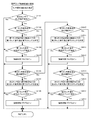
ここで、図10は、主制御装置4のMPU41により実行される主タイマ割込処理の手順の一例を説明するためのフローチャートである。主タイマ割込処理は、例えば2msecごとに実行される。
[Main timer interrupt process of main controller 4]
Here, FIG. 10 is a flowchart for explaining an example of the procedure of the main timer interrupt process executed by the
<ステップS1001>
まず、ステップS1001では、MPU41は、主制御装置4に接続されているセンサ又はスイッチの検出状態を判断するセンサ検出処理を実行する。例えば、入球センサ313a〜317a、磁石センサ35、及び電波センサ36などの検出状態を判断する。このとき、MPU41は、入球センサ313a〜317aのいずれかへの遊技球の入球が検出された場合には、その情報を入賞検知情報としてRAM412に保存する。
<Step S1001>
First, in step S1001, the
<ステップS1002>
次に、ステップS1002では、MPU41は、乱数初期値カウンタCIN1,CIN2の更新を実行する。具体的には、MPU41は、乱数初期値カウンタCIN1,CIN2でのカウンタ値に1を加算し、そのカウンタ値が最大値に達した場合は当該カウンタ値を0にクリアする。
<Step S1002>
Next, in step S1002, the
<ステップS1003>
続いて、ステップS1003では、MPU41は、大当たり乱数カウンタC1、大当たり種別カウンタC2、リーチ乱数カウンタC3、及び普通当たり乱数カウンタC4の更新を実行する。具体的には、MPU41は、大当たり乱数カウンタC1、大当たり種別カウンタC2、リーチ乱数カウンタC3、及び普通当たり乱数カウンタC4でのカウンタ値にそれぞれ1を加算し、それらのカウンタ値が最大値に達した場合は当該カウンタ値を0にクリアする。
<Step S1003>
Subsequently, in step S1003, the
<ステップS1004及びS1005>
その後、MPU41は、第1作動口314又は第2作動口315への遊技球の入賞に伴う始動入賞処理を実行し(ステップS1004)、発射制御処理を実行する(ステップS1005)。なお、始動入賞処理の詳細は、図11を参照して後述する。
<Steps S1004 and S1005>
After that, the
一方、発射制御処理は、遊技者が発射ハンドル22に触れていることがタッチセンサ21aにより検出されており、発射を停止させるための球止めスイッチ21bが操作されていないことを条件に、遊技球の発射を有効にする処理である。また、発射制御処理は、遊技者が発射ハンドル22に触れていないことがタッチセンサ21aにより検出されている場合、又は球止めスイッチ21bが操作されている場合には、遊技球の発射を無効にする処理である。MPU41は、遊技球の発射が有効である場合に、発射制御装置8に対して遊技球の発射指示をする。
On the other hand, in the launch control process, the game ball is provided on condition that the
<ステップS1006>
ステップS1006では、MPU41は、電役保留エリア412cに格納されている普通当たり乱数カウンタC4に基づいて第2作動口315の電動役物315bを電役開放状態とするか否かを抽選するスルーゲート処理を実行する。具体的に、スルーゲート処理では、まずMPU41が、高頻度モードフラグに基づいて現在の遊技モードが高頻度サポートモードであるか否かを判断する。そして、MPU41は、高頻度サポートモードでない場合には、普通当たり乱数カウンタC4が0〜29である場合に普通図柄当選であると判断し、普通当たり乱数カウンタC4が30〜249である場合に外れであると判断する。また、MPU41は、高頻度サポートモードの場合には、普通当たり乱数カウンタC4が0〜199である場合に普通図柄当選であると判断し、普通当たり乱数カウンタC4が200〜249である場合に外れであると判断する。そして、MPU41は、スルーゲート処理において普通図柄当選であると判断した場合には、電動役物315bが予め定められた所定時間だけ開放状態にする。これにより、電動役物315bが並設された遊技盤31の右上方の第2作動口315への遊技球の入賞が可能になる。
<Step S1006>
In step S1006, the
[始動入賞処理]
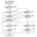
ここで、図11を参照しつつ、図10のステップS1004でMPU41により実行される始動入賞処理を説明する。
[Starting prize processing]
Here, with reference to FIG. 11, a start winning process executed by the
<ステップS1101>
まず、ステップS1101では、MPU41は、第1作動口314に遊技球が入賞したか否かを判断する。ここで、MPU41は、遊技球が第1作動口314に入賞したと判断すると(ステップS1101:Yes)、処理をステップS1102に移行し、遊技球が第1作動口314に入賞していないと判断すると(ステップS1101:No)、処理をステップS1106に移行する。
<Step S1101>
First, in step S1101, the
<ステップS1102及びS1103>
ステップS1102では、MPU41は、RAM412の保留数記憶エリアNAAに記憶されている保留数Nが最大保留数(本実施形態では4)であるか否かを判断する。ここで、MPU41は、保留数Nが最大保留数であれば(ステップS1102:Yes)、処理をステップS1106に移行する。一方、MPU41は、保留数Nが最大保留数でなければ(ステップS1102:No)、保留数Nに1を加算する(ステップS1103)。
<Steps S1102 and S1103>
In step S1102, the
<ステップS1104>
ステップS1104では、MPU41は、図10のステップS1003で更新される大当たり乱数カウンタC1、大当たり種別カウンタC2及びリーチ乱数カウンタC3と、後述のメイン処理で更新される変動種別カウンタCS1(図13のステップS1302及びS1310)とのカウンタ値を取得し、そのカウンタ値をRAM412における保留格納エリア412bの第1保留格納エリアREAの第1保留エリアREA1〜第4保留エリアREA4のうち最初の空き保留エリアに格納する。
<Step S1104>
In step S1104, the
<ステップS1105>
ステップS1105では、MPU41は、ステップS1104で取得された第1保留に対する当否情報が後述の変動開始処理(図14のS1408、図16)における大当たりの当否の判定対象となる前に当否情報の内容を確認し、この確認結果に基づいて第1保留コマンドをRAM412に設定する第1保留コマンド設定処理を実行する。なお、第1保留コマンド設定処理の詳細は、図12を参照して後述する。
<Step S1105>
In step S1105, the
<ステップS1106>
ステップS1106では、MPU41は、第2作動口315に遊技球が入賞したか否かを判断する。ここで、MPU41は、遊技球が第2作動口315に入賞したと判断すると(ステップS1106:Yes)、処理をステップS1107に移行し、遊技球が第2作動口315に入賞していないと判断すると(ステップS1106:No)、当該始動入賞処理を終了し、処理を図10のステップS1005に移行する。
<Step S1106>
In step S1106, the
<ステップS1107及びS1108>
ステップS1107では、MPU41は、RAM412の保留数記憶エリアNABに記憶されている保留数Mが最大保留数(本実施形態では4)であるか否かを判断する。ここで、MPU41は、保留数Mが最大保留数であれば(ステップS1107:Yes)、当該始動入賞処理を終了し、処理を図10のステップS1005に移行する。一方、MPU41は、保留数Mが最大保留数でなければ(ステップS1107:No)、保留数Mに1を加算する(ステップS1108)。
<Steps S1107 and S1108>
In step S1107, the
<ステップS1109>
ステップS1109では、MPU41は、図10のステップS1003で更新される大当たり乱数カウンタC1、大当たり種別カウンタC2及びリーチ乱数カウンタC3と、後述のメイン処理で更新される変動種別カウンタCS1(図13のステップS1302及びS1310)とのカウンタ値を取得し、そのカウンタ値をRAM412における保留格納エリア412bの第2保留格納エリアREBの第1保留エリアREB1〜第4保留エリアREB4のうち最初の空き保留エリアに格納する。
<Step S1109>
In step S1109, the
<ステップS1110>
ステップS1110では、MPU41は、ステップS1109で取得された第2保留に対する当否情報が後述の変動開始処理(図14のS1408、図16)における大当たりの当否の判定対象となる前に、前記当否情報の内容を確認し、この確認結果に基づいて第2保留コマンドをRAM412に設定する第2保留コマンド設定処理を実行する。ここで、第2保留コマンド設定処理は、図12を参照して後述する第1保留コマンド設定処理と同様であるため、詳細な説明は省略する。なお、第2保留コマンド設定処理は、図12の第1保留コマンド設定処理において、「第1保留コマンド」を「第2保留コマンド」、「保留数N」を「保留数M」と読み替えればよい。
<Step S1110>
In step S1110, the
[第1保留コマンド設定処理]
ここで、図12を参照しつつ、図11のステップS1105でMPU41により実行される第1保留コマンド設定処理を説明する。なお、第1保留コマンドには、当該コマンドが第1保留コマンドである旨を示す情報と、第1保留コマンドの種別(大当たり種別又は外れ)、変動パターン及び保留数Nなどの情報とが含まれる。
[First pending command setting process]
Here, the first hold command setting process executed by the
<ステップS1201>
ステップS1201では、MPU41は、第1保留格納エリアREAの保留数記憶エリアNAAから保留数Nを読み出すと共に、それぞれの第1保留に対応する大当たり乱数カウンタC1の値をRAM412から読み出す。
<Step S1201>
In step S1201, the
<ステップS1202>
ステップS1202では、MPU41は、高確率モードであるか否かを判断し、高確率モードである場合は(ステップS1202:Yes)、処理をステップS1203に移行し、高確率モードでない場合は(ステップS1202:No)、処理をステップS1204に移行する。例えば、MPU41は、高確率モードであるか否かを、後述のメイン処理における遊技状態移行処理(図13のステップS1306)において高確率モードへの移行時にオンに設定され、高確率モードから大当たり遊技状態などの他の遊技状態への移行時にオフに設定される高確率モードフラグに基づいて判断する。
<Step S1202>
In step S1202, the
<ステップS1203及びS1204>
ステップS1203では、MPU41は、高確率モード当否テーブル(図9(B)参照)に基づいて、ステップS1201で読み出された大当たり乱数カウンタC1のカウンタ値が大当たり当選に対応する値であるか否かの当否判定を実行する。一方、ステップS1204では、MPU41は、低確率モード当否テーブル(図9(A)参照)に基づいて、ステップS1201で読み出された大当たり乱数カウンタC1のカウンタ値が大当たり当選に対応する値であるか否かの当否判定を実行する。
<Steps S1203 and S1204>
In step S1203, the
<ステップS1205>
ステップS1205では、MPU41は、大当たり乱数カウンタC1のカウンタ値が大当たり当選に対応する値であるか否かを判断する。ここで、MPU41は、大当たり乱数カウンタC1から読み出されたカウンタ値が大当たり当選に対応する値であると判断した場合は(ステップS1205:Yes)、処理をステップS1206に移行し、大当たり乱数カウンタC1から読み出されたカウンタ値が大当たり当選に対応する値でないと判断した場合は(ステップS1205:No)、処理をステップS1208に移行する。
<Step S1205>
In step S1205, the
<ステップS1206>
ステップS1206では、MPU41は、RAM412から大当たり種別カウンタC2及び変動種別カウンタCS1のカウンタ値を読み出す。例えば、図11のステップS1104で当否情報が第3保留エリアRE3に格納された場合には、その第3保留エリアRE3に格納された当否情報に含まれる大当たり種別カウンタC2及び変動種別カウンタCS1のカウンタ値が読み出される。なお、第1保留エリアRE1〜第4保留エリアRE4のうち図11のステップS1104で当否情報が格納された保留エリアは、保留数記憶エリアNAに記憶されている保留数Nの値によって判断可能である。
<Step S1206>
In step S1206, the
<ステップS1207>
ステップS1207では、MPU41は、大当たり種別カウンタC2、変動種別カウンタCS1及び保留数Nを第1保留コマンドに設定する。このように、第1保留コマンドに、ステップS1201で読み出された保留数Nが含まれるため、第1保留コマンドを受信する音声ランプ制御装置5のMPU51は、第1保留コマンドに含まれる保留数Nを参照することにより、当該第1保留コマンドが第1保留エリアRE1〜第4保留エリアRE4のいずれに格納された当否情報に対応するものであるかを認識することが可能である。
<Step S1207>
In step S1207, the
<ステップS1208及びS1209>
ステップS1208では、MPU41は、RAM412から変動種別カウンタCS1のカウンタ値を読み出す。次いで、MPU41は、大当たり抽選での抽選結果が外れであることを示す情報、変動種別カウンタCS1及び保留数Nを第1保留コマンドに設定する(ステップS1209)。
<Steps S1208 and S1209>
In step S1208, the
なお、当該第1保留コマンド設定処理でオンに設定される第1保留コマンドは、RAM412に記憶されており、主制御装置4のMPU41によって実行される後述の図13のメイン処理のステップS1301において他のコマンドと共に音声ランプ制御装置5に送信された後に消去される。さらに、ここで説明した第1保留コマンドの内容は一例に過ぎず、音声ランプ制御装置5において前記保留コマンドと同様の内容を把握することが可能であれば、ここで説明するものに限らない。例えば、第1保留コマンドの一部又は全部の情報が他のコマンドに含まれることも考えられる。
The first hold command set to be turned on in the first hold command setting process is stored in the
[主制御装置4のメイン処理]
次に、図13を参照しつつ、主制御装置4のMPU41によって実行されるメイン処理について説明する。メイン処理では変動遊技及び大当たり遊技の進行に対する主要な制御処理が実行される。メイン処理では、ステップS1301〜S1307の処理が、例えば4msec周期の定期処理として実行され、ステップS1308〜S1310のカウンタ更新処理がステップS1301〜S1307の処理の終了後から次周期までの残余時間で実行される。
[Main processing of main controller 4]
Next, the main processing executed by the
<ステップS1301>
まず、ステップS1301では、MPU41は、図10の主タイマ割込処理又は前回のメイン処理で設定されたコマンドなどの出力データをサブ制御ユニット332や周辺制御ユニット140などの制御装置に送信する外部出力処理を実行する。例えば、RAM412において変動パターンコマンド、第1保留コマンド、第2保留コマンド、シフトコマンドなどのコマンドが設定されている場合には、音声ランプ制御装置5にそのコマンドを送信する。また、当該メイン処理での後述のステップS1303の賞球コマンド設定処理においてRAM412に賞球コマンドが設定されている場合には、その賞球コマンドを払出制御装置7に対して送信する。
<Step S1301>
First, in step S1301, the
<ステップS1302>
ステップS1302では、MPU41は、変動種別カウンタCS1の値を更新する。具体的には、MPU41は、変動種別カウンタCS1でのカウンタ値に1を加算し、そのカウンタ値が最大値に達した場合は当該カウンタ値を0にクリアする。
<Step S1302>
In step S1302, the
<ステップS1303>
ステップS1303では、MPU41は、払出制御装置7及びサブ制御ユニット332に出力する賞球コマンドをRAM412に設定する。具体的に、MPU41は、RAM412に記憶されている入賞検知情報に基づいて、一般入賞口313、可変入賞口316などに入賞が発生したか否かを判断する。そして、入賞が発生している場合は、その入賞に応じて払い出す賞球数を示す賞球コマンドをRAM412に設定する。
<Step S1303>
In step S1303, the
<ステップS1304>
ステップS1304では、MPU41は、変動遊技における遊技を制御するための変動遊技制御処理を実行する。なお、変動遊技制御処理の詳細については後述するが、変動遊技制御処理では、前述の大当たり抽選が実行され、図柄表示部341による図柄変動表示に必要な変動パターンコマンドが設定される。このとき、MPU41は、図10の主タイマ割込処理のステップS1003で更新される大当たり乱数カウンタC1、大当たり種別カウンタC2、リーチ乱数カウンタC3、並びに本処理のステップS1302及びステップS1310で更新される変動種別カウンタCS1の各値に基づいて、大当たり抽選の抽選結果及び変動表示時間を示す変動パターンコマンドをRAM412に設定する。
<Step S1304>
In step S1304, the
<ステップS1305>
ステップS1305では、MPU41は、大当たり遊技における遊技の進行を制御するための大当たり遊技制御処理を実行する。大当たり遊技制御処理では、MPU41は、可変入賞口316が開放されるラウンド遊技を、開閉扉316bの開閉動作を制御することで、当該大当たり遊技への移行の契機となった大当たり抽選の結果(大当たり種別)に応じた数だけ実行する。例えば、MPU41は、大当たり種別が5R通常大当たり及び5R確変大当たりである場合にはラウンド遊技を5回実行し、大当たり種別が16R確変大当たりである場合にはラウンド遊技を16回実行する。
<Step S1305>
In step S1305, the
<ステップS1306>
ステップS1306では、MPU41は、図15の変動開始処理におけるステップS1602,S1603での大当たり抽選の抽選結果に基づいて、遊技状態を移行させるための遊技状態移行処理を実行する。遊技状態移行処理では、MPU41は、所定の条件を満たす場合に遊技状態を、開閉実行モードを有する大当たり遊技状態、高確率モードかつ高頻度サポートモードである確変時短遊技状態、低確率モードかつ高頻度サポートモードである通常時短遊技状態、低確率モードで高頻度サポートモードでもない通常非時短遊技状態などに移行させる。
<Step S1306>
In step S1306, the
例えば、MPU41は、大当たり抽選での抽選結果が大当たりである場合、当該抽選結果を報知する変動遊技の終了後に遊技状態を大当たり遊技状態に移行させる。このとき、MPU41は、RAM412に記憶された大当たり遊技開始フラグをオンに設定する。また、MPU41は、大当たり遊技が終了した場合、当該大当たり遊技を実行する契機となった大当たり抽選での抽選結果に応じて、遊技状態を大当たり遊技状態から所定の遊技状態に移行させる。本実施形態では、MPU41は、大当たり抽選での抽選結果が5R確変大当たり又は16R確変大当たりである場合に、大当たり遊技の終了後に確変時短遊技状態に移行させ、大当たり抽選での抽選結果が5R通常大当たりである場合に、大当たり遊技の終了後に通常時短遊技状態に移行させる。
For example, when the lottery result in the jackpot lottery is a jackpot, the
また、MPU41は、遊技状態の移行を移行させた場合、移行前の遊技状態に対するフラグをオフに設定する一方で、移行後の遊技状態に対するフラグをオンに設定する。例えば、MPU41は、大当たり遊技状態から確変時短遊技状態への遊技状態の移行があった場合に大当たり遊技フラグをオフに設定する一方で高確率モードフラグをオンに設定する。一方、確変時短遊技状態から大当たり遊技状態への遊技状態の移行があった場合に高確率モードフラグをオフに設定する一方で大当たり遊技フラグをオンに設定する。
Further, when the transition of the gaming state is transitioned, the
<ステップS1307>
ステップS1307では、MPU41は、メイン表示部37の表示制御処理を実行する。この表示制御処理により、メイン表示部37における7セグメント表示器372,373で、変動パターンコマンドに対応する変動表示時間の間だけ図柄変動表示が実行され、その図柄変動表示は抽選結果を示す図柄で停止表示さることになる。また、表示制御処理により、メイン表示部37におけるLED対371で、予め定められた普通図柄変動表示時間の間だけ各LEDランプが点滅され、普通図柄当選の有無を一対のLEDランプの点灯及び消灯の組み合わせである点灯パターンによって示すことになる。なお、普通図柄当選の場合には第2作動口315に付随する電動役物315bが所定時間だけ開放される。
<Step S1307>
In step S1307, the
<ステップS1308>
ステップS1308では、MPU41は、次のメイン処理の実行タイミングが到来したか否か、即ち今回のメイン処理の開始から所定時間(本実施形態では4msec)が経過したか否かを判断する。ここで、MPU41は、次のメイン処理の実行タイミングが到来したと判断すると(ステップS1308:Yes)、処理をステップS1301に移行させ、前述したS1301以降の各処理を実行する。一方、MPU41は、次のメイン処理の実行タイミングが到来していないと判断すると(ステップS1308:No)、次のメイン処理の実行タイミングが到来するまでの間、即ち次のメイン処理の実行タイミングに至るまでの残余時間の間は、次のメイン処理の実行タイミングが到来したと判断するまで(ステップS1308:Yes)、ステップS1308、ステップS1309及びステップS1310を繰り返し実行する。
<Step S1308>
In step S1308, the
<ステップS1309>
ステップS1309では、MPU41は、乱数初期値カウンタCIN1,CIN2を更新する。具体的には、MPU41は、乱数初期値カウンタCIN1,CIN2でのカウンタ値に1を加算し、そのカウンタ値が最大値に達した場合には当該カウンタ値を0にクリアする。
<Step S1309>
In step S1309, the
<ステップS1310>
ステップS1310では、MPU41は、変動種別カウンタCS1を更新する。具体的には、変動種別カウンタCS1でのカウンタ値に1を加算し、それらのカウンタ値が最大値に達した場合には当該カウンタ値を0にクリアする。そして、MPU41は、変動種別カウンタCS1を更新した後、処理をステップS1308に戻す。
<Step S1310>
In step S1310, the
[変動遊技制御処理]
ここで、図14を参照しつつ、図13のメイン処理でのステップS1304において実行される変動遊技制御処理について説明する。
[Variable game control processing]
Here, the variable game control process executed in step S1304 in the main process of FIG. 13 will be described with reference to FIG.
<ステップS1401>
ステップS1401では、MPU41は、遊技機10が大当たり遊技中であるか否かを判断し、大当たり遊技中である場合は(ステップS1401:Yes)、当該変動遊技制御処理を終了し、大当たり遊技中でない場合は(ステップS1401:No)、処理をステップS1402に移行する。大当たり遊技の実行の有無は、例えば図13のメイン処理での遊技状態移行処理において、大当たり遊技状態への移行時にオンに設定され、大当たり遊技状態から他の遊技状態への移行時にオフに設定される大当たり遊技フラグに基づいて判断される。
<Step S1401>
In step S1401, the
<ステップS1402>
ステップS1402では、MPU41は、図柄変動表示中であるか否かを判断し、図柄変動表示中である場合は(ステップS1402:Yes)、処理をステップS1403に移行させ、図柄変動表示中でない場合は(ステップS1402:No)、処理をステップS1406に移行させる。例えば、図柄変動表示中であるか否かは、後述の図16の変動開始処理でのステップS1606においてオンに設定され、変動表示時間が経過した場合に(ステップS1403:Yes)、当該変動遊技制御処理のステップS1405でオフに設定される変動表示中フラグに基づいて判断される。
<Step S1402>
In step S1402, the
<ステップS1403>
ステップS1403では、MPU41は、図柄変動表示の開始から変動表示時間が経過したか否かを判断し、変動表示時間が経過したと判断した場合は(ステップS1403:Yes)、処理をステップS1404に移行し、変動表示時間が経過していないと判断した場合は(ステップS1403:No)、当該変動遊技制御処理を終了する。
<Step S1403>
In step S1403, the
<ステップS1404及びS1405>
変動表示時間が経過した場合(ステップS1403:Yes)、MPU41は、メイン表示部37の7セグメント表示器372,373において、当該変動遊技に対応する大当たり抽選の結果に応じた図柄を停止表示させ(ステップS1404)、変動表示中フラグがオフに設定する(ステップS1405)。
<Steps S1404 and S1405>
When the variable display time has elapsed (step S1403: Yes), the
<ステップS1406>
図柄変動表示中でない場合は(ステップS1402:No)、MPU41は、保留格納エリア412bの保留数記憶エリアNAAに記憶されている保留数N、保留数記憶エリアNABに記憶されている保留数Mの両方が0であるか否かを判断する(ステップS1406)。ここで、MPU41は、保留数N及び保留数Mの両方が0である場合(ステップS1406:Yes)、当該変動遊技制御処理を終了する。一方、MPU41は、保留数N及び保留数Mのいずれか一方が0でない場合は(ステップS1406:No)、処理をステップS1407に移行する。
<Step S1406>
When the symbol variation display is not in progress (step S1402: No), the
<ステップS1407>
ステップS1407では、MPU41は、保留格納エリア412bに記憶されている当否情報のデータについてデータ設定処理を実行する。MPU41は、ステップS1407の処理を終了した場合、処理をステップS1408に移行する。なお、データ設定処理の詳細は図15を参照して後述する。
<Step S1407>
In step S1407, the
<ステップS1408>
ステップS1408では、MPU41は、実行エリアAEに格納された当否情報に基づく変動表示を図柄表示部341に実行させるための変動開始処理を実行し、当該変動遊技制御処理を終了する。なお、変動開始処理の詳細は、図16を参照して後述する。
<Step S1408>
In step S1408, the
[データ設定処理]
ここで、図15を参照しつつ、図14のステップS1407においてMPU41によって実行されるデータ設定処理の一例について説明する。
[Data setting process]
Here, an example of the data setting process executed by the
<ステップS1501>
ステップS1501では、MPU41は、第2特別図柄遊技に対応する保留数Mが0であるか否かを判断し、保留数Mが0である場合(ステップS1501:Yes)、処理をステップS1502に移行する。一方、MPU41は、保留数Mが0でない場合(ステップS1501:No)、処理をステップS1505に移行する。
<Step S1501>
In step S1501, the
<ステップS1502〜S1504>
保留数Mが0である場合(ステップS1501:Yes)、MPU41は、保留数記憶エリアNAAに記憶されている保留数Nを1減算し(ステップS1502)、第1保留エリアREA1から実行エリアAEに当否情報を移動させる(ステップS1503)。続いて、MPU41は、第2保留エリアREA2〜第4保留エリアREA4の当否情報を1つずつシフトさせる(ステップS1504)。具体的に、ステップS1504では、第2保留エリアREA2の当否情報を第1保留エリアREA1に移動させ、第3保留エリアREA3の当否情報を第2保留エリアREA2に移動させ、第4保留エリアREA4の当否情報を第3保留エリアREA3に移動させる。MPU41は、ステップS1504の処理が終了した場合、処理をステップS1508に移行する。
<Steps S1502 to S1504>
When the number of reservations M is 0 (step S1501: Yes), the
<ステップS1505〜S1507>
ステップS1505は、保留数Mが0である場合に移行するが(ステップS1501:No)、ステップS1501は、図14のステップS1406において保留数M及び保留数Nの両方又は一方が0でない場合に移行する(ステップS1406:No)。そのため、MPU41は、保留数Mが0である場合(ステップS1501:No)、保留数Nが0でないと判断できるため、ステップS1505〜S1507の処理を実行する。
<Steps S1505 to S1507>
Step S1505 shifts when the number M of reservations is 0 (step S1501: No), but step S1501 shifts when either or both of the number M of reservations and the number N of reservations are not 0 in step S1406 of FIG. Yes (step S1406: No). Therefore, when the number M of reservations is 0 (step S1501: No), the
具体的には、MPU41は、保留数記憶エリアNABに記憶されている保留数Mを1減算し(ステップS1505)、第1保留エリアREB1から実行エリアAEに当否情報を移動させる(ステップS1506)。続いて、MPU41は、第2保留エリアREB2〜第4保留エリアREB4の当否情報を1つずつシフトさせる(ステップS1507)。具体的に、ステップS1507では、第2保留エリアREB2の当否情報を第1保留エリアREB1に移動させ、第3保留エリアREB3の当否情報を第2保留エリアREB2に移動させ、第4保留エリアREB4の当否情報を第3保留エリアREB3に移動させる。MPU41は、ステップS1507の処理が終了した場合、処理をステップS1508に移行する。
Specifically, the
<ステップS1508>
ステップS1508では、MPU41は、第1保留エリアREA1〜第4保留エリアREA4又は第1保留エリアREB1〜第4保留エリアREB4の当否情報がシフトした旨を示すシフトコマンドをRAM412に設定する。そして、このステップS1508で設定されたシフトコマンドは、MPU41により実行される次回のメイン処理(図13参照)のステップS1301の外部出力処理で音声ランプ制御装置5に送信される。これにより、図柄表示部341に表示される保留図柄の表示数などが変更されることになる。ステップS1508の処理が終了した場合、MPU41は、当該データ設定処理を終了し、処理を図14のステップS1408に移行する。
<Step S1508>
In step S1508, the
[変動開始処理]
ここで、図16を参照しつつ、図14のステップS1408においてMPU41によって実行される変動開始処理の一例について説明する。
[Variation start processing]
Here, an example of the fluctuation start process executed by the
<ステップS1601>
ステップS1601では、MPU41は、遊技状態が高確率モードである否かを判断する。高確率モードであるか否かは、例えば図13のメイン処理でのステップS1306の遊技状態移行処理でオンに設定される高確率モードフラグがオンに設定されているか否かに基づいて判断される。MPU41は、遊技状態が高確率モードである場合(ステップS1601:Yes)、処理をステップS1602に移行し、遊技状態が高確率モードでない場合(ステップS1601:No)、即ち遊技状態が低確率モードである場合、処理をステップS1603に移行する。
<Step S1601>
In step S1601, the
<ステップS1602及びS1603>
ステップS1602では、MPU41は、高確率モード当否テーブル(図9(B)参照)に基づいて、保留格納エリア412bの実行エリアAEに格納された当否情報に数値情報として含まれる大当たり乱数カウンタC1のカウンタ値が大当たり当選に対応する値であるか否かの当否判定を行う。一方、ステップS1604では、MPU41は、低確率モード当否テーブル(図9(B)参照)に基づいて、保留格納エリア412bの実行エリアAEに格納された当否情報に数値情報として含まれる大当たり乱数カウンタC1のカウンタ値が大当たり当選に対応する値であるか否かの当否判定を行う。
<Steps S1602 and S1603>
In step S1602, the
<ステップS1604>
ステップS1604では、MPU41は、当該変動遊技の変動パターンに対応するメイン表示部37の7セグメント表示器372,373の変動表示時間を変動表示時間カウンタに設定する。具体的に、MPU41は、ステップS1602又はS1603での当否判定の結果が通常大当たりである場合には、変動種別カウンタCS1と通常大当たり変動テーブル(図9(E)参照)とに基づいて変動パターンを特定する。また、MPU41は、ステップS1602又はS1603での当否判定の結果が確変大当たりである場合には、変動種別カウンタCS1と確変大当たり変動テーブル(図9(F)参照)とに基づいて変動パターンを特定する。さらに、MPU41は、ステップS1602又はS1603での当否判定の結果が外れである場合には、変動種別カウンタCS1と外れ変動テーブル(図9(G)参照)とに基づいて変動パターンを特定する。
<Step S1604>
In step S1604, the
<ステップS1605>
ステップS1605では、MPU41は、当該変動遊技に対する大当たり抽選での抽選結果とステップS1604で特定された変動パターンとを含む変動パターンコマンドをRAM412に設定する。これにより、MPU41により実行される次回のメイン処理(図13参照)のステップS1301では、変動パターンコマンドが音声ランプ制御装置5に送信され、音声ランプ制御装置5は、変動パターンコマンドに基づいて図柄表示部341による図柄変動表示などを実行する。
<Step S1605>
In step S1605, the
なお、前述したように、MPU41は、抽選結果が「通常大当たり」である場合、変動パターン「01」〜「03」に5R通常大当たりである旨を示す「A」を付した「A01」〜「A03」のいずれかを変動パターンコマンドとしてRAM412に設定する。また、MPU41は、抽選結果が「5R確変大当たり」である場合、変動パターン「01」〜「03」に5R確変大当たりである旨を示す「B」を付した「B01」〜「B03」のいずれかを変動パターンコマンドとしてRAM412に設定する。さらに、MPU41は、抽選結果が「16R確変大当たり」である場合、変動パターン「01」〜「03」に16R確変大当たりである旨を示す「C」を付した「C01」〜「C03」のいずれかを変動パターンコマンドとしてRAM412に設定する。また、MPU41は、抽選結果が「外れ」である場合、変動パターン「01」〜「08」に外れである旨を示す「D」を付した「D01」〜「D08」のいずれかを変動パターンコマンドとしてRAM412に設定する。また、MPU41は、抽選結果が「外れ」である場合、前後外れリーチ、前後外れ以外リーチ及び完全外れのいずれであるかの情報を変動パターンコマンドに含ませる。
As described above, when the lottery result is “normal jackpot”, the
<ステップS1606>
ステップS1606では、MPU41は、メイン表示部37の図柄変動表示を開始させ、当該変動開始処理を終了する。なお、MPU41は、メイン表示部37の図柄変動表示を開始させた場合、変動表示中フラグをオンに設定する。
<Step S1606>
In step S1606, the
[音声ランプ制御装置5の処理]
次に、図17〜図38を参照しつつ、音声ランプ制御装置5でMPU51によって実行される処理について説明する。
[Processing of voice lamp controller 5]
Next, the processing executed by the
なお、本実施形態で音声ランプ制御装置5のMPU51が実行する処理の一部又は全部が、表示制御装置6のMPU61によって実行されることも他の実施形態として考えられる。また、音声ランプ制御装置5では、MPU51が、スピーカ26及び電飾部27の制御処理、音声ランプ制御装置5の立ち上げ時の立ち上げ処理、停電時のNMI割込処理なども実行するが、それらの処理については説明を省略する。
It is also conceivable as another embodiment that a part or all of the processing executed by the
[音声ランプ制御装置5の副タイマ割込処理]
ここで、図17は、音声ランプ制御装置5のMPU51によって実行される副タイマ割込処理の手順の一例を示すフローチャートである。MPU51は、例えば副タイマ割込処理を1msec周期の定期処理として実行する。
[Sub-timer interrupt process of voice lamp controller 5]
Here, FIG. 17 is a flowchart showing an example of the procedure of the sub-timer interrupt process executed by the
図17に示すように、MPU51は、副タイマ割込処理において、操作ボタン操作検出処理(ステップS1701)、操作検出パターン判定処理(ステップS1702)、タッチ操作検出処理(ステップS1703)、タッチ操作検出パターン判定処理(ステップS1704)、カウンタ更新処理(ステップS1705)、コマンド判定処理(ステップS1706)、変動遊技演出処理(ステップS1707)、及び大当たり遊技演出処理(ステップS1708)を実行する。
As shown in FIG. 17, the
[操作ボタン操作検出処理]
ここで、図18は、図17の副タイマ割込処理における操作ボタン操作検出処理(ステップS1701)の手順の一例を示すフローチャートである。操作ボタン操作検出処理では、操作ボタン20の操作状態を検出し、過去3回分の操作履歴を順次更新するための処理を実行する。遊技機10では、MPU51によって操作ボタン操作検出処理が実行されることにより、副タイマ割込処理の割込周期に対応した予め定められた間隔(本実施形態では1msec間隔)で操作ボタン20の操作の有無が判断されることになる。
[Operation button operation detection process]
Here, FIG. 18 is a flowchart showing an example of the procedure of the operation button operation detection process (step S1701) in the sub-timer interrupt process of FIG. In the operation button operation detection process, the operation state of the
<ステップS1801〜S1803>
図18に示すように、ステップS1801では、MPU51は、第2操作検出フラグの設定を第1操作検出フラグにシフト(上書き)させる。また、ステップS1802では、MPU51は、第3操作検出フラグの設定を第2操作検出フラグにシフト(上書き)させる。その後、ステップS1803では、MPU51は、操作スイッチ20aにより検出される操作ボタン20の操作状態を第3操作検出フラグに設定(上書き)し、当該操作ボタン操作検出処理は終了する。
<Steps S1801 to S1803>
As shown in FIG. 18, in step S1801, the
このように、操作ボタン操作検出処理では、ステップS1801〜S1803の処理が実行されることにより、操作ボタン20の操作履歴として1msec間隔の直近の3回分の操作状態が第1操作検出フラグ〜第3操作検出フラグとしてRAM512に記憶される。具体的に、第3操作検出フラグとして直近の操作状態が記憶され、第2操作検出フラグとして一つ前の操作状態が記憶され、第1操作検出フラグとして二つ前の操作状態が記憶される。
As described above, in the operation button operation detection process, the processes of steps S1801 to S1803 are executed, so that the operation states of the
[操作検出パターン判定処理]
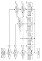
ここで、図19は、図17の副タイマ割込処理における操作検出パターン判定処理(ステップS1702)の手順の一例を示すフローチャートである。操作検出パターン判定処理では、第1操作検出フラグ、第2操作検出フラグ及び第3操作検出フラグに基づいて判定される操作ボタン20の操作履歴から操作ボタン20に対する操作状態を判定するための操作パターンフラグを設定する。操作パターンフラグは第1〜第3操作パターンフラグからなり、第1〜第3操作パターンフラグのオン及びオフの組み合わせによって操作ボタン20の操作状態を判定できる。例えば、図22(A)に示すように、第1操作パターンフラグのみがオンに設定されている場合には、操作ボタン20に対する操作が継続されていると判定できる。また、第2操作パターンフラグのみがオンに設定されている場合には、操作ボタン20に対する操作が開始されたと判定できる。また、第3操作パターンフラグのみがオンに設定されている場合には、操作ボタン20に対する操作が終了したと判定できる。そして、第1〜第3操作パターンフラグの全てがオフに設定されている場合には、操作ボタン20に対する操作がなされていないと判定できる。
[Operation detection pattern determination processing]
Here, FIG. 19 is a flowchart showing an example of the procedure of the operation detection pattern determination process (step S1702) in the sub-timer interrupt process of FIG. In the operation detection pattern determination process, an operation pattern for determining the operation state of the
<ステップS1901>
図19に示すように、ステップS1901では、MPU51は、3回前の操作ボタン20の操作状態を示す第1操作検出フラグがオンに設定されているか否かを判断する。ここで、MPU51は、第1操作検出フラグがオンである場合(ステップS1901:Yes)、処理をステップS1902に移行し、第1操作検出フラグがオフである場合(ステップS1901:No)、処理をステップS1905に移行する。
<Step S1901>
As shown in FIG. 19, in step S1901, the
<ステップS1902>
ステップS1902では、MPU51は、2回前の操作ボタン20の操作状態を示す第2操作検出フラグがオンに設定されているか否かを判断する。ここで、MPU51は、第2操作検出フラグがオンである場合(ステップS1902:Yes)、処理をステップS1903に移行し、第2操作検出フラグがオフである場合(ステップS1902:No)、処理をステップS1908に移行する。
<Step S1902>
In step S1902, the
<ステップS1903>
ステップS1903では、MPU51は、直近の操作ボタン20の操作状態を示す第3操作検出フラグがオンに設定されているか否かを判断する。ここで、MPU51は、第3操作検出フラグがオンである場合(ステップS1903:Yes)、処理をステップS1904に移行し、第3操作検出フラグがオフである場合(ステップS1903:No)、処理をステップS1910に移行する。
<Step S1903>
In step S1903, the
<ステップS1904>
ステップS1904では、MPU51は、第1操作パターンフラグをオン、第2操作パターンフラグ及び第3操作パターンフラグをオフに設定し、当該操作検出パターン判定処理を終了する。即ち、MPU51は、操作ボタン20の3回分の操作状態として「オン」、「オン」、「オン」の操作パターンが発生した場合に、操作ボタン20の操作状態が継続していると判断できるため、第1操作パターンフラグをオンに設定し、第2操作パターンフラグ及び第3操作パターンフラグをオフに設定する(図22(A)参照)。そして、第1操作パターンフラグは、操作ボタン20の操作状態が継続しているか否かを判断するための指標として利用される。
<Step S1904>
In step S1904, the
<ステップS1905>
MPU51は、ステップS1901において第1操作検出フラグがオフであると判断した場合(ステップS1901:No)、2回前の操作ボタン20の操作状態を示す第2操作検出フラグがオンであるか否かを判断する(ステップS1905)。ここで、MPU51は、第2操作検出フラグがオンである場合(ステップS1905:Yes)、処理をステップS1906に移行し、第2操作検出フラグがオフである場合(ステップS1905:No)、処理をステップS1910に移行する。
<Step S1905>
When the
<ステップS1906>
ステップS1906では、MPU51は、直近の操作ボタン20の操作状態を示す第3操作検出フラグがオンであるか否かを判断する。ここで、MPU51は、第3操作検出フラグがオンである場合(ステップS1906:Yes)、処理をステップS1907に移行し、第3操作検出フラグがオフである場合(ステップS1906:No)、処理をステップS1910に移行する。
<Step S1906>
In step S1906, the
<ステップS1907>
ステップS1907では、MPU51は、第2操作パターンフラグをオン、第1操作パターンフラグ及び第3操作パターンフラグをオフに設定し、当該操作検出パターン判定処理を終了する。即ち、MPU51は、操作ボタン20の3回分の操作状態として「オフ」、「オン」、「オン」の操作パターンが発生した場合に、操作ボタン20が非操作状態から操作状態に変化した(操作が開始された)と判断できるため、第2操作パターンフラグをオンに設定し、第1操作パターンフラグ及び第3操作パターンフラグをオフに設定する(図22(A)参照)。そして、第2操作パターンフラグは、操作ボタン20が非操作状態から操作状態に変化したか否かを(操作ボタン20の操作が開始されたか否か)を判断するための指標として利用される。このように、第2操作パターンフラグを用いて、操作ボタン20が非操作状態から操作状態に変化したか否かを判断すれば、操作ボタン20の3回分の操作状態が反映されるため、電波又は静電気などのノイズに起因する操作ボタン20の操作開始の誤検出が防止され、遊技者が意図しないタイミングで操作ボタン20の操作開始が演出表示に反映されることが防止される。
<Step S1907>
In step S1907, the
<ステップS1908>
MPU51は、ステップS1902において第2操作検出フラグがオフであると判断した場合(ステップS1902:No)、直近の操作ボタン20の操作状態を示す第3操作検出フラグがオンであるか否かを判断する(ステップS1908)。ここで、MPU51は、第3操作検出フラグがオンである場合(ステップS1908:Yes)、処理をステップS1910に移行し、第2操作検出フラグがオフである場合(ステップS1908:No)、処理をステップS1909に移行する。
<Step S1908>
When the
<ステップS1909>
ステップS1909では、MPU51は、第3操作パターンフラグをオン、第1操作パターンフラグ及び第2操作パターンフラグをオフに設定し、当該操作検出パターン判定処理を終了する。即ち、MPU51は、操作ボタン20の3回分の操作状態として「オン」、「オフ」、「オフ」の操作パターンが発生した場合に、操作ボタン20が操作状態から非操作状態に変化した(操作が終了した)と判断できるため、第3操作パターンフラグをオンに設定し、第1操作パターンフラグ及び第2操作パターンフラグをオフに設定する(図22(A)参照)。そして、第3操作パターンフラグは、操作ボタン20が操作状態から非操作状態に変化したか否かを(操作ボタン20の操作が終了したか否か)を判断するための指標として利用される。このように、第3操作パターンフラグを用いて、操作ボタン20が操作状態から非操作状態に変化したか否かを判断すれば、操作ボタン20の3回分の操作状態が反映されるため、電波又は静電気などのノイズに起因する操作ボタン20の操作開始の誤検出が防止され、遊技者が意図しないタイミングで操作ボタン20の操作終了が演出表示に反映されることが防止される。
<Step S1909>
In step S1909, the
<ステップS1910>
ステップS1910では、MPU51は、第1操作パターンフラグ、第2操作パターンフラグ及び第3操作パターンフラグをオフに設定し、当該操作検出パターン判定処理を終了する。即ち、MPU51は、操作ボタン20の3回分の操作状態として「オフ」、「オフ」、「オフ」など上記以外の操作パターンが発生した場合に、第1〜第3操作パターンフラグの全てをオフに設定する(図22(A)参照)。なお、MPU51は、第1〜第3操作パターンフラグの全てがオフの場合、操作ボタン20が非操作状態であると判定する。
<Step S1910>
In step S1910, the
[タッチ操作検出処理]
ここで、図20は、図17の副タイマ割込処理におけるタッチ操作検出処理(ステップS1703)の手順の一例を示すフローチャートである。タッチ操作検出処理では、複数の検知センサ38a〜38dでの検知結果に基づいて、図柄表示部341の正面側の所定領域(パネル25における特定領域)に対するタッチ操作状態を検出し、図柄表示部341の正面側の所定領域(パネル25の特定領域)(例えば図6(C)のクロスハッチング部分)に対する過去3回分のタッチ操作履歴を順次更新するための処理を実行する。遊技機10では、MPU51によってタッチ操作検出処理が実行されることにより、副タイマ割込処理の割込周期に対応した予め定められた間隔(本実施形態では1msec間隔)で図柄表示部341の正面側の所定領域(パネル25における特定領域)に対する遊技者によるタッチ操作の有無が判断されることになる。
[Touch operation detection process]
Here, FIG. 20 is a flowchart showing an example of the procedure of the touch operation detection process (step S1703) in the sub timer interrupt process of FIG. In the touch operation detection process, the touch operation state for a predetermined area (specific area on the panel 25) on the front side of the
<ステップS2001〜S2003>
図20に示すように、ステップS2001では、MPU51は、第2タッチ操作検出フラグの設定を第1タッチ操作検出フラグにシフト(上書き)させる。また、ステップS2002では、MPU51は、第3タッチ操作検出フラグの設定を第2タッチ操作検出フラグにシフト(上書き)させる。その後、ステップS2003では、MPU51は、複数の検知センサ38a〜38dにより検出される物体の存在の検知結果を第3タッチ操作検出フラグに設定(上書き)し、当該タッチ操作検出処理は終了する。例えば、MPU51は、複数の検知センサ38a〜38dの全てにおいて物体の存在が検知された場合に、パネル25における特定領域(図柄表示部341の正面側の所定領域)に物体が存在している(遊技者によりタッチされている)と判断する。これとは逆に、MPU51は、複数の検知センサ38a〜38dの1以上において物体の存在が検知されなかった場合に、図柄表示部341の正面側の所定領域(パネル25における特定領域)に物体が存在していない(遊技者によりタッチ操作が行われていない)と判断する。
<Steps S2001 to S2003>
As shown in FIG. 20, in step S2001, the
このように、タッチ操作検出処理では、ステップS2001〜S2003の処理が実行されることにより、図柄表示部341の正面側の所定領域(パネル25における特定領域)に対するタッチ操作履歴として1msec間隔の直近の3回分のタッチ操作状態が第1タッチ操作検出フラグ〜第3タッチ操作検出フラグとしてRAM512に記憶される。具体的に、第3タッチ操作検出フラグとして直近のタッチ操作状態が記憶され、第2タッチ操作検出フラグとして一つ前のタッチ操作状態が記憶され、第1タッチ操作検出フラグとして二つ前のタッチ操作状態が記憶される。
In this way, in the touch operation detection processing, the processing of steps S2001 to S2003 is executed, and thus the touch operation history for the predetermined area (specific area on the panel 25) on the front side of the
[タッチ操作検出パターン判定処理]
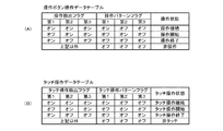
ここで、図21は、図17の副タイマ割込処理におけるタッチ操作検出パターン判定処理(ステップS1704)の手順の一例を示すフローチャートである。タッチ操作検出パターン判定処理では、第1タッチ操作検出フラグ、第2タッチ操作検出フラグ及び第3タッチ操作検出フラグに基づいて判定されるタッチ操作履歴から図柄表示部341の正面側の所定領域(パネル25における特定領域)に対するタッチ操作状態を判定するためのタッチ操作パターンフラグを設定する。タッチ操作パターンフラグは第1〜第3タッチ操作パターンフラグからなり、第1〜第3タッチ操作パターンフラグのオン及びオフの組み合わせによって図柄表示部341の正面側の所定領域(パネル25における特定領域)に対するタッチ操作状態を判定できる。例えば、図22(B)に示すように、第1タッチ操作パターンフラグのみがオンに設定されている場合には、図柄表示部341の正面側の所定領域(パネル25における特定領域)に対するタッチ操作が継続されていると判定できる。また、第2タッチ操作パターンフラグのみがオンに設定されている場合には、図柄表示部341の正面側の所定領域(パネル25における特定領域)に対するタッチ操作が開始されたと判定できる。また、第3タッチ操作パターンフラグのみがオンに設定されている場合には、図柄表示部341の正面側の所定領域(パネル25における特定領域)に対するタッチ操作が終了したと判定できる。そして、第1〜第3タッチ操作パターンフラグの全てがオフに設定されている場合には、図柄表示部341の正面側の所定領域(パネル25における特定領域)に対するタッチ操作がなされていないと判定できる。
[Touch operation detection pattern determination process]
Here, FIG. 21 is a flowchart showing an example of the procedure of the touch operation detection pattern determination process (step S1704) in the sub timer interrupt process of FIG. In the touch operation detection pattern determination process, from the touch operation history determined based on the first touch operation detection flag, the second touch operation detection flag, and the third touch operation detection flag, a predetermined area on the front side of the symbol display unit 341 (panel The touch operation pattern flag for determining the touch operation state for the specific area 25) is set. The touch operation pattern flag includes first to third touch operation pattern flags, and a predetermined area on the front side of the symbol display unit 341 (a specific area on the panel 25) depending on a combination of ON and OFF of the first to third touch operation pattern flags. The touch operation state for can be determined. For example, as shown in FIG. 22B, when only the first touch operation pattern flag is set to ON, a touch operation on a predetermined area (specific area on the panel 25) on the front side of the
<ステップS2101〜S2105>
図21に示すように、ステップS2101〜ステップS2105では、MPU51は、二つ前のタッチ操作検出処理に対する第1タッチ操作検出フラグがオンに設定されているか否か、一つ前のタッチ操作検出処理に対する第2タッチ操作検出フラグがオンに設定されているか否か、直近のタッチ操作検出処理に対する第3タッチ操作検出フラグがオンに設定されているか否かを判断する。
<Steps S2101 to S2105>
As shown in FIG. 21, in steps S2101 to S2105, the
<ステップS2107〜S2110>
ステップS2107〜ステップS2110では、MPU51は、ステップS2101〜ステップS2105での第1〜第3タッチ操作検出フラグがオンであるか否かの判定結果に基づいて、第1〜第3タッチ操作パターンフラグをオン又はオフに設定する。
<Steps S2107 to S2110>
In steps S2107 to S2110, the
具体的には、ステップS2107において、MPU51は、第2タッチ操作パターンフラグをオン、第1タッチ操作パターンフラグ及び第3タッチ操作パターンフラグをオフに設定し、当該タッチ操作検出パターン判定処理を終了する。即ち、MPU51は、図柄表示部341の正面側の所定領域(パネル25における特定領域)に対する3回分のタッチ操作状態として「オフ」、「オン」、「オン」のタッチ操作パターンが発生した場合に、図柄表示部341の正面側の所定領域(パネル25における特定領域)に対する非タッチ操作状態からタッチ操作状態に変化した(タッチ操作が開始された)と判断できるため、第2タッチ操作パターンフラグをオンに設定し、第1タッチ操作パターンフラグ及び第3タッチ操作パターンフラグをオフに設定する(図22(B)参照)。
Specifically, in step S2107, the
また、ステップS2108において、MPU51は、第1タッチ操作パターンフラグをオン、第2タッチ操作パターンフラグ及び第3タッチ操作パターンフラグをオフに設定し、当該タッチ操作検出パターン判定処理を終了する。即ち、MPU51は、図柄表示部341の正面側の所定領域(パネル25における特定領域)に対する3回分の操作状態として「オン」、「オン」、「オン」のタッチ操作パターンが発生した場合に、図柄表示部341の正面側の所定領域(パネル25における特定領域)に対するタッチ操作状態が継続していると判断できるため、第1タッチ操作パターンフラグをオンに設定し、第2タッチ操作パターンフラグ及び第3タッチ操作パターンフラグをオフに設定する(図22(B)参照)。
In addition, in step S2108, the
また、ステップS2109において、MPU51は、第3タッチ操作パターンフラグをオン、第1タッチ操作パターンフラグ及び第2タッチ操作パターンフラグをオフに設定し、当該タッチ操作検出パターン判定処理を終了する。即ち、MPU51は、図柄表示部341の正面側の所定領域(パネル25における特定領域)に対する3回分のタッチ操作状態として「オン」、「オフ」、「オフ」のタッチ操作パターンが発生した場合に図柄表示部341の正面側の所定領域(パネル25における特定領域)に対するタッチ操作状態から非タッチ操作状態に変化した(タッチ操作が終了した)と判断できるため、第3タッチ操作パターンフラグをオンに設定し、第1タッチ操作パターンフラグ及び第2タッチ操作パターンフラグをオフに設定する(図22(B)参照)。
Further, in step S2109, the
また、ステップS2110において、MPU51は、第1タッチ操作パターンフラグ、第2タッチ操作パターンフラグ及び第3タッチ操作パターンフラグをオフに設定し、当該タッチ操作検出パターン判定処理を終了する。即ち、MPU51は、図柄表示部341の正面側の所定領域(パネル25における特定領域)に対する3回分のタッチ操作状態として「オフ」、「オフ」、「オフ」など上記以外のタッチ操作パターンが発生した場合に、第1〜第3タッチ操作パターンフラグの全てをオフに設定する(図22(B)参照)。なお、MPU51は、第1〜第3タッチ操作パターンフラグの全てがオフの場合、図柄表示部341の正面側の所定領域(パネル25における特定領域)に対して非タッチ状態であると判定する。
Further, in step S2110, the
[カウンタ更新処理]
ここで、図17の説明に戻り、カウンタ更新処理(ステップS1705)では、MPU51は、演出パターン種別カウンタ、変動表示カウンタ、第1〜第4タッチ操作演出種別カウンタ、特定演出種別カウンタなどの更新を実行する。具体的には、MPU51は、演出パターン種別カウンタでのカウンタ値に1を加算し、そのカウンタ値が最大値に達した場合は当該カウンタ値を0にクリアする。ここで更新される演出種別カウンタは、主制御装置4から受信する変動パターンコマンドに基づいて変動種別及び演出種別を決定するために使用される。例えば、演出種別カウンタは0〜99の間でループするループカウンタである。一方、MPU51は、変動表示カウンタを1減算する。この変動表示カウンタは、図柄表示部341の変動表示時間を計時するためのものであり、変動表示カウンタでのカウンタ値は残り変動表示時間が0になる場合に0になるように設定される。従って、変動表示カウンタのカウンタ値に基づいて、残りの変動表示時間、変動中であること、図柄表示部341の変動表示が終了したことなどを把握できる。また、MPU51は、第1〜第4タッチ操作演出種別カウンタでのカウンタ値に1を加算し、そのカウンタ値が最大値に達した場合は当該カウンタ値を0にクリアする。ここで更新される第1〜第4タッチ操作演出種別カウンタは、第1〜第4タッチ操作受付期間R1〜R4での図柄表示部341の正面側の所定領域(パネル25における特定領域)に対するタッチ操作によって実行されるタッチ操作演出種別を決定するために使用される。例えば、第1タッチ操作演出種別カウンタは0〜39の間でループするループカウンタであり、第2タッチ操作演出種別カウンタは0〜59の間でループするループカウンタであり、第3タッチ操作演出種別カウンタは0〜79の間でループするループカウンタであり、第4タッチ操作演出種別カウンタは0〜99の間でループするループカウンタである。また、MPU51は、特定演出種別カウンタでのカウンタ値に1を加算し、そのカウンタ値が最大値に達した場合は当該カウンタ値を0にクリアする。ここで更新される特定演出種別カウンタは、スーパーリーチ演出やスペシャルリーチ演出の実行中の第2〜第4タッチ操作受付期間R2〜R4において図柄表示部341の正面側の所定領域での物体の存在が検知された場合にタッチ操作演出に代えて実行される特定演出種別を決定するために使用される。例えば、特定演出種別カウンタは0〜99の間でループするループカウンタである。
[Counter update process]
Here, returning to the description of FIG. 17, in the counter update processing (step S1705), the
[コマンド判定処理]
コマンド判定処理(ステップS1706)では、コマンド判定処理では、主制御装置4から受信するコマンドを判定し、そのコマンドに対応する処理を実行する。ここで、図23は、図17の副タイマ割込処理でのステップS1706で実行されるコマンド判定処理の手順の一例を示すフローチャートである。
[Command judgment processing]
In the command determination process (step S1706), in the command determination process, the command received from the
<ステップS2201>
図23に示すように、ステップS2201では、MPU51は、主制御装置4からコマンドを受信したか否かを判断する。ここで、MPU51は、コマンドを受信した場合(ステップS2201:Yes)、処理をステップS2202に移行する。一方、MPU51は、コマンドを受信していない場合(ステップS2201:No)、当該コマンド判定処理を終了する。なお、主制御装置4から受信したコマンドは、RAM512の未処理コマンド記憶エリアに格納され、MPU51は、未処理コマンド記憶エリアを参照することによりコマンドの受信の有無を判断する。なお、未処理コマンド記憶エリアに記憶されているコマンドは、ステップS2201でコマンドを受信したと判断され、処理の対象となった場合に未処理コマンド記憶エリアから消去され、例えば処理作業用記憶エリアに記憶される。
<Step S2201>
As shown in FIG. 23, in step S2201, the
<ステップS2202>
ステップS2202では、MPU51は、受信コマンドが変動パターンコマンドであるか否かを判断する。ここで、MPU51は、変動パターンコマンドである場合(ステップS2202:Yes)、処理をステップS2203に移行し、受信コマンドが変動パターンコマンドでない場合(ステップS2202:No)、処理をステップS2206に移行する。
<Step S2202>
In step S2202, the
<ステップS2203>
ステップS2203では、MPU51は、主制御装置4から受信した変動パターンコマンドに基づいて、主図柄の停止図柄組み合わせ、及び変動種別(演出パターン)を決定する。具体的に、MPU51は、変動パターンコマンドと、予めROM511に記憶されている第1停止図柄選択テーブル(図24(A)参照)及び変動種別テーブル(図24(B)参照)と、RAM512に記憶されている演出パターン種別カウンタのカウンタ値とに基づいて、主図柄の停止図柄組み合わせ及び変動種別(演出パターン)を決定する。また、MPU51は、変動パターンコマンドに大当たり種別に関する情報が含まれている場合、大当たり種別に応じた大当たりフラグをオンに設定する。具体的には、MPU51は、大当たり種別が5R通常大当たりである場合に5R通常大当たりフラグをオンに設定し、大当たり種別が5R確変大当たりである場合に5R確変大当たりフラグをオンに設定し、大当たり種別が16R確変大当たりである場合に16R確変大当たりフラグをオンに設定する。
<Step S2203>
In step S2203, the
主図柄の停止図柄組み合わせは、第1停止図柄、第2停止図柄及び最終停止図柄からなる。第1停止図柄は、図柄表示部341において最初に停止表示される主図柄であり、第2停止図柄は、2番目に停止表示される主図柄であり、最終停止図柄は、最後に停止表示される図柄である。演出パターン種別テーブルには、変動遊技演出における最終の個別演出種別がノーマルリーチ演出(図27参照)であるノーマルリーチ演出パターン種別テーブル(図25(A)参照)、変動遊技演出における最終の個別演出種別がスーパーリーチ演出(図27参照)であるスーパーリーチ演出パターン種別テーブル(図25(B)参照)、変動遊技演出における最終の個別演出種別がスペシャルリーチ演出(図27参照)であるスペシャルリーチ演出パターン種別テーブル(図25(C)参照)が含まれる。
The stop symbol combination of the main symbols consists of a first stop symbol, a second stop symbol and a final stop symbol. The first stop symbol is the main symbol that is first stopped and displayed in the
ここで、図24(A)は、第1停止図柄選択テーブルの一例を示す図である。図24(A)に示すように、第1停止図柄選択テーブルでは、図柄表示部341において最初に停止表示させる主図柄(第1停止図柄)が定められている。なお、図24(A)は、主図柄が「1」〜「9」であり、「333」が確変大当たり(5R確変大当たり及び16R確変大当たりのいずれか)であることを示す図柄組み合わせ、「777」が16R確変大当たりであることを示す図柄組み合わせ、「333」及び「777」以外のゾロ目が5R通常大当たり、5R確変大当たり及び16R確変大当たりのいずれかであることを示す図柄組み合わせであることを前提としている。
Here, FIG. 24A is a diagram showing an example of a first stop symbol selection table. As shown in FIG. 24(A), in the first stop symbol selection table, the main symbol (first stop symbol) to be stopped and displayed first in the
主制御装置4のMPU41による大当たり抽選の抽選結果が「5R通常大当たり」には、第1停止図柄として「3」及び「7」の振り分けはなく、「3」及び「7」以外の主図柄から予め定められた確率で第1停止図柄決定される。即ち、抽選結果が「5R通常大当たり」の場合、5R確変大当たり又は16R確変大当たり(確変大当たり)であることを示す「333」又は「777」の図柄組み合わせが停止表示されることはない。
The lottery result of the jackpot lottery by the
また、抽選結果が「5R確変大当たり」には、第1停止図柄として「7」の振り分けはなく、「7」以外の主図柄から予め定められた確率で第1停止図柄決定される。即ち、抽選結果が「5R確変大当たり」の場合、16R確変大当たりであることを示す「777」の図柄組み合わせが停止表示されることはない。一方、抽選結果が「5R確変大当たり」の場合であっても、5R確変大当たりであることを示す「333」の図柄組み合わせ以外のゾロ目の図柄組み合わせが停止表示され得る。即ち、抽選結果が「5R確変大当たり」の場合であっても、主図柄の停止表示結果が5R通常大当たりを示唆する「333」の図柄組み合わせ以外のゾロ目の図柄組み合わせが停止表示され得る。そして、抽選結果が「5R確変大当たり」である場合に、第1停止図柄として「7」を除く「3」以外の主図柄が決定された場合、当該変動遊技の終了後に移行する大当たり遊技において、抽選結果が「5R確変大当たり」であることを明示する昇格演出が実行される。 Further, the lottery result is "5R probability variation jackpot", there is no distribution of "7" as the first stop symbol, and the first stop symbol is determined with a predetermined probability from the main symbols other than "7". That is, when the lottery result is "5R certainty variation jackpot", the symbol combination of "777" indicating the 16R certainty variation jackpot is not stopped and displayed. On the other hand, even when the lottery result is “5R probability variable jackpot”, the symbol combinations of the doublet other than the symbol combination “333” indicating the 5R probability variable jackpot can be stopped and displayed. That is, even if the lottery result is "5R probability variation big hit", the symbol combination other than the symbol combination "333", which is the main symbol stop display result suggesting the 5R normal big hit, can be stopped and displayed. And, when the lottery result is "5R probability variation jackpot", if the main symbols other than "3" except "7" are determined as the first stop symbol, in the jackpot game to be transferred after the end of the variation game, The promotion effect that clearly shows that the lottery result is “5R probability variation jackpot” is executed.
さらに、抽選結果が「16R確変大当たり」には、「1」〜「9」の全ての主図柄に対する振り分けがあり、「1」〜「9」の主図柄から予め定められた確率で第1停止図柄決定される。即ち、抽選結果が「16R確変大当たり」の場合であっても、16R確変大当たりであることを示す「777」の図柄組み合わせ以外のゾロ目の図柄組み合わせが停止表示され得る。即ち、抽選結果が「16R確変大当たり」の場合であっても、主図柄の停止表示結果が5R確変大当たり又は5R通常大当たりを示唆する「777」の図柄組み合わせ以外のゾロ目の図柄組み合わせが停止表示され得る。そして、抽選結果が「16R確変大当たり」である場合に、第1停止図柄として「7」以外の主図柄が決定された場合、当該変動遊技の終了後に移行する大当たり遊技において、抽選結果が「16R確変大当たり」であることを明示する昇格演出が実行される。 Furthermore, in the lottery result "16R probability variation jackpot", there is a distribution for all the main symbols of "1" to "9", and the first stop with a predetermined probability from the main symbols of "1" to "9". The design is determined. That is, even if the lottery result is "16R probability variable jackpot", the symbol combinations other than the symbol combination "777" indicating the 16R probability variable jackpot can be stopped and displayed. That is, even if the lottery result is "16R probability variation jackpot", the stop display of the main symbol suggests a 5R probability variation jackpot or a 5R normal jackpot. Can be done. Then, when the lottery result is "16R probability variable jackpot", if the main symbol other than "7" is determined as the first stop symbol, in the jackpot game to be transferred after the end of the variation game, the lottery result is "16R A promotion effect that clearly indicates that it is a "probably strange jackpot" is executed.
そして、MPU51は、抽選結果が大当たりである場合に第1停止図柄を決定すると、第2停止図柄及び最終停止図柄を先に決定した第1停止図柄と同じ図柄に決定する。これにより、当該変動遊技に図柄表示部341の有効ラインに停止表示される停止図柄組み合わせが決定される。
Then, the
一方、抽選結果が「外れ」には、「1」〜「9」の全ての主図柄に対する振り分けがあり、「1」〜「9」の主図柄から予め定められた確率で第1停止図柄決定される。そして、MPU51は、抽選結果が「外れ」である場合に第1停止図柄を決定すると、外れ種別テーブル(図9(D)参照)に基づいて選択された外れ種別に関する情報、及び先に決定した第1停止図柄に基づいて第2停止図柄を決定する。例えば、外れ種別が前後外れリーチである場合、第2停止図柄が第1停止図柄と同じ図柄に決定され、最終停止図柄が第1停止図柄の前後の図柄に決定される。また、前記外れ種別が前後外れ以外リーチである場合、第2停止図柄が第1停止図柄と同じ図柄に決定され、最終停止図柄が第1停止図柄及び第1停止図柄の前後の図柄とは異なる図柄に決定される。また、前記外れ種別が完全外れである場合、第2停止図柄が第1停止図柄とは異なる図柄に決定され、最終停止図柄が第1停止図柄及び第2停止図柄とは無関係に決定される。なお、主図柄の停止図柄組み合わせは、表示制御装置6において決定してもよく、第1停止図柄のみを音声ランプ制御装置5において決定し、第2停止図柄及び最終停止図柄を表示制御装置6において決定してもよい。
On the other hand, the lottery result is "out", there is a distribution for all the main symbols of "1" to "9", the first stop symbol determination with a predetermined probability from the main symbols of "1" to "9" To be done. Then, the
また、図24(B)は、変動種別テーブルの一例を示す図である。図24(B)に示すように、変動種別テーブルでは、変動パターンコマンドに対応する変動表示時間及び変動種別(演出パターン)の内容が定められている。例えば、抽選結果が「通常大当たり」であり変動パターンが「01」である変動パターンコマンド「A01」には、変動表示時間「30s」及び変動種別「ノーマルリーチ演出パターン」が対応付けられている。また、抽選結果が「5R確変大当たり」であり変動パターンが「02」である変動パターンコマンド「B02」には、変動表示時間「60s」及び変動種別「スーパーリーチ演出パターン」が対応付けられており、抽選結果が「16R確変大当たり」であり変動パターンが「03」である変動パターンコマンド「C03」には変動表示時間「90s」及び変動種別「スペシャルリーチ演出パターン」が対応付けられている。さらに、抽選結果が「外れ」であり変動パターンが「04」である変動パターンコマンド「D04」には、変動表示時間「7s」及び変動種別「非リーチ演出パターン」が対応付けられており、抽選結果が「外れ」であり変動パターンが「05」である変動パターンコマンド「D05」には、変動表示時間「10s」及び変動種別「非リーチ演出パターン」が対応付けられている。 Further, FIG. 24B is a diagram showing an example of the fluctuation type table. As shown in FIG. 24B, in the fluctuation type table, the contents of the fluctuation display time and the fluctuation type (effect pattern) corresponding to the fluctuation pattern command are defined. For example, the variation display time “30 s” and the variation type “normal reach effect pattern” are associated with the variation pattern command “A01” whose lottery result is “normal jackpot” and the variation pattern is “01”. In addition, the variation display time “60 s” and the variation type “super reach production pattern” are associated with the variation pattern command “B02” in which the lottery result is “5R probability variation jackpot” and the variation pattern is “02”. The variation display time “90 s” and the variation type “special reach effect pattern” are associated with the variation pattern command “C03” in which the lottery result is “16R probability variation jackpot” and the variation pattern is “03”. Furthermore, the variation pattern command “D04” whose lottery result is “out” and the variation pattern is “04” is associated with the variation display time “7s” and the variation type “non-reach effect pattern”. A fluctuation display time “10 s” and a fluctuation type “non-reach effect pattern” are associated with the fluctuation pattern command “D05” whose result is “out” and the fluctuation pattern is “05”.
さらに、図25(A)〜図25(C)は、演出パターン種別テーブルの一例を示す図である。演出パターン種別テーブルは、変動種別(演出パターン)ごとに設定されている。具体的に、図25(A)は変動遊技演出における最終の個別演出種別がノーマルリーチ演出(図27参照)である場合に参照されるノーマルリーチ演出パターン種別テーブルであり、図25(B)は変動遊技演出における最終の個別演出種別がスーパーリーチ演出(図27参照)である場合に参照されるスーパーリーチ演出パターンテーブルであり、図25(C)は変動遊技演出における最終の個別演出種別がスペシャルリーチ演出(図27参照)である場合に参照されるスペシャルリーチ演出パターンテーブルである。 Further, FIG. 25(A) to FIG. 25(C) are diagrams showing an example of the effect pattern type table. The effect pattern type table is set for each variation type (effect pattern). Specifically, FIG. 25(A) is a normal reach effect pattern type table that is referred to when the final individual effect type in the variable game effect is the normal reach effect (see FIG. 27), and FIG. 25(B) is the variable game. FIG. 25C is a super-reach effect pattern table that is referenced when the final individual effect type in the effect is the super-reach effect (see FIG. 27). It is a special reach effect pattern table referred to in the case of (see FIG. 27).
なお、本実施の形態では、変動種別各々に対応する演出種別が5種類である場合を例に挙げて説明するが、演出種別は6種類以上であってよい。また、図25では、変動種別がリーチなしの場合の演出種別テーブルは省略している。 In the present embodiment, a case will be described as an example in which there are five types of effect corresponding to each variation type, but the number of effect types may be six or more. Further, in FIG. 25, the effect type table when the change type is no reach is omitted.
図25(A)に示すノーマルリーチ演出パターン種別テーブルでは、抽選結果(5R通常大当たり、5R確変大当たり、16R確変大当たり、及び外れ)に応じて、演出パターン種別カウンタのカウンタ値に対応する演出パターン種別として「演出パターンX1」〜「演出パターンX5」が定められている。そして、MPU51は、変動種別(演出パターン)がノーマルリーチ演出パターンであると判断した場合には、演出パターン種別カウンタのカウンタ値に対応する演出パターン種別を抽選結果に応じてノーマルリーチ演出パターン種別テーブルから選択する。ここで、ノーマルリーチ演出パターン種別テーブルに含まれる演出パターンX1〜演出パターンX3は、例えば主図柄が高速変動する高速変動演出の終了後に主図柄がリーチ状態となるノーマルリーチ演出が実行される演出であり、最終の個別演出種別がノーマルリーチ演出となる演出である(図27参照)。
In the normal reach effect pattern type table shown in FIG. 25(A), as the effect pattern type corresponding to the counter value of the effect pattern type counter, in accordance with the lottery result (5R normal jackpot, 5R probability variation jackpot, 16R probability variation jackpot, and deviation). "Production pattern X1" to "production pattern X5" are defined. Then, when the
また、図25(B)に示すスーパーリーチ演出パターンテーブルでは、抽選結果に応じて演出パターン種別カウンタのカウンタ値に対応する演出パターン種別として「演出パターンY1」〜「演出パターンY5」が定められている。そして、MPU51は、変動種別(演出パターン)がスーパーリーチ演出パターンであると判断した場合には、演出パターン種別カウンタのカウンタ値に対応する演出パターン種別を抽選結果に応じてスーパーリーチ演出パターンテーブルから選択する。ここで、スーパーリーチ演出パターンテーブルに含まれる演出パターンY1〜演出パターンY3は、例えば高速変動演出の終了後にノーマルリーチ演出が実行され、さらに最終の個別演出種別としてノーマルリーチ演出よりも大当たり期待度の高く、ノーマルリーチ演出よりも演出実行時間の長いスーパーリーチ演出に発展する演出である(図27参照)。なお、スーパーリーチ演出パターンテーブルは、ノーマルリーチ演出を経由することなく、高速変動演出の終了後にスーパーリーチ演出に発展するスーパーリーチ演出パターン演出を含んでいてもよい。
In the super reach effect pattern table shown in FIG. 25(B), "effect pattern Y1" to "effect pattern Y5" are defined as effect pattern types corresponding to the counter value of the effect pattern type counter according to the lottery result. There is. Then, when the
さらに、図25(C)に示すスペシャルリーチ演出パターンテーブルでは、抽選結果に応じて演出パターン種別カウンタのカウンタ値に対応する演出パターン種別として「演出パターンZ1」〜「演出パターンZ5」が定められている。そして、MPU51は、変動種別(演出パターン)がスペシャルリーチ演出パターンであると判断した場合には、演出パターン種別カウンタのカウンタ値に対応する演出パターン種別を抽選結果に応じてスペシャルリーチ演出パターンテーブルから選択する。ここで、スペシャルリーチ演出パターンテーブルに含まれる演出パターンZ1〜演出パターンZ3は、例えば高速変動演出の終了後にノーマルリーチ演出及びスーパーリーチ演出が実行され、さらに最終の個別演出種別としてノーマルリーチ演出やスーパーリーチ演出よりも大当たり期待度の高く、ノーマルリーチ演出よりも演出実行時間の長いスペシャルリーチ演出に発展する演出である(図27参照)。なお、スペシャルリーチ演出パターンテーブルは、ノーマルリーチ演出及びスーパーリーチ演出の少なくとも一方を経由することなく、高速変動演出又はノーマルリーチ演出の終了後などにスペシャルリーチ演出に発展するスペシャルリーチ演出パターンを含んでいてもよい。
Further, in the special reach effect pattern table shown in FIG. 25C, "effect pattern Z1" to "effect pattern Z5" are defined as effect pattern types corresponding to the counter value of the effect pattern type counter according to the lottery result. There is. Then, when the
そして、MPU51は、変動パターンコマンド、変動種別テーブル、演出種別テーブル及び演出種別カウンタに基づいて決定される主図柄の停止図柄組み合わせ、及び変動種別(演出パターン種別)を示す表示変動パターンコマンドをRAM512に設定する。
Then, the
<ステップS2204>
図23の説明に戻り、ステップS2204では、MPU51は、可動役物部材39の作動タイミング(可動役物部材作動演出の実行期間)を決定する可動役物部材作動タイミング決定処理を実行する。可動役物部材作動タイミング決定処理では、ステップS2203において決定される演出パターン種別に応じて選択される可動役物部材作動タイミング選択テーブルに基づいて、複数の作動タイミングのそれぞれでの可動役物部材39の作動の有無(可動役物部材作動演出の実行の有無)を決定する。
<Step S2204>
Returning to the description of FIG. 23, in step S2204, the
ここで、図26は、可動役物部材作動演出の一例を示す図である。可動役物部材作動演出は、大当たり抽選での抽選結果が大当たりでることの期待度を示唆するチャンスアップ演出、又は抽選結果が大当たりであることを明示する確定演出(一発告知演出)として実行される。この可動役物部材作動演出は、可動役物部材39が図26(A)に示す図柄表示部341で実行される画像演出の視認を阻害しない待機位置から、図26(B)に示す図柄表示部341の中央部の正面である作動位置に移動した後、図26(A)に示す待機位置に復帰する演出である。
Here, FIG. 26 is a diagram showing an example of the movable accessory member operation effect. The movable accessory member operation effect is executed as a chance up effect that suggests the degree of expectation that the lottery result in the jackpot lottery will be a big hit, or as a confirmed effect (one notification effect) that clearly indicates that the lottery result is a jackpot. It This movable accessory member operation effect is displayed from the standby position where the
可動役物部材作動演出では、可動役物部材39が図26(B)に示す作動位置において一定期間停止される。このとき、可動役物部材39では、周縁部に円環状に設けられた複数のランプ391によって、大当たり抽選での抽選結果が大当たりでることの期待度を示唆し、又は抽選結果が大当たりであることを明示する。例えば、複数のランプ391の点灯色によって大当たり抽選での抽選結果に対する大当たり期待度を示唆する。具体的には、複数のランプ391の点灯色が、白色、黄色、緑色、赤色の順に大当たり期待度が高くなるように設定しておき、可動役物部材作動演出において可動役物部材39が図26(B)に示す待機位置に停止している間、大当たり抽選での抽選結果に応じて決定される大当たり期待度の点灯色で複数のランプ391を点灯させる。また、複数のランプ391の点灯色として、白色、黄色、緑色及び赤色の全てを含む点灯態様とすることで、抽選結果が大当りであることを明示するようにしてもよく、また点灯パターンと点灯色と適宜設定することで、レインボーのランプ演出を実行することで抽選結果が大当りであることを明示するようにしてもよい。
In the movable accessory member operation effect, the
もちろん、複数のランプ391の点灯色に依らず、複数のランプ391の点灯及び消灯の組み合わせによって、大当たり期待度を示し、あるいは大当たりであることを明示してもよい。また、可動役物部材39が図26(B)に示す作動位置にある場合に、図柄表示部341において可動役物部材39の周辺にエフェクトを発生させるエフェクト演出を実行してもよい。この場合のエフェクト演出では、エフェクトの色や大きさにより大当たり期待度を示し、あるいは大当たりであることを明示することができる。
Of course, regardless of the lighting color of the plurality of
また、可動役物部材作動演出を実行するに当たり、図柄表示部341を利用して大当たり期待度を示唆するチャンス演出を実行することも考えられる。例えば、図26(C)に示すように、可動役物部材39を待機位置から作動位置に移動させる前に、可動役物部材39における開口31Aから露出した部分に配置された4つランプ391に対応させて図柄表示部341に大当たり期待度や今後の演出展開を示唆する画像が図柄表示部341に表示される演出が実行されることが考えられる。図26(C)では、図柄表示部341に左側から順位に、「?」、「チャンス」(大当たり期待度示唆)、「リーチ」(演出展開示唆)及び「激熱」(大当たり期待度示唆)の文字画像が表示される。そして、可動役物部39では、前記4つのランプ391が点滅された後に1つのランプ391が点灯されるルーレット演出が実行される。なお、図26(C)では「チャンス」に対応するランプ391が点灯して状態が示されている。
Further, when executing the movable accessory member operation effect, it is also possible to use the
また、図26(C)に示すルーレット演出が実行された場合、可動役物部材39が作動位置に移動されることで、可動役物部材39の複数のランプ391を利用して、大当たり期待度を示唆する演出や大当たりであることを明示する確定演出を実行することも考えられる。例えば、図26(D)に示すように、複数のランプ391の点灯個数に応じて大当たり期待度を示唆し(ランプの点灯個数が多いほど大当たり期待度を高くし)、全てのランプ391が点灯した場合に大当たり確定演出とすることも考えられる。以下、可動役物演出によって抽選結果が大当たりであることを明示する演出を「一発告知演出」という場合がある。
In addition, when the roulette effect shown in FIG. 26C is executed, the
なお、可動役物部材39が作動位置にある場合にランプ391の点灯個数によって大当たり期待度を示唆する演出が実行される場合(一発告知演出を除く)、可動役物部材39が待機位置に復帰した場合にスーパーリーチ演出、スペシャルリーチ演出などの発展演出が実行されるようにしてもよい。この場合、可動役物部材39が作動位置にある場合にランプ391の点灯個数と、発展演出によって示唆される大当たり期待度(例えば発展演出の実行開始時に表示される当該発展演出の大当たり期待度を示す星の数など)とをリンクさせてもよい。つまり、可動役物部材39が作動位置にある場合にランプ391の点灯個数によって後に実行される発展演出の大当たり期待度を先に示唆することも考えられる。例えば、発展演出の大当たり期待度が星の数(例えば星の数が1〜5)で示唆される場合に発展演出として星3つの発展演出が実行される場合に、可動役物部材39が作動位置にある場合にランプ391の点灯個数を3つとすることが考えられる。
In addition, when the effect that suggests the jackpot expectation degree is executed by the number of the lit
また、一発告知演出が実行される場合、可動役物部材39の中央部分を点灯させることで、確定演出であることを強調するようにしてもよい。そして、一発告知演出が実行される場合、可動役物部材39が待機位置に復帰した場合に主図柄の変動がゾロ目で停止されるようにしてもよいし、主図柄の変動を継続して後において主図柄がゾロ目で停止さされるようにしてもよい。なお、一発告知演出が実行後に可動役物部材39が復帰した場合に主図柄の変動が停止されるかは、決定されている演出パターンと可動役物部材39の作動タイミングとの関係で決定される。
In addition, when the one-shot notification effect is executed, the central part of the
また、可動役物部材39が作動位置にある場合に、可動役物部材39の周囲にエフェクトを発生させる画像を図柄表示部341に表示させる演出を実行することも考えられる。この場合、エフェクトの色や大きさによって大当たり期待度を示唆し、又は大当たりであることを明示することも考えられる。例えば、可動役物部材39の周囲に虹色のエフェクトを発生させることで大当たりであることを明示することができる。このような可動役物部材39の周囲に虹色のエフェクトを発生させることにより大当たりであることを明示する演出も「一発告知演出」に含まれる。つまり、「一発告知演出」は、可動役物部材39の作動に伴い抽選結果が大当たりであることが明示される演出であり、この「一発告知演出」には、可動役物部材39の作動に連動して図柄表示部341で実行される演出によって大当たり確定演出が実行される場合も含まれる。
Further, when the
ここで、図27は、可動役物部材39の作動タイミング及びタッチ操作演出に対するタッチ操作受付期間の一例を演出パターンと共に示すタイミングチャートである。まず、図27を参照し、可動役物部材39の作動タイミングを説明する。なお、タッチ操作演出に対するタッチ操作受付期間については、後述のステップS2205のタッチ操作演出決定処理を説明する際に言及する。また、図27において、各演出パターンにおける最終の個別演出の終了後に規定されている可動役物部材39の作動タイミングは、当該演出パターンにおいて設定されていないことを意味する。例えば、図27において、作動タイミングG2は、非リーチ演出パターンでは設定されていないことを意味する。
Here, FIG. 27 is a timing chart showing an example of the operation timing of the
図27に示すように、本実施形態では、可動役物部材39が作動し得るタイミングとして、6つの作動タイミングG1〜G6が固定的に規定されている。なお、可動役物部材39の作動タイミングは、全ての演出パターンで固定的に規定する必要はなく、例えば演出パターン種別ごとに可動役物部材39の作動タイミングを個別に規定してもよい。
As shown in FIG. 27, in this embodiment, six operation timings G1 to G6 are fixedly defined as the timings at which the
作動タイミングG1は、高速変動演出の開始直後(主図柄の変動開始直後)に開始され、高速変動演出の序盤で終了する。つまり、作動タイミングG1は、非リーチ演出パターン、ノーマルリーチ演出パターン、スーパーリーチ演出パターン及びスペシャルリーチ演出パターンに対して設定され得る。 The operation timing G1 is started immediately after the start of the high speed fluctuation effect (immediately after the start of the fluctuation of the main symbol), and ends at the beginning of the high speed fluctuation effect. That is, the operation timing G1 can be set for the non-reach effect pattern, the normal reach effect pattern, the super reach effect pattern, and the special reach effect pattern.
作動タイミングG2は、ノーマルリーチ演出の開始直後に開始され、ノーマルリーチ演出の序盤で終了する。つまり、作動タイミングG2は、ノーマルリーチ演出パターン、スーパーリーチ演出パターン及びスペシャルリーチ演出パターンに対して設定され得る。 The operation timing G2 starts immediately after the start of the normal reach effect and ends at the beginning of the normal reach effect. That is, the operation timing G2 can be set for the normal reach effect pattern, the super reach effect pattern, and the special reach effect pattern.
作動タイミングG3は、スーパーリーチ演出の開始直後に開始され、スーパーリーチ演出の序盤で終了する。作動タイミングG4は、スーパーリーチ演出の中盤に設定されている。つまり、作動タイミングG3,G4は、スーパーリーチ演出パターン及びスペシャルリーチ演出パターンに対して設定され得る。 The operation timing G3 starts immediately after the start of the super reach effect and ends at the beginning of the super reach effect. The operation timing G4 is set in the middle stage of the super reach production. That is, the operation timings G3 and G4 can be set for the super reach effect pattern and the special reach effect pattern.
作動タイミングG5は、スペシャルリーチ演出の開始直後に開始され、スペシャルリーチ演出の序盤で終了する。作動タイミングG6は、スペシャルリーチ演出の終盤に設定されている。つまり、作動タイミングG5,G6は、スペシャルリーチ演出パターンに対して設定され得る。 The operation timing G5 starts immediately after the start of the special reach effect and ends at the beginning of the special reach effect. The operation timing G6 is set at the end of the special reach effect. That is, the operation timings G5 and G6 can be set for the special reach effect pattern.
換言すれば、各演出パターン種別で設定される作動タイミングの数は、演出パターン種別によって異なる。具体的には、演出パターンが非リーチ演出パターンである場合、高速変動演出の開始直後からの序盤に作動タイミングG1が設定されている。なお、非リーチ演出パターンは、主図柄が変動開始直後から高速変動する高速変動演出のみが実行される演出パターンである。 In other words, the number of operation timings set for each effect pattern type differs depending on the effect pattern type. Specifically, when the effect pattern is the non-reach effect pattern, the operation timing G1 is set in the early stage immediately after the start of the high speed fluctuation effect. The non-reach effect pattern is an effect pattern in which only the high-speed fluctuation effect in which the main symbol changes at high speed immediately after the start of fluctuation is executed.
また、演出パターンがノーマルリーチ演出パターンである場合、作動タイミングG1に加えて、ノーマルリーチ演出の開始直後からの序盤に作動タイミングG2が設定されている。なお、ノーマルリーチ演出パターンは、高速変動演出の終了後にスーパーリーチ演出やスペシャルリーチ演出に発展しないノーマルリーチ演出が最終の個別演出として実行される演出パターンである。 When the effect pattern is the normal reach effect pattern, in addition to the operation timing G1, the operation timing G2 is set in the early stage immediately after the start of the normal reach effect. The normal reach effect pattern is an effect pattern in which the normal reach effect that does not develop into the super reach effect or the special reach effect is executed as the final individual effect after the high speed variable effect is finished.
また、演出パターンがスーパーリーチ演出パターンである場合、作動タイミングG1,G2に加えて、スーパーリーチ演出の開始直後からの序盤の作動タイミングG3と、スーパーリーチ演出の中盤の作動タイミングG4とが設定されている。なお、スーパーリーチ演出パターンは、高速変動演出及びノーマルリーチ演出の終了後に、最終の個別演出としてスーパーリーチ演出が実行される演出パターンである。 When the effect pattern is the super reach effect pattern, in addition to the operation timings G1 and G2, the operation timing G3 in the opening stage immediately after the start of the super reach effect and the operation timing G4 in the middle stage of the super reach effect are set. ing. The super reach effect pattern is an effect pattern in which the super reach effect is executed as the final individual effect after the high speed variable effect and the normal reach effect are finished.
また、演出パターンがスペシャルリーチ演出パターンである場合、作動タイミングG1〜G4に加えて、スペシャルリーチ演出の開始直後からの序盤の作動タイミングG5と、スーパーリーチ演出の終盤の作動タイミングG6とが設定されている。なお、スペシャルリーチ演出パターンは、高速変動演出、ノーマルリーチ演出及びスーパーリーチ演出の終了後に、最終の個別演出としてスペシャルリーチ演出が実行される演出パターンである。 When the production pattern is the special reach production pattern, in addition to the operation timings G1 to G4, the opening operation timing G5 immediately after the start of the special reach production and the operation timing G6 of the final stage of the super reach production are set. ing. The special reach effect pattern is an effect pattern in which the special reach effect is executed as the final individual effect after the high speed variation effect, the normal reach effect and the super reach effect are finished.
ここで、図28〜図30は、可動役物部材作動タイミング選択テーブルA〜Cの一例を示す図であり、図28に示す可動役物部材作動タイミング選択テーブルAは演出パターン種別がノーマルリーチ演出である場合に可動役物部材39の作動タイミングを決定する場合に参照され、図29に示す可動役物部材作動タイミング選択テーブルBは演出パターン種別がスーパーリーチ演出である場合に可動役物部材39の作動タイミングを決定する場合に参照され、図30に示す可動役物部材作動タイミング選択テーブルCは演出パターン種別がスペシャルリーチ演出である場合に可動役物部材39の作動タイミングを決定する場合に参照される。
Here, FIGS. 28 to 30 are views showing examples of the movable accessory member operation timing selection tables A to C. In the movable accessory member operation timing selection table A shown in FIG. 28, the effect pattern type is the normal reach effect. In some cases, the movable
なお、図28〜図30において、「◎」は大当たり確定演出(一発告知演出)として可動役物部材39が作動されること、「○」はチャンスアップ演出(大当たり期待度示唆演出)として可動役物部材39が作動されること、「×」は可動役物部材39が作動されないこと、「−」は該当する作動タイミングが存在しないことを意味している。また、図28〜図30では、演出パターンが非リーチ演出パターンである場合については省略されているが、可動役物部材作動演出を実行するかについては適宜設定すればよい。
28 to 30, "◎" indicates that the
図28に示すように、演出パターン種別がノーマルリーチ演出である場合に参照される可動役物部材作動タイミング選択テーブルAは、ノーマルリーチ演出パターンのうちの演出パターン種別(演出パターンX1〜X5)ごとに、大当たり抽選での抽選結果に応じて、可動役物部材39の作動タイミングG1,G2のそれぞれで可動役物部材39を作動させるか否か(可動役物部材作動演出を実行するか否か)が規定されている。
As shown in FIG. 28, the movable auditor member member operation timing selection table A referred to when the effect pattern type is the normal reach effect, the effect pattern types (effect patterns X1 to X5) of the normal reach effect patterns, Whether to operate the
例えば、演出パターン種別が演出パターンX1であり、抽選結果が5R確変大当たりである場合には、作動タイミングG1では可動役物部材39が作動され、作動タイミングG2では可動役物部材39が作動されない。つまり、抽選結果が5R確変大当たりである場合に演出パターンX1が選択された場合、ノーマルリーチ演出パターンでの高速変動演出の開始直後のみでチャンスアップ演出として可動役物部材作動演出が実行される。
For example, when the effect pattern type is the effect pattern X1 and the lottery result is the 5R probability variation big hit, the
また、演出パターン種別が演出パターンX3であり、抽選結果が外れである場合には、作動タイミングG1及び作動タイミングG2のいずれにおいても、可動役物部材39が作動されない。つまり、抽選結果が外れである場合に演出パターンX3が選択された場合、ノーマルリーチ演出パターンでは可動役物部材作動演出が全く実行されない。
When the effect pattern type is the effect pattern X3 and the lottery result is off, the
図29に示すように、演出パターン種別がスーパーリーチ演出である場合に参照される可動役物部材作動タイミング選択テーブルBは、スーパーリーチ演出パターンのうちの演出パターン種別(演出パターンY1〜Y5)ごとに、大当たり抽選での抽選結果に応じて、可動役物部材39の作動タイミングG1〜G4のそれぞれで可動役物部材39を作動させるか否か(可動役物部材作動演出を実行するか否か)が規定されている。
As shown in FIG. 29, the movable accessory member operation timing selection table B referred to when the effect pattern type is the super reach effect is for each effect pattern type (effect patterns Y1 to Y5) of the super reach effect patterns. Whether or not to operate the
例えば、演出パターン種別が演出パターンY1であり、抽選結果が5R通常大当たりである場合には、作動タイミングG1〜G4のうちの作動タイミングG3のみで可動役物部材39が作動され、残りの作動タイミングG1,G2,G4では可動役物部材39が作動されない。つまり、抽選結果が5R通常大当たりである場合に演出パターンY1が選択された場合、スーパーリーチ演出パターンでのスーパーリーチ演出の開始直後のみでチャンスアップ演出として可動役物部材作動演出が実行される。
For example, when the effect pattern type is the effect pattern Y1 and the lottery result is the 5R normal big hit, the
また、演出パターン種別が演出パターンY3であり、抽選結果が16R確変大当たりである場合には、作動タイミングG1〜G4のうちの作動タイミングG2,G3で可動役物部材39が作動され、残りの作動タイミングG1,G4では可動役物部材39が作動されない。つまり、抽選結果が16R確変大当たりである場合に演出パターンY3が選択された場合、ノーマルリーチ演出パターンでのノーマルリーチ演出の開始直後及びスーパーリーチ演出の開始直後でチャンスアップ演出として可動役物部材作動演出が実行される。
When the effect pattern type is the effect pattern Y3 and the lottery result is the 16R probability variation big hit, the
また、演出パターン種別が演出パターンY5であり、抽選結果が外れである場合には、作動タイミングG1〜G4のうちの作動タイミングG1のみで可動役物部材39が作動され、残りの作動タイミングG2〜G4では可動役物部材39が作動されない。つまり、抽選結果が外れである場合に演出パターンY5が選択された場合、スペシャルリーチ演出パターンでの高速変動演出の開始直後のみでチャンスアップ演出として可動役物部材作動演出が実行される。
When the effect pattern type is the effect pattern Y5 and the lottery result is out of alignment, the
図30に示すように、演出パターン種別がスペシャルリーチ演出パターンである場合に参照される可動役物部材作動タイミング選択テーブルCは、スペシャルリーチ演出パターンのうちの演出パターン種別(演出パターンZ1〜Z5)ごとに、大当たり抽選での抽選結果に応じて、可動役物部材39の作動タイミングG1〜G6のそれぞれで可動役物部材39を作動させるか否か(可動役物部材作動演出を実行するか否か)が規定されている。
As shown in FIG. 30, the movable accessory member operation timing selection table C referred to when the effect pattern type is the special reach effect pattern, the effect pattern types (effect patterns Z1 to Z5) of the special reach effect patterns. Whether or not to operate the
例えば、演出パターン種別が演出パターンZ1であり、抽選結果が5R通常大当たりである場合には、作動タイミングG1〜G6のうちの作動タイミングG3のみで可動役物部材39が作動され、残りの作動タイミングG1,G2,G4〜G6では可動役物部材39が作動されない。つまり、抽選結果が5R通常大当たりである場合に演出パターンZ1が選択された場合、スペシャルリーチ演出パターンでのスーパーリーチ演出の開始直後のみでチャンスアップ演出として可動役物部材作動演出が実行される。
For example, when the effect pattern type is the effect pattern Z1 and the lottery result is the 5R normal big hit, the
また、演出パターン種別が演出パターンZ3であり、抽選結果が16R確変大当たりである場合には、作動タイミングG1〜G6のうちの作動タイミングG5,G6で可動役物部材39が作動され、残りの作動タイミングG1〜G4では可動役物部材39が作動されない。つまり、抽選結果が16R確変大当たりである場合に演出パターンZ3が選択された場合、スペシャルリーチ演出パターンでのスペシャルリーチ演出の開始直後及び終盤で大当たり確定演出(一発告知演出)として可動役物部材作動演出が実行される。
Further, when the effect pattern type is the effect pattern Z3 and the lottery result is the 16R probability variable big hit, the
また、演出パターン種別が演出パターンZ4であり、抽選結果が5R通常大当たりである場合には、作動タイミングG1〜G6のうちの作動タイミングG2,G3,G6で可動役物部材39が作動され、残りの作動タイミングG1,G4,G5では可動役物部材39が作動されない。つまり、抽選結果が5R通常大当たりである場合に演出パターンZ4が選択された場合、スペシャルリーチ演出パターンでのノーマルリーチ演出の開始直後及びスーパーの開始直後でチャンスアップ演出として可動役物部材作動演出が実行され、さらにスペシャルリーチ演出の終盤で大当たり確定演出(一発告知演出)として可動役物部材作動演出が実行される。
When the effect pattern type is the effect pattern Z4 and the lottery result is the 5R normal big hit, the
そして、MPU51は、ステップS2203において決定される演出パターンと、大当たり抽選での抽選結果に応じて選択される可動役物部材作動タイミング選択テーブルA〜Cとに基づいて、各作動タイミングでの可動役物部材39の作動の有無(可動役物部材作動演出の実行の有無)を決定する。このようにして決定された可動役物部材39の作動タイミングはRAM512に記憶され、RAM512に記憶された作動タイミングに基づいて、変動遊技演出の実行中に可動役物部材作動演出が実行される。
Then, the
<ステップS2205>
図23の説明に戻り、ステップS2205では、MPU51は、タッチ操作演出決定処理を実行する。タッチ操作演出決定処理では、タッチ操作演出の受付期間及び内容が決定される。なお、タッチ操作演出決定処理の詳細は、図31を参照して後述する。また、タッチ操作演出は、タッチ操作受付期間内にタッチ操作が行われることでタッチ操作演出が実行されることが決定された段階で決定するようにしてもよい。この場合、コマンド判定処理におけるタッチ操作演出決定処理は省略され、またステップS2205において、タッチ操作演出を決定することに代えて、タッチ操作受付期間を決定してもよい。
<Step S2205>
Returning to the description of FIG. 23, in step S2205, the
<ステップS2206>
ステップS2206では、MPU51は、変動パターンコマンドに対応する変動表示時間を変動表示カウンタに設定する。変動表示時間は、変動パターンコマンドに含まれる変動パターン情報に応じて判断される。そして、変動表示カウンタは、図17の副タイマ割込処理におけるステップS1705のカウンタ更新処理で1ずつ減算され、MPU51は、変動表示カウンタに基づいて、図柄変動表示中であるか否か、変動表示時間の残り時間などを判断することが可能である。例えば、MPU51は、変動表示カウンタのカウンタ値が0になった場合に図柄変動表示の終了と判断することが可能である。
<Step S2206>
In step S2206, the
<ステップS2207>
ステップS2207では、MPU51は、図柄表示部341における主図柄の停止図柄組み合わせと、変動種別(演出パターン)及びタッチ操作演出を含む変動遊技演出の内容を特定するための表示変動パターンコマンドを表示制御装置6に送信し、当該コマンド判定処理を終了させる。表示変動パターンコマンドは、ステップS2203で決定された主図柄の停止図柄組み合わせ、変動遊技演出の内容を識別するための情報である。一方、表示制御装置6のROM611には、表示変動パターンコマンド各々に対応する主図柄の変動画像及び演出画像などが記憶されている。これにより、表示制御装置6では、MPU61が、表示変動パターンコマンドに対応する主図柄の停止図柄組み合わせ、変動種別及び変動遊技演出に応じて、図柄表示部341における変動表示及び演出表示を実行させ、可動役物部材39などの他の演出手段に対して可動役物部材作動演出、音声出力演出及びランプ演出を実行させる。
<Step S2207>
In step S2207, the
具体的に、図柄表示部341では、表示制御装置6のMPU61は、予め設定されている変動表示時間が経過するまでの間に複数の主図柄(本実施形態では3つ)の変動表示を実行し、複数の主図柄の変動が順に停止表示させる。そして、全ての主図柄が停止表示して大当たり抽選の結果が表示されると、次の変動遊技の図柄変動表示又は大当たり遊技に対応する処理などが実行される。ここで、主図柄の変動表示中には、表示変動パターンコマンドによって特定される遊技演出が実行される。
Specifically, in the
<ステップS2208>
ステップS2208では、MPU51は、主制御装置4から受信したその他のコマンドに基づく処理を実行した後、当該コマンド判定処理を終了させる。
<Step S2208>
In step S2208, the
[タッチ操作演出決定処理]
ここで、図31は、図26のコマンド判定処理でのステップS2205で実行されるタッチ操作演出決定処理の手順の一例を示すフローチャートである。タッチ操作演出決定処理では、図23のコマンド判定処理でのステップS2203において決定される演出パターンと、大当たり抽選での抽選結果と、タッチ操作演出種別抽選カウンタの値とに基づいて、複数のタッチ操作受付タイミングごとにタッチ操作受付期間中にタッチ操作が行われた場合のタッチ操作演出を決定する。
[Touch operation effect determination process]
Here, FIG. 31 is a flowchart showing an example of the procedure of the touch operation effect determination processing executed in step S2205 in the command determination processing of FIG. In the touch operation effect determination process, a plurality of touch operations are performed based on the effect pattern determined in step S2203 in the command determination process of FIG. 23, the lottery result in the jackpot lottery, and the value of the touch operation effect type lottery counter. A touch operation effect when a touch operation is performed during the touch operation reception period is determined for each reception timing.
ところで、可動役物部材作動演出やタッチ操作演出が実行される遊技機10では、タッチ操作受付期間内に可動役物部材39が作動することで、遊技者によってタッチ操作が行われたものと誤検知されることがある。一方、本実施形態では、コマンド判定処理において変動パターンコマンドを受信した場合に(図23のステップS2202:Yes)、可動役物部材39の作動タイミング決定処理(図23のステップS2204)の後にタッチ操作演出決定処理が実行される(図23のステップS2205)。そこで、可動役物部材39の作動による誤検知を回避するために、図23のステップS2202で決定された可動役物部材39の作動タイミングを避けて、タッチ操作演出を実行させるための受付期間を決定することも考えられる。しかしながら、先に決定される可動役物部材39の作動タイミングを避けてタッチ操作受付期間を決定することは制御処理が複雑化する上にタッチ操作の受付期間(タッチ操作演出の実行期間)に制約が生じる。そのため、本実施形態では、先に決定される可動役物部材39の作動タイミングを考慮することなく、タッチ操作演出が決定される。
By the way, in the
ここで、図32はタッチ操作演出の一例を示す図である。具体的には、図32(A)は、タッチ操作受付期間中であることを明示するタッチ操作受付演出が実行されないタッチ操作演出Aの一例を示す図であり、図32(B)は、タッチ操作受付演出が実行されるタッチ操作演出Bの一例を示す図である。 Here, FIG. 32 is a diagram showing an example of the touch operation effect. Specifically, FIG. 32A is a diagram showing an example of the touch operation effect A in which the touch operation acceptance effect that clearly indicates that the touch operation acceptance period is in progress is not executed, and FIG. It is a figure showing an example of touch operation production B by which operation acceptance production is performed.
図32(A)(図32(A1)〜図(A3))に示すように、タッチ操作受付演出が実行されないタッチ操作演出Aは、いわゆる裏ボタン演出であり、遊技機10の内部的にタッチ操作受付期間である場合に図柄表示部341の正面側の所定領域(パネル25の特定領域)に対するタッチ操作が行われた場合、例えば図柄表示部341に所定の画像が一定期間表示される演出である。タッチ操作演出Aは、大当たり抽選での抽選結果を示唆又は明示する演出であってもよく、大当たり抽選での抽選結果とは無関係に所定の画像が表示される演出であってもよい。また、タッチ操作演出Aは、タッチ操作受付期間中に複数回のタッチ操作があった場合に、繰り返し実行されるものであってもよいし、最初のタッチ操作に対してのみ実行され、2回目以降のタッチ操作によっては実行されないものであってもよい。
As shown in FIG. 32(A) (FIG. 32(A1) to FIG. 32(A3)), the touch operation effect A in which the touch operation reception effect is not executed is a so-called back button effect, and is internally touched by the
一方、図32(B1)に示すように、タッチ操作演出Bは、タッチ操作受付期間中であることを明示するタッチ操作受付演出が実行される。本実施形態では、タッチ操作受付演出として、図柄表示部341にタッチ操作受付期間であることを明示するタッチ操作受付画像(「画面をタッチして」の文字)が表示される。また、タッチ操作演出Bでは、タッチ操作受付画像が表示されている間(タッチ操作受付期間)に図柄表示部341の正面側の所定領域(パネル25の特定領域)に対するタッチ操作が行われた場合、例えば図柄表示部341に所定の画像が一定期間表示される演出である。タッチ操作演出Bは、大当たり抽選での抽選結果を示唆又は明示する演出であってもよく、大当たり抽選での抽選結果とは無関係に所定の画像が表示される演出であってもよいが、大当たり抽選での抽選結果を示唆又は明示する演出であることが好ましい。また、タッチ操作演出Bは、タッチ操作受付期間中に複数回のタッチ操作があった場合に、繰り返し実行されるものであってもよいし、最初のタッチ操作に対してのみ実行され、2回目以降のタッチ操作によっては実行されないものであってもよいが、最初のタッチ操作に対してのみ実行されるものであることが好ましい。
On the other hand, as shown in FIG. 32(B1), in the touch operation effect B, the touch operation acceptance effect that clearly indicates that the touch operation acceptance period is in progress is executed. In the present embodiment, as the touch operation reception effect, a touch operation reception image (characters “touch the screen”) that clearly indicates that it is the touch operation reception period is displayed on the
タッチ操作演出Aやタッチ操作演出Bを大当たり抽選での抽選結果を示唆又は明示する演出(大当たり期待度を示唆する演出)として実行する場合、例えば図柄表示部341の正面側の所定領域(パネル25の特定領域)に対するタッチ操作が行われた場合に表示される画像の種類などによって期待度が示唆され、大当たりであることが明示される。なお、タッチ操作演出は、スピーカ26による音声出力演出や電飾部27によるランプ演出として実行してもよく、図柄表示部341、スピーカ26及び電飾部27のうちの2以上を組み合わせてタッチ操作演出を実行してもよい。また、スピーカ26による音声出力演出や電飾部27によるランプ演出においてタッチ操作演出を実行する場合にも、これらの演出は大当たり期待度を示唆する演出として実行してもよい。
When the touch operation effect A or the touch operation effect B is executed as an effect that suggests or clearly indicates the lottery result in the jackpot lottery (an effect that suggests the jackpot expectation degree), for example, a predetermined area on the front side of the symbol display unit 341 (
ここで、図27は、上述のように可動役物部材39の作動タイミング及びタッチ操作受付期間の一例を演出パターンと共に示すタイミングチャートであり、この図27を参照してタッチ操作受付期間を説明する。図27に示すように、本実施形態では、第1〜第4タッチ操作受付期間R1〜R4が固定的に規定されている。なお、タッチ操作受付期間は全ての演出パターンで固定的に規定する必要はなく、例えば演出パターン種別ごとにタッチ操作受付期間を個別に規定してもよい。
Here, FIG. 27 is a timing chart showing an example of the operation timing of the
また、図27において、第1タッチ操作受付期間R1又は第2タッチ操作受付期間R2の途中で最終の個別演出が終了する演出パターンでは、第1タッチ操作受付期間R1又は第2タッチ操作受付期間R2が設定されていないことを意味している。例えば、図27の非リーチ演出パターンでは、最終の個別演出である高速変動演出が第1タッチ操作受付期間R1の途中で終了しているように記載されており、第1タッチ操作受付期間R1が設定されていないことを意味する。同様に、図27のノーマルリーチ演出パターンでは、最終の個別演出であるノーマルリーチ演出が第2タッチ操作受付期間R2の途中で終了しているように記載されており、第2タッチ操作受付期間R2が設定されていないことを意味する。もちろん、図27において、各演出パターンにおける最終の個別演出の終了後に規定されているタッチ操作受付期間は、当該演出パターンにおいて設定されていないことを意味する。 Further, in FIG. 27, in the effect pattern in which the final individual effect ends in the middle of the first touch operation acceptance period R1 or the second touch operation acceptance period R2, the first touch operation acceptance period R1 or the second touch operation acceptance period R2. Means that is not set. For example, in the non-reach effect pattern of FIG. 27, it is described that the high-speed variation effect which is the final individual effect ends in the middle of the first touch operation acceptance period R1, and the first touch operation acceptance period R1. It means that it is not set. Similarly, in the normal reach effect pattern of FIG. 27, the normal reach effect, which is the final individual effect, is described as ending in the middle of the second touch operation acceptance period R2, and the second touch operation acceptance period R2 is set. Means not been done. Of course, in FIG. 27, it means that the touch operation acceptance period defined after the end of the final individual effect in each effect pattern is not set in the effect pattern.
第1タッチ操作受付期間R1及び第2タッチ操作受付期間R2は、タッチ操作演出A(32(A)参照)に対するタッチ操作を受け付ける期間であり、第3及び第4タッチ操作受付期間R3,R4よりも長く、比較的長時間に設定されている。第1タッチ操作受付期間R1は、高速変動演出の開始直後からノーマルリーチ演出の中盤まで継続する期間である。第1タッチ操作受付期間R1は、ノーマルリーチ演出パターン(X1〜X3)、スーパーリーチ演出パターン(Y1〜Y3)及びスペシャルリーチ演出パターン(Z1〜Z3)に対して設定される。また、第1タッチ操作受付期間R1には、可動役物部材39の作動タイミングG1,G2が設定されている。一方、第2タッチ操作受付期間R2は、第1タッチ操作受付期間R1に連続し、ノーマルリーチ演出の中盤からスーパーリーチ演出の序盤まで継続する期間である。第2タッチ操作受付期間R2は、スーパーリーチ演出パターン(Y1〜Y3)及びスペシャルリーチ演出パターン(Z1〜Z3)に対して設定される。第2タッチ操作受付期間R2には、可動役物部材39の作動タイミングG3が設定されている。なお、第2タッチ操作受付期間R2は、第1タッチ操作受付期間R1に連続している必要はなく、第1タッチ操作受付期間R1と分離されていてもよい。
The first touch operation acceptance period R1 and the second touch operation acceptance period R2 are periods in which a touch operation for the touch operation effect A (see 32(A)) is accepted, and from the third and fourth touch operation acceptance periods R3, R4. Is set to be relatively long and relatively long. The first touch operation acceptance period R1 is a period that continues from immediately after the start of the high-speed fluctuation effect to the middle stage of the normal reach effect. The first touch operation acceptance period R1 is set for the normal reach effect patterns (X1 to X3), the super reach effect patterns (Y1 to Y3), and the special reach effect patterns (Z1 to Z3). Further, the operation timings G1 and G2 of the
第3タッチ操作受付期間R3及び第4タッチ操作受付期間R4は、タッチ操作演出B(32(B)参照)に対するタッチ操作を受け付ける期間である。第3タッチ操作受付期間R3は、スーパーリーチ演出の中盤に設定されており、スーパーリーチ演出パターン(Y1〜Y3)及びスペシャルリーチ演出パターン(Z1〜Z3)に対して設定される。第3タッチ操作受付期間R3は、可動役物部材39の作動タイミングG4と一部が重複する。具体的には、第3タッチ操作受付期間R3は、作動タイミングG4で開始され、作動タイミングG4の終了後の一定時間後に終了する。一方、第4タッチ操作受付期間R4は、スペシャルリーチ演出開始直後に設定されており、スペシャルリーチ演出パターン(Z1〜Z3)に対して設定される。第4タッチ操作受付期間R4は、可動役物部材39の作動タイミングG5の一部と重複する。具体的には、第4タッチ操作受付期間R4は、作動タイミングG5と同時に開始され、作動タイミングG5の途中で終了する。
The third touch operation reception period R3 and the fourth touch operation reception period R4 are periods in which a touch operation for the touch operation effect B (see 32(B)) is received. The third touch operation acceptance period R3 is set in the middle stage of the super reach production, and is set for the super reach production pattern (Y1 to Y3) and the special reach production pattern (Z1 to Z3). The third touch operation reception period R3 partially overlaps with the operation timing G4 of the
ここで、図33及び図34は、タッチ操作演出選択テーブルの一例を示す図である。タッチ操作演出選択テーブルは、タッチ操作受付期間においてタッチ操作が行われた場合に実行するタッチ操作演出を選択するためのものであり、図31のタッチ操作演出決定処理において参照される。なお、図33及び図34では、タッチ操作演出に対して、大当たり抽選での抽選結果が大当たりでることの期待度(大当たり期待度)を同時に示してある。 Here, FIG. 33 and FIG. 34 are diagrams showing an example of the touch operation effect selection table. The touch operation effect selection table is for selecting a touch operation effect to be executed when a touch operation is performed during the touch operation acceptance period, and is referred to in the touch operation effect determination process of FIG. 31. 33 and 34, the degree of expectation that the lottery result in the jackpot lottery will be a jackpot (the jackpot expectation degree) is also shown for the touch operation effect.
図33(A)は、タッチ操作演出A(図32(A)参照)を実行させるための第1タッチ操作受付期間R1(図27参照)においてタッチ操作が行われた場合に実行されるタッチ操作演出を決定するためのタッチ操作演出選択テーブルA1の一例を示す図である。タッチ操作演出選択テーブルAでは、抽選結果(5R通常大当たり、5R確変大当たり、16R確変大当たり、及び外れ)に応じて、第1タッチ操作演出種別カウンタのカウンタ値に対応するタッチ操作演出種別として「タッチ操作演出A1−1」〜「タッチ操作演出A1−4」及び「タッチ操作演出なし」が設定されている。 FIG. 33A shows a touch operation executed when the touch operation is performed in the first touch operation reception period R1 (see FIG. 27) for executing the touch operation effect A (see FIG. 32A). It is a diagram showing an example of a touch operation effect selection table A1 for determining an effect. In the touch operation effect selection table A, in accordance with the lottery result (5R normal jackpot, 5R probability variation jackpot, 16R probability variation jackpot, and deviation), the touch operation effect type corresponding to the counter value of the first touch operation effect type counter is “touch”. "Operation effect A1-1" to "touch operation effect A1-4" and "no touch operation effect" are set.
「タッチ操作演出A1−1」は大当たり期待度が「極低」であり、「タッチ操作演出A1−2」は大当たり期待度が「低」であり、「タッチ操作演出A1−3」は大当たり期待度が「中」であり、「タッチ操作演出A1−4」は大当たり期待度が「高」である。「タッチ操作演出無し」では、第1タッチ操作受付期間R1にタッチ操作が行われた場合でもタッチ操作演出が実行されない。そして、MPU51は、第1タッチ操作受付期間R1でのタッチ操作演出を決定する必要があると判断した場合には、第1タッチ操作演出種別カウンタのカウンタ値に対応するタッチ操作演出種別を抽選結果に応じて選択する。
The "touch operation effect A1-1" has a jackpot expectation of "very low", the "touch operation effect A1-2" has a jackpot expectation of "low", and the "touch operation effect A1-3" has a jackpot expectation. The degree is “medium”, and the “touch operation effect A1-4” has a jackpot expectation degree of “high”. In "no touch operation effect", the touch operation effect is not executed even if the touch operation is performed in the first touch operation acceptance period R1. When the
具体的には、抽選結果が5R通常大当たり又は外れである場合に演出パターン種別として演出パターンX1〜X3,Y1〜Y3,Z1〜Z3が選択された場合、第1タッチ操作演出種別カウンタのカウンタ値が0〜19であればタッチ操作演出を実行しないことが決定され、第1タッチ操作演出種別カウンタのカウンタ値が20〜29であれば大当たり期待度が「極低」であるタッチ操作演出A1−1が決定され、第1タッチ操作演出種別カウンタのカウンタ値が30〜39であれば大当たり期待度が「低」であるタッチ操作演出A1−2が決定される。 Specifically, when the effect pattern X1 to X3, Y1 to Y3, Z1 to Z3 is selected as the effect pattern type when the lottery result is 5R normal jackpot or out of focus, the counter value of the first touch operation effect type counter Is 0 to 19, it is determined that the touch operation effect is not executed, and if the counter value of the first touch operation effect type counter is 20 to 29, the jackpot expectation degree is “extremely low”. 1 is determined, and if the counter value of the first touch operation effect type counter is 30 to 39, the touch operation effect A1-2 having the jackpot expectation level “low” is determined.
また、抽選結果が5R確変大当たり又は16R確変大当たりである場合に演出パターン種別として演出パターンX1〜X3,Y1〜Y3,Z1〜Z3が選択された場合、第1タッチ操作演出種別カウンタのカウンタ値が0〜19であればタッチ操作演出を実行しないことが決定され、第1タッチ操作演出種別カウンタのカウンタ値が20〜29であれば大当たり期待度が「極低」であるタッチ操作演出A1−1が決定され、第1タッチ操作演出種別カウンタのカウンタ値が30〜37であれば大当たり期待度が「低」であるタッチ操作演出A1−2が決定され、第1タッチ操作演出種別カウンタのカウンタ値が38であれば大当たり期待度が「中」であるタッチ操作演出A1−3が決定され、第1タッチ操作演出種別カウンタのカウンタ値が39であれば大当たり期待度が「高」であるタッチ操作演出A1−4が決定される。 When the lottery result is the 5R probability variation big hit or the 16R probability variation big hit, when the effect patterns X1 to X3, Y1 to Y3, and Z1 to Z3 are selected as the effect pattern types, the counter value of the first touch operation effect type counter is If it is 0 to 19, it is determined that the touch operation effect is not executed, and if the counter value of the first touch operation effect type counter is 20 to 29, the jackpot expectation degree is “extremely low” touch operation effect A1-1. Is determined and the counter value of the first touch operation effect type counter is 30 to 37, the touch operation effect A1-2 having the jackpot expectation level of “low” is determined, and the counter value of the first touch operation effect type counter is determined. Is 38, the touch operation effect A1-3 having the jackpot expectation degree of “medium” is determined, and if the counter value of the first touch operation effect type counter is 39, the touch operation having the jackpot expectation degree of “high”. The effect A1-4 is determined.
つまり、第1タッチ操作受付期間R1では、抽選結果を問わず、基本的にタッチ操作無し、又は大当たり期待度が「極低」又は「低」である大当たり期待度の低いタッチ操作演出が決定され、抽選結果が確変大当たりである場合に低い確率で大当たり期待度が「中」又は「高」のタッチ操作演出が決定される。換言すれば、高速変動演出の第1タッチ操作受付期間R1においてタッチ操作が行われた場合、抽選結果が大当たりである場合の低い確率で選択される場合を除いて、裏ボタン演出としてのタッチ操作演出として、大当たり期待度の高いタッチ操作演出は実行され難い。そのため、高速変動演出における第1タッチ操作受付期間R1では、タッチ操作によって抽選結果を判別することは困難である。 That is, in the first touch operation acceptance period R1, basically, no touch operation is performed, or a touch operation effect with a low jackpot expectation degree of “extremely low” or “low” is determined regardless of the lottery result. If the lottery result is a probability variation jackpot, the touch operation effect with the jackpot expectation level “medium” or “high” is determined with a low probability. In other words, when the touch operation is performed in the first touch operation acceptance period R1 of the high-speed change effect, the touch operation as the back button effect is performed unless the lottery result is a big hit and the selection is made with a low probability. As an effect, it is difficult to execute a touch operation effect with a high expectation of a big hit. Therefore, it is difficult to determine the lottery result by the touch operation during the first touch operation acceptance period R1 in the high-speed fluctuation effect.
図33(B)は、タッチ操作演出A(図32(A)参照)を実行させるための第2タッチ操作受付期間R2(図27参照)においてタッチ操作が行われた場合に実行されるタッチ操作演出を決定するためのタッチ操作演出選択テーブルA2の一例を示す図である。タッチ操作演出選択テーブルA2では、抽選結果(5R通常大当たり、5R確変大当たり、16R確変大当たり、及び外れ)に応じて、第2タッチ操作演出種別カウンタのカウンタ値に対応するタッチ操作演出種別として「タッチ操作演出A2−1」〜「タッチ操作演出A2−4」及び「タッチ操作演出なし」が設定されている。 FIG. 33B shows a touch operation executed when the touch operation is performed in the second touch operation reception period R2 (see FIG. 27) for executing the touch operation effect A (see FIG. 32A). It is a diagram showing an example of a touch operation effect selection table A2 for determining an effect. In the touch operation effect selection table A2, the touch operation effect type corresponding to the counter value of the second touch operation effect type counter is “touch” according to the lottery result (5R normal jackpot, 5R probability jackpot, 16R probability jackpot, and deviation). "Operation effect A2-1" to "touch operation effect A2-4" and "no touch operation effect" are set.
「タッチ操作演出A2−1」は大当たり期待度が「低」であり、「タッチ操作演出A2−2」は大当たり期待度が「中」であり、「タッチ操作演出A3−3」は大当たり期待度が「高」であり、「タッチ操作演出A2−4」は「大当たり確定」である。「タッチ操作演出無し」では、第2タッチ操作受付期間R2にタッチ操作が行われた場合でもタッチ操作演出が実行されない。そして、MPU51は、第2タッチ操作受付期間R2でのタッチ操作演出を決定する必要があると判断した場合には、第2タッチ操作演出種別カウンタのカウンタ値に対応するタッチ操作演出種別を抽選結果に応じて選択する。
“Touch operation effect A2-1” has a low jackpot expectation degree, “touch operation effect A2-2” has a jackpot expectation degree of “medium”, and “touch operation effect A3-3” has a jackpot expectation degree. Is "high", and "touch operation effect A2-4" is "big hit confirmation". With "no touch operation effect", the touch operation effect is not executed even if the touch operation is performed in the second touch operation acceptance period R2. Then, when the
具体的には、抽選結果が5R通常大当たり又は外れである場合に演出パターン種別として演出パターンY1〜Y3,Z1〜Z3が選択された場合、第2タッチ操作演出種別カウンタのカウンタ値が0〜29であればタッチ操作演出を実行しないことが決定され、第2タッチ操作演出種別カウンタのカウンタ値が30〜49であれば大当たり期待度が「低」であるタッチ操作演出A2−1が決定され、第2タッチ操作演出種別カウンタのカウンタ値が50〜59であれば大当たり期待度が「中」であるタッチ操作演出A2−2が決定される。 Specifically, if the effect pattern Y1 to Y3 or Z1 to Z3 is selected as the effect pattern type when the lottery result is a 5R normal jackpot or a miss, the counter value of the second touch operation effect type counter is 0 to 29. If so, it is determined that the touch operation effect is not executed, and if the counter value of the second touch operation effect type counter is 30 to 49, the touch operation effect A2-1 having the jackpot expectation level of "low" is determined, If the counter value of the second touch operation effect type counter is 50 to 59, the touch operation effect A2-2 with the jackpot expectation degree of "medium" is determined.
また、抽選結果が5R確変大当たり又は16R確変大当たりである場合に演出パターン種別として演出パターンY1〜Y3,Z1〜Z3が選択された場合、第2タッチ操作演出種別カウンタのカウンタ値が0〜19であればタッチ操作演出を実行しないことが決定され、第2タッチ操作演出種別カウンタのカウンタ値が20〜39であれば大当たり期待度が「低」であるタッチ操作演出A2−1が決定され、第2タッチ操作演出種別カウンタのカウンタ値が40〜54であれば大当たり期待度が「中」であるタッチ操作演出A2−2が決定され、第2タッチ操作演出種別カウンタのカウンタ値が55〜57であれば大当たり期待度が「高」であるタッチ操作演出A2−3が決定され、第2タッチ操作演出種別カウンタのカウンタ値が58,59であれば「大当たり確定」であるタッチ操作演出A2−4が決定される。 Moreover, when the effect patterns Y1 to Y3 and Z1 to Z3 are selected as the effect pattern types when the lottery result is the 5R probability varying jackpot or the 16R probability varying jackpot, the counter value of the second touch operation effect type counter is 0 to 19. If there is, it is determined that the touch operation effect is not executed, and if the counter value of the second touch operation effect type counter is 20 to 39, the touch operation effect A2-1 having the jackpot expectation degree of "low" is determined, and If the counter value of the two-touch operation effect type counter is 40 to 54, the touch operation effect A2-2 having the jackpot expectation degree of "medium" is determined, and the counter value of the second touch operation effect type counter is 55 to 57. If so, the touch operation effect A2-3 having the jackpot expectation level of "high" is determined, and if the counter value of the second touch operation effect type counter is 58 or 59, the touch operation effect A2-4 of "jackpot determination". Is determined.
つまり、第2タッチ操作受付期間R2では、抽選結果を問わず、基本的にタッチ操作無し、又は大当たり期待度の「低」又は「中」である比較的に大当たり期待度の低いタッチ操作演出が決定され、抽選結果が確変大当たりである場合に、低い確率で大当たり期待度が「高」又は「大当たり確定」のタッチ操作演出が決定される。換言すれば、ノーマルリーチ演出及びスーパーリーチ演出の第2タッチ操作受付期間R2おいてタッチ操作が行われた場合、抽選結果が大当たりである場合の低い確率で選択される場合を除いて、裏ボタン演出としてのタッチ操作演出として、大当たり確定を含む大当たり期待度の高いタッチ操作演出は実行され難い。そのため、ノーマルリーチ演出及びスーパーリーチ演出の第2タッチ操作受付期間R2においても、大当たり確定のタッチ操作演出が実行される場合を除いて、タッチ操作によって抽選結果を判別することは困難である。 That is, in the second touch operation acceptance period R2, regardless of the lottery result, there is basically no touch operation, or a relatively low jackpot expectation touch operation effect in which the jackpot expectation degree is “low” or “medium”. When it is determined and the lottery result is the probability variation jackpot, the touch operation effect with the jackpot expectation level “high” or “jackpot confirmed” is determined with a low probability. In other words, when the touch operation is performed in the second touch operation reception period R2 of the normal reach effect and the super reach effect, the back button effect is selected unless the lottery result is a big hit and the selection is made with a low probability. As the touch operation effect as above, it is difficult to execute the touch operation effect with a high jackpot expectation degree including the jackpot determination. Therefore, even in the second touch operation reception period R2 of the normal reach effect and the super reach effect, it is difficult to determine the lottery result by the touch operation, except when the big hit confirmation touch operation effect is executed.
図34(A)は、タッチ操作演出B(図32(B)参照)を実行させるための第3タッチ操作受付期間R3(図27参照)においてタッチ操作が行われた場合に実行されるタッチ操作演出を決定するためのタッチ操作演出選択テーブルB1の一例を示す図である。タッチ操作演出選択テーブルB1では、抽選結果(5R通常大当たり、5R確変大当たり、16R確変大当たり、及び外れ)に応じて、第3タッチ操作演出種別カウンタのカウンタ値に対応するタッチ操作演出種別として「タッチ操作演出B1−1」〜「タッチ操作演出B1−5」が設定されている。なお、タッチ操作演出選択テーブルB1では、「タッチ操作演出なし」が設定されておらず、第3タッチ操作受付期間R3においてタッチ操作を行うことで、必ず「タッチ操作演出B1−1」〜「タッチ操作演出B1−5」のいずれかのタッチ操作演出が実行される。 FIG. 34A shows a touch operation executed when the touch operation is performed in the third touch operation reception period R3 (see FIG. 27) for executing the touch operation effect B (see FIG. 32B). It is a diagram showing an example of a touch operation effect selection table B1 for determining an effect. In the touch operation effect selection table B1, according to the lottery result (5R normal big hit, 5R probability change big hit, 16R probability change big hit, and out), as a touch operation effect type corresponding to the counter value of the third touch operation effect type counter, “touch "Operation effect B1-1" to "touch operation effect B1-5" are set. In addition, in the touch operation effect selection table B1, "no touch operation effect" is not set, and by performing the touch operation in the third touch operation acceptance period R3, "touch operation effect B1-1" to "touch" are always performed. One of the touch operation effects "operation effect B1-5" is executed.
「タッチ操作演出B1−1」は大当たり期待度が「低」であり、「タッチ操作演出B1−2」は大当たり期待度が「中」であり、「タッチ操作演出B1−3」は大当たり期待度が「高」であり、「タッチ操作演出B1−4」は大当たり期待度が「激高」であり、「タッチ操作演出B1−5」は「大当たり確定」である。そして、MPU51は、第3タッチ操作受付期間R3でのタッチ操作演出を決定する必要があると判断した場合には、第3タッチ操作演出種別カウンタのカウンタ値に対応するタッチ操作演出種別を抽選結果に応じて選択する。
“Touch operation effect B1-1” has a low jackpot expectation degree, “touch operation effect B1-2” has a high jackpot expectation degree, and “touch operation effect B1-3” has a jackpot expectation degree. Is “high”, the jackpot expectation degree of “touch operation effect B1-4” is “extremely high”, and “touch operation effect B1-5” is “big hit confirmation”. Then, when the
具体的には、抽選結果が5R通常大当たり又は外れである場合に演出パターン種別として演出パターンY1〜Y3,Z1〜Z3が選択された場合、第3タッチ操作演出種別カウンタのカウンタ値が0〜39であれば大当たり期待度が「低」であるタッチ操作演出B1−1が決定され、第3タッチ操作演出種別カウンタのカウンタ値が40〜69であれば大当たり期待度が「中」であるタッチ操作演出B1−2が決定され、第3タッチ操作演出種別カウンタのカウンタ値が70〜79であれば大当たり期待度が「高」であるタッチ操作演出B1−3が決定される。 Specifically, when the lottery result is 5R normal jackpot or out of place, when the effect patterns Y1 to Y3 and Z1 to Z3 are selected as the effect pattern types, the counter value of the third touch operation effect type counter is 0 to 39. If so, the touch operation effect B1-1 having the jackpot expectation degree of “low” is determined, and if the counter value of the third touch operation effect type counter is 40 to 69, the touch operation having the jackpot expectation degree of “medium”. The effect B1-2 is determined, and if the counter value of the third touch operation effect type counter is 70 to 79, the touch operation effect B1-3 having the jackpot expectation level “high” is determined.
また、抽選結果が5R確変大当たり又は16R確変大当たりである場合に演出パターン種別として演出パターンY1〜Y3,Z1〜Z3が選択された場合、第3タッチ操作演出種別カウンタのカウンタ値が0〜19であれば大当たり期待度が「低」であるタッチ操作演出B1−1が決定され、第3タッチ操作演出種別カウンタのカウンタ値が20〜39であれば大当たり期待度が「中」であるタッチ操作演出B1−2が決定され、第3タッチ操作演出種別カウンタのカウンタ値が40〜69であれば大当たり期待度が「高」であるタッチ操作演出B1−3が決定され、第3タッチ操作演出種別カウンタのカウンタ値が70〜77であれば大当たり期待度が「激高」であるタッチ操作演出B1−4が決定され、第3タッチ操作演出種別カウンタのカウンタ値が78,79であれば「大当たり確定」であるタッチ操作演出B1−5が決定される。 When the effect pattern Y1 to Y3, Z1 to Z3 is selected as the effect pattern type when the lottery result is the 5R probability variable jackpot or the 16R probability variable jackpot, the counter value of the third touch operation effect type counter is 0 to 19. If so, the touch operation effect B1-1 having the jackpot expectation degree of “low” is determined, and if the counter value of the third touch operation effect type counter is 20 to 39, the touch operation effect having the jackpot expectation degree of “medium”. If B1-2 is determined and the counter value of the third touch operation effect type counter is 40 to 69, the touch operation effect B1-3 whose jackpot expectation is “high” is determined and the third touch operation effect type counter is determined. If the counter value of 70 to 77, the big hit expectation degree is determined to be the touch operation effect B1-4 having a "high intensity", and if the counter value of the third touch operation effect type counter is 78 or 79, "the big hit is confirmed. The touch operation effect B1-5 is determined.
つまり、第3タッチ操作受付期間R3では、大当たり期待度が「高」以上であるタッチ操作演出が比較的に選択され易く、特に抽選結果が確変大当たりである場合には大当たり期待度が「高」以上であるタッチ操作演出が選択され易い。換言すれば、スーパーリーチ演出の第3タッチ操作受付期間R3においてタッチ操作が行われた場合、大当たり期待度が「高」以上であるタッチ操作演出が比較的に実行され易く、特に抽選結果が確変大当たりである場合には、大当たり期待度が「高」以上であるタッチ操作演出が実行され易い。そのため、スーパーリーチ演出の第3タッチ操作受付期間R3では、タッチ操作演出Aに対する第1タッチ操作受付期間R1及び第2タッチ操作受付期間R2に比べて、タッチ操作によって抽選結果を予測し易くなる。 That is, in the third touch operation acceptance period R3, a touch operation effect having a jackpot expectation of “high” or higher is relatively easy to be selected, and particularly when the lottery result is a probability variation jackpot, the jackpot expectation is “high”. The touch operation effects described above are easily selected. In other words, when the touch operation is performed in the third touch operation reception period R3 of the super reach effect, the touch operation effect having the jackpot expectation level of “high” or higher is relatively easy to be executed, and particularly the lottery result changes suddenly. When it is a big hit, a touch operation effect with a big hit expectation degree of “high” or higher is easily executed. Therefore, in the third touch operation acceptance period R3 of the super reach effect, the lottery result can be more easily predicted by the touch operation than in the first touch operation acceptance period R1 and the second touch operation acceptance period R2 for the touch operation effect A.
図34(B)は、タッチ操作演出B(図32(B)参照)を実行させるための第4タッチ操作受付期間R4(図27参照)においてタッチ操作が行われた場合に実行されるタッチ操作演出を決定するためのタッチ操作演出選択テーブルB2の一例を示す図である。タッチ操作演出選択テーブルB2では、抽選結果(5R通常大当たり、5R確変大当たり、16R確変大当たり、及び外れ)に応じて、第4タッチ操作演出種別カウンタのカウンタ値に対応するタッチ操作演出種別として「タッチ操作演出B2−1」〜「タッチ操作演出B2−5」が設定されている。なお、タッチ操作演出選択テーブルB2では、「タッチ操作演出なし」が設定されておらず、第4タッチ操作受付期間R4においてタッチ操作を行うことで、必ず「タッチ操作演出B2−1」〜「タッチ操作演出B2−5」のいずれかのタッチ操作演出が実行される。 FIG. 34B shows a touch operation executed when the touch operation is performed in the fourth touch operation reception period R4 (see FIG. 27) for executing the touch operation effect B (see FIG. 32B). It is a diagram showing an example of a touch operation effect selection table B2 for determining an effect. In the touch operation effect selection table B2, the touch operation effect type corresponding to the counter value of the fourth touch operation effect type counter is “touch” according to the lottery result (5R normal jackpot, 5R probability jackpot, 16R probability jackpot, and deviation). "Operation effect B2-1" to "touch operation effect B2-5" are set. In addition, in the touch operation effect selection table B2, "no touch operation effect" is not set, and by performing the touch operation in the fourth touch operation acceptance period R4, "touch operation effect B2-1" to "touch" are always performed. One of the touch operation effects "operation effect B2-5" is executed.
「タッチ操作演出B2−1」は大当たり期待度が「低」であり、「タッチ操作演出B2−2」は大当たり期待度が「中」であり、「タッチ操作演出B2−3」は大当たり期待度が「高」であり、「タッチ操作演出B2−4」は大当たり期待度が「激高」であり、「タッチ操作演出B2−5」は「大当たり確定」である。そして、MPU51は、第4タッチ操作受付期間R4でのタッチ操作演出を決定する必要があると判断した場合には、第4タッチ操作演出種別カウンタのカウンタ値に対応するタッチ操作演出種別を抽選結果に応じて選択する。
“Touch operation effect B2-1” has a low jackpot expectation degree, “touch operation effect B2-2” has a jackpot expectation degree of “medium”, and “touch operation effect B2-3” has a jackpot expectation degree. Is “high”, the jackpot expectation degree of “touch operation effect B2-4” is “extremely high”, and “touch operation effect B2-5” is “big hit confirmation”. When the
具体的には、抽選結果が5R通常大当たり又は外れである場合に演出パターン種別として演出パターンZ1〜Z3が選択された場合、第4タッチ操作演出種別カウンタのカウンタ値が0〜59であれば大当たり期待度が「低」であるタッチ操作演出B2−1が決定され、第4タッチ操作演出種別カウンタのカウンタ値が60〜89であれば大当たり期待度が「中」であるタッチ操作演出B2−2が決定され、第4タッチ操作演出種別カウンタのカウンタ値が90〜99であれば大当たり期待度が「高」であるタッチ操作演出B1−3が決定される。 Specifically, when the effect patterns Z1 to Z3 are selected as the effect pattern types when the lottery result is a 5R normal jackpot or a win, if the counter value of the fourth touch operation effect type counter is 0 to 59, it is a jackpot. The touch operation effect B2-1 having the expectation level “low” is determined, and if the counter value of the fourth touch operation effect type counter is 60 to 89, the touch operation effect B2-2 having the jackpot expectation degree “medium”. Is determined, and if the counter value of the fourth touch operation effect type counter is 90 to 99, the touch operation effect B1-3 having a high jackpot expectation degree of “high” is determined.
また、抽選結果が5R確変大当たり又は16R確変大当たりである場合に演出パターン種別として演出パターンZ1〜Z3が選択された場合、第4タッチ操作演出種別カウンタのカウンタ値が0〜19であれば大当たり期待度が「低」であるタッチ操作演出B2−1が決定され、第4タッチ操作演出種別カウンタのカウンタ値が20〜59であれば大当たり期待度が「中」であるタッチ操作演出B2−2が決定され、第4タッチ操作演出種別カウンタのカウンタ値が60〜84であれば大当たり期待度が「高」であるタッチ操作演出B2−3が決定され、第4タッチ操作演出種別カウンタのカウンタ値が85〜94であれば大当たり期待度が「激高」であるタッチ操作演出B2−4が決定され、第4タッチ操作演出種別カウンタのカウンタ値が95〜99であれば「大当たり確定」であるタッチ操作演出B2−5が決定される。 Further, when the effect pattern Z1 to Z3 is selected as the effect pattern type when the lottery result is the 5R probability variation jackpot or the 16R probability variation jackpot, if the counter value of the fourth touch operation effect type counter is 0 to 19, the jackpot expectation is expected. The touch operation effect B2-1 whose degree is “low” is determined, and when the counter value of the fourth touch operation effect type counter is 20 to 59, the touch operation effect B2-2 whose jackpot expectation degree is “medium” is determined. If the counter value of the fourth touch operation effect type counter is determined to be 60 to 84, the touch operation effect B2-3 having the jackpot expectation level of “high” is determined, and the counter value of the fourth touch operation effect type counter is determined. In the case of 85 to 94, the touch operation effect B2-4 having the jackpot expectation degree of “super high” is determined, and in the case of the counter value of the fourth touch operation effect type counter being 95 to 99, the touch of “jacket determination”. Operation effect B2-5 is determined.
つまり、第4タッチ操作受付期間R4では、大当たり期待度が「高」以上であるタッチ操作演出が選択され易く、特に抽選結果が確変大当たりである場合には大当たり期待度が「高」以上であるタッチ操作演出が選択され易い。換言すれば、スペシャルリーチ演出の第4タッチ操作受付期間R4においてタッチ操作が行われた場合、大当たり期待度が「高」以上であるタッチ操作演出が実行され易く、特に抽選結果が確変大当たりである場合には、大当たり期待度が「高」以上であるタッチ操作演出が実行され易い。そのため、スペシャルリーチ演出の第4タッチ操作受付期間R4では、全てのタッチ操作受付期間R1〜R4の中で、タッチ操作によって抽選結果を最も予測し易くなる。 That is, in the fourth touch operation acceptance period R4, a touch operation effect having a jackpot expectation of “high” or higher is likely to be selected, and particularly when the lottery result is a probability variation jackpot, the jackpot expectation is “high” or higher. Touch operation effects are easily selected. In other words, when the touch operation is performed in the fourth touch operation reception period R4 of the special reach effect, the touch operation effect having the jackpot expectation level of “high” or more is likely to be executed, and particularly the lottery result is a sudden change jackpot. In this case, a touch operation effect with a jackpot expectation of “high” or higher is likely to be executed. Therefore, in the fourth touch operation reception period R4 of the special reach effect, the lottery result is most easily predicted by the touch operation in all the touch operation reception periods R1 to R4.
<ステップS2301>
図31の説明に戻り、ステップS2301では、MPU51は、図23のコマンド判定処理でのステップS2203で決定される演出パターンが、非リーチ演出パターンであるか否かを判断する。ここで、MPU51は、演出パターンが非リーチ演出パターンである場合(ステップS2301:Yes)、当該タッチ操作演出決定処理を終了する。即ち、MPU51は、演出パターンが非リーチ演出パターンである場合(ステップS2301:Yes)、タッチ操作演出が実行されない。もちろん、演出パターンが非リーチ演出パターンである場合にタッチ操作演出を実行するようにしてもよい。一方、MPU51は、演出パターンが非リーチ演出パターンでない場合(ステップS2301:No)、処理をステップS2302に移行する。
<Step S2301>
Returning to the description of FIG. 31, in step S2301, the
<ステップS2302>
ステップS2302では、MPU51は、タッチ操作演出Aを実行させるための第1タッチ操作受付期間R1(図27参照)でのタッチ操作演出を決定する。即ち、MPU51は、演出パターンが非リーチ演出パターンでない場合には演出パターンがノーマルリーチ演出パターン、スーパーリーチ演出パターン及びスペシャルリーチ演出パターンのいずれかであり、第1タッチ操作受付期間R1が存在すると判断できるため、第1タッチ操作受付期間R1でのタッチ操作演出を決定する。
<Step S2302>
In step S2302, the
具体的には、MPU51は、タッチ操作演出選択テーブルA1(図33(A)参照)に基づいて、大当たり抽選での抽選結果、及び第1タッチ操作演出種別カウンタのカウンタ値に応じたタッチ操作演出を決定する。そして、MPU51は、決定されたタッチ操作演出種別を第1タッチ操作受付期間R1に対するタッチ操作演出である旨の情報と共に表示変動パターンコマンドとしてRAM512に設定する。なお、第1タッチ操作受付期間R1においてタッチ操作が行われた場合にタッチ操作演出を実行しないことが決定された場合には、表示変動パターンコマンドにはタッチ操作演出種別として「タッチ操作演出なし」として設定してもよいし、第1タッチ操作受付期間R1に対するタッチ操作演出に関する情報を含ませないようにしてもよい。
Specifically, the
<ステップS2303>
ステップS2303では、MPU51は、図23のコマンド判定処理でのステップS2203で決定される演出パターンが、ノーマルリーチ演出パターンであるか否かを判断する。ここで、MPU51は、演出パターンがノーマルリーチ演出パターンである場合(ステップS2303:Yes)、当該タッチ操作演出決定処理を終了する。即ち、MPU51は、演出パターンがノーマルリーチ演出パターンである場合(ステップS2303:Yes)、第2〜第4タッチ操作受付期間R2〜R4に対するタッチ操作演出を決定することなく、第1タッチ操作受付期間R1に対するタッチ操作演出のみを決定する。一方、MPU51は、演出パターンがノーマルリーチ演出パターンでない場合(ステップS2303:No)、処理をステップS2304に移行する。
<Step S2303>
In step S2303, the
<ステップS2304及びS2305>
演出パターンが非リーチ演出パターン及びノーマルリーチ演出パターンでない場合(ステップS2303:No)、MPU51は、タッチ操作演出Aを実行させるための第2タッチ操作受付期間R2(図27参照)でのタッチ操作演出を決定し(ステップS2304)、さらにタッチ操作演出Bを実行させるための第3タッチ操作受付期間R3(図27参照)でのタッチ操作演出を決定する(ステップS2305)。即ち、MPU51は、演出パターンが非リーチ演出パターンでもノーマルリーチ演出パターンでもない場合には演出パターンがスーパーリーチ演出パターン及びスペシャルリーチ演出パターンのいずれかであり、第2タッチ操作受付期間R2及び第3タッチ操作受付期間R3が存在すると判断できるため、第2タッチ操作受付期間R2でのタッチ操作演出、及び第3タッチ操作受付期間R3でのタッチ操作演出を決定する。
<Steps S2304 and S2305>
When the effect pattern is not the non-reach effect pattern or the normal reach effect pattern (step S2303: No), the
具体的には、MPU51は、タッチ操作演出選択テーブルA2(図33(B)参照)に基づいて、大当たり抽選での抽選結果、及び第2タッチ操作演出種別カウンタのカウンタ値に応じて、第2タッチ操作受付期間R2に対するタッチ操作演出を決定する。そして、MPU51は、決定されたタッチ操作演出種別を第2タッチ操作受付期間R2に対するタッチ操作演出である旨の情報と共に表示変動パターンコマンドとしてRAM512に設定する。なお、第2タッチ操作受付期間R2においてタッチ操作が行われた場合にタッチ操作演出を実行しないことが決定された場合には、表示変動パターンコマンドにはタッチ操作演出種別として「タッチ操作演出なし」として設定してもよいし、第2タッチ操作受付期間R2に対するタッチ操作演出に関する情報を含ませないようにしてもよい。
Specifically, the
また、MPU51は、タッチ操作演出選択テーブルB1(図34(A)参照)に基づいて、大当たり抽選での抽選結果、及び第3タッチ操作演出種別カウンタのカウンタ値に応じて、第3タッチ操作受付期間R3に対するタッチ操作演出を決定する。そして、MPU51は、決定されたタッチ操作演出種別を第3タッチ操作受付期間R3に対するタッチ操作演出である旨の情報と共に表示変動パターンコマンドとしてRAM512に設定する。
Further, the
<ステップS2306>
ステップS2306では、MPU51は、図23のコマンド判定処理でのステップS2203で決定される演出パターンが、スーパーリーチ演出パターンであるか否かを判断する。ここで、MPU51は、演出パターンがスーパーリーチ演出パターンである場合(ステップS2306:Yes)、当該タッチ操作演出決定処理を終了する。即ち、MPU51は、演出パターンがスーパーリーチ演出パターンである場合(ステップS2306:Yes)、第4タッチ操作受付期間R4に対するタッチ操作演出を決定することなく、第1〜第3タッチ操作受付期間R1〜R3に対するタッチ操作受付演出を決定する。一方、MPU51は、演出パターンがスーパーリーチ演出パターンでない場合(ステップS2306:No)、処理をステップS2307に移行する。
<Step S2306>
In step S2306, the
<ステップS2307>
演出パターンが非リーチ演出パターン、ノーマルリーチ演出パターン及びスーパーリーチ演出パターンのいずれでない場合(ステップS2307:No)、MPU51は、タッチ操作演出Bを実行させるための第4タッチ操作受付期間R4(図27参照)でのタッチ操作演出を決定する(ステップS2307)。即ち、MPU51は、演出パターンが非リーチ演出パターン、ノーマルリーチ演出パターン及びスーパーリーチ演出パターンのいずれでない場合には演出パターンがスペシャルリーチ演出パターンであり、第4タッチ操作受付期間R4が存在すると判断できるため、第4タッチ操作受付期間R4でのタッチ操作演出を決定する。
<Step S2307>
When the effect pattern is not a non-reach effect pattern, a normal reach effect pattern, or a super reach effect pattern (step S2307: No), the
具体的には、MPU51は、タッチ操作演出選択テーブルB2(図34(B)参照)に基づいて、大当たり抽選での抽選結果、及び第4タッチ操作演出種別カウンタのカウンタ値に応じて、第4タッチ操作受付期間R4に対するタッチ操作演出を決定する。そして、MPU51は、決定されたタッチ操作演出種別を第4タッチ操作受付期間R4に対するタッチ操作演出である旨の情報と共に表示変動パターンコマンドとしてRAM512に設定する。
Specifically, the
なお、第1〜第4タッチ操作受付期間R4に対するタッチ操作演出種別は、表示変動パターンコマンドとは別のコマンドとしてRAM512に設定してもよい。
The touch operation effect type for the first to fourth touch operation acceptance periods R4 may be set in the
[変動遊技演出処理]
図17の説明に戻り、変動遊技演出処理(ステップS1707)では、大当たり抽選での抽選結果を報知する変動遊技において、コマンド判定処理において変動パターンコマンドを受信した場合に決定される可動役物部材39の作動タイミング(図23のステップS2204)で可動役物部材39を作動させ、コマンド判定処理において変動パターンコマンドを受信した場合に決定されるタッチ操作演出(図23のステップS2205)を図柄表示部341、スピーカ26、電飾部27などに実行させる。ここで、図35は、図17の副タイマ割込処理でのステップS1707で実行される変動遊技演出処理の手順の一例を示すフローチャートである。
[Variable game production processing]
Returning to the explanation of FIG. 17, in the variable game effect process (step S1707), the
<ステップS2401及びS2402>
図35に示すように、MPU51は、変動カウンタのカウンタ値を確認し(ステップS2401)、変動カウンタのカウンタ値が0であるか否かを判断する(ステップS2402)。ここで、MPU51は、変動カウンタのカウンタ値が0である場合(ステップS2402:Yes)、図柄変動中でないと判断できるため、当該変動遊技制御処理を終了し、変動カウンタのカウンタ値が0でない場合(ステップS2402:No)、処理をステップS2403に移行する。
<Steps S2401 and S2402>
As shown in FIG. 35, the
<ステップS2403>
ステップS2403では、MPU51は、可動役物部材作動処理を実行する。可動役物部材作動処理では、演出パターン種別と大当たり抽選での抽選結果に基づいて決定される可動役物部材39の作動タイミングG1〜G6(図27〜図30参照)である場合に可動役物部材39が作動される。なお、可動役物部材作動処理の詳細は、図36を参照して後述する。
<Step S2403>
In step S2403, the
<ステップS2404>
ステップS2404では、MPU51は、タッチ操作演出実行処理を実行する。タッチ操作演出実行処理では、第1〜第4タッチ操作受付期間R1〜R4(図27参照)に図柄表示部341の正面側の所定領域(パネル25の特定領域)に対するタッチ操作が行われた場合に、タッチ操作演出の実行が制限される場合を除いて、タッチ操作演出が実行される。なお、タッチ操作演出実行処理の詳細は、図37を参照して後述する。
<Step S2404>
In step S2404, the
[可動役物部材作動処理]
ここで、図36は、図35の変動遊技演出処理で実行される可動役物部材作動処理の手順の一例を示すフローチャートである。可動役物部材作動処理では、可動役物部材作動タイミング決定処理(図23のコマンド判定処理のステップS2204)において決定される作動タイミングで可動役物部材39を待機位置(第1位置)から作動位置(第2位置)に移動させ、また作動位置から待機位置に移動させる。
[Movable accessory member operation processing]
Here, FIG. 36 is a flowchart showing an example of the procedure of the movable accessory member operation process executed in the variable game effect process of FIG. In the movable accessory member operation process, the
<ステップS2501>
図36に示すように、ステップS2501では、MPU51は、可動役物部材作動タイミング決定処理(図23のコマンド判定処理のステップS2204)で決定される可動役物部材39の作動タイミングG1〜G6(図27〜図30参照)の開始時点に相当する値に到達したか否かを判断する。ここで、MPU51は、可動役物部材39の作動開始タイミングである場合(ステップS2501:Yes)、処理をステップS2502に移行し、可動役物部材39の作動開始タイミングでない場合(ステップS2501:No)、処理をステップS2504に移行する。
<Step S2501>
As shown in FIG. 36, in step S2501, the
<ステップS2502及びS2503>
可動役物部材39の作動開始タイミングである場合(ステップS2501:Yes)、MPU51は、可動役物部材39に対して駆動力を付与するモーター39aを駆動するモータードライバ39cに作動開始信号を出力する(ステップS2502)。これにより、モータードライバ39cは、モーター39aを制御することで可動役物部材39を待機位置から作動位置に移動させる。そして、MPU51は、可動役物部材作動中フラグをオンに設定し(ステップS2503)、当該可動役物部材作動処理を終了する。
<Steps S2502 and S2503>
When it is the operation start timing of the movable accessory member 39 (step S2501: Yes), the
<ステップS2504>
可動役物部材39の作動開始タイミングでない場合(ステップS2501:No)、MPU51は、可動役物部材39の復帰タイミングであるか否かを判断する(ステップS2504)。即ち、MPU51は、可動役物部材作動タイミング決定処理(図23のコマンド判定処理のステップS2204)で決定される可動役物部材39の作動タイミングG1〜G6(図27〜図30参照)の終了時点に相当する値に到達したか否かを判断する。ここで、MPU51は、可動役物部材39の復帰タイミングである場合(ステップS2504:Yes)、処理をステップS2505に移行し、可動役物部材39の復帰タイミングでない場合(ステップS2504:No)、処理をステップS2506に移行する。
<Step S2504>
When it is not the operation start timing of the movable accessory member 39 (step S2501: No), the
<ステップS2505>
可動役物部材39の復帰タイミングである場合(ステップS2504:Yes)、MPU51は、可動役物部材39に対して駆動力を付与するモーター39aを駆動するモータードライバ39cに復帰信号を出力し(ステップS2505)、当該可動役物部材作動処理を終了する。これにより、モータードライバ39cは、モーター39aを制御することで可動役物部材39を作動位置から待機位置に移動させる。
<Step S2505>
If it is the return timing of the movable accessory member 39 (step S2504: Yes), the
<ステップS2506及びS2507>
可動役物部材39の復帰タイミングでない場合(ステップS2504:No)、MPU51は、復帰検出部39bからの検知信号に基づいて、可動役物部材39が待機位置に復帰したか否かを判断する(ステップS2506)。ここで、MPU51は、可動役物部材39が待機位置に復帰した場合(ステップS2506:Yes)、可動役物部材作動中フラグをオフに設定し(ステップS2507)、当該可動役物部材作動処理を終了する。また、MPU51は、可動役物部材39が待機位置に復帰していない場合(ステップS2506:No)、当該可動役物部材作動処理を終了する。
<Steps S2506 and S2507>
When it is not the return timing of the movable accessory member 39 (step S2504: No), the
[タッチ操作演出実行処理]
ここで、図37は、図35の変動遊技演出処理で実行されるタッチ操作演出実行処理の手順の一例を示すフローチャートである。
[Touch operation effect execution process]
Here, FIG. 37 is a flowchart showing an example of the procedure of the touch operation effect execution process executed in the variable game effect process of FIG.
<ステップS2601>
図37に示すように、第1〜第3タッチ操作パターンフラグに基づいて複数の検知センサ38a〜38dによってタッチ操作が検知されたか否か(図柄表示部341の正面側の所定領域(パネル25の特定領域)に物体が存在するか否か)を判断する。具体的には、MPU51は、図21のタッチ操作検出パターン判定処理において決定される第1〜第3タッチ操作パターンフラグの組み合わせが「オフ」、「オン」、「オフ」である場合に、タッチ操作状態がタッチ操作開始に該当すると判断し、第1〜第3タッチ操作パターンフラグの組み合わせが「オン」、「オフ」、「オフ」である場合に、タッチ操作状態がタッチ操作継続に該当すると判断する(図22(B)参照)。なお、本ステップS2601での図柄表示部341の正面側の所定領域に物体が存在するとは、実際に遊技者によってタッチ操作がなされているか否かではなく、複数の検知センサ38a〜38dの全てにおいて物体の存在が検知されることを意味する。そのため、可動役物部材39の作動によっても、図柄表示部341の正面側の所定領域に物体が存在すると判断され、可動役物部材39による物体の検知がタッチ操作であると誤検知される場合がある。
<Step S2601>
As shown in FIG. 37, whether or not a touch operation is detected by the plurality of
ここで、MPU51は、複数の検知センサ38a〜38dによってタッチ操作が検知されたと判断される場合(ステップS2601:Yes)、処理をステップS2602に移行し、複数の検知センサ38a〜38dによってタッチ操作が検知されたと判断されない場合(ステップS2601:No)、当該タッチ操作演出実行処理を終了する。
Here, when the
<ステップS2602>
ステップS2602では、MPU51は、図36の可動役物部材作動処理でのステップS2503でオンに設定される可動役物部材作動中フラグがオンに設定されているか否かを判断する。ここで、MPU51は、可動役物部材作動中フラグがオフに設定されている場合(ステップS2602:No)、第1〜第4タッチ操作受付期間R1〜R4(図27参照)のいずれかであることを条件に、タッチ操作演出決定処理(図23のコマンド判定処理でのステップS2205)において決定されるタッチ操作演出を図柄表示部341に実行させるためのタッチ操作演出実行コマンドを表示制御装置6に送信し(後述のステップS2603〜ステップS2610)、タッチ操作演出を実行させる。
<Step S2602>
In step S2602, the
これに対して、MPU51は、可動役物部材作動中フラグがオンに設定されている場合(ステップS2602:Yes)、当該タッチ操作演出実行処理を終了する。即ち、本実施形態では、複数の検知センサ38a〜38dによって図柄表示部341の正面側の所定領域での物体の存在が検知される場合には、たとえ第1〜第4タッチ操作受付期間R1〜R4であったとしても、可動役物部材作動中フラグがオンに設定されている場合に当該タッチ操作演出実行処理を終了することで、複数の検知センサ38a〜38dでの検知結果を無視する。
On the other hand, when the movable accessory member in-operation flag is set to ON (step S2602: Yes), the
ここで、可動役物部材作動中フラグは、可動役物部材39の作動開始タイミングに到達してモータードライバ39cに可動役物部材39を作動させるための作動開始信号が出力された段階でオンに設定されるため(図36のステップS2501〜S2503)、可動役物部材作動中フラグかオンに設定された段階では可動役物部材39は作動しておらず待機位置にある。一方、可動役物部材作動中フラグは、復帰検出部39bによって待機位置への復帰が検出された段階でオフに設定されるため(図36のステップS2506及びS2507)、可動役物部材作動中フラグかオフに設定された段階では可動役物部材39は待機位置にある。つまり、可動役物部材39を作動させることが決定された段階(可動役物部材39の作動が開始される直前でメイン可動役物部材39Aが待機位置にある段階)から、可動役物部材39の復帰が確認されて可動役物部材39が待機位置にある段階までの間で可動役物部材作動中フラグがオンに設定され、複数の検知センサ38a〜38dでの検知結果が無視される。そのため、可動役物部材作動中フラグがオンに設定されている場合は、複数の検知センサ38a〜38dによって図柄表示部341の正面側の所定領域での物体の存在が検知されたとしても、それが遊技者によるタッチ操作であるか、可動役物部材39の作動に基づくものかを問わず、複数の検知センサ38a〜38dでの検知結果が無視されることで、たとえ第1〜第4タッチ操作受付期間R1〜R4であったとしてもタッチ操作演出が実行されることはない。
Here, the movable accessory member operating flag is turned on when the operation start timing of the
<ステップS2603及びS2604>
ステップS2603では、MPU51は、第1タッチ操作受付期間R1(図27参照)であるか否かを判断する。第1タッチ操作受付期間R1であるか否かは、例えば変動表示カウンタのカウンタ値を参照することで判断することができ、また第1タッチ操作受付期間R1であるか否かを判断するためのカウンタを作動させることで判断してもよい。
<Steps S2603 and S2604>
In step S2603, the
ここで、MPU51は、第1タッチ操作受付期間R1である場合(ステップS2603:Yes)、第1タッチ操作受付期間R1でのタッチ操作演出を図柄表示部341に実行させるための第1タッチ操作演出実行コマンドを設定して表示制御装置6に送信し(ステップS2604)、当該タッチ操作演出実行処理を終了する。これにより、図柄表示部341において第1タッチ操作受付期間R1でのタッチ操作演出が実行される。一方、MPU51は、第1タッチ操作受付期間R1でない場合(ステップS2603:No)、処理をステップS2605に移行する。
Here, when the
<ステップS2605及びS2606>
ステップS2605では、MPU51は、第2タッチ操作受付期間R2(図27参照)であるか否かを判断する。第2タッチ操作受付期間R2であるか否かは、例えば変動表示カウンタのカウンタ値を参照することで判断することができ、また第2タッチ操作受付期間R2であるか否かを判断するためのカウンタを作動させることで判断してもよい。
<Steps S2605 and S2606>
In step S2605, the
ここで、MPU51は、第2タッチ操作受付期間R2である場合(ステップS2605:Yes)、第2タッチ操作受付期間R2でのタッチ操作演出を図柄表示部341に実行させるための第2タッチ操作演出実行コマンドを設定して表示制御装置6に送信し(ステップS2606)、当該タッチ操作演出実行処理を終了する。これにより、図柄表示部341において第2タッチ操作受付期間R2でのタッチ操作演出が実行される。一方、MPU51は、第2タッチ操作受付期間R2でない場合(ステップS2605:No)、処理をステップS2607に移行する。
Here, when the
<ステップS2607及びS2608>
ステップS2607では、MPU51は、第3タッチ操作受付期間R3(図27参照)であるか否かを判断する。第3タッチ操作受付期間R3であるか否かは、例えば変動表示カウンタのカウンタ値を参照することで判断することができ、また第3タッチ操作受付期間R3であるか否かを判断するためのカウンタを作動させることで判断してもよい。
<Steps S2607 and S2608>
In step S2607, the
ここで、MPU51は、第3タッチ操作受付期間R3である場合(ステップS2607:Yes)、第3タッチ操作受付期間R3でのタッチ操作演出を図柄表示部341に実行させるための第3タッチ操作演出実行コマンドを設定して表示制御装置6に送信し(ステップS2608)、当該タッチ操作演出実行処理を終了する。これにより、図柄表示部341において第3タッチ操作受付期間R3でのタッチ操作演出が実行される。一方、MPU51は、第3タッチ操作受付期間R3でない場合(ステップS2607:No)、処理をステップS2609に移行する。
Here, when the
<ステップS2609及びS2610>
ステップS2609では、MPU51は、第4タッチ操作受付期間R4(図27参照)であるか否かを判断する。第4タッチ操作受付期間R4であるか否かは、例えば変動表示カウンタのカウンタ値を参照することで判断することができ、また第4タッチ操作受付期間R4であるか否かを判断するためのカウンタを作動させることで判断してもよい。
<Steps S2609 and S2610>
In step S2609, the
ここで、MPU51は、第4タッチ操作受付期間R4である場合(ステップS2609:Yes)、第4タッチ操作受付期間R4でのタッチ操作演出を図柄表示部341に実行させるための第4タッチ操作演出実行コマンドを設定して表示制御装置6に送信し(ステップS2610)、当該タッチ操作演出実行処理を終了する。これにより、図柄表示部341において第4タッチ操作受付期間R4でのタッチ操作演出が実行される。一方、MPU51は、第4タッチ操作受付期間R4でない場合(ステップS2609:No)、第1〜第4タッチ操作受付期間R1〜R4のいずれにも該当しないと判断できるため、タッチ操作演出を実行させることなく、当該タッチ操作演出実行処理を終了する。
Here, when the
[大当たり遊技演出処理]
図17の説明に戻り、大当たり遊技演出処理(ステップS1708)では、大当たり遊技において、例えばコマンド判定処理において変動パターンコマンドを受信した場合に決定される大当たり遊技演出(オープニング演出、開閉実行モード演出及びエンディング演出)を図柄表示部341、スピーカ26、電飾部27などに実行させる。
[Big hit game production processing]
Returning to the description of FIG. 17, in the jackpot game effect process (step S1708), in the jackpot game, for example, when the variation pattern command is received in the command determination process, the jackpot game effect (opening effect, opening/closing execution mode effect and ending). The effect is performed by the
ところで、従来の遊技機としては、本実施形態に係る遊技機10と同様に、変動遊技演出として、可動役物部材を作動させる可動役物部材作動演出や、タッチ操作受付期間内に図柄表示部の正面側に対するタッチ操作が遊技者によって行われることでタッチ操作演出が実行されるものがある。この種の遊技機では、タッチ操作受付期間内に可動役物部材が作動することに起因し、タッチ操作が行われたものとして想定外にタッチ操作演出が実行されることがある。即ち、可動役物部材の作動が、遊技者によってタッチ操作が行われたものと誤検知されることで、タッチ操作演出が実行されることがある。
By the way, as a conventional gaming machine, as in the
また、タッチ操作受付期間では、タッチ操作受付期間であることを明示するタッチ操作受付演出が実行される場合と実行されない場合とがあり、タッチ操作受付演出が実行されない場合のタッチ操作受付期間にタッチ操作が行われた場合のタッチ操作演出は、一般に大当たり期待度が大きいものではない。一方、可動役物部材作動演出は、チャンスアップ演出や大当たり確定演出として実行されることが多い。そのため、可動役物部材の作動によって大当たりに対する期待度が高められ、あるいは大当たりであることが明示されている状態で、可動役物部材の作動に起因して大当たり期待度の低いタッチ操作演出が実行されることは興趣を低下させる原因ともなりかねない。 Further, in the touch operation reception period, there may be a case where a touch operation reception effect that clearly indicates that it is a touch operation reception period is executed, and there is a case where it is not executed. Touch operation is performed during the touch operation reception period when the touch operation reception effect is not executed. The touch operation effect when the operation is performed is not generally high in jackpot expectation. On the other hand, the movable accessory member operation effect is often executed as a chance-up effect or a big hit confirmation effect. Therefore, when the movable accessory member operates, the expectation for the jackpot is increased, or when it is clearly indicated that the jackpot is a big hit, the touch operation effect with a low jackpot expectation is executed due to the operation of the movable accessory member. Being given may cause a decline in interest.
これに対して、本実施形態の遊技機10では、可動役物部材作動中フラグがオンに設定されている間、即ち可動役物部材39を作動させることが決定された段階(可動役物部材39の作動が開始される直前で可動役物部材が待機位置にある段階)から、可動役物部材39の復帰が確認されて可動役物部材39が待機位置にある段階までの間は、複数の検知センサ38a〜38dでの検知結果が無視されることで、タッチ操作演出の実行が制限される。そのため、可動役物部材作動中フラグがオンに設定されてから可動役物部材39が作動を開始したとしても、タッチ操作演出が実行されることを制限でき、もちろん可動役物部材39が待機位置に復帰するまでの間にタッチ操作演出が実行されることも制限できる。その結果、本実施形態に係る遊技機10では、可動役物部材39の作動が、遊技者によってタッチ操作が行われたものと誤検知されることに起因してタッチ操作演出が実行されることを防止できる。従って、可動役物部材39の作動によって大当たりに対する期待度が高められ、あるいは大当たりであることが明示されている状態で、大当たり期待度の低いタッチ操作演出が実行されることもないため、興趣の低下を抑止できる。
On the other hand, in the
[他の実施形態]
以下、本発明に係る遊技機10の他の実施形態について説明する。また、下記の他の実施形態において、前述の第1の実施形態で説明した遊技機10と同様の構成、及び処理手順と同様のステップについては説明を省略する。なお、前述の第1の実施形態及び下記の他の実施形態の各構成及び各処理機能を取捨選択して任意に組み合わせることも可能である。
[Other Embodiments]
Hereinafter, another embodiment of the
[第2の実施形態]
前述の第1の実施形態では、複数の検知センサ38a〜38dによって物体の存在が検知された場合に、可動役物部材作動中フラグがオンに設定されている間、即ち可動役物部材39を作動させることが決定された段階(可動役物部材39の作動が開始される直前の可動役物部材39が待機位置にある段階)から、可動役物部材39の復帰が確認されて可動役物部材39が待機位置にある段階までの間は、複数の検知センサ38a〜38dでの物体の検知結果が無視され、タッチ操作演出の実行が制限される場合について説明した。
[Second Embodiment]
In the above-described first embodiment, when the presence of an object is detected by the plurality of
一方、本実施形態は、可動役物部材作動中フラグがオンに設定されている間、即ち可動役物部材を作動させることが決定された段階(可動役物部材の作動が開始される直前)から、可動役物部材の復帰が確認されるまでの間は、複数の検知センサによって物体の存在が検知されたか否かを判断する処理を実行しない点で前述の第1の実施形態とは異なる。 On the other hand, in the present embodiment, while the movable accessory member operating flag is set to ON, that is, at the stage when it is determined to operate the movable accessory member (immediately before the operation of the movable accessory member is started). Until the return of the movable accessory member is confirmed, the processing for determining whether or not the presence of an object is detected by the plurality of detection sensors is not executed, which is different from the first embodiment. .
以下、本実施形態に係る遊技機を前述の第1の実施形態に係る遊技機10との相違点を中心に図38を参照して説明する。ここで、図38は、本実施形態の音声ランプ制御装置5で実行されるタッチ操作演出実行処理の手順の一例を示すフローチャートである。
Hereinafter, the gaming machine according to the present embodiment will be described with reference to FIG. 38, focusing on differences from the
図38に示すように、本実施形態のタッチ操作演出実行処理では、前述の第1の実施形態のタッチ操作演出実行処理とは異なり、可動役物部材作動中フラグがオンに設定されているか否かを先に判断し(ステップS2701)、可動役物部材作動中フラグがオフに設定されていることを条件に(ステップS2701:No)、図21のタッチ操作検出パターン判定処理において決定される第1〜第3タッチ操作パターンフラグの組み合わせ(図22(B)参照)に基づいて、タッチ操作が検知されるか否かを判断する(ステップS2702)。そして、MPU51は、タッチ操作が検知されたと判断される場合に(ステップS2702:Yes)、前述の第1の実施形態と同様に、第1〜第4タッチ操作受付期間R1〜R4のいずれかである場合に(ステップS2603、S2605、S2607及びS2609のいずれかでYes)、対応するタッチ操作受付期間R1〜R4でのタッチ操作演出実行コマンドを設定して表示制御装置6に送信する(ステップS2604、S2606、S2608又はS2610)。
As shown in FIG. 38, in the touch operation effect execution process of the present embodiment, unlike the touch operation effect execution process of the first embodiment described above, whether or not the movable accessory member operating flag is set to ON. It is determined first (step S2701), and on the condition that the movable accessory member in-operation flag is set to OFF (step S2701: No), it is determined in the touch operation detection pattern determination process of FIG. Based on the combination of the first to third touch operation pattern flags (see FIG. 22B), it is determined whether or not a touch operation is detected (step S2702). Then, when it is determined that the touch operation is detected (step S2702: YES), the
このように、本実施形態では、可動役物部材作動中フラグがオンに設定されている間、即ち可動役物部材39を作動させることが決定された段階(可動役物部材39の作動が開始される直前)から、可動役物部材39の復帰が確認されるまでの間は(ステップS2701:Yes)、遊技者によりタッチ操作が行われたか、可動役物部材39が作動したかを問わず、図柄表示部341の所定領域の正面側に物体が存在するか否かを判断する処理(ステップS2702)が実行されない。これにより、可動役物部材作動中フラグがオンに設定されている間は、タッチ操作演出が実行されることはない。そのため、前述の第1の実施形態と同様に、可動役物部材の作動が、遊技者によってタッチ操作が行われたものと誤検知されることに起因してタッチ操作演出が実行されることを防止できる。その結果、可動役物部材39の作動によって大当たりに対する期待度が高められ、あるいは大当たりであることが明示されている状態で、大当たり期待度の低いタッチ操作演出が実行されることもないため、興趣の低下を抑止できる。
As described above, in the present embodiment, while the movable accessory member operating flag is set to ON, that is, at the stage when it is determined to operate the movable accessory member 39 (operation of the
[第3の実施形態]
前述の第1の実施形態では、可動役物部材作動中フラグがオンに設定されている場合(可動役物部材39を作動させることが決定された段階(可動役物部材39の作動が開始される直前)から可動役物部材39の復帰が確認されるまでの間)、複数の検知センサ38a〜38dでの検知結果が無視され、タッチ操作演出の実行が制限される場合について説明した。
[Third Embodiment]
In the above-described first embodiment, when the movable accessory member member in-operation flag is set to ON (a stage in which it is determined to operate the movable accessory member 39 (operation of the
一方、本実施形態は、可動役物部材の作動に伴い抽選結果が大当たりであることを明示する一発告知演出が実行される場合に、一発告知演出の実行タイミング(検知センサによってタッチ操作があったと判断される状況)に応じてタッチ操作演出の実行が制限される点で前述の第1の実施形態とは異なる。具体的には、本実施形態では、一発告知演出の実行タイミングがスーパーリーチ演出又はスペシャルリーチ演出の実行中である場合、タッチ操作演出の実行が制限される。また、本実施形態では、タッチ操作演出の実行が制限される場合に、タッチ操作演出に代えてタッチ操作演出とは異なる演出(特定演出)が実行される点でも前述の第1の実施形態とは異なる。特定演出は、大当たり抽選結果に対する期待度を示す演出であってもよいし、大当たり抽選結果とは無関係な演出であってもよい。 On the other hand, in the present embodiment, when the one-shot notification effect that clearly indicates that the lottery result is a big hit is executed with the operation of the movable accessory member, the execution timing of the one-shot notification effect (touch operation by the detection sensor is performed. It is different from the above-described first embodiment in that execution of the touch operation effect is restricted depending on the situation (determined to be present). Specifically, in the present embodiment, when the execution timing of the one-shot notification effect is the execution of the super reach effect or the special reach effect, the execution of the touch operation effect is limited. Further, in the present embodiment, when the execution of the touch operation effect is restricted, an effect (specific effect) different from the touch operation effect is executed instead of the touch operation effect, which is the same as the first embodiment. Is different. The specific effect may be an effect showing the degree of expectation for the jackpot lottery result, or may be an effect unrelated to the jackpot lottery result.
以下、本実施形態に係る遊技機を前述の第1の実施形態に係る遊技機10との相違点を中心に図39及び図40を参照して説明する。ここで、図39は、本実施形態の音声ランプ制御装置5で実行されるタッチ操作演出実行処理の手順の一例を示すフローチャートである。図40(A)は図39のタッチ操作演出実行処理で参照される特定演出決定テーブルの一例を示す図であり、図40(B)は図40(A)の特定演出決定テーブルで設定される特定演出に対する大当たり抽選での抽選結果が大当たりであることの期待度(大当たり期待度)を示す図である。
Hereinafter, the gaming machine according to the present embodiment will be described with reference to FIGS. 39 and 40 focusing on the differences from the
<ステップS2801>
図39に示すように、MPU51は、表示制御装置6に演出実行コマンドを送信済みであるか否かを判断する(ステップS2801)。この演出実行コマンドは、図柄表示部341でタッチ操作演出又は特定演出を実行させるためのコマンドであり、後述のステップS2810又はS2811で表示制御装置6に送信される。表示制御装置6に演出実行コマンドを送信済みであるか否かは、例えば後述のステップS2810又はS2811で表示制御装置6にタッチ演出実行コマンドを送信した場合に送信済フラグがオンに設定されるようにし、その送信済フラグがオンに設定されているか否かを確認することで判断することができる。なお、本ステップS2801において演出実行フラグを送信済みであるか否かを判断することで、タッチ操作演出や特定演出が繰り返し開始されてしまうことを防止できる。但し、タッチ操作演出や特定演出の終了後にタッチ操作が検知されたと判断される場合(図柄表示部341の正面側の所定領域に物体が存在すると判断される場合)には、タッチ操作受付期間であることを条件に、再びタッチ操作演出や特定演出を実行させてもよい。
<Step S2801>
As shown in FIG. 39, the
ここで、MPU51は、表示制御装置6に演出実行コマンドを送信済みである場合(ステップS2801:Yes)、当該タッチ操作演出実行処理を終了し、表示制御装置6に演出実行コマンドを送信済みでない場合(ステップS2801:No)、処理をステップS2802に移行する。
Here, when the
<ステップS2802>
表示制御装置6に演出実行コマンドを送信済みでない場合(ステップS2801:No)、MPU51は、図21のタッチ操作検出パターン判定処理において決定される第1〜第3タッチ操作パターンフラグの組み合わせ(図22(B)参照)に基づいて複数の検知センサ38a〜38dによってタッチ操作が検知されたか否かを判断する(ステップS2802)。ここで、MPU51は、複数の検知センサ38a〜38dによってタッチ操作が検知されたと判断される場合(ステップS2802:Yes)、処理をステップS2803に移行し、複数の検知センサ38a〜38dによってタッチ操作が検知されたと判断されない場合(ステップS2802:No)、当該タッチ操作演出実行処理を終了する。
<Step S2802>
When the effect execution command has not been transmitted to the display control device 6 (step S2801: No), the
<ステップS2803>
ステップS2803では、MPU51は、第1タッチ操作受付期間R1(図27参照)であるか否かを判断する。第1タッチ操作受付期間R1であるか否かは、例えば変動カウンタの値と、図23のコマンド判定処理でのステップS2203で決定される変動種別(演出パターン)とに基づいて判断される。なお、以下において、第2タッチ操作受付期間R2〜第4タッチ操作受付期間R4であるか否か判断する場合にも同様に、変動カウンタの値と、図23のコマンド判定処理でのステップS2203で決定される変動種別(演出パターン)とに基づいて判断される。
<Step S2803>
In step S2803, the
ここで、MPU51は、第1タッチ操作受付期間R1である場合(ステップS2803:Yes)、処理をステップS2811に移行し、第1タッチ操作受付期間R1でない場合(ステップS2803:No)、処理をステップS2804に移行する。
Here, if the
<ステップS2804>
第1タッチ操作受付期間R1でない場合(ステップS2803:No)、MPU51は、第2タッチ操作受付期間R2(図27参照)であるか否かを判断する(ステップS2804)。ここで、MPU51は、第2タッチ操作受付期間R2である場合(ステップS2804:Yes)、処理をステップS2805に移行し、第2タッチ操作受付期間R2でない場合(ステップS2804:No)、処理をステップS2806に移行する。
<Step S2804>
When it is not the first touch operation reception period R1 (step S2803: No), the
<ステップS2805>
第2タッチ操作受付期間R2である場合(ステップS2804:Yes)、MPU51は、スーパーリーチ演出を実行中であるか否かを判断する(ステップS2805)。即ち、MPU51は、当該第2タッチ操作受付期間R2が、ノーマルリーチ演出を実行している場合の受付期間か、スーパーリーチ演出を実行している場合の受付期間であるかを判断する。スーパーリーチ演出を実行中であるか否かは、例えば変動カウンタの値と、図23のコマンド判定処理でのステップS2203で決定される変動種別(演出パターン)とに基づいて判断される。ここで、MPU51は、スーパーリーチ演出を実行中である場合(ステップS2805:Yes)、処理をステップS2807に移行し、スーパーリーチ演出を実行中でない場合(ステップS2805:No)、処理をステップS2811に移行する。
<Step S2805>
When it is the second touch operation reception period R2 (step S2804: YES), the
<ステップS2806>
第2タッチ操作受付期間R2でない場合(ステップS2804:No)、MPU51は、第3タッチ操作受付期間R3又は第4タッチ操作受付期間R4であるか否かを判断する(ステップS2806)。ここで、MPU51は、第3タッチ操作受付期間R3又は第4タッチ操作受付期間R4である場合(ステップS2806:Yes)、処理をステップS2807に移行し、第3タッチ操作受付期間R3又は第4タッチ操作受付期間R4でない場合(ステップS2807:No)、当該タッチ操作演出実行処理を終了する。
<Step S2806>
When it is not the second touch operation reception period R2 (step S2804: No), the
<ステップS2807>
スーパーリーチ演出を実行中の第2タッチ操作受付期間R2である場合(ステップS2807:Yes)、又は第3タッチ操作受付期間R3及び第4タッチ操作受付期間R4のいずれかである場合(ステップS2806:Yes)、MPU51は、図36の可動役物部材作動処理でのステップS2503でオンに設定される可動役物部材作動中フラグがオンに設定されているか否かを判断する。ここで、MPU51は、可動役物部材作動中フラグがオンに設定されている場合(ステップS2807:Yes)、処理をステップS2808に移行し、可動役物部材作動中フラグがオフに設定されている場合(ステップS2807:No)、処理をステップS2811に移行する。
<Step S2807>
If it is the second touch operation acceptance period R2 during execution of the super reach effect (step S2807: Yes), or if it is either the third touch operation acceptance period R3 or the fourth touch operation acceptance period R4 (step S2806: Yes), the
<ステップS2808>
可動役物部材作動中フラグがオンに設定されている場合(ステップS2807:Yes)、MPU51は、可動役物部材39の作動によって大当たり抽選での抽選結果が大当たりであることを明示する一発告知演出が実行されるか否かを判断する(ステップS2808)。ここで、MPU51は、可動役物部材39の作動によって一発告知演出が実行される場合(ステップS2808:Yes)、処理をステップS2809に移行し、可動役物部材39の作動によって一発告知演出が実行されない場合(ステップS2809:No)、処理をステップS2811に移行する。
<Step S2808>
When the movable accessory member operating flag is set to ON (step S2807: Yes), the
<ステップS2809>
可動役物部材39の作動によって一発告知演出が実行される場合(ステップS2809:Yes)、MPU51は、特定演出決定処理を実行する(ステップS2810)。即ち、MPU51は、スーパーリーチ演出又はスペシャルリーチ演出の実行中に、複数の検知センサ38a〜38dによってタッチ操作が検知されたと判断される場合に、タッチ操作演出決定処理(図23のコマンド判定処理でのステップS2205)で決定されるタッチ操作演出を実行することに代えて特定演出を実行させるために、本ステップS2809の特定演出決定処理においてタッチ操作演出とは異なる特定演出が決定される。特定演出は、大当たり抽選結果に対する期待度(大当たり期待度)を示す演出であってもよいし、大当たり抽選結果とは無関係な演出であってもよいが、本実施形態では大当たり期待度を示す演出として実行される。
<Step S2809>
When the one-shot notification effect is executed by the operation of the movable accessory member 39 (step S2809: Yes), the
ここで、図40(A)は図39のタッチ操作演出実行処理でのステップS2809で実行される特定演出決定処理で参照される特定演出決定テーブルの一例を示す図、図40(B)は図40(A)の特定演出決定テーブルで設定される特定演出の大当たり期待度を示す図である。 Here, FIG. 40(A) is a diagram showing an example of the specific effect determination table referred to in the specific effect determination process executed in step S2809 in the touch operation effect execution process of FIG. 39, and FIG. 40(B) is a diagram. It is a figure which shows the jackpot expectation degree of the specific effect set by the specific effect determination table of 40(A).
図40(A)に示すように、特定演出決定テーブルでは、抽選結果(5R通常大当たり、5R確変大当たり、16R確変大当たり、及び外れ)に応じて、特定演出パターン種別カウンタのカウンタ値に対応する特定演出パターン種別として「特定演出A1」〜「特定演出A3」、「確定演出A」、「確定演出B」、及び「プレミア演出」が定められている。図40(B)に示すように、「特定演出A1」は、大当たり期待度が「中」の演出であり、「特定演出A2」は、大当たり期待度が「高」の演出であり、「特定演出A3」は、大当たり期待度が「激高」の演出である。 As shown in FIG. 40(A), in the specific effect determination table, the identification corresponding to the counter value of the specific effect pattern type counter according to the lottery result (5R normal jackpot, 5R probability variation jackpot, 16R probability variation jackpot, and deviation). "Specific effect A1" to "specific effect A3", "determined effect A", "determined effect B", and "premier effect" are defined as effect pattern types. As shown in FIG. 40(B), "specific effect A1" is an effect whose jackpot expectation is "medium", "specific effect A2" is an effect whose jackpot expectation is "high", and "specific" "Production A3" is a production in which the jackpot expectation is "extremely high".
「確定演出A」は図柄表示部341で実行される「大当たり確定」の画像演出である。確定演出Aとしての画像演出は、例えば可動役物部材39が作動位置にある場合に視認不能又は視認困難な位置で実行される演出である。この場合、確定演出Aは、可動役物部材が待機位置に復帰することで視認することができる。そのため、特定演出として確定演出Aが含まれることで、可動役物部材39が作動するか否かだけでなく、遊技者に対し、可動役物部材39の復帰後に図柄表示部341で確定演出が実行されるか否かに着目させることができる。これにより、可動役物部材演出の終了後にも遊技者に演出に対する興味を継続させることができるため、遊技の興趣が向上される。
“Final confirmation effect A” is an image effect of “big hit confirmation” executed on the
「確定演出B」は「大当たり確定」の画像演出以外の演出であり、例えば大当たり確定の告知音や告知ボイスをスピーカ26から出力させる音声出力演出、大当たり確定の態様(例えばレインボーでの点灯)で電飾部27を点灯させるランプ演出、可動役物部材39を作動させる可動役物部材作動演出が考えられる。なお、ステップS2802において、可動役物部材39の作動によりタッチ操作が検知されたと判断される場合、可動役物部材39が待機位置に復帰された後に、即座に可動役物部材39を再度作動させることが考えられる。この場合、確定演出Bは、連続して実行される可動役物部材作動演出の2回目の可動役物部材作動演出として実行されるため、確定演出Bが予想外の演出として実行される。また、遊技者に対し、可動役物部材39の復帰後に可動役物部材39が再び作動されるか否かに着目させることができる。これにより、可動役物部材演出の終了後にも遊技者に演出に対する興味を継続させることができるため、遊技の興趣が向上される。
The “determined effect B” is an effect other than the “big hit fixed” image effect, and is, for example, a sound output effect of outputting a notification sound or a notification voice of the jackpot determination from the
「プレミア演出」は「確変大当たり確定」の演出である。また、「プレミア演出」は、他の演出に比べて選択率が極端に低い演出であり、本実施形態では抽選結果が確変大当たりの場合にのみ選択され、その選択率が1%である。例えば、「プレミア演出」としては、他のキャラクタに比べて出現率が極端に低いレアキャラクタの画像が図柄表示部341に表示される画像演出が考えられる。
"Premier production" is a production of "probably strange jackpot confirmed". Further, the "premier effect" is an effect having an extremely low selection rate as compared with other effects, and in the present embodiment, it is selected only when the lottery result is a probability variation big hit, and the selection rate is 1%. For example, as the “premier effect”, an image effect in which an image of a rare character whose appearance rate is extremely low compared to other characters is displayed on the
図40(A)の説明に戻り、抽選結果が5R通常大当たりである場合、特定演出種別カウンタのカウンタ値に応じて、特定演出A1〜A3、確定演出A及び確定演出Bのいずれかが選択されるが、プレミア演出が選択されることはない。また、抽選結果が5R通常大当たりである場合、確定演出A及び確定演出Bが選択され得るが、選択率が低い。 Returning to the explanation of FIG. 40(A), when the lottery result is the 5R normal jackpot, any one of the specific effects A1 to A3, the fixed effect A and the fixed effect B is selected according to the counter value of the specific effect type counter. However, the premiere production is not selected. In addition, when the lottery result is the 5R normal jackpot, the fixed effect A and the fixed effect B can be selected, but the selection rate is low.
抽選結果が5R確変大当たりである場合、特定演出種別カウンタのカウンタ値に応じて、特定演出A1〜A3、確定演出A及び確定演出Bのいずれかが選択されるが、プレミア演出が選択されることはない。また、抽選結果が5R確変大当たりである場合、確定演出A及び確定演出は、5R通常大当たりに比べて選択され易い。 When the lottery result is the 5R probability variation jackpot, any one of the specific effects A1 to A3, the fixed effect A and the fixed effect B is selected according to the counter value of the specific effect type counter, but the premium effect is selected. There is no. Moreover, when the lottery result is the 5R probability variation jackpot, the fixed effect A and the fixed effect are easier to be selected than the 5R normal jackpot.
抽選結果が16R確変大当たりである場合、特定演出種別カウンタのカウンタ値に応じて、特定演出A1〜A3、確定演出A、確定演出B及びプレミア演出のいずれかが選択される。また、抽選結果が16R確変大当たりである場合、プレミア演出を含めた大当たりが確定する演出は、5R通常大当たりに比べて選択され易いが、5R確変大当たりと同じ選択率であり、低い確率でプレミア演出が選択される。 When the lottery result is the 16R probability variation jackpot, any of the specific effects A1 to A3, the final effect A, the final effect B, and the premium effect is selected according to the counter value of the specific effect type counter. In addition, when the lottery result is a 16R certainty variation jackpot, the effect that determines the jackpot including the premiere effect is more easily selected than the 5R regular jackpot, but the selection rate is the same as the 5R certainty variation jackpot, and there is a low probability that the premium effect Is selected.
抽選結果が外れである場合、特定演出種別カウンタのカウンタ値に応じて、特定演出A1〜A3のいずれかが選択され、確定演出A、確定演出B及びプレミア演出は選択されない。また、抽選結果が外れである場合、大当たり期待度が「中」である特定演出Aが選択され易く、大当たり期待度が「高」である特定演出B及び「激高」である特定演出Cの選択率は低い。 When the result of the lottery is wrong, one of the specific effects A1 to A3 is selected according to the counter value of the specific effect type counter, and the final effect A, the final effect B and the premium effect are not selected. Further, if the lottery result is out of alignment, it is easy to select the specific effect A whose jackpot expectation is "medium", and the specific effect B whose jackpot expectation is "high" and the specific effect C which is "extremely high". The selectivity is low.
<ステップS2810>
図39の説明に戻り、ステップS2810では、MPU51は、ステップS2809で決定される特定演出を図柄表示部341に実行させるための特定演出実行コマンドを設定して表示制御装置6に送信する。これにより、図柄表示部341において特定演出が実行される。
<Step S2810>
Returning to the explanation of FIG. 39, in step S2810, the
<ステップS2811>
ステップS2811では、MPU51は、タッチ操作が検知されたと判断される場合(図柄表示部341の正面側の所定領域(パネル25の特定領域)に物体が存在する場合)、タッチ操作演出決定処理(図23のコマンド判定処理でのステップS2205)で決定されるタッチ操作演出を図柄表示部341に実行させるためのタッチ操作演出実行コマンドを表示制御装置6に送信する。これにより、表示制御装置6は、タッチ操作が検知されたと判断されることに基づいて(図柄表示部341の正面側の所定領域での物体の存在の検知に基づいて)(ステップS2802::Yes)、タッチ操作演出を図柄表示部341に実行させる。
<Step S2811>
In step S2811, the
具体的には、表示制御装置6は、MPU51によって第1タッチ操作受付期間R1、又はノーマルリーチ演出の実行中の第2タッチ操作受付期間R2に、図柄表示部341の正面側の所定領域に物体が存在するか否かを判断される場合に、事前に決定されたタッチ操作演出を実行させる。つまり、ノーマルリーチ演出では、タッチ操作演出が実行され、特定演出が実行されることはない。また、第1タッチ操作受付期間R1では、必ず事前に決定されたタッチ操作演出が実行される。
Specifically, the
一方、表示制御装置6は、可動役物部材39の作動によって一発告知演出が実行されることを条件に、MPU51によってスーパーリーチ演出の実行中の第2タッチ操作受付期間R2、第3タッチ操作受付期間R3、第4タッチ操作受付期間R4にタッチ操作状態がタッチ操作開始に該当すると判断された場合に、事前に決定されるタッチ操作演出に代えて特定演出が実行される。つまり、スーパーリーチ演出やスペシャルリーチ演出において可動役物部材39の作動によって一発告知演出が実行される場合に特定演出が実行され、タッチ操作演出が実行されることはない。換言すれば、スーパーリーチ演出やスペシャルリーチ演出において可動役物部材39の作動によって一発告知演出が実行される場合には、タッチ操作を実行させることが可能なタッチ操作を受け付ける期間でのタッチ操作演出の実行が制限される。また、タッチ操作受付演出が実行される第3タッチ操作受付期間R3及び第4タッチ操作受付期間R4では、必ずタッチ操作演出に代えて特定演出が実行される。
On the other hand, the
上述のように、可動役物部材作動演出やタッチ操作演出が実行される従来の遊技機では、可動役物部材の作動が遊技者によってタッチ操作が行われたものと誤検知されることで、タッチ操作演出が実行されることがある。ここで、可動役物部材作動演出は、大当たりであることを明示する一発告知演出として実行されることがある。特に、スーパーリーチ演出やスペシャルリーチ演出では、ノーマルリーチ演出に比べて大当たり確定演出として実行されることが多い。一方、タッチ操作演出には、抽選結果が大当たりであることを殆ど期待できない演出が含まれることが多い。そのため、可動役物部材の作動に起因して図柄表示部の正面側の所定領域に対する遊技者のタッチ操作が行われたものと誤検知された場合に、可動役物部材の作動によって一発告知演出が行われているにも関わらず、その直後に大当たりであることが殆ど期待できない演出が実行された場合には、遊技者が一気に遊技に対する興味が低下してしまうことが懸念される。 As described above, in the conventional game machine in which the movable accessory member operation effect and the touch operation effect are executed, the operation of the movable accessory member is erroneously detected as the touch operation performed by the player, Touch operation effects may be executed. Here, the movable accessory member operation effect may be executed as a one-shot notification effect that clearly indicates a big hit. In particular, in the super reach effect and the special reach effect, it is often executed as a jackpot fixed effect as compared with the normal reach effect. On the other hand, the touch operation effect often includes an effect in which the lottery result can hardly be expected to be a big hit. Therefore, when it is erroneously detected that the player's touch operation is performed on the predetermined area on the front side of the symbol display portion due to the operation of the movable accessory member, one notification is issued by the operation of the movable accessory member. Even if the production is being performed, immediately after that, when a production that is hardly expected to be a big hit is executed, it is feared that the player may suddenly lose interest in the game.
これに対して、本実施形態に係る遊技機10では、スーパーリーチ演出やスペシャルリーチ演出において可動役物部材39の作動による一発告知演出が実行される場合に、大当たりであることが殆ど期待できない演出として実行される可能性のあるタッチ操作演出に代えて特定演出を実行する。ここで、特定演出は、図40(A)及び図40(B)に示すように、最も大当たり期待度の低い特定演出A1でも、大当たり期待度が「中」であり、大当たりであることが殆ど期待できない演出は含まれない。そのため、本実施形態の遊技機10では、スーパーリーチ演出やスペシャルリーチ演出において一発告知演出が行われた直後に大当たりであることが殆ど期待できない演出が実行されることが防止される。
On the other hand, in the
ところで、前述の第1の実施形態では、可動役物部材39が作動している間はタッチ操作が確認されてもタッチ操作演出が実行されない。また、前述の第2の実施形態では、可動役物部材39が作動している間は、タッチ操作の有無を確認しないことでタッチ操作演出が実行されない。つまり、前述の第1の実施形態及び第2の実施形態のいずれにおいても、可動役物部材39が作動している間は、可動役物部材39の作動タイミングに関係なくタッチ操作演出が実行されない。しかしながら、演出パターンの序盤、例えばノーマルリーチ演出では大当たり期待度が高い演出が実行され難いとから、高速変動演出やノーマルリーチ演出などではタッチ操作演出の実行を制限する必要性が低い。特に、第1タッチ操作受付期間R1におけるタッチ操作によるタッチ操作演出は実行を制限する必要性に乏しい。
By the way, in the above-described first embodiment, the touch operation effect is not executed even when the touch operation is confirmed while the
これに対して、本実施形態に係る遊技機10では、高速変動演出及びノーマルリーチ演出では、タッチ操作演出の実行が制限されない。また、第1タッチ操作受付期間R1において、タッチ操作演出の実行が制限されない。つまり、本実施形態に係る遊技機10では、可動役物部材39の作動タイミングに応じて、タッチ操作演出の実行が制限される場合と制限されない場合とがある。これにより、主図柄の変動表示が開始されてから変動表示が停止されるまでの全体の演出を通じて、遊技に対する興味の低下が生じやすいタイミングにおいてタッチ操作演出の実行を制限しつつ、その他のタイミングでは予定通りにタッチ操作演出が実行されるため、タッチ操作演出が無意味化することを防止できる。
On the other hand, in the
なお、本実施形態では、スペシャルリーチ演出パターンでは、スーパーリーチ演出及びスペシャルリーチ演出のいずれにおいても、タッチ操作演出の実行が制限されるが、スペシャルリーチ演出パターンでは、スペシャルリーチ演出においてのみタッチ操作演出の実行が制限されるようにしてもよい。 In the present embodiment, in the special reach effect pattern, execution of the touch operation effect is restricted in both the super reach effect and the special reach effect, but in the special reach effect pattern, the touch operation effect is performed only in the special reach effect. May be restricted in execution.
また、本実施形態では、タッチ操作があったと判断した場合に、即座にタッチ操作演出又は特定演出が実行されるが、タッチ操作があったと判断した後にタッチ操作が終了したと判断した場合に、タッチ操作演出又は特定演出が実行されてもよい。例えば。可動役物部材39の作動によってタッチ操作があったと判断された場合、可動役物部材39が復帰してから、タッチ操作演出又は特定演出が実行されてもよい。
Further, in the present embodiment, when it is determined that the touch operation is performed, the touch operation effect or the specific effect is immediately executed, but when it is determined that the touch operation is ended after it is determined that the touch operation is performed, A touch operation effect or a specific effect may be executed. For example. When it is determined that the touch operation is performed by the operation of the
[第4の実施形態]
前述の第1の実施形態では、遊技機10が1つの可動役物部材39を備え、可動役物部材作動中フラグがオンに設定されている場合、4つの検知センサ38a〜38dでの検知結果が無視され、タッチ操作演出の実行が制限される場合について説明した。
[Fourth Embodiment]
In the above-described first embodiment, when the
一方、本実施形態は、遊技機が2つの可動役物部材を備え、一方の可動役物部材の作動中はタッチ操作演出の実行が制限され、他方の可動役物部材の作動中はタッチ操作演出の実行が制限されない点で前述の第1の実施形態とは異なる。また、本実施形態では、2つの検知センサによってタッチ操作が行われたか否かを判断する点でも前述の第1の実施形態とは異なる。 On the other hand, in the present embodiment, the game machine is provided with two movable accessory members, the execution of the touch operation effect is restricted while one movable accessory member is operating, and the touch operation is performed while the other movable accessory member is operating. It is different from the first embodiment described above in that the execution of the effect is not limited. Further, the present embodiment is also different from the above-described first embodiment in that it determines whether or not the touch operation is performed by the two detection sensors.
以下、本実施形態に係る遊技機を前述の第1の実施形態に係る遊技機10との相違点を中心に図41〜図49を参照して説明する。
Hereinafter, the gaming machine according to the present embodiment will be described with reference to FIGS. 41 to 49, focusing on differences from the
ここで、図41は、本実施形態に係る遊技機10の遊技盤の一例を示す正面図である。図42は、図41に示す遊技機のシステム構成の一例を示すブロック図である。図41及び図42に示すように、本実施形態に係る遊技機10は、メイン可動役物部材39A、サブ可動役物部材39B、第1メイン検知センサ38A、第2メイン検知センサ38B、第1サブ検知センサ38C及び第2サブ検知センサ38Dを備える。
Here, FIG. 41 is a front view showing an example of the game board of the
メイン可動役物部材39Aは、前述の第1の実施形態に係る遊技機10の可動役物部材39と同様な部材であり、図柄表示部341の上方に位置する予め定められた第1待機位置(図4参照)と、第1待機位置よりも下方に設定される第2作動位置(図5参照)との間で、第1モーター39a1からの駆動力によって図柄表示部341の表面に沿って上下方向に移動可能である。第1モーター39a1は、MPU51からの制御信号(作動開始信号及び復帰信号)に基づいてモータードライバ39cによって制御される。本実施形態では、メイン可動役物部材39Aは、図27に示す作動タイミングG1〜G6のうちの作動タイミングG2,G4,G6で作動され得る。また、メイン可動役物部材39Aが第1作動位置にある場合の図柄表示部341の正面側での被覆率は、サブ可動役物部材39Bが第2作動位置にある場合の図柄表示部341の正面側での被覆率よりも高い。また、メイン可動役物部材39Aの作動頻度は、サブ可動役物部材39Bの作動頻度よりも高い。
The main
サブ可動役物部材39Bは、図柄表示部341の左側領域において、第2待機位置と第2待機位置よりも右側の図柄表示部341の中央よりの第2作動位置との間で、第2モーター39a2からの駆動力によって図柄表示部341の表面に沿って左右方向に移動可能である。第2モーター39a2は、MPU51からの制御信号(作動開始信号及び復帰信号)に基づいてモータードライバ39cによって制御される。本実施形態では、サブ可動役物部材39Bは、図27に示す作動タイミングG1〜G6のうちの作動タイミングG1,G3,G5で作動され得る。
The sub
このサブ可動役物部材39Bは、液晶ディスプレイやドットマトリックスディスプレイなどにより構成される表示部391Bを備える。つまり、サブ可動役物部材39は、サブディスプレイとしての機能も有する。表示部391Bでは、例えば図柄表示部341で実行される変動遊技演出に連動した演出が実行される。また、表示部391Bでは、タッチ操作受付演出及びタッチ操作演出が実行される。表示部391Bでの表示内容は、MPU51から送信される変動表示コマンドなどに基づいて、表示制御装置6のMPU61によって制御される。
The sub
なお、図27に示す第1〜第4タッチ操作受付期間R1〜R4のうち、第1タッチ操作受付期間R1及び第3タッチ操作受付期間R3がサブ可動役物部材39Bの表示部391Bでタッチ操作演出を実行させるためのタッチ操作を表示部391Bで受け付ける期間であり、第2タッチ操作受付期間R2及び第4タッチ操作受付期間R4が図柄表示部341でタッチ操作演出を実行させるためのタッチ操作を図柄表示部341で受け付ける期間である。また、第3タッチ操作受付期間R3及び第4タッチ操作受付期間R4では、タッチ操作受付期間であることを明示するタッチ操作受付演出が実行される。
Note that among the first to fourth touch operation reception periods R1 to R4 illustrated in FIG. 27, the first touch operation reception period R1 and the third touch operation reception period R3 are touch operations performed on the
第1メイン検知センサ38A及び第2メイン検知センサ38Bは、図柄表示部341の正面側の所定領域での物体の存在を検知するものであり、拡散反射型センサなどの光学式センサである。第1メイン検知センサ38A及び第2メイン検知センサ38Bは、例えば受光される反射光の光量変化に基づいて物体の存在を検知する。第1メイン検知センサ38Aは図柄表示部341の右方側の上部に配置され、第2メイン検知センサ38Bは図柄表示部341の中央部の左方よりの部位に配置されており、それぞれ物体の存在を検知できる範囲が異なる。
The first
ここで、図43は、図41に示す遊技機10の図柄表示部341に対するメイン検知センサ38A,38Dの検知範囲を模式的に示す正面図である。具体的には、図43(A)は第1メイン検知センサ38Aの検知範囲(図中にクロスハッチングを施した部分)であり、図43(B)は第2メイン検知センサ38Bの検知範囲(図中にクロスハッチングを施した部分)であり、図43(C)は第1メイン検知センサ38Aの検知範囲と第2メイン検知センサ38Bの検知範囲との重複範囲(図中にクロスハッチングを施した部分)である。
Here, FIG. 43 is a front view schematically showing the detection ranges of the
図43(A)に示すように、第1メイン検知センサ38Aは、受光される反射光の光量変化に基づいて、図柄表示部341の下部及び右上部を除く領域での物体の存在を検知する。
As shown in FIG. 43(A), the first
図43(B)に示すように、第2メイン検知センサ38Bは、受光される反射光の光量変化に基づいて、図柄表示部341の左部(サブ可動役物部材39Bの作動領域)及び右下部を除く領域での物体の存在を検知する。
As shown in FIG. 43(B), the second
図43(C)に示すように、第1メイン検知センサ38Aの検知範囲(図42(A)参照)と第2メイン検知センサ38Bの検知範囲(図42(B)参照)との重複範囲は、図柄表示部341の左部(サブ可動役物部材39Bの作動領域)、下部、右上部及び右下部を除く領域である。この重複領域では、図柄表示部341の左部(サブ可動役物部材39Bの作動領域)及び下部が検知範囲でないことで、例えばワープを通過した遊技球によって遊技者によってタッチ操作が行われたと誤検知されることが防止可能になる。また、重複領域では、図柄表示部341の左部(サブ可動役物部材39Bの作動領域)が検知範囲でないことで、例えばサブ可動役物部材39Bの表示部391Bの正面側に対するタッチ操作が行われた場合に図柄表示部341の正面側に対するタッチ操作が行われたと誤検知されることが防止可能になる。そのため、本実施形態では、第1メイン検知センサ38Aの検知範囲(図42(A)参照)と第2メイン検知センサ38Bの検知範囲(図42(B)参照)との重複範囲での物体の存在を検知することで、図柄表示部341の正面側の所定領域に対するタッチ操作が行われたか否かが判断する。つまり、MPU51は、第1メイン検知センサ38A及び第2メイン検知センサ38Bの双方において物体の存在が検知された場合に、図柄表示部341の正面側の所定領域(パネル25の特定領域)に対するタッチ操作が行われたと判断する。
As shown in FIG. 43C, the overlapping range between the detection range of the first
もちろん、第1メイン検知センサ38A及び第2メイン検知センサ38Bのうちの一方によって物体が検知された場合に図柄表示部341の正面側に物体が存在すると判断するようにしてもよい。また、第1メイン検知センサ38A及び第2メイン検知センサ38Bは、図柄表示部341の周辺に限らず、図柄表示部341の周縁部に配置してもよい。さらに、メイン検知センサは1以上あればよく、2つに限らず他の個数であってもよい。
Of course, when one of the first
第1サブ検知センサ38C及び第2サブ検知センサ38Dは、サブ可動役物部材39Bの表示部391Bの正面側の所定領域での物体の存在を検知するものであり、拡散反射型センサなどの光学式センサである。第1サブ検知センサ38C及び第2サブ検知センサ38Dは、例えば受光される反射光の光量変化に基づいて物体の存在を検知する。第1サブ検知センサ38Cは表示部391Bの上部中央に配置され、第2サブ検知センサ38Dは表示部391Bの下部中央に配置されており、それぞれ物体の存在を検知できる範囲が異なる。
The
ここで、図44は、サブ可動役物部材39Bの表示部391Bに対する第1及び第2サブ検知センサ38C,38Dの検知範囲を模式的に示す正面図である。具体的には、図44(A)は第1サブ検知センサ38Cの検知範囲(図中にクロスハッチングを施した部分)であり、図44(B)は第2サブ検知センサ38Dの検知範囲(図中にクロスハッチングを施した部分)であり、図44(C)は第1サブ検知センサ38Cの検知範囲と第2サブ検知センサ38Dの検知範囲との重複範囲(図中にクロスハッチングを施した部分)である。
Here, FIG. 44 is a front view schematically showing the detection ranges of the first and second
図44(A)に示すように、第1サブ検知センサ38Cは、受光される反射光の光量変化に基づいて、サブ可動役物部材39Bの表示部391Bの左上角部及び右上角部を除く領域での物体の存在を検知する。
As shown in FIG. 44(A), the first
図44(B)に示すように、第2サブ検知センサ38Dは、受光される反射光の光量変化に基づいて、サブ可動役物部材39Bの表示部391Bの左下角部及び右下角部を除く領域での物体の存在を検知する。
As shown in FIG. 44(B), the second
図44(C)に示すように、第1サブ検知センサ38Cの検知範囲(図44(A)参照)と第2サブ検知センサ38Dの検知範囲(図44(B)参照)との重複範囲は、表示部391Bの四隅部を除く領域である。つまり、メイン検知センサ38A,38Bと、サブ検知センサ38C,38Dとで検知範囲が異なるように設定されている。
As shown in FIG. 44C, the overlapping range between the detection range of the first
ところで、第1サブ検知センサ38C及び第2サブ検知センサ38Dのぞれぞれでは、表示部391Bの正面側以外(表示部391Bの左方又は右方)の物体を検知する可能性がある。例えば、ワープを通過して表示部391Bの左方側を通過する遊技球、表示部391Bの右側で移動するメイン可動役物部材39A、図柄表示部341の正面側での遊技者の動作が検知される可能性がある。これに対して、第1サブ検知センサ38Cの検知範囲と第2サブ検知センサ38Dの検知範囲との重複範囲をサブ可動役物部材39Bの表示部391Bの正面側に対するタッチ操作が行われたか否かを判断する検知範囲とすれば、表示部391Bの周囲に存在する物体によってタッチ操作が行われたと誤検知されることを防止できる。そのため、本実施形態では、第1サブ検知センサ38Cの検知範囲と第2サブ検知センサ38Dの検知範囲との重複範囲をサブ可動役物部材39Bの表示部391Bの正面側に対するタッチ操作が行われたか否かを判断するための検知範囲とする。つまり、MPU51は、第1サブ検知センサ38C及び第2サブ検知センサ38Dの双方において物体の存在が検知された場合に、表示部341の正面側に対するタッチ操作が行われたと判断する。もちろん、第1サブ検知センサ38C及び第2サブ検知センサ38Dのうちの一方によって物体が検知された場合に表示部391Bの正面側に物体が存在すると判断するようにしてもよい。また、サブ検知センサは1以上あればよく、2つに限らず他の個数であってもよい。
By the way, each of the first
このように、本実施形態に係る遊技機10は、2つの可動役物部材39A,39B、2つの表示部341,391Bを備え、それぞれの表示部341,391Bに対するタッチ操作を検知する検知センサ38A〜38Dを備える。つまり、本実施形態では、検知範囲が異なるメイン検知センサ38A,38Bとサブ検知センサ38C,38Dとを備える。そのため、本実施形態では、メイン可動役物部材39Aの作動による誤検知を防止しつつ、図柄表示部341とは異なるサブ可動役物部材39Bの正面側に対するタッチ操作に基づくタッチ操作演出をメイン可動役物部材39Aの表示部391Bに実行させることが可能になる。これにより、メイン可動役物部材39Aが作動している場合であってもタッチ操作を受け付け、タッチ操作演出が実行することが可能になる。このような本実施形態では、主にタッチ操作検出処理、可動役物部材作動処理、タッチ操作演出実行処理などの処理が前述の第1の実施形態とは異なる。以下、前述の第1の実施形態と異なる上述の処理について、図45〜図49を参照して説明する。
As described above, the
[タッチ操作検出処理]
ここで、図45は、本実施形態に係る遊技機の音声ランプ制御装置5で実行されるタッチ操作検出処理(ステップS1703)の手順の一例を示すフローチャートである。
[Touch operation detection process]
Here, FIG. 45 is a flowchart showing an example of the procedure of the touch operation detection process (step S1703) executed by the voice
本実施形態のタッチ操作検出処理では、前述の第1の実施形態と同様な手順により、メイン検知センサ38A,38Bでの検知結果に基づいて、図柄表示部341の正面側の所定領域(パネル25における特定領域)に対するタッチ操作状態を検出し、図柄表示部341の正面側の所定領域に対する過去3回分のタッチ操作履歴を順次更新するための処理を実行する(ステップS2901〜S2908)。これにより、遊技機10では、MPU51によってタッチ操作検出処理が実行されることにより、副タイマ割込処理の割込周期に対応した予め定められた間隔(本実施形態では1msec間隔)で図柄表示部341の正面側の所定領域(パネル25における特定領域)に対する遊技者によるタッチ操作の有無が判断されることになる。
In the touch operation detection process of the present embodiment, a predetermined region (panel 25) on the front side of the
本実施形態のタッチ操作検出処理ではさらに、前述の第1の実施形態とは異なり、サブ検知センサ38C,38Dでの検知結果に基づいて、サブ可動役物部材39Bの表示部391Bの正面側に対するタッチ操作状態を検出し、表示部391Bの正面側に対する過去3回分のタッチ操作履歴を順次更新するための処理を実行する(ステップS2909〜S2916)。これにより、遊技機10では、MPU51によってタッチ操作検出処理が実行されることにより、副タイマ割込処理の割込周期に対応した予め定められた間隔(本実施形態では1msec間隔)で表示部391Bの正面側に対する遊技者によるタッチ操作の有無が判断されることになる。
In the touch operation detection process of the present embodiment, unlike the above-described first embodiment, the sub movable
<ステップS2901及びS2902>
図45に示すように、ステップS2901及びS2902では、MPU51は、図柄表示部341の正面側の所定領域に対するタッチ操作履歴のうち、二つ前及び一つ前のタッチ操作履歴をシフトさせる処理を実行する。具体的には、MPU51は、第2メインタッチ操作検出フラグの設定を第1メインタッチ操作検出フラグにシフト(上書き)させ(ステップS2901)、第3メインタッチ操作検出フラグの設定を第2メインタッチ操作検出フラグにシフト(上書き)させる(ステップS2902)。
<Steps S2901 and S2902>
As shown in FIG. 45, in steps S2901 and S2902, the
<ステップS2903及びS2904>
ステップS2903では、MPU51は、第1メイン検知センサ38Aによってタッチ操作物体の存在が検知されたか否かを判断し、第1メイン検知センサ38Aによって物体の存在が検知された場合に(ステップS2903:Yes)、第1メイン検知センサ検知フラグをオンに設定し(ステップS2904)、処理をステップS2905に移行する。一方、MPU51は、第1メイン検知センサ38Aによって物体の存在が検知されない場合に(ステップS2903:No)、第1メイン検知センサ検知フラグをオンに設定することなく、処理をステップS2905に移行する。
<Steps S2903 and S2904>
In step S2903, the
<ステップS2905及びS2906>
ステップS2905では、MPU51は、第2メイン検知センサ38Bによって物体の存在が検知されたか否かを判断し、第2メイン検知センサ38Bによって物体の存在が検知された場合に(ステップS2905:Yes)、第2メイン検知センサ検知フラグをオンに設定し(ステップS2906)、処理をステップS2907に移行する。一方、MPU51は、第2メイン検知センサ38Bによって物体の存在が検知されない場合に(ステップS2905:No)、第2メイン検知センサ検知フラグをオンに設定することなく、処理をステップS2907に移行する。
<Steps S2905 and S2906>
In step S2905, the
<ステップS2907及びS2908>
ステップS2907では、MPU51は、第1メイン検知センサ検知フラグ及び第2メイン検知センサ検知フラグに基づいて、直近のタッチ操作状態を第3メインタッチ操作検出フラグに設定する。具体的には、MPU51は、第1メイン検知センサ検知フラグ及び第2メイン検知センサ検知フラグの双方がオンに設定されている場合に第3メインタッチ操作検出フラグをオンに設定する。つまり、MPU51は、第1メイン検知センサ38A及び第2メイン検知センサ38Bの双方で物体の存在が検知された場合に図柄表示部341の正面側の所定領域に物体が存在すると判断して第3メインタッチ操作検出フラグをオンに設定する。一方、MPU51は、第1メイン検知センサ検知フラグ及び第2メイン検知センサ検知フラグのうちの少なくとも一方がオフに設定されている場合には、図柄表示部341の正面側の所定領域に物体が存在しないと判断し、第3メインタッチ操作検出フラグをオフに設定する。また、MPU51は、第3メインタッチ操作検出フラグの設定が終了した場合、第1メイン検知センサ検知フラグ及び第2メイン検知センサ検知フラグをオフに設定し、処理をステップS2909に移行させる。
<Steps S2907 and S2908>
In step S2907, the
<ステップS2909及びS2910>
ステップS2909及びS2910では、MPU51は、サブ可動役物部材39Bの表示部391Bの正面側に対するタッチ操作履歴のうち、二つ前及び一つ前のタッチ操作履歴をシフトさせる処理を実行する。具体的には、MPU51は、第2サブタッチ操作検出フラグの設定を第1サブタッチ操作検出フラグにシフト(上書き)させ(ステップS2909)、第3サブタッチ操作検出フラグの設定を第2サブタッチ操作検出フラグにシフト(上書き)させる(ステップS2910)。
<Steps S2909 and S2910>
In steps S2909 and S2910, the
<ステップS2911及びS2912>
ステップS2911では、MPU51は、第1サブ検知センサ38Cによって物体の存在が検知されたか否かを判断し、第1サブ検知センサ38Cによって物体の存在が検知された場合に(ステップS2911:Yes)、第1サブ検知センサ検知フラグをオンに設定し(ステップS2912)、処理をステップS2913に移行する。一方、MPU51は、第1サブ検知センサ38Cによって物体の存在が検知されない場合に(ステップS2911:No)、第1サブ検知センサ検知フラグをオンに設定することなく、処理をステップS2913に移行する。
<Steps S2911 and S2912>
In step S2911, the
<ステップS2913及びS2914>
ステップS2913では、MPU51は、第2サブ検知センサ38Dによって物体の存在が検知されたか否かを判断し、第2サブ検知センサ38Dによって物体の存在が検知された場合に(ステップS2911:Yes)、第2サブ検知センサ検知フラグをオンに設定し(ステップS2914)、処理をステップS2915に移行する。一方、MPU51は、第2サブ検知センサ38Dによって物体の存在が検知されない場合に(ステップS2913:No)、第2サブ検知センサ検知フラグをオンに設定することなく、処理をステップS2915に移行する。
<Steps S2913 and S2914>
In step S2913, the
<ステップS2915及びS2916>
ステップS2915では、MPU51は、第1サブ検知センサ検知フラグ及び第2サブ検知センサ検知フラグに基づいて、直近のタッチ操作状態を第3サブタッチ操作検出フラグに設定する。具体的には、MPU51は、第1サブ検知センサ検知フラグ及び第2サブ検知センサ検知フラグの双方がオンに設定されている場合に第3サブタッチ操作検出フラグをオンに設定する。つまり、MPU51は、第1サブ検知センサ38C及び第2サブ検知センサ38Dの双方で物体の存在が検知された場合にサブ可動役物部材39Bの表示部391Bの正面側の所定領域に物体が存在すると判断して第3サブタッチ操作検出フラグをオンに設定する。一方、MPU51は、第1サブ検知センサ検知フラグ及び第2サブ検知センサ検知フラグのうちの少なくとも一方がオフに設定されている場合には、表示部391Bの正面側の所定領域に物体が存在しないと判断し、第3サブタッチ操作検出フラグをオフに設定する。また、MPU51は、第3サブタッチ操作検出フラグの設定が終了した場合、第1サブ検知センサ検知フラグ及び第2サブ検知センサ検知フラグをオフに設定し、当該タッチ操作検出処理を終了する。
<Steps S2915 and S2916>
In step S2915, the
このように、タッチ操作検出処理では、ステップS2901〜S2908の処理が実行されることにより、図柄表示部341の正面側の所定領域に対するメインタッチ操作履歴として1msec間隔の直近の3回分のタッチ操作状態が第1メインタッチ操作検出フラグ〜第3メインタッチ操作検出フラグとしてRAM512に記憶される。具体的に、第3メインタッチ操作検出フラグとして直近のタッチ操作状態が記憶され、第2メインタッチ操作検出フラグとして一つ前のタッチ操作状態が記憶され、第1メインタッチ操作検出フラグとして二つ前の操作状態が記憶される。そして、第1メインタッチ操作検出フラグ〜第3メインタッチ操作検出フラグからなる図柄表示部341の正面側の所定領域に対するメインタッチ操作履歴に基づいて、図柄表示部341の正面側の所定領域に対するタッチ操作検出パターンが判定される。
In this way, in the touch operation detection process, the processes of steps S2901 to S2908 are executed, so that the touch operation state for the last three times at 1 msec intervals as the main touch operation history for the predetermined area on the front side of the
ここで、図46(A)はメインタッチ操作検出パターンとメインタッチ操作状況との関係を示すメインタッチ操作データテーブルの一例を示す図である。 Here, FIG. 46A is a diagram showing an example of a main touch operation data table showing the relationship between the main touch operation detection pattern and the main touch operation status.
図46(A)に示すように、MPU51は、メインタッチ操作履歴が「オン」、「オン」、「オン」である場合に、図柄表示部341の正面側の所定領域に対するタッチ操作が継続していると判断し、第1メインタッチ操作パターンフラグを「オン」、第2メインタッチ操作パターンフラグを「オフ」、第3メインタッチ操作パターンフラグを「オフ」に設定する。
As shown in FIG. 46(A), when the main touch operation history is “ON”, “ON”, or “ON”, the
また、MPU51は、メインタッチ操作履歴が「オフ」、「オン」、「オン」である場合に、図柄表示部341の正面側の所定領域に対するタッチ操作が開始されたと判断し、第1メインタッチ操作パターンフラグを「オフ」、第2メインタッチ操作パターンフラグを「オン」、第3メインタッチ操作パターンフラグを「オフ」に設定する。
When the main touch operation history is “OFF”, “ON”, or “ON”, the
また、MPU51は、メインタッチ操作履歴が「オン」、「オフ」、「オフ」である場合に、図柄表示部341の正面側の所定領域に対するタッチ操作が終了したと判断し、第1メインタッチ操作パターンフラグを「オフ」、第2メインタッチ操作パターンフラグを「オフ」、第3メインタッチ操作パターンフラグを「オン」に設定する。
When the main touch operation history is “ON”, “OFF”, or “OFF”, the
また、MPU51は、メインタッチ操作履歴がタッチ操作の継続、タッチ操作の開始、タッチ操作の終了のいずれでもない場合、図柄表示部341の正面側の所定領域に対するタッチ操作が行われていないと判断し、第1メインタッチ操作パターンフラグを「オフ」、第2メインタッチ操作パターンフラグを「オフ」、第3メインタッチ操作パターンフラグを「オフ」に設定する。
If the main touch operation history is neither the continuation of the touch operation, the start of the touch operation, nor the end of the touch operation, the
タッチ操作検出処理ではさらに、ステップS2909〜S2916の処理が実行されることにより、サブ可動役物部材39Bの表示部391Bの正面側に対するサブタッチ操作履歴として1msec間隔の直近の3回分のタッチ操作状態が第1サブタッチ操作検出フラグ〜第3サブタッチ操作検出フラグとしてRAM512に記憶される。具体的に、第3サブタッチ操作検出フラグとして直近のタッチ操作状態が記憶され、第2サブタッチ操作検出フラグとして一つ前のタッチ操作状態が記憶され、第1サブタッチ操作検出フラグとして二つ前の操作状態が記憶される。そして、第1サブタッチ操作検出フラグ〜第3サブタッチ操作検出フラグからなるサブ可動役物部材39Bの表示部391Bの正面側に対するメインタッチ操作履歴に基づいて、表示部391Bの正面側に対するタッチ操作検出パターンが判定される。
In the touch operation detection process, further, the processes of steps S2909 to S2916 are executed, so that the last three touch operation states at 1 msec intervals as the sub touch operation history on the front side of the
ここで、図46(B)はサブタッチ操作検出パターンとサブタッチ操作状況との関係を示すサブタッチ操作データテーブルの一例を示す図である。 Here, FIG. 46B is a diagram showing an example of the sub-touch operation data table showing the relationship between the sub-touch operation detection pattern and the sub-touch operation status.
図46(B)に示すように、MPU51は、サブタッチ操作履歴が「オン」、「オン」、「オン」である場合に、サブ可動役物部材39Bの表示部391Bの正面側に対するタッチ操作が継続していると判断し、第1サブタッチ操作パターンフラグを「オン」、第2サブタッチ操作パターンフラグを「オフ」、第3サブタッチ操作パターンフラグを「オフ」に設定する。
As shown in FIG. 46(B), when the sub-touch operation history is “ON”, “ON”, or “ON”, the
また、MPU51は、サブタッチ操作履歴が「オフ」、「オン」、「オン」である場合に、サブ可動役物部材39Bの表示部391Bの正面側に対するタッチ操作が開始されたと判断し、第1サブタッチ操作パターンフラグを「オフ」、第2サブタッチ操作パターンフラグを「オン」、第3サブタッチ操作パターンフラグを「オフ」に設定する。
Further, the
また、MPU51は、サブタッチ操作履歴が「オン」、「オフ」、「オフ」である場合に、サブ可動役物部材39Bの表示部391Bの正面側に対するタッチ操作が終了したと判断し、第1サブタッチ操作パターンフラグを「オフ」、第2サブタッチ操作パターンフラグを「オフ」、第3サブタッチ操作パターンフラグを「オン」に設定する。
Further, when the sub touch operation history is “ON”, “OFF”, or “OFF”, the
また、MPU51は、サブタッチ操作履歴がタッチ操作の継続、タッチ操作の開始、タッチ操作の終了のいずれでもない場合、サブ可動役物部材39Bの表示部391Bの正面側に対するタッチ操作が行われていないと判断し、第1サブタッチ操作パターンフラグを「オフ」、第2サブタッチ操作パターンフラグを「オフ」、第3サブタッチ操作パターンフラグを「オフ」に設定する。
When the sub-touch operation history is neither the continuation of the touch operation, the start of the touch operation, nor the end of the touch operation, the
[可動役物部材作動処理]
ここで、図47は、本発明の第4の実施形態に係る遊技機の音声ランプ制御装置5で実行される可動役物部材作動処理の手順の一例を示すフローチャートである。
[Movable accessory member operation processing]
Here, FIG. 47 is a flowchart showing an example of the procedure of the movable accessory member operation processing executed by the voice
本実施形態の可動役物部材作動処理では、前述の第1の実施形態の可動役物部材39を作動させる処理と同様な手順で、メイン可動役物部材39Aを作動させる処理が実行される(ステップS3001〜S3007)。本実施形態の可動役物部材作動処理ではさらに、前述の第1の実施形態とは異なり、サブ可動役物部材39Bを作動させる処理が実行される(ステップS3008〜S3011)。
In the movable accessory member operating process of the present embodiment, the process of operating the main
<ステップS3001>
図47に示すように、ステップS3001では、MPU51は、メイン可動役物部材39Aの作動開始タイミングであるか否かを判断する(ステップS3001)。即ち、MPU51は、変動表示カウンタのカウンタ値が、演出パターン種別と大当たり抽選での抽選結果に基づいて決定される可動役物部材39の作動タイミングG2,G4,G6(図27〜図30参照)の開始時点に相当する値に到達したか否かを判断する。ここで、MPU51は、メイン可動役物部材39Aの作動開始タイミングである場合(ステップS3001:Yes)、処理をステップS3002に移行し、可動役物部材39の作動開始タイミングでない場合(ステップS3001:No)、処理をステップS3004に移行する。
<Step S3001>
As shown in FIG. 47, in step S3001, the
<ステップS3002及びS3003>
メイン可動役物部材39Aの作動開始タイミングである場合(ステップS3001:Yes)、MPU51は、メイン可動役物部材39Aに対して駆動力を付与する第1モーター39a1を駆動するモータードライバ39cに作動開始信号を出力する(ステップS3002)。これにより、モータードライバ39cは、第1モーター39a1を制御することでメイン可動役物部材39Aを待機位置から作動位置に移動させる。そして、MPU51は、メイン可動役物部材作動中フラグをオンに設定し(ステップS3003)、当該可動役物部材作動処理を終了する。
<Steps S3002 and S3003>
When it is the operation start timing of the main
<ステップS3004>
メイン可動役物部材39の作動開始タイミングでない場合(ステップS3001:No)、MPU51は、メイン可動役物部材39Aの復帰タイミングであるか否かを判断する(ステップS3004)。即ち、MPU51は、変動表示カウンタのカウンタ値が、演出パターン種別と大当たり抽選での抽選結果に基づいて決定される可動役物部材39の作動タイミングG2,G4,G6(図27〜図30参照)の終了時点に相当する値に到達したか否かを判断する。ここで、MPU51は、メイン可動役物部材39Aの復帰タイミングである場合(ステップS3004:Yes)、処理をステップS3005に移行し、メイン可動役物部材39Aの復帰タイミングでない場合(ステップS3004:No)、処理をステップS3006に移行する。
<Step S3004>
When it is not the operation start timing of the main movable accessory member 39 (step S3001: No), the
<ステップS3006>
メイン可動役物部材39Aの復帰タイミングである場合(ステップS3004:Yes)、MPU51は、メイン可動役物部材39Aに対して駆動力を付与する第1モーター39a1を駆動するモータードライバ39cに復帰信号を出力し(ステップS3005)、当該可動役物部材作動処理を終了する。これにより、モータードライバ39cは、第1モーター39a1を制御することでメイン可動役物部材39Aを作動位置から待機位置に移動させる。
<Step S3006>
When it is the return timing of the main
<ステップS3006及びS3007>
メイン可動役物部材39Aの復帰タイミングでない場合(ステップS3004:No)、MPU51は、復帰検出部39bからの検知信号に基づいて、メイン可動役物部材39Aが待機位置に復帰したか否かを判断する(ステップS3006)。ここで、MPU51は、メイン可動役物部材39Aが待機位置に復帰した場合(ステップS3006:Yes)、メイン可動役物部材作動中フラグをオフに設定し(ステップS3007)、当該可動役物部材作動処理を終了する。また、MPU51は、メイン可動役物部材39Aが待機位置に復帰していない場合(ステップS3006:No)、処理をステップS3008に移行する。
<Steps S3006 and S3007>
When it is not the return timing of the main
<ステップS3008>
メイン可動役物部材39Aの作動開始タイミングでない場合(ステップS3006:No)、MPU51は、サブ可動役物部材39Bの作動開始タイミングであるか否かを判断する(ステップS3008)。即ち、MPU51は、変動表示カウンタのカウンタ値が、演出パターン種別と大当たり抽選での抽選結果に基づいて決定される可動役物部材39の作動タイミングG1,G3,G5(図27〜図30参照)の開始時点に相当する値に到達したか否かを判断する。ここで、MPU51は、サブ可動役物部材39Bの作動開始タイミングである場合(ステップS3008:Yes)、処理をステップS3009に移行し、サブ可動役物部材39Bの作動開始タイミングでない場合(ステップS3008:No)、処理をステップS3010に移行する。
<Step S3008>
When it is not the operation start timing of the main
<ステップS3009>
サブ可動役物部材39Bの作動開始タイミングである場合(ステップS3009:Yes)、MPU51は、サブ可動役物部材39Bに対して駆動力を付与する第2モーター39a2を駆動するモータードライバ39cに作動開始信号を出力し(ステップS3009)、当該可動役物部材作動処理を終了する。これにより、モータードライバ39cは、第2モーター39a2を制御することでサブ可動役物部材39Bを待機位置から作動位置に移動させる。
<Step S3009>
When it is the operation start timing of the sub
<ステップS3010>
サブ可動役物部材39Bの作動開始タイミングでない場合(ステップS3008:No)、MPU51は、サブ可動役物部材39Bの復帰タイミングであるか否かを判断する(ステップS3010)。即ち、MPU51は、変動表示カウンタのカウンタ値が、演出パターン種別と大当たり抽選での抽選結果に基づいて決定される可動役物部材39の作動タイミングG1,G3,G5(図27〜図30参照)の終了時点に相当する値に到達したか否かを判断する。ここで、MPU51は、サブ可動役物部材39Bの復帰タイミングである場合(ステップS3010:Yes)、処理をステップS3011に移行し、サブ可動役物部材39Bの復帰タイミングでない場合(ステップS3010:No)、当該可動役物部材作動処理を終了する。
<Step S3010>
When it is not the operation start timing of the sub
<ステップS3011>
サブ可動役物部材39Bの復帰タイミングである場合(ステップS3010:Yes)、MPU51は、サブ可動役物部材39Bに対して駆動力を付与する第2モーター39a2を駆動するモータードライバ39cに復帰信号を出力し(ステップS3011)、当該可動役物部材作動処理を終了する。これにより、モータードライバ39cは、第2モーター39a2を制御することでサブ可動役物部材39Bを作動位置から待機位置に移動させる。
<Step S3011>
When it is the return timing of the sub
[タッチ操作演出実行処理]
ここで、図48は、本実施形態に係る遊技機の音声ランプ制御装置5で実行されるタッチ操作演出実行処理の手順の一例を示すフローチャートである。
[Touch operation effect execution process]
Here, FIG. 48 is a flowchart showing an example of a procedure of a touch operation effect execution process executed by the voice
本実施形態のタッチ操作演出実行処理では、前述の第1の実施形態と同様の手順で、所定のタッチ操作受付期間で図柄表示部341の正面側の所定領域に対するタッチ操作が行われた場合にタッチ操作演出を実行させる処理、又はタッチ操作演出の実行を制限する処理が行われる(ステップS3101〜S3106)。但し、本実施形態では、第2タッチ操作受付期間R2及び第4タッチ操作受付期間R4では、図柄表示部341の正面側の所定領域に対するタッチ操作が行われた場合には図柄表示部341でのタッチ操作演出の実行又は制限は行われるが、第1タッチ操作受付期間R1及び第3タッチ操作受付期間R3では、図柄表示部341でのタッチ操作演出の実行又は制限は行われない。
In the touch operation effect execution process of the present embodiment, when a touch operation is performed on a predetermined area on the front side of the
本実施形態のタッチ操作演出実行処理ではさらに、前述の第1の実施形態とは異なり、第1タッチ操作受付期間R1及び第3タッチ操作受付期間R3でサブ可動役物部材39Bの表示部391Bの正面側に対するタッチ操作が行われた場合にタッチ操作演出が実行される(ステップS3107〜S3111)。なお、本実施形態では、メイン可動役物部材39A又はサブ可動役物部材39Bの作動中であっても、タッチ操作演出の実行が制限されない。
In the touch operation effect execution processing of the present embodiment, further, unlike the above-described first embodiment, the
<ステップS3100>
図48に示すように、MPU51は、表示制御装置6に演出実行コマンドを送信済みであるか否かを判断する(ステップS3100)。この演出実行コマンドは、図柄表示部341やサブ可動役物部材39Bの表示部391Bでタッチ操作演出を実行させるためのコマンドであり、後述のステップS3104、S3106、S3109又はS3111で表示制御装置6に送信される。表示制御装置6に演出実行コマンドを送信済みであるか否かは、例えば後述のステップS3104、S3106、S3109又はS3111で表示制御装置6にタッチ演出実行コマンドを送信した場合に送信済フラグがオンに設定されるようにし、その送信済フラグがオンに設定されているか否かを確認することで判断することができる。なお、本ステップS3100において演出実行フラグを送信済みであるか否かを判断することで、タッチ操作演出が繰り返し開始されてしまうことを防止できる。但し、タッチ操作演出の終了後にメインタッチ操作状態のメインタッチ操作開始であると判断される場合(図柄表示部341の正面側の所定領域に物体が存在すると判断される場合)には、タッチ操作受付期間であることを条件に、再びタッチ操作演出を実行させてもよい。
<Step S3100>
As shown in FIG. 48, the
ここで、MPU51は、演出実行コマンドを送信済みである場合(ステップS3100:Yes)、当該タッチ操作演出実行処理を終了し、演出実行コマンドを送信済みでない場合(ステップS3100:No)、処理をステップS3101に移行する。
Here, if the effect execution command has been transmitted (step S3100: Yes), the
<ステップS3101>
演出実行コマンドを送信済みである場合(ステップS3100:Yes)、MPU51は、第1〜第3メインタッチ操作パターンフラグの組み合わせに基づいてメイン検知センサ38A,38Bによってメインタッチ操作が検知されたか否か(図柄表示部341の正面側の所定領域(パネル25の特定領域)に物体が存在するか否か)を判断する(ステップS3101)。即ち、MPU51は、図柄表示部341の正面側の所定領域に対するタッチ操作(メインタッチ操作)の状態(メインタッチ操作状態)がメインタッチ操作開始又はメインタッチ操作継続に該当するか否かを判断する。具体的には、MPU51は、タッチ操作検出パターン判定処理において決定される第1〜第3メインタッチ操作パターンフラグの組み合わせが「オフ」、「オン」、「オフ」である場合に、メインタッチ操作状態がメインタッチ操作開始に該当すると判断し、第1〜第3メインタッチ操作パターンフラグの組み合わせが「オン」、「オフ」、「オフ」である場合に、メインタッチ操作状態がメインタッチ操作継続に該当すると判断する(図46(A)参照)。本ステップS3101でのメイン検知センサ38A,38Bによってメインタッチ操作が検知とは、実際に遊技者によってメインタッチ操作がなされているか否かではなく、メイン検知センサ38A,38Bの双方において物体の存在が検知されることを意味する。そのため、メイン可動役物部材39Aの作動によっても、図柄表示部341の正面側の所定領域に対するメインタッチ操作が行われたと判断され、メイン可動役物部材39Aによる物体の検知がメインタッチ操作であると誤検知される場合がある。
<Step S3101>
When the effect execution command has been transmitted (step S3100: Yes), the
ここで、MPU51は、メイン検知センサ38A,38Bによってメインタッチ操作が検知されたと判断される場合(ステップS3101:Yes)、処理をステップS3102に移行し、メイン検知センサ38A,38Bによってメインタッチ操作が検知されたと判断されない場合(ステップS3101:No)、処理をステップS3107に移行する。
Here, when the
<ステップS3102>
ステップS3102では、MPU51は、図47の可動役物部材作動処理でのステップS3003でオンに設定されるメイン可動役物部材作動中フラグがオンに設定されているか否かを判断する。ここで、MPU51は、メイン可動役物部材作動中フラグがオフに設定されている場合(ステップS3102:No)、第2タッチ操作受付期間R2又は第4タッチ操作受付期間R4(図27参照)であることを条件に、図23のコマンド判定処理でのステップS2205のタッチ操作演出決定処理において決定されたタッチ操作演出を図柄表示部341に実行させるためのタッチ操作演出実行コマンドを表示制御装置6に送信する(後述のステップS3103〜ステップS3106)。
<Step S3102>
In step S3102, the
これに対して、MPU51は、メイン可動役物部材作動中フラグがオンに設定されている場合(ステップS3102:Yes)、当該タッチ操作演出実行処理を終了する。即ち、本実施形態では、第1メイン検知センサ38A及び第2メイン検知センサ38Bによって図柄表示部341の正面側の所定領域での物体の存在が検知されることでメインタッチ操作状態がメインタッチ操作開始に該当すると判断される場合には、たとえ第2タッチ操作受付期間R2又は第4タッチ操作受付期間R4であったとしても、メイン可動役物部材作動中フラグがオンに設定されている場合に当該タッチ操作演出実行処理を終了することで、第1メイン検知センサ38A及び第2メイン検知センサ38Bでの検知結果を無視する。
On the other hand, when the main movable accessory member member in-operation flag is set to ON (step S3102: Yes), the
ここで、メイン可動役物部材作動中フラグは、メイン可動役物部材39Aの作動開始タイミングに到達してモータードライバ39cにメイン可動役物部材39Aを作動させるための作動開始信号が出力された段階でオンに設定されるため(図47のステップS3001〜S3003)、メイン可動役物部材作動中フラグかオンに設定された段階ではメイン可動役物部材39Aは作動しておらず待機位置にある。一方、メイン可動役物部材作動中フラグは、復帰検出部39bによって待機位置への復帰が検出された段階でオフに設定されるため(図47のステップS3006及びS3007)、メイン可動役物部材作動中フラグかオフに設定された段階ではメイン可動役物部材39Aは作動しておらず待機位置にある。つまり、メイン可動役物部材39Aを作動させることが決定された段階(メイン可動役物部材39Aの作動が開始される直前でメイン可動役物部材39Aが待機位置にある段階)から、メイン可動役物部材39Aの復帰が確認されてメイン可動役物部材39Aが待機位置にある段階までの間でメイン可動役物部材作動中フラグがオンに設定され、第1メイン検知センサ38A及び第2メイン検知センサ38Bでの検知結果が無視される。そのため、メイン可動役物部材作動中フラグがオンに設定されている場合は、第1メイン検知センサ38A及び第2メイン検知センサ38Bによって図柄表示部341の正面側の所定領域での物体の存在が検知されたとしても、それが遊技者によるタッチ操作であるか、メイン可動役物部材39Aの作動に基づくものかを問わず、第1メイン検知センサ38A及び第2メイン検知センサ38Bでの検知結果が無視されることで、たとえ第2タッチ操作受付期間R2又は第4タッチ操作受付期間R4であったとしてもタッチ操作演出が実行されることはない。
Here, the flag indicating that the main movable accessory member operating flag has reached the operation start timing of the main
<ステップS3103及びS3104>
ステップS3103では、MPU51は、第2タッチ操作受付期間R2(図27参照)であるか否かを判断する。第2タッチ操作受付期間R2であるか否かは、例えば変動表示カウンタのカウンタ値を参照することで判断することができ、また第2タッチ操作受付期間R2であるか否かを判断するためのカウンタを作動させることで判断してもよい。
<Steps S3103 and S3104>
In step S3103, the
ここで、MPU51は、第2タッチ操作受付期間R2である場合(ステップS3103:Yes)、第2タッチ操作受付期間R2でのタッチ操作演出を図柄表示部341に実行させるための第2タッチ操作演出実行コマンドを設定して表示制御装置6に送信し(ステップS3104)、当該タッチ操作演出実行処理を終了する。これにより、図柄表示部341において第2タッチ操作受付期間R2でのタッチ操作演出が実行される。一方、MPU51は、第2タッチ操作受付期間R2でない場合(ステップS3103:No)、処理をステップS3105に移行する。
Here, when the
<ステップS3105及びS3106>
ステップS3105では、MPU51は、第4タッチ操作受付期間R4(図27参照)であるか否かを判断する。第4タッチ操作受付期間R4であるか否かは、例えば変動表示カウンタのカウンタ値を参照することで判断することができ、また第4タッチ操作受付期間R4であるか否かを判断するためのカウンタを作動させることで判断してもよい。
<Steps S3105 and S3106>
In step S3105, the
ここで、MPU51は、第4タッチ操作受付期間R4である場合(ステップS3105:Yes)、第4タッチ操作受付期間R4でのタッチ操作演出を図柄表示部341に実行させるための第4タッチ操作演出実行コマンドを設定して表示制御装置6に送信し(ステップS3106)、当該タッチ操作演出実行処理を終了する。これにより、図柄表示部341において第4タッチ操作受付期間R4でのタッチ操作演出が実行される。一方、MPU51は、第4タッチ操作受付期間R4でない場合(ステップS3105:No)、タッチ操作演出を実行させることなく、当該タッチ操作演出実行処理を終了する。
Here, when the
<ステップS3107>
メイン検知センサ38A,38Bによってタッチ操作が検知された判断されない場合(ステップS3101:No)、MPU51は、第1〜第3サブタッチ操作パターンフラグの組み合わせに基づいてサブ検知センサ38C,38Dによってサブタッチ操作が検知されたか否か(サブ可動役物部材39Bの表示部391Bの正面側の所定領域に物体が存在するか否か)を判断する(ステップS3107)。即ち、MPU51は、サブ可動役物部材39Bの表示部391Bの正面側の所定領域に対するタッチ操作(サブタッチ操作)の状態(サブタッチ操作状態)がサブタッチ操作開始又はサブタッチ操作継続に該当するか否かを判断する。具体的には、MPU51は、図21のタッチ操作検出パターン判定処理において決定される第1〜第3サブタッチ操作パターンフラグの組み合わせが「オフ」、「オン」、「オフ」である場合に、サブタッチ操作状態がサブタッチ操作開始に該当すると判断し、第1〜第3タッチ操作パターンフラグの組み合わせが「オン」、「オフ」、「オフ」である場合に、サブタッチ操作状態がサブタッチ操作継続に該当すると判断する(図46(B)参照)。
<Step S3107>
When it is not determined that the touch operation is detected by the
ここで、MPU51は、サブ検知センサ38C,38Dによってサブタッチ操作が検知されたと判断される場合(ステップS3107:Yes)、処理をステップS3108に移行し、サブ検知センサ38C,38Dによってサブタッチ操作が検知されないと判断される場合(ステップS3107:No)、当該タッチ操作演出実行処理を終了する。
Here, when the
<ステップS3108及びS3109>
サブ検知センサ38C,38Dによってサブタッチ操作が検知されたと判断される場合(ステップS3107:Yes)、MPU51は、第1タッチ操作受付期間R1(図27参照)であるか否かを判断する(ステップS3108)。第1タッチ操作受付期間R1であるか否かは、例えば変動表示カウンタのカウンタ値を参照することで判断することができ、また第1タッチ操作受付期間R1であるか否かを判断するためのカウンタを作動させることで判断してもよい。
<Steps S3108 and S3109>
When it is determined that the sub-touch operation is detected by the
ここで、MPU51は、第1タッチ操作受付期間R1である場合(ステップS3108:Yes)、第1タッチ操作受付期間R1でのタッチ操作演出をサブ可動役物部材39Bの表示部391Bに実行させるための第1タッチ操作演出実行コマンドを設定して表示制御装置6に送信し(ステップS3109)、当該タッチ操作演出実行処理を終了する。これにより、表示部391Bにおいて第1タッチ操作受付期間R1でのタッチ操作演出が実行される。なお、第1タッチ操作受付期間R1は、タッチ操作受付演出が実行されず、タッチ操作が開始されることでタッチ操作演出Aが実行される(図49(A)参照)。一方、MPU51は、第1タッチ操作受付期間R1でない場合(ステップS3108:No)、処理をステップS3110に移行する。
Here, in the case of the first touch operation reception period R1 (step S3108: Yes), the
<ステップS3110及びS3111>
ステップS3110では、MPU51は、第3タッチ操作受付期間R3(図27参照)であるか否かを判断する。第3タッチ操作受付期間R3であるか否かは、例えば変動表示カウンタのカウンタ値を参照することで判断することができ、また第3タッチ操作受付期間R3であるか否かを判断するためのカウンタを作動させることで判断してもよい。
<Steps S3110 and S3111>
In step S3110, the
ここで、MPU51は、第3タッチ操作受付期間R3である場合(ステップS3110:Yes)、第3タッチ操作受付期間R3でのタッチ操作演出をサブ可動役物部材39Bの表示部391Bに実行させるための第3タッチ操作演出実行コマンドを設定して表示制御装置6に送信し(ステップS3111)、当該タッチ操作演出実行処理を終了する。これにより、表示部391Bにおいて第3タッチ操作受付期間R3でのタッチ操作演出が実行される。なお、第3タッチ操作受付期間R3は、タッチ操作受付演出が実行され、タッチ操作が開始されることでタッチ操作演出Bが実行される(図49(B)参照)。一方、MPU51は、第3タッチ操作受付期間R3でない場合(ステップS3110:No)、当該タッチ操作演出実行処理を終了する。
Here, in the case of the third touch operation reception period R3 (step S3110: Yes), the
上述のように、第1メイン検知センサ38Aの検知範囲と第2メイン検知センサ38Bの検知範囲との重複範囲(図43(C)参照)での物体の存在を検知する場合、メイン可動役物部材39Aが作動されることで第1メイン検知センサ38A及び第2メイン検知センサ38Bの双方で物体の存在が検知される。すなわち、第1メイン検知センサ38Aの検知範囲と第2メイン検知センサ38Bの検知範囲との重複範囲を物体の存在の検知範囲とする場合、メイン可動役物部材39Aの作動によってメインタッチ操作状態がメインタッチ操作開始に該当すると判断されるため、第2タッチ操作受付期間R2又は第4タッチ操作受付期間R4おいてメイン可動役物部材39Aが作動した場合には誤検知に起因してタッチ操作演出が実行されてしまうという問題が生じる。
As described above, when detecting the presence of an object in the overlapping range (see FIG. 43(C)) of the detection range of the first
これに対して、本実施形態に係る遊技機10では、メイン可動役物部材作動中フラグがオンに設定されている間、即ちメイン可動役物部材39Aを作動させることが決定された段階(メイン可動役物部材39Aの作動が開始される直前でメイン可動役物部材39が待機位置にある段階)から、メイン可動役物部材39Aの復帰が確認されてメイン可動役物部材39Aが待機位置にある段階までの間は、第1メイン検知センサ38A及び第2メイン検知センサ38Bでの物体の検知が無視され、タッチ操作演出の実行が制限される。そのため、メイン可動役物部材作動中フラグがオンに設定されてからメイン可動役物部材39Aが作動を開始したとしても、タッチ操作演出が実行されることを制限でき、もちろんメイン可動役物部材39Aが待機位置に復帰するまでの間にタッチ操作演出が実行されることも制限できる。その結果、本実施形態に係る遊技機10では、メイン可動役物部材の作動が、遊技者によってタッチ操作が行われたものと誤検知されることに起因してタッチ操作演出が実行されることを防止できる。
On the other hand, in the
また、本実施形態では、図柄表示部341だけでなく、サブ可動役物部材39Bの表示部391Bにおいてもタッチ操作演出が実行される。そのため、タッチ操作演出を多様化が図られるため、遊技の興趣を向上させることができる。
Further, in the present embodiment, the touch operation effect is performed not only on the
そして、本実施形態では、サブ可動役物部材39Bの表示部391Bで実行されるタッチ操作演出は、メイン可動役物部材作動中フラグがオンに設定されているか否かに関係なく実行される。これにより、メイン可動役物部材39Aの作動によって、メイン可動役物部材39Aが作動位置にあっても視認可能な位置で実行されるサブ可動役物部材39Bの表示部391Bで実行されるタッチ操作演出まで不必要に実行が制限されることを防止できる。
Then, in the present embodiment, the touch operation effect executed on the
なお、本実施形態では、サブ可動役物部材39Bの表示部391Bの正面側に対するタッチ操作によって表示部391Bでタッチ操作演出が実行される場合について説明したが、例えば図50に示すように、第1又は第3タッチ操作受付期間R1,R3における表示部391Bの正面側に対するタッチ操作によって、メイン可動役物部材39Aが作動していないことを条件に、図柄表示部341でタッチ操作演出が実行されるようにしてもよい。これとは逆に、図51に示すように、第2又は第4タッチ操作受付期間R2,R4における図柄表示部341の正面側に対するタッチ操作によって、メイン可動役物部材39Aが作動していないことを条件に、表示部391Bでタッチ操作演出が実行されるようにしてもよい。また、図50及び図51では、タッチ操作受付期間にタッチ操作受付演出が実行される場合を例示しているが、タッチ操作受付期間にタッチ操作受付演出が実行されない場合であっても、タッチ操作が行われた表示部とは異なる表示部でタッチ操作演出が実行されるようにしてもよい。さらに、大当たり抽選での抽選結果が大当たりであることを条件にタッチ操作が行われた表示部とは異なる表示部でタッチ操作演出が実行されるようにしてもよく、抽選結果が確変大当たりであることを条件にタッチ操作が行われた表示部とは異なる表示部でタッチ操作演出が実行されるようにしてもよい。
Note that, in the present embodiment, the case where the touch operation effect is executed on the
このように、タッチ操作が行われた表示部とは異なる表示部でタッチ操作演出が実行される場合、遊技者が予期しない表示部においてタッチ操作演出が実行されることで、どのような種別(期待度)のタッチ操作演出が実行されるかということだけでなく、どの表示部でタッチ操作演出が実行されるということにも着目させることができる。これにより、遊技に対する興味が薄れることを抑制できるため、遊技の興趣を向上させることができる。特に、大当たり抽選での抽選結果が大当たりであることを条件にタッチ操作が行われた表示部とは異なる表示部でタッチ操作演出が実行されるようにすれば、効果的に遊技の興趣を向上させることができ、抽選結果が確変大当たりであることを条件とすることで、さらに効果的に遊技の興趣を向上させることができる。 In this way, when the touch operation effect is performed on the display unit different from the display unit on which the touch operation is performed, the touch operation effect is performed on the display unit that is not expected by the player, so that what type ( It is possible to focus not only on whether the touch operation effect of (expectation level) is executed, but also on which display unit the touch operation effect is executed. As a result, it is possible to prevent the interest in the game from being diminished, so that the interest of the game can be improved. In particular, if the touch operation effect is executed on a display unit different from the display unit on which the touch operation is performed on condition that the lottery result in the big hit lottery is a big hit, the interest of the game is effectively improved. If the lottery result is a probability variation jackpot, the interest of the game can be improved more effectively.
また、図柄表示部341の正面側に対するタッチ操作と、サブ可動役物部材39Bの表示部391Bの正面側に対するタッチ操作とを同時に受け付け、いずれかのタッチ操作が行われた場合に図柄表示部341及びサブ可動役物部材39Bの表示部391Bのうちの少なくとも一方でタッチ操作演出を実行させることも考えられる。
In addition, a touch operation on the front side of the
また、本実施形態では、前述の第1の実施形態と同様に、メイン可動役物部材39Aの作動中での第1メイン検知センサ38A及び第2メイン検知センサ38Bでの検知結果を無視してタッチ操作演出の実行を制限することで、第1メイン検知センサ38A及び第2メイン検知センサ38Bでのタッチ操作の誤検知に対応しているが、前述の第2の実施形態と同様に、可動役物部材作動中フラグがオンに設定されている間、第1メイン検知センサ38A及び第2メイン検知センサ38Bによって物体の存在が検知されたか否かを判断する処理を実行しないことで誤検知に対応してもよい。
Further, in the present embodiment, similarly to the above-described first embodiment, the detection results of the first
さらに、本実施形態では、サブ可動役物部材39Bが表示部391Bを備えていたが、サブ可動役物部材39Bは表示部391Bを備えない構成であってもよく、位置固定された非可動のサブディスプレイを備える構成であってもよい。
Furthermore, in the present embodiment, the sub
[第5の実施形態]
前述の第4の実施形態では、メイン可動役物部材作動中フラグがオンに設定されている場合(メイン可動役物部材39Aを作動させることが決定された段階(メイン可動役物部材39Aの作動が開始される直前)からメイン可動役物部材39Aの復帰が確認されるまでの間)、第1メイン検知センサ38A及び第2メイン検知センサ38Bでの物体の検知結果が無視され、タッチ操作演出の実行が制限される場合について説明した。
[Fifth Embodiment]
In the above-described fourth embodiment, when the main movable accessory member member in-operation flag is set to ON (a stage in which it is determined to operate the main movable
一方、本実施形態は、図柄表示部でタッチ操作を実行させるためのタッチ操作受付期間においてメイン可動役物部材が作動中である場合に、サブ可動役物部材の表示部においてタッチ演出とは異なる特定演出が実行される点で前述の第1の実施形態とは異なる。 On the other hand, the present embodiment is different from the touch effect on the display portion of the sub movable accessory member when the main movable accessory member is in operation during the touch operation reception period for executing the touch operation on the symbol display portion. This is different from the first embodiment in that a specific effect is executed.
以下、本実施形態に係る遊技機を前述の第4の実施形態に係る遊技機10との相違点を中心に図52〜図54を参照して説明する。
Hereinafter, the gaming machine according to the present embodiment will be described with reference to FIGS. 52 to 54, focusing on the differences from the
ここで、図52は、本実施形態に係る遊技機10のサブ可動役物部材39Bの表示部391Bで実行される特定演出の一例を示す図である。
Here, FIG. 52 is a diagram showing an example of a specific effect executed on the
図52に示すように、本実施形態では、第2タッチ操作受付期間R2又は第4タッチ操作受付期間R4にメイン可動役物部材39Aが作動された場合、又はメイン可動役物部材39Aの作動中に第2タッチ操作受付期間R2が開始された場合、図柄表示部341ではなく、サブ可動役物部材39Bの表示部391Bで、タッチ操作演出とは異なる特定演出が実行される。
As shown in FIG. 52, in the present embodiment, when the main
第2タッチ操作受付期間R2ではタッチ操作受付期間であることを明示するタッチ操作受付演出が図柄表示部341において実行されない一方、第4タッチ操作受付期間R4ではタッチ操作受付演出が図柄表示部341において実行される。また、第2タッチ操作受付期間R2又は第4タッチ操作受付期間R4において、メイン可動役物部材作動中フラグがオンに設定されていなければ、図柄表示部341でタッチ操作演出が実行される。
In the second touch operation acceptance period R2, the touch operation acceptance effect that clearly indicates that it is the touch operation acceptance period is not executed in the
なお、特定演出は、大当たり抽選結果に対する期待度(大当たり期待度)を示す演出であってもよいし、大当たり抽選結果とは無関係な演出であってもよいが、本実施形態では大当たり期待度を示す演出として実行される(図40参照)。 It should be noted that the specific effect may be an effect indicating the degree of expectation for the jackpot lottery result (a jackpot expectation degree) or an effect unrelated to the jackpot lottery result, but in the present embodiment, the jackpot expectation degree is set. It is executed as the effect shown (see FIG. 40).
[タッチ操作演出実行処理]
ここで、図53及び図54は、本実施形態に係る遊技機の音声ランプ制御装置5で実行されるタッチ操作演出実行処理の手順の一例を示すフローチャートである。
[Touch operation effect execution process]
Here, FIG. 53 and FIG. 54 are flowcharts showing an example of the procedure of the touch operation effect execution processing executed by the voice
本実施形態のタッチ操作演出実行処理では、前述の第4の実施形態と同様に、第1タッチ操作受付期間R1及び第3タッチ操作受付期間R3でサブ可動役物部材39Bの表示部391Bの正面側に対するタッチ操作が行われた場合にタッチ操作演出が実行される(図54のS3108〜S3111)。
In the touch operation effect execution process of the present embodiment, the front surface of the
本実施形態のタッチ操作演出実行処理ではさらに、前述の第4の実施形態とは異なり、第2タッチ操作受付期間R2又は第4タッチ操作受付期間R4において、メイン可動役物部材作動中フラグがオンに設定されている場合に、サブ可動役物部材39Bの表示部391Bにおいてタッチ演出とは異なる特定演出が実行される(図53のステップS3202〜S3205及びステップS3208〜S3211)。特定演出は、大当たり抽選結果に対する期待度(大当たり期待度)を示す演出であってもよいし、大当たり抽選結果とは無関係な演出であってもよいが、本実施形態では大当たり期待度を示す演出として実行される(図40参照)。なお、表示部391Bでの表示内容は、MPU51から送信される変動表示コマンドなどに基づいて、表示制御装置6のMPU61によって制御される。
In the touch operation effect execution process of the present embodiment, further, unlike the above-described fourth embodiment, in the second touch operation reception period R2 or the fourth touch operation reception period R4, the main movable auditors member operating flag is turned on. When set to, a specific effect different from the touch effect is executed on the
<ステップS3200>
図53に示すように、ステップS3200では、MPU51は、表示制御装置6に演出実行コマンドを送信済みであるか否かを判断する。この演出実行コマンドは、図柄表示部341でのタッチ操作演出、又はサブ可動役物部材39Bの表示部391Bでタッチ操作演出や特定演出を実行させるためのコマンドであり、後述のステップS3205、S3207、S3211又はS3213で表示制御装置6に送信される。表示制御装置6に演出実行コマンドを送信済みであるか否かは、例えば後述のステップS3205、S3207、S3211又はS3213で表示制御装置6に演出実行コマンドを送信した場合に送信済フラグがオンに設定されるようにし、その送信済フラグがオンに設定されているか否かを確認することで判断することができる。
<Step S3200>
As shown in FIG. 53, in step S3200, the
ここで、MPU51は、演出実行コマンドを送信済みである場合(ステップS3200:Yes)、当該タッチ操作演出実行処理を終了し、演出実行コマンドを送信済みでない場合(ステップS3200:No)、処理をステップS3201に移行する。
Here, when the effect execution command has been transmitted (step S3200: Yes), the
<ステップS3201>
演出実行コマンドを送信済みでない場合(ステップS3200:No)、MPU51は、第1〜第3サブタッチ操作パターンフラグの組み合わせに基づいてサブ検知センサ38C,38Dによってサブタッチ操作が検知されたか否か(サブ可動役物部材39Bの表示部391Bの正面側の所定領域に物体が存在するか否か)を判断する(ステップS3201)。即ち、MPU51は、サブ可動役物部材39Bの表示部391Bの正面側に対するタッチ操作(サブタッチ操作)の状態(サブタッチ操作状態)がサブタッチ操作開始又はサブタッチ操作継続に該当するか否かを判断する。具体的には、MPU51は、サブタッチ操作検出パターン判定処理において決定される第1〜第3サブタッチ操作パターンフラグの組み合わせが「オフ」、「オン」、「オフ」である場合に、サブタッチ操作状態がサブタッチ操作開始に該当すると判断し、第1〜第3サブタッチ操作パターンフラグの組み合わせが「オン」、「オフ」、「オフ」である場合に、サブタッチ操作状態がサブタッチ操作継続に該当すると判断する(図46(B)参照)。
<Step S3201>
When the effect execution command has not been transmitted (step S3200: No), the
ここで、MPU51は、サブ検知センサ38C,38Dによってサブタッチ操作が検知されたと判断される場合(ステップS3201:Yes)、処理を図54のステップS3108に移行する。図54に示すように、サブ検知センサ38C,38Dによってサブタッチ操作が検知されたと判断されて以降の処理は、前述の第4の実施形態と同様であり、第1タッチ操作受付期間R1又は第3タッチ操作受付期間R3にサブタッチ操作が行われた場合にタッチ操作を実行させるためのコマンドを表示制御装置6に送信する(ステップS3108〜S3111)。
Here, when it is determined that the sub-touch operation is detected by the
一方、MPU51は、サブ検知センサ38C,38Dによってサブタッチ操作が検知されたと判断されない場合(ステップS3201:No)、処理を図53のステップS3202に移行する。
On the other hand, when the
<ステップS3202>
サブ検知センサ38C,38Dによってサブタッチ操作が検知されたと判断されない場合(ステップS3201:No)、MPU51は、第2タッチ操作受付期間R2(図27参照)であるか否かを判断する(ステップS3202)。第2タッチ操作受付期間R2であるか否かは、例えば変動表示カウンタのカウンタ値を参照することで判断することができ、また第2タッチ操作受付期間R2であるか否かを判断するためのカウンタを作動させることで判断してもよい。ここで、MPU51は、第2タッチ操作受付期間R2である場合(ステップS3202:Yes)、処理をステップS3203に移行し、第2タッチ操作受付期間R2でない場合(ステップS3202:No)、処理をステップS3208に移行する。
<Step S3202>
When it is not determined that the sub-touch operation is detected by the
<ステップS3203>
第2タッチ操作受付期間R2である場合(ステップS3202:Yes)、MPU51は、メイン可動役物部材39Aが作動していることを示すメイン可動役物部材作動中フラグがオンに設定されているか否かを判断する(ステップS3203)。ここで、MPU51は、メイン可動役物部材作動中フラグがオンに設定されている場合(ステップS3203:Yes)、処理をステップS3204に移行し、メイン可動役物部材作動中フラグがオフに設定されている場合(ステップS3203:No)、処理をステップS3206に移行する。
<Step S3203>
In the case of the second touch operation reception period R2 (step S3202: Yes), the
<ステップS3204及びS3205>
メイン可動役物部材作動中フラグがオンに設定されている場合(ステップS3203:Yes)、MPU51は、サブ可動役物部材39Bの表示部391Bで実行させる特定演出(タッチ操作演出とは異なる演出)を決定する(ステップS3204)。そして、MPU51は、図23のコマンド判定処理でのステップS2205のタッチ操作演出決定処理において決定されたタッチ操作演出を図柄表示部341に実行させることに代えて、ステップS3204で決定された特定演出を表示部391Bで実行させるための特定演出実行コマンドを表示制御装置6に送信し(ステップS3205)、当該タッチ操作演出実行処理を終了する。これにより、サブ可動役物部材39Bの表示部391Bにおいて特定演出が実行される。
<Steps S3204 and S3205>
When the main movable accessory member member in-operation flag is set to ON (step S3203: Yes), the
<ステップS3206及びS3207>
メイン可動役物部材作動中フラグがオフに設定されている場合(ステップS3203:No)、MPU51は、第1〜第3メインタッチ操作パターンフラグの組み合わせに基づいてメイン検知センサ38A,38Bによってメインタッチ操作が検知されたか否か(図柄表示部341の正面側の所定領域(パネル25の特定領域)に物体が存在するか否か)を判断する(ステップS3206)。即ち、MPU51は、図柄表示部341の正面側の所定領域に対するタッチ操作(メインタッチ操作)の状態(メインタッチ操作状態)がメインタッチ操作開始又はメインタッチ操作継続に該当するか否かを判断する。具体的には、MPU51は、タッチ操作検出パターン判定処理において決定される第1〜第3メインタッチ操作パターンフラグの組み合わせが「オフ」、「オン」、「オフ」である場合に、メインタッチ操作状態がメインタッチ操作開始に該当すると判断し、第1〜第3メインタッチ操作パターンフラグの組み合わせが「オン」、「オフ」、「オフ」である場合に、メインタッチ操作状態がメインタッチ操作継続に該当すると判断する(図46(A)参照)。
<Steps S3206 and S3207>
When the flag in operation of the main movable accessory member is set to OFF (step S3203: No), the
ここで、MPU51は、メイン検知センサ38A,38Bによってタッチ操作が検知される場合(ステップS3206:Yes)、第2タッチ操作受付期間R2でのタッチ操作演出を図柄表示部341に実行させるための第2タッチ操作演出実行コマンドを設定して表示制御装置6に送信し(ステップS3207)、当該タッチ操作演出実行処理を終了する。これにより、図柄表示部341において第2タッチ操作受付期間R2でのタッチ操作演出が実行される。一方、MPU51は、メイン検知センサ38A,38Bによってメインタッチ操作が検知されたと判断されない場合(ステップS3206:No)、タッチ操作演出を実行させることなく、当該タッチ操作演出実行処理を終了する。
Here, when the touch operation is detected by the
<ステップS3208>
ステップS3208では、MPU51は、第4タッチ操作受付期間R4(図27参照)であるか否かを判断する。第4タッチ操作受付期間R4であるか否かは、例えば変動表示カウンタのカウンタ値を参照することで判断することができ、また第4タッチ操作受付期間R4であるか否かを判断するためのカウンタを作動させることで判断してもよい。ここで、MPU51は、第4タッチ操作受付期間R4である場合(ステップS3208:Yes)、処理をステップS3209に移行し、第4タッチ操作受付期間R4でない場合(ステップS3208:No)、当該タッチ操作演出実行処理を終了する。
<Step S3208>
In step S3208, the
<ステップS3209>
第4タッチ操作受付期間R4である場合(ステップS3208:Yes)、MPU51は、メイン可動役物部材39Aが作動していることを示すメイン可動役物部材作動中フラグがオンに設定されているか否かを判断する(ステップS3209)。ここで、MPU51は、メイン可動役物部材作動中フラグがオンに設定されている場合(ステップS3209:Yes)、処理をステップS3210に移行し、メイン可動役物部材作動中フラグがオフに設定されている場合(ステップS3209:No)、処理をステップS3212に移行する。
<Step S3209>
When it is the fourth touch operation reception period R4 (step S3208: Yes), the
<ステップS3210及びS3211>
メイン可動役物部材作動中フラグがオンに設定されている場合(ステップS3209:Yes)、MPU51は、サブ可動役物部材39Bの表示部391Bで実行させる特定演出(タッチ操作演出とは異なる演出)を決定する(ステップS3210)。そして、MPU51は、図23のコマンド判定処理でのステップS2205のタッチ操作演出決定処理において決定されたタッチ操作演出を図柄表示部341に実行させることに代えて、ステップS3210で決定された特定演出を表示部391Bで実行させるための特定演出実行コマンドを表示制御装置6に送信し(ステップS3211)、当該タッチ操作演出実行処理を終了する。これにより、サブ可動役物部材39Bの表示部391Bにおいて特定演出が実行される。
<Steps S3210 and S3211>
When the main movable accessory member member in-operation flag is set to ON (step S3209: Yes), the
<ステップS3212及びS3213>
メイン可動役物部材作動中フラグがオフに設定されている場合(ステップS3209:No)、MPU51は、先のステップS3206と同様に、第1〜第3メインタッチ操作パターンフラグの組み合わせに基づいてメイン検知センサ38A,38Bによってメインタッチ操作が検知されたか否か(図柄表示部341の正面側の所定領域(パネル25の特定領域)に物体が存在するか否か)を判断する(ステップS3212)。ここで、MPU51は、メイン検知センサ38A,38Bによってメインタッチ操作が検知されたと判断される場合(ステップS3212:Yes)、第4タッチ操作受付期間R4でのタッチ操作演出を図柄表示部341に実行させるための第4タッチ操作演出実行コマンドを設定して表示制御装置6に送信し(ステップS3213)、当該タッチ操作演出実行処理を終了する。これにより、図柄表示部341において第2タッチ操作受付期間R2でのタッチ操作演出が実行される。一方、MPU51は、メイン検知センサ38A,38Bによってメインタッチ操作が検知されたと判断されない場合(ステップS3212:No)、タッチ操作演出を実行させることなく、当該タッチ操作演出実行処理を終了する。
<Steps S3212 and S3213>
When the main movable accessory member member in-operation flag is set to OFF (step S3209: No), the
上述のように、第1メイン検知センサ38Aの検知範囲と第2メイン検知センサ38Bの検知範囲との重複範囲での物体の存在を検知する場合、メイン可動役物部材39Aが作動されることで第1メイン検知センサ38A及び第2メイン検知センサ38Bの双方で物体の存在が検知される。すなわち、第1メイン検知センサ38Aの検知範囲と第2メイン検知センサ38Bの検知範囲との重複範囲を物体の存在の検知範囲とする場合、メイン可動役物部材39Aの作動によってタッチ操作が行われたと判断されるため、第2タッチ操作受付期間R2又は第4タッチ操作受付期間R4においてメイン可動役物部材39Aが作動した場合には誤検知に起因してタッチ操作演出が実行されてしまうと問題が生じる。
As described above, when detecting the presence of an object in the overlapping range of the detection range of the first
これに対して、本実施形態に係る遊技機10では、図柄表示部341においてタッチ操作演出が実行され得る第2タッチ操作受付期間R2又は第4タッチ操作受付期間R4である場合に、メイン可動役物部材作動中フラグがオンに設定されていることを条件に、即ちメイン可動役物部材39Aを作動させることが決定された段階(メイン可動役物部材39Aの作動が開始される直前でメイン可動役物部材39が待機位置にある段階)から、メイン可動役物部材39Aの復帰が確認されてメイン可動役物部材39Aが待機位置にある段階までの間であることを条件に、図柄表示部341でタッチ操作演出を実行することに代えて、サブ可動役物部材39Bの表示部391Bでタッチ操作演出とは異なる特定演出が実行される。そのため、図柄表示部341においてタッチ操作演出が実行され得る第2タッチ操作受付期間R2又は第4タッチ操作受付期間R4では、メイン可動役物部材39Aが作動されたとしても、タッチ操作演出が実行されることを制限できる。それに加えて、図柄表示部341でのタッチ操作演出に代えて、メイン可動役物部材39Aの作動時に視認が阻害されないサブ可動役物部材39Bの表示部391Bで特定演出が実行される。これにより、単にタッチ操作演出の実行が制限される場合に比べて、遊技の興趣を向上させることが可能になる。
On the other hand, in the
なお、大当たり抽選での抽選結果が大当たりであることを条件に、第2タッチ操作受付期間R2又は第4タッチ操作受付期間R4にメイン可動役物部材作動中フラグがオンに設定されている場合に、図柄表示部341でタッチ操作演出を実行することに代えて、サブ可動役物部材39Bの表示部391Bでタッチ操作演出とは異なる特定演出が実行されるようにしてもよく、抽選結果が確変大当たりであることを条件にサブ可動役物部材39Bの表示部391Bでタッチ操作演出とは異なる特定演出が実行されるようにしてもよい。このように、図柄表示部341でタッチ操作演出を実行することに代えて、サブ可動役物部材39Bの表示部391Bでタッチ操作演出とは異なる特定演出が実行される場合、遊技者が予期しない表示部において特定演出が実行されることで、どのような種別(期待度)のタッチ操作演出が実行されるかということだけでなく、どの表示部で演出が実行されるということにも着目させることができる。これにより、遊技に対する興味が薄れることを抑制できるため、遊技の興趣を向上させることができる。特に、大当たり抽選での抽選結果が大当たりであることを条件に、図柄表示部341でタッチ操作演出が実行されることに代えてサブ可動役物部材39Bの表示部391Bで特定演出が実行されるようにすれば、効果的に遊技の興趣を向上させることができ、抽選結果が確変大当たりであることを条件とすることで、さらに効果的に遊技の興趣を向上させることができる。
In addition, on condition that the lottery result in the jackpot lottery is a jackpot, when the main movable accessory member operating flag is set to ON in the second touch operation reception period R2 or the fourth touch operation reception period R4. Instead of executing the touch operation effect on the
[第6の実施形態]
前述の第1の実施形態では、遊技機10が待機位置と作動位置との間で移動される可動役物部材39を備え、この可動役物部材39を作動させることでチャンスアップ演出や大当たり確定演出が実行される場合について説明した。また、前述の第1の実施形態では、可動役物部材作動中フラグがオンに設定されている間(可動役物部材39を作動させることが決定された段階(可動役物部材39の作動が開始される直前)から可動役物部材39の復帰が確認されるまでの間)、複数の検知センサ38a〜38dでの検知結果が無視され、タッチ操作演出の実行が制限される場合について説明した。
[Sixth Embodiment]
In the above-described first embodiment, the
一方、本実施形態は、可動役物部材を備える点で前述の第1の実施形態と共通するものの、可動役物部材が表示部を有する点で前述の第1の実施形態とは異なる。また、本実施形態では、図柄表示部でタッチ操作演出を実行させるためのタッチ操作を受け付ける期間において可動役物部材が作動中である場合に、可動役物部材の表示部においてタッチ演出とは異なる特定演出が実行される点で前述の第1の実施形態とは異なる。 On the other hand, the present embodiment is common to the above-described first embodiment in that a movable accessory member is provided, but is different from the above-described first embodiment in that the movable accessory member has a display portion. Further, in the present embodiment, when the movable accessory member is in operation during the period for accepting the touch operation for executing the touch operation effect on the symbol display portion, the display effect of the movable accessory member is different from the touch effect. This is different from the first embodiment in that a specific effect is executed.
以下、本実施形態に係る遊技機を前述の第1の実施形態に係る遊技機10との相違点を中心に図55〜図57を参照して説明する。
Hereinafter, the gaming machine according to the present embodiment will be described with reference to FIGS. 55 to 57, focusing on the differences from the
ここで、図55は、本実施形態に係る遊技機10で実行される可動役物部材作動演出の一例を示す図である。図55に示すように、可動役物部材39Cは、液晶ディスプレイやドットマトリックスディスプレイなどにより構成される表示部392Cを備える。つまり、可動役物部材39Cは、サブディスプレイとしての機能も有する。表示部392でCでは、例えば可動役物部材39Cが作動位置にある場合に画像演出が実行される。本実施形態では、可動役物部材演出の実行期間と、タッチ操作受付期間R1〜R4(図7参照)とが重複する場合に、タッチ操作演出に代えてタッチ操作演出とは異なる特定演出が実行される。特定演出は、大当たり抽選結果に対する期待度(大当たり期待度)を示す演出であってもよいし、大当たり抽選結果とは無関係な演出であってもよいが、本実施形態では大当たり期待度を示す演出として実行される(図40参照)。なお、表示部392Cでの表示内容は、MPU51から送信される変動表示コマンドなどに基づいて、表示制御装置6のMPU61によって制御される。
Here, FIG. 55 is a diagram showing an example of the movable accessory member operation effect executed by the
[タッチ操作演出実行処理]
ここで、図56及び図57は本実施形態に係る遊技機の音声ランプ制御装置5で実行されるタッチ操作演出実行処理の手順の一例を示すフローチャートである。
[Touch operation effect execution process]
Here, FIG. 56 and FIG. 57 are flowcharts showing an example of the procedure of the touch operation effect execution processing executed by the voice
本実施形態のタッチ操作演出実行処理では、前述の第1の実施形態と同様に、第1〜第4タッチ操作受付期間R1〜R4で図柄表示部341の正面側の所定領域(パネル25の特定領域)に対するタッチ操作が行われた場合にタッチ操作演出が実行され得る。 In the touch operation effect execution process of the present embodiment, as in the above-described first embodiment, in the first to fourth touch operation reception periods R1 to R4, the predetermined area on the front side of the symbol display unit 341 (specification of the panel 25). A touch operation effect can be executed when a touch operation is performed on the area.
本実施形態のタッチ操作演出実行処理ではさらに、前述の第1の実施形態とは異なり、第1〜第4タッチ操作受付期間R1〜R4において、可動役物部材作動中フラグがオンに設定されている場合に、可動役物部材39Cの表示部392Cにおいてタッチ演出とは異なる特定演出が実行される。
In the touch operation effect execution process of the present embodiment, unlike the above-described first embodiment, the movable accessory member operating flag is set to ON in the first to fourth touch operation reception periods R1 to R4. When it is present, a specific effect different from the touch effect is executed on the
<ステップS3300>
図56に示すように、ステップS3300では、MPU51は、表示制御装置6に演出実行コマンドを送信済みであるか否かを判断する。この演出実行コマンドは、図柄表示部341でタッチ操作演出を実行させ、又は可動役物部材39Cの表示部392Cで特定演出を実行させるためのコマンドであり、後述のステップS3305、ステップS3306、S3210、ステップS3311、S3315、ステップS3316、ステップS3305、又はS3320で表示制御装置6に送信される。表示制御装置6に演出実行コマンドを送信済みであるか否かは、例えば後述のステップS3305、S3210、S3320又はS3321で表示制御装置6に演出実行コマンド送信をした場合に送信済フラグがオンに設定されるようにし、その送信済フラグがオンに設定されているか否かを確認することで判断することができる。
<Step S3300>
As shown in FIG. 56, in step S3300, the
ここで、MPU51は、演出実行コマンドを送信済みである場合(ステップS3300:Yes)、当該タッチ操作演出実行処理を終了し、演出実行コマンドを送信済みでない場合(ステップS3300:No)、処理をステップS3301に移行する。
Here, when the effect execution command has been transmitted (step S3300: Yes), the
<ステップS3301>
演出実行コマンドを送信済みでない場合(ステップS3300:No)、MPU51は、第1〜第3タッチ操作パターンフラグの組み合わせに基づいて複数の検知センサ38a〜38dによってタッチ操作が検知されたか否か(図柄表示部341の正面側の所定領域(パネル25の特定領域)に物体が存在するか否か)を判断する(ステップS3301)。即ち、MPU51は、図柄表示部341の正面側の所定領域に対するタッチ操作の状態(タッチ操作状態)がタッチ操作開始又はタッチ操作継続に該当するか否かを判断する。具体的には、MPU51は、図21のタッチ操作検出パターン判定処理において決定される第1〜第3タッチ操作パターンフラグの組み合わせが「オフ」、「オン」、「オフ」である場合にタッチ操作状態がタッチ操作開始に該当し、第1〜第3タッチ操作パターンフラグの組み合わせが「オン」、「オフ」、「オフ」である場合にタッチ操作状態がタッチ操作継続に該当すると判断する(図22(B)参照)。なお、本ステップS3301での複数の検知センサ38a〜38dによってタッチ操作が検知とは、遊技者によってタッチ操作による場合と、可動役物部材39Cの作動による場合とが含まれる。つまり、MPU51は、可動役物部材39Cが作動された場合に、タッチ操作状態がタッチ操作開始又はタッチ操作継続であると誤検知される場合がある。ここで、MPU51は、複数の検知センサ38a〜38dによってタッチ操作が検知されたと判断される場合(ステップS3301:Yes)、処理をステップS3302に移行し、複数の検知センサ38a〜38dによってタッチ操作が検知された判断されない場合(ステップS3301:No)、当該タッチ操作演出実行処理を終了する。
<Step S3301>
When the production execution command has not been transmitted (step S3300: No), the
<ステップS3302>
複数の検知センサ38a〜38dによってタッチ操作が検知されたと判断される場合(ステップS3301:Yes)、MPU51は、第1タッチ操作受付期間R1(図27参照)であるか否かを判断する(ステップS3302)。第1タッチ操作受付期間R1であるか否かは、例えば変動表示カウンタのカウンタ値を参照することで判断することができ、また第1タッチ操作受付期間R1であるか否かを判断するためのカウンタを作動させることで判断してもよい。ここで、MPU51は、第1タッチ操作受付期間R1である場合(ステップS3302:Yes)、処理をステップS3303に移行し、第1タッチ操作受付期間R1でない場合(ステップS3302:No)、処理をステップS3307に移行する。
<Step S3302>
When it is determined that the touch operation is detected by the plurality of
<ステップS3303>
第1タッチ操作受付期間R1である場合(ステップS3302:Yes)、MPU51は、可動役物部材39Cが作動していることを示す可動役物部材作動中フラグがオンに設定されているか否かを判断する(ステップS3303)。ここで、MPU51は、可動役物部材作動中フラグがオンに設定されている場合(ステップS3303:Yes)、処理をステップS3304に移行し、可動役物部材作動中フラグがオフに設定されている場合(ステップS3303:No)、処理をステップS3306に移行する。
<Step S3303>
When it is the first touch operation reception period R1 (step S3302: Yes), the
<ステップS3304及びS3305>
可動役物部材作動中フラグがオンに設定されている場合(ステップS3303:Yes)、MPU51は、可動役物部材39Cの表示部392Cで実行させる特定演出(タッチ操作演出とは異なる演出)を決定する(ステップS3304)。そして、MPU51は、タッチ操作演出決定処理(図23のコマンド判定処理でのステップS2205)において決定されたタッチ操作演出を図柄表示部341に実行させることに代えて、ステップS3304で決定された特定演出を表示部392Cで実行させるための特定演出実行コマンドを表示制御装置6に送信し(ステップS3305)、当該タッチ操作演出実行処理を終了する。これにより、これにより、可動役物部材39Cの表示部392Cでは、図柄表示部341での第1タッチ操作受付期間R1に対するタッチ操作演出に代えて特定演出が実行される。
<Steps S3304 and S3305>
When the movable accessory member operating flag is set to ON (step S3303: Yes), the
<ステップS3306>
図柄表示部341の正面側の所定領域に物体が存在しない場合(ステップS3303:No)、MPU51は、第1タッチ操作受付期間R1でのタッチ操作演出を図柄表示部341に実行させるための第1タッチ操作演出実行コマンドを設定して表示制御装置6に送信し(ステップS3306)、当該タッチ操作演出実行処理を終了する。これにより、図柄表示部341では第1タッチ操作受付期間R1でのタッチ操作演出が実行される。
<Step S3306>
When the object does not exist in the predetermined area on the front side of the symbol display unit 341 (step S3303: No), the
<ステップS3307>
第1タッチ操作受付期間R1でない場合(ステップS3302:No)、MPU51は、第2タッチ操作受付期間R2(図27参照)であるか否かを判断する(ステップS3307)。第2タッチ操作受付期間R2であるか否かは、例えば変動表示カウンタのカウンタ値を参照することで判断することができ、また第2タッチ操作受付期間R2であるか否かを判断するためのカウンタを作動させることで判断してもよい。ここで、MPU51は、第2タッチ操作受付期間R2である場合(ステップS3307:Yes)、処理をステップS3308に移行し、第2タッチ操作受付期間R2でない場合(ステップS3307:No)、処理を図57のステップS3312に移行する。
<Step S3307>
When it is not the first touch operation reception period R1 (step S3302: No), the
<ステップS3308>
第2タッチ操作受付期間R2である場合(ステップS3307:Yes)、MPU51は、可動役物部材39Cが作動していることを示す可動役物部材作動中フラグがオンに設定されているか否かを判断する(ステップS3308)。ここで、MPU51は、可動役物部材作動中フラグがオンに設定されている場合(ステップS3308:Yes)、処理をステップS3309に移行し、可動役物部材作動中フラグがオフに設定されている場合(ステップS3308:No)、処理をステップS3311に移行する。
<Step S3308>
When it is the second touch operation reception period R2 (step S3307: Yes), the
<ステップS3309及びS3310>
可動役物部材作動中フラグがオンに設定されている場合(ステップS3308:Yes)、MPU51は、可動役物部材39Cの表示部392Cで実行させる特定演出(タッチ操作演出とは異なる演出)を決定する(ステップS3309)。そして、MPU51は、タッチ操作演出決定処理(図23のコマンド判定処理でのステップS2205)において決定されたタッチ操作演出を図柄表示部341に実行させることに代えて、ステップS3309で決定された特定演出を表示部392Cで実行させるための特定演出実行コマンドを表示制御装置6に送信し(ステップS3310)、当該タッチ操作演出実行処理を終了する。これにより、可動役物部材39Cの表示部392Cでは、図柄表示部341での第2受付期間R2に対するタッチ操作演出に代えて特定演出が実行される。
<Steps S3309 and S3310>
When the movable accessory member operating flag is set to ON (step S3308: Yes), the
<ステップS3311>
可動役物部材作動中フラグがオフに設定されている場合(ステップS3308:No)、MPU51は、第2タッチ操作受付期間R2でのタッチ操作演出を図柄表示部341に実行させるための第2タッチ操作演出実行コマンドを設定して表示制御装置6に送信し(ステップS3311)、当該タッチ操作演出実行処理を終了する。これにより、図柄表示部341では第2タッチ操作受付期間R2でのタッチ操作演出が実行される。
<Step S3311>
When the movable accessory member operating flag is set to OFF (step S3308: No), the
<ステップS3312>
図57に示すように、第2タッチ操作受付期間R2でない場合(ステップS3307:No)、MPU51は、第3タッチ操作受付期間R3(図27参照)であるか否かを判断する(ステップS3312)。第3タッチ操作受付期間R3であるか否かは、例えば変動表示カウンタのカウンタ値を参照することで判断することができ、また第3タッチ操作受付期間R3であるか否かを判断するためのカウンタを作動させることで判断してもよい。ここで、MPU51は、第3タッチ操作受付期間R3である場合(ステップS3312:Yes)、処理をステップS3313に移行し、第3タッチ操作受付期間R3でない場合(ステップS3312:No)、処理をステップS3317に移行する。
<Step S3312>
As shown in FIG. 57, when it is not the second touch operation reception period R2 (step S3307: No), the
<ステップS3313>
第3タッチ操作受付期間R3である場合(ステップS3312:Yes)、MPU51は、可動役物部材39Cが作動していることを示す可動役物部材作動中フラグがオンに設定されているか否かを判断する(ステップS3313)。ここで、MPU51は、可動役物部材作動中フラグがオンに設定されている場合(ステップS3313:Yes)、処理をステップS3314に移行し、可動役物部材作動中フラグがオフに設定されている場合(ステップS3313:No)、処理をステップS3316に移行する。
<Step S3313>
When it is the third touch operation acceptance period R3 (step S3312: Yes), the
<ステップS3314及びS3315>
可動役物部材作動中フラグがオンに設定されている場合(ステップS3313:Yes)、MPU51は、可動役物部材39Cの表示部392Cで実行させる特定演出(タッチ操作演出とは異なる演出)を決定する(ステップS3314)。そして、MPU51は、タッチ操作演出決定処理(図23のコマンド判定処理でのステップS2205)において決定されたタッチ操作演出を図柄表示部341に実行させることに代えて、ステップS3314で決定された特定演出を表示部392Cで実行させるための特定演出実行コマンドを表示制御装置6に送信し(ステップS3315)、当該タッチ操作演出実行処理を終了する。これにより、可動役物部材39Cの表示部392Cでは、図柄表示部341での第3タッチ操作受付期間R3に対するタッチ操作演出に代えて特定演出が実行される。
<Steps S3314 and S3315>
When the movable accessory member operating flag is set to ON (step S3313: Yes), the
<ステップS3316>
可動役物部材作動中フラグがオフに設定されている場合(ステップS3313:No)、MPU51は、第3タッチ操作受付期間R3でのタッチ操作演出を図柄表示部341に実行させるための第3タッチ操作演出実行コマンドを設定して表示制御装置6に送信し(ステップS3316)、当該タッチ操作演出実行処理を終了する。これにより、図柄表示部341では第3タッチ操作受付期間R3でのタッチ操作演出が実行される。
<Step S3316>
When the movable accessory member operating flag is set to OFF (step S3313: No), the
<ステップS3317>
第3タッチ操作受付期間R3でない場合(ステップS3312:No)、MPU51は、第4タッチ操作受付期間R4(図27参照)であるか否かを判断する(ステップS3317)。第4タッチ操作受付期間R4であるか否かは、例えば変動表示カウンタのカウンタ値を参照することで判断することができ、また第4タッチ操作受付期間R4であるか否かを判断するためのカウンタを作動させることで判断してもよい。ここで、MPU51は、第4タッチ操作受付期間R4である場合(ステップS3317:Yes)、処理をステップS3318に移行し、第4タッチ操作受付期間R4でない場合(ステップS3317:No)、第1〜第4タッチ操作受付期間R1〜R4のいずれでもないと判断できるため、当該タッチ操作演出実行処理を終了する。
<Step S3317>
When it is not the third touch operation reception period R3 (step S3312: No), the
<ステップS3318>
第4タッチ操作受付期間R4である場合(ステップS3317:Yes)、MPU51は、可動役物部材39Cが作動していることを示す可動役物部材作動中フラグがオンに設定されているか否かを判断する(ステップS3318)。ここで、MPU51は、可動役物部材作動中フラグがオンに設定されている場合(ステップS3318:Yes)、処理をステップS3319に移行し、可動役物部材作動中フラグがオフに設定されている場合(ステップS3318:No)、処理をステップS3321に移行する。
<Step S3318>
When it is the fourth touch operation reception period R4 (step S3317: Yes), the
<ステップS3319及びS3320>
可動役物部材作動中フラグがオンに設定されている場合(ステップS3318:Yes)、MPU51は、可動役物部材39Cの表示部392Cで実行させる特定演出(タッチ操作演出とは異なる演出)を決定する(ステップS3319)。そして、MPU51は、タッチ操作演出決定処理(図23のコマンド判定処理でのステップS2205)において決定されたタッチ操作演出を図柄表示部341に実行させることに代えて、ステップS3319で決定された特定演出を表示部392Cで実行させるための特定演出実行コマンドを表示制御装置6に送信し(ステップS3320)、当該タッチ操作演出実行処理を終了する。これにより、可動役物部材39Cの表示部392Cでは、図柄表示部341での第4タッチ操作受付期間R4に対するタッチ操作演出に代えて特定演出が実行される。
<Steps S3319 and S3320>
When the movable accessory member operating flag is set to ON (step S3318: Yes), the
<ステップS3321>
可動役物部材作動中フラグがオフに設定されている場合(ステップS3318:No)、MPU51は、第4タッチ操作受付期間R4でのタッチ操作演出を図柄表示部341に実行させるための第4タッチ操作演出実行コマンドを設定して表示制御装置6に送信し(ステップS3321)、当該タッチ操作演出実行処理を終了する。これにより、図柄表示部341では第4タッチ操作受付期間R4でのタッチ操作演出が実行される。
<Step S3321>
When the movable accessory member operating flag is set to OFF (step S3318: No), the
ところで、前述の第1の実施形態では、図柄表示部341の正面側の所定領域に物体が存在すると判断される場合に可動役物部材作動中フラグがオンに設定されていれば、複数の検知センサ38a〜38dでの検知結果を無視することでタッチ操作演出が実行されないようにしている。しかしながら、本来実行されるべきタッチ操作演出が実行されないことで、遊技に対する興味が薄れてしまうことが懸念される。
By the way, in the above-described first embodiment, if the movable accessory member operating flag is set to ON when it is determined that an object exists in a predetermined area on the front side of the
これに対して、本実施形態に係る遊技機10では、図柄表示部341においてタッチ操作演出が実行され得る第1〜第4タッチ操作受付期間R1〜R4において可動役物部材作動中フラグがオンに設定されている場合に、図柄表示部341でタッチ操作演出を実行することに代えて、可動役物部材39Cの表示部392Cでタッチ操作演出とは異なる特定演出が実行される。そのため、図柄表示部341においてタッチ操作演出が実行され得る第1〜第4タッチ操作受付期間R1〜R4では、可動役物部材作動中フラグがオンに設定されている限りは、タッチ操作演出が実行されることを制限できる。それに加えて、図柄表示部341でのタッチ操作演出に代えて、可動役物部材39Cの作動時に視認が阻害されない可動役物部材39Cの表示部392Cで特定演出が実行される。そのため、遊技者が予期しない表示部において特定演出が実行されることで、どのような種別(期待度)のタッチ操作演出が実行されるかということだけでなく、どの表示部で演出が実行されるということにも着目させることができる。これにより、遊技に対する興味が薄れることを抑制できるため、遊技の興趣を向上させることができる。
On the other hand, in the
なお、大当たり抽選での抽選結果が大当たりであることを条件に、第1〜第4タッチ操作受付期間R1〜R4に可動役物部材作動中フラグがオンに設定されている場合に、図柄表示部341でタッチ操作演出を実行することに代えて、可動役物部材39Cの表示部392Cでタッチ操作演出とは異なる特定演出が実行されるようにしてもよく、抽選結果が確変大当たりであることを条件に可動役物部材39Cの表示部392Cでタッチ操作演出とは異なる特定演出が実行されるようにしてもよい。このように、大当たり抽選での抽選結果が大当たりであることを条件に、図柄表示部341でタッチ操作演出が実行されることに代えて可動役物部材39Cの表示部392Cで特定演出が実行されるようにすれば、効果的に遊技の興趣を向上させることができ、抽選結果が確変大当たりであることを条件とすることで、さらに効果的に遊技の興趣を向上させることができる。
In addition, on the condition that the lottery result in the jackpot lottery is a jackpot, when the movable accessory member operating flag is set to ON in the first to fourth touch operation reception periods R1 to R4, the symbol display portion Instead of executing the touch operation effect in 341, a specific effect different from the touch operation effect may be executed in the
また、本実施形態では、第1〜第4タッチ操作受付期間R1〜R4において可動役物部材作動中フラグがオンに設定されている場合に、図柄表示部341でのタッチ操作演出の実行に代えて可動役物部材39Cの表示部392Cで特定演出が実行されるが、タッチ操作演出と同じ演出を表示部392Cで実行させてもよい。つまり、図柄表示部341で実行されるべきタッチ操作演出を可動役物部材39Cの表示部392Cで実行されるようにしてもよい。
Further, in the present embodiment, when the movable accessory member operating flag is set to ON in the first to fourth touch operation reception periods R1 to R4, instead of performing the touch operation effect on the
また、本実施形態では、全てのタッチ操作受付期間R1〜R4で可動役物部材作動中フラグがオンに設定されている場合に特定演出が実行されるが、特定演出は必ずしも全てのタッチ操作受付期間で実行する必要はなく、少なくとも一つの操作受付期間で特定演出が実行されればよい。 Further, in the present embodiment, the specific effect is executed when the movable accessory member operating flag is set to ON in all the touch operation reception periods R1 to R4, but the specific effect is not necessarily required for all the touch operation reception. It is not necessary to execute in a period, and the specific effect may be executed in at least one operation reception period.
[第7の実施形態]
前述の第4の実施形態では、メイン可動役物部材39Aと、表示部391Bを有するサブ可動役物部材39Bとを備える遊技機10について説明した。また、前述の第4の実施形態では、図柄表示部341だけでなく、サブ可動役物部材39Bの表示部391Bにおいてもタッチ操作演出が実行される場合について説明した。さらに、前述の第4の実施形態では、メイン可動役物部材作動中フラグがオンに設定されている間(メイン可動役物部材39Aを作動させることが決定された段階(メイン可動役物部材39Aの作動が開始される直前のメイン可動役物部材39Aが待機位置にある段階)から、メイン可動役物部材39Aの復帰が確認されてメイン可動役物部材39Aが待機位置にある段階までの間)、第1メイン検知センサ38A及び第2メイン検知センサ38Bでの検知結果が無視され、タッチ操作演出の実行が制限される場合について説明した。
[Seventh Embodiment]
In the above-described fourth embodiment, the
前述の第6の実施形態では、表示部392Cを有する可動役物部材39Cを備える遊技機10について説明した。また、前述の第6の実施形態では、図柄表示部341の正面側の所定領域でのタッチ操作に対するタッチ操作演出を実行するためのタッチ操作受付期間R1〜R4において可動役物部材作動中フラグがオンに設定されている場合(可動役物部材39Cを作動させることが決定された段階(可動役物部材39Cの作動が開始される直前)から可動役物部材39Cの復帰が確認されるまでの間)、可動役物部材39Cの表示部392Cでタッチ操作演出とは異なる特定演出が実行される場合について説明した。
In the above-described sixth embodiment, the
一方、本実施形態に係る遊技機は、メイン可動役物部材と、表示部を有するサブ可動役物部材を備える点で前述の第4の実施形態と共通する一方で前述の第6の実施形態とは異なり、メイン可動役物部材が表示部を備える点で前述の第4の実施形態とは異なる一方で前述の第6の実施形態と共通する。 On the other hand, the gaming machine according to the present embodiment is common to the above-described fourth embodiment in that it includes a main movable accessory member and a sub-movable accessory member having a display portion, while the sixth embodiment described above. Unlike the above, the main movable accessory member is different from the above-described fourth embodiment in that the main movable accessory member is provided with a display portion, but is common to the above-described sixth embodiment.
本実施形態ではさらに、サブ可動役物部材の表示部の正面側でのタッチ操作に対するタッチ操作演出を実行するためのタッチ操作受付期間において、メイン可動役物部材作動中フラグがオンに設定されている場合に、サブ可動役物部材の表示部の正面側に対するタッチ操作が行われることを条件に、メイン可動役物部材の表示部でタッチ操作演出とは異なる特定演出が実行される点で、前述の第4の実施形態及び第6の実施形態とは異なる。 Further, in the present embodiment, the main movable accessory member operating flag is set to ON in the touch operation acceptance period for executing the touch operation effect for the touch operation on the front side of the display portion of the sub movable accessory member. In the case where the touch operation is performed on the front side of the display part of the sub movable accessory member, if a specific effect different from the touch operation effect is executed on the display part of the main movable accessory member, It is different from the above-described fourth and sixth embodiments.
以下、本実施形態に係る遊技機を前述の第4の実施形態及び第6の実施形態に係る遊技機10との相違点を中心に図58〜図61を参照して説明する。
Hereinafter, the gaming machine according to this embodiment will be described with reference to FIGS. 58 to 61, focusing on the differences from the
ここで、図58及び図59は、メイン可動役物部材39Aの表示部392Aで実行される特定演出の一例を示す図である。なお、図58はタッチ操作受付期間であることを明示するタッチ操作受付演出が実行されない場合に特定演出が実行される例であり(第1タッチ操作受付期間R1)、図59はタッチ操作受付演出が実行される場合に特定演出が実行される例である(第3タッチ操作受付期間R3)。
Here, FIGS. 58 and 59 are diagrams showing an example of the specific effect executed on the
図58に示すように、第1タッチ操作受付期間R1ではタッチ操作受付期間であることを明示するタッチ操作受付演出が実行されないが、この第1タッチ操作受付期間R1にサブ可動役物部材39Bの表示部391Bの正面側に対するタッチ操作が行われた場合にメイン可動役物部材作動中フラグがオンに設定されている場合、サブ可動役物部材39Bの表示部391Bではなく、メイン可動役物部材39Aの表示部392Aで、タッチ操作演出とは異なる特定演出が実行される。
As shown in FIG. 58, in the first touch operation reception period R1, the touch operation reception effect clearly indicating that it is the touch operation reception period is not executed, but in the first touch operation reception period R1, the sub
図59に示すように、第3タッチ操作受付期間R3ではタッチ操作受付期間であることを明示するタッチ操作受付演出が実行され、この第3タッチ操作受付期間R3にサブ可動役物部材39Bの表示部391Bの正面側に対するタッチ操作が行われた場合にメイン可動役物部材作動中フラグがオンに設定されている場合にも、サブ可動役物部材39Bの表示部391Bではなく、メイン可動役物部材39Aの表示部392Aで、タッチ操作演出とは異なる特定演出が実行される。
As shown in FIG. 59, in the third touch operation reception period R3, a touch operation reception effect that clearly indicates that it is the touch operation reception period is executed, and during the third touch operation reception period R3, the display of the sub
なお、第1タッチ操作受付期間R1又は第3タッチ操作受付期間R3において、サブ可動役物部材39Bの表示部391Bの正面側に対するタッチ操作が行われた場合にメイン可動役物部材作動中フラグがオンに設定されていない場合、前述の第4の実施形態と同様に、サブ可動役物部材39Bの表示部391Bでタッチ操作演出が実行される(図49参照)。また、特定演出は、大当たり抽選結果に対する期待度(大当たり期待度)を示す演出であってもよいし、大当たり抽選結果とは無関係な演出であってもよいが、本実施形態では大当たり期待度を示す演出として実行される(図40参照)。
In addition, during the first touch operation reception period R1 or the third touch operation reception period R3, when a touch operation is performed on the front side of the
[タッチ操作演出実行処理]
ここで、図60及び図61は、本実施形態に係る遊技機の音声ランプ制御装置5で実行されるタッチ操作演出実行処理の手順の一例を示すフローチャートである。
[Touch operation effect execution process]
Here, FIG. 60 and FIG. 61 are flowcharts showing an example of the procedure of the touch operation effect execution processing executed by the voice
本実施形態のタッチ操作演出実行処理では、第2タッチ操作受付期間R2及び第4タッチ操作受付期間R4において、前述の第4の実施形態と同様に、メイン可動役物部材作動中フラグがオンに設定されている間(メイン可動役物部材39Aを作動させることが決定された段階(メイン可動役物部材39Aの作動が開始される直前のメイン可動役物部材39Aが待機位置にある段階)から、メイン可動役物部材39Aの復帰が確認されてメイン可動役物部材39Aが待機位置にある段階までの間)、第1メイン検知センサ38A及び第2メイン検知センサ38Bでの検知結果が無視され、タッチ操作演出の実行が制限される(図60のステップS3101〜S3106)。
In the touch operation effect execution process of the present embodiment, during the second touch operation reception period R2 and the fourth touch operation reception period R4, the main movable auditors member operating flag is turned on as in the fourth embodiment described above. From the time when it is set (when the main
また、本実施形態のタッチ操作演出実行処理では、第1タッチ操作受付期間R1及び第3タッチ操作受付期間R3において、メイン可動役物部材作動中フラグがオフに設定されている場合にサブ可動役物部材39Bの表示部391Bの正面側に物体が存在する場合、サブ可動役物部材39Bの表示部391Bでのタッチ操作演出に代えて、メイン可動役物部材39Aの表示部392Aでタッチ操作演出とは異なる特定演出が実行される(図61のステップS3401〜S3105及びステップS3407〜S3110)。
In addition, in the touch operation effect execution process of the present embodiment, in the first touch operation reception period R1 and the third touch operation reception period R3, when the main movable accessory member member in-operation flag is set to OFF, the sub movable combination. When an object exists on the front side of the
<ステップS3101〜S3106>
図60に示すように、MPU51は、図柄表示部341の正面側の所定領域(パネル25の特定領域)に物体が存在する場合(ステップS3101:Yes)、メイン可動役物部材作動中フラグがオンに設定されていれば(ステップS3102:Yes)、タッチ操作演出を実行することなく、当該タッチ操作演出実行処理を終了する。一方、メイン可動役物部材作動中フラグがオフに設定されていれば(ステップS3102:No)、第2タッチ操作受付期間R2又は第4タッチ操作受付期間R4であることを条件に(ステップS3103又はS3105でYes)、図柄表示部341でタッチ操作演出を実行させるためのタッチ操作演出実行コマンドを表示制御装置6に送信する(ステップS3104又はS3106)。
<Steps S3101-S3106>
As shown in FIG. 60, when the object is present in the predetermined area (specific area of the panel 25) on the front side of the symbol display unit 341 (Yes at Step S3101:), the main movable accessory member operating flag is turned on. If it is set to (step S3102: Yes), the touch operation effect execution process is ended without executing the touch operation effect. On the other hand, if the main movable accessory member in-operation flag is set to OFF (step S3102: No), the condition is that it is the second touch operation reception period R2 or the fourth touch operation reception period R4 (step S3103 or Yes in S3105), the touch operation effect execution command for executing the touch operation effect on the
<ステップS3400>
図61に示すように、MPU51は、メイン検知センサ38A,38Bによってメインタッチ操作が検知されたと判断されない場合(図柄表示部341の正面側の所定領域(パネル25の特定領域)に物体が存在しない場合)(ステップS3401:No)、表示制御装置6に演出実行コマンドを送信済みであるか否かを判断する(ステップS3400)。この演出実行コマンドは、図柄表示部341又はサブ可動役物部材でタッチ操作演出を実行させ、メイン可動役物部材39Aの表示部392Aで特定演出を実行させるためのコマンドであり、後述のステップS3406又はS3411で表示制御装置6に送信される。表示制御装置6に演出実行コマンドを送信済みであるか否かは、例えばステップS3104、S3106、後述のステップS3405、S3406、S3410又はS3411で表示制御装置6に演出実行コマンド送信をした場合に送信済フラグがオンに設定されるようにし、その送信済フラグがオンに設定されているか否かを確認することで判断することができる。
<Step S3400>
As shown in FIG. 61, when the
ここで、MPU51は、演出実行コマンドを送信済みである場合(ステップS3400:Yes)、当該タッチ操作演出実行処理を終了し、演出実行コマンドを送信済みでない場合(ステップS3400:No)、処理をステップS3401に移行する。
Here, when the effect execution command has been transmitted (step S3400: Yes), the
<ステップS3401>
演出実行コマンドを送信済みでない場合(ステップS3400:No)、MPU51は、第1〜第3サブタッチ操作パターンフラグの組み合わせに基づいてサブ検知センサ38C,38Dによってサブタッチ操作が検知されたか否か(サブ可動役物部材39Bの表示部391Bの正面側の所定領域に物体が存在するか否か)を判断する(ステップS3401)。即ち、MPU51は、サブ可動役物部材39Bの表示部391Bの正面側に対するタッチ操作(サブタッチ操作)の状態(サブタッチ操作状態)がサブタッチ操作開始又はサブタッチ操作継続に該当するか否かを判断する。具体的には、MPU51は、第1〜第3サブタッチ操作パターンフラグの組み合わせが「オフ」、「オン」、「オフ」である場合にサブタッチ操作状態がサブタッチ操作開始に該当し、第1〜第3サブタッチ操作パターンフラグの組み合わせが「オン」、「オフ」、「オフ」である場合にサブタッチ操作状態がサブタッチ操作継続に該当すると判断する(図46(B)参照)。
<Step S3401>
When the effect execution command has not been transmitted (step S3400: No), the
ここで、MPU51は、サブ検知センサ38C,38Dによってサブタッチ操作が検知されたと判断される場合(ステップS3401:Yes)、処理をステップS3402に移行し、サブ検知センサ38C,38Dによってサブタッチ操作が検知されたと判断されない場合(ステップS3401:No)、当該タッチ操作演出実行処理を終了する。
Here, when the
<ステップS3402>
ステップS3402では、MPU51は、第1タッチ操作受付期間R1(図27参照)であるか否かを判断する。第1タッチ操作受付期間R1であるか否かは、例えば変動表示カウンタのカウンタ値を参照することで判断することができ、また第1タッチ操作受付期間R1であるか否かを判断するためのカウンタを作動させることで判断してもよい。ここで、MPU51は、第1タッチ操作受付期間R1である場合(ステップS3402:Yes)、処理をステップS3403に移行し、第1タッチ操作受付期間R1でない場合(ステップS3402:No)、処理をステップS3407に移行する。
<Step S3402>
In step S3402, the
<ステップS3403>
第1タッチ操作受付期間R1である場合(ステップS3402:Yes)、MPU51は、メイン可動役物部材39Aが作動していることを示すメイン可動役物部材作動中フラグがオンに設定されているか否かを判断する(ステップS3403)。ここで、MPU51は、メイン可動役物部材作動中フラグがオンに設定されている場合(ステップS3403:Yes)、処理をステップS3404に移行し、メイン可動役物部材作動中フラグがオフに設定されている場合(ステップS3403:No)、処理をステップS3406に移行する。
<Step S3403>
In the case of the first touch operation acceptance period R1 (step S3402: Yes), the
<ステップS3404及びS3405>
メイン可動役物部材作動中フラグがオンに設定されている場合(ステップS3403:Yes)、MPU51は、メイン可動役物部材39Aの表示部392Aで実行させる特定演出(タッチ操作演出とは異なる演出)を決定する(ステップS3404)。そして、MPU51は、タッチ操作演出決定処理(図23のコマンド判定処理でのステップS2205)において決定されたタッチ操作演出をサブ可動役物部材39Bの表示部391Bに実行させることに代えて、ステップS3404で決定された特定演出をメイン可動役物部材39Aの表示部392Aで実行させるための特定演出実行コマンドを表示制御装置6に送信し(ステップS3605)、当該タッチ操作演出実行処理を終了する。これにより、サブ可動役物部材39Bの表示部391Bで第1タッチ操作受付期間R1に対するタッチ操作演出が実行されることに代えて、メイン可動役物部材39Aの表示部392Aにおいて特定演出が実行される。
<Steps S3404 and S3405>
When the flag in operation of the main movable accessory member is set to ON (step S3403: Yes), the
<ステップS3406>
メイン可動役物部材作動中フラグがオフに設定されている場合(ステップS3403:No)、MPU51は、第1タッチ操作受付期間R1でのタッチ操作演出をサブ可動役物部材39Bの表示部391Bに実行させるための第1タッチ操作演出実行コマンドを設定して表示制御装置6に送信し(ステップS3406)、当該タッチ操作演出実行処理を終了する。これにより、表示部391Bにおいて第1タッチ操作受付期間R1でのタッチ操作演出が実行される。
<Step S3406>
When the main movable accessory member operating flag is set to OFF (step S3403: No), the
<ステップS3407>
ステップS3407では、MPU51は、第3タッチ操作受付期間R3(図27参照)であるか否かを判断する。第3タッチ操作受付期間R3であるか否かは、例えば変動表示カウンタのカウンタ値を参照することで判断することができ、また第3タッチ操作受付期間R3であるか否かを判断するためのカウンタを作動させることで判断してもよい。ここで、MPU51は、第3タッチ操作受付期間R3である場合(ステップS3407:Yes)、処理をステップS3408に移行し、第3タッチ操作受付期間R3でない場合(ステップS3407:No)、当該タッチ操作演出実行処理を終了する。
<Step S3407>
In step S3407, the
<ステップS3408>
第3タッチ操作受付期間R3である場合(ステップS3407:Yes)、MPU51は、メイン可動役物部材39Aが作動していることを示すメイン可動役物部材作動中フラグがオンに設定されているか否かを判断する(ステップS3408)。ここで、MPU51は、メイン可動役物部材作動中フラグがオンに設定されている場合(ステップS3408:Yes)、処理をステップS3409に移行し、メイン可動役物部材作動中フラグがオフに設定されている場合(ステップS3408:No)、処理をステップS3411に移行する。
<Step S3408>
In the case of the third touch operation reception period R3 (step S3407: Yes), the
<ステップS3409及びS3410>
メイン可動役物部材作動中フラグがオンに設定されている場合(ステップS3408:Yes)、MPU51は、メイン可動役物部材39Aの表示部392Aで実行させる特定演出(タッチ操作演出とは異なる演出)を決定する(ステップS3409)。そして、MPU51は、タッチ操作演出決定処理(図23のコマンド判定処理でのステップS2205)において決定されたタッチ操作演出をサブ可動役物部材39Bの表示部391Bに実行させることに代えて、ステップS3409で決定された特定演出をメイン可動役物部材39Aの表示部392Aで実行させるための特定演出実行コマンドを表示制御装置6に送信し(ステップS3410)、当該タッチ操作演出実行処理を終了する。これにより、サブ可動役物部材39Bの表示部391Bで第3タッチ操作受付期間R3に対するタッチ操作演出が実行されることに代えて、メイン可動役物部材39Aの表示部392Aにおいて特定演出が実行される。
<Steps S3409 and S3410>
When the flag in operation of the main movable accessory member is set to ON (step S3408: Yes), the
<ステップS3411>
メイン可動役物部材作動中フラグがオフに設定されている場合(ステップS3408:No)、MPU51は、第3タッチ操作受付期間R3でのタッチ操作演出をサブ可動役物部材39Bの表示部391Bに実行させるための第3タッチ操作演出実行コマンドを設定して表示制御装置6に送信し(ステップS3411)、当該タッチ操作演出実行処理を終了する。これにより、表示部391Bにおいて第3タッチ操作受付期間R3でのタッチ操作演出が実行される。
<Step S3411>
When the flag in operation of the main movable accessory member is set to OFF (step S3408: No), the
ところで、前述の第1の実施形態では、複数の検知センサ38a〜38dによってタッチ操作が検知されたと判断される場合(図柄表示部341の正面側の所定領域に物体が存在する場合)に可動役物部材作動中フラグがオンに設定されていれば、複数の検知センサ38a〜38dでの検知結果を無視することでタッチ操作演出が実行されないようにしている。しかしながら、本来実行されるべきタッチ操作演出が実行されないことで、遊技に対する興味が薄れてしまうことが懸念される。
By the way, in the above-described first embodiment, when it is determined that the touch operation is detected by the plurality of
これに対して、本実施形態に係る遊技機10では、サブ可動役物部材39Bの表示部391Bにおいてタッチ操作演出が実行され得る第1タッチ操作受付期間R1又は第3タッチ操作受付期間R3において可動役物部材作動中フラグがオンに設定されている場合に、サブ可動役物部材39Bの表示部391Bでタッチ操作演出を実行することに代えて、メイン可動役物部材39Aの表示部392Aでタッチ操作演出とは異なる特定演出が実行される。そのため、図柄表示部341においてタッチ操作演出が実行され得る第1又は第3タッチ操作受付期間R1,R3では、可動役物部材作動中フラグがオンに設定されている場合にタッチ操作演出が実行されることを制限できる。それに加えて、第1又は第3タッチ操作受付期間R1,R3では、サブ可動役物部材39Bの表示部391Bでのタッチ操作演出に代えて、メイン可動役物部材39Aの作動時に視認が阻害されないメイン可動役物部材39Aの表示部392Aで特定演出が実行される。そのため、遊技者が予期しない表示部において特定演出が実行されることで、どのような種別(期待度)のタッチ操作演出が実行されるかということだけでなく、どの表示部で演出が実行されるということにも着目させることができる。これにより、遊技に対する興味が薄れることを抑制できるため、遊技の興趣を向上させることができる。
On the other hand, in the
なお、大当たり抽選での抽選結果が大当たりであることを条件に、第1タッチ操作受付期間R1又は第3タッチ操作受付期間R3で可動役物部材作動中フラグがオンに設定されている場合に、サブ可動役物部材39Bの表示部391Bでタッチ操作演出が実行されることに代えて、メイン可動役物部材39Aの表示部392Aでタッチ操作演出とは異なる特定演出が実行されるようにしてもよく、抽選結果が確変大当たりであることを条件にメイン可動役物部材39Aの表示部392Aでタッチ操作演出とは異なる特定演出が実行されるようにしてもよい。このように、大当たり抽選での抽選結果が大当たりであることを条件に、サブ可動役物部材39Bの表示部391Bでタッチ操作演出が実行されることに代えてメイン可動役物部材39Aの表示部392Aで特定演出が実行されるようにすれば、効果的に遊技の興趣を向上させることができ、抽選結果が確変大当たりであることを条件とすることで、さらに効果的に遊技の興趣を向上させることができる。
In addition, on condition that the lottery result in the jackpot lottery is a jackpot, when the movable accessory member operating flag is set to ON in the first touch operation reception period R1 or the third touch operation reception period R3, Even if the touch operation effect is executed on the
また、本実施形態では、第1タッチ操作受付期間R1又は第3タッチ操作受付期間R3においてメイン可動役物部材作動中フラグがオンに設定されている場合に、図柄表示部341でのタッチ操作演出の実行に代えてメイン可動役物部材39Aの表示部392Aで特定演出が実行されるが、タッチ操作演出と同じ演出を表示部392Cで実行させてもよい。つまり、サブ可動役物部材39Bの表示部391Bで実行されるべきタッチ操作演出をメイン可動役物部材39Aの表示部392Aで実行されるようにしてもよい。
Further, in the present embodiment, when the main movable accessory member member in-operation flag is set to ON in the first touch operation reception period R1 or the third touch operation reception period R3, the touch operation effect on the
[第8の実施形態]
前述の第4の実施形態では、メイン可動役物部材39Aと、表示部391Bを有するサブ可動役物部材39Bとを備える遊技機10について説明した。また、前述の第4の実施形態では、図柄表示部341だけでなく、サブ可動役物部材39Bの表示部391Bにおいてもタッチ操作演出が実行される場合について説明した。さらに、前述の第4の実施形態では、メイン可動役物部材作動中フラグがオンに設定されている間(メイン可動役物部材39Aを作動させることが決定された段階(メイン可動役物部材39Aの作動が開始される直前のメイン可動役物部材39Aが待機位置にある段階)から、メイン可動役物部材39Aの復帰が確認されてメイン可動役物部材39Aが待機位置にある段階までの間)、第1メイン検知センサ38A及び第2メイン検知センサ38Bでの検知結果が無視され、タッチ操作演出の実行が制限される場合について説明した。
[Eighth Embodiment]
In the above-described fourth embodiment, the
一方、本実施形態に係る遊技機は、メイン可動役物部材と、表示部を有するサブ可動役物部材を備える点で前述の第4の実施形態と共通するが、図柄表示部の正面側の所定領域でのタッチ操作に対するタッチ操作演出を実行するための第2タッチ操作受付期間又は第4タッチ操作受付期間において、メイン可動役物部材作動中フラグがオンに設定されている場合に、サブ可動役物部材の表示部でタッチ操作受付演出が実行され、サブ可動役物部材の表示部の正面側に対するタッチ操作によってメイン可動役物部材の表示部でタッチ操作演出とは異なる特定演出が実行される点で、前述の第4の実施形態とは異なる。 On the other hand, the gaming machine according to the present embodiment is common with the above-described fourth embodiment in that the main movable accessory member and the sub movable accessory member having the display portion are provided, but the front side of the symbol display portion When the main movable accessory member member in-operation flag is set to ON in the second touch operation reception period or the fourth touch operation reception period for executing the touch operation effect for the touch operation in the predetermined area, the sub movable state is set. A touch operation reception effect is executed on the display part of the accessory member, and a specific effect different from the touch operation effect is executed on the display part of the main movable accessory member by a touch operation on the front side of the display part of the sub movable accessory member. The present embodiment is different from the above-described fourth embodiment in that
以下、本実施形態に係る遊技機を前述の第4の実施形態に係る遊技機10との相違点を中心に図62〜図64を参照して説明する。
Hereinafter, the gaming machine according to the present embodiment will be described with reference to FIGS. 62 to 64, focusing on the differences from the
ここで、図62は、本実施形態に係る遊技機10のサブ可動役物部材39Bの表示部391Bで実行される特定演出の一例を示す図である。
Here, FIG. 62 is a diagram showing an example of a specific effect executed on the
図62に示すように、本実施形態では、第4タッチ操作受付期間R4にメイン可動役物部材39Aが作動された場合、又はメイン可動役物部材39Aの作動中に第4タッチ操作受付期間R4が開始された場合、タッチ操作演出が実行される図柄表示部341ではなく、サブ可動役物部材39Bの表示部391Bで、タッチ操作演出に代えてタッチ操作受付演出が実行される。そして、第4タッチ操作受付期間R4においてサブ可動役物部材39Bの表示部391Bでタッチ操作受付演出が実行されている間に、サブ可動役物部材39Bの表示部391Bの正面側で物体の存在が検知された場合(タッチ操作が行われた場合)、メイン可動役物部材39Aの表示部392Aでタッチ操作演出とは異なる特定演出が実行される。
As shown in FIG. 62, in the present embodiment, when the main
また、図示していないが、第2タッチ操作受付期間R2にメイン可動役物部材39Aが作動された場合、又はメイン可動役物部材39Aの作動中に第2タッチ操作受付期間R2が開始された場合にも、タッチ操作演出が実行される図柄表示部341ではなく、サブ可動役物部材39Bの表示部391Bで、タッチ操作演出に代えてタッチ操作受付演出が実行される。そして、第2タッチ操作受付期間R2においてサブ可動役物部材39Bの表示部391Bでタッチ操作受付演出が実行されている間に、サブ可動役物部材39Bの表示部391Bの正面側で物体の存在が検知された場合(タッチ操作が行われた場合)、メイン可動役物部材39Aの表示部392Aでタッチ操作演出とは異なる特定演出が実行される。
Although not shown, the second touch operation reception period R2 is started when the main
また、第2タッチ操作受付期間R2又は第4タッチ操作受付期間R4において、メイン可動役物部材作動中フラグがオンに設定されていなければ、図柄表示部341でタッチ操作演出が実行される。
Further, in the second touch operation acceptance period R2 or the fourth touch operation acceptance period R4, if the main movable accessory member member in-operation flag is not set to ON, the touch operation effect is executed in the
なお、特定演出は、大当たり抽選結果に対する期待度(大当たり期待度)を示す演出であってもよいし、大当たり抽選結果とは無関係な演出であってもよいが、本実施形態では大当たり期待度を示す演出として実行される(図40参照)。 It should be noted that the specific effect may be an effect indicating the degree of expectation for the jackpot lottery result (a jackpot expectation degree) or an effect unrelated to the jackpot lottery result, but in the present embodiment, the jackpot expectation degree is set. It is executed as the effect shown (see FIG. 40).
[タッチ操作演出実行処理]
ここで、図63及び図64は、本実施形態で実行されるタッチ操作演出実行処理の手順の一例を示すフローチャートある。
[Touch operation effect execution process]
Here, FIG. 63 and FIG. 64 are flowcharts showing an example of the procedure of the touch operation effect execution processing executed in the present embodiment.
本実施形態のタッチ操作演出実行処理では、第2タッチ操作受付期間R2又は第4タッチ操作受付期間R4と可動役物部材作動中フラグがオンに設定されている期間との少なくとも一部が重複する場合に、図柄表示部341でのタッチ操作演出の実行が制限され、サブ可動役物部材39Bの表示部391Bでタッチ操作受付演出が実行される。そして、このタッチ操作受付演出が実行されている間にサブ可動役物部材39Bの表示部391Bでタッチ操作が実行されると、メイン可動役物部材39Cの表示部392Cでタッチ操作演出とは異なる特定演出が実行される。
In the touch operation effect execution process of the present embodiment, at least a part of the second touch operation reception period R2 or the fourth touch operation reception period R4 and the period in which the movable accessory member operating flag is set to ON overlap. In this case, the execution of the touch operation effect on the
<ステップS3500>
図63に示すように、MPU51は、表示制御装置6に演出実行コマンドを送信済みであるか否かを判断する(ステップS3500)。この演出実行コマンドは、図柄表示部341でタッチ操作演出を実行させ、メイン可動役物部材39Cの表示部392Cでタッチ操作演出とは異なる特定演出を実行させ、サブ可動役物部材39Bの表示部391Bでタッチ操作受付演出又はタッチ操作演出を実行させるためのコマンドであり、後述のステップS3105、S3107、S3511、S3513、図64のS3109、S3111又はS3516で表示制御装置6に送信される。表示制御装置6に演出実行コマンドを送信済みであるか否かは後述のステップS3105、S3107、S3511、S3513、図64のS3109、S3111又はS3516で表示制御装置6に演出実行コマンド送信をした場合に送信済フラグがオンに設定されるようにし、その送信済フラグがオンに設定されているか否かを確認することで判断することができる。
<Step S3500>
As shown in FIG. 63, the
ここで、MPU51は、演出実行コマンドを送信済みである場合(ステップS3500:Yes)、処理をステップS3514に移行し、演出実行コマンドを送信済みでない場合(ステップS3500:No)、処理をステップS3501に移行する。
Here, when the
<ステップS3501>
演出実行コマンドを送信済みでない場合(ステップS3500:No)、MPU51は、第1〜第3サブタッチ操作パターンフラグの組み合わせに基づいてサブ検知センサ38C,38Dによってサブタッチ操作が検知されたか否か(サブ可動役物部材39Bの表示部391Bの正面側の所定領域に物体が存在するか否か)を判断する(ステップS3501)。即ち、MPU51は、サブ可動役物部材39Bの表示部391Bの正面側に対するタッチ操作(サブタッチ操作)の状態(サブタッチ操作状態)がサブタッチ操作開始又はサブタッチ操作継続に該当するか否かを判断する。具体的には、MPU51は、第1〜第3サブタッチ操作パターンフラグの組み合わせが「オフ」、「オン」、「オフ」である場合にサブタッチ操作状態がサブタッチ操作開始に該当すると判断し、第1〜第3サブタッチ操作パターンフラグの組み合わせが「オン」、「オフ」、「オフ」である場合にサブタッチ操作状態がサブタッチ操作継続に該当すると判断する(図46(B)参照)。
<Step S3501>
When the effect execution command has not been transmitted (step S3500: No), the
ここで、MPU51は、サブ検知センサ38C,38Dによってサブタッチ操作が検知されと判断される場合(ステップS3501:Yes)、処理を図64のステップS3108に移行し、サブ検知センサ38C,38Dによってサブタッチ操作が検知されたと判断されない場合(ステップS3501:No)、処理をステップS3502に移行する。
Here, when the
<ステップS3502>
サブ検知センサ38C,38Dによってサブタッチ操作が検知されと判断されない場合(ステップS3501:No)、MPU51は、第2タッチ操作受付期間R2(図27参照)であるか否かを判断する(ステップS3502)。第2タッチ操作受付期間R2であるか否かは、例えば変動表示カウンタのカウンタ値を参照することで判断することができ、また第2タッチ操作受付期間R2であるか否かを判断するためのカウンタを作動させることで判断してもよい。ここで、MPU51は、第2タッチ操作受付期間R2である場合(ステップS3502:Yes)、処理をステップS3503に移行し、第2タッチ操作受付期間R2でない場合(ステップS3502:No)、処理をステップS3508に移行する。
<Step S3502>
When it is not determined that the sub-touch operation is detected by the
<ステップS3503>
第2タッチ操作受付期間R2である場合(ステップS3502:Yes)、MPU51は、メイン可動役物部材39Aが作動していることを示すメイン可動役物部材作動中フラグがオンに設定されているか否かを判断する(ステップS3503)。ここで、MPU51は、メイン可動役物部材作動中フラグがオンに設定されている場合(ステップS3503:Yes)、処理をステップS3504に移行し、メイン可動役物部材作動中フラグがオフに設定されている場合(ステップS3503:No)、処理をステップS3506に移行する。
<Step S3503>
In the case of the second touch operation reception period R2 (step S3502: Yes), the
<ステップS3504及びS3505>
メイン可動役物部材作動中フラグがオンに設定されている場合(ステップS3503:Yes)、MPU51は、特定演出用受付フラグをオンに設定する(ステップS3504)。この特定演出用受付フラグは、第2又は第4タッチ操作受付期間R2,R4においてメイン可動役物部材作動中フラグがオンに設定されている場合に、メイン可動役物部材39Cの表示部392Cでタッチ操作演出を実行させるためのタッチ操作をサブ可動役物部材39Bの表示部391Bで受け付けていることを示すフラグであり、後述のステップS3514で参照される。そして、MPU51は、タッチ操作受付演出実行コマンドを表示制御装置6に送信し(ステップS3605)、当該タッチ操作演出実行処理を終了する。これにより、サブ可動役物部材39Bの表示部391Bで、第2タッチ操作受付期間R2に対するタッチ操作演出が実行されることに代えて、サブ可動役物部材39Bの表示部391Bにおいて、メイン可動役物部材39Cの表示部392Cでタッチ操作演出を実行させるためのタッチ操作を受け付けていることを示すタッチ操作受付演出が実行される。
<Steps S3504 and S3505>
When the main movable accessory member operating flag is set to ON (step S3503: Yes), the
<ステップS3506及びS3507>
メイン可動役物部材作動中フラグがオフに設定されている場合(ステップS3503:No)、MPU51は、第1〜第3メインタッチ操作パターンフラグの組み合わせに基づいてメイン検知センサ38A,38Bによってメインタッチ操作が検知されたか否か(図柄表示部341の正面側の所定領域(パネル25の特定領域)に物体が存在するか否か)を判断する(ステップS3506)。即ち、MPU51は、図柄表示部341の正面側の所定領域に対するタッチ操作(メインタッチ操作)の状態(メインタッチ操作状態)がタッチ操作開始又はタッチ操作継続に該当するか否かを判断する。具体的には、MPU51は、第1〜第3メインタッチ操作パターンフラグの組み合わせが「オフ」、「オン」、「オフ」である場合に、メインタッチ操作状態がメインタッチ操作開始に該当すると判断し、第1〜第3メインタッチ操作パターンフラグの組み合わせが「オン」、「オフ」、「オフ」である場合に、メインタッチ操作状態がメインタッチ操作継続に該当すると判断する(図46(A)参照)。そして、MPU51は、メイン検知センサ38A,38Bによってメインタッチ操作が検知されたと判断される場合(ステップS3506:Yes)、第2タッチ操作受付期間R2でのタッチ操作演出を図柄表示部341に実行させるための第2タッチ操作演出実行コマンドを設定して表示制御装置6に送信し(ステップS3507)、当該タッチ操作演出実行処理を終了する。これにより、図柄表示部341において第2タッチ操作受付期間R2でのタッチ操作演出が実行される。一方、MPU51は、図柄表示部341の正面側の所定領域に物体が存在しない場合(ステップS3506:No)、タッチ操作演出を実行させることなく、当該タッチ操作演出実行処理を終了する。
<Steps S3506 and S3507>
When the flag in operation of the main movable accessory member is set to OFF (step S3503: No), the
<ステップS3508>
第2タッチ操作受付期間R2でない場合(ステップS3502:No)、MPU51は、第4タッチ操作受付期間R4(図27参照)であるか否かを判断する(ステップS3508)。第4タッチ操作受付期間R4であるか否かは、例えば変動表示カウンタのカウンタ値を参照することで判断することができ、また第4タッチ操作受付期間R4であるか否かを判断するためのカウンタを作動させることで判断してもよい。ここで、MPU51は、第4タッチ操作受付期間R4である場合(ステップS3708:Yes)、処理をステップS3509に移行し、第4タッチ操作受付期間R4でない場合(ステップS3708:No)、当該タッチ操作演出実行処理を終了する。
<Step S3508>
When it is not the second touch operation reception period R2 (step S3502: No), the
<ステップS3509>
第4タッチ操作受付期間R4である場合(ステップS3508:Yes)、MPU51は、メイン可動役物部材39Aが作動していることを示すメイン可動役物部材作動中フラグがオンに設定されているか否かを判断する(ステップS3509)。ここで、MPU51は、メイン可動役物部材作動中フラグがオンに設定されている場合(ステップS3509:Yes)、処理をステップS3510に移行し、メイン可動役物部材作動中フラグがオフに設定されている場合(ステップS3509:No)、処理をステップS3512に移行する。
<Step S3509>
In the case of the fourth touch operation reception period R4 (step S3508: Yes), the
<ステップS3510及びS3511>
メイン可動役物部材作動中フラグがオンに設定されている場合(ステップS3509:Yes)、MPU51は、ステップS3504と同様に特定演出用受付フラグをオンに設定し(ステップS3510)、タッチ操作受付演出実行コマンドを表示制御装置6に送信し(ステップS3611)、当該タッチ操作演出実行処理を終了する。これにより、サブ可動役物部材39Bの表示部391Bで、第2タッチ操作受付期間R2に対するタッチ操作演出が実行されることに代えて、サブ可動役物部材39Bの表示部391Bにおいて、メイン可動役物部材39Cの表示部392Cでタッチ操作演出を実行させるためのタッチ操作を受け付けていることを示すタッチ操作受付演出が実行される。
<Steps S3510 and S3511>
When the main movable accessory member in-operation flag is set to ON (step S3509: Yes), the
<ステップS3512及びS3513>
メイン可動役物部材作動中フラグがオフに設定されている場合(ステップS3509:No)、MPU51は、ステップS3506と同様の手順により、第1〜第3メインタッチ操作パターンフラグの組み合わせに基づいてメイン検知センサ38A,38Bによってメインタッチ操作が検知されたか否か(図柄表示部341の正面側の所定領域(パネル25の特定領域)に物体が存在するか否か)を判断する。そして、MPU51は、メイン検知センサ38A,38Bによってメインタッチ操作が検知されたと判断される場合(ステップS3512:Yes)、第4タッチ操作受付期間R4でのタッチ操作演出を図柄表示部341に実行させるための第4タッチ操作演出実行コマンドを設定して表示制御装置6に送信し(ステップS3513)、当該タッチ操作演出実行処理を終了する。これにより、図柄表示部341において第4タッチ操作受付期間R4でのタッチ操作演出が実行される。一方、MPU51は、メイン検知センサ38A,38Bによってメインタッチ操作が検知されないと判断される場合(ステップS3512:No)、タッチ操作演出を実行させることなく、当該タッチ操作演出実行処理を終了する。
<Steps S3512 and S3513>
When the main movable accessory member in-operation flag is set to OFF (step S3509: NO), the
<ステップS3514>
演出実行コマンドを送信済みでない場合(ステップS3500:No)、MPU51は、ステップS3510又はS3516でオンに設定される特定演出用受付フラグがオンに設定されているか否かを判断する(ステップS3514)。ここで、MPU51は、特定演出用受付フラグがオンに設定されている場合(ステップS3501:Yes)、処理を図64のステップS3515に移行し、特定演出用受付フラグがオフに設定されている場合(ステップS3501:No)、当該タッチ操作演出実行処理を終了する。
<Step S3514>
When the effect execution command has not been transmitted (step S3500: No), the
<ステップS3515>
特定演出用受付フラグがオンに設定されている場合(ステップS3514:Yes)、図64に示すように、MPU51は、第2又は第4タッチ操作受付期間R2,R4であるか否かを判断する(ステップS3515)。ここで、MPU51は、第2又は第4タッチ操作受付期間R2,R4である場合(ステップS3515:Yes)、処理をステップS3516に移行し、第2又は第4タッチ操作受付期間R2,R4でない場合(ステップS3515:No)、処理をステップS3519に移行する。
<Step S3515>
When the reception flag for specific effect is set to ON (step S3514: Yes), as shown in FIG. 64, the
<ステップS3516>
第2又は第4タッチ操作受付期間R2,R4である場合(ステップS3515:Yes)、MPU51は、図63のステップS3501と同様な手順により、第1〜第3サブタッチ操作パターンフラグの組み合わせに基づいてサブ検知センサ38C,38Dによってサブタッチ操作が検知されたか否か(サブ可動役物部材39Bの表示部391Bの正面側の所定領域に物体が存在するか否か)を判断する(ステップS3516)。ここで、MPU51は、サブ検知センサ38C,38Dによってサブタッチ操作が検知されたと判断される場合(ステップS3516:Yes)、処理をステップS3517に移行し、サブ検知センサ38C,38Dによってサブタッチ操作が検知されたと判断されない場合(ステップS3516:No)、当該タッチ操作演出実行処理を終了する。
<Step S3516>
In the case of the second or fourth touch operation reception period R2, R4 (step S3515: Yes), the
<ステップS3517及びS3518>
サブ検知センサ38C,38Dによってサブタッチ操作が検知されたと判断される場合(ステップS3516:Yes)、MPU51は、メイン可動役物部材39Cの表示部392Cで実行させる特定演出(タッチ操作演出とは異なる演出)を決定する(ステップS3517)。そして、MPU51は、ステップS3517で決定された特定演出をメイン可動役物部材39Cの表示部392Cで実行させるための特定演出実行コマンドを表示制御装置6に送信し(ステップS3618)、当該タッチ操作演出実行処理を終了する。これにより、図柄表示部341で第2又は第4タッチ操作受付期間R2,R4に対するタッチ操作演出が実行されることに代えて、メイン可動役物部材39Cの表示部392Cにおいて特定演出が実行される。
<Steps S3517 and S3518>
When it is determined that the sub-touch operation is detected by the
<ステップS3519>
第2又は第4タッチ操作受付期間R2,R4でない場合(ステップS3515:No)、又は特定演出実行コマンドを表示制御装置6に送信した場合(ステップS3618)、特定演出用受付フラグをオフに設定し、当該タッチ操作演出実行処理を終了する。つまり、第2又は第4タッチ操作受付期間R2,R4が終了した場合には、又は特定演出が実行されることが決定された場合、特定演出を実行させることを許容する特定演出用フラグをオフに設定し、特定演出を実行させるための受け付けを終了する。
<Step S3519>
When it is not the second or fourth touch operation reception period R2, R4 (step S3515: No) or when the specific effect execution command is transmitted to the display control device 6 (step S3618), the specific effect reception flag is set to OFF. , The touch operation effect execution processing is ended. That is, when the second or fourth touch operation reception period R2, R4 is finished, or when it is determined that the specific effect is executed, the specific effect flag that allows the specific effect to be executed is turned off. And the acceptance for executing the specific effect is ended.
<ステップS3108〜S3111>
サブ可動役物部材39Bの表示部391Bの正面側に物体が存在する場合(ステップS3507:Yes)、MPU51は、第1タッチ操作受付期間R1又は第3タッチ操作受付期間R3であることを条件に(ステップS3108又はS3110でYes)、サブ可動役物部材39Bの表示部391Bでタッチ操作演出を実行させるための第1又は第3タッチ操作演出実行コマンドを表示制御装置6に送信する(ステップS3109又はS3111)。そして、MPU51は、第1又は第3タッチ操作演出実行コマンドを表示制御装置6に送信した場合(ステップS3109又はS3111)、又は第1タッチ操作受付期間R1又は第3タッチ操作受付期間R3でない場合(ステップS3108又はS3110でNo)、当該タッチ操作演出実行処理を終了する。
<Steps S3108 to S3111>
When an object exists on the front side of the
ところで、前述の第1の実施形態では、図柄表示部341の正面側の所定領域に物体が存在する場合に可動役物部材作動中フラグがオンに設定されていれば、複数の検知センサ38a〜38dでの検知結果を無視することでタッチ操作演出が実行されないようにしている。しかしながら、本来実行されるべきタッチ操作演出が実行されないことで、遊技に対する興味が薄れてしまうことが懸念される。
By the way, in the above-described first embodiment, if the movable accessory member operating flag is set to ON when an object exists in a predetermined area on the front side of the
これに対して、本実施形態に係る遊技機10では、第2タッチ操作受付期間R2又は第4タッチ操作受付期間R4と可動役物部材作動中フラグがオンに設定されている期間との少なくとも一部が重複する場合に、図柄表示部341でのタッチ操作演出の実行が制限され、サブ可動役物部材39Bの表示部391Bでタッチ操作受付演出が実行される。そして、このタッチ操作受付演出が実行されている間にサブ可動役物部材39Bの表示部391Bにタッチ操作が実行されると、メイン可動役物部材39Cの表示部392Cでタッチ操作演出とは異なる特定演出が実行される。そのため、図柄表示部341においてタッチ操作演出が実行され得る第2又は第4タッチ操作受付期間R2,R4では、メイン可動役物部材作動中フラグがオンに設定されている場合であってもタッチ操作受付演出が実行される。それに加えて、第2又は第4タッチ操作受付期間R2,R4では、図柄表示部341でのタッチ操作演出の実行に代えて、メイン可動役物部材39Aの作動時に視認が阻害されないサブ可動役物部材39Bの表示部391Bでタッチ操作受付演出が実行され、このタッチ操作受付演出の実行中にサブ可動役物部材39Bの表示部391Bに対するタッチ操作が行われことで特定演出が実行される。そのため、遊技者が予期しない表示部においてタッチ操作受付演出が実行され、さらに予期しないタッチ操作受付に対してサブ可動役物部材39Bの表示部391Bに対するタッチ操作を行うことで特定演出が実行される。これにより、遊技者は、どのような種別(期待度)のタッチ操作演出が実行されるかということだけでなく、どの表示部で演出が実行されるということにも着目させることができ、遊技に対する興味が薄れることを抑制し、遊技の興趣を向上させることができる。
On the other hand, in the
なお、大当たり抽選での抽選結果が大当たりであることを条件に、第2タッチ操作受付期間R2又は第4タッチ操作受付期間R4でメイン可動役物部材作動中フラグがオンに設定されている場合に、図柄表示部341でタッチ操作演出が実行されることに代えて、サブ可動役物部材39Bの表示部391Bでタッチ操作受付演出が、メイン可動役物部材39Cの表示部392Cで特定演出が実行されるようにしてもよく、抽選結果が確変大当たりであることを条件に先のタッチ操作受付演出や特定演出が実行されるようにしてもよい。このように、大当たり抽選での抽選結果が大当たりであることを条件に、図柄表示部341でタッチ操作演出が実行されることに代えて、タッチ操作受付演出や特定演出が実行されるようにすれば、効果的に遊技の興趣を向上させることができ、抽選結果が確変大当たりであることを条件とすることで、さらに効果的に遊技の興趣を向上させることができる。
If the lottery result in the jackpot lottery is a jackpot, and the main movable accessory member operating flag is set to ON in the second touch operation reception period R2 or the fourth touch operation reception period R4. Instead of executing the touch operation effect on the
[第9の実施形態]
前述の第1の実施形態では、待機位置と作動位置との間で可動役物部材が移動する可動役物部材作動演出が実行され、複数の検知センサ38a〜38dによって図柄表示部341の正面側の所定領域での物体の存在を検知する場合について説明した。また、前述の第1の実施形態では、可動役物部材作動中フラグがオンに設定されている場合(可動役物部材39を作動させることが決定された段階(可動役物部材39の作動が開始される直前)から可動役物部材39の復帰が確認されるまでの間)、複数の検知センサ38a〜38dでの検知結果が無視され、タッチ操作演出の実行が制限される場合について説明した。
[Ninth Embodiment]
In the above-described first embodiment, the movable accessory member operation effect in which the movable accessory member moves between the standby position and the operation position is executed, and the plurality of
一方、本実施形態は、可動役物部材作動演出に加えて、待機位置と、この待機位置と作動位置との間に設定される中間位置との間で可動役物部材が移動されるフェイク作動演出が実行される点で前述の第1の実施形態とは異なる。また、本実施形態では、1つの検知センサ38を備え、その検知センサ38によって図柄表示部341の正面側の所定領域での物体の存在が検知される点で前述の第1の実施形態とは異なる。
On the other hand, in the present embodiment, in addition to the movable effect member operation effect, the fake operation in which the movable accessory member is moved between the standby position and the intermediate position set between the standby position and the operation position. This is different from the first embodiment in that an effect is executed. Further, in the present embodiment, one
以下、本実施形態に係る遊技機を前述の第1の実施形態に係る遊技機10との相違点を中心に図65〜図67を参照して説明する。
Hereinafter, the gaming machine according to this embodiment will be described with reference to FIGS. 65 to 67, focusing on the differences from the
ここで、図65は、本実施形態に係る遊技機の音声ランプ制御装置5で実行される可動役物部材作動タイミング決定処理において、演出パターン種別がスペシャルリーチ演出である場合に参照される可動役物部材作動タイミング選択テーブルCの一例を示す図である。なお、図65において、「◎」は大当たり確定演出(一発告知演出)として可動役物部材39が作動されること、「○」はチャンスアップ演出(大当たり期待度示唆演出)として可動役物部材39が作動されること、「△」は可動役物部材39がフェイク作動されること(待機位置ではなく中間位置まで可動役物部材が作動されること)、「×」は可動役物部材39が作動されないこと、「−」は該当する作動期間が存在しないことを意味している。
Here, FIG. 65 is a movable role which is referred to when the effect pattern type is the special reach effect in the movable accessory member operation timing determination process executed by the voice
ここで、図66は、本実施形態に係る遊技機で実行される可動役物部材のフェイク作動演出の一例を示す図である。図66に示すように、フェイク作動演出では、待機位置にある可動役物部材39が、作動位置(仮想線で示す位置)と待機位置との間に設定される中間位置まで移動した後に待機位置に復帰する。また、図柄表示部341の右方の中央部には、図柄表示部341の正面側の所定領域での物体の存在を検知する検知センサ38が配置されている。この検知センサ38では、可動役物部材39が待機位置又は中間位置にある場合には可動役物部材39が検知されず、可動役物部材39が作動位置にある場合に可動役物部材39が検知される。
Here, FIG. 66 is a diagram showing an example of the fake operation effect of the movable accessory member executed in the gaming machine according to the present embodiment. As shown in FIG. 66, in the fake operation effect, the
図65の説明に戻り、演出パターン種別がスペシャルリーチ演出パターンである場合に参照される可動役物部材作動タイミング選択テーブルCは、スペシャルリーチ演出パターンのうちの演出パターン種別(演出パターンZ1〜Z5)ごとに、大当たり抽選での抽選結果に応じて、可動役物部材39の作動タイミングG1〜G6のそれぞれで可動役物部材39を作動させるか否か(可動役物部材作動演出を実行するか否か)、可動役物部材39をフェイク作動させるか否かが規定されている。
Returning to the description of FIG. 65, the movable accessory member operation timing selection table C referred to when the effect pattern type is the special reach effect pattern, the effect pattern types (effect patterns Z1 to Z5) of the special reach effect patterns. For each, whether to operate the
例えば、演出パターン種別が演出パターンZ1であり、抽選結果が5R通常大当たりである場合には、作動タイミングG1〜G6のうちの作動タイミングG2で可動役物部材39がフェイク作動され、作動タイミングG3で可動役物部材39が作動され、残りの作動タイミングG1,G4〜G6では可動役物部材39が作動されない。つまり、抽選結果が5R通常大当たりである場合に演出パターンZ1が選択された場合、スペシャルリーチ演出パターン中のスーパーリーチ演出の開始直後のみでチャンスアップ演出として可動役物部材作動演出が実行される。
For example, when the effect pattern type is the effect pattern Z1 and the lottery result is the 5R normal big hit, the
また、演出パターン種別が演出パターンZ3であり、抽選結果が16R確変大当たりである場合には、作動タイミングG1〜G6のうちの作動タイミングG5,G6で可動役物部材39が作動され、残りの作動タイミングG1〜G4では可動役物部材39が作動されることもフェイク作動されることもない。つまり、抽選結果が16R確変大当たりである場合に演出パターンZ3が選択された場合、スペシャルリーチ演出パターン中のスペシャルリーチ演出の開始直後及び終盤で大当たり確定演出(一発告知演出)として可動役物部材作動演出が実行される。
Further, when the effect pattern type is the effect pattern Z3 and the lottery result is the 16R probability variable big hit, the
また、演出パターン種別が演出パターンZ4であり、抽選結果が16R確変大当たりである場合には、作動タイミングG1〜G6のうちの作動タイミングG2でフェイク作動演出が実行され、作動タイミングG3,G5,G5で可動役物部材39が作動され、残りの作動タイミングG1,G4では可動役物部材39が作動もフェイク作動もされない。なお、作動タイミングG5,G6では、可動役物部材39の作動が大当たり確定演出(一発告知演出)として実行される。つまり、抽選結果が16R通常大当たりである場合に演出パターンZ4が選択された場合、スペシャルリーチ演出パターン中のノーマルリーチ演出の開始直後でフェイク作動演出が実行され、スーパー演出開始直後でチャンスアップ演出として可動役物部材作動演出が実行され、さらにスペシャルリーチ演出の開始直後及び終盤で大当たり確定演出(一発告知演出)として可動役物部材作動演出が実行される。
Further, when the effect pattern type is the effect pattern Z4 and the lottery result is the 16R probability variable jackpot, the fake operation effect is executed at the operation timing G2 of the operation timings G1 to G6, and the operation timings G3, G5, and G5. Then, the
なお、図65では、演出パターン種別がスペシャルリーチ演出である場合に参照される可動役物部材作動タイミング選択テーブルCを示しているが、演出パターン種別がノーマルリーチ演出パターンやスーパーリーチ演出パターンである場合にも、可動役物部材39がフェイク作動されるようにしてもよい。
65 shows the movable accessory member operation timing selection table C referred to when the effect pattern type is the special reach effect, but when the effect pattern type is the normal reach effect pattern or the super reach effect pattern. Alternatively, the
[可動役物部材作動処理]
ここで、図67は、本実施形態に係る遊技機の音声ランプ制御装置5で実行される可動役物部材作動処理の手順の一例を示すフローチャートである。可動役物部材作動処理では、可動役物部材39の作動位置まで作動に加えて、可動役物部材39が中間位置までの作動が制御される。
[Movable accessory member operation processing]
Here, FIG. 67 is a flowchart showing an example of the procedure of the movable accessory member operation process executed by the voice
<ステップS3601>
図67に示すように、ステップS3601では、MPU51は、可動役物部材39の作動開始タイミングであるか否かを判断する。即ち、MPU51は、変動表示カウンタのカウンタ値が、演出パターン種別と大当たり抽選での抽選結果に基づいて決定される可動役物部材39の作動タイミングG1〜G6(図27、図65参照)の開始時点に相当する値に到達したか否かを判断する。ここで、MPU51は、可動役物部材39の作動開始タイミングである場合(ステップS3601:Yes)、処理をステップS3602に移行し、可動役物部材39の作動開始タイミングでない場合(ステップS3601:No)、処理をステップS3606に移行する。
<Step S3601>
As shown in FIG. 67, in step S3601, the MPU 51 determines whether or not it is the operation start timing of the
<ステップS3602〜S3605>
可動役物部材39の作動開始タイミングである場合(ステップS3601:Yes)、MPU51は、フェイク作動による可動役物部材39の作動タイミングであるか否かを判断する(ステップS3602)。フェイク作動による可動役物部材39の作動タイミングである場合(ステップS3602:Yes)、可動役物部材39に対して駆動力を付与するモーター39aを駆動するモータードライバ39cに、可動役物部材39の待機位置から中間位置まで移動させるための第1作動開始信号を出力し(ステップS3603)、当該可動役物部材作動処理を終了する。これにより、モータードライバ39cは、モーター39aを制御することで可動役物部材39を待機位置から中間位置に移動させる。
<Steps S3602 to S3605>
When it is the operation start timing of the movable accessory member 39 (step S3601: Yes), the
一方、フェイク作動による可動役物部材39の作動タイミングでない場合(ステップS3602:No)、即ち待機位置から作動位置まで可動役物部材39を作動させるタイミングである場合、可動役物部材39に対して駆動力を付与するモーター39aを駆動するモータードライバ39cに、可動役物部材39の待機位置から作動位置まで移動させるための第2作動開始信号を出力する(ステップS3604)。そして、MPU51は、可動役物部材作動中フラグをオンに設定し(ステップS3605)、当該可動役物部材作動処理を終了する。これにより、モータードライバ39cは、モーター39aを制御することで可動役物部材39を待機位置から作動位置に移動させる。
On the other hand, when it is not the operation timing of the
<ステップS3606及びS3607>
可動役物部材39の作動開始タイミングでない場合(ステップS3601:No)、MPU51は、可動役物部材39の復帰タイミングであるか否かを判断する(ステップS3606)。即ち、MPU51は、変動表示カウンタのカウンタ値が、演出パターン種別と大当たり抽選での抽選結果に基づいて決定される可動役物部材39の作動タイミングG1〜G6(図27〜図30参照)の終了時点に相当する値に到達したか否かを判断する。ここで、MPU51は、可動役物部材39の復帰タイミングである場合(ステップS3606:Yes)、可動役物部材39に対して駆動力を付与するモーター39aを駆動するモータードライバ39cに復帰信号を出力し(ステップS3607)、当該可動役物部材作動処理を終了する。これにより、モータードライバ39cは、モーター39aを制御することで可動役物部材39を作動位置又は中間位置から待機位置に移動させる。
<Steps S3606 and S3607>
When it is not the operation start timing of the movable accessory member 39 (step S3601: No), the
<ステップS3608〜S3610>
可動役物部材39の復帰タイミングでない場合(ステップS3606:No)、MPU51は、復帰検出部39bからの検知信号に基づいて、可動役物部材39が待機位置に復帰したか否かを判断する(ステップS3608)。ここで、MPU51は、可動役物部材39が待機位置に復帰した場合(ステップS3608:Yes)、フェイク作動に基づく中間位置から待機位置への可動役物部材39の復帰であるか否かを判断する(ステップS3609)。MPU51は、フェイク作動に基づく中間位置から待機位置への可動役物部材39の復帰である場合(ステップS3609:Yes)、当該可動役物部材作動処理を終了し、フェイク作動に基づく可動役物部材39の待機位置への復帰でない場合(ステップS3609:No)、即ち可動役物部材39が作動位置から待機位置への復帰である場合、可動役物部材作動中フラグをオフに設定し、当該可動役物部材作動処理を終了する。
<Steps S3608 to S3610>
When it is not the return timing of the movable accessory member 39 (step S3606: No), the
本実施形態では、可動役物部材39が中間位置にある場合には、検知センサ38によって可動役物部材39が検知されない。そのため、本実施形態では、可動役物部材39が中間位置にある場合、つまり可動役物部材39がフェイク作動する場合には、タッチ操作受付期間にタッチ操作が行われることを条件にタッチ操作演出が実行される。そのため、可動役物部材39のフェイク作動の場合にまでタッチ操作演出の実行が制限されてしまうことを防止でき、必要以上にタッチ操作演出の実行が制限されることを防止することで、遊技に対する興趣の低下を抑制できる。
In the present embodiment, when the
なお、本実施形態では、可動役物部材作動中フラグがオンに設定されている間、前述の第1の実施形態と同様に検知センサ38からの検知信号を無視することでタッチ操作演出が実行されることを制限してもよいし、前述の第2の実施形態と同様に検知センサ38からの検知確認する処理を行わないことでタッチ操作演出が実行されることを制限してもよい。換言すれば、待機位置から作動位置まで可動役物部材39を移動させるためにモーター39aを駆動することが決定されてからモーター39aの駆動が開始されるまでの間にタッチ操作演出の実行の制限を開始し、復帰検出部39bによって可動役物部材39が待機位置に復帰していることが検知された場合にタッチ操作演出の実行の制限を解除するようにしてもよい。
In this embodiment, while the movable accessory member operating flag is set to ON, the touch operation effect is executed by ignoring the detection signal from the
また、可動役物部材作動中フラグがオンに設定されている期間とタッチ操作受付期間が重複した場合に、タッチ操作演出に代えて特定演出(図40参照)が実行されるようにしてもよい。この場合、特定演出は、可動役物部材39Aが表示部を備えるものとし(図54参照)、可動役物部材39Aが表示部で実行されるようにしてもよいし、表示部を有するサブ可動役物部材を備えるものとして(図43参照)、サブ可動役物部材の表示部で実行されるようにしてもよい。
Further, when the period in which the movable accessory member operating flag is set to ON and the touch operation reception period overlap, the specific effect (see FIG. 40) may be executed instead of the touch operation effect. .. In this case, the specific effect may be performed by the
[第10の実施形態]
前述の第1の実施形態では、待機位置と作動位置との間で可動役物部材が移動する可動役物部材作動演出が実行され、複数の検知センサ38a〜38dによって図柄表示部341の正面側の所定領域での物体の存在を検知する場合について説明した。また、前述の第1の実施形態では、可動役物部材39が作動していることを示す可動役物部材作動中フラグがオンに設定されている場合、複数の検知センサ38a〜38dでの検知結果が無視され、タッチ操作演出の実行が制限される場合について説明した。
[Tenth Embodiment]
In the above-described first embodiment, the movable accessory member operation effect in which the movable accessory member moves between the standby position and the operation position is executed, and the plurality of
一方、本実施形態は、タッチ操作受付期間において可動役物部材の作動開始タイミング(可動役物部材作動演出を開始させるタイミング)であると判断される場合に可動役物部材の作動を開始(可動役物部材作動演出を開始)させる処理を実行しないことで、可動役物部材作動演出の実行が制限される点で前述の第1の実施形態とは異なる。 On the other hand, in the present embodiment, the operation of the movable accessory member is started (movable) when it is determined to be the operation start timing of the movable accessory member (timing for starting the movable effect member operation effect) in the touch operation reception period. This is different from the first embodiment in that the execution of the movable accessory member operation effect is limited by not executing the process of starting the accessory member operation effect.
以下、本実施形態に係る遊技機を前述の第1の実施形態に係る遊技機10との相違点を中心に図68を参照して説明する。ここで、図68は、本実施形態に係る遊技機10の音声ランプ制御装置5で実行される可動役物部材作動処理の手順の一例を示すフローチャートである。
Hereinafter, the gaming machine according to the present embodiment will be described with reference to FIG. 68, focusing on differences from the
[可動役物部材作動処理]
本実施形態の可動役物部材作動処理は、前述の第1の実施形態の可動役物部材作動処理と同様に可動役物部材を待機位置と作動位置との間で移動させる処理が実行されるが、第1〜第4タッチ操作受付期間R1〜R4のいずれかである場合に可動役物部材39の作動が開始されない点で前述の第1の実施形態の可動役物部材作動処理とは異なる。
[Movable accessory member operation processing]
In the movable accessory member operating process of the present embodiment, a process of moving the movable accessory member between the standby position and the operating position is executed similarly to the movable accessory member operating process of the first embodiment. Is different from the movable accessory member operating process of the above-described first embodiment in that the operation of the
<ステップS3701>
図68に示すように、MPU51は、可動役物部材39の作動開始タイミングであるか否かを判断する(ステップS3701)。具体的には、MPU51は、可動役物部材作動タイミング決定処理(図23のコマンド判定処理のステップS2204)で決定される可動役物部材39の作動タイミングG1〜G6(図27〜図30参照)の開始時点に相当する値に到達したか否かを判断する。ここで、MPU51は、可動役物部材39の作動開始タイミングである場合(ステップS3701:Yes)、処理をステップS3702に移行し、可動役物部材39の作動開始タイミングでない場合(ステップS3701:No)、処理をステップS3705に移行する。
<Step S3701>
As shown in FIG. 68, the
<ステップS3702〜S3704>
可動役物部材39の作動開始タイミングである場合(ステップS3701:Yes)、MPU51は、第1〜第4タッチ操作受付期間R1〜R4であるか否かを判断する(ステップS3702)。第1〜第4タッチ操作受付期間R1〜R4であるか否かは、例えば変動表示カウンタのカウンタ値を参照することで判断することができ、また第1〜第4タッチ操作受付期間R1〜R4であるか否かを判断するためのカウンタを作動させることで判断してもよい。ここで、MPU51は、第1〜第4タッチ操作受付期間R1〜R4でない場合(ステップS3502:No)、可動役物部材39に対して駆動力を付与するモーター39aを駆動するモータードライバ39cに作動開始信号を出力する。これにより、モータードライバ39cは、モーター39aを制御することで可動役物部材39を待機位置から作動位置に移動させる。そして、MPU51は、可動役物部材の復帰タイミングを設定し(ステップS3704)、当該可動役物部材作動処理を終了する。
<Steps S3702 to S3704>
When it is the operation start timing of the movable accessory member 39 (step S3701: Yes), the
これに対して、MPU51は、第1〜第4タッチ操作受付期間R1〜R4である場合(ステップS2702:Yes)、当該可動役物部材作動処理を終了する。即ち、本実施形態では、可動役物部材39の作動開始タイミングであっても、第1〜第4タッチ操作受付期間R1〜R4である場合には、可動役物部材39の作動を開始することなく当該可動役物部材作動処理を終了する。これにより、第1〜第4タッチ操作受付期間R1〜R4での可動役物部材39の作動(可動役物部材作動演出の実行)が制限される。
On the other hand, in the case of the first to fourth touch operation reception periods R1 to R4 (step S2702: Yes), the
<ステップS3705>
可動役物部材39の作動開始タイミングでない場合(ステップS3701:No)、MPU51は、ステップS3704で設定される可動役物部材39の復帰タイミングであるか否かを判断する(ステップS3705)。ここで、MPU51は、可動役物部材39の復帰タイミングである場合(ステップS3705:Yes)、可動役物部材39に対して駆動力を付与するモーター39aを駆動するモータードライバ39cに復帰信号を出力し(ステップS3706)、当該可動役物部材作動処理を終了する。これにより、モータードライバ39cは、モーター39aを制御することで可動役物部材39を作動位置から待機位置に移動させる。一方、可動役物部材39の復帰タイミングでない場合(ステップS3704:No)、MPU51は、当該可動役物部材作動処理を終了する。
<Step S3705>
When it is not the operation start timing of the movable accessory member 39 (step S3701: No), the
上述のように、従来の遊技機としては、本実施形態に係る遊技機10と同様に、変動遊技演出として、可動役物部材を作動させる可動役物部材作動演出や、タッチ操作受付期間内に図柄表示部の正面側に対するタッチ操作が遊技者によって行われることでタッチ操作演出が実行されるものがある。この種の遊技機では、タッチ操作受付期間内に可動役物部材が作動することに起因し、想定外にタッチ操作演出が実行されることがある。即ち、可動役物部材の作動が、遊技者によってタッチ操作が行われたものと誤検知されることで、タッチ操作演出が実行されることがある。
As described above, as the conventional gaming machine, as in the
これに対して、本実施形態の遊技機10では、図柄表示部341でタッチ操作演出を実行させるためのタッチ操作を受け付ける第1〜第4タッチ操作受付期間R1〜R4では、可動役物部材39の作動開始タイミングであっても、可動役物部材39の作動が開始されず、可動役物部材作動演出が実行されない。その結果、本実施形態に係る遊技機10では、可動役物部材39の作動が、遊技者によってタッチ操作が行われたものと誤検知されることに起因してタッチ操作演出が実行されることを防止できる。
On the other hand, in the
なお、本実施形態では、第1〜第4タッチ操作受付期間R1〜R4の全てにおいて可動役物部材39の作動が制限されているが、第1〜第4タッチ操作受付期間R1〜R4の少なくとも1つのタッチ操作受付期間で可動役物部材39の作動を制限すればよい。例えば、第1及び第2タッチ操作受付期間R1,R2で可動役物部材39の作動を制限する一方で、第3及び第4タッチ操作受付期間R3,R4で可動役物部材39の作動を制限することなく可動役物部材作動演出を実行させることが考えられる。
In the present embodiment, the operation of the
[第11の実施形態]
前述の第10の実施形態は、タッチ操作受付期間R1〜R4において可動役物部材39の作動開始タイミング(可動役物部材作動演出を開始させるタイミング)であると判断される場合に可動役物部材39の作動を開始(可動役物部材作動演出を開始)させる処理が実行されないことで、タッチ操作受付期間R1〜R4での可動役物部材作動演出の実行が制限される場合について説明した。
[Eleventh Embodiment]
In the tenth embodiment described above, the movable accessory member is determined when it is the operation start timing of the movable accessory member 39 (the timing to start the movable accessory member operation effect) in the touch operation reception periods R1 to R4. The case where execution of the movable accessory member operation effect in the touch operation reception periods R1 to R4 is restricted by not executing the process of starting the operation of 39 (starting the movable accessory member operation effect) has been described.
一方、本実施形態は、タッチ操作受付期間において可動役物部材の作動開始タイミング(可動役物部材作動演出を開始させるタイミング)であると判断される場合に可動役物部材の作動を開始(可動役物部材作動演出を開始)させる処理が実行されない点で前述の第10の実施形態と共通するが、タッチ操作受付期間の終了後に可動役物部材の作動が開始(可動役物部材作動演出を開始)される点で前述の第10の実施形態とは異なる。 On the other hand, in the present embodiment, the operation of the movable accessory member is started (movable) when it is determined to be the operation start timing of the movable accessory member (timing for starting the movable effect member operation effect) in the touch operation reception period. Although it is common with the above-described tenth embodiment in that the processing for starting the accessory member operation effect is not executed, the operation of the movable accessory member starts after the end of the touch operation reception period (the movable accessory member operation effect is generated). It is different from the tenth embodiment described above in that it is started).
以下、本実施形態に係る遊技機を前述の第10の実施形態に係る遊技機10との相違点を中心に図69を参照して説明する。ここで、図69は本実施形態に係る遊技機10の音声ランプ制御装置5で実行される可動役物部材作動処理の手順の一例を示すフローチャートである。
Hereinafter, the gaming machine according to the present embodiment will be described with reference to FIG. 69 focusing on the differences from the
[可動役物部材作動処理]
本実施形態の可動役物部材作動処理は、前述の第10の実施形態の可動役物部材作動処理と基本的に同様であるが、可動役物部材39の開始タイミングが第1〜第4タッチ操作受付期間R1〜R4である場合に可動役物部材39の作動が保留され(ステップS3801)、保留された可動役物部材39の作動が第1〜第4タッチ操作受付期間R1〜R4の終了後に行われる点で(ステップS3802、S3803及びS3703)、前述の第10の実施形態の可動役物部材作動処理とは異なる。
[Movable accessory member operation processing]
The movable accessory member operation process of the present embodiment is basically the same as the movable accessory member operation process of the tenth embodiment described above, but the start timing of the
<ステップS3801>
図69に示すように、MPU51は、可動役物部材39の作動タイミングG1〜G6(図27〜図30参照)の開始時点(作動開始タイミング)である場合に(ステップS3701:Yes)、第1〜第4タッチ操作受付期間R1〜R4である場合(ステップS3702:Yes)、役物作動保留フラグをオンに設定する(ステップS3801)。この役物作動保留フラグは、第1〜第4タッチ操作受付期間R1〜R4の終了後に可動役物部材39の作動を開始(可動役物部材作動演出を開始)させるフラグであり、後述のステップS3802で参照される。
<Step S3801>
As shown in FIG. 69, when the
なお、MPU51は、可動役物部材39の作動開始タイミングである場合に(ステップS3701:Yes)、第1〜第4タッチ操作受付期間R1〜R4でない場合(ステップS3702:No)、前述の第10の実施形態と同様にモータードライバ39cに作動開始信号を出力して可動役物部材39の作動を開始し(ステップS3703)、可動役物部材39の復帰タイミングを設定する。
In addition, when it is the operation start timing of the movable accessory member 39 (step S3701: Yes), the
<ステップS3802及びS3803>
可動役物部材39の作動開始タイミングでも復帰タイミングでもない場合(ステップS3701及びS3705で共にNo)、MPU51は、ステップS3801でオンに設定される役物作動保留フラグがオンに設定されているか否か判断する(ステップS3802)。役物作動保留フラグがオンに設定されている場合に(ステップS3802:Yes)、第1〜第4タッチ操作受付期間R1〜R4でない場合(ステップS3803:No)、処理をステップS3703に移行させる。つまり、役物作動保留フラグがオンに設定されている場合に(ステップS3802:Yes)、第1〜第4タッチ操作受付期間R1〜R4の終了時点でモータードライバ39cに作動開始信号を出力することで可動役物部材39の作動(可動役物部材作動演出の実行)を開始させ(ステップS3703)、可動役物部材39を待機位置から作動位置に移動させる。待機位置にある可動役物部材39は、前述の第10の実施形態と同様に、ステップS3704で設定される復帰タイミングである場合に(ステップS3705:Yes)、モータードライバ39cに作動開始信号が出力されることで(ステップS3706)、待機位置に復帰される。
<Steps S3802 and S3803>
If neither the operation start timing nor the return timing of the
ところで、前述の第10の実施形態では、タッチ操作受付期間R1〜R4において可動役物部材39の作動開始タイミング(可動役物部材作動演出を開始させるタイミング)であると判断される場合に可動役物部材39の作動を開始(可動役物部材作動演出を開始)させる処理を実行しないことで、可動役物部材39の作動によって図柄表示部341に対するタッチ操作が行われたものと誤検知されることを防止している。しかしながら、可動役物部材39が作動する可動役物部材作動演出は、通常、チャンスアップ演出や大当たり確定演出として実行されるため、そのような期待度の高い演出が実行されないとなると、遊技に対する興味や興趣が低下することが懸念される。
By the way, in the above-described tenth embodiment, when it is determined that it is the operation start timing of the movable accessory member member 39 (the timing to start the movable accessory member operation effect) in the touch operation reception periods R1 to R4, the movable accessory member. By not performing the process of starting the operation of the object member 39 (starting the movable accessory member operation effect), it is erroneously detected that the touch operation on the
これに対して、本実施形態では、前述の第10の実施形態と同様に、タッチ操作受付期間R1〜R4において可動役物部材39の作動開始タイミング(可動役物部材作動演出を開始させるタイミング)であると判断される場合に可動役物部材39の作動を開始(可動役物部材作動演出を開始)させる処理を実行しないものの、前述の第10の実施形態とは異なり、タッチ操作受付期間R1〜R4の終了後に可動役物部材作動演出が実行される。つまり、可動役物部材作動演出がタッチ操作受付期間R1〜R4で開始されないたようにすることで可動役物部材39の作動によって図柄表示部341に対するタッチ操作が行われたものと誤検知されることを防止しつつ、タッチ操作受付期間R1〜R4の終了後に、一般に期待度の高い演出として実行される可動役物部材作動演出が実行されることで、遊技に対する興味や興趣の低下を抑制できる。
On the other hand, in the present embodiment, similarly to the tenth embodiment described above, the operation start timing of the movable accessory member member 39 (timing for starting the movable accessory member operation effect) in the touch operation reception periods R1 to R4. However, unlike the tenth embodiment described above, the touch operation reception period R1 is not executed although the process of starting the operation of the movable accessory member 39 (starting the movable accessory member operation effect) is not executed when it is determined that After the completion of R4, the movable accessory member operation effect is executed. That is, it is erroneously detected that the touch operation on the
なお、本実施形態では、保留された可動役物部材作動演出がタッチ操作受付期間R1〜R4の終了後が確認された後に開始されるが、保留された可動役物部材作動演出の開始タイミングはタッチ操作受付期間R1〜R4の終了とは無関係に設定してもよい。例えば、タッチ操作演出が実行される場合にはタッチ操作演出の終了後であってもよいし、図柄表示部341に対するタッチ操作が行われたことが確認された後であってもよい。また、保留された可動役物部材作動演出は、タッチ操作受付期間R1〜R4において遊技者によって図柄表示部341に対するタッチ操作が実行されなかったことを条件に、タッチ操作受付期間R1〜R4の終了後に実行を開始してもよい。
In the present embodiment, the suspended movable accessory member operation effect is started after it is confirmed after the end of the touch operation reception periods R1 to R4, but the start timing of the suspended movable accessory member operation effect is It may be set regardless of the end of the touch operation acceptance periods R1 to R4. For example, when the touch operation effect is executed, it may be after the end of the touch operation effect, or after it is confirmed that the touch operation on the
[第12の実施形態]
前述の第10の実施形態は、タッチ操作受付期間R1〜R4において可動役物部材39の作動開始タイミング(可動役物部材作動演出を開始させるタイミング)であると判断される場合に可動役物部材39の作動を開始(可動役物部材作動演出を開始)させる処理が実行されないことで、タッチ操作受付期間R1〜R4での可動役物部材作動演出の実行が制限される場合について説明した。
[Twelfth Embodiment]
In the tenth embodiment described above, the movable accessory member is determined to be the operation start timing of the movable accessory member 39 (timing to start the movable accessory member operation effect) in the touch operation reception periods R1 to R4. The case where execution of the movable accessory member operation effect in the touch operation reception periods R1 to R4 is restricted by not executing the process of starting the operation of 39 (starting the movable accessory member operation effect) has been described.
一方、本実施形態は、タッチ操作受付期間R1〜R4である場合に、可動役物部材39の作動開始タイミング(可動役物部材作動演出を開始させるタイミング)であるか否かを判断する処理が実行されないことで、タッチ操作受付期間R1〜R4での可動役物部材作動演出の実行が制限される点で前述の第10の実施形態とは異なる。 On the other hand, in the present embodiment, in the touch operation reception period R1 to R4, the process of determining whether or not it is the operation start timing of the movable accessory member 39 (the timing to start the movable accessory member operation effect). This is different from the tenth embodiment described above in that the execution of the movable accessory member operation effect in the touch operation reception periods R1 to R4 is restricted by not performing the operation.
以下、本実施形態に係る遊技機を前述の第10の実施形態に係る遊技機10との相違点を中心に図70を参照して説明する。ここで、図70は本実施形態に係る遊技機10の音声ランプ制御装置5で実行される可動役物部材作動処理の手順の一例を示すフローチャートである。
Hereinafter, the gaming machine according to the present embodiment will be described with reference to FIG. 70, focusing on differences from the
[可動役物部材作動処理]
図70に示すように、本実施形態の可動役物部材作動処理では、前述の第10の実施形態の可動役物部材作動処理とは異なり、第1〜第4タッチ操作受付期間R1〜R4であるか否かを先に判断し(ステップS3901)、第1〜第4タッチ操作受付期間R1〜R4でないことを条件に(ステップS3902:No)、可動役物部材39の作動開始タイミングであるか否かを判断する(ステップS3902)。一方、本実施形態の可動役物部材作動処理では、第1〜第4タッチ操作受付期間R1〜R4である場合(ステップS3901:Yes)、可動役物部材39の作動開始タイミングであるか否かを判断する処理(ステップS3902)を実行することなく、可動役物部材39の復帰タイミングであるか否かを判断する(ステップS3905)。なお、可動役物部材39の作動開始タイミングである場合(ステップS3902:Yes)、及び可動役物部材39の復帰タイミングである場合(ステップS3905:Yes)、以降の処理手順は前述の第10の実施形態と同様である。
[Movable accessory member operation processing]
As shown in FIG. 70, the movable accessory member operation process of the present embodiment is different from the movable accessory member operation process of the tenth embodiment described above in the first to fourth touch operation reception periods R1 to R4. It is first determined whether or not there is (step S3901), and if it is not the first to fourth touch operation reception periods R1 to R4 (step S3902: No), it is the operation start timing of the
上述のように、従来の遊技機としては、本実施形態に係る遊技機10と同様に、変動遊技演出として、可動役物部材を作動させる可動役物部材作動演出や、タッチ操作受付期間内に図柄表示部の正面側に対するタッチ操作が遊技者によって行われることでタッチ操作演出が実行されるものがある。この種の遊技機では、タッチ操作受付期間内に可動役物部材が作動することに起因し、想定外にタッチ操作演出が実行されることがある。即ち、可動役物部材の作動が、遊技者によってタッチ操作が行われたものと誤検知されることで、タッチ操作演出が実行されることがある。
As described above, as the conventional gaming machine, as in the
これに対して、本実施形態の遊技機10では、タッチ操作受付期間R1〜R4である場合に、可動役物部材39の作動開始タイミング(可動役物部材作動演出を開始させるタイミング)であるか否かを判断する処理が実行されない。つまり、タッチ操作受付期間R1〜R4である場合には可動役物部材39の作動が開始されることはなく、可動役物部材作動演出の実行が制限される。その結果、本実施形態に係る遊技機10では、可動役物部材39の作動が、遊技者によってタッチ操作が行われたものと誤検知されることに起因してタッチ操作演出が実行されることを防止できる。
On the other hand, in the
なお、本実施形態では、第1〜第4タッチ操作受付期間R1〜R4の全てにおいて可動役物部材39の作動が制限されているが、第1〜第4タッチ操作受付期間R1〜R4の少なくとも1つのタッチ操作受付期間で可動役物部材39の作動を制限すればよい。例えば、第1及び第2タッチ操作受付期間R1,R2で可動役物部材39の作動を制限する一方で、第3及び第4タッチ操作受付期間R3,R4で可動役物部材39の作動を制限することなく可動役物部材作動演出を実行させることが考えられる。
In the present embodiment, the operation of the
[第13の実施形態]
前述の第10の実施形態は、タッチ操作受付期間R1〜R4において可動役物部材39の作動開始タイミング(可動役物部材作動演出を開始させるタイミング)であると判断される場合に可動役物部材39の作動を開始(可動役物部材作動演出を開始)させる処理が実行されないことで、タッチ操作受付期間R1〜R4での可動役物部材作動演出の実行が制限される場合について説明した。
[Thirteenth Embodiment]
In the tenth embodiment described above, the movable accessory member is determined to be the operation start timing of the movable accessory member 39 (timing to start the movable accessory member operation effect) in the touch operation reception periods R1 to R4. The case where execution of the movable accessory member operation effect in the touch operation reception periods R1 to R4 is restricted by not executing the process of starting the operation of 39 (starting the movable accessory member operation effect) has been described.
一方、本実施形態は、基本的には前述の第10の実施形態と同様にタッチ操作受付期間において可動役物部材の作動開始タイミング(可動役物部材作動演出を開始させるタイミング)であると判断される場合に可動役物部材の作動を開始(可動役物部材作動演出を開始)させる処理が実行されない。一方、本実施形態では、例外的にタッチ操作演出としてプレミア演出が決定された場合には、特定の条件を満たす場合に可動役物部材が作動される点で前述の第10の実施形態とは異なる。具体的には、本実施形態では、タッチ操作演出としてプレミア演出が実行されることが決定されている場合に、タッチ操作受付期間の開始から所定期間内に、遊技者による図柄表示部の正面側の所定領域に対するタッチ操作が行われない場合、可動役物部材の強制作動を伴う大当たり確定演出が実行され、可動役物部材の強制作動による誤検知を利用してタッチ操作演出としてのプレミア演出が実行される。 On the other hand, the present embodiment is basically determined to be the operation start timing of the movable accessory member (timing to start the movable accessory member operation effect) in the touch operation reception period as in the above-described tenth embodiment. In such a case, the process for starting the operation of the movable accessory member (starting the movable accessory member operation effect) is not executed. On the other hand, in the present embodiment, when the premium effect is exceptionally determined as the touch operation effect, the movable accessory member is operated when the specific condition is satisfied, which is different from the tenth embodiment. different. Specifically, in the present embodiment, when it is determined that the premium effect is executed as the touch operation effect, the front side of the symbol display section by the player is determined within a predetermined period from the start of the touch operation acceptance period. When the touch operation is not performed on the predetermined area of, the jackpot confirmation effect accompanied by the forced operation of the movable accessory member is executed, and the premium effect as the touch operation effect is produced by using the false detection due to the forced operation of the movable accessory member. Executed.
以下、本実施形態に係る遊技機を前述の第10の実施形態に係る遊技機10との相違点を中心に図71から図73を参照して説明する。
Hereinafter, the gaming machine according to the present embodiment will be described with reference to FIGS. 71 to 73 focusing on the differences from the
ここで、図71は、本実施形態に係る遊技機で実行される可動役物部材作動演出とタッチ操作演出との連続演出の一例を示す図である。 Here, FIG. 71 is a diagram showing an example of a continuous effect of the movable accessory member operation effect and the touch operation effect executed in the gaming machine according to the present embodiment.
図71に示すように、本実施形態では、特定の条件が満たされる場合に可動役物部材作動演出とタッチ操作演出との連続演出が実行される。例えば、タッチ操作演出としてプレミア演出が選択されている場合に、タッチ操作受付期間R1〜R4の開始から、タッチ操作受付期間R1〜R4よりも短く設定される所定時間が経過するまでに遊技者によるタッチ操作が行われなかった場合、可動役物部材39の作動を伴う大当たり確定演出(一発告知演出)を実行し、さらに可動役物部材39が複数の検知センサ38a〜38dで検知されることで、タッチ操作演出として決定されていたプレミア演出が実行される。
As shown in FIG. 71, in the present embodiment, a continuous effect of the movable accessory member operation effect and the touch operation effect is executed when a specific condition is satisfied. For example, when the premium effect is selected as the touch operation effect, depending on the player, from the start of the touch operation acceptance period R1 to R4 until the predetermined time set shorter than the touch operation acceptance period R1 to R4 elapses. When the touch operation is not performed, the jackpot confirmation effect (one-shot notification effect) accompanied by the operation of the
ここで、可動役物部材39の作動を伴う大当たり確定演出(一発告知演出)は、例えば図71に示すように、可動役物部材39が作動位置にある場合に、可動役物部材39の周辺にレインボーのエフェクトEfを発生させる演出である。また、可動役物部材39の作動を伴う大当たり確定演出(一発告知演出)としては、例えば可動役物部材39の周縁部に円環状に配置される複数のランプ391によって実行されるレインボーのランプ演出、可動役物部材39の作動態様を通常とは異なる特殊な作動態様とすることなどが考えられる。また、プレミア演出は、他の演出に比べて選択率が極端に低い演出であり、少なくとも大当たり抽選での抽選結果が大当たりであることを明示する演出である。本実施形態では、プレミア演出は、抽選結果が確変大当たりの場合にのみ選択される確変大当たり確定演出であり、例えば図71に示すように、図柄表示部341に金色の魚の群(金魚群)が右から左に移動する画像演出である。もちろん、プレミア演出は、他のキャラクタに比べて出現率が極端に低いレアキャラクタの画像が図柄表示部341に表示される画像演出などの他の演出であってもよい。
Here, the jackpot confirmation effect (one-shot notification effect) that accompanies the operation of the
[可動役物部材作動処理]
ここで、図72は本実施形態に係る遊技機10の音声ランプ制御装置5で実行される可動役物部材作動処理の手順の一例を示すフローチャートである。
[Movable accessory member operation processing]
Here, FIG. 72 is a flowchart showing an example of the procedure of the movable accessory member operation processing executed by the voice
本実施形態の可動役物部材作動処理は、タッチ操作受付期間において可動役物部材の作動開始タイミング(可動役物部材作動演出を開始させるタイミング)であると判断される場合に可動役物部材の作動を開始(可動役物部材作動演出を開始)させる処理が実行されない点で前述の第10の実施形態と共通する。一方、本実施形態では、例外的にタッチ操作演出としてプレミア演出が決定された場合には、タッチ操作受付期間の開始から所定期間内に、遊技者による図柄表示部の正面側の所定領域に対するタッチ操作が行われない場合、可動役物部材の強制作動を伴う大当たり確定演出が実行され、可動役物部材の強制作動による誤検知を利用してタッチ操作演出としてのプレミア演出が実行される点で前述の第10の実施形態とは異なる。 The movable accessory member operation process of the present embodiment is performed when the movable accessory member operation start timing (timing for starting the movable accessory member operation effect) is determined in the touch operation reception period. It is common to the tenth embodiment described above in that the process of starting the operation (starting the movable accessory member operation effect) is not executed. On the other hand, in the present embodiment, when the premium effect is exceptionally determined as the touch operation effect, the player touches a predetermined area on the front side of the symbol display unit within a predetermined period from the start of the touch operation reception period. When the operation is not performed, the jackpot confirmation effect accompanied by the forcible operation of the movable accessory member is executed, and the premium effect as the touch operation effect is executed by using the false detection due to the forcible operation of the movable accessory member. This is different from the tenth embodiment described above.
<ステップS4001〜S4006>
図72に示すように、MPU51は、可動役物部材39の作動開始タイミングである場合に(ステップS4001:Yes)、第1〜第4タッチ操作受付期間R1〜R4あれば(ステップS4002:Yes)、当該可動役物部材作動処理を終了する一方で、第1〜第4タッチ操作受付期間R1〜R4でなければ(ステップS4002:No)、モータードライバ39cに作動開始信号を出力して可動役物部材39を待機位置から作動位置に移動させ(ステップS4003)、可動役物部材39の復帰タイミングを設定し(ステップS4004)、当該可動役物部材作動処理を終了する。これにより、前述の第10の実施形態と同様に、第1〜第4タッチ操作受付期間R1〜R4において、可動役物部材39の作動を開始する処理を実行しないことで可動役物部材39の作動が制限される。
<Steps S4001 to S4006>
As shown in FIG. 72, when it is the operation start timing of the movable accessory member 39 (step S4001: Yes), the
また、MPU51は、前述の第10の実施形態と同様に、可動役物部材39の作動開始タイミングでない場合に(ステップS4001:No)、復帰タイミングであれば(ステップS4005:Yes)、モータードライバ39cに復帰信号を出力して可動役物部材39を作動位置から待機位置に復帰させ(ステップS4006)、当該可動役物部材作動処理を終了する。
Further, similarly to the tenth embodiment described above, the
<ステップS4007>
可動役物部材39の作動開始タイミングでも、可動役物部材39の復帰タイミングでない場合(ステップS4001及びS4005で共にNo)、MPU51は、前述の第10の実施形態とは異なる処理を実行する。即ち、MPU51は、第1〜第4タッチ操作受付期間R1〜R4であるか否かを判断し(ステップS4007)、第1〜第4タッチ操作受付期間R1〜R4あれば(ステップS4007:Yes)、処理をステップS4008に移行し、第1〜第4タッチ操作受付期間R1〜R4でなければ(ステップS4007:No)、当該可動役物部材作動処理を終了する。
<Step S4007>
Even when the operation start timing of the
<ステップS4008>
第1〜第4タッチ操作受付期間R1〜R4である場合(ステップS4007:Yes)MPU51は、第1〜第4タッチ操作受付期間R1〜R4の開始から所定時間が経過したか否かを判断し(ステップS4008)、所定時間が経過していれば(ステップS4008:Yes)、処理をステップS4009に移行し、所定時間が経過していなければ(ステップS4008:No)、当該可動役物部材作動処理を終了する。ここで、所定時間は、可動役物部材39を強制作動させることを決定するためのリミットであり、可動役物部材39の誤作動を利用してタッチ操作演出を実行させるために第1〜第4タッチ操作受付期間R1〜R4よりも短い時間に設定される。この所定時間は、第1〜第4タッチ操作受付期間R1〜R4の全てで同一の時間に設定してもよいし、第1〜第4タッチ操作受付期間R1〜R4ごとに個別に設定してもよい。
<Step S4008>
In the case of the first to fourth touch operation reception periods R1 to R4 (step S4007: Yes), the
<ステップS4009>
第1〜第4タッチ操作受付期間R1〜R4の開始から所定時間が経過している場合(ステップS4008:Yes)、MPU51は、強制作動フラグがオンに設定されているか否かを判断する(ステップS4009)。この強制作動フラグは、第1〜第4タッチ操作受付期間R1〜R4の開始から所定時間が経過するまでに遊技者によりタッチ操作が行われなかった場合、即ち所定時間が経過するまでに図柄表示部341の正面側の所定領域での物体の存在が確認されない場合に可動役物部材39を強制的に作動させるためのフラグであり、後述の図73のタッチ操作演出実行処理のステップS4105、S4109、S4113又はS4117においてオンに設定される。
<Step S4009>
When the predetermined time has elapsed from the start of the first to fourth touch operation reception periods R1 to R4 (step S4008: Yes), the
ここで、MPU51は、強制作動フラグがオンに設定されている場合(ステップS4009:Yes)、処理をステップS4010に移行し、強制作動フラグがオンに設定されていない場合(ステップS4009:No)、当該可動役物部材作動処理を終了する。
Here, when the forced operation flag is set to ON (step S4009: Yes), the
<ステップS4010>
強制作動フラグがオンに設定されている場合(ステップS4009:Yes)、MPU51は、確定作動演出実行コマンドを表示制御装置6に送信する(ステップS4010)。これにより、表示制御装置6のMPU61は、可動役物部材39の強制作動に伴う画像演出を図柄表示部341に実行させる。本実施形態では、表示制御装置6のMPU61は、可動役物部材39が作動位置にあるタイミングで、可動役物部材39の周辺にレインボーのエフェクトEf(図71参照)を発生させる画像演出を図柄表示部341に実行させる。
<Step S4010>
When the compulsory operation flag is set to ON (step S4009: Yes), the
そして、MPU51は、確定作動演出実行コマンドを表示制御装置6に送信した場合に処理をステップS4003に移行する。これにより、可動役物部材39の作動が開始され、ステップS4004で設定される復帰タイミングで可動役物部材39が作動位置から待機位置に復帰される(ステップS4004〜S4006)。即ち、第1〜第4タッチ操作受付期間R1〜R4の開始から所定時間が経過してもタッチ操作が行われない場合(ステップS4007及びS4008で共にYes)、タッチ操作演出としてプレミア演出が決定されることでオンに設定される強制作動フラグに基づいて、可動役物部材39の作動開始タイミングG1〜G6(図27参照)でなくとも可動役物部材39が強制的に作動される。
Then, the
[タッチ操作演出実行処理]
ここで、図73は、本実施形態に係る遊技機の音声ランプ制御装置5で実行されるタッチ操作演出実行処理の手順の一例を示すフローチャートである。
[Touch operation effect execution process]
Here, FIG. 73 is a flowchart showing an example of a procedure of a touch operation effect execution process executed by the voice
本実施形態のタッチ操作演出実行処理は、基本的に前述の第10の実施形態と同様であるが、タッチ操作演出としてプレミア演出が決定されている場合に、可動役物部材39を強制作動させるための強制作動フラグがオンに設定される点で前述の第10の実施形態とは異なる。
The touch operation effect execution process of the present embodiment is basically the same as that of the tenth embodiment described above, but when the premium effect is determined as the touch operation effect, the movable
<ステップS4101〜S4105>
図73に示すように、ステップS4101〜S4103では、前述の第10の実施形態と同様に、第1〜第3タッチ操作パターンフラグの組み合わせに基づいて検知センサ38によってタッチ操作が検知されたと判断される場合(図柄表示部341の正面側の所定領域(パネル25の特定領域)に物体が存在する場合)(ステップS4101:Yes)、第1タッチ操作受付期間R1であれば(ステップS4102:Yes)、第1タッチ操作受付期間R1での第1タッチ操作演出を図柄表示部341に実行させるための第1タッチ操作演出実行コマンドを表示制御装置6に送信する(ステップS4103)。
<Steps S4101 to S4105>
As shown in FIG. 73, in steps S4101 to S4103, it is determined that the touch operation is detected by the
そして、MPU51は、第1タッチ操作演出実行コマンドを表示制御装置6に送信した場合に(ステップS4103)、前述の第10の実施形態とは異なり、第1タッチ操作演出としてプレミア演出が決定されている場合には(ステップS4104:Yes)、可動役物部材39の強制作動を可能とする強制作動フラグをオンに設定し(ステップS4105)、当該タッチ操作演出実行処理を終了する。
Then, when the
<ステップS4106〜S4109>
ステップS4106及びS4107では、前述の第10の実施形態と同様に、第2タッチ操作受付期間R2である場合に(ステップS4106:Yes)、第2タッチ操作受付期間R2での第2タッチ操作演出を図柄表示部341に実行させるための第2タッチ操作演出実行コマンドを表示制御装置6に送信する(ステップS4107)。
<Steps S4106 to S4109>
In steps S4106 and S4107, when the second touch operation reception period R2 is set (step S4106: Yes), the second touch operation presentation in the second touch operation reception period R2 is performed as in the tenth embodiment. A second touch operation effect execution command to be executed by the
そして、MPU51は、第2タッチ操作演出実行コマンドを表示制御装置6に送信した場合に(ステップS4107)、前述の第10の実施形態とは異なり、第2タッチ操作演出としてプレミア演出が決定されている場合には(ステップS4108:Yes)、可動役物部材39の強制作動を可能とする強制作動フラグをオンに設定し(ステップS4109)、当該タッチ操作演出実行処理を終了する。
Then, when the
<ステップS4110〜S4113>
ステップS4110及びS4111では、前述の第10の実施形態と同様に、第3タッチ操作受付期間R3である場合に(ステップS4110:Yes)、第3タッチ操作受付期間R3での第3タッチ操作演出を図柄表示部341に実行させるための第3タッチ操作演出実行コマンドを表示制御装置6に送信する(ステップS4111)。
<Steps S4110 to S4113>
In steps S4110 and S4111, when the third touch operation acceptance period R3 is set (step S4110: Yes), the third touch operation presentation in the third touch operation acceptance period R3 is performed, as in the tenth embodiment. A third touch operation effect execution command to be executed by the
そして、MPU51は、第3タッチ操作演出実行コマンドを表示制御装置6に送信した場合に(ステップS4111)、前述の第10の実施形態とは異なり、第3タッチ操作演出としてプレミア演出が決定されている場合には(ステップS4112:Yes)、可動役物部材39の強制作動を可能とする強制作動フラグをオンに設定し(ステップS4113)、当該タッチ操作演出実行処理を終了する。
Then, when the
<ステップS4114〜S4117>
ステップS4114及びS4115では、前述の第10の実施形態と同様に、第4タッチ操作受付期間R4である場合に(ステップS4114:Yes)、第4タッチ操作受付期間R4での第4タッチ操作演出を図柄表示部341に実行させるための第4タッチ操作演出実行コマンドを表示制御装置6に送信する(ステップS4115)。
<Steps S4114 to S4117>
In steps S4114 and S4115, similarly to the tenth embodiment described above, in the case of the fourth touch operation acceptance period R4 (step S4114: Yes), the fourth touch operation effect in the fourth touch operation acceptance period R4 is performed. A fourth touch operation effect execution command to be executed by the
そして、MPU51は、第4タッチ操作演出実行コマンドを表示制御装置6に送信した場合に(ステップS4115)、前述の第10の実施形態とは異なり、第4タッチ操作演出としてプレミア演出が決定されている場合には(ステップS4116:Yes)、可動役物部材39の強制作動を可能とする強制作動フラグをオンに設定し(ステップS4117)、当該タッチ操作演出実行処理を終了する。
Then, when the
本実施形態では、第1〜第4タッチ操作受付期間R1〜R4に可動役物部材39の作動開始タイミングとなった場合でも、可動役物部材39の作動を開始させる処理が実行されないことで、可動役物部材39の作動が制限される。これにより、可動役物部材39の作動に基づく誤検知により、遊技者の意に反してタッチ操作演出が実行されてしまうことを防止できる。
In the present embodiment, the process of starting the operation of the
本実施形態ではさらに、タッチ操作演出としてプレミア演出が決定されている場合に、タッチ操作受付期間R1〜R4の開始から所定時間が経過した段階で遊技者によるタッチ操作がない場合に可動役物部材39が強制作動されることで大当たり確定演出が実行され、可動役物部材39の作動に基づく誤検知によってタッチ操作演出として決定されているプレミア演出が実行される。そのため、タッチ操作を受け付けている間にタッチ操作を実行しないにも関わらず、遊技者が予期し難い可動役物部材39の強制作動により、遊技者に驚きを与えることができるため、遊技に対する興味や興趣を向上させることができる。
Further, in the present embodiment, when the premium effect is determined as the touch operation effect, the movable accessory member is used when there is no touch operation by the player when a predetermined time has elapsed from the start of the touch operation acceptance periods R1 to R4. When 39 is forcibly operated, the jackpot confirmation effect is executed, and the premium effect determined as the touch operation effect is executed by the false detection based on the operation of the
さらに、可動役物部材39の強制作動に基づく誤検知を利用して、遊技者の意思を問わずタッチ操作演出として強制的にプレミア演出が実行されることで、折角選択された選択率の極めて低いプレミア演出の実行がスキップ(キャンセル)されてしまうことを防止できる。これにより、滅多に見ることのできないプレミア演出がタッチ操作演出として決定されている場合に、そのプレミア演出を遊技者に対して確実に見せることができる。
Further, by using the false detection based on the forcible operation of the
加えて、可動役物部材39の作動に基づく誤検知を利用することで、「(タッチ操作演出→)可動役物部材39の強制作動を伴う大当たり確定演出→プレミア演出」という、今までにない衝撃的かつ興味深い一連の演出を実現することができる。これにより、遊技に対する興味や興趣を格段に向上させることができる。
In addition, by utilizing the erroneous detection based on the operation of the
なお、本実施形態では、第1〜第4タッチ操作受付期間R1〜R4である場合に可動役物部材39の作動を開始する処理を実行しないことで、可動役物部材39の作動が制限されるが、可動役物部材39の作動を制限する方法は、他の方法であってもよい。例えば、タッチ操作受付期間R1〜R4である場合に、可動役物部材39の作動開始タイミングであるか否かを判断する処理を実行しないことで、可動役物部材39の作動が制限されるようにしてもよい(例えば第12の実施形態)。
In the present embodiment, the operation of the
また、プレミア演出は、確変大当たり確定演出ではなく、大当たり確定演出として実行されてもよい。 Further, the premiere effect may be executed as a jackpot confirmed effect instead of the probability variation jackpot confirmed effect.
さらに、本実施形態のタッチ操作演出実行処理では、第1〜第4タッチ操作受付期間R1〜R4の全てのタッチ操作受付期間で強制作動フラグがオンに設定され得るが、第1〜第4タッチ操作受付期間R1〜R4のうちの少なくとも一つのタッチ操作受付期間で強制作動フラグがオンに設定され得るようにしてもよい。この場合、タッチ操作受付演出が実行される第3及び第4タッチ操作受付期間R3,R4の一方又は両方で強制作動フラグがオンに設定され得るようにすることが好ましい。 Further, in the touch operation effect execution process of the present embodiment, the forced operation flag may be set to ON in all the touch operation reception periods of the first to fourth touch operation reception periods R1 to R4, but the first to fourth touches may be set. The forced operation flag may be set to ON in at least one touch operation reception period of the operation reception periods R1 to R4. In this case, it is preferable that the forced operation flag can be set to ON in one or both of the third and fourth touch operation reception periods R3 and R4 in which the touch operation reception effect is executed.
[第14の実施形態]
前述の第4の実施形態では、メイン可動役物部材39Aと、表示部391Bを有するサブ可動役物部材39Bの2つの可動役物部材を備える遊技機10について説明した。また、前述の第4の実施形態のサブ可動役物部材39Bは、メイン検知センサ38A,38Bで検知されない範囲で待機位置と作動位置との間で移動される。
[Fourteenth Embodiment]
In the above-described fourth embodiment, the
また、前述の第10の実施形態は、1つの可動役物部材39を備える遊技機10において、タッチ操作受付期間R1〜R4に可動役物部材39の作動開始タイミング(可動役物部材作動演出を開始させるタイミング)であると判断される場合に、可動役物部材39の作動を開始(可動役物部材作動演出を開始)させる処理が実行されない場合について説明した。
Further, in the tenth embodiment described above, in the
一方、本実施形態に係る遊技機は、前述の第4の実施形態と同様な2つの可動役物部材(メイン可動役物部材39A、及び表示部391Bを有するサブ可動役物部材39B)を備え、タッチ操作受付期間において、メイン可動役物部材39Aの作動を開始させる処理が実行されない一方でサブ可動役物部材39Bの作動を開始させる処理が実行される点で、前述の第10の実施形態とは異なる。
On the other hand, the gaming machine according to this embodiment includes two movable accessory members (the main
以下、本実施形態に係る遊技機を前述の第10の実施形態に係る遊技機10との相違点を中心に図74を参照して説明する。
Hereinafter, the gaming machine according to the present embodiment will be described with reference to FIG. 74, focusing on the differences from the
[可動役物部材作動処理]
ここで、図74は、本実施形態に係る遊技機の音声ランプ制御装置5で実行される可動役物部材作動処理の手順の一例を示すフローチャートである。
[Movable accessory member operation processing]
Here, FIG. 74 is a flowchart showing an example of the procedure of the movable accessory member operation process executed by the voice
本実施形態の可動役物部材作動処理では、前述の第10の実施形態の可動役物部材39を作動させる処理と同様な手順で、メイン可動役物部材39Aを作動させる処理が実行される(ステップS4201〜S4206)。本実施形態の可動役物部材作動処理ではさらに、前述の第10の実施形態とは異なり、前述の第4の実施形態と同様な手順で、サブ可動役物部材39Bを作動させる処理が実行される(ステップS4207〜S4210)。
In the movable accessory member operating process of the present embodiment, the process of operating the main
<ステップS4201>
図74に示すように、ステップS4201では、MPU51は、メイン可動役物部材39Aの作動開始タイミングであるか否かを判断する(ステップS4201)。即ち、MPU51は、変動表示カウンタのカウンタ値が、演出パターン種別と大当たり抽選での抽選結果に基づいて決定される可動役物部材39の作動タイミングG2,G4,G6(図27〜図30参照)の開始時点に相当する値に到達したか否かを判断する。ここで、MPU51は、メイン可動役物部材39Aの作動開始タイミングである場合(ステップS4201:Yes)、処理をステップS4202に移行し、可動役物部材39の作動開始タイミングでない場合(ステップS4201:No)、処理をステップS4205に移行する。
<Step S4201>
As shown in FIG. 74, in step S4201, the
<ステップS4202〜S4204>
メイン可動役物部材39Aの作動開始タイミングである場合(ステップS4201:Yes)、MPU51は、第1〜第4タッチ操作受付期間R1〜R4であるか否かを判断する(ステップS4202)。第1〜第4タッチ操作受付期間R1〜R4であるか否かは、例えば変動表示カウンタのカウンタ値を参照することで判断することができ、また第1〜第4タッチ操作受付期間R1〜R4であるか否かを判断するためのカウンタを作動させることで判断してもよい。ここで、MPU51は、第1〜第4タッチ操作受付期間R1〜R4でない場合(ステップS4202:No)、メイン可動役物部材39Aに対して駆動力を付与する第1モーター39a1を駆動するモータードライバ39cに作動開始信号を出力し(ステップS4203)、当該可動役物部材作動処理を終了する。これにより、モータードライバ39cは、第1モーター39a1を制御することでメイン可動役物部材39Aを待機位置から作動位置に移動させる。そして、MPU51は、メイン可動役物部材39Aの復帰タイミングを設定し(ステップS4204)、当該可動役物部材作動処理を終了する。
<Steps S4202 to S4204>
When it is the operation start timing of the main
これに対して、MPU51は、第1〜第4タッチ操作受付期間R1〜R4である場合(ステップS4202:Yes)、当該可動役物部材作動処理を終了する。即ち、本実施形態では、メイン可動役物部材39Aの作動開始タイミングであっても、第1〜第4タッチ操作受付期間R1〜R4である場合には、メイン可動役物部材39Aの作動を開始することなく当該可動役物部材作動処理を終了する。これにより、第1〜第4タッチ操作受付期間R1〜R4でのメイン可動役物部材39Aの作動が制限される。
On the other hand, in the case of the first to fourth touch operation reception periods R1 to R4 (step S4202: Yes), the
<ステップS4205〜S4210>
メイン可動役物部材39Aの作動開始タイミングでない場合(ステップS4201:No)、MPU51は、メイン可動役物部材39Aの復帰タイミングである場合に(ステップS4205:Yes)、第1モーター39a1を駆動するモータードライバ39cに復帰信号を出力し(ステップS4206)、サブ可動役物部材39Bの作動開始タイミングである場合に(ステップS4207:Yes)、サブ可動役物部材39Bに対して駆動力を付与する第2モーター39a2を駆動するモータードライバ39cに作動開始信号を出力し(ステップS4208)、サブ可動役物部材39Bの復帰タイミングである場合に(ステップS4209:Yes)、サブ可動役物部材39Bに対して駆動力を付与する第2モーター39a2を駆動するモータードライバ39cに復帰信号を出力する(ステップS4210)。
<Steps S4205 to S4210>
When it is not the operation start timing of the main
なお、MPU51は、メイン可動役物部材39Aの作動開始タイミング、メイン可動役物部材39Aの復帰タイミング、サブ可動役物部材39Bの作動開始タイミング、及びサブ可動役物部材39Bの復帰タイミングのいずれでもない場合には(ステップS4201、S4205、S4207及びS4209のいずれもNo)、当該可動役物部材作動処理を終了する。また、モータードライバ39cに作動開始信号又は復帰信号を出力した場合にも(ステップS4206、S4208又はS4210)、当該可動役物部材作動処理を終了する。
It should be noted that the
ところで、本実施形態に係る遊技機10では、第1〜第4タッチ操作受付期間R1〜R4である場合にメイン可動役物部材39Aの作動を開始する処理を実行しないことで、メイン可動役物部材39Aの作動が制限される。これにより、メイン可動役物部材39Aの作動に基づいて、図柄表示部341の正面側の所定領域に対するタッチ操作が行われたものと誤検知されることが防止される。
By the way, in the
また、本実施形態に係る遊技機10では、第1〜第4タッチ操作受付期間R1〜R4である場合にサブ可動役物部材39Bの作動を開始する処理を実行され、サブ可動役物部材39Bの作動が制限されない。ここで、本実施形態のサブ可動役物部材39Bは、メイン検知センサ38A,38Bで検知されない範囲で待機位置と作動位置との間で移動される。つまり、本実施形態では、サブ可動役物部材39Bが作動されたとしても誤検知が発生しない。そのため、サブ可動役物部材39Bの作動については制限されないことで、誤作動が生じないサブ可動役物部材39Bの作動に対してまで不必要に作動が制限されることが防止される。その結果、過剰に可動役物部材作動演出の実行が制限されることが防止されることで演出が単調なものとなることを抑制し、遊技に対する興味や興趣の低下を抑制できる。
Further, in the
なお、本実施形態では、第1〜第4タッチ操作受付期間R1〜R4である場合にメイン可動役物部材39Aの作動を開始する処理を実行しないことで、メイン可動役物部材39Aの作動が制限されるが、メイン可動役物部材39Aの作動を制限する方法は、他の方法であってもよい。例えば、タッチ操作受付期間R1〜R4である場合に、メイン可動役物部材39Aの作動開始タイミングであるか否かを判断する処理を実行しないことで、メイン可動役物部材39Aの作動が制限されるようにしてもよい(上述の第12の実施形態参照)。
In the present embodiment, the operation of the main
また、本実施形態では、サブ可動役物部材39Bが表示部391Bを備えていたが、サブ可動役物部材39Bは表示部391Bを備えない構成であってもよい。
Further, in this embodiment, the sub
さらに、本実施形態では、受付期間R1〜R4においてメイン可動役物部材作動演出の実行が制限される場合に、メイン可動役物部材作動演出の実行を保留し、保留されたメイン可動役物部材作動演出が受付期間R1〜R4の終了後やタッチ操作演出の終了後に実行されるようにしてもよい(前述の第11の実施形態参照)。 Further, in the present embodiment, when the execution of the main movable accessory member member production effect is restricted in the reception period R1 to R4, the execution of the main movable accessory member member production effect is suspended, and the suspended main movable accessory member member is suspended. The operation effect may be executed after the reception periods R1 to R4 have ended or after the touch operation effect has ended (see the eleventh embodiment described above).
[第15の実施形態]
前述の第1の実施形態では、複数の検知センサ38a〜38dによって物体の存在が検知された場合に、可動役物部材作動中フラグがオンに設定されている間、複数の検知センサ38a〜38dでの物体の検知結果が無視され、タッチ操作演出の実行が制限される場合について説明した。
[Fifteenth Embodiment]
In the first embodiment described above, when the presence of an object is detected by the plurality of
また、前述の第10の実施形態は、タッチ操作受付期間R1〜R4において可動役物部材39の作動開始タイミング(可動役物部材作動演出を開始させるタイミング)であると判断される場合に可動役物部材39の作動を開始(可動役物部材作動演出を開始)させる処理が実行されない場合について説明した。 In the tenth embodiment described above, when it is determined that it is the operation start timing of the movable accessory member 39 (the timing at which the movable accessory member operation effect is started) in the touch operation reception periods R1 to R4, the movable prize is determined. The case where the process of starting the operation of the object member 39 (starting the movable auditors member member operation effect) is not executed has been described.
一方、本実施形態は、タッチ操作受付期間と可動役物部材作動演出の実行期間とが重複する場合、可動役物部材作動演出が先に開始される場合にはタッチ操作演出の実行が制限され、タッチ操作受付期間が先に開始される場合には可動役物部材作動演出の実行が制限される点で、前述の第1及び第10の実施形態とは異なる。 On the other hand, in the present embodiment, when the touch operation reception period and the execution period of the movable accessory member operation effect overlap, the execution of the touch operation effect is limited when the movable accessory member operation effect is started first. In the case where the touch operation acceptance period is started first, the execution of the movable accessory member operation effect is limited, which is different from the first and tenth embodiments.
例えば、可動役物部材作動演出がタッチ操作受付期間R1〜R4よりも先に開始される場合には、前述の第1の実施形態のタッチ操作演出実行処理と同様に、可動役物部材作動中フラグがオンに設定されている間、複数の検知センサ38a〜38dでの物体の検知結果が無視され、タッチ操作演出の実行が制限される(図37参照)。もちろん、本実施形態では、前述の第2〜第9の実施形態と同様な構成を採用し、前述の第2〜第9の実施形態と同様なタッチ操作演出実行処理を実行することで、可動役物部材の作動中にタッチ操作演出の実行を制限してもよい。
For example, when the movable accessory member operation effect is started before the touch operation acceptance period R1 to R4, the movable accessory member is in operation as in the touch operation effect execution process of the first embodiment. While the flag is set to ON, the detection results of the objects by the plurality of
また、タッチ操作受付期間R1〜R4が可動役物部材作動演出よりも先に開始される場合には、前述の第10の実施形態と同様に、タッチ操作受付期間R1〜R4において可動役物部材39の作動開始タイミング(可動役物部材作動演出を開始させるタイミング)であると判断される場合に可動役物部材39の作動を開始(可動役物部材作動演出を開始)させる処理が実行されないことで、可動役物部材作動演出の実行が制限される(図68参照)。もちろん、本実施形態では、前述の第11〜第14の実施形態と同様な構成を採用し、前述の第11〜第14の実施形態と同様な可動役物部材作動処理を実行することで、タッチ操作受付期間に可動役物部材作動演出が実行されることを制限してもよい。 When the touch operation acceptance periods R1 to R4 start before the movable accessory member operation effect, the movable accessory members are moved in the touch operation acceptance periods R1 to R4, as in the tenth embodiment. When it is determined that it is the operation start timing of 39 (the timing of starting the movable accessory member operation effect), the process of starting the operation of the movable accessory member member 39 (starting the movable accessory member operation effect) is not executed. Thus, the execution of the movable accessory member operation effect is limited (see FIG. 68). Of course, in the present embodiment, by adopting the same configuration as the above-described first to fourteenth embodiments and executing the same movable accessory member operation processing as in the above-described first to fourteenth embodiments, Execution of the movable accessory member operation effect may be restricted during the touch operation acceptance period.
本実施形態に係る遊技機10は、可動役物部材の作動中にタッチ操作演出の実行が制限される場合の利点と、タッチ操作受付期間に可動役物部材作動演出の実行が制限される場合の利点とを享受できる。即ち、タッチ操作受付期間と可動役物部材作動演出の実行期間とが重複する場合、可動役物部材作動演出が先に開始される場合及びタッチ操作受付期間が先に開始される場合のいずれであっても、可動役物部材39の作動に基づく誤検知によって不必要にタッチ操作演出が実行されることが防止される。
The
[第16の実施形態]
前述の第4の実施形態では、2つのメイン検知センサ38A,38Bによって図柄表示部341の正面側の所定領域での物体の存在が検知される場合について説明した。また、前述の第4の実施形態では、2つのメイン検知センサ38A,38Bがサブ可動役物部材39Bの作動領域(図柄表示部341の左側領域)での物体の存在を検知できない場合について説明した。
[Sixteenth Embodiment]
In the above-described fourth embodiment, the case where the presence of an object in a predetermined area on the front side of the
一方、本実施形態では、前述の第4の実施形態と同様に、2つのメイン検知センサによって図柄表示部の左側領域を除く図柄表示部の正面側の所定領域での物体の存在が検知されが、2つのメイン検知センサとは別に、図柄表示部の左側領域の正面側領域での物体の存在を検知するサブ検知センサを備える点で前述の第4の実施形態とは異なる。つまり、本実施形態では、メイン検知センサとサブ検知センサとで図柄表示部での検知範囲が異なったものとされており、それぞれの検知センサで個別に物体の存在が検知される。そして、可動役物部材が作動せず待機位置にある場合にメイン検知センサとサブ検知センサとの双方で物体の存在が検知され、可動役物部材が作動する場合にサブ検知センサのみによって図柄表示部の左側領域の正面側領域での物体の存在が検知される点でも前述の第1の実施形態とは異なる。また、本実施形態では、前述の第4の実施形態でのサブ可動役物部材39Bを備えておらず、メイン可動役物部材39Aに相当する可動役物部材を備える点でも前述の第4の実施形態とは異なる。
On the other hand, in the present embodiment, as in the above-described fourth embodiment, the presence of an object in a predetermined area on the front side of the symbol display unit except the left side region of the symbol display unit is detected by the two main detection sensors. In addition to the two main detection sensors, it differs from the above-described fourth embodiment in that a sub-detection sensor that detects the presence of an object in the front side area of the left side area of the symbol display unit is provided. That is, in the present embodiment, the main detection sensor and the sub detection sensor have different detection ranges in the symbol display portion, and the presence of an object is individually detected by each detection sensor. Then, when the movable accessory member does not operate and is in the standby position, the presence of an object is detected by both the main detection sensor and the sub detection sensor, and when the movable accessory member operates, the symbol is displayed only by the sub detection sensor. It is also different from the above-described first embodiment in that the presence of an object is detected in the front side area of the left side area of the section. In addition, the present embodiment does not include the sub
以下、本実施形態に係る遊技機を前述の第4の実施形態に係る遊技機10との相違点を中心に図75及び図76を参照して説明する。
Hereinafter, the gaming machine according to the present embodiment will be described with reference to FIGS. 75 and 76, focusing on the differences from the
ここで、図75は、本実施形態に係る遊技機10の図柄表示部341に対する検知センサ38A,38B,38Dの検知範囲を模式的に示す正面図である。
Here, FIG. 75 is a front view schematically showing the detection ranges of the
図75に示すように、本実施形態に係る遊技機10は、可動役物部材39、第1メイン検知センサ38A、第2メイン検知センサ38B及びサブ検知センサ38Eを備える。
As shown in FIG. 75, the
可動役物部材39は、前述の第1の実施形態に係る遊技機10の可動役物部材39及び前述の第4の実施形態のメイン可動役物部材39Aと同様な部材であり、図柄表示部341の上方に位置する予め定められた第1待機位置(図4参照)と、第1待機位置よりも下方に設定される第2作動位置(図5参照)との間で、第1モーター39a1からの駆動力によって図柄表示部341の表面に沿って上下方向に移動可能である。
The
第1メイン検知センサ38A及び第2メイン検知センサ38Bは、前述の第4の実施形態の第1及び第2メイン検知センサ38A,39Bと同様なものであり、第1メイン検知センサ38Aの検知範囲と第2メイン検知センサ38Bの検知範囲との重複範囲における物体の存在が検知される。第1メイン検知センサ38Aの検知範囲(図42(A)参照)と第2メイン検知センサ38Bの検知範囲(図42(B)参照)との重複検知範囲は、図柄表示部341の正面側の左部(サブ可動役物部材39Bの作動領域)、下部、右上部及び右下部を除く中央領域であり、可動役物部材39の作動領域でのタッチ操作を検知可能である。
The first
サブ検知センサ38Eは、第2メイン検知センサ38Bの左方に配置されており、図柄表示部341の正面側の左側領域での物体の存在を検知する。サブ検知センサ38Eの検知範囲は、第1及び第2メイン検知センサ38A,38Bの重複検知範囲とは重複していない。つまり、サブ検知センサ38Eでは、メイン検知センサ38A,38Bで検知不能な可動役物部材39の作動領域の左側領域でのタッチ操作を検知可能である。即ち、第1メイン検知センサ38A及び第2メイン検知センサ38Bと、サブ検知センサ38Eとで検知範囲が分担されており、可動役物部材39の作動範囲内ある前記中央領域と、可動役物部材39の作動範囲外である前記左側領域とで個別にタッチ操作の有無が検知される。
The
なお、本実施形態では、前述の第1の実施形態と同様な手法によって3回分のタッチ操作検出フラグに基づいて、タッチ操作状態が判断され、タッチ操作状態は第1〜第3タッチ操作パターンフラグのオンオフの組み合わせとしてRAM412に記憶される(図22(B)参照)。
In the present embodiment, the touch operation state is determined based on the touch operation detection flags for three times by the same method as in the first embodiment described above, and the touch operation states are the first to third touch operation pattern flags. Are stored in the
[タッチ操作演出実行処理]
ここで、図76は、本実施形態に係る遊技機10の音声ランプ制御装置5で実行されるタッチ操作演出実行処理の手順の一例を示すフローチャートである。
[Touch operation effect execution process]
Here, FIG. 76 is a flowchart showing an example of a procedure of a touch operation effect execution process executed by the voice
本実施形態のタッチ操作演出実行処理では、タッチ操作受付期間R1〜R4において可動役物部材39が作動中である場合に可動役物部材39の作動を検知可能なメイン検知センサ38A,38Bでの検知結果を確認することなく可動役物部材39の作動を検知不能なサブ検知センサ38Eでの検知結果に基づいて図柄表示部341の正面側の左側領域でのタッチ操作の有無が判断される。なお、タッチ操作受付期間R1〜R4において可動役物部材39が作動中でない場合には、メイン検知センサ38A,38Bでの検知結果に基づいてタッチ操作の有無が判断され、メイン検知センサ38A,38Bでの検知結果に基づいてタッチ操作が確認されない場合にサブ検知センサ38Eでの検知結果に基づいてタッチ操作の有無が判断される。
In the touch operation effect execution process of the present embodiment, the
<ステップS4301>
図76に示すように、MPU51は、第1〜第4タッチ操作受付期間R1〜R4であるか否かを判断し(ステップS4301)、第1〜第4タッチ操作受付期間R1〜R4である場合(ステップS4301:Yes)、処理をステップS4302に移行し、第1〜第4タッチ操作受付期間R1〜R4でない場合(ステップS4301:No)、当該タッチ操作演出実行処理を終了する。
<Step S4301>
As shown in FIG. 76, the
<ステップS4302>
第1〜第4タッチ操作受付期間R1〜R4である場合に(ステップS4301:Yes)、MPU51は、表示制御装置6に演出実行コマンドを送信済みであるか否かを判断する(ステップS4302)。この演出実行コマンドは、図柄表示部341でタッチ操作演出を実行させるためのコマンドであり、後述のステップS4306又はS4308で表示制御装置6に送信される。表示制御装置6に演出実行コマンドを送信済みであるか否かは、例えば後述のステップS4306又はS4308で表示制御装置6にタッチ演出実行コマンドを送信した場合に送信済フラグがオンに設定されるようにし、その送信済フラグがオンに設定されているか否かを確認することで判断することができる。なお、本ステップS4301において演出実行フラグを送信済みであるか否かを判断することで、タッチ操作演出が繰り返し開始されてしまうことを防止できる。但し、タッチ操作演出の終了後にメインタッチ操作状態のメインタッチ操作開始であると判断される場合(図柄表示部341の正面側の所定領域に物体が存在すると判断される場合)には、タッチ操作受付期間であることを条件に、再びタッチ操作演出を実行させてもよい。
<Step S4302>
In the case of the first to fourth touch operation reception periods R1 to R4 (step S4301: YES), the
ここで、MPU51は、演出実行コマンドを送信済みである場合(ステップS4302:Yes)、当該タッチ操作演出実行処理を終了し、演出実行コマンドを送信済みでない場合(ステップS4302:No)、処理をステップS4303に移行する。
Here, if the effect execution command has been transmitted (step S4302: Yes), the
<ステップS4303>
演出実行コマンドを送信済みでない場合(ステップS4302:No)、MPU51は、可動役物部材が作動中であることを示す可動役物部材作動中フラグがオンに設定されているか否かを判断する(ステップS4303)。ここで、MPU51は、可動役物部材作動中フラグがオンに設定されている場合(ステップS4303:Yes)、処理をステップS4307に移行し、可動役物部材作動中フラグがオフに設定されている場合(ステップS4303:No)、処理をステップS4304に移行する。
<Step S4303>
When the effect execution command has not been transmitted (step S4302: No), the
<ステップS4304>
可動役物部材作動中フラグがオフに設定されている場合(ステップS4303:No)、MPU51は、図柄表示部341の正面側の中央領域に対する第1〜第3タッチ操作パターンフラグの組み合わせに基づいてメイン検知センサ38A,38Bによってタッチ操作が検知されたか否か(図柄表示部341の正面側の中央領域に物体が存在するか否か)を判断する(ステップS4304)。ここで、MPU41は、メイン検知センサ38A,38Bによってタッチ操作が検知されたと判断される場合(ステップS4304:Yes)、処理をステップS4306に移行し、メイン検知センサ38A,38Bによってタッチ操作が検知されないと判断される場合(ステップS4304:No)、処理をステップS4305に移行する。
<Step S4304>
When the movable accessory member operating flag is set to off (step S4303: No), the
<ステップS4305>
メイン検知センサ38A,38Bによってタッチ操作が検知されないと判断される場合(ステップS4304:No)、MPU51は、図柄表示部341の正面側の左領域に対する第1〜第3タッチ操作パターンフラグの組み合わせに基づいてサブ検知センサ38Eによってタッチ操作が検知されたか否か(図柄表示部341の正面側の左側領域に物体が存在するか否か)を判断する(ステップS4305)。ここで、MPU41は、サブ検知センサ38Eによってタッチ操作が検知されたと判断される場合(ステップS4305:Yes)、処理をステップS4306に移行し、サブ検知センサ38Eによってタッチ操作が検知されないと判断される場合(ステップS4305:No)、当該タッチ操作演出実行処理を終了する。
<Step S4305>
When it is determined that the touch operation is not detected by the
<ステップS4306>
メイン検知センサ38A,38B又はサブ検知センサ38Eによってタッチ操作が検知されたと判断される場合(ステップS4304又はS4305でYes)、MPU41は、コマンド判定処理のタッチ操作演出決定処理において決定されたタッチ操作演出を図柄表示部341に実行させるためのタッチ操作演出実行コマンドを表示制御装置6に送信し(ステップS4306)、当該タッチ操作演出実行処理を終了する。
<Step S4306>
When it is determined that the touch operation is detected by the
<ステップS4307>
可動役物部材作動中フラグがオンに設定されている場合(ステップS4303:Yes)、MPU51は、図柄表示部341の正面側の左側領域に対する第1〜第3タッチ操作パターンフラグの組み合わせに基づいてサブ検知センサ38Eによってタッチ操作が検知されたか否か(図柄表示部341の正面側の左領域に物体が存在するか否か)を判断する(ステップS4307)。即ち、可動役物部材作動中フラグがオンに設定されている場合(可動役物部材39が作動中である場合)(ステップS4303:Yes)、メイン検知センサ38A,38Bによって前記中央領域に対するタッチ操作が検知されたか否かを判断することなく、サブ検知センサ38Eによって前記左側領域に対するタッチ操作が検知されたか否かを判断する。
<Step S4307>
When the movable accessory member in-operation flag is set to ON (step S4303: Yes), the
ここで、MPU41は、サブ検知センサ38Eによってタッチ操作が検知されたと判断される場合(ステップS4307:Yes)、処理をステップS4308に移行し、サブ検知センサ38Eによってタッチ操作が検知されないと判断される場合(ステップS4307:No)、当該タッチ操作演出実行処理を終了する。
Here, when the
<ステップS4308及びS4309>
サブ検知センサ38Eによってタッチ操作が検知されたと判断される場合(ステップS4307:Yes)、MPU41は、図柄表示部341の左側領域で実行させる代替タッチ操作演出を決定するための代替タッチ操作演出決定処理を実行する(ステップS4308)。そして、MPU41は、代替タッチ操作演出を図柄表示部341に実行させるための代替タッチ操作演出実行コマンドを設定して表示制御装置6に送信する(ステップS4308)。これにより、図柄表示部341の左側領域において代替タッチ操作演出が実行される。即ち、第1〜第4タッチ操作受付期間R1〜R4において可動役物部材39が作動中である場合に、作動位置にある可動役物部材39によって視認が阻害されない図柄表示部341の左側領域で代替タッチ操作演出が実行される。
<Steps S4308 and S4309>
When it is determined that the touch operation is detected by the
上述のように、タッチ操作演出及び可動役物部材作動演出が実行される遊技機では、可動役物部材39が作動されることで誤検知によってタッチ操作演出が実行され得る。
As described above, in the gaming machine in which the touch operation effect and the movable accessory member operation effect are executed, the touch operation effect can be executed by erroneous detection when the
これに対して、本実施形態に係る遊技機10では、可動役物部材作動中フラグがオンに設定されている間(可動役物部材39を作動させることが決定された段階(可動役物部材39Aの作動が開始される直前で可動役物部材39が待機位置にある段階)から、可動役物部材39の復帰が確認されて可動役物部材39が待機位置にある段階までの間)、第1メイン検知センサ38A及び第2メイン検知センサ38Bによるタッチ操作の検知が実行されない。つまり、本実施形態では、メイン検知センサ38A,38Bとサブ検知センサ38Eとで検知範囲が異なるものとされ、それぞれの検知範囲での物体の存在の有無が個別に検知される。そのため、可動役物部材作動中フラグがオンに設定された後に可動役物部材39の作動が開始されたとしても、タッチ操作演出が実行されることを制限でき、もちろん可動役物部材39が待機位置に復帰するまでの間にタッチ操作演出が実行されることも制限できる。その結果、本実施形態に係る遊技機10では、可動役物部材39の作動が、遊技者によってタッチ操作が行われたものと誤検知されることに起因してタッチ操作演出が実行されることを防止できる。
On the other hand, in the
ところで、可動役物部材39が作動位置にある場合、図柄表示部341の左側領域などは遊技者に視認可能である。そこで、本実施形態では、第1〜第4タッチ操作受付期間R1〜R4において可動役物部材39が作動中である場合、図柄表示部341の正面側の左側領域に対するタッチ操作が行われた場合に、図柄表示部341の左側領域で代替タッチ操作演出が実行される。これにより、可動役物部材39が作動される場合であっても、タッチ操作受付期間R1〜R4を有効に利用して(代替)タッチ操作演出を実行させることができ、遊技の興趣が向上される。
By the way, when the
なお、代替タッチ操作演出は、タッチ操作演出として図柄表示部341の中央領域で表示させるべき画像を図柄表示部341の左側領域で表示させるものであってもよいし、タッチ操作演出とは全く異なる画像を表示させるものであってもよい。
The alternative touch operation effect may be an image to be displayed in the central area of the
また、本実施形態に係る遊技機10は、図柄表示部341の正面側の左側領域にサブ表示器を設け、このサブ表示器でタッチ操作を受け付けて、サブ表示器でタッチ演出又は代替タッチ操作演出が実行されるようにしてもよい。この場合、可動役物部材39が作動している場合にあっても、サブ表示器でのタッチ演出の実行が制限されない。さらに、サブ表示器は、図柄表示部341の正面側の左側領域で移動可能(例えば左右方向)な可動役物部材に設けられていてもよい。
In addition, the
また、本実施形態では、タッチ操作受付期間R1〜R4において可動役物部材39が作動している場合にメイン検知センサ38A,38Bの検知結果を確認しないことでメイン検知センサ38A,38Bによって物体が存在することによるタッチ操作演出の実行が制限されるが、可動役物部材39が作動している場合にメイン検知センサ38A,38Bの検知結果を無視することでメイン検知センサ38A,38Bによって物体が存在することによるタッチ操作演出の実行が制限してもよい。
In addition, in the present embodiment, when the
また、本実施形態では、可動役物部材39が待機位置に存在する場合にメイン検知センサ38A,38B及びサブ検知センサ38Eで物体の存在を検知する一方で、可動役物部材39が待機位置に存在しない場合にサブ検知センサ38Eのみで物体の存在が検知されるが、他の条件(特定の条件)が満たされる場合にメイン検知センサ38A,38B及びサブ検知センサ38Eの一部の検知センサによって物体の存在を検知することも考えられる。例えば、2つのメイン検知センサ38A,38B及び1つのサブ検知センサ38Eのうちの一部のセンサが故障している場合に故障していない残りの検知センサによって物体の存在を検知するようにしてもよいし、遊技機10の主電源をオンにした場合の可動役物部材39の作動チェックにおいて、2つのメイン検知センサ38A,38B及び1つのサブ検知センサ38Eのそれぞれによって個別に可動役物部材39が作動位置にあるか否かを判断することで各検知センサ38A,38B,38Eが故障していないかのチェックを行うことができる。
Further, in the present embodiment, when the
[発明の概要]
以下、上述の各実施形態から抽出される発明の概要について付記する。なお、各付記と各実施形態との対応関係の理解に供するために便宜上符号などを付して説明することがあるが、当該付記に係る発明はその符号を付した具体的構成に限定されるものではない。また、以下で説明する各構成及び各処理機能を取捨選択して任意に組み合わせることも可能である。
[Outline of the Invention]
The outline of the invention extracted from each of the above-described embodiments will be additionally described below. It should be noted that in order to provide an understanding of the correspondence between each appendix and each embodiment, a reference numeral or the like may be added for convenience, but the invention according to the appendix is limited to a specific configuration with the reference numeral. Not a thing. Further, it is also possible to select each configuration and each processing function described below and combine them arbitrarily.
[付記A0]
遊技の進行を制御する主制御手段(41)と、
飾り図柄(主図柄)が変動表示される変動表示画像が表示される画像表示手段(341)と、
前記画像表示手段(341)の正面側の所定領域において物体が存在する場合に当該物体を検知するための検知手段(38a〜38d)と、
第1位置(待機位置)と第2位置(作動位置)との間で移動され、前記第1位置と前記第2位置との間で移動される場合に前記検知手段(38a〜38d)によって検知される可動役物部材(39)と、
遊技の進行において遊技演出を前記画像表示手段(341)及び前記可動役物部材(39)に実行させる演出実行手段(51)と、
を備え、
前記演出実行手段(51)は、
所定期間(タッチ操作受付期間)に前記所定領域での物体の存在が前記検知手段(38a〜38d)によって検知された場合に第1演出(タッチ操作演出)を実行させる第1演出実行手段と、
前記可動役物部材(39)を前記第1位置と前記第2位置との間で移動させる第2演出(可動役物部材作動演出)を実行させる第2演出実行手段と、
前記所定期間と前記第2演出の実行期間とが重複する重複期間において、前記第1演出及び前記第2演出のうちの一方の演出の実行を制限する演出制限手段と、
を備えることを特徴とする遊技機。
[Appendix A0]
A main control means (41) for controlling the progress of the game,
An image display means (341) for displaying a variable display image in which a decorative pattern (main pattern) is variably displayed,
Detection means (38a to 38d) for detecting an object when the object exists in a predetermined area on the front side of the image display means (341);
Detected by the detecting means (38a to 38d) when moved between a first position (standby position) and a second position (operating position), and when moved between the first position and the second position A movable accessory member (39),
Production execution means (51) for causing the image display means (341) and the movable accessory member (39) to execute a game effect in the course of the game,
Equipped with
The effect execution means (51),
First effect executing means for executing a first effect (touch operation effect) when the presence of an object in the predetermined area is detected by the detection means (38a to 38d) for a predetermined period (touch operation acceptance period);
Second effect executing means for executing a second effect (movable effect member operation effect) for moving the movable accessory member (39) between the first position and the second position;
Production restriction means for limiting execution of one of the first production and the second production in an overlapping period in which the predetermined period and the execution period of the second production overlap.
A gaming machine comprising:
付記A0に係る遊技機では、重複期間において演出制限手段によって第1演出及び第2演出のうちの一方の演出の実行が制限される。そのため、検知手段によって前記所定領域に物体が存在することが検知された場合に、それが遊技者の動作に基づくものと誤検知されることに起因して第1演出が実行されるという不都合が生じることを防止できる。 In the gaming machine according to supplementary note A0, execution of one of the first effect and the second effect is restricted by the effect restriction unit in the overlapping period. Therefore, when the detection unit detects that an object is present in the predetermined area, it is erroneously detected as being based on the motion of the player, and thus the first effect is executed. It can be prevented from occurring.
[付記A1]
前記演出制限手段は、前記重複期間において前記第1演出の実行を制限することを特徴とする付記A0に記載の遊技機。
[Appendix A1]
The gaming machine according to Supplementary Note A0, wherein the effect limiting means limits the execution of the first effect in the overlapping period.
付記A1に係る遊技機では、重複期間において演出制限手段によって第1演出の実行が制限されることで、可動役物部材の作動が、遊技者によってタッチ操作が行われたものと誤検知されることに起因して検知演出が実行されることを防止できる。 In the gaming machine according to Supplementary Note A1, the execution of the first effect is restricted by the effect restricting means in the overlapping period, so that the operation of the movable accessory member is erroneously detected as a touch operation performed by the player. It is possible to prevent the detection effect from being executed due to this.
[付記A2]
前記演出制限手段は、前記可動役物部材(39)を作動させることが決定されてから前記可動役物部材(39)が前記第1位置に復帰するまでの特定期間において、前記検知手段(38a〜38d)によって物体の存在が検知された場合に、前記第1演出の実行を制限することを特徴とする付記A1に記載の遊技機。
[Appendix A2]
The effect restricting means (38a) detects the detecting means (38a) during a specific period from when it is determined that the movable accessory member (39) is actuated until the movable accessory member (39) returns to the first position. ~ 38d), if the presence of an object is detected, the execution of the first effect is limited, the gaming machine according to supplementary note A1.
付記A2に係る遊技機では、検知手段によって物体の存在が検知された場合であっても特定期間における第1演出の実行が制限されるため、重複期間において簡易な処理によって誤検知により第1演出が実行されることを防止できる。 In the gaming machine according to supplementary note A2, execution of the first effect in the specific period is restricted even when the presence of the object is detected by the detection unit, and thus the first effect is erroneously detected by a simple process in the overlapping period. Can be prevented from being executed.
[付記A3]
前記演出制限手段は、前記可動役物部材(39)を作動させることが決定されてから前記可動役物部材(39)が前記第1位置に復帰するまでの特定期間において、前記検知手段(38a〜38d)によって物体の存在が検知されたか否かを確認する処理の実行を制限することを特徴とする付記A1に記載の遊技機。
[Appendix A3]
The effect restricting means (38a) detects the detecting means (38a) during a specific period from when it is determined that the movable accessory member (39) is actuated until the movable accessory member (39) returns to the first position. ~ 38d) restricts the execution of the process of confirming whether or not the presence of an object is detected, the gaming machine according to Appendix A1.
付記A3に係る遊技機では、特定期間において検知手段によって物体の存在が検知されたか否かを確認する処理が実行されないことで、重複期間での第1演出の実行を制限できるため、簡易な処理によって誤検知により検知演出が実行されることを防止できる。 In the gaming machine according to Supplementary Note A3, since the process of confirming whether or not the presence of the object is detected by the detection unit is not executed in the specific period, execution of the first effect in the overlapping period can be limited, and thus a simple process. Therefore, it is possible to prevent the detection effect from being executed due to the false detection.
[付記A4]
前記可動役物部材(39)を前記第1位置と前記第2位置との間で移動させるための駆動力を付与する駆動手段(39a)をさらに備え、
前記演出制限手段は、前記駆動手段(39a)を駆動することが決定されてから前記駆動手段(39a)の駆動が開始されるまでの間に、前記第1演出の実行の制限を開始することを特徴とする付記A1から付記A3のいずれかに記載の遊技機。
[Appendix A4]
A driving means (39a) for applying a driving force for moving the movable accessory member (39) between the first position and the second position,
The effect restricting means starts the restriction of the execution of the first effect from when it is determined to drive the driving means (39a) to when the driving of the driving means (39a) is started. The gaming machine according to any one of appendices A1 to A3.
付記A4に係る遊技機では、駆動手段によって可動役物部材が作動される直前から第1演出の実行が制限される。そのため、可動役物部材の作動による検知手段での誤検知を確実に防止できる。 In the gaming machine according to supplementary note A4, the execution of the first effect is restricted immediately before the movable accessory member is activated by the drive means. Therefore, it is possible to reliably prevent erroneous detection by the detection means due to the operation of the movable accessory member.
[付記A5]
前記可動役物部材(39)が前記第1位置から前記第2位置に移動された場合に、前記可動役物部材(39)が前記第2位置から前記第1位置に復帰したことを検知する復帰検出手段(39b)をさらに備え、
前記演出制限手段は、前記復帰検出手段(39b)によって前記可動役物部材(39)が前記第1位置に復帰していることが検知された場合に、前記第1演出の実行の制限を解除することを特徴とする付記A1から付記A4のいずれかに記載の遊技機。
[Appendix A5]
When the movable accessory member (39) is moved from the first position to the second position, it is detected that the movable accessory member (39) is returned from the second position to the first position. A return detection means (39b),
The effect restricting means cancels the restriction on the execution of the first effect when the return detecting means (39b) detects that the movable accessory member (39) has returned to the first position. The gaming machine according to any one of supplementary notes A1 to A4, characterized in that
付記A5に係る遊技機では、可動役物部材の復帰が検知された場合に第1演出の実行の制限が解除される。そのため、可動役物部材の作動による検知手段での誤検知を確実に防止できる。 In the gaming machine according to supplementary note A5, the restriction on execution of the first effect is lifted when the return of the movable accessory member is detected. Therefore, it is possible to reliably prevent erroneous detection by the detection means due to the operation of the movable accessory member.
[付記A6]
判定条件の成立に基づいて、遊技者に有利な特別遊技状態(大当たり遊技状態)に移行させるか否かの判定を行う判定手段(41)をさらに備え、
前記演出実行手段(51)は、前記所定期間と前記第2演出の実行期間とが重複する重複期間において前記第2演出を前記判定手段(41)での判定結果が前記特別遊技状態に移行させるものであることを明示する演出(大当たり確定演出、一発告知演出)として実行する場合に、前記検知手段(38a〜38d)によって前記所定領域での物体の存在が検知された場合、前記所定領域での物体の存在が検知された場合の状況に応じた種別の前記遊技演出を実行させることを特徴とする付記A0に記載の遊技機。
[Appendix A6]
A determination means (41) for determining whether or not to shift to a special game state (big hit game state) advantageous to the player based on the establishment of the determination condition,
The effect execution means (51) causes the determination result of the determination means (41) to shift the second effect to the special game state in an overlapping period in which the predetermined period and the execution period of the second effect overlap. When the presence of an object in the predetermined area is detected by the detection means (38a to 38d) when it is executed as an effect (big hit confirmation effect, one-shot notification effect) that clearly indicates that the object is the predetermined area. The game machine according to Supplementary Note A0, wherein the game effect of the type according to the situation when the presence of the object is detected.
付記A6に係る遊技機では、重複期間において判定結果が特別遊技状態に移行させるものであることを明示する演出を実行する場合に所定領域での物体の存在が検知された場合、所定領域での物体の存在が検知された場合の状況に応じた種別の遊技演出が実行される。そのため、遊技演出の全体を通じて、遊技の興醒めが生じやすい状況において第1演出の実行を制限することができる。これにより、遊技に対する興醒めが防止され、遊技に対する興趣を向上される。また、遊技の興醒めが生じ難い状況では、予定通りに第1演出を実行させることが可能になるため、第1演出が無意味化することを防止できる。 In the gaming machine according to supplementary note A6, when the presence of an object in the predetermined area is detected when executing the effect that clearly shows that the determination result is to shift to the special game state in the overlapping period, A type of game effect according to the situation when the presence of an object is detected is executed. Therefore, it is possible to restrict the execution of the first effect throughout the game effect in a situation where arousing the game is likely to occur. As a result, the excitement for the game is prevented, and the interest for the game is improved. In addition, in a situation in which the excitement of the game is unlikely to occur, it is possible to execute the first effect as scheduled, so that it is possible to prevent the first effect from becoming meaningless.
[付記A7]
前記演出実行手段(51)は、前記重複期間において前記検知手段(38a〜38d)によって前記所定領域での物体の存在が検知された場合に、前記所定領域での物体の存在が検知された場合に実行されている前記遊技演出の種別に応じた演出を実行させることを特徴とする付記A6に記載の遊技機。
[Appendix A7]
When the presence of an object in the predetermined area is detected by the detection means (38a to 38d) in the overlapping period, the effect execution means (51) detects the presence of an object in the predetermined area. The game machine according to Supplementary Note A6, wherein an effect according to the type of the game effect being executed is executed.
[付記A8]
前記遊技演出は、前記判定手段(41)での判定結果を遊技者に報知する報知遊技(変動遊技)において実行される報知遊技演出(変動遊技演出)を含み、
前記報知遊技演出は、前記報知遊技の開始時点から実行される基本演出(高速変動演出)と、前記基本演出の終了後に実行され得る第1発展演出(ノーマルリーチ演出)と、前記第1発展演出の実行後に実行され得る第2発展演出(スーパーリーチ演出、スペシャルリーチ演出)とを含み、
前記演出制限手段は、前記重複期間において前記検知手段(38a〜38d)によって前記所定領域での物体の存在が検知された場合に前記第2発展演出の実行中である場合、前記第1演出の実行を制限し、
前記演出実行手段(51)は、
前記演出制限手段によって前記第1演出の実行を制限する場合に、前記第1演出とは異なる特定演出を実行させる特定演出実行手段をさらに備えることを特徴とする付記A7に記載の遊技機。
[Appendix A8]
The game effect includes an information game effect (fluctuation game effect) executed in an information game (fluctuation game) that informs the player of the determination result of the determination means (41),
The notification game effect includes a basic effect (high-speed fluctuation effect) that is executed from the start of the information game, a first development effect (normal reach effect) that can be executed after the basic effect is finished, and a first development effect. Including a second development effect (super reach effect, special reach effect) that can be executed after execution,
When the presence of an object in the predetermined area is detected by the detection means (38a to 38d) during the overlapping period, the effect limiting means is performing the second development effect, and if the second effect is the first effect. Limit execution,
The effect execution means (51),
The gaming machine according to supplementary note A7, further comprising: a specific effect executing unit that executes a specific effect different from the first effect when the effect limiting unit restricts the execution of the first effect.
付記A7及び付記A8に係る遊技機では、重複期間において検知手段によって所定領域での物体の存在が検知された場合に実行されている遊技演出の種別に応じた演出が実行される。例えば、重複期間において検知手段によって所定領域での物体の存在が検知された場合に実行されている遊技演出が第2発展演出である場合、第1演出とは異なる特定演出が実行される。そのため、第1演出として、判定結果が特別遊技状態に移行させるものであることが殆ど期待できない低期待度演出が決定されていたとしても、可動役物部材の作動後に低期待度演出が実行されることを防止されるため、遊技に対する興醒めが防止され、遊技に対する興趣が向上される。 In the gaming machines according to supplementary note A7 and supplementary note A8, an effect is executed according to the type of game effect executed when the presence of an object in the predetermined area is detected by the detection means in the overlapping period. For example, when the game effect executed when the presence of the object in the predetermined area is detected by the detection unit in the overlapping period is the second development effect, a specific effect different from the first effect is executed. Therefore, as the first effect, even if the low-expectation effect is determined, which can hardly be expected to cause the determination result to shift to the special game state, the low-expectation effect is executed after the operation of the movable accessory member. Since this is prevented, the amusement of the game is prevented and the interest of the game is improved.
[付記A9]
前記第1演出実行手段は、前記重複期間において前記検知手段(38a〜38d)によって前記所定領域での物体の存在が検知された場合に前記基本演出又は前記第1発展演出の実行中である場合、前記第1演出を実行させることを特徴とする付記A8に記載の遊技機。
[Appendix A9]
The first effect execution means is executing the basic effect or the first development effect when the presence of an object in the predetermined area is detected by the detection means (38a to 38d) in the overlapping period. The gaming machine according to Supplementary Note A8, characterized in that the first effect is executed.
付記A9に係る遊技機では、重複期間において検知手段によって所定領域での物体の存在が検知された場合であっても、基本演出又は第1発展演出の実行中である場合には第1演出実行手段によって第1演出が実行される。そのため、低期待度演出が実行されても興醒めし難いタイミングでは、可動役物部材の作動などによって重複期間に物体が検知されたとしても、予定通りに第1演出が実行されることで、遊技に対する興醒めが防止しつつ、第1演出の無意味化を防止できる。 In the gaming machine according to supplementary note A9, even when the presence of an object in the predetermined area is detected by the detection unit in the overlapping period, the first effect execution is performed when the basic effect or the first development effect is being executed. The first effect is executed by the means. Therefore, at the timing when it is difficult to revive even if the low expectation effect is executed, even if the object is detected in the overlapping period due to the operation of the movable accessory member, the first effect is executed as scheduled, so that the game is performed. It is possible to prevent meaninglessness of the first effect while preventing arousal of the first effect.
[付記A10]
前記所定期間は、前記所定期間であることを遊技者に明示する演出(タッチ操作受付演出)が実行される第1所定期間(第3タッチ操作受付期間、第4タッチ操作受付期間)を含み、
前記演出実行手段(51)は、前記第1所定期間において前記検知手段(38a〜38d)によって前記所定領域での物体の存在が検知された場合に、前記演出制限手段によって前記第1演出の実行を制限させ、前記特定演出実行手段によって前記第1演出とは異なる特定演出を実行させることを特徴とする付記A8又は付記A9に記載の遊技機。
[Appendix A10]
The predetermined period includes a first predetermined period (third touch operation reception period, fourth touch operation reception period) in which an effect (touch operation reception effect) that clearly indicates to the player that the predetermined time period is performed is executed.
The effect executing means (51) executes the first effect by the effect limiting means when the presence of an object in the predetermined area is detected by the detecting means (38a to 38d) in the first predetermined period. The gaming machine according to supplementary note A8 or supplementary note A9, characterized in that the specific demonstration execution means executes a specific demonstration different from the first demonstration.
付記A10に係る遊技機では、第1所定期間(受付演出実行中)において検知手段によって所定領域での物体の存在が検知された場合に、演出制限手段によって第1演出の実行が制限され、特定演出実行手段によって第1演出とは異なる特定演出が実行される。即ち、可動役物部材が作動することで検知手段によって所定領域での物体の存在が検知された場合において、第1所定期間(受付演出実行中)では第1演出に代えて特定演出が実行される。そのため、第1演出として、判定結果が特別遊技状態に移行させるものであることが殆ど期待できない低期待度演出が決定されていたとしても、可動役物部材の作動後に低期待度演出が実行されることを防止されるため、遊技に対する興醒めが防止され、遊技に対する興趣が向上される。 In the gaming machine according to supplementary note A10, when the presence of an object in the predetermined area is detected by the detection unit during the first predetermined period (during reception effect execution), execution of the first effect is restricted by the effect restriction unit, and is specified. A specific effect different from the first effect is executed by the effect executing means. That is, in the case where the presence of an object in a predetermined area is detected by the detection means by the operation of the movable accessory member, the specific effect is executed in place of the first effect during the first predetermined period (during reception effect execution). It Therefore, as the first effect, even if the low-expectation effect is determined, which can hardly be expected to cause the determination result to shift to the special game state, the low-expectation effect is executed after the operation of the movable accessory member. Since this is prevented, the amusement of the game is prevented and the interest of the game is improved.
[付記A11]
前記所定期間は、前記所定期間であることを遊技者に明示する演出(タッチ操作受付演出)が実行されない第2所定期間(第1タッチ操作受付期間)を含み、
前記演出実行手段(51)は、前記第2所定期間において前記検知手段(38a〜38d)によって前記所定領域での物体の存在が検知された場合に、前記第1演出を実行させることを特徴とする付記A6から付記A10のいずれかに記載の遊技機。
[Appendix A11]
The predetermined period includes a second predetermined period (first touch operation reception period) in which an effect (touch operation reception effect) that clearly indicates to the player that the predetermined period is not executed,
The effect executing means (51) executes the first effect when the presence of an object in the predetermined area is detected by the detecting means (38a to 38d) in the second predetermined period. The gaming machine according to any one of supplementary notes A6 to A10.
付記A11に係る遊技機では、重複期間において検知手段によって所定領域での物体の存在が検知された場合であっても、第2所定期間である場合には第1演出が実行される。そのため、低期待度演出が実行されても興醒めし難いタイミングでは、可動役物部材の作動などによって第2所定期間に物体が検知されたとしても、予定通りに第1演出が実行されることで、遊技に対する興醒めが防止しつつ、第1演出の無意味化を防止できる。 In the gaming machine according to supplementary note A11, the first effect is executed in the second predetermined period even when the presence of the object in the predetermined region is detected by the detection unit in the overlapping period. Therefore, at the timing when it is difficult to revive even if the low-expectation effect is executed, even if the object is detected in the second predetermined period due to the operation of the movable accessory member, the first effect is executed as scheduled. , It is possible to prevent meaninglessness of the first effect while preventing arousal of the game.
[付記A12]
前記特定演出は、前記第1演出に比べて、相対的に前記判定手段(41)での判定結果が前記特別遊技状態に移行させるものであることに対する期待度(大当たり期待度)が高いことを特徴とする付記A6から付記A11のいずれかに記載の遊技機。
[Appendix A12]
The specific effect has a higher expectation (big hit expectation) for the determination result of the determination means (41) to shift to the special game state, as compared with the first effect. The gaming machine according to any one of the supplementary notes A6 to A11.
付記A12に係る遊技機では、特定演出が第1演出よりも相対的に期待度が高いことで、予定通りに第1演出が実行される場合に比べて、可動役物部材の作動後での遊技に対する興醒めが効果的に防止され、遊技に対する興趣が効果的に向上される。 In the gaming machine according to supplementary note A12, since the specific effect has a relatively higher degree of expectation than the first effect, compared to the case where the first effect is executed as scheduled, after the operation of the movable accessory member, Amusement for games is effectively prevented, and interest for games is effectively improved.
[付記A13]
前記特定演出は、前記判定手段(41)での判定結果が前記特別遊技状態に移行させるものであることを明示する確定演出であることを特徴とする付記A6から付記A12のいずれかに記載の遊技機。
[Appendix A13]
The specific effect is a finalized effect that clearly indicates that the determination result by the determination means (41) is to shift to the special game state, according to any one of the additional notes A6 to A12. Amusement machine.
付記A13に係る遊技機では、特定演出が確定演出であることで、予定通りに第1演出が実行される場合に比べて、可動役物部材の作動後での遊技に対する興醒めがより効果的に防止され、遊技に対する興趣がより効果的に向上される。 In the gaming machine according to supplementary note A13, since the specific effect is the final effect, the awakening for the game after the operation of the movable accessory member is more effective than in the case where the first effect is executed as scheduled. It is prevented and the interest in the game is improved more effectively.
[付記A14]
前記確定演出は、前記演出実行手段(51)によって実行される確率が高い通常確定演出と、前記演出実行手段(51)によって実行される確率が前記通常確定演出よりも低い希少確定演出(プレミア演出)とを含み、
前記特定演出は、前記希少確定演出であることを特徴とする付記A13に記載の遊技機。
[Appendix A14]
The final effect is a normal final effect having a high probability of being executed by the effect executing means (51), and a rare final effect (premier effect that has a lower probability of being executed by the effect executing means (51) than the normal final effect. ) And
The gaming machine according to Appendix A13, wherein the specific effect is the rare fixed effect.
付記A14に係る遊技機では、特定演出が希少確定演出であることで、予定通りに第1演出が実行される場合に比べて、可動役物部材の作動後での遊技に対する興醒めがさらに効果的に防止され、遊技に対する興趣がさらに効果的に向上される。 In the gaming machine according to Supplementary Note A14, the specific effect is a rare finalized effect, so that the excitement for the game after the operation of the movable accessory member is more effective than when the first effect is executed as scheduled. Therefore, the interest in the game is improved more effectively.
[付記A15]
前記画像表示手段(341)とは異なる第2画像表示手段(391B)と、
前記演出実行手段(51)によって第3位置(第2待機位置)と第4位置(第2作動位置)との間で移動され、前記第2画像表示手段(391B)が設けられた第2可動役物部材(39B)と、
前記第2画像表示手段(391B)の正面側の特定領域における物体の存在を検知する第2検知手段(38C,38D)と、
をさらに備え、
前記可動役物部材(39A)は、前記第1位置(第1待機位置)と前記第2位置(第1作動位置)との間で移動される場合に、前記検知手段(38A,38B)によって検知され前記第2検知手段(39C,39D)によって検知されず、
前記第2可動役物部材(39B)は、前記第3位置(第1待機位置)と前記第4位置(第1作動位置)との間で移動される場合に、前記検知手段(38A,38B)によって検知されず、
前記第1演出実行手段は、第2所定期間(タッチ操作受付期間)に前記特定領域での物体の存在が前記第2検知手段(38C,38D)によって検知された場合に前記画像表示手段(341)に第1演出(タッチ操作演出)を実行させ、
前記演出制限手段は、前記第2所定期間と前記第2演出の実行期間とが重複する第2重複期間において前記画像表示手段(341)での前記第1演出の実行を制限しないことを特徴とする付記A0に記載の遊技機。
[Appendix A15]
A second image display means (391B) different from the image display means (341),
It is moved between a third position (second standby position) and a fourth position (second operating position) by the effect executing means (51), and is second movable provided with the second image display means (391B). Accessory member (39B),
Second detection means (38C, 38D) for detecting the presence of an object in a specific area on the front side of the second image display means (391B);
Further equipped with,
The movable accessory member (39A) is moved by the detection means (38A, 38B) when moved between the first position (first standby position) and the second position (first operating position). Detected and not detected by the second detection means (39C, 39D),
When the second movable accessory member (39B) is moved between the third position (first standby position) and the fourth position (first operating position), the detection means (38A, 38B). ) Is not detected by
The first effect execution means, when the presence of an object in the specific area is detected by the second detection means (38C, 38D) during a second predetermined period (touch operation acceptance period), the image display means (341). ) To execute the first effect (touch operation effect),
The effect limiting unit does not limit the execution of the first effect on the image display unit (341) in a second overlapping period in which the second predetermined period and the execution period of the second effect overlap. The gaming machine described in Appendix A0.
付記A15に係る遊技機では、第2所定期間と第2演出の実行期間とが重複する第2重複期間において、演出制限手段によって第1演出及び第2演出の実行が制限されない。そのため、第1演出を実行されるための所定期間及び第2所定期間と第2演出の実行期間とが重複する場合であっても、不必要に第2画像表示手段で実行される第1演出の実行されることが防止される。これにより、第1演出の実行頻度が極端に低下することを抑制できるため、遊技の興趣の低下を抑制できる。 In the gaming machine according to supplementary note A15, the execution of the first effect and the second effect is not restricted by the effect restriction unit in the second overlapping period in which the second predetermined period and the execution period of the second effect overlap. Therefore, even if the predetermined period and the second predetermined period for executing the first effect and the execution period of the second effect overlap, the first effect is unnecessarily executed by the second image display means. Is prevented from being performed. As a result, it is possible to prevent the execution frequency of the first effect from being extremely reduced, so that it is possible to prevent a decrease in the interest of the game.
[付記A16]
前記演出制限手段は、前記可動役物部材(39A)を作動させることが決定されてから前記可動役物部材(39A)が前記第1位置に復帰するまでの特定期間において、前記検知手段(38A,38B)によって物体の存在が検知された場合に、前記第1演出の実行を制限することを特徴とする付記A15に記載の遊技機。
[Appendix A16]
The effect restricting means is configured to detect the means (38A) during a specific period from when the movable accessory member (39A) is determined to be actuated until the movable accessory member (39A) returns to the first position. , 38B), the execution of the first effect is limited when the presence of an object is detected, the gaming machine according to supplementary note A15.
付記A16に係る遊技機では、検知手段によって物体の存在が検知された場合であっても特定期間における第1演出の実行が制限されるため、簡易な処理によって誤検知により第1演出が実行されることを防止できる。 In the gaming machine according to supplementary note A16, execution of the first effect in the specific period is limited even when the presence of the object is detected by the detection unit, and therefore the first effect is executed by erroneous detection by simple processing. Can be prevented.
[付記A17]
前記演出制限手段は、前記可動役物部材(39A)を作動させることが決定されてから前記可動役物部材(39A)が前記第1位置に復帰するまでの特定期間において、前記検知手段(38A,38B)によって物体の存在が検知されたか否かを確認する処理の実行を制限することを特徴とする付記A15に記載の遊技機。
[Appendix A17]
The effect restricting means is configured to detect the means (38A) during a specific period from when the movable accessory member (39A) is determined to be actuated until the movable accessory member (39A) returns to the first position. , 38B) restricts execution of a process for confirming whether or not the presence of an object is detected by the game machine according to supplementary note A15.
付記A17に係る遊技機では、検知手段によって物体の存在が検知されたか否かを確認する処理が実行されないことで、特定期間での第1演出の実行を制限できるため、簡易な処理によって誤検知により第1演出が実行されることを防止できる。 In the gaming machine according to supplementary note A17, since the process of confirming whether or not the presence of the object is detected by the detection unit is not executed, the execution of the first effect in the specific period can be limited, and thus the false detection is performed by the simple process. Thus, it is possible to prevent the first effect from being executed.
[付記A18]
前記可動役物部材(39A)を前記第1位置と前記第2位置との間で移動させるための駆動力を付与する駆動手段(39a)をさらに備え、
前記演出実行手段(51)は、前記駆動手段(39a)を駆動することが決定されてから前記駆動手段(39a)の駆動が開始されるまでの間に、前記第1演出の実行の制限を開始することを特徴とする付記A15から付記A17のいずれかに記載の遊技機。
[Appendix A18]
A driving means (39a) for applying a driving force for moving the movable accessory member (39A) between the first position and the second position;
The effect execution means (51) limits execution of the first effect between when it is determined to drive the drive means (39a) and when driving of the drive means (39a) is started. The gaming machine according to any one of appendices A15 to A17, which is started.
付記A18に係る遊技機では、駆動手段によって可動役物部材が作動される直前から第1演出の実行が制限される。そのため、可動役物部材の作動による第1検知手段での誤検知を確実に防止できる。 In the gaming machine according to supplementary note A18, execution of the first effect is restricted immediately before the movable accessory member is operated by the drive means. Therefore, it is possible to reliably prevent erroneous detection by the first detection means due to the operation of the movable accessory member.
[付記A19]
前記第1可動役物部材(39A)が前記第1位置から前記第2位置に移動された場合に、前記第1可動役物部材(39A)が前記第2位置から前記第1位置に復帰したことを検知する復帰検出手段(39b)をさらに備え、
前記演出制限手段は、前記復帰検出手段(39b)によって前記可動役物部材(39A)が前記第1位置に復帰していることが検知された場合に、前記第1演出の実行の制限を解除することを特徴とする付記A15から付記A18のいずれかに記載の遊技機。
[Appendix A19]
When the first movable accessory member (39A) is moved from the first position to the second position, the first movable accessory member (39A) is returned from the second position to the first position. A return detection means (39b) for detecting that
The effect restricting means cancels the restriction on the execution of the first effect when the return detecting means (39b) detects that the movable accessory member (39A) has returned to the first position. The gaming machine according to any one of supplementary notes A15 to A18, characterized in that
付記A19に係る遊技機では、可動役物部材の復帰が検知された場合に第1演出の実行の制限が解除される。そのため、可動役物部材の作動による検知手段での誤検知を確実に防止できる。 In the gaming machine according to supplementary note A19, the restriction on the execution of the first effect is lifted when the return of the movable accessory member is detected. Therefore, it is possible to reliably prevent erroneous detection by the detection means due to the operation of the movable accessory member.
[付記A20]
前記可動役物部材(39A)が前記第2位置にある場合の前記画像表示手段(341)に対する被覆率は、前記第2可動役物部材(39B)が前記第4位置にある場合の前記画像表示手段(341)に対する被覆率よりも大きいことを特徴とする付記A15から付記A19のいずれかに記載の遊技機。
[Appendix A20]
The coverage of the image display means (341) when the movable accessory member (39A) is in the second position is the image when the second movable accessory member (39B) is in the fourth position. The gaming machine according to any one of appendices A15 to A19, which is larger than the coverage with respect to the display means (341).
[付記A21]
前記可動役物部材(39A)と前記第2可動役物部材(39B)とは、前記遊技演出における作動頻度が異なることを特徴とする付記A15から付記A20のいずれかに記載の遊技機。
[Appendix A21]
The gaming machine according to any one of appendices A15 to A20, wherein the movable accessory member (39A) and the second movable accessory member (39B) have different operation frequencies in the game effect.
[付記A22]
前記第1画像表示手段(341)とは異なる第2画像表示手段(391B,392C)をさらに備え、
前記演出実行手段(51)は、
前記演出制限手段によって前記画像表示手段(341)での前記第1演出の実行が制限される場合に、前記第1演出とは異なる特定演出を前記第2画像表示手段(381B,392C)に実行させる特定演出実行手段をさらに備えることを特徴とする付記A0に記載の遊技機。
[Appendix A22]
A second image display means (391B, 392C) different from the first image display means (341),
The effect execution means (51),
When execution of the first effect on the image display means (341) is restricted by the effect restriction means, a specific effect different from the first effect is executed on the second image display means (381B, 392C). The gaming machine according to Supplementary Note A0, further comprising a specific effect executing means for causing the effect.
付記A22に係る遊技機では、重複期間において演出制限手段によって画像表示手段での第1演出の実行が制限される場合、特定演出実行手段によって第2画像表示手段で第1演出とは異なる特定演出が実行される。この特定演出は、重複期間において可動役物部材の作動に基づいて検知手段によって所定領域での物体の存在が検知されることで、第2画像表示手段において実行される。つまり、検知手段での物体の誤検知を利用して、第2画像表示手段において特定演出が実行される。これにより、所定期間での誤検知に基づいて第1演出に代えて特定演出が実行されることで、第1演出が実行されることを制限できるだけでなく、単に第1演出の実行が制限される場合に比べて、遊技の興趣を向上させることが可能になる。 In the gaming machine according to supplementary note A22, when the execution of the first effect on the image display means is restricted by the effect restriction means in the overlapping period, the specific effect different from the first effect on the second image display means by the specific effect execution means. Is executed. This specific effect is executed by the second image display means when the detection means detects the presence of an object in a predetermined area based on the operation of the movable accessory member in the overlapping period. That is, the specific effect is executed in the second image display means by utilizing the erroneous detection of the object by the detection means. As a result, the specific effect is executed instead of the first effect based on an erroneous detection in the predetermined period, so that not only the execution of the first effect can be restricted but also the execution of the first effect is restricted. It becomes possible to improve the interest of the game as compared with the case of playing.
また、特定演出が、第1演出が実行されるべき画像表示手段ではなく第2画像表示手段で実行されることで、遊技者が予期しない第2画像表示手段において特定演出が実行されるため、どのような種別(期待度)の演出が実行されるかということだけでなく、どの画像表示手段で演出が実行されるということにも着目させることができる。これにより、遊技に対する興味が薄れることを抑制できるため、遊技の興趣を向上させることができる。 Further, since the specific effect is executed by the second image display means instead of the image display means by which the first effect is to be executed, the specific effect is executed by the second image display means that the player does not expect, It is possible to focus not only on what type (expectation level) of the effect is executed, but also on which image display means the effect is executed. As a result, it is possible to prevent the interest in the game from being diminished, so that the interest of the game can be improved.
[付記A23]
判定条件の成立に基づいて、遊技者に有利な特別遊技状態(大当たり遊技状態)に移行させるか否かの判定を行う判定手段(41)をさらに備え、
前記特定演出は、前記第1演出に比べて、相対的に判定手段(41)での判定結果が前記特別遊技状態に移行させるものであることに対する期待度(大当たり期待度)が高いことを特徴とする付記A22に記載の遊技機。
[Appendix A23]
A determination means (41) for determining whether or not to shift to a special game state (big hit game state) advantageous to the player based on the establishment of the determination condition,
Compared to the first effect, the specific effect is characterized by a higher expectation (big hit expectation) for the determination result of the determination means (41) to shift to the special game state. The gaming machine described in Appendix A22.
付記A23に係る遊技機では、特定演出が第1演出よりも相対的に期待度が高いことで、予定通りに第1演出が実行される場合に比べて、可動役物部材の作動後での遊技に対する興醒めが効果的に防止され、遊技に対する興趣が効果的に向上される。 In the gaming machine according to Supplementary Note A23, since the specific effect has a relatively higher degree of expectation than the first effect, compared to the case where the first effect is executed as scheduled, the operation after the movable accessory member operates. Amusement for games is effectively prevented, and interest for games is effectively improved.
[付記A24]
判定条件の成立に基づいて、遊技者に有利な特別遊技状態(大当たり遊技状態)に移行させるか否かの判定を行う判定手段(41)をさらに備え、
前記特定演出は、前記判定手段(41)での判定結果が前記特別遊技状態に移行させるものであることを明示する確定演出であることを特徴とする付記A22又は付記A23に記載の遊技機。
[Appendix A24]
A determination means (41) for determining whether or not to shift to a special game state (big hit game state) advantageous to the player based on establishment of the determination condition,
The gaming machine according to Supplementary Note A22 or Supplementary Note A23, wherein the specific effect is a finalized effect that clearly indicates that the determination result of the determining means (41) is to shift to the special game state.
付記A24に係る遊技機では、特定演出が確定演出であることで、予定通りに第1演出が実行される場合に比べて、可動役物部材の作動後での遊技に対する興醒めがより効果的に防止され、遊技に対する興趣がより効果的に向上される。 In the gaming machine according to supplementary note A24, since the specific effect is the final effect, the awakening for the game after the operation of the movable accessory member is more effective than in the case where the first effect is executed as scheduled. It is prevented and the interest in the game is improved more effectively.
[付記A25]
前記確定演出は、前記演出実行手段(51)によって実行される確率が高い通常確定演出と、前記演出実行手段(51)によって実行される確率が前記通常確定演出よりも低い希少確定演出(プレミア演出)とを含み、
前記特定演出は、前記希少確定演出であることを特徴とする付記A24に記載の遊技機。
[Appendix A25]
The final effect is a normal final effect having a high probability of being executed by the effect executing means (51), and a rare final effect (premier effect that has a lower probability of being executed by the effect executing means (51) than the normal final effect. ) And
The gaming machine according to Appendix A24, wherein the specific effect is the rare fixed effect.
付記A25に係る遊技機では、特定演出が希少確定演出であることで、予定通りに第1演出が実行される場合に比べて、可動役物部材の作動後での遊技に対する興醒めがさらに効果的に防止され、遊技に対する興趣がさらに効果的に向上される。 In the gaming machine according to Supplementary Note A25, the specific effect is a rare fixed effect, so that the awakening for the game after the operation of the movable accessory member is more effective than when the first effect is executed as scheduled. Therefore, the interest in the game can be improved more effectively.
[付記A26]
前記第2画像表示手段(391C)は、前記可動役物部材(39C)に設けられていることを特徴とする付記A22から付記A25のいずれかに記載の遊技機。
[Appendix A26]
The gaming machine according to any one of appendices A22 to A25, wherein the second image display means (391C) is provided on the movable accessory member (39C).
[付記A27]
第3位置(第2待機位置)と第4位置(第2作動位置)との間で移動され、前記検知手段(38A,38B)によって検知されない第2可動役物部材(39B)と、
前記第2画像表示手段(392B)の正面側の特定領域において物体が存在する場合に当該物体を検知するための第2検知手段(38C,38D)と、
をさらに備え
前記第2画像表示手段(392B)は、前記第2可動役物部材(39B)に設けられていることを特徴とする付記A22から付記A26のいずれかに記載の遊技機。
[Appendix A27]
A second movable accessory member (39B) that is moved between a third position (second standby position) and a fourth position (second operating position) and is not detected by the detection means (38A, 38B);
Second detection means (38C, 38D) for detecting an object when the object exists in a specific area on the front side of the second image display means (392B),
The gaming machine according to any one of supplementary notes A22 to A26, characterized in that the second image display means (392B) is provided on the second movable accessory member (39B).
付記A26及び付記A27に係る遊技機では、検知手段での物体の誤検知を利用して、可動役物部材又は第2可動役物部材に設けられた第2画像表示手段において特定演出が実行される。これにより、誤検知を生じさせる所定期間で可動役物部材が第2位置にある場合に、第2画像表示手段において特定演出が実行されるため、可動役物部材の作動と特定演出とが複合化されることで、単に可動役物部材が作動される場合に比べて、遊技の興趣を格段に向上させることができる。 In the gaming machines according to supplementary note A26 and supplementary note A27, the specific effect is executed in the second image display means provided on the movable accessory member or the second movable accessory member by utilizing the erroneous detection of the object by the detecting means. It As a result, when the movable accessory member is in the second position for a predetermined period that causes erroneous detection, the specific effect is executed by the second image display means, so the operation of the movable accessory member and the specific effect are combined. By doing so, the enjoyment of the game can be significantly improved as compared with the case where the movable accessory member is simply activated.
[付記A28]
前記第1画像表示手段(341)とは異なる第2画像表示手段(391B)と、
前記第2画像表示手段(391B)の正面側の特定領域における物体の存在を検知する第2検知手段(38C,38D)と、
前記第1画像表示手段(341)及び前記第2画像表示手段(391B)とは異なり、前記可動役物部材(39A)に設けられた第3画像表示手段(392A)と、
をさらに備え、
前記第1演出実行手段は、第2所定期間(タッチ操作受付期間)に前記特定領域での物体の存在が前記第2検知手段(38C,38D)によって検知された場合に前記第2画像表示手段(391B)に第1演出を実行させ、
前記演出制限手段は、前記第2所定期間と前記第2演出の実行期間とが重複する第2重複期間において前記第2画像表示手段(391B)での前記第1演出の実行を制限し、
前記演出実行手段(51)は、前記第2重複期間において前記第2画像表示手段(391B)での前記第1演出の実行を制限する場合に前記第3画像表示手段(392B)に前記第1演出とは異なる特定演出を実行させる特定演出実行手段をさらに備えることを特徴とする付記A0に記載の遊技機。
[Appendix A28]
A second image display means (391B) different from the first image display means (341),
Second detection means (38C, 38D) for detecting the presence of an object in a specific area on the front side of the second image display means (391B);
Different from the first image display means (341) and the second image display means (391B), a third image display means (392A) provided on the movable accessory member (39A),
Further equipped with,
The first effect execution means, when the presence of an object in the specific area is detected by the second detection means (38C, 38D) during a second predetermined period (touch operation acceptance period), the second image display means. (391B) to execute the first effect,
The effect limiting unit limits the execution of the first effect on the second image display unit (391B) in a second overlapping period in which the second predetermined period and the execution period of the second effect overlap.
When the execution effecting means (51) restricts the execution of the first effect on the second image display means (391B) during the second overlap period, the effect on the third image display means (392B) is changed to the first effect. The gaming machine according to Supplementary Note A0, further comprising a specific effect execution unit that executes a specific effect different from the effect.
[付記A29]
第3位置(第2待機位置)と第4位置(第2作動位置)との間で移動され、前記検知手段(38A,38B)によって検知されない第2可動役物部材(39B)をさらに備え
前記第2画像表示手段(391B)は、前記第2可動役物部材(39B)に設けられていることを特徴とする付記A28に記載の遊技機。
[Appendix A29]
A second movable accessory member (39B) that is moved between a third position (second standby position) and a fourth position (second operating position) and is not detected by the detection means (38A, 38B). The gaming machine according to Appendix A28, wherein the second image display means (391B) is provided on the second movable accessory member (39B).
付記A28及び付記A29に係る遊技機では、第2重複期間に第2検知手段によって特定領域での物体の存在が検知された場合、第2画像表示手段で第1演出を実行することに代えて、第3画像表示手段で第1演出とは異なる特定演出が実行される。これにより、第2重複期間で可動役物部材が作動される場合に、遊技者が予期しない可動役物部材に設けられた第3画像表示手段において特定演出が実行されるため、どのような種別(期待度)の演出が実行されるかということだけでなく、どの画像表示手段で演出が実行されるということにも着目させることができる。また、可動役物部材に設けられた第3画像表示手段において特定演出が実行されることで、可動役物部材の作動と特定演出とが複合化されるため、単に可動役物部材が作動される場合に比べて、遊技の興趣を格段に向上させることができる。 In the gaming machines according to supplementary note A28 and supplementary note A29, when the presence of an object in the specific region is detected by the second detection unit during the second overlap period, instead of executing the first effect by the second image display unit. The third image display means executes a specific effect different from the first effect. As a result, when the movable accessory member is operated in the second overlapping period, the specific effect is executed by the third image display means provided on the movable accessory member that the player does not expect, so what type is it? It is possible to focus not only on whether the effect of (expectation) is executed, but also on which image display means the effect is executed. Further, since the specific effect is executed by the third image display means provided on the movable accessory member, the operation of the movable accessory member and the specific effect are combined, so that the movable accessory member is simply operated. The interest in the game can be significantly improved as compared with the case where the game is played.
[付記A30]
判定条件の成立に基づいて、遊技者に有利な特別遊技状態(大当たり遊技状態)に移行させるか否かの判定を行う判定手段(41)をさらに備え、
前記特定演出は、前記第1演出に比べて、相対的に前記判定手段(41)での判定結果が前記特別遊技状態に移行させるものであることに対する期待度(大当たり期待度)が高いことを特徴とする付記A28又は付記A29に記載の遊技機。
[Appendix A30]
A determination means (41) for determining whether or not to shift to a special game state (big hit game state) advantageous to the player based on establishment of the determination condition,
The specific effect has a higher expectation (big hit expectation) for the determination result of the determination means (41) to shift to the special game state, as compared with the first effect. The gaming machine described in Additional Note A28 or Additional Note A29.
付記A30に係る遊技機では、特定演出が第1演出よりも相対的に期待度が高いことで、予定通りに第1演出が実行される場合に比べて、可動役物部材の作動後での遊技に対する興醒めが効果的に防止され、遊技に対する興趣が効果的に向上される。 In the gaming machine according to supplementary note A30, the specific effect has a relatively higher degree of expectation than the first effect, so that after the operation of the movable accessory member, as compared with the case where the first effect is executed as scheduled. Amusement for games is effectively prevented, and interest for games is effectively improved.
[付記A31]
判定条件の成立に基づいて、遊技者に有利な特別遊技状態(大当たり遊技状態)に移行させるか否かの判定を行う判定手段(41)をさらに備え、
前記特定演出は、前記判定手段(41)での判定結果が前記特別遊技状態に移行させるものであることを明示する確定演出であることを特徴とする付記A28から付記A30のいずれかに記載の遊技機。
[Appendix A31]
A determination means (41) for determining whether or not to shift to a special game state (big hit game state) advantageous to the player based on establishment of the determination condition,
The specific effect is a finalized effect that clearly indicates that the determination result of the determination means (41) is to shift to the special game state, according to any one of the additional notes A28 to A30. Amusement machine.
付記A31に係る遊技機では、特定演出が確定演出であることで、予定通りに第1演出が実行される場合に比べて、可動役物部材の作動後での遊技に対する興醒めがより効果的に防止され、遊技に対する興趣がより効果的に向上される。 In the gaming machine according to supplementary note A31, since the specific effect is the final effect, the awakening for the game after the operation of the movable accessory member is more effective than when the first effect is executed as scheduled. It is prevented and the interest in the game is improved more effectively.
[付記A32]
前記確定演出は、前記演出実行手段(51)によって実行される確率が高い通常確定演出と、前記演出実行手段(51)によって実行される確率が前記通常確定演出よりも低い希少確定演出(プレミア演出)とを含み、
前記特定演出は、前記希少確定演出であることを特徴とする付記A31に記載の遊技機。
[Appendix A32]
The final effect is a normal final effect having a high probability of being executed by the effect executing means (51), and a rare final effect (premier effect that has a lower probability of being executed by the effect executing means (51) than the normal final effect. ) And
The gaming machine according to Supplementary Note A31, wherein the specific effect is the rare fixed effect.
付記A32に係る遊技機では、特定演出が希少確定演出であることで、予定通りに第1演出が実行される場合に比べて、可動役物部材の作動後での遊技に対する興醒めがさらに効果的に防止され、遊技に対する興趣がさらに効果的に向上される。 In the gaming machine according to supplementary note A32, the specific effect is a rare finalized effect, so that the excitement for the game after the operation of the movable accessory member is more effective than when the first effect is executed as scheduled. Therefore, the interest in the game is improved more effectively.
[付記A33]
前記第1画像表示手段(341)とは異なる第2画像表示手段(391B)と、
前記第2画像表示手段(391B)の正面側の特定領域における物体の存在を検知する第2検知手段(38C,38D)と、
前記第1画像表示手段(341)及び前記第2画像表示手段(391B)とは異なり、前記可動役物部材(39A)に設けられた第3画像表示手段(392A)と、
をさらに備え、
前記演出実行手段(51)は、前記重複期間において前記演出制限手段によって前記第1画像表示手段(341)での前記第1演出の実行が制限される場合に、前記第1演出に代えて前記第2画像表示手段(381B)で前記所定期間であることを明示する第1特定演出を実行させ、前記所定期間において前記特定領域で物体が検知された場合に第3画像表示手段(392C)に前記第1演出及び前記第1特定演出とは異なる第2特定演出を実行させる特定演出実行手段をさらに備えることを特徴とする付記A0に記載の遊技機。
[Appendix A33]
A second image display means (391B) different from the first image display means (341),
Second detection means (38C, 38D) for detecting the presence of an object in a specific area on the front side of the second image display means (391B);
Different from the first image display means (341) and the second image display means (391B), a third image display means (392A) provided on the movable accessory member (39A),
Further equipped with,
The effect performing means (51) replaces the first effect when the effect limiting means limits the execution of the first effect on the first image display means (341) during the overlapping period. The second image display unit (381B) executes the first specific effect that clearly indicates the predetermined period, and the third image display unit (392C) displays when an object is detected in the specific region during the predetermined period. The gaming machine according to Supplementary Note A0, further comprising: a specific effect executing unit that executes a second specific effect different from the first effect and the first specific effect.
[付記A34]
第3位置(第2待機位置)と第4位置(第2作動位置)との間で移動され、前記検知手段(38A,38B)によって検知されない第2可動役物部材(39B)をさらに備え、
前記第2画像表示手段(391B)は、前記第2可動役物部材(39B)に設けられていることを特徴とする付記A33に記載の遊技機。
[Appendix A34]
Further comprising a second movable accessory member (39B) which is moved between a third position (second standby position) and a fourth position (second operating position) and is not detected by the detection means (38A, 38B),
The gaming machine according to Appendix A33, wherein the second image display means (391B) is provided on the second movable accessory member (39B).
付記A34に係る遊技機では、演出制限手段によって重複期間において画像表示手段での第1演出の実行が制限される場合に、第1演出に代えて第2画像表示手段で第1特定演出が実行され、前記特定領域での物体の存在が検知されることを条件に、第3画像表示手段で第1演出及び第1特定演出とは異なる第2特定演出が実行される。これにより、単に第1演出の実行が制限される場合に比べて、遊技の興趣を向上させることが可能になる。また、重複期間で可動役物部材が第1位置にある場合に、可動役物部材に設けられた第3画像表示手段において第2特定演出が実行されるため、可動役物部材の作動と第2特定演出とを複合化することで、単に可動役物が作動される場合に比べて、遊技の興趣を格段に向上させることができる。 In the gaming machine according to supplementary note A34, when the effect limiting means limits the execution of the first effect on the image display means in the overlapping period, the first specific effect is executed on the second image display means instead of the first effect. Then, the first effect and the second specific effect different from the first specific effect are executed by the third image display means on condition that the presence of the object in the specific area is detected. As a result, it becomes possible to improve the interest of the game as compared with the case where the execution of the first effect is simply limited. Further, when the movable accessory member is at the first position in the overlapping period, the second specific effect is executed by the third image display means provided on the movable accessory member, so that the operation of the movable accessory member and the first By combining the two specific effects, the enjoyment of the game can be significantly improved as compared with the case where the movable accessory is simply operated.
[付記A35]
判定条件の成立に基づいて、遊技者に有利な特別遊技状態(大当たり遊技状態)に移行させるか否かの判定を行う判定手段(41)をさらに備え、
前記第2特定演出は、前記第1演出に比べて、相対的に前記判定手段(41)での判定結果が前記特別遊技状態に移行させるものであることに対する期待度(大当たり期待度)が高いことを特徴とする付記A33又は付記A34に記載の遊技機。
[Appendix A35]
A determination means (41) for determining whether or not to shift to a special game state (big hit game state) advantageous to the player based on establishment of the determination condition,
The second specific effect has a higher degree of expectation (big hit expectation degree) with respect to the determination result of the determination means (41) relatively shifting to the special game state, as compared with the first effect. The gaming machine according to Supplementary Note A33 or Supplementary Note A34.
付記A35に係る遊技機では、第2特定演出が第1演出よりも相対的に期待度が高いことで、予定通りに第1演出が実行される場合に比べて、可動役物部材の作動後での遊技に対する興醒めが効果的に防止され、遊技に対する興趣が効果的に向上される。 In the gaming machine according to Supplementary Note A35, the second specific effect has a relatively higher degree of expectation than the first effect, so that after the operation of the movable accessory member, the first effect is executed as scheduled. Amusement for games is effectively prevented, and interest for games is effectively improved.
[付記A36]
判定条件の成立に基づいて、遊技者に有利な特別遊技状態(大当たり遊技状態)に移行させるか否かの判定を行う判定手段(41)をさらに備え、
前記第2特定演出は、前記判定手段(41)での判定結果が前記特別遊技状態に移行させるものであることを明示する確定演出であることを特徴とする付記A33又は付記A34に記載の遊技機。
[Appendix A36]
A determination means (41) for determining whether or not to shift to a special game state (big hit game state) advantageous to the player based on establishment of the determination condition,
The game according to supplementary note A33 or supplementary note A34, characterized in that the second specific effect is a finalized effect that clearly indicates that the determination result of the determination means (41) is to shift to the special game state. Machine.
付記A36に係る遊技機では、第2特定演出が確定演出であることで、予定通りに第1演出が実行される場合に比べて、可動役物部材の作動後での遊技に対する興醒めがより効果的に防止され、遊技に対する興趣がより効果的に向上される。 In the gaming machine according to supplementary note A36, since the second specific effect is the final effect, the effect on the game after the operation of the movable accessory member is more effective than in the case where the first effect is executed as scheduled. It is prevented, and the interest in the game is improved more effectively.
[付記A37]
前記確定演出は、前記演出実行手段(51)によって実行される確率が高い通常確定演出と、前記演出実行手段(51)によって実行される確率が前記通常確定演出よりも低い希少確定演出(プレミア演出)とを含み、
前記第2特定演出は、前記希少確定演出であることを特徴とする付記A36に記載の遊技機。
[Appendix A37]
The final effect is a normal final effect having a high probability of being executed by the effect executing means (51), and a rare final effect (premier effect that has a lower probability of being executed by the effect executing means (51) than the normal final effect. ) And
The gaming machine according to Appendix A36, wherein the second specific effect is the rare fixed effect.
付記A37に係る遊技機では、特定演出が希少確定演出であることで、予定通りに第1演出が実行される場合に比べて、可動役物部材の作動後での遊技に対する興醒めがさらに効果的に防止され、遊技に対する興趣がさらに効果的に向上される。 In the gaming machine according to Supplementary Note A37, the specific effect is a rare finalized effect, so that the excitement for the game after the operation of the movable accessory member is more effective than when the first effect is executed as scheduled. Therefore, the interest in the game can be improved more effectively.
[付記A38]
前記可動役物部材(39)は、前記第1位置と、前記第1位置と前記第2位置との中間位置と、の間で移動可能であり、
前記演出制限手段は、前記所定期間において前記可動役物部材(39)が前記中間位置にある場合に前記第1演出の実行を可能にすることを特徴とする付記A0に記載の遊技機。
[Appendix A38]
The movable accessory member (39) is movable between the first position and an intermediate position between the first position and the second position,
The gaming machine according to Appendix A0, wherein the effect limiting means enables execution of the first effect when the movable accessory member (39) is in the intermediate position during the predetermined period.
付記A38に係る遊技機では、所定期間において可動役物部材が第2位置にある場合に第1演出の実行が制限される一方で、可動役物部材が中間位置にある場合には第1演出の実行が制限されない。そのため、可動役物部材の作動が、遊技者によってタッチ操作が行われたものと誤検知されることに起因して第1演出が実行されることを防止できると共に、可動役物部材が中間位置にある場合に不必要に第1演出の実行が制限されることを防止できる。 In the gaming machine according to supplementary note A38, execution of the first effect is limited when the movable accessory member is at the second position for a predetermined period, while the first effect is performed when the movable accessory member is at the intermediate position. The execution of is not limited. Therefore, it is possible to prevent the first effect from being executed due to the operation of the movable accessory member being erroneously detected as a touch operation performed by the player, and the movable accessory member is positioned at the intermediate position. It is possible to prevent the execution of the first effect from being unnecessarily limited in the case of.
[付記A39]
前記演出実行手段(51)は、前記所定期間において前記可動役物部材が前記第2位置にある場合に前記検知手段(38)によって前記所定領域での物体の存在が検知された場合、前記第1演出とは異なる特定演出を実行させる特定演出実行手段をさらに備えることを特徴とする付記A38に記載の遊技機。
[Appendix A39]
When the presence of an object in the predetermined area is detected by the detection means (38) when the movable accessory member is in the second position in the predetermined period, the effect execution means (51) The gaming machine according to supplementary note A38, further comprising a specific effect execution means for executing a specific effect different from the one effect.
付記A39に係る遊技機では、所定期間において可動役物部材が第2位置にある場合に当該物体を検知手段によって所定領域での物体の存在が検知された場合、特定演出実行手段によって第1演出とは異なる特定演出を実行させる。つまり、検知手段での物体の誤検知を利用して特定演出が実行される。このように、所定期間での誤検知に基づいて第1演出に代えて特定演出が実行されることで、第1演出が実行されることを制限できるだけでなく、単に第1演出の実行が制限される場合に比べて、遊技の興趣を向上させることが可能になる。 In the gaming machine according to supplementary note A39, when the presence of an object in a predetermined area is detected by the detection unit for the object when the movable accessory member is at the second position for a predetermined period, the first effect is performed by the specific effect execution unit. A specific effect different from is executed. That is, the specific effect is executed by utilizing the erroneous detection of the object by the detection means. In this way, the specific effect is executed instead of the first effect based on the erroneous detection in the predetermined period, so that not only the execution of the first effect can be limited but also the execution of the first effect is limited. It becomes possible to improve the interest of the game as compared with the case of being played.
[付記A40]
前記可動役物部材(39)は、前記画像表示手段(341)とは異なる第2画像表示手段(392C)をさらに備え、
前記特定演出実行手段は、前記第1演出の実行が制限される場合に前記特定演出を前記第2画像表示手段(392C)に実行させることを特徴とする付記A39に記載の遊技機。
[Appendix A40]
The movable accessory member (39) further includes a second image display means (392C) different from the image display means (341),
The gaming machine according to supplementary note A39, wherein the specific effect execution unit causes the second image display unit (392C) to execute the specific effect when execution of the first effect is restricted.
付記A40に係る遊技機では、特定演出が、第1演出が実行されるべき画像表示手段ではなく画像表示手段とは異なる第2画像表示手段で実行される。そのため、遊技者が予期しない第2画像表示手段において特定演出が実行され、どのような種別(期待度)の演出が実行されるかということだけでなく、どの画像表示手段で演出が実行されるということにも着目させることができる。これにより、遊技に対する興味が薄れることを抑制できるため、遊技の興趣を向上させることができる。 In the gaming machine according to supplementary note A40, the specific effect is executed by the second image display means different from the image display means rather than the image display means for which the first effect is to be executed. Therefore, not only what kind of (expectation) effect is executed by the second image display means that the player does not expect, but also by which image display means the effect is executed. You can also focus on that. As a result, it is possible to prevent the interest in the game from being diminished, so that the interest of the game can be improved.
[付記A41]
判定条件の成立に基づいて、遊技者に有利な特別遊技状態(大当たり遊技状態)に移行させるか否かの判定を行う判定手段(41)をさらに備え、
前記特定演出は、前記第1演出に比べて、相対的に判定手段(41)での判定結果が前記特別遊技状態に移行させるものであることに対する期待度(大当たり期待度)が高いことを特徴とする付記A39又は付記A40に記載の遊技機。
[Appendix A41]
A determination means (41) for determining whether or not to shift to a special game state (big hit game state) advantageous to the player based on establishment of the determination condition,
Compared to the first effect, the specific effect is characterized by a higher expectation (big hit expectation) for the determination result of the determination means (41) to shift to the special game state. The gaming machine according to supplementary note A39 or supplementary note A40.
付記A41に係る遊技機では、特定演出が第1演出よりも相対的に期待度が高いことで、予定通りに第1演出が実行される場合に比べて、第1可動役物部材の作動後での遊技に対する興醒めが効果的に防止され、遊技に対する興趣が効果的に向上される。 In the gaming machine according to Supplementary Note A41, since the specific effect has a relatively higher degree of expectation than the first effect, compared to the case where the first effect is executed as scheduled, after the operation of the first movable accessory member. Amusement for games is effectively prevented, and interest for games is effectively improved.
[付記A42]
判定条件の成立に基づいて、遊技者に有利な特別遊技状態(大当たり遊技状態)に移行させるか否かの判定を行う判定手段(41)をさらに備え、
前記特定演出は、前記判定手段(41)での判定結果が前記特別遊技状態に移行させるものであることを明示する確定演出であることを特徴とする付記A39又は付記A40に記載の遊技機。
[Appendix A42]
A determination means (41) for determining whether or not to shift to a special game state (big hit game state) advantageous to the player based on the establishment of the determination condition,
The gaming machine according to supplementary note A39 or supplementary note A40, wherein the specific effect is a finalized effect that clearly indicates that the determination result of the determining means (41) is to shift to the special game state.
付記A42に係る遊技機では、特定演出が確定演出であることで、予定通りに第1演出が実行される場合に比べて、第1可動役物部材の作動後での遊技に対する興醒めがより効果的に防止され、遊技に対する興趣がより効果的に向上される。 In the gaming machine according to Supplementary Note A42, the specific effect is the finalized effect, so that the awakening effect on the game after the operation of the first movable accessory member is more effective than when the first effect is executed as scheduled. It is prevented, and the interest in the game is improved more effectively.
[付記A43]
前記確定演出は、前記演出実行手段(51)によって実行される確率が高い通常確定演出と、前記演出実行手段(51)によって実行される確率が前記通常確定演出よりも低い希少確定演出(プレミア演出)とを含み、
前記特定演出は、前記希少確定演出であることを特徴とする付記A42に記載の遊技機。
[Appendix A43]
The final effect is a normal final effect having a high probability of being executed by the effect executing means (51), and a rare final effect (premier effect that has a lower probability of being executed by the effect executing means (51) than the normal final effect. ) And
The gaming machine according to Supplementary Note A42, wherein the specific effect is the rare fixed effect.
付記A43に係る遊技機では、特定演出が希少確定演出であることで、予定通りに第1演出が実行される場合に比べて、可動役物部材の作動後での遊技に対する興醒めがさらに効果的に防止され、遊技に対する興趣がさらに効果的に向上される。 In the gaming machine according to Supplementary Note A43, the specific effect is a rare finalized effect, so that the excitement for the game after the operation of the movable accessory member is more effective than when the first effect is executed as scheduled. Therefore, the interest in the game can be improved more effectively.
[付記A44]
前記検知手段(38)は、
前記可動役物部材(39)が前記中間位置にある場合に前記画像表示手段(341)の正面側の前記所定領域に物体が存在することを検知せず、
前記可動役物部材(39)が前記第2位置にある場合に前記画像表示手段(341)の正面側の前記所定領域に物体が存在することを検知することを特徴とする付記A38から付記A43のいずれかに記載の遊技機。
[Appendix A44]
The detection means (38) is
When the movable accessory member (39) is at the intermediate position, the presence of an object in the predetermined area on the front side of the image display unit (341) is not detected,
When the movable accessory member (39) is in the second position, it is detected that an object is present in the predetermined area on the front side of the image display means (341). A gaming machine according to any one of 1.
付記A44に係る遊技機では、前記可動役物部材(39)が前記中間位置にある場合に誤検知によって第1演出が実行されることを防止しつつ、所定期間において検知手段によって物体の存在が検知された場合に第1演出を実行させることができる。 In the gaming machine according to supplementary note A44, the presence of the object is detected by the detection unit during a predetermined period while preventing the first effect from being executed due to an erroneous detection when the movable accessory member (39) is at the intermediate position. When it is detected, the first effect can be executed.
[付記A45]
前記演出制限手段は、前記可動役物部材(39)を前記第2位置に作動させることが決定されてから前記可動役物部材(39)が前記第2位置に復帰するまでの特定期間において、前記検知手段(38)によって物体の存在が検知された場合に、前記第1演出の実行を制限することを特徴とする付記A38に記載の遊技機。
[Appendix A45]
In the specific period from when it is determined that the movable accessory member (39) is operated to the second position until the movable accessory member (39) is returned to the second position, The gaming machine according to appendix A38, wherein execution of the first effect is restricted when the presence of an object is detected by the detection means (38).
付記A45に係る遊技機では、検知手段によって物体の存在が検知された場合であっても特定期間における第1演出の実行が制限されるため、簡易な処理によって誤検知により第1演出が実行されることを防止できる。 In the gaming machine according to supplementary note A45, execution of the first effect in the specific period is limited even when the presence of the object is detected by the detection unit, and therefore the first effect is executed by erroneous detection by simple processing. Can be prevented.
[付記A46]
前記演出制限手段は、前記可動役物部材(39)を作動させることが決定されてから前記可動役物部材(39)が前記第1位置に復帰するまでの特定期間において、前記検知手段(38)によって物体の存在が検知されたか否かを確認する処理の実行を制限することを特徴とする付記A38に記載の遊技機。
[Appendix A46]
The effect restricting means is configured to detect the detecting means (38) during a specific period from when the movable accessory member (39) is determined to be actuated until the movable accessory member (39) returns to the first position. ) Restricts the execution of the process of confirming whether or not the presence of an object is detected by the above).
付記A46に係る遊技機では、検知手段によって物体の存在が検知されたか否かを確認する処理が実行されないことで、特定期間での第1演出の実行を制限できるため、簡易な処理によって誤検知により第1演出が実行されることを防止できる。 In the gaming machine according to supplementary note A46, since the process of confirming whether or not the presence of the object is detected by the detection unit is not executed, the execution of the first effect in the specific period can be restricted, and thus the false detection is performed by a simple process. Thus, it is possible to prevent the first effect from being executed.
[付記A47]
前記可動役物部材(39)を前記第1位置と、前記中間位置と、前記第2位置との間で移動させるための駆動力を付与する駆動手段(39a)をさらに備え、
前記演出制限手段は、前記第1位置から前記第2位置まで前記可動役物部材(39)を移動させるために前記駆動手段(39a)を駆動することが決定されてから前記駆動手段(39a)の駆動が開始されるまでの間に、前記第1演出の実行の制限を開始することを特徴とする付記A45又は付記A46に記載の遊技機。
[Appendix A47]
Further comprising drive means (39a) for applying a driving force for moving the movable accessory member (39) among the first position, the intermediate position and the second position,
The drive means (39a) is determined after it is determined that the effect limiting means drives the drive means (39a) to move the movable accessory member (39) from the first position to the second position. The game machine according to supplementary note A45 or supplementary note A46, characterized in that the limitation of execution of the first effect is started before the drive of No.
付記A47に係る遊技機では、駆動手段によって可動役物部材が作動される直前から第1演出の実行が制限される。そのため、可動役物部材の作動による検知手段での誤検知を確実に防止できる。 In the gaming machine according to supplementary note A47, execution of the first effect is restricted immediately before the movable accessory member is operated by the drive means. Therefore, it is possible to reliably prevent erroneous detection by the detection means due to the operation of the movable accessory member.
[付記A48]
前記可動役物部材(39)が前記第1位置から前記第2位置に移動された場合に、前記可動役物部材(39)が前記第2位置から前記第1位置に復帰したことを検知する復帰検出手段(39b)をさらに備え、
前記演出制限手段は、前記復帰検出手段(39b)によって前記可動役物部材(39)が前記第2位置に復帰していることが検知された場合に、前記第1演出の実行の制限を解除することを特徴とする付記A45又は付記A46に記載の遊技機。
[Appendix A48]
When the movable accessory member (39) is moved from the first position to the second position, it is detected that the movable accessory member (39) is returned from the second position to the first position. A return detection means (39b),
The effect restricting means releases the restriction on the execution of the first effect when the return detecting means (39b) detects that the movable accessory member (39) has returned to the second position. The gaming machine according to Supplementary Note A45 or Supplementary Note A46.
付記A48に係る遊技機では、可動役物部材の復帰が検知された場合に第1演出の実行の制限が解除される。そのため、可動役物部材の作動による検知手段での誤検知を確実に防止できる。 In the gaming machine according to supplementary note A48, the restriction on execution of the first effect is lifted when the return of the movable accessory member is detected. Therefore, it is possible to reliably prevent erroneous detection by the detection means due to the operation of the movable accessory member.
[付記A49]
前記演出制限手段は、前記重複期間において前記第2演出の実行を制限することを特徴とする付記A0に記載の遊技機。
[Appendix A49]
The gaming machine according to Supplementary Note A0, wherein the effect limiting means limits the execution of the second effect in the overlapping period.
付記A49に係る遊技機では、所定期間において第2演出の実行を制限可能であるため、可動役物部材の作動に基づいて遊技者によって画像表示手段に対する操作が行われたものと誤検知されることに起因して不必要に第1演出が実行されることを防止できる。 In the gaming machine according to supplementary note A49, since the execution of the second effect can be limited in a predetermined period, it is erroneously detected that the player has operated the image display means based on the operation of the movable accessory member. It is possible to prevent the first effect from being unnecessarily executed due to this.
[付記A50]
前記演出制限手段は、前記所定期間において前記第2演出を開始させるタイミングであると判断した場合に、前記第2演出を開始させる処理の実行を制限することを特徴とする付記A49に記載の遊技機。
[Appendix A50]
The game according to supplementary note A49, characterized in that the effect limiting means limits the execution of the process for starting the second effect when it is determined that it is the timing to start the second effect in the predetermined period. Machine.
付記A50に係る遊技機では、所定期間において第2演出を開始させるタイミングであると判断される場合であっても第2演出を開始させる処理の実行を制限することで所定期間での第2演出の実行を制限できるため、簡易な処理によって誤検知により第1演出が実行されることを防止できる。 In the gaming machine according to supplementary note A50, the second effect in the predetermined period is limited by limiting the execution of the process for starting the second effect even when it is determined that it is the timing to start the second effect in the predetermined period. Since it is possible to limit the execution of the first effect, it is possible to prevent the first effect from being executed due to an erroneous detection by a simple process.
[付記A51]
前記第2演出実行手段は、前記第2演出を開始させるタイミングが前記所定期間である場合に、前記所定期間の開始から一定期間が経過した時点で前記第2演出を実行させることを特徴とする付記A50に記載の遊技機。
[Appendix A51]
When the timing for starting the second effect is the predetermined period, the second effect executing means causes the second effect to be executed when a certain period has elapsed from the start of the predetermined period. The gaming machine described in Appendix A50.
[付記A52]
前記一定期間が経過した時点は、前記所定期間の終了時点であることを特徴とする付記A51に記載の遊技機。
[Appendix A52]
The gaming machine according to supplementary note A51, wherein the time when the predetermined period has elapsed is the end of the predetermined period.
[付記A53]
前記一定期間が経過した時点は、前記第1演出が実行される場合の前記第1演出の終了時点であることを特徴とする付記A51又は付記A52に記載の遊技機。
[Appendix A53]
The gaming machine according to supplementary note A51 or supplementary note A52, wherein the time when the certain period of time has elapsed is the end time of the first production when the first production is executed.
付記A51から付記A53に係る遊技機では、所定期間において第2演出を開始させるタイミングであると判断される場合に、所定期間の開始から一定期間が経過した時点で第2演出が実行される。そのため、可動役物部材の作動によって画像表示手段に対する操作が行われたものと誤検知されることを防止しつつ、所定期間の開始から一定期間が経過した時点、例えば所定期間や第1演出の終了後に、一般に期待度の高い演出として実行される第2演出が実行されることで、遊技に対する興味や興趣の低下を抑制できる。 In the gaming machines according to supplementary notes A51 to A53, when it is determined that it is time to start the second effect in the predetermined period, the second effect is executed when a certain period has elapsed from the start of the predetermined period. Therefore, while preventing erroneous detection that the operation of the image display means is performed due to the operation of the movable accessory member, at the time when a certain period elapses from the start of the predetermined period, for example, the predetermined period or the first effect. After the end, the second effect, which is generally executed as an effect with high expectations, is executed, so that it is possible to suppress a decrease in interest in and interest in the game.
[付記A54]
前記演出実行手段(51)は、前記所定期間において前記第2演出を開始させるタイミングであるか否かを確認する処理の実行を制限することを特徴とする付記A49に記載の遊技機。
[Appendix A54]
The gaming machine according to supplementary note A49, wherein the effect executing means (51) restricts execution of a process of confirming whether or not it is a timing to start the second effect in the predetermined period.
付記A54に係る遊技機では、前記所定期間において前記第2演出を開始させるタイミングであるか否かを確認する処理の実行を制限することで所定期間での第2演出の実行を制限できるため、簡易な処理によって誤検知により第1演出が実行されることを防止できる。 In the gaming machine according to supplementary note A54, the execution of the second effect in the predetermined period can be restricted by restricting the execution of the process of confirming whether or not it is the timing to start the second effect in the predetermined period. It is possible to prevent the first effect from being executed due to an erroneous detection by a simple process.
[付記A55]
前記第1演出は、前記第1演出実行手段によって実行される確率が高い通常演出と、前記第1演出実行手段(51)によって実行される確率が前記通常演出よりも低く、前記判定手段(41)での判定結果が前記特別遊技状態に移行させるものであること明示する希少演出(プレミア演出)とを含み、
前記第2演出実行手段は、前記所定期間(タッチ操作受付期間)に前記所定領域での物体の存在が前記検知手段(38a〜38d)によって検知された場合に前記第1演出手段によって前記第1演出として前記希少演出が実行されることが決定されている場合に、前記所定期間よりも短い時間に設定される強制作動時間が経過するまでの間に、前記検知手段(38a〜38d)によって前記所定領域での物体の存在が検知されない場合、前記所定期間の経過前に前記可動役物部材(39)の強制作動により、前記第2演出を前記判定結果が前記特別遊技状態に移行させるものであることを明示する演出として実行し、
前記第1演出実行手段は、前記可動役物部材(39)の強制作動によって前記所定領域に物体が存在することが前記検知手段(38a〜38d)によって検知されることで、前記第1演出として前記希少演出を実行させることを特徴とする付記A0に記載の遊技機。
[Appendix A55]
The first effect has a higher probability of being executed by the first effect executing means and a lower probability of being executed by the first effect executing means (51) than the normal effect, and the determining means (41) ) Includes a rare effect (premier effect) that clearly indicates that the determination result in () is to shift to the special game state,
When the presence of an object in the predetermined area is detected by the detection means (38a to 38d) during the predetermined period (touch operation acceptance period), the second effect execution means causes the first effect means to perform the first effect. When it is determined that the rare effect is executed as the effect, the detection unit (38a to 38d) causes the detection unit (38a to 38d) to perform the operation until the forced operation time set to a time shorter than the predetermined period elapses. When the presence of an object in a predetermined area is not detected, the second effect is shifted to the special game state by the forced operation of the movable accessory member (39) before the predetermined period has elapsed. Perform as a performance that clearly indicates that there is,
The first effect executing means detects the presence of an object in the predetermined area by the forced operation of the movable accessory member (39) by the detecting means (38a to 38d), and thus, as the first effect. The gaming machine according to Appendix A0, characterized in that the rare effect is executed.
付記A55に係る遊技機では、第1演出として希少演出が実行されることが決定されている場合に、所定期間の開始から強制作動時間が経過するまでの間に検知手段によって所定領域での物体の存在が検知されない場合、所定時間の経過前に可動役物部材が強制的に作動される。このような遊技者が予期しない可動役物部材の強制作動により、遊技者に対して驚きや衝撃を与えることができるため、遊技の興味や興趣を向上させることができる。また、可動役物部材の強制作動による誤検知を利用して検知演出が実行されることで、遊技者に対して第1演出を確実に見させることができる。そして、付記A55に係る遊技機では、第1演出として判定結果が特別遊技状態に移行させるものであること明示する希少演出が実行されるため、可動役物部材の作動による誤検知によって希少演出が実行されることで、滅多に見ることのできない希少演出が検知演出として決定されている場合に、その希少演出を遊技者に対して確実に見せることができるだけでなく、予想外の可動役物部材の作動に加えて希少演出が実行されることで、遊技者に対してさらなる驚きや衝撃を与えることができる。これにより、遊技の興味や興趣をさらに向上させることができる。 In the gaming machine according to supplementary note A55, when it is determined that the rare effect is to be executed as the first effect, the object in the predetermined area is detected by the detection means from the start of the predetermined period until the forced operation time elapses. Is not detected, the movable accessory member is forcibly activated before the elapse of a predetermined time. Since such a forced actuation of the movable accessory member which is not expected by the player can give a surprise or shock to the player, interest and interest in the game can be improved. Further, since the detection effect is executed by utilizing the false detection due to the forcible operation of the movable accessory member, the player can be sure to see the first effect. Then, in the gaming machine according to supplementary note A55, a rare effect that clearly indicates that the determination result is to shift to the special game state is executed as the first effect, so the rare effect is caused by an erroneous detection due to the operation of the movable accessory member. When the rare effect that can rarely be seen is determined as the detection effect by being executed, the rare effect can be surely shown to the player, and an unexpected movable accessory member By executing the rare effect in addition to the operation of, it is possible to further surprise and shock the player. As a result, the interest and interest of the game can be further improved.
[付記A56]
前記判定手段(41)での判定結果を報知する報知遊技が実行される報知遊技状態と、前記特別遊技状態との間で遊技状態を移行させる遊技状態移行手段(41)をさらに備え、
前記特別遊技は、第1特別遊技と、前記第1特別遊技よりも遊技者に有利な第2特別遊技とを含み、
前記特別遊技状態は、前記第1特別遊技が実行される第1特別遊技状態(5R通常大当たり遊技状態)と、前記第2特別遊技が実行される第2特別遊技状態(5R確変大当たり遊技状態、16R確変大当たり遊技状態)とを含み、
前記報知遊技状態は、第1報知遊技状態と、前記第1報知遊技状態よりも前記判定手段(41)によって前記特別遊技状態に移行させると判定される確率が高い第2報知遊技状態とを含み、
前記遊技状態移行手段(41)は、前記第1特別遊技の終了後に前記第1報知遊技状態に移行させ、前記第2特別遊技の終了後に前記第2報知遊技状態に移行させ、
前記希少演出は、前記判定手段(41)での判定結果が、当該報知遊技の終了後に前記遊技状態移行手段(41)によって前記第2特別遊技状態に移行されるものであることを明示する演出であることを特徴とする付記A55に記載の遊技機。
[Appendix A56]
A game state transition means (41) for transitioning the game state between the information game state in which the information game for informing the determination result of the determination means (41) is executed and the special game state,
The special game includes a first special game and a second special game that is more advantageous to the player than the first special game,
The special game state is a first special game state in which the first special game is executed (5R normal jackpot game state) and a second special game state in which the second special game is executed (5R probability variation jackpot game state, 16R probability variation jackpot gaming state) and
The notification game state includes a first notification game state and a second notification game state in which the determination means (41) has a higher probability of determining to shift to the special game state than the first notification game state. ,
The game state transition means (41) shifts to the first notification game state after the end of the first special game, and shifts to the second notification game state after the end of the second special game,
The rare effect clearly indicates that the determination result by the determination means (41) is to be transferred to the second special game state by the game state transfer means (41) after the notification game is finished. The gaming machine according to supplementary note A55.
付記A56に係る遊技機では、希少演出が判定手段での判定結果が(第2)特別遊技状態((確変)大当たり遊技状態)に移行させるものであることを明示する演出である。つまり、希少演出は、可動役物部材の強制作動による誤検知によって、(第2)特別遊技状態((確変)大当たり遊技状態)に移行させるものであることを明示する演出として実行される。これにより、遊技者は、可動役物部材の強制作動後に希少演出が実行される場合に、判定結果が有利なものであることを報知遊技が終了する前に知り得るため、遊技に対する興味や興趣を向上させることができる。 In the gaming machine according to supplementary note A56, the rare effect is an effect that clearly indicates that the determination result by the determination means is to shift to the (second) special gaming state ((probably changed) jackpot gaming state). That is, the rare effect is executed as an effect that clearly indicates that the (second) special game state ((probably changed) jackpot game state) is to be shifted due to erroneous detection due to the forced operation of the movable accessory member. This allows the player to know that the determination result is advantageous before the notification game ends, when the rare effect is executed after the compulsory actuation of the movable accessory member. Can be improved.
[付記A57]
前記演出制限手段は、前記第1演出が前記希少演出でない場合に、前記第2演出の実行を制限することを特徴する付記A55又は付記A56に記載の遊技機。
[Appendix A57]
The gaming machine according to supplementary note A55 or supplementary note A56, wherein the effect limiting unit limits execution of the second effect when the first effect is not the rare effect.
付記A57に係る遊技機では、第1演出が希少演出でない場合に演出制限手段によって重複期間での第2演出の実行が制限される。これにより、可動役物部材の作動に基づく誤検知により、遊技者の意に反して第1演出が実行されてしまうことを防止できる。 In the gaming machine according to supplementary note A57, execution of the second effect in the overlapping period is restricted by the effect restricting means when the first effect is not a rare effect. As a result, it is possible to prevent the first effect from being executed against the player's will due to an erroneous detection based on the operation of the movable accessory member.
[付記A58]
第3位置(第2待機位置)と第4位置(第2作動位置)との間で移動され、前記第3位置と前記第4位置との間で移動される場合に前記検知手段(38a〜38d)によって検知されない第2可動役物部材(39B)をさらに備え、
前記第2演出実行手段は、前記第2可動役物部材(39B)を前記第3位置と前記第4位置との間で移動させる第2演出(可動役物部材作動演出)を実行させ、
前記演出制限手段は、前記重複期間において、前記第2演出実行手段によって実行される前記可動役物部材(39A)による前記第2演出の実行を制限可能であり、前記第2可動役物部材(39B)による前記第2演出の実行を制限しないことを特徴とする付記A0に記載の遊技機。
[Appendix A58]
The detection means (38a-) is moved between a third position (second standby position) and a fourth position (second operating position), and is moved between the third position and the fourth position. 38d) further comprises a second movable accessory member (39B),
The second effect execution means executes a second effect (movable accessory member operation effect) of moving the second movable accessory member (39B) between the third position and the fourth position,
The effect restricting means can restrict the execution of the second effect by the movable accessory member (39A) executed by the second effect executing means in the overlapping period, and the second movable accessory member ( 39B) does not limit the execution of the second effect, the gaming machine described in Appendix A0.
付記A58に係る遊技機では、所定期間において第1可動役物部材による第2演出の実行が制限可能であるため、第1可動役物部材の作動に基づいて画像表示手段の正面側の所定領域に対して遊技者による操作が行われたものと誤検知されることが防止される。 In the gaming machine according to supplementary note A58, since the execution of the second effect by the first movable accessory member can be limited in the predetermined period, the predetermined area on the front side of the image display means based on the operation of the first movable accessory member. Again, it is prevented from being erroneously detected as an operation performed by the player.
また、第2可動役物部材は、第3位置と第4位置との間で移動される場合に当該物体を検知手段によって検知されない。そのため、第2可動役物部材の作動によって検知手段での誤検知が発生することもないことから、誤検知が発生しない第2可動役物部材の作動が不必要に制限されることを防止できる。その結果、過剰に可動役物演出の実行が制限されることが防止されることで演出が単調なものとなることを抑制し、遊技に対する興味や興趣の低下を抑制できる。 Further, the second movable accessory member is not detected by the detecting means when the object is moved between the third position and the fourth position. Therefore, erroneous detection by the detection means does not occur due to the operation of the second movable accessory member, and thus it is possible to prevent the operation of the second movable accessory member that does not cause erroneous detection from being unnecessarily limited. .. As a result, it is possible to prevent the effect from being monotonous by preventing the execution of the movable accessory effect from being excessively restricted, and to suppress a decrease in interest in and interest in the game.
[付記A59]
前記演出制限手段は、前記所定期間において前記第1可動役物部材による前記第2演出を開始させるタイミングであると判断した場合、前記第1可動役物部材の作動を開始させる処理の実行を制限することを特徴とする付記A58に記載の遊技機。
[Appendix A59]
When it is determined that it is time to start the second effect by the first movable accessory member in the predetermined period, the effect restricting means restricts the execution of the process of starting the operation of the first movable accessory member. The gaming machine described in appendix A58.
付記A59に係る遊技機では、所定期間において前記第1可動役物部材による前記第2演出を開始させるタイミングであると判断した場合であっても第1可動役物部材の作動を開始させる処理の実行を制限することで所定期間での第1可動役物演出の実行を制限できるため、簡易な処理によって誤検知により第1演出が実行されることを防止できる。 In the gaming machine according to Supplementary Note A59, even if it is determined that it is time to start the second effect by the first movable accessory member in a predetermined period, a process of starting the operation of the first movable accessory member is performed. Since the execution of the first movable accessory effect in the predetermined period can be restricted by limiting the execution, it is possible to prevent the first effect from being executed due to an erroneous detection by a simple process.
[付記A60]
前記演出制限手段は、前記第1可動役物演出を開始させるタイミングが前記所定期間である場合に、前記所定期間の開始から一定期間が経過した時点で前記第1可動役物部材による前記第2演出を実行させることを特徴とする付記A59に記載の遊技機。
[Appendix A60]
When the timing for starting the first movable accessory effect is the predetermined period, the effect restricting unit causes the second movable accessory member to perform the second operation when a predetermined period elapses from the start of the predetermined period. The gaming machine according to supplementary note A59, characterized in that an effect is executed.
[付記A61]
前記一定期間が経過した時点は、前記所定期間の終了時点であることを特徴とする付記A60に記載の遊技機。
[Appendix A61]
The gaming machine according to appendix A60, wherein the time when the predetermined period has elapsed is the end of the predetermined period.
[付記A62]
前記一定期間が経過した時点は、前記第1演出が実行される場合の前記第1演出の終了時点であることを特徴とする付記A60に記載の遊技機。
[Appendix A62]
The game machine according to supplementary note A60, wherein the time point when the certain period of time has elapsed is the end time point of the first effect when the first effect is executed.
付記A60から付記A62に係る遊技機では、所定期間において第1可動役物部材による第2演出を開始させるタイミングであると判断される場合に、所定期間の開始から一定期間が経過した時点で第1可動役物部材による第2演出が実行される。そのため、第1可動役物部材の作動によって画像表示手段に対する操作が行われたものと誤検知されることを防止しつつ、所定期間の開始から一定期間が経過した時点、例えば所定期間や第1演出の終了後に、一般に期待度の高い演出として実行される第1可動役物部材による第2演出が実行されることで、遊技に対する興味や興趣の低下を抑制できる。 In the gaming machine according to supplementary note A60 to supplementary note A62, when it is determined that it is time to start the second effect by the first movable accessory member in the predetermined period, when the predetermined period has elapsed from the start of the predetermined period, The second effect by one movable accessory member is executed. Therefore, it is possible to prevent the operation of the first movable accessory member from being erroneously detected as an operation on the image display unit, and at the time when a certain period of time elapses from the start of the predetermined period, for example, the predetermined period or the first period. After the end of the effect, the second effect by the first movable accessory member, which is generally executed as a highly expected effect, is executed, so that it is possible to suppress a decrease in interest or interest in the game.
[付記A63]
前記演出制限手段は、前記所定期間において前記第1可動役物部材による前記第2演出を開始させるタイミングであるか否かを確認する処理の実行を制限することを特徴とする付記A58に記載の遊技機。
[Appendix A63]
The effect limiting means limits the execution of the process for confirming whether or not it is the timing to start the second effect by the first movable accessory member in the predetermined period, and the effect is described in A58. Amusement machine.
付記A63に係る遊技機では、所定期間において第1可動役物部材による第2演出を開始させるタイミングであるか否かを確認する処理の実行を制限することで所定期間での第2演出の実行を制限できるため、簡易な処理によって誤検知により第1演出が実行されることを防止できる。 In the gaming machine according to supplementary note A63, execution of the second effect in the predetermined period is restricted by restricting execution of a process of confirming whether or not it is time to start the second effect by the first movable accessory member in the predetermined period. Therefore, it is possible to prevent the first effect from being executed due to an erroneous detection by a simple process.
[付記A64]
前記第1可動役物部材(39A)が前記第2位置にある場合の前記画像表示手段(341)に対する被覆率は、前記第2可動役物部材(39B)が前記第4位置にある場合の前記画像表示手段(341)に対する被覆率よりも大きいことを特徴とする付記A58から付記A63のいずれかに記載の遊技機。
[Appendix A64]
The coverage of the image display means (341) when the first movable accessory member (39A) is at the second position is the same as when the second movable accessory member (39B) is at the fourth position. The gaming machine according to any one of appendices A58 to A63, which has a larger coverage than the image display means (341).
[付記A65]
前記第1可動役物部材(39A)と前記第2可動役物部材(39B)とは、前記遊技演出における作動頻度が異なることを特徴とする付記A58から付記A64のいずれかに記載の遊技機。
[Appendix A65]
The gaming machine according to any one of appendices A58 to A64, wherein the first movable accessory member (39A) and the second movable accessory member (39B) have different operation frequencies in the game effect. ..
[付記A66]
前記演出制限手段は、前記重複期間よりも前記所定期間が先に開始される場合に前記第2演出の実行を制限可能であり、前記重複期間よりも前記実行期間が先に開始される場合に前記第1演出の実行を制限可能であることを特徴とする付記A0に記載の遊技機。
[Appendix A66]
The effect limiter can limit the execution of the second effect when the predetermined period starts before the overlapping period, and when the execution period starts before the overlapping period. The gaming machine according to appendix A0, wherein execution of the first effect can be limited.
付記A66に係る遊技機では、重複期間よりも所定期間が先に開始される場合に第2演出の実行が制限されることで可動役物部材の作動によって所定領域に物体が存在することを検知手段が誤検知してしまうことが防止され、前記重複期間よりも実行期間が先に開始される場合に第1演出の実行が制限されることで可動役物部材の作動によって所定領域に物体が存在することを検知手段が誤検知してしまうことが防止される。そのため、所定期間と第2演出の実行期間とが重複する場合において、所定期間が先に開始される場合及び実行期間が先に開始される場合のいずれであっても、可動役物部材の作動に基づく誤検知を防止でき、誤検知に基づいて不必要に検知演出が実行されることが防止される。 In the gaming machine according to supplementary note A66, when the predetermined period starts before the overlapping period, the execution of the second effect is limited, and thus it is detected that the object is present in the predetermined region by the operation of the movable accessory member. The means is prevented from erroneously detecting, and the execution of the first effect is restricted when the execution period is started earlier than the overlapping period, whereby the movable accessory member is actuated so that an object is present in a predetermined area. It is possible to prevent the detection unit from erroneously detecting the existence. Therefore, when the predetermined period and the execution period of the second effect overlap, the operation of the movable accessory member is performed regardless of whether the predetermined period is started first or the execution period is started first. It is possible to prevent erroneous detection based on erroneous detection, and it is possible to prevent unnecessary detection performance from being performed based on erroneous detection.
[付記B1]
遊技の進行を制御する主制御手段(41)と、
判定条件の成立に基づいて、遊技者に有利な特別遊技状態(大当たり遊技状態)に移行させるか否かの判定を行う判定手段(41)と、
飾り図柄(主図柄)が変動表示される変動表示画像が表示される画像表示手段(341)と、
前記画像表示手段(341)の正面側の所定領域において物体が存在する場合に当該物体を検知するための検知手段(38a〜38d)と、
第1位置(待機位置)と第2位置(作動位置)との間で移動され、前記第1位置と前記第2位置との間で移動される場合に前記検知手段(38a〜38d)によって検知される可動役物部材(39)と、
遊技の進行において遊技演出を前記画像表示手段(341)及び前記可動役物部材(39)に実行させる演出実行手段(51)と、
を備え、
前記演出実行手段(51)は、
所定期間(タッチ操作受付期間)に前記所定領域での物体の存在が前記検知手段(38a〜38d)によって検知された場合に第1演出(タッチ操作演出)を実行させる第1演出実行手段と、
前記可動役物部材(39)を前記第1位置と前記第2位置との間で移動させる第2演出(可動役物部材作動演出)を実行させる第2演出実行手段と、
を備え、
前記所定期間と前記第2演出の実行期間とが重複する重複期間において前記第2演出を前記判定手段(41)での判定結果が前記特別遊技状態に移行させるものであることを明示する演出(大当たり確定演出、一発告知演出)として実行する場合に、前記検知手段(38a〜38d)によって前記所定領域での物体の存在が検知された場合、前記所定領域での物体の存在が検知された場合の状況に応じた種別の前記遊技演出を実行させることを特徴とする遊技機。
[Appendix B1]
A main control means (41) for controlling the progress of the game,
Determination means (41) for determining whether or not to shift to a special game state (big hit game state) advantageous to the player based on establishment of the determination condition;
An image display means (341) for displaying a variable display image in which a decorative pattern (main pattern) is variably displayed,
Detection means (38a to 38d) for detecting an object when the object exists in a predetermined area on the front side of the image display means (341);
Detected by the detecting means (38a to 38d) when moved between a first position (standby position) and a second position (operating position), and when moved between the first position and the second position A movable accessory member (39),
Production execution means (51) for causing the image display means (341) and the movable accessory member (39) to execute a game effect in the course of the game,
Equipped with
The effect execution means (51),
First effect executing means for executing a first effect (touch operation effect) when the presence of an object in the predetermined area is detected by the detection means (38a to 38d) for a predetermined period (touch operation acceptance period);
Second effect executing means for executing a second effect (movable effect member operation effect) for moving the movable accessory member (39) between the first position and the second position;
Equipped with
In the overlap period in which the predetermined period and the execution period of the second effect overlap, an effect that clearly shows that the determination result of the determination means (41) shifts the second effect to the special game state ( When the presence of an object in the predetermined area is detected by the detection means (38a to 38d) when executed as a jackpot finalization effect, one-shot notification effect), the presence of an object in the predetermined area is detected. A gaming machine, which executes the game effect of a type according to the situation of the case.
付記B1に係る遊技機では、重複期間において判定結果が特別遊技状態に移行させるものであることを明示する演出を実行する場合に所定領域での物体の存在が検知された場合、所定領域での物体の存在が検知された場合の状況に応じた種別の遊技演出が実行される。そのため、遊技演出の全体を通じて、遊技の興醒めが生じやすい状況において第1演出の実行を制限することができる。これにより、遊技に対する興醒めが防止され、遊技に対する興趣を向上される。また、遊技の興醒めが生じ難い状況では、予定通りに第1演出を実行させることが可能になるため、第1演出が無意味化することを防止できる。 In the gaming machine according to Appendix B1, when the presence of an object in the predetermined area is detected when executing the effect that clearly shows that the determination result is to shift to the special game state in the overlapping period, A type of game effect according to the situation when the presence of an object is detected is executed. Therefore, it is possible to restrict the execution of the first effect throughout the game effect in a situation where arousing the game is likely to occur. As a result, the excitement for the game is prevented, and the interest for the game is improved. In addition, in a situation in which the excitement of the game is unlikely to occur, it is possible to execute the first effect as scheduled, so that it is possible to prevent the first effect from becoming meaningless.
[付記B2]
前記演出実行手段(51)は、前記重複期間において前記検知手段(38a〜38d)によって前記所定領域での物体の存在が検知された場合に、前記所定領域での物体の存在が検知された場合に実行されている前記遊技演出の種別に応じた演出を実行させることを特徴とする付記B1に記載の遊技機。
[Appendix B2]
When the presence of an object in the predetermined area is detected by the detection means (38a to 38d) in the overlapping period, the effect execution means (51) detects the presence of an object in the predetermined area. The game machine according to Supplementary Note B1, wherein an effect according to the type of the game effect being executed is executed.
[付記B3]
前記遊技演出は、前記判定手段(41)での判定結果を遊技者に報知する報知遊技(変動遊技)において実行される報知遊技演出(変動遊技演出)を含み、
前記報知遊技演出は、前記報知遊技の開始時点から実行される基本演出(高速変動演出)と、前記基本演出の終了後に実行され得る第1発展演出(ノーマルリーチ演出)と、前記第1発展演出の実行後に実行され得る第2発展演出(スーパーリーチ演出、スペシャルリーチ演出)とを含み、
前記演出実行手段(51)は、
前記重複期間において前記検知手段(38a〜38d)によって前記所定領域での物体の存在が検知された場合に前記第2発展演出の実行中である場合、前記第1演出の実行を制限する演出制限手段と、
前記演出制限手段によって前記第1演出の実行を制限する場合に、前記第1演出とは異なる特定演出を実行させる特定演出実行手段と、
をさらに備えることを特徴とする付記B2に記載の遊技機。
[Appendix B3]
The game effect includes an information game effect (fluctuation game effect) executed in an information game (fluctuation game) that informs the player of the determination result of the determination means (41),
The notification game effect includes a basic effect (high-speed fluctuation effect) that is executed from the start of the information game, a first development effect (normal reach effect) that can be executed after the basic effect is finished, and a first development effect. Including a second development effect (super reach effect, special reach effect) that can be executed after execution,
The effect execution means (51),
If the presence of an object in the predetermined area is detected by the detection means (38a to 38d) in the overlapping period, and the second development effect is being executed, an effect restriction that restricts the execution of the first effect. Means and
Specific effect executing means for executing a specific effect different from the first effect when the effect limiting means restricts the execution of the first effect;
The gaming machine according to Appendix B2, further comprising:
付記B2及び付記B3に係る遊技機では、重複期間において検知手段によって所定領域での物体の存在が検知された場合に実行されている遊技演出の種別に応じた演出が実行される。例えば、重複期間において検知手段によって所定領域での物体の存在が検知された場合に実行されている遊技演出が第2発展演出である場合、第1演出とは異なる特定演出が実行される。そのため、第1演出として、判定結果が特別遊技状態に移行させるものであることが殆ど期待できない低期待度演出が決定されていたとしても、可動役物部材の作動後に低期待度演出が実行されることを防止されるため、遊技に対する興醒めが防止され、遊技に対する興趣が向上される。 In the gaming machines according to supplementary note B2 and supplementary note B3, effects corresponding to the type of game effect executed when the presence of an object in the predetermined area is detected by the detection means in the overlapping period are executed. For example, when the game effect executed when the presence of the object in the predetermined area is detected by the detection unit in the overlapping period is the second development effect, a specific effect different from the first effect is executed. Therefore, as the first effect, even if the low-expectation effect is determined, which can hardly be expected to cause the determination result to shift to the special game state, the low-expectation effect is executed after the operation of the movable accessory member. Since this is prevented, the amusement of the game is prevented and the interest of the game is improved.
[付記B4]
前記第1演出実行手段は、前記重複期間において前記検知手段(38a〜38d)によって前記所定領域での物体の存在が検知された場合に前記基本演出又は前記第1発展演出の実行中である場合、前記第1演出を実行させることを特徴とする付記B3に記載の遊技機。
[Appendix B4]
The first effect execution means is executing the basic effect or the first development effect when the presence of an object in the predetermined area is detected by the detection means (38a to 38d) in the overlapping period. , The game machine according to Appendix B3, characterized in that the first effect is executed.
付記B4に係る遊技機では、重複期間において検知手段によって所定領域での物体の存在が検知された場合であっても、基本演出又は第1発展演出の実行中である場合には第1演出実行手段によって第1演出が実行される。そのため、低期待度演出が実行されても興醒めし難いタイミングでは、可動役物部材の作動などによって重複期間に物体が検知されたとしても、予定通りに第1演出が実行されることで、遊技に対する興醒めが防止しつつ、第1演出の無意味化を防止できる。 In the gaming machine according to supplementary note B4, even if the presence of an object in the predetermined area is detected by the detection unit in the overlapping period, the first effect execution is performed when the basic effect or the first development effect is being executed. The first effect is executed by the means. Therefore, at the timing when it is difficult to revive even if the low expectation effect is executed, even if the object is detected in the overlapping period due to the operation of the movable accessory member, the first effect is executed as scheduled, so that the game is performed. It is possible to prevent meaninglessness of the first effect while preventing arousal of the first effect.
[付記B5]
前記所定期間は、前記所定期間であることを遊技者に明示する演出(タッチ操作受付演出)が実行される第1所定期間(第3タッチ操作受付期間、第4タッチ操作受付期間)を含み、
前記演出実行手段(51)は、前記第1所定期間において前記検知手段(38a〜38d)によって前記所定領域での物体の存在が検知された場合に、前記演出制限手段によって前記第1演出の実行を制限させ、前記特定演出実行手段によって前記第1演出とは異なる特定演出を実行させることを特徴とする付記B3又は付記B4に記載の遊技機。
[Appendix B5]
The predetermined period includes a first predetermined period (third touch operation reception period, fourth touch operation reception period) in which an effect (touch operation reception effect) that clearly indicates to the player that the predetermined time period is performed is executed.
The effect executing means (51) executes the first effect by the effect limiting means when the presence of an object in the predetermined area is detected by the detecting means (38a to 38d) in the first predetermined period. And a specific effect different from the first effect is executed by the specific effect executing means. The game machine according to Note B3 or Note B4.
付記B5に係る遊技機では、第1所定期間(受付演出実行中)において検知手段によって所定領域での物体の存在が検知された場合に、演出制限手段によって第1演出の実行が制限され、特定演出実行手段によって第1演出とは異なる特定演出が実行される。即ち、可動役物部材が作動することで検知手段によって所定領域での物体の存在が検知された場合において、第1所定期間(受付演出実行中)では第1演出に代えて特定演出が実行される。そのため、第1演出として、判定結果が特別遊技状態に移行させるものであることが殆ど期待できない低期待度演出が決定されていたとしても、可動役物部材の作動後に低期待度演出が実行されることを防止されるため、遊技に対する興醒めが防止され、遊技に対する興趣が向上される。 In the gaming machine according to supplementary note B5, when the presence of an object in the predetermined area is detected by the detecting unit during the first predetermined period (during reception effect execution), execution of the first effect is restricted by the effect restricting unit and is specified. A specific effect different from the first effect is executed by the effect executing means. That is, in the case where the presence of an object in a predetermined area is detected by the detection means by the operation of the movable accessory member, the specific effect is executed in place of the first effect during the first predetermined period (during reception effect execution). It Therefore, as the first effect, even if the low-expectation effect is determined, which can hardly be expected to cause the determination result to shift to the special game state, the low-expectation effect is executed after the operation of the movable accessory member. Since this is prevented, the amusement of the game is prevented and the interest of the game is improved.
[付記B6]
前記所定期間は、前記所定期間であることを遊技者に明示する演出(タッチ操作受付演出)が実行されない第2所定期間(第1タッチ操作受付期間)を含み、
前記演出実行手段(51)は、前記第2所定期間において前記検知手段(38a〜38d)によって前記所定領域での物体の存在が検知された場合に、前記第1演出を実行させることを特徴とする付記B1から付記B5のいずれかに記載の遊技機。
[Appendix B6]
The predetermined period includes a second predetermined period (first touch operation reception period) in which an effect (touch operation reception effect) that clearly indicates to the player that the predetermined period is not executed,
The effect executing means (51) executes the first effect when the presence of an object in the predetermined area is detected by the detecting means (38a to 38d) in the second predetermined period. The gaming machine according to any one of supplementary notes B1 to B5.
付記B6に係る遊技機では、重複期間において検知手段によって所定領域での物体の存在が検知された場合であっても、第2所定期間である場合には第1演出が実行される。そのため、低期待度演出が実行されても興醒めし難いタイミングでは、可動役物部材の作動などによって第2所定期間に物体が検知されたとしても、予定通りに第1演出が実行されることで、遊技に対する興醒めが防止しつつ、第1演出の無意味化を防止できる。 In the gaming machine according to supplementary note B6, the first effect is executed in the second predetermined period even when the presence of the object in the predetermined region is detected by the detection unit in the overlapping period. Therefore, at the timing when it is difficult to revive even if the low-expectation effect is executed, even if the object is detected in the second predetermined period due to the operation of the movable accessory member, the first effect is executed as scheduled. , It is possible to prevent meaninglessness of the first effect while preventing arousal of the game.
[付記B7]
前記特定演出は、前記第1演出に比べて、相対的に前記判定手段(41)での判定結果が前記特別遊技状態に移行させるものであることに対する期待度(大当たり期待度)が高いことを特徴とする付記B1から付記B6のいずれかに記載の遊技機。
[Appendix B7]
The specific effect has a higher expectation (big hit expectation) for the determination result of the determination means (41) to shift to the special game state, as compared with the first effect. The gaming machine according to any one of Supplementary Notes B1 to B6.
付記B7に係る遊技機では、特定演出が第1演出よりも相対的に期待度が高いことで、予定通りに第1演出が実行される場合に比べて、可動役物部材の作動後での遊技に対する興醒めが効果的に防止され、遊技に対する興趣が効果的に向上される。 In the gaming machine according to Supplementary Note B7, since the specific effect has a relatively higher degree of expectation than the first effect, compared to the case where the first effect is executed as scheduled, the operation after the movable accessory member is activated Amusement for games is effectively prevented, and interest for games is effectively improved.
[付記B8]
前記特定演出は、前記判定手段(41)での判定結果が前記特別遊技状態に移行させるものであることを明示する確定演出であることを特徴とする付記B1から付記B7のいずれかに記載の遊技機。
[Appendix B8]
The specific effect is a finalized effect that clearly indicates that the determination result of the determination means (41) is to shift to the special game state, according to any one of supplementary notes B1 to B7. Amusement machine.
付記B8に係る遊技機では、特定演出が確定演出であることで、予定通りに第1演出が実行される場合に比べて、可動役物部材の作動後での遊技に対する興醒めがより効果的に防止され、遊技に対する興趣がより効果的に向上される。 In the gaming machine according to Supplementary Note B8, since the specific effect is the final effect, the awakening for the game after the operation of the movable accessory member is more effective than in the case where the first effect is executed as scheduled. It is prevented and the interest in the game is improved more effectively.
[付記B9]
前記確定演出は、前記演出実行手段(51)によって実行される確率が高い通常確定演出と、前記演出実行手段(51)によって実行される確率が前記通常確定演出よりも低い希少確定演出(プレミア演出)とを含み、
前記特定演出は、前記希少確定演出であることを特徴とする付記B8に記載の遊技機。
[Appendix B9]
The final effect is a normal final effect having a high probability of being executed by the effect executing means (51), and a rare final effect (premier effect that has a lower probability of being executed by the effect executing means (51) than the normal final effect. ) And
The game machine according to Appendix B8, wherein the specific effect is the rare fixed effect.
付記B9に係る遊技機では、特定演出が希少確定演出であることで、予定通りに第1演出が実行される場合に比べて、可動役物部材の作動後での遊技に対する興醒めがさらに効果的に防止され、遊技に対する興趣がさらに効果的に向上される。 In the gaming machine according to Supplementary Note B9, the specific effect is a rare finalized effect, so that the excitement for the game after the operation of the movable accessory member is more effective than in the case where the first effect is executed as scheduled. Therefore, the interest in the game can be improved more effectively.
[付記C1]
遊技の進行を制御する主制御手段(41)と、
判定条件の成立に基づいて、遊技者に有利な特別遊技状態(大当たり遊技状態)に移行させるか否かの判定を行う判定手段(41)と、
前記判定手段(41)での判定結果を報知する報知遊技が実行される報知遊技状態と、前記特別遊技状態との間で遊技状態を移行させる遊技状態移行手段(41)と、
飾り図柄(主図柄)が変動表示される変動表示画像が表示される画像表示手段(341)と、
前記画像表示手段(341)の正面側の所定領域において物体が存在する場合に当該物体を検知するための検知手段(38a〜38d)と、
第1位置(待機位置)と第2位置(作動位置)との間で移動され、前記第1位置と前記第2位置との間で移動される場合に前記検知手段(38a〜38d)によって検知される可動役物部材(39)と、
遊技の進行において遊技演出を前記画像表示手段(341)及び前記可動役物部材(39)に実行させる演出実行手段(51)と、
を備え、
前記演出実行手段(51)は、
所定期間(タッチ操作受付期間)に前記所定領域での物体の存在が前記検知手段(38a〜38d)によって検知された場合に第1演出(タッチ操作演出)を実行させる第1演出実行手段を備え、
前記所定期間において前記可動役物部材(39)が前記第1位置から前記第2位置に移動されることによって前記判定手段(41)での判定結果が前記特別遊技状態に移行させるものであることの期待度を向上させる期待度向上演出(チャンスアップ演出)が実行される場合に、前記期待度向上演出が実行されることで前記検知手段(38a〜38d)によって前記所定領域で前記可動役物部材の存在が検知された場合、前記判定手段(41)での判定結果が前記特別遊技状態に移行させるものであることを明示する確定演出を実行させることが可能であることを特徴とする遊技機。
[Appendix C1]
A main control means (41) for controlling the progress of the game,
Determination means (41) for determining whether or not to shift to a special game state (big hit game state) advantageous to the player based on establishment of the determination condition;
A game state transition means (41) for transitioning the game state between the informing game state in which the informing game for informing the determination result of the determining means (41) is executed and the special game state,
An image display means (341) for displaying a variable display image in which a decorative pattern (main pattern) is variably displayed,
Detection means (38a to 38d) for detecting an object when the object exists in a predetermined area on the front side of the image display means (341);
Detected by the detecting means (38a to 38d) when moved between a first position (standby position) and a second position (operating position), and when moved between the first position and the second position A movable accessory member (39),
Production execution means (51) for causing the image display means (341) and the movable accessory member (39) to execute a game effect in the course of the game,
Equipped with
The effect execution means (51),
A first effect execution unit that executes a first effect (touch operation effect) when the presence of an object in the predetermined area is detected by the detection unit (38a to 38d) during a predetermined period (touch operation acceptance period). ,
In the predetermined period, the movable accessory member (39) is moved from the first position to the second position so that the determination result of the determination means (41) shifts to the special game state. When the expectation improving effect (opportunity increasing effect) for improving the expectation degree is executed, the detecting means (38a to 38d) causes the movable accessory in the predetermined area by executing the expectation improving effect. When the presence of a member is detected, it is possible to execute a final effect that clearly indicates that the determination result of the determination means (41) is to shift to the special game state. Machine.
付記C1に係る遊技機では、可動役物部材が作動する期待度向上演出が実行されることによって所定領域での可動役物部材の存在が検知された場合に、確定演出が実行させることが可能である。即ち、可動役物部材の作動を契機として検知手段によって所定領域での物体の存在が検知された場合、それが遊技者による遊技者の動作によるものと誤検知された場合であっても、その誤検知を利用して確定演出が実行される。つまり、可動役物部材の作動後に特別遊技状態に移行されることの期待度が低い第1演出が実行されることによる興醒めが生じ得るという問題を、誤検知を逆手にとって利用することで解決することができる。 In the gaming machine according to Supplementary Note C1, when the presence of the movable accessory member in the predetermined area is detected by executing the expectation improving effect in which the movable accessory member operates, the final effect can be executed. Is. That is, when the presence of an object in a predetermined area is detected by the detection means triggered by the operation of the movable accessory member, even if it is erroneously detected as due to the movement of the player by the player, The confirmation effect is executed by utilizing the false detection. In other words, the problem that arousing awakening due to the execution of the first effect, which has a low degree of expectation of shifting to the special game state after the operation of the movable accessory member, can be solved by using false detection as a wrong hand. be able to.
[付記C2]
前記演出実行手段(51)は、前記所定期間において前記検知手段(38a〜38d)によって前記所定領域での物体の存在が検知された場合に所定演出が実行されている場合、前記確定演出を実行可能であることを特徴とする付記C1に記載の遊技機。
[Appendix C2]
The effect executing means (51) executes the finalized effect when the predetermined effect is executed when the presence of an object in the predetermined area is detected by the detecting means (38a to 38d) in the predetermined period. The gaming machine described in appendix C1, which is possible.
[付記C3]
前記遊技演出は、前記判定手段(41)での判定結果を遊技者に報知する報知遊技(変動遊技)において実行される報知遊技演出(変動遊技演出)を含み、
前記報知遊技演出は、前記報知遊技の開始時点から実行される基本演出(高速変動演出)と、前記基本演出の終了後に実行され得る第1発展演出(ノーマルリーチ演出)と、前記第1発展演出の実行後に実行され得る第2発展演出(スーパーリーチ演出、スペシャルリーチ演出)とを含み、
前記所定演出は、前記第2発展演出であることを特徴とする付記C2に記載の遊技機。
[Appendix C3]
The game effect includes an information game effect (fluctuation game effect) executed in an information game (fluctuation game) that informs the player of the determination result of the determination means (41),
The notification game effect includes a basic effect (high-speed fluctuation effect) that is executed from the start of the information game, a first development effect (normal reach effect) that can be executed after the basic effect is finished, and a first development effect. Including a second development effect (super reach effect, special reach effect) that can be executed after execution,
The gaming machine according to Appendix C2, wherein the predetermined effect is the second development effect.
付記C2及び付記C3に係る遊技機では、所定期間において検知手段によって所定領域での物体の存在が検知された場合に所定演出(例えば第2発展演出)の実行中である場合、確定演出が実行され得る。即ち、可動役物部材が作動することで検知手段によって所定領域での物体の存在が検知された場合において、第2発展演出などの所定演出の実行中では確定演出が実行され得る。そのため、第1演出として、判定結果が特別遊技状態に移行させるものであることが殆ど期待できない低期待度演出が決定されていたとしても、可動役物部材の作動後に低期待度演出が実行されることを防止されるため、遊技に対する興醒めが防止され、遊技に対する興趣が向上される。 In the gaming machines according to supplementary note C2 and supplementary note C3, if the presence of an object in a predetermined area is detected by the detecting means for a predetermined period, if the predetermined effect (for example, the second development effect) is being executed, the fixed effect is executed. Can be done. That is, when the presence of an object in the predetermined area is detected by the detection means by the operation of the movable accessory member, the fixed effect can be executed during execution of the predetermined effect such as the second development effect. Therefore, as the first effect, even if the low-expectation effect is determined, which can hardly be expected to cause the determination result to shift to the special game state, the low-expectation effect is executed after the operation of the movable accessory member. Since this is prevented, the amusement of the game is prevented and the interest of the game is improved.
[付記C4]
前記所定期間は、前記所定期間であることを遊技者に明示する演出(タッチ操作受付演出)が実行される第1所定期間(第3タッチ操作受付期間、第4タッチ操作受付期間)を含み、
前記演出実行手段(51)は、前記第1所定期間において前記検知手段(38a〜38d)によって前記所定領域での物体の存在が検知された場合に、前記確定演出を実行させることが可能であることを特徴とする付記C1から付記C3のいずれかに記載の遊技機。
[Appendix C4]
The predetermined period includes a first predetermined period (third touch operation reception period, fourth touch operation reception period) in which an effect (touch operation reception effect) that clearly indicates to the player that the predetermined time period is performed is executed.
The effect executing means (51) can execute the finalized effect when the presence of an object in the predetermined area is detected by the detecting means (38a to 38d) in the first predetermined period. The gaming machine according to any one of Appendix C1 to Appendix C3.
付記C4に係る遊技機では、第1所定期間(受付演出実行中)において検知手段によって所定領域での物体の存在が検知された場合に、確定演出が実行され得る。即ち、可動役物部材が作動することで検知手段によって所定領域での物体の存在が検知された場合において、第1所定期間(受付演出実行中)では確定演出が実行され得る。そのため、第1演出として、判定結果が特別遊技状態に移行させるものであることが殆ど期待できない低期待度演出が決定されていたとしても、可動役物部材の作動後に低期待度演出が実行されることを防止されるため、遊技に対する興醒めが防止され、遊技に対する興趣が向上される。 In the gaming machine according to supplementary note C4, when the presence of the object in the predetermined area is detected by the detection unit during the first predetermined period (during execution of the reception effect), the fixed effect can be executed. That is, when the presence of an object in a predetermined area is detected by the detection means by the operation of the movable accessory member, the final effect can be executed during the first predetermined period (during reception effect execution). Therefore, as the first effect, even if the low-expectation effect is determined, which can hardly be expected to cause the determination result to shift to the special game state, the low-expectation effect is executed after the operation of the movable accessory member. Since this is prevented, the amusement of the game is prevented and the interest of the game is improved.
[付記C5]
前記確定演出は、前記可動役物部材(39)が前記第1位置に復帰した後に実行される演出であって、前記可動役物部材(39)の前記第1位置から前記第2位置への移動を伴う演出(確定演出B)であることを特徴とする付記C1から付記C4のいずれかに記載の遊技機。
[Appendix C5]
The final effect is an effect that is executed after the movable accessory member (39) returns to the first position, and the movable accessory member (39) moves from the first position to the second position. The gaming machine according to any one of supplementary notes C1 to C4, which is a demonstration accompanied by movement (confirmed demonstration B).
付記C5に係る遊技機では、可動役物部材の作動が終了した後に確定演出として再度可動役物の作動を伴う演出が実行される。即ち、確定演出が、連続して実行される可動役物部材作動演出の2回目の作動役物部材作動演出として実行される。そのため、確定演出が予想外の演出として実行される。また、遊技者に対し、可動役物部材の復帰後に可動役物部材が再び作動されるか否かに着目させることができる。これにより、可動役物部材演出の終了後にも遊技者に演出に対する興味を継続させることができるため、遊技の興趣が向上される。 In the gaming machine according to supplementary note C5, after the operation of the movable accessory member is completed, the effect accompanied by the operation of the movable accessory is executed again as the finalized effect. That is, the finalized effect is executed as the second operation accessory member operation effect of the continuously executed movable accessory member operation effect. Therefore, the fixed effect is executed as an unexpected effect. Further, it is possible to make the player pay attention to whether or not the movable accessory member is activated again after the movable accessory member is returned. As a result, the player can continue to have an interest in the effect even after the end of the movable accessory member effect, so that the interest of the game is improved.
[付記C6]
前記特別遊技は、第1特別遊技と、前記第1特別遊技よりも遊技者に有利な第2特別遊技とを含み、
前記特別遊技状態は、前記第1特別遊技が実行される第1特別遊技状態(5R通常大当たり遊技状態)と、前記第2特別遊技が実行される第2特別遊技状態(5R確変大当たり遊技状態、16R確変大当たり遊技状態)とを含み、
前記演出実行手段(51)は、前記可動役物部材(39)が移動されることによって前記期待度向上演出が実行される場合に、前記可動役物部材(39)が前記第1位置から前記第2位置に移動されることを契機として前記検知手段(38a〜38d)によって前記所定領域における物体の存在が検知された場合、前記判定手段(41)での判定結果が前記第2特別遊技状態に移行させるものであることを条件に、前記確定演出を実行させることを特徴とする付記C1から付記C5のいずれかに記載の遊技機。
[Appendix C6]
The special game includes a first special game and a second special game that is more advantageous to the player than the first special game,
The special game state is a first special game state in which the first special game is executed (5R normal jackpot game state) and a second special game state in which the second special game is executed (5R probability variation jackpot game state, 16R probability variation jackpot gaming state) and
The effect execution means (51) moves the movable accessory member (39) from the first position when the expectation improving effect is executed by moving the movable accessory member (39). When the presence of an object in the predetermined area is detected by the detection means (38a to 38d) triggered by the movement to the second position, the determination result of the determination means (41) is the second special game state. The gaming machine according to any one of supplementary notes C1 to C5, characterized in that the finalized effect is executed on condition that the game machine is to be moved to.
付記C6に係る遊技機では、判定結果が、第1特別遊技よりも遊技者に有利な第2特別遊技が実行される第2特別遊技状態に移行させるものであることを条件に確定演出が実行される。例えば、判定結果が、判定手段によって特別遊技状態に移行させると判定される確率が第1報知遊技よりも高い第2報知遊技に特別遊技の終了後に移行される第2特別遊技状態に移行させるものであることを条件に確定演出が実行される。そのため、遊技者は、可動役物部材が作動されることを契機として検知手段によって所定領域における物体の存在が検知された場合に確定演出が実行された場合、判定結果が第1特別遊技状態よりも遊技者に有利な第2特別遊技状態に移行させるものであることを知り得ることができるため、遊技の興趣が向上される。 In the gaming machine according to supplementary note C6, the final production is executed on condition that the determination result is to shift to the second special game state in which the second special game, which is more advantageous to the player than the first special game, is executed. To be done. For example, the determination result is a second special game state in which the probability of being judged by the judging means to be changed to the special game state is higher than that of the first notification game, and the second notification game is moved to after the special game. The fixed effect is executed under the condition that Therefore, if the player performs the finalized effect when the presence of the object in the predetermined area is detected by the detection means triggered by the operation of the movable accessory member, the determination result is from the first special game state. Also, since it is possible to know that the game is to be shifted to the second special game state which is advantageous to the player, the interest of the game is improved.
[付記C7]
前記確定演出は、前記演出実行手段(51)によって実行される確率が高い通常確定演出と、前記演出実行手段(51)によって実行される確率が前記通常確定演出よりも低い希少確定演出(プレミア演出)とを含み、
前記確定演出は、前記希少確定演出であることを特徴とする付記C1から付記C6のいずれかに記載の遊技機。
[Appendix C7]
The final effect is a normal final effect having a high probability of being executed by the effect executing means (51), and a rare final effect (premier effect that has a lower probability of being executed by the effect executing means (51) than the normal final effect. ) And
The gaming machine according to any one of appendixes C1 to C6, wherein the finalization effect is the rare finalization effect.
付記C7に係る遊技機では、確定演出が希少確定演出であるため、判定結果が第1特別遊技状態よりも遊技者に有利な第2特別遊技状態に移行させるものであることを容易に知り得ることができるため、遊技の興趣が向上される。 In the gaming machine according to supplementary note C7, since the finalized effect is a rare finalized effect, it can be easily known that the determination result is to shift to the second special gaming state which is more advantageous to the player than the first special gaming state. Therefore, the enjoyment of the game is improved.
[付記D1]
遊技の進行を制御する主制御手段(41)と、
飾り図柄(主図柄)が変動表示される変動表示画像が表示される第1画像表示手段(341)と、
前記第1画像表示手段(341)とは異なる第2画像表示手段(391B)と、
第1位置(第1待機位置)と第2位置(第1作動位置)との間で移動される第1可動役物部材(39A)と、
第3位置(第2待機位置)と第4位置(第2作動位置)との間で移動され、前記第2画像表示手段(391B)が設けられた第2可動役物部材(39B)と、
前記第1画像表示手段(341)の正面側の所定領域における物体の存在を検知する第1検知手段(38A,38B)と、
前記第2画像表示手段(391B)の正面側の特定領域における物体の存在を検知する第2検知手段(38C,38D)と、
遊技の進行において遊技演出を前記画像表示手段(341)、前記第1可動役物部材(39A)及び前記第2可動役物部材(39B)に実行させる演出実行手段(51)と、
を備え、
前記第1可動役物部材(39A)は、前記第1位置(第1待機位置)と前記第2位置(第1作動位置)との間で移動される場合に、前記第1検知手段(38A,38B)によって検知され前記第2検知手段(39C,39D)によって検知されず、
前記第2可動役物部材(39B)は、前記第3位置(第1待機位置)と前記第4位置(第1作動位置)との間で移動される場合に、前記第1検知手段(38A,38B)によって検知されず、
前記演出実行手段(51)は、
第1所定期間(タッチ操作受付期間)に前記所定領域での物体の存在が前記第1検知手段(38A,38B)によって検知された場合、及び第2所定期間(タッチ操作受付期間)に前記特定領域での物体の存在が前記第2検知手段(38C,38D)によって検知された場合に前記第1画像表示手段(341)に第1演出(タッチ操作演出)を実行させる第1演出実行手段と、
前記第1可動役物部材(39)を前記第1位置と前記第2位置との間で移動させる第2演出(可動役物部材作動演出)を実行させる第2演出実行手段と、
前記第1所定期間と前記第2演出の実行期間とが重複する第1重複期間において前記第1画像表示手段(341)での前記第1演出の実行を制限し、前記第2所定期間と前記第2演出の実行期間とが重複する第2重複期間において前記第1画像表示手段(341)での前記第1演出の実行を制限しない演出制限手段と、
を備えることを特徴とする遊技機。
[Appendix D1]
A main control means (41) for controlling the progress of the game,
A first image display means (341) displaying a variable display image in which a decorative pattern (main pattern) is variably displayed,
A second image display means (391B) different from the first image display means (341),
A first movable accessory member (39A) that is moved between a first position (first standby position) and a second position (first operating position);
A second movable accessory member (39B) that is moved between a third position (second standby position) and a fourth position (second operating position) and is provided with the second image display means (391B);
First detection means (38A, 38B) for detecting the presence of an object in a predetermined area on the front side of the first image display means (341);
Second detection means (38C, 38D) for detecting the presence of an object in a specific area on the front side of the second image display means (391B);
Production execution means (51) for causing the image display means (341), the first movable accessory member (39A) and the second movable accessory member (39B) to execute a game effect in the course of the game.
Equipped with
When the first movable accessory member (39A) is moved between the first position (first standby position) and the second position (first operating position), the first detection means (38A). , 38B) and not the second detection means (39C, 39D),
When the second movable accessory member (39B) is moved between the third position (first standby position) and the fourth position (first operating position), the first detection means (38A). , 38B),
The effect execution means (51),
When the presence of an object in the predetermined area is detected by the first detection unit (38A, 38B) during a first predetermined period (touch operation reception period), and during the second predetermined period (touch operation reception period), the identification is performed. First effect execution means for causing the first image display means (341) to execute a first effect (touch operation effect) when the presence of an object in the area is detected by the second detection means (38C, 38D). ,
Second effect execution means for executing a second effect (movable accessory member operation effect) for moving the first movable accessory member (39) between the first position and the second position;
Execution of the first effect on the first image display means (341) is restricted in a first overlapping period in which the first predetermined period and the execution period of the second effect overlap, and the second predetermined period and the Production limiting means that does not limit the execution of the first production on the first image display means (341) in a second overlapping period in which the execution period of the second production overlaps;
A gaming machine comprising:
付記D1に係る遊技機では、第1所定期間と第2演出の実行期間とが重複する第1重複期間において、演出制限手段によって第1演出及び第2演出のうちの一方の演出の実行が制限される。そのため、第1検知手段によって前記所定領域に物体が存在することが検知された場合に、それが遊技者の動作に基づくものと誤検知されることに起因して第1演出が実行されるという不都合が生じることを防止できる。一方、演出制限手段は、第2所定期間と第2演出の実行期間とが重複する第2重複期間において第1演出及び第2演出の実行が制限されない。そのため、第1演出を実行されるための所定期間(第1所定期間及び第2所定期間)と第2演出の実行期間とが重複する場合であっても、不必要に第2画像表示手段で実行される第1演出の実行されることが防止される。これにより、第1演出の実行頻度が極端に低下することを抑制できるため、遊技の興趣の低下を抑制できる。 In the gaming machine according to supplementary note D1, the execution of one of the first effect and the second effect is restricted by the effect restriction unit in the first overlapping period in which the first predetermined period and the execution period of the second effect overlap. To be done. Therefore, when the first detection means detects that an object exists in the predetermined area, it is erroneously detected as being based on the motion of the player, and thus the first effect is executed. It is possible to prevent inconvenience. On the other hand, the effect limiting unit does not limit the execution of the first effect and the second effect in the second overlapping period in which the second predetermined period and the execution period of the second effect overlap. Therefore, even if the predetermined period (first predetermined period and second predetermined period) for executing the first effect and the execution period of the second effect overlap, the second image display unit unnecessarily. The execution of the first effect to be executed is prevented. As a result, it is possible to prevent the execution frequency of the first effect from being extremely reduced, so that it is possible to prevent a decrease in the interest of the game.
[付記D2]
前記演出制限手段は、前記第1可動役物部材(39A)を作動させることが決定されてから前記第1可動役物部材(39A)が前記第1位置に復帰するまでの特定期間において、前記第1検知手段(38A,38B)によって物体の存在が検知された場合に、前記第1演出の実行を制限することを特徴とする付記D1に記載の遊技機。
[Appendix D2]
In the specific period from when it is determined that the first movable accessory member (39A) is actuated to when the first movable accessory member (39A) returns to the first position, the effect limiting unit is configured to: The gaming machine described in Appendix D1, wherein execution of the first effect is restricted when the presence of an object is detected by the first detection means (38A, 38B).
付記D2に係る遊技機では、第1検知手段によって物体の存在が検知された場合であっても特定期間における第1演出の実行が制限されるため、簡易な処理によって誤検知により第1演出が実行されることを防止できる。 In the gaming machine according to supplementary note D2, the execution of the first effect in the specific period is limited even when the presence of the object is detected by the first detection unit, and therefore the first effect is erroneously detected by a simple process. It can be prevented from being executed.
[付記D3]
前記演出制限手段は、前記第1可動役物部材(39A)を作動させることが決定されてから前記第1可動役物部材(39A)が前記第1位置に復帰するまでの特定期間において、前記第1検知手段(38A,38B)によって物体の存在が検知されたか否かを確認する処理の実行を制限することを特徴とする付記D1に記載の遊技機。
[Appendix D3]
In the specific period from when it is determined that the first movable accessory member (39A) is actuated to when the first movable accessory member (39A) returns to the first position, the effect limiting unit is configured to: The gaming machine according to appendix D1, wherein execution of a process for confirming whether or not the presence of an object is detected by the first detection means (38A, 38B) is restricted.
付記D3に係る遊技機では、第1検知手段によって物体の存在が検知されたか否かを確認する処理が実行されないことで、特定期間での第1演出の実行を制限できるため、簡易な処理によって誤検知により第1演出が実行されることを防止できる。 In the gaming machine according to supplementary note D3, since the process of confirming whether or not the presence of the object is detected by the first detection unit is not executed, execution of the first effect in the specific period can be restricted, and thus the simple process is performed. It is possible to prevent the first effect from being executed due to erroneous detection.
[付記D4]
前記第1可動役物部材(39A)を前記第1位置と前記第2位置との間で移動させるための駆動力を付与する駆動手段(39a)をさらに備え、
前記演出実行手段(51)は、前記駆動手段(39a)を駆動することが決定されてから前記駆動手段(39a)の駆動が開始されるまでの間に、前記第1演出の実行の制限を開始することを特徴とする付記D1から付記D3のいずれかに記載の遊技機。
[Appendix D4]
A driving means (39a) for applying a driving force for moving the first movable accessory member (39A) between the first position and the second position;
The effect execution means (51) limits execution of the first effect between when it is determined to drive the drive means (39a) and when driving of the drive means (39a) is started. The gaming machine according to any one of appendixes D1 to D3, which is started.
付記D4に係る遊技機では、駆動手段によって第1可動役物部材が作動される直前から第1演出の実行が制限される。そのため、第1可動役物部材の作動による第1検知手段での誤検知を確実に防止できる。 In the gaming machine according to supplementary note D4, the execution of the first effect is restricted from immediately before the first movable accessory member is operated by the drive means. Therefore, it is possible to reliably prevent erroneous detection by the first detection means due to the operation of the first movable accessory member.
[付記D5]
前記第1可動役物部材(39A)が前記第1位置から前記第2位置に移動された場合に、前記第1可動役物部材(39A)が前記第2位置から前記第1位置に復帰したことを検知する復帰検出手段(39b)をさらに備え、
前記演出制限手段は、前記復帰検出手段(39b)によって前記第1可動役物部材(39A)が前記第1位置に復帰していることが検知された場合に、前記第1演出の実行の制限を解除することを特徴とする付記D1から付記D4のいずれかに記載の遊技機。
[Appendix D5]
When the first movable accessory member (39A) is moved from the first position to the second position, the first movable accessory member (39A) is returned from the second position to the first position. A return detection means (39b) for detecting that
The effect limiting means limits execution of the first effect when the return detecting means (39b) detects that the first movable accessory member (39A) has returned to the first position. The gaming machine according to any one of supplementary notes D1 to D4, wherein the gaming machine is released.
付記D5に係る遊技機では、第1可動役物部材の復帰が検知された場合に第1演出の実行の制限が解除される。そのため、第1可動役物部材の作動による第1検知手段での誤検知を確実に防止できる。 In the gaming machine according to supplementary note D5, the restriction on execution of the first effect is lifted when the return of the first movable accessory member is detected. Therefore, it is possible to reliably prevent erroneous detection by the first detection means due to the operation of the first movable accessory member.
[付記D6]
前記第1可動役物部材(39A)が前記第2位置にある場合の前記第1画像表示手段(341)に対する被覆率は、前記第2可動役物部材(39B)が前記第4位置にある場合の前記第1画像表示手段(341)に対する被覆率よりも大きいことを特徴とする付記D1から付記D5のいずれかに記載の遊技機。
[Appendix D6]
The coverage of the first image display means (341) when the first movable accessory member (39A) is in the second position is such that the second movable accessory member (39B) is in the fourth position. The gaming machine according to any one of supplementary notes D1 to D5, which is larger than a coverage rate to the first image display means (341) in the case.
[付記D7]
前記第1可動役物部材(39A)と前記第2可動役物部材(39B)とは、前記遊技演出における作動頻度が異なることを特徴とする付記D1から付記D6のいずれかに記載の遊技機。
[Appendix D7]
The gaming machine according to any one of Appendix D1 to Appendix D6, wherein the first movable accessory member (39A) and the second movable accessory member (39B) have different operation frequencies in the game effect. ..
[付記E1]
遊技の進行を制御する主制御手段(41)と、
飾り図柄(主図柄)が変動表示される変動表示画像が表示される第1画像表示手段(341)と、
前記第1画像表示手段(341)とは異なる第2画像表示手段(391B,392C)と、
前記画像表示手段(341)の正面側の所定領域において物体が存在する場合に当該物体を検知するための検知手段(38a〜38d,38A,38B)と、
第1位置(待機位置)と第2位置(作動位置)との間で移動され、前記第1位置と前記第2位置との間で移動される場合に前記検知手段(38a〜38d,38A,38B)によって検知される可動役物部材(39A,39C)と、
遊技の進行において遊技演出を第1画像表示手段(341)、前記第2画像表示手段(391B,392C)及び前記可動役物部材(39A,39C)に実行させる演出実行手段(51)と、
を備え、
前記演出実行手段(51)は、
所定期間(タッチ操作受付期間)に前記所定領域での物体の存在が前記検知手段(38a〜38d,38A,38B)によって検知された場合に前記第1画像表示手段(341)に第1演出(タッチ操作演出)を実行させる第1演出実行手段と、
前記可動役物部材(39,39C)を前記第1位置と前記第2位置との間で移動させる第2演出(可動役物部材作動演出)を実行させる第2演出実行手段と、
前記所定期間と前記第2演出の実行期間とが重複する重複期間において、前記第1画像表示手段(341)での前記第1演出の実行を制限する演出制限手段と、
前記演出制限手段によって前記第1画像表示手段(341)での前記第1演出の実行が制限される場合に、前記第1演出とは異なる特定演出を前記第2画像表示手段(381B,392C)に実行させる特定演出実行手段と、
を備えることを特徴とする遊技機。
[Appendix E1]
A main control means (41) for controlling the progress of the game,
A first image display means (341) displaying a variable display image in which a decorative pattern (main pattern) is variably displayed,
Second image display means (391B, 392C) different from the first image display means (341),
Detection means (38a to 38d, 38A, 38B) for detecting an object when the object exists in a predetermined area on the front side of the image display means (341),
The detection means (38a to 38d, 38A, 38A, 38A, 38A, 38A, 38A, 38A, 38A, 38A, 38A, 38A, 38B) the movable accessory members (39A, 39C) detected by
Production execution means (51) for causing the first image display means (341), the second image display means (391B, 392C) and the movable accessory member (39A, 39C) to execute the game effect in the course of the game.
Equipped with
The effect execution means (51),
When the presence of an object in the predetermined area is detected by the detection unit (38a to 38d, 38A, 38B) for a predetermined period (touch operation reception period), the first effect ((1) is displayed on the first image display unit (341). First effect executing means for executing (touch operation effect),
Second effect execution means for executing a second effect (movable accessory member operation effect) for moving the movable accessory member (39, 39C) between the first position and the second position;
Production limiting means for limiting execution of the first production on the first image display means (341) in an overlapping period in which the predetermined period and the execution period of the second production overlap.
When execution of the first effect on the first image display means (341) is restricted by the effect restriction means, a specific effect different from the first effect is given to the second image display means (381B, 392C). Specific performance executing means to be executed by,
A gaming machine comprising:
付記E1に係る遊技機では、重複期間において演出制限手段によって第1画像表示手段での第1演出の実行が制限される。そのため、検知手段によって前記所定領域に物体が存在することが検知された場合に、それが遊技者の動作に基づくものと誤検知されることに起因して第1演出が実行されるという不都合が生じることを防止できる。一方、重複期間において演出制限手段によって第1画像表示手段での第1演出の実行が制限される場合、特定演出実行手段によって第2画像表示手段で第1演出とは異なる特定演出が実行される。この特定演出は、重複期間において可動役物部材の作動に基づいて検知手段によって所定領域での物体の存在が検知されることで、第2画像表示手段において実行される。つまり、検知手段での物体の誤検知を利用して、第2画像表示手段において特定演出が実行される。これにより、所定期間での誤検知に基づいて第1演出に代えて特定演出が実行されることで、第1演出が実行されることを制限できるだけでなく、単に第1演出の実行が制限される場合に比べて、遊技の興趣を向上させることが可能になる。 In the gaming machine according to supplementary note E1, the execution of the first effect on the first image display means is restricted by the effect restriction means during the overlapping period. Therefore, when the detection unit detects that an object is present in the predetermined area, it is erroneously detected as being based on the motion of the player, and thus the first effect is executed. It can be prevented from occurring. On the other hand, when the execution restriction unit restricts the execution of the first effect on the first image display unit in the overlapping period, the specific effect execution unit executes the specific effect different from the first effect on the second image display unit. .. This specific effect is executed by the second image display means when the detection means detects the presence of an object in a predetermined area based on the operation of the movable accessory member in the overlapping period. That is, the specific effect is executed in the second image display means by utilizing the erroneous detection of the object by the detection means. As a result, the specific effect is executed instead of the first effect based on an erroneous detection in the predetermined period, so that not only the execution of the first effect can be restricted but also the execution of the first effect is restricted. It becomes possible to improve the interest of the game as compared with the case of playing.
また、特定演出が、第1演出が実行されるべき第1画像表示手段ではなく第2画像表示手段で実行されることで、遊技者が予期しない第2画像表示手段において特定演出が実行されるため、どのような種別(期待度)の演出が実行されるかということだけでなく、どの画像表示手段で演出が実行されるということにも着目させることができる。これにより、遊技に対する興味が薄れることを抑制できるため、遊技の興趣を向上させることができる。 Further, the specific effect is executed by the second image display means instead of the first image display means by which the first effect should be executed, so that the specific effect is executed by the second image display means which is not expected by the player. Therefore, not only what type (expectation level) of the effect is executed, but also which image display means the effect is executed can be focused on. As a result, it is possible to prevent the interest in the game from being diminished, so that the interest of the game can be improved.
[付記E2]
判定条件の成立に基づいて、遊技者に有利な特別遊技状態(大当たり遊技状態)に移行させるか否かの判定を行う判定手段(41)をさらに備え、
前記特定演出は、前記第1演出に比べて、相対的に判定手段(41)での判定結果が前記特別遊技状態に移行させるものであることに対する期待度(大当たり期待度)が高いことを特徴とする付記E1に記載の遊技機。
[Appendix E2]
A determination means (41) for determining whether or not to shift to a special game state (big hit game state) advantageous to the player based on the establishment of the determination condition,
Compared to the first effect, the specific effect is characterized by a higher expectation (big hit expectation) for the determination result of the determination means (41) to shift to the special game state. The gaming machine described in Appendix E1.
付記E2に係る遊技機では、特定演出が第1演出よりも相対的に期待度が高いことで、予定通りに第1演出が実行される場合に比べて、第1可動役物部材の作動後での遊技に対する興醒めが効果的に防止され、遊技に対する興趣が効果的に向上される。 In the gaming machine according to supplementary note E2, since the specific effect is relatively higher than the first effect in comparison with the case where the first effect is executed as scheduled, after the first movable accessory member is activated. Amusement for games is effectively prevented, and interest for games is effectively improved.
[付記E3]
判定条件の成立に基づいて、遊技者に有利な特別遊技状態(大当たり遊技状態)に移行させるか否かの判定を行う判定手段(41)をさらに備え、
前記特定演出は、前記判定手段(41)での判定結果が前記特別遊技状態に移行させるものであることを明示する確定演出であることを特徴とする付記E1又は付記E2に記載の遊技機。
[Appendix E3]
A determination means (41) for determining whether or not to shift to a special game state (big hit game state) advantageous to the player based on the establishment of the determination condition,
The gaming machine according to supplementary note E1 or supplementary note E2, characterized in that the specific effect is a finalized effect that clearly indicates that the judgment result of the judging means (41) is to shift to the special game state.
付記E3に係る遊技機では、特定演出が確定演出であることで、予定通りに第1演出が実行される場合に比べて、第1可動役物部材の作動後での遊技に対する興醒めがより効果的に防止され、遊技に対する興趣がより効果的に向上される。 In the gaming machine according to Supplementary Note E3, the specific effect is the finalized effect, so that the awakening for the game after the operation of the first movable accessory member is more effective than in the case where the first effect is executed as scheduled. It is prevented, and the interest in the game is improved more effectively.
[付記E4]
前記確定演出は、前記演出実行手段(51)によって実行される確率が高い通常確定演出と、前記演出実行手段(51)によって実行される確率が前記通常確定演出よりも低い希少確定演出(プレミア演出)とを含み、
前記特定演出は、前記希少確定演出であることを特徴とする付記E3に記載の遊技機。
[Appendix E4]
The final effect is a normal final effect having a high probability of being executed by the effect executing means (51), and a rare final effect (premier effect that has a lower probability of being executed by the effect executing means (51) than the normal final effect. ) And
The gaming machine according to Appendix E3, wherein the specific effect is the rare fixed effect.
付記E4に係る遊技機では、特定演出が希少確定演出であることで、予定通りに第1演出が実行される場合に比べて、第1可動役物部材の作動後での遊技に対する興醒めがさらに効果的に防止され、遊技に対する興趣がさらに効果的に向上される。 In the gaming machine according to supplementary note E4, the specific effect is a rare finalized effect, so that the arousal for the game after the operation of the first movable accessory member is further increased as compared with the case where the first effect is executed as scheduled. It is effectively prevented and the interest in the game is improved more effectively.
[付記E5]
前記第2画像表示手段(391C)は、前記第1可動役物部材(39C)に設けられていることを特徴とする付記E1から付記E4のいずれかに記載の遊技機。
[Appendix E5]
The gaming machine according to any one of supplementary notes E1 to E4, wherein the second image display means (391C) is provided on the first movable accessory member (39C).
[付記E6]
第3位置(第2待機位置)と第4位置(第2作動位置)との間で移動され、前記検知手段(38A,38B)によって検知されない第2可動役物部材(39B)と、
前記第2画像表示手段(392B)の正面側の特定領域において物体が存在する場合に当該物体を検知するための第2検知手段(38C,38D)と、
をさらに備え
前記第2画像表示手段(392B)は、前記第2可動役物部材(39B)に設けられていることを特徴とする付記E1から付記E4のいずれかに記載の遊技機。
[Appendix E6]
A second movable accessory member (39B) that is moved between a third position (second standby position) and a fourth position (second operating position) and is not detected by the detection means (38A, 38B);
Second detection means (38C, 38D) for detecting an object when the object exists in a specific area on the front side of the second image display means (392B),
The gaming machine according to any one of supplementary notes E1 to E4, further comprising: the second image display means (392B) provided on the second movable accessory member (39B).
付記E5及び付記E6に係る遊技機では、検知手段での物体の誤検知を利用して、可動役物部材又は第2可動役物部材に設けられた第2画像表示手段において特定演出が実行される。これにより、誤検知を生じさせる所定期間で可動役物部材が第2位置にある場合に、第2画像表示手段において特定演出が実行されるため、可動役物部材の作動と特定演出とが複合化されることで、単に可動役物部材が作動される場合に比べて、遊技の興趣を格段に向上させることができる。 In the gaming machines according to supplementary note E5 and supplementary note E6, the specific effect is executed on the second image display means provided on the movable accessory member or the second movable accessory member by utilizing the erroneous detection of the object by the detecting means. It As a result, when the movable accessory member is in the second position for a predetermined period that causes erroneous detection, the specific effect is executed by the second image display means, so the operation of the movable accessory member and the specific effect are combined. By doing so, the enjoyment of the game can be significantly improved as compared with the case where the movable accessory member is simply activated.
[付記F1]
遊技の進行を制御する主制御手段(41)と、
飾り図柄(主図柄)が変動表示される変動表示画像が表示される第1画像表示手段(341)と、
前記第1画像表示手段(341)とは異なる第2画像表示手段(391B)と、
前記第1画像表示手段(391B)の正面側の所定領域における物体の存在を検知する第1検知手段(38A,38B)と、
前記第2画像表示手段(391B)の正面側の特定領域における物体の存在を検知する第2検知手段(38C,38D)と、
第1位置(待機位置)と第2位置(作動位置)との間で移動され、前記第1位置と前記第2位置との間で移動される場合に前記第1検知手段(38A,38B)によって検知される可動役物部材(39A)と、
前記第1画像表示手段(341)及び前記第2画像表示手段(391B)とは異なり、前記可動役物部材(39A)に設けられた第3画像表示手段(392A)と、
遊技の進行において遊技演出を前記第1画像表示手段(341)、前記第2画像表示手段(391B)、前記第3画像表示手段(392A)及び前記可動役物部材(39)に実行させる演出実行手段(51)と、
を備え、
前記演出実行手段(51)は、
第1所定期間(タッチ操作受付期間)に前記所定領域での物体の存在が前記第1検知手段(38A,38B)によって検知された場合に前記第1画像表示手段(341)に第1演出を実行させ、第2所定期間(タッチ操作受付期間)に前記特定領域での物体の存在が前記第2検知手段(38C,38D)によって検知された場合に前記第2画像表示手段(391B)に第1演出を実行させる第1演出実行手段と、
前記可動役物部材(39)を前記第1位置と前記第2位置との間で移動させる第2演出(可動役物部材作動演出)を実行させる第2演出実行手段と、
前記第1所定期間と前記第2演出の実行期間とが重複する第1重複期間において前記第1画像表示手段(341)での前記第1演出の実行を制限し、前記第2所定期間と前記第2演出の実行期間とが重複する第2重複期間において前記第2画像表示手段(391B)での前記第1演出の実行を制限する演出制限手段と、
前記第2重複期間において前記第2画像表示手段(391B)での前記第1演出の実行を制限する場合に前記第3画像表示手段(392B)に前記第1演出とは異なる特定演出を実行させる特定演出実行手段と、
を備えることを特徴とする遊技機。
[Appendix F1]
A main control means (41) for controlling the progress of the game,
A first image display means (341) displaying a variable display image in which a decorative pattern (main pattern) is variably displayed,
A second image display means (391B) different from the first image display means (341),
First detection means (38A, 38B) for detecting the presence of an object in a predetermined area on the front side of the first image display means (391B);
Second detection means (38C, 38D) for detecting the presence of an object in a specific area on the front side of the second image display means (391B);
The first detecting means (38A, 38B) is moved between a first position (standby position) and a second position (operating position), and is moved between the first position and the second position. A movable accessory member (39A) detected by
Different from the first image display means (341) and the second image display means (391B), a third image display means (392A) provided on the movable accessory member (39A),
In the progress of the game, the effect execution for causing the first image display means (341), the second image display means (391B), the third image display means (392A), and the movable accessory member (39) to execute the game effect Means (51),
Equipped with
The effect execution means (51),
When the presence of an object in the predetermined area is detected by the first detection unit (38A, 38B) during a first predetermined period (touch operation reception period), a first effect is displayed on the first image display unit (341). When the presence of an object in the specific area is detected by the second detection unit (38C, 38D) during a second predetermined period (touch operation reception period), the second image display unit (391B) displays the second image display unit (391B). First effect executing means for executing one effect,
Second effect executing means for executing a second effect (movable effect member operation effect) for moving the movable accessory member (39) between the first position and the second position;
Execution of the first effect on the first image display means (341) is restricted in a first overlapping period in which the first predetermined period and the execution period of the second effect overlap, and the second predetermined period and the Production limiting means for limiting execution of the first production on the second image display means (391B) in a second overlapping period in which the execution period of the second production overlaps,
When limiting the execution of the first effect on the second image display means (391B) in the second overlap period, the third image display means (392B) is caused to execute a specific effect different from the first effect. Specific effect execution means,
A gaming machine comprising:
[付記F2]
第3位置(第2待機位置)と第4位置(第2作動位置)との間で移動され、前記第1検知手段(38A,38B)によって検知されない第2可動役物部材(39B)をさらに備え
前記第2画像表示手段(391B)は、前記第2可動役物部材(39B)に設けられていることを特徴とする付記F1に記載の遊技機。
[Appendix F2]
A second movable accessory member (39B) that is moved between a third position (second standby position) and a fourth position (second operating position) and is not detected by the first detection means (38A, 38B) is further added. The gaming machine according to Appendix F1, wherein the second image display means (391B) is provided on the second movable accessory member (39B).
付記F1及び付記F2に係る遊技機では、演出制限手段によって第1所定期間と第2演出の実行期間とが重複する第1重複期間において第1画像表示手段での第1演出の実行を制限可能である。そのため、第1検知手段によって所定領域に物体が存在することが検知された場合に、それが遊技者の動作に基づくものと誤検知されることに起因して第1演出が実行されるという不都合が生じることを防止できる。 In the gaming machines according to supplementary notes F1 and F2, the execution of the first effect on the first image display means can be restricted by the effect restricting means in the first overlapping period in which the first predetermined period and the execution period of the second effect overlap. Is. Therefore, when the presence of an object in the predetermined area is detected by the first detection means, it is erroneously detected as being based on the motion of the player, and thus the first effect is executed. Can be prevented.
また、第2重複期間に第2検知手段によって特定領域での物体の存在が検知された場合、第2画像表示手段で第1演出を実行することに代えて、第3画像表示手段で第1演出とは異なる特定演出が実行される。これにより、第2重複期間で可動役物部材が作動される場合に、遊技者が予期しない可動役物部材に設けられた第3画像表示手段において特定演出が実行されるため、どのような種別(期待度)の演出が実行されるかということだけでなく、どの画像表示手段で演出が実行されるということにも着目させることができる。また、可動役物部材に設けられた第3画像表示手段において特定演出が実行されることで、可動役物部材の作動と特定演出とが複合化されるため、単に可動役物部材が作動される場合に比べて、遊技の興趣を格段に向上させることができる。 When the presence of an object in the specific area is detected by the second detection unit during the second overlap period, the first image is displayed by the third image display unit instead of executing the first effect by the second image display unit. A specific effect different from the effect is executed. As a result, when the movable accessory member is operated in the second overlapping period, the specific effect is executed by the third image display means provided on the movable accessory member that the player does not expect, so what type is it? It is possible to focus not only on whether the (expectation) effect is executed, but also on which image display means the effect is executed. Further, since the specific effect is executed by the third image display means provided on the movable accessory member, the operation of the movable accessory member and the specific effect are combined, so that the movable accessory member is simply operated. The interest in the game can be significantly improved as compared with the case where the game is played.
[付記F3]
判定条件の成立に基づいて、遊技者に有利な特別遊技状態(大当たり遊技状態)に移行させるか否かの判定を行う判定手段(41)をさらに備え、
前記特定演出は、前記第1演出に比べて、相対的に前記判定手段(41)での判定結果が前記特別遊技状態に移行させるものであることに対する期待度(大当たり期待度)が高いことを特徴とする付記F1又は付記F2に記載の遊技機。
[Appendix F3]
A determination means (41) for determining whether or not to shift to a special game state (big hit game state) advantageous to the player based on establishment of the determination condition,
The specific effect has a higher expectation (big hit expectation) for the determination result of the determination means (41) to shift to the special game state, as compared with the first effect. The gaming machine according to Supplementary Note F1 or Supplementary Note F2.
付記F3に係る遊技機では、特定演出が第1演出よりも相対的に期待度が高いことで、予定通りに第1演出が実行される場合に比べて、可動役物部材の作動後での遊技に対する興醒めが効果的に防止され、遊技に対する興趣が効果的に向上される。 In the gaming machine according to Supplementary Note F3, since the specific effect has a relatively higher degree of expectation than the first effect, compared to the case where the first effect is executed as scheduled, the operation after the movable accessory member is activated Amusement for games is effectively prevented, and interest for games is effectively improved.
[付記F4]
判定条件の成立に基づいて、遊技者に有利な特別遊技状態(大当たり遊技状態)に移行させるか否かの判定を行う判定手段(41)をさらに備え、
前記特定演出は、前記判定手段(41)での判定結果が前記特別遊技状態に移行させるものであることを明示する確定演出であることを特徴とする付記F1から付記F3のいずれかに記載の遊技機。
[Appendix F4]
A determination means (41) for determining whether or not to shift to a special game state (big hit game state) advantageous to the player based on the establishment of the determination condition,
The specific effect is a finalized effect that clearly indicates that the determination result of the determination means (41) is to shift to the special game state, according to any one of Supplementary Notes F1 to F3. Amusement machine.
付記F4に係る遊技機では、特定演出が確定演出であることで、予定通りに第1演出が実行される場合に比べて、可動役物部材の作動後での遊技に対する興醒めがより効果的に防止され、遊技に対する興趣がより効果的に向上される。 In the gaming machine according to Supplementary Note F4, since the specific effect is the final effect, the awakening for the game after the operation of the movable accessory member is more effective than when the first effect is executed as scheduled. It is prevented and the interest in the game is improved more effectively.
[付記F5]
前記確定演出は、前記演出実行手段(51)によって実行される確率が高い通常確定演出と、前記演出実行手段(51)によって実行される確率が前記通常確定演出よりも低い希少確定演出(プレミア演出)とを含み、
前記特定演出は、前記希少確定演出であることを特徴とする付記F4に記載の遊技機。
[Appendix F5]
The final effect is a normal final effect having a high probability of being executed by the effect executing means (51), and a rare final effect (premier effect that has a lower probability of being executed by the effect executing means (51) than the normal final effect. ) And
The gaming machine according to Appendix F4, wherein the specific effect is the rare fixed effect.
付記F5に係る遊技機では、特定演出が希少確定演出であることで、予定通りに第1演出が実行される場合に比べて、可動役物部材の作動後での遊技に対する興醒めがさらに効果的に防止され、遊技に対する興趣がさらに効果的に向上される。 In the gaming machine according to Supplementary Note F5, the specific effect is a rare fixed effect, so that the awakening for the game after the operation of the movable accessory member is more effective than when the first effect is executed as scheduled. Therefore, the interest in the game can be improved more effectively.
[付記G1]
遊技の進行を制御する主制御手段(41)と、
飾り図柄(主図柄)が変動表示される変動表示画像が表示される第1画像表示手段(341)と、
前記第1画像表示手段(341)とは異なる第2画像表示手段(391B)と、
前記第1画像表示手段(391B)の正面側の所定領域における物体の存在を検知する第1検知手段(38A,38B)と、
前記第2画像表示手段(391B)の正面側の特定領域における物体の存在を検知する第2検知手段(38C,38D)と、
第1位置(第1待機位置)と第2位置(第1作動位置)との間で移動され、前記第1位置と前記第2位置との間で移動される場合に前記第1検知手段(38A,38B)によって検知される可動役物部材(39A)と、
前記第1画像表示手段(341)及び前記第2画像表示手段(391B)とは異なり、前記可動役物部材(39A)に設けられた第3画像表示手段(392A)と、
遊技の進行において遊技演出を前記第1画像表示手段(341)、前記第2画像表示手段(391B)、前記第3画像表示手段(392A)及び前記可動役物部材(39)に実行させる演出実行手段(51)と、
を備え、
前記演出実行手段(51)は、
所定期間(タッチ操作受付期間)に前記所定領域での物体の存在が前記検知手段(38A,38B)によって検知された場合に前記第1画像表示手段(341)に第1演出(タッチ操作演出)を実行させる第1演出実行手段と、
前記可動役物部材(39)を前記第1位置と前記第2位置との間で移動させる第2演出(可動役物部材作動演出)を実行させる第2演出実行手段と、
前記所定期間と前記第2演出の実行期間とが重複する重複期間において、前記第1画像表示手段(341)での前記第1演出の実行を制限する演出制限手段と、
前記重複期間において前記演出制限手段によって前記第1画像表示手段(341)での前記第1演出の実行が制限される場合に、前記第1演出に代えて前記第2画像表示手段(381B)で前記所定期間であることを明示する第1特定演出を実行させ、前記所定期間において前記特定領域で物体が検知された場合に第3画像表示手段(392C)に前記第1演出及び前記第1特定演出とは異なる第2特定演出を実行させる特定演出実行手段と、
を備えることを特徴とする遊技機。
[Appendix G1]
A main control means (41) for controlling the progress of the game,
A first image display means (341) displaying a variable display image in which a decorative pattern (main pattern) is variably displayed,
A second image display means (391B) different from the first image display means (341),
First detection means (38A, 38B) for detecting the presence of an object in a predetermined area on the front side of the first image display means (391B);
Second detection means (38C, 38D) for detecting the presence of an object in a specific area on the front side of the second image display means (391B);
The first detection means (when moving between a first position (first standby position) and a second position (first operating position) and between the first position and the second position) 38A, 38B), a movable accessory member (39A) detected by
Different from the first image display means (341) and the second image display means (391B), a third image display means (392A) provided on the movable accessory member (39A),
In the progress of the game, the effect execution for causing the first image display means (341), the second image display means (391B), the third image display means (392A), and the movable accessory member (39) to execute the game effect Means (51),
Equipped with
The effect execution means (51),
First effect (touch operation effect) on the first image display means (341) when the presence of an object in the predetermined area is detected by the detection means (38A, 38B) for a predetermined period (touch operation acceptance period). A first effect executing means for executing
Second effect executing means for executing a second effect (movable effect member operation effect) for moving the movable accessory member (39) between the first position and the second position;
Production limiting means for limiting execution of the first production on the first image display means (341) in an overlapping period in which the predetermined period and the execution period of the second production overlap.
When execution of the first effect on the first image display means (341) is restricted by the effect restricting means during the overlapping period, the second image display means (381B) is used instead of the first effect. The first specific effect that clearly indicates the predetermined period is executed, and when the object is detected in the specific region during the predetermined period, the third image display unit (392C) displays the first effect and the first specific effect. Specific effect executing means for executing a second specific effect different from the effect,
A gaming machine comprising:
[付記G2]
第3位置(第2待機位置)と第4位置(第2作動位置)との間で移動され、前記第1検知手段(38A,38B)によって検知されない第2可動役物部材(39B)をさらに備え、
前記第2画像表示手段(391B)は、前記第2可動役物部材(39B)に設けられていることを特徴とする付記G1に記載の遊技機。
[Appendix G2]
A second movable accessory member (39B) that is moved between a third position (second standby position) and a fourth position (second operating position) and is not detected by the first detection means (38A, 38B) is further added. Prepare,
The gaming machine according to Appendix G1, wherein the second image display means (391B) is provided on the second movable accessory member (39B).
付記G1及びG2に係る遊技機では、演出制限手段によって重複期間において第1画像表示手段での第1演出の実行が制限される。そのため、第1検知手段によって所定領域に物体が存在することが検知された場合に、それが遊技者の動作に基づくものと誤検知されることに起因して第1演出が実行されるという不都合が生じることを防止できる。一方、演出制限手段によって重複期間において第1画像表示手段での第1演出の実行が制限される場合に、第1演出に代えて第2画像表示手段で第1特定演出が実行され、前記特定領域での物体の存在が検知されることを条件に、第3画像表示手段で第1演出及び第1特定演出とは異なる第2特定演出が実行される。これにより、単に第1演出の実行が制限される場合に比べて、遊技の興趣を向上させることが可能になる。また、重複期間で可動役物部材が第1位置にある場合に、可動役物部材に設けられた第3画像表示手段において第2特定演出が実行されるため、可動役物部材の作動と第2特定演出とを複合化することで、単に可動役物が作動される場合に比べて、遊技の興趣を格段に向上させることができる。 In the gaming machines according to supplementary notes G1 and G2, execution of the first effect on the first image display means is restricted by the effect restriction means during the overlapping period. Therefore, when the presence of an object in the predetermined area is detected by the first detection means, it is erroneously detected as being based on the motion of the player, and thus the first effect is executed. Can be prevented. On the other hand, when the effect limiting means limits the execution of the first effect on the first image display means in the overlapping period, the first specific effect is executed on the second image display means instead of the first effect, and the identification is performed. On condition that the presence of an object in the area is detected, the third image display means executes the second specific effect different from the first effect and the first specific effect. As a result, it becomes possible to improve the interest of the game as compared with the case where the execution of the first effect is simply limited. Further, when the movable accessory member is at the first position in the overlapping period, the second specific effect is executed by the third image display means provided on the movable accessory member, so that the operation of the movable accessory member and the first By combining the two specific effects, the enjoyment of the game can be significantly improved as compared with the case where the movable accessory is simply operated.
[付記G3]
判定条件の成立に基づいて、遊技者に有利な特別遊技状態(大当たり遊技状態)に移行させるか否かの判定を行う判定手段(41)をさらに備え、
前記第2特定演出は、前記第1演出に比べて、相対的に前記判定手段(41)での判定結果が前記特別遊技状態に移行させるものであることに対する期待度(大当たり期待度)が高いことを特徴とする付記G1又は付記G2に記載の遊技機。
[Appendix G3]
A determination means (41) for determining whether or not to shift to a special game state (big hit game state) advantageous to the player based on establishment of the determination condition,
The second specific effect has a higher degree of expectation (big hit expectation degree) with respect to the determination result of the determination means (41) relatively shifting to the special game state, as compared with the first effect. The gaming machine according to Supplementary Note G1 or Supplementary Note G2.
付記G3に係る遊技機では、第2特定演出が第1演出よりも相対的に期待度が高いことで、予定通りに第1演出が実行される場合に比べて、可動役物部材の作動後での遊技に対する興醒めが効果的に防止され、遊技に対する興趣が効果的に向上される。 In the gaming machine according to supplementary note G3, since the second specific effect has a relatively higher degree of expectation than the first effect, compared to the case where the first effect is executed as scheduled, after the movable accessory member is activated. Amusement for games is effectively prevented, and interest for games is effectively improved.
[付記G4]
判定条件の成立に基づいて、遊技者に有利な特別遊技状態(大当たり遊技状態)に移行させるか否かの判定を行う判定手段(41)をさらに備え、
前記第2特定演出は、前記判定手段(41)での判定結果が前記特別遊技状態に移行させるものであることを明示する確定演出であることを特徴とする付記G1又は付記G2に記載の遊技機。
[Appendix G4]
A determination means (41) for determining whether or not to shift to a special game state (big hit game state) advantageous to the player based on establishment of the determination condition,
The game according to supplementary note G1 or supplementary note G2, characterized in that the second specific effect is a finalized effect that clearly indicates that the determination result of the determination means (41) is to shift to the special game state. Machine.
付記G4に係る遊技機では、第2特定演出が確定演出であることで、予定通りに第1演出が実行される場合に比べて、可動役物部材の作動後での遊技に対する興醒めがより効果的に防止され、遊技に対する興趣がより効果的に向上される。 In the gaming machine according to supplementary note G4, the second specific effect is the final effect, so that the awakening for the game after the operation of the movable accessory member is more effective than when the first effect is executed as scheduled. It is prevented, and the interest in the game is improved more effectively.
[付記G5]
前記確定演出は、前記演出実行手段(51)によって実行される確率が高い通常確定演出と、前記演出実行手段(51)によって実行される確率が前記通常確定演出よりも低い希少確定演出(プレミア演出)とを含み、
前記第2特定演出は、前記希少確定演出であることを特徴とする付記G4に記載の遊技機。
[Appendix G5]
The final effect is a normal final effect having a high probability of being executed by the effect executing means (51), and a rare final effect (premier effect that has a lower probability of being executed by the effect executing means (51) than the normal final effect. ) And
The gaming machine according to Appendix G4, wherein the second specific effect is the rare fixed effect.
付記G5に係る遊技機では、特定演出が希少確定演出であることで、予定通りに第1演出が実行される場合に比べて、可動役物部材の作動後での遊技に対する興醒めがさらに効果的に防止され、遊技に対する興趣がさらに効果的に向上される。 In the gaming machine according to supplementary note G5, the specific effect is a rare fixed effect, so that the awakening for the game after the operation of the movable accessory member is more effective than in the case where the first effect is executed as scheduled. Therefore, the interest in the game can be improved more effectively.
[付記H1]
遊技の進行を制御する主制御手段(41)と、
飾り図柄(主図柄)が変動表示される変動表示画像が表示される画像表示手段(341)と、
前記画像表示手段(341)の正面側の所定領域において物体が存在する場合に当該物体を検知するための検知手段(38a〜38d)と、
第1位置(待機位置)と、第2位置(作動位置)と、前記第1位置と前記第2位置との中間位置と、の間で移動され、前記第1位置と前記第2位置との間で移動される場合に前記検知手段(38a〜38d)によって検知される可動役物部材(39)と、
遊技の進行において遊技演出を前記画像表示手段(341)及び前記可動役物部材(39)に実行させる演出実行手段(51)と、
を備え、
前記演出実行手段(51)は、
所定期間(タッチ操作受付期間)に前記所定領域での物体の存在が前記検知手段(38a〜38d)によって検知された場合に第1演出(タッチ操作演出)を実行させる第1演出実行手段と、
前記可動役物部材(39)を前記第1位置と前記第2位置と前記第1位置と前記第2位置との間で移動させる第2演出(可動役物部材作動演出)を実行させる第2演出実行手段と、
前記所定期間において、前記可動役物部材(39)が前記第2位置にある場合に前記第1演出の実行を制限し、前記可動役物部材(39)が前記中間位置にある場合に前記第1演出の実行を可能にする演出制限手段と、
を備えることを特徴とする遊技機。
[Appendix H1]
A main control means (41) for controlling the progress of the game,
An image display means (341) for displaying a variable display image in which a decorative pattern (main pattern) is variably displayed,
Detection means (38a to 38d) for detecting an object when the object exists in a predetermined area on the front side of the image display means (341);
It is moved between a first position (standby position), a second position (operating position), and an intermediate position between the first position and the second position, and is moved between the first position and the second position. A movable accessory member (39) detected by the detection means (38a to 38d) when being moved between
Production execution means (51) for causing the image display means (341) and the movable accessory member (39) to execute a game effect in the course of the game,
Equipped with
The effect execution means (51),
First effect executing means for executing a first effect (touch operation effect) when the presence of an object in the predetermined area is detected by the detection means (38a to 38d) for a predetermined period (touch operation acceptance period);
Second execution of a second effect (movable accessory member operation effect) of moving the movable accessory member (39) between the first position, the second position, the first position and the second position Production execution means,
During the predetermined period, execution of the first effect is restricted when the movable accessory member (39) is in the second position, and when the movable accessory member (39) is in the intermediate position, the first effect is restricted. A production limiting means that enables execution of one production,
A gaming machine comprising:
付記H1に係る遊技機では、所定期間において可動役物部材が第2位置にある場合に第1演出の実行が制限される一方で、可動役物部材が中間位置にある場合には第1演出の実行が制限されない。そのため、可動役物部材の作動が、遊技者によってタッチ操作が行われたものと誤検知されることに起因して第1演出が実行されることを防止できると共に、可動役物部材が中間位置にある場合に不必要に第1演出の実行が制限されることを防止できる。 In the gaming machine according to supplementary note H1, execution of the first effect is limited when the movable accessory member is at the second position for a predetermined period, while the first effect is performed when the movable accessory member is at the intermediate position. The execution of is not limited. Therefore, it is possible to prevent the first effect from being executed due to the operation of the movable accessory member being erroneously detected as a touch operation performed by the player, and the movable accessory member is positioned at the intermediate position. It is possible to prevent the execution of the first effect from being unnecessarily limited in the case of.
[付記H2]
前記演出実行手段(51)は、前記所定期間において前記可動役物部材が前記第2位置にある場合に前記検知手段(38)によって前記所定領域での物体の存在が検知された場合、前記第1演出とは異なる特定演出を実行させる特定演出実行手段をさらに備えることを特徴とする付記H1に記載の遊技機。
[Appendix H2]
When the presence of an object in the predetermined area is detected by the detection means (38) when the movable accessory member is in the second position in the predetermined period, the effect execution means (51) The gaming machine according to Supplementary Note H1, further comprising a specific effect execution means for executing a specific effect different from the one effect.
付記H2に係る遊技機では、所定期間において可動役物部材が第2位置にある場合に当該物体を検知手段によって所定領域での物体の存在が検知された場合、特定演出実行手段によって第1演出とは異なる特定演出を実行させる。つまり、検知手段での物体の誤検知を利用して特定演出が実行される。このように、所定期間での誤検知に基づいて第1演出に代えて特定演出が実行されることで、第1演出が実行されることを制限できるだけでなく、単に第1演出の実行が制限される場合に比べて、遊技の興趣を向上させることが可能になる。 In the gaming machine according to supplementary note H2, when the presence of the object in the predetermined region is detected by the detection unit for the object when the movable accessory member is in the second position for the predetermined period, the first effect is performed by the specific effect execution unit. A specific effect different from is executed. That is, the specific effect is executed by utilizing the erroneous detection of the object by the detection means. In this way, the specific effect is executed instead of the first effect based on the erroneous detection in the predetermined period, so that not only the execution of the first effect can be limited but also the execution of the first effect is limited. It becomes possible to improve the interest of the game as compared with the case of being played.
[付記H3]
前記可動役物部材(39)は、前記画像表示手段(341)とは異なる第2画像表示手段(392C)をさらに備え、
前記特定演出実行手段は、前記第1演出の実行が制限される場合に前記特定演出を前記第2画像表示手段(392C)に実行させることを特徴とする付記H2に記載の遊技機。
[Appendix H3]
The movable accessory member (39) further includes a second image display means (392C) different from the image display means (341),
The gaming machine according to supplementary note H2, wherein the specific effect executing means causes the second image display means (392C) to execute the specific effect when execution of the first effect is restricted.
付記H3に係る遊技機では、特定演出が、第1演出が実行されるべき画像表示手段ではなく画像表示手段とは異なる第2画像表示手段で実行される。そのため、遊技者が予期しない第2画像表示手段において特定演出が実行され、どのような種別(期待度)の演出が実行されるかということだけでなく、どの画像表示手段で演出が実行されるということにも着目させることができる。これにより、遊技に対する興味が薄れることを抑制できるため、遊技の興趣を向上させることができる。 In the gaming machine according to Supplementary Note H3, the specific effect is executed by the second image display means different from the image display means rather than the image display means for which the first effect should be executed. Therefore, not only what kind of (expectation) effect is executed by the second image display means that the player does not expect, but also by which image display means the effect is executed. You can also focus on that. As a result, it is possible to prevent the interest in the game from being diminished, so that the interest of the game can be improved.
[付記H4]
判定条件の成立に基づいて、遊技者に有利な特別遊技状態(大当たり遊技状態)に移行させるか否かの判定を行う判定手段(41)をさらに備え、
前記特定演出は、前記第1演出に比べて、相対的に判定手段(41)での判定結果が前記特別遊技状態に移行させるものであることに対する期待度(大当たり期待度)が高いことを特徴とする付記H2又は付記H3に記載の遊技機。
[Appendix H4]
A determination means (41) for determining whether or not to shift to a special game state (big hit game state) advantageous to the player based on establishment of the determination condition,
Compared to the first effect, the specific effect is characterized by a higher expectation (big hit expectation) for the determination result of the determination means (41) to shift to the special game state. The gaming machine according to supplementary note H2 or supplementary note H3.
付記H4に係る遊技機では、特定演出が第1演出よりも相対的に期待度が高いことで、予定通りに第1演出が実行される場合に比べて、可動役物部材の作動後での遊技に対する興醒めが効果的に防止され、遊技に対する興趣が効果的に向上される。 In the gaming machine according to Supplementary Note H4, the specific effect has a relatively higher degree of expectation than the first effect, so that the operation after the movable accessory member is activated, as compared with the case where the first effect is executed as scheduled. Amusement for games is effectively prevented, and interest for games is effectively improved.
[付記H5]
判定条件の成立に基づいて、遊技者に有利な特別遊技状態(大当たり遊技状態)に移行させるか否かの判定を行う判定手段(41)をさらに備え、
前記特定演出は、前記判定手段(41)での判定結果が前記特別遊技状態に移行させるものであることを明示する確定演出であることを特徴とする付記H2又は付記H3に記載の遊技機。
[Appendix H5]
A determination means (41) for determining whether or not to shift to a special game state (big hit game state) advantageous to the player based on the establishment of the determination condition,
The gaming machine according to Supplementary Note H2 or Supplementary Note H3, wherein the specific effect is a finalized effect that clearly indicates that the determination result of the determining means (41) is to shift to the special game state.
付記H5に係る遊技機では、特定演出が確定演出であることで、予定通りに第1演出が実行される場合に比べて、第1可動役物部材の作動後での遊技に対する興醒めがより効果的に防止され、遊技に対する興趣がより効果的に向上される。 In the gaming machine according to supplementary note H5, the specific effect is the finalized effect, so that the awakening effect on the game after the operation of the first movable accessory member is more effective than when the first effect is executed as scheduled. It is prevented, and the interest in the game is improved more effectively.
[付記H6]
前記確定演出は、前記演出実行手段(51)によって実行される確率が高い通常確定演出と、前記演出実行手段(51)によって実行される確率が前記通常確定演出よりも低い希少確定演出(プレミア演出)とを含み、
前記特定演出は、前記希少確定演出であることを特徴とする付記H5に記載の遊技機。
[Appendix H6]
The final effect is a normal final effect having a high probability of being executed by the effect executing means (51), and a rare final effect (premier effect that has a lower probability of being executed by the effect executing means (51) than the normal final effect. ) And
The gaming machine according to Appendix H5, wherein the specific effect is the rare fixed effect.
付記H6に係る遊技機では、特定演出が希少確定演出であることで、予定通りに第1演出が実行される場合に比べて、第1可動役物部材の作動後での遊技に対する興醒めがさらに効果的に防止され、遊技に対する興趣がさらに効果的に向上される。 In the gaming machine according to Supplementary Note H6, the specific effect is a rare finalized effect, so that the arousal of the game after the operation of the first movable accessory member is further increased compared to the case where the first effect is executed as scheduled. It is effectively prevented and the interest in the game is improved more effectively.
[付記H7]
前記検知手段(38)は、
前記可動役物部材(39)が前記中間位置にある場合に前記画像表示手段(341)の正面側の前記所定領域に物体が存在することを検知せず、
前記可動役物部材(39)が前記第2位置にある場合に前記画像表示手段(341)の正面側の前記所定領域に物体が存在することを検知することを特徴とする付記H1から付記H6のいずれかに記載の遊技機。
[Appendix H7]
The detection means (38) is
When the movable accessory member (39) is at the intermediate position, the presence of an object in the predetermined area on the front side of the image display unit (341) is not detected,
Additional Notes H1 to H6, wherein when the movable accessory member (39) is in the second position, the presence of an object in the predetermined area on the front side of the image display means (341) is detected. A gaming machine according to any one of 1.
付記H7に係る遊技機では、前記可動役物部材(39)が前記中間位置にある場合に誤検知によって第1演出が実行されることを防止しつつ、所定期間において検知手段によって物体の存在が検知された場合に第1演出を実行させることができる。 In the gaming machine according to supplementary note H7, the presence of the object is detected by the detection unit in a predetermined period while preventing the first effect from being executed by erroneous detection when the movable accessory member (39) is at the intermediate position. When it is detected, the first effect can be executed.
[付記H8]
前記演出制限手段は、前記可動役物部材(39)を前記第2位置に作動させることが決定されてから前記可動役物部材(39)が前記第2位置に復帰するまでの特定期間において、前記検知手段(38)によって物体の存在が検知された場合に、前記第1演出の実行を制限することを特徴とする付記H1に記載の遊技機。
[Appendix H8]
In the specific period from when it is determined that the movable accessory member (39) is operated to the second position until the movable accessory member (39) is returned to the second position, The gaming machine according to appendix H1, wherein execution of the first effect is restricted when the presence of an object is detected by the detection means (38).
付記H8に係る遊技機では、検知手段によって物体の存在が検知された場合であっても特定期間における第1演出の実行が制限されるため、簡易な処理によって誤検知により第1演出が実行されることを防止できる。 In the gaming machine according to supplementary note H8, the execution of the first effect in the specific period is limited even when the presence of the object is detected by the detection unit, so the first effect is executed by a false detection by a simple process. Can be prevented.
[付記H9]
前記演出制限手段は、前記可動役物部材(39)を作動させることが決定されてから前記可動役物部材(39)が前記第1位置に復帰するまでの特定期間において、前記検知手段(38)によって物体の存在が検知されたか否かを確認する処理の実行を制限することを特徴とする付記H1に記載の遊技機。
[Appendix H9]
The effect restricting means is configured to detect the detecting means (38) during a specific period from when the movable accessory member (39) is determined to be actuated until the movable accessory member (39) returns to the first position. ) Restricts the execution of the process of confirming whether or not the presence of an object is detected by the above).
付記H9に係る遊技機では、検知手段によって物体の存在が検知されたか否かを確認する処理が実行されないことで、特定期間での第1演出の実行を制限できるため、簡易な処理によって誤検知により第1演出が実行されることを防止できる。 In the gaming machine according to supplementary note H9, since the process of confirming whether or not the presence of the object is detected by the detection unit is not executed, execution of the first effect in the specific period can be restricted, and thus the false detection is performed by a simple process. Thus, it is possible to prevent the first effect from being executed.
[付記H10]
前記可動役物部材(39)を前記第1位置と、前記中間位置と、前記第2位置との間で移動させるための駆動力を付与する駆動手段(39a)をさらに備え、
前記演出制限手段は、前記第1位置から前記第2位置まで前記可動役物部材(39)を移動させるために前記駆動手段(39a)を駆動することが決定されてから前記駆動手段(39a)の駆動が開始されるまでの間に、前記第1演出の実行の制限を開始することを特徴とする付記H8又は付記H9に記載の遊技機。
[Appendix H10]
Further comprising drive means (39a) for applying a driving force for moving the movable accessory member (39) among the first position, the intermediate position and the second position,
The drive means (39a) is determined after it is determined that the effect limiting means drives the drive means (39a) to move the movable accessory member (39) from the first position to the second position. The gaming machine according to supplementary note H8 or supplementary note H9, wherein the limitation of execution of the first effect is started before the driving of the game machine is started.
付記H10に係る遊技機では、駆動手段によって可動役物部材が作動される直前から第1演出の実行が制限される。そのため、可動役物部材の作動による検知手段での誤検知を確実に防止できる。 In the gaming machine according to supplementary note H10, the execution of the first effect is limited immediately before the movable accessory member is activated by the drive means. Therefore, it is possible to reliably prevent erroneous detection by the detection means due to the operation of the movable accessory member.
[付記H11]
前記可動役物部材(39)が前記第1位置から前記第2位置に移動された場合に、前記可動役物部材(39)が前記第2位置から前記第1位置に復帰したことを検知する復帰検出手段(39b)をさらに備え、
前記演出制限手段は、前記復帰検出手段(39b)によって前記可動役物部材(39)が前記第2位置に復帰していることが検知された場合に、前記第1演出の実行の制限を解除することを特徴とする付記H8又は付記H9に記載の遊技機。
[Appendix H11]
When the movable accessory member (39) is moved from the first position to the second position, it is detected that the movable accessory member (39) is returned from the second position to the first position. A return detection means (39b),
The effect restricting means releases the restriction on the execution of the first effect when the return detecting means (39b) detects that the movable accessory member (39) has returned to the second position. The gaming machine according to Supplementary Note H8 or Supplementary Note H9.
付記H11に係る遊技機では、可動役物部材の復帰が検知された場合に第1演出の実行の制限が解除される。そのため、可動役物部材の作動による検知手段での誤検知を確実に防止できる。 In the gaming machine according to supplementary note H11, the restriction on execution of the first effect is lifted when the return of the movable accessory member is detected. Therefore, it is possible to reliably prevent erroneous detection by the detection means due to the operation of the movable accessory member.
[付記I1]
遊技の進行を制御する主制御手段(41)と、
飾り図柄(主図柄)が変動表示される変動表示画像が表示される画像表示手段(341)と、
前記画像表示手段(341)の正面側の所定領域において物体が存在する場合に当該物体を検知するための検知手段(38a〜38d)と、
第1位置(待機位置)と第2位置(作動位置)との間で移動され、前記第1位置と前記第2位置との間で移動される場合に前記検知手段(38a〜38d)によって検知される可動役物部材(39)と、
遊技の進行において遊技演出を前記画像表示手段(341)及び前記可動役物部材(39)に実行させる演出実行手段(51)と、
を備え、
所定期間(タッチ操作受付期間)に前記所定領域での物体の存在が前記検知手段(38a〜38d)によって検知された場合に第1演出(タッチ操作演出)を実行させる第1演出実行手段と、
前記可動役物部材(39)を前記第1位置と前記第2位置との間で移動させる第2演出(可動役物部材作動演出)を実行させる第2演出実行手段と、
前記所定期間と前記第2演出の実行期間とが重複する重複期間において、前記第2演出の実行を制限する演出制限手段と、
を備えることを特徴とする遊技機。
[Appendix I1]
A main control means (41) for controlling the progress of the game,
An image display means (341) for displaying a variable display image in which a decorative pattern (main pattern) is variably displayed,
Detection means (38a to 38d) for detecting an object when the object exists in a predetermined area on the front side of the image display means (341);
Detected by the detecting means (38a to 38d) when moved between a first position (standby position) and a second position (operating position), and when moved between the first position and the second position A movable accessory member (39),
Production execution means (51) for causing the image display means (341) and the movable accessory member (39) to execute a game effect in the course of the game,
Equipped with
First effect executing means for executing a first effect (touch operation effect) when the presence of an object in the predetermined area is detected by the detection means (38a to 38d) for a predetermined period (touch operation acceptance period);
Second effect executing means for executing a second effect (movable effect member operation effect) for moving the movable accessory member (39) between the first position and the second position;
Production limiting means for limiting execution of the second production in an overlapping period in which the predetermined period and the execution period of the second production overlap.
A gaming machine comprising:
付記I1に係る遊技機では、所定期間において第2演出の実行を制限可能であるため、可動役物部材の作動に基づいて遊技者によって画像表示手段に対する操作が行われたものと誤検知されることに起因して不必要に第1演出が実行されることを防止できる。 In the gaming machine according to appendix I1, since the execution of the second effect can be restricted in a predetermined period, it is erroneously detected that the player has operated the image display means based on the operation of the movable accessory member. It is possible to prevent the first effect from being unnecessarily executed due to this.
[付記I2]
前記演出制限手段は、前記所定期間において前記第2演出を開始させるタイミングであると判断した場合に、前記第2演出を開始させる処理の実行を制限することを特徴とする付記I1に記載の遊技機。
[Appendix I2]
The game according to supplementary note I1, wherein the effect limiting unit limits execution of a process for starting the second effect when it is determined that it is a timing to start the second effect in the predetermined period. Machine.
付記I2に係る遊技機では、所定期間において第2演出を開始させるタイミングであると判断される場合であっても第2演出を開始させる処理の実行を制限することで所定期間での第2演出の実行を制限できるため、簡易な処理によって誤検知により第1演出が実行されることを防止できる。 In the gaming machine according to supplementary note I2, the second effect in the predetermined period is limited by restricting the execution of the process for starting the second effect even when it is determined that it is time to start the second effect in the predetermined period. Since it is possible to limit the execution of the first effect, it is possible to prevent the first effect from being executed due to an erroneous detection by a simple process.
[付記I3]
前記第2演出実行手段は、前記第2演出を開始させるタイミングが前記所定期間である場合に、前記所定期間の開始から一定期間が経過した時点で前記第2演出を実行させることを特徴とする付記I2に記載の遊技機。
[Appendix I3]
When the timing for starting the second effect is the predetermined period, the second effect executing means causes the second effect to be executed when a certain period has elapsed from the start of the predetermined period. The gaming machine described in Appendix I2.
[付記I4]
前記一定期間が経過した時点は、前記所定期間の終了時点であることを特徴とする付記I3に記載の遊技機。
[Appendix I4]
The gaming machine according to appendix I3, wherein the time when the predetermined period has elapsed is the end of the predetermined period.
[付記I5]
前記一定期間が経過した時点は、前記第1演出が実行される場合の前記第1演出の終了時点であることを特徴とする付記I3又は付記I4に記載の遊技機。
[Appendix I5]
The gaming machine according to supplementary note I3 or supplementary note I4, wherein the time when the predetermined period of time has elapsed is the end time of the first production when the first production is executed.
付記I3から付記I5に係る遊技機では、所定期間において第2演出を開始させるタイミングであると判断される場合に、所定期間の開始から一定期間が経過した時点で第2演出が実行される。そのため、可動役物部材の作動によって画像表示手段に対する操作が行われたものと誤検知されることを防止しつつ、所定期間の開始から一定期間が経過した時点、例えば所定期間や第1演出の終了後に、一般に期待度の高い演出として実行される第2演出が実行されることで、遊技に対する興味や興趣の低下を抑制できる。 In the gaming machine according to supplementary note I3 to supplementary note I5, when it is determined that it is time to start the second effect in the predetermined period, the second effect is executed when a certain period has elapsed from the start of the predetermined period. Therefore, while preventing erroneous detection that the operation of the image display means is performed due to the operation of the movable accessory member, at the time when a certain period elapses from the start of the predetermined period, for example, the predetermined period or the first effect. After the end, the second effect, which is generally executed as an effect with high expectations, is executed, so that it is possible to suppress a decrease in interest in and interest in the game.
[付記I6]
前記演出実行手段(51)は、前記所定期間において前記第2演出を開始させるタイミングであるか否かを確認する処理の実行を制限することを特徴とする付記I1に記載の遊技機。
[Appendix I6]
The gaming machine according to appendix I1, wherein the effect executing means (51) limits execution of a process of confirming whether or not it is a timing to start the second effect in the predetermined period.
付記I6に係る遊技機では、前記所定期間において前記第2演出を開始させるタイミングであるか否かを確認する処理の実行を制限することで所定期間での第2演出の実行を制限できるため、簡易な処理によって誤検知により第1演出が実行されることを防止できる。 In the gaming machine according to supplementary note I6, the execution of the second effect in the predetermined period can be restricted by restricting the execution of the process of confirming whether or not it is the timing to start the second effect in the predetermined period. It is possible to prevent the first effect from being executed due to an erroneous detection by a simple process.
[付記J1]
遊技の進行を制御する主制御手段(41)と、
判定条件の成立に基づいて、遊技者に有利な特別遊技が実行される特別遊技状態に移行させるか否かの判定を行う判定手段(41)と、
飾り図柄(主図柄)が変動表示される変動表示画像が表示される画像表示手段(341)と、
前記画像表示手段(341)の正面側の所定領域において物体が存在する場合に当該物体を検知するための検知手段(38a〜38d)と、
第1位置(待機位置)と第2位置(作動位置)との間で移動され、前記第1位置と前記第2位置との間で移動される場合に前記検知手段(38a〜38d)によって検知される可動役物部材(39)と、
遊技の進行において遊技演出を前記画像表示手段(341)及び前記可動役物部材(39)に実行させる演出実行手段(51)と、
を備え、
前記演出実行手段(51)は、
所定期間(タッチ操作受付期間)に前記所定領域での物体の存在が前記検知手段(38a〜38d)によって検知された場合に第1演出(タッチ操作演出)を実行させる第1演出実行手段と、
前記可動役物部材(39)を前記第1位置と前記第2位置との間で移動させる第2演出(可動役物部材作動演出)を実行させる第2演出実行手段と、
を備え、
前記第1演出は、前記第1演出実行手段によって実行される確率が高い通常演出と、前記第1演出実行手段(51)によって実行される確率が前記通常演出よりも低く、前記判定手段(41)での判定結果が前記特別遊技状態に移行させるものであること明示する希少演出(プレミア演出)とを含み、
前記第2演出実行手段は、前記所定期間(タッチ操作受付期間)に前記所定領域での物体の存在が前記検知手段(38a〜38d)によって検知された場合に前記第1演出手段によって前記第1演出として前記希少演出が実行されることが決定されている場合に、前記所定期間よりも短い時間に設定される強制作動時間が経過するまでの間に、前記検知手段(38a〜38d)によって前記所定領域での物体の存在が検知されない場合、前記所定期間の経過前に前記可動役物部材(39)の強制作動により、前記第2演出を前記判定結果が前記特別遊技状態に移行させるものであることを明示する演出として実行し、
前記第1演出実行手段は、前記可動役物部材(39)の強制作動によって前記所定領域に物体が存在することが前記検知手段(38a〜38d)によって検知されることで、前記第1演出として前記希少演出を実行させることを特徴とする遊技機。
[Appendix J1]
A main control means (41) for controlling the progress of the game,
Determination means (41) for determining whether or not to shift to a special game state in which a special game advantageous to the player is executed, based on the satisfaction of the determination condition,
An image display means (341) for displaying a variable display image in which a decorative pattern (main pattern) is variably displayed,
Detection means (38a to 38d) for detecting an object when the object exists in a predetermined area on the front side of the image display means (341);
Detected by the detecting means (38a to 38d) when moved between a first position (standby position) and a second position (operating position), and when moved between the first position and the second position A movable accessory member (39),
Production execution means (51) for causing the image display means (341) and the movable accessory member (39) to execute a game effect in the course of the game,
Equipped with
The effect execution means (51),
First effect executing means for executing a first effect (touch operation effect) when the presence of an object in the predetermined area is detected by the detection means (38a to 38d) for a predetermined period (touch operation acceptance period);
Second effect executing means for executing a second effect (movable effect member operation effect) for moving the movable accessory member (39) between the first position and the second position;
Equipped with
The first effect has a higher probability of being executed by the first effect executing means and a lower probability of being executed by the first effect executing means (51) than the normal effect, and the determining means (41) ) Includes a rare effect (premier effect) that clearly indicates that the determination result in () is to shift to the special game state,
When the presence of an object in the predetermined area is detected by the detection means (38a to 38d) during the predetermined period (touch operation acceptance period), the second effect execution means causes the first effect means to perform the first effect. When it is determined that the rare effect is executed as the effect, the detection unit (38a to 38d) causes the detection unit (38a to 38d) to perform the operation until the forced operation time set to a time shorter than the predetermined period elapses. When the presence of an object in a predetermined area is not detected, the second effect is shifted to the special game state by the forced operation of the movable accessory member (39) before the predetermined period has elapsed. Perform as a performance that clearly indicates that there is,
The first effect executing means detects the presence of an object in the predetermined area by the forced operation of the movable accessory member (39) by the detecting means (38a to 38d), and thus, as the first effect. A game machine that executes the rare effect.
付記J1に係る遊技機では、第1演出として希少演出が実行されることが決定されている場合に、所定期間の開始から強制作動時間が経過するまでの間に検知手段によって所定領域での物体の存在が検知されない場合、所定時間の経過前に可動役物部材が強制的に作動される。このような遊技者が予期しない可動役物部材の強制作動により、遊技者に対して驚きや衝撃を与えることができるため、遊技の興味や興趣を向上させることができる。また、可動役物部材の強制作動による誤検知を利用して検知演出が実行されることで、遊技者に対して第1演出を確実に見させることができる。そして、付記J1に係る遊技機では、第1演出として判定結果が特別遊技状態に移行させるものであること明示する希少演出が実行されるため、可動役物部材の作動による誤検知によって希少演出が実行されることで、滅多に見ることのできない希少演出が検知演出として決定されている場合に、その希少演出を遊技者に対して確実に見せることができるだけでなく、予想外の可動役物部材の作動に加えて希少演出が実行されることで、遊技者に対してさらなる驚きや衝撃を与えることができる。これにより、遊技の興味や興趣をさらに向上させることができる。 In the gaming machine according to Supplementary Note J1, when it is determined that the rare effect is to be executed as the first effect, an object in a predetermined area is detected by the detection means from the start of the predetermined period until the forced operation time elapses. Is not detected, the movable accessory member is forcibly activated before the elapse of a predetermined time. Since such a forced actuation of the movable accessory member which is not expected by the player can give a surprise or shock to the player, interest and interest in the game can be improved. Further, since the detection effect is executed by utilizing the false detection due to the forcible operation of the movable accessory member, the player can be sure to see the first effect. Then, in the gaming machine according to supplementary note J1, since a rare effect that clearly indicates that the determination result is to shift to the special game state is executed as the first effect, the rare effect is caused by an erroneous detection due to the operation of the movable accessory member. When the rare effect that can rarely be seen is determined as the detection effect by being executed, the rare effect can be surely shown to the player, and an unexpected movable accessory member By executing the rare effect in addition to the operation of, it is possible to further surprise and shock the player. As a result, the interest and interest of the game can be further improved.
[付記J2]
前記判定手段(41)での判定結果を報知する報知遊技が実行される報知遊技状態と、前記特別遊技状態との間で遊技状態を移行させる遊技状態移行手段(41)をさらに備え、
前記特別遊技は、第1特別遊技と、前記第1特別遊技よりも遊技者に有利な第2特別遊技とを含み、
前記特別遊技状態は、前記第1特別遊技が実行される第1特別遊技状態(5R通常大当たり遊技状態)と、前記第2特別遊技が実行される第2特別遊技状態(5R確変大当たり遊技状態、16R確変大当たり遊技状態)とを含み、
前記報知遊技状態は、第1報知遊技状態と、前記第1報知遊技状態よりも前記判定手段(41)によって前記特別遊技状態に移行させると判定される確率が高い第2報知遊技状態とを含み、
前記遊技状態移行手段(41)は、前記第1特別遊技の終了後に前記第1報知遊技状態に移行させ、前記第2特別遊技の終了後に前記第2報知遊技状態に移行させ、
前記希少演出は、前記判定手段(41)での判定結果が、当該報知遊技の終了後に前記遊技状態移行手段(41)によって前記第2特別遊技状態に移行されるものであることを明示する演出であることを特徴とする付記J1に記載の遊技機。
[Appendix J2]
A game state transition means (41) for transitioning the game state between the information game state in which the information game for informing the determination result of the determination means (41) is executed and the special game state,
The special game includes a first special game and a second special game that is more advantageous to the player than the first special game,
The special game state is a first special game state in which the first special game is executed (5R normal jackpot game state) and a second special game state in which the second special game is executed (5R probability variation jackpot game state, 16R probability variation jackpot gaming state) and
The informing game state includes a first informing game state and a second informing game state in which it is more likely than the first informing game state that the determination means (41) determines to shift to the special game state. ,
The game state transition means (41) shifts to the first notification game state after the end of the first special game, and shifts to the second notification game state after the end of the second special game,
The rare effect clearly indicates that the determination result by the determination means (41) is to be transferred to the second special game state by the game state transfer means (41) after the notification game is finished. The gaming machine according to Supplementary Note J1.
付記J2に係る遊技機では、希少演出が判定手段での判定結果が(第2)特別遊技状態((確変)大当たり遊技状態)に移行させるものであることを明示する演出である。つまり、希少演出は、可動役物部材の強制作動による誤検知によって、(第2)特別遊技状態((確変)大当たり遊技状態)に移行させるものであることを明示する演出として実行される。これにより、遊技者は、可動役物部材の強制作動後に希少演出が実行される場合に、判定結果が有利なものであることを報知遊技が終了する前に知り得るため、遊技に対する興味や興趣を向上させることができる。 In the gaming machine according to supplementary note J2, the rare effect is an effect that clearly shows that the determination result by the determination means is to shift to the (second) special game state ((probably changed) jackpot game state). That is, the rare effect is executed as an effect that clearly indicates that the (second) special game state ((probably changed) jackpot game state) is to be shifted due to erroneous detection due to the forced operation of the movable accessory member. This allows the player to know that the determination result is advantageous before the notification game ends, when the rare effect is executed after the compulsory actuation of the movable accessory member. Can be improved.
[付記J3]
前記演出制限手段は、前記第1演出が前記希少演出でない場合に、前記第2演出の実行を制限することを特徴する付記J1又は付記J2に記載の遊技機。
[Appendix J3]
The gaming machine according to supplementary note J1 or supplementary note J2, wherein the effect limiting unit limits execution of the second effect when the first effect is not the rare effect.
付記J3に係る遊技機では、第1演出が希少演出でない場合に演出制限手段によって重複期間での第2演出の実行が制限される。これにより、可動役物部材の作動に基づく誤検知により、遊技者の意に反して第1演出が実行されてしまうことを防止できる。 In the gaming machine according to supplementary note J3, execution of the second effect in the overlapping period is restricted by the effect restricting means when the first effect is not a rare effect. As a result, it is possible to prevent the first effect from being executed against the player's will due to an erroneous detection based on the operation of the movable accessory member.
[付記K1]
遊技の進行を制御する主制御手段(41)と、
飾り図柄(主図柄)が変動表示される変動表示画像が表示される画像表示手段(341)と、
前記画像表示手段(341)の正面側の所定領域において物体が存在する場合に当該物体を検知するための検知手段(38a〜38d)と、
第1位置(第1待機位置)と第2位置(第1作動位置)との間で移動され、前記第1位置と前記第2位置との間で移動される場合に前記検知手段(38a〜38d)によって検知される第1可動役物部材(39A)と、
第3位置(第2待機位置)と第4位置(第2作動位置)との間で移動され、前記第3位置と前記第4位置との間で移動される場合に前記検知手段(38a〜38d)によって検知されない第2可動役物部材(39B)と、
遊技の進行において遊技演出を前記画像表示手段(341)、前記第1可動役物部材(39A)及び前記第2可動役物部材(39B)に実行させる演出実行手段(51)と、
を備え、
前記演出実行手段(51)は、
所定期間(タッチ操作受付期間)に前記所定領域での物体の存在が前記検知手段(38a〜38d)によって検知された場合に第1演出(タッチ操作演出)を実行させる第1演出実行手段と、
前記第1可動役物部材(39A)を前記第1位置と前記第2位置との間で移動させ、又は前記第2可動役物部材(39B)を前記第3位置と前記第4位置との間で移動させる第2演出(可動役物部材作動演出)を実行させる第2演出実行手段と、
前記所定期間と前記第2演出の実行期間とが重複する重複期間において、前記第2演出実行手段によって実行される前記第1可動役物部材(39A)による前記第2演出の実行を制限可能であり、前記第2可動役物部材(39B)による前記第2演出の実行を制限しない演出制限手段と、
を備えることを特徴とする遊技機。
[Appendix K1]
A main control means (41) for controlling the progress of the game,
An image display means (341) for displaying a variable display image in which a decorative pattern (main pattern) is variably displayed,
Detection means (38a to 38d) for detecting an object when the object exists in a predetermined area on the front side of the image display means (341);
The detector (38a-) is moved between a first position (first standby position) and a second position (first operating position), and is moved between the first position and the second position. 38d) detects the first movable accessory member (39A),
The detection means (38a-) is moved between a third position (second standby position) and a fourth position (second operating position), and is moved between the third position and the fourth position. 38d) a second movable accessory member (39B) which is not detected by
Production execution means (51) for causing the image display means (341), the first movable accessory member (39A) and the second movable accessory member (39B) to execute a game effect in the course of the game.
Equipped with
The effect execution means (51),
First effect executing means for executing a first effect (touch operation effect) when the presence of an object in the predetermined area is detected by the detection means (38a to 38d) for a predetermined period (touch operation acceptance period);
The first movable accessory member (39A) is moved between the first position and the second position, or the second movable accessory member (39B) is moved between the third position and the fourth position. Second effect execution means for executing a second effect (movable accessory member operation effect) that is moved between
In the overlapping period in which the predetermined period and the execution period of the second effect overlap, it is possible to limit the execution of the second effect by the first movable accessory member (39A) executed by the second effect executing means. And a production limiting means that does not limit execution of the second production by the second movable accessory member (39B),
A gaming machine comprising:
付記K1に係る遊技機では、所定期間において第1可動役物部材による第2演出の実行が制限可能であるため、第1可動役物部材の作動に基づいて画像表示手段の正面側の所定領域に対して遊技者による操作が行われたものと誤検知されることが防止される。 In the gaming machine according to supplementary note K1, since execution of the second effect by the first movable accessory member can be restricted in a predetermined period, a predetermined area on the front side of the image display means based on the operation of the first movable accessory member. Again, it is prevented from being erroneously detected as an operation performed by the player.
また、第2可動役物部材は、第3位置と第4位置との間で移動される場合に当該物体を検知手段によって検知されない。そのため、第2可動役物部材の作動によって検知手段での誤検知が発生することもないことから、誤検知が発生しない第2可動役物部材の作動が不必要に制限されることを防止できる。その結果、過剰に可動役物演出の実行が制限されることが防止されることで演出が単調なものとなることを抑制し、遊技に対する興味や興趣の低下を抑制できる。 Further, the second movable accessory member is not detected by the detection means when the object is moved between the third position and the fourth position. Therefore, erroneous detection by the detection unit does not occur due to the operation of the second movable accessory member, and thus it is possible to prevent the operation of the second movable accessory member that does not cause erroneous detection from being unnecessarily limited. . As a result, it is possible to prevent the effect from becoming monotonous by preventing the execution of the movable accessory effect from being excessively restricted, and to suppress a decrease in interest and interest in the game.
[付記K2]
前記演出制限手段は、前記所定期間において前記第1可動役物部材による前記第2演出を開始させるタイミングであると判断した場合、前記第1可動役物部材の作動を開始させる処理の実行を制限することを特徴とする付記K1に記載の遊技機。
[Appendix K2]
When it is determined that it is time to start the second effect by the first movable accessory member in the predetermined period, the effect restricting means restricts the execution of the process of starting the operation of the first movable accessory member. The gaming machine according to Supplementary Note K1.
付記K2に係る遊技機では、所定期間において前記第1可動役物部材による前記第2演出を開始させるタイミングであると判断した場合であっても第1可動役物部材の作動を開始させる処理の実行を制限することで所定期間での第1可動役物演出の実行を制限できるため、簡易な処理によって誤検知により第1演出が実行されることを防止できる。 In the gaming machine according to supplementary note K2, the process of starting the operation of the first movable accessory member is started even when it is determined that it is time to start the second effect by the first movable accessory member in the predetermined period. Since the execution of the first movable accessory effect in the predetermined period can be restricted by limiting the execution, it is possible to prevent the first effect from being executed due to an erroneous detection by a simple process.
[付記K3]
前記演出制限手段は、前記第1可動役物演出を開始させるタイミングが前記所定期間である場合に、前記所定期間の開始から一定期間が経過した時点で前記第1可動役物部材による前記第2演出を実行させることを特徴とする付記K2に記載の遊技機。
[Appendix K3]
When the timing for starting the first movable accessory effect is the predetermined period, the effect restricting unit causes the second movable accessory member to perform the second operation when a predetermined period elapses from the start of the predetermined period. The gaming machine described in appendix K2, which is characterized by causing the production to be executed.
[付記K4]
前記一定期間が経過した時点は、前記所定期間の終了時点であることを特徴とする付記K3に記載の遊技機。
[Appendix K4]
The gaming machine according to appendix K3, wherein the time when the predetermined period has elapsed is the end of the predetermined period.
[付記K5]
前記一定期間が経過した時点は、前記第1演出が実行される場合の前記第1演出の終了時点であることを特徴とする付記K3に記載の遊技機。
[Appendix K5]
The gaming machine according to supplementary note K3, wherein the time when the certain period of time has elapsed is an end time of the first effect when the first effect is executed.
付記K3から付記K5に係る遊技機では、所定期間において第1可動役物部材による第2演出を開始させるタイミングであると判断される場合に、所定期間の開始から一定期間が経過した時点で第1可動役物部材による第2演出が実行される。そのため、第1可動役物部材の作動によって画像表示手段に対する操作が行われたものと誤検知されることを防止しつつ、所定期間の開始から一定期間が経過した時点、例えば所定期間や第1演出の終了後に、一般に期待度の高い演出として実行される第1可動役物部材による第2演出が実行されることで、遊技に対する興味や興趣の低下を抑制できる。 In the gaming machines according to Supplementary Note K3 to Supplementary Note K5, when it is determined that it is time to start the second effect by the first movable accessory member in the predetermined period, when the predetermined period has elapsed from the start of the predetermined period, The second effect by one movable accessory member is executed. Therefore, it is possible to prevent the operation of the first movable accessory member from being erroneously detected as an operation on the image display unit, and at the time when a certain period of time elapses from the start of the predetermined period, for example, the predetermined period or the first period. After the end of the effect, the second effect by the first movable accessory member, which is generally executed as a highly expected effect, is executed, so that it is possible to suppress a decrease in interest or interest in the game.
[付記K6]
前記演出制限手段は、前記所定期間において前記第1可動役物部材による前記第2演出を開始させるタイミングであるか否かを確認する処理の実行を制限することを特徴とする付記K1に記載の遊技機。
[Appendix K6]
The effect limiting means limits the execution of the process of confirming whether or not it is the timing to start the second effect by the first movable accessory member in the predetermined period, and the supplementary note K1 is provided. Amusement machine.
付記K6に係る遊技機では、所定期間において第1可動役物部材による第2演出を開始させるタイミングであるか否かを確認する処理の実行を制限することで所定期間での第2演出の実行を制限できるため、簡易な処理によって誤検知により第1演出が実行されることを防止できる。 In the gaming machine according to supplementary note K6, execution of the second effect in the predetermined period is restricted by restricting execution of a process of confirming whether or not it is time to start the second effect by the first movable accessory member in the predetermined period. Therefore, it is possible to prevent the first effect from being executed due to an erroneous detection by a simple process.
[付記K7]
前記第1可動役物部材(39A)が前記第2位置にある場合の前記画像表示手段(341)に対する被覆率は、前記第2可動役物部材(39B)が前記第4位置にある場合の前記画像表示手段(341)に対する被覆率よりも大きいことを特徴とする付記K1から付記K6のいずれかに記載の遊技機。
[Appendix K7]
The coverage of the image display means (341) when the first movable accessory member (39A) is at the second position is the same as when the second movable accessory member (39B) is at the fourth position. The gaming machine according to any one of supplementary notes K1 to K6, characterized in that it is larger than the coverage of the image display means (341).
[付記K8]
前記第1可動役物部材(39A)と前記第2可動役物部材(39B)とは、前記遊技演出における作動頻度が異なることを特徴とする付記K1から付記K7のいずれかに記載の遊技機。
[Appendix K8]
The gaming machine according to any one of appendixes K1 to K7, wherein the first movable accessory member (39A) and the second movable accessory member (39B) have different operation frequencies in the game effect. ..
[付記L1]
遊技の進行を制御する主制御手段(41)と、
飾り図柄(主図柄)が変動表示される変動表示画像が表示される画像表示手段(341)と、
前記画像表示手段(341)の正面側の所定領域において物体が存在する場合に当該物体を検知するための検知手段(38a〜38d)と、
第1位置(待機位置)と第2位置(作動位置)との間で移動され、前記第1位置と前記第2位置との間で移動される場合に前記検知手段(38a〜38d)によって検知される可動役物部材(39)と、
遊技の進行において遊技演出を前記画像表示手段(341)及び前記可動役物部材(39)に実行させる演出実行手段(51)と、
を備え、
前記演出実行手段(51)は、
所定期間(タッチ操作受付期間)に前記所定領域での物体の存在が前記検知手段(38a〜38d)によって検知された場合に第1演出(タッチ操作演出)を実行させる第1演出実行手段と、
前記可動役物部材(39)を前記第1位置と前記第2位置との間で移動させる第2演出(可動役物部材作動演出)を実行させる第2演出実行手段と、
前記所定期間と前記第2演出の実行期間とが重複する重複期間において、前記第1演出及び前記第2演出のうちの一方の演出の実行を制限する演出制限手段と、
を備え
前記演出制限手段は、前記重複期間よりも前記所定期間が先に開始される場合に前記第2演出の実行を制限可能であり、前記重複期間よりも前記実行期間が先に開始される場合に前記第1演出の実行を制限可能であることを特徴とする遊技機。
[Appendix L1]
A main control means (41) for controlling the progress of the game,
An image display means (341) for displaying a variable display image in which a decorative pattern (main pattern) is variably displayed,
Detection means (38a to 38d) for detecting an object when the object exists in a predetermined area on the front side of the image display means (341);
Detected by the detecting means (38a to 38d) when moved between a first position (standby position) and a second position (operating position), and when moved between the first position and the second position A movable accessory member (39),
Production execution means (51) for causing the image display means (341) and the movable accessory member (39) to execute a game effect in the course of the game,
Equipped with
The effect execution means (51),
First effect executing means for executing a first effect (touch operation effect) when the presence of an object in the predetermined area is detected by the detection means (38a to 38d) for a predetermined period (touch operation acceptance period);
Second effect executing means for executing a second effect (movable effect member operation effect) for moving the movable accessory member (39) between the first position and the second position;
Production restriction means for limiting execution of one of the first production and the second production in an overlapping period in which the predetermined period and the execution period of the second production overlap.
The production limiting means can limit the execution of the second production when the predetermined period is started before the overlapping period, and the execution period is started before the overlapping period. In this case, it is possible to limit the execution of the first effect, the game machine.
付記L1に係る遊技機では、重複期間よりも所定期間が先に開始される場合に第2演出の実行が制限されることで可動役物部材の作動によって所定領域に物体が存在することを検知手段が誤検知してしまうことが防止され、前記重複期間よりも実行期間が先に開始される場合に第1演出の実行が制限されることで可動役物部材の作動によって所定領域に物体が存在することを検知手段が誤検知してしまうことが防止される。そのため、所定期間と第2演出の実行期間とが重複する場合において、所定期間が先に開始される場合及び実行期間が先に開始される場合のいずれであっても、可動役物部材の作動に基づく誤検知を防止でき、誤検知に基づいて不必要に検知演出が実行されることが防止される。 In the gaming machine according to supplementary note L1, execution of the second effect is restricted when the predetermined period starts before the overlapping period, and thus it is detected that an object exists in the predetermined region by the operation of the movable accessory member. The means is prevented from erroneously detecting, and the execution of the first effect is restricted when the execution period is started earlier than the overlapping period, whereby the movable accessory member is actuated so that an object is present in a predetermined area. It is possible to prevent the detection unit from erroneously detecting the existence. Therefore, when the predetermined period and the execution period of the second effect overlap, the operation of the movable accessory member is performed regardless of whether the predetermined period is started first or the execution period is started first. It is possible to prevent erroneous detection based on erroneous detection, and it is possible to prevent unnecessary detection performance from being performed based on erroneous detection.
[付記L2]
前記演出制限手段は、前記可動役物部材(39)を作動させることが決定されてから前記可動役物部材(39)が前記第1位置に復帰するまでの特定期間において、前記検知手段(38a〜38d)によって物体の存在が検知された場合に、前記第1演出の実行を制限することを特徴とする付記L1に記載の遊技機。
[Appendix L2]
The effect restricting means (38a) detects the detecting means (38a) during a specific period from when it is determined that the movable accessory member (39) is actuated until the movable accessory member (39) returns to the first position. ~ 38d), if the presence of an object is detected, the execution of the first effect is limited, the gaming machine according to supplementary note L1.
付記L2に係る遊技機では、検知手段によって物体の存在が検知された場合であっても特定期間における第1演出の実行が制限されるため、重複期間において簡易な処理によって誤検知により第1演出が実行されることを防止できる。 In the gaming machine according to supplementary note L2, the execution of the first effect in the specific period is limited even when the presence of the object is detected by the detection unit, and therefore the first effect is erroneously detected by a simple process in the overlapping period. Can be prevented from being executed.
[付記L3]
前記演出制限手段は、前記可動役物部材(39)を作動させることが決定されてから前記可動役物部材(39)が前記待機位置に復帰するまでの特定期間において、前記検知手段(38a〜38d)によって物体の存在が検知されたか否かを確認する処理の実行を制限することを特徴とする付記L1に記載の遊技機。
[Appendix L3]
The effect restricting means detects the detecting means (38a to 38a) during a specific period from when the movable accessory member (39) is determined to be actuated until the movable accessory member (39) returns to the standby position. 38d) restricts the execution of the process of confirming whether or not the presence of an object is detected by 38d), and the gaming machine according to supplementary note L1.
付記L3に係る遊技機では、特定期間において検知手段によって物体の存在が検知されたか否かを確認する処理が実行されないことで、重複期間での検知演出の実行を制限できるため、簡易な処理によって誤検知により検知演出が実行されることを防止できる。 In the gaming machine according to supplementary note L3, since the process of confirming whether or not the presence of the object is detected by the detection unit is not executed in the specific period, it is possible to limit the execution of the detection effect in the overlapping period. Execution of the detection effect due to erroneous detection can be prevented.
[付記L4]
前記可動役物部材(39)を前記第1位置と前記第2位置との間で移動させるための駆動力を付与する駆動手段(39a)をさらに備え、
前記演出制限手段は、前記駆動手段(39a)を駆動することが決定されてから前記駆動手段(39a)の駆動が開始されるまでの間に、前記第1演出の実行の制限を開始することを特徴とする付記L1から付記L3のいずれかに記載の遊技機。
[Appendix L4]
A driving means (39a) for applying a driving force for moving the movable accessory member (39) between the first position and the second position;
The effect restricting means starts the restriction of the execution of the first effect from when it is determined to drive the driving means (39a) to when the driving of the driving means (39a) is started. The gaming machine according to any one of appendices L1 to L3.
付記L4に係る遊技機では、駆動手段によって可動役物部材が作動される直前から第1演出の実行が制限される。そのため、可動役物部材の作動による検知手段での誤検知を確実に防止できる。 In the gaming machine according to supplementary note L4, execution of the first effect is restricted immediately before the movable accessory member is operated by the drive means. Therefore, it is possible to reliably prevent erroneous detection by the detection means due to the operation of the movable accessory member.
[付記L5]
前記可動役物部材(39)が前記第1位置から前記第2位置に移動された場合に、前記可動役物部材(39)が前記第1位置から前記第2位置に復帰したことを検知する復帰検出手段(39b)をさらに備え、
前記演出制限手段は、前記復帰検出手段(39b)によって前記可動役物部材(39)が前記第1位置に復帰していることが検知された場合に、前記第1演出の実行の制限を解除することを特徴とする付記L1から付記L4のいずれかに記載の遊技機。
[Appendix L5]
When the movable accessory member (39) is moved from the first position to the second position, it is detected that the movable accessory member (39) has returned from the first position to the second position. A return detection means (39b),
The effect limiter releases the restriction on the execution of the first effect when the return detector (39b) detects that the movable accessory member (39) has returned to the first position. The gaming machine according to any one of Supplementary Notes L1 to L4.
付記L5に係る遊技機では、可動役物部材の復帰が検知された場合に第1演出の実行の制限が解除される。そのため、可動役物部材の作動による検知手段での誤検知を確実に防止できる。 In the gaming machine according to supplementary note L5, the restriction on the execution of the first effect is lifted when the return of the movable accessory member is detected. Therefore, it is possible to reliably prevent erroneous detection by the detection means due to the operation of the movable accessory member.
[付記L6]
前記演出制限手段は、前記所定期間において前記第2演出を開始させるタイミングであると判断した場合、前記第2演出を開始させる処理の実行を制限することを特徴とする付記L1から付記L5のいずれかに記載の遊技機。
[Appendix L6]
Any of the supplementary notes L1 to L5 characterized in that, when it is determined that it is time to start the second demonstration in the predetermined period, the effect restricting unit restricts execution of the process for starting the second effect. A game machine described in Crab.
付記L6に係る遊技機では、所定期間において第2演出を開始させるタイミングであると判断される場合であっても第2演出を開始させる処理の実行を制限することで所定期間での第2演出の実行を制限できるため、簡易な処理によって誤検知により第2演出が実行されることを防止できる。 In the gaming machine according to supplementary note L6, the second effect in the predetermined period is limited by limiting the execution of the process for starting the second effect even when it is determined that it is time to start the second effect in the predetermined period. Since it is possible to limit the execution of the second effect, it is possible to prevent the second effect from being executed due to an erroneous detection by a simple process.
[付記L7]
前記演出制限手段は、前記所定期間において前記可動役物演出を開始させるタイミングであるか否かを確認する処理の実行を制限することを特徴とする付記L1から付記L5のいずれかに記載の遊技機。
[Appendix L7]
The game according to any one of supplementary notes L1 to L5, characterized in that the production limiting means limits execution of a process for confirming whether or not it is a timing to start the movable accessory production in the predetermined period. Machine.
付記L7に係る遊技機では、受付期間において可動役物演出を開始させるタイミングであるか否かを確認する処理の実行を制限することで受付期間での可動役物演出の実行を制限できるため、簡易な処理によって誤検知により検知演出が実行されることを防止できる。 In the gaming machine according to supplementary note L7, the execution of the movable accessory effect in the acceptance period can be restricted by limiting the execution of the process of confirming whether or not it is the timing to start the movable accessory effect in the acceptance period. It is possible to prevent the detection effect from being executed due to erroneous detection by a simple process.
[付記M1]
遊技の進行を制御する主制御手段(41)と、
飾り図柄(主図柄)が変動表示される変動表示画像が表示される画像表示手段(341)と、
前記画像表示手段(341)の正面側の第1所定領域おいて物体が存在する場合に当該物体を検知するための第1検知手段(38A,38B)と、
前記画像表示手段(341)の正面側の前記第1所定領域とは少なくとも一部が異なる第2所定領域おいて物体が存在する場合に当該物体を検知するための第2検知手段(38C,38D)と、
前記第1検知手段(38A,38B)での検知結果と前記第2検知手段(38C,38D)での検知結果との双方に基づいて前記第1所定領域又は前記第2所定領域に物体が存在するか否かを判断する第1判断手段(51)と、
特定の条件が満たされる場合に前記第1検知手段(38A,38B)及び前記第2検知手段(38C,38D)のうちの一方に基づいて物体が存在するか否かを判断する第2判断手段(51)と、
を備えることを特徴とする遊技機。
[Appendix M1]
A main control means (41) for controlling the progress of the game,
An image display means (341) for displaying a variable display image in which a decorative pattern (main pattern) is variably displayed,
First detection means (38A, 38B) for detecting an object when the object exists in a first predetermined area on the front side of the image display means (341);
Second detection means (38C, 38D) for detecting an object when the object exists in a second predetermined area that is at least partially different from the first predetermined area on the front side of the image display means (341). )When,
An object exists in the first predetermined area or the second predetermined area based on both the detection result of the first detection means (38A, 38B) and the detection result of the second detection means (38C, 38D). A first judging means (51) for judging whether or not
Second determination means for determining whether or not an object exists based on one of the first detection means (38A, 38B) and the second detection means (38C, 38D) when a specific condition is satisfied. (51),
A gaming machine comprising:
付記M1に係る遊技機では、第1判断手段によって第1検知手段及び第2検知手段の双方での検知結果に基づいて物体の存在が判断されるが、特定の条件が満たされる場合には、第2判断手段によって第1検知手段及び第2検知手段の一方に基づいて物体が存在するか否かが判断される。そのため、特定の条件が満たされる場合、例えば第1検知手段及び第2検知手段の双方の検知結果を参照することでは不具合が発生し得る場合であっても、一方の検知手段に基づいて物体の存在を判断することで、不具合の発生を防止しつつ物体が存在するか否かを適切に判断できる。 In the gaming machine according to supplementary note M1, the presence of an object is determined by the first determination means based on the detection results of both the first detection means and the second detection means, but if a specific condition is satisfied, The second determination means determines whether or not an object exists based on one of the first detection means and the second detection means. Therefore, when a specific condition is satisfied, for example, even if a problem may occur by referring to the detection results of both the first detection unit and the second detection unit, the object detection based on one detection unit is performed. By judging the existence, it is possible to appropriately judge whether or not the object exists while preventing the occurrence of a defect.
[付記M2]
第1位置(第1待機位置)と前記第1所定領域に設定される第2位置(第1作動位置)との間で移動される可動役物部材(39)をさらに備え、
前記第1判断手段(51)は、前記可動役物部材(39)が前記第1位置にある場合に、前記第1検知手段(38C,38D)及び前記第2検知手段(38C,38D)に基づいて前記第1所定領域又は前記第2所定領域に物体が存在を検知するか否かを判断し、
前記第2判断手段(51)は、前記可動役物部材(39)が前記第2位置にある場合に、前記特定の条件が満たされるものとして、前記第2検知手段(38C,38D)に基づいて前記第2所定領域に物体が存在するか否かを判断することを特徴とする付記M1に記載の遊技機。
[Appendix M2]
A movable accessory member (39) that is moved between a first position (first standby position) and a second position (first operating position) set in the first predetermined region,
The first determination means (51) controls the first detection means (38C, 38D) and the second detection means (38C, 38D) when the movable accessory member (39) is at the first position. Based on whether to detect the presence of an object in the first predetermined region or the second predetermined region,
The second determination means (51) is based on the second detection means (38C, 38D), as the specific condition is satisfied when the movable accessory member (39) is in the second position. The gaming machine according to appendix M1, wherein it is determined whether or not an object exists in the second predetermined area.
[付記M3]
前記可動役物部材(39)は、前記第1位置と前記第2位置との間で移動される場合に前記第1検知手段(38A,38B)によって検知され、前記第2検知手段(38C,38D)によって検知されないことを特徴とする付記M2に記載の遊技機。
[Appendix M3]
When the movable accessory member (39) is moved between the first position and the second position, the movable accessory member (39) is detected by the first detection means (38A, 38B), and the second detection means (38C, 38C). 38D) is not detected. The gaming machine described in appendix M2.
付記M3に係る遊技機では、可動役物部材が第2位置にある場合に、第1検知手段に基づく第1所定領域での物体の存在の有無が判断されず、第2検知手段に基づいて第2所定領域での物体の存在の有無が判断される。そのため、可動役物部材が第2位置にある場合に可動役物部材の作動が、遊技者によってタッチ操作が行われたものと誤検知されることを防止できる。また、可動役物部材が作動している場合でも第2所定領域に対して遊技者がタッチ操作を行ったか否かを判断できる。これにより、可動役物部材の作動領域以外で遊技者のタッチ操作に基づくタッチ演出を実行させることが可能になる。 In the gaming machine according to supplementary note M3, when the movable accessory member is at the second position, it is not determined whether or not there is an object in the first predetermined area based on the first detection means, and based on the second detection means. It is determined whether or not there is an object in the second predetermined area. Therefore, when the movable accessory member is at the second position, it is possible to prevent the operation of the movable accessory member from being erroneously detected as a touch operation performed by the player. Further, even when the movable accessory member is operating, it is possible to determine whether or not the player has performed a touch operation on the second predetermined area. As a result, it becomes possible to execute the touch effect based on the touch operation by the player in a region other than the operation region of the movable accessory member.
[付記M4]
前記可動役物部材(39)は、前記第1位置と前記第2位置との間で移動される場合に前記第1検知手段(38A,38B)及び前記第2検知手段(38C,38D)によって検知されることを特徴とする付記M2に記載の遊技機。
[Appendix M4]
The movable accessory member (39) is moved by the first detection means (38A, 38B) and the second detection means (38C, 38D) when moved between the first position and the second position. The gaming machine described in Appendix M2, which is detected.
付記M4に係る遊技機では、例えば遊技が進行されている場合に第1検知手段及び第2検知手段のうちの一方が故障したとしても、可動役物部材が第2位置にあることを検知できる。また、遊技機の主電源をオンにした場合の可動役物部材などの作動チェックを行う場合に、第1検知手段での検知結果のみで可動役物部材が第2位置にあることをチェックし、これとは逆に第2検知手段での検知結果のみで可動役物部材が第2位置にあることをチェックすることで、第1検知手段及び第2検知手段が故障しているかをチェックすることも可能になる。 In the gaming machine according to supplementary note M4, it is possible to detect that the movable accessory member is in the second position even if one of the first detection means and the second detection means fails, for example, when the game is in progress. . In addition, when checking the operation of the movable accessory member when the main power of the gaming machine is turned on, it is checked that the movable accessory member is in the second position only by the detection result of the first detection means. On the contrary, by checking only the detection result of the second detection means that the movable accessory member is in the second position, it is checked whether the first detection means and the second detection means are out of order. It also becomes possible.
[付記M5]
遊技の進行において遊技演出を前記画像表示手段(341)及び前記可動役物部材(39)に実行させる演出実行手段(51)をさらに備え、
前記演出実行手段(51)は、
所定期間(タッチ操作受付期間)において、前記第1所定領域に物体が存在すること、又は前記第2所定領域に物体が存在することを契機として第1演出(タッチ操作演出、代替タッチ操作演出)を実行させる第1演出実行手段と、
前記可動役物部材(39)を前記第1位置と前記第2位置との間で移動させる第2演出(可動役物部材作動演出)を実行させる第2演出実行手段と、
前記所定期間と前記第2演出の実行期間とが重複する重複期間において、前記第1所定領域に物体が存在することを契機とする前記第1演出の実行を制限可能であり、前記第2所定領域に物体が存在することを契機とする前記第1演出の実行可能とする演出制限手段と、
を備えることを特徴とする付記M3に記載の遊技機。
[Appendix M5]
In the progress of the game, there is further provided effect execution means (51) for causing the image display means (341) and the movable accessory member (39) to execute the game effect.
The effect execution means (51),
First effect (touch operation effect, alternative touch operation effect) triggered by the existence of an object in the first predetermined area or the existence of an object in the second predetermined area in a predetermined period (touch operation acceptance period) A first effect executing means for executing
Second effect executing means for executing a second effect (movable effect member operation effect) for moving the movable accessory member (39) between the first position and the second position;
In the overlapping period in which the predetermined period and the execution period of the second effect overlap, it is possible to limit the execution of the first effect triggered by the existence of an object in the first predetermined region, and the second predetermined period. An effect limiting means for enabling execution of the first effect triggered by the presence of an object in the area;
The gaming machine described in appendix M3, characterized in that:
付記M5に係る遊技機では、第1位置と第2位置との間で移動される場合に第1検知手段によって検知される可動役物部材による第2演出の実行期間で第1所定領域に物体が存在することを契機とする第1演出の実行が演出制限手段によって制限される。そのため、可動役物部材の作動が、遊技者によってタッチ操作が行われたものと誤検知されることに起因して検知演出が実行されることを防止できる。一方、第1検知手段の検知範囲外の第2所定領域域に物体が存在する場合には、第2演出の実行期間であっても第2検知手段によって物体の存在が検知された場合に第1演出が制限されることなく実行される。そのため、不必要に第1演出が実行されることが防止され、第1演出の実行頻度が極端に低下することを抑制できるため、遊技の興趣の低下を抑制できる。 In the gaming machine according to Supplementary Note M5, an object is placed in the first predetermined area during the execution period of the second effect by the movable accessory member detected by the first detection unit when the game machine is moved between the first position and the second position. Execution of the first effect triggered by the presence of is limited by the effect limiting unit. Therefore, it is possible to prevent the detection effect from being executed due to the operation of the movable accessory member being erroneously detected as a touch operation performed by the player. On the other hand, when the object is present in the second predetermined area outside the detection range of the first detection means, the second detection means detects the presence of the object even during the execution period of the second effect. One effect is executed without restriction. Therefore, it is possible to prevent the first effect from being unnecessarily executed, and it is possible to prevent the execution frequency of the first effect from being extremely reduced.
[付記M6]
前記演出制限手段は、前記重複期間において、前記第1検知手段(38A,38B)によって物体の存在が検知されたか否かを確認する処理の実行を制限することを特徴とする付記M5に記載の遊技機。
[Appendix M6]
The effect limiting unit limits the execution of the process of confirming whether or not the presence of an object is detected by the first detecting unit (38A, 38B) during the overlapping period. Amusement machine.
付記M6に係る遊技機では、重複期間において第1検知手段によって物体の存在が検知されたか否かを確認する処理が実行されないことで、重複期間での第1演出の実行を制限できるため、簡易な処理によって誤検知により検知演出が実行されることを防止できる。 In the gaming machine according to supplementary note M6, since the process of confirming whether or not the presence of the object is detected by the first detection unit is not executed in the overlapping period, execution of the first effect in the overlapping period can be restricted, which is simple. With such a process, it is possible to prevent the detection effect from being executed due to erroneous detection.
[付記M7]
前記演出制限手段は、前記重複期間において、前記第1検知手段(38A,38B)によって物体の存在が検知された場合に、前記第1演出の実行を制限することを特徴とする付記M6に記載の遊技機。
[Appendix M7]
The effect limiting means limits the execution of the first effect when the presence of an object is detected by the first detecting means (38A, 38B) in the overlapping period, and the additional effect M6 is described. Game machine.
付記M7に係る遊技機では、検知手段によって物体の存在が検知された場合であっても特定期間における第1演出の実行が制限されるため、重複期間において簡易な処理によって誤検知により第1演出が実行されることを防止できる。 In the gaming machine according to supplementary note M7, the execution of the first effect in the specific period is limited even when the presence of the object is detected by the detection unit, and therefore the first effect is erroneously detected by a simple process in the overlapping period. Can be prevented from being executed.
[付記M8]
前記第1演出実行手段は、前記重複期間において、前記第2所定領域での物体の存在が前記第2検知手段(38C,38D)によって検知された場合に前記第1演出を前記画像表示手段(341)における前記第2所定領域に対応する領域で実行させることを特徴とする付記M5から付記M7のいずれかに記載の遊技機。
[Appendix M8]
The first effect executing means, when the presence of an object in the second predetermined area is detected by the second detecting means (38C, 38D) during the overlap period, the first effect is displayed on the image display means ( 341) The gaming machine according to any one of appendices M5 to M7, which is executed in an area corresponding to the second predetermined area.
付記M8に係る遊技機では、画像表示手段で実行される第1演出が制限されることを防止できるため、他の演出手段(例えばスピーカやランプ)での第1演出の実行が制限される場合に比べて、第1演出の実行が制限されることによる興趣の低下を効果的に抑制できる。 In the gaming machine according to supplementary note M8, since it is possible to prevent the first effect executed by the image display means from being restricted, when the execution of the first effect by another effect means (for example, a speaker or a lamp) is restricted. As compared with the above, it is possible to effectively suppress a decrease in interest due to the limitation of the execution of the first effect.
[付記M9]
前記第2所定領域に対応する位置に配置され、前記第1画像表示手段(341)とは異なる第2画像表示手段(391B)をさらに備え、
前記第1演出実行手段は、前記演出制限手段によって前記重複期間において前記第1所定領域に物体が存在することを契機とする前記第1演出の実行が制限される場合に、前記2所定領域に物体が存在することが前記第2検知手段(38C,38D)によって検知された場合、前記第1演出を前記第2画像表示手段によって実行させることを特徴とする付記M5から付記M8のいずれかに記載の遊技機。
[Appendix M9]
A second image display means (391B) arranged at a position corresponding to the second predetermined area and different from the first image display means (341),
The first effect executing means, when the effect restricting means restricts the execution of the first effect triggered by the existence of an object in the first predetermined area in the overlapping period, the first effect executing means In any one of appendices M5 to M8, characterized in that when the presence of an object is detected by the second detection means (38C, 38D), the first effect is executed by the second image display means. The game machine described.
付記M9に係る遊技機では、第2画像表示手段を備える場合において、第2画像表示手段で実行される第1演出が制限されることを防止できるため、他の演出手段(例えばスピーカやランプ)での第1演出の実行が制限される場合に比べて、第1演出の実行が制限されることによる興趣の低下を効果的に抑制できる。 In the gaming machine according to supplementary note M9, when the second image display means is provided, it is possible to prevent the first effect executed by the second image display means from being limited, and therefore other effect means (for example, a speaker or a lamp). As compared with the case where the execution of the first effect is restricted in (1), it is possible to effectively suppress the decrease in interest due to the restriction of the execution of the first effect.
[付記M10]
前記特定の条件は、前記第1検知手段(38A,38B)及び前記第2検知手段(38C,38D)うちの一方によって、前記第1所定領域又は前記第2所定領域での物体の存在を検知できない状態であることであることを特徴とする付記M1から付記M9のいずれかに記載の遊技機。
[Appendix M10]
The specific condition is that the presence of an object in the first predetermined region or the second predetermined region is detected by one of the first detection unit (38A, 38B) and the second detection unit (38C, 38D). The gaming machine according to any one of appendices M1 to M9, which is in a state in which the gaming machine cannot be played.
付記M10に係る遊技機では、第1検知手段又は第2検知手段が故障している場合に第2判断手段によって第1検知手段及び第2検知手段のうちの一方に基づいて物体が存在するか否かが判断される。そのため、第1検知手段又は第2検知手段が故障している場合であっても、故障していない検知手段によって物体の存在、例えば画像表示手段の正面側の所定領域に対するタッチ操作が行われたか否かを判断することが可能になる。 In the gaming machine according to supplementary note M10, is there an object based on one of the first detection means and the second detection means by the second determination means when the first detection means or the second detection means is out of order? It is determined whether or not. Therefore, even when the first detection unit or the second detection unit is out of order, whether there is an object, for example, a touch operation is performed on a predetermined area on the front side of the image display unit by the detection unit that is not out of order It becomes possible to judge whether or not.
[付記M11]
前記特定の条件は、前記第1検知手段(38A,38B)又は前記第2検知手段(38C,38D)の作動チェックが行われることであることを特徴とする付記M1から付記M10のいずれかに記載の遊技機。
[Appendix M11]
In any one of appendices M1 to M10, the specific condition is that an operation check of the first sensing means (38A, 38B) or the second sensing means (38C, 38D) is performed. The game machine described.
付記M11に係る遊技機では、第1検知手段又は第2検知手段の作動チェックが行われる場合に、第2判断手段によって第1検知手段及び第2検知手段のうちの一方に基づいて物体が存在するか否かが判断される。これにより、第1検知手段及び第2検知手段のうちの一方が故障しているか否かを判断できる。ここで、第1検知手段又は第2検知手段の作動チェックは、例えば主電源の投入時に実行される作動チェックが含まれる。また、作動チャックは、遊技の進行時において行うこともできる。例えば、可動役物部材が第2位置に移動される場合に、第1検知手段及び第2検知手段のうちの一方での検知結果に基づいて第2判断手段によって物体が存在するか否かを判断することで、第1検知手段及び第2検知手段のうちの一方が正常に作動されるか否かの作動チェックを行うことも可能である。そして、付記M11での作動チェックには、主電源の投入時に実行される作動チェックだけでなく、遊技の進行時に行われる作動チェックも含まれる。 In the gaming machine according to supplementary note M11, when the operation check of the first detection means or the second detection means is performed, an object exists based on one of the first detection means and the second detection means by the second determination means. It is determined whether or not to do it. Thereby, it is possible to determine whether or not one of the first detection means and the second detection means is out of order. Here, the operation check of the first detection means or the second detection means includes, for example, an operation check executed when the main power source is turned on. Further, the operation chuck can be performed during the progress of the game. For example, when the movable accessory member is moved to the second position, it is determined whether or not the object is present by the second determination means based on the detection result of one of the first detection means and the second detection means. By making a determination, it is possible to perform an operation check as to whether or not one of the first detection means and the second detection means is normally operated. Then, the operation check in Supplementary Note M11 includes not only the operation check executed when the main power source is turned on, but also the operation check executed when the game progresses.
10:遊技機
25:パネル
38:検知センサ
38a:左上検知センサ
38b:左下検知センサ
38c:右上検知センサ
38d:右下検知センサ
38A:第1メイン検知センサ
38B:第2メイン検知センサ
38C:第1サブ検知センサ
38D:第2サブ検知センサ
38E:サブ検知センサ
341:図柄表示部
39,39C:可動役物部材
392C:表示部
39A:メイン可動役物部材
392A:表示部
39B:サブ可動役物部材
391B:表示部
39a:モーター
39a1:第1モーター
39a2:第2モーター
39b:復帰検出部
39c:モータードライバ
4:主制御装置
41:MPU
5:音声ランプ制御装置
51:MPU
6:表示制御装置
10: Gaming machine 25: Panel 38:
5: Voice lamp control device 51: MPU
6: Display control device
Claims (1)
判定条件の成立に基づいて、遊技者に有利な特別遊技状態に移行させるか否かの判定を行う判定手段と、
飾り図柄が変動表示される変動表示画像が表示される画像表示手段と、
前記画像表示手段の正面側の所定領域において物体が存在する場合に当該物体を検知するための検知手段と、
第1位置と第2位置との間で移動され、前記第1位置と前記第2位置との間で移動される場合に前記検知手段によって検知される可動役物部材と、
遊技の進行において遊技演出を前記画像表示手段及び前記可動役物部材に実行させる演出実行手段と、
を備え、
前記演出実行手段は、
所定期間に前記所定領域での物体の存在が前記検知手段によって検知された場合に第1演出を実行させる第1演出実行手段と、
前記可動役物部材を前記第1位置と前記第2位置との間で移動させる第2演出を実行させる第2演出実行手段と、
を備え、
前記所定期間と前記第2演出の実行期間とが重複する重複期間において前記第2演出を前記判定手段での判定結果が前記特別遊技状態に移行させるものであることを明示する演出として実行する場合に、前記検知手段によって前記所定領域での物体の存在が検知された場合、前記所定領域での物体の存在が検知された場合の状況に応じた種別の前記遊技演出を実行させることを特徴とする遊技機。 Main control means for controlling the progress of the game,
Determination means for determining whether or not to shift to a special game state advantageous to the player based on the establishment of the determination condition,
An image display means for displaying a variable display image in which the decorative pattern is variably displayed,
Detection means for detecting an object when the object exists in a predetermined area on the front side of the image display means,
A movable accessory member which is moved between a first position and a second position, and which is detected by the detection means when moved between the first position and the second position;
Production execution means for causing the image display means and the movable accessory member to execute the game production in the progress of the game,
Equipped with
The effect execution means,
First effect executing means for executing a first effect when the presence of an object in the predetermined area is detected by the detecting means for a predetermined period;
Second effect executing means for executing a second effect of moving the movable accessory member between the first position and the second position;
Equipped with
In the case of executing the second effect as an effect that clearly indicates that the determination result of the determination means is to shift to the special game state in an overlapping period in which the predetermined period and the execution period of the second effect overlap. In the case where the presence of an object in the predetermined area is detected by the detection means, the game effect of the type according to the situation when the presence of the object in the predetermined area is detected is executed. A gaming machine.
Priority Applications (1)
| Application Number | Priority Date | Filing Date | Title |
|---|---|---|---|
| JP2020029320A JP2020078597A (en) | 2020-02-25 | 2020-02-25 | Game machine |
Applications Claiming Priority (1)
| Application Number | Priority Date | Filing Date | Title |
|---|---|---|---|
| JP2020029320A JP2020078597A (en) | 2020-02-25 | 2020-02-25 | Game machine |
Related Parent Applications (1)
| Application Number | Title | Priority Date | Filing Date |
|---|---|---|---|
| JP2017209924A Division JP6669149B2 (en) | 2017-10-31 | 2017-10-31 | Gaming machine |
Publications (2)
| Publication Number | Publication Date |
|---|---|
| JP2020078597A true JP2020078597A (en) | 2020-05-28 |
| JP2020078597A5 JP2020078597A5 (en) | 2021-09-24 |
Family
ID=70801176
Family Applications (1)
| Application Number | Title | Priority Date | Filing Date |
|---|---|---|---|
| JP2020029320A Pending JP2020078597A (en) | 2020-02-25 | 2020-02-25 | Game machine |
Country Status (1)
| Country | Link |
|---|---|
| JP (1) | JP2020078597A (en) |
Cited By (3)
| Publication number | Priority date | Publication date | Assignee | Title |
|---|---|---|---|---|
| JP2020078596A (en) * | 2020-02-25 | 2020-05-28 | 株式会社三洋物産 | Game machine |
| JP2020146513A (en) * | 2020-06-10 | 2020-09-17 | 株式会社三洋物産 | Game machine |
| JP2020146512A (en) * | 2020-06-10 | 2020-09-17 | 株式会社三洋物産 | Game machine |
Citations (7)
| Publication number | Priority date | Publication date | Assignee | Title |
|---|---|---|---|---|
| JP2011050550A (en) * | 2009-09-01 | 2011-03-17 | Fujishoji Co Ltd | Pinball game machine |
| JP2013027574A (en) * | 2011-07-29 | 2013-02-07 | Daiichi Shokai Co Ltd | Game machine |
| JP2015155065A (en) * | 2015-06-05 | 2015-08-27 | 株式会社ソフイア | Game machine |
| JP2016086908A (en) * | 2014-10-30 | 2016-05-23 | 株式会社大一商会 | Game machine |
| JP2020078596A (en) * | 2020-02-25 | 2020-05-28 | 株式会社三洋物産 | Game machine |
| JP2020146512A (en) * | 2020-06-10 | 2020-09-17 | 株式会社三洋物産 | Game machine |
| JP2020146513A (en) * | 2020-06-10 | 2020-09-17 | 株式会社三洋物産 | Game machine |
-
2020
- 2020-02-25 JP JP2020029320A patent/JP2020078597A/en active Pending
Patent Citations (7)
| Publication number | Priority date | Publication date | Assignee | Title |
|---|---|---|---|---|
| JP2011050550A (en) * | 2009-09-01 | 2011-03-17 | Fujishoji Co Ltd | Pinball game machine |
| JP2013027574A (en) * | 2011-07-29 | 2013-02-07 | Daiichi Shokai Co Ltd | Game machine |
| JP2016086908A (en) * | 2014-10-30 | 2016-05-23 | 株式会社大一商会 | Game machine |
| JP2015155065A (en) * | 2015-06-05 | 2015-08-27 | 株式会社ソフイア | Game machine |
| JP2020078596A (en) * | 2020-02-25 | 2020-05-28 | 株式会社三洋物産 | Game machine |
| JP2020146512A (en) * | 2020-06-10 | 2020-09-17 | 株式会社三洋物産 | Game machine |
| JP2020146513A (en) * | 2020-06-10 | 2020-09-17 | 株式会社三洋物産 | Game machine |
Cited By (3)
| Publication number | Priority date | Publication date | Assignee | Title |
|---|---|---|---|---|
| JP2020078596A (en) * | 2020-02-25 | 2020-05-28 | 株式会社三洋物産 | Game machine |
| JP2020146513A (en) * | 2020-06-10 | 2020-09-17 | 株式会社三洋物産 | Game machine |
| JP2020146512A (en) * | 2020-06-10 | 2020-09-17 | 株式会社三洋物産 | Game machine |
Similar Documents
| Publication | Publication Date | Title |
|---|---|---|
| JP7293639B2 (en) | game machine | |
| JP7225778B2 (en) | game machine | |
| JP7225775B2 (en) | game machine | |
| JP7225783B2 (en) | game machine | |
| JP7225777B2 (en) | game machine | |
| JP7303968B2 (en) | game machine | |
| JP7225781B2 (en) | game machine | |
| JP7225780B2 (en) | game machine | |
| JP7225776B2 (en) | game machine | |
| JP6547810B2 (en) | Gaming machine | |
| JP2020078597A (en) | Game machine | |
| JP2020078596A (en) | Game machine | |
| JP2020146513A (en) | Game machine | |
| JP2020146512A (en) | Game machine | |
| JP2022168191A (en) | game machine | |
| JP6717283B2 (en) | Amusement machine | |
| JP6717284B2 (en) | Amusement machine | |
| JP2021073024A (en) | Game machine | |
| JP6913272B2 (en) | Pachinko machine | |
| JP6935618B2 (en) | Pachinko machine | |
| JP7311001B2 (en) | game machine | |
| JP7318769B2 (en) | game machine | |
| JP7311000B2 (en) | game machine | |
| JP7070618B2 (en) | Pachinko machine | |
| JP6669150B2 (en) | Gaming machine |
Legal Events
| Date | Code | Title | Description |
|---|---|---|---|
| A621 | Written request for application examination |
Free format text: JAPANESE INTERMEDIATE CODE: A621 Effective date: 20201028 |
|
| A521 | Request for written amendment filed |
Free format text: JAPANESE INTERMEDIATE CODE: A523 Effective date: 20210810 |
|
| A131 | Notification of reasons for refusal |
Free format text: JAPANESE INTERMEDIATE CODE: A131 Effective date: 20210824 |
|
| A521 | Request for written amendment filed |
Free format text: JAPANESE INTERMEDIATE CODE: A523 Effective date: 20210922 |
|
| A131 | Notification of reasons for refusal |
Free format text: JAPANESE INTERMEDIATE CODE: A131 Effective date: 20220125 |
|
| A521 | Request for written amendment filed |
Free format text: JAPANESE INTERMEDIATE CODE: A523 Effective date: 20220323 |
|
| A131 | Notification of reasons for refusal |
Free format text: JAPANESE INTERMEDIATE CODE: A131 Effective date: 20220607 |
|
| A02 | Decision of refusal |
Free format text: JAPANESE INTERMEDIATE CODE: A02 Effective date: 20221129 |