JP2020076490A - High-pressure tank - Google Patents
High-pressure tank Download PDFInfo
- Publication number
- JP2020076490A JP2020076490A JP2019162515A JP2019162515A JP2020076490A JP 2020076490 A JP2020076490 A JP 2020076490A JP 2019162515 A JP2019162515 A JP 2019162515A JP 2019162515 A JP2019162515 A JP 2019162515A JP 2020076490 A JP2020076490 A JP 2020076490A
- Authority
- JP
- Japan
- Prior art keywords
- liner
- pressure tank
- hole
- insert ring
- base
- Prior art date
- Legal status (The legal status is an assumption and is not a legal conclusion. Google has not performed a legal analysis and makes no representation as to the accuracy of the status listed.)
- Granted
Links
Images


Classifications
-
- Y—GENERAL TAGGING OF NEW TECHNOLOGICAL DEVELOPMENTS; GENERAL TAGGING OF CROSS-SECTIONAL TECHNOLOGIES SPANNING OVER SEVERAL SECTIONS OF THE IPC; TECHNICAL SUBJECTS COVERED BY FORMER USPC CROSS-REFERENCE ART COLLECTIONS [XRACs] AND DIGESTS
- Y02—TECHNOLOGIES OR APPLICATIONS FOR MITIGATION OR ADAPTATION AGAINST CLIMATE CHANGE
- Y02E—REDUCTION OF GREENHOUSE GAS [GHG] EMISSIONS, RELATED TO ENERGY GENERATION, TRANSMISSION OR DISTRIBUTION
- Y02E60/00—Enabling technologies; Technologies with a potential or indirect contribution to GHG emissions mitigation
- Y02E60/30—Hydrogen technology
- Y02E60/32—Hydrogen storage
Landscapes
- Filling Or Discharging Of Gas Storage Vessels (AREA)
Abstract
Description
本発明は、高圧タンクに関する。 The present invention relates to a high pressure tank.
天然ガス自動車や燃料電池自動車などに用いられる燃料ガスを貯蔵する高圧タンクには、気体を密封するための空間を形成するライナーと、ライナーに取り付けられた口金とを備えるものがある。このような高圧タンクにおけるライナーと口金との固定には、熱圧着による接着を用いることが知られている(特許文献1参照)。 Some high-pressure tanks for storing fuel gas used in natural gas vehicles, fuel cell vehicles, and the like include a liner that forms a space for sealing the gas and a mouthpiece attached to the liner. It is known to use thermocompression bonding to fix the liner and the base in such a high-pressure tank (see Patent Document 1).
高圧タンクの口金は、比較的高価である。このため、廃棄される高圧タンクから口金を分離してリサイクルすることが考えられる。しかし、特許文献1のような高圧タンクでは、ライナーと口金とが接着されていることから、リサイクル時に高圧タンクから口金を分離する作業が煩雑になる可能性が高い。また、ライナーの成分もしくは接着剤などが分離した口金に付着している量によっては、分離した口金をリサイクルに用いることができない虞がある。このような問題を解決するために、高圧タンクにおいて、ライナーから口金を簡潔に分離できるとともに、再利用性の高い口金を分離しやすくできる技術が望まれている。 The base of the high pressure tank is relatively expensive. For this reason, it is conceivable to separate the base from the discarded high-pressure tank and recycle it. However, in the high-pressure tank as in Patent Document 1, since the liner and the mouthpiece are bonded together, the work of separating the mouthpiece from the high-pressure tank during recycling is likely to be complicated. Further, depending on the amount of the components of the liner or the adhesive adhered to the separated die, there is a possibility that the separated die cannot be used for recycling. In order to solve such a problem, in a high-pressure tank, there is a demand for a technique capable of simply separating the mouthpiece from the liner and easily separating the mouthpiece with high reusability.
本発明は、上述の課題を解決するためになされたものであり、以下の形態として実現することが可能である。 The present invention has been made to solve the above problems, and can be implemented as the following modes.
(1)本発明の一形態によれば、高圧タンクが提供される。この高圧タンクは、気体を密封するための空間を形成するライナーと、前記ライナーの長手方向の端に形成された貫通孔に対して取り付けられる口金と、前記口金とは異なる材料で形成され、前記ライナーと前記口金との間に配されて、前記ライナーと前記嵌合部材との間を密閉する嵌合部材と、を備え、前記口金のうち前記ライナーから外部に露出している露出部分は、前記貫通孔のうち前記貫通孔の大きさが最も小さくなる最小部分を前記長手方向に投影した領域の内側に含まれる。このような形態とすれば、高圧タンクから口金を分離する際に、口金を高圧タンクの内側方向に押すことによって、口金をライナーから分離することができる。また、ライナーと口金とは、嵌合部材によって固定されていることから、ライナーの成分もしくは接着剤などが分離した口金に付着することを避けることができる。このため、高圧タンクにおいて、ライナーから口金を簡潔に分離できるとともに、再利用性の高い口金を分離しやすくできる。 (1) According to one aspect of the present invention, a high-pressure tank is provided. This high-pressure tank is formed of a liner that forms a space for sealing gas, a mouthpiece attached to a through hole formed at a longitudinal end of the liner, and a material different from the mouthpiece. A fitting member that is arranged between the liner and the mouthpiece and seals between the liner and the fitting member, and an exposed portion of the mouthpiece that is exposed to the outside from the liner, A minimum portion of the through hole having the smallest size of the through hole is included inside the region projected in the longitudinal direction. With this configuration, when the cap is separated from the high-pressure tank, the cap can be separated from the liner by pushing the cap inward of the high-pressure tank. Further, since the liner and the mouthpiece are fixed by the fitting member, it is possible to prevent the components of the liner or the adhesive from adhering to the separated mouthpiece. Therefore, in the high-pressure tank, the cap can be simply separated from the liner, and the cap with high reusability can be easily separated.
(2)上記形態の高圧タンクにおいて、前記ライナーは、前記長手方向端のドーム部の頂上側内壁に、前記貫通孔を形成し、前記嵌合部材が気密に接触するインサートリングを有し、該インサートリングは、前記貫通孔を形成する筒状の貫通孔形成部と、該貫通孔形成部から連続して拡張した拡張形状をなし前記ドーム部の頂上側内壁に没して前記長手方向に沿って掛かるタンク内圧を受圧する拡張受圧部とを有するようにできる。こうすれば、インサートリングは、拡張受圧部がドーム部の頂上側内壁に没されていることから、この拡張受圧部に長手方向に沿ってタンク内圧が掛かっても、拡張受圧部を没させているライナーのドーム部で支えられる。よって、インサートリングが貫通孔に沿ってずれたりライナーから抜け落ちたりすることを防止できる。 (2) In the high-pressure tank according to the above aspect, the liner has an insert ring in which the through hole is formed in the top inner wall of the dome portion at the longitudinal end, and the fitting member is in airtight contact with the through hole. The insert ring has a cylindrical through-hole forming portion that forms the through-hole, and has an expanded shape that is continuously expanded from the through-hole forming portion, and is inserted into the top inner wall of the dome portion to extend along the longitudinal direction. And an expanded pressure receiving portion for receiving the internal pressure of the tank. By doing this, in the insert ring, since the expanded pressure receiving portion is submerged in the top inner wall of the dome portion, even if the internal pressure of the tank is applied to the expanded pressure receiving portion along the longitudinal direction, the expanded pressure receiving portion is depressed. It is supported by the dome of the existing liner. Therefore, it is possible to prevent the insert ring from slipping along the through hole and falling off from the liner.
本発明は、高圧タンクに限るものではなく、例えば、高圧タンクの製造方法、高圧タンクの製造装置などの種々の形態に適用することも可能である。また、本発明は、前述の形態に何ら限定されるものではなく、本発明の趣旨を逸脱しない範囲内において様々な形態で実施し得ることは勿論である。 The present invention is not limited to the high-pressure tank, and can be applied to various forms such as a high-pressure tank manufacturing method and a high-pressure tank manufacturing apparatus. Further, the present invention is not limited to the above-described embodiment, and it goes without saying that the present invention can be implemented in various forms without departing from the spirit of the present invention.
A.第1実施形態:
A1.装置構成:
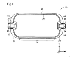
図1は、本発明の第1実施形態の高圧タンク10の概略構成を示した説明図である。図1には、相互に直交するXYZ軸が図示されている。図1のXYZ軸は、他の図のXYZ軸に対応する。XYZ軸において、矢印の指す方向を+側、矢印の指す方向と反対方向を−側とする。高圧タンク10には、例えば、70MPa程度の高圧の水素ガスが貯蔵される。高圧タンク10は、ライナー20と、口金34,35と、補強層40と、を備えている。
A. First embodiment:
A1. Device configuration:
FIG. 1 is an explanatory diagram showing a schematic configuration of a high-
ライナー20は、気体である水素ガスを密封するための空間を形成する樹脂製の中空ライナーである。ライナー20は、例えば、ポリエチレン、ナイロン、ポリプロピレン、ポリエステル等の熱可塑性樹脂によって形成されている。ライナー20は、シリンダー部21とドーム部22,23とを備える。
The
シリンダー部21は、X軸方向に沿って伸びた円筒形状を有している。ドーム部22は、シリンダー部21のX軸方向の−側における端部に設けられている。ドーム部23は、シリンダー部21のX軸方向の+側における端部に設けられている。ドーム部22,23は、ライナー20の外側に向けて凸となる曲面状に形成されている。
The
ドーム部22,23の頂点には、それぞれ、アルミニウムやステンレス鋼等の金属によって形成された口金34,35が設けられている。換言すれば、口金34,35は、ライナー20の長手方向であるX軸方向の端に形成された貫通孔24,25に対して取り付けられている。この状態は、口金34,35が、ドーム部22,23の内側の面でのみライナー20と接触しているともいえる。口金34は、高圧タンク10内からのガスの取り出しまたは高圧タンク10内へのガスの補充に用いられる。口金35は、ライナー20の補強ないし補強層30形成時におけるライナーの回転のために用いられる。口金35は省略することも可能である。
補強層40は、ライナー20の周囲を覆う層であり、ライナー20を補強するための層である。補強層40は、図示しないフープ層およびヘリカル層から構成されている。
The reinforcing
図2は、口金34付近の拡大図である。嵌合部材54は、ライナー20と口金34との間に配されて、ライナー20と口金34との間を密閉する。口金34は、ライナー20との間に嵌合部材54が嵌まることによって、貫通孔24に対して固定される。嵌合部材54は、口金34とは異なる材料で形成されている。本実施形態では、嵌合部材54は、EPDM(エチレン−プロピレン−ジエンゴム)にて形成されたOリングである。嵌合部材54は、NBR(アクリロニトリルブタジエンゴム)にて形成されていてもよいし、他の合成ゴム、天然ゴム、または合成樹脂にて形成されていてもよい。口金35は、口金34に対応する嵌合部材54と同様に、口金35に対応する嵌合部材55(図1)によって、貫通孔25に対して固定されている。
FIG. 2 is an enlarged view of the vicinity of the
口金34のうちライナー20から外部に露出している露出部分EXは、貫通孔24のうち貫通孔24の大きさが最も小さくなる最小部分MNをX軸方向に投影した領域Rの内側に含まれる。ここでいう最小部分MNとは、貫通孔24をYZ平面で切ったときの断面のうち該断面が最も小さくなる部分のことである。図2において、最小部分MNは、破線で示されている。口金34の露出部分EXに対応する領域Rと同様に、口金35のうちライナー20から外部に露出している露出部分は、貫通孔25の大きさが最も小さくなる最小部分をX軸方向に投影した領域の内側に含まれる。
The exposed portion EX of the
図2で説明した構造を高圧タンク10が備えることにより、以下の効果が奏される。すなわち、口金34,35をリサイクルするために、口金34,35を高圧タンク10から分離する際に、口金34,35を高圧タンク10の内側方向に押すことによって、口金34,35をライナー20から分離することができる。より詳細には、口金34を高圧タンク10から分離する場合、露出部分EXは、領域Rの内側に含まれることから、口金34を高圧タンク10の外側から−X軸方向に押すことによって、露出部分EXは、貫通孔24を通って高圧タンク10の内側に移動することができる。このとき、嵌合部材54が、口金34に伴って高圧タンク10の内側に移動することによってライナー20と口金34との間の密閉を解放する。そして、口金34は、貫通孔24から高圧タンク10の内側に向けて外れる。高圧タンク10の内側に向けて外れた口金34は、高圧タンク10から口金34を分離する前後のいずれかにおいて、高圧タンク10のうちX軸方向中央寄りの部分で高圧タンク10を切断することによって回収することができる。高圧タンク10の内側に向けて外れた口金34を切断することを回避するためには、口金34を分離する前に高圧タンク10を切断しておくことが好ましい。
By providing the high-
上述の記載では、口金34を高圧タンク10から分離する場合について説明したが、口金35を高圧タンク10から分離する場合についても、同様である。すなわち、口金35を高圧タンク10から分離する場合、口金35のうちライナー20から外部に露出している露出部分は、貫通孔25の大きさが最も小さくなる最小部分をX軸方向に投影した領域の内側に含まれることから、口金35を高圧タンク10の外側から+X軸方向に押すことによって、口金35のうちライナー20から外部に露出している露出部分は、貫通孔25を通って高圧タンク10の内側に移動することができる。その結果、口金35も、口金34と同様に、貫通孔25から高圧タンク10の内側に向けて外れる。
In the above description, the case where the
図3は、ライナー20への口金34の組み付けの様子を示す説明図である。なお、図3以降においては、部材構成の明示のため、ハッチングを付して各部材を図示する。
FIG. 3 is an explanatory view showing how the
図3に示すように、口金34は、ライナー20の内側からライナー20のドーム部22頂上の貫通孔24に挿入される。この口金挿入は、図1に示すライナー20が円筒状のシリンダー部21で2分割されたライナーパーツに対してなされる。つまり、2分割されたライナーパーツは、シリンダー部21の分割端を開口させているので、この分割端の開口から嵌合部材54がライナー内部に搬送され、貫通孔24に挿入される。こうした口金挿入により、口金34がライナー20に組み付けられ、この組み付け状態において、ライナー20の固定ボルト(図視略)の挿入用のボルト穴28と、口金34に空けられた雌ネジ孔37とが一致するようにされる。雌ネジ孔37は、シールテープを併用することでシール機能を発揮するテーパー状の雌ネジ孔である。ボルト穴28と雌ネジ孔37は、ライナー20の貫通好軸回りに等ピッチで形成されている。上記した口金組み付けは、口金34と反対側の口金35についても同様になされる。
As shown in FIG. 3, the
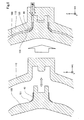
口金34の組み付け対象となるライナー20は、長手方向端のドーム部22の頂上側内壁22aに、インサートリング42を有する。インサートリング42は、ステンレス鋼を用いた成形品であり、筒状の管体部42aと、この管体部42aから連続して徐々に拡張した拡張形状の拡張部42bとを有する。管体部42aは、本発明における貫通孔形成部に該当し、ライナー20を軸方向に貫く貫通孔24のうち、既述した嵌合部材54が気密に接触する領域を含む貫通孔領域24bにおいて、貫通孔24を形成する。貫通孔24は、貫通孔領域24bとこの領域より先端側の開口側領域24aとに分けられ、開口側領域24aはライナー20におけるドーム部22の環状の頂上部にて形成されている。拡張部42bは、本発明における拡張受圧部に該当し、ドーム部22の頂上側内壁22aに没してライナー長手方向に沿って掛かるタンク内圧を受圧する。なお、インサートリング42の管体部42aは、ドーム部22の環状の頂上部に没した状態で貫通孔領域24bを形成する。
The
図4は、ライナー20をインサートリング42が装着済みの状態で型成形する様子を示す説明図である。図示するように、ライナー20の型成形には、インナー金型100とアウター金型110とが用いられる。インナー金型100は、ライナー20の内壁面を形成する金型面を有し、アウター金型110は、ライナー20の外壁面を形成する金型面を有し、両金型は、互いの金型面を向かい合わせている。両金型のセットの前に、インナー金型100にインサートリング42が装着され、インサートリング42の内壁面、詳しくは、既述した管体部42aとこれに連続した拡張部42bの内壁面は、インナー金型100の金型面に密着する。インサートリング42を装着済みのインナー金型100がアウター金型110にセットされると、両金型面が向かい合う領域にキャビティー120が形成される。金型セット後に、キャビティー120に、図示するゲート位置から溶融樹脂が流し込まれ、樹脂が硬化すると、インサートリング42が装着済みのライナー20が得られる。
FIG. 4 is an explanatory diagram showing a state of molding the
以上説明した第1実施形態によれば、高圧タンク10から口金34,35を分離する際に、口金34,35を高圧タンク10の内側方向に押すことによって、口金34,35をライナー20から分離することができる。また、ライナー20と口金34,35とは、嵌合部材54,55によって固定されていることから、ライナーと口金とが熱圧着もしくは接着剤による接着で固定されている形態と比べて、ライナー20の成分もしくは接着剤などが分離した口金34,35に付着することを避けることができる。このため、高圧タンク10において、ライナー20から口金34,35を簡潔に分離できるとともに、再利用性の高い口金34,35を分離しやすくできる。
According to the first embodiment described above, when the
第1実施形態の高圧タンク10は、ライナー20における長手方向端のドーム部22の頂上部にインサートリング42を備える。インサートリング42の管体部42aにより、貫通孔24の貫通孔領域24bが形成され、インサートリング42は、管体部42aに連続しドーム部22の頂上側内壁22aに没した拡張部42bで、ライナー長手方向に沿って掛かるタンク内圧を受圧する。よって、第1実施形態の高圧タンク10によれば、インサートリング42の拡張部42bがドーム部22の頂上側内壁22aに没されていることから、この拡張部42bにライナー長手方向に沿ってタンク内圧が掛かっても、拡張部42bを没させているライナー20のドーム部22で拡張部42bを支えられる。このため、第1実施形態の高圧タンク10によれば、インサートリング42が貫通孔24に沿ってずれたりする事態や、ライナー20から抜け落ちたりする事態を回避できる。
The high-
第1実施形態の高圧タンク10を構成するライナー20を得るに当たり、インナー金型100にインサートリング42を予め装着して、インサートリング42の管体部42aとこれに連続した拡張部42bの内壁面を、インナー金型100の金型面に密着させる。よって、キャビティー120にゲート位置からキャビティー120に流し込まれる際、インサートリング42は、拡張部42bにおいてインナー金型100に支えられるので、ライナー20の樹脂成形の際のインサートリング42のズレを回避できる。
In obtaining the
B.第2実施形態:
図5は、第2実施形態の高圧タンク10Aを構成するライナー20への口金34の組み付けの様子を示す説明図である。図6は、第2実施形態の高圧タンク10Aを構成するライナー20を型成形する様子を示す説明図である。以下の説明に当たっては、同一の機能を果たす部材については、符合を変えて同一の部材名を用いることとする。
B. Second embodiment:
FIG. 5 is an explanatory view showing how the
第2実施形態の高圧タンク10Aは、インサートリング42の拡張部42bの最拡張端側に内壁凹部26を有する。この内壁凹部26は、ライナー20の内周壁が陥没するようにして形成されている。この内壁凹部26の陥没形成のため、アウター金型110は、図6に示すように、装着済みインサートリング42の最拡張端が当接する凸部101を有する。凸部101を有するアウター金型110が、この凸部101にインサートリング42の最拡張端が当接した状態で、アウター金型110にセットされると、キャビティー120に凸部101が突出するため、ライナー20のドーム部22に、内壁凹部26が陥没形成される。内壁凹部26は、環状の陥没凹溝でも、ライナー軸心回りに所定の間隔で点在する陥没凹部でもよい。
The high-
第2実施形態の高圧タンク10Aによっても、第1実施形態と同様の効果を奏することができる。そして、第2実施形態の高圧タンク10Aによれば、インナー金型100の凸部101でインサートリング42を支えることで、ライナー20の樹脂成形の際のインサートリング42のズレを、より確実に回避できる。
The high-
C.第3実施形態:
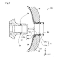
図7は、第3実施形態の高圧タンク10Bを構成するライナー20への口金34の組み付けの様子を示す説明図である。図8は、第3実施形態の高圧タンク10Bを構成するライナー20を型成形する様子を示す説明図である。
C. Third embodiment:
FIG. 7 is an explanatory diagram showing how the
第3実施形態の高圧タンク10Bは、インサートリング42Aの拡張部42bを管体部42aに対してほぼ垂直に拡張させて備える。このインサートリング42Aにあっても、拡張部42bは、ドーム部22の頂上側内壁22aに没してライナー長手方向に沿って掛かるタンク内圧を受圧する。インサートリング42Aを装着したライナー20を得るためのアウター金型110には、図8に示すように、インサートリング42Aの拡張部42bがドーム部22の形成のための金型面から離れるようにして、インサートリング42Aが装着される。そして、アウター金型110がアウター金型110にセットされると、ライナー20形成用のキャビティー120では、拡張部42bが金型面から離れるが、この拡張部42bは、キャビティー120にゲート位置から流し込まれた樹脂により取り囲まれ、その後に硬化した樹脂により、頂上側内壁22aに埋没することになる。
The high-
第3実施形態の高圧タンク10Bによっても、既述した実施形態と同様の効果を奏することができる。そして、第3実施形態の高圧タンク10Bによれば、拡張部42bがライナー20を構成する硬化済み樹脂に埋没されているので、インサートリング42Aが貫通孔24に沿ってずれたりする事態や、ライナー20から抜け落ちたりする事態をより確実に回避できる。
The high-
D.第4実施形態:
図9は、第4実施形態の高圧タンク10Cを構成するライナー20への口金34の組み付けの様子を示す説明図である。図10は、第4実施形態の高圧タンク10Cを構成するライナー20を型成形する様子を示す説明図である。
D. Fourth Embodiment:
FIG. 9 is an explanatory diagram showing how the
第4実施形態の高圧タンク10Cは、インサートリング42Bの拡張部42bを管体部42aに対してほぼ垂直に拡張させた上で、この拡張部42bからライナー軸方向に環状部42cを突出させている。このインサートリング42Bでは、拡張部42bと環状部42cとが、ドーム部22の頂上側内壁22aに埋没し、拡張部42bでライナー長手方向に沿って掛かるタンク内圧を受圧する。これに加え、第4実施形態の高圧タンク10Cは、インサートリング42Bの拡張部42bの屈曲部に、第2実施形態と同様、内壁凹部26を有する。この内壁凹部26は、ライナー20の内周壁が陥没するようにして形成されている。この内壁凹部26の陥没形成のため、アウター金型110は、図10に示すように、装着済みインサートリング42Bにおける拡張部42bの屈曲部が当接する凸部101を有する。凸部101を有するアウター金型110が、凸部101にインサートリング42Bにおける拡張部42bの屈曲部が当接した状態で、アウター金型110にセットされると、キャビティー120に凸部101が突出するため、ライナー20のドーム部22に、内壁凹部26が陥没形成される。内壁凹部26は、環状の陥没凹溝でも、ライナー軸心回りに所定の間隔で点在する陥没凹部でもよい。そして、この第4実施形態では、金型セットの後のゲート位置からの樹脂流し込みとその硬化により、拡張部42bと環状部42cとが硬化済み樹脂により取り囲まれて、頂上側内壁22aに埋没する。
In the high-
第4実施形態の高圧タンク10Cによっても、既述した実施形態と同様の効果を奏することができる。そして、第4実施形態の高圧タンク10Cによれば、拡張部42bと環状部42cがライナー20を構成する硬化済み樹脂に埋没されているので、インサートリング42Aが貫通孔24に沿ってずれたりする事態や、ライナー20から抜け落ちたりする事態をより確実に回避できる。
The high-
E.他の実施形態:
上述した第1実施形態では、嵌合部材54は、EPDM(エチレン−プロピレン−ジエンゴム)にて形成されたOリングであったが、本発明はこれに限られない。例えば、嵌合部材54は、口金34より破壊されやすい材質で形成されていてもよい。このような場合、口金34を高圧タンク10の内側方向に押すことで嵌合部材54が口金34の移動に伴い破壊されることによって、口金34が高圧タンク10の内側に向けて外れる。また、嵌合部材54は、口金34より融点の低い材質で形成されていてもよい。このような場合、口金34および嵌合部材54の付近を高温にすることで嵌合部材54を融解させることによって、口金34が高圧タンク10の内側に向けて外れる。
E. Other embodiments:
In the above-described first embodiment, the
インサートリング42やインサートリング42A、およびインサートリング42Bを有する形態は、貫通孔24に対して嵌合部材54で気密に口金34を組み付けた上で、ライナー20から外部に露出している口金34の露出部分を貫通孔24より小径とした形態以外にも適用できる。例えば、筒状のインサートリングをライナー20の貫通孔24に装着した形態の高圧タンクに対して、インサートリング42やインサートリング42A、或いはインサートリング42Bを適用する形態を適用してもよい。
In the form having the
本発明は、上述の実施形態に限られるものではなく、その趣旨を逸脱しない範囲において種々の構成で実現することができる。例えば、発明の概要の欄に記載した各形態中の技術的特徴に対応する実施形態中の技術的特徴は、上述の課題の一部または全部を解決するために、あるいは、上述の効果の一部または全部を達成するために、適宜、差し替えや、組み合わせを行うことが可能である。また、その技術的特徴が本明細書中に必須なものとして説明されていなければ、適宜、削除することが可能である。 The present invention is not limited to the above-described embodiment, and can be realized with various configurations without departing from the spirit of the present invention. For example, the technical features in the embodiments corresponding to the technical features in each mode described in the section of the summary of the invention are to solve some or all of the above problems, or It is possible to appropriately replace or combine in order to achieve a part or all. If the technical features are not described as essential in this specification, they can be deleted as appropriate.
10,10A〜10C…高圧タンク、20…ライナー、21…シリンダー部、22,23…ドーム部、22a…頂上側内壁、24,25…貫通孔、24a…開口側領域、24b…貫通孔領域、26…内壁凹部、28…ボルト穴、34,35…口金、37…雌ネジ孔、40…補強層、42,42A,インサートリング、42a…管体部、42b…拡張部、42c…環状部、54,55…嵌合部材、100…インナー金型、101…凸部、110…アウター金型、120…キャビティー、EX…露出部分、MN…最小部分、R…領域 10, 10A to 10C ... High-pressure tank, 20 ... Liner, 21 ... Cylinder part, 22, 23 ... Dome part, 22a ... Top inner wall, 24, 25 ... Through hole, 24a ... Opening side region, 24b ... Through hole region, 26 ... Inner wall concave part, 28 ... Bolt hole, 34, 35 ... Base, 37 ... Female screw hole, 40 ... Reinforcing layer, 42, 42A, insert ring, 42a ... Tube part, 42b ... Expansion part, 42c ... Annular part, 54, 55 ... Fitting member, 100 ... Inner mold, 101 ... Convex part, 110 ... Outer mold, 120 ... Cavity, EX ... Exposed part, MN ... Minimal part, R ... Region
Claims (2)
気体を密封するための空間を形成するライナーと、
前記ライナーの長手方向の端に形成された貫通孔に対して取り付けられる口金と、
前記口金とは異なる材料で形成され、前記ライナーと前記口金との間に配されて、前記ライナーと前記口金との間を密閉する嵌合部材と、を備え、
前記口金のうち前記ライナーから外部に露出している露出部分は、前記貫通孔のうち前記貫通孔の大きさが最も小さくなる最小部分を前記長手方向に投影した領域の内側に含まれる、高圧タンク。 A high pressure tank,
A liner forming a space for sealing the gas,
A base attached to a through hole formed at the longitudinal end of the liner,
A fitting member formed of a material different from that of the base, disposed between the liner and the base, and sealing between the liner and the base,
An exposed portion of the die, which is exposed from the liner to the outside, is included inside a region in which the smallest portion of the through hole having the smallest size is projected in the longitudinal direction. ..
前記ライナーは、
前記長手方向端のドーム部の頂上側内壁に、前記貫通孔を形成し、前記嵌合部材が気密に接触するインサートリングを有し、
該インサートリングは、
前記貫通孔を形成する筒状の貫通孔形成部と、該貫通孔形成部から連続して拡張した拡張形状をなし前記ドーム部の頂上側内壁に没して前記長手方向に沿って掛かるタンク内圧を受圧する拡張受圧部とを有する、高圧タンク。 The high pressure tank according to claim 1,
The liner is
The insert hole that forms the through hole in the top inner wall of the dome portion at the longitudinal end and in which the fitting member comes into airtight contact,
The insert ring is
A cylindrical through-hole forming portion that forms the through-hole, and a tank internal pressure that is formed in an expanded shape that is continuously expanded from the through-hole forming portion and that is immersed in the top inner wall of the dome portion and is applied along the longitudinal direction High-pressure tank having an expanded pressure receiving portion for receiving pressure.
Applications Claiming Priority (2)
| Application Number | Priority Date | Filing Date | Title |
|---|---|---|---|
| JP2018206438 | 2018-11-01 | ||
| JP2018206438 | 2018-11-01 |
Publications (2)
| Publication Number | Publication Date |
|---|---|
| JP2020076490A true JP2020076490A (en) | 2020-05-21 |
| JP7259658B2 JP7259658B2 (en) | 2023-04-18 |
Family
ID=70723782
Family Applications (1)
| Application Number | Title | Priority Date | Filing Date |
|---|---|---|---|
| JP2019162515A Active JP7259658B2 (en) | 2018-11-01 | 2019-09-06 | high pressure tank |
Country Status (1)
| Country | Link |
|---|---|
| JP (1) | JP7259658B2 (en) |
Cited By (1)
| Publication number | Priority date | Publication date | Assignee | Title |
|---|---|---|---|---|
| JP7416017B2 (en) | 2021-06-14 | 2024-01-17 | トヨタ自動車株式会社 | pressure vessel |
Citations (4)
| Publication number | Priority date | Publication date | Assignee | Title |
|---|---|---|---|---|
| JP2005048919A (en) * | 2003-07-31 | 2005-02-24 | Toyota Motor Corp | Tank |
| JP2008164089A (en) * | 2006-12-28 | 2008-07-17 | Toyota Motor Corp | Mouthpiece for tank, tank provided with the mouthpiece, and method for attachment to tank |
| JP2012036952A (en) * | 2010-08-05 | 2012-02-23 | Toyota Motor Corp | Insert ring for high pressure gas tank, manufacturing method thereof and high pressure gas tank |
| JP2015113957A (en) * | 2013-12-13 | 2015-06-22 | 株式会社Fts | Mouthpiece structure of pressure container |
-
2019
- 2019-09-06 JP JP2019162515A patent/JP7259658B2/en active Active
Patent Citations (4)
| Publication number | Priority date | Publication date | Assignee | Title |
|---|---|---|---|---|
| JP2005048919A (en) * | 2003-07-31 | 2005-02-24 | Toyota Motor Corp | Tank |
| JP2008164089A (en) * | 2006-12-28 | 2008-07-17 | Toyota Motor Corp | Mouthpiece for tank, tank provided with the mouthpiece, and method for attachment to tank |
| JP2012036952A (en) * | 2010-08-05 | 2012-02-23 | Toyota Motor Corp | Insert ring for high pressure gas tank, manufacturing method thereof and high pressure gas tank |
| JP2015113957A (en) * | 2013-12-13 | 2015-06-22 | 株式会社Fts | Mouthpiece structure of pressure container |
Cited By (1)
| Publication number | Priority date | Publication date | Assignee | Title |
|---|---|---|---|---|
| JP7416017B2 (en) | 2021-06-14 | 2024-01-17 | トヨタ自動車株式会社 | pressure vessel |
Also Published As
| Publication number | Publication date |
|---|---|
| JP7259658B2 (en) | 2023-04-18 |
Similar Documents
| Publication | Publication Date | Title |
|---|---|---|
| US9316357B2 (en) | Pressure vessel | |
| WO2013080810A1 (en) | Pressure container and method for manufacturing pressure container | |
| JP6614180B2 (en) | Method for manufacturing hydrogen tank body, and method for manufacturing hydrogen tank | |
| JP2014238110A (en) | Pressure vessel | |
| JP5741482B2 (en) | Pressure vessel and method for manufacturing the same | |
| JP5559333B2 (en) | Fuel tank seal structure and method for forming the same | |
| CN110345374B (en) | High-pressure tank | |
| JP4525021B2 (en) | tank | |
| JP2020076490A (en) | High-pressure tank | |
| CN110906163B (en) | Liner constituting member, high-pressure tank, and method for manufacturing high-pressure tank | |
| JP6601425B2 (en) | Gas tank liners and gas tanks | |
| JP2013228082A (en) | Pressure container | |
| JP2006226374A (en) | Joint structure of pipe body and joint method of pipe body | |
| JP6637292B2 (en) | Pressure vessel and method of manufacturing the same | |
| WO2016167034A1 (en) | Pressure vessel | |
| US8105518B2 (en) | Method for joining first and second members to each other through a joint material | |
| JP2008175341A (en) | Pressure vessel and manufacturing method for pressure vessel | |
| JP2020506099A (en) | Method of manufacturing hollow injection molded article and hollow injection molded article manufactured using the same | |
| JP2007064341A (en) | Connector | |
| EP3715281B1 (en) | Aircraft water tank and method for producing same | |
| JP2018013176A (en) | Manufacturing method of tank | |
| KR101487872B1 (en) | Manufacturing method of integrated liner boss for fiber reinforced plastic LPG cylinder and manufacturing method of fiber reinforced plastic LPG cylinder by the same and fiber reinforced plastic LPG cylinder made by the same | |
| JP6409531B2 (en) | tank | |
| JP2018179084A (en) | Liner | |
| JP2017013470A (en) | Molding device for built-in component fixing part of fuel tank |
Legal Events
| Date | Code | Title | Description |
|---|---|---|---|
| A621 | Written request for application examination |
Free format text: JAPANESE INTERMEDIATE CODE: A621 Effective date: 20211020 |
|
| A977 | Report on retrieval |
Free format text: JAPANESE INTERMEDIATE CODE: A971007 Effective date: 20220927 |
|
| A131 | Notification of reasons for refusal |
Free format text: JAPANESE INTERMEDIATE CODE: A131 Effective date: 20221011 |
|
| A521 | Request for written amendment filed |
Free format text: JAPANESE INTERMEDIATE CODE: A523 Effective date: 20221130 |
|
| TRDD | Decision of grant or rejection written | ||
| A01 | Written decision to grant a patent or to grant a registration (utility model) |
Free format text: JAPANESE INTERMEDIATE CODE: A01 Effective date: 20230307 |
|
| A61 | First payment of annual fees (during grant procedure) |
Free format text: JAPANESE INTERMEDIATE CODE: A61 Effective date: 20230320 |
|
| R151 | Written notification of patent or utility model registration |
Ref document number: 7259658 Country of ref document: JP Free format text: JAPANESE INTERMEDIATE CODE: R151 |