JP2020076216A - Partition wall structure and construction method of this partition wall structure - Google Patents
Partition wall structure and construction method of this partition wall structure Download PDFInfo
- Publication number
- JP2020076216A JP2020076216A JP2018208595A JP2018208595A JP2020076216A JP 2020076216 A JP2020076216 A JP 2020076216A JP 2018208595 A JP2018208595 A JP 2018208595A JP 2018208595 A JP2018208595 A JP 2018208595A JP 2020076216 A JP2020076216 A JP 2020076216A
- Authority
- JP
- Japan
- Prior art keywords
- studs
- partition wall
- attached
- wall structure
- runners
- Prior art date
- Legal status (The legal status is an assumption and is not a legal conclusion. Google has not performed a legal analysis and makes no representation as to the accuracy of the status listed.)
- Granted
Links
Images
Landscapes
- Building Environments (AREA)
Abstract
【課題】高い遮音性及び耐火性を得ることができる間仕切壁構造、及びその施工方法を提供する。【解決手段】上駆体50に互いに離間した並列状態で取り付けられた第1及び第2の上部ランナー2、3と、下駆体51に互いに離間した並列状態で取り付けられた第1及び第2の下部ランナー4、5と、第1及び第2の上部ランナー2、3の各々に上部を支持され、かつ第1及び第2の下部ランナー4、5の各々に下部を支持された第1及び第2の複数のスタッド6、7とを備える。第1下地材8を第1の複数のスタッド6の表面側に取り付け、第2下地材9を第2の複数のスタッド7の表面側に取り付けることで、これら下地材同士8、9を互いに連絡部分のない完全に独立したものとする。【選択図】図2PROBLEM TO BE SOLVED: To provide a partition wall structure capable of obtaining high sound insulation and fire resistance, and a construction method thereof. SOLUTION: First and second upper runners 2 and 3 attached to an upper drive body 50 in a parallel state separated from each other, and first and second upper runners 2 and 3 attached to a lower drive body 51 in a parallel state separated from each other. The lower runners 4 and 5 and the first and second upper runners 2 and 3 each support the upper part, and the first and second lower runners 4 and 5 each support the lower part. A second plurality of studs 6 and 7 are provided. By attaching the first base material 8 to the surface side of the first plurality of studs 6 and attaching the second base material 9 to the surface side of the second plurality of studs 7, these base materials 8 and 9 communicate with each other. It shall be completely independent without any parts. [Selection diagram] Fig. 2
Description
本発明は、建物の内部空間を仕切るための乾式の間仕切壁構造及びその施工方法に関し、特に遮音性、耐火性及び施工性に優れた間仕切壁構造及びその施工方法に関するものである。 The present invention relates to a dry partition wall structure for partitioning an internal space of a building and a construction method thereof, and more particularly to a partition wall structure excellent in sound insulation, fire resistance and construction work and a construction method thereof.
RC造・SRC造の湿式の構造物であるコンクリート構造では、遮音性、耐火性に優れるものの型枠工事が必須であり、多大なコストを要する。建築物の工期短縮、コストダウンなどを目的として、乾式の間仕切壁を施工することが多くなってきている。集合住宅やホテルなどでは、隣り合う居住空間を区画し、遮音性能と耐火性能を有する乾式の耐火遮音間仕切壁が使用されている。 A concrete structure, which is a wet structure made of RC and SRC, has excellent sound insulation and fire resistance, but requires formwork, which requires a great deal of cost. For the purpose of shortening the construction period of buildings and reducing costs, dry-type partition walls are increasingly used. In apartments, hotels, etc., dry fireproof and soundproof partition walls are used that divide adjacent living spaces and have soundproofing and fireproofing performance.
乾式の間仕切壁構造として、上下の駆体であるスラブ面(天井面、床面)に取り付けられた上下のランナーに、所定の間隔で金属製の間柱を取り付け、その両面に壁パネルを貼り付けた構造が知られている。特許文献1には、同一壁芯上に間柱中心が整列するように所定間隔をもって複数の間柱を配置し、1つおきの間柱の一方の側面に断熱材スペーサーを介して壁面材を固定し、次いで残りの別の1つおきの間柱の反対側の側面に断熱材スペーサーを介して壁面材を固定し、両側の壁面材を相互に緩衝することなく独立させた間仕切壁構造が記載されている。
As a dry partition wall structure, metal studs are attached at predetermined intervals to the upper and lower runners attached to the upper and lower slab surfaces (ceiling surface, floor surface), and wall panels are attached to both surfaces. Known structure. In
特許文献2には、建築物の駆体に、空間部を有する独立二重構造からなる間仕切壁を固定する間仕切壁であって、間仕切壁の固定手段を間仕切壁のそれぞれの独立した壁面ごとに分割し、その固定手段と駆体との間に緩衝材を設けた間仕切壁構造が記載されている。
特許文献1の構造は、両側の壁面材を、断熱材スペーサーを介して1つおきに間柱に取り付けることで、耐火性、遮音性などを向上させるものである。しかしながら、断熱材スペーサーは非常に薄いものであり、両側の壁面材同士が1つの間柱を介して略連絡された状態となっていることから、振動や熱が伝搬し易く、十分な遮音性及び耐火性を得ることができない。
In the structure of
特許文献2の構造では、同文献の図2のように2枚のパネルのそれぞれの内側にこれらのパネルと一体成形されたリブが形成されている。一方のパネルの表面側の振動や熱は一体となったリブにそのまま伝搬し、他方のパネルのリブ、パネルへと伝搬し易く、十分な遮音性能及び耐火性を得ることは困難である。
In the structure of
本発明は従来技術の問題点に鑑み、高い遮音性及び耐火性を得ることができる間仕切壁構造、及びその施工方法を提供することを目的とする。 The present invention has been made in view of the problems of the prior art, and an object of the present invention is to provide a partition wall structure capable of obtaining high sound insulation and fire resistance, and a construction method thereof.
本発明の間仕切壁構造は、建築物の間仕切りを構成する間仕切壁構造であって、上駆体に互いに離間した並列状態で取り付けられた第1及び第2の上部ランナーと、下駆体に当該上部ランナーと対をなすように互いに離間した並列状態で取り付けられた第1及び第2の下部ランナーと、前記第1及び第2の上部ランナーの各々に上部を支持され、かつ前記第1及び第2の下部ランナーの各々に下部を支持され、間仕切方向に沿って並列状態で設けられた第1及び第2の複数のスタッドと、前記第1の複数のスタッドの表面側に固定され建物の内部空間を仕切る第1下地材と、前記第2の複数のスタッドの表面側に固定され建物の内部空間を仕切る第2下地材と、を備えるものである。 The partition wall structure of the present invention is a partition wall structure that constitutes a partition of a building, and is related to the first and second upper runners that are attached to the upper precursor in a parallel state and are separated from each other. First and second lower runners mounted in parallel with each other so as to form a pair with the upper runner, and an upper portion supported by each of the first and second upper runners, and the first and second upper runners. The lower part of each of the two lower runners is supported in its lower part, and the first and second plurality of studs are provided in parallel along the partitioning direction, and the inside of the building fixed to the surface side of the first plurality of studs. A first base material for partitioning the space and a second base material fixed to the surface side of the second plurality of studs for partitioning the internal space of the building are provided.
本発明によれば、第1及び第2の上部ランナー、第1及び第2の下部ランナーは、それぞれ互いに離間していることから、第1の上部ランナーと第1の下部ランナーに支持された第1の複数のスタッドと、第2の上部ランナーと第2の下部ランナーに支持された第2の複数のスタッドと、が互いに離れた状態となっている。そのため、第1の複数のスタッドの表面側に固定された第1下地材と、第2の複数のスタッドの表面側に固定された第2下地材と、が互いに連絡部分のない完全に独立したものとなり、隣り合う居住空間における振動や熱の伝搬を効果的に抑制できる。 According to the present invention, since the first and second upper runners and the first and second lower runners are separated from each other, respectively, the first upper runner and the first lower runner support the first and second lower runners. One plurality of studs and the second plurality of studs supported by the second upper runner and the second lower runner are separated from each other. Therefore, the first base material fixed to the front surface side of the first plurality of studs and the second base material fixed to the front surface side of the second plurality of studs are completely independent of each other and have no connecting portion. Therefore, it is possible to effectively suppress the propagation of vibration and heat in the adjacent living spaces.
前記第1及び第2の複数のスタッドの各々の上端と、前記上駆体と、が間隔を空けた状態とされ、かつ前記第1及び第2の複数のスタッドの各々の下端と、前記下駆体と、が間隔を空けた状態とされていることが好ましい。この場合、隣り合う居住空間における振動や熱の伝搬の抑制効果をさらに向上させることができる。 The upper end of each of the first and second plurality of studs and the upper precursor are spaced from each other, and the lower end of each of the first and second plurality of studs and the lower end of the lower stud. It is preferable that the vehicle body and the vehicle body are spaced from each other. In this case, it is possible to further improve the effect of suppressing the propagation of vibration and heat in the adjacent living spaces.
前記第1及び第2の複数のスタッドの上部が、上下方向に挿脱自在な係止手段を介して前記第1及び第2の上部ランナーの各々に支持されていることが好ましい。 It is preferable that the upper portions of the first and second plurality of studs are supported by the first and second upper runners, respectively, through locking means that can be inserted and removed in the vertical direction.
この場合、スタッドを上部ランナーに嵌め込むだけで簡単に取り付けることができ、施工性が格段に向上する。これによりコストを低減できる。上部ランナーにスタッドが完全には固定されておらず、層間変位時にスタッドが変位に追従し易くなるので、耐震性も向上させることができる。 In this case, the stud can be easily attached by just fitting it into the upper runner, and the workability is greatly improved. This can reduce costs. Since the studs are not completely fixed to the upper runner and the studs easily follow the displacement during the interlayer displacement, the earthquake resistance can be improved.
前記第1の複数のスタッドと、前記第1下地材との間、及び前記第2の複数のスタッドと、前記第2下地材との間に弾性変形していない状態で挟持された弾性体からなる緩衝材を更に備えることが好ましい。 From an elastic body sandwiched between the first plurality of studs and the first base material and between the second plurality of studs and the second base material without elastic deformation. It is preferable to further include a cushioning material.
スタッドと下地材との間に挟持された緩衝材によって振動が吸収され、振動の伝搬をさらに低減できる。スタッドと下地材とが異なる材質である場合に、これらの伸縮率の違いによる反りの発生を防止できる。 Vibration is absorbed by the cushioning material sandwiched between the stud and the base material, and the propagation of vibration can be further reduced. When the stud and the base material are different materials, it is possible to prevent warpage due to the difference in expansion and contraction rates.
前記上駆体に前記第1の上部ランナーを取り付ける複数の取付部と、当該上駆体に前記第2の上部ランナーを取り付ける複数の取付部と、を間仕切方向に沿って互いに千鳥状としてもよい。この場合、隣り合う居住空間における振動や熱の伝搬の抑制効果を高めることができ、施工性を高めることができる。 A plurality of mounting portions for mounting the first upper runner on the upper body and a plurality of mounting portions for mounting the second upper runner on the upper body may be staggered with respect to each other along the partition direction. .. In this case, the effect of suppressing the propagation of vibration and heat in the adjacent living spaces can be enhanced, and the workability can be enhanced.
本発明の間仕切壁の施工方法は、建築物の間仕切りを構成する上記のいずれかに記載の間仕切壁構造の施工方法であって、前記上駆体に前記第1及び第2の上部ランナーを取り付け、前記下駆体に前記第1及び第2の下部ランナーを取り付け、前記第1の複数のスタッドの上部を、前記第1の上部ランナーで支持し、当該第1の複数のスタッドの下部を、前記第1の下部ランナーで支持し、当該第1の複数のスタッドの内側に断熱材を設け、前記第2の複数のスタッドの上部を、前記第2の上部ランナーで支持し、当該第2の複数のスタッドの下部を、前記第2の下部ランナーで支持し、前記第1の複数のスタッドの表面側に前記第1下地材を取り付けると共に、前記第2の複数のスタッドの表面側に前記第2下地材を取り付けるものである。 The construction method of the partition wall of the present invention is the construction method of the partition wall structure according to any one of the above, which constitutes a partition of a building, wherein the first and second upper runners are attached to the upper precursor. , Attaching the first and second lower runners to the lower body, supporting the upper portions of the first plurality of studs with the first upper runner, and lowering the lower portions of the first plurality of studs, Supported by the first lower runner, a heat insulating material is provided inside the first plurality of studs, and upper parts of the second plurality of studs are supported by the second upper runner, and the second upper runner is supported by the second upper runner. The lower parts of the plurality of studs are supported by the second lower runner, the first base material is attached to the front surface side of the first plurality of studs, and the first base material is attached to the front surface side of the second plurality of studs. 2 The base material is attached.
本発明の施工方法によれば、隣り合う居住空間における振動や熱の伝搬を効果的に抑制できる。 According to the construction method of the present invention, it is possible to effectively suppress the propagation of vibration and heat in the adjacent living spaces.
前記第1及び第2の複数のスタッドの上部を、上下方向に挿脱自在な係止手段を介して前記第1及び第2の上部ランナーの各々で支持することが好ましい。この場合、スタッドを上部ランナーに嵌め込むだけで簡単に取り付けることができ、施工性が格段に向上する。これによりコストを低減できる。例えばL型に形成した上部ランナーの垂直片にスタッドの上部に設けたツメ部を嵌め込むようにして当該スタッドを支持すればよい。このようにすれば、上部ランナーにスタッドが完全に固定されることはなく、層間変位時にスタッドが変位に追従し易くなるので、耐震性も向上させることができる。 It is preferable that the upper portions of the first and second plurality of studs are supported by the respective first and second upper runners via locking means that is vertically insertable and removable. In this case, the stud can be easily attached by just fitting it into the upper runner, and the workability is greatly improved. This can reduce costs. For example, the stud may be supported by fitting a claw portion provided on the upper portion of the stud into a vertical piece of an upper runner formed in an L shape. With this configuration, the stud is not completely fixed to the upper runner, and the stud easily follows the displacement during the interlayer displacement, so that the earthquake resistance can be improved.
前記第1の複数のスタッドに、弾性変形していない状態の弾性体からなる緩衝材を予め取り付けておくか又は施工時に取り付け、前記第2の複数のスタッドに、弾性変形していない状態の弾性体からなる前記緩衝材を予め取り付けておくか又は施工時に取り付け、前記第1の複数のスタッドの表面側に、前記緩衝材を挟持させつつ前記第1下地材を取り付けると共に、前記第2の複数のスタッドの表面側に、前記緩衝材を挟持させつつ前記第2下地材を取り付けることが好ましい。 A cushioning material made of an elastic body that is not elastically deformed is attached to the first plurality of studs in advance, or is attached at the time of construction, and the elastic force of the second plurality of studs is not elastically deformed. The cushioning material composed of a body is attached in advance or is attached at the time of construction, and the first base material is attached to the front surface side of the first plurality of studs while sandwiching the cushioning material, and the second plurality It is preferable that the second base material is attached to the surface side of the stud while sandwiching the cushioning material.
スタッドと下地材との間に、弾性変形していない状態で挟持された緩衝材を設けるため、振動が吸収され、振動の伝搬をさらに低減できる。スタッドと下地材とが異なる材質である場合に、これらの伸縮率の違いによる反りの発生を防止できる。 Since the cushioning material sandwiched between the studs and the base material in a state where it is not elastically deformed is provided, the vibration is absorbed and the propagation of the vibration can be further reduced. When the stud and the base material are different materials, it is possible to prevent warpage due to the difference in expansion and contraction rates.
本発明のとおり、第1下地材と、第2下地材と、が互いに連絡部分のない完全に独立したものとなり、隣り合う居住空間における振動や熱の伝搬を効果的に抑制でき、極めて高い遮音性及び耐火性を得ることができる。 As in the present invention, the first base material and the second base material are completely independent of each other with no connecting portions, and vibration and heat propagation in adjacent living spaces can be effectively suppressed, resulting in extremely high sound insulation. And fire resistance can be obtained.
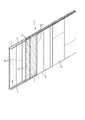
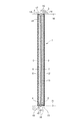
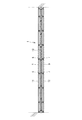
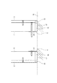
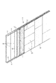
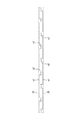
本発明の実施形態について図面を参照して説明する。図1は本発明の一実施形態に係る間仕切壁構造1を示す斜視図であり、図2はその間仕切壁構造1の縦断面図であり、図3はその間仕切壁構造1の横断面図である。
Embodiments of the present invention will be described with reference to the drawings. FIG. 1 is a perspective view showing a
本実施形態の間仕切壁構造1は、建築物の間仕切壁を構成するものであり、上駆体50に互いに離間した並列状態で取り付けられた第1及び第2の上部ランナー2、3と、下駆体51に当該上部ランナー2、3と対をなすように互いに離間した並列状態で取り付けられた第1及び第2の下部ランナー4、5と、第1及び第2の上部ランナー2、3の各々に上部を支持され、かつ第1及び第2の下部ランナー4、5の各々に下部を支持され、間仕切方向に沿って並列状態で設けられた上下方向に長い第1及び第2の複数のスタッド6、7とを備えている。建物の内部空間を仕切る一方の第1下地材8が、第1の複数のスタッド6の表面側に固定され、建物の内部空間を仕切る他方の第2下地材9が、第2の複数のスタッド7の表面側に固定されている。
The
第1及び第2の上部ランナー2、3及び第1及び第2の下部ランナー4、5は、いずれも間仕切方向に長いL型鋼材である。上駆体50に、第1及び第2の上部ランナー2、3が、垂直片s1に対して水平片s2を内側に向けるようにしてボルトや鋲などで固定されている。下駆体51に、第1及び第2の下部ランナー4、5が垂直片c1に対して水平片c2を外側に向けるようにしてボルトや鋲などで固定されている。
The first and second
本実施形態の第1及び第2下地材8、9は、図示のように正面視長方形状に形成された板材である。各下地材8、9の形状、寸法は限定されないが、施工場所の大きさに合わせて割り付けた形状、寸法に設定される。各下地材8、9を形成する材料は、建物の仕切りとして使用できる不燃性のものであれば限定されず、例えば厚みが3〜15mm程度のセメント系のフレキシブルボード、石膏ボード、ケイ酸カルシウム板、中質繊維板、パーティクルボード、木質系合板、硬質繊維板、鋼板などが挙げられる。
The first and
各下地材8、9としては無機系の繊維強化セメント板や石膏ボードを用いることができる。無機系の材料を選択する場合の比重は0.5〜1.8g/cm3程度のものが好適である。一般的な集合住宅の階高を考慮した場合の各下地材8、9の最大長さは3000mm程度とされるが、繊維強化セメント板のように厚みが3〜10mm程度の薄い下地では、この長さのものを小端建てした際に、1.3g/cm3以上の比重のものを用いれば、施工時に曲がらないようにすることができる。また1.8g/cm3以下の比重のものを用いることで、重量が大きくなり過ぎるのを防ぐことができる。
As each of the
図2のように第1及び第2下地材8、9の上下にシーリング材10が設けられている。第1及び第2下地材8、9の表面側には、それぞれビス、ステイプルなどで石膏ボードなどの第1及び第2の仕上げ材11、12が取り付けられ、各仕上げ材11、12の表面に壁紙が貼り付けられる。グラスウール、ロックウールなどの吸音・断熱材13が、第1及び第2の複数のスタッド6、7の間に挟まれるように取り付けられている。
As shown in FIG. 2, the sealing
第1及び第2の複数のスタッド6、7は、間仕切方向に沿って一定間隔をおいて立設されている。本実施形態の各スタッド6、7は、鉄、ステンレス、アルミなどを断面矩形状に形成した薄板の鋼材からなる。各スタッド6、7は不燃性のものであれば金属製に限定されず、各下地材8、9の補強効果を発揮でき、間仕切壁とした際に自立できるものであればよい。各スタッド6、7を各下地材8、9と同じ材料で形成してもよい。
The first and
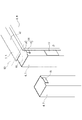
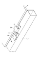
図4は各スタッド6、7の上部と、各スタッド6、7と各上部ランナー2、3との係止形態を示す斜視図である。第1及び第2の上部ランナー2、3の各々に、上下方向に挿脱自在な係止手段14を介して、第1及び第2の複数のスタッド6、7の上部が嵌め込まれるようにして係止されている。各スタッド6、7の上部の一部を加工することで、ツメ部15が形成されており、このツメ部15と各上部ランナー2、3の垂直片s1とで係止手段14が構成されている。同図のように各スタッド6、7のツメ部15の溝に、各上部ランナー2、3の垂直片s1を嵌め込むことで、各上部ランナー2、3に各スタッド6、7が支持されている。
FIG. 4 is a perspective view showing an upper part of each
図5は間仕切壁構造1の下部の断面図である。第1の下部ランナー4の垂直片c1に1の複数のスタッド6が側からビス留めされている。第2の下部ランナー5の垂直片c1に2の複数のスタッド7がスタッドを通じて外側からビス留めされている。このようなビス留め形態は、第1及び第2の下部ランナー4、5の取り付け工程に伴うものであり、適宜変更される。施工現場の状況に合わせて第1及び第2の下部ランナー4、5の向きを変え、当該両側のスタッド6、7とも外側から留め付けるようにしてもよい。
FIG. 5 is a cross-sectional view of the lower portion of the
図4及び図5に示すように、第1及び第2の複数のスタッド6、7の各々の上端と、第1及び第2の上部ランナー2、3の水平片s2との間に間隔16が空けられている。第1及び第2の複数のスタッド6、7の各々の下端と、第1及び第2の下部ランナー4、5の水平片c2との間に間隔16が空けられている。これにより、第1及び第2の複数のスタッド6、7の各々の上端と、上駆体50と、が間隔16を空けた状態とされ、かつ第1及び第2の複数のスタッド6、7の各々の下端と、下駆体51と、が間隔16を空けた状態とされ、各スタッド6、7と上下駆体50、51との間に十分な空間が保たれている。これにより、各スタッド6、7を介して第1及び第2下地材8、9から伝搬する振動を効果的に防止することができる。
As shown in FIGS. 4 and 5, there is a
図1及び図4に示すように、第1の複数のスタッド6と第1下地材8との間、及び第2の複数のスタッド7と第2下地材9との間に、弾性変形していない状態で挟持された弾性体からなる緩衝材17が、上下方向に間隔を空けて設けられている。
As shown in FIGS. 1 and 4, elastic deformation occurs between the first plurality of
各スタッド6、7と各下地材8、9に挟持されている緩衝材17は、所要の寸法にカットされたシート状となっている。緩衝材17の寸法、厚みは適宜変更できる。緩衝材17は弾性体からなり、弾性変形していない状態で挟持されている。これにより、各スタッド6、7と各下地材8、9との間に生じる振動を吸収できる。
The cushioning
各スタッド6、7と各下地材8、9との間の振動が吸収されることで、振動の伝搬が抑えられ遮音効果を格段に向上させることができる。さらに、各スタッド6、7と各下地材8、9との間にかかる力が緩和されることで、両部材の伸縮率の差が許容され、各下地材8、9の反りを抑制することができる。
By absorbing the vibrations between the
緩衝材17を圧縮しないように取り付ける点が重要である。緩衝材17を弾性変形させないような、各スタッド6、7と各下地材8、9との間隔は緩衝材17の厚み分となる。従って各スタッド6、7と各下地材8、9とは、緩衝材17の厚み分の間隔を空けて取り付けられている。緩衝材17を挟持した状態で取り付ける方法として、本実施形態ではビス留めが用いられている。
It is important to mount the
ビス留めの他、各スタッド6、7と各下地材8、9との間隔を保つことができれば、ピン、リベットなど、どのような形態でもよい。各スタッド6、7を各下地材8、9に取り付ける際には、緩衝材17を圧縮しないように、緩衝材17と同じ厚みのスレートや塩ビなどのパッキン材を、予め各スタッド6、7と各下地材8、9との間に挟んでおき、取り付けが完了した後、これを除去すればよい。
In addition to the screw fastening, any form such as pins and rivets may be used as long as the distance between the
接着剤を用いる場合、緩衝材17の表裏に接着剤を塗布して、各下地材8、9と緩衝材17、緩衝材17と各スタッド6、7を互いに密着させて固定する。接着剤を用いれば、緩衝材17を押す力は作用しないため、確実に圧縮しない状態で取り付けることができる。
When an adhesive is used, the adhesive is applied to the front and back surfaces of the
緩衝材17を形成する材料として、例えば天然ゴム、合成ゴム、スチレン−ブタジエンゴム、ブタジエンゴム、クロロプレンゴム、ブチルゴム、ニトリルゴム、エチレンプロピレンゴム、クロロスルホン化ポリエチレンゴム、アクリルゴム、ウレタンゴム、シリコンゴム、フッ素ゴム、多硫化ゴム、これらの発泡体などが挙げられる。
Examples of the material forming the
緩衝材17の硬度は、タイプAのデュロメータで20〜80が好ましく、より好ましくは30〜60である。緩衝材17の硬度を20以上とすることで、ビス留めの際に緩衝材17が圧縮されにくくなり、高い遮音性を得ることができる。緩衝材17の硬度を80以下とすることで、緩衝材17に伝わる音の振動が大きくなり過ぎず、高い遮音性を維持することができる。
The hardness of the
間仕切壁構造1は例えば次のようにして施工される。上駆体50に第1及び第2の上部ランナー2、3を取り付け、下駆体51に第1の下部ランナー4を取り付ける。第1の複数のスタッド6の上部のツメ部15に、第1の上部ランナー2の垂直片s1を嵌め込むようにして当該スタッド6を係止させる。第1の複数のスタッド6の下部を、第1の下部ランナー4にビス留めして固定する。その際、第1の複数のスタッド6に、緩衝材17を予め取り付けておくか又は施工時に取り付ける。
The
第1の複数のスタッド6の内側に吸音・断熱材13を取り付け、下駆体51に第2の下部ランナー5を取り付ける。第2の複数のスタッド7の上部のツメ部15に、第2の上部ランナー3の垂直片s1を嵌め込むようにして当該スタッド7を係止させる。第2の複数のスタッド7の下部を、第2の下部ランナー5にビス留めして固定する。その際、第2の複数のスタッド7に、緩衝材17を予め取り付けておくか又は施工時に取り付ける。緩衝材のスタッドへの取り付けは、接着剤や両面テープで行う。
The sound absorbing /
第1の複数のスタッド6の表面側に、緩衝材17を変形させないように第1下地材8を取り付ける。第2の複数のスタッド7の表面側に、緩衝材17を変形させないように第2下地材9を取り付ける。第1及び第2下地材8、9の上側及び下側の隙間に、シーリング材10を充填する。その後、第1及び第2下地材8、9の表面に第1及び第2の仕上げ材である石膏ボード11、12を取り付け、更に壁紙を貼り付けて仕上げる。これらの施工手順は一例を示したものであり、間仕切壁構造1の形態に応じて任意に設定できる。
The
本実施形態の間仕切壁構造1及びその施工方法によれば、第1及び第2の上部ランナー2、3、第1及び第2の下部ランナー4、5は、それぞれ互いに離間していることから、第1の上部ランナー2と第1の下部ランナー4に支持された第1の複数のスタッド6と、第2の上部ランナー3と第2の下部ランナー5に支持された第2の複数のスタッド7と、が互いに離れた状態となっている。そのため、第1の複数のスタッド6の表面側に取り付けられた第1下地材8と、第2の複数のスタッド7の表面側に取り付けられた第2下地材9と、が互いに連絡部分のない完全に独立したものとなる。これにより、隣り合う居住空間における振動や熱の伝搬を効果的に抑制できる。
According to the
第1及び第2の複数のスタッド6、7の上部が、上下方向に挿脱自在な係止手段14を介して第1及び第2の上部ランナー2、3の各々に支持されているため、各スタッド6、7を各上部ランナー2、3に嵌め込むだけで簡単に取り付けることができ、施工性が格段に向上する。これによりコストを低減できる。また、各上部ランナー2、3の垂直片s1に各スタッド6、7の上部のツメ部15を嵌め込むだけで、当該各スタッド6、7が支持された状態となる。そのため、各上部ランナー2、3に各スタッド6、7が完全に固定されることはなく、層間変位時に各スタッド6、7が変位に追従し易くなるので、耐震性も向上させることができる。
Since the upper portions of the first and second plurality of
第1及び第2の複数のスタッド6、7の各々の上端と、上駆体50と、が間隔16を空けた状態とされ、かつ第1及び第2の複数のスタッド6、7の各々の下端と、下駆体51と、が間隔16を空けた状態とされていることで、隣り合う居住空間における振動や熱の伝搬の抑制効果をさらに向上させることができる。
The upper end of each of the first and second plurality of
第1の複数のスタッド6と、第1下地材8との間、及び第2の複数のスタッド7と、第2下地材9との間に弾性変形していない状態で挟持された弾性体からなる緩衝材17を備えるため、振動が緩衝材17で吸収され、振動の伝搬をさらに低減できる。各スタッド6、7と各下地材8、9とが異なる材質となっている場合に、これらの伸縮率の違いによる反りの発生を防止できる。
From the elastic body sandwiched between the first plurality of
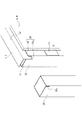
本発明は上記実施形態に限定されず、スタッド、下地材、上部及び下部ランナーの形状、寸法、取り付け方法などは、建物の内部空間を仕切る仕様に応じて適宜変更できる。上記実施形態では、図1のように各下地材8、9を縦張りとしているが、図6のように下地材21を横張りとしてもよい。下地材21を横張りとする場合、各スタッド6、7に下地材21を留め付けるための図7に示す留付部材22を用いてもよい。この留付部材22は、ネジ部を有するS型本体22aと、このS型本体22aから互いに逆向きの2つの嵌込ツメ22bからなる。各嵌込ツメ22bに隣り合う下地材21の端部を嵌め込むことで、各スタッド6、7に下地材21を簡単に留め付けることができる。
The present invention is not limited to the above-described embodiment, and the shapes, dimensions, attachment methods, etc. of the studs, the base material, the upper and lower runners can be appropriately changed according to the specifications for partitioning the internal space of the building. In the above embodiment, the
各スタッドを各上部ランナーに上下方向に挿脱自在に係止させる係止手段は、施工し易くかつ確実に係止できるものであればよい。図8は各スタッド25の上部の係止部分の変形例と、その各スタッド25と各上部ランナー2、3との係止形態を示す斜視図である。この例では、各スタッド25の小口に切り欠き25aを形成し、この切り欠き25aに各上部ランナー2、3の垂直片s1を差し込むようにしている。この係止手段26を用いた場合も、各スタッド25を簡単に取り付けることができ、施工性を格段に向上させることができる。さらに上部ランナー2、3の変位に各スタッド25を追従させることができ、耐震性を向上させることができる。
The locking means for locking the studs to the upper runners in the vertical direction so that they can be inserted and removed may be any means that can be easily installed and can be reliably locked. FIG. 8 is a perspective view showing a modified example of an upper locking portion of each
図9は第1及び第2の上部ランナー27、28の変形例を示す図である。各上部ランナー27、28は、間仕切方向に長いランナー本体e1と、このランナー本体e1に等間隔をおいて形成された複数の凸部e2とからなる。各凸部e2にはネジ孔が貫通形成されている。第1の上部ランナー27と第2の上部ランナー28とが、複数の凸部e2を互いに向かい合わせとした状態で、図1の上駆体50にネジ留めされて固定される。
FIG. 9 is a view showing a modified example of the first and second
第1の上部ランナー27を取り付ける複数の凸部e2(取付部)と、第2の上部ランナー28を取り付ける複数の凸部e2(取付部)と、が間仕切方向に沿って互いに千鳥状となるように、当該両部材27、28を配設する。凸部e2の形状、箇所、数は変更可能である。この場合、隣り合う居住空間における振動や熱の伝搬の抑制効果を高めることができ、さらに施工性も高めることができる。
The plurality of convex portions e2 (mounting portions) to which the first
上記実施形態ではスタッドを断面矩形状としているが、断面コ型、L型、C型、円型、三角型、多角型など緩衝材を取り付けることができる形状であればどのような断面形状としてもよい。断面コ型又はC型のスタッドを用いる場合には、2つのスタッドの開口が互いに向かい合うように当該スタッドを取りつける。それら2つのスタッドの間に断熱材を取りつければよい。スタッドをより長く形成して、これを下地材に対して斜め方向に向けるようにしてもよい。スタッドを斜め方向に取り付ければ、取り付け本数が少なくなり施工性が向上する。 Although the stud has a rectangular cross section in the above-described embodiment, any cross section such as a U-shaped, L-shaped, C-shaped, circular, triangular, or polygonal shape can be used as long as the cushioning material can be attached. Good. When using a stud having a U-shaped or C-shaped cross section, the studs are mounted so that the openings of the two studs face each other. Insulation may be attached between the two studs. The studs may be formed longer and oriented diagonally with respect to the substrate. If the studs are attached diagonally, the number of attachments will be reduced and workability will be improved.
本発明に係る間仕切壁構造、及びその施工方法は、特許請求の範囲に記載した技術的範囲において変更可能である。間仕切壁構造、その施工方法に、必要に応じて設けられる他の部材、他の工程は本発明の効果を損なわない限りにおいてどのような形態のものであってもよい。 The partition wall structure and the construction method thereof according to the present invention can be modified within the technical scope described in the claims. The partition wall structure, other members provided according to need in the construction method, and other steps may have any form as long as the effects of the present invention are not impaired.
1 間仕切壁構造
2 第1の上部ランナー
3 第2の上部ランナー
s1 垂直片
s2 水平片
4 第1の下部ランナー
5 第2の下部ランナー
c1 垂直片
c2 水平片
6 第1の複数のスタッド
7 第2の複数のスタッド
8 第1下地材
9 第2下地材
10 シーリング材
11 第1の仕上げ材
12 第2の仕上げ材
13 吸音・断熱材
14、26 係止手段
15 ツメ部
16 間隔
17 緩衝材
21 下地材
22 留付部材
22a S型本体
22b 嵌込ツメ
25 スタッド
25a 切り欠き
27 第1の上部ランナー
28 第2の上部ランナー
e1 ランナー本体
e2 凸部
1
Claims (8)
上駆体に互いに離間した並列状態で取り付けられた第1及び第2の上部ランナーと、
下駆体に当該上部ランナーと対をなすように互いに離間した並列状態で取り付けられた第1及び第2の下部ランナーと、
前記第1及び第2の上部ランナーの各々に上部を支持され、かつ前記第1及び第2の下部ランナーの各々に下部を支持され、間仕切方向に沿って並列状態で設けられた第1及び第2の複数のスタッドと、
前記第1の複数のスタッドの表面側に固定され建物の内部空間を仕切る第1下地材と、
前記第2の複数のスタッドの表面側に固定され建物の内部空間を仕切る第2下地材と、を備える間仕切壁構造。 A partition wall structure that constitutes a partition of a building,
First and second upper runners attached to the upper body in parallel with each other,
First and second lower runners attached to the lower body in parallel so as to form a pair with the upper runner and spaced apart from each other;
An upper part supported by each of the first and second upper runners, and a lower part supported by each of the first and second lower runners, provided in parallel along the partition direction. 2 studs,
A first base material that is fixed to the surface side of the first plurality of studs and partitions the internal space of the building;
A partition wall structure, comprising: a second base material fixed to the front surface side of the second plurality of studs and partitioning the internal space of the building.
前記上駆体に前記第1及び第2の上部ランナーを取り付け、
前記下駆体に前記第1及び第2の下部ランナーを取り付け、
前記第1の複数のスタッドの上部を、前記第1の上部ランナーで支持し、
当該第1の複数のスタッドの下部を、前記第1の下部ランナーで支持し、
当該第1の複数のスタッドの内側に断熱材を設け、
前記第2の複数のスタッドの上部を、前記第2の上部ランナーで支持し、
当該第2の複数のスタッドの下部を、前記第2の下部ランナーで支持し、
前記第1の複数のスタッドの表面側に前記第1下地材を取り付けると共に、前記第2の複数のスタッドの表面側に前記第2下地材を取り付ける間仕切壁構造の施工方法。 A method of constructing a partition wall structure according to any one of claims 1 to 5, which constitutes a partition of a building,
Attaching the first and second upper runners to the upper body,
Attaching the first and second lower runners to the lower body,
Supporting the tops of the first plurality of studs with the first upper runner,
Supporting the lower portions of the first plurality of studs with the first lower runner,
Insulating material is provided inside the first plurality of studs,
Supporting the upper portions of the second plurality of studs with the second upper runner,
Supporting the lower parts of the second plurality of studs with the second lower runner,
A method of constructing a partition wall structure, wherein the first base material is attached to the front surface sides of the first plurality of studs, and the second base material is attached to the front surface sides of the second plurality of studs.
前記第2の複数のスタッドに、弾性変形していない状態の弾性体からなる前記緩衝材を予め取り付けておくか又は施工時に取り付け、
前記第1の複数のスタッドの表面側に、前記緩衝材を挟持させつつ前記第1下地材を取り付けると共に、前記第2の複数のスタッドの表面側に、前記緩衝材を挟持させつつ前記第2下地材を取り付ける請求項6に記載の間仕切壁構造の施工方法。 A cushioning material made of an elastic body that is not elastically deformed is previously attached to the first plurality of studs, or is attached at the time of construction,
The cushioning material made of an elastic body that is not elastically deformed is previously attached to the second plurality of studs, or is attached at the time of construction,
The first base material is attached to the front surface side of the first plurality of studs while sandwiching the cushioning material, and the second base material is sandwiched while sandwiching the cushioning material on the surface side of the second plurality of studs. The method for constructing a partition wall structure according to claim 6, wherein a base material is attached.
Priority Applications (1)
| Application Number | Priority Date | Filing Date | Title |
|---|---|---|---|
| JP2018208595A JP7266385B2 (en) | 2018-11-06 | 2018-11-06 | Partition wall structure and construction method for this partition wall structure |
Applications Claiming Priority (1)
| Application Number | Priority Date | Filing Date | Title |
|---|---|---|---|
| JP2018208595A JP7266385B2 (en) | 2018-11-06 | 2018-11-06 | Partition wall structure and construction method for this partition wall structure |
Publications (2)
| Publication Number | Publication Date |
|---|---|
| JP2020076216A true JP2020076216A (en) | 2020-05-21 |
| JP7266385B2 JP7266385B2 (en) | 2023-04-28 |
Family
ID=70724939
Family Applications (1)
| Application Number | Title | Priority Date | Filing Date |
|---|---|---|---|
| JP2018208595A Active JP7266385B2 (en) | 2018-11-06 | 2018-11-06 | Partition wall structure and construction method for this partition wall structure |
Country Status (1)
| Country | Link |
|---|---|
| JP (1) | JP7266385B2 (en) |
Cited By (1)
| Publication number | Priority date | Publication date | Assignee | Title |
|---|---|---|---|---|
| CN113982143A (en) * | 2021-10-28 | 2022-01-28 | 苏州君洁空调净化设备有限公司 | Color steel plate partition wall for installation of purification engineering |
Citations (8)
| Publication number | Priority date | Publication date | Assignee | Title |
|---|---|---|---|---|
| JPS498020A (en) * | 1972-05-12 | 1974-01-24 | ||
| JPH11247324A (en) * | 1998-03-02 | 1999-09-14 | Yoshino Gypsum Co Ltd | Refractory structural wall |
| JP2002061316A (en) * | 2000-08-11 | 2002-02-28 | Shimizu Corp | Damping building, building material and damping building using the same |
| KR20080007905A (en) * | 2006-07-18 | 2008-01-23 | 윤원복 | 160 mm fireproof, runner clip, minor channel clip firewall system |
| JP2012026193A (en) * | 2010-07-26 | 2012-02-09 | Sumitomo Metal Ind Ltd | Runner |
| JP2014118777A (en) * | 2012-12-18 | 2014-06-30 | Daiwa House Industry Co Ltd | Dry-type wall structure |
| JP2018115531A (en) * | 2017-01-20 | 2018-07-26 | 大成建設株式会社 | Base structure of drywall |
| JP2019143466A (en) * | 2018-02-22 | 2019-08-29 | 株式会社ノザワ | Partition unit, and partition structure using the partition unit |
-
2018
- 2018-11-06 JP JP2018208595A patent/JP7266385B2/en active Active
Patent Citations (8)
| Publication number | Priority date | Publication date | Assignee | Title |
|---|---|---|---|---|
| JPS498020A (en) * | 1972-05-12 | 1974-01-24 | ||
| JPH11247324A (en) * | 1998-03-02 | 1999-09-14 | Yoshino Gypsum Co Ltd | Refractory structural wall |
| JP2002061316A (en) * | 2000-08-11 | 2002-02-28 | Shimizu Corp | Damping building, building material and damping building using the same |
| KR20080007905A (en) * | 2006-07-18 | 2008-01-23 | 윤원복 | 160 mm fireproof, runner clip, minor channel clip firewall system |
| JP2012026193A (en) * | 2010-07-26 | 2012-02-09 | Sumitomo Metal Ind Ltd | Runner |
| JP2014118777A (en) * | 2012-12-18 | 2014-06-30 | Daiwa House Industry Co Ltd | Dry-type wall structure |
| JP2018115531A (en) * | 2017-01-20 | 2018-07-26 | 大成建設株式会社 | Base structure of drywall |
| JP2019143466A (en) * | 2018-02-22 | 2019-08-29 | 株式会社ノザワ | Partition unit, and partition structure using the partition unit |
Non-Patent Citations (1)
| Title |
|---|
| 国土交通省住宅局建築指導課 新耐火防火部便覧編集委員会編集, 挿入式 新耐火防火構造・材料等便覧, vol. 新耐火728号, JPN6022026681, 13 November 2009 (2009-11-13), JP, pages 15535 - 15541, ISSN: 0004815091 * |
Cited By (1)
| Publication number | Priority date | Publication date | Assignee | Title |
|---|---|---|---|---|
| CN113982143A (en) * | 2021-10-28 | 2022-01-28 | 苏州君洁空调净化设备有限公司 | Color steel plate partition wall for installation of purification engineering |
Also Published As
| Publication number | Publication date |
|---|---|
| JP7266385B2 (en) | 2023-04-28 |
Similar Documents
| Publication | Publication Date | Title |
|---|---|---|
| CZ394298A3 (en) | Soundproof system for buildings | |
| JP2020521896A (en) | Method for forming a recess in the base region of a wall structure, corresponding wall structure and its system and building element | |
| KR20090003503U (en) | Drywall with Resilient Channels | |
| USRE19431E (en) | Acoustical wall support | |
| JP7173942B2 (en) | Damping ceiling structure | |
| KR20160023284A (en) | Sandwich panels | |
| JP7206006B2 (en) | partition wall | |
| JP7266385B2 (en) | Partition wall structure and construction method for this partition wall structure | |
| JP5588920B2 (en) | Method for forming interior base structure | |
| JP2024128075A (en) | Soundproofing structures and buildings | |
| JP7222746B2 (en) | Partition unit and partition structure using this partition unit | |
| KR101835071B1 (en) | Assembly type light weight partition pannel having fire-resistant | |
| JPS6378942A (en) | Room partition wall and its execution | |
| KR101680738B1 (en) | Wall to block noise of apartment house | |
| KR101783849B1 (en) | Apartment house residential soundroof wall | |
| CA3249022A1 (en) | A collaborating joist and suspended ceiling system and a method for assembling the system | |
| JP2000087472A (en) | Interior finish system | |
| JP3236554U (en) | Sound insulation structure of the wall | |
| JP2003105904A (en) | Fire-resistant, sound insulating partition wall | |
| EP3158147B1 (en) | Building structural connector | |
| JP5582094B2 (en) | Building ceiling structure | |
| JP7831745B2 (en) | Ceiling and partition wall construction | |
| WO2024047941A1 (en) | Intersection-portion structure of building wall | |
| JPH0313642A (en) | Fireproof sound insulation partition wall | |
| JPH085204Y2 (en) | Fireproof and soundproof panel members, fireproof and soundproof walls and floors |
Legal Events
| Date | Code | Title | Description |
|---|---|---|---|
| A521 | Request for written amendment filed |
Free format text: JAPANESE INTERMEDIATE CODE: A523 Effective date: 20190612 |
|
| A711 | Notification of change in applicant |
Free format text: JAPANESE INTERMEDIATE CODE: A711 Effective date: 20200110 |
|
| RD02 | Notification of acceptance of power of attorney |
Free format text: JAPANESE INTERMEDIATE CODE: A7422 Effective date: 20200117 |
|
| A521 | Request for written amendment filed |
Free format text: JAPANESE INTERMEDIATE CODE: A821 Effective date: 20200110 |
|
| A521 | Request for written amendment filed |
Free format text: JAPANESE INTERMEDIATE CODE: A523 Effective date: 20200220 |
|
| A521 | Request for written amendment filed |
Free format text: JAPANESE INTERMEDIATE CODE: A821 Effective date: 20200220 |
|
| A621 | Written request for application examination |
Free format text: JAPANESE INTERMEDIATE CODE: A621 Effective date: 20210710 |
|
| A977 | Report on retrieval |
Free format text: JAPANESE INTERMEDIATE CODE: A971007 Effective date: 20220621 |
|
| A131 | Notification of reasons for refusal |
Free format text: JAPANESE INTERMEDIATE CODE: A131 Effective date: 20220630 |
|
| A521 | Request for written amendment filed |
Free format text: JAPANESE INTERMEDIATE CODE: A523 Effective date: 20220829 |
|
| A131 | Notification of reasons for refusal |
Free format text: JAPANESE INTERMEDIATE CODE: A131 Effective date: 20221130 |
|
| A521 | Request for written amendment filed |
Free format text: JAPANESE INTERMEDIATE CODE: A523 Effective date: 20230124 |
|
| TRDD | Decision of grant or rejection written | ||
| A01 | Written decision to grant a patent or to grant a registration (utility model) |
Free format text: JAPANESE INTERMEDIATE CODE: A01 Effective date: 20230414 |
|
| A61 | First payment of annual fees (during grant procedure) |
Free format text: JAPANESE INTERMEDIATE CODE: A61 Effective date: 20230418 |
|
| R150 | Certificate of patent or registration of utility model |
Ref document number: 7266385 Country of ref document: JP Free format text: JAPANESE INTERMEDIATE CODE: R150 |
|
| R250 | Receipt of annual fees |
Free format text: JAPANESE INTERMEDIATE CODE: R250 |